1 Smart Optics for ESA Space Science Missions Dr. Ph. Gondoin (ESA) • Gaia, JWST, Darwin • Scientific objectives • Payload description • Optical technology developments ESA’s IR and visible astronomy missions JWST Planck Herschel Eddington GAIA DARWIN

Welcome message from author
This document is posted to help you gain knowledge. Please leave a comment to let me know what you think about it! Share it to your friends and learn new things together.
Transcript

1
Smart Optics for
ESASpace Science Missions
Dr. Ph. Gondoin (ESA)
• Gaia, JWST, Darwin
• Scientific objectives
• Payload description
• Optical technology developments
ESA’s IR and visible astronomy missions
JWST
Planck
Herschel
Eddington
GAIA
DARWIN

2
Understanding the structure and evolution of the Galaxy, i.e.:
– census of the content of a large part of the Galaxy
– quantification of the present spatial structure from distance (3-D map)
– knowledge of the 3-D space motions
Complementary astrometry, photometry and radial velocities:– Astrometry: distance and tranverse kinematics
– Photometry: extinction, intrinsic luminosity, abundances, ages,
– Radial velocities: 3-D kinematics, gravitational forces, mass distribution, stellar orbits
GAIA Science Objectives
GAIA (compared with Hipparcos)
Hipparcos GAIA
Magnitude limit 12 20-21 mag Completeness 7.3 – 9.0 ~20 mag Bright limit ~0 ~3-7 mag Number of objects 120 000 26 million to V = 15 250 million to V = 18 1000 million to V = 20 Effective distance limit 1 kpc 1 Mpc Quasars None ~5 × 10⁵ Galaxies None 106 - 107 Accuracy ~1 milliarcsec 4 µarcsec at V = 10 10 µarcsec at V = 15 200 µarcsec at V = 20 Broad band photometry
2-colour (B and V) 4-colour to V = 20 Medium band photometry
None 11-colour to V = 20 Radial velocity None 1-10 km/s to V = 16-17 Observing programme Pre-selected On-board and unbiased

3
Payload• 2 astrometric telescopes:
• Separated by 106o
• SiC mirrors (1.4 m × 0.5 m)• Large focal plane (TDI operating CCDs)
• 1 additional telescope equipped with:
• Medium-band photometer • Radial-velocity spectrometer
GAIA payload
Optical technology for GAIA
• CCD’s and focal plane technology: (ASTRIUM.GB+E2V under ESA TRP contract)
– Astrometry: 3 side buttable, small pixel (9 µm), high perf. CCDs – Spectrometer: wide size, ultra low-noise, high perf. CCDs– Photometer: wide size, high perf. CCDs– Representative focal plane breadboard (TDI operation test)
• Telescopes and optical bench: (ASTRIUM Fr. + Boostec under ESA TRP contract)
– large size (1.4 x 0.5 m) SiC mirrors (highly aspherized for good off-axis optical performance)
– Ultra-stable large size SiC structure

4
Large SiC mirror for space telescopes (Boostec)
ESA Herschell telescope:
1.35 m prototype
3.5 m brazed flight model
(12 petals)
James Webb Space Telescope (JWST)
Secondary Mirror (SM)• Deployable tripod for
stiffness• 6 DOF to assure telescope
alignment
Optical Telescope Element (OTE)• Beryllium (Be) or ULE optics( Four deployments)
Primary Mirror (PM) – 7 meter• 36 (1 m) hex segments simplify mfg and design • Simple semi-rigid WFS&C for phasing
• Tip, tilt, piston, and radius corrections• Segment performance demonstrated • Stable GFRP/Boron structure over temperature
Tower• Isolates telescope from
spacecraft dynamic noise
ISIM• 3 Instruments• Large volume• Simple three-
point interface
Sunshield• Passive cooling of OTE to <40K
Spacecraft Bus• Heritage components• Compatible with ESA

5
• 7m deployable primary
• diffraction-limited at 2 µm
• wavelength range: 0.6-28 µm
• passively cooled to <40 K
• operating at Sun-Earth L2 orbit
• 3 core instruments:
– NIRCam: 0.6-5 µm wide field camera (US-Canada)
– NIRSpec: 1-5 µm multi-object spectrometer (ESA)– MIRI: 5-28 µm camera/spectrometer (US-Europe)
• 5 year lifetime (10 year goal)
• launch in 2010
JWST specifications
ESA NIRSpec Studies
• Two ongoing Definition Studies• Two competing consortia• Completion: February 2003
• Related Technology Developments• C/SiC Optical Bench• SiC Mirrors• Image Slicer • Backup Mechanical Slit Mask
6
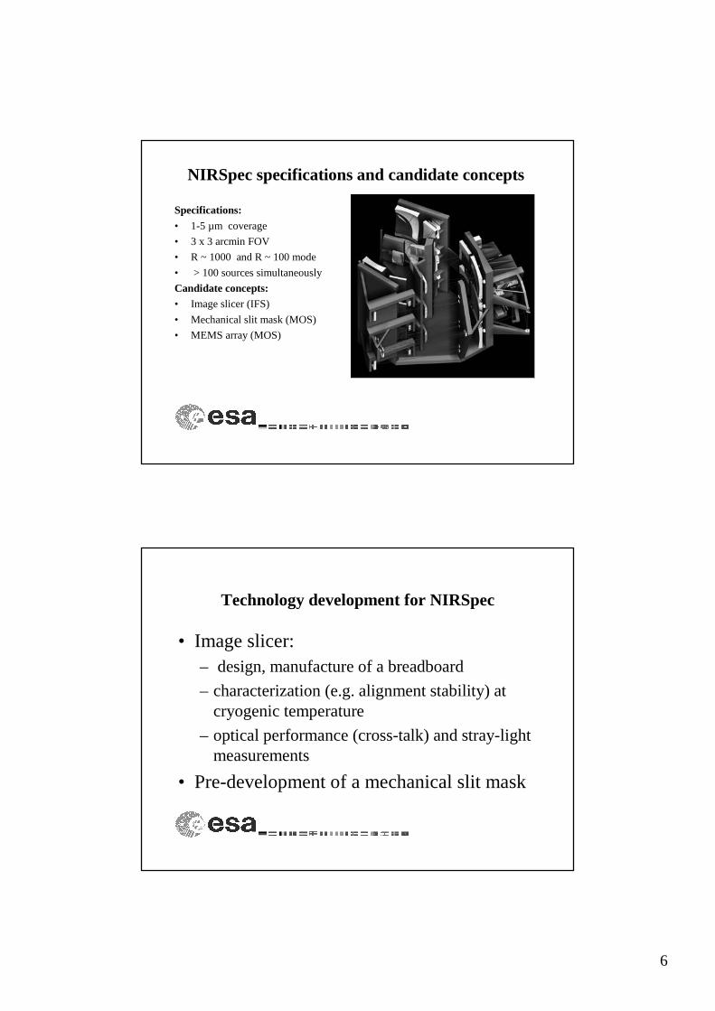
NIRSpec specifications and candidate concepts
Specifications:
• 1-5 µm coverage
• 3 x 3 arcmin FOV
• R ~ 1000 and R ~ 100 mode
• > 100 sources simultaneously
Candidate concepts:• Image slicer (IFS)
• Mechanical slit mask (MOS)
• MEMS array (MOS)
Technology development for NIRSpec
• Image slicer:– design, manufacture of a breadboard
– characterization (e.g. alignment stability) at cryogenic temperature
– optical performance (cross-talk) and stray-light measurements
• Pre-development of a mechanical slit mask
7
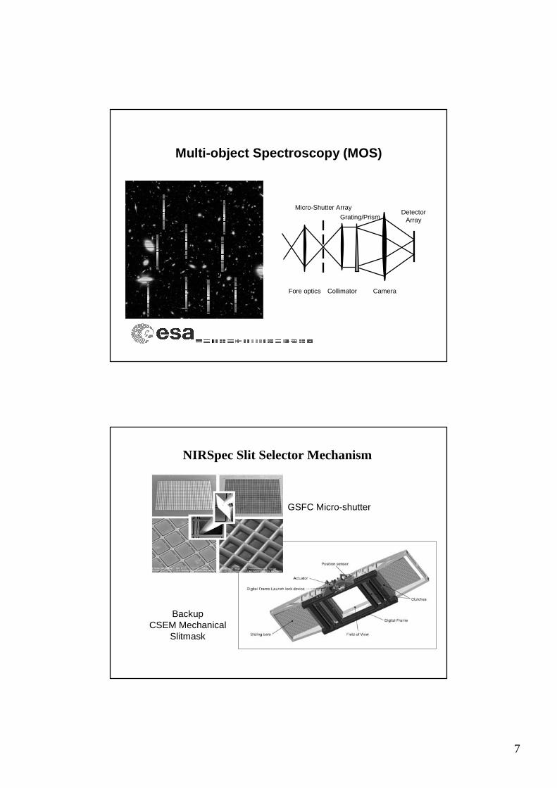
Multi-object Spectroscopy (MOS)
Fore optics Collimator Camera
Micro-Shutter Array
Grating/PrismDetector
Array
NIRSpec Slit Selector Mechanism
GSFC Micro-shutter
BackupCSEM Mechanical
Slitmask
8
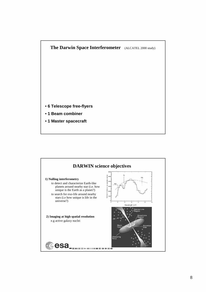
The Darwin Space Interferometer (ALCATEL 2000 study)
• 6 Telescope free-flyers
• 1 Beam combiner
• 1 Master spacecraft
DARWIN science objectives
1) Nulling interferometryto detect and characterize Earth-like
planets around nearby star (i.e. how unique is the Earth as a planet?)
to search for exo-life around nearby stars (i.e how unique is life in the universe?)
2) Imaging at high spatial resolutione.g active galaxy nuclei
9
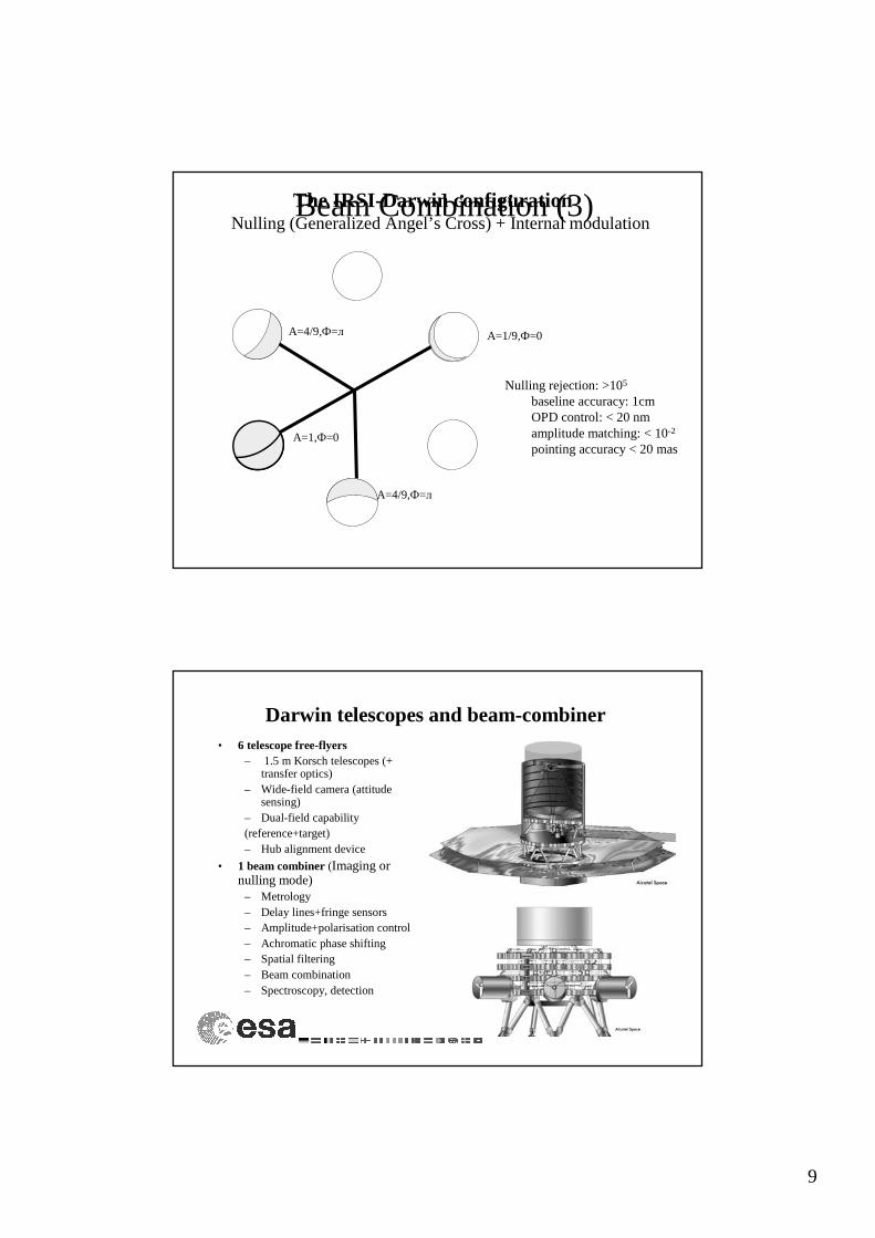
Beam Combination (3)The IRSI-Darwin configurationNulling (Generalized Angel’s Cross) + Internal modulation
A=4/9,Ф=л
A=4/9,Ф=л
A=1,Ф=0
A=1/9,Ф=0
Nulling rejection: >105
baseline accuracy: 1cmOPD control: < 20 nmamplitude matching: < 10-2
pointing accuracy < 20 mas
Darwin telescopes and beam-combiner• 6 telescope free-flyers
– 1.5 m Korsch telescopes (+ transfer optics)
– Wide-field camera (attitude sensing)
– Dual-field capability(reference+target)– Hub alignment device
• 1 beam combiner (Imaging or nulling mode)
– Metrology– Delay lines+fringe sensors– Amplitude+polarisation control– Achromatic phase shifting– Spatial filtering– Beam combination– Spectroscopy, detection

10
IRSI-Darwin (Launch 2014)
SMART3In-orbit technology demonstration
(2009?)
Darwin-GENIE(2001 – 2005, ops. 2006)
IRSI-DarwinTechnology Research Program (2001 – 2004)
IRSI-DarwinSystem study
(2000)
The Darwin development programme
DARWIN Technology Research Programme
• Pre-cursor flight technology (--> In-orbit testing?)– Control and operation system for constellation deployment and formation
flying)– Positioning RF subsystem, milli- and micro- Newton thrusters (FEEP)– High precision inter satellite metrology (interferometer coherencing)– Fringe sensors , delay lines (interferometer co-phasing)
• Optical components and subsystems (--> Ground-based testing)– Achromatic phase shifter – Integrated optics – Wavefront filtering, IR single mode fibres– IR detectors , cooler– Optical components (coatings, manufacturing reproducibility)– Multi-aperture laboratory breadboards
11
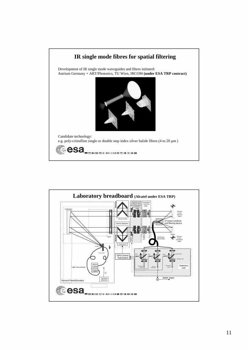
IR single mode fibres for spatial filtering
Development of IR single mode waveguides and fibres initiated:Astrium Germany + ART/Photonics, TU Wien, IRCOM (under ESA TRP contract)
Candidate technology: e.g. poly-cristalline single or double step index silver halide fibres (4 to 20 µm )
Laboratory breadboard (Alcatel under ESA TRP)
DetectionUnit
OPD ControlSub-system
Photometricoutput 1
Nulled output
Photometric output 2
Two-pupilsmask
Mov
able
knife
-edg
e
Bandpass filter
Sciencefocal plane
OPD1
Multimodeoptical fibers
Collimator
Star and PlanetSimulator
Adjustable delayline
Piezo-actuators
Slaved delayline
Off-axismirror
injectionoptics
IO beam combinerand filtering device
Pol
ariz
er
Bire
fring
ence
com
pens
ator
Amplitude andPi-phase shift
and chromatismCompens.
Polarisationmatchingstage
Science
Laser
Synchonedetection
Chopper
Laserstar
Light sources head
Off-axismirror
translationstage
OPD2OPD Dichroic plate
& Planet
Dichroic plate
stage

12
Integrated optics beam combiner
IR integrated optics for DARWIN
Why ?• compactness• weight• volume• modularity • low sensitivity to environment
(temperature, vibrations, etc.)
Potential Materials• Chalcogenide glasses• Silicon• Si/SiGe• Germanium• CdTe• ZnS/ZnSe• GaAs/AlGaAs• “Vacuum”
Potential Technologies• Thin film deposition and etching• Doping of bulk material• Photo-exposition• MEMS technologies
Development of IR integrated optics components for Darwin initiated:IMEP + LETI-CEA, LAOG, Alcatel Space (under ESA TRP contract)

13
Darwin-GENIE: an ESA-ESO collaboration
(Groundbased European Nulling Interferometer Experiment)
to experiment nulling interferometry on-ground (obs. scenarios, op. procedures, spectral bands, targets)
to benefit from ESO VLTI infrastructure and experience
to test key Darwin technology in an integrated system
Smart Optics for ESA Space MissionsSummary
1) ESA Space Science Missions require and stimulate the development of smart optical components and subsystems
2) ESA Technology Research Program (TRP) implement the development of smart optical components and subsystems
3) Major requirements for future ESA space missions:• Improvement of space observatories performance requires large,
lightweight telescopes (e.g. Herschell, JWST, Gaia)
• Future space observatories requires large focal plane arrays (Gaia, Eddington, JWST)
• New instrument concepts (NIRSpec, Darwin) requires (e.g.) IR optical fibers, MEMS, IR integrated optics …
4) Interferometry in space (Darwin - exo-planets) is a driver for the development of smart optical components and subsystems.
Related Documents