1 NHP Electrical Engineering Products 0800 NHP NHP 1300 NHP NHP nhp.com.au NZ AUS Smart Machine Safety Selection Guide A tool for selection of integrated and reliable machine safety components

Welcome message from author
This document is posted to help you gain knowledge. Please leave a comment to let me know what you think about it! Share it to your friends and learn new things together.
Transcript
1NHP Electrical Engineering Products 0800 NHP NHP1300 NHP NHP nhp.com.auNZAUS
Smart Machine Safety Selection Guide A tool for selection of integrated and reliable machine safety components
2
856T Control Tower
Stack Light
440N Non-Contact
440N Integrated Latch
440G-TLSZ Guard Lock
Two Sensor T-Type Muting Arrangement
442L CIP Safety Laser
Scanner
800F Emergency Stop
440C-CR30 Configurable Safety Relay
5069 Compact GuardLogix
100S-E Safety Contactors
442G Multifunctional
Access Box
843ES CIP Safety Encoder
Two Sensor L-Type Muting Arrangement
450LSafety
Light Curtain
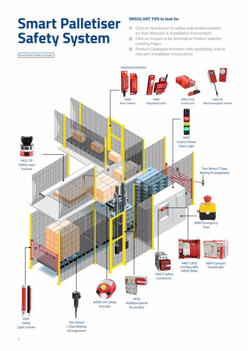
Smart Palletiser Safety System
Functional Safety System
SMSSG HOT TIPS to look for
1) Click on 'text boxes' to utilize web-linked content. ex 'User Manuals' & 'Installation Instructions'
2) Click on images to be directed to Product website Landing Pages.
3) Product Catalogue Numbers with underlines, link to relevant 'Installation Instructions'.
440G-EZ Electromagnetic Switch
Interlock Switches

3
4-5 Safety Categories Explained
6-7 GuardLink Technology
Presence Sensing Safety DevicesLight Curtains
8-11 450L Guardshield POC Safety Light Curtains
12-13 445L Guardshield PAC Safety Light Curtains
Laser Scanners
14-15 442L SafeZone3 CIP Safety Laser Scanner
16-18 442L SazeZone Laser Scanner
20-21 Safety Mats
Safety Interlock Switches22 Guard Locking Switches
23 440G-MZ Guard Lock Switch
24 440G-TLS-Z GD2 Guard Lock Switch
25 440G-LZ Bolt Lock Switch
26 440G-EZ Electromagnetic Interlocking Switch
27 440G TLS GD2 Guard Lock Switch
28-30 442G Multifunctional Access Box
31 440J Grip Enabling Switch
Trapped Key Interlock Switches
32-38 440T Prosafe Trapped Key Systems
40 Tongue Interlock Switches
41 440K Trojan T15 GD2 Tongue Interlock Switch
42 440K Trojan T5/T6 Universal Tongue Interlock Switch
43 440K Elf Miniature Tongue Interlock Switch
44 440K Cadet 3 Tongue Interlock Switch
45 440K MT GD2 Tongue Interlock Switch
Non-Contact Interlock Switches
46-48 440N SensaGuard Non-Contact Interlock Switches
49-50 440N Magnetically Coded Non-Contact Interlock Switches
Safety Operator Devices
Safety Limit Switches
52-53 440P Limit Switches
Emergency Stop Devices
54-56 440E Cable Pull Wire Switches
58-61 800F Emergency-Stop & Operator Devices
62 Safety Logic Devices63 Safety Relays
63-67 440R Guardmaster Safety Monitoring Relay
68-69 440C CR30 Software Configurable Safety Relay
70 440R MSR55P Back EMF Monitoring Relay
72 Safety Programmable Controllers (PLCs)73-74 5069 Compact Guardlogix 5380 Safety Controller
75-76 1756 Contrologix 5580 Safety Controller
77 Safety Input/Output (I/O) Modules78 Compact 5000 I/O Modules
79 Flex 5000 I/O Modules
80 Point Guard I/O Modules
81 ArmorBlock Guard I/O Modules
Safety Motor ControlAbsolute Encoders on EtherNet/IP
82-83 843ES CIP Safety over EtherNet/IP Encoders
84 842E EtherNet/IP Encoders
Safety Contactors
86-88 100S Safety Contactors
89-91 100S Contactor Overloads
Visual Devices92-93 856T Control Tower Stack Lights
EtherNet/IP Network94-95 Stratix Switches
96 EtherNet Cables
97 DC Micro M12 Cables
98 Safety Services99 Machine Scalable Assessment Audit
100 SAF-TUV-0T Functional Safety for Machinery Technician Course
101 SAF- TUV1 Functional Safety for Machinery Introduction Course
102 SAF-TUV2 Functional Safety for Machinery Engineer Certification
Table of contents
4
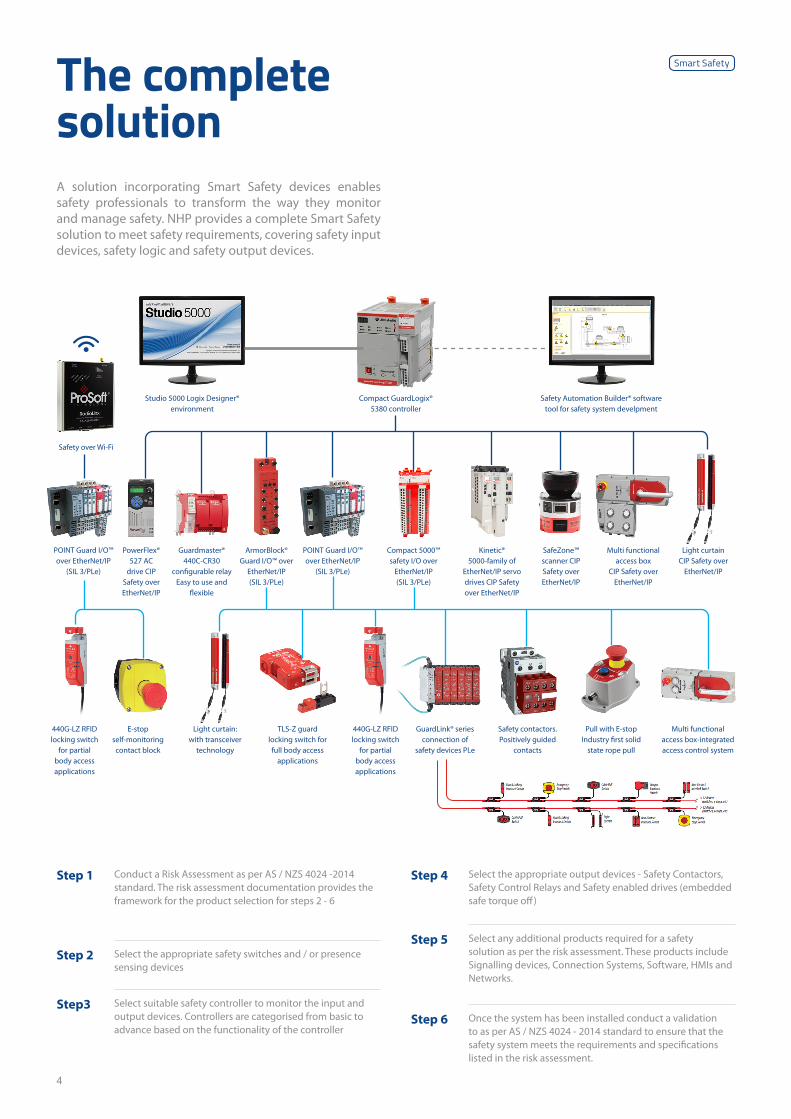
The complete solutionA solution incorporating Smart Safety devices enables safety professionals to transform the way they monitor and manage safety. NHP provides a complete Smart Safety solution to meet safety requirements, covering safety input devices, safety logic and safety output devices.
Step 4 Select the appropriate output devices - Safety Contactors, Safety Control Relays and Safety enabled drives (embedded safe torque off)
Step 5 Select any additional products required for a safety solution as per the risk assessment. These products include Signalling devices, Connection Systems, Software, HMIs and Networks.
Step 6 Once the system has been installed conduct a validation to as per AS / NZS 4024 - 2014 standard to ensure that the safety system meets the requirements and specifications listed in the risk assessment.
Step 1 Conduct a Risk Assessment as per AS / NZS 4024 -2014 standard. The risk assessment documentation provides the framework for the product selection for steps 2 - 6
Step 2 Select the appropriate safety switches and / or presence sensing devices
Step3 Select suitable safety controller to monitor the input and output devices. Controllers are categorised from basic to advance based on the functionality of the controller
Studio 5000 Logix Designer® environment
Safety over Wi-Fi
Compact GuardLogix® 5380 controller
Safety Automation Builder® software tool for safety system develpment
POINT Guard I/O™ over EtherNet/IP
(SIL 3/PLe)
440G-LZ RFID locking switch
for partial body access applications
440G-LZ RFID locking switch
for partial body access applications
TLS-Z guard locking switch for full body access
applications
PowerFlex® 527 AC
drive CIP Safety over EtherNet/IP
E-stop self-monitoring contact block
Pull with E-stop Industry first solid
state rope pull
Multi functional access box-integrated access control system
Light curtain: with transceiver
technology
Light curtain CIP Safety over
EtherNet/IP
Guardmaster® 440C-CR30
configurable relay Easy to use and
flexible
ArmorBlock® Guard I/O™ over
EtherNet/IP (SIL 3/PLe)
POINT Guard I/O™ over EtherNet/IP
(SIL 3/PLe)
SafeZone™ scanner CIP Safety over EtherNet/IP
GuardLink® series connection of
safety devices PLe
Compact 5000™ safety I/O over
EtherNet/IP (SIL 3/PLe)
Kinetic® 5000-family of
EtherNet/IP servo drives CIP Safety over EtherNet/IP
Multi functional access box
CIP Safety over EtherNet/IP
Safety contactors. Positively guided
contacts
Smart Safety

5
Safety categories explainedStandards are available to help with a safety system design – however there are a few around which are currently in use in Australia/New Zealand and around the world.
All three are perfectly valid for use in Australia and New Zealand for machine safety applications.
These standards can be categorised into two types: Quali-tative, and Quantitative, and this depends on the methods used to determine how a safety control system is designed to ensure an adequate level of risk reduction.
Category AS/NZS 4024.1501 / EN 954
Performance Level AS/NZS 4024.1503 / ISO 13849
Safety Integrity Level AS 62061 / IEC 62061
Category B PL a -
Category 1 PL bSIL 1
Category 2 PL c
Category 3 PL d SIL 2
Category 4 PL e SIL 3
Performance Level
Average probability of dangerous failure per hour
Safety Integrity Level (SIL)
Average probability of dangerous failure per hour
a ≥ 10-5 to < 10-4
b ≥ 3 x 10⁻⁶ to < 10-5
c ≥ 10-6 to < 3 x 10⁻⁶ 1 ≥ 10-6 to < 10-5
d ≥ 10-7 to < 10-8 2 ≥ 10-7 to < 10-6
e ≥ 10-8 to < 10-7 3 ≥ 10-8 to < 10-7
Category Level
Safety Function
B Standard product not designed specifically for safety application.
1Product designed using reliable components and well tried safety principles. Can still fail but is less likely to. In practice Category 1 is regarded as the minimum Category for safety.
2Product designed using reliable components and well tried safety principles, plus a periodic manual of automatic check of safety function.
3A single fault shall not cause the loss of the safety function and that fault should be detected at or before next demand on the safety function.
4
A single fault must be detected before the next demand on the safety function. An accumulation of non-detected single faults shall not cause the loss of the safety function (in practice, 2 or 3 faults).
Note: Intended to show approximate equivalency for guidance only; attain-ing the corresponding PL or SIL requires more information and calculation based on several additional factors.
Qualitative Category LevelsThe Qualitative standard is based on Safety Categories, and there are 5 of them between Category B and Category 4.
What makes this a Qualitative standard is that it is based around the behaviour of a safety control system and how it responds to faults – in other words, the “Quality” of the safety control system.
It does not address the probability of faults occurring, or the time taken for them to occur.
The categories are scaled from least effective to most effec-tive in reducing risk.
Quantitative Safety Integrity Level (SIL) and Performance Level (PL)The Quantitative standards consider not only the beha-viour of the system with respect to faults, but also consider calculated probabilities, which include the likelihood of a failure occurring, the failure being dangerous or safe and the likelihood of detecting failures.
Both ratings are based on calculations of the performance of the individual components in the safety control system and how they are arranged; and ultimately are a function of the probability of dangerous failure in any given hour.
For example, PLe and SIL 3 are defined by the probability of a dangerous fault in any given hour of between 10-8 and 10-7 – you could also look at this as the reciprocal, which is roughly the equivalent of once every 1,000 to 10,000 years. Considering the defined expected lifetime of the machine is 20 years, you can see how effective a high integrity safety control system to PLe or SIL3 can be.
Machinery Safebook 5 Safety Functions Documents
6
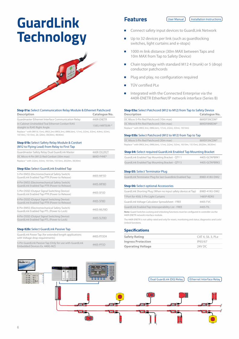
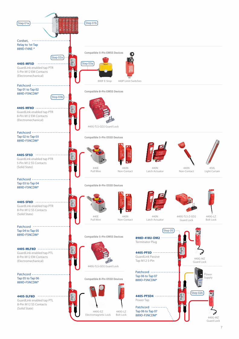
GuardLink Technology
Features ■ Connect safety input devices to GuardLink Network
■ Up to 32 devices per link (such as guardlocking switches, light curtains and e-stops)
■ 1000 m link distance (30m MAX between Taps and 10m MAX from Tap to Safety Device)
■ Chain topology with standard M12 4 (trunk) or 5 (drop) conductor patchcords
■ Plug and play, no configuration required
■ TÜV certified PLe
■ Integrated with the Connected Enterprise via the 440R-ENETR EtherNet/IP network interface (Series B)
Step 02a: Select GuardLink Enabled Tap
5-Pin EMSS (Electromechanical Safety Switch) GuardLink Enabled Tap PTR (Power to Release) 440S-MF5D
8-Pin EMSS (Electromechanical Safety Switch) GuardLink Enabled Tap PTR (Power to Release) 440S-MF8D
5-Pin OSSD (Output Signal Switching Device) GuardLink Enabled Tap PTR (Power to Release) 440S-SF5D
8-Pin OSSD (Output Signal Switching Device) GuardLink Enabled Tap PTR (Power to Release) 440S-SF8D
8-Pin EMSS (Electromechanical Safety Switch) GuardLink Enabled Tap PTL (Power to Lock) 440S-MLF8D
8-Pin OSSD (Output Signal Switching Device) GuardLink Enabled Tap PTL (Power to Lock) 440S-SLF8D
Step 02b: Select GuardLink Passive Tap
GuardLink Power Tap (for extended length applications with Voltage drop requirements) 440S-PF5D4
5-Pin GuardLink Passive Tap (Only for use with GuardLink Embedded Devices Ex. 440G-MZ) 440S-PF5D
Step 04: Select required GuardLink Enabled Tap Mounting Bracket
GuardLink Enabled Tap Mounting Bracket - QTY 1 440S-GLTAPBRK1
GuardLink Enabled Tap Mounting Bracket - QTY 5 440S-GLTAPBRK5
Step 05: Select Terminator Plug
GuardLink Terminator Plug for last Guardlink Enabled Tap 898D-418U-DM2
Step 06: Select optional Accessories
GuardLink Shorting Plug (When no input safety device at Tap) 898D-41KU-DM2
T-Port for 450L 5-Pin Light Curtains 1485P-RDR5
GuardLink Voltage Calculator Spreadsheet - FREE 440S-TVC
GuardLink Enabled Tap Interoperability List - FREE 440S-TIL
Specifications
Safety Rating CAT 4, SIL 3, PLeIngress Protection IP65/67Operating Voltage 24V DC
Step 01a: Select Communication Relay Module & Ethernet PatchcordDescription Catalogue No.Guardmaster Ethernet Interface Communication Relay 440R-ENETR
In-Cabinet Unshielded Teal Ethernet Cordset RJ45 straight to RJ45 Right Angle
1585J-M8TBJM-*
Replace * with 0M15(.15m), 0M2(.2m) 0M3(.3m), 0M6(.6m), 1(1m), 2(2m), 3(3m), 4(4m), 5(5m), 10(10m), 15(15m), 20, (20m), 30(30m), 40(40m)
Step 01b: Select Safety Relay Module & Cordset (M12 to Flying Lead) from Relay to First Tap
Guardmaster Safety Relay Dual GuardLink Master 440R-DG2R2T
DC Micro 4-Pin (M12) Red Cordset (30m max) 889D-F4NE*Replace * with 2(2m), 5(5m), 10(10m, 15(15m), 20(20m, 30(30m)
Step 03a: Select Patchcord (M12 to M12) from Tap to Safety DeviceDescription Catalogue No.DC Micro 5-Pin Red Patchcord (10m max) 889DF5NCDM*
DC Micro 8-Pin Red Patchcord (10m max) 889DF8NBDM*Replace * with 0M3(.3m), 0M6(.6m), 1(1m), 2(2m), 5(5m), 10(10m)
Step 03b: Select Patchcord (M12 to M12) from Tap to Tap
DC Micro 5-Pin Red Patchcord (30m max) 889DF5NCDM*Replace * with 0M3(.3m), 0M6(.6m), 1(1m), 2(2m), 5(5m), 10(10m, 15(15m), 20(20m, 30(30m)
User Manual Installation Instructions
Note: Guard Switches Locking and Unlocking functions must be configured in controller via the 440R-ENETR network interface module.
The 440R-ENETR is not safety rated and only for resets, monitoring and status, diagnostics and Lock/ Unlock functions.
Dual GuardLink (DG) Relay Ethernet Interface Relay
7
Patchcord Tap 06 to Tap 07 889D-F5NCDM*
Power Supply
Patchcord Tap 06 to Tap 07 889D-F5NCDM*
440S-PF5D4Power Tap
440S-PF5DGuardLink Passive Tap M12 5-Pin
898D-418U-DM2Terminator Plug
440S-MF5DGuardLink enabled tap PTR 5-Pin M12 EM Contacts (Electromechanical)
Cordset, Relay to 1st Tap 889D-F4NE-*
Patchcord Tap 04 to Tap 05 889D-F5NCDM*
440S-MF8DGuardLink enabled tap PTR 8-Pin M12 EM Contacts (Electromechanical)
440S-SF5DGuardLink enabled tap PTR 5-Pin M12 SS Contacts(Solid State)
440S-SF8DGuardLink enabled tap PTR 8-Pin M12 SS Contacts (Solid State)
440S-SLF8DGuardLink enabled tap PTL 8-Pin M12 SS Contacts (Solid State)
Patchcord Tap 01 to Tap 02 889D-F5NCDM*
Patchcord Tap 02 to Tap 03 889D-F5NCDM*
440S-MLF8DGuardLink enabled tap PTL 8-Pin M12 EM Contacts (Electromechanical)
Patchcord Tap 05 to Tap 06 889D-F5NCDM*
Patchcord Tap 03 to Tap 04 889D-F5NCDM*
Compatible 5-Pin EMSS Devices
Compatible 5-Pin OSSD Devices
Compatible 5-Pin EMSS Devices
Compatible 8-Pin OSSD Devices
Compatible 8-Pin OSSD Devices
Compatible 8-Pin EMSS Devices
800F E-Stop 440P Limit Switches
440G-TLS-GD2 Guard Lock
440G-TLS-GD2 Guard Lock
440G-TLS-Z-GD2Guard Lock
440E Pull Wire
440E Pull Wire
440G-MZGuard Lock
440G-MZGuard Lock
440G-LZBolt Lock
440G-LZBolt Lock
440G-EZElectromagnetic Lock
440N Non-Contact
440N Non-Contact
440N Non-Contact
440N Latch Actuator
440N Latch Actuator
450L Light Curtain
Step 03b
Step 03a
Step 01bStep 01a
Step 02b
Step 05
Step 02a
8
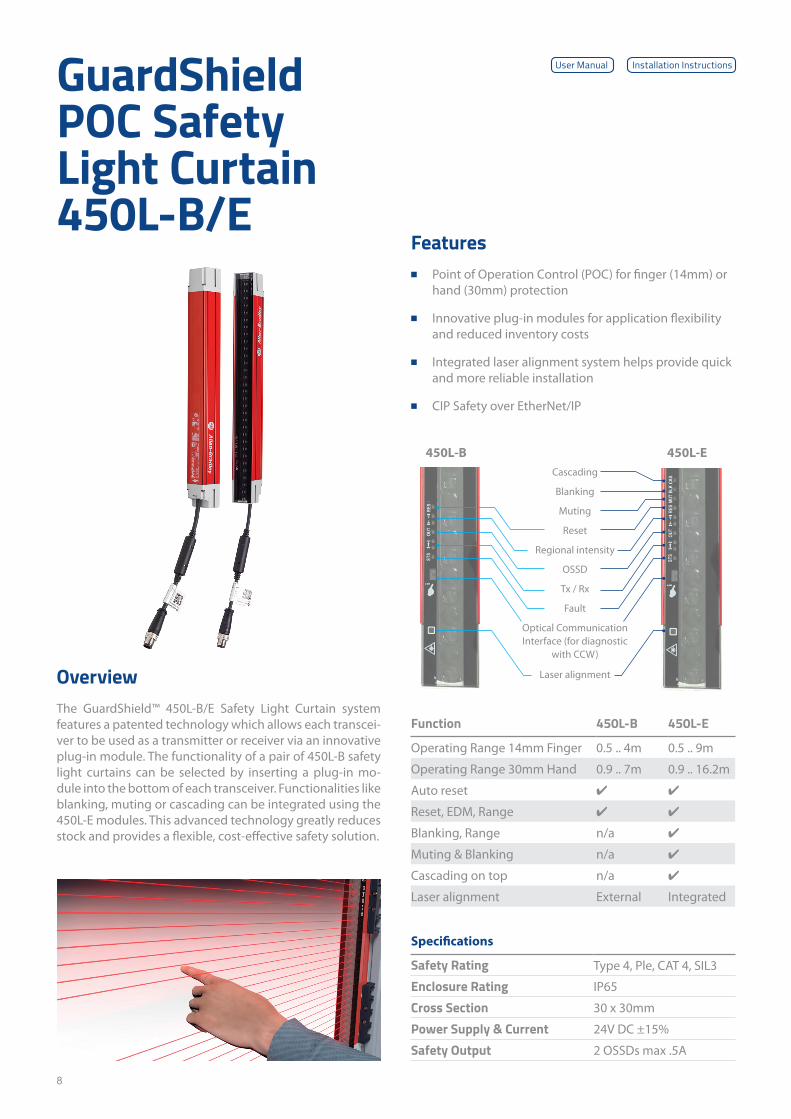
GuardShield POC Safety Light Curtain 450L-B/E
Specifications
Safety Rating Type 4, Ple, CAT 4, SIL3
Enclosure Rating IP65
Cross Section 30 x 30mm
Power Supply & Current 24V DC ±15%
Safety Output 2 OSSDs max .5A
Function 450L-B 450L-E
Operating Range 14mm Finger 0.5 .. 4m 0.5 .. 9m
Operating Range 30mm Hand 0.9 .. 7m 0.9 .. 16.2m
Auto reset ✔ ✔
Reset, EDM, Range ✔ ✔
Blanking, Range n/a ✔
Muting & Blanking n/a ✔
Cascading on top n/a ✔
Laser alignment External Integrated
OverviewThe GuardShield™ 450L-B/E Safety Light Curtain system features a patented technology which allows each transcei-ver to be used as a transmitter or receiver via an innovative plug-in module. The functionality of a pair of 450L-B safety light curtains can be selected by inserting a plug-in mo- dule into the bottom of each transceiver. Functionalities like blanking, muting or cascading can be integrated using the 450L-E modules. This advanced technology greatly reduces stock and provides a flexible, cost-effective safety solution.
Features ■ Point of Operation Control (POC) for finger (14mm) or
hand (30mm) protection
■ Innovative plug-in modules for application flexibility and reduced inventory costs
■ Integrated laser alignment system helps provide quick and more reliable installation
■ CIP Safety over EtherNet/IP
Laser alignment
Optical Communication Interface (for diagnostic
with CCW)
Fault
Tx / Rx
OSSD
Regional intensity
Reset
Muting
Blanking
Cascading
450L-B 450L-E
User Manual Installation Instructions
9
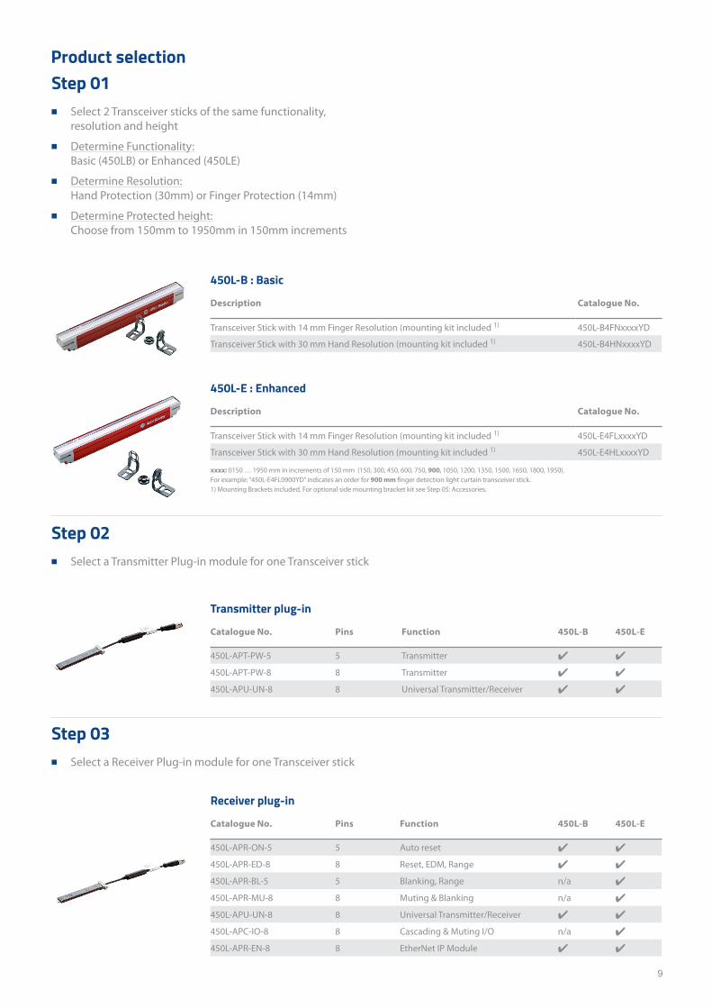
Transmitter plug-in
Catalogue No. Pins Function 450L-B 450L-E
450L-APT-PW-5 5 Transmitter ✔ ✔
450L-APT-PW-8 8 Transmitter ✔ ✔
450L-APU-UN-8 8 Universal Transmitter/Receiver ✔ ✔
Receiver plug-in
Catalogue No. Pins Function 450L-B 450L-E
450L-APR-ON-5 5 Auto reset ✔ ✔
450L-APR-ED-8 8 Reset, EDM, Range ✔ ✔
450L-APR-BL-5 5 Blanking, Range n/a ✔
450L-APR-MU-8 8 Muting & Blanking n/a ✔
450L-APU-UN-8 8 Universal Transmitter/Receiver ✔ ✔
450L-APC-IO-8 8 Cascading & Muting I/O n/a ✔
450L-APR-EN-8 8 EtherNet IP Module ✔ ✔
Product selection
450L-B : Basic
Description Catalogue No.
Transceiver Stick with 14 mm Finger Resolution (mounting kit included 1) 450L-B4FNxxxxYD
Transceiver Stick with 30 mm Hand Resolution (mounting kit included 1) 450L-B4HNxxxxYD
450L-E : Enhanced
Description Catalogue No.
Transceiver Stick with 14 mm Finger Resolution (mounting kit included 1) 450L-E4FLxxxxYD
Transceiver Stick with 30 mm Hand Resolution (mounting kit included 1) 450L-E4HLxxxxYD
xxxx: 0150 … 1950 mm in increments of 150 mm (150, 300, 450, 600, 750, 900, 1050, 1200, 1350, 1500, 1650, 1800, 1950). For example: “450L-E4FL0900YD” indicates an order for 900 mm finger detection light curtain transceiver stick.1) Mounting Brackets included. For optional side mounting bracket kit see Step 05: Accessories.
Step 02 ■ Select a Transmitter Plug-in module for one Transceiver stick
Step 03 ■ Select a Receiver Plug-in module for one Transceiver stick
Step 01 ■ Select 2 Transceiver sticks of the same functionality,
resolution and height
■ Determine Functionality: Basic (450LB) or Enhanced (450LE)
■ Determine Resolution: Hand Protection (30mm) or Finger Protection (14mm)
■ Determine Protected height: Choose from 150mm to 1950mm in 150mm increments
10
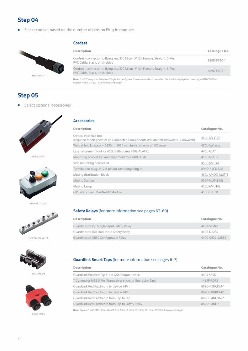
Step 04 ■ Select cordset based on the number of pins on Plug-in modules
Step 05 ■ Select optional accessories
Cordset
Description Catalogue No.
Cordset - connector to flying lead DC Micro (M12), Female, Straight, 5-Pin, PVC Cable, Black, Unshielded
889D-F5BC-*
Cordset - connector to flying lead DC Micro (M12), Female, Straight, 8-Pin, PVC Cable, Black, Unshielded
889D-F8AB-*
Accessories
Description Catalogue No.
Optical interface tool (required for diagnostics on Connected Components Workbench software v12 onwards)
450L-AD-OID
Weld shield kit (xxxx = 0150 … 1950 mm in increments of 150 mm) 450L-AW-xxxx
Laser alignment tool for 450L-B (Requires 450L-ALAT-C) 440L-ALAT
Mounting bracket for laser alignment tool 440L-ALAT 450L-ALAT-C
Side mounting bracket kit 450L-AM-SM
Termination plug, M12 8-pin for cascading plug-in 898D-81CU-DM
Muting distribution block 450L-AMOD-MUT-8
Muting Station 800F-MUT-2-MS
Muting Lamp 450L-AMUT-IL
CIP Safety over EtherNet/IP Module 450L-ENETR
Safety Relays (for more information see pages 62-69)
Description Catalogue No.
Guardmaster (SI) Single Input Safety Relay 440R-S12R2
Guardmaster (DI) Dual Input Safety Relay 440R-D22R2
Guardmaster CR30 Configurable Relay 440C-CR30-22BBB
Guardlink Smart Taps (for more information see pages 6-7)
Description Catalogue No.
GuardLink Enabled Tap 5-pin OSSD Input device 440S-SF5D
T Connector M12-5 Pin (Transceiver sticks to GuardLink Tap) 1485P-RDR5
GuardLink Red Patchcord to device 5-Pin 889D-F5NCDM-*
GuardLink Red Patchcord to device 8-Pin 889D-F8NBDM-*
GuardLink Red Patchcord from Tap to Tap 889D-F4NEDM-*
GuardLink Red Patchcord from Tap to Safety Relay 889D-F4NE-*
Note: For CIP Safety over EtherNet/IP Light Curtain System it's recommended to use a Red Patchord as displayed on next page 889D-F8NBDM-*. Replace * with 2, 5, 10, 15, 20 for required length
450L-AM-SM
1485P-RDR5
450L-AMOD-MUT-8
800F-MUT-2-MS
Note: Replace * with 0M3 (0.3m), 0M6 (0.6m), 2 (2m), 5 (5m), 10 (10m), 15 (15m), 20 (20m) for required length.
450L-AD-OID
889D-F5BC-*
11
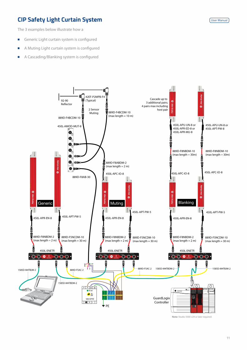
CIP Safety Light Curtain SystemThe 3 examples below illustrate how a
■ Generic Light curtain system is configured
■ A Muting Light curtain system is configured
■ A Cascading/Blanking system is configured
450L-APT-PW-5
GuardLogixController
450L-ENETR450L-ENETR
450L-APC-IO-8
450L-APU-UN-8 or450L-APT-PW-8
450L-APR-EN-8450L-APT-PW-5
450L-APC-IO-8
450L-APU-UN-8 or450L-APR-ED-8 or450L-APR-MU-8
450L-APR-EN-8
450L-ENETR
450L-APT-PW-5
450L-APR-EN-8
Cascade up to 3 additional pairs;
4 pairs max includinghost pair
L
++
N
1606-XLP95E
24-28V
DC ok
PE
Blanking
889D-F8NBDM-10(max length = 30m)
889D-F8NBDM-10(max length = 30m)
889D-F5NCDM-10(max length = 30 m)
889D-F5NCDM-10(max length = 30 m)
889D-F5NCDM-10(max length = 30 m)
889D-F8NBDM-2(max length = 2 m)
889D-F8NBDM-2(max length = 2 m)
889D-F8NBDM-2(max length = 2 m)
2 SensorMuting
889D-F8ABDM-2(max length = 2 m)
889D-F4BCDM-10
889D-F8AB-30
450L-AMOD-MUT-8
889D-F4BCDM-10(max length = 10 m)
42EF-P2MPB-F4(Typical)92-90
Re�ector
1
5
4
3
2
6
450L-APC-IO-8
MutingGeneric
User Manual
1585D-M4TBJM-2
1585D-M4TBDM-2
889D-F5AC-2 889D-F5AC-2 1585D-M4TBDM-2 1585D-M4TBJM-2
Note: Studio 5000 v24 or later required.
12
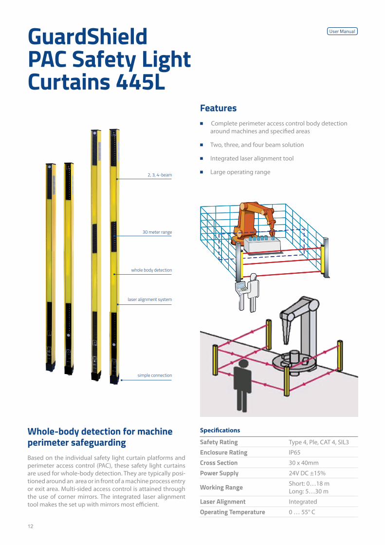
GuardShield PAC Safety Light Curtains 445L
Whole-body detection for machine perimeter safeguardingBased on the individual safety light curtain platforms and perimeter access control (PAC), these safety light curtains are used for whole-body detection. They are typically posi-tioned around an area or in front of a machine process entry or exit area. Multi-sided access control is attained through the use of corner mirrors. The integrated laser alignment tool makes the set up with mirrors most efficient.
Specifications
Safety Rating Type 4, Ple, CAT 4, SIL3
Enclosure Rating IP65
Cross Section 30 x 40mm
Power Supply 24V DC ±15%
Working Range Short: 0…18 mLong: 5…30 m
Laser Alignment Integrated
Operating Temperature 0 … 55° C
2, 3, 4-beam
30 meter range
whole body detection
laser alignment system
simple connection
Features ■ Complete perimeter access control body detection
around machines and specified areas
■ Two, three, and four beam solution
■ Integrated laser alignment tool
■ Large operating range
User Manual
13
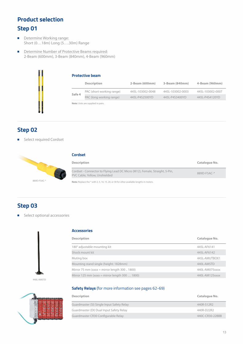
Product selectionStep 01
■ Determine Working range: Short (0…18m) Long (5….30m) Range
■ Determine Number of Protective Beams required: 2-Beam (600mm), 3-Beam (840mm), 4-Beam (960mm)
Protective beam
Description 2-Beam (600mm) 3-Beam (840mm) 4-Beam (960mm)
Safe 4PAC (short working range) 445L-103002-0048 445L-103002-0003 445L-103002-0007
PAC (long working range) 445L-P4S2500YD 445L-P4S3400YD 445L-P4S4120YD
Step 02 ■ Select required Cordset
Step 03 ■ Select optional accessories
Cordset
Description Catalogue No.
Cordset - Connector to Flying Lead DC Micro (M12), Female, Straight, 5-Pin, PVC Cable, Yellow, Unshielded
889D-F5AC-*
Accessories
Description Catalogue No.
180° adjustable mounting kit 445L-AF6141
Shock mount kit 445L-AF6142
Muting box 445L-AMUTBOX1
Mounting stand single (height: 1828mm) 440L-AMSTD
Mirror 75 mm (xxxx = mirror length 300 .. 1800) 440L-AM075xxxx
Mirror 125 mm (xxxx = mirror length 300 … 1800) 440L-AM125xxxx
Safety Relays (for more information see pages 62-69)
Description Catalogue No.
Guardmaster (SI) Single Input Safety Relay 440R-S12R2
Guardmaster (DI) Dual Input Safety Relay 440R-D22R2
Guardmaster CR30 Configurable Relay 440C-CR30-22BBB
Note: Replace the * with 2, 5, 10, 15, 20, or 30 for other available lengths in meters.
Note: Units are supplied in pairs.
440L-AMSTD
889D-F5AC-*
14
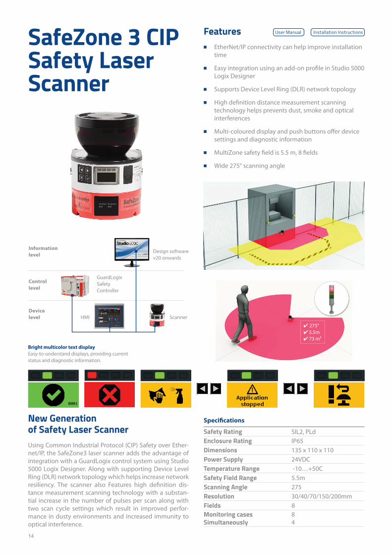
SafeZone 3 CIP Safety Laser Scanner
New Generation of Safety Laser ScannerUsing Common Industrial Protocol (CIP) Safety over Ether-net/IP, the SafeZone3 laser scanner adds the advantage of integration with a GuardLogix control system using Studio 5000 Logix Designer. Along with supporting Device Level Ring (DLR) network topology which helps increase network resiliency. The scanner also Features high definition dis-tance measurement scanning technology with a substan-tial increase in the number of pulses per scan along with two scan cycle settings which result in improved perfor-mance in dusty environments and increased immunity to optical interference.
Specifications
Safety Rating SIL2, PLdEnclosure Rating IP65Dimensions 135 x 110 x 110Power Supply 24VDCTemperature Range -10…+50CSafety Field Range 5.5mScanning Angle 275Resolution 30/40/70/150/200mmFields 8Monitoring cases Simultaneously
84
Features ■ EtherNet/IP connectivity can help improve installation
time
■ Easy integration using an add-on profile in Studio 5000 Logix Designer
■ Supports Device Level Ring (DLR) network topology
■ High definition distance measurement scanning technology helps prevents dust, smoke and optical interferences
■ Multi-coloured display and push buttons offer device settings and diagnostic information
■ MultiZone safety field is 5.5 m, 8 fields
■ Wide 275° scanning angle
Information level
Controllevel
Devicelevel
Design software v20 onwards
GuardLogix Safety Controller
Scanner
Bright multicolor text displayEasy-to-understand displays, providing current status and diagnostic information.
HMI
✔ 275°✔ 5.5m✔ 73 m²
User Manual Installation Instructions
15
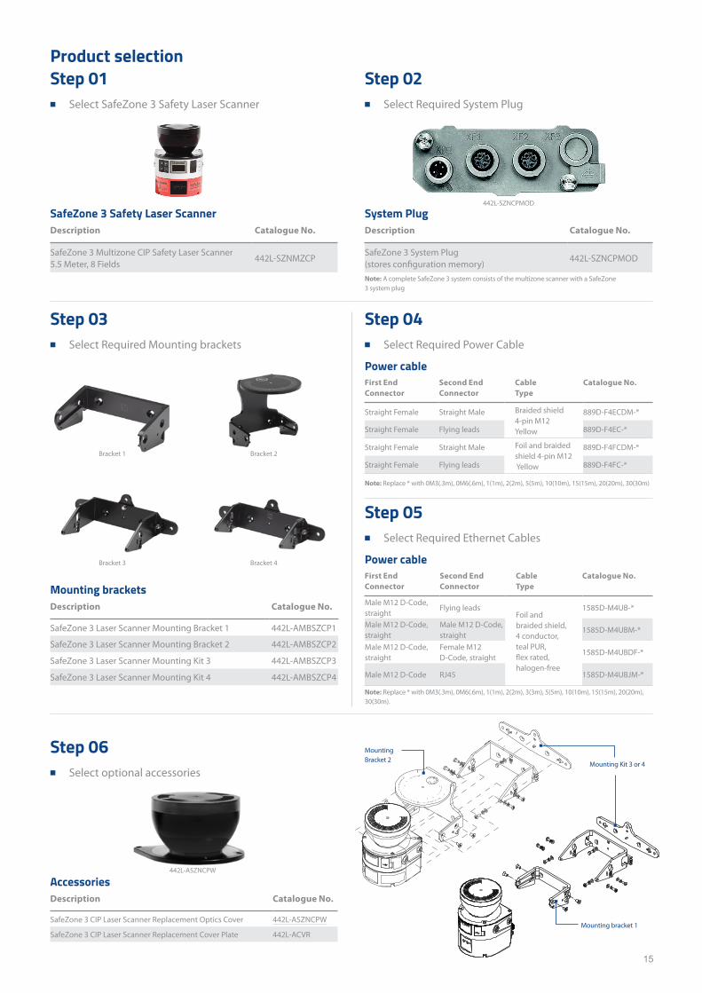
Product selectionStep 01
■ Select SafeZone 3 Safety Laser Scanner
Step 06 ■ Select optional accessories
Step 02 ■ Select Required System Plug
Step 03 ■ Select Required Mounting brackets
Step 04 ■ Select Required Power Cable
Step 05 ■ Select Required Ethernet Cables
System PlugDescription Catalogue No.
SafeZone 3 System Plug (stores configuration memory)
442L-SZNCPMOD
Mounting bracketsDescription Catalogue No.
SafeZone 3 Laser Scanner Mounting Bracket 1 442L-AMBSZCP1
SafeZone 3 Laser Scanner Mounting Bracket 2 442L-AMBSZCP2
SafeZone 3 Laser Scanner Mounting Kit 3 442L-AMBSZCP3
SafeZone 3 Laser Scanner Mounting Kit 4 442L-AMBSZCP4
Power cableFirst End Connector
Second End Connector
Cable Type
Catalogue No.
Straight Female Straight Male Braided shield 4-pin M12 Yellow
889D-F4ECDM-*
Straight Female Flying leads 889D-F4EC-*
Straight Female Straight Male Foil and braided shield 4-pin M12 Yellow
889D-F4FCDM-*
Straight Female Flying leads 889D-F4FC-*
Power cableFirst End Connector
Second End Connector
Cable Type
Catalogue No.
Male M12 D-Code, straight
Flying leadsFoil and braided shield, 4 conductor, teal PUR, flex rated, halogen-free
1585D-M4UB-*
Male M12 D-Code, straight
Male M12 D-Code, straight
1585D-M4UBM-*
Male M12 D-Code, straight
Female M12 D-Code, straight
1585D-M4UBDF-*
Male M12 D-Code RJ45 1585D-M4UBJM-*
SafeZone 3 Safety Laser ScannerDescription Catalogue No.
SafeZone 3 Multizone CIP Safety Laser Scanner 5.5 Meter, 8 Fields
442L-SZNMZCP
AccessoriesDescription Catalogue No.
SafeZone 3 CIP Laser Scanner Replacement Optics Cover 442L-ASZNCPW
SafeZone 3 CIP Laser Scanner Replacement Cover Plate 442L-ACVR
Note: A complete SafeZone 3 system consists of the multizone scanner with a SafeZone 3 system plug
Note: Replace * with 0M3(.3m), 0M6(.6m), 1(1m), 2(2m), 3(3m), 5(5m), 10(10m), 15(15m), 20(20m), 30(30m).
Mounting Bracket 2
Mounting Kit 3 or 4
Mounting bracket 1
Note: Replace * with 0M3(.3m), 0M6(.6m), 1(1m), 2(2m), 5(5m), 10(10m), 15(15m), 20(20m), 30(30m)
Bracket 1
Bracket 3
Bracket 2
Bracket 4
442L-SZNCPMOD
442L-ASZNCPW
16
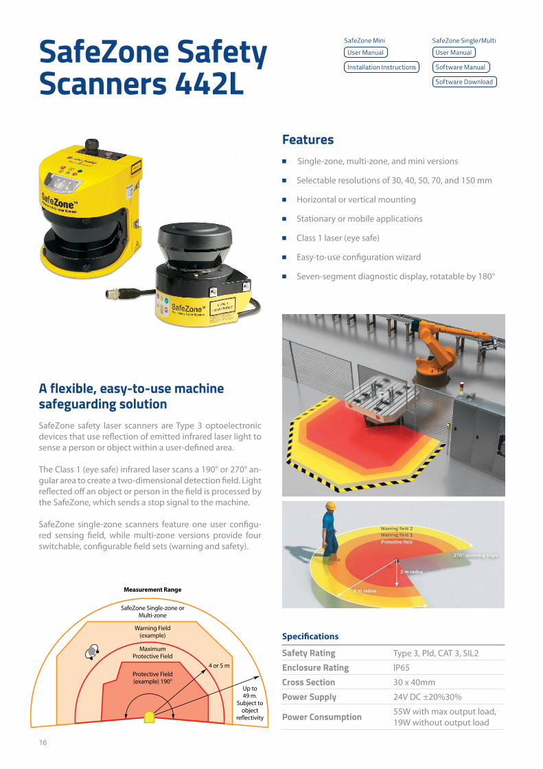
SafeZone Safety Scanners 442L
A flexible, easy-to-use machine safeguarding solutionSafeZone safety laser scanners are Type 3 optoelectronic devices that use reflection of emitted infrared laser light to sense a person or object within a user-defined area.
The Class 1 (eye safe) infrared laser scans a 190° or 270° an-gular area to create a two-dimensional detection field. Light reflected off an object or person in the field is processed by the SafeZone, which sends a stop signal to the machine.
SafeZone single-zone scanners feature one user configu-red sensing field, while multi-zone versions provide four switchable, configurable field sets (warning and safety).
Specifications
Safety Rating Type 3, Pld, CAT 3, SIL2
Enclosure Rating IP65
Cross Section 30 x 40mm
Power Supply 24V DC ±20%30%
Power Consumption 55W with max output load, 19W without output load
Features ■ Single-zone, multi-zone, and mini versions
■ Selectable resolutions of 30, 40, 50, 70, and 150 mm
■ Horizontal or vertical mounting
■ Stationary or mobile applications
■ Class 1 laser (eye safe)
■ Easy-to-use configuration wizard
■ Seven-segment diagnostic display, rotatable by 180°
Safety Field
Measurement Range
4 or 5 m
Up to 49 m.
Subject to object
reflectivity
SafeZone Single-zone or Multi-zone
Warning Field (example)
Maximum Protective Field
Protective Field (example) 190°
User ManualUser Manual
Software Manual
Software Download
Installation Instructions
SafeZone Mini SafeZone Single/Multi
17
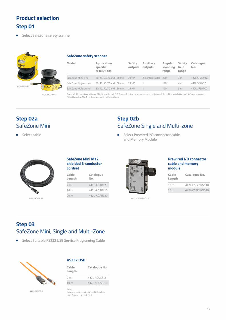
Product selectionStep 01
■ Select SafeZone safety scanner
SafeZone safety scanner
Model Application specific resolutions
Safety outputs
Auxiliary outputs
Angular scanning range
Safety field range
Catalogue No.
SafeZone Mini, 3 m 30, 40, 50, 70 and 150 mm 2 PNP 2 (configurable) 270° 3 m 442L-SFZNMN3
SafeZone Single-zone 30, 40, 50, 70 and 150 mm 2 PNP 1 190° 4 m 442L-SFZNSZ
SafeZone Multi-zone* 30, 40, 50, 70 and 150 mm 2 PNP 1 190° 5 m 442L-SFZNMZ
Step 02a SafeZone Mini
■ Select cable
Step 03 SafeZone Mini, Single and Multi-Zone
■ Select Suitable RS232 USB Service Programing Cable
Step 02b SafeZone Single and Multi-zone
■ Select Prewired I/O connector cable and Memory Module
SafeZone Mini M12 shielded 8-conductor cordsetCable Length
Catalogue No.
2 m 442L-ACABL2
10 m 442L-ACABL10
20 m 442L-ACABL20
RS232 USB
Cable Length
Catalogue No.
2 m 442L-ACUSB-2
10 m 442L-ACUSB-10
Prewired I/O connector cable and memory moduleCable Length
Catalogue No.
10 m 442L-CSFZNMZ-10
20 m 442L-CSFZNMZ-20
NoteOnly one cable required if multiple safety Laser Scanners are selected
442L-ACABL10
442L-ACUSB-2
442L-CSFZNMZ-10
442L-SFZNSZ
442L-SFZNMN3 Note: V3.0.0 operating software CD ships with each SafeZone safety laser scanner and also contains pdf files of the Installation and Software manuals.*Multi Zone has FOUR configurable switchable field sets
18
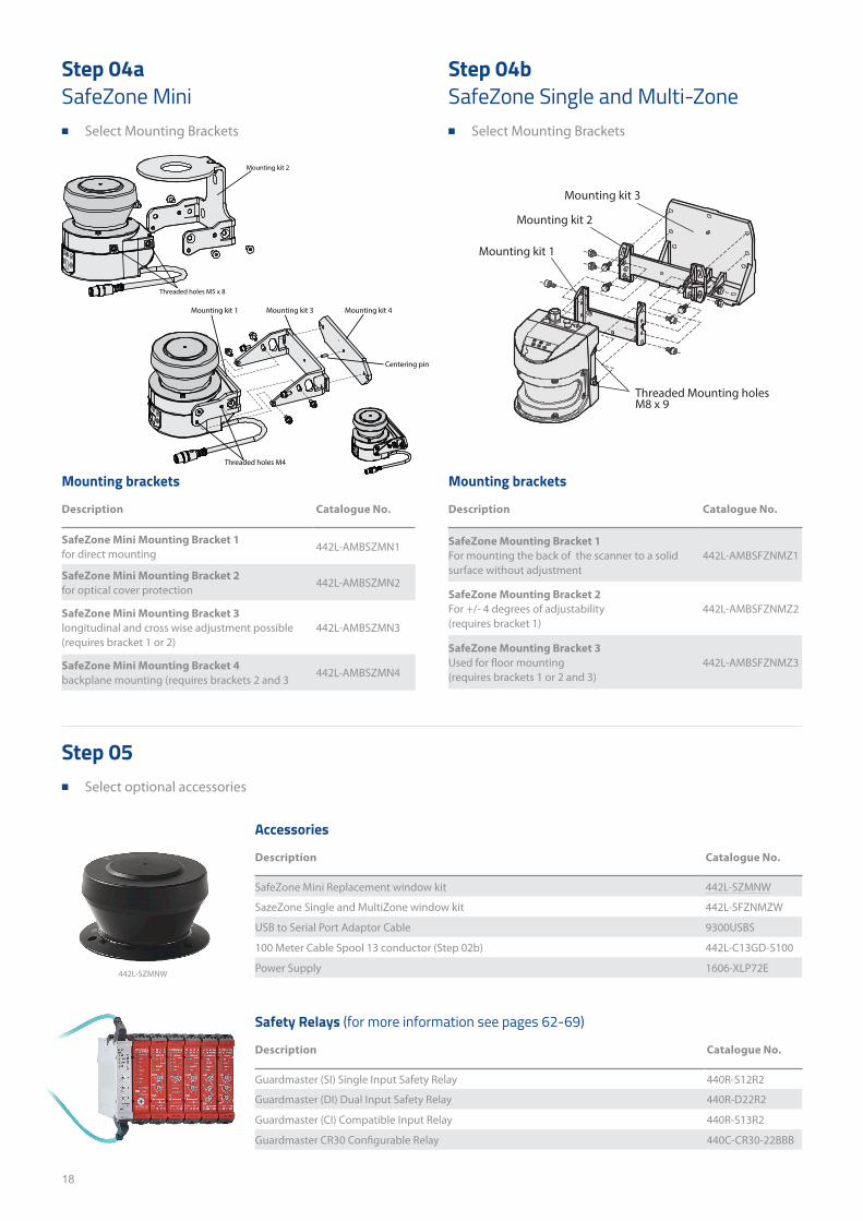
Step 04a SafeZone Mini
■ Select Mounting Brackets
Step 04b SafeZone Single and Multi-Zone
■ Select Mounting Brackets
Step 05 ■ Select optional accessories
Mounting brackets
Description Catalogue No.
SafeZone Mounting Bracket 1 For mounting the back of the scanner to a solid surface without adjustment
442L-AMBSFZNMZ1
SafeZone Mounting Bracket 2For +/- 4 degrees of adjustability (requires bracket 1)
442L-AMBSFZNMZ2
SafeZone Mounting Bracket 3 Used for floor mounting (requires brackets 1 or 2 and 3)
442L-AMBSFZNMZ3
Accessories
Description Catalogue No.
SafeZone Mini Replacement window kit 442L-SZMNW
SazeZone Single and MultiZone window kit 442L-SFZNMZW
USB to Serial Port Adaptor Cable 9300USBS
100 Meter Cable Spool 13 conductor (Step 02b) 442L-C13GD-S100
Power Supply 1606-XLP72E
Safety Relays (for more information see pages 62-69)
Description Catalogue No.
Guardmaster (SI) Single Input Safety Relay 440R-S12R2
Guardmaster (DI) Dual Input Safety Relay 440R-D22R2
Guardmaster (CI) Compatible Input Relay 440R-S13R2
Guardmaster CR30 Configurable Relay 440C-CR30-22BBB
442L-SZMNW
Mounting kit 2
Threaded holes M5 x 8
Mounting kit 1
Threaded holes M4
Mounting kit 3 Mounting kit 4
Centering pin
Threaded Mounting holesM8 x 9
Mounting kit 1
Mounting kit 2
Mounting kit 3
Mounting brackets
Description Catalogue No.
SafeZone Mini Mounting Bracket 1 for direct mounting
442L-AMBSZMN1
SafeZone Mini Mounting Bracket 2 for optical cover protection
442L-AMBSZMN2
SafeZone Mini Mounting Bracket 3 longitudinal and cross wise adjustment possible (requires bracket 1 or 2)
442L-AMBSZMN3
SafeZone Mini Mounting Bracket 4 backplane mounting (requires brackets 2 and 3
442L-AMBSZMN4

19
This page has been left intentionally blank
20
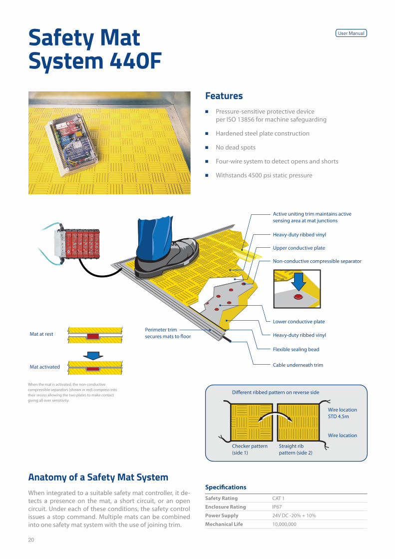
Safety Mat System 440F
Anatomy of a Safety Mat SystemWhen integrated to a suitable safety mat controller, it de-tects a presence on the mat, a short circuit, or an open circuit. Under each of these conditions, the safety control issues a stop command. Multiple mats can be combined into one safety mat system with the use of joining trim.
Specifications
Safety Rating CAT 1
Enclosure Rating IP67
Power Supply 24V DC -20% + 10%
Mechanical Life 10,000,000
Features ■ Pressure-sensitive protective device
per ISO 13856 for machine safeguarding
■ Hardened steel plate construction
■ No dead spots
■ Four-wire system to detect opens and shorts
■ Withstands 4500 psi static pressure
Different ribbed pattern on reverse side
Checker pattern (side 1)
Straight rib pattern (side 2)
Wire location STD 4.5m
Wire location
Active uniting trim maintains active sensing area at mat junctions
Non-conductive compressible separator
Lower conductive plate
Heavy-duty ribbed vinyl
Flexible sealing bead
Perimeter trim secures mats to floor
Cable underneath trim
Upper conductive plate
Heavy-duty ribbed vinyl
When the mat is activated, the non-conductive compressible separators (shown in red) compress into their recess allowing the two plates to make contact giving all over sensitivity.
Mat at rest
Mat activated
User Manual
21
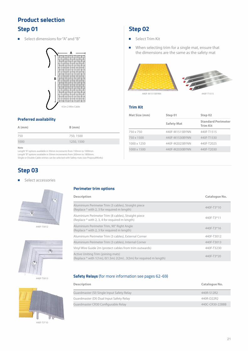
Trim Kit
Mat Size (mm) Step 01 Step 02
Safety MatStandard Perimeter Trim Kit
750 x 750 440F-M1515BYNN 440F-T1515
750 x 1500 440F-M1530BYNN 440F-T1530
1000 x 1250 440F-M2025BYNN 440F-T2025
1000 x 1500 440F-M2030BYNN 440F-T2030
Product selection
Preferred availability
A (mm) B (mm)
750 750, 1500
1000 1250, 1500
Perimeter trim options
Description Catalogue No.
Aluminium Perimeter Trim (3 cables), Straight piece (Replace * with 2, 3 for required m length)
440F-T3*10
Aluminium Perimeter Trim (8 cables), Straight piece (Replace * with 2, 3, 4 for required m length)
440F-T3*11
Aluminium Perimeter Trim, 90° Right Angle (Replace * with 2, 3 for required m length)
440F-T3*16
Aluminium Perimeter Trim (3 cables), External Corner 440F-T3012
Aluminium Perimeter Trim (3 cables), Internal Corner 440F-T3013
Vinyl Wire Guide 2m (protect cables from trim outwards) 440F-T3230
Active Uniting Trim (joining mats) (Replace * with 1(1m), 0(1.5m) 2(2m) , 3(3m) for required m length)
440F-T3*20
Step 02 ■ Select Trim Kit
■ When selecting trim for a single mat, ensure that the dimensions are the same as the safety mat
Step 03 ■ Select accessories
Step 01 ■ Select dimensions for “A” and “B”
Safety Relays (for more information see pages 62-69)
Description Catalogue No.
Guardmaster (SI) Single Input Safety Relay 440R-S12R2
Guardmaster (DI) Dual Input Safety Relay 440R-D22R2
Guardmaster CR30 Configurable Relay 440C-CR30-22BBB
440F-M1515BYNN 440F-T1515
Note Length “A” options available in 50mm increments from 150mm to 1000mm Length “B” options available in 50mm increments from 200mm to 1800mm.Single or Double Cable entries can be selected with Safety mats (see ProposalWorks)
4.5m 2-Wire Cable
440F-T3013
440F-T3012
440F-T3*10
22
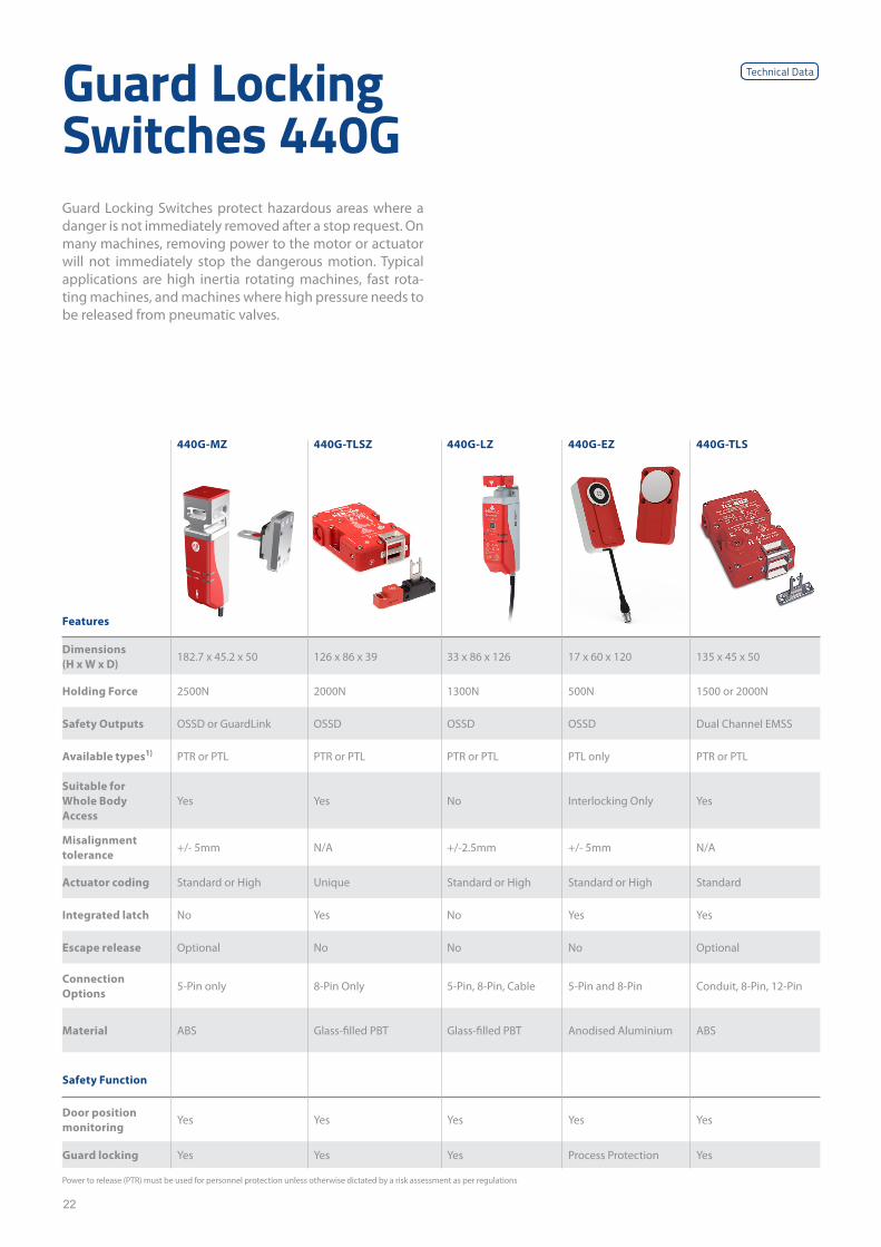
440G-MZ 440G-TLSZ 440G-LZ 440G-EZ 440G-TLS
Features
Dimensions (H x W x D)
182.7 x 45.2 x 50 126 x 86 x 39 33 x 86 x 126 17 x 60 x 120 135 x 45 x 50
Holding Force 2500N 2000N 1300N 500N 1500 or 2000N
Safety Outputs OSSD or GuardLink OSSD OSSD OSSD Dual Channel EMSS
Available types1) PTR or PTL PTR or PTL PTR or PTL PTL only PTR or PTL
Suitable for Whole Body Access
Yes Yes No Interlocking Only Yes
Misalignment tolerance
+/- 5mm N/A +/-2.5mm +/- 5mm N/A
Actuator coding Standard or High Unique Standard or High Standard or High Standard
Integrated latch No Yes No Yes Yes
Escape release Optional No No No Optional
Connection Options
5-Pin only 8-Pin Only 5-Pin, 8-Pin, Cable 5-Pin and 8-Pin Conduit, 8-Pin, 12-Pin
Material ABS Glass-filled PBT Glass-filled PBT Anodised Aluminium ABS
Safety Function
Door position monitoring
Yes Yes Yes Yes Yes
Guard locking Yes Yes Yes Process Protection Yes
Power to release (PTR) must be used for personnel protection unless otherwise dictated by a risk assessment as per regulations
Guard Locking Switches 440GGuard Locking Switches protect hazardous areas where a danger is not immediately removed after a stop request. On many machines, removing power to the motor or actuator will not immediately stop the dangerous motion. Typical applications are high inertia rotating machines, fast rota-ting machines, and machines where high pressure needs to be released from pneumatic valves.
Technical Data
23
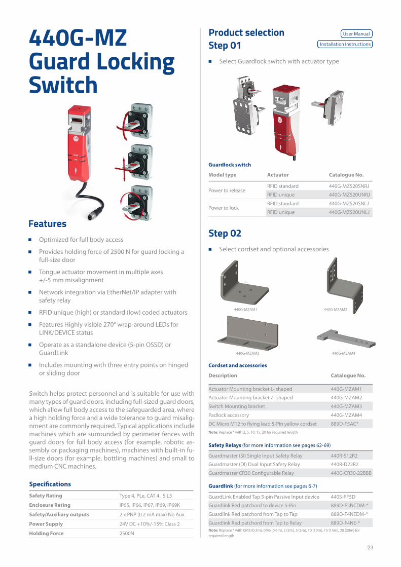
440G-MZ Guard Locking Switch
Specifications
Safety Rating Type 4, PLe, CAT 4 , SIL3
Enclosure Rating IP65, IP66, IP67, IP69, IP69K
Safety/Auxiliary outputs 2 x PNP (0.2 mA max) No Aux
Power Supply 24V DC +10%/-15% Class 2
Holding Force 2500N
Switch helps protect personnel and is suitable for use with many types of guard doors, including full-sized guard doors, which allow full body access to the safeguarded area, where a high holding force and a wide tolerance to guard misalig-nment are commonly required. Typical applications include machines which are surrounded by perimeter fences with guard doors for full body access (for example, robotic as-sembly or packaging machines), machines with built-in fu-ll-size doors (for example, bottling machines) and small to medium CNC machines.
Product selectionStep 01
■ Select Guardlock switch with actuator type
Step 02 ■ Select cordset and optional accessories
Cordset and accessories
Description Catalogue No.
Actuator Mounting bracket L- shaped 440G-MZAM1
Actuator Mounting bracket Z- shaped 440G-MZAM2
Switch Mounting bracket 440G-MZAM3
Padlock accessory 440G-MZAM4
DC Micro M12 to flying lead 5-Pin yellow cordset 889D-F5AC*Note: Replace * with 2, 5, 10, 15, 20 for required length
Safety Relays (for more information see pages 62-69)
Guardmaster (SI) Single Input Safety Relay 440R-S12R2
Guardmaster (DI) Dual Input Safety Relay 440R-D22R2
Guardmaster CR30 Configurable Relay 440C-CR30-22BBB
Guardlink (for more information see pages 6-7)
GuardLink Enabled Tap 5-pin Passive Input device 440S-PF5D
Guardlink Red patchord to device 5-Pin 889D-F5NCDM-*
Guardlink Red patchord from Tap to Tap 889D-F4NEDM-*
Guardlink Red patchord from Tap to Relay 889D-F4NE-*Note: Replace * with 0M3 (0.3m), 0M6 (0.6m), 2 (2m), 5 (5m), 10 (10m), 15 (15m), 20 (20m) for required length
440G-MZAM2
440G-MZAM4440G-MZAM3
440G-MZAM1
Guardlock switch
Model type Actuator Catalogue No.
Power to releaseRFID standard 440G-MZS20SNRJ
RFID unique 440G-MZS20UNRJ
Power to lockRFID standard 440G-MZS20SNLJ
RFID unique 440G-MZS20UNLJ
User Manual
Installation Instructions
Features ■ Optimized for full body access
■ Provides holding force of 2500 N for guard locking a full-size door
■ Tongue actuator movement in multiple axes +/-5 mm misalignment
■ Network integration via EtherNet/IP adapter with safety relay
■ RFID unique (high) or standard (low) coded actuators
■ Features Highly visible 270° wrap-around LEDs for LINK/DEVICE status
■ Operate as a standalone device (5-pin OSSD) or GuardLink
■ Includes mounting with three entry points on hinged or sliding door
24
Product selectionStep 01
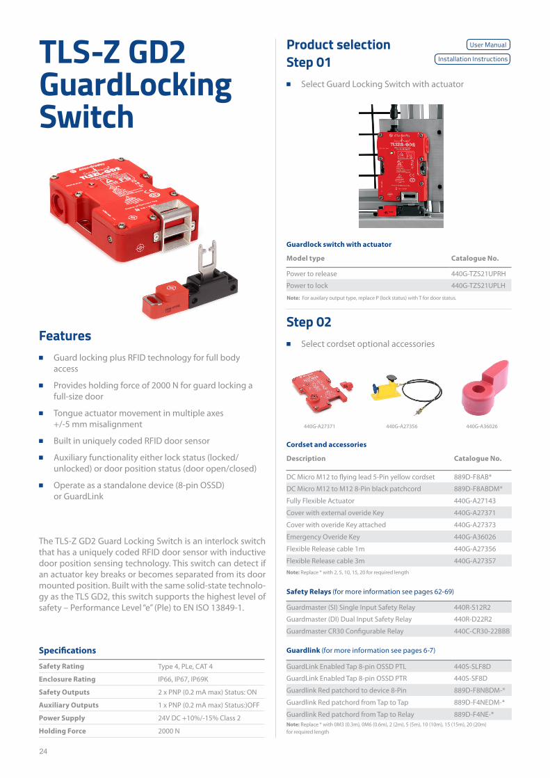
■ Select Guard Locking Switch with actuator
Step 02 ■ Select cordset optional accessories
Guardlock switch with actuator
Model type Catalogue No.
Power to release 440G-TZS21UPRH
Power to lock 440G-TZS21UPLH
Cordset and accessories
Description Catalogue No.
DC Micro M12 to flying lead 5-Pin yellow cordset 889D-F8AB*
DC Micro M12 to M12 8-Pin black patchcord 889D-F8ABDM*
Fully Flexible Actuator 440G-A27143
Cover with external overide Key 440G-A27371
Cover with overide Key attached 440G-A27373
Emergency Overide Key 440G-A36026
Flexible Release cable 1m 440G-A27356
Flexible Release cable 3m 440G-A27357Note: Replace * with 2, 5, 10, 15, 20 for required length
Safety Relays (for more information see pages 62-69)
Guardmaster (SI) Single Input Safety Relay 440R-S12R2
Guardmaster (DI) Dual Input Safety Relay 440R-D22R2
Guardmaster CR30 Configurable Relay 440C-CR30-22BBB
Guardlink (for more information see pages 6-7)
GuardLink Enabled Tap 8-pin OSSD PTL 440S-SLF8D
GuardLink Enabled Tap 8-pin OSSD PTR 440S-SF8D
Guardlink Red patchord to device 8-Pin 889D-F8NBDM-*
Guardlink Red patchord from Tap to Tap 889D-F4NEDM-*
Guardlink Red patchord from Tap to Relay 889D-F4NE-*Note: Replace * with 0M3 (0.3m), 0M6 (0.6m), 2 (2m), 5 (5m), 10 (10m), 15 (15m), 20 (20m) for required length
TLS-Z GD2 GuardLocking Switch
Specifications
Safety Rating Type 4, PLe, CAT 4
Enclosure Rating IP66, IP67, IP69K
Safety Outputs 2 x PNP (0.2 mA max) Status: ON
Auxiliary Outputs 1 x PNP (0.2 mA max) Status:)OFF
Power Supply 24V DC +10%/-15% Class 2
Holding Force 2000 N
The TLS-Z GD2 Guard Locking Switch is an interlock switch that has a uniquely coded RFID door sensor with inductive door position sensing technology. This switch can detect if an actuator key breaks or becomes separated from its door mounted position. Built with the same solid-state technolo-gy as the TLS GD2, this switch supports the highest level of safety – Performance Level “e” (Ple) to EN ISO 13849-1.
Note: For auxilary output type, replace P (lock status) with T for door status.
Features ■ Guard locking plus RFID technology for full body
access
■ Provides holding force of 2000 N for guard locking a full-size door
■ Tongue actuator movement in multiple axes +/-5 mm misalignment
■ Built in uniquely coded RFID door sensor
■ Auxiliary functionality either lock status (locked/unlocked) or door position status (door open/closed)
■ Operate as a standalone device (8-pin OSSD) or GuardLink
440G-A27371 440G-A27356 440G-A36026
User Manual
Installation Instructions
25
440G-LZ Guard to Bolt Locking Switch
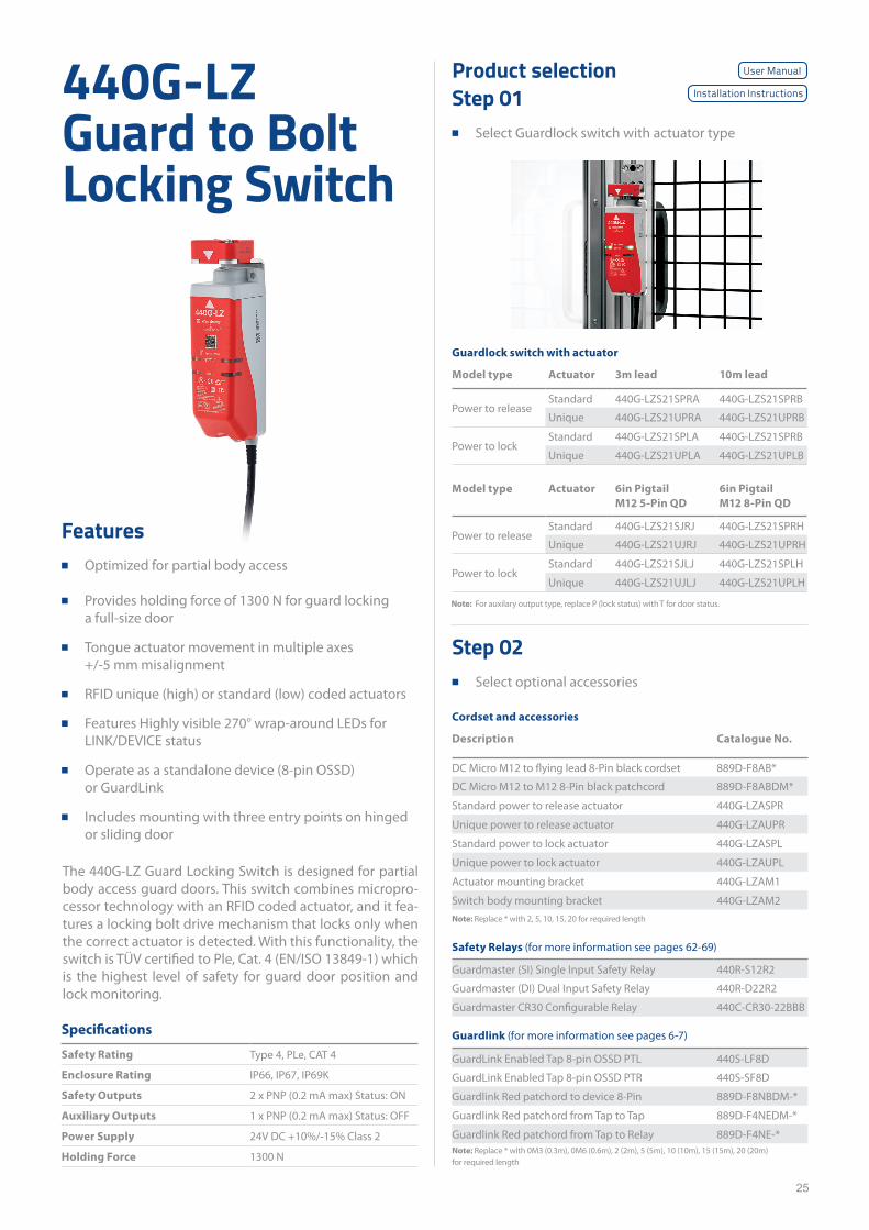
The 440G-LZ Guard Locking Switch is designed for partial body access guard doors. This switch combines micropro-cessor technology with an RFID coded actuator, and it fea-tures a locking bolt drive mechanism that locks only when the correct actuator is detected. With this functionality, the switch is TÜV certified to Ple, Cat. 4 (EN/ISO 13849-1) which is the highest level of safety for guard door position and lock monitoring.
Product selectionStep 01
■ Select Guardlock switch with actuator type
Specifications
Safety Rating Type 4, PLe, CAT 4
Enclosure Rating IP66, IP67, IP69K
Safety Outputs 2 x PNP (0.2 mA max) Status: ON
Auxiliary Outputs 1 x PNP (0.2 mA max) Status: OFF
Power Supply 24V DC +10%/-15% Class 2
Holding Force 1300 N
Guardlock switch with actuator
Model type Actuator 3m lead 10m lead
Power to releaseStandard 440G-LZS21SPRA 440G-LZS21SPRB
Unique 440G-LZS21UPRA 440G-LZS21UPRB
Power to lockStandard 440G-LZS21SPLA 440G-LZS21SPRB
Unique 440G-LZS21UPLA 440G-LZS21UPLB
Model type Actuator 6in Pigtail M12 5-Pin QD
6in Pigtail M12 8-Pin QD
Power to releaseStandard 440G-LZS21SJRJ 440G-LZS21SPRH
Unique 440G-LZS21UJRJ 440G-LZS21UPRH
Power to lockStandard 440G-LZS21SJLJ 440G-LZS21SPLH
Unique 440G-LZS21UJLJ 440G-LZS21UPLH
Note: For auxilary output type, replace P (lock status) with T for door status.
Step 02 ■ Select optional accessories
Cordset and accessories
Description Catalogue No.
DC Micro M12 to flying lead 8-Pin black cordset 889D-F8AB*
DC Micro M12 to M12 8-Pin black patchcord 889D-F8ABDM*
Standard power to release actuator 440G-LZASPR
Unique power to release actuator 440G-LZAUPR
Standard power to lock actuator 440G-LZASPL
Unique power to lock actuator 440G-LZAUPL
Actuator mounting bracket 440G-LZAM1
Switch body mounting bracket 440G-LZAM2Note: Replace * with 2, 5, 10, 15, 20 for required length
Safety Relays (for more information see pages 62-69)
Guardmaster (SI) Single Input Safety Relay 440R-S12R2
Guardmaster (DI) Dual Input Safety Relay 440R-D22R2
Guardmaster CR30 Configurable Relay 440C-CR30-22BBB
Guardlink (for more information see pages 6-7)
GuardLink Enabled Tap 8-pin OSSD PTL 440S-LF8D
GuardLink Enabled Tap 8-pin OSSD PTR 440S-SF8D
Guardlink Red patchord to device 8-Pin 889D-F8NBDM-*
Guardlink Red patchord from Tap to Tap 889D-F4NEDM-*
Guardlink Red patchord from Tap to Relay 889D-F4NE-*Note: Replace * with 0M3 (0.3m), 0M6 (0.6m), 2 (2m), 5 (5m), 10 (10m), 15 (15m), 20 (20m) for required length
User Manual
Installation Instructions
Features
■ Optimized for partial body access
■ Provides holding force of 1300 N for guard locking a full-size door
■ Tongue actuator movement in multiple axes +/-5 mm misalignment
■ RFID unique (high) or standard (low) coded actuators
■ Features Highly visible 270° wrap-around LEDs for LINK/DEVICE status
■ Operate as a standalone device (8-pin OSSD) or GuardLink
■ Includes mounting with three entry points on hinged or sliding door
26
440G-EZ Electromagnetic Switch
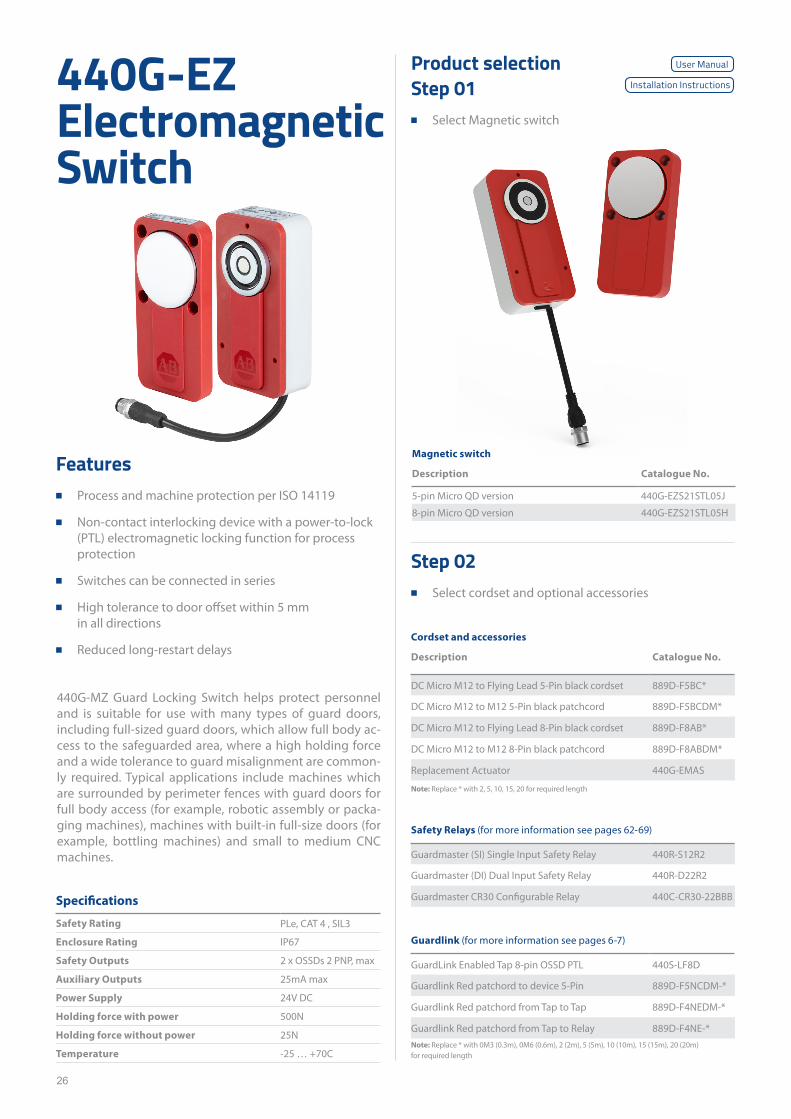
Features ■ Process and machine protection per ISO 14119
■ Non-contact interlocking device with a power-to-lock (PTL) electromagnetic locking function for process protection
■ Switches can be connected in series
■ High tolerance to door offset within 5 mm in all directions
■ Reduced long-restart delays
440G-MZ Guard Locking Switch helps protect personnel and is suitable for use with many types of guard doors, including full-sized guard doors, which allow full body ac-cess to the safeguarded area, where a high holding force and a wide tolerance to guard misalignment are common-ly required. Typical applications include machines which are surrounded by perimeter fences with guard doors for full body access (for example, robotic assembly or packa-ging machines), machines with built-in full-size doors (for example, bottling machines) and small to medium CNC machines.
Specifications
Safety Rating PLe, CAT 4 , SIL3
Enclosure Rating IP67
Safety Outputs 2 x OSSDs 2 PNP, max
Auxiliary Outputs 25mA max
Power Supply 24V DC
Holding force with power 500N
Holding force without power 25N
Temperature -25 … +70C
Product selectionStep 01
■ Select Magnetic switch
Step 02 ■ Select cordset and optional accessories
Cordset and accessories
Description Catalogue No.
DC Micro M12 to Flying Lead 5-Pin black cordset 889D-F5BC*
DC Micro M12 to M12 5-Pin black patchcord 889D-F5BCDM*
DC Micro M12 to Flying Lead 8-Pin black cordset 889D-F8AB*
DC Micro M12 to M12 8-Pin black patchcord 889D-F8ABDM*
Replacement Actuator 440G-EMAS
Note: Replace * with 2, 5, 10, 15, 20 for required length
Safety Relays (for more information see pages 62-69)
Guardmaster (SI) Single Input Safety Relay 440R-S12R2
Guardmaster (DI) Dual Input Safety Relay 440R-D22R2
Guardmaster CR30 Configurable Relay 440C-CR30-22BBB
Guardlink (for more information see pages 6-7)
GuardLink Enabled Tap 8-pin OSSD PTL 440S-LF8D
Guardlink Red patchord to device 5-Pin 889D-F5NCDM-*
Guardlink Red patchord from Tap to Tap 889D-F4NEDM-*
Guardlink Red patchord from Tap to Relay 889D-F4NE-*Note: Replace * with 0M3 (0.3m), 0M6 (0.6m), 2 (2m), 5 (5m), 10 (10m), 15 (15m), 20 (20m) for required length
Magnetic switch
Description Catalogue No.
5-pin Micro QD version 440G-EZS21STL05J
8-pin Micro QD version 440G-EZS21STL05H
User Manual
Installation Instructions
27
TLS-GD2 Guard Locking Switch
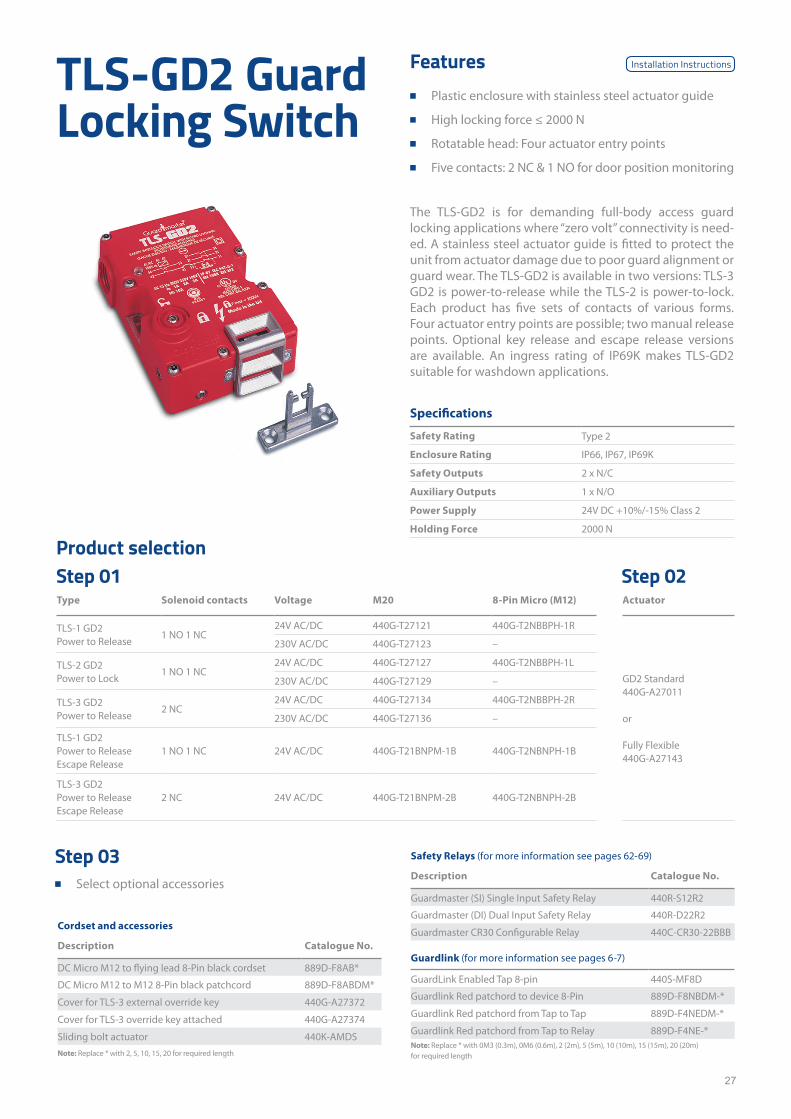
Features ■ Plastic enclosure with stainless steel actuator guide
■ High locking force ≤ 2000 N
■ Rotatable head: Four actuator entry points
■ Five contacts: 2 NC & 1 NO for door position monitoring
The TLS-GD2 is for demanding full-body access guard locking applications where “zero volt” connectivity is need-ed. A stainless steel actuator guide is fitted to protect the unit from actuator damage due to poor guard alignment or guard wear. The TLS-GD2 is available in two versions: TLS-3 GD2 is power-to-release while the TLS-2 is power-to-lock. Each product has five sets of contacts of various forms. Four actuator entry points are possible; two manual release points. Optional key release and escape release versions are available. An ingress rating of IP69K makes TLS-GD2 suitable for washdown applications.
Specifications
Safety Rating Type 2
Enclosure Rating IP66, IP67, IP69K
Safety Outputs 2 x N/C
Auxiliary Outputs 1 x N/O
Power Supply 24V DC +10%/-15% Class 2
Holding Force 2000 N
Type Solenoid contacts Voltage M20 8-Pin Micro (M12) Actuator
TLS-1 GD2 Power to Release
1 NO 1 NC24V AC/DC 440G-T27121 440G-T2NBBPH-1R
GD2 Standard440G-A27011
or
Fully Flexible 440G-A27143
230V AC/DC 440G-T27123 –
TLS-2 GD2 Power to Lock
1 NO 1 NC24V AC/DC 440G-T27127 440G-T2NBBPH-1L
230V AC/DC 440G-T27129 –
TLS-3 GD2 Power to Release
2 NC24V AC/DC 440G-T27134 440G-T2NBBPH-2R
230V AC/DC 440G-T27136 –
TLS-1 GD2 Power to Release Escape Release
1 NO 1 NC 24V AC/DC 440G-T21BNPM-1B 440G-T2NBNPH-1B
TLS-3 GD2 Power to Release Escape Release
2 NC 24V AC/DC 440G-T21BNPM-2B 440G-T2NBNPH-2B
Product selectionStep 01 Step 02
Cordset and accessories
Description Catalogue No.
DC Micro M12 to flying lead 8-Pin black cordset 889D-F8AB*
DC Micro M12 to M12 8-Pin black patchcord 889D-F8ABDM*
Cover for TLS-3 external override key 440G-A27372
Cover for TLS-3 override key attached 440G-A27374
Sliding bolt actuator 440K-AMDSNote: Replace * with 2, 5, 10, 15, 20 for required length
Step 03 ■ Select optional accessories
Safety Relays (for more information see pages 62-69)
Description Catalogue No.
Guardmaster (SI) Single Input Safety Relay 440R-S12R2
Guardmaster (DI) Dual Input Safety Relay 440R-D22R2
Guardmaster CR30 Configurable Relay 440C-CR30-22BBB
Guardlink (for more information see pages 6-7)
GuardLink Enabled Tap 8-pin 440S-MF8D
Guardlink Red patchord to device 8-Pin 889D-F8NBDM-*
Guardlink Red patchord from Tap to Tap 889D-F4NEDM-*
Guardlink Red patchord from Tap to Relay 889D-F4NE-*Note: Replace * with 0M3 (0.3m), 0M6 (0.6m), 2 (2m), 5 (5m), 10 (10m), 15 (15m), 20 (20m) for required length
Installation Instructions
28
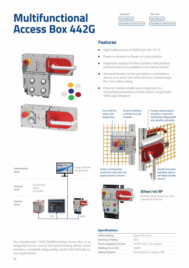
Multifunctional Access Box 442G
The Guardmaster® 442G Multifunctional Access Box, is an integrated access control and guard locking device which provides a complete safeguarding solution for full body ac-cess applications.
Specifications
Safety Rating Type 4, Ple, CAT 4
Enclosure Rating IP65
Power Supply & Current 24V DC ±10/-15% required
Holding Force Fzh 2000N
Safety Outputs Semiconductor outputs, PNP
Features ■ High holding force of 2000 N per ISO 14119
■ Power-to-Release or Power-to-Lock modules
■ Diagnostic outputs for door position, bolt position, and lock status are available to the control system
■ Standard models can be operated as a standalone device or in series with other devices, maintaining a PLe Cat 4 safety rating
■ Ethernet models enable easy integration in a networked automation control system using Studio 5000 Logix Designer
Handle Assembly Available right or left (Right handle shown)
Power-to-Release or Power-to-Lock modules
Four LEDs for status and diagnostics
Choice of integrated controls (E-stop with two push buttons is shown)
Escape release option provides a means for exiting the safeguarded area quickly and easily
Multifunctional Access Box with EtherNet/IP Interface
Information level
Controllevel
Devicelevel
Design software v20 upwards
GuardLogix Safety Controller
HMI MAB
User ManualUser Manual
Installation InstructionsInstallation Instructions
Standard Ethernet
29
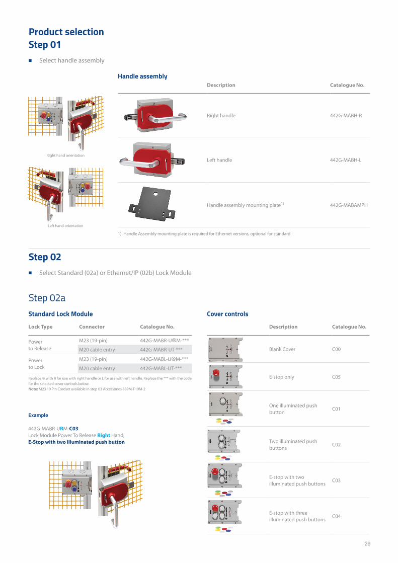
Product selectionStep 01
■ Select handle assembly
Step 02 ■ Select Standard (02a) or Ethernet/IP (02b) Lock Module
Handle assemblyDescription Catalogue No.
Right handle 442G-MABH-R
Left handle 442G-MABH-L
Handle assembly mounting plate1) 442G-MABAMPH
Cover controls
Description Catalogue No.
Blank Cover C00
E-stop only C05
One illuminated push button
C01
Two illuminated push buttons
C02
E-stop with two illuminated push buttons
C03
E-stop with three illuminated push buttons
C04
1) Handle Assembly mounting plate is required for Ethernet versions, optional for standard
Step 02aStandard Lock Module
Lock Type Connector Catalogue No.
Power to Release
M23 (19-pin) 442G-MABR-U⊗M-***
M20 cable entry 442G-MABR-UT-***
Power to Lock
M23 (19-pin) 442G-MABL-U⊗M-***
M20 cable entry 442G-MABL-UT-***
Replace ⊗ with R for use with right handle or L for use with left handle. Replace the *** with the code for the selected cover controls below. Note: M23 19 Pin Cordset available in step 03 Accessories 889M-F19M-2
Example
442G-MABR-URM-C03 Lock Module Power To Release Right Hand, E-Stop with two illuminated push button
Right hand orientation
Left hand orientation
30
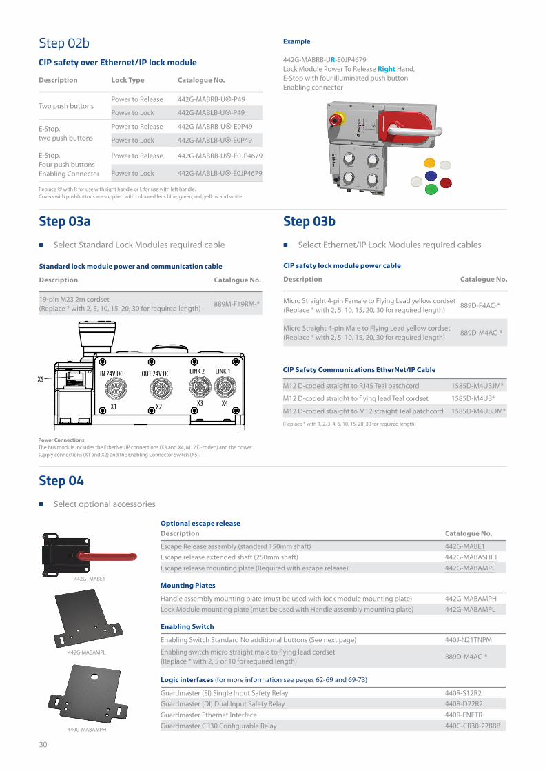
Step 03a ■ Select Standard Lock Modules required cable
Step 04 ■ Select optional accessories
Step 03b ■ Select Ethernet/IP Lock Modules required cables
Step 02bCIP safety over Ethernet/IP lock module
Description Lock Type Catalogue No.
Two push buttonsPower to Release 442G-MABRB-U⊗-P49
Power to Lock 442G-MABLB-U⊗-P49
E-Stop, two push buttons
Power to Release 442G-MABRB-U⊗-E0P49
Power to Lock 442G-MABLB-U⊗-E0P49
E-Stop, Four push buttons Enabling Connector
Power to Release 442G-MABRB-U⊗-E0JP4679
Power to Lock 442G-MABLB-U⊗-E0JP4679
Replace ⊗ with R for use with right handle or L for use with left handle. Covers with pushbuttons are supplied with coloured lens blue, green, red, yellow and white.
Example
442G-MABRB-UR-E0JP4679 Lock Module Power To Release Right Hand, E-Stop with four illuminated push buttonEnabling connector
CIP safety lock module power cable
Description Catalogue No.
Micro Straight 4-pin Female to Flying Lead yellow cordset (Replace * with 2, 5, 10, 15, 20, 30 for required length)
889D-F4AC-*
Micro Straight 4-pin Male to Flying Lead yellow cordset (Replace * with 2, 5, 10, 15, 20, 30 for required length)
889D-M4AC-*
Standard lock module power and communication cable
Description Catalogue No.
19-pin M23 2m cordset (Replace * with 2, 5, 10, 15, 20, 30 for required length)
889M-F19RM-*
Optional escape releaseDescription Catalogue No.
Escape Release assembly (standard 150mm shaft) 442G-MABE1Escape release extended shaft (250mm shaft) 442G-MABASHFTEscape release mounting plate (Required with escape release) 442G-MABAMPE
Mounting Plates
Handle assembly mounting plate (must be used with lock module mounting plate) 442G-MABAMPHLock Module mounting plate (must be used with Handle assembly mounting plate) 442G-MABAMPL
Enabling Switch
Enabling Switch Standard No additional buttons (See next page) 440J-N21TNPM
Enabling switch micro straight male to flying lead cordset (Replace * with 2, 5 or 10 for required length)
889D-M4AC-*
Logic interfaces (for more information see pages 62-69 and 69-73)
Guardmaster (SI) Single Input Safety Relay 440R-S12R2Guardmaster (DI) Dual Input Safety Relay 440R-D22R2Guardmaster Ethernet Interface 440R-ENETRGuardmaster CR30 Configurable Relay 440C-CR30-22BBB
Power ConnectionsThe bus module includes the EtherNet/IP connections (X3 and X4, M12 D-coded) and the power supply connections (X1 and X2) and the Enabling Connector Switch (X5).
440G-MABAMPH
X1 3 X4XX2
IN 24V DC LINK 1 LINK 2 OUT 24V DCX5
CIP Safety Communications EtherNet/IP Cable
M12 D-coded straight to RJ45 Teal patchcord 1585D-M4UBJM*
M12 D-coded straight to flying lead Teal cordset 1585D-M4UB*
M12 D-coded straight to M12 straight Teal patchcord 1585D-M4UBDM*
(Replace * with 1, 2, 3, 4, 5, 10, 15, 20, 30 for required length)
442G-MABAMPL
442G- MABE1

31
Enabling switches 440J
Specifications
Enclosure Rating IP66 Standard switchIP65 job button/E-STOP
Thermal current 3 A
Switch current @ Voltage, min
5 mA @ 3V AC/DC
Safety Outputs Semiconductor outputs, PNP
Features ■ Three position enabling switch
■ Lightweight and easy-to-use
■ Optional jog and e-stop functions
■ M20 conduit
Product selectionStep 01
■ Select Desired Enabling switch
Description Main contacts
Monitoring contacts
Jog contacts
Emergency stop contacts
Connection type
Catalogue No.
Switch with Jog Pushbutton 2 N/C 2 N/O 1 N/O - M20 Conduit + Cable Strain 440J-N21TNPM-NPStandard Switch 2 N/C 2 N/O - - M20 Conduit + Cable Strain 440J-N21TNPMSwitch with E-Stop Pushbutton 2 N/C - - 2 N/C M20 Conduit + Cable Strain 440J-N2NTNPM-NE
OverviewThe 440J is a three position enabling switch that can be used to reduce risks when working inside a machine guard, The standard model includes two independent three-posi-tion switches which are actuated by squeezing the trigger. The trigger switch has three positions. The mid-position is the “enabled” position.
Position 1 – there is no pressure on the trigger switch, and the safety contacts are open.
Position 2 – the trigger switch is squeezed to the mid-position, and the safety contacts are closed. This mid-position is the “enabled” position.
Position 3 – the trigger switch is fully pressed and the safety contacts are open.
When the trigger switch is released from position three back to position one, the safety contacts remain open, as it passes through position two
Step 02 ■ Select optional accessories
AccessoriesDescription Catalogue No.
Mounting Bracket for Single Enabling Switch 440J-A00NMounting Bracket for Single Enabling Switch and Safety Interlock Switch 440J-A02NMounting Bracket Suitable for Single Enabling Switch and Two Safety Interlock switches 440J-A04NRubber Boot Kit( Silicone Free) 440J-A10N440J-A00N
Multiple Personnel Access
When more than one person must access the hazard, all persons utilize their own enabling device.
Installation instructions
32
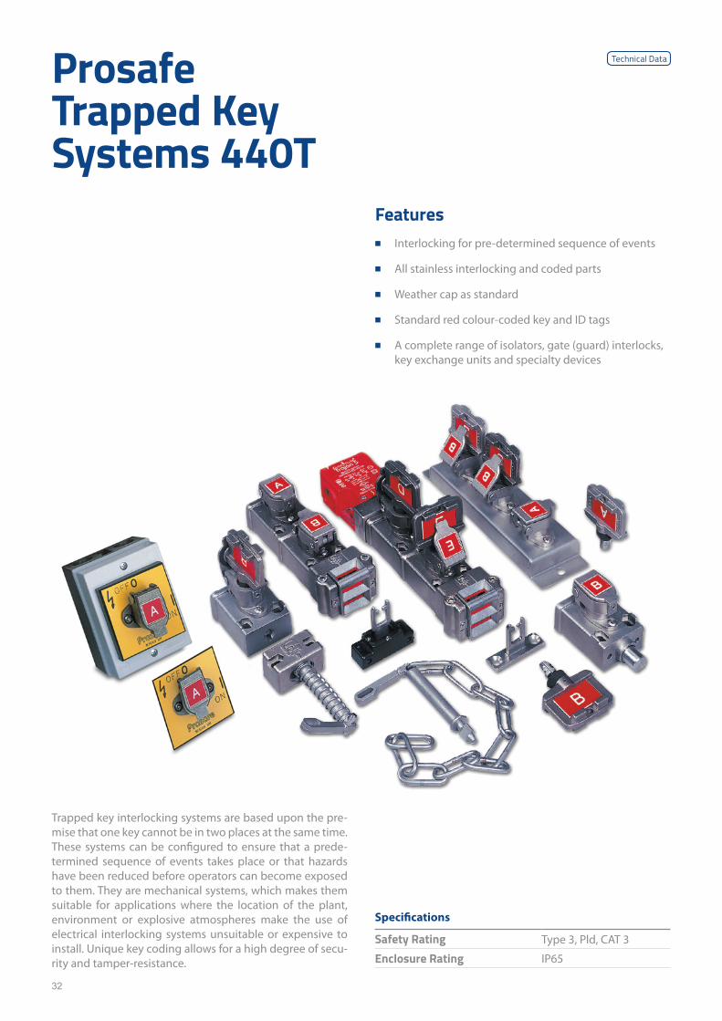
Prosafe Trapped Key Systems 440T
Trapped key interlocking systems are based upon the pre-mise that one key cannot be in two places at the same time. These systems can be configured to ensure that a prede-termined sequence of events takes place or that hazards have been reduced before operators can become exposed to them. They are mechanical systems, which makes them suitable for applications where the location of the plant, environment or explosive atmospheres make the use of electrical interlocking systems unsuitable or expensive to install. Unique key coding allows for a high degree of secu-rity and tamper-resistance.
Features ■ Interlocking for pre-determined sequence of events
■ All stainless interlocking and coded parts
■ Weather cap as standard
■ Standard red colour-coded key and ID tags
■ A complete range of isolators, gate (guard) interlocks, key exchange units and specialty devices
Specifications
Safety Rating Type 3, Pld, CAT 3
Enclosure Rating IP65
Technical Data
33
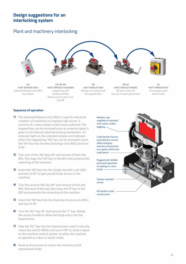
Sequence of operation
1) The Solenoid Release Unit (SRU) is used for electrical isolation of machinery to improve safe access. It consists of a rotary power switch and a solenoid. The trapped key can be removed once an external signal is given to its internal solenoid locking mechanism. An indicator light on the solenoid release unit indicates when the trapped key “AA” key can be removed. Insert the “AA” key into the Key Exchange Unit (KEX) and turn it 90°.
2) Turn one of the “AB” keys 90° and remove it from the KEX. This traps the “AA” key in the KEX and prevents the restarting of the machine.
3) Insert the “AB” key into the Single-key Bolt Lock (SBL)and turn it 90° to gain partial body access to the machine.
4) Turn the second “AB” key 90° and remove it from the KEX. Removal of this key also traps the “A” key in the KEX and prevents the restarting of the machine.
5) Insert the “AB” key into the Dual-key Access Lock (DAL) and turn it 90°.
6) Turn the “AC” key 90° and remove the “C” key. Rotate the access handle to allow full body entry into the hazard zone.
7) Take the “AC” key into the hazard zone, insert it into the rotary key switch (RKSE) and turn it 90° to send a signal to the machine control system, to allow the machine to operate in a slow or teach mode.
8) Reverse the process to return the machine to full operational mode.
Design suggestions for an interlocking system
Plant and machinery interlocking
AA 440T-MSRUE10AA
Solenoid Release Unit (SRU)key release
AA AB AB440T-MKEXE11AAABAB
Trapped key ‘AA’Locking off SRU,
Release access door lock, key ‘AB’
AB440T-MSBLE10AB
‘AB’ key in to retract boltfrom guard door
AB AC440T-MDALE10ABAC
AB’ key in then ‘AC’key out to open guard door
AC440T-MRKSE10ACTo energize robot
teach mode
Code barrels: factory assembled to ensure safety integrity. Internal components are captive within the code barrel.
Rugged and reliable push-pull operation no springs or cams to fail.
Tamper-resistant screws
All stainless steel construction
Weather cap supplied as standard with colour coded tagging.
34
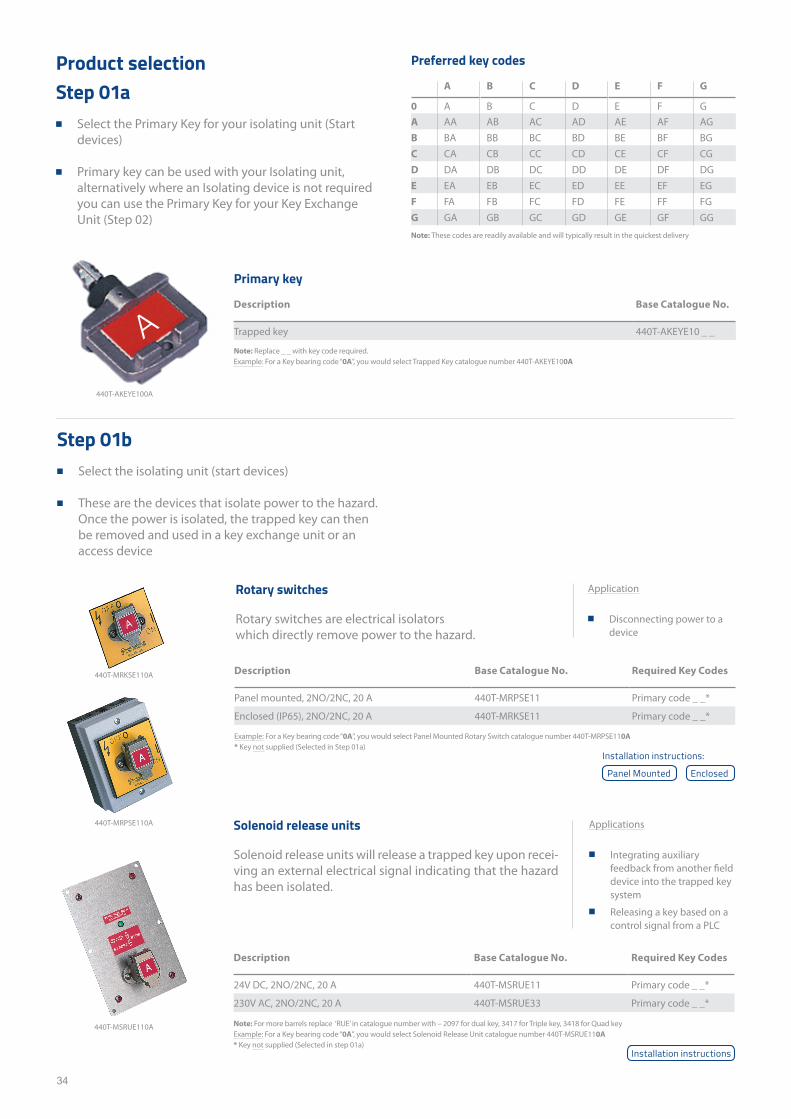
Product selectionStep 01a
■ Select the Primary Key for your isolating unit (Start devices)
■ Primary key can be used with your Isolating unit, alternatively where an Isolating device is not required you can use the Primary Key for your Key Exchange Unit (Step 02)
Step 01b ■ Select the isolating unit (start devices)
■ These are the devices that isolate power to the hazard. Once the power is isolated, the trapped key can then be removed and used in a key exchange unit or an access device
Description Base Catalogue No. Required Key Codes
Panel mounted, 2NO/2NC, 20 A 440T-MRPSE11 Primary code _ _*
Enclosed (IP65), 2NO/2NC, 20 A 440T-MRKSE11 Primary code _ _*
Description Base Catalogue No. Required Key Codes
24V DC, 2NO/2NC, 20 A 440T-MSRUE11 Primary code _ _*
230V AC, 2NO/2NC, 20 A 440T-MSRUE33 Primary code _ _*
Example: For a Key bearing code “0A”, you would select Panel Mounted Rotary Switch catalogue number 440T-MRPSE110A* Key not supplied (Selected in Step 01a)
Note: For more barrels replace ‘RUE’ in catalogue number with – 2097 for dual key, 3417 for Triple key, 3418 for Quad key Example: For a Key bearing code “0A”, you would select Solenoid Release Unit catalogue number 440T-MSRUE110A* Key not supplied (Selected in step 01a)
Note: Replace _ _ with key code required.Example: For a Key bearing code “0A”, you would select Trapped Key catalogue number 440T-AKEYE100A
Note: These codes are readily available and will typically result in the quickest delivery
Primary key
Description Base Catalogue No.
Trapped key 440T-AKEYE10 _ _
Preferred key codes
A B C D E F G
0 A B C D E F GA AA AB AC AD AE AF AGB BA BB BC BD BE BF BGC CA CB CC CD CE CF CGD DA DB DC DD DE DF DGE EA EB EC ED EE EF EGF FA FB FC FD FE FF FGG GA GB GC GD GE GF GG
Rotary switches
Rotary switches are electrical isolators which directly remove power to the hazard.
Solenoid release units
Solenoid release units will release a trapped key upon recei-ving an external electrical signal indicating that the hazard has been isolated.
Applications
■ Integrating auxiliary feedback from another field device into the trapped key system
■ Releasing a key based on a control signal from a PLC
Application
■ Disconnecting power to a device
440T-AKEYE100A
440T-MRKSE110A
440T-MRPSE110A
440T-MSRUE110A
A
Installation instructions:
Panel Mounted Enclosed
Installation instructions
35
Description Base Catalogue No. Required Key Codes
Single key 24 V DC, 2NO/1NC, 20 A 440T-MSTUE11 Primary code _ _*
Single key 230 V AC, 2NO/1NC, 20 A 440T-MSTUE33 Primary code _ _*
Dual key 24 V DC, 2NO/1NC, 20 A 440T-MDTUE11 Primary code _ _*
Dual key 230 V AC, 2NO/1NC, 20 A 440T-MDTUE33 Primary code _ _*
Example: For a Key bearing code “0A”, you would select Dual Key ETDU catalogue number 440T-MDTUE110A0A* Key not supplied (Selected in step 01a)
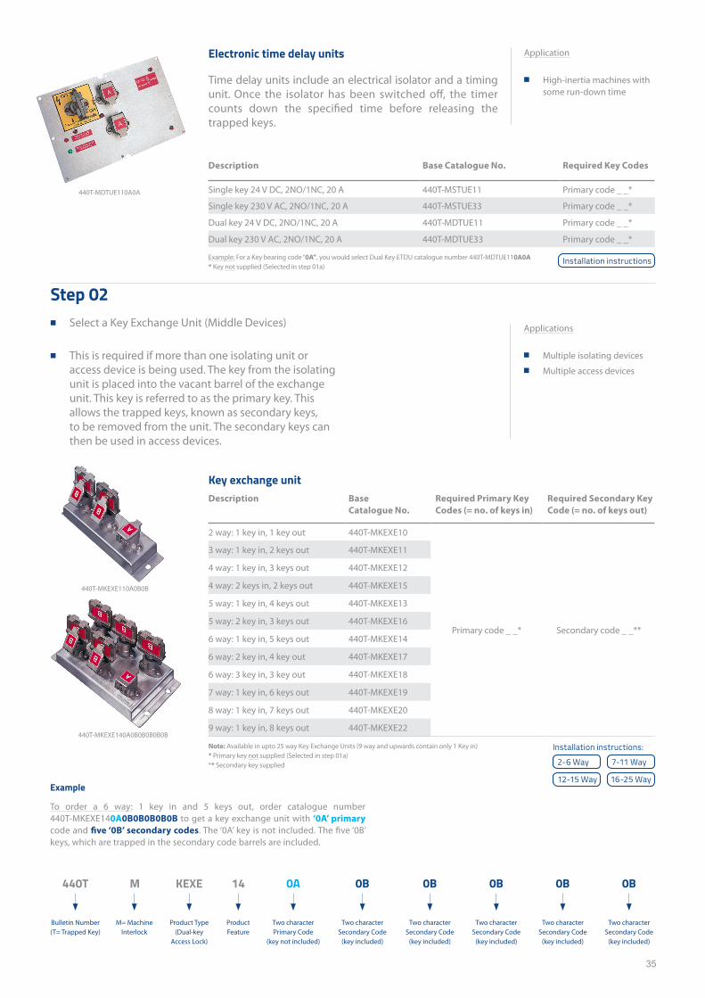
Electronic time delay units
Time delay units include an electrical isolator and a timing unit. Once the isolator has been switched off, the timer counts down the specified time before releasing the trapped keys.
Application
■ High-inertia machines with some run-down time
440T-MDTUE110A0A
Step 02 ■ Select a Key Exchange Unit (Middle Devices)
■ This is required if more than one isolating unit or access device is being used. The key from the isolating unit is placed into the vacant barrel of the exchange unit. This key is referred to as the primary key. This allows the trapped keys, known as secondary keys, to be removed from the unit. The secondary keys can then be used in access devices.
Applications
■ Multiple isolating devices ■ Multiple access devices
Key exchange unit Description Base
Catalogue No.Required Primary Key Codes (= no. of keys in)
Required Secondary Key Code (= no. of keys out)
2 way: 1 key in, 1 key out 440T-MKEXE10
Primary code _ _* Secondary code _ _**
3 way: 1 key in, 2 keys out 440T-MKEXE11
4 way: 1 key in, 3 keys out 440T-MKEXE12
4 way: 2 keys in, 2 keys out 440T-MKEXE15
5 way: 1 key in, 4 keys out 440T-MKEXE13
5 way: 2 key in, 3 keys out 440T-MKEXE16
6 way: 1 key in, 5 keys out 440T-MKEXE14
6 way: 2 key in, 4 key out 440T-MKEXE17
6 way: 3 key in, 3 key out 440T-MKEXE18
7 way: 1 key in, 6 keys out 440T-MKEXE19
8 way: 1 key in, 7 keys out 440T-MKEXE20
9 way: 1 key in, 8 keys out 440T-MKEXE22
Note: Available in upto 25 way Key Exchange Units (9 way and upwards contain only 1 Key in)* Primary key not supplied (Selected in step 01a)** Secondary key supplied
14
Product Feature
KEXE
Product Type (Dual-key
Access Lock)
M
M= Machine Interlock
440T
Bulletin Number (T= Trapped Key)
Example
To order a 6 way: 1 key in and 5 keys out, order catalogue number 440T-MKEXE140A0B0B0B0B0B to get a key exchange unit with ‘0A’ primary code and five ‘0B’ secondary codes. The ‘0A’ key is not included. The five ‘0B’ keys, which are trapped in the secondary code barrels are included.
440T-MKEXE110A0B0B
440T-MKEXE140A0B0B0B0B0B
Two character Primary Code
(key not included)
0A
Two character Secondary Code
(key included)
0B
Two character Secondary Code
(key included)
0B
Two character Secondary Code
(key included)
0B
Two character Secondary Code
(key included)
0B
Two character Secondary Code
(key included)
0B
Installation instructions:
2-6 Way
12-15 Way
7-11 Way
16-25 Way
Installation instructions
36
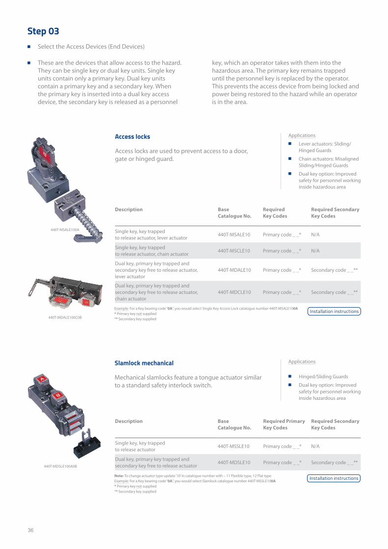
Step 03 ■ Select the Access Devices (End Devices)
■ These are the devices that allow access to the hazard. They can be single key or dual key units. Single key units contain only a primary key. Dual key units contain a primary key and a secondary key. When the primary key is inserted into a dual key access device, the secondary key is released as a personnel
Description Base Catalogue No.
Required Key Codes
Required Secondary Key Codes
Single key, key trapped to release actuator, lever actuator
440T-MSALE10 Primary code _ _* N/A
Single key, key trapped to release actuator, chain actuator
440T-MSCLE10 Primary code _ _* N/A
Dual key, primary key trapped and secondary key free to release actuator, lever actuator
440T-MDALE10 Primary code _ _* Secondary code _ _**
Dual key, primary key trapped and secondary key free to release actuator, chain actuator
440T-MDCLE10 Primary code _ _* Secondary code _ _**
Description Base Catalogue No.
Required Primary Key Codes
Required Secondary Key Codes
Single key, key trapped to release actuator
440T-MSSLE10 Primary code _ _* N/A
Dual key, primary key trapped and secondary key free to release actuator
440T-MDSLE10 Primary code _ _* Secondary code _ _**
Example: For a Key bearing code “0A”, you would select Single Key Access Lock catalogue number 440T-MSALE100A* Primary key not supplied** Secondary key supplied
Note: To change actuator type update ‘10’ in catalogue number with – 11 Flexible type, 12 Flat typeExample: For a Key bearing code “0A”, you would select Slamlock catalogue number 440T-MSSLE100A* Primary key not supplied** Secondary key supplied
Access locks
Access locks are used to prevent access to a door, gate or hinged guard.
Slamlock mechanical
Mechanical slamlocks feature a tongue actuator similar to a standard safety interlock switch.
key, which an operator takes with them into the hazardous area. The primary key remains trapped until the personnel key is replaced by the operator. This prevents the access device from being locked and power being restored to the hazard while an operator is in the area.
440T-MSALE100A
440T-MDALE100C0B
440T-MDSLE100A0B
Applications ■ Lever actuators: Sliding/
Hinged Guards ■ Chain actuators: Misaligned
Sliding/Hinged Guards ■ Dual key option: Improved
safety for personnel working inside hazardous area
Applications
■ Hinged/Sliding Guards ■ Dual key option: Improved
safety for personnel working inside hazardous area
Installation instructions
Installation instructions
37
Description Base Catalogue No.
Required Primary Key Codes
Required Secondary Key Codes
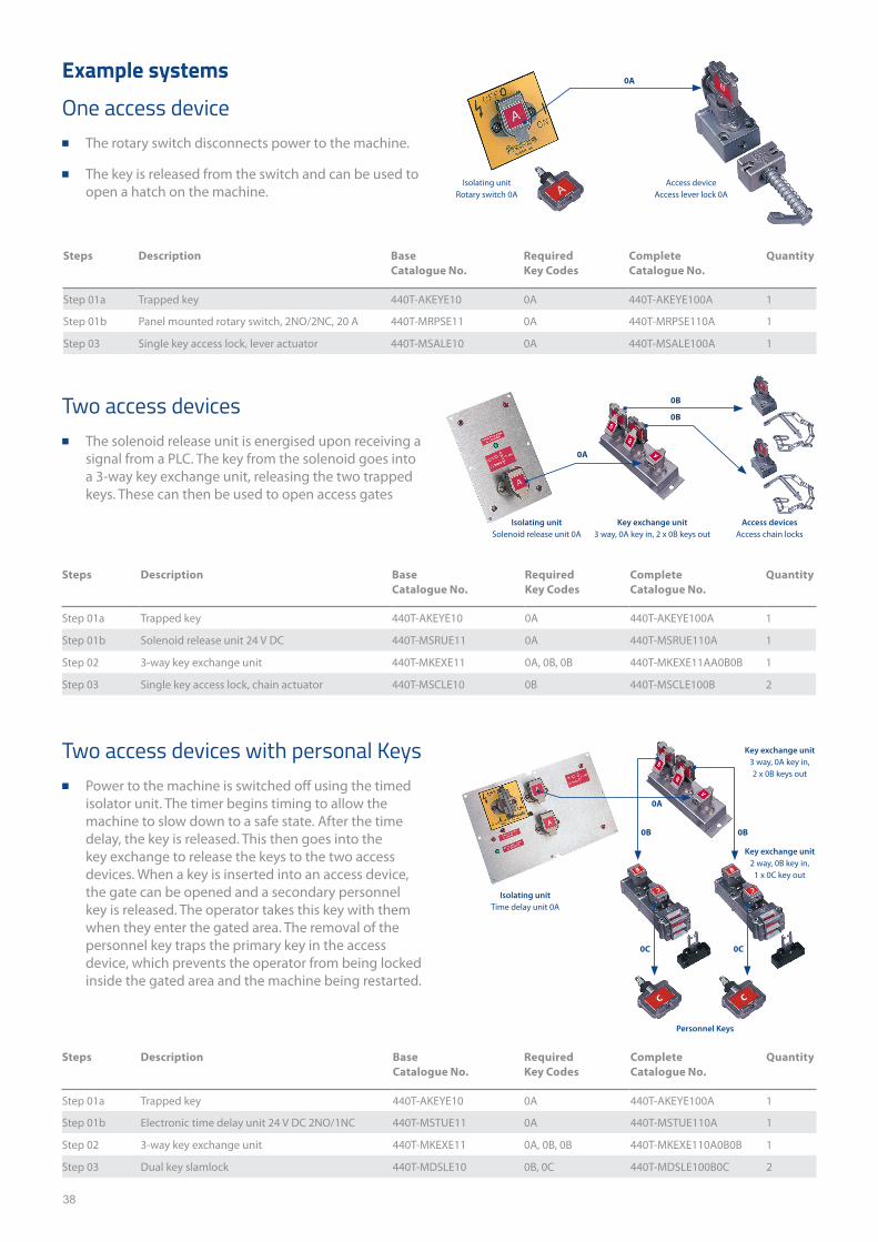
Single key, key trapped to retract bolt 440T-MSBLE10 Primary code _ _* –
Dual key, primary key trapped and secondary key free to retract bolt
440T-MDBLE14 Primary code _ _* Secondary code _ _**
Description Base Catalogue No.
Required Primary Key Codes
Trapped key 440T-AKEYE10 Primary code _ _
Trapped ejector key 440T-AKEYE13 Primary code _ _
Spare weatherproof dust cap 440T-ASFC10 Primary code _ _
Emergency Repair Kit for code barrels 440T-AKITE45ER* –
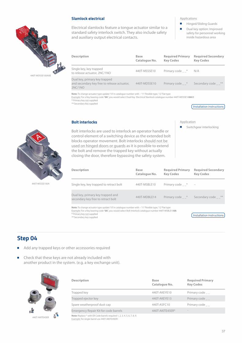
Note: To change actuator type update ‘10’ in catalogue number with – ‘11’ Flexible type, ‘12’ Flat type Example: For a Key bearing code “0A”, you would select Dual Key Electrical Slamlock catalogue number 440T-MDSSE100A0E* Primary key not supplied** Secondary key supplied
Note: To change actuator type update ‘10’ in catalogue number with – ‘11’ Flexible type, ‘12’ Flat type Example: For a Key bearing code “0A”, you would select Bolt Interlock catalogue number 440T-MSBLE100A* Primary key not supplied** Secondary key supplied
Note: Replace * with ER Code barrels required 1, 2, 3, 4, 5, 6, 7, 8, 9.Example: for single barrel use 440T-AKITE45ER1
Slamlock electrical
Electrical slamlocks feature a tongue actuator similar to a standard safety interlock switch. They also include safety and auxiliary output electrical contacts.
Bolt interlocks
Bolt interlocks are used to interlock an operator handle or control element of a switching device as the extended bolt blocks operator movement. Bolt interlocks should not be used on hinged doors or guards as it is possible to extend the bolt and remove the trapped key without actually closing the door, therefore bypassing the safety system.
Description Base Catalogue No.
Required Primary Key Codes
Required Secondary Key Codes
Single key, key trapped to release actuator, 2NC/1NO
440T-MSSSE10 Primary code _ _* N/A
Dual key, primary key trapped and secondary key free to release actuator, 2NC/1NO
440T-MDSSE10 Primary code _ _* Secondary code _ _**
Step 04 ■ Add any trapped keys or other accessories required
■ Check that these keys are not already included with another product in the system. (e.g. a key exchange unit).
440T-MDSSE100A0E
440T-MSSSE100A
Applications ■ Hinged/Sliding Guards ■ Dual key option: Improved
safety for personnel working inside hazardous area
Application ■ Switchgear interlocking
A
Installation instructions
Installation instructions
440T-AKITE45ER
38
Steps Description Base Catalogue No.
Required Key Codes
Complete Catalogue No.
Quantity
Step 01a Trapped key 440T-AKEYE10 0A 440T-AKEYE100A 1
Step 01b Panel mounted rotary switch, 2NO/2NC, 20 A 440T-MRPSE11 0A 440T-MRPSE110A 1
Step 03 Single key access lock, lever actuator 440T-MSALE10 0A 440T-MSALE100A 1
Steps Description Base Catalogue No.
Required Key Codes
Complete Catalogue No.
Quantity
Step 01a Trapped key 440T-AKEYE10 0A 440T-AKEYE100A 1
Step 01b Solenoid release unit 24 V DC 440T-MSRUE11 0A 440T-MSRUE110A 1
Step 02 3-way key exchange unit 440T-MKEXE11 0A, 0B, 0B 440T-MKEXE11AA0B0B 1
Step 03 Single key access lock, chain actuator 440T-MSCLE10 0B 440T-MSCLE100B 2
Steps Description Base Catalogue No.
Required Key Codes
Complete Catalogue No.
Quantity
Step 01a Trapped key 440T-AKEYE10 0A 440T-AKEYE100A 1
Step 01b Electronic time delay unit 24 V DC 2NO/1NC 440T-MSTUE11 0A 440T-MSTUE110A 1
Step 02 3-way key exchange unit 440T-MKEXE11 0A, 0B, 0B 440T-MKEXE110A0B0B 1
Step 03 Dual key slamlock 440T-MDSLE10 0B, 0C 440T-MDSLE100B0C 2
Example systems
One access device ■ The rotary switch disconnects power to the machine.
■ The key is released from the switch and can be used to open a hatch on the machine.
Two access devices ■ The solenoid release unit is energised upon receiving a
signal from a PLC. The key from the solenoid goes into a 3-way key exchange unit, releasing the two trapped keys. These can then be used to open access gates
Two access devices with personal Keys ■ Power to the machine is switched off using the timed
isolator unit. The timer begins timing to allow the machine to slow down to a safe state. After the time delay, the key is released. This then goes into the key exchange to release the keys to the two access devices. When a key is inserted into an access device, the gate can be opened and a secondary personnel key is released. The operator takes this key with them when they enter the gated area. The removal of the personnel key traps the primary key in the access device, which prevents the operator from being locked inside the gated area and the machine being restarted.
Isolating unit Rotary switch 0A
Access device Access lever lock 0A
0A
0B
0A
0A
0B
Isolating unit Solenoid release unit 0A
Key exchange unit 3 way, 0A key in, 2 x 0B keys out
Access devices Access chain locks
Isolating unit Time delay unit 0A
Key exchange unit 3 way, 0A key in, 2 x 0B keys out
Key exchange unit 2 way, 0B key in,
1 x 0C key out
Personnel Keys
0B 0B
0C0C
C C
A
C C
B B

39
This page has been left intentionally blank
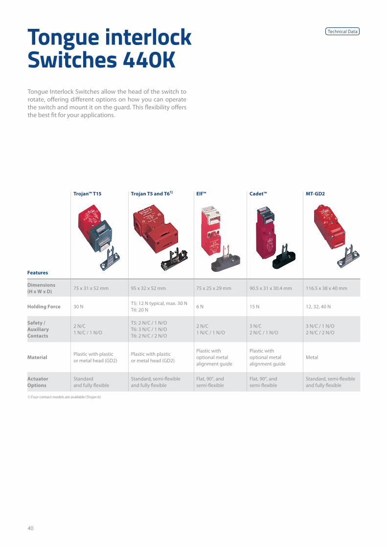
40
Tongue interlock Switches 440K
Trojan™ T15 Trojan T5 and T61) Elf™ Cadet™ MT-GD2
Features
Dimensions (H x W x D)
75 x 31 x 52 mm 95 x 32 x 52 mm 75 x 25 x 29 mm 90.5 x 31 x 30.4 mm 116.5 x 38 x 40 mm
Holding Force 30 NT5: 12 N typical, max. 30 N T6: 20 N
6 N 15 N 12, 32, 40 N
Safety / Auxiliary Contacts
2 N/C 1 N/C / 1 N/O
T5: 2 N/C / 1 N/O T6: 3 N/C / 1 N/O T6: 2 N/C / 2 N/O
2 N/C 1 N/C / 1 N/O
3 N/C 2 N/C / 1 N/O
3 N/C / 1 N/O 2 N/C / 2 N/O
MaterialPlastic with plastic or metal head (GD2)
Plastic with plastic or metal head (GD2)
Plastic with optional metal alignment guide
Plastic with optional metal alignment guide
Metal
Actuator Options
Standard and fully flexible
Standard, semi-flexible and fully flexible
Flat, 90°, and semi-flexible
Flat, 90°, and semi-flexible
Standard, semi-flexible and fully flexible
1) Four-contact models are available (Trojan 6).
Tongue Interlock Switches allow the head of the switch to rotate, offering different options on how you can operate the switch and mount it on the guard. This flexibility offers the best fit for your applications.
Technical Data
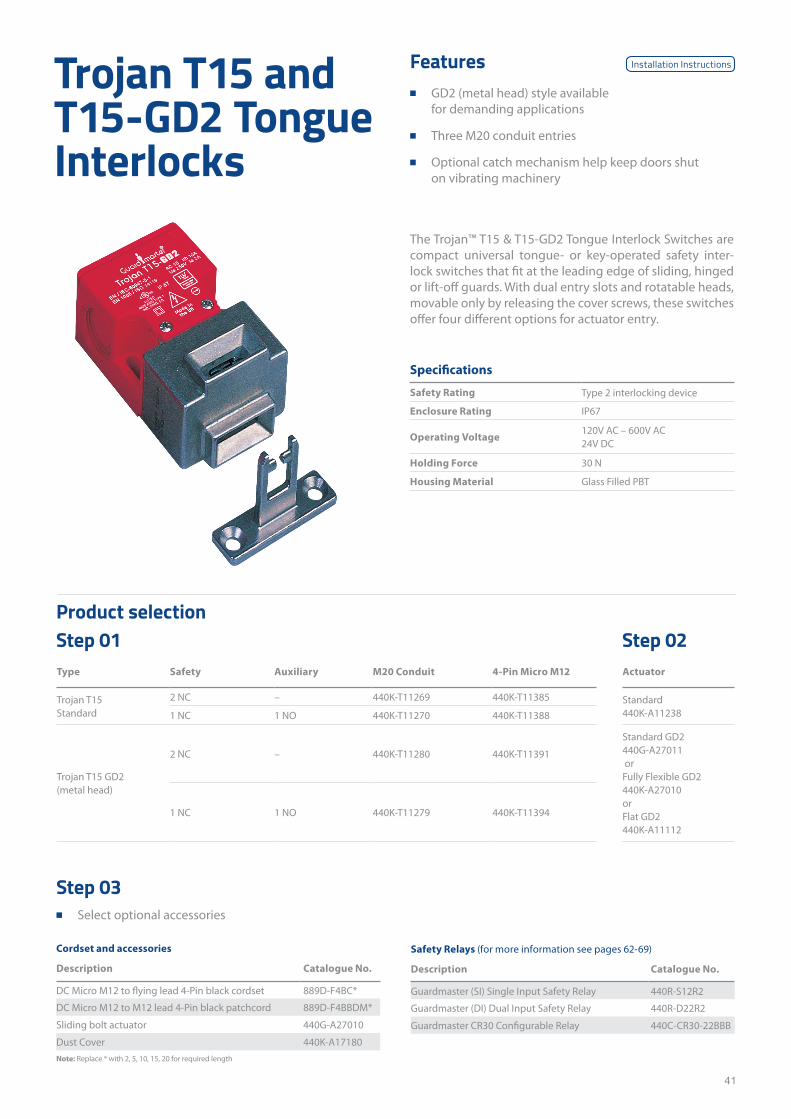
41
Trojan T15 and T15-GD2 Tongue Interlocks
Features ■ GD2 (metal head) style available
for demanding applications
■ Three M20 conduit entries
■ Optional catch mechanism help keep doors shut on vibrating machinery
The Trojan™ T15 & T15-GD2 Tongue Interlock Switches are compact universal tongue- or key-operated safety inter-lock switches that fit at the leading edge of sliding, hinged or lift-off guards. With dual entry slots and rotatable heads, movable only by releasing the cover screws, these switches offer four different options for actuator entry.
Specifications
Safety Rating Type 2 interlocking device
Enclosure Rating IP67
Operating Voltage120V AC – 600V AC 24V DC
Holding Force 30 N
Housing Material Glass Filled PBT
Type Safety Auxiliary M20 Conduit 4-Pin Micro M12 Actuator
Trojan T15 Standard
2 NC – 440K-T11269 440K-T11385 Standard 440K-A112381 NC 1 NO 440K-T11270 440K-T11388
Trojan T15 GD2 (metal head)
2 NC – 440K-T11280 440K-T11391
Standard GD2 440G-A27011 orFully Flexible GD2 440K-A27010or Flat GD2 440K-A11112
1 NC 1 NO 440K-T11279 440K-T11394
Product selectionStep 01 Step 02
Cordset and accessories
Description Catalogue No.
DC Micro M12 to flying lead 4-Pin black cordset 889D-F4BC*
DC Micro M12 to M12 lead 4-Pin black patchcord 889D-F4BBDM*
Sliding bolt actuator 440G-A27010
Dust Cover 440K-A17180Note: Replace * with 2, 5, 10, 15, 20 for required length
Step 03 ■ Select optional accessories
Safety Relays (for more information see pages 62-69)
Description Catalogue No.
Guardmaster (SI) Single Input Safety Relay 440R-S12R2
Guardmaster (DI) Dual Input Safety Relay 440R-D22R2
Guardmaster CR30 Configurable Relay 440C-CR30-22BBB
Installation Instructions
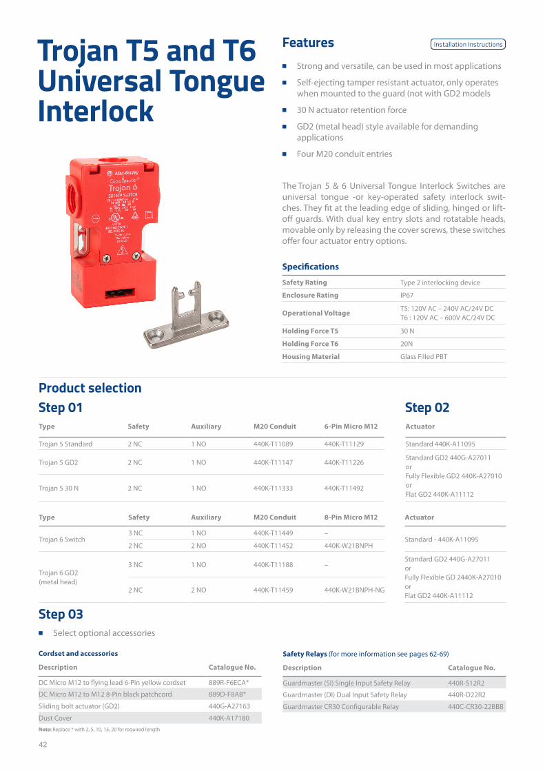
42
Trojan T5 and T6 Universal Tongue Interlock
Features ■ Strong and versatile, can be used in most applications
■ Self-ejecting tamper resistant actuator, only operates when mounted to the guard (not with GD2 models
■ 30 N actuator retention force
■ GD2 (metal head) style available for demanding applications
■ Four M20 conduit entries
The Trojan 5 & 6 Universal Tongue Interlock Switches are universal tongue -or key-operated safety interlock swit-ches. They fit at the leading edge of sliding, hinged or lift-off guards. With dual key entry slots and rotatable heads, movable only by releasing the cover screws, these switches offer four actuator entry options.
Specifications
Safety Rating Type 2 interlocking device
Enclosure Rating IP67
Operational VoltageT5: 120V AC – 240V AC/24V DC T6 : 120V AC – 600V AC/24V DC
Holding Force T5 30 N
Holding Force T6 20N
Housing Material Glass Filled PBT
Type Safety Auxiliary M20 Conduit 6-Pin Micro M12 Actuator
Trojan 5 Standard 2 NC 1 NO 440K-T11089 440K-T11129 Standard 440K-A11095
Trojan 5 GD2 2 NC 1 NO 440K-T11147 440K-T11226Standard GD2 440G-A27011 orFully Flexible GD2 440K-A27010 or Flat GD2 440K-A11112
Trojan 5 30 N 2 NC 1 NO 440K-T11333 440K-T11492
Type Safety Auxiliary M20 Conduit 8-Pin Micro M12 Actuator
Trojan 6 Switch3 NC 1 NO 440K-T11449 –
Standard - 440K-A110952 NC 2 NO 440K-T11452 440K-W21BNPH
Trojan 6 GD2 (metal head)
3 NC 1 NO 440K-T11188 –Standard GD2 440G-A27011 or Fully Flexible GD 2440K-A27010 or Flat GD2 440K-A11112
2 NC 2 NO 440K-T11459 440K-W21BNPH-NG
Product selectionStep 01 Step 02
Cordset and accessories
Description Catalogue No.
DC Micro M12 to flying lead 6-Pin yellow cordset 889R-F6ECA*
DC Micro M12 to M12 8-Pin black patchcord 889D-F8AB*
Sliding bolt actuator (GD2) 440G-A27163
Dust Cover 440K-A17180Note: Replace * with 2, 5, 10, 15, 20 for required length
Step 03 ■ Select optional accessories
Safety Relays (for more information see pages 62-69)
Description Catalogue No.
Guardmaster (SI) Single Input Safety Relay 440R-S12R2
Guardmaster (DI) Dual Input Safety Relay 440R-D22R2
Guardmaster CR30 Configurable Relay 440C-CR30-22BBB
Installation Instructions
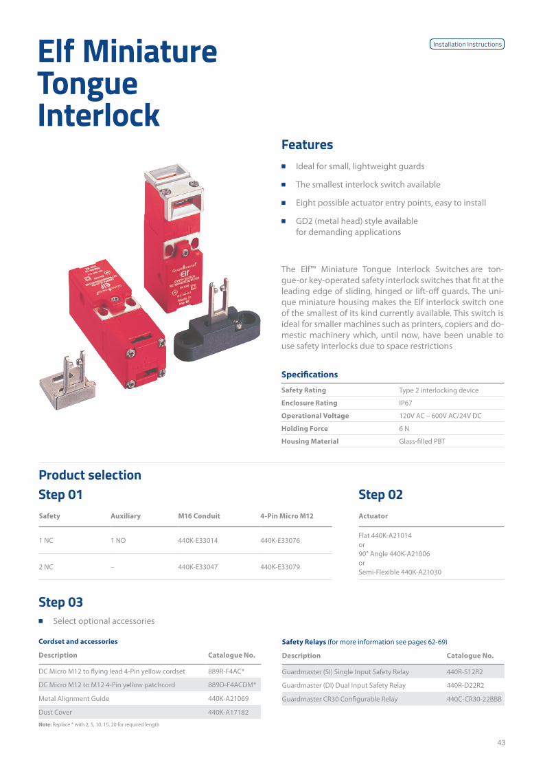
43
Elf Miniature Tongue Interlock
Features ■ Ideal for small, lightweight guards
■ The smallest interlock switch available
■ Eight possible actuator entry points, easy to install
■ GD2 (metal head) style available for demanding applications
The Elf™ Miniature Tongue Interlock Switches are ton-gue-or key-operated safety interlock switches that fit at the leading edge of sliding, hinged or lift-off guards. The uni-que miniature housing makes the Elf interlock switch one of the smallest of its kind currently available. This switch is ideal for smaller machines such as printers, copiers and do-mestic machinery which, until now, have been unable to use safety interlocks due to space restrictions
Specifications
Safety Rating Type 2 interlocking device
Enclosure Rating IP67
Operational Voltage 120V AC – 600V AC/24V DC
Holding Force 6 N
Housing Material Glass-filled PBT
Safety Auxiliary M16 Conduit 4-Pin Micro M12 Actuator
1 NC 1 NO 440K-E33014 440K-E33076Flat 440K-A21014or90° Angle 440K-A21006orSemi-Flexible 440K-A21030
2 NC – 440K-E33047 440K-E33079
Product selectionStep 01 Step 02
Cordset and accessories
Description Catalogue No.
DC Micro M12 to flying lead 4-Pin yellow cordset 889R-F4AC*
DC Micro M12 to M12 4-Pin yellow patchcord 889D-F4ACDM*
Metal Alignment Guide 440K-A21069
Dust Cover 440K-A17182
Note: Replace * with 2, 5, 10, 15, 20 for required length
Step 03 ■ Select optional accessories
Safety Relays (for more information see pages 62-69)
Description Catalogue No.
Guardmaster (SI) Single Input Safety Relay 440R-S12R2
Guardmaster (DI) Dual Input Safety Relay 440R-D22R2
Guardmaster CR30 Configurable Relay 440C-CR30-22BBB
Installation Instructions

44
Cadet 3 Tongue Interlock Switches
Features ■ Compact size
■ Ideal for small, lightweight guards
■ Eight possible actuator entry points
■ GD2 (metal head) style available for demanding applications
The Cadet 3 Tongue Interlock Switches are tongue- or key-operated safety interlock switches that fit at the lea-ding edge of sliding, hinged or lift-off guards. With dual en-try slots and rotatable head, the versatile Cadet 3 offers up to eight different actuator entry options.
Specifications
Safety Rating Type 2 interlocking device
Enclosure Rating IP67
Operational Voltage 120V AC – 600V AC/24V DC
Holding Force 15 N
Housing Material Glass Filled PBT
Safety Auxiliary M16 Conduit Actuator
3 NC – 440K-C21070 Flat 440K-A21014 or90° Angle 440K-A21006 or Semi-Flexible 440K-A21030
2 NC 1 NO 440K-C21055
2 NC 1 NO 440K-C21080
Product selectionStep 01 Step 02
Accessories
Description Catalogue No.
Replacement Cover 440A-A21115
Dust Cover 440K-A17182
Step 03 ■ Select optional accessories
Safety Relays (for more information see pages 62-69)
Description Catalogue No.
Guardmaster (SI) Single Input Safety Relay 440R-S12R2
Guardmaster (DI) Dual Input Safety Relay 440R-D22R2
Guardmaster CR30 Configurable Relay 440C-CR30-22BBB
Installation Instructions
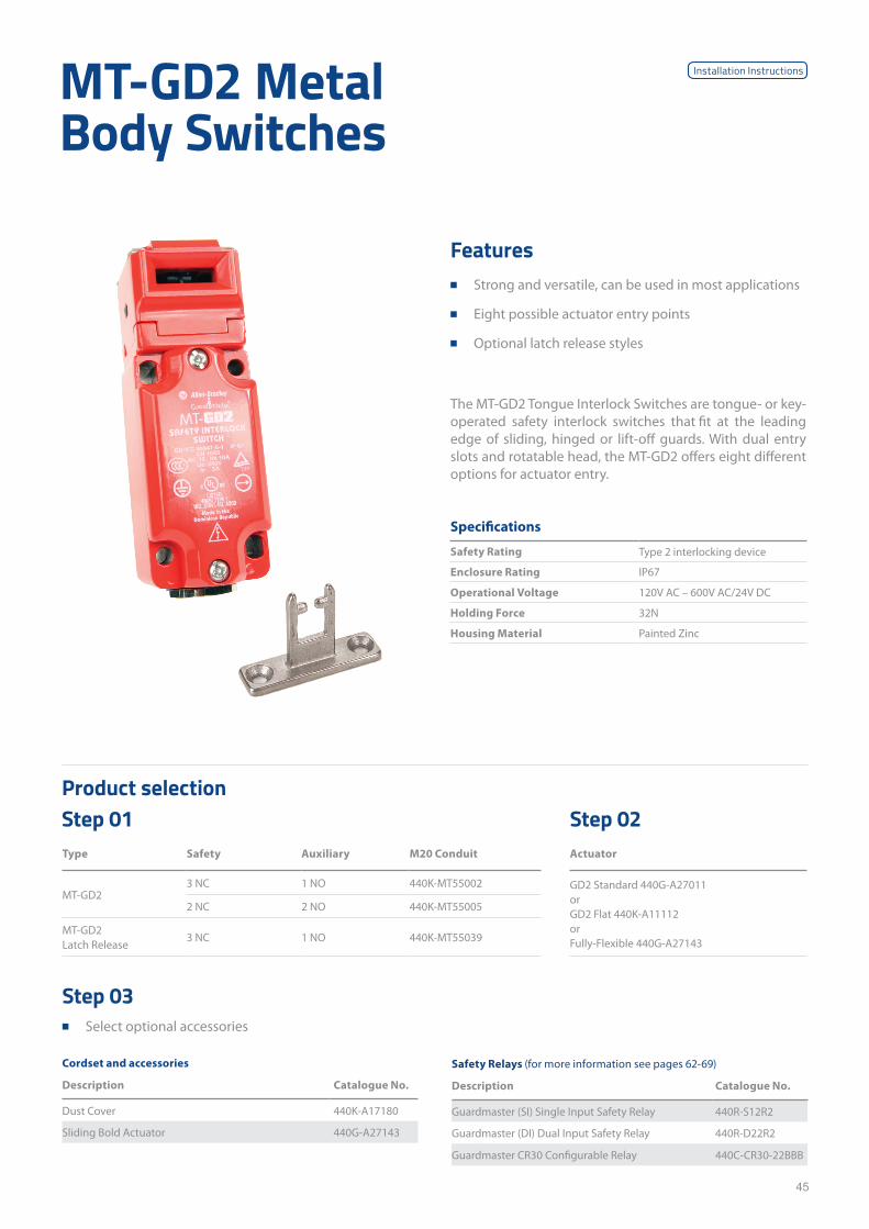
45
MT-GD2 Metal Body Switches
Features ■ Strong and versatile, can be used in most applications
■ Eight possible actuator entry points
■ Optional latch release styles
The MT-GD2 Tongue Interlock Switches are tongue- or key- operated safety interlock switches that fit at the leading edge of sliding, hinged or lift-off guards. With dual entry slots and rotatable head, the MT-GD2 offers eight different options for actuator entry.
Specifications
Safety Rating Type 2 interlocking device
Enclosure Rating IP67
Operational Voltage 120V AC – 600V AC/24V DC
Holding Force 32N
Housing Material Painted Zinc
Type Safety Auxiliary M20 Conduit Actuator
MT-GD23 NC 1 NO 440K-MT55002 GD2 Standard 440G-A27011
orGD2 Flat 440K-A11112 or Fully-Flexible 440G-A27143
2 NC 2 NO 440K-MT55005
MT-GD2 Latch Release
3 NC 1 NO 440K-MT55039
Product selectionStep 01 Step 02
Cordset and accessories
Description Catalogue No.
Dust Cover 440K-A17180
Sliding Bold Actuator 440G-A27143
Step 03 ■ Select optional accessories
Safety Relays (for more information see pages 62-69)
Description Catalogue No.
Guardmaster (SI) Single Input Safety Relay 440R-S12R2
Guardmaster (DI) Dual Input Safety Relay 440R-D22R2
Guardmaster CR30 Configurable Relay 440C-CR30-22BBB
Installation Instructions
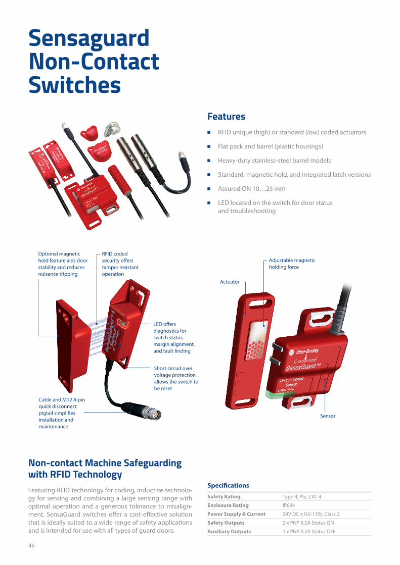
46
Sensaguard Non-Contact Switches
Non-contact Machine Safeguarding with RFID Technology Featuring RFID technology for coding, inductive technolo-gy for sensing and combining a large sensing range with optimal operation and a generous tolerance to misalign-ment, SensaGuard switches offer a cost-effective solution that is ideally suited to a wide range of safety applications and is intended for use with all types of guard doors.
Specifications
Safety Rating Type 4, Ple, CAT 4
Enclosure Rating IP69k
Power Supply & Current 24V DC ±10/-15%; Class 2
Safety Outputs 2 x PNP 0.2A Status ON
Auxiliary Outputs 1 x PNP 0.2A Status OFF
Features ■ RFID unique (high) or standard (low) coded actuators
■ Flat pack and barrel (plastic housings)
■ Heavy-duty stainless-steel barrel models
■ Standard, magnetic hold, and integrated latch versions
■ Assured ON 10…25 mm
■ LED located on the switch for door status and troubleshooting
Actuator
Sensor
LED offers diagnostics for switch status, margin alignment, and fault finding
RFID coded security offers tamper resistant operation
Optional magnetic hold feature aids door stability and reduces nuisance tripping
Cable and M12 8-pin quick disconnect pigtail simplifies installation and maintenance
Adjustable magnetic holding force
Short circuit over voltage protection allows the switch to be reset
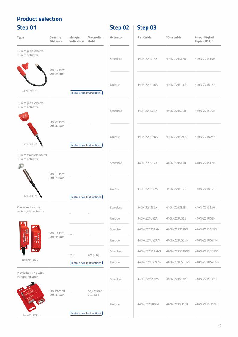
47
Type Sensing Distance
Margin Indication
Magnetic Hold
Actuator 3 m Cable 10 m cable 6 inch Pigtail 8-pin (M12)*
18 mm plastic barrel 18 mm actuator
On: 15 mm Off: 25 mm
– –
Standard 440N-Z21S16A 440N-Z21S16B 440N-Z21S16H
Unique 440N-Z21U16A 440N-Z21U16B 440N-Z21U16H
18 mm plastic barrel 30 mm actuator
On: 25 mm Off: 35 mm
– –
Standard 440N-Z21S26A 440N-Z21S26B 440N-Z21S26H
Unique 440N-Z21U26A 440N-Z21U26B 440N-Z21U26H
18 mm stainless barrel 18 mm actuator
On: 10 mm Off: 20 mm
– –
Standard 440N-Z21S17A 440N-Z21S17B 440N-Z21S17H
Unique 440N-Z21U17A 440N-Z21U17B 440N-Z21U17H
Plastic rectangular rectangular actuator
On: 15 mm Off: 35 mm
– –
Standard 440N-Z21SS2A 440N-Z21SS2B 440N-Z21SS2H
Unique 440N-Z21US2A 440N-Z21US2B 440N-Z21US2H
Yes –
Standard 440N-Z21SS2AN 440N-Z21SS2BN 440N-Z21SS2HN
Unique 440N-Z21US2AN 440N-Z21US2BN 440N-Z21US2HN
Yes Yes (9 N)Standard 440N-Z21SS2AN9 440N-Z21SS2BN9 440N-Z21SS2HN9
Unique 440N-Z21US2AN9 440N-Z21US2BN9 440N-Z21US2HN9
Plastic housing with integrated latch
On: latched Off: 35 mm
–Adjustable 20…60 N
Standard 440N-Z21SS3PA 440N-Z21SS3PB 440N-Z21SS3PH
Unique 440N-Z21SU3PA 440N-Z21SU3PB 440N-Z21SU3PH
Product selectionStep 01 Step 02 Step 03
440N-Z21S16H
440N-Z21S26A
440N-Z21SS2AN
440N-Z21SS3PH
440N-Z21S17A
Installation Instructions
Installation Instructions
Installation Instructions
Installation Instructions
Installation Instructions
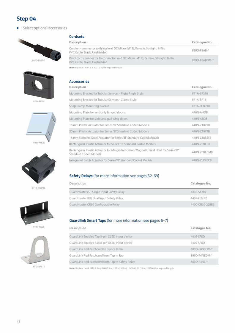
48
Step 04 ■ Select optional accessories
CordsetsDescription Catalogue No.
Cordset - connector to flying lead DC Micro (M12), Female, Straight, 8-Pin, PVC Cable, Black, Unshielded
889D-F8AB-*
Patchcord - connector to connector lead DC Micro (M12), Female, Straight, 8-Pin, PVC Cable, Black, Unshielded
889D-F8ABDM-*
Note: Replace * with 2, 5, 10, 15, 20 for required length
AccessoriesDescription Catalogue No.
Mounting Bracket for Tubular Sensors - Right Angle Style 871A-BRS18
Mounting Bracket for Tubular Sensors - Clamp Style 871A-BP18
Snap Clamp Mounting Bracket 871A-SCBP18
Mounting Plate for vertically hinged doors 440N-AHDB
Mounting Plate for slide and gull wing doors 440N-ASDB
18 mm Plastic Actuator for Series “B” Standard Coded Models 440N-Z18PTB
30 mm Plastic Actuator for Series “B” Standard Coded Models 440N-Z30PTB
18 mm Stainless Steel Actuator for Series “B” Standard Coded Models 440N-Z18SSTB
Rectangular Plastic Actuator for Series “B” Standard Coded Models 440N-ZPRECB
Rectangular Plastic Actuator for Margin Indication/Magnetic Field Hold for Series “B” Standard Coded Models
440N-ZPRECMB
Integrated Latch Actuator for Series “B” Standard Coded Models 440N-ZLPRECB
871A-SCBP18
440N-ASDB
440N-AHDB
871A-BP18
Note: Replace * with 0M3 (0.3m), 0M6 (0.6m), 2 (2m), 5 (5m), 10 (10m), 15 (15m), 20 (20m) for required length
Safety Relays (for more information see pages 62-69)
Description Catalogue No.
Guardmaster (SI) Single Input Safety Relay 440R-S12R2
Guardmaster (DI) Dual Input Safety Relay 440R-D22R2
Guardmaster CR30 Configurable Relay 440C-CR30-22BBB
Guardlink Smart Taps (for more information see pages 6-7)
Description Catalogue No.
GuardLink Enabled Tap 5-pin OSSD Input device 440S-SF5D
GuardLink Enabled Tap 8-pin OSSD Input device 440S-SF8D
GuardLink Red Patchcord to device 8-Pin 889D-F8NBDM-*
GuardLink Red Patchcord from Tap to Tap 889D-F4NEDM-*
GuardLink Red Patchcord from Tap to Safety Relay 889D-F4NE-*
889D-F8AB-*
871A-BRS18
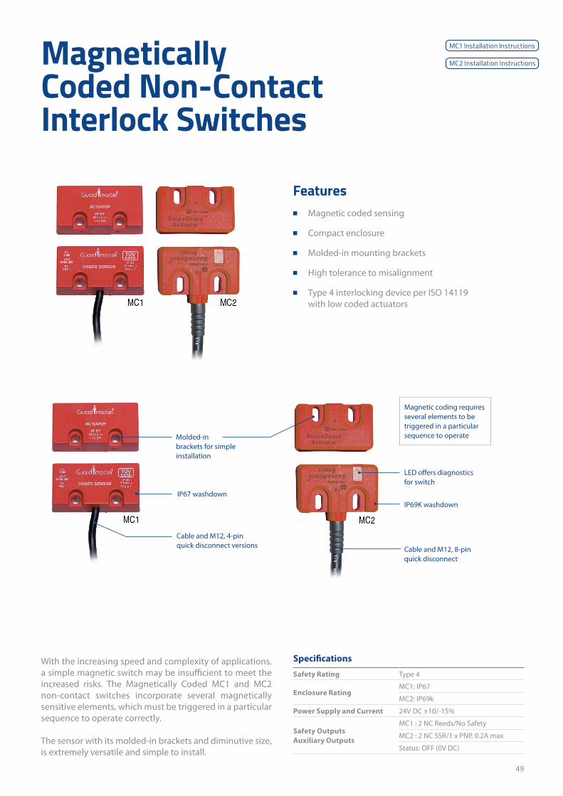
49
Magnetically Coded Non-Contact Interlock Switches
With the increasing speed and complexity of applications, a simple magnetic switch may be insufficient to meet the increased risks. The Magnetically Coded MC1 and MC2 non-contact switches incorporate several magnetically sensitive elements, which must be triggered in a particular sequence to operate correctly.
The sensor with its molded-in brackets and diminutive size, is extremely versatile and simple to install.
Specifications
Safety Rating Type 4
Enclosure RatingMC1: IP67
MC2: IP69k
Power Supply and Current 24V DC ±10/-15%
Safety OutputsAuxiliary Outputs
MC1 : 2 NC Reeds/No Safety
MC2 : 2 NC SSR/1 x PNP, 0.2A max
Status: OFF (0V DC)
Features ■ Magnetic coded sensing
■ Compact enclosure
■ Molded-in mounting brackets
■ High tolerance to misalignment
■ Type 4 interlocking device per ISO 14119 with low coded actuators
IP67 washdown
LED offers diagnostics for switch
IP69K washdown
Magnetic coding requires several elements to be triggered in a particular sequence to operate
Cable and M12, 8-pin quick disconnect
Cable and M12, 4-pin quick disconnect versions
Molded-in brackets for simple installation
MC1 Installation Instructions
MC2 Installation Instructions
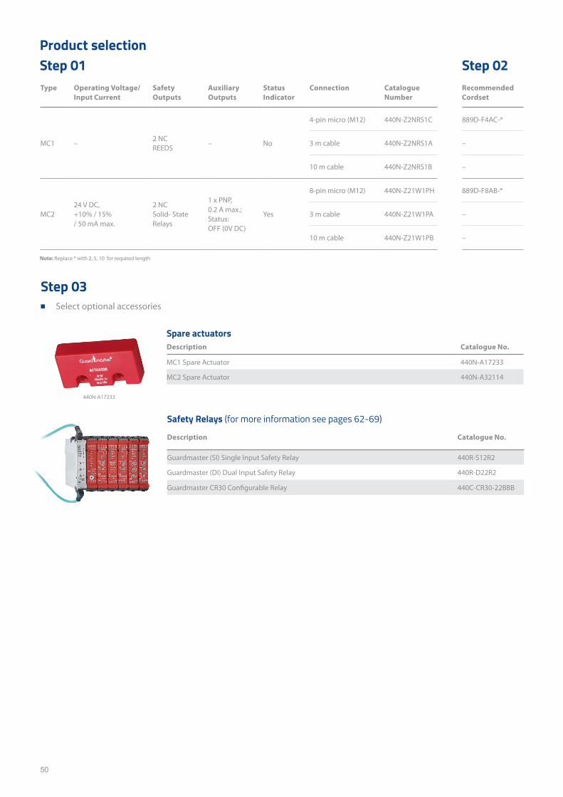
50
Type Operating Voltage/ Input Current
Safety Outputs
Auxiliary Outputs
Status Indicator
Connection Catalogue Number
Recommended Cordset
MC1 –2 NC REEDS
– No
4-pin micro (M12) 440N-Z2NRS1C 889D-F4AC-*
3 m cable 440N-Z2NRS1A –
10 m cable 440N-Z2NRS1B –
MC224 V DC, +10% / 15% / 50 mA max.
2 NC Solid- State Relays
1 x PNP, 0.2 A max.; Status: OFF (0V DC)
Yes
8-pin micro (M12) 440N-Z21W1PH 889D-F8AB-*
3 m cable 440N-Z21W1PA –
10 m cable 440N-Z21W1PB –
Product selectionStep 01 Step 02
Spare actuatorsDescription Catalogue No.
MC1 Spare Actuator 440N-A17233
MC2 Spare Actuator 440N-A32114
Safety Relays (for more information see pages 62-69)
Description Catalogue No.
Guardmaster (SI) Single Input Safety Relay 440R-S12R2
Guardmaster (DI) Dual Input Safety Relay 440R-D22R2
Guardmaster CR30 Configurable Relay 440C-CR30-22BBB
Note: Replace * with 2, 5, 10 for required length
Step 03 ■ Select optional accessories
440N-A17233

51
This page has been left intentionally blank

52
440P Safety Limit Switches
A full line of IEC safety switches The 440P limit switch family offers a full range of interna-tional-style solutions for both safety and standard sensing applications. Available in four different body styles – 30 mm metal, 22 mm metal and plastic, and 15 mm plastic – with a broad selection of operator types, circuit arrangements and connection options, the 440P is ideal for a wide variety of applications. These include material handling, packaging, elevators, escalators, scissor lifts, industrial trucks and trac-tors, cranes and hoists, overhead door as well as general safety guarding applications.
Features ■ 30 mm metal, 22 mm metal and plastic,
and 15 mm plastic body styles
■ Flexible installation, wide range of actuator and contact configurations
■ Safety Rated, Positive opening-action contacts (Slow Acting)
Snap Action: Slow Action:
Contacts change instantaneously at point of actuation.
Contacts make or break at separate points of actuation.
Output
Actuator
Output
Actuator
Open Closed
Specifications30mm Metal 22mm Plastic 22mm Metal 15mm Plastic
Dimensions (H x W x D) mm 76.5 x 40 x 45 68 x 31 x 30 34 x 35 x 16 37.7 x 25.1 x 23.3
Safety Rating Type 1, CAT 1 Type 1, CAT 1 Type 1, CAT 1 Type 1, CAT 1
Enclosure Rating IP66 IP66 IP66, IP67, IP69K IP30
Safety outputs 1NC, 2 NC, 3NC, 4NC 1NC, 2NC, 3NC 1NC, 2NC, 3NC, 4NC 1NC
Auxiliary outputs 1NO (with 2NC) 1NO 1NO, 2NO 1NO
Operational Voltage 240V / 3A 240V / 3A 240V / 3A 240V / 3A
Short roller lever
Spring rod Hinge lever Offset hinge Cross roller plunger
Adjustable roller lever
Dome plunger
Roller plunger
Panel mount roller plunger
Rod lever
Telescopic arm
Actuator Head Types
Installation Instructions Installation Instructions Installation Instructions Installation Instructions
Technical Data
Note: Adjustable actuators cannot be used in Safety applications (Adjustable Roller Lever, Spring Rod, Telescopic Arm).
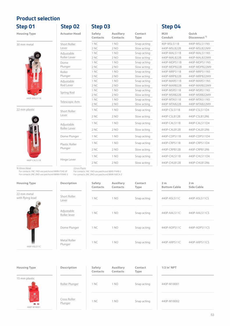
53
Housing Type Actuator Head Safety Contacts
AuxilIary Contacts
Contact Type
M20 Conduit
Quick Disconnect 1)
30 mm metal Short Roller Lever
1 NC 1 NO Snap acting 40P-MSLS11B 440P-MSLS11N52 NC 2 NO Slow acting 440P-MSLB22B 440P-MSLB22M9
Adjustable Roller Lever
1 NC 1 NO Snap acting 440P-MALS11B 440P-MALS11N52 NC 2 NO Slow acting 440P-MALB22B 440P-MALB22M9
Dome Plunger
1 NC 1 NO Snap acting 440P-MDPS11B 440P-MDPS11N52 NC 2 NO Slow acting 440P-MDPB22B 440P-MDPB22M9
Roller Plunger
1 NC 1 NO Snap acting 440P-MRPS11B 440P-MRPS11N52 NC 2 NO Slow acting 440P-MRPB22B 440P-MRPB22M9
Adjustable Rod Lever
1 NC 1 NO Snap acting 440P-MARS11B 440P-MARS11N52 NC 2 NO Slow acting 440P-MARB22B 440P-MARB22M9
Spring Rod1 NC 1 NO Snap acting 440P-MSRS11B 440P-MSRS11N52 NC 2 NO Slow acting 440P-MSRB22B 440P-MSRB22M9
Telescopic Arm1 NC 1 NO Snap acting 440P-MTAS11B 440P-MTAS11N52 NC 2 NO Slow acting 440P-MTAB22B 440P-MTAB22M9
22 mm plastic Short Roller Lever
1 NC 1 NO Snap acting 440P-CSLS11B 440P-CSLS11D4
2 NC 2 NO Slow acting 440P-CSLB12B 440P-CSLB12R6
Adjustable Roller Lever
1 NC 1 NO Snap acting 440P-CALS11B 440P-CALS11D4
2 NC 2 NO Slow acting 440P-CALB12B 440P-CALB12R6
Dome Plunger 1 NC 1 NO Snap acting 440P-CDPS11B 440P-CDPS11D4
Plastic Roller Plunger
1 NC 1 NO Snap acting 440P-CRPS11B 440P-CRPS11D4
2 NC 2 NO Slow acting 440P-CRPB12B 440P-CRPB12R6
Hinge Lever1 NC 1 NO Snap acting 440P-CHLS11B 440P-CHLS11D4
2 NC 2 NO Slow acting 440P-CHLB12B 440P-CHLB12R6
Housing Type Description Safety Contacts
AuxilIary Contacts
Contact Type
2 m Bottom Cable
2 m Side Cable
22 mm metal with flying lead Short Roller
Lever1 NC 1 NO Snap acting 440P-ASLS11C 440P-ASLS11CS
Adjustable Roller lever
1 NC 1 NO Snap acting 440P-AALS11C 440P-AALS11CS
Dome Plunger 1 NC 1 NO Snap acting 440P-ADPS11C 440P-ADPS11CS
Metal Roller Plunger
1 NC 1 NO Snap acting 440P-ARPS11C 440P-ARPS11CS
Housing Type Description Safety Contacts
AuxilIary Contacts
Contact Type
1/2 in’ NPT
15 mm plastic
Roller Plunger 1 NC 1 NO Snap acting 440P-M18001
Cross Roller Plunger
1 NC 1 NO Snap acting 440P-M18002
Product selectionStep 01 Step 02 Step 03 Step 04
440P-MALS11B
440P-CALS11B
440P-ASLS11C
440P-M18001
1) 30mm MetalFor contacts 1NC 1NO use patchcord 889N-F5AE-6FFor contacts 2NC 2NO use patchcord 889M-FX9AE-2
22mm PlasticFor contacts 1NC 1NO use patchcord 889D-F4AB-2 For contacts 2NC 2NO use patchcord 889R-F6ECA-2
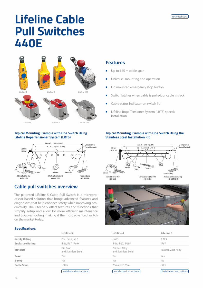
54
Lifeline Cable Pull Switches 440E
Cable pull switches overview The patented Lifeline 5 Cable Pull Switch is a micropro-cessor-based solution that brings advanced features and diagnostics that help enhance safety while improving pro-ductivity. The Lifeline 5 offers features and functions that simplify setup and allow for more efficient maintenance and troubleshooting, making it the most advanced switch on the market today.
Features ■ Up to 125 m cable span
■ Universal mounting and operation
■ Lid mounted emergency stop button
■ Switch latches when cable is pulled, or cable is slack
■ Cable status indicator on switch lid
■ Lifeline Rope Tensioner System (LRTS) speeds installation
SpecificationsLifeline 5 Lifeline 4 Lifeline 3
Safety Rating PLe, Cat 4, SIL3 CAT3 CAT3
Enclosure Rating IP66,IP67, IP69K IP66, IP67, IP69K IP67
MaterialDie Cast and Stainless Steel
Painted Alloy and Stainless Steel
Painted Zinc Alloy
Reset Yes Yes Yes
E-stop Yes Yes No
Cable Span 100m 75m and 125m 30m
Typical Mounting Example with One Switch Using Lifeline Rope Tensioner System (LRTS)
Typical Mounting Example with One Switch Using the Stainless Steel Installation Kit
(1)
Lifeline 5 = ≤ 100 m (328 ft)
2…3 m (6.56…9.84 ft)300 mm(11.81 in.)
Lifeline 5
P BoltsRope Grip Tensioner
Tensioner Spring
Polypropylene Covered Steel Cable
Lifeline 5 Stainless Steel440E-LLSS8
Stainless Steel Installation Kit440E-A13200
Stainless Steel Tensioner Spring440E-ASPRING-SS
(1)
Lifeline 5 = ≤ 100 m (328 ft)
2…3 m (6.56…9.84 ft)300 mm
(11.81 in.)
P Bolts Tensioner Cable Grip
Lifeline 5 with e-stop440E-LL5SE8
LRTS Rope Installation Kit440E-A13085
Tensioner Spring440E-ASPRING
Polypropylene Covered Steel Cable
Installation InstructionsInstallation InstructionsInstallation Instructions
Lifeline 4 SS
Lifeline 5
Lifeline 3
Lifeline 5
Lifeline 4
Lifeline 5 SS
Technical Data
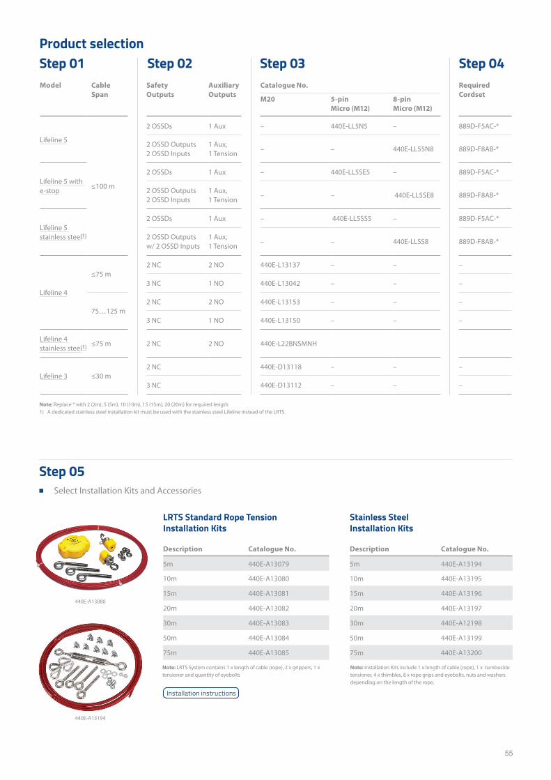
55
Model Cable Span
Safety Outputs
Auxiliary Outputs
Catalogue No. Required Cordset
M20 5-pin Micro (M12)
8-pin Micro (M12)
Lifeline 5
≤100 m
2 OSSDs 1 Aux – 440E-LL5N5 – 889D-F5AC-*
2 OSSD Outputs 2 OSSD Inputs
1 Aux, 1 Tension
– – 440E-LL55N8 889D-F8AB-*
Lifeline 5 with e-stop
2 OSSDs 1 Aux – 440E-LL5SE5 – 889D-F5AC-*
2 OSSD Outputs 2 OSSD Inputs
1 Aux, 1 Tension
– – 440E-LL5SE8 889D-F8AB-*
Lifeline 5 stainless steel1)
2 OSSDs 1 Aux – 440E-LL5SS5 – 889D-F5AC-*
2 OSSD Outputsw/ 2 OSSD Inputs
1 Aux, 1 Tension
– – 440E-LLSS8 889D-F8AB-*
Lifeline 4
≤75 m2 NC 2 NO 440E-L13137 – – –
3 NC 1 NO 440E-L13042 – – –
75…125 m2 NC 2 NO 440E-L13153 – – –
3 NC 1 NO 440E-L13150 – – –
Lifeline 4 stainless steel1) ≤75 m 2 NC 2 NO 440E-L22BNSMNH
Lifeline 3 ≤30 m2 NC 440E-D13118 – – –
3 NC 440E-D13112 – – –
Product selectionStep 01 Step 02 Step 03 Step 04
Note: Replace * with 2 (2m), 5 (5m), 10 (10m), 15 (15m), 20 (20m) for required length1) A dedicated stainless steel installation kit must be used with the stainless steel Lifeline instead of the LRTS.
Note: LRTS System contains 1 x length of cable (rope), 2 x grippers, 1 x tensioner and quantity of eyebolts
Note: Installation Kits include 1 x length of cable (rope), 1 x turnbuckle tensioner, 4 x thimbles, 8 x rope grips and eyebolts, nuts and washers depending on the length of the rope.
LRTS Standard Rope Tension Installation Kits
Description Catalogue No.
5m 440E-A13079
10m 440E-A13080
15m 440E-A13081
20m 440E-A13082
30m 440E-A13083
50m 440E-A13084
75m 440E-A13085
Stainless Steel Installation Kits
Description Catalogue No.
5m 440E-A13194
10m 440E-A13195
15m 440E-A13196
20m 440E-A13197
30m 440E-A12198
50m 440E-A13199
75m 440E-A13200
Step 05 ■ Select Installation Kits and Accessories
440E-A13080
440E-A13194
Installation instructions
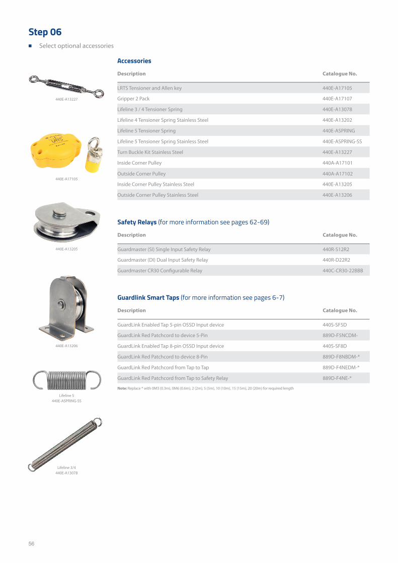
56
Accessories
Description Catalogue No.
LRTS Tensioner and Allen key 440E-A17105
Gripper 2 Pack 440E-A17107
Lifeline 3 / 4 Tensioner Spring 440E-A13078
Lifeline 4 Tensioner Spring Stainless Steel 440E-A13202
Lifeline 5 Tensioner Spring 440E-ASPRING
Lifeline 5 Tensioner Spring Stainless Steel 440E-ASPRING-SS
Turn Buckle Kit Stainless Steel 440E-A13227
Inside Corner Pulley 440A-A17101
Outside Corner Pulley 440A-A17102
Inside Corner Pulley Stainless Steel 440E-A13205
Outside Corner Pulley Stainless Steel 440E-A13206
Safety Relays (for more information see pages 62-69)
Description Catalogue No.
Guardmaster (SI) Single Input Safety Relay 440R-S12R2
Guardmaster (DI) Dual Input Safety Relay 440R-D22R2
Guardmaster CR30 Configurable Relay 440C-CR30-22BBB
Guardlink Smart Taps (for more information see pages 6-7)
Description Catalogue No.
GuardLink Enabled Tap 5-pin OSSD Input device 440S-SF5D
GuardLink Red Patchcord to device 5-Pin 889D-F5NCDM-
GuardLink Enabled Tap 8-pin OSSD Input device 440S-SF8D
GuardLink Red Patchcord to device 8-Pin 889D-F8NBDM-*
GuardLink Red Patchcord from Tap to Tap 889D-F4NEDM-*
GuardLink Red Patchcord from Tap to Safety Relay 889D-F4NE-*
Note: Replace * with 0M3 (0.3m), 0M6 (0.6m), 2 (2m), 5 (5m), 10 (10m), 15 (15m), 20 (20m) for required length
440E-A13205
440E-A17105
440E-A13206
Lifeline 5440E-ASPRING-SS
440E-A13227
Lifeline 3/4440E-A13078
Step 06 ■ Select optional accessories

57
This page has been left intentionally blank
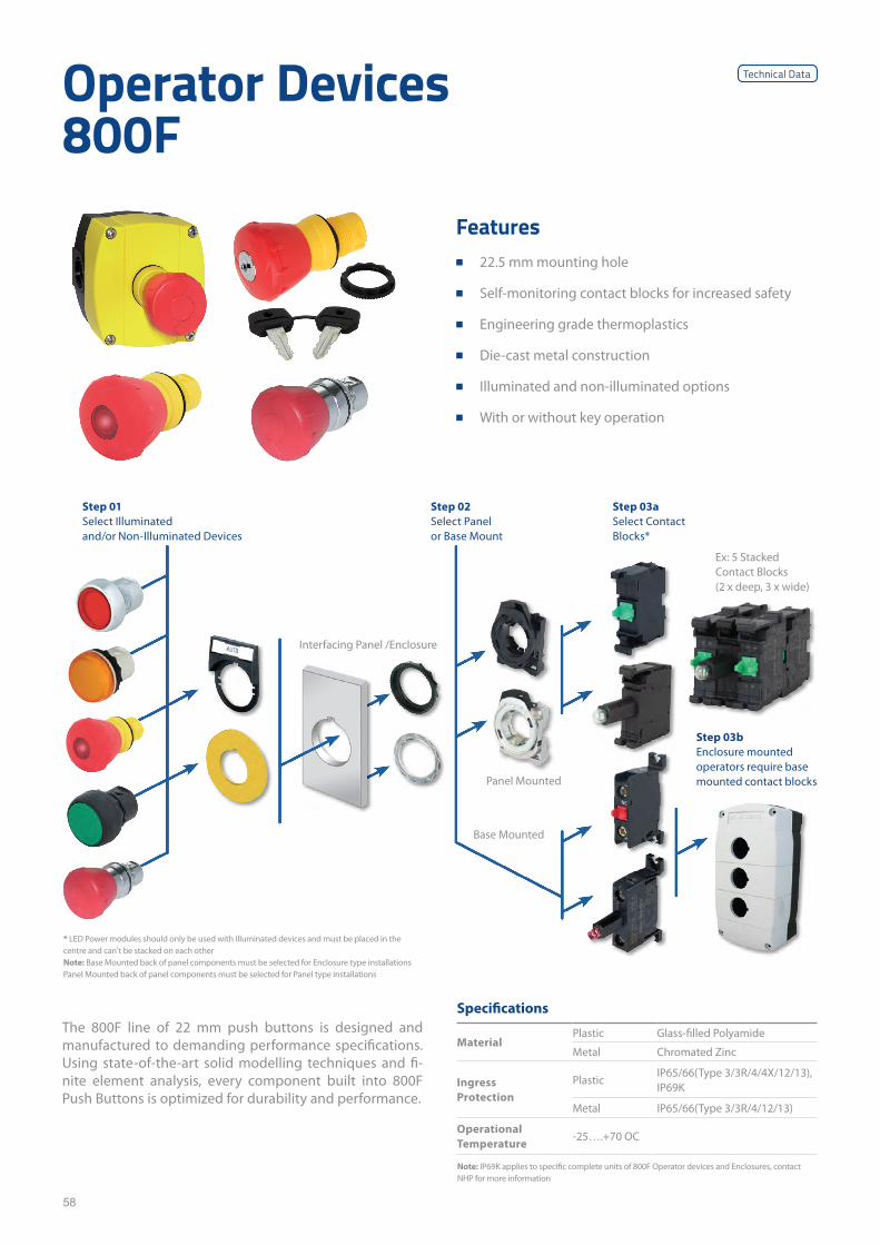
58
Operator Devices 800F
The 800F line of 22 mm push buttons is designed and manufactured to demanding performance specifications. Using state-of-the-art solid modelling techniques and fi-nite element analysis, every component built into 800F Push Buttons is optimized for durability and performance.
Specifications
MaterialPlastic Glass-filled Polyamide
Metal Chromated Zinc
Ingress Protection
PlasticIP65/66(Type 3/3R/4/4X/12/13), IP69K
Metal IP65/66(Type 3/3R/4/12/13)
Operational Temperature
-25….+70 OC
Features ■ 22.5 mm mounting hole
■ Self-monitoring contact blocks for increased safety
■ Engineering grade thermoplastics
■ Die-cast metal construction
■ Illuminated and non-illuminated options
■ With or without key operation
* LED Power modules should only be used with Illuminated devices and must be placed in the centre and can't be stacked on each other Note: Base Mounted back of panel components must be selected for Enclosure type installations Panel Mounted back of panel components must be selected for Panel type installations
Note: IP69K applies to specific complete units of 800F Operator devices and Enclosures, contact NHP for more information
Step 01Select Illuminated and/or Non-Illuminated Devices
Step 02Select Panel or Base Mount
Step 03aSelect Contact Blocks*
Step 03bEnclosure mounted operators require base mounted contact blocks
Interfacing Panel /Enclosure
Panel Mounted
Base Mounted
Ex: 5 Stacked Contact Blocks(2 x deep, 3 x wide)
Technical Data
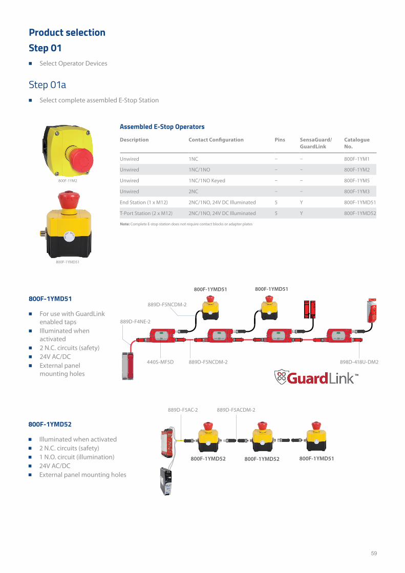
59
Product selection
Step 01a ■ Select complete assembled E-Stop Station
800F-1YMD51
■ For use with GuardLink enabled taps
■ Illuminated when activated
■ 2 N.C. circuits (safety) ■ 24V AC/DC ■ External panel
mounting holes
800F-1YMD52
■ Illuminated when activated ■ 2 N.C. circuits (safety) ■ 1 N.O. circuit (illumination) ■ 24V AC/DC ■ External panel mounting holes
Assembled E-Stop Operators
Description Contact Configuration Pins SensaGuard/ GuardLink
Catalogue No.
Unwired 1NC – – 800F-1YM1
Unwired 1NC/1NO – – 800F-1YM2
Unwired 1NC/1NO Keyed – – 800F-1YM5
Unwired 2NC – – 800F-1YM3
End Station (1 x M12) 2NC/1NO, 24V DC Illuminated 5 Y 800F-1YMD51
T-Port Station (2 x M12) 2NC/1NO, 24V DC Illuminated 5 Y 800F-1YMD52
Note: Complete E-stop station does not require contact blocks or adapter plates
800F-1YM2
800F-1YMD51
Step 01 ■ Select Operator Devices
800F-1YMD51
™
800F-1YMD51
800F-1YMD52 800F-1YMD52 800F-1YMD51
889D-F4NE-2
889D-F5NCDM-2
889D-F5NCDM-2 898D-418U-DM2440S-MF5D
889D-F5AC-2 889D-F5ACDM-2
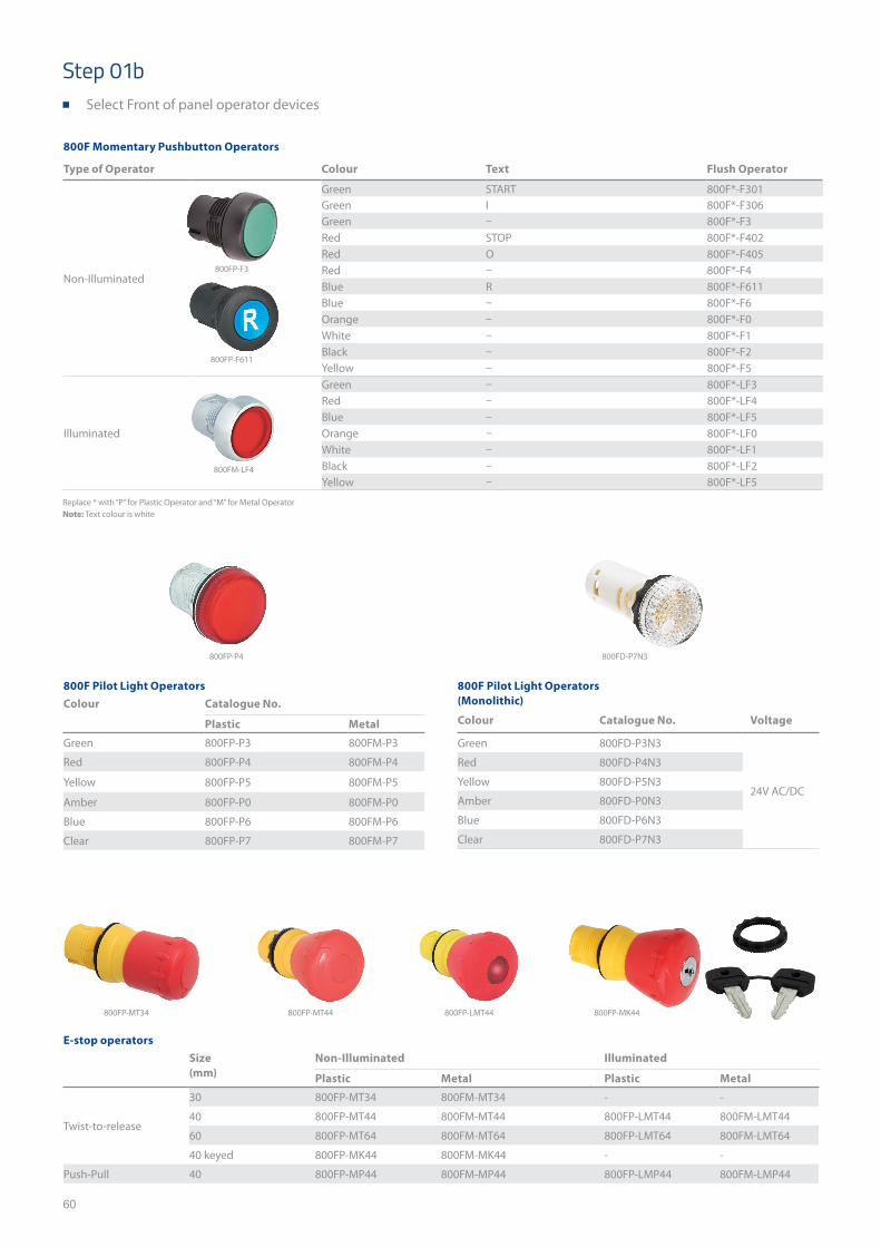
60
Replace * with “P” for Plastic Operator and “M” for Metal Operator Note: Text colour is white
800F Momentary Pushbutton Operators
Type of Operator Colour Text Flush Operator
Non-Illuminated
Green START 800F*-F301Green I 800F*-F306Green – 800F*-F3Red STOP 800F*-F402Red O 800F*-F405Red – 800F*-F4Blue R 800F*-F611Blue – 800F*-F6Orange – 800F*-F0White – 800F*-F1Black – 800F*-F2Yellow – 800F*-F5
Illuminated
Green – 800F*-LF3Red – 800F*-LF4Blue – 800F*-LF5Orange – 800F*-LF0White – 800F*-LF1Black – 800F*-LF2Yellow – 800F*-LF5
800F Pilot Light Operators Colour Catalogue No.
Plastic Metal
Green 800FP-P3 800FM-P3
Red 800FP-P4 800FM-P4
Yellow 800FP-P5 800FM-P5
Amber 800FP-P0 800FM-P0
Blue 800FP-P6 800FM-P6
Clear 800FP-P7 800FM-P7
E-stop operators Size (mm)
Non-Illuminated Illuminated
Plastic Metal Plastic Metal
Twist-to-release
30 800FP-MT34 800FM-MT34 - -
40 800FP-MT44 800FM-MT44 800FP-LMT44 800FM-LMT44
60 800FP-MT64 800FM-MT64 800FP-LMT64 800FM-LMT64
40 keyed 800FP-MK44 800FM-MK44 - -
Push-Pull 40 800FP-MP44 800FM-MP44 800FP-LMP44 800FM-LMP44
800F Pilot Light Operators (Monolithic)
Colour Catalogue No. Voltage
Green 800FD-P3N3
24V AC/DC
Red 800FD-P4N3
Yellow 800FD-P5N3
Amber 800FD-P0N3
Blue 800FD-P6N3
Clear 800FD-P7N3
Step 01b ■ Select Front of panel operator devices
800FP-P4 800FD-P7N3
800FM-LF4
800FP-F611
800FP-F3
800FP-MT34 800FP-MT44 800FP-LMT44 800FP-MK44
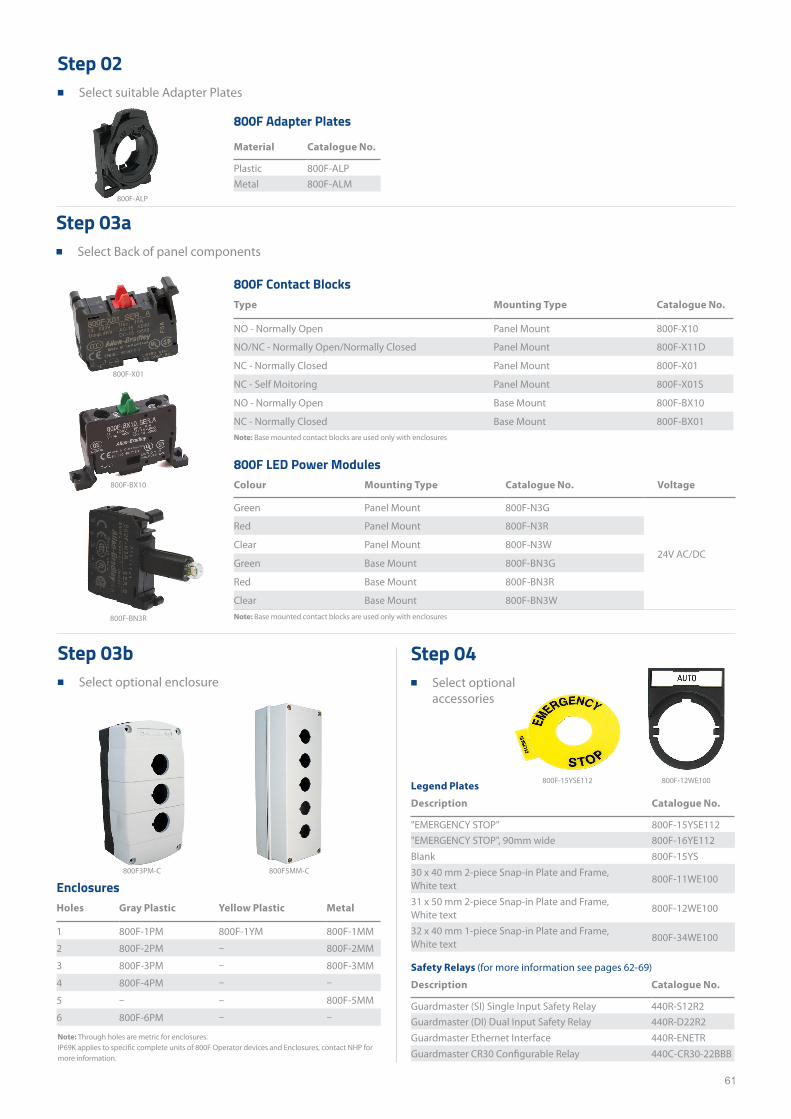
61
Step 02 ■ Select suitable Adapter Plates
800F Adapter Plates
Material Catalogue No.
Plastic 800F-ALPMetal 800F-ALM
800F LED Power Modules Colour Mounting Type Catalogue No. Voltage
Green Panel Mount 800F-N3G
24V AC/DC
Red Panel Mount 800F-N3R
Clear Panel Mount 800F-N3W
Green Base Mount 800F-BN3G
Red Base Mount 800F-BN3R
Clear Base Mount 800F-BN3W
800F Contact Blocks Type Mounting Type Catalogue No.
NO - Normally Open Panel Mount 800F-X10
NO/NC - Normally Open/Normally Closed Panel Mount 800F-X11D
NC - Normally Closed Panel Mount 800F-X01
NC - Self Moitoring Panel Mount 800F-X01S
NO - Normally Open Base Mount 800F-BX10
NC - Normally Closed Base Mount 800F-BX01
Enclosures Holes Gray Plastic Yellow Plastic Metal
1 800F-1PM 800F-1YM 800F-1MM
2 800F-2PM – 800F-2MM
3 800F-3PM – 800F-3MM
4 800F-4PM – –
5 – – 800F-5MM
6 800F-6PM – –
Note: Base mounted contact blocks are used only with enclosures
Note: Base mounted contact blocks are used only with enclosures
Note: Through holes are metric for enclosures.IP69K applies to specific complete units of 800F Operator devices and Enclosures, contact NHP for more information.
Step 03a ■ Select Back of panel components
Step 04 ■ Select optional
accessories
Step 03b ■ Select optional enclosure
800F-15YSE112 800F-12WE100
800F-X01
800F-BX10
800F3PM-C 800F5MM-C
800F-BN3R
Safety Relays (for more information see pages 62-69)
Description Catalogue No.
Guardmaster (SI) Single Input Safety Relay 440R-S12R2Guardmaster (DI) Dual Input Safety Relay 440R-D22R2Guardmaster Ethernet Interface 440R-ENETRGuardmaster CR30 Configurable Relay 440C-CR30-22BBB
Legend Plates
Description Catalogue No.
"EMERGENCY STOP" 800F-15YSE112"EMERGENCY STOP", 90mm wide 800F-16YE112Blank 800F-15YS30 x 40 mm 2-piece Snap-in Plate and Frame, White text
800F-11WE100
31 x 50 mm 2-piece Snap-in Plate and Frame, White text
800F-12WE100
32 x 40 mm 1-piece Snap-in Plate and Frame, White text
800F-34WE100
800F-ALP
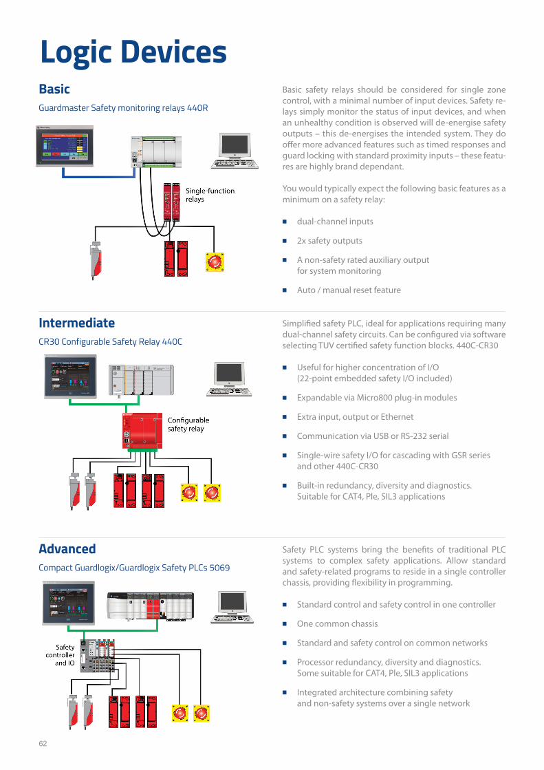
62
Logic DevicesBasic safety relays should be considered for single zone control, with a minimal number of input devices. Safety re-lays simply monitor the status of input devices, and when an unhealthy condition is observed will de-energise safety outputs – this de-energises the intended system. They do offer more advanced features such as timed responses and guard locking with standard proximity inputs – these featu-res are highly brand dependant.
You would typically expect the following basic features as a minimum on a safety relay:
■ dual-channel inputs
■ 2x safety outputs
■ A non-safety rated auxiliary output for system monitoring
■ Auto / manual reset feature
BasicGuardmaster Safety monitoring relays 440R
Safety PLC systems bring the benefits of traditional PLC systems to complex safety applications. Allow standard and safety-related programs to reside in a single controller chassis, providing flexibility in programming.
■ Standard control and safety control in one controller
■ One common chassis
■ Standard and safety control on common networks
■ Processor redundancy, diversity and diagnostics. Some suitable for CAT4, Ple, SIL3 applications
■ Integrated architecture combining safety and non-safety systems over a single network
AdvancedCompact Guardlogix/Guardlogix Safety PLCs 5069
Simplified safety PLC, ideal for applications requiring many dual-channel safety circuits. Can be configured via software selecting TUV certified safety function blocks. 440C-CR30
■ Useful for higher concentration of I/O (22-point embedded safety I/O included)
■ Expandable via Micro800 plug-in modules
■ Extra input, output or Ethernet
■ Communication via USB or RS-232 serial
■ Single-wire safety I/O for cascading with GSR series and other 440C-CR30
■ Built-in redundancy, diversity and diagnostics. Suitable for CAT4, Ple, SIL3 applications
IntermediateCR30 Configurable Safety Relay 440C
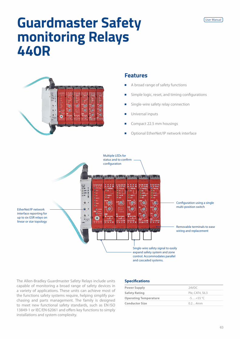
63
Guardmaster Safety monitoring Relays 440R
The Allen-Bradley Guardmaster Safety Relays include units capable of monitoring a broad range of safety devices in a variety of applications. These units can achieve most of the functions safety systems require, helping simplify pur-chasing and parts management. The family is designed to meet new functional safety standards, such as EN ISO 13849-1 or IEC/EN 62061 and offers key functions to simply installations and system complexity.
Features ■ A broad range of safety functions
■ Simple logic, reset, and timing configurations
■ Single-wire safety relay connection
■ Universal inputs
■ Compact 22.5 mm housings
■ Optional EtherNet/IP network interface
Specifications
Power Supply 24VDC
Safety Rating Ple, CAT4, SIL3
Operating Temperature -5….+55 °C
Conductor Size 0.2…4mm
Multiple LEDs for status and to confirm configuration
EtherNet/IP network interface reporting for up to six GSR relays on linear or star topology
Configuration using a single multi-position switch
Removable terminals to ease wiring and replacement
Single-wire safety signal to easily expand safety system and zone control. Accommodates parallel and cascaded systems.
User Manual
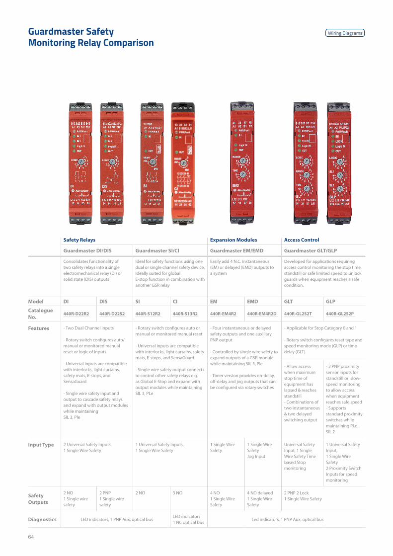
64
Safety Relays Expansion Modules Access Control
Guardmaster DI/DIS Guardmaster SI/CI Guardmaster EM/EMD Guardmaster GLT/GLP
Consolidates functionality of two safety relays into a single electromechanical relay (DI) or solid state (DIS) outputs
Ideal for safety functions using one dual or single channel safety device. Ideally suited for global E-stop function in combination with another GSR relay
Easily add 4 N.C. instantaneous (EM) or delayed (EMD) outputs to a system
Developed for applications requiring access control monitoring the stop time, standstill or safe limited speed to unlock guards when equipment reaches a safe condition.
Model DI DIS SI CI EM EMD GLT GLP
Catalogue No.
440R-D22R2 440R-D22S2 440R-S12R2 440R-S13R2 440R-EM4R2 440R-EM4R2D 440R-GL2S2T 440R-GL2S2P
Features - Two Dual Channel inputs
- Rotary switch configures auto/manual or monitored manual reset or logic of inputs - Universal inputs are compatible with interlocks, light curtains, safety mats, E-stops, and SensaGuard
- Single wire safety input and output to cascade safety relays and expand with output modules while maintaining SIL 3, Ple
- Rotary switch configures auto or manual or monitored manual reset
- Universal inputs are compatible with interlocks, light curtains, safety mats, E-stops, and SensaGuard
- Single wire safety output connects to control other safety relays e.g. as Global E-Stop and expand with output modules while maintaining SIL 3, PLe
- Four instantaneous or delayed safety outputs and one auxiliary PNP output - Controlled by single wire safety to expand outputs of a GSR module while maintaining SIL 3, Ple
- Timer version provides on-delay, off-delay and jog outputs that can be configured via rotary switches
- Applicable for Stop Category 0 and 1
- Rotary switch configures reset type and speed monitoring mode (GLP) or time delay (GLT)
- Allow access when maximum stop time of equipment has lapsed & reaches standstill - Combinations of two instantaneous & two delayed switching output
- 2 PNP proximity sensor inputs for standstill or slow-speed monitoring to allow access when equipment reaches safe speed - Supports standard proximity switches while maintaining PLd, SIL 2
Input Type 2 Universal Safety Inputs, 1 Single Wire Safety
1 Universal Safety Inputs, 1 Single Wire Safety
1 Single Wire Safety
1 Single Wire Safety Jog Input
Universal Safety Input, 1 Single Wire Safety Time based Stop monitoring
1 Universal Safety Input, 1 Single Wire Safety 2 Proximity Switch Inputs for speed monitoring
Safety Outputs
2 NO 1 Single wire safety
2 PNP 1 Single wire safety
2 NO 3 NO 4 NO 1 Single Wire Safety
4 NO delayed 1 Single Wire Safety
2 PNP 2 Lock 1 Single Wire Safety
Diagnostics LED indicators, 1 PNP Aux, optical busLED indicators 1 NC optical bus
Led indicators, 1 PNP Aux, optical bus
Guardmaster Safety Monitoring Relay Comparison
Wiring Diagrams
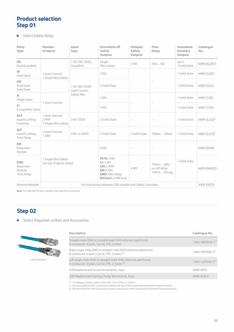
65
Product selectionStep 01
■ Select Safety Relay
Relay Type
Number of inputs
Input Type
Immediate off Safety Outputs
Delayed Safety Outputs
Time Delay
Immediate Auxiliary Outputs
Catalogue No.
DG Dual Guardlink
2 dual-channel 1 Single Wire Safety
1 NC 2NC OSSD, Guardlink
Single Wire Safety
2 NO 0ms…30sup to 1 Solid State
440R-DG2R2T
DI Dual Input
1 NC 2NC OSSD Light Curtain, Safety Mat
2 NO
– –
1 Solid State 440R-D22R2
DIS Dual Input Solid State
2 Solid State 1 Solid State 440R-D22S2
SI Single Input
1 dual-channel
2 NO
– –
1 Solid State 440R-S12R2
CI Compatible Input
3 NO 1 Solid State 440R-S13R2
GLP Guard Locking Proximity
1 dual-channel 2 PNP 1 Single Wire Safety
2 NC OSSD 2 Solid State – – 1 Solid State 440R-GL2S2P
GLT Guard Locking Time Delay
1 dual-channel 1 SWS
2 NC or OSSD 2 Solid State 2 Solid State 100ms… 30min 1 Solid State 440R-GL2S2T
EM Expansion Module
1 Single Wire Safety (on top of above relays)
4 NO – –
1 Solid State
440R-EM4R2
EMD Expansion Module Time Delay
DI/SI: 2 NO CI: 3 NO DIS: 2 PNP EM: 4 NO EMD: 4NO delay DIS/GLP: 2 PNP lock
4 NO100ms…300s on/off delay 100ms…20s jog
440R-EM4R2D
Ethernet Module For interfacing between GSR module and Safety Controller 440R-ENETR
Note: For 440R-ENETR Select suitable E/net cable from accessories
1) In catalogue number, replace 2(2m) with 1(1m), 5(5m), or 10(10m)2) Recommended for RJ45 connection located at the top of the Guardmaster EtherNet/IP network interface. 3) Recommended for RJ45 connection located at the bottom of the Guardmaster EtherNet/IP network interface.
Description Catalogue No.
Straight male RJ45 to straight male RJ45 ethernet patchcord, 8-conductor (4 pair), Cat 5e, TPE, 2meter
1585J-M8TBJM-21)
Right angle male RJ45 to straight male RJ45 ethernet patchcord, 8-conductor (4 pair), Cat 5e, TPE, 2meter 2) 1585J-E8TBJM-21)
Left angle male RJ45 to straight male RJ45 ethernet patchcord, 8-conductor (4 pair), Cat 5e, TPE, 2 meter 3) 1585J-L8TBJM-21)
GSR Replacement Screw Terminal kit, 4 pcs 440R-ATP4
GSR Replacement Spring Clamp Terminal kit, 4 pcs 440R-ATSC4
Step 02 ■ Select Required cordset and Accessories
1585J-M8TBJM-2
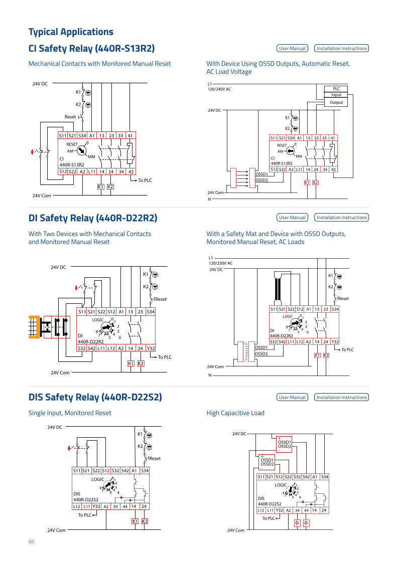
66
Typical ApplicationsCI Safety Relay (440R-S13R2) Mechanical Contacts with Monitored Manual Reset
With Two Devices with Mechanical Contacts and Monitored Manual Reset
Single Input, Monitored Reset
With Device Using OSSD Outputs, Automatic Reset, AC Load Voltage
With a Safety Mat and Device with OSSD Outputs, Monitored Manual Reset, AC Loads
High Capacitive Load
DI Safety Relay (440R-D22R2)
DIS Safety Relay (440R-D22S2)
User Manual
User Manual
User Manual
Installation Instructions
Installation Instructions
Installation Instructions
S11
S12
S21
S22
S34 A1 13
412A 11L
23
24
33 41
34 42
CI440R-S13R2
RESET 0
MMAM
K1
24V DC
24V Com
K2
Reset
To PLCK1 K2
S11
S12
S21
S22
S34 A1 13
412A 11L
23
24
33 41
34 42
CI440R-S13R2
RESET 0
MMAM
K1
24V DC
L1120/240V AC
N
24V Com
K2
K1 K2
InputPLC
Output
OSSD1OSSD2
A122S 21S12S11S
S32 L11 Y32L12
13
14S42
23
24
S34
A2
DI440R-D22R2
01
23
45 67
8
LOGIC
K124V DC
24V Com
K2
Reset
To PLCK1 K2
A122S 21S12S11S
S32 L11 Y32L12
13
14S42
23
24
S34
A2
DI440R-D22R2
01
23
45 67
8
LOGIC
K124V DC
24V Com
K2
To PLCK1 K2
L1120/230V AC
N
Reset
OSSD1OSSD2
LOGIC 0 123
45 67
8
DIS440R-D22S2
S32 A1
Y32
21S22S11S 12S S34S42
L12 L11 442A 43 14 24
K124V DC
24V Com
K2
Reset
To PLCK1 K2
LOGIC 0 123
45 67
8
DIS440R-D22S2
S32 A1
Y32
21S 22S11S 12S S34S42
L12 L11 442A 43 14 24
24V DC
+OSSD1 OSSD2-
24V Com
To PLC
+OSSD1 OSSD2-
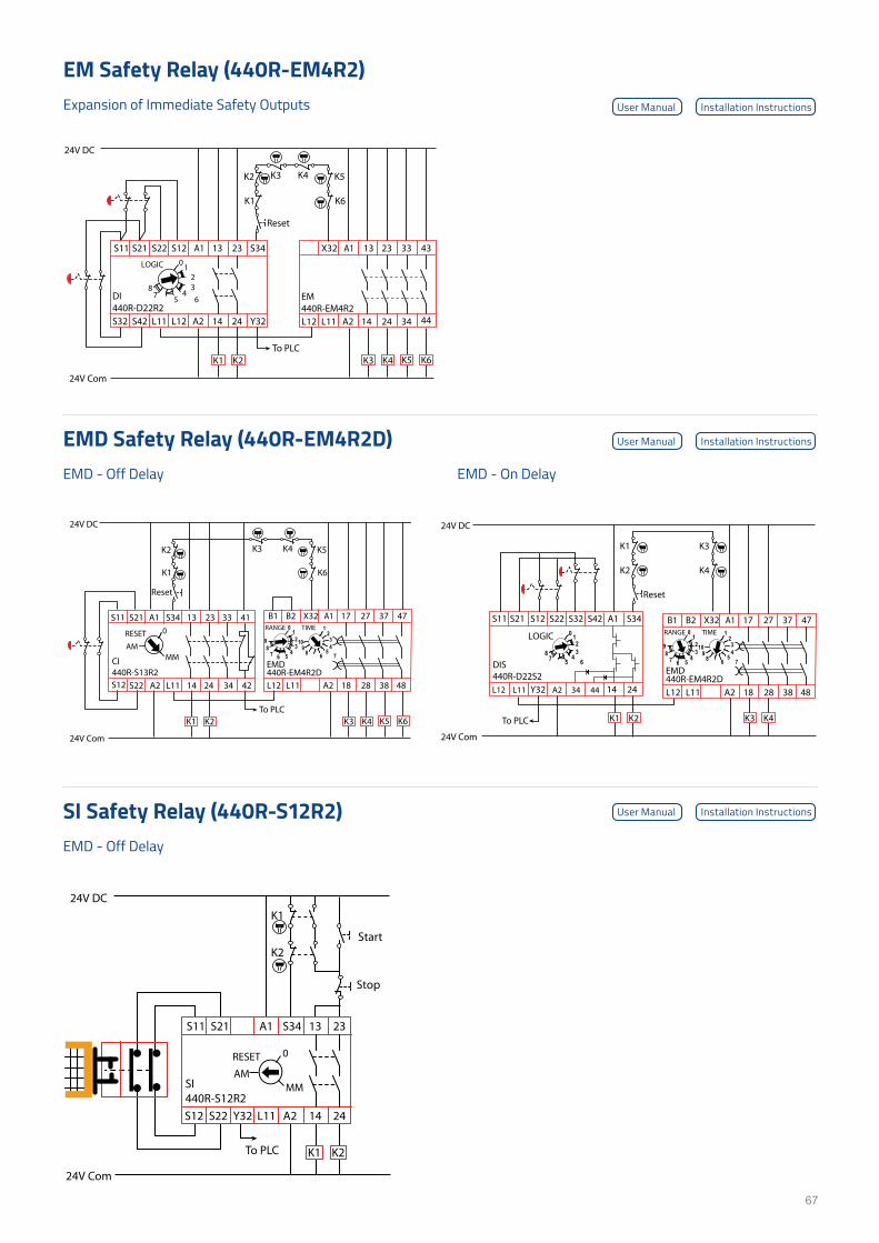
67
Expansion of Immediate Safety Outputs
EM Safety Relay (440R-EM4R2)
EMD - Off Delay
EMD - Off Delay
EMD - On Delay
EMD Safety Relay (440R-EM4R2D)
SI Safety Relay (440R-S12R2)
User Manual
User Manual
User Manual
Installation Instructions
Installation Instructions
Installation Instructions
K124V DC
24V Com
K2Start
Stop
To PLC K1 K2
S11
S12
S21
S22
311A 43S
L11 A2 14
23
24Y32
SI440R-S12R2
RESET 0
MMAM
A1
L11
X32
L12 14 34 4424
32 343331
A2
EM440R-EM4R2
A122S 21S12S11S
S32 L11 Y32L12
13
14S42
23
24
S34
A2
DI440R-D22R2
01
23
45 67
8
LOGIC
K1
24V DC
24V Com
K2
K6
K5K3 K4
Reset
To PLCK1 K2 K3 K4 K5 K6
LOGIC 0 123
45 67
8
DIS440R-D22S2
S32 A1
Y32
21S 22S11S 12S S34S42
L12 L11 442A 43 14 24
K1
24V DC
24V Com
K2
K3
K4
Reset
To PLC K1 K2
A1
L11
X32B1 B2
82 84838121L
72 747371
A2
EMD440R-EM4R2D
RANGE TIME0123
4567
89
1234
56 78
109
K3 K4
A1
L11
X32B1 B2
82 84838121L
72 747371
A2
EMD440R-EM4R2D
RANGE TIME0123
4567
89
1234
56 78
109
K1
24V DC
24V Com
K2
K6
K5K3 K4
Reset
To PLCK1 K2 K3 K4 K5 K6
S11
S12
S21
S22
311A 43S
412A 11L
23
24
33 41
34 42
CI440R-S13R2
RESET 0
MMAM
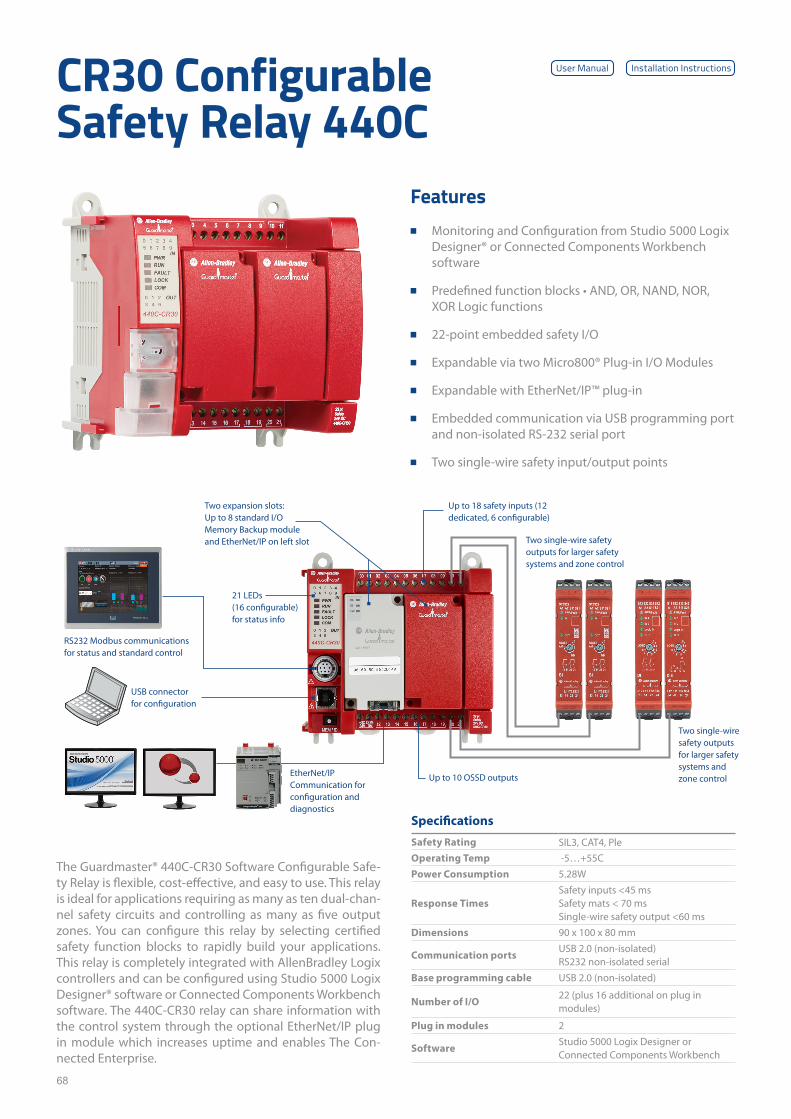
68
CR30 Configurable Safety Relay 440C
The Guardmaster® 440C-CR30 Software Configurable Safe-ty Relay is flexible, cost-effective, and easy to use. This relay is ideal for applications requiring as many as ten dual-chan-nel safety circuits and controlling as many as five output zones. You can configure this relay by selecting certified safety function blocks to rapidly build your applications. This relay is completely integrated with AllenBradley Logix controllers and can be configured using Studio 5000 Logix Designer® software or Connected Components Workbench software. The 440C-CR30 relay can share information with the control system through the optional EtherNet/IP plug in module which increases uptime and enables The Con-nected Enterprise.
Specifications
Safety Rating SIL3, CAT4, PleOperating Temp -5…+55CPower Consumption 5.28W
Response TimesSafety inputs <45 ms Safety mats < 70 ms Single-wire safety output <60 ms
Dimensions 90 x 100 x 80 mm
Communication portsUSB 2.0 (non-isolated) RS232 non-isolated serial
Base programming cable USB 2.0 (non-isolated)
Number of I/O22 (plus 16 additional on plug in modules)
Plug in modules 2
SoftwareStudio 5000 Logix Designer or Connected Components Workbench
Features ■ Monitoring and Configuration from Studio 5000 Logix
Designer® or Connected Components Workbench software
■ Predefined function blocks • AND, OR, NAND, NOR, XOR Logic functions
■ 22-point embedded safety I/O
■ Expandable via two Micro800® Plug-in I/O Modules
■ Expandable with EtherNet/IP™ plug-in
■ Embedded communication via USB programming port and non-isolated RS-232 serial port
■ Two single-wire safety input/output points
RS232 Modbus communications for status and standard control
21 LEDs(16 configurable) for status info
Two expansion slots: Up to 8 standard I/O Memory Backup module and EtherNet/IP on left slot
Up to 18 safety inputs (12 dedicated, 6 configurable)
USB connector for configuration
EtherNet/IP Communication for configuration and diagnostics
Up to 10 OSSD outputs
Two single-wire safety outputs for larger safety systems and zone control
Two single-wire safety outputs for larger safety systems and zone control
User Manual Installation Instructions
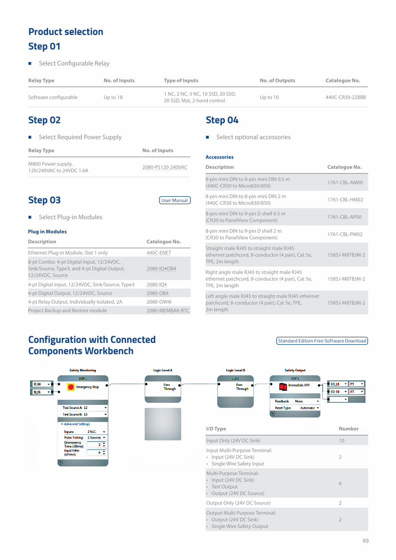
69
Product selection
Configuration with Connected Components Workbench
Step 01 ■ Select Configurable Relay
Step 02 ■ Select Required Power Supply
Step 03 ■ Select Plug-in Modules
Step 04 ■ Select optional accessories
Accessories
Description Catalogue No.
8-pin mini DIN to 8-pin mini DIN 0.5 m (440C-CR30 to Micro830/850)
1761-CBL-AM00
8-pin mini DIN to 8-pin mini DIN 2 m (440C-CR30 to Micro830/850)
1761-CBL-HM02
8-pin mini DIN to 9-pin D shell 0.5 m (CR30 to PanelView Component)
1761-CBL-AP00
8-pin mini DIN to 9-pin D shell 2 m (CR30 to PanelView Component)
1761-CBL-PM02
Straight male RJ45 to straight male RJ45 ethernet patchcord, 8-conductor (4 pair), Cat 5e, TPE, 2m length
1585J-M8TBJM-2
Right angle male RJ45 to straight male RJ45 ethernet patchcord, 8-conductor (4 pair), Cat 5e, TPE, 2m length
1585J-M8TBJM-2
Left angle male RJ45 to straight male RJ45 ethernet patchcord, 8-conductor (4 pair), Cat 5e, TPE, 2m length
1585J-M8TBJM-2
Plug in Modules
Description Catalogue No.
Ethernet Plug-in Module, Slot 1 only 440C-ENET
8-pt Combo: 4-pt Digital Input, 12/24VDC, Sink/Source, Type3, and 4-pt Digital Output, 12/24VDC, Source
2080-IQ4OB4
4-pt Digital Input, 12/24VDC, Sink/Source, Type3 2080-IQ4
4-pt Digital Output, 12/24VDC, Source 2080-OB4
4-pt Relay Output, Individually Isolated, 2A 2080-OW4I
Project Backup and Restore module 2080-MEMBAK-RTC
Relay Type No. of Inputs Type of Inputs No. of Outputs Catalogue No.
Software configurable Up to 181 NC, 2 NC, 3 NC, 10 SSD, 20 SSD, 20 SSD, Mat, 2-hand control
Up to 10 440C-CR30-22BBB
Relay Type No. of Inputs
M800 Power supply, 120/240VAC to 24VDC 1.6A
2080-PS120-240VAC
I/O Type Number
Input Only (24V DC Sink) 10
Input Multi-Purpose Terminal:• Input (24V DC Sink)• Single Wire Safety Input
2
Multi-Purpose Terminal:• Input (24V DC Sink)• Test Output• Output (24V DC Source)
6
Output Only (24V DC Source) 2
Output Multi-Purpose Terminal:• Output (24V DC Sink)• Single Wire Safety Output
2
User Manual
Standard Edition Free Software Download
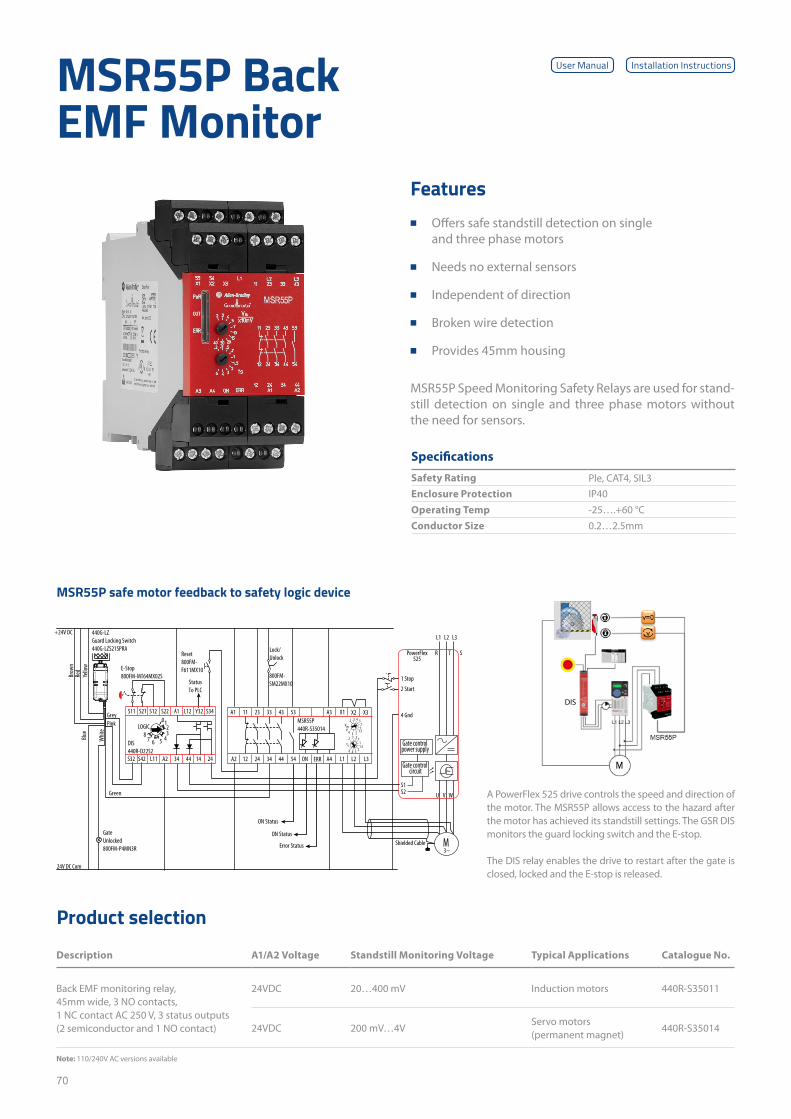
70
Product selection
Description A1/A2 Voltage Standstill Monitoring Voltage Typical Applications Catalogue No.
Back EMF monitoring relay, 45mm wide, 3 NO contacts, 1 NC contact AC 250 V, 3 status outputs (2 semiconductor and 1 NO contact)
24VDC 20…400 mV Induction motors 440R-S35011
24VDC 200 mV…4VServo motors (permanent magnet)
440R-S35014
MSR55P Back EMF Monitor
MSR55P Speed Monitoring Safety Relays are used for stand-still detection on single and three phase motors without the need for sensors.
Specifications
Safety Rating Ple, CAT4, SIL3Enclosure Protection IP40Operating Temp -25….+60 °CConductor Size 0.2…2.5mm
Features ■ Offers safe standstill detection on single
and three phase motors
■ Needs no external sensors
■ Independent of direction
■ Broken wire detection
■ Provides 45mm housing
Note: 110/240V AC versions available
MSR55P safe motor feedback to safety logic device
User Manual Installation Instructions
+24V DC
24V DC Com
A2
X1 X2
1L 2L 3L
X3
34 44
A1 A311 32 33
21 42 ON ERR A454
43 53
Brow
nRe
dYe
llow
Whit
e
Blue
Grey
Green
Pink
E-Stop800FM-MT64MX02S
Reset800FM-F611MX10
Lock/Unlock
800FM-SM22MX10
Gate Unlocked800FM-P4MN3R Error Status
ON Status
ON Status
StatusTo PLC
Gate controlpower supply
Gate controlcircuit
M
S1S2
1 Stop
PowerFlex525
2 Start
4 Gnd
R
L1 L2 L3
T S
V WU
A1S11 S21 S12 S22
S32 L11
21L 23Y
4443 41S42 24
S34
A2
DIS440R-D22S2
0123
45678
LOGIC
440G-LZGuard Locking Switch440G-LZS21SPRA
MSR55P440R-S35014
3~
.2 .3 .5.711.5
6 342
ts
.2 .3 .4 .5.71
234 1.5VmV
Shielded Cable
A PowerFlex 525 drive controls the speed and direction of the motor. The MSR55P allows access to the hazard after the motor has achieved its standstill settings. The GSR DIS monitors the guard locking switch and the E-stop.
The DIS relay enables the drive to restart after the gate is closed, locked and the E-stop is released.
DIS

71
This page has been left intentionally blank
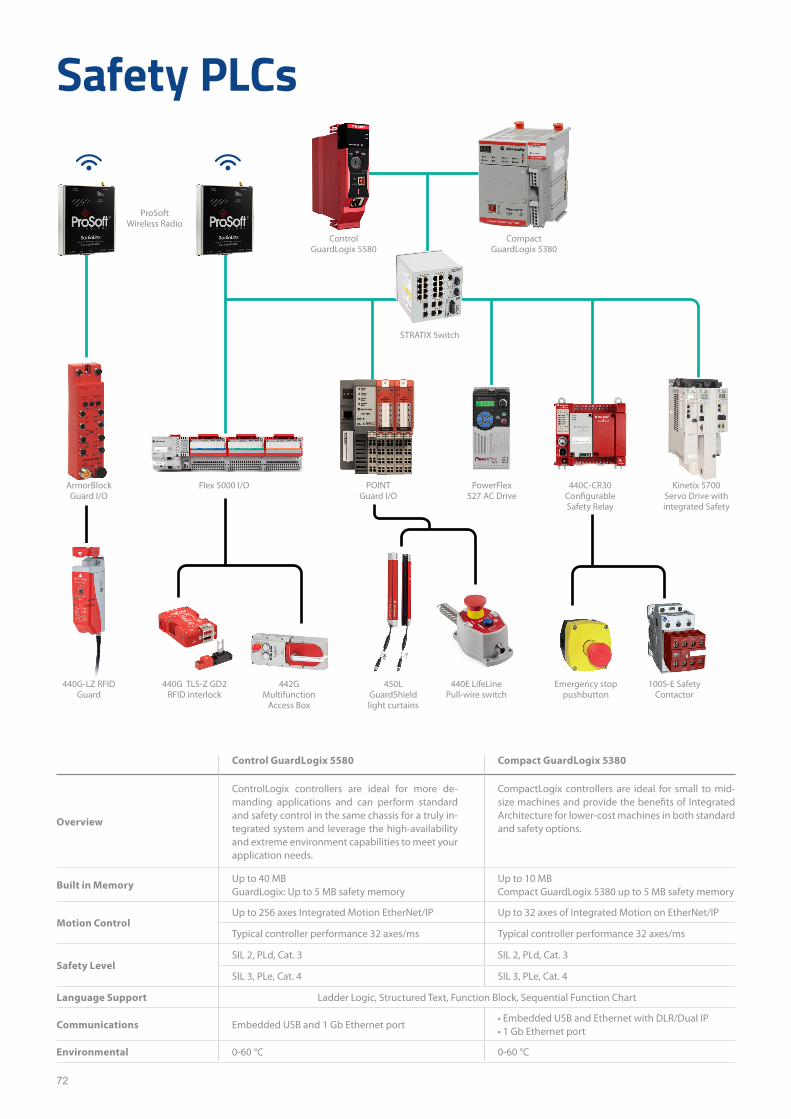
72
Safety PLCs
Control GuardLogix 5580 Compact GuardLogix 5380
Overview
ControlLogix controllers are ideal for more de-manding applications and can perform standard and safety control in the same chassis for a truly in-tegrated system and leverage the high-availability and extreme environment capabilities to meet your application needs.
CompactLogix controllers are ideal for small to mid- size machines and provide the benefits of Integrated Architecture for lower-cost machines in both standard and safety options.
Built in MemoryUp to 40 MB GuardLogix: Up to 5 MB safety memory
Up to 10 MBCompact GuardLogix 5380 up to 5 MB safety memory
Motion ControlUp to 256 axes Integrated Motion EtherNet/IP Up to 32 axes of Integrated Motion on EtherNet/IP
Typical controller performance 32 axes/ms Typical controller performance 32 axes/ms
Safety LevelSIL 2, PLd, Cat. 3 SIL 2, PLd, Cat. 3
SIL 3, PLe, Cat. 4 SIL 3, PLe, Cat. 4
Language Support Ladder Logic, Structured Text, Function Block, Sequential Function Chart
Communications Embedded USB and 1 Gb Ethernet port• Embedded USB and Ethernet with DLR/Dual IP• 1 Gb Ethernet port
Environmental 0-60 °C 0-60 °C
ArmorBlock Guard I/O
ProSoft Wireless Radio
440G TLS-Z GD2 RFID interlock
442G Multifunction
Access Box
450L GuardShield light curtains
440E LifeLine Pull-wire switch
Emergency stop pushbutton
100S-E Safety Contactor
Flex 5000 I/O POINT Guard I/O
STRATIX Switch
PowerFlex 527 AC Drive
440C-CR30 Configurable Safety Relay
Kinetix 5700 Servo Drive with integrated Safety
Compact GuardLogix 5380
440G-LZ RFID Guard
Control GuardLogix 5580
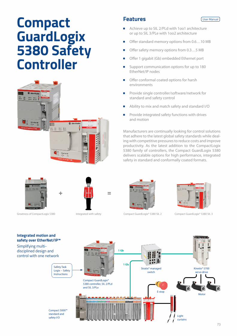
73
Manufacturers are continually looking for control solutions that adhere to the latest global safety standards while deal-ing with competitive pressures to reduce costs and improve productivity. As the latest addition to the CompactLogix 5380 family of controllers, the Compact GuardLogix 5380 delivers scalable options for high performance, integrated safety in standard and conformally coated formats.
Features ■ Achieve up to SIL 2/PLd with 1oo1 architecture
or up to SIL 3/PLe with 1oo2 architecture
■ Offer standard memory options from 0.6…10 MB
■ Offer safety memory options from 0.3…5 MB
■ Offer 1 gigabit (Gb) embedded Ethernet port
■ Support communication options for up to 180 EtherNet/IP nodes
■ Offer conformal coated options for harsh environments
■ Provide single controller/software/network for standard and safety control
■ Ability to mix and match safety and standard I/O
■ Provide integrated safety functions with drives and motion
Compact GuardLogix 5380 Safety Controller
Greatness of CompactLogix 5380 Integrated with safety Compact GuardLogix® 5380 SIL 2 Compact GuardLogix® 5380 SIL 3
+ =
Integrated motion and safety over EtherNet/IP™Simplifying multi-disciplined design and control with one network
Compact GuardLogix® 5380 controller, SIL 2/PLd and SIL 3/PLe
Compact 5000™ standard and safety I/O
Stratix® managed switch
1 Gb
1 Gb
Kinetix® 5700 servo drive
Motor
Light curtains
E-stop
Safety Task Logix − Safety Instructions
User Manual
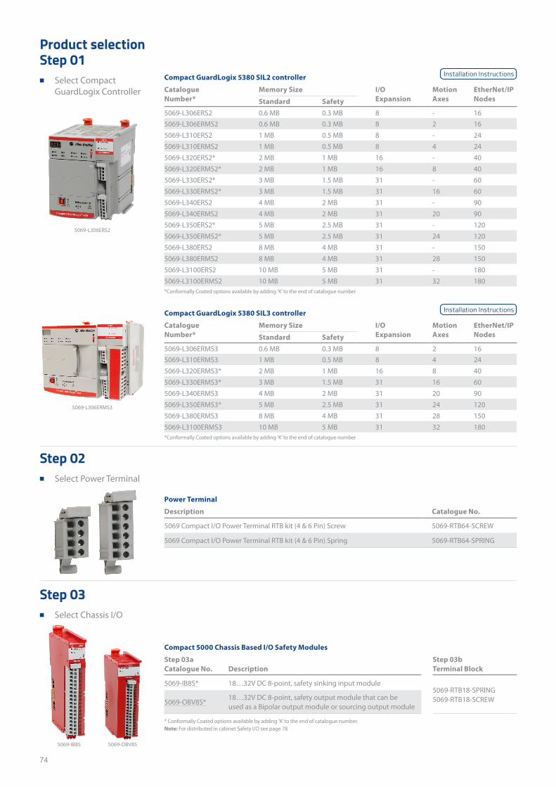
74
Compact GuardLogix 5380 SIL2 controller
Catalogue Number*
Memory Size I/O Expansion
Motion Axes
EtherNet/IP NodesStandard Safety
5069-L306ERS2 0.6 MB 0.3 MB 8 - 165069-L306ERMS2 0.6 MB 0.3 MB 8 2 165069-L310ERS2 1 MB 0.5 MB 8 - 245069-L310ERMS2 1 MB 0.5 MB 8 4 245069-L320ERS2* 2 MB 1 MB 16 - 405069-L320ERMS2* 2 MB 1 MB 16 8 405069-L330ERS2* 3 MB 1.5 MB 31 - 605069-L330ERMS2* 3 MB 1.5 MB 31 16 605069-L340ERS2 4 MB 2 MB 31 - 905069-L340ERMS2 4 MB 2 MB 31 20 905069-L350ERS2* 5 MB 2.5 MB 31 - 1205069-L350ERMS2* 5 MB 2.5 MB 31 24 1205069-L380ERS2 8 MB 4 MB 31 - 1505069-L380ERMS2 8 MB 4 MB 31 28 1505069-L3100ERS2 10 MB 5 MB 31 - 1805069-L3100ERMS2 10 MB 5 MB 31 32 180
Compact GuardLogix 5380 SIL3 controller
Catalogue Number*
Memory Size I/O Expansion
Motion Axes
EtherNet/IP NodesStandard Safety
5069-L306ERMS3 0.6 MB 0.3 MB 8 2 165069-L310ERMS3 1 MB 0.5 MB 8 4 245069-L320ERMS3* 2 MB 1 MB 16 8 405069-L330ERMS3* 3 MB 1.5 MB 31 16 605069-L340ERMS3 4 MB 2 MB 31 20 905069-L350ERMS3* 5 MB 2.5 MB 31 24 1205069-L380ERMS3 8 MB 4 MB 31 28 1505069-L3100ERMS3 10 MB 5 MB 31 32 180
Power Terminal
Description Catalogue No.
5069 Compact I/O Power Terminal RTB kit (4 & 6 Pin) Screw 5069-RTB64-SCREW
5069 Compact I/O Power Terminal RTB kit (4 & 6 Pin) Spring 5069-RTB64-SPRING
Compact 5000 Chassis Based I/O Safety Modules
Step 03a Step 03bCatalogue No. Description Terminal Block
5069-IB8S* 18…32V DC 8-point, safety sinking input module5069-RTB18-SPRING5069-RTB18-SCREW5069-OBV8S*
18…32V DC 8-point, safety output module that can be used as a Bipolar output module or sourcing output module
5069-L306ERS2
5069-L306ERMS3
5069-IB8S 5069-OBV8S
*Conformally Coated options available by adding ’K’ to the end of catalogue number
*Conformally Coated options available by adding ’K’ to the end of catalogue number
* Conformally Coated options available by adding ’K’ to the end of catalogue number.Note: For distributed in cabinet Safety I/O see page 78
Installation Instructions
Installation Instructions
Product selectionStep 01
■ Select Compact GuardLogix Controller
Step 02 ■ Select Power Terminal
Step 03 ■ Select Chassis I/O
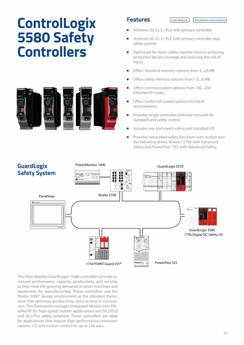
75
The Allen-Bradley GuardLogix® 5580 controllers provide in-creased performance, capacity, productivity, and security to help meet the growing demands of smart machines and equipment for manufacturing. These controllers use the Studio 5000® design environment as the standard frame-work that optimizes productivity, reduces time to commis-sion. This framework manages Integrated Motion over Eth-erNet/IP for high-speed motion applications and SIL2/PLd and SIL3/PLe safety solutions. These controllers are ideal for applications that require high-performance communi-cations, I/O, and motion control for up to 256 axes.
Features ■ Achieves SIL CL 2 / PLd with primary controller
■ Achieves SIL CL 3 / PLE with primary controller plus safety partner
■ Optimized for faster safety reaction time to achieving protective device coverage and reducing the risk of injury
■ Offers Standard memory options from 3...20 MB
■ Offers safety memory options from 1.5...6 MB
■ Offers communication options from 100...250 EtherNet/IP nodes
■ Offers conformal coated options for harsh environments
■ Provides single controller/software/network for standard and safety control
■ Includes mix and match safety and standard I/O
■ Provides networked safety functions with motion and the following drives: Kinetix® 5700 with Advanced Safety and PowerFlex® 755 with Advanced Safety
ControlLogix 5580 Safety Controllers
GuardLogix Safety System RS-485 STATUSRS-485
RX
SHLDLNK ACT
TX Mod Net
+ -
Powermonitor 1000conformance testedTM
DC OUTPUT
SAFETY
FLT
ST 0 1 2 3 4 5 6 7
0 1 2 3 4 5 6 7 OK
SAFETY
FLT
ST 0 1 2 3 4 5 6 7
0 1 2 3 4 5 6 7 OK
DC INPUT
FLT
ST 8 9 10 11 12 13 14 15
8 9 10 11 12 13 14 15
PanelView
PowerMonitor 1000
Stratix 5700
PowerFlex 5251734 POINT Guard I/O™
GuardLogix 5570
GuardLogix 55801756 Digital DC Safety I/O
User Manual Installation Instructions
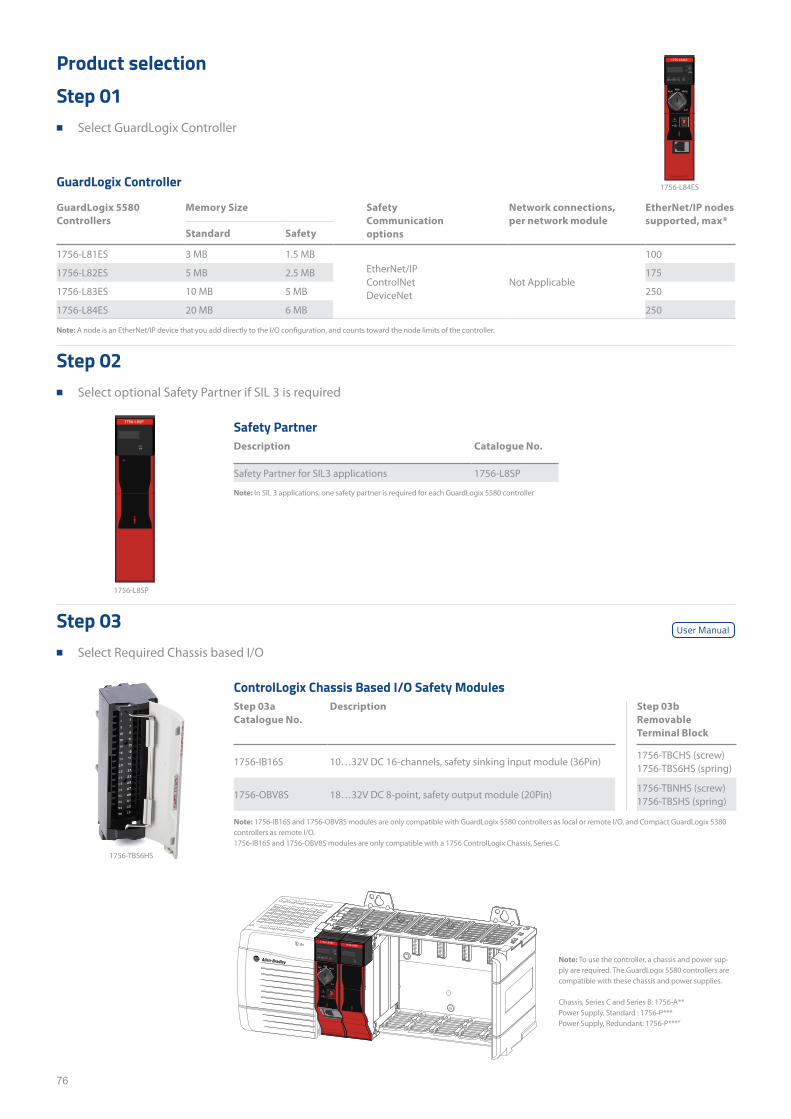
76
Product selectionStep 01
■ Select GuardLogix Controller
Step 02 ■ Select optional Safety Partner if SIL 3 is required
Step 03 ■ Select Required Chassis based I/O
GuardLogix Controller
GuardLogix 5580 Controllers
Memory Size Safety Communication options
Network connections, per network module
EtherNet/IP nodes supported, max*
Standard Safety
1756-L81ES 3 MB 1.5 MBEtherNet/IPControlNetDeviceNet
Not Applicable
100
1756-L82ES 5 MB 2.5 MB 175
1756-L83ES 10 MB 5 MB 250
1756-L84ES 20 MB 6 MB 250
Note: A node is an EtherNet/IP device that you add directly to the I/O configuration, and counts toward the node limits of the controller.
Note: To use the controller, a chassis and power sup-ply are required. The GuardLogix 5580 controllers are compatible with these chassis and power supplies.
Chassis, Series C and Series B: 1756-A**Power Supply, Standard : 1756-P***Power Supply, Redundant: 1756-P***”
Note: In SIL 3 applications, one safety partner is required for each GuardLogix 5580 controller
Note: 1756-IB16S and 1756-OBV8S modules are only compatible with GuardLogix 5580 controllers as local or remote I/O, and Compact GuardLogix 5380 controllers as remote I/O.1756-IB16S and 1756-OBV8S modules are only compatible with a 1756 ControlLogix Chassis, Series C.
Safety PartnerDescription Catalogue No.
Safety Partner for SIL3 applications 1756-L8SP
ControlLogix Chassis Based I/O Safety ModulesStep 03a Catalogue No.
Description Step 03b Removable Terminal Block
1756-IB16S 10…32V DC 16-channels, safety sinking input module (36Pin)1756-TBCHS (screw)1756-TBS6HS (spring)
1756-OBV8S 18…32V DC 8-point, safety output module (20Pin)1756-TBNHS (screw)1756-TBSHS (spring)
1756-L8SP
1756-L84ES
1756-TBS6HS
User Manual
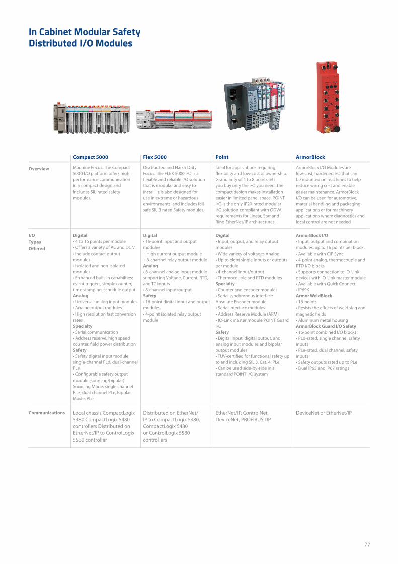
77
Compact 5000 Flex 5000 Point ArmorBlock
Overview Machine Focus. The Compact 5000 I/O platform offers high performance communication in a compact design and includes SIL-rated safety modules.
Disrtibuted and Harsh Duty Focus. The FLEX 5000 I/O is a flexible and reliable I/O solution that is modular and easy to install. It is also designed for use in extreme or hazardous environments, and includes fail-safe SIL 3 rated Safety modules.
Ideal for applications requiring flexibility and low-cost of ownership. Granularity of 1 to 8 points lets you buy only the I/O you need. The compact design makes installation easier in limited panel space. POINT I/O is the only IP20-rated modular I/O solution compliant with ODVA requirements for Linear, Star and Ring EtherNet/IP architectures.
ArmorBlock I/O Modules are low-cost, hardened I/O that can be mounted on machines to help reduce wiring cost and enable easier maintenance. ArmorBlock I/O can be used for automotive, material handling and packaging applications or for machinery applications where diagnostics and local control are not needed
I/O Types Offered
Digital• 4 to 16 points per module• Offers a variety of AC and DC V.• Include contact output modules• Isolated and non-isolated modules• Enhanced built-in capabilties; event triggers, simple counter, time stamping, schedule outputAnalog• Universal analog input modules• Analog output modules• High resolution fast conversion ratesSpecialty• Serial communication• Address reserve, high speed counter, field power distributionSafety• Safety digital input module single-channel PLd, dual-channel PLe• Configurable safety output module (sourcing/bipolar) Sourcing Mode: single channel PLe, dual channel PLe, Bipolar Mode: PLe
Digital• 16-point input and output modules - High current output module - 8-channel relay output moduleAnalog• 8-channel analog input module supporting Voltage, Current, RTD, and TC inputs• 8-channel input/outputSafety• 16-point digital input and output modules• 4-point isolated relay output module
Digital• Input, output, and relay output modules• Wide variety of voltages Analog• Up to eight single inputs or outputs per module• 4-channel input/output• Thermocouple and RTD modules Specialty• Counter and encoder modules• Serial synchronous interface Absolute Encoder module• Serial interface modules• Address Reserve Module (ARM)• IO-Link master module POINT Guard I/O Safety• Digital input, digital output, and analog input modules and bipolar output modules• TUV-certified for functional safety up to and including SIL 3, Cat. 4, PLe• Can be used side-by-side in a standard POINT I/O system
ArmorBlock I/O• Input, output and combination modules, up to 16 points per block• Available with CIP Sync • 4-point analog, thermocouple and RTD I/O blocks• Supports connection to IO-Link devices with IO-Link master module• Available with Quick Connect• IP69KArmor WeldBlock• 16-points• Resists the effects of weld slag and magnetic fields• Aluminum metal housingArmorBlock Guard I/O Safety• 16-point combined I/O blocks• PLd-rated, single channel safety inputs• PLe-rated, dual channel, safety inputs• Safety outputs rated up to PLe• Dual IP65 and IP67 ratings
Communications Local chassis CompactLogix 5380 CompactLogix 5480 controllers Distributed on EtherNet/IP to ControlLogix 5580 controller
Distributed on EtherNet/IP to CompactLogix 5380, CompactLogix 5480or ControlLogix 5580 controllers
EtherNet/IP, ControlNet, DeviceNet, PROFIBUS DP
DeviceNet or EtherNet/IP
In Cabinet Modular Safety Distributed I/O Modules
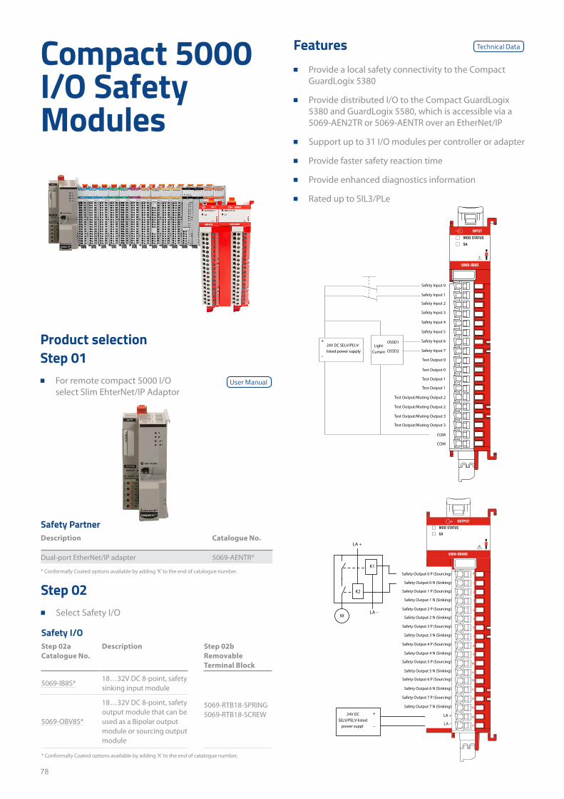
78
Features ■ Provide a local safety connectivity to the Compact
GuardLogix 5380
■ Provide distributed I/O to the Compact GuardLogix 5380 and GuardLogix 5580, which is accessible via a 5069-AEN2TR or 5069-AENTR over an EtherNet/IP
■ Support up to 31 I/O modules per controller or adapter
■ Provide faster safety reaction time
■ Provide enhanced diagnostics information
■ Rated up to SIL3/PLe
Compact 5000 I/O Safety Modules
Product selectionStep 01
■ For remote compact 5000 I/O select Slim EhterNet/IP Adaptor
Step 02 ■ Select Safety I/O
* Conformally Coated options available by adding ’K’ to the end of catalogue number.
* Conformally Coated options available by adding ’K’ to the end of catalogue number.
Safety PartnerDescription Catalogue No.
Dual-port EtherNet/IP adapter 5069-AENTR*
Safety I/OStep 02a Catalogue No.
Description Step 02b Removable Terminal Block
5069-IB8S*18…32V DC 8-point, safety sinking input module
5069-RTB18-SPRING 5069-RTB18-SCREW
5069-OBV8S*
18…32V DC 8-point, safety output module that can be used as a Bipolar output module or sourcing output module
5069-IB8S
Safety Input 0
Safety Input 1
Safety Input 2
Safety Input 3
Safety Input 4
Safety Input 5
Safety Input 6
Safety Input 7
Test Output 0
Test Output 0
Test Output 1
Test Output 1
Test Output/Muting Output 2
Test Output/Muting Output 2
Test Output/Muting Output 3
Test Output/Muting Output 3
COM
COM
OSSD1
OSSD2Light
Curtain
24V DC SELV/PELV-listed power supply
+
–
5069-OBV8S
OUTPUT
0
7
6
5
4
3
2
1
17
16
15
14
13
12
11
10
9
8
Safety Output 0 P (Sourcing)
LA +
LA –
Safety Output 3 P (Sourcing)
Safety Output 4 P (Sourcing)
Safety Output 4 N (Sinking)
Safety Output 1 N (Sinking)
Safety Output 5 P (Sourcing)
Safety Output 5 N (Sinking)
Safety Output 6 P (Sourcing)
Safety Output 6 N (Sinking)
Safety Output 7 P (Sourcing)
Safety Output 7 N (Sinking)
Safety Output 3 N (Sinking)
Safety Output 2 N (Sinking)
Safety Output 2 P (Sourcing)
Safety Output 1 P (Sourcing)
Safety Output 0 N (Sinking)
24V DC SELV/PELV-listed
power suppl –
+
M
K1
K2
LA –
LA +
Technical Data
User Manual
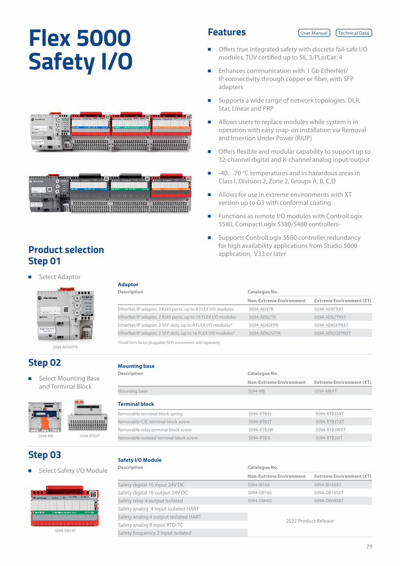
79
Features ■ Offers true integrated safety with discrete fail-safe I/O
modules, TÜV certified up to SIL 3/PLe/Cat. 4
■ Enhances communication with 1 Gb EtherNet/IP connectivity through copper or fiber, with SFP adapters
■ Supports a wide range of network topologies: DLR, Star, Linear and PRP
■ Allows users to replace modules while system is in operation with easy snap-on installation via Removal and Insertion Under Power (RIUP)
■ Offers flexible and modular capability to support up to 32-channel digital and 8-channel analog input/output
■ -40…70 °C temperatures and in hazardous areas in Class I, Division 2, Zone 2, Groups A, B, C,D
■ Allows for use in extreme environments with XT version up to G3 with conformal coating
■ Functions as remote I/O modules with ControlLogix 5580, CompactLogix 5380/5480 controllers-
■ Supports ControlLogix 5580 controller redundancy for high availability applications from Studio 5000 application, V33 or later
Flex 5000 Safety I/O
Product selection
Step 02 ■ Select Mounting Base
and Terminal Block
Step 01 ■ Select Adaptor
Step 03 ■ Select Safety I/O Module
*Small form factor pluggable (SFP) transceivers sold separately
AdaptorDescription Catalogue No.
Non-Extreme Environment Extreme Environment (XT)
EtherNet/IP adapter, 2 RJ45 ports, up to 8 FLEX I/O modules 5094-AENTR 5094-AENTRXT
EtherNet/IP adapter, 2 RJ45 ports, up to 16 FLEX I/O modules 5094-AEN2TR 5094-AEN2TRXT
EtherNet/IP adapter, 2 SFP slots, up to 8 FLEX I/O modules* 5094-AENSFPR 5094-AENSFPRXT
EtherNet/IP adapter, 2 SFP slots, up to 16 FLEX I/O modules* 5094-AEN2SFPR 5094-AEN2SFPRXT
Mounting baseDescription Catalogue No.
Non-Extreme Environment Extreme Environment (XT)
Mounting base 5094-MB 5094-MBXT
Terminal block
Removable terminal block spring 5094-RTB3S 5094-RTB3SXT
Removable CJC terminal block screw 5094-RTB3T 5094-RTB3TXT
Removable relay terminal block screw 5094-RTB3W 5094-RTB3WXT
Removable isolated terminal block screw 5094-RTB3I 5094-RTB3IXT
Safety I/O ModuleDescription Catalogue No.
Non-Extreme Environment Extreme Environment (XT)
Safety digital 16 input 24V DC 5094-IB16S 5094-IB16SXT
Safety digital 16 output 24V DC 5094-OB16S 5094-OB16SXT
Safety relay 4 output isolated 5094-OW4IS 5094-OW4ISXT
Safety analog 4 input isolated HART
2022 Product ReleaseSafety analog 4 output isolated HARTSafety analog 8 input RTD/TCSafety frequency 2 input isolated
5094-AENSFPR
5094-MB 5094-RTB3T
5094-OB16S
Technical DataUser Manual
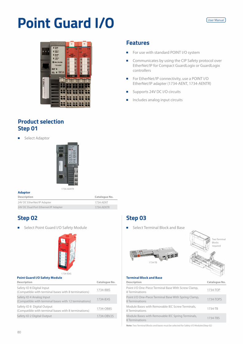
80
Features ■ For use with standard POINT I/O system
■ Communicates by using the CIP Safety protocol over EtherNet/IP for Compact GuardLogix or GuardLogix controllers
■ For EtherNet/IP connectivity, use a POINT I/O EtherNet/IP adapter (1734-AENT, 1734-AENTR)
■ Supports 24V DC I/O circuits
■ Includes analog input circuits
Point Guard I/O
Product selection
Step 02 ■ Select Point Guard I/O Safety Module
Step 01 ■ Select Adaptor
Step 03 ■ Select Terminal Block and Base
AdaptorDescription Catalogue No.
24V DC EtherNet/IP Adapter 1734-AENT
24V DC Dual Port Ethernet/IP Adapter 1734-AENTR
Point Guard I/O Safety ModuleDescription Catalogue No.
Safety IO 8 Digital Input (Compatible with terminal bases with 8 terminations)
1734-IB8S
Safety IO 4 Analog Input (Compatible with terminal bases with 12 terminations)
1734-IE4S
Safety IO 8 Digital Output (Compatible with terminal bases with 8 terminations)
1734-OB8S
Safety IO 2 Digital Output 1734-OBV2S
Terminal Block and BaseDescription Catalogue No.
Point I/O One-Piece Terminal Base With Screw Clamp, 8 Terminations
1734-TOP
Point I/O One-Piece Terminal Base With Spring Clamp, 8 Terminations
1734-TOPS
Module Bases with Removable IEC Screw Terminals, 8 Terminations
1734-TB
Module Bases with Removable IEC Spring Terminals, 8 Terminations
1734-TBS
1734-AENTR
1734-IE4S
1734-TB
Two Terminal Blocks required
Note: Two Terminal Blocks and bases must be selected for Safety I/O Modules(Step 02)
User Manual
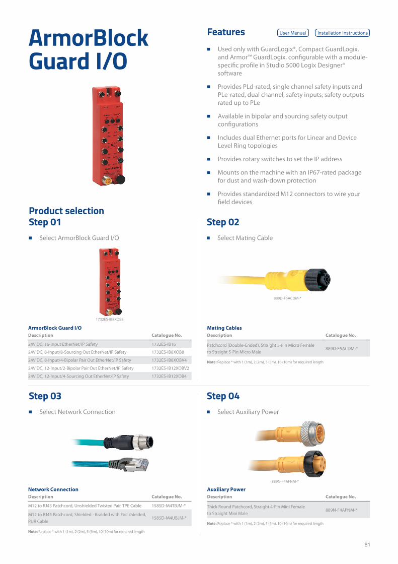
81
Features ■ Used only with GuardLogix®, Compact GuardLogix,
and Armor™ GuardLogix, configurable with a module-specific profile in Studio 5000 Logix Designer® software
■ Provides PLd-rated, single channel safety inputs and PLe-rated, dual channel, safety inputs; safety outputs rated up to PLe
■ Available in bipolar and sourcing safety output configurations
■ Includes dual Ethernet ports for Linear and Device Level Ring topologies
■ Provides rotary switches to set the IP address
■ Mounts on the machine with an IP67-rated package for dust and wash-down protection
■ Provides standardized M12 connectors to wire your field devices
ArmorBlock Guard I/O
Product selectionStep 02
■ Select Mating Cable
Step 04 ■ Select Auxiliary Power
Step 01 ■ Select ArmorBlock Guard I/O
Step 03 ■ Select Network Connection
ArmorBlock Guard I/ODescription Catalogue No.
24V DC, 16-Input EtherNet/IP Safety 1732ES-IB16
24V DC, 8-Input/8-Sourcing Out EtherNet/IP Safety 1732ES-IB8XOB8
24V DC, 8-Input/4-Bipolar Pair Out EtherNet/IP Safety 1732ES-IB8XOBV4
24V DC, 12-Input/2-Bipolar Pair Out EtherNet/IP Safety 1732ES-IB12XOBV2
24V DC, 12-Input/4-Sourcing Out EtherNet/IP Safety 1732ES-IB12XOB4
Network ConnectionDescription Catalogue No.
M12 to RJ45 Patchcord, Unshielded Twisted Pair, TPE Cable 1585D-M4TBJM-*
M12 to RJ45 Patchcord, Shielded - Braided with Foil shielded, PUR Cable
1585D-M4UBJM-*
Mating CablesDescription Catalogue No.
Patchcord (Double-Ended), Straight 5-Pin Micro Female to Straight 5-Pin Micro Male
889D-F5ACDM-*
Auxiliary PowerDescription Catalogue No.
Thick Round Patchcord, Straight 4-Pin Mini Female to Straight Mini Male
889N-F4AFNM-*
889D-F5ACDM-*
889N-F4AFNM-*
Note: Replace * with 1 (1m), 2 (2m), 5 (5m), 10 (10m) for required length
Note: Replace * with 1 (1m), 2 (2m), 5 (5m), 10 (10m) for required length
Note: Replace * with 1 (1m), 2 (2m), 5 (5m), 10 (10m) for required length
1732ES-IB8XOB8
User Manual Installation Instructions
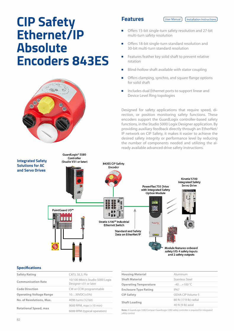
82
CIP Safety Ethernet/IP Absolute Encoders 843ES
Designed for safety applications that require speed, di-rection, or position monitoring safety functions. These encoders support the GuardLogix controller-based safety functions, in the Studio 5000 Logix Designer application. By providing auxiliary feedback directly through an EtherNet/IP network on CIP Safety, it makes it easier to achieve the desired safety integrity or performance level by reducing the number of components needed and utilizing the al-ready available advanced drive safety instructions.
Features
■ Offers 15-bit single-turn safety resolution and 27-bit multi-turn safety resolution
■ Offers 18-bit single-turn standard resolution and 30-bit multi-turn standard resolution
■ Features feather key solid shaft to prevent relative rotation
■ Blind-hollow shaft available with stator coupling
■ Offers clamping, synchro, and square flange options for solid shaft
■ Includes dual Ethernet ports to support linear and Device Level Ring topologies
Specifications
Safety Rating CAT3, SIL3, Ple
Communication Rate10/100 Mbit/s Studio 5000 Logix Designer v31 or later
Code Direction CW or CCW programmable
Operating Voltage Range 10…30VDC(±5%)
No. of Revolutions, Max. 4096 turns (12 bit)
Rotational Speed, max9000 RPM, max (<10 min)
6000 RPM (typical operation)
Integrated Safety Solutions for AC and Servo Drives
Housing Material Aluminum
Shaft Material Stainless Steel
Operating Temperature -40…+100 °C
Enclosure Type Rating IP67
CIP Safety ODVA CIP Volume 5
Shaft Loading80 N (17.9 lb) radial
40 N (9 lb) axial
User Manual Installation Instructions
Note: A GuardLogix 5580/Compact GuardLogix 5380 safety controller is required for integrated safety control.
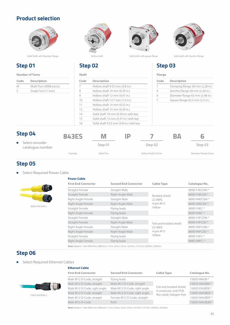
83
1585D-M4TBJM-2
843ES IP BA
Number of Turns Shaft Flange
Code Description Code Description Code Description
M Multi Turn (4096 turns) 7 Hollow shaft 9.52 mm (3/8 in.) 1 Clamping flange 58 mm (2.28 in.)S Single Turn (1 turn) 8 Hollow shaft 10 mm (0.39 in.) 4 Synchro flange 58 mm (2.28 in.)
9 Hollow shaft 12 mm (0.47 in.) 6 Diameter flange 63 mm (2.48 in.)10 Hollow shaft 12.7 mm (1/2 in.) 7 Square flange 63.5 mm (2.5 in.)11 Hollow shaft 14 mm (0.55 in.)12 Hollow shaft 15 mm (0.59 in.)14 Solid shaft 10 mm (0.39 in) with key15 Solid shaft 12 mm (0.47 in.) with key16 Solid shaft 9.52 mm (3/8 in.) with key
Product selection
Step 01 Step 02 Step 03
Step 04 ■ Select encoder
catalogue number
Step 05 ■ Select Required Power Cable
Step 06 ■ Select Required Ethernet Cables
M 7 6
Example Multi-Turn
Hollow shaftSolid Shaft with Diameter flange Solid shaft with square flange Solid shaft with Synchro flange
Hollow Shaft 9.52mm Diameter Flange 63mm
Power Cable
First End Connector Second End Connector Cable Type Catalogue No.
Straight Female Straight Male
Braided shield22 AWG4-pin M12Yellow
889D-F4ECDM-*Straight Female Right Angle Male 889D-F4ECDE-*Right Angle Female Straight Male 889D-R4ECDM-*Right Angle Female Right Angle Male 889D-R4ECDE-*Straight Female Flying leads 889D-F4EC-*Right Angle Female Flying leads 889D-R4EC-*
Straight Female Straight Male
Foil and braided shield 22 AWG4-pin M12Yellow
889D-F4FCDM-*Straight Female Right Angle Male 889D-F4FCDE-*Right Angle Female Straight Male 889D-R4FCDM-*Right Angle Female Right Angle Male 889D-R4FCDE-*Straight Female Flying leads 889D-F4FC-*Right Angle Female Flying leads 889D-R4FC-*
Ethernet Cable
First End Connector Second End Connector Cable Type Catalogue No.
Male M12 D-Code, straight Flying leads
Foil and braided shield, 4 conductor, teal PUR, flex rated, halogen-free
1585D-M4UB-*Male M12 D-Code, straight Male M12 D-Code, straight 1585D-M4UBM-*Male M12 D-Code, right angle Male M12 D-Code, right angle 1585D-E4UBDE-*Male M12 D-Code, straight Male M12 D-Code, right angle 1585D-M4UBDE-*Male M12 D-Code, straight Female M12 D-Code, straight 1585D-M4UBDF-*Male M12 D-Code RJ45 1585D-M4UBJM-*
Note: Replace * with 0M3(.3m), 0M6(.6m), 1(1m), 2(2m), 5(5m), 10(10m), 15(15m), 20(20m), 30(30m)
Note: Replace * with 0M3(.3m), 0M6(.6m), 1(1m), 2(2m), 3(3m), 5(5m), 10(10m), 15(15m), 20(20m), 30(30m)
889D-F4ECDM-2
Step 01 Step 02 Step 03
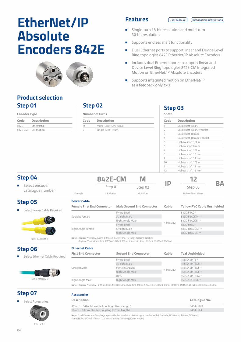
84
842E-CMStep 01 IP BA
Product selectionStep 01 Step 02 Step 03
Step 04 ■ Select encoder
catalogue number
Step 05 ■ Select Power Cable Required
Step 06 ■ Select Ethernet Cable Required
Step 07 ■ Select Accessories
MStep 02 Step 03
12
CIP MotionExample Multi-Turn Hollow Shaft 15mm
Power Cable
Female First End Connector Male Second End Connector Cable Yellow PVC Cable Unshielded
Straight FemaleFlying Lead
4 Pin M12
889D-F4AC-* Straight Male 889D-F4ACDM-** Right Angle Male 889D-F4ACDE-**
Right Angle FemaleFlying Lead 889D-R4AC-* Straight Male 889D-R4ACDM-** Right Angle Male 889D-R4ACDE-**
Ethernet Cable
First End Connector Second End Connector Cable Teal Unshielded
Straight Male
Flying Lead
4 Pin M12
1585D-M4TB-* Straight Male 1585D-M4TBDM-* Female Straight 1585D-M4TBDF-* Right Angle Male 1585D-M4TBDE-* RJ45 1585D-M4TBJM-*
Right Angle Male Right Angle Male 1585D-E4TBDE-*
Accessories
Description Catalogue No.
3/8inch .. 3/8inch Flexible Coupling (32mm length) 845-FC-B-B10mm ... 10mm Flexible Coupling (32mm length) 845-FC-T-T
EtherNet/IP Absolute Encoders 842E
Features ■ Single-turn 18-bit resolution and multi-turn
30-bit resolution
■ Supports endless shaft functionality
■ Dual Ethernet ports to support linear and Device Level Ring topologies 842E EtherNet/IP Absolute Encoders
■ Includes dual Ethernet ports to support linear and Device Level Ring topologies 842E-CM Integrated Motion on EtherNet/IP Absolute Encoders
■ Supports integrated motion on EtherNet/IP as a feedback only axis
Note: Replace * with 0M3(.3m), 2(2m), 5(5m), 10(10m), 15(15m), 20(20m), 30(30m)Replace ** with 0M3(.3m), 0M6(.6m), 1(1m), 2(2m), 5(5m), 10(10m), 15(15m), 20, (20m), 30(30m)
Note: Replace * with 0M15(.15m), 0M2(.2m) 0M3(.3m), 0M6(.6m), 1(1m), 2(2m), 3(3m), 4(4m), 5(5m), 10(10m), 15(15m), 20, (20m), 30(30m), 40(40m)
Note: For diifferent size Couplings replace the last two letters in catalogue number with A(1/4Inch), B(3/8Inch), R(6mm), T(10mm). Example: 845-FC-A-B 1/4inch … 3/8inch Flexible Coupling (32mm length)
Encoder Type Number of turns Shaft
Code Description Code Description Code Description
842E EtherNet/IP M Multi Turn (4096 turns) 1 Solid shaft 3/8 in.842E-CM CIP Motion S Single Turn (1 turn) 2 Solid shaft 3/8 in. with flat
3 Solid shaft 10 mm4 Solid shaft 10 mm with flat5 Hollow shaft 1/4 in.6 Hollow shaft 8 mm7 Hollow shaft 3/8 in8 Hollow shaft 10 mm9 Hollow shaft 12 mm10 Hollow shaft 1/2 in11 Hollow shaft 14 mm12 Hollow shaft 15 mm
889D-F4ACDM-2
1585D-M4TBJM-2
845-FC-T-T
User Manual Installation Instructions

85
This page has been left intentionally blank
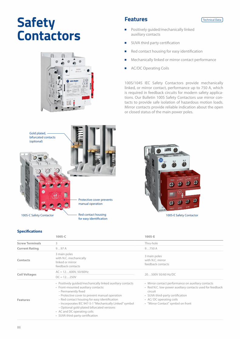
86
Safety Contactors
100S/104S IEC Safety Contactors provide mechanically linked, or mirror contact, performance up to 750 A, which is required in feedback circuits for modern safety applica-tions. Our Bulletin 100S Safety Contactors use mirror con-tacts to provide safe isolation of hazardous motion loads. Mirror contacts provide reliable indication about the open or closed status of the main power poles.
Features ■ Positively guided/mechanically linked
auxiliary contacts
■ SUVA third party certification
■ Red contact housing for easy identification
■ Mechanically linked or mirror contact performance
■ AC/DC Operating Coils
Specifications100S-C 100S-E
Screw Terminals 3 Thru-hole
Current Rating 9…97 A 9…750 A
Contacts
3 main poles with N.C. mechanically linked or mirror feedback contacts
3 main poles with N.C. mirror feedback contacts
Coil VoltagesAC = 12…600V, 50/60Hz
20…500V 50/60 Hz/DCDC = 12…250V
Features
• Positively guided/mechanically linked auxiliary contacts • Front-mounted auxiliary contacts:
– Permanently fixed – Protective cover to prevent manual operation – Red contact housing for easy identification – Incorporates IEC 947-5-1 “Mechanically Linked” symbol – Optional gold-plated bifurcated versions
• AC and DC operating coils • SUVA third-party certification
• Mirror contact performance on auxiliary contacts • Red N.C. low-power auxiliary contacts used for feedback
circuit • SUVA third-party certification • AC/ DC operating coils • "Mirror Contact" symbol on front
Red contact housing for easy identification
100S-C Safety Contactor
Protective cover prevents manual operation
Gold plated, bifurcated contacts (optional)
Technical Data
100S-E Safety Contactor
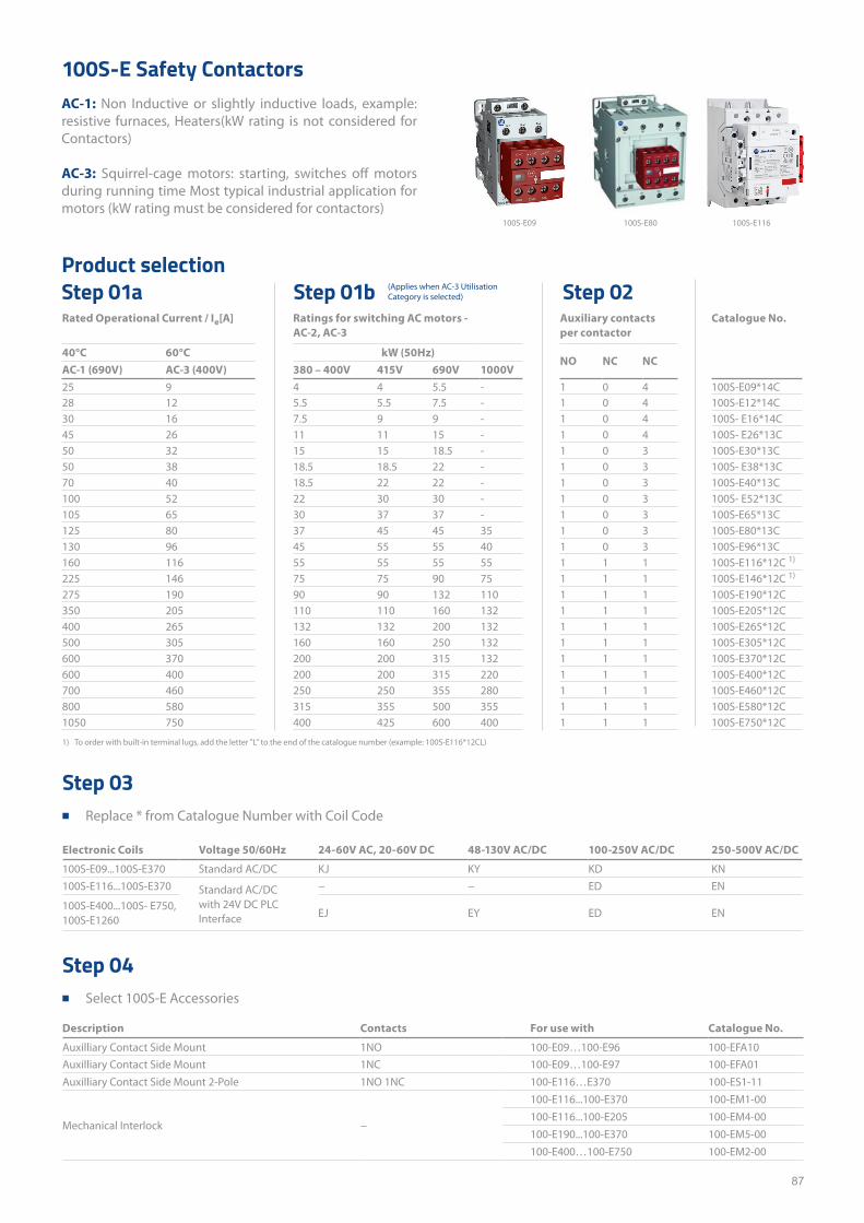
87
Rated Operational Current / Ie[A] Ratings for switching AC motors - AC-2, AC-3
Auxiliary contacts per contactor
Catalogue No.
40°C 60°C kW (50Hz)NO NC NC
AC-1 (690V) AC-3 (400V) 380 – 400V 415V 690V 1000V25 9 4 4 5.5 - 1 0 4 100S-E09*14C28 12 5.5 5.5 7.5 - 1 0 4 100S-E12*14C30 16 7.5 9 9 - 1 0 4 100S- E16*14C45 26 11 11 15 - 1 0 4 100S- E26*13C50 32 15 15 18.5 - 1 0 3 100S-E30*13C50 38 18.5 18.5 22 - 1 0 3 100S- E38*13C70 40 18.5 22 22 - 1 0 3 100S-E40*13C100 52 22 30 30 - 1 0 3 100S- E52*13C105 65 30 37 37 - 1 0 3 100S-E65*13C125 80 37 45 45 35 1 0 3 100S-E80*13C130 96 45 55 55 40 1 0 3 100S-E96*13C160 116 55 55 55 55 1 1 1 100S-E116*12C 1)
225 146 75 75 90 75 1 1 1 100S-E146*12C 1)
275 190 90 90 132 110 1 1 1 100S-E190*12C350 205 110 110 160 132 1 1 1 100S-E205*12C 400 265 132 132 200 132 1 1 1 100S-E265*12C500 305 160 160 250 132 1 1 1 100S-E305*12C600 370 200 200 315 132 1 1 1 100S-E370*12C 600 400 200 200 315 220 1 1 1 100S-E400*12C700 460 250 250 355 280 1 1 1 100S-E460*12C800 580 315 355 500 355 1 1 1 100S-E580*12C1050 750 400 425 600 400 1 1 1 100S-E750*12C
Product selection
100S-E Safety ContactorsAC-1: Non Inductive or slightly inductive loads, example: resistive furnaces, Heaters(kW rating is not considered for Contactors)
AC-3: Squirrel-cage motors: starting, switches off motors during running time Most typical industrial application for motors (kW rating must be considered for contactors)
Step 01a Step 01b Step 02
100S-E09 100S-E80 100S-E116
(Applies when AC-3 Utilisation Category is selected)
1) To order with built-in terminal lugs, add the letter "L" to the end of the catalogue number (example: 100S-E116*12CL)
Step 03 ■ Replace * from Catalogue Number with Coil Code
Step 04 ■ Select 100S-E Accessories
Electronic Coils Voltage 50/60Hz 24-60V AC, 20-60V DC 48-130V AC/DC 100-250V AC/DC 250-500V AC/DC
100S-E09...100S-E370 Standard AC/DC KJ KY KD KN100S-E116...100S-E370 Standard AC/DC
with 24V DC PLC Interface
− − ED EN
100S-E400...100S- E750,100S-E1260
EJ EY ED EN
Description Contacts For use with Catalogue No.
Auxilliary Contact Side Mount 1NO 100-E09…100-E96 100-EFA10Auxilliary Contact Side Mount 1NC 100-E09…100-E97 100-EFA01Auxilliary Contact Side Mount 2-Pole 1NO 1NC 100-E116…E370 100-ES1-11
Mechanical Interlock −
100-E116...100-E370 100-EM1-00100-E116...100-E205 100-EM4-00100-E190...100-E370 100-EM5-00100-E400…100-E750 100-EM2-00
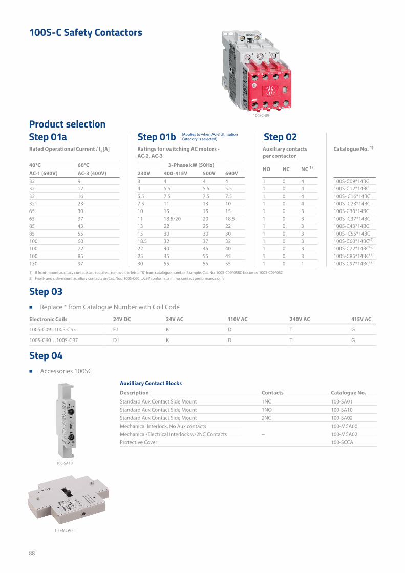
88
Rated Operational Current / Ie[A] Ratings for switching AC motors - AC-2, AC-3
Auxiliary contacts per contactor
Catalogue No. 1)
40°C 60°C 3-Phase kW (50Hz)NO NC NC 1)
AC-1 (690V) AC-3 (400V) 230V 400-415V 500V 690V32 9 3 4 4 4 1 0 4 100S-C09*14BC32 12 4 5.5 5.5 5.5 1 0 4 100S-C12*14BC32 16 5.5 7.5 7.5 7.5 1 0 4 100S- C16*14BC32 23 7.5 11 13 10 1 0 4 100S- C23®14BC65 30 10 15 15 15 1 0 3 100S-C30*14BC65 37 11 18.5/20 20 18.5 1 0 3 100S- C37*14BC85 43 13 22 25 22 1 0 3 100S-C43*14BC85 55 15 30 30 30 1 0 3 100S- C55*14BC100 60 18.5 32 37 32 1 0 3 100S-C60*14BC(2)
100 72 22 40 45 40 1 0 3 100S-C72*14BC(2)
100 85 25 45 55 45 1 0 3 100S-C85*14BC(2)
130 97 30 55 55 55 1 0 1 100S-C97*14BC(2)
Product selection
100S-C Safety Contactors
Step 01a Step 01b Step 02
100SC-09
(Applies to when AC-3 Utilisation Category is selected)
1) If front-mount auxiliary contacts are required, remove the letter "B" from catalogue number Example: Cat. No. 100S-C09*05BC becomes 100S-C09*05C2) Front- and side-mount auxiliary contacts on Cat. Nos. 100S-C60…C97 conform to mirror contact performance only
Step 03 ■ Replace * from Catalogue Number with Coil Code
Step 04 ■ Accessories 100SC
Electronic Coils 24V DC 24V AC 110V AC 240V AC 415V AC
100S-C09...100S-C55 EJ K D T G
100S-C60…100S-C97 DJ K D T G
Auxilliary Contact Blocks
Description Contacts Catalogue No.
Standard Aux Contact Side Mount 1NC 100-SA01Standard Aux Contact Side Mount 1NO 100-SA10Standard Aux Contact Side Mount 2NC 100-SA02Mechanical Interlock, No Aux contacts
−100-MCA00
Mechanical/Electrical Interlock w/2NC Contacts 100-MCA02Protective Cover 100-SCCA
100-SA10
100-MCA00
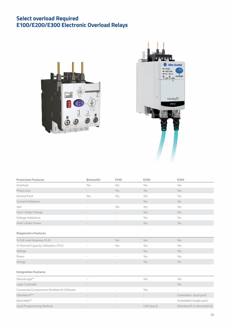
89
Select overload Required E100/E200/E300 Electronic Overload Relays
Protection Features Bimetallic E100 E200 E300
Overload Yes Yes Yes Yes
Phase Loss - Yes Yes Yes
Ground Fault Yes Yes Yes Yes
Current Imbalance - Yes Yes
Jam - Yes Yes Yes
Over/ Under Voltage - - Yes Yes
Voltage Imbalance - - Yes Yes
Over/ Under Power - - Yes Yes
Diagnostics Features
% Full Load Amperes (FLA) - Yes Yes Yes
% Thermal Capacity Utilization (TCU) - Yes Yes Yes
Voltage - - Yes Yes
Power - - Yes Yes
Energy - - Yes Yes
Integration Features
DeviceLogix™ - Yes Yes
Logix Controller - - - Yes
Connected Components Workbench Software - - Yes -
EtherNet/IP™ - - - Embedded (dual-port)
DeviceNet™ - - - Embedded (single-port)
Local Programming Method - - USB Type B EtherNet/IP or DeviceNet(2)
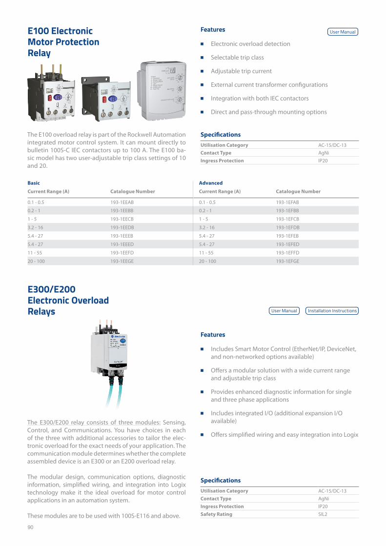
90
Specifications
Utilisation Category AC-15/DC-13Contact Type AgNiIngress Protection IP20
Specifications
Utilisation Category AC-15/DC-13Contact Type AgNiIngress Protection IP20Safety Rating SIL2
E100 Electronic Motor Protection Relay
E300/E200 Electronic Overload Relays
Features
■ Electronic overload detection
■ Selectable trip class
■ Adjustable trip current
■ External current transformer configurations
■ Integration with both IEC contactors
■ Direct and pass-through mounting options
Features
■ Includes Smart Motor Control (EtherNet/IP, DeviceNet, and non-networked options available)
■ Offers a modular solution with a wide current range and adjustable trip class
■ Provides enhanced diagnostic information for single and three phase applications
■ Includes integrated I/O (additional expansion I/O available)
■ Offers simplified wiring and easy integration into Logix
Basic Advanced
Current Range (A) Catalogue Number Current Range (A) Catalogue Number
0.1 - 0.5 193-1EEAB 0.1 - 0.5 193-1EFAB
0.2 - 1 193-1EEBB 0.2 - 1 193-1EFBB
1 - 5 193-1EECB 1 - 5 193-1EFCB
3.2 - 16 193-1EEDB 3.2 - 16 193-1EFDB
5.4 - 27 193-1EEEB 5.4 - 27 193-1EFEB
5.4 - 27 193-1EEED 5.4 - 27 193-1EFED
11 - 55 193-1EEFD 11 - 55 193-1EFFD
20 - 100 193-1EEGE 20 - 100 193-1EFGE
The E100 overload relay is part of the Rockwell Automation integrated motor control system. It can mount directly to bulletin 100S-C IEC contactors up to 100 A. The E100 ba-sic model has two user-adjustable trip class settings of 10 and 20.
The E300/E200 relay consists of three modules: Sensing, Control, and Communications. You have choices in each of the three with additional accessories to tailor the elec-tronic overload for the exact needs of your application. The communication module determines whether the complete assembled device is an E300 or an E200 overload relay.
The modular design, communication options, diagnostic information, simplified wiring, and integration into Logix technology make it the ideal overload for motor control applications in an automation system.
These modules are to be used with 100S-E116 and above.
User Manual
User Manual Installation Instructions
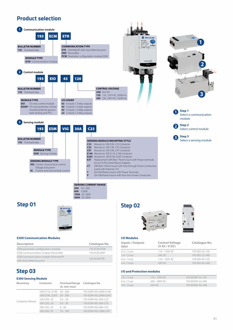
91
Product selection
Step 01 Step 02
E300 Communication Modules
Description Catalogue No.
E200 parameter configuration module 193-ECM-PCME300 communication module DeviceNet 193-ECM-DNTE300 communication module Ethernet/IP with dual ethernet ports
193-ECM-ETR
I/O ModulesInputs / Outputs (qty)
Control Voltage (V AC / V DC)
Catalogue No.
2 in / 2 out 110 - 120V AC 193-EIO-22-1202 in / 2 out 24V DC 193-EIO-22-24D4 in / 3 out 110 - 120V AC 193-EIO-43-1206 in / 3 out 24V DC 193-EIO-63-24D
I/O and Protection modules
2 in / 2 out 110 - 120V AC 193-EIOGP-22-1202 in / 2 out 220 - 240V AC 193-EIOGP-22-2404 in / 2 out 24V DC 193-EIOGP-42-24D
Step 03E300 Sensing ModuleMounting Contactor Overload Range
(A, min-max)Catalogue No.
Contactor Mount
100-E116...E146 20 - 200 193-ESM-VIG-200A-E146100-E190...E205 20 - 200 193-ESM-VIG-200A-E205100-C09...23 0.5 - 30 193-ESM-VIG-30A-C23100-C30...55 0.5 - 30 193-ESM-VIG-30A-C55100-C30...55 6 - 60 193-ESM-VIG-60A-C55100-C60...97 10 - 100 193-ESM-VIG-100A-C97
1
2
3
1 Step 1Select a communication module
2 Step 2Select control module
3 Step 3Select a sensing module
Communication module
193 ECM ETR
BULLETIN NUMBER193 Overload relay
MODULE TYPEECM Communication module
COMMUNICATION TYPEETR EtherNet/IP with dual ethernet portsDNT DeviceNet PCM
1
A1605D03_dCKEY-S01
A1605D03_dCKEY-S02
Control module
Sensing module
193 EIO 43 120
BULLETIN NUMBER193 Overload relay
MODULE TYPEEIO I/O only control module EIOGP I/O and protection control module (external ground fault sensing and PTC)
I/O COUNT63 6 inputs / 3 relay outputs43 4 inputs / 3 relay outputs42 4 inputs / 2 relay outputs22 2 inputs / 2 relay outputs
CONTROL VOLTAGE24D 24 V DC120 110...120 V AC, 50/60 Hz240 220...240 V AC, 50/60 Hz
193 ESM VIG 30A C23
BULLETIN NUMBER193 Overload relay
MODULE TYPEESM Sensing module
SENSING MODULE TYPEVIG Current, Ground fault current, Voltage and powerIG Current and Ground fault current
SENSING MODULE MOUNTING STYLEC23 Mounts to 100-C09...C23 ContactorC55 Mounts to 100-C30...C55 ContactorC97 Mounts to 100-C60...C97 ContactorE146 Mounts to 100-E116...E146 ContactorE205 Mounts to 100-E190...E205 ContactorE3T Replacement DIN Rail / Panel mount with Power terminals for an E3 Plus Panel Mount AdapterCT DIN Rail / Panel mount with Pass-through Power Conductors (used with External CTs)T Din Rail/Panel mount with Power TerminalsP Din Rail/Panel mount with Pass-thru Power Conductors
SENSING CURRENT RANGE30A 0.5...30A60A 6..60A100A 10...100A200A 20...200A
2
3
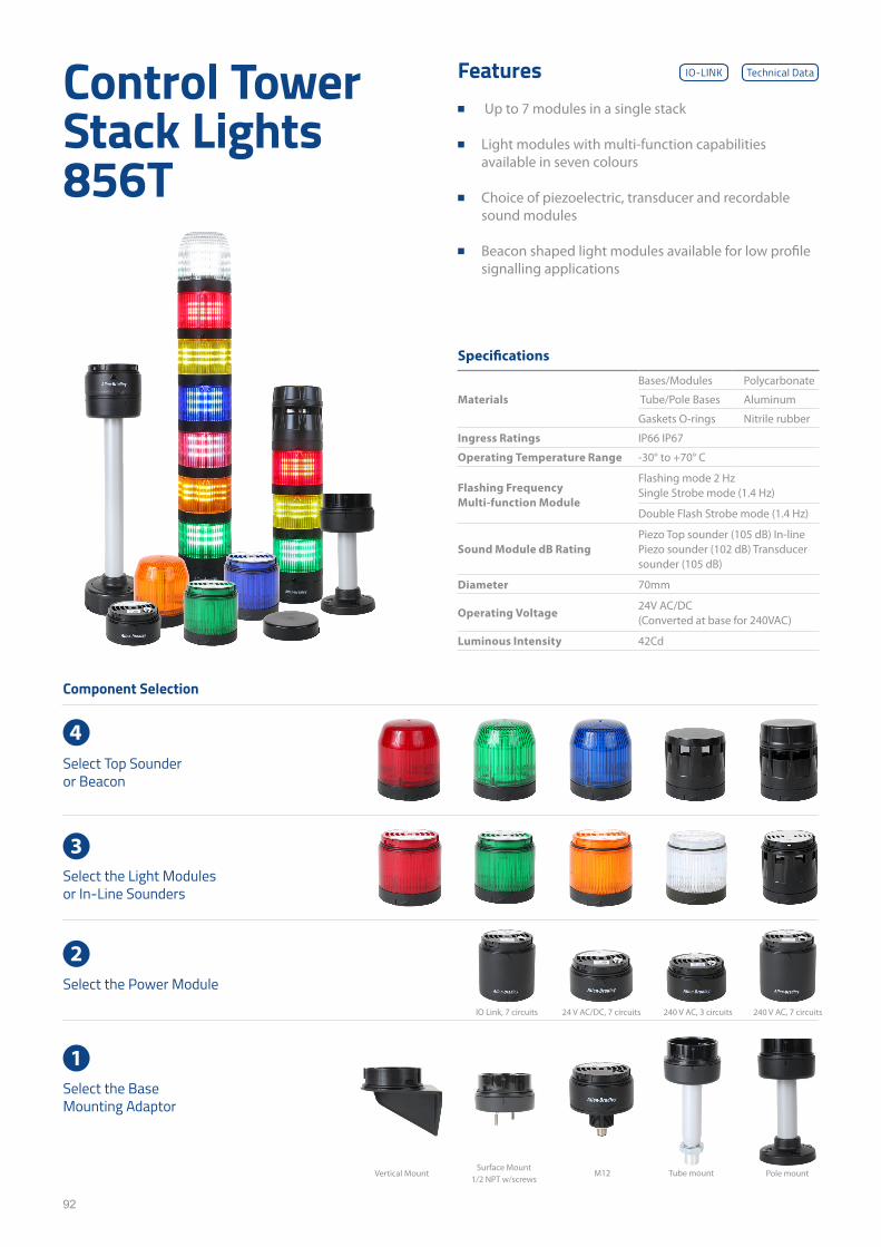
92
Control Tower Stack Lights 856T
Features ■ Up to 7 modules in a single stack
■ Light modules with multi-function capabilities available in seven colours
■ Choice of piezoelectric, transducer and recordable sound modules
■ Beacon shaped light modules available for low profile signalling applications
Specifications
Materials
Bases/Modules Polycarbonate
Tube/Pole Bases Aluminum
Gaskets O-rings Nitrile rubber
Ingress Ratings IP66 IP67
Operating Temperature Range -30° to +70° C
Flashing Frequency Multi-function Module
Flashing mode 2 Hz Single Strobe mode (1.4 Hz)
Double Flash Strobe mode (1.4 Hz)
Sound Module dB RatingPiezo Top sounder (105 dB) In-line Piezo sounder (102 dB) Transducer sounder (105 dB)
Diameter 70mm
Operating Voltage24V AC/DC (Converted at base for 240VAC)
Luminous Intensity 42Cd
Component Selection
Select Top Sounder or Beacon
4
Select the Light Modules or In-Line Sounders
3
Select the Power Module
2
Select the Base Mounting Adaptor
1
Pole mount
240 V AC, 7 circuits IO Link, 7 circuits 240 V AC, 3 circuits 24 V AC/DC, 7 circuits
Tube mountM12Surface Mount
1/2 NPT w/screws Vertical Mount
Technical DataIO-LINK
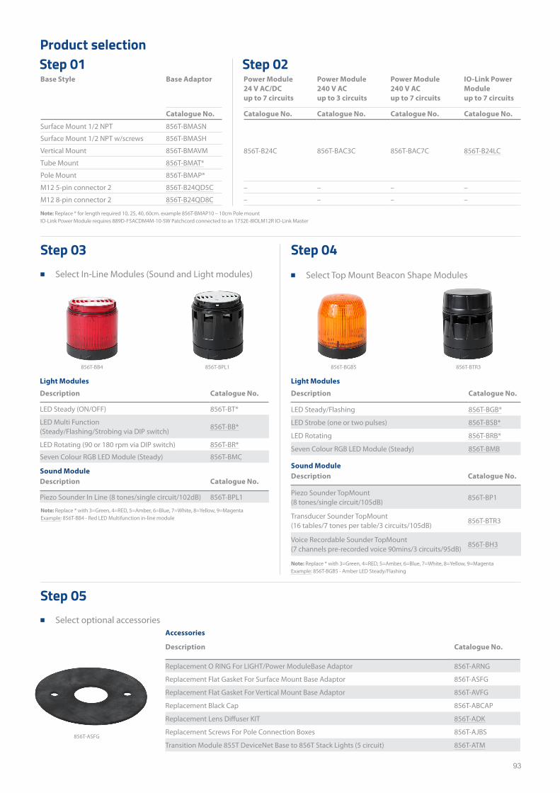
93
Base Style Base Adaptor Power Module 24 V AC/DC up to 7 circuits
Power Module 240 V AC up to 3 circuits
Power Module 240 V AC up to 7 circuits
IO-Link Power Module up to 7 circuits
Catalogue No. Catalogue No. Catalogue No. Catalogue No. Catalogue No.
Surface Mount 1/2 NPT 856T-BMASN
856T-B24C 856T-BAC3C 856T-BAC7C 856T-B24LC
Surface Mount 1/2 NPT w/screws 856T-BMASH
Vertical Mount 856T-BMAVM
Tube Mount 856T-BMAT*
Pole Mount 856T-BMAP*
M12 5-pin connector 2 856T-B24QD5C – – – –
M12 8-pin connector 2 856T-B24QD8C – – – –
Product selectionStep 01 Step 02
Note: Replace * for length required 10, 25, 40, 60cm. example 856T-BMAP10 – 10cm Pole mount IO-Link Power Module requires 889D-F5ACDM4M-10-SW Patchcord connected to an 1732E-8IOLM12R IO-Link Master
Note: Replace * with 3=Green, 4=RED, 5=Amber, 6=Blue, 7=White, 8=Yellow, 9=Magenta Example: 856T-BB4 - Red LED Multifunction in-line module
Note: Replace * with 3=Green, 4=RED, 5=Amber, 6=Blue, 7=White, 8=Yellow, 9=Magenta Example: 856T-BGB5 - Amber LED Steady/Flashing
Light Modules
Description Catalogue No.
LED Steady (ON/OFF) 856T-BT*
LED Multi Function (Steady/Flashing/Strobing via DIP switch)
856T-BB*
LED Rotating (90 or 180 rpm via DIP switch) 856T-BR*
Seven Colour RGB LED Module (Steady) 856T-BMC
Light Modules
Description Catalogue No.
LED Steady/Flashing 856T-BGB*
LED Strobe (one or two pulses) 856T-BSB*
LED Rotating 856T-BRB*
Seven Colour RGB LED Module (Steady) 856T-BMB
Sound ModuleDescription Catalogue No.
Piezo Sounder In Line (8 tones/single circuit/102dB) 856T-BPL1
Sound ModuleDescription Catalogue No.
Piezo Sounder TopMount (8 tones/single circuit/105dB)
856T-BP1
Transducer Sounder TopMount (16 tables/7 tones per table/3 circuits/105dB)
856T-BTR3
Voice Recordable Sounder TopMount(7 channels pre-recorded voice 90mins/3 circuits/95dB)
856T-BH3
Step 03 ■ Select In-Line Modules (Sound and Light modules)
Step 05 ■ Select optional accessories
Step 04 ■ Select Top Mount Beacon Shape Modules
Accessories
Description Catalogue No.
Replacement O RING For LIGHT/Power ModuleBase Adaptor 856T-ARNG
Replacement Flat Gasket For Surface Mount Base Adaptor 856T-ASFG
Replacement Flat Gasket For Vertical Mount Base Adaptor 856T-AVFG
Replacement Black Cap 856T-ABCAP
Replacement Lens Diffuser KIT 856T-ADK
Replacement Screws For Pole Connection Boxes 856T-AJBS
Transition Module 855T DeviceNet Base to 856T Stack Lights (5 circuit) 856T-ATM856T-ASFG
856T-BB4 856T-BPL1 856T-BGB5 856T-BTR3
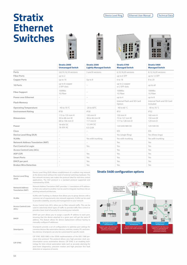
94
Stratix Ethernet Switches
Stratix 2000Unmanaged Switch
Stratix 2500Lightly Managed Switch
Stratix 5700Managed Switch
Stratix 5400Managed Switch
Ports 5,8,10,16,18 versions 5 and 8 versions 6,10,18,20 versions 8,12,16,20 versions
Fiber Ports up to 2 - up to 6 SFP up to 12 SFP
Copper Ports up to 16 Up to 8 6 to 18 8 to 20
1G Portsup to 8 copper2 SFP slots –
up to 2 copper or 2 SFP slots
up to all
Fiber Support100Mbs1G Fiber –
100Mbs1G Fiber
100Mbs1G Fiber
Power over Ethernet – – up to 4 up to 8
Flash Memory – –Internal Flash and SD CardOption
Internal Flash and SD Card Included
Operating Temperature -40 to 70 °C -20 to 60°C -40 to 60 ˚C -40 to 70 ˚C
Environment Rating IP30 IP30 IP31 IP32
Dimensions115 to 135 mm H30 to 88 mm W68 to 106 mm D
130 mm H38 to 46 mm W117 mm D
130 mm H75 to 127 mm W117 to 128 mm D
160 mm H150 mm W129 mm D
Power18-60V DC18-30V AC
12-24V DC0.3-2.0A
12V/24V/48V DC 12V-54V DC
Cisco – – IOS IOS
Device Level Ring (DLR) – – Yes (single Ring) Yes (three rings)
VLANs – Yes with trunking Yes with trunking Yes with trunking
Network Address Translation (NAT) – – Yes Yes
Port Control in Logix – Yes Yes Yes
Access Control Lists (ACL) – – Yes Yes
AOP (CIP) – Yes Yes Yes
Smart Ports – Yes Yes Yes
DHCP per port – Yes Yes Yes
Broken Wire Detection – Yes Yes Yes
Device Level Ring (DLR)
Device Level Ring (DLR) Allows establishment of a resilient ring network at the device level without the need of external switching hardware. The fast network recovery rate makes the protocol ideal for real-time control applications. The DLR protocol is a standard protocol supported and maintained by ODVA.
Network Address Translation (NAT)
Network Address Translation (NAT) provides 1:1 translations of IP address-es from one subnet to another. Can be used to integrate machines into an existing network architecture.
VLANsVLANs with Trunking is a feature that allows you to group devices with a common set of requirements into network segments. VLANs can be used to provide scalability, security and management to your network
Access Control Lists (ACL)
Access Control Lists (ACL) allow you to filter network traffic. This can be used to selectively block types of traffic to provide traffic flow control or provide a basic level of security for accessing your network.
DHCP
DHCP per port allows you to assign a specific IP address to each port, ensuring that the device attached to a given port will get the same IP address. This feature allows for device replacement without having to manually configure IP addresses.
SmartportsSmartports provide a set of configurations to optimize port settings for common devices like automation devices, switches, routers, PCs and wire-less devices. Smartports can also be customized for specific needs
CIP SYNC
CIP SYNC (IEEE1588) is the ODVA implementation of the IEEE 1588 pre-cision time protocol. This protocol allows very high precision clock syn-chronization across automation devices. CIP SYNC is an enabling tech-nology for time-critical automation tasks such as accurate alarming for post-event diagnostics, precision motion and high precision first fault detection or sequence of events
Ethernet User ManualDevice Level Ring Technical Data
ST
ST
DIAGNOSTIC
OK
0 1 2 3 4 5 6 7
8 9 101112131415
AC OUTPUT
ST
ST
DIAGNOSTIC
OK
0 1 2 3 4 5 6 7
8 9 101112131415
AC INTPUT
LINK HART
MOD POWER
SA POWER
ADAPTER
5069-AENTR
1
OK
NET
LINK 1
LINK 2
2
Compact I/O™
ModNet5700
ModNet5700
ModNet5700
ModNet5700
ModNet570 0
ModNet5700
ModuleStatus
NetworkActivity
NetworkStatus
1734-AENT
Point BusStatus
SystemPower
FieldPower
ModuleStatus
NetworkActivity
NetworkStatus
1734-AENT
Point BusStatus
SystemPower
FieldPower
MOD POWER
SA POWER
ADAPTER
5069-AENTR
1
OK
NET
LINK 1
LINK 2
2
Compact I/O™
MOD POWER
SA POWER
ADAPTER
5069-AENTR
1
OK
NET
LINK 1
LINK 2
2
Compact I/O™
All Gigabit Ethernet Architectures
Supports Layer 2 GE switching for high speed interface to high
performance end devices.
Dual GE switch ring for network residency with media redundancy.
Integrated DLR with three-ring support for expanded device
connectivity and high performance resiliency.
Dual GE Switch Ring Architectures
Plant-wide Site-wide
Operation systems
Integrated DLR Architectures
DLR
DLR
DLR
REP
Layer 3 GE routing for
high performance network architectures.
Stratix 5400 configuration options
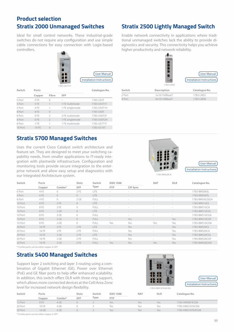
95
Product selectionStratix 2000 Unmanaged SwitchesIdeal for small control networks. These industrial-grade switches do not require any configuration and use simple cable connections for easy connection with Logix-based controllers.
Stratix 2500 Lightly Managed SwitchEnable network connectivity in applications where tradi-tional unmanaged switches lack the ability to provide di-agnostics and security. This connectivity helps you achieve higher productivity and network reliability.
Stratix 5400 Managed SwitchesSupport layer 2 switching and layer 3 routing using a com-bination of Gigabit Ethernet (GE), Power over Ethernet (PoE) and GE fiber ports to help offer enhanced scalability. In addition, this switch offers DLR with three-ring support, which allows more connected devices at the Cell/Area Zone level for increased network design flexibility.
Stratix 5700 Managed SwitchesUses the current Cisco Catalyst switch architecture and feature set. They are designed to meet your switching ca-pability needs, from smaller applications to IT-ready inte-gration with plantwide infrastructure. Configuration and monitoring tools provide secure integration to the enter-prise network and allow easy setup and diagnostics with our Integrated Architecture system.
Switch Ports Catalogue No.
Copper Fibre SFP
5 Port 5 FE 0 – 1783-US5T5 Port 5 FE 1 1 FE multimode 1783-US4T1F5 Port 4 FE 1 1 FE singlemode 1783-US4T1H8 Port 8 FE 0 – 1783-US8T8 Port 6 FE 2 2 FE multimode 1783-US6T2F8 Port 6 FE 2 1 FE singlemode 1783-US6T2H8 Port 7 FE 1 1 FE multimode 1783-US7T1F16 Port 16 FE 0 – 1783-US16T
Switch Ports Slots Switch Type
IEEE 1588 NAT DLR Catalogue No.
Copper Combo* SFP PTP CIP Sync6 Port 4 FE 0 2 FE LITE - - - - 1783-BMS06SL6 Port 6 FE 0 0 LITE - - - - 1783-BMS06TL6 Port 4 FE 0 2 GE FULL - - - - 1783-BMS4S2SGA10 Port 8 FE 2 FE 0 LITE - - - - 1783-BMS10CL10 Port 8 FE 2 FE 0 FULL - - - - 1783-BMS10CA10 Port 8 FE 2 GE 0 LITE - - - - 1783-BMS10CGL10 Port 8 FE 2 GE 0 FULL - - - - 1783-BMS10CGA10 Port 8 FE 2 GE 0 FULL - Yes - Yes 1783-BMS10CGP10 Port 8 FE 2 GE 0 FULL Yes Yes Yes Yes 1783-BMS10CGN20 Port 16 FE 2 FE 2 FE LITE - Yes - Yes 1783-BMS20CL20 Port 16 FE 2 FE 2 FE FULL - Yes - Yes 1783-BMS20CA20 Port 16 FE 2 GE 2 FE LITE - Yes - Yes 1783-BMS20CGL20 Port 16 FE 2 GE 2 FE FULL - Yes - Yes 1783-BMS20CGP20 Port 16 FE 2 GE 2 FE FULL Yes Yes Yes Yes 1783-BMS20CGN
Switch Ports Slots Switch Type
IEEE 1588 NAT DLR Catalogue No.
Copper Combo* SFP PTP12 Port 8 FE 4 GE 0 2 Yes Yes Yes 1783-HMS8T4CGN20 Port 16 FE 4 GE 0 2 Yes Yes Yes 1783-HMS16T4CGN20 Port 16 GE 4 GE 0 2 Yes Yes Yes 1783-HMS16TG4CGN
Switch Description Catalogue No.
5 Port 5x10/100BaseT 1783-LMS58 Port 8x10/100BaseT 1783-LMS8
1783-US7T1F 1783-LMS5
1783-HMS16TG4CGN
1783-BMS20CA
* Combo ports can be either copper or SFP
* Combo ports can be either copper or SFP
User Manual User Manual
User Manual
User Manual
Installation Instructions Installation Instructions
Installation Instructions
Installation Instructions
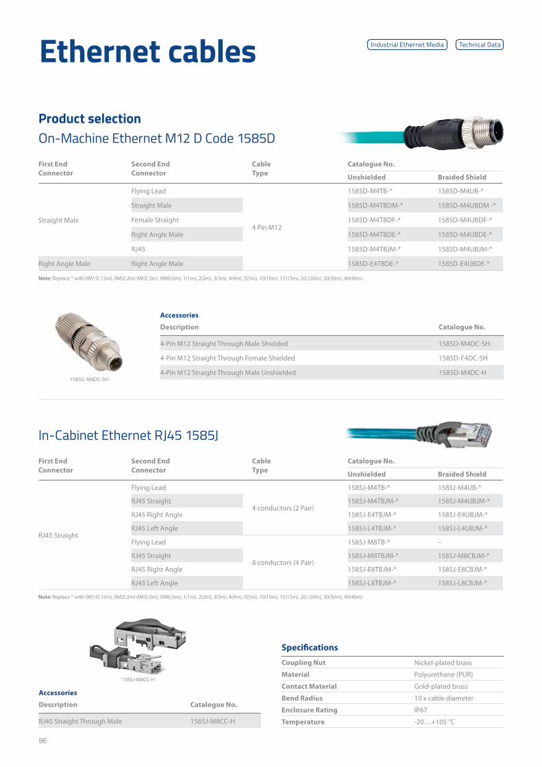
96
Specifications
Coupling Nut Nickel-plated brass
Material Polyurethane (PUR)
Contact Material Gold-plated brass
Bend Radius 10 x cable diameter
Enclosure Rating IP67
Temperature -20…+105 °C
Accessories
Description Catalogue No.
RJ45 Straight Through Male 1585J-M8CC-H
1585J-M8CC-H
1585D-M4DC-SH
In-Cabinet Ethernet RJ45 1585J
Note: Replace * with 0M15(.15m), 0M2(.2m) 0M3(.3m), 0M6(.6m), 1(1m), 2(2m), 3(3m), 4(4m), 5(5m), 10(10m), 15(15m), 20, (20m), 30(30m), 40(40m)
Accessories
Description Catalogue No.
4-Pin M12 Straight Through Male Shielded 1585D-M4DC-SH
4-Pin M12 Straight Through Female Shielded 1585D-F4DC-SH
4-Pin M12 Straight Through Male Unshielded 1585D-M4DC-H
First End Connector
Second End Connector
Cable Type
Catalogue No.
Unshielded Braided Shield
Straight Male
Flying Lead
4 Pin M12
1585D-M4TB-* 1585D-M4UB-*
Straight Male 1585D-M4TBDM-* 1585D-M4UBDM -*
Female Straight 1585D-M4TBDF-* 1585D-M4UBDF-*
Right Angle Male 1585D-M4TBDE-* 1585D-M4UBDE-*
RJ45 1585D-M4TBJM-* 1585D-M4UBJM-*
Right Angle Male Right Angle Male 1585D-E4TBDE-* 1585D-E4UBDE-*
Note: Replace * with 0M15(.15m), 0M2(.2m) 0M3(.3m), 0M6(.6m), 1(1m), 2(2m), 3(3m), 4(4m), 5(5m), 10(10m), 15(15m), 20, (20m), 30(30m), 40(40m)
Ethernet cables
On-Machine Ethernet M12 D Code 1585DProduct selection
Technical DataIndustrial Ethernet Media
First End Connector
Second End Connector
Cable Type
Catalogue No.
Unshielded Braided Shield
RJ45 Straight
Flying Lead
4 conductors (2 Pair)
1585J-M4TB-* 1585J-M4UB-*
RJ45 Straight 1585J-M4TBJM-* 1585J-M4UBJM-*
RJ45 Right Angle 1585J-E4TBJM-* 1585J-E4UBJM-*
RJ45 Left Angle 1585J-L4TBJM-* 1585J-L4UBJM-*
Flying Lead
8 conductors (4 Pair)
1585J-M8TB-* –
RJ45 Straight 1585J-M8TBJM-* 1585J-M8CBJM-*
RJ45 Right Angle 1585J-E8TBJM-* 1585J-E8CBJM-*
RJ45 Left Angle 1585J-L8TBJM-* 1585J-L8CBJM-*
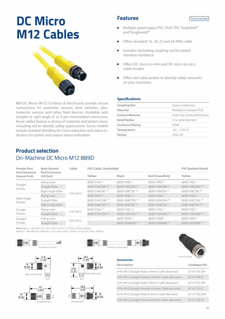
97
DC Micro M12 Cables
889 DC Micro (M12) Cordsets & Patchcords provide secure connections for proximity sensors, limit switches, pho-toelectric sensors and other field devices. Available with straight or right-angle 4- or 5-pin overmolded connectors, these cables feature a choice of materials and jacket colors, including red to identify safety applications. Some models include braided shielding for noise reduction and status in-dicators for power and output status indication.
Features ■ Multiple jacket types: PVC, PUR, TPE, Toughlink™
and Toughweld™
■ Offers standard 16, 18, 22 and 24 AWG cable
■ Includes ratcheting coupling nut for added vibration resistance
■ Offers DC micro-to-mini and DC micro-to-pico cable models
■ Offers red cable jackets to identify safety networks on your machines
Specifications
Coupling Nut Epoxy-coated zinc
Material Molded oil-resistant PUR
Contact Material Gold over nickel-plated brass
Bend Radius 10 x cable diameter
Enclosure Rating IP69K
Temperature -20…+105 °C
Rating 250V, 4A
Female First End Connector (Sensor End)
Male Second End Connector (I/O End)
Cable PVC Cable, Unshielded PVC Braided Shield
Yellow Black Red (Guardlink) Yellow
Straight Female
Flying Lead
4 Pin M12
889D-F4AC-* 889D-F4BC-* 889D-F4NE-* 889D-F4EC-*Straight Male 889D-F4ACDM-** 889D-F4BCDM-** 889D-F4NEDM-** 889D-F4ECDM-**Right Angle Male 889D-F4ACDE-** 889D-F4BCDE-** 889D-F4NEDE-** 889D-F4ECDE-**
Right Angle Female
Flying Lead 889D-R4AC-* 889D-R4BC-* 889D-R4NE-* 889D-R4EC-*Straight Male 889D-R4ACDM-** 889D-R4BCDM-** 889D-R4NEDM-** 889D-R4ECDM-**Right Angle Male 889D-R4ACDE-** 889D-R4BCDE-** 889D-R4NEDE-** 889D-R4ECDE-**
Straight Female
Flying Lead5 Pin M12
889D-F5AC-* 889D-F5BC-2 889D-F5NC-* 889D-F5EC-*Straight Male 889D-F5ACDM-** 889D-F5BCDM-** 889D-F5NCDM-** 889D-F5ECDM-**
Straight Female
Flying Lead8 Pin M12
– 889D-F8AB-* 889D-F8NB-* 889D-F8FB-*Straight Male – 889D-F8ABDM-** 889D-F8NBDM-** 889D-F8FBDM-**
Note: Replace * with 0M3(.3m), 2(2m), 5(5m), 10(10m), 15(15m), 20(20m), 30(30m) Replace ** with 0M3(.3m), 0M6(.6m), 1(1m), 2(2m), 5(5m), 10(10m), 15(15m), 20, (20m), 30(30m)
Accessories
Description Catalogue No.
4-Pin M12 Straight Male (4-6mm Cable diameter) 871A-TS4-DM
4-Pin M12 Straight Female (4-6mm Cable diameter) 871A-TR4-D
5-Pin M12 Straight Male (4-6mm Cable diameter) 871A-TS5-DM
5-Pin M12 Straight Female (4-6mm Cable diameter) 871A-TS5-D
8-Pin M12 Straight Male (6-8mm Cable diameter) 871A-TS8-DM1
8-Pin M12 Straight Female (6-8mm Cable diameter) 871A-TS8-D1
31.8(1.25)
14(0.56)
34.3(1.35)
31.8(1.25)
14(0.56)
47(1.85)
14(0.56)
50.8(2.0)
14(0.56)
Example of Cordset
Straight female
Right angle maleRight angle female
Straight male
Example of Patchcord
871A-TS4-DM
On-Machine DC Micro M12 889DProduct selection
Technical Data
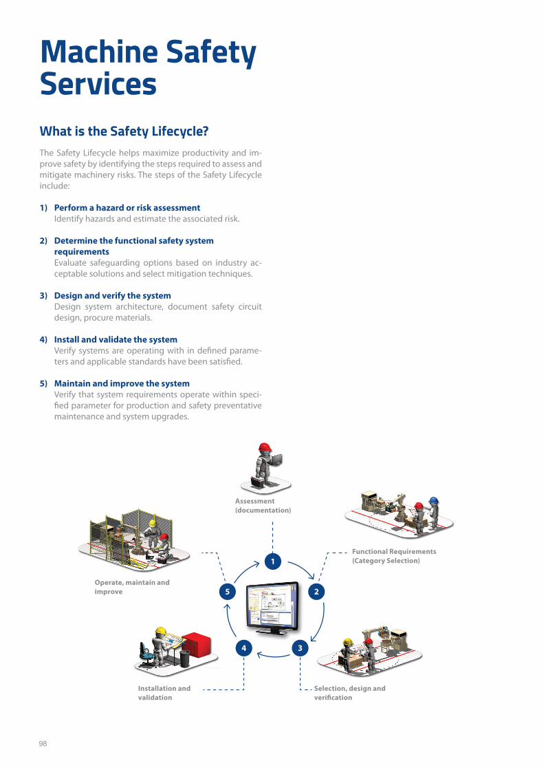
98
Machine Safety ServicesWhat is the Safety Lifecycle?The Safety Lifecycle helps maximize productivity and im-prove safety by identifying the steps required to assess and mitigate machinery risks. The steps of the Safety Lifecycle include:
1) Perform a hazard or risk assessmentIdentify hazards and estimate the associated risk.
2) Determine the functional safety system requirements Evaluate safeguarding options based on industry ac-ceptable solutions and select mitigation techniques.
3) Design and verify the systemDesign system architecture, document safety circuit design, procure materials.
4) Install and validate the systemVerify systems are operating with in defined parame-ters and applicable standards have been satisfied.
5) Maintain and improve the systemVerify that system requirements operate within speci-fied parameter for production and safety preventative maintenance and system upgrades.
Assessment (documentation)
Functional Requirements (Category Selection)
Selection, design and verification
Installation and validation
Operate, maintain and improve
1
25
34
99
Scalable Assessment SolutionsNHP, an Australian owned company providing power/control solutions for over 50 years, has the experience and expertise to provide you with the most appropriate audit solution for your application and can assist with:
■ Reducing unscheduled downtime
■ Stabilising maintenance budgets
■ Maximising productivity
■ Improving security and safety
■ Increase reliability Contact your local sales representative or the NHP Services and Training team for more details. Better understand and pinpoint your lifecycle risk through a comprehensive analysis of your critical plant assets and their condition
Product selectionDescription Catalogue No.
Audit On-Site Rockwell Machine Safety SAT-AUD-R02
Scalable Assessment SolutionsConformity Audits Guarding Evaluation Risk Assessments
Multiple machines/ plant-wide machine audit
Identifies primary guarding hazards
Risk Assessment or Team-Based Risk Assessment (TBRA)
Provides a high-level analysis of specific safety areas
Identifies guarding hazards for immediate plant actions
Risk Assessment – provides analysis using limited customer personnel
Team-Based Risk Assessment – In-depth analysis from a multidisciplinary team, required for critical or complex machines
Provides a high-level safety analysis of machine:• Conformity audit that analyses
guarding, components that perform a safety function, E-stops, lockout/tagout and/or isolation devices are identified and labelled
• Existing safety circuit estimation
• Prioritizes machines for further assessment
Provides a rapid approach to identifying point-of-operation and power transmission hazards and identifying appropriate and effective safeguarding measures for reducing risk and exposure
Generates report identifying:• Hazard exposure
• Category/performance level per standards
• Potential safeguard or risk miti-gation solution
Risk Assessment (Standard):• Evaluation by Rockwell Automation safety engineer/consultant, limited
customer involvement (typically operations/maintenance)
• Evaluation report includes: – Documentation of participants – Identification of primary hazards/tasks – Risk-in/risk-out rating – Recommendations for safety improvements, such as: protective
guarding; electrical safety controls; pneumatic/fluid power safety controls
• Safety circuit performance requirements
• Photograph of critical identified hazards (based on customer approval)
Team-based Risk Assessment: All features of the standard Risk Assessment (above) with the following additional features:• Team-based assessment facilitated by Rockwell Automation safety
engineer/consultant
• Customer team typically consists of operations, maintenance, engineering, technicians, cleaning, sanitation and safety personnel
• Basic risk assessment training
• Hazard identification during setup, normal and abnormal operation, sanitation/cleaning, maintenance (under limited energy), emergency conditions
• Report documentation includes all elements from safety evaluation with additional information:
– Plan view machine layout with recommended safety improvements – Limits of machine – Incident/accident history – This service can satisfy the risk assessment requirements of safety
standards

100
Product selectionDescription Catalogue No.
Training Rockwell TUV Functional Safety Technician SAF-TUV0T
SAF-TUV0T – Functional Safety for Machinery Technician Certification Course
Course Purpose
The standards regarding functional safety and relevant laws and directives demand that people and organiza-tions performing responsible tasks during relevant life cy-cle phases of a machine must achieve and prove required competencies.
In this training, students will learn how the current standards dictate the selection, assembly, installation, validation, and maintenance of safety devices and components to reduce hazards from machinery and ensure the safety of people and the environment. Practical examples will demonstrate possibilities regarding machine protection.
This training will also cover safety topics, such as: redun-dancy, testing, distance calculations, assigning required level of risk reduction as PL, monitoring moveable guard positions, and fault avoidance for relevant life cycle phases.
After completing this course, students should understand and be able to use ISO 12100, IEC 60204-1 and other rele-vant machine functional safety standards.
Who Should Attend
Machine technicians, application engineers, safety specia-lists, and those responsible for repairing and maintaining machine safety should attend this course.
Certificate Eligibility Requirements
Requirements to receive the Functional Safety for Machi-nery Technician Certificate (TÜV Rheinland):
■ Before taking the course, an eligibility form from TÜV Rheinland must be completed and approved, proving:
– Minimum of 1 year experience working on industrial machinery
– Documented education, high school diploma or global equivalent or
– Experience in machinery maintenance and operation verified by employer
■ Attended complete two-day course
■ Passing grade of 75% or higher on the exam
Course AgendaDay 1
■ Understanding the Functional Safety for Machinery Technician Certification (TÜV Rheinland)
■ Defining Legal Guidelines and Standards ■ Defining Risk Analysis and Processes(ISO 12100:2010) ■ Defining Basic Electrical Safety Principles (IEC 60204-1) ■ Defining Basic Safety Principles ■ Defining Machine Guarding Principles
Day 2
■ Identifying Safety Functions ■ Identifying Safety Devices ■ Identifying Circuits, Schematics, and Examples ■ Defining New Standards Regarding Safety of
Machinery ■ Evaluating Machine Safety Using a Practical Example ■ Exam (1 hour)

101
Product selectionDescription Catalogue No.
TÜV Functional Safety for Machinery - Introduction SAF-TUV1
SAF-TUV1 – Functional Safety for Machinery Introduction Course
Course Purpose
This is an introduction to functional safety for machinery standards and is highly recommended to prepare students for the Rockwell Automation/TÜV Rheinland engineer cer-tification course.
This course will define the design and proof requirements for functional safety of machines, according to current standards and guidelines. Practical examples will demon-strate possible techniques for machine guarding and pro-tection.
This course will also introduce organizational measures that can be instituted to protect employees and equip-ment. The organizational measures include quality assur-ance techniques and documentation for lifecycle design and validation.
After completing this course, you should understand how safety devices and components are assembled and applied to reduce hazards from machinery so the necessary safety for people and the environment is achieved.
Who Should Attend
Application engineers, system integrators, developers, safe-ty specialists, and authorized experts in machinery should attend this course.
Standards Required
■ IEC 60204-1 ■ IEC 62061 ■ ISO 12100: 2010 ■ ISO 13849 part 1 and part 2
Course AgendaDay 1
■ Understanding the Functional Safety for Machinery Certification (TÜV Rheinland)
■ Defining European Guidelines and Requirements ■ Defining OSHA Guidelines and Requirements ■ Defining Risk Analysis and Processes (ISO 12100:2010) ■ Defining ISO 13849-1 ■ Identifying Safety Devices
Day 2
■ Identifying Safety Functions of Machines ■ Identifying Circuits, Schematics, and Examples ■ Defining New Standards Regarding Safety of
Machinery
Day 3
■ Defining ISO 13849-1/2 ■ Defining IEC 62061 ■ Defining Basic Electrical Safety Principles (IEC 60204-1) ■ Performing ISO 13849/IEC 62061 calculations
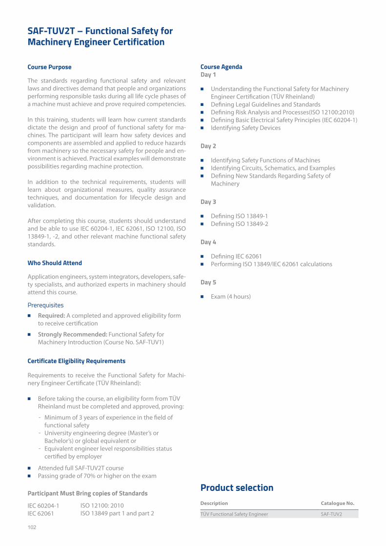
102
Product selectionDescription Catalogue No.
TÜV Functional Safety Engineer SAF-TUV2
SAF-TUV2T – Functional Safety for Machinery Engineer Certification
Course Purpose
The standards regarding functional safety and relevant laws and directives demand that people and organizations performing responsible tasks during all life cycle phases of a machine must achieve and prove required competencies.
In this training, students will learn how current standards dictate the design and proof of functional safety for ma-chines. The participant will learn how safety devices and components are assembled and applied to reduce hazards from machinery so the necessary safety for people and en-vironment is achieved. Practical examples will demonstrate possibilities regarding machine protection.
In addition to the technical requirements, students will learn about organizational measures, quality assurance techniques, and documentation for lifecycle design and validation.
After completing this course, students should understand and be able to use IEC 60204-1, IEC 62061, ISO 12100, ISO 13849-1, -2, and other relevant machine functional safety standards.
Who Should Attend
Application engineers, system integrators, developers, safe-ty specialists, and authorized experts in machinery should attend this course.
Prerequisites ■ Required: A completed and approved eligibility form
to receive certification
■ Strongly Recommended: Functional Safety for Machinery Introduction (Course No. SAF-TUV1)
Certificate Eligibility Requirements
Requirements to receive the Functional Safety for Machi-nery Engineer Certificate (TÜV Rheinland):
■ Before taking the course, an eligibility form from TÜV Rheinland must be completed and approved, proving:
– Minimum of 3 years of experience in the field of functional safety
– University engineering degree (Master’s or Bachelor’s) or global equivalent or
– Equivalent engineer level responsibilities status certified by employer
■ Attended full SAF-TUV2T course ■ Passing grade of 70% or higher on the exam
Participant Must Bring copies of Standards
IEC 60204-1IEC 62061
Course AgendaDay 1
■ Understanding the Functional Safety for Machinery Engineer Certification (TÜV Rheinland)
■ Defining Legal Guidelines and Standards ■ Defining Risk Analysis and Processes(ISO 12100:2010) ■ Defining Basic Electrical Safety Principles (IEC 60204-1) ■ Identifying Safety Devices
Day 2
■ Identifying Safety Functions of Machines ■ Identifying Circuits, Schematics, and Examples ■ Defining New Standards Regarding Safety of
Machinery
Day 3
■ Defining ISO 13849-1 ■ Defining ISO 13849-2
Day 4
■ Defining IEC 62061 ■ Performing ISO 13849/IEC 62061 calculations
Day 5
■ Exam (4 hours)
ISO 12100: 2010ISO 13849 part 1 and part 2

103
This page has been left intentionally blank

104
nhp.com.auSALES 1300 NHP NHP
nhp-nz.comSALES 0800 NHP NHP
NHP Electrical Engineering Products
A.B.N. 84 004 304 812
© COPYRIGHT NHP 2020
NHP12BCH 03/21
Related Documents