Smart JVA Module For use with AquaLink ® RS systems with rev R firmware or newer. H0370200 Rev C INStALLAtIoN ANd oPERAtIoN MANuAL WARNING FOR YOUR SAFETY - This product must be installed and serviced by a contractor who is licensed and qualified in pool equipment by the jurisdiction in which the product will be installed where such state or local requirements exist. The maintainer must be a professional with sufficient experience in pool equipment installation and maintenance so that all of the instructions in this manual can be followed exactly. Before installing this product, read and follow all warning notices and instructions that accompany this product. Failure to follow warning notices and instructions may result in property damage, personal injury, or death. Improper installation and/or operation will void the warranty. Improper installation and/or operation can create unwanted electrical hazard which can cause serious injury, property damage, or death.

Welcome message from author
This document is posted to help you gain knowledge. Please leave a comment to let me know what you think about it! Share it to your friends and learn new things together.
Transcript

Smart JVA Module
For use with AquaLink® RS systems with rev R firmware or newer.
H03
7020
0 R
ev C
INStALLAtIoN ANd oPERAtIoN MANuAL
WARNINGFOR YOUR SAFETY - This product must be installed and serviced by a contractor who is licensed and qualified in pool equipment by the jurisdiction in which the product will be installed where such state or local requirements exist. The maintainer must be a professional with sufficient experience in pool equipment installation and maintenance so that all of the instructions in this manual can be followed exactly. Before installing this product, read and follow all warning notices and instructions that accompany this product. Failure to follow warning notices and instructions may result in property damage, personal injury, or death. Improper installation and/or operation will void the warranty.Improper installation and/or operation can create unwanted electrical hazard which can cause serious injury, property damage, or death.

Page 2 ENGLISH Smart JVA Module | Installation and Operation Manual

Table of Contents
Section 1. Important Safety Instructions ........ 5
Section 2. System overview ............................ 7
2.1 SmartJVAModule.............................................. 7
Section 3. SMARt JVA/AquaLink® RS Interface Installation ....................... 7
3.1 PowerCenterBezelInstallation......................... 73.2 Low-VoltageRacewayInstallation...................... 83.3 WiringtheSMARTJVA/AquaLinkRS
Interface............................................................. 8
Section 4. SMARt JVA/AquaLink RS Interface onetouchtM Set up ....... 10
4.1 SmartJVAModuleSetUp................................ 10
Page 3 ENGLISH Smart JVA Module | Installation and Operation Manual

Page 4 ENGLISH Smart JVA Module | Installation and Operation Manual
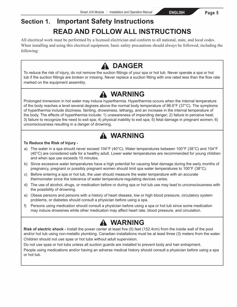
Section 1. Important Safety Instructions
REAd ANd FoLLoW ALL INStRuCtIoNSAll electrical work must be performed by a licensed electrician and conform to all national, state, and local codes. When installing and using this electrical equipment, basic safety precautions should always be followed, including the following:
WARNINGProlongedimmersioninhotwatermayinducehyperthermia.Hyperthermiaoccurswhentheinternaltemperatureofthebodyreachesalevelseveraldegreesabovethenormalbodytemperatureof98.6°F(37°C).Thesymptomsofhyperthermiaincludedizziness,fainting,drowsiness,lethargy,andanincreaseintheinternaltemperatureofthebody.Theeffectsofhyperthermiainclude:1)unawarenessofimpendingdanger;2)failuretoperceiveheat;3)failuretorecognizetheneedtoexitspa;4)physicalinabilitytoexitspa;5)fetaldamageinpregnantwomen;6)unconsciousnessresultinginadangerofdrowning.
dANGERToreducetheriskofinjury,donotremovethesuctionfittingsofyourspaorhottub.Neveroperateaspaorhottubifthesuctionfittingsarebrokenormissing.Neverreplaceasuctionfittingwithoneratedlessthantheflowratemarkedontheequipmentassembly.
WARNINGto Reduce the Risk of Injury -
a) Thewaterinaspashouldneverexceed104°F(40°C).Watertemperaturesbetween100°F(38°C)and104°F(40°C)areconsideredsafeforahealthyadult.Lowerwatertemperaturesarerecommendedforyoungchildrenandwhenspauseexceeds10minutes.
b) Sinceexcessivewatertemperatureshaveahighpotentialforcausingfetaldamageduringtheearlymonthsofpregnancy,pregnantorpossiblypregnantwomenshouldlimitspawatertemperaturesto100°F(38°C).
c) Beforeenteringaspaorhottub,theusershouldmeasurethewatertemperaturewithanaccuratethermometersincethetoleranceofwatertemperature-regulatingdevicesvaries.
d) Theuseofalcohol,drugs,ormedicationbeforeorduringspaorhottubusemayleadtounconsciousnesswiththepossibilityofdrowning.
e) Obesepersonsandpersonswithahistoryofheartdisease,loworhighbloodpressure,circulatorysystemproblems,ordiabetesshouldconsultaphysicianbeforeusingaspa.
f) Personsusingmedicationshouldconsultaphysicianbeforeusingaspaorhottubsincesomemedicationmayinducedrowsineswhileothermedicationmayaffectheartrate,bloodpressure,andcirculation.
WARNINGRisk of electric shock - Installthepowercenteratleastfive(5)feet(152.4cm)fromtheinsidewallofthepooland/orhottubusingnon-metallicplumbing.Canadianinstallationsmustbeatleastthree(3)metersfromthewater.Childrenshouldnotusespasorhottubswithoutadultsupervision.Donotusespasorhottubsunlessallsuctionguardsareinstalledtopreventbodyandhairentrapment.Peopleusingmedicationsand/orhavinganadversemedicalhistoryshouldconsultaphysicianbeforeusingaspaorhottub.
Page 5 ENGLISH Smart JVA Module | Installation and Operation Manual

CAutIoNAground-faultcircuit-interruptermustbeprovidedifthisdeviceisusedtocontrolunderwaterlightingfixtures.Theconductorsontheloadsideoftheground-faultcircuit-interruptershallnotoccupyconduit,boxes,orenclosurescontainingotherconductorsunlesstheadditionalconductorsarealsoprotectedbyaground-faultcircuit-interrupter.Refertolocalcodesforcompletedetails.
CAutIoNAterminalbarmarked"GROUND"isprovidedwithinthepowercenter.Toreducetheriskofelectricalshock,connectthisterminalbartothegroundingterminalofyourelectricserviceorsupplypanelwithacontinuouscopperconductorhavinggreeninsulationandonethatisequivalentinsizetothecircuitconductorssupplyingthisequipment,butnosmallerthanno.12AWG(3.3mm2).Inaddition,asecondwireconnectorshouldbebondedwithano.8AWG(8.4mm2)copperwiretoanymetalladders,waterpipes,orothermetalwithinfive(5)feet(1.52m)ofthetub.
SAVE tHESE INStRuCtIoNS
WARNINGPeoplewithinfectiousdiseasesshouldnotuseaspaorhottub.Toavoidinjury,exercisecarewhenenteringorexitingthespaorhottub.Donotusedrugsoralcoholbeforeorduringtheuseofaspaorhottubtoavoidunconsciousnessandpossibledrowning.Pregnantorpossiblypregnantwomenshouldconsultaphysicianbeforeusingaspaorhottub.Watertemperatureinexcessof100°F(38°C)maybeinjurioustoyourhealth.Beforeenteringaspaorhottubmeasurethewatertemperaturewithanaccuratethermometer.Donotuseaspaorhottubimmediatelyfollowingstrenuousexercise.Prolongedimmersioninaspaorhottubmaybeinjurioustoyourhealth.Donotpermitanyelectricappliance(suchasalight,telephone,radio,ortelevision)within5feet(1.5m)ofaspaorhottub.Theuseofalcohol,drugsormedicationcangreatlyincreasetheriskoffatalhyperthermiainhottubsandspas.Watertemperatureinexcessof100°F(38°C)maybehazardoustoyourhealth.
Attention installer: Installtoprovidedrainageofcompartmentforelectricalcomponents.
WARNINGToavoidinjuryensurethatyouusethiscontrolsystemtocontrolonlypackagedpool/spaheaterswhichhavebuilt-inoperatingandhighlimitcontrolstolimitwatertemperatureforpool/spaapplications.Thisdeviceshouldnotberelieduponasasafetylimitcontrol.
Page 6 ENGLISH Smart JVA Module | Installation and Operation Manual

Section 2. System overview
The Smart JVA Module is designed to control a standard JVA to adjust the amount of water flow to a water feature from any auxiliary.
The Smart JVA Module consists of one printed circuit assembly and can be mounted in any of these locations as best suited for your system:
(a) inside of the power center enclosure on the AquaLink® RS bezel assembly as a daughter card,
(b) or in the low-voltage raceway of the power center enclosure.
2.1 the Smart JVA Module Components
The package of the Smart JVA Module components (see Figure 1) include the following items:
1. A PCB Assembly mounted on a Mounting Bracket (Mounted at factory)
2. Two (2) Self-tapping Screws
Figure 1. Smart JVA Module Components
LED Light
Self-TappingScrew (2)
Mounting Bracket
Smart JVA Board
24 VACConnector from
Transformer
SJVA (JVA) Socket
Connector 2to Auxiliary Socket
Connector 124 VAC to AquaLink® Board
Section 3. Smart JVA Module Installation
WARNING
Risk of Electric Shock which can result In Serious Injury or death. Beforeattemptinginstallationorservice,ensurethatallpowertothecircuitsupplyingpowertothesystemisdisconnectedorturnedoffatthecircuitbreaker.
AllwiringmustbedoneinaccordancewiththeNationalElectricalCode®(NEC®),NFPA-70.InCanada,theCanadianElectricalCode®(CEC),CSAC22.1,mustbefollowed.Allapplicablelocalinstallationcodesandregulationsmustbefollowed.
3.1 Power Center Bezel Installation
NotE Ensurethatallcircuitssupplyingpowertopowercenterhavebeenturnedoffatthecircuitbreakers
1. Unscrew and remove the power center PCB and bezel assembly from the power center can as shown in Figure 2.
Figure 2. Installation of the Smart JVA Module on the Bezel Assembly
Bezel Assembly Daughter Card Mounting Area
Self-TappingScrew (2)
Power Center andBezel Assembly
4 3 2 1
4 3 2 1
6 5 4 3 2 110 9 8 7 6 5 4 3 2 1
Page 7 ENGLISH Smart JVA Module | Installation and Operation Manual

High Voltage
Low
Vol
tage
Rac
eway
Filter Pump Relay Aux. 3 Relay
S1
S2
RESET
SERVICE
TIME OUT
FILTER PUMP
AUX 1AUX 2
AUX 3AUX 4
AUX 5AUX 6
AUX 7
RS6 & RS8 ONLY RS8 ONLY
HEATER SOLAR
POOL MODE
SPA MODE
SPA DRAIN
SPA FILL
AUTO
6 5 4 3 2 1 10 9 8 7 6 5 4 3 2 14 3 2 1 4 3 2 1
Self-TappingScrew (2)
Figure 3. Installation of the Smart JVA Module board in the Low-Voltage Raceway
2. Secure the Smart JVA Module board and mounting bracket to the daughter card mounting area in the bezel assembly with the two self-tapping screws provided.
NotE MakesurethatthecomponentsideoftheSmartJVAModuleboardfacesleft.
3. Reinstall the power center PCB and bezel assembly in the power center enclosure using the screws previously removed.
3.2 Low-Voltage Raceway Installation
1. If the daughter card area is not available or if the slots on the bezel assembly are all used, install the mounting bracket and Smart JVA Module board in the low-voltage raceway of the power center.
2. Secure the Smart JVA Module board and mounting bracket inside of the power center enclosure in the low voltage raceway with the two self-tapping screws provided as shown in Figure 3.
3.3 Wiring the Smart JVA Module
WARNING
PotentiallyhighvoltagesintheAquaLink®RSpowercentercancreatedangerouselectricalhazards,possiblycausingdeath,seriousinjuryorpropertydamage.TurnoffpoweratthemaincircuitfeedingtheAquaLinkRSpowercentertodisconnectthepowercenterfromthesystem.
1. Disconnect power to the power center.
2. Connect the 24VAC from the Power Center transformer to the Smart JVA module.
3. Connect the 24VAC OUT wire harness from the Smart JVA module into the 24VAC input on the Power Center.
NotE Neverrunhighvoltageandlowvoltageinthesameconduit.
4. Plug the Smart JVA two wire harness into any available auxiliary.
5. Connect the cord from the JVA to the SJVA OUT port on the Smart JVA module.
6. Turn on the power to the Power Center
4 3 2 16 5 4 3 2 1
10 9 8 7 6 5 4 3 2 1
1
3
5
2
4
6
Page 8 ENGLISH Smart JVA Module | Installation and Operation Manual

Figure 4. Wiring Multiple Smart JVA Module Boards
4 3 2 1
4 3 2 1
6 5 4 3 2 110 9 8 7 6 5 4 3 2 1
JVA 2444MAXIMUM TORQUE
JVA 2444MAXIMUM TORQUE
JVA 2444MAXIMUM TORQUE
Standard JVA’s
Multiple Smart JVA wiring diagram
24V from transformer
Smart JVA Modules
24V fromSmart JVA toPower Center
3
5
2
4
Page 9 ENGLISH Smart JVA Module | Installation and Operation Manual

Section 4. Smart JVA Module onetouch™ Set upThe Smart JVA Module will operate with any AquaLink® RS control panel with Rev R or newer firmware, including the iAquaLink™, but can only be set up from the OneTouch control panel.
4.1 Smart JVA Module Set up
Starting at the HOME screen, navigate to the following screens.
MENU ➤ SYSTEM SETUP ➤ SMART JVA ➤ ASSIGN SMART JVA
4.1.1 Assign the Smart JVA
Scroll to the auxiliary port that the Smart JVA board is plugged in to and press SELECT.
ASSIGN SMART JVA ➤ AUX3 ➤
The Smart JVA is assigned when an X appears to the right of the auxiliary port. Press the BACK DONE button to return to the SMART JVA SETUP screen.
4.1.2 CALIBRAtE the Smart JVA
NOTE Turn off all equipment prior to Calibration. Calibration will take up to two minutes. During this time the filter pump and any water feature pump should be turned off.
From the SMART JVA SETUP screen, select CALIBRATE JVA.
CALIBRATE JVA ➤ AUX3 ➤ OK
JANDY AquaLink RS
FILTER PUMP OFFAIR 79°
06/02/03 MON6:00 PM
EQUIPMENT ON/OFF
MENU / HELPONETOUCH ON/OFF
MENU
HELPPROGRAMSET TEMPSET TIMEDISPLAY LIGHTLOCKOUTSPROGRAM GROUPSYSTEM SETUP
SYSTEM SETUP
SMART JVAiAquaLinkCover-PoolsONETOUCHLABEL AUXFREEZE PROTECTAIR TEMPSEASONAL ADJ
MORE Use ARROW KEYSto set value.Then SELECT.
SMART JVA SETUP
ADJUST JVAASSIGN SMART JVA
CALIBRATE JVA
ASSIGN SMART JVA
AUX1
BACKDONE
AUX2AUX3AUX4AUX5AUX6AUX7
X
ASSIGN SMART JVA
AUX1AUX2AUX3AUX4AUX5AUX6AUX7
Use ARROW KEYSto set value.Then SELECT.
SMART JVA SETUP
ADJUST JVAASSIGN SMART JVA
CALIBRATE JVA
CALIBRATESMART JVA
AUX3
Use ARROW KEYSto set value.Then SELECT.
SMART JVA SETUP
ADJUST JVAASSIGN SMART JVA
CALIBRATE JVA
WARNING
Calibration takes 2 minutes.No Smart JVA
operations can bemade during this time.
OKGO BACK
Page 10 ENGLISH Smart JVA Module | Installation and Operation Manual

4.1.3 AdJuSt the Smart JVA
From the SMART JVA SETUP screen, select ADJUST JVA.
ADJUST JVA ➤ AUX3 ➤ 50%
Note: A standard 180 degree rotation JVA will rotate 90 degrees when set to 50%. When the Smart JVA auxiliary is turned on or off, three asterics will flash indicating that the JVA is rotating to the next position.
BACKDONE
ADJUST SMART JVAPOSITION
AUX3 50%
ADJUST SMART JVAPOSITION
AUX3 50%
Use ARROW KEYSto set value.Then SELECT.
SMART JVA SETUP
ADJUST JVAASSIGN SMART JVA
CALIBRATE JVA
FILTER PUMP OFFSPA OFFPOOL HEAT OFFSPA HEAT OFFSOLAR HEAT OFFAUX1 OFFAUX2 OFFAUX3 OFFAUX4 OFFAUX5 OFFAUX6 OFF
MORE
FILTER PUMP OFFSPA OFFPOOL HEAT OFFSPA HEAT OFFSOLAR HEAT OFFAUX1 OFFAUX2 OFFAUX3 ONAUX4 OFFAUX5 OFFAUX6 OFF
MORE
FILTER PUMP OFFSPA OFFPOOL HEAT OFFSPA HEAT OFFSOLAR HEAT OFFAUX1 OFFAUX2 OFFAUX3 ***AUX4 OFFAUX5 OFFAUX6 OFF
MORE
For a 180° Jandy Valve, with the mechanical stops set at 0° & 180°, to open the valve to 45°, set the JVA to 25%...
Setting Valve Position
5% 9º
10% 18º
15% 27º
20% 36º
25% 45º
30% 54º
35% 63º
40% 72º
45% 81º
50% 90º
Setting Valve Position
55% 99º
60% 108º
65% 117º
70% 126º
75% 135º
80% 144º
85% 153º
90% 162º
95% 171º
100% 180º
➤ 50% x 180º = 90º
Page 11 ENGLISH Smart JVA Module | Installation and Operation Manual

Zodiac Group Australia, ABN 87 002 641 965, 219 Woodpark Rd, Smithfield NSW 2164, Australia
Zodiac Pool Systems, Inc. 2620 Commerce Way, Vista, CA 92081 1.800.822.7933 | www.ZodiacPoolSystems.com
ZODIAC® is a registered trademark of Zodiac International, S.A.S.U., used under license.All trademarks referenced herein are the property of their respective owners.
©2012 Zodiac Pool Systems, Inc. H0370200 Rev C 1210
Related Documents