WIRELESS NETWORKING ARCHITECTURE FOR SMART GRID APPLICATIONS

Welcome message from author
This document is posted to help you gain knowledge. Please leave a comment to let me know what you think about it! Share it to your friends and learn new things together.
Transcript

WIRELESS NETWORKING ARCHITECTURE FOR SMART GRID APPLICATIONS

CONTENTS
• Introduction
• Existing work
• Challenges
• Literature
• Objective
• Planned architecture
• References

INTRODUCTIONSMART GRID
•A smart grid is an electricity network that can intelligentlyintegrate the actions of all use connected to it – generators,
consumers and those that do both in order to efficiently deliversustainable economics and serve electricity supplies.
•It uses sensing embedded processing and digital communicationsto enable the electricity grid to be
Observable (able to be measure and visualized)
Controllable (able to be manipulated and optimized)
Automated (able to adapt and self-heal)
Fully integrated (fully interoperable with existing systems andwith the capacity to incorporate a divorce set of energy sources).
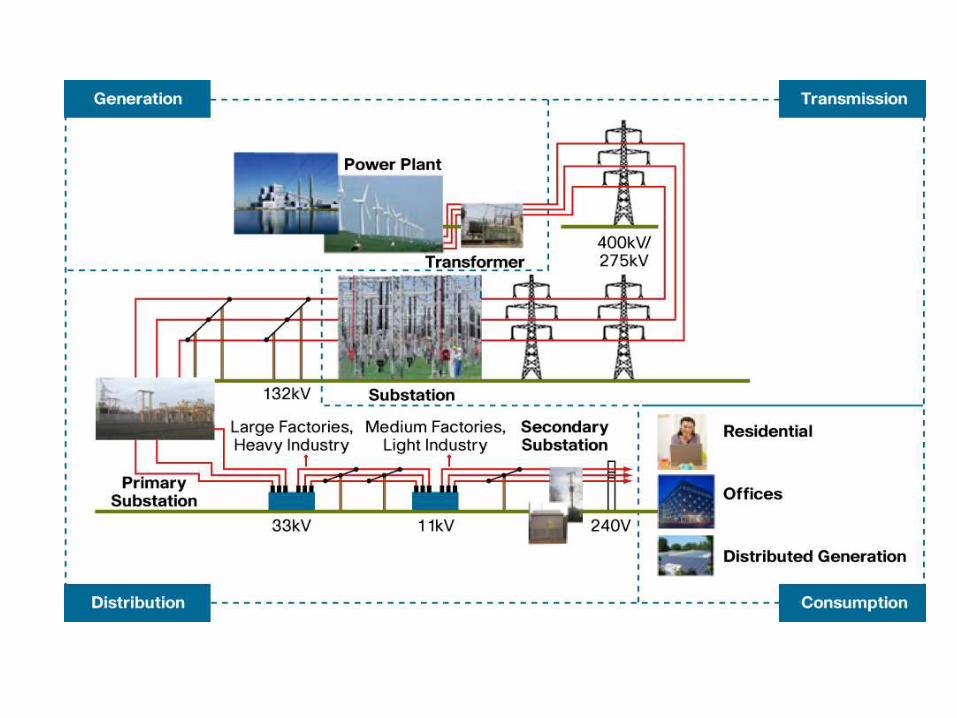

Different consumption areas
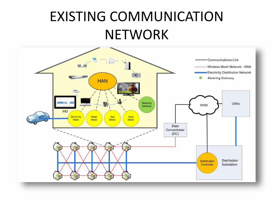
EXISTING COMMUNICATION NETWORK

Wireless Sensor Network• Communication via Zigbee protocol stack
– IEEE 802.15.4 standard• Low power
– Duty cycles• Low data rate
– Data rates of 250 kbps, 100kbps, 40 kbps and 20 kbps• Zigbee utilizes three ISM bands
– 2.4GHz ISM band worldwide , 915MHz band in North America, 868MHz band in Europe
• Zigbee uses 16-bit and 64-bit addressing modes– 6lowpan for IP integration
• Star, cluster-tree or mesh topologies

CHALLENGES
• Complexity• Efficiency
1) Better Telemetry2) Faster Controls3) More Robust Controls4) Embedded Intelligent Device Communications5) Integrated Communications6) Enhanced Computing Capabilities7)security
• Reliability• Enhanced Computing Capabilities

LITERATURE
WIRELESS SENSOR NETWORK VS
WIRELESS RELAY NETWORK
By introducing wireless relay network,
• Brings down the number of sensors in network.
• Reduced Power consumption.
• Node failures can be identified easily.
• Data of desired lane or avenue can be easily accessed.
• Low installation cost.

OBJECTIVE
The objective of this project is to accomplish a wireless relay in communication between sensor and control area network and
finding reliable link, when next hope node fails in communicating.

Architecture
Control Area Network
Main Relay
Sub-Relay (1)
Lane(1)
Sub-Relay (2)
Lane(2)
Sub-Relay (3)
Lane(3)

REFERENCES :1. Hossam M. H. Shalaby.” Performance Analysis of SAC-OCDMA SystemsAdopting Overlapping PPM
Schemes, “IEEE Trans.Commun., vol. 31, no. 12, June 2013.
2. Naser G. Tarhuni, “Multiclass Optical Orthogonal Codes for Multiservice Optical CDMA Networks,”IEEE Trans.Commun., vol. 24, no. 2, Feb 2006
3. H. M. H. Shalaby, “A Performance Analysis of Optical Overlapping PPM-CDMA CommunicationSystems,” J. Lightw. Technol., vol. 17, no. 3, pp. 426–433, Mar. 1999.
4. G -C. Yang, “Variable-Weight Optical Orthogonal Codes for CDMA Network with MultiplePerformance Requirements,” IEEE Trans. Commun., vol. 44, no. 1, pp. 47–55, Jan. 1996
5. H. M. H. Shalaby, “Performance analysis of optical synchronous CDMAcommunication systems with PPM signaling,” IEEE Trans. Commun.,vol. 43, pp. 624–634, Feb-Apr. 1995.
6. J. A. Salehi and C. A. Brackett, “Code Division Multiple-Access Techniques in Optical Fiber Network—Part I: Fundamental Principles,” IEEE Trans. Commun., vol. 37, no. 8, pp. 824–833, Aug. 1989.
7. J. A. Salehi, “Code Division Multiple-Access Techniques in Optical Fiber Network—Part II: SystemsPerformance Analysis,” IEEE Trans. Commun., vol. 37, no. 8, pp. 834–842, Aug. 1989.
Related Documents


![[Smart Grid Market Research] Brazil: The Smart Grid Network, Zpryme Smart Grid Insights, October 2011](https://static.cupdf.com/doc/110x72/577d20871a28ab4e1e931ff6/smart-grid-market-research-brazil-the-smart-grid-network-zpryme-smart-grid.jpg)

