Small-sized acoustic resonators for ultrasound in air Tobias MERKEL (1) , Jürgen HARPAIN (2) , Norbert GORENFLO (1) , Jonas STEIN (1) (1) Beuth University Berlin, Germany, [email protected] (2) Fischer Elektronik GmbH & Co. KG, Lüdenscheid, Germany Abstract A rigid-walled cavity which is connected with a neck to the surrounding air provides an acoustic system with significant resonance frequency, well known as Helmholtz resonator. By stimulating the system with an intense acoustic wave directional air flow can be observed near the neck mouth, which differs from the expected peri- odically mass flow caused by oscillation. For technical applications the resonance frequency of the resonator must be shifted to ultrasonic range to main- tain the well-being of a human and to avoid noise pollution. Based on studies with resonators at low kHz-range we perform a successive miniaturization to obtain well-working Helmholtz resonators in an inaudible area. The measurement of acoustic and air-fluidic characteristics of those tiny devices is a high technical challenge, because of the small dimensions and wave length of air-borne ultrasound. Therefore we developed a special small-sized Kundt’s tube to estimate the resonance frequency and Q-factor of our samples. Another problem is to detect and characterize the estimated air flow near the resonator hole; especially the commonly used hot wire anemometers are too large for this measurement. To enhance the effectiveness we tried to combine many identical samples into one device. A good method to produce resonators must be discovered to ensure similar center frequencies. Additionally the specific shape of the neck and its opening influences the acoustic and fluidic properties, so the device must be manufactured with very high precision. Our investigations are assisted with numerical simulations based on linear wave acoustics as well as on fluid dynamical computations using the Navier-Stokes equation. Keywords: Helmholtz resonator, Ultrasound in air 1 HELMHOLTZ RESONATORS A cavity with rigid walls is connected to the surrounding air through a small opening. This very simple con- struct forms an acoustic resonator, the so called Helmholtz resonator [1]. Its behavior can be described as a spring-mass-system: the air inside the opening channel functions as mass m, which is periodically interacting with the air volume inside the cavity, which works as a spring with the flexibility n. The resonance frequency is given approximately by the relationship f res ∼ (m · n) -0,5 and is defined by the geometry of the resonator [2]. By increasing the volume of the opening channel and simultaneously decreasing the volume of the cavity there will occur no change of resonance frequency. Other characteristics are necessary to describe the resonator behavior, like the quality factor Q [3]. 2 AIR FLOW NEAR OPENINGS An exterior acoustic wave with the same frequency as the resonance frequency affects periodically air flow through the opening channel. Thereby differences between both half cycles can be observed (see Figure 1): With increasing of the instantaneous pressure air flows into the resonator cavity. During the following phase of decrease the same amount of air flows back through the opening, but now a directivity of the mass flow is observable. This directivity is probably caused by the kinetic energy of air particles. Although the masses of inflowing and out flowing air are equal, in summary a directed air flow can be measured above the opening[4]. 956

Welcome message from author
This document is posted to help you gain knowledge. Please leave a comment to let me know what you think about it! Share it to your friends and learn new things together.
Transcript
Small-sized acoustic resonators for ultrasound in air
Tobias MERKEL(1), Jürgen HARPAIN(2), Norbert GORENFLO(1), Jonas STEIN(1)
(1)Beuth University Berlin, Germany, [email protected](2)Fischer Elektronik GmbH & Co. KG, Lüdenscheid, Germany
AbstractA rigid-walled cavity which is connected with a neck to the surrounding air provides an acoustic system withsignificant resonance frequency, well known as Helmholtz resonator. By stimulating the system with an intenseacoustic wave directional air flow can be observed near the neck mouth, which differs from the expected peri-odically mass flow caused by oscillation.For technical applications the resonance frequency of the resonator must be shifted to ultrasonic range to main-tain the well-being of a human and to avoid noise pollution. Based on studies with resonators at low kHz-rangewe perform a successive miniaturization to obtain well-working Helmholtz resonators in an inaudible area.The measurement of acoustic and air-fluidic characteristics of those tiny devices is a high technical challenge,because of the small dimensions and wave length of air-borne ultrasound. Therefore we developed a specialsmall-sized Kundt’s tube to estimate the resonance frequency and Q-factor of our samples. Another problem isto detect and characterize the estimated air flow near the resonator hole; especially the commonly used hot wireanemometers are too large for this measurement.To enhance the effectiveness we tried to combine many identical samples into one device. A good method toproduce resonators must be discovered to ensure similar center frequencies. Additionally the specific shape ofthe neck and its opening influences the acoustic and fluidic properties, so the device must be manufactured withvery high precision. Our investigations are assisted with numerical simulations based on linear wave acousticsas well as on fluid dynamical computations using the Navier-Stokes equation.Keywords: Helmholtz resonator, Ultrasound in air
1 HELMHOLTZ RESONATORSA cavity with rigid walls is connected to the surrounding air through a small opening. This very simple con-struct forms an acoustic resonator, the so called Helmholtz resonator [1]. Its behavior can be described as aspring-mass-system: the air inside the opening channel functions as mass m, which is periodically interactingwith the air volume inside the cavity, which works as a spring with the flexibility n. The resonance frequencyis given approximately by the relationship fres ∼ (m ·n)−0,5 and is defined by the geometry of the resonator [2].By increasing the volume of the opening channel and simultaneously decreasing the volume of the cavity therewill occur no change of resonance frequency. Other characteristics are necessary to describe the resonatorbehavior, like the quality factor Q [3].
2 AIR FLOW NEAR OPENINGSAn exterior acoustic wave with the same frequency as the resonance frequency affects periodically air flowthrough the opening channel. Thereby differences between both half cycles can be observed (see Figure 1):With increasing of the instantaneous pressure air flows into the resonator cavity. During the following phaseof decrease the same amount of air flows back through the opening, but now a directivity of the mass flow isobservable. This directivity is probably caused by the kinetic energy of air particles. Although the masses ofinflowing and out flowing air are equal, in summary a directed air flow can be measured above the opening[4].
956

Figure 1. Differences between inflow and outflow on resonator openings with exterior acoustic wave.
3 SMALL-SIZED RESONATORSThe aim of our investigations is to use the described air flow for technical applications, for instance for coolingof electronic devices. Therefore the resonators must work at ultrasonic frequencies to maintain the well-beingof a human and to avoid noise pollution. The geometry of the resonators must be optimized for maximum airflow at a given sound pressure. We expect resonator dimensions im the lower and sub-millimeter range. Thefollowing aspects have to be investigated:
– Will the very simple mass-spring model be valid also for very small-sized resonators?
– Which aspect ratio between diameter and length of the opening will produce the maximum air flow?
– How can the resonator characteristics, like resonance frequency or quality factor, be measured?
– How can the expected air flow be detected?
As an intermediate step we have explored resonators with resonance frequency of about 6500 Hz [4] and ob-served a directed air flow with a velocity up to 25 m/s near the opening.
4 NUMERICAL SIMULATIONParallel to the experimental studies we model the behavior of the resonators, and there especially the fluid flow,with numerical methods [5]. At the beginning we have considered the linear Helmholtz equation for modelingbasic resonator characteristics. To this end we used the FEM and the BEM method and got equal results.Then we used the non-linear Navier-Stokes equation and obtained the same values in the case of small waveamplitudes. Also, we made use of Bernoulli equation.Until now we couldn’t demonstrate a directed mass flow with simulation. In further steps we must expand ourmodels and take into consideration viscous shaping as well as thermo-acoustically effects.
5 KUNDT’S TUBE FOR ULTRASOUNDThe Kundt’s tube can be used to measure the resonance frequency of a Helmholtz resonator (Fig. 2). Atresonance, the absorption coefficient has a maximum. This is due to the loss of energy in the rapidly movingairThe diameter of the tube must be less than half of wave length λ to ensure wave propagation only lengthwise.For measurements in ultrasonic range between 20 kHz and 60 kHz a diameter of 4 mm is well suited.
957
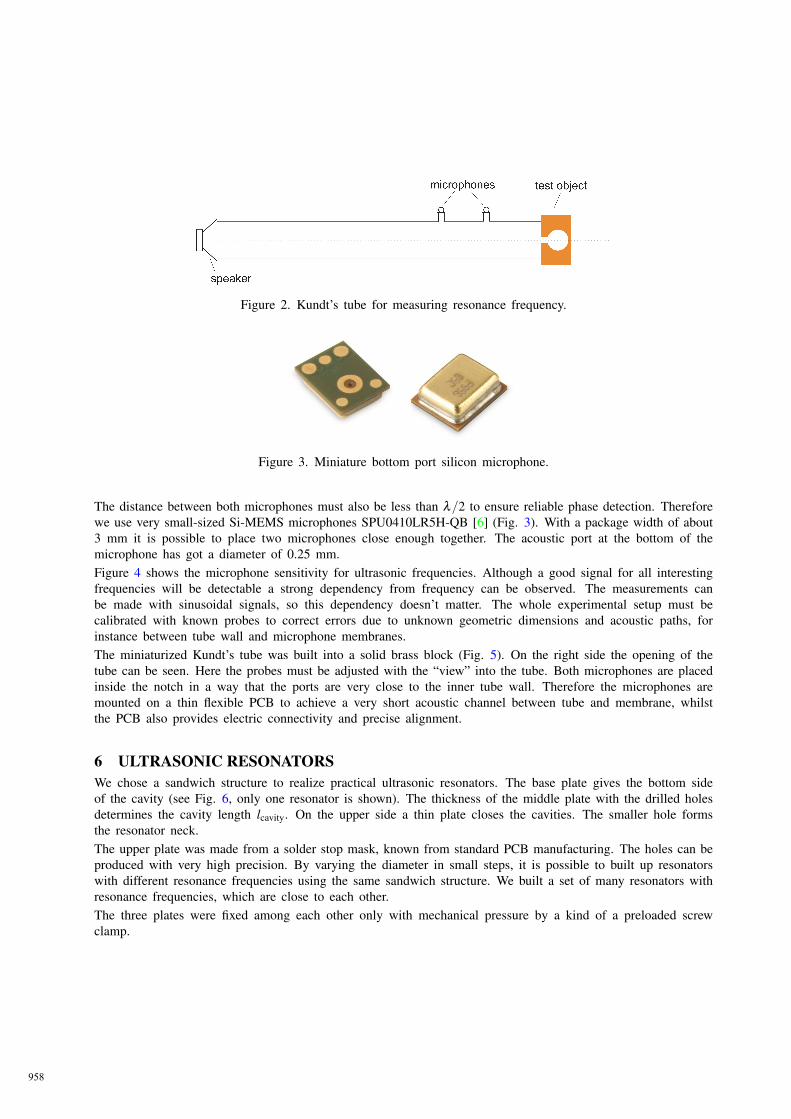
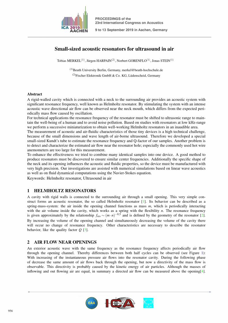
Figure 2. Kundt’s tube for measuring resonance frequency.
Figure 3. Miniature bottom port silicon microphone.
The distance between both microphones must also be less than λ/2 to ensure reliable phase detection. Thereforewe use very small-sized Si-MEMS microphones SPU0410LR5H-QB [6] (Fig. 3). With a package width of about3 mm it is possible to place two microphones close enough together. The acoustic port at the bottom of themicrophone has got a diameter of 0.25 mm.Figure 4 shows the microphone sensitivity for ultrasonic frequencies. Although a good signal for all interestingfrequencies will be detectable a strong dependency from frequency can be observed. The measurements canbe made with sinusoidal signals, so this dependency doesn’t matter. The whole experimental setup must becalibrated with known probes to correct errors due to unknown geometric dimensions and acoustic paths, forinstance between tube wall and microphone membranes.The miniaturized Kundt’s tube was built into a solid brass block (Fig. 5). On the right side the opening of thetube can be seen. Here the probes must be adjusted with the “view” into the tube. Both microphones are placedinside the notch in a way that the ports are very close to the inner tube wall. Therefore the microphones aremounted on a thin flexible PCB to achieve a very short acoustic channel between tube and membrane, whilstthe PCB also provides electric connectivity and precise alignment.
6 ULTRASONIC RESONATORSWe chose a sandwich structure to realize practical ultrasonic resonators. The base plate gives the bottom sideof the cavity (see Fig. 6, only one resonator is shown). The thickness of the middle plate with the drilled holesdetermines the cavity length lcavity. On the upper side a thin plate closes the cavities. The smaller hole formsthe resonator neck.The upper plate was made from a solder stop mask, known from standard PCB manufacturing. The holes can beproduced with very high precision. By varying the diameter in small steps, it is possible to built up resonatorswith different resonance frequencies using the same sandwich structure. We built a set of many resonators withresonance frequencies, which are close to each other.The three plates were fixed among each other only with mechanical pressure by a kind of a preloaded screwclamp.
958

Figure 4. Microphone sensitivity at lower ultrasonic range [6].
Figure 5. Miniaturized Kundt’s tube, only one microphone can be seen.
Figure 6. Resonator cross section (neck diameter dneck = 300 µm, cavity diameter dcavity = 600 µm, neck lengthlneck = 75 µm, cavity length lcavity = 1.5 mm (graphic not true to scale).
959
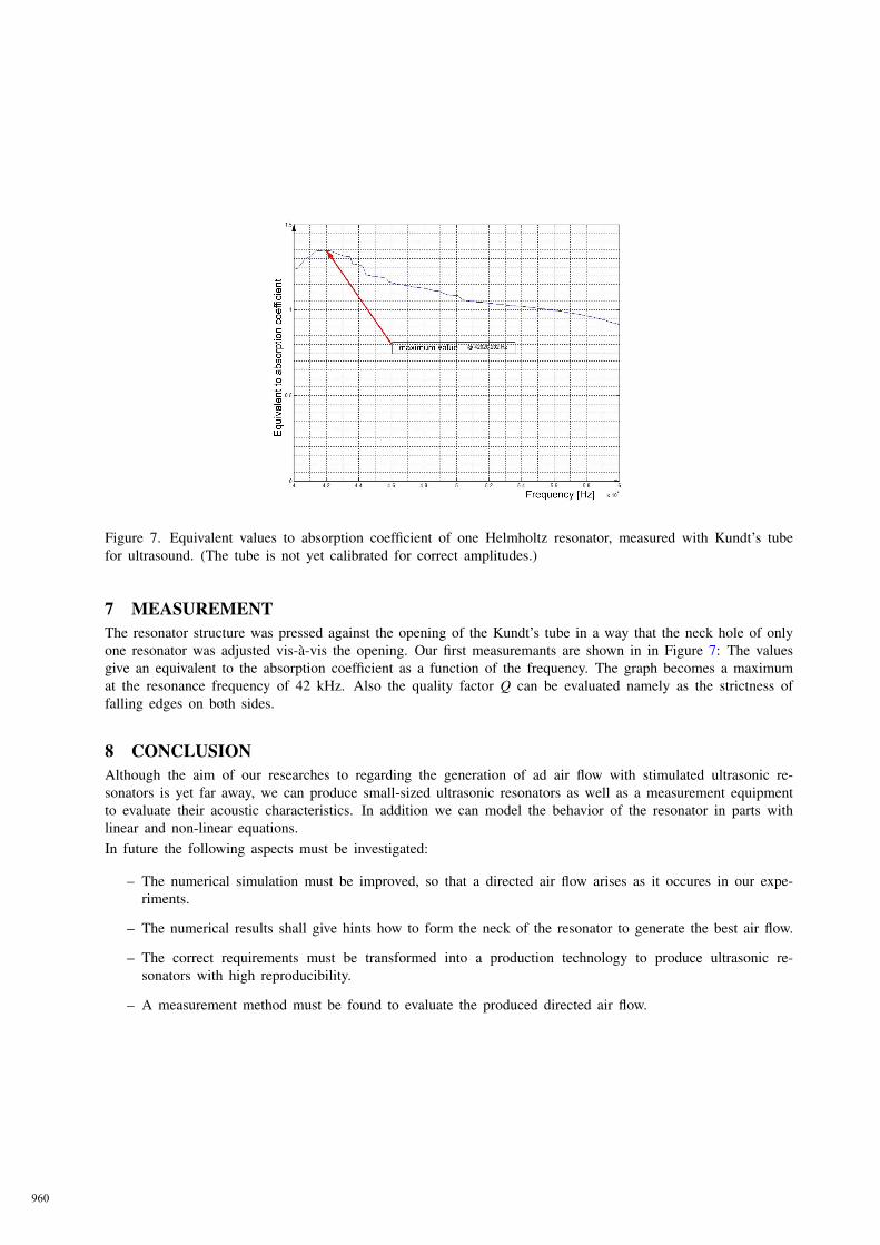
Figure 7. Equivalent values to absorption coefficient of one Helmholtz resonator, measured with Kundt’s tubefor ultrasound. (The tube is not yet calibrated for correct amplitudes.)
7 MEASUREMENTThe resonator structure was pressed against the opening of the Kundt’s tube in a way that the neck hole of onlyone resonator was adjusted vis-à-vis the opening. Our first measuremants are shown in in Figure 7: The valuesgive an equivalent to the absorption coefficient as a function of the frequency. The graph becomes a maximumat the resonance frequency of 42 kHz. Also the quality factor Q can be evaluated namely as the strictness offalling edges on both sides.
8 CONCLUSIONAlthough the aim of our researches to regarding the generation of ad air flow with stimulated ultrasonic re-sonators is yet far away, we can produce small-sized ultrasonic resonators as well as a measurement equipmentto evaluate their acoustic characteristics. In addition we can model the behavior of the resonator in parts withlinear and non-linear equations.In future the following aspects must be investigated:
– The numerical simulation must be improved, so that a directed air flow arises as it occures in our expe-riments.
– The numerical results shall give hints how to form the neck of the resonator to generate the best air flow.
– The correct requirements must be transformed into a production technology to produce ultrasonic re-sonators with high reproducibility.
– A measurement method must be found to evaluate the produced directed air flow.
960

ACKNOWLEDGEMENTSThis paper has arisen from a joint project of the university of applied sciences “Beuth Hochschule fuer TechnikBerlin” and the German company “Fischer Elektronik GmbH & Co. KG”. The project aims at developingcooling devices based on tiny Helmholtz resonators which are excited by ultrasound. It is funded by the Germangovernmental department “Federal Ministry for Economic Affairs and Energy” within the program “ZentralesInnovationsprogramm Mittelstand” (ZIM).
REFERENCES[1] Helmholtz, Hermann von. Die Lehre von den Tonempfindungen. Friedr. Vieweg & Sohn, Braunschweig,
1913.
[2] Kinsler, Lawrence E. et. al. Fundamentals of Acoustics. John Wiley & Sons, Inc., 1999.
[3] Merkel, T. Investigations To Small-Sized Helmholtz Resonators And Numerical Simulation ConsideringThermoacoustics Effects. 7th Forum Acousticum, Krakow, Poland, 2014
[4] Merkel, T. Experimentelle Untersuchung der Luftströmung an kleinen akustischen Resonatoren. DAGAAachen, Germany, 2016.
[5] Gorenflo, N. et. al. Air flow computations for Helmholtz resonators in a sound field. Proceedings of the23rd International Congress on Acoustics, Aachen, Germany, September 9-13, 2019.
[6] Knowles Electronics. www.knowles.com, 2013.
961
Related Documents