CS 8100 and CS 8100 Access Installation Guide

Welcome message from author
This document is posted to help you gain knowledge. Please leave a comment to let me know what you think about it! Share it to your friends and learn new things together.
Transcript

CS 8100 and CS 8100 Access
Installation Guide

Notice
Congratulations on your purchase of the CS 8100 and CS 8100 Access. Thank you for your confidence in our products and we will do all in our power to ensure your complete satisfaction.
The Installation Guide for the CS 8100 and CS 8100 Access includes information on complete or partial tomographic digital panoramic X-ray features. We recommend that you thoroughly familiarize yourself with this Guide in order to make the most effective use of your system.
The information contained in this Guide may be subject to modification without notice, justification or notification to the persons concerned.
No part of this Guide may be reproduced without the express permission of Carestream Health, Inc.
The US Federal law restricts this device to sale by or on the order of a physician.
This document was originally written in English.
Manual Name: CS 8100 and CS 8100 Access Installation GuidePart Number: SM786Revision Number: 01Print Date: 2012-04
The CS 8100 and CS 8100 Access complies with Directive 93/42/EEC relating to medical equipment.
Manufacturer
Authorized Representative in the European Community
TROPHY 4, Rue F. Pelloutier, Croissy-Beaubourg
77435 Marne la Vallée Cedex 2, France
WARNING: We recommend that you consult the “Safety, Regulatory and the Technical Specification User Guide” before using the CS 8100 and CS 8100 Access.
0086
Carestream Health, Inc.150 Verona StreetRochester, NY 14 608, USA
EC REP

Contents
1—About This GuideConventions in this Guide. . . . . . . . . . . . . . . . . . . . . . . . . . . . . . . . . . . . . . . . . . . . . . . . . . . . . . . . . . . . . . . . . . . . . 1–1
2—CS 8100 GENERAL OVERVIEWMobile Components . . . . . . . . . . . . . . . . . . . . . . . . . . . . . . . . . . . . . . . . . . . . . . . . . . . . . . . . . . . . . . . . . . . . . . . . . 2–1General Functional Components . . . . . . . . . . . . . . . . . . . . . . . . . . . . . . . . . . . . . . . . . . . . . . . . . . . . . . . . . . . . . . . 2–2Head and Chin Rest . . . . . . . . . . . . . . . . . . . . . . . . . . . . . . . . . . . . . . . . . . . . . . . . . . . . . . . . . . . . . . . . . . . . . . . . . 2–3
Positioning Accessories and Replacement Parts. . . . . . . . . . . . . . . . . . . . . . . . . . . . . . . . . . . . . . . . . . . . . . . 2–4Positioning Panel . . . . . . . . . . . . . . . . . . . . . . . . . . . . . . . . . . . . . . . . . . . . . . . . . . . . . . . . . . . . . . . . . . . . . . . . . . . . 2–5X-Ray Remote Control Overview . . . . . . . . . . . . . . . . . . . . . . . . . . . . . . . . . . . . . . . . . . . . . . . . . . . . . . . . . . . . . . . 2–6
3—CS 8100 PACKAGINGStandard Packaging . . . . . . . . . . . . . . . . . . . . . . . . . . . . . . . . . . . . . . . . . . . . . . . . . . . . . . . . . . . . . . . . . . . . . . . . . 3–1Column Assembly Components (Box A) . . . . . . . . . . . . . . . . . . . . . . . . . . . . . . . . . . . . . . . . . . . . . . . . . . . . . . . . . 3–2Head Assembly Components (Box B) . . . . . . . . . . . . . . . . . . . . . . . . . . . . . . . . . . . . . . . . . . . . . . . . . . . . . . . . . . . 3–2Head and Chin Rest (Box C) . . . . . . . . . . . . . . . . . . . . . . . . . . . . . . . . . . . . . . . . . . . . . . . . . . . . . . . . . . . . . . . . . . 3–3Installation Kit, Accessories Kit, Documentation (Box D). . . . . . . . . . . . . . . . . . . . . . . . . . . . . . . . . . . . . . . . . . . . 3–3Column Accessories (Box E) . . . . . . . . . . . . . . . . . . . . . . . . . . . . . . . . . . . . . . . . . . . . . . . . . . . . . . . . . . . . . . . . . . 3–4
4—SITE PREPARATION BEFORE INSTALLATIONStandard Compliance . . . . . . . . . . . . . . . . . . . . . . . . . . . . . . . . . . . . . . . . . . . . . . . . . . . . . . . . . . . . . . . . . . . . . . . . 4–1Environmental Requirements . . . . . . . . . . . . . . . . . . . . . . . . . . . . . . . . . . . . . . . . . . . . . . . . . . . . . . . . . . . . . . . . . . 4–1Unit Dimensions . . . . . . . . . . . . . . . . . . . . . . . . . . . . . . . . . . . . . . . . . . . . . . . . . . . . . . . . . . . . . . . . . . . . . . . . . . . . . 4–2Electrical Requirements. . . . . . . . . . . . . . . . . . . . . . . . . . . . . . . . . . . . . . . . . . . . . . . . . . . . . . . . . . . . . . . . . . . . . . . 4–3X-Ray Room Requirement . . . . . . . . . . . . . . . . . . . . . . . . . . . . . . . . . . . . . . . . . . . . . . . . . . . . . . . . . . . . . . . . . . . . . 4–6Computer System Requirements . . . . . . . . . . . . . . . . . . . . . . . . . . . . . . . . . . . . . . . . . . . . . . . . . . . . . . . . . . . . . . . 4–8
5—Preparing The Unit Acquisition SystemInstalling the Ethernet Boards in the Computer . . . . . . . . . . . . . . . . . . . . . . . . . . . . . . . . . . . . . . . . . . . . . . . . . . . 5–1Installing the KODAK Dental Imaging Software and Acquisition Interface . . . . . . . . . . . . . . . . . . . . . . . . . . . . . 5–3
6—INSTALLING THE UNITTool Requirements . . . . . . . . . . . . . . . . . . . . . . . . . . . . . . . . . . . . . . . . . . . . . . . . . . . . . . . . . . . . . . . . . . . . . . . . . . . 6–1Technical Staff Requirements . . . . . . . . . . . . . . . . . . . . . . . . . . . . . . . . . . . . . . . . . . . . . . . . . . . . . . . . . . . . . . . . . . 6–1Installing the UNIT . . . . . . . . . . . . . . . . . . . . . . . . . . . . . . . . . . . . . . . . . . . . . . . . . . . . . . . . . . . . . . . . . . . . . . . . . . . 6–2
Installing the Column. . . . . . . . . . . . . . . . . . . . . . . . . . . . . . . . . . . . . . . . . . . . . . . . . . . . . . . . . . . . . . . . . . . . . . 6–2Installing the Head. . . . . . . . . . . . . . . . . . . . . . . . . . . . . . . . . . . . . . . . . . . . . . . . . . . . . . . . . . . . . . . . . . . . . . . . 6–5Installing the Head and Chin Rest . . . . . . . . . . . . . . . . . . . . . . . . . . . . . . . . . . . . . . . . . . . . . . . . . . . . . . . . . . . 6–8Fitting the covers . . . . . . . . . . . . . . . . . . . . . . . . . . . . . . . . . . . . . . . . . . . . . . . . . . . . . . . . . . . . . . . . . . . . . . . . . 6–9
Post-Installation Control . . . . . . . . . . . . . . . . . . . . . . . . . . . . . . . . . . . . . . . . . . . . . . . . . . . . . . . . . . . . . . . . . . . . . 6–10
7—Maintenance
CS 8100 and CS 8100 Access Installation Guide (SM786)_Ed 01 iii

Contents
Annual Maintenance. . . . . . . . . . . . . . . . . . . . . . . . . . . . . . . . . . . . . . . . . . . . . . . . . . . . . . . . . . . . . . . . . . . . . . . . . . 7–1
iv

Chapter 1
About This Guide
Conventions in this Guide
The following special messages emphasize information or indicate potential risk to persons or equipment:
WARNINGWarns you to avoid injury to yourself or others by following the safety instructions precisely.
CAUTIONAlerts you to a condition that might cause serious damage.
IMPORTANTAlerts you to a condition that might cause problems.
NOTEEmphasizes important information.
TIPProvides extra information and hints.
CS 8100 and CS 8100 Access Installation Guide (SM786)_Ed 01 1–1

Conventions in this Guide
1–2 About This Guide
Chapter 2
CS 8100 GENERAL OVERVIEWThe CS 8100 Family includes:
CS 8100: complete modality CS 8100 Access: modality without the thin slicing feature
This document refers to both models as CS 8100 unless otherwise specified.
The following figures illustrate the general overview of the CS 8100.
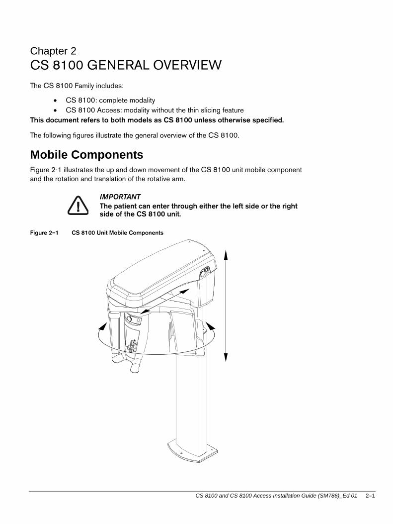
Mobile ComponentsFigure 2-1 illustrates the up and down movement of the CS 8100 unit mobile component and the rotation and translation of the rotative arm.
Figure 2–1 CS 8100 Unit Mobile Components
IMPORTANTThe patient can enter through either the left side or the right side of the CS 8100 unit.
CS 8100 and CS 8100 Access Installation Guide (SM786)_Ed 01 2–1

General Functional Components
General Functional Components
Figure 2-2 illustrates the general functional components of the CS 8100 unit.
Figure 2–2 CS 8100 Unit Functional Components
1 ON/OFF button 8 Unit head
2 Emergency stop knob 9 X-Ray remote control
3 Unit rotative arm 10 PC hosting the imaging and the acquisition software
4 X-Ray generator source assembly
5 Unit column
6 Head and chin rest
7 Digital sensor
9
10
2
6
4
3
1
7
5
8
2–2 CS 8100 GENERAL OVERVIEW

Head and Chin Rest
Head and Chin RestFigure 2-3 illustrates the functional components of the CS 8100 head and chin rest.
Figure 2–3 Head and Chin Rest Functional Components
1 Positioning Panel
2 Frontal head rest adjustment knob
3 Frontal head rest
4 Bite block
5 Chin rest
6 Hand grips
2
3
6
4
5
1
CS 8100 and CS 8100 Access Installation Guide (SM786)_Ed 01 2–3

Head and Chin Rest
Positioning Accessories and Replacement PartsThe following accessories are used when positioning a patient. They are delivered with the CS 8100 unit.
Table 2-1 lists the panoramic positioning accessories.
Table 2–1 Panoramic Positioning Accessories and Replacement Parts
Accessory Description
Panoramic chin rest
Sinus chin rest
TMJ nose rest
Standard bite block
Bite block for edentulous patients
Single use sheaths for bite block
2–4 CS 8100 GENERAL OVERVIEW

Positioning Panel
Positioning PanelThe positioning panel is a console that enables you to correctly position and align a patient before you acquire an image.
Figure 2–4 Unit Positioning Panel
1 Height Adjustment button: Adjusts the height of the unit to the height of the patient.
2 Ready Indicator LED: Green indicates that the unit is ready for acquisition.
3 Frontal head rest adjustment knob: Positions the up or down inclination of the patient head by turning the knob.
CS 8100 and CS 8100 Access Installation Guide (SM786)_Ed 01 2–5

X-Ray Remote Control Overview
X-Ray Remote Control Overview
The x- ray remote control enables you to launch a radiological image acquisition via the exposure button from outside the x-ray room. You must press and hold the exposure button until the end of acquisition. Premature release of the exposure button interrupts the acquisition.
Figure 2–5 X-Ray Remote Control
1 Exposure button: launches image acquisition.
2–6 CS 8100 GENERAL OVERVIEW

Chapter 3
CS 8100 PACKAGING
Standard Packaging When unpacking the boxes, ensure that you received the following components.
Column assembly components (A) Head assembly components (B) Head and chin rest components (C) Installation kit, accessories kit, documentation (D) Column accessories (E)
A
D
C
E
B
CS 8100 and CS 8100 Access Installation Guide (SM786)_Ed 01 3–1

Column Assembly Components (Box A)
Column Assembly Components (Box A)
Head Assembly Components (Box B)
Table 3–1 Head Assembly Components
Box Content Dimension (mm) Weight
(A) System column
755 mm (D) x 1600 mm (L) x 860 mm (H) ± 80 kg
(B) System head
Head top cover
(C) Head and chin rest
(D) Installation Kit
Accessories Kit
Documentation (User Guide, Installation Guide, Safety and Regulatory Guide, CD ROM)
(E) Column front cover
Column rear cover
Mounting bracket
Table 3–2 Box A
Content Description Quantity
Column assembly 1
Table 3–3 Box B
Content Description Quantity
System head 1
Head top cover 1
3–2 CS 8100 PACKAGING

Head and Chin Rest (Box C)
Head and Chin Rest (Box C)
Installation Kit, Accessories Kit, Documentation (Box D)Box D is divided into 3 compartments:
D1: Accessories kit
D2: Installation kit
D3: Documentation
Table 3–5 Box D
Table 3–4 Box C
Content Description Quantity
Head and chin rest 1
Content Description
Box D1
Panoramic chin rest
Sinus chin rest
TMJ nose rest
Standard bite block (x5)
Bite block for edentulous patients (x2)
CS 8100 and CS 8100 Access Installation Guide (SM786)_Ed 01 3–3

Column Accessories (Box E)
Column Accessories (Box E)Table 3–6 Box E
Single use sheaths for bite block
Box D2
Screws
Exposure switch
Box D3
User Guide, Installation Guide, Safety and Regulatory Guide
Others (CD ROM)
Content Description Quantity
Column front cover 1
Column rear cover 1
Mounting bracket 1
Content Description
3–4 CS 8100 PACKAGING

Chapter 4
SITE PREPARATION BEFORE INSTALLATION
IMPORTANT
Prior to placing the order and before installation, carefully check the following requirements for the x-ray room.
Standard ComplianceInstall the system in an x-ray room compliant with all official regulations applicable to protection against radiation.
Environmental RequirementsCheck the following ambient operating condition requirements of the x-ray room before installing the system:
Temperatures: 5 ~35 °C
Relative humidity: 30 ~ 85%
Atmospheric pressure: 700 ~ 1060 hpa
CS 8100 and CS 8100 Access Installation Guide (SM786)_Ed 01 4–1

Unit Dimensions
Unit Dimensions
The unit dimensions illustrated in the above figure are as follows:
Maximum height of the system (2196 mm) Minimum (1062,5 mm) and maximum (1662,5 mm) height of the chin rest Depth (1104 mm)
WARNINGIf you need to add a base plate you must add 12,5 mm to the height of the system.
MAXI 1104 mm (43.4643'')
600
500
4–2 SITE PREPARATION BEFORE INSTALLATION

Electrical Requirements
Electrical Requirements
WARNING*You MUST select the operating voltage when placing an order. The operating voltage CANNOT be modified on site.
The system can operate at:
100 V - 130 V - 50 Hz/60 Hz 220 V - 230 V - 50 Hz/60 Hz
CAUTION
The power supply cable must be equipped with a connection box that ensures constant connection. This ensures that it is not possible to disconnect the system from power supply without using tools. The system must be protected against any accidental disconnection.
If other systems are installed on the same line, interference and voltage fluctuations can cause the radiological system to operate abnormally. We strongly recommend that a separate electrical line be dedicated to supply power to the CS 8100.
This line should be protected by a circuit breaker with a maximum current of:
16 A at 230/240 V 20 A at 110/130 V A differential circuit breaker of 30 mA
Table 4–1 Optional Operating Voltages of the System
Nominal voltage * (no load) Minimum Maximum Maximum line
current
100 V - 130 V - 50 Hz/60 Hz 90 V 143 V 20 A
220 V - 230 V - 50Hz/60 Hz 198 V 264 V 10 A
CS 8100 and CS 8100 Access Installation Guide (SM786)_Ed 01 4–3

Electrical Requirements
Figure 4–1 Electrical Diagram of the X-ray Room and the System Connections
1 General mains 7bis X-ray warning lamp connecting terminal
2 Differential circuit breaker 8 Column connecting terminals
3 Red color actuator emergency stop push-button 9 X-ray remote control
4 Red color actuator emergency stop push-button 10 Door safety switch
5 Red warning lamp, power ON indicator 11 Mains outlet (for electric tools)
6 System mains connecting terminal 12 Ethernet outlet (RJ45/1)
7 Green warning lamp, ready state indicator 13 Contactor
N
L
G NL
NL
L N
1A
12
10
9
7
11
5
4
3
2
1
6
8
7bis
RJ45
CS8100
13
4–4 SITE PREPARATION BEFORE INSTALLATION

Electrical Requirements
A single-phase alternating current power supply is required. The electrical installation specifications should be as follows:
Table 4–2 Electrical Installation Specifications
Supply Voltage 220 V - 230 V 100 V - 130 V
Frequency 50/60 Hz 50/60 Hz
Electrical supply 6 kW 6 kW
Line current required 16 A 20 A
Cable cross-section according to length
For 30 m:
2.5 mm2
For 10 m:
2.5 mm2
Max. line impedance 0.5 0.12
Differential circuit breaker (2) 30 mA 30 mA
Maximum current to trip circuit breaker
16 A 20 A Protect the power supply line with a differential circuit breaker that trips at maximum current.
Specifications of 2 red color actuator emergency stop push-button
(3) and (4)
250 V 5 A
UL listed
250 V 5 A
UL listed Install these stop push-buttons to
simultaneously, switch off the current to the active conductors of the radiological installation and exclude any other electric equipment.
Locate (3) inside the x-ray room, near the system, for the operator, if necessary, to quickly cut the power supply.
Locate (4) outside the x-ray room, near the x-ray remote control, for the operator, if necessary, to quickly cut the power supply.
Maintain them in OFF (open) position until a deliberate action is performed.
Specifications of the warning lamps
(5) and (7)
60 W 60 W Locate the red warning lamp (5) outside the x-ray room to indicate the system is active (1 lamp at each access point).
Locate the green warning lamp (7) outside the x-ray room to indicate the ready state of the system for acquisition.
Contactor (13) 16 A - 250 V UL listed
20 A - 250 V UL listed
Door Safety Switch (10)
1 A / 250 V 1 A / 130 V Optionally, connect the door safety switch (9) that deactivates the x-ray remote control if the door remains open.
CS 8100 and CS 8100 Access Installation Guide (SM786)_Ed 01 4–5

X-Ray Room Requirement
X-Ray Room RequirementIMPORTANT
Use an appropriate wall fixing system suitable for the type of wall construction. See the examples below.
The following illustrations provide examples of wall types and fixations.
IMPORTANTInstall the system where a minimum amount of space is provided to allow easy access for the patient or the maintenance technician (see Figure 4-2).
Table 4–3 X-Ray Room Requirements
Room Components Minimum Requirement Comments
Width of the door 75 cm (30")
Height of the ceiling 240 cm (95") If needed, it is possible to lower the height of the system.
Strength of the wall Withstanding an extraction force of 150 kPa at each point of attachment.
It is the responsibility of the installer to choose an appropriate fixing system that withstands the extraction force.
Load-bearing capacity of the floor
500 kg/m2 The floor must be solid and flat.
Required space for the CS 8100
1200 (L) x 1400 (D) x 2400 (H) mm
16 mm
2 x
16 mm
2 x
16 mm
2 x
16 mm
2 x
4–6 SITE PREPARATION BEFORE INSTALLATION

X-Ray Room Requirement
Figure 4–2 Minimum X-Ray Room Space Configuration
WARNINGYou MUST prepare the appropriate electrical requirements and configurations of the x-ray room before installing the unit. You MUST locate separately the following low voltage and high voltage connections:- Low Voltage: (12 & 12bis), (9), (10)- High Voltage: (6), (5), (7bis)
3 Red color actuator emergency stop push-button 9 X-ray remote control
4 Red color actuator emergency stop push-button 10 Door safety switch
5 Red warning lamp, power ON indicator 11 Mains outlet (for electrical tools)
6 Unit mains connecting terminal 12 Ethernet min Class 5E outlet (RJ45/1)
7 Green warning lamp, ready state indicator 13 Local Area Network (LAN), (RJ45/2)
7bis X-Ray warning lamp connecting terminal
MINI 1500 mm (59 ')7
128MINI 468 mm
(18 ')716 32
5 7
9 10
13
RJ45/1
RJ45/2
MINI 493 mm (19 ')
4
13
3
1110 6 5 7bis912
CS 8100 and CS 8100 Access Installation Guide (SM786)_Ed 01 4–7
Computer System Requirements
Computer System RequirementsThe CS 8100 and CS 8100 Access Minimum Computer System Requirements is posted on the Trophy technician site as a separate document with an edition number.
Before you intervene on a client site, see the Trophy technician website for the latest edition of the document.
IMPORTANT
It is MANDATORY to check that the computer system configuration is compatible with the computer system requirements for the CS 8100 and CS 8100 Access software. If necessary you MUST update your computer system configuration. The CS 8100 and CS 8100 Access MUST be connected to the computer via a point-to-point Ethernet link and not via a LAN.
4–8 SITE PREPARATION BEFORE INSTALLATION

Chapter 5
Preparing The Unit Acquisition System
Installing the Ethernet Boards in the ComputerBefore installing the Ethernet boards in the computer, check that the computer is:
Switched off. Disconnected from the mains power supply.
To install the Ethernet boards in the computer, follow these steps:
1. Install a 1 Gbits Ethernet board* (A) in an unoccupied slot.
*Not supplied
x1
A
CS 8100 and CS 8100 Access Installation Guide (SM786)_Ed 01 5–1

Installing the Ethernet Boards in the Computer
2. Connect the following Ethernet cables:
The Ethernet “System” cable (A) to the Ethernet (1 GB) connector. The LAN connection is optional.
3. Reboot the computer. Wait for Windows to detect the presence of new boards.
4. Install the Ethernet board driver provided with the board.
You can now proceed with the installation of the Imaging Software.
LAN
A
5–2 Preparing The Unit Acquisition System

Installing the KODAK Dental Imaging Software and Acquisition Interface
Installing the KODAK Dental Imaging Software and Acquisition Interface Before installing the KODAK Dental Imaging Software, check that:
The computer has all the PC system requirements You have the software CD
To install the KODAK Dental Imaging Software, follow these steps:
1. Insert the software CD in the CD-ROM drive of the computer.
Wait for the installation program to start. If the program does not start automatically, click Start > Run and enter D:\setup.exe if D is the letter for the CD-ROM drive, or the letter of the relevant drive on the computer.
2. The Choose Setup Language dialog box is displayed. Select the installation language and click OK.
3. The Imaging Software welcome page and the InstallShield wizard are displayed.
CS 8100 and CS 8100 Access Installation Guide (SM786)_Ed 01 5–3

Installing the KODAK Dental Imaging Software and Acquisition Interface
4. The Welcome to Kodak Dental Imaging Software Installation dialog box is displayed. Click Next to launch the installation.
5. The License Agreement dialog box is displayed. Accept and click Yes.
6. The Choose Destination Location dialog box is displayed. Click Next if you accept the default destination folder or browse to choose another destination folder.
7. The Kodak Dental Imaging Software dialog box is displayed. The Patient file is selected by default but you must select the radiological unit.
5–4 Preparing The Unit Acquisition System

Installing the KODAK Dental Imaging Software and Acquisition Interface
8. To select the desired radiological unit, do the following:
Click on the drop-down list of No Pano/Ceph Installation and select CS8100 Panoramic.
Check that you have made the right selections. Click Next to begin the installation.
9. The CS 8100 installation wizard launches the installation procedure.
CS 8100 and CS 8100 Access Installation Guide (SM786)_Ed 01 5–5

Installing the KODAK Dental Imaging Software and Acquisition Interface
If the firewall is active, the Windows Security Alert dialog box is displayed. Click Unblock.
10. The KODAK Dental Imaging Software dialog box is displayed. Click Yes, I want to restart my computer now and click Finish.
11. The Windows Firewall window is displayed. Click Off (not recommended). Click OK.
5–6 Preparing The Unit Acquisition System

Installing the KODAK Dental Imaging Software and Acquisition Interface
12. Double-click to open the Patient window.
13. Create a patient record. From the toolbar, click and enter the required patient
information. Click to access the Imaging window.
14. The Enter the licence number dialog box is displayed. Enter the licence number and click Validate if you have the licence number or click Cancel to continue.
CS 8100 and CS 8100 Access Installation Guide (SM786)_Ed 01 5–7

Installing the KODAK Dental Imaging Software and Acquisition Interface
5–8 Preparing The Unit Acquisition System

Chapter 6
INSTALLING THE UNIT
Tool RequirementsThe installer must supply the following tools:
Power drill Screws and heavy duty fixings Spirit level Measuring tape Cutter Metric Allen keys Metric spanners
Technical Staff RequirementsThe installation requires the following number of technicians:
IMPORTANTThe tool references mentioned in this manual are ISO tool references.
System Component Technicians
Head 1
Column 1
CS 8100 and CS 8100 Access Installation Guide (SM786)_Ed 01 6–1

Installing the UNIT
Installing the UNIT Before installing the unit, check that you have:
All the necessary tools All the cables All the switches
Installing the ColumnTo install the column, follow these steps:
1. Take the column out of the box, taking care not to trap any cables between the column and the floor. Place the column on the floor in a horizontal position.
2. Place the mounting bracket (A) inside the column and fix it to the column using 2 screws.
6 mm
x2
A
6–2 INSTALLING THE UNIT

Installing the UNIT
3. Lift the column up vertically and hold it against the wall. The mounting bracket must be placed flat against the wall. Mark the position of the fixing holes for the mounting bracket on the wall. Move the column aside and drill the holes.
4. Install the wall fixing system (B) into the drilled holes.
IMPORTANT
To ensure that the column is firmly fixed to the wall, you MUST use the appropriate wall fixing system that is suitable for the type of wall construction.
5. Re-position the column against the wall and place the mounting bracket into the bolts of the wall fixing system but do not fit the nuts.
6. Mark the position of the fixing holes (C) of the base plate on the floor. Move the column aside and drill the holes.
X4
C
115 115
175
B
CS 8100 and CS 8100 Access Installation Guide (SM786)_Ed 01 6–3

Installing the UNIT
7. Check that the column is evenly positioned by placing a spirit level horizontally and vertically (D).
IMPORTANT
If the floor is uneven, place the rubber mat (E) under the base plate before you fix it to the floor.
8. Screw and fix the base plate (F) to the floor. Screw and fix the mounting brackets (G) securely to the wall.
9. Fit the column space fillers (H).
The column is ready for the system head attachment.
13
12 mm
x4
F
E
D
D
H
H
x2
G
6–4 INSTALLING THE UNIT

Installing the UNIT
Installing the HeadTo install the head, follow these steps:
1. Take the head out from the box and place it on the floor (A). Remove the head cover.
2. Place the empty box in front of the column (B) and turn it up vertically (C).
3. Grab the top and bottom end of the head, lift it up from the floor, and place it on the empty box.
4. Pull out the packaging foam (D).
5. Push the box, with the head on it, towards the column.
6. Mount and position the head on the hook of the column sliding system (E). Screw and tighten the 2 upper screws with washers.
WARNING
Pay attention to the cables as you mount and position the head. Ensure that they are free from trap and tangle.
A
x2
10 mm
x1
C
F
E
B
D
E
F
CS 8100 and CS 8100 Access Installation Guide (SM786)_Ed 01 6–5

Installing the UNIT
7. Remove the transport security pin.
8. Rotate the system rotating arm by hand to have access to the screw located under the system head. Screw and tighten it (E).
9. Check that the head is correctly positioned using a spirit level.
10. Connect the Ethernet cable to the Ethernet coupler. Connect the Ethernet cable from the J3 connector to the other side of the Ethernet coupler.
11. Connect the following cables:
Cable ... To connector ... On the ...
Ethernet (A) J3 Sensor control board (CJ852)
Column resistive track (B) J7 Motor board (CJ856)
Column actuator (C) J4 Motor board (CJ856)
Warning lamp (D) J8 PFC board (JZ036)
Exposure switch (E) J1 PFC board (JZ036)
6–6 INSTALLING THE UNIT

Installing the UNIT
12. Put feed-through sleeves around the Ethernet cable and the exposure cable and push them into the feed-through hole at the top back of the head to stop them from sliding down.
13. Tie the cables to the connecting box at the base of the head using cable ties.
JZ036
J4
C
A
J1
J8
D
E
JZ036
B
CJ856
CJ856
J7
CJ856
CS 8100 and CS 8100 Access Installation Guide (SM786)_Ed 01 6–7

Installing the UNIT
Installing the Head and Chin Rest1. Remove the hatch (A).
2. Fit the head and chin rest to the plate using the 3 screws (B) but do not tighten the screws.
3. Connect the control panel cable (C) and tighten the 3 screws (B).
4. Push the control panel cable well into the top of the head and chin rest. This will prevent the control panel cable from getting trapped when you replace the hatch.
5. Replace the hatch.
3 mm
A
x3
BC
6–8 INSTALLING THE UNIT

Installing the UNIT
Fitting the covers1. Slide the back column cover (A) into the mounting drains and screw it in.
IMPORTANT
Make sure that the ethernet cable and the exposure cable comes out through the opening on one side of the back column cover opening. The power cable comes out from the opening on the other side.
2. Slide the front column cover (B) into the mounting drains and screw it in.
3. Fit the top head cover (C) and screw it in.
4. Connect the power supply cable to the power source and press on the positioning panel to check if the head moves up or down correctly.
CAUTION
The power supply cable must be equipped with a connection box that ensures constant connection. This ensures that it is not possible to disconnect the system from power supply without using tools. The system must be protected against any accidental disconnection.
WARNING
The cables that are connected to the head follow the up or down movement of the head. To protect them from physical damage, make sure that they are free from trap and tangle.
The system is ready for post-installation control.
T25
2 x M5x12
A
B
C
2 x M5x12
2 x M5x12
CS 8100 and CS 8100 Access Installation Guide (SM786)_Ed 01 6–9

Post-Installation Control
Post-Installation ControlBefore post-installation control, check that:
The installation of the unit is complete. The installation of the imaging software is complete. You have the test tools. The unit and the computer is on.
To execute post-installation control tasks, follow these steps:
1. On your desktop, double-click . The CS 8100 Technician Tools window is displayed.
2. Insert the USB key which contains the embedded password into your computer.
3. Click here.
The CS 8100 Technician Access window is displayed:
6–10 INSTALLING THE UNIT
Post-Installation Control
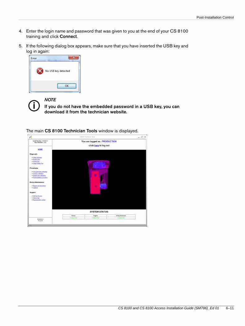
4. Enter the login name and password that was given to you at the end of your CS 8100 training and click Connect.
5. If the following dialog box appears, make sure that you have inserted the USB key and log in again:
NOTE
If you do not have the embedded password in a USB key, you can download it from the technician website.
The main CS 8100 Technician Tools window is displayed.
CS 8100 and CS 8100 Access Installation Guide (SM786)_Ed 01 6–11

Post-Installation Control
6. In the left pane, click Post installation procedure.
The Post Installation Procedure window is displayed.
7. Read and implement the instructions and the warning that are displayed.
8. Click Start and follow the on-screen instructions.
6–12 INSTALLING THE UNIT

Chapter 7
Maintenance
Annual MaintenanceWe recommend that a general inspection of the system should be carried out every year by an approved dental systems technician.
The inspection should cover the following points:
Check the attachment points to the floor and the wall.
Check all the mobile components of the system.
Check the X-ray generator.
Make an image acquisition with the test tools and check the image.
Check the focal trough and the symmetry.
Check the degree of legibility of the labels.
Check for damage to cables, covers, oil leaks, etc.
If the results of any of these inspections are unsatisfactory, see the CS 8100 and CS 8100 Access Service Guide (SM787), in order to rectify any problems.
If you have any doubts, do not operate the system.
CS 8100 and CS 8100 Access Installation Guide (SM786)_Ed 01 7–1

Annual Maintenance
7–2 Maintenance
Related Documents