SM Air Terminal Installation, Operation, and Maintenance Manual (Model 264 and Model 296 Only) Document 8018721 May 17, 1993 Version 3 Claircom Communications Group, Inc. 700 Fifth Avenue, Suite 2100 Seattle, Washington 98104 (206) 621-7174

Welcome message from author
This document is posted to help you gain knowledge. Please leave a comment to let me know what you think about it! Share it to your friends and learn new things together.
Transcript

SM
Air TerminalInstallation, Operation, and Maintenance
Manual(Model 264 and Model 296 Only)
Document 8018721May 17, 1993
Version 3
Claircom Communications Group, Inc.700 Fifth Avenue, Suite 2100Seattle, Washington 98104
(206) 621-7174

Copyright © 1993, Claircom Communications Group, L.P.All Rights Reserved.

8018721 03 Contents • iii
Contents
About this manual ................................................................................. xi
1 General description..................................................................... 1-11.1 In-cabin equipment ............................................................. 1-4
Seatback phone units ....................................................... 1-4Electrical connection boxes ............................................. 1-5
1.2 Radio equipment ................................................................. 1-6Baseband unit................................................................... 1-6Radio frequency unit........................................................ 1-8Power supply unit ............................................................ 1-9EMI filter ....................................................................... 1-10UHF/L-band antennas.................................................... 1-10
2 Installation................................................................................... 2-12.1 Required tools and materials............................................... 2-12.2 Materials inspection and inventory ..................................... 2-12.3 Installing air terminal equipment ........................................ 2-3
Installing the power supply unit....................................... 2-3Installing the radio frequency unit ................................... 2-6Installing the baseband unit ............................................. 2-6Installing the electrical connection boxes........................ 2-7Installing the UHF/L-band antennas .............................. 2-11Installing the seatback phone units ................................ 2-14Installing the EMI filter ................................................. 2-16
3 Commissioning ............................................................................ 3-13.1 Required test equipment ..................................................... 3-13.2 System power-up and self tests ........................................... 3-23.3 System testing ..................................................................... 3-4
4 Operation and shutdown............................................................ 4-14.1 Operation............................................................................. 4-14.2 System shutdown ................................................................ 4-24.3 Restarting the air terminal................................................... 4-3
5 Theory of operation .................................................................... 5-15.1 BBU description.................................................................. 5-1
CP description.................................................................. 5-2CSM description .............................................................. 5-3BSP module description................................................... 5-3MOM module description................................................ 5-4
5.2 RFU description .................................................................. 5-55.3 PSU description................................................................... 5-55.4 Phone unit description......................................................... 5-55.5 AT initialization .................................................................. 5-7
AT power failure recovery............................................... 5-75.6 Call processing.................................................................... 5-7
Dialing ............................................................................. 5-7Ending a call .................................................................... 5-8

iv • Contents 8018721 03
Follow-on calls ................................................................. 5-8Call queuing ..................................................................... 5-8Blocked calls .................................................................... 5-9
6 Troubleshooting........................................................................... 6-16.1 Required troubleshooting equipment .................................. 6-26.2 Fault analysis procedure ...................................................... 6-26.3 Troubleshooting flowcharts ................................................. 6-56.4 Handset self-tests .............................................................. 6-12
Software cold restart ..................................................... 6-12Sleep mode test ............................................................. 6-12
7 Maintenance................................................................................. 7-17.1 Required tools and materials for maintenance .................... 7-17.2 Periodic maintenance........................................................... 7-1
Calibration........................................................................ 7-17.3 Electrostatic discharge control ............................................ 7-17.4 Field replacement procedures.............................................. 7-2
Replacing the PSU ........................................................... 7-2Replacing the RFU........................................................... 7-4Replacing the BBU........................................................... 7-5Replacing an ECO box ..................................................... 7-6Replacing a UHF/L-band antenna .................................... 7-8Replacing a seatback phone unit ...................................... 7-9Replacing an avionics tray cooling fan ......................... 7-10Returning failed equipment to the Depot for testing ..... 7-12
A List of acronyms ......................................................................... A-1

8018721 03 Contents • v

vi • Figures 8018721 03
Figures
1-1 The Claircom telephony system.................................................. 1-11-2 Air terminal system (typical Model 296 installation) ................. 1-21-3 Seatback phone unit .................................................................... 1-41-4 Electrical connection box............................................................ 1-51-5 ECO box terminator .................................................................... 1-51-6 Baseband unit and BBU avionics tray ........................................ 1-71-7 Radio frequency unit and RFU avionics tray .............................. 1-81-8 Power supply unit and PSU avionics tray................................... 1-91-9 EMI filter................................................................................... 1-101-10 UHF/L-band antenna................................................................. 1-10
2-1 Removing the dust cover............................................................. 2-42-2 PSU power switch....................................................................... 2-42-3 Hold-down fastener components ................................................ 2-52-4 Locking and tightening the hold-down fasteners........................ 2-52-5 Installing an ECO box onto an ECO bracket .............................. 2-72-6 Installing an ECO bracket onto a seat frame............................... 2-82-7 Installing phone cables................................................................ 2-92-8 Installing the terminator ............................................................ 2-102-9 Antenna doubler plate ............................................................... 2-112-10 Installing the antenna onto the aircraft...................................... 2-122-11 Installing the cable assembly onto the antenna......................... 2-132-12 Installing the RJ-11 connector onto the seatback phone unit ... 2-142-13 Installing phone unit mounting hardware ................................. 2-152-14 Installing the EMI filter............................................................. 2-16
3-1 RF translator box......................................................................... 3-13-2 PSU status lamps......................................................................... 3-23-3 BBU indicator lamps................................................................... 3-33-4 Placing the RF translator box...................................................... 3-43-5 Claircom Commissioning Program Application Select Menu.... 3-53-6 Claircom Maintenance Console Maintenance Test Menu .......... 3-63-7 RF Loopback Test signal flow.................................................... 3-73-8 Claircom Maintenance Console Configuration Menu ................ 3-8
4-1 PSU power switch....................................................................... 4-24-2 PSU status lamps......................................................................... 4-34-3 BBU indicator lamps................................................................... 4-4
5-1 Phone unit components ............................................................... 5-6
6-1 BBU and PSU front panel indicator lamps ................................. 6-4
7-1 Cooling fan replacement ........................................................... 7-11

8018721 03 Figures • vii

viii • Flowcharts 8018721 03
Flowcharts
6-1 Air terminal failed startup self-test ........................................... 6-56-2 RFU alarm lamp is lit................................................................ 6-66-3 Channel A or B pilot lamp never illuminates ........................... 6-66-4 Phone unit handset LCD readout stays blank ........................... 6-76-5 Call setup is slow or never succeeds ......................................... 6-86-6 Air terminal failed RF Loopback Test ...................................... 6-96-7 Air terminal failed IF Test ..................................................... 6-106-8 PSU DC lamp does not illuminate when power switch
is set to ON......................................................................... 6-11

8018721 03 Flowcharts • ix

x • Tables 8018721 03
Tables
2-1 Air terminal installation kit components.................................... 2-2
4-1 Normal operating configuration for air terminal switchesand indicators........................................................................ 4-1
5-1 Soft key functions ...................................................................... 5-6
6-1 BBU and PSU front panel indicator lamp displays duringfault conditions ..................................................................... 6-3
6-2 BBU and PSU controls and indicators....................................... 6-4

8018721 03 Tables• xi

8018721 03 About this manual • xi
About this manual
The Air Terminal Installation, Operation, and Maintenance Manualcontains the information necessary to install the ClaircomSM Model 264or Model 296 air terminal equipment on a commercial aircraft. Thisdocument describes installing the following hardware portion of the airterminal only, all other hardware must already be installed (refer to theas-built documentation for more information):
• Baseband unit
• Power supply unit
• Radio frequency unit
• ECO boxes
• UHF/L-band antennas
• Seatback phone units
• EMI filter
• ISDN terminator
Audience This manual is written for the Claircom-approved technician. The airterminal equipment is complex and precludes installation by untrainedpersonnel.
Structure This manual contains the following chapters and appendices:
• Chapter 1 provides a description of the air terminal equipment.
• Chapter 2 covers installation prerequisites, describes the airterminal kit, and contains the installation procedures.
• Chapter 3 describes commissioning the air terminal.
• Chapter 4 describes operating and deactivating the air terminal.
• Chapter 5 covers the theory of operation.
• Chapter 6 describes troubleshooting procedures.
• Chapter 7 covers preventative maintenance, describes measures forprotecting personnel and equipment from electrostatic discharge,and contains the procedures for replacing failed equipment.
• Appendix A lists the acronyms used throughout this manual.
Claircom is a servicemark of Claircom Communications Group, L.P.
xii • About this manual 8018721 03
Before installing the air terminal hardware, take a few minutes to reviewthe contents of this manual. By doing so, you will become familiar withthe basic components that make up the air terminal and how they are tobe installed.
Assumptions Installation and maintenance procedures in this manual are based on thefollowing assumptions:
• All procedures will be performed by qualified service personnelwho are familiar with the Claircom architecture and configuration,air terminal hardware elements, and terminology.
• Personnel responsible for equipment installation will have accessto the Claircom as-built drawings. This documentation providesinformation needed to install the air terminal into a particularaircraft.
• The aircraft has been prepared in accordance with the instructionscontained in the as-built drawings.
• All equipment to be installed is available at the aircraft.
• All special equipment, tools, and test equipment required forinstallation and maintenance are available.
Conventions used in thisdocument
Notes, cautions, and warnings, defined as follows, are used throughoutthis manual to help you become familiar with possible safety orequipment hazards.
Note
Presents additional information or interesting
sidelights.
Caution
Indicates a procedure that may result in equipmentdamage if not strictly observed.
WARNING
Indicates a procedure that may result in personalinjury if not strictly observed.

8018721 03 About this manual • xiii
Version record Version Date Description
1 10/08/92 First version released.
2 01/04/93 Second version released
3 05/17/93 Third version released.

8018721 03 General description • 1-1
Chapter 1General description
The ClaircomSM air-to-ground telephony system provides publictelephone service to users making calls from commercial aircraft.The passenger initiates a phone call by dialing the desired phonenumber into the handset (see figure 1-1). The call is transmitted tothe nearest ground station via air terminal radio equipment locatedinside the aircraft. The ground station then routes the call to thepublic switched telephone network (PSTN) at which point the useroperates the system in the same way as a standard pay telephone.
AIR TERMINAL EQUIPMENT
(LOCATIONS VARY)
HANDSET
GROUND STATION
Figure 1-1. The Claircom telephony system

1-2 • General description 8018721 03
The Claircom air terminal system (see figure 1-2) consists ofin-cabin equipment and radio equipment.
IN-CABIN EQUIPMENT(LEFT SIDE OF AIRCRAFT)
JUNCTION BOX
POWERSUPPLY
UNIT
5 A
115 VAC
115 VAC
115 VAC
CIRCUIT BREAKER PANEL
BASEBANDUNIT
RADIOFREQUENCY
UNIT
RADIO EQUIPMENT
UHF/L-BAND ANTENNA
UHF/L-BAND ANTENNA
TO THE IN-CABIN EQUIPMENT JUNCTION BOX LOCATED ON RIGHT SIDE OF AIRCRAFT
115 VAC
REGULATED DC VOLTAGE AND STATUS REGULATED DC VOLTAGE
EMIFILTER
TERMINATORPHONE UNITS
89 THRU 96
ECO BOX
ECO BOX
ISDN "S" LOOP #10
TERMINATORPHONE UNITS
81 THRU 88
ECO BOX
ECO BOX
ISDN "S" LOOP #8
TERMINATORPHONE UNITS
73 THRU 80
ECO BOX
ECO BOX
ISDN "S" LOOP #6
TERMINATORPHONE UNITS
65 THRU 72
ECO BOX
ECO BOX
ISDN "S" LOOP #4
TERMINATORPHONE UNITS
57 THRU 64
ECO BOX
ECO BOX
ISDN "S" LOOP #2
TERMINATORPHONE UNITS
49 THRU 56
ECO BOX
ECO BOX
ISDN "S" LOOP #0
Figure 1-2. Air terminal system (typical Model 296 installation), sheet 1 of 2

8018721 03 General description • 1-3
IN-CABIN EQUIPMENT(RIGHT SIDE OF AIRCRAFT)
JUNCTION BOX
TERMINATORPHONE UNITS
41 THRU 48
ECO BOX
ECO BOX
ISDN "S" LOOP #11
TERMINATORPHONE UNITS
33 THRU 40
ECO BOX
ECO BOX
ISDN "S" LOOP #9
TERMINATORPHONE UNITS
25 THRU 32
ECO BOX
ECO BOX
ISDN "S" LOOP #7
TERMINATORPHONE UNITS
17 THRU 24
ECO BOX
ECO BOX
ISDN "S" LOOP #5
TERMINATORPHONE UNITS
9 THRU 16
ECO BOX
ECO BOX
ISDN "S" LOOP #3
TERMINATORPHONE UNITS
1 THRU 8
ECO BOX
ECO BOX
ISDN "S" LOOP #1
TO THE RADIO EQUIPMENTBASEBAND UNIT
Figure 1-2. Air terminal system (typical Model 296 installation), sheet 2 of 2

1-4 • General description 8018721 03
SEE INSTRUCTION CARD FOR USE
THIS TELEPHONE MODEM EQUIPPED
2ABC
1
3DEF
7PRS
4GHI
5JKL
8TUV
0OPR
#
9WXY
6MNO
*
CRADLE
HANDSET
VOL
Figure 1-3. Seatback phone unit
1.1In-cabin equipment In-cabin equipment includes the seatback phone units and electrical
connection boxes.
Seatback phone units A seatback phone unit (shown in figure 1-3) provides the followingfunctions:
• Voice and modem data services between users and the PSTN.
• A credit card reader for credit card billing.
• A three-line liquid-crystal display (LCD) that displays callprogress messages for the user.

8018721 03 General description • 1-5
• A standard 12-button dual-tone multi-frequency (DTMF) key-pad, along with three special-function keys, and a volumecontrol.
Electrical connectionboxes
Electrical connection (ECO) boxes (see figure 1-4) convert thephone cable wiring to the integrated services digital network (ISDN)wiring used to communicate with the radio equipment. Typically,one ECO box is installed for each row in the aircraft that will have aphone unit installed (as shown in figure 1-2). ECO boxes areavailable in one, two, or three registered jack (RJ)-11 jackconfigurations to accommodate multiple phone units in a seat row(or phones units mounted on a bulkhead).
The phone cable connects between the 6-wire RJ-45 jack on theECO box and the 6-wire RJ-11 jack on the back of the phone unit.
The ISDN connects the in-cabin equipment to the radio equipment.The ISDN is subdivided into as many as eight “S” interfaces (called“S” loops). Each “S” loop serves up to eight phone units for a totalof up to 96 phones. The “S” loop begins at a junction box (seefigure 1-2) and connects to the IN connector on the ECO box.Another cable connects the OUT connector of the ECO box to the INconnector of another box (up to the maximum 12 ECO boxes). Aterminator (see figure 1-5) is installed on the OUT connector of thelast ECO box in the “S” loop.
HANDSET
OUT
IN
HANDSET
ISDN "S" LOOP OUTPUT CONNECTOR
ISDN "S" LOOP INPUT CONNECTOR
HANDSET RJ-45 JACK
Figure 1-4. Electrical connection box

1-6 • General description 8018721 03
Figure 1-5. ECO box terminator
1.2Radio equipment Radio equipment includes the baseband unit, radio frequency unit,
power supply unit, an electromagnetic interference (EMI) filter andtwo ultra-high frequency (UHF)/L-band antennas.
Baseband unit The baseband unit (BBU) performs the following major functionswithin the air terminal:
• It controls connecting phone units to the radio channels.
• During transmit operations the BBU selects a channel fortransmission to a ground station, performs baseband process-ing (voice compression and modulation/demodulation) for thatchannel, and upconverts the signal to radio frequency (RF).The BBU also communicates with the receiving ground stationto determine the best power output level.
• During receive operations, the BBU downconverts thereceived signal and routes the signal via the ISDN “S”interface to the appropriate phone unit. The BBU receiveschannel availability information on the pilot channel using achannel thread which is not currently occupied by voice traffic.During voice traffic, a low-rate overhead data channel ismultiplexed onto the traffic channel by a ground station whichcarries air terminal transmit power and Doppler frequencyadjustment commands.
• The BBU also provides the 10-MHz frequency reference forthe air terminal.
8018721 03 General description • 1-7
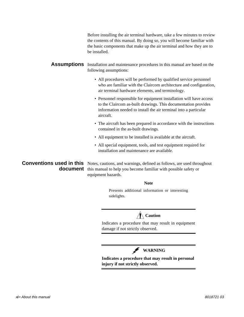
The BBU is installed in the BBU aviation electronics (avionics) tray(shown in figure 1-6).
Hughes Network Systems, Inc. Germantown, MD.
Part No.
FAA-PMASerial No.
Usable On
IDLE
PILOT
TRAFFIC
TRAFFIC
IDLE
PILOT
RF UNIT
CHAN A
PROCESSOR
TELEPHONY
PS UNIT
ALARM
CHAN B
MODECHANNEL A
CHANNEL B
DIAGNOSTIC
ACTIVE
TEST
BASEBAND UNIT
COOLING FAN
BBU AVIONICS TRAY
BBU
Figure 1-6. Baseband unit and BBU avionics tray

1-8 • General description 8018721 03
Radio frequency unit The radio frequency unit (RFU) performs the following functions:
• Obtains the upconverted 895-MHz signal from the BBU andamplifying it in a solid-state power amplifier (SSPA) fortransmission at a UHF/L-band antenna.
• Receives the 850-MHz signal transmitted from a groundstation and passing the signal first through a low-noiseamplifier (LNA) that increases the power level of the receivedsignal. The RFU then outputs the signal to the BBU for down-conversion.
• Provides filtering to protect against radio frequency interfer-ence (RFI).
The RFU is installed in the RFU avionics tray (shown in figure 1-7).
REDUCED 78%
ENLARGED 156.02%REDUCED 73%
RFU
Hughes Network Systems, Inc. Germantown, MD.
Part No.
FAA-PMASerial No.
Usable On
RF UNIT
COOLING FAN
RFU AVIONICS TRAY
Figure 1-7. Radio frequency unit and RFU avionics tray

8018721 03 General description • 1-9
Power supply unit The power supply unit (PSU) supplies regulated direct current (DC)power to the air terminal system. It also provides status monitoringinterfaces, fail-safe functions, and voltage transient protection. Theregulated power derives from 3-phase, 5-wire, 400-Hz, 115-Voltalternating current (AC).
The PSU provides the following voltages:
• 115 VAC, 3-phase, 400-Hz power to the avionics trays coolingfans.
• +48 VDC to the in-cabin equipment ISDN “S” interfaces (viathe BBU).
• +5 VDC, -6.5 VDC, +8 VDC, and +15 VDC to the BBU.
• +15 VDC and +27 VDC to the RFU.
The PSU is installed in the PSU avionics tray (shown in figure 1-8).
POWER
STATUS
AC PILOT
DC
POWER
POWER SUPPLY UNIT
Hughes Network Systems, Inc. Germantown, MD.
Part No.
FAA-PMASerial No.
Usable On
PSU
COOLING FAN
PSU AVIONICS TRAY
Figure 1-8. Power supply unit and PSU avionics tray

1-10 • General description 8018721 03
EMI filter The electromagnetic interference (EMI) filter (shown in figure 1-9)is installed in the 115-VAC line between the circuit breaker paneland the PSU. The filter prevents EMI from entering the PSU via thepower input lines.
LINE
LOAD
Figure 1-9. EMI filter
UHF/L-band antennas The UHF/L-band antenna (shown in figure 1-10) is a 3.5-inch tallomnidirectional blade-type antenna. Each air terminal has twoantennas, either one of which functions as a receive antenna(operating at 850 MHz) or transmit antenna (operating at 895 MHz).
Figure 1-10. UHF/L-band antenna

8018721 03 Installation • 2-1
Chapter 2Installation
This section describes inspecting, inventorying and installing airterminal hardware.
2.1Required tools andmaterials
The following are required:
• Hex wrench, #6
• Crosstip torque screwdriver
• Diagonal cutters, small
• Alodine 1200, Irridite, or equivalent (used to treat barealuminum surfaces to prevent oxidation)
• RTV sealant, or equivalent
• Cable ties, assorted sizes
2.2Materials inspectionand inventory
1. Inspect the shipping containers for external damage. Anydamage should be noted before opening the container.Report damaged equipment to the shipping carrier immedi-ately for claim purposes. Save all packing materials untilinstallation has been completed.
2. Each air terminal installation kit contains a documentationpackage that includes an itemized bill of materials (BOM)which details exactly what that particular kit should contain.Use the BOM as a checklist to inventory the shipment con-tents and verify that all items are present. Report all short-ages to Claircom Communications Group, L.P. forresolution.
Table 2-1 lists the equipment you will be installing.

2-2 • Installation 8018721 03
Table 2-1. Air terminal installation kit components
Baseband unitC23VB-7100-00 (Qty: 1)
Hughes Network Systems, Inc. Germantown, MD.
Part No .
FAA-PMASerial No.
Usable On
IDLE
PILOT
TRAFFIC
TRAFFIC
IDLE
PILOT
RF UNIT
CHAN A
PROCESSOR
TELEPHONY
PS UNIT
ALARM
CHAN B
MODECHANNEL A
CHANNEL B
DIAGNOSTIC
ACTIVE
TEST
BASEBAND UNIT
Radio frequency unitC23VR-7500-00 (Qty: 1)
Hughe s Network Sys tems, Inc. Germantown , MD.
Part No.
FAA-PMASerial No.
Usable On
RF UNIT
Power supply unitC23VP-7300-00 (Qty: 1)
POWER
STATUS
AC PILOT
DC
POWER
POWER SUPPLY UNIT
Hughes Network Systems, Inc. Germantown, MD.
Part No.
FAA-PMASerial No.
Usable On
Seatback phone unitC23PS-6100-00 (Qty: Variable)
SEE INSTRUCTION CARD FOR USE
THIS TELEPHONE MODEM EQUIPPED
2 AB
C
13 DE
F
7 PRS
4 GHI
5 JKL
8 TUV
0 OPR
#
9 WXY
6 MNO
*
CREDIT CARD READER
ECO box(“S” loop box, 1 RJ)
C23CE-4100-01(Qty: Variable)
HANDSET
ECO box(“S” loop box, 2 RJ)
C23CE-4100-02(Qty: Variable)
HANDSET
ECO box(“S” loop box, 3 RJ)
C23CE-4100-03(Qty: Variable)
HANDSET
UHF/L-band antennaCI-105-15-2 (Qty: 2)
TerminatorC23CE-4200-00(Qty: Variable)
RJ-45 blank plug9006494-0008(Qty: Variable)
EMI filter1015401-0001
(Qty: 1)
LINE
LOAD

8018721 03 Installation • 2-3
2.3Installing air terminalequipment
This section describes installing the following air terminalequipment:
• Power supply unit
• Radio frequency unit
• Baseband unit
• Electrical connection (ECO) boxes
• Ultra-high frequency (UHF)/L-band antennas
• Seatback phone units
• The electromagnetic interference (EMI) filter
• Integrated services digital network (ISDN) terminator
Installing the powersupply unit
Perform the following procedure to install the power supply unit(PSU) into the PSU avionics tray.
WARNING
Set all air terminal circuit breakers to OFFbefore continuing with this procedure (referto the as-built drawings for the locations ofthe circuit breakers).
Caution
Wear an electrostatic discharge (ESD) wriststrap at all times while handling air terminalequipment. Connect the wrist strap groundingclip to the grounding connection on any of theavionics trays.
1. Remove the PSU (see table 2-1) from its shippingcontainer.

2-4 • Installation 8018721 03
DUST COVER
Figure 2-1. Removing the dust cover
2. Remove the ESD-protective dust cover from the rearconnectors on the PSU (see figure 2-1). Verify that there areno damaged or bent pins on the connectors.
3. Open the switch cover and verify that the PSU powerswitch is set to OFF (down position) as shown in figure 2-2.Close the switch cover.
4. Insert the unit into the avionics tray labeled PSU.
POWER
STATUS
AC PILOT
DC
POWER
POWER SUPPLY UNIT
Hughes Network Systems, Inc. Germantown, MD.
Part No.
FAA-PMASerial No.
Usable On
ON
OFF
POWER SWITCH
SWITCH COVER
Figure 2-2. PSU power switch

8018721 03 Installation • 2-5
POWER
STATUS
AC PILOT
DC
POWER
POWER SUPPLY UNIT
Hughes Network Systems, Inc. Germantown, MD.
Part No.
FAA-PMASerial No.
Usable On
FRONT LIP
WHITE LOCKING LEVER
HOOK
HOLD-DOWN FASTENERS
Figure 2-3. Hold-down fastener components
5. Carefully slide the unit into the tray until it makes contactwith the connectors.
6. Raise both hold-down fasteners so that the front lip of eachfastener rests just behind the lower front panel of the PSU(see figure 2-3). Turn the white locking lever (seefigure 2-3) clockwise (left to right) as far as it can go,making sure the cup engages the hook. This locks the hold-downs against the PSU (see figure 2-4).
Hughes Network Systems, Inc. Germantown, MD.
Part No.
FAA-PMASerial No.
Usable On ROTATE LEVER CLOCKWISE TO
LOCK IT
REDINDICATOR BAND
Figure 2-4. Locking and tightening the hold-down fasteners

2-6 • Installation 8018721 03
7. Turn both fluted knobs clockwise until the red indicatorbands (see figure 2-4) have disappeared. When thathappens, you will feel the fasteners clutching out. Thatmeans the full load required for mating has been appliedand the PSU is seated securely.
Installing the radiofrequency unit
The following procedure describes installing the radio frequency unit(RFU) into the RFU avionics tray.
1. Remove the RFU (see table 2-1) from its shippingcontainer.
2. Remove the ESD-protective dust cover from the rear con-nectors. Verify that there are no damaged or bent pins onthe connectors.
3. Insert the unit into the avionics tray labeled RFU.
4. Carefully slide the unit into the tray until it makes contactwith the connector.
5. Raise both hold-down fasteners so that the front lip of eachfastener rests just behind the lower front panel of the RFU.Turn the white locking lever clockwise as far as it can go,making sure the cup engages the hook.
6. Turn both fluted knobs clockwise until the red indicatorbands have disappeared. When that happens, the RFU isseated securely.
Installing the basebandunit
Perform the following procedure to install the baseband unit (BBU)into the BBU avionics tray.
1. Remove the baseband unit (see table 2-1) from its shippingcontainer
2. Remove the ESD-protective dust cover from the rear con-nectors. Verify that there are no damaged or bent pins onthe connectors.
3. Insert the unit into the avionics tray labeled BBU.
4. Carefully slide the unit into the tray until it makes contactwith the connector.
5. Raise both hold-down fasteners so that the front lip of eachfastener rests just behind the lower front panel of the BBU.Turn the white locking lever clockwise as far as it can go,making sure the cup engages the hook.
6. Turn both fluted knobs clockwise until the red indicatorbands have disappeared. When that happens, the BBU isseated securely.
8018721 03 Installation • 2-7
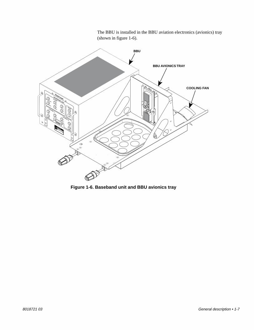
Installing the electricalconnection boxes
The following procedure describes installing the electrical connec-tion (ECO) boxes. As installations may vary from aircraft to aircraft,refer to the as-built drawings to determine where each ECO box willbe located.
1. Remove an ECO box (see table 2-1) from its shipping con-tainer.
2. Place the ECO box onto an ECO bracket as shown infigure 2-5.
ANCHORING STRAPS
ECO BOX
ECO BRACKET
ANCHORING STRAPS
(INSTALLED)
Figure 2-5. Installing an ECO box onto an ECO bracket
3. Insert an anchoring strap through one of the slots in thebracket and the ECO box (see figure 2-5). Bend the strapand insert it through the adjacent slot in the ECO box andbracket as shown in figure 2-5. Slide the tip of the strap intothe hole in the head of the strap and pull the tip until anyslack in the strap has been removed. Use a pair of diagonalcutters to remove excess strap.

2-8 • Installation 8018721 03
4. Use anchoring straps to install the ECO bracket onto theseat frame as shown in figure 2-6.
HANDSET
SEAT FRAME(AS SEEN FROM
UNDERSIDE OF SEAT)
ECO BRACKET
Figure 2-6. Installing an ECO bracket onto a seat frame

8018721 03 Installation • 2-9
5. Install an ISDN “S” loop input cable connector to the ECObox connector labeled IN (see figure 2-7 for locations).Close both spring latches to secure the connector.
6. Install an ISDN “S” loop output cable connector to the ECObox connector labeled OUT (see figure 2-7). Close thespring latches.
7. Install the RJ-45 phone cable connectors to the ECO boxconnectors labeled HANDSET (see figure 2-7 forlocations).
OUT
IN
HANDSET
HANDSET
OUTCONNECTOR
INCONNECTOR
HANDSETCONNECTORS
SPRING LATCHES
Figure 2-7. Installing phone cables
NoteIf the ECO box you are installing will haveunused handset jacks, install RJ-45 blankplugs (see table 2-1) into the empty jacks.
8. Repeat steps 1 through 7 to install the remaining ECOboxes in the “S” loop.
2-10 • Installation 8018721 03
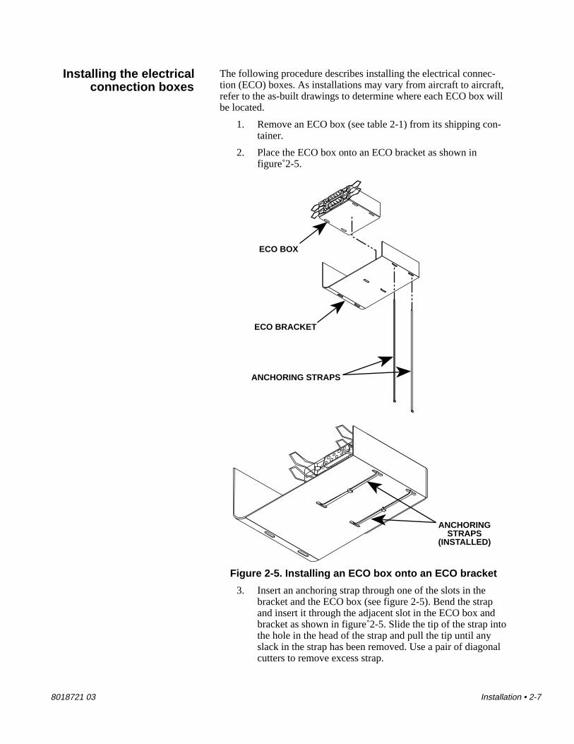
9. After installing the last ECO box in the “S” loop, install anISDN terminator to the ECO box connector labeled OUT(see figure 2-8). Close the spring latches.
10. Repeat steps 1 through 9 to install ECO boxes on remaining“S” loops.
OUT
IN
HANDSET
TERMINATOR
Figure 2-8. Installing the terminator

8018721 03 Installation • 2-11
Installing theUHF/L-band antennas
The following procedure describes installing the two UHF/L-bandantennas onto the aircraft. As installations may vary from aircraft toaircraft, refer to the as-built drawings to determine where the cableassemblies that connect to each antenna are located.
Caution
Before proceeding, verify the following:
• That a doubler plate (see figure 2-9) hasbeen installed at each location where anantenna will be mounted
• All paint, primer, etc. has been removedfrom an area matching the footprint of theantenna on the outside of the aircraftfuselage.
• Bare metal antenna mounting surfaces havebeen treated with Alodine 1200 or Irriditeto prevent aluminum oxidation.
DOUBLER PLATE
Figure 2-9. Antenna doubler plate
1. Remove a UHF/L-band antenna (see table 2-1) from itsshipping container.

2-12 • Installation 8018721 03
FRONT OF AIRCRAFT
UHF/L-BAND ANTENNA
MOUNTING HARDWARE1
4
3
6
5
2
Figure 2-10. Installing the antenna onto the aircraft
2. Using a crosstip torque screwdriver, mount the antenna tothe aircraft with six sets of 6-32 screws, as shown infigure 2-10. Tighten screw #1 (see figure 2-10) a smallamount, then tighten screw #2 the same amount. Continuetightening the remaining screws a small amount followingthe sequence shown in figure 2-10. Repeat the sequenceagain, using the same side-to-side pattern so that uniformstress is placed on the antenna, until the screws have beenset to a torque of 8 to 10 inch/pounds.
3. Using RTV sealant, apply a small, smooth fillet along thejoint between the antenna and the aircraft fuselage. Also,apply sealant over the mounting hardware heads at the baseof the antenna.
Caution
Allow the sealant to dry for 4 hours beforeexposing it to water.

8018721 03 Installation • 2-13
CABLE ASSEMBLY
N-TYPE CONNECTOR
Figure 2-11. Installing the cable assembly onto theantenna
4. Connect the cable assembly to the N-type connector on theantenna as shown in figure 2-11. Hand-tighten the connec-tor to secure it. Create a service loop with the excess cablelength and clamp as specified in the aircraft manufacturer’srecommendation for antenna installations.
Caution
Be careful when bending the cable that you donot exceed the minimum bend radius of sixtimes the cable’s outside diameter. Exceedingthe minimum bend radius could result in cablefailure.
5. Repeat steps 1 through 4 to install the remainingUHF/L-band antenna.

2-14 • Installation 8018721 03
Installing the seatbackphone units
The following procedure describes installing the telephone handsetsinto the seatback headrests.
1. Remove a seatback phone unit (see table 2-1) from itsshipping container.
2. Record the phone unit handset serial number per Claircom’srequirements.
RJ-11 SEATBACK
CONNECTOR
CRADLE CONNECTOR
Figure 2-12. Installing the RJ-11 connector onto the seatback phone unit
3. Install the RJ-11 connector (located inside the seatbackheadrest) into the cradle connector, as shown in figure 2-12.
4. Insert the cradle into the slot in the seatback headrest (seefigure 2-12).

8018721 03 Installation • 2-15
SEE INSTRUCTION CARD FOR USE
THIS TELEPHONE MODEM EQUIPPED
2 AB
C
13 DE
F
7 PR
S
4 GH
I5 JK
L
8 TUV
0 OP
R#
9 WX
Y
6 MN
O
*CREDIT CARD READER
RELEASELATCH
MOUNTING SCREWS
Figure 2-13. Installing phone unit mounting hardware
5. Slide the release latch to the left and remove the handsetfrom the cradle (see figure 2-13). Pull out enough handsetcord so that you can install the cradle mounting hardwarewithout the handset or its cord getting in the way.
6. Using the appropriate tool, install the cradle into the seat-back headrest with four mounting screws (see figure 2-13).(Verify that the seat cover material is not buckled and thatthere are no exposed seams visible after securing thecradle.)
7. Verify proper mechanical operation of the handset (makesure the reel coils the cord properly and that the handsetrelease latch works)
8. Repeat steps 1 through 7 to install remaining phone units.

2-16 • Installation 8018721 03
MAIN DISCONNECTPANEL
EMI FILTER
LINE
LOAD
LINE CONECTOR
8-32 MOUNTING HARDWARE
8-32 MOUNTINGHARDWARE
Figure 2-14. Installing the EMI filter
Installing the EMI filter Perform the following procedure to install the electromagnetic inter-ference (EMI) filter.
1. Remove the EMI filter (see table 2-1) from its shippingcontainer.
2. Using a crosstip torque screwdriver, mount the filter to themain disconnect panel with four sets of 8-32 mountinghardware, as shown in figure 2-14. Torque the screws to12 to 15 inch/pounds.
NoteThe following steps describe installing EMIfilter cables. There are two cable connec-tions to the EMI filter. One of them, theLINE connection, is the cable link betweenthe AC voltage source and the EMI filter.The other connection (LOAD) is the cablelink between the filter and the PSU.
3. Install the AC voltage source cable connector to the EMIfilter connector labeled LINE.
4. Install the PSU cable connector to the EMI filter connectorlabeled LOAD.

8018721 03 Installation • 2-17
Air terminal installation is now complete. Fill out required documen-tation. Then refer to chapter 3, “Commissioning” to configure the airterminal for operation in the Claircom network.

2-18 • Installation 8018721 03

8018721 03 Commissioning • 3-1
Chapter 3Commissioning
This section contains the following procedures for commissioningthe air terminal:
• Applying power to the radio equipment and observing as theyperform automatic self-tests.
• Using the maintenance console and the RF translator box torun loopback tests of radio equipment and in-cabin equipment.
• Testing the phone units.
3.1Required testequipment
• Maintenance console in the following minimum configuration:
— 386 SX IBM or compatible notebook computer
— 4-Mbytes RAM
— 3.5-inch disk drive
— 60-Mbyte disk drive
— Serial I/O port
• ATC Commissioning Program (version R1.60c, or higher)
• RF translator box (shown in figure 3-1). The translatorreceives the 895-MHz signal from one UHF/L-band antenna,converts the signal to 850 MHz, and transmits the translatedsignal to the other UHF/L-band antenna.
Figure 3-1. RF translator box

3-2 • Commissioning 8018721 03
• Test card (used to test the credit card readers on the phoneunits).
• Digital multimeter (Fluke Type 77 or equivalent).
3.2System power-up andself tests
Perform the following procedure to apply power to the air terminalradio equipment.
1. Set all air terminal circuit breakers to ON.
2. Open the switch cover on the PSU front panel and set thepower switch to ON (up position). Close the switch cover.Verify that the AC PILOT and DC status lamps (seefigure 3-2 for locations) illuminate and remain lit:
POWER
STATUS
AC PILOT
DC
POWER
POWER SUPPLY UNIT
Hughes Network Systems, Inc. Germantown, MD.
Part No.
FAA-PMASerial No.
Usable On
AC PILOT LAMP
DC LAMP
Figure 3-2. PSU status lamps
3. Set the air terminal circuit breakers to OFF. Verify that theAC lamp on the front panel of the PSU extinguishes.

8018721 03 Commissioning • 3-3
4. Set the air terminal circuit breakers to ON. Verify that theAC lamp on the front panel of the PSU illuminates.
Hughes Network Systems, Inc. Germantown, MD.
Part No.
FAA-PMASerial No.
Usable On
IDLE
PILOT
TRAFFIC
TRAFFIC
IDLE
PILOT
RF UNIT
CHAN A
PROCESSOR
TELEPHONY
PS UNIT
ALARM
CHAN B
MODECHANNEL A
CHANNEL B
DIAGNOSTIC
ACTIVE
TEST
BASEBAND UNIT
PROCESSOR ALARM LAMP
RFU ALARM LAMP
CHANNEL A ALARM LAMP
TELEPHONY ALARM LAMP
PSU ALARM LAMP
CHANNEL A IDLESTATUS LAMP
CHANNEL A PILOTSTATUS LAMP
CHANNEL A TRAFFICSTATUS LAMP
DIAGNOSTIC CONNECTOR(FOR MAINTENANCE CONSOLE)
CHANNEL B IDLESTATUS LAMP
CHANNEL B PILOTSTATUS LAMP
CHANNEL B TRAFFICSTATUS LAMP
PRESS-TO-TESTSWITCH
ACTIVE MODELAMP
PR
ESS-TO-TEST
CHANNEL B ALARM LAMP
Figure 3-3. BBU indicator lamps
5. Following power up the air terminal will automatically runself-diagnostics tests. This is indicated by all lamps on thePSU and BBU illuminating for approximately one second,then extinguishing, except for the PRESS-TO-TEST lamp(see figure 3-3). The lamp on the PRESS-TO-TEST switchwill remain lit until the diagnostics tests are complete.
NoteIf the sequence does not terminate with theACTIVE lamp flashing, the air terminal hasfailed startup self-tests. Refer to section 6.3,“Troubleshooting flowcharts.”

3-4 • Commissioning 8018721 03
6. After approximately 30 seconds, the following will occur:
• The PRESS-TO-TEST lamp will extinguish, indicat-ing that diagnostics test are completed.
• The PROCESSOR alarm lamp will flash on and offonce.
• The ACTIVE lamp will flash on and off twice, thenilluminate for approximately 15 seconds, then beginflashing.
7. Once the diagnostics are complete, the system will test thefunctioning of the channel threads. The tests last approxi-mately 60 seconds. After the tests are complete, theACTIVE lamp will be flashing.
NoteIf the sequence does not terminate with theACTIVE lamp flashing, the air terminal hasfailed startup self-tests. Refer to section 6.3,“Troubleshooting flowcharts.”
Air terminal power-up and self-test diagnostics are complete. Referto the next section to perform system tests.
3.3System testing This section describes testing the radio equipment and in-cabin
equipment using the maintenance console and RF translator box.
WARNING
To avoid potential health risks caused by RFradiation, do not come within 4 feet of aUHF/L-band antenna while the PSU is activated.
1. Verify that the maintenance console is deactivated.
2. Install the maintenance console/BBU interface cable to theBBU port labeled DIAGNOSTIC (see figure 3-3).

8018721 03 Commissioning • 3-5
10-FOOTRADIUS
20-FOOTRADIUS
PLACE RFTRANSLATOR BOXINSIDE THIS ZONE
PLACE RFTRANSLATOR BOXINSIDE THIS ZONE
Figure 3-4. Placing the RF translator box
3. Place the RF translator box at a location underneath theUHF/L-band antennas no closer than 10 feet and no fartherthan 20 feet from the antennas (see figure 3-4).
4. Activate the RF translator box.
5. Activate the maintenance console. Once the console hasfinished booting up, a prompt resembling the following willbe displayed:
A:\MC>

3-6 • Commissioning 8018721 03
6. Type CP, then press the [Enter] key. The ClaircomCommissioning Program Application Select Menu will bedisplayed (see figure 3-5).
NoteIf you make a mistake while typing, pressthe [Backspace] key to delete the entry.
R1.60c Claircom Commissioning Program Application Select Menu
1. Commissioning Configuration Menu 2. Maintenance Test Menu
Enter Selection Number and press Return Key _
<ESC>: Exit Screen Enter Number 1,2
Figure 3-5. Claircom Commissioning Program Application Select Menu

8018721 03 Commissioning • 3-7
Claircom Maintenance Console Maintenance Test Menu
1. Display Handset TEI Table 2. IF Test 3. RF Loopback Test Test result:
Enter Selection Number and press Return Key _
(Handset) TEI Table 0 1 2 3 4 5 6 7 (Loop) 0x 1x 2x 3x 4x 5x 6x 7x 8x 9x 10x 11x
<ESC>: Exit Screen Enter Number 1-3
Figure 3-6. Claircom Maintenance Console Maintenance Test Menu
7. Type 2, then press the [Enter] key. The Claircom Mainte-nance Console Maintenance Test Menu will be displayed(see figure 3-6).
NoteIf you are using a version of the ATCCommissioning Program that was releasedprior to version 1.60c, the Claircom Mainte-nance Console Maintenance Test Menu willshow 8 loops instead of 12.
8. Type 1, then press the [Enter] key to begin the DisplayHandset TEI (terminal equipment identifier) Table test.This test verifies that each phone unit on each ISDN loopresponds to queries from the BBU. OK is used to representphones that respond properly; blank entries in the tableindicate that there is either no phone unit present or thephone unit is not responding.
If TEI table results are correct, go to step 9. Otherwise,verify that phone units are installed in the proper configura-tion (for instance, too many phones on one “S” loop and notenough phones on another will result in incorrect TEI tablelistings). If the phone units are installed correctly, refer tosection 6.3, “Troubleshooting flowcharts,” flowchart 6-4.

3-8 • Commissioning 8018721 03
9. Type 2, then press the [Enter] key to begin the IF Test. Thesystem will display PASS or FAIL at the conclusion of thetest. If the result is PASS, continue on to step 10; otherwise,refer to section 6.3, “Troubleshooting flowcharts.”
10. Type 3, then press the [Enter] key to begin the RF Loop-back Test. In this loopback test, the BBU transmits a num-ber of signal packets (called RR sequences) through theloopback circuit shown in figure 3-7 and examines thesuccess rate of the arrival of the packets on the receive side.The system will display PASS or FAIL at the conclusion ofthe test. If the result is PASS, continue on to step 11;otherwise, refer to section 6.3, “Troubleshootingflowcharts.”
TRANSMITCIRCUITRY
RECEIVECIRCUITRY
DIAGNOSTICSPORT
POWERSUPPLY
UNIT
BBU
UHF/L-BAND ANTENNA #1
UHF/L-BAND ANTENNA #2
REGULATED DC VOLTAGE
RFU
TRANSMITCIRCUITRY
RECEIVECIRCUITRY
MAINTENANCETERMINAL
RF TRANSLATOR BOX
895 MHz
850 MHz
895-MHz signal is translated to 850-MHz
Figure 3-7. RF Loopback Test signal flow
11. Press on the [Esc] key to return to the Claircom Commis-sioning Program Application Select Menu.

8018721 03 Commissioning • 3-9
Claircom Maintenance Console Configuration Menu
Airline ID 0 AT ID 0 ICAO ID 0 0 0
AT Service State 1 AT Features 0 0 0 0 0 0
ICC Variables _______________________________________________________________ Num Loop Present Install Priority 0 Y 8 0 1 Y 8 0 2 Y 8 0 3 Y 8 0 4 Y 8 0 5 Y 8 0 6 Y 8 0 7 Y 8 0 8 Y 8 0 9 Y 8 0 10 Y 8 0 11 Y 8 0
<ESC>: Exit Screen <F2>: Write Config <F4>: ReRead Config Enter Number 0-15
Figure 3-8. Claircom Maintenance Console Configuration Menu
12. Type 1, then press the [Enter] key. The Claircom Mainte-nance Console Configuration Menu will be displayed (seefigure 3-8).
NoteIf you are using a version of the ATCCommissioning Program that was releasedprior to version 1.60c, the Claircom Mainte-nance Console Configuration Menu willshow 8 loops instead of 12.
13. Type in the Airline ID (identification) number (the numbermust be between 00 and 15), then press [Enter].
NoteIf you want to skip a field, or modify oneyou have already set, press the [Tab] key tojump the cursor forward (or press the[Shift] + [Tab] keys to move the cursorbackward) to that field.
14. Type in the AT (air terminal) ID (the number must bebetween 0 and 1023), then press [Enter].
15. Press the [Tab] key to jump the cursor past the ICAO ID,AT Service State, and AT Features fields.

3-10 • Commissioning 8018721 03
16. Type a Y in the Loop 0 Present field if there is a looppresent; otherwise, type an N. Press the [Enter] key tomove to the next field
17. Type the number of phone unit handsets installed on“S” loop 0 in the Num Install field, then press [Enter].
18. Type a number from 0 through 3 (0 is the highest levelpriority, 3 is the lowest) to set the loop priority of“S” loop 0, then press [Enter].
19. Repeat steps 16 through 18 to configure “S” loops1 through 7. Then continue on to step 20.
20. Press the [F2] key to write the configuration changes to theair terminal. After approximately five seconds, press the[Esc] key to exit from the ATC Commissioning Program.
21. Deactivate the maintenance console.
22. Disconnect the maintenance console/BBU interface cablefrom the diagnostics port on the BBU.
23. Set the power switch on the RF translator box to OFF.
24. Open the switch cover on the PSU front panel and set thepower switch to OFF. Wait 10 seconds, then set the switchto ON. Close the switch cover.
25. Steps 26 through 35 describe tests that check the followinghandset features:
• Keypad operation
• LCD readout operation
• Card reader operation
• Mouthpiece microphone and earpiece speakeroperation
• Volume key operation
If you find a handset that has an LCD readout displayingerror codes, refer to section “Replacing a seatback phoneunit” in chapter 7, “Maintenance.” If the handset ismalfunctioning, but you are unable to determine the cause,refer to section 6.3, “Troubleshooting flowcharts.”
NoteYou will need a password to perform thefollowing tests. Contact your supervisor toobtain the handset password.

8018721 03 Commissioning • 3-11
26. Enter the accessing keys into the handset. The handset LCDreadout will display the following:
1=EMI Mode2=Auto Dial3=A-Dial Rst
27. Press the [1] key on the keypad. The LCD will display thefollowing:
Please Enter Password:
28. Enter the password into the handset. The LCD readout willdisplay:
1=Start EMI2=Stop EMI
29. Press the [1] key on the keypad. The LCD will display:
PRESS ONTO MAKE CALL
ON HELP
30. Press the ON key. When the prompt appears on the LCDreadout, slide the test card through the card reader slot. Ifthe message PLEASE SLIDE CARD SLOWLY appears,slowly slide the test card through the reader slot again. Ifthe PLEASE SLIDE CARD SLOWLY message appearsagain, the handset is defective.
31. Press each key on the keypad; verify that a tone is generatedas each key is pressed and that the key’s alphanumericcharacter is displayed on the LCD readout.
32. Press each of the soft keys and verify that the LCD readoutdisplay is correct.
33. Talk into the mouthpiece and verify that—after a shortdelay—you hear your voice in the earpiece. While perform-ing this test, press on the ▲ (increase) volume and ▼(decrease) volume buttons and verify that the voice volumecontrol operates properly.
34. Verify proper mechanical operation of the handset (makesure the reel coils the cord correctly and that the handsetrelease latch works).
35. Press the END key to allow another phone unit to be tested.
36. Repeat steps 30 through 35 to test each remaining phoneunit.

3-12 • Commissioning 8018721 03
37. Press the [2] key on a phone unit keypad to return the airterminal to normal operating mode.
38. Open the switch cover on the PSU front panel and set thepower switch to OFF. Wait 10 seconds, then set the switchto ON. Close the switch cover.
The air terminal is now operational. Refer to chapter 4, “Operation.”

8018721 03 Operation and shutdown • 4-1
Chapter 4Operation and shutdown
This section contains information required to operate, deactivate, orrestart the air terminal.
4.1Operation Once the air terminal has been installed, tested, and commissioned,
no operator action is required under normal conditions; the air termi-nal is designed for unattended operation. Leave the PSU ON/OFFpower switch set to ON at all times (except when the air terminalshould have power removed for servicing). Table 4-1 is a summaryof air terminal switch positions and indications under normal operat-ing conditions. If your air terminal is not operating as specified, referto chapter 6, “Troubleshooting.”
Table 4-1. Normal operating configuration for air terminal switches and indicators
Device Switch/Lamp Setting/Indication
PSU ON/OFF switch ON
PSU AC PILOT lamp Lit
PSU DC lamp Lit
BBU ACTIVE lamp Flashing
BBU CHANNEL A IDLE Lit if CHANNEL A TRAFFIC lamp is extinguished
BBU CHANNEL A TRAFFIC Lit if CHANNEL A IDLE lamp is extinguished
BBU CHANNEL A PILOT Lit if Channel A is being used to search for a pilot signal
BBU CHANNEL B IDLE Lit if CHANNEL B TRAFFIC lamp is extinguished
BBU CHANNEL B TRAFFIC Lit if CHANNEL B IDLE lamp is extinguished
BBU CHANNEL B PILOT Lit if Channel B is being used to search for a pilot signal

4-2 • Operation and shutdown 8018721 03
4.2System shutdown Perform the following procedure to deactivate the air terminal
equipment:
1. Open the switch cover on the PSU front panel and set thepower switch to OFF (down position). (Refer to figure 4-1for switch location.) Close the switch cover.
POWER
STATUS
AC PILOT
DC
POWER
POWER SUPPLY UNIT
Hughes Network Systems, Inc. Germantown, MD.
Part No.
FAA-PMASerial No.
Usable On
ON
OFF
POWER SWITCH
SWITCH COVER
Figure 4-1. PSU power switch
2. Set all air terminal circuit breakers to OFF (refer to the as-built drawings for the locations of the circuit breakers).
3. Verify that the AC PILOT lamp on the PSU is extinguished.
The air terminal is now deactivated. If you need to restart the system,refer to section 4.3, “Restarting the air terminal” to do so.

8018721 03 Operation and shutdown • 4-3
4.3Restarting the airterminal
Perform the following procedure to apply power to the air terminalradio equipment.
1. Set all air terminal circuit breakers to ON.
2. Open the switch cover on the PSU front panel and set thepower switch to ON (up position). Close the switch cover.Verify that the AC PILOT and DC status lamps (see figure4-2 for locations) illuminate and remain lit.
POWER
STATUS
AC PILOT
DC
POWER
POWER SUPPLY UNIT
Hughes Network Systems, Inc. Germantown, MD.
Part No.
FAA-PMASerial No.
Usable On
AC PILOT LAMP
DC LAMP
Figure 4-2. PSU status lamps

4-4 • Operation and shutdown 8018721 03
Hughes Network Systems, Inc. Germantown, MD.
Part No.
FAA-PMASerial No.
Usable On
IDLE
PILOT
TRAFFIC
TRAFFIC
IDLE
PILOT
RF UNIT
CHAN A
PROCESSOR
TELEPHONY
PS UNIT
ALARM
CHAN B
MODECHANNEL A
CHANNEL B
DIAGNOSTIC
ACTIVE
TEST
BASEBAND UNIT
PROCESSOR ALARM LAMP
RFU ALARM LAMP
CHANNEL A ALARM LAMP
TELEPHONY ALARM LAMP
PSU ALARM LAMP
CHANNEL A IDLESTATUS LAMP
CHANNEL A PILOTSTATUS LAMP
CHANNEL A TRAFFICSTATUS LAMP
DIAGNOSTIC CONNECTOR(FOR MAINTENANCE CONSOLE)
CHANNEL B IDLESTATUS LAMP
CHANNEL B PILOTSTATUS LAMP
CHANNEL B TRAFFICSTATUS LAMP
PRESS-TO-TESTSWITCH
ACTIVE MODELAMP
PR
ESS-TO-TEST
CHANNEL B ALARM LAMP
Figure 4-3. BBU indicator lamps
3. Following power up the air terminal will automatically runself-diagnostics tests. This is indicated by all lamps on thePSU and BBU illuminating for approximately one second,then extinguishing, except for the PRESS-TO-TEST lamp(see figure 4-3 for lamp locations). The lamp on thePRESS-TO-TEST switch will remain lit until thediagnostics tests are complete.
NoteIf a test fails, the PROCESSOR alarmlamp will illuminate. If that occurs, refer tosection 6.3, “Troubleshooting flowcharts.”

8018721 03 Operation and shutdown • 4-5
4. After approximately 30 seconds, the following will occur:
• The PRESS-TO-TEST lamp will extinguish, indicat-ing that diagnostics test are completed.
• The PROCESSOR alarm lamp will flash on and offonce.
• The ACTIVE lamp will flash on and off twice, thenilluminate for approximately 15 seconds, then beginflashing.
5. Once the diagnostics are complete, the system will test thefunctioning of the channel threads. The tests last approxi-mately 60 seconds. When the tests are complete, theACTIVE lamp will be flashing.
NoteIf the sequence does not terminate with theACTIVE lamp flashing, the air terminal hasfailed startup self-tests. Refer to section 6.3,“Troubleshooting flowcharts.”
Air terminal power-up and self-test diagnostics are complete.

4-6 • Operation and shutdown 8018721 03

8018721 03 Theory of operation • 5-1
Chapter 5Theory of operation
This chapter describes the theory of operation of the major air termi-nal hardware components (BBU, RFU, PSU, and handsets) andbriefly details how phone calls are made.
5.1BBU description The baseband unit performs the following functions:
• During transmit operations, the BBU receives ISDN-formattedpulse code modulated (PCM) telephone data from as many as96 phone units in 12 ISDN “S” loops. The BBU compressesthe voice data so that it can be transmitted in a 13.2-Kb/sbandwidth signal. The baseband unit then scrambles,interleaves, and convolutionally encodes the data to prepare itfor transmission through a possibly noisy or fading radio linkto the nearest ground station. After encoding the data, the BBUmodulates the data in BPSK (phase modulation having twopossible phase states) or 8-PSK (phase modulation havingeight possible phase states) as appropriate to the stage in callsetup, at an intermediate frequency (IF) in a band centered at23.6 MHz. The baseband unit then upconverts the IF carrier toradio frequency (RF) in a band centered at 895 MHz. The RFsignal is then passed on to the RFU for final processing andtransmission through one of the two radio channels.
• During receive operations, the BBU downconverts the850-MHz carrier band to an IF frequency centered at21.4 MHz. The baseband unit then demodulates the receivedsignal in either BPSK or 8-PSK modes; it performs automaticgain control (AGC) and automatic frequency control (AFC) tocounter the effects of Doppler caused by aircraft motion andvarious effects of signal fading and signal blockage. Afterdemodulating the signal, the BBU unscrambles, de-interleavesand performs forward error correction (FEC) to reproduce theoriginal data stream. The baseband unit then synthesizes thevoice signal based upon the compressed parameters in thereceive data and outputs an ISDN signal for the phone unitreceivers in the aircraft cabin. The BBU performs this actionfor two radio channels and up to 12 ISDN “S” loops.
BBU functions are provided by the following modules:
• Control processor (CP). The CP coordinates all in-cabin andBBU activities; monitors the phone units, operates the radio

5-2 • Theory of operation 8018721 03
link, communicates with the control center and keeps records.The CP controls the other modules through a monitor andcontrol (M&C) bus.
• Circuit switch module (CSM). The CSM provides the ISDNlink to the phone units in the cabin; the circuit switch moduledirects the data to one of the two channels through a backplanebus.
• Baseband processor (BSP). The BSP interchanges voice datawith the CSM and analyzes the voice data for compressionbefore transmission. The analysis results in a set of parametersthat are used later by the receiving end to decompress thevoice signal.
• Modem module (MOM). The MOM modulates/demodulateseither BPSK data or 8-PSK data.
CP description The control processor is an i9601 processor operating under a real-time operating system called Vx960 which is based upon the UNIX2
operating system. The control processor has dynamic random-accessmemory (DRAM) and flash erasable programmable read-onlymemory (EPROM) that contain the program firmware used by theCP and the digital signal processors (DSPs) located on the BSP andthe MOM. Upon startup, the CP program is loaded from flashEPROM into DRAM. The CP program code then loads the DSPcode into the MOM and BSP module.
The CP module’s M&C bus controls the BSP module, MOM, andCSM. The CP also has an Ethernet3 interface that is used duringmanufacturing to test the module.
The CP has an RS-232 serial port that is used to debug software or toload new software. The serial port provides access to the UNIX-likeshell of Vx960 (a command line interpreter). The serial port islocated on the front panel of the BBU and is labeled DIAGNOSTIC.
The CP communicates with its counterpart CP modules in the groundstations through an overhead channel. The overhead channel iscreated by the firmware on the BSP module. The BSP firmware canbe commanded into overhead mode in which the entire channelbandwidth carries data from the CP or the BSP firmware can be
1 The terms i960 and Vx960 are trademarks of INTEL Corporation.2 The term UNIX is a registered trademark of AT&T.3 The term Ethernet is a trademark of Xerox Corporation.

8018721 03 Theory of operation • 5-3
commanded into voice mode in which only a few bits per 120-msframe are available for overhead data from the CP.
CSM description The circuit switch module contains all of the ISDN circuitry. Thereare up to 12 ISDN “S” loops. Each loop is a time-division multiple-access (TDMA) arrangement in which there is a control channel andtwo traffic channels available per loop. Any phone unit connected toa loop can seize control of one of the traffic channels through appro-priate use of the control channel and in cooperation with the CP pro-gram monitoring the process. Once two phone units have seized thetraffic channels, all others must wait until a channel is released.
Each ISDN “S” loop is a bipolar circuit that requires 48 VDC(supplied by a transformer inside the CSM).
Decoded data sent to the CSM is directed to the selected radiochannel on a high-speed serial bus using a time-division multiplexed(TDM) format.
The CP code programs the integrated circuits on the CSM and isresponsible for responding to phone unit handset keystrokes duringthe radio link setup phase of the call. The control processor decideswhich radio link, if any, is available and programs the CSM to directthe pulse-code modulated (PCM) data from the handset to the appro-priate BSP module.
BSP module description The BSP module has three DSPs and a variety of field-programmable gate array (FPGA) logic circuits. The FPGA logicprovides the interface to the M&C bus from the CP as well as inter-face to the high-speed serial bus from the BSP. The logic alsocontrols the dual-port random-access memory (RAM) used to inter-face between the DSPs.
The CP program sends commands via the M&C bus that control theoperating mode of the BSP module. There are two BSP modes: over-head mode, in which all of the data comes from the air terminalserial controller; or voice mode, in which most of the data comesfrom the CSM via the high-speed serial bus and only a small per-centage comes as overhead data from the CP.
Three DSPs—operating in parallel to share computing tasks—partition the voice compression and pre-transmission data processingso that it is performed in real-time.
The BSP firmware receives the PCM data from the CSM andanalyzes the data’s frequency, amplitude, and noise level character-

5-4 • Theory of operation 8018721 03
istics. These characteristics are then expressed as a set of parametersthat are then formatted for delivery to the modulator.
Before going to the modulator the data is interleaved and convolu-tionally encoded to reduce errors.
A synchronous serial line is used to send the data to the MOM. Themodem module controls the rate at which the data is output and pro-vides the clock signal used to synchronize the connection.
The BSP firmware synthesizes the voice from the parameters in thereceive data and sends it in PCM format (via the high-speed serialbus) to the CSM module.
MOM moduledescription
The MOM primarily uses hardware to perform the modulation func-tion and firmware to perform the demodulation function. The MOMfeatures direct digital synthesis (DDS) of transmit and receive carri-ers that control synthesizers rated for 1-Hz adjustment. The MOMalso has a digital transmit filter (finite impulse response—FIR—implementation). Implemented as a lookup table in DRAM, the filteris loaded by firmware but driven during operation by hardware.
The MOM is controlled by the CP via the monitor and control inter-face. The CP controls the modes of the MOM and monitors its statusin order to manage the radio link.
MOM firmware, besides performing the demodulation function, alsomanages the interface of the CP with the modulator. The CP has nodirect control over the MOM hardware; all operations requested bythe CP are overseen by the MOM firmware before actions are taken.
Demodulator firmware provides the following capabilities:
• Continuously tracks the receive frequency as it shifts as muchas ±2000 Hz because of the Doppler effect.
• Continuously adjusts the transmit frequency to track thereceive Doppler frequency shifts.
• Firmware-controlled hardware AGC with a 70-dB dynamicand numerical AGC with a 70-dB dynamic range for a total of140dB of dynamic range of the receive signal.
• Automatically selects of the optimal demodulation method
Transmit data from the BSP is not processed by the firmware butpasses directly to the modulator hardware. Received data demodu-lated by the firmware is passed in a synchronous serial stream to theBSP.

8018721 03 Theory of operation • 5-5
5.2RFU description The RFU performs the following functions:
• During transmit operations, the RFU receives an RF carrier inthe 895-MHz band from the BBU and amplifies it based uponan analog control signal from the baseband unit. The RFU thenfilters the transmit signal to reduce spurious outputs and sendsthe signal to one of the two UHF/L-band antennas.
• During receive operations, the RFU uses a low-noise amplifier(LNA) to amplify the signal received from a UHF/L-bandantenna. The RFU then outputs the amplified 850-MHz carrierband to the BBU for downconversion.
5.3PSU description The PSU supplies regulated direct current (DC) power to the air ter-
minal system. It also provides status monitoring interfaces, fail-safefunctions, and voltage transient protection. The regulated powerderives from 3-phase, 5-wire, 400-Hz, 115-Volt alternating current(AC).
The PSU provides the following voltages:
• 115 VAC, 3-phase, 400-Hz power to the avionics trays coolingfans.
• +48 VDC to the in-cabin equipment ISDN “S” interfaces (viathe BBU).
• +5 VDC, -6.5 VDC, +8 VDC, and +15 VDC to the BBU.
• +15 VDC and +27 VDC to the RFU.
5.4Phone unit description The phone unit consists of two major components: the cradle and the
handset.
The cradle holds the handset when it is not in use. The cradle con-tains a reel mechanism for coiling the handset cord and a slidinglatch that secures the handset.
The handset has the following components:
• A credit card reader for credit card billing.
• A three-line liquid-crystal display (LCD) that displays callprogress messages for the user.

5-6 • Theory of operation 8018721 03
• A volume control switch (see figure 5-1).
• A standard 12-button dual-tone multi-frequency (DTMF) key-pad (see figure 5-1).
• Three special-function keys (called soft keys), shown infigure 5-1. Soft key functions vary depending on where in thecall cycle they are used. Table 5-1 lists the different soft keyfunctions.
*
7PRS
4GHI
1
2ABC
5JKL
8TUV
0OPR
#
9WXY
6MNO
3DEF
VOL
CR
ED
IT C
AR
D R
EA
DE
R
VOLUME CONTROL
KEYPAD
SOFT KEYS FUNCTIONDISPLAY
LCD READOUT
EARPIECE
MOUTHPIECE
CREDIT CARD
READER
SOFT KEY #3
SOFT KEY #2
SOFT KEY #1
ON HELPNEW
Figure 5-1. Phone unit components
Table 5-1. Soft key functions
Key No. Key display Description
1ON
END
When displayed, pressing this key activates the handset and begins a new callprocess.
Pressing this key ends the current call.
2 NEW When displayed, pressing this key begins a new call process.
3 HELP Pressing this key displays additional information or instructions pertaining to thecurrent call status.

8018721 03 Theory of operation • 5-7
5.5AT initialization The air terminal undergoes an initialization procedure whenever
power is interrupted and restored, or when a manually-initiated resetcommand occurs.
Air terminal initialization consists of the following sequence ofevents:
1. The CP performs self-initialization.
2. Once the ATC is ready, it loads the computers on the othermodules in the AT.
3. Those individual modules that can perform self-diagnostictests do so.
4. The AT performs a thorough self-check consisting of inter-nal module checks as well as internal loopbacks.
5. If all is well, the AT searches for any Claircom pilot chan-nel and performs a coarse reference frequency calibrationusing the selected pilot channel.
AT power failurerecovery
The air terminal must save its state whenever power is about to belost to the processor modules so that it may survive short power out-ages. The random-access memory (RAM) for the processors have aride-through capability of several milliseconds after the power failsfor this purpose. In addition, there is a small quantity of capacitor-backed-up RAM available for saving statistics and other informationthat should be preserved even if power fails for a long time.
5.6Call processing Operation of the in-cabin telephone service is very similar to stan-
dard telephone operation. To make a call the user removes a phoneunit handset from its cradle on the seatback in front of the user. Thecaller presses the ON button and dials the desired phone number.
Dialing There are two methods that can be used to dial a call. The differencebetween them is the way the credit card information is entered intothe handset and the point at which you do so.
In the first method, the user removes the handset from the cradle,listens for the dial tone, slides a credit card’s magnetic stripe throughthe handset card reader, listens again for the dial tone, then dials Oand the area code followed by the standard seven-digit phone

5-8 • Theory of operation 8018721 03
number (O-XXX-XXX-XXXX). The user can also access the long-distance operator by dialing O.
In the second method, the user removes the handset from the cradle,listens for the dial tone, dials O and the area code followed by thestandard seven-digit phone number (O-XXX-XXX-XXXX), listens fora bong tone, then keys the credit card number into the handset usingthe keypad.
The only difference from a normal phone call is that when the userpresses the ON button, an air-to-ground channel may not be avail-able. This can be due to the lack of aircraft channels or because theaircraft is out of range of all ground stations. In all of these cases theuser will be put into a queue and will be notified (by a beep, LEDreadout, and a message on the LCD readout on the handset) when thechannel becomes available.
Ending a call To terminate a call the user presses the END button and returns thehandset to the cradle. The user may also press the NEW button whichdisconnects the present call but does not drop the air-to-ground link.The user may then make another call. A call may also be ended bythe called party hanging up, which is detected by the GS. When thishappens, the voice circuit is converted to data mode and a message issent to the aircraft. The AT then initiates the hang-up sequence.
In the following cases the user has a set amount of time to begintelephone operation before the air-to-ground link is disconnected:
• 90 seconds after waiting through the queue and being notifiedof an available air-to-ground link
• 15 seconds after concluding a call and pressing the NEWbutton
• 30 seconds after the called party hangs up.
Follow-on calls Follow-on calls are calls that the user makes using the NEW key toterminate an existing call. This terminates the first call, restores dialtone, and allows the user to dial a new number without having to re-enter a credit card number. This service is provided by the Claircomsystem; the use of this feature is recorded in the call data record forthis call. A user making a follow-on call has priority over a usermaking a call from scratch.

8018721 03 Theory of operation • 5-9
Call queuing When the air telephone user requests service, the user will be queuedfor service if there are no available in-cabin channels, or there are noavailable air-ground channels, or there are no ground stations withinrange. The passenger may then replace the handset in the cradle. Thehandset will beep, illuminate an LED and display a message on theLCD when a dial tone becomes available. The user will then have90 seconds to begin to operate the telephone before the air-to-groundchannel is dropped and the phone is deactivated.
Blocked calls The interexchange carrier (IEC) can recognize and block certaincalled numbers. The numbers or number groups (that is, those with aspecific area code) are configurable via the carrier that implementsthe capability.
Blocked calls receive a service signal/message, and are recorded assuch in the call data record for the call.

5-10 • Theory of operation 8018721 03

8018721 03 Troubleshooting • 6-1
Chapter 6Troubleshooting
Troubleshooting procedures and tests in this section will help isolatea problem to a specific source for correction. Once you have deter-mined the cause of the malfunction, refer to chapter 7, “Mainte-nance” for the appropriate repair or replacement procedure. If theproblem in the air terminal is intermittent, the most efficient courseof action is to sequentially replace equipment in the system. Byreplacing suspect hardware, the problem can be isolated by carefullyobserving the long-term effects after swapping out each item.Determining which item in the circuit to start with is mostly a matterof past equipment history and intuition on the part of the technicianrepairing the equipment.
Caution
Wear an electrostatic discharge (ESD) wrist strap at all timeswhile handling air terminal equipment. Connect the wriststrap grounding clip to the grounding connection on any ofthe avionics trays.
Methods used to troubleshoot hardware failures differ depending onwhether you have a maintenance console. If so, there are tests thatcan be run to diagnose the malfunction (refer to section 3.3, “Systemtesting” for information on running the tests). If you don’t have amaintenance console, rely on the indicator lamps on the front panelsof the BBU and PSU, and on the troubleshooting flow chartsincluded in this section.
In addition to any specific troubleshooting at the site, it is a goodidea to check out some general items. (This is particularly importantif the failure is intermittent rather than solid.)
Verify that:
• The equipment bay where the radio equipment is installed isnot being subjected to abnormally hot or cold temperatures.The radio equipment is designed to cease operating automati-cally during over- or under-temperature conditions. Once thoseconditions have ended, the equipment begins operating again.This can lead to what appears to be intermittent failures if thetemperature problems are continual.
• The antenna casing is undamaged, and that there are no cracksin the sealant that covers the heads of the antenna mounting

6-2 • Troubleshooting 8018721 03
hardware and seals the joint between the antenna and thefuselage.
• The equipment bay does not leak, allowing water or otherfluids to enter the equipment. If there are signs of fluiddamage, replace the affected unit because liquids collectinginside electrical equipment will eventually damage the equip-ment.
6.1Requiredtroubleshootingequipment
• Maintenance console computer in the following minimumconfiguration:
— 386 SX IBM laptop or compatible notebook computer
— 4-Mbytes RAM
— 3.5-inch disk drive
— 60-Mbyte disk drive
— Serial I/O port
• ATC Commissioning Program (version R1.60c, or higher)
• RF translator box.
• Test card (used to test the credit card readers on the phoneunits).
• Digital multimeter (Fluke Type 77 or equivalent).
6.2Fault analysisprocedure
The following procedures outline steps you should follow whentroubleshooting an air terminal system malfunction.
1. If possible, speak with the person who filed the troublecomplaint and determine the operational symptoms. Recordthe symptoms on the appropriate Claircom form.
2. Check the BBU and PSU front panel indicator lamps andnote the status of the alarms on the trouble report. Comparethe recorded results against those in table 6-1, then refer tothe section recommended in the table for the troubleshoot-ing or maintenance procedure. Figure 6-1 shows thelocations of the BBU and PSU indicators; table 6-2describes the functions of items called out in the figures.
NoteIf the BBU and PSU front panel indicatorlamps are normal, refer to section“Troubleshooting flowcharts.”

8018721 03 Troubleshooting • 6-3
3. If you have a malfunctioning phone unit, refer to section 6.4to perform handset self-tests.
Table 6-1. BBU and PSU front panel indicator lamp displays during fault conditions
PSU front panellamps
BBU alarmlamps
BBU modelamp
AC pilot DC Processor RFU Chan A Chan B Telephony PSU Active Refer to…
Off Off Off Off Off Off Off Off Off As-built documentation to troubleshoot
aircraft electrical system.
On Off Off Off Off Off Off Off Off Troubleshooting flowchart 6-8, “PSU
DC lamp does not illuminate when
power switch is set to ON.”
On On Off Off Off Off Off Off Off Section “Replacing the BBU” in
chapter 7, “Maintenance.”
On On On Off Off Off Off Off Flashing Section “Replacing the BBU” in
chapter 7, “Maintenance.”
On On Off Off On Off Off Off Flashing Section “Replacing the BBU” in
chapter 7, “Maintenance.”
On On Off Off Off On Off Off Flashing Section “Replacing the BBU” in
chapter 7, “Maintenance.”
On On Off Off Off Off On Off Flashing Section “Replacing the BBU” in
chapter 7, “Maintenance.”
On On Off Off Off Off Off On Flashing Section “Replacing the PSU” in
chapter 7, “Maintenance.”
On On Off On On Off Off Off Flashing Troubleshooting flowchart 6-3, “RFU
alarm lamp lit.”
On On Off On Off On Off Off Flashing Troubleshooting flowchart 6-3, “RFU
alarm lamp lit.”

6-4 • Troubleshooting 8018721 03
POWER
STATUS
AC PILOT DC
POWER
POWER SUPPLY UNIT
Hughes Network Systems, Inc. Germantown, MD.
Part No.
FAA-PMA
Serial No.
Usable On
PR
ESS-TO-TEST
Hughes Network Systems, Inc. Germantown, MD.
Part No.
FAA-PMA
Serial No.
Usable On
IDLE
PILOT
TRAFFICTRAFFICIDLE
PILOT
RF UNIT CHAN APROCESSOR
TELEPHONY PS UNIT
ALARM
CHAN B
MODE
CHANNEL A CHANNEL B
DIAGNOSTIC
ACTIVE
TEST
BASEBAND UNIT
2
3 4 5 6 7 8
11
10
9
1213
14
15
1
16 17
18
Figure 6-1. BBU and PSU front panel indicator lamps
Table 6-2. BBU and PSU controls and indicators
Callout No. Name Device Description
1 Telephony alarm lamp BBU When lit, indicates that there is a fault in the BBU.
2 Processor alarm lamp BBU When lit, indicates there is a major fault in the BBU.
3 PS unit alarm lamp BBU When lit, indicates that there is a fault in the PSU.
4 RF unit alarm lamp BBU When lit, indicates that there is a fault in the RFU.
5 Chan B alarm lamp BBU When lit, indicates that there is a fault in the Channel B channel thread.
6 Chan A alarm lamp BBU When lit, indicates that there is a fault in the Channel A channel thread.
7 Press-to-test switchTest indicator lamp
BBU When pressed, the Press-to-test switch resets BBU software.When lit, the test lamp indicates that the BBU is running self-tests.
8 Active indicator lamp BBU When flashing, indicates that the air terminal is operational.
9 Channel B idle lamp BBU When lit, indicates that channel thread B is idle.
10 Channel B pilot lamp BBU When lit, indicates that channel thread B is searching for a pilot signal.
11 Channel B traffic lamp BBU When lit, indicates that there is traffic on channel thread B.
12 Diagnostic port BBU Used to interface with the maintenance console.
13 Channel A traffic lamp BBU When lit, indicates that channel thread A is idle.
14 Channel A pilot lamp BBU When lit, indicates that channel thread A is searching for a pilot signal.
15 Channel A idle lamp BBU When lit, indicates that there is traffic on channel thread A.
16 AC pilot status lamp PSU When lit, this lamp indicates that AC power is active.
17 DC status lamp PSU When lit, this lamp indicates that DC power is active.
18 Power switch PSU When set to on, the PSU is supplying regulated DC power to the AT.
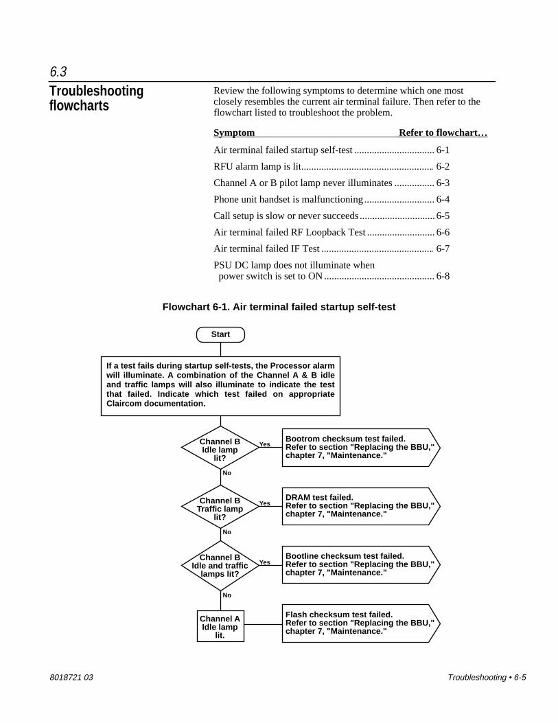
8018721 03 Troubleshooting • 6-5
6.3Troubleshootingflowcharts
Review the following symptoms to determine which one mostclosely resembles the current air terminal failure. Then refer to theflowchart listed to troubleshoot the problem.
Symptom Refer to flowchart…
Air terminal failed startup self-test ................................ 6-1
RFU alarm lamp is lit..................................................... 6-2
Channel A or B pilot lamp never illuminates ................ 6-3
Phone unit handset is malfunctioning ............................ 6-4
Call setup is slow or never succeeds .............................. 6-5
Air terminal failed RF Loopback Test ........................... 6-6
Air terminal failed IF Test ............................................. 6-7
PSU DC lamp does not illuminate when power switch is set to ON ............................................ 6-8
Flowchart 6-1. Air terminal failed startup self-test
Start
No
YesChannel BIdle lamp
lit?
Bootrom checksum test failed.Refer to section "Replacing the BBU," chapter 7, "Maintenance."
No
YesChannel BTraffic lamp
lit?
No
YesChannel B
Idle and trafficlamps lit?
Channel AIdle lamp
lit.
If a test fails during startup self-tests, the Processor alarm will illuminate. A combination of the Channel A & B idle and traffic lamps will also illuminate to indicate the test that failed. Indicate which test failed on appropriate Claircom documentation.
DRAM test failed.Refer to section "Replacing the BBU," chapter 7, "Maintenance."
Bootline checksum test failed.Refer to section "Replacing the BBU," chapter 7, "Maintenance."
Flash checksum test failed.Refer to section "Replacing the BBU," chapter 7, "Maintenance."

6-6 • Troubleshooting 8018721 03
Flowchart 6-2. RFU alarm lamp is lit
Start
Yes
NoRFU
alarm lamplit?
Air terminal is operational.
Replace the RFU
Refer to section "Restarting the air terminal,"in chapter 4, "Operation and shutdown."
Yes
NoRFU
alarm lamplit?
Install the original RFU and replace the BBU.Then refer to section "Restarting the air terminal,"
in chapter 4, "Operation and shutdown."
Possible BBU or RFU avionicstray connector failure.
Air terminal is operational.
Flowchart 6-3. Channel A or B pilot lamp never illuminates
Start
Refer to section "Replacing the BBU," chapter 7, "Maintenance."

8018721 03 Troubleshooting • 6-7
Flowchart 6-4. Phone unit handset LCD readout stays blank
Start
No
Yes
Aremultiple
handsets malfunctioning?
No
YesHandset
stillmalfunctioning?
Replace malfunctioningphone unit.
Replace BBU.
Yes
No
Isfailure
common to phoneunits on all ISDN "S" loops connected to
same junctionbox?
Install originalphone unit and refer to as-builtdocumentationto troubleshoot
phone unit cableand ECO box
Air terminal is operational.
Refer to section "Restarting the air terminal,"in chapter 4, "Operation and shutdown."
Handsetsstill
malfunctioning?No
Yes
Air terminal is operational.
Install original BBUand refer to as-built
documentationto troubleshoot
junction box circuitry for failed
phone units.
Install original BBU and refer to as-built documentation to troubleshootmalfunctioning ISDN "S" loop circuitry in the following order: 1. ECO boxes, 2. ECO box terminators 3. ISDN cables 4. Junction box.

6-8 • Troubleshooting 8018721 03
Flowchart 6-5. Call setup is slow or never succeeds
Start
Yes
NoCan
you verify the problem?
Problem is intermittent and cannot be verified. Return equipment to normal service, but monitor it in the future to verify that it is functioning reliably.
Refer to section 3.3, "System testing" and perform RF loopback tests.
Replace the BBU
Refer to section "Restarting the air terminal,"in chapter 4, "Operation and shutdown."
Problemsolved?
Yes
No
Air terminal is operational.
Install the original RFU and refer to as-built documentation totroubleshoot malfunctioning RF circuitry in the following order: 1. RF cables 2. Antenna grounding 3. Antennas
Install the original BBU and replace the RFU.Then refer to section "Restarting the air terminal,"
in chapter 4, "Operation and shutdown."
Problemsolved?
Yes
No
Air terminal is operational.

8018721 03 Troubleshooting • 6-9
Flowchart 6-6. Air terminal failed RF Loopback Test
Start
Replace the BBU
Refer to section "Restarting the air terminal,"in chapter 4, "Operation and shutdown." Then
perform the RF Loopback Test again.
Problemsolved?
Yes
No
Air terminal is operational.
Install the original RFU and refer to as-built documentation totroubleshoot malfunctioning RF circuitry in the following order: 1. RF cables 2. Antenna grounding 3. Antennas
Install the original BBU and replace the RFU."Refer to section "Restarting the air terminal,"in chapter 4, "Operation and shutdown." Then
perform the RF Loopback Test again.
Problemsolved?
Yes
No
Air terminal is operational.

6-10 • Troubleshooting 8018721 03
Flowchart 6-7. Air terminal failed IF Test
Start
No
Yes
Didthe air
terminal pass theIF Test?
Air terminal is operational.
Replace the BBU
Refer to section "Restarting the air terminal,"in chapter 4, "Operation and shutdown." Then
perform the IF Test again.
Install the original BBU and replace the RFU.Refer to section "Restarting the air terminal," in chapter 4, "Operation and shutdown." Then
perform the IF Test again.
Possible BBU or RFU avionicstray connector failure.
Yes
Didthe air
terminal pass theIF Test?
Air terminal is operational.

8018721 03 Troubleshooting • 6-11
Flowchart 6-8. PSU DC lamp does not illuminate when power switch is set to ON
Start
No
YesPSU DC lamp illuminated? Air terminal is operational.
Replace the PSU
Refer to section "Restarting the air terminal,"in chapter 4, "Operation and shutdown."
The PSU is not causing the fault. The problem may be caused by a shorted "S" loop cable or connector.Perform the following: 1. Install original PSU. 2. Refer to as-built documentation for location of main "S" loop cable junction box. 3. Disconnect the cables from the box. 4. Refer to section "Restarting the air terminal," in chapter 4, "Operation and shutdown."
No
YesPSU DC lamp illuminated?
Possible PSU avionicstray connector failure.
One of the "S" loop circuits has a shorted cable or connector. Peform the following: 1. Determine which "S" loop is malfunctioning by installing each "S" loop connector to the junction box until the DC lamp on the PSU extinguishes. 2. Refer to as-built documentation to trouble- shoot the malfunctioning ISDN "S" loop circuitry in the following order: • ISDN cables • Phone units • ECO boxes • ECO box terminators • Junction box.

6-12 • Troubleshooting 8018721 03
6.4Handset self-tests Perform the following procedures to test a phone unit. If a handset
fails a test, refer to section “Replacing a seatback phone unit” inchapter 7, “Maintenance.”
Software cold restart 1. Press the [*] and [#] at the same time, then release them.
2. Press the [7] and [9] keys at the same time, then releasethem.
3. Press the [8] key once, then release it.
4. Press the [0] key once, then release it.
The handset LCD readout will resemble the following:
Serial No.00000005E712
08/18/92 1156
The second line displayed will be the handset’s serial number. Thebottom line contains the date and time the software was created andchanges with each software version released.
After approximately 10 seconds, the software will reset and the LCDwill display the power-up READY message identifying the handsetsoftware release number. The LCD will then display the messagePRESS -ON- TO START.
Sleep mode test 1. Press the [*] and [#] at the same time, then release them.
2. Press the [7] and [9] keys at the same time, then releasethem.
3. Press the [8] key once, then release it.
4. Press the [1] key once, then release it.
The handset LCD will display the following:
Zzz Zzz ZzzZzz Zzz Zzz
During sleep mode, the computer inside the handset reduces itspower demands and the data link portions of the ISDN circuit aredisabled. After 60 seconds, a warm restart will begin and the LCD

8018721 03 Troubleshooting • 6-13
will display the power-up READY message. The LCD will thendisplay the message PRESS -ON- TO START.

8018721 03 Maintenance • 7-1
Chapter 7Maintenance
This section describes periodic maintenance procedures for the airterminal and removal and replacement procedures for air terminalline-replaceable units.
Before replacing any air terminal hardware, read the informationcontained in section “Electrostatic discharge control” for procedureson handling electrostatic discharge sensitive (ESDS) equipment.
7.1Required tools andmaterials formaintenance
The following are required:
• Hex wrench, #6
• Crosstip torque screwdriver
• Diagonal cutters, small
• Alodine 1200, Irridite, or equivalent (used to treat barealuminum surfaces to prevent oxidation)
• RTV sealant, or equivalent
• Cable ties, assorted sizes
7.2Periodic maintenance Periodic maintenance procedures consist of cleaning the phone unit
handsets according to airline-specified schedules.
Calibration The air terminal system requires no calibration.
7.3Electrostatic dischargecontrol
Air terminal equipment electronic assemblies can be damaged byelectrostatic discharge (ESD) if they are removed from their chassisenclosures without protective measures. These protective measuresinclude:
• Grounded wrist straps—Technicians handling ESDS items inan ESD environment should wear skin-contact wrist straps.

7-2 • Maintenance 8018721 03
The wrist strap should connect to a labeled ESD connectorplug or to the nearest connection to the site’s common ground.
WARNING
To avoid the risk of electric shock, the wriststrap should have a resistance in series withground of at least 250,000 ohms.
• Grounded tools—Use grounded power tools and tools withuninsulated handles that can be grounded. If tools with insu-lated handles are used, the handles should be treated with anantistatic coating. Neutralize hand tools before and during useby contacting with a grounded surface.
• Conductive tote boxes and shunts—ESDS assemblies shouldalways be stored in conductive trays, tote boxes, or bags.Shorting bars, clips, or special shunts should be used forgrounding component leads. Ground or contact together allconductive tote boxes or containers before transferring ESDSassemblies from one carrier to another.
7.4Field replacementprocedures
The following line-replaceable units (LRUs) can be replaced on-site:
• Baseband unit
• Radio frequency unit
• Power supply unit
• Electrical connection box
• UHF/L-band antenna
• Seatback phone unit
• Avionics tray cooling fan
Instructions replacing failed LRUs are contained in the followingprocedures.

8018721 03 Maintenance • 7-3
Replacing the PSU If you isolate a problem to a PSU, the entire assembly must bereplaced as follows:
WARNING
Set all air terminal circuit breakers to OFF beforecontinuing with this procedure (refer to the as-builtdrawings for the locations of the circuit breakers).
Caution
Wear an electrostatic discharge (ESD) wrist strap at alltimes while handling air terminal equipment. Connectthe wrist strap grounding clip to the groundingconnection on any of the avionics trays.
1. Open the switch cover on the PSU front panel and verifythat the power switch is set to OFF. Close the switch cover.
2. Turn both hold-down fastener fluted knobs counter-clockwise (from right to left). Do not disengage the whitelocking levers at this time.
3. Continue to turn the fluted knobs until the PSU extracts andthe connectors fully disengage.
4. Disengage the white locking levers by turning themcounter-clockwise. The PSU is now free to be removedfrom the avionics tray.
5. Remove the defective PSU from the tray and place it on anantistatic surface.
6. Remove the replacement PSU from its shipping containerand place it on an antistatic surface.
7. Remove the dust cover from the rear connectors on thereplacement PSU and install them onto the defective PSU.
8. Place the defective PSU into the shipping container so itcan be returned to the Claircom Distribution andMaintenance Center in Seattle, Washington for repair.Complete documentation per Claircom’s requirements.
9. Open the switch cover on the replacement PSU front paneland verify that the power switch is set to OFF (down posi-tion). Close the switch cover.

7-4 • Maintenance 8018721 03
10. Insert the unit into the PSU avionics tray.
11. Carefully slide the unit into the tray until it makes contactwith the connectors.
12. Raise both hold-down fasteners so that the front lip of eachfastener rests just behind the lower front panel of the PSU.Turn the white locking lever clockwise (left to right) as faras it can go, making sure the cup engages the hook. Thislocks the hold-downs against the PSU.
13. Turn both fluted knobs clockwise until the red indicatorbands have disappeared. When that happens, you will feelthe fasteners clutching out. That means the full loadrequired for mating has been applied and the PSU is seatedsecurely.
14. Refer to section 4.3,“Restarting the air terminal” to verifyproper air terminal operation. Next complete requiredpaperwork.
Replacing the RFU If you isolate a problem to an RFU, the entire assembly must bereplaced as follows:
Caution
Wear an electrostatic discharge (ESD) wriststrap at all times while handling air terminalequipment. Connect the wrist strap groundingclip to the grounding connection on any of theavionics trays.
1. Open the switch cover on the PSU front panel and verifythat the power switch is set to OFF (down position). Closethe switch cover.
2. Turn both hold-down fastener fluted knobs counter-clockwise (from right to left). Do not disengage the whitelocking levers at this time.
3. Continue to turn the fluted knobs until the RFU extracts andthe connectors fully disengage.
4. Disengage the white locking levers by turning themcounter-clockwise. The RFU is now free to be removedfrom the avionics tray.

8018721 03 Maintenance • 7-5
5. Remove the defective RFU from the tray and place it on anantistatic surface.
6. Remove the replacement RFU from its shipping containerand place it on an antistatic surface.
7. Remove the ESD-protective dust cover from the rearconnectors on the replacement RFU and install them ontothe defective RFU.
8. Place the defective RFU into the shipping container so itcan be returned to the Claircom Distribution andMaintenance Center in Seattle, Washington for repair.Complete documentation per Claircom’s requirements.
9. Insert the replacement unit into the RFU avionics tray.
10. Carefully slide the unit into the tray until it makes contactwith the connectors.
11. Raise both hold-down fasteners so that the front lip of eachfastener rests just behind the lower front panel of the RFU.Turn the white locking lever clockwise (left to right) as faras it can go, making sure the cup engages the hook. Thislocks the hold-downs against the RFU.
12. Turn both fluted knobs clockwise until the red indicatorbands have disappeared. When that happens, you will feelthe fasteners clutching out. That means the full loadrequired for mating has been applied and the RFU is seatedsecurely.
13. Refer to section 4.3,“Restarting the air terminal” to verifyproper air terminal operation. Next complete requiredpaperwork.
Replacing the BBU If you isolate a problem to a BBU, the entire assembly must bereplaced as follows:
Caution
Wear an electrostatic discharge (ESD) wriststrap at all times while handling air terminalequipment. Connect the wrist strap groundingclip to the grounding connection on any of theavionics trays.

7-6 • Maintenance 8018721 03
1. Open the switch cover on the PSU front panel and verifythat the power switch is set to OFF (down position). Closethe switch cover.
2. Turn both hold-down fastener fluted knobs counter-clock-wise (from right to left). Do not disengage the white lockinglevers at this time.
3. Continue to turn the fluted knobs until the BBU extractsand the connectors fully disengage.
4. Disengage the white locking levers by turning themcounter-clockwise. The BBU is now free to be removedfrom the avionics tray.
5. Remove the defective BBU from the tray and place it on anantistatic surface.
6. Remove the replacement BBU from its shipping containerand place it on an antistatic surface.
7. Remove the ESD-protective dust cover from the rearconnectors on the replacement BBU and install them ontothe defective BBU.
8. Place the defective BBU into the shipping container so itcan be returned to the Claircom Distribution andMaintenance Center in Seattle, Washington for repair.Complete documentation per Claircom’s requirements.
9. Insert the replacement unit into the BBU avionics tray.
10. Carefully slide the unit into the tray until it makes contactwith the connectors.
11. Raise both hold-down fasteners so that the front lip of eachfastener rests just behind the lower front panel of the BBU.Turn the white locking lever clockwise (left to right) as faras it can go, making sure the cup engages the hook. Thislocks the hold-downs against the BBU.
12. Turn both fluted knobs clockwise until the red indicatorbands have disappeared. When that happens, you will feelthe fasteners clutching out. That means the full loadrequired for mating has been applied and the BBU is seatedsecurely.
13. Refer to section chapter 3,“Commissioning” to verifyproper air terminal operation. Next complete requiredpaperwork.

8018721 03 Maintenance • 7-7
Replacing an ECO box If you isolate a problem to an ECO box, the entire assembly must bereplaced as follows:
1. Open the switch cover on the PSU front panel and verifythat the power switch is set to OFF (down position). Closethe switch cover.
2. Release the spring latches attaching the ISDN “S” loopinput cable connector to the IN connector of the ECO box.Then disconnect the input cable connector.
3. Release the spring latches attaching the ISDN “S” loopoutput cable connector (or ISDN terminator) to the OUTconnector of the ECO box. Then disconnect the outputcable connector (or remove the terminator).
4. Disconnect the RJ-11 phone cable connectors from thejacks labeled HANDSET.
5. While supporting the ECO bracket with one hand, use a pairof diagonal cutters to cut the anchoring straps that securethe bracket to the seat frame.
6. Remove the ECO bracket.
7. Use a pair of diagonal cutters to cut the anchoring strapsthat secure the ECO box to the ECO bracket.
8. Remove the malfunctioning ECO box from the bracket anduse a small flat-tip screwdriver to remove the RJ-45 blankplugs (if any) from the ECO box.
9. Remove the replacement ECO box from its shippingcontainer. Install the RJ-45 blank plugs (if any) into theECO box handset connectors.
10. Place the defective ECO box in the shipping container so itcan be returned to the Claircom Distribution andMaintenance Center in Seattle, Washington for repair.Complete documentation per Claircom’s requirements.
11. Place the replacement ECO box onto the ECO bracket.
12. Insert an anchoring strap through one of the slots in thebracket and the ECO box. Bend the strap and insert itthrough the adjacent slot in the ECO box. Slide the tip ofthe strap into the hole in the head of the strap and pull thetip until any slack in the strap has been removed. Use a pairof diagonal cutters to remove excess strap.

7-8 • Maintenance 8018721 03
13. Use anchoring straps to install the ECO bracket onto theseat frame.
14. Install the ISDN “S” loop input cable connector to the ECObox connector labeled IN. Close both spring latches tosecure the connector.
15. Install the ISDN “S” loop output cable connector (or theISDN terminator) to the ECO box connector labeled OUT.Close the spring latches.
16. Install the RJ-11 phone cable connectors to the ECO boxconnectors labeled HANDSET.
17. Refer to section 4.3,“Restarting the air terminal” to verifyproper air terminal operation, then continue on to step 18.
18. Remove the handset of a phone unit connected to the ECObox from its cradle and verify that the messagePRESS -ON- TO START is displayed on the LCD readout.After verifying proper operation, place the handset back inthe cradle and complete required paperwork.
Replacing a UHF/L-bandantenna
Perform the following procedure to replace a malfunctioningantenna.
Caution
Check aircraft maintenance manual for specialrequirements before continuing.
1. Open the switch cover on the PSU front panel and verifythat the power switch is set to OFF (down position). Closethe switch cover.
2. Disconnect the cable assembly from the N-type connectoron the failed antenna.
3. Use a crosstip screwdriver to remove the six sets of6-32 screws and lower the failed antenna from the aircraft.
4. Remove the replacement UHF/L-band antenna from itsshipping container. Place the defective antenna into theshipping container so it can be returned to the ClaircomDistribution and Maintenance Center in Seattle,Washington for repair. Complete documentation perClaircom’s requirements.

8018721 03 Maintenance • 7-9
5. Verify that the mounting surface is free of corrosion andany sealant residue.
6. Using a crosstip torque screwdriver, mount the replacementantenna to the aircraft with six sets of 6-32 screws. Tighteneach screw a small amount, then tighten the screw on theopposite side the same way. Continue tightening the screwsusing this side-to-side pattern so that uniform stress isplaced on the antenna. Torque the screws to 8 to 10inch/pounds.
7. Using RTV sealant, apply a small, smooth fillet along thejoint between the antenna and the aircraft fuselage. Also,apply sealant over the mounting hardware heads at the baseof the antenna.
Caution
Allow the sealant to dry for 4 hours beforeexposing it to water.
8. Connect the cable assembly to the N-type connector on theantenna. Hand-tighten the connector to secure it. Create aservice loop with the excess cable length and clamp asspecified in the aircraft manufacturer’s recommendation forantenna installations.
Caution
Be careful when bending the cable that you donot exceed the minimum bend radius of sixtimes the cable’s outside diameter. Exceedingthe minimum bend radius could result in cablefailure.
9. Refer to section 4.3,“Restarting the air terminal” to verifyproper air terminal operation. Next complete requiredpaperwork.
Replacing a seatbackphone unit
If you isolate a problem to a phone unit, the entire assembly must bereplaced as follows:
1. Slide the release latch to the left and remove the handsetfrom the cradle. Pull out enough handset cord so that you

7-10 • Maintenance 8018721 03
can remove the cradle mounting hardware without thehandset or its cord getting in the way.
2. Use the appropriate tool to remove the four mountingscrews from the cradle.
3. Remove the malfunctioning phone unit from the seatbackand place it on an antistatic surface.
4. Remove the replacement seatback phone unit from its ship-ping container. Place the defective phone unit into theshipping container so it can be returned to the ClaircomDistribution and Maintenance Center in Seattle,Washington for repair. Complete documentation perClaircom’s requirements.
5. Record the replacement phone unit handset serial numberper Claircom’s requirements.
6. Install the RJ-11 connector (located inside the seatbackheadrest) into the cradle connector.
7. Insert the cradle into the slot in the seatback headrest.
8. Slide the release latch to the left and remove the handsetfrom the cradle. Pull out enough handset cord so that youcan install the cradle mounting hardware without the hand-set or its cord getting in the way.
9. Using the appropriate tool, install the cradle into the seat-back headrest with four mounting screws. (Verify that theseat cover material is not buckled and that there are noexposed seams visible after securing the cradle.)
10. Verify proper mechanical operation of the handset (makesure the reel coils the cord properly and that the handsetrelease latch works).
11. Open the switch cover on the PSU front panel and set thepower switch to OFF. Wait 10 seconds, then set the switchto ON. Close the switch cover.
12. Remove phone unit handset from its cradle and verify thatthe message PRESS ON TO MAKE CALL is displayed onthe LCD readout. After verifying proper operation, placethe handset back in the cradle and complete required paper-work.

8018721 03 Maintenance • 7-11
Replacing an avionicstray cooling fan
If you isolate a problem to a cooling fan, the entire assembly must bereplaced as follows:
WARNING
Set all air terminal circuit breakers to OFFbefore continuing with this procedure (referto the as-built drawings for the locations ofthe circuit breakers).
Caution
Wear an electrostatic discharge (ESD) wriststrap at all times while handling air terminalequipment. Connect the wrist strap groundingclip to the grounding connection on any of theavionics trays.
1. Open the switch cover on the PSU front panel and verifythat the power switch is set to OFF. Close the switch cover.
2. Disconnect the cooling fan power cable connector from thecooling fan terminal strip (see figure 7-1).

7-12 • Maintenance 8018721 03
CAPTIVEFASTENERS
MOUNTINGSCREW
COOLING FAN
FAN MOUNTINGPLATE
REMOVABLEFASTENER
TERMINAL STRIP
Figure 7-1. Cooling fan replacement
3. Using a flat-tip screwdriver, turn one of the captive fasten-ers (see figure 7-1) counter-clockwise (right to left) until itstops. Repeat for the other captive fastener.
4. Using a Phillips crosstip screwdriver, remove the mountingscrew and removable fastener (see figure 7-1) from the fanassembly. The cooling fan is now free to be removed fromthe avionics tray.
5. Remove the fan from the tray and place it on an antistaticsurface.
6. Remove the replacement fan from its shipping container.Place the defective fan into the shipping container so it canbe returned to the Claircom Distribution and MaintenanceCenter in Seattle, Washington for repair. Completedocumentation per Claircom’s requirements.
7. Install the replacement fan onto the fan mounting plate.

8018721 03 Maintenance • 7-13
8. Using a crosstip screwdriver, install the mounting screw asshown in figure 7-1.
9. Using a flat-tip screwdriver, rotate both captive fastenersclockwise to secure the cooling fan.
10. Install the cooling fan power cable connector onto thecooling fan terminal strip.
11. Refer to section 4.3,“Restarting the air terminal” to verifyproper air terminal operation. Then complete requiredpaperwork.
Returning failedequipment to the Depot
for testing
Return failed equipment to Claircom for disposition per Claircom’srequirements.

8018721 03 List of acronyms • A-1
Appendix AList of acronyms
AC Alternating current
AGC Automatic gain control
AFC Automatic frequency control
AT Air terminal
ATC Air terminal controller
ASC Air system manager
AVC Air view console
BBU Baseband unit
BOM Bill of materials
BSP Baseband signal processor
CP Control processor
CSM Circuit switch module
dB Decibel
DC Direct current
DRAM Dynamic random-access memory
DSP Digital signal processor
DTMF Dual-tone multi-frequency
ECO Electrical connection
EMI Electromagnetic interference
EPROM Erasable programmable read-only memory
ESD Electrostatic discharge
ESDS Electrostatic discharge sensitive
FAA Federal Aviation Administration
FCC Federal Communications Commission
FEC Forward error correction
FIR Finite impulse response
FPGA Field-programmable gate array
LRU Line-replaceable unit
GS Ground station
GSC Ground station controller
GSM Ground station manager
Continues on next page

A-2 • List of acronyms 8018721 03
Hz Hertz
IEC Inter-exchange carrier
IF Intermediate frequency
ISDN Integrated services digital network
LCD Liquid-crystal display
LED Light-emitting diode
LNA Low-noise amplifier
M&C Monitor and control
MHz Megahertz
MOM Modem module
MT Maintenance terminal
NMCC Network management control center
NMCS Network management control system
PCM Pulse-code modulated
PSU Power supply unit
PSTN Public switched telephone network
RAM Random-access memory
RF Radio frequency
RFI Radio frequency interference
RFU Radio frequency unit
RJ Registered jack
RMA Return merchandise authorization
SSPA Solid-state power amplifier
TDM Time-division multiplexed
TDMA Time-division multiple-access
UHF Ultra-high frequency
VAC Alternating-current voltage
VDC Direct-current voltage
Related Documents