1 SLOSHING Odd M. Faltinsen and Olav F. Rognebakke Department of Marine Hydrodynamics Norwegian University of Science and Technology N-7491 Trondheim, Norway ABSTRACT Physical aspects of sloshing in ship tanks are discussed. The importance of hydroelasticity for small angles between impacting fluid and body surface is stressed. Performance requirements for numerical methods are presented. CFD methods are reviewed. The drawbacks are long simulation time, sensitivity to numerical parameters and general inability to predict impact loads and resulting structural response. An analytically based sloshing model is therefore recommended. Its drawbacks are that the tank has to be smooth with vertical sides at the free surface. Shallow fluid phenomena are excluded. The method consists of a basic method that assumes infinite tank roof height and a second part, which accounts for tank roof impact. The importance of tank roof impact damping on sloshing is demonstrated. Extensive validation of free surface elevation, total forces and moments for 2-D flow in rectangular and prismatic tanks are reported. This includes realistic motion excitation and studies close to critical depth 0.3374 times the tank breadth.

Welcome message from author
This document is posted to help you gain knowledge. Please leave a comment to let me know what you think about it! Share it to your friends and learn new things together.
Transcript
1
SLOSHING
Odd M. Faltinsen and Olav F. RognebakkeDepartment of Marine Hydrodynamics
Norwegian University of Science and TechnologyN-7491 Trondheim, Norway
ABSTRACT
Physical aspects of sloshing in ship tanks are discussed. The importance ofhydroelasticity for small angles between impacting fluid and body surface isstressed. Performance requirements for numerical methods are presented. CFDmethods are reviewed. The drawbacks are long simulation time, sensitivity tonumerical parameters and general inability to predict impact loads and resultingstructural response. An analytically based sloshing model is thereforerecommended. Its drawbacks are that the tank has to be smooth with verticalsides at the free surface. Shallow fluid phenomena are excluded. The methodconsists of a basic method that assumes infinite tank roof height and a secondpart, which accounts for tank roof impact. The importance of tank roof impactdamping on sloshing is demonstrated. Extensive validation of free surfaceelevation, total forces and moments for 2-D flow in rectangular and prismatictanks are reported. This includes realistic motion excitation and studies close tocritical depth 0.3374 times the tank breadth.

2
INTRODUCTION
A partially filled tank will experience violent fluid motion when the shipmotions contain energy in the vicinity of the highest natural period for the fluidmotion inside the tank. Impact between the fluid and the tank roof is then likelyto occur for larger filling ratios. The consequence is wave breaking, spray andmixing of air (or gas) and fluid. Actually, extreme cases with air bubbleseverywhere in the fluid have been experimentally observed. The resonant fluid motion has different main characteristics depending onthe fluid depth and the three-dimensionality of the flow. Swirling (rotational)motion is a special feature of 3-D flow ([1],[2]). Our focus is on the highestsloshing period, 2-D flow and finite fluid depth. It implies that typical shallowwater phenomena like travelling waves and hydraulic bores are excluded [3]. Since sloshing is a typical resonance phenomenon, it is not necessarily themost extreme ship motions or external wave loads that cause the most severesloshing. This implies that external wave induced loads can in many practicalcases be described by linear theory. However, nonlinearities must be accountedfor in the tank fluid motions. Since it is the highest sloshing period (naturalperiod) that is of prime interest, vertical tank excitation is of secondaryimportance. Generally speaking the larger the tank size is and the less internal structuresobstructing the flow in the tank are present, the more severe sloshing is. Thereasons are: a) Increased tank size tends to increase the highest naturalsloshing period and hence higher sea states and larger ship motions will excitethe severe sloshing. b) Internal structures dampen the fluid motions. [4] reported damages due to sloshing in bulk carriers, combination Oil-Bulk-Ore (OBO) carriers and LNG carriers. Large and smooth tanks characterizedthese. Partial fillings in LNG carriers are a consequence of boil-off of gas duringoperations. Sloshing has always been an important design criterion for oiltankers even if partial filling is rare in actual operation. Since environmentalconcerns have caused requirements about double hull tankers and ship ownersdo not want to use internal structures in cargo tanks for easier cleaning, this haslead to wide and smooth oil tanks that increase the probability of severesloshing. Sloshing is also of concern for Floating Production Storage andOffloading (FPSO) units and shuttle tankers. However, this is for shuttle tankersonly in a limited time during loading. Obviously the severity of sloshing isconnected to possible filling height restrictions for oil tankers, gas carriers,shuttle tankers and FPSOs. Since ballast exchange is required outside the portfor a bulk carrier, there are possibilities for slamming damages. Damage to thehatch cover is of particular concern. The hydrodynamic loads occurring inside a tank are often classified asimpact loads and “dynamic” loads. Impact loads are of course also dynamicloads. But in this context dynamic loads mean loads that have dominant timevariations on the time scale of the sloshing period, while impact loads may onlylast 10-2 to 10-3 seconds. Both resulting fatigue and ultimate strength are ofconcern. Local structural response due to fluid impact (slamming) is an importantresponse variable. But loads on possible internal stringers, web-frames, cross-

3
ties, piping supports and equipment like LNG pump towers must also beconsidered. Since some internal structures like a web-frame at the tank roofmay be out of the fluid at certain time intervals, impact as well as dynamic loadsmay matter. Dynamic pressures on the tank wall and bottom as well as totaldynamic loads on the tank are also of interest. The latter is needed to estimatetank support reactions and possible global interactions with the ship dynamics.For instance, the horizontal but not the vertical support reaction is important forspherical LNG tanks. Anti-rolling tanks exemplify that global interaction betweenthe tank fluid motion and ship motion, i.e. rolling, can be strong. If several tanksare partially filled like it may be on a FPSO, global ship motions and wavebending moments may be strongly affected. The following study will concentrate on numerical methods and validation,but starts out stating performance requirements of numerical methods andphysical aspects of sloshing.
PHYSICAL AND MATHEMATICAL MODELING
A theoretical method has to be robust and time efficient. Long timesimulations are needed to obtain statistical estimates of the tank response. Thisshould ideally be coupled with the ship motions in a stochastic sea. Both impactand non-impact loads should be evaluated. Impact loads may requirehydroelastic analysis. There is a variety of tank shapes. This includesrectangular, prismatic, tapered and spherical tanks as well as horizontalcylindrical tanks. The fluid may be oil, liquefied gas, water or heavy densitycargoes like molasses and caustic soda. The fluid dynamic properties of the twolast cargo types are not focused on in this context. Ideally one should be able topredict two phase flow due to strong mixing of air (or gas) with the fluid.However, this is not focused on. It is hard enough to predict one phase flow. Internal structures obstructing the flow may be present. This causes flowseparation and implies that Navier-Stokes equations have to be solved. Thequestion of turbulence modeling arises, but may not be a dominant effect whenflow separation from sharp corners occurs. The argument is that dominant scaleeffects due to difference between laminar and turbulent flow for separated flowpast a blunt body is due to differences in separation line position (or point for 2-D flow). On the other hand the wake behind an internal structural part mayinteract with another internal structure, the free surface and the tankboundaries. A wake flow would in practice be turbulent. What turbulence modelto use is still a research issue. Numerical simulations of flow separation fromsharp corners require fine gridding in the vicinity of the corners. The main effectof viscosity for a smooth tank with conventional fluid like oil is normallyconcentrated in thin boundary layers along the tank boundaries. The boundarylayer flow may be laminar in model scale, but is turbulent in full scale. Butanyway the boundary layer flow has a negligible influence on tank response ofpractical interest. It implies that Euler equations can be used for a smooth tank.Further compressibility of the fluid is of secondary importance. Anyway asmooth tank would give the most violent response and provide a conservativeestimate if internal structures are present. It is also possible to provide

4
estimates of the effect of internal structures in combination with potential flow. Itassumes the cross-dimensions of the internal structures are small relative tofluid depth and tank breadth. The internal structures are then handled asappendages with Morison type calculations [5]. Equivalent damping of the fluidmotion has to be introduced in a similar way as described later in connectionwith tank roof impact damping. The previous discussion assumes a submerged internal structure. Someinternal structures may be part of the time in and out of the fluid. Fluid impactbecomes then part of the problem. The impact pressures can become veryhigh. [2] reported full scale measured pressures up to 24 bar in an OBO tank.We will in the following text discuss fluid impact in a more general sense.Different physical effects occur during slamming. When the local angle betweenthe fluid surface and the body surface is small before impact, an air (or gas)cushion may be formed between the body and the fluid. Compressibilityinfluences the airflow. The airflow interacts with the fluid flow, which isinfluenced by the compressibility of the fluid. When the air cushion collapses, airbubbles are formed. Air bubbles may also be entrapped in the fluid fromprevious impacts. The ullage pressure influences the presence and behaviourof air bubbles. The large loads that can occur during impact when the anglebetween the fluid surface and body surface is small can cause important localdynamic hydroelastic effects. The vibrations can lead to subsequent cavitationand ventilation. These physical effects have different time scales. The importanttime scale from a structural point of view is when maximum stresses occur. Thisscale is given by the highest wet natural period ( 1nT ) for the local structure.Compressibility and the formation and collapse of an air cushion are importantinitially and normally in a time scale smaller than the time scale of when localmaximum stresses occur. Hence, the effect on maximum local stress isgenerally small. The theoretical and experimental studies of wave impact onhorizontal elastic plates of steel and aluminium presented by [6], [7], [8], [9] and[10] are relevant in this context. Significant dynamic hydroelastic effects weredemonstrated. The physics can be explained as follows. The plate experiencesa large force impulse during a small time relative to the highest natural periodfor the plate vibrations. (Structural inertia phase). This causes the space-averaged relative velocity between the elastic vibration velocity and the rigidbody impact velocity V to be zero at the end of the initial phase. The plate thenstarts to vibrate as a free vibration with an initial vibration velocity V and zerodeflection. Maximum strains occur during the free vibration phase. The detailsof the pressure distribution during the first initial phase are not important. Verylarge pressures that are sensitive to small changes in the physical conditions,may occur in this phase. This can be seen from the collection of measuredmaximum pressures during the tests. The measured maximum strains showeda very small scatter for given impact velocity and plate even if maximumpressure varied strongly. The largest measured pressure was approximately 80bar for V equal to 6 m/s. Fluid impact against a horizontal tank roof during sloshing has similaritieswith water impact of elastic plates. The tank roof impact will also causehydroelastic vibrations in the tank wall adjacent to the impact area. [11] studiedthis by a hydroelastic beam theory. The effect of a chamfered tank roof was
5
also investigated. This problem is similar to water entry of a wedge before thehorizontal roof part is reached. The effect of hydroelasticity decreases withincreasing deadrise angle of the wedge. The tank roof impact causes alsodamping of the fluid motions. This will be further discussed later in the text. [12] studied the relative importance of hydroelasticity for an elastic hull withwedge-shaped cross-sections penetrating an initially cal+m water surface. Astiffened plating between two rigid transverse frames was examined. Aparameter that is proportional to the ratio between the wetting time of the rigidwedge and the natural period of a longitudinal stiffener, was introduced toquantify the relative importance of hydroelasticity. We can associate the wettingtime of the wedge with the duration of the loading. If we make an analogy to asimple mechanical system consisting of a mass and spring, then we know thatthe duration of the loading relative to the natural period characterizes dynamiceffects. The wetting time depends on the impact velocity V and deadrise angleβ . It means that the importance of hydroelasticity increases with increasing Vand decreasing β . In practice we should be aware of hydroelastic effects when
°<≈5β . The literature on sloshing contains many studies on slamming pressures.There is a strong tendency to focus on the high slamming pressures that canoccur. Few seem to be aware of the importance of hydroelasticity. It ismisleading to use physical pressures as parameter for structural response whenthe pressures become high and concentrated in time and space. What we aresaying is that the structure needs time to react. The previous discussion on fluidimpact has severe consequences for how sloshing should be numericallymodeled. It has become popular to use CFD to model sloshing. The problem has to besolved in the time domain due to the strong nonlinearities associated with thefree surface conditions. There is a broad variety of numerical methods. The loadcommittee of the 13th ISSC has provided a survey in 1997. Normally theReynolds Averaged Navier Stokes equations (RANSE) are solved, but alsoEuler equations or potential flows for incompressible fluid are used. 2-D flowstudies are most common. The field equations are numerically solved by eitherFinite Difference Methods (FDM), Finite Volume Methods (FVM) or FiniteElement Methods (FEM). The use of Boundary Element Methods (BEM) isbased on a velocity potential satisfying Laplace equation. Methods based onfield discretization can handle nonlinear free surface motion by height functionmethod, marker method, volume of fluid method or a level set technique. More recently some meshless methods have been developed to deal withlarge deformations and even fragmentation of the free surface. Among these,Smoothed Particle Hydrodynamics (SPH) [13] is currently under testing forsloshing problems by Landrini and Colagrossi at INSEAN, Italy. A goodagreement with BEM solutions up to breaking has been obtained. Long timesimulation for cases with large excitation amplitudes show the ability to followthe post breaking behaviour. What are then the disadvantages and advantages of using CFD?Advantages are that complex tank geometries, any fluid depth and generalexcitation may in principle be considered. A CFD method may provide goodflow visualization. Flow separation around internal structures can be simulated

6
by a RANSE-code. A disadvantage is that the CFD methods are timeconsuming which makes statistical estimates of tank response variablesdifficult. Some methods may not be robust enough. For instance a BoundaryElement Method based on mixed Eulerian-Lagrangian method breaks downwhen an overturning wave hits the free surface. Numerical problems may alsoarise with a BEM at the intersection between the free surface and the tankboundary. [14] discussed numerical problems associated with BEM andsloshing. If not sufficient care is shown, some of the methods may numericallyloose or generate fluid mass on a long time scale. Since the highest naturalperiod of the fluid motion is strongly dependent on fluid mass, this can result inan unphysical numerical simulation. This was demonstrated by Solaas [15] byusing the commercial, multipurpose FLOW-3D code, developed by FlowScience, Inc. The method uses a combination of the SOLA finite differencescheme for solving Navier-Stokes equations and the Volume of Fluid (VOF)technique for tracing the free boundaries of the fluid. Kim [16] has presented aCFD method where conservation of fluid mass is satisfied. The amount of fluidin the tank is corrected for each time step by slightly moving the free surface.The correction is so small that the global motion is not affected. It seems generally accepted that CFD codes have difficulties in predictingimpact loads. This was also the conclusion of the load committee of 13th ISSCin 1997. A reason is rapid changes in time and space occurring even forrelatively large local angles between the impacting free surface and the bodysurface ([17]). Few codes include hydroelasticity during impact. However, ifdoing so, the structural modeling requires also special care. [9] demonstratedthe numerical difficulties in modeling hydroelastic impact of a horizontal beam.The complications are associated with the many structural modes that areinitially excited and the very rapid change of the wetted body surface. Moreanalytically based methods were therefore used to provide robust solutions. There exist examples on satisfactory predictions of non-impact loading byCFD (f. ex. [15] and [18]). However the load committee of the 13th ISSCpresented a comparative study by 12 different CFD codes belonging to differentclassification societies, a shipyard, research organizations and universities. Theagreement in predicted free surface elevations in non-extreme cases was notconvincing. [15] illustrated the grid dependence and the sensitivity to parameters used innumerical differentiation and iteration procedures in the FLOW-3D code. TheEPSADJ parameter gives an automatic adjustment of the convergence criterionin the pressure iteration algorithm in order to fulfill the continuity equation. Thedefault value is 1.0, but a much smaller value had to be used for resonant fluidmotion to satisfy mass conservation. But even so the results were not perfect. Acase with EPSADJ=0.01 showed that the volume error was 4% after 30oscillation periods. This illustrates also the problem of using a multipurposeprogram. The different main applications have different main important physicaleffects. The ALPHA parameter in FLOW-3D controls the weighting of theadvective flux terms in Navier-Stokes equation. ALPHA can be between 0 and1. The default value is 1.0, which means fully upstream differencing and a firstorder approximation of the advective flux terms is used. ALPHA=0.0 meanscentral differencing, but this gave a numerically unstable solution. It is difficult
7
from a physical point of view to state that the default value ALPHA=1.0 shouldbe used for sloshing. [15] demonstrated that there could be a large sensitivity tochoice of parameters and grid size. Convergence studies by decreasing the gridsize were performed. This gives a qualitative but not quantitative guidance onhow to select grid size. The reasons are that convergence is dependent on theALPHA parameter and that in some cases the results did not converge bydecreasing grid size. There is of course also a limit to how small the grid sizecan be before the demand on computer resources gets too large. Instead of developing a CFD code we have decided to develop a moreanalytically based method. The method is time efficient and seems easy tocombine with the ship motions and external linear wave induced loads. Thesimulation time depends on the chosen approximate modal model andexcitation parameters. Consider for instance a typical calculation of 100 forcedmotion oscillation periods presented later in the paper. This may take from 1 to20 seconds on a Pentium-III 500. The numbers are based on non-optimizedcomputer code. The fluid depth has to be finite. Our selected procedure appliesto any tank shape as long as the tank walls are vertical near the mean freesurface. Details have so far been developed for a rectangular 2-D tank and avertical circular tank. Since irrotational fluid motion is assumed, internalstructures causing flow separation can only be treated empirically by Morisontype calculations. The basic method assumes infinite tank roof height. Theeffect of the tank roof impact is handled by generalizing Wagner's method [19].Since analytically based methods are used, fluid impact load predictions arerobust. The effect of hydroelasticity can be incorporated. The method will bedescribed in more details in the next chapter.
ANALYTICALLY BASED SLOSHING MODEL
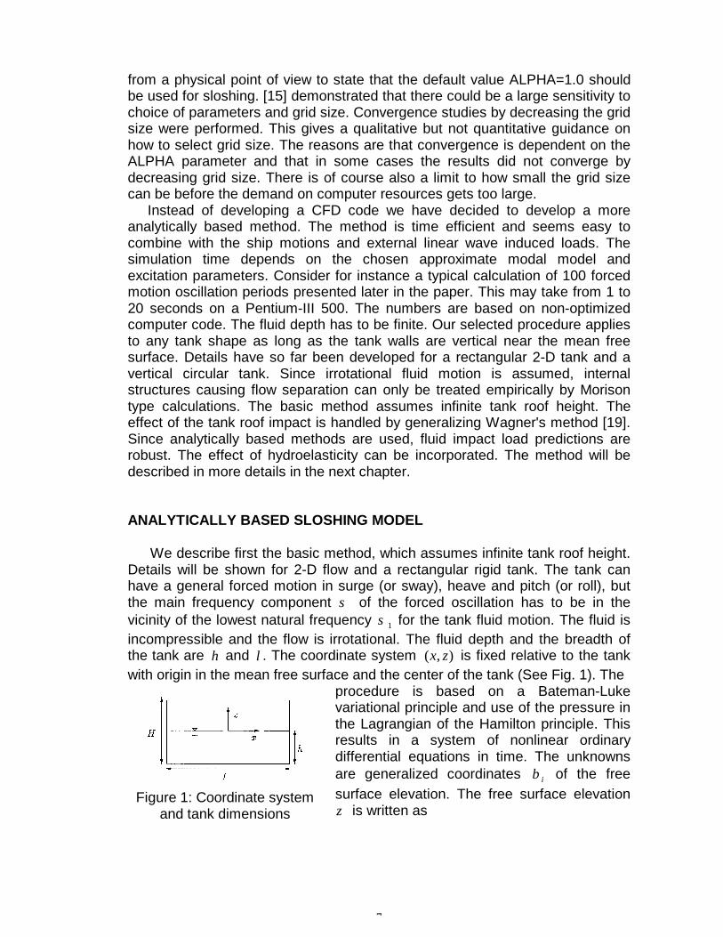
We describe first the basic method, which assumes infinite tank roof height.Details will be shown for 2-D flow and a rectangular rigid tank. The tank canhave a general forced motion in surge (or sway), heave and pitch (or roll), butthe main frequency component σ of the forced oscillation has to be in thevicinity of the lowest natural frequency 1σ for the tank fluid motion. The fluid isincompressible and the flow is irrotational. The fluid depth and the breadth ofthe tank are h and l . The coordinate system ),( zx is fixed relative to the tankwith origin in the mean free surface and the center of the tank (See Fig. 1). The
Figure 1: Coordinate systemand tank dimensions
procedure is based on a Bateman-Lukevariational principle and use of the pressure inthe Lagrangian of the Hamilton principle. Thisresults in a system of nonlinear ordinarydifferential equations in time. The unknownsare generalized coordinates iβ of the freesurface elevation. The free surface elevationζ is written as

8
∑=
+=
N
ii l
lxit
1
)5.0(cos)(
πβζ (1)
Since Eq. 1 assumes ζ to be a single valued function of x , it implies nooverturning waves and vertical tank sides in the free surface. Further Eq. 1 doesnot permit travelling waves. The consequence is that shallow water conditionscannot be simulated. The forced oscillation amplitude is assumed small and of
)(εO . There exist different possibilities for how to order iβ , but it should reflectthat the fluid response is lower order than )(εO . This reflects that a strongamplification of the flow occurs due to a small excitation. However, in order todevelop an asymptotic theory, we must assume ζ to be asymptotically small.The original method presented by Faltinsen et al. [20] assumed )( 3/i
i O εβ = ,3,1=i . Higher order terms than ε are neglected in the nonlinear equations. The
following system of nonlinear ordinary differential equations for the generalizedcoordinates describing the free surface are derived for forced motions
( ) ( ) ( )0)( 101101123
12
12
112212111211
=+−−+++++++
βψωβββββββββββσβ
zx vQgSvPd
dd
&&&&&
&&&&&&&&&
( ) 02022
151142222 =++++ βββββσβ zvQdd &&&&&&
( )0)( 3033031
2110
2191282
1172163233
=+−−+++++++
βψωβββββββββββσβ
zx vQgSvPd
dddd
&&&&
&&&&&&&&&&
4,0)( 002 ≥=+−−++ ivQgSvP iziixiiiii βψωβσβ &&&&&
(2)
Here dots mean time derivatives. xv0 and zv0 are projections of translationalvelocity onto axes of xzΟ , )(tω and )(tψ are the angular velocity and angle ofcoordinate system xyzΟ with respect to an earth fixed coordinate system. Both
xv0 and ω cannot be zero. g means acceleration of gravity. The calculationformulas for the coefficients iσ , iP , iS , iQ , 1≥i and jd , 10,,1K=j are given inFaltinsen et al. [20]. iσ means the natural frequencies. The equation system issolved numerically by a fourth order Runge-Kutta method. Faltinsen & Timokha [21] found that the excitation amplitude had to be verysmall and that the depth should not be close to the critical value 3374.0/ =lh inorder for Eqs. 2 to be valid. This was explained to be due to secondaryresonance. An example of such mechanisms is as follows. Nonlinearities causeoscillations with frequency σ2 , where σ is the excitation frequency of the rigidbody motion. If the second natural frequency 2σ of the fluid is close to σ2 ,secondary resonance will occur. The generalized coordinate 2β will beamplified and can be of same order as 1β . Nonlinear interactions can alsocause resonant oscillations at the other natural frequencies. If the excitationamplitude is increased, the fluid response becomes large in an increasedfrequency domain around the first natural frequency. This increases thepossibility that large nonlinearly excited resonance oscillations at a higher

9
natural frequency can occur. Both the second and third mode associated withrespectively 2β and 3β can be the same order as 1β . Since the amplification ofthe fluid motion is relatively larger at the critical depth than at other fluid depths,the upper bound of tank excitation amplitude where the theory of Faltinsen et al.[20] is applicable for critical depth is relatively small. An adaptive procedure thatallows for different ordering of iβ is presented by Faltinsen & Timokha [21].This worked for all excitation periods as long as 24.0/ >lh . When 24.0/ <lh ,good agreement with experiments was documented in isolated cases for lh /down to 0.173. When the water impacts on the tank roof, fluid damping is believed to occur.The hypothesis is that the kinetic and potential energy in the jet flow caused bythe impact is dissipated when the jet flow later on impinges on the free surface.The latter process resembles rainfall on water. We will illustrate the procedureby the tank with chamfered tank roof shown in Fig. 3. The upper corner is onehalf part of a wedge. When the water reaches this corner, the problem is similarto water entry of a wedge. Rognebakke & Faltinsen [22] estimated the dampingof sloshing due to tank roof impact, by first evaluating the potential and kineticenergy flux tE d/d pot and tE d/d kin into the jet caused by the impact. Theambient flow was based on [20], but [21] can also be used. This theory gives atime varying impact velocity and radius of curvature R of impacting surface. Rhas to be large, i.e. run-up cannot be considered. The Wagner theory isconvenient to use because a time varying velocity, R and the change from thewedge part to the horizontal part of the roof can be analytically accounted for.The effect of the tank bottom and the opposite wall is negligible (Faltinsen &Rognebakke [23]). Since the Wagner theory overpredicts tE d/d pot and
tE d/d kin , a correction factor based on the similarity solution by Dobrovol'skaya[24] was introduced. An alternative is to use the generalized Wagner theorypresented by Faltinsen [25]. The linear damping terms ii βξσ &2 are included ineach of eqs. 2. The damping is found as an equivalent damping so that theenergy E∆ removed from the system during one full cycle is equal to the kineticand potential energy lost in the impact, i.e. )4/( EE πξ ∆= . E is the total energyin the system, which is found from xxvFE 0=& for forced surge motion. Here xF isthe horizontal hydrodynamic force. An iterative procedure is followed. Asimulation over one period is started with no damping. A first estimate of ξ isfound. The simulation is repeated, which results in a new E∆ and thereafter anew ξ . This is done for iteration 1>i as πξ4/)(5.0 1 =∆+∆ − EEE ii . Typically, 5iterations are sufficient for convergence. The procedure conserves fluid mass,which is essential in sloshing problems. Further, when the basic method and thetank roof impact model are combined, overturning waves are accounted forthrough the impact model. Faltinsen et al. [20] presented an extensive validation by comparing withexperimental values of free surface elevation in a rectangular tank with 2-Dflow. The tank was forced to oscillate in the horizontal direction in the cross-sectional plane with excitation frequency in the vicinity of the lowest naturalfrequency. It was demonstrated that it takes a very long time for transient fluid
10
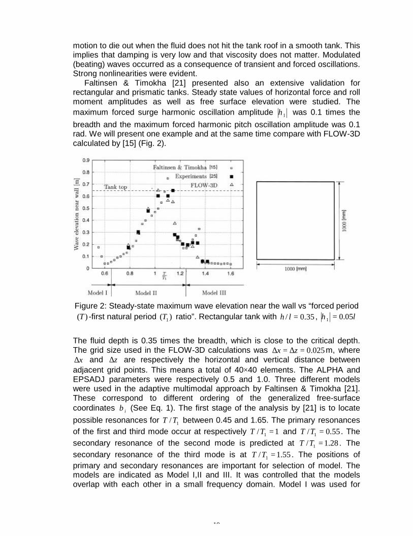
motion to die out when the fluid does not hit the tank roof in a smooth tank. Thisimplies that damping is very low and that viscosity does not matter. Modulated(beating) waves occurred as a consequence of transient and forced oscillations.Strong nonlinearities were evident. Faltinsen & Timokha [21] presented also an extensive validation forrectangular and prismatic tanks. Steady state values of horizontal force and rollmoment amplitudes as well as free surface elevation were studied. Themaximum forced surge harmonic oscillation amplitude 1η was 0.1 times thebreadth and the maximum forced harmonic pitch oscillation amplitude was 0.1rad. We will present one example and at the same time compare with FLOW-3Dcalculated by [15] (Fig. 2).
Figure 2: Steady-state maximum wave elevation near the wall vs “forced period)(T -first natural period )( 1T ratio”. Rectangular tank with 35.0/ =lh , l05.01 =η
The fluid depth is 0.35 times the breadth, which is close to the critical depth.The grid size used in the FLOW-3D calculations was 025.0=∆=∆ zx m, where
x∆ and z∆ are respectively the horizontal and vertical distance betweenadjacent grid points. This means a total of 40×40 elements. The ALPHA andEPSADJ parameters were respectively 0.5 and 1.0. Three different modelswere used in the adaptive multimodal approach by Faltinsen & Timokha [21].These correspond to different ordering of the generalized free-surfacecoordinates iβ (See Eq. 1). The first stage of the analysis by [21] is to locatepossible resonances for 1/TT between 0.45 and 1.65. The primary resonancesof the first and third mode occur at respectively 1/ 1 =TT and 55.0/ 1 =TT . Thesecondary resonance of the second mode is predicted at 28.1/ 1 =TT . Thesecondary resonance of the third mode is at 55.1/ 1 =TT . The positions ofprimary and secondary resonances are important for selection of model. Themodels are indicated as Model I,II and III. It was controlled that the modelsoverlap with each other in a small frequency domain. Model I was used for

11
65.0/5.0 1 ≤≤ TT . The expected resonances are due to primary excitation of thethird and first mode. They have the same main frequency response σ . Nosecondary resonance is expected. This causes the relations )( 3/1
31 εββ O=≈ .This means that the secondary modes have the main harmonic σ2 . Suchmodes are )( 3/2
62 εββ O=≈ . Other modes (up to 9th) are considered as drivenand having )(εO . Model II was used for 25.1/6.0 1 ≤≤ TT . The system is of thirdorder in 1β and 2β . It contains all the necessary terms in Eq. 2 as well as atheory considering )( 2/1
21 εββ O=≈ . The modes 3β , 4β , 5β and 6β wereincluded as driven. If the response is not too large, the modal system gives thesame results as Eqs. 2. When 28.1/ 1 >TT , the third mode response wasassumed to have the same order as 1β and 2β (Model III). The reason is theinfluence of the secondary resonance of third mode at 55.1/ 1 =TT . Model IIIwas used for 65.1/28.1 1 ≤≤ TT . The predicted values in Fig. 2 belong todifferent branches of the steady-state periodic solution. The concept ofbranches of the solutions was for instance extensively discussed by Faltinsen etal. [20]. There exist in their solution an upper and lower branch. The lowerbranch is divided into an upper and lower branch. The lower branch is dividedinto a stable and unstable sub-branch with a turning point between them. Ajump in the solution will happen at an excitation period corresponding to theturning point. The results in Fig. 2 have two jumps, one around 1.1/ 1 =TT andthe other one around 3.1/ 1 =TT . Fig. 2 shows that the multimodal approach byFaltinsen & Timokha [21] agrees well with the experiments. No tank roofdamping was included. Even if the steady-state free surface elevation did not hitthe tank roof, impact would occur during the transient phase. The FLOW-3Dcalculations agree also well with the experiments. However, it should be notedthat the results would depend on grid size and the ALPHA and EPSADJparameters previously discussed. Horizontal forced harmonic oscillations of the LNG tank in Fig. 3 will now bestudied. Two-dimensional fluid motions occur. The mean fluid depth h is l4.0where l is the tank breadth. The forced oscillation amplitude 1η is l01.0 . Fig. 3shows numerical and experimental predictions of steady-state maximumhorizontal force F as a function of the forced oscillation frequency σ . Thelowest natural frequency 1σ is 4.36 rad/s. Different fluids with different viscosityare used in the experiments. This has small influence on the non-dimensionalforce. There are two theoretical curves based on Faltinsen & Timokha [21]. Oneassumes infinite tank roof height and the other one accounts for tank roofdamping. The impact-induced horizontal force is not included in the latter case.The effect of the two lower corners submerged in the fluid was neglected. Theerror in doing so is small ([21]). The previous described Model II and III wereused for respectively 3.1/65.0 1 ≤≤ TT and 65.1/3.1 1 ≤≤ TT . Results by FLOW-3D published by [15] are also presented in Fig. 3. The grid size was
0276.0=∆x m and 02782.0=∆z m corresponding to 50×37 elements. The effectof the corners was accounted for. There are also shown two curvescorresponding to ALPHA=1.0 and 0.5. In both cases EPSADJ=0.01 which is
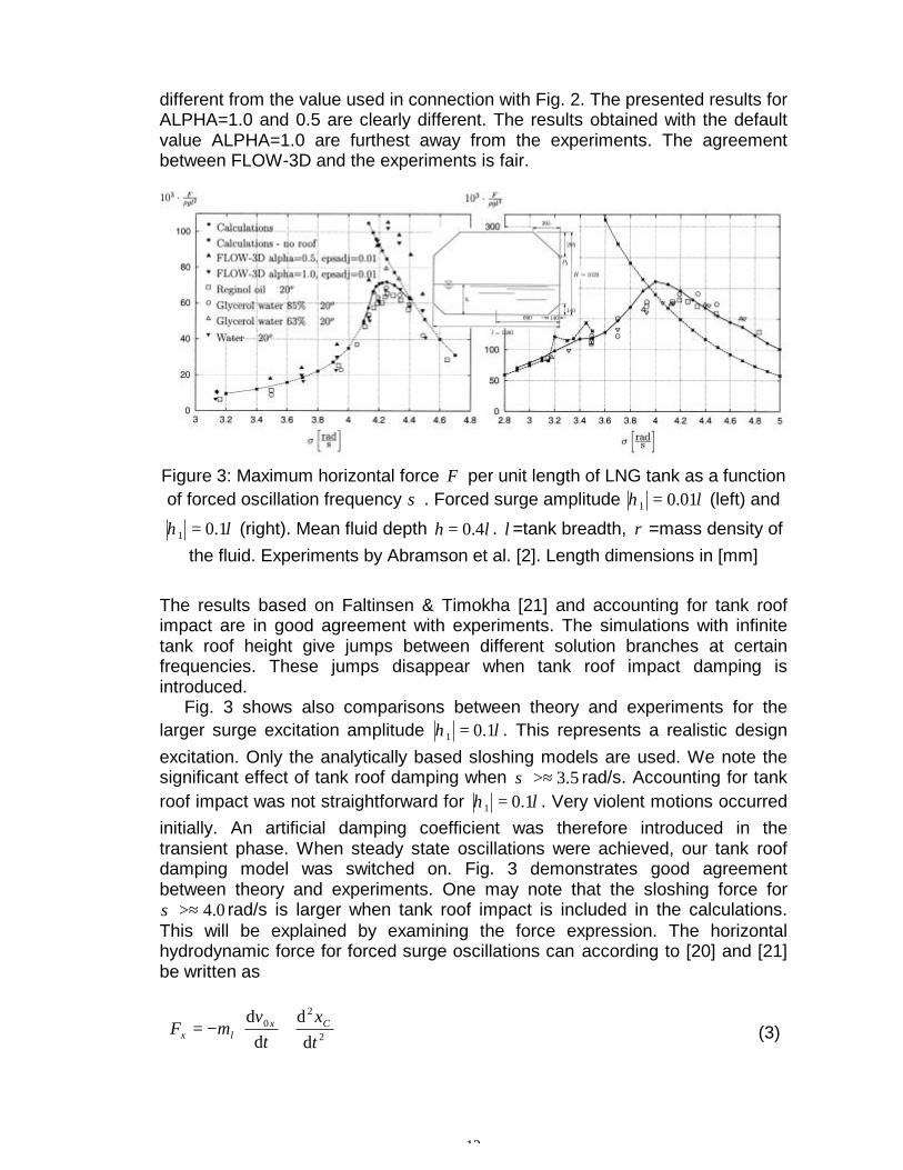
12
different from the value used in connection with Fig. 2. The presented results forALPHA=1.0 and 0.5 are clearly different. The results obtained with the defaultvalue ALPHA=1.0 are furthest away from the experiments. The agreementbetween FLOW-3D and the experiments is fair.
Figure 3: Maximum horizontal force F per unit length of LNG tank as a functionof forced oscillation frequency σ . Forced surge amplitude l01.01 =η (left) and
l1.01 =η (right). Mean fluid depth lh 4.0= . l =tank breadth, ρ =mass density ofthe fluid. Experiments by Abramson et al. [2]. Length dimensions in [mm]
The results based on Faltinsen & Timokha [21] and accounting for tank roofimpact are in good agreement with experiments. The simulations with infinitetank roof height give jumps between different solution branches at certainfrequencies. These jumps disappear when tank roof impact damping isintroduced. Fig. 3 shows also comparisons between theory and experiments for thelarger surge excitation amplitude l1.01 =η . This represents a realistic designexcitation. Only the analytically based sloshing models are used. We note thesignificant effect of tank roof damping when 5.3>≈σ rad/s. Accounting for tankroof impact was not straightforward for l1.01 =η . Very violent motions occurredinitially. An artificial damping coefficient was therefore introduced in thetransient phase. When steady state oscillations were achieved, our tank roofdamping model was switched on. Fig. 3 demonstrates good agreementbetween theory and experiments. One may note that the sloshing force for
0.4>≈σ rad/s is larger when tank roof impact is included in the calculations.This will be explained by examining the force expression. The horizontalhydrodynamic force for forced surge oscillations can according to [20] and [21]be written as
+−= 2
20
dd
dd
tx
tv
mF Cxlx (3)
13
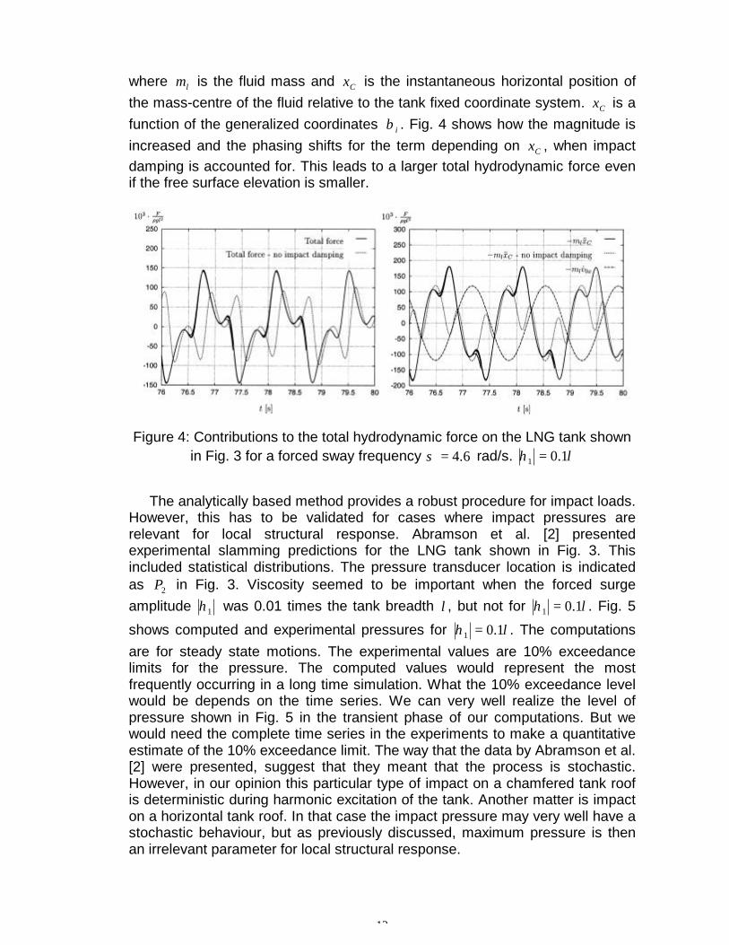
where lm is the fluid mass and Cx is the instantaneous horizontal position ofthe mass-centre of the fluid relative to the tank fixed coordinate system. Cx is afunction of the generalized coordinates iβ . Fig. 4 shows how the magnitude isincreased and the phasing shifts for the term depending on Cx , when impactdamping is accounted for. This leads to a larger total hydrodynamic force evenif the free surface elevation is smaller.
Figure 4: Contributions to the total hydrodynamic force on the LNG tank shownin Fig. 3 for a forced sway frequency 6.4=σ rad/s. l1.01 =η
The analytically based method provides a robust procedure for impact loads.However, this has to be validated for cases where impact pressures arerelevant for local structural response. Abramson et al. [2] presentedexperimental slamming predictions for the LNG tank shown in Fig. 3. Thisincluded statistical distributions. The pressure transducer location is indicatedas 2P in Fig. 3. Viscosity seemed to be important when the forced surgeamplitude 1η was 0.01 times the tank breadth l , but not for l1.01 =η . Fig. 5
shows computed and experimental pressures for l1.01 =η . The computationsare for steady state motions. The experimental values are 10% exceedancelimits for the pressure. The computed values would represent the mostfrequently occurring in a long time simulation. What the 10% exceedance levelwould be depends on the time series. We can very well realize the level ofpressure shown in Fig. 5 in the transient phase of our computations. But wewould need the complete time series in the experiments to make a quantitativeestimate of the 10% exceedance limit. The way that the data by Abramson et al.[2] were presented, suggest that they meant that the process is stochastic.However, in our opinion this particular type of impact on a chamfered tank roofis deterministic during harmonic excitation of the tank. Another matter is impacton a horizontal tank roof. In that case the impact pressure may very well have astochastic behaviour, but as previously discussed, maximum pressure is thenan irrelevant parameter for local structural response.

14
Figure 5: Measured [2] and calculated impact pressures p at the location 2P inthe LNG tank shown in Fig. 3 presented as a function of forced oscillation
period T . l1.01 =η
Figure 6: Sway motions of a rectangular ship section in regular beam sea. 1σ isthe first natural frequency of the fluid motion in the tanks for 184.0=h m
The analytically based sloshing model facilitates coupling between fluidmotion in the tank and wave induced ship motion. Experimental 2-D studies witha ship cross-section containing two tanks have therefore been carried out at the

15
wave flume of the Department of Marine Hydrodynamics at the NorwegianUniversity of Science and Technology. The wave flume has an overall length of13.5m and is 0.6m wide. It is equipped with an electronically operated,computer controlled, single flap wavemaker, calibrated for a water depth of1.03m. The wavemaker has the ability to dampen out waves reflected by themodel at the same time as new waves are generated. The rectangular shipsection shown in Fig. 6 is free to move in sway. The draught is 0.20m, and thesection is excited by regular beam waves with frequency ω . The length of theship model is 0.596m. The mass of the model is adjusted to be equal to thebuoyancy for both empty and half-filled tanks. The amplitude aζ of the incomingwave is lowered as the wave frequency increases to have acceptable wavesteepness. The relationship between aζ and ω is shown in Fig. 6. The modelcontains two identical tanks with an inner length l =0.376mm. The width of atank is 0.15m, and the height is 0.388m. The section is prevented from driftingoff by two springs with a total stiffness of 30.9 N/m. Fig. 6 shows calculated and measured values for the sway amplitude 2η ofthe section. The calculations have presently not been performed with fluidinside the tanks. The sway amplitude is normalized by the amplitude of theincoming wave.
Figure 7: Example of time history of the sway motion of the ship section withfluid in the tank. 42.9=ω rad/s and 015.0=aζ m
Fig. 7 shows a typical time history of the measured sway motion of the shipsection. First there is a transient phase before the system reach a steady state.A beating period of approx. 5 seconds is evident during the transient phase.This is the eigenperiod for horizontal motion of the system consisting of thesprings and the ship model without fluid in the tanks. Due to 2. order drift force a

16
shift in mean position of the section occurs. The steady state is ended whenwaves are reflected from the wavemaker and beach at the end of the waveflume and a second transient phase starts. The steady state motions showalmost no trace of higher order harmonics. This indicates that the higher orderpart of the sloshing force is filtered out by the system. The experimental resultsfor rigid mass agree well with the computed values from the linear seakeepingcode VERES. In these computations, infinite water depth is assumed. Thisexplains the discrepancy for low frequencies. Calculated results from longwavelength, finite water depth theory show better agreement when thewavelength is long compared to the water depth and section length. We observe a large effect of the fluid motions inside the tanks for 7>≈ωrad/s. An excitation 9<≈ω rad/s results in a lower sway response for half-filledtanks than for a rigid mass. The resulting force from the fluid motion in the tanksacts then against the sway excitation force. When nσω ≈ there is almost nosway motion. For 9>≈ω rad/s the sway motion is increased due to the filling ofthe tanks. This behaviour can be explained by using a linear model for thesloshing. We then find that the phase of the horizontal sloshing force shifts 180°when the excitation frequency is changed from being slightly below to slightlyabove the first natural frequency. This is well known from linear dynamicsystems.
CONCLUSIONS AND PERSPECTIVES
Sloshing represents violent fluid motion with strong nonlinearities duringresonant motion in the vicinity of the highest natural period. The physicalbehaviour during impact is discussed. The importance of hydroelasticity forsmall angles between impacting fluid and body surface is stressed. The veryhigh slamming pressures are then unimportant for the structural response. CFDmethods are reviewed. The drawbacks are long simulation time, sensitivity tonumerical parameters and general inability to predict strong impact. Ananalytically based sloshing model is therefore recommended. Its drawbacks arethat the tank has to be smooth with vertical sides at the free surface. Shallowfluid phenomena are excluded. However, this can be studied by the method of[3]. This was done with satisfactory results for horizontal forces by Abramson etal. [2] for a 2-D rectangular tank with fluid depth 0.12 times the breadth. Theimportance of tank roof impact damping on sloshing is demonstrated. Extensivevalidation of free surface elevation, total forces and moments for 2-D flow inrectangular and prismatic tanks are reported. This includes realistic motionexcitation and studies close to critical depth 0.3374 times the tank breadth. The analytical method provides a robust way to predict impact pressures.However, this has to be validated for cases where impact pressures arerelevant for local structural response. The study shows that steady-state impactpressures are clearly lower than would occur during a transient phase. The structure of our method facilitates coupling with the ship dynamics.Experimental 2-D studies with a ship cross-section containing two tanks arepresently performed. These show that the ship response is strongly influencedby the fluid motion in the tanks. The next step is to perform a complete time

17
domain solution of a ship by combining external linear wave loads with thenonlinear analytically based sloshing model for head and beam sea conditions. The details of the analytically based method have to be developed for a shiptank with 3-D flow. A 3-D rectangular tank would represent a directgeneralization of the 2-D method for a rectangular tank. Analysis can be used tothe same extent. However, a tapered tank would require numerical methods todescribe the linear eigenfunctions as a part of the solution procedure.
AKNOWLEDGEMENTS
The contributions from Dr. Hang Sub Urm from DNV concerning importantsloshing problems are appreciated.
BIBLIOGRAPHY
[1] Abramson, M.N., Chu, W.H., Kana, D.D. : ”Some Studies of NonlinearLateral Sloshing in Rigid Containers”, Journal of Applied Mechanics, Vol.33, No. 4, (1966).
[2] Abramson, M.N., Bass, R.G., Faltinsen, O.M., Olsen, H.A. : ”Liquid Sloshin LNG Carriers”, 10th Symp. on Naval Hydrodynamics, Boston, (1974).
[3] Verhagen, J.H.G, and van Wijngaarden, L. : “Nonlinear Oscillations ofFluid in a Container” , J. Fluid Mech., Vol. 22, Part. 4, (1965).
[4] Hansen, H.R. : ”Damage Experience, Potential Damages, CurrentProblems Involving Slosh Considerations”, Seminar on Liquid Sloshing,Det Norske Veritas, Høvik, Norway, (1976).
[5] Faltinsen, O.M. : ”Sea Loads on Ships and Offshore Structures”,Cambridge University Press, (1990).
[6] Faltinsen, O.M. : ”The Effect of Hydroelasticity on Slamming”, Phil. Trans.R. Soc. Lond., A. 355, pp. 575-591, (1997).
[7] Faltinsen, O.M., Kvålsvold, J., and Aarsnes, J.V. : ”Wave Impact on aHorizontal Elastic Plate”, J. Marine Science and Techn., Vol. 2, No. 2, pp.87-100, (1997).
[8] Haugen, E.M. : ”Hydroelastic Analysis of Slamming on Stiffened Plateswith Application to Catamaran Wetdeck”, Dr. Ing. thesis, Dept. MarineHydrodyn., NTNU, Trondheim, Norway, (1999).
[9] Kvålsvold, J. : “Hydroelastic Modelling of Wetdeck Slamming on MultihullVessels”, Dr. Ing. thesis, Dept. Marine Hydrodynamics, NTH, Trondheim,Norway, MTA-Report 1994:100, (1994).
[10] Kvålsvold, J., Faltinsen, O.M., Aarsnes, J.V. : “Effect of Structural Elasticityon Slamming Against Wetdecks of Multihull Vessels”, Proc. PRADS'95,Korea, The Society of Naval Architects of Korea, pp. 1.684-1699, (1995).
[11] Faltinsen, O.M. : “Slamming on Ships”, Keynote lecture, IMAM 2000,Naples, Italy, (2000).
[12] Faltinsen, O.M. : “Water Entry of a Wedge by Hydroelastic OrthotropicPlate Theory” , J. Ship Research, Vol. 43, No. 3., pp. 180-193, (1999).
[13] Monaghan, J.J. : “Smoothed Particle Hydrodynamics”, Annu. Rev. Astron.Astrophys, Vol. 30, pp. 543-74, (1992)
18
[14] Landrini, M., Grytøyr, G., Faltinsen, O.M. : “A B-Spline based BEM forUnsteady Free-Surface Flows”, J. Ship Research, Vol. 13, No. 1, pp. 13-24, (1999).
[15] Solaas, F. : “Analytical and Numerical Studies of Sloshing”, Dr. Ing. thesis,Dept. Marine Hydrodynamics, NTNU, Trondheim, Norway, (1995).
[16] Kim, Y. : “Numerical Simulation of Sloshing Flows with Impact Load”, Tobe submitted
[17] Zhao, R., and Faltinsen, O.M. : “Water Entry of Two-Dimensional Bodies” ,J. Fluid Mech., Vol. 246, pp. 593-612, (1993).
[18] Mikelis, N.E., Miller, J.K., Taylor, K.V. : “Sloshing in Partially Filled LiquidTanks and Its Effect on Ship Motions” , Numerical simulations andexperimental verification, RINA, Spring meeting, (1984).
[19] Wagner, H. : Über Stoss- und Gleitvorgänge an der Oberflache vonFlussigkeiten”, Zeitschr. F. Angew. Math. und Mech., 12, pp. 193-235,(1932).
[20] Faltinsen, O.M., Rognebakke, O.F., Lukovsky, I.A., Timokha, A.N. :“Multidimensional Modal Analysis of Nonlinear Sloshing in a RectangularTank with Finite Water Depth” , J. Fluid Mech., Vol. 407, pp. 201-234,(2000).
[21] Faltinsen, O.M, and Timokha, A.N. : “Adaptive Multimodel Approach toNonlinear Sloshing in a Rectangular Tank” , Submitted for publication,(2000).
[22] Rognebakke, O.F., and Faltinsen, O.M. : “Damping of Sloshing due toTank Roof Impact” , 15th Int. Workshop on Water Waves and FloatingBodies, Caesarea, Israel, (2000).
[23] Faltinsen, O.M., and Rognebakke, O.F. : “Sloshing and Slamming inTanks” , Hydronav'99-Manouevring'99, Gdansk-Ostrada, Poland, (1999).
[24] Dobrovol'skaya, Z.N. : “On Some Problems of Similarity Flow of Fluid witha Free Surface” , J. Fluid Mech., Vol. 36, pp. 805-829, (1969).
[25] Faltinsen, O.M. : “Water Entry of a Wedge with Finite Deadrise Angle”, tobe published, (2000).
[26] Olsen, H., and Johnsen, K.R. : “Nonlinear Sloshing in Rectangular Tanks.A Pilot Study on the Applicability of Analytical Models”, Report No. 74-72-5, Vol. 2, Det Norske Veritas, Høvik, Norway, (1975).
Related Documents

![Sloshing motion in excited tanks - context/Earthcontextearth.com/wp-content/uploads/2016/07/JCP04.pdf · Sloshing motion in excited tanks ... [35] modelled inviscid sloshing motion](https://static.cupdf.com/doc/110x72/5a78985e7f8b9aa2448e4299/sloshing-motion-in-excited-tanks-context-motion-in-excited-tanks-35-modelled.jpg)