Please visit at NB Website for more examples of machining. EXAMPLES OF MACHINING ② SLIDE WAY SLIDE WAY SLIDE TABLE MINIATURE SLIDE GONIO WAY SLIDE WAY STRUCTURE・AND・ADVANTAGES ・ G-2 TYPES ・ ・・・・・・・・・・・・・・・・・・・・・・・・・・・ G-3 ACCURACY ・ ・・・・・・・・・・・・・・・・・・・・・・ G-4 RATED・LIFE ・ ・・・・・・・・・・・・・・・・・・・・・・ G-4 LOAD・RATING ・ ・・・・・・・・・・・・・・・・・・・・ G-4 STROKE ・ ・・・・・・・・・・・・・・・・・・・・・・・・・・ G-6 LUBRICATION・AND・DUST・PREVENTION ・ G-6 MOUNTING ・ ・・・・・・・・・・・・・・・・・・・・・・・ G-6 INSTALLATION・PROCEDURE・OF・NV・TYPE ・ G-7 INSTALLATION・PROCEDURE・OF・SV・TYPE ・ G-8 SPECIAL・MOUNTING・SCREW・BT・TYPE ・ G-9 USE・AND・HANDLING・PRECAUTIONS ・ G-9 DIMENSION・TABLE ・・・・・・・・・・・・・・・・ G-10〜 SLIDE TABLE STRUCTURE・AND・ADVANTAGES ・ G-26 TYPES ・ ・・・・・・・・・・・・・・・・・・・・・・・・・・・ G-27 ACCURACY ・ ・・・・・・・・・・・・・・・・・・・・・・ G-27 RATED・LIFE ・ ・・・・・・・・・・・・・・・・・・・・・・ G-28 LOAD・RATING ・ ・・・・・・・・・・・・・・・・・・・・ G-28 USE・AND・HANDLING・PRECAUTIONS ・ G-28 SPECIAL・REQUIREMENTS ・ ・・・・・・・・ G-29 DIMENSION・TABLE ・・・・・・・・・・・・・・・・ G-30〜 MINIATURE SLIDE STRUCTURE・AND・ADVANTAGES ・ G-52 ACCURACY ・ ・・・・・・・・・・・・・・・・・・・・・・ G-53 LOAD・RATING ・ ・・・・・・・・・・・・・・・・・・・・ G-53 RATED・LIFE ・ ・・・・・・・・・・・・・・・・・・・・・・ G-53 MOUNTING ・ ・・・・・・・・・・・・・・・・・・・・・・・ G-54 USE・AND・HANDLING・PRECAUTIONS ・ G-55 DIMENSION・TABLE ・・・・・・・・・・・・・・・・ G-56〜 GONIO WAY STRUCTURE・AND・ADVANTAGES ・ G-58 ACCURACY・OF・RVF・TYPE ・ ・・・・・・・ G-59 ACCURACY・OF・RV・TYPE ・・・・・・・・・ G-59 RATED・LIFE ・ ・・・・・・・・・・・・・・・・・・・・・・ G-59 MOUNTING・OF・RVF・TYPE ・・ ・・・・・・・ G-60 MOUNTING・OF・RV・TYPE ・ ・・・・・・・・・ G-62 RVF・TYPE・2・AXES・AND・SPECIAL・REQUIREMENTS ・ G-64 USE・AND・HANDLING・PRECAUTIONS ・ G-65 DIMENSION・TABLE ・・・・・・・・・・・・・・・・ G-66〜 F-46 G-1

Welcome message from author
This document is posted to help you gain knowledge. Please leave a comment to let me know what you think about it! Share it to your friends and learn new things together.
Transcript
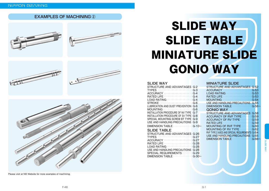
Please visit at NB Website for more examples of machining.
EXAMPLES OF MACHINING ②
SLID
E WA
Y
SLIDE WAYSLIDE TABLE
MINIATURE SLIDEGONIO WAY
SLIDE WAYSTRUCTURE・AND・ADVANTAGES・ G-2TYPES・ ・・・・・・・・・・・・・・・・・・・・・・・・・・・ G-3ACCURACY・ ・・・・・・・・・・・・・・・・・・・・・・ G-4RATED・LIFE・ ・・・・・・・・・・・・・・・・・・・・・・ G-4LOAD・RATING・・・・・・・・・・・・・・・・・・・・・ G-4STROKE・・・・・・・・・・・・・・・・・・・・・・・・・・・ G-6LUBRICATION・AND・DUST・PREVENTION・ G-6MOUNTING・・・・・・・・・・・・・・・・・・・・・・・・ G-6INSTALLATION・PROCEDURE・OF・NV・TYPE・ G-7INSTALLATION・PROCEDURE・OF・SV・TYPE・ G-8SPECIAL・MOUNTING・SCREW・BT・TYPE・ G-9USE・AND・HANDLING・PRECAUTIONS・ G-9DIMENSION・TABLE・・・・・・・・・・・・・・・・ G-10〜SLIDE TABLESTRUCTURE・AND・ADVANTAGES・ G-26TYPES・ ・・・・・・・・・・・・・・・・・・・・・・・・・・・ G-27ACCURACY・ ・・・・・・・・・・・・・・・・・・・・・・ G-27RATED・LIFE・ ・・・・・・・・・・・・・・・・・・・・・・ G-28LOAD・RATING・・・・・・・・・・・・・・・・・・・・・ G-28USE・AND・HANDLING・PRECAUTIONS・ G-28SPECIAL・REQUIREMENTS・・・・・・・・・ G-29DIMENSION・TABLE・・・・・・・・・・・・・・・・ G-30〜
MINIATURE SLIDESTRUCTURE・AND・ADVANTAGES・ G-52ACCURACY・ ・・・・・・・・・・・・・・・・・・・・・・ G-53LOAD・RATING・・・・・・・・・・・・・・・・・・・・・ G-53RATED・LIFE・ ・・・・・・・・・・・・・・・・・・・・・・ G-53MOUNTING・・・・・・・・・・・・・・・・・・・・・・・・ G-54USE・AND・HANDLING・PRECAUTIONS・ G-55DIMENSION・TABLE・・・・・・・・・・・・・・・・ G-56〜GONIO WAYSTRUCTURE・AND・ADVANTAGES・ G-58ACCURACY・OF・RVF・TYPE・ ・・・・・・・ G-59ACCURACY・OF・RV・TYPE・・・・・・・・・・ G-59RATED・LIFE・ ・・・・・・・・・・・・・・・・・・・・・・ G-59MOUNTING・OF・RVF・TYPE・・ ・・・・・・・ G-60MOUNTING・OF・RV・TYPE・・・・・・・・・・ G-62RVF・TYPE・2・AXES・AND・SPECIAL・REQUIREMENTS・G-64USE・AND・HANDLING・PRECAUTIONS・ G-65DIMENSION・TABLE・・・・・・・・・・・・・・・・ G-66〜
F-46 G-1
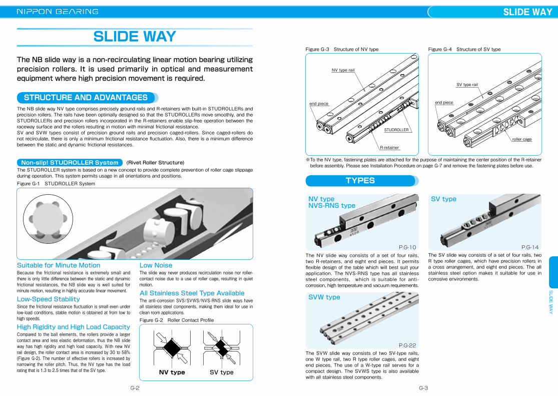
The NB slide way NV type comprises precisely ground rails and R-retainers with built-in STUDROLLERs and precision rollers. The rails have been optimally designed so that the STUDROLLERs move smoothly, and the STUDROLLERs and precision rollers incorporated in the R-retainers enable slip-free operation between the raceway surface and the rollers resulting in motion with minimal frictional resistance.SV and SVW types consist of precision ground rails and precision caged-rollers. Since caged-rollers do not recirculate, there is only a minimum frictional resistance fluctuation. Also, there is a minimum difference between the static and dynamic frictional resistances.
The STUDROLLER system is based on a new concept to provide complete prevention of roller cage slippage during operation. This system permits usage in all orientations and positions.
The NB slide way is a non-recirculating linear motion bearing utilizing precision rollers. It is used primarily in optical and measurement equipment where high precision movement is required.
STRUCTURE AND ADVANTAGES
※To the NV type, fastening plates are attached for the purpose of maintaining the center position of the R-retainer before assembly. Please see Installation Procedure on page G-7 and remove the fastening plates before use.
SLIDE WAY
(Rivet Roller Structure)
Figure G-1 STUDROLLER System
Figure G-3 Structure of NV type
NV type rail
end piece
R-retainer
STUDROLLER
TYPES
The NV slide way consists of a set of four rails, two R-retainers, and eight end pieces. It permits flexible design of the table which will best suit your application. The NVS-RNS type has all stainless steel components, which is suitable for anti-corrosion, high temperature and vacuum requirements.
NV typeNVS-RNS type
P.G-10
Suitable for Minute MotionBecause the frictional resistance is extremely small and there is only little difference between the static and dynamic frictional resistances, the NB slide way is well suited for minute motion, resulting in highly accurate linear movement.
Low-Speed StabilitySince the frictional resistance fluctuation is small even under low-load conditions, stable motion is obtained at from low to high speeds.
High Rigidity and High Load CapacityCompared to the ball elements, the rollers provide a larger contact area and less elastic deformation, thus the NB slide way has high rigidity and high load capacity. With new NV rail design, the roller contact area is increased by 30 to 58% (Figure G-2). The number of effective rollers is increased by narrowing the roller pitch. Thus, the NV type has the load rating that is 1.3 to 2.5 times that of the SV type.
Low NoiseThe slide way never produces recirculation noise nor roller-contact noise due to a use of roller cage, resulting in quiet motion.
All Stainless Steel Type AvailableThe anti-corrosion SVS/SVWS/NVS-RNS slide ways have all stainless steel components, making them ideal for use in clean room applications.Figure G-2 Roller Contact Profile
SV typeNV type
Figure G-4 Structure of SV type
roller cage
SV type rail
end piece
SV type
P.G-14
SVW type
P.G-22
The SV slide way consists of a set of four rails, two R type roller cages, which have precision rollers in a cross arrangement, and eight end pieces. The all stainless steel option makes it suitable for use in corrosive environments.
The SVW slide way consists of two SV-type rails, one W type rail, two R type roller cages, and eight end pieces. The use of a W-type rail serves for a compact design. The SVWS type is also available with all stainless steel components.
Non-slip! STUDROLLER System
G-2
SLIDE WAYS
LIDE W
AY
G-3
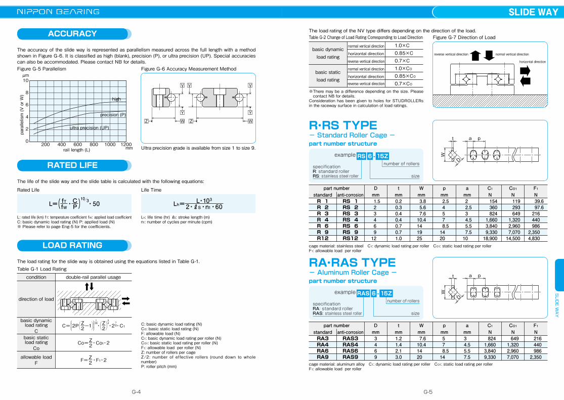
ACCURACY Table G-2 Change of Load Rating Corresponding to Load Direction
basic dynamic load rating
basic static load rating
normal vertical direction horizontal direction reverse vertical direction normal vertical direction horizontal direction reverse vertical direction
1.0×C0.85×C0.7×C1.0×CO
0.85×CO
0.7×CO
LOAD RATING
※There may be a difference depending on the size. Please contact NB for details.
Consideration has been given to holes for STUDROLLERs in the raceway surface in calculation of load ratings.
Figure G-7 Direction of Load
horizontal direction
reverse vertical direction normal vertical direction
RATED LIFE
The life of the slide way and the slide table is calculated with the following equations:
Rated Life Life Time
Lh: life time (hr) ℓS: stroke length (m) n1: number of cycles per minute (cpm)
L: rated life (km) fT: temperature coefficient fW: applied load coefficientC: basic dynamic load rating (N) P: applied load (N)※ Please refer to page Eng-5 for the coefficients.
L=( fTfW・C
P )10/3・50 Lh= L・103
2・ℓS・n1・60
The accuracy of the slide way is represented as parallelism measured across the full length with a method shown in Figure G-6. It is classified as high (blank), precision (P), or ultra precision (UP). Special accuracies can also be accommodated. Please contact NB for details. Figure G-5 Parallelism Figure G-6 Accuracy Measurement Method
10
8
6
4
2
0
high
precision (P)
ultra precision (UP)
rail length (L) mm
μm
200 400 600 800 1000 1200
parallelism (V or W)
WW
V V V
Y
Z Z
Y
Ultra precision grade is available from size 1 to size 9.
The load rating of the NV type differs depending on the direction of the load.
R・RS TYPE - Standard Roller Cage -part number structure
D
t a p
W
specificationR: standard rollerRS: stainless steel roller
example RS 6 15Z
size
number of rollers-
part numberanti-corrosionstandard
Dmm
tmm
Wmm
pmm
amm
C1
NCO1
NF1
NR 1R 2R 3R 4R 6R 9R12
1.5 2 3 4 6 9 12
0.20.30.40.40.70.71.0
3.8 5.6 7.6 10.4 14 19 25
2.5 4 5 7 8.5 14 20
2 2.5 3 4.5 5.5 7.5 10
154360824
1,6603,8409,330
18,900
119293649
1,3202,9607,070
14,500
39.6 97.6 216 440 986 2,350 4,830
cage material: stainless steel C1: dynamic load rating per roller CO1: static load rating per rollerF1: allowable load per roller
RA・RAS TYPE- Aluminum Roller Cage -
D
t a p
W
specificationRA: standard rollerRAS: stainless steel roller
RAS 6 15Z
size
number of rollers-
part number Dmm
tmm
Wmm
pmm
amm
C1
NCO1
NF1
NRA3RA4RA6RA9
3469
RAS3RAS4RAS6RAS9
1.21.42.13.0
7.6 10.4 14 20
5 7 8.5 14
3 4.5 5.5 7.5
8241,6603,8409,330
6491,3202,9607,070
216440986
2,350cage material: aluminum alloy C1: dynamic load rating per roller CO1: static load rating per rollerF1: allowable load per roller
part number structure
example
anti-corrosionstandard
The load rating for the slide way is obtained using the equations listed in Table G-1.Table G-1 Load Rating
condition double-rail parallel usage
direction of load
basic dynamic load rating
Cbasic staticload rating
Co
allowable loadF
C=⎧⎨2P⎩
⎛⎝
Z2 ・⎞
⎠⎫⎬⎭
1─36−1 ⎛
⎝Z2⎞⎠
3─4・2 ・C1
7─9
Co=Z2・Co1・2
F=Z2・F1・2
C: basic dynamic load rating (N)CO: basic static load rating (N)F: allowable load (N)C1: basic dynamic load rating per roller (N)CO1: basic static load rating per roller (N)F1: allowable load per roller (N) Z: number of rollers per cageZ/2: number of effective rollers (round down to whole number)P: roller pitch (mm)
RS 1RS 2RS 3RS 4RS 6RS 9RS12
G-4
SLIDE WAYS
LIDE W
AY
G-5
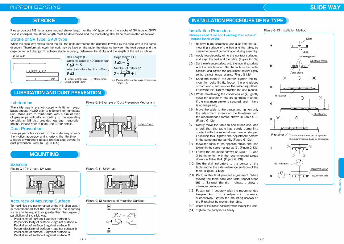
INSTALLATION PROCEDURE OF NV TYPE
Installation Procedure※Please read“Use and Handling Precautions”
before installation. ( 1 ) Remove burrs, scratches, and dust from the rail-
mounting surface of the bed and the table, be careful to prevent contamination during assembly.
( 2 ) Apply low-viscosity oil to the contact surfaces, and align the bed and the table. (Figure G-13a)
( 3 ) Set the reference surface onto the mounting surface with the rails fastened. Set the table in the center position, and tighten the adjustment screws lightly so that almost no gap remains. (Figure G-13b)
( 4 ) Keep the table in the center, tighten the rail mounting bolts lightly, loosen the end pieces of both ends, and remove the fastening plates. Following this, lightly retighten the end pieces.
( 5 )While maintaining the conditions of (4), gently move the assembly through its stroke to check if the maximum stroke is secured, and if there is no irregularity.
( 6 ) Move the table to the center and tighten only the adjustment screws on the R-retainer with the recommended torque shown in Table G-3. (Figure G-13c)
( 7 ) Gently move the table to one stroke end, and check that the table has surely come into contact with the external mechanical stopper.Following this, tighten the adjustment screws in the same manner as (6). (Figure G-13d)
( 8 ) Move the table to the opposite stroke end, and tighten in the same manner as (6). (Figure G-13e)
( 9 ) Fasten the mounting screws on rails 1, 2, and 3 by tightening with the recommended torque shown in Table G-4. (Figure G-13f)
(10) Set the dial indicators to the center of the table and to the side (reference surface) of the table. (Figure G-13g)
(11) Perform the final preload adjustment. While moving the table back and forth, repeat steps (6) to (8) until the dial indicators show a minimum deviation.
(12) Fasten rail 4 securely with the recommended to rque . As fo r the adjustment screws , successively tighten the mounting screws on the R-retainer by moving the table.
(13) Recheck the motion accuracy while moving the table.(14) Tighten the end pieces finally.
Figure G-13 Installation Method
adjustment screws
dial indicators
R-retainer
R-retainer
R-retainer
adjustment screws
end piece
fastening plates
table
bed
×: Adjustment screws should not be tightened.
◯: Adjustment screws can be tightened.
g
f
e
d
c
b
a
adjustment side
① ④
② ③
Figure G-8
L
ℓ S/2
STROKE
Please contact NB for a non-standard stroke length for the NV type. When the stroke of SV type or SVW type is changed, the stroke length must be determined and the load rating should be re-estimated as follows.
Stroke of SV type, SVW typeWhen the slide way moves along the rail, the cage moves half the distance traveled by the slide way in the same direction. Therefore, although the work may be fixed on the table, the distance between the load center and the cage center will change. To achieve stable accuracy, determine the stroke and the length of the rail as follows.
Rail Length (L)When the stroke is 400mm or over
a,p: Please refer to roller cage dimensions (page G-5)
ℓ: cage length(mm) S: stroke(mm)L: rail length(mm)
S≦L/1.5When the stroke is less than 400 mm,S≦L
ℓ≦L− S2
Cage length(ℓ)
Z=ℓ−2ap
Number of rollers(Z)
+1
LUBRICATION AND DUST PREVENTION
Lubrication The slide way is pre-lubricated with lithium soap-based grease No.00 prior to shipment for immediate use. Make sure to relubricate with a similar type of grease periodically according to the operating conditions. NB also provides low dust generation grease. Please refer to page Eng-39 for details.
Dust Prevention Foreign particles or dust in the slide way affects the motion accuracy and shortens the life time. In a harsh environment please provide side covers for dust prevention. (refer to Figure G-9)
Figure G-9 Example of Dust Prevention Mechanism
side cover
MOUNTING
ExampleFigure G-10 NV type, SV type Figure G-11 SVW type
Accuracy of Mounting Surface To maximize the performance of the NB slide way, it is recommended that the accuracy of the mounting surface to be equal to or greater than the degree of parallelism of the slide way.
Parallelism of surface 1 against surface A Perpendicularity of surface 2 against surface A Parallelism of surface 3 against surface B Perpendicularity of surface 4 against surface B Parallelism of surface 2 against surface C Parallelism of surface 4 against surface C
Figure G-12 Accuracy of Mounting Surface
31.6
4 412
31.6
1.6 1.6
1.6
1.6
1.6
A
B
C
G-6
SLIDE WAYS
LIDE W
AY
G-7
USE AND HANDLING PRECAUTIONSCareful HandlingDropping the slide way causes the rolling elements to make dents in the raceway surface. This will prevent smooth motion and will also affect accuracy. Be sure to handle the product with care. The NV type is packaged as a set of rails and R-retainers. Do not separate or disassemble until assembly/installation is completed. Precision is not guaranteed if disassembled.Fastening PlatesFor the NV type, fastening plates are attached at both end faces of the rails to maintain the R-retainer center position prior to assembly. The fastening plates are not required after the NV type is mounted to a table and bed, however, when removal of the NV type is necessary such as when it will be reassembled, be sure to return the R-retainer to the proper center position, secure the fastening plates with the end pieces, and then remove the NV type. Specified Allowable StrokeFor the NV type, exceeding the specified stroke (over-stroke) shall cause the raceway surface of the rail to be damaged and the performance of the STUDROLLER to drastically deteriorate. Be sure to provide external mechanical stoppers.
AdjustmentUsing the product with insufficient accuracy of the mounting surface or before adjusting the preload will cause the motion accuracy of the product to drop and will have a negative influence upon product life and accuracy. Make sure to assemble, install, and adjust the product with care. Caution against Excess PreloadIt is essential to give preload on the Slide Way products in order to assure rigidity and accuracy.However, excess preload causes damage on the raceways and roller cages/R-retainers.On installation, please follow the installation procedure and recommended torque on page G-8.
Operating TemperatureThe NV type uses resin parts. Please use the product in environments that are lower than 80℃ .
Use as a SetThe accuracy of the rails has been matched within each set. Note that the accuracy will be affected when the rails of different sets are combined.
Allowable LoadThe allowable load is a load under which the sum of elastic deformations of the rolling element and the raceway in the contact area subject to the maximum contact stress is small enough to guarantee smooth rolling movement. When very smooth and highly accurate linear motion is required, make sure to use the product within the allowable load.
Cage SlippageFor the SV/SVW type, the cage can slip under high-speed motion, vertical application, unbalanced-loading, and vibrating conditions. It is advised that the stroke be set with sufficient margin and an excessive preload should be avoided. It is also recommended that the rails be cycled to perform the maximum stroke several times, so that the cage returns to its central position.
End PiecesEnd pieces are attached to each end of the slide way to prevent removal of the cage. Do not use them as a mechanical stopper.
Knock Pin HoleWhen using SVW type knock pin holes to attach a slide way, please do the hole-machining on the mounting surface after attaching the W type rail. After machining, remove the chips completely and wash as required.
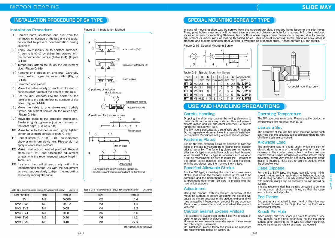
SPECIAL MOUNTING SCREW BT TYPE
Installation Procedure( 1 ) Remove burrs, scratches, and dust from the
rail-mounting surface of the bed and the table, be careful to prevent contamination during assembly.
( 2 ) Apply low-viscosity oil to contact surfaces. Attach rails ①-③ by tightening screws with the recommended torque (Table G-4). (Figure G-14a)
( 3 ) Temporarily attach rail ④ on the adjustment side. (Figure G-14b)
( 4 ) Remove end pieces on one end. Carefully insert roller cages between rails. (Figure G-14c)
( 5 ) Re-attach end pieces. ( 6 ) Move the table slowly to each stroke end to
position roller cages at the center of the rails.( 7 ) Set the dial indicators to the center of the
table and to the side (reference surface) of the table. (Figure G-14d)
( 8 ) Move the table to one stroke end. Lightly tighten adjustment screws on the roller cage. (Figure G-14e)
( 9 ) Move the table to the opposite stroke end. Similarly lightly tighten adjustment screws on the roller cage. (Figure G-14f)
(10) Move table to the center and lightly tighten center adjustment screws. (Figure G-14g)
(11) Repeat steps (8) ~ (10) until the indicators show a minimum deviation. Please do not apply an excessive preload.
(12) Make final adjustment of preload. Repeat steps (8) ~ (10) and tighten the adjustment screws with the recommended torque listed in Table G-3.
(13) Fa s te n t h e r a i l ④ s e c u r e l y w i t h t h e recommended torque. As with the adjustment screws, successively tighten the mounting screws by moving the table.
INSTALLATION PROCEDURE OF SV TYPE
Figure G-14 Installation Method
①
② ③
④
a
b
c
attach rails ①-③
temporarily attach rail ④
insert cages
d positions of indicators
adjustment side
adjustment screws
dial indicators
g
roller cage
○: Adjustment screws can be tightened. ×: Adjustment screws should not be tightened.
e positions of adjustment screws
roller cagef
roller cage
Table G-3 Recommended Torque for Adjustment Screw Unit/N・m
part numberSV1
NV2, SV2NV3, SV3NV4, SV4NV6, SV6NV9, SV9
sizeM2M3M4M4M5M6
torque 0.008 0.012 0.05 0.08 0.20 0.40
Table G-4 Recommended Torque for Mounting screw Unit/N・m
sizeM2M3M4M5M6M8
torque 0.4 1.4 3.2 6.611.227.6
(for steel alloy screw)
In case of mounting slide way by screws from the counterbore side, threaded holes become the pilot holes. Thus, pilot hole's clearance will be less than a standard clearance hole for a screw. NB offers reduced shoulder screws for mounting SlideWay from bottom when larger screw clearance is required due to preload adjustment or inaccuracy of mating threaded holes. This special mounting screw made of alloy steel is stocked, and custom stainless steel version is available as a special order. Please contact NB for details.
Figure G-15 Special Mounting Screw
S
B
d
L1L2
H
D
BT 3BT 4BT 6BT 9BT12
part number
Table G-5 Special Mounting Screw
M3M4M5M6M8
B
2.3 3.1 3.9 4.6 6.25
dmm
Dmm
5 5.8 8 8.5 11.3
34568
Hmm
L1
mm1215203040
5 7 81217
L2
mmS
mm 2.5 3 4 5 6
NV 3, SV 3NV 4, SV 4NV 6, SV 6NV 9, SV 9NV12, SV12
applicable size
special mounting screw
G-8
SLIDE WAYS
LIDE W
AY
G-9
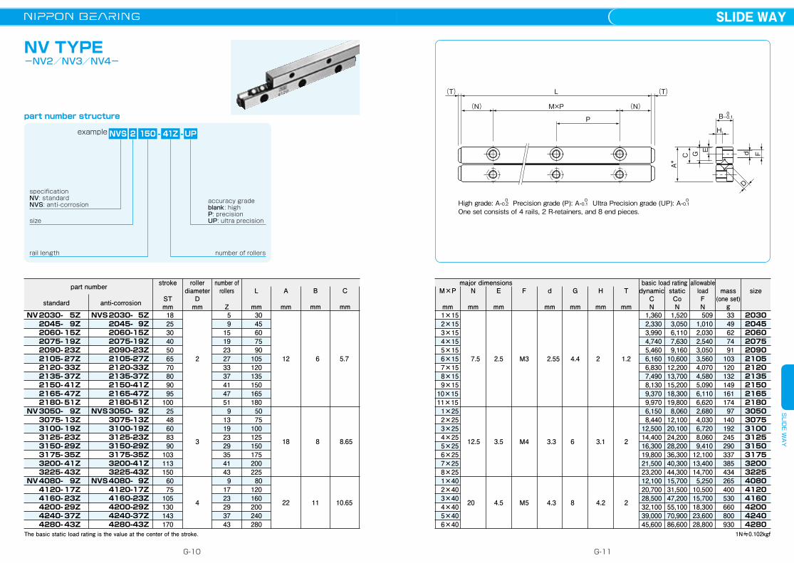
NV TYPE-NV2/NV3/NV4-
(T)(T)
C
A*
G E
H
Fd
D
P
(N)(N)
L
M×P 0-0.1B
High grade: A-0.2 Precision grade (P): A-0.1 Ultra Precision grade (UP): A-0.10 0 0
One set consists of 4 rails, 2 R-retainers, and 8 end pieces.size
example 2 150 41Z
specificationNV: standardNVS: anti-corrosion
UP-
rail length number of rollers
accuracy gradeblank: highP: precisionUP: ultra precision
-
The basic static load rating is the value at the center of the stroke.
part number structure
NVS
NV 2030- 5Z 2045- 9Z 2060- 15Z 2075- 19Z 2090- 23Z 2105- 27Z 2120- 33Z 2135- 37Z 2150- 41Z 2165- 47Z 2180- 51Z NV 3050- 9Z 3075- 13Z 3100- 19Z 3125- 23Z 3150- 29Z 3175- 35Z 3200- 41Z 3225- 43Z NV 4080- 9Z 4120- 17Z 4160- 23Z 4200- 29Z 4240- 37Z 4280- 43Z
NVS 2030- 5Z 2045- 9Z 2060- 15Z 2075- 19Z 2090- 23Z 2105- 27Z 2120- 33Z 2135- 37Z 2150- 41Z 2165- 47Z 2180- 51Z NVS 3050- 9Z 3075- 13Z 3100- 19Z 3125- 23Z 3150- 29Z 3175- 35Z 3200- 41Z 3225- 43Z NVS 4080- 9Z 4120- 17Z 4160- 23Z 4200- 29Z 4240- 37Z 4280- 43Z
stroke
STmm 18 25 30 40 50 65 70 80 90 95100 25 48 60 83 90103113150 60 75105130143170
number of rollers
Z
L
mm
A
mm
rollerdiameter
Dmm
2
3
4
5 9151923273337414751 913192329354143 91723293743
30 45 60 75 90105120135150165180 50 75100125150175200225 80120160200240280
12
18
22
6
8
11
5.7
8.65
10.65
B
mm
C
mm
part number
anti-corrosionstandard
1N≒0.102kgf
2030204520602075209021052120213521502165218030503075310031253150317532003225408041204160420042404280
3349627491
10312013214916117497
140192245290337385434265400530660800930
F
M3
M4
M5
1×15 2×15 3×15 4×15 5×15 6×15 7×15 8×15 9×1510×1511×15 1×25 2×25 3×25 4×25 5×25 6×25 7×25 8×25 1×40 2×40 3×40 4×40 5×40 6×40
7.5
12.5
20
2.5
3.5
4.5
M×P
mm
N
mm
E
mm
d
mm
G
mm
H
mm
T
mm
2.55
3.3
4.3
4.4
6
8
2
3.1
4.2
1.2
2
2
1,3602,3303,9904,7405,4606,1606,8307,4908,1309,3709,9706,1508,440
12,50014,40016,30019,80021,50023,20012,10020,70028,50032,10039,00045,600
1,5203,0506,1107,6309,160
10,60012,20013,70015,20018,30019,8008,060
12,10020,10024,20028,20036,30040,30044,30015,70031,50047,20055,10070,90086,600
509 1,010 2,030 2,540 3,050 3,560 4,070 4,580 5,090 6,110 6,620 2,680 4,030 6,720 8,060 9,41012,10013,40014,700 5,25010,50015,70018,30023,60028,800
dynamicCN
staticCoN
sizemass(one set)
g
major dimensions basic load rating allowable loadFN
G-10
SLIDE WAYS
LIDE W
AY
G-11
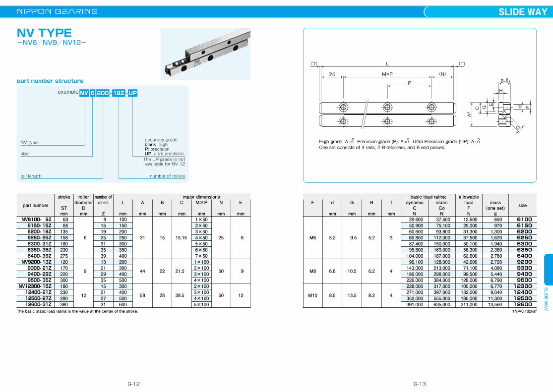
NV TYPE-NV6/NV9/NV12-
(T)(T)
C
A*
G E
H
Fd
D
P
(N)(N)
L
M×P 0-0.1B
High grade: A-0.2 Precision grade (P): A-0.1 Ultra Precision grade (UP): A-0.10 0 0
One set consists of 4 rails, 2 R-retainers, and 8 end pieces.
1N≒0.102kgf
dynamicCN
staticCoN
major dimensions
part number
NV6100- 9Z 6150- 15Z 6200- 19Z 6250- 25Z 6300- 31Z 6350- 35Z 6400- 39Z NV9200- 13Z 9300- 21Z 9400- 29Z 9500- 35Z NV12300- 15Z 12400- 21Z 12500- 27Z 12600- 31Z
stroke
STmm 63 85135158180230275120170220300180230280380
basic load ratingnumber of rollers
Z
L
mm
A
mm
size
6100 6150 6200 6250 6300 6350 6400 9200 9300 9400 950012300124001250012600
mass(one set)
g650970
1,3001,6201,9402,3602,7802,7204,0805,4406,7906,7709,040
11,30013,560
rollerdiameter
Dmm
allowable load
FN
F
M6
M8
M10
size
NV 6 200 19Z
NV type
UP-
rail length number of rollers
The UP grade is not available for NV 12
accuracy gradeblank: highP: precisionUP: ultra precision
6
9
12
91519253135391321293515212731
100150200250300350400200300400500300400500600
31
44
58
15
22
28
15.15
21.5
28.5
1×502×503×504×505×506×507×501×1002×1003×1004×1002×1003×1004×1005×100
25
50
50
6
9
12
B
mm
C
mm
M×P
mm
N
mm
E
mm
d
mm
G
mm
H
mm
T
mm
5.2
6.8
8.5
9.5
10.5
13.5
5.2
6.2
8.2
3
4
4
29,60050,90060,60069,80087,40095,800
104,00096,100
143,000186,000226,000228,000271,000352,000391,000
37,50075,10093,900
112,000150,000169,000187,000128,000213,000298,000384,000317,000397,000555,000635,000
12,50025,00031,30037,50050,10056,30062,60042,60071,10099,500
128,000105,000132,000185,000211,000
-
The basic static load rating is the value at the center of the stroke.
part number structure
example
G-12
SLIDE WAYS
LIDE W
AY
G-13

NVS-RNS TYPE-Special Environments Type-
part number structure
size
NVS 4 200 27ZRNS
specificationNVS: anti-corrosion
P-
rail length
number of rollers
cage typeRNS: stainless steel cage stainless steel rollerRN: stainless steel cage standard roller
accuracy gradeblank: highP: precisionUP: ultra precision
-
1N≒0.102kgf
part number
NVS 2030-RNS 7Z 2045-RNS11Z 2060-RNS13Z 2075-RNS17Z 2090-RNS21Z 2105-RNS23Z 2120-RNS27Z 2135-RNS31Z 2150-RNS33Z 2165-RNS37Z 2180-RNS43ZNVS 3050-RNS 9Z 3075-RNS13Z 3100-RNS17Z 3125-RNS21Z 3150-RNS25Z 3175-RNS29Z 3200-RNS33Z 3225-RNS35ZNVS 4080-RNS 9Z 4120-RNS17Z 4160-RNS21Z 4200-RNS27Z 4240-RNS31Z 4280-RNS37Z
※Some specification values are different from those of NV standard type. Please contact NB for details.
High: A-0.2 Precision (P): A-0.1 Ultra Precision (UP): A-0.10 0 0
One set consists of 4 rails, 2 cages, and 8 end pieces.
P
M×P (N)(N)
(T) L (T)
d
EGC
A*
H
D
F
0-0.1B
example
major dimensionsstroke
STmm 15 20 30 40 50 65 70 80 90 95100 20 38 55 70 85103113150 58 60 98115143170
number of rollers
ZL
mm
A
mm
rollerdiameter
Dmm
2
3
4
7111317212327313337439
131721252933359
1721273137
3045607590
1051201351501651805075
10012515017520022580
120160200240280
12
18
22
6
8
11
5.7
8.65
10.65
1×152×153×154×155×156×157×158×159×15
10×1511×151×252×253×254×255×256×257×258×251×402×403×404×405×406×40
7.5
12.5
20
2.5
3.5
4.5
B
mm
C
mm
M×P
mm
N
mm
E
mm
dynamicCN
staticCoN
basic load rating
size
2030204520602075209021052120213521502165218030503075310031253150317532003225408041204160420042404280
mass(one set)
g30 44 58 73 87
101 115 130 144 158 173 102 151 200 249 297 346 395 443 269 405 536 670 801 935
allowable load
FN
F
M3
M4
M5
d
mm
G
mm
H
mm
T
mm
2.55
3.3
4.3
4.4
6
8
2
3.1
4.2
1.2
2
2
2,320 3,190 3,190 4,000 4,760 5,490 6,190 6,870 6,870 7,530 8,800 6,150 8,460
10,600 12,600 14,500 16,400 18,200 19,900 12,100 20,800 24,800 32,200 35,800 39,200
3,050 4,580 4,580 6,110 7,630 9,160
10,600 12,200 12,200 13,700 16,800 8,060
12,100 16,100 20,100 24,200 28,200 32,200 36,300 15,700 31,500 39,300 55,100 63,000 70,900
1,010 1,520 1,520 2,030 2,540 3,050 3,560 4,070 4,070 4,580 5,600 2,680 4,030 5,370 6,720 8,060 9,410
10,700 12,100 5,250
10,500 13,100 18,300 21,000 23,600
G-14
SLIDE WAYS
LIDE W
AY
G-15
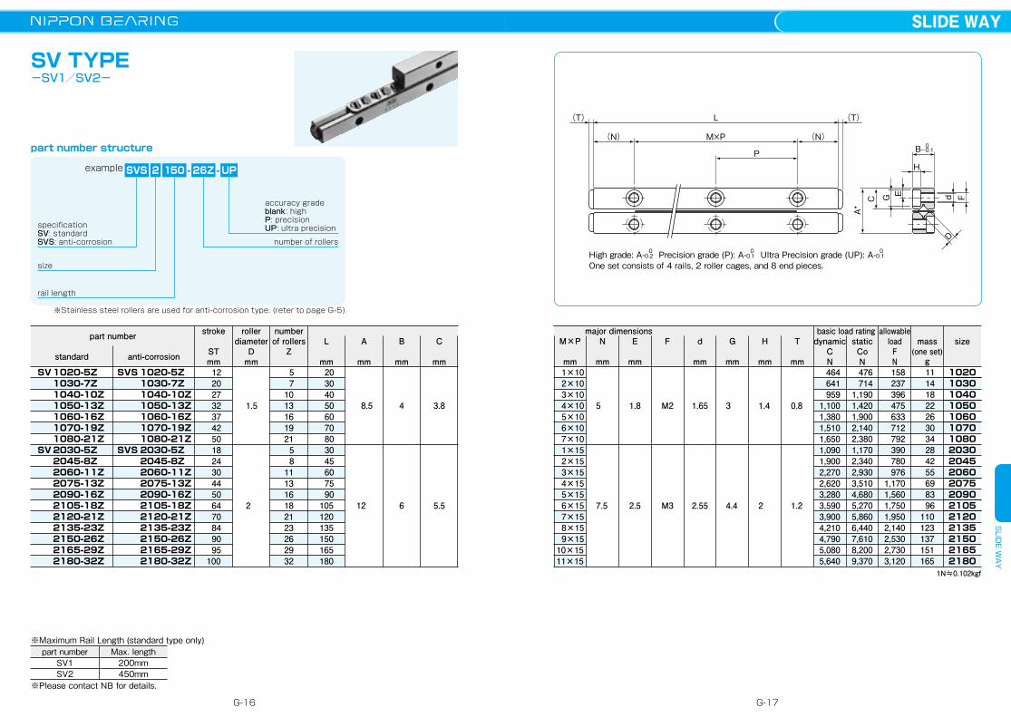
SV TYPE -SV1/SV2-
part number structure
L
mm
part number
SV 1020-5Z 1030-7Z 1040-10Z 1050-13Z 1060-16Z 1070-19Z 1080-21ZSV 2030-5Z 2045-8Z 2060-11Z 2075-13Z 2090-16Z 2105-18Z 2120-21Z 2135-23Z 2150-26Z 2165-29Z 2180-32Z
12 20 27 32 37 42 50 18 24 30 44 50 64 70 84 90 95100
size
example SVS 2 UP-
rail length
number of rollers
※Stainless steel rollers are used for anti-corrosion type. (reter to page G-5)
150 - 26Z
accuracy gradeblank: highP: precisionUP: ultra precision
SVS 1020-5Z 1030-7Z 1040-10Z 1050-13Z 1060-16Z 1070-19Z 1080-21ZSVS 2030-5Z 2045-8Z 2060-11Z 2075-13Z 2090-16Z 2105-18Z 2120-21Z 2135-23Z 2150-26Z 2165-29Z 2180-32Z
stroke
STmm
rollerdiameter
Dmm
number of rollers
ZA
mm
B
mm
C
mm
1.5
2
5 71013161921 5 8111316182123262932
20 30 40 50 60 70 80 30 45 60 75 90105120135150165180
8.5
12
4
6
※Please contact NB for details.
part numberSV1SV2
Max. length200mm450mm
※Maximum Rail Length (standard type only)
3.8
5.5
anti-corrosionstandard
specificationSV: standardSVS: anti-corrosion D
d F
H
C EG
A*
(T)(T) L
(N)(N) M×P
P 0-0.1B
High grade: A-0.2 Precision grade (P): A-0.1 Ultra Precision grade (UP): A-0.10 0 0
One set consists of 4 rails, 2 roller cages, and 8 end pieces.
dynamicCN
staticCoN
sizemass(one set)
g102010301040105010601070108020302045206020752090210521202135215021652180
major dimensions
1N≒0.102kgf
1×10 2×10 3×10 4×10 5×10 6×10 7×10 1×15 2×15 3×15 4×15 5×15 6×15 7×15 8×15 9×1510×1511×15
5
7.5
1.8
2.5
M2
M3
1.65
2.55
3
4.4
1.4
2
0.8
1.2
464641959
1,1001,3801,5101,6501,0901,9002,2702,6203,2803,5903,9004,2104,7905,0805,640
476714
1,1901,4201,9002,1402,3801,1702,3402,9303,5104,6805,2705,8606,4407,6108,2009,370
158237396475633712792390780976
1,1701,5601,7501,9502,1402,5302,7303,120
11 14 18 22 26 30 34 28 42 55 69 83 96110123137151165
M×P
mm
N
mm
E
mm
F d
mm
G
mm
H
mm
T
mm
basic load rating allowable load
FN
G-16
SLIDE WAYS
LIDE W
AY
G-17

D
d F
H
C EG
A*
(T)(T) L
(N)(N) M×P
P 0-0.1B
High grade: A-0.2 Precision grade (P): A-0.1 Ultra Precision grade (UP): A-0.10 0 0
One set consists of 4 rails, 2 roller cages, and 8 end pieces.
SV TYPE -SV3/SV4-
part number structure
dynamicCN
staticCoN
sizebasic load rating
mass(one set)
g305030753100312531503175320032253250327533003325335040804120416042004240428043204360440044404480
L
mm
major dimensionspart number
anti-corrosionstandard
1N≒0.102kgf
1×25 2×25 3×25 4×25 5×25 6×25 7×25 8×25 9×2510×2511×2512×2513×25 1×40 2×40 3×40 4×40 5×40 6×40 7×40 8×40 9×4010×4011×40
SV 3050-7Z 3075-10Z 3100-14Z 3125-17Z 3150-21Z 3175-24Z 3200-28Z 3225-31Z 3250-35Z 3275-38Z 3300-42Z 3325-45Z 3350-49ZSV 4080-7Z 4120-11Z 4160-15Z 4200-19Z 4240-23Z 4280-27Z 4320-31Z 4360-35Z 4400-39Z 4440-43Z 4480-47Z
allowable load
FN
28 48 58 78 88105115135145165175195205 58 82105130150175200225250270295
size
example SVS 4 UP
specificationSV: standardSVS: anti-corrosion
-
rail length
cage typeblank: standard cageRA(RAS): aluminum cage
number of rollers
200 - RAS 19Zaccuracy gradeblank: highP: precisionUP: ultra precision
SVS 3050-7Z 3075-10Z 3100-14Z 3125-17Z 3150-21Z 3175-24Z 3200-28Z 3225-31Z 3250-35Z 3275-38Z 3300-42Z 3325-45Z 3350-49ZSVS 4080-7Z 4120-11Z 4160-15Z 4200-19Z 4240-23Z 4280-27Z 4320-31Z 4360-35Z 4400-39Z 4440-43Z 4480-47Z
stroke
STmm
roller diameter
Dmm
number of rollers
ZA
mm
B
mm
C
mm
3
4
7101417212428313538424549 711151923273135394347
50 75100125150175200225250275300325350 80120160200240280320360400440480
18
22
8
11
12.5
20
※Please contact NB for details.
part numberSV3SV4
Max. length700mm700mm
※Maximum Rail Length (standard type only)
3.5
4.5
M4
M5
3.3
4.3
6
8
3.1
4.2
2
2
3,4905,2306,8107,5609,000
10,30011,70012,30013,60014,80016,00016,60017,8007,110
10,60013,80016,80019,70022,40025,10027,60030,20032,60035,000
3,8906,4909,080
10,30012,90015,50018,10019,40022,00024,60027,20028,50031,1007,920
13,20018,40023,70029,00034,30039,60044,80050,10055,40060,700
1,2902,1603,0203,4504,3205,1806,0406,4807,3408,2009,0709,500
10,3002,6404,4006,1607,9209,680
11,40013,20014,90016,70018,40020,200
94135187234281327374421468514561608655255385510635770905
1,0201,1601,2801,4101,540
8.3
10.2
M×P
mm
N
mm
E
mm
F d
mm
G
mm
H
mm
T
mm
※Stainless steel rollers are used for anti-corrosion type. (reter to page G-5)
G-18
SLIDE WAYS
LIDE W
AY
G-19
D
d F
H
C EG
A*
(T)(T) L
(N)(N) M×P
P 0-0.1B
High grade: A-0.2 Precision grade (P): A-0.1 Ultra Precision grade (UP): A-0.10 0 0
One set consists of 4 rails, 2 roller cages, and 8 end pieces.
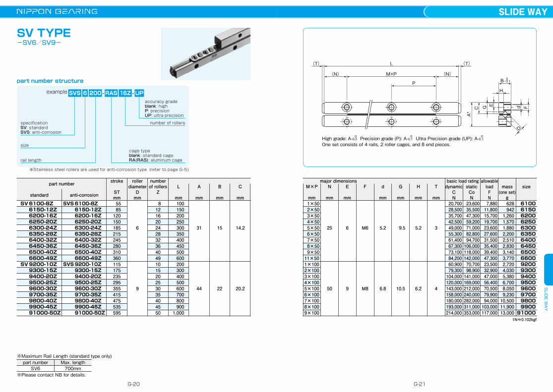
SV TYPE -SV6/SV9-
part number structure
dynamicCN
staticCoN
sizemass(one set)
g610061506200625063006350640064506500660092009300940095009600970098009900
91000
L
mm
major dimensionspart number
1N≒0.102kgf
1×50 2×50 3×50 4×50 5×50 6×50 7×50 8×50 9×5011×501×1002×1003×1004×1005×1006×1007×1008×1009×100
SV 6100-8Z 6150-12Z 6200-16Z 6250-20Z 6300-24Z 6350-28Z 6400-32Z 6450-36Z 6500-40Z 6600-49ZSV 9200-10Z 9300-15Z 9400-20Z 9500-25Z 9600-30Z 9700-35Z 9800-40Z 9900-45Z 91000-50Z
55 85120150185215245280310360115175235295355415475535595
size
example SVS 6 UP-
rail length
cage typeblank: standard cageRA(RAS): aluminum cage
number of rollers
200 - RAS 16Z
SVS 6100-8Z 6150-12Z 6200-16Z 6250-20Z 6300-24Z 6350-28Z 6400-32Z 6450-36Z 6500-40Z 6600-49ZSVS 9200-10Z 9300-15Z 9400-20Z 9500-25Z 9600-30Z 9700-35Z 9800-40Z 9900-45Z 91000-50Z
stroke
STmm
roller diameter
Dmm
number of rollers
ZA
mm
B
mm
C
mm
6
9
8121620242832364049101520253035404550
100150200250300350400450500600200300400500600700800900
1,000
31
44
15
22
25
50
※Please contact NB for details.
part numberSV6
Max. length700mm
※Maximum Rail Length (standard type only)
6
9
M6
M8
5.2
6.8
9.5
10.5
5.2
6.2
3
4
20,70028,50035,70042,50049,00055,30061,40067,30073,10084,20060,90079,300
104,000120,000143,000158,000180,000193,000214,000
23,60035,50047,30059,20071,00082,80094,700
106,000118,000142,00070,70098,900
141,000169,000212,000240,000282,000311,000353,000
7,88011,80015,70019,70023,60027,60031,50035,40039,40047,30023,50032,90047,00056,40070,50079,90094,000
103,000117,000
628942
1,2601,5701,8802,2002,5102,8303,1403,7702,7204,0305,3806,7008,0509,230
10,50011,90013,000
14.2
20.2
M×P
mm
N
mm
E
mm
F d
mm
G
mm
H
mm
T
mm
specificationSV: standardSVS: anti-corrosion
accuracy gradeblank: highP: precisionUP: ultra precision
anti-corrosionstandard
basic load rating allowable load
FN
※Stainless steel rollers are used for anti-corrosion type. (reter to page G-5)
G-20
SLIDE WAYS
LIDE W
AY
G-21
D
d F
H
C EG
A*
(T)(T) L
(N)(N) M×P
P 0-0.1B
High grade: A-0.2 Precision grade (P): A-0.1 0 0
One set consists of 4 rails, 2 roller cages, and 8 end pieces.
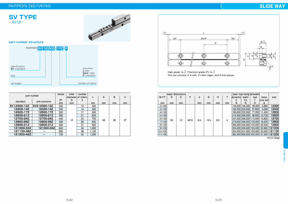
SV TYPE-SV12-
part number structure
dynamicCN
staticCoN
sizemass(one set)
g12300124001250012600127001280012900
121000121100121200
L
mm
major dimensionspart number
1N≒0.102kgf
2×100 3×100 4×100 5×100 6×100 7×100 8×100 9×10010×10011×100
SV 12300-10Z 12400-14Z 12500-17Z 12600-21Z 12700-24Z 12800-28Z 12900-31Z 121000-34Z 121100-38Z 121200-42Z
200240320360440480560640680720
size
example SV 12 P
specificationSV: standard
-
rail length number of rollers
500 - 17Z
accuracy gradeblank: highP: precision
stroke
STmm
roller diameter
Dmm
number of rollers
ZA
mm
B
mm
C
mm
12
10141721242831343842
300400500600700800900
1,0001,1001,200
58 28 50 12 M10 8.5 13.5 8.2 4
124,000162,000180,000214,000247,000279,000294,000324,000354,000382,000
145,000203,000232,000290,000348,000406,000435,000493,000551,000609,000
48,30067,60077,20096,600
115,000135,000144,000164,000183,000202,000
6,8809,090
11,40013,70015,80018,20020,50022,80025,00027,300
27
M×P
mm
N
mm
E
mm
F d
mm
G
mm
H
mm
T
mmanti-corrosionstandard
basic load rating allowable load
FN
SVS 12300-10Z 12400-14Z 12500-17Z 12600-21Z 12700-24Z 12800-28Z 12900-31Z 121000-34Z
——
G-22
SLIDE WAYS
LIDE W
AY
G-23

M2×P3
M1×P2
L (T)(T)
(N2)
(N1)
(N2)
(N1)
P3
P2
d2(knock pin hole)
A
H
H
tt
CF
FG
G B2
d1
d1
P1
B1 -0.40
D
SVW TYPE
part number structure
dynamicCN
staticCoN
sizemass(one set)
g102010301040105010601070108020302045206020752090210521203050307531003125315031753200408041204160420042404280
L
mm
major dimensionspart number
1N≒0.102kgf
−1×102×103×104×105×106×10
−1×152×153×154×155×156×15
−1×252×253×254×255×256×25
−1×402×403×404×405×40
SVW 1020- 5Z 1030- 7Z 1040-10Z 1050-13Z 1060-16Z 1070-19Z 1080-21ZSVW 2030- 5Z 2045- 8Z 2060-11Z 2075-13Z 2090-16Z 2105-18Z 2120-21ZSVW 3050- 7Z 3075-10Z 3100-14Z 3125-17Z 3150-21Z 3175-24Z 3200-28ZSVW 4080- 7Z 4120-11Z 4160-15Z 4200-19Z 4240-23Z 4280-27Z
12 20 27 32 37 42 50 18 24 30 44 50 64 70 28 48 58 78 88105115 58 82105130150175
size
example SVWS 4 UP-
rail length
cage typeblank: standard cageRA: aluminum cage standard rollerRAS: aluminum cage stainless steel roller
number of rollers
200 - RAS 19Zaccuracy gradeblank: highP: precisionUP: ultra precision
SVWS 1020- 5Z 1030- 7Z 1040-10Z 1050-13Z 1060-16Z 1070-19Z 1080-21ZSVWS 2030- 5Z 2045- 8Z 2060-11Z 2075-13Z 2090-16Z 2105-18Z 2120-21ZSVWS 3050- 7Z 3075-10Z 3100-14Z 3125-17Z 3150-21Z 3175-24Z 3200-28ZSVWS 4080- 7Z 4120-11Z 4160-15Z 4200-19Z 4240-23Z 4280-27Z
stroke
STmm
roller diameter
Dmm
number of rollers
ZA
mm
M1×P2
mm
1.5
2
3
4
5 71013161921 5 81113161821 7101417212428 71115192327
20 30 40 50 60 70 80 30 45 60 75 90105120 50 75100125150175200 80120160200240280
10
15
25
40
+0.0102 0
+0.0103 0
+0.0124 0
+0.0125 0
0.8
1.2
2
2
464641959
1,1001,3801,5101,6501,0901,9002,2702,6203,2803,5903,9003,4905,2306,8107,5609,000
10,30011,7007,110
10,60013,80016,80019,70022,400
476714
1,1901,4201,9002,1402,3801,1702,3402,9303,5104,6805,2705,8603,8906,4909,080
10,30012,90015,50018,1007,920
13,20018,40023,70029,00034,300
158237396475633712792390780976
1,1701,5601,7501,9501,2902,1603,0203,4504,3205,1806,0402,6404,4006,1607,9209,680
11,400
11 14 18 22 26 30 34 28 42 55 69 83 96110 94135187234281327374255385510635770905
M2×P3
mm
N2
mm
d2
mm
T
mm
H
mm
G
mm
d1
mm
FN1
mm
5
7.5
12.5
20
M2
M3
M4
M5
1.65
2.55
3.3
4.3
3
4.4
6
8
1.4
2
3.1
4.2
4.5
6.5
8.5
11.5
0.5
0.5
0.5
0.5
17
24
36
44
7.6
11
16.6
20.4
3.8
5.5
8.3
10.2
13.4
19
29
35
t
mm
B1
mm
B2
mm
P1
mm
C
mm1×102×103×104×105×106×107×101×152×153×154×155×156×157×151×252×253×254×255×256×257×251×402×403×404×405×406×40
anti-corrosionstandard
basic load rating allowable load
FN
specificationSVW: standardSVWS: anti-corrosion
* Refer to page G-5 for information on cage types.** Aluminum cuge is not available for size 1 and 2.
G-24
SLIDE WAYS
LIDE W
AY
G-25

The NB slide table is a precision table equipped with a slide way. Its high-precision and low-friction characteristics make it well suited for use in electronics automatic-assembly machines, optical measurement devices, etc.
SLIDE TABLE
The motion accuracy of a slide table is measured by placing indicators at the center of the top and side surface of the table, as illustrated in Figure G-18.It is expressed in terms of the indicator deviation when the table is moved the full stroke without any load.For accuracy, please see the dimension tables.
Figure G-20 Accuracy Measurement Method
T
S
The NB slide table consists of a slide way sandwiched between an accurately machined table and a bed. Stoppers are provided inside the table.
High AccuracyThe mounting surfaces of the table and bed are precision finished to ensure high precision linear motion, resulting in a high performance slide way.
Low FrictionIts non-recirculating mechanism provides stable motion at from low to high speeds.
Compact and High RigidityBeing designed compactly, the NB slide table holds the high load capacity and high rigidity characteristics.
No Need for AdjustmentThe table is carefully assembled so that the accuracy and preload are optimized, it can be used immediately without any further adjustment.
Ease of MountingStandardized mounting holes are provided in the table and bed. High precision linear motion can be achieved simply by mounting.
SYT・SYTS typeThe SYT/SYTS type is a thin, compact slide table. Either tapped or counterbore type (D type) is available for the mounting hole. The anti-corrosion SYTS type slide table is made of all stainless steel components, making it suitable for use in clean rooms.
P.G-42
SVT・SVTS typeIn the SVT type slide table, the SV type slide way is sandwitched between an accurately machined steel table and bed. In the SVTS type, the anti-corrosion SVS type slide way is sandwitched between an accurately machined aluminum table and bed.
P.G-36
NYT・NYTS typeThe NYT/NYTS type is a thin, compact slide table, utilizing the studroller system. Either tapped or counterbore mounting type (D type) is available.The anti-corrosion type NYTS slide table is made of all stainless steel components except for R-retainer.
P.G-32
P.G-28
NVT・NVTS typeThe NVT type slide table incorporates the NV type slide way. The table and bed have been precision machined to provide a high degree of accuracy and the product can be used, without any need for troublesome accuracy or preload adjustments.In the NVTS type, the anti-corrosion NVS type slide way is sandwitched between an accurately machined aluminum table and bed.
STRUCTURE AND ADVANTAGES
TYPES
ACCURACYFigure G-18 Structure of SVT type Figure G-19 Structure of SYT type
Figure G-16 Structure of NVT type Figure G-17 Structure of NYT type
stopper
table
adjustment screw
slide way SV type
roller cageslide way W type
table
stoppers
adjustmentscrew
slide wayNV type
bed R-retainer
stoppers
slide waySV type
bed
table
roller cage
adjustmentscrew
table
slide way NV type
adjustment screw
stopper
slide way W typeR-retainer
G-26 G-27
SLIDE TABLES
LIDE TA
BLE

The life of an NB slide table is calculated using the following equations.
Rated Life Life Time
Lh: life time (hr) ℓS: stroke length(m) n1: number of cycles per minute(cpm)
L: rated life(km) fT: temperature coefficient fW: applied load coefficientC: basic dynamic load rating(N) P: applied load(N)※Please refer to page Eng-5 for the coefficients.
L=( fTfW・C
P )10/3・50 Lh= L・103
2・ℓS・n1・60
Careful HandlingDropping the slide table causes the rolling elements to make dents in the raceway surface. This will prevent smooth motion and will also affect accuracy. Be sure to handle the product with care.
Dust PreventionDust and foreign particles affect the accuracy and lifetime of a slide table. A slide table used in a harsh environment should be protected with a cover.
LubricationThe slide table is prelubricated with lithium soap based grease prior to shipment for immediate use. Make sure to relubricate with a similar type of grease periodically depending on the operating conditions.
Cage SlippageFor the SVT/SYT type, the cage can slip under high-speed motion, vertical application, unbalanced-loading, and vibrating conditions. It is advised
that the motion speed be kept under 0.5m/s under general operating conditions. It is also recommended that the rails be cycled to perform the maximum stroke several times, so that the cage returns to its central position.
Adjustment/Installation Screw The NB slide table is adjusted to achieve optimum accuracy and preload. The adjustment screw and rail installation screws should be kept untouched.
Allowable LoadThe allowable load is a load under which the sum of elastic deformations of the rolling element and the raceway in the contact area subject to the maximum contact stress is small enough to guarantee smooth rolling movement. When very smooth and highly accurate linear motion is required, make sure to use the product within the allowable load.
NB can machine tables to meet special requirements, including tables with a micrometer head and tables for projectors. Please contact NB for details.
Table G-6 Change of Load Rating Corresponding to Load Direction
basic dynamic load rating
basic staticload rating
normal vertical direction
horizontal direction reverse vertical direction normal vertical direction
horizontal direction reverse vertical direction
1.0×C0.85×C0.7×C1.0×CO
0.85×CO
0.7×CO
The load rating of the slide table NVT type and NYT type differs depending on the direction of the load.
※There may be a difference depending on the size. Please contact NB for details. Consideration has been given to holes for STUDROLLERs in the raceway surface in calculation of load ratings.
Figure G-21 Direction of Load
horizontal direction
reverse vertical direction normal vertical direction
RATED LIFE
LOAD RATING
SPECIAL REQUIREMENTS
USE AND HANDLING PRECAUTIONS
G-28 G-29
SLIDE TABLES
LIDE TA
BLE

MR MP
center of R-retainercenter of R-retainer
MY
NVT TYPE-NVT2/NVT3/NVT4-
part number structure
P1 Dd
ht1
c1
c2
t2
Ab
h2 P2h1
L(N)M×PN
P
B
S1depth fa
S2depth fb
(f1) f2f4f6f7
f5f3
f1
1N≒0.102kgf 1N・m≒0.102kgf・m
example 3 205
specificationNVT: standardNVTS: anti-corrosion size
table length
The basic static load rating is the value at the center of the stroke. ※For accuracy (T, S), refer to Figure G-18 (page G-25).
NVTS
stroke
STmm 18 30 40 50 60 70 80 90100110120 30 45 60 75 90105130155 50 75105130155185
major dimensions
21±0.1
28±0.1
35±0.1
Amm
Bmm
Lmm
bmm
P1
mmS1 fa
mmN
mmM×Pmm
h1
mmh2
mmt1
mmt2
mmS2 fb
mm
table-top mounting hole dimensions
table-end mounting hole dimensions
−0.240−0.4
60±0.1
80±0.1
14
18.5
24
15
25
40
M3
M4
M5
6
8
10
17.5
27.5
42.5
16
40
55
−
−
−
3.4
5.5
6.5
−
−
−
M2
M3
M3
6
6
6
NVT20352050206520802095211021252140215521702185
NVT30553080310531303155318032053230
NVT408541254165420542454285
NVTS20352050206520802095211021252140215521702185
NVTS30553080310531303155318032053230
NVTS408541254165420542454285
35 50 65 80 95110125140155170185 55 80105130155180205230 85125165205245285
− 1×15 2×15 3×15 4×15 5×15 6×15 7×15 8×15 9×1510×15
− 1×25 2×25 3×25 4×25 5×25 6×25 7×25
− 1×40 2×40 3×40 4×40 5×40
part number
anti-corrosionstandard
dynamic
CN
static
CoN
basic load rating
size
2035205020652080209521102125214021552170218530553080310531303155318032053230408541254165420542454285
massNVT
g
NVTS
g 200 287 377 455 550 640 730 810 890 9801,070 643 9601,2601,5801,8602,1602,4602,7801,7102,5203,3204,1304,9305,730
95 140
182 225 260 295 340 370 410 450
490 303 445
590725860
1,0001,1401,310
7901,1601,5301,9002,2702,630
allowableload
FN
3.5×6.5×3.5
4.5×8×4.5
5.5×10×5.4
P2
mmd×D×h
mm
30
40
55
c1
mmc2
mmf1
mmf2
mmf3
mmf4
mmf5
mmf6
mmf7
mmT
μmS
μmMP
N・mMY
N・mMR
N・m
bed-surface mounting hole dimensions accuracy※(deviation)
allowablestatic moment
6.5
9
10.5
10.9
15
18
5
10
10
−−−−−−−−−−−−−−−
85110135160−−−
105145185
−−−
40 55 70 85100115130145−−−−−−
85110−−−−−−
−−−−−−−−−−−−−−−−−−−−−−−−−
−−−−−−−
70 85100115−−−−−−−−−−−−−−
−−−−−−−−−−85−−−−−−−−−−−−−−
2222233333322333333233333
4455566667755666777567777
1,3602,3303,1903,9904,7405,4606,1606,8308,1308,7509,3706,1508,440
10,50014,40016,30018,10019,80021,50012,10020,70024,70032,10039,00042,400
1,5203,0504,5806,1107,6309,160
10,60012,20015,20016,80018,3008,060
12,10016,10024,20028,20032,20036,30040,30015,70031,50039,30055,10070,90078,700
5091,0101,5202,0302,5403,0503,5604,0705,0905,6006,1102,6804,0305,3708,0609,410
10,70012,10013,4005,250
10,50013,10018,30023,60026,200
10.1 18.9 36.9 53.2 80.3 104 130 171 235 275 317 20.8 125 188 300 508 630 763 906 156 327 656 1,270 1,740 2,380
8.8 18.7 35.7 53.8 79.9 106 135 176 244 289 338 37.2 119 186 319 505 635 779 936 147 357 660 1,250 1,780 2,400
13.7 18.6 32.4 37.3 51.1 56 60.9 74.7 88.4 93.3 98.3 27.3 140 167 195 308 335 362 390 239 320 559 874 956 1,190
25 40 55 70 85100115130145160175 35 60 85110135160185210 65105145185225265
G-30 G-31
SLIDE TABLES
LIDE TA
BLE

NVT TYPE-NVT6/NVT9-
part numbermajor dimensions
NVT 6 210
NVT type size
table length
45±0.1
60±0.1
7×11.5×7
9×14×9
The basic static load rating is the value at the center of the stroke.
Amm
Bmm
Lmm
bmm
P1
mmS1 fa
mmN
mmM×Pmm
h1
mmh2
mmt1
mmt2
mmS2 fb
mmP2
mmd×D×h
mm
table-top mounting hole dimensions
table-end mounting hole dimensions
100±0.1
145±0.1
31
43
50
85
M6
M8
12
16
55
105
60
90
92
135
8
11
15
20
M4
M4
8
8
60
90
part number structure
example
stroke
STmm
MR MP
center of R-retainercenter of R-retainer
MY
P1 Dd
ht1
c1
c2
t2
Ab
h2 P2h1
L(N)M×PN
P
B
S1depth fa
S2depth fb
f2f4f6f7
f5f3
f1(f1)
1N≒0.102kgf 1N・m≒0.102kgf・m
size
61106160621062606310636064109210931094109510
mass
g3,3004,8506,3107,7909,260
10,90012,46012,55018,00024,01030,100
c1
mmc2
mmf1
mmf2
mmf3
mmf4
mmf5
mmf6
mmf7
mmT
μmS
μmMP
N・mMY
N・mMR
N・m
bed-surface mounting hole dimensions
allowable static moment
13
16
23
29
10
55
90140190240290340390100200300400
−−
90140190240290−−−−
−−−−−
140190−−−−
−−−−−−−−−−−
−−−−−−−−−−−
−−−−−−−−−−−
33333443333
66777886677
29,60040,70060,60069,80078,80087,400
104,00096,100
143,000186,000206,000
37,50056,30093,900
112,000131,000150,000187,000128,000213,000298,000341,000
12,50018,70031,30037,50043,80050,10062,60042,60071,10099,500
113,000
216937
1,9502,6804,4605,5707,4401,7006,550
12,60018,700
303927
1,9802,7704,4105,5807,6602,1106,580
12,70018,600
343995
1,4101,6402,4902,7202,9502,2605,3307,770
10,200※For accuracy (T, S), refer to Figure G-18 (page G-25).
dynamicCN
staticCoN
basic load rating allowableloadFN
accuracy※(deviation)
NVT6110616062106260631063606410
NVT9210931094109510
60 95130165200235265130180220300
110160210260310360410210310410510
−1×502×503×504×505×506×50−
1×1002×1003×100
G-32 G-33
SLIDE TABLES
LIDE TA
BLE

NYT TYPE
part number structure
part number
NYT 2035 2050 2065 2080 2095 2110 2125NYT 3055 3080 3105 3130 3155 3180 3205
stroke
STmm 18 30 40 50 60 70 80 30 45 60 75 90105130
major dimensions
example NYT 2 065
specificationNYT: standardNYTS: anti-corrosion size
table length
B1
mm
A
mm
L
mm
M1×P2
mm
P1
mm
c
mm
B2
mm
b
mm
S1 f
mm
N1
mm
table-top mounting hole dimensions
35 50 65 80 95110125 55 80105130155180205
1×281×431×301×452×301×452×451×401×651×501×752×501×752×75
22
30
6
8
12.4
16.7
11.5
15.5
30±0.1
40±0.1
12±0.1
16±0.1
M3
M4
5
7
3.5 3.517.517.517.532.517.5 7.5 7.527.527.527.552.527.5
anti-corrosionstandard
NYTS 2035 2050 2065 2080 2095 2110 2125NYTS 3055 3080 3105 3130 3155 3180 3205
The basic static load rating is the value at the center of the stroke. 1N≒0.102kgf 1N・m≒0.102kgf・m
dynamicCN
staticCoN
basic load rating
size
20352050206520802095211021253055308031053130315531803205
allowableloadFN
S2 N2
mm
M2×P3
mm
M3
M4
7.510 10 10 10 10 10 10 15 15 15 15 15 15
1×202×153×154×155×156×157×151×352×253×254×255×256×257×25
Tμm
Sμm
MP
N・m
MY
N・m
MR
N・m
bed-surface mounting hole dimensions accuracy※(deviation)
allowable static moment
22222222233333
44555555555555
1,360 2,330 3,190 3,990 4,740 5,460 6,160 6,150 8,44010,50014,40016,30018,10019,800
1,520 3,050 4,580 6,110 7,630 9,16010,600 8,06012,10016,10024,20028,20032,20036,300
5091,0101,520 2,030 2,540 3,050 3,560 2,680 4,030 5,370 8,060 9,41010,70012,100
10.1 18.9 36.9 53.2 80.3 104 130 23.6 125 188 302 508 630 763
8.80 18.7 35.7 53.8 79.9 106 135 37.2 119 186 319 505 635 779
9.93 13.4 23.4 26.9 36.9 40.4 44.0 17.0 87.2 104 121 191 208 225
mass
g 84120157190225265305228345450570665780890
S1depth f
P1
B1
P2N1 M1×P2 (N1)
LAb
c
S2
B2
(N2) M2×P3 N2P3
center of R-retainer
center of R-retainer
MPMRMY
※For accuracy (T, S), refer to Figure G-20 (page G-25).
G-34 G-35
SLIDE TABLES
LIDE TA
BLE

NYT-D TYPE
part number structure
part number
NYT 2035-D 2050-D 2065-D 2080-D 2095-D 2110-D 2125-DNYT 3055-D 3080-D 3105-D 3130-D 3155-D 3180-D 3205-D
stroke
STmm 18 30 40 50 60 70 80 30 45 60 75 90105130
major dimensions
example NYTS 3 D-125
specificationNYT:standardNYTS:anti-corrosion size
table length
with counterbore
B1
mm
A
mm
L
mm
M1×P2
mm
P1
mm
c
mm
B2
mm
b
mm
S1 f
mm
N1
mm
table-top mounting hole dimensions
35 50 65 80 95110125 55 80105130155180205
1×281×431×301×452×301×452×451×401×651×501×752×501×752×75
22
30
6
8
12.4
16.7
11.5
15.5
30±0.1
40±0.1
12±0.1
16±0.1
M3
M4
5
7
3.5 3.517.517.517.532.517.5 7.5 7.527.527.527.552.527.5
anti-corrosionstandard
NYTS 2035-D 2050-D 2065-D 2080-D 2095-D 2110-D 2125-DNYTS 3055-D 3080-D 3105-D 3130-D 3155-D 3180-D 3205-D
The basic static load rating is the value at the center of the stroke. 1N≒0.102kgf 1N・m≒0.102kgf・m
dynamicCN
staticCoN
basic load rating
size
20352050206520802095211021253055308031053130315531803205
allowableloadFN
d×D×h
mm
f3
mm
f2
mm
f1
mm
3.5×6×3.3
4.5×7.5×4.3
−−3340455055−435565958590
25 35 55 70 85 95110 40 68 90115140165190
5 7.55 5 5 7.57.57.56 7.57.57.57.57.5
Tμm
Sμm
MP
N・m
MY
N・m
MR
N・m
bed-surface mounting hole dimensions accuracy※(deviation)
allowable static moment
22222222233333
44555555555555
1,360 2,330 3,190 3,990 4,740 5,460 6,160 6,150 8,44010,50014,40016,30018,10019,800
1,520 3,050 4,580 6,110 7,630 9,16010,600 8,06012,10016,10024,20028,20032,20036,300
509 1,010 1,520 2,030 2,540 3,050 3,560 2,680 4,030 5,370 8,060 9,41010,70012,100
10.1 18.9 36.9 53.2 80.3 104 130 23.6 125 188 302 508 630 763
8.80 18.7 35.7 53.8 79.9 106 135 37.2 119 186 319 505 635 779
9.93 13.4 23.4 26.9 36.9 40.4 44.0 17.0 87.2 104 121 191 208 225
mass
g 84120157190225265305228345450570665780890
P1
B1
P2N1 M1×P2 (N1)
L
h
Ab
c
d D
B2
(f1) f2 f1f3S1depth f
center of R-retainer
center of R-retainer
MPMRMY
※For accuracy (S, P), refer to Figure G-20 (page G-25).
G-36 G-37
SLIDE TABLES
LIDE TA
BLE
MR MP
center of roller cagecenter of roller cage
MY
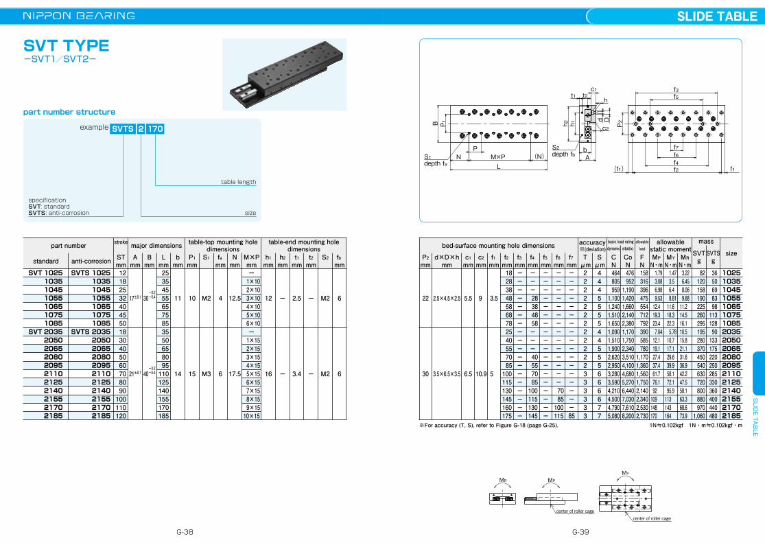
SVT TYPE-SVT1/SVT2-
part number structure
1N≒0.102kgf 1N・m≒0.102kgf・m
size
102510351045105510651075108520352050206520802095211021252140215521702185
SVTSg
3650698398
11312890
133175220250285330360400440480
example SVTS 2 170
specificationSVT: standardSVTS: anti-corrosion size
table length
2.5×4.5×2.5
3.5×6.5×3.5
P2
mmd×D×h
mm
22
30
c1
mmc2
mmf1
mmf2
mmf3
mmf4
mmf5
mmf6
mmf7
mmT
μmS
μmMP
N・mMY
N・mMR
N・m
bed-surface mounting hole dimensions
5.5
6.5
9
10.9
3.5
5
18 28 38 48 58 68 78 25 40 55 70 85100115130145160175
−−−−−−−−−−−−−−−−−−
−−−
28 38 48 58−−−
40 55 70 85100115130145
−−−−−−−−−−−−−−−−−−
−−−−−−−−−−−−−−
70 85100115
−−−−−−−−−−−−−−−−−85
222222222222333333
444555544555666677
464805959
1,1001,2401,5101.6501,0901,5101,9002,6202,9503,2803,5904,2104,5004,7905,080
476952
1,1901,4201,6602,1402,3801,1701,7502,3403,5104,1004,6805,2706,4407,0307,6108,200
158316396475554712792390585780
1,1701,3601,5601,7502,1402,3402,5302,730
1.79 3.08 6.98 9.53 12.4 19.3 23.4 7.04 12.1 19.1 27.4 37.4 61.7 76.1 92 109 148 170
1.47 3.5 6.4 8.81 11.6 18.3 22.3 5.78 10.7 17.1 29.6 39.9 58.1 72.1 95.9 113 143 164
3.22 6.45 8.06 9.68 11.2 14.5 16.1 10.5 15.8 21.1 31.6 36.9 42.2 47.5 58.1 63.3 68.6 73.9
※For accuracy (T, S), refer to Figure G-18 (page G-25).
mass
SVTg
82120158190225260295195280370450540630720800880970
1,060
P1 Dd
ht1
c1
c2
t2
Ab
h2 P2h1
L(N)M×PN
P
B
S1depth fa
S2depth fb
f2f4f6f7
f5f3
f1(f1)
part number
SVT 1025 1035 1045 1055 1065 1075 1085SVT 2035 2050 2065 2080 2095 2110 2125 2140 2155 2170 2185
121825324045501830405060708090
100110120
major dimensions
17±0.1
21±0.1
Amm
Bmm
Lmm
bmm
P1
mmS1 fa
mmN
mmM×Pmm
h1
mmh2
mmt1
mmt2
mmS2 fb
mm
table-top mounting hole dimensions
table-end mounting hole dimensions
−0.230−0.4
−0.240−0.4
253545556575853550658095
110125140155170185
11
14
10
15
M2
M3
4
6
12.5
17.5
− 1×10 2×10 3×10 4×10 5×10 6×10
− 1×15 2×15 3×15 4×15 5×15 6×15 7×15 8×15 9×1510×15
12
16
−
−
2.5
3.4
−
−
M2
M2
6
6
SVTS 1025 1035 1045 1055 1065 1075 1085SVTS 2035 2050 2065 2080 2095 2110 2125 2140 2155 2170 2185
stroke
STmm standard anti-corrosion
dynamic
CN
static
CoN
basic load rating allowableload
FN
allowablestatic moment
accuracy※(deviation)
G-38 G-39
SLIDE TABLES
LIDE TA
BLE
MR MP
center of roller cagecenter of roller cage
MY
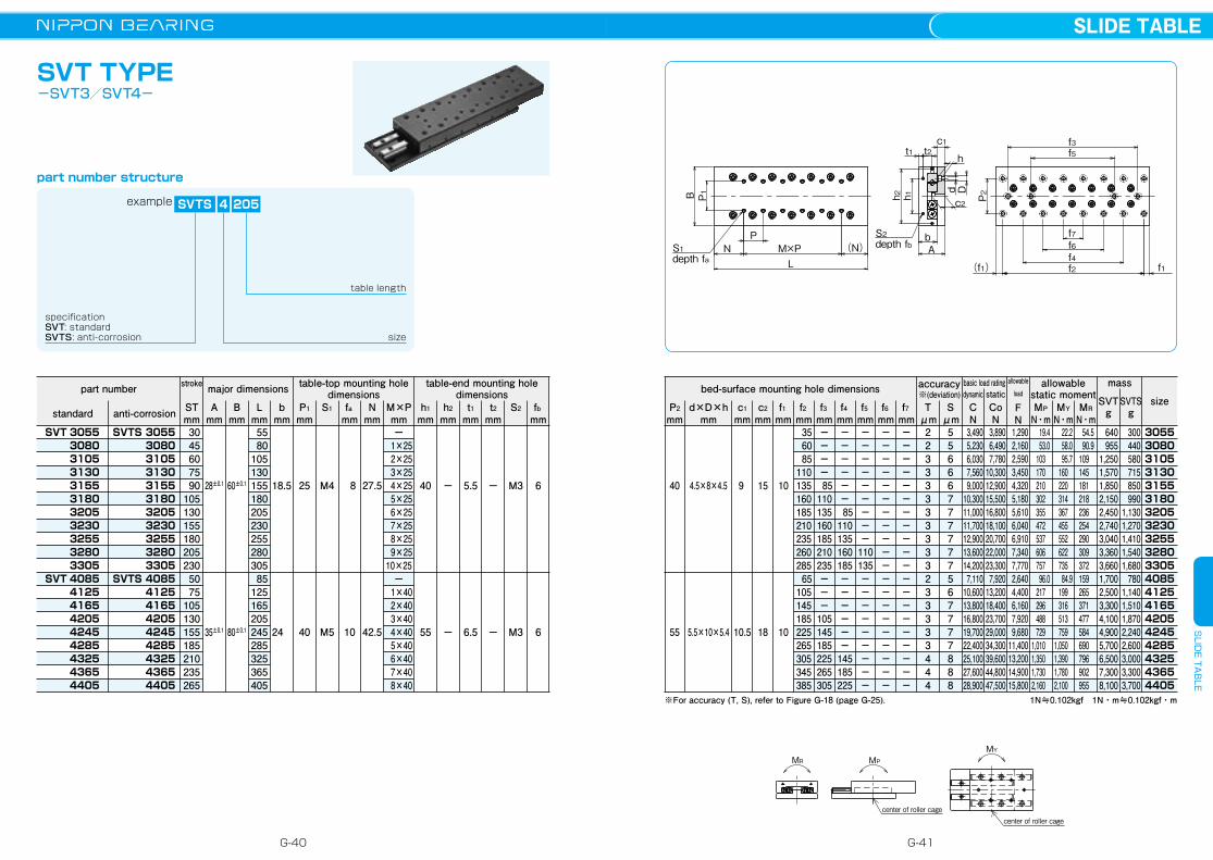
SVT TYPE-SVT3/SVT4-
1N≒0.102kgf 1N・m≒0.102kgf・m
part number
SVT 3055 3080 3105 3130 3155 3180 3205 3230 3255 3280 3305SVT 4085 4125 4165 4205 4245 4285 4325 4365 4405
3045607590
1051301551802052305075
105130155185210235265
size
30553080310531303155318032053230325532803305408541254165420542454285432543654405
300440580715850990
1,1301,2701,4101,5401,680
7801,1401,5101,8702,2402,6003,0003,3003,700
major dimensions
SVTS 4 205
size
table length
28±0.1
35±0.1
4.5×8×4.5
5.5×10×5.4
Amm
Bmm
Lmm
bmm
P1
mmS1 fa
mmN
mmM×Pmm
h1
mmh2
mmt1
mmt2
mmS2 fb
mmP2
mmd×D×h
mm
table-top mounting hole dimensions
table-end mounting hole dimensions
60±0.1
80±0.1
5580
10513015518020523025528030585
125165205245285325365405
18.5
24
25
40
M4
M5
8
10
27.5
42.5
− 1×25 2×25 3×25 4×25 5×25 6×25 7×25 8×25 9×2510×25
− 1×40 2×40 3×40 4×40 5×40 6×40 7×40 8×40
40
55
−
−
5.5
6.5
−
−
M3
M3
6
6
40
55
c1
mmc2
mmf1
mmf2
mmf3
mmf4
mmf5
mmf6
mmf7
mmT
μmS
μmMP
N・mMY
N・mMR
N・m
bed-surface mounting hole dimensions
9
10.5
15
18
10
10
35 60 85110135160185210235260285 65105145185225265305345385
−−−−
85110135160185210235−−−
105145185225265305
−−−−−−
85110135160185−−−−−−
145185225
−−−−−−−−−
110135−−−−−−−−−
−−−−−−−−−−−−−−−−−−−−
−−−−−−−−−−−−−−−−−−−−
22333333333233333444
55666777777567777888
3,4905,2306,0307,5609,000
10,30011,00011,70012,90013,60014,2007,110
10,60013,80016,80019,70022,40025,10027,60028,900
3,8906,4907,780
10,30012,90015,50016,80018,10020,70022,00023,3007,920
13,20018,40023,70029,00034,30039,60044,80047,500
1,2902,1602,5903,4504,3205,1805,6106,0406,9107,3407,7702,6404,4006,1607,9209,680
11,40013,20014,90015,800
19.4 53.0 103 170 210 302 355 472 537 606 757 96.0 217 296 488 729 1,010 1,350 1,730 2,160
22.2 58.0 95.7 160 220 314 367 455 552 622 735 84.9 199 316 513 759 1,050 1,390 1,780 2,100
54.5 90.9 109 145 181 218 236 254 290 309 372 159 265 371 477 584 690 796 902 955
※For accuracy (T, S), refer to Figure G-18 (page G-25).
mass
640955
1,2501,5701,8502,1502,4502,7403,0403,3603,6601,7002,5003,3004,1004,9005,7006,5007,3008,100
SVTS 3055 3080 3105 3130 3155 3180 3205 3230 3255 3280 3305SVTS 4085 4125 4165 4205 4245 4285 4325 4365 4405
P1 Dd
ht1
c1
c2
t2
Ab
h2 P2h1
L(N)M×PN
P
B
S1depth fa
S2depth fb
f2f4f6f7
f5f3
f1(f1)
SVTSg
SVTg
part number structure
example
specificationSVT: standardSVTS: anti-corrosion
stroke
STmm standard anti-corrosion
dynamicCN
staticCoN
basic load rating allowable
load
FN
allowablestatic moment
accuracy※(deviation)
G-40 G-41
SLIDE TABLES
LIDE TA
BLE
MR MP
center of roller cagecenter of roller cage
MY
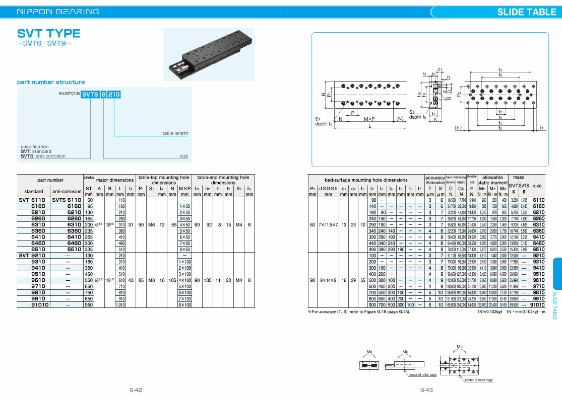
SVT TYPE-SVT6/SVT9-
1N≒0.102kgf 1N・m≒0.102kgf・m
dynamic
CN
static
CoN
part number
SVT 6110 6160 6210 6260 6310 6360 6410 6460 6510SVT 9210 9310 9410 9510 9610 9710 9810 9910 91010
stroke
STmm 6095
130165200235265300335130180350450550650750850950
basic load rating
size
61106160621062606310636064106460651092109310941095109610971098109910
91010
1,7052,4803,2554,0304,8055,5806,3557,1307,905—————————
major dimensionsallowable
load
FN
SVTS 6 210
size
table length
45±0.1
60±0.1
7×11.5×7
9×14×9
Amm
Bmm
Lmm
bmm
P1
mmS1 fa
mmN
mmM×Pmm
h1
mmh2
mmt1
mmt2
mmS2 fb
mmP2
mmd×D×h
mm
table-top mounting hole dimensions
table-end mounting hole dimensions
100±0.1
145±0.1
110160210260310360410460510210310410510610710810910
1,010
31
43
50
85
M6
M8
12
16
55
105
−1×502×503×504×505×506×507×508×50−
1×1002×1003×1004×1005×1006×1007×1008×100
60
90
92
135
8
11
15
20
M4
M4
8
8
60
90
c1
mmc2
mmf1
mmf2
mmf3
mmf4
mmf5
mmf6
mmf7
mmT
μmS
μmMP
N・mMY
N・mMR
N・m
bed-surface mounting hole dimensions allowablestatic moment
13
16
23
29
10
55
90140190240290340390440490100200300400500600700800900
−−
90140190240290340390−−
100200300400500600700
−−−−−
140190240290−−−−
100200300400500
−−−−−−−−
190−−−−−−
100200300
−−−−−−−−−−−−−−−−−
100
−−−−−−−−−−−−−−−−−−
333334444334444555
6 6 7 7 7 8 8 8 8 7 7 8 8 9 9101010
16,50024,70032,20039,20045,80052,20058,40064,40070,20051,10079,30079,30096,600
112,000128,000136,000151,000165,000
17,70029,60041,40053,20065,10076,90088,800
100,000112,00056,50098,90098,900
127,000155,000183,000197,000226,000254,000
5,9109,860
13,80017,70021,60025,60029,50033,50037,40018,80032,90032,90042,30051,70061,10065,80075,20084,600
260588
1,0401,6302,3402,7503,6604,7005,8701,6103,1504,1106,4207,760
10,80014,40018,50023,100
230539978
1,5402,2402,8503,7704,8306,0101,4403,3603,8406,0808,090
11,20013,90017,90022,400
400666933
1,2001,4601,7302,0002,2602,5302,0303,5603,5604,5805,6006,6207,1308,1409,160
※For accuracy (T, S), refer to Figure G-18 (page G-25).
mass
3,2804,8206,2707,7409,200
10,74012,19013,80015,30012,52017,95023,95030,09035,99041,89047,79053,69059,590
SVTS 6110 6160 6210 6260 6310 6360 6410 6460 6510
—————————
P1 Dd
ht1
c1
c2
t2
Ab
h2 P2h1
L(N)M×PN
P
B
S1depth fa
S2depth fb
f2f4f6f7
f5f3
f1(f1)
SVTSg
SVTg
part number structure
example
specificationSVT: standardSVTS: anti-corrosion
standard anti-corrosion
accuracy※(deviation)
G-42 G-43
SLIDE TABLES
LIDE TA
BLE

MYMPMR
center of roller cagecenter of roller cage
SYT TYPE-SYT1/SYT2-
c
AbS1depth f
P1
B1
LN1 (N1)M1×P2
P2 S2
B2
(N2) N2M2×P3P3
1N≒0.102kgf 1N・m≒0.102kgf・m
part number
SYT 1025 1035 1045 1055 1065 1075 1085SYT 2035 2050 2065 2080 2095 2110 2125
stroke
STmm 1218253240455018304050607080
size
10251035104510551065107510852035205020652080209521102125
mass
g 22 33 42 52 63 72 83 79113150185215255295
major dimensions
SYTS 2 110
size
table length
8±0.1
12±0.1
Amm
B1
mmL
mmb
mmP1
mmS1 f
mmN1
mmM1×P2
mm
table-top mounting hole dimensions
20±0.1
30±0.1
253545556575853550658095
110125
7.5
11.5
14
22
M2.6
M3
3
5
3.5 3.512.512.512.522.512.5 3.5 3.517.517.517.532.517.5
Tμm
Sμm
MP
N・mMY
N・mMR
N・m
allowable static moment
22222222222222
44555554455555
464805959
1,1001,2401,5101,6501,0901,5101,9002,6202,9503,2803,590
476952
1,1901,4201,6602,1402,3801,1701,7502,3403,5104,1004,6805,270
158316396475554712792390585780
1,1701,3601,5601,750
1.79 3.08 6.98 9.53 12.4 19.3 23.4 7.04 12.1 19.1 27.4 37.4 61.7 76.1
1.47 3.50 6.40 8.81 11.6 18.3 22.3 5.78 10.7 17.1 29.6 39.9 58.1 72.1
1.79 3.58 4.48 5.37 6.27 8.06 8.96 7.63 11.4 15.2 22.8 26.7 30.5 34.3
※For accuracy (T, S), refer to Figure G-18 (page G-25).
anti-corrosionstandard
SYTS 1025 1035 1045 1055 1065 1075 1085SYTS 2035 2050 2065 2080 2095 2110 2125
S2 N2
mmM2×P3
mm1×181×281×201×302×201×302×301×281×431×301×452×301×452×45
M2.6
M3
5 7.5 7.5 7.5 7.5 7.5 7.5 7.5 10 10 10 10 10 10
2×7.52×103×104×105×106×107×101×202×153×154×155×156×157×15
cmm
4
6
B2
mm
6.6
12
part number structure
example
specificationSVT: standardSVTS: anti-corrosion
bed-surface mountinghole dimensions dynamic
CN
staticCoN
basic load rating allowable loadFN
accuracy※(deviation)
G-44 G-45
SLIDE TABLES
LIDE TA
BLE
MYMPMR
center of roller cagecenter of roller cage
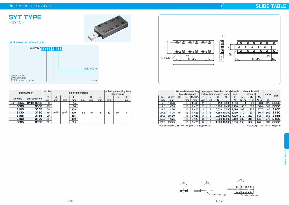
SYT TYPE-SYT3-
part number structure
1N≒0.102kgf 1N・m≒0.102kgf・m
part number
SYT 3055 3080 3105 3130 3155 3180 3205
30 45 60 75 90105130
size
3055308031053130315531803205
mass
g225340440560655770880
major dimensions
example SYTS 3 155
specificationSYT: standardSYTS: anti-corrosion size
table length
16±0.1
Amm
B1
mmL
mmb
mmP1
mmS1 f
mmN1
mmM1×P2
mm
40±0.1
5580
105130155180205
15.5 30 M4 7
7.5 7.527.527.527.552.527.5
Tμm
Sμm
MP
N・mMY
N・mMR
N・m
bed-surface mountinghole dimensions
allowable static moment
2233333
5555555
3,4905,2306,0307,5609,000
10,30011,000
3,8906,4907,790
10,30012,90015,50016,800
1,2902,1602,5903,4504,3205,1805,610
19.4 53.0 103 170 210 302 355
22.2 58.0 95.7 160 220 314 367
33.8 56.4 67.7 90.3 112 135 146
※For accuracy (T, S), refer to Figure G-18 (page G-25).
SYTS 3055 3080 3105 3130 3155 3180 3205
S2 N2
mmM2×P3
mm1×401×651×501×752×501×752×75
M4
10151515151515
1×352×253×254×255×256×257×25
cmm
8
B2
mm
16
c
AbS1depth f
P1
B1
LN1 (N1)M1×P2
P2 S2
B2
(N2) N2M2×P3P3
stroke
STmm
table-top mounting hole dimensions
anti-corrosionstandard
dynamicCN
staticCoN
basic load rating allowable loadFN
accuracy※(deviation)
G-46 G-47
SLIDE TABLES
LIDE TA
BLE

M1×P2
mm 3.5 3.512.512.512.522.512.5 3.5 3.517.517.517.532.517.5
MYMPMR
center of roller cagecenter of roller cage
SYT-D TYPE-SYT1/SYT2-
h
Dd
c
Ab
P1B1
B2
LN1 (N1)M1×P2
P2
f1(f1) f2f3S1depth f
1N≒0.102kgf 1N・m≒0.102kgf・m
part number
SYT 1025-D 1035-D 1045-D 1055-D 1065-D 1075-D 1085-DSYT 2035-D 2050-D 2065-D 2080-D 2095-D 2110-D 2125-D
1218253240455018304050607080
size
10251035104510551065107510852035205020652080209521102125
mass
g 22 33 42 52 63 72 83 79113150185215255295
major dimensions
SYTS 2 110
size
table length
8±0.1
12±0.1
Amm
B1
mmL
mmb
mmP1
mmS1 f
mmd×D×h
mmM1×P2
mm
20±0.1
30±0.1
253545556575853550658095
110125
7.5
11.5
14
22
M2.6
M3
3
5
Tμm
Sμm
MP
N・mMY
N・mMR
N・m
bed-surface mounting hole dimensions
allowable static moment
22222222222222
44555554455555
464805959
1,1001,2401,5101,6501,0901,5101,9002,6202,9503,2803,590
476952
1,1901,4201,6602,1402,3801,1701,7502,3403,5104,1004,6805,270
158316396475554712792390585780
1,1701,3601,5601,750
1.79 3.08 6.98 9.53 12.4 19.3 23.4 7.04 12.1 19.1 27.4 37.4 61.7 76.1
1.47 3.50 6.40 8.81 11.6 18.3 22.3 5.78 10.7 17.1 29.6 39.9 58.1 72.1
1.79 3.58 4.48 5.37 6.27 8.06 8.96 7.63 11.4 15.2 22.8 26.7 30.5 34.3
※For accuracy (T, S), refer to Figure G-18 (page G-25).
SYTS 1025-D 1035-D 1045-D 1055-D 1065-D 1075-D 1085-DSYTS 2035-D 2050-D 2065-D 2080-D 2095-D 2110-D 2125-D
f1mm
f2mm
1×181×281×201×302×201×302×301×281×431×301×452×301×452×45
2.5×4.1×2.2
3.5×6×3.3
3.5 5 3.5 3.5 5 5 5 5 7.5 5 5 5 7.5 7.5
cmm
4
6
B2
mm
6.6
12
D-
with counterbore
f3mm
18 25 38 48 55 65 75 25 35 55 70 85 95110
−−2529313540−−3340455055
N1
mm
part number structure
example
specificationSYT: standardSYTS: anti-corrosion
stroke
STmm
table-top mounting hole dimensions
anti-corrosionstandard
dynamicCN
staticCoN
basic load rating allowable loadFN
accuracy※(deviation)
G-48 G-49
SLIDE TABLES
LIDE TA
BLE
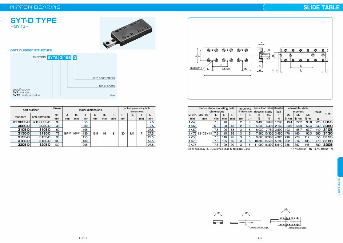
M1×P2
mm 7.5 7.527.527.527.552.527.5
MYMPMR
center of roller cagecenter of roller cage
SYT-D TYPE-SYT3-
1N≒0.102kgf 1N・m≒0.102kgf・m
dynamicCN
staticCoN
part number
SYT 3055-D 3080-D 3105-D 3130-D 3155-D 3180-D 3205-D
30 45 60 75 90105130
basic load rating
size
3055308031053130315531803205
mass
g225340440560655770880
major dimensions allowable loadFN
SYTS 3 155
size
table length
16±0.1
Amm
B1
mmL
mmb
mmP1
mmS1 f
mmd×D×h
mmM1×P2
mm
40±0.1
5580
105130155180205
15.5 30 M4 7
Tμm
Sμm
MP
N・mMY
N・mMR
N・m
bed-surface mounting hole dimensions
allowable static moment
2233333
5555555
3,4905,2306,0307,5609,000
10,30011,000
3,8906,4907,780
10,30012,90015,50016,800
1,2902,1602,5903,4504,3205,1805,610
19.4 53.0 103 170 210 302 355
22.2 58.0 95.7 160 220 314 367
33.8 56.4 67.7 90.3 112 135 146
※For accuracy (T, S), refer to Figure G-18 (page G-25).
SYTS 3055-D 3080-D 3105-D 3130-D 3155-D 3180-D 3205-D
f1mm
f2mm
1×401×651×501×752×501×752×75
4.5×7.5×4.3
7.5 6 7.5 7.5 7.5 7.5 7.5
cmm
8
B2
mm
16
D-
with counterbore
f3mm
40 68 90115140165190
−435565958590
N1
mm
h
Dd
c
Ab
P1B1
B2
LN1 (N1)M1×P2
P2
f1(f1) f2f3S1depth f
part number structure
example
specificationSYT: standardSYTS: anti-corrosion
stroke
STmm
table-top mounting hole dimensions
anti-corrosionstandard
accuracy※(deviation)
G-50 G-51
SLIDE TABLES
LIDE TA
BLE
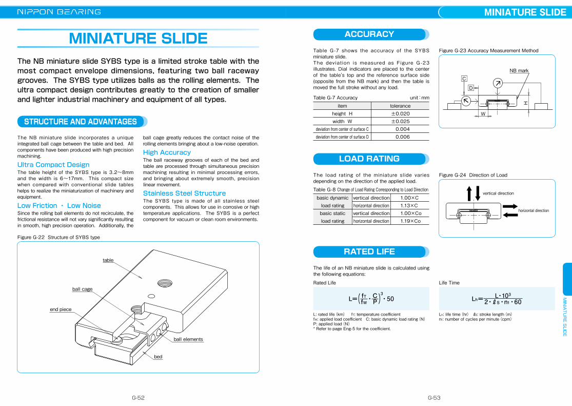
MINIATURE SLIDEThe NB miniature slide SYBS type is a limited stroke table with the most compact envelope dimensions, featuring two ball raceway grooves. The SYBS type utilizes balls as the rolling elements. The ultra compact design contributes greatly to the creation of smaller and lighter industrial machinery and equipment of all types.
STRUCTURE AND ADVANTAGES
The NB miniature slide incorporates a unique integrated ball cage between the table and bed. All components have been produced with high precision machining.
Ultra Compact DesignThe table height of the SYBS type is 3.2~8mm and the width is 6~17mm. This compact size when compared with conventional slide tables helps to realize the miniaturization of machinery and equipment.
Low Friction ・ Low NoiseSince the rolling ball elements do not recirculate, the frictional resistance will not vary significantly resulting in smooth, high precision operation. Additionally, the
ball cage greatly reduces the contact noise of the rolling elements bringing about a low-noise operation.
High AccuracyThe ball raceway grooves of each of the bed and table are processed through simultaneous precision machining resulting in minimal processing errors, and bringing about extremely smooth, precision linear movement.
Stainless Steel StructureThe SYBS type is made of all stainless steel components. This allows for use in corrosive or high temperature applications. The SYBS is a perfect component for vacuum or clean room environments.
Figure G-22 Structure of SYBS type
table
ball cage
end piece
bed
ball elements
ACCURACY
Table G -7 shows the accuracy of the SYBS miniature slide. The deviation is measured as Figure G -23 illustrates. Dial indicators are placed to the center of the table's top and the reference surface side (opposite from the NB mark) and then the table is moved the full stroke without any load.
Figure G-23 Accuracy Measurement Method
Table G-7 Accuracy unit:mm
basic dynamicload rating basic staticload rating
vertical direction horizontal direction vertical direction horizontal direction
1.00×C1.13×C1.00×Co1.19×Co
itemheight Hwidth W
deviation from center of surface Cdeviation from center of surface D
tolerance±0.020±0.025 0.004 0.006
NB mark
H
C
W
D
LOAD RATING
The load rating of the miniature slide varies depending on the direction of the applied load.
Figure G-24 Direction of Load
Table G-8 Change of Load Rating Corresponding to Load Direction
horizontal direction
vertical direction
RATED LIFE
The life of an NB miniature slide is calculated using the following equations:
Rated Life Life Time
Lh: life time(hr) ℓS: stroke length(m) n1: number of cycles per minute(cpm)
L: rated life(km) fT: temperature coefficient fW: applied load coefficient C: basic dynamic load rating(N)P: applied load(N)* Refer to page Eng-5 for the coefficient.
L=( fTfW・C
P )3・50 Lh= L・103
2・ℓS・n1・60
G-52 G-53
MINIATURE SLIDEM
INIA
TUR
E SLID
E
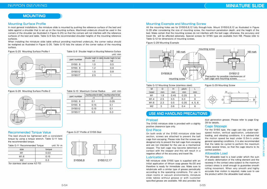
MOUNTING
Mounting Surface ProfileIn most general installations, the miniature slide is mounted by pushing the reference surface of the bed and table against a shoulder that is set up on the mounting surface. Machined undercuts should be used in the corners of the shoulder (as illustrated in Figure G-25) so that the corners will not interfere with the reference surfaces of the bed and table. Table G-9 lists the recommended shoulder heights of the mounting reference surfaces.When installing the miniature slide table without providing machined undercuts, the corner radius should be realigned as illustrated in Figure G-26. Table G-10 lists the values of the corner radius of the mounting surface.
Figure G-25 Mounting Surface Profile-1
h2h1
Figure G-26 Mounting Surface Profile-2
r2 r2
r1
r1
Table G-9 Shoulder Height on Mounting Reference Surface unit:mm
Table G-10 Maximum Corner Radius unit:mm
Recommended Torque ValueThe bed should be tightened with a consistent torque by using a torque wrench. Table G-11 lists the recommended torque.
Table G-11 Recommended Torque unit:N・m
sizeM1
M1.6M2
torque 0.03 0.15 0.3
(for stainless steel screw A2-70)
Figure G-27 Profile of SYBS Bed
SYBS12,17SYBS6,8
Mounting Example and Mounting ScrewAll the mounting holes are for SYBS 6,8,12 fully through-hole. Mount SYBS 6,8,12 as illustrated in Figure G-28 after considering the size of mounting screw, the maximum penetration depth, and the height of the bed. Make certain that the mounting screws do not interfere with the ball cage; otherwise, the accuracy and travel life will be affected adversely. Special screws for SYBS type are available from NB. Please refer to Table G-12 for dimensions of mounting screws.
Figure G-28 Mounting Example
SYBS6,8 SYBS12Precaution for possible interferences of ball cage and mounting screws.
NB markmounting screw
mounting screw
NB mark
Table G-12 Mounting Screw (stainless steel)
M1M1.4M1.6M2
M(size)
USE AND HANDLING PRECAUTIONS
PreloadThe SYBS miniature slide is provided with a slightly positive clearance type only.
End PieceOn both ends of the SYBS miniature slide bed section, screws are attached to prevent the ball cage from escaping. Please note that the screws are designed only to prevent the ball cage from escaping and are not intended for the use as a mechanical stopper. The ball cage may become deformed on contact with the stopper and this will result in a negative affect of the accuracy and travel life.
LubricationNB miniature slide SYBS type is supplied with an initial application of lithium soap grease No.00 and therefore is ready for immediate use. Make sure to relubricate with a similar type of grease periodically according to the operating conditions. For use in clean rooms or vacuum environments, miniature slide tables without grease or with customer specified grease are available. NB also provides low
dust generation grease. Please refer to page Eng-39 for details.
Cage SlippageFor the SYBS type, the cage can slip under high-speed motion, vertical application, unbalanced-loading, and vibrating conditions. It is advised that the motion speed be kept under 0.5m/s under general operating conditions. It is also recommended that the table be cycled to perform the maximum stroke several times, so that the cage returns to its central position.
Allowable LoadThe allowable load is a load under which the sum of elastic deformation of the rolling element and the raceway in the contact area subject to the maximum contact stress is small enough to guarantee smooth rolling movement. When very smooth and highly accurate liner motion is required, make sure to use the product within the allowable load values.
1.8 2.5 2.3 3
Dmm
0.45 0.5 0.5 0.6
Hmm
pitchmm
0.25 0.3 0.35 0.4
56
4, 5, 66
Lmm
Figure G-29 Mounting Screw
M
H L
D
SYBS 6SYBS 8SYBS12SYBS17
1.01.21.52.5
0.5 0.8 0.8 1
part number shoulder height for tableh1
shoulder height for bedh2
SYBS 6SYBS 8SYBS12SYBS17
0.1 0.15 0.15 0.3
0.05 0.1 0.1 0.3
part numbermounting surface for table
r1mounting surface for bed
r2
G-54 G-55
MINIATURE SLIDEM
INIA
TUR
E SLID
E

SYBS TYPE
part number structure
H2
S1
H1P2L
P1n×P3
P3
S2
h
Gd
W±0.025
W±0.025
0-0.05
C 0-0.05
C
0-0.05
B 0-0.05
B
H±0.020
H±0.020
H2H1
S1
P4
P3
P1
P2
L
MP
MR
MY
SYBS6,8
SYBS12
SYBS17
C 0-0.05
0-0.1
W±0.025H±0.020
P1
B1
L
S1
H1H2
d G
B
h
P3P4
SYBS type
SYBS 31
size
example 8 -
table length
※1: Custom mounting screws are provided with the SYBS-12 type only. Other screw sizes are also available.(Please refer to page G-53)
tabel-top dimensions
part number
SYBS 6−13SYBS 6−21SYBS 8−11SYBS 8−21SYBS 8−31SYBS12−23SYBS12−31SYBS12−46SYBS17−23SYBS17−31SYBS17−46
H
mm
major dimensions
3.2
4
4.5
8
W
mm
2
2.5
3
5
0.7
1
1
1.5
H1
mm
stroke
mm
B
mm
L
mm
P1
mm
P2
mm
B1
mm
maximumscrew
penetrationdepthmm
S1
512 41218121828141929
6
8
12
17
1321112131233146233146
6.010.0 5.510.010.0 8.015.015.010.020.030.0
−−−−21−−31−−−
−−−−−−−−
12
M1.4
M2
0.5
0.7
1.2
3
mass
g
dynamic
CN
static
CoN
basic load rating
6−13 6−21 8−11 8−21 8−3112−2312−3112−4617−2317−3117−46
1N≒0.102kgf 1N・m≒0.102kgf・m
H2
mm
2.0
2.6
2.6
4.7
bed-surface dimensionssizeC
mm
d×G×h
mm
S2 P3
mm
n
mm
P4
mm
allowable load
FN
allowable static moment
MP
N・mMY
N・mMR
N・m
2
3
6
7
−
−
※12.4×4×1.5
2.4×4.2×2.3
M1
M1.6
−
−
7 7 51010151520151520
12112−−−−−−
−−−−−−−30−−30
154229201368473404473658775984
1,350
180315211493704563704
1,120888
1,2401,950
60.1 105 70.4 164 234 187 234 375 296 414 651
0.210.570.231.021.971.301.974.802.093.808.75
0.25 0.69 0.28 1.22 2.35 1.55 2.35 5.72 2.49 4.53 10.4
0.210.370.350.831.191.802.253.603.334.667.32
1.4 2.2 2.0 3.7 5.5 7.610.215.219.226.238.4
G-56 G-57
MINIATURE SLIDEM
INIA
TUR
E SLID
E

RATED LIFE
The life of a gonio way is obtained using the following equations.Rated Life Life Time
Lh: life time(hr) n1: number of cycles per minute(cpm)
L: travel life(106cycles)θ: rotating angle(degree) C: basic dynamic load rating(N)P: applied load(N) fT: temperature coefficient fW: applied load coefficient※Refer to page Eng-5 for the coeffieients.
Lh= L×106
60×n
ACCURACY OF RVF TYPE
The accuracies of the gonio way RVF type are represented by mutual dimensional errors of four rails, which are measured along the overall length using the procedure as shown in Figure G-32.
The NB gonio way is a curved cross roller slide way. It is a curved motion bearing utilizing low-friction, non-recirculating precision rollers. It is used when there is a need to change the gradient or obtain an accurate gradient angle without changing the center of rotation in high-precision optical and measurement equipment.
STRUCTURE AND ADVANTAGES
Low Frictional Resistance and Minute MotionThe precision grinding and curved roller cage allow for extremely low frictional resistance. The negligible difference between static and dynamic frictions allows the gonio way to follow minute movements accurately, realizing curved movement of high accuracy.
Low NoiseSince NB gonio way employs a non-recirculating design, there is no noise from the circulating area. In addition, the curved roller cage realizes quiet operation without contact noise between the rolling elements.
High Rigidity and High Load CapacityThe rollers provide a larger contact area and less
elastic deformation compared to the ball elements. Additionally, since the rollers do not recirculate, the effective number of rotating elements is larger, resulting in high rigidity and high load capacity.
Flat Installation SurfaceThe flat installation surfaces of the RVF type do not require complicated machining of tables and beds when installing the product. As a result, machining costs can be reduced greatly.
Same Rotation CenterThe curved V-grooves, which are finished with a precise grinding process, provide an accurate center of rotation. Furthermore, the products are composed to provide identical rotation centers when products of each size are installed to two axes.(refer to Table G-17.)
GONIO WAY
The NB gonio way RVF type consists of curved tracking bases with precisely ground V-grooves and flat installation surfaces, as well as curved roller cages. The NB gonio way RV type consists of curved rails with precisely machined V-grooves and curved roller cages. Precision rollers are employed as the rolling elements, since the rolling elements do not recirculate, the frictional resistance will not vary significantly, providing curved movement with extremely low frictional resistance.
Figure G-30 Structure of Gonio Way RVF type
a-curved tracking bases
end pieces
b-curved tracking bases
curved roller cage
installationsurface
installation surface
installation surface
Table G-13 Accuracy unit:μm
RVF2050- 70RVF2050- 87RVF2050-103RVF2050-120RVF3070- 85RVF3070-110RVF3100-125RVF3100-160
10 10
part numbermutual error between A and Bmutual error between C and D
mutual error between E and Fmutual error between H and I
Figure G-32 Accuracy Measuring Method
AB
EF
I
CD
H
inside section
NB mark NB mark
reference edge
NB mark NB mark
reference surface ofb-curved tracking base
reference surface ofb-curved tracking base
reference surface ofa-curved tracking base
L= ( fTfW × C
P )10─390θ ×
θ
rotating angle
Figure G-31 Structure of Gonio Way RV type
curved rail
curved roller cageend piece
ACCURACY OF RV TYPE
The accuracies of the gonio way RV type are represented by mutual dimensional errors of four rails, which are measured along the overall length using the procedure as shown in Figure G-33.
Table G-14 Accuracy unit:μm
RV2040- 50RV2060- 60RV3070- 90RV3070-110RV3100-160
10
part number accuracy
Figure G-33 Accuracy Measuring Method
F
H
EG
A
C
B D inner-diameterreference surface
outer-diameterreference surface
NB mark
NB mark
The reference surfaces are located on the opposite side of the NB mark. There are inner reference surface and outer reference surface in one set of RV.
G-58 G-59
GONIO WAYG
ON
IO W
AY

Accuracy of Mounting SurfaceTo maximize the performance of NB gonio way, it is important to finish the installation surface with high accuracies.
Parallelism of surface 1 against surface APerpendicularity of surface 2 against surface APerpendicularity of surface 5 against surface AParallelism of surface 3 against surface BPerpendicularity of surface 4 against surface BPerpendicularity of surface 6 against surface BParallelism of surface 2 against surface CParallelism of surface 4 against surface C
MOUNTING OF RVF TYPE
Installation ProcedureSetting the curved tracking bases temporarily
( 1 ) Remove burrs, stains, and dust from the installation surfaces of the curved tracking bases of tables and beds. Foreign particles must be kept out of the assembly work as well.
( 2 ) Apply low viscosity oil to contact surfaces, check the reference edges of an a-curved tracking base and bed, and then tighten the screws temporarily. (Figure G-36a)
( 3 ) Align the reference edges (NB mark side) of a b-curved tracking base and an a-curved tracking base to the same orientation. Then, insert the curved roller cages between the curved tracking bases at the center area. Make sure that the curved roller cages will not interfere with the curved raceway grooves of the curved roller tracking bases. (Figure G-36b)
( 4 ) Check the reference edge of the table, set the table over the b-curved tracking base, and then secure the table temporarily. (Figure G-36c)
Figure G-36 Installation Method(1)
Figure G-35 Example of Installation of RVF type
Setting four curved tracking bases in parallel position
( 5 ) Move the table to the maximum stroke ends of both sides and adjust the setting so that the curved roller cage is positioned at the center of the curved tracking base.
( 6 ) Move the table to the center position and tighten the adjustment screws with ※slightly strong torque by using a torque wrench. (Figure G-37d)
※"Slightly strong torque" here means slightly stronger than the torque at which the oscillation of the dial indicator is stabilized at the minimum value when the table is moved right and left, or when pressure is applied to the rolling direction while the dial indicator is attached to the side face (reference side) of the table. (Figure G-37i)
( 7 ) Move the table to the maximum stroke end of one side and tighten the adjustment screws on the curved roller cage with the same torque as in step (6). (Figure G-37e)
( 8 ) Move the table to the maximum stroke end of the other side and tighten the adjustment screws with a torque wrench by repeating the procedure above. (Figure G-37f)
Securing the curved tracking bases( 9 ) Mount an edge reference plate between the
reference edge of the a-curved tracking base and end piece, press it against the reference edge of the bed, and then tighten only the mounting screws in the middle. (Figure G-37g)
(10) Repeat the procedure above to mount an edge reference plate between the reference edge of the b-curved tracking base and the end piece. Press it against the reference edge of the bed, and then tighten only the mounting screws in the middle. (Figure G-37h) In order to maintain parallelism of curved tracking bases, do not cycle the table during this process and make sure that there is no clearance between the edge of the table and the edge reference plate.
(11) Secure the rest of the mounting screws on the curved roller cage one by one by moving the table as instructed in steps(7)and(8).
Adjusting the preload(12) Move the table to the right and left with the
test indicator attached to the side face of the table (reference side). Or, apply pressure in the rolling direction and confirm that the oscillation of the indicator is stabilized at the minimum level. (Figure G-37i)
(13) Return the mounting screws on the b-curved tracking base at the adjustment screw side to the temporary setting.
(14) Return the table to the center position, slightly loosen the adjustment screws in the middle, and then gradually loosen the adjustment screws on the curved roller cage while moving the table as instructed in steps(7)and(8)Make sure not to reduce the preload too much.
(15) Finally, secure the b-curved tracking base at the adjustment screw side, which has been installed temporarily. Secure the mounting screws on the curved roller cage one by one by moving the table as instructed above.
reference edge of the bed
reference edge of the table
a
c
b
reference edge (NB mark side)
reference edge (NB mark side)
reference edge of the bed
reference edge of the bed
Figure G-37 Installation Method(2)
edge reference plate
dial indicator rolling direction adjustment screw
h
g
i
adjustment screw
position of the curved roller cage
d
○: adjustment screw can be tightened×: adjustment screw should not be tightened
e
f
position of the curved roller cage
position of the curved roller cage
edge reference plate
Table G-15 Recommended Torque for Mounting Screw unit:N・m
sizeM2.5M3
tightening torque0.51.1
(for stainless steel screw A2-70)
Figure G-34 Accuracy of Mounting Surface
B
A
1.61.6
1.61.6
1.6
1.6
1.6
C
6
5 center line
43
24
1
3
b
a
G-60 G-61
GONIO WAYG
ON
IO W
AY
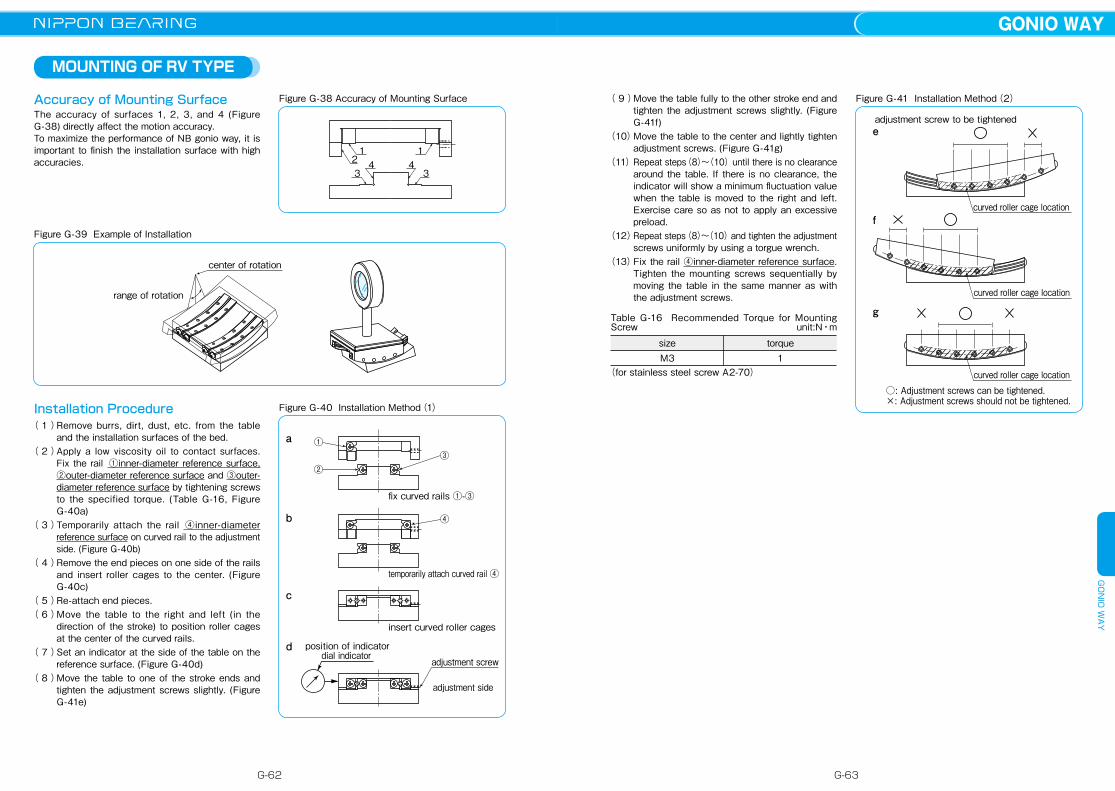
MOUNTING OF RV TYPE
Accuracy of Mounting SurfaceThe accuracy of surfaces 1, 2, 3, and 4 (Figure G-38) directly affect the motion accuracy. To maximize the performance of NB gonio way, it is important to finish the installation surface with high accuracies.
Figure G-39 Example of Installation
center of rotation
range of rotation
Figure G-38 Accuracy of Mounting Surface
1 12 4 43 3
Installation Procedure( 1 ) Remove burrs, dirt, dust, etc. from the table
and the installation surfaces of the bed.( 2 ) Apply a low viscosity oil to contact surfaces.
Fix the rail ①inner-diameter reference surface, ②outer-diameter reference surface and ③outer-diameter reference surface by tightening screws to the specified torque. (Table G-16, Figure G-40a)
( 3 ) Temporarily attach the rail ④inner-diameter reference surface on curved rail to the adjustment side. (Figure G-40b)
( 4 ) Remove the end pieces on one side of the rails and insert roller cages to the center. (Figure G-40c)
( 5 ) Re-attach end pieces.( 6 ) Move the table to the right and left (in the
direction of the stroke) to position roller cages at the center of the curved rails.
( 7 ) Set an indicator at the side of the table on the reference surface. (Figure G-40d)
( 8 ) Move the table to one of the stroke ends and tighten the adjustment screws slightly. (Figure G-41e)
( 9 ) Move the table fully to the other stroke end and tighten the adjustment screws slightly. (Figure G-41f)
(10) Move the table to the center and lightly tighten adjustment screws. (Figure G-41g)
(11) Repeat steps(8)~(10)until there is no clearance around the table. If there is no clearance, the indicator will show a minimum fluctuation value when the table is moved to the right and left. Exercise care so as not to apply an excessive preload.
(12) Repeat steps(8)~(10) and tighten the adjustment screws uniformly by using a torgue wrench.
(13) Fix the rail ④inner-diameter reference surface. Tighten the mounting screws sequentially by moving the table in the same manner as with the adjustment screws.
Figure G-40 Installation Method(1)
①
②③
④
fix curved rails ①-③
temporarily attach curved rail ④
insert curved roller cages
adjustment screw
adjustment side
dial indicatorposition of indicator
a
b
c
d
Figure G-41 Installation Method(2)
e
f
g
curved roller cage location
curved roller cage location
curved roller cage location
adjustment screw to be tightened
○: Adjustment screws can be tightened.×: Adjustment screws should not be tightened.
Table G-16 Recommended Torque for Mounting Screw unit:N・m
sizeM3
torque1
(for stainless steel screw A2-70)
G-62 G-63
GONIO WAYG
ON
IO W
AY
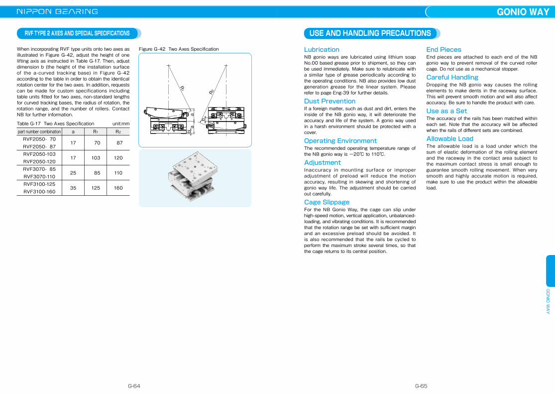
RVF TYPE 2 AXES AND SPECIAL SPECIFICATIONS
When incorporating RVF type units onto two axes as illustrated in Figure G-42, adjust the height of one lifting axis as instructed in Table G-17. Then, adjust dimension b (the height of the installation surface of the a-curved tracking base) in Figure G-42 according to the table in order to obtain the identical rotation center for the two axes. In addition, requests can be made for custom specifications including table units fitted for two axes, non-standard lengths for curved tracking bases, the radius of rotation, the rotation range, and the number of rollers. Contact NB for further information.
Figure G-42 Two Axes Specification
Table G-17 Two Axes Specification unit:mm
part number combinationRVF2050- 70RVF2050- 87RVF2050-103RVF2050-120RVF3070- 85RVF3070-110RVF3100-125RVF3100-160
a
17
17
25
35
R1
70
103
85
125
R2
87
120
110
160
R2
ab
b
R1
a
USE AND HANDLING PRECAUTIONS
LubricationNB gonio ways are lubricated using lithium soap No.00 based grease prior to shipment, so they can be used immediately. Make sure to relubricate with a similar type of grease periodically according to the operating conditions. NB also provides low dust generation grease for the linear system. Please refer to page Eng-39 for further details.
Dust PreventionIf a foreign matter, such as dust and dirt, enters the inside of the NB gonio way, it will deteriorate the accuracy and life of the system. A gonio way used in a harsh environment should be protected with a cover.
Operating EnvironmentThe recommended operating temperature range of the NB gonio way is ー20℃ to 110℃.
AdjustmentInaccuracy in mounting surface or improper adjustment of preload will reduce the motion accuracy, resulting in skewing and shortening of gonio way life. The adjustment should be carried out carefully.
Cage SlippageFor the NB Gonio Way, the cage can slip under high-speed motion, vertical application, unbalanced-loading, and vibrating conditions. It is recommended that the rotation range be set with sufficient margin and an excessive preload should be avoided. It is also recommended that the rails be cycled to perform the maximum stroke several times, so that the cage returns to its central position.
End PiecesEnd pieces are attached to each end of the NB gonio way to prevent removal of the curved roller cage. Do not use as a mechanical stopper.
Careful HandlingDropping the NB gonio way causes the rolling elements to make dents in the raceway surface. This will prevent smooth motion and will also affect accuracy. Be sure to handle the product with care.
Use as a SetThe accuracy of the rails has been matched within each set. Note that the accuracy will be affected when the rails of different sets are combined.
Allowable LoadThe allowable load is a load under which the sum of elastic deformation of the rolling element and the raceway in the contact area subject to the maximum contact stress is small enough to guarantee smooth rolling movement. When very smooth and highly accurate motion is required, make sure to use the product within the allowable load.
G-64 G-65
GONIO WAYG
ON
IO W
AY
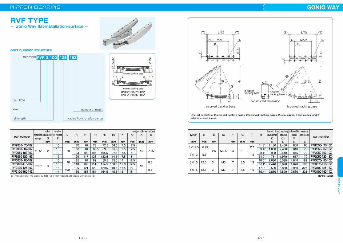
2.7
1.5
1.9
1.9
41.8°33.4°28.1°24.0°48.6°37.1°47.2°36.4°
1,1801,060
998751
2,6802,4403,5202,860
2,4002,4302,4401,9705,5305,6208,8507,890
800810815657
1,8401,8702,9502,630
66 70 70 70182182327323
S1
D
G
f
PM×PN
R (radius from rotation center)
B
R2
h2H2
A
b-curved tracking base
constructed dimension
S1
(θ゚ ) (θ゚ )
B
(T)
R (radius from rotation center)
h1H1
f
(T)
G
R1
E
E
-0.1-0.3
0-0.3
0-0.1
0-0.1
L (T) (T)-0.1-0.3L
N M×PP
a-curved tracking base
a-curvedtracking base
b-curvedtracking base
RVF TYPE- Gonio Way flat-installation-surface -
part number structure
number of rollers
radius from rotation centerrail length
size
RVF type
example RVF 3 100 16Z
(0.25)
5.2
(0.25)
5.2
b-curved tracking base
a-curved tracking base
RVF2050-87-10ZRVF2050-70-10Z
8.2
3
8.2
(T)
3 (T)
3(T)
3(T)
- 125 -
T
mm
θ°allowable
loadFN
mass(one set)
g
basic load ratingmajor dimensions
part number
RVF2050- 70-10ZRVF2050- 87-10ZRVF2050-103-10ZRVF2050-120- 9ZRVF3070- 85-10ZRVF3070-110-10ZRVF3100-125-16ZRVF3100-160-14Z
1N≒0.102kgf
B
mm
A
mm
h2
mm
h1
mm
H2
mm
H1
mm
R2
mm
R1
mm
R
mm
7.25
8.5
8.5
15
18
7.5 7.5 8 8 12.5 12.5 18 18
7.5 7.5 7.5 7.5 14 12.8 17.5 15
64.5 81.5 97.5114.5 75.5100.5110.5145.5
72.5 89.5105.5122.5 89.5114.5129.5164.5
73 89.5 106 123 89 114 129 164
67 84100117 81106121156
70 87103120 85110125160
2
3
± 5°
±10°
dynamicCN
staticCoN
※ Please refer to page G-68 for information on cage dimensions.
L
mm
50
70
100
number of rollers
Z
roller diameter
Dmm
rotation range
101010 910101614
part number
RVF2050- 70-10ZRVF2050- 87-10ZRVF2050-103-10ZRVF2050-120- 9ZRVF3070- 85-10ZRVF3070-110-10ZRVF3100-125-16ZRVF3100-160-14Z
G
mm
3
3.5
3.5
f
mm
S1E
mm
N
mm
M×P
mm
4
7
7
M2.5
M3
M3
2.5
3
3
6.25
5.5
12.5
12.5
3×12.5
3×13
3×15
5×15
One set consists of 2 a-curved tracking bases, 2 b-curved tracking bases, 2 roller cages, 8 end pieces, and 2 edge reference plates.
G-66 G-67
GONIO WAYG
ON
IO W
AY
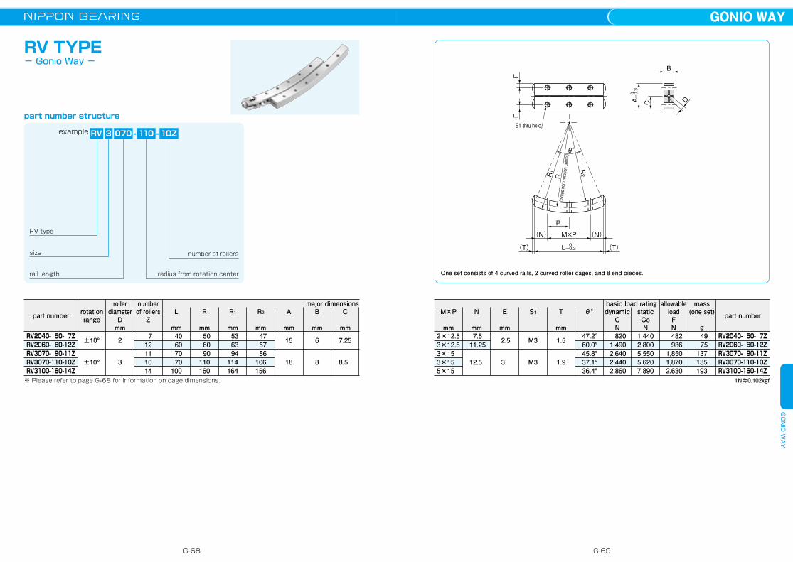
RV TYPE- Gonio Way -
part number structure
number of rollers
radius from rotation centerrail length
size
RV type
example RV 3 070 10Z- 110 -
major dimensions
part number
RV2040- 50- 7ZRV2060- 60-12ZRV3070- 90-11ZRV3070-110-10ZRV3100-160-14Z
B
mm
A
mm
R2
mm
R1
mm
R
mm
6
8
15
18
47 57 86106156
53 63 94114164
50 60 90110160
2
3
±10°
±10°
※ Please refer to page G-68 for information on cage dimensions.
L
mm 40 60 70 70100
numberof rollers
Z
roller diameter
Dmm
rotation range
C
mm
7.25
8.5
712111014
1.5
1.9
47.2°60.0°45.8°37.1°36.4°
8201,4902,6402,4402,860
1,4402,8005,5505,6207,890
482936
1,8501,8702,630
49 75137135193
S1 thru hole
R2
(radius from rotation center)
RR1
θ°
EE
(T)(T)
(N)(N) M×P
P
B
DC
L 0-0.3
A 0-0.3
T
mm
θ°allowable
loadFN
mass(one set)
g
basic load rating
1N≒0.102kgf
dynamicCN
staticCoN
part number
RV2040- 50- 7ZRV2060- 60-12ZRV3070- 90-11ZRV3070-110-10ZRV3100-160-14Z
S1E
mm
N
mm
M×P
mm
M3
M3
2.5
3
7.5 11.25
12.5
2×12.53×12.53×153×155×15
One set consists of 4 curved rails, 2 curved roller cages, and 8 end pieces.
G-68 G-69
GONIO WAYG
ON
IO W
AY

CR TYPE- Standard Curved Roller Cage -
part number structure
part number
CR2- 50- 7ZCR2- 60-12ZCR2- 70-10ZCR2- 87-10ZCR2-103-10ZCR2-120- 9ZCR3- 85-10ZCR3- 90-11ZCR3-110-10ZCR3-125-16ZCR3-160-14Z
A
t
W
D
a°p°
center radius
2
3
size
CR type
example CR 3 110
center radius
10Z
number of rollers
-
roller diameterD
mm
center radiusA
mmt
mmw
mm p° a° applicable
type
50 60 70 87103120 85 90110125160
0.3
0.4
5.6
7.2
4.6° 3.8° 3.3° 2.6° 2.2° 1.9° 3.4° 3.2° 2.6° 2.3° 1.8°
2.9° 2.4° 2.0° 1.6° 1.4° 1.2° 2.0° 1.9° 1.5° 1.3° 1.0°
RVRVRVFRVFRVFRVFRVFRV
RVF、RVRVF
RVF、RV
-
ACTUATOR
ACTUATORADVANTAGES ・・・・・・・・・・・・・・・・・ H-3PART NUMBER STRUCTURE ・・ H-4SPECIFICATIONS ・・・・・・・・・・・・・・ H-6ALLOWABLE SPEED AND STROKE LIMIT H-7ACCURACY ・・・・・・・・・・・・・・・・・・・ H-8RATED LIFE ・・・・・・・・・・・・・・・・・・・ H-10DIMENSION TABLE ・・・・・・・・・・・・ H-14〜29MOTOR BRACKET CONFIGURATIONS & APPLICABLE MOTORS H-30EXPOSED BRACKET R0 ・・・・・・・ H-43RETURN PULLEY UNIT ・・・・・・・ H-46LOW HOUSING ・・・・・・・・・・・・・・・・ H-48BELLOWS ・・・・・・・・・・・・・・・・・・・・・ H-50SENSOR ・・・・・・・・・・・・・・・・・・・・・・・ H-59PNP SENSOR ・・・・・・・・・・・・・・・・・ H-70SENSOR SPECIFICATIONS ・・・・ H-71POSITIONING PIN HOLE ・・・・・・・ H-74LUBRICATION ・・・・・・・・・・・・・・・・・ H-79OPERATING TEMPERATURE ・・ H-79USE AND HANDLING PRECAUTIONS H-79
G-70
GONIO WAYA
CTU
ATO
R
H-1
AC
TUA
TOR
Related Documents