Digital Design 2e Copyright © 2010 Frank Vahid 1 Digital Design Chapter 4: Datapath Components Copyright © 2010 Frank Vahid Instructors of courses requiring Vahid's Digital Design textbook (published by John Wiley and Sons) have permission to modify and use these slides for customary course- related activities, subject to keeping this copyright notice in place and unmodified. These slides may be posted as unanimated pdf versions on publicly-accessible course websites.. PowerPoint source (or pdf with animations) may not be posted to publicly-accessible websites, but may be posted for students on internal protected sites or distributed directly to students by other electronic means. Instructors may make printouts of the slides available to students for a reasonable photocopying charge, without incurring royalties. Any other use requires explicit permission. Instructors may obtain PowerPoint source or obtain special use permissions from Wiley – see http://www.ddvahid.com for information. Slides to accompany the textbook Digital Design, with RTL Design, VHDL, and Verilog , 2nd Edition, by Frank Vahid, John Wiley and Sons Publishers, 2010. http://www.ddvahid.com

Welcome message from author
This document is posted to help you gain knowledge. Please leave a comment to let me know what you think about it! Share it to your friends and learn new things together.
Transcript

Digital Design 2eCopyright © 2010 Frank Vahid
1
Digital DesignChapter 4:
Datapath Components
Copyright © 2010 Frank VahidInstructors of courses requiring Vahid's Digital Design textbook (published by John Wiley and Sons) have permission to modify and use these slides for customary course-related activities, subject to keeping this copyright notice in place and unmodified. These slides may be posted as unanimated pdf versions on publicly-accessible course websites.. PowerPoint source (or pdf with animations) may not be posted to publicly-accessible websites, but may be posted for students on internal protected sites or distributed directly to students by other electronic means. Instructors may make printouts of the slides available to students for a reasonable photocopying charge, without incurring royalties. Any other use requires explicit permission. Instructors may obtain PowerPoint source or obtain special use permissions from Wiley – see http://www.ddvahid.com for information.
Slides to accompany the textbook Digital Design, with RTL Design, VHDL, and Verilog, 2nd Edition,
by Frank Vahid, John Wiley and Sons Publishers, 2010. http://www.ddvahid.com

Digital Design 2eCopyright © 2010 Frank Vahid
2
0
Subtractors and Signed Numbers• Can build subtractor as we built carry-ripple adder
– Mimic subtraction by hand– Compute the borrows from columns on left
• Use full-subtractor component: – wi is borrow by column on right, wo borrow from column on left
4.6
1 1 000 1 1
11
10
-
1st column1 1 010 00 1 1
10 11-
3rdcolumn1 1 00 00 1 1
100 11-
4thcolumn
wo
a3
a bFS
wi
wo s
b3
s3
a2
a bFS
wi
wo s
b2
s2
a1
a bFS
wi
wo s
b1
s1
a0
a bFS
wi
wi
wo s
b0
s0(b)
a3a2a1a0 b3
s3s2s1s0wowi
b2b1b0
(c)
4-bit subtractor a
1 1 00 1 1
1 11
10
-
2ndcolumn10
1 1a

Digital Design 2eCopyright © 2010 Frank Vahid
3
Subtractor Example: DIP-Switch Based Adding/Subtracting Calculator
• Extend earlier calculator example– Switch f indicates
whether want to add (f=0) or subtract (f=1)
– Use subtractor and 2x1 mux
DIP switches10
8-bit registerCALC
LEDs
e
f
clkld
8
8
80 0
8
8
8
882x10 11
0
wiciA AB B
S Sco wo8-bit adder 8-bit subtractor
Digital Design 2eCopyright © 2010 Frank Vahid
4
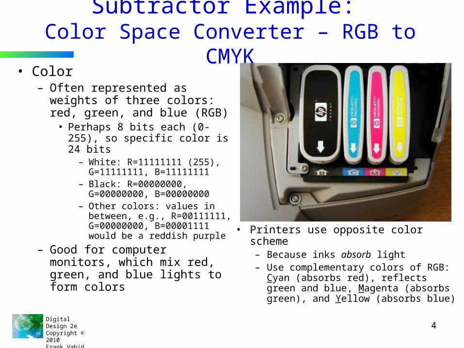
Subtractor Example: Color Space Converter – RGB to CMYK
• Color– Often represented as weights
of three colors: red, green, and blue (RGB)
• Perhaps 8 bits each (0-255), so specific color is 24 bits
– White: R=11111111 (255), G=11111111, B=11111111
– Black: R=00000000, G=00000000, B=00000000
– Other colors: values in between, e.g., R=00111111, G=00000000, B=00001111 would be a reddish purple
– Good for computer monitors, which mix red, green, and blue lights to form colors
• Printers use opposite color scheme– Because inks absorb light– Use complementary colors of RGB:
Cyan (absorbs red), reflects green and blue, Magenta (absorbs green), and Yellow (absorbs blue)

Digital Design 2eCopyright © 2010 Frank Vahid
5
Subtractor Example: Color Space Converter – RGB to CMYK
• Printers must quickly convert RGB to CMY – C=255-R, M=255-G, Y=255-B– Use subtractors as shown
— — —
R G B8
88888
8 8 8
255 255 255
C M Y

Digital Design 2eCopyright © 2010 Frank Vahid
6
Subtractor Example: Color Space Converter – RGB to CMYK
• Try to save colored inks– Expensive– Imperfect – mixing C, M, Y doesn’t
yield good-looking black
• Solution: Factor out the black or gray from the color, print that part using black ink– e.g., CMY of (250,200,200)=
(200,200,200) + (50,0,0).• (200,200,200) is a dark gray – use
black ink
Digital Design 2eCopyright © 2010 Frank Vahid
7
Subtractor Example: Color Space Converter – RGB to CMYK
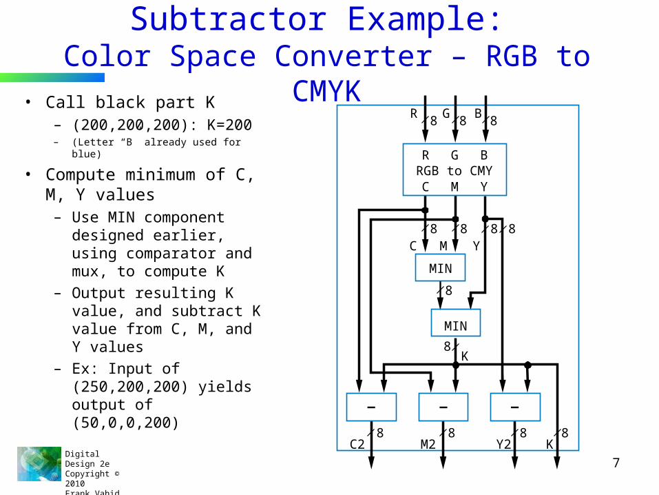
• Call black part K– (200,200,200): K=200– (Letter “B” already used for blue)
• Compute minimum of C, M, Y values– Use MIN component
designed earlier, using comparator and mux, to compute K
– Output resulting K value, and subtract K value from C, M, and Y values
– Ex: Input of (250,200,200) yields output of (50,0,0,200) — — —
8 8C2 M2 Y2 K
8
8
888 8
8 8
MIN
MIN
C
C M Y
R GRGB to CMY
B
M Y
K
R G B8 8 8

Digital Design 2eCopyright © 2010 Frank Vahid
8
Representing Negative Numbers: Two’s Complement
• Negative numbers common– How represent in binary?
• Signed-magnitude– Use leftmost bit for sign bit
• So -5 would be:1101 using four bits10000101 using eight bits
• Better way: Two’s complement– Big advantage: Allows us to perform subtraction using addition– Thus, only need adder component, no need for separate
subtractor component

Digital Design 2eCopyright © 2010 Frank Vahid
9
Ten’s Complement
• Before introducing two’s complement, let’s consider ten’s complement– But, be aware that computers DO NOT
USE TEN’S COMPLEMENT. Introduced for intuition only.
– Complements for each base ten number shown to right. Complement is the number that when added results in 10
9
8
7
65
4
3
2
1
1
2
3
45
6
7
8
9

Digital Design 2eCopyright © 2010 Frank Vahid
10
Ten’s Complement• Nice feature of ten’s complement
– Instead of subtracting a number, adding its complement results in answer exactly 10 too much– So just drop the 1 – results in subtracting using addition only
4 610
7
–4 +60 10 20
3 13
133
0 10
1
2
3
4
5
6
7
8
9
9
8
7
6
5
4
3
2
1
complements
7–4=3 7+6=13 3
Adding the complement results in an answer that isexactly 10 too much – dropping the tens column givesthe right answer.
a
Digital Design 2eCopyright © 2010 Frank Vahid
11
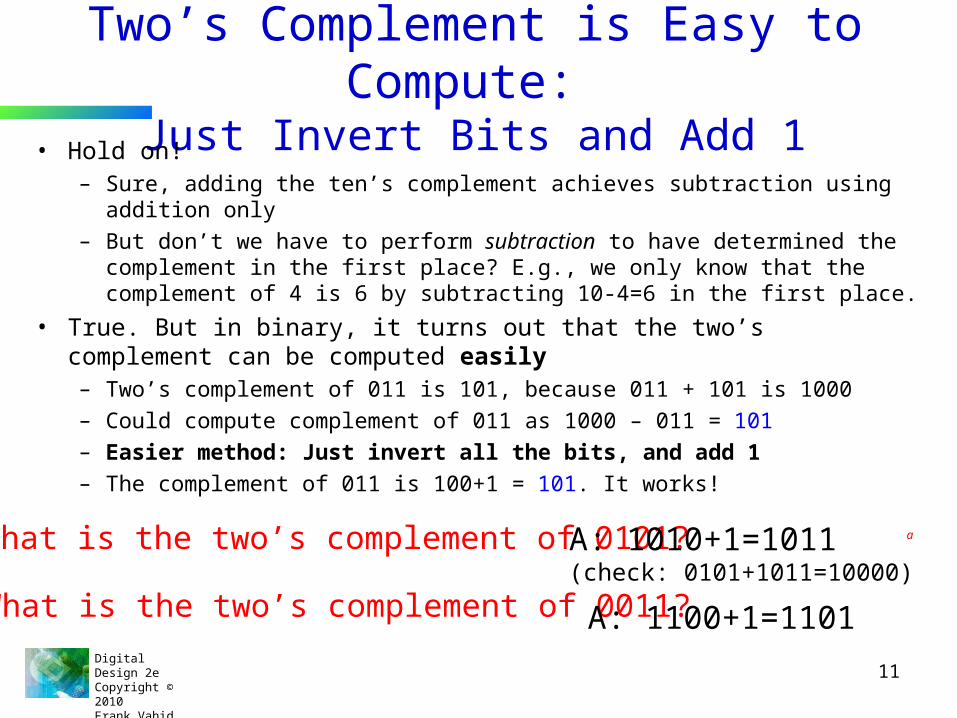
Two’s Complement is Easy to Compute: Just Invert Bits and Add 1
• Hold on!– Sure, adding the ten’s complement achieves subtraction using addition only– But don’t we have to perform subtraction to have determined the
complement in the first place? E.g., we only know that the complement of 4 is 6 by subtracting 10-4=6 in the first place.
• True. But in binary, it turns out that the two’s complement can be computed easily– Two’s complement of 011 is 101, because 011 + 101 is 1000– Could compute complement of 011 as 1000 – 011 = 101– Easier method: Just invert all the bits, and add 1– The complement of 011 is 100+1 = 101. It works!
Q: What is the two’s complement of 0101? A: 1010+1=1011(check: 0101+1011=10000)
a
Q: What is the two’s complement of 0011? A: 1100+1=1101
Digital Design 2eCopyright © 2010 Frank Vahid
12
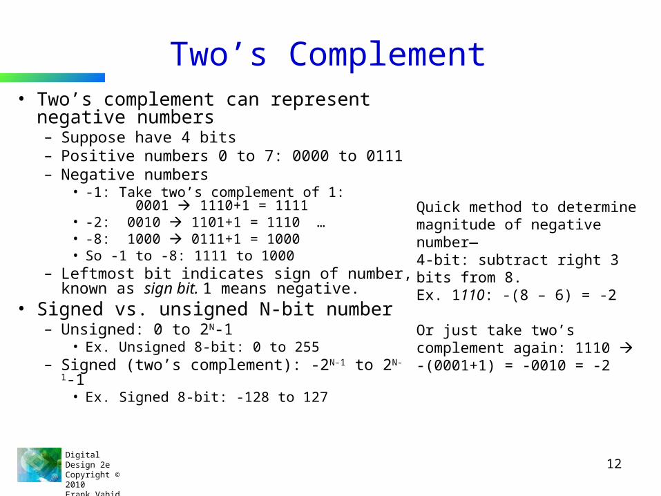
Two’s Complement• Two’s complement can represent
negative numbers– Suppose have 4 bits– Positive numbers 0 to 7: 0000 to 0111– Negative numbers
• -1: Take two’s complement of 1: 0001 1110+1 = 1111
• -2: 0010 1101+1 = 1110 …• -8: 1000 0111+1 = 1000• So -1 to -8: 1111 to 1000
– Leftmost bit indicates sign of number, known as sign bit. 1 means negative.
• Signed vs. unsigned N-bit number– Unsigned: 0 to 2N-1
• Ex. Unsigned 8-bit: 0 to 255– Signed (two’s complement): -2N-1 to 2N-1-1
• Ex. Signed 8-bit: -128 to 127
Quick method to determine magnitude of negative number—4-bit: subtract right 3 bits from 8. Ex. 1110: -(8 – 6) = -2
Or just take two’s complement again: 1110 -(0001+1) = -0010 = -2
Digital Design 2eCopyright © 2010 Frank Vahid
13
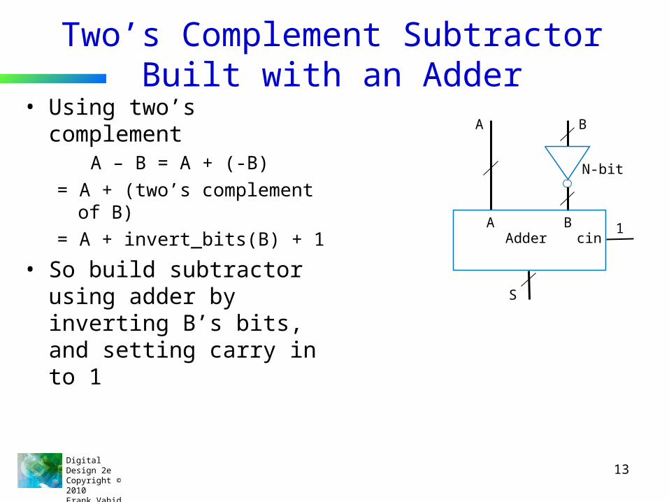
Two’s Complement Subtractor Built with an Adder• Using two’s complement
A – B = A + (-B) = A + (two’s complement of B) = A + invert_bits(B) + 1
• So build subtractor using adder by inverting B’s bits, and setting carry in to 1
1cinBA
Adder
S
BA
N-bit
Digital Design 2eCopyright © 2010 Frank Vahid
14
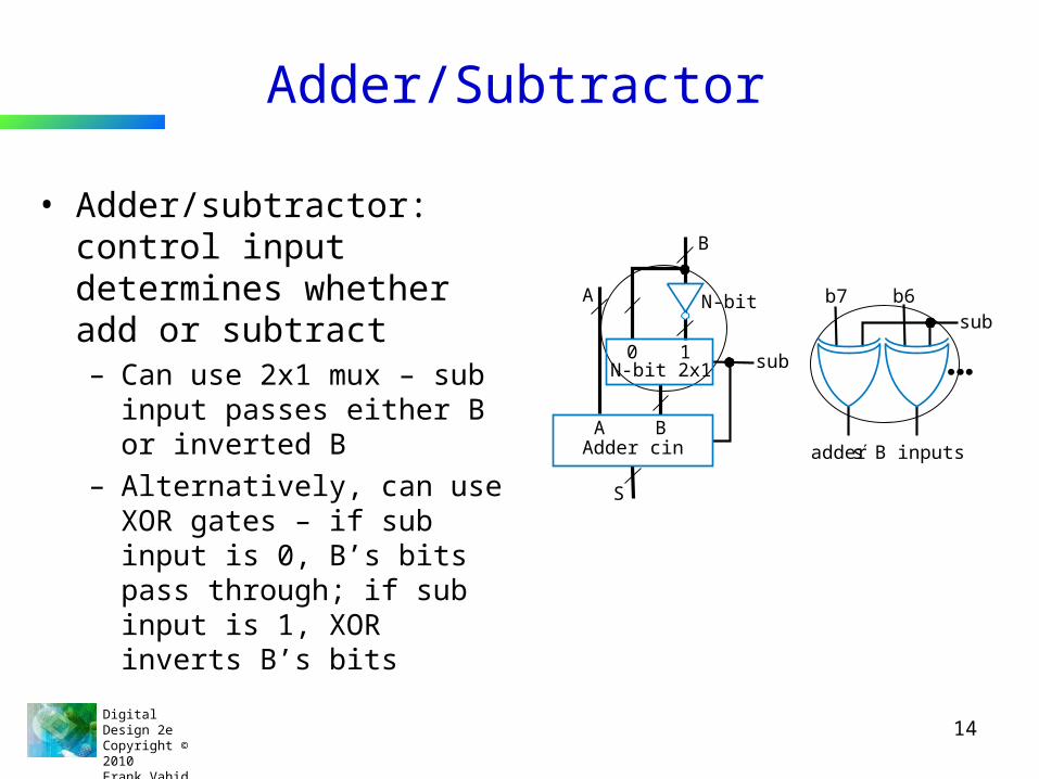
Adder/Subtractor
• Adder/subtractor: control input determines whether add or subtract– Can use 2x1 mux – sub input
passes either B or inverted B– Alternatively, can use XOR
gates – if sub input is 0, B’s bits pass through; if sub input is 1, XOR inverts B’s bits
b7 b6sub
adders B inputs
0 1N-bit 2x1
N-bitA
A
S
B
B
sub
Adder cin

Digital Design 2eCopyright © 2010 Frank Vahid
15
Adder/Subtractor Example: Calculator• Previous calculator
used separate adder and subtractor
• Improve by using adder/subtractor, and two’s complement numbers
DIP switches10
8-bit register
8-bit adder/subtractorsub
CALC
LEDs
e
S
A Bf
clkld
10
8 8
8
8
DIP switches10
8-bitregisterCALC
LEDs
e
f
clkld
8
8
80 0
8
8
8
88 2x10 110
wiciA AB B
S Sco wo8-bit adder 8-bit subtractor

Digital Design 2eCopyright © 2010 Frank Vahid
16
Overflow• Sometimes result can’t be represented with given
number of bits– Either too large magnitude of positive or negative– Ex. 4-bit two’s complement addition of 0111+0001 (7+1=8). But
4-bit two’s complement can’t represent number >7• 0111+0001 = 1000 WRONG answer, 1000 in two’s complement is
-8, not +8– Adder/subtractor should indicate when overflow has occurred,
so result can be discarded
Digital Design 2eCopyright © 2010 Frank Vahid
17
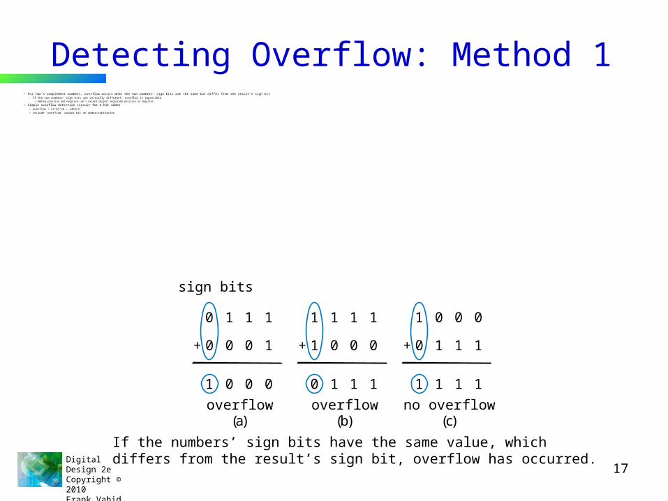
Detecting Overflow: Method 1• For two’s complement numbers, overflow occurs when the two numbers’ sign bits are the same but differ from the result’s sign bit
– If the two numbers’ sign bits are initially different, overflow is impossible• Adding positive and negative can’t exceed largest magnitude positive or negative
• Simple overflow detection circuit for 4-bit adder– overflow = a3’b3’s3 + a3b3s3’– Include “overflow” output bit on adder/subtractor
0 1 1 1
1 0 0 0
+ 00 0 1
sign bits
overflow(a)
1 1 1 1
0 1 1 1
+ 01 0 0
overflow(b)
1 0 0 0
1 1 1 1
+ 10 1 1
no overflow(c)
If the numbers’ sign bits have the same value, whichdiffers from the result’s sign bit, overflow has occurred.
Digital Design 2eCopyright © 2010 Frank Vahid
18
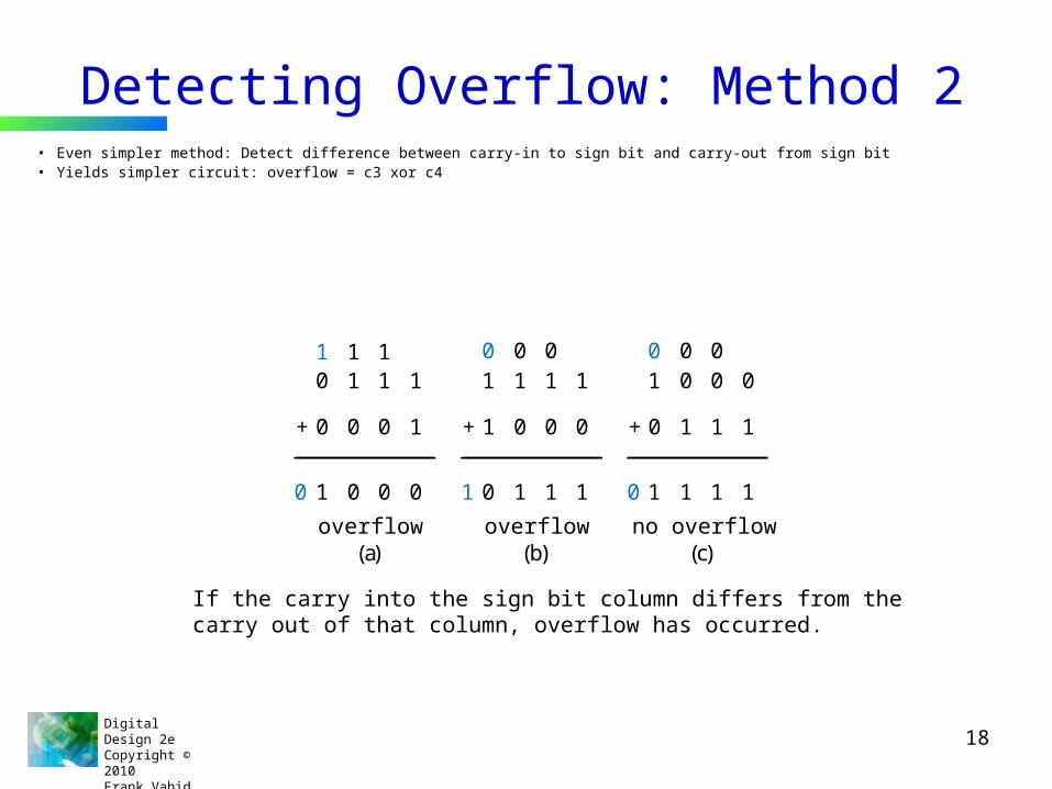
Detecting Overflow: Method 2• Even simpler method: Detect difference between carry-in to sign bit and carry-out from sign bit• Yields simpler circuit: overflow = c3 xor c4
0 1 11 1 1
1
10 010 0 0
+ 00 0 1
overflow(a)
1 1 10 0 0
1
0 1 1 1
+ 01 0 0
overflow(b)
1 0 00 0 0
0
1 1 1 1
+ 10 1 1
no overflow(c)
If the carry into the sign bit column differs from thecarry out of that column, overflow has occurred.

Digital Design 2eCopyright © 2010 Frank Vahid
19
Arithmetic-Logic Unit: ALU
• ALU: Component that can perform various arithmetic (add, subtract, increment, etc.) and logic (AND, OR, etc.) operations, based on control inputs
4.7
Digital Design 2eCopyright © 2010 Frank Vahid
20
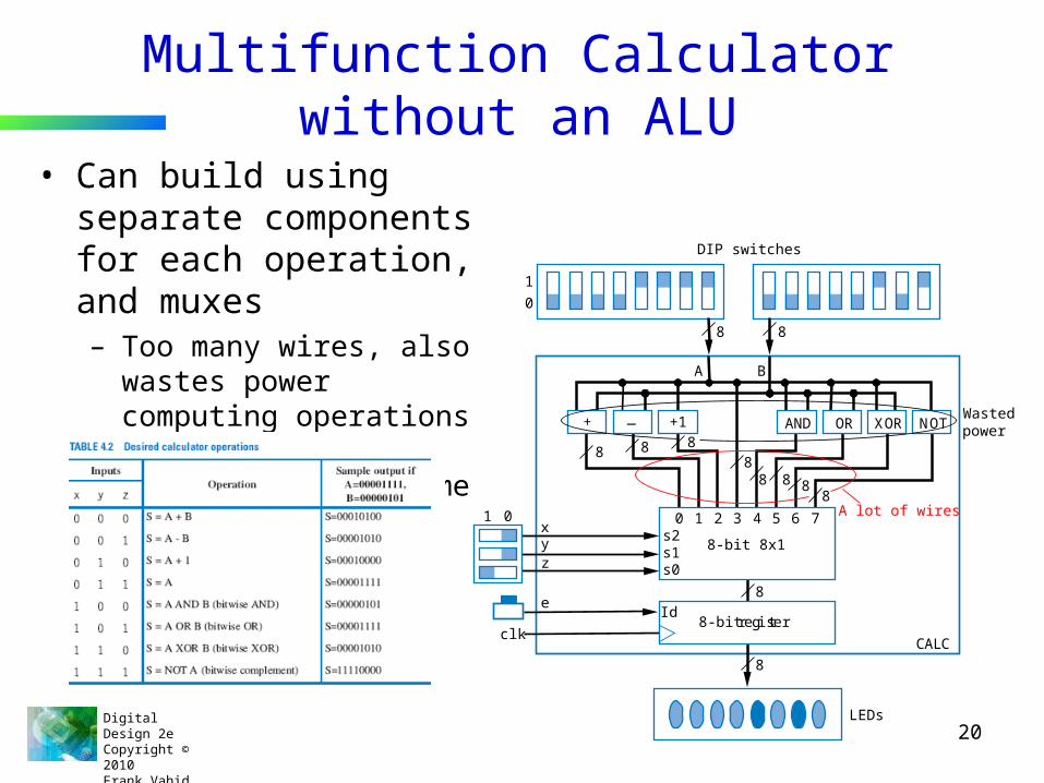
Multifunction Calculator without an ALU
• Can build using separate components for each operation, and muxes– Too many wires, also
wastes power computing operations when only use one result at given time
DIP switches
10
8-bit register
8-bit 8x1
CALC
LEDs
e
zyx
clkId
s0s1s2
1 0 0 1 2 3 4 5 6 7
NOTXORORAND+1+
8 8
88
8
8
8
8 8 8
88
A B
A lot of wires
Wastedpower—

Digital Design 2eCopyright © 2010 Frank Vahid
21
ALU• More efficient design uses ALU
– ALU design not just separate components multiplexed (same problem as previous slide)
– Instead, ALU design uses single adder, plus logic in front of adder’s A and B inputs• Logic in front is called an arithmetic-logic extender
– Extender modifies A and B inputs so desired operation appears at output of the adder
(a)
ALU
IA IB
IS
Adder cin
A B
S
xyz
AL-extender
abext abext abext cinext
AL-extender
ia7 ib7
a7 b7
ia6 ib6
a6 b6
ia0 ib0
a0 b0
cin(b)
xyz
a

Digital Design 2eCopyright © 2010 Frank Vahid
22
Arithmetic-Logic Extender in Front of ALU
• xyz=000 Want S=A+B : just pass a to ia, b to ib, and set cin=0• xyz=001 Want S=A-B : pass a to ia, b’ to ib and set cin=1 (two’s complement)• xyz=010 Want S=A+1 : pass a to ia, set ib=0, and set cin=1• xyz=011 Want S=A : pass a to ia, set ib=0, and set cin=0• xyz=100 Want S=A AND B : set ia=a*b, b=0, and cin=0• Others: likewise• Based on above, create logic for ia(x,y,z,a,b) and ib(x,y,z,a,b) for each abext, and create
logic for cin(x,y,z), to complete design of the AL-extender component
abext abext abext cinext
xyz
AL-extender
ia7 ib7
a7 b7
ia6 ib6
a6 b6
ia0 ib0
a0 b0
cin(b)
(a)
ALU
IA IB
IS
Adder cin
A B
AL-extender
S
xyz

Digital Design 2eCopyright © 2010 Frank Vahid
23
ALU Example: Multifunction Calculator
• Design using ALU is elegant and efficient– No mass of wires– No big waste of power
DIP switches10
10
8-bit register
ALUS
CALC
LEDs
e
zyx
clkld
zyx
8
8
8
8A
AB
B
DIP swi tches10
8-bit register
8-bit 8 1
CALC
LEDs
e
zyx
clkId
s0s1s2
1 0 0 1 2 3 4 5 6 7
NOTXORORAND+1Ð+
8 8
88
8
8
8
8 8 8
88
A B
A lot of wi res.
Wastedpower

Digital Design 2eCopyright © 2010 Frank Vahid
24
Chapter Summary• Need datapath components to store and operate on multi-bit data
– Also known as register-transfer-level (RTL) components• Components introduced
– Registers– Adders– Comparators – Multipliers – Subtractors– Arithmetic-Logic Units
Digital Design 2eCopyright © 2010 Frank Vahid
25
Digital DesignChapter 6:
Optimizations and Tradeoffs
Slides to accompany the textbook Digital Design, with RTL Design, VHDL, and Verilog, 2nd Edition,
by Frank Vahid, John Wiley and Sons Publishers, 2010. http://www.ddvahid.com
Copyright © 2010 Frank VahidInstructors of courses requiring Vahid's Digital Design textbook (published by John Wiley and Sons) have permission to modify and use these slides for customary course-related activities, subject to keeping this copyright notice in place and unmodified. These slides may be posted as unanimated pdf versions on publicly-accessible course websites.. PowerPoint source (or pdf with animations) may not be posted to publicly-accessible websites, but may be posted for students on internal protected sites or distributed directly to students by other electronic means. Instructors may make printouts of the slides available to students for a reasonable photocopying charge, without incurring royalties. Any other use requires explicit permission. Instructors may obtain PowerPoint source or obtain special use permissions from Wiley – see http://www.ddvahid.com for information.

Digital Design 2eCopyright © 2010 Frank Vahid
26
Introduction• We now know how to build digital circuits
– How can we build better circuits?• Let’s consider two important design criteria
– Delay – the time from inputs changing to new correct stable output– Size – the number of transistors– For quick estimation, assume
• Every gate has delay of “1 gate-delay”• Every gate input requires 2 transistors• Ignore inverters
6.1
16 transistors2 gate-delays
F1
wxy
wxyF1 = wxy + wxy’
(a)
4 transistors1 gate-delay
F2
F2 = wx(b)
wx
= wx(y+y’) = wx
Transforming F1 to F2 represents an optimization: Better in all
criteria of interest
(c)
2015105
F1
F21 2 3 4
delay (gate-delays)siz
e(tr
ansis
tors
)
Note: Slides with animation are denoted with a small red "a" near the animated items
a
a

Digital Design 2eCopyright © 2010 Frank Vahid
27
Introduction• Tradeoff
– Improves some, but worsens other, criteria of interest
Transforming G1 to G2 represents a tradeoff: Some criteria better, others worse.
14 transistors2 gate-delays
G1
wx
wyz
G1 = wx + wy + z
12 transistors3 gate-delays
G2
wxyz
G2 = w(x+y) + z
2015105
G1G2
1 2 3 4delay (gate-delays)
size
(tran
sisto
rs)
a
a

Digital Design 2eCopyright © 2010 Frank Vahid
28
Introduction
• We obviously prefer optimizations, but often must accept tradeoffs– You can’t build a car that is the most comfortable, and has the best
fuel efficiency, and is the fastest – you have to give up something to gain other things.
delaydelay
OptimizationsTradeoffs
All criteria of interestare improved (or at
least kept the same)
Some criteria of interest are improved, while others are worsenedsi
ze
size
a

Digital Design 2eCopyright © 2010 Frank Vahid
29
Combinational Logic Optimization and Tradeoffs• Two-level size optimization using
algebraic methods– Goal: Two-level circuit (ORed AND
gates) with fewest transistors• Though transistors getting cheaper
(Moore’s Law), still cost something
• Define problem algebraically– Sum-of-products yields two levels
• F = abc + abc’ is sum-of-products; G = w(xy + z) is not.
– Transform sum-of-products equation to have fewest literals and terms
• Each literal and term translates to a gate input, each of which translates to about 2 transistors (see Ch. 2)
• For simplicity, ignore inverters
6.2
F = xyz + xyz’ + x’y’z’ + x’y’z
F = xy(z + z’) + x’y’(z + z’)
F = xy*1 + x’y’*1
F = xy + x’y’
0
1
x’ y’
ny’
x’
0
1
m
m
n
nF
0
1
y
my
x
x
F
xy
x’y’
m
n
4 literals + 2 terms = 6 gate inputs
6 gate inputs = 12 transistors
Note: Assuming 4-transistor 2-input AND/OR circuits;in reality, only NAND/NOR use only 4 transistors.
Example
a
a

Digital Design 2eCopyright © 2010 Frank Vahid
30
Algebraic Two-Level Size Optimization• Previous example showed common
algebraic minimization method– (Multiply out to sum-of-products, then...)– Apply following as much as possible
• ab + ab’ = a(b + b’) = a*1 = a• “Combining terms to eliminate a variable”
– (Formally called the “Uniting theorem”)
– Duplicating a term sometimes helps• Doesn’t change function
– c + d = c + d + d = c + d + d + d + d ...
– Sometimes after combining terms, can combine resulting terms
F = xyz + xyz’ + x’y’z’ + x’y’zF = xy(z + z’) + x’y’(z + z’)F = xy*1 + x’y’*1F = xy + x’y’
F = x’y’z’ + x’y’z + x’yzF = x’y’z’ + x’y’z + x’y’z + x’yzF = x’y’(z+z’) + x’z(y’+y)F = x’y’ + x’z
G = xy’z’ + xy’z + xyz + xyz’G = xy’(z’+z) + xy(z+z’)G = xy’ + xy (now do again)G = x(y’+y)G = x
a
a
a

Digital Design 2eCopyright © 2010 Frank Vahid
31
Karnaugh Maps for Two-Level Size Optimization• Easy to miss possible opportunities to
combine terms when doing algebraically• Karnaugh Maps (K-maps)
– Graphical method to help us find opportunities to combine terms
– Minterms differing in one variable are adjacent in the map
– Can clearly see opportunities to combine terms – look for adjacent 1s
• For F, clearly two opportunities• Top left circle is shorthand for:
x’y’z’+x’y’z = x’y’(z’+z) = x’y’(1) = x’y’• Draw circle, write term that has all the literals
except the one that changes in the circle– Circle xy, x=1 & y=1 in both cells of the circle,
but z changes (z=1 in one cell, 0 in the other)• Minimized function: OR the final terms
F = x’y’z + xyz + xyz’ + x’y’z’
0 0
0 0
00 01 11 10
0
1
F yzx
1
x’y’
1 1 0 0
00 01 11 10
0 0
0
1 1 1
F yzx
xy
x’y’z’00 01 11 10
0
1
x’y’z x’yz x’yz’
xy’z’ xy’z xyz xyz’
F yzx
1
Notice not in binary order
Treat left & right as adjacent too
1 1
F = x’y’ + xy
Easier than algebraically:
F = xyz + xyz’ + x’y’z’ + x’y’zF = xy(z + z’) + x’y’(z + z’)F = xy*1 + x’y’*1F = xy + x’y’
K-map
a
a
a
Digital Design 2eCopyright © 2010 Frank Vahid
32
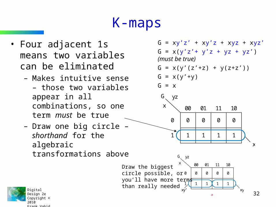
K-maps• Four adjacent 1s means
two variables can be eliminated– Makes intuitive sense – those
two variables appear in all combinations, so one term must be true
– Draw one big circle – shorthand for the algebraic transformations above
G = xy’z’ + xy’z + xyz + xyz’G = x(y’z’+ y’z + yz + yz’) (must be true)G = x(y’(z’+z) + y(z+z’))G = x(y’+y)G = x
0 0 0 000 01 11 10
1 1
0
1 1 1
G yzx
x
0 0 0 000 01 11 10
1 1
0
1 1 1
G yzx
xyxy’
Draw the biggestcircle possible, oryou’ll have more termsthan really needed
a

Digital Design 2eCopyright © 2010 Frank Vahid
33
K-maps• Four adjacent cells can be in
shape of a square• OK to cover a 1 twice
– Just like duplicating a term• Remember, c + d = c + d + d
• No need to cover 1s more than once– Yields extra terms – not minimized
0 1 1 000 01 11 10
0 1
0
1 1 0
H yzx
z
H = x’y’z + x’yz + xy’z + xyz (xy appears in all combinations)
0 1 0 000 01 11 10
1 1
0
1 1 1
I yzx
x
y’z
The two circles are shorthand for:I = x’y’z + xy’z’ + xy’z + xyz + xyz’I = x’y’z + xy’z + xy’z’ + xy’z + xyz + xyz’I = (x’y’z + xy’z) + (xy’z’ + xy’z + xyz + xyz’)I = (y’z) + (x)
1 1 0 000 01 11 10
0 1
0
1 1 0
J yzx
xz
y’zx’y’
a
a
a
Digital Design 2eCopyright © 2010 Frank Vahid
34
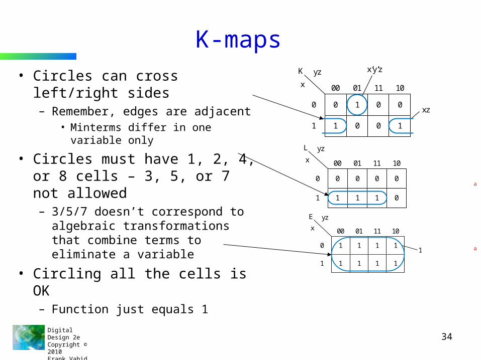
K-maps• Circles can cross left/right sides
– Remember, edges are adjacent• Minterms differ in one variable only
• Circles must have 1, 2, 4, or 8 cells – 3, 5, or 7 not allowed– 3/5/7 doesn’t correspond to
algebraic transformations that combine terms to eliminate a variable
• Circling all the cells is OK– Function just equals 1
0 1 0 000 01 11 10
1 0
0
1 0 1
K yzx
xz’
x’y’z
0 0 0 000 01 11 10
1 1
0
1 1 0
L yzx
1 1 1 1 1
00 01 11 10
1 1
0
1 1 1
E yzx
a
a
Related Documents