A Quantitative Reliability, Maintainability and Supportability Approach for NASA's Second Generation Reusable Launch Vehicle Fayssai M. Safie, Ph. D. Marshall Space Flight Center Huntsville, Alabama Tel: 256-544-5278 E-mail: Fayssal.Safie @ msfc.nasa.gov Charles Daniel, Ph.D. Marshall Space Flight Center Huntsville, Alabama Tel: 256-544-5278 E-mail: Charles.Daniel @msfc.nasa.gov Prince Kalia Raytheon ITSS Marshall Space Flight Center Huntsville, Alabama Tel: 256-544-6871 E-mail: Prince.Kalia @ msfc.nasa.gov ABSTRACT The United States National Aeronautics and Space Administration (NASA) is in the midst of a 10-year Second Generation Reusable Launch Vehicle (RLV) program to improve its space transportation capabilities for both cargo and crewed missions. The objectives of the program are to: significantly increase safety and reliability, reduce the cost of accessing low-earth orbit, attempt to leverage commercial launch capabilities, and provide a growth path for manned space exploration. The safety, reliability and life cycle cost of the next generation vehicles are major concerns, and NASA aims to achieve orders of magnitude improvement in these areas. To get these significant improvements, requires a rigorous process that addresses Reliability, Maintainability and Supportability (RMS) and safety through all the phases of the life cycle of the program. This paper discusses the RMS process being implemented for the Second Generation RLV program. 1.0 INTRODUCTION The 2nd Generation RLV program has in place quantitative Level-I RMS, and cost requirements [Ref 1] as shown in Table 1, a paradigm shift from the Space Shuttle program. This paradigm shift is generating a change in how space flight system design is approached. As a result, the program has set forth a system design philosophy that focuses on the system rather than the vehicle as shown in Figure 1.

Welcome message from author
This document is posted to help you gain knowledge. Please leave a comment to let me know what you think about it! Share it to your friends and learn new things together.
Transcript
A Quantitative Reliability, Maintainability and Supportability Approach for
NASA's Second Generation Reusable Launch Vehicle
Fayssai M. Safie, Ph. D.
Marshall Space Flight Center
Huntsville, Alabama
Tel: 256-544-5278
E-mail: Fayssal.Safie @ msfc.nasa.gov
Charles Daniel, Ph.D.
Marshall Space Flight Center
Huntsville, AlabamaTel: 256-544-5278
E-mail: Charles.Daniel @msfc.nasa.gov
Prince Kalia
Raytheon ITSS
Marshall Space Flight Center
Huntsville, Alabama
Tel: 256-544-6871
E-mail: Prince.Kalia @ msfc.nasa.gov
ABSTRACT
The United States National Aeronautics and Space Administration (NASA) is in the
midst of a 10-year Second Generation Reusable Launch Vehicle (RLV) program to
improve its space transportation capabilities for both cargo and crewed missions. The
objectives of the program are to: significantly increase safety and reliability, reduce the
cost of accessing low-earth orbit, attempt to leverage commercial launch capabilities, and
provide a growth path for manned space exploration. The safety, reliability and life cycle
cost of the next generation vehicles are major concerns, and NASA aims to achieve
orders of magnitude improvement in these areas. To get these significant improvements,
requires a rigorous process that addresses Reliability, Maintainability and Supportability
(RMS) and safety through all the phases of the life cycle of the program. This paper
discusses the RMS process being implemented for the Second Generation RLV program.
1.0 INTRODUCTION
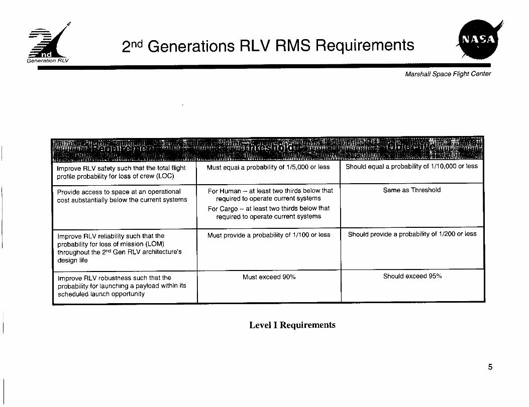
The 2nd Generation RLV program has in place quantitative Level-I RMS, and cost
requirements [Ref 1] as shown in Table 1, a paradigm shift from the Space Shuttle
program. This paradigm shift is generating a change in how space flight system design is
approached. As a result, the program has set forth a system design philosophy that
focuses on the system rather than the vehicle as shown in Figure 1.

SLI DESIGN PHILOSPHY
Figure 1. SLI Design Philosophy
In addition, the 2 no Generation RLV Program is trying to adopt an analysis based decision
process as opposed to the traditional rule based system that has been applied to previous
NASA Programs. Central to this process is the utilization of integrated RMS as discussed
in the next section.
Improve RLV safety such that the total flight
profile probability for loss of crew (LOC)
Must equal a probability of 1/5,000 or less Should equal a probability of 1/10,000 or less
Provide access to space at an operational For Human -- at least two thirds below that NA
cost substantially below the current systems required to operate current systems
For Cargo -- at least two thirds below that
required to operate current systems
Improve RLV reliability such that the Must p_ovide a probability of 1/100 or less Should provide a probability of 1/200 or less
probability for loss of mission (LOM)
throughout the 2 nd Gen RLV architecture's
design life
Improve RLV robustness such that the Must exceed 90% Should exceed 95%
probability for launching a payload within its
scheduled launch opportunity
Table I. Level l Safety and RMS Requirements

2.0 THE RMS INTEGRATED PROCESS
Reliability, maintainability, and supportability engineering are closely interrelated design
support disciplines that provide essential systems analysis capability for reusable systems
requiring high reliability, high availability, and low operational cost. Each RMS
engineering discipline has been practiced in industry and within the Department of
Defense for decades following standard methodologies.. In the In the 2 nd Generation
RLV Program, NASA is adopting the best-in-class integrated RMS practices from
Department of Defense (DoD) and commercial industry to provide a cost effective
solution. Specifically, the RMS disciplines will be brought together similar to the way
they have been practiced in industry and in other government agencies through an
integrated RMS Process under the direction of the RMS Program Lead.
2.1 Reliability Engineering
Reliability engineering is the application of mathematical and scientific principles to the
practical end of achieving, cost effectively, the predictability required or desired in the
level of functional output or performance. It supports design engineering in delivering a
design that meets both mission reliability and availability requirements within cost
constraints. Reliability engineering is the primary design-support discipline to help drive
2 nd Generation RLV design to meet the quantitative Crew Safety and Mission Success
requirements and to measure the capability of the launch vehicle to meet those
requirements.
2.2 Maintainability Engineering
Maintainability engineering is the application of mathematical and scientific principles to
the practical end of achieving easy, rapid, safe, and cost effective retention or restoration
of function to specified levels of performance. It supports design engineering in
delivering a design that is capable of having function restored to or retained at
specification within availability and cost constraints. Maintainability engineering is the
primary design-support discipline to help drive the design to meet allocated downtime orturnaround time for the Launch Availability requirement and then to measure the
capability of the design to meet that requirement.
2.3 Supportability Engineering
Supportability engineering is the application of mathematical and scientific principles to
the practical end of providing effective, economical support infrastructure (facilities,
people, spares, etc.) for mission operations and the maintenance cycle. It provides
product engineering design support through identification of support requirements
(facilities, manpower, support equipment, etc.) for both mission operations and the
maintenance cycle that will meet design reference mission requirements while satisfying
both availability and recurring cost constraints. Supportability engineering is the primary

design-supportdisciplineto helpdrive2 nd Generation RLV design to meet the
operational support cost constraint. Supportability engineering provides fundamental
input into the life-cycle cost breakdown structure for estimating the capability of the
design to meet the operational support cost constraint.
2.4 The Second Generation RLV RMS Process
The RMS Process, illustrated in Figure 2, integrates the disciplines of reliability,
maintainability, and supportability engineering through a specific sequencing of related
RMS modeling and analysis tasks and through the flow of specific RMS data between the
sequenced RMS tasks. The RMS Process also integrates the RMS modeling and analysis
tasks, through the systems engineering process, with design engineering and with other
engineering support disciplines such as cost and assurance.
The basic RMS Process begins with identification of failure states/events associated with
the design, their severity, their causes, and their effects. This is done primarily through a
Failure Modes and Effects Analysis (FMEA) of the design and is supported by Hazard
Analyses and Human Factors Analyses. Next, reliability modeling and analysis develops
reliability models of the failure modes/events and then arranges the individual models
into a failure structure/logic model representing the ways in which system function may
be lost. This logic model is executed analytically or through simulation to produce the
primary output of the reliability modeling and analysis task: an estimation of system
capability to meet reliability and safety figures of merit (FOM) [Ref 2] of Probability of
Loss of Crew (PLOC), Probability of Loss of Vehicle (PLOV), and Probability of Loss of
Mission (PLOM). At the same time, parameters from reliability models along with
certain FMEA data serve as input into reliability-centered maintenance (RCM) analysis.
The RCM analysis takes this input and runs it through an established RCM logic flow to
generate an inventory of maintenance significant items (MSI) and basic maintenance
actions required to retain or restore MSI function at or to specified levels of
reliability/safety. The inventory of MSI and basic maintenance actions serves as primary
input into both the maintainability and supportability modeling and analyses tasks that are
closely interrelated and performed concurrently.

r m.
i
, Systems EnglneerlngI
.................
I RMS Analyses
',[] _,_t_dAaalys_smmmm_
II • Requirements and Factors
v L Analysis
| ........................... ....................................
Figure 2. RMS Integrated Process
_1
Maintainability modeling and analysis begins with the development of a top-level
maintenance event sequence model initiated during conceptual design. It is continually
decomposed to lower levels of indenture with increasing definition of systemarchitecture, of maintenance and support tasks, and of maintenance packaging schemes.
Once complete it provides a definitive maintenance and support (e.g., ground processing)
flow model. Maintainability models estimating elapsed time for individual and grouped
maintenance actions/events are developed concurrently at each level of indenture in the
maintenance event sequence model. A downtime analysis is performed when required by
executing the maintenance event sequence model analytically or through simulation. The
downtime analysis estimates the capability of the maintenance and support system to
deliver a space flight system ready for integration or flight within specified time
constraints. This output at the vehicle level is combined with estimates of the start-up
reliability of the launch vehicle and with estimates of the probability of the launch vehicle
architecture not exceeding day-of-launch environmental constraints to produce an
estimate of the launch availability FOM for the launch vehicle architecture.
Supportability modeling and analysis begins primarily with the maintenance task analysisthat is initiated for each maintenance action output of the RCM analysis. This analysis is
a decomposition of each maintenance action into all necessary steps for successful
completion. A supportability analysis is performed concurrently with and on the
maintenance task analysis to determine the required resource loading (facilities,
personnel, support equipment, parts, etc.) for each maintenance action. Following the
maintenance task analysis and concurrent supportability analysis, the individual
maintenance actions are grouped into packaged sets of tasks that most effectively and
efficiently meetmission,reliability, andcostrequirements.Thefinal setof packagedmaintenanceactionsaredocumented(e.g.,SpaceShuttleOrganizationalMaintenanceRequirementsSupportDocument(OMRSD))for useby maintenanceengineering.Thesupportabilityanalysisis updatedto reflectthepackagedtasksandtheoutputis providedto costanalysisin theform of totalsupportresourcespercost-breakdown-structuretosupportestimatesof recurringcost.
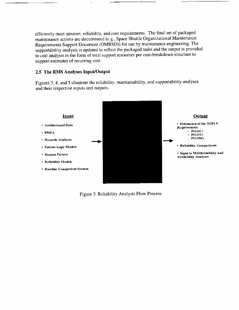
2.5 The RMS Analyses Input/Output
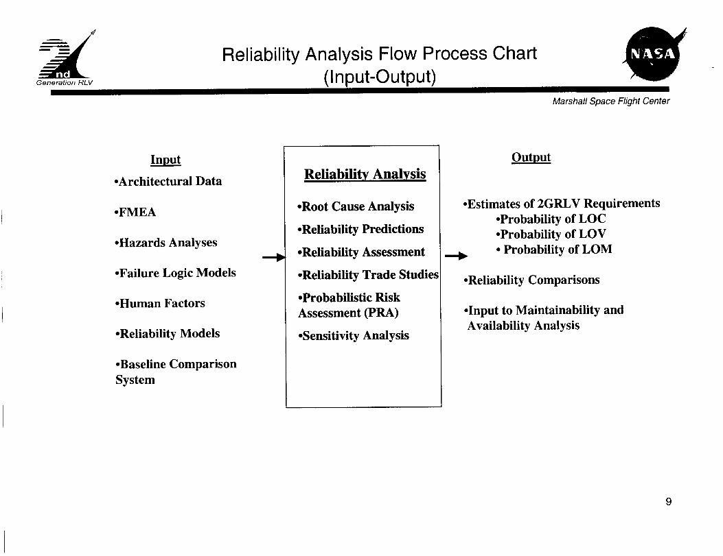
Figures 3, 4, and 5 illustrate the reliability, maintainability, and supportability analyses
and their respective inputs and outputs.
Input
• Architectural Data
• FMEA
• Hazards Analyses
• Failure Logic Models
• Human Factors
• Reliability Models
• Baseline Comparison System
Output
• Estimation of the 2GRLV
Requirements
- P(LOC)
- P(LOV)
- P(LOM)
• Reliability Comparisons
• Input to Maintainability and
Availability Analyses
Figure 3. Reliability Analysis Flow Process

Input Output
• Architecture Data
• Reliability Analysis
• Maintainability Models
- Historical Data:
- Baseline Comparison System
- Space Shuttle OMRSD/IMRSD
• Turn Around Time
• MeanTime Between
Maintenance (MTBM)
• Availability
Figure 4. Maintainability Analysis Flow Process
Inout
• Maintenance & Support
Concept
• Operations Concept
• RCM Maintenance
Actions
• Reliability/Maintainability
Predictions
• Baseline Comparison System
Outp___
• Facility Requirements
• Manpo_a_r, PersonnelandTraining
Requirements
• Spare/Repair Parts/Consumable
Requirements
• Maintenance Task Analysis Resources
* Test and Ground Support Equipment
Requirements
• Packaging, handling, storage and
transportation requirements
• Technical data, documentation and
database re quire ments
• Post-production support (e.g., fielding,
performance evaluation, sustaining
engineering) requirements
Figure 5. Supportability Analysis Process Flow
3.0 THE RMS MODELING AND ANALYSIS ENVIRONMENT
The 2GRLV Program has established a series of FOM's to serve as relative value
indicator for the various proposed system architectures. The RMS Team is responsible
for the FOMs associated with Loss of Crew (LOC), Loss of Vehicle (LOV), Loss of
Mission (LOM) and Launch/Systems Availability (LA). In order to estimate the relative
values associated with these FOMS, the RMS Team has established a modeling
environment per 2GRLV Program Design Reference Mission [Ref 3].
The modeling environment is intended to establishthe groundrules, assumptions and
supporting data to be utilized in modeling and analyzing the various system architectures
proposed to meet the requirements and goals of the 2GRLV Program. This environmentestablishes a common set of assumptions that will be applied by both the architectural
contractors and by the NASA in-house modeling effort. Within this environment each of
the architectural contractors and NASA will formulate models to describe the RMS
relationships present within the proposed systems. Basic to this environments definition
is that the "System" includes all element including flight, ground, support, etc. The
System model must account for all of the factors impacting the performance of the
system and must do so over all of the phases of the Program. It is incumbent on all
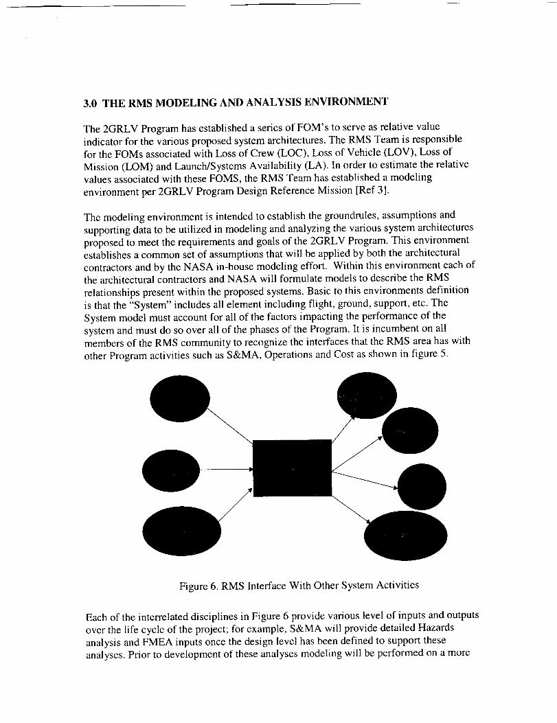
members of the RMS community to recognize the interfaces that the RMS area has with
other Program activities such as S&MA, Operations and Cost as shown in figure 5.
Figure 6. RMS Interface With Other System Activities
Each of the interrelated disciplines in Figure 6 provide various level of inputs and outputs
over the life cycle of the project; for example, S&MA will provide detailed Hazards
analysis and FMEA inputs once the design level has been defined to support these
analyses. Prior to development of these analyses modeling will be performed on a more
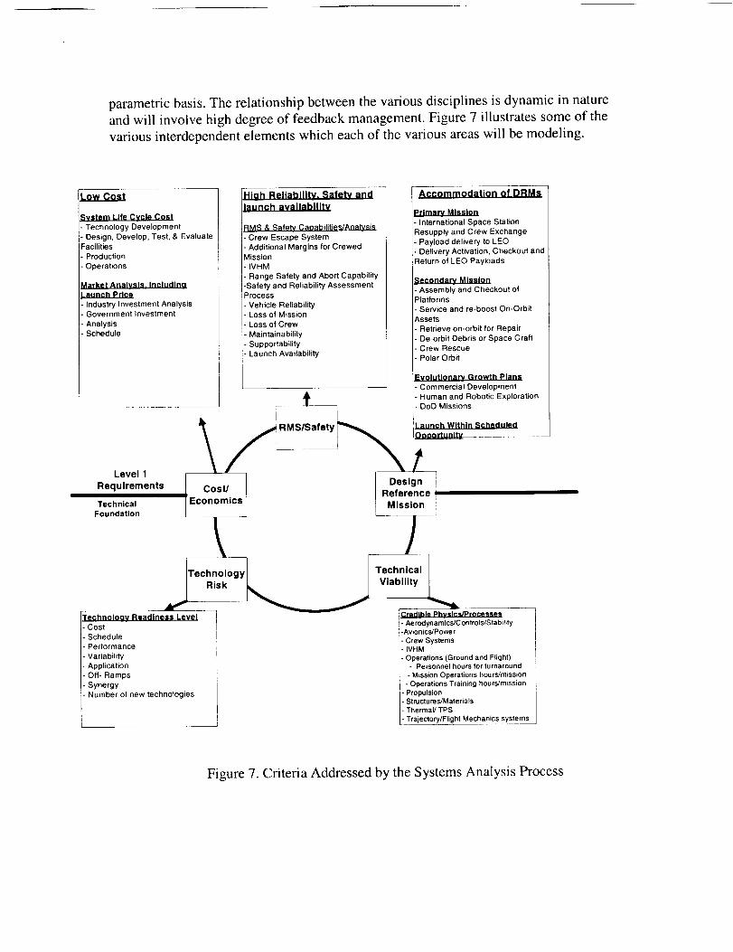
parametric basis. The relationship between the various disciplines is dynamic in nature
and will involve high degree of feedback management. Figure 7 illustrates some of the
various interdependent elements which each of the various areas will be modeling.
Low Cost
System Life Cycle Cost
Technology Development
Design, Develop, Test, & Evaluate--acilities
Production
Operations
_larket Analysis, Includlno.aunch Price
Industry Investment AnalysisGovernment Investment
AnalysisSchedule
Level 1
Requirements
Technical
Foundation
Technoloov Readiness Level
Cost
Schedule
Performance
Variability
ApplicationOff- Ramps
SynergyNumber of new technologies
H_h Reliabllitv. Safetv and
launch avallabilitv
[RMS & Safety Caoabilities/Analvsis
I" Crew Escape System
I" Additional Margins for Crewed
IMission
I" IVHM
I" Range Safety and Abort Capability
I-Safety and Reliability Assessment
IProcess
Vehicle Reliability
Loss of MissionLoss of Crew
Maintainability
Supportability
Launch Availability
Accommodation of DRMs
Primary Mission
- International Space Station
Resupply and Crew Exchange
Payload delivery to LEO
Delivery Activation, Checkout and
:leturn of LEO Payloads
Secondary Mission
- Assembly and Checkout ofPlatforms
- Service and re-boost On-Orbit
Assets
Retrieve on-orbit for Repair
De-orbit Debris or Space Craft
Crew Rescue
Polar Orbit
-'volutlonarv Growth Plans
Commercial Development
_IL Human and Robotic ExplorationDoD Missions
_ RMSISafety _;unch Within Scheduled
_aza_ua_t_
Design
Cost/ Reference
Economics Mission
l J
Credible Physics/Processes
. Ae rodynamics/C ontrols/Stability-Avionics/Power
Crew SystemsIVHM
Operations (Ground and Flight)- Personnel hours for turnaround
- Mission Operations hours/mission- Operations Training hours/mission
Propulsion- Structures/Materials
- Thermal/TPS
- Trajectory/Flight Mechanics systems
Figure 7. Criteria Addressed by the Systems Analysis Process

RMS Engineeringwithin the2 GRLV Programfunctionsasanelementof theSE&IOOrganization.As anelementof theSE&IO organizationtheRMSTeamis integratedwithin theanalysisandtradesenvironmentbeingexecutedby the2GRLV Program.TheRMS Teamdrawson thecommondatadictionaryutilized to performall systemsanalyses.Theoutputsof theRMSanalysisprocessbecomeinputsto thecommondatadictionaryand,assuch,arereflectedin interfacinganalyses.TheRMS ModelingandAnalysisactivity functionsasanintegralpartof the2GRLVAdvancedEngineeringEnvironment.This environmentwill evolveovertimeto reflectincreasinglevelof bothmodelanddatafidelity. Figure8 illustratessomeof thekeyelementsof this modelingenvironment.Eachof thevariousmodelingprocessesis linked to allow for aninterdependenceof thevariousanalysisproducts.
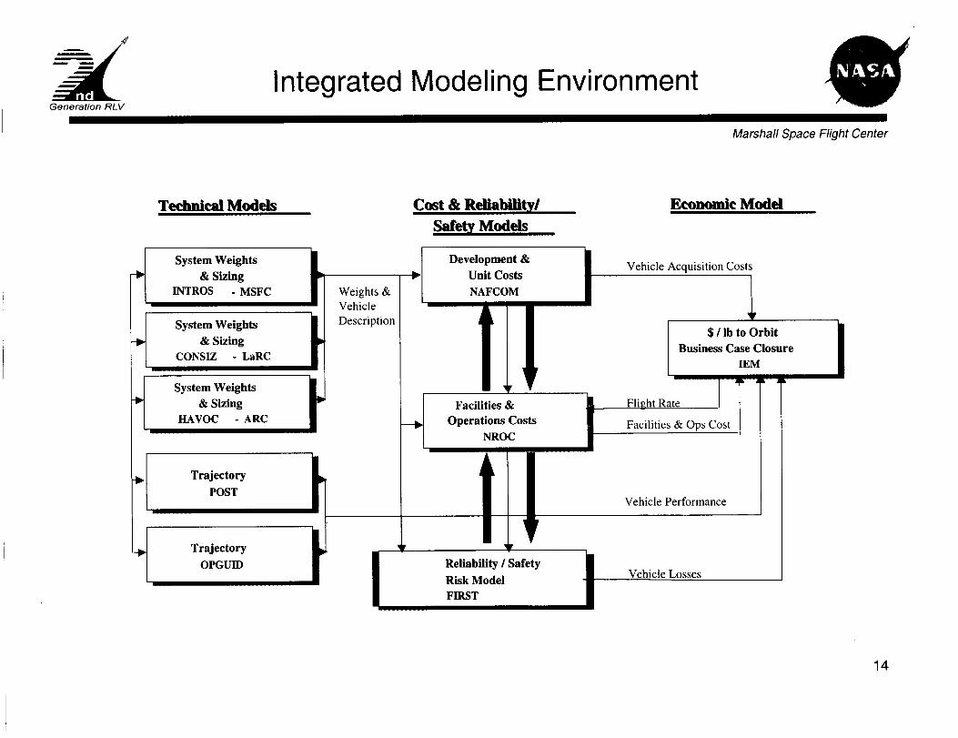
At thepresentstageof modelingfidelity thereliability calculationsareperformedutilizing theFlight-orientedIntegratedReliability andSafetyTool (FIRST)Model andthemaintenanceandsupportabilityis calculatedutilizing theNROC Model.Thesemodelingtoolsarefocusedon theconceptualdesignphaseof theprogram.As theprogrammovesinto thepreliminarydesignphasethesemodelswill besupplementedbymoredetailedmodelingtechniques.Thesetechniqueswill beutilized for bothtotalsystemsanalysisandfor focusedlower level tradestudies.
Technical Models Cost & Reliability/
Safety Models
Economic Model
Sys tem V,'eights
I & Sizing
& Sizing
Weights
& Vehicle
Description
Reliability / Safety
Risk Model V hkqe Losse's
Figure 7. Integrated Modeling Environment

parametricbasis.The relationshipbetweenthevariousdisciplinesis dynamicin natureandwill involvehighdegreeof feedbackmanagement.Figure7 illustratessomeof thevariousinterdependentelementswhicheachof the variousareaswill bemodeling.
.ow Cost
_ystem Life Cycle Cost
- Technology Development
- Design, Develop, Test, & Evaluate
Facilities
- Production
- Operations
Market Analysis. includinaLaunch Price
- Industry Investment Analysis. Government Investment
- Analysis
- Schedule
Level 1
Requirements
Technical
Foundation
Technoloov Readiness Level- Cost
- Schedule
- Performance
- Variability
- Application- Off- Ramps
- Synergy- Number of new technologies
Hiah Reliability. Safety and
launch availability
IRMS & Safety Capabilities/Analysis
- Crew Escape System
- Additional Margins for Crewed
Mission_- IVHM
- Range Safety and Abort Capability
-Safety and Reliability AssessmentProcess
Vehicle ReliabilityLoss of Mission
Loss of Crew
Maintainability
Supportability
- Launch Availability
Accommodation of DRMs
Primary Mission
- International Space Station
Resupply and Crew Exchange
- Payload delivery to LEO
- Delivery Activation, Checkout andReturno LEO Payloads
Secondary Mission
- Assembly and Checkout ofPlatforms
- Service and re-boost On-Orbit
Assets
- Retrieve on-orbit for Repair
- De-orbit Debris or Space Craft
- Crew Rescue
- Polar Orbit
_volutionarv Growth Plans
- Commercial Development
,_ - Human and Robotic Exploration.... DoD Missions
J_ _RMS/Safety_ r_a$$:r_uWii:h i n S c h e d u 'e d __
'Reference
Economics Mission
Risk _....._._._ Viability ,
Credible Physics/Processes- Aerodynamics�Controls�Stability-Avionics/Power
- Crew Systems- IVHM
- Operations (Ground and Flight)- Personnel hours for turnaround
- Mission Operations hours/mission
- Operations Training hours/missionPropulsionSlructures/Materials
Thermal/TPS
Trajectory/Flight Mechanics systems
Figure 7. Criteria Addressed by the Systems Analysis Process

RMS Engineering within the 2 GRLV Program functions as an element of the SE&IO
Organization. As an element of the SE&IO organization the RMS Team is integrated
within the analysis and trades environment being executed by the 2 GRLV Program. The
RMS Team draws on the common data dictionary utilized to perform all systems
analyses. The outputs of the RMS analysis process become inputs to the common data
dictionary and, as such, are reflected in interfacing analyses. The RMS Modeling and
Analysis activity functions as an integral part of the 2GRLV Advanced EngineeringEnvironment. This environment will evolve over time to reflect increasing level of both
model and data fidelity. Figure 8 illustrates some of the key elements of this modeling
environment. Each of the various modeling processes is linked to allow for an
interdependence of the various analysis products.
At the present stage of modeling fidelity the reliability calculations are performed
utilizing the Flight-oriented Integrated Reliability and Safety Tool (FIRST) Model and
the maintenance and supportability is calculated utilizing the NROC Model. These
modeling tools are focused on the conceptual design phase of the program. As the
program moves into the preliminary design phase these models will be supplemented bymore detailed modeling techniques. These techniques will be utilized for both total
systems analysis and for focused lower level trade studies.
Technical Models Cost & Reliability/
Safety Models
Economic Model
Weights
& Vehicle
Description
Vehicle l_)s_cs
Figure 7. Integrated Modeling Environment
4.0 CONCLUDING REMARKS
In this paper we have discussed NASA's new integrated RMS approach that is consistent
with the program system design approach. An approach that is based on a well-defined
systems engineering analyses and processes, which, for the first time includes safety,
reliability, maintainability, supportability and life cycle cost at the conceptual stage as
part of system trades. This innovative approach provides the pathway for a risk based and
analysis based decision process that is necessary to achieve NASA's goal of significantly
improving safety and reducing cost. A goal that should greatly enhance the prospects for
manned space flight in the future.
REFERENCES
1. "2 nd Generation Space Transportation Architecture Level ! Requirements"' MSFC-
RQMT-3221 Rev A, April 26, 2002
2. "2GRLV-DOC-016, Rev. B, "2GRLV Figures of Merit (FOMs)", August 2, 2002.
3. "2GRLV-DOC-010, Rev. B, "2GRLV Program Design Reference Missions", May 1,2002.
Generation RLV
Marshall Space Flight Center
A Quantitative Reliability, Maintainability, andSupportability Approach for NASA's Second Generation
Reusable Launch Vehicle
Life Cycle Systems Engineering Conference
Nov 6 - 7,2002 at Redstone Arsenal, Alabama
Dr. Fayssal M. Safie
Dr. Charles Daniel
Prince Kalia

Generation RLV
AGENDA
Marshall Space Flight Center
Background
Program Design Philosophy
2 ndGeneration RLV Requirements
The RMS Integrated Process
Reliability Analysis Flow Process Chart
Maintainability Analysis Flow Process Chart
Supportability Analysis Flow Process Chart
RMS Analysis and Modeling Environment
- RMS Interface with other System Activities
- Criteria Addressed by the Systems Analysis Process
- Integrated Modeling Environment flow diagram
Conclusion
2
Generation RLV
Background
Marshall Space Flight Center
NASA's Space Launch Initiative (SLI) Team is in the
midst of designing system for Second GenerationReusable Launch Vehicle (2GRLV) with very ambitious
goals to improve its space transportation capability:
- Significantly Safer and Reliable System than thepresent Space Shuttle
- Significantly cheaper launch transportation system
3
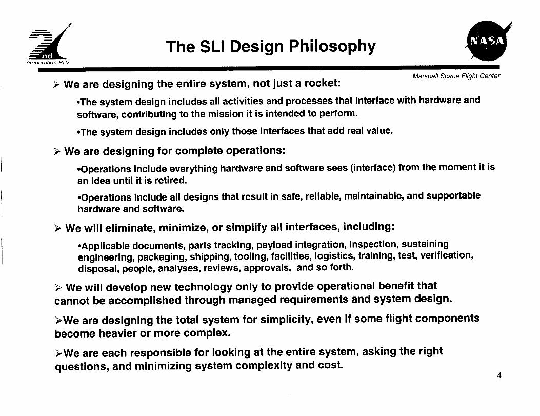
The SLI Design PhilosophyGeneration RLV
Marshall Space Flight Center
We are designing the entire system, not just a rocket:
•The system design includes all activities and processes that interface with hardware and
software, contributing to the mission it is intended to perform.
•The system design includes only those interfaces that add real value.
We are designing for complete operations:
•Operations include everything hardware and software sees (interface) from the moment it isan idea until it is retired.
•Operations include all designs that result in safe, reliable, maintainable, and supportablehardware and software.
We will eliminate, minimize, or simplify all interfaces, including:
•Applicable documents, parts tracking, payload integration, inspection, sustainingengineering, packaging, shipping, tooling, facilities, logistics, training, test, verification,disposal, people, analyses, reviews, approvals, and so forth.
We will develop new technology only to provide operational benefit that
cannot be accomplished through managed requirements and system design.
We are designing the total system for simplicity, even if some flight components
become heavier or more complex.
We are each responsible for looking at the entire system, asking the right
questions, and minimizing system complexity and cost.4
Generation RLV
2 ndGenerations RLV RMS Requirements
Marshall Space Flight Center
..... r .... _ ......................................
Improve RLV safety such that the total flight
profile probability for loss of crew (LOC)
Provide access to space at an operational
cost substantially below the current systems
Improve RLV reliability such that the
probability for loss of mission (LOM)
throughout the 2nd Gen RLV architecture's
design life
Improve RLV robustness such that the
probability for launching a payload within its
scheduled launch opportunity
Must equal a probability of 1/5,000 or less
For Human -- at least two thirds below that
required to operate current systems
For Cargo -- at least two thirds below that
required to operate current systems
Must provide a probability of 1/100 or less
Must exceed 90%
Should equal a probability of 1/10,000 or less
Same as Threshold
Should provide a probability of 1/200 or less
Should exceed 95%
Level I Requirements
5
Generation RLV
The Integrated Reliability, Maintainability,Supportability (RMS) Process
and
Marshall Space Flight Center
NASA is adopting best-in-class integrated RMS
practices from Department of De!ense (DoD)and Commercial Industry to provide systemanalysis capabilities and trade studies.
6

Generation RLV
The Integrated Reliability, Maintainability,Supportability (RMS) Process
and
Marshall
Systems Engineering
Center
Hazard
Analysis andFMEA
Other
SupportingAnalysis/Data
I
I
r I
II
II
Ops/Cost
*Risk is PRA Focused
RMS Analyses
Related Analyses
l Requirements and Factors
RMS Process Flow Chart 7
Generation RLV
How Integrated RMS Process Works
Marshal/Space Flight Center
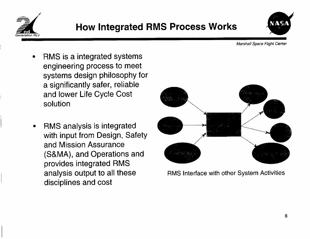
RMS is a integrated systems
engineering process to meetsystems design philosophy fora significantly safer, reliableand lower Life Cycle Costsolution
RMS analysis is integratedwith input from Design, Safetyand Mission Assurance
(S&MA), and Operations andprovides integrated RMSanalysis output to all thesedisciplines and cost
RMS Interface with other System Activities
8
Generation RLV
Reliability Analysis Flow Process Chart
(Input-Output)Marshall Space Flight Center
•Architectural Data
-FMEA
•Hazards Analyses
•Failure Logic Models
•Human Factors
•Reliability Models
•Baseline Comparison
System
....¢
Reliabili_ Analysis
•Root Cause Analysis
•Reliability Predictions
•Reliability Assessment ___
•Reliability Trade Studies
•Probabilistic Risk
Assessment (PRA)
•Sensitivity Analysis
Output
•Estimates of 2GRLV Requirements
•Probability of LOC
•Probability of LOV
• Probability of LOM
•Reliability Comparisons
•Input to Maintainability and
Availability Analysis
9

Generation RLV
Maintainability Analysis Flow Process Chart
Input-OutputMarshall Space Flight Center
.Support/Maintenance
Concept
•Architecture Data
•Reliability AnalysisResults
-Failure rates
Failure modes
Maintenance frequency
Levels of criticality/
hazards
Life limits
•Maintainability Models
•Historical Data
Baseline Comparison
system
-Test Data
Maintainability
Analysis
.Availability/Downtime
Analysis (TAT)
• -Reliability Center_
Maintenance (RCM)
•Maintainability TradeStudies
Output
• Maintenance Actions List
• Maintainability Predictions
(MTTR)
• Scheduled maintenance times
• Corrective maintenance times
•Availability
10

Generation RLV
Supportability Analysis Flow Process Chartinput-output
Marshall Space Flight Center
• Maintenance & Support
Concept
• Operations Concept
• RCM Maintenance
Actions
• Reliability/MaintainabilityPredictions
• Baseline Comparison System
Output
• Facility Requirements
• Manpower, Personnel and Training
Requirements
• Spare/Repair Parts/Consumable
Requirements
• Maintenance Task Analysis Resources
• Test and Ground Support Equipment
Requirements
• Packaging, handling, storage and
transportation requirements
• Technical data, documentation and
database requirements
• Post-production support (e.g., fielding,
performance evaluation, sustaining
engineering) requirements
11

Generation RLV
RMS Analysis and Modeling Environment
Marshall Space Flight Center
RMS Engineering is part of SE&I Organization
RMS Modeling and Analysis part of the 2GRLV Advanced EngineeringEnvironment.
RMS Figures of Merit (FOM) serve as relative evaluator of proposedarchitecture
- Probability of LOC
- Probability of LOV
- Probability of LOM
- Launch/System Availability
RMS work within an Engineering analysis process that addresses 5 criteria:
1. High Reliability, Safety and launch availability
2. Low Cost
3. Accommodation of DRM
4. Technology Risk
5. Technical Viability
12

Generation RLV
Criteria Addressed by thems a is Process
L,OW Cost
System Life Cvcle Cost
• TechnologyDevelopment• Design, Develop, andTest• Production
- Operations
Market Analvsis.includina Launch Price
. Industry InvestmentAnalysis. GovernmentInvestment
- AnalysisSchedule
Level 1Requirements
Technical
Foundation
LowTechno,toqyRisk
TechnoloqvReadinessLevel. Cost. Schedule- Performance- Variability- etc
High Re!i_bilitv. Safety.aunqh availabili.ty
_MS/SafetvCapabilities/Analysis
Crew Escape SystemAdditional Margins forCrewed Mission
Range Safety andAbort CapabilitySafety and ReliabilityAssessment Process
. etc
Accommodation of
DRM_
Primary Mission- International SpaceStation Resupply andCrew Exchange- Payload delivery toLEO
- Delivery Activation,Checkout and Return
of LEO payload
/t
I L°":gnlCost/ ReferenceEconomics Mission
\ /TechnologyI Technical L
Risk _ ViabilityHigh TechnicalVi,_bility
_redible Physics/Processes
- Aerodynamics/Controls/Stability.Avionics/Power- Crew Systems
IVHMOperations(Ground and:light)PropulsionStructures/MaterialsThermal/TPS etc
Marshal/Space Flight Center
13
Generation RLV
Integrated Modeling Environment
Marshall Space Flight Center
Technical Models
System Weights
& SizingINTROS - MSFC
System Weights
& SizingCONSIZ - LaRC
System Weights
& SizingHAVOC - ARC
Trajectory
POST
Trajectory
OPGUID
Cost & Reliabilit_l Economic Model
Safet_ Models
' weightSveh,c,e°evel°pment UnitNAFc°Mc°s vehic'eAcquisiti°nC°stiDescription 1 I $ / lb to Orbit /
li Business Case Closure I
IEM., !
] Facilities & / Flight Rate [
___ Operations Costs ! Facilities & Ops Cost ll
! _ROC i
ill Vehicle Performance
y Reliability/Safety i
1 Risk Model 1 Vehicle Losses
FIRST
14

Generation RLV
CONCLUSION
Marshall Space Flight Center
We have presented an integrated RMS approach that
provides the pathway for a risk based and analysis
based decision process that is necessary to achieve
NASA's goal of significantly improving safety andreliability and reducing the life cycle cost of future LEO
transportation system.
15
Related Documents