1 SLH 1333 Getty 011 Company Attention: «r. Claud* L. Merple Poet Offict Sox Sl 367 Lafay(»tto t Louisiana 70506 Gentle** Reference 1s made to your Initial Plan of Exploration and tnvlronnoital Raport received Septenber 26* 1983, for Leases OCS-S 53Srt, 5870, and 5871, Blocks *«J9, 852, and 853, Mississippi Canyon Araa. This plan Includes tha drilling of 11 wills. In accordance with 30 CFH 250,34, ravlsad ^cennar 13, 1979, and our lattar dated January 39, 1079, this plan has benn determined to he conplete as of September 29, 1981, and Is now heing considered for approval* Tour plan control number 1s H-13«6 and should 6* referenced 1n your communica- tion and correspondence concerning this plan. Sincerelv yours, (Orfg. Sfld.) D.W. Solanas D. w. Solanas Heelonal Supervisor Offshore Operations Support bcc: Lease OCS-G 585*1 (OHS-2-3) Lease OCS-G 5870 (OMS-2-3) Lease GCS-G 5871 (OMS-2-3) OJS-IL-.: '/Public Info. Copy of the plan and ER NHekr*atdoost:gtj:9/27/83 Disk 3b >ort

Welcome message from author
This document is posted to help you gain knowledge. Please leave a comment to let me know what you think about it! Share it to your friends and learn new things together.
Transcript
1 SLH 1333
Getty 011 Company Attention: «r. Claud* L. Merple Poet Offict Sox Sl 367 Lafay(»tto t Louisiana 70506
Gentle**
Reference 1s made to your Initial Plan of Exploration and tnvlronnoital Raport received Septenber 26* 1983, for Leases OCS-S 53Srt, 5870, and 5871, Blocks *«J9, 852, and 853, Mississippi Canyon Araa. This plan Includes tha dril l ing of 11 w i l l s .
In accordance with 30 CFH 250,34, ravlsad ^cennar 13, 1979, and our lattar dated January 39, 1079, this plan has benn determined to he conplete as of September 29, 1981, and Is now heing considered for approval*
Tour plan control number 1s H-13«6 and should 6* referenced 1n your communication and correspondence concerning this plan.
Sincerelv yours,
(Orfg. Sfld.) D.W. Solanas
D. w. Solanas Heelonal Supervisor Offshore Operations Support
bcc: Lease OCS-G 585*1 (OHS-2-3) Lease OCS-G 5870 (OMS-2-3) Lease GCS-G 5871 (OMS-2-3) OJS-IL-.: '/Public Info. Copy of the plan and ER
NHekr*atdoost:gtj:9/27/83 Disk 3b
>ort
SEP::., jog.
cr, r -•.
Getty
Office of ' Management Support
SI * !> WOJ
Records Management omcs of •
M a r » ^ w n f Support
• , 1
A PL N OF EXPLORATION
FOR
HISSISSIPPI CANYON BLOCK 809 MISSISSIPPI CANYON BLOCK 852 MISSISSIPPI CANYON BLOCK 853
OCS-G 5868 (809) OCS-G 5870 (852) OCS-G 5871 (853)
GULF OF MEXICO, CENTRAL
OFFSHORE PLAQUEMINES PARISH
LOUISIANA
SUBMI"TED BY
GETTY OIL COMPANY
LAFAYETTE OFFSHORE AREA OFFICE
LAFAYETTE, LOUISIANA
SEPTEMBER, 1983
Getty Getty Oil Company j Post Office Box 51367. Lafayette, Louisiana 70505 . Telephone (318) 232-5813
Lafayette Area Offshore District Southern Exploretion kndjProduction Division-
- \
September 20, 1983
v..
F i l e : OCS-G 5868 Lease OCS-G 5870 Lease OCS-G 5871 Lease Mississippi Canyon Block 809 Mississippi Canyon Block 852 Mississippi Canyon Block 853 Gulf of Mexico, Central Offshore Plaquemines Parish Louisiana
RE: USDI, Minerals Management Service Plan of Exploration (Proposed) I n i t i a l Plan
United States Department of the Interior Minerals Management Service, OS-2-2 P. 0. Box 7944 Metairie, LA 70010
Attention: Mr. D. W. Solanas
Gentlemen:
Enclosed are nine (9) copies of Getty Oil Company's proposed Plan of Exploration for the captioned leases. Included in the Plan is Getty Oil Company18 Coastal Zone Management Consistency C e r t i f i cation for the State of Louisiana. Additionally, nine (9) copies of the Environmental Report (ER) are enclosed for your distribution as required pursuant to the provisions of Title 30 CFR, Part 250.34 and NTL 80-6 of June 2, 1980. Final well numbers, locations, and depths will be included on the United States Department of tbe Interior, MMS Form 9-331C, Application for Permit to D r i l l , Deepen, or Plugback (APD). Other relevant information to be provided therein shall Include casing, cement, and mud programs, procedures to be followed throughout the drilling of the well, Including testing of cement Jobs, Installation of casing, blowout prevention equipment, lines, and other such data as the District Supervisor may require.
United States Department of the Inter ior Page Two September 20, 1983
• i •
As specified ln the Plan, Getty proposes to use a drilling vessel such as the SEDCO 471 drillship drilling vessel or equivalent. Howeverj, l t should f>e noted that the final decision to use any rig Is contingent 'upon several factors, e.g., rig commitment(s) at the 'time this Plan is approved, and the timely consummation of a contract witb,.a drilling contractor. A complete rig description and inventory will be submitted with the Application for Permit to D r i l l .
Additionally, that information presente 1 herein judged exempt (by Getty) from public disclosure under the Freedom of Information Act (5 U.S.C. 552) and implementing regulations (43 CFR, Part 2) bas been marked "CONFIDENTIAL" or deleted.
This letter i s to be considered part of the Plan.
Getty respectfully solicits your timely approval of this document and appreciates your consideration ln this matter. Should you require additional Information relevant to the Plan, please cor tact Mr. Louis Hoover, I I I of this office.
Tours truly,
GETTY OIL COMPANY
Area Superintendent
LH,III/ddh
Enclosures
cc: MMS FO-5 (w/enclosures) CZM-LA (w/enclosures)
GETTY OIL COMPANY 9-83
EXPLORATORY DRILLING PLAN
MISSISSIPPI CANYON BLOCK 809, OCS-G 5868 MISSISSIPPI CANYON BLOCK 852, OCS G 8570 MISSISSIPPI CANYON BLOCK 853, OCS-G 5871
Exploratory drilling on these blocks will be accomplished
by drilling up to eleven (11) wells with a drillship MODU.
A typical MODU that will be employed for the proposed operations
is the SEDCO 471 Drillship MODU.
After drilling the required number of exploratory wells
to effectively evaluate the lease, and i f the wells are con
sidered to be productive, then a Plan of Development/Production
would be submitted for approval.
Should a well indicate the presence of hydrocarbon bearing
sands in commercially paying quantities, the well may be tempo
rarily abandoned according to the provisions of GOM-OCS Order No.
3 and any other requirements as specified by the District Super
visor. Additionally, approved DOT, United States Coast Guard
Navigational Aids shall be Installed where required following
temporary abandonment.
Upon completion of exploratory drilling, a platform may
be installed over thc location(s) for the development/production
phases. A separate platform installation application with
appropriate documentation would be submitted at that time.
Throughout the l i f e of the proposed project, a l l available
safeguards shall be utilized in an effort to prevent any possible
damage to the ecosystem.
Getty. Oil Company Is an active member of Clean Gulf Associates
(CGA). Should an upset occur at tbr* proposed project site, tbe
nearest $G|I base Is located at Grand Isle , Louisiana. The anti
cipated response time from Grand Isle, Louisiana, including
loadout of equipment, i s approximately twenty-four (24) hours.
Getty will be operating under EPA Gulf of Mexico General Permit
Number TX0085642 (PR 46 No. 64, 20284).
The following exhibits shall constitute the remainder of
this proposed Plan of Exploration:
1. EXHIBIT I — Louisiana CZM Consistency Certification
2. EXHIBIT I I — A table Indicating the proposed well
locations and proposed total depth. Exact locations
will be determined prior to submittal of the MMS APD.
A discussion of the proposed ' stable i s also presented.
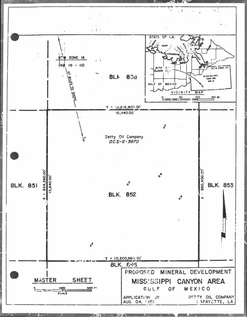
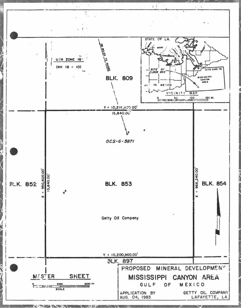
3. EXHIBIT I I I — Site Specific Location Plat (3 leases)
4. EXHIBIT IV — General Well Location Plat (3 leases)
5. EXHIBIT V — Structure Map (3 leases)
6. EXHIBIT VI — Cross Section Map (3 leases)
7. EXHIBIT VII — Geophysical Report (Oceanonics, Inc.) (enclosed as a separate report)
8. EXHIBIT VIII — SEDCO 471 Rig Inventory and Description
9. EXHIBIT IX — Oil Spill Contingency Plan Brief
10. EXHIBIT X — Typical Drilling Mud Components Listing
11. EXHIBIT XI — Onshore Support Base Facilities Description
-3-
1S5* EXHIBIT XII — Listing of typical field equipment that
Note 2: A pollution Contingency Plan has been submitted and
approved by the Hinerals Management Service pursuant to
the provisions of GOM-OCS Order No. 7.
Note 3: The Environmental Report (ER) i s enclosed with this Plan
as a separate document.
Note 4: Getty Oil Company representative:
Mr. Louis Hoover, I I I
(318) 232-5813
vould be used vhen doing seismic surveys on the block
NOTES
Note 1: Getty Oil Company i s a member of Clean Gulf Associates.
COASTAL ZONE MANAGEMENT
CONSISTENCY CERTIFICATION
MISSISSIPPI CANYON BLOCK 809 MISSISSIPPI CANYON BLOCK 852 MISSISSIPPI CANYON BLOCK 853 " AREA AND BLOCK
OCS-G 5868 OCS-G 5870 OCS-G 5871
LEASE NUMBER
- \ EXPLORATION TYPE OF PLAN
v..
THE PROPOSED ACTIVITIES DESCRIBED IN DETAIL IN THIS PLAN COMPLY
WITH LOUISIANA'S APPROVED COASTAL ZONE MANAGEMENT PROGRAM AND
WILL BE COMPLETED IN A MANNER CONSISTENT WITH SUCH PROGRAM.
ARRANGEMENTS HAVE BEEN MADE WITH THE STATE-TIMES IN BATON ROUGE,
LOUISIANA TO PUBLISH A PUBLIC NOTICE OF THE PROPOSED ACTIVITIES NO
LATER THAN SEPTEMBER 29, 1983.
GETTY OIL COMPANY LESSEE OR OPERATOR
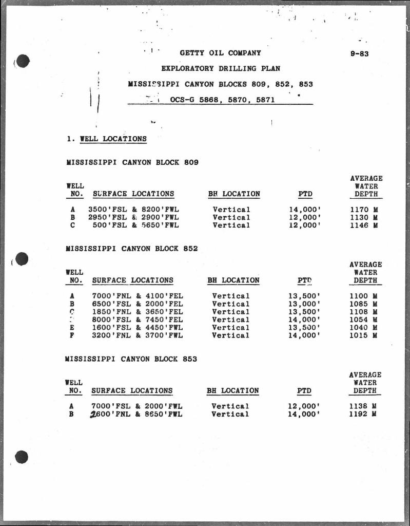
• 1 • GETTY OIL COMPANY
EXPLORATORY DRILLING PLAN
MISSISSIPPI CANYON BLOCKS 809, 852, 853
"V> OCS-G 5868, 5870, 5871
9-83
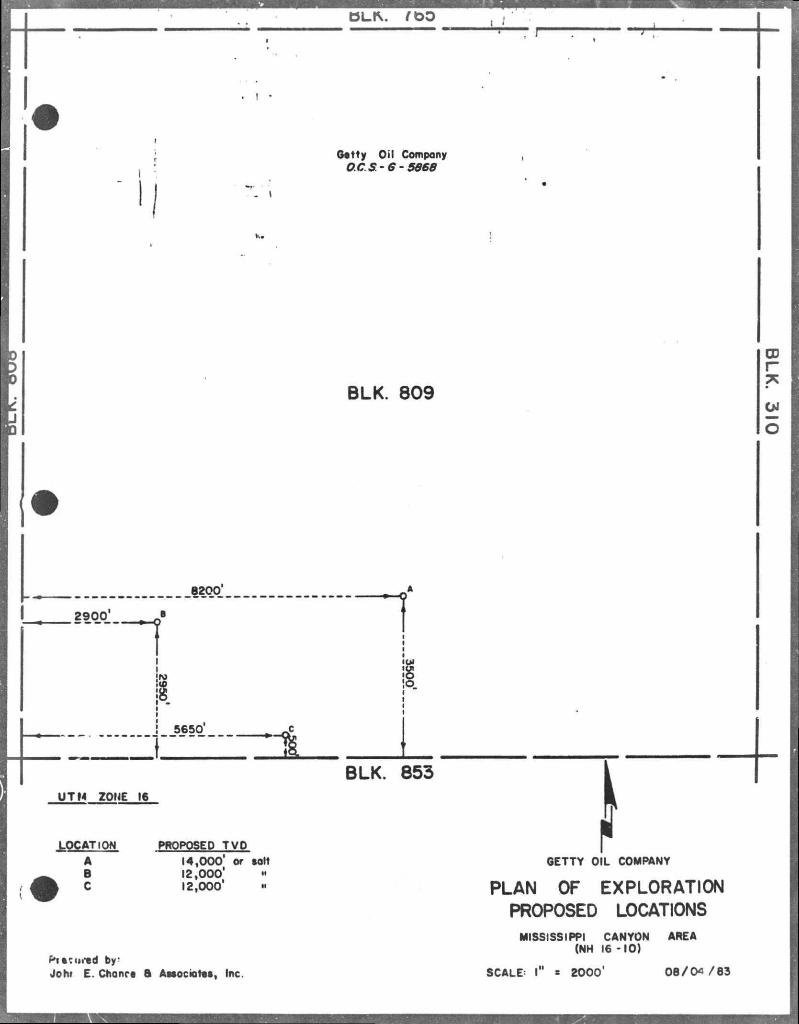
1. WELL LOCATIONS
MISSISSIPPI CANYON BLOCK 809
WELL NO.
A B C
SURFACE LOCATIONS
3500'FSL 2950*FSL 500'FSL
& 8200'FWL fc 2900*FWL fr 56501FWL
BH LOCATION
Vertical Vertical Vertical
PTD
14,000' 12,000* 12,000'
AVERAGE WATER DEPTH
1170 M 1130 M 1146 M
MISSISSIPPI CANYON BLOCK 852
WELL AVERAGE
WATER NO. SURFACE LOCATIONS BH LOCATION PTD DEPTH
A 70001FNL & 4100'FEL Vertical 13,500' 1100 M B 6500 1FSL & 2000'FEL Vertical 13,000' 1085 M c 1850'FNL & 3650'FEL Vertical 13,500' 1108 M
*• 8000'FSL & 7450'FEL Vertical 14,000' 1054 H
E 1600'FSL & 4450'FWL Vertical 13,500' 1040 M F 3200'FNL & 3700'FWL Vertical 14,000' 1015 M
MISSISSIPPI CANYON BLOCK 853
WELL NO. SURFACE LOCATIONS
A 7000'FSL & 2000'FWL B £600 'FNL fr 8650'FWL
BH LOCATION
Vertical Vertical
PTD
12,000' 14,000'
AVERAGE WATER DEPTH
1138 M 1192 M
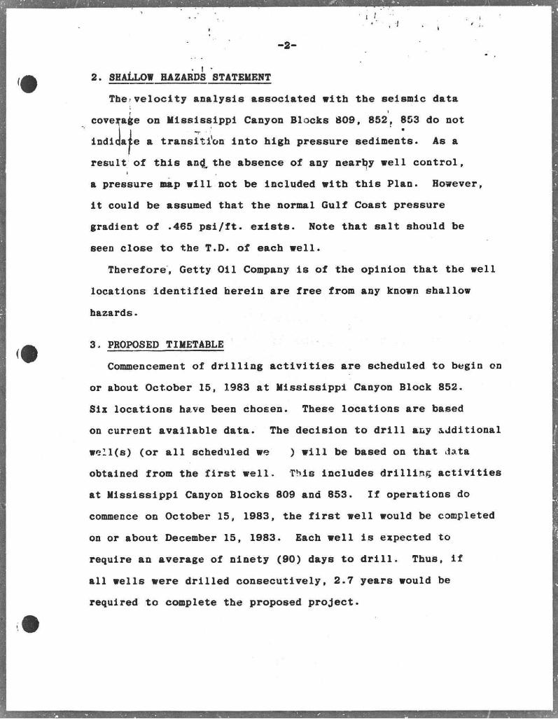
-2-
2. SHALLOW HAZARDS STATEMENT
The velocity analysis associated vith the seismic data
coverage on Mississippi Canyon Blocks 809, 852, 853 do not
indi a transition into high pressure sediments. As a
result of this an^ the absence of any nearby veil control,
a pressure nap v i l l not be included vith this Plan. Hovever,
i t could be assumed that the normal Gulf Coast pressure
gradient of .465 psi/ft. exists. Note that salt should be
seen close to the T.D. of each v e i l .
Therefore, Getty Oil Company i s of the opinion that the veil
locations identified herein are free from any knovn shallov
hazards.
3. PROPOSED TIMETABLE
Commencement of drilling activities are scheduled to begin on
or about October 15, 1983 at Mississippi Canyon Block 852.
Six locations have been chosen. These locations are based
on current available data. The decision to d r i l l any additional
we 11(8) (or a l l scheduled ve ) v i l l be based on that data
obtained from the f i r s t well. This includes drilling activities
at Mississippi Canyon Blocks 809 and 853. If operations do
commence on October 15, 1983, the f i r s t well would be completed
on or about December 15, 1983. Each well i s expected to
require an average of ninety (90) days to d r i l l . Thus, i f
al l wells were drilled consecutively, 2.7 years would be
required to complete the proposed project.
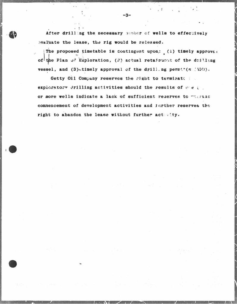
of
After drilling tbe necessary anmber of veils to effectively
evaluate the lease, the rig vould be released.
The proposed timetable le contingent upon.: (1) timely approve x
t|ie Plan %>T Exploration, (;*) actual reta* D-ar-at of tbe drilling
vessel, and (3)v..timely approval of the dril:.ng perir4. + (s '4M>>.
Getty Oil Company reserves the right to terminate :
exploratory drilling activities should the results of i> e ( .
or more veils indicate a lack of sufficient reserves to r&ofc
commencement of development activities and Jtirther reserves tbo
right to abandon the lease vithout further act 'ty.
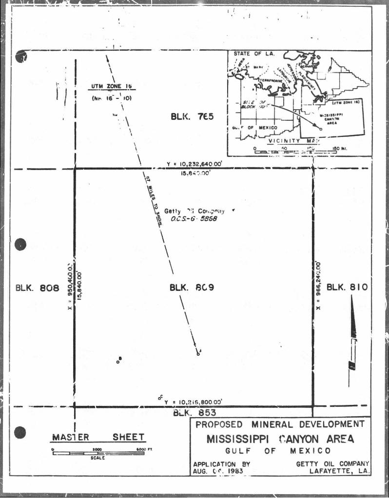
BLK. 8 0 8 8
UTM ZONE lb
• ** 1,1"' *"" (hh 16" - »0)
STATE OF LA
I MAST ER
> \
BLK. 7£5
\
S / ; £ 9 f \0LOCK ..JOM '
uu
1 l i \ ***** Jl MM*
• ' Of MEXICO r * | ^ S J J
V I C I N I T Y B7:"'
AO rir. « 0 * '
Y « 10,232,640 00
V 15,6*0.00 f-
„ Getty "Vi Co»..pni»y * \| OCS-G 5868
\
\
\
BLK. 809
\
\
\
Y * 10,£i 6,600.00
BLK. 853
SHEET
fc: •000 •ooo n
SCALC
8
jg BLK. 810 a*
PROPOSED MINERAL DEVELOPMENT MISSISSIPPI CANYON AREA
GULF OF MEXICO APPLICATION BY AUG. C <\ 1983
GETTY OIL COMPANY LAFAYETTE, LA.
MASTER SHEET >»ooo
PROPOSED MINERAL DEVELOPMENT
MISSISSIPPI CANYON AREA GULF OF MEXICO
APPLICATION 3Y AUG. 04. ».#e»i
flF.T TY OIL COMPANY 5. 1FAYCTTE, LA.
"STATE OF LA.
UTM ZONE 16-
(NH 16 - 10)
'8 6 o
BLK. 852 |
I
rv? BLK. 809
\
\ \ \
Y = IO,2ie,C<00 oo'
sire e»-_ fJXK KS
I 1 MI:.- OF ME'ICO
(UTM I 0 * t I f )
_J .'HJ-_r-J' L— x V I C I N I T V M<
SO 100 160 Ml.
15,840.00'
\
V OCS-G-587/
BLK. 853
Getty Oil Company
Y s 10,200,960.00
BLK. 897
8 o
jg BLK. 854 N
X
SHEET aooo •ooo rr
PROPOSED MINERAL DEVELOPMENT
MISSISSIPPI CANYON AREA GULF OF MEXICO
SCALE APPLICATION BY AUG. 04, 1983
GETTY OIL COMPANY LAFAYETTE, LA.
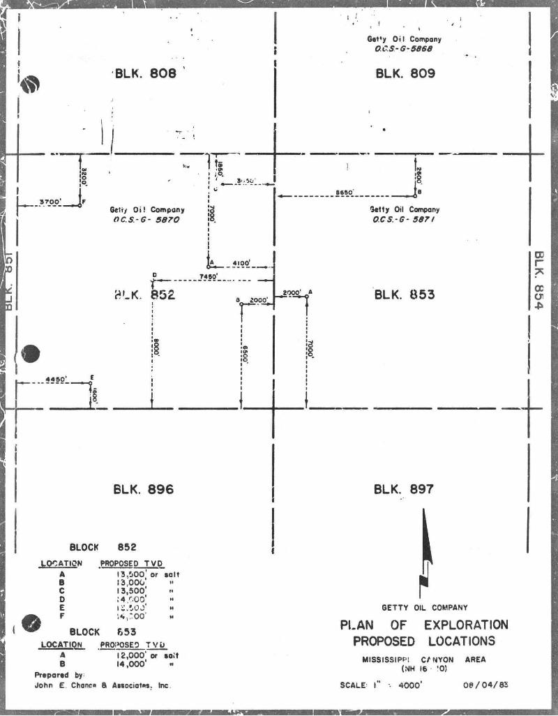
BLK. 808
Get'y Oil Company OC.S-G-5868
BLK. 809
8'* 40'
Qetry Oi! Compony OCS.-G- 5870
I S
sesjy t
Getty Oil Compony O.CS.-G- 5871
0
?LK. 85£
T460'
4«*Q'_ e
9^ ^000^ BLK. 853
r
a cx
BLK. 896 BLK. 897
BLOCK 852
LOCATION
A B C 0 E
PROPOSED T V D
13,500 ' or t a l t 13,000' 13,500* I*.WO'
F j4,:oo
BLOCK 653 LOCATION PROI>OSEO T V D
GETTY OIL COMPANY
PLAN OF EXPLORATION PROPOSED LOCATIONS
12,000' or toit 14,000'
A B
Prepored by John E. Chanco B Awociot**. Inc
MISSISSIPPI C/NYON (NH 16 '0)
SCALE I 4 0 0 0 '
AREA
0 8 / 0 4 / 8 3
Gttty Oil Company OCS' 6 -5666
BLK. 809
6200'
2900 '
"1 ro
5650
UTM ZONE 16 ± BLK. 853
LOCATION A B C
PROPOSED TVO 14,000' or »olt 12,000' 12,000*
Pi •cured by!
Joht E. Chanre 6 Astociotat, Inc.
GETTY OIL COMPANY
PLAN OF EXPLORATION PROPOSED LOCATIONS
MISSISSIPPI CANYON (NH 16-10)
SCALE= I 2000'
AREA
0 8 / 0 « / 8 3
SEDCO 471 DRILLSHIP
CONTRACT EQUIPMENT LIST (Currently under revision)
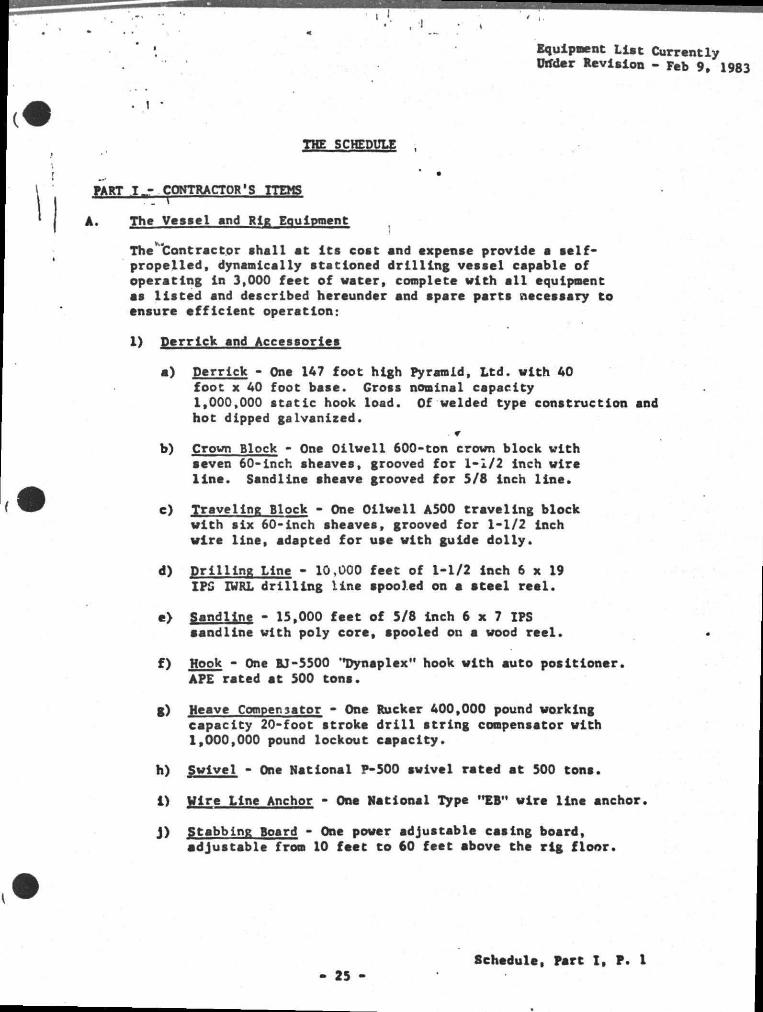
Equipment Li»t Currently (Titter Revision - Feb 9, 1983
THE SCHEDULE
PART I CONTRACTOR'S ITEMS
A. Thc Vesiel end Rig Equipment ^
The "Contractor shall at i t s cost and expense provide a self-propelled, dynamically stationed drilling vessel capable of operating ln 3,000 feet of water, coaplete with a l l equipment as listed and described hereunder and spare parts necessary to ensure efficient operation:
I) Derrick and Accessories
a) Derrick - One 1A7 foot high Pyramid, Ltd. with AO foot x 40 foot base. Gross nominal capacity 1,000,000 static hook load. Of welded type construction and hot dipped galvanized.
b) Crown Block - One Oilwell 600-ton crown block with seven 60-inch sheaves, grooved for 1-1/2 inch wire line. Sandline sheave grooved for S/8 inch line*
c) Traveling Block - One Oilwell A500 traveling block with six 60-inch sheaves, grooved for 1-1/2 inch wire line, adapted for use with guide dolly.
d) Drilling Line - 10,000 feet of 1-1/2 Inch 6 x 19 IPS IWRL drilling line spooled on a steel reel.
e> Sandline - 15,000 feet of 5/8 inch 6 x 7 IPS aandline with poly core, apooled on a wood reel.
f) Hook - One BJ-5500 'Dynaplex" hook with auto positioner. APE rated at 500 tons.
g) Heave Compensator - One Rucker AOO,000 pound working capacity 20-foot stroke d r i l l string compensator with 1,000,000 pound lockout capacity.
h) Swivel - One National P-500 swivel rated at 500 tons.
I) Wire Line Anchor - One National Type "EB" wire line anchor.
J) Stabbing Board - One power adjustable casing board, adjustable from 10 feet to 60 feet above the rig floor.
25 Schedule, Fart I , P. 1
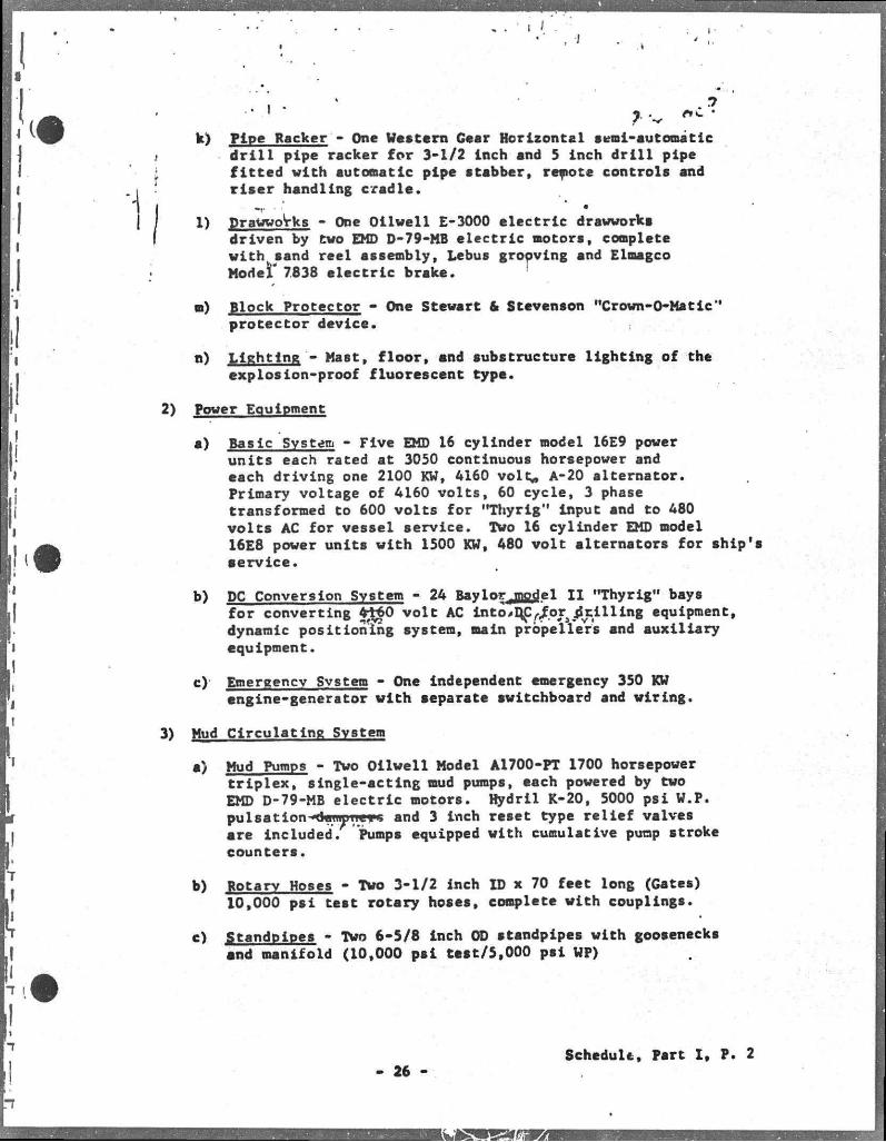
k) Pipe Racker - One Western Gear Horizontal semi-automatic d r i l l pipe racker for 3-1/2 inch and 5 inch d r i l l pipe fitted with automatic pipe stabber, remote controls and ris e r handling cradle. • •' •
1) Drawworks - One Oilwell E-3000 electric drawworks driven by two EMD D-79-MB electric motors, complete with sand reel assembly, Lebus grooving and Elmagco Model' 7838 electric brake.
D) Block Protector - One Stewart & Stevenson "Crown-O-Matic" protector device.
n) Lighting - Mast, floor, and substructure lighting of the explosion-proof fluorescent type.
2) Power Equipment
a) Basic Svstem - Five EMD 16 cylinder model 16E9 power units each rated at 3050 continuous horsepower and each driving one 2100 KW, 4160 volt* A-20 alternator. Primary voltage of 4160 volts, 60 cycle, 3 phase transformed to 600 volts for "Thyrig" input and to 480 volts AC for vessel service. TWo 16 cylinder EMD model 16E8 power units with 1500 KW, 480 volt alternators for ship's aervice.
b) DC Conversion Svstem - 24 BaylorjQCj|el I I "Thyrig" bays for converting 4t60 volt AC int o*D£r/.ors grilling equipment, dynamic positioning system, main propellers and auxiliary equipment.
c) Emergency Svstem - One independent emergency 350 KW engine-generator with separate switchboard and wiring.
3) Mud Circulating Svstem
a) Mud Pumps - Two Oilwell Model A1700-PT 1700 horsepower triplex, single-acting mud pumps, each powered by two EMD D-79-MB electric motors. Hydril K-20, 5000 psi W.P. pu 1 sation • deuiutie• s and 3 inch reset type relief valves are Included. Pumps equipped with cumulative pump stroke counters.
b) Rotary Hoses - Two 3-1/2 inch ID x 70 feet long (Gates) 10,000 psi test rotary hoses, complete with couplings.
«) Standpipes - Two 6-5/8 inch OD standpipes with goosenecks and manifold (10,000 psi test/5,000 psi WP)
Schedule, Part I , P. 2 - 26 -
I
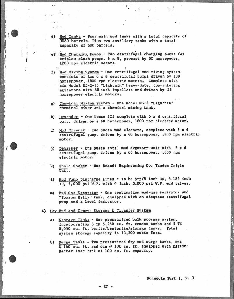
d) Mud Tanks - Four main mud tanks vith a total capacity of 3080 barrels. Plus tvo auxiliary tanks vith a total capacity of 600 barrels.
eT Mud Charging Pumps - Tvo centrifugal charging pumps for triplex slush pumps, 6 x 8 , povered by 50 horsepower, 1200 rpm electric motors.
K. ;
f) Miid Mixing Svstem - One centrifugal mud mixing system, consists of tvo 6 x 8 centrifugal pumps driven by 100 horsepower, 1800 rpm electr ic motors. Complete vith six Model 85-Q-20 *%ightnin" heavy-duty, top-entering agitators vith 48 inch impellers and driven by 25 horsepower electric motors.
g) Chemical Mixing Svstem - One model NS-2 "Lightnin" chemical mixer and a chemical mixing tank.
h) Desander - One Demco 123 complete vith 5 x 6 centrifugal pump, driven by a 60 horsepower, 1800 rpm electric motor.
i) Mud Cleaner - Two Sveco mud cleaners, complete vith 5 x 6 centrifugal pump, driven by a 60 horsepower, 1800 rpm electric motor.
J) Degasser - One Swaco total mud degasser unit with 5 x 6 centrifugal pump, driven by a 60 horsepower, 1800 rpm e lec tr ic motor.
k) Shale Shaker - One Brandt Engineering Co. Tandem Triple Unit.
1). Mud Pump Discharge Lines - to be 6-5/8 inch OD, 5.189 inch ID, 5,000 psi W.P. with 4 inch, 5,000 psi W.P. mud valves.
n) Mud Gas Separator - One combination mud-gas separator and "Possum Belly" tank, equipped with an adequate centrifugal pump and a level indicator.
4) Drv Mud and Cement Storage & Transfer Svstem
a) Storage Tanks - One pressurised bulk storage system, incorporating 3 TK 5,250 cu. f t . cement tanks and 5 TK 8,050 cu. f t . barite/bentonite/storage tanks. Total system storage capacity i s 13,300 cubic feet.
b) Surge Tanks - Two pressurized dry mud surge tanks, one @ 160 cu. f t . and one @ 100 cu. f t . equipped with Martin-Decker load tank of 100 cu. f t . capacity.
Schedule Part I , P. 3
- 27 -
... j . .
• . • f "
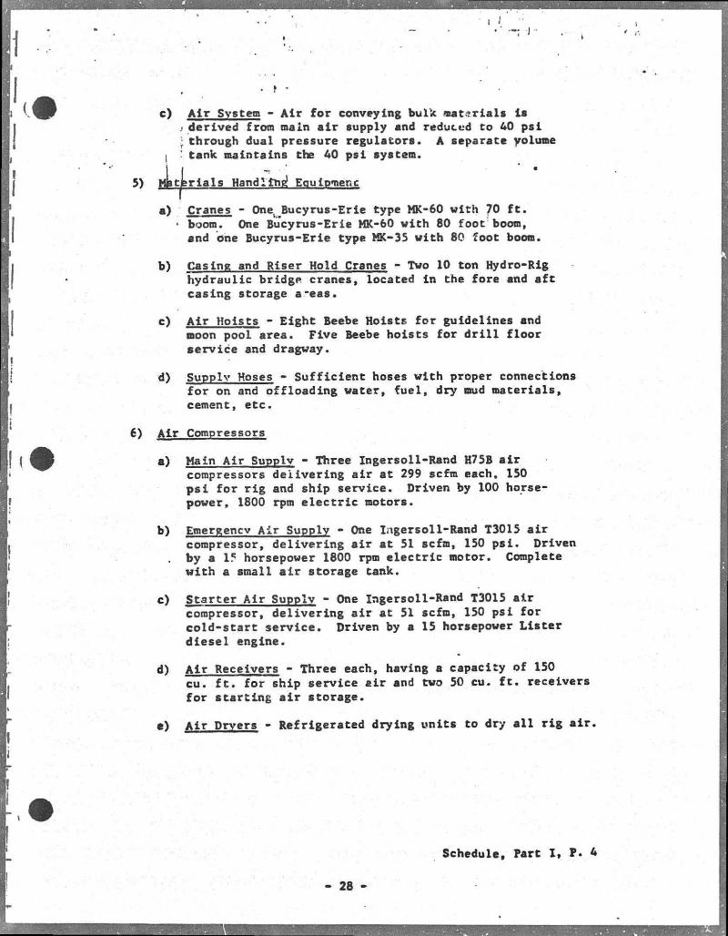
c) Air Svstem - Air for conveying bulk materials Is ) derived from main air supply and reduced to 40 psi J through dual pressure regulators. A separate yolume tank maintains the 40 psi system.
5) Materials Handling* Equipment
Cranes - Onel Bucyrus-Erie type MK-60 with 70 fc»
• boom. One Bucyrus-Erie MK-60 with 80 foot boom, and one Bucyrus-Erie type MK-35 with 80 foot boom.
b) Casing and Riser Hold Cranes - Two 10 ton Hydro-Rig hydraulic bridge cranes, located in the fore and aft casing storage a-eas.
c) Air Hoists - Eight Beebe Hoists for guidelines and moon pool area. Five Beebe hoists for d r i l l floor service and dragway.
d) Supply Hoses - Sufficient hoses with proper connections for on and offloading water, fuel, dry mud materials, cement, etc.
6) Air Compressors
a) Main Air Supplv - Three Ingersoll-Rand H75B air compressors delivering air at 299 scfm each, 150 psi for rig and ship service. Driven by 100 horsepower, 1800 rpm electric motors.
b) Emergency Air Supply - One Ingersol1-Rand T3015 air compressor, delivering air at 51 scfm, 150 psi. Driven by a 15 horsepower 1800 rpm electric motor. Complete with a small air storage tank.
c) Starter Air Supplv - One Ingersoll-Rand T3015 air compressor, delivering air at 51 scfm, 150 psi for cold-start service. Driven by a 15 horsepower Lister diesel engine.
d) Air Receivers - Three each, having a capacity of 150 cu. f t . for ship service air and two 50 cu. f t . receivers for starting air storage.
e) Air Dryers - Refrigerated drying units to dry a l l rig air.
Schedule, Part I , P. 4
- 28
. 1 -
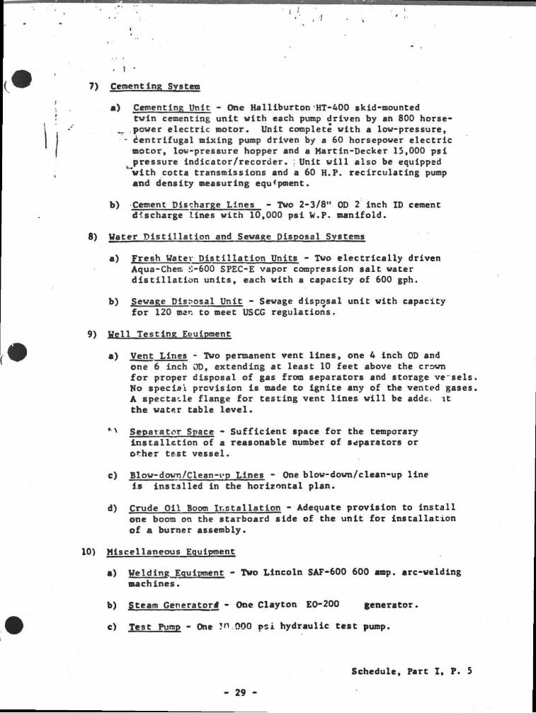
7) Cementing System
e) Cementing Unit - One Halliburton HT-400 skid-mounted twin cementing uni t with each pump driven by an 800 horse-
^ power e l e c t r i c motor. Unit complete with a low-pressure, - centr i fugal mixing pump driven by a 60 horsepower e l e c t r i c
motor, low-pressure hopper and a Martin-Decker 15,000 ps i pressure indicator/recorder . ; Unit w i l l a lso be equipped
"with cotta transmissions and a 60 H.P. rec irculat ing pump and density measuring equipment.
b) Cement Discharge Lines - Two 2-3/8" OD 2 inch ID cement discharge lines with 10,000 ps i W.P. manifold.
8) Water D i s t i l l a t i o n and Sewage Disposal Systems
a) Fresh Water D i s t i l l a t i o n Units - Two e l e c t r i c a l l y driven Aqua-Chem £-600 SPEC-E vapor compression s a l t water d i s t i l l a t i o n un i t s , each with a capacity of 600 gph.
b) Sewage Disposal Unit - Sewage disposal unit with capacity for 120 men to meet USCG regulations.
9) Well Test ing Eoulpment
a) Vent Lines - TWo permanent vent l i n e s , one 4 inch 0D and one 6 inch 0D, extending at least 10 feet above the crown f o r proper disposal of gas from separators and storage ve seis No spec ia l prevision i s made to Ignite any of the vented gases A spectacle flange for testing vent l ines w i l l be adde. i t the water table l e v e l .
Separator Space - S u f f i c i e n t space for the temporary i n s t a l l a t i o n of a reasonable number of separators or other test ves se l .
c) Bl ow-d own/C lean-vp Lines - One blow-down/clean-up l ine i s i n s t a l l e d in the horizontal plan.
d) Crude O i l Boom I n s t a l l a t i o n - Adequate provision to i n s t a l l one boom on the starboard side of the uni t for ins ta l la t ion of a burner assembly.
10) Miscellaneous Equipment
a) Welding Equipment - Two Lincoln SAF-600 600 amp. arc-welding machines.
b) Steam Generators' - One Clayton EO-200 generator.
c) Test Pump - One 3'V,000 p s i hydraulic test pump.
Schedule, Part I , P. 5
29
I
. I •
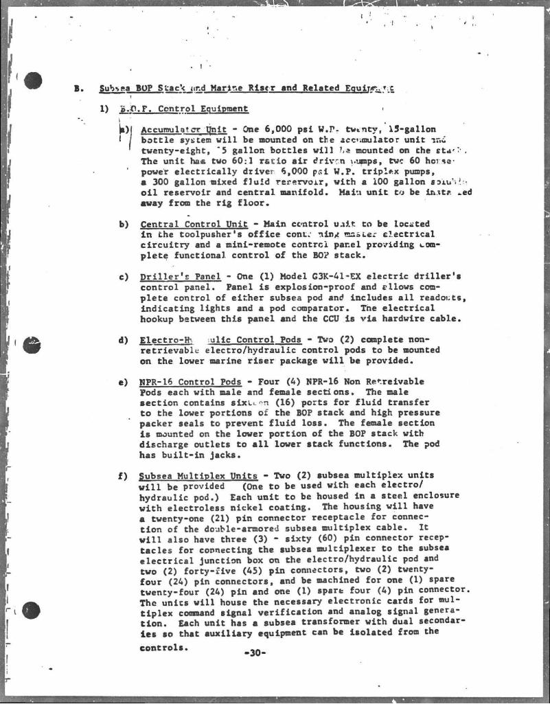
B • Subsea BOP S tack i ir.d Marine Riser and Related Equ ipe*.. T X I
1) B.O.P. Control Equipment i
U)l Accumulator qnlt - One 6,000 psi W.P- twenty, 15-gallon I / bottle system v i l l be mounted on the accvmulator unit i a i ' twenty-eight, '5 gallon bottles v i l l f*a mounted on the ft*'?'.
The unit has tvo 60:1 ratio air driven \.umps, tve 60 horsepower electrically driver 6,000 psl W.P. triplex pumps, a 300 gallon mixed fluid rerervoir, vith a 100 gallon aoi.u'>'. -o i l reservoir and central manifold. Main unit to be In.tt* -ed away from the rig floor.
b) Central Control Unit - Main ccntroi uait to be located in the toolpusher's office cont.- nin^ master electrical circuitry and a mini-remote control panel providing complete functional control of the BO? stack.
c) Driller's Panel - One (1) Model G3K-41-EX electric driller's control panel. Panel is explosion-proof and cllows complete control of either subsea pod and includes a l l readouts, indicating lights and a pod comparator. Tne electrical hookup between this panel and the CCU is via hardwire cable.
d) Electro-fo iulic Control Pods - Two (2) complete non-retrievable electro/hydraulic control pods to be mounted on the lower marine riser package wi l l be provided.
e) WPR-16 Control Pods - Four (4) NPR-16 Non Receivable Pods each with male and female sections. The male section contains s i x i n (16) ports for fluid transfer to the lower portions of the BOP stack and high pressure packer seals to prevent fluid loss. The female section i s mounted on the lover portion of the BOP stack vith discharge outlets to a l l lover stack functions. The pod has built-in jacks.
f) Subsea Multiplex Units - Tvo (2) subsea multiplex units w i l l be provided (One to be used vith each electro/ hydraulic pod.) Each unit to be housed in a steel enclosure vith electroless nickel coating. The housing v i l l have a tventy-one (21) pin connector receptacle for connection of the doable-armored subsea multiplex cable. It w i l l also have three (3) - sixty (60) pin connector receptacles for connecting the subsea multiplexer to the subsea electrical junction box on the electro/hydraulic pod and two (2) forty-five (45) pin connectors, two (2) twenty-four (24) pin connectors, and be machined for one (1) spare twenty-four (24) pin and one (1) spare four (4) pin connector. Thc units will house the necessary electronic cards for multiplex command signal verification and analog signal generation. Each unit has a subsea transformer with dual secondaries so that auxiliary equipment can be isolated from the
controls. , A
, J
, • I * Multiplex Control Cable/Reels - Two 7500 foot £apaci7v hydraulic powered multiplex cable reels having^wer.ry-c '-Kp-ring assembly. These sl ip ring? are nitrogen pur 4' J and rated explosion proof. .
|Two 7000' lengths Vector armored multiplex cabl* conplete with 21 pin CCP/FCR terminations. The Vector armored cable
.consists of 2-No. 10 AWG, 2 RG.59 coaxial snd 3 No. 20 AWG shielded jacketed quads. The cable ia shielded with polyurethane and double armor. The armor has a breaking strength of 39,800 pounds and l s 1.37 inches in diameter.
h) Emergency Power Supply - The emergency power supply equipment consists of a battery pack, battery charger and a 7.0KVA inverter per pod. The Lfch-gear is rated to handle 7.0KVA to allow ship power f - used to tbat rating.
i ) Diverter Control - One (1) hydraulic diverter controi system including a combination diverter/30" latch/power flow line connector Dri l ler 's control panel.
J) Nitrogen Intensif ier - One (1) Haskell nitrogen booster pump (dual pumps and associated manifolding and valves .)
k) Acoustic Backup - One (1) acoustic backup system for actuating four command functions composed of a surface control unit with one f i x mounted transducer and oue portable -t ws.-iucer and a battery operated, dual transducer-receiver sv^sea unit. A self-containec' UJP stack mounted electvehye' raulic accumulator package ?; Lu ing three ,.3) 15 gallon ac .um-ulators i s provide*? w(.uh the acoustic system.
2) BOP and Riser Equipment
a) Blowout Preventer Stacks - Two (2) 16-3/4", 10,000 psi WP blowout preventer stacks (BOP). A l l components ol the BOP stack w i l l be rated for 10,000 psi WP unless otherwise stated. A l l components of tbe HOP stack subject to exposure to wellbore fluids are to '•>* suitable for H2S service, I . e . , a l l s teel components are to hsve a maximum hardness of P„22. Contractor wi l l provide appropriate API test documents on thc ram-type blowout preventers and, where possible, on other components. Each BOP stack w i l l consist of the following components:
(1) One (1) VKTC0 16-3/4" H-4 wellhead connector with Integral extension.
(2) Two (2) Cameron 16-3/4" "Type U" double ram blowout preventer units each complete with wed^elock, pressure balance chambers and rams. Blowout preventer bodies to be configured with 30" spacing between the top
31
of the lower raa and the bottom of the upper ram to fac i l i tate hanging off and shearing dril l -pipe. One Unit to •»< equipoed with blind/shear rams in the lower rarr cavity and ~" drillpipe rims in the upper
- ••' cau'icy. Second unit tr be equipped with 5" drillpipe ' raw* in both cavities.
(3), Nine McEvoy 3" nominal type, EDU fai lsafe valves (9 straight valves). A l l stack mounted valves to be equipped for /Jail safe close operation and k i l l and choke line test valves for f a i l safe open operation.
(4) One.(l) VETCO 16-3/4" H-4 mandrel with internal preparations for latch bumper head. . .
(5) One (1) VETCO lower BOP guide frame and re-entry cone assembly.
(6) One (1) VETCO 16-3/4" h-4 high angle release connector with external orientation preparation.
(7) One (1) wangle Shaffer 16-3/4", 5000 psi WP annular blowout prevents equipped with surge dampeners.
(8) One (1) BOP upper guide frame assembly.
(9) Two (2) VETCO nominal 3" C/K retractable connectors.
(10) Two (2) VETCO nominal 3" C/K loops.
(11) One (1) VETCO 16-3/4", 10-degree single unit flex joint with internal orientation preparation.
(12) One (1) VETCO emergency BOP recovery system.
(13) One (1) VETCO 16-3/4" test stump.
(14) Twenty-eight (28) Koomey nominal 15 gallon, 6000 psi WP, USCG approved, bladder-type separator accumulators complete with necessary support racks and isolation valving for installation on the BOP stack.
(15) A l l clamps, connectors, ring gaskets, piping, hoses and other equipment required to assemble the BOP stack.
b) Marine Riser and Associated Equipment
(1) Marine Riser - 4350 f t . VETCO integral marine riser in 50 foot lengths plus various pup Joints. The riser is fsbricsted from 18 5/8" OD, 0.438" wall. FG-47T, 65,000 psi minimum yield seamless pipe with VETCO MRJLTC heavy duty couplings. The riser joints are complete with two (2) 4" OD, 0.5" wall, X.65
32
*
C/K lines, two (2) 1.660" OD, 0.146" wel 70/30 Cupro ni.vkel hydraulic supply lines snd preparations for securing buoyancy modules and two (2) multiplex control rabies.
The >engthi> of the riser joints are as follows
Eighty-seven (87) - 50 f t . KTwu (2) - 40 f t . Two (2) - 25 f t . Two (2) - 10 f t . Two (2) - 5 f t .
One (1) 10 f t . joint with riser fill-up valve.
(2) Two (2) TETCO 18-5/8", 55* stroke telescopic joints, complete with dual packing, C/K lines, C/K terminations, hydraulic supply lines and tensioning ring preparation.
(3) two (2) Cofiexip, 65' length, 3" ID, 10,000 psi WP C/K hoses complete with end connections.
(4) Two (2) 6000 psi WP, 55' length, 1-1/4" ID flexible hoses complete with end connections for riser hydraulic supply lines.
(5) One (1) VETCO fluid bearing, rotatable riser tensioning ring.
(6) One (1) Regan type KFDS diverter, diverter housing, power actuated flowling coupling, diverter support housing and ball joint.
(7) One (1) VETCO marine rirer spider Model E46014, shock and gimbal type.
(8) Three (3) VETCO riser l i f t subs.
(9) One (1) set C/K test plugs, hydrauHc line test plugs and portable 10,000 psi WP hydraulic test unit.
(10) Ont (1) Hydril instrumented riser joint to monitor axial tension and compression in four quadrants (1,000,000// ax i a l ) , mud temperature and mud pressure along with a l l required electronics and connectors to interface with Koomey multiplex BOP control system. Readout to be provided ln Central Control Unit.
(11) One (1) VETCO 30" latch assembly complete with necessary connectors and wiring, etc., to transmit instrumented riser Joint and riser angle indicator signals to the surfsce when utilizing the 30" latch. 3500 f t . of 16 conductor cable to be provided.
33
' (13) One (1) VETCO 10-degree single unit flex joint prepared to run in conjuctlon with 30" latch.
< (14) Emerson & Cuming r iser buoyancy modules suitable ? for service in 3000 ft water depth wi l l be provided
sufficient for 3000 f t . of r i ser . The .buoyancy modules\will be designed snd installed on each riser
f joint so as to provide a net buoyancy equal 98% of the inseawater-weight of the riser joint .
K.
(15) One (1) VETCO Model D-46039 or equivalent riser f i l lup sub with necessary hose, surfsee snd subsurface controls.
Auxiliary Subsea/Well Control Equipment
a) Riser Tensioning Svstem - One (1) Rucker Marine Riser Tensioning System, complete with control panel, a ir receivers, 60-inch diameter sheaves for 1-3/4" wireline, and twelve 60,000 pound extended l i f e tenslone s, each providing for 50 f t wire line travel. Total system capacity is 960,000 pounds nominally.
b) Guideline Tensioning Svstem for TV Svstem - One (1) Rucker guideline tensioning system, complete with control panel, a i r receivers, 28-inch diameter sheaves for 3/4-inch wireline and four 40-foot stroke extended l i f e units each with a capacity of 16,000 pounds. 2200 f t . of 3/4-inch wireline and sufficient storage reel capacity w i l l also be provided to fac i l i ta te the use of guidelines to a water depth of 5000 f t . One stbd taut wire with Rucker 20' stroke tensioner with 4,000', 3/8" wire l ine .
c) BOP Handling Svstem - Two (2) complete handling systems Including slings, shackles, etc. for handling and transfer of BOP's. Powered dollies to move BOP's from storage to center cf d r i l l l loor. Dollies equipped with 25 hp rack and pinion drives.
d) Miscellaneous Handling Tools - Spiders, running and retrieving tools and handling tools for Contractor-furnished equipment.
e) Underwater TV System - EDO Western underwater TV system suitable for operation at 3000 f t . water depth including the following:
(1) Four (4) TV cameras per stack for mounting on the BOP stack complete with lights and required wiring and connectors, etc. , for operation via the multiplex BOP control cable.
(2) Two (2) TV monitors and required cables, connectors, e t c . , for operation with BOP stsck mounted TV cameras and slimhole TV earners.
« J i ' I.
• I *
f ) Sonar/TV Re-Entry Tool - (tae (1) EDO Model 627 HRR comb ina t ion slimhole TV/Sonar u n i t complete wi th l i g h t s , d i sp lay , control panel, and winch.
g) Latch -Bumper Head - One (1) VETCO la tch bumper head wi th o r i en t a t ing sleeve assembly D-120533H in te rna l ly prepared to accept Sonar/TV re-entry t o o l .
h) Choke and K i l l Manifo?d - One (1) 10,000 psi WP H2S service McEvoy 3" nominal C/K manifold complete wi th one pos i t ive , one manual adjustable, and two remote adjustable Cameron chokes.
Casing and Wellhead Running and Testing Tools - A l l necessary running, tes t ing tools and wear bushings fo r VETCO SG.S w e l l head syscem.
35
C. Drilling Equipment and D r i l l String
1) Rotarv Equipment
a) Rotary Table - One Oilwell Type A 49-1/2 Inch rotary table driven by-a»D-79MB electric motor through a two-«peed gear
( box, complete with adapter ring to allow use of 37-1/2 inch standard components.
v" ! b) Master Bushing - One Varco hinged type MPCH master bushing.
c) Kellv Bushing - One Varco pin type HDP, Roller Kelly Drive Bushing.
d) Kelly - Two Kellys, 5-1/4 inch hexagon, 46 f t . long with 43 f t . working length, 5,000 psl W.P. with wiper assembly.
e) Kellv Saver Subs - Two saver subs with casing protectors for 5-1/4 inch Kelly. Four throw away subs.
O Kellv Spinner - One Varco Kelly Spinner or power sub for Kelly connections.
g) Two Hydril Kelly cock assemblies 10,000 psi maximum service pressure.
One Hydril concentric plain flapper type back pressure valve assembly.
Two Hydril drop-in type back pressure valve assemblies.
h) One Spinnerhawk d r i l l pipe spinner to handle d r i l l pipe, kellys and collars from 2 7/8" through 7".
2) D r i l l String
s) D r i l l Pipe - 15,000 f t . of 5 inch x-hole d r i l l pipe. Made up of 5 inch O.D. IEU, 19.5 lbs/ft. Grade 1" Range 2 pipe. Internally plastic-coated and with 18 degree taper box and velded-on tool joints vith smooth inbedded hard facing. Standard API 4-1/2 Inch IF connections, 6-3/8 inch 0Dx3-1/2 inch ID, a l l equipped with casing protectors. 6,000 f t . of 5 inch 19.5 ibs./ft. Grade S-135 Range 2 Pipe.
10,000 f t . of 3V l 5 « 5 lbs/ft. Grade "E" Range 2 pipe. Internally plastic-coated and with IB degree taper box and weld-on tool joints. Reed 3fc" IF connections, 4-3/4"0Dx2 11/16"' ID with box connection 2" longer than standard length, pin standard length, a l l equipped with thread protectors.
b) Heviwate Drill Pipe - 30 joints of 5 inch OD, 50.0 lbs/ft., Range 2 Drilco "Heviwate" d r i l l pipe with 4-1/2" IF tool joints, 6-3/8 inch OD x 3-1/8" inch ID.
- 36 -
. I •
c) PUP Joints - Tvo each 10 f t . and 15 f t . d r i l l pipe joints, 5 i!.ch OD, 19.5 lbs/ft. Grade 'S-135M plastic lined with API A' 1/3 inch IF tool joints.
d) Dr-i 11 Collars - Six (6) 9-1/2 inch OD x 32 f t . long d r i l l collars with 7-5/8 inch API Reg. connections. Twenty-eight (28) 6 inch OD x 32*long d r i l l collars with 6-5/8 inch APE Reg*, connections. Forty-eight (48) 6-1/2 Inch OD x 32 ft long spiral d r i l l collars with 4 Inch IF connections (All d r i l l collars are "xip : l grooved, recessed for elevator and slip handling with API stress relief grooves on pins snd Drilco "Boreback" boxes. Threads and stress-relief grooves to be cold-worked and to receive an anti-galling treatment). Twenty-four (24) 4-3/4" OD x 32 f t . long d r i l l collars with 3V I F connections. Six (6) special re-entry d r i l l collars, 8" x 3V ID x 6 5/8 Reg.
e) Bit Subs 6t Subs - Two (2) aach bit subs, crossover subs and kelly subs for a l l contractor supplied d r i l l pipe, d r i l l collars, and fishing tools.
f) Bumper Subs - Two (2) 8" OD x 3" © 60" stroke Baash Ross bumper subs. Two (2) 6 OD x 2\TD 60" stroke Baash Ross bumper subs. Two (2) 4-3/4 OD x 2" ID 60 stroke Baash Ross bumper subs. Two (2) 8" OD x 3\"n> Special re-entry bumper subs. Shaeffer
Type "E" g) Fishing Tools - Bowen 11 fc, 9 5/8, and 8 1/8 ful l strength
series 150 releasing and circulating overshots and parts to engage and packoff 9fc"0D, 8*0D, 6feOD d r i l l collars, 6 3/8 tool joints and 5" pp d r i l l pipe inside 2G" hole, 20 ' casing 171 hole 13 3/8' casing and 12- hole. Also parts to engage and packoff 6fc" OD DC, 6,3/8"tool joint and 5" OD
• d r i l l pipe In 17V'hole, 13 3/8'casing, 12%; hole, 9 5/8* casing and 8^hole.
h) Jars - One 8" and one 6V* type ,2* Bowen oil jars.
i) Safetv Joints - One 8" and one 6V Bowen safety joint.
J) Ju^k Baskets - One each 15 ' 0D, 11" OD, and 7 7/8 0D standard reverse ci r c u l a t e * Bowen junk baskets.
k) Junk Subs - Oae each 9 5/8 and 6 5/8 OD Bowen jun.. subs.
3) Dri l l String Accessories
a) Circulating Head - One Howco "Unltree" cirulating head with 5 iae!* X-hole d r i l l pipe connections, 10,000 psl V.P. complete with swivel.
4) Dri l l String Handling Equipment
a) Sli-ps - Two (2) sets slips for 5" OD drillpipe; two (2) sets slips for 3V OD drillpipe; two (2) sets nonnal slips for each d r i l l collar else (9fc", 8", 6-1/2", and A 3/4" OD).
b) Elevators - Two (2) sets elevators for 5-inch OD d r i l l pipe with 18 degree tapered tool joints; two (2) sets of elevators for 3V OD drillpipe with 18 degree tapered tool
r jo ints; two (2) sets s i p - l i f t elevators for each dril). ' col lar size (9V\ 8", 6-1/2", and 4 3/4" OD).
I c ) Links " One set 2-3/4 inch x 132 Inch elevator links.
d) Breaker Plates - One each for 17Vs, il2fc" and 8 V bits .
e) Miscellaneous - Safety Clamps for d r i l l collars a l l subs V x Contractor's dri l l ing string.
5) Casing Handling Equipment
a) Tongs - One set tongs with jaws to f i t 3fc" and 5" OD d r i l l pipe and 5-inch, 7-inch, 9-5/8 inch, and 13-3/8 inch casing. One (1) set tongs with jaws to f i t 20-inch cas ing.
b) Power tongs - One (1) set Lamb Power Casing Tongs, Model 16000 for 7 inch, 9 5/8 inch, 13-3/8 Inch casing.
c ) Elevators - Two (2) side door elevators for 20" casing 1
two (2) side door elevators for 30" conductor; two (1) each single joint auxiliary elevators, complete with swivel assembly, for 13-3/8 inch, 9-5/8 inch and 7 inch X-line casing; one (1) each side door casing elevators for 13-3/8 inch, 9-5/8 inch and 7 inch casing.
d) Elevator/Spiders - Two (2) Varco 500 ton casing elevator/ spiders, to handle 7 Inch*9 5/8 inch and 13-3/8 inch casing.
e) Slips and Bushings - One set Varco slips for30 Inch casing. One set Varco CMS-XL slips for 20 inch casing. One Varco CB split casing bushing for 20 inch casing with inserts for 13-3/8", 9-5/8" and 7" casing.
f) Links - One set 3-1/2" x 144" elevator links.
g) Link Adapters -One (1) set Varco link adapters to f i t 144" links to Varco 500 ton casing equipment.
h) Klampon Protectors - 6 each for 13 3/8", 9 5/8", and 7" casing
Instrumentation
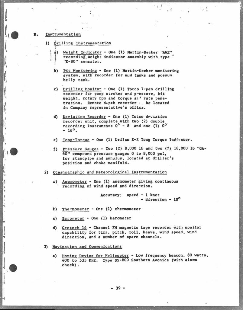
1) D r i l l i n g Instrumentation f i
j a) Weight Indicator - One (1) Martin-Decker ,'AWEH
-
recording.weight indicator assembly with type / *E-80" sensator.
b) Pit Monitoring - One (1) Martin-Decker monitoring system, with recorder for mud tanks and possum belly tank.
c) Drilling Monitor - One (1) Totco 7-pen drilling recorder for pump strokes and p-essure, bit weight, rotary rpm and torque ar* rate penetration. Remote depth recorder . , be located in Company representative'a offica.
d) Deviation Recorder - One (1) Totco deviation recorder unic, complete with two (2) double recording instruments 0 C - 8 and one (1) 0° - 16°.
e) Tong-Torque - One (1) Drilco E-Z Tong Torque Indicator.
f) Pressure Gauges - Two (2) 8,000 lb and two (?) 16,000 lb "GA-60" compound pressure gauges 0 to 8,000 psl, for standpipe and annulus, located at driller's position and choke manifold.
2) Oceanographic and Meteorological Instrumentation
a) Anemometer - One (1) anemometer giving continuous recording of wind speed and direction.
Accuracy: speed - 1 knot
- direction - 10°
b) The -mometer - One (1) thermometer
c) Barometer - One (1) barometer d) Geotech 16 - Channel FM magnetic tape recorder with monitor
capability for time, pitch, r o l l , heave, wind speed, wind direction, snd s number of spare channels.
3) Navigation and Communications
a) Homing Device for Helicopter - Low frequency beacon, 80 watts, AOO to 535 KHZ. Type SS-800 Southern Avonies (with alarm check).
39 -
• I / ••
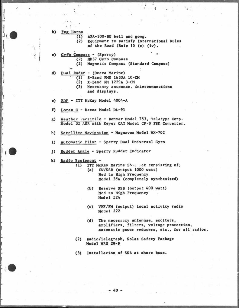
b) Fog Horns (1) APA-100-BC bell and gong. (2) Equipnent to satisfy International Rules
of the Road (Rule 15 (c) ( i v ) .
c) Gyro Compass - (Sperry) • (2) MK37 Gyro Compass (2) Magnetic Compass (Standard Compass)
K. j
d) Dual Radar - (Decca Marine) (1) S-Band RMS 1630A 10-CM (2) X-Band RM 1229A 3-CM (3) Necessary antennae. Interconnections
and displays.
e) £DF - ITT McKay Model 4004-A
f) Loran C - Decca Model DL-91
g) Weather Facsimile - Benmar Model 753, Teletype Corp. Model 32 ASR with Keyer CAI Model CF-8 FSK Converter.
h) Satellite Navigation - Magnavox Model MX-702
1) Automatic Pilot - Sperry Dual Universal Gyro
j ) Rudder Angle - Sperry Rudder Indicator
k) Radio Equipment -(1) ITT McKay Marine Shit ,et consisting of:
(a) CW/SSB (output 1000 watt) Med to High Frequency Model 35A (completely synthesized)
(b) Reserve SSB (output 400 watt) Med to High Frequency Model 224
(c) VHF/FM (output) local activity radio Model 222
(d) The necessary antennae, exciters, amplifiers, f i l t e r s , voltage protection, automatic power reducers, etc. , for a l l radios
(2) Radio/Telegraph, Solas Safety Package Model MRU 29-B
(3) Installation of SSB at shore base.
40
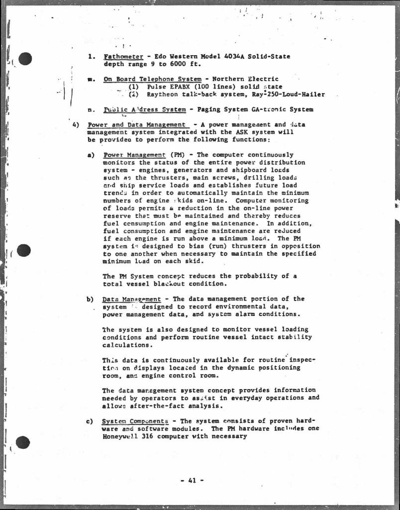
. I -1. Fathometer - Edo Western Nodel 4034A Solid-State
depth rsnge 9 to 6000 f t .
•. On Board Telephone Svstem - Northern Electric ( I ) Pulse EPABX (100 lines) solid state
~ (2) Raytheon talk-back system, Ray-250-Loud-Hailer
n. Puolic A'dress Svstem - Paging System GA-tronic System
Power and Data Management - A power manage,nent and -J«ta management system integrated with the ASK system w i l l be provideo to perform the following functions:
a) Power Management (PM) - The computer continuously monitors the status of the entire power di s t r i b u t i o n system - engines, generators snd shipboard locds such ao the thrusters, main screws, d r i l l i n g loads Qj>d ship service loads and establishes future load trends in order to automatically maintain the minimum numbers of engine -kids on-line. Computer monitoring of loads permits a reduction in the on-line power reserve thst must b» maintained and thereby reduces f u e l consumption and engine maintenance. In addition, f u e l consumption and engine maintenance are reduced i f each engine is run above a minimum load. The PM system i - designed to bias (run) thrusters in opposition to one another when necessary to maintain the specified minimum load on each skid.
The PM System concept reduces the probability of a t o t a l vessel blackout condition.
b) Data Management - The data management portion of the system '-• designed to record environmental data, power management data, and system alarm conditions.
The system is also designed to monitor vessel loading conditions and perform routine vessel intact s t a b i l i t y calculations.
This data Is continuously available for routine inspect i o n on displays locaced i n the dynamic positioning room, anc engine control room.
The data management system concept provides Information needed by operators to assist i n everyday operations and allows after-the-fact analysis.
c) System Components - The system consists of proven hardware and software modules. The PM hardware ind"des one Honeywell 316 computer v i t h necessary
41
core memory end peripheral equipnent Including a one nil l i o n word drun memory which has one head per track, magnetic tape recorders, and sensor interface. The system Includes CRT display consoles * t Che engineers' control room and dynamic positioning room. Hard copy printer tlogs are provided in the engineers* control room. Sensor data and display output will be transferred between the dynamic positioning room and the engineers' control room via a multiplexing system.
The power management system will be Integrated with the ASK system in the dynamic positioning room.
The system Includes software for the following functions:
(1) Power Management (2) Data Management (3) Vessel Intact Stability Calculations (4) 12-Channel Strip Chart Plotting
The system will also allow ship's personnel to create their own program ln the BASIC computer language. Additional software functions (canned programs) can be added to the system.
42 -
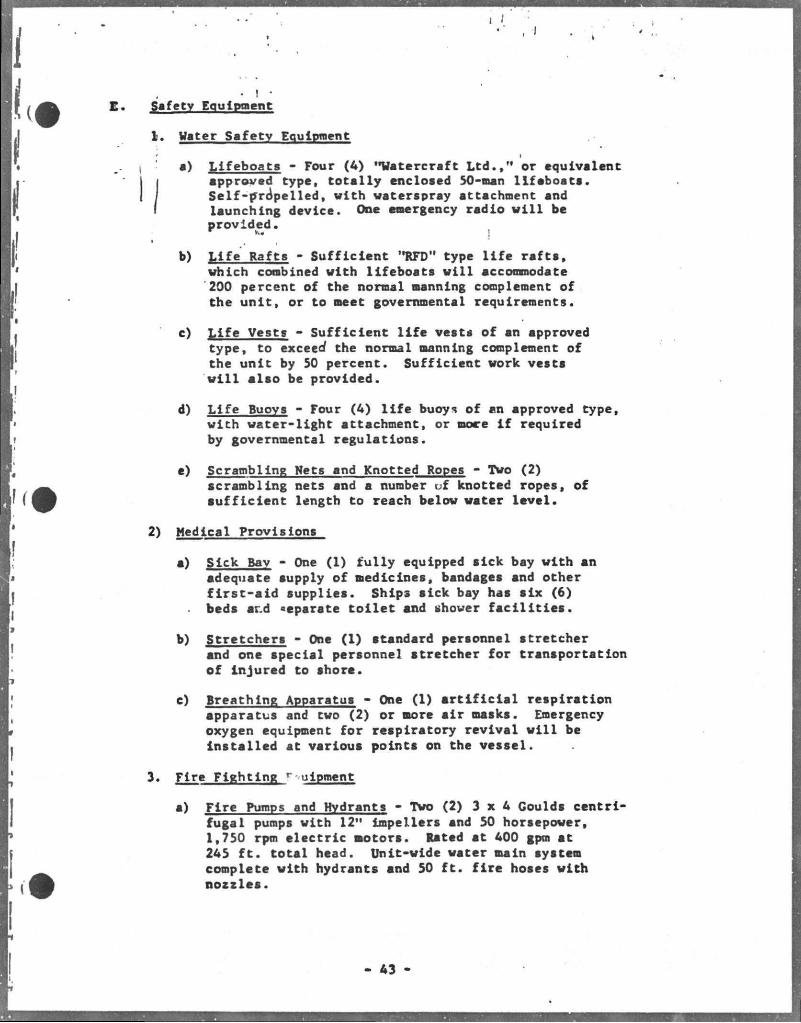
• I • Safety Equipment
1. Water Safetv Equipment
a) Lifeboats - Four (4) "Watercraft L t d . , " or equivalent | approved type, totally enclosed 50-man lifeboats. I Self-propelled, with waterspray attachment and I launching device. One emergency radio w i l l be
provided. ]
b) Life Rafts - Sufficient "RFD" type l i f e rafts, which combined with lifeboats wiil accommodate 200 percent of the normal manning complement of the unit, or to meet governmental requirements.
c) Life Vests - Sufficient l i f e vests of an approved type, to exceed the normal manning complement of the unit by 50 percent. Sufficient work vests w i l l also be provided.
d) Life Buoys - Four (4) l i f e buoys of an approved type, with water-light attachment, or more i f required by governmental regulations.
a) Scrambling Wets and Knotted Ropes - Two (2) scrambling nets and a number uf knotted ropes, of sufficient length to reach below water level.
2) Medical Provisions
a) Sick Bay - One (1) fully equipped sick bay with an adequate supply of medicines, bandages and other fir s t - a i d supplies. Ships sick bay has six (6) beds ar.d separate toilet and shower f a c i l i t i e s .
b) Stretchers - One (1) standard personnel stretcher and one special personnel stretcher for transportation of injured to shore.
c) Breathing Apparatus - One (1) a r t i f i c i a l respiration apparatus and two (2) or more air masks. Emergency oxygen equipment for respiratory revival will be Installed at various points on the vessel.
3. Fire Fighting r uipment
s) Fire Pumps and Hydrants - Two (2) 3 x 4 Goulds centrifugal pumps with 12" impellers and 50 horsepower, 1,750 rpm electric motors. Rated at 400 gpm at 245 f t . total head. Unit-wide water main system complete with hydrants and 50 f t . fire hoses with nozzles.
- 43
J
b) Fire Extinguishers - An adequate number of portable and mobile dry-chemical type fire extinguishers sufficient to comply with governmental regulations. V i l l be placed at various points on the vessel 1
; Including helicopter deck.
c) 1 Fixed F i r e Fighting Svstem - A fixed CO2 system to be installed in the engine room and boiler room.
AA -
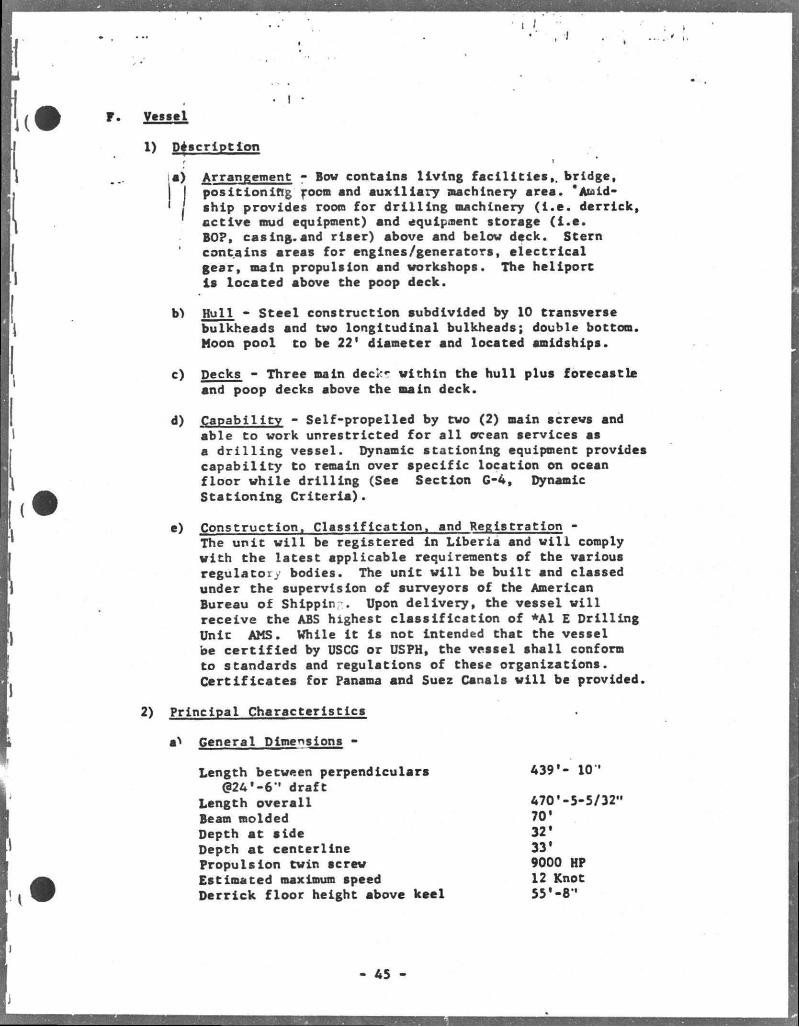
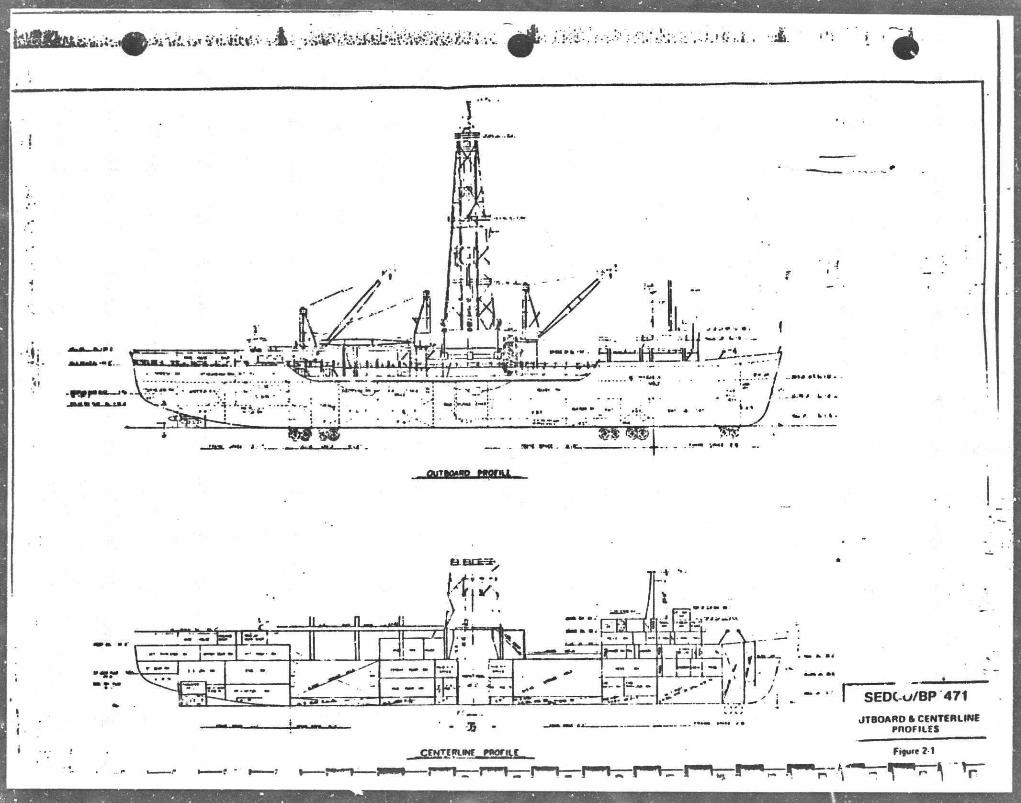
Vessel
1) Description r i
a) Arrangement - Bov contains living fac i l i t i es , , bridge, I positioning room snd auxiliary machinery area. "Auid-
' I ship provides room for dr i l l ing machinery ( I . e . derrick, active mud equipment) and equipment storage ( i . e . BO?, casing.and riser) above and belov deck. Stern contains areas for engines/generators, e lectrical gear, main propulsion and workshops. The heliport is located above the poop deck.
b) Hull - Steel construction subdivided by 10 transverse bulkheads and tvo longitudinal bulkheads; double bottom. Moon pool to be 22' diameter and located amidships.
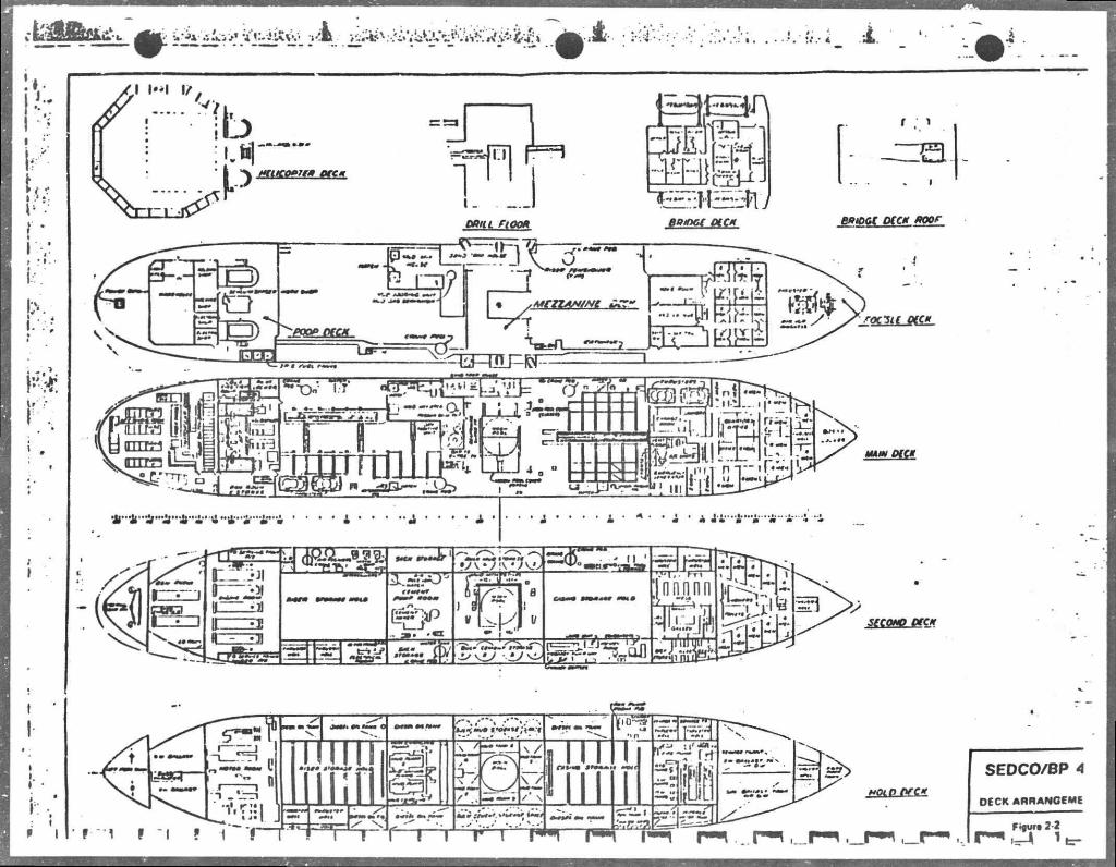
c) Decks - Three main deck? vithin the hull plus forecastle and poop decks above the main deck.
d) Capability - Self-propelled by tvo (2) main screws and able to work unrestricted for a l l ore an services as a d r i l l i n g vessel. Dynamic stationing equipment provides capability to remain over specific location on ocean floor vhi le dril l ing (See Section G-4, Dynamic Stationing Cri ter ia) .
e) Construction. Classification, and Registration -The unit v i l l be registered in Liberia and v i l l comply vith the latest applicable requirements of the various regulatory bodies. The unit v i l l be built and classed under the supervision of surveyors of the American Bureau of Shlppin . Upon delivery, the vessel v i l l receive the ABS highest classif ication of *A1 E Drill ing Unic AMS. While i t is not intended that the vessel be cer t i f i ed by USCG or USPH, the vessel shall conform to standards and regulations of these organizations. Cert i f icates for Panama and Suez Canals v i l l be provided.
2) Principal Characteristics
a General Dimensions -
Length betveen perpendiculars (324*-6" draft
Length overall Beam molded Depth at side Depth at centerline Propulsion twin screw Estimated maximum speed Derrick floor height above keel
439'- 10'
470*-5-5/32" 701
32* 33' 9000 HP 12 Knot 55*-8"
45
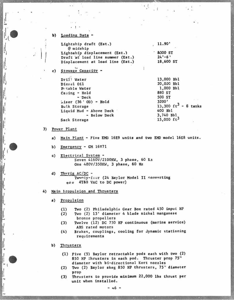
b) Loading Pata -
Lightship draft (Est.) 11.90' @ midship
Lightship displacement ( E s t . ) Draft at load l ine summer ( E s t . ) Displacement at load l ine ( E s t . )
8300 ST 24 ' - 6 ' 18,600 ST
c) Stowage Capacitv -
D r i l l Vater Diese l O i l Pi table Vater Casing - Hold
13,000 Bbl 20,000 Bbl
1,000 Bbl 880 ST
- Deck iviser (36 ' OD) - Hold Bulk Storage Liquid Mud - Above Deck
- Below Deck Sack Storage
500 ST 3200' 13,300 f t 3 - 8 tanks 400 Bbl 3,740 Bbl 15,000 f t 3
Power Plant
a) Main Plant - Five EMD 16E9 units and two EMD model 16E8 units.
b) Emergency - GM 16V71
c) Electrical System -Seven 4160V/2100KV, 3 phase, 60 Kx One 480V/350KV, 3 phase, 60 Hz
d) Thvrig AC/DC -Twvnty-four (24 Baylor Model I I converting
oes OVoQ VAC to DC power)
Main Propulsion and Thrusters
a) Propulsion
(1) Two (2) Philadelphia Gear Box rated 450 input HP (2) Two (2) 13' diameter 4 blade nickel manganese
bronze propellers (3) Twelve (12) DC 750 HP continuous (marine service)
ABS rated motors (4) Brakes, couplings, cooling for Jynamic stationing
requirements
b) Thrusters
(1) Five (5) Baylor retractable pods each with two (2) 850 HP thrusters in each pod. Thruster prop 75" diameter with bi-directional Kort nozzles
(2) Two (2) Baylor skeg 850 HP thrusters, 75" diameter prop
(3) Thrusters to provide minimum 22,000 lbs thrust per unit when installed.
*6 -
I
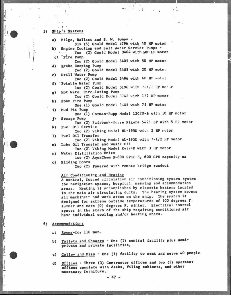
5) Ship's Systems
a) Bilge, Ballast and S. V. Jumps -Six (6) Gould Model 3796 with AO HP motor
b) Engine Cooling and Salt Water Service Pumps -- ' Two (2) Gould Model 3404 with U)0 l.P motor
c> "F^re Pump Two (2) Gould Model 3405 with 50 HP motor
d) Brake Cooping Pump .. Two (2) Gould Model 3405 with 20 HP motor
e) D r i l l Vater Pump Two (2) Gould Model 3496 with 40 Hr motor
f) Potable Vater Pump Iwo (2) Gould Model 3196 with 7-1/2 HP motjr
g) Hot Vate. Circulating Pump Two (2) Gould Model 3742 vith 1/2 HP motor
h) Foam Fire Pump One (1) Gould Model 3 05 with 75 HP motor
i) Mud Pit Pump One (1) Corman-Rupp Model 13C20-B with 10 HP motor
y< Sewage Pump Two (2) Fairbank-Morse Figure 5421-BP with 5 HP motor
k) Fue* Oil Servire Two (2) Viking Moiel HL-195D with 2 HP motor
1) Fuel Oil Transfer Two (2> Viking Model AL-195D with 7-1/2 HP motor
m) Lube 011 Transfer and waste Oil Two (2") Viking Model K412AR with 3 HP motor
n) Vater Distillation Units Two (2) AquaChem S-600 SPEC-E, 600 GPH capacity ea
o) Sliding Doors Two (2) Powered with remote bridge readout
Air Conditioning and Heating A central, forced circulation air conditioning system system the navigation spaces, hospital, messing and accommodation areas. Heating is accomplished by electric heaters located in the main air circulating ducts. The heating system covers a l l machines and work areas on the ship. The system ls designed for extreme outside temperatures of 100 degrees F. summer and aero (0) degrees F. winter. Electrical control spaces in the stern of the ship requiring conditioned s i r hsve Individual cooling and/or heating units.
6) Accommodations
t\) Rooms-for 116 men.
b) Toilets and Showers - One (1) central facility plus semi-privste snd private f a c i l i t i e s .
c) Galley and Mess - One <l) facility to seat and serve 40 people.
d) Offices - Three (3) Contractor offices and two (2) operator offices complete with desks, f i l i n g cabinets, and other necessary furniture.
- 47 -
* ,.
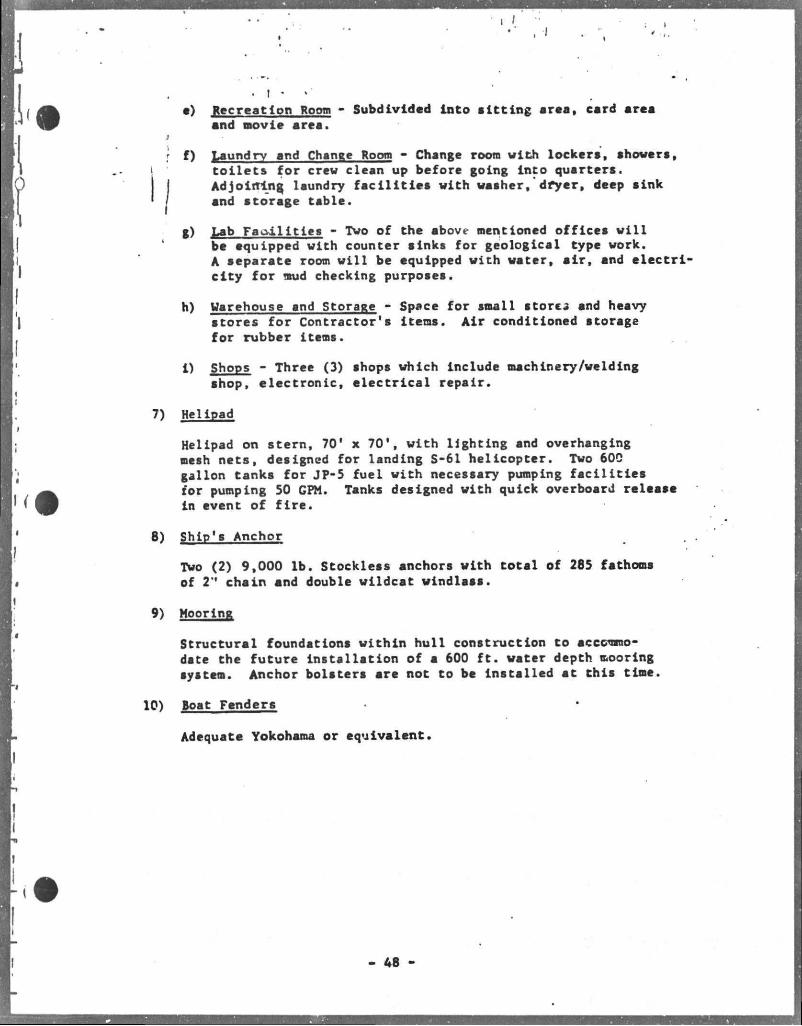
. I . •) Recreation Room - Subdivided into sitting area, card area
and movie area.
f) Laundry and Change Room - Change room with lockers, showers, toilets for crew clean up before going into quarters. Adjoining laundry f a c i l i t i e s with washer, dryer, deep sink and storage table.
g) Lab F a c i l i t i e s - Two of the above mentioned offices will be equipped with counter sinks for geological type work. A separate room will be equipped with water, air, and electricity for mud checking purposes.
h) Warehouse and Storage - Space for small stores and heavy stores for Contractor's items. Air conditioned storage for rubber items. . .
i) Shops - Three (3) shops which Include machinery/weIding shop, electronic, electrical repair.
7) Helipad
Helipad on stern, 70' x 70', with lighting and overhanging mesh nets, designed for landing S-61 helicopter. Two 600 gallon tanks for JP-5 fuel with necessary pumping fac i l i t i e s for pumping 50 GPM. Tanks designed with quick overboard release in event of f i r e .
8) Ship's Anchor
Two (2) 9,000 lb. Stockless anchors with total of 285 fathoms of 2M chain and double wildcat windlass.
9) Mooring
Structural foundations within hull construction to accommodate the future Installation of a 600 f t . water depth mooring system. Anchor bolsters are not to be Installed at this time.
10) Boat Fenders
Adequate Yokohama or equivalent.
A8
. I .
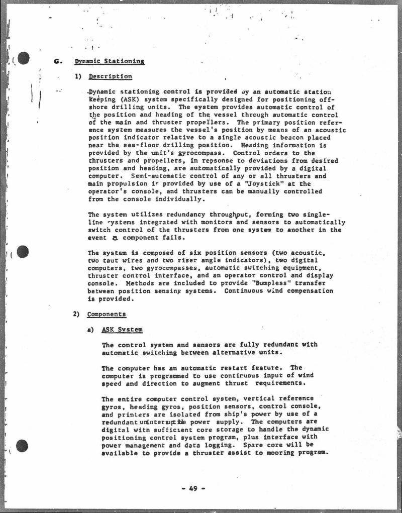
Gm Dynamic Stationing:
1) Description
-Dynamic stationing control is provided ay an automatic station keeping (ASK) system specifically designed for positioning offshore dr i l l ing units. The system provides automatic control of the position and heading of the vessel through automatic control of the main and thruster propellers. The primary position reference system measures the vessel's position by means of an acoustic position indicator relative to a single acoustic beacon placed near the sea-floor dri l l ing position. Heading information is provided by the unit's gyrocompass. Control orders to the thrusters and propellers, in repsonse to deviations from desired position and heading, are automatically provided by a digital computer. Semi-automatic control of any or a l l thrusters and main propulsion ir provided by use of a "Joystick" at the operator's console, and thrusters can be manually controlled from the console individually.
The system ut i l izes redundancy throughout, forming tvo single-line systems Integrated vith monitors and sensors to automatically svitch control of the thrusters from one system to another in the event & component f a i l s .
The system l s composed of six position sensors (tvo acoustic, tvo taut vires and tvo riser angle indicators), tvo digital computers, tvo gyrocompasses, automatic svitching equipment, thruster control interface, and an operator control and display console. Methods are included to provide "Bumpless" transfer betveen position sensing systems. Continuous wind compensation is provided.
2) Components
a) ASK Svstem
The control system and sensors are fully redundant vith automatic svitching betveen alternative units.
The computer hss an automatic restart feature. The computer is programmed to use continuous input of vind apeed and direction to augment thrust requirements.
The entire computer control system, vertlcsi reference gyros, heading gyros, position sensors, control console, and printers are Isolated from ship's power by use of a redundant unlntersipttie power suppiy. The computers are digital vitn sufficient core storage to handle the dynamic positioning control system program, plus interface vith power management and data logging. Spare core v i l l be available to provide a thruster assist to mooring program.
49
i
I 4 I .
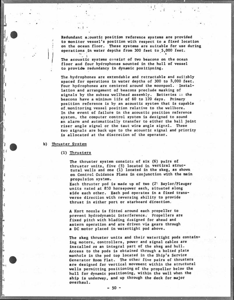
Redundant a;oustic positicm reference systens are provided ' to monitor vessel's position with respect to a fixed location ,' on the ocean floor. These systens are suitable for use during
operations in water depths fron 300 feet to 5,000 feet.
i ; • • / The acoustic systens consist of two beacons on the ocean
floor and four hydrophones nounted in the hull of vessel to providm redundancy In dynamic positioning. The hydrophones are extendable and retractable and suitably spaced for operations in water depths of 300 to 5,000 feet. Four hydrophones are centered around the noonpool. Installation and arrangement of beacons preclude masking of signals by the subsea wellhead assembly. Batteries in the beacons have a nlnimum l i f e of 60 to 120 days. Primary position reference is by an acoustic system that is capable of.monitoring vessel position relative to the wellbore. In the event of failure in the acoustic position reference system, the computer control system Is designed to sound an alarm and automatically transfer to either the ball joint r i ser angle signal or the taut wire angle signal. These two signals are back ups to the acoustic signal and priority is allocated at the discretion of the operator.
b) Thruster Svstem
(1) Thrusters
The thruster system consists of six (6) pairs of thruster units, f ive (5) located ln vertical structural wells and one (1) located in the skeg, as shown on Control Guidance Plans in conjunction with the main propulsion system. Each thruster pod is made up of two (2%- Bayior/Pleuger units rated at 850 horsepower each, situated along aide each other. Each pod operates in a fixed transverse direction with reversing ability to provide thrust in either port or starboard direction.
A Kort nozzle Is f itted around each propeller to prevent hydrodynamic Interference. Propellers are fixed pitch with blading designed for ahead and astern operation and are driven via gears through a DC motor placed In watertight pod above.
The skeg thruster units and their watertight pods containing motors, controllers, power and signal cables are installed as an Integral part of the skeg and hull . Access to the pods is obtained through a bolted plate manhole in the pod top located in the Ship's Service Generator Room Fla t . The other five pairs of thrusters are designed for vertical movement within the structural wells permitting positioning of the propeller below the hul l for dynamic positioning, within the well when the ship i s underway, and up through the deck for major overhaul.
- 50 -
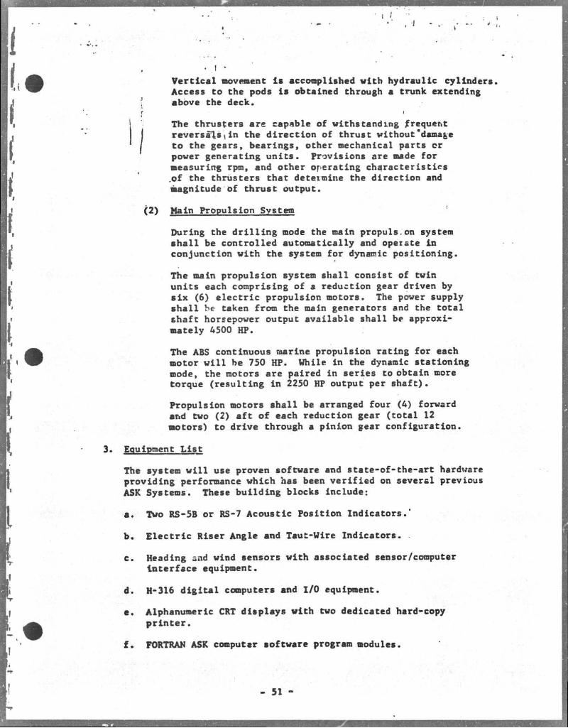
Vertical movement la acconpliahed with hydraulic cylinders Access to the pods is obtained through a trunk extending above the deck.
The thrusters are capable of withstanding frequent
( reversals,in the direction of thrust without"damage to the gears, bearings, other nechanical parts cr power generating units. Provisions are nade for measuring rpm, and other operating characteristics .of the thrusters that deteimine the direction and magnitude of thrust output.
(2) Main Propulsion Systen
During the drilling node the main propuls.on systen shall be controlled automatically and operate in conjunction with the system for dynamic positioning.
The main propulsion system shall consist of twin units each comprising of a reduction gear driven by six (6) electric propulsion motors. The power supply shall be taken from the main generators and the total shaft horsepower output available shall be approxi' mately 4500 HP.
The ABS continuous marine propulsion rating for each motor wi l l be 750 HP. While in the dynamic stationing mode, the motors are paired in series to obtain more torque (resulting in 2250 HP output per shaft).
Propulsion motors shall be arranged four (4) forward and two (2) aft of each reduction gear (total 12 motors) to drive through a pinion gear configuration.
Equipment L i s t
The system w i l l use proven software and state-of-the-art hardware providing performance which has been verified on several previous ASK Systems. These building blocks include:
a. Two RS-5B or RS-7 Acoustic Position Indicators.'
b. Electric Riser Angle and Taut-Wire Indicators.
c. Heading and wind sensors with associated sensor/computer interface equipment.
d. H-316 digital computers and I/O equipment.
a. Alphanumeric CRT displays with two dedicated hard-copy printer.
f. FORTRAN ASK computer software program modules.
- 51 -
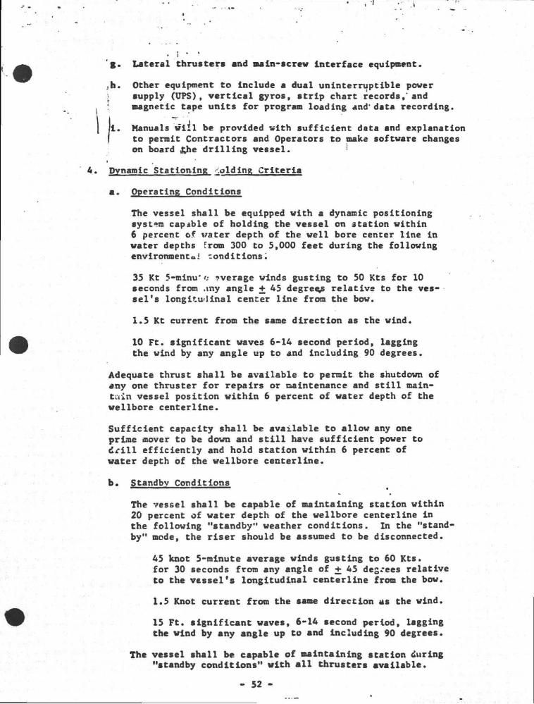
. 1 • ' g. Lateral thrusters and main-screw interface equipment.
jh. Other equipment to include a dual uninterruptible power j supply (UPS), v e r t l c s l gyros, strip chart records,'snd
magnetic tape units for program loading and'data recording.
II . Manuals w i i l be provided with sufficient data and explanation to permit Contractors and Operators to make software changes on board &he dril l i n g vessel. • • _ •
Dynamic Stationing .olding Criteria
a. Operating Conditions
The vessel shall be equipped with a dynamic positioning system capable of holding the vessel on station within 6 percent of vater depth of the well bore center line ln water depths from 300 to 5,000 feet during the following environment*.i conditions
35 Kt 5-minu* n average winds gust ing to 50 Kts for 10 seconds from .my angle + 45 degrees relative to the vessel's longitudinal center line from the bow.
1.5 Kt current from the same direction as the wind.
10 Ft. significant waves 6-14 second period, lagging the wind by any angle up to and including 90 degrees.
Adequate thrust shall be available to permit the shutdown of any one thruster for repairs or maintenance and s t i l l maintain vessel position within 6 percent of water depth of the wellbore centerline.
Sufficient capacity shall be available to allow any one prime mover to be down and s t i l l have sufficient power to d r i l l efficiently and hold station within 6 percent of water depth of the wellbore centerline.
b. Standby Conditions
The vessel shall be capable of maintaining station within 20 percent of water depth of the wellbore centerline in the following "standby" weather conditions. In the "standby" mode, the riser should be assumed to be disconnected.
45 knot 5-minute average winds gusting to 60 Kts. for 30 seconds from any angle of + 45 degrees relative to the vessel's longitudinal centerline from the bow.
1.5 Knot current from the same direction as the wind.
15 Ft. significant waves, 6-14 second period, legging the wind by any angle up to and including 90 degrees.
The vessel shall be capable of maintaining station during "standby conditions" with a l l thrusters available.
- 52 -
- t
8.c. SEDCO/B? 471 GENERAL INFORMATION
! 9?Fab/83
• I. •
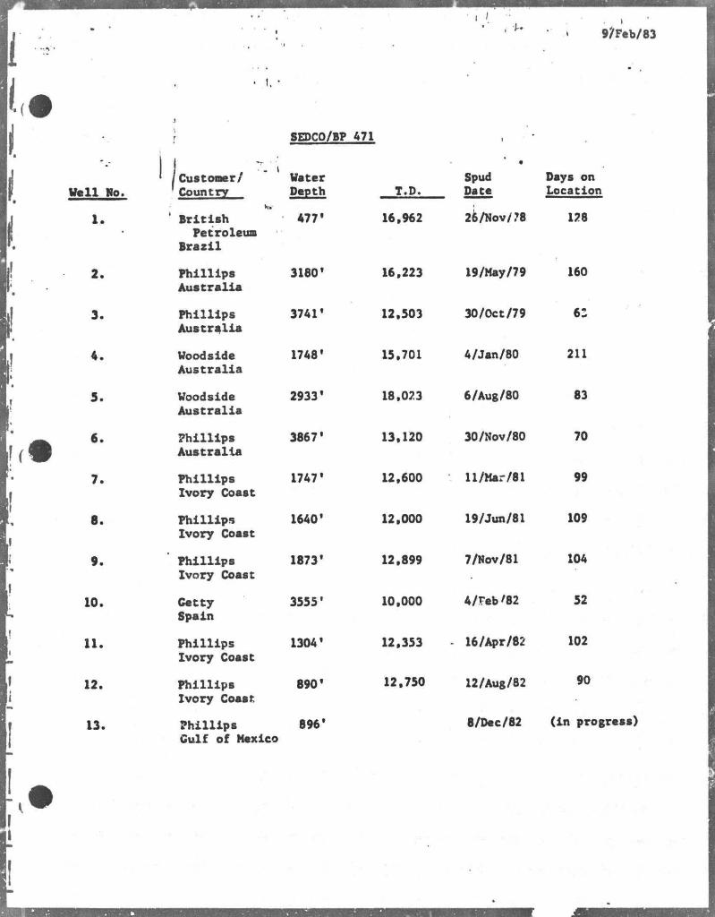
} 8EDC0/BP 471 ,
Vcll No. ' 1 Customer/ ! Country
Vater Depth T.D.
Spud Date
Days on Location
1. Ww
' British Petroleum
Brazil
477' 16,962 26/Nov/78 128
2. Phillips Australia
3180' 16,223 19/May/79 160
3. Phillips Australia
3741' 12,503 30/Oct/79 62
4. Woodside Australia
1748' 15.701 A/Jan/80 211
5. Woodside Australia
2933' 18,023 6/Aug/80 83
6. Phillips Australia
3867' 13,120 30/Nov/80 70
7. Phillips Ivory Coast
1747' 12,600 ll/Mar/81 99
8. Phillips Ivory Coast
1640' 12,000 19/Jun/81 109
9. Phillips Ivory Coast
1873' 12,899 7/Nov/81 104
10. Catty Spain
3555' 10,000 A/Fab'82 52
11. Phillips Ivory Coaat
1304' 12,353 - 16/Apr/82 102
12. Phillipa Ivory Coaat
890' 12,750 12/Aug/82 90
13. Phillips Culf of Mexico
896' 8/Dec/82 (in progress)
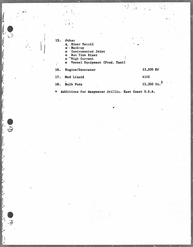
15. Other q Riser Recoil • o - Back-up o Instrumented Joint o Run Tine Riser o h"H4gh Current o Vessel Equipnent (Prod. Test)
16. Engine/Generator 13,500 KU
17. Hud Liquid
18. Bulk Poda
* Additions for deepwater drill in.. East Coast U.S.A.
AUO
13,300 f t . 3
I / • I
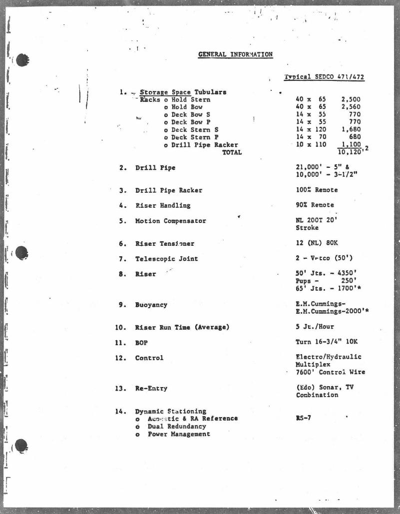
GENERAL INFORMATION
Typical SEPCO 671/672
, Storage Space Tubulars " Racks o Hold Stern
o Hold Bov K v o Deck Bov S
o Deck Bov P o Deck Stem S o Deck Stern P o D r i l l Pipe Racker
TOTAL
D r i l l Pipe
D r i l l Pipe Racker
Riser Handling
Motion Compensator
6. Riser Tensioner
7. Telescopic Joint
8. Riser
9. Buoyancy
10. Riser Run Tine (Average)
11. BOP
12. Control
13. Re-Entry
14. Dynamic Stationing o Aco:stic A RA Reference 6 Dual Redundancy o Power Management
40 X 65 2.500 40 X 65 2.560 IA X 55 770 IA X 55 770 IA X 120 1.680 14 X 70 680 10 X 110 1,100
10.120
21.000' 10,000'
5" & 3-1/2"
,2
100% Remote
90Z Remote
NL 200T 20' Stroke
12 (NL) 80K
2 - Wtco (50')
50* Jts . - 4350' Pups - 250' 65' J t s . - 1700'*
E.M.Cummings-E.M.Cunnings-2000'*
5 Jt./Hour
Turn 16-3/4" 10K
Electro/Hydraulic Multiplex 7600' Control Wire
(Edo) Sonar, TV Combination
RS-7
I* • { ' I v » :»-•
ft
^ ^ Mfttcow* ore* CTL • M l "
f , 1
fl*ipgf Of or poor
.AMTZlAMftM £ X ~
T
W
be1
»WMO£CK
Si CONO DtCK
r: •. MOL oar c
SEDCO/BP A
OCCK ARRANGEME
F-guf« 2 2
OIL SPILL CONTINGENCY PIAN
Pursuant to J.S.G.S. OCS Order No. 7 (Pollution Control and Waste .Disposal) Getty Oii Coinpany \as an approved Oil Spill Contingency Plan on*file with the U.S.G.S. Thia Plan provides specifip information for notification and action procedures in the event an s p i l l situation occurs in tbe Gulf of Mexico.
Action and notification procedures are specified in the Plan for varying d-- ;rees of response depending on the size and nature of the s p i l l . Notification and reporting procedures include state and federal agency requirements and emergency notification telephone numbers. Action procedures are specified to include responsibility, s p i l l containment and cleanup, eguipment and material, operating personnel, communication, and Offshore Dis t r i c t Oil S p i l l Task Force.
Getty Oil Company i s a member of the CLEAN GULF ASSOCIATES, hereafter referred to as CGA. By reference the CGA Operations Nanual i s incorporated into and made a part of Getty Oil Company's Offshore Dis t r i c t Oil S p i l l Contingency Plan. Eguipment stored and maintained by CGA i s available should the need arise. In an emergency situation Getty Oil Company will c a l l for as much assistance and additional eguipment as necessary from a number of contractors who are located on the Gulf Coast that specialize in o i l s p i l l containment and cleanup. These contractors, with capabilities to include manpower, equipment and material, are listed in the Contingency Plan.
CGA equipment located at Grand I s l e , Intracoastal City, Cameron and Houma, Louisiana, can be utilized and deployed from the CGA base location or the Getty Oil Company onshore support base located at Cameron, Theriot, or Venice, Louisiana. A Fast Response Open Sea Skimmer System w i l l be used as the primary s p i l l containment and cleanup •quiprant and i s located at the above mentioned CGA base locations. This i s a portable system designed for boat mounting. I t consists in part, of a floating o i l boom, skimmer, outrigger, pump and storage tanks. The system i s designed to provide equipment capable of fart response to emergency s p i l l situations. Allowinc/ 2 hours for loadout and 10 hours cruising at 10 knots remits in % ?o leral capability of being 100 miles offshore 12 hours it' v.*r notification of a s p i l l . Maximum recovery with the system i s 360 barrels fluid. Trainer operating personnel for the fast response skimmer and other CGA equipment will be obtained from a contractor.
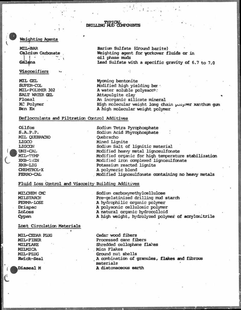
DRILLING
Weighting Agents
MIXr-BA C S l c i u MlLr-BAR
Lura Carbonate - \
viscos i f i ers
HTL GEL SUPER-COL MIL-POLYMER 302 SALT WAIER GEL F l o s a l XC Polymer Ben Ex
Barium Sulfate (Ground barite) Weighting agent for workover f luids or in o i l phase muds Lead Sulfate with a specif ic gravity of 6.7 to 7.0
Wyoming bentonite Modified high yielding ber * A water soluble polysacch: Attapulgite clay An inorganic s i l i cate mineral High molecular weight long chain polymer xanthum gum A high molecular weight polymer
Def locculants and Fi l trat ion Control Additives
Qi l fo s S .A .P .P . MIL QUEBRACHO LIGCO LIGCON UNI-CAL MTL-TEMP XKB—1HIN XKB-LIG CHEMTROL-X FERRO-CAL
Sodium Tetra Pyrophosphate Sodium Acid Phyruphosphate Quebracho Mined Lignite Sodium Salt of l ign i t i c material Modified heavy metal lignosulfonate Modified organic for high temperature stabilization Modified iron complexed lignosulfonate Potassium reacted lignite A polymeric blend Modified lignosulfonate containing no heavy metals
F l u i d Loss Control and Viscosity Building Additives
MILCHEM QC MILSTARCH PERMA-LOSE Drispac LoLcss Cypan
Lost Circulation Materials 1
MIL-CEDAR PLUG MIL—FIBER MILFLAKE MILMICA MIL—PLUG Jfcdcx-Seal
.Diaseal M
Sodium carbaxynE thy leel lulose Pre-gelatinized drilling mud starch A hydrophilic organic polymer A polyaonic cellulosic polymer A natural organic hydrocolloid A high weight, hydrolyzed polymer of acrylonitrile
Cedar wood fibers Processed cane fibers Shredded cellophane flakes
. Mica Flakes Ground nut shells
. A combination of granules, flakes snd fibrous materials A cUatcrnaceous earth
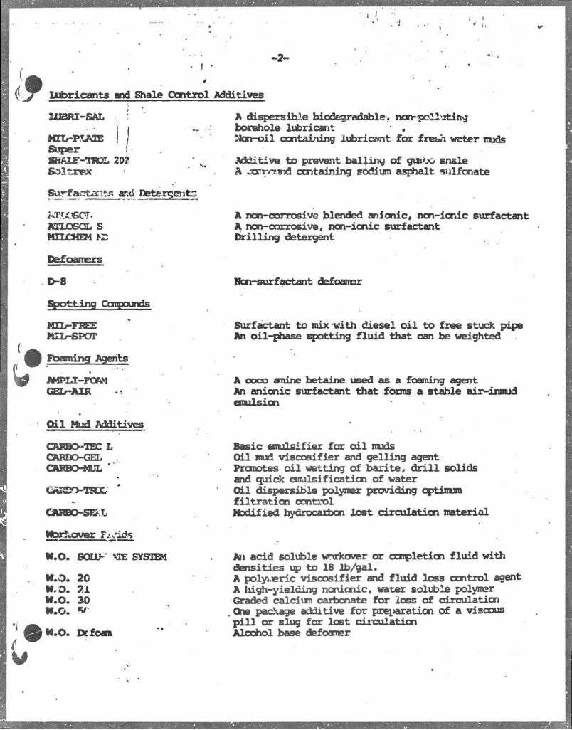
- 2 -
Lubricants and Shale Control Additives
LUBRI-SAL
KTIHPLAXB Super SKALF-UCSL 202
Surfacrta-.t^ snd Detergents
ATLOSOL S MILCHEM
Defoamers
D-8
Shotting Compounds
MIL-FREE MIL-SPOT
Foaming Agents
AMPLI-FOAM GEL—AXR
A dispersible biodegradable., non-polluting borehole lubricant • . "ton-oil containing lubricant for fresh wtter muds
Additive to prevent bailing of gunfoc shale A jcrrvnnd containing sodium asphalt sulfonate
A non-corrosive blended anionic, non-ionic surfactant A non-corrosive, non-ionic surfactant Drilling detergent
Non-surfactant defoamer
Surfactant to mix-with diesel o i l to free stuck pipe An oil-phase spotting fluid that can be weighted
A coco amine betaine used as a foaming agent An anionic surfactant that forms a stable air-inmud emulsion
O i l Mud Additives
CARBO-TEC L CARBO-GEL CARBO-MUL '"
iARSo-rax;
QfcRBO-SEkL
Wbrkover Tiyids
W.O. SOLO- TO SYSTEM
W.O. 20 W. O. 21 W.O. 30 W.O.
W.O. Defoam
Basic emulsifier for o i l muds Oil mud viscosifier and gelling agent Promotes o i l wetting of barite, d r i l l solids snd quick emulsification of water Oil dispersible polymer providing optimum fil t r a t i o n control Modified hydrocarbon lost circulation material
An add soluble workover or completion fluid with densities up to 18 lb/gal. A polyueric viscosifier and fluid loss control agent A liigh-yielding nonionic, water soluble polymer Graded calcium carbonate for loss of circulation One package additive for preparation of a viscous pil l or slug for lost circulation Alcohol base defoamer
>
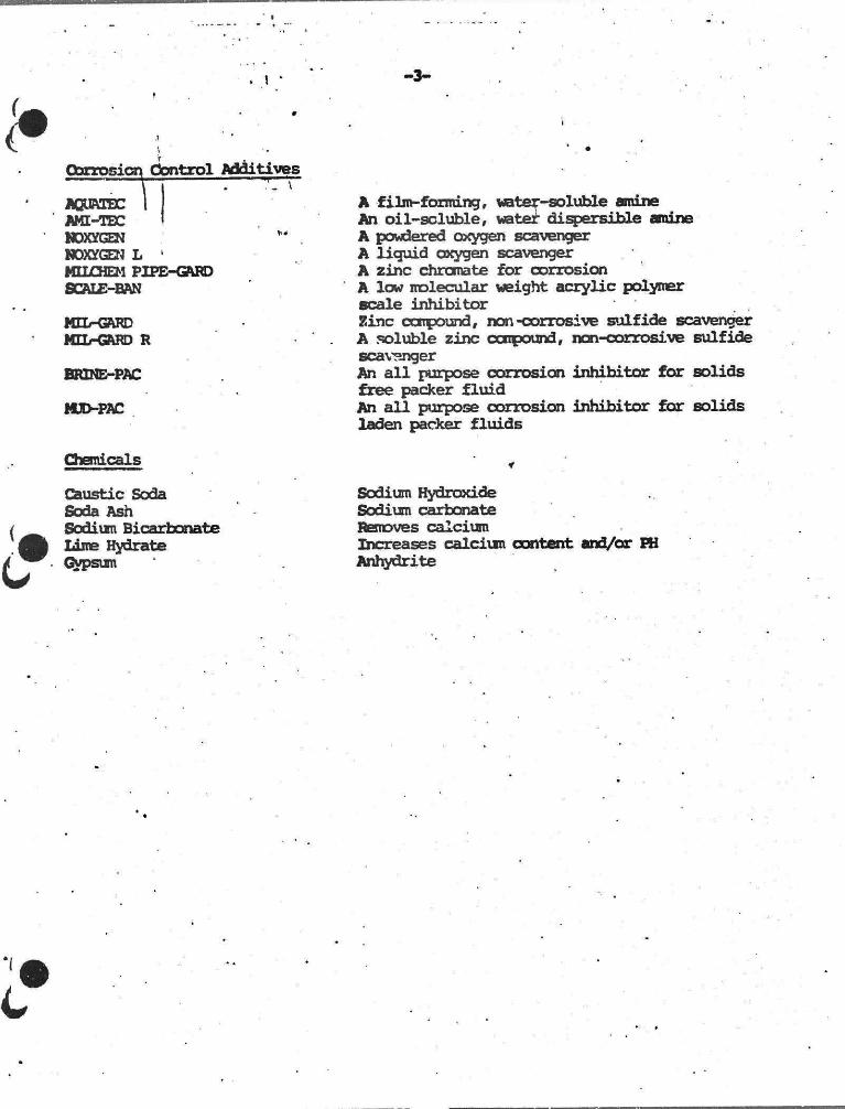
1 3-
Oorrosion Control Additives Lon
: I AQUATBC AMI-TEC NOXYGEN NOXYGEN L 1
MILCHEM PIPE-GARD SCALE-BAN
MIL-GARD MEL-GARD R
BRINE-PAC
MUD-PAC
A filin-forming, -water-soluble amine An oil-soluble, water dispersible amine A powdered oxygen scavenger A liguid oxygen scavenger A zinc chromate for corrosion A low molecular weight acrylic polymer scale inhibitor Zinc compound, non-corrosive sulfide scavenger A soluble zinc compound, ncn-corrosive sulfide scavenger An al l purpose corrosion inhibitor for solids free packer fluid An all purpose corrosion inhibitor for solids laden packer fluids
Chemicals
Caustic Soda Soda Ash Sodium Bicarbonate Lime Hydrate Gypsum
Sodium Hydroxide Sodium carbonate Removes calcium Increases calcium content and/or PH Anhydrite
ONSHORE SUPFORT BASE F A C I L I T I E S ' •
I
Getty Oil Company has tliree onshore support base f a c i l i t i e s located at Cameron, Theriot, and Venice, Louisiana, and one located at Port 0'Conner, Texas.
The Cameron, Louisiana Shore Base i s located on the east bank of the Calcasieu River and consists of docking f a c i l i t i e s , crane, heliport, crew quarters and twenty-four hour communications.
The Theriot, Louisiana Shore Base i s located South of Theriot, Louisiana on Grand Bayou DuLarge and includes docking f a c i l i t i e s and working hour communications.
The Venice, Louisiana Shore Base is located South of New Orleans, Louisiana near the mouth of the Mississippi River and includes docking f a c i l i t i e s , crane, heliport and twenty-four hour communications.
The Port 0(Conner, Texas Shore Base i s normally set up at one of the mud company's dock f a c i l i t y . These normally include docking f a c i l i t i e s , cranes, twenty-four hour communications.
AIR QUALITY REVIEW REPORT PURSUANT TO 30 CFR 250.57
EXPLORATION HISSISSIPPI CANYON BLOCK 809 AIR QUALITY REVIEW REPORT
GETTY OIL COMPANY LAFAYETTE- LOUISIANA
CONTACT PERSON LJUIS HOOVER, I I I , ESQ.
PERMIT ANALYST P.U BOX 51367
LAFAYETTE, LOUISIANA 70505 (318-232-5813)
SEPTEMBER 19, 1983
Prepared by:
ED ROY'S, LTO. nvironmental Service* D i v i s i o n
• I •
jr (
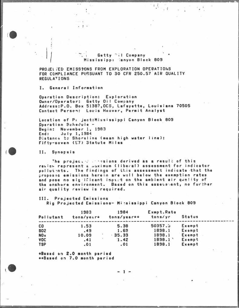
I % " V t G e t t y ~ > \ Company ( M i s s i s s i p p i ,'anyon B l o c k 809
PRO J.E I .'ED EMISSIONS FROM EXPLORATION OPERATIONS FOR COMPLIANCE PURSUANT TO 30 CFR 2 5 0 . 5 7 AIR OUALITY REGULATIONS
I . G a n a r a l I n f o r m a t i o n
O p e r a t i o n D e s c r i p t i o n : E x p l o r s t i o n O w n e r / O p e r a t o r : G e t t y Oi I Conipany A d d r e s s : P . 0 . Box 5 1 3 8 7 , O C S , L a f a y e t t e , L o u i s i a n a 70505 Contact P e r s o n : L o u i s H o o v e r , P e r a i t A n a l y s t
L o c s t i o n of Pr j e c t : M i s s i s s i p p i Csnyon B l o c k 809 O p e r s t i o n S c h e d u l e -B e g i n : Noveniber 1, 1983 End: J u l y 1,1984 D i s t a n t - t c S h o r e l i n e (mean h igh water l i n e ) : F i f t y - s e v e n ( 1 7 ) S t s t u t e M i l e s
I I . Synop s i s
rhe p r o j e c t - J ' n i om derived as a r e s u l t of t h i s revie* represent a ...jximum ( l i b e r a l ) assessment for indicator pollutants. The f i n d i n g i of t h i s assessment indicate that the Kropos»o emissions herein are woll below the exemption r s t e s and pose no s i g i f i c a n t i s p t . t on the ambient a i r qua!ity of the onshore environment. Based on t h i s asset** ient, no further si r q u a l i t y review is required.
I I I . P r o j e c t e d Emissions Rig P r o j e c t e d Emissions- M i s s i s s i p p i Canyon Block 809
1983 1984 Exmpt.Rato Pollutant tons/ye>r* tons/year** tons/yr Status
CO 1.53 5.38 50357.o Exempt S02 .49 1.69 1898.1 Exempt NOx 10.09 35.33 1898.1 Exempt VOC .41 1.42 1898.1 v Exempt TSP .01 .01 1898.1 Exempt
*Bts*d o<ri 2.0 aonth period ••Based on 7.0 month period
- 1 -
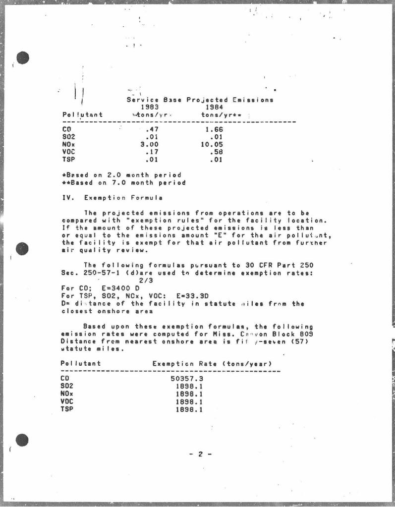
Pol'utant
CO SQ2 NOx VOC TSP
.47
.Oi 3.00 .17 .01
10.05
1.66 .01
.58
.01
*B?sed on 2.0 Month period ••Based on 7.0 month period
IV. Exemption Formula
The projected emissions from operations are to be compared with "exemption r u l e s " for the f a c i l i t y location. If the amount of these projected emissions is less than or equal to the emissions amount "E" for the a i r pollutant, the f a c i l i t y is exempt for that a i r pollutant from further • i r que I i ty rev i ew.
The following formulas pursuant to 30 CFR Part 250 Sec. 250-57-1 (d)are used tn determine exemption r a t e s :
For CO; E=3400 D For TSP, S02, NCx, VOC: E-33.3D D* di tance of the f a c i l i t y in statute n i l e s fmm the clo s e s t onshore srea
Based upon these exemption formulas, the following emission r a t e s were computed for Miss. Ce'von Block 809 Distance frcm nearest onshore srea is f i i -seven (57) vtstute mi l e s .
Pollutant Exemption Rate (tons/year)
CO 50357.3 S02 1898.1 NOx 1898.1 VOC 1898.1 TSP 1898.1
2/3
- 2 -
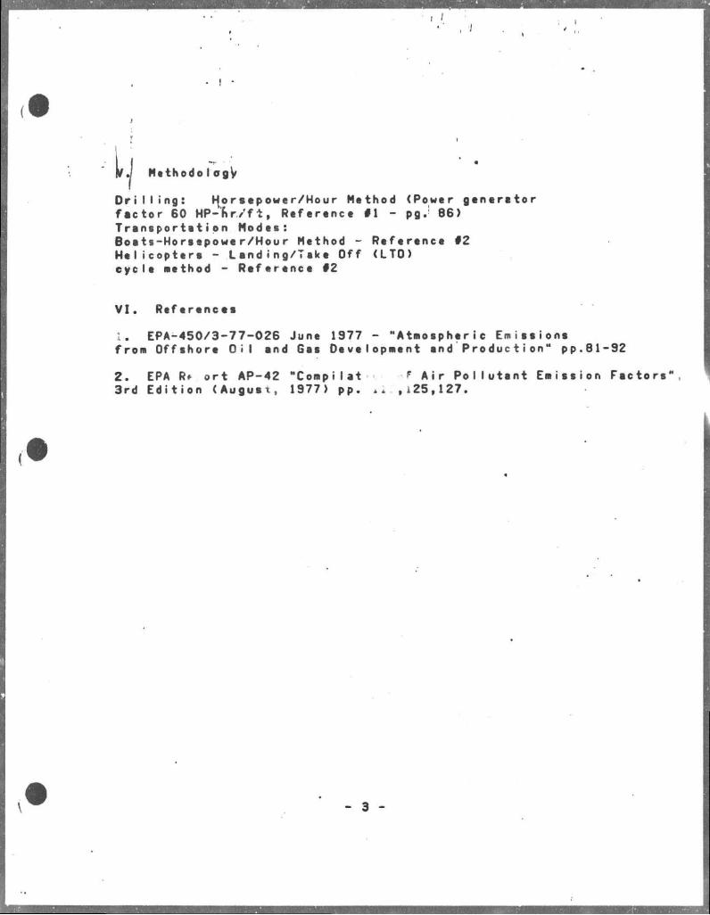
t
Me th od oIogy
D r i l l i n g : Horsepower/Hour Method (Power generator factor 60 MP-nr/ft, Reference #1 - pg.1 86) Transportation Modes: Boats-Horsepower/Hour Method - Reference #2 Helicopters - Landing/Take Off (LTO) cycle method - Reference #2
VI. References
1. EPA-450/3-77-026 June 1977 - "Atmospheric Emissions from Offshore O i l and Gas Oevelopment and Production" pp.81-92
2. EPA Rf ort AP-42 "Compilat f Air Pollutant Emission Factors 3rd Edition (August, 1977) pp. i i ,125,127.
- 3 -
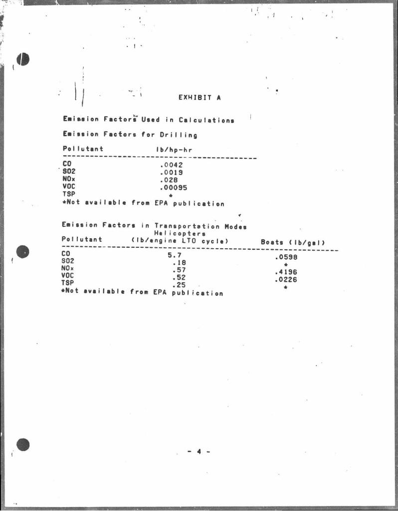
" ' EXHIBIT A
Emission Factors' Used in Calculations
Eaisaion Factors for D r i l l i n g
Pollutant lb/hp-hr
CO .0042 302 .0019 NOx .028 VOC .00095 TSP • •Not availabla fros> EPA publication
Eaission Factors in Transportation Modes He I i c o p t e r s
Po M u t a n t < l b / e n g i n e L T O c y c l e ) B o a t s ( l b / g a l )
voc 'll - 4 1 9 6
?SP :ii °f26
• N o t a v a i l a b l e f r o n EPA p u b l i c a t i o n
AIR QUALITY REVIEW REPORT* PURSUANT TO 30 CFR 250.57
EXPLORATION MISSISSIPPI CANYON BLOCKS 852 ft 853
AIR QUALITY REVIEW REPORT GETTY OIL COMPANY
LAFAYETTE, LOUISIANA
CONTACT PERSON LOUIS HOOVER, I I I , ESQ.
PERMIT ANALYST P.O BOX 51367
LAFAYETTE, LOUISIANA 70505 <318-232-5813>
AUGUST 26, 1983
Prepared by:
EO ROY't, LTO. Environmental Servloee Diviaion
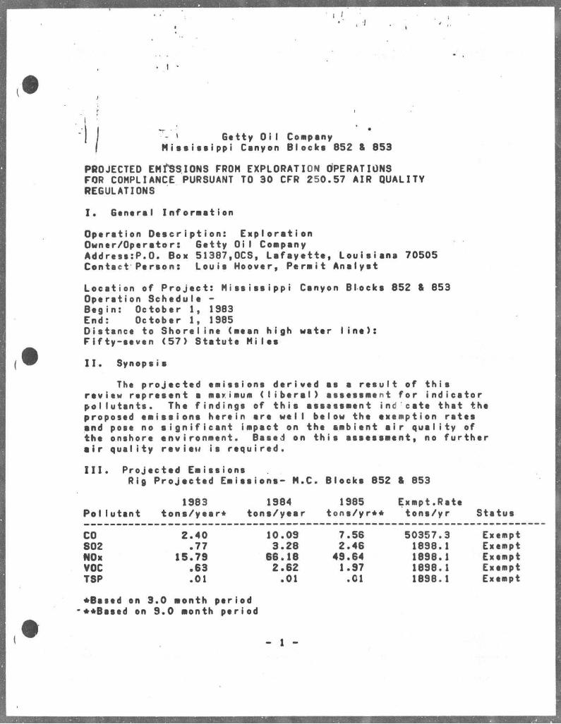
• I •
J
f I I j - » Gttty OiI Coapany ( Mississippi Canyon Blocks 852 & 853
PROJECTED EMISSIONS FROM EXPLORATION OPERATIONS FQR COMPLIANCE PURSUANT TO 30 CFR 250.57 AIR QUALITY REGULATIONS
I . Gsntral Inforastion
Optrstion Doscription: Exploration Owner/Operator: Gstty OiI Coapany Address:P.O. Box 51387,00s, Lafayatta, Louisiana 70505 Contact Person: Louis Hoover, Permit Analyst
Locstion of Project: Mississippi Canyon Blocks 852 & 853 Operstion Schedule -Begin: October 1, 1983 End: October 1, 1985 Distsnce to Shoreline (aesn high water l i n e ) : Fifty-seven (57) Statute Miles
I I . Synopsis
The projected emissions derived ss a result of this review represent a maximum ( l i b e r a l ) assessaent for indicator pollutants. The findings of this asseesaent ind cate that the proposed eaissions herein are well below the exemption rotes and pose no aignificant iapact on the aabient a i r quality of the onshore environment. Based on this assessment, no further a i r quslity review is required.
I I I . Projected Eaissions Rig Projected Eaissions- M.C. Blocks 852 8 853
1983 1984 1985 Exapt.Rste Pollutant tons/year* tons/year tons/yr** tons/yr Ststus
CO 2.40 10.09 7.56 50357.3 Exempt 802 .77 3.28 2.46 1898.1 Exempt NOx 15.79 66.18 49.64 1898.1 Exempt VOC .63 2.62 1.97 1898.1 Exempt TSP .01 .01 .01 1698.1 Exempt
•Bssed on 3.0 month period -••Based on 9.0 aonth period
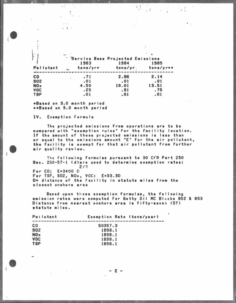
' Service Bait Projected Emissions 1983 1984 1985
Pollutant K B tona/yr* tona/yr, tona/yr**
CO .71 2.86 2.14 802 .01 .01 .01 NOx 4.50 18.01 13.51 VOC .25 .81 .75 T8P .01 .01 .01
•Based on 3.0 month period ••Based on 9.0 month period
IV. Exemption Formula
The projected emissions from operatione are to be compared with "exemption rules" for the f a c i l i t y location. I f the amount of these projected emissions is less than or equal to the emissions amount "E" for the air pollutant, the f e c i l i t y is exempt for thst a i r pollutant from further a i r quali ty rev i ew.
The following formulas pursusnt to 30 CFR Psrt 250 Sec. 250-57-1 (d)are used to determine exemption rates:
2/3 Fer CO; E-3400 D For TSP, S02, NOx, VOC: E-33.3D D* distsnce of the f e c i l i t y in statute miles from the closest onshore area
Based upon these exemption formulas, the following amission rstes were computed for Getty Oil HC Blocks 852 ft 853 Oistsnee from nearest onshore area ia fifty-seven (57) atatute miles.
Poilutsnt Exemption Rate (tone/year)
CO 50357.3 802 1898.1 NOx 1898.1 VOC 1898.1 TSP 1898.1
- 2 -
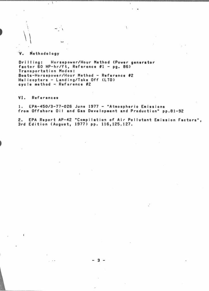
\ 1
V. Methodology
D r i l l i n g : Horsepower/Hour Method (Power generator factor 60 HP-hr/ft, Reference #1 - pg. 86) Transportation Modes: Boats-Horsepower/Hour Method - Reference #2 Helicopters - Landing/Take Off (LTO) cycle aethod - Reference #2
VI. References
1. EPA-450/3-77-026 June 1977 - "Atmo sp heri e Eaissions froM Offshore Oil and Gas Develcpment and Production" pp.81-92
2. EPA Report AP-42 "Compilation of Air Pollutant Emission Factors", 3rd Edition (August, 1977) pp. 116,125,127.
- 3 -
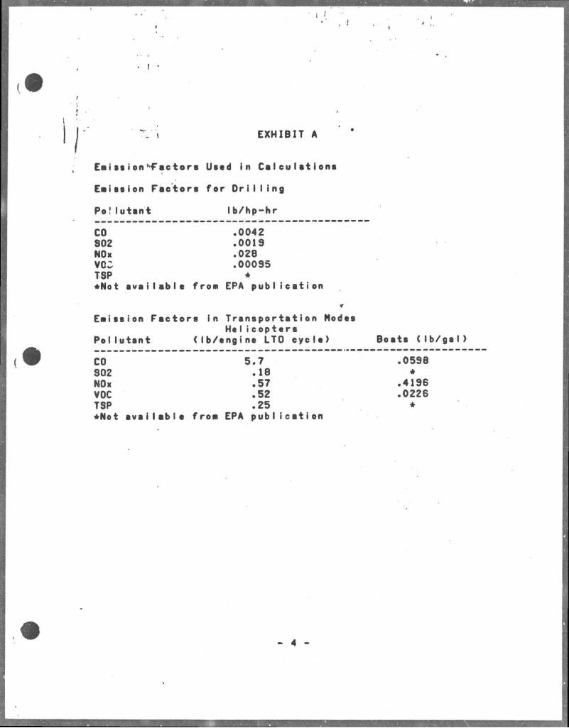
- t EXHIBIT A
Eeiasion Factors Used in Calculations
Emission Factora for OriI Iing
Po!Iutant lb/hp-hr
CO S02 NOx VCC TSP
.0042
.0019
.028
.00095 *
•Not availabla froa EPA publication
Emission Factors in Trsnsportation Nodes He I i copters
Pollutant <lb/engine LTO cycle) Boots ( Ib/gsl)
CO S02 NOx VOC TSP
5.7 .18 .57 .52 .25
•Not available froa EPA publication
.0598 *
.4196
.0226 •
- 4
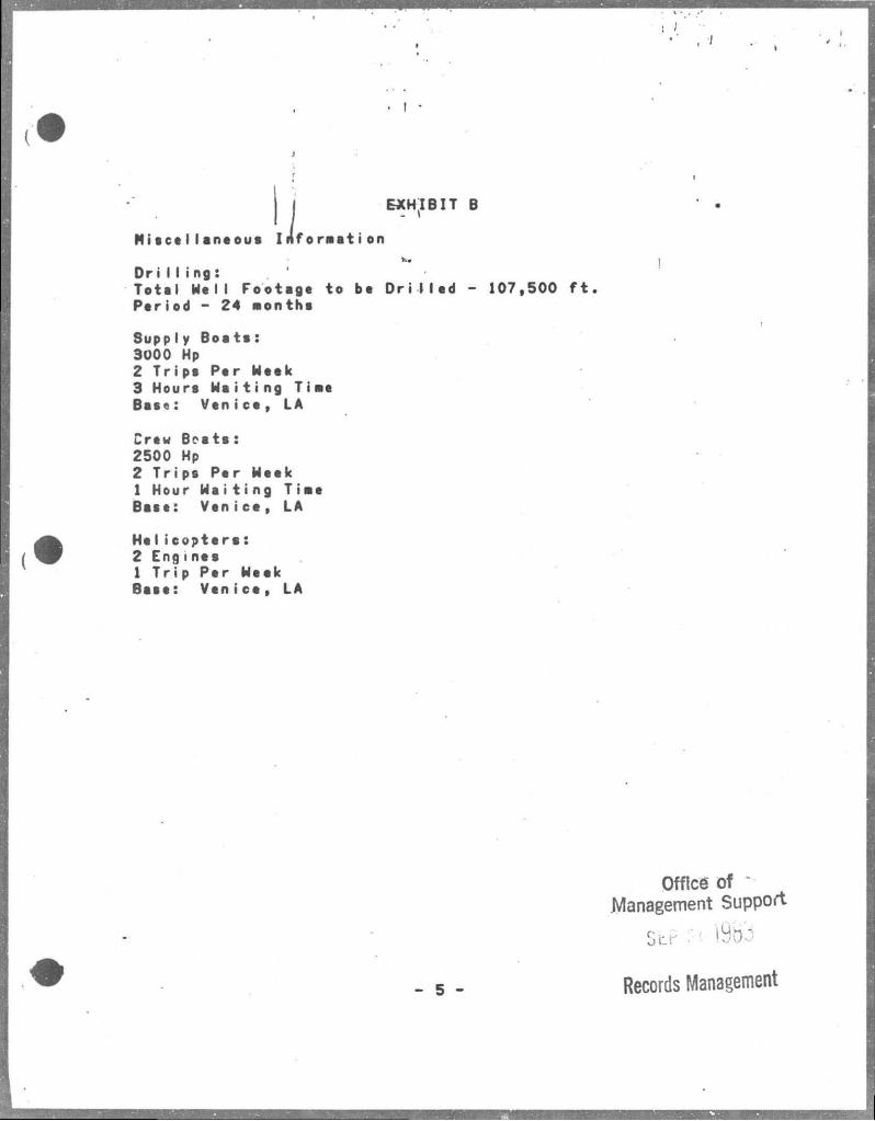
EXHIBIT B
MiocelIane ous Inforaation fcw
D r i I I i ng: To ta l No l l Footage to be Dr i Mod - 107 ,500 f t . P e r i o d - 24 months
Supply B o a t s : 3000 Hp 2 T r i p s P e r Week 3 Hours H s i t i n g T i a e B a s e : Ven i c e , LA
Crew B e s t s : 2500 Hp 2 T r i p s P e r Meek 1 Hour Us i t i ng T i a e B a s e : V e n i c e , LA
He I i c o p t e r s : 2 E n g i n e s 1 T r i p P e r Meek B a s e : V e n i c e , LA
- 5 -
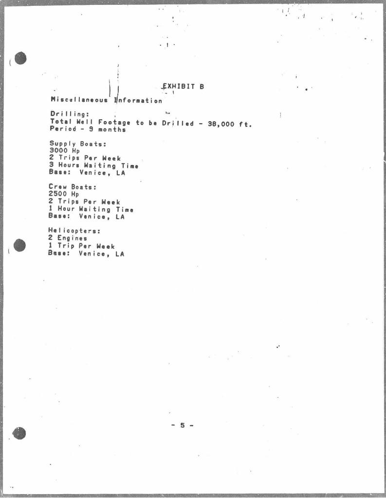
1 I
EXHIBIT B
M i s c e l l a n e o u s I n f o r m a t i o n
D r i l l i n g : ; h-To t a l Uell Footage to be D r i l l e d - 38,000 f t . Pariod - 9 months
Supply Boats: 3000 Hp 2 Trips Per Meek 3 Hours W a i t i n g Time Base: Venice, LA
Crew Boats: 2500 Hp 2 Trips Per Week 1 Hour Wa i t i ng Time Base: Venice, LA
He I i c o p t e r s : 2 Engines 1 T r i p Per Week Base: Venice, LA
5
I / •
. I •
\ ENVIRONMENTAL REPORT FOR COASTAL ZONE MANAGEMENT CONSISTENCY DETERMINATION
»w ,
EXPLORATION MISSISSIPPI CANYON BLOCK 852 (OCS-5870) BLOCK 853 (OCS-5871) ENVIRONMENTAL REPORT GETTY OIL COMPANY
LAFAYETTE, LOUISIANA
CONTACT PERSON: LOUIS HOOVER, I I I , ESQ.
PERMIT ANALYST P.O. BOX 51387
LAFAYETTE, LOUISIANA 70505 (318-232-5813)
SEPTEMBER 19, 1983
Prepared by: ED ROY'S, LTO.
Environmental Services Division
TABLE OF CONTENTS'
I. DESCRIPTION OF THE PROPOSED ACTIVITY 1
A. Transportation Modes, Routes and Support Vessels . .2
B. Support Base 2
C. New Support F a c i l i t i e s .2
D. New or Unus'tal Technologies 2
E. Haps . 3
F. Transportation of Oil and Gas . . . 3
I I . DESCRIPTION OF THE AFFECTED ENVIRONHENT AND IMPACTS. 4
A. Physical snd Environmental 4
1. Commercial Fishing .4
2. Shipping 5
3. Recreation 5
4. Cultural Resources 6
5. Ecologically Sensitive Features . . . . . . . . . .6
6. Existing Pipelines snd Cables 7
7. Othar Mineral Uses 7
8. Ocean Dumping Grounds . . .7
9. Endangered or Threatened Species 7
B. Socio-economic 9
I I I . UNAVOIDABLE ADVERSE IMPACTS 10
AP'INDJX 14
Cor.- v->| one Management Consistency Certification .15
LIST 0 r MAPS
MAP #1 , IA
MAP #2 3A
MAP #3 3B
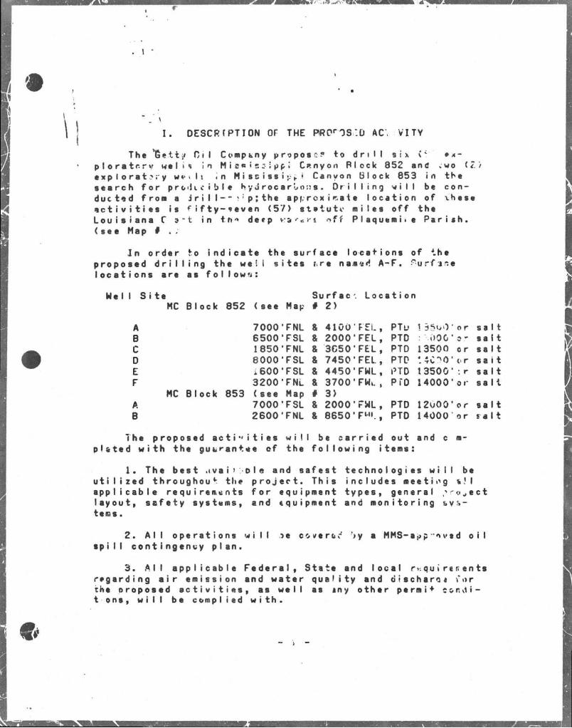
r
. \
I . DESCR CPT I ON OF THE FRPrOS:0 AC. VI.TV
The *6etti/ Ci I Company propose? to dri II six ( c • A-p I o r a t c r %t we I i <> in M I 8« ? BS ; pp < Canyon Plock 852 end ;wo (2 ) exploratory w * . I ; in M i s s i s s i *r > • Canyon Block 853 in the search for pro - l i e i b l e hydrocarbons. D r i l l i n g v i l l be conducted from a j r i I I - - vp;the approximate location of xhese e c t i v i t i e s is f i f t y - i e v e n (57) statute miles off the Louisiana C » " t in t ft *> deep fr.* sr'«r t off P I a q u e m i • e P a r i s h , (see Map # .
In order to indioate the surface locations of the proposed d r i l l i n g the well s i t e s rre n a *'£<*. A-F. ? u r f j s e l o c a tions are es follow*.:
Hell S i t e Surfac • Locetion MC Block 852 (see Mep # 2)
A 7000'FNL & 4100'FEL, PTu \ dSv'V or s s l t B 6500'FSL & 2000'FEL, PTD : 000'or salt C 1850'FNL & 3650'FEL, PTD 13500 or s s l t D 8000'FSL & 7450'FEL, PTD sai t E i 600'FSL & 44501FWL, PTD 13500':r salt F 3200'FNL & 3700'FWc, pro 14000'or salt
MC Block 853 (see Map # 3) A 7000'FSL & 2000'FWL, PTD I2o00* or salt B 2600'FNL & 8650* F"«., PTD 14000 or r a i t
The proposed a c t i " i t i e s wil be cerr i ed out and c m-plated w th the guarantee of the following i tems:
1. The best .ivai> oie and safest technologies w i l l be u t i l i z e d throughout the p r o j e c t . This includes meetiog i ! I applicable requirements for equipment types, general - o e c t layout, s a f e t y systems, and equipment and monitoring systems.
2. A l l operations w i l l .*>e cove ret1 >y a MMS-opp ~nved o i l s p i l l contingency plan.
3. A l l applicable F e d e r a l , State and local r qu»rer.ents regarding a i r emission and water quality and discharoi vur che oroposed e c t i v i t i e s , as well es iny other perm i + c o r v1 i -t ons, w i l l be complied with.
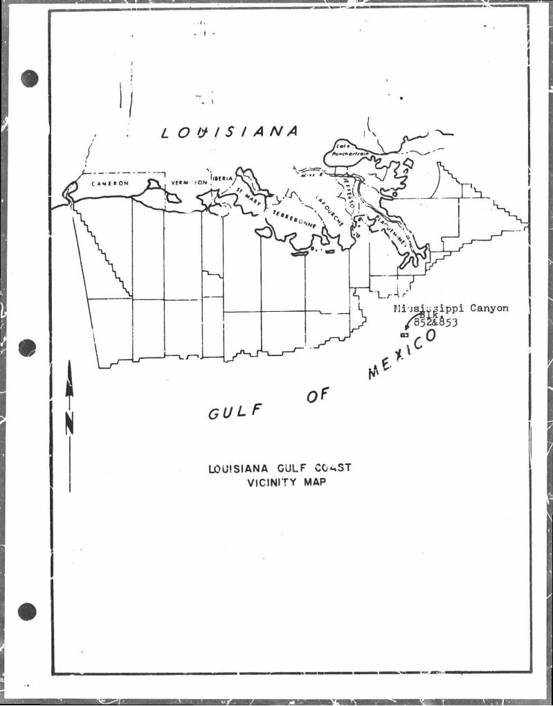
of CULF
LOUISIANA GULF CG^ST VICINITY MAP
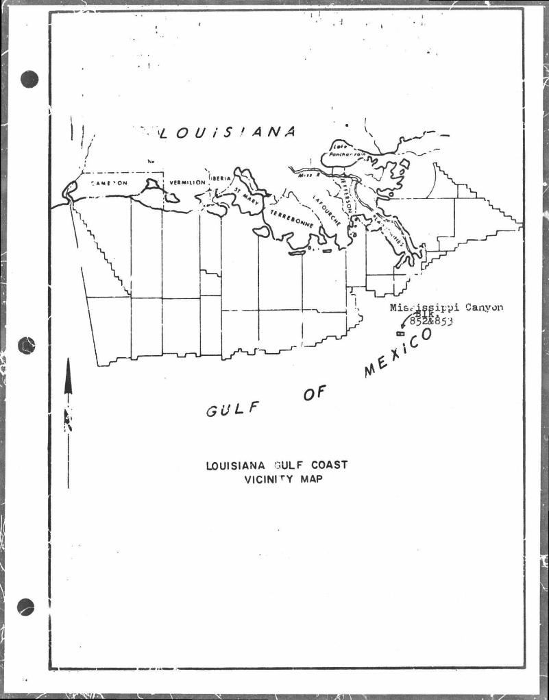
K LOUISIANA OULF COAST
VICINITY MAP
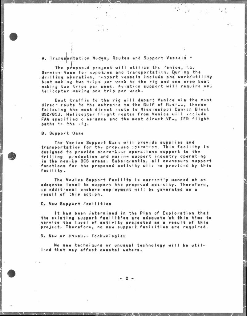
, J
A. T r»»r.s pi ation Mod-es(, Routes and Support Vessels *
Tht proposed project w i l l u t i l i z e tht •'•nice, La. Servic- Base for a*,'poUea and transportation. Ojuring the d r i l l i n g operation, voport vessels include one w o r k / u t i I i t y beat nicking two t r i p s >* r «-*»ek to the r i g and one crew boot makir.g two t r i p s per week. Aviation support w i l l require onn helicopter making one t r i p per week.
Boat t r a f f i c tc the r i g w i l l depart: Venice vie the most direc- route to the i n t r a n t to the Gulf of rlex'***, thence folloving the .tost d i r t c t route to M i s s i s s i p p i Cam tn Block 852/853. Helicopter f l i g h t routes from Venice w i l l i*.elude FAA s p e c i f i e d c earance and the most d i r e c t VF.,, IFR f l i g h t pethe *t tha r » j .
B. Support 'Jase
The Venice Support Bale w i l provide supplies and transportation for th% prepiseo ;?«r»':ier!. Th • s f e c i l i t y ia designed to provide sfore-u-.c oparn:i one support to the • f r i l l i n g production and mar in» support industry operacing in the neaiby OCS erees. Sub s •-. q,e n 11 y , a t l n e c i s s i r y support functions for the proposed a c t i v i t y w i i i Se p r o v i d e by t h i s f s c i I i t y .
The Vt/iice Support f e c i l i t y ie curr«nt'y Manned at an adeqi'ite lev e l to support the propesed a c t i v i t y . Therefore, rie additional onshore employment w i l ! be generated ss s result of bh i f action.
C. New Support f a c i l i t i e s
I t hs* been determined in the Plan of Exploration that the e x i a t i n g support fact I i t ; a a art adequate at t h i t tlmt to yerv'ce tne I we I ef a e t l v l t y orejeeted et a r e e u l t of thio project. Therefore, no new support f e c i l i t i e s are required-
0. New or Unu8*141 Ten-hue i og i eu
No new techniques or unusual technology w i l l be u t i l ised tl at mi:y ef f e c t coastal wsters.
•• 2 -
J
I E. |MJps
'Three maps are in i ed in thie report; Map #1 ie a v i c i n i t y map showing general location of the proposed project in r e l e t i o n to the affected State's coastel zone. Meps #2 and #3 contain location p l a t s .
F. Transportation of Oil and Gas
The proposed project i s of an exploretory nature, should a discovery be made adequate plens w i l l then be prepored f or the development end production of hydrocarbons. Therefore, no transportation of o i l or gas w i l l occur during this phese of tho p r o j e c t .
- 3 *
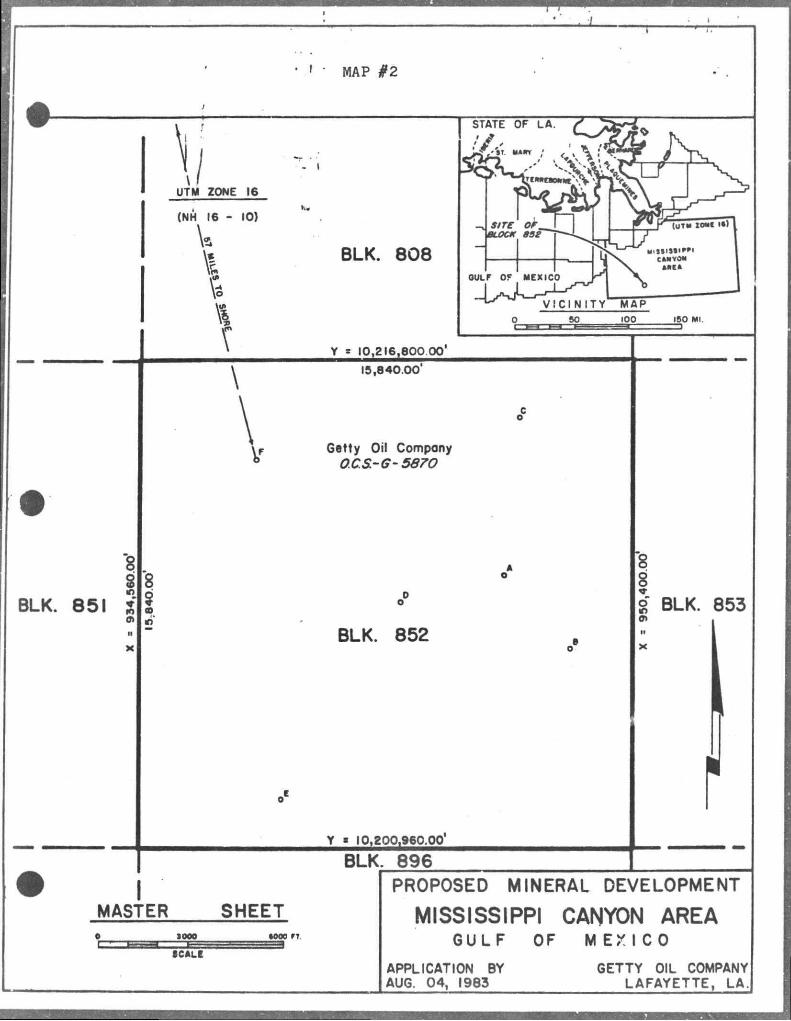
F
' ' • MAP #2
- i \
UTM ZONE 16
(NH 16 - 10)
X BLK. 808
Y - 10,216,600 00'
15,840.00
Getty Oil Company OCS-G-5670
BLK. 851
8 8 $ ro
BLK. 852
Y » 10,200,960.00'
BLK. 896 I
MASTER SHEET IOOO •000 IT
SCALE
8 |
8' BLK. 853 0» N
r PROPOSED MINERAL DEVELOPMENT
MISSISSIPPI CANYON AREA GULF OF MEXICO
APPLICATION BY AUG. 04, 1983
GETTY OIL COMPANY LAFAYETTE, LA.
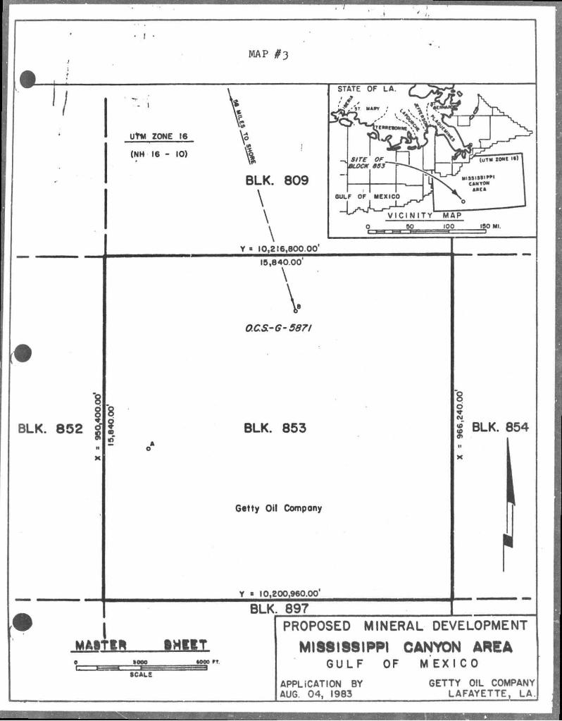
UtM ZONE 16
(NH 16 - 10)
'8
BLK. 852 $
MAP #3
STATE OF LA.
BLK. 809
\
\
\ Y « 10,216,800 00'
V IC IN ITY MAP SO 100 ISO Ml.
15,840.00
\
V 0CS.-G-587I
BLK. 853
Getty Oil Company
Y « 10,200,960.00'
BLK. 897
•oeo rt. 5
SCALE
'8 6
• BLK. 854
PROPOSED MINERAL DEVELOPMENT
MISSISSIPPI CANYON AREA GULF OF MEXICO
APPLICATION BY AUG. 04 , 1983
GETTY OIL COMPANY LAFAYETTE, LA.
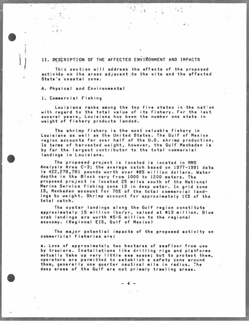
I I . D E S C R I P T I O N OF THE A F F E C T E D ENVIRONMENT AND IMPACTS
T h i s s e c t i o n w i i l a d d r e s s the e f f e c t s of t h e p r o p o s e d a c t i v i t y on t h e a r e a s a d j a c e n t ito t h e s i t e and t h e a f f e c t e d S t a t e ' s c o a s t a l z o n e .
A . P h y s i c a l a n d E n v i r o n m e n t a l
1. C o m m e r c i a l F i s h i n g
L o u i s i a n a r a n k s among t h e top f i v e s t s t e o i n t h e n a t v o n w i t h r e g a r d t o t h e t o t a l v a l u e of i t s f i s h e r y . F o r t h e l a s t s e v e r a l y e a r s , L o u i s i a n a h a s b e e n t h e number one s t a t e i n w e i g h t of f i s h e r y p r o d u c t s l a n d e d .
The s h r i m p f i s h e r y i s t h e mos t v a l u a b l e f i s h e r y i n L o u i s i e n e a s w e l l es t h e U n i t e d S t e t e s . The G u l f of M e x i c o r e g i o n a c c o u n t s f o r o v e r h a l f of t h e U . S . s h r i m p p r o d u c t i o n . I n t e r m s o f h a r v e s t e d w e i g h t , h o w e v e r , t h e G u l f Menhaden i s by f a r t h e l a r g e s t c o n t r i b u t o r to t h e t o t a l c o m m e r c i a l l a n d i n g s i n L o u i s i a n a .
The p r o p o s e d p r o j e c t i s l o c a t e d i s l o c a t e d in MMS A n e l y s i s A r e a C - 3 ; t h e a v e r a g e c a t c h b a s e d on 1 3 7 7 - 1 9 8 1 d a t a i s 4 2 2 , 2 7 8 , 7 8 1 p o u n d s w o r t h o v e r $ 8 5 m i l l i o n d o l l a r s . W a t e r d e p t h s i n t h e B l o c k v e r y f r o m 1000 to 1200 m e t e r s . The p r o p o s e d p r o j e c t i s l o c a t e d 25 m i l e s s o u t h of t h e N e t i o n e l M a r i n e S e r v i c e f i s h i n g z o n e 13 in deep w a t e r . In g r i d z o n e 1 3 , Menhaden a c c o u n t f o r 70% o f t h e t o t a l c o m m e r c i e l l a n d i n g s by w e i g h t . S h r i m p a c c o u n t f o r a p p r o x i m a t e l y 1CZ of t h e t o t e l c a t c h .
The o y s t e r l a n d i n g s a l o n g t h e G u l f r e g i o n c o n s t i t u t e a p p r o x i m a t e l y 15 m i l l i o n i b s / y r , v a l u e d a t $ 1 3 m i l l i o n . B l u e c r e b l a n d i n g s a r e w o r t h $ 5 - 6 m i l l i o n t o t h e r e g i o n a l economy. ( R e g i o n a l E I S , G u l f o f M e x i c o )
The m a j o r p o t e n t i a l i m p a c t s of t h e p r o p o s e d e c t i v i t y on c o m m e r i c i a l f i s h e r i e s s r e :
s . L o s s of s p p r o x i m a t e I y two h e c t e r e s of s e a f l o o r f r o m u s e by t r a w l e r s . I n s t a l l a t i o n s l i k e d r i l l i n g r i g s s n d p l a t f o r m s a c t u a l l y t a k e up v e r y l i t t l e s e e s p a c e ; b u t to p r o t e c t t h e m , o p e r e t o r s s r e p e r m i t t e d t o e s t a b l i s h s s a f e t y z o n e a r o u n d them, g e n e r a l l y one q u a r t e r n a u t i c e l m i l e i n r a d i u s . The deep a r e a s o f t h e G u l f s r e n o t p r i m s r y t r a w l i n g a r e a s .
. I •
The OCS; A(C t Amendments provide for a Fishermen's Contingency Fund financed from o i l revenues to compensate commercial fisherman for losses or demage to geer r e s u l t i n g from o i l i n d u s t r y . o p e r a t i o n s .
The impacts associated with the proposed a c t i v i t y are considered minimal. These impacts are otherwise offset by the b e n e f i c i a l increese in biomass neer the pIetform/rig. These s t r u c t u r e s serve es a r t i f i c i a l reefs for marine communities by providing a substrate for epifauna to grow on. Pelagic f i s h then are e t t r a c t e d to these areas to feed on the attached organisms thereby r e s u l t i n g in greeter f i s h e r y yields in these arees.
2. Sh i pp i ng
The Louisiana Offshore Oil Port (LOOP or Superport) i s loceted 19 miles off of the Lafourche Parish shore and is approximately 75 miles northwest of the proposed pr o j e c t . The Port adds a new dimension in wsterborne commerce; the deepwster locstion allows large tankers used in international o i l trade to moor and offload v i a pipeline to on-land sto rage f a c i I i t i e s .
There are no shipping f s i r w s y s in or neer Blocks 852 snd 853. The c l o s e s t fsirway i s sppproximsteIy 43 miles due west of the proposed action. Consequently, the proposed ection w i l l not e f f e c t the operations of any shipping f a i r way, LOOP ope rations,or sny transit/snchorage areas.
3. Recreation
Many f i s h snd s h e l l f i s h sought s f t e r for commercisl vslue ere s l s o pursued for sport in coastal Louisiana. Ssltwster sport species include spotted eee trout, red drum, red snapper, FI orida pompano and tarpon. The offshore permanent s t r u c t u r e s provide highly productive a r t i f i c i a l reefs thet ere favorable f i a h i n g ereas for saltweter sport f i s h e r men. An area of high productivity for big game f i s h i n g is locsted epproximateIy three miles south of the project sree;the a c t i v i t i e s associated with t h i s project are not expected to a f f e c t t h i s area. Thus, the implementation of this p r o j e c t i s not expected to produce any edverse impecte on sport fishing.snd plessure booting; in f e c t , recreational potential w i l l be s l i g h t l y increased due to t h i s action.
5
1 /
4 . C u l t u r a l , R e s o u r c e s
T h e r e a r e no s h i p w r e c k s o r o t h e r i d e n t i f i a b l e c u l t u r a l o r a r c h e o l o g i c a l f e a t u r e s i n M i s s i s s i p p i C a n y o n B l o c k 8 5 2 o r 8 5 3 . ( U S D I , BLM OCS S a l e 6 2 V i s u a l # 4 ) .
T>a p r o p o s e d l o c a t i o n i s s e a w a r d o f t h e h i g h p r o b a b i l i t y l i n e f o r c u l t u r a l , h i s t o r i c o r p r e - h i s t o r i c r e s o u r c e s ( U S D I , R e g i o n a I I n p a c t S t m t . , V i s u a l # 1 1 ) . T h e r e f o r e , t h e p r o p o s e d a c t i o n i s n o t e x p e c t e d t o p r o d u c e a n y s i g n i f i c a n t i m p a c t s on t h e s e r e s o u r c e s .
5 . E c o l o g i c a l l y S e n s i t i v e F e a t u r e s
The p r o p o s e d p r o j e c t i s l o c a t e d a p p r o x i m a t e l y 57 m i l e s f r o m t h e P l a q u e m i n e P a r i s h c o a s t . T h i s c o a s t a l a r e a i s c h a r e c t e r i z e d by n u m e r o u s a c r e s o f m a r s h w h i c h p r o v i d e h a b i t a t f o r a v a r i e t y o f w i l d l i f e a n d a l s o s e r v e as p r i m a r y n u r s e r y g r o u n d s f o r f i s h a n d s h e l l f i s h . A l o n g t h i s c o a s t a l a r e a i s f o u n d t h e P a s s A L o u t r e W i l d l i f e M a n a g e m e n t A r e a a n d t h e D e l t a N a t i o n a l W i l d l i f e R e f u g e , t h e s e a r e a s a r e m o r e t h a n 60 m i l e s f r o m t h e p r o p o s e d a c t i v i t y .
The L a f o u r c h e and J e f f e r s o n P a r i s h c o e s t a l a r e a s a r e a p p r o x i m e t e I y 9 0 t o 100 m i l e s n o r t h w e s t o f t h e p r o p o s e d p r o j e c t . T h e c o a s t a l a r s e s o f t h e s e p a r i s h e s i n c l u d e e n v i r onmen a I I y s e n s i t i v e e r e e s s u c h as t h e W i s n e r S t a t e W i l d l i f e M a n a g e m e n t A r e a a n d t h e b a r r i e r i s l a n d s .
The W i s n e r S t a t e W i l d l i f e M a n a g e m e n t A r e a c o n t a i n s 2 1 , 6 2 1 a c r e s o f m e r s h . T h i s a r e e s e r v e s many c o n s s r v a t i o n and p r e s e r v a t i o n f u n c t i o n s i n w i l d l i f e m a n a g e m e n t . The G r a n d I s l e - G r a n d T e r r e I s l a n d s a n d t h e T i m b a l i e r I s l a n d s a r e i m p o r t a n t g e o l o g i c a l f e a t u r e s a l o n g t h e L o u i s i a n a c o a s t . These b a r r i e r i s l a n d s a r e e x t r e m e l y i m p o r t a n t i n r e g u l a t i n g and m a i n t a i n i n g w a t e r e x c h a n g e ar.d s a l t w a t e r b a l a n c e b e t w e e n t h e G u l f and t h o b e y s . T h e y a l s o r e d u c e s t o r m s u r g e and wave a c t i o n on t h e m a r s h e s a n d b a y s b e h i n d t h e i s l a n d s end p r o v i d e n e s t i n g a r s e s f o r msny s h o r e b i r d s e n d sea b i r d s . The p r o p o s e d a c t i o n i s 9 0 t o 100 m i l e s s o u t h o f t h e s e e n v i r o n m e n t a l l y s e n s i t i v e a r e a s .
The n e a r e s t r e c r e a t i o n a l b e a c h i s l o c a t e d e t G r a n d I s l e a p p r o x i m a t e l y 9 0 m i l e s n o r t h w e s t o f t h e p r o p o s e d p r o j e c t .
- 6 -
• ! *
i The pToposed p r o j e c t w i l l not generate any new or expanded onshore f a c i l i t i e s . Subsequently no adverse impacts on the c o a s t a l environment, the w i l d l i f e management areas or the r e c r e a t i o n a l p o t e n t i a l of the co a s t a l beaches is e x -'pected as a r e s u l t of t h i s a c t i o n .
There are no known e c o l o g i c a l l y s e n s i t i v e areas or areas of p a r t i c u l a r concern in or near M i s s i s s i p p i Canyon Block 852/853, i . e . Sackett Bank is approx i m a i e l y 40 miles northwest of the p r o j e c t s i t e , t h a t would be adversely or otherwise a f f e c t e d by the proposed a c t i o n .
6. F x : - t i n g P i p e l i n e s and Cables
I ' r e arc io e x i s t i n g p i p e l i n e s i n M i s s i s s i p p i Block 852 or bL-3. There are no known cables in the Blocks which would h i n d e r or o b s t r u c t the proposed p r o j e c t .
7. Other Mineral Uses
There are no known plans to produce o t h e r m i n e r a l s other than those h/drocarbons associated w i t h the proposed a c t i v i t y .
8. Ocean Dumping Grounds
Ocean dumping is p r o h i b i t e d i n M i s s i s s i p p i Canyon Blocks 852 and 853. The nearest E.P.A. approved ocean dumping s i t e i s over 200 n i l e s to the west. (USDI,Visual No.11,EIS 1983 Gulf of Mexico) A smaller s i t e which has been i n a c t i v e f o r several years borders Block 852 was ised f o r the d i s p o s a l of i n d u s t r i a l waste but whose d e s i g n a t i o n as an EPA approved has J r C u r r e n t l y the s i t e in the western Gu I f i s the on I y *•* .
G e t t y Oi! Co.uj*-., * . • i dispose of d r i l l c u t t i n g s , s a n i t a r y and domestic wastes in accordance w i t h t h e i r NPDES permit. F o l l o w i n q d r i l l i n g a l l d r i l l i n g f l u i d s w i l l be ret a i n e d f o r f u r t h e r use or a p p r o p r i a t e land d i s p o s a l .
9. Endangered or Threatened Species
The proposed p r o j e c t , located 57 mile s o f f the Plaquemine P a r i s h coast, i s w i t h i n the range of. f i v e endangered species of whales, t h r e e species of endangered t u r t l e s and
- 7 -
I
two species of threatened t u r t l o r Onshc re thc Plaquemine Parish i.^ea ia within the rnr,.,c of LPe endangered bald eagle and the threatened Arte** i * \ r i a l l i g a t o r . The onshore area east of day * J Lafourche : r L »'.. f o u r c h ft P A r » a h i s within the rsrge of the orown P a l i c t u
e. Wholes (Endangered)
-Sei whale (Balaenoptera b o r e a l i s ) fhis species is « poss i b l e winter resident of the Gulf of Hexico.
-Fin whale (balaenoptera phys...us) This species is 3 poss i b l e winter resident of the Gulf of Me,< ico.
-Blue whale (balaenoptera musculus) Tbis species i s uncommon to the Gulf of Hexico.
-Humpback whale (Megaptera novaeangliae) This species i s r possible winter resident of the Gulf of Mexico.
-Sperm whale (Physeter catodon) The most common of the endangered whales to occur in the Gulf of Mexico.
Migratory patterns of the wholes l i s t e d above are not d i r e c t l y known. I t i s presumed thst these species occur msinly in the deeper waters of the Gulf of Mexico. The proposed project is considered s deep water project .however, the proposed project is not expected to adversely a f f e c t whaie populations nr migratory patterns.
b. T u r t l e s (Endsngered snd Threstened)
-kemrs A t l a n t i c r i d l e y (Lepidochelys kempii) The shrimping grounds of the northern Gulf of Mexico i s o primsry feeding ares for t h i s endsngered species.
-Hswksbill t u r t l e (Eretmochelys imbricata) An endangered species t h s t msy occur in the coastsl waters of Louisiana.
-Leatherback t u r t l e (Dermochelys corioces) The rsnge of t h i s endsngered species is usually the deeper waters of the Gulf of Mexico; however, observations have been made of large numbers of leatherbacks feeding on j e l l y f i s h in inshore wsters during summer (USDI, E I S , OCS Sale 58A, pg. 62.).
- 8 -
• I •
I
\ t •
I :
•j-Gheen t u r t l e ^Chelonia mydas) and tha Logge'rhead t u r t l a (Caretta c a r e t t a ) are l i s t e d as threatened and occur in the Gulf of Mexico waters.
K. 1
There are no tea t u r t l e nesting areas in the coastal waters adjacent to Plequemine and Lafourche parishes ; therefore, no impacts are expected t> occur with respect to endangered or threetened sea t u r t l e s in the area.
c. Onshore Species (Endangered and Threatened)
-Americon a l l i g a t o r ( A l l i g a t o r m i s s i s s i p p i e n s i s ) This spscies is c u r r e n t l y c l a s s i f i e d as Threatened due to the " S i m i l a r i t y of Appearance 1 4 on the federal l i s t of endangered species in the coastal arees of Louisiana. Subsequently, twelve perishes currently are allowed to permit regulated harvests of a l l i g a t o r s in t h e ; r respective parishes; P l a quemine and Lafourche perishes are emong these. Stote laws govern the harvests and ellow the taking of a l l i g a t o r hides and meat during harvest seasons.
The American A l l i g a t o r is the only spec •»». . j r r e n t l y on the federel l i s t of endangered or threatened species thet i s commonly found in the coastal areas neer the project.
-Southern Bald Eagle (Haliaeetus I ucocephaI us ) Plaquemine and Lifoi - che parishes are within the renge of the bald eagle. Nes+ing s i t e s are found in the trees near water-bod i t s .
-Brown P e l i c a n (Pelicanus o c c i d e n t a l i s ) There is a small colony of brown pelicans that nest in the Queen Bess Inland end Grand Terre Islands aree of Southern B a r r a t a r i a Bay. Thie area is approximately 90 miles northwest of the proposed p r o j e c t .
The proposed project does not rvqui'O sny additional onehore f e e i l i t i e s ; therefore, there are >o expected impaots on the hab i t a t of these onshore endangered or threatened species ss a r e s u l t of t h i s ac ion.
B. Socio-economic
Not applicable et t h i s time.
- 9 -
I
• I •
I
\ I
j ^ » I I I . UNAVOIDABLE ADVERSF IMPACTS
The env i ronmenta I cc n n quene es of the proposed project •re expected to bt minimal. Most impacts idontifiod w i l l be of a temporary nature and w i l l occur in ths immediate v i c i n i t y of tha operation. Therefore, no long term e f f e c t on the environment is expected.
Unevoidable adverse impacts i r ^ l u d e :
a. An increase in a i r pollutants l«- a r e s u l t of powe.* generation during d r i l l i n g and transportstion modes. However, en a i r q uality review has been conducted pursusnt to 30 CFft 250.57. The findings of t h i s review indi c s t e thst the projected emissions sre well below the exemption rotes and pose no s i g n i f i c s n t iapsct on the smbient s i r q u s l i t y of the onshore environment.
b. A temporary reduction in water quality due to the d i s posal of d r i l l c u t t i n g s , deck drsinsge end sanitary and domestic waste w i l l occur as a r e s u l t of t h i s action. During the disposal of d r i l l c u t t i n g s , an increase in t u r b i d i t y w i l l be evident as a r e s u l t of d r i l l i n g f l u i d s adhering to these p a r t i c l e s . Since tha a v a i l a b i l i t y of sunlight is sn iaportsnt f a c t o r in photosynthesis, i t hss been found thet increased t u r b i d i t v reduces photosynthesis. However, t h i s e f f e c t w i l l be short-term snd w i l l return to normal once the d r i l l i n g phase is coapleted. The additional sources of wster pollutants sre also expected to produce eiin'm.! snd short-term e f f e c t s on the wster q u s l i t y nesr the r i g . These pollutants sre regulated by the U.S. Environmentai Protection Agency's e f f l u e n t ouidelines (40 CFR Part 435) for o i l snd gas e x t r a c t i o n . Con. ormence to these guidelines w i l l be carried out throughout the project period.
c. Burial of immobile benthic organisms w i l l occur during the discharge of d r i l l c u t t i n g s . D r i l l cuttings sccumulste on the tea f l o o r covering an area of approximately 150 feet in diameter; in the affected area the impaet is loeelized and d i s s i p a t e s over time by currents. Mobils benthic organisms from the surrounding see f l o o r adjuat rather rapidly to these changes and build homes on top of the c u t t i n g s . Hithin months the affected ores i s again f l o u r i s h i n g with new benthic communitiee (Zingulo et s l , 1977). Thus, the impscts asaociated with t h i s a c t i v i t y w i l l be short-term end
- 10 -
l o c i ' Tze,d.
\ . Thtrt M M I bt a temporary loss of approx i tea tt I y f i v t acres v-2 S e c t : res) of s t a space ;that w i l l bt unawei lable for commercial f t a h i . g . I f the wells are economically p r o c j c i b l e ther- aver.tue.' 'cture development/production operations would hi* a z more ><eraanwnt e f f e c t . However, there ere some posi-tive ex : * - .ia ! i t i es s s s o c i s t e d with the proposed a c t i v i t i e s :hftt would, in ihe long run, benefit comcerciel and recreation f i s h i r g ; these are:
-An increase in biomass ner*' the rig/platform, thus, r e s u l t ing in higher productivity.
-Offshora s t r u c t u r e s may serve es navigation aids snd during mechanical breakdowns or inclement westher provide refuge for t i n t o p e r a t o r s .
- 11 -
. I •
I
\ t I
I - , REFERENCES ' *
Buck, O.H. " E f f e c t s of Turbidity on F i s h and F i s h i n g " . North American W i l d l i f e Conference 21:249-261
Burke and Associates, Inc. Unique Ecological Features of the Louisiana Coast prepared for Louisiane State Planning Off i c e : Baton Rouge, Louisiana, 1977.
Gowaniock, James Nelson. F i s h e s and Fishing in Louisiana. C l a i t o r ' s Book Store Press: Baton Rouge, Louisiana. 1965.
Hay, K e i t h . "Fishing and OCS Energy Development/Charging a Course of Compatibility" Coastal Zone'80 Proceedings of the Second Symposium on Coastal and Oceen Management. 1980.
Renner, James R. The Coastal Zone: An Overview of Economic, Recreational and Demographic Patterns. Baton Rouge: Lou siana State Plenning O f f i c e , 1976.
Lowery, G.H., J r . The Mamnals of Louisiana and i t s Adjacent Haters. L o u i s i s n a University Press, Bston Rouge, Lo i s i a n a , 1974.
United S t a t e s Depsrtment of Commerce, Netionsl Oceanic snd Atmospheric Administration. Final Environments! Impsct Ststement for the L o u i s i s n s Coastal Resources Program. Office of Coastal Zone Hsnsgement, Washington, D.C, 1980.
United S t a t e s Depsrtment of the I n t e r i o r , Buresu of Land Hsnsgement. D r s f t Environmental Impact Statement; OCS Sole 58A. Pro».o ed 1979 Outer Continental Shelf Oil and Gas Lesse Ssle 58A. Gulf of Hexico, Washington, D.C, 1979.
United Spates Department of the I n t e r i o r , Bureau of Land Management. Draft Environments! Impsct Ststement; OCS Seles I^Z snd 82. Propoeed 1980 Outer Continental Shelf Oi! snd b«s Leese S* i c > A62 snd 62: Gulf cf Mexico, Washington, D.C, 1976.
United S t a t e s Departmeni of the I n t e r i o r , Minerals Management S e r v i c e . Final Regional Environmental Impact Statement; Volumes 18X1: Gulf of Mexico, Washi ngton,D.C. ,1983
United S t a t e s Depertment of the I n t e r i o r , U.S. Geologies!
- 12 -
. I •
y r v t y . C o m p f l a t i o n of R e g u l a t i o n s R e l a t e d to M i n e r a l R e s o u r c e A c t i v i t i e s on t h e O u t e r C o n t i n e n t a l S h e l f : Vo lume and 2 . W a s h i n g t o n , O . C . 1 9 8 1 .
U n i t e d S h a l e . - D e p a r t m e n t of t h e I n t e r i o r , F i s h and W i i d l i f S e r v i c e ; R « j . o n 4 E n d a n g e r e d S p e c i e s N o t e b o o k . A t l a n t a , G e o r g i a , 1 9 7 9 .
Z i n g u l a , ^ R i c h a r d P . and L a r s o n , Dana W. " F a t e of D r i l l C u t t i n g s i n t h e M a r i n e E n v i r o n m e n t " O f f s h o r e T e c h n o l o g y C o n f e r e n c e . 1 9 7 7 .
• I '
APPENDIX"
COASTAL ZONE MANAGEMENT CONSISTENCY, CERTIFICATE
- 14 -
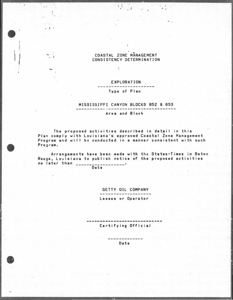
COASTAL ZONE MANAGEMENT CONSISTENCY DETERMINATION
v..
EXPLORATION
Type of Plan
MISSISSIPPI CANYON BLOCKS 852 & 853
Area and Block
The proposed a c t i v i t i e s described in detail in this Plan comply with Louisiana's approved Coastal Zone Management Program and w i l l be conducted in a manner consistent with such Program.
Arrangements have been made with the States-Times in Baton Rouge, Louisiana to publish notice of the proposed a c t i v i t i e s no later than
"Date
GETTY OIL COMPANY
Lessee or Operetor
Certifying Official
Date
\ " \ ENVIRONMENTAL REPORT FOR COASTAL ZONE MANAGEMENT CONSISTENCY DETERMINATION
EXPLORATION MISSISSIPPI CANYON BLOCK 809 (OCS-G-5868)
ENVIRONMENTAL REPORT GETTY OIL COMPANY
LAFAYETTE, LOUISIANA
CONTACT PERSON: LOUIS HOOVER, I I I , ESQ.
PERMIT ANALYST P.O. BOX 51367
LAFAYETTE, LOUISIANA 70505 (318-232-5813)
SEPTEMBER 19,1983
Prepared by: ED ROYS, LTD.
Environmental Services Diviaion
J
; r •
| - \ TABLE OF CONTENTS
I I . DESCRIRJION OF THE PROPOSED ACTIVITY 1
A. Transportation Nodes, Routes and Support Vessels . .1
B. Support Base 2
C. New Support F a c i l i t i e s 2
D. New or Unusual Technologies 2
E. Haps 2
F. Transportation of Oil and Gas 3
I I . DESCRIPTION OF THE AFFECTED ENVIRONMENT AND IMPACTS 4
A. Physical and Environmental 4
1. Commercial Fishing . . . . 4
2. Shipping 5
3. Recrea tion 5
4. Cuiturai Resources 6
5. E c o l o g i c a l l y S e n s i t i v e Features 6
6. E x i s t i n g P i p e l i n e s and Cables 7
7. Other Mineral Uses 7
8. Ocean Dumping Grounds 7
9. Endangered or Threatened Species 7
B. Socio-economic 9
I I I . UNAVOIDABLE ADVERSE IMPACTS 10
i
IV. 7. REFERENCES 12
V. APPENDIX 14
Coastal Zone Management Consistency Certification .15
LIST OF MAPS
MAP #1 IA
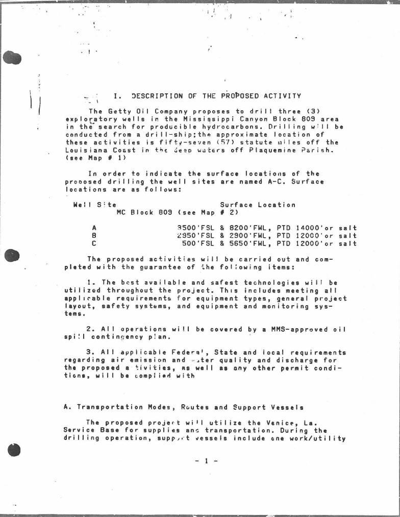
I . DESCRIPTION OF THE PROPOSED ACTIVITY
Thc Getty Oil Company proposes to d r i l l three <3> exploratory wells in the M i s s i s s i p p i Canyon Block 809 area in the* search for producible hydrocarbons. D r i l l i n g w i l l be conducted from a d r i l l - s h i p ; t h * approximate location of these a c t i v i t i e s i s f i f t y - s e v e n (57) statute wiles off the Louisiana Coast in the Jeeo waters off Plaquemine P a r i s h , (see Map # 1)
In order to indicate the surface locations of the prooosed d r i l l i n g the well s i t e s are named A-C. Surface locations are as follows:
Hell S i t e Surface Location MC Block 809 (see Map # 2)
A 3500'FSL & 8200'FWL, PTD 14000'or s a l t B ic'SSO'FSL & 2900'FWL, PTD 12000' or s a l t C 500'FSL & 5650'FHL, PTD 12000'or s a l t
The proposed a c t i v i t i e s w i l l be c a r r i e d out and completed with the guarantee of ihe folSowing items:
1. The best a v a i l a b l e and s a f e s t technologies w i l l be u t i l i z e d throughout the p r o j e c t . This includes meeting a l l applicable requirements for equipment types, general project leyout, safety systems, and equipment and monitoring systems.
2. A l l operations w i l l be covered by a MMS-approved o i l spi!I contingency p!an.
3. A l l applicable Federa 1, State and local requirements regarding a i r emission and ater quality and discharge for the propoeed a * t i v i t i e s , as well as any other permit conditions, w i l l be complied with
A. Transportation Modes, Routes end Support Vessele
The proposed project wi'l u t i l i z e the Venice, Le. Service Base for supplies anc transportation. During the d r i l l i n g operation, s u p p x t vessels include cne w o r k / u t i l i t y
_ 1 -
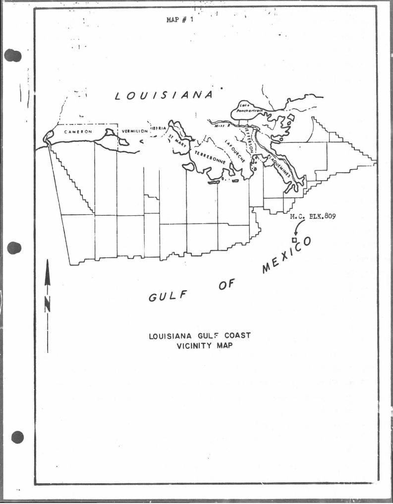
MAP # 1
J •. r
tjotkt making Two, t r i p s per week to the rig an'd one crew boat making two t r i p s per week. Aviation support w i l l require one helicopter making one t r i p per week.
rr« j
Boat t r a f f i c to the r i g w i l l deport Venice via the most direct route to the entrance to the Gulf of Mexico, thence following the most d i r e c t route to M i s s i s s i p p i Canyon Block 803. Helicopter f l i g h t routes from Venice w i l l include FAA specified clearance and the most d i r e c t VFR, IFR f l i g h t paths to the r i g .
B. Support Bese
The Venice Suppo-t Base w i l l provide supplies and transportation for the proposed operation. This f a c i l i t y is designed to provide shore-base operetions support to the d r i l l i n g , production and marine support industry opereting in the nearby OCS areas. Subsequently, a i l necessary support functions for the proposed a c t i v i t y w i l l be provided by t h i s fac i i i t y .
The Venice Support f a c i l i t y is currently manned at an adequate l e v e l to support the proposed a c t i v i t y . Therefore, no edditional onshore ployment w i l l be generated as a result of t h i s action.
C. New Support F a c i l i t i e s
I t hes been determined in the Plan of Exploration that the e x i s t i n g support f a c i l i t i e s are adequate at t h i s time to service the level of a c t i v i t y projected es a r e s u l t of t h i s project. Therefore, no new support f o c i l i t i e s sre required.
0. New or Unususl Technologies
No new techniques or unusual technology w i l l be u t i l ized that may a f f e c t coastal waters.
E. Meps
Two. maps are i n c l u d e d in t h i e r e p o r t ; Msp #1 i s s v i c i n i t y msp showing Lhe g e n e r a l l o c o t i o n of the proposed p r o j e c t in r e l a t i o n to the a f f e c t e d S t a t e ' s c o a s t a l z o n e .
, J
- 2 -
#2 contafhsi a location p l a t .
F. 'Transportation of Oil and Gas
Tha proposed p r o j e c t is of en exploratory nature, should a discovery be nade adequete plans w i l l then be prepared for the developnent and production of hydrocarbons. Therefore, no transportation of o i l or gas w i l l occur during th i s phase of the p r o j e c t .
- 3 -
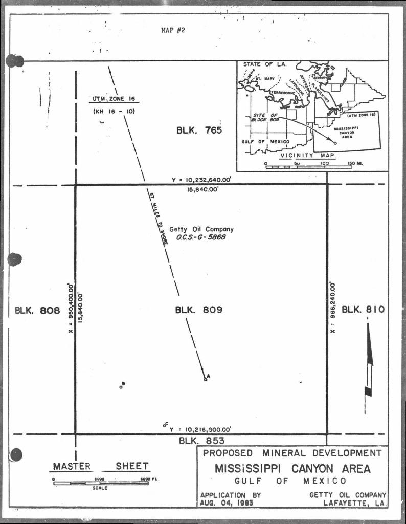
MAP #2
\ • \
JTM \ ZONE 16
(KH 16 - 10)
V \ \
BLK. 765
\
\
\
STATE OF LA.
/ y ,
VICINITY MAP bu 100 150 Ml.
Y « 10,232,640.00
V 15,840.00'
"8
i BLK. 808 S
•» X
Getty Oil Company ^ OCS-G-5663
\
\
\
Y = 10,216,300.00
BLK. 853
8 o
I BLK. 810 0» ,
I MASTER SHEET
SCALE
PROPOSED MINERAL DEVELOPMENT
MISSiSSIPPI CANYON AREA G U L F OF M E X I C O
APPLICATION BY AUO, 04, 1913
GETTY OIL COMPANY LAFAYETTE, LA,
I I . D E S C R I P T I O N OF THE A F F E C T E D ENVIRONMENT AND IMPACTS
T h i s s e c t i o n w i l l a d d r e s s t h s e f f e c t s of t h e p r o p o s e d a c t i v i t y on t h e a r s a s a d j a c e n t to t h e e i t e a n d t h e e f f s c t e d S t a t e ' s c o a s t a l z o n e .
A . P h y s i c a l a n d E n v i r o n m e n t a l
1. C o m m e r c i a l F i s h i n g
L o u i s i a n a r a n k s among t h e t o p f i v e s t a t e s i n t h e n a t i o n w i t h r e g a r d t o t h e t o t e l v a l u e of i t s f i s h e r y . F o r t h e l a s t s e v e r a l y e a r s , L o u i s i a n a h a s b e e n t h e number one s t o t e i n w e i g h t of f i s h e r y p r o d u c t s l a n d e d .
The s h r i m p f i s h e r y i s t h e mos t v a l u a b l e f i s h e r y i n L o u i s i s n a a s w e l l es the U n i t e d S t e t e s . The G u l f of M e x i c o r e g i o n e e c o u n t s f o r o v e r h a l f of t h e U . S . s h r i m p p r o d u c t i o n . I n terms o f h o r v e e t e d w e i g h t , h o w e v e r , t h e G u l f Menheden i s by f e r the l a r g e s t c o n t r i b u t o r to t h e t o t s l c o m m e r c i a l I s n d i n g s i n L o u i s i a n a .
The p r o p o s e d p r o j e c t i s l o c a t e d i s l o c a t e d in MMS A n a l y s i s A r e a C - 3 ; the a v e r a g e c a t c h b a s e d on 1 9 7 7 - 1 9 8 1 d e t a i s 4 2 2 , 2 7 8 , 7 8 1 p o u n d s w o r t h o v e r $85 m i l l i o n d o l l a r s . W s t e r d e p t h s i n t h e B l o c k v e r y f r o m 1000 to 1200 m e t e r s . The p r o p o s e d p r o j e c t i s l o c s t e d 2 5 m i l e s s o u t h of t h e N s t i o n s l ' ' a r i n e S e r v i c e f i s h i n g z o n e 13 i n deep w s t e r . I n g r i d z o n e 1 3 , Menhaden a c c o u n t f o r 70X o f t h e t o t e l c o m m e r c i a l l a n d i n g s by w e i g h t . S h r i m p a c c o u n t f o r a p p r o x i m a t e l y IOX of t h e t o t e l c e t c h .
The o y s ' e r l a n d i n g s e l o n g t h e G u l f r e g i o n c o n s t i t u t e a p p r o x i m e t e I y 15 m i l l i o n I b s / y r , v s l u e d a t $ 1 3 m i l l i o n . B l u e c r a b l a n d i n g s s r e w o r t h $ 5 - 6 m i l l i o n t o t h e r e g i o n a l economy. ( R e g i o n o l E I S , G u l f o f M e x i c o )
The m a j o r p o t e n t i a l i m p a c t s of t h e p r o p o s e d a c t i v i t y on c o m m e r i c i a l f i s h e r i e s e r e :
s . L o s s of s p p r o x i m e t e I y two h e c t a r e s of s e a f l o o r f r o m u s e by t r a w l e r s . I n s t s I I s t i o n s l i k e d r i l l i n g r i g s s n d p l a t f o r m s a c t u a l l y t a k e up v e r y l i t t l e s e a s p a c e ; b u t t o p r o t e c t t h e m , o p e r a t o r s a r e p e r m i t t e d to e s t a b l i s h a s a f e t y z o n e a r o u n d
» >
hem, generality one quarter nautical at i I e in radius. The eep areas of the Gulf are not primary trawling areas.
Jhe GCS Ac t Amendments provide for a IF i s he rman ' s Contingency Fund financed from o i l revenues to compensate commercial fisherman for losses or damage to gear r e s u l t i n g from o i l industry operations.
The impacts aesociated with the proposed a c t i v i t y are considered minimal. These impacts are otherwise o f f s e t by the b e n e f i c i a l increase in biomass neer the pI atform/rig. These s t r u c t u r e s serve as a r t i f i c i a l reefs for marine comnunities by providing a substrate for epifauna to grow on. Pelegic f i s h then sre a t t r a c t e d to these areas to feed on the attached organisms thereby resulting in greater f i s h e r y yields in these s r e s s .
2. Sh i pp i ng
The L o u i s i a n a Offshore Oil Port (LOOP or Superport) is locsted 19 miles off of the Lafourche Parish shore snd ia approximately 70 miles northwest of the proposed p r o j e c t . The Port sdds a new dimeneion in waterborne commerce; the deepwater location allows large tankers used in international o i l trade to moor and offload v i a pipeline to on-I and sto rage f a c i I i t i e s .
There are no shipping fairways in or .mr Block 809. The c l o s e s t fairway is sppproximateIy 45 miles due west of the proposed action. Consequently, the proposed action w i l l not a f f e c t the operetions of any shipping fairway, LOOP operations,or sny transit/anchorage arees.
3. Recreation
Manv f i s h and s h e l l f i s h sought s f t e r for commercial value'are also pursued for sport in coestsl L o u i s i s n a . Saltwater sport species include spotted ses trout, red drum, red snapper, F l o r i d a pompano and tarpon. The offshore permanent s t r u c t u r e s provide highly productive a r t i f i c i a l r m f s that are favorable f i s h i n g areas for saltweter sport f i s h e r men. An area of high productivity for big gems f i s h i n g i s looated approximately f i v e miles south of the project eree;the a c t i v i t i e s essociated with t h i s project are not expected to a f f e c t t h i s s r e s . Thus, the implementation of
- 5 -
I* t k i s p r o j e c l t9 not expected to produce any" adverse impacts on sport f i s h i n g and pleasure boating; in f a c t , recreational potential w i l l be s l i g h t l y increased due to thi s action.
4. Cultural Resources
There are no shipwrecks or other i d e n t i f i a b l e c u l t u r a l or archeoIogica I features in Mi s s i s s i p p i Canyon Block 809. (USDI, BLM OCS Sale 62 Visual #4).
The proposed location is seaward of the high probability line f o r c u l t u r a l , h i s t o r i c or p r e - h i s t o r i c resources (USDI,RegionaI Impact Stmt., Visual # 11). Therefore, the proposed a c t i o n is not expected to produce any s i g n i f i c a n t impacts on these resources.
5. E c o l o g i c a l l y S e n s i t i v e Features
The proposed project is located approximete Iy 57 miles from the Plaquemine Perish coast. This coastal area i s cherecterized by numerous acres of marsh which provide habitat f or a variety of w i l d l i f e and also serve as primary nursery grounds for f i s h snd s h e l l f i s h . Along th i s coastal area is found the Pess A Loutre W i l d l i f e Management Area and the Delta National W i l d l i f e Refuge these areas are more than 60 miles from the proposed a c t i v i t y . The Lafourche and Jefferson P a r i s h coastal areas are approximately 90 to 100 miles northwest of the proposed pr o j e c t . The coestal areas of these parishes include envi-onmenaI Iy s e n s i t i v e areas such as the Wisner State W i l d l i f e Management Area and the ber r ier i s l a n d s .
The Wiener Stete W i l d l i f e Manegement Aree conteins 21,621 acres of marsh. This area serves many conservation and preservation functions in w i l d l i f e management. The Grand I s l e - Grsnd Terre Islands snd the Timbelier Islands sre important geological features along the Louisiana coast. These b a r r i e r islands are extremely importent in regulating and maintaining water exchange and s a l t water balance between the Gulf end the baye. They also reduce etorm surge and wave ac t i o n on the marshes snd bsys behind the islands snd provide nesting areas for msny shorebirds snd ses birds. The propoeed oction is 90 to 100 miles south of these envi ronmen ts I I y sensi ve areas.
- 6 -
The. n e a r e s t r e c r e a t i o n a l b e a c h i s l o c a t e d a t G r a n d I s l e epp r o x i m a t e I y 9 0 m i l e s n o r t h w e s t of the p r o p o s e d p r o j e c t .
T h e K ' p r o p o s e d p r o j e c t w i l l n o t g e n e r a t e eny new o r expanded o n s h o r e f a c i l i t i e s . C o n s e q u e n t l y , no a d v e r s e i m p a c t s on t h e c o a s t a l e n v i r o n m e n t , t h e w i l d l i f e management a r e a s or t h e r e c r e a t i o n a l p o t e n t i e l of t h e c o a s t a l b e a c h e s i s e x p e c t e d a s a r e s u l t of t h i s a c t i o n .
T h e r e a r e no known e c o l o g i c a l l y s e n s i t i v e e r e a s or a r e a s of p a r t i c u l a r c o n c e r n i n o r n e a r H i s s i s s i p p i C s n y o n B l o c k 8 0 9 , i . e . S o c k e t t Bank i s a p p r o x i m a t e l y 35 m i l e s n o r t h w e s t o f t h e p r o j e c t s i t e , t h a t w o u l d be a d v e r s e l y o r o t h e r w i s e a f f e c t e d by the p r o p o s e d e c t i o n .
6 . E x i s t i n g P i p e l i n e s and C a b l e s
T h e r e a r e no e x i s t i n g p i p e l i n e s i n M i s s i s s i p p i B l o c k 8 0 S . T h e r e a r e no kncwn c a b l e s i n t h e B l o c k w h i c h w o u l d h i n d e r o r o b s t r u c t t h e p r o p o s e d p r o j e c t .
7 . O t h e r M i n e r a l U s e s
T h e r e a r e no known p l a n s t o p r o d u c e o t h e r m i n e r a l s o t h e r t h a n t h o s e h y d r o c a r b o n s a s s o c i a t e d w i t h t h e p r o p o s e d a c t i v i t y .
8 . Oceen D u m p i n g G r o u n d s
O c e a n d u m p i n g i s p r o h i b i t e d i n M i s s i s s i p p i C a n y o n B l o c k 8 0 9 . T h e n e a r e s t E . P . A . a p p r o v e d o c e a n dumping v i t a i s o v e r ZOO m i l e s t o t h e w e s t . ( U S D I , V i s u a l N o . 1 1 , E I S 1983 G u l f of M e x i c o ) A s m a l l e r s i t e w h i c h h s s been i n s e t i v e f o r • e v e r a l y e a r a i s a p p r o x i m a t e l y 2 m i l e s w e s t o f t h e p . o j e c t . T h i s s i t e w s s u s e d f o r t h e d i s p o s e l of i n d u s t r i s l w s s t e b u t whose d e s i g n a t i o n as sn EPA a p p r o v e d h e s l a p s e d . C u r r e n t l y the s i t e i n t h e w e s t e r n G u l f i s t h e o n l y a p p r o v e d s i t e .
G e t t y O i l Compeny w i l l d i s p o s e o f d r i l l c u t t i n g s , s s n i t s r y a n d d o m e s t i c w a s t e s i n a c c o r d a n c e w i t h t h e i r NPDES p e r m i t . F o l l o w i n g d r i l l i n g a l l d r i l l i n g f l u i d s w i l l be r e t a i n e d f o r f u r t h e r u s e o r a p p r o p r i a t e l a n d d i s p o s a l .
9 . E n d a n g e r e d o r T h r e a t e n e d S p e c i e s
The proposed project, located 57 n i l e s off the Pl a -juemine P a r i s h coast, is within the range of five endangered ipecies of whales, three species of endangered t u r t l e s and two species v.© f threatened t u r t l e s . Onshore the Plaquemine Parish area is within the range of the endangered bald eagle and the threatened American a l l i g a t o r . The onshore area east of Bayou Lafourche in Lafourche Parish i s within the range of the Brown P e l i c a n .
a. Whales (Endangered)
-Sei whale (Balaenoptera b o r e a l i s ) This species is a possible winter resident of the Gulf of Mexico.
-Fin whale (balaenoptera physalus) This species is s possible winter resident of the Gulf of Mexico.
-Blue whale (balaenoptera musculus) This species is uncommon to the Gulf of Mexico.
-Humpback whale (Megaptera novaeangliae) This species is a possible winter resident of the Gulf of Mexico.
-Sperm whale (Physeter catodon) The most common of the endangered whales to occur in the Gulf of Mexico.
Migretory patterns of the whales l i s t e d above are not directly known. I t is presumed that these species occur mainly in the deeper waters of the Gulf of Mexico. The proposed p r o j e c t is considered a deep water project ,however, the proposed project is not expected to adversely affect whole populations or migratory patterns.
b. Turtles (Endangered and Threatened)
-Kemps A t l a n t i c rid l e y (Lepidochelys kempii) The shrimping grounds of the northern Gulf of Mexico is a primary feeding area for t h i s endangered species.
-Hawksbill t u r t l e (Eretmochelys imbricata) An endangered species that may occur in the coastal waters of Louisiana.
-Leetherback t u r t l e (Dermochelys coriacea) The rsnge of t h i s endsngered species is usually the deeper wsters of the Gulf of Mexico; however, observations hsve been msde of large
I
numbers o(f leatherbacks feedinp on j e l l y f i s h in inshore waters during summer (USDI, EIS, OCS Sale 58A, pg. 62.).
-Green t j u r t l * (Chelonia mydas) and the Loggerhead t u r t l e (Caretta c a r e t t a ) are l i s t e d as threatened and occur in the Gulf of Hexico waters.
There are no sea t u r t l e nesting areas in the coastal waters adjacent to Plequemine and Lafourche parishes ; therefore, no impacts are expected to occur with respect to endangered or threatened sea t u r t l e s in the area.
c. Onshore Species (Endangered and Throatened)
-American a l l i g a t o r ( A l l i g a t o r m i s s i s s i p p i e n s i s ) This species is currently c l a s s i f i e d as Threatened due to the " S i m i l a r i t y of Appearance" on the federal l i s t of endangered species in the coastal areas of Louis i a n a . Subsequently, twelve parishes currently are allowed to permit regulated harvests of a l l i g a t o r s in t h e i r reepective parishes; P l a quemine and Lafourche parishes are among these. State laws govern the harvests and allow the taking of a l l i g a t o r ii ides and meet during harvest seasons.
The American A l l i g a t o r is the only species currently on the federel l i s t of endangered or threatened species that i s commonly found in the coastal areas near the project.
-Southern Bald Eagle (Haliaeetus Iucoc%pha I us ) Plaquemine and Lafourche parishes are within the range of the bald eagle. Nesting s i t e s ore found in the treee near watei— bodies.
-Brown Pel i c a n (Pelicanus o c c i d e n t a l i s ) There is a small colony of brown pelicans that nest in the Queen Bess I s l s n d and Grand Terre Islands area of Southern B a r r a t a r i a Bay. This area is approximately 90 miles northwest of the proooeed pr o i e c t .
The proposed project does not require any additional onshore f a c i l i t i e s ; therefore, there are no expected impacts on the habitat of these onshore endsngered or threatened species as a r e s u l t of t h i s action.
B. Socio-economic- Not applicable at t h i s time.
- 9 -
1 I 4 ..
• ! •
) 7."j I I I . UNAVOIDABLE ADVERSE IMPACTS
The environniental consequences of the proposed project aro expecterd to be minimal. Most impacts i d e n t i f i e d w i l l be of a temporary nature and w i l l occur in the immediate v i c i n i t y of the operation. Therefore, no long term e f f e c t on the environment is expected.
Unavoidable adverse impacts include:
e. An increase in a i r poi lutants is a r e s u l t of power genei— ation during d r i l l i n g and transportation modes. However, an a i r q u a l i t y review has been conducted pursuant to 30 CFR 250.57. The findings of t h i s review indicate that the projected emissions ere weil below the exemption retes and pose no s i g n i f i c a n t impact on the ambient a i r quality of the onshore environment.
b. A temporary reduction in water q u s l i t y due to the d i s posal of d r i l l cuttings, deck dra'.t'.fce end s a n i t a r y and domestic waste w i l l occur as a resul of t h i s action. During the disposal of d r i l l c u t t i n g s , an i i-rease in t u r b i d i t y will be evident es a r e s u l t of d r i l l ng f l u i d s adhering to these p a r t i c l e s . Since tS« a v a i l a b i l i t y of sunlight is an important factor in photosynthesis, i t has been fcund that increased t u r b i d i t y reduces photosynthesis. However, t h i s effect w i l l be short-te./i and w i l l return to normal cnce the d r i l i i n g phase is comp sted. The additional sources of water pollutants are also expected to produce minimal and short-term e f f e c t s on the water quality near the r i g . Ihese pollutants are regulated by the U.S. Environmental Protection Agency's e f f l u e n t guidelines (40 CFR Part 435) for o i l and gas e x t r a c t i o n . Conformance to these guidelines w i l l be carried out throughout the project period,
c. Burial of immobile benthic organisms w i l l occur during the discharge of d r i l l c u t t i n g s . D r i l l cuttings accumulate on the see f l o o r covering an area of approximately 150 feet in diameter; in the affected area the impact is l o c a l i z e d and d i s s i p a t e s over time by currents. Mobile benthic organisms froa the surrounding sea floor adjust rather rapidly to thesv' changes and build homes on top of the c u t t i n g s . Within months the effected area is agein f l o u r i s h i n g with new benthic communities (Zingula et a l , 1977). Thus, the impacts associated with t h i s a c t i v i t y w i l l be short-term and
- 10 -
local rzed
4. There w i l l be a temporary loss of approximately f i v e acres 12 hectares) of sea space that w i l l be unavailable for commercial f i s h i n g . I f the wells are economically producible then eventual future development/production operations would have a more permanent e f f e c t . However, there are some posit i v e e x t e r n a l i t i e s associated wit. the proposed a c t i v i t i e s that would, in the long run, benefit commercial and recreation f i s h i n g ; these are:
-An increase in biomass near the rig/platform, thus, r e s u l t ing in higher productivity.
-Offshore structures may serve as navigation aids and during mechanical breakdowns or inclement weether provide refuge for boat operators.
- \ REFERENCES
Buck, O.H. " E f f e c t s of Turbidity on Fish ond Fishing". North Amer i con vU i Idl ife Conference 21:243-261.
Burke and Associates, I n c . Unique Ecological Feetures of the Louisiana Coast prepared for Louisiana State Planning Off i c e : Baton Rouge, Louiaiana, 1977.
Gowanlock, James Nelson. Fis h e s and Fishing in Louisiana. C l a i t o r ' s Book Store Press: Bston Rouge, Louisiene. 1965.
Hey, K e i t h . "Fishing snd OCS Energy Development/Charging a Course of Compatibility" Coastal Zone'80 Proceedings of the Second Symposium on Coeetel snd Oceen Management. 1980.
Renner, James R. The Coeetel Zone: An Overview of Economic, Recreational snd Demogrsphic P s t t e r n s . Bston Rouge: Lou l s i s n s S t s t e Plsnning O f f i c e , 1976.
Lowery, G.H., J r . The Mammals of Louisisns snd i t s Adjscent Metere. L o u i s i s n s University Press, Bston Rouge, L o u i s i s n s , 1974.
United States Depsrtment of Commerce, Nstionol Oceonic and Atmospheric Administrstion. F i n s l Environmental Impsct Ststement for the L o u i s i s n s Coasts' Resources Program. Office of Coostsl Zone Management, Washington, D.C, 1980.
United S t a t e t Depsrtment of the I n t e r i o r , Buresu of Lsnd Hsnsgement. Dreft Environmsntal Impact Statement; OCS Sale 58A. Proposed 1979 Outer Continental Shelf Oil and GLO Lease Sale 58A. Gulf of Msxico, Washington, O.C, 1979.
United States Deportment of the I n t e r i o r , Bureau of Land Management. Draft Environmenta! Impact Statement: OCS S s l e s A62 snd 62. Proposed 1980 Outer Continentel Shelf Oil snd Gss Lesse S s l e s A62 snd 62: Gulf of Mexico, Wsshington, D.C, 1976.
United S t a t e s Department of the I n t e r i o r , Minerals Management Serwice F i r s ! Regional Environmentei Impact Statement; Volumee 181- Gulf nt' Mexico, Washi ngton,D.C. , 1983
United S t a t e " Oe^ar^ment of the I n t e r i o r , U.S. Geological
12
I
Survey., Compilation of Regulations Related to Nintral Resource Activitiee on tht Outer Continental Shelf: Volume 1 and 2. Washington, D.C. 1981.
K. |
United Statea Department of the Interior, Fieh end Wildlife Service; Region 4 Endangered Species Notebook. Atlenta, Georgia, 1979.
Zingula, Richard P. and Larson, Dana W. "Fate of D r i l l Cuttinga in the Marine Environment* Offshore Technclogy Conference. 1977.
- 13 -
I
- I APPENDIX
COASTAL ZONE MANAGEMENT K. CONSISTENCY CERTIFICATE}
- M -
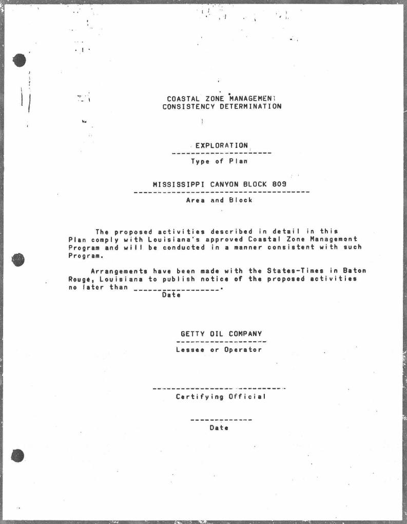
••• . I I
' I.
• I •
_ t COASTAL ZONE MANAGEMENI CONSISTENCY DETERMINATION
K. !
EXPLORATION
Type of Plen
MISSISSIPPI CANYON BLOCK 809
Aree and Block
The proposed a c t i v i t i e s described in detail in this Plan comply with Louisiana's approved Coastal Zone Management Program and w i l l be conducted in a manner consistent with such Program.
Arrangements have been made with the States-Times in Baton Rouge, Louisiana to publish notice of the proposed a c t i v i t i e s no later than
"6ite
GETTY OIL COMPANY
Lessee or Operetor
Certi fy ing Off i c i a l
Date
Related Documents