SLE-GSM Radio Reporting & Quickloader 6.1 Setup and Configuration Instructions Before powering up the radio, you must: 1. Be an active NAPCO StarLink dealer (SL-1 series or SLE series) and have a StarLink account. If you are not a registered StarLink dealer, go the StarLink Radio Management Center (SRMC) at www.napconoc.com and click the link to become a new StarLink registered dealer. 2. The radio ID# that came with your radio must be registered in your account. At www.napconoc.com, click the link to register the radio and select your data plan. No reporting or programming information is required INTRODUCTION The default settings of the SLE-GSM radio allow the radio to be attached to a NAPCO (or non-NAPCO) alarm control pan- el and report alarms to the central station programmed into the alarm panel without any additional programming of the ra- dio or the NAPCO website. The SLE-GSM Radio sends its signals to the NAPCO Network Operations Center (NOC) and these signals are processed using the data captured by the radio from the alarm control panel. The NOC, which is acces- sible from the Internet using a web browser, provides dealer access to the StarLink Radio Management Center (SRMC) and includes features the dealer may want to make use of, including the ability to change the way the radio's programma- ble inputs and outputs work, reporting properties, messaging, logging, radio status, etc. The SLE-GSM radio and NOC provide a complete transmission path and return receipt service ("kiss off") to ensure your alarm control panel knows that the alarm is delivered. The process is simple: The radio captures the alarm from the panel and then "kisses off" the panel. The alarm is routed to your central station and waits for the CS kiss off. The kiss off is routed back to the radio, which is waiting for the return receipt. When the receipt arrives, the radio clears the alarm from its memory and the process is done. If the receipt is not received within a predetermined period, the radio re-transmits the alarm. If the receipt is still not received, then the Fail to Communicate PGM output on the radio is activated which can be read by the control panel and reported to the panel's keypad display. AUTO ENROLLING Auto enrolling is a feature that allows an installer to simply connect a registered radio to an alarm panel, turn on power and send an alarm to a third party central station without any programming of the NAPCO NOC. This section describes how to auto enroll the radio and report the first alarm. The radio has the following defaults automatically programmed: a. Works with Contact ID or 4/2 automatically. b. Has a default 30 day GSM radio check-in supervisory time out. c. Will send a check-in to the NOC every 30 days. d. Radio PGM output 1 is programmed to be normally low and will go open collector high if ANY troubles are detect- ed by the radio. These include: Low battery, line cut, fail to communicate, etc. e. Radio PGM output 2 is programmed to be normally open collector and will go low if the radio fails to receive a kiss off. f. Radio PGM output 3 is programmed to be normally open collector and will go low if the radio detects Telco Line Cut (backup mode). g. Radio jumpers are set for PRIMARY mode – means there is no telephone line available – panel connects to the radio only. Procedure: 1. Program your alarm control panel to report to the central station of your choice using Telco reporting. Be sure to program your central station account number and CS Receiver Telephone number in the alarm control panel in- cluding a (1) prefix (if supported) and a 10 digit phone number. 2. Connect power and the Tip/Ring to the radio as described in the Quick Start Guide (WI1972) or WI1936. 3. Power up the panel and radio and wait until the green LED in the lower right corner blinks a repeating pattern. Is the blink rate at least a 4? (Note: A blink rate of 3 may work if the cell tower does not vary much). If so, you have SLE-GSM Radio Reporting & Quickloader 6.1 Setup and Configuration Instructions 333 Bayview Avenue Amityville, New York 11701 For Sales and Repairs, (800) 645-9445 For Technical Service, (800) 645-9440 (Note: Technical Service is for security professionals only) Publicly traded on NASDAQ Symbol: NSSC © NAPCO 2015 WI1974B.a 12/15

Welcome message from author
This document is posted to help you gain knowledge. Please leave a comment to let me know what you think about it! Share it to your friends and learn new things together.
Transcript
SLE-GSM Radio Reporting & Quickloader 6.1 Setup and Configuration Instructions 1
Before powering up the radio, you must:
1. Be an active NAPCO StarLink dealer (SL-1 series or SLE series) and have a StarLink account. If you are not a registered StarLink dealer, go the StarLink Radio Management Center (SRMC) at www.napconoc.com and click the link to become a new StarLink registered dealer.
2. The radio ID# that came with your radio must be registered in your account. At www.napconoc.com, click the link
to register the radio and select your data plan. No reporting or programming information is required INTRODUCTION The default settings of the SLE-GSM radio allow the radio to be attached to a NAPCO (or non-NAPCO) alarm control pan-el and report alarms to the central station programmed into the alarm panel without any additional programming of the ra-dio or the NAPCO website. The SLE-GSM Radio sends its signals to the NAPCO Network Operations Center (NOC) and these signals are processed using the data captured by the radio from the alarm control panel. The NOC, which is acces-sible from the Internet using a web browser, provides dealer access to the StarLink Radio Management Center (SRMC) and includes features the dealer may want to make use of, including the ability to change the way the radio's programma-ble inputs and outputs work, reporting properties, messaging, logging, radio status, etc. The SLE-GSM radio and NOC provide a complete transmission path and return receipt service ("kiss off") to ensure your alarm control panel knows that the alarm is delivered. The process is simple: The radio captures the alarm from the panel and then "kisses off" the panel. The alarm is routed to your central station and waits for the CS kiss off. The kiss off is routed back to the radio, which is waiting for the return receipt. When the receipt arrives, the radio clears the alarm from its memory and the process is done. If the receipt is not received within a predetermined period, the radio re-transmits the alarm. If the receipt is still not received, then the Fail to Communicate PGM output on the radio is activated which can be read by the control panel and reported to the panel's keypad display. AUTO ENROLLING Auto enrolling is a feature that allows an installer to simply connect a registered radio to an alarm panel, turn on power and send an alarm to a third party central station without any programming of the NAPCO NOC. This section describes how to auto enroll the radio and report the first alarm. The radio has the following defaults automatically programmed:
a. Works with Contact ID or 4/2 automatically. b. Has a default 30 day GSM radio check-in supervisory time out. c. Will send a check-in to the NOC every 30 days. d. Radio PGM output 1 is programmed to be normally low and will go open collector high if ANY troubles are detect-
ed by the radio. These include: Low battery, line cut, fail to communicate, etc. e. Radio PGM output 2 is programmed to be normally open collector and will go low if the radio fails to receive a kiss
off. f. Radio PGM output 3 is programmed to be normally open collector and will go low if the radio detects Telco Line
Cut (backup mode). g. Radio jumpers are set for PRIMARY mode – means there is no telephone line available – panel connects to the
radio only. Procedure:
1. Program your alarm control panel to report to the central station of your choice using Telco reporting. Be sure to program your central station account number and CS Receiver Telephone number in the alarm control panel in-cluding a (1) prefix (if supported) and a 10 digit phone number.
2. Connect power and the Tip/Ring to the radio as described in the Quick Start Guide (WI1972) or WI1936. 3. Power up the panel and radio and wait until the green LED in the lower right corner blinks a repeating pattern. Is
the blink rate at least a 4? (Note: A blink rate of 3 may work if the cell tower does not vary much). If so, you have
SLE-GSM Radio Reporting & Quickloader 6.1
Setup and Configuration Instructions 333 Bayview Avenue
Amityville, New York 11701 For Sales and Repairs, (800) 645-9445 For Technical Service, (800) 645-9440
(Note: Technical Service is for security professionals only) Publicly traded on NASDAQ Symbol: NSSC
© NAPCO 2015 WI1974B.a 12/15
2 SLE-GSM Radio Reporting & Quickloader 6.1 Setup and Configuration Instructions
adequate signal strength and are on-line. 4. Send a signal of any kind from the alarm panel. The radio will capture the CS telephone number, the CS account
number, format and alarm information and will send it to the NOC. The alarm will be forwarded to the CS tele-phone number captured. The NOC will remember the CS telephone number, the CS account number and format and save it for future use (see 5 below).
5. The radio will automatically send GSM check-in signals to the NOC; however, if the NOC does not receive a check-in within a 30 day period, a Supervisory signal will be transmitted to the CS using the information captured in (4) above. It will report as a Contact ID E356 or a 99 for 4/2. More frequent check-in intervals are available by modifying the configuration on-line at www.napconoc.com.
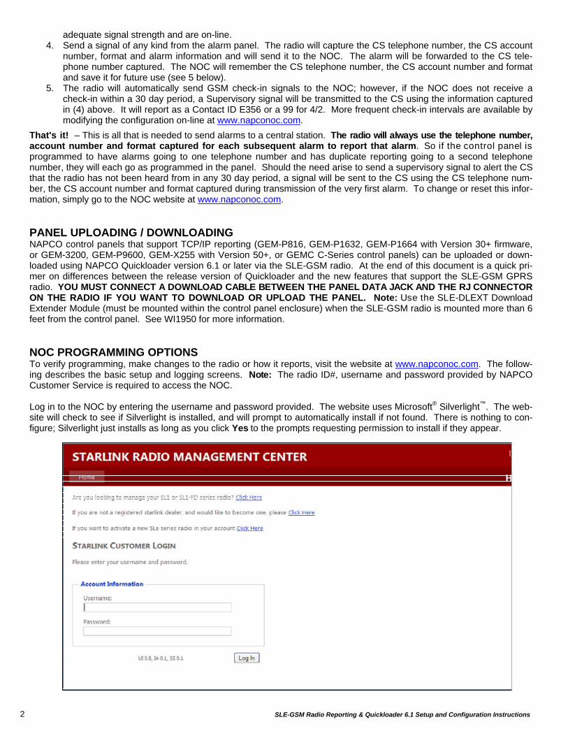
That's it! – This is all that is needed to send alarms to a central station. The radio will always use the telephone number, account number and format captured for each subsequent alarm to report that alarm. So if the control panel is programmed to have alarms going to one telephone number and has duplicate reporting going to a second telephone number, they will each go as programmed in the panel. Should the need arise to send a supervisory signal to alert the CS that the radio has not been heard from in any 30 day period, a signal will be sent to the CS using the CS telephone num-ber, the CS account number and format captured during transmission of the very first alarm. To change or reset this infor-mation, simply go to the NOC website at www.napconoc.com. PANEL UPLOADING / DOWNLOADING NAPCO control panels that support TCP/IP reporting (GEM-P816, GEM-P1632, GEM-P1664 with Version 30+ firmware, or GEM-3200, GEM-P9600, GEM-X255 with Version 50+, or GEMC C-Series control panels) can be uploaded or down-loaded using NAPCO Quickloader version 6.1 or later via the SLE-GSM radio. At the end of this document is a quick pri-mer on differences between the release version of Quickloader and the new features that support the SLE-GSM GPRS radio. YOU MUST CONNECT A DOWNLOAD CABLE BETWEEN THE PANEL DATA JACK AND THE RJ CONNECTOR ON THE RADIO IF YOU WANT TO DOWNLOAD OR UPLOAD THE PANEL. Note: Use the SLE-DLEXT Download Extender Module (must be mounted within the control panel enclosure) when the SLE-GSM radio is mounted more than 6 feet from the control panel. See WI1950 for more information. NOC PROGRAMMING OPTIONS To verify programming, make changes to the radio or how it reports, visit the website at www.napconoc.com. The follow-ing describes the basic setup and logging screens. Note: The radio ID#, username and password provided by NAPCO Customer Service is required to access the NOC. Log in to the NOC by entering the username and password provided. The website uses Microsoft® Silverlight™. The web-site will check to see if Silverlight is installed, and will prompt to automatically install if not found. There is nothing to con-figure; Silverlight just installs as long as you click Yes to the prompts requesting permission to install if they appear.
SLE-GSM Radio Reporting & Quickloader 6.1 Setup and Configuration Instructions 3
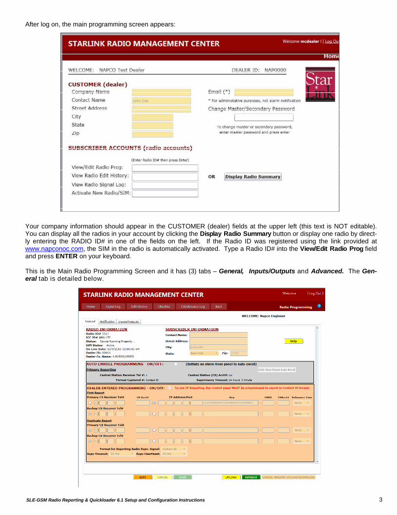
After log on, the main programming screen appears: Your company information should appear in the CUSTOMER (dealer) fields at the upper left (this text is NOT editable). You can display all the radios in your account by clicking the Display Radio Summary button or display one radio by direct-ly entering the RADIO ID# in one of the fields on the left. If the Radio ID was registered using the link provided at www.napconoc.com, the SIM in the radio is automatically activated. Type a Radio ID# into the View/Edit Radio Prog field and press ENTER on your keyboard. This is the Main Radio Programming Screen and it has (3) tabs – General, Inputs/Outputs and Advanced. The Gen-eral tab is detailed below.
4 SLE-GSM Radio Reporting & Quickloader 6.1 Setup and Configuration Instructions
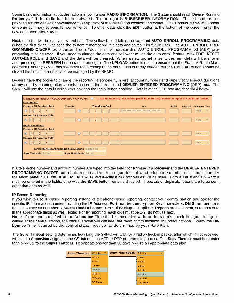
Some basic information about the radio is shown under RADIO INFORMATION. The Status should read "Device Running Properly…" if the radio has been activated. To the right is SUBSCRIBER INFORMATION. These locations are provided for the dealer's convenience to keep track of the installation location and owner. The Contact Name will appear on some summary screens for convenience. To enter data, click the EDIT button at the bottom of the screen; enter the new data, then click SAVE. Next, note the two boxes, yellow and tan. The yellow box at left is the captured AUTO ENROLL PROGRAMMING data (when the first signal was sent, the system remembered this data and saves it for future use). The AUTO ENROLL PRO-GRAMMING ON/OFF radio button has a "dot" in it to indicate that AUTO ENROLL PROGRAMMING (AEP) pro-gramming is being used. If you need to change the data and still want to use the auto enroll feature, click EDIT, RESET AUTO-ENROLL and SAVE and the data will be cleared. When a new signal is sent, the new data will be shown after pressing the REFRESH button (at bottom right). The UPLOAD button is used to ensure that the StarLink Radio Man-agement Center (SRMC) has the latest radio configuration data. This is rarely needed but the UPLOAD button should be clicked the first time a radio is to be managed by the SRMC. Dealers have the option to change the reporting telephone numbers, account numbers and supervisory timeout durations at any time by entering alternate information in the tan colored DEALER ENTERED PROGRAMMING (DEP) box. The SRMC will use the data in which ever box has the radio button enabled. Details of the DEP box are described below: If a telephone number and account number are typed into the fields for Primary CS Receiver and the DEALER ENTERED PROGRAMMING ON/OFF radio button is enabled, then regardless of what telephone number or account number the alarm panel dials, the DEALER ENTERED PROGRAMMING box values will be used. Both a Tel # and CS Acct # must be entered in the fields, otherwise the SAVE button remains disabled. If backup or duplicate reports are to be sent, enter that data as well. IP-Based Reporting If you wish to use IP-based reporting instead of telephone-based reporting, contact your central station and ask for the specific IP information to enter, including the IP Address, Port number, encryption Key characters, DNIS number, cen-tral station account number (CSAcct#) and Debounce Time. If Backup or Duplicate Reports are to be sent, enter that data in the appropriate fields as well. Note: For IP reporting, each digit must be 0-9 (do not use hex). Note: If the time specified in the Debounce Time field is exceeded without the radio's check in signal being re-ceived at the central station, the central station will consider the radio communication link non-functional. Verify the De-bounce Time required by the central station receiver as determined by your Rate Plan. The Supv Timeout setting determines how long the SRMC will wait for a radio check-in packet after which, if not received, will send a Supervisory signal to the CS listed in the AEP or DEP programming boxes. The Supv Timeout must be greater than or equal to the Supv Heartbeat. Heartbeats shorter than 30 days require an appropriate data plan.
SLE-GSM Radio Reporting & Quickloader 6.1 Setup and Configuration Instructions 5
Note: Alarm panel generated Test Timers are reportable signals and are forwarded to the Central Station. Radio "Check-in's" are dead-ended at the NOC (meaning they are not sent to the central station but are tracked by the SRMC). If they are not received within the supervisory time window, then the SRMC sends a Supervisory Signal to the Central Sta-tion.
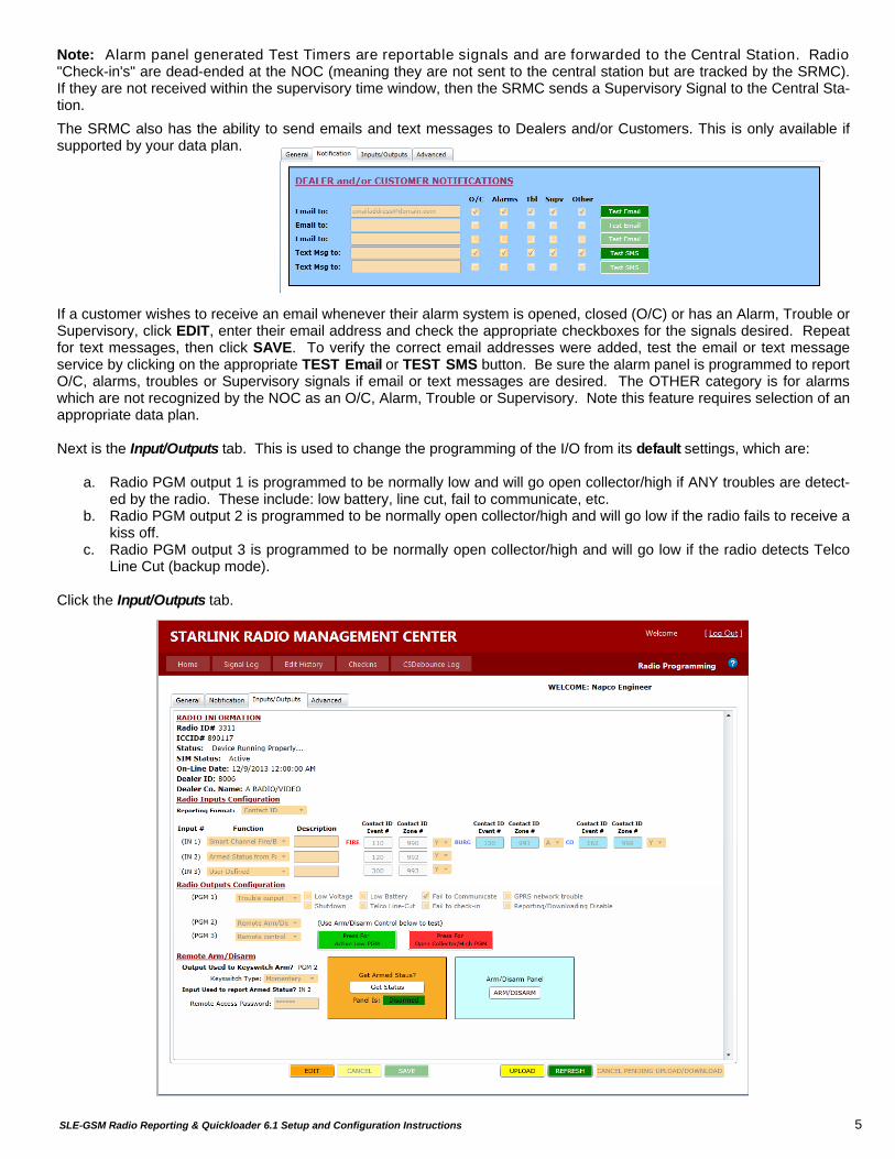
The SRMC also has the ability to send emails and text messages to Dealers and/or Customers. This is only available if supported by your data plan. If a customer wishes to receive an email whenever their alarm system is opened, closed (O/C) or has an Alarm, Trouble or Supervisory, click EDIT, enter their email address and check the appropriate checkboxes for the signals desired. Repeat for text messages, then click SAVE. To verify the correct email addresses were added, test the email or text message service by clicking on the appropriate TEST Email or TEST SMS button. Be sure the alarm panel is programmed to report O/C, alarms, troubles or Supervisory signals if email or text messages are desired. The OTHER category is for alarms which are not recognized by the NOC as an O/C, Alarm, Trouble or Supervisory. Note this feature requires selection of an appropriate data plan. Next is the Input/Outputs tab. This is used to change the programming of the I/O from its default settings, which are:
a. Radio PGM output 1 is programmed to be normally low and will go open collector/high if ANY troubles are detect-ed by the radio. These include: low battery, line cut, fail to communicate, etc.
b. Radio PGM output 2 is programmed to be normally open collector/high and will go low if the radio fails to receive a kiss off.
c. Radio PGM output 3 is programmed to be normally open collector/high and will go low if the radio detects Telco Line Cut (backup mode).
Click the Input/Outputs tab.

6 SLE-GSM Radio Reporting & Quickloader 6.1 Setup and Configuration Instructions
Radio Inputs Configuration The next section is the Radio Inputs Configuration. First, select the reporting format required by your central station from the Reporting Format pull-down list. Next note the IN 1, IN 2 and IN 3 pull-downs have three choices as shown below.
Smart Channel Fire/Burg This feature is only supported on IN1. For this selection to be used, the IN 1 input must be connected to the bell
output of the control panel. The radio will monitor the bell circuit to detect a Fire cadence, a Burg Cadence or a CO (Carbon Monoxide) cadence. Upon detecting a Fire, Burg or CO signal, the radio will report to the SRMC which signal type was detected. The SRMC will report the signal using the format selected and code entered for each of the alarm types. The pull-down after each alarm type permits that item to be enabled (Y), disabled (N) or have an abort delay of 16 seconds (A). The abort delay duration is a globally programmable option – see Ad-vanced tab.
Armed Status From Panel For this selection to be used, the input must be connected to armed status output lug of the panel and the panel
programmed to enable or disable an output based on the armed state of the panel. When configured in this way, the system can be used to signal to the radio the actual status of the control panel. This control panel status can then be displayed on the SRMC screen, or in the future on NAPCO Customer Control screens.
User Defined This selection allows the input to be used to sense a signal from whatever input device is connected. When the
input is triggered, the code entered will be reported. Note: The radio can be used to monitor equipment and sys-tems without the need for any alarm panel to be connected.
Radio Outputs Configuration Next is a review of the Radio Outputs Configuration. Note the PGM 1, PGM 2 and PGM 3 pull-downs each have four se-lections, three of which are shown below (the fourth is Ring-Back).
Trouble Output This selection allows the PGM to change state when any of the troubles that are checked occur. Note: PGM 1 is
a special PGM that is normally low and will go open collector/high if there is a trouble. PGM 2 and PGM 3 work in reverse (normally open collector and go low when activated).
Remote Control Output This selection allows the PGM to change state when the green ACTIVE LOW PGM or red OPEN COLLECTOR /
HIGH PGM buttons are clicked. Again, note that PGM 1 is a special PGM that is normally low and will go open collector/high if activated. PGM 2 and PGM 3 work in reverse (normally open collector and go low when ac-tivated). These outputs can be used to control equipment or panel features; currently, access to control these out-puts is allowed only from the NAPCO SRMC Dealer Account, and will be controllable in the future in NAPCO Cus-tomer Control screens. This feature requires an appropriate data plan.
Remote Arm/Disarm Output This selection allows the PGM to momentarily change state when the white ARM/DISARM button is clicked.
PGM 2 and PGM 3 work in reverse (normally open collector and go low when activated). Currently, these outputs can be controlled only from the NAPCO SRMC Dealer Account, and will be controllable in the future in NAPCO Customer Control screens. This feature requires an appropriate data plan.
SLE-GSM Radio Reporting & Quickloader 6.1 Setup and Configuration Instructions 7
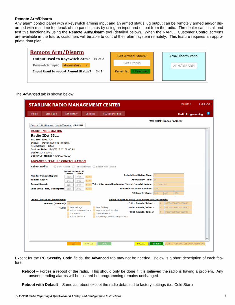
Remote Arm/Disarm Any alarm control panel with a keyswitch arming input and an armed status lug output can be remotely armed and/or dis-armed with real time feedback of the panel status by using an input and output from the radio. The dealer can install and test this functionality using the Remote Arm/Disarm tool (detailed below). When the NAPCO Customer Control screens are available in the future, customers will be able to control their alarm system remotely. This feature requires an appro-priate data plan. The Advanced tab is shown below: Except for the PC Security Code fields, the Advanced tab may not be needed. Below is a short description of each fea-ture:
Reboot – Forces a reboot of the radio. This should only be done if it is believed the radio is having a problem. Any unsent pending alarms will be cleared but programming remains unchanged.
Reboot with Default – Same as reboot except the radio defaulted to factory settings (i.e. Cold Start)
8 SLE-GSM Radio Reporting & Quickloader 6.1 Setup and Configuration Instructions
Monitor / Tamper / Reboot / Line Cut - The section allows for changing the default point ID codes and Zone Num-
bers used for reporting the listed signals. The dropdown following each line allows for the choice of: A = Abort Delay, Y = Enabled, N= Disabled.
Create Line Cut at Control Panel – This features causes the radio to turn off the Telco Voltage supplied on the
phone line connected to the Alarm Panel so that the Alarm Panel, which has been programmed to detect LINE CUT, can locally report one or more of the selected Troubles. The duration field defines the length of time the alarm panel keeps the Telco Voltage low. NOTE: The alarm panel will be unable to report alarms to the radio during this period therefore if this feature is to be used, select the shortest possible Line Cut detection time for your alarm panel. For example if line cut is detected in 1.5 minutes then select 2 minutes.
Installation Dialing Plan – If the Alarm Panel and SLE-GSM radio is behind a PBX then the panel is most likely pro-
grammed to dial a "9" or some other digit to get an outside line. The radio must know this so that when trying to capture the CS phone number it knows to supply a second dial tone after receipt of the "9". This field has a two-digit entry. The first position defines the digit to look for and the second defines what to do if that digit is identified. The default is 0T (number 0 and letter T), which means supply dial tone once when off hook. A 9T would mean provide a second dial tone after receipt of a "9". If the second digit is a "W" instead of a "T", it means wait up to 45 seconds after the digit is detected to look for a second digit, but no second dial tone is provided.
Abort Delay – This time provide a delay, in seconds, after a condition is detected by the module before it is reported
to the Central Station. If the condition is restored within this window the alarm is not transmitted Telco # For Reporting … and Subscriber Number: The telephone number and subscriber account number for
reporting Monitor Voltage, Tamper, Reboot, Land Line Cut and Parallel Inputs must be entered in the Telco # and Subscriber Account fields. The system can be programmed to dead end the reports at the NOC or send them to the CS using the information supplied in these two fields. A "9999999999" means dead end the report at the NOC. Note: If TCP/IP reporting is selected for the Primary central station telephone number, then entering any valid 10 digit telephone number other than 9999999999 will cause these aforementioned events to report to the Primary IP address and Subscriber ID number in the "Main Radio Programming Screen" General tab.
PC Security Code – This entry provides an additional level of security to prevent unauthorized users from gaining
access to the radio remotely. Radios are shipped with 0,0,0 and it is up to the installer to enter a new code if de-sired. Once the new PC code is downloaded it must be used for further communications with the radio. CAU-TION: IF YOU FORGET THIS NUMBER FURTHER COMMUNICATIONS WITH THE RADIO ARE IMPOSSIBLE – NAPCO CANNOT OVERRIDE THIS SETTING REMOTELY – YOU WILL BE REQUIRED TO RETURN THE RADIO TO NAPCO FOR FACTORY PROGRAMMING.
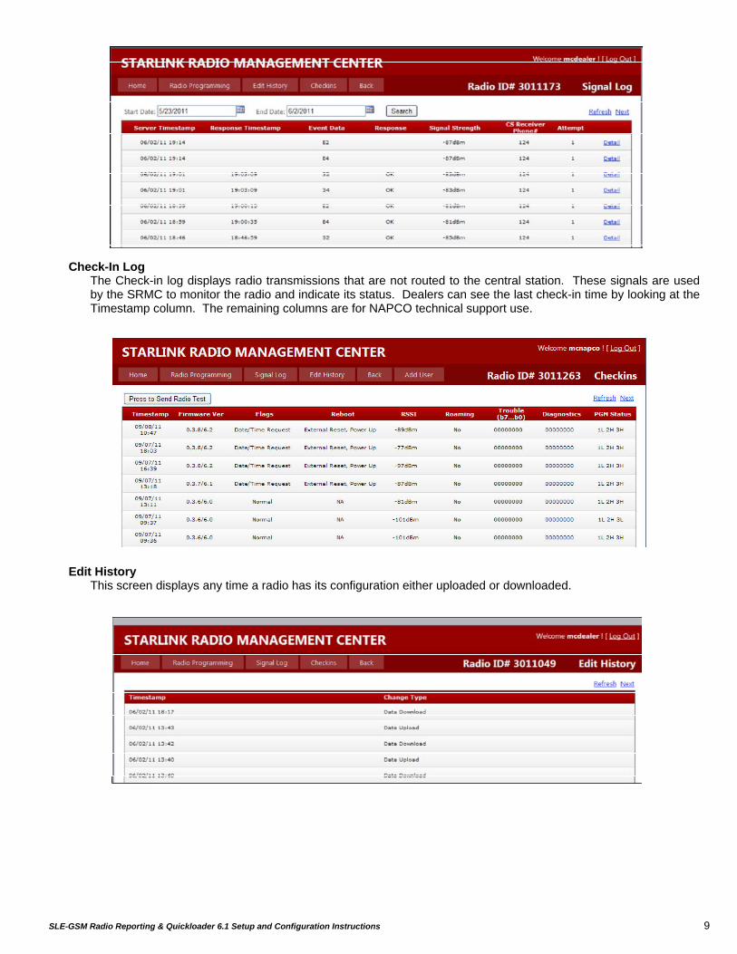
LOGS Status logs and reporting information can be found on the Signal Log, Check-in Log or Edit History logs as shown be-low:
Signal Log The Signal log displays the date and time reportable signals, troubles and alarms were received at the NOC. It
also displays the event data received if the signal was processed without error (marked "OK"); the signal strength of the radio at the time the signal was received, the CS telephone number dialed and the number of attempts the radio made to deliver the signal. Clicking Detail will show the step-by-step process used to handle this particular alarm signal. For each signal the radio delivers to the NOC, the SRMC will try 8 times to reach the Central Station programmed. If the radio does not receive a kiss off, it will re-transmit the alarm and show a "2" in the log. After (another) 8 unsuccessful tries by the SRMC to contact the central station, the radio will then output a "Fail to Com-municate" signal.
SLE-GSM Radio Reporting & Quickloader 6.1 Setup and Configuration Instructions 9
Check-In Log The Check-in log displays radio transmissions that are not routed to the central station. These signals are used
by the SRMC to monitor the radio and indicate its status. Dealers can see the last check-in time by looking at the Timestamp column. The remaining columns are for NAPCO technical support use.
Edit History This screen displays any time a radio has its configuration either uploaded or downloaded.
10 SLE-GSM Radio Reporting & Quickloader 6.1 Setup and Configuration Instructions
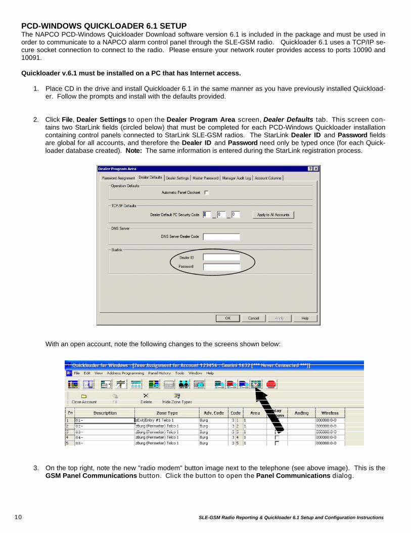
PCD-WINDOWS QUICKLOADER 6.1 SETUP The NAPCO PCD-Windows Quickloader Download software version 6.1 is included in the package and must be used in order to communicate to a NAPCO alarm control panel through the SLE-GSM radio. Quickloader 6.1 uses a TCP/IP se-cure socket connection to connect to the radio. Please ensure your network router provides access to ports 10090 and 10091. Quickloader v.6.1 must be installed on a PC that has Internet access.
1. Place CD in the drive and install Quickloader 6.1 in the same manner as you have previously installed Quickload-er. Follow the prompts and install with the defaults provided.
2. Click File, Dealer Settings to open the Dealer Program Area screen, Dealer Defaults tab. This screen con-
tains two StarLink fields (circled below) that must be completed for each PCD-Windows Quickloader installation containing control panels connected to StarLink SLE-GSM radios. The StarLink Dealer ID and Password fields are global for all accounts, and therefore the Dealer ID and Password need only be typed once (for each Quick-loader database created). Note: The same information is entered during the StarLink registration process.
With an open account, note the following changes to the screens shown below: 3. On the top right, note the new "radio modem" button image next to the telephone (see above image). This is the
GSM Panel Communications button. Click the button to open the Panel Communications dialog.

SLE-GSM Radio Reporting & Quickloader 6.1 Setup and Configuration Instructions 11
4. In the field labeled "GPRS Device ID, type the radio ID# (this is the 7-digit number printed on the bar code tag on
the SLE-GSM radio and also shown on the first page of your Agreement). 5. Select the transfer operation options located at the bottom of the box and check off the appropriate data you wish
to move. Click OK to proceed. 6. At this time, Quickloader will retrieve the IP address of your radio and make the connection. If you see the error
(popup) message shown below, it means the Internet was not accessible by the Quickloader program or your net-work is preventing Quickloader from making a connection. Check to ensure your network router provides access to ports 10090 and 10091.
Note: In the above Panel Communication screen shown above, the PC Security Code is also set in the
Advanced tab in the StarLink Radio Management Center at www.napconoc.com. For a description of the PC Security Code, see page 8.
12 SLE-GSM Radio Reporting & Quickloader 6.1 Setup and Configuration Instructions
NAPCO SECURITY SYSTEMS, INC. (NAPCO) warrants its products to be free from manufacturing defects in materials and workmanship for thirty-six months following the date of manufacture. NAPCO will, within said period, at its option, repair or replace any product failing to operate correctly without charge to the original purchaser or user.
This warranty shall not apply to any equipment, or any part thereof, which has been repaired by others, improperly installed, improperly used, abused, altered, damaged, subjected to acts of God, or on which any serial numbers have been altered, defaced or removed. Seller will not be responsible for any dismantling or reinstallation charges.
THERE ARE NO WARRANTIES, EXPRESS OR IMPLIED, WHICH EXTEND BEYOND THE DESCRIPTION ON THE FACE HEREOF. THERE IS NO EXPRESS OR IMPLIED WARRANTY OF MERCHANTABILITY OR A WARRANTY OF FITNESS FOR A PARTICULAR PURPOSE. ADDITIONALLY, THIS WARRANTY IS IN LIEU OF ALL OTHER OBLIGATIONS OR LIABILITIES ON THE PART OF NAPCO.
Any action for breach of warranty, including but not limited to any implied warranty of merchantability, must be brought within the six months following the end of the warranty period. IN NO CASE SHALL NAPCO BE LIABLE TO ANYONE FOR ANY CONSEQUENTIAL OR INCIDENTAL DAMAGES FOR BREACH OF THIS OR ANY OTHER WARRANTY, EXPRESS OR IMPLIED, EVEN IF THE LOSS OR DAMAGE IS CAUSED BY THE SELLER'S OWN NEGLIGENCE OR FAULT.
In case of defect, contact the security professional who installed and maintains your security system. In order to exercise the warranty, the product must be returned by the security professional, shipping costs prepaid and insured to NAPCO. After repair or replacement, NAPCO assumes the cost of returning products under warranty. NAPCO shall have no obligation under this warranty, or otherwise, if the product has been repaired by others, improperly installed, improperly used, abused, altered, damaged, subjected to accident, nuisance, flood, fire or acts of God, or on which any serial numbers have been altered, defaced or removed. NAPCO will not be responsible for any dismantling, reassembly or reinstallation charges.
This warranty contains the entire warranty. It is the sole warranty and any prior agreements or representations, whether oral or written, are either merged herein or are expressly cancelled. NAPCO neither assumes, nor authorizes any other person purporting to act on its
behalf to modify, to change, or to assume for it, any other warranty or liability concerning its products.
In no event shall NAPCO be liable for an amount in excess of NAPCO's original selling price of the product, for any loss or damage, whether direct, indirect, incidental, consequential, or otherwise arising out of any failure of the product. Seller's warranty, as hereinabove set forth, shall not be enlarged, diminished or affected by and no obligation or liability shall arise or grow out of Seller's rendering of technical advice or service in connection with Buyer's order of the goods furnished hereunder.
NAPCO RECOMMENDS THAT THE ENTIRE SYSTEM BE COMPLETELY TESTED WEEKLY.
Warning: Despite frequent testing, and due to, but not limited to, any or all of the following; criminal tampering, electrical or communications disruption, it is possible for the system to fail to perform as expected. NAPCO does not represent that the product/system may not be compromised or circumvented; or that the product or system will prevent any personal injury or property loss by burglary, robbery, fire or otherwise; nor that the product or system will in all cases provide adequate warning or protection. A properly installed and maintained alarm may only reduce risk of burglary, robbery, fire or otherwise but it is not insurance or a guarantee that these events will not occur. CONSEQUENTLY, SELLER SHALL HAVE NO LIABILITY FOR ANY PERSONAL INJURY, PROPERTY DAMAGE, OR OTHER LOSS BASED ON A CLAIM THE PRODUCT FAILED TO GIVE WARNING. Therefore, the installer should in turn advise the consumer to take any and all precautions for his or her safety including, but not limited to, fleeing the premises and calling police or fire department, in order to mitigate the possibilities of harm and/or damage.
NAPCO is not an insurer of either the property or safety of the user's family or employees, and limits its liability for any loss or damage including incidental or consequential damages to NAPCO's original selling price of the product regardless of the cause of such loss or damage.
Some states do not allow limitations on how long an implied warranty lasts or do not allow the exclusion or limitation of incidental or consequential damages, or differentiate in their treatment of limitations of liability for ordinary or gross negligence, so the above limitations or exclusions may not apply to you. This Warranty gives you specific legal rights and you may also have other rights which vary from state to state.
NAPCO LIMITED WARRANTY
Related Documents