Slant Fin Corp. │ Installation and Operation Instructions CHS Series 60 Refractory Ceramic Fibers (RFC) Personal Protective Equipment Recommended - Read the following warnings and handling instructions carefully before commencing any service work in the combustion chamber. The insulating material on the inside of the burner plate contains Refractory Ceramic Fibers and should not be handled without personal protective equipment. Potential Carcinogen - Use of Refractory Ceramic Fibers in high temperature applications (above 1000 o C/1800ºF) can result in the formation of Crystalline Silica (cristobalite), a respirable silica dust. Repeated airborne exposure to crystalline silica dust may result in chronic lung infections, acute respiratory illness, or death. Crystalline silica is listed as a (potential) occupational carcinogen by the following regulatory organizations: International Agency for Research on Cancer (IARC), Canadian Centre for Occupational Health and Safety (CCOHS), Occupational Safety and Health Administration (OSHA), and National Institute for Occupational Safety and Health (NIOSH). Failure to comply with handling instructions in Table 14-1 may result in serious injury or death. Crystalline Silica - Certain components confined in the combustion chamber may contain this potential carcinogen. Improper installation, adjustment, alteration, service or maintenance can cause property damage, serious injury (exposure to hazardous materials) or death. Refer to Table 14-1 for handling instruction and recommended personal protective equipment. Installation and service must be performed by a qualified installer, service agency or the gas supplier (who must read and follow the supplied instructions before installing, servicing, or removing this boiler. This boiler contains materials that have been identified as carcinogenic, or possibly carcinogenic, to humans). Table 14-1 Handling Instructions for Refractory Ceramic Fibers (RCF) Reduce the Risk of Exposure Precautions and Recommended Personal Protective Equipment Avoid contact with skin and eyes • Wear long-sleeved clothing, gloves, and safety goggles or glasses. Avoid breathing in silica dust • Wear a respirator with an N95-rated filter efficiency or better. 1 • Use water to reduce airborne dust levels when cleaning the combustion chamber. • Do not dry sweep silica dust. Pre-wet or use a vacuum with a high efficiency filter. Avoid transferring contamination • When installing or removing RFCs, place the material in a sealable plastic bag. • Remove contaminated clothing after use. Store in sealable container until cleaned. • Wash contaminated clothing separately from other laundry. First Aid Measures If irritation persists after implementing first aid measures consult a physician. • Skin - Wash with soap and water. • Eyes - Do not rub eyes; flush with water immediately. • Inhalation – Breathe in fresh air; drink water, sneeze or cough to clear irritated passage ways. Notes: 1 Respirator recommendations based on CCOHS and OSHA requirements at the time this document was written. Consult your local regulatory authority regarding current requirements for respirators, personal protective equipment, handling, and disposal of RCFs. For more information on Refractory Ceramic Fibers, the risks, recommended handling procedures and acceptable disposal practices contact the organization(s) listed below: Canada (CCOHS): Telephone directory listing under Government Blue Pages Canada—Health and Safety—Canadian Centre for Occupational Health and Safety; or website http://www.ccohs.ca. United States (OSHA): Telephone directory listing under United States Government—Department of Labor—Occupational Safety and Health Administration; or website http://www.osha.gov.

Welcome message from author
This document is posted to help you gain knowledge. Please leave a comment to let me know what you think about it! Share it to your friends and learn new things together.
Transcript

Slant Fin Corp. Installation and Operation Instructions CHS Series
60
Refractory Ceramic Fibers (RFC)
Personal Protective Equipment Recommended - Read the following warnings and handling instructions carefully before commencing any service work in the combustion
chamber. The insulating material on the inside of the burner plate contains Refractory Ceramic Fibers and should not be handled without personal protective equipment.
Potential Carcinogen - Use of Refractory Ceramic Fibers in high temperature applications (above 1000oC/1800ºF) can result in the formation of Crystalline Silica
(cristobalite), a respirable silica dust. Repeated airborne exposure to crystalline silica dust may result in chronic lung infections, acute respiratory illness, or death. Crystalline silica is listed as a (potential) occupational carcinogen by the following regulatory organizations: International Agency for Research on Cancer (IARC), Canadian Centre for Occupational Health and Safety (CCOHS), Occupational Safety and Health Administration (OSHA), and National Institute for Occupational Safety and Health (NIOSH). Failure to comply with handling instructions in Table 14-1 may result in serious injury or death.
Crystalline Silica - Certain components confined in the combustion chamber may contain this potential carcinogen. Improper installation, adjustment, alteration, service or
maintenance can cause property damage, serious injury (exposure to hazardous materials) or death. Refer to Table 14-1 for handling instruction and recommended personal protective equipment. Installation and service must be performed by a qualified installer, service agency or the gas supplier (who must read and follow the supplied instructions before installing, servicing, or removing this boiler. This boiler contains materials that have been identified as carcinogenic, or possibly carcinogenic, to humans).
Table 14-1 Handling Instructions for Refractory Ceramic Fibers (RCF) Reduce the Risk of Exposure Precautions and Recommended Personal Protective Equipment Avoid contact with skin and eyes • Wear long-sleeved clothing, gloves, and safety goggles or glasses. Avoid breathing in silica dust
• Wear a respirator with an N95-rated filter efficiency or better. 1 • Use water to reduce airborne dust levels when cleaning the combustion chamber. • Do not dry sweep silica dust. Pre-wet or use a vacuum with a high efficiency filter.
Avoid transferring contamination
• When installing or removing RFCs, place the material in a sealable plastic bag. • Remove contaminated clothing after use. Store in sealable container until cleaned. • Wash contaminated clothing separately from other laundry.
First Aid Measures
If irritation persists after implementing first aid measures consult a physician. • Skin - Wash with soap and water. • Eyes - Do not rub eyes; flush with water immediately. • Inhalation – Breathe in fresh air; drink water, sneeze or cough to clear irritated
passage ways.
Notes: 1 Respirator recommendations based on CCOHS and OSHA requirements at the time this document was written. Consult your local regulatory authority regarding current requirements for respirators, personal protective equipment, handling, and disposal of RCFs.
For more information on Refractory Ceramic Fibers, the risks, recommended handling procedures and acceptable disposal practices contact the organization(s) listed below:
Canada (CCOHS): Telephone directory listing under Government Blue Pages Canada—Health and Safety—Canadian Centre for Occupational Health and Safety; or website http://www.ccohs.ca.
United States (OSHA): Telephone directory listing under United States Government—Department of Labor—Occupational Safety and Health Administration; or website http://www.osha.gov.

CHS Series Installation and Operation Instructions Slant Fin Corp.
61
15.0 TROUBLESHOOTING
Observe the following precautions when servicing the boiler. Failure to comply with these may result in fire, property damage, serious injury or death.
Servicing the Boiler • Disconnect or shutoff all energy sources to the boiler: 120VAC power, water and gas. • Identify and mark wires before disconnecting or removing them. • Never bypass electrical fuses or limit devices except temporarily for testing. • Use proper personal protective equipment (PPE) i.e. eye protection, safety footwear.
These procedures should only be performed by qualified service personnel, when abnormal operation of the boiler is suspected. The boiler incorporates a sophisticated microprocessor based control which normally responds appropriately to varying conditions. If the boiler operation appears to be incorrect, or it is not responding at all to a demand for heat, the following is suggested to determine and correct the problem.
Before undertaking any troubleshooting procedures it is highly recommended to have available a digital multimeter(s) capable of measuring AC and DC volts, Amperes,
Resistance (Ohms) and Continuity.
Check 120VAC and 24VAC at the Boiler First, verify the following: • There is 120V being supplied to the boiler:
o The circuit breaker in the electrical panel supplying power to the boiler is not tripped. o The service switch (if applicable) is in the ON position. o The boiler service switch located on the front of the boiler is in the ON (1) position
• There is a heat call from the thermostat: o Verify 24VAC to thermostat. o The thermostat is placed at a sufficiently high setting to create a call for heat to the boiler.
To check for the presence of 120VAC and 24VAC at the boiler follow this procedure: • Remove the boiler front cover (remove screw from bottom, undo side latches, then lift cover up and off0. • 120VAC
o Remove the control panel cover. Loosen the three #8 hex-head sheet metal screws securing the cover to the control panel (one on the bottom, and one on each side). Lift the cover off and remove it from the unit; this will expose the field wiring barrier strips.
o With an AC voltmeter set on the appropriate scale, measure the voltage across the L1 and L2 terminals (terminals 1 and 5).
o If 120VAC is not detected, check the electrical service as suggested above. If the service is verified, inspect the circuit wiring from the panel to the boiler for broken or disconnected conductors.
o If 120VAC is detected, turn power off to the boiler at the service switch and check the 120VAC fuse located on the right side of the control panel; refer to Figure 15-1 – replace if necessary.
• 24VAC (only check if 120VAC supply is verified). o Remove the control panel cover. Loosen the three #8 hex-head sheet metal screws securing the cover to
the control panel (one on the bottom, and one on each side). Lift the cover off and remove it from the unit; this will expose the field wiring barrier strips.
o With an AC voltmeter set on the appropriate scale, measure the voltage between the R and COM terminals (terminals 1 and 2).
o If 24VAC is not detected, check the 24VAC fuse located at the transformer in the control panel; refer to Figure 15-1 – replace if necessary.
Only replace fuses with identical parts, see Figure 15-1. Failure to follow this warning may result in component failure, fire, property damage, serious injury or death.

Slant Fin Corp. Installation and Operation Instructions CHS Series
62
Figure 15-1 CHS Control Panel
Fuses The CHS boiler is equipped with three (3) fuses. Check these fuses before replacing the controller or any other electrical component; if the fuse is blown, it will prevent the protected device(s) from functioning.
To check, and if necessary replace, the fuses: • Remove all 120VAC power from the appliance. Be careful to check that the unit is not powered from more
than one source e.g. a UPS (uninterruptible power supply). • Remove the front cover. • Fuses "A" and "B" are accessible by removing the spring-loaded knurled knob of their respective holders.
Push the knob toward the panel, and twist approximately 1/4 turn counter-clockwise. • Fuse "C" is an auto blade type and is installed in an “inline” fuse holder; gain access by removing the
control panel cover.
After inspecting and if necessary replacing fuses, replace the panel cover and front cover. Restore power to the appliance and confirm proper operation.
Only replace fuses with identical parts, see Figure 15-1. Failure to follow this warning may result in component failure, fire, property damage, serious injury or death.
User Interface (LCD Dot-Matrix Display) The User Interface (display) provides the communication between the boiler controller and the user. If the communication fails, the User Interface will display, “Boiler Search, Modbus address: 1,2,3…” indefinitely, if the display loses power (or fails completely) the screen will appear blank. To troubleshoot these issues perform the following procedures:
Blank Screen 1. Confirm that 120VAC is being supplied to the boiler and that the service switch located below the display is
turned ON (1). 2. Remove the front cover from the boiler; confirm that the green “power” light is illuminated on the boiler
controller (Sola). If the light is NOT illuminated check the 24VAC fuse (Step 3); if the light is illuminated, proceed to Step 4.
3. Remove the control panel cover and check Fuse “C” (Auto Blade Type); if faulty check for shorts in the thermostat wiring, correct, then replace fuse (see Figure 15-1).
4. Ensure the Molex connector, located behind the display at the top, is connected and that the wires are fully inserted (see Figures 15-2 and 15-3). Verify that 5VDC is present between the Red and Black wires; if not trace wiring back to the boiler controller (see Figure 12-1); check for 5VDC at boiler controller (Sola).
5. Remove the display assembly from the control panel and check the wiring connections (see Figure 15-3).
Fuse “C” ATO 2A 32V Auto Blade Type
Fuses “A” and “B” 3AG 7A 250 Fast -Acting
Control Panel Cover
Control Panel

CHS Series Installation and Operation Instructions Slant Fin Corp.
63
Loss of Communication If the Display is not blank, but is displaying “Boiler Search, Modbus address: 1,2,3…” indefinitely, ensure the Molex connector, located behind the display at the top, is connected and that the wires are fully inserted (see Figures 15-2 and 15-3). If the connector appears to be fine, check the wiring connections on the back of the display (remove display assembly - Figure 15-3); trace wiring back to boiler controller (Sola).
Figure 15-2 Display Electrical Disconnect (Molex Connector)
Figure 15-3 Display Electrical Connection Access
Electrical Disconnect Located Behind Display at Top
Access the electrical connections in the back of the display by removing the screws securing the display assembly to the control panel.
White
Green
Green (data +)
Black (Common)
White (data -)
Red (5VDC)
Red
Black

Slant Fin Corp. Installation and Operation Instructions CHS Series
64
Display Diagnostics – The CHS controller and user interface provide detailed operational and diagnostic information for aid in troubleshooting. When power is applied to the boiler the initial screen displayed is the Home page. Information presented on the Home page includes Demand, State, status of sensors, and so forth. Any current Alert or Lockout condition is also displayed. Refer to Appendix A - Controller and Display Instructions for more information. Lockout and Alert History – The controller maintains a record of the fifteen (15) most recent events for both Lockouts and Alerts (refer to Appendix A - Controller and Display Instructions). In any situation where a malfunction is suspected, always check the Alerts and Lockouts history. Entries recorded in the history provide useful information for determining the cause of the malfunction. Table 15-1 Troubleshooting Chart
PROBLEM POSSIBLE CAUSE CORRECTIVE ACTION Communication wire disconnected See, “Loss of Communication” above. Display shows “Boiler
Search, Modbus address: 1,2,3…” constantly
Faulty Sola controller or display If wiring and connections are correct, replace display, then Sola controller.
Heat demand satisfied; no call for heat
Check Demand and Setpoints via user interface. Check thermostat and DHW aquastat settings (as applicable).
Appliance outlet temperature exceeds “Setpoint - On Hysteresis”
Check outlet temperature, setpoint and hysteresis settings via user interface.
Hold, Delay or Lockout Check Home page on user interface for code.
Burner not operating
Burner switch off Check Home page, if Demand indicates “Burner switch off” go to Manual burner operation Test page and switch on (see Appendix A).
Lockout 2 – Waiting for safety data verification
Faulty Sola controller Replace Sola controller
4-20mA input being overdriven. If using 4-20mA input, check to ensure current is not greater than 21mA.
Lockout 9 – Flame bias out of range
Control malfunction Cycle power, if problem returns replace Sola controller.
Hold 27 – Flame sensor shorted to ground detected
A flame circuit shorted to ground may show up as a flame circuit timeout. Zero-Ohm shorts can display as Hold 27.
Check to ensure condensate drain is not blocked. Check to ensure no external voltage is applied to R & CH terminals. If using 4-20mA input, check to ensure current is not greater than 21mA.
Hold 61 – Anti short-cycle Normal operation Allow timer to expire, or reduce Anti short-cycle setting as needed (See Appendix A)
Normal Operation (Drive to Lightoff)
Hold 62 is momentarily displayed prior to burner ignition during the Drive to Lightoff.
Blown fuse Check Fuse "A", blown fuse prevents blower from operating.
Wiring defect Inspect blower wiring, ensure connectors at Sola controller and blower are securely attached.
Hold 62 – Fan speed not proved
- Blower problem - Faulty Sola controller
If Hold 62 persists for 15 seconds or more, check "Fan speed" on user interface. If "LOW RPM", "HIGH RPM" or rapidly changing RPM value is displayed, try connecting another blower. If problem remains, replace Sola controller.
Hold 63 – LCI OFF (Limit control input) Hold 65 – Interrupted Air Switch OFF Hold 66 – Interrupted air switch ON
Incorrect Sola controller. Replace control with correct model .
Hold 67 – ILK OFF Low Water Condition Check operation of internal LWCO.

CHS Series Installation and Operation Instructions Slant Fin Corp.
65
Table 15-1 Troubleshooting Chart PROBLEM POSSIBLE CAUSE CORRECTIVE ACTION
External Limit Tripped Indication that an external limit (wired to “LIM”) is open. Not a problem with boiler, check external limit.
CH or DHW settings Check if CH and/or DHW setpoint temperature plus off hysteresis exceed “High limit” setpoint – factory setting = 200°F (93°C).
CH or DHW pump problem See "Inoperative CH or DHW pump" below. Incorrect “Outlet high limit” setting Increase “Outlet high limit” setting; maximum
setting = 200°F (93°C).
Lockout or Hold 79 – Outlet High Limit
Incorrect “Outlet high limit response” setting
Unless deemed unacceptable by local installation codes, the “Outlet high limit response” should be set to “recycle and hold” to prevent lockout.
Lockout 81 – Delta T limit OR Appliance making banging or hissing sounds
Insufficient water flow • Check Fuse "B" • Check appliance pump. • Ensure plumbing is correct. Refer to Section
10.0 System Piping. Check that water pressure is at least 15PSI.
• Boiler heat transfer surfaces may be fouled with scale or magnetite. Clean with Fernox DS-40 Descaler and Cleanser. See Table 10-1.
Dirty heat exchanger Inspect and if required clean the combustion chamber and/or heat exchanger. Refer to Section 14.0 Annual Maintenance and Inspection and Section 10.0 Boiler and Heating System Piping.
Lockout 82 – Stack limit
Incorrect “Stack limit setpoint” Unless installed in Canada with PVC exhaust venting, set “Stack limit setpoint” to maximum setting of 220ºF (104ºC). In Canada PVC exhaust venting is limited to 149ºF (65ºC).
Lockout 85 – Inlet/Outlet Inversion Limit
Pump flowing in the wrong direction
Ensure water circulation through the boiler is in the correct direction, see Figure 10-1.
Lockout 88 – Outlet T Rise limit
Insufficient water flow See Lockout 81.
Sensor disconnected Check sensor connection located on the bottom of the heat exchanger. Check connection on control board.
Hold 91– Inlet sensor fault
Faulty sensor Check resistance of sensor and compare to thermistor resistance chart, see Table 15-2.
Sensor disconnected Check sensor connection located on the top of the heat exchanger. Check connection on control board.
Hold 92 – Outlet sensor fault
Faulty sensor Check resistance of sensor and compare to thermistor resistance chart, see Table 15-2. (Note the Outlet sensor incorporates two sensors, check resistance individually.)
Sensor disconnected Check sensor connection located at the bottom of the flue pipe inside the boiler cabinet. Check connection on control board.
Hold 95 – Stack sensor fault
Faulty sensor Check resistance of sensor and compare to thermistor resistance chart, see Table 15-2. (Note the Outlet sensor incorporates two sensors, check resistance individually.)
Hold 110 – Ignition failure occurred (failure to prove flame after 3 ignition attempts)
Spark cable disconnected Ensure that the high voltage spark cable is securely connected to the spark generator and the igniter electrode. Check that the green ground wire is securely attached to the ¼” quick connect tab on the igniter electrode.

Slant Fin Corp. Installation and Operation Instructions CHS Series
66
Table 15-1 Troubleshooting Chart PROBLEM POSSIBLE CAUSE CORRECTIVE ACTION
Blocked venting Check for blockage of the exhaust-vent, Air-inlet, combustion blower, gas valve venturi, heat exchanger etc.
Insufficient gas line pressure Ensure the manual gas shutoff valve is open. Refer to Section 9.0 GAS VALVE AND BURNER SETUP.
Flame rod disconnected Verify that the flame rod signal wire is securely attached to the flame rod and the Sola controller.
No 120VAC to Spark Generator Check wiring from Sola controller to spark generator. With an AC voltmeter measure voltage across J5-6 and ground (the Sola controller chassis is connected to the 120VAC supply ground) during trial for ignition.
Faulty Spark Generator During trial for ignition check for arc on spark electrode via the observation port located next to the spark electrode in the burner door. If the spark generator is receiving 120VAC and no spark is observed, replace the spark generator.
No 24VAC to Gas Valve Check the wiring harness for loose or interrupted connections of the gas valve wiring. With an AC voltmeter, measure the voltage between Sola controller terminals J5-2 to J4-10. There should be 24VAC present during trial for ignition, if not replace Sola controller.
Faulty Gas Valve The gas valve emits an audible click when it switches on or off. If the Sola controller is providing 24VAC to the gas valve, and the wiring is intact, it should be possible to detect if the valve is responding.
Lockout 113 – Flame circuit timeout
A flame circuit shorted to ground may show up as a flame circuit timeout. High resistance shorts can display as Lockout 113.
Check to ensure condensate drain is not blocked. Check to ensure no voltage is applied to R & CH terminals. If using 4-20mA input, check to ensure current is not greater than 21mA.
Alert 128 - Modulation rate was limited due to IAS open
Incorrect Sola controller. Replace control with correct model.
Blocked venting Check for blockage of the exhaust-vent, Air-inlet, combustion blower, gas valve venturi, heat exchanger etc.
Lockout 138 – Flame too low
Fowled or faulty flame sensor Inspect flame sensor for cracks of fowling, clean or replace as necessary.
External Electrical Noise Look for sources of electrical noise, i.e. a large motor or multiple pieces of equipment starting at the same time.
Failing Limit Switch in ILK circuit Check operation of internal LWCO, and/or external limit (i.e. devise connected between “R” and “LIM”); replace as necessary
Lockout 174 – Safety relay feedback incorrect
Hardware failure of Sola controller Reset power, If problem persists replace Sola controller.
Alert 206 – Lead Lag header temperature was invalid
System Sensor not connected If desired, install System Sensor and wire to SENSOR input connections “SYSTEM” and “COM”. Otherwise ignore Alert 206
Alert 233 – Lead Lag outdoor temperature was invalid
See Alert 248
Alert 248 – CH outdoor temperature was invalid
Outdoor sensor not connected The CHS is factory set with Outdoor Reset enabled. Connect outdoor sensor or disable Outdoor Reset.

CHS Series Installation and Operation Instructions Slant Fin Corp.
67
Table 15-1 Troubleshooting Chart PROBLEM POSSIBLE CAUSE CORRECTIVE ACTION
Outdoor sensor wiring Check wiring of outdoor sensor. Wires should connect to SENSOR inputs “OUTDOOR” and “COM”.
Faulty sensor Check sensor. Should be free of ice and snow. Check resistance of sensor and compare to thermistor resistance chart, see Table 15-2.
Alert 449 – Modulation rate was limited due to flame strength
Normal operation Indicates that the minimum permissible modulation rate was temporarily increased due to low flame signal strength. If Alert persists, refer to Lockout 138.
Blown fuse Check Fuse "B". Faulty Sola controller If Fuse “B” not blown, and Sola controller is
operating, navigate to pump diagnostic on display. Manually switch pump on, check for 120VAC at pump connection terminal on line voltage barrier strip. If 120VAC not detected, replace Sola controller.
Inoperative CH and/or DHW pump
Faulty pump If 120VAC supplied to pump, and pump does not operate, replace pump.
Blower signal cable disconnected • Verify that the 5-position Molex connector on the wiring harness is securely connected to its mating connector on the blower.
• Check that the 4-position Molex connector on wiring harness is securely connected to its mating connector on the Sola controller.
Blower operating at high speed while burner off
No 24VAC to Sola controller • Check Power LED on Sola controller. • Check Fuse "C". • With an AC voltmeter measure voltage at
terminals J8 1 & 2, 24VAC should be present. Blower signal cable disconnected Verify that the 5-position Molex connector on the
wiring harness is securely connected to its mating connector on the blower.
Blower power disconnected Verify that the 3-position Molex connector on the wiring harness is securely connected to its mating connector on the blower.
Blown fuse Check Fuse "A" using the procedure described above. Fuse "A" protects the blower as well as the ignition spark generator and appliance pump.
Blower not operating
Faulty blower Measure voltage across pins 1 & 2 (black and white wires) of 3-position connector on wiring harness. If 120VAC detected, replace power connector and remove 5-position signal connector. Blower should rotate at high speed. If blower does not rotate, replace blower.
Slant Fin Corp. Installation and Operation Instructions CHS Series
68
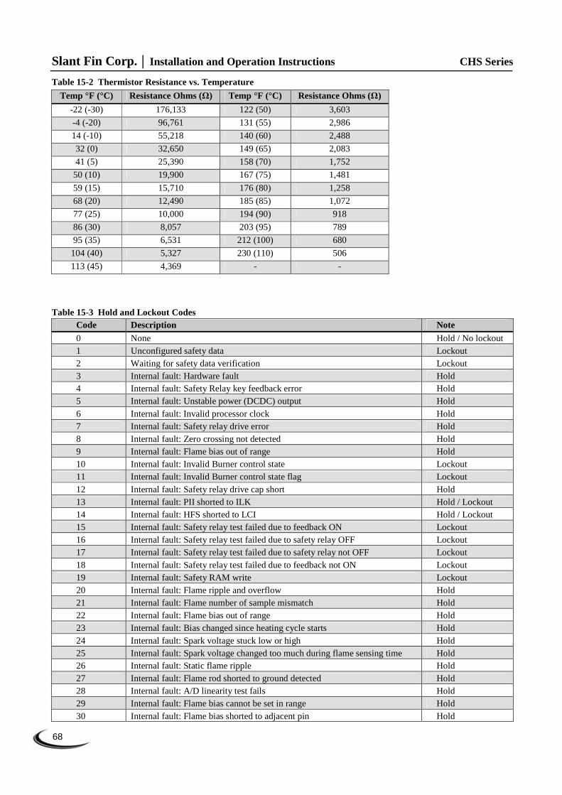
Table 15-2 Thermistor Resistance vs. Temperature
Temp °F (°C) Resistance Ohms (Ω) Temp °F (°C) Resistance Ohms (Ω)
-22 (-30) 176,133 122 (50) 3,603
-4 (-20) 96,761 131 (55) 2,986
14 (-10) 55,218 140 (60) 2,488
32 (0) 32,650 149 (65) 2,083
41 (5) 25,390 158 (70) 1,752
50 (10) 19,900 167 (75) 1,481
59 (15) 15,710 176 (80) 1,258
68 (20) 12,490 185 (85) 1,072
77 (25) 10,000 194 (90) 918
86 (30) 8,057 203 (95) 789
95 (35) 6,531 212 (100) 680
104 (40) 5,327 230 (110) 506
113 (45) 4,369 - -
Table 15-3 Hold and Lockout Codes Code Description Note
0 None Hold / No lockout 1 Unconfigured safety data Lockout 2 Waiting for safety data verification Lockout 3 Internal fault: Hardware fault Hold 4 Internal fault: Safety Relay key feedback error Hold 5 Internal fault: Unstable power (DCDC) output Hold 6 Internal fault: Invalid processor clock Hold 7 Internal fault: Safety relay drive error Hold 8 Internal fault: Zero crossing not detected Hold 9 Internal fault: Flame bias out of range Hold 10 Internal fault: Invalid Burner control state Lockout 11 Internal fault: Invalid Burner control state flag Lockout 12 Internal fault: Safety relay drive cap short Hold 13 Internal fault: PII shorted to ILK Hold / Lockout 14 Internal fault: HFS shorted to LCI Hold / Lockout 15 Internal fault: Safety relay test failed due to feedback ON Lockout 16 Internal fault: Safety relay test failed due to safety relay OFF Lockout 17 Internal fault: Safety relay test failed due to safety relay not OFF Lockout 18 Internal fault: Safety relay test failed due to feedback not ON Lockout 19 Internal fault: Safety RAM write Lockout 20 Internal fault: Flame ripple and overflow Hold 21 Internal fault: Flame number of sample mismatch Hold 22 Internal fault: Flame bias out of range Hold 23 Internal fault: Bias changed since heating cycle starts Hold 24 Internal fault: Spark voltage stuck low or high Hold 25 Internal fault: Spark voltage changed too much during flame sensing time Hold 26 Internal fault: Static flame ripple Hold 27 Internal fault: Flame rod shorted to ground detected Hold 28 Internal fault: A/D linearity test fails Hold 29 Internal fault: Flame bias cannot be set in range Hold 30 Internal fault: Flame bias shorted to adjacent pin Hold

CHS Series Installation and Operation Instructions Slant Fin Corp.
69
Table 15-3 Hold and Lockout Codes Code Description Note 31 Internal fault: SLO electronics unknown error Hold 32 Internal fault: Safety Key 0 Lockout 33 Internal fault: Safety Key 1 Lockout 34 Internal fault: Safety Key 2 Lockout 35 Internal fault: Safety Key 3 Lockout 36 Internal fault: Safety Key 4 Lockout 37 Internal fault: Safety Key 5 Lockout 38 Internal fault: Safety Key 6 Lockout 39 Internal fault: Safety Key 7 Lockout 40 Internal fault: Safety Key 8 Lockout 41 Internal fault: Safety Key 9 Lockout 42 Internal fault: Safety Key 10 Lockout 43 Internal fault: Safety Key 11 Lockout 44 Internal fault: Safety Key 12 Lockout 45 Internal fault: Safety Key 13 Lockout 46 Internal fault: Safety Key 14 Lockout 47 Flame rod to ground leakage Hold 48 Static flame (not flickering) Hold 49 24VAC voltage low/high Hold 50 Modulation fault Hold 51 Pump fault Hold 52 Motor tachometer fault Hold 53 AC inputs phase reversed Lockout 54-57 RESERVED 58 Internal fault: HFS shorted to IAS Lockout 59 Internal fault: Mux pin shorted Lockout 60 Internal fault: HFS shorted to LFS Lockout 61 Anti short cycle Hold 62 Fan speed not proved Hold 63 LCI OFF Hold 64 PII OFF N/A 65 Interrupted Airflow Switch OFF Hold 66 Interrupted Airflow Switch ON Hold 67 ILK OFF Hold 68 ILK ON N/A 69 Pilot test hold Hold 70 Wait for leakage test completion Hold 71-77 RESERVED 78 Demand lost in run Hold 79 Outlet high limit Hold 80 DHW high limit Disabled 81 Delta T limit Hold / Lockout 82 Stack limit Lockout 83-84 RESERVED 85 Inlet/Outlet inversion limit (See Table 16-1) Hold 86-87 RESERVED
88 Outlet T-Rise limit (See Table 16-1) Lockout 89-90 RESERVED 91 Inlet sensor fault Hold

Slant Fin Corp. Installation and Operation Instructions CHS Series
70
Table 15-3 Hold and Lockout Codes Code Description Note 92 Outlet sensor fault Hold 93 DHW sensor fault Hold 94 Header sensor fault Hold 95 Stack sensor fault Hold 96 Outdoor sensor fault Hold 97 Internal fault: A2D mismatch Lockout 98 Internal fault: Exceeded VSNSR voltage tolerance Lockout 99 Internal fault: Exceeded 28V voltage tolerance Lockout 100 Pressure sensor fault Hold 101-104 RESERVED 105 Flame detected out of sequence Hold / Lockout 106 Flame lost in MFEP Lockout 107 Flame lost early in run Lockout 108 Flame lost in run Lockout 109 Ignition failed Lockout 110 Ignition failure occurred Hold 111 Flame current lower than WEAK threshold Hold 112 Pilot test flame timeout Lockout 113 Flame circuit timeout Lockout 114-121 RESERVED 122 Light off rate proving failed Lockout 123 Purge rate proving failed Lockout 124 High fire switch OFF Hold 125 High fire switch stuck ON Hold 126 Low fire switch OFF Hold 127 Low fire switch stuck ON Hold 128 Fan speed failed during pre-purge Hold / Lockout 129 Fan speed failed during pre-ignition Hold / Lockout 130 Fan speed failed during ignition Hold / Lockout 131 Fan movement detected during standby Hold 132 Fan speed failed during run Hold 133-135 RESERVED 136 Interrupted Airflow Switch failed to close Hold 137 ILK failed to close Hold 138-148 RESERVED 149 Flame detected Hold / Lockout 150 Flame not detected Hold 151 High fire switch ON Hold / Lockout 152 Combustion pressure ON Hold / Lockout 153 Combustion pressure OFF Hold / Lockout 154 Purge fan switch ON Hold / Lockout 155 Purge fan switch OFF Hold / Lockout 156 Combustion pressure and Flame ON Hold / Lockout 157 Combustion pressure and Flame OFF Lockout 158 Main valve ON Lockout 159 Main valve OFF Lockout 160 Ignition ON Lockout 161 Ignition OFF Lockout 162 Pilot valve ON Lockout

CHS Series Installation and Operation Instructions Slant Fin Corp.
71
Table 15-3 Hold and Lockout Codes Code Description Note 163 Pilot valve OFF Lockout 164 Block intake ON Lockout 165 Block intake OFF Lockout 166-171 RESERVED 172 Main relay feedback incorrect Lockout 173 Pilot relay feedback incorrect Lockout 174 Safety relay feedback incorrect Lockout 175 Safety relay open Lockout 176 Main relay ON at safe start check Lockout 177 Pilot relay ON at safe start check Lockout 178 Safety relay ON at safe start check Lockout 179-183 RESERVED 184 Invalid BLOWER/HSI output setting Lockout 185 Invalid Delta T limit enable setting Lockout 186 Invalid Delta T limit response setting Lockout 187 Invalid DHW high limit enable setting Lockout 188 Invalid DHW high limit response setting Lockout 189 Invalid Flame sensor type setting Lockout 190 Invalid interrupted air switch enable setting Lockout 191 Invalid interrupted air switch start check enable setting Lockout 192 Invalid Igniter on during setting Lockout 193 Invalid Ignite failure delay setting Lockout 194 Invalid Ignite failure response setting Lockout 195 Invalid Ignite failure retries setting Lockout 196 Invalid Ignition source setting Lockout 197 Invalid Interlock open response setting Lockout 198 Invalid Interlock start check setting Lockout 199 Invalid LCI enable setting Lockout 200 Invalid light off rate setting Lockout 201 Invalid Light off rate proving setting Lockout 202 Invalid Main Flame Establishing Period time setting Lockout 203 Invalid MFEP flame failure response setting Lockout 204 Invalid NTC sensor type setting Lockout 205 Invalid Outlet high limit response setting Lockout 206 Invalid Pilot Flame Establishing Period setting Lockout 207 Invalid PII enable setting Lockout 208 Invalid pilot test hold setting Lockout 209 Invalid Pilot type setting Lockout 210 Invalid Post-purge time setting Lockout 211 Invalid Power up with lockout setting Lockout 212 Invalid Pre-ignition time setting Lockout 213 Invalid Pre-purge rate setting Lockout 214 Invalid Pre-purge time setting Lockout 215 Invalid Purge rate proving setting Lockout 216 Invalid Run flame failure response setting Lockout 217 Invalid Run stabilization time setting Lockout 218 Invalid Stack limit enable setting Lockout 219 Invalid Stack limit response setting Lockout 220 Unconfigured Delta T limit set point setting Lockout

Slant Fin Corp. Installation and Operation Instructions CHS Series
72
Table 15-3 Hold and Lockout Codes Code Description Note 221 Unconfigured DHW high limit set point setting Lockout 222 Unconfigured Outlet high limit set point setting Lockout 223 Unconfigured Stack limit set point setting Lockout 224 Invalid DHW demand source setting Lockout 225 Invalid Flame threshold setting Lockout 226 Invalid Outlet high limit set point setting Lockout 227 Invalid DHW high limit set point setting Lockout 228 Invalid Stack limit set point setting Lockout 229 Invalid Modulation output setting Lockout 230 Invalid CH demand source setting Lockout 231 Invalid Delta T limit delay setting Lockout 232 Invalid Pressure sensor type setting Lockout 233 Invalid IAS closed response setting Lockout 234 Invalid Outlet high limit enable setting Lockout 235 Invalid Outlet connector type setting Lockout 236 Invalid Inlet connector type setting Lockout 237 Invalid DHW connector type setting Lockout 238 Invalid Stack connector type setting Lockout 239 Invalid Header connector type setting Lockout 240 Invalid Outdoor connector type setting Lockout 241-255 RESERVED
CHS Series Installation and Operation Instructions Slant Fin Corp.
73
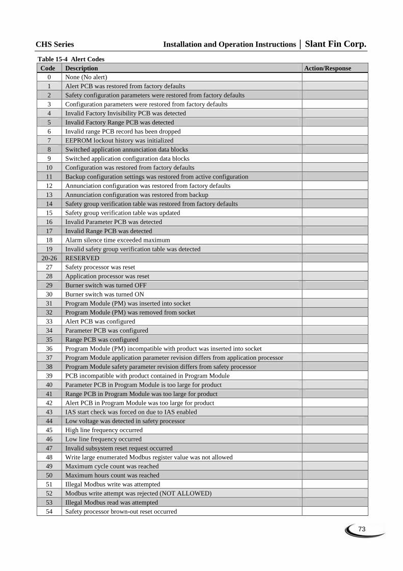
Table 15-4 Alert Codes Code Description Action/Response
0 None (No alert) 1 Alert PCB was restored from factory defaults 2 Safety configuration parameters were restored from factory defaults 3 Configuration parameters were restored from factory defaults 4 Invalid Factory Invisibility PCB was detected 5 Invalid Factory Range PCB was detected 6 Invalid range PCB record has been dropped 7 EEPROM lockout history was initialized 8 Switched application annunciation data blocks 9 Switched application configuration data blocks 10 Configuration was restored from factory defaults 11 Backup configuration settings was restored from active configuration 12 Annunciation configuration was restored from factory defaults 13 Annunciation configuration was restored from backup 14 Safety group verification table was restored from factory defaults 15 Safety group verification table was updated 16 Invalid Parameter PCB was detected 17 Invalid Range PCB was detected 18 Alarm silence time exceeded maximum 19 Invalid safety group verification table was detected
20-26 RESERVED 27 Safety processor was reset 28 Application processor was reset 29 Burner switch was turned OFF 30 Burner switch was turned ON 31 Program Module (PM) was inserted into socket 32 Program Module (PM) was removed from socket 33 Alert PCB was configured 34 Parameter PCB was configured 35 Range PCB was configured 36 Program Module (PM) incompatible with product was inserted into socket 37 Program Module application parameter revision differs from application processor 38 Program Module safety parameter revision differs from safety processor 39 PCB incompatible with product contained in Program Module 40 Parameter PCB in Program Module is too large for product 41 Range PCB in Program Module was too large for product 42 Alert PCB in Program Module was too large for product 43 IAS start check was forced on due to IAS enabled 44 Low voltage was detected in safety processor 45 High line frequency occurred 46 Low line frequency occurred 47 Invalid subsystem reset request occurred 48 Write large enumerated Modbus register value was not allowed 49 Maximum cycle count was reached 50 Maximum hours count was reached 51 Illegal Modbus write was attempted 52 Modbus write attempt was rejected (NOT ALLOWED) 53 Illegal Modbus read was attempted 54 Safety processor brown-out reset occurred

Slant Fin Corp. Installation and Operation Instructions CHS Series
74
Table 15-4 Alert Codes Code Description Action/Response
55 Application processor watchdog reset occurred 56 Application processor brown-out reset occurred 57 Safety processor watchdog reset occurred 58 Alarm was reset by the user at the control 59 Burner control firing rate was > absolute max rate 60 Burner control firing rate was < absolute min rate 61 Burner control firing rate was invalid, % vs. RPM 62 Burner control was firing with no fan request 63 Burner control rate (non-firing) was > absolute max rate 64 Burner control rate (non-firing) was < absolute min rate 65 Burner control rate (non-firing) was absent 66 Burner control rate (non-firing) was invalid, % vs. RPM 67 Fan off cycle rate was invalid, % vs. RPM 68 Set point was over ridden due to sensor fault 69 Modulation was over ridden due to sensor fault 70 No demand source was set due to demand priority conflicts 71 CH 4-20mA signal was invalid.
72-73 RESERVED 74 Periodic forced recycle 75 Absolute max fan speed was out of range 76 Absolute min fan speed was out of range 77 Fan gain down was invalid 78 Fan gain up was invalid 79 Fan minimum duty cycle was invalid 80 Fan pulses per revolution was invalid 81 Fan PWM frequency was invalid
82-89 RESERVED 90 Modulation output type was invalid 91 Firing rate control parameter was invalid 92 Forced rate was out of range vs. min/max modulation 93 Forced rate was invalid, % vs. RPM 94 Slow start ramp value was invalid 95 Slow start degrees value was invalid 96 Slow start was ended due to outlet sensor fault 97 Slow start was end due to reference set point fault 98 CH max modulation rate was invalid, % vs. RPM 99 CH max modulation rate was > absolute max rate 100 CH modulation range (max minus min) was too small (< 4% or 40 RPM) 101 DHW max modulation rate was invalid, % vs. RPM 102 DHW max modulation rate was > absolute max rate 103 DHW modulation range (max minus min) was too small (< 4% or 40 RPM) 104 Min modulation rate was < absolute min rate 105 Min modulation rate was invalid, % vs. RPM 106 Manual rate was invalid, % vs. RPM 107 Slow start enabled, but forced rate was invalid 108 Analog output hysteresis was invalid 109 Analog modulation output type was invalid 110 IAS open rate differential was invalid 111 IAS open step rate was invalid

CHS Series Installation and Operation Instructions Slant Fin Corp.
75
Table 15-4 Alert Codes Code Description Action/Response
112 -114 RESERVED 115 Fan was limited to its minimum duty cycle 116 Manual rate was > CH max modulation rate 117 Manual rate was > DHW max modulation rate 118 Manual rate was < min modulation rate 119 Manual rate in Standby was > absolute max rate 120 Modulation commanded rate was > CH max modulation rate 121 Modulation commanded rate was > DHW max modulation rate 122 Modulation commanded rate was < min modulation rate 123 Modulation rate was limited due to outlet limit 124 Modulation rate was limited due to Delta-T limit 125 Modulation rate was limited due to stack limit 126 Modulation rate was limited due to anti-condensation 127 Fan Speed out of range in RUN 128 Modulation rate was limited due to IAS was open 129 Slow start ramp setting of zero will result in no modulation rate change 130 No forced rate was configured for slow start ramp 131 CH demand source was invalid 132 CH P-gain was invalid 133 CH I-gain was invalid 134 CH D-gain was invalid 135 CH OFF hysteresis was invalid 136 CH ON hysteresis was invalid 137 CH sensor type was invalid 138 CH hysteresis step time was invalid 139 CH remote control parameter was invalid 140 CH ODR not allowed with remote control
141-145 RESERVED 146 CH control was suspended due to fault 147 CH header temperature was invalid 148 CH outlet temperature was invalid 149 CH steam pressure was invalid
150-156 RESERVED 157 DHW demand source was invalid 158 DHW P-gain was invalid 159 DHW I-gain was invalid 160 DHW D-gain was invalid 161 DHW OFF hysteresis was invalid 162 DHW ON hysteresis was invalid 163 DHW hysteresis step time was invalid 164 DHW sensor type was invalid 165 Inlet sensor type was invalid for DHW 166 Outlet sensor type was invalid for DHW
167-170 RESERVED 171 DHW control was suspended due to fault 172 DHW temperature was invalid 173 DHW inlet temperature was invalid 174 DHW outlet temperature was invalid
175-182 RESERVED

Slant Fin Corp. Installation and Operation Instructions CHS Series
76
Table 15-4 Alert Codes Code Description Action/Response
183 Lead Lag P-gain was invalid 184 Lead Lag I-gain was invalid 185 Lead Lag D-gain was invalid 186 Lead Lag OFF hysteresis was invalid 187 Lead Lag ON hysteresis was invalid 188 Lead Lag slave enable was invalid 189 Lead Lag hysteresis step time was invalid
190-203 RESERVED 204 Lead Lag master was suspended due to fault 205 Lead Lag slave was suspended due to fault 206 Lead Lag header temperature was invalid 207 Lead Lag was suspended due to no enabled Program Module installed 208 Lead Lag slave session has timed out
209-221 RESERVED 222 CH frost protection temperature was invalid 223 CH frost protection inlet temperature was invalid 224 DHW frost protection temperature was invalid
225-230 RESERVED 231 LL set point was invalid 232 LL time of day set point was invalid 233 LL outdoor temperature was invalid 234 LL ODR time of day set point was invalid 235 LL ODR time of day set point exceeded normal set point 236 LL max outdoor set point was invalid 237 LL min outdoor set point was invalid 238 LL min water set point was invalid 239 LL outdoor temperature range was too small (minimum 12 C / 22 F) 240 LL water temperature range was too small (minimum 12 C / 22 F)
241-245 RESERVED 246 CH set point was invalid 247 CH time of day set point was invalid 248 CH outdoor temperature was invalid 249 CH ODR time of day setpoint was invalid 250 CH ODR time of day set point exceeds normal set point 251 CH max outdoor set point was invalid 252 CH min outdoor setp oint was invalid 253 CH min water set point was invalid 254 CH outdoor temperature range was too small (minimum 12 C / 22 F) 255 CH water temperature range was too small (minimum 12 C / 22 F)
256-260 RESERVED 261 DHW set point was invalid 262 DHW time of day set point was invalid
263-271 RESERVED 272 Abnormal Recycle: Pressure sensor fault 273 Abnormal Recycle: Safety relay drive test failed 274 Abnormal Recycle: Demand off during Pilot Flame Establishing Period 275 Abnormal Recycle: LCI off during Drive to Purge Rate 276 Abnormal Recycle: LCI off during Measured Purge Time 277 Abnormal Recycle: LCI off during Drive to Light off Rate

CHS Series Installation and Operation Instructions Slant Fin Corp.
77
Table 15-4 Alert Codes Code Description Action/Response
278 Abnormal Recycle: LCI off during Pre-Ignition test 279 Abnormal Recycle: LCI off during Pre-Ignition time 280 Abnormal Recycle: LCI off during Main Flame Establishing Period 281 Abnormal Recycle: LCI off during Ignition period 282 Abnormal Recycle: Demand off during Drive to Purge Rate 283 Abnormal Recycle: Demand off during Measured Purge Time 284 Abnormal Recycle: Demand off during Drive to Light off Rate 285 Abnormal Recycle: Demand off during Pre-Ignition test 286 Abnormal Recycle: Demand off during Pre-Ignition time 287 Abnormal Recycle: Flame was on during Safe Start check 288 Abnormal Recycle: Flame was on during Drive to Purge Rate 289 Abnormal Recycle: Flame was on during Measured Purge Time 290 Abnormal Recycle: Flame was on during Drive to Light off Rate 291 Abnormal Recycle: Flame was not on at end of Ignition period 292 Abnormal Recycle: Flame was lost during Main Flame Establishing Period 293 Abnormal Recycle: Flame was lost early in Run 294 Abnormal Recycle: Flame was lost during Run 295 Abnormal Recycle: Leakage test failed 296 Abnormal Recycle: Interrupted air flow switch was off during Drive to Purge Rate 297 Abnormal Recycle: Interrupted air flow switch was off during Measured Purge Time 298 Abnormal Recycle: Interrupted air flow switch was off during Drive to Light off Rate 299 Abnormal Recycle: Interrupted air flow switch was off during Pre-Ignition test 300 Abnormal Recycle: Interrupted air flow switch was off during Pre-Ignition time 301 Abnormal Recycle: Interrupted air flow switch was off during Main Flame Establishing
Period
302 Abnormal Recycle: Ignition failed due to interrupted air flow switch was off 303 Abnormal Recycle: ILK off during Drive to Purge Rate 304 Abnormal Recycle: ILK off during Measured Purge Time 305 Abnormal Recycle: ILK off during Drive to Light off Rate 306 Abnormal Recycle: ILK off during Pre-Ignition test 307 Abnormal Recycle: ILK off during Pre-Ignition time 308 Abnormal Recycle: ILK off during Main Flame Establishing Period 309 Abnormal Recycle: ILK off during Ignition period 310 Run was terminated due to ILK was off 311 Run was terminated due to interrupted air flow switch was off 312 Stuck reset switch 313 Run was terminated due to fan failure 314 Abnormal Recycle: Fan failed during Drive to Purge Rate 315 Abnormal Recycle: Fan failed during Measured Purge Time 316 Abnormal Recycle: Fan failed during Drive to Light off Rate 317 Abnormal Recycle: Fan failed during Pre-Ignition test 318 Abnormal Recycle: Fan failed during Pre-Ignition time 319 Abnormal Recycle: Fan failed during Ignition period 320 Abnormal Recycle: Fan failed during Main Flame Establishing Period 321 Abnormal Recycle: Main Valve off after 10 seconds of RUN 322 Abnormal Recycle: Pilot Valve off after 10 seconds of RUN 323 Abnormal Recycle: Safety Relay off after 10 seconds of RUN 324 Abnormal Recycle: Hardware flame bias 325 Abnormal Recycle: Hardware static flame 326 Abnormal Recycle: Hardware flame current invalid

Slant Fin Corp. Installation and Operation Instructions CHS Series
78
Table 15-4 Alert Codes Code Description Action/Response
327 Abnormal Recycle: Hardware flame rod short 328 Abnormal Recycle: Hardware invalid power 329 Abnormal Recycle: Hardware invalid AC line 330 Abnormal Recycle: Hardware SLO flame ripple 331 Abnormal Recycle: Hardware SLO flame sample 332 Abnormal Recycle: Hardware SLO flame bias range 333 Abnormal Recycle: Hardware SLO flame bias heat 334 Abnormal Recycle: Hardware SLO spark stuck 335 Abnormal Recycle: Hardware SLO spark changed 336 Abnormal Recycle: Hardware SLO static flame 337 Abnormal Recycle: Hardware SLO rod shorted 338 Abnormal Recycle: Hardware SLO AD linearity 339 Abnormal Recycle: Hardware SLO bias not set 340 Abnormal Recycle: Hardware SLO bias shorted 341 Abnormal Recycle: Hardware SLO electronics 342 Abnormal Recycle: Hardware processor clock 343 Abnormal Recycle: Hardware AC phase 344 Abnormal Recycle: Hardware A2D mismatch 345 Abnormal Recycle: Hardware VSNSR A2D 346 Abnormal Recycle: Hardware 28V A2D 347 Abnormal Recycle: Hardware HFS IAS shorted 348 Abnormal Recycle: Hardware PII INTLK shorted 349 Abnormal Recycle: Hardware HFS LCI shorted 350 Abnormal Recycle: Hardware HFS LFS shorted 351 Abnormal Recycle: Invalid zero crossing 352 Abnormal Recycle: fault stack sensor 353 Abnormal Recycle: stack limit 354 Abnormal Recycle: delta T limit 355 Abnormal Recycle: fault outlet sensor 356 Abnormal Recycle: outlet high limit 357 Abnormal Recycle: fault DHW sensor 358 Abnormal Recycle: DHW high limit 359 Abnormal Recycle: fault inlet sensor 360 Abnormal Recycle: Check Parameters Failed 361 Internal error: No factory parameters were detected in control 362 Internal error: PID iteration frequency was invalid 363 Internal error: Demand-Rate interval time was invalid 364 Internal error: Factory calibration parameter for modulation was invalid 365 Internal error: CH PID P-scaler was invalid 366 Internal error: CH PID I-scaler was invalid 367 Internal error: CH PID D-scaler was invalid 368 Internal error: DHW PID P-scaler was invalid 369 Internal error: DHW PID I-scaler was invalid 370 Internal error: DHW PID D-scaler was invalid 371 Internal error: Lead Lag master PID P-scaler was invalid 372 Internal error: Lead Lag master PID I-scaler was invalid 373 Internal error: Lead Lag master PID D-scaler was invalid
374-459 RESERVED 460 LCI demand lost in run

CHS Series Installation and Operation Instructions Slant Fin Corp.
79
Table 15-4 Alert Codes Code Description Action/Response
461 Demand lost in run 462 STAT demand lost in run 463 Demand lost in run due to no flame 464-466
RESERVED 467 Internal error: EEPROM write was attempted before EEPROM was initialized 468 Internal error: EEPROM cycle count address was invalid 469 Internal error: EEPROM days count address was invalid 470 Internal error: EEPROM hours count address was invalid 471 Internal error: Lockout record EEPROM index was invalid 472 Internal error: Request to write PM status was invalid 473 Internal error: PM parameter address was invalid 474 Internal error: PM safety parameter address was invalid 475 Internal error: Invalid record in lockout history was removed 476 Internal error: EEPROM write buffer was full 477 Internal error: Data too large was not written to EEPROM 478 Internal error: Safety key bit 0 was incorrect 479 Internal error: Safety key bit 1 was incorrect 480 Internal error: Safety key bit 2 was incorrect 481 Internal error: Safety key bit 3 was incorrect 482 Internal error: Safety key bit 4 was incorrect 483 Internal error: Safety key bit 5 was incorrect 484 Internal error: Safety key bit 6 was incorrect 485 Internal error: Safety key bit 7 was incorrect 486 Internal error: Safety key bit 8 was incorrect 487 Internal error: Safety key bit 9 was incorrect 488 Internal error: Safety key bit 10 was incorrect 489 Internal error: Safety key bit 11 was incorrect 490 Internal error: Safety key bit 12 was incorrect 491 Internal error: Safety key bit 13 was incorrect 492 Internal error: Safety key bit 14 was incorrect 493 Internal error: Safety key bit 15 was incorrect 494 Internal error: Safety relay timeout 495 Internal error: Safety relay commanded off 496 Internal error: Unknown safety error occurred 497 Internal error: Safety timer was corrupt 498 Internal error: Safety timer was expired 499 Internal error: Safety timings 500 Internal error: Safety shutdown

Slant Fin Corp. Installation and Operation Instructions CHS Series
80
16.0 PARTS LIST For a list of parts that corresponds to the item numbers in the callouts, refer to Table 16-1. Note that some item numbers may appear more than once in the parts list depending on which model number is being referenced.
Building Owners - Replacement parts are available from your stocking wholesaler. Contact your local Installer or Wholesaler for assistance with parts.
Wholesalers - Contact Slant/Fin inside sales department when ordering replacement parts at 1-516-484-2600.
Installers - Contact Slant/Fin tech support department if technical assistance required at 1-516-484-2600.
Figure 16-1(a) CHS Heat Engine and Gas Train Heat Exchanger, Gas Valve, Blower and Burner Assembly
20
23
19
21
15
12
18
16 26
22
11
1
13
10
14
9 8
7
6
4
5
3
2
16
24
17
25
17

CHS Series Installation and Operation Instructions Slant Fin Corp.
81
Figure 16-1(b) CHS Cabinet Cabinet, Vent and Air-Inlet Parts
Figure 16-1(c) CHS Controls Electrical Housing, Controller, and Display Module
85
84
86
87
42
41
52
39
43 40
44 50
46
45
49
48
40
49 50
46
47
80
82
34
30
27
35
33
32
36
38
37
33
28
31
29 29 29
31
74
73
75
75
76
77
78
79
83
81

Slant Fin Corp. Installation and Operation Instructions CHS Series
82
Figure 16-1(d) CHS Installation Kit
Table 16-1 Parts List:
Item Model Part Number Description 1 CHS 85-110 81 8010 000 Premix Burner CHS 85-110 1 CHS 155-250 81 8011 000 Premix Burner CHS 155-250 1 CHS 300-399 81 8012 000 Premix burner CHS 300-399 2 CHS 85-110 81 8013 000 Premix Burner Gasket CHS 85-110 2 CHS 155-250 81 8014 000 Premix Burner Gasket CHS 155-250 2 CHS 300-399 81 8015 000 Premix Burner Gasket CHS 300-399 3 CHS 85-110 81 8064 000 Burner Plate Gasket CHS 85-110 3 CHS 155-250 81 8065 000 Burner Plate Gasket CHS 155-250 3 CHS 300-399 81 8066 000 Burner Plate Gasket CHS 300-399 4 CHS 85-399 81 8016 000 Blower Gasket CHS 85-399 5 CHS 85-110 81 8017 000 Combustion Blower RG130, CHS 85-110 5 CHS 155-250 81 8018 000 Combustion Blower RG148, CHS 155-250 5 CHS 300-399 81 8019 000 Combustion Blower RG148 Enhanced, CHS 300-399 6 CHS 85-250 81 8021 000 Venturi Gasket, Cork CHS 85-250 6 CHS 300-399 81 8020 000 Venturi to Blower O-ring CHS 300-399 7 CHS 85 81 8022 000 Venturi 051, CHS 85 7 CHS 110 81 8023 000 Venturi 45900450-010, CHS 110 7 CHS 155-250 81 8024 000 Venturi 003, CHS 155-250 7 CHS 300-399 81 8025 000 Venturi 002, CHS 300-399
53 54
55
56
57 58
59
60
61
62
63
65
66
67
68 69
64
70
71
72 61
60
Natural to LP Conversion Kit

CHS Series Installation and Operation Instructions Slant Fin Corp.
83
Item Model Part Number Description 8 CHS 300-399 (NG) 81 8029 000 Gas Valve NG Orifice 9.6mm CHS 300-399 9 CHS 300-399 (NG) 81 8144 000 Gas Valve NG Orifice O-Ring CHS 300-399 9 CHS 85-250 81 8143 000 Gas Valve Screws/Seals CHS 85-250
10 CHS 85-250 81 8032 000 Gas Valve VK8115V1341B (Valve Only), CHS 85-250 10 CHS 300-399 81 8031 000 Gas Valve VR8615VB 1044B, CHS 300-399 11 CHS 85-399 81 8033 000 Ignition Electrode, Dual – c/w gasket 12 CHS 85-399 81 8034 000 Igniter Gasket, Graphite (Ignition Electrode / Flame Rod) 13 CHS 85-250 81 8035 000 Gas Valve Regulator Vent Adapter 14 CHS 85-250 81 8037 000 Gas Valve Inlet O-ring Gasket CHS 85-250 14 CHS 300-399 81 8036 000 Gas Valve Inlet O-ring Gasket CHS 300-399 15 CHS 85-250 81 8039 000 Gas Valve ½” NPT adapter CHS 85-250 15 CHS 300-399 81 8038 000 Gas Valve ¾” NPT adapter CHS 300-399 16 CHS 85-250 81 8041 000 Sensor, Supply & Return, Dual CHS 85-250 16 CHS 300-399 81 8040 000 Sensor, Supply & Return, Dual CHS 300-399 17 CHS 85-110 81 8043 000 Pipe Coupling, Groove-Joint, 1” CHS 85-110 17 CHS 155-250 81 8044 000 Pipe Coupling, Groove-Joint, 1 ¼” CHS 155-250 17 CHS 300-399 81 8045 000 Pipe Coupling, Groove-Joint, 1 ½” CHS 300-399 18 CHS 85-110 81 8046 000 Supply Pipe, SS, 1” 18 CHS 155-250 81 8047 000 Supply Pipe, SS, 1 ¼” 18 CHS 300-399 81 8048 000 Supply Pipe, SS, 1 ½” 19 CHS 85-110 81 8051 000 Return Pipe, SS, 1” 19 CHS 155-250 81 8052 000 Return Pipe, SS, 1 ¼” 19 CHS 300-399 81 8053 000 Return Pipe, SS, 1 ½” 20 CHS 85-250 81 8158 000 Gas Valve Harness CHS 85-250 20 CHS 300-399 81 8159 000 Gas Valve Harness CHS 300-399 21 CHS 85-399 81 8074 000 Flame Rod CHS 85-399 (Includes p/n: 82774) 22 CHS 85-110 81 8070 000 Burner Plate CHS 85-110 22 CHS 155-250 81 8071 000 Burner Plate CHS 155-250 22 CHS 300-399 81 8072 000 Burner Plate CHS 300-399 23 CHS 85-110 81 8067 000 Burner Plate Ceramic Disc CHS 85-110 23 CHS 155-250 81 8068 000 Burner Plate Ceramic Disc CHS 155-250 23 CHS 300-399 81 8069 000 Burner Plate Ceramic Disc CHS 300-399 24 CHS 85-399 81 8042 000 Low Water Cutoff 25 CHS 85-399 81 8055 000 Sight Glass Assembly 26 CHS 85-110 81 8056 000 Heat Exchanger-ASME CHS 85-110 26 CHS 155-250 81 8057 000 Heat Exchanger-ASME CHS 155-250 26 CHS 300-399 81 8058 000 Heat Exchanger-ASME CHS 300-399 27 CHS 85-250 81 8059 000 Tube Strap CHS 85-250 27 CHS 300-399 81 8060 000 Tube Strap CHS 300-399 28 CHS 85-399 81 8061 000 Flue Sensor Plug (3009354) 29 CHS 85-399 81 8073 000 Grommet, Diaphragm, ½” 30 CHS 85-250 81 8084 000 Air-inlet Adapter, SS, 3” CHS 85-250 30 CHS 300-399 81 8085 000 Air-inlet Adapter, SS, 4” CHS 300-399 31 CHS 85-399 81 8156 000 Dome Plug, Black, 7/8" 32 CHS 85-399 81 8086 000 Flue Adapter Test Port Plug, 12mm 33 CHS 85-110 81 8091 000 Grommet, Vinyl, 1” IPS (1300) CHS 85-110 33 CHS 155-250 81 8092 000 Grommet, Vinyl, 1-¼” IPS (1625) CHS 155-250 33 CHS 300-399 81 8093 000 Grommet, Vinyl, 1-½” IPS (1875) CHS 300-399 34 CHS 85-250 81 8089 000 Grommet, Vinyl, ½” IPS (1020-T) CHS 85-250 34 CHS 300-399 81 8090 000 Grommet, Vinyl, ¾” IPS (1020) CHS 300-399

Slant Fin Corp. Installation and Operation Instructions CHS Series
84
Item Model Part Number Description 35 CHS 85-399 81 8050 000 Flue Sensor, Dual 36 CHS 85-250 81 8075 000 1 ½” MJ Coupling CHS 85-250 36 CHS 300-399
81 8076 000 2" MJ Coupling CHS 300-399
37 CHS 85-110 81 8078 000 Air-inlet Assembly CHS 85-110 37 CHS 155-250 81 8079 000 Air-inlet Assembly CHS 155-250 37 CHS 300-399 81 8080 000 Air-inlet Assembly CHS 300-399 38 CHS 85-110 81 8081 000 Flue Outlet Adapter, SS, 3” CHS 85-110 38 CHS 155-250 81 8082 000 Flue Outlet Adapter, SS, 3” CHS 155-250 38 CHS 300-399 81 8083 000 Flue Outlet Adapter, SS, 4” CHS 300-399 39 CHS 85-399 81 8111 000 Ignition Coil 40 CHS 85-399
81 8113 000 Snap Bushing, 1”
41 CHS 85-399 81 8160 000 Round Rocker Switch, On-Off (LCD Dot-Matrix Display) 42 CHS 85-399 81 8112 000 Spark Igniter Wire, 12" 43 CHS 85-399 81 8095 000 User Interface (LCD Dot-Matrix Display) 44 CHS 85-399 81 8114 000 Transformer, 24V, 40VA 45 CHS 85-399 81 8115 000 Controller, CHS series 46 CHS 85-399 81 8097 000 Terminal, Barrier, 2 Row, 8 Position 47 CHS 85-399 81 8118 000 Terminal, Barrier, 2 Row, 9 Position 48 CHS 85-399 81 8119 000 Fuse, 2A, 32V, Plug Style 49 CHS 85-399 81 8120 000 Fuse Holder, Panel Mount, 20 Amp at 250VAC Max 50 CHS 85-399 81 8121 000 Fuse, 7A, 250VAC, Fast-Acting 52 CHS 85-399 81 8054 000 Receptacle, 120VAC 53 CHS 85-250
81 8161 000 3” CPVC Pipe, System 636, 5” long CHS 85-250
53 CHS 300-399 81 8161 000 4” CPVC Pipe, System 636, 5” long CHS 300-399 54 CHS 85-399 81 8049 000 Auto Air Vent, ½” NPT 55 CHS 85-399 81 8163 000 Pressure Relief Valve, ASME, ¾” NPT, 30psi 56 CHS 85-399 81 8164 000 Pressure Gauge, 0-60psi 57 CHS 85-399 81 8063 000 Brass Elbow, 90, Street, ¾” 58 CHS 85-110 81 8150 000 Brass Bushing, 1” x ¾” CHS 85-110 58 CHS 155-250 81 8151 000 Brass Bushing, 1 ¼” x ¾” CHS 155-250 58 CHS 300-399 81 8152 000 Brass Bushing, 1 ½” x ¾” CHS 300-399 59 CHS 85-110 81 8153 000 Brass Tee, 1” x ½” x 1” CHS 85-110 59 CHS 155-250 81 8154 000 Brass Tee, 1 ¼” x ½” x 1 ¼” CHS 155-250 59 CHS 300-399 81 8155 000 Brass Tee, 1 ½” x ½” x 1 ½” CHS 300-399 60 CHS 85-110 81 8077 000 2” Round Mesh Vent Screen CHS 85-110 61 CHS 85-250 81 8165 000 3” Round Mesh Vent Screen CHS 85-250 61 CHS 300-399 81 8166 000 4” Round Mesh Vent Screen CHS 300-399 62 CHS 85-399 81 8126 000 Outdoor Sensor, 10K 63 CHS 85-399 81 8146 000 System Sensor, 10K 64 CHS 85-250 81 8167 000 Natural Gas to LP Conversion Instructions CHS 85-250 64 CHS 300-399 81 8168 000 Natural Gas to LP Conversion Instructions CHS 300-399 65 CHS 85-250 81 8169 000 Conversion Decal CHS 85-250 65 CHS 300-399 81 8170 000 Conversion Decal CHS 300-399 66 CHS 85 81 8028 000 Gas Valve LP Orifice 4.15mm CHS 85 67 CHS 110 81 8026 000 Gas Valve LP Orifice 5.2mm CHS 110 68 CHS 155-250 81 8027 000 Gas Valve LP Orifice 6.2mm CHS 155-250 68 CHS 300-399 (LP) 81 8030 000 Gas Valve LP Orifice 7.4mm CHS 300-399 69 CHS 300-399 (LP) n/a Gas Valve LP Orifice O-ring CHS 300-399 70 CHS 85-250 81 8157 000 Torx Allen Key CHS 85-250 71 CHS 85-399 81 8094 000 Wall Mount Bracket Bottom CHS 85-399
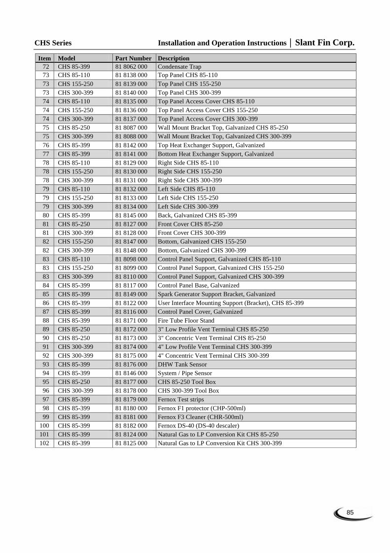
CHS Series Installation and Operation Instructions Slant Fin Corp.
85
Item Model Part Number Description 72 CHS 85-399 81 8062 000 Condensate Trap 73 CHS 85-110 81 8138 000 Top Panel CHS 85-110 73 CHS 155-250 81 8139 000 Top Panel CHS 155-250 73 CHS 300-399 81 8140 000 Top Panel CHS 300-399 74 CHS 85-110 81 8135 000 Top Panel Access Cover CHS 85-110 74 CHS 155-250 81 8136 000 Top Panel Access Cover CHS 155-250 74 CHS 300-399 81 8137 000 Top Panel Access Cover CHS 300-399 75 CHS 85-250 81 8087 000 Wall Mount Bracket Top, Galvanized CHS 85-250 75 CHS 300-399 81 8088 000 Wall Mount Bracket Top, Galvanized CHS 300-399 76 CHS 85-399 81 8142 000 Top Heat Exchanger Support, Galvanized 77 CHS 85-399 81 8141 000 Bottom Heat Exchanger Support, Galvanized 78 CHS 85-110 81 8129 000 Right Side CHS 85-110 78 CHS 155-250 81 8130 000 Right Side CHS 155-250 78 CHS 300-399 81 8131 000 Right Side CHS 300-399 79 CHS 85-110 81 8132 000 Left Side CHS 85-110 79 CHS 155-250 81 8133 000 Left Side CHS 155-250 79 CHS 300-399 81 8134 000 Left Side CHS 300-399 80 CHS 85-399 81 8145 000 Back, Galvanized CHS 85-399 81 CHS 85-250 81 8127 000 Front Cover CHS 85-250 81 CHS 300-399 81 8128 000 Front Cover CHS 300-399 82 CHS 155-250 81 8147 000 Bottom, Galvanized CHS 155-250 82 CHS 300-399 81 8148 000 Bottom, Galvanized CHS 300-399 83 CHS 85-110 81 8098 000 Control Panel Support, Galvanized CHS 85-110 83 CHS 155-250 81 8099 000 Control Panel Support, Galvanized CHS 155-250 83 CHS 300-399 81 8110 000 Control Panel Support, Galvanized CHS 300-399 84 CHS 85-399 81 8117 000 Control Panel Base, Galvanized 85 CHS 85-399 81 8149 000 Spark Generator Support Bracket, Galvanized 86 CHS 85-399 81 8122 000 User Interface Mounting Support (Bracket), CHS 85-399 87 CHS 85-399 81 8116 000 Control Panel Cover, Galvanized 88 CHS 85-399 81 8171 000 Fire Tube Floor Stand 89 CHS 85-250 81 8172 000 3" Low Profile Vent Terminal CHS 85-250 90 CHS 85-250 81 8173 000 3" Concentric Vent Terminal CHS 85-250 91 CHS 300-399 81 8174 000 4" Low Profile Vent Terminal CHS 300-399 92 CHS 300-399 81 8175 000 4" Concentric Vent Terminal CHS 300-399 93 CHS 85-399 81 8176 000 DHW Tank Sensor 94 CHS 85-399 81 8146 000 System / Pipe Sensor 95 CHS 85-250 81 8177 000 CHS 85-250 Tool Box 96 CHS 300-399 81 8178 000 CHS 300-399 Tool Box 97 CHS 85-399 81 8179 000 Fernox Test strips 98 CHS 85-399 81 8180 000 Fernox F1 protector (CHP-500ml) 99 CHS 85-399 81 8181 000 Fernox F3 Cleaner (CHR-500ml)
100 CHS 85-399 81 8182 000 Fernox DS-40 (DS-40 descaler) 101 CHS 85-399 81 8124 000 Natural Gas to LP Conversion Kit CHS 85-250 102 CHS 85-399 81 8125 000 Natural Gas to LP Conversion Kit CHS 300-399
Slant Fin Corp. Installation and Operation Instructions CHS Series
86
NOTES

CHS Series Installation and Operation Instructions Slant Fin Corp.
87
NOTES

SLANT/FIN CORPORATION, Greenvale, N.Y. 11548 • Phone: (516) 484-2600FAX: (516) 484-5921 • Canada: Slant/Fin LTD/LTEE, Mississauga, Ontario
www.slantfin.com
©Slant/Fin Corp. 2012
Related Documents