Southwest Windpower, Inc. 1801 West Route 66 Flagstaff, Arizona 86001 Phone: ++ (1) 928 - 779 - 9463 Fax: ++ (1) 928 - 779 - 1485 www.skystreamenergy.com OWNER’S MANUAL 60 HZ (NORTH AMERICA) EDITION Installation Operation Maintenance © March 2008 Southwest Windpower, Inc. All Rights Reserved

Welcome message from author
This document is posted to help you gain knowledge. Please leave a comment to let me know what you think about it! Share it to your friends and learn new things together.
Transcript
Southwest Windpower, Inc.1801 West Route 66Flagstaff, Arizona 86001Phone: ++ (1) 928 - 779 - 9463Fax: ++ (1) 928 - 779 - 1485
www.skystreamenergy.com
Owner’s Manual 60 HZ (nOrTH aMerICa) edITIOn
Installation
Operation
Maintenance
© March 2008 Southwest Windpower, Inc. All Rights Reserved


Southwest WindpowerCongratulations on your purchase and welcome to our family!
Dear Skystream 3.7® Owner,
Thank you for your purchase of Skystream. You have just selected the most technologically advanced, cost-effective renewable energy appliance available for a home or small business. We congratulate you on your choice and are confident you will experience years of dependable service.
Before going any further, please complete and return the enclosed Warranty Registration Card. The conditions of your warranty are dependent upon the proper installation of Skystream. Furthermore, this will assure you of being kept up-to-date with the latest developments from Southwest Windpower. These include new options, performance tips, updated software to maximize output and user notices. It is important to know that we do not sell or distribute your information to any third party. We understand your privacy is important.
If you have any questions or comments, we would like to hear from you. Please call during working hours (Monday-Friday 8:00 am to 5:00 pm - Mountain Time Zone - Daylight Savings not observed). Our phone number is 928-779-9463, toll free 866-807-9463.
Again, welcome to our family and thank you for investing in the future of wind energy with Skystream.
Sincerely,
Southwest Windpower
Enter the serial and model number below
Serial Number __________________________________
Model Number __________________________________
Skystream Owner’s Manual3-CMLT-1054Revision: J
4 Skystream 3.7® Owner’s Manual, Rev J
ImporTanT SafETy InSTruCTIonSrEad ThESE InSTruCTIonS In ThEIr EnTIrETy bEforE InSTallIng or opEraTIng.
1) SAVE THESE INSTRUCTIONS. This manual contains important instructions for Skystream that must be followed during installation and maintenance. 2) Read, understand and respect all warnings. 3) Turn Skystream “OFF” if “gROWLINg” or unusual noise or opera tion is observed. Contact Southwest Windpower Technical service. 4) Install Skystream on a calm day - no wind at ground level. 5) Install Skystream in accordance with National Electric Code (NEC) and local building codes. 6) Always obtain a building permit before construction. 7) A minimum of 2 adults are required to safely lift or move Skystream. Use proper equipment such as hydraulic hoists to lift Skystream. 8) Always wear appropriate protective personal equipment such as closed toe work shoes, hard hat, work gloves, and safety glasses when working on or installing Skystream. 9) Turn Skystream “OFF” if ice accumulates on blades to avoid pos- sible injury resulting from ice flying off blades. 10) This wind generator complies with international safety standards, and therefore the design or its installation must never be compro mised. a. Do not open the inverter cover; doing so without factory authorization will void the warranty. b. Apply the proper torque to all fasteners. c. Torque field wire connections to Skystream to 2.3-2.5 N·m. Refer to Electrical Connections section of this manual (Section 2-1-2). d. Install only on a Professional Engineer (PE) certified tower. e. Do not paint the blades.
Professional installation: southwest Windpower strongly recommends skystream be installed by trained professionals.
TIp: Helpful information to ease the installation
Warning: Risk of injury or death - proceed with extreme caution
professional installation highly recommended
In this manual
ImporTanT: Please take note
11) Use only proper grounding techniques as established by the NEC. 12) Properly complete the warranty registration card; failure to complete and return the card may affect your warranty. 13) Skystream must be installed in accordance with this manual and local and national building codes. Failure to comply with the manual and local codes will affect and possibly void your warranty. 14) Skystream uses high voltage and is potentially dangerous. Be sure to use all safety precautions at all times.
Skystream 3.7® Owner’s Manual, Rev J 5
radio (rf) interference (Usa)
Skystream 3.7 has been tested and found to comply with the limits for a class b digital device, pursuant to part 15 of the fCC rules (uS federal Communications Commission). These limits are designed to provide rea-sonable protection against harmful interference in a residential installation. Skystream generates, uses and can radiate radio frequency energy and, if not installed and used in accordance with the instructions, may cause harm-ful interference to radio communications. however, there is no guarantee that interference will not occur in a particular installation. If Skystream does cause harmful interference to radio or television reception, which can be de-termined by turning the Skystream on and off, you are encouraged to correct the interference by one or more of the following measures:
• Reorient or relocate the Skyview Interface Module or Remote Display.
• Increase the separation between Skystream and Skyview Interface Module or remote display.
radio (rf) interference (eU)
Complies to European Standards En 61000-6-3 (2007), En 61000-6-2 (2005), En 61000-3-2 (1995), En 61000-3-3 (2000).
6 Skystream 3.7® Owner’s Manual, Rev J
TablE of ConTEnTS
IMPORTANT SAFETY INSTRUCTIONS _____________________ 4RADIO INTERFERENCE _________________________________ 5SkYSTREAM 3.7® WARRANTY ____________________________ 7SkYSTREAM 3.7® SPECIFICATIONS _______________________ 8-9EUROPEAN gRID STANDARDS __________________________ 10
Prior to installation ______________________________ 11
INTENDED USE ________________________________________ 11UNINTENDED USE _____________________________________ 11INSTALLATION PERSONNEL _____________________________ 12TYPICAL SkYSTREAM INSTALLATION _____________________ 13SITINg – FINDINg THE BEST LOCATION FOR SkYSTREAM __ 14LOCAL REQUIREMENTS ________________________________ 14
installation ________________________________________ 15
INTRODUCTION ________________________________________ 15WIRE SIZINg ___________________________________________ 15gROUNDINg __________________________________________ 16UTILITY PANEL CONNECTIONS __________________________ 16ELECTRICAL CONNECTIONS TO SkYSTREAM _____________ 17-18INSTALLINg SkYSTREAM ON A TOWER ___________________ 19BOLTINg SkYSTREAM TO THE TOWER ____________________ 20-22BLADES, NOSECONE AND ANTENNA ASSEMBLY __________ 23-24
oPeration anD aDJUstMents ______________________ 25
MANUAL OPERATION OF SkYSTREAM ____________________ 25ADJUSTMENTS _________________________________________ 25MAINTENANCE _________________________________________ 25-26 SERVICE ______________________________________________ 26TROUBLESHOOTINg ___________________________________ 26EMERgENCY SHUTDOWN ______________________________ 26kEY OPERATINg CHARACTERISTICS _____________________ 27DISPOSAL OF SkYSTREAM ______________________________ 28FREQUENTLY ASkED QUESTIONS _______________________ 29
appEndICES
appendix a: Electrical diagrams 1 grid Connection Option A __________________________ 3 2 grid Connection Option B __________________________ 4 3 grid Connection Option C __________________________ 5 4 grid Connection Option D __________________________ 6 5 Skystream Block Diagram __________________________ 7 appendix b: Tower grounding 1 Introduction ______________________________________ 4 2 Grounding Techniques _____________________________ 4-9
appendix C: battery Charging 1 120/240 Volt, 60 Hz, 2 Phase System, using two inverters: Option A ___________________________________________ 3 2 120/240 Volt, 60 Hz, 2 Phase System, using one inverter with a transformer: Option B ________________________________ 4 3 120 Volt, 60 Hz, 1 Phase System, using one inverter: Option C ___________________________________________ 5 4 Battery Charging with Controller kits _________________ 6
appendix d: lightning protection 1 Introduction_______________________________________ 4 2 Lightning Protection Data ___________________________ 4-9
appendix E: Compliance/Certification documents 1 UL (US & Canada) ________________________________ 2-3 2 CE (Europe) _____________________________________ 4
Skystream 3.7® Owner’s Manual, Rev J 7
hardware WarrantySouthwest Windpower, Inc., (“Southwest Windpower”) will repair or replace free ofcharge any part or parts of the Southwest Windpower Skystream 3.7® wind generator determined by Southwest Windpower to be defective in materials and/or workmanship under normal authorized use consistent with product instructions for a period of five years from the date the original purchaser (“Customer”) receives the wind generator (“Start Date”). This warranty extends only to the original purchaser. The Customer’s sole and exclusive remedy and the entire liability of Southwest Windpower, its suppli-ers and affiliates under the warranty is, at Southwest Windpower’s option, either (i) to replace the wind generator with new or reconditioned wind generator, (ii) to correct the reported problem, or (iii) to refund the purchase price of the wind generator. Repaired or replaced products are warranted for the remainder of the original warranty period.
restrictionsProblems with the wind generator products can be due to improper use, maintenance,non-Southwest Windpower additions or modifications or other problems not due todefects in Southwest Windpower’s workmanship or materials. No warranty will apply if the wind generator (i) has been altered or modified except by Southwest Wind-power, (ii) has not been installed, operated, repaired, or maintained in accordance with instructions supplied by Southwest Windpower (iii), or (iv) has been exposed to winds exceeding 140 mph (63 m/s), or has been subjected to abnormal physical, thermal or electrical stress, misuse, negligence, or accident. If Southwest Windpower’s repair facility determines that the problem with the wind generator is not due to a defect in Southwest Windpower’s workmanship or materials, then the party requesting warranty service will be responsible for the costs of all necessary repairs and expenses incurred by Southwest Windpower.
Warranty Claims & return proceduresIn order to be eligible for service under this warranty the Customer MUST return the warranty registration card included with this Warranty Agreement within 60 days of pur-chasing the wind generator. Additionally, the Customer must submit a service request for the wind generator covered by this warranty within the warranty period by contact-ing Southwest Windpower in writing or via telephone and obtaining a Return Authoriza-tion (“RA”) number. This RA must be obtained before returning any product under this warranty. Notification must include a description of the alleged defect, the manner in which the wind generator was used, the serial number, and the original purchase date in addition to the name, address, and telephone number of the party requesting war-ranty service. Within 3 business days of the date of notification, Southwest Windpower will provide the Customer with a RA number and the location to which the Customer must return the defective wind generator. Any wind generator requiring warranty repair shall be transported at the expense and risk of the party requiring warranty service, including but not limited to proper packaging of the product. The Customer must return the entire wind generator kit within 30 days after issuance of the RA number. South-
west Windpower will be under no obligation to accept any returned wind generator that does not have a valid RA number. Customer’s failure to return the wind generator within 30 days of its receipt of a RA number may result in cancellation of the RA. All parts that Southwest Windpower replaces shall become Southwest Windpower’s property on the date Southwest Windpower ships the repaired wind generator or part back to the Customer. Southwest Windpower will use all reasonable efforts within five days of receipt of the defective wind generator to repair or replace such wind generator. If a warranty claim is invalid for any reason, the Customer will be charged at Southwest Windpower’s current rates for services performed and will be charged for all necessary repairs and expenses incurred by Southwest Windpower.
disclaimerExCEPT FOR THE ExPRESSED WARRANTy SET FORTH AbOVE, SOUTHWESTWINDPOWER DISClAIMS All OTHER ExPRESSED AND IMPlIED WARRAN-TIES, INClUDING THE IMPlIED WARRANTIES OF FITNESS FOR A PARTICUlAR PURPOSE, MERCHANTAbIlITy AND NON-INFRINGEMENT. NO OTHER WAR-RANTy, ExPRESSED OR IMPlIED, WHETHER OR NOT SIMIlAR IN NATURE TO ANy OTHER WARRANTy PROVIDED HEREIN, SHAll ExIST WITH RESPECT TO THE PRODUCT SOlD UNDER THE PROVISIONS OF THESE TERMS AND CON-DITIONS. SOUTHWEST WINDPOWER ExPRESSly DISClAIMS All lIAbIlITy FOR bODIly INJURIES OR DEATH THAT MAy OCCUR, DIRECTly OR INDIRECT-ly, by USE OF THE PRODUCT by ANy PERSON. All OTHER WARRANTIES ARE ExPRESSly WAIVED by THE CUSTOMER.
limitation of liabilityUNDER NO CIRCUMSTANCES WIll SOUTHWEST WINDPOWER OR ITS AFFIlI-ATES OR SUPPlIERS bE lIAblE OR RESPONSIblE FOR ANy lOSS OF USE, INTERRUPTION OF bUSINESS, lOST PROFITS, lOST DATA, OR INDIRECT, SPE-CIAl, INCIDENTAl, OR CONSEqUENTIAl DAMAGES, OF ANy kIND REGARD-lESS OF THE FORM OF ACTION, WHETHER IN CONTRACT, TORT (INClUDING NEGlIGENCE), STRICT lIAbIlITy OR OTHERWISE, RESUlTING FROM THE DE-FECT, REPAIR, REPlACEMENT, SHIPMENT OR OTHERWISE, EVEN IF SOUTH-WEST WINDPOWER OR ITS AFFIlIATE OR SUPPlIER HAS bEEN ADVISED OF THE POSSIbIlITy OF SUCH DAMAGE. (Note: some states and provinces do not allow the exclusion or limitation of incidental or consequential damages, so these limitations may not apply to you.) Neither Southwest Windpower nor its affiliates or sup-pliers will be held liable or responsible for any damage or loss to any items or products connected to, powered by or otherwise attached to the Hardware. The total cumulative liability to Customer, from all causes of action and all theories of liability, will be limited to and will not exceed the purchase price of the product paid by Customer. This War-ranty gives the Customer specific legal rights and the Customer may also have other legal rights that vary from state to state or province to province.
skystream 3.7® limited 5-Year Warranty
WInd TurbInE WarranTy agrEEmEnT
3-CmlT-1063
8 Skystream 3.7® Owner’s Manual, Rev J
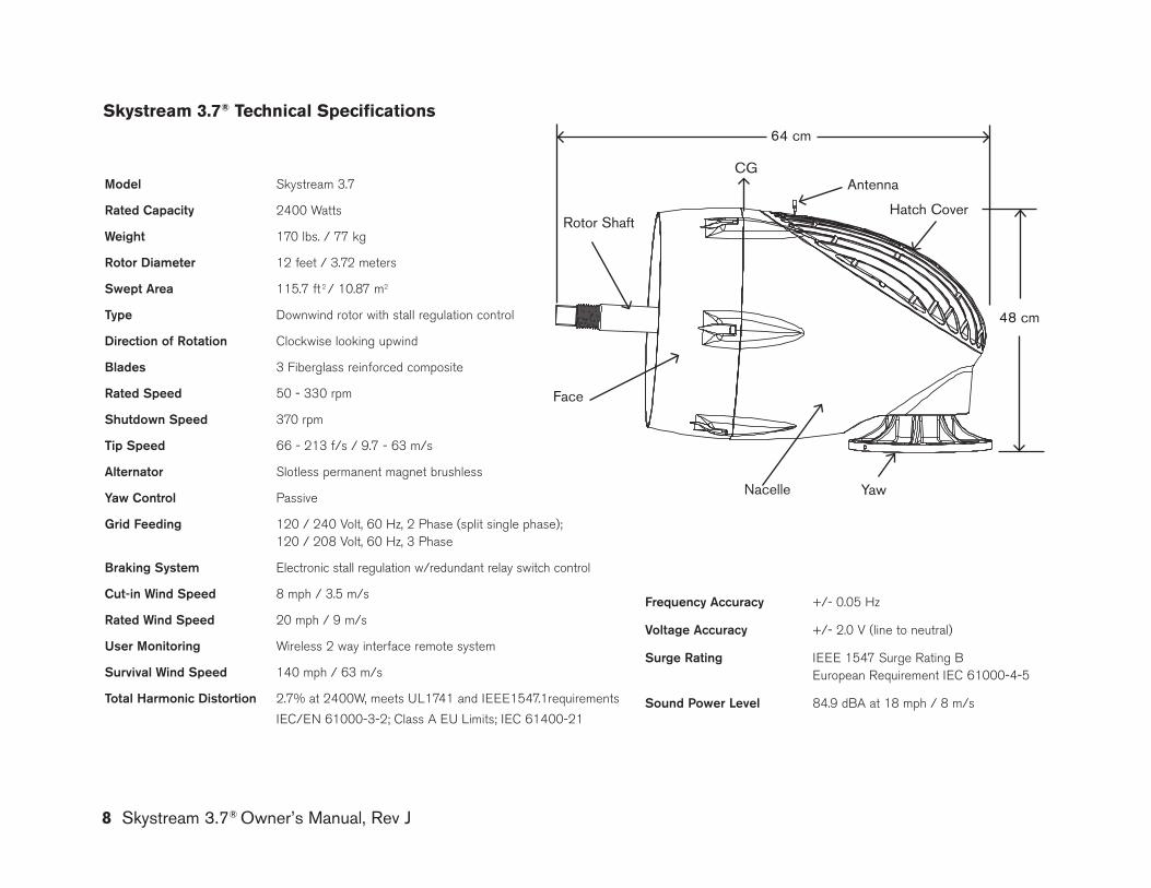
skystream 3.7® technical specifications
model Skystream 3.7
rated Capacity 2400 Watts
Weight 170 lbs. / 77 kg
rotor diameter 12 feet / 3.72 meters
Swept area 115.7 ft 2 / 10.87 m2
Type Downwind rotor with stall regulation control
direction of rotation Clockwise looking upwind
blades 3 Fiberglass reinforced composite
rated Speed 50 - 330 rpm
Shutdown Speed 370 rpm
Tip Speed 66 - 213 f/s / 9.7 - 63 m/s
alternator Slotless permanent magnet brushless
yaw Control Passive
grid feeding 120 / 240 Volt, 60 Hz, 2 Phase (split single phase); 120 / 208 Volt, 60 Hz, 3 Phase
braking System Electronic stall regulation w/redundant relay switch control
Cut-in Wind Speed 8 mph / 3.5 m/s
rated Wind Speed 20 mph / 9 m/s
user monitoring Wireless 2 way interface remote system
Survival Wind Speed 140 mph / 63 m/s
Total harmonic distortion 2.7% at 2400W, meets UL1741 and IEEE1547.1requirements
IEC/EN 61000-3-2; Class A EU Limits; IEC 61400-21
frequency accuracy +/- 0.05 Hz
Voltage accuracy +/- 2.0 V (line to neutral)
Surge rating IEEE 1547 Surge Rating B European Requirement IEC 61000-4-5
Sound power level 84.9 dBA at 18 mph / 8 m/s
Hatch Cover
Antenna
Rotor Shaft
Face
Nacelle yaw
48 cm
CG
64 cm
Skystream 3.7® Owner’s Manual, Rev J 9
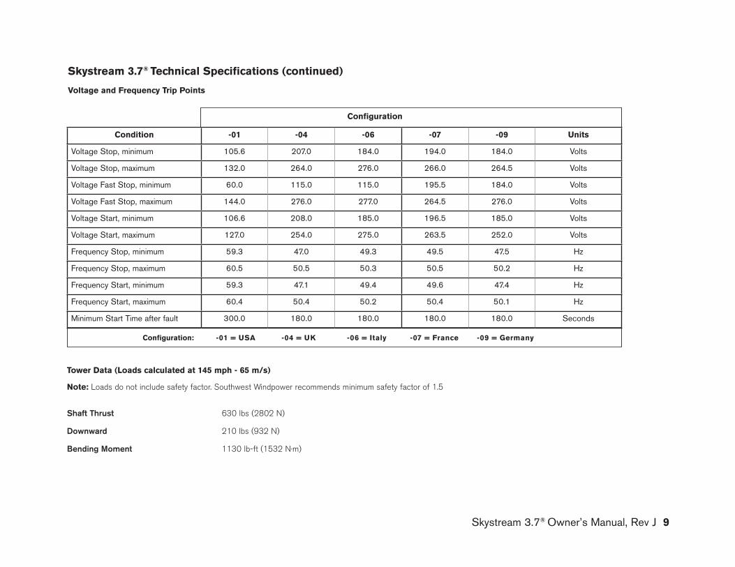
skystream 3.7® technical specifications (continued)
Voltage and frequency trip Points
Configuration
Condition -01 -04 -06 -07 -09 Units
Voltage Stop, minimum 105.6 207.0 184.0 194.0 184.0 Volts
Voltage Stop, maximum 132.0 264.0 276.0 266.0 264.5 Volts
Voltage Fast Stop, minimum 60.0 115.0 115.0 195.5 184.0 Volts
Voltage Fast Stop, maximum 144.0 276.0 277.0 264.5 276.0 Volts
Voltage Start, minimum 106.6 208.0 185.0 196.5 185.0 Volts
Voltage Start, maximum 127.0 254.0 275.0 263.5 252.0 Volts
Frequency Stop, minimum 59.3 47.0 49.3 49.5 47.5 Hz
Frequency Stop, maximum 60.5 50.5 50.3 50.5 50.2 Hz
Frequency Start, minimum 59.3 47.1 49.4 49.6 47.4 Hz
Frequency Start, maximum 60.4 50.4 50.2 50.4 50.1 Hz
Minimum Start Time after fault 300.0 180.0 180.0 180.0 180.0 Seconds
tower Data (loads calculated at 145 mph - 65 m/s)
note: Loads do not include safety factor. Southwest Windpower recommends minimum safety factor of 1.5
Shaft Thrust 630 lbs (2802 N)
downward 210 lbs (932 N)
bending moment 1130 lb-ft (1532 N·m)
Configuration: -01 = Usa -04 = UK -06 = italy -07 = france -09 = Germany

10 Skystream 3.7® Owner’s Manual, Rev J
european Grid standards
Skystream 3.7 complies with the relivant grid connetion requirements taken from the following European grid Codes:
• Verband der Electrizitätswirtschaft – VDEW –e.V. “Eigenerzeugungsanlagen am Niederspannungsnetz” (generation units at low voltage level), 4th Edition, 2001, germany
• ENA Energy Networks Association “Engineering Recommendation G83/1 – Recommendations for the connection of small-scale embedded generators (up to 16 A per phase) in parallel with the public low voltage distribution net works”’ September 2003
• EDF Référentiel Technique “Modele de Contrat de raccordment, d’accés et d’exploitation pour une installation de production de puissant ≤ 36 kVA rac cordée au Réseau Public de Distribution basse tension Conditions Générales” / Standard Form Agreement for the Connection, Access and Operation of Power generating Stations ≤ 36 kVA Connected to the Public Low Voltage Dis tribution Network general Terms and Conditions”, Referentiel technique – NOP- RES_55E, Vesion V6, 2006, France.
• DIN V VDE V 0126-1-1 (VDE V 0126-1-1) “Automatic disconnection device between a generator and the public low voltage grid”, February 2006 germany.
• Italian Standard CEI 11-20 “Electrical energy production systems and uninter ruptible power systems connected to LV and MV networks”
• ÖVE/ÖNORM prEN 50438 “ Requirements for the connection of micro-co generators in parallel with public low-voltage distribution system”, 01.10.2004
Skystream 3.7® Owner’s Manual, Rev J 11
Prior to installation
• Do not attempt to modify Skystream in any fashion – internally or externally.
• Do not install blades other than those supplied with Skystream. Use only genuine replacement blades supplied by Southwest Windpower.
• Do not attempt to use a power source other than the wind to power Skystream – for example connecting pulleys or as water powered
turbine.
intended Use
Skystream 3.7 is a wind powered electricity generator containing an inte-gral AC power inverter. It is designed to supplement the electrical power provided by the local electrical utility company in residential applications by connecting directly to the main AC utility panel. Skystream 3.7 may also be utilized to provide power with battery based residential electrical systems or utility grid connected systems with battery backup. A typical Skystream installation is depicted in Figure 1 of this manual.
Skystream 3.7 is designed to operate at sites with average wind speeds less than 8.5 m/s - IEC (International Electrotechnical Commission) Class II wind conditions. The installation of Skystream at sites with higher aver-age wind speeds will accelerate component wear and require more fre-quent inspections.
Unintended Use
Utilizing Skystream 3.7 for other than its intended purposes or with inappropriate equipment or modifying Skystream is not authorized by Southwest Windpower and will void the warranty and may result in serious or even fatal injury. Observe the following precautions.
• Disconnect power to Skystream prior to servicing – observe “Lock-out” and “Tag-out” procedures.
• Observe all Electrical Code Requirements including tower ground-ing requirements, electrical disconnect switches, wire sizes and types. Reference the appendices in this manual.
• Skystream may only be installed on a tower approved by Southwest Windpower for use with Skystream. Do not install Skystream on roofs or on unauthorized towers.
• Do not use unauthorized fasteners. Use fasteners supplied with Skystream. Contact your dealer for authorized replacement fasteners.
• Observe fastener torque requirements.
ImporTanT: Precautions listed here cannot address all the possible misuses of Skystream, therefore contact Southwest Windpower. If there is any doubt or question regarding the installation or use of Skystream.
12 Skystream 3.7® Owner’s Manual, Rev J
Your Skystream shipment includes the following components. For your convenience a small quantity of spare fasteners is included with each Skystream. The quantities indicated below are quantities required to assemble Skystream:
Turbine assembly on pallet• Includes: turbine, nosecone, blade hub, blade plate (screwed to pallet), M42 hub mounting nut.
blades (may be shipped separately)• Blade mounting hardware - M10 x 120, grade 10.9, hex head bolts (quantity 12) - M10, grade 10.9, nut (quantity 12)
nosecone mounting hardware• M6 x 12 socket head screws, A2 stainless steel (quantity 3)
Skystream to Tower mounting hardware• Vibration Isolators (quantity 8)• Vibration Isolator Snubbing Washers (quantity 8)• M12 x 90 hex head bolts, grade 10.9 (quantity 8)• M12 nuts, grade 10.9 (quantity 8)• M12 flat washers, A2 stainless steel (quantity 8)
yaw Shield• Yaw shield halves (quantity 2)• M5 x 12 socket head screws (quantity 4)
Strain relief Cover• Cover with ground wire (quantity 1)• M5 x 12 socket head screws (quantity 4)
miscellaneous • RF antenna (quantity 1)
TIp: See exploded view on page 23
Your skystream shipment includes:
skystream Dealer
installation Personnel
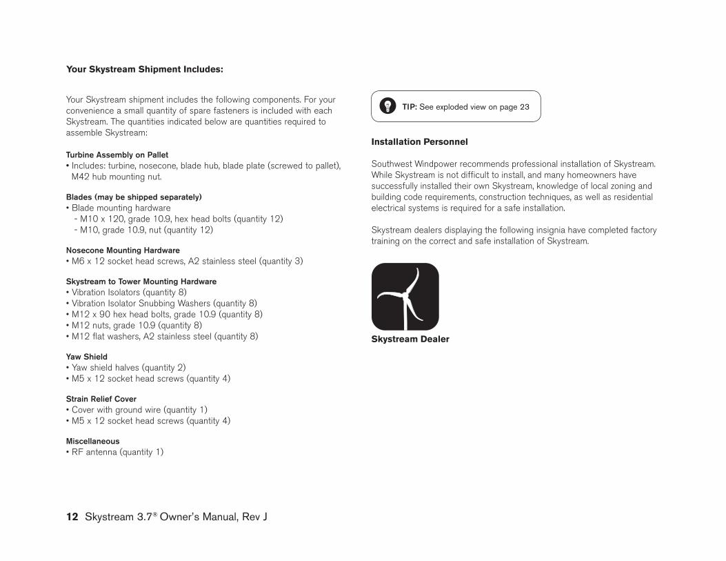
Southwest Windpower recommends professional installation of Skystream. While Skystream is not difficult to install, and many homeowners have successfully installed their own Skystream, knowledge of local zoning and building code requirements, construction techniques, as well as residential electrical systems is required for a safe installation.
Skystream dealers displaying the following insignia have completed factory training on the correct and safe installation of Skystream.
Skystream 3.7® Owner’s Manual, Rev J 13
L 1G N L 2
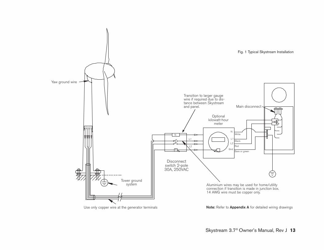
Fig. 1 Typical Skystream Installation
Yaw ground wire
Disconnect switch 2-pole 30A, 250VAC
Optional kilowatt-hour
meter
Main disconnect
note: Refer to appendix a for detailed wiring drawings
White
Black
Red
Bare or green
Tower groundsystem
N
L1
L2
G N l2 l1
g
Use only copper wire at the generator terminals
Aluminium wires may be used for home/utility connection if transition is made in junction box. 14 AWg wire must be copper only.
N
L1
L2
gnd
Transition to larger gauge wire if required due to dis-tance between Skystream and panel.
14 Skystream 3.7® Owner’s Manual, Rev J
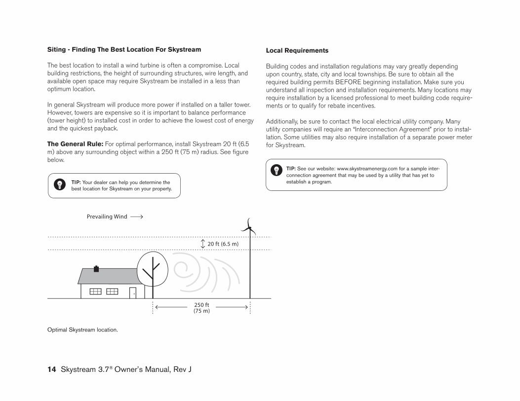
250 ft (75 m)
20 ft (6.5 m)
Prevailing Wind
TIp: your dealer can help you determine the best location for Skystream on your property.
Optimal Skystream location.
siting - finding the Best location for skystream
The best location to install a wind turbine is often a compromise. Local building restrictions, the height of surrounding structures, wire length, and available open space may require Skystream be installed in a less than optimum location.
In general Skystream will produce more power if installed on a taller tower. However, towers are expensive so it is important to balance performance (tower height) to installed cost in order to achieve the lowest cost of energy and the quickest payback.
the General rule: For optimal performance, install Skystream 20 ft (6.5 m) above any surrounding object within a 250 ft (75 m) radius. See figure below.
TIp: See our website: www.skystreamenergy.com for a sample inter-connection agreement that may be used by a utility that has yet to establish a program.
local requirements
Building codes and installation regulations may vary greatly depending upon country, state, city and local townships. Be sure to obtain all the required building permits BEFORE beginning installation. Make sure you understand all inspection and installation requirements. Many locations may require installation by a licensed professional to meet building code require-ments or to qualify for rebate incentives.
Additionally, be sure to contact the local electrical utility company. Many utility companies will require an “Interconnection Agreement” prior to instal-lation. Some utilities may also require installation of a separate power meter for Skystream.
Skystream 3.7® Owner’s Manual, Rev J 15
installation
introduction
The following sections of this manual assume a tower and foundation ap-propriate for use with a Skystream are in place and ready for Skystream to be installed.
Southwest Windpower designed Skystream for easy installation by minimiz-ing the number of electrical connections. In most cases Skystream may be connected directly to the electrical utility panel. However, local requirements may require installation of a disconnect switch and a second power meter between Skystream and the utility panel.
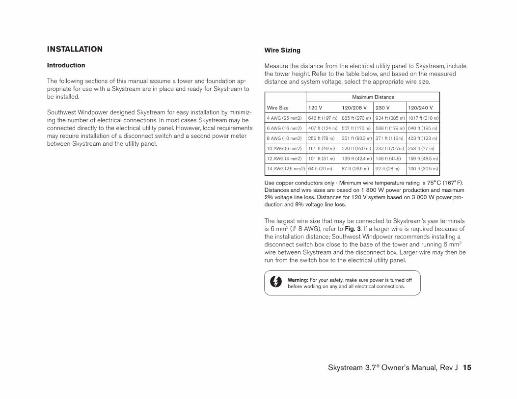
Wire sizing
Measure the distance from the electrical utility panel to Skystream, include the tower height. Refer to the table below, and based on the measured distance and system voltage, select the appropriate wire size.
Warning: For your safety, make sure power is turned off before working on any and all electrical connections.
Use copper conductors only - Minimum wire temperature rating is 75° C (167° F). Distances and wire sizes are based on 1 800 W power production and maximum 2% voltage line loss. Distances for 120 V system based on 3 000 W power pro-duction and 8% voltage line loss.
The largest wire size that may be connected to Skystream’s yaw terminals is 6 mm2 (# 8 AWg), refer to fig. 3. If a larger wire is required because of the installation distance; Southwest Windpower recommends installing a disconnect switch box close to the base of the tower and running 6 mm2 wire between Skystream and the disconnect box. Larger wire may then be run from the switch box to the electrical utility panel.
Wire Size 120 V 120/208 V 230 V 120/240 V
4 AWg (25 mm2) 646 ft (197 m) 885 ft (270 m) 934 ft (285 m) 1017 ft (310 m)
6 AWg (16 mm2) 407 ft (124 m) 557 ft (170 m) 588 ft (179 m) 640 ft (195 m)
8 AWg (10 mm2) 256 ft (78 m) 351 ft (93.3 m) 371 ft (113m) 403 ft (123 m)
10 AWg (6 mm2) 161 ft (49 m) 220 ft (67.0 m) 232 ft (70.7m) 253 ft (77 m)
12 AWg (4 mm2) 101 ft (31 m) 139 ft (42.4 m) 146 ft (44.5) 159 ft (48.5 m)
14 AWg (2.5 mm2) 64 ft (20 m) 87 ft (26.5 m) 92 ft (28 m) 100 ft (30.5 m)
Maximum Distance
16 Skystream 3.7® Owner’s Manual, Rev J
Grounding
All electrical systems must be grounded in accordance with local and national standards. grounding provides protection from electrical shock, voltage surges and static charge build up.
The figures in appendix a provide information for grounding the tower and Skystream at the service panel by means of the ground lead coming from the yaw terminals of the turbine.
appendix b provides information for grounding the tower according to the National Electric Code (USA) and IEC 60364-5-54. Information about grounding electrodes, grounding conductors, and connections is provided.
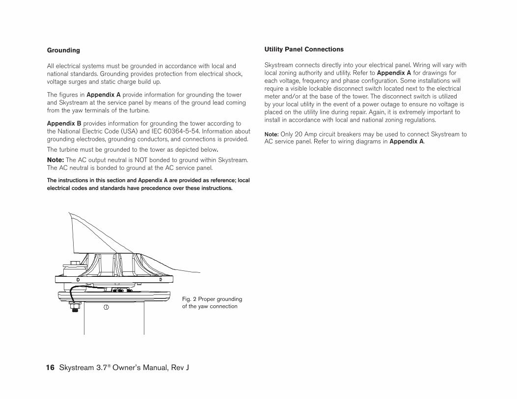
The turbine must be grounded to the tower as depicted below.
note: The AC output neutral is NOT bonded to ground within Skystream. The AC neutral is bonded to ground at the AC service panel.
The instructions in this section and appendix a are provided as reference; local electrical codes and standards have precedence over these instructions.
Fig. 2 Proper grounding of the yaw connection
Utility Panel Connections
Skystream connects directly into your electrical panel. Wiring will vary with local zoning authority and utility. Refer to appendix a for drawings for each voltage, frequency and phase configuration. Some installations will require a visible lockable disconnect switch located next to the electrical meter and/or at the base of the tower. The disconnect switch is utilized by your local utility in the event of a power outage to ensure no voltage is placed on the utility line during repair. Again, it is extremely important to install in accordance with local and national zoning regulations.
note: Only 20 Amp circuit breakers may be used to connect Skystream to AC service panel. Refer to wiring diagrams in appendix a.
Skystream 3.7® Owner’s Manual, Rev J 17
electrical Connections to skystream
CauTIon – be sure power is turned off when making electrical connections.
The following section provides directions for completing the main power connections to the Skystream yaw assembly. The connections are most easily accomplished with Skystream on the ground as would be the case when utilizing a tilt-up tower. If the installation does not incorporate a tilt-up tower, the connections may still be made on the ground by utilizing a sufficient length of cable to con-nect Skystream to the nearest junction point. If, for example, an electrical disconnect box will be installed at the base of the tower, connect enough cable to Skystream to make the connections at the disconnect box – leave some extra cable for connections. The wire connections can then be made on the ground, Skystream hoisted to the top of the tower and the cable “lowered” down the tower and Skysteam bolted to the tower.
l Position Skystream on its side to access the wire terminals.
l Remove approximately 5 cm of protective sheathing from cable and strip approximately 1 cm of insulation off wire leads.
l Note the maximum wire size that can be connected directly to Skystream is 6 mm2 Metric Wire Size or #8 AWg. Refer to Wire Sizing Section of this manual for instructions on selecting correct size wire.
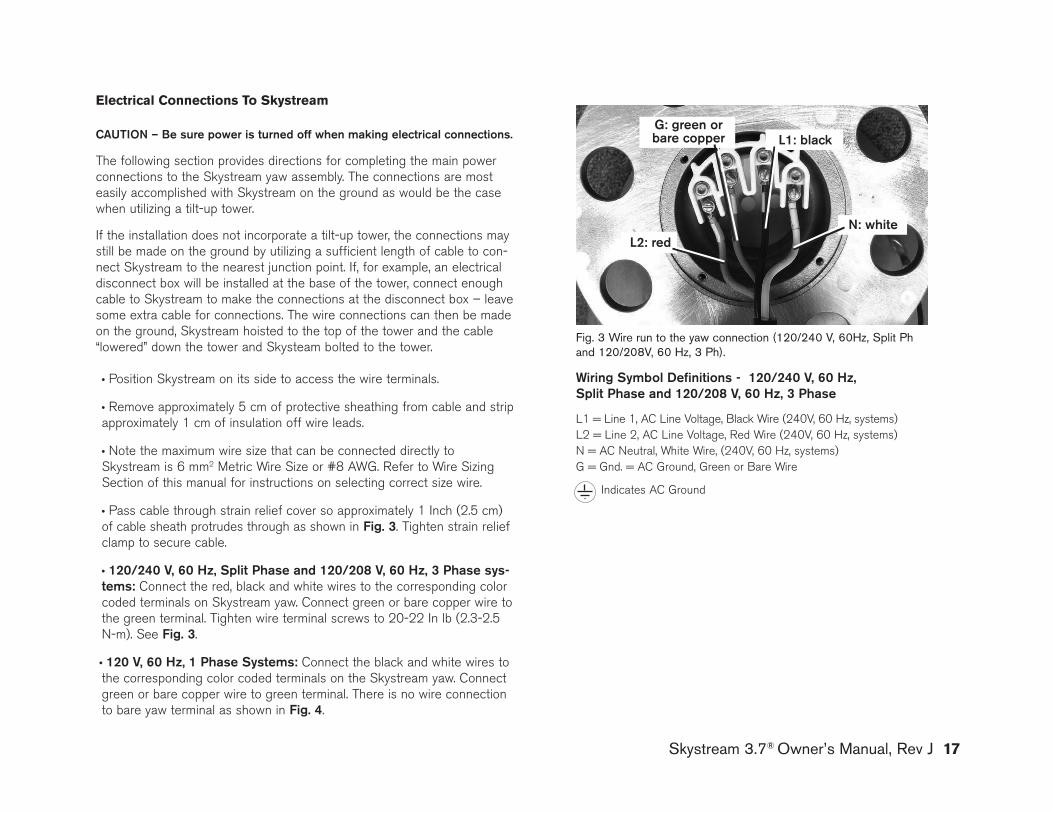
l Pass cable through strain relief cover so approximately 1 Inch (2.5 cm) of cable sheath protrudes through as shown in fig. 3. Tighten strain relief clamp to secure cable.
l 120/240 V, 60 hz, Split phase and 120/208 V, 60 hz, 3 phase sys-tems: Connect the red, black and white wires to the corresponding color coded terminals on Skystream yaw. Connect green or bare copper wire to the green terminal. Tighten wire terminal screws to 20-22 In lb (2.3-2.5 N-m). See fig. 3.
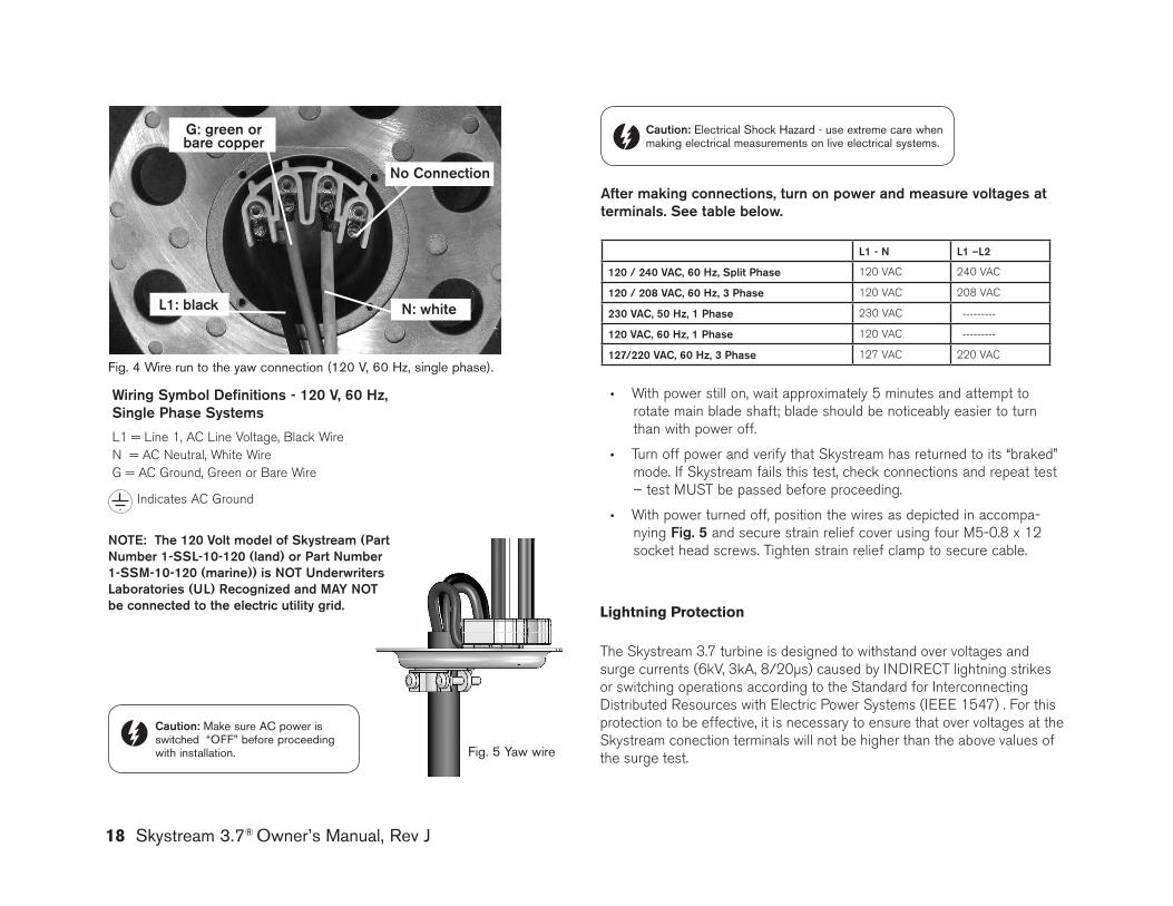
l 120 V, 60 hz, 1 phase Systems: Connect the black and white wires to the corresponding color coded terminals on the Skystream yaw. Connect green or bare copper wire to green terminal. There is no wire connection to bare yaw terminal as shown in fig. 4.
Fig. 3 Wire run to the yaw connection (120/240 V, 60Hz, Split Ph and 120/208V, 60 Hz, 3 Ph).
Wiring Symbol definitions - 120/240 V, 60 hz, Split phase and 120/208 V, 60 hz, 3 phase
L1 = Line 1, AC Line Voltage, Black Wire (240V, 60 Hz, systems) L2 = Line 2, AC Line Voltage, Red Wire (240V, 60 Hz, systems) N = AC Neutral, White Wire, (240V, 60 Hz, systems) g = gnd. = AC ground, green or Bare Wire
Indicates AC ground
n: white
g: green or bare copper l1: black
l2: red
18 Skystream 3.7® Owner’s Manual, Rev J
after making connections, turn on power and measure voltages atterminals. See table below.
l1 - n l1 –l2
120 / 240 VaC, 60 hz, Split phase 120 VAC 240 VAC
120 / 208 VaC, 60 hz, 3 phase 120 VAC 208 VAC
230 VaC, 50 hz, 1 phase 230 VAC ---------
120 VaC, 60 hz, 1 phase 120 VAC ---------
127/220 VaC, 60 hz, 3 phase 127 VAC 220 VAC
l With power still on, wait approximately 5 minutes and attempt to rotate main blade shaft; blade should be noticeably easier to turn than with power off.
l Turn off power and verify that Skystream has returned to its “braked” mode. If Skystream fails this test, check connections and repeat test – test MUST be passed before proceeding.
l With power turned off, position the wires as depicted in accompa-nying fig. 5 and secure strain relief cover using four M5-0.8 x 12 socket head screws. Tighten strain relief clamp to secure cable.
Caution: Make sure AC power is switched “OFF” before proceeding with installation. Fig. 5 yaw wire
Caution: Electrical Shock Hazard - use extreme care when making electrical measurements on live electrical systems.
Wiring Symbol definitions - 120 V, 60 hz, Single phase Systems
L1 = Line 1, AC Line Voltage, Black WireN = AC Neutral, White Wireg = AC ground, green or Bare Wire
Indicates AC ground
Fig. 4 Wire run to the yaw connection (120 V, 60 Hz, single phase).
no Connection
n: whitel1: black
g: green or bare copper
noTE: The 120 Volt model of Skystream (part number 1-SSl-10-120 (land) or part number 1-SSm-10-120 (marine)) is noT underwriters laboratories (ul) recognized and may noT be connected to the electric utility grid. lightning Protection
The Skystream 3.7 turbine is designed to withstand over voltages and surge currents (6kV, 3kA, 8/20µs) caused by INDIRECT lightning strikes or switching operations according to the Standard for Interconnecting Distributed Resources with Electric Power Systems (IEEE 1547) . For this protection to be effective, it is necessary to ensure that over voltages at the Skystream conection terminals will not be higher than the above values of the surge test.
Skystream 3.7® Owner’s Manual, Rev J 19
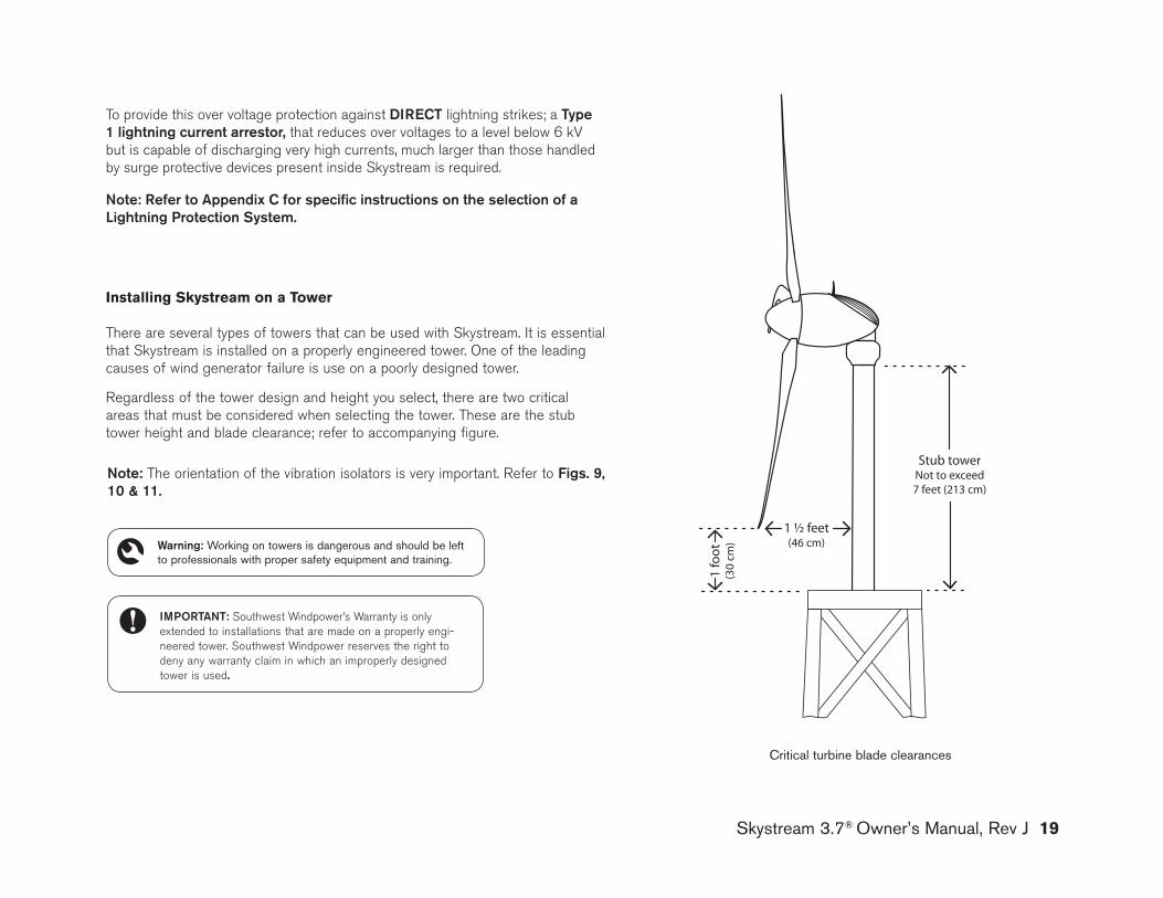
Critical turbine blade clearances
installing skystream on a tower
There are several types of towers that can be used with Skystream. It is essential that Skystream is installed on a properly engineered tower. One of the leading causes of wind generator failure is use on a poorly designed tower.
Regardless of the tower design and height you select, there are two critical areas that must be considered when selecting the tower. These are the stub tower height and blade clearance; refer to accompanying figure.
ImporTanT: Southwest Windpower’s Warranty is only extended to installations that are made on a properly engi-neered tower. Southwest Windpower reserves the right to deny any warranty claim in which an improperly designed tower is used.
note: The orientation of the vibration isolators is very important. Refer to figs. 9, 10 & 11.
Warning: Working on towers is dangerous and should be left to professionals with proper safety equipment and training.
1 ½ feet(46 cm)
1 fo
ot
(30
cm)
Stub towerNot to exceed7 feet (213 cm)
To provide this over voltage protection against dIrECT lightning strikes; a Type 1 lightning current arrestor, that reduces over voltages to a level below 6 kV but is capable of discharging very high currents, much larger than those handled by surge protective devices present inside Skystream is required.
note: refer to appendix C for specific instructions on the selection of a lightning protection System.
20 Skystream 3.7® Owner’s Manual, Rev J
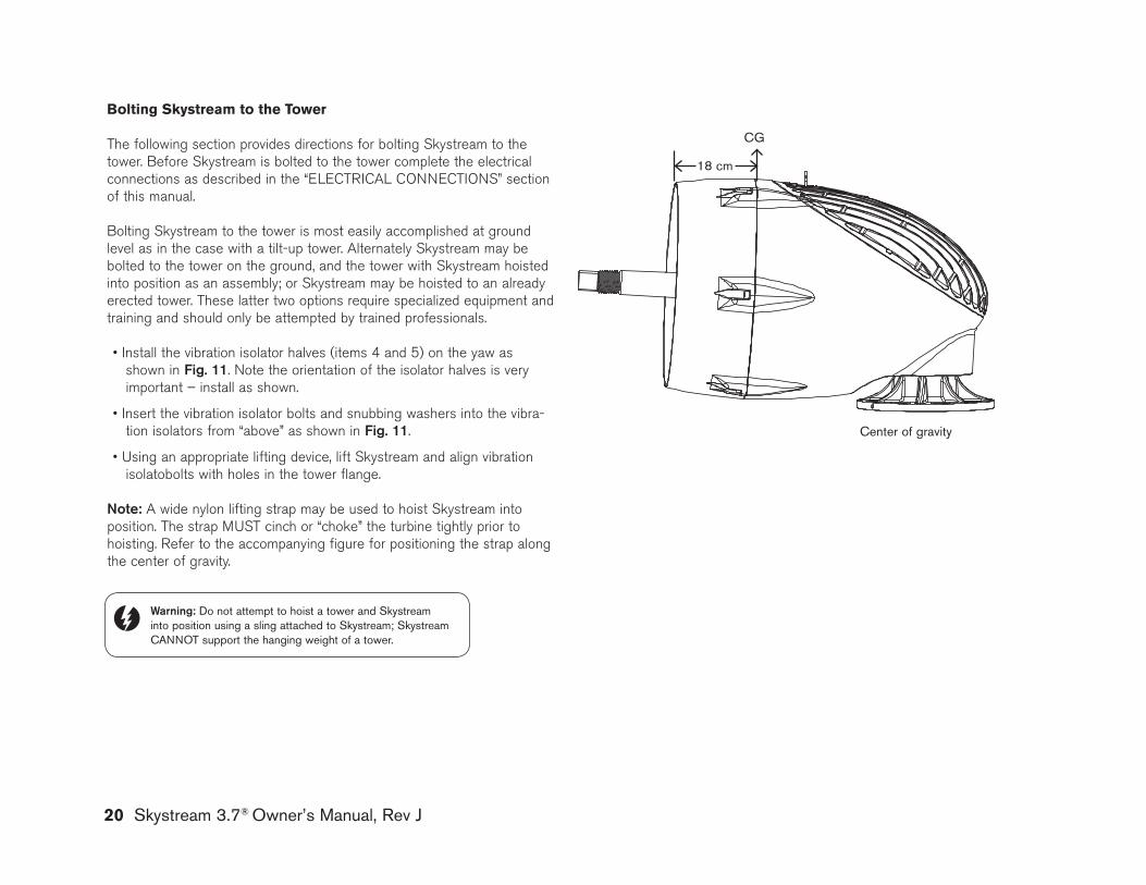
Bolting skystream to the tower
The following section provides directions for bolting Skystream to the tower. Before Skystream is bolted to the tower complete the electrical connections as described in the “ELECTRICAL CONNECTIONS” section of this manual.
Bolting Skystream to the tower is most easily accomplished at ground level as in the case with a tilt-up tower. Alternately Skystream may be bolted to the tower on the ground, and the tower with Skystream hoisted into position as an assembly; or Skystream may be hoisted to an already erected tower. These latter two options require specialized equipment and training and should only be attempted by trained professionals.
• Install the vibration isolator halves (items 4 and 5) on the yaw as shown in fig. 11. Note the orientation of the isolator halves is very important – install as shown.
• Insert the vibration isolator bolts and snubbing washers into the vibra-tion isolators from “above” as shown in fig. 11.
• Using an appropriate lifting device, lift Skystream and align vibration isolatobolts with holes in the tower flange.
note: A wide nylon lifting strap may be used to hoist Skystream into position. The strap MUST cinch or “choke” the turbine tightly prior to hoisting. Refer to the accompanying figure for positioning the strap along the center of gravity.
Center of gravity
CG
18 cm
Warning: Do not attempt to hoist a tower and Skystream into position using a sling attached to Skystream; Skystream CANNOT support the hanging weight of a tower.
Skystream 3.7® Owner’s Manual, Rev J 21
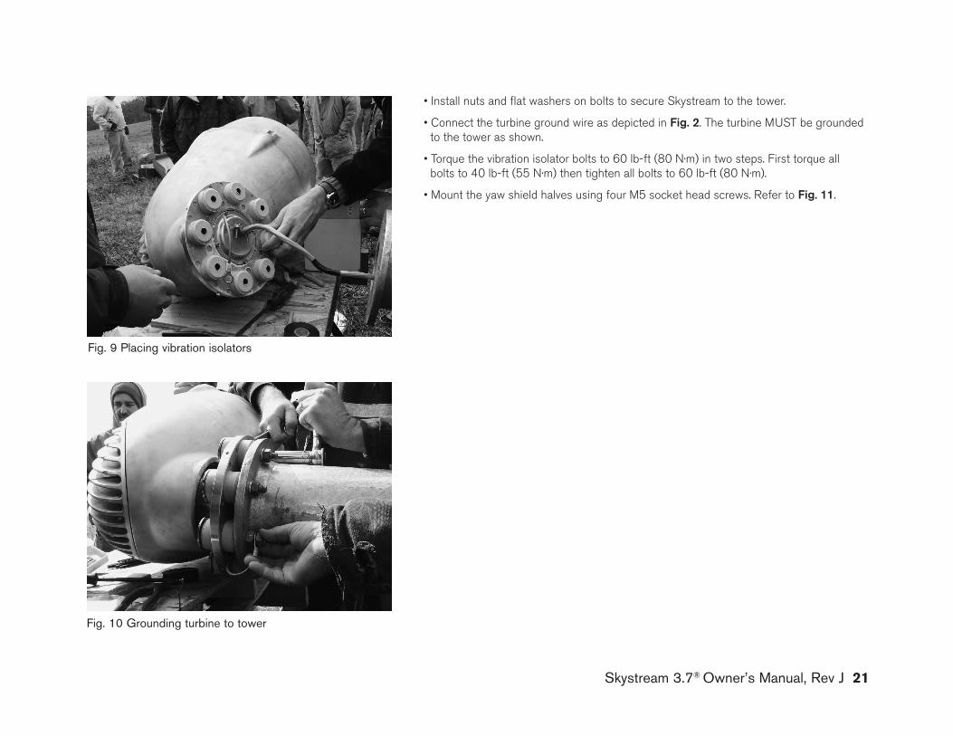
Fig. 9 Placing vibration isolators
Fig. 10 Grounding turbine to tower
• Install nuts and flat washers on bolts to secure Skystream to the tower.
• Connect the turbine ground wire as depicted in fig. 2. The turbine MUST be grounded to the tower as shown.
• Torque the vibration isolator bolts to 60 lb-ft (80 N·m) in two steps. First torque all bolts to 40 lb-ft (55 N·m) then tighten all bolts to 60 lb-ft (80 N·m).
• Mount the yaw shield halves using four M5 socket head screws. Refer to fig. 11.
22 Skystream 3.7® Owner’s Manual, Rev J
Proper installation of the blades is critical for safe operation. The blade nuts and bolts are a unique grade of steel and are specially coated to prevent corrosion. DO NOT substitute different nuts and bolts. Spare nuts and bolts are provided with Skystream.
Carefully follow these instructions to obtain secure bolted joints and maxi-mum corrosion protection, particularly in corrosive marine environments.
l Start the assembly by positioning a blade between the blade hub and blade plate. The blades may only be installed in one position due to the triangular boss cast into one side of the blade root.
l Install the bolts by passing the bolt through the BLADE PLATE and AWAY from the NACELLE as shown in fig. 12.
l Leave the nuts loose until all blades are installed and then tighten the bolts just enough to clamp the blades between the hub and plate.
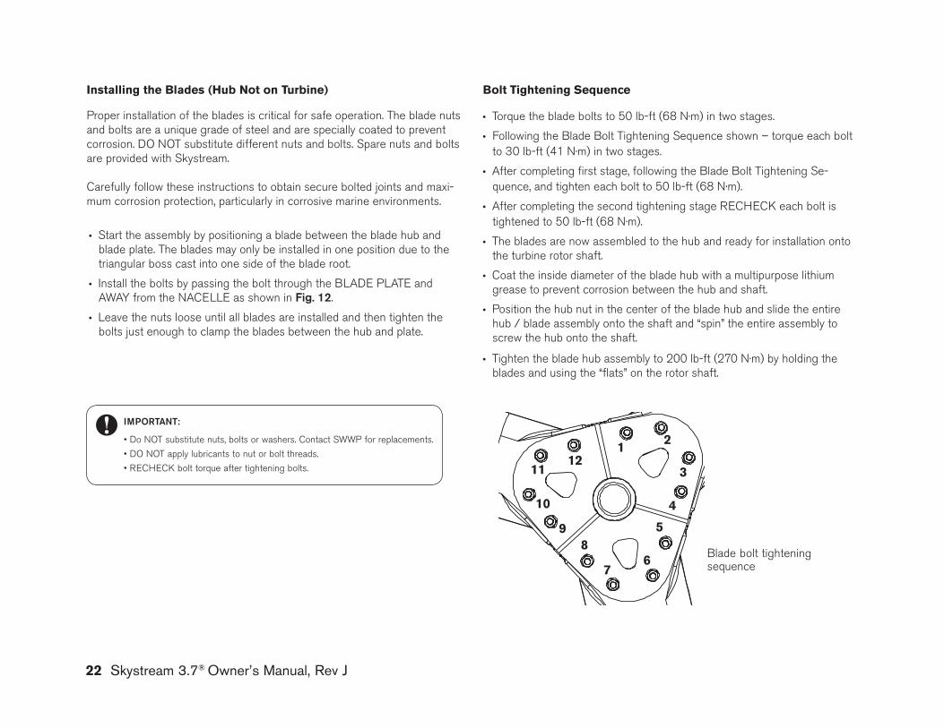
installing the Blades (Hub not on turbine) Bolt tightening sequence
l Torque the blade bolts to 50 lb-ft (68 N·m) in two stages.
l Following the Blade Bolt Tightening Sequence shown – torque each bolt to 30 lb-ft (41 N·m) in two stages.
l After completing first stage, following the Blade Bolt Tightening Se-quence, and tighten each bolt to 50 lb-ft (68 N·m).
l After completing the second tightening stage RECHECk each bolt is tightened to 50 lb-ft (68 N·m).
l The blades are now assembled to the hub and ready for installation onto the turbine rotor shaft.
l Coat the inside diameter of the blade hub with a multipurpose lithium grease to prevent corrosion between the hub and shaft.
l Position the hub nut in the center of the blade hub and slide the entire hub / blade assembly onto the shaft and “spin” the entire assembly to screw the hub onto the shaft.
l Tighten the blade hub assembly to 200 lb-ft (270 N·m) by holding the blades and using the “flats” on the rotor shaft.
Blade bolt tightening sequence
1112
10
9
1 2
3
4
8
76
5
ImporTanT:
• Do NOT substitute nuts, bolts or washers. Contact SWWP for replacements.
• DO NOT apply lubricants to nut or bolt threads.
• RECHECK bolt torque after tightening bolts.
Skystream 3.7® Owner’s Manual, Rev J 23
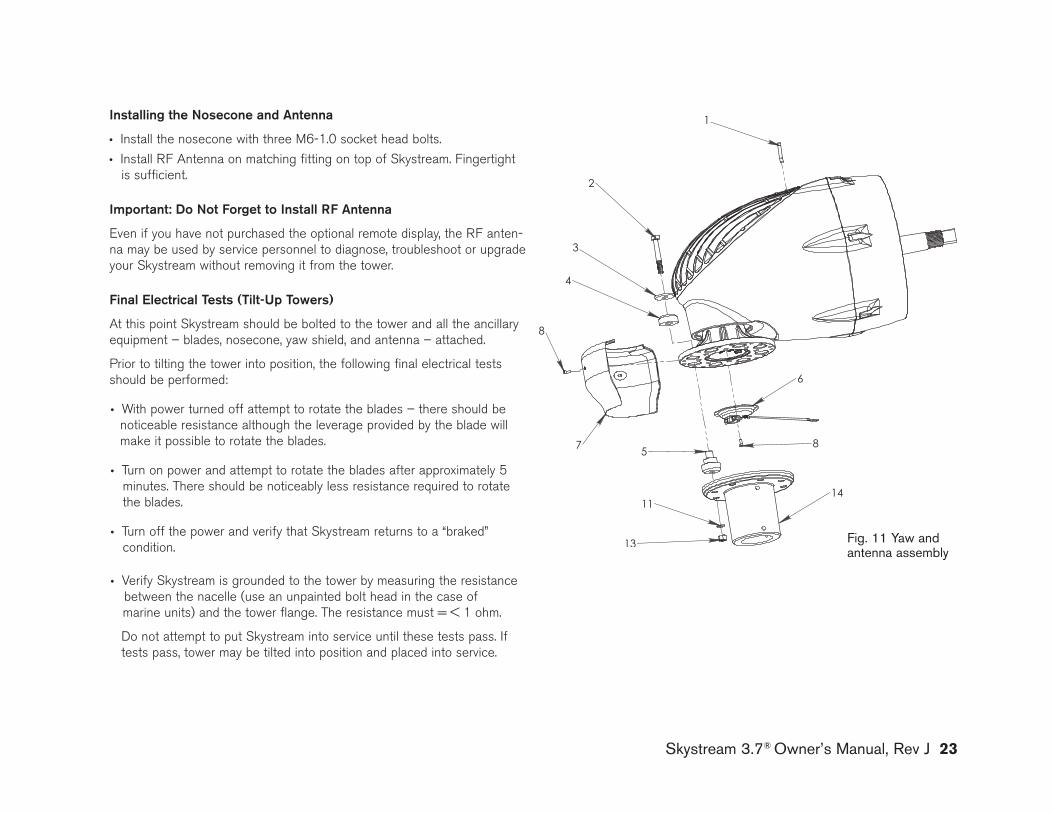
Installing the nosecone and antenna
l Install the nosecone with three M6-1.0 socket head bolts. l Install RF Antenna on matching fitting on top of Skystream. Fingertight is sufficient.
Important: do not forget to Install rf antenna
Even if you have not purchased the optional remote display, the RF anten-na may be used by service personnel to diagnose, troubleshoot or upgrade your Skystream without removing it from the tower.
final Electrical Tests (Tilt-up Towers)
At this point Skystream should be bolted to the tower and all the ancillary equipment – blades, nosecone, yaw shield, and antenna – attached.
Prior to tilting the tower into position, the following final electrical tests should be performed:
l With power turned off attempt to rotate the blades – there should be noticeable resistance although the leverage provided by the blade will make it possible to rotate the blades.
l Turn on power and attempt to rotate the blades after approximately 5 minutes. There should be noticeably less resistance required to rotate the blades.
l Turn off the power and verify that Skystream returns to a “braked” condition.
l Verify Skystream is grounded to the tower by measuring the resistance between the nacelle (use an unpainted bolt head in the case of
marine units) and the tower flange. The resistance must = < 1 ohm.
Do not attempt to put Skystream into service until these tests pass. If tests pass, tower may be tilted into position and placed into service.
Fig. 11 yaw and antenna assembly
18
19
24
1620
21
17
23
15
22
24 Skystream 3.7® Owner’s Manual, Rev J
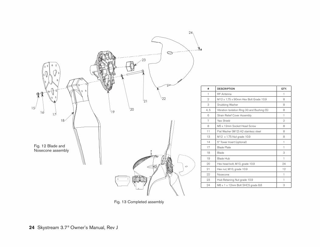
Fig. 13 Completed assembly
Fig. 12 blade and Nosecone assembly
# dESCrIpTIon QTy.
1 RF Antenna 1
2 M12 x 1.75 x 90mm Hex Bolt grade 10.9 8
3 Snubbing Washer 8
4, 5 Vibration Isolation Ring (4) and Bushing (5) 8
6 Strain Relief Cover Assembly 1
7 Yaw Shield 2
8 M5 x 12mm Socket Head Screw 8
11 Flat Washer (M12) A2 stainless steel 8
13 M12 x 1.75 Nut grade 10.9 8
14 5” Tower Insert (optional) 1
17 Blade Plate 1
18 Blade 3
19 Blade Hub 1
20 Hex head bolt, M10, grade 10.9 24
21 Hex nut, M10, grade 10.9 12
22 Nosecone 1
23 Hub Retaining Nut grade 10.9 1
24 M6 x 1 x 12mm Bolt SHCS grade 8.8 3
Skystream 3.7® Owner’s Manual, Rev J 25
Manual operation of skystream
Manual operation of Skystream is limited to starting and stopping using the circuit breakers at the electrical utility panel or electrical disconnect switch if equipped. To stop Skystream, switch the circuit breakers to “OFF,” and to restart Skystream switch the circuit breakers to “ON.” Note that Skystream may require approximately 5 minutes to restart after the circuit breaker is switched “ON.”
An “ATTENTION” label, depicted below, is provided to indicate the location of the AC power disconnect switch or circuit breakers. Apply the label in a prominent location where it will be seen by operators or service personnel.
adjustments
Adjustments to Skystream are limited to setting the elevation. As delivered, Skystream is configured for operation up 1000 m above sea level. There is no need to reset the elevation unless Skystream is installed above that elevation. The elevation may be reset using the optional remote display. If a remote display is unavailable to you, contact your Skystream dealer about resetting the elevation.
Maintenance
after 20 years of service the blades MUst be replaced – even if there is not apparent damage. The blades should be replaced as a set. Do not attempt to replace individual blades. All blade mounting hardware – bolts, nuts and washers – should be replaced at the same time. Do NOT attempt to reuse the blade fasteners.
There are no periodic service requirements other than replacing the blades after 20 years. All bearings and rotating components were designed for a 20-year life at an IEC Wind Class II site, under the IEC 61400-2 Small Wind Safety Standard. This corresponds to a site with an average wind speed of 8.5 m/s.
Although there are no routine service or maintenance requirements, Skystream owners should be observant of any unusual sounds, vibrations or erratic behavior. If unusual behavior is noticed, the best course of action is usually to shut down the turbine and contact the dealer or service cen-ter.
One area of Skystream that may experience damage is the blades, for example from flying debris during a high wind storm. For this reason Southwest Windpower recommends Skystream be shut down on an annu-al basis and an inspection of the blades performed. The inspection may be accomplished using binoculars or by close visual inspection. Inspect for cracks and chips particularly along the edges of the blades. Any damage is cause for replacing the blades. If in doubt, contact your local service cen-ter.
oPeration anD aDJUstMents
For artwork see DOC 0325Label: 2"W x 4"H Z-Ultimate 3000 White, Zebra part #68431Ribbon: 3.27" x 1.476" Premium 5100 Resin Ribbon, Zebra part # 05100BK08345
--9/30/06ECO#1012NC
REVISIONSREV. DESCRIPTION DATE APPROVED
Proprietary rights are included in the information disclosed herein. This information issubmitted in confidence and neither the document nor the information disclosed here-in shall be reproduced or transferred to other documents for manufacturing or for anyother purpose except as specifically authorized in writing by Southwest Windpower.
DO NOT SCALE DRAWING
----FINISH
MATERIAL
QUAL
MFG
PROD EGR
R&D
DRAWN
APPROVALS DATE
rev. NC sheet 1 of 1
dwg. n° 3-CMLB-1039
CAD file :
size A
CAD-generated drawingdo not manually update Flagstaff, Arizona U.S.A.
9/30/06Dan NielsenLABEL, SAFETY
3-CMLB-1039 LABEL SAFETY
DW
G #
3-C
MLB
-103
9
unless otherwise specifieddimensions are in [inches] tolerances are : decimals angles X. ±1 ± 30 ' .X ± .5 .XX ± .2
Dimensions[inches] mm
26 Skystream 3.7® Owner’s Manual, Rev J
service
The internal components of Skystream should only be serviced by qualified technicians specifically trained to perform the service. Under no circum-stances should untrained technicians attempt to perform service or repairs unless under the direct guidance of a trained technician. Service operations that were performed during the installation of Skystream, for example bolting on the blades or bolting Skystream to the tower may be performed as necessary by the user / operator.
troubleshooting
Without the optional wireless “Skyview Interface kit”, troubleshooting Skystream is limited to checking the Skystream connections to the util-ity grid. Check the connections as “close” to Skystream as possible. Depending on the installation this may be at the utility panel or at a dis-connect switch. The connections may also be checked at yaw terminals (see Electrical Connections Section in this manual), however, this will require removing Skystream from the tower.
Using the Skyview Interface kit this voltage and additional troubleshoot-ing information may be accessed without the need to remove the turbine. Contact your local dealer or Southwest Windpower Technical Service.
emergency shutdown
If Skystream’s internal microprocessor determines a serious internal fault has occurred, it will execute an Emergency Stop – an E-Stop. An E-Stop will only take place if the fault is severe and requires servicing Skystream’s internal components. Refer to the key Operating Characteristics section of this manual for a complete description of the Skystream’s various “shut down” modes including Emergency Stops.
Resetting an Emergency Stop requires special equipment and can only be accomplished by a trained technician. If you suspect your Skystream has executed an Emergency Stop, contact Skystream Technical Support.
Warning: There is risk of electric shock from both AC and DC voltages within Skystream. Do not attempt to remove the hatchcover to access the internal components. AC power should always be disconnected, the turbine restrained from yawing, and blades secured from rotating prior to servicing or serious or fatal injury may occur.
In the event you must gain access to Skystream, use the opportunity to perform the following inspections:
• Remove yaw shield and verify yaw bearing snap ring is properly seated. Wipe any grease that may have seeped from yaw bearing. A small amount of lubricant is normal – consult technical support if there is large amount of leakage.
• Check the hatch cover bolts are tight. Bolts should be tightened 60 in lb (7 N·m).
• Check the tightness of the (8) yaw bolts with a torque wrench. All yaw bolts should be torqued to 60 lb-ft (80 N·m). • Reinstall the yaw shield and secure the fasteners. • Check tightness of blade bolts with torque wrench. All blade bolts should be torqued to 50 lb-ft (68 N·m). • Clean the rotor blades with a mild soap and water. Remove as much of the dead bug matter as possible from the blades. • Look for any problems with the blades such as cracks or damage to the edges of the rotor blade. • Inspect the face, nacelle, and the rest of the Skystream, and note any potential damage or problem.
Skystream 3.7® Owner’s Manual, Rev J 27
The Skystream 3.7 operates by converting the kinetic energy of the wind into rotational motion that turns an alternator and ultimately produces usable electric power. In actuality this is a great oversimplification of Skystream’s operation since it must very precisely match the frequency and voltage of the electricity supplied by the local utility company in order to power your home and its appliances. Additionally, Skystream monitors and adjusts its performance to provide safe operation and extract the maximum energy from even low speed winds.
Skystream will begin producing power in a wind of approximately 3.5 m/s. At that speed the blades will rotate at approximately 120 rpm. Once it has started producing power, it will continue to produce power at lower speeds down to 80 rpm and less than 3 m/s. As the wind speed increases, the blade speed will also increase. At about 9 m/s the blades achieve a rota-tional speed of 330 rpm. This is Skystream’s rated speed. Should the wind speed increase above 9 m/s, the blade speed will remain essentially fixed at 330 rpm. If a condition occurs that causes the rotational speed to exceed 360 rpm, Skystream will shut down for approximately 10 minutes after which it will resume normal operation unless a fault is detected caus-ing it to remain shut down. This is an unlikely scenario that should never occur in normal operation. It is important to set the elevation for the turbine to operate correctly. If it is not set, the turbine may experience premature shut downs.
If a wind gust exceeds 25 m/s, then the Skystream will shut down for 1 hour. After 1 hour, the Skystream will turn back on and resume normal charging. If the wind is still above 25 m/s, then the Skystream will shut down for another hour.
In addition to adjusting its operation in response to wind conditions, Skystream also monitors the electrical utility grid and its own inter-nal health. Should the electric utility voltage or frequency differ from Skystream’s voltage, for example due to a power failure, Skystream will disconnect from the grid and enter a “braked mode.” While in this mode the blades are held stationary while the Skystream monitors the utility power. If
Skystream determines that the power has returned to within specification, it will re-connect to the grid and resume normal operation. This is the same cycle that occurs when Skystream is initially powered. Additionally, should Skystream determine an internal fault exists, it will execute an emergency shutdown – an E-stop. An E-stop will only take place if a severe fault that requires servicing internal components has occurred. For that reason resetting an E-stop requires gaining access to the interior of Skystream. It cannot be reset from the ground.
electronic stall regulation
The Skystream 3.7 has the ability to adjust the rotational speed of its blades or even stop the blades if required by ambient conditions. This is referred to as Stall Control, and it is accomplished by adjusting the current draw from the alternator. The higher the current draw, the greater the elec-tromagnetic torque applied to the rotor, and if enough torque is applied, the blades will slow or even stop. In simple terms the inverter is demanding more power than the available wind can provide thus causing the blade rotational speed to decrease.
As a safety feature, the alternator is capable of producing approximately five times the torque required to control the turbine. This extra available power means that even if segments of the alternator windings are dam-aged, there is still sufficient torque to stop the turbine.
While Skystream is connected to the utility grid it constantly monitors that all conditions, for example grid voltage and frequency, are within limits. If the inverter determines that all operating conditions are within limits, it opens three Normally Closed (NC) relays, RL1, 2 and 3, removing the short from the alternator windings and allowing the blades to spin freely.
KeY oPeratinG CHaraCteristiCs
28 Skystream 3.7® Owner’s Manual, Rev J
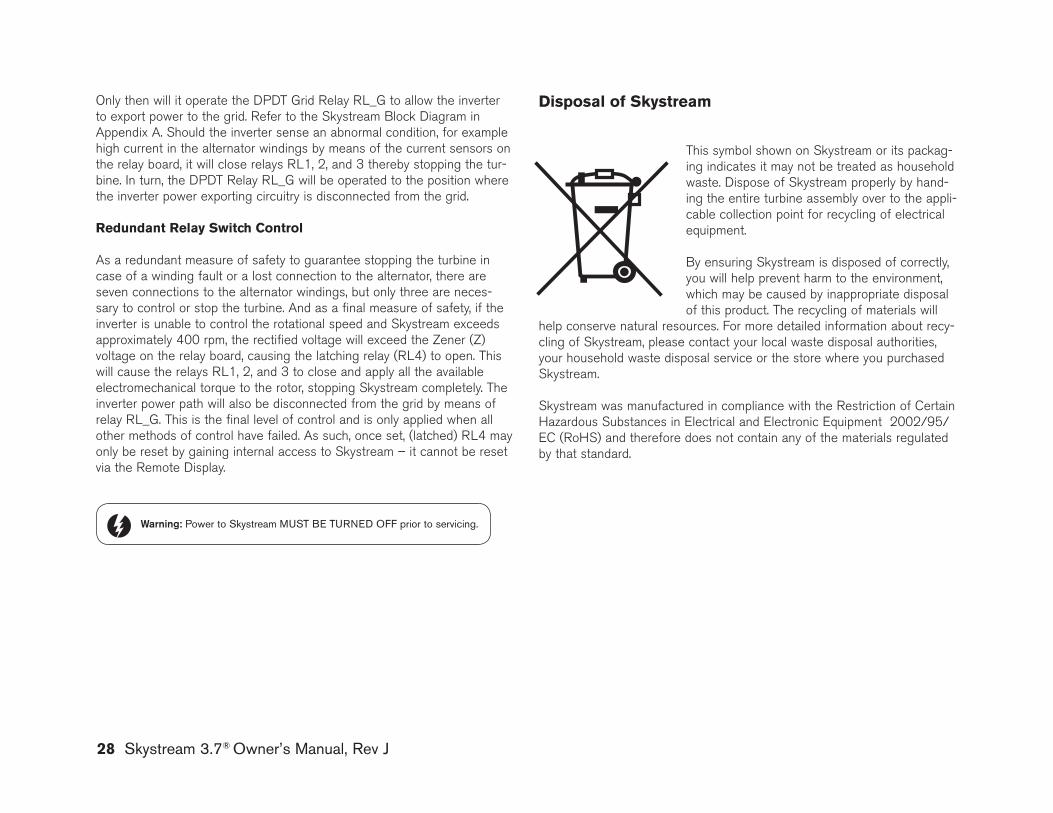
This symbol shown on Skystream or its packag-ing indicates it may not be treated as household waste. Dispose of Skystream properly by hand-ing the entire turbine assembly over to the appli-cable collection point for recycling of electrical equipment.
By ensuring Skystream is disposed of correctly, you will help prevent harm to the environment, which may be caused by inappropriate disposal of this product. The recycling of materials will
help conserve natural resources. For more detailed information about recy-cling of Skystream, please contact your local waste disposal authorities, your household waste disposal service or the store where you purchased Skystream.
Skystream was manufactured in compliance with the Restriction of Certain Hazardous Substances in Electrical and Electronic Equipment 2002/95/EC (RoHS) and therefore does not contain any of the materials regulated by that standard.
Warning: Power to Skystream MUST bE TURNED OFF prior to servicing.
Disposal of skystreamOnly then will it operate the DPDT grid Relay RL_g to allow the inverter to export power to the grid. Refer to the Skystream Block Diagram in Appendix A. Should the inverter sense an abnormal condition, for example high current in the alternator windings by means of the current sensors on the relay board, it will close relays RL1, 2, and 3 thereby stopping the tur-bine. In turn, the DPDT Relay RL_g will be operated to the position where the inverter power exporting circuitry is disconnected from the grid.
redundant relay switch Control
As a redundant measure of safety to guarantee stopping the turbine in case of a winding fault or a lost connection to the alternator, there are seven connections to the alternator windings, but only three are neces-sary to control or stop the turbine. And as a final measure of safety, if the inverter is unable to control the rotational speed and Skystream exceeds approximately 400 rpm, the rectified voltage will exceed the Zener (Z) voltage on the relay board, causing the latching relay (RL4) to open. This will cause the relays RL1, 2, and 3 to close and apply all the available electromechanical torque to the rotor, stopping Skystream completely. The inverter power path will also be disconnected from the grid by means of relay RL_g. This is the final level of control and is only applied when all other methods of control have failed. As such, once set, (latched) RL4 may only be reset by gaining internal access to Skystream – it cannot be reset via the Remote Display.
frequently asked Questions
1) What happens if I lose power from my utility company?
If there is a power outage the Skystream will shut down within one sec-ond. It will resume normal operation when power is restored. There are many safety requirements of a utility-tied inverter. The Skystream meets all of these requirements per UL 1741 and IEEE 1547 and appropriate European Regulations.
2) does Skystream have lightning protection ?
Yes, Skystream has lightning protection. Skystream can withstand 6000 volts as required by UL 1741, IEEE 1547 and appropriate European Regulations. However, if you live in a lightning prone area Southwest Windpower recommends an additional lightning arrestor at the base of the tower.”
3) When should I contact an authorized service technician?
a) If “growling” noise is detected turn Skystream “OFF” and contact Technical service.
b) If frequent “shut-downs” are observed.c) Unusual noises or vibrations are observed. Use caution. If in doubt
turn Skystream “OFF” and contact Technical service.d) Circuit breaker and switches are turned “ON” and Skystream is not
turning in response to wind.
4) What should I do if I’m expecting a severe storm?
The Skystream is designed for very high winds, but it is always a good idea to shut Skystream down if there is going to be a severe storm to protect against any flying debris.
5) how do I shut down Skystream?
To turn off Skystream, all you need to do is turn off the breaker Skystream is connected to. This will cause NO damage to the unit.
6) Can I leave Skystream unattended?
Yes, the Skystream is designed to operate without any user input. If there is any fault, it will shut down on its own.
7) What do I do if Skystream is facing upwind even though there is a strong wind?
If the Skystream is not tracking correctly, you should check to see if the tower is level.
8) Can I mount Skystream to my roof?
Roof and building mount is not recommended. Because of the size and weight of the wind generator, Skystream needs to be mounted on a PE certified tower to ensure the quietest and safest system. Roof mounting will invalidate the warranty.
9) What should I do if ice forms on Skystream blades?
To avoid the possibility of injury from ice breaking loose from the blades and injuring anyone, Skystream should be turned OFF if ice accumulates on the blades.
Skystream 3.7® Owner’s Manual, Rev J 29

3
8
7
2
6
-
A ECO 1212
-
-4/13/07ECO# 1180NC5/24/07
Flagstaff, Arizona U.S.A.
'07
DATEDESCRIPTION
CAD-generated drawing
W/ JCT BOX
other purpose except as specifically authorized in writing by Southwest Windpower.
D
E
F
C
1 2 3 4
B
A
321 5
C
D
4 6 7 8
A
B
- - 3-CMLT-1085 rev A 230V 50HZ 1PH
N.Agrawal
APPROVED
-
in shall be reproduced or transferred to other documents for manufacturing or for any
3-CMLT-1085Skystream
8 Mar
do not manually update
scale none size A3
CAD file :
doc. n°
sheet 1 of 1rev. A
DATEAPPROVALSDRAWN
CHECKED
RESP ENG
MFG ENG
QUAL ENGDO NOT SCALE DRAWINGAPPLICATIONUSED ONNEXT ASSY
E
-
REVISIONSREV.
Proprietary rights are included in the information disclosed herein. This information issubmitted in confidence and neither the document nor the information disclosed here-
230 V 50Hz 1Ph
5
UTILITY
40 A
G
4 AWG (25mm^2)
4
GND
20 A
N
92 FT. 14 AWG (2.5mm^2)
LINE-NEUTRAL
WIND TURBINE
5
N
G
CABLE FROM SAFTY SWITCH
N
TO MAIN SERVICE PANEL
oth
er l
oa
ds
CONNECTION TO
12 AWG (4mm^2)146 FT.
30A, 240VAC
G
G
POWER SYSTEMKILOWATT-HOUR
DISCONNECT
BETW'N TURBINE AND
TURBINE OUTPUT 1.8kW
232 FT. 10 AWG (6mm^2)
8 AWG (10mm^2)
WIND POWER
CU WIRE), ASSUMING
371 FT.
SYSTEM
VOLTAGE DROP
MAIN SERVICE PANEL,
L1
BURIAL CABLE W/#10
"SKYSTREAM"
230VAC (L-N) AT THE AC
934 FT.
+green)
GL1L1 (brown)
L2
MAIN SERVICE PANEL
USABLE AWG FOR 2%
2
6 AWG (16mm^2)
SEE WIRE CHART.
588 FT.
N (blue)
DEDICATED WIND
LENGTH < 187 FT.
N
GND (yellow
1-PH, 50HZ)SAFETY SWITCH (230V
KILOWATT-HOUR
9
PANEL (FOR
GND FROM YAW
SQ-D #DU221RB
L1
G
N
4
L1
TO AC MAIN
METER
#10-2 W/#10 GND THWN-2
SWITCH 2-POLE
METER
*
N
GND
SPAN BETW'N TOWER TOP
#10-2 UFB DIRECT
CABLE EXAMPLE INDICATES #10 AWG CABLE BASED ON 45 FT FROM TOWER TO SWITCH, 187FT FROM SWITCH TO MAIN PANEL. TOTAL 232 FT. FOR LONGER SPANS
230 VAC (L-N)
LOCAL EUROPEAN ELECTRICAL WIRING GUIDELINES
RIGID PVC CONDUIT;1" DIA. SCHED. 40
VARIATIONS MAY BE MADE IN ACCORDANCE WITH
SUNLIGHT RESISTANT;
TO SERVICE
AND NOT IN SUB-PANEL.
G N
UTILITY GRID
GROUND TRANSFORMER,
L1
6" MIN.
SYSTEM
LUG ONLY IN AC MAIN PANELCONNECT NEUTRAL AND GND
UL LISTED
TOWER BASE TO HOME
ELECTRICALLYCONNECTED
GROUND LVL.
RUN FROM JNC. BOX AT
ELECTRICALLYMUST BE
HIGH)
12 INCH MAX.
35 FT.
NACELLE
NACELLE
CONNECTED TO
CHASSIS
THE TOWER
LEVEL
AT TOWER BASESQUARE D #DU221RB
FOUNDATION TOPTOWER
24 INCH MIN.
GROUND
2-POLE, 30A, 240VAC,
10 INCH MIN.
(APPROX.TOWER
SURFACE TO BE
TO YAW, WHICHPANELSERVICEAC MAIN230V, 1-ph,
SAFETY SWITCH
FOUNDATION DWG.REFER TO SWWP
SYSTEM
THIS DRAWING IS FOR REFERENCE
GROUND TOWER
MIN. 6" ABOVE
NOTES:
1. EQUIPMENT SHALL BE INSTALLED IN ACCORDANCE WITH LOCAL EUROPEAN ELECTRICAL WIRING REGULATIONS.2. PROVIDE WARNING SIGN READING "WARNING-ELECTRIC SHOCK HAZARD-DO NOT TOUCH TERMINALS - TERMINALS ON BOTH THE LINE AND LOAD MAY BE ENERGIZED IN THE OFF POSITION".3. LABEL "WIND POWER SYSTEM DEDICATED kW-HR METER".4. LABEL SWITCH AS "WIND GENERATOR SAFETY DISCONNECT SWITCH; REMOVING AC POWER TO TURBINE ACTIVATES ITS SAFETY BRAKE".5. OPTION IS TO USE A JUNCTION BOX AT TOWER BASE INSTEAD OF A SWITCH.6. LABEL "REMOVING AC POWER TO TURBINE ACTIVATES ITS SAFETY BRAKE".7. BI-DIRECTIONAL METER TO BE INSTALLED BY UTILITY (WHEN REQUIRED).8. USE COPPER WIRES ONLY AT TURBINE TERMINALS9. ALUMINUM WIRES MAY BE USED FOR HOME / UTILITY CONNECTION IF TRANSITION WERE DONE IN A JNC. BOX. 14AWG WIRE MUST BE COPPER ONLY.
Southwest Windpower, Inc.1801 West Route 66Flagstaff, Arizona 86001 USAPhone: 928-779-9463Fax: 928-779-1485
www.skystreamenergy.com
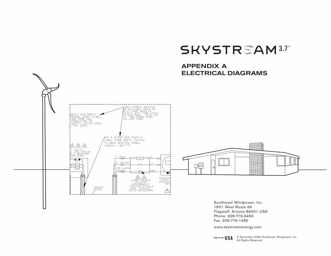
aPPendIX aeleCTrICal dIaGraMs
© December 2008 Southwest Windpower, Inc. All Rights Reserved
Skystream 3.7® owner’s manual
appendix a: Electrical diagrams
1) grId ConnECTIon opTIon a: 120/240 V, 60 Hz, Split Phase, Junction Box at Tower Base __________________________________________ 3
2) grId ConnECTIon opTIon b: 120/240 V, 60 Hz, Split Phase, Without Junction Box at Tower Base ___________________________________ 4
3) grId ConnECTIon opTIon C: 120/208 V, 60 Hz, 3 Phase, Junction Box at Tower Base ____________________________________________ 5
4) grId ConnECTIon opTIon d: 120/208 V, 60 Hz, 3 Phase, Without Junction Box at Tower Base _____________________________________ 6
5) SkySTrEam bloCk dIagram ________________________________________________________________ 7
2 Skystream 3.7® Owner’s Manual, Rev J

Skystream 3.7® Owner’s Manual, Rev J 3
32
7
98
G
N
120/240VAC MAINSERVICEPANEL
4
#10-3 W/#10 GND THWN-2 CABLE FROM SAFETY SWITCH TO MAIN SERVICE PANEL LENGTH < 208FT.
DEDICATED WIND POWER SYSTEMKILOWATT-HOUR
METER(OPTIONAL)
N
G
240 VACTO SERVICETRANSFORMER,UTILITY GRID
THIS DRAWING IS FOR REFERENCE
TOWERGROUNDSYSTEM
L1L2
#10-3 UF-B DIRECT BURIAL CABLE W/#10 GND FROM YAW CONNECTION TO SAFETY SWITCH. 240V AC SPLIT-PH 60Hz
L1
L2
UTILITYKILOWATT-HOUR
METER
G
L1 (black)
L2 (red)
N (white)
WIND POWERSYSTEM
DISCONNECT SWITCH 2-POLE30A, 240VAC
SQ-D #DU221RB
L1
L2
N
"SKYSTREAM"WIND TURBINE
TOWERFOUNDATION TOPSURFACE TO BEMIN. 6" ABOVEGROUND LVL.REFER TO SWWPFOUNDATION DWG.
1" DIA. SCHED. 40RIGID PVC CONDUIT;SUNLIGHT RESISTANT;UL LISTED
SAFETY SWITCH2-POLE, 30A, 240VAC,SQUARE D #DU221RBAT TOWER BASE
RUN FROM JNC. BOX ATTOWER BASE TO HOME 24 INCH MIN.
GROUNDLEVEL
NACELLECHASSISELECTRICALLYCONNECTEDTO YAW, WHICHMUST BEELECTRICALLYCONNECTED TOTHE TOWER
NACELLE
TOWER(APPROX.35 FT.HIGH)
12 INCH MAX.10 INCH MIN.
G
VARIATIONS MAY BE MADE IN ACCORD WITH NEC GUIDELINES
6" MIN.
5 6
403 FT. 8 AWG
10 AWG253 FT.
SPAN BETW'N TOWER TOP TO AC MAIN SERVICE PANEL FOR COPPER
WIRE ONLY, ASSUMING GRID VOLTAGE IS 240V, TURBINE PUTS OUT
1.8kW
159 FT. 12 AWG14 AWG100 FT.
* NOTES:
1. EQUIPMENT SHALL BE INSTALLED IN ACCORDANCE WITH NEC ARTICLE 705.2. PROVIDE WARNING SIGN PER NEC 690-17 READING "WARNING-ELECTRIC SHOCK HAZARD-DO NOT TOUCH TERMINALS - TERMINALS ON BOTH THE LINE AND LOAD MAY BE ENERGIZED IN THE OFF POSITION".3. LABEL "WIND POWER SYSTEM DEDICATED kW-HR METER".4. LABEL SWITCH AS "WIND GENERATOR SAFETY DISCONNECT SWITCH; REMOVING AC POWER TO TURBINE ACTIVATES ITS SAFETY BRAKE".5. OPTION IS TO USE A JUNCTION BOX AT TOWER BASE INSTEAD OF A SWITCH.6. LABEL "REMOVING AC POWER TO TURBINE ACTIVATES ITS SAFETY BRAKE".7. BI-DIRECTIONAL METER TO BE INSTALLED BY UTILITY (WHEN REQUIRED).8. USE COPPER WIRES ONLY AT TURBINE TERMINALS9. ALUMINUM WIRES MAY BE USED FOR HOME / UTILITY CONNECTION IF TRANSITION WERE DONE IN A JNC. BOX. 14AWG WIRE MUST BE COPPER ONLY.
L1L2NGN/G
GROUNDSYSTEM
GND (bare/green)
40 A
40 A
20 A
20 A
CABLE EXAMPLE INDICATES #10 AWG CABLE BASED ON 45FT FROM THE TOWER TO SWITCH, 208FT FROM SWITCH TO MAIN PANEL, TOTAL =253FT. FOR LONGER SPANS SEE WIRE CHART.
6 AWG
4 AWG
640 FT.
1017 FT.
SPD
SPD = SURGE PROTECTIVE DEVICE SUCH AS ALIGHTNING CURRENT ARRESTOR. AN APPROPRIATE ARRESTOR TO SATISFY THE REQUIRED LIGHTNING PROTECTION LEVEL MUST BE INSTALLED. SEE LIGHTNING PROTECTION SECTION OF MANUAL FOR RECOMMENDATIONS.
NOTE 10.
B
B
USABLE AWG (FORLINE AND NEUTRAL
CONDUCTORS ONLY) FOR 2% VOLTAGE RISE (L-L) AT THE
TURBINE INVERTER
Proprietary rights are included in the information disclosed herein. This information issubmitted in confidence and neither the document nor the information disclosed here-in shall be reproduced or transferred to other documents for manufacturing or for anyother purpose except as specifically authorized in writing by Southwest Windpower.
D
E
F
C
1 2 3 4
B
A
321 5
C
D
4 6 7 8
A
B
D. Calley3-CMLT-1083 rev B 120-240V 60Hz ELECTRICAL CONNECTION (2)
N.Agrawal
Skystream
29Apr '08
Flagstaff, Arizona U.S.A.CAD-generated drawingdo not manually update
scale none size A3
CAD file :
dwg #3-CMLT-1083sheet 1 of 2rev. B
DATEAPPROVALSDRAWN
CHECKED
RESP ENG
MFG ENG
QUAL ENGDO NOT SCALE DRAWINGAPPLICATIONUSED ONNEXT ASSY
E
REVISIONSREV. DESCRIPTION DATE APPROVED
-
120/240 V 60 HzW/JCT BOX
5
P. Thomas
NC ECO 1180 4/13/07A ECO 1212 5/24/07
29Apr '08
29Apr '08
B Admin Ch# 0056 Added SPD 8/21/08 tg
Southwest Windpower
Fig. 1. grid Connection Option A: 120/240 V, 60 Hz, Split Phase, Junction Box at Tower Base
4 Skystream 3.7® Owner’s Manual, Rev J
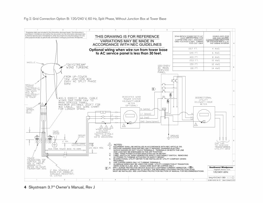
Fig 2. grid Connection Option B: 120/240 V, 60 Hz, Split Phase, Without Junction Box at Tower Base
23
5
6
TOWER(APPROX.35 FT.HIGH)
NACELLE
NACELLECHASSISELECTRICALLYCONNECTED TOYAW WHICHMUST BEELECTRICALLYCONNECTEDTO TOWER
GROUNDLEVEL
24 INCH MIN.RUN FROM TOWER BASE TO HOME
TOWERFOUNDATION TOPSURFACE TO BEMIN. 6" ABOVEGROUND LVL.REFER TO SWWPFOUNDATION DWG.
N
L2L1
WIND POWERSYSTEM
DISCONNECT SWITCH 2-POLE30A, 250VAC
SQ-D #DU221RB
N (white)
L2 (red)
L1 (black)
G
BIDIRECTIONALUTILITY
KILOWATT-HOURMETER
L2
L1
240 VACTO SERVICETRANSFORMER,UTILITY GRID
GROUNDSYSTEM
G
N
DEDICATED WIND POWER SYSTEMKILOWATT-HOUR
METER(OPTIONAL)
4
120/240VAC MAINSERVICEPANEL
G
* NOTES:1. EQUIPMENT SHALL BE INSTALLED IN ACCORDANCE WITH NEC ARTICLE 705.2. PROVIDE WARNING SIGN PER NEC 690-17 READING "WARNING-ELECTRIC SHOCK HAZARD-DO NOT TOUCH TERMINALS - TERMINALS ON BOTH THE LINE AND LOAD MAY BE ENERGIZED IN THE OFF POSITION".3. LABEL "WIND POWER SYSTEM DEDICATED kW-HR METER".4. LABEL SWITCH AS "WIND GENERATOR SAFETY DISCONNECT SWITCH; REMOVING AC POWER TO TURBINE ACTIVATES ITS SAFETY BRAKE".5. BI-DIRECTIONAL UTILITY METER TO BE INSTALLED BY UTILITY COMPANY (WHEN REQUIRED)6. USE COPPER WIRES ONLY AT TURBINE TERMINALS7. ALUMINUM WIRES MAY BE USED FOR HOME / UTILITY CONNECTION IF TRANSITION WERE DONE IN A JNC. BOX. 14AWG WIRE MUST BE COPPER ONLY.8. SPD = SURGE PROTECTIVE DEVICE SUCH AS A LIGHTNING CURRENT ARRESTOR. AN APPROPRIATE ARRESTOR TO SATISFY THE REQUIRED LIGHTNING PROTECTION LEVEL MUST BE INSTALLED. SEE LIGHTNING PROTECTION SECTION OF MANUAL FOR RECOMMENDATIONS.
FROM UP-TOWERYAW JUNCTION BOX240V AC SPLIT PHASE60Hz
#10-3 DIRECT BURIAL CABLE W/#10 GND FROM YAW TO MAIN SERVICE PANEL. MAXIMUM DISTANCE 253FT FOR #10 CABLE. SEE WIRE CHART FOR LONGER SPANS.G N L2 L1
1" DIA. SCHEDULE 40RIGID PVC CONDUIT;SUNLIGHT RESISTANT;UL LISTED
VARIATIONS MAY BE MADE IN ACCORDANCE WITH NEC GUIDELINES
THIS DRAWING IS FOR REFERENCE
6" MIN.
TOWERGROUNDSYSTEM
100 FT. 14 AWG
12 AWG159 FT.
USABLE AWG (FORLINE AND NEUTRAL
CONDUCTORS ONLY) FOR 2% VOLTAGE RISE (L-L) AT
THE TURBINE INVERTER
SPAN BETW'N TOWER TOP TO AC MAIN SERVICE PANEL FOR
COPPER WIRE ONLY, ASSUMING GRID VOLTAGE IS 240V, TURBINE
PUTS OUT 1.8kW
GND (bare/green)
N/G
7
253 FT. 10 AWG
403 FT.
"SKYSTREAM"WIND TURBINE
20 A
640 FT.
1017 FT.
8 AWG
6 AWG
4 AWG
40 A
40 A
20 A
B
B
Optional wiring when wire run from tower base to AC service panel is less than 30 feet.
Proprietary rights are included in the information disclosed herein. This information issubmitted in confidence and neither the document nor the information disclosed here-in shall be reproduced or transferred to other documents for manufacturing or for anyother purpose except as specifically authorized in writing by Southwest Windpower.
D
E
F
C
1 2 3 4
B
A
321 5
C
D
4 6 7 8
A
B
Flagstaff, Arizona U.S.A.
scale none size A
dwg #3-CMLT-1083sheet 2 of 2rev. B
E
120/240V 60Hz
5 76
F
Southwest Windpower
Skystream 3.7® Owner’s Manual, Rev J 5
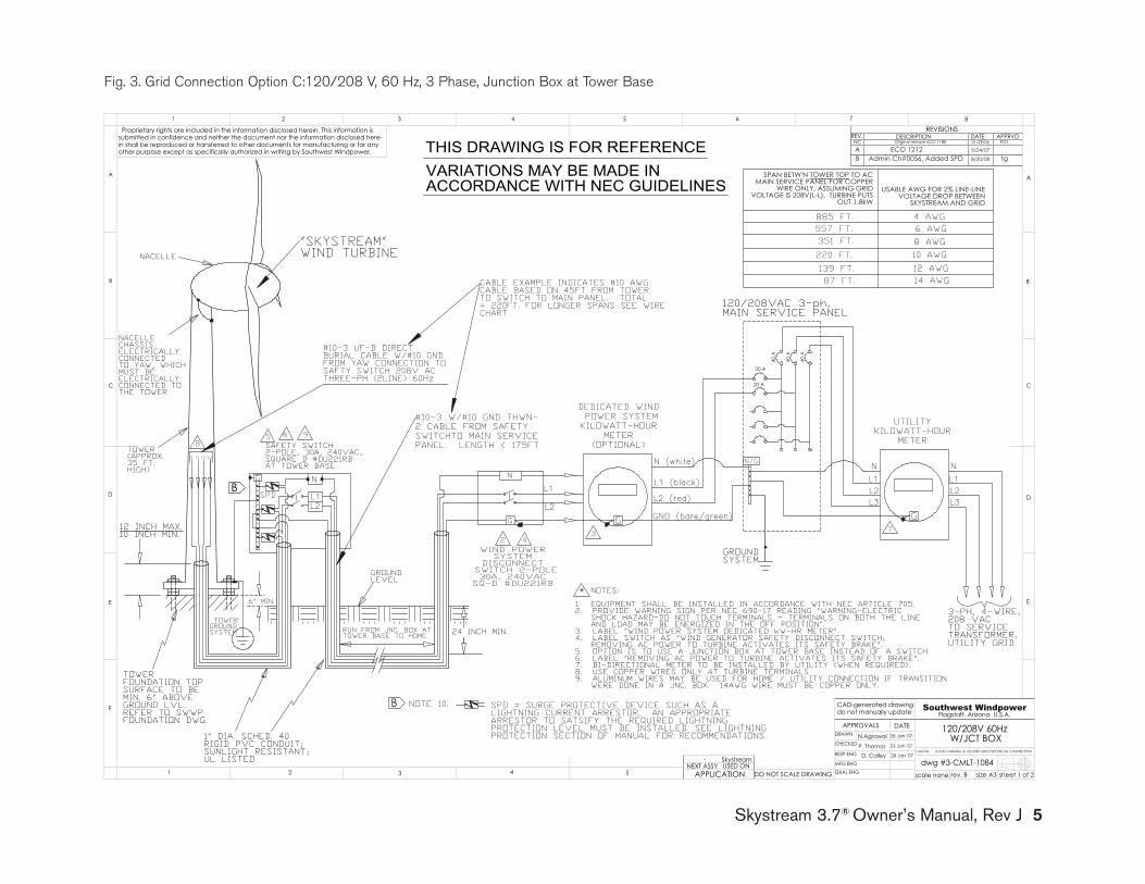
Fig. 3. grid Connection Option C:120/208 V, 60 Hz, 3 Phase, Junction Box at Tower Base
32
7
98
G
N
4
#10-3 W/#10 GND THWN-2 CABLE FROM SAFETY SWITCHTO MAIN SERVICE PANEL. LENGTH < 175FT
DEDICATED WIND POWER SYSTEMKILOWATT-HOUR
METER(OPTIONAL)
N
G
3-PH, 4-WIRE,208 VACTO SERVICETRANSFORMER,UTILITY GRID
THIS DRAWING IS FOR REFERENCE
TOWERGROUNDSYSTEM
L1L2
#10-3 UF-B DIRECT BURIAL CABLE W/#10 GND FROM YAW CONNECTION TO SAFTY SWITCH 208V AC THREE-PH (2LINE) 60Hz
L1
L2
UTILITYKILOWATT-HOUR
METER
G
L1 (black)
L2 (red)
N (white)
WIND POWERSYSTEM
DISCONNECT SWITCH 2-POLE30A, 240VAC
SQ-D #DU221RB
L1
L3
N
"SKYSTREAM"WIND TURBINE
TOWERFOUNDATION TOPSURFACE TO BEMIN. 6" ABOVEGROUND LVL.REFER TO SWWPFOUNDATION DWG.
1" DIA. SCHED. 40RIGID PVC CONDUIT;SUNLIGHT RESISTANT;UL LISTED
SAFETY SWITCH2-POLE, 30A, 240VAC,SQUARE D #DU221RBAT TOWER BASE
RUN FROM JNC. BOX ATTOWER BASE TO HOME 24 INCH MIN.
GROUNDLEVEL
NACELLECHASSISELECTRICALLYCONNECTEDTO YAW, WHICHMUST BEELECTRICALLYCONNECTED TOTHE TOWER
NACELLE
TOWER(APPROX.35 FT.HIGH)
12 INCH MAX.10 INCH MIN.
VARIATIONS MAY BE MADE IN ACCORDANCE WITH NEC GUIDELINES
6" MIN.
5 6
351 FT. 8 AWG10 AWG220 FT.
SPAN BETW'N TOWER TOP TO AC MAIN SERVICE PANEL FOR COPPER
WIRE ONLY, ASSUMING GRID VOLTAGE IS 208V(L-L), TURBINE PUTS
OUT 1.8kW
USABLE AWG FOR 2% LINE-LINE VOLTAGE DROP BETWEEN
SKYSTREAM AND GRID
139 FT. 12 AWG14 AWG87 FT.
* NOTES:
1. EQUIPMENT SHALL BE INSTALLED IN ACCORDANCE WITH NEC ARTICLE 705.2. PROVIDE WARNING SIGN PER NEC 690-17 READING "WARNING-ELECTRIC SHOCK HAZARD-DO NOT TOUCH TERMINALS - TERMINALS ON BOTH THE LINE AND LOAD MAY BE ENERGIZED IN THE OFF POSITION".3. LABEL "WIND POWER SYSTEM DEDICATED kW-HR METER".4. LABEL SWITCH AS "WIND GENERATOR SAFETY DISCONNECT SWITCH; REMOVING AC POWER TO TURBINE ACTIVATES ITS SAFETY BRAKE".5. OPTION IS TO USE A JUNCTION BOX AT TOWER BASE INSTEAD OF A SWITCH.6. LABEL "REMOVING AC POWER TO TURBINE ACTIVATES ITS SAFETY BRAKE".7. BI-DIRECTIONAL METER TO BE INSTALLED BY UTILITY (WHEN REQUIRED).8. USE COPPER WIRES ONLY AT TURBINE TERMINALS9. ALUMINUM WIRES MAY BE USED FOR HOME / UTILITY CONNECTION IF TRANSITION WERE DONE IN A JNC. BOX. 14AWG WIRE MUST BE COPPER ONLY.
L1L2NGN/G
GROUNDSYSTEM
GND (bare/green)
40 A
40 A
20 A
20 A
40 A
L2L1
L3L2
N
4 AWG557 FT.885 FT.
6 AWG
120/208VAC 3-ph, MAIN SERVICE PANEL
CABLE EXAMPLE INDICATES #10 AWGCABLE BASED ON 45FT FROM TOWER TO SWITCH TO MAIN PANEL. TOTAL= 220FT. FOR LONGER SPANS SEE WIRE CHART
NOTE 10. SPD = SURGE PROTECTIVE DEVICE SUCH AS ALIGHTNING CURRENT ARRESTOR. AN APPROPRIATE ARRESTOR TO SATSIFY THE REQUIRED LIGHTNING PROTECTION LEVEL MUST BE INSTALLED. SEE LIGHTNING PROTECTION SECTION OF MANUAL FOR RECOMMENDATIONS.
SPD
GB
B
Proprietary rights are included in the information disclosed herein. This information issubmitted in confidence and neither the document nor the information disclosed here-in shall be reproduced or transferred to other documents for manufacturing or for anyother purpose except as specifically authorized in writing by Southwest Windpower.
D
E
F
C
1 2 3 4
B
A
321 5
C
D
4 6 7 8
A
B
D. Calley 26 Jan '073-CMLT-1084 Rev B 120-208V 60Hz ELECTRICAL CONNECTION
N.Agrawal
Skystream
26 Jan '07
Flagstaff, Arizona U.S.A.CAD-generated drawingdo not manually update
scale none size A3
CAD file :
dwg #3-CMLT-1084sheet 1 of 2rev. B
DATEAPPROVALSDRAWN
CHECKED
RESP ENG
MFG ENG
QUAL ENGDO NOT SCALE DRAWINGAPPLICATIONUSED ONNEXT ASSY
E
POT01/29/06Original release ECO 1180NC
REVISIONSREV. DESCRIPTION DATE APPRVD
-
120/208V 60Hz W/JCT BOX
5
P. Thomas 26 Jan '07
A ECO 1212 5/24/07
B 8/20/08Admin Ch#0056, Added SPD tg
Southwest Windpower
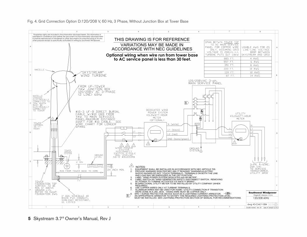
Fig. 4. grid Connection Option D:120/208 V, 60 Hz, 3 Phase, Without Junction Box at Tower Base
23
6
7
TOWER(APPROX.35 FT.HIGH)
NACELLE
NACELLECHASSISELECTRICALLYCONNECTED TOYAW WHICHMUST BEELECTRICALLYCONNECTEDTO TOWER
GROUNDLEVEL
24 INCH MIN.RUN FROM TOWER BASE TO HOME
TOWERFOUNDATION TOPSURFACE TO BEMIN. 6" ABOVEGROUND LVL.REFER TO SWWPFOUNDATION DWG.
WIND POWERSYSTEM
DISCONNECT SWITCH 2-POLE30A, 250VAC
SQ-D #DU221RB
N (white)
L2 (red)
L1 (black)
L2
L1
G
N
DEDICATED WIND POWER SYSTEMKILOWATT-HOUR
METER(OPTIONAL)
4
G
* NOTES:1. EQUIPMENT SHALL BE INSTALLED IN ACCORDANCE WITH NEC ARTICLE 705.2. PROVIDE WARNING SIGN PER NEC 690-17 READING "WARNING-ELECTRIC SHOCK HAZARD-DO NOT TOUCH TERMINALS - TERMINALS ON BOTH THE LINE AND LOAD MAY BE ENERGIZED IN THE OFF POSITION".3. LABEL "WIND POWER SYSTEM DEDICATED kW-HR METER".4. LABEL SWITCH AS "WIND GENERATOR SAFETY DISCONNECT SWITCH; REMOVING AC POWER TO TURBINE ACTIVATES ITS SAFETY BRAKE".5. BI-DIRECTIONAL UTILITY METER TO BE INSTALLED BY UTILITY COMPANY (WHEN REQUIRED)6. USE COPPER WIRES ONLY AT TURBINE TERMINALS7. ALUMINUM WIRES MAY BE USED FOR HOME / UTILITY CONNECTION IF TRANSITION WERE DONE IN A JNC. BOX. 14AWG WIRE MUST BE COPPER ONLY.8. SPD = SURGE PROTECTIVE DEVICE SUCH AS A LIGHTNING CURRENT ARRESTOR. AN APPROPRIATE ARRESTOR TO SATISFY THE REQUIRED LIGHTNING PROTECTION LEVEL MUST BE INSTALLED. SEE LIGHTNING PROTECTION SECTION OF MANUAL FOR RECOMMENDATIONS.
FROM UP-TOWERYAW JUNCTION BOX120/208V AC 3-PHASE(2 LINE) 60Hz
#10-3 UF-B DIRECT BURIAL CABLE W/#10 GND FROM YAW TO MAIN SERVICES PANEL.MAXIMUM DISTANCE 220FT FOR #10 CABLE. SEE WIRE CHART FOR LONGER SPANS
G N L2 L1
1" DIA. SCHEDULE 40RIGID PVC CONDUIT;SUNLIGHT RESISTANT;UL LISTED
VARIATIONS MAY BE MADE IN ACCORDANCE WITH NEC GUIDELINES
THIS DRAWING IS FOR REFERENCE
6" MIN.
TOWERGROUNDSYSTEM
GND (bare/green)
7
"SKYSTREAM"WIND TURBINE
6 AWG885 FT.557 FT.
4 AWG
87 FT. 14 AWG12 AWG139 FT.
USABLE AWG FOR 2% LINE-LINE VOLTAGE
DROP BETWEEN SKYSTREAM AND GRID
SPAN BETW'N TOWER TOP TO AC MAIN SERVICE
PANEL FOR COPPER WIRE ONLY, ASSUMING GRID
VOLTAGE IS 208V(L-L), TURBINE PUTS OUT 1.8kW
220 FT. 10 AWG8 AWG351 FT.
N
L2L3
L1
L2
40 A
40 A
40 A
GROUNDSYSTEM
N/G
N
L3
L1
G
UTILITYKILOWATT-HOUR
METER
120/208VAC 3-ph, MAIN SERVICE PANEL
3-PH, 4-WIRE,208 VACTO SERVICETRANSFORMER,UTILITY GRID
B
20 A
20 A
B
Optional wiring when wire run from tower base to AC service panel is less than 30 feet.
Proprietary rights are included in the information disclosed herein. This information issubmitted in confidence and neither the document nor the information disclosed here-in shall be reproduced or transferred to other documents for manufacturing or for anyother purpose except as specifically authorized in writing by Southwest Windpower.
D
E
F
C
1 2 3 4
B
A
321 5
C
D
4 6 7 8
A
B
Flagstaff, Arizona U.S.A.
scale none size A
dwg #3-CMLT-1084sheet 2 of 2rev. B
E
120/208 60Hz
5 76
F
Southwest Windpower
5 Skystream 3.7® Owner’s Manual, Rev J
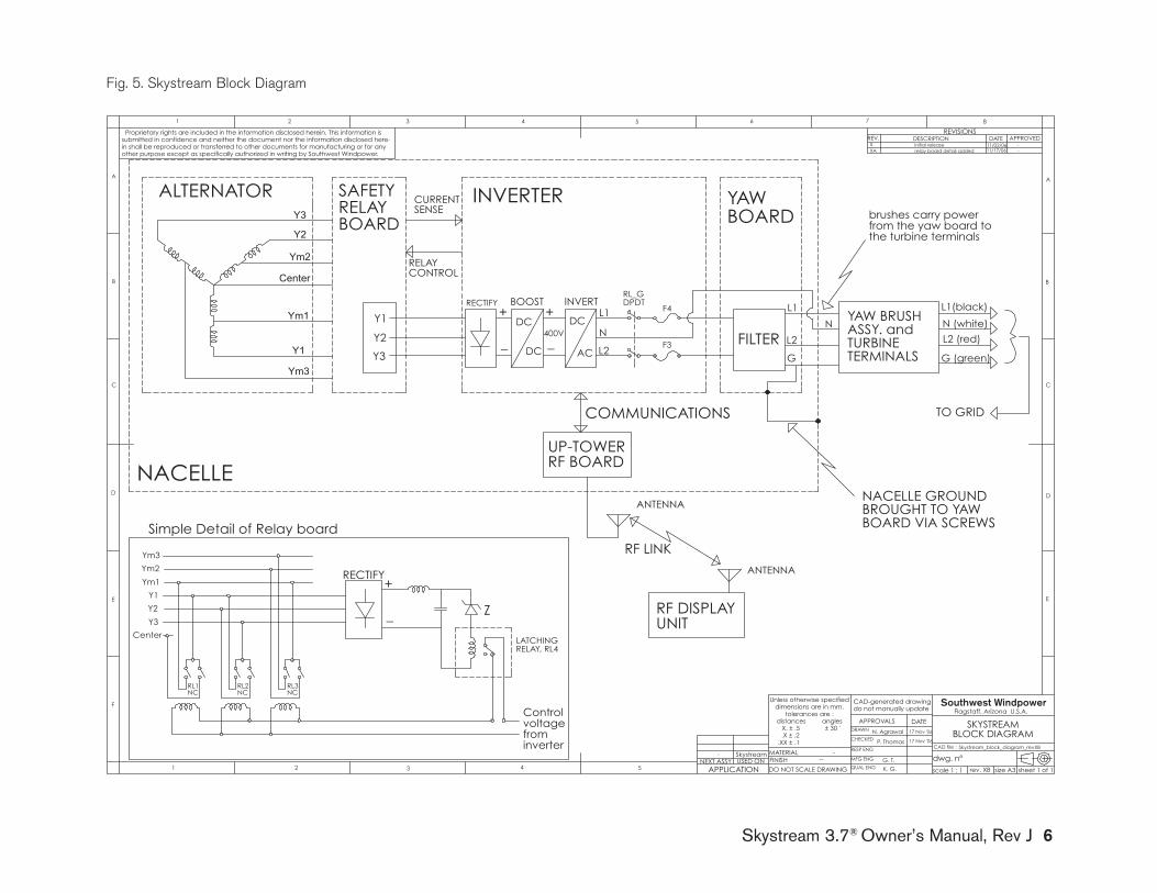
Skystream 3.7® Owner’s Manual, Rev J 6
BLOCK DIAGRAM.X ± .2
-
N. Agrawal
submitted in confidence and neither the document nor the information disclosed here-initial release
other purpose except as specifically authorized in writing by Southwest Windpower.
D
E
F
C
21 3 4
B
A
321 5
C
D
4 6 7 8
A
B
G. T.
17 Nov '06
in shall be reproduced or transferred to other documents for manufacturing or for anyAPPROVED
5
DATEDESCRIPTION
Flagstaff, Arizona U.S.A.
CAD-generated drawing
QUAL ENG
Skystream
Proprietary rights are included in the information disclosed herein. This information is
X
REVISIONS
do not manually update
scale 1 : 1 size A3
CAD file :
dwg. n°sheet 1 of 1rev. XB
DATEAPPROVALSDRAWN
CHECKED
RESP ENG
17 Nov '06
P. Thomas
-
11/02/06
Skystream_block_diagram_revXB
REV.
MFG ENG
XA
.XX ± .1
MATERIALFINISH --
-
DO NOT SCALE DRAWINGAPPLICATIONUSED ONNEXT ASSY
E
-11/17/06relay board detail added
Unless otherwise specifieddimensions are in mm.
tolerances are :distances angles X. ± .5 ± 30 ' SKYSTREAM
K. G.
from
Y3
Y2
Ym2
Center
Ym1
Y1
Ym3
Y1
Y2
Y3
L1+
_
DC
DC AC
DC+
_400V N
L2
N
L1
L2
RECTIFY BOOST INVERT
FILTER
INVERTER
F4
BOARDYAW
F3
BOARD
ALTERNATORRELAY SENSE
CURRENT
CONTROLRELAY
RF BOARD
RF LINK
UP-TOWER
UNIT
COMMUNICATIONS
G
L1(black)
N (white)
L2 (red)
TO GRID
NACELLE
RF DISPLAY
SAFETY
BOARD VIA SCREWSBROUGHT TO YAW NACELLE GROUND
the turbine terminals
G (green)
from the yaw board to brushes carry power
inverter
TERMINALS
ANTENNA
ANTENNA
Y3
Y2
Y1
TURBINE
Relay board
Center
Ym3
Ym1
Ym2
Simple Detail of
NCRL1
NCRL2
NC
+RECTIFY
_
RL3
RELAY, RL4
Z
LATCHING
ASSY. and YAW BRUSH
Controlvoltage
RL_GDPDT
Southwest Windpower
Fig. 5. Skystream Block Diagram

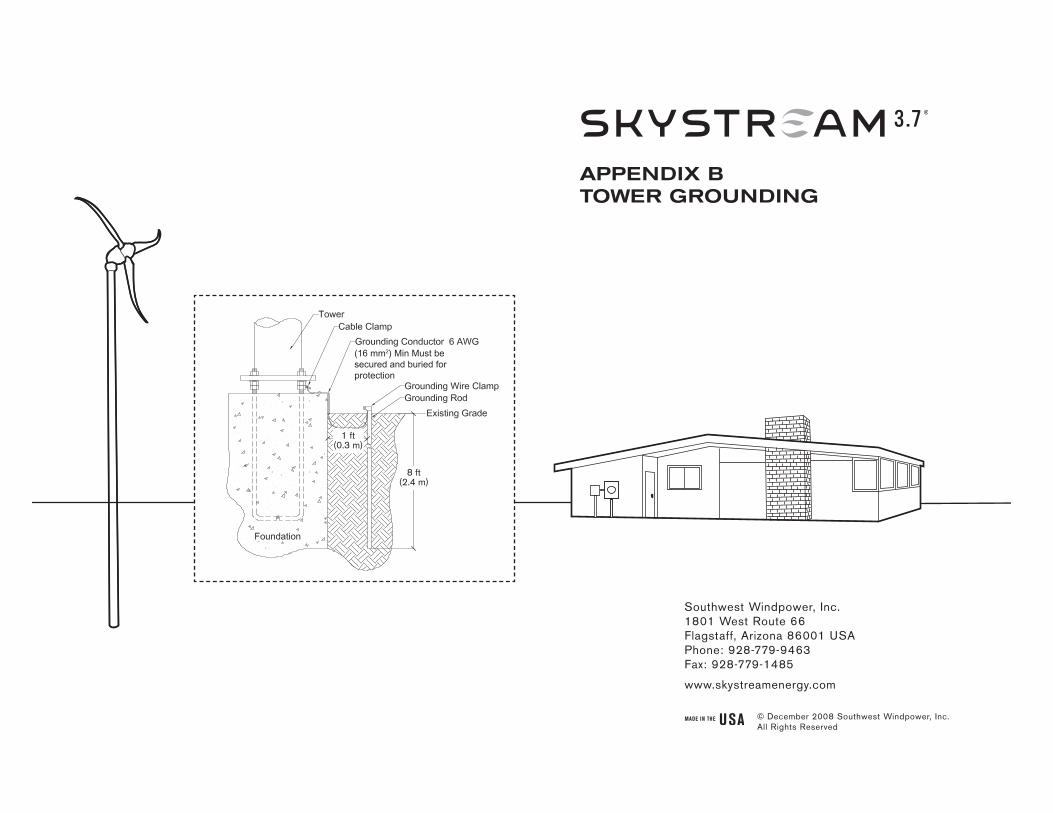
8 ft(2.4 m)
1 ft(0.3 m)
(16 mm2) Min Must be secured and buried for protection
Southwest Windpower, Inc.1801 West Route 66Flagstaff, Arizona 86001 USAPhone: 928-779-9463Fax: 928-779-1485
www.skystreamenergy.com
aPPendIX BTOwer GrOundInG
© December 2008 Southwest Windpower, Inc. All Rights Reserved
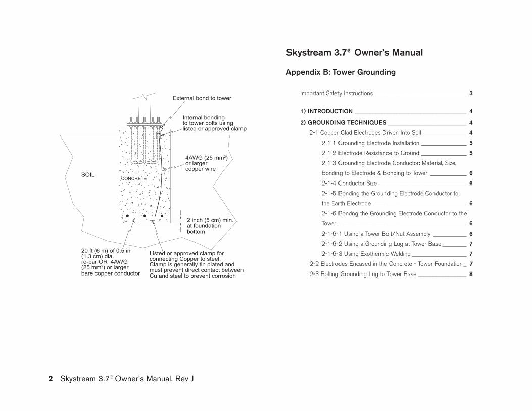
Skystream 3.7® owner’s manual
appendix b: Tower grounding
Important Safety Instructions ______________________________ 3
1) InTroduCTIon _____________________________________ 4
2) groundIng TEChnIQuES __________________________ 4
2-1 Copper Clad Electrodes Driven Into Soil _______________ 4
2-1-1 grounding Electrode Installation _______________ 5
2-1-2 Electrode Resistance to ground _______________ 5
2-1-3 grounding Electrode Conductor: Material, Size,
Bonding to Electrode & Bonding to Tower ____________ 6
2-1-4 Conductor Size _____________________________ 6
2-1-5 Bonding the grounding Electrode Conductor to
the Earth Electrode _______________________________ 6
2-1-6 Bondng the grounding Electrode Conductor to the
Tower ___________________________________________ 6
2-1-6-1 Using a Tower Bolt/Nut Assembly ___________ 6
2-1-6-2 Using a grounding Lug at Tower Base ________ 7
2-1-6-3 Using Exothermic Welding __________________ 7
2-2 Electrodes Encased in the Concrete - Tower Foundation _ 7
2-3 Bolting grounding Lug to Tower Base ________________ 8
20 ft (6 m) of 0.5 in (1.3 cm) dia. re-bar OR 4AWG (25 mm2) or larger bare copper conductor
2 inch (5 cm) min.at foundationbottom
Listed or approved clamp forconnecting Copper to steel.Clamp is generally tin plated andmust prevent direct contact betweenCu and steel to prevent corrosion
4AWG (25 mm2) or larger copper wire
Internal bondingto tower bolts usinglisted or approved clamp
External bond to tower
SOILCONCRETE
Proprietary rights are included in the information disclosed herein. This information issubmitted in confidence and neither the document nor the information disclosed here-in shall be reproduced or transferred to other documents for manufacturing or for anyother purpose except as specifically authorized in writing by Southwest Windpower.
D
E
F
C
1 2 3 4
B
A
321 5
C
D
4 6 7 8
A
B
D. Calley 26 Jan '07Tower_Grounding
N.Agrawal
3-CMBP-3026Skystream
26 Jan '07
Flagstaff, Arizona U.S.A.
CAD-generated drawingdo not manually update
scale none size A3
CAD file :
dwg. n°
sheet 1 of 2rev. A
DATEAPPROVALSDRAWN
CHECKED
RESP ENG
MFG ENG
QUAL ENG
Unless otherwise specifieddimensions are in mm.
tolerances are :distances angles X. ± .5 ± 30 '.X ± .2
.XX ± .1
MATERIALFINISH --
-
DO NOT SCALE DRAWINGAPPLICATIONUSED ONNEXT ASSY
E
POT01/29/06Original releaseNC
REVISIONSREV. DESCRIPTION DATE APPROVED
-
Concrete encased electrode
5
P. Thomas 26 Jan '07
2 Skystream 3.7® Owner’s Manual, Rev J
Skystream 3.7® Owner’s Manual, Rev J 3
ImporTanT SafETy InSTruCTIonSrEad ThESE InSTruCTIonS In ThEIr EnTIrETy bEforE InSTallIng.
1) SAVE THESE INSTRUCTIONS. This manual contains important instructions for grounding your Skystream tower.
2) Read these instructions in their entirety before beginning.
3) Do not start installation unless all required equipment and tools are on site.
professional installation highly recommended
tiP: Helpful information to ease the installation
Warning: Risk of injury or death - proceed with extreme caution
Professional installation highly recommended
In this guide
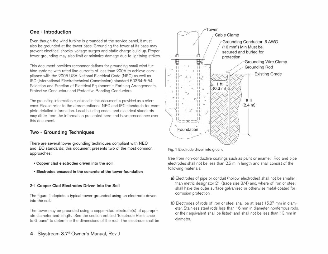
4 Skystream 3.7® Owner’s Manual, Rev J
Even though the wind turbine is grounded at the service panel, it must also be grounded at the tower base. grounding the tower at its base may prevent electrical shocks, voltage surges and static charge build up. Proper tower grounding may also limit or minimize damage due to lightning strikes.
This document provides recommendations for grounding small wind tur-bine systems with rated line currents of less than 200A to achieve com-pliance with the 2005 USA National Electrical Code (NEC) as well as IEC (International Electrotechnical Commission) standard 60364-5-54 Selection and Erection of Electrical Equipment – Earthing Arrangements, Protective Conductors and Protective Bonding Conductors.
The grounding information contained in this document is provided as a refer-ence. Please refer to the aforementioned NEC and IEC standards for com-plete detailed information. Local building codes and electrical standards may differ from the information presented here and have precedence over this document.
Two - grounding Techniques
There are several tower grounding techniques compliant with NEC and IEC standards; this document presents two of the most common approaches:
• Copper clad electrodes driven into the soil
• Electrodes encased in the concrete of the tower foundation
2-1 Copper Clad Electrodes driven Into the Soil
The figure 1 depicts a typical tower grounded using an electrode driven into the soil.
The tower may be grounded using a copper-clad electrode(s) of appropri-ate diameter and length. See the section entitled “Electrode Resistance to ground” to determine the dimensions of the rod. The electrode shall be
free from non-conductive coatings such as paint or enamel. Rod and pipe electrodes shall not be less than 2.5 m in length and shall consist of the following materials:
a) Electrodes of pipe or conduit (hollow electrodes) shall not be smaller than metric designator 21 (trade size 3/4) and, where of iron or steel, shall have the outer surface galvanized or otherwise metal-coated for corrosion protection.
b) Electrodes of rods of iron or steel shall be at least 15.87 mm in diam-eter. Stainless steel rods less than 16 mm in diameter, nonferrous rods, or their equivalent shall be listed* and shall not be less than 13 mm in diameter.
8 ft(2.4 m)
1 ft(0.3 m)
(16 mm2) Min Must be secured and buried for protection
one - Introduction
Fig. 1 Electrode driven into ground.
Skystream 3.7® Owner’s Manual, Rev J 5
NEC section 250.52 and in accordance with the user’s local electrical code authority.
*Be included in a list published by an organization (or marked as such) that is acceptable to the local authority having jurisdiction in the area. For example, UL/CSA listed in USA/Canada.
2-1-1 grounding Electrode Installation
The following information is excerpted from the 2005 NEC article 250.53 (g). Refer to code for additional detailed information. The electrode shall be installed such that at least 2.44 m of length is in contact with the soil. It shall be driven into undisturbed soil within 0.3 m of the tower foundation. It shall be driven to a depth of not less than 2.44 m except that, where rock bottom is encountered, the electrode shall be driven at an oblique angle not to exceed 45 degrees from the vertical or, where rock bottom is encountered at an angle up to 45 degrees, the elec-trode shall be permitted to be buried in a trench that is at least 750 mm deep. The upper end of the electrode shall be flush with or below ground level unless the aboveground end and grounding electrode conductor are protected against physical damage as specified below (quoted from 2005 NEC article 250.10):
a) In installations where they are not likely to be damaged
b) Where enclosed in metal, wood, or equivalent protective covering
2-1-2 Electrode resistance to ground
The resistance to earth of a single ground rod can be calculated using Dwight’s equation: R = [r/(2πl)]x[ln(4l/R)-1], where r is the soil resistivity, L is the length of the rod buried inside the earth and R = radius of the rod; ln stands for the natural logarithm.
For calculating the resistance of the rod to ground, one must know the value of soil resistivity. This may be found in the local electrical code or building inspector’s office/municipal office or by an actual soil resistivity test.
The resistance of a rod electrode to ground may be lowered by increasing the rod diameter, increasing the buried length of the rod or by treatment of the soil to reduce its resistivity.
If the single chosen electrode does not have a resistance to ground of 10 ohm or less, it shall be augmented by additional electrodes as necessary. The overall resistance of multiple rods to ground would roughly equal the resistance of a single rod to ground divided by the number of rods. Where multiple such electrodes are installed to meet the above requirement, they shall not be less than 1.8 m apart. The multiple rods must be bonded together using the grounding electrode conductor.
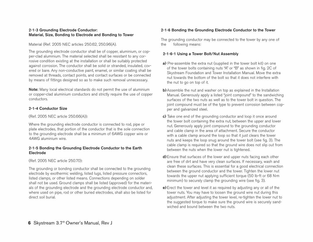
6 Skystream 3.7® Owner’s Manual, Rev J
2-1-3 grounding Electrode Conductor: material, Size, bonding to Electrode and bonding to Tower
Material (Ref. 2005 NEC articles 250.62, 250.96(A). The grounding electrode conductor shall be of copper, aluminium, or cop-per-clad aluminium. The material selected shall be resistant to any cor-rosive condition existing at the installation or shall be suitably protected against corrosion. The conductor shall be solid or stranded, insulated, cov-ered or bare. Any non-conductive paint, enamel, or similar coating shall be removed at threads, contact points, and contact surfaces or be connected by means of fittings designed so as to make such removal unnecessary.
note: Many local electrical standards do not permit the use of aluminium or copper-clad aluminium conductors and strictly require the use of copper conductors.
2-1-4 Conductor Size (Ref. 2005 NEC article 250.66(A)): Where the grounding electrode conductor is connected to rod, pipe or plate electrodes, that portion of the conductor that is the sole connection to the grounding electrode shall be a minimum of 6AWg copper wire or 4AWg aluminium wire.
2-1-5 bonding the grounding Electrode Conductor to the Earth Electrode
(Ref. 2005 NEC article 250.70): The grounding or bonding conductor shall be connected to the grounding electrode by exothermic welding, listed lugs, listed pressure connectors, listed clamps, or other listed means. Connections depending on solder shall not be used. ground clamps shall be listed (approved) for the materi-als of the grounding electrode and the grounding electrode conductor and, where used on pipe, rod or other buried electrodes, shall also be listed for direct soil burial.
2-1-6 bonding the grounding Electrode Conductor to the Tower The grounding conductor may be connected to the tower by any one of the following means:
2-1-6-1 using a Tower bolt/nut assembly a) Pre-assemble the extra nut (supplied in the tower bolt kit) on one
of the tower bolts containing nuts “A” or “B” as shown in fig. 2C of Skystream Foundation and Tower Installation Manual. Move the extra nut towards the bottom of the bolt so that it does not interfere with the nut to go on top of it.
b) Assemble the nut and washer on top as explained in the Installation
Manual. generously apply a listed “joint compound” to the sandwiching surfaces of the two nuts as well as to the tower bolt in question. The joint compound must be of the type to prevent corrosion between cop-per and galvanized steel.
c) Take one end of the grounding conductor and loop it once around
the tower bolt containing the extra nut, between the upper and lower nut. generously apply joint compound to the grounding conductor and cable clamp in the area of attachment. Secure the conductor with a cable clamp around the loop so that it just clears the tower nuts and keeps the loop snug around the tower bolt (see fig. 3). The cable clamp is required so that the ground wire does not slip out from between the nuts when the lower nut is tightened.
d) Ensure that surfaces of the lower and upper nuts facing each other
are free of dirt and have very clean surfaces. If necessary, wash and clean these surfaces. This is essential for a good electrical connection between the ground conductor and the tower. Tighten the lower nut towards the upper nut applying sufficient torque (50 lb-ft or 68 N·m minimum) to securely clamp the grounding wire (see fig. 3).
e) Erect the tower and level it as required by adjusting any or all of the
tower nuts. You may have to loosen the ground wire nut during this adjustment. After adjusting the tower level, re-tighten the lower nut to the suggested torque to make sure the ground wire is securely sand-wiched and bound between the two nuts.
Skystream 3.7® Owner’s Manual, Rev J 7
2-1-6-2 using a grounding lug at Tower base
Bond the grounding conductor to the tower base flange through a ground terminal lug attached to the tower base as shown in figure 2. Use a 1/4-20 x 44.5 mm long stainless steel bolt through a hole in the tower base and a Nyloc stainless steel nut to fasten the ground lug to the underside of the tower base. The ground lug must be UL listed and must be a type that accommodates up to 1/ 0 AWg wire minimum.
2-1-6-3 using Exothermic Welding
Bond the grounding conductor to the tower base flange by exothermic welding of the conductor to the base flange. Make exothermic welds strictly in accordance with the weld manufacturer’s written recommenda-tions.
Electrode conductor routing and placement / installation:Ensure that the grounding conductor has no sharp bends in it. This is important to keep its inductance low. The grounding conductor may be buried or contained in a conduit as explained in 2005 NEC article 250.64.
2-2 Electrodes encased in the concrete of the tower foundation(reference 2005 NEC article 250.52(A)(3))
A grounding electrode may also be encased in the concrete of the tower foundation. The electrode is located at the bottom of the founda-tion and connects to the tower mounting “J” bolts and to the tower base by means of a grounding conductor.
Because the grounding electrode will be encased in concrete it should be inspected and approved prior to pouring the foundation to avoid con-flicts with local construction inspectors.
Two types of electrodes, their locations and their connection to the elec-trode grounding conductor are described below:
a) The electrode must be at least 6.0 m of one or more (electrically connected by steel tie wires) bare or zinc galvanized steel or other electrically conductive coated steel reinforcing bars or rods of not less than 13 mm in diameter, located near the bottom of the concrete foundation that is in direct contact with the earth. The electrode must be encased by at least 50 mm of concrete as shown in figure 4. The reinforcing bars, if bare, must not be rusted at the time of installa-tion to prevent bad electrical connection between bars and with the grounding electrode conductor. The reinforcing bars must be electri-cally connected to the anchor bolts either using the steel tie wires or using the grounding electrode conductor. The grounding electrode conductor must not be smaller than 4AWg copper and must be elec-trically bonded to the bottom reinforcing bars using listed/approved means that is suitable for concrete encasement. Sufficient extra length of the conductor must be available to bring it out of the foundation top and at least 46 cm above the foundation top. It should then be bonded to the tower as described in section 2-1-6 of this document.
A
DETAIL A SCALE 1 : 1
Fig. 2 Attaching the grounding wire to the tower base.
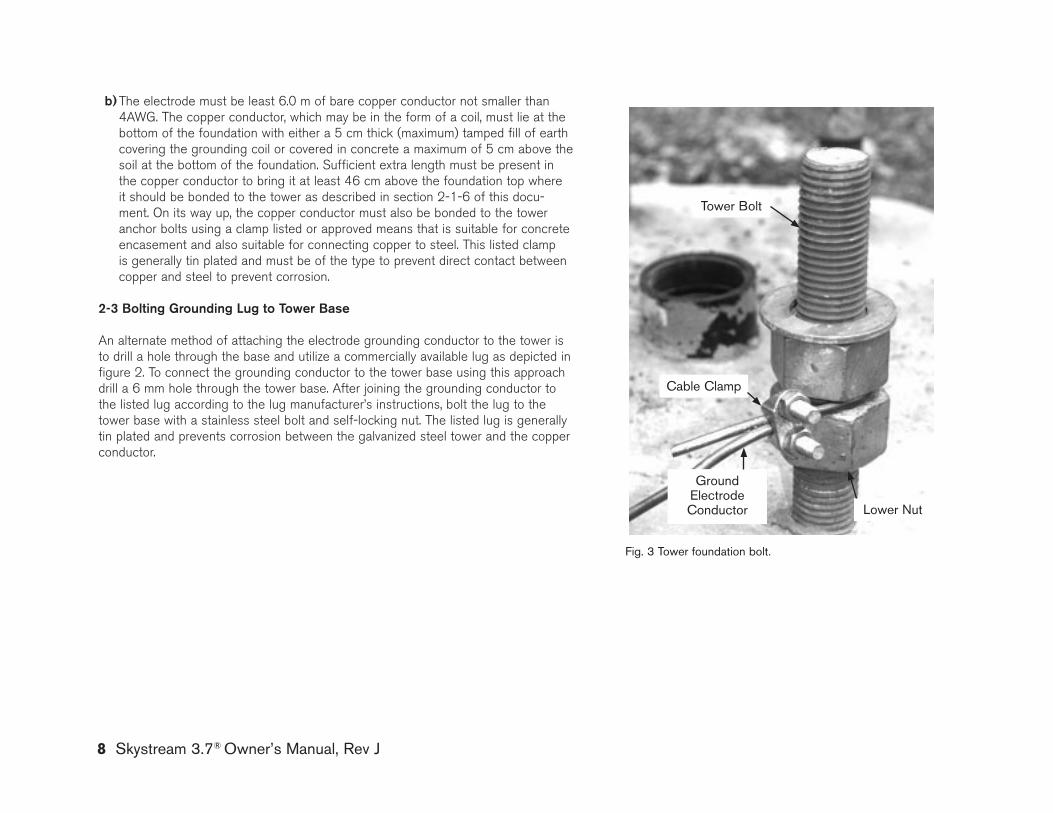
8 Skystream 3.7® Owner’s Manual, Rev J
b) The electrode must be least 6.0 m of bare copper conductor not smaller than 4AWg. The copper conductor, which may be in the form of a coil, must lie at the bottom of the foundation with either a 5 cm thick (maximum) tamped fill of earth covering the grounding coil or covered in concrete a maximum of 5 cm above the soil at the bottom of the foundation. Sufficient extra length must be present in the copper conductor to bring it at least 46 cm above the foundation top where it should be bonded to the tower as described in section 2-1-6 of this docu-ment. On its way up, the copper conductor must also be bonded to the tower anchor bolts using a clamp listed or approved means that is suitable for concrete encasement and also suitable for connecting copper to steel. This listed clamp is generally tin plated and must be of the type to prevent direct contact between copper and steel to prevent corrosion.
2-3 bolting grounding lug to Tower base An alternate method of attaching the electrode grounding conductor to the tower is to drill a hole through the base and utilize a commercially available lug as depicted in figure 2. To connect the grounding conductor to the tower base using this approach drill a 6 mm hole through the tower base. After joining the grounding conductor to the listed lug according to the lug manufacturer’s instructions, bolt the lug to the tower base with a stainless steel bolt and self-locking nut. The listed lug is generally tin plated and prevents corrosion between the galvanized steel tower and the copper conductor.
Tower bolt
Fig. 3 Tower foundation bolt.
Cable Clamp
Ground ElectrodeConductor lower Nut
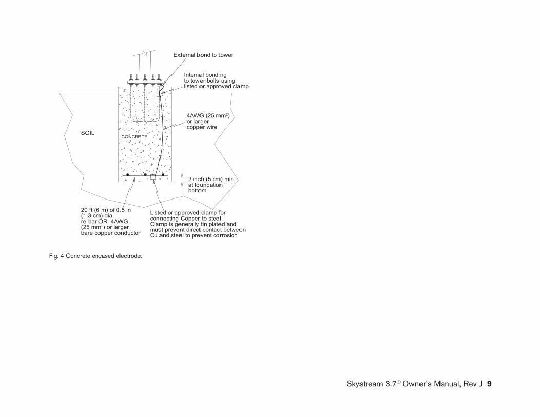
Skystream 3.7® Owner’s Manual, Rev J 9
Fig. 4 Concrete encased electrode.
20 ft (6 m) of 0.5 in (1.3 cm) dia. re-bar OR 4AWG (25 mm2) or larger bare copper conductor
2 inch (5 cm) min.at foundationbottom
Listed or approved clamp forconnecting Copper to steel.Clamp is generally tin plated andmust prevent direct contact betweenCu and steel to prevent corrosion
4AWG (25 mm2) or larger copper wire
Internal bondingto tower bolts usinglisted or approved clamp
External bond to tower
SOILCONCRETE
Proprietary rights are included in the information disclosed herein. This information issubmitted in confidence and neither the document nor the information disclosed here-in shall be reproduced or transferred to other documents for manufacturing or for anyother purpose except as specifically authorized in writing by Southwest Windpower.
D
E
F
C
1 2 3 4
B
A
321 5
C
D
4 6 7 8
A
B
D. Calley 26 Jan '07Tower_Grounding
N.Agrawal
3-CMBP-3026Skystream
26 Jan '07
Flagstaff, Arizona U.S.A.
CAD-generated drawingdo not manually update
scale none size A3
CAD file :
dwg. n°
sheet 1 of 2rev. A
DATEAPPROVALSDRAWN
CHECKED
RESP ENG
MFG ENG
QUAL ENG
Unless otherwise specifieddimensions are in mm.
tolerances are :distances angles X. ± .5 ± 30 '.X ± .2
.XX ± .1
MATERIALFINISH --
-
DO NOT SCALE DRAWINGAPPLICATIONUSED ONNEXT ASSY
E
POT01/29/06Original releaseNC
REVISIONSREV. DESCRIPTION DATE APPROVED
-
Concrete encased electrode
5
P. Thomas 26 Jan '07


BatteryChargingController
UtilityPanel
240V
Battery Inverter
Battery Charging Controller Block DiagramSouthwest Windpower, Inc.1801 West Route 66Flagstaff, Arizona 86001 USAPhone: 928-779-9463Fax: 928-779-1485
www.skystreamenergy.com
aPPendIX CBaTTery CHarGInG
© December 2008 Southwest Windpower, Inc. All Rights Reserved
2 Skystream 3.7® Owner’s Manual, Rev J
Skystream 3.7® owner’s manual
appendix C: battery Charging
1) baTTEry ChargIng opTIon a: 120/240 V, 60 Hz, 2 Phase System, Using Two Inverters _____________________________________________ 3
2) baTTEry ChargIng opTIon b: 120/240 V, 60 Hz, 2 Phase System, Using One Inverter With A Transformer _____________________________ 4
3) baTTEry ChargIng opTIon C: 120 V, 60 Hz, 1 Phase System, Using One Inverter __________________________________________________ 5
4) baTTEry ChargIng WITh ConTrollEr kITS: ________________________________________________ 6
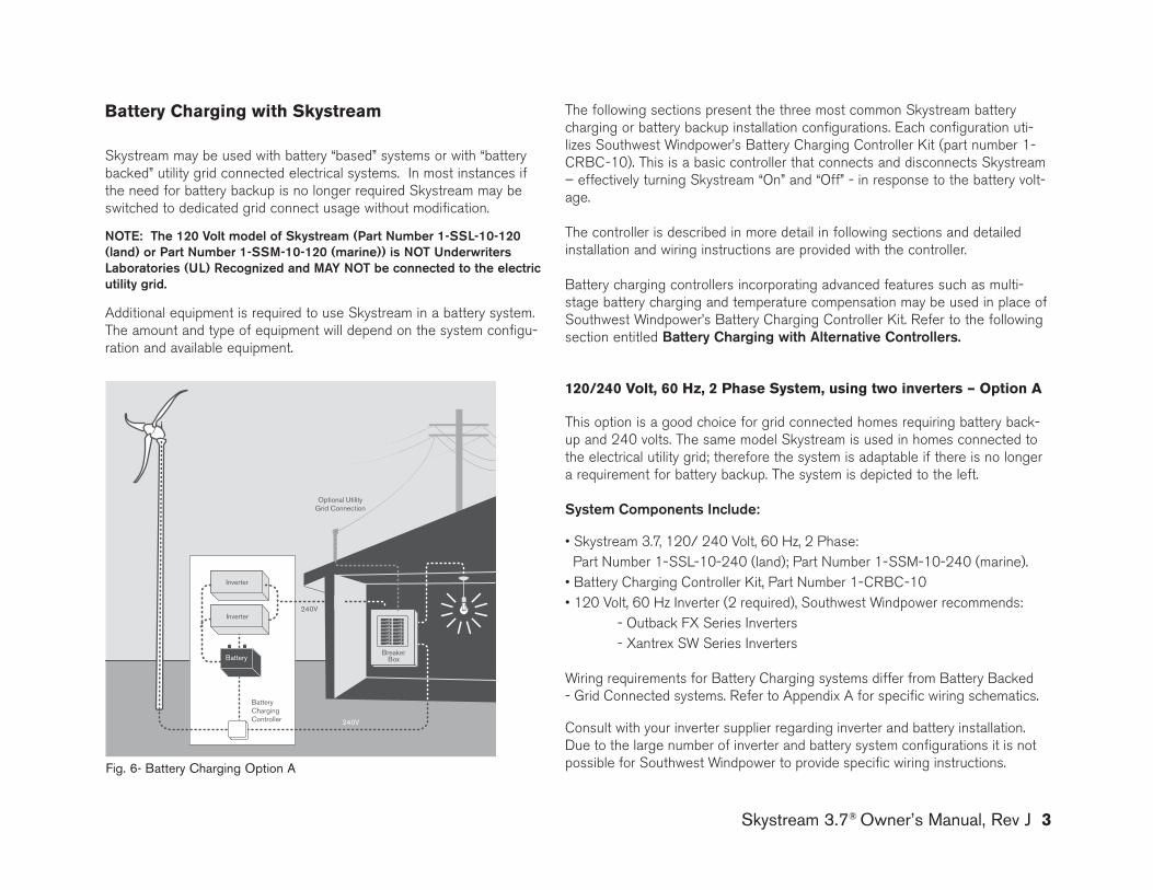
Skystream 3.7® Owner’s Manual, Rev J 3
Battery Charging with skystream
Skystream may be used with battery “based” systems or with “battery backed” utility grid connected electrical systems. In most instances if the need for battery backup is no longer required Skystream may be switched to dedicated grid connect usage without modification. noTE: The 120 Volt model of Skystream (part number 1-SSl-10-120 (land) or part number 1-SSm-10-120 (marine)) is noT underwriters laboratories (ul) recognized and may noT be connected to the electric utility grid.
Additional equipment is required to use Skystream in a battery system. The amount and type of equipment will depend on the system configu-ration and available equipment.
Optional UtilityGrid Connection
Inverter
BreakerBox
240V
240V
Battery
Inverter
BatteryChargingController
The following sections present the three most common Skystream battery charging or battery backup installation configurations. Each configuration uti-lizes Southwest Windpower’s Battery Charging Controller kit (part number 1-CRBC-10). This is a basic controller that connects and disconnects Skystream – effectively turning Skystream “On” and “Off” - in response to the battery volt-age.
The controller is described in more detail in following sections and detailed installation and wiring instructions are provided with the controller.
Battery charging controllers incorporating advanced features such as multi-stage battery charging and temperature compensation may be used in place of Southwest Windpower’s Battery Charging Controller kit. Refer to the following section entitled battery Charging with alternative Controllers.
120/240 Volt, 60 Hz, 2 Phase system, using two inverters – option a
This option is a good choice for grid connected homes requiring battery back-up and 240 volts. The same model Skystream is used in homes connected to the electrical utility grid; therefore the system is adaptable if there is no longer a requirement for battery backup. The system is depicted to the left.
System Components Include: • Skystream 3.7, 120/ 240 Volt, 60 Hz, 2 Phase: Part Number 1-SSL-10-240 (land); Part Number 1-SSM-10-240 (marine).• Battery Charging Controller Kit, Part Number 1-CRBC-10• 120 Volt, 60 Hz Inverter (2 required), Southwest Windpower recommends: - Outback FX Series Inverters - Xantrex SW Series Inverters
Wiring requirements for Battery Charging systems differ from Battery Backed - grid Connected systems. Refer to Appendix A for specific wiring schematics.
Consult with your inverter supplier regarding inverter and battery installation. Due to the large number of inverter and battery system configurations it is not possible for Southwest Windpower to provide specific wiring instructions.Fig. 6- battery Charging Option A
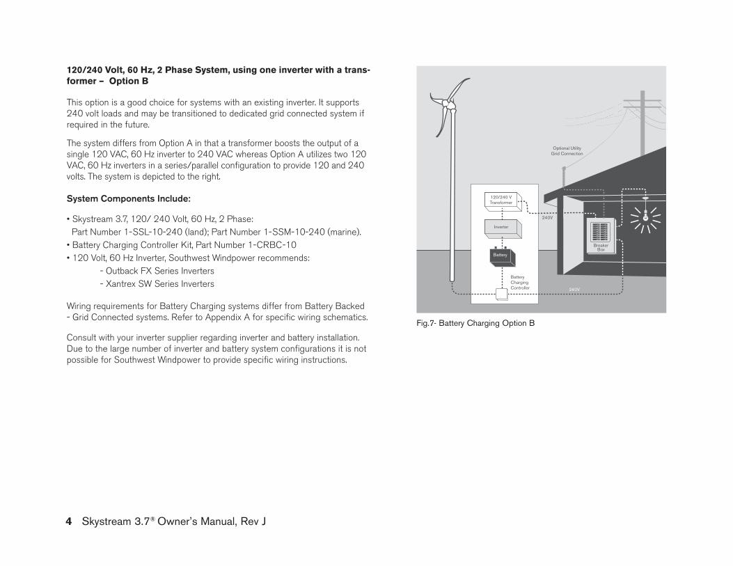
4 Skystream 3.7® Owner’s Manual, Rev J
120/240 Volt, 60 Hz, 2 Phase system, using one inverter with a trans-former – option B
This option is a good choice for systems with an existing inverter. It supports 240 volt loads and may be transitioned to dedicated grid connected system if required in the future.
The system differs from Option A in that a transformer boosts the output of a single 120 VAC, 60 Hz inverter to 240 VAC whereas Option A utilizes two 120 VAC, 60 Hz inverters in a series/parallel configuration to provide 120 and 240 volts. The system is depicted to the right.
System Components Include: • Skystream 3.7, 120/ 240 Volt, 60 Hz, 2 Phase: Part Number 1-SSL-10-240 (land); Part Number 1-SSM-10-240 (marine).• Battery Charging Controller Kit, Part Number 1-CRBC-10• 120 Volt, 60 Hz Inverter, Southwest Windpower recommends: - Outback FX Series Inverters - Xantrex SW Series Inverters
Wiring requirements for Battery Charging systems differ from Battery Backed - grid Connected systems. Refer to Appendix A for specific wiring schematics.
Consult with your inverter supplier regarding inverter and battery installation. Due to the large number of inverter and battery system configurations it is not possible for Southwest Windpower to provide specific wiring instructions.
Inverter
BatteryChargingController
Optional UtilityGrid Connection
BreakerBox
240V
240V
Battery
120/240 VTransformer
Fig.7- battery Charging Option b
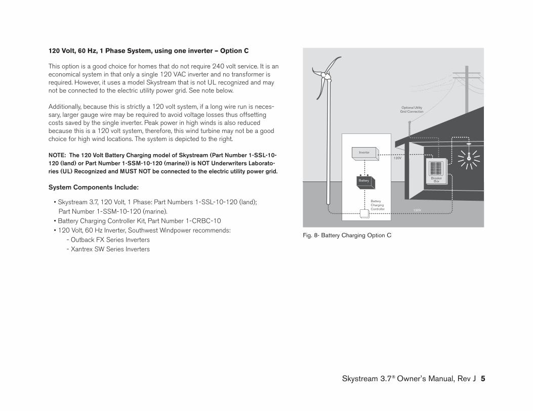
Skystream 3.7® Owner’s Manual, Rev J 5
120 Volt, 60 Hz, 1 Phase system, using one inverter – option C
This option is a good choice for homes that do not require 240 volt service. It is an economical system in that only a single 120 VAC inverter and no transformer is required. However, it uses a model Skystream that is not UL recognized and may not be connected to the electric utility power grid. See note below.
Additionally, because this is strictly a 120 volt system, if a long wire run is neces-sary, larger gauge wire may be required to avoid voltage losses thus offsetting costs saved by the single inverter. Peak power in high winds is also reduced because this is a 120 volt system, therefore, this wind turbine may not be a good choice for high wind locations. The system is depicted to the right.
noTE: The 120 Volt battery Charging model of Skystream (part number 1-SSl-10-120 (land) or part number 1-SSm-10-120 (marine)) is noT underwriters laborato-ries (ul) recognized and muST noT be connected to the electric utility power grid.
System Components Include:
• Skystream 3.7, 120 Volt, 1 Phase: Part Numbers 1-SSL-10-120 (land); Part Number 1-SSM-10-120 (marine).• Battery Charging Controller Kit, Part Number 1-CRBC-10• 120 Volt, 60 Hz Inverter, Southwest Windpower recommends:
- Outback FX Series Inverters - Xantrex SW Series Inverters
Inverter
BatteryChargingController
Optional UtilityGrid Connection
BreakerBox
120V
120V
Battery
Fig. 8- battery Charging Option C
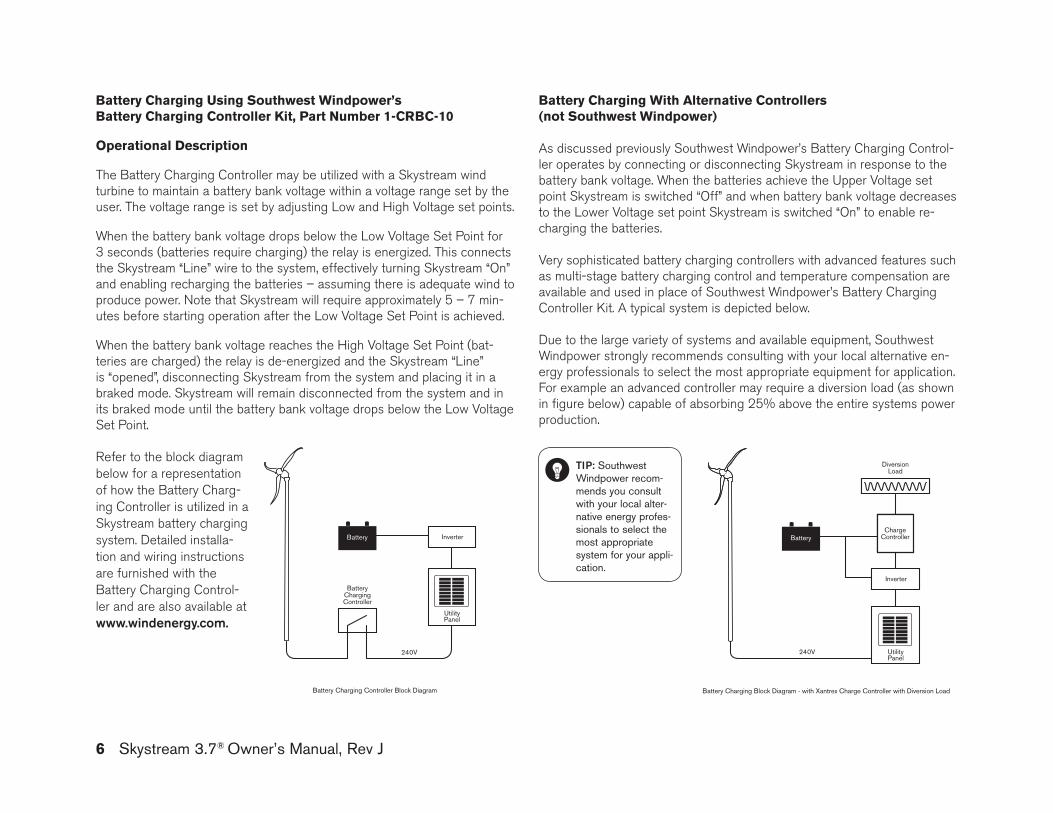
6 Skystream 3.7® Owner’s Manual, Rev J
Battery Charging Using southwest Windpower’s Battery Charging Controller Kit, Part number 1-CrBC-10
operational Description
The Battery Charging Controller may be utilized with a Skystream wind turbine to maintain a battery bank voltage within a voltage range set by the user. The voltage range is set by adjusting Low and High Voltage set points.
When the battery bank voltage drops below the Low Voltage Set Point for 3 seconds (batteries require charging) the relay is energized. This connects the Skystream “Line” wire to the system, effectively turning Skystream “On” and enabling recharging the batteries – assuming there is adequate wind to produce power. Note that Skystream will require approximately 5 – 7 min-utes before starting operation after the Low Voltage Set Point is achieved.
When the battery bank voltage reaches the High Voltage Set Point (bat-teries are charged) the relay is de-energized and the Skystream “Line” is “opened”, disconnecting Skystream from the system and placing it in a braked mode. Skystream will remain disconnected from the system and in its braked mode until the battery bank voltage drops below the Low Voltage Set Point.
BatteryChargingController
UtilityPanel
240V
Battery Inverter
Battery Charging Controller Block Diagram
UtilityPanel
240V
Battery
Inverter
ChargeController
DiversionLoad
Battery Charging Block Diagram - with Xantrex Charge Controller with Diversion Load
Battery Charging With alternative Controllers(not southwest Windpower)
As discussed previously Southwest Windpower’s Battery Charging Control-ler operates by connecting or disconnecting Skystream in response to the battery bank voltage. When the batteries achieve the Upper Voltage set point Skystream is switched “Off” and when battery bank voltage decreases to the Lower Voltage set point Skystream is switched “On” to enable re-charging the batteries.
Very sophisticated battery charging controllers with advanced features such as multi-stage battery charging control and temperature compensation are available and used in place of Southwest Windpower’s Battery Charging Controller kit. A typical system is depicted below.
Due to the large variety of systems and available equipment, Southwest Windpower strongly recommends consulting with your local alternative en-ergy professionals to select the most appropriate equipment for application. For example an advanced controller may require a diversion load (as shown in figure below) capable of absorbing 25% above the entire systems power production.
Refer to the block diagram below for a representation of how the Battery Charg-ing Controller is utilized in a Skystream battery charging system. Detailed installa-tion and wiring instructions are furnished with the Battery Charging Control-ler and are also available at www.windenergy.com.
TIp: Southwest Windpower recom-mends you consult with your local alter-native energy profes-sionals to select the most appropriate system for your appli-cation.
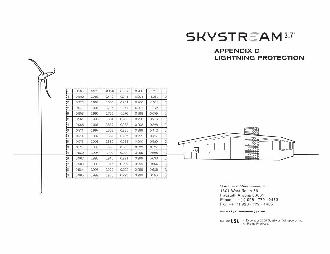
Table 1 - Lightning Protection Efficiency for 33 ft (10m) Towers
1 -1.353 0.765 0.976 -0.176 0.882 0.988 -3.705 0.529 0.953
2 -0.176 0.882 0.988 0.412 0.941 0.994 -1.353 0.765 0.976
3 0.216 0.922 0.992 0.608 0.961 0.966 -0.568 0.843 0.984
4 0.412 0.941 0.994 0.706 0.971 0.997 -0.176 0.882 0.988
5 0.529 0.953 0.995 0.765 0.976 0.998 0.059 0.906 0.991
6 0.608 0.961 0.996 0.804 0.980 0.998 0.216 0.922 0.992
7 0.664 0.966 0.997 0.832 0.983 0.998 0.328 0.933 0.993
8 0.706 0.971 0.997 0.853 0.985 0.999 0.412 0.941 0.994
9 0.739 0.974 0.997 0.869 0.987 0.999 0.477 0.948 0.995
10 0.765 0.976 0.998 0.882 0.988 0.999 0.529 0.953 0.995
11 0.786 0.979 0.998 0.893 0.989 0.999 0.572 0.957 0.996
12 0.804 0.980 0.998 0.902 0.990 0.999 0.608 0.961 0.996
13 0.819 0.982 0.998 0.910 0.991 0.999 0.638 0.964 0.216
14 0.832 0.983 0.998 0.916 0.992 0.999 0.664 0.966 0.997
15 0.843 0.984 0.998 0.922 0.992 0.999 0.686 0.969 0.997
16 0.853 0.985 0.999 0.926 0.993 0.999 0.706 0.971 0.997
17 0.862 0.986 0.999 0.931 0.993 0.999 0.723 0.972 0.997
18 0.869 0.987 0.999 0.935 0.993 0.999 0.739 0.974 0.997
19 0.876 0.988 0.999 0.938 0.994 0.999 0.752 0.975 0.998
20 0.882 0.988 0.999 0.941 0.994 0.999 0.765 0.976 0.998
30 0.922 0.992 0.999 0.961 0.996 1.000 0.843 0.984 0.998
40 0.941 0.994 0.999 0.971 0.997 1.000 0.882 0.988 0.999
50 0.953 0.995 1.000 0.976 0.998 1.000 0.906 0.991 0.999
60 0.961 0.996 1.000 0.980 0.998 1.000 0.922 0.992 0.999
70 0.966 0.967 1.000 0.983 0.998 1.000 0.933 0.993 0.999
Nc = 1/100
Nc = 1/1000
Nc = 1/10000
Nc = 1/100
Nc = 1/1000
Nc = 1/10000
Nc = 1/100
Nc = 1/1000
Nc = 1/10000
0.01 0.001 0.0001 0.01 0.001 0.0001 0.01 0.001 0.0001
Isolated Flat Land Hill or Knoll Non-Isolated Flat Land
Ng E = Lightning protection system efficiency
E = Lightning protection system efficiency
E = Lightning protection system efficiency
Southwest Windpower, Inc.1801 West Route 66Flagstaff, Arizona 86001Phone: ++ (1) 928 - 779 - 9463Fax: ++ (1) 928 - 779 - 1485
www.skystreamenergy.com
aPPendIX dlIGHTnInG PrOTeCTIOn
December 2008 Southwest Windpower, Inc. All Rights Reserved.
Skystream 3.7® owner’s manual
appendix d: lightning protection
Important Safety Instructions ______________________________ 3
Introduction ____________________________________________ 4
Location of Lightning Current Arrestors______________________ 4
Selecting Appropriate Lightning Protection System ____________ 4
Determine Tower Height __________________________________ 5
Determine Flash Density __________________________________ 5
Table 1: Lightning Protection Efficiency for 33 ft Tower ________ 5
Determine Topography ____________________________________ 6
Permitted Annual Number of Critical Event (Nc) _______________ 6
Lightning Protection System Efficiency ______________________ 6
Table 2: Lightning Protection Efficiency for 45 ft Tower ________ 6
Table 3: Lightning Protection Efficiency for 60 ft Tower ________ 7
Table 4: Lightning Protection Efficiency for 70 ft Tower ________ 8
Lightning Protection Level ________________________________ 8
Select Model & Number of Lightning Current Arrestor(s) _______ 9
2 Skystream 3.7® Owner’s Manual, Rev J
ImporTanT SafETy InSTruCTIonSrEad ThESE InSTruCTIonS In ThEIr EnTIrETy bEforE InSTallIng.
1) SAVE THESE INSTRUCTIONS. This manual contains important instructions for grounding your Skystream monopole tower.
2) Read these instructions in their entirety before beginning.
3) Do not start installation unless all required equipment and tools are on site.
professional installation highly recommended
Warning: Risk of injury or death - proceed with extreme caution
Professional installation highly recommended
In this guide
ImporTanT: Please take note
Skystream 3.7® Owner’s Manual, Rev J 3
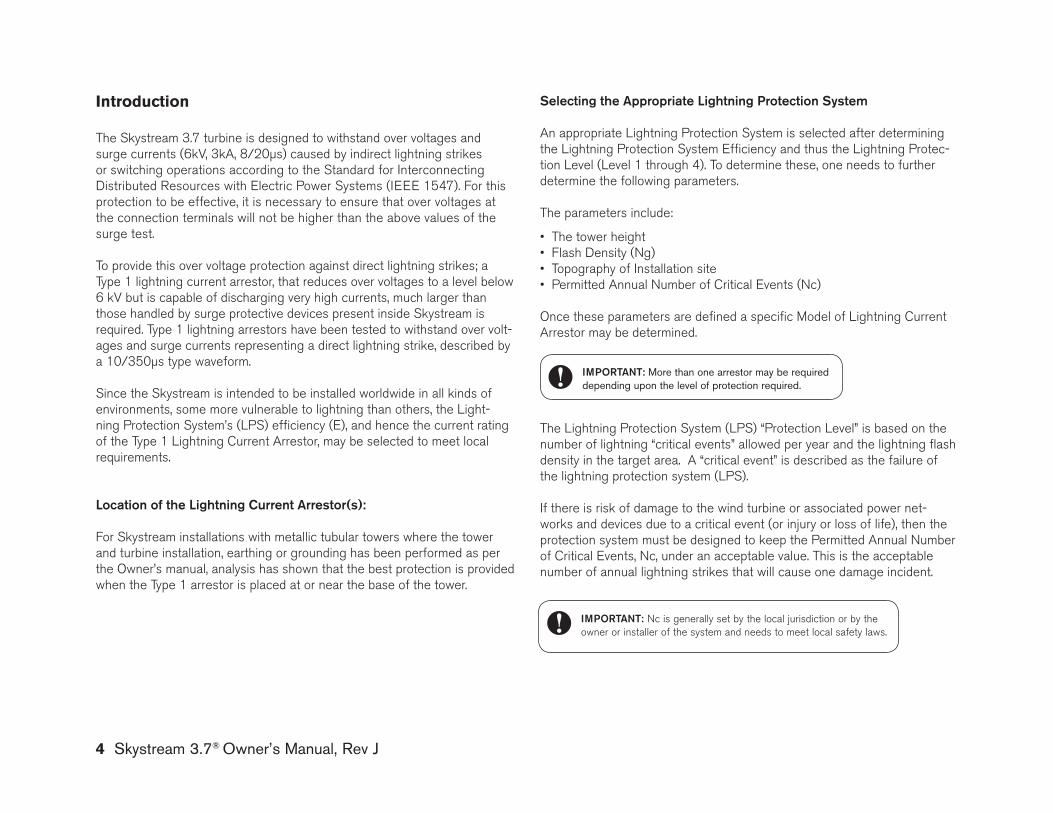
The Skystream 3.7 turbine is designed to withstand over voltages and surge currents (6kV, 3kA, 8/20µs) caused by indirect lightning strikes or switching operations according to the Standard for Interconnecting Distributed Resources with Electric Power Systems (IEEE 1547). For this protection to be effective, it is necessary to ensure that over voltages at the connection terminals will not be higher than the above values of the surge test.
To provide this over voltage protection against direct lightning strikes; a Type 1 lightning current arrestor, that reduces over voltages to a level below 6 kV but is capable of discharging very high currents, much larger than those handled by surge protective devices present inside Skystream is required. Type 1 lightning arrestors have been tested to withstand over volt-ages and surge currents representing a direct lightning strike, described by a 10/350µs type waveform.
Since the Skystream is intended to be installed worldwide in all kinds of environments, some more vulnerable to lightning than others, the Light-ning Protection System’s (LPS) efficiency (E), and hence the current rating of the Type 1 Lightning Current Arrestor, may be selected to meet local requirements.
location of the lightning Current arrestor(s):
For Skystream installations with metallic tubular towers where the tower and turbine installation, earthing or grounding has been performed as per the Owner’s manual, analysis has shown that the best protection is provided when the Type 1 arrestor is placed at or near the base of the tower.
Selecting the appropriate lightning protection System An appropriate Lightning Protection System is selected after determining the Lightning Protection System Efficiency and thus the Lightning Protec-tion Level (Level 1 through 4). To determine these, one needs to further determine the following parameters.
The parameters include:
• The tower height• Flash Density (Ng)• Topography of Installation site• Permitted Annual Number of Critical Events (Nc)
Once these parameters are defined a specific Model of Lightning Current Arrestor may be determined.
The Lightning Protection System (LPS) “Protection Level” is based on the number of lightning “critical events” allowed per year and the lightning flash density in the target area. A “critical event” is described as the failure of the lightning protection system (LPS).
If there is risk of damage to the wind turbine or associated power net-works and devices due to a critical event (or injury or loss of life), then the protection system must be designed to keep the Permitted Annual Number of Critical Events, Nc, under an acceptable value. This is the acceptable number of annual lightning strikes that will cause one damage incident.
introduction
ImporTanT: Nc is generally set by the local jurisdiction or by the owner or installer of the system and needs to meet local safety laws.
ImporTanT: More than one arrestor may be required depending upon the level of protection required.
4 Skystream 3.7® Owner’s Manual, Rev J
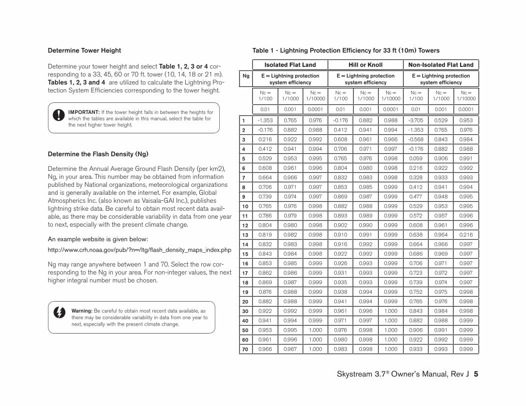
Skystream 3.7® Owner’s Manual, Rev J 5
Table 1 - lightning protection Efficiency for 33 ft (10m) Towers
1 -1.353 0.765 0.976 -0.176 0.882 0.988 -3.705 0.529 0.953
2 -0.176 0.882 0.988 0.412 0.941 0.994 -1.353 0.765 0.976
3 0.216 0.922 0.992 0.608 0.961 0.966 -0.568 0.843 0.984
4 0.412 0.941 0.994 0.706 0.971 0.997 -0.176 0.882 0.988
5 0.529 0.953 0.995 0.765 0.976 0.998 0.059 0.906 0.991
6 0.608 0.961 0.996 0.804 0.980 0.998 0.216 0.922 0.992
7 0.664 0.966 0.997 0.832 0.983 0.998 0.328 0.933 0.993
8 0.706 0.971 0.997 0.853 0.985 0.999 0.412 0.941 0.994
9 0.739 0.974 0.997 0.869 0.987 0.999 0.477 0.948 0.995
10 0.765 0.976 0.998 0.882 0.988 0.999 0.529 0.953 0.995
11 0.786 0.979 0.998 0.893 0.989 0.999 0.572 0.957 0.996
12 0.804 0.980 0.998 0.902 0.990 0.999 0.608 0.961 0.996
13 0.819 0.982 0.998 0.910 0.991 0.999 0.638 0.964 0.216
14 0.832 0.983 0.998 0.916 0.992 0.999 0.664 0.966 0.997
15 0.843 0.984 0.998 0.922 0.992 0.999 0.686 0.969 0.997
16 0.853 0.985 0.999 0.926 0.993 0.999 0.706 0.971 0.997
17 0.862 0.986 0.999 0.931 0.993 0.999 0.723 0.972 0.997
18 0.869 0.987 0.999 0.935 0.993 0.999 0.739 0.974 0.997
19 0.876 0.988 0.999 0.938 0.994 0.999 0.752 0.975 0.998
20 0.882 0.988 0.999 0.941 0.994 0.999 0.765 0.976 0.998
30 0.922 0.992 0.999 0.961 0.996 1.000 0.843 0.984 0.998
40 0.941 0.994 0.999 0.971 0.997 1.000 0.882 0.988 0.999
50 0.953 0.995 1.000 0.976 0.998 1.000 0.906 0.991 0.999
60 0.961 0.996 1.000 0.980 0.998 1.000 0.922 0.992 0.999
70 0.966 0.967 1.000 0.983 0.998 1.000 0.933 0.993 0.999
Nc = 1/100
Nc = 1/1000
Nc = 1/10000
Nc = 1/100
Nc = 1/1000
Nc = 1/10000
Nc = 1/100
Nc = 1/1000
Nc = 1/10000
0.01 0.001 0.0001 0.01 0.001 0.0001 0.01 0.001 0.0001
isolated flat land Hill or Knoll non-isolated flat land
ng E = lightning protection system efficiency
E = lightning protection system efficiency
E = lightning protection system efficiency
determine Tower height
Determine your tower height and select Table 1, 2, 3 or 4 cor-responding to a 33, 45, 60 or 70 ft. tower (10, 14, 18 or 21 m). Tables 1, 2, 3 and 4 are utilized to calculate the Lightning Pro-tection System Efficiencies corresponding to the tower height.
determine the flash density (ng)
Determine the Annual Average ground Flash Density (per km2), Ng, in your area. This number may be obtained from information published by National organizations, meteorological organizations and is generally available on the internet. For example, global Atmospherics Inc. (also known as Vaisala-gAI Inc.), publishes lightning strike data. Be careful to obtain most recent data avail-able, as there may be considerable variability in data from one year to next, especially with the present climate change.
An example website is given below:
http://www.crh.noaa.gov/pub/?n=/ltg/flash_density_maps_index.php
Ng may range anywhere between 1 and 70. Select the row cor-responding to the Ng in your area. For non-integer values, the next higher integral number must be chosen.
Warning: Be careful to obtain most recent data available, as there may be considerable variability in data from one year to next, especially with the present climate change.
ImporTanT: If the tower height falls in between the heights for which the tables are available in this manual, select the table for the next higher tower height.
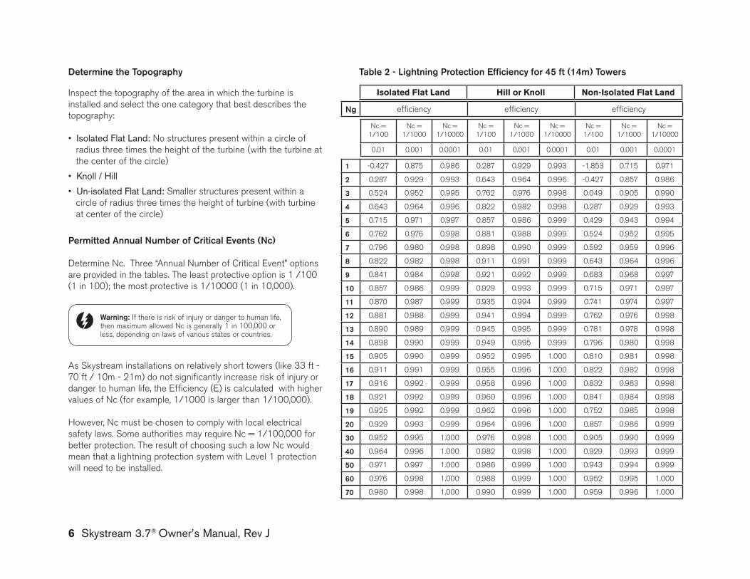
permitted annual number of Critical Events (nc)
Determine Nc. Three “Annual Number of Critical Event” options are provided in the tables. The least protective option is 1 /100 (1 in 100); the most protective is 1/10000 (1 in 10,000).
As Skystream installations on relatively short towers (like 33 ft - 70 ft / 10m - 21m) do not significantly increase risk of injury or danger to human life, the Efficiency (E) is calculated with higher values of Nc (for example, 1/1000 is larger than 1/100,000).
However, Nc must be chosen to comply with local electrical safety laws. Some authorities may require Nc = 1/100,000 for better protection. The result of choosing such a low Nc would mean that a lightning protection system with Level 1 protection will need to be installed.
Warning: If there is risk of injury or danger to human life, then maximum allowed Nc is generally 1 in 100,000 or less, depending on laws of various states or countries.
Table 2 - lightning protection Efficiency for 45 ft (14m) Towers
isolated flat land Hill or Knoll non-isolated flat land
ng efficiency efficiency efficiency
Nc = 1/100
Nc = 1/1000
Nc = 1/10000
Nc = 1/100
Nc = 1/1000
Nc = 1/10000
Nc = 1/100
Nc = 1/1000
Nc = 1/10000
0.01 0.001 0.0001 0.01 0.001 0.0001 0.01 0.001 0.0001
1 -0.427 0.875 0.986 0.287 0.929 0.993 -1.853 0.715 0.971
2 0.287 0.929 0.993 0.643 0.964 0.996 -0.427 0.857 0.986
3 0.524 0.952 0.995 0.762 0.976 0.998 0.049 0.905 0.990
4 0.643 0.964 0.996 0.822 0.982 0.998 0.287 0.929 0.993
5 0.715 0.971 0.997 0.857 0.986 0.999 0.429 0.943 0.994
6 0.762 0.976 0.998 0.881 0.988 0.999 0.524 0.952 0.995
7 0.796 0.980 0.998 0.898 0.990 0.999 0.592 0.959 0.996
8 0.822 0.982 0.998 0.911 0.991 0.999 0.643 0.964 0.996
9 0.841 0.984 0.998 0.921 0.992 0.999 0.683 0.968 0.997
10 0.857 0.986 0.999 0.929 0.993 0.999 0.715 0.971 0.997
11 0.870 0.987 0.999 0.935 0.994 0.999 0.741 0.974 0.997
12 0.881 0.988 0.999 0.941 0.994 0.999 0.762 0.976 0.998
13 0.890 0.989 0.999 0.945 0.995 0.999 0.781 0.978 0.998
14 0.898 0.990 0.999 0.949 0.995 0.999 0.796 0.980 0.998
15 0.905 0.990 0.999 0.952 0.995 1.000 0.810 0.981 0.998
16 0.911 0.991 0.999 0.955 0.996 1.000 0.822 0.982 0.998
17 0.916 0.992 0.999 0.958 0.996 1.000 0.832 0.983 0.998
18 0.921 0.992 0.999 0.960 0.996 1.000 0.841 0.984 0.998
19 0.925 0.992 0.999 0.962 0.996 1.000 0.752 0.985 0.998
20 0.929 0.993 0.999 0.964 0.996 1.000 0.857 0.986 0.999
30 0.952 0.995 1.000 0.976 0.998 1.000 0.905 0.990 0.999
40 0.964 0.996 1.000 0.982 0.998 1.000 0.929 0.993 0.999
50 0.971 0.997 1.000 0.986 0.999 1.000 0.943 0.994 0.999
60 0.976 0.998 1.000 0.988 0.999 1.000 0.952 0.995 1.000
70 0.980 0.998 1.000 0.990 0.999 1.000 0.959 0.996 1.000
determine the Topography
Inspect the topography of the area in which the turbine is installed and select the one category that best describes the topography:
• Isolated Flat land: No structures present within a circle of radius three times the height of the turbine (with the turbine at the center of the circle)
• knoll / Hill
• Un-isolated Flat land: Smaller structures present within a circle of radius three times the height of turbine (with turbine at center of the circle)
6 Skystream 3.7® Owner’s Manual, Rev J
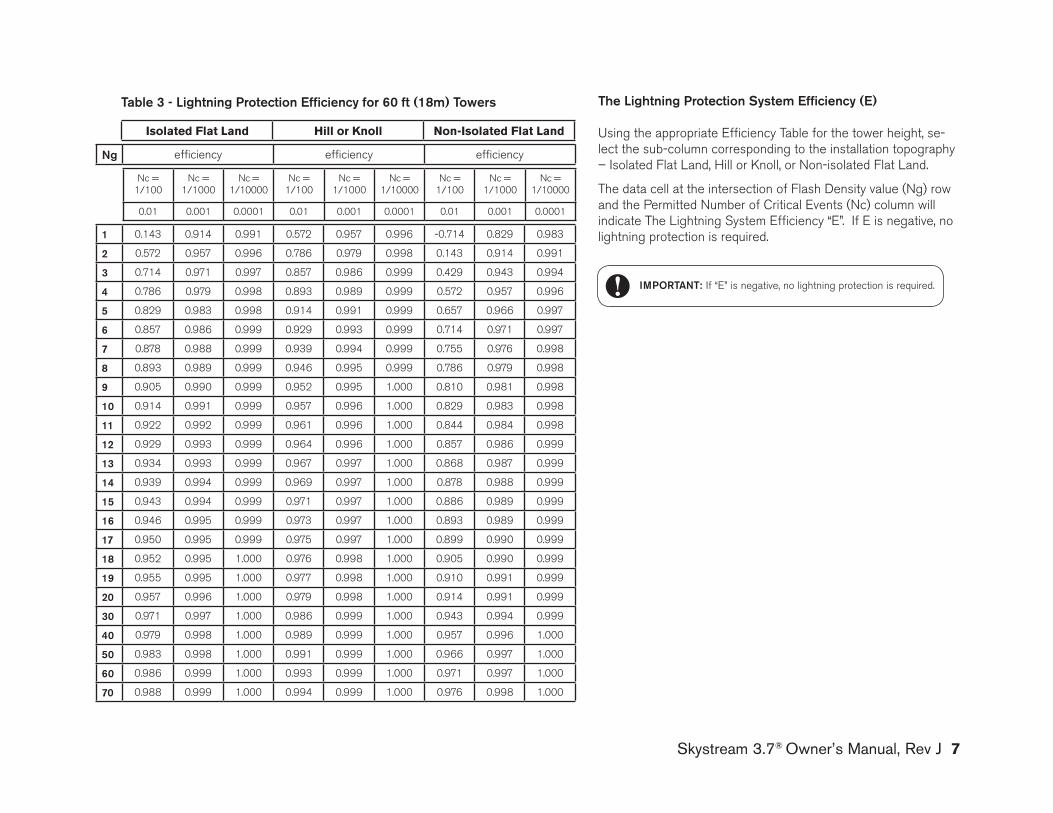
Skystream 3.7® Owner’s Manual, Rev J 7
Table 3 - lightning protection Efficiency for 60 ft (18m) Towers
isolated flat land Hill or Knoll non-isolated flat land
ng efficiency efficiency efficiency
Nc = 1/100
Nc = 1/1000
Nc = 1/10000
Nc = 1/100
Nc = 1/1000
Nc = 1/10000
Nc = 1/100
Nc = 1/1000
Nc = 1/10000
0.01 0.001 0.0001 0.01 0.001 0.0001 0.01 0.001 0.0001
1 0.143 0.914 0.991 0.572 0.957 0.996 -0.714 0.829 0.983
2 0.572 0.957 0.996 0.786 0.979 0.998 0.143 0.914 0.991
3 0.714 0.971 0.997 0.857 0.986 0.999 0.429 0.943 0.994
4 0.786 0.979 0.998 0.893 0.989 0.999 0.572 0.957 0.996
5 0.829 0.983 0.998 0.914 0.991 0.999 0.657 0.966 0.997
6 0.857 0.986 0.999 0.929 0.993 0.999 0.714 0.971 0.997
7 0.878 0.988 0.999 0.939 0.994 0.999 0.755 0.976 0.998
8 0.893 0.989 0.999 0.946 0.995 0.999 0.786 0.979 0.998
9 0.905 0.990 0.999 0.952 0.995 1.000 0.810 0.981 0.998
10 0.914 0.991 0.999 0.957 0.996 1.000 0.829 0.983 0.998
11 0.922 0.992 0.999 0.961 0.996 1.000 0.844 0.984 0.998
12 0.929 0.993 0.999 0.964 0.996 1.000 0.857 0.986 0.999
13 0.934 0.993 0.999 0.967 0.997 1.000 0.868 0.987 0.999
14 0.939 0.994 0.999 0.969 0.997 1.000 0.878 0.988 0.999
15 0.943 0.994 0.999 0.971 0.997 1.000 0.886 0.989 0.999
16 0.946 0.995 0.999 0.973 0.997 1.000 0.893 0.989 0.999
17 0.950 0.995 0.999 0.975 0.997 1.000 0.899 0.990 0.999
18 0.952 0.995 1.000 0.976 0.998 1.000 0.905 0.990 0.999
19 0.955 0.995 1.000 0.977 0.998 1.000 0.910 0.991 0.999
20 0.957 0.996 1.000 0.979 0.998 1.000 0.914 0.991 0.999
30 0.971 0.997 1.000 0.986 0.999 1.000 0.943 0.994 0.999
40 0.979 0.998 1.000 0.989 0.999 1.000 0.957 0.996 1.000
50 0.983 0.998 1.000 0.991 0.999 1.000 0.966 0.997 1.000
60 0.986 0.999 1.000 0.993 0.999 1.000 0.971 0.997 1.000
70 0.988 0.999 1.000 0.994 0.999 1.000 0.976 0.998 1.000
The lightning protection System Efficiency (E)
Using the appropriate Efficiency Table for the tower height, se-lect the sub-column corresponding to the installation topography – Isolated Flat Land, Hill or knoll, or Non-isolated Flat Land.
The data cell at the intersection of Flash Density value (Ng) row and the Permitted Number of Critical Events (Nc) column will indicate The Lightning System Efficiency “E”. If E is negative, no lightning protection is required.
ImporTanT: If “E” is negative, no lightning protection is required.
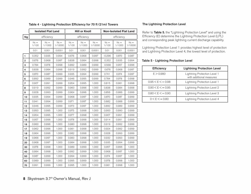
8 Skystream 3.7® Owner’s Manual, Rev J
The lightning protection level
Refer to Table 5, the “Lightning Protection Level” and using the Efficiency (E) determine the Lightning Protection Level (LPL) and corresponding peak lightning current discharge capability.
Lightning Protection Level 1 provides highest level of protection and Lightning Protection Level 4, the lowest level of protection.
Efficiency lightning protection level
E > 0.980 Lightning Protection Level 1 with additional measures
0.95 < E < = 0.98 Lightning Protection Level 1
0.90 < E < = 0.95 Lightning Protection Level 2
0.80 < E < = 0.90 Lightning Protection Level 3
0 < E < = 0.80 Lightning Protection Level 4
Table 5 - lightning protection level
Table 4 - lightning protection Efficiency for 70 ft (21m) Towers
isolated flat land Hill or Knoll non-isolated flat land
ng efficiency efficiency efficiency
Nc = 1/100
Nc = 1/1000
Nc = 1/10000
Nc = 1/100
Nc = 1/1000
Nc = 1/10000
Nc = 1/100
Nc = 1/1000
Nc = 1/10000
0.01 0.001 0.0001 0.01 0.001 0.0001 0.01 0.001 0.0001
1 0.352 0.935 0.994 0.676 0.968 0.997 -0.296 0.870 0.987
2 0.676 0.968 0.997 0.838 0.984 0.998 0.352 0.935 0.994
3 0.784 0.978 0.998 0.892 0.989 0.999 0.568 0.957 0.996
4 0.838 0.984 0.998 0.919 0.992 0.999 0.676 0.968 0.997
5 0.870 0.987 0.999 0.935 0.994 0.999 0.741 0.974 0.997
6 0.892 0.989 0.999 0.946 0.995 0.999 0.784 0.978 0.998
7 0.907 0.991 0.999 0.954 0.995 1.000 0.815 0.981 0.998
8 0.919 0.992 0.999 0.960 0.996 1.000 0.838 0.984 0.998
9 0.928 0.993 0.999 0.964 0.996 1.000 0.856 0.986 0.999
10 0.935 0.994 0.999 0.968 0.997 1.000 0.870 0.987 0.999
11 0.941 0.994 0.999 0.971 0.997 1.000 0.882 0.988 0.999
12 0.946 0.995 0.999 0.973 0.997 1.000 0.892 0.989 0.999
13 0.950 0.995 1.000 0.975 0.998 1.000 0.900 0.990 0.999
14 0.954 0.995 1.000 0.977 0.998 1.000 0.907 0.991 0.999
15 0.957 0.996 1.000 0.978 0.998 1.000 0.914 0.991 0.999
16 0.960 0.996 1.000 0.980 0.998 1.000 0.919 0.992 0.999
17 0.962 0.996 1.000 0.981 0.998 1.000 0.924 0.992 0.999
18 0.964 0.996 1.000 0.982 0.998 1.000 0.928 0.993 0.999
19 0.966 0.997 1.000 0.983 0.998 1.000 0.932 0.993 0.999
20 0.968 0.997 1.000 0.984 0.998 1.000 0.935 0.994 0.999
30 0.978 0.998 1.000 0.989 0.999 1.000 0.957 0.996 1.000
40 0.984 0.998 1.000 0.992 0.999 1.000 0.968 0.997 1.000
50 0.987 0.999 1.000 0.994 0.999 1.000 0.974 0.997 1.000
60 0.989 0.999 1.000 0.995 0.999 1.000 0.978 0.998 1.000
70 0.991 0.999 1.000 0.995 1.000 1.000 0.981 0.998 1.000
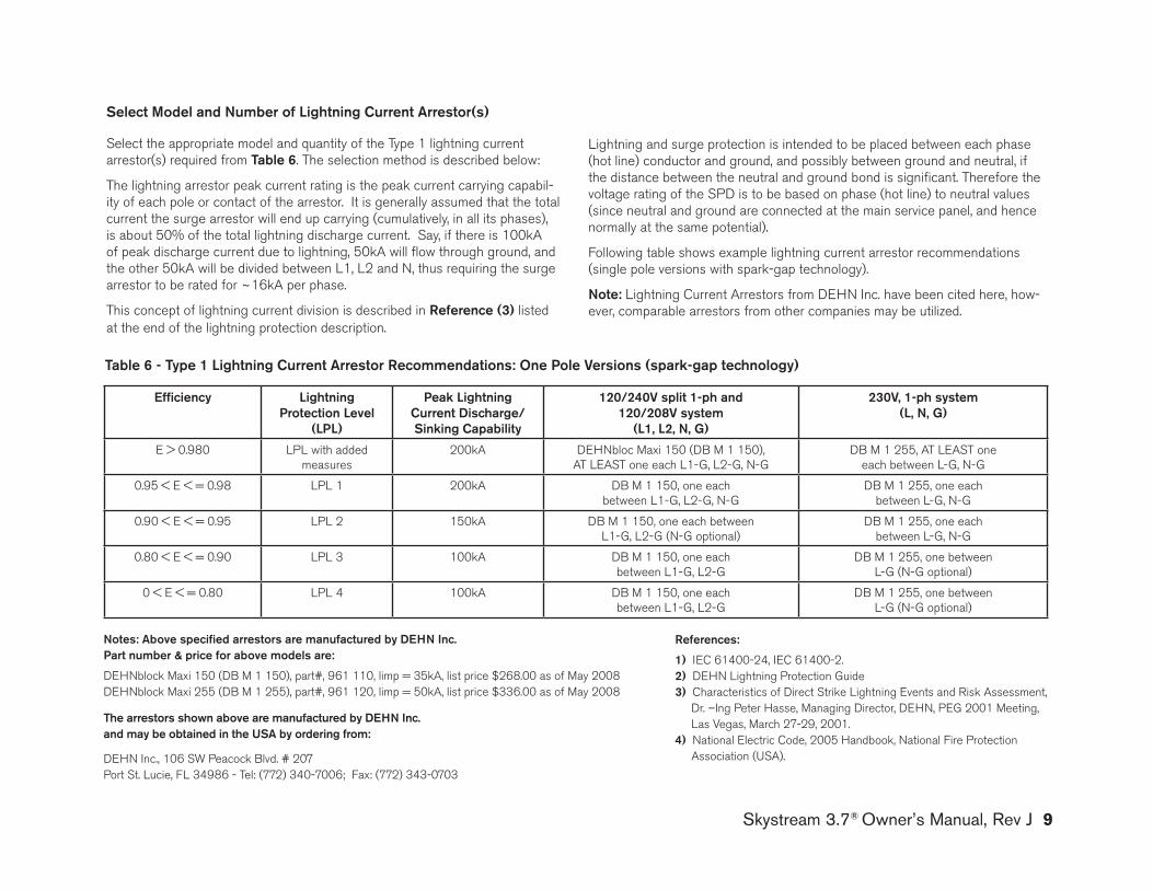
Skystream 3.7® Owner’s Manual, Rev J 9
Efficiency lightning protection level
(lpl)
peak lightning Current discharge/Sinking Capability
120/240V split 1-ph and 120/208V system
(l1, l2, n, g)
230V, 1-ph system (l, n, g)
E > 0.980 LPL with added measures
200kA DEHNbloc Maxi 150 (DB M 1 150), AT LEAST one each L1-g, L2-g, N-g
DB M 1 255, AT LEAST one each between L-g, N-g
0.95 < E < = 0.98 LPL 1 200kA DB M 1 150, one each between L1-g, L2-g, N-g
DB M 1 255, one each between L-g, N-g
0.90 < E < = 0.95 LPL 2 150kA DB M 1 150, one each between L1-g, L2-g (N-g optional)
DB M 1 255, one each between L-g, N-g
0.80 < E < = 0.90 LPL 3 100kA DB M 1 150, one each between L1-g, L2-g
DB M 1 255, one between L-g (N-g optional)
0 < E < = 0.80 LPL 4 100kA DB M 1 150, one each between L1-g, L2-g
DB M 1 255, one between L-g (N-g optional)
Table 6 - Type 1 lightning Current arrestor recommendations: one pole Versions (spark-gap technology)
Lightning and surge protection is intended to be placed between each phase (hot line) conductor and ground, and possibly between ground and neutral, if the distance between the neutral and ground bond is significant. Therefore the voltage rating of the SPD is to be based on phase (hot line) to neutral values (since neutral and ground are connected at the main service panel, and hence normally at the same potential).
Following table shows example lightning current arrestor recommendations (single pole versions with spark-gap technology).
note: Lightning Current Arrestors from DEHN Inc. have been cited here, how-ever, comparable arrestors from other companies may be utilized.
Select model and number of lightning Current arrestor(s)
Select the appropriate model and quantity of the Type 1 lightning current arrestor(s) required from Table 6. The selection method is described below:
The lightning arrestor peak current rating is the peak current carrying capabil-ity of each pole or contact of the arrestor. It is generally assumed that the total current the surge arrestor will end up carrying (cumulatively, in all its phases), is about 50% of the total lightning discharge current. Say, if there is 100kA of peak discharge current due to lightning, 50kA will flow through ground, and the other 50kA will be divided between L1, L2 and N, thus requiring the surge arrestor to be rated for ~16kA per phase.
This concept of lightning current division is described in reference (3) listed at the end of the lightning protection description.
notes: above specified arrestors are manufactured by dEhn Inc. part number & price for above models are:
DEHNblock Maxi 150 (DB M 1 150), part#, 961 110, limp = 35kA, list price $268.00 as of May 2008DEHNblock Maxi 255 (DB M 1 255), part#, 961 120, limp = 50kA, list price $336.00 as of May 2008
The arrestors shown above are manufactured by dEhn Inc. and may be obtained in the uSa by ordering from:
DEHN Inc., 106 SW Peacock Blvd. # 207Port St. Lucie, FL 34986 - Tel: (772) 340-7006; Fax: (772) 343-0703
references:
1) IEC 61400-24, IEC 61400-2.2) DEHN Lightning Protection guide3) Characteristics of Direct Strike Lightning Events and Risk Assessment, Dr. –Ing Peter Hasse, Managing Director, DEHN, PEg 2001 Meeting, Las Vegas, March 27-29, 2001.4) National Electric Code, 2005 Handbook, National Fire Protection Association (USA).

Southwest Windpower, Inc.1801 West Route 66Flagstaff, Arizona 86001 USAPhone: 928-779-9463Fax: 928-779-1485
www.skystreamenergy.com
aPPendIX eCerTIFICaTIOn/COMPlIanCe
© December 2008 Southwest Windpower, Inc. All Rights Reserved
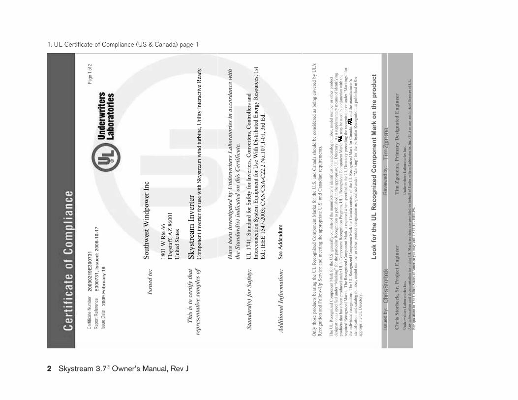
2 Skystream 3.7® Owner’s Manual, Rev J
1. UL Certificate of Compliance (US & Canada) page 1
Cer
tific
ate
Num
ber
2009
0219
E300
731
Page
1 of
2R
epor
t Ref
eren
ceE3
0073
1, Is
sued
: 200
6-10
-17
Issu
e D
ate
2009
Feb
ruar
y 19
Issu
ed to
:So
uthw
est W
indp
ower
Inc
1801
W R
te 6
6Fl
agst
aff,
AZ
8600
1U
nite
d St
ates
Skys
tream
Inve
rter
This
is to
cer
tify
that
repr
esen
tativ
e sa
mpl
es o
fCo
mpo
nent
inve
rter f
or u
se w
ith S
kystr
eam
win
d tu
rbin
e, U
tility
Inte
ract
ive
Read
y
Hav
e be
en in
vesti
gate
d by
Und
erw
riter
s Lab
orat
orie
s in
acco
rdan
ce w
ith
the
Stan
dard
(s) i
ndic
ated
on
this
Cer
tific
ate.
Stan
dard
(s) f
or S
afet
y:U
L 17
41, S
tand
ard
for S
afet
y fo
r Inv
erte
rs, C
onve
rters
, Con
trolle
rs a
nd
Inte
rcon
nect
ion
Syste
m E
quip
men
t for
Use
With
Dist
ribut
ed E
nerg
y Re
sour
ces,
1st
Ed.;
IEEE
154
7-20
03; C
AN
/CSA
-C22
.2 N
o.10
7.1-
01, 3
rd E
d.
Add
ition
al In
form
atio
n:Se
e A
dden
dum
Look
for t
he U
L R
ecog
nize
d C
ompo
nent
Mar
k on
the
prod
uct
Issu
ed b
y:
Chr
is St
orbe
ckR
evie
wed
by:
Ti
m Z
gone
na
Chr
is S
torb
eck,
Sr.
Pro
ject
Eng
inee
rT
im Z
gone
na, P
rim
ary
Des
igna
ted
Eng
inee
rU
nder
wri
ters
Lab
orat
orie
s Inc
.U
nder
wri
ters
Lab
orat
orie
s Inc
.A
ny in
form
atio
n an
d do
cum
enta
tion
invo
lvin
g U
L M
ark
serv
ices
are
pro
vide
d on
beh
alf o
f Und
erw
rite
rs L
abor
ator
ies I
nc. (
UL)
or
any
auth
oriz
ed li
cens
ee o
f UL.
For
ques
tions
in T
he U
nite
d St
ates
of A
mer
ica
you
may
cal
l 1-8
77-U
L-H
EL
PS.
Onl
y th
ose
prod
ucts
bea
ring
the
UL
Rec
ogni
zed
Com
pone
nt M
arks
for t
he U
.S. a
nd C
anad
a sh
ould
be
cons
ider
ed a
s be
ing
cove
red
by U
L's
Rec
ogni
tion
and
Follo
w-U
p Se
rvic
e an
d m
eetin
g th
e ap
prop
riate
U.S
. and
Can
adia
n re
quire
men
ts.
The
UL
Rec
ogni
zed
Com
pone
nt M
ark
for t
he U
.S. g
ener
ally
con
sists
of th
e m
anuf
actu
rer’s
iden
tific
atio
n an
d ca
talo
g nu
mbe
r, m
odel
num
ber o
r oth
er p
rodu
ct
desig
natio
n as
spec
ified
und
er “
Mar
king
” fo
r the
par
ticul
ar R
ecog
nitio
n as
pub
lishe
d in
the
appr
opria
te U
L D
irect
ory.
As a
supp
lem
enta
ry m
eans
of i
dent
ifyin
g pr
oduc
ts th
at h
ave
been
pro
duce
d un
der U
L’s C
ompo
nent
Rec
ogni
tion
Prog
ram
, UL’
s Rec
ogni
zed
Com
pone
nt M
ark:
, m
ay b
e us
ed in
con
junc
tion
with
the
requ
ired
Reco
gniz
ed M
arks
. Th
e Re
cogn
ized
Com
pone
nt M
ark
is re
quire
d w
hen
spec
ified
in th
e U
L D
irect
ory
prec
edin
g th
e re
cogn
ition
s or u
nder
“M
arki
ngs”
for
the
indi
vidu
al re
cogn
ition
s. Th
e U
L Re
cogn
ized
Com
pone
nt M
ark
for C
anad
a co
nsist
s of t
he U
L Re
cogn
ized
Mar
k fo
r Can
ada:
a
nd th
e m
anuf
actu
rer’s
id
entif
icat
ion
and
cata
log
num
ber,
mod
el n
umbe
r or o
ther
pro
duct
des
igna
tion
as sp
ecifi
ed u
nder
“M
arki
ng”
for t
he p
artic
ular
Rec
ogni
tion
as p
ublis
hed
in th
e ap
prop
riate
UL
Dire
ctor
y.
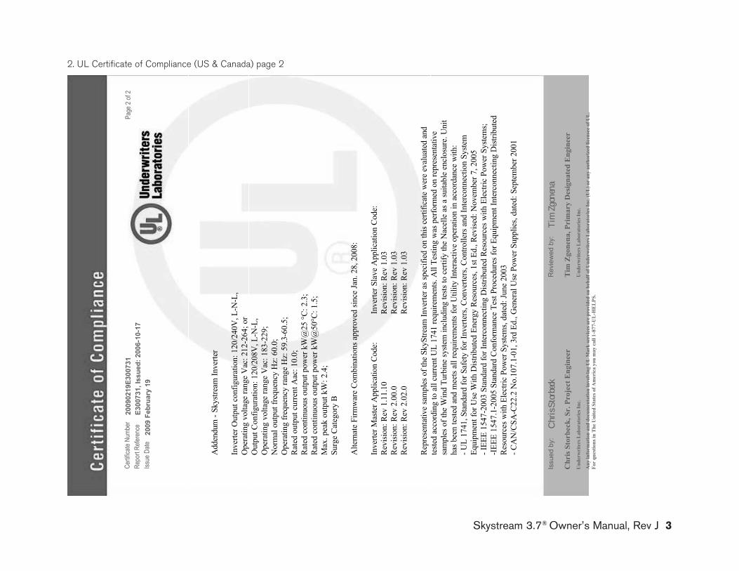
Skystream 3.7® Owner’s Manual, Rev J 3
Cer
tific
ate
Num
ber
2009
0219
E300
731
Page
2 of
2R
epor
t Ref
eren
ceE3
0073
1, Is
sued
: 200
6-10
-17
Issu
e D
ate
2009
Feb
ruar
y 19
Add
endu
m- S
kystr
eam
Inve
rter
Inve
rter O
utpu
t con
figur
atio
n: 1
20/2
40V
, L-N
-L,
Ope
ratin
g vo
ltage
rang
e V
ac: 2
12-2
64; o
r O
utpu
t Con
figur
atio
n: 1
20/2
08V
, L-N
-L,
Ope
ratin
g vo
ltage
rang
e V
ac: 1
83-2
29;
Nor
mal
out
put f
requ
ency
Hz:
60.
0;
Ope
ratin
g fre
quen
cy ra
nge
Hz:
59.
3-60
.5;
Rat
ed o
utpu
t cur
rent
Aac
: 10.
0;R
ated
con
tinuo
us o
utpu
t pow
er k
W@
25 °C
: 2.3
; Ra
ted
cont
inuo
us o
utpu
t pow
er k
W@
50°C
: 1.5
; M
ax. p
eak
outp
ut k
W: 2
.4;
Surg
e C
ateg
ory
B
Alte
rnat
e Fi
rmw
are
Com
bina
tions
app
rove
d sin
ce Ja
n. 2
8, 2
008:
Inve
rter M
aste
r App
licat
ion
Code
:
Inv
erte
r Sla
ve A
pplic
atio
n Co
de:
Rev
ision
: Rev
1.1
1.10
Revi
sion:
Rev
1.0
3Re
visio
n: R
ev 2
.00.
0
R
evisi
on: R
ev 1
.03
Revi
sion:
Rev
2.0
2.0
Rev
ision
: Rev
1.0
3
Repr
esen
tativ
e sa
mpl
es o
f the
Sky
Stre
am In
verte
r as s
peci
fied
on th
is ce
rtific
ate
wer
e ev
alua
ted
and
teste
d ac
cord
ing
to a
ll cu
rrent
UL
1741
requ
irem
ents.
All
Testi
ng w
as p
erfo
rmed
on
repr
esen
tativ
e sa
mpl
es o
f the
Win
d Tu
rbin
e sy
stem
incl
udin
g te
sts to
cer
tify
the
Nac
elle
as a
suita
ble
encl
osur
e. U
nit
has b
een
teste
d an
d m
eets
all r
equi
rem
ents
for U
tility
Inte
ract
ive
oper
atio
n in
acc
orda
nce
with
:- U
L 17
41, S
tand
ard
for S
afet
y fo
r Inv
erte
rs, C
onve
rters
, Con
trolle
rs a
nd In
terc
onne
ctio
n Sy
stem
Eq
uipm
ent f
or U
se W
ith D
istrib
uted
Ene
rgy
Res
ourc
es, 1
st Ed
., R
evise
d: N
ovem
ber 7
, 200
5- I
EEE
1547
-200
3 St
anda
rd fo
r Int
erco
nnec
ting
Dist
ribut
ed R
esou
rces
with
Ele
ctric
Pow
er S
yste
ms;
-IEE
E 15
47.1
-200
5 St
anda
rd C
onfo
rman
ce T
est P
roce
dure
s for
Equ
ipm
ent I
nter
conn
ectin
g D
istrib
uted
R
esou
rces
with
Ele
ctric
Pow
er S
yste
ms,
date
d: Ju
ne 2
003
- CA
N/C
SA-C
22.2
No.
107.
1-01
, 3rd
Ed.
, Gen
eral
Use
Pow
er S
uppl
ies,
date
d: S
epte
mbe
r 200
1
Issu
ed b
y:
Chr
is St
orbe
ckR
evie
wed
by:
Ti
m Z
gone
na
Chr
is S
torb
eck,
Sr.
Pro
ject
Eng
inee
rT
im Z
gone
na, P
rim
ary
Des
igna
ted
Eng
inee
rU
nder
wri
ters
Lab
orat
orie
s Inc
.U
nder
wri
ters
Lab
orat
orie
s Inc
.
Any
info
rmat
ion
and
docu
men
tatio
n in
volv
ing
UL
Mar
k se
rvic
es a
re p
rovi
ded
on b
ehal
f of U
nder
wri
ters
Lab
orat
orie
s Inc
. (U
L) o
r an
y au
thor
ized
lice
nsee
of U
L.Fo
r qu
estio
ns in
The
Uni
ted
Stat
es o
f Am
eric
a yo
u m
ay c
all 1
-877
-UL-
HEL
PS.
2. UL Certificate of Compliance (US & Canada) page 2
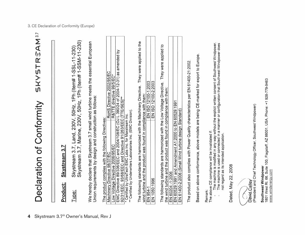
3. CE Declaration of Conformity (Europe)
4 Skystream 3.7® Owner’s Manual, Rev J


Southwest Windpower, Inc.1801 West Route 66Flagstaff, Arizona 86001 USAPhone: 928-779-9463Fax: 928-779-1485
www.skystreamenergy.com
Related Documents