i. Enter the curren t MPI N (Master Identi fic ati on Number) in the Security Control Panel (SC-001) ii. Press [B]. ii i. Pres s the n umber key t o iden tify which zone to add the Mo tion Sensor to [1, 2, 3, 4]. We recommend you program the motion sensor to zone 2. The zone light will flash for eight seconds. iv. While the zone lig ht is flashin g, pr ess [ *]. v. While the zone light is flashi ng, p ress the Le arn Button inside the battery compartment (diagram 1) of the Motion Sensor in order to activate it. You will hear a long beep if the motion sensor is “learned” to the control panel. The zone light will stop flashing and the remote sensor will now communicate to that zone. 2. SET UP THE MOTION SENSOR 1. INTRODUCTION Motion Sensor Model PS-434A The Motion Sensor is designed to monitor movement around your house. It can be placed either indoor or outdoor. In this package, you should find a Motion Sensor (battery included), ball-head joint and screws. Please follow the instructions below to setup your motion sensor. 2 pcs 3 x 18 screws (Included) Motion Sensor (battery included) Ball-head joint The sensitivity of the motion sensor is adjustable. Change the setting by placing the connector on either the ”High” or “Low” position. When the sensitivity is set to “Low”, more movement is required to trigger the sensor. It is recommended to set the sensitivity to “Low” and perform a “Walk Test” (Described in Section 3 - “Walk Test”). If the walk test result is satisfied, the sensitivity does not require to be adjusted further. If the walk test result shows the sensitivity is too low, then you can change the sensitivity setting to “High”. Please perform the walk test after changing the sensitivity setting. 5. SENSOR SENSITIVITY Sensitivity Connectors on Motion Sensor A ball-head joint is necessary to mount the sensor at a desire location. A height of 5-6 ft is recommended, depending on your application. Once a location is selected, mount the ball-head joint to this location by screws provided, (see diagram 2). Once the ball-head joint is mounted to the wall, slide the back of the sensor into the ball-head joint (see diagram 3). The mounting angle can be adjusted. Please refer to Section 3 “Walk Test” to determine the best mounting angle. 2. PROGRAM THE MOTION SENSOR TO THE SECURITY CONTROL PANEL (SC-001) i. Wit h onl y the “ ON” lig ht li t on th e Audio Alarm, pre ss an d hol d the learn button located on the bottom of the Audio Alarm. ii . Whil e pre ssin g dow n on the b utton , pre ss t he L earn Butt on in side the battery compartment (diagram 1) of the Motion Sensor in order to activate it. ii i. If a con nect ion ha s been made, th e Audi o Alar m will stop b eepin g and make a continuous tone until the black learn button on the Audio Alarm is released. 3. PROGRAM THE MOTION SENSOR TO THE AUDIO ALARM (AA-433) i. Pres s [L], [5] when in clo ck mode , the display will show “L5 Id code”. ii . With in 5 seco nds, press the Learn Butto n in side the batte ry compartment (diagram 1) of the Motion Sensor in order to activate it. The display will return to clock mode once the Motion Sensor has been learned. ii i. If the Motio n Sensor detects an y move ment, it will trigger the Emergency Dialer and start dialing the preset phone numbers (refer to AD-433S, AD-1010, ED-1010 User’s Instruction). 4. PROGRAM THE MOTION SENSOR TO THE EMERGENCY DIALER (AD-433S, AD-1010, ED-1010) 4. FCC Diagram 2 Diagram 3 This device complies with Part 15 of the FCC Rules. Operation is subject to the following two conditions: (1) This device may not cause harmful interference, and (2) This device must accept any interference received, including interference that may cause undesired operation. WARNING: Changes or modifications to this unit not expressly approved by the party responsible for compliance could void the user’s authority to operate the equipment. NOTE: This equipment has been tested and found to comply with the limits for a Class B digital device, pursuant to Part 15 of the FCC Rules. These limits are designed to provide reasonable protection against harmful interference in a residential installation. This equipment generates, uses and can radiate radio frequency energy and, if not installed and used in accordance with the instructions, may cause harmful inter- ference to radio communications. However, there is no guarantee that interference will not occur in a particular installation. If this equipment dose cause harmful interference to radio or television reception, which can be determined by turning the equipment off and on, the user is encouraged to try to correct the interference by one or more of the following measures: - Reorient or relocate the receiving antenna. - Increase the separation between the equipment and receiver. - Connect the equipment into an outlet on a circuit different from that to which the receiver is connected. - Consult the dealer or an experienced radio/TV technician for help. Learn button Insert a 9V alkaline battery to the motion sensor. The sensor requires a warm up time of approx. 45 seconds before it can function properly. Insert 9V alkaline battery to the sensor 1. POWER UP Diagram1 1. MOUNTING 3. INSTALLING THE MOTION SENSOR After mounting the sensor at the desired location, it is important to perform a walk test in order to determine if the sensor is detecting the things you want to detect. In order to control how far the sensor can “see”, this can be done by adjusting the angle of the sensor. T o reduce the detection range, simply move the sensor downward. To increase the range, move the sensor up to around 12 degrees. This will give the maximum rang e. However , this may not be desired if the sensor is placed outdoors, since a false trigger may occur if the sensor is set to detect motion in a distance. Disarm the control panel or dialer before you perform the work test, or you will trigger an alarm (please refer to the user’s instruction of your receiver) 2. WALK TEST You should walk in the area that you would like the sensor to monitor. If movement is detected the red light inside the unit will appear. If the red light does not appear, adjust the mounting angle accordingly . Perform the walk test again after 30 seconds. Repeat this procedure until your motion is detected. There should be no movement in the detected area during the 30 seconds. Perform walk test in the undesired area to ensure movement cannot be detected. Tips: The sensor should not face towards direct sunlight, placing near heat or cold producing devices (i.e. A/C or furnance vents, fans, ovens, heaters etc.) that may cause false triggers. 12º Move the sensor downward to reduce the range. Move the sensor up to around 12 º to give maximumrange.

Welcome message from author
This document is posted to help you gain knowledge. Please leave a comment to let me know what you think about it! Share it to your friends and learn new things together.
Transcript
8/4/2019 Sky Link Alarm Motion Sensor PS434A_manual
http://slidepdf.com/reader/full/sky-link-alarm-motion-sensor-ps434amanual 1/2
i. Enter the current MPIN (Master Identification Number) in theSecurity Control Panel (SC-001)
ii. Press [B].iii. Press the number key to identify which zone to add the Motion
Sensor to [1, 2, 3, 4]. We recommend you program the motionsensor to zone 2. The zone light will flash for eight seconds.
iv. While the zone light is flashing, press [*].v. While the zone light is flashing, press the Learn Button inside the
battery compartment (diagram 1) of the Motion Sensor in order toactivate it. You will hear a long beep if the motion sensor is“learned” to the control panel. The zone light will stop flashing andthe remote sensor will now communicate to that zone.
2. SET UP THE MOTION SENSOR
1. INTRODUCTION
Motion Sensor Model PS-434A
The Motion Sensor is designed to monitor movement around your house.It can be placed either indoor or outdoor.
In this package, you should find aMotion Sensor (battery included),ball-head joint and screws.
Please follow the instructions below to setup your motion sensor.
2 pcs 3 x 18 screws
(Included) Motion Sensor(battery included)
Ball-head joint
The sensitivity of the motion sensor is adjustable. Change the setting byplacing the connector on either the ”High” or “Low” position. When thesensitivity is set to “Low”, more movement is required to trigger thesensor. It is recommended to set thesensitivity to “Low” and perform a“Walk Test” (Described in Section 3 -
“Walk Test”). If the walk test result issatisfied, the sensitivity does notrequire to be adjusted further. If thewalk test result shows the sensitivityis too low, then you can change thesensitivity setting to “High”. Pleaseperform the walk test after changingthe sensitivity setting.
5. SENSOR SENSITIVITY
Sensitivity Connectors on Motion Sensor
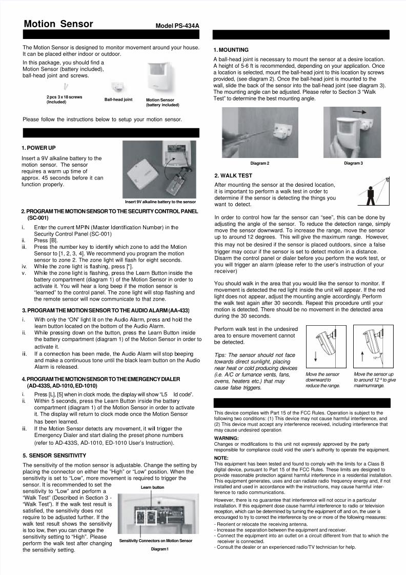
A ball-head joint is necessary to mount the sensor at a desire location.A height of 5-6 ft is recommended, depending on your application. Oncea location is selected, mount the ball-head joint to this location by screwsprovided, (see diagram 2). Once the ball-head joint is mounted to thewall, slide the back of the sensor into the ball-head joint (see diagram 3).The mounting angle can be adjusted. Please refer to Section 3 “Walk
Test” to determine the best mounting angle.
2. PROGRAM THE MOTION SENSOR TO THE SECURITY CONTROL PANEL(SC-001)
i. With only the “ON” light lit on the Audio Alarm, press and hold thelearn button located on the bottom of the Audio Alarm.
ii. While pressing down on the button, press the Learn Button insidethe battery compartment (diagram 1) of the Motion Sensor in order to
activate it.
iii. If a connection has been made, the Audio Alarm will stop beepingand make a continuous tone until the black learn button on the AudioAlarm is released.
3. PROGRAM THE MOTION SENSOR TO THE AUDIO ALARM (AA-433)
i. Press [L], [5] when in clock mode, the display will show “L5 Id code”.
ii. Within 5 seconds, press the Learn Button inside the batterycompartment (diagram 1) of the Motion Sensor in order to activateit. The display will return to clock mode once the Motion Sensor
has been learned.
iii. If the Motion Sensor detects any movement, it will trigger theEmergency Dialer and start dialing the preset phone numbers
(refer to AD-433S, AD-1010, ED-1010 User’s Instruction).
4. PROGRAM THE MOTION SENSOR TO THE EMERGENCY DIALER(AD-433S, AD-1010, ED-1010)
4. FCC
Diagram 2 Diagram 3
This device complies with Part 15 of the FCC Rules. Operation is subject to thefollowing two conditions: (1) This device may not cause harmful interference, and(2) This device must accept any interference received, including interference thatmay cause undesired operation.
WARNING:Changes or modifications to this unit not expressly approved by the partyresponsible for compliance could void the user’s authority to operate the equipment.
NOTE:This equipment has been tested and found to comply with the limits for a Class Bdigital device, pursuant to Part 15 of the FCC Rules. These limits are designed toprovide reasonable protection against harmful interference in a residential installation.This equipment generates, uses and can radiate radio frequency energy and, if notinstalled and used in accordance with the instructions, may cause harmful inter-ference to radio communications.
However, there is no guarantee that interference will not occur in a particular
installation. If this equipment dose cause harmful interference to radio or televisionreception, which can be determined by turning the equipment off and on, the user isencouraged to try to correct the interference by one or more of the following measures:
- Reorient or relocate the receiving antenna.- Increase the separation between the equipment and receiver.- Connect the equipment into an outlet on a circuit different from that to which the
receiver is connected.- Consult the dealer or an experienced radio/TV technician for help.
Learn button
Insert a 9V alkaline battery to themotion sensor. The sensorrequires a warm up time ofapprox. 45 seconds before it canfunction properly.
Insert 9V alkaline battery to the sensor
1. POWER UP
Diagram 1
1. MOUNTING
3. INSTALLING THE MOTION SENSOR
After mounting the sensor at the desired location,it is important to perform a walk test in order todetermine if the sensor is detecting the things youwant to detect.
In order to control how far the sensor can “see”, this can be done byadjusting the angle of the sensor. To reduce the detection range, simplymove the sensor downward. To increase the range, move the sensorup to around 12 degrees. This will give the maximum range. However,
this may not be desired if the sensor is placed outdoors, since a false
trigger may occur if the sensor is set to detect motion in a distance.Disarm the control panel or dialer before you perform the work test, oryou will trigger an alarm (please refer to the user’s instruction of yourreceiver)
2. WALK TEST
You should walk in the area that you would like the sensor to monitor. Ifmovement is detected the red light inside the unit will appear. If the redlight does not appear, adjust the mounting angle accordingly. Perform
the walk test again after 30 seconds. Repeat this procedure until yourmotion is detected. There should be no movement in the detected areaduring the 30 seconds.
Perform walk test in the undesiredarea to ensure movement cannotbe detected.
Tips: The sensor should not face towards direct sunlight, placing near heat or cold producing devices (i.e. A/C or furnance vents, fans,ovens, heaters etc.) that may cause false triggers.
12º
Move the sensor downward to reduce the range.
Move the sensor up to around 12 º to give maximum range.

8/4/2019 Sky Link Alarm Motion Sensor PS434A_manual
http://slidepdf.com/reader/full/sky-link-alarm-motion-sensor-ps434amanual 2/2
If, within one year from date of purchase, this product should become defective(except battery), due to faulty workmanship or materials, it will be repaired orreplaced, without charge. Proof of purchase and a Return Authorization are required.
5. WARRANTY
6. CUSTOMER SERVICE
If you would like to order Skylink’s products or have difficulty getting them to work,
please :1. visit our FAQ website at www.skylinkhome.com, or2. email us at [email protected] (reply within 24 hrs), or3. call our toll free at 1-800-304-1187 from Monday to Friday, 9 am to 5 pm EST.
Fax +800 286-1320 (for customers in USA & Canada only)
CUSTOMER SERVICE
17 Sheard Avenue, Brampton, Ontario, Canada L6Y 1J3Email:[email protected] (Reply within 24 hrs)http://www.skylinkhome.comP/N. 101A255 Rev.0US Patent. 6243000B1
©2004 SKYLINK GROUP
CUSTOMER SERVICE
17 Sheard Avenue, Brampton, Ontario, Canada L6Y 1J3
Email: [email protected] (Reply within 24 hrs)
http://www.skylinkhome.com
P/N. 101A255 Rev.0
US Patent. 6243000B1
©2004 SKYLINK GROUP
Related Documents


