Protected by copyright. Copying for private or commercial purposes, in part or in whole, is not permitted unless authorised by ŠKODA AUTO A. S. ŠKODA AUTO A. S. does not guarantee or accept any liability with respect to the correctness of information in this document. Copyright by ŠKODA AUTO A. S.� Workshop Manual Octavia II 2004 ➤ Octavia II 2010 ➤ Axles, steering Edition 05.2018 Service Service Department. Technical Information

Welcome message from author
This document is posted to help you gain knowledge. Please leave a comment to let me know what you think about it! Share it to your friends and learn new things together.
Transcript
Protected by copyright. Copying for private or commercial purposes, in part or in whole, is not permitted unless authorised by ŠKODA AUTO A. S. ŠKODA AUTO A. S. does not guarantee or accept any liability
with respect to the correctness of information in this document. Copyright by ŠKODA AUTO A. S.�
Workshop ManualOctavia II 2004 ➤Octavia II 2010 ➤Axles, steeringEdition 05.2018
Service
Service Department. Technical Information

Protected by copyright. Copying for private or commercial purposes, in part or in whole, is not permitted unless authorised by ŠKODA AUTO A. S. ŠKODA AUTO A. S. does not guarantee or accept any liability
with respect to the correctness of information in this document. Copyright by ŠKODA AUTO A. S.�
List of Workshop Manual Repair Groups
Repai r Group00 - Technical data40 - Front suspension42 - Rear suspension43 - Self-levelling suspension44 - Wheels, tyres, vehicle geometry48 - Steering
Technical information should always be available to the foremen and mechanics, because theircareful and constant adherence to the instructions is essential to ensure vehicle road-worthiness andsafety. In addition, the normal basic safety precautions for working on motor vehicles must, as amatter of course, be observed.
Service
All rights reserved.No reproduction without prior agreement from publisher.
Copyright © 2018 ŠKODA AUTO a. s. S0057030020

Protected by copyright. Copying for private or commercial purposes, in part or in whole, is not permitted unless authorised by ŠKODA AUTO A. S. ŠKODA AUTO A. S. does not guarantee or accept any liability
with respect to the correctness of information in this document. Copyright by ŠKODA AUTO A. S.�
Contents
00 - Technical data . . . . . . . . . . . . . . . . . . . . . . . . . . . . . . . . . . . . . . . . . . . . . . . . . . . . 11 Safety instructions . . . . . . . . . . . . . . . . . . . . . . . . . . . . . . . . . . . . . . . . . . . . . . . . . . . . . . . . 11.1 Safety precautions when working on vehicles with a start/stop system . . . . . . . . . . . . . . . . 11.2 Safety precautions during road tests in which testing and measuring equipment is used . . 21.3 Safety precautions when working on the assembly carrier . . . . . . . . . . . . . . . . . . . . . . . . 22 Accident vehicle assessment . . . . . . . . . . . . . . . . . . . . . . . . . . . . . . . . . . . . . . . . . . . . . . . . 32.1 Checklist for assessing the chassis of accident vehicles . . . . . . . . . . . . . . . . . . . . . . . . . . 33 Repair instructions . . . . . . . . . . . . . . . . . . . . . . . . . . . . . . . . . . . . . . . . . . . . . . . . . . . . . . . . 53.1 Steering gear . . . . . . . . . . . . . . . . . . . . . . . . . . . . . . . . . . . . . . . . . . . . . . . . . . . . . . . . . . . . 53.2 Seals and sealing rings . . . . . . . . . . . . . . . . . . . . . . . . . . . . . . . . . . . . . . . . . . . . . . . . . . . . 53.3 Bolts, nuts . . . . . . . . . . . . . . . . . . . . . . . . . . . . . . . . . . . . . . . . . . . . . . . . . . . . . . . . . . . . . . 53.4 Electrical components . . . . . . . . . . . . . . . . . . . . . . . . . . . . . . . . . . . . . . . . . . . . . . . . . . . . 53.5 Lift the wheel bearing in the unladen weight position . . . . . . . . . . . . . . . . . . . . . . . . . . . . . . 5
40 - Front suspension . . . . . . . . . . . . . . . . . . . . . . . . . . . . . . . . . . . . . . . . . . . . . . . . . . 81 Front axle . . . . . . . . . . . . . . . . . . . . . . . . . . . . . . . . . . . . . . . . . . . . . . . . . . . . . . . . . . . . . . 81.1 Overview - front axle . . . . . . . . . . . . . . . . . . . . . . . . . . . . . . . . . . . . . . . . . . . . . . . . . . . . . . 82 Front axle with aluminium assembly carrier . . . . . . . . . . . . . . . . . . . . . . . . . . . . . . . . . . . . 102.1 Assembly overview - subframe, aluminium subframe . . . . . . . . . . . . . . . . . . . . . . . . . . . . 102.2 Fixing the assembly carrier and the console, aluminium assembly carrier . . . . . . . . . . . . 142.3 Lower the assembly carrier in the service position, aluminium assembly carrier . . . . . . . . 152.4 Removing and installing assembly carrier without steering gear, aluminium assembly
carrier . . . . . . . . . . . . . . . . . . . . . . . . . . . . . . . . . . . . . . . . . . . . . . . . . . . . . . . . . . . . . . . . . . 192.5 Removing and installing assembly carrier with steering gear, aluminium assembly carrier
. . . . . . . . . . . . . . . . . . . . . . . . . . . . . . . . . . . . . . . . . . . . . . . . . . . . . . . . . . . . . . . . . . . . . . . . 242.6 Replacing rubber-metal bearing for pendulum support, aluminium assembly carrier . . . . 332.7 Removing and installing anti-roll bar, aluminium assembly carrier . . . . . . . . . . . . . . . . . . 402.8 Removing and installing coupling rods from anti-roll bars, aluminium assembly carrier . . 432.9 Removing and installing track control arm with bracket, aluminium assembly carrier . . . . 442.10 Replacing rubber-metal bearing for track control arm, aluminium assembly carrier . . . . . . 512.11 Replacing bracket with bearing for track control arm - aluminium assembly carrier . . . . . . 532.12 Inspecting the suspension link . . . . . . . . . . . . . . . . . . . . . . . . . . . . . . . . . . . . . . . . . . . . . . 542.13 Removing and installing the suspension link . . . . . . . . . . . . . . . . . . . . . . . . . . . . . . . . . . . . 543 Front axle with assembly carrier made of steel sheet . . . . . . . . . . . . . . . . . . . . . . . . . . . . 583.1 Summary of components - assembly carrier, sheet steel assembly carrier . . . . . . . . . . . . 583.2 Fixing the assembly carrier, assembly carrier made of steel sheet . . . . . . . . . . . . . . . . . . 643.3 Lower the assembly carrier in the service position, assembly carrier made of sheet steel
. . . . . . . . . . . . . . . . . . . . . . . . . . . . . . . . . . . . . . . . . . . . . . . . . . . . . . . . . . . . . . . . . . . . . . . . 663.4 Removing and installing assembly carrier without steering gear, sheet steel assembly
carrier . . . . . . . . . . . . . . . . . . . . . . . . . . . . . . . . . . . . . . . . . . . . . . . . . . . . . . . . . . . . . . . . . . 703.5 Removing and installing assembly carrier with steering gear, sheet steel assembly carrier
. . . . . . . . . . . . . . . . . . . . . . . . . . . . . . . . . . . . . . . . . . . . . . . . . . . . . . . . . . . . . . . . . . . . . . . . 753.6 Replacing rubber-metal bearing for track pendulum support, sheet steel assembly carrier
. . . . . . . . . . . . . . . . . . . . . . . . . . . . . . . . . . . . . . . . . . . . . . . . . . . . . . . . . . . . . . . . . . . . . . . . 863.7 Removing and installing the anti-roll bar, sheet steel assembly carrier . . . . . . . . . . . . . . . . 903.8 Removing and installing coupling rod from anti-roll bar, sheet steel assembly carrier . . . . 933.9 Removing and installing the track control arm, sheet steel assembly carrier . . . . . . . . . . . . 933.10 Replacing rubber-metal bearing for track control arm, assembly carrier made of steel
sheet . . . . . . . . . . . . . . . . . . . . . . . . . . . . . . . . . . . . . . . . . . . . . . . . . . . . . . . . . . . . . . . . . . 1013.11 Inspecting the suspension link . . . . . . . . . . . . . . . . . . . . . . . . . . . . . . . . . . . . . . . . . . . . . . 1053.12 Removing and installing the suspension link . . . . . . . . . . . . . . . . . . . . . . . . . . . . . . . . . . . . 1064 Wheel suspension . . . . . . . . . . . . . . . . . . . . . . . . . . . . . . . . . . . . . . . . . . . . . . . . . . . . . . . . 1104.1 Summary of components of wheel suspension . . . . . . . . . . . . . . . . . . . . . . . . . . . . . . . . . . 1104.2 Removing and installing the suspension strut . . . . . . . . . . . . . . . . . . . . . . . . . . . . . . . . . . 111
Octavia II 2004 ➤ , Octavia II 2010 ➤Axles, steering - Edition 05.2018
Contents i

Protected by copyright. Copying for private or commercial purposes, in part or in whole, is not permitted unless authorised by ŠKODA AUTO A. S. ŠKODA AUTO A. S. does not guarantee or accept any liability
with respect to the correctness of information in this document. Copyright by ŠKODA AUTO A. S.�
4.3 Repairing suspension strut . . . . . . . . . . . . . . . . . . . . . . . . . . . . . . . . . . . . . . . . . . . . . . . . . . 1164.4 Inspect shock absorber . . . . . . . . . . . . . . . . . . . . . . . . . . . . . . . . . . . . . . . . . . . . . . . . . . . . 1184.5 Degas front gas-filled shock absorber, and empty. . . . . . . . . . . . . . . . . . . . . . . . . . . . . . . 1205 Wheel bearing . . . . . . . . . . . . . . . . . . . . . . . . . . . . . . . . . . . . . . . . . . . . . . . . . . . . . . . . . . 1215.1 Summary of components of the wheel bearing . . . . . . . . . . . . . . . . . . . . . . . . . . . . . . . . . . 1215.2 Removing and installing the wheel hub with wheel bearing . . . . . . . . . . . . . . . . . . . . . . . . 1225.3 Removing and installing wheel bearing housing . . . . . . . . . . . . . . . . . . . . . . . . . . . . . . . . 1266 Drive shaft . . . . . . . . . . . . . . . . . . . . . . . . . . . . . . . . . . . . . . . . . . . . . . . . . . . . . . . . . . . . . . 1306.1 Overview of the drive shafts . . . . . . . . . . . . . . . . . . . . . . . . . . . . . . . . . . . . . . . . . . . . . . . . 1306.2 Designation, distinguish the diameter as specified and grease quantity for joints . . . . . . . . 1316.3 Summary of components - cardan shaft . . . . . . . . . . . . . . . . . . . . . . . . . . . . . . . . . . . . . . 1326.4 Removing and installing cardan shaft . . . . . . . . . . . . . . . . . . . . . . . . . . . . . . . . . . . . . . . . 1406.5 Loosen and tighten cardan shaft screwed connection . . . . . . . . . . . . . . . . . . . . . . . . . . . . 1586.6 Removing and installing heat shield for cardan shaft . . . . . . . . . . . . . . . . . . . . . . . . . . . . . . 1606.7 Disassembling and assembling cardan shaft . . . . . . . . . . . . . . . . . . . . . . . . . . . . . . . . . . . . 1626.8 Inspecting outer CV joint . . . . . . . . . . . . . . . . . . . . . . . . . . . . . . . . . . . . . . . . . . . . . . . . . . 1796.9 Inspecting inner CV joint . . . . . . . . . . . . . . . . . . . . . . . . . . . . . . . . . . . . . . . . . . . . . . . . . . 181
42 - Rear suspension . . . . . . . . . . . . . . . . . . . . . . . . . . . . . . . . . . . . . . . . . . . . . . . . . . 1831 Rear axle . . . . . . . . . . . . . . . . . . . . . . . . . . . . . . . . . . . . . . . . . . . . . . . . . . . . . . . . . . . . . . 1831.1 Overview - rear axle . . . . . . . . . . . . . . . . . . . . . . . . . . . . . . . . . . . . . . . . . . . . . . . . . . . . . . 1831.2 Removing and installing rear suspension . . . . . . . . . . . . . . . . . . . . . . . . . . . . . . . . . . . . . . 1862 Subframe, control arm, tie rod for rear axle . . . . . . . . . . . . . . . . . . . . . . . . . . . . . . . . . . . . 1982.1 Summary of components- assembly carrier . . . . . . . . . . . . . . . . . . . . . . . . . . . . . . . . . . . . 1982.2 Repairing assembly carrier . . . . . . . . . . . . . . . . . . . . . . . . . . . . . . . . . . . . . . . . . . . . . . . . . . 2062.3 Removing and installing top suspension arm . . . . . . . . . . . . . . . . . . . . . . . . . . . . . . . . . . . . 2202.4 Removing and installing bottom suspension arm . . . . . . . . . . . . . . . . . . . . . . . . . . . . . . . . 2232.5 Removing and installing track rod for rear axle . . . . . . . . . . . . . . . . . . . . . . . . . . . . . . . . . . 2272.6 Removing and installing bracket for the speed sensor cable . . . . . . . . . . . . . . . . . . . . . . . . 2303 Anti-roll bar . . . . . . . . . . . . . . . . . . . . . . . . . . . . . . . . . . . . . . . . . . . . . . . . . . . . . . . . . . . . . . 2323.1 Summary of components - anti-roll bar . . . . . . . . . . . . . . . . . . . . . . . . . . . . . . . . . . . . . . . . 2323.2 Removing and installing the anti-roll bar . . . . . . . . . . . . . . . . . . . . . . . . . . . . . . . . . . . . . . 2343.3 Removing and installing coupling rod . . . . . . . . . . . . . . . . . . . . . . . . . . . . . . . . . . . . . . . . . . 2364 Suspension strut/shock absorber, spring . . . . . . . . . . . . . . . . . . . . . . . . . . . . . . . . . . . . . . 2384.1 Summary of components - Suspension strut/shock absorber, spring . . . . . . . . . . . . . . . . 2384.2 Removing and installing shock absorber . . . . . . . . . . . . . . . . . . . . . . . . . . . . . . . . . . . . . . 2414.3 Repairing shock absorber . . . . . . . . . . . . . . . . . . . . . . . . . . . . . . . . . . . . . . . . . . . . . . . . . . 2414.4 Removing and installing spring . . . . . . . . . . . . . . . . . . . . . . . . . . . . . . . . . . . . . . . . . . . . . . 2424.5 Inspect shock absorber . . . . . . . . . . . . . . . . . . . . . . . . . . . . . . . . . . . . . . . . . . . . . . . . . . . . 2444.6 Degas rear gas-filled shock absorber, and empty. . . . . . . . . . . . . . . . . . . . . . . . . . . . . . . . . 2455 Wheel bearing, trailing arm . . . . . . . . . . . . . . . . . . . . . . . . . . . . . . . . . . . . . . . . . . . . . . . . 2465.1 Summary of components - wheel bearing housing, trailing arm . . . . . . . . . . . . . . . . . . . . 2465.2 Removing and installing wheel bearing housing . . . . . . . . . . . . . . . . . . . . . . . . . . . . . . . . 2515.3 Removing and installing wheel-bearing unit . . . . . . . . . . . . . . . . . . . . . . . . . . . . . . . . . . . . 2585.4 Replacing the rubber-metal bearing for wheel-bearing housing . . . . . . . . . . . . . . . . . . . . . . 2635.5 Removing and installing trailing arm with bracket . . . . . . . . . . . . . . . . . . . . . . . . . . . . . . . . 2675.6 Repairing trailing arm . . . . . . . . . . . . . . . . . . . . . . . . . . . . . . . . . . . . . . . . . . . . . . . . . . . . . . 2716 Drive shaft . . . . . . . . . . . . . . . . . . . . . . . . . . . . . . . . . . . . . . . . . . . . . . . . . . . . . . . . . . . . . . 2736.1 Summary of components - cardan shaft . . . . . . . . . . . . . . . . . . . . . . . . . . . . . . . . . . . . . . 2736.2 Designation, distinguish the diameter as specified and grease quantity for joints . . . . . . . . 2786.3 Removing and installing cardan shaft . . . . . . . . . . . . . . . . . . . . . . . . . . . . . . . . . . . . . . . . 2796.4 Disassembling and assembling cardan shaft . . . . . . . . . . . . . . . . . . . . . . . . . . . . . . . . . . . . 2826.5 Loosen and tighten cardan shaft screwed connection . . . . . . . . . . . . . . . . . . . . . . . . . . . . 2886.6 Inspecting outer CV joint . . . . . . . . . . . . . . . . . . . . . . . . . . . . . . . . . . . . . . . . . . . . . . . . . . 2906.7 Inspecting inner CV joint . . . . . . . . . . . . . . . . . . . . . . . . . . . . . . . . . . . . . . . . . . . . . . . . . . 291
Octavia II 2004 ➤ , Octavia II 2010 ➤Axles, steering - Edition 05.2018
ii Contents

Protected by copyright. Copying for private or commercial purposes, in part or in whole, is not permitted unless authorised by ŠKODA AUTO A. S. ŠKODA AUTO A. S. does not guarantee or accept any liability
with respect to the correctness of information in this document. Copyright by ŠKODA AUTO A. S.�
43 - Self-levelling suspension . . . . . . . . . . . . . . . . . . . . . . . . . . . . . . . . . . . . . . . . . . . . 2931 Vehicle level sensor . . . . . . . . . . . . . . . . . . . . . . . . . . . . . . . . . . . . . . . . . . . . . . . . . . . . . . 2931.1 Summary of components - vehicle level sender front . . . . . . . . . . . . . . . . . . . . . . . . . . . . 2931.2 Summary of components - vehicle level sender rear . . . . . . . . . . . . . . . . . . . . . . . . . . . . . . 2941.3 Removing and installing front vehicle level encoder G78 . . . . . . . . . . . . . . . . . . . . . . . . . . 2951.4 Removing and installing vehicle level rear encoder G76 . . . . . . . . . . . . . . . . . . . . . . . . . . 296
44 - Wheels, tyres, vehicle geometry . . . . . . . . . . . . . . . . . . . . . . . . . . . . . . . . . . . . . . 2971 Wheels, Tyres . . . . . . . . . . . . . . . . . . . . . . . . . . . . . . . . . . . . . . . . . . . . . . . . . . . . . . . . . . 2971.1 Wheel change . . . . . . . . . . . . . . . . . . . . . . . . . . . . . . . . . . . . . . . . . . . . . . . . . . . . . . . . . . 2971.2 Tightening torque of the wheel screws . . . . . . . . . . . . . . . . . . . . . . . . . . . . . . . . . . . . . . . . 3011.3 Disposing of tyre sealant . . . . . . . . . . . . . . . . . . . . . . . . . . . . . . . . . . . . . . . . . . . . . . . . . . 3011.4 Vehicles with breakdown set . . . . . . . . . . . . . . . . . . . . . . . . . . . . . . . . . . . . . . . . . . . . . . . . 3012 Chassis - Specified values of steering geometry . . . . . . . . . . . . . . . . . . . . . . . . . . . . . . . . 3022.1 Front axle - Specified values of steering geometry . . . . . . . . . . . . . . . . . . . . . . . . . . . . . . 3022.2 Rear axle - Specified values of steering geometry . . . . . . . . . . . . . . . . . . . . . . . . . . . . . . . . 3042.3 Vehicle data sticker and PR numbers . . . . . . . . . . . . . . . . . . . . . . . . . . . . . . . . . . . . . . . . 3043 Axle alignment . . . . . . . . . . . . . . . . . . . . . . . . . . . . . . . . . . . . . . . . . . . . . . . . . . . . . . . . . . 3063.1 General points . . . . . . . . . . . . . . . . . . . . . . . . . . . . . . . . . . . . . . . . . . . . . . . . . . . . . . . . . . 3063.2 Measurement preliminaries . . . . . . . . . . . . . . . . . . . . . . . . . . . . . . . . . . . . . . . . . . . . . . . . 3073.3 Axle alignment . . . . . . . . . . . . . . . . . . . . . . . . . . . . . . . . . . . . . . . . . . . . . . . . . . . . . . . . . . 3093.4 Overview of the work sequence for the axle alignment . . . . . . . . . . . . . . . . . . . . . . . . . . . . 3113.5 Check transversal inclination of the vehicle “straight-ahead position” . . . . . . . . . . . . . . . . 3123.6 Adjusting camber at front wheels . . . . . . . . . . . . . . . . . . . . . . . . . . . . . . . . . . . . . . . . . . . . 3123.7 Adjust the camber on the rear axle . . . . . . . . . . . . . . . . . . . . . . . . . . . . . . . . . . . . . . . . . . 3153.8 Adjust the track on the front axle . . . . . . . . . . . . . . . . . . . . . . . . . . . . . . . . . . . . . . . . . . . . 3173.9 Adjust the track on the rear axle . . . . . . . . . . . . . . . . . . . . . . . . . . . . . . . . . . . . . . . . . . . . . . 3183.10 Check position of steering wheel, align if necessary . . . . . . . . . . . . . . . . . . . . . . . . . . . . . . 318
48 - Steering . . . . . . . . . . . . . . . . . . . . . . . . . . . . . . . . . . . . . . . . . . . . . . . . . . . . . . . . 3201 Steering column . . . . . . . . . . . . . . . . . . . . . . . . . . . . . . . . . . . . . . . . . . . . . . . . . . . . . . . . . . 3201.1 Summary of components - steering column . . . . . . . . . . . . . . . . . . . . . . . . . . . . . . . . . . . . 3201.2 Check the steering column for damage . . . . . . . . . . . . . . . . . . . . . . . . . . . . . . . . . . . . . . . . 3261.3 Observe handling and transportation of the steering column . . . . . . . . . . . . . . . . . . . . . . . . 3261.4 Removing and installing steering column . . . . . . . . . . . . . . . . . . . . . . . . . . . . . . . . . . . . . . 3281.5 Removing and installing holder for steering column and frequency link . . . . . . . . . . . . . . 3492 Steering gear . . . . . . . . . . . . . . . . . . . . . . . . . . . . . . . . . . . . . . . . . . . . . . . . . . . . . . . . . . . . 3562.1 Summary of components - steering gear . . . . . . . . . . . . . . . . . . . . . . . . . . . . . . . . . . . . . . 3562.2 Removing and installing steering gear . . . . . . . . . . . . . . . . . . . . . . . . . . . . . . . . . . . . . . . . 3612.3 Removing and installing bellows . . . . . . . . . . . . . . . . . . . . . . . . . . . . . . . . . . . . . . . . . . . . 3722.4 Removing and installing track rod . . . . . . . . . . . . . . . . . . . . . . . . . . . . . . . . . . . . . . . . . . . . 3752.5 Removing and installing track rod ends . . . . . . . . . . . . . . . . . . . . . . . . . . . . . . . . . . . . . . . . 3792.6 Repairing steering box . . . . . . . . . . . . . . . . . . . . . . . . . . . . . . . . . . . . . . . . . . . . . . . . . . . . 380
Octavia II 2004 ➤ , Octavia II 2010 ➤Axles, steering - Edition 05.2018
Contents iii

Protected by copyright. Copying for private or commercial purposes, in part or in whole, is not permitted unless authorised by ŠKODA AUTO A. S. ŠKODA AUTO A. S. does not guarantee or accept any liability
with respect to the correctness of information in this document. Copyright by ŠKODA AUTO A. S.�
Octavia II 2004 ➤ , Octavia II 2010 ➤Axles, steering - Edition 05.2018
iv Contents
Protected by copyright. Copying for private or commercial purposes, in part or in whole, is not permitted unless authorised by ŠKODA AUTO A. S. ŠKODA AUTO A. S. does not guarantee or accept any liability
with respect to the correctness of information in this document. Copyright by ŠKODA AUTO A. S.�
00 – Technical data1 Safety instructions(SRL001172; Edition 05.2018)⇒ “1.1 Safety precautions when working on vehicles with a start/stop system”, page 1⇒ “1.2 Safety precautions during road tests in which testing andmeasuring equipment is used”, page 2⇒ “1.3 Safety precautions when working on the assembly carrier”,page 2
1.1 Safety precautions when working on ve‐hicles with a start/stop system
When working on vehicles with start/stop system, please observethe following instructions:
WARNING
Risk of injury as a result of automatic engine start in vehicleswith start/stop system.♦ In vehicles with the start/stop system activated (identifia‐
ble by an indication in the dash panel insert) the enginecan start automatically if required.
♦ It is necessary to ensure that the start-stop system is de‐activated when carrying out work on the vehicle (switchignition off and if required switch ignition on again).
Octavia II 2004 ➤ , Octavia II 2010 ➤Axles, steering - Edition 05.2018
1. Safety instructions 1

Protected by copyright. Copying for private or commercial purposes, in part or in whole, is not permitted unless authorised by ŠKODA AUTO A. S. ŠKODA AUTO A. S. does not guarantee or accept any liability
with respect to the correctness of information in this document. Copyright by ŠKODA AUTO A. S.�
1.2 Safety precautions during road tests inwhich testing and measuring equipmentis used
Note the following if testers and measuring instruments have tobe used during a road test:
WARNING
There is a risk of accident from deflection and insufficient se‐curing of testers and measuring instruments.♦ Using testers and measuring instruments during driving
operation causes distraction.♦ There is an increased risk of injury from unsecured testers
and measuring instruments.♦ Always attach the testing and measurement equipment to
the rear seat.♦ Have the testing and measurement equipment operated
by a 2nd person.♦ Always operate the testing and measurement equipment
from the rear seat.♦ Do not operate the testing and measurement equipment
from the front passenger seat.♦ Persons can be injured by the release of the passenger
airbag in the event of an accident.
1.3 Safety precautions when working on theassembly carrier
♦ Welding and straightening work is not allowed on the bearingand wheel control components of the wheel suspension.
♦ Always replace the self-locking screws and nuts.♦ Always replace corroded self-locking nuts and screws.♦ Bolts on running gear components with bonded rubber bushes
may be tightened only when the component is in the unladenposition (unladen state)⇒ “3.5 Lift the wheel bearing in the unladen weight position”,page 5 .
Octavia II 2004 ➤ , Octavia II 2010 ➤Axles, steering - Edition 05.2018
2 Rep. gr.00 - Technical data
Protected by copyright. Copying for private or commercial purposes, in part or in whole, is not permitted unless authorised by ŠKODA AUTO A. S. ŠKODA AUTO A. S. does not guarantee or accept any liability
with respect to the correctness of information in this document. Copyright by ŠKODA AUTO A. S.�
2 Accident vehicle assessment⇒ “2.1 Checklist for assessing the chassis of accident vehicles”,page 3
2.1 Checklist for assessing the chassis ofaccident vehicles
Concealed chassis damage may remain after load-bearing andwheel-bearing parts have been repaired on accident vehicles.Under certain circumstances, this hidden damage could lead toserious consequential damage during later vehicle operation. Onaccident vehicles it is therefore necessary to check the specifiedparts in the manner described and in the order specified, irre‐spective of the axle alignment being carried out. If you cannot findany deviations from the nominal values during axle alignment, thismeans the suspension does not have any deformations.Visual inspection and check functional reliability of the steeringsystem♦ Visual inspection of deformations and cracks♦ Check the play of the link rod and steering gear♦ Check the state of the track rods♦ Visual inspection: fault-free bellows and collars, greased♦ Check electrical and hydraulic lines and hoses for abrasions,
cuts or bends♦ Make sure hydraulic lines, thread connections and steering
gear are leak tight♦ Make sure the steering gear and lines are securely fastened♦ Check the faultless functioning of the steering over the entire
steering range by turning the steering from one extreme angleto the other; when applying constant pressure, the steeringwheel should turn without juddering
Visual inspection and check functional reliability of the chassisAdhere to the sequence of the following inspection steps!♦ Check all of the parts listed in the summary of components to
make sure they are not deformed, cracked or otherwise dam‐aged
♦ Replace damaged component parts♦ Align the vehicle on a Škoda-approved alignment gaugeVisual inspection and check functional reliability of the wheels,tyres♦ Check for evenness and balance♦ Make sure the profile or side wall has not cracked or been
damaged as a result of the impact♦ Check tyre pressure; compare pressure with the specification
on the tank flapThe tyre must be replaced if the rim and/or tyre is/are damaged.The same applies if non-recognizable damages are assumed tohave occurred, given the type of accident and ensuing damageto the vehicle.If in doubt, the following always applies:Whenever a safety risk cannot be excluded, the tyre(s) must berenewed.
Octavia II 2004 ➤ , Octavia II 2010 ➤Axles, steering - Edition 05.2018
2. Accident vehicle assessment 3

Protected by copyright. Copying for private or commercial purposes, in part or in whole, is not permitted unless authorised by ŠKODA AUTO A. S. ŠKODA AUTO A. S. does not guarantee or accept any liability
with respect to the correctness of information in this document. Copyright by ŠKODA AUTO A. S.�
Whole vehicleCheck other vehicle systems, such as:♦ Brake system including ABS♦ Exhaust gas system, occupant protection system: visual in‐
spection and check functional reliabilityFor check values, settings and notes, refer to the appropriate re‐pair manual/the ELSA system.The examination of accident vehicles described in this documentonly relates to the chassis and does not constitute a complex ex‐amination of the entire vehicle.Electronic vehicle systemsFor basic safety systems, such as: anti-block system; airbag;electronically-controlled suspension systems; electro-mechani‐cal and electro-hydraulic steering systems; on other driver assis‐tance systems, the saved error messages may need to beretrieved from the ⇒ Vehicle diagnostic tester system where nec‐essary. If the indicated system faults are saved in the eventmemories, they must be correct according to the instructions inthe repair manual/ELSA system. After a successful repair, thesystems concerned must be re-examined to make sure no entriesare in the event memory in order to make sure proper operationhas been restored.
Octavia II 2004 ➤ , Octavia II 2010 ➤Axles, steering - Edition 05.2018
4 Rep. gr.00 - Technical data

Protected by copyright. Copying for private or commercial purposes, in part or in whole, is not permitted unless authorised by ŠKODA AUTO A. S. ŠKODA AUTO A. S. does not guarantee or accept any liability
with respect to the correctness of information in this document. Copyright by ŠKODA AUTO A. S.�
3 Repair instructions⇒ “3.1 Steering gear”, page 5⇒ “3.2 Seals and sealing rings”, page 5⇒ “3.3 Bolts, nuts”, page 5⇒ “3.4 Electrical components”, page 5⇒ “3.5 Lift the wheel bearing in the unladen weight position”, page5
3.1 Steering gear♦ Thoroughly clean all unions and the adjacent areas before
disconnecting.♦ When installing the steering gear, ensure the dowel sleeves
are correctly located between the console and steering gear.♦ Place removed parts on a clean supporting plate and cover,
in order to avoid contamination. Do not use fluffy cloths!♦ Only install clean parts: Remove spare parts from their wrap‐
ping immediately before installing.♦ Use only the grease and sealants with specified part numbers.♦ Carefully cover or close opened components if the repair is not
completed immediately.
3.2 Seals and sealing rings♦ Replace all gaskets and seals every time they are removed.♦ After removing gaskets, examine the contact surfaces in the
housing or on shafts for sharp edges or damage, and correctif necessary.
♦ Completely remove all liquid sealants from the sealing surfa‐ces, making sure that no residual sealant gets into the steeringbox housing.
3.3 Bolts, nuts♦ Slacken and tighten securing bolts and nuts of covers and
housings diagonally.♦ Avoid canting particularly sensitive parts such as servo motor
with control unit. Loosen and tighten them diagonally instages.
♦ Tightening torques are for unlubricated nuts, bolts and screws.♦ Always replace the self-locking screws and nuts.
3.4 Electrical components♦ Touch an earthed object - e.g. water pipe, heating, metal sup‐
port or lift platform - before working on the electrical compo‐nents. Please do not touch the connector contacts.
3.5 Lift the wheel bearing in the unladenweight position
Special tools and workshop equipment required♦ Engine and gearbox jack , e.g. -V.A.G 1383A- or -VAS6931-♦ Tensioning strap - T10038-♦ Support - T10149-
Octavia II 2004 ➤ , Octavia II 2010 ➤Axles, steering - Edition 05.2018
3. Repair instructions 5

Protected by copyright. Copying for private or commercial purposes, in part or in whole, is not permitted unless authorised by ŠKODA AUTO A. S. ŠKODA AUTO A. S. does not guarantee or accept any liability
with respect to the correctness of information in this document. Copyright by ŠKODA AUTO A. S.�
Note
All screws must always be tightened firmly in the unladen weightposition to the chassis parts with rubber-metal bearings.
Unladen weight:Unladen weight of the vehicle ready for driving (full fuel tank andwasher fluid/headlight cleaning system reservoir, spare wheeland jack (if the vehicle was fitted at the factory with them), tool kitand without driver). The spare wheel, tool kit and jack must belocated in the position prescribed by the vehicle manufacturer.Rubber-metal bearings can be twisted only to a limited extent.Therefore the axle components with rubber-metal bearings mustbe put in a position before tightening, which corresponds to theposition while driving (unladen weight position).Otherwise the rubber-metal bearing will be under tension and asa result, will have a lower life.This position can be simulated on the lift platform by raising thecorresponding wheel bearing housing with the engine/gearboxjack e. g. -V.A.G 1383A- or -VAS6931- and the uptake - T10149- .– Before commencing work, measure e.g with a measuring
tape, the dimension -a- from wheel centre to lower edge of thewheelhouse.
Measuring must be performed in the unladen weight position.Dimension -a-⇒ “2 Chassis - Specified values of steering geometry”,page 302 .– Note the measured value. It is required for tightening the
screws/nuts.Before the corresponding wheel suspension is lifted, the vehiclemust be lashed securely at the supporting arms of the lift platformwith the tensioning straps - T10038- .
WARNING
If the vehicle is not lashed, there is a risk of the vehicle topplingoff the lift platform.
– Remove wheel.– Rotate the wheel hub until one of the holes for the wheel bolts
is located at the top.– Install support - T10149- with wheel bolt at the wheel hub.
Octavia II 2004 ➤ , Octavia II 2010 ➤Axles, steering - Edition 05.2018
6 Rep. gr.00 - Technical data

Protected by copyright. Copying for private or commercial purposes, in part or in whole, is not permitted unless authorised by ŠKODA AUTO A. S. ŠKODA AUTO A. S. does not guarantee or accept any liability
with respect to the correctness of information in this document. Copyright by ŠKODA AUTO A. S.�
The tightening of the corresponding screw/nut must only be per‐formed, if the measured dimension -a- between the wheel hubcentre and the lower edge of the wheel house is achieved beforecommencing work.– Raise up the wheel-bearing housing using the engine/gearbox
jack e. g. or -V.A.G 1383A- -VAS6931- until dimension -a-⇒ page 6 is achieved.
WARNING
♦ Do not raise or lower the vehicle, if the engine/gearboxjack is positioned under the vehicle.
♦ Do not leave the engine and gearbox jack e. g. -V.A.G1383A - positioned under the vehicle for longer than nec‐essary.
– Tighten up the corresponding screws fully to the specifiedtightening torque.
– Lower the wheel bearing housing.– Pull out the engine/gearbox jack e. g. -V.A.G 1383A- or -
VAS6931- from underneath the vehicle.– Remove support - T10149- .– Remove tensioning strap - T10038- .
Octavia II 2004 ➤ , Octavia II 2010 ➤Axles, steering - Edition 05.2018
3. Repair instructions 7

Protected by copyright. Copying for private or commercial purposes, in part or in whole, is not permitted unless authorised by ŠKODA AUTO A. S. ŠKODA AUTO A. S. does not guarantee or accept any liability
with respect to the correctness of information in this document. Copyright by ŠKODA AUTO A. S.�
40 – Front suspension1 Front axle⇒ “1.1 Overview - front axle”, page 8
1.1 Overview - front axle
I -⇒ “2 Front axle with aluminiumassembly carrier”, page 10II -⇒ “3.1.2 Assembly overview -subframe, sheet steel assem‐bly carrier, right hand drive”,page 62
Octavia II 2004 ➤ , Octavia II 2010 ➤Axles, steering - Edition 05.2018
8 Rep. gr.40 - Front suspension

Protected by copyright. Copying for private or commercial purposes, in part or in whole, is not permitted unless authorised by ŠKODA AUTO A. S. ŠKODA AUTO A. S. does not guarantee or accept any liability
with respect to the correctness of information in this document. Copyright by ŠKODA AUTO A. S.�
III -⇒ “5 Wheel bearing”,page 121IV -⇒ “4 Wheel suspension”, page110
⇒ “6 Drive shaft”, page 130
Octavia II 2004 ➤ , Octavia II 2010 ➤Axles, steering - Edition 05.2018
1. Front axle 9

Protected by copyright. Copying for private or commercial purposes, in part or in whole, is not permitted unless authorised by ŠKODA AUTO A. S. ŠKODA AUTO A. S. does not guarantee or accept any liability
with respect to the correctness of information in this document. Copyright by ŠKODA AUTO A. S.�
2 Front axle with aluminium assemblycarrier
⇒ “2.1 Assembly overview - subframe, aluminium subframe”,page 10⇒ “2.2 Fixing the assembly carrier and the console, aluminiumassembly carrier”, page 14⇒ “2.3 Lower the assembly carrier in the service position, alumi‐nium assembly carrier”, page 15⇒ “2.4 Removing and installing assembly carrier without steeringgear, aluminium assembly carrier”, page 19⇒ “2.5 Removing and installing assembly carrier with steeringgear, aluminium assembly carrier”, page 24⇒ “2.6 Replacing rubber-metal bearing for pendulum support, alu‐minium assembly carrier”, page 33⇒ “2.7 Removing and installing anti-roll bar, aluminium assemblycarrier”, page 40⇒ “2.8 Removing and installing coupling rods from anti-roll bars,aluminium assembly carrier”, page 43⇒ “2.9 Removing and installing track control arm with bracket,aluminium assembly carrier”, page 44⇒ “2.10 Replacing rubber-metal bearing for track control arm, alu‐minium assembly carrier”, page 51⇒ “2.11 Replacing bracket with bearing for track control arm -aluminium assembly carrier”, page 53⇒ “2.12 Inspecting the suspension link”, page 54⇒ “2.13 Removing and installing the suspension link”, page 54
2.1 Assembly overview - subframe, aluminium subframe
Note
♦ Welding and straightening work is not allowed on the bearing and wheel control components of the wheelsuspension.
♦ Self-locking nuts must always be replaced.♦ Always replace corroded self-locking nuts and screws.
Octavia II 2004 ➤ , Octavia II 2010 ➤Axles, steering - Edition 05.2018
10 Rep. gr.40 - Front suspension

Protected by copyright. Copying for private or commercial purposes, in part or in whole, is not permitted unless authorised by ŠKODA AUTO A. S. ŠKODA AUTO A. S. does not guarantee or accept any liability
with respect to the correctness of information in this document. Copyright by ŠKODA AUTO A. S.�
1 - Nut❑ Counterhold the internal
serration of the pivot pinwhen tightening
❑ self-locking❑ replace after each re‐
moval❑ 65 Nm
2 - Coupling rod❑ connects anti-roll bar
with suspension strut❑ Removing and installing
⇒ “2.8 Removing and in‐stalling coupling rodsfrom anti-roll bars, alu‐minium assembly carri‐er”, page 43
3 - Console❑ fix
⇒ “2.2 Fixing the assem‐bly carrier and the con‐sole, aluminium assem‐bly carrier”, page 14
❑ If the console is re‐placed, the vehicle mustbe aligned⇒ “3.3 Axle alignment”,page 309
4 - Bearing bracket❑ fix
⇒ “2.2 Fixing the assem‐bly carrier and the con‐sole, aluminium assem‐bly carrier”, page 14
❑ with rubber-metal bear‐ing
5 - Screw❑ M10 x 76❑ replace after each removal❑ 50 Nm + 90°
6 - Screw❑ M12 x 1.5 x 90❑ replace after each removal❑ 70 Nm + 135°
7 - Screw❑ M12 x 1.5 x 90❑ replace after each removal❑ 70 Nm + 135°
8 - Front left side vehicle level sensor - G78 -❑ can be checked ⇒ Vehicle diagnostic tester in the guided fault detection system❑ Removing and installing ⇒ “1.3 Removing and installing front vehicle level encoder G78 ”, page 295
9 - Screw❑ 9 Nm
Octavia II 2004 ➤ , Octavia II 2010 ➤Axles, steering - Edition 05.2018
2. Front axle with aluminium assembly carrier 11

Protected by copyright. Copying for private or commercial purposes, in part or in whole, is not permitted unless authorised by ŠKODA AUTO A. S. ŠKODA AUTO A. S. does not guarantee or accept any liability
with respect to the correctness of information in this document. Copyright by ŠKODA AUTO A. S.�
10 - Suspension link❑ also replace the axle link in the event of damage of the steering joint❑ Removing and installing
⇒ “2.9.1 Removing and installing track control arm with bracket, aluminium assembly carrier”,page 44
❑ Removing and installing left track control arm with bracket, vehicles with an automatic gearbox⇒ “2.9.2 Removing and installing left track control arm with bearing bracket, vehicles with automatictransmission, aluminium assembly carrier”, page 47
❑ Replacing the bearing⇒ “2.10 Replacing rubber-metal bearing for track control arm, aluminium assembly carrier”, page 51
❑ different versions - steel casting/steel sheet❑ Assignment ⇒ Electronic Catalogue of Original Parts
11 - Nut❑ self-locking❑ replace after each removal❑ 60 Nm
12 - Steering joint❑ Check ⇒ “2.12 Inspecting the suspension link”, page 54❑ Removing and installing ⇒ “2.13 Removing and installing the suspension link”, page 54❑ also replace the axle link in the event of damage of the steering joint❑ observe left/right version
⇒ Fig. ““Fitting position according to the identification -arrow- on the suspension link”“ , page 1313 - Nut
❑ self-locking❑ replace after each removal❑ Track control arm made of steel casting = 60 Nm❑ Track control arm made of steel sheet = 100 Nm
14 - Nut❑ 9 Nm
15 - Screw❑ M12 x 1.5 x 100❑ replace after each removal❑ 70 Nm + 135°
16 - Screw❑ M8 x 75❑ replace after each removal❑ 20 Nm + 90°
17 - Screw❑ M12 x 1.5 x 75❑ replace after each removal❑ 70 Nm + 90°
18 - Screw❑ replace after each removal❑ Tightening torque ⇒ Engine; Rep. gr. 10
19 - Holder of the noise insulation❑ Assignment ⇒ Electronic Catalogue of Original Parts
20 - Screw❑ replace after each removal❑ Tightening torque ⇒ Engine; Rep. gr. 10
Octavia II 2004 ➤ , Octavia II 2010 ➤Axles, steering - Edition 05.2018
12 Rep. gr.40 - Front suspension

Protected by copyright. Copying for private or commercial purposes, in part or in whole, is not permitted unless authorised by ŠKODA AUTO A. S. ŠKODA AUTO A. S. does not guarantee or accept any liability
with respect to the correctness of information in this document. Copyright by ŠKODA AUTO A. S.�
21 - Screw❑ replace after each removal❑ Tightening torque ⇒ Engine; Rep. gr. 10
22 - Pendulum support❑ screw first to the gearbox then to the assembly carrier❑ Assignment ⇒ Electronic Catalogue of Original Parts❑ Removing and Installing ⇒ Engine; Rep. gr. 10
23 - Bottom rubber-metal bearing for pendulum support❑ Removing and installing
⇒ “2.6 Replacing rubber-metal bearing for pendulum support, aluminium assembly carrier”, page 33❑ Assignment ⇒ Electronic Catalogue of Original Parts
24 - Assembly carrier❑ Removing and installing without steering gear
⇒ “2.4 Removing and installing assembly carrier without steering gear, aluminium assembly carrier”,page 19
❑ Installing and removing with steering gear⇒ “2.5.1 Removing and installing assembly carrier with steering gear, aluminium assembly carrier, left-hand drive”, page 24
❑ Assignment ⇒ Electronic Catalogue of Original Parts25 - Top rubber-metal bearing for pendulum support
❑ Removing and installing⇒ “2.6 Replacing rubber-metal bearing for pendulum support, aluminium assembly carrier”, page 33
❑ Assignment ⇒ Electronic Catalogue of Original Parts26 - Screw
❑ M12 x 1.5 x 110❑ replace after each removal❑ tighten in unladen weight position ⇒ “3.5 Lift the wheel bearing in the unladen weight position”, page 5❑ 70 Nm + 180°
27 - Nut❑ Counterhold the internal serration of the pivot pin when tightening❑ self-locking❑ replace after each removal❑ 65 Nm
28 - Anti-roll bar❑ Assignment ⇒ Electronic Catalogue of Original Parts❑ removing and installing
⇒ “2.7.1 Removing and installing anti-roll bars, aluminium assembly carrier, left-hand drive”, page 40 ,⇒ “2.7.2 Removing and installing anti-roll bars, aluminium assembly carrier, right-hand drive”,page 42
Fitting position according to the identification -arrow- on the sus‐pension linkR - means rightL - means left
Octavia II 2004 ➤ , Octavia II 2010 ➤Axles, steering - Edition 05.2018
2. Front axle with aluminium assembly carrier 13

Protected by copyright. Copying for private or commercial purposes, in part or in whole, is not permitted unless authorised by ŠKODA AUTO A. S. ŠKODA AUTO A. S. does not guarantee or accept any liability
with respect to the correctness of information in this document. Copyright by ŠKODA AUTO A. S.�
2.2 Fixing the assembly carrier and the con‐sole, aluminium assembly carrier
Special tools and workshop equipment required♦ Fixing device - T10096 -♦ Engine and gearbox jack , e.g. -V.A.G 1383A- or -VAS6931-Fixing– Place the engine/gearbox jack e. g. -V.A.G 1383A- or -
VAS6931- -1- underneath the assembly carrier.
In order to fix the assembly carrier, install the fixing bolts - T10096-successively at the positions -1-, -2-, -3- and -4-.
Note
The locating pin - T10096 - must only be tightened to maximum20 Nm as otherwise the fixing bolt thread becomes damaged.
Fix the brackets– Successively tighten the fixing bolts of the brackets/body with
fixing devices - T10096- and tighten to 20 Nm.
Octavia II 2004 ➤ , Octavia II 2010 ➤Axles, steering - Edition 05.2018
14 Rep. gr.40 - Front suspension

Protected by copyright. Copying for private or commercial purposes, in part or in whole, is not permitted unless authorised by ŠKODA AUTO A. S. ŠKODA AUTO A. S. does not guarantee or accept any liability
with respect to the correctness of information in this document. Copyright by ŠKODA AUTO A. S.�
Fix the consoles– Successively replace the fixing screws of the consoles on the
body with fixing devices - T10096- and tighten to 20 Nm.The position of the front axle is now fixed.InstallingInstallation is carried out in the reverse order. Make sure that thefixing devices - T10096- are replaced successively with newscrews.
Note
It is necessary to perform an axle alignment in the event of:⇒ “3.3 Axle alignment”, page 309
– Perform a test drive– Check the steering wheel position during the test drive.
Note
If after the test drive and with the wheels pointing straight aheadthe steering wheel is off straight, perform an axle alignment⇒ “3.3 Axle alignment”, page 309 .
Tightening torques - summaries of components
Note
Replace bolts / nuts that are tightened at an angle of rotation, aswell as replacement components after removal.
♦ ⇒ “2.1 Assembly overview - subframe, aluminium subframe”,page 10
♦ ⇒ “1.2 Tightening torque of the wheel screws”, page 301
2.3 Lower the assembly carrier in the serv‐ice position, aluminium assembly carrier
Special tools and workshop equipment required♦ Fixing device - T10096-♦ Engine and gearbox jack , e.g. -V.A.G 1383A- or -VAS6931-Lower– Turn steering wheel to the straight ahead position.– Remove the ignition key and lock the steering wheel lock.– Disconnect battery ⇒ Electrical System; Rep. gr. 27 .
Octavia II 2004 ➤ , Octavia II 2010 ➤Axles, steering - Edition 05.2018
2. Front axle with aluminium assembly carrier 15
Protected by copyright. Copying for private or commercial purposes, in part or in whole, is not permitted unless authorised by ŠKODA AUTO A. S. ŠKODA AUTO A. S. does not guarantee or accept any liability
with respect to the correctness of information in this document. Copyright by ŠKODA AUTO A. S.�
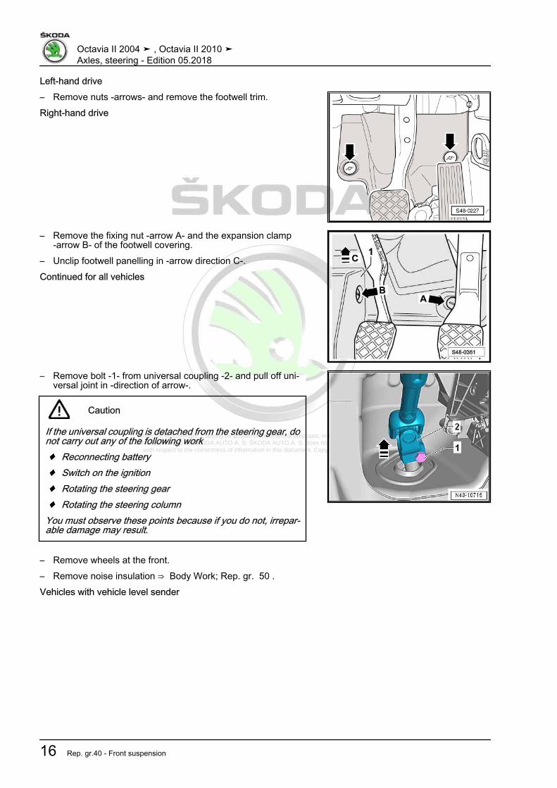
Left-hand drive– Remove nuts -arrows- and remove the footwell trim.Right-hand drive
– Remove the fixing nut -arrow A- and the expansion clamp-arrow B- of the footwell covering.
– Unclip footwell panelling in -arrow direction C-.Continued for all vehicles
– Remove bolt -1- from universal coupling -2- and pull off uni‐versal joint in -direction of arrow-.
Caution
If the universal coupling is detached from the steering gear, donot carry out any of the following work♦ Reconnecting battery♦ Switch on the ignition♦ Rotating the steering gear♦ Rotating the steering column
You must observe these points because if you do not, irrepar‐able damage may result.
– Remove wheels at the front.– Remove noise insulation ⇒ Body Work; Rep. gr. 50 .Vehicles with vehicle level sender
Octavia II 2004 ➤ , Octavia II 2010 ➤Axles, steering - Edition 05.2018
16 Rep. gr.40 - Front suspension

Protected by copyright. Copying for private or commercial purposes, in part or in whole, is not permitted unless authorised by ŠKODA AUTO A. S. ŠKODA AUTO A. S. does not guarantee or accept any liability
with respect to the correctness of information in this document. Copyright by ŠKODA AUTO A. S.�
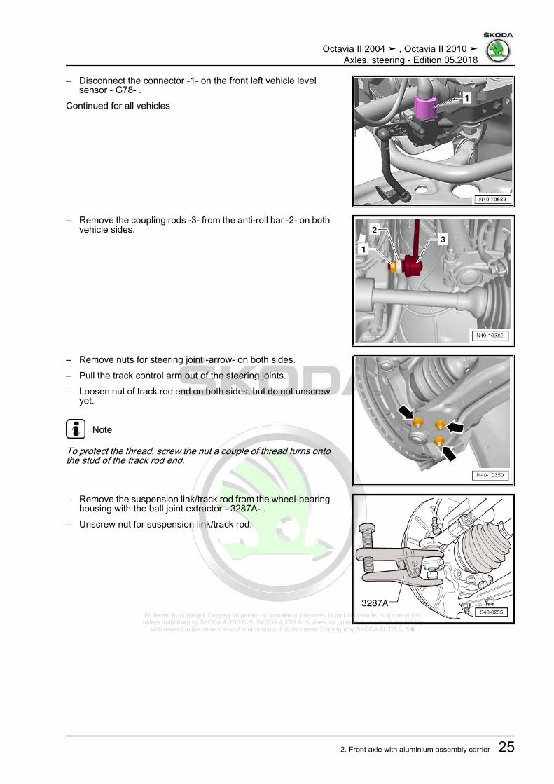
– Disconnect the connector -1- on the front left vehicle levelsensor - G78- .
Continued for all vehicles
– Disconnect plug -2- for oil level and oil temperature sender -G266- -1-, if present.
– Remove the coupling rods -3- from the anti-roll bar -2- on bothvehicle sides.
– Unbolt bracket for exhaust system -arrows- from assemblycarrier.
Octavia II 2004 ➤ , Octavia II 2010 ➤Axles, steering - Edition 05.2018
2. Front axle with aluminium assembly carrier 17

Protected by copyright. Copying for private or commercial purposes, in part or in whole, is not permitted unless authorised by ŠKODA AUTO A. S. ŠKODA AUTO A. S. does not guarantee or accept any liability
with respect to the correctness of information in this document. Copyright by ŠKODA AUTO A. S.�
– Unscrew screws -1- of pendulum support.– Fix the assembly carrier
⇒ “2.2 Fixing the assembly carrier and the console, aluminiumassembly carrier”, page 14 .
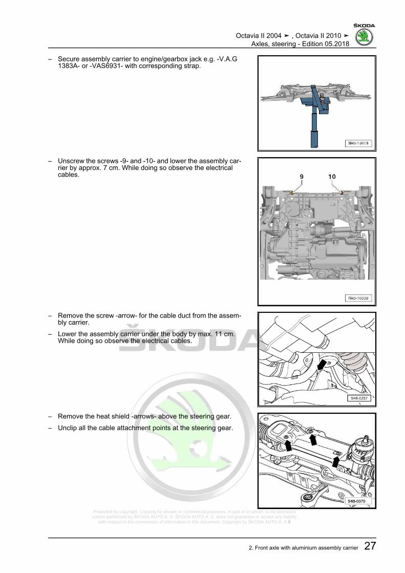
– Secure assembly carrier to engine/gearbox jack e.g. -V.A.G1383A- or -VAS6931- with corresponding strap.
– Remove the screws -9- and -10- and lower the assembly car‐rier by approx. 7 cm. While doing so observe the electricalcables.
Lower the assembly carrier by max. 11 cm.
Octavia II 2004 ➤ , Octavia II 2010 ➤Axles, steering - Edition 05.2018
18 Rep. gr.40 - Front suspension

Protected by copyright. Copying for private or commercial purposes, in part or in whole, is not permitted unless authorised by ŠKODA AUTO A. S. ŠKODA AUTO A. S. does not guarantee or accept any liability
with respect to the correctness of information in this document. Copyright by ŠKODA AUTO A. S.�
– Remove the screw -arrow- for the cable duct from the assem‐bly carrier.
– Lower the assembly carrier by approx. 11 cm. While doing soobserve the electrical cables.
InstallingInstallation is performed in the reverse order, pay attention to thefollowing points:
Note
♦ Coat the sealing sleeve on the steering gear with lubricant,e.g. lubricating soap, before installing the steering gear.
♦ Make sure the boot is neither damaged nor twisted.♦ Make sure all sealing surfaces are clean.♦ It is necessary to perform an axle alignment in the event of:
⇒ “3.3 Axle alignment”, page 309
– Replace the fixing devices - T10096- one by one with newscrews⇒ “2.2 Fixing the assembly carrier and the console, aluminiumassembly carrier”, page 14 .
– Perform a test drive– Check the steering wheel position during the test drive.
Note
If after the test drive and with the wheels pointing straight aheadthe steering wheel is off straight, perform an axle alignment⇒ “3.3 Axle alignment”, page 309 .
Tightening torques - summaries of components
Note
Replace bolts / nuts that are tightened at an angle of rotation, aswell as replacement components after removal.
♦ ⇒ “2.1 Assembly overview - subframe, aluminium subframe”,page 10
♦ ⇒ “1.1 Summary of components - steering column”,page 320
♦ ⇒ “1.2 Tightening torque of the wheel screws”, page 301♦ Pendulum support ⇒ Engine; Rep. gr. 10 .♦ Exhaust System ⇒ Engine; Rep. gr. 26♦ Noise insulation ⇒ Body work assembly; Rep. gr. 50
2.4 Removing and installing assembly car‐rier without steering gear, aluminium as‐sembly carrier
Special tools and workshop equipment required♦ Fixing device - T10096-
Octavia II 2004 ➤ , Octavia II 2010 ➤Axles, steering - Edition 05.2018
2. Front axle with aluminium assembly carrier 19

Protected by copyright. Copying for private or commercial purposes, in part or in whole, is not permitted unless authorised by ŠKODA AUTO A. S. ŠKODA AUTO A. S. does not guarantee or accept any liability
with respect to the correctness of information in this document. Copyright by ŠKODA AUTO A. S.�
♦ Engine and gearbox jack , e.g. -V.A.G 1383A- or -VAS6931-♦ Ball joint extractor - 3287A-Removing– Turn steering wheel to the straight ahead position.– Remove wheels at the front.– Remove noise insulation ⇒ Body Work; Rep. gr. 50 .Vehicles with vehicle level sender– Disconnect the connector -1- on the front left vehicle level
sensor - G78- .Continued for all vehicles
– Remove the screw -arrow- for the cable duct from the assem‐bly carrier.
– Remove the coupling rods -3- from the anti-roll bar -2- on bothvehicle sides.
– Remove nuts for steering joint -arrow- on both sides.
Octavia II 2004 ➤ , Octavia II 2010 ➤Axles, steering - Edition 05.2018
20 Rep. gr.40 - Front suspension

Protected by copyright. Copying for private or commercial purposes, in part or in whole, is not permitted unless authorised by ŠKODA AUTO A. S. ŠKODA AUTO A. S. does not guarantee or accept any liability
with respect to the correctness of information in this document. Copyright by ŠKODA AUTO A. S.�
– Unbolt bracket for exhaust system -arrows- from assemblycarrier.
– Unscrew screws -1- of pendulum support.
– Disconnect plug -2- for oil level and oil temperature sender -G266- -1-, if present.
– Remove steering gear fastening screws⇒ “2.1 Summary of components - steering gear”, page 356 .
– Tie up the power-steering gear e.g with wire (attach), so thatit maintains its position.
– Place the engine/gearbox jack e. g. -V.A.G 1383A- or -VAS6931- -1- underneath the assembly carrier.
– Fix the assembly carrier with consoles⇒ “2.2 Fixing the assembly carrier and the console, aluminiumassembly carrier”, page 14 .
Octavia II 2004 ➤ , Octavia II 2010 ➤Axles, steering - Edition 05.2018
2. Front axle with aluminium assembly carrier 21

Protected by copyright. Copying for private or commercial purposes, in part or in whole, is not permitted unless authorised by ŠKODA AUTO A. S. ŠKODA AUTO A. S. does not guarantee or accept any liability
with respect to the correctness of information in this document. Copyright by ŠKODA AUTO A. S.�
– Secure assembly carrier on engine/gearbox jack e.g. -V.A.G1383A- or -VAS6931- with corresponding strap.
– Unscrew the screws -9- and -10- and lower the assembly car‐rier by approx. 7 cm. While doing so observe the electricalcables.
Octavia II 2004 ➤ , Octavia II 2010 ➤Axles, steering - Edition 05.2018
22 Rep. gr.40 - Front suspension

Protected by copyright. Copying for private or commercial purposes, in part or in whole, is not permitted unless authorised by ŠKODA AUTO A. S. ŠKODA AUTO A. S. does not guarantee or accept any liability
with respect to the correctness of information in this document. Copyright by ŠKODA AUTO A. S.�
– Remove the screw -arrow- for the cable duct from the assem‐bly carrier.
– Slacken the wiring harness for oil level and oil temperaturesender - G266- (if present).
– Lower the assembly carrier with engine/gearbox jack e. g. -V.A.G 1383A- or -VAS6931- .
InstallingInstallation is carried out in the reverse order; pay attention to thefollowing points:– Raise the assembly carrier and fit the power steering gear onto
the assembly carrier.– Replace the fixing devices - T10096- one by one with new
screws⇒ “2.2 Fixing the assembly carrier and the console, aluminiumassembly carrier”, page 14 .
– On vehicles with vehicle level encoder, after disconnectingand connecting the connector, perform the basic adjustmentof the headlamps ⇒ Maintenance ; Booklet Octavia II .
Note
It is necessary to perform an axle alignment in the event of:⇒ “3.3 Axle alignment”, page 309
– Perform a test drive– Check the steering wheel position during the test drive.
Note
If after the test drive and with the wheels pointing straight aheadthe steering wheel is off straight, perform an axle alignment⇒ “3.3 Axle alignment”, page 309 .
Tightening torques - summaries of components
Note
Replace bolts / nuts that are tightened at an angle of rotation, aswell as replacement components after removal.
♦ ⇒ “2.1 Assembly overview - subframe, aluminium subframe”,page 10
♦ ⇒ “1.1 Summary of components - steering column”,page 320
♦ ⇒ “2.1 Summary of components - steering gear”, page 356♦ ⇒ “1.2 Tightening torque of the wheel screws”, page 301♦ Pendulum support ⇒ Engine; Rep. gr. 10 .♦ Exhaust System ⇒ Engine; Rep. gr. 26♦ Noise insulation ⇒ Body work assembly; Rep. gr. 50
Octavia II 2004 ➤ , Octavia II 2010 ➤Axles, steering - Edition 05.2018
2. Front axle with aluminium assembly carrier 23

Protected by copyright. Copying for private or commercial purposes, in part or in whole, is not permitted unless authorised by ŠKODA AUTO A. S. ŠKODA AUTO A. S. does not guarantee or accept any liability
with respect to the correctness of information in this document. Copyright by ŠKODA AUTO A. S.�
2.5 Removing and installing assembly car‐rier with steering gear, aluminium as‐sembly carrier
⇒ “2.5.1 Removing and installing assembly carrier with steeringgear, aluminium assembly carrier, left-hand drive”, page 24⇒ “2.5.2 Removing and installing assembly carrier with steeringgear, aluminium assembly carrier right-hand drive”, page 29
2.5.1 Removing and installing assembly car‐rier with steering gear, aluminium as‐sembly carrier, left-hand drive
Special tools and workshop equipment required♦ Fixing device - T10096-♦ Engine and gearbox jack , e.g. -V.A.G 1383A- or -VAS6931-♦ Ball joint extractor - 3287A-Removing– Turn steering wheel to the straight ahead position.– Remove the ignition key and lock the steering wheel lock.– Disconnect battery ⇒ Electrical System; Rep. gr. 27 .– Remove nuts -arrows- and remove the footwell trim.
– Remove bolt -1- from universal coupling -2- and pull off uni‐versal joint in -direction of arrow-.
Caution
If the universal coupling is detached from the steering gear, donot carry out any of the following work♦ Reconnecting battery♦ Switch on the ignition♦ Rotating the steering gear♦ Rotating the steering column
You must observe these points because if you do not, irrepar‐able damage may result.
– Remove wheels at the front.– Remove noise insulation ⇒ Body Work; Rep. gr. 50 .Vehicles with vehicle level sender
Octavia II 2004 ➤ , Octavia II 2010 ➤Axles, steering - Edition 05.2018
24 Rep. gr.40 - Front suspension
Protected by copyright. Copying for private or commercial purposes, in part or in whole, is not permitted unless authorised by ŠKODA AUTO A. S. ŠKODA AUTO A. S. does not guarantee or accept any liability
with respect to the correctness of information in this document. Copyright by ŠKODA AUTO A. S.�
– Disconnect the connector -1- on the front left vehicle levelsensor - G78- .
Continued for all vehicles
– Remove the coupling rods -3- from the anti-roll bar -2- on bothvehicle sides.
– Remove nuts for steering joint -arrow- on both sides.– Pull the track control arm out of the steering joints.– Loosen nut of track rod end on both sides, but do not unscrew
yet.
Note
To protect the thread, screw the nut a couple of thread turns ontothe stud of the track rod end.
– Remove the suspension link/track rod from the wheel-bearinghousing with the ball joint extractor - 3287A- .
– Unscrew nut for suspension link/track rod.
Octavia II 2004 ➤ , Octavia II 2010 ➤Axles, steering - Edition 05.2018
2. Front axle with aluminium assembly carrier 25

Protected by copyright. Copying for private or commercial purposes, in part or in whole, is not permitted unless authorised by ŠKODA AUTO A. S. ŠKODA AUTO A. S. does not guarantee or accept any liability
with respect to the correctness of information in this document. Copyright by ŠKODA AUTO A. S.�
– Unbolt bracket for exhaust system -arrows- from assemblycarrier.
– Unscrew screws -1- of pendulum support.
– Disconnect plug -2- for oil level and oil temperature sender -G266- -1-, if present.
– Place the engine/gearbox jack e. g. -V.A.G 1383A- or -VAS6931- -1- underneath the assembly carrier.
– Fix the assembly carrier with consoles⇒ “2.2 Fixing the assembly carrier and the console, aluminiumassembly carrier”, page 14 .
Octavia II 2004 ➤ , Octavia II 2010 ➤Axles, steering - Edition 05.2018
26 Rep. gr.40 - Front suspension
Protected by copyright. Copying for private or commercial purposes, in part or in whole, is not permitted unless authorised by ŠKODA AUTO A. S. ŠKODA AUTO A. S. does not guarantee or accept any liability
with respect to the correctness of information in this document. Copyright by ŠKODA AUTO A. S.�
– Secure assembly carrier to engine/gearbox jack e.g. -V.A.G1383A- or -VAS6931- with corresponding strap.
– Unscrew the screws -9- and -10- and lower the assembly car‐rier by approx. 7 cm. While doing so observe the electricalcables.
– Remove the screw -arrow- for the cable duct from the assem‐bly carrier.
– Lower the assembly carrier under the body by max. 11 cm.While doing so observe the electrical cables.
– Remove the heat shield -arrows- above the steering gear.– Unclip all the cable attachment points at the steering gear.
Octavia II 2004 ➤ , Octavia II 2010 ➤Axles, steering - Edition 05.2018
2. Front axle with aluminium assembly carrier 27

Protected by copyright. Copying for private or commercial purposes, in part or in whole, is not permitted unless authorised by ŠKODA AUTO A. S. ŠKODA AUTO A. S. does not guarantee or accept any liability
with respect to the correctness of information in this document. Copyright by ŠKODA AUTO A. S.�
– Disconnect the plug connections -1- and -2- from the steeringgear.
When doing this, it is necessary to:– Pull out the fuse of the plug connection in
-direction of arrow A-.– Press together the catch of the plug connection in
-direction of arrow B- and separate the plug connection bypulling.
– Slacken the wiring harness for oil level and oil temperaturesender - G266- (if present).
– Lower assembly carrier.InstallingInstallation is performed in the reverse order, pay attention to thefollowing points:
Note
♦ Coat the sealing sleeve on the steering gear with lubricant,e.g. lubricating soap, before installing the steering gear.
♦ When installing, make sure the steering gear boot is neitherdamaged nor twisted.
♦ It is necessary to perform an axle alignment in the event of:⇒ “3.3 Axle alignment”, page 309
– On vehicles with vehicle level sensor, carry out a basic settingfor the headlights ⇒ Maintenance ; Booklet Octavia II .
– Perform a test drive– Check the steering wheel position during the test drive.
Note
If after the test drive and with the wheels pointing straight aheadthe steering wheel is off straight, perform an axle alignment⇒ “3.3 Axle alignment”, page 309 .
Tightening torques - summaries of components
Note
Replace bolts / nuts that are tightened at an angle of rotation, aswell as replacement components after removal.
♦ ⇒ “2.1 Assembly overview - subframe, aluminium subframe”,page 10
♦ ⇒ “1.1 Summary of components - steering column”,page 320
♦ ⇒ “2.1 Summary of components - steering gear”, page 356♦ ⇒ “1.2 Tightening torque of the wheel screws”, page 301♦ Pendulum support ⇒ Engine; Rep. gr. 10 .♦ Exhaust System ⇒ Engine; Rep. gr. 26♦ Noise insulation ⇒ Body work assembly; Rep. gr. 50
Octavia II 2004 ➤ , Octavia II 2010 ➤Axles, steering - Edition 05.2018
28 Rep. gr.40 - Front suspension

Protected by copyright. Copying for private or commercial purposes, in part or in whole, is not permitted unless authorised by ŠKODA AUTO A. S. ŠKODA AUTO A. S. does not guarantee or accept any liability
with respect to the correctness of information in this document. Copyright by ŠKODA AUTO A. S.�
2.5.2 Removing and installing assembly car‐rier with steering gear, aluminium as‐sembly carrier right-hand drive
Special tools and workshop equipment required♦ Fixing device - T10096-♦ Engine and gearbox jack , e.g. -V.A.G 1383A- or -VAS6931-♦ Ball joint extractor - 3287A-Removing
Note
On right-hand drive vehicles, the wiring harness is removed fromthe engine compartment at the same when removing the assem‐bly carrier.
– Turn steering wheel to the straight ahead position.– Remove the ignition key and lock the steering wheel lock.– Remove battery and battery tray ⇒ Electrical System; Rep.
gr. 27 .– Remove air filter and air guide with air mass meter ⇒ Engine;
Rep. gr. 23 or ⇒ Engine; Rep. gr. 24 .– Disconnect cable -1- from the E-box.– Disconnect plug -3- for oil level and oil temperature sender -
G266- , if present.– Disconnect earth line -4-.– Unclip wiring harness -2-.
– Remove the fixing nut -arrow A- and the expansion clamp-arrow B- of the footwell covering.
– Unclip footwell panelling in -arrow direction C-.
Octavia II 2004 ➤ , Octavia II 2010 ➤Axles, steering - Edition 05.2018
2. Front axle with aluminium assembly carrier 29

Protected by copyright. Copying for private or commercial purposes, in part or in whole, is not permitted unless authorised by ŠKODA AUTO A. S. ŠKODA AUTO A. S. does not guarantee or accept any liability
with respect to the correctness of information in this document. Copyright by ŠKODA AUTO A. S.�
– Remove bolt -1- from universal coupling -2- and pull off uni‐versal joint in -direction of arrow-.
Caution
If the universal coupling is detached from the steering gear, donot carry out any of the following work♦ Reconnecting battery♦ Switch on the ignition♦ Rotating the steering gear♦ Rotating the steering column
You must observe these points because if you do not, irrepar‐able damage may result.
– Remove wheels at the front.– Remove noise insulation ⇒ Body Work; Rep. gr. 50 .Vehicles with vehicle level sender
– Disconnect the connector -1- on the front left vehicle levelsensor - G78- .
Continued for all vehicles
– Remove the coupling rods -3- from the anti-roll bar -2- on bothvehicle sides.
– Remove nuts for steering joint -arrow- on both sides.– Pull the track control arm out of the steering joints.– Loosen nut of track rod end on both sides, but do not unscrew
yet.
Note
To protect the thread, screw the nut a couple of thread turns ontothe stud of the track rod end.
Octavia II 2004 ➤ , Octavia II 2010 ➤Axles, steering - Edition 05.2018
30 Rep. gr.40 - Front suspension

Protected by copyright. Copying for private or commercial purposes, in part or in whole, is not permitted unless authorised by ŠKODA AUTO A. S. ŠKODA AUTO A. S. does not guarantee or accept any liability
with respect to the correctness of information in this document. Copyright by ŠKODA AUTO A. S.�
– Remove the steering joint/track rod from the wheel-bearinghousing with the ball joint extractor - 3287A- .
– Unscrew nut for suspension link/track rod.
– Unbolt bracket for exhaust system -arrows- from assemblycarrier.
– Unscrew screws -1- of pendulum support.
– Disconnect plug -2- for oil level and oil temperature sender -G266- -1-, if present.
Octavia II 2004 ➤ , Octavia II 2010 ➤Axles, steering - Edition 05.2018
2. Front axle with aluminium assembly carrier 31

Protected by copyright. Copying for private or commercial purposes, in part or in whole, is not permitted unless authorised by ŠKODA AUTO A. S. ŠKODA AUTO A. S. does not guarantee or accept any liability
with respect to the correctness of information in this document. Copyright by ŠKODA AUTO A. S.�
– Place the engine/gearbox jack e. g. -V.A.G 1383A- or -VAS6931- -1- underneath the assembly carrier.
– Fix the assembly carrier with consoles⇒ “2.2 Fixing the assembly carrier and the console, aluminiumassembly carrier”, page 14 .
– Secure assembly carrier to engine/gearbox jack e.g. -V.A.G1383A- or -VAS6931- with corresponding strap.
Octavia II 2004 ➤ , Octavia II 2010 ➤Axles, steering - Edition 05.2018
32 Rep. gr.40 - Front suspension

Protected by copyright. Copying for private or commercial purposes, in part or in whole, is not permitted unless authorised by ŠKODA AUTO A. S. ŠKODA AUTO A. S. does not guarantee or accept any liability
with respect to the correctness of information in this document. Copyright by ŠKODA AUTO A. S.�
– Unscrew screws -9- and -10- and lower the assembly carrier.While doing so observe the electrical cables.
InstallingInstallation is performed in the reverse order, pay attention to thefollowing points:
Note
♦ Coat the sealing sleeve on the steering gear with lubricant,e.g. lubricating soap, before installing the steering gear.
♦ When installing, make sure the steering gear boot is neitherdamaged nor twisted.
♦ It is necessary to perform an axle alignment in the event of:⇒ “3.3 Axle alignment”, page 309
– Replace the fixing devices - T10096- one by one with newscrews⇒ “2.2 Fixing the assembly carrier and the console, aluminiumassembly carrier”, page 14 .
– On vehicles with vehicle level encoder, after disconnectingand connecting the connector, perform the basic adjustmentof the headlamps ⇒ Maintenance ; Booklet Octavia II .
– Perform a test drive– Check the steering wheel position during the test drive.
Note
If after the test drive and with the wheels pointing straight aheadthe steering wheel is off straight, perform an axle alignment⇒ “3.3 Axle alignment”, page 309 .
Tightening torques - summaries of components
Note
Replace bolts / nuts that are tightened at an angle of rotation, aswell as replacement components after removal.
♦ ⇒ “2.1 Assembly overview - subframe, aluminium subframe”,page 10
♦ ⇒ “1.1 Summary of components - steering column”,page 320
♦ ⇒ “2.1 Summary of components - steering gear”, page 356♦ ⇒ “1.2 Tightening torque of the wheel screws”, page 301♦ Pendulum support ⇒ Engine; Rep. gr. 10 .♦ Exhaust System ⇒ Engine; Rep. gr. 26♦ Noise insulation ⇒ Body work assembly; Rep. gr. 50
2.6 Replacing rubber-metal bearing for pen‐dulum support, aluminium assemblycarrier
Special tools and workshop equipment required
Octavia II 2004 ➤ , Octavia II 2010 ➤Axles, steering - Edition 05.2018
2. Front axle with aluminium assembly carrier 33

Protected by copyright. Copying for private or commercial purposes, in part or in whole, is not permitted unless authorised by ŠKODA AUTO A. S. ŠKODA AUTO A. S. does not guarantee or accept any liability
with respect to the correctness of information in this document. Copyright by ŠKODA AUTO A. S.�
♦ Hydraulic cylinder - VAS 6178-♦ Foot pump - VAS 6179-♦ Assembly device - VAS 6779- or -VAS 6779A-♦ Pressure spindle - MP3-408 (VW 412)-♦ Pressure plate - MP3-406 (VW 401)-Replacing rubber-metal bearing for pendulum support.– Remove noise insulation ⇒ Body Work; Rep. gr. 50 .– Remove the coupling rods -3- from the anti-roll bar -2- on both
vehicle sides.
– Remove screws -7- and -8- for anti-roll clamps.• Leave the anti-roll bar in the installation position.– Remove pendulum support ⇒ Engine; Rep. gr. 10 .– Fit Assembly device - VAS 6779- or -VAS 6779A- to the as‐
sembly carrier as shown in the figure.
Octavia II 2004 ➤ , Octavia II 2010 ➤Axles, steering - Edition 05.2018
34 Rep. gr.40 - Front suspension

Protected by copyright. Copying for private or commercial purposes, in part or in whole, is not permitted unless authorised by ŠKODA AUTO A. S. ŠKODA AUTO A. S. does not guarantee or accept any liability
with respect to the correctness of information in this document. Copyright by ŠKODA AUTO A. S.�
– Place the pressure piece - VAS 6779/1- -1- onto the rubber-metal bearing with the flat side -arrow- in the driving direction.
1 - Thrust piece - VAS 6779/1-2 - Pipe - VAS 6779/4- - with the small outer diameter to the as‐sembly carrier3 - Thrust piece - VAS 6779/5-4 - Hydraulic cylinder - VAS 6178-5 - Hexagon nut - VAS 6779/3-6 - Threaded rod - VAS 6779/2-
– Press in both bonded rubber bushes far enough for the topbonded rubber bushing -2- in the opening for pendulum sup‐port in the assembly carrier -arrow- is visible.
– Carry out a visual inspection of the rubber-metal bearing -2-.• if the upper part is deformed, it must be disrupted through the
opening in the assembly carrier -arrow-.– Push through the outer ring for the top part of the rubber-metal
bearing -2- e.g. using a cold chisel -1-.
Note
Pushing through the deformed bearing prevents tilting in the as‐sembly carrier during removal.
– Remove both parts of the rubber-metal bearing at the sametime.
Prepare the rubber-metal bearing for pressing in
Note
♦ There are two different versions of rubber-metal bearings.♦ Assignment ⇒ Electronic Catalogue of Original Parts
I - The edges of the inner core -1- point to the recess of the rubber-metal bearing.
Octavia II 2004 ➤ , Octavia II 2010 ➤Axles, steering - Edition 05.2018
2. Front axle with aluminium assembly carrier 35

Protected by copyright. Copying for private or commercial purposes, in part or in whole, is not permitted unless authorised by ŠKODA AUTO A. S. ŠKODA AUTO A. S. does not guarantee or accept any liability
with respect to the correctness of information in this document. Copyright by ŠKODA AUTO A. S.�
lI - The edges of the inner core -2- point away from the recess ofthe rubber-metal bearing.
– Place the top part -1- and bottom part -2- on top of each otherso that the edges of the opening -arrows- fit together precisely.
– Screw both parts together with the original screw -3- (hand-tight); the cutouts -arrows- must face each other exactly, thescrew head points upwards.
– Place the rubber metal bearing on larger diameter side in thecone - VAS 6779/6- -2-.
– Align the rubber metal bearing -1- in the cone - VAS 6779/6- ,the edges of the opening must lie flush opposite the recess inthe cone - VAS 6779/6- -arrows-.
Octavia II 2004 ➤ , Octavia II 2010 ➤Axles, steering - Edition 05.2018
36 Rep. gr.40 - Front suspension

Protected by copyright. Copying for private or commercial purposes, in part or in whole, is not permitted unless authorised by ŠKODA AUTO A. S. ŠKODA AUTO A. S. does not guarantee or accept any liability
with respect to the correctness of information in this document. Copyright by ŠKODA AUTO A. S.�
– Retract the rubber metal bearing -3- up to the stop in the cone- VAS 6779/6- as shown.
1 - Pressure spindle - MP3-408 (VW 412)-2 - Thrust element - VAS 6779/5- - side with marking »A« must
face upwards3 - Rubber-metal bearing4 - Cone - VAS 6779/6-5 - Knock-in bushing - VAS 6779/4-6 - Pressure plate - MP3-406 (VW 401)-– Remove screw from rubber metal bearing.
– Place the support ring - VAS 6779/11- -1- on the assemblycarrier so that the nose of the clamping ring points to the left.
Note
When placing the support ring - VAS 6779/11- , make sure it is atsufficient distance to the steering gear -2- -arrows-.
– Turn the support ring - VAS 6779/11- -1- in such a way that-arrow- the nose of the ring -arrow- is pointing to the rear.
– Place the counterholder - VAS 6779/7- -1- from the left in-arrow- on the support ring - VAS 6779/11- -2-.
Octavia II 2004 ➤ , Octavia II 2010 ➤Axles, steering - Edition 05.2018
2. Front axle with aluminium assembly carrier 37

Protected by copyright. Copying for private or commercial purposes, in part or in whole, is not permitted unless authorised by ŠKODA AUTO A. S. ŠKODA AUTO A. S. does not guarantee or accept any liability
with respect to the correctness of information in this document. Copyright by ŠKODA AUTO A. S.�
– Insert the socket insert - VAS 6779/7-1A- -1- into the openingfor the pendulum support in the assembly carrier.
– Screw the plug insert - VAS 6779/7-1A- with screw -arrow-onto the counterholder - VAS 6779/7- -2-.
Note
Make sure that the plug insert - VAS 6779/7-1A- -1- is fitted cor‐rectly in the bore of the assembly carrier -arrow-.
Inserting the rubber-metal bearing– Screw the threaded rod - VAS 6779/2- -7- into the counter‐
holder - VAS 6779/7- -1-.– Fit Assembly device - VAS 6779- or -VAS 6779A- to the as‐
sembly carrier as shown in the figure.
Octavia II 2004 ➤ , Octavia II 2010 ➤Axles, steering - Edition 05.2018
38 Rep. gr.40 - Front suspension

Protected by copyright. Copying for private or commercial purposes, in part or in whole, is not permitted unless authorised by ŠKODA AUTO A. S. ŠKODA AUTO A. S. does not guarantee or accept any liability
with respect to the correctness of information in this document. Copyright by ŠKODA AUTO A. S.�
1 - Counterholder - VAS 6779/7-2 - Cone - VAS 6779/6- , the -arrow- marking on the pipe mustpoint exactly to the centre between the screws on the counter‐holder - VAS 6779/7- -arrow-3 - Thrust piece - VAS 6779/9-4 - Composite seal - VAS 6779/8- - the mark -IIII- on the compositeseal must face the tab -Arrow B- on the pressure piece - VAS6779/9- .5 - Hydraulic cylinder - VAS 6178-6 - Hexagon nut - VAS 6779/3-7 - Threaded rod - VAS 6779/2-– Draw in both parts of the rubber-metal bearing.– Remove the assembly device - VAS 6779- or -VAS 6779A-
from the assembly carrier.– Check the bearing of the rubber-metal bearing.– Screw the anti-roll bar with the assembly carrier, and the cou‐
pling rods.– Install pendulum support ⇒ Engine; Rep. gr. 10 .
Octavia II 2004 ➤ , Octavia II 2010 ➤Axles, steering - Edition 05.2018
2. Front axle with aluminium assembly carrier 39

Protected by copyright. Copying for private or commercial purposes, in part or in whole, is not permitted unless authorised by ŠKODA AUTO A. S. ŠKODA AUTO A. S. does not guarantee or accept any liability
with respect to the correctness of information in this document. Copyright by ŠKODA AUTO A. S.�
– Install the noise insulation ⇒ Body Work; Rep. gr. 50 .Tightening torques - summaries of components
Note
Replace bolts / nuts that are tightened at an angle of rotation, aswell as replacement components after removal.
♦ ⇒ “2.1 Assembly overview - subframe, aluminium subframe”,page 10
♦ Pendulum support ⇒ Engine; Rep. gr. 10 .♦ Noise insulation ⇒ Body work assembly; Rep. gr. 50
2.7 Removing and installing anti-roll bar,aluminium assembly carrier
⇒ “2.7.1 Removing and installing anti-roll bars, aluminium as‐sembly carrier, left-hand drive”, page 40⇒ “2.7.2 Removing and installing anti-roll bars, aluminium as‐sembly carrier, right-hand drive”, page 42
2.7.1 Removing and installing anti-roll bars,aluminium assembly carrier, left-handdrive
Special tools and workshop equipment required♦ Fixing device - T10096 -♦ Engine and gearbox jack , e.g. -V.A.G 1383A- or -VAS6931-♦ Ball joint extractor - 3287A-Removing– Remove wheels.– Remove noise insulation ⇒ Body Work; Rep. gr. 50 .Vehicles with vehicle level sender– Remove front left vehicle level sensor - G78- -1-
⇒ “1.3 Removing and installing front vehicle level encoder G78”, page 295 .
Continued for all vehicles
Octavia II 2004 ➤ , Octavia II 2010 ➤Axles, steering - Edition 05.2018
40 Rep. gr.40 - Front suspension
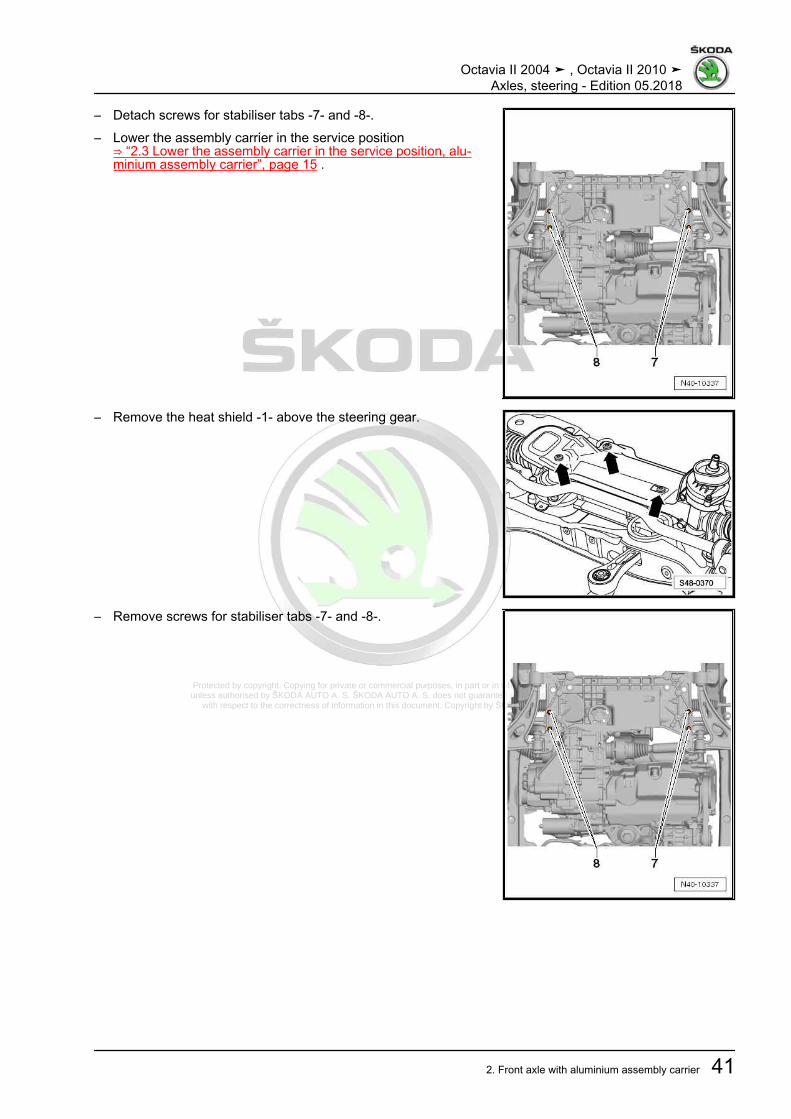
Protected by copyright. Copying for private or commercial purposes, in part or in whole, is not permitted unless authorised by ŠKODA AUTO A. S. ŠKODA AUTO A. S. does not guarantee or accept any liability
with respect to the correctness of information in this document. Copyright by ŠKODA AUTO A. S.�
– Detach screws for stabiliser tabs -7- and -8-.– Lower the assembly carrier in the service position
⇒ “2.3 Lower the assembly carrier in the service position, alu‐minium assembly carrier”, page 15 .
– Remove the heat shield -1- above the steering gear.
– Remove screws for stabiliser tabs -7- and -8-.
Octavia II 2004 ➤ , Octavia II 2010 ➤Axles, steering - Edition 05.2018
2. Front axle with aluminium assembly carrier 41

Protected by copyright. Copying for private or commercial purposes, in part or in whole, is not permitted unless authorised by ŠKODA AUTO A. S. ŠKODA AUTO A. S. does not guarantee or accept any liability
with respect to the correctness of information in this document. Copyright by ŠKODA AUTO A. S.�
– Lift the anti-roll bar -1- to the front via the console, -2- off theassembly carrier.
InstallingInstallation is performed in the reverse order, pay attention to thefollowing points:
Note
♦ Coat the sealing sleeve on the steering gear with lubricant,e.g. lubricating soap, before installing the steering gear.
♦ After positioning the steering gear on the drive shaft make surethe seal on the steering gear is not bent on the assembly plateand correctly seals the footwell opening. Otherwise this couldcause water penetration and/or noise.
♦ Make sure all sealing surfaces are clean.
– On vehicles with vehicle level encoder, after disconnectingand connecting the connector, perform the basic adjustmentof the headlamps ⇒ Maintenance ; Booklet Octavia II .
– Perform a test drive– Check the steering wheel position during the test drive.
Note
If after the test drive and with the wheels pointing straight aheadthe steering wheel is off straight, perform an axle alignment⇒ “3.3 Axle alignment”, page 309 .
Tightening torques - summaries of components
Note
Replace bolts / nuts that are tightened at an angle of rotation, aswell as replacement components after removal.
♦ ⇒ “2.1 Assembly overview - subframe, aluminium subframe”,page 10
♦ ⇒ “1.1 Summary of components - vehicle level sender front”,page 293
♦ ⇒ “1.2 Tightening torque of the wheel screws”, page 301♦ Noise insulation ⇒ Body work assembly; Rep. gr. 50
2.7.2 Removing and installing anti-roll bars,aluminium assembly carrier, right-handdrive
Special tools and workshop equipment required♦ Fixing device - T10096 -♦ Ball joint extractor - 3287A-♦ Engine and gearbox jack , e.g. -V.A.G 1383A- or -VAS6931-
Octavia II 2004 ➤ , Octavia II 2010 ➤Axles, steering - Edition 05.2018
42 Rep. gr.40 - Front suspension
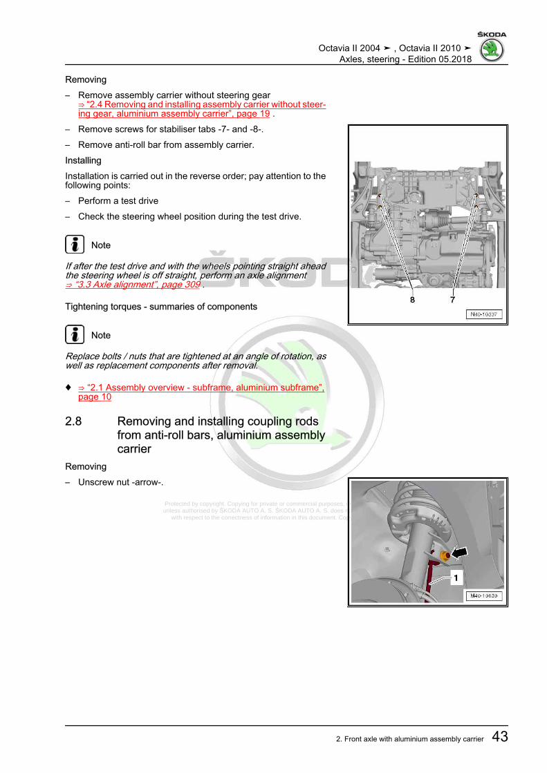
Protected by copyright. Copying for private or commercial purposes, in part or in whole, is not permitted unless authorised by ŠKODA AUTO A. S. ŠKODA AUTO A. S. does not guarantee or accept any liability
with respect to the correctness of information in this document. Copyright by ŠKODA AUTO A. S.�
Removing– Remove assembly carrier without steering gear
⇒ “2.4 Removing and installing assembly carrier without steer‐ing gear, aluminium assembly carrier”, page 19 .
– Remove screws for stabiliser tabs -7- and -8-.– Remove anti-roll bar from assembly carrier.InstallingInstallation is carried out in the reverse order; pay attention to thefollowing points:– Perform a test drive– Check the steering wheel position during the test drive.
Note
If after the test drive and with the wheels pointing straight aheadthe steering wheel is off straight, perform an axle alignment⇒ “3.3 Axle alignment”, page 309 .
Tightening torques - summaries of components
Note
Replace bolts / nuts that are tightened at an angle of rotation, aswell as replacement components after removal.
♦ ⇒ “2.1 Assembly overview - subframe, aluminium subframe”,page 10
2.8 Removing and installing coupling rodsfrom anti-roll bars, aluminium assemblycarrier
Removing– Unscrew nut -arrow-.
Octavia II 2004 ➤ , Octavia II 2010 ➤Axles, steering - Edition 05.2018
2. Front axle with aluminium assembly carrier 43

Protected by copyright. Copying for private or commercial purposes, in part or in whole, is not permitted unless authorised by ŠKODA AUTO A. S. ŠKODA AUTO A. S. does not guarantee or accept any liability
with respect to the correctness of information in this document. Copyright by ŠKODA AUTO A. S.�
– Unscrew nut -1-.– Pull out coupling rod -3- from the anti-roll bar -2-.InstallingInstallation is carried out in the reverse order.Tightening torques - summaries of components
Note
Replace bolts / nuts that are tightened at an angle of rotation, aswell as replacement components after removal.
♦ ⇒ “2.1 Assembly overview - subframe, aluminium subframe”,page 10
2.9 Removing and installing track controlarm with bracket, aluminium assemblycarrier
⇒ “2.9.1 Removing and installing track control arm with bracket,aluminium assembly carrier”, page 44⇒ “2.9.2 Removing and installing left track control arm with bear‐ing bracket, vehicles with automatic transmission, aluminium as‐sembly carrier”, page 47
2.9.1 Removing and installing track controlarm with bracket, aluminium assemblycarrier
Special tools and workshop equipment required♦ Fixing device - T10096-Removing– Remove wheel.– Dimension -a- Measure unladen weight of the vehicle
⇒ “3.5 Lift the wheel bearing in the unladen weight position”,page 5 ,
– Remove noise insulation ⇒ Body Work; Rep. gr. 50 .Vehicles with vehicle level sender– Unscrew nut -1-.– Remove the holder -2- of the front left vehicle level encoder -
G78- from the wishbone -3-.Continued for all vehicles
Octavia II 2004 ➤ , Octavia II 2010 ➤Axles, steering - Edition 05.2018
44 Rep. gr.40 - Front suspension

Protected by copyright. Copying for private or commercial purposes, in part or in whole, is not permitted unless authorised by ŠKODA AUTO A. S. ŠKODA AUTO A. S. does not guarantee or accept any liability
with respect to the correctness of information in this document. Copyright by ŠKODA AUTO A. S.�
– Release fixing nuts -arrows-.– Pull suspension link out of swivel joint and turn wheel bearing
housing to outside to relieve load on suspension link.– Fix position for the bracket
⇒ “2.2 Fixing the assembly carrier and the console, aluminiumassembly carrier”, page 14 .
– Remove the new screw -12- for the left vehicle side or -11- forthe right vehicle side.
– Remove screws -1-.– Remove track control arm.InstallingInstallation is performed in the reverse order, pay attention to thefollowing points:– Insert the track control arm along with the bracket in the as‐
sembly carrier.
Note
Tighten screws/nuts when the vehicle is in unladen weight posi‐tion⇒ “3.5 Lift the wheel bearing in the unladen weight position”, page5 .
Octavia II 2004 ➤ , Octavia II 2010 ➤Axles, steering - Edition 05.2018
2. Front axle with aluminium assembly carrier 45

Protected by copyright. Copying for private or commercial purposes, in part or in whole, is not permitted unless authorised by ŠKODA AUTO A. S. ŠKODA AUTO A. S. does not guarantee or accept any liability
with respect to the correctness of information in this document. Copyright by ŠKODA AUTO A. S.�
– Screw on new screw -11- for the right vehicle side or -12- forthe left vehicle side, but do not tighten yet.
– Insert new screws -1- and tighten.
– Insert new screws -1- and tighten.– Replace the fixing device - T10096- with a new screw and
tighten.
– Insert swivel joint in suspension link and tighten bolts-arrows-.
Octavia II 2004 ➤ , Octavia II 2010 ➤Axles, steering - Edition 05.2018
46 Rep. gr.40 - Front suspension

Protected by copyright. Copying for private or commercial purposes, in part or in whole, is not permitted unless authorised by ŠKODA AUTO A. S. ŠKODA AUTO A. S. does not guarantee or accept any liability
with respect to the correctness of information in this document. Copyright by ŠKODA AUTO A. S.�
– Tighten screw -11- or -12- of track control arm to console (inthe unladen weight position)⇒ “3.5 Lift the wheel bearing in the unladen weight position”,page 5 .
– On vehicles with vehicle level encoder, after disconnectingand connecting the connector, perform the basic adjustmentof the headlamps ⇒ Maintenance ; Booklet Octavia II .
– Perform a test drive– Check the steering wheel position during the test drive.
Note
Make sure the steering joint boot is neither damaged nor twisted.
– Perform a test drive– Check the steering wheel position during the test drive.
Note
If after the test drive and with the wheels pointing straight aheadthe steering wheel is off straight, perform an axle alignment⇒ “3.3 Axle alignment”, page 309 .
Tightening torques - summaries of components
Note
Replace bolts / nuts that are tightened at an angle of rotation, aswell as replacement components after removal.
♦ ⇒ “2.1 Assembly overview - subframe, aluminium subframe”,page 10
♦ ⇒ “1.1 Summary of components - vehicle level sender front”,page 293
♦ ⇒ “1.2 Tightening torque of the wheel screws”, page 301♦ Noise insulation ⇒ Body work assembly; Rep. gr. 50
2.9.2 Removing and installing left track con‐trol arm with bearing bracket, vehicleswith automatic transmission, aluminiumassembly carrier
Special tools and workshop equipment required♦ Fixing device - T10096-♦ Engine and gearbox jack , e.g. -V.A.G 1383A- or -VAS6931-
Note
♦ The following procedure applies to removing and installing theleft suspension link.
♦ Removing and installing right suspension link⇒ “2.9.1 Removing and installing track control arm with brack‐et, aluminium assembly carrier”, page 44 .
Octavia II 2004 ➤ , Octavia II 2010 ➤Axles, steering - Edition 05.2018
2. Front axle with aluminium assembly carrier 47

Protected by copyright. Copying for private or commercial purposes, in part or in whole, is not permitted unless authorised by ŠKODA AUTO A. S. ŠKODA AUTO A. S. does not guarantee or accept any liability
with respect to the correctness of information in this document. Copyright by ŠKODA AUTO A. S.�
Removing– Turn steering wheel to the straight ahead position.– Remove the ignition key and lock the steering wheel lock.– Disconnect battery ⇒ Electrical System; Rep. gr. 27 .Left-hand drive– Remove nuts -arrows- and remove the footwell trim.Right-hand drive
– Remove the fixing nut -arrow A- and the expansion clamp-arrow B- of the footwell covering.
– Unclip footwell panelling in -arrow direction C-.
Continued for all vehicles
Caution
If the universal coupling is detached from the steering gear, donot carry out any of the following work♦ Reconnecting battery♦ Switch on the ignition♦ Rotating the steering gear♦ Rotating the steering column
You must observe these points because if you do not, irrepar‐able damage may result.
– Remove front left wheel.– Dimension -a- Measure unladen weight of the vehicle
⇒ “3.5 Lift the wheel bearing in the unladen weight position”,page 5 ,
– Remove noise insulation ⇒ Body Work; Rep. gr. 50 .Vehicles with vehicle level sender
Octavia II 2004 ➤ , Octavia II 2010 ➤Axles, steering - Edition 05.2018
48 Rep. gr.40 - Front suspension

Protected by copyright. Copying for private or commercial purposes, in part or in whole, is not permitted unless authorised by ŠKODA AUTO A. S. ŠKODA AUTO A. S. does not guarantee or accept any liability
with respect to the correctness of information in this document. Copyright by ŠKODA AUTO A. S.�
– Unscrew nut -1-.– Remove the holder -2- of the front left vehicle level encoder -
G78- from the wishbone -3-.Continued for all vehicles
– Release fixing nuts -arrows-.– Pull suspension link out of swivel joint and turn wheel bearing
housing to outside to relieve load on suspension link.
– Loosen screw -12- and leave temporarily screwed in.
Octavia II 2004 ➤ , Octavia II 2010 ➤Axles, steering - Edition 05.2018
2. Front axle with aluminium assembly carrier 49
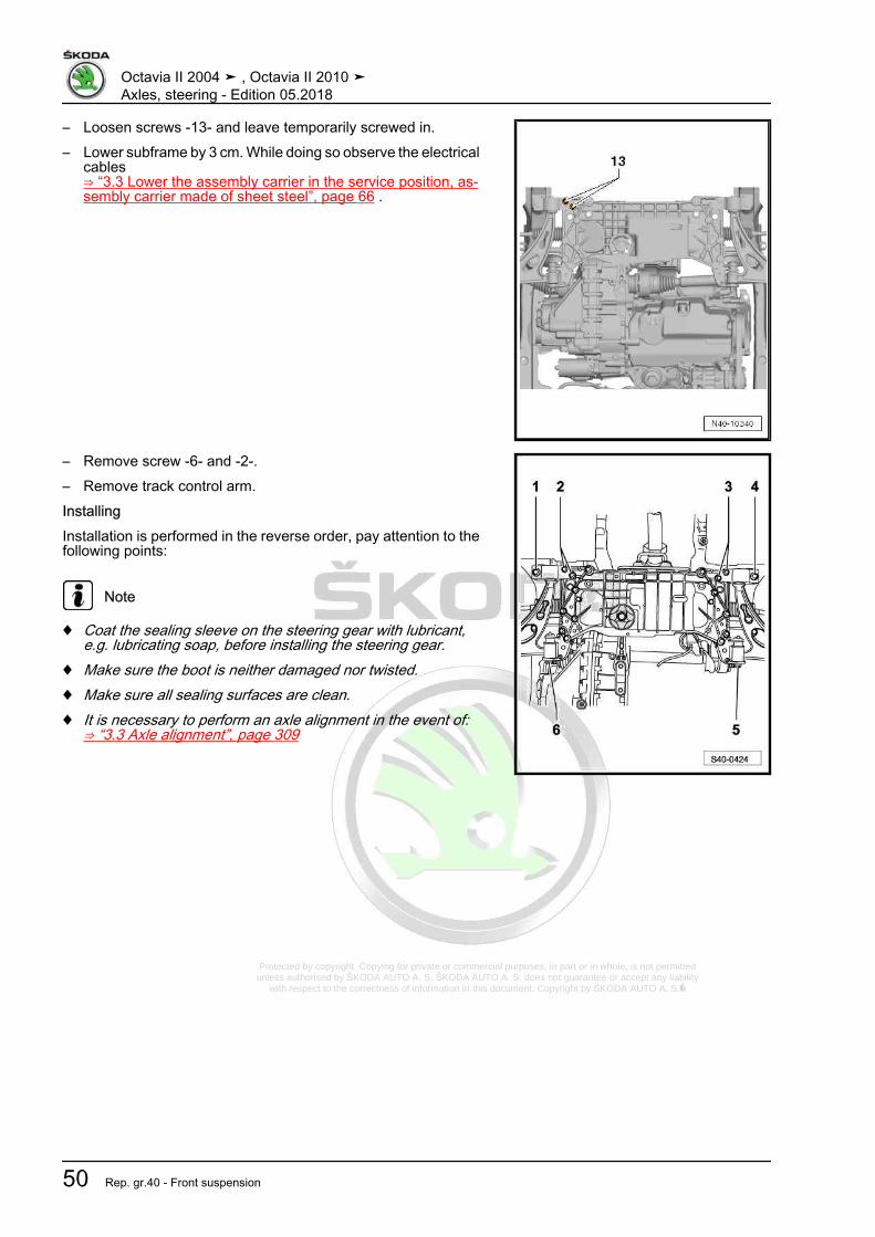
Protected by copyright. Copying for private or commercial purposes, in part or in whole, is not permitted unless authorised by ŠKODA AUTO A. S. ŠKODA AUTO A. S. does not guarantee or accept any liability
with respect to the correctness of information in this document. Copyright by ŠKODA AUTO A. S.�
– Loosen screws -13- and leave temporarily screwed in.– Lower subframe by 3 cm. While doing so observe the electrical
cables⇒ “3.3 Lower the assembly carrier in the service position, as‐sembly carrier made of sheet steel”, page 66 .
– Remove screw -6- and -2-.– Remove track control arm.InstallingInstallation is performed in the reverse order, pay attention to thefollowing points:
Note
♦ Coat the sealing sleeve on the steering gear with lubricant,e.g. lubricating soap, before installing the steering gear.
♦ Make sure the boot is neither damaged nor twisted.♦ Make sure all sealing surfaces are clean.♦ It is necessary to perform an axle alignment in the event of:
⇒ “3.3 Axle alignment”, page 309
Octavia II 2004 ➤ , Octavia II 2010 ➤Axles, steering - Edition 05.2018
50 Rep. gr.40 - Front suspension

Protected by copyright. Copying for private or commercial purposes, in part or in whole, is not permitted unless authorised by ŠKODA AUTO A. S. ŠKODA AUTO A. S. does not guarantee or accept any liability
with respect to the correctness of information in this document. Copyright by ŠKODA AUTO A. S.�
– Tighten screw -12- of track control arm to console (in the un‐laden weight position)⇒ “3.5 Lift the wheel bearing in the unladen weight position”,page 5 .
– On vehicles with vehicle level encoder, after disconnectingand connecting the connector, perform the basic adjustmentof the headlamps ⇒ Maintenance ; Booklet Octavia II .
– Perform a test drive– Check the steering wheel position during the test drive.
Note
If after the test drive and with the wheels pointing straight aheadthe steering wheel is off straight, perform an axle alignment⇒ “3.3 Axle alignment”, page 309 .
Tightening torques - summaries of components
Note
Replace bolts / nuts that are tightened at an angle of rotation, aswell as replacement components after removal.
♦ ⇒ “2.1 Assembly overview - subframe, aluminium subframe”,page 10
♦ ⇒ “1.1 Summary of components - steering column”,page 320
♦ ⇒ “1.1 Summary of components - vehicle level sender front”,page 293
♦ ⇒ “1.2 Tightening torque of the wheel screws”, page 301♦ Noise insulation ⇒ Body work assembly; Rep. gr. 50♦ Pendulum support ⇒ Engine; Rep. gr. 10 .♦ Exhaust System ⇒ Engine; Rep. gr. 26
2.10 Replacing rubber-metal bearing fortrack control arm, aluminium assemblycarrier
Special tools and workshop equipment required♦ Pressure plate - MP3-407 (VW 402)-♦ Thrust piece - MP6-405 (VW 411)-♦ Pipe section - T10219/1-♦ Mandrel - T10219/2-
Octavia II 2004 ➤ , Octavia II 2010 ➤Axles, steering - Edition 05.2018
2. Front axle with aluminium assembly carrier 51

Protected by copyright. Copying for private or commercial purposes, in part or in whole, is not permitted unless authorised by ŠKODA AUTO A. S. ŠKODA AUTO A. S. does not guarantee or accept any liability
with respect to the correctness of information in this document. Copyright by ŠKODA AUTO A. S.�
Pulling out the rubber-metal bearing– Press out rubber-metal bearing as shown.1 - Drive bushing - MP6-405 (VW 411)-2 - Pipe section - T10219/1-3 - Pressure plate - MP3-407 (VW 402)-Inserting the rubber-metal bearingIn order not to damage the rubber-metal bearing when insertingit, it must be positioned at an angle. During the press-in procedurethe rubber-metal bearing straightens.– Apply assembly sliding oil - G 294 421 A1- to the outside of
the rubber-metal bearing.
– Position the rubber-metal bearing at an angle (in direction oftrack control arm), at the same time the lip -arrow- must slideinto the hole (as shown in the figure).
1 - Drift - T10219/2-2 - Pipe section - T10219/1-3 - Pressure plate - MP3-407 (VW 402)-
– Insert the core of the rubber-metal bearing -1- into the hole ofthe track control arm -2-.
Dimensions -a- and -b- must be identical.If the dimensions -a- and -b- are not identical:
Octavia II 2004 ➤ , Octavia II 2010 ➤Axles, steering - Edition 05.2018
52 Rep. gr.40 - Front suspension

Protected by copyright. Copying for private or commercial purposes, in part or in whole, is not permitted unless authorised by ŠKODA AUTO A. S. ŠKODA AUTO A. S. does not guarantee or accept any liability
with respect to the correctness of information in this document. Copyright by ŠKODA AUTO A. S.�
– Slightly pull back the bearing from the track control arm.1 - Pipe section - T10219/1-2 - Pressure plate - MP3-407 (VW 402)-– Perform a test drive– Check the steering wheel position during the test drive.
Note
If after the test drive and with the wheels pointing straight aheadthe steering wheel is off straight, perform an axle alignment⇒ “3.3 Axle alignment”, page 309 .
2.11 Replacing bracket with bearing for trackcontrol arm - aluminium assembly carri‐er
Special tools and workshop equipment required♦ Pressure plate - MP3-406 (VW 401)-♦ Pressure plate - MP3-407 (VW 402)-♦ Guide piece - MP3-454 (VW 439)-♦ Pipe section - MP3-409 (VW 418 A)-Press off track control arm from bracketRubber-metal bearing only exists with the bracket as a spare part.– Press off track control arm from rubber-metal bearing of brack‐
et.
Note
During the press-out procedure, hold the track control arm.
1 - Pressure plate - MP3-406 (VW 401)-2 - Guide piece - MP3-454 (VW 439)-3 - Pressure plate - MP3-407 (VW 402)-Press bracket with bearing onto track control arm– Coat the track control arm hexagon with assembly sliding oil -
G 294 421 A1- (1:20 diluted).
Octavia II 2004 ➤ , Octavia II 2010 ➤Axles, steering - Edition 05.2018
2. Front axle with aluminium assembly carrier 53

Protected by copyright. Copying for private or commercial purposes, in part or in whole, is not permitted unless authorised by ŠKODA AUTO A. S. ŠKODA AUTO A. S. does not guarantee or accept any liability
with respect to the correctness of information in this document. Copyright by ŠKODA AUTO A. S.�
– Carefully press the bracket with rubber-metal bearing as faras the stop onto the track control arm.
1 - Pipe section - MP3-409 (VW 418 A)-2 - Bracket with rubber-metal bearing3 - Suspension link4 - Pressure plate - MP3-406 (VW 401)-– Perform a test drive– Check the steering wheel position during the test drive.
Note
If after the test drive and with the wheels pointing straight aheadthe steering wheel is off straight, perform an axle alignment⇒ “3.3 Axle alignment”, page 309 .
2.12 Inspecting the suspension linkInspecting axial play– Pull the track control arm down with force and push up again.Inspecting radial play
– Forcefully push the wheel at the bottom towards the inside andthe outside.
Note
♦ For these two tests no “play” may be felt or be visible.♦ Observe the suspension link during the tests.♦ Take into account possible wheel bearing play or “play” in top
suspension strut bearing.♦ Inspect rubber bellows for damage, if necessary replace.
2.13 Removing and installing the suspensionlink
Special tools and workshop equipment required♦ Ball joint extractor - 3287A-♦ Engine and gearbox jack , e.g. -V.A.G 1383A- or -VAS6931-
Octavia II 2004 ➤ , Octavia II 2010 ➤Axles, steering - Edition 05.2018
54 Rep. gr.40 - Front suspension

Protected by copyright. Copying for private or commercial purposes, in part or in whole, is not permitted unless authorised by ŠKODA AUTO A. S. ŠKODA AUTO A. S. does not guarantee or accept any liability
with respect to the correctness of information in this document. Copyright by ŠKODA AUTO A. S.�
Removing– Remove fixing screw of drive shaft at wheel hub
⇒ “6.5 Loosen and tighten cardan shaft screwed connection”,page 158 .
Note
♦ If the fixing screw of the drive shaft is loosened more than 90°,the wheel bearings must not be loaded through the weight ofthe vehicle, i.e the vehicle must not stand on its wheels.
♦ If the wheel bearings are loaded through the weight of the ve‐hicle when the fixing screw for the drive shaft is removed, theinner wheel bearing will be damaged. This shortens the life ofthe wheel bearing.
♦ If the vehicle is standing on its wheels or moves, pay attentionto the following: Install the outer joint instead of the drive shaft.Tighten the fixing screw (use the one which was previouslyremoved) of the outer joint to the tightening torque of 120 Nm.
– Remove wheel.– Remove noise insulation ⇒ Body Work; Rep. gr. 50 .Vehicles with vehicle level sender– Unscrew nut -1-.– Undo holder -2- from the front left vehicle level sensor - G78-
and front right vehicle level sender - G289- from the suspen‐sion link -3-.
Continued for all vehicles
– Release fixing nuts -arrows-.– Unhook steering joint out of the suspension link.– Swivel out the wheel-bearing housing with the suspension
strut and simultaneously pull the cardan shaft out of the wheelhub and attach it to the body e.g with a wire.
Note
♦ The cardan shaft must not hang down, otherwise the inner jointwill be damaged.
♦ If the cardan shaft cannot be removed from the wheel hub, itcan be pressed out using the extractor⇒ “6.4.6 Push the cardan shaft out of the wheel hub.”,page 155 .
– Slacken the nut of the steering joint and partially unscrew.
Octavia II 2004 ➤ , Octavia II 2010 ➤Axles, steering - Edition 05.2018
2. Front axle with aluminium assembly carrier 55

Protected by copyright. Copying for private or commercial purposes, in part or in whole, is not permitted unless authorised by ŠKODA AUTO A. S. ŠKODA AUTO A. S. does not guarantee or accept any liability
with respect to the correctness of information in this document. Copyright by ŠKODA AUTO A. S.�
– Using the ball joint extractor - 3287A- -1-, press the steeringjoint -2- out from the wheel-bearing housing.
Note
♦ Risk of accident while the steering joint is being pressed out;observe: the ball joint extractor - 3287A- can fall off whenloosening the pivot pin, therefore place the engine/gearboxjack underneath, e.g. -V.A.G 1383A - or -VAS6931- with awooden plate.
♦ To protect the thread, only partially unscrew the nut of thesteering joint, in order to position the ball joint extractor -3287A- .
Installing– Insert suspension link in the wheel-house bearing. Note in‐
stallation position⇒ Fig. ““Fitting position according to the identification -arrow-on the suspension link”“ , page 13 .
Note
Make sure the steering joint boot is neither damaged nor twisted.
– Screw on and tighten new self locking nut of steering joint.
Note
Use the Torx key to counterhold at the suspension.
– Insert drive shaft back into the wheel-bearing housing.Installation is carried out in the reverse order. When installing,note the following:– Tighten fixing screw of drive shaft to wheel hub
⇒ “6.5 Loosen and tighten cardan shaft screwed connection”,page 158 .
Note
At the same time the vehicle must not be standing on its wheels,otherwise the wheel bearing will be damaged.
– On vehicles with vehicle level encoder, after disconnectingand connecting the connector, perform the basic adjustmentof the headlamps ⇒ Maintenance ; Booklet Octavia II .
Tightening torques - summaries of components
Note
Replace bolts / nuts that are tightened at an angle of rotation, aswell as replacement components after removal.
♦ ⇒ “2.1 Assembly overview - subframe, aluminium subframe”,page 10
♦ ⇒ “1.1 Summary of components - vehicle level sender front”,page 293
Octavia II 2004 ➤ , Octavia II 2010 ➤Axles, steering - Edition 05.2018
56 Rep. gr.40 - Front suspension

Protected by copyright. Copying for private or commercial purposes, in part or in whole, is not permitted unless authorised by ŠKODA AUTO A. S. ŠKODA AUTO A. S. does not guarantee or accept any liability
with respect to the correctness of information in this document. Copyright by ŠKODA AUTO A. S.�
♦ ⇒ “6.5 Loosen and tighten cardan shaft screwed connection”,page 158
♦ ⇒ “1.2 Tightening torque of the wheel screws”, page 301♦ Noise insulation ⇒ Body work assembly; Rep. gr. 50
Octavia II 2004 ➤ , Octavia II 2010 ➤Axles, steering - Edition 05.2018
2. Front axle with aluminium assembly carrier 57

Protected by copyright. Copying for private or commercial purposes, in part or in whole, is not permitted unless authorised by ŠKODA AUTO A. S. ŠKODA AUTO A. S. does not guarantee or accept any liability
with respect to the correctness of information in this document. Copyright by ŠKODA AUTO A. S.�
3 Front axle with assembly carriermade of steel sheet
⇒ “3.1 Summary of components - assembly carrier, sheet steelassembly carrier”, page 58⇒ “3.2 Fixing the assembly carrier, assembly carrier made of steelsheet”, page 64⇒ “3.3 Lower the assembly carrier in the service position, assem‐bly carrier made of sheet steel”, page 66⇒ “3.4 Removing and installing assembly carrier without steeringgear, sheet steel assembly carrier”, page 70⇒ “3.5 Removing and installing assembly carrier with steeringgear, sheet steel assembly carrier”, page 75⇒ “3.6 Replacing rubber-metal bearing for track pendulum sup‐port, sheet steel assembly carrier”, page 86⇒ “3.7 Removing and installing the anti-roll bar, sheet steel as‐sembly carrier”, page 90⇒ “3.8 Removing and installing coupling rod from anti-roll bar,sheet steel assembly carrier”, page 93⇒ “3.9 Removing and installing the track control arm, sheet steelassembly carrier”, page 93⇒ “3.10 Replacing rubber-metal bearing for track control arm, as‐sembly carrier made of steel sheet”, page 101⇒ “3.11 Inspecting the suspension link”, page 105⇒ “3.12 Removing and installing the suspension link”, page 106
3.1 Summary of components - assemblycarrier, sheet steel assembly carrier
⇒ “3.1.1 Assembly overview - subframe, sheet steel assemblycarrier, left-hand drive”, page 58⇒ “3.1.2 Assembly overview - subframe, sheet steel assemblycarrier, right hand drive”, page 62
3.1.1 Assembly overview - subframe, sheet steel assembly carrier, left-hand drive
Note
♦ Welding and straightening work is not allowed on the bearing and wheel control components of the wheelsuspension.
♦ Self-locking nuts must always be replaced.♦ Always replace corroded self-locking nuts and screws.
Octavia II 2004 ➤ , Octavia II 2010 ➤Axles, steering - Edition 05.2018
58 Rep. gr.40 - Front suspension

Protected by copyright. Copying for private or commercial purposes, in part or in whole, is not permitted unless authorised by ŠKODA AUTO A. S. ŠKODA AUTO A. S. does not guarantee or accept any liability
with respect to the correctness of information in this document. Copyright by ŠKODA AUTO A. S.�
1 - Screw❑ Tightening torque
⇒ “2.1.3 Summary ofcomponents - steeringgear, left-hand drive,sheet steel assemblycarrier”, page 359
2 - Protection plate3 - Power-steering gear
❑ Summary of compo‐nents⇒ “2.1.3 Summary ofcomponents - steeringgear, left-hand drive,sheet steel assemblycarrier”, page 359
4 - Coupling rod❑ connects anti-roll bar
with suspension strut❑ Removing and installing
⇒ “3.8 Removing and in‐stalling coupling rodfrom anti-roll bar, sheetsteel assembly carrier”,page 93
5 - Nut❑ 65 Nm
6 - Nut❑ Tightening torque
⇒ “2.1.3 Summary ofcomponents - steeringgear, left-hand drive,sheet steel assemblycarrier”, page 359
7 - Nut❑ always replace❑ when loosening or tightening the screw ⇒ Item 9 (page 59) , counterhold with wrench❑ 70 Nm + 180°
8 - Assembly carrier❑ Welded part made of steel sheet❑ Assignment ⇒ Electronic Catalogue of Original Parts❑ Removing and installing without steering gear
⇒ “3.4 Removing and installing assembly carrier without steering gear, sheet steel assembly carrier”,page 70
❑ Installing and removing with steering gear⇒ “3.5.1 Removing and installing assembly carrier with steering gear, sheet steel assembly carrier, left-hand drive”, page 75
9 - Screw❑ always replace❑ 70 Nm + 180°❑ Counterhold nut ⇒ Item 7 (page 59) with wrench when loosening or tightening
10 - Nut❑ self-locking❑ replace after each removal❑ 60 Nm
Octavia II 2004 ➤ , Octavia II 2010 ➤Axles, steering - Edition 05.2018
3. Front axle with assembly carrier made of steel sheet 59

Protected by copyright. Copying for private or commercial purposes, in part or in whole, is not permitted unless authorised by ŠKODA AUTO A. S. ŠKODA AUTO A. S. does not guarantee or accept any liability
with respect to the correctness of information in this document. Copyright by ŠKODA AUTO A. S.�
11 - Steering joint❑ Check ⇒ “2.12 Inspecting the suspension link”, page 54❑ Removing and installing ⇒ “2.13 Removing and installing the suspension link”, page 54❑ also replace the axle link in the event of damage of the steering joint❑ observe left/right version
⇒ Fig. ““Fitting position according to the identification -arrow- on the suspension link”“ , page 6112 - Nut
❑ self-locking❑ replace after each removal❑ 100 Nm
13 - Suspension link❑ also replace the axle link in the event of damage of the steering joint❑ Steel sheet version❑ Assignment ⇒ Electronic Catalogue of Original Parts
14 - Screw❑ M14 x 1.5 x 70❑ replace after each removal❑ Tightening torque ⇒ Engine; Rep. gr. 10
15 - Bottom rubber-metal bearing for pendulum support❑ Assignment ⇒ Electronic Catalogue of Original Parts❑ Replace
⇒ “3.6 Replacing rubber-metal bearing for track pendulum support, sheet steel assembly carrier”,page 86
16 - Screw❑ M10 x 75❑ replace after each removal❑ Tightening torque ⇒ Engine; Rep. gr. 10
17 - Screw❑ M10 x 35❑ replace after each removal❑ Tightening torque ⇒ Engine; Rep. gr. 10
18 - Pendulum support❑ screw first to the gearbox then to the assembly carrier❑ Assignment ⇒ Electronic Catalogue of Original Parts
19 - Screw❑ always replace❑ 90 Nm + 180°
20 - Screw❑ replace after each removal❑ Tightening torque
⇒ “2.1.3 Summary of components - steering gear, left-hand drive, sheet steel assembly carrier”,page 359
21 - Screw❑ M8 x 75❑ replace after each removal❑ 20 Nm + 90°
22 - Top rubber-metal bearing for pendulum support❑ Assignment ⇒ Electronic Catalogue of Original Parts
Octavia II 2004 ➤ , Octavia II 2010 ➤Axles, steering - Edition 05.2018
60 Rep. gr.40 - Front suspension

Protected by copyright. Copying for private or commercial purposes, in part or in whole, is not permitted unless authorised by ŠKODA AUTO A. S. ŠKODA AUTO A. S. does not guarantee or accept any liability
with respect to the correctness of information in this document. Copyright by ŠKODA AUTO A. S.�
❑ Replace⇒ “3.6 Replacing rubber-metal bearing for track pendulum support, sheet steel assembly carrier”,page 86
23 - Anti-roll bar❑ Assignment ⇒ Electronic Catalogue of Original Parts❑ Removing and installing
⇒ “3.7.1 Removing and installing the anti-roll bar, steel sheet assembly carrier, left-hand drive”,page 90
Fitting position according to the identification -arrow- on the sus‐pension linkR - means rightL - means left
Octavia II 2004 ➤ , Octavia II 2010 ➤Axles, steering - Edition 05.2018
3. Front axle with assembly carrier made of steel sheet 61

Protected by copyright. Copying for private or commercial purposes, in part or in whole, is not permitted unless authorised by ŠKODA AUTO A. S. ŠKODA AUTO A. S. does not guarantee or accept any liability
with respect to the correctness of information in this document. Copyright by ŠKODA AUTO A. S.�
3.1.2 Assembly overview - subframe, sheet steel assembly carrier, right handdrive
Note
♦ Welding and straightening work is not allowed on the bearing and wheel control components of the wheelsuspension.
♦ Self-locking nuts must always be replaced.♦ Always replace corroded self-locking nuts and screws.
1 - Screw❑ Tightening torque
⇒ “2.1.4 Summary ofcomponents - steeringgear, right-hand drive,sheet steel assemblycarrier”, page 360
2 - Protection plate3 - Power-steering gear
❑ Summary of compo‐nents⇒ “2.1.4 Summary ofcomponents - steeringgear, right-hand drive,sheet steel assemblycarrier”, page 360
4 - Coupling rod❑ connects anti-roll bar
with suspension strut❑ Removing and installing
⇒ “3.8 Removing and in‐stalling coupling rodfrom anti-roll bar, sheetsteel assembly carrier”,page 93
5 - Nut❑ replace after each re‐
moval❑ 65 Nm
6 - Nut❑ always replace❑ Tightening torque
⇒ “2.1.4 Summary ofcomponents - steeringgear, right-hand drive,sheet steel assembly carrier”, page 360
7 - Nut❑ always replace❑ when loosening or tightening the screw ⇒ Item 9 (page 63) , counterhold with wrench❑ 70 Nm + 180°
8 - Assembly carrier❑ Welded part made of steel sheet❑ Assignment ⇒ Electronic Catalogue of Original Parts
Octavia II 2004 ➤ , Octavia II 2010 ➤Axles, steering - Edition 05.2018
62 Rep. gr.40 - Front suspension

Protected by copyright. Copying for private or commercial purposes, in part or in whole, is not permitted unless authorised by ŠKODA AUTO A. S. ŠKODA AUTO A. S. does not guarantee or accept any liability
with respect to the correctness of information in this document. Copyright by ŠKODA AUTO A. S.�
❑ Removing and installing without steering gear⇒ “3.4 Removing and installing assembly carrier without steering gear, sheet steel assembly carrier”,page 70
❑ Installing and removing with steering gear⇒ “3.5.2 Removing and installing assembly carrier with steering gear, sheet steel assembly carrier, right-hand drive”, page 81
9 - Screw❑ always replace❑ Counterhold nut ⇒ Item 7 (page 62) with wrench when loosening or tightening❑ 70 Nm + 180°
10 - Nut❑ self-locking❑ replace after each removal❑ 60 Nm
11 - Steering joint❑ Check ⇒ “2.12 Inspecting the suspension link”, page 54❑ Removing and installing ⇒ “2.13 Removing and installing the suspension link”, page 54❑ also replace the axle link in the event of damage of the steering joint❑ observe left/right version
⇒ Fig. ““Fitting position according to the identification -arrow- on the suspension link”“ , page 1312 - Nut
❑ self-locking❑ replace after each removal❑ 100 Nm
13 - Suspension link❑ also replace the axle link in the event of damage of the steering joint❑ Steel sheet version❑ Assignment ⇒ Electronic Catalogue of Original Parts❑ Removing and installing
⇒ “3.9.1 Removing and installing the track control arm, sheet steel assembly carrier”, page 93❑ Removing and installing left track control arm with bracket, vehicles with an automatic gearbox
⇒ “3.9.2 Removing and installing left track control arm, sheet steel assembly carrier vehicles with anautomatic gearbox”, page 96
14 - Screw❑ M14 x 1.5 x 70❑ first tighten when the pendulum support is screwed to the gearbox❑ replace after each removal❑ Tightening torque ⇒ Engine; Rep. gr. 10
15 - Bottom rubber-metal bearing for pendulum support❑ Assignment ⇒ Electronic Catalogue of Original Parts❑ Replace
⇒ “3.6 Replacing rubber-metal bearing for track pendulum support, sheet steel assembly carrier”,page 86
16 - Screw❑ M10 x 75❑ replace after each removal❑ Tightening torque ⇒ Engine; Rep. gr. 10
17 - Screw❑ M10 x 35❑ replace after each removal❑ Tightening torque ⇒ Engine; Rep. gr. 10
Octavia II 2004 ➤ , Octavia II 2010 ➤Axles, steering - Edition 05.2018
3. Front axle with assembly carrier made of steel sheet 63

Protected by copyright. Copying for private or commercial purposes, in part or in whole, is not permitted unless authorised by ŠKODA AUTO A. S. ŠKODA AUTO A. S. does not guarantee or accept any liability
with respect to the correctness of information in this document. Copyright by ŠKODA AUTO A. S.�
18 - Pendulum support❑ screw first to the gearbox then to the assembly carrier❑ Assignment ⇒ Electronic Catalogue of Original Parts
19 - Screw❑ replace after each removal❑ 90 Nm + 180°
20 - Screw❑ M10 x 76❑ replace after each removal❑ Tightening torque
⇒ “2.1.4 Summary of components - steering gear, right-hand drive, sheet steel assembly carrier”,page 360
21 - Screw❑ M8 x 75❑ replace after each removal❑ 20 Nm + 90°
22 - Top rubber-metal bearing for pendulum support❑ Assignment ⇒ Electronic Catalogue of Original Parts❑ Replace
⇒ “3.6 Replacing rubber-metal bearing for track pendulum support, sheet steel assembly carrier”,page 86
23 - Anti-roll bar❑ different versions❑ Assignment ⇒ Electronic Catalogue of Original Parts❑ Removing and installing
⇒ “3.7.2 Removing and installing the anti-roll bar, steel sheet assembly carrier, right-hand drive”,page 92
Fitting position according to the identification -arrow- on the sus‐pension linkR - means rightL - means left
3.2 Fixing the assembly carrier, assemblycarrier made of steel sheet
Special tools and workshop equipment required♦ Fixing device - T10096- (smaller diameter)♦ Fixing device - T10452- (larger diameter)♦ Engine and gearbox jack , e.g. -V.A.G 1383A- or -VAS6931-FixingIn order to fix the assembly carrier, the fixing devices must besuccessively screwed into the following positions:
Octavia II 2004 ➤ , Octavia II 2010 ➤Axles, steering - Edition 05.2018
64 Rep. gr.40 - Front suspension

Protected by copyright. Copying for private or commercial purposes, in part or in whole, is not permitted unless authorised by ŠKODA AUTO A. S. ŠKODA AUTO A. S. does not guarantee or accept any liability
with respect to the correctness of information in this document. Copyright by ŠKODA AUTO A. S.�
Fixing devices - T10096- (smaller diameter) in positions -2-Fixing devices - T10452- (larger diameter) in positions -3-
Note
The locating pin - T10096- and - T10452- must only be tightenedto maximum 20 Nm as otherwise the fixing bolt thread becomesdamaged.
– Successively screw out the fixing screws of the assembly car‐rier/body -2- and replace on both sides with the fixing devices- T10096- (smaller diameter) and tighten to 20 Nm.
– Support the assembly carrier with engine/gearbox jack e.g. -V.A.G 1383A- or -VAS6931- -1-.
Octavia II 2004 ➤ , Octavia II 2010 ➤Axles, steering - Edition 05.2018
3. Front axle with assembly carrier made of steel sheet 65

Protected by copyright. Copying for private or commercial purposes, in part or in whole, is not permitted unless authorised by ŠKODA AUTO A. S. ŠKODA AUTO A. S. does not guarantee or accept any liability
with respect to the correctness of information in this document. Copyright by ŠKODA AUTO A. S.�
– Successively screw out the fixing screws of the assembly car‐rier/body -3- and replace on both sides with the fixing devices- T10452- (larger diameter) and tighten to 20 Nm.
The position of the front axle is now fixed.If it is not possible to insert the fixing devices - T10096- or -T10452- into the corresponding openings of the assembly carrier,the following measures must be carried out:– Prepare the inlet openings in the lower area of the assembly
carrier e.g. with a file so that the fixing devices - T10096- or -T10452- can be inserted into the openings.
– Treat prepared openings to protect against corrosion, e.g. withzinc spray - D 007 500 04- .
InstallingInstallation is carried out in the reverse order.– Successively replace the fixing devices - T10096- and -
T10452- with new screws.– Tighten screws to corresponding tightening torque.
Note
It is necessary to perform an axle alignment in the event of:⇒ “3.3 Axle alignment”, page 309
– Perform a test drive– Check the steering wheel position during the test drive.
Note
If after the test drive and with the wheels pointing straight aheadthe steering wheel is off straight, perform an axle alignment⇒ “3.3 Axle alignment”, page 309 .
Tightening torques - summaries of components
Note
Replace bolts / nuts that are tightened at an angle of rotation, aswell as replacement components after removal.
♦ ⇒ “3.1.1 Assembly overview - subframe, sheet steel assemblycarrier, left-hand drive”, page 58
♦ ⇒ “1.2 Tightening torque of the wheel screws”, page 301
3.3 Lower the assembly carrier in the serv‐ice position, assembly carrier made ofsheet steel
Special tools and workshop equipment required♦ Fixing device - T10096- (smaller diameter)♦ Fixing device - T10452- (larger diameter)♦ Engine and gearbox jack , e.g. -V.A.G 1383A- or -VAS6931-
Octavia II 2004 ➤ , Octavia II 2010 ➤Axles, steering - Edition 05.2018
66 Rep. gr.40 - Front suspension

Protected by copyright. Copying for private or commercial purposes, in part or in whole, is not permitted unless authorised by ŠKODA AUTO A. S. ŠKODA AUTO A. S. does not guarantee or accept any liability
with respect to the correctness of information in this document. Copyright by ŠKODA AUTO A. S.�
Lower– Turn steering wheel to the straight ahead position.– Remove the ignition key and lock the steering wheel lock.– Disconnect battery ⇒ Electrical System; Rep. gr. 27 .Left-hand drive– Remove nuts -arrows- and remove the footwell trim.Right-hand drive
– Remove the fixing nut -arrow A- and the expansion clamp-arrow B- of the footwell covering.
– Unclip footwell panelling in -arrow direction C-.Continued for all vehicles
– Remove bolt -1- from universal coupling -2- and pull off uni‐versal joint in -direction of arrow-.
Caution
If the universal coupling is detached from the steering gear, donot carry out any of the following work♦ Reconnecting battery♦ Switch on the ignition♦ Rotating the steering gear♦ Rotating the steering column
You must observe these points because if you do not, irrepar‐able damage may result.
– Remove wheels at the front.– Remove noise insulation ⇒ Body Work; Rep. gr. 50 .Vehicles with vehicle level sender
Octavia II 2004 ➤ , Octavia II 2010 ➤Axles, steering - Edition 05.2018
3. Front axle with assembly carrier made of steel sheet 67

Protected by copyright. Copying for private or commercial purposes, in part or in whole, is not permitted unless authorised by ŠKODA AUTO A. S. ŠKODA AUTO A. S. does not guarantee or accept any liability
with respect to the correctness of information in this document. Copyright by ŠKODA AUTO A. S.�
– Disconnect the connector -1- on the front left vehicle levelsensor - G78- .
Continued for all vehicles
– Disconnect plug -2- for oil level and oil temperature sender -G266- -1-, if present.
– Remove the coupling rods -3- from the anti-roll bar -2- on bothvehicle sides.
– Unbolt bracket for exhaust system -arrows- from assemblycarrier.
Octavia II 2004 ➤ , Octavia II 2010 ➤Axles, steering - Edition 05.2018
68 Rep. gr.40 - Front suspension

Protected by copyright. Copying for private or commercial purposes, in part or in whole, is not permitted unless authorised by ŠKODA AUTO A. S. ŠKODA AUTO A. S. does not guarantee or accept any liability
with respect to the correctness of information in this document. Copyright by ŠKODA AUTO A. S.�
– Unscrew screws -1- of pendulum support.– Fix the assembly carrier
⇒ “3.2 Fixing the assembly carrier, assembly carrier made ofsteel sheet”, page 64 .
– Secure assembly carrier to engine/gearbox jack e.g. -V.A.G1383A- or -VAS6931- with corresponding strap.
– Unscrew the screws -1- and lower the assembly carrier bymax. 7 cm. While doing so observe the electrical cables.
Lower the assembly carrier by max. 11 cm.
Octavia II 2004 ➤ , Octavia II 2010 ➤Axles, steering - Edition 05.2018
3. Front axle with assembly carrier made of steel sheet 69

Protected by copyright. Copying for private or commercial purposes, in part or in whole, is not permitted unless authorised by ŠKODA AUTO A. S. ŠKODA AUTO A. S. does not guarantee or accept any liability
with respect to the correctness of information in this document. Copyright by ŠKODA AUTO A. S.�
– Detach the screw -1- for the cable duct -2- from the assemblycarrier.
– Lower the assembly carrier by approx. 11 cm. While doing soobserve the electrical cables.
InstallingInstallation is performed in the reverse order, pay attention to thefollowing points:
Note
♦ Coat the sealing sleeve on the steering gear with lubricant,e.g. lubricating soap, before installing the steering gear.
♦ Make sure the boot is neither damaged nor twisted.♦ Make sure all sealing surfaces are clean.♦ It is necessary to perform an axle alignment in the event of:
⇒ “3.3 Axle alignment”, page 309
– On vehicles with vehicle level encoder, after disconnectingand connecting the connector, perform the basic adjustmentof the headlamps ⇒ Maintenance ; Booklet Octavia II .
– Perform a test drive– Check the steering wheel position during the test drive.
Note
If after the test drive and with the wheels pointing straight aheadthe steering wheel is off straight, perform an axle alignment⇒ “3.3 Axle alignment”, page 309 .
Tightening torques - summaries of components
Note
Replace bolts / nuts that are tightened at an angle of rotation, aswell as replacement components after removal.
♦ ⇒ “3.1 Summary of components - assembly carrier, sheet steelassembly carrier”, page 58
♦ ⇒ “1.2 Tightening torque of the wheel screws”, page 301♦ ⇒ “1.1 Summary of components - steering column”,
page 320♦ Pendulum support to gearbox ⇒ Engine; Rep. gr. 10♦ Exhaust System ⇒ Engine; Rep. gr. 26♦ Noise insulation ⇒ Body work assembly; Rep. gr. 50
3.4 Removing and installing assembly car‐rier without steering gear, sheet steelassembly carrier
Special tools and workshop equipment required♦ Fixing device - T10096- (smaller diameter)♦ Fixing device - T10452- (larger diameter)
Octavia II 2004 ➤ , Octavia II 2010 ➤Axles, steering - Edition 05.2018
70 Rep. gr.40 - Front suspension
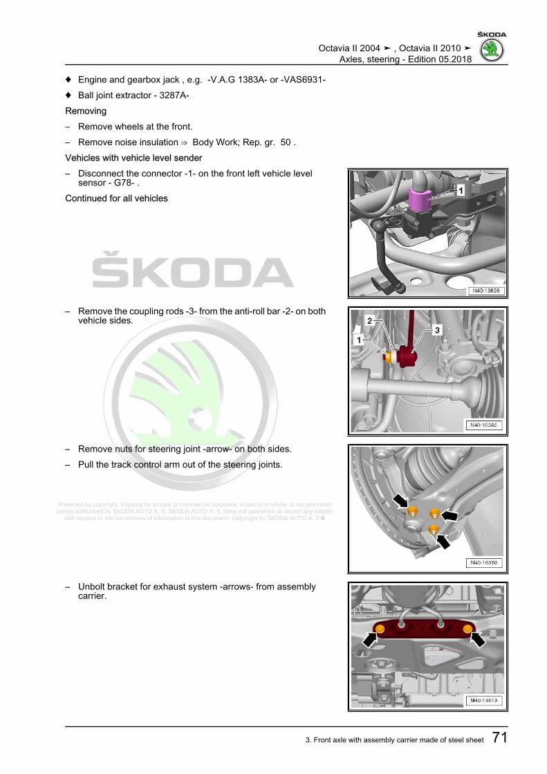
Protected by copyright. Copying for private or commercial purposes, in part or in whole, is not permitted unless authorised by ŠKODA AUTO A. S. ŠKODA AUTO A. S. does not guarantee or accept any liability
with respect to the correctness of information in this document. Copyright by ŠKODA AUTO A. S.�
♦ Engine and gearbox jack , e.g. -V.A.G 1383A- or -VAS6931-♦ Ball joint extractor - 3287A-Removing– Remove wheels at the front.– Remove noise insulation ⇒ Body Work; Rep. gr. 50 .Vehicles with vehicle level sender– Disconnect the connector -1- on the front left vehicle level
sensor - G78- .Continued for all vehicles
– Remove the coupling rods -3- from the anti-roll bar -2- on bothvehicle sides.
– Remove nuts for steering joint -arrow- on both sides.– Pull the track control arm out of the steering joints.
– Unbolt bracket for exhaust system -arrows- from assemblycarrier.
Octavia II 2004 ➤ , Octavia II 2010 ➤Axles, steering - Edition 05.2018
3. Front axle with assembly carrier made of steel sheet 71
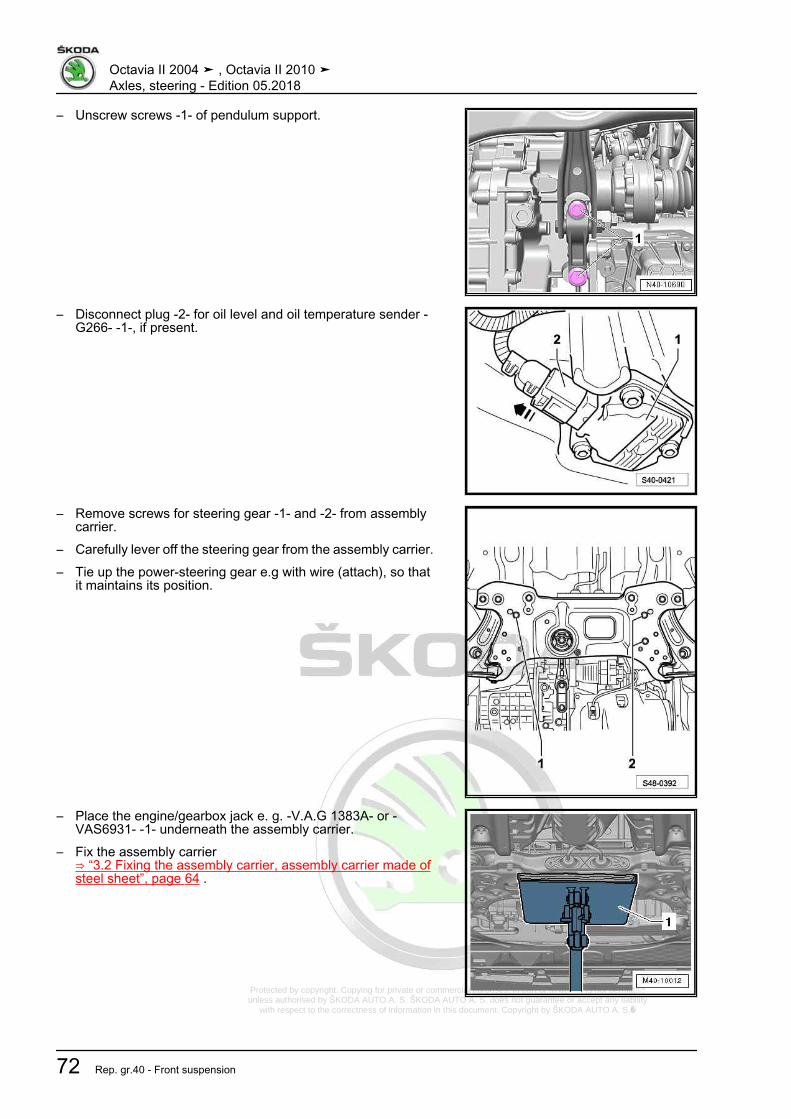
Protected by copyright. Copying for private or commercial purposes, in part or in whole, is not permitted unless authorised by ŠKODA AUTO A. S. ŠKODA AUTO A. S. does not guarantee or accept any liability
with respect to the correctness of information in this document. Copyright by ŠKODA AUTO A. S.�
– Unscrew screws -1- of pendulum support.
– Disconnect plug -2- for oil level and oil temperature sender -G266- -1-, if present.
– Remove screws for steering gear -1- and -2- from assemblycarrier.
– Carefully lever off the steering gear from the assembly carrier.– Tie up the power-steering gear e.g with wire (attach), so that
it maintains its position.
– Place the engine/gearbox jack e. g. -V.A.G 1383A- or -VAS6931- -1- underneath the assembly carrier.
– Fix the assembly carrier⇒ “3.2 Fixing the assembly carrier, assembly carrier made ofsteel sheet”, page 64 .
Octavia II 2004 ➤ , Octavia II 2010 ➤Axles, steering - Edition 05.2018
72 Rep. gr.40 - Front suspension

Protected by copyright. Copying for private or commercial purposes, in part or in whole, is not permitted unless authorised by ŠKODA AUTO A. S. ŠKODA AUTO A. S. does not guarantee or accept any liability
with respect to the correctness of information in this document. Copyright by ŠKODA AUTO A. S.�
– Secure assembly carrier on engine/gearbox jack e.g. -V.A.G1383A- or -VAS6931- with corresponding strap.
– Unscrew the screws -1- and lower the assembly carrier bymax. 11 cm. While doing so observe the electrical cables.
Octavia II 2004 ➤ , Octavia II 2010 ➤Axles, steering - Edition 05.2018
3. Front axle with assembly carrier made of steel sheet 73

Protected by copyright. Copying for private or commercial purposes, in part or in whole, is not permitted unless authorised by ŠKODA AUTO A. S. ŠKODA AUTO A. S. does not guarantee or accept any liability
with respect to the correctness of information in this document. Copyright by ŠKODA AUTO A. S.�
– Detach the screw -1- for the cable duct -2- from the assemblycarrier.
– Slacken the wiring harness for oil level and oil temperaturesender - G266- (if present).
– Lower the assembly carrier with engine/gearbox jack e. g. -V.A.G 1383A- or -VAS6931- .
InstallingInstallation is carried out in the reverse order; pay attention to thefollowing points:
Note
It is necessary to perform an axle alignment in the event of:⇒ “3.3 Axle alignment”, page 309
– On vehicles with vehicle level encoder, after disconnectingand connecting the connector, perform the basic adjustmentof the headlamps ⇒ Maintenance ; Booklet Octavia II .
– Perform a test drive– Check the steering wheel position during the test drive.
Note
If after the test drive and with the wheels pointing straight aheadthe steering wheel is off straight, perform an axle alignment⇒ “3.3 Axle alignment”, page 309 .
Tightening torques - summaries of components
Note
Replace bolts / nuts that are tightened at an angle of rotation, aswell as replacement components after removal.
♦ ⇒ “3.1 Summary of components - assembly carrier, sheet steelassembly carrier”, page 58
♦ ⇒ “1.1 Summary of components - steering column”,page 320
♦ ⇒ “2.1 Summary of components - steering gear”, page 356♦ ⇒ “1.2 Tightening torque of the wheel screws”, page 301♦ Pendulum support to gearbox ⇒ Engine; Rep. gr. 10♦ Exhaust System ⇒ Engine; Rep. gr. 26♦ Noise insulation ⇒ Body work assembly; Rep. gr. 50
Octavia II 2004 ➤ , Octavia II 2010 ➤Axles, steering - Edition 05.2018
74 Rep. gr.40 - Front suspension

Protected by copyright. Copying for private or commercial purposes, in part or in whole, is not permitted unless authorised by ŠKODA AUTO A. S. ŠKODA AUTO A. S. does not guarantee or accept any liability
with respect to the correctness of information in this document. Copyright by ŠKODA AUTO A. S.�
3.5 Removing and installing assembly car‐rier with steering gear, sheet steel as‐sembly carrier
⇒ “3.5.1 Removing and installing assembly carrier with steeringgear, sheet steel assembly carrier, left-hand drive”, page 75⇒ “3.5.2 Removing and installing assembly carrier with steeringgear, sheet steel assembly carrier, right-hand drive”, page 81
3.5.1 Removing and installing assembly car‐rier with steering gear, sheet steel as‐sembly carrier, left-hand drive
Special tools and workshop equipment required♦ Fixing device - T10096- (smaller diameter)♦ Fixing device - T10452- (larger diameter)♦ Engine and gearbox jack , e.g. -V.A.G 1383A- or -VAS6931-♦ Ball joint extractor - 3287A-Removing– Turn steering wheel to the straight ahead position.– Remove the ignition key and lock the steering wheel lock.– Disconnect battery ⇒ Electrical System; Rep. gr. 27 .– Remove nuts -arrows- and remove the footwell trim.
Octavia II 2004 ➤ , Octavia II 2010 ➤Axles, steering - Edition 05.2018
3. Front axle with assembly carrier made of steel sheet 75

Protected by copyright. Copying for private or commercial purposes, in part or in whole, is not permitted unless authorised by ŠKODA AUTO A. S. ŠKODA AUTO A. S. does not guarantee or accept any liability
with respect to the correctness of information in this document. Copyright by ŠKODA AUTO A. S.�
– Remove bolt -1- from universal coupling -2- and pull off uni‐versal joint in -direction of arrow-.
Caution
If the universal coupling is detached from the steering gear, donot carry out any of the following work♦ Reconnecting battery♦ Switch on the ignition♦ Rotating the steering gear♦ Rotating the steering column
You must observe these points because if you do not, irrepar‐able damage may result.
– Remove wheels at the front.– Remove noise insulation ⇒ Body Work; Rep. gr. 50 .Vehicles with vehicle level sender
– Disconnect the connector -1- on the front left vehicle levelsensor - G78- .
– Remove the coupling rods -3- from the anti-roll bar -2- on bothvehicle sides.
– Remove nuts for steering joint -arrow- on both sides.– Pull the track control arm out of the steering joints.– Loosen nut of track rod end on both sides, but do not unscrew
yet.
Note
To protect the thread, screw the nut a couple of thread turns ontothe stud of the track rod end.
Octavia II 2004 ➤ , Octavia II 2010 ➤Axles, steering - Edition 05.2018
76 Rep. gr.40 - Front suspension

Protected by copyright. Copying for private or commercial purposes, in part or in whole, is not permitted unless authorised by ŠKODA AUTO A. S. ŠKODA AUTO A. S. does not guarantee or accept any liability
with respect to the correctness of information in this document. Copyright by ŠKODA AUTO A. S.�
– Remove the steering joint/track rod from the wheel-bearinghousing with the ball joint extractor - 3287A- .
– Unscrew nut for suspension link/track rod on both sides.
– Unbolt bracket for exhaust system -arrows- from assemblycarrier.
– Unscrew screws -1- of pendulum support.
– Disconnect plug -2- for oil level and oil temperature sender -G266- -1-, if present.
Octavia II 2004 ➤ , Octavia II 2010 ➤Axles, steering - Edition 05.2018
3. Front axle with assembly carrier made of steel sheet 77

Protected by copyright. Copying for private or commercial purposes, in part or in whole, is not permitted unless authorised by ŠKODA AUTO A. S. ŠKODA AUTO A. S. does not guarantee or accept any liability
with respect to the correctness of information in this document. Copyright by ŠKODA AUTO A. S.�
– Release the screw -1- for the cable duct -2- from the assemblycarrier.
– Place the engine/gearbox jack e. g. -V.A.G 1383A- or -VAS6931- -1- underneath the assembly carrier.
– Fix the assembly carrier⇒ “3.2 Fixing the assembly carrier, assembly carrier made ofsteel sheet”, page 64 .
– Secure assembly carrier to engine/gearbox jack e.g. -V.A.G1383A- or -VAS6931- with corresponding strap.
– Unscrew the screws -1- and lower the assembly carrier bymax. 11 cm. While doing so observe the electrical cables.
Octavia II 2004 ➤ , Octavia II 2010 ➤Axles, steering - Edition 05.2018
78 Rep. gr.40 - Front suspension
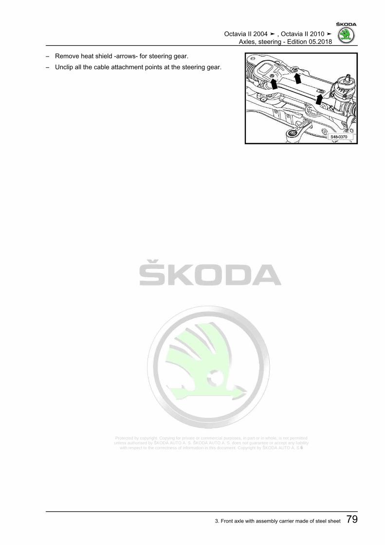
Protected by copyright. Copying for private or commercial purposes, in part or in whole, is not permitted unless authorised by ŠKODA AUTO A. S. ŠKODA AUTO A. S. does not guarantee or accept any liability
with respect to the correctness of information in this document. Copyright by ŠKODA AUTO A. S.�
– Remove heat shield -arrows- for steering gear.– Unclip all the cable attachment points at the steering gear.
Octavia II 2004 ➤ , Octavia II 2010 ➤Axles, steering - Edition 05.2018
3. Front axle with assembly carrier made of steel sheet 79
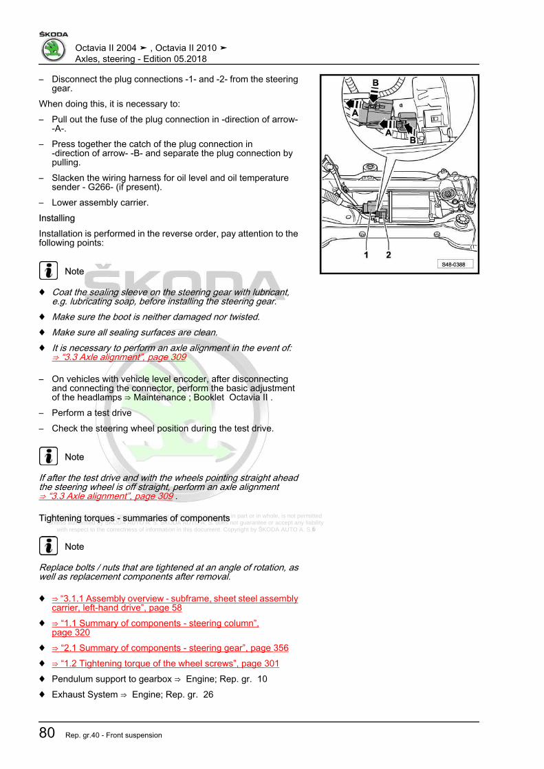
Protected by copyright. Copying for private or commercial purposes, in part or in whole, is not permitted unless authorised by ŠKODA AUTO A. S. ŠKODA AUTO A. S. does not guarantee or accept any liability
with respect to the correctness of information in this document. Copyright by ŠKODA AUTO A. S.�
– Disconnect the plug connections -1- and -2- from the steeringgear.
When doing this, it is necessary to:– Pull out the fuse of the plug connection in -direction of arrow-
-A-.– Press together the catch of the plug connection in
-direction of arrow- -B- and separate the plug connection bypulling.
– Slacken the wiring harness for oil level and oil temperaturesender - G266- (if present).
– Lower assembly carrier.InstallingInstallation is performed in the reverse order, pay attention to thefollowing points:
Note
♦ Coat the sealing sleeve on the steering gear with lubricant,e.g. lubricating soap, before installing the steering gear.
♦ Make sure the boot is neither damaged nor twisted.♦ Make sure all sealing surfaces are clean.♦ It is necessary to perform an axle alignment in the event of:
⇒ “3.3 Axle alignment”, page 309
– On vehicles with vehicle level encoder, after disconnectingand connecting the connector, perform the basic adjustmentof the headlamps ⇒ Maintenance ; Booklet Octavia II .
– Perform a test drive– Check the steering wheel position during the test drive.
Note
If after the test drive and with the wheels pointing straight aheadthe steering wheel is off straight, perform an axle alignment⇒ “3.3 Axle alignment”, page 309 .
Tightening torques - summaries of components
Note
Replace bolts / nuts that are tightened at an angle of rotation, aswell as replacement components after removal.
♦ ⇒ “3.1.1 Assembly overview - subframe, sheet steel assemblycarrier, left-hand drive”, page 58
♦ ⇒ “1.1 Summary of components - steering column”,page 320
♦ ⇒ “2.1 Summary of components - steering gear”, page 356♦ ⇒ “1.2 Tightening torque of the wheel screws”, page 301♦ Pendulum support to gearbox ⇒ Engine; Rep. gr. 10♦ Exhaust System ⇒ Engine; Rep. gr. 26
Octavia II 2004 ➤ , Octavia II 2010 ➤Axles, steering - Edition 05.2018
80 Rep. gr.40 - Front suspension

Protected by copyright. Copying for private or commercial purposes, in part or in whole, is not permitted unless authorised by ŠKODA AUTO A. S. ŠKODA AUTO A. S. does not guarantee or accept any liability
with respect to the correctness of information in this document. Copyright by ŠKODA AUTO A. S.�
♦ Noise insulation ⇒ Body work assembly; Rep. gr. 50
3.5.2 Removing and installing assembly car‐rier with steering gear, sheet steel as‐sembly carrier, right-hand drive
Special tools and workshop equipment required♦ Fixing device - T10096- (smaller diameter)♦ Fixing device - T10452- (larger diameter)♦ Engine and gearbox jack , e.g. -V.A.G 1383A- or -VAS6931-♦ Ball joint extractor - 3287A-Removing
Note
On right-hand drive vehicles, the wiring harness is removed fromthe engine compartment at the same when removing the assem‐bly carrier.
– Turn steering wheel to the straight ahead position.– Remove the ignition key and lock the steering wheel lock.– Remove battery and battery tray ⇒ Electrical System; Rep.
gr. 27 .– Remove air filter and air guide with air mass meter ⇒ Engine;
Rep. gr. 23 or ⇒ Engine; Rep. gr. 24 .– Disconnect cable -1- from the E-box.– Disconnect plug -3- for oil level and oil temperature sender -
G266- , if present.– Disconnect earth line -4-.– Unclip wiring harness -2-.
– Remove the fixing nut -arrow A- and the expansion clamp-arrow B- of the footwell covering.
– Unclip footwell panelling in -arrow direction C-.
Octavia II 2004 ➤ , Octavia II 2010 ➤Axles, steering - Edition 05.2018
3. Front axle with assembly carrier made of steel sheet 81

Protected by copyright. Copying for private or commercial purposes, in part or in whole, is not permitted unless authorised by ŠKODA AUTO A. S. ŠKODA AUTO A. S. does not guarantee or accept any liability
with respect to the correctness of information in this document. Copyright by ŠKODA AUTO A. S.�
– Remove bolt -1- from universal coupling -2- and pull off uni‐versal joint in -direction of arrow-.
Caution
If the universal coupling is detached from the steering gear, donot carry out any of the following work♦ Reconnecting battery♦ Switch on the ignition♦ Rotating the steering gear♦ Rotating the steering column
You must observe these points because if you do not, irrepar‐able damage may result.
– Remove wheels at the front.– Remove noise insulation ⇒ Body Work; Rep. gr. 50 .Vehicles with vehicle level sender
– Disconnect the connector -1- on the front left vehicle levelsensor - G78- .
Continued for all vehicles
– Remove the coupling rods -3- from the anti-roll bar -2- on bothvehicle sides.
– Remove nuts for steering joint -arrow- on both sides.– Pull the track control arm out of the steering joints.– Loosen nut of track rod end on both sides, but do not unscrew
yet.
Note
To protect the thread, screw the nut a couple of thread turns ontothe stud of the track rod end.
Octavia II 2004 ➤ , Octavia II 2010 ➤Axles, steering - Edition 05.2018
82 Rep. gr.40 - Front suspension

Protected by copyright. Copying for private or commercial purposes, in part or in whole, is not permitted unless authorised by ŠKODA AUTO A. S. ŠKODA AUTO A. S. does not guarantee or accept any liability
with respect to the correctness of information in this document. Copyright by ŠKODA AUTO A. S.�
– Remove the steering joint/track rod from the wheel-bearinghousing with the ball joint extractor - 3287A- .
– Unscrew nut for suspension link/track rod.
– Unbolt bracket for exhaust system -arrows- from assemblycarrier.
– Unscrew screws -1- of pendulum support.
– Disconnect plug -2- for oil level and oil temperature sender -G266- -1-, if present.
Octavia II 2004 ➤ , Octavia II 2010 ➤Axles, steering - Edition 05.2018
3. Front axle with assembly carrier made of steel sheet 83

Protected by copyright. Copying for private or commercial purposes, in part or in whole, is not permitted unless authorised by ŠKODA AUTO A. S. ŠKODA AUTO A. S. does not guarantee or accept any liability
with respect to the correctness of information in this document. Copyright by ŠKODA AUTO A. S.�
– Place the engine/gearbox jack e. g. -V.A.G 1383A- or -VAS6931- -1- underneath the assembly carrier.
– Fix the assembly carrier⇒ “3.2 Fixing the assembly carrier, assembly carrier made ofsteel sheet”, page 64 .
– Secure assembly carrier to engine/gearbox jack e.g. -V.A.G1383A- or -VAS6931- with corresponding strap.
Octavia II 2004 ➤ , Octavia II 2010 ➤Axles, steering - Edition 05.2018
84 Rep. gr.40 - Front suspension

Protected by copyright. Copying for private or commercial purposes, in part or in whole, is not permitted unless authorised by ŠKODA AUTO A. S. ŠKODA AUTO A. S. does not guarantee or accept any liability
with respect to the correctness of information in this document. Copyright by ŠKODA AUTO A. S.�
– Unscrew screws -1- and lower the assembly carrier. While do‐ing so, pay attention to the electrical cables which must beremoved together with the assembly carrier.
InstallingInstallation is performed in the reverse order, pay attention to thefollowing points:
Note
♦ Coat the sealing sleeve on the steering gear with lubricant,e.g. lubricating soap, before installing the steering gear.
♦ Make sure the boot is neither damaged nor twisted.♦ Make sure all sealing surfaces are clean.♦ It is necessary to perform an axle alignment in the event of:
⇒ “3.3 Axle alignment”, page 309
– On vehicles with vehicle level encoder, after disconnectingand connecting the connector, perform the basic adjustmentof the headlamps ⇒ Maintenance ; Booklet Octavia II .
– Perform a test drive– Check the steering wheel position during the test drive.
Note
If after the test drive and with the wheels pointing straight aheadthe steering wheel is off straight, perform an axle alignment⇒ “3.3 Axle alignment”, page 309 .
Tightening torques - summaries of components
Note
Replace bolts / nuts that are tightened at an angle of rotation, aswell as replacement components after removal.
♦ ⇒ “3.1.2 Assembly overview - subframe, sheet steel assemblycarrier, right hand drive”, page 62
♦ ⇒ “1.1 Summary of components - steering column”,page 320
♦ ⇒ “2.1 Summary of components - steering gear”, page 356♦ ⇒ “1.2 Tightening torque of the wheel screws”, page 301♦ Pendulum support to gearbox ⇒ Engine; Rep. gr. 10♦ Exhaust System ⇒ Engine; Rep. gr. 26♦ Battery and battery tray ⇒ Electrical system; Rep. gr. 27 .♦ Air filter and air guide with air mass meter ⇒ Engine; Rep. gr.
23 or ⇒ Engine; Rep. gr. 24 .♦ Noise insulation ⇒ Body work assembly; Rep. gr. 50
Octavia II 2004 ➤ , Octavia II 2010 ➤Axles, steering - Edition 05.2018
3. Front axle with assembly carrier made of steel sheet 85

Protected by copyright. Copying for private or commercial purposes, in part or in whole, is not permitted unless authorised by ŠKODA AUTO A. S. ŠKODA AUTO A. S. does not guarantee or accept any liability
with respect to the correctness of information in this document. Copyright by ŠKODA AUTO A. S.�
3.6 Replacing rubber-metal bearing fortrack pendulum support, sheet steel as‐sembly carrier
Special tools and workshop equipment required♦ Hydraulic cylinder - VAS 6178-♦ Foot pump - VAS 6179-♦ Assembly device - VAS 6779- or -VAS 6779A-♦ Pressure spindle - MP3-408 (VW 412)-♦ Pressure plate - MP3-406 (VW 401)-Replacing rubber-metal bearing for pendulum support.– Remove noise insulation ⇒ Body Work; Rep. gr. 50 .– Remove the coupling rods -3- from the anti-roll bar -2- on both
vehicle sides.
– Remove screws -1- and -2- for anti-roll clamps.• Leave the anti-roll bar in the installation position.– Remove pendulum support ⇒ Engine; Rep. gr. 10 .
Octavia II 2004 ➤ , Octavia II 2010 ➤Axles, steering - Edition 05.2018
86 Rep. gr.40 - Front suspension

Protected by copyright. Copying for private or commercial purposes, in part or in whole, is not permitted unless authorised by ŠKODA AUTO A. S. ŠKODA AUTO A. S. does not guarantee or accept any liability
with respect to the correctness of information in this document. Copyright by ŠKODA AUTO A. S.�
– Fit Assembly device - VAS 6779- or -VAS 6779A- to the as‐sembly carrier as shown in the figure.
– Place the pressure piece - VAS 6779/1- -1- onto the rubber-metal bearing with the flat side -arrow- in the driving direction.
1 - Thrust piece - VAS 6779/1-2 - Knock-in bushing - VAS 6779/4-3 - Thrust piece - VAS 6779/5-4 - Hydraulic cylinder - VAS 6178-5 - Hexagon nut - VAS 6779/3-6 - Threaded rod - VAS 6779/2-
– Press in both bonded rubber bushes far enough for the topbonded rubber bushing -2- in the opening for pendulum sup‐port in the assembly carrier -arrow- is visible.
– Carry out a visual inspection of the rubber-metal bearing -2-.• if the upper part is deformed, it must be disrupted through the
opening in the assembly carrier -arrow-.– Push through the outer ring for the top part of the rubber-metal
bearing -2- e.g. using a cold chisel -1-.
Note
Pushing through the deformed bearing prevents tilting in the as‐sembly carrier during removal.
– Remove both parts of the rubber-metal bearing at the sametime.
Prepare the rubber-metal bearing for pressing in– Place the top part -1- and bottom part -2- on top of each other
so that the edges of the opening -arrows- fit together precisely.– Screw both parts together with the original screw -3- (hand-
tight); the cutouts -arrows- must face each other exactly, thescrew head points upwards.
Octavia II 2004 ➤ , Octavia II 2010 ➤Axles, steering - Edition 05.2018
3. Front axle with assembly carrier made of steel sheet 87
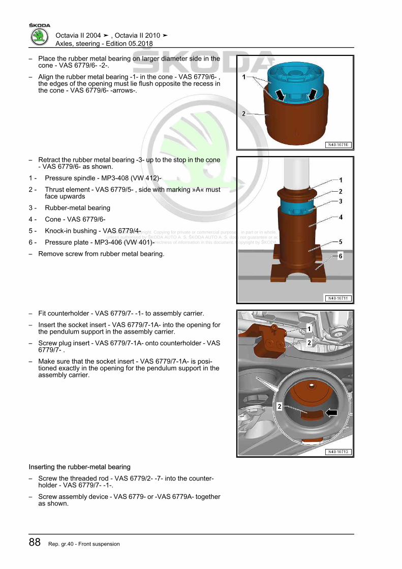
Protected by copyright. Copying for private or commercial purposes, in part or in whole, is not permitted unless authorised by ŠKODA AUTO A. S. ŠKODA AUTO A. S. does not guarantee or accept any liability
with respect to the correctness of information in this document. Copyright by ŠKODA AUTO A. S.�
– Place the rubber metal bearing on larger diameter side in thecone - VAS 6779/6- -2-.
– Align the rubber metal bearing -1- in the cone - VAS 6779/6- ,the edges of the opening must lie flush opposite the recess inthe cone - VAS 6779/6- -arrows-.
– Retract the rubber metal bearing -3- up to the stop in the cone- VAS 6779/6- as shown.
1 - Pressure spindle - MP3-408 (VW 412)-2 - Thrust element - VAS 6779/5- , side with marking »A« must
face upwards3 - Rubber-metal bearing4 - Cone - VAS 6779/6-5 - Knock-in bushing - VAS 6779/4-6 - Pressure plate - MP3-406 (VW 401)-– Remove screw from rubber metal bearing.
– Fit counterholder - VAS 6779/7- -1- to assembly carrier.– Insert the socket insert - VAS 6779/7-1A- into the opening for
the pendulum support in the assembly carrier.– Screw plug insert - VAS 6779/7-1A- onto counterholder - VAS
6779/7- .– Make sure that the socket insert - VAS 6779/7-1A- is posi‐
tioned exactly in the opening for the pendulum support in theassembly carrier.
Inserting the rubber-metal bearing– Screw the threaded rod - VAS 6779/2- -7- into the counter‐
holder - VAS 6779/7- -1-.– Screw assembly device - VAS 6779- or -VAS 6779A- together
as shown.
Octavia II 2004 ➤ , Octavia II 2010 ➤Axles, steering - Edition 05.2018
88 Rep. gr.40 - Front suspension

Protected by copyright. Copying for private or commercial purposes, in part or in whole, is not permitted unless authorised by ŠKODA AUTO A. S. ŠKODA AUTO A. S. does not guarantee or accept any liability
with respect to the correctness of information in this document. Copyright by ŠKODA AUTO A. S.�
1 - Counterholder - VAS6779/7-2 - Cone - VAS 6779/6-
❑ The marking -arrow- onthe pipe must point ex‐actly to the centre be‐tween the screws on thecounterholder - VAS6779/7- -arrow-
3 - Thrust piece - VAS 6779/9-4 - Composite seal - VAS6779/8-
❑ Marking -I- on the com‐posite seal must line upwith marking -X- on thethrust piece - VAS6779/9- .
5 - Hydraulic cylinder - VAS6178-6 - Hexagon nut - VAS 6779/3-7 - Threaded rod - VAS6779/2-
– Draw in both parts of the rubber-metal bearing.– Remove the assembly device - VAS 6779- or -VAS 6779A-
from the assembly carrier.– Check the bearing of the rubber-metal bearing.– Screw the anti-roll bar with the assembly carrier, and the cou‐
pling rods.– Install pendulum support ⇒ Engine; Rep. gr. 10 .– Install the noise insulation ⇒ Body Work; Rep. gr. 50 .Tightening torques - summaries of components
Note
Replace bolts / nuts that are tightened at an angle of rotation, aswell as replacement components after removal.
♦ ⇒ “3.1.1 Assembly overview - subframe, sheet steel assemblycarrier, left-hand drive”, page 58
♦ ⇒ “3.1.2 Assembly overview - subframe, sheet steel assemblycarrier, right hand drive”, page 62
Octavia II 2004 ➤ , Octavia II 2010 ➤Axles, steering - Edition 05.2018
3. Front axle with assembly carrier made of steel sheet 89

Protected by copyright. Copying for private or commercial purposes, in part or in whole, is not permitted unless authorised by ŠKODA AUTO A. S. ŠKODA AUTO A. S. does not guarantee or accept any liability
with respect to the correctness of information in this document. Copyright by ŠKODA AUTO A. S.�
♦ Pendulum support ⇒ Engine; Rep. gr. 10 .♦ Noise insulation ⇒ Body work assembly; Rep. gr. 50
3.7 Removing and installing the anti-roll bar,sheet steel assembly carrier
⇒ “3.7.1 Removing and installing the anti-roll bar, steel sheet as‐sembly carrier, left-hand drive”, page 90⇒ “3.7.2 Removing and installing the anti-roll bar, steel sheet as‐sembly carrier, right-hand drive”, page 92
3.7.1 Removing and installing the anti-roll bar,steel sheet assembly carrier, left-handdrive
Special tools and workshop equipment required♦ Fixing device - T10096- (smaller diameter)♦ Fixing device - T10452- (larger diameter)♦ Ball joint extractor - 3287A-♦ Engine and gearbox jack , e.g. -V.A.G 1383A- or -VAS6931-Removing– Remove wheels.– Remove noise insulation ⇒ Body Work; Rep. gr. 50 .– Detach screws for stabiliser tabs -1- and -2-.– Lower the assembly carrier in the service position
⇒ “3.3 Lower the assembly carrier in the service position, as‐sembly carrier made of sheet steel”, page 66 .
– Remove the heat shield -arrows- above the steering gear.
Octavia II 2004 ➤ , Octavia II 2010 ➤Axles, steering - Edition 05.2018
90 Rep. gr.40 - Front suspension

Protected by copyright. Copying for private or commercial purposes, in part or in whole, is not permitted unless authorised by ŠKODA AUTO A. S. ŠKODA AUTO A. S. does not guarantee or accept any liability
with respect to the correctness of information in this document. Copyright by ŠKODA AUTO A. S.�
– Remove screws for stabiliser tabs -1- and -2-.
– Remove the anti-roll bar -1- from the assembly carrier towardsthe front via the support for the assembly carrier.
InstallingInstallation is performed in the reverse order, pay attention to thefollowing points:
Note
♦ Coat the sealing sleeve on the steering gear with lubricant,e.g. lubricating soap, before installing the steering gear.
♦ After positioning the steering gear on the drive shaft make surethe seal on the steering gear is not bent on the assembly plateand correctly seals the footwell opening. Otherwise this couldcause water penetration and/or noise.
♦ Make sure all sealing surfaces are clean.
– Perform a test drive– Check the steering wheel position during the test drive.
Note
If after the test drive and with the wheels pointing straight aheadthe steering wheel is off straight, perform an axle alignment⇒ “3.3 Axle alignment”, page 309 .
Tightening torques - summaries of components
Note
Replace bolts / nuts that are tightened at an angle of rotation, aswell as replacement components after removal.
♦ ⇒ “3.1.1 Assembly overview - subframe, sheet steel assemblycarrier, left-hand drive”, page 58
♦ Noise insulation ⇒ Body work assembly; Rep. gr. 50
Octavia II 2004 ➤ , Octavia II 2010 ➤Axles, steering - Edition 05.2018
3. Front axle with assembly carrier made of steel sheet 91

Protected by copyright. Copying for private or commercial purposes, in part or in whole, is not permitted unless authorised by ŠKODA AUTO A. S. ŠKODA AUTO A. S. does not guarantee or accept any liability
with respect to the correctness of information in this document. Copyright by ŠKODA AUTO A. S.�
3.7.2 Removing and installing the anti-roll bar,steel sheet assembly carrier, right-handdrive
Special tools and workshop equipment required♦ Fixing device - T10096- (smaller diameter)♦ Fixing device - T10452- (larger diameter)♦ Ball joint extractor - 3287A-♦ Engine and gearbox jack , e.g. -V.A.G 1383A- or -VAS6931-Removing– Remove assembly carrier without steering gear
⇒ “3.4 Removing and installing assembly carrier without steer‐ing gear, sheet steel assembly carrier”, page 70 .
– Remove screws for stabiliser tabs -1- and -2-.– Remove anti-roll bar from assembly carrier.InstallingInstallation is performed in the reverse order, pay attention to thefollowing points:– Perform a test drive– Check the steering wheel position during the test drive.
Note
If after the test drive and with the wheels pointing straight aheadthe steering wheel is off straight, perform an axle alignment⇒ “3.3 Axle alignment”, page 309 .
Tightening torques - summaries of components
Note
Replace bolts / nuts that are tightened at an angle of rotation, aswell as replacement components after removal.
♦ ⇒ “3.1.2 Assembly overview - subframe, sheet steel assemblycarrier, right hand drive”, page 62
Octavia II 2004 ➤ , Octavia II 2010 ➤Axles, steering - Edition 05.2018
92 Rep. gr.40 - Front suspension

Protected by copyright. Copying for private or commercial purposes, in part or in whole, is not permitted unless authorised by ŠKODA AUTO A. S. ŠKODA AUTO A. S. does not guarantee or accept any liability
with respect to the correctness of information in this document. Copyright by ŠKODA AUTO A. S.�
3.8 Removing and installing coupling rodfrom anti-roll bar, sheet steel assemblycarrier
Removing– Unscrew nut -arrow-.
– Unscrew nut -1-.– Pull out coupling rod -3- from the anti-roll bar -2-.InstallingInstallation is carried out in the reverse order.Tightening torques - summaries of components
Note
Replace bolts / nuts that are tightened at an angle of rotation, aswell as replacement components after removal.
♦ ⇒ “3.1 Summary of components - assembly carrier, sheet steelassembly carrier”, page 58
3.9 Removing and installing the track con‐trol arm, sheet steel assembly carrier
⇒ “3.9.1 Removing and installing the track control arm, sheet steelassembly carrier”, page 93⇒ “3.9.2 Removing and installing left track control arm, sheet steelassembly carrier vehicles with an automatic gearbox”,page 96
3.9.1 Removing and installing the track con‐trol arm, sheet steel assembly carrier
Removing– Remove wheel.
Octavia II 2004 ➤ , Octavia II 2010 ➤Axles, steering - Edition 05.2018
3. Front axle with assembly carrier made of steel sheet 93

Protected by copyright. Copying for private or commercial purposes, in part or in whole, is not permitted unless authorised by ŠKODA AUTO A. S. ŠKODA AUTO A. S. does not guarantee or accept any liability
with respect to the correctness of information in this document. Copyright by ŠKODA AUTO A. S.�
Vehicles with vehicle level sender– Unscrew nut -1-.– Remove the holder -2- of the front left vehicle level encoder -
G78- from the wishbone -3-.Continued for all vehicles
– Release fixing nuts -arrows-.– Pull suspension link out of swivel joint and turn wheel bearing
housing to outside to relieve load on suspension link.
– Remove screws -arrows-.
Note
The rear bolt is fitted with a washer. Counterhold the washer whenreleasing.
– Turn the track control arm out of the assembly carrier and re‐move -arrows-.
InstallingInstallation is performed in the reverse order, pay attention to thefollowing points:
Octavia II 2004 ➤ , Octavia II 2010 ➤Axles, steering - Edition 05.2018
94 Rep. gr.40 - Front suspension

Protected by copyright. Copying for private or commercial purposes, in part or in whole, is not permitted unless authorised by ŠKODA AUTO A. S. ŠKODA AUTO A. S. does not guarantee or accept any liability
with respect to the correctness of information in this document. Copyright by ŠKODA AUTO A. S.�
– Insert suspension link -arrow- at rear into assembly carrier,insert new screw with new nut, but do not tighten yet.
– Swivel suspension link forwards and insert into the assemblycarrier.
– Screw in new bolt for front bearing bracket for wishbone par‐tially, but do not tighten yet.
Note
Tighten screws/nuts when the vehicle is in unladen weight posi‐tion⇒ “3.5 Lift the wheel bearing in the unladen weight position”, page5 .
– Insert swivel joint in suspension link and tighten bolts-arrows-.
– Move the vehicle into the unladen weight position⇒ “3.5 Lift the wheel bearing in the unladen weight position”,page 5 .
Octavia II 2004 ➤ , Octavia II 2010 ➤Axles, steering - Edition 05.2018
3. Front axle with assembly carrier made of steel sheet 95

Protected by copyright. Copying for private or commercial purposes, in part or in whole, is not permitted unless authorised by ŠKODA AUTO A. S. ŠKODA AUTO A. S. does not guarantee or accept any liability
with respect to the correctness of information in this document. Copyright by ŠKODA AUTO A. S.�
– Tighten the screws of the control arm -arrows- to the specifiedtightening torque.
Note
Tighten screws/nuts when the vehicle is in unladen weight posi‐tion⇒ “3.5 Lift the wheel bearing in the unladen weight position”, page5 .
– On vehicles with vehicle level encoder, after disconnectingand connecting the connector, perform the basic adjustmentof the headlamps ⇒ Maintenance ; Booklet Octavia II .
– Perform a test drive– Check the steering wheel position during the test drive.
Note
If after the test drive and with the wheels pointing straight aheadthe steering wheel is off straight, perform an axle alignment⇒ “3.3 Axle alignment”, page 309 .
Tightening torques - summaries of components
Note
Replace bolts / nuts that are tightened at an angle of rotation, aswell as replacement components after removal.
♦ ⇒ “3.1 Summary of components - assembly carrier, sheet steelassembly carrier”, page 58
♦ ⇒ “1.1 Summary of components - vehicle level sender front”,page 293
♦ ⇒ “1.2 Tightening torque of the wheel screws”, page 301♦ Noise insulation ⇒ Body work assembly; Rep. gr. 50
3.9.2 Removing and installing left track con‐trol arm, sheet steel assembly carriervehicles with an automatic gearbox
Special tools and workshop equipment required♦ Fixing device - T10096- (smaller diameter)♦ Fixing device - T10452- (larger diameter)♦ Engine and gearbox jack , e.g. -V.A.G 1383A- or -VAS6931-
Note
♦ The following procedure applies to removing and installing theleft suspension link.
♦ Removing and installing right suspension link⇒ “3.9.1 Removing and installing the track control arm, sheetsteel assembly carrier”, page 93 .
Octavia II 2004 ➤ , Octavia II 2010 ➤Axles, steering - Edition 05.2018
96 Rep. gr.40 - Front suspension

Protected by copyright. Copying for private or commercial purposes, in part or in whole, is not permitted unless authorised by ŠKODA AUTO A. S. ŠKODA AUTO A. S. does not guarantee or accept any liability
with respect to the correctness of information in this document. Copyright by ŠKODA AUTO A. S.�
Removing– Turn steering wheel to the straight ahead position.– Remove the ignition key and lock the steering wheel lock.– Disconnect battery ⇒ Electrical System; Rep. gr. 27 .Left-hand drive– Remove nuts -arrows- and remove the footwell trim.Right-hand drive
– Remove the fixing nut -arrow A- and the expansion clamp-arrow B- of the footwell covering.
– Unclip footwell panelling in -arrow direction C-.Continued for all vehicles
– Remove bolt -1- from universal coupling -2- and pull off uni‐versal joint in -direction of arrow-.
Caution
If the universal coupling is detached from the steering gear, donot carry out any of the following work♦ Reconnecting battery♦ Switch on the ignition♦ Rotating the steering gear♦ Rotating the steering column
You must observe these points because if you do not, irrepar‐able damage may result.
– Remove front left wheel.– Dimension -a- Measure unladen weight of the vehicle
⇒ “3.5 Lift the wheel bearing in the unladen weight position”,page 5 ,
– Remove noise insulation ⇒ Body Work; Rep. gr. 50 .Vehicles with vehicle level sender
Octavia II 2004 ➤ , Octavia II 2010 ➤Axles, steering - Edition 05.2018
3. Front axle with assembly carrier made of steel sheet 97

Protected by copyright. Copying for private or commercial purposes, in part or in whole, is not permitted unless authorised by ŠKODA AUTO A. S. ŠKODA AUTO A. S. does not guarantee or accept any liability
with respect to the correctness of information in this document. Copyright by ŠKODA AUTO A. S.�
– Unscrew nut -1-.– Remove the holder -2- of the front left vehicle level encoder -
G78- from the wishbone -3-.Continued for all vehicles
– Release fixing nuts -arrows-.
– Loosen screws -arrows- and leave temporarily screwed in.
Note
The rear bolt is fitted with a washer. Counterhold the washer whenreleasing.
– Pull suspension link out of swivel joint and turn wheel bearinghousing to outside to relieve load on suspension link.
– Lower subframe by 3 cm. While doing so observe the electricalcables⇒ “3.3 Lower the assembly carrier in the service position, as‐sembly carrier made of sheet steel”, page 66 .
– Remove screws -arrows-.
Note
The rear bolt is fitted with a washer. Counterhold the washer whenreleasing.
Octavia II 2004 ➤ , Octavia II 2010 ➤Axles, steering - Edition 05.2018
98 Rep. gr.40 - Front suspension

Protected by copyright. Copying for private or commercial purposes, in part or in whole, is not permitted unless authorised by ŠKODA AUTO A. S. ŠKODA AUTO A. S. does not guarantee or accept any liability
with respect to the correctness of information in this document. Copyright by ŠKODA AUTO A. S.�
– Turn the track control arm out of the assembly carrier and re‐move -arrows-.
InstallingInstallation is performed in the reverse order, pay attention to thefollowing points:
– Insert suspension link -arrow- at rear into assembly carrier,insert new screw with new nut, but do not tighten yet.
– Swivel suspension link forwards and insert into the assemblycarrier.
– Screw in new bolt for front bearing bracket for wishbone par‐tially, but do not tighten yet.
Note
Tighten screws/nuts when the vehicle is in unladen weight posi‐tion⇒ “3.5 Lift the wheel bearing in the unladen weight position”, page5 .
– Raise the assembly carrier in such a way that the fixing holesof the assembly carrier rest fully against the fixing devices -T10096- and - T10452- , while doing so pay attention to theelectrical cables.
Note
♦ Coat the sealing sleeve on the steering gear with lubricant,e.g. lubricating soap, before installing the steering gear.
♦ When installing, make sure the steering gear boot is neitherdamaged nor twisted.
Octavia II 2004 ➤ , Octavia II 2010 ➤Axles, steering - Edition 05.2018
3. Front axle with assembly carrier made of steel sheet 99
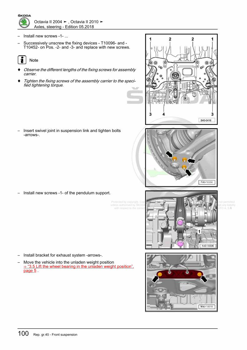
Protected by copyright. Copying for private or commercial purposes, in part or in whole, is not permitted unless authorised by ŠKODA AUTO A. S. ŠKODA AUTO A. S. does not guarantee or accept any liability
with respect to the correctness of information in this document. Copyright by ŠKODA AUTO A. S.�
– Install new screws -1- ...– Successively unscrew the fixing devices - T10096- and -
T10452- on Pos. -2- and -3- and replace with new screws.
Note
♦ Observe the different lengths of the fixing screws for assemblycarrier.
♦ Tighten the fixing screws of the assembly carrier to the speci‐fied tightening torque.
– Insert swivel joint in suspension link and tighten bolts-arrows-.
– Install new screws -1- of the pendulum support.
– Install bracket for exhaust system -arrows-.– Move the vehicle into the unladen weight position
⇒ “3.5 Lift the wheel bearing in the unladen weight position”,page 5 .
Octavia II 2004 ➤ , Octavia II 2010 ➤Axles, steering - Edition 05.2018
100 Rep. gr.40 - Front suspension

Protected by copyright. Copying for private or commercial purposes, in part or in whole, is not permitted unless authorised by ŠKODA AUTO A. S. ŠKODA AUTO A. S. does not guarantee or accept any liability
with respect to the correctness of information in this document. Copyright by ŠKODA AUTO A. S.�
– Tighten the screws of the control arm -arrows- to the specifiedtightening torque.
Note
Tighten screws/nuts when the vehicle is in unladen weight posi‐tion⇒ “3.5 Lift the wheel bearing in the unladen weight position”, page5 .
– On vehicles with vehicle level encoder, after disconnectingand connecting the connector, perform the basic adjustmentof the headlamps ⇒ Maintenance ; Booklet Octavia II .
– Perform a test drive– Check the steering wheel position during the test drive.
Note
If after the test drive and with the wheels pointing straight aheadthe steering wheel is off straight, perform an axle alignment⇒ “3.3 Axle alignment”, page 309 .
Tightening torques - summaries of components
Note
Replace bolts / nuts that are tightened at an angle of rotation, aswell as replacement components after removal.
♦ ⇒ “3.1 Summary of components - assembly carrier, sheet steelassembly carrier”, page 58
♦ ⇒ “1.1 Summary of components - steering column”,page 320
♦ ⇒ “2.1 Summary of components - steering gear”, page 356♦ ⇒ “1.1 Summary of components - vehicle level sender front”,
page 293♦ ⇒ “1.2 Tightening torque of the wheel screws”, page 301♦ Pendulum support to gearbox ⇒ Engine; Rep. gr. 10♦ Exhaust System ⇒ Engine; Rep. gr. 26♦ Noise insulation ⇒ Body work assembly; Rep. gr. 50
3.10 Replacing rubber-metal bearing fortrack control arm, assembly carriermade of steel sheet
⇒ “3.10.1 Replacing the rubber-metal bearing for track controlarm, front bearing”, page 101⇒ “3.10.2 Replacing the rubber-metal bearing for rear track con‐trol arm, rear bearing”, page 103
3.10.1 Replacing the rubber-metal bearing fortrack control arm, front bearing
Special tools and workshop equipment required
Octavia II 2004 ➤ , Octavia II 2010 ➤Axles, steering - Edition 05.2018
3. Front axle with assembly carrier made of steel sheet 101

Protected by copyright. Copying for private or commercial purposes, in part or in whole, is not permitted unless authorised by ŠKODA AUTO A. S. ŠKODA AUTO A. S. does not guarantee or accept any liability
with respect to the correctness of information in this document. Copyright by ŠKODA AUTO A. S.�
♦ Pressure plate - MP3-407 (VW 402)-♦ Thrust piece - MP6-405 (VW 411)-♦ Pipe section - T10219/1-♦ Mandrel - T10219/2-♦ Pressure spindle - MP3–408 (VW 412)-– Removing the suspension link:♦ Vehicles fitted with a manual gearbox
⇒ “3.9.1 Removing and installing the track control arm, sheetsteel assembly carrier”, page 93
♦ with an ATF radiator for vehicles with an automatic gearbox⇒ “3.9.2 Removing and installing left track control arm, sheetsteel assembly carrier vehicles with an automatic gearbox”,page 96
Pressing out rubber-metal bearing– Press out rubber-metal bearing as shown.1 - Drive bushing - MP6-405 (VW 411)-2 - Pipe section - T10219/1-3 - Pressure plate - MP3-407 (VW 402)-
Installing front rubber-metal bearingIn order not to damage the rubber-metal bearing when insertingit, it must be positioned at an angle. During the press-in procedurethe rubber-metal bearing straightens.– Observe the fitting position of the rubber-metal bearing -1- to
the track control arm -2-.The grooves -3- must point to the suspension link -2- as shown.In order not to damage the rubber-metal bearing when insertingit, it must be positioned at an angle. During the press-in procedurethe rubber-metal bearing straightens.– Apply assembly sliding oil - G 294 421 A1- to the outside of
the rubber-metal bearing.
– Position the rubber-metal bearing at an angle (in direction oftrack control arm), at the same time the lip must slide into thehole.
1 - Drift - T10219/2-2 - Rubber-metal bearing3 - Pipe section - T10219/1-4 - Pressure plate - MP3-407 (VW 402)-
Octavia II 2004 ➤ , Octavia II 2010 ➤Axles, steering - Edition 05.2018
102 Rep. gr.40 - Front suspension

Protected by copyright. Copying for private or commercial purposes, in part or in whole, is not permitted unless authorised by ŠKODA AUTO A. S. ŠKODA AUTO A. S. does not guarantee or accept any liability
with respect to the correctness of information in this document. Copyright by ŠKODA AUTO A. S.�
– Insert the core of the rubber-metal bearing -1- into the hole ofthe track control arm -2-.
Dimensions -a- and -b- must be identical.If the dimensions -a- and -b- are not identical:
– Slightly pull back the bearing from the track control arm.1 - Pressure spindle - MP3–408 (VW 412)-2 - Pipe section - T10219/1-3 - Pressure plate - MP3-407 (VW 402)-– Installing the track control arm
⇒ “3.9.1 Removing and installing the track control arm, sheetsteel assembly carrier”, page 93
– Perform a test drive– Check the steering wheel position during the test drive.
Note
If after the test drive and with the wheels pointing straight aheadthe steering wheel is off straight, perform an axle alignment⇒ “3.3 Axle alignment”, page 309 .
3.10.2 Replacing the rubber-metal bearing forrear track control arm, rear bearing
Special tools and workshop equipment required♦ Pressure spindle - MP3-423 (VW 407)-♦ Assembly tool - MP5-401 (VW 3345)-♦ Pipe - T30019-♦ Pressure plate - MP3-407 (VW 402)-♦ Pressure spindle - MP3–408 (VW 412)-♦ Pressure element - T10453-– Removing the suspension link:
Octavia II 2004 ➤ , Octavia II 2010 ➤Axles, steering - Edition 05.2018
3. Front axle with assembly carrier made of steel sheet 103

Protected by copyright. Copying for private or commercial purposes, in part or in whole, is not permitted unless authorised by ŠKODA AUTO A. S. ŠKODA AUTO A. S. does not guarantee or accept any liability
with respect to the correctness of information in this document. Copyright by ŠKODA AUTO A. S.�
♦ Vehicles fitted with a manual gearbox⇒ “3.9.1 Removing and installing the track control arm, sheetsteel assembly carrier”, page 93
♦ with an ATF radiator for vehicles with an automatic gearbox⇒ “3.9.2 Removing and installing left track control arm, sheetsteel assembly carrier vehicles with an automatic gearbox”,page 96
Pressing out rear rubber-metal bearing– Press out rubber-metal bearing as shown.1 - Pressure spindle - MP3-423 (VW 407)-2 - Assembly tool - MP5-401 (VW 3345)-3 - Arm of wheel suspension - the hole in the arm of the wheel
suspension must point upwards4 - Pipe - T30019-5 - Pressure plate - MP3-407 (VW 402)-
Installation position of rear bearing in arm of wheel suspensionInsert the rubber-metal bearing in such a way that the arrow ofthe bearing points between the set of markings -arrows A- on thearm of the wheel suspension.The shoulder -arrow B- must always point to the outside of thevehicle.Inserting the rubber-metal bearing
Octavia II 2004 ➤ , Octavia II 2010 ➤Axles, steering - Edition 05.2018
104 Rep. gr.40 - Front suspension

Protected by copyright. Copying for private or commercial purposes, in part or in whole, is not permitted unless authorised by ŠKODA AUTO A. S. ŠKODA AUTO A. S. does not guarantee or accept any liability
with respect to the correctness of information in this document. Copyright by ŠKODA AUTO A. S.�
– Insert rubber-metal bearing as shown.1 - Pressure spindle - MP3–408 (VW 412)-2 - Pressure element - T10453- - the marking -A- on the pres‐
sure element must point to the markings -arrows- on the arm3 - Rubber-metal bearing4 - Arm of wheel suspension - the hole in the arm of the wheel
suspension must point downwards5 - Pipe - T30019-6 - Pressure plate - MP3-407 (VW 402)-
Note
Insert the rubber-metal bearing in such a way that the pressureelement - T10453- rests against the arm of the wheel suspension.
– Installing the track control arm⇒ “3.9.1 Removing and installing the track control arm, sheetsteel assembly carrier”, page 93
– Perform a test drive– Check the steering wheel position during the test drive.
Note
If after the test drive and with the wheels pointing straight aheadthe steering wheel is off straight, perform an axle alignment⇒ “3.3 Axle alignment”, page 309 .
3.11 Inspecting the suspension linkInspecting axial play– Pull the track control arm down with force and push up again.Inspecting radial play
Octavia II 2004 ➤ , Octavia II 2010 ➤Axles, steering - Edition 05.2018
3. Front axle with assembly carrier made of steel sheet 105

Protected by copyright. Copying for private or commercial purposes, in part or in whole, is not permitted unless authorised by ŠKODA AUTO A. S. ŠKODA AUTO A. S. does not guarantee or accept any liability
with respect to the correctness of information in this document. Copyright by ŠKODA AUTO A. S.�
– Forcefully push the wheel at the bottom towards the inside andthe outside.
Note
♦ For these two tests no “play” may be felt or be visible.♦ Observe the suspension link during the tests.♦ Take into account possible wheel bearing play or “play” in top
suspension strut bearing.♦ Inspect rubber bellows for damage, if necessary replace.
3.12 Removing and installing the suspensionlink
Special tools and workshop equipment required♦ Ball joint extractor - 3287A-♦ Engine and gearbox jack , e.g. -V.A.G 1383A- or -VAS6931-Removing– Remove fixing screw of drive shaft at wheel hub
⇒ “6.5 Loosen and tighten cardan shaft screwed connection”,page 158 .
Note
♦ If the fixing screw of the drive shaft is loosened more than 90°,the wheel bearings must not be loaded through the weight ofthe vehicle, i.e the vehicle must not stand on its wheels.
♦ If the wheel bearings are loaded through the weight of the ve‐hicle when the fixing screw for the drive shaft is removed, theinner wheel bearing will be damaged. This shortens the life ofthe wheel bearing.
♦ If the vehicle is standing on its wheels or moves, pay attentionto the following: Install the outer joint instead of the drive shaft.Tighten the fixing screw (use the one which was previouslyremoved) of the outer joint to the tightening torque of 120 Nm.
– Remove wheel.– Remove noise insulation ⇒ Body Work; Rep. gr. 50 .Vehicles with vehicle level sender– Unscrew nut -1-.– Undo holder -2- from the front left vehicle level sensor - G78-
and front right vehicle level sender - G289- from the suspen‐sion link -3-.
Continued for all vehicles
Octavia II 2004 ➤ , Octavia II 2010 ➤Axles, steering - Edition 05.2018
106 Rep. gr.40 - Front suspension

Protected by copyright. Copying for private or commercial purposes, in part or in whole, is not permitted unless authorised by ŠKODA AUTO A. S. ŠKODA AUTO A. S. does not guarantee or accept any liability
with respect to the correctness of information in this document. Copyright by ŠKODA AUTO A. S.�
– Release fixing nuts -arrows-.– Unhook steering joint out of the suspension link.– Swivel out the wheel-bearing housing with the suspension
strut and simultaneously pull the cardan shaft out of the wheelhub and attach it to the body e.g with a wire.
Note
♦ The cardan shaft must not hang down, otherwise the inner jointwill be damaged.
♦ If the cardan shaft cannot be removed from the wheel hub, itcan be pressed out using the extractor⇒ “6.4.6 Push the cardan shaft out of the wheel hub.”,page 155 .
– Slacken the nut of the steering joint and partially unscrew.
Octavia II 2004 ➤ , Octavia II 2010 ➤Axles, steering - Edition 05.2018
3. Front axle with assembly carrier made of steel sheet 107

Protected by copyright. Copying for private or commercial purposes, in part or in whole, is not permitted unless authorised by ŠKODA AUTO A. S. ŠKODA AUTO A. S. does not guarantee or accept any liability
with respect to the correctness of information in this document. Copyright by ŠKODA AUTO A. S.�
– Using the ball joint extractor - 3287A- -1-, press the steeringjoint -2- out from the wheel-bearing housing.
Note
♦ Risk of accident while the steering joint is being pressed out;observe: the ball joint extractor - 3287A- can fall off whenloosening the pivot pin, therefore place the engine/gearboxjack underneath, e.g. -V.A.G 1383A - or -VAS6931- with awooden plate.
♦ To protect the thread, only partially unscrew the nut of thesteering joint, in order to position the ball joint extractor -3287A- .
Installing– Insert suspension link in the wheel-house bearing. Note in‐
stallation position⇒ Fig. ““Fitting position according to the identification -arrow-on the suspension link”“ , page 13 .
Note
Make sure the steering joint boot is neither damaged nor twisted.
– Screw on and tighten new self locking nut of steering joint.
Note
Use the Torx key to counterhold at the suspension.
– Insert drive shaft back into the wheel-bearing housing.Installation is carried out in the reverse order. When installing,note the following:– Tighten fixing screw of drive shaft to wheel hub
⇒ “6.5 Loosen and tighten cardan shaft screwed connection”,page 158 .
Note
At the same time the vehicle must not be standing on its wheels,otherwise the wheel bearing will be damaged.
– On vehicles with vehicle level encoder, after disconnectingand connecting the connector, perform the basic adjustmentof the headlamps ⇒ Maintenance ; Booklet Octavia II .
Tightening torques - summaries of components
Note
Replace bolts / nuts that are tightened at an angle of rotation, aswell as replacement components after removal.
♦ ⇒ “3.1 Summary of components - assembly carrier, sheet steelassembly carrier”, page 58
♦ ⇒ “1.1 Summary of components - vehicle level sender front”,page 293
Octavia II 2004 ➤ , Octavia II 2010 ➤Axles, steering - Edition 05.2018
108 Rep. gr.40 - Front suspension

Protected by copyright. Copying for private or commercial purposes, in part or in whole, is not permitted unless authorised by ŠKODA AUTO A. S. ŠKODA AUTO A. S. does not guarantee or accept any liability
with respect to the correctness of information in this document. Copyright by ŠKODA AUTO A. S.�
♦ ⇒ “6.5 Loosen and tighten cardan shaft screwed connection”,page 158
♦ ⇒ “1.2 Tightening torque of the wheel screws”, page 301♦ Noise insulation ⇒ Body work assembly; Rep. gr. 50
Octavia II 2004 ➤ , Octavia II 2010 ➤Axles, steering - Edition 05.2018
3. Front axle with assembly carrier made of steel sheet 109

Protected by copyright. Copying for private or commercial purposes, in part or in whole, is not permitted unless authorised by ŠKODA AUTO A. S. ŠKODA AUTO A. S. does not guarantee or accept any liability
with respect to the correctness of information in this document. Copyright by ŠKODA AUTO A. S.�
4 Wheel suspension⇒ “4.1 Summary of components of wheel suspension”,page 110⇒ “4.2 Removing and installing the suspension strut”, page 111⇒ “4.3 Repairing suspension strut”, page 116⇒ “4.4 Inspect shock absorber”, page 118⇒ “4.5 Degas front gas-filled shock absorber, and empty.”,page 120
4.1 Summary of components of wheel suspension
1 - Shock absorber❑ can be replaced sepa‐
rately❑ Assignment ⇒ Electron‐
ic Catalogue of OriginalParts
❑ Check⇒ “4.4 Inspect shock ab‐sorber”, page 118
❑ disposing of⇒ “4.5 Degas front gas-filled shock absorber,and empty.”, page 120
2 - Stop buffer3 - Boot4 - Coil spring
❑ Removing and installing⇒ “4.3 Repairing sus‐pension strut”,page 116
❑ check colour coding❑ Assignment ⇒ Electron‐
ic Catalogue of OriginalParts
❑ The surface of thespring coil must not bedamaged
5 - Axial grooved ball bearing6 - Suspension strut bearing
❑ Note installation posi‐tion⇒ “4.2 Removing and in‐stalling shock absorb‐er”, page 241
7 - Nut❑ self-locking❑ replace after each removal❑ 60 Nm
8 - Suspension strut dome9 - Screw
❑ replace after each removal
Octavia II 2004 ➤ , Octavia II 2010 ➤Axles, steering - Edition 05.2018
110 Rep. gr.40 - Front suspension

Protected by copyright. Copying for private or commercial purposes, in part or in whole, is not permitted unless authorised by ŠKODA AUTO A. S. ŠKODA AUTO A. S. does not guarantee or accept any liability
with respect to the correctness of information in this document. Copyright by ŠKODA AUTO A. S.�
❑ 15 Nm + 90°10 - Protective cap
4.2 Removing and installing the suspensionstrut
Special tools and workshop equipment required♦ Spreader - 3424-♦ Engine and gearbox jack , e.g. -V.A.G 1383A- or -VAS6931-♦ Support - T10149-Removing– Remove fixing screw of drive shaft at wheel hub
⇒ “6.5 Loosen and tighten cardan shaft screwed connection”,page 158
Note
♦ If the fixing screw of the drive shaft is loosened more than 90°,the wheel bearings must not be loaded through the weight ofthe vehicle, i.e the vehicle must not stand on its wheels.
♦ If the wheel bearings are loaded through the weight of the ve‐hicle when the fixing screw for the drive shaft is removed, theinner wheel bearing will be damaged. This shortens the life ofthe wheel bearing.
♦ If the vehicle is standing on its wheels or moves, pay attentionto the following: Install the outer joint instead of the drive shaft.Tighten the fixing screw (use the one which was previouslyremoved) of the outer joint to the tightening torque of 120 Nm.
– Remove wheel.– Unscrew nut -arrow- and pull coupling rod -1- out from sus‐
pension strut.– Unhook ABS speed sensor cable at the suspension strut.
Vehicles with vehicle level sender– Unscrew nut -1-.– Remove the holder -2- of the front left vehicle level encoder -
G78- from the wishbone -3-.Continued for all vehicles
Octavia II 2004 ➤ , Octavia II 2010 ➤Axles, steering - Edition 05.2018
4. Wheel suspension 111

Protected by copyright. Copying for private or commercial purposes, in part or in whole, is not permitted unless authorised by ŠKODA AUTO A. S. ŠKODA AUTO A. S. does not guarantee or accept any liability
with respect to the correctness of information in this document. Copyright by ŠKODA AUTO A. S.�
– Release fixing nuts -arrows-.– Unhook steering joint out of the suspension link.– Swivel out the wheel-bearing housing with the suspension
strut and simultaneously pull the cardan shaft out of the wheelhub and attach it to the body e.g with a wire.
Note
♦ The cardan shaft must not hang down, otherwise the inner jointwill be damaged.
♦ If the cardan shaft cannot be removed from the wheel hub, itcan be pressed out using the extractor⇒ “6.4.6 Push the cardan shaft out of the wheel hub.”,page 155 .
– Plug a screwdriver -1- into the brake disc between the brakecalliper and brake anchor plate.
– Secure the engine and gearbox jack e.g. -V.A.G 1383A- or -VAS6931- with support - T10149- -2- on the wheel hub with awheel bolt.
Note
♦ Do not lift or lower vehicle while engine and gearbox jack e.g.-V.A.G 1383A- or -VAS6931- is under vehicle. The vehiclecould slip off the lifting platform.
♦ Do not leave the engine/gearbox jack e. g. -V.A.G 1383A- or-VAS6931- positioned under the vehicle for longer than nec‐essary.
– Separate the screwed connection wheel-bearing housing/sus‐pension strut -arrow-.
Octavia II 2004 ➤ , Octavia II 2010 ➤Axles, steering - Edition 05.2018
112 Rep. gr.40 - Front suspension

Protected by copyright. Copying for private or commercial purposes, in part or in whole, is not permitted unless authorised by ŠKODA AUTO A. S. ŠKODA AUTO A. S. does not guarantee or accept any liability
with respect to the correctness of information in this document. Copyright by ŠKODA AUTO A. S.�
– Insert the spreader - 3424- in the slot on the wheel-bearinghousing.
– Turn ratchet with spreader - 3424 - by 90° and remove ratchet.– Press the brake disc by hand towards the suspension strut.Otherwise the shock absorber tube can cant in the opening of thewheel bearing housing.
– Lower the wheel bearing housing -1- with the engine andgearbox jack e.g. -V.A.G 1383A- or -VAS6931- until the shockabsorber tube hangs freely, -arrow-.
– Screw the wheel bearing housing back to the suspension linkand secure the wheel bearing housing to the assembly carrier.
– Remove the engine and gearbox jack e.g. -V.A.G 1383A- or -VAS6931- under the support - T10149- .
Note
♦ Do not lift or lower vehicle while engine and gearbox jack e.g.-V.A.G 1383A- or -VAS6931- is under vehicle. The vehiclecould slip off the lifting platform.
♦ Do not leave the engine/gearbox jack e. g. -V.A.G 1383A- or-VAS6931- positioned under the vehicle for longer than nec‐essary.
– Remove plenum chamber cover ⇒ Body Work; Rep. gr. 66 .
– Unscrew screws -arrows- for top shock-absorber fixture andtake out suspension strut.
Installing
– Insert suspension strut, while doing so one of the two markings-arrows- must point in direction of travel.
Octavia II 2004 ➤ , Octavia II 2010 ➤Axles, steering - Edition 05.2018
4. Wheel suspension 113

Protected by copyright. Copying for private or commercial purposes, in part or in whole, is not permitted unless authorised by ŠKODA AUTO A. S. ŠKODA AUTO A. S. does not guarantee or accept any liability
with respect to the correctness of information in this document. Copyright by ŠKODA AUTO A. S.�
– Tighten the screws -1- to the specified tightening torque.– Install the plenum chamber cover ⇒ Body Work; Rep. gr. 66 .
– Attach engine/gearbox jack e.g. -V.A.G 1383A- or -VAS6931-with support - T10149- to the wheel hub with a wheel bolt.
– Loosen the wheel bearing housing from the assembly carrier.
– Release fixing nuts -arrows-.– Pull the wheel-bearing housing with suspension link out of the
track control arm.
Octavia II 2004 ➤ , Octavia II 2010 ➤Axles, steering - Edition 05.2018
114 Rep. gr.40 - Front suspension

Protected by copyright. Copying for private or commercial purposes, in part or in whole, is not permitted unless authorised by ŠKODA AUTO A. S. ŠKODA AUTO A. S. does not guarantee or accept any liability
with respect to the correctness of information in this document. Copyright by ŠKODA AUTO A. S.�
– Lower the wheel bearing housing -1- with engine and gearboxjack e.g. -V.A.G 1383/A- or -VAS6931- in-the direction of the arrow-.
– Raise the wheel bearing housing with engine and gearbox jacke.g. -V.A.G 1383/A- or -VAS6931- and thread it onto the sus‐pension strut at the same time.
– Screw the suspension link with suspension link and press thewheel bearing housing further upwards until the end positionon the suspension link has been reached.
– Remove spreader - 3424- .
Octavia II 2004 ➤ , Octavia II 2010 ➤Axles, steering - Edition 05.2018
4. Wheel suspension 115

Protected by copyright. Copying for private or commercial purposes, in part or in whole, is not permitted unless authorised by ŠKODA AUTO A. S. ŠKODA AUTO A. S. does not guarantee or accept any liability
with respect to the correctness of information in this document. Copyright by ŠKODA AUTO A. S.�
– Insert a new screw with the tip pointing in the driving direction.Installation is carried out in the reverse order. When installing,note the following:– Tighten fixing screw of drive shaft to wheel hub
⇒ “6.5 Loosen and tighten cardan shaft screwed connection”,page 158 .
Note
♦ If the fixing screw of the drive shaft is loosened more than 90°,the wheel bearings must not be loaded through the weight ofthe vehicle, i.e the vehicle must not stand on its wheels.
♦ If the wheel bearings are loaded through the weight of the ve‐hicle when the fixing screw for the drive shaft is removed, theinner wheel bearing will be damaged. This shortens the life ofthe wheel bearing.
♦ If the vehicle is standing on its wheels or moves, pay attentionto the following: Install the outer joint instead of the drive shaft.Tighten the fixing screw (use the one which was previouslyremoved) of the outer joint to the tightening torque of 120 Nm.
– On vehicles with vehicle level sensor, carry out a basic settingfor the headlights ⇒ Maintenance ; Booklet Octavia II .
Tightening torques - summaries of components
Note
Replace bolts / nuts that are tightened at an angle of rotation, aswell as replacement components after removal.
♦ ⇒ “4.1 Summary of components of wheel suspension”,page 110
♦ ⇒ “5.1 Summary of components of the wheel bearing”,page 121
♦ ⇒ “2.1 Assembly overview - subframe, aluminium subframe”,page 10
♦ ⇒ “3.1.1 Assembly overview - subframe, sheet steel assemblycarrier, left-hand drive”, page 58
♦ ⇒ “3.1.2 Assembly overview - subframe, sheet steel assemblycarrier, right hand drive”, page 62
♦ ⇒ “6.5 Loosen and tighten cardan shaft screwed connection”,page 158
♦ ⇒ “1.1 Summary of components - vehicle level sender front”,page 293
♦ ⇒ “1.2 Tightening torque of the wheel screws”, page 301
4.3 Repairing suspension strutSpecial tools and workshop equipment required♦ Spring tensioning device , e.g. -V.A.G 1752/1-♦ Spring holder , e.g. -V.A.G 1752/5-♦ Shock absorber set - T10001-
Octavia II 2004 ➤ , Octavia II 2010 ➤Axles, steering - Edition 05.2018
116 Rep. gr.40 - Front suspension

Protected by copyright. Copying for private or commercial purposes, in part or in whole, is not permitted unless authorised by ŠKODA AUTO A. S. ŠKODA AUTO A. S. does not guarantee or accept any liability
with respect to the correctness of information in this document. Copyright by ŠKODA AUTO A. S.�
Removing the coil spring– Remove shock absorber
⇒ “4.2 Removing and installing the suspension strut”,page 111 ¨.
Note
♦ Ensure that the coil spring -arrow- is correctly seated in thespring tensioner e.g. -V.A.G 1752/1- -2-.
♦ Do not use an impact screw driver when working with thespring tensioner.
– Preload the coil spring with tensioning device e.g. -V.A.G 1752/1- until the top axial grooved ball bearing is re‐leased.
1 - Remove the nut from the piston rod using the socket insert- T10001/5- -5-. While doing so, counterhold the piston rodwith socket insert - T10001/8- with an external hexagonalkey -3-.
2 - Spring tensioning device , e.g. -V.A.G 1752/1-3 - Torque wrench4 - Socket - T10001/8-5 - Ratchet - T10001/11-6 - Socket - T10001/5-7 - Spring holder , e.g. -V.A.G 1752/4-– Remove individual parts of the suspension strut and the coil
spring using the spring tensioning device , e.g. -V.A.G1752/1- .
Installing the coil spring– Insert the spring seat -1- into the shock absorber -2-.– Place the coil spring -3- with spring tensioner e.g. -
V.A.G 1752/1- onto the lower spring seat.The thread end of the helical spring must lie against the stop-arrow-.Further installation occurs in reverse order.Tightening torques - summaries of components
Note
Replace bolts / nuts that are tightened at an angle of rotation, aswell as replacement components after removal.
♦ ⇒ “4.1 Summary of components of wheel suspension”,page 110
Octavia II 2004 ➤ , Octavia II 2010 ➤Axles, steering - Edition 05.2018
4. Wheel suspension 117
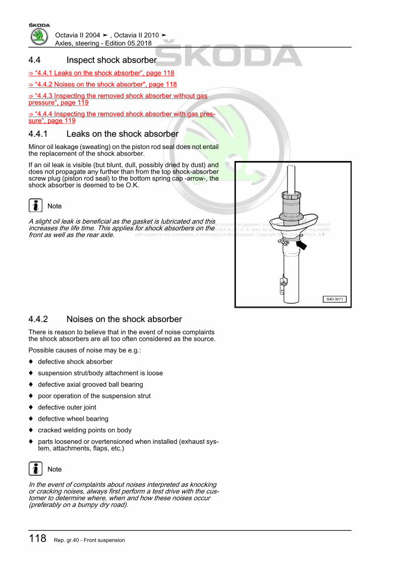
Protected by copyright. Copying for private or commercial purposes, in part or in whole, is not permitted unless authorised by ŠKODA AUTO A. S. ŠKODA AUTO A. S. does not guarantee or accept any liability
with respect to the correctness of information in this document. Copyright by ŠKODA AUTO A. S.�
4.4 Inspect shock absorber⇒ “4.4.1 Leaks on the shock absorber”, page 118⇒ “4.4.2 Noises on the shock absorber”, page 118⇒ “4.4.3 Inspecting the removed shock absorber without gaspressure”, page 119⇒ “4.4.4 Inspecting the removed shock absorber with gas pres‐sure”, page 119
4.4.1 Leaks on the shock absorberMinor oil leakage (sweating) on the piston rod seal does not entailthe replacement of the shock absorber.If an oil leak is visible (but blunt, dull, possibly dried by dust) anddoes not propagate any further than from the top shock-absorberscrew plug (piston rod seal) to the bottom spring cap -arrow-, theshock absorber is deemed to be O.K.
Note
A slight oil leak is beneficial as the gasket is lubricated and thisincreases the life time. This applies for shock absorbers on thefront as well as the rear axle.
4.4.2 Noises on the shock absorberThere is reason to believe that in the event of noise complaintsthe shock absorbers are all too often considered as the source.Possible causes of noise may be e.g.:♦ defective shock absorber♦ suspension strut/body attachment is loose♦ defective axial grooved ball bearing♦ poor operation of the suspension strut♦ defective outer joint♦ defective wheel bearing♦ cracked welding points on body♦ parts loosened or overtensioned when installed (exhaust sys‐
tem, attachments, flaps, etc.)
Note
In the event of complaints about noises interpreted as knockingor cracking noises, always first perform a test drive with the cus‐tomer to determine where, when and how these noises occur(preferably on a bumpy dry road).
Octavia II 2004 ➤ , Octavia II 2010 ➤Axles, steering - Edition 05.2018
118 Rep. gr.40 - Front suspension
Protected by copyright. Copying for private or commercial purposes, in part or in whole, is not permitted unless authorised by ŠKODA AUTO A. S. ŠKODA AUTO A. S. does not guarantee or accept any liability
with respect to the correctness of information in this document. Copyright by ŠKODA AUTO A. S.�
4.4.3 Inspecting the removed shock absorberwithout gas pressure
Defective shock absorbers become noticeable while driving be‐cause of the knocking noises caused by wheel hopping, morespecifically on poor road surfaces and they must be replaced. Thefailure is mainly caused by the loss of oil. The shock absorberthen compresses and/or expands in jolts. It exhibits “idle”, beforeit begins to operate.
Note
The shock absorbers are maintenance-free. It is not possible totop up the shock absorber oil.
4.4.4 Inspecting the removed shock absorberwith gas pressure
Damaged shock absorbers with gas pressure become noticeablebecause of a laud banging sound, caused by wheel hopping, andalso because a strong oil leak occurs.
Manual testing, as described below, can determine if theshock absorber is damaged or not:
– Compress the shock absorber by hand.– The piston rod must move evenly over the entire stroke without
jolting.– Release the piston rod. On sufficiently pressurized shock ab‐
sorbers it will automatically return to its original position.If this is not the case, the shock absorber need not necessarilybe replaced, as it will still operate as a conventional shock ab‐sorber (see instructions below).
Note
♦ The absorbing function is still fully present without sufficientgas pressure as long as the oil leakage is not too large. How‐ever, the noise level may increase. On older vehicles it ispossible to continue using an operational yet pressurelessshock absorber without problem.
♦ Adequate gas pressure in the shock absorber improves thenoise behaviour and function when driving over poor road sur‐faces.
Octavia II 2004 ➤ , Octavia II 2010 ➤Axles, steering - Edition 05.2018
4. Wheel suspension 119

Protected by copyright. Copying for private or commercial purposes, in part or in whole, is not permitted unless authorised by ŠKODA AUTO A. S. ŠKODA AUTO A. S. does not guarantee or accept any liability
with respect to the correctness of information in this document. Copyright by ŠKODA AUTO A. S.�
4.5 Degas front gas-filled shock absorber,and empty.
– Clamp gas-filled shock absorber vertically with the piston rodpointing downwards in a vice.
Caution
Wear safety goggles during the drilling procedure.
– Drill a hole ∅ 3 mm -A- through the outer pipe of the shockabsorber.
Note
Gas will escape during drilling.
– Drill further until the inner pipe has also been drilled through(approx. 25 mm deep).
– Drill a second hole ∅ 6 mm -B- through the outer and innershock absorber pipes.
– Hold the shock absorber over an oil catching pan. Move thepiston rod several times up and down over its entire stroke untilno more oil escapes.
Octavia II 2004 ➤ , Octavia II 2010 ➤Axles, steering - Edition 05.2018
120 Rep. gr.40 - Front suspension

Protected by copyright. Copying for private or commercial purposes, in part or in whole, is not permitted unless authorised by ŠKODA AUTO A. S. ŠKODA AUTO A. S. does not guarantee or accept any liability
with respect to the correctness of information in this document. Copyright by ŠKODA AUTO A. S.�
5 Wheel bearing⇒ “5.1 Summary of components of the wheel bearing”,page 121⇒ “5.2 Removing and installing the wheel hub with wheel bearing”,page 122⇒ “5.3 Removing and installing wheel bearing housing”,page 126
5.1 Summary of components of the wheel bearing
1 - Wheel hub with wheel bear‐ing
❑ 3-point support - FS IIIbrake
❑ Removing and installing⇒ “5.2 Removing and in‐stalling the wheel hubwith wheel bearing”,page 122
❑ Sensor ring for ABS isbuilt into the wheel hub
❑ Assignment ⇒ Electron‐ic Catalogue of OriginalParts
2 - Wheel bearing housing❑ 3-point support - FS III
brake❑ Removing and installing
⇒ “5.3 Removing and in‐stalling wheel bearinghousing”, page 126
❑ If the wheel bearinghousing is replaced, thevehicle must be aligned⇒ “3.3 Axle alignment”,page 309
❑ Assignment ⇒ Electron‐ic Catalogue of OriginalParts
3 - Suspension strut4 - Screw
❑ the tip of bolt must pointin the direction of travel
5 - Front left wheel speed sen‐sor - G47- / Front right wheelspeed sensor - G45-
❑ removing and installing ⇒ Brake systems; Rep. gr. 456 - Screw
❑ Tightening torque ⇒ Brake systems; Rep. gr. 457 - Track rod end8 - Protection plate9 - Screw
❑ Tightening torque ⇒ Brake systems; Rep. gr. 46
Octavia II 2004 ➤ , Octavia II 2010 ➤Axles, steering - Edition 05.2018
5. Wheel bearing 121

Protected by copyright. Copying for private or commercial purposes, in part or in whole, is not permitted unless authorised by ŠKODA AUTO A. S. ŠKODA AUTO A. S. does not guarantee or accept any liability
with respect to the correctness of information in this document. Copyright by ŠKODA AUTO A. S.�
10 - Nut❑ replace after each removal❑ Tightening torque ⇒ “2.1 Summary of components - steering gear”, page 356
11 - Wheel bearing housing❑ 4-point support - FS III brake❑ Removing and installing ⇒ “5.3 Removing and installing wheel bearing housing”, page 126❑ If the wheel bearing housing is replaced, the vehicle must be aligned
⇒ “3.3 Axle alignment”, page 309❑ Assignment ⇒ Electronic Catalogue of Original Parts
12 - Brake disc❑ internally ventilated
13 - Screw❑ replace after each removal❑ Assignment ⇒ Electronic Catalogue of Original Parts❑ When loosening and tightening the screw, the prescribed procedure must be followed❑ Removing and installing ⇒ “6.5 Loosen and tighten cardan shaft screwed connection”, page 158❑ Tightening torque ⇒ “6.5 Loosen and tighten cardan shaft screwed connection”, page 158
14 - Screw❑ Tightening torque ⇒ Brake systems; Rep. gr. 46
15 - Wheel hub with wheel bearing❑ 4-point support - FS III and FN3 brake❑ Removing and installing ⇒ “5.2 Removing and installing the wheel hub with wheel bearing”, page 122❑ Sensor ring for ABS is built into the wheel hub❑ different versions❑ Assignment ⇒ Electronic Catalogue of Original Parts
16 - Wheel bearing housing❑ 4-point support - FN3 brake❑ Removing and installing ⇒ “5.3 Removing and installing wheel bearing housing”, page 126❑ If the wheel bearing housing is replaced, the vehicle must be aligned
⇒ “3.3 Axle alignment”, page 309❑ Assignment ⇒ Electronic Catalogue of Original Parts
17 - Screw❑ replace after each removal❑ 70 Nm + 90°
18 - Drive shaft❑ Removing and installing ⇒ “6.4 Removing and installing cardan shaft”, page 140
19 - Nut❑ self-locking❑ replace after each removal❑ 70 Nm + 90°
5.2 Removing and installing the wheel hubwith wheel bearing
Removing– Remove fixing screw of drive shaft at wheel hub
⇒ “6.5 Loosen and tighten cardan shaft screwed connection”,page 158 .
Octavia II 2004 ➤ , Octavia II 2010 ➤Axles, steering - Edition 05.2018
122 Rep. gr.40 - Front suspension

Protected by copyright. Copying for private or commercial purposes, in part or in whole, is not permitted unless authorised by ŠKODA AUTO A. S. ŠKODA AUTO A. S. does not guarantee or accept any liability
with respect to the correctness of information in this document. Copyright by ŠKODA AUTO A. S.�
Note
♦ Wheel bearings must not be subjected to load after bolt se‐curing cardan shaft to wheel hub has been loosened.
♦ If the wheel bearings are loaded through the vehicle's ownweight, the wheel bearing will be initially damaged. This short‐ens the life of the wheel bearing.
♦ It is not permissible to turn cardan shaft screw more than 90°anti-clockwise if vehicle is standing on its wheels.
♦ Do not attempt to move the vehicle without the cardan shaftsfitted as this would damage the wheel bearing. If a vehiclenevertheless has to be moved, comply with the following:
♦ Install an outer joint instead of the cardan shaft.♦ Tighten outer joint to 120 Nm.
– Remove wheel.– Remove brake caliper or brake caliper with brake carrier and
tie with wire to the body ⇒ Brake systems; Rep. gr. 46 .– Remove the ABS-speed sensor ⇒ Brake systems; Rep. gr.
45 .– Remove brake disc ⇒ Brake systems; Rep. gr. 46 .Vehicles with vehicle level sender– Unscrew nut -1-.– Remove the holder -2- of the front left vehicle level encoder -
G78- from the wishbone -3-.Continued for all vehicles
– Remove coupling rod -3- from the anti-roll bar -2-.
Octavia II 2004 ➤ , Octavia II 2010 ➤Axles, steering - Edition 05.2018
5. Wheel bearing 123

Protected by copyright. Copying for private or commercial purposes, in part or in whole, is not permitted unless authorised by ŠKODA AUTO A. S. ŠKODA AUTO A. S. does not guarantee or accept any liability
with respect to the correctness of information in this document. Copyright by ŠKODA AUTO A. S.�
– Release fixing nuts -arrows-.– Unhook steering joint out of the suspension link.– Swivel out the wheel-bearing housing with the suspension
strut and simultaneously pull the cardan shaft out of the wheelhub and attach it to the body e.g with a wire.
Note
♦ If the cardan shaft cannot be removed from the wheel hub, itcan be pressed out using the extractor⇒ “6.4.6 Push the cardan shaft out of the wheel hub.”,page 155 .
♦ The cardan shaft must not hang down, otherwise the inner jointwill be damaged.
– Screw suspension link to the suspension link again -arrows-.
– Remove screws -arrows-.Depending on the build status, the wheel hub with wheel bearingis supported with 3 or 4 screws.– Remove the wheel bearing out of the wheel-bearing housing.
Octavia II 2004 ➤ , Octavia II 2010 ➤Axles, steering - Edition 05.2018
124 Rep. gr.40 - Front suspension

Protected by copyright. Copying for private or commercial purposes, in part or in whole, is not permitted unless authorised by ŠKODA AUTO A. S. ŠKODA AUTO A. S. does not guarantee or accept any liability
with respect to the correctness of information in this document. Copyright by ŠKODA AUTO A. S.�
Octavia II 2004 ➤ , Octavia II 2010 ➤Axles, steering - Edition 05.2018
5. Wheel bearing 125

Protected by copyright. Copying for private or commercial purposes, in part or in whole, is not permitted unless authorised by ŠKODA AUTO A. S. ŠKODA AUTO A. S. does not guarantee or accept any liability
with respect to the correctness of information in this document. Copyright by ŠKODA AUTO A. S.�
• When laying the wheel bearing unit in position, the wheelbearing -1- must always point upwards.
• Always lay the wheel bearing unit on the wheel hub -2-.• When picking up the wheel bearing, never take hold from the
inside.• Only take hold of the wheel bearing from the outside.InstallingInstallation is performed in the reverse order, pay attention to thefollowing points:– Tighten fixing screw of drive shaft to wheel hub
⇒ “6.5 Loosen and tighten cardan shaft screwed connection”,page 158 .
Note
When tightening the fixing screw of the drive shaft, the wheel mustbe raised until it is fully off the ground, otherwise the wheel bearingcan be damaged.
– On vehicles with vehicle level sensor, carry out a basic settingfor the headlights ⇒ Maintenance ; Booklet Octavia II .
Tightening torques - summaries of components
Note
Replace bolts / nuts that are tightened at an angle of rotation, aswell as replacement components after removal.
♦ ⇒ “5.1 Summary of components of the wheel bearing”,page 121
♦ ⇒ “2.1 Assembly overview - subframe, aluminium subframe”,page 10
♦ ⇒ “3.1.1 Assembly overview - subframe, sheet steel assemblycarrier, left-hand drive”, page 58
♦ ⇒ “3.1.2 Assembly overview - subframe, sheet steel assemblycarrier, right hand drive”, page 62
♦ ⇒ “6.5 Loosen and tighten cardan shaft screwed connection”,page 158
♦ ⇒ “1.2 Tightening torque of the wheel screws”, page 301♦ ABS speed sensor ⇒ Brake systems; Rep. gr. 45♦ Brake disc, brake caliper, brake carrier ⇒ Braking systems;
Rep. gr. 46
5.3 Removing and installing wheel bearinghousing
Special tools and workshop equipment required♦ Ball joint extractor - 3287A-♦ Spreader - 3424-♦ Engine/gearbox jack , e.g. -V.A.G 1383/A-
Octavia II 2004 ➤ , Octavia II 2010 ➤Axles, steering - Edition 05.2018
126 Rep. gr.40 - Front suspension

Protected by copyright. Copying for private or commercial purposes, in part or in whole, is not permitted unless authorised by ŠKODA AUTO A. S. ŠKODA AUTO A. S. does not guarantee or accept any liability
with respect to the correctness of information in this document. Copyright by ŠKODA AUTO A. S.�
Removing– Remove fixing screw of drive shaft at wheel hub
⇒ “6.5 Loosen and tighten cardan shaft screwed connection”,page 158 .
Note
♦ Wheel bearings must not be subjected to load after bolt se‐curing cardan shaft to wheel hub has been loosened.
♦ If the wheel bearings are loaded through the vehicle's ownweight, the wheel bearing will be initially damaged. This short‐ens the life of the wheel bearing.
♦ It is not permissible to turn cardan shaft screw more than 90°anti-clockwise if vehicle is standing on its wheels.
♦ Do not attempt to move the vehicle without the cardan shaftsfitted as this would damage the wheel bearing. If a vehiclenevertheless has to be moved, comply with the following:
♦ Install an outer joint instead of the cardan shaft.♦ Tighten outer joint to 120 Nm.
– Remove wheel.– Remove brake caliper with brake carrier and tie with wire to
the body ⇒ Brake systems; Rep. gr. 46 .– Remove the ABS-speed sensor ⇒ Brake systems; Rep. gr.
45 .– Remove brake disc ⇒ Brake systems; Rep. gr. 46 .– Removing heat shield from wheel-bearing housing.– Loosen nut of track rod end, but do not unscrew yet.
Note
To protect the thread, screw the nut a couple of thread turns ontothe pivot pin.
– Push the suspension link/track rod off the wheel bearing hous‐ing with the ball joint extractor - 3287A- .
– Unscrew nut for suspension link/track rod.– Pull track rod end out of the wheel bearing housing.
Octavia II 2004 ➤ , Octavia II 2010 ➤Axles, steering - Edition 05.2018
5. Wheel bearing 127

Protected by copyright. Copying for private or commercial purposes, in part or in whole, is not permitted unless authorised by ŠKODA AUTO A. S. ŠKODA AUTO A. S. does not guarantee or accept any liability
with respect to the correctness of information in this document. Copyright by ŠKODA AUTO A. S.�
Vehicles with vehicle level sender– Unscrew nut -1-.– Remove the holder -2- of the front left vehicle level encoder -
G78- from the wishbone -3-.Continued for all vehicles
– Unscrew nut -1- from coupling rod -3-.– Pull out coupling rod -3- from the anti-roll bar -2-.
– Release fixing nuts -arrows-.– Unhook steering joint out of the suspension link.– Swivel out the wheel-bearing housing with the suspension
strut and simultaneously pull the cardan shaft out of the wheelhub and attach it to the body e.g with a wire.
Note
♦ The cardan shaft must not hang down, otherwise the inner jointwill be damaged.
♦ If the cardan shaft cannot be removed from the wheel hub, itcan be pressed out using the extractor⇒ “6.4.6 Push the cardan shaft out of the wheel hub.”,page 155 .
– Position the engine/gearbox jack e.g. -V.A.G 1383A - or -VAS6931- under the wheel-bearing housing.
– Separate the screwed connection wheel-bearing housing/sus‐pension strut -arrow-.
Octavia II 2004 ➤ , Octavia II 2010 ➤Axles, steering - Edition 05.2018
128 Rep. gr.40 - Front suspension

Protected by copyright. Copying for private or commercial purposes, in part or in whole, is not permitted unless authorised by ŠKODA AUTO A. S. ŠKODA AUTO A. S. does not guarantee or accept any liability
with respect to the correctness of information in this document. Copyright by ŠKODA AUTO A. S.�
– Insert the spreader - 3424- in the slot on the wheel-bearinghousing.
Note
Make sure that the spreader - 3424- is only inserted into the wheelbearing housing. Do not insert it too far otherwise you may dam‐age the metal tabs of the suspension strut.
– Turn ratchet with spreader - 3424 - by 90° and remove ratchet.– Pull wheel bearing housing from suspension strut.InstallingInstallation is performed in the reverse order; pay attention to thefollowing points:– Tighten fixing screw of drive shaft to wheel hub
⇒ “6.5 Loosen and tighten cardan shaft screwed connection”,page 158 .
Note
When tightening the fixing screw of the drive shaft, the wheel mustbe raised until it is fully off the ground, otherwise the wheel bearingcan be damaged.
If the wheel-bearing housing was replaced, the vehicle must bealigned ⇒ “3.3 Axle alignment”, page 309 .– On vehicles with vehicle level sensor, carry out a basic setting
for the headlights ⇒ Maintenance ; Booklet Octavia II .Tightening torques - summaries of components
Note
Replace bolts / nuts that are tightened at an angle of rotation, aswell as replacement components after removal.
♦ ⇒ “5.1 Summary of components of the wheel bearing”,page 121
♦ ⇒ “2.1 Assembly overview - subframe, aluminium subframe”,page 10
♦ ⇒ “3.1.1 Assembly overview - subframe, sheet steel assemblycarrier, left-hand drive”, page 58
♦ ⇒ “3.1.2 Assembly overview - subframe, sheet steel assemblycarrier, right hand drive”, page 62
♦ ⇒ “2.1 Summary of components - steering gear”, page 356♦ ⇒ “6.5 Loosen and tighten cardan shaft screwed connection”,
page 158♦ ⇒ “1.1 Summary of components - vehicle level sender front”,
page 293♦ ⇒ “1.2 Tightening torque of the wheel screws”, page 301♦ ABS speed sensor ⇒ Brake systems; Rep. gr. 45♦ Brake disc, brake caliper, brake carrier, protective plate ⇒
Braking systems; Rep. gr. 46
Octavia II 2004 ➤ , Octavia II 2010 ➤Axles, steering - Edition 05.2018
5. Wheel bearing 129

Protected by copyright. Copying for private or commercial purposes, in part or in whole, is not permitted unless authorised by ŠKODA AUTO A. S. ŠKODA AUTO A. S. does not guarantee or accept any liability
with respect to the correctness of information in this document. Copyright by ŠKODA AUTO A. S.�
6 Drive shaft⇒ “6.1 Overview of the drive shafts”, page 130⇒ “6.2 Designation, distinguish the diameter as specified andgrease quantity for joints”, page 131⇒ “6.3 Summary of components - cardan shaft”, page 132⇒ “6.4 Removing and installing cardan shaft”, page 140⇒ “6.5 Loosen and tighten cardan shaft screwed connection”,page 158⇒ “6.6 Removing and installing heat shield for cardan shaft”, page160⇒ “6.7 Disassembling and assembling cardan shaft”, page 162⇒ “6.8 Inspecting outer CV joint”, page 179⇒ “6.9 Inspecting inner CV joint”, page 181
6.1 Overview of the drive shafts
I -⇒ “6.3.1 Summary of compo‐nents - Drive shaft, CV jointVL90 and VL100”, page 132II -⇒ “6.3.2 Summary of compo‐nents - Cardan shaft CV jointVL107”, page 134III -⇒ “6.3.3 Summary of compo‐nents - Drive shaft with innertripod joint AAR2600i”,page 136IV -⇒ “6.3.4 Summary of compo‐nents - Drive shaft with innertripod joint AAR3300i”,page 138
Octavia II 2004 ➤ , Octavia II 2010 ➤Axles, steering - Edition 05.2018
130 Rep. gr.40 - Front suspension

Protected by copyright. Copying for private or commercial purposes, in part or in whole, is not permitted unless authorised by ŠKODA AUTO A. S. ŠKODA AUTO A. S. does not guarantee or accept any liability
with respect to the correctness of information in this document. Copyright by ŠKODA AUTO A. S.�
6.2 Designation, distinguish the diameter as specified and grease quantity forjoints
Outer joint
Denomination Diameter GreaseRF90 81 mm 80g, grind the grease evenly in the jointUF100 90 mm 100 g, grind the grease evenly in the jointUF107 98 mm 120 g, grind the grease evenly in the joint from both sidesRO104 94 mm 120 g, grind the grease evenly in the jointRO3700 100 mm 140 g, grind the grease evenly in the joint from both sides
Use the relevant grease for outer joints, assignment ⇒ ElectronicCatalogue of Original Parts .
Inner joint
Denomination Diameter GreaseVL90 90 mm 80g, evenly in both halves of the jointVL100 110 mm 110 g, evenly in both halves of the jointVL107 108 mm 140 g, evenly in both halves of the jointAAR2600i 74 mm1) 130 g, evenly in the jointAAR3300i 77 mm1) 130 g, evenly in the joint
Use heat-resistant grease for inner joints, assignment ⇒ Elec‐tronic Catalogue of Original Parts .1) On tripod joints, measure the dimension -A- instead of the di‐ameter.
Octavia II 2004 ➤ , Octavia II 2010 ➤Axles, steering - Edition 05.2018
6. Drive shaft 131

Protected by copyright. Copying for private or commercial purposes, in part or in whole, is not permitted unless authorised by ŠKODA AUTO A. S. ŠKODA AUTO A. S. does not guarantee or accept any liability
with respect to the correctness of information in this document. Copyright by ŠKODA AUTO A. S.�
6.3 Summary of components - cardan shaft⇒ “6.3.1 Summary of components - Drive shaft, CV joint VL90 andVL100”, page 132⇒ “6.3.2 Summary of components - Cardan shaft CV joint VL107”,page 134⇒ “6.3.3 Summary of components - Drive shaft with inner tripodjoint AAR2600i”, page 136⇒ “6.3.4 Summary of components - Drive shaft with inner tripodjoint AAR3300i”, page 138
6.3.1 Summary of components - Drive shaft, CV joint VL90 and VL100
1 - Outer CV joint complete❑ must be replaced com‐
pletely❑ Type of joint, grease
quantity⇒ “6.2 Designation, dis‐tinguish the diameter asspecified and greasequantity for joints”, page131
❑ Removing⇒ “6.7.9 Removing out‐er CV joint”, page 175
❑ installing⇒ “6.7.10 Installing theouter CV joint”,page 176
❑ Check⇒ “6.8 Inspecting outerCV joint”, page 179
2 - Screw❑ replace after each re‐
moval❑ Assignment ⇒ Electron‐
ic Catalogue of OriginalParts
❑ When loosening andtightening the screw, theprescribed proceduremust be followed
❑ Removing and installing⇒ “6.5 Loosen and tight‐en cardan shaftscrewed connection”,page 158
❑ Tightening torque⇒ “6.5 Loosen and tight‐en cardan shaft screwed connection”, page 158
3 - Drive shaft❑ Removing and installing ⇒ “6.4 Removing and installing cardan shaft”, page 140
4 - Clamp❑ replace after each removal❑ tensioning ⇒ Fig. ““Tighten the open warm-type clamp at the smaller diameter”“ , page 178
5 - Collar❑ inspect for tears and chafing points
Octavia II 2004 ➤ , Octavia II 2010 ➤Axles, steering - Edition 05.2018
132

Protected by copyright. Copying for private or commercial purposes, in part or in whole, is not permitted unless authorised by ŠKODA AUTO A. S. ŠKODA AUTO A. S. does not guarantee or accept any liability
with respect to the correctness of information in this document. Copyright by ŠKODA AUTO A. S.�
❑ Assignment ⇒ Electronic Catalogue of Original Parts6 - Clamp
❑ replace after each removal❑ tensioning ⇒ Fig. ““Tighten the open warm-type clamp at the larger diameter”“ , page 178
7 - Disc spring❑ Fitting position ⇒ “6.7.10 Installing the outer CV joint”, page 176
8 - Thrust ring❑ Fitting position ⇒ “6.7.10 Installing the outer CV joint”, page 176
9 - Circlip❑ replace after each removal❑ insert in the shaft groove
10 - Joint boot for inner joint❑ with sheet metal cover❑ without ventilation hole❑ inspect for tears and chafing points❑ drive off from joint with a drift❑ before the installation on the joint, cover the sealing surface with -D 454 300 A2-❑ Assignment ⇒ Electronic Catalogue of Original Parts
11 - Clamp❑ replace after each removal❑ tensioning ⇒ Fig. ““Tighten warm-type clamp”“ , page 168
12 - Drive shaft❑ Removing and installing ⇒ “6.4 Removing and installing cardan shaft”, page 140
13 - Supporting plate14 - Screw
❑ M8 x 48❑ replace after each removal❑ first of all pre-tighten all screws crosswise to 10 Nm and subsequently tighten the screws crosswise to
final torque❑ 40 Nm
15 - Circlip❑ remove and install e.g. with circlip pliers - VW 161A-
16 - Seal❑ The adhesive surface must be free of grease and oil❑ replace after each removal❑ Pull off protective foil and stick in joint❑ Assignment ⇒ Electronic Catalogue of Original Parts
17 - Inner joint❑ must be replaced completely❑ Removing ⇒ “6.7.1 Removing inner joint VL90 and VL100”, page 162❑ installing ⇒ “6.7.5 Installing inner joint VL90 and VL100”, page 166❑ Check ⇒ “6.9 Inspecting inner CV joint”, page 181
18 - Disc spring❑ Fitting position ⇒ Fig. ““Fitting position of the disc spring at inner joint”“ , page 166
Octavia II 2004 ➤ , Octavia II 2010 ➤Axles, steering - Edition 05.2018
133

Protected by copyright. Copying for private or commercial purposes, in part or in whole, is not permitted unless authorised by ŠKODA AUTO A. S. ŠKODA AUTO A. S. does not guarantee or accept any liability
with respect to the correctness of information in this document. Copyright by ŠKODA AUTO A. S.�
6.3.2 Summary of components - Cardan shaft CV joint VL107
1 - Outer CV joint complete❑ must be replaced com‐
pletely❑ Type of joint, grease
quantity⇒ “6.2 Designation, dis‐tinguish the diameter asspecified and greasequantity for joints”, page131
❑ Removing⇒ “6.7.9 Removing out‐er CV joint”, page 175
❑ installing⇒ “6.7.10 Installing theouter CV joint”,page 176
❑ Check⇒ “6.8 Inspecting outerCV joint”, page 179
2 - Screw❑ replace after each re‐
moval❑ Assignment ⇒ Electron‐
ic Catalogue of OriginalParts
❑ When loosening andtightening the screw, theprescribed proceduremust be followed
❑ Removing and installing⇒ “6.5 Loosen and tight‐en cardan shaftscrewed connection”,page 158
❑ Tightening torque⇒ “6.5 Loosen and tight‐en cardan shaft screwed connection”, page 158
3 - Clamp❑ replace after each removal❑ tensioning ⇒ Fig. ““Tighten the open warm-type clamp at the smaller diameter”“ , page 178
4 - Collar❑ inspect for tears and chafing points❑ Assignment ⇒ Electronic Catalogue of Original Parts
5 - Clamp❑ replace after each removal❑ tensioning ⇒ Fig. ““Tighten the open warm-type clamp at the larger diameter”“ , page 178
6 - Disc spring❑ Fitting position ⇒ “6.7.10 Installing the outer CV joint”, page 176
7 - Thrust ring❑ Fitting position ⇒ “6.7.10 Installing the outer CV joint”, page 176
8 - Circlip❑ replace after each removal
Octavia II 2004 ➤ , Octavia II 2010 ➤Axles, steering - Edition 05.2018
134

Protected by copyright. Copying for private or commercial purposes, in part or in whole, is not permitted unless authorised by ŠKODA AUTO A. S. ŠKODA AUTO A. S. does not guarantee or accept any liability
with respect to the correctness of information in this document. Copyright by ŠKODA AUTO A. S.�
❑ insert in the shaft groove9 - Joint boot for inner joint
❑ without ventilation hole❑ inspect for tears and chafing points❑ Assignment ⇒ Electronic Catalogue of Original Parts
10 - Clamp❑ replace after each removal❑ tensioning ⇒ Fig. ““Tighten the open warm-type clamp at the smaller diameter”“ , page 171
11 - Drive shaft❑ Removing and installing ⇒ “6.4 Removing and installing cardan shaft”, page 140
12 - Intermediate shaft❑ right vehicle side❑ Removing and installing ⇒ “6.4.5 Removing and installing intermediate shaft”, page 155❑ repairing ⇒ “6.7.11 Repairing intermediate shaft”, page 178
13 - Cover❑ replace after each removal❑ drive out of the CV joint with a drift❑ Removing ⇒ Fig. ““Remove cover for inner joint”“ , page 164
14 - Circlip❑ removing and installing, e.g. with circlip pliers - VW 161 A-
15 - Seal❑ The adherend must be free of grease and oil!❑ replace after each removal❑ Pull off protective foil and stick in joint❑ Assignment ⇒ Electronic Catalogue of Original Parts
16 - Inner joint❑ must be replaced completely❑ Grease quantity
⇒ “6.2 Designation, distinguish the diameter as specified and grease quantity for joints”, page 131❑ Removing ⇒ “6.7.2 Remove inner joint VL107”, page 163❑ installing ⇒ “6.7.6 Install inner joint VL107”, page 168❑ Check ⇒ “6.9 Inspecting inner CV joint”, page 181
17 - Cap❑ carefully remove with a drift❑ before the installation on the joint, cover the sealing surface with -D 454 300 A2-❑ The adherend must be free of grease and oil!
18 - Supporting plate19 - Screw
❑ M10 x 52❑ replace after each removal❑ first of all pre-tighten all screws crosswise to 10 Nm and subsequently tighten the screws crosswise to
final torque❑ 70 Nm
20 - Clamp❑ replace after each removal❑ tensioning ⇒ Fig. ““Tighten the open warm-type clamp at the larger diameter”“ , page 170
21 - Screw❑ 20 Nm
Octavia II 2004 ➤ , Octavia II 2010 ➤Axles, steering - Edition 05.2018
135

Protected by copyright. Copying for private or commercial purposes, in part or in whole, is not permitted unless authorised by ŠKODA AUTO A. S. ŠKODA AUTO A. S. does not guarantee or accept any liability
with respect to the correctness of information in this document. Copyright by ŠKODA AUTO A. S.�
22 - Screw❑ first tighten to 5 Nm and then tighten to final torque❑ 35 Nm
23 - Bearing bracket24 - Bearings
❑ pressing in and pressing out ⇒ “6.7.11 Repairing intermediate shaft”, page 178
6.3.3 Summary of components - Drive shaft with inner tripod joint AAR2600i
1 - Outer CV joint complete❑ must be replaced com‐
pletely❑ Type of joint, grease
quantity⇒ “6.2 Designation, dis‐tinguish the diameter asspecified and greasequantity for joints”, page131
❑ Removing⇒ “6.7.9 Removing out‐er CV joint”, page 175
❑ installing⇒ “6.7.10 Installing theouter CV joint”,page 176
❑ Check⇒ “6.8 Inspecting outerCV joint”, page 179
2 - Screw❑ replace after each re‐
moval❑ Assignment ⇒ Electron‐
ic Catalogue of OriginalParts
❑ When loosening andtightening the screw, theprescribed proceduremust be followed
❑ Removing and installing⇒ “6.5 Loosen and tight‐en cardan shaftscrewed connection”,page 158
❑ Tightening torque⇒ “6.5 Loosen and tight‐en cardan shaft screwed connection”, page 158
3 - Drive shaft❑ removing and installing with wedge - T10161-
⇒ “6.4.2 Removing and installing cardan shaft with Keil T10161 T10161, inserted in gearbox, tripod jointAAR2600i”, page 144
❑ Remove and install with extractor for drive shafts - T10382-⇒ “6.4.3 PTO shaft with extractor for drive shafts T10382 , inserted in the gearbox, removing and installingtripod joint AAR2600i”, page 147
Octavia II 2004 ➤ , Octavia II 2010 ➤Axles, steering - Edition 05.2018
136

Protected by copyright. Copying for private or commercial purposes, in part or in whole, is not permitted unless authorised by ŠKODA AUTO A. S. ŠKODA AUTO A. S. does not guarantee or accept any liability
with respect to the correctness of information in this document. Copyright by ŠKODA AUTO A. S.�
4 - Drive shaft❑ removing and installing with wedge - T10161-
⇒ “6.4.2 Removing and installing cardan shaft with Keil T10161 T10161, inserted in gearbox, tripod jointAAR2600i”, page 144
❑ Remove and install with extractor for drive shafts - T10382-⇒ “6.4.3 PTO shaft with extractor for drive shafts T10382 , inserted in the gearbox, removing and installingtripod joint AAR2600i”, page 147
5 - Clamp❑ replace after each removal❑ tensioning ⇒ Fig. ““Tighten the open warm-type clamp at the smaller diameter”“ , page 178
6 - Joint boot for inner joint❑ inspect for tears and chafing points❑ Assignment ⇒ Electronic Catalogue of Original Parts
7 - Clamp❑ replace after each removal❑ tensioning ⇒ Fig. ““Tighten the open warm-type clamp at the larger diameter”“ , page 178
8 - Disc spring❑ Fitting position ⇒ “6.7.10 Installing the outer CV joint”, page 176
9 - Thrust ring❑ Fitting position ⇒ “6.7.10 Installing the outer CV joint”, page 176
10 - Circlip❑ replace after each removal❑ insert in the shaft groove
11 - Clamp❑ replace after each removal❑ tensioning ⇒ Fig. ““Tighten the open warm-type clamp at the larger diameter”“ , page 172
12 - Joint boot for tripod joint❑ inspect for tears and chafing points❑ Assignment ⇒ Electronic Catalogue of Original Parts
13 - Clamp❑ replace after each removal❑ tensioning ⇒ Fig. ““Tighten the open warm-type clamp at the smaller diameter”“ , page 173
14 - Circlip❑ replace after each removal
15 - Driver16 - Circlip
❑ replace after each removal❑ insert with circlip pliers into the groove of the shaft
17 - Tripod spider with rollersthe chamfer -arrow- points towards the cardan shaft serration
Octavia II 2004 ➤ , Octavia II 2010 ➤Axles, steering - Edition 05.2018
137

Protected by copyright. Copying for private or commercial purposes, in part or in whole, is not permitted unless authorised by ŠKODA AUTO A. S. ŠKODA AUTO A. S. does not guarantee or accept any liability
with respect to the correctness of information in this document. Copyright by ŠKODA AUTO A. S.�
6.3.4 Summary of components - Drive shaft with inner tripod joint AAR3300i
1 - Outer CV joint complete❑ must be replaced com‐
pletely❑ Type of joint, grease
quantity⇒ “6.2 Designation, dis‐tinguish the diameter asspecified and greasequantity for joints”, page131
❑ Removing⇒ “6.7.9 Removing out‐er CV joint”, page 175
❑ installing⇒ “6.7.10 Installing theouter CV joint”,page 176
❑ Check⇒ “6.8 Inspecting outerCV joint”, page 179
2 - Screw❑ replace after each re‐
moval❑ Assignment ⇒ Electron‐
ic Catalogue of OriginalParts
❑ When loosening andtightening the screw, theprescribed proceduremust be followed
❑ Removing and installing⇒ “6.5 Loosen and tight‐en cardan shaftscrewed connection”,page 158
❑ Tightening torque⇒ “6.5 Loosen and tight‐en cardan shaft screwed connection”, page 158
3 - Clamp❑ replace after each removal❑ tensioning ⇒ Fig. ““Tighten the open warm-type clamp at the smaller diameter”“ , page 178
4 - Joint boot for inner joint❑ inspect for tears and chafing points❑ Assignment ⇒ Electronic Catalogue of Original Parts
5 - Clamp❑ replace after each removal❑ tensioning ⇒ Fig. ““Tighten the open warm-type clamp at the larger diameter”“ , page 178
6 - Disc spring❑ Fitting position ⇒ “6.7.10 Installing the outer CV joint”, page 176
7 - Thrust ring❑ Fitting position ⇒ “6.7.10 Installing the outer CV joint”, page 176
8 - Circlip❑ replace after each removal
Octavia II 2004 ➤ , Octavia II 2010 ➤Axles, steering - Edition 05.2018
138

Protected by copyright. Copying for private or commercial purposes, in part or in whole, is not permitted unless authorised by ŠKODA AUTO A. S. ŠKODA AUTO A. S. does not guarantee or accept any liability
with respect to the correctness of information in this document. Copyright by ŠKODA AUTO A. S.�
❑ insert in the shaft groove9 - Circlip
❑ replace after each removal❑ insert with circlip pliers into the groove of the shaft
10 - Tripod spider with rollers❑ the chamfer -arrow- points towards the cardan shaft serration
11 - Clamp❑ replace after each removal❑ tighten, for example, using hose binding claw - V.A.G 1275-
12 - Joint boot for tripod joint❑ inspect for tears and chafing points❑ Assignment ⇒ Electronic Catalogue of Original Parts
13 - Clamp❑ replace after each removal❑ tighten, for example, using hose binding claw - V.A.G 1275-
14 - Drive shaft15 - Screw
❑ 20 Nm16 - Bearing bracket17 - Bearings18 - Joint part with intermediate shaft
❑ for the right vehicle side19 - Screw
❑ first tighten to 5 Nm and then tighten to final torque❑ 35 Nm
20 - Driver21 - Screw
❑ replace after each removal❑ first of all pre-tighten all screws crosswise to 10 Nm and subsequently tighten the screws crosswise to
final torque❑ 70 Nm
Octavia II 2004 ➤ , Octavia II 2010 ➤Axles, steering - Edition 05.2018
139

Protected by copyright. Copying for private or commercial purposes, in part or in whole, is not permitted unless authorised by ŠKODA AUTO A. S. ŠKODA AUTO A. S. does not guarantee or accept any liability
with respect to the correctness of information in this document. Copyright by ŠKODA AUTO A. S.�
6.4 Removing and installing cardan shaft⇒ “6.4.1 Removing and installing cardan shaft, CV joint VL90,VL100 and VL107”, page 140⇒ “6.4.2 Removing and installing cardan shaft with Keil T10161T10161, inserted in gearbox, tripod joint AAR2600i”, page 144⇒ “6.4.3 PTO shaft with extractor for drive shafts T10382 , inser‐ted in the gearbox, removing and installing tripod joint AAR2600i”,page 147⇒ “6.4.4 Removing and installing drive shaft with inner tripod jointAAR3300i”, page 151⇒ “6.4.5 Removing and installing intermediate shaft”, page 155⇒ “6.4.6 Push the cardan shaft out of the wheel hub.”,page 155
6.4.1 Removing and installing cardan shaft,CV joint VL90, VL100 and VL107
WARNING
During disassembly and assembly work on the vehicle, thecardan shafts must not hang down loosely and through over‐stretching rest against the stop in the joints.
Removing– Remove fixing screw of drive shaft at wheel hub
⇒ “6.5 Loosen and tighten cardan shaft screwed connection”,page 158 .
Note
♦ Wheel bearings must not be subjected to load after bolt se‐curing cardan shaft to wheel hub has been loosened.
♦ If the wheel bearings are loaded through the vehicle's ownweight, the wheel bearing will be initially damaged. This short‐ens the life of the wheel bearing.
♦ It is not permissible to turn cardan shaft screw more than 90°anti-clockwise if vehicle is standing on its wheels.
♦ Do not attempt to move the vehicle without the cardan shaftsfitted as this would damage the wheel bearing. If a vehiclenevertheless has to be moved, comply with the following:
♦ Install an outer joint instead of the cardan shaft.♦ Tighten outer joint to 120 Nm.
– Remove wheel.– Remove noise insulation ⇒ Body Work; Rep. gr. 50 .– Removing heat shield for the cardan shaft (if present)
⇒ “6.6 Removing and installing heat shield for cardan shaft”,page 160 .
Vehicles with intermediate shaft– Remove cardan shaft from the intermediate shaft and attach
to the body e.g. with a wire.
Octavia II 2004 ➤ , Octavia II 2010 ➤Axles, steering - Edition 05.2018
140

Protected by copyright. Copying for private or commercial purposes, in part or in whole, is not permitted unless authorised by ŠKODA AUTO A. S. ŠKODA AUTO A. S. does not guarantee or accept any liability
with respect to the correctness of information in this document. Copyright by ŠKODA AUTO A. S.�
Note
The cardan shaft must not hang down, otherwise the inner jointwill be damaged.
Vehicles without intermediate shaft– Remove cardan shaft from gearbox -arrows- and attach to the
body e.g. with a wire.
Note
The cardan shaft must not hang down, otherwise the inner jointwill be damaged.
Continued for all vehicles
– Unscrew nut -1- from coupling rod -3-.– Pull out coupling rod -3- from the anti-roll bar -2-.
Vehicles with vehicle level sender– Unscrew nut -1-.– Undo holder -2- from the front left vehicle level sensor - G78-
and front right vehicle level sender - G289- from the suspen‐sion link -3-.
Continued for all vehicles
Octavia II 2004 ➤ , Octavia II 2010 ➤Axles, steering - Edition 05.2018
141

Protected by copyright. Copying for private or commercial purposes, in part or in whole, is not permitted unless authorised by ŠKODA AUTO A. S. ŠKODA AUTO A. S. does not guarantee or accept any liability
with respect to the correctness of information in this document. Copyright by ŠKODA AUTO A. S.�
– Release fixing nuts -arrows-.– Unhook steering joint out of the suspension link.– Swivel out the wheel-bearing housing with the suspension
strut and simultaneously pull the cardan shaft out of the wheelhub and attach it to the body e.g with a wire.
Note
♦ The cardan shaft must not hang down, otherwise the inner jointwill be damaged.
♦ If the cardan shaft cannot be removed from the wheel hub, itcan be pressed out using the extractor⇒ “6.4.6 Push the cardan shaft out of the wheel hub.”,page 155 .
– Remove cardan shaft from the vehicle.InstallingInstallation is performed in the reverse order, pay attention to thefollowing points:– Remove possible paint and/or corrosion residue from the
thread/the serration of the outer joint– Before assembly of the outer join into the wheel hub, thinly
coat the teeth on the outer joint with assembly paste ⇒ Elec‐tronic Catalogue of Original Parts .
– Guide outer joint into wheel hub splines as far as possible.
Octavia II 2004 ➤ , Octavia II 2010 ➤Axles, steering - Edition 05.2018
142

Protected by copyright. Copying for private or commercial purposes, in part or in whole, is not permitted unless authorised by ŠKODA AUTO A. S. ŠKODA AUTO A. S. does not guarantee or accept any liability
with respect to the correctness of information in this document. Copyright by ŠKODA AUTO A. S.�
– Screw steering joint to the track control arm -arrows-.
Note
♦ Make sure the steering joint boot is neither damaged nor twis‐ted.
♦ Use new nuts.
– Fit the inner joint of the PTO shaft and tighten new bolts cross‐wise in 2 stages with the appropriate tightening torque.
♦ ⇒ “6.3.1 Summary of components - Drive shaft, CV joint VL90and VL100”, page 132
♦ ⇒ “6.3.2 Summary of components - Cardan shaft CV jointVL107”, page 134
– Tighten fixing screw of drive shaft to wheel hub⇒ “6.5 Loosen and tighten cardan shaft screwed connection”,page 158 .
Note
When tightening the fixing screw of the drive shaft, the wheel mustbe raised until it is fully off the ground, otherwise the wheel bearingcan be damaged.
– On vehicles with vehicle level sensor, carry out a basic settingfor the headlights ⇒ Maintenance ; Booklet Octavia II .
Tightening torques - summaries of components
Note
Replace bolts / nuts that are tightened at an angle of rotation, aswell as replacement components after removal.
♦ ⇒ “6.3.1 Summary of components - Drive shaft, CV joint VL90and VL100”, page 132
♦ ⇒ “6.3.2 Summary of components - Cardan shaft CV jointVL107”, page 134
♦ ⇒ “2.1 Assembly overview - subframe, aluminium subframe”,page 10
♦ ⇒ “3.1.1 Assembly overview - subframe, sheet steel assemblycarrier, left-hand drive”, page 58
♦ ⇒ “3.1.2 Assembly overview - subframe, sheet steel assemblycarrier, right hand drive”, page 62
♦ ⇒ “6.5 Loosen and tighten cardan shaft screwed connection”,page 158
♦ ⇒ “6.6 Removing and installing heat shield for cardan shaft”,page 160
♦ ⇒ “1.1 Summary of components - vehicle level sender front”,page 293
♦ ⇒ “1.2 Tightening torque of the wheel screws”, page 301♦ Noise insulation ⇒ Body work assembly; Rep. gr. 50
Octavia II 2004 ➤ , Octavia II 2010 ➤Axles, steering - Edition 05.2018
143

Protected by copyright. Copying for private or commercial purposes, in part or in whole, is not permitted unless authorised by ŠKODA AUTO A. S. ŠKODA AUTO A. S. does not guarantee or accept any liability
with respect to the correctness of information in this document. Copyright by ŠKODA AUTO A. S.�
6.4.2 Removing and installing cardan shaftwith Keil - T10161- T10161, inserted ingearbox, tripod joint AAR2600i
Special tools and workshop equipment required♦ Wedge - T10161-
WARNING
During disassembly and assembly work on the vehicle, thecardan shafts must not hang down loosely and through over‐stretching rest against the stop in the joints.
Removing– Remove fixing screw of drive shaft at wheel hub
⇒ “6.5 Loosen and tighten cardan shaft screwed connection”,page 158 .
Note
♦ Wheel bearings must not be subjected to load after bolt se‐curing cardan shaft to wheel hub has been loosened.
♦ If the wheel bearings are loaded through the vehicle's ownweight, the wheel bearing will be initially damaged. This short‐ens the life of the wheel bearing.
♦ It is not permissible to turn cardan shaft screw more than 90°anti-clockwise if vehicle is standing on its wheels.
♦ Do not attempt to move the vehicle without the cardan shaftsfitted as this would damage the wheel bearing. If a vehiclenevertheless has to be moved, comply with the following:
♦ Install an outer joint instead of the cardan shaft.♦ Tighten outer joint to 120 Nm.
– Remove wheel.– Remove noise insulation ⇒ Body Work; Rep. gr. 50 .– Unscrew nut -1- from coupling rod -3-.– Pull out coupling rod -3- from the anti-roll bar -2-.
Octavia II 2004 ➤ , Octavia II 2010 ➤Axles, steering - Edition 05.2018
144
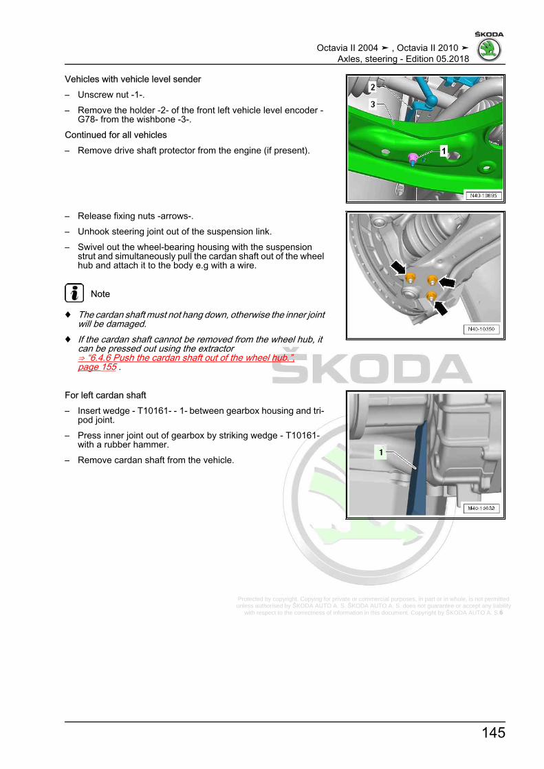
Protected by copyright. Copying for private or commercial purposes, in part or in whole, is not permitted unless authorised by ŠKODA AUTO A. S. ŠKODA AUTO A. S. does not guarantee or accept any liability
with respect to the correctness of information in this document. Copyright by ŠKODA AUTO A. S.�
Vehicles with vehicle level sender– Unscrew nut -1-.– Remove the holder -2- of the front left vehicle level encoder -
G78- from the wishbone -3-.Continued for all vehicles– Remove drive shaft protector from the engine (if present).
– Release fixing nuts -arrows-.– Unhook steering joint out of the suspension link.– Swivel out the wheel-bearing housing with the suspension
strut and simultaneously pull the cardan shaft out of the wheelhub and attach it to the body e.g with a wire.
Note
♦ The cardan shaft must not hang down, otherwise the inner jointwill be damaged.
♦ If the cardan shaft cannot be removed from the wheel hub, itcan be pressed out using the extractor⇒ “6.4.6 Push the cardan shaft out of the wheel hub.”,page 155 .
For left cardan shaft– Insert wedge - T10161- - 1- between gearbox housing and tri‐
pod joint.– Press inner joint out of gearbox by striking wedge - T10161-
with a rubber hammer.– Remove cardan shaft from the vehicle.
Octavia II 2004 ➤ , Octavia II 2010 ➤Axles, steering - Edition 05.2018
145

Protected by copyright. Copying for private or commercial purposes, in part or in whole, is not permitted unless authorised by ŠKODA AUTO A. S. ŠKODA AUTO A. S. does not guarantee or accept any liability
with respect to the correctness of information in this document. Copyright by ŠKODA AUTO A. S.�
For right cardan shaft– Drive off the left cardan shaft from the rigid shaft of the gearbox
-1-, e.g. with a wooden block -2-.– Remove cardan shaft from the vehicle.InstallingInstallation is performed in the reverse order, pay attention to thefollowing points:– Fit new retaining ring into groove of joint pin.– Mesh outer and inner splines of joint body and gearbox.– Slide cardan shaft into joint body to stop by hand.– Now »suddenly« push joint body into gearbox.The joint travel can be used for the »sudden push«. Do not, how‐ever, pull the cardan shaft too far out of the joint body.
Note
Never use a hammer or other driving tools.
– Check that the cardan shaft is securely seated in the gearboxby pulling the joint body against the resistance of retaining ring.
Note
Only pull on the joint part, not on the cardan shaft.
– Guide outer joint into wheel hub splines as far as possible.
Octavia II 2004 ➤ , Octavia II 2010 ➤Axles, steering - Edition 05.2018
146

Protected by copyright. Copying for private or commercial purposes, in part or in whole, is not permitted unless authorised by ŠKODA AUTO A. S. ŠKODA AUTO A. S. does not guarantee or accept any liability
with respect to the correctness of information in this document. Copyright by ŠKODA AUTO A. S.�
– Tighten the nuts -arrows-.
Note
Use new nuts.
– Tighten fixing screw of drive shaft to wheel hub⇒ “6.5 Loosen and tighten cardan shaft screwed connection”,page 158 .
Note
When tightening the fixing screw of the drive shaft, the wheel mustbe raised until it is fully off the ground, otherwise the wheel bearingcan be damaged.
– On vehicles with vehicle level sensor, carry out a basic settingfor the headlights ⇒ Maintenance ; Booklet Octavia II .
Tightening torques - summaries of components
Note
Replace bolts / nuts that are tightened at an angle of rotation, aswell as replacement components after removal.
♦ ⇒ “6.3.3 Summary of components - Drive shaft with inner tri‐pod joint AAR2600i”, page 136
♦ ⇒ “2.1 Assembly overview - subframe, aluminium subframe”,page 10
♦ ⇒ “3.1.1 Assembly overview - subframe, sheet steel assemblycarrier, left-hand drive”, page 58
♦ ⇒ “3.1.2 Assembly overview - subframe, sheet steel assemblycarrier, right hand drive”, page 62
♦ ⇒ “6.5 Loosen and tighten cardan shaft screwed connection”,page 158
♦ ⇒ “6.6 Removing and installing heat shield for cardan shaft”,page 160
♦ ⇒ “1.1 Summary of components - vehicle level sender front”,page 293
♦ ⇒ “1.2 Tightening torque of the wheel screws”, page 301♦ Noise insulation ⇒ Body work assembly; Rep. gr. 50
6.4.3 PTO shaft with extractor for drive shafts- T10382- , inserted in the gearbox, re‐moving and installing tripod jointAAR2600i
Special tools and workshop equipment required♦ Extractor for drive shafts - T10382 -♦ Multi-purpose tool - MP3-419- ♦ Tensioning strap - T10038-♦ Puller plate - T10382/1-
Octavia II 2004 ➤ , Octavia II 2010 ➤Axles, steering - Edition 05.2018
147
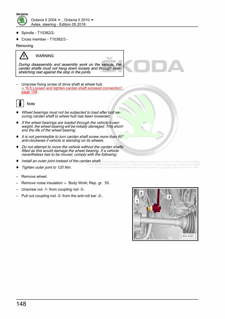
Protected by copyright. Copying for private or commercial purposes, in part or in whole, is not permitted unless authorised by ŠKODA AUTO A. S. ŠKODA AUTO A. S. does not guarantee or accept any liability
with respect to the correctness of information in this document. Copyright by ŠKODA AUTO A. S.�
♦ Spindle - T10382/2-♦ Cross member - T10382/3 -Removing
WARNING
During disassembly and assembly work on the vehicle, thecardan shafts must not hang down loosely and through over‐stretching rest against the stop in the joints.
– Unscrew fixing screw of drive shaft at wheel hub⇒ “6.5 Loosen and tighten cardan shaft screwed connection”,page 158 .
Note
♦ Wheel bearings must not be subjected to load after bolt se‐curing cardan shaft to wheel hub has been loosened.
♦ If the wheel bearings are loaded through the vehicle's ownweight, the wheel bearing will be initially damaged. This short‐ens the life of the wheel bearing.
♦ It is not permissible to turn cardan shaft screw more than 90°anti-clockwise if vehicle is standing on its wheels.
♦ Do not attempt to move the vehicle without the cardan shaftsfitted as this would damage the wheel bearing. If a vehiclenevertheless has to be moved, comply with the following:
♦ Install an outer joint instead of the cardan shaft.♦ Tighten outer joint to 120 Nm.
– Remove wheel.– Remove noise insulation ⇒ Body Work; Rep. gr. 50 .– Unscrew nut -1- from coupling rod -3-.– Pull out coupling rod -3- from the anti-roll bar -2-.
Octavia II 2004 ➤ , Octavia II 2010 ➤Axles, steering - Edition 05.2018
148

Protected by copyright. Copying for private or commercial purposes, in part or in whole, is not permitted unless authorised by ŠKODA AUTO A. S. ŠKODA AUTO A. S. does not guarantee or accept any liability
with respect to the correctness of information in this document. Copyright by ŠKODA AUTO A. S.�
Vehicles with vehicle level sender– Unscrew nut -1-.– Remove the holder -2- of the front left vehicle level encoder -
G78- from the wishbone -3-.Continued for all vehicles– Remove drive shaft guard (if present).
– Release fixing nuts -arrows-.– Unhook steering joint out of the suspension link.– Swivel out the wheel-bearing housing with the suspension
strut and simultaneously pull the cardan shaft out of the wheelhub and attach it to the body e.g with a wire.
Note
♦ The cardan shaft must not hang down, otherwise the inner jointwill be damaged.
♦ If the cardan shaft cannot be removed from the wheel hub, itcan be pressed out using the extractor⇒ “6.4.6 Push the cardan shaft out of the wheel hub.”,page 155 .
Left drive shaft– Tighten the suspension strut with tensioning strap - T10038-
to the body at the rear so that the extractor for drive shafts -T10382 - can be fitted in parallel to the driveshaft.
– Fit the puller plate - T10382/1- behind the inner joint -arrow-so that the recess points to the spindles - T10382/2- .
– Connect spindles - T10382/2- and cross members - T10382/3- with puller plate - T10382/1- .
– Connect multi-purpose tool - MP3-419- to cross member -T10382/3- .
– Pull the drive shaft out of the gearbox by tapping the multi-purpose tool - MP3-419- .
Right drive shaft
Octavia II 2004 ➤ , Octavia II 2010 ➤Axles, steering - Edition 05.2018
149
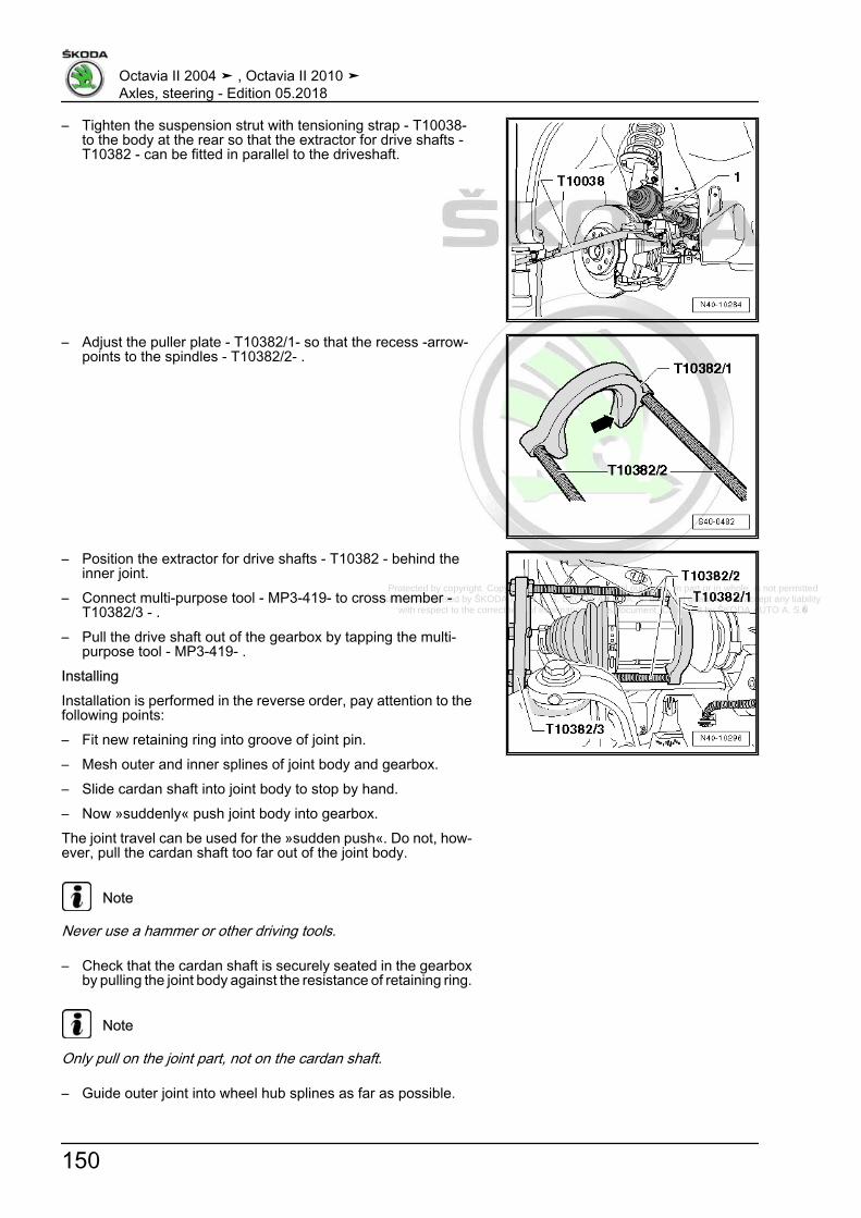
Protected by copyright. Copying for private or commercial purposes, in part or in whole, is not permitted unless authorised by ŠKODA AUTO A. S. ŠKODA AUTO A. S. does not guarantee or accept any liability
with respect to the correctness of information in this document. Copyright by ŠKODA AUTO A. S.�
– Tighten the suspension strut with tensioning strap - T10038-to the body at the rear so that the extractor for drive shafts -T10382 - can be fitted in parallel to the driveshaft.
– Adjust the puller plate - T10382/1- so that the recess -arrow-points to the spindles - T10382/2- .
– Position the extractor for drive shafts - T10382 - behind theinner joint.
– Connect multi-purpose tool - MP3-419- to cross member -T10382/3 - .
– Pull the drive shaft out of the gearbox by tapping the multi-purpose tool - MP3-419- .
InstallingInstallation is performed in the reverse order, pay attention to thefollowing points:– Fit new retaining ring into groove of joint pin.– Mesh outer and inner splines of joint body and gearbox.– Slide cardan shaft into joint body to stop by hand.– Now »suddenly« push joint body into gearbox.The joint travel can be used for the »sudden push«. Do not, how‐ever, pull the cardan shaft too far out of the joint body.
Note
Never use a hammer or other driving tools.
– Check that the cardan shaft is securely seated in the gearboxby pulling the joint body against the resistance of retaining ring.
Note
Only pull on the joint part, not on the cardan shaft.
– Guide outer joint into wheel hub splines as far as possible.
Octavia II 2004 ➤ , Octavia II 2010 ➤Axles, steering - Edition 05.2018
150
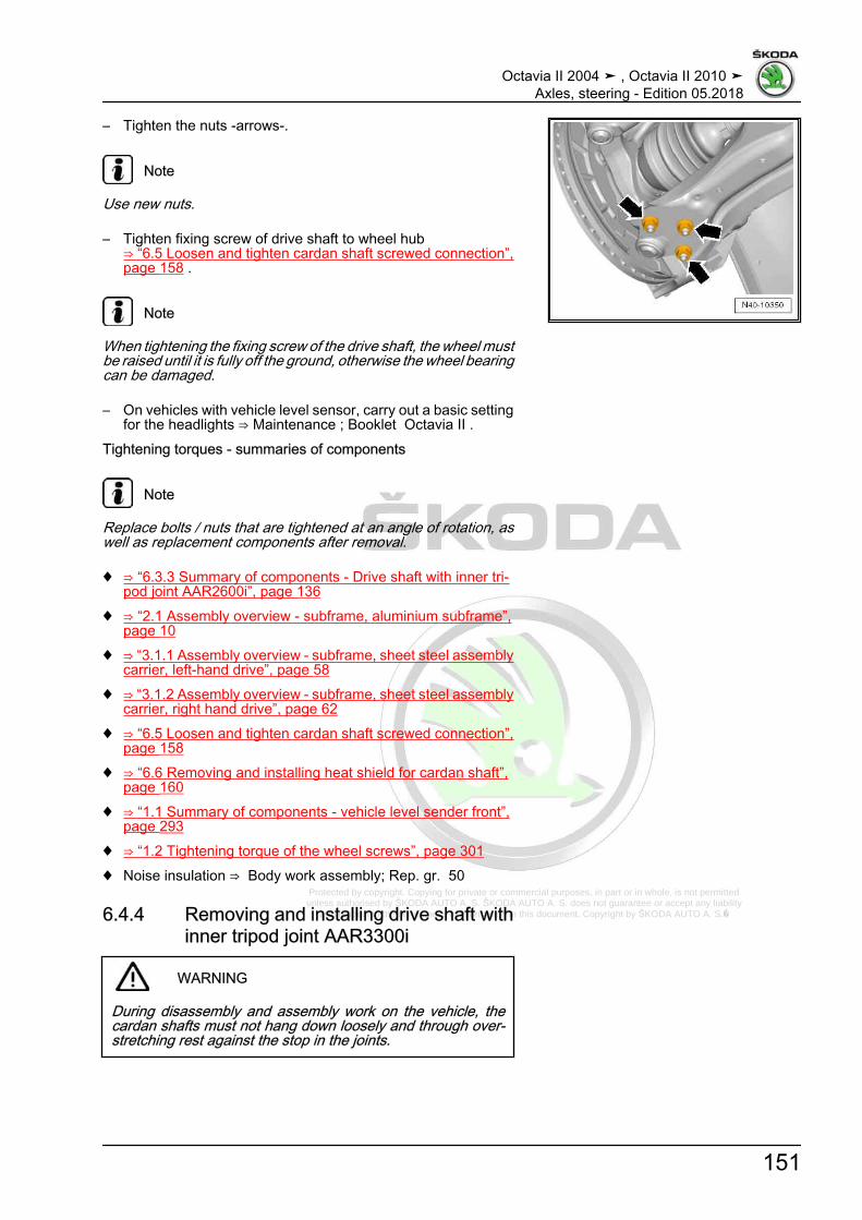
Protected by copyright. Copying for private or commercial purposes, in part or in whole, is not permitted unless authorised by ŠKODA AUTO A. S. ŠKODA AUTO A. S. does not guarantee or accept any liability
with respect to the correctness of information in this document. Copyright by ŠKODA AUTO A. S.�
– Tighten the nuts -arrows-.
Note
Use new nuts.
– Tighten fixing screw of drive shaft to wheel hub⇒ “6.5 Loosen and tighten cardan shaft screwed connection”,page 158 .
Note
When tightening the fixing screw of the drive shaft, the wheel mustbe raised until it is fully off the ground, otherwise the wheel bearingcan be damaged.
– On vehicles with vehicle level sensor, carry out a basic settingfor the headlights ⇒ Maintenance ; Booklet Octavia II .
Tightening torques - summaries of components
Note
Replace bolts / nuts that are tightened at an angle of rotation, aswell as replacement components after removal.
♦ ⇒ “6.3.3 Summary of components - Drive shaft with inner tri‐pod joint AAR2600i”, page 136
♦ ⇒ “2.1 Assembly overview - subframe, aluminium subframe”,page 10
♦ ⇒ “3.1.1 Assembly overview - subframe, sheet steel assemblycarrier, left-hand drive”, page 58
♦ ⇒ “3.1.2 Assembly overview - subframe, sheet steel assemblycarrier, right hand drive”, page 62
♦ ⇒ “6.5 Loosen and tighten cardan shaft screwed connection”,page 158
♦ ⇒ “6.6 Removing and installing heat shield for cardan shaft”,page 160
♦ ⇒ “1.1 Summary of components - vehicle level sender front”,page 293
♦ ⇒ “1.2 Tightening torque of the wheel screws”, page 301♦ Noise insulation ⇒ Body work assembly; Rep. gr. 50
6.4.4 Removing and installing drive shaft withinner tripod joint AAR3300i
WARNING
During disassembly and assembly work on the vehicle, thecardan shafts must not hang down loosely and through over‐stretching rest against the stop in the joints.
Octavia II 2004 ➤ , Octavia II 2010 ➤Axles, steering - Edition 05.2018
151

Protected by copyright. Copying for private or commercial purposes, in part or in whole, is not permitted unless authorised by ŠKODA AUTO A. S. ŠKODA AUTO A. S. does not guarantee or accept any liability
with respect to the correctness of information in this document. Copyright by ŠKODA AUTO A. S.�
Removing– Remove fixing screw of drive shaft at wheel hub
⇒ “6.5 Loosen and tighten cardan shaft screwed connection”,page 158
Note
♦ Wheel bearings must not be subjected to load after bolt se‐curing cardan shaft to wheel hub has been loosened.
♦ If the wheel bearings are loaded through the vehicle's ownweight, the wheel bearing will be initially damaged. This short‐ens the life of the wheel bearing.
♦ It is not permissible to turn cardan shaft screw more than 90°anti-clockwise if vehicle is standing on its wheels.
♦ Do not attempt to move the vehicle without the cardan shaftsfitted as this would damage the wheel bearing. If a vehiclenevertheless has to be moved, comply with the following:
♦ Install an outer joint instead of the cardan shaft.♦ Tighten outer joint to 120 Nm.
– Remove wheel.– Remove noise insulation ⇒ Body Work; Rep. gr. 50 .– Remove drive shaft protector from the engine (if present).– Remove cardan shaft from gearbox -arrows- and attach to the
body e.g. with a wire.
Note
The cardan shaft must not hang down, otherwise the inner jointwill be damaged.
– Unscrew nut -1- from coupling rod -3-.– Pull out coupling rod -3- from the anti-roll bar -2-.
Octavia II 2004 ➤ , Octavia II 2010 ➤Axles, steering - Edition 05.2018
152

Protected by copyright. Copying for private or commercial purposes, in part or in whole, is not permitted unless authorised by ŠKODA AUTO A. S. ŠKODA AUTO A. S. does not guarantee or accept any liability
with respect to the correctness of information in this document. Copyright by ŠKODA AUTO A. S.�
Vehicles with vehicle level sender– Unscrew nut -1-.– Undo holder -2- from the front left vehicle level sensor - G78-
and front right vehicle level sender - G289- from the suspen‐sion link -3-.
Continued for all vehicles
– Release fixing nuts -arrows-.– Unhook steering joint out of the suspension link.– Swivel out the wheel-bearing housing with the suspension
strut and simultaneously pull the cardan shaft out of the wheelhub and attach it to the body e.g with a wire.
Note
♦ The cardan shaft must not hang down, otherwise the inner jointwill be damaged.
♦ If the cardan shaft cannot be removed from the wheel hub, itcan be pressed out using the extractor⇒ “6.4.6 Push the cardan shaft out of the wheel hub.”,page 155 .
– Remove cardan shaft from the vehicle.InstallingInstallation is performed in the reverse order, pay attention to thefollowing points:– Remove possible paint and/or corrosion residue from the
thread/the serration of the outer joint– Before assembly of the outer join into the wheel hub, thinly
coat the teeth on the outer joint with assembly paste ⇒ Elec‐tronic Catalogue of Original Parts .
– Guide outer joint into wheel hub splines as far as possible.
Octavia II 2004 ➤ , Octavia II 2010 ➤Axles, steering - Edition 05.2018
153
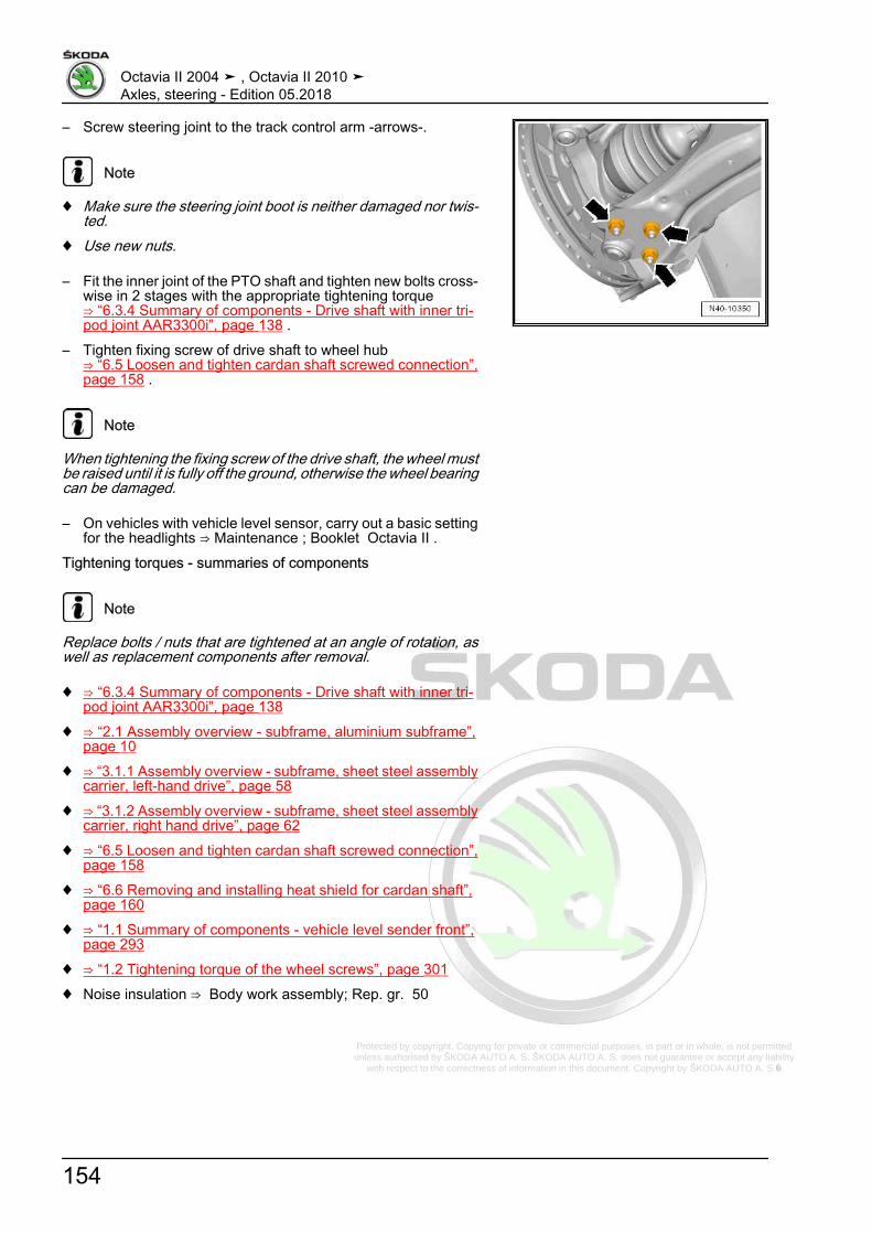
Protected by copyright. Copying for private or commercial purposes, in part or in whole, is not permitted unless authorised by ŠKODA AUTO A. S. ŠKODA AUTO A. S. does not guarantee or accept any liability
with respect to the correctness of information in this document. Copyright by ŠKODA AUTO A. S.�
– Screw steering joint to the track control arm -arrows-.
Note
♦ Make sure the steering joint boot is neither damaged nor twis‐ted.
♦ Use new nuts.
– Fit the inner joint of the PTO shaft and tighten new bolts cross‐wise in 2 stages with the appropriate tightening torque⇒ “6.3.4 Summary of components - Drive shaft with inner tri‐pod joint AAR3300i”, page 138 .
– Tighten fixing screw of drive shaft to wheel hub⇒ “6.5 Loosen and tighten cardan shaft screwed connection”,page 158 .
Note
When tightening the fixing screw of the drive shaft, the wheel mustbe raised until it is fully off the ground, otherwise the wheel bearingcan be damaged.
– On vehicles with vehicle level sensor, carry out a basic settingfor the headlights ⇒ Maintenance ; Booklet Octavia II .
Tightening torques - summaries of components
Note
Replace bolts / nuts that are tightened at an angle of rotation, aswell as replacement components after removal.
♦ ⇒ “6.3.4 Summary of components - Drive shaft with inner tri‐pod joint AAR3300i”, page 138
♦ ⇒ “2.1 Assembly overview - subframe, aluminium subframe”,page 10
♦ ⇒ “3.1.1 Assembly overview - subframe, sheet steel assemblycarrier, left-hand drive”, page 58
♦ ⇒ “3.1.2 Assembly overview - subframe, sheet steel assemblycarrier, right hand drive”, page 62
♦ ⇒ “6.5 Loosen and tighten cardan shaft screwed connection”,page 158
♦ ⇒ “6.6 Removing and installing heat shield for cardan shaft”,page 160
♦ ⇒ “1.1 Summary of components - vehicle level sender front”,page 293
♦ ⇒ “1.2 Tightening torque of the wheel screws”, page 301♦ Noise insulation ⇒ Body work assembly; Rep. gr. 50
Octavia II 2004 ➤ , Octavia II 2010 ➤Axles, steering - Edition 05.2018
154

Protected by copyright. Copying for private or commercial purposes, in part or in whole, is not permitted unless authorised by ŠKODA AUTO A. S. ŠKODA AUTO A. S. does not guarantee or accept any liability
with respect to the correctness of information in this document. Copyright by ŠKODA AUTO A. S.�
6.4.5 Removing and installing intermediateshaft
Removing– Remove drive shaft on the right side
⇒ “6.4.1 Removing and installing cardan shaft, CV joint VL90,VL100 and VL107”, page 140 .
– Remove the nuts -arrows- from the bearing bracket.– Pull off intermediate shaft from gearbox.Repairing intermediate shaft⇒ “6.7.11 Repairing intermediate shaft”, page 178 .InstallingInstallation is performed in the reverse order, pay attention to thefollowing points:
– First replace the gasket ring -1- on the gearbox.
– Push the rigid shaft as far as possible onto the gearbox shaftuntil the bearing -2- rests »free of gap« on the bracket -1-.
Tightening torques - summaries of components
Note
Replace bolts / nuts that are tightened at an angle of rotation, aswell as replacement components after removal.
♦ ⇒ “6.3.2 Summary of components - Cardan shaft CV jointVL107”, page 134
6.4.6 Push the cardan shaft out of the wheelhub.
Special tools and workshop equipment required♦ Extractor - T10520A-
Note
If the cardan shaft cannot be pulled out of the wheel hub, it canbe pressed out using the extractor - T10520A- .
Octavia II 2004 ➤ , Octavia II 2010 ➤Axles, steering - Edition 05.2018
155

Protected by copyright. Copying for private or commercial purposes, in part or in whole, is not permitted unless authorised by ŠKODA AUTO A. S. ŠKODA AUTO A. S. does not guarantee or accept any liability
with respect to the correctness of information in this document. Copyright by ŠKODA AUTO A. S.�
– Remove fixing screw of drive shaft at wheel hub⇒ “6.5 Loosen and tighten cardan shaft screwed connection”,page 158 .
Note
♦ Wheel bearings must not be subjected to load after bolt se‐curing cardan shaft to wheel hub has been loosened.
♦ If the wheel bearings are loaded through the vehicle's ownweight, the wheel bearing will be initially damaged. This short‐ens the life of the wheel bearing.
♦ It is not permissible to turn cardan shaft screw more than 90°anti-clockwise if vehicle is standing on its wheels.
♦ Do not attempt to move the vehicle without the cardan shaftsfitted as this would damage the wheel bearing. If the vehicleis moving in spite of this, pay attention to the following: Installthe outer joint instead of the drive shaft. Tighten outer joint to120 Nm.
– Remove wheel.– Remove noise insulation ⇒ Body Work; Rep. gr. 50 .– Unscrew nut -1- from coupling rod -3-.– Pull out coupling rod -3- from the anti-roll bar -2-.– For vehicles fitted with automatic headlight range control, re‐
move the front left vehicle level sensor - G78-⇒ “1.3 Removing and installing front vehicle level encoder G78”, page 295 .
– Release fixing nuts -arrows-.– Remove suspension link from suspension link of the wheel
bearing housing.– Press out drive shaft with extractor - T10520A- .Process for pressing out with extractor - T10520A-
Octavia II 2004 ➤ , Octavia II 2010 ➤Axles, steering - Edition 05.2018
156

Protected by copyright. Copying for private or commercial purposes, in part or in whole, is not permitted unless authorised by ŠKODA AUTO A. S. ŠKODA AUTO A. S. does not guarantee or accept any liability
with respect to the correctness of information in this document. Copyright by ŠKODA AUTO A. S.�
Note
Before using extractor - T10520A- , make sure that the thrustpiece -1- is inserted.
– Secure the extractor - T10520A- -1- with 3 wheel bolts -2- tothe wheel hub in order to be able to press out the cardan shaft-3-.
Therefore, the following order must be observed:
– Tighten the knurled nut -1- by hand.– Turn the screw -2- and press out the cardan shaft from the
wheel hub.
Note
At the end of the procedure or for pressing out cardan shaft furtherthe spindle must be moved to its original position in order to de‐ploy the hydraulic force!
– Remove cardan shaft from wheel hub.
Octavia II 2004 ➤ , Octavia II 2010 ➤Axles, steering - Edition 05.2018
157

Protected by copyright. Copying for private or commercial purposes, in part or in whole, is not permitted unless authorised by ŠKODA AUTO A. S. ŠKODA AUTO A. S. does not guarantee or accept any liability
with respect to the correctness of information in this document. Copyright by ŠKODA AUTO A. S.�
6.5 Loosen and tighten cardan shaftscrewed connection
Note
♦ If the fixing screw of the drive shaft is loosened more than 90°,the wheel bearings must not be loaded through the weight ofthe vehicle, i.e the vehicle must not stand on its wheels.
♦ If the wheel bearings are loaded through the weight of the ve‐hicle when the fixing screw for the drive shaft is removed, theinner wheel bearing will be damaged. This shortens the life ofthe wheel bearing.
♦ If the vehicle is standing on its wheels or moves, pay attentionto the following: Install the outer joint instead of the drive shaft.Tighten the fixing screw (use the one which was previouslyremoved) of the outer joint to the tightening torque of 120 Nm.
Distinguishing feature of twelve-sided boltsThe twelve-sided bolts differ in the surface area -arrow A- and-arrow B-.♦ I - Twelve-sided bolt with serration - -arrow A-♦ lI - Twelve-sided bolt without serration - -arrow B-Remove twelve-sided bolt– Remove wheel trim cap, for light-alloy wheels remove the cap
on the removed wheel (depending on version) ⇒ Wheels,Tyres; Rep. gr. 44 .
Octavia II 2004 ➤ , Octavia II 2010 ➤Axles, steering - Edition 05.2018
158

Protected by copyright. Copying for private or commercial purposes, in part or in whole, is not permitted unless authorised by ŠKODA AUTO A. S. ŠKODA AUTO A. S. does not guarantee or accept any liability
with respect to the correctness of information in this document. Copyright by ŠKODA AUTO A. S.�
– Slacken the screw -arrow- by max. 90° on the vehicle while itis standing on its wheels, otherwise the wheel bearing may bedamaged.
– Raise the vehicle until the wheels are fully off the ground.– Depress brake pedal (assistance of second mechanic re‐
quired).– Unscrew plug -arrow-.Install twelve-sided bolt– Always install a new screw.
Note
♦ Assign screw via the ⇒ Electronic Catalogue of Original Parts .♦ When tightening the fixing screw of the drive shaft, the wheel
must be raised until it is fully off the ground, otherwise thewheel bearing can be damaged.
Twelve-sided screw - WHT 002 795- with serration– Depress brake pedal (assistance of second mechanic re‐
quired).– Tighten the twelve-sided bolt to 70 Nm.– Place vehicle onto its wheels.– Depress brake pedal (assistance of second mechanic re‐
quired).– Tighten the 12-point screw a further 90°.– Install wheel trim cap, for light-alloy wheels (depending on
version) install cap.Twelve head screw - WHT 005 437- without teeth (black)– Depress brake pedal (assistance of second mechanic re‐
quired).– Tighten the twelve-sided bolt to 200 Nm.– Place vehicle onto its wheels.– Depress brake pedal (assistance of second mechanic re‐
quired).– Tighten the 12-point screw a further 180°.– Install wheel trim cap, for light-alloy wheels (depending on
version) install cap.12-point screw - WHT 005 437 A- without teeth (silver)– Depress brake pedal (assistance of second mechanic re‐
quired).– Tighten the twelve-sided bolt to 200 Nm.– Place vehicle onto its wheels.– Depress brake pedal (assistance of second mechanic re‐
quired).– Tighten the 12-point screw a further 90°.– Install wheel trim cap, for light-alloy wheels (depending on
version) install cap.
Octavia II 2004 ➤ , Octavia II 2010 ➤Axles, steering - Edition 05.2018
159

Protected by copyright. Copying for private or commercial purposes, in part or in whole, is not permitted unless authorised by ŠKODA AUTO A. S. ŠKODA AUTO A. S. does not guarantee or accept any liability
with respect to the correctness of information in this document. Copyright by ŠKODA AUTO A. S.�
Tightening torques - summaries of components
Note
Replace bolts / nuts that are tightened at an angle of rotation, aswell as replacement components after removal.
♦ ⇒ “1.2 Tightening torque of the wheel screws”, page 301
6.6 Removing and installing heat shield forcardan shaft
⇒ “6.6.1 Removing and installing the heat shield for cardan shaft,heat shield fastened with plate”, page 160⇒ “6.6.2 Removing and installing heat shield for propshaft, pro‐tective cover secured with 2 pipe nuts”, page 160⇒ “6.6.3 Removing and installing heat shield for propshaft, pro‐tective cover secured with 3 pipe nuts”, page 161
6.6.1 Removing and installing the heat shieldfor cardan shaft, heat shield fastenedwith plate
Removing– Remove noise insulation ⇒ Body Work; Rep. gr. 50 .– Remove screws -1-.– Remove heat shield for driveshaftInstallingInstallation is carried out in the reverse order.Tightening torques - summaries of components
Note
Replace bolts / nuts that are tightened at an angle of rotation, aswell as replacement components after removal.
Component Tightening torqueScrews M10 x 20 25 NmScrews M8 x 20 20 Nm
♦ Noise insulation ⇒ Body work assembly; Rep. gr. 50
6.6.2 Removing and installing heat shield forpropshaft, protective cover secured with2 pipe nuts
Removing– Remove noise insulation ⇒ Body Work; Rep. gr. 50 .
Octavia II 2004 ➤ , Octavia II 2010 ➤Axles, steering - Edition 05.2018
160
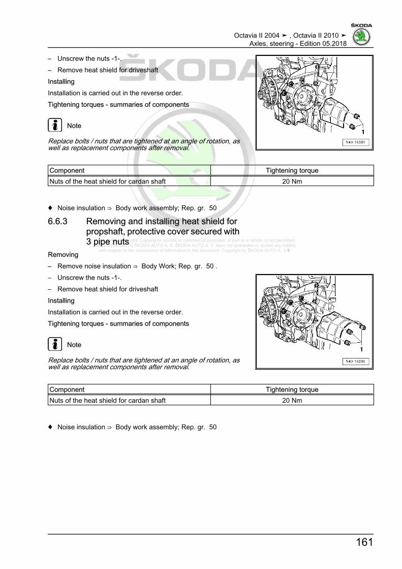
Protected by copyright. Copying for private or commercial purposes, in part or in whole, is not permitted unless authorised by ŠKODA AUTO A. S. ŠKODA AUTO A. S. does not guarantee or accept any liability
with respect to the correctness of information in this document. Copyright by ŠKODA AUTO A. S.�
– Unscrew the nuts -1-.– Remove heat shield for driveshaftInstallingInstallation is carried out in the reverse order.Tightening torques - summaries of components
Note
Replace bolts / nuts that are tightened at an angle of rotation, aswell as replacement components after removal.
Component Tightening torqueNuts of the heat shield for cardan shaft 20 Nm
♦ Noise insulation ⇒ Body work assembly; Rep. gr. 50
6.6.3 Removing and installing heat shield forpropshaft, protective cover secured with3 pipe nuts
Removing– Remove noise insulation ⇒ Body Work; Rep. gr. 50 .– Unscrew the nuts -1-.– Remove heat shield for driveshaftInstallingInstallation is carried out in the reverse order.Tightening torques - summaries of components
Note
Replace bolts / nuts that are tightened at an angle of rotation, aswell as replacement components after removal.
Component Tightening torqueNuts of the heat shield for cardan shaft 20 Nm
♦ Noise insulation ⇒ Body work assembly; Rep. gr. 50
Octavia II 2004 ➤ , Octavia II 2010 ➤Axles, steering - Edition 05.2018
161

Protected by copyright. Copying for private or commercial purposes, in part or in whole, is not permitted unless authorised by ŠKODA AUTO A. S. ŠKODA AUTO A. S. does not guarantee or accept any liability
with respect to the correctness of information in this document. Copyright by ŠKODA AUTO A. S.�
6.7 Disassembling and assembling cardanshaft
⇒ “6.7.1 Removing inner joint VL90 and VL100”, page 162⇒ “6.7.2 Remove inner joint VL107”, page 163⇒ “6.7.3 Remove inner joint AAR2600i”, page 164⇒ “6.7.4 Remove inner joint AAR3300i”, page 165⇒ “6.7.5 Installing inner joint VL90 and VL100”, page 166⇒ “6.7.6 Install inner joint VL107”, page 168⇒ “6.7.7 Install inner joint AAR2600i”, page 171⇒ “6.7.8 Install inner joint AAR3300i”, page 173⇒ “6.7.9 Removing outer CV joint”, page 175⇒ “6.7.10 Installing the outer CV joint”, page 176⇒ “6.7.11 Repairing intermediate shaft”, page 178
6.7.1 Removing inner joint VL90 and VL100Special tools and workshop equipment required♦ Pressure plate - MP3-406 (VW 401)-♦ Pressure plate - MP3-407 (VW 402)-♦ Thrust piece - MP3-411 (VW 454)-♦ Pressure spindle - MP3-448 (VW 408 A)-♦ Thrust washer - MP3-455 (VW 447 H)-♦ Thrust piece - MP6-405 (VW 411)-♦ Circlip pliers , e.g. -VW 161 A-♦ Tensioning pliers , e.g. -V.A.G 1682 A-♦ Assembly tool - T10065-
Note
♦ Before removing the joints and the joint boots, thoroughlyclean their surrounding areas.
♦ When disassembling the joint, remove the old lubricant andany dirt present.
♦ Clean the joint with great care.♦ Dispose of old lubricant and cleaning agent in compliance with
the applicable regulations.♦ Place removed and cleaned parts on a clean surface and cov‐
er as needed. Use lint-free cloths!♦ Carefully cover removed parts if the repair is not completed
immediately.♦ Only install clean parts: remove spare parts from their wrap‐
ping immediately before fitting. Do not use any parts whichhave been stored unwrapped (e.g. on a shelf or in a tool boxetc...).
Removing and installing outer joint⇒ “6.7.9 Removing outer CV joint”, page 175 .
Octavia II 2004 ➤ , Octavia II 2010 ➤Axles, steering - Edition 05.2018
162
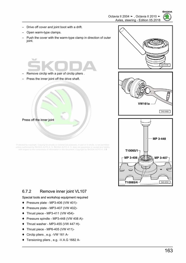
Protected by copyright. Copying for private or commercial purposes, in part or in whole, is not permitted unless authorised by ŠKODA AUTO A. S. ŠKODA AUTO A. S. does not guarantee or accept any liability
with respect to the correctness of information in this document. Copyright by ŠKODA AUTO A. S.�
– Drive off cover and joint boot with a drift.– Open warm-type clamps.– Push the cover with the warm-type clamp in direction of outer
joint.
– Remove circlip with a pair of circlip pliers .– Press the inner joint off the drive shaft.
Press off the inner joint
6.7.2 Remove inner joint VL107Special tools and workshop equipment required♦ Pressure plate - MP3-406 (VW 401)-♦ Pressure plate - MP3-407 (VW 402)-♦ Thrust piece - MP3-411 (VW 454)-♦ Pressure spindle - MP3-448 (VW 408 A)-♦ Thrust washer - MP3-455 (VW 447 H)-♦ Thrust piece - MP6-405 (VW 411)-♦ Circlip pliers , e.g. -VW 161 A-♦ Tensioning pliers , e.g. -V.A.G 1682 A-
Octavia II 2004 ➤ , Octavia II 2010 ➤Axles, steering - Edition 05.2018
163

Protected by copyright. Copying for private or commercial purposes, in part or in whole, is not permitted unless authorised by ŠKODA AUTO A. S. ŠKODA AUTO A. S. does not guarantee or accept any liability
with respect to the correctness of information in this document. Copyright by ŠKODA AUTO A. S.�
♦ Assembly tool - T10065-Removing and installing outer joint⇒ “6.7.9 Removing outer CV joint”, page 175 .– Drive off cover for inner joint with a drift.Remove cover for inner joint– Remove open warm-type clamps, push the joint boot to the
outer joint.
– Drive off cap of joint boot with a drift.– Remove circlip with a pair of circlip pliers.– Press the inner joint off the drive shaft.
Press off the inner joint
6.7.3 Remove inner joint AAR2600iSpecial tools and workshop equipment required♦ Pressure plate - MP3-406 (VW 401)-♦ Pressure plate - MP3-407 (VW 402)-♦ Thrust washer - MP3-455 (VW 447 H)-♦ Pressure spindle - MP3-448 (VW 408 A)-♦ Thrust piece - MP6-405 (VW 411)-
Octavia II 2004 ➤ , Octavia II 2010 ➤Axles, steering - Edition 05.2018
164

Protected by copyright. Copying for private or commercial purposes, in part or in whole, is not permitted unless authorised by ŠKODA AUTO A. S. ŠKODA AUTO A. S. does not guarantee or accept any liability
with respect to the correctness of information in this document. Copyright by ŠKODA AUTO A. S.�
♦ Pipe section - MP3-4012 (VW 416 B)-♦ Circlip pliers , e.g. -VW 161A-♦ Hose strap pliers , e.g. -V.A.G 1275 -♦ Assembly tool - T10065-Removing and installing outer joint⇒ “6.7.9 Removing outer CV joint”, page 175 .– Open both warm-type clamps at inner joint and push back the
joint boot.– Remove the joint part from the cardan shaft.– Remove circlip with circlip pliers -1-.– Insert the cardan shaft in the press.
– Press tripod spider off the cardan shaft.– Remove the joint boot from the shaft.– Clean the shaft, the joint part and the slot for the gasket ring.
6.7.4 Remove inner joint AAR3300iSpecial tools and workshop equipment required♦ Pressure plate - MP3-406 (VW 401)-♦ Pressure plate - MP3-407 (VW 402)-♦ Thrust washer - MP3-455 (VW 447 H)-♦ Pressure spindle - MP3-448 (VW 408 A)-♦ Thrust piece - MP6-405 (VW 411)-♦ Pipe section - MP3-4012 (VW 416 B)-♦ Circlip pliers , e.g. -VW 161A-♦ Hose strap pliers , e.g. -V.A.G 1275-
Octavia II 2004 ➤ , Octavia II 2010 ➤Axles, steering - Edition 05.2018
165

Protected by copyright. Copying for private or commercial purposes, in part or in whole, is not permitted unless authorised by ŠKODA AUTO A. S. ŠKODA AUTO A. S. does not guarantee or accept any liability
with respect to the correctness of information in this document. Copyright by ŠKODA AUTO A. S.�
♦ Assembly tool - T10065-Removing and installing outer joint⇒ “6.7.9 Removing outer CV joint”, page 175 .– Open both warm-type clamps at inner joint and push back the
joint boot.– Remove the joint part or the driver from the drive shaft.– Remove circlip with circlip pliers -1-.1 - Pliers (commercially available) or e.g. -VW 161A-– Insert the cardan shaft in the press.
– Press tripod spider off the cardan shaft.– Remove the joint boot from the shaft.– Clean the shaft, the joint part and the slot for the gasket ring.
6.7.5 Installing inner joint VL90 and VL100– Push a small open warm-type clamp for the joint boot onto the
drive shaft.– Push the sheet metal cover with the joint boot onto the drive
shaft.– Pay attention to the fitting position of the disc spring at the inner
joint.Fitting position of the disc spring at inner joint1 - Disc spring
Octavia II 2004 ➤ , Octavia II 2010 ➤Axles, steering - Edition 05.2018
166

Protected by copyright. Copying for private or commercial purposes, in part or in whole, is not permitted unless authorised by ŠKODA AUTO A. S. ŠKODA AUTO A. S. does not guarantee or accept any liability
with respect to the correctness of information in this document. Copyright by ŠKODA AUTO A. S.�
– Thinly coat the serration -A- with joint grease.– Press the joint up to the stop.
Pressing on the inner joint
Note
Chamfer on inner diameter of the ball hub (serration) must pointtowards the bearing collar of the drive shaft.
– Install circlip.– Fill the joint with grease
⇒ “6.2 Designation, distinguish the diameter as specified andgrease quantity for joints”, page 131 .
– Clean and degrease the end faces of the joint.– Clean and degrease the end face of the sheet metal cover for
the joint boot which rests against the joint.
– Apply sealant -D 454 300 A2- on the shaded surfaces of thecover.
♦ Sealant bead: apply continuously, Ø 2...3 mm, in the area ofthe holes from inside -arrow-.
– Push the sheet metal cover with the joint boot onto the joint.
– Align the cover with the joint boot to the screw holes withscrews -arrows-.
Note
The alignment must be performed very carefully as this is no lon‐ger possible after striking it.
– Use a plastic hammer to strike the sheet metal cover with thejoint boot on the joint.
– Wipe off any excess sealant, if necessary.– Remove the protective foil from the gasket and stick the gasket
into the joint from the gearbox side.
Octavia II 2004 ➤ , Octavia II 2010 ➤Axles, steering - Edition 05.2018
167

Protected by copyright. Copying for private or commercial purposes, in part or in whole, is not permitted unless authorised by ŠKODA AUTO A. S. ŠKODA AUTO A. S. does not guarantee or accept any liability
with respect to the correctness of information in this document. Copyright by ŠKODA AUTO A. S.�
– Insert the joint boot into the outer groove of the shaft-arrow B-.
– Install warm-type clamp.
Tighten warm-type clamp– Position the tensioning pliers as shown in the figure. Make
sure the cutting edges of the pliers are positioned in the cor‐ners -arrows B- of the open warm-type clamp.
– Tighten the open warm-type clamp by turning the spindle witha torque wrench (do not tilt the pliers during this process).
Note
♦ In view of the hard material (as opposed to rubber) of the jointboot, which requires the use of stainless steel open warm-typeclamps, these can only be tightened with tensioning pliers ,e.g. -V.A.G 1682 A- .
♦ Tightening torque: 25 Nm.♦ Use torque wrench -C-.♦ Make sure that the thread of the spindle -A- of the pliers moves
freely. Lubricate with grease if necessary.♦ If it is not smooth, e.g. if the thread is dirty, the necessary
clamping force of the open warm-type clamp is not reached atthe given torque.
6.7.6 Install inner joint VL107– Push a small open warm-type clamp for the joint boot onto the
drive shaft.– Push the joint boot and the cap of the boot onto the drive shaft.– Thinly coat the serration -A- with joint grease.– Press the joint up to the stop.
Octavia II 2004 ➤ , Octavia II 2010 ➤Axles, steering - Edition 05.2018
168

Protected by copyright. Copying for private or commercial purposes, in part or in whole, is not permitted unless authorised by ŠKODA AUTO A. S. ŠKODA AUTO A. S. does not guarantee or accept any liability
with respect to the correctness of information in this document. Copyright by ŠKODA AUTO A. S.�
Pressing on the inner joint
Note
Chamfer on inner diameter of the ball hub (serration) must pointtowards the bearing collar of the drive shaft.
– Insert the circlip.– Fill the joint with grease
⇒ “6.2 Designation, distinguish the diameter as specified andgrease quantity for joints”, page 131 .
– Clean and degrease the end faces of the joint.– Clean and degrease the end face of the cover or the sheet
metal cap for the joint boot which rests against the joint.
– Apply sealant -D 454 300 A2- on the shaded surfaces of thecover or the cap.
♦ Sealant bead: apply continuously, Ø 2...3 mm, in the area ofthe holes from inside -arrow-.
– Push the sheet metal cap of the joint boot onto the joint.
– Align the cap of the joint boot to the screw holes with screws-arrows-.
Note
The alignment must be performed very carefully as this is no lon‐ger possible after striking it.
– Use a plastic hammer to strike the sheet metal cap of the jointboot on the joint.
– Wipe off any excess sealant, if necessary.– If necessary, stick the gasket into the joint from the gearbox
side (remove the protective foil and stick the gasket into thejoint). Assignment ⇒ Electronic Catalogue of Original Parts .
Octavia II 2004 ➤ , Octavia II 2010 ➤Axles, steering - Edition 05.2018
169

Protected by copyright. Copying for private or commercial purposes, in part or in whole, is not permitted unless authorised by ŠKODA AUTO A. S. ŠKODA AUTO A. S. does not guarantee or accept any liability
with respect to the correctness of information in this document. Copyright by ŠKODA AUTO A. S.�
– Align the new cover to the screw holes -arrows-.
Note
The alignment must be performed very carefully as this is no lon‐ger possible after striking it.
– Use a plastic hammer to strike the sheet metal cover on thejoint.
– Wipe off any excess sealant, if necessary.
– Insert the joint boot on the joint and into the outer groove ofthe shaft -arrow B-.
– Install warm-type clamps.
Tighten the open warm-type clamp at the larger diameter
Octavia II 2004 ➤ , Octavia II 2010 ➤Axles, steering - Edition 05.2018
170

Protected by copyright. Copying for private or commercial purposes, in part or in whole, is not permitted unless authorised by ŠKODA AUTO A. S. ŠKODA AUTO A. S. does not guarantee or accept any liability
with respect to the correctness of information in this document. Copyright by ŠKODA AUTO A. S.�
Tighten the open warm-type clamp at the smaller diameter– Fit tensioning pliers , e.g. -V.A.G 1682 A- , as shown Make
sure the cutting edges of the pliers are positioned in the cor‐ners -arrows B- of the open warm-type clamp.
– Tighten the open warm-type clamp by turning the spindle witha torque wrench (do not tilt the pliers during this process).
Note
♦ In view of the hard material (as opposed to rubber) of the jointboot, which requires the use of stainless steel open warm-typeclamps, these can only be tightened with tensioning pliers ,e.g. -V.A.G 1682 A- .
♦ Tightening torque: 25 Nm.♦ Use torque wrench -C-.♦ Make sure that the thread of the spindle -A- of the pliers moves
freely. Lubricate with grease if necessary.♦ If it is not smooth, e.g. if the thread is dirty, the necessary
clamping force of the open warm-type clamp is not reached atthe given torque.
6.7.7 Install inner joint AAR2600i– Push a small open warm-type clamp for the joint boot onto the
drive shaft.– Push the joint boot onto the shaft.– Push the joint piece onto the cardan shaft.Install tripod spiderCardan shaft in conical versionThe chamfer of the tripod spider points towards the shaft and as‐sists installation.– If necessary, coat the serration of the drive shaft and the tripod
spider with joint grease.– Insert the tripod spider onto the shaft and press it up to the
stop.– Make sure that the force of pressure does not exceed 3.0 kN!– Insert circlip and pay attention to correct position.– Press 70 grams of grease for the drive shaft from the repair kit
in the tripod joint.– Slide the joint part over the rollers and hold down.– Press 60 grams of grease for the drive shaft from the repair kit
in the rear side of the tripod joint.Grease⇒ “6.2 Designation, distinguish the diameter as specified andgrease quantity for joints”, page 131 .– Installing the joint boot.Install tripod spiderCardan shaft in cylindrical version– If necessary, coat the serration of the drive shaft and the tripod
spider with joint grease.
Octavia II 2004 ➤ , Octavia II 2010 ➤Axles, steering - Edition 05.2018
171

Protected by copyright. Copying for private or commercial purposes, in part or in whole, is not permitted unless authorised by ŠKODA AUTO A. S. ŠKODA AUTO A. S. does not guarantee or accept any liability
with respect to the correctness of information in this document. Copyright by ŠKODA AUTO A. S.�
– Insert the tripod spider onto the shaft and press it up to thestop.
– Make sure that the force of pressure does not exceed 3.0 kN!– Insert circlip and pay attention to correct position.– Press 70 grams of grease for the drive shaft from the repair kit
in the tripod joint.– Slide the joint part over the rollers and hold down.– Press 60 grams of grease for the drive shaft from the repair kit
in the rear side of the tripod joint.Grease⇒ “6.2 Designation, distinguish the diameter as specified andgrease quantity for joints”, page 131 .– Installing the joint boot.
– Install warm-type clamps.
Note
In order to better guide the splined nuts when installing the driveshaft, it is necessary that the clamping pipe of the open warm-type clamp -arrow A- is located between the holes for the fixingflanges of the joint part -arrows B-.
Tighten the open warm-type clamp at the larger diameter
Octavia II 2004 ➤ , Octavia II 2010 ➤Axles, steering - Edition 05.2018
172
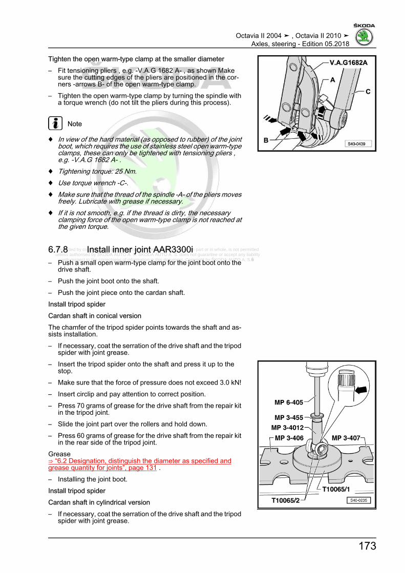
Protected by copyright. Copying for private or commercial purposes, in part or in whole, is not permitted unless authorised by ŠKODA AUTO A. S. ŠKODA AUTO A. S. does not guarantee or accept any liability
with respect to the correctness of information in this document. Copyright by ŠKODA AUTO A. S.�
Tighten the open warm-type clamp at the smaller diameter– Fit tensioning pliers , e.g. -V.A.G 1682 A- , as shown Make
sure the cutting edges of the pliers are positioned in the cor‐ners -arrows B- of the open warm-type clamp.
– Tighten the open warm-type clamp by turning the spindle witha torque wrench (do not tilt the pliers during this process).
Note
♦ In view of the hard material (as opposed to rubber) of the jointboot, which requires the use of stainless steel open warm-typeclamps, these can only be tightened with tensioning pliers ,e.g. -V.A.G 1682 A- .
♦ Tightening torque: 25 Nm.♦ Use torque wrench -C-.♦ Make sure that the thread of the spindle -A- of the pliers moves
freely. Lubricate with grease if necessary.♦ If it is not smooth, e.g. if the thread is dirty, the necessary
clamping force of the open warm-type clamp is not reached atthe given torque.
6.7.8 Install inner joint AAR3300i– Push a small open warm-type clamp for the joint boot onto the
drive shaft.– Push the joint boot onto the shaft.– Push the joint piece onto the cardan shaft.Install tripod spiderCardan shaft in conical versionThe chamfer of the tripod spider points towards the shaft and as‐sists installation.– If necessary, coat the serration of the drive shaft and the tripod
spider with joint grease.– Insert the tripod spider onto the shaft and press it up to the
stop.– Make sure that the force of pressure does not exceed 3.0 kN!– Insert circlip and pay attention to correct position.– Press 70 grams of grease for the drive shaft from the repair kit
in the tripod joint.– Slide the joint part over the rollers and hold down.– Press 60 grams of grease for the drive shaft from the repair kit
in the rear side of the tripod joint.Grease⇒ “6.2 Designation, distinguish the diameter as specified andgrease quantity for joints”, page 131 .– Installing the joint boot.Install tripod spiderCardan shaft in cylindrical version– If necessary, coat the serration of the drive shaft and the tripod
spider with joint grease.
Octavia II 2004 ➤ , Octavia II 2010 ➤Axles, steering - Edition 05.2018
173

Protected by copyright. Copying for private or commercial purposes, in part or in whole, is not permitted unless authorised by ŠKODA AUTO A. S. ŠKODA AUTO A. S. does not guarantee or accept any liability
with respect to the correctness of information in this document. Copyright by ŠKODA AUTO A. S.�
– Insert the tripod spider onto the shaft and press it up to thestop.
– Make sure that the force of pressure does not exceed 3.0 kN!– Insert circlip and pay attention to correct position.– Press 70 grams of grease for the drive shaft from the repair kit
in the tripod joint.– Slide the joint part over the rollers and hold down.– Press 60 grams of grease for the drive shaft from the repair kit
in the rear side of the tripod joint.Grease⇒ “6.2 Designation, distinguish the diameter as specified andgrease quantity for joints”, page 131 .– Installing the joint boot.
– Install warm-type clamp.
Note
In order to better guide the splined nuts when installing the driveshaft, it is necessary that the clamping pipe of the open warm-type clamp -arrow A- is located between the holes for the fixingflanges of the joint part -arrows B-.
– Tighten warm-type clamp e.g. using hose binding claw - V.A.G1275-
– tighten small warm-type clamp using hose binding claw -V.A.G 1275- .
Octavia II 2004 ➤ , Octavia II 2010 ➤Axles, steering - Edition 05.2018
174

Protected by copyright. Copying for private or commercial purposes, in part or in whole, is not permitted unless authorised by ŠKODA AUTO A. S. ŠKODA AUTO A. S. does not guarantee or accept any liability
with respect to the correctness of information in this document. Copyright by ŠKODA AUTO A. S.�
6.7.9 Removing outer CV jointSpecial tools and workshop equipment required♦ Multi-purpose tool - MP3-419 (VW 771)-♦ Extractor - T10382-The types of joints must be distinguished according to the diam‐eter⇒ “6.2 Designation, distinguish the diameter as specified andgrease quantity for joints”, page 131 .
Note
♦ Before removing the joints and the joint boots, thoroughlyclean their surrounding areas.
♦ When disassembling the joint, remove the old lubricant andany dirt present.
♦ Clean the joint with great care.♦ Dispose of old lubricant and cleaning agent in compliance with
the applicable regulations.♦ Place removed and cleaned parts on a clean surface and cov‐
er as needed. Use lint-free cloths!♦ Carefully cover removed parts if the repair is not completed
immediately.♦ Only install clean parts: remove spare parts from their wrap‐
ping immediately before fitting. Do not use any parts whichhave been stored unwrapped (e.g. on a shelf or in a tool boxetc...).
Removing outer CV joint– Clamp the cardan shaft in a vice with protective jaws.– Open both warm-type clamps and remove the joint boot from
the outer joint.– Set extractor - T10382- up so that the smooth side of the puller
plate - T10382/1- points to the spindles - T10382/2- .– Fit multi-purpose tool - T10382- to extractor - MP3-419- .– Detach the CV joint with extractor - T10382- and multi-purpose
tool - MP3-419- from the drive shaft.1 - Puller plate - T10382/1-2 - Spindles - T10382/2-The drift must be positioned exactly at the tripod spider of the CVjoin.
Octavia II 2004 ➤ , Octavia II 2010 ➤Axles, steering - Edition 05.2018
175
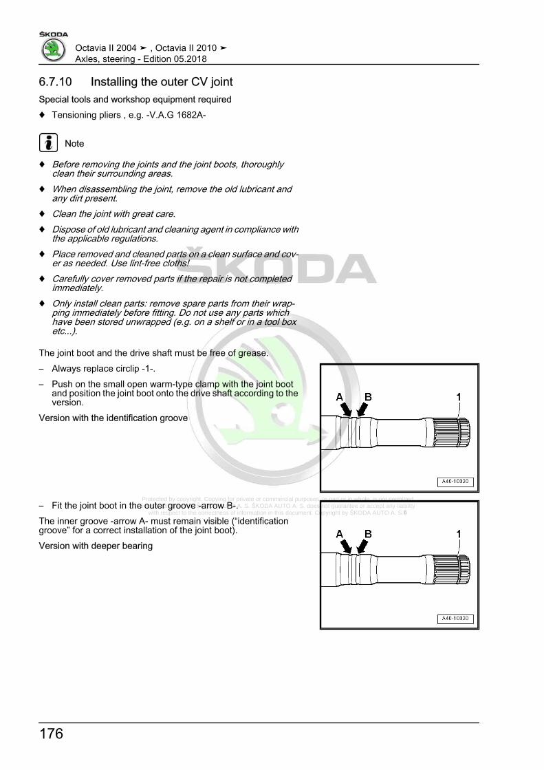
Protected by copyright. Copying for private or commercial purposes, in part or in whole, is not permitted unless authorised by ŠKODA AUTO A. S. ŠKODA AUTO A. S. does not guarantee or accept any liability
with respect to the correctness of information in this document. Copyright by ŠKODA AUTO A. S.�
6.7.10 Installing the outer CV jointSpecial tools and workshop equipment required♦ Tensioning pliers , e.g. -V.A.G 1682A-
Note
♦ Before removing the joints and the joint boots, thoroughlyclean their surrounding areas.
♦ When disassembling the joint, remove the old lubricant andany dirt present.
♦ Clean the joint with great care.♦ Dispose of old lubricant and cleaning agent in compliance with
the applicable regulations.♦ Place removed and cleaned parts on a clean surface and cov‐
er as needed. Use lint-free cloths!♦ Carefully cover removed parts if the repair is not completed
immediately.♦ Only install clean parts: remove spare parts from their wrap‐
ping immediately before fitting. Do not use any parts whichhave been stored unwrapped (e.g. on a shelf or in a tool boxetc...).
The joint boot and the drive shaft must be free of grease.– Always replace circlip -1-.– Push on the small open warm-type clamp with the joint boot
and position the joint boot onto the drive shaft according to theversion.
Version with the identification groove
– Fit the joint boot in the outer groove -arrow B-.The inner groove -arrow A- must remain visible (“identificationgroove” for a correct installation of the joint boot).Version with deeper bearing
Octavia II 2004 ➤ , Octavia II 2010 ➤Axles, steering - Edition 05.2018
176

Protected by copyright. Copying for private or commercial purposes, in part or in whole, is not permitted unless authorised by ŠKODA AUTO A. S. ŠKODA AUTO A. S. does not guarantee or accept any liability
with respect to the correctness of information in this document. Copyright by ŠKODA AUTO A. S.�
– Fit the joint boot between the -arrows-.– Fill the joint with allowed grease quantity
⇒ “6.2 Designation, distinguish the diameter as specified andgrease quantity for joints”, page 131 .
– Thinly coat the serration -A- with joint grease before installingthe joint.
– Observe the fitting position of the disc spring -1- and the thrustring -2-.
Fitting position of the disc spring and the thrust ring
Note
The fitting position of the disc spring -1- and the thrust ring -2- isnot valid for CV joints RO104 and RO3700, which do not havethese parts.
1 - Disc spring2 - Thrust ring– Insert circlip in the groove of the shaft.– Push the CV joint up to the circlip.
– Align the circlip upwards to the centre of the hole, see-arrows-.
Octavia II 2004 ➤ , Octavia II 2010 ➤Axles, steering - Edition 05.2018
177

Protected by copyright. Copying for private or commercial purposes, in part or in whole, is not permitted unless authorised by ŠKODA AUTO A. S. ŠKODA AUTO A. S. does not guarantee or accept any liability
with respect to the correctness of information in this document. Copyright by ŠKODA AUTO A. S.�
– Screw the old screw for the drive shaft, as shown, into the joint.– Use a plastic hammer to strike the joint onto the drive shaft
until the circlip locks in place.– Fill the joint with the allowed grease quantity on the side of the
boot, see table⇒ “6.2 Designation, distinguish the diameter as specified andgrease quantity for joints”, page 131 .
– Push the joint boot onto the joint.– Bleed the joint boot.– Pay attention to the correct position of the joint boot on the
outer joint.The joint boot must be positioned in the groove and must rest onthe contour of the joint.– Tighten the open warm-type clamp on the outer joint.
Tighten the open warm-type clamp at the larger diameter
Tighten the open warm-type clamp at the smaller diameter– Position the tensioning pliers as shown in the figure. Make
sure the cutting edges of the pliers are positioned in the cor‐ners -arrows B- of the open warm-type clamp.
– Tighten the open warm-type clamp by turning the spindle witha torque wrench (do not tilt the pliers during this process).
Note
♦ In view of the hard material (as opposed to rubber) of the jointboot, which requires the use of stainless steel open warm-typeclamps, these can only be tightened with tensioning pliers ,e.g. -V.A.G 1682A- .
♦ Tightening torque: 25 Nm.♦ Use torque wrench -C-.♦ Make sure that the thread of the spindle -A- of the pliers moves
freely. Lubricate with grease if necessary.♦ If it is not smooth, e.g. if the thread is dirty, the necessary
clamping force of the open warm-type clamp is not reached atthe given torque.
6.7.11 Repairing intermediate shaftSpecial tools and workshop equipment required♦ Pressure plate - MP3-406 (VW 401)-♦ Pressure plate - MP3-407 (VW 402)-
Octavia II 2004 ➤ , Octavia II 2010 ➤Axles, steering - Edition 05.2018
178

Protected by copyright. Copying for private or commercial purposes, in part or in whole, is not permitted unless authorised by ŠKODA AUTO A. S. ŠKODA AUTO A. S. does not guarantee or accept any liability
with respect to the correctness of information in this document. Copyright by ŠKODA AUTO A. S.�
♦ Thrust piece - T10032-♦ Thrust piece - MP3-472 (3118)-♦ Separating tool , e.g. -15-2-Press off bearing– Press the bearing off the intermediate shaft as shown in the
figure.The cutting edges of the separating device - 15-2- must point atthe same time towards the shaft.1 - Intermediate shaft with bearing2 - Pressure plate - MP3-406 (VW 401)-3 - Separating tool , e.g. -15-2-4 - Pressure plate - MP3-407 (VW 402)-
Note
When pressing off, hold the shaft.
Press on the bearing
– Press the bearing, as shown in the figure, up to the stop ontothe intermediate shaft.
1 - Thrust piece - T10032-2 - Intermediate shaft3 - Bearings4 - Thrust piece - MP3-472 (3118)-5 - Pressure plate - MP3-406 (VW 401)-6 - Separating tool , e.g. -15-2-7 - Pressure plate - MP3-407 (VW 402)-The shoulder -arrow- of the pressure plate - MP3-472 (3118)-must point to the bearing.
6.8 Inspecting outer CV jointDisassemble the joint to replace badly soiled grease or if the con‐tact surfaces of the balls must be inspected for wear and damage.RemovingRemove outer joint⇒ “6.7.9 Removing outer CV joint”, page 175 .
Octavia II 2004 ➤ , Octavia II 2010 ➤Axles, steering - Edition 05.2018
179

Protected by copyright. Copying for private or commercial purposes, in part or in whole, is not permitted unless authorised by ŠKODA AUTO A. S. ŠKODA AUTO A. S. does not guarantee or accept any liability
with respect to the correctness of information in this document. Copyright by ŠKODA AUTO A. S.�
– Mark the opposite position of the ball hub, the cage, the ballsand the joint body before disassembling -arrow- (e.g. electricstylus, rubstone or felt-tip pen).
– Swivel the ball hub and the cage with balls until individual ballshave to be removed.
– Remove the balls one after the other.
– Turn the cage until two rectangular cage windows -arrow- reston the joint part.
– Remove cage with hub.
– Turn the hub segment in the window of the cage.– Tilt hub out of the cage.The 6 balls of each joint belong to a tolerance group. Inspect theaxle studs, hub, cage and balls for small depressions (pitting =point erosion) and seizing marks. Load alteration shocks indicatetoo much torsional clearance in the joint. If this is the case, replacethe joint. Smoothing and bearing marks do not justify a joint re‐placement.Installing– Press half of the total grease quantity into the joint body
⇒ “6.2 Designation, distinguish the diameter as specified andgrease quantity for joints”, page 131 .
– Insert the cage and hub in the joint body.
Note
Absolutely observe the opposite position of the ball hub, the cageand the joint body on joints RO104 and RO3700.
Fitting position of the ball hub -B- and the cage -A- for jointsRO104 and RO3700The shoulder of the hub -B- and the wider side of the cage -A-must point into the joint body.– Press in opposite balls one after the other, during this process
observe the prior position of the ball hub relatively to the ballcage and to the joint body.
– Spread the remaining grease in the joint from the side of theboot⇒ “6.2 Designation, distinguish the diameter as specified andgrease quantity for joints”, page 131 .
Octavia II 2004 ➤ , Octavia II 2010 ➤Axles, steering - Edition 05.2018
180

Protected by copyright. Copying for private or commercial purposes, in part or in whole, is not permitted unless authorised by ŠKODA AUTO A. S. ŠKODA AUTO A. S. does not guarantee or accept any liability
with respect to the correctness of information in this document. Copyright by ŠKODA AUTO A. S.�
6.9 Inspecting inner CV jointRemovingDisassemble the joint to replace badly soiled grease or if the con‐tact surfaces of the balls must be inspected for wear and damage.Remove inner joint⇒ “6.7 Disassembling and assembling cardan shaft”, page 162 .– Rotate the ball hub and ball cage.– Press out the ball hub and the ball cage in
-direction of arrow-.– Successively press out the balls from the cage.
Note
The ball hub and joint piece are paired. These are not inter‐changeable.
– Tilt the ball hub out of the ball cage over the ball bearing track-arrows-.
– Inspect the joint part, ball hub, ball cage and balls for smallbroken out depressions (pitting = point corrosion) and seizingmarks.
Load alteration shocks indicate too much torsional clearance inthe joint. If this is the case, replace the joint. Smoothing and bear‐ing marks do not justify a joint replacement.Installing
– Insert the ball hub in the ball cage over the two chamfers. Thefitting location is random. Press the balls into the cage.
– Insert the hub with cage upright into the joint part.
♦ When inserting make sure the greatest distance -a- on the jointpart is close to the short distance -b- on the hub after it hasbeen swivelled in.
♦ Chamfer on inner diameter of the ball hub (serration) mustpoint towards the large diameter of the joint body.
Octavia II 2004 ➤ , Octavia II 2010 ➤Axles, steering - Edition 05.2018
181

Protected by copyright. Copying for private or commercial purposes, in part or in whole, is not permitted unless authorised by ŠKODA AUTO A. S. ŠKODA AUTO A. S. does not guarantee or accept any liability
with respect to the correctness of information in this document. Copyright by ŠKODA AUTO A. S.�
– Swivel in the ball hub, to do so swivel the hub out of the cage-arrows- until the balls are at bearing track distance.
– Lock the hub with the balls into position by exerting consider‐able pressure on the cage -arrow-.
Octavia II 2004 ➤ , Octavia II 2010 ➤Axles, steering - Edition 05.2018
182

Protected by copyright. Copying for private or commercial purposes, in part or in whole, is not permitted unless authorised by ŠKODA AUTO A. S. ŠKODA AUTO A. S. does not guarantee or accept any liability
with respect to the correctness of information in this document. Copyright by ŠKODA AUTO A. S.�
42 – Rear suspension1 Rear axle⇒ “1.1 Overview - rear axle”, page 183⇒ “1.2 Removing and installing rear suspension”, page 186
1.1 Overview - rear axle⇒ “1.1.1 Overview - rear axle, vehicles with front-wheel drive”,page 183⇒ “1.1.2 Overview - rear axle, vehicles with four-wheel drive”,page 185
1.1.1 Overview - rear axle, vehicles with front-wheel drive
Note
♦ Welding and straightening work is not allowed on the bearing and wheel control components of the wheelsuspension.
♦ Self-locking nuts must always be replaced.♦ Always replace corroded self-locking nuts and screws.♦ Rubber-metal bearings can be twisted only to a limited extent. Therefore first tighten the screwed connec‐
tions to the components with rubber-metal bearings, if the wheel-bearing housing is lifted (unladen weightposition) ⇒ “3.5 Lift the wheel bearing in the unladen weight position”, page 5 .
♦ Always replace rubber-metal bearing on both sides of the vehicle.
Octavia II 2004 ➤ , Octavia II 2010 ➤Axles, steering - Edition 05.2018
1. Rear axle 183

Protected by copyright. Copying for private or commercial purposes, in part or in whole, is not permitted unless authorised by ŠKODA AUTO A. S. ŠKODA AUTO A. S. does not guarantee or accept any liability
with respect to the correctness of information in this document. Copyright by ŠKODA AUTO A. S.�
I -⇒ “2.1.1 Summary of compo‐nents: Assembly carrier, sus‐pension arm, track rod for rearaxle, vehicles with front drive”,page 198II -⇒ “5.1.1 Summary of compo‐nents: wheel-bearing housing,trailing arm, vehicles with front-wheel drive”, page 246III -⇒ “4.1.1 Summary of compo‐nents - strut / shock absorber,spring, vehicles with frontwheel drive”, page 238IV -⇒ “3.1.1 Summary of compo‐nents - anti-roll bar, vehicleswith front-wheel drive”,page 232
Octavia II 2004 ➤ , Octavia II 2010 ➤Axles, steering - Edition 05.2018
184 Rep. gr.42 - Rear suspension

Protected by copyright. Copying for private or commercial purposes, in part or in whole, is not permitted unless authorised by ŠKODA AUTO A. S. ŠKODA AUTO A. S. does not guarantee or accept any liability
with respect to the correctness of information in this document. Copyright by ŠKODA AUTO A. S.�
1.1.2 Overview - rear axle, vehicles with four-wheel drive
Note
♦ Welding and straightening work is not allowed on the bearing and wheel control components of the wheelsuspension.
♦ Self-locking nuts must always be replaced.♦ Always replace corroded self-locking nuts and screws.♦ Rubber-metal bearings can be twisted only to a limited extent. Therefore first tighten up the screwed con‐
nections to the components with rubber-metal bearings, if the wheel-bearing housing is lifted (unladen weightposition) ⇒ “3.5 Lift the wheel bearing in the unladen weight position”, page 5 .
♦ Always replace rubber-metal bearing on both sides of the vehicle.
I -⇒ “2.1.3 Summary of compo‐nents: assembly carrier, finaldrive, vehicles with four-wheeldrive”, page 205II -⇒ “2.1.2 Summary of compo‐nents: Assembly carrier, sus‐pension arm, track rod for rearaxle, vehicles with four-wheeldrive”, page 202
-Arrows- point in direction of travel.
Octavia II 2004 ➤ , Octavia II 2010 ➤Axles, steering - Edition 05.2018
1. Rear axle 185

Protected by copyright. Copying for private or commercial purposes, in part or in whole, is not permitted unless authorised by ŠKODA AUTO A. S. ŠKODA AUTO A. S. does not guarantee or accept any liability
with respect to the correctness of information in this document. Copyright by ŠKODA AUTO A. S.�
III -⇒ “5.1.2 Summary of compo‐nents: wheel-bearing housing,trailing arm, vehicles with four-wheel drive”, page 249IV -⇒ “4.1.2 Summary of compo‐nents - strut / shock absorber,spring, vehicles with all-wheeldrive”, page 240V -⇒ “3.1.2 Summary of compo‐nents - anti-roll bar, vehicleswith four-wheel drive”,page 233
⇒ “6.1 Summary of components - cardan shaft”, page 273
1.2 Removing and installing rear suspen‐sion
⇒ “1.2.1 Removing and installing rear axle, vehicles with front-wheel drive”, page 186⇒ “1.2.2 Removing and installing the rear axle, vehicles with four-wheel drive”, page 191
1.2.1 Removing and installing rear axle, vehi‐cles with front-wheel drive
Special tools and workshop equipment required♦ Engine and gearbox jack , e.g. -V.A.G 1383A- or -VAS6931-♦ Tensioning strap - T10038-♦ Fixing device - T10096-
Octavia II 2004 ➤ , Octavia II 2010 ➤Axles, steering - Edition 05.2018
186 Rep. gr.42 - Rear suspension

Protected by copyright. Copying for private or commercial purposes, in part or in whole, is not permitted unless authorised by ŠKODA AUTO A. S. ŠKODA AUTO A. S. does not guarantee or accept any liability
with respect to the correctness of information in this document. Copyright by ŠKODA AUTO A. S.�
Removing
Note
The components of the rear axle must be removed and installedin the same way on both sides of the axle.
– Remove wheels.– Remove coil springs
⇒ “4.4 Removing and installing spring”, page 242 .Vehicles with vehicle level sender– Disconnect plug -1- and slacken line holder from the sender
-3-.Continued for all vehicles
– Disconnect the plug connections for the ABS speed sensor-1- on both sides of the vehicle.
– Unclip sensor cables -arrows- from the holders -1-.
Octavia II 2004 ➤ , Octavia II 2010 ➤Axles, steering - Edition 05.2018
1. Rear axle 187

Protected by copyright. Copying for private or commercial purposes, in part or in whole, is not permitted unless authorised by ŠKODA AUTO A. S. ŠKODA AUTO A. S. does not guarantee or accept any liability
with respect to the correctness of information in this document. Copyright by ŠKODA AUTO A. S.�
– Remove screws -arrows-.
Version with spring clip– Slacken the spring clip -1- for the hand-brake cable.– Press the lever -2- in the -direction of the arrow- and while
doing so unhook the hand-brake cable -3-.
Version with spring bushing– Press the lever -2- in the -direction of the arrow- and while
doing so unhook the hand-brake cable -3-.– Slacken the spring bushing -1- for the hand-brake cable from
the bracket on the brake caliper.Continued for all vehicles– Remove screw for hand brake cable holder from trailing arm.
– Remove retaining clips for brake line -1-.
Octavia II 2004 ➤ , Octavia II 2010 ➤Axles, steering - Edition 05.2018
188 Rep. gr.42 - Rear suspension

Protected by copyright. Copying for private or commercial purposes, in part or in whole, is not permitted unless authorised by ŠKODA AUTO A. S. ŠKODA AUTO A. S. does not guarantee or accept any liability
with respect to the correctness of information in this document. Copyright by ŠKODA AUTO A. S.�
– Remove the brake calipers with brake carriers and hook onthe body (e.g. with wire) ⇒ Brake systems; Rep. gr. 46 .
– Mark the installed position of the bracket on the body.– Remove screws -arrows-.– Unhook the rear silencer from the retaining strap on the as‐
sembly carrier ⇒ Engine; Rep. gr. 26 .
– Lash the vehicle to the lift platform using the tensioning straps- T10038- .
WARNING
If the vehicle is not lashed, there is a risk of the vehicle topplingoff the lift platform.
– Place engine and gearbox jack e.g. -V.A.G 1383A- or -VAS6931- with gearbox mount - V.A.G 1359/2- beneath theassembly carrier and secure with tensioning strap .
Octavia II 2004 ➤ , Octavia II 2010 ➤Axles, steering - Edition 05.2018
1. Rear axle 189

Protected by copyright. Copying for private or commercial purposes, in part or in whole, is not permitted unless authorised by ŠKODA AUTO A. S. ŠKODA AUTO A. S. does not guarantee or accept any liability
with respect to the correctness of information in this document. Copyright by ŠKODA AUTO A. S.�
– Release screw -1- or -2- on both sides.
Note
To provide a clearer illustration, only the left vehicle side is illus‐trated.
– Fix the position of the assembly carrier using fixing devices -T10096- .
Note
The locating pin - T10096- must only be tightened to maximum20 Nm as otherwise the fixing bolt thread becomes damaged.
– Successively replace the fixing bolts at the assembly carrieron both sides with fixing devices - T10096- and tighten to 20Nm.
The fitting position of the assembly carrier is now fixed.– Carefully lower assembly carrier to maximum 30 mm.
Note
Ensure adequate clearance of brake and electric lines when low‐ering.
Octavia II 2004 ➤ , Octavia II 2010 ➤Axles, steering - Edition 05.2018
190 Rep. gr.42 - Rear suspension

Protected by copyright. Copying for private or commercial purposes, in part or in whole, is not permitted unless authorised by ŠKODA AUTO A. S. ŠKODA AUTO A. S. does not guarantee or accept any liability
with respect to the correctness of information in this document. Copyright by ŠKODA AUTO A. S.�
– Unclip brake line -1- -arrows-.
Note
The fig. shows the assembly carrier from above and in the re‐moved condition for purposes of clear presentation.
– Lowering assembly carrier with attached parts.InstallingInstallation is performed in the reverse order, pay attention to thefollowing points:– Carry out axle alignment ⇒ “3.3 Axle alignment”, page 309 .– On vehicles with vehicle level sensor, carry out a basic setting
for the headlights ⇒ Maintenance ; Booklet Octavia II .Tightening torques - summaries of components
Note
Replace bolts / nuts that are tightened at an angle of rotation, aswell as replacement components after removal.
♦ ⇒ “2.1.1 Summary of components: Assembly carrier, suspen‐sion arm, track rod for rear axle, vehicles with front drive”, page198
♦ ⇒ “4.1.1 Summary of components - strut / shock absorber,spring, vehicles with front wheel drive”, page 238
♦ ⇒ “5.1.1 Summary of components: wheel-bearing housing,trailing arm, vehicles with front-wheel drive”, page 246
♦ ⇒ “1.2 Tightening torque of the wheel screws”, page 301♦ Brake calipers with brake carrier ⇒ Brake systems; Rep. gr.
46 .♦ Rear silencer ⇒ Engine; Rep. gr. 26
1.2.2 Removing and installing the rear axle,vehicles with four-wheel drive
Special tools and workshop equipment required♦ Engine and gearbox jack , e.g. -V.A.G 1383A- or -VAS6931-♦ Tensioning strap - T10038-♦ Fixing device - T10096-Removing
Note
♦ During certain installations the fixing screw of the drive shaftmust be released⇒ “6.5 Loosen and tighten cardan shaft screwed connection”,page 288 .
♦ The components of the rear axle must be removed and instal‐led in the same way on both sides of the axle.
– Remove wheels.
Octavia II 2004 ➤ , Octavia II 2010 ➤Axles, steering - Edition 05.2018
1. Rear axle 191

Protected by copyright. Copying for private or commercial purposes, in part or in whole, is not permitted unless authorised by ŠKODA AUTO A. S. ŠKODA AUTO A. S. does not guarantee or accept any liability
with respect to the correctness of information in this document. Copyright by ŠKODA AUTO A. S.�
– Remove the rear silencer ⇒ Engine; Rep. gr. 26 .– Remove coil springs
⇒ “4.4 Removing and installing spring”, page 242 .– Disconnect the plug connection -2- at the control unit of the
four-wheel drive clutch.Vehicles with vehicle level sender
– Disconnect plug -1- and slacken line holder from the sender-3-.
Continued for all vehicles
– Disconnect the plug of the ABS speed sensor -1- from thewheel bearing housing.
– Unclip speed sensor cable from bracket -1- -arrows-.
Octavia II 2004 ➤ , Octavia II 2010 ➤Axles, steering - Edition 05.2018
192 Rep. gr.42 - Rear suspension
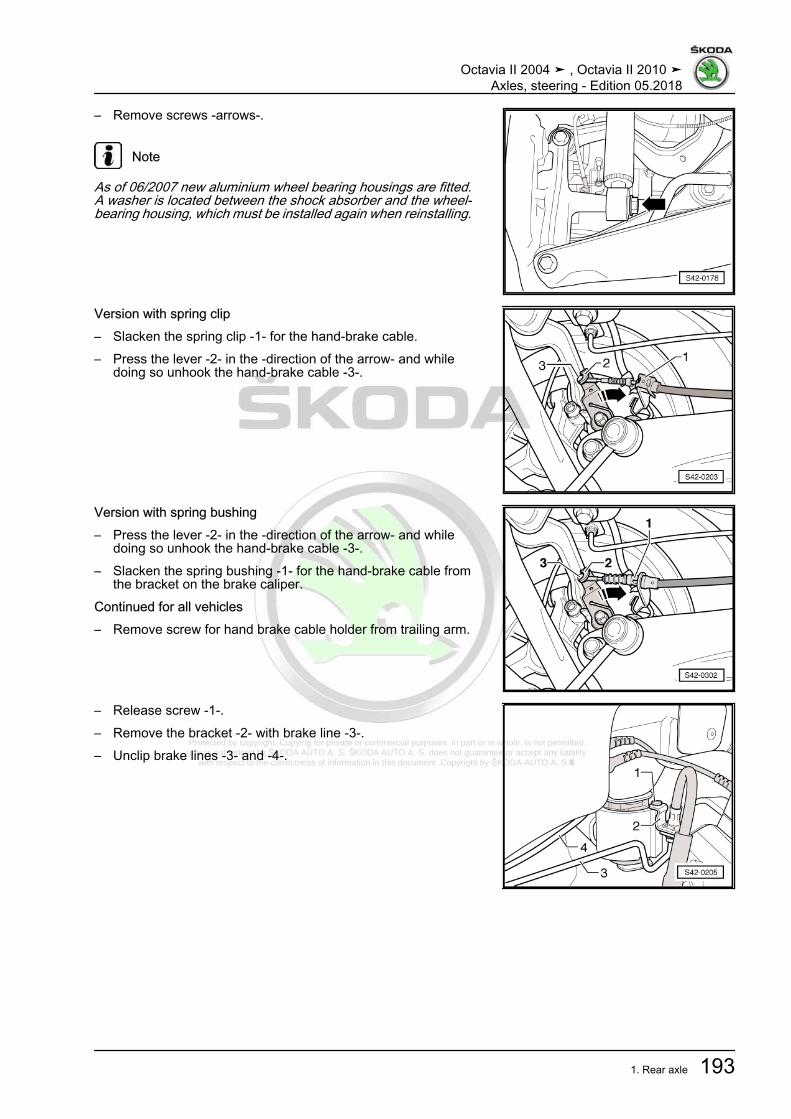
Protected by copyright. Copying for private or commercial purposes, in part or in whole, is not permitted unless authorised by ŠKODA AUTO A. S. ŠKODA AUTO A. S. does not guarantee or accept any liability
with respect to the correctness of information in this document. Copyright by ŠKODA AUTO A. S.�
– Remove screws -arrows-.
Note
As of 06/2007 new aluminium wheel bearing housings are fitted.A washer is located between the shock absorber and the wheel-bearing housing, which must be installed again when reinstalling.
Version with spring clip– Slacken the spring clip -1- for the hand-brake cable.– Press the lever -2- in the -direction of the arrow- and while
doing so unhook the hand-brake cable -3-.
Version with spring bushing– Press the lever -2- in the -direction of the arrow- and while
doing so unhook the hand-brake cable -3-.– Slacken the spring bushing -1- for the hand-brake cable from
the bracket on the brake caliper.Continued for all vehicles– Remove screw for hand brake cable holder from trailing arm.
– Release screw -1-.– Remove the bracket -2- with brake line -3-.– Unclip brake lines -3- and -4-.
Octavia II 2004 ➤ , Octavia II 2010 ➤Axles, steering - Edition 05.2018
1. Rear axle 193

Protected by copyright. Copying for private or commercial purposes, in part or in whole, is not permitted unless authorised by ŠKODA AUTO A. S. ŠKODA AUTO A. S. does not guarantee or accept any liability
with respect to the correctness of information in this document. Copyright by ŠKODA AUTO A. S.�
– Remove the brake calipers with brake carriers and hook onthe body (e.g. with wire) ⇒ Brake systems; Rep. gr. 46 .
– Mark the installed position of the bracket on the body.– Remove screws -arrows-.
– Check, if a marking (colour point) is present on the flexible diskand at the flange on the final drive -arrows-. If no marking ispresent, mark -arrows- opposite position of the flexible disk/flange on the rear final drive.
– Remove rear cardan shaft pipe with flexible disk and oscilla‐tion damper from rear final drive -arrows-.
Octavia II 2004 ➤ , Octavia II 2010 ➤Axles, steering - Edition 05.2018
194 Rep. gr.42 - Rear suspension

Protected by copyright. Copying for private or commercial purposes, in part or in whole, is not permitted unless authorised by ŠKODA AUTO A. S. ŠKODA AUTO A. S. does not guarantee or accept any liability
with respect to the correctness of information in this document. Copyright by ŠKODA AUTO A. S.�
– Loosen combination screws for propshaft middle bearing -1-by two turns (the combination screws also hold the heat pro‐tection plate -2-).
– This will allow you to see the combination screws for middlebearing -arrows- without the heat protection plate.
Note
♦ For the purposes of clear presentation the propshaft middlebearing and the combination screws -arrows- are shown with‐out the heat protection plate.
♦ Propshaft with inseparable middle bearing as of 06/2007.
– Support propshaft on the tunnel bridge with a wooden wedge.– Push the rear propshaft pipe as far as possible in direction of
gearbox.
– Lash the vehicle to the lift platform using the tensioning straps- T10038- .
WARNING
If the vehicle is not lashed, there is a risk of the vehicle topplingoff the lift platform.
Octavia II 2004 ➤ , Octavia II 2010 ➤Axles, steering - Edition 05.2018
1. Rear axle 195

Protected by copyright. Copying for private or commercial purposes, in part or in whole, is not permitted unless authorised by ŠKODA AUTO A. S. ŠKODA AUTO A. S. does not guarantee or accept any liability
with respect to the correctness of information in this document. Copyright by ŠKODA AUTO A. S.�
– Place engine and gearbox jack e.g. -V.A.G 1383A- or -VAS6931- with gearbox mount - V.A.G 1359/2- beneath theassembly carrier and secure with tensioning strap .
– Remove screw -1- or -2- on both sides.
Note
To provide a clearer illustration, only the left vehicle side is illus‐trated.
– Fix the position of the assembly carrier using fixing devices -T10096- .
Note
The locating pin - T10096- must only be tightened to maximum20 Nm as otherwise the fixing bolt thread becomes damaged.
– Successively replace the fixing bolts at the assembly carrieron both sides with fixing devices - T10096- and tighten to 20Nm.
– Carefully lower assembly carrier to maximum 30 mm.
Note
When lowering, make sure that there is adequate clearance ofthe brake lines, electrical wires and centering stud to the prop‐shaft.
Octavia II 2004 ➤ , Octavia II 2010 ➤Axles, steering - Edition 05.2018
196 Rep. gr.42 - Rear suspension

Protected by copyright. Copying for private or commercial purposes, in part or in whole, is not permitted unless authorised by ŠKODA AUTO A. S. ŠKODA AUTO A. S. does not guarantee or accept any liability
with respect to the correctness of information in this document. Copyright by ŠKODA AUTO A. S.�
– Unclip the brake lines -2- from the clips -1- and the bracket-3-.
Note
The fig. shows the assembly carrier from above and in the re‐moved condition for purposes of clear presentation.
– Lowering assembly carrier with attached parts.InstallingInstallation is carried out in reverse order of removal. When in‐stalling, note the following:
Note
As of 06/2007 new aluminium wheel bearing housings are fitted.A washer is located between the shock absorber and the wheel-bearing housing, which must be installed again when reinstalling.
Install propshaft at rear final drive ⇒ Gearbox; Rep. gr. 39 .– Carry out axle alignment ⇒ “3.3 Axle alignment”, page 309 .Tightening torques - summaries of components
Note
Replace bolts / nuts that are tightened at an angle of rotation, aswell as replacement components after removal.
♦ ⇒ “2.1.2 Summary of components: Assembly carrier, suspen‐sion arm, track rod for rear axle, vehicles with four-wheeldrive”, page 202
♦ ⇒ “2.1.3 Summary of components: assembly carrier, finaldrive, vehicles with four-wheel drive”, page 205
♦ ⇒ “4.1.2 Summary of components - strut / shock absorber,spring, vehicles with all-wheel drive”, page 240
♦ ⇒ “3.1.2 Summary of components - anti-roll bar, vehicles withfour-wheel drive”, page 233
♦ ⇒ “5.1.2 Summary of components: wheel-bearing housing,trailing arm, vehicles with four-wheel drive”, page 249
♦ ⇒ “1.2 Tightening torque of the wheel screws”, page 301♦ Cardan shaft ⇒ Gearbox; Rep. gr. 39♦ Brake calipers with brake carrier ⇒ Brake systems; Rep. gr.
46 .♦ Rear silencer ⇒ Engine; Rep. gr. 26
Octavia II 2004 ➤ , Octavia II 2010 ➤Axles, steering - Edition 05.2018
1. Rear axle 197

Protected by copyright. Copying for private or commercial purposes, in part or in whole, is not permitted unless authorised by ŠKODA AUTO A. S. ŠKODA AUTO A. S. does not guarantee or accept any liability
with respect to the correctness of information in this document. Copyright by ŠKODA AUTO A. S.�
2 Subframe, control arm, tie rod for rearaxle
⇒ “2.1 Summary of components- assembly carrier”, page 198⇒ “2.2 Repairing assembly carrier”, page 206⇒ “2.3 Removing and installing top suspension arm”, page 220⇒ “2.4 Removing and installing bottom suspension arm”,page 223⇒ “2.5 Removing and installing track rod for rear axle”,page 227⇒ “2.6 Removing and installing bracket for the speed sensor ca‐ble”, page 230
2.1 Summary of components- assemblycarrier
⇒ “2.1.1 Summary of components: Assembly carrier, suspensionarm, track rod for rear axle, vehicles with front drive”, page 198⇒ “2.1.2 Summary of components: Assembly carrier, suspensionarm, track rod for rear axle, vehicles with four-wheel drive”, page202⇒ “2.1.3 Summary of components: assembly carrier, final drive,vehicles with four-wheel drive”, page 205
2.1.1 Summary of components: Assembly carrier, suspension arm, track rod forrear axle, vehicles with front drive
Octavia II 2004 ➤ , Octavia II 2010 ➤Axles, steering - Edition 05.2018
198 Rep. gr.42 - Rear suspension
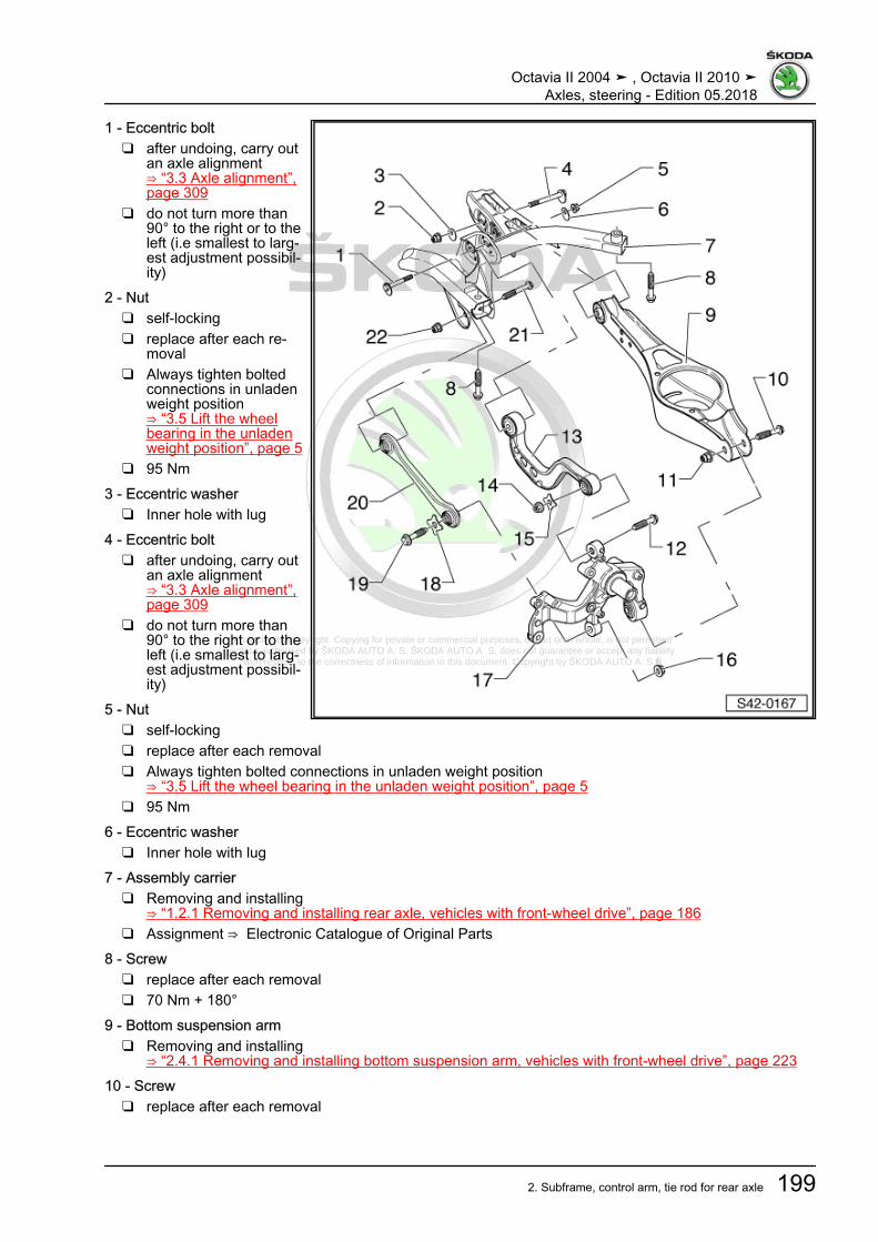
Protected by copyright. Copying for private or commercial purposes, in part or in whole, is not permitted unless authorised by ŠKODA AUTO A. S. ŠKODA AUTO A. S. does not guarantee or accept any liability
with respect to the correctness of information in this document. Copyright by ŠKODA AUTO A. S.�
1 - Eccentric bolt❑ after undoing, carry out
an axle alignment⇒ “3.3 Axle alignment”,page 309
❑ do not turn more than90° to the right or to theleft (i.e smallest to larg‐est adjustment possibil‐ity)
2 - Nut❑ self-locking❑ replace after each re‐
moval❑ Always tighten bolted
connections in unladenweight position⇒ “3.5 Lift the wheelbearing in the unladenweight position”, page 5
❑ 95 Nm3 - Eccentric washer
❑ Inner hole with lug4 - Eccentric bolt
❑ after undoing, carry outan axle alignment⇒ “3.3 Axle alignment”,page 309
❑ do not turn more than90° to the right or to theleft (i.e smallest to larg‐est adjustment possibil‐ity)
5 - Nut❑ self-locking❑ replace after each removal❑ Always tighten bolted connections in unladen weight position
⇒ “3.5 Lift the wheel bearing in the unladen weight position”, page 5❑ 95 Nm
6 - Eccentric washer❑ Inner hole with lug
7 - Assembly carrier❑ Removing and installing
⇒ “1.2.1 Removing and installing rear axle, vehicles with front-wheel drive”, page 186❑ Assignment ⇒ Electronic Catalogue of Original Parts
8 - Screw❑ replace after each removal❑ 70 Nm + 180°
9 - Bottom suspension arm❑ Removing and installing
⇒ “2.4.1 Removing and installing bottom suspension arm, vehicles with front-wheel drive”, page 22310 - Screw
❑ replace after each removal
Octavia II 2004 ➤ , Octavia II 2010 ➤Axles, steering - Edition 05.2018
2. Subframe, control arm, tie rod for rear axle 199

Protected by copyright. Copying for private or commercial purposes, in part or in whole, is not permitted unless authorised by ŠKODA AUTO A. S. ŠKODA AUTO A. S. does not guarantee or accept any liability
with respect to the correctness of information in this document. Copyright by ŠKODA AUTO A. S.�
11 - Nut❑ self-locking❑ replace after each removal❑ Always tighten bolted connections in unladen weight position
⇒ “3.5 Lift the wheel bearing in the unladen weight position”, page 5❑ Tightening torque can be applied via the screw Pos. 10❑ 70 Nm + 180°
12 - Screw❑ replace after each removal❑ Always tighten bolted connections in unladen weight position
⇒ “3.5 Lift the wheel bearing in the unladen weight position”, page 5❑ 130 Nm + 180°
13 - Top suspension arm❑ Removing and installing
⇒ “2.3.1 Removing and installing top suspension arm, vehicles with front-wheel drive”, page 22014 - Nut
❑ self-locking❑ replace after each removal❑ The tightening torque must be applied via the screw Pos. 12, in order not to put the bearing under tension
15 - Supporting plate16 - Nut
❑ self-locking❑ replace after each removal❑ The tightening torque must be applied via the screw Pos. 19, in order not to put the bearing under tension❑ Always tighten bolted connections in unladen weight position
⇒ “3.5 Lift the wheel bearing in the unladen weight position”, page 517 - Wheel bearing housing
❑ Removing and installing⇒ “5.1.1 Summary of components: wheel-bearing housing, trailing arm, vehicles with front-wheel drive”,page 246
❑ Assignment ⇒ Electronic Catalogue of Original Parts18 - Supporting plate19 - Screw
❑ replace after each removal❑ Always tighten bolted connections in unladen weight position
⇒ “3.5 Lift the wheel bearing in the unladen weight position”, page 5❑ 130 Nm + 180°
20 - Track rod for rear axle❑ different versions ⇒ Fig. ““Track rod versions”“ , page 201❑ closed in direction of travel (track rods on the right and left differ)❑ opened towards the bottom (track rods on the right and left are identical)❑ combined installation is not allowed❑ Assignment ⇒ Electronic Catalogue of Original Parts❑ Removing and installing
⇒ “2.5.1 Removing and installing track rod for rear axle, vehicles with front-wheel drive”, page 22721 - Screw
❑ replace after each removal22 - Nut
❑ self-locking❑ replace after each removal
Octavia II 2004 ➤ , Octavia II 2010 ➤Axles, steering - Edition 05.2018
200 Rep. gr.42 - Rear suspension

Protected by copyright. Copying for private or commercial purposes, in part or in whole, is not permitted unless authorised by ŠKODA AUTO A. S. ŠKODA AUTO A. S. does not guarantee or accept any liability
with respect to the correctness of information in this document. Copyright by ŠKODA AUTO A. S.�
❑ Always tighten bolted connections in unladen weight position⇒ “3.5 Lift the wheel bearing in the unladen weight position”, page 5
❑ 70 Nm + 180°
Track rod versions1 - Track rod closed in direction of travel (track rods on the rightand left differ)2 - Track rod opened towards the bottom (track rods on the rightand left are identical)♦ The -arrow- shows the direction of travel.♦ A combined installation of the track rod versions -1- and -2- is
allowed.♦ Pay attention to correct installation position.
Octavia II 2004 ➤ , Octavia II 2010 ➤Axles, steering - Edition 05.2018
2. Subframe, control arm, tie rod for rear axle 201

Protected by copyright. Copying for private or commercial purposes, in part or in whole, is not permitted unless authorised by ŠKODA AUTO A. S. ŠKODA AUTO A. S. does not guarantee or accept any liability
with respect to the correctness of information in this document. Copyright by ŠKODA AUTO A. S.�
2.1.2 Summary of components: Assembly carrier, suspension arm, track rod forrear axle, vehicles with four-wheel drive
The -arrow- shows the direction of travel.
1 - Eccentric bolt❑ after undoing, carry out
an axle alignment⇒ “3.3 Axle alignment”,page 309
❑ do not turn more than90° to the right or to theleft (i.e smallest to larg‐est adjustment possibil‐ity)
2 - Nut❑ self-locking❑ replace after each re‐
moval❑ Always tighten bolted
connections in unladenweight position⇒ “3.5 Lift the wheelbearing in the unladenweight position”, page 5
❑ 95 Nm3 - Eccentric washer
❑ Inner hole with lug4 - Eccentric bolt
❑ after undoing, carry outan axle alignment⇒ “3.3 Axle alignment”,page 309
❑ do not turn more than90° to the right or to theleft (i.e smallest to larg‐est adjustment possibil‐ity)
5 - Eccentric washer❑ Inner hole with lug
6 - Nut❑ self-locking❑ replace after each removal❑ Always tighten bolted connections in unladen weight position
⇒ “3.5 Lift the wheel bearing in the unladen weight position”, page 5❑ 95 Nm
7 - Assembly carrier❑ Removing and installing
⇒ “1.2.2 Removing and installing the rear axle, vehicles with four-wheel drive”, page 191❑ up to 05/2007 aluminium version❑ as of 06/2007 steel version❑ Assignment ⇒ Electronic Catalogue of Original Parts
8 - Screw❑ replace after each removal❑ 70 Nm + 180°
Octavia II 2004 ➤ , Octavia II 2010 ➤Axles, steering - Edition 05.2018
202 Rep. gr.42 - Rear suspension

Protected by copyright. Copying for private or commercial purposes, in part or in whole, is not permitted unless authorised by ŠKODA AUTO A. S. ŠKODA AUTO A. S. does not guarantee or accept any liability
with respect to the correctness of information in this document. Copyright by ŠKODA AUTO A. S.�
9 - Bottom suspension arm❑ Removing and installing
⇒ “2.4.2 Removing and installing bottom suspension arm, vehicles with four-wheel drive”, page 22510 - Nut
❑ self-locking❑ replace after each removal❑ Always tighten bolted connections in unladen weight position
⇒ “3.5 Lift the wheel bearing in the unladen weight position”, page 5❑ Tightening torque can be applied via the screw Pos. 11❑ 70 Nm + 180°
11 - Screw❑ replace after each removal
12 - Threaded rivet❑ M6
13 - Body-bound rivet14 - Protection plate
❑ Assignment ⇒ Electronic Catalogue of Original Parts15 - Screw
❑ 8 Nm16 - Nut
❑ self-locking❑ replace after each removal❑ The tightening torque must be applied via the screw - Pos. 26, in order not to put the bearing under
tension17 - Screw
❑ replace after each removal❑ Always tighten bolted connections in unladen weight position
⇒ “3.5 Lift the wheel bearing in the unladen weight position”, page 5❑ 130 Nm + 180°
18 - Washer❑ as of 06/2007 only in combination with the aluminium wheel bearing housing❑ Assignment ⇒ Electronic Catalogue of Original Parts
19 - Top suspension arm❑ Removing and installing
⇒ “2.3.2 Removing and installing top suspension arm, vehicles with four-wheel drive”, page 22120 - Supporting plate21 - Nut
❑ self-locking❑ replace after each removal❑ Always tighten bolted connections in unladen weight position
⇒ “3.5 Lift the wheel bearing in the unladen weight position”, page 5❑ The tightening torque must be applied via the screw Pos. 17, in order not to put the bearing under tension
22 - Support❑ for speed sensor cable❑ clipped with top suspension arm❑ Removing and installing
⇒ “2.6 Removing and installing bracket for the speed sensor cable”, page 23023 - Wheel bearing housing
❑ up to 05/2007 steel casting version
Octavia II 2004 ➤ , Octavia II 2010 ➤Axles, steering - Edition 05.2018
2. Subframe, control arm, tie rod for rear axle 203
Protected by copyright. Copying for private or commercial purposes, in part or in whole, is not permitted unless authorised by ŠKODA AUTO A. S. ŠKODA AUTO A. S. does not guarantee or accept any liability
with respect to the correctness of information in this document. Copyright by ŠKODA AUTO A. S.�
❑ Assignment ⇒ Electronic Catalogue of Original Parts❑ Removing and installing
⇒ “5.2.2 Removing and installing the wheel bearing housing, vehicles with four-wheel drive”, page 25424 - Wheel bearing housing
❑ as of 06/2007 aluminium version❑ Assignment ⇒ Electronic Catalogue of Original Parts❑ Removing and installing
⇒ “5.2.2 Removing and installing the wheel bearing housing, vehicles with four-wheel drive”, page 25425 - Supporting plate26 - Screw
❑ replace after each removal❑ Always tighten bolted connections in unladen weight position
⇒ “3.5 Lift the wheel bearing in the unladen weight position”, page 5❑ 130 Nm + 180°
27 - Track rod for rear axle❑ different versions ⇒ Fig. ““Track rod versions”“ , page 205❑ closed in direction of travel (track rods on the right and left differ)❑ opened towards the bottom (track rods on the right and left are identical)❑ combined installation is not allowed❑ Assignment ⇒ Electronic Catalogue of Original Parts❑ Removing and installing
⇒ “2.5.2 Removing and installing track rod for rear axle, vehicles with four-wheel drive”, page 22828 - Washer
❑ as of 06/2007 only in combination with the aluminium wheel bearing housing❑ Assignment ⇒ Electronic Catalogue of Original Parts
29 - Nut❑ self-locking❑ replace after each removal❑ 70 Nm + 180°
30 - Screw❑ replace after each removal❑ Always tighten bolted connections in unladen weight position
⇒ “3.5 Lift the wheel bearing in the unladen weight position”, page 5
Octavia II 2004 ➤ , Octavia II 2010 ➤Axles, steering - Edition 05.2018
204 Rep. gr.42 - Rear suspension

Protected by copyright. Copying for private or commercial purposes, in part or in whole, is not permitted unless authorised by ŠKODA AUTO A. S. ŠKODA AUTO A. S. does not guarantee or accept any liability
with respect to the correctness of information in this document. Copyright by ŠKODA AUTO A. S.�
Track rod versions1 - Track rod closed in direction of travel (track rods on the rightand left differ)2 - Track rod opened towards the bottom (track rods on the rightand left are identical)♦ The -arrow- shows the direction of travel.♦ A combined installation of the track rod versions -1- and -2- is
allowed.♦ Pay attention to correct installation position.
2.1.3 Summary of components: assembly carrier, final drive, vehicles with four-wheel drive
The -arrow- shows the direction of travel.
1 - Assembly carrier❑ Removing and installing
⇒ “1.2.2 Removing andinstalling the rear axle,vehicles with four-wheeldrive”, page 191
❑ up to 05/2007 alumini‐um version
❑ as of 06/2007 steel ver‐sion
❑ Assignment ⇒ Electron‐ic Catalogue of OriginalParts
2 - Nut❑ no longer applicable as
of 06/2007❑ replace after each re‐
moval❑ Assignment ⇒ Electron‐
ic Catalogue of OriginalParts
❑ 50 Nm + 180°3 - Rear rubber-metal bearing
❑ pressing out and in foraluminium assemblycarrier⇒ “2.2.1 Rubber-metalbearings in and out, alu‐minium assembly carri‐er, four-wheel drive ve‐hicles”, page 206
❑ pressing out and in forsteel assembly carrier⇒ “2.2.3 Removing andinstalling bonded rubber
Octavia II 2004 ➤ , Octavia II 2010 ➤Axles, steering - Edition 05.2018
2. Subframe, control arm, tie rod for rear axle 205

Protected by copyright. Copying for private or commercial purposes, in part or in whole, is not permitted unless authorised by ŠKODA AUTO A. S. ŠKODA AUTO A. S. does not guarantee or accept any liability
with respect to the correctness of information in this document. Copyright by ŠKODA AUTO A. S.�
rear bearings, steel assembly carrier, four-wheel drive vehicles”, page 215❑ Assignment ⇒ Electronic Catalogue of Original Parts
4 - Front rubber-metal bearing❑ pressing out and in for aluminium assembly carrier
⇒ “2.2.1 Rubber-metal bearings in and out, aluminium assembly carrier, four-wheel drive vehicles”, page206
❑ pressing out and in for steel assembly carrier⇒ “2.2.2 Removing and installing bonded rubber bush at front, steel assembly carrier, vehicles with four-wheel drive”, page 210
❑ Assignment ⇒ Electronic Catalogue of Original Parts5 - Cross member
❑ no longer applicable as of 06/2007❑ Assignment ⇒ Electronic Catalogue of Original Parts
6 - Screw❑ no longer applicable as of 06/2007❑ Assignment ⇒ Electronic Catalogue of Original Parts
7 - Final drive❑ removing and installing ⇒ Gearbox; Rep. gr. 39 .
8 - Screw❑ replace after each removal❑ 60 Nm + 90°
9 - Supporting plate10 - Support
❑ Assignment ⇒ Electronic Catalogue of Original Parts11 - Screw
❑ replace after each removal❑ 60 Nm + 180°
2.2 Repairing assembly carrier⇒ “2.2.1 Rubber-metal bearings in and out, aluminium assemblycarrier, four-wheel drive vehicles”, page 206⇒ “2.2.2 Removing and installing bonded rubber bush at front,steel assembly carrier, vehicles with four-wheel drive”,page 210⇒ “2.2.3 Removing and installing bonded rubber rear bearings,steel assembly carrier, four-wheel drive vehicles”, page 215
2.2.1 Rubber-metal bearings in and out, alu‐minium assembly carrier, four-wheeldrive vehicles
Special tools and workshop equipment required♦ Engine/gearbox jack , e.g. -V.A.G 1383/A-♦ Hydraulic cylinder e.g. -VAS 6178-♦ Foot pump , e. g. -VAS 6179-♦ Tensioning strap - T10038-♦ Fixing device - T10096-♦ Assembly tool - T10263-
Octavia II 2004 ➤ , Octavia II 2010 ➤Axles, steering - Edition 05.2018
206 Rep. gr.42 - Rear suspension

Protected by copyright. Copying for private or commercial purposes, in part or in whole, is not permitted unless authorised by ŠKODA AUTO A. S. ŠKODA AUTO A. S. does not guarantee or accept any liability
with respect to the correctness of information in this document. Copyright by ŠKODA AUTO A. S.�
Extraction– Remove rear wheels.– Remove coil springs
⇒ “4.4 Removing and installing spring”, page 242 .– Remove pre-exhaust pipe and rear silencer ⇒ Engine; Rep.
gr. 26 .– Disconnect the plug connection -2- at the control unit of the
four-wheel drive clutch.Vehicles with vehicle level sender
– Disconnect plug -1- and slacken line holder from the sender-3-.
Continued for all vehicles
– Disconnect the plug of the ABS speed sensor -1- from thewheel bearing housing.
Octavia II 2004 ➤ , Octavia II 2010 ➤Axles, steering - Edition 05.2018
2. Subframe, control arm, tie rod for rear axle 207
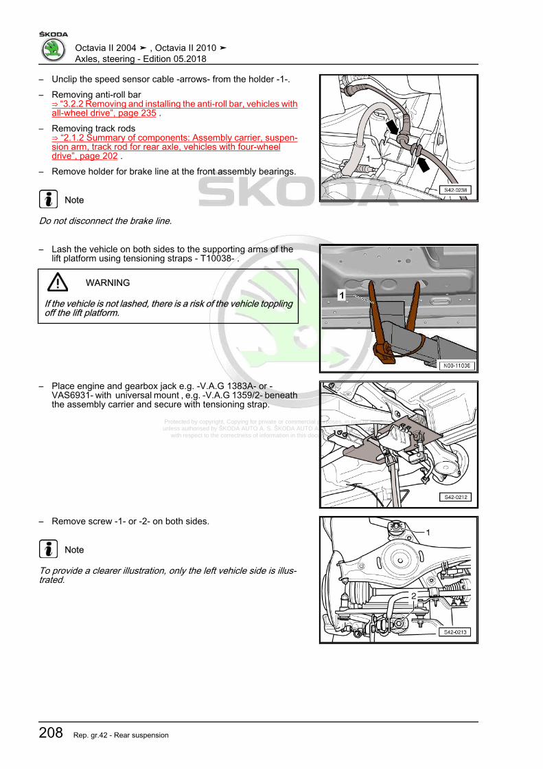
Protected by copyright. Copying for private or commercial purposes, in part or in whole, is not permitted unless authorised by ŠKODA AUTO A. S. ŠKODA AUTO A. S. does not guarantee or accept any liability
with respect to the correctness of information in this document. Copyright by ŠKODA AUTO A. S.�
– Unclip the speed sensor cable -arrows- from the holder -1-.– Removing anti-roll bar
⇒ “3.2.2 Removing and installing the anti-roll bar, vehicles withall-wheel drive”, page 235 .
– Removing track rods⇒ “2.1.2 Summary of components: Assembly carrier, suspen‐sion arm, track rod for rear axle, vehicles with four-wheeldrive”, page 202 .
– Remove holder for brake line at the front assembly bearings.
Note
Do not disconnect the brake line.
– Lash the vehicle on both sides to the supporting arms of thelift platform using tensioning straps - T10038- .
WARNING
If the vehicle is not lashed, there is a risk of the vehicle topplingoff the lift platform.
– Place engine and gearbox jack e.g. -V.A.G 1383A- or -VAS6931- with universal mount , e.g. -V.A.G 1359/2- beneaththe assembly carrier and secure with tensioning strap.
– Remove screw -1- or -2- on both sides.
Note
To provide a clearer illustration, only the left vehicle side is illus‐trated.
Octavia II 2004 ➤ , Octavia II 2010 ➤Axles, steering - Edition 05.2018
208 Rep. gr.42 - Rear suspension

Protected by copyright. Copying for private or commercial purposes, in part or in whole, is not permitted unless authorised by ŠKODA AUTO A. S. ŠKODA AUTO A. S. does not guarantee or accept any liability
with respect to the correctness of information in this document. Copyright by ŠKODA AUTO A. S.�
– Fix the position of the assembly carrier using fixing devices -T10096- .
Note
The locating pin - T10096- must only be tightened to maximum20 Nm as otherwise the fixing bolt thread becomes damaged.
– Lower the assembly carrier with engine/gearbox jack e.g. -V.A.G 1383A- Or -VAS6931- by approx. 10 cm.
– Position the special tools as shown in the figure.1 - Nut - T10263/1-2 - Washer , commercially available3 - Assembly carrier4 - Pipe section - T10263/1-5 - Hydraulic cylinder e.g. -VAS 6178-6 - Washer , commercially available7 - Nut - T10263/1-8 - Screw - T10263/4-– Pretension special tool.– Pull out the rubber-metal bearing by actuating the pump.InstallingInstallation is carried out in the reverse order; pay attention to thefollowing points:The front and rear rubber-metal bearing differ only slightly in theoverall height. When installing, pay attention to correct assign‐ment ⇒ Electronic catalogue of original parts .
The rubber-metal bearing must be installed in direction of orien‐tation.The tabs of the outer sleeve -arrows A- must point transverselyto the direction of travel -arrow C-.
Octavia II 2004 ➤ , Octavia II 2010 ➤Axles, steering - Edition 05.2018
2. Subframe, control arm, tie rod for rear axle 209

Protected by copyright. Copying for private or commercial purposes, in part or in whole, is not permitted unless authorised by ŠKODA AUTO A. S. ŠKODA AUTO A. S. does not guarantee or accept any liability
with respect to the correctness of information in this document. Copyright by ŠKODA AUTO A. S.�
– Insert special tool together with rubber-metal bearing asshown in the assembly carrier.
Caution
The pressure plate - T10263/3- must be laid in such a way thatthe tabs align the outer sleeve of the rubber-metal bearing-arrow A- with the window at the pressure plate - T10263/3--arrow B-.This positioning is absolutely necessary, as the tabs interlockin the area of the window with the bearing seat after removingthe rubber-metal bearing.
1 - Nut - T10263/1-2 - Washer , commercially available3 - Thrust piece - T10263/3-4 - Assembly carrier5 - Rubber-metal bearing6 - Thrust piece - T10263/2-7 - Hydraulic cylinder e.g. -VAS 6178-8 - Washer , commercially available9 - Nut - T10263/1-10 - Screw - T10263/4-– Pretension special tool with rubber-metal bearing.
– Carefully install the rubber-metal bearing by actuating thepump, until the collar -arrow B- rests “free of gap” against theassembly carrier.
– Carry out axle alignment ⇒ “3.3 Axle alignment”, page 309 .Tightening torques - summaries of components
Note
Replace bolts / nuts that are tightened at an angle of rotation, aswell as replacement components after removal.
♦ ⇒ “2.1.2 Summary of components: Assembly carrier, suspen‐sion arm, track rod for rear axle, vehicles with four-wheeldrive”, page 202
♦ ⇒ “3.1.2 Summary of components - anti-roll bar, vehicles withfour-wheel drive”, page 233
♦ ⇒ “4.1.2 Summary of components - strut / shock absorber,spring, vehicles with all-wheel drive”, page 240
♦ ⇒ “1.2 Tightening torque of the wheel screws”, page 301♦ Rear silencer ⇒ Engine; Rep. gr. 26
2.2.2 Removing and installing bonded rubberbush at front, steel assembly carrier, ve‐hicles with four-wheel drive
Special tools and workshop equipment required
Octavia II 2004 ➤ , Octavia II 2010 ➤Axles, steering - Edition 05.2018
210 Rep. gr.42 - Rear suspension

Protected by copyright. Copying for private or commercial purposes, in part or in whole, is not permitted unless authorised by ŠKODA AUTO A. S. ŠKODA AUTO A. S. does not guarantee or accept any liability
with respect to the correctness of information in this document. Copyright by ŠKODA AUTO A. S.�
♦ Tensioning strap - T10038-♦ Fixing device - T10096-♦ Assembly tool - T10263-♦ Engine and gearbox jack , e.g. -V.A.G 1383A- or -VAS6931-♦ Hydraulic cylinder e.g. -VAS 6178-♦ Foot pump , e. g. -VAS 6179-Extraction– Remove rear wheels.– Remove coil springs
⇒ “4.4 Removing and installing spring”, page 242 .– Remove the rear silencer ⇒ Engine; Rep. gr. 26 .– Disconnect the plug connection -2- at the control unit of the
four-wheel drive clutch.Vehicles with vehicle level sender
– Disconnect plug -1- and slacken line holder from the sender-3-.
Continued for all vehicles
– Disconnect the plug of the ABS speed sensor -1- from thewheel bearing housing.
– Unclip the speed sensor cable from the bracket at the top sus‐pension arm.
– Removing anti-roll bar⇒ “3.2.2 Removing and installing the anti-roll bar, vehicles withall-wheel drive”, page 235 .
– Removing track rods⇒ “2.1.2 Summary of components: Assembly carrier, suspen‐sion arm, track rod for rear axle, vehicles with four-wheeldrive”, page 202 .
Octavia II 2004 ➤ , Octavia II 2010 ➤Axles, steering - Edition 05.2018
2. Subframe, control arm, tie rod for rear axle 211

Protected by copyright. Copying for private or commercial purposes, in part or in whole, is not permitted unless authorised by ŠKODA AUTO A. S. ŠKODA AUTO A. S. does not guarantee or accept any liability
with respect to the correctness of information in this document. Copyright by ŠKODA AUTO A. S.�
– Remove bracket - 1 -.
Note
Do not disconnect the brake line.
– Lash the vehicle on both sides to the supporting arms of thelift platform using tensioning straps - T10038- .
WARNING
If the vehicle is not lashed, there is a risk of the vehicle topplingoff the lift platform.
– Place engine and gearbox jack e.g. -V.A.G 1383A- or -VAS6931- with universal mount , e.g. -V.A.G 1359/2- beneaththe assembly carrier and secure with tensioning strap.
– Remove screw -1- or -2- on both sides.
Note
To provide a clearer illustration, only the left vehicle side is illus‐trated.
In order to fix the assembly carrier, the fixing devices - T10096-must be successively screwed into the positions -1- and -2- onboth vehicle sides.
Octavia II 2004 ➤ , Octavia II 2010 ➤Axles, steering - Edition 05.2018
212 Rep. gr.42 - Rear suspension

Protected by copyright. Copying for private or commercial purposes, in part or in whole, is not permitted unless authorised by ŠKODA AUTO A. S. ŠKODA AUTO A. S. does not guarantee or accept any liability
with respect to the correctness of information in this document. Copyright by ŠKODA AUTO A. S.�
– Fix the position of the assembly carrier using fixing devices -T10096- .
Note
The locating pin - T10096- must only be tightened to maximum20 Nm as otherwise the fixing bolt thread becomes damaged.
– Successively replace the fixing bolts at the assembly carrieron both sides with fixing devices - T10096- and tighten to 20Nm.
The position of the assembly carrier is now fixed.– Lower the assembly carrier with engine/gearbox jack e.g. -
V.A.G 1383A- Or -VAS6931- by approx. 10 cm.– Mark the position of the rubber-metal bearing to the assembly
carrier e.g with a felt-tip pen.
– Position the special tools as shown in the figure.1 - Nut - T10263/5-2 - Washer out -T10263-3 - Pipe section - T10263/6-4 - Hydraulic cylinder e.g. -VAS 6178-5 - Nut - T10263/5-6 - Screw - T10263/4-– Pretension special tool.– Pull out the rubber-metal bearing by actuating the pump.
Note
When pulling out the rubber-metal bearing, the outer ring of thebearing is sheared off. This is done with a loud bang.
– After pulling out the rubber-metal bearing, it must be removedfrom the pipe section - T10263/6- .
– Clamp pipe section - T10263/6- on the surfaces provided in avice.
– Lever between the pipe section - T10263/6- and the rubber-metal bearing -arrow- using a screwdriver and drive out therubber-metal bearing; if necessary slightly knock onto the driftwith a hammer.
InstallingInstallation is carried out in the reverse order. Pay attention to thefollowing:
Octavia II 2004 ➤ , Octavia II 2010 ➤Axles, steering - Edition 05.2018
2. Subframe, control arm, tie rod for rear axle 213

Protected by copyright. Copying for private or commercial purposes, in part or in whole, is not permitted unless authorised by ŠKODA AUTO A. S. ŠKODA AUTO A. S. does not guarantee or accept any liability
with respect to the correctness of information in this document. Copyright by ŠKODA AUTO A. S.�
Distinguishing feature of the rubber-metal bearingI - Front rubber-metal bearingII - Rear rubber-metal bearingThe front rubber-metal bearings have two recesses on the topside -arrows- and differ only slightly in the overall height ⇒ Elec‐tronic Catalogue of Original Parts .The rubber-metal bearing must be installed in a certain direction;the markings on the assembly carrier should be noted.
– Insert rubber-metal bearing -1- into the assembly carrier insuch a way, that the recess and the panel -arrows- point trans‐versely to the direction of travel.
– Position pressure plate - T10263/3- -2- in such a way, that theflattened side also points transversely to the direction of travel.
Octavia II 2004 ➤ , Octavia II 2010 ➤Axles, steering - Edition 05.2018
214 Rep. gr.42 - Rear suspension

Protected by copyright. Copying for private or commercial purposes, in part or in whole, is not permitted unless authorised by ŠKODA AUTO A. S. ŠKODA AUTO A. S. does not guarantee or accept any liability
with respect to the correctness of information in this document. Copyright by ŠKODA AUTO A. S.�
– Insert special tool together with rubber-metal bearing asshown in the assembly carrier.
1 - Nut - T10263/5-2 - Thrust piece - T10263/3-3 - Rubber-metal bearing4 - Thrust piece - T10263/2-5 - Hydraulic cylinder e.g. -VAS 6178-6 - Nut - T10263/5-7 - Screw - T10263/4-– Pretension special tool with rubber-metal bearing.– Carefully install the rubber-metal bearing by actuating the
pump, until the collar rests »free of gap« against the assemblycarrier.
– Install track rods⇒ “2.1.2 Summary of components: Assembly carrier, suspen‐sion arm, track rod for rear axle, vehicles with four-wheeldrive”, page 202 .
– Install anti-roll bar⇒ “3.2.2 Removing and installing the anti-roll bar, vehicles withall-wheel drive”, page 235 .
– Mount plug between rear axle and body.– Install the rear silencer ⇒ Engine; Rep. gr. 26 .– Installing the helical springs
⇒ “4.4 Removing and installing spring”, page 242 .– Attach rear wheels.Tightening torques - summaries of components
Note
Replace bolts / nuts that are tightened at an angle of rotation, aswell as replacement components after removal.
♦ ⇒ “2.1.2 Summary of components: Assembly carrier, suspen‐sion arm, track rod for rear axle, vehicles with four-wheeldrive”, page 202
♦ ⇒ “3.1.2 Summary of components - anti-roll bar, vehicles withfour-wheel drive”, page 233
♦ ⇒ “4.1.2 Summary of components - strut / shock absorber,spring, vehicles with all-wheel drive”, page 240
♦ ⇒ “1.2 Tightening torque of the wheel screws”, page 301♦ Rear silencer ⇒ Engine; Rep. gr. 26
2.2.3 Removing and installing bonded rubberrear bearings, steel assembly carrier,four-wheel drive vehicles
Special tools and workshop equipment required♦ Tensioning strap - T10038-♦ Fixing device - T10096-♦ Assembly tool - T10263-
Octavia II 2004 ➤ , Octavia II 2010 ➤Axles, steering - Edition 05.2018
2. Subframe, control arm, tie rod for rear axle 215

Protected by copyright. Copying for private or commercial purposes, in part or in whole, is not permitted unless authorised by ŠKODA AUTO A. S. ŠKODA AUTO A. S. does not guarantee or accept any liability
with respect to the correctness of information in this document. Copyright by ŠKODA AUTO A. S.�
♦ Engine and gearbox jack , e.g. -V.A.G 1383A- or -VAS6931-♦ Hydraulic cylinder e.g. -VAS 6178-♦ Foot pump , e. g. -VAS 6179-Extraction– Remove rear wheels.– Remove coil springs
⇒ “4.4 Removing and installing spring”, page 242 .– Remove the rear silencer ⇒ Engine; Rep. gr. 26 .Vehicles with vehicle level sender– Disconnect plug -1- and slacken line holder from the sender
-3-.Continued for all vehicles
– Unplug connector -1- from the wheel speed sensors.– Unclip the speed sensor cable from the bracket at the top sus‐
pension arm.
– Remove bracket - 1 -.
Note
Do not disconnect the brake line.
Octavia II 2004 ➤ , Octavia II 2010 ➤Axles, steering - Edition 05.2018
216 Rep. gr.42 - Rear suspension

Protected by copyright. Copying for private or commercial purposes, in part or in whole, is not permitted unless authorised by ŠKODA AUTO A. S. ŠKODA AUTO A. S. does not guarantee or accept any liability
with respect to the correctness of information in this document. Copyright by ŠKODA AUTO A. S.�
– Lash the vehicle on both sides to the supporting arms of thelift platform using tensioning straps - T10038- .
WARNING
If the vehicle is not lashed, there is a risk of the vehicle topplingoff the lift platform.
– Place engine and gearbox jack e.g. -V.A.G 1383A- or -VAS6931- with universal mount , e.g. -V.A.G 1359/2- beneaththe assembly carrier and secure with tensioning strap.
– Remove screw -1- or -2- on both sides of the assembly carrier.
Note
To provide a clearer illustration, only the left vehicle side is illus‐trated.
In order to fix the assembly carrier, the fixing devices - T10096-must be successively screwed into the positions -1- and -2- onboth vehicle sides.
– Fix the position of the assembly carrier using fixing devices -T10096- .
Note
The locating pin - T10096- must only be tightened to maximum20 Nm as otherwise the fixing bolt thread becomes damaged.
– Successively replace the fixing bolts at the assembly carrieron both sides with fixing devices - T10096- and tighten to 20Nm.
The position of the assembly carrier is now fixed.– Lower the assembly carrier with engine/gearbox jack e.g. -
V.A.G 1383A- Or -VAS6931- by approx. 10 cm.– Mark the position of the rubber-metal bearing to the assembly
carrier e.g with a felt-tip pen.
Octavia II 2004 ➤ , Octavia II 2010 ➤Axles, steering - Edition 05.2018
2. Subframe, control arm, tie rod for rear axle 217

Protected by copyright. Copying for private or commercial purposes, in part or in whole, is not permitted unless authorised by ŠKODA AUTO A. S. ŠKODA AUTO A. S. does not guarantee or accept any liability
with respect to the correctness of information in this document. Copyright by ŠKODA AUTO A. S.�
– Position the special tools as shown in the figure.1 - Nut - T10263/5-2 - Washer out -T10263-3 - Pipe section - T10263/6-4 - Hydraulic cylinder e.g. -VAS 6178-5 - Nut - T10263/5-6 - Screw - T10263/4-– Pretension special tool.– Pull out the rubber-metal bearing by actuating the pump.
Note
When pulling out the rubber-metal bearing, the outer ring of thebearing is sheared off. This is done with a loud bang.
– After pulling out the rubber-metal bearing, it must be removedfrom the pipe section - T10263/6- .
– Clamp pipe section - T10263/6- on the surfaces provided in avice.
– Lever between the pipe section - T10263/6- and the rubber-metal bearing -arrow- using a screwdriver and drive out therubber-metal bearing; if necessary slightly knock onto the driftwith a hammer.
InstallingInstallation is carried out in the reverse order. Pay attention to thefollowing:
Distinguishing feature of the rubber-metal bearingI - Front rubber-metal bearingII - Rear rubber-metal bearingThe front rubber-metal bearings have two recesses on the topside -arrows- and differ only slightly in the overall height ⇒ Elec‐tronic Catalogue of Original Parts .The rubber-metal bearing must be installed in a certain direction;the markings on the assembly carrier should be noted.
Octavia II 2004 ➤ , Octavia II 2010 ➤Axles, steering - Edition 05.2018
218 Rep. gr.42 - Rear suspension

Protected by copyright. Copying for private or commercial purposes, in part or in whole, is not permitted unless authorised by ŠKODA AUTO A. S. ŠKODA AUTO A. S. does not guarantee or accept any liability
with respect to the correctness of information in this document. Copyright by ŠKODA AUTO A. S.�
– Insert rubber-metal bearing -1- into the assembly carrier insuch a way, that the recess and the panel -arrows- point trans‐versely to the direction of travel.
– Position pressure plate - T10263/3- -2- in such a way, that theflattened side also points transversely to the direction of travel.
– Insert special tool together with rubber-metal bearing asshown in the assembly carrier.
1 - Nut - T10263/5-2 - Thrust piece - T10263/3-3 - Rubber-metal bearing4 - Thrust piece - T10263/2-5 - Hydraulic cylinder e.g. -VAS 6178-6 - Nut - T10263/5-7 - Screw - T10263/4-– Pretension special tool with rubber-metal bearing.– Carefully install the rubber-metal bearing by actuating the
pump, until the collar rests »free of gap« against the assemblycarrier.
– Install the rear silencer ⇒ Engine; Rep. gr. 26 .– Installing the helical springs
⇒ “4.4 Removing and installing spring”, page 242 .– Attach rear wheels.Tightening torques - summaries of components
Note
Replace bolts / nuts that are tightened at an angle of rotation, aswell as replacement components after removal.
♦ ⇒ “2.1.2 Summary of components: Assembly carrier, suspen‐sion arm, track rod for rear axle, vehicles with four-wheeldrive”, page 202
♦ ⇒ “3.1.2 Summary of components - anti-roll bar, vehicles withfour-wheel drive”, page 233
♦ ⇒ “4.1.2 Summary of components - strut / shock absorber,spring, vehicles with all-wheel drive”, page 240
♦ ⇒ “1.2 Tightening torque of the wheel screws”, page 301♦ Rear silencer ⇒ Engine; Rep. gr. 26
Octavia II 2004 ➤ , Octavia II 2010 ➤Axles, steering - Edition 05.2018
2. Subframe, control arm, tie rod for rear axle 219

Protected by copyright. Copying for private or commercial purposes, in part or in whole, is not permitted unless authorised by ŠKODA AUTO A. S. ŠKODA AUTO A. S. does not guarantee or accept any liability
with respect to the correctness of information in this document. Copyright by ŠKODA AUTO A. S.�
2.3 Removing and installing top suspensionarm
⇒ “2.3.1 Removing and installing top suspension arm, vehicleswith front-wheel drive”, page 220⇒ “2.3.2 Removing and installing top suspension arm, vehicleswith four-wheel drive”, page 221
2.3.1 Removing and installing top suspensionarm, vehicles with front-wheel drive
Removing– Determine dimension “a”
⇒ “3.5 Lift the wheel bearing in the unladen weight position”,page 5 .
– Remove wheel.– Remove coil spring
⇒ “4.4 Removing and installing spring”, page 242 .– Unhook cable -arrow A- for wheel speed sensor at top sus‐
pension arm.– Release screw -1-.
– For example mark with a felt-tip pen the position of the eccen‐tric bolt -arrow- to the assembly carrier.
– Unscrew screw -arrow-.– Remove top suspension arm.InstallingInstallation is performed in the reverse order, pay attention to thefollowing points:– Insert top suspension arm into the vehicle and tighten the
screws by hand.
Note
The bolted connection of the top suspension arm must only beperformed, if the measured dimension “a” between the wheel hubcentre and the lower edge of the wheel house is respected (un‐laden weight position)!⇒ “3.5 Lift the wheel bearing in the unladen weight position”, page5
Octavia II 2004 ➤ , Octavia II 2010 ➤Axles, steering - Edition 05.2018
220 Rep. gr.42 - Rear suspension
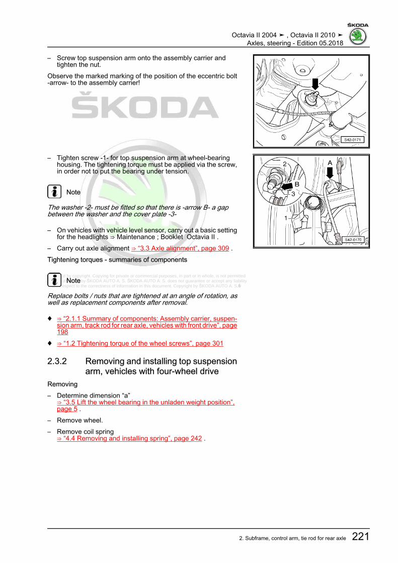
Protected by copyright. Copying for private or commercial purposes, in part or in whole, is not permitted unless authorised by ŠKODA AUTO A. S. ŠKODA AUTO A. S. does not guarantee or accept any liability
with respect to the correctness of information in this document. Copyright by ŠKODA AUTO A. S.�
– Screw top suspension arm onto the assembly carrier andtighten the nut.
Observe the marked marking of the position of the eccentric bolt-arrow- to the assembly carrier!
– Tighten screw -1- for top suspension arm at wheel-bearinghousing. The tightening torque must be applied via the screw,in order not to put the bearing under tension.
Note
The washer -2- must be fitted so that there is -arrow B- a gapbetween the washer and the cover plate -3-
– On vehicles with vehicle level sensor, carry out a basic settingfor the headlights ⇒ Maintenance ; Booklet Octavia II .
– Carry out axle alignment ⇒ “3.3 Axle alignment”, page 309 .Tightening torques - summaries of components
Note
Replace bolts / nuts that are tightened at an angle of rotation, aswell as replacement components after removal.
♦ ⇒ “2.1.1 Summary of components: Assembly carrier, suspen‐sion arm, track rod for rear axle, vehicles with front drive”, page198
♦ ⇒ “1.2 Tightening torque of the wheel screws”, page 301
2.3.2 Removing and installing top suspensionarm, vehicles with four-wheel drive
Removing– Determine dimension “a”
⇒ “3.5 Lift the wheel bearing in the unladen weight position”,page 5 .
– Remove wheel.– Remove coil spring
⇒ “4.4 Removing and installing spring”, page 242 .
Octavia II 2004 ➤ , Octavia II 2010 ➤Axles, steering - Edition 05.2018
2. Subframe, control arm, tie rod for rear axle 221

Protected by copyright. Copying for private or commercial purposes, in part or in whole, is not permitted unless authorised by ŠKODA AUTO A. S. ŠKODA AUTO A. S. does not guarantee or accept any liability
with respect to the correctness of information in this document. Copyright by ŠKODA AUTO A. S.�
– Unhook speed sensor cable from holder -1- at top suspensionarm -arrows-.
– Release screw -1-.
Note
As of 06/2007 new aluminium wheel bearing housings are fitted.A washer is located between the top suspension arm and thewheel-bearing housing, which must be installed again when re‐installing.
– For example mark with a felt-tip pen the position of the eccen‐tric bolt -arrow- to the assembly carrier.
– Unscrew screw -arrow-.– Remove top suspension arm.InstallingInstallation is performed in the reverse order, pay attention to thefollowing points:
Note
The bolted connection of the top suspension arm must only beperformed, if the measured dimension “a” between the wheel hubcentre and the lower edge of the wheel house is respected (un‐laden weight position)!⇒ “3.5 Lift the wheel bearing in the unladen weight position”, page5 .
– Screw top suspension arm onto the assembly carrier andtighten the nut.
– Observe the marked marking of the position of the eccentricbolt -arrow- to the assembly carrier!
Octavia II 2004 ➤ , Octavia II 2010 ➤Axles, steering - Edition 05.2018
222 Rep. gr.42 - Rear suspension

Protected by copyright. Copying for private or commercial purposes, in part or in whole, is not permitted unless authorised by ŠKODA AUTO A. S. ŠKODA AUTO A. S. does not guarantee or accept any liability
with respect to the correctness of information in this document. Copyright by ŠKODA AUTO A. S.�
– Tighten screw -1- for top suspension arm at wheel-bearinghousing. The tightening torque must be applied via the screw,in order not to put the bearing under tension.
Note
♦ The washer -2- must be fitted so that there is a gap -arrow-between the washer and the cover plate -3-.
♦ As of 06/2007 new aluminium wheel bearing housings are fit‐ted. A washer is located between the top suspension arm andthe wheel-bearing housing, which must be installed againwhen reinstalling.
– On vehicles with vehicle level sensor, carry out a basic settingfor the headlights ⇒ Maintenance ; Booklet Octavia II .
– Carry out axle alignment ⇒ “3.3 Axle alignment”, page 309 .Tightening torques - summaries of components
Note
Replace bolts / nuts that are tightened at an angle of rotation, aswell as replacement components after removal.
♦ ⇒ “2.1.2 Summary of components: Assembly carrier, suspen‐sion arm, track rod for rear axle, vehicles with four-wheeldrive”, page 202
♦ ⇒ “1.2 Tightening torque of the wheel screws”, page 301
2.4 Removing and installing bottom suspen‐sion arm
⇒ “2.4.1 Removing and installing bottom suspension arm, vehi‐cles with front-wheel drive”, page 223⇒ “2.4.2 Removing and installing bottom suspension arm, vehi‐cles with four-wheel drive”, page 225
2.4.1 Removing and installing bottom suspen‐sion arm, vehicles with front-wheel drive
Removing– Determine dimension “a”
⇒ “3.5 Lift the wheel bearing in the unladen weight position”,page 5 .
– Remove wheel.– Unhook exhaust system at rear and lower.– Remove coil spring
⇒ “4.4 Removing and installing spring”, page 242 .
Octavia II 2004 ➤ , Octavia II 2010 ➤Axles, steering - Edition 05.2018
2. Subframe, control arm, tie rod for rear axle 223

Protected by copyright. Copying for private or commercial purposes, in part or in whole, is not permitted unless authorised by ŠKODA AUTO A. S. ŠKODA AUTO A. S. does not guarantee or accept any liability
with respect to the correctness of information in this document. Copyright by ŠKODA AUTO A. S.�
– Release screw -arrow- for bottom suspension arm -1-.Vehicles with vehicle level sender
– Remove screw -1- from the holder for rear left vehicle levelsensor - G76- .
Continued for all vehicles– For example mark with a felt-tip pen the position of the eccen‐
tric bolt -arrow- to the assembly carrier.– Unscrew screw -arrow-.– Remove bottom suspension arm.InstallingInstallation is carried out in the reverse order. Pay attention to thefollowing:– Insert bottom suspension arm into the vehicle and tighten the
screws by hand.
Note
The bolted connection of the bottom suspension arm must onlybe performed, if the measured dimension “a” between the wheelhub centre and the lower edge of the wheel house is respected(unladen weight position)!⇒ “3.5 Lift the wheel bearing in the unladen weight position”, page5 .
– Screw bottom suspension arm onto the assembly carrier andtighten the nuts to tightening torque.
Observe the marked marking of the eccentric bolt -arrow B- to theassembly carrier!– Hook on exhaust system at rear.
Octavia II 2004 ➤ , Octavia II 2010 ➤Axles, steering - Edition 05.2018
224 Rep. gr.42 - Rear suspension

Protected by copyright. Copying for private or commercial purposes, in part or in whole, is not permitted unless authorised by ŠKODA AUTO A. S. ŠKODA AUTO A. S. does not guarantee or accept any liability
with respect to the correctness of information in this document. Copyright by ŠKODA AUTO A. S.�
– Tighten screw -arrow- for bottom suspension arm -1-.– On vehicles with vehicle level sensor, carry out a basic setting
for the headlights ⇒ Maintenance ; Booklet Octavia II .– Carry out axle alignment ⇒ “3.3 Axle alignment”, page 309 .Tightening torques - summaries of components
Note
Replace bolts / nuts that are tightened at an angle of rotation, aswell as replacement components after removal.
♦ ⇒ “2.1.1 Summary of components: Assembly carrier, suspen‐sion arm, track rod for rear axle, vehicles with front drive”, page198
♦ ⇒ “1.2 Tightening torque of the wheel screws”, page 301
2.4.2 Removing and installing bottom suspen‐sion arm, vehicles with four-wheel drive
Removing– Determine dimension “a”
⇒ “3.5 Lift the wheel bearing in the unladen weight position”,page 5 .
– Remove wheel.– Unhook exhaust system at rear and lower.– Remove coil spring
⇒ “4.4 Removing and installing spring”, page 242 .Vehicles with vehicle level sender– Remove screw -1- from the holder for rear left vehicle level
sensor - G76- .Continued for all vehicles– For example mark with a felt-tip pen the position of the eccen‐
tric bolt -arrow- to the assembly carrier.
Octavia II 2004 ➤ , Octavia II 2010 ➤Axles, steering - Edition 05.2018
2. Subframe, control arm, tie rod for rear axle 225

Protected by copyright. Copying for private or commercial purposes, in part or in whole, is not permitted unless authorised by ŠKODA AUTO A. S. ŠKODA AUTO A. S. does not guarantee or accept any liability
with respect to the correctness of information in this document. Copyright by ŠKODA AUTO A. S.�
– Release screw -arrow- for bottom suspension arm -1-.– Remove bottom suspension arm.InstallingInstallation is performed in the reverse order, pay attention to thefollowing points:– Insert bottom suspension arm into the vehicle and tighten the
screws by hand.
Note
The bolted connection of the bottom suspension arm must onlybe performed, if the measured dimension “a” between the wheelhub centre and the lower edge of the wheel house is respected(unladen weight position)!⇒ “3.5 Lift the wheel bearing in the unladen weight position”, page5 .
– Screw bottom suspension arm onto the assembly carrier andtighten the nuts to tightening torque.
Observe the marked marking of the eccentric bolt -arrow B- to theassembly carrier!– Hook on exhaust system at rear.
– Tighten screw -arrow- for bottom suspension arm -1-.– On vehicles with vehicle level sensor, carry out a basic setting
for the headlights ⇒ Maintenance ; Booklet Octavia II .– Carry out axle alignment ⇒ “3.3 Axle alignment”, page 309 .Tightening torques - summaries of components
Note
Replace bolts / nuts that are tightened at an angle of rotation, aswell as replacement components after removal.
♦ ⇒ “2.1.2 Summary of components: Assembly carrier, suspen‐sion arm, track rod for rear axle, vehicles with four-wheeldrive”, page 202
♦ ⇒ “1.2 Tightening torque of the wheel screws”, page 301
Octavia II 2004 ➤ , Octavia II 2010 ➤Axles, steering - Edition 05.2018
226 Rep. gr.42 - Rear suspension

Protected by copyright. Copying for private or commercial purposes, in part or in whole, is not permitted unless authorised by ŠKODA AUTO A. S. ŠKODA AUTO A. S. does not guarantee or accept any liability
with respect to the correctness of information in this document. Copyright by ŠKODA AUTO A. S.�
2.5 Removing and installing track rod forrear axle
⇒ “2.5.1 Removing and installing track rod for rear axle, vehicleswith front-wheel drive”, page 227⇒ “2.5.2 Removing and installing track rod for rear axle, vehicleswith four-wheel drive”, page 228
2.5.1 Removing and installing track rod forrear axle, vehicles with front-wheel drive
Removing– Determine dimension “a”
⇒ “3.5 Lift the wheel bearing in the unladen weight position”,page 5 .
– Remove wheel.– Remove coil spring
⇒ “4.4 Removing and installing spring”, page 242 .– Remove nut -1- and pull screw out of anti-roll bar and coupling
rod -2-.– Tighten screw -arrow- for track rod for rear axle -3-.
– Unscrew screws -arrows- for clamp of anti-roll bar.
Octavia II 2004 ➤ , Octavia II 2010 ➤Axles, steering - Edition 05.2018
2. Subframe, control arm, tie rod for rear axle 227

Protected by copyright. Copying for private or commercial purposes, in part or in whole, is not permitted unless authorised by ŠKODA AUTO A. S. ŠKODA AUTO A. S. does not guarantee or accept any liability
with respect to the correctness of information in this document. Copyright by ŠKODA AUTO A. S.�
– Unscrew nut -arrow- and remove screw towards the rear– Remove track rod for rear axle.InstallingInstallation is performed in the reverse order, pay attention to thefollowing points:– Insert track rod for rear axle into the vehicle and tighten the
screws by hand.
Note
♦ Pay attention to the different versions of track rods: openedtowards the bottom or closed in direction of travel. Combinedinstallation is allowed.
♦ The screwing of the track rod for rear axle and the clamps ofthe anti-roll bar must only be performed, if the measured di‐mension “a” between the wheel hub centre and the lower edgeof the wheel house is respected (unladen weight position)!⇒ “3.5 Lift the wheel bearing in the unladen weight position”,page 5
– Carry out axle alignment ⇒ “3.3 Axle alignment”, page 309 .Tightening torques - summaries of components
Note
Replace bolts / nuts that are tightened at an angle of rotation, aswell as replacement components after removal.
♦ ⇒ “2.1.1 Summary of components: Assembly carrier, suspen‐sion arm, track rod for rear axle, vehicles with front drive”, page198
♦ ⇒ “3.1.1 Summary of components - anti-roll bar, vehicles withfront-wheel drive”, page 232
♦ ⇒ “1.2 Tightening torque of the wheel screws”, page 301
2.5.2 Removing and installing track rod forrear axle, vehicles with four-wheel drive
Removing– Determine dimension “a”
⇒ “3.5 Lift the wheel bearing in the unladen weight position”,page 5 .
– Remove wheel.– Remove coil spring
⇒ “4.4 Removing and installing spring”, page 242 .
Octavia II 2004 ➤ , Octavia II 2010 ➤Axles, steering - Edition 05.2018
228 Rep. gr.42 - Rear suspension

Protected by copyright. Copying for private or commercial purposes, in part or in whole, is not permitted unless authorised by ŠKODA AUTO A. S. ŠKODA AUTO A. S. does not guarantee or accept any liability
with respect to the correctness of information in this document. Copyright by ŠKODA AUTO A. S.�
– Remove nut -1- and pull screw out of anti-roll bar and couplingrod -2-.
– Tighten screw -arrow- for track rod for rear axle -3-.
Note
As of 06/2007 new aluminium wheel bearing housings are fitted.A washer is located between the track rod for rear axle and thewheel-bearing housing, which must be installed again when re‐installing.
– Unscrew screws -arrows- for clamp of anti-roll bar.
Octavia II 2004 ➤ , Octavia II 2010 ➤Axles, steering - Edition 05.2018
2. Subframe, control arm, tie rod for rear axle 229

Protected by copyright. Copying for private or commercial purposes, in part or in whole, is not permitted unless authorised by ŠKODA AUTO A. S. ŠKODA AUTO A. S. does not guarantee or accept any liability
with respect to the correctness of information in this document. Copyright by ŠKODA AUTO A. S.�
– Unscrew nut -arrow- and remove screw towards the rear– Remove track rod for rear axle.InstallingInstallation is performed in the reverse order, pay attention to thefollowing points:
Note
♦ As of 06/2007 new aluminium wheel bearing housings are fit‐ted. A washer is located between the track rod for rear axleand the wheel-bearing housing, which must be installed againwhen reinstalling.
♦ Pay attention to the different versions of track rods: openedtowards the bottom or closed in direction of travel. Combinedinstallation is allowed.
♦ The screwing of the track rod for rear axle and the clamps ofthe anti-roll bar must only be performed, if the measured di‐mension “a” between the wheel hub centre and the lower edgeof the wheel house is respected (unladen weight position)!⇒ “3.5 Lift the wheel bearing in the unladen weight position”,page 5 .
– Carry out axle alignment ⇒ “3.3 Axle alignment”, page 309 .Tightening torques - summaries of components
Note
Replace bolts / nuts that are tightened at an angle of rotation, aswell as replacement components after removal.
♦ ⇒ “2.1.2 Summary of components: Assembly carrier, suspen‐sion arm, track rod for rear axle, vehicles with four-wheeldrive”, page 202
♦ ⇒ “3.1.2 Summary of components - anti-roll bar, vehicles withfour-wheel drive”, page 233
♦ ⇒ “1.2 Tightening torque of the wheel screws”, page 301
2.6 Removing and installing bracket for thespeed sensor cable
Removing– Unclip speed sensor cable -1- from the holder.– Unclip the top part of the holder -arrow A- from the tab
-arrow B- and open the holder.– Remove the holder from the top suspension arm -2-.Installing
Octavia II 2004 ➤ , Octavia II 2010 ➤Axles, steering - Edition 05.2018
230 Rep. gr.42 - Rear suspension

Protected by copyright. Copying for private or commercial purposes, in part or in whole, is not permitted unless authorised by ŠKODA AUTO A. S. ŠKODA AUTO A. S. does not guarantee or accept any liability
with respect to the correctness of information in this document. Copyright by ŠKODA AUTO A. S.�
– Push the opened holder -2- from below onto the top suspen‐sion arm -1-.
Note
The surrounding components are not shown in the illustration forpurposes of clear presentation.
– Insert the holder at the top suspension arm and position theholder in such a way, that the dent -arrow B- and the recess-arrow A- are flush.
– Close holder.
– Interlock the top part of the holder -arrow°A- with the tab-arrow°B-.
– Clip the speed sensor cable -1- into the holder.
Octavia II 2004 ➤ , Octavia II 2010 ➤Axles, steering - Edition 05.2018
2. Subframe, control arm, tie rod for rear axle 231

Protected by copyright. Copying for private or commercial purposes, in part or in whole, is not permitted unless authorised by ŠKODA AUTO A. S. ŠKODA AUTO A. S. does not guarantee or accept any liability
with respect to the correctness of information in this document. Copyright by ŠKODA AUTO A. S.�
3 Anti-roll bar⇒ “3.1 Summary of components - anti-roll bar”, page 232⇒ “3.2 Removing and installing the anti-roll bar”, page 234⇒ “3.3 Removing and installing coupling rod”, page 236
3.1 Summary of components - anti-roll bar⇒ “3.1.1 Summary of components - anti-roll bar, vehicles withfront-wheel drive”, page 232⇒ “3.1.2 Summary of components - anti-roll bar, vehicles withfour-wheel drive”, page 233
3.1.1 Summary of components - anti-roll bar, vehicles with front-wheel drive
1 - Anti-roll bar❑ Assignment ⇒ Electron‐
ic Catalogue of OriginalParts
❑ Removing and installing⇒ “3.2.1 Removing andinstalling the anti-rollbar, vehicles with frontwheel drive”, page 234
2 - Rubber bearing❑ Assignment ⇒ Electron‐
ic Catalogue of OriginalParts
❑ replace on both sides ofthe vehicle.
3 - Retaining clip4 - Screw
❑ replace after each re‐moval
❑ tighten in unladenweight position⇒ “3.5 Lift the wheelbearing in the unladenweight position”, page 5
❑ tighten bolts alternative‐ly and evenly
❑ 20 Nm + 90°5 - Wheel bearing housing6 - Nut
❑ self-locking❑ replace after each re‐
moval❑ 45 Nm
7 - Screw8 - Coupling rod
❑ if damaged, replace on both sides of the axle❑ Assignment ⇒ Electronic Catalogue of Original Parts❑ Removing and installing ⇒ “3.3 Removing and installing coupling rod”, page 236
Octavia II 2004 ➤ , Octavia II 2010 ➤Axles, steering - Edition 05.2018
232 Rep. gr.42 - Rear suspension

Protected by copyright. Copying for private or commercial purposes, in part or in whole, is not permitted unless authorised by ŠKODA AUTO A. S. ŠKODA AUTO A. S. does not guarantee or accept any liability
with respect to the correctness of information in this document. Copyright by ŠKODA AUTO A. S.�
9 - Assembly carrier❑ Assignment ⇒ Electronic Catalogue of Original Parts
3.1.2 Summary of components - anti-roll bar, vehicles with four-wheel driveThe -arrow- shows the direction of travel.
1 - Anti-roll bar❑ Assignment ⇒ Electron‐
ic Catalogue of OriginalParts
❑ Removing and installing⇒ “3.2.2 Removing andinstalling the anti-rollbar, vehicles with all-wheel drive”, page 235
2 - Rubber bearing❑ Assignment ⇒ Electron‐
ic Catalogue of OriginalParts
❑ replace on both sides ofthe vehicle.
3 - Retaining clip4 - Screw
❑ replace after each re‐moval
❑ tighten in unladenweight position⇒ “3.5 Lift the wheelbearing in the unladenweight position”, page 5
❑ tighten bolts alternative‐ly and evenly
❑ 20 Nm + 90°5 - Wheel bearing housing
❑ up to 05/2007 steel cast‐ing version
❑ as of 06/2007 alumini‐um version
❑ Assignment ⇒ Electron‐ic Catalogue of OriginalParts
6 - Nut❑ self-locking❑ replace after each removal❑ 45 Nm
7 - Screw8 - Coupling rod
❑ if damaged, replace on both sides of the axle❑ Assignment ⇒ Electronic Catalogue of Original Parts❑ Removing and installing ⇒ “3.3 Removing and installing coupling rod”, page 236
9 - Assembly carrier❑ Assignment ⇒ Electronic Catalogue of Original Parts
Octavia II 2004 ➤ , Octavia II 2010 ➤Axles, steering - Edition 05.2018
3. Anti-roll bar 233

Protected by copyright. Copying for private or commercial purposes, in part or in whole, is not permitted unless authorised by ŠKODA AUTO A. S. ŠKODA AUTO A. S. does not guarantee or accept any liability
with respect to the correctness of information in this document. Copyright by ŠKODA AUTO A. S.�
3.2 Removing and installing the anti-roll bar⇒ “3.2.1 Removing and installing the anti-roll bar, vehicles withfront wheel drive”, page 234⇒ “3.2.2 Removing and installing the anti-roll bar, vehicles withall-wheel drive”, page 235
3.2.1 Removing and installing the anti-roll bar,vehicles with front wheel drive
Removing– Determine dimension “a”
⇒ “3.5 Lift the wheel bearing in the unladen weight position”,page 5 .
– Remove rear wheels.
Note
The following steps are described for the left side of the vehicle.The steps apply also for the right side of the vehicle.
– Remove nut -1- and pull screw out of anti-roll bar and couplingrod -2-.
Octavia II 2004 ➤ , Octavia II 2010 ➤Axles, steering - Edition 05.2018
234 Rep. gr.42 - Rear suspension

Protected by copyright. Copying for private or commercial purposes, in part or in whole, is not permitted unless authorised by ŠKODA AUTO A. S. ŠKODA AUTO A. S. does not guarantee or accept any liability
with respect to the correctness of information in this document. Copyright by ŠKODA AUTO A. S.�
– Remove screws -arrows- for anti-roll bar.– Remove anti-roll bar.InstallingInstallation is performed in the reverse order, pay attention to thefollowing points:
Note
The bolted connection of the anti-roll bar and the assembly carriermust only be performed, if the measured dimension “a” betweenthe wheel hub centre and the lower edge of the wheel house isrespected (unladen weight position)!⇒ “3.5 Lift the wheel bearing in the unladen weight position”, page5
Tightening torques - summaries of components
Note
Replace bolts / nuts that are tightened at an angle of rotation, aswell as replacement components after removal.
♦ ⇒ “3.1.1 Summary of components - anti-roll bar, vehicles withfront-wheel drive”, page 232
♦ ⇒ “1.2 Tightening torque of the wheel screws”, page 301
3.2.2 Removing and installing the anti-roll bar,vehicles with all-wheel drive
Removing– Determine dimension “a”
⇒ “3.5 Lift the wheel bearing in the unladen weight position”,page 5 .
– Remove rear wheels.
Note
The following steps are described for the left side of the vehicle.The steps apply also for the right side of the vehicle.
– Remove nut -1- and pull screw out of anti-roll bar and couplingrod -2-.
Octavia II 2004 ➤ , Octavia II 2010 ➤Axles, steering - Edition 05.2018
3. Anti-roll bar 235

Protected by copyright. Copying for private or commercial purposes, in part or in whole, is not permitted unless authorised by ŠKODA AUTO A. S. ŠKODA AUTO A. S. does not guarantee or accept any liability
with respect to the correctness of information in this document. Copyright by ŠKODA AUTO A. S.�
– Remove screws -arrows- for anti-roll bar.– Remove anti-roll bar.InstallingInstallation is performed in the reverse order, pay attention to thefollowing points:
Note
The bolted connection of the anti-roll bar to the assemble carriermust only be performed, if the measured dimension “a” betweenthe wheel hub centre and the lower edge of the wheel house isachieved before assembly (unladen weight position)!⇒ “3.5 Lift the wheel bearing in the unladen weight position”, page5
Tightening torques - summaries of components
Note
Replace bolts / nuts that are tightened at an angle of rotation, aswell as replacement components after removal.
♦ ⇒ “3.1.2 Summary of components - anti-roll bar, vehicles withfour-wheel drive”, page 233
♦ ⇒ “1.2 Tightening torque of the wheel screws”, page 301
3.3 Removing and installing coupling rodSpecial tools and workshop equipment required♦ Engine and gearbox jack , e.g. -V.A.G 1383A- or -VAS6931-Removing– Determine dimension “a”
⇒ “3.5 Lift the wheel bearing in the unladen weight position”,page 5 .
– Remove rear wheels.– Position the engine/gearbox jack e.g. -V.A.G 1383A- with uni‐
versal mount - V.A.G 1359/2- under the bottom suspensionarm.
– Raise the suspension arm until the dimension “a” is reached⇒ “3.5 Lift the wheel bearing in the unladen weight position”,page 5 .
Note
The following steps are described for the left side of the vehicle.These steps apply also for the right side of the vehicle.
Octavia II 2004 ➤ , Octavia II 2010 ➤Axles, steering - Edition 05.2018
236 Rep. gr.42 - Rear suspension

Protected by copyright. Copying for private or commercial purposes, in part or in whole, is not permitted unless authorised by ŠKODA AUTO A. S. ŠKODA AUTO A. S. does not guarantee or accept any liability
with respect to the correctness of information in this document. Copyright by ŠKODA AUTO A. S.�
– Unscrew the nut of the coupling rod -arrow-.
– Remove nut -1- and pull screw out of anti-roll bar and couplingrod -2-.
– Remove coupling rod.InstallingInstallation is performed in the reverse order, pay attention to thefollowing points:
Note
The bolted connection of the coupling rod must only be per‐formed, if the measured dimension “a” between the wheel hubcentre and the lower edge of the wheel house is respected (un‐laden weight position)!⇒ “3.5 Lift the wheel bearing in the unladen weight position”, page5
Tightening torques - summaries of components
Note
Replace bolts / nuts that are tightened at an angle of rotation, aswell as replacement components after removal.
♦ ⇒ “3.1.1 Summary of components - anti-roll bar, vehicles withfront-wheel drive”, page 232
♦ ⇒ “3.1.2 Summary of components - anti-roll bar, vehicles withfour-wheel drive”, page 233
♦ ⇒ “3.1.2 Summary of components - anti-roll bar, vehicles withfour-wheel drive”, page 233
Octavia II 2004 ➤ , Octavia II 2010 ➤Axles, steering - Edition 05.2018
3. Anti-roll bar 237

Protected by copyright. Copying for private or commercial purposes, in part or in whole, is not permitted unless authorised by ŠKODA AUTO A. S. ŠKODA AUTO A. S. does not guarantee or accept any liability
with respect to the correctness of information in this document. Copyright by ŠKODA AUTO A. S.�
4 Suspension strut/shock absorber,spring
⇒ “4.1 Summary of components - Suspension strut/shock ab‐sorber, spring”, page 238⇒ “4.2 Removing and installing shock absorber”, page 241⇒ “4.3 Repairing shock absorber”, page 241⇒ “4.4 Removing and installing spring”, page 242⇒ “4.5 Inspect shock absorber”, page 244⇒ “4.6 Degas rear gas-filled shock absorber, and empty.”,page 245
4.1 Summary of components - Suspensionstrut/shock absorber, spring
⇒ “4.1.1 Summary of components - strut / shock absorber, spring,vehicles with front wheel drive”, page 238⇒ “4.1.2 Summary of components - strut / shock absorber, spring,vehicles with all-wheel drive”, page 240
4.1.1 Summary of components - strut / shock absorber, spring, vehicles with frontwheel drive
Octavia II 2004 ➤ , Octavia II 2010 ➤Axles, steering - Edition 05.2018
238 Rep. gr.42 - Rear suspension

Protected by copyright. Copying for private or commercial purposes, in part or in whole, is not permitted unless authorised by ŠKODA AUTO A. S. ŠKODA AUTO A. S. does not guarantee or accept any liability
with respect to the correctness of information in this document. Copyright by ŠKODA AUTO A. S.�
1 - Top spring seat2 - Coil spring
❑ Removing and installing⇒ “4.4 Removing and in‐stalling spring”,page 242
❑ Assignment ⇒ Electron‐ic Catalogue of OriginalParts
3 - Bottom spring seat❑ Turn spring coil end up
to the stop4 - Screw
❑ tighten in unladenweight position
❑ 180 Nm5 - Screw
❑ replace after each re‐moval
❑ 50 Nm + 45°6 - Shock absorber
❑ Removing and installing⇒ “4.2 Removing and in‐stalling shock absorb‐er”, page 241
❑ Assignment ⇒ Electron‐ic Catalogue of OriginalParts
❑ Check⇒ “4.5 Inspect shock ab‐sorber”, page 244
❑ disposing of⇒ “4.6 Degas rear gas-filled shock absorber,and empty.”, page 245
7 - Bottom suspension arm❑ Removing and installing
⇒ “2.4.1 Removing and installing bottom suspension arm, vehicles with front-wheel drive”, page 2238 - Wheel bearing housing
❑ Removing and installing⇒ “5.2.1 Removing and installing wheel bearing housing, vehicles with front-wheel drive”, page 251
❑ Assignment ⇒ Electronic Catalogue of Original Parts
Octavia II 2004 ➤ , Octavia II 2010 ➤Axles, steering - Edition 05.2018
4. Suspension strut/shock absorber, spring 239

Protected by copyright. Copying for private or commercial purposes, in part or in whole, is not permitted unless authorised by ŠKODA AUTO A. S. ŠKODA AUTO A. S. does not guarantee or accept any liability
with respect to the correctness of information in this document. Copyright by ŠKODA AUTO A. S.�
4.1.2 Summary of components - strut / shock absorber, spring, vehicles with all-wheel drive
1 - Top spring seat2 - Coil spring
❑ Removing and installing⇒ “4.4 Removing and in‐stalling spring”,page 242
❑ Assignment ⇒ Electron‐ic Catalogue of OriginalParts
3 - Bottom spring seat❑ Turn spring coil end up
to the stop4 - Screw
❑ tighten in unladenweight position
❑ 180 Nm5 - Screw
❑ replace after each re‐moval
❑ 50 Nm + 45°6 - Shock absorber
❑ Removing and installing⇒ “4.2 Removing and in‐stalling shock absorb‐er”, page 241
❑ Assignment ⇒ Electron‐ic Catalogue of OriginalParts
❑ Check⇒ “4.5 Inspect shock ab‐sorber”, page 244
❑ disposing of⇒ “4.6 Degas rear gas-filled shock absorber, and empty.”, page 245
7 - Washer❑ as of 06/2007 only in combination with the aluminium wheel bearing housing❑ Assignment ⇒ Electronic Catalogue of Original Parts
8 - Bottom suspension arm❑ Removing and installing
⇒ “2.4.2 Removing and installing bottom suspension arm, vehicles with four-wheel drive”, page 2259 - Wheel bearing housing
❑ up to 05/2007 steel casting version❑ as of 06/2007 aluminium version❑ Assignment ⇒ Electronic Catalogue of Original Parts❑ Removing and installing
⇒ “5.2.2 Removing and installing the wheel bearing housing, vehicles with four-wheel drive”, page 254
Octavia II 2004 ➤ , Octavia II 2010 ➤Axles, steering - Edition 05.2018
240 Rep. gr.42 - Rear suspension

Protected by copyright. Copying for private or commercial purposes, in part or in whole, is not permitted unless authorised by ŠKODA AUTO A. S. ŠKODA AUTO A. S. does not guarantee or accept any liability
with respect to the correctness of information in this document. Copyright by ŠKODA AUTO A. S.�
4.2 Removing and installing shock absorberRemoving– Determine dimension “a”
⇒ “3.5 Lift the wheel bearing in the unladen weight position”,page 5 .
– Remove wheel.– Remove wheelhouse liner ⇒ Body Work; Rep. gr. 66 .– Remove coil spring
⇒ “4.4 Removing and installing spring”, page 242 .– Remove screws -arrows-.
– Unscrew screw -arrow-.– Take out shock absorber.InstallingInstallation is performed in the reverse order, pay attention to thefollowing points:
Note
The bolted connection of the shock absorber to the wheel-bearinghousing must only be performed, if the dimension “a” between thewheel hub centre and the lower edge of the wheel house is re‐spected (unladen weight position)!⇒ “3.5 Lift the wheel bearing in the unladen weight position”, page5
Tightening torques - summaries of components
Note
Replace bolts / nuts that are tightened at an angle of rotation, aswell as replacement components after removal.
♦ ⇒ “4.1.1 Summary of components - strut / shock absorber,spring, vehicles with front wheel drive”, page 238
♦ ⇒ “4.1.2 Summary of components - strut / shock absorber,spring, vehicles with all-wheel drive”, page 240
♦ ⇒ “1.2 Tightening torque of the wheel screws”, page 301
4.3 Repairing shock absorberSpecial tools and workshop equipment required♦ Shock absorber set - T10001-
Octavia II 2004 ➤ , Octavia II 2010 ➤Axles, steering - Edition 05.2018
4. Suspension strut/shock absorber, spring 241

Protected by copyright. Copying for private or commercial purposes, in part or in whole, is not permitted unless authorised by ŠKODA AUTO A. S. ŠKODA AUTO A. S. does not guarantee or accept any liability
with respect to the correctness of information in this document. Copyright by ŠKODA AUTO A. S.�
1 - Shock absorber❑ Removing and installing
⇒ “4.2 Removing and in‐stalling shock absorb‐er”, page 241
❑ Assignment ⇒ Electron‐ic Catalogue of OriginalParts
❑ Check⇒ “4.5 Inspect shock ab‐sorber”, page 244
❑ disposing of⇒ “4.6 Degas rear gas-filled shock absorber,and empty.”, page 245
2 - Protective cap3 - Protective tube4 - Support ring
❑ Assignment ⇒ Electron‐ic Catalogue of OriginalParts
5 - Stop buffer❑ Assignment ⇒ Electron‐
ic Catalogue of OriginalParts
6 - Shock absorber bushing❑ Assignment ⇒ Electron‐
ic Catalogue of OriginalParts
7 - Nut❑ replace after each re‐
moval❑ slacken and tighten
⇒ Fig. ““Release thescrew connection of the shock absorber bushing and tighten up again”“ , page 242
❑ 25 Nm8 - Cover
Release the screw connection of the shock absorber bushing andtighten up again1 - Ratchet (commercially available)2 - Tool - T10001/9-3 - Ratchet - T10001/11-4 - Tool - T10001/1-
4.4 Removing and installing springSpecial tools and workshop equipment required♦ Tensioning device for the suspension struts , e.g. -V.A.G
1752-
Octavia II 2004 ➤ , Octavia II 2010 ➤Axles, steering - Edition 05.2018
242 Rep. gr.42 - Rear suspension

Protected by copyright. Copying for private or commercial purposes, in part or in whole, is not permitted unless authorised by ŠKODA AUTO A. S. ŠKODA AUTO A. S. does not guarantee or accept any liability
with respect to the correctness of information in this document. Copyright by ŠKODA AUTO A. S.�
♦ Spring holder , e.g. -V.A.G 1752/3A-♦ Adapter , e.g. -V.A.G 1752/9 -Removing– Remove wheel.– Insert spring tensioning device , e.g. -V.A.G 1752/1- -3-.
WARNING
Pay attention to the correct seating of the helical spring in thespring tensioner , e.g. -V.A.G 1752/3A- (risk of accident).
– Tension helical spring sufficiently until it can be taken out.– Remove coil spring.1 - Adapter , e.g. -V.A.G 1752/9-2 - Spring holder , e.g. -V.A.G 1752/3A-3 - Spring tensioning device , e.g. -V.A.G 1752/1-InstallingInstallation is performed in the reverse order, pay attention to thefollowing points:
Note
The beginning of the spring -arrow- must be positioned at the stopof the bottom spring seat.
– Install the helical spring along with the spring seat.
Octavia II 2004 ➤ , Octavia II 2010 ➤Axles, steering - Edition 05.2018
4. Suspension strut/shock absorber, spring 243
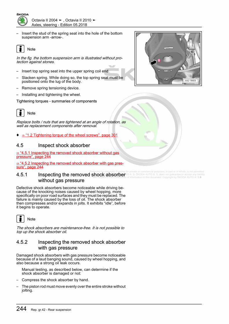
Protected by copyright. Copying for private or commercial purposes, in part or in whole, is not permitted unless authorised by ŠKODA AUTO A. S. ŠKODA AUTO A. S. does not guarantee or accept any liability
with respect to the correctness of information in this document. Copyright by ŠKODA AUTO A. S.�
– Insert the stud of the spring seat into the hole of the bottomsuspension arm -arrow-.
Note
In the fig. the bottom suspension arm is illustrated without pro‐tection against stones.
– Insert top spring seat into the upper spring coil end.– Slacken spring. While doing so, the top spring seat must be
positioned onto the lug of the body.– Remove spring tensioning device.– Installing and tightening the wheel.Tightening torques - summaries of components
Note
Replace bolts / nuts that are tightened at an angle of rotation, aswell as replacement components after removal.
♦ ⇒ “1.2 Tightening torque of the wheel screws”, page 301
4.5 Inspect shock absorber⇒ “4.5.1 Inspecting the removed shock absorber without gaspressure”, page 244⇒ “4.5.2 Inspecting the removed shock absorber with gas pres‐sure”, page 244
4.5.1 Inspecting the removed shock absorberwithout gas pressure
Defective shock absorbers become noticeable while driving be‐cause of the knocking noises caused by wheel hopping, morespecifically on poor road surfaces and they must be replaced. Thefailure is mainly caused by the loss of oil. The shock absorberthen compresses and/or expands in jolts. It exhibits “idle”, beforeit begins to operate.
Note
The shock absorbers are maintenance-free. It is not possible totop up the shock absorber oil.
4.5.2 Inspecting the removed shock absorberwith gas pressure
Damaged shock absorbers with gas pressure become noticeablebecause of a laud banging sound, caused by wheel hopping, andalso because a strong oil leak occurs.
Manual testing, as described below, can determine if theshock absorber is damaged or not:
– Compress the shock absorber by hand.– The piston rod must move evenly over the entire stroke without
jolting.
Octavia II 2004 ➤ , Octavia II 2010 ➤Axles, steering - Edition 05.2018
244 Rep. gr.42 - Rear suspension
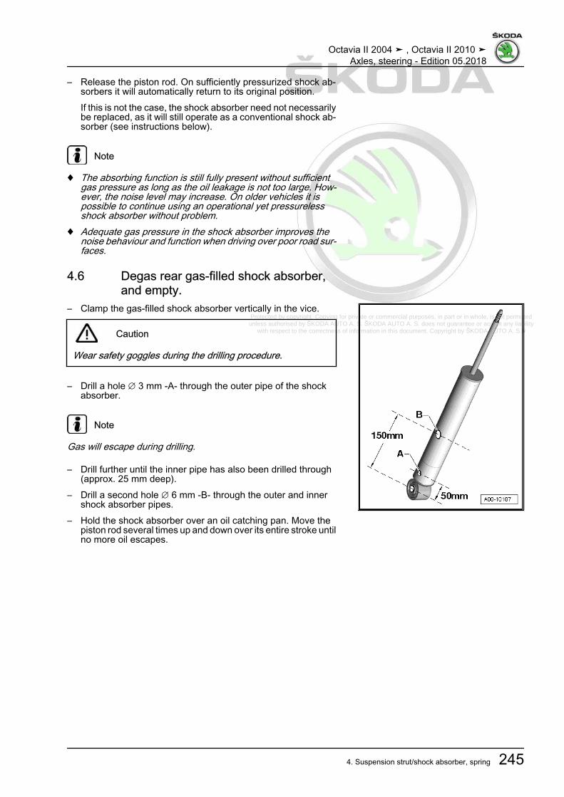
Protected by copyright. Copying for private or commercial purposes, in part or in whole, is not permitted unless authorised by ŠKODA AUTO A. S. ŠKODA AUTO A. S. does not guarantee or accept any liability
with respect to the correctness of information in this document. Copyright by ŠKODA AUTO A. S.�
– Release the piston rod. On sufficiently pressurized shock ab‐sorbers it will automatically return to its original position.If this is not the case, the shock absorber need not necessarilybe replaced, as it will still operate as a conventional shock ab‐sorber (see instructions below).
Note
♦ The absorbing function is still fully present without sufficientgas pressure as long as the oil leakage is not too large. How‐ever, the noise level may increase. On older vehicles it ispossible to continue using an operational yet pressurelessshock absorber without problem.
♦ Adequate gas pressure in the shock absorber improves thenoise behaviour and function when driving over poor road sur‐faces.
4.6 Degas rear gas-filled shock absorber,and empty.
– Clamp the gas-filled shock absorber vertically in the vice.
Caution
Wear safety goggles during the drilling procedure.
– Drill a hole ∅ 3 mm -A- through the outer pipe of the shockabsorber.
Note
Gas will escape during drilling.
– Drill further until the inner pipe has also been drilled through(approx. 25 mm deep).
– Drill a second hole ∅ 6 mm -B- through the outer and innershock absorber pipes.
– Hold the shock absorber over an oil catching pan. Move thepiston rod several times up and down over its entire stroke untilno more oil escapes.
Octavia II 2004 ➤ , Octavia II 2010 ➤Axles, steering - Edition 05.2018
4. Suspension strut/shock absorber, spring 245

Protected by copyright. Copying for private or commercial purposes, in part or in whole, is not permitted unless authorised by ŠKODA AUTO A. S. ŠKODA AUTO A. S. does not guarantee or accept any liability
with respect to the correctness of information in this document. Copyright by ŠKODA AUTO A. S.�
5 Wheel bearing, trailing arm⇒ “5.1 Summary of components - wheel bearing housing, trailingarm”, page 246⇒ “5.2 Removing and installing wheel bearing housing”,page 251⇒ “5.3 Removing and installing wheel-bearing unit”, page 258⇒ “5.4 Replacing the rubber-metal bearing for wheel-bearinghousing”, page 263⇒ “5.5 Removing and installing trailing arm with bracket”,page 267⇒ “5.6 Repairing trailing arm”, page 271
5.1 Summary of components - wheel bear‐ing housing, trailing arm
⇒ “5.1.1 Summary of components: wheel-bearing housing, trail‐ing arm, vehicles with front-wheel drive”, page 246⇒ “5.1.2 Summary of components: wheel-bearing housing, trail‐ing arm, vehicles with four-wheel drive”, page 249
5.1.1 Summary of components: wheel-bearing housing, trailing arm, vehicles withfront-wheel drive
The -arrow- shows the direction of travel.
Octavia II 2004 ➤ , Octavia II 2010 ➤Axles, steering - Edition 05.2018
246 Rep. gr.42 - Rear suspension

Protected by copyright. Copying for private or commercial purposes, in part or in whole, is not permitted unless authorised by ŠKODA AUTO A. S. ŠKODA AUTO A. S. does not guarantee or accept any liability
with respect to the correctness of information in this document. Copyright by ŠKODA AUTO A. S.�
1 - Screw❑ replace after each re‐
moval❑ 50 Nm + 45°
2 - Bearing bracket3 - Screw
❑ replace after each re‐moval
❑ determine ⇒ page 252the fitting position of thebracket to the trailingarm before tighteningthe screw
❑ 90 Nm + 90°4 - Coupling rod
❑ connects anti-roll barwith trailing arm/wheel-bearing housing
5 - Screw❑ Observe tightening se‐
quence ⇒ page 252❑ replace after each re‐
moval❑ determine ⇒ page 252
the fitting position of thetrailing arm to the wheel-bearing housing beforetightening the screws
❑ 70 Nm + 90°6 - Trailing arm
❑ Removing and installing⇒ “5.5 Removing and in‐stalling trailing arm withbracket”, page 267
❑ repairing ⇒ “5.6 Repairing trailing arm”, page 2717 - Screw
❑ 8 Nm8 - Rear right wheel speed sensor - G44- / Rear left wheel speed sensor - G46-
❑ can be checked ⇒ Vehicle diagnostic tester in the guided fault detection system❑ Clean the inner surface of the hole before inserting the sensor and coat with a solid lubricant paste -
G 000 650- .9 - Wheel bearing housing
❑ Assignment ⇒ Electronic Catalogue of Original Parts❑ Removing and installing
⇒ “5.2.1 Removing and installing wheel bearing housing, vehicles with front-wheel drive”, page 25110 - Rubber-metal bearing
❑ Replace⇒ “5.4.1 Replacing the rubber-metal bearing for wheel-bearing housing, vehicles with front-wheel drive”,page 263
11 - Nut❑ self-locking❑ replace after each removal❑ Tightening torque
⇒ “3.1.1 Summary of components - anti-roll bar, vehicles with front-wheel drive”, page 232
Octavia II 2004 ➤ , Octavia II 2010 ➤Axles, steering - Edition 05.2018
5. Wheel bearing, trailing arm 247

Protected by copyright. Copying for private or commercial purposes, in part or in whole, is not permitted unless authorised by ŠKODA AUTO A. S. ŠKODA AUTO A. S. does not guarantee or accept any liability
with respect to the correctness of information in this document. Copyright by ŠKODA AUTO A. S.�
12 - Screw❑ 8 Nm
13 - Brake disc14 - Cap
❑ replace after each removal❑ extracting and inserting
⇒ “5.3.1 Removing and installing wheel hub with wheel bearing, vehicles with front-wheel drive”,page 258
a professional seal can only be achieved with a new cap
15 - Screw❑ replace after each removal❑ Assignment ⇒ Electronic Catalogue of Original Parts❑ 200 Nm + 90°
16 - Wheel hub with wheel bearing❑ Sensor ring for ABS is built into the wheel hub❑ Removing and installing
⇒ “5.3.1 Removing and installing wheel hub with wheel bearing, vehicles with front-wheel drive”,page 258
Wheel hub and wheel bearing form one unit. It is clearance free, adjusting and repairs are not possible.
17 - Screw❑ 12 Nm
18 - Protection plate
Octavia II 2004 ➤ , Octavia II 2010 ➤Axles, steering - Edition 05.2018
248 Rep. gr.42 - Rear suspension

Protected by copyright. Copying for private or commercial purposes, in part or in whole, is not permitted unless authorised by ŠKODA AUTO A. S. ŠKODA AUTO A. S. does not guarantee or accept any liability
with respect to the correctness of information in this document. Copyright by ŠKODA AUTO A. S.�
5.1.2 Summary of components: wheel-bearing housing, trailing arm, vehicles withfour-wheel drive
The -arrow- shows the direction of travel.
1 - Screw❑ replace after each re‐
moval❑ 50 Nm + 45°
2 - Bearing bracket3 - Screw
❑ replace after each re‐moval
❑ determine⇒ “5.5 Removing and in‐stalling trailing arm withbracket”, page 267 thefitting position of thebracket to the trailingarm before tighteningthe screw
❑ 90 Nm + 90°4 - Coupling rod
❑ connects anti-roll barwith trailing arm/wheel-bearing housing
5 - Screw❑ Observe tightening se‐
quence⇒ “5.5 Removing and in‐stalling trailing arm withbracket”, page 267
❑ replace after each re‐moval
❑ note⇒ “5.5 Removing and in‐stalling trailing arm withbracket”, page 267 thefitting position of thetrailing arm to the wheel-bearing housing before tightening the screws
❑ 70 Nm + 90°6 - Trailing arm
❑ Removing and installing ⇒ “5.5 Removing and installing trailing arm with bracket”, page 267❑ repairing ⇒ “5.6 Repairing trailing arm”, page 271
7 - Drive shaft❑ Summary of components ⇒ “6 Drive shaft”, page 273❑ Removing and installing ⇒ “6.3.1 Removing and installing cardan shaft”, page 279
8 - Screw❑ replace after each removal❑ 90 Nm + 90°
9 - Wheel bearing housing❑ up to 05/2007 steel casting version❑ as of 06/2007 aluminium version❑ Assignment ⇒ Electronic Catalogue of Original Parts
Octavia II 2004 ➤ , Octavia II 2010 ➤Axles, steering - Edition 05.2018
5. Wheel bearing, trailing arm 249

Protected by copyright. Copying for private or commercial purposes, in part or in whole, is not permitted unless authorised by ŠKODA AUTO A. S. ŠKODA AUTO A. S. does not guarantee or accept any liability
with respect to the correctness of information in this document. Copyright by ŠKODA AUTO A. S.�
❑ Removing and installing⇒ “5.2.2 Removing and installing the wheel bearing housing, vehicles with four-wheel drive”, page 254
10 - Rear right wheel speed sensor - G44- / Rear left wheel speed sensor - G46-❑ can be checked ⇒ Vehicle diagnostic tester in the guided fault detection system❑ Clean the inner surface of the hole before inserting the sensor and coat with a solid lubricant paste - G
000 650- .11 - Screw
❑ 8 Nm12 - Rubber-metal bearing
❑ Replace⇒ “5.4.2 Replacing the rubber-metal bearing for wheel-bearing housing, vehicles with four-wheel drive”,page 265
13 - Nut❑ self-locking❑ replace after each removal❑ Tightening torque
⇒ “3.1.2 Summary of components - anti-roll bar, vehicles with four-wheel drive”, page 23314 - Screw
❑ 8 Nm15 - Brake disc16 - Screw
❑ replace after each removal❑ Assignment ⇒ Electronic Catalogue of Original Parts❑ When loosening and tightening the screw, the prescribed procedure must be followed❑ Tightening torque ⇒ “6.5 Loosen and tighten cardan shaft screwed connection”, page 288❑ Removing and installing ⇒ “6.5 Loosen and tighten cardan shaft screwed connection”, page 288
17 - Wheel hub with wheel bearing❑ Sensor ring for ABS is built into the wheel hub❑ Removing and installing
⇒ “5.3.2 Removing and installing wheel hub with wheel bearing, vehicles with four-wheel drive”,page 261
Wheel hub and wheel bearing form one unit. It is clearance free, adjusting and repairs are not possible.
18 - Screw❑ up to 05/2007 wheel bearing housing in steel casting and 3 screws❑ as of 06/2007 aluminium wheel bearing housing and 4 screws❑ Assignment ⇒ Electronic Catalogue of Original Parts❑ 12 Nm
19 - Protection plate❑ up to 05/2007 for wheel bearing housing in steel casting with 3 holes❑ as of 06/2007 for aluminium wheel bearing housing with 4 holes❑ Assignment ⇒ Electronic Catalogue of Original Parts
Octavia II 2004 ➤ , Octavia II 2010 ➤Axles, steering - Edition 05.2018
250 Rep. gr.42 - Rear suspension
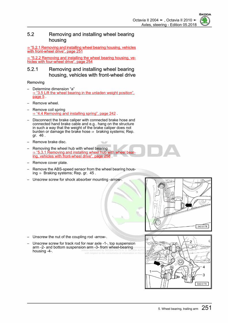
Protected by copyright. Copying for private or commercial purposes, in part or in whole, is not permitted unless authorised by ŠKODA AUTO A. S. ŠKODA AUTO A. S. does not guarantee or accept any liability
with respect to the correctness of information in this document. Copyright by ŠKODA AUTO A. S.�
5.2 Removing and installing wheel bearinghousing
⇒ “5.2.1 Removing and installing wheel bearing housing, vehicleswith front-wheel drive”, page 251⇒ “5.2.2 Removing and installing the wheel bearing housing, ve‐hicles with four-wheel drive”, page 254
5.2.1 Removing and installing wheel bearinghousing, vehicles with front-wheel drive
Removing– Determine dimension “a”
⇒ “3.5 Lift the wheel bearing in the unladen weight position”,page 5 .
– Remove wheel.– Remove coil spring
⇒ “4.4 Removing and installing spring”, page 242 .– Disconnect the brake caliper with connected brake hose and
connected hand brake cable and e.g.. hang on the structurein such a way that the weight of the brake caliper does notburden or damage the brake hose ⇒ braking systems; Rep.gr. 46 .
– Remove brake disc.– Removing the wheel hub with wheel bearing
⇒ “5.3.1 Removing and installing wheel hub with wheel bear‐ing, vehicles with front-wheel drive”, page 258 .
– Remove cover plate.– Remove the ABS-speed sensor from the wheel bearing hous‐
ing ⇒ Braking systems; Rep. gr. 45 .– Unscrew screw for shock absorber mounting -arrow-.
– Unscrew the nut of the coupling rod -arrow-.– Unscrew screw for track rod for rear axle -1-, top suspension
arm -2- and bottom suspension arm -3- from wheel-bearinghousing -4-.
Octavia II 2004 ➤ , Octavia II 2010 ➤Axles, steering - Edition 05.2018
5. Wheel bearing, trailing arm 251

Protected by copyright. Copying for private or commercial purposes, in part or in whole, is not permitted unless authorised by ŠKODA AUTO A. S. ŠKODA AUTO A. S. does not guarantee or accept any liability
with respect to the correctness of information in this document. Copyright by ŠKODA AUTO A. S.�
– Hold the wheel-bearing housing and unscrew screws-arrows-.
– Take the wheel-bearing housing out of the coupling rod jointthread -1-.
– Remove the wheel bearing housing.InstallingInstallation is performed in the reverse order, pay attention to thefollowing points:
Note
Pay attention to correct installation position of trailing arm andwheel-bearing housing.
Installation position of trailing arm and wheel-bearing housing.The screwed connection of the trailing arm/wheel-bearing hous‐ing must only be tightened if all other components (spring andshock absorber are required) of the wheel suspension in questionare already fitted. For tightening, the wheel-bearing housing mustbe in the unladen weight position⇒ “3.5 Lift the wheel bearing in the unladen weight position”, page5 . Only move the trailing arm and the wheel-bearing housing intothe necessary position for tightening the screwed connection-arrows- under these conditions.
Note
Note the following work steps and absolutely ensure that you fol‐low the sequence!
– Screw wheel-bearing housing with screws -1- onto trailing armand coupling rod -2-, but do not tighten the screws and the nutyet!
– Screw the track rod for rear axle -1-, top suspension arm -2-and bottom suspension arm -3- to the wheel-bearing housing-4- but do not tighten yet!
– Install cover plate.– Installing the whhel bearing/wheel hub with wheel bearing
⇒ “5.3.1 Removing and installing wheel hub with wheel bear‐ing, vehicles with front-wheel drive”, page 258 .
Octavia II 2004 ➤ , Octavia II 2010 ➤Axles, steering - Edition 05.2018
252 Rep. gr.42 - Rear suspension

Protected by copyright. Copying for private or commercial purposes, in part or in whole, is not permitted unless authorised by ŠKODA AUTO A. S. ŠKODA AUTO A. S. does not guarantee or accept any liability
with respect to the correctness of information in this document. Copyright by ŠKODA AUTO A. S.�
– Screw in screw for shock absorber mounting -arrow-, but donot tighten yet!
– Install coil spring⇒ “4.4 Removing and installing spring”, page 242 .
Note
The tightening of the track control arm and shock absorber to thewheel-bearing housing must only be performed, if the dimension“a” between the wheel hub centre and the lower edge of the wheelhouse is respected (unladen weight position)!⇒ “3.5 Lift the wheel bearing in the unladen weight position”, page5 .
– Adjust dimension -a-⇒ “3.5 Lift the wheel bearing in the unladen weight position”,page 5 .
– Tighten screw for track rod for rear axle -1-.– Tighten screw for bottom suspension arm -3-.
– Tighten screw -1- for top suspension arm.
Note
The washer -2- must be fitted so that there is -arrow B- a gapbetween the washer and the cover plate -3-
– Tighten screw for shock absorber mounting.
Octavia II 2004 ➤ , Octavia II 2010 ➤Axles, steering - Edition 05.2018
5. Wheel bearing, trailing arm 253

Protected by copyright. Copying for private or commercial purposes, in part or in whole, is not permitted unless authorised by ŠKODA AUTO A. S. ŠKODA AUTO A. S. does not guarantee or accept any liability
with respect to the correctness of information in this document. Copyright by ŠKODA AUTO A. S.�
– Tighten screws -1- of trailing arm with tightening torque, whiledoing so pay attention to the required position of the trailingarm and wheel-bearing housing ⇒ page 252 .
– Tighten nut of coupling rod -2- to wheel-bearing housing.– Remove tools for adjusting the dimension -a-.– Install the ABS-speed sensor in the wheel-bearing housing.– Install brake disc.– Install brake caliper with brake carrier ⇒ Brake systems; Rep.
gr. 46 .– Carry out axle alignment ⇒ “3.3 Axle alignment”, page 309 .Tightening torques - summaries of components
Note
Replace bolts / nuts that are tightened at an angle of rotation, aswell as replacement components after removal.
♦ ⇒ “5.1.1 Summary of components: wheel-bearing housing,trailing arm, vehicles with front-wheel drive”, page 246
♦ ⇒ “4.1.1 Summary of components - strut / shock absorber,spring, vehicles with front wheel drive”, page 238
♦ ⇒ “3.1.1 Summary of components - anti-roll bar, vehicles withfront-wheel drive”, page 232
♦ ⇒ “2.1.1 Summary of components: Assembly carrier, suspen‐sion arm, track rod for rear axle, vehicles with front drive”, page198
♦ ⇒ “1.2 Tightening torque of the wheel screws”, page 301♦ Brake caliper, disc ⇒ braking systems; Rep. gr. 46
5.2.2 Removing and installing the wheel bear‐ing housing, vehicles with four-wheeldrive
Removing– Determine dimension “a”
⇒ “3.5 Lift the wheel bearing in the unladen weight position”,page 5 .
– Release drive shaft screw connection⇒ “6.5 Loosen and tighten cardan shaft screwed connection”,page 288 ,
Octavia II 2004 ➤ , Octavia II 2010 ➤Axles, steering - Edition 05.2018
254 Rep. gr.42 - Rear suspension

Protected by copyright. Copying for private or commercial purposes, in part or in whole, is not permitted unless authorised by ŠKODA AUTO A. S. ŠKODA AUTO A. S. does not guarantee or accept any liability
with respect to the correctness of information in this document. Copyright by ŠKODA AUTO A. S.�
Note
♦ Wheel bearings must not be subjected to load after bolt se‐curing cardan shaft to wheel hub has been loosened.
♦ If the wheel bearings are loaded through the vehicle's ownweight, the wheel bearing will be initially damaged. This short‐ens the life of the wheel bearing.
♦ It is not permissible to turn cardan shaft screw more than 90°anti-clockwise if vehicle is standing on its wheels.
♦ Do not attempt to move the vehicle without the cardan shaftsfitted as this would damage the wheel bearing. If a vehiclenevertheless has to be moved, comply with the following:
♦ Install an outer joint instead of the cardan shaft.♦ Tighten outer joint to 120 Nm.
– Remove wheel.– Remove coil spring
⇒ “4.4 Removing and installing spring”, page 242 .– Disconnect the brake caliper with connected brake hose and
connected hand brake cable and e.g.. hang on the structurein such a way that the weight of the brake caliper does notburden or damage the brake hose ⇒ braking systems; Rep.gr. 46 .
– Remove brake disc.– Remove cover plate.– Removing the wheel hub with wheel bearing
⇒ “5.3.2 Removing and installing wheel hub with wheel bear‐ing, vehicles with four-wheel drive”, page 261 .
– Remove the ABS-speed sensor from the wheel bearing hous‐ing ⇒ Braking systems; Rep. gr. 45 .
– Unscrew screw for shock absorber mounting -arrow-.
Note
As of 06/2007 new aluminium wheel bearing housings are fitted.A washer is located between the shock absorber and the wheel-bearing housing, which must be installed again when reinstalling.
Octavia II 2004 ➤ , Octavia II 2010 ➤Axles, steering - Edition 05.2018
5. Wheel bearing, trailing arm 255

Protected by copyright. Copying for private or commercial purposes, in part or in whole, is not permitted unless authorised by ŠKODA AUTO A. S. ŠKODA AUTO A. S. does not guarantee or accept any liability
with respect to the correctness of information in this document. Copyright by ŠKODA AUTO A. S.�
– Unscrew the nut of the coupling rod -arrow-.
Note
As of 06/2007 new aluminium wheel bearing housings are fitted.A washer is located between the top suspension arm/track rod forrear axle and the wheel-bearing housing, which must be installedagain when reinstalling.
– Unscrew screw for track rod for rear axle -1-, top suspensionarm -2- and bottom suspension arm -3- from wheel-bearinghousing -4-.
– Hold the wheel-bearing housing and unscrew screws-arrows-.
– Take the wheel-bearing housing out of the coupling rod jointthread -1-.
– Remove the wheel bearing housing.InstallingInstallation is performed in the reverse order, pay attention to thefollowing points:
Note
Pay attention to correct installation position of trailing arm andwheel-bearing housing.
Installation position of trailing arm and wheel-bearing housing.The screwed connection of the trailing arm/wheel-bearing hous‐ing must only be tightened if all other components (spring andshock absorber are required) of the wheel suspension in questionare already fitted. For tightening, the wheel-bearing housing mustbe in the unladen weight position⇒ “3.5 Lift the wheel bearing in the unladen weight position”, page5 . Only move the trailing arm and the wheel-bearing housing intothe necessary position for tightening the screwed connection-arrows- under these conditions.
Note
Note the following work steps and absolutely ensure that you fol‐low the sequence!
– Screw wheel-bearing housing with screws -1- onto trailing armand coupling rod -2-, but do not tighten the screws and the nutyet!
Octavia II 2004 ➤ , Octavia II 2010 ➤Axles, steering - Edition 05.2018
256 Rep. gr.42 - Rear suspension

Protected by copyright. Copying for private or commercial purposes, in part or in whole, is not permitted unless authorised by ŠKODA AUTO A. S. ŠKODA AUTO A. S. does not guarantee or accept any liability
with respect to the correctness of information in this document. Copyright by ŠKODA AUTO A. S.�
– Screw the track rod for rear axle -1-, top suspension arm -2-and bottom suspension arm -3- to the wheel-bearing housing-4- but do not tighten yet!
Note
As of 06/2007 new aluminium wheel bearing housings are fitted.A washer is located between the top suspension arm/track rod forrear axle and the wheel-bearing housing, which must be installedagain when reinstalling.
– Installing the wheel hub with wheel bearing⇒ “5.3.2 Removing and installing wheel hub with wheel bear‐ing, vehicles with four-wheel drive”, page 261 .
– Install cover plate.
– Screw in screw for shock absorber mounting -arrow-, but donot tighten yet!
Note
As of 06/2007 new aluminium wheel bearing housings are fitted.A washer is located between the shock absorber and the wheel-bearing housing, which must be installed again when reinstalling.
– Installing the helical spring⇒ “4.4 Removing and installing spring”, page 242
Note
The tightening of the track control arm and shock absorber to thewheel-bearing housing must only be performed, if the dimension“a” between the wheel hub centre and the lower edge of the wheelhouse is respected (unladen weight position)!⇒ “3.5 Lift the wheel bearing in the unladen weight position”, page5
– Adjust dimension -a-⇒ “3.5 Lift the wheel bearing in the unladen weight position”,page 5 .
– Tighten screw for track rod for rear axle -1-.– Tighten screw for bottom suspension arm -3-.
Octavia II 2004 ➤ , Octavia II 2010 ➤Axles, steering - Edition 05.2018
5. Wheel bearing, trailing arm 257
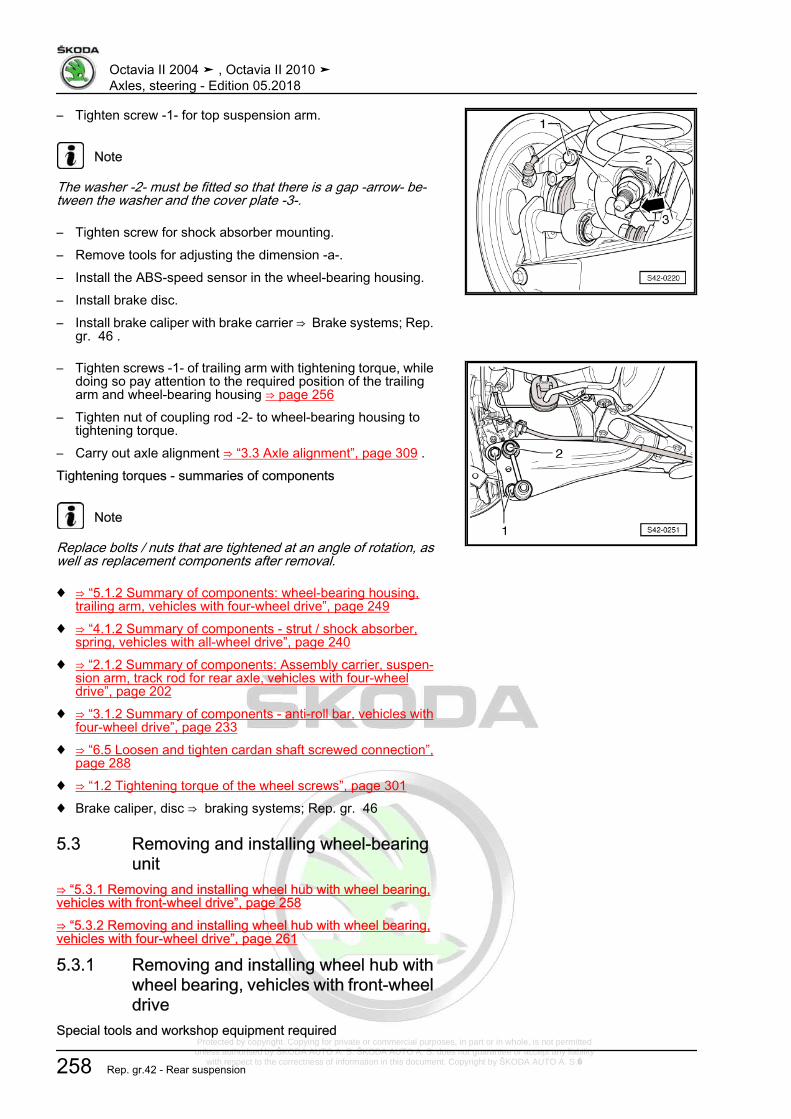
Protected by copyright. Copying for private or commercial purposes, in part or in whole, is not permitted unless authorised by ŠKODA AUTO A. S. ŠKODA AUTO A. S. does not guarantee or accept any liability
with respect to the correctness of information in this document. Copyright by ŠKODA AUTO A. S.�
– Tighten screw -1- for top suspension arm.
Note
The washer -2- must be fitted so that there is a gap -arrow- be‐tween the washer and the cover plate -3-.
– Tighten screw for shock absorber mounting.– Remove tools for adjusting the dimension -a-.– Install the ABS-speed sensor in the wheel-bearing housing.– Install brake disc.– Install brake caliper with brake carrier ⇒ Brake systems; Rep.
gr. 46 .
– Tighten screws -1- of trailing arm with tightening torque, whiledoing so pay attention to the required position of the trailingarm and wheel-bearing housing ⇒ page 256
– Tighten nut of coupling rod -2- to wheel-bearing housing totightening torque.
– Carry out axle alignment ⇒ “3.3 Axle alignment”, page 309 .Tightening torques - summaries of components
Note
Replace bolts / nuts that are tightened at an angle of rotation, aswell as replacement components after removal.
♦ ⇒ “5.1.2 Summary of components: wheel-bearing housing,trailing arm, vehicles with four-wheel drive”, page 249
♦ ⇒ “4.1.2 Summary of components - strut / shock absorber,spring, vehicles with all-wheel drive”, page 240
♦ ⇒ “2.1.2 Summary of components: Assembly carrier, suspen‐sion arm, track rod for rear axle, vehicles with four-wheeldrive”, page 202
♦ ⇒ “3.1.2 Summary of components - anti-roll bar, vehicles withfour-wheel drive”, page 233
♦ ⇒ “6.5 Loosen and tighten cardan shaft screwed connection”,page 288
♦ ⇒ “1.2 Tightening torque of the wheel screws”, page 301♦ Brake caliper, disc ⇒ braking systems; Rep. gr. 46
5.3 Removing and installing wheel-bearingunit
⇒ “5.3.1 Removing and installing wheel hub with wheel bearing,vehicles with front-wheel drive”, page 258⇒ “5.3.2 Removing and installing wheel hub with wheel bearing,vehicles with four-wheel drive”, page 261
5.3.1 Removing and installing wheel hub withwheel bearing, vehicles with front-wheeldrive
Special tools and workshop equipment required
Octavia II 2004 ➤ , Octavia II 2010 ➤Axles, steering - Edition 05.2018
258 Rep. gr.42 - Rear suspension

Protected by copyright. Copying for private or commercial purposes, in part or in whole, is not permitted unless authorised by ŠKODA AUTO A. S. ŠKODA AUTO A. S. does not guarantee or accept any liability
with respect to the correctness of information in this document. Copyright by ŠKODA AUTO A. S.�
♦ Insertion sleeve - MP1-228 (3241)-♦ Hub cap extractor - MP5-404 (VW 637/2)-♦ Socket insert XZN 18 - T10162-Removing– Remove wheel.– Release cap from its position by gently tapping the claw of the
hub cap extractor -1-.
– Press off cap.– Disconnect the brake caliper with connected brake hose and
connected hand brake cable and e.g.. hang on the structurein such a way that the weight of the brake caliper does notburden or damage the brake hose ⇒ braking systems; Rep.gr. 46 .
Note
Do not hang the brake caliper on the brake hose - risk of damage.
– Remove brake disc.
– Remove screw -1- with socket insert XZN 18 - T10162- -2-.
Caution
Do not use an impact screwdriver for loosening the screw!
– Remove wheel bearing unit from the axle stud.
Note
♦ Do not damage the sensor ring for ABS.♦ Avoid any contamination or damage to the gasket when han‐
dling and storing it.
Octavia II 2004 ➤ , Octavia II 2010 ➤Axles, steering - Edition 05.2018
5. Wheel bearing, trailing arm 259
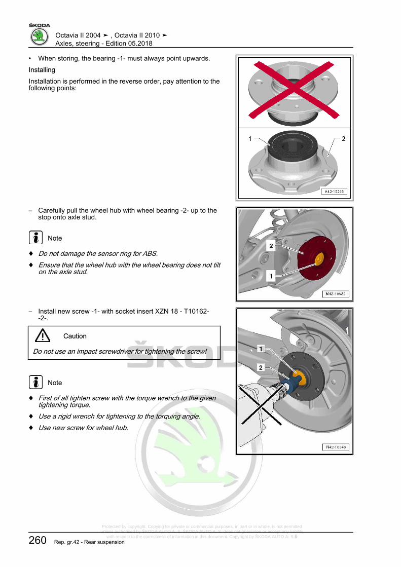
Protected by copyright. Copying for private or commercial purposes, in part or in whole, is not permitted unless authorised by ŠKODA AUTO A. S. ŠKODA AUTO A. S. does not guarantee or accept any liability
with respect to the correctness of information in this document. Copyright by ŠKODA AUTO A. S.�
• When storing, the bearing -1- must always point upwards.InstallingInstallation is performed in the reverse order, pay attention to thefollowing points:
– Carefully pull the wheel hub with wheel bearing -2- up to thestop onto axle stud.
Note
♦ Do not damage the sensor ring for ABS.♦ Ensure that the wheel hub with the wheel bearing does not tilt
on the axle stud.
– Install new screw -1- with socket insert XZN 18 - T10162--2-.
Caution
Do not use an impact screwdriver for tightening the screw!
Note
♦ First of all tighten screw with the torque wrench to the giventightening torque.
♦ Use a rigid wrench for tightening to the torquing angle.♦ Use new screw for wheel hub.
Octavia II 2004 ➤ , Octavia II 2010 ➤Axles, steering - Edition 05.2018
260 Rep. gr.42 - Rear suspension

Protected by copyright. Copying for private or commercial purposes, in part or in whole, is not permitted unless authorised by ŠKODA AUTO A. S. ŠKODA AUTO A. S. does not guarantee or accept any liability
with respect to the correctness of information in this document. Copyright by ŠKODA AUTO A. S.�
– Drive in the dust cap with insertion sleeve - MP1-228 (3241)--1-.
Note
♦ Always replace dust caps.♦ Damaged dust caps allow moisture to penetrate. Therefore
absolutely use the shown tool.
Tightening torques - summaries of components
Note
Replace bolts / nuts that are tightened at an angle of rotation, aswell as replacement components after removal.
♦ ⇒ “5.1.1 Summary of components: wheel-bearing housing,trailing arm, vehicles with front-wheel drive”, page 246
♦ ⇒ “1.2 Tightening torque of the wheel screws”, page 301♦ Brake caliper, disc ⇒ braking systems; Rep. gr. 46
5.3.2 Removing and installing wheel hub withwheel bearing, vehicles with four-wheeldrive
Removing– Release drive shaft screw connection
⇒ “6.5 Loosen and tighten cardan shaft screwed connection”,page 288 ,
Note
♦ Wheel bearings must not be subjected to load after bolt se‐curing cardan shaft to wheel hub has been loosened.
♦ If the wheel bearings are loaded through the vehicle's ownweight, the wheel bearing will be initially damaged. This short‐ens the life of the wheel bearing.
♦ It is not permissible to turn cardan shaft screw more than 90°anti-clockwise if vehicle is standing on its wheels.
♦ Do not attempt to move the vehicle without the cardan shaftsfitted as this would damage the wheel bearing. If a vehiclenevertheless has to be moved, comply with the following:
♦ Install an outer joint instead of the cardan shaft.♦ Tighten outer joint to 120 Nm.
– Remove wheel.– Remove coil spring
⇒ “4.4 Removing and installing spring”, page 242 .– Remove cardan shaft
⇒ “6.3.1 Removing and installing cardan shaft”, page 279 .– Disconnect the brake caliper with connected brake hose and
connected hand brake cable and e.g.. hang on the structurein such a way that the weight of the brake caliper does not
Octavia II 2004 ➤ , Octavia II 2010 ➤Axles, steering - Edition 05.2018
5. Wheel bearing, trailing arm 261

Protected by copyright. Copying for private or commercial purposes, in part or in whole, is not permitted unless authorised by ŠKODA AUTO A. S. ŠKODA AUTO A. S. does not guarantee or accept any liability
with respect to the correctness of information in this document. Copyright by ŠKODA AUTO A. S.�
burden or damage the brake hose ⇒ braking systems; Rep.gr. 46 .
Note
Do not hang the brake caliper on the brake hose.
– Remove brake disc.– Remove cover plate.– Remove screws -2-.– Pull the wheel bearing out of the wheel-bearing housing.– Remove wheel bearing unit from the axle stud.
Note
♦ Do not damage the sensor ring for ABS.♦ Avoid any contamination or damage to the gasket when han‐
dling and storing it.
• When storing, the bearing -1- must always point upwards.
Octavia II 2004 ➤ , Octavia II 2010 ➤Axles, steering - Edition 05.2018
262 Rep. gr.42 - Rear suspension

Protected by copyright. Copying for private or commercial purposes, in part or in whole, is not permitted unless authorised by ŠKODA AUTO A. S. ŠKODA AUTO A. S. does not guarantee or accept any liability
with respect to the correctness of information in this document. Copyright by ŠKODA AUTO A. S.�
• When picking up the wheel bearing, never take hold from theinside.
• Only take hold of the wheel bearing from the outside.InstallingInstallation is performed in the reverse order, pay attention to thefollowing points:• The wheel bearing housing is only to be bolted in the unladen
weight position⇒ “3.5 Lift the wheel bearing in the unladen weight position”,page 5 .
– Tighten fixing screw of the drive shaft⇒ “6.5 Loosen and tighten cardan shaft screwed connection”,page 288 .
Tightening torques - summaries of components
Note
Replace bolts / nuts that are tightened at an angle of rotation, aswell as replacement components after removal.
♦ ⇒ “5.1.2 Summary of components: wheel-bearing housing,trailing arm, vehicles with four-wheel drive”, page 249
♦ ⇒ “6.5 Loosen and tighten cardan shaft screwed connection”,page 288
♦ ⇒ “1.2 Tightening torque of the wheel screws”, page 301♦ Brake caliper, disc ⇒ braking systems; Rep. gr. 46
5.4 Replacing the rubber-metal bearing forwheel-bearing housing
⇒ “5.4.1 Replacing the rubber-metal bearing for wheel-bearinghousing, vehicles with front-wheel drive”, page 263⇒ “5.4.2 Replacing the rubber-metal bearing for wheel-bearinghousing, vehicles with four-wheel drive”, page 265
5.4.1 Replacing the rubber-metal bearing forwheel-bearing housing, vehicles withfront-wheel drive
Special tools and workshop equipment required♦ Nut - MP5-401/3 (3346)-♦ Screw - MP5-401/2 (3346)-♦ Pipe section - MP5-402/3 (3301)-♦ Assembly tool - MP5-402 (3301)-♦ Assembly tool - T30017/1 (3350)-♦ Assembly tool - T30017/2 (3350)-♦ Knock-in bushing - T30034 (41-501)-♦ Press-in ring - MP3-483 (30204)-Removing– Remove wheel.
Octavia II 2004 ➤ , Octavia II 2010 ➤Axles, steering - Edition 05.2018
5. Wheel bearing, trailing arm 263

Protected by copyright. Copying for private or commercial purposes, in part or in whole, is not permitted unless authorised by ŠKODA AUTO A. S. ŠKODA AUTO A. S. does not guarantee or accept any liability
with respect to the correctness of information in this document. Copyright by ŠKODA AUTO A. S.�
– Remove coil spring⇒ “4.4 Removing and installing spring”, page 242 .
– Disconnect the brake caliper with connected brake hose andconnected hand brake cable and e.g.. hang on the structurein such a way that the weight of the brake caliper does notburden or damage the brake hose ⇒ braking systems; Rep.gr. 46 .
– Remove brake disc.– Removing the wheel hub with wheel bearing
⇒ “5.3.1 Removing and installing wheel hub with wheel bear‐ing, vehicles with front-wheel drive”, page 258 .
– Remove cover plate.– Release screw -arrow- for bottom suspension arm -1-.
Pulling out the rubber-metal bearing– Position the special tools as shown in the figure.1 - Nut - MP5-401/3 (3346)-2 - Assembly tool - MP5-402 (3301)-3 - Pipe section - MP5-402/3 (3301)-4 - Knock-in bushing - T30034 (41-501)-5 - Assembly tool - T30017/1 (3350)-6 - Nut, commercially available7 - Screw - MP5-401/2 (3346)-– Pull out rubber-metal bearing by turning the nut -1-.
Octavia II 2004 ➤ , Octavia II 2010 ➤Axles, steering - Edition 05.2018
264 Rep. gr.42 - Rear suspension

Protected by copyright. Copying for private or commercial purposes, in part or in whole, is not permitted unless authorised by ŠKODA AUTO A. S. ŠKODA AUTO A. S. does not guarantee or accept any liability
with respect to the correctness of information in this document. Copyright by ŠKODA AUTO A. S.�
Inserting the rubber-metal bearing
Note
♦ Do not use any lubricant!♦ Carefully insert the rubber-metal bearing, so that it does not
tilt.
– Position the special tools as shown in the figure.1 - Screw - MP5-401/2 (3346)-2 - Nut - MP5-401/3 (3346)-3 - Assembly tool - MP5-402 (3301)-4 - Assembly tool - T30017/2 (3350)-5 - Rubber-metal bearing6 - Press-in ring - MP3-483 (30-204)-7 - Nut, commercially available– Insert the rubber-metal bearing -5- by turning the nut -2-.InstallingInstallation is carried out in the reverse order. When installing,note the following:
Note
The tightening of the track control arm and shock absorber to thewheel-bearing housing must only be performed, if the dimension“a” between the wheel hub centre and the lower edge of the wheelhouse is respected (unladen weight position)!⇒ “3.5 Lift the wheel bearing in the unladen weight position”, page5 .
Tightening torques - summaries of components
Note
Replace bolts / nuts that are tightened at an angle of rotation, aswell as replacement components after removal.
♦ ⇒ “5.1.1 Summary of components: wheel-bearing housing,trailing arm, vehicles with front-wheel drive”, page 246
♦ ⇒ “2.1.1 Summary of components: Assembly carrier, suspen‐sion arm, track rod for rear axle, vehicles with front drive”, page198
♦ ⇒ “1.2 Tightening torque of the wheel screws”, page 301♦ Brake caliper, disc ⇒ braking systems; Rep. gr. 46
5.4.2 Replacing the rubber-metal bearing forwheel-bearing housing, vehicles withfour-wheel drive
Special tools and workshop equipment required♦ Nut - MP5-401/3 (3346)-
Octavia II 2004 ➤ , Octavia II 2010 ➤Axles, steering - Edition 05.2018
5. Wheel bearing, trailing arm 265

Protected by copyright. Copying for private or commercial purposes, in part or in whole, is not permitted unless authorised by ŠKODA AUTO A. S. ŠKODA AUTO A. S. does not guarantee or accept any liability
with respect to the correctness of information in this document. Copyright by ŠKODA AUTO A. S.�
♦ Screw - MP5-401/2 (3346)-♦ Pipe section - MP5-402/3 (3301)-♦ Assembly tool - MP5-402 (3301)-♦ Assembly tool - T30017/1 (3350)-♦ Assembly tool - T30017/2 (3350)-♦ Knock-in bushing - T30034 (41-501)-♦ Press-in ring - MP3-483 (30204)-Removing– Remove wheel.– Remove coil spring
⇒ “4.4 Removing and installing spring”, page 242 .– Disconnect the brake caliper with connected brake hose and
connected hand brake cable and e.g.. hang on the structurein such a way that the weight of the brake caliper does notburden or damage the brake hose ⇒ braking systems; Rep.gr. 46 .
– Remove brake disc.– Remove wheel hub
⇒ “5.3.2 Removing and installing wheel hub with wheel bear‐ing, vehicles with four-wheel drive”, page 261 .
– Remove cover plate.– Release screw -arrow- for bottom suspension arm -1-.
Pulling out the rubber-metal bearing– Position the special tools as shown in the figure.1 - Nut - MP5-401/3 (3346)-2 - Assembly tool - MP5-402 (3301)-3 - Pipe section - MP5-402/3 (3301)-4 - Knock-in bushing - T30034 (41-501)-5 - Assembly tool - T30017/1 (3350)-6 - Nut, commercially available7 - Screw - MP5-401/2 (3346)-– Pull out rubber-metal bearing by turning the nut -1-.
Octavia II 2004 ➤ , Octavia II 2010 ➤Axles, steering - Edition 05.2018
266 Rep. gr.42 - Rear suspension
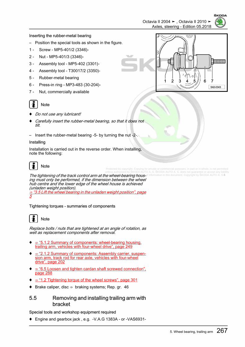
Protected by copyright. Copying for private or commercial purposes, in part or in whole, is not permitted unless authorised by ŠKODA AUTO A. S. ŠKODA AUTO A. S. does not guarantee or accept any liability
with respect to the correctness of information in this document. Copyright by ŠKODA AUTO A. S.�
Inserting the rubber-metal bearing– Position the special tools as shown in the figure.1 - Screw - MP5-401/2 (3346)-2 - Nut - MP5-401/3 (3346)-3 - Assembly tool - MP5-402 (3301)-4 - Assembly tool - T30017/2 (3350)-5 - Rubber-metal bearing6 - Press-in ring - MP3-483 (30-204)-7 - Nut, commercially available
Note
♦ Do not use any lubricant!♦ Carefully insert the rubber-metal bearing, so that it does not
tilt.
– Insert the rubber-metal bearing -5- by turning the nut -2-.InstallingInstallation is carried out in the reverse order. When installing,note the following:
Note
The tightening of the track control arm at the wheel-bearing hous‐ing must only be performed, if the dimension between the wheelhub centre and the lower edge of the wheel house is achieved(unladen weight position).⇒ “3.5 Lift the wheel bearing in the unladen weight position”, page5
Tightening torques - summaries of components
Note
Replace bolts / nuts that are tightened at an angle of rotation, aswell as replacement components after removal.
♦ ⇒ “5.1.2 Summary of components: wheel-bearing housing,trailing arm, vehicles with four-wheel drive”, page 249
♦ ⇒ “2.1.2 Summary of components: Assembly carrier, suspen‐sion arm, track rod for rear axle, vehicles with four-wheeldrive”, page 202
♦ ⇒ “6.5 Loosen and tighten cardan shaft screwed connection”,page 288
♦ ⇒ “1.2 Tightening torque of the wheel screws”, page 301♦ Brake caliper, disc ⇒ braking systems; Rep. gr. 46
5.5 Removing and installing trailing arm withbracket
Special tools and workshop equipment required♦ Engine and gearbox jack , e.g. -V.A.G 1383A - or -VAS6931-
Octavia II 2004 ➤ , Octavia II 2010 ➤Axles, steering - Edition 05.2018
5. Wheel bearing, trailing arm 267
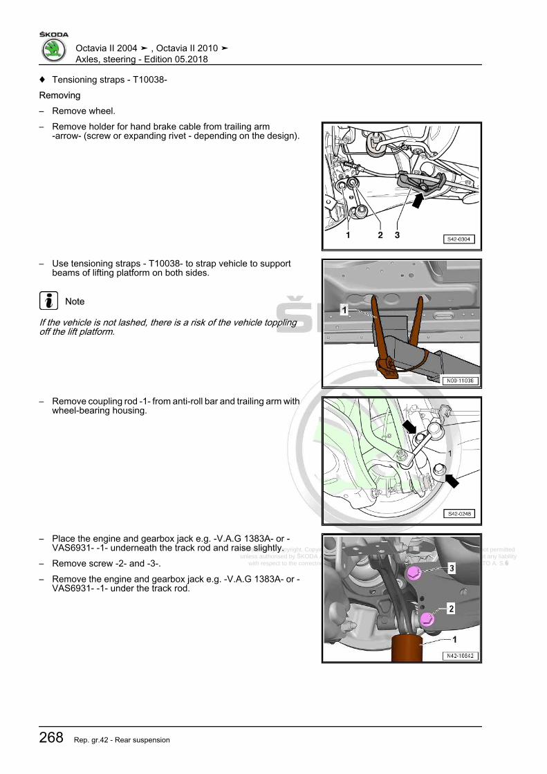
Protected by copyright. Copying for private or commercial purposes, in part or in whole, is not permitted unless authorised by ŠKODA AUTO A. S. ŠKODA AUTO A. S. does not guarantee or accept any liability
with respect to the correctness of information in this document. Copyright by ŠKODA AUTO A. S.�
♦ Tensioning straps - T10038-Removing– Remove wheel.– Remove holder for hand brake cable from trailing arm
-arrow- (screw or expanding rivet - depending on the design).
– Use tensioning straps - T10038- to strap vehicle to supportbeams of lifting platform on both sides.
Note
If the vehicle is not lashed, there is a risk of the vehicle topplingoff the lift platform.
– Remove coupling rod -1- from anti-roll bar and trailing arm withwheel-bearing housing.
– Place the engine and gearbox jack e.g. -V.A.G 1383A- or -VAS6931- -1- underneath the track rod and raise slightly.
– Remove screw -2- and -3-.– Remove the engine and gearbox jack e.g. -V.A.G 1383A- or -
VAS6931- -1- under the track rod.
Octavia II 2004 ➤ , Octavia II 2010 ➤Axles, steering - Edition 05.2018
268 Rep. gr.42 - Rear suspension

Protected by copyright. Copying for private or commercial purposes, in part or in whole, is not permitted unless authorised by ŠKODA AUTO A. S. ŠKODA AUTO A. S. does not guarantee or accept any liability
with respect to the correctness of information in this document. Copyright by ŠKODA AUTO A. S.�
– Mark the installed position of the bracket on the body.– Release the screws of the bracket -arrows-.– Remove the trailing arm with the bracket.Replace the trailing armIf the trailing arm should be replaced, the bracket must be re‐moved from the trailing arm.The installation position of the bracket to the trailing arm mustthen be adjusted.
Determine the fitting position of the bracket to the trailing armThe dimension -a- is 34 ± 1 mm.1 - Bearing bracket2 - Trailing arm– If the dimension -a- is adjusted, tighten the screw.InstallingInstallation is performed in the reverse order, pay attention to thefollowing points:
Note
Pay attention to correct installation position of trailing arm andwheel-bearing housing.
Installation position of trailing arm and wheel-bearing housing.The screwed connection of the trailing arm/wheel-bearing hous‐ing must only be tightened if all other components (spring andshock absorber are required) of the wheel suspension in questionare already fitted. For tightening, the wheel-bearing housing mustbe in the unladen weight position⇒ “3.5 Lift the wheel bearing in the unladen weight position”, page5 . Only move the trailing arm and the wheel-bearing housing intothe necessary position for tightening the screwed connection-arrows- under these conditions.
Note
Note the following work steps and absolutely ensure that you fol‐low the sequence!
– Screw trailing arm including bracket with screws -1- onto thewheel-bearing housing, but do not tighten yet.
– Insert the coupling rod -2- into the trailing arm with wheel-bearing housing, but do not tighten the nut yet!
– Insert the coupling rod -2- into the trailing arm with wheel-bearing housing, but do not tighten the nut yet!
Octavia II 2004 ➤ , Octavia II 2010 ➤Axles, steering - Edition 05.2018
5. Wheel bearing, trailing arm 269

Protected by copyright. Copying for private or commercial purposes, in part or in whole, is not permitted unless authorised by ŠKODA AUTO A. S. ŠKODA AUTO A. S. does not guarantee or accept any liability
with respect to the correctness of information in this document. Copyright by ŠKODA AUTO A. S.�
– Raise wheel-bearing housing with trailing arm using engine/gearbox jack e.g. -V.A.G 1383A- or -VAS6931- -1- until thebracket rests on the body.
– Tighten screws -arrows- to the marked fitting location - to the“former positions”.
– Remove the engine/gearbox jack e.g. -V.A.G 1383A- or -VAS6931- from underneath the vehicle.
The screwed connection of the trailing arm/wheel-bearing hous‐ing must only be tightened if all other components (spring andshock absorber are required) of the wheel suspension in questionare already fitted. The wheel suspension must be in the reboundstate for tightening. Only in this state do the trailing arm and wheelbearing housing move into the necessary position -arrows-.
– Tighten screws -1- and -2- of trailing arm with tightening tor‐que, while doing so pay attention to the required position ofthe trailing arm and wheel-bearing housing.
Octavia II 2004 ➤ , Octavia II 2010 ➤Axles, steering - Edition 05.2018
270 Rep. gr.42 - Rear suspension
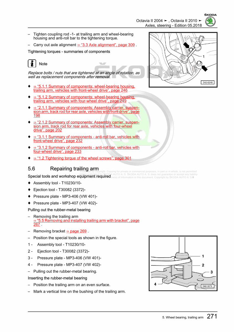
Protected by copyright. Copying for private or commercial purposes, in part or in whole, is not permitted unless authorised by ŠKODA AUTO A. S. ŠKODA AUTO A. S. does not guarantee or accept any liability
with respect to the correctness of information in this document. Copyright by ŠKODA AUTO A. S.�
– Tighten coupling rod -1- at trailing arm and wheel-bearinghousing and anti-roll bar to the tightening torque.
– Carry out axle alignment ⇒ “3.3 Axle alignment”, page 309 .Tightening torques - summaries of components
Note
Replace bolts / nuts that are tightened at an angle of rotation, aswell as replacement components after removal.
♦ ⇒ “5.1.1 Summary of components: wheel-bearing housing,trailing arm, vehicles with front-wheel drive”, page 246
♦ ⇒ “5.1.2 Summary of components: wheel-bearing housing,trailing arm, vehicles with four-wheel drive”, page 249
♦ ⇒ “2.1.1 Summary of components: Assembly carrier, suspen‐sion arm, track rod for rear axle, vehicles with front drive”, page198
♦ ⇒ “2.1.2 Summary of components: Assembly carrier, suspen‐sion arm, track rod for rear axle, vehicles with four-wheeldrive”, page 202
♦ ⇒ “3.1.1 Summary of components - anti-roll bar, vehicles withfront-wheel drive”, page 232
♦ ⇒ “3.1.2 Summary of components - anti-roll bar, vehicles withfour-wheel drive”, page 233
♦ ⇒ “1.2 Tightening torque of the wheel screws”, page 301
5.6 Repairing trailing armSpecial tools and workshop equipment required♦ Assembly tool - T10230/10-♦ Ejection tool - T30082 (3372)-♦ Pressure plate - MP3-406 (VW 401)-♦ Pressure plate - MP3-407 (VW 402)-Pulling out the rubber-metal bearing– Removing the trailing arm
⇒ “5.5 Removing and installing trailing arm with bracket”, page267 .
– Removing bracket ⇒ page 269 .– Position the special tools as shown in the figure.1 - Assembly tool - T10230/10-2 - Ejection tool - T30082 (3372)-3 - Pressure plate - MP3-406 (VW 401)-4 - Pressure plate - MP3-407 (VW 402)-– Pulling out the rubber-metal bearing.Inserting the rubber-metal bearing– Position the trailing arm on an even surface.– Mark a vertical line on the bushing of the trailing arm.
Octavia II 2004 ➤ , Octavia II 2010 ➤Axles, steering - Edition 05.2018
5. Wheel bearing, trailing arm 271

Protected by copyright. Copying for private or commercial purposes, in part or in whole, is not permitted unless authorised by ŠKODA AUTO A. S. ŠKODA AUTO A. S. does not guarantee or accept any liability
with respect to the correctness of information in this document. Copyright by ŠKODA AUTO A. S.�
Dimension -A- = 114 mm
The marked line must be between the lobes -1- after inserting.
– Position the special tools as shown in the figure.1 - Pressure plate e.g. -T10230/12- , the chamfer must point to
the rubber-metal bearing.2 - Rubber-metal bearing3 - Ejection tool - T30082 (3372)-4 - Pressure plate - MP3-407 (VW 402)-– Insert the rubber-metal bearing flush.– Install bracket at trailing arm
⇒ “5.5 Removing and installing trailing arm with bracket”, page267 .
– Installing the trailing arm⇒ “5.5 Removing and installing trailing arm with bracket”, page267 .
– Carry out axle alignment ⇒ “3.3 Axle alignment”, page 309 .
Octavia II 2004 ➤ , Octavia II 2010 ➤Axles, steering - Edition 05.2018
272 Rep. gr.42 - Rear suspension

Protected by copyright. Copying for private or commercial purposes, in part or in whole, is not permitted unless authorised by ŠKODA AUTO A. S. ŠKODA AUTO A. S. does not guarantee or accept any liability
with respect to the correctness of information in this document. Copyright by ŠKODA AUTO A. S.�
6 Drive shaft⇒ “6.1 Summary of components - cardan shaft”, page 273⇒ “6.2 Designation, distinguish the diameter as specified andgrease quantity for joints”, page 278⇒ “6.3 Removing and installing cardan shaft”, page 279⇒ “6.4 Disassembling and assembling cardan shaft”, page 282⇒ “6.5 Loosen and tighten cardan shaft screwed connection”,page 288⇒ “6.6 Inspecting outer CV joint”, page 290⇒ “6.7 Inspecting inner CV joint”, page 291
6.1 Summary of components - cardan shaft⇒ “6.1.1 Summary of components - cardan shaft, vehicles up to06/2007”, page 273⇒ “6.1.2 Summary of components - cardan shaft, vehicles as ofMY 07/2007”, page 276
6.1.1 Summary of components - cardan shaft, vehicles up to 06/2007The types of joints must be distinguished according to the diam‐eter⇒ “6.2 Designation, distinguish the diameter as specified andgrease quantity for joints”, page 278 .
Note
♦ Before removing the joints and the joint boots, thoroughly clean their surrounding areas.♦ When disassembling the joint, remove the old lubricant and any dirt present.♦ Clean the joint with great care.♦ Dispose of old lubricant and cleaning agent in compliance with the applicable regulations.♦ Place removed and cleaned parts on a clean surface and cover as needed. Use lint-free cloths!♦ Carefully cover removed parts if the repair is not completed immediately.♦ Only install clean parts: remove spare parts from their wrapping immediately before fitting. Do not use any
parts which have been stored unwrapped (e.g. on a shelf or in a tool box etc...).
Octavia II 2004 ➤ , Octavia II 2010 ➤Axles, steering - Edition 05.2018
6. Drive shaft 273

Protected by copyright. Copying for private or commercial purposes, in part or in whole, is not permitted unless authorised by ŠKODA AUTO A. S. ŠKODA AUTO A. S. does not guarantee or accept any liability
with respect to the correctness of information in this document. Copyright by ŠKODA AUTO A. S.�
1 - Outer CV joint complete❑ Type of joint, grease
quantity⇒ “6.2 Designation, dis‐tinguish the diameter asspecified and greasequantity for joints”, page278
❑ must be replaced com‐pletely
❑ Removing and installing⇒ “6.4 Disassemblingand assembling cardanshaft”, page 282
❑ Check⇒ “6.6 Inspecting outerCV joint”, page 290
2 - Screw❑ replace after each re‐
moval❑ Assignment ⇒ Electron‐
ic Catalogue of OriginalParts
❑ When loosening andtightening the screw, theprescribed proceduremust be followed
❑ Removing and installing⇒ “6.5 Loosen and tight‐en cardan shaftscrewed connection”,page 288
❑ Tightening torque⇒ “6.5 Loosen and tight‐en cardan shaftscrewed connection”,page 288
3 - Drive shaft❑ Assignment ⇒ Electronic Catalogue of Original Parts
4 - Clamp❑ replace after each removal❑ tensioning ⇒ Fig. ““Tighten the open warm-type clamp at the smaller diameter”“ , page 285
5 - Collar❑ inspect for tears and chafing points
6 - Clamp❑ replace after each removal❑ tensioning ⇒ Fig. ““Tighten the open warm-type clamp at the larger diameter”“ , page 285
7 - Disc spring❑ Fitting position
⇒ Fig. ““Fitting position of the disc spring and thrust ring on the outer joint for vehicles up to 06.2007”“ ,page 283
8 - Thrust ring❑ Fitting position
⇒ Fig. ““Fitting position of the disc spring and thrust ring on the outer joint for vehicles up to 06.2007”“ ,page 283
9 - Circlip❑ replace after each removal
Octavia II 2004 ➤ , Octavia II 2010 ➤Axles, steering - Edition 05.2018
274 Rep. gr.42 - Rear suspension

Protected by copyright. Copying for private or commercial purposes, in part or in whole, is not permitted unless authorised by ŠKODA AUTO A. S. ŠKODA AUTO A. S. does not guarantee or accept any liability
with respect to the correctness of information in this document. Copyright by ŠKODA AUTO A. S.�
❑ insert in the shaft groove10 - Clamp
❑ replace after each removal❑ tensioning ⇒ Fig. ““Tighten warm-type clamp”“ , page 288
11 - Collar❑ with sheet metal cover❑ without ventilation hole❑ inspect for tears and chafing points❑ drive off from joint with a drift❑ before the installation on the joint, cover the sealing surface with -D 454 300 A2-❑ Assignment ⇒ Electronic Catalogue of Original Parts
12 - Screw❑ M8 x 48❑ first of all pre-tighten all screws crosswise up to 10 Nm❑ Replace after removal❑ 20 Nm + 180°
13 - Supporting plate14 - Circlip
❑ replace after each removal❑ removing and installing with circlip pliers
15 - Seal❑ The adherend must be free of grease and oil!❑ replace after each removal❑ Pull off protective foil and stick in joint❑ Assignment ⇒ Electronic Catalogue of Original Parts
16 - Inner joint❑ Type of joint, grease quantity
⇒ “6.2 Designation, distinguish the diameter as specified and grease quantity for joints”, page 278❑ must be replaced completely❑ pressing off ⇒ Fig. ““Press off the inner joint”“ , page 286❑ pressing on ⇒ Fig. ““Pressing on the inner joint”“ , page 287❑ Check ⇒ “6.7 Inspecting inner CV joint”, page 291
17 - Disc spring❑ with internal serration❑ Fitting position ⇒ Fig. ““Fitting position of the disc spring at inner joint”“ , page 286
Octavia II 2004 ➤ , Octavia II 2010 ➤Axles, steering - Edition 05.2018
6. Drive shaft 275
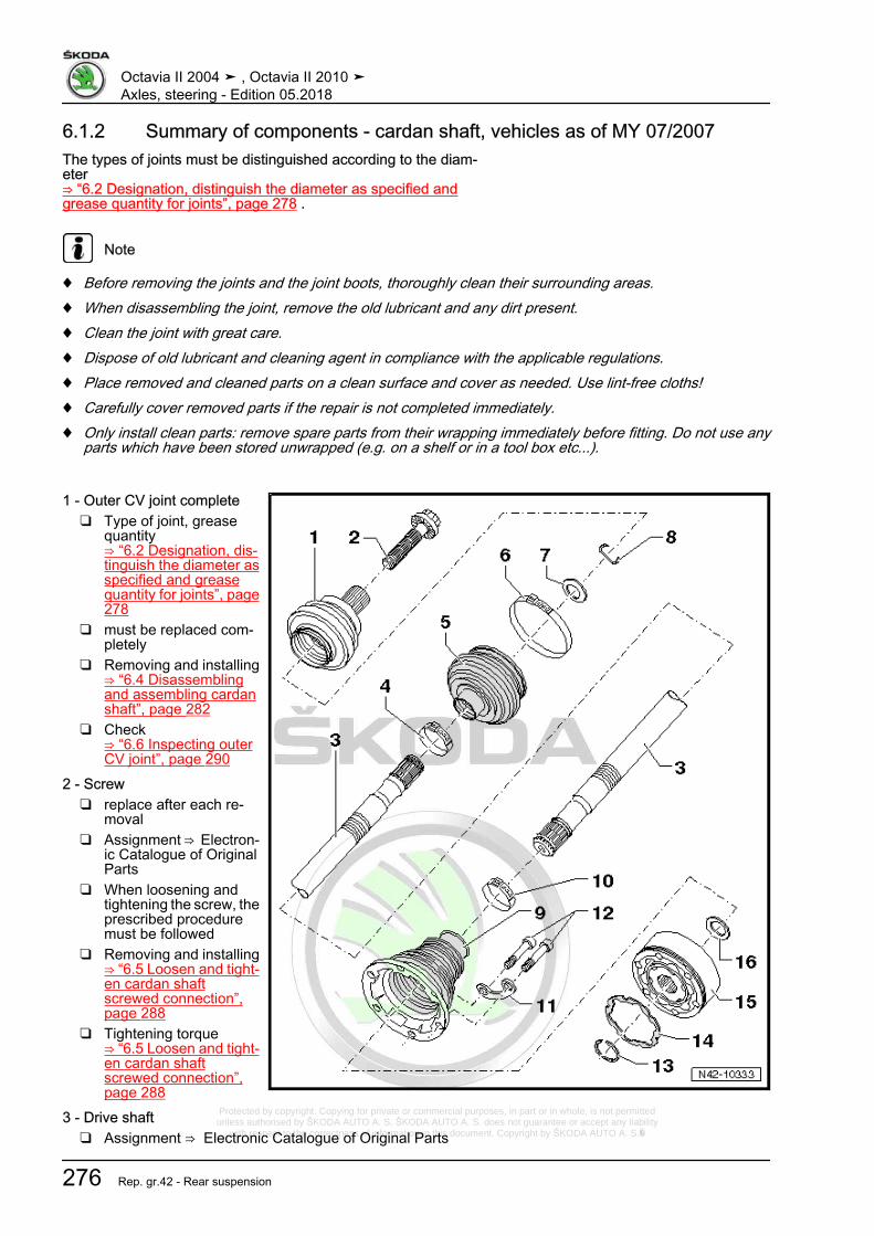
Protected by copyright. Copying for private or commercial purposes, in part or in whole, is not permitted unless authorised by ŠKODA AUTO A. S. ŠKODA AUTO A. S. does not guarantee or accept any liability
with respect to the correctness of information in this document. Copyright by ŠKODA AUTO A. S.�
6.1.2 Summary of components - cardan shaft, vehicles as of MY 07/2007The types of joints must be distinguished according to the diam‐eter⇒ “6.2 Designation, distinguish the diameter as specified andgrease quantity for joints”, page 278 .
Note
♦ Before removing the joints and the joint boots, thoroughly clean their surrounding areas.♦ When disassembling the joint, remove the old lubricant and any dirt present.♦ Clean the joint with great care.♦ Dispose of old lubricant and cleaning agent in compliance with the applicable regulations.♦ Place removed and cleaned parts on a clean surface and cover as needed. Use lint-free cloths!♦ Carefully cover removed parts if the repair is not completed immediately.♦ Only install clean parts: remove spare parts from their wrapping immediately before fitting. Do not use any
parts which have been stored unwrapped (e.g. on a shelf or in a tool box etc...).
1 - Outer CV joint complete❑ Type of joint, grease
quantity⇒ “6.2 Designation, dis‐tinguish the diameter asspecified and greasequantity for joints”, page278
❑ must be replaced com‐pletely
❑ Removing and installing⇒ “6.4 Disassemblingand assembling cardanshaft”, page 282
❑ Check⇒ “6.6 Inspecting outerCV joint”, page 290
2 - Screw❑ replace after each re‐
moval❑ Assignment ⇒ Electron‐
ic Catalogue of OriginalParts
❑ When loosening andtightening the screw, theprescribed proceduremust be followed
❑ Removing and installing⇒ “6.5 Loosen and tight‐en cardan shaftscrewed connection”,page 288
❑ Tightening torque⇒ “6.5 Loosen and tight‐en cardan shaftscrewed connection”,page 288
3 - Drive shaft❑ Assignment ⇒ Electronic Catalogue of Original Parts
Octavia II 2004 ➤ , Octavia II 2010 ➤Axles, steering - Edition 05.2018
276 Rep. gr.42 - Rear suspension
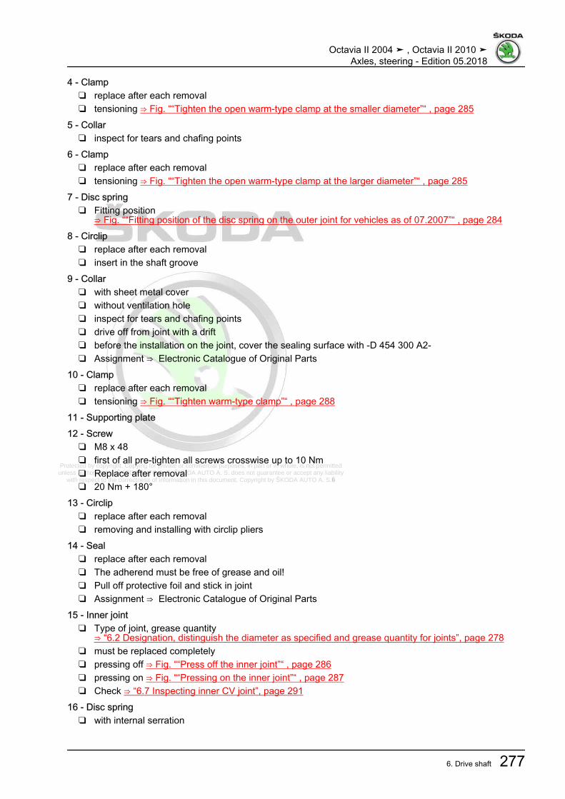
Protected by copyright. Copying for private or commercial purposes, in part or in whole, is not permitted unless authorised by ŠKODA AUTO A. S. ŠKODA AUTO A. S. does not guarantee or accept any liability
with respect to the correctness of information in this document. Copyright by ŠKODA AUTO A. S.�
4 - Clamp❑ replace after each removal❑ tensioning ⇒ Fig. ““Tighten the open warm-type clamp at the smaller diameter”“ , page 285
5 - Collar❑ inspect for tears and chafing points
6 - Clamp❑ replace after each removal❑ tensioning ⇒ Fig. ““Tighten the open warm-type clamp at the larger diameter”“ , page 285
7 - Disc spring❑ Fitting position
⇒ Fig. ““Fitting position of the disc spring on the outer joint for vehicles as of 07.2007”“ , page 2848 - Circlip
❑ replace after each removal❑ insert in the shaft groove
9 - Collar❑ with sheet metal cover❑ without ventilation hole❑ inspect for tears and chafing points❑ drive off from joint with a drift❑ before the installation on the joint, cover the sealing surface with -D 454 300 A2-❑ Assignment ⇒ Electronic Catalogue of Original Parts
10 - Clamp❑ replace after each removal❑ tensioning ⇒ Fig. ““Tighten warm-type clamp”“ , page 288
11 - Supporting plate12 - Screw
❑ M8 x 48❑ first of all pre-tighten all screws crosswise up to 10 Nm❑ Replace after removal❑ 20 Nm + 180°
13 - Circlip❑ replace after each removal❑ removing and installing with circlip pliers
14 - Seal❑ replace after each removal❑ The adherend must be free of grease and oil!❑ Pull off protective foil and stick in joint❑ Assignment ⇒ Electronic Catalogue of Original Parts
15 - Inner joint❑ Type of joint, grease quantity
⇒ “6.2 Designation, distinguish the diameter as specified and grease quantity for joints”, page 278❑ must be replaced completely❑ pressing off ⇒ Fig. ““Press off the inner joint”“ , page 286❑ pressing on ⇒ Fig. ““Pressing on the inner joint”“ , page 287❑ Check ⇒ “6.7 Inspecting inner CV joint”, page 291
16 - Disc spring❑ with internal serration
Octavia II 2004 ➤ , Octavia II 2010 ➤Axles, steering - Edition 05.2018
6. Drive shaft 277

Protected by copyright. Copying for private or commercial purposes, in part or in whole, is not permitted unless authorised by ŠKODA AUTO A. S. ŠKODA AUTO A. S. does not guarantee or accept any liability
with respect to the correctness of information in this document. Copyright by ŠKODA AUTO A. S.�
❑ Fitting position ⇒ Fig. ““Fitting position of the disc spring at inner joint”“ , page 286
6.2 Designation, distinguish the diameter as specified and grease quantity forjoints
Outer joint
Denomination Diameter GreaseUF100 90 mm 110 g, grind the grease evenly in the jointCG-FIX2000 82 mm 45 g, grind the grease evenly in the joint
Use the relevant grease for outer joints, assignment ⇒ ElectronicCatalogue of Original Parts .
Inner joint
Denomination Diameter GreaseVL100 100 mm 110 g, grind the grease evenly in the joint
Use heat-resistant grease for inner joints, assignment ⇒ Elec‐tronic Catalogue of Original Parts .
Octavia II 2004 ➤ , Octavia II 2010 ➤Axles, steering - Edition 05.2018
278 Rep. gr.42 - Rear suspension

Protected by copyright. Copying for private or commercial purposes, in part or in whole, is not permitted unless authorised by ŠKODA AUTO A. S. ŠKODA AUTO A. S. does not guarantee or accept any liability
with respect to the correctness of information in this document. Copyright by ŠKODA AUTO A. S.�
6.3 Removing and installing cardan shaft⇒ “6.3.1 Removing and installing cardan shaft”, page 279⇒ “6.3.2 Push the cardan shaft out of the wheel hub.”,page 281
6.3.1 Removing and installing cardan shaft
Note
During disassembly and assembly work on the vehicle, the driveshafts must not hang down loosely and through overstretchingrest against the stop in the joints.
Removing– Determine dimension “a”
⇒ “3.5 Lift the wheel bearing in the unladen weight position”,page 5 .
– Remove fixing screw of drive shaft at wheel hub⇒ “6.5 Loosen and tighten cardan shaft screwed connection”,page 288 .
Note
♦ Wheel bearings must not be subjected to load after bolt se‐curing cardan shaft to wheel hub has been loosened.
♦ If the wheel bearings are loaded through the vehicle's ownweight, the wheel bearing will be initially damaged. This short‐ens the life of the wheel bearing.
♦ It is not permissible to turn cardan shaft screw more than 90°anti-clockwise if vehicle is standing on its wheels.
♦ Do not attempt to move the vehicle without the cardan shaftsfitted as this would damage the wheel bearing. If a vehiclenevertheless has to be moved, comply with the following:
♦ Install an outer joint instead of the cardan shaft.♦ Tighten outer joint to 120 Nm.
– Remove wheel.– Remove coil spring
⇒ “4.4 Removing and installing spring”, page 242 .Vehicles with vehicle level sender– Remove screw -1- from the holder for rear left vehicle level
sensor - G76- .Continued for all vehicles
Octavia II 2004 ➤ , Octavia II 2010 ➤Axles, steering - Edition 05.2018
279

Protected by copyright. Copying for private or commercial purposes, in part or in whole, is not permitted unless authorised by ŠKODA AUTO A. S. ŠKODA AUTO A. S. does not guarantee or accept any liability
with respect to the correctness of information in this document. Copyright by ŠKODA AUTO A. S.�
– Remove nut -1- and pull screw out of anti-roll bar and couplingrod -2-.
– Unscrew screw for track rod for rear axle -1-and bottom sus‐pension arm -3- from wheel-bearing housing -4-.
– Unscrew screw -arrow-.– Remove cardan shaft from flange of final drive.– Swivel out the wheel-bearing housing and pull the drive shaft
out of the internal serration.
Note
If the drive shaft cannot be removed from the wheel hub, it canbe pressed out using the extractor⇒ “6.3.2 Push the cardan shaft out of the wheel hub.”,page 281 .
– Remove the cardan shaft.InstallingInstallation is performed in the reverse order, pay attention to thefollowing points:
Note
♦ Make sure the boot is neither damaged nor twisted.♦ Use new washers and new screws.
– Position the inner joint of the drive shaft and tighten newscrews to 10 Nm crosswise.
– Tighten the screws with internal serrations crosswise accord‐ing to the specified torque.
Octavia II 2004 ➤ , Octavia II 2010 ➤Axles, steering - Edition 05.2018
280

Protected by copyright. Copying for private or commercial purposes, in part or in whole, is not permitted unless authorised by ŠKODA AUTO A. S. ŠKODA AUTO A. S. does not guarantee or accept any liability
with respect to the correctness of information in this document. Copyright by ŠKODA AUTO A. S.�
– Screw the screw for track rod for rear axle -1- and bottom sus‐pension arm -3- into the wheel-bearing housing -4-.
– Install coil spring⇒ “4.4 Removing and installing spring”, page 242 .
– Tighten fixing screw of drive shaft to wheel hub⇒ “6.5 Loosen and tighten cardan shaft screwed connection”,page 288 .
Note
The bolted connection to the wheel-bearing housing must only beperformed, if the dimension “a” between the wheel hub centre andthe lower edge of the wheel house is respected (in unladen weightposition)!⇒ “3.5 Lift the wheel bearing in the unladen weight position”, page5 .
On vehicles with vehicle level sensor, carry out a basic setting forthe headlights ⇒ Maintenance ; Booklet Octavia II .Tightening torques - summaries of components
Note
Replace bolts / nuts that are tightened at an angle of rotation, aswell as replacement components after removal.
♦ ⇒ “5.1.2 Summary of components: wheel-bearing housing,trailing arm, vehicles with four-wheel drive”, page 249
♦ ⇒ “2.1.2 Summary of components: Assembly carrier, suspen‐sion arm, track rod for rear axle, vehicles with four-wheeldrive”, page 202
♦ ⇒ “3.1.2 Summary of components - anti-roll bar, vehicles withfour-wheel drive”, page 233
♦ ⇒ “6.5 Loosen and tighten cardan shaft screwed connection”,page 288
♦ ⇒ “1.2 Tightening torque of the wheel screws”, page 301
6.3.2 Push the cardan shaft out of the wheelhub.
Special tools and workshop equipment required♦ Extractor - T10520A- or -T10520- with -T10520/5-
Note
If the cardan shaft cannot be pulled out of the wheel hub, it canbe pressed out using the extractor - T10520A- .
Octavia II 2004 ➤ , Octavia II 2010 ➤Axles, steering - Edition 05.2018
281

Protected by copyright. Copying for private or commercial purposes, in part or in whole, is not permitted unless authorised by ŠKODA AUTO A. S. ŠKODA AUTO A. S. does not guarantee or accept any liability
with respect to the correctness of information in this document. Copyright by ŠKODA AUTO A. S.�
Note
Before using extractor - T10520A- , make sure that the thrustpiece -1- is inserted.
– Secure the extractor - T10520A- -1- with 3 wheel bolts -2- tothe wheel hub in order to be able to press out the cardan shaft-3-.
Therefore, the following order must be observed.
– Tighten the knurled nut -1- by hand.– Turn the screw -2- and press out the cardan shaft from the
wheel hub.
Note
At the end of the procedure or for pressing out cardan shaft furtherthe spindle must be moved to its original position in order to de‐ploy the hydraulic force!
– Remove cardan shaft from wheel hub.
6.4 Disassembling and assembling cardanshaft
Special tools and workshop equipment required♦ Pressure plate - MP3-406 (VW 401)-♦ Pressure plate - MP3-407 (VW 402)-♦ Thrust piece - MP3-411 (VW 454)-♦ Pressure spindle - MP3-448 (VW 408A)-♦ Thrust washer - MP3-455 (VW 447H)-♦ Thrust piece - MP6-405 (VW 411)-♦ Assembly tool - T10065-
Octavia II 2004 ➤ , Octavia II 2010 ➤Axles, steering - Edition 05.2018
282

Protected by copyright. Copying for private or commercial purposes, in part or in whole, is not permitted unless authorised by ŠKODA AUTO A. S. ŠKODA AUTO A. S. does not guarantee or accept any liability
with respect to the correctness of information in this document. Copyright by ŠKODA AUTO A. S.�
♦ Circlip pliers , e.g. -VW 161A-♦ Tensioning pliers , e.g. -V.A.G 1682 A-Driving off outer constant velocity joint– Clamp the cardan shaft in a vice with protective jaws.– Open both warm-type clamps and remove the joint boot from
the outer joint.– Remove the CV joint from the drive shaft using a drift (copper
or brass) -A-.The drift must be positioned exactly at the tripod spider of the CVjoin.Drive on the joint
– Replace circlip -1-.– Push the joint boot and the open warm-type clamp on the drive
shaft.– Pay attention to the fitting position of the disc spring or the
thrust ring on the outer joint.
Fitting position of the disc spring and thrust ring on the outer jointfor vehicles up to 06.20071 - Disc spring2 - Thrust ring
Octavia II 2004 ➤ , Octavia II 2010 ➤Axles, steering - Edition 05.2018
283
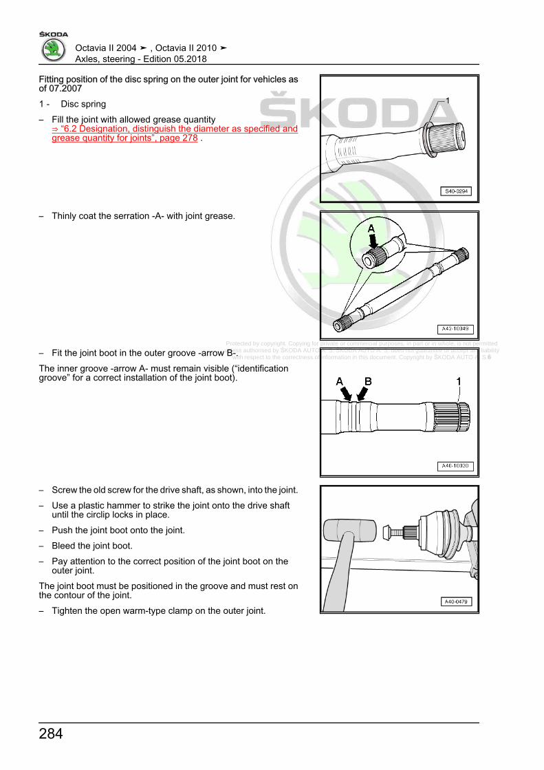
Protected by copyright. Copying for private or commercial purposes, in part or in whole, is not permitted unless authorised by ŠKODA AUTO A. S. ŠKODA AUTO A. S. does not guarantee or accept any liability
with respect to the correctness of information in this document. Copyright by ŠKODA AUTO A. S.�
Fitting position of the disc spring on the outer joint for vehicles asof 07.20071 - Disc spring– Fill the joint with allowed grease quantity
⇒ “6.2 Designation, distinguish the diameter as specified andgrease quantity for joints”, page 278 .
– Thinly coat the serration -A- with joint grease.
– Fit the joint boot in the outer groove -arrow B-.The inner groove -arrow A- must remain visible (“identificationgroove” for a correct installation of the joint boot).
– Screw the old screw for the drive shaft, as shown, into the joint.– Use a plastic hammer to strike the joint onto the drive shaft
until the circlip locks in place.– Push the joint boot onto the joint.– Bleed the joint boot.– Pay attention to the correct position of the joint boot on the
outer joint.The joint boot must be positioned in the groove and must rest onthe contour of the joint.– Tighten the open warm-type clamp on the outer joint.
Octavia II 2004 ➤ , Octavia II 2010 ➤Axles, steering - Edition 05.2018
284

Protected by copyright. Copying for private or commercial purposes, in part or in whole, is not permitted unless authorised by ŠKODA AUTO A. S. ŠKODA AUTO A. S. does not guarantee or accept any liability
with respect to the correctness of information in this document. Copyright by ŠKODA AUTO A. S.�
Tighten the open warm-type clamp at the larger diameter
Tighten the open warm-type clamp at the smaller diameter– Position the tensioning pliers as shown in the figure. Make
sure the cutting edges of the pliers are positioned in the cor‐ners -arrows B- of the open warm-type clamp.
– Tighten the open warm-type clamp by turning the spindle witha torque wrench (do not tilt the pliers during this process).
Note
♦ In view of the hard material (as opposed to rubber) of the jointboot, which requires the use of stainless steel open warm-typeclamps, these can only be tightened with tensioning pliers ,e.g. -V.A.G 1682 A- .
♦ Tightening torque: 25 Nm.♦ Use torque wrench -C-.♦ Make sure that the thread of the spindle -A- of the pliers moves
freely. Lubricate with grease if necessary.♦ If it is not smooth, e.g. if the thread is dirty, the necessary
clamping force of the open warm-type clamp is not reached atthe given torque.
Remove inner joint
– Drive off cover and joint boot with a drift.– Open warm-type clamp.– Push the cover with the warm-type clamp in direction of outer
joint.
Octavia II 2004 ➤ , Octavia II 2010 ➤Axles, steering - Edition 05.2018
285

Protected by copyright. Copying for private or commercial purposes, in part or in whole, is not permitted unless authorised by ŠKODA AUTO A. S. ŠKODA AUTO A. S. does not guarantee or accept any liability
with respect to the correctness of information in this document. Copyright by ŠKODA AUTO A. S.�
– Remove circlip with a pair of circlip pliers .– Press the inner joint off the drive shaft.
Press off the inner jointInstall inner joint– Push the open warm-type clamp on the drive shaft.– Push the sheet metal cover with the joint boot onto the drive
shaft.– Pay attention to the fitting position of the disc spring at the inner
joint.
Fitting position of the disc spring at inner joint1 - Disc spring
– Thinly coat the serration -A- with joint grease.– Press the joint up to the stop.
Octavia II 2004 ➤ , Octavia II 2010 ➤Axles, steering - Edition 05.2018
286

Protected by copyright. Copying for private or commercial purposes, in part or in whole, is not permitted unless authorised by ŠKODA AUTO A. S. ŠKODA AUTO A. S. does not guarantee or accept any liability
with respect to the correctness of information in this document. Copyright by ŠKODA AUTO A. S.�
Pressing on the inner joint
Note
Chamfer on inner diameter of the ball hub (serration) must pointtowards the bearing collar of the drive shaft.
– Install circlip.– Fill the joint with allowed grease quantity
⇒ “6.2 Designation, distinguish the diameter as specified andgrease quantity for joints”, page 278 .
– Clean and degrease the end faces of the joint.– Clean and degrease the end face of the sheet metal cover for
the joint boot which rests against the joint.
– Apply sealant -D 454 300 A2- on the shaded surfaces of thecover.
♦ Sealant bead: apply continuously, Ø 2...3 mm, in the area ofthe holes from inside -arrow-.
– Push the sheet metal cover with the joint boot onto the joint.
– Align the cover with the joint boot to the screw holes withscrews -arrows-.
Note
The alignment must be performed very carefully as this is no lon‐ger possible after striking it.
– Use a plastic hammer to strike the sheet metal cover with thejoint boot on the joint.
– Wipe off any excess sealant, if necessary.– Remove the protective foil from the gasket and stick the gasket
into the joint from the gearbox side.
– Insert the joint boot into the outer groove of the shaft-arrow B-.
– Install warm-type clamp.
Octavia II 2004 ➤ , Octavia II 2010 ➤Axles, steering - Edition 05.2018
287

Protected by copyright. Copying for private or commercial purposes, in part or in whole, is not permitted unless authorised by ŠKODA AUTO A. S. ŠKODA AUTO A. S. does not guarantee or accept any liability
with respect to the correctness of information in this document. Copyright by ŠKODA AUTO A. S.�
Tighten warm-type clamp– Position the tensioning pliers as shown in the figure. Make
sure the cutting edges of the pliers are positioned in the cor‐ners -arrows B- of the open warm-type clamp.
– Tighten the open warm-type clamp by turning the spindle witha torque wrench (do not tilt the pliers during this process).
Note
♦ In view of the hard material (as opposed to rubber) of the jointboot, which requires the use of stainless steel open warm-typeclamps, these can only be tightened with tensioning pliers ,e.g. -V.A.G 1682 A- .
♦ Tightening torque: 25 Nm.♦ Use torque wrench -C-.♦ Make sure that the thread of the spindle -A- of the pliers moves
freely. Lubricate with grease if necessary.♦ If it is not smooth, e.g. if the thread is dirty, the necessary
clamping force of the open warm-type clamp is not reached atthe given torque.
6.5 Loosen and tighten cardan shaftscrewed connection
Special tools and workshop equipment required♦ Socket insert, 24 mm - T10361-
Note
♦ If the fixing screw of the drive shaft is loosened more than 90°,the wheel bearings must not be loaded through the weight ofthe vehicle, i.e the vehicle must not stand on its wheels.
♦ If the wheel bearings are loaded through the weight of the ve‐hicle when the fixing screw for the drive shaft is removed, theinner wheel bearing will be damaged. This shortens the life ofthe wheel bearing.
♦ If the vehicle is standing on its wheels or moves, pay attentionto the following: Install the outer joint instead of the drive shaft.Tighten the fixing screw (use the one which was previouslyremoved) of the outer joint to the tightening torque of 120 Nm.
Distinguishing feature of twelve-sided boltsThe twelve-sided bolts differ in the surface area -arrow A- and-arrow B-.♦ I - Twelve-sided bolt with serration - -arrow A-♦ lI - Twelve-sided bolt without serration - -arrow B-Removing– Remove wheel trim cap, for light-alloy wheels remove the cap
on the removed wheel (depending on version) ⇒ Wheels,Tyres; Rep. gr. 44 .
– Re-install light-alloy wheel (depending on the version) withoutcap.
Octavia II 2004 ➤ , Octavia II 2010 ➤Axles, steering - Edition 05.2018
288

Protected by copyright. Copying for private or commercial purposes, in part or in whole, is not permitted unless authorised by ŠKODA AUTO A. S. ŠKODA AUTO A. S. does not guarantee or accept any liability
with respect to the correctness of information in this document. Copyright by ŠKODA AUTO A. S.�
– Slacken the screw -arrow- by max. 90° on the vehicle while itis standing on its wheels, otherwise the wheel bearing may bedamaged.
– Raise the vehicle until the wheels are fully off the ground.– Depress brake pedal (assistance of second mechanic re‐
quired).– Unscrew screw -arrow- and release brake pedal.Installing– Always install a new screw.
Note
♦ Assign screw via the ⇒ Electronic Catalogue of Original Parts .♦ The wheels should not touch the ground when tightening the
drive shaft screwed connection, otherwise the wheel bearingwill be damaged.
Twelve-sided screw - WHT 002 795- with serration– Depress brake pedal (assistance of second mechanic re‐
quired).– Tighten the twelve-sided bolt to 70 Nm.– Place vehicle onto its wheels.– Depress brake pedal (assistance of second mechanic re‐
quired).– Tighten the 12-point screw a further 90°.– Install wheel trim cap, for light-alloy wheels (depending on
version) install cap.Twelve head screw - WHT 005 437- without teeth (black)– Depress brake pedal (assistance of second mechanic re‐
quired).– Tighten the twelve-sided bolt to 200 Nm.– Place vehicle onto its wheels.– Depress brake pedal (assistance of second mechanic re‐
quired).– Tighten the 12-point screw a further 180°.– Install wheel trim cap, for light-alloy wheels (depending on
version) install cap.12-point screw - WHT 005 437 A- without teeth (silver)– Depress brake pedal (assistance of second mechanic re‐
quired).– Tighten the twelve-sided bolt to 200 Nm.– Place vehicle onto its wheels.– Depress brake pedal (assistance of second mechanic re‐
quired).– Tighten the 12-point screw a further 90°.– Install wheel trim cap, for light-alloy wheels (depending on
version) install cap.
Octavia II 2004 ➤ , Octavia II 2010 ➤Axles, steering - Edition 05.2018
289

Protected by copyright. Copying for private or commercial purposes, in part or in whole, is not permitted unless authorised by ŠKODA AUTO A. S. ŠKODA AUTO A. S. does not guarantee or accept any liability
with respect to the correctness of information in this document. Copyright by ŠKODA AUTO A. S.�
Tightening torques - summaries of components
Note
Replace bolts / nuts that are tightened at an angle of rotation, aswell as replacement components after removal.
♦ ⇒ “1.2 Tightening torque of the wheel screws”, page 301
6.6 Inspecting outer CV jointDisassemble the joint to replace badly soiled grease or if the con‐tact surfaces of the balls must be inspected for wear and damage.Removing– Before dismantling, mark position of ball hub in relation to ball
cage and joint body with an electric scriber or oil stone.– Rotate the ball hub and ball cage.– Remove the balls one after the other.
– Turn cage until the two rectangular windows -arrow- lie on jointbody.
– Remove cage with hub.
Octavia II 2004 ➤ , Octavia II 2010 ➤Axles, steering - Edition 05.2018
290

Protected by copyright. Copying for private or commercial purposes, in part or in whole, is not permitted unless authorised by ŠKODA AUTO A. S. ŠKODA AUTO A. S. does not guarantee or accept any liability
with respect to the correctness of information in this document. Copyright by ŠKODA AUTO A. S.�
– Turn the hub segment in the rectangular window of the cage.– Tilt hub out of the cage.The 6 balls of each joint belong to a tolerance group. Inspect theaxle studs, hub, cage and balls for small depressions (pitting =point erosion) and seizing marks. Excessive circumferential back‐lash in the joint is noticeable during a load change jolt. If this isthe case, replace the joint. Smoothing and bearing marks do notjustify a joint replacement.Installing– Pack half of total grease quantity (40 g) into joint body.– Insert the cage and hub in the joint body.– Press in opposite balls one after the other, during this process
observe the prior position of the ball hub relatively to the ballcage and to the joint body.
– Insert new circlip in the groove of the shaft.– Spread any residual grease in the joint boot.
6.7 Inspecting inner CV jointRemovingThe joint must be disassembled for the following work:♦ replacing the grease in presence of major soiling♦ checking the treads for wear♦ checking the balls for wear– Rotate the ball hub and ball cage.– Press out joint part in -direction of arrow-.– Press out the balls from the cage.
Note
The ball hub and joint piece are paired. These are not inter‐changeable.
– Tilt the ball hub out of the ball cage over the ball bearing track-arrows-.
– Inspect the joint part, ball hub, ball cage and balls for smallbroken out depressions (pitting = point corrosion) and seizingmarks.
Excessive circumferential backlash in the joint is noticeable dur‐ing a load change jolt. If this is the case, replace the joint.Smoothing and bearing marks do not justify a joint replacement.Installing
Octavia II 2004 ➤ , Octavia II 2010 ➤Axles, steering - Edition 05.2018
291

Protected by copyright. Copying for private or commercial purposes, in part or in whole, is not permitted unless authorised by ŠKODA AUTO A. S. ŠKODA AUTO A. S. does not guarantee or accept any liability
with respect to the correctness of information in this document. Copyright by ŠKODA AUTO A. S.�
– Insert the ball hub in the ball cage over the two chamfers. Thefitting location is random. Press the balls into the cage.
The ball hub has 2 different distances between the ball bearingtracks, a larger and a smaller one.– Insert the hub with cage upright into the joint part.
When inserting make sure the greatest distance -a- on the jointpart is close to the short distance -b- on the hub after it has beenswivelled in.Chamfer on inner diameter of the ball hub (serration) must pointtowards the large diameter of the joint body.– Also pay attention to the chamfer on the inner diameter of the
ball hub. This must be visible after swivelling in.
– Swivel in the ball hub, to do so swivel the hub out of the cage-arrows- until the balls are at bearing track distance.
– Lock the hub with the balls into position by exerting consider‐able pressure on the cage -arrow-.
Check proper operation of joint.The CV joint is correctly assembled if the ball hub can be rolledby hand up and down the entire linear compensation.
Octavia II 2004 ➤ , Octavia II 2010 ➤Axles, steering - Edition 05.2018
292

Protected by copyright. Copying for private or commercial purposes, in part or in whole, is not permitted unless authorised by ŠKODA AUTO A. S. ŠKODA AUTO A. S. does not guarantee or accept any liability
with respect to the correctness of information in this document. Copyright by ŠKODA AUTO A. S.�
43 – Self-levelling suspension1 Vehicle level sensor⇒ “1.1 Summary of components - vehicle level sender front”, page293⇒ “1.2 Summary of components - vehicle level sender rear”, page294⇒ “1.3 Removing and installing front vehicle level encoder G78 ”,page 295⇒ “1.4 Removing and installing vehicle level rear encoder G76 ”,page 296
1.1 Summary of components - vehicle level sender front
Note
The front left vehicle level sensor - G78- is supplied complete with coupling rod and upper and lower retainingbracket as a spare part.
1 - Suspension link2 - Assembly carrier3 - Plug connection4 - Front left side vehicle levelsensor - G78-
❑ complete with compo‐nent parts
❑ The lever must point to‐wards the outer side ofthe vehicle
❑ Removing and installing⇒ “1.3 Removing and in‐stalling front vehicle lev‐el encoder G78 ”,page 295
❑ Carrying out a basic set‐ting of the headlights⇒ Maintenance ; Book‐let Octavia II
5 - Screw❑ 9 Nm
6 - Nut❑ Replace after removal❑ 9 Nm
Octavia II 2004 ➤ , Octavia II 2010 ➤Axles, steering - Edition 05.2018
1. Vehicle level sensor 293

Protected by copyright. Copying for private or commercial purposes, in part or in whole, is not permitted unless authorised by ŠKODA AUTO A. S. ŠKODA AUTO A. S. does not guarantee or accept any liability
with respect to the correctness of information in this document. Copyright by ŠKODA AUTO A. S.�
1.2 Summary of components - vehicle level sender rear
Note
♦ The rear left vehicle level sensor - G76- is supplied complete with coupling rod and upper and lower retainingbracket as a spare part.
♦ Replace with installed assembly carrier⇒ “1.4 Removing and installing vehicle level rear encoder G76 ”, page 296 .
1 - Assembly carrier2 - Bottom suspension arm3 - Screw
❑ 5 Nm4 - Rear left vehicle level sen‐sor - G76-
❑ complete with compo‐nent parts
❑ Lever -arrow- mustpoints towards the outerside of the vehicle
❑ replace in vehicle⇒ “1.4 Removing and in‐stalling vehicle levelrear encoder G76 ”,page 296
❑ after replacing, carry outthe basic setting of theheadlight range controlunit - J431- ⇒ Vehicle di‐agnostic tester in thefunction “Targeted faultfinding”.
Octavia II 2004 ➤ , Octavia II 2010 ➤Axles, steering - Edition 05.2018
294 Rep. gr.43 - Self-levelling suspension
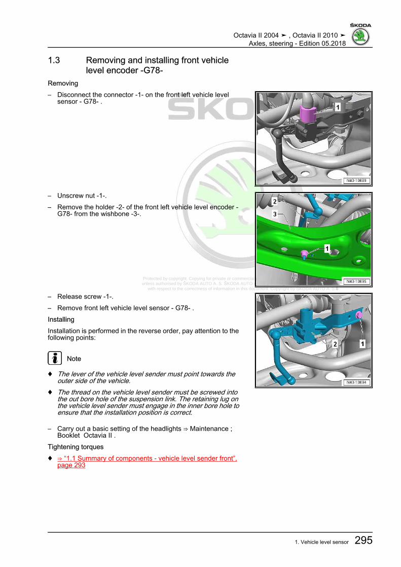
Protected by copyright. Copying for private or commercial purposes, in part or in whole, is not permitted unless authorised by ŠKODA AUTO A. S. ŠKODA AUTO A. S. does not guarantee or accept any liability
with respect to the correctness of information in this document. Copyright by ŠKODA AUTO A. S.�
1.3 Removing and installing front vehiclelevel encoder -G78-
Removing– Disconnect the connector -1- on the front left vehicle level
sensor - G78- .
– Unscrew nut -1-.– Remove the holder -2- of the front left vehicle level encoder -
G78- from the wishbone -3-.
– Release screw -1-.– Remove front left vehicle level sensor - G78- .InstallingInstallation is performed in the reverse order, pay attention to thefollowing points:
Note
♦ The lever of the vehicle level sender must point towards theouter side of the vehicle.
♦ The thread on the vehicle level sender must be screwed intothe out bore hole of the suspension link. The retaining lug onthe vehicle level sender must engage in the inner bore hole toensure that the installation position is correct.
– Carry out a basic setting of the headlights ⇒ Maintenance ;Booklet Octavia II .
Tightening torques♦ ⇒ “1.1 Summary of components - vehicle level sender front”,
page 293
Octavia II 2004 ➤ , Octavia II 2010 ➤Axles, steering - Edition 05.2018
1. Vehicle level sensor 295

Protected by copyright. Copying for private or commercial purposes, in part or in whole, is not permitted unless authorised by ŠKODA AUTO A. S. ŠKODA AUTO A. S. does not guarantee or accept any liability
with respect to the correctness of information in this document. Copyright by ŠKODA AUTO A. S.�
1.4 Removing and installing vehicle levelrear encoder -G76-
Removing– Disconnect plug connection -1-.– Unscrew screws -2- from bottom suspension arm.– Unscrew support screws for sender housing -arrows-.– Remove sensor.InstallingInstallation is carried out in the reverse order. Pay attention to thefollowing:The lever of the sensor must point towards the outer side of thevehicle.– After replacing the rear left vehicle level sensor - G76- carry
out the basic setting of the headlight range control unit - J431-⇒ Vehicle diagnostic tester in the function “Targeted faultfinding”.
Tightening torques - summaries of components
Note
Replace bolts / nuts that are tightened at an angle of rotation, aswell as replacement components after removal.
♦ ⇒ “1.2 Summary of components - vehicle level sender rear”,page 294
Octavia II 2004 ➤ , Octavia II 2010 ➤Axles, steering - Edition 05.2018
296 Rep. gr.43 - Self-levelling suspension
Protected by copyright. Copying for private or commercial purposes, in part or in whole, is not permitted unless authorised by ŠKODA AUTO A. S. ŠKODA AUTO A. S. does not guarantee or accept any liability
with respect to the correctness of information in this document. Copyright by ŠKODA AUTO A. S.�
44 – Wheels, tyres, vehicle geometry1 Wheels, Tyres⇒ “1.1 Wheel change”, page 297⇒ “1.2 Tightening torque of the wheel screws”, page 301⇒ “1.3 Disposing of tyre sealant”, page 301⇒ “1.4 Vehicles with breakdown set”, page 301
1.1 Wheel change⇒ “1.1.1 Rotating wheels”, page 297⇒ “1.1.2 Wheel change, protecting wheel centring seat againstcorrosion”, page 297⇒ “1.1.3 Wheel replacement, assembly conditions”, page 298⇒ “1.1.4 Wheel change, installation instructions for wheelchange”, page 299⇒ “1.1.5 Wheel change, wheel installation”, page 300⇒ “1.1.6 Wheel change, position of anti-theft wheel bolts for steelwheels”, page 300
1.1.1 Rotating wheelsVehicles with front-wheel drive exhibit more tread wear on thefront wheels due to the greater forces they have to transmit.In order for all 4 wheels on the vehicle to have the same servicelife, we recommend rotating the front and rear wheels and tyres.Ensure that unidirectional tyres are not reversed.The longer the tyre runs at one position, the more it wears at cer‐tain points. Therefore it is recommended to rotate the wheels atshort intervals, for example every 5,000 km.Diagonal rotation is possible only with non-directional tyres. Thismethod of wheel rotation is especially advantageous in the caseof saw-tooth wear.If saw-tooth wear has already progressed and the tread is wornto more than 50%, only slight improvements would be achievedand rotation is not recommended. The elasticity of the treadblocks declines and the saw-tooth wear does not progress.
1.1.2 Wheel change, protecting wheel cen‐tring seat against corrosion
Valid for light alloy and steel wheelsWhen a wheel is installed, the wheel centring seat should bewaxed with wax spray - D 322 000 A2- to prevent corrosion be‐tween the wheel centring seat and the wheel rim ⇒ ElectronicCatalogue of Original Parts .– Remove wheel.– Clean wheel centring seat of hub and centring ring of wheel
rim.
Octavia II 2004 ➤ , Octavia II 2010 ➤Axles, steering - Edition 05.2018
1. Wheels, Tyres 297

Protected by copyright. Copying for private or commercial purposes, in part or in whole, is not permitted unless authorised by ŠKODA AUTO A. S. ŠKODA AUTO A. S. does not guarantee or accept any liability
with respect to the correctness of information in this document. Copyright by ŠKODA AUTO A. S.�
– Apply wax to centring ring -arrow-.
Note
♦ Ensure that only centring ring -arrow- but not contact surfaceof wheel rim has been waxed. Otherwise, the brakes will besoiled, which would reduce the braking efficiency.
♦ Wheel bolts, contact surfaces of wheel hub and wheel rim andwheel hub threads must not be waxed. Never treat wheel se‐curing bolts with lubricant or corrosion protection materials!
– Installing and tightening the wheel⇒ “1.2 Tightening torque of the wheel screws”, page 301 .
1.1.3 Wheel replacement, assembly condi‐tions
Warming cold tyres to minimum installation temperature
Note
♦ This instruction also applies to ultra-high performance tyres(height/width ratio smaller than/same as 45 % and speed sym‐bol greater than/same as V).
♦ The minimum installation temperature of a tyre should be be‐tween 15 °C and 30 °C in the core of the tyre.
• To install tyres without damage, it is especially important towarm the upper part of the sidewall and the inside of the upperbead to at least 15 ℃.
• This internal temperature is referred to as the core tempera‐ture.
• Rubber is a poor conductor of heat. Therefore, a cold tyre mustbe left in an area with the correct temperature for a sufficientlylong period so the inner rubber layers can warm up to at least15 °C.
• The surface temperature of the tyre in the warm-up phase isnot an indication of the temperature on the inside of the tyre.
• To prevent cold tyres from rapidly absorbing heat from theambient air, do not stack them up. Position them individuallyso that warm air can “circulate around” them effectively.
• Tyres must never be placed in front of a radiator or hot airblower for warming, since this can very quickly lead to criticalsurface temperatures.
• Tyres can only be heated up without damaging the tyre withwarm water or warm air (maximum 50 °C)!
• When cold tyres (below 0 °C) are transferred to a warm envi‐ronment (above 0 °C), a layer of condensation immediatelyforms on the surface of the tyre. This layer of condensationindicates that the tyre is intensively absorbing heat from itsenvironment through the process of water vapour in the aircondensing out on the tyre surface.
• Condensation will form if the surface of the tyre thaws. Thisshould be dried with a cloth so that the further warming proc‐ess is not delayed due to a temperature drop caused byevaporation.
Octavia II 2004 ➤ , Octavia II 2010 ➤Axles, steering - Edition 05.2018
298 Rep. gr.44 - Wheels, tyres, vehicle geometry

Protected by copyright. Copying for private or commercial purposes, in part or in whole, is not permitted unless authorised by ŠKODA AUTO A. S. ŠKODA AUTO A. S. does not guarantee or accept any liability
with respect to the correctness of information in this document. Copyright by ŠKODA AUTO A. S.�
Warm-up times♦ Tyres with a temperature of above 0 °C must be stored on at
least 19 °C for at least 2 hours.♦ Tyres with a temperature below 0 °C must be stored on at least
19 °C for at least 2.5 hours.Warm-up recommendations♦ If possible, tyres should be stored in the workshop 1 day before
they are fitted (order preparation)♦ Store on an insulated base, pallet or the like, high up.♦ Position the tyres individually to allow the warm air to “circulate
around” them effectively♦ Wipe off condensation♦ Never heat with a radiator or hot air blower!
1.1.4 Wheel change, installation instructionsfor wheel change
Note
♦ Perform the checks and follow the instructions listed below.This is important to ensure that the wheel bolts and the wheelsare properly secured.
♦ On vehicles with a tyre control indication, after one or morewheels are removed or installed, the tyre check display mustbe re-calibrated ⇒ Owner's Manual .
– Check to ensure that contact surfaces -arrows- on brake discare free of corrosion and dirt.
– Check to ensure that contact surface -arrow- on centring seatof brake disc are free of corrosion and dirt.
Octavia II 2004 ➤ , Octavia II 2010 ➤Axles, steering - Edition 05.2018
1. Wheels, Tyres 299

Protected by copyright. Copying for private or commercial purposes, in part or in whole, is not permitted unless authorised by ŠKODA AUTO A. S. ŠKODA AUTO A. S. does not guarantee or accept any liability
with respect to the correctness of information in this document. Copyright by ŠKODA AUTO A. S.�
– Check to ensure that contact surface -arrow- on inner side ofwheel (rim) and also centring seat of rim are free of corrosionand dirt.
– The concave seats * in the holes for the wheel bolts and thethreads of the wheel bolts must also be free of corrosion anddirt, oil or grease.
* The concave seat is the curved surface of a section of a spherecut by a plane.
– Check whether the wheel bolts can be easily screwed in byhand. The thread of the wheel bolts must not come into contactwith the bore in the brake disc -arrow-.
If the thread of the wheel bolt touches the hole -arrow-, the brakedisc must be turned relative to the wheel hub accordingly.If necessary, remove dirt and corrosion:♦ Oil or grease from contact surfaces♦ Oil or grease from the threads in the wheel hub♦ Oil or grease from the threads of the wheel bolts
Note
Damaged, badly corroded or difficult to remove wheel bolts mustbe renewed.
1.1.5 Wheel change, wheel installation– Keep the wheel centring seat
⇒ “1.1.2 Wheel change, protecting wheel centring seat againstcorrosion”, page 297 .
1 - When fitting the wheel, screw in all wheel bolts uniformly byhand.
2 - Tighten the wheel bolts in diagonal sequence to approx. 30Nm.
3 - Drain the vehicle on the floor. Tighten all wheel bolts cross‐wise to specified tightening torque using a torque wrench!⇒ “1.2 Tightening torque of the wheel screws”, page 301 .
Note
Do not use an impact screwdriver for screwing in the wheel bolts!
1.1.6 Wheel change, position of anti-theftwheel bolts for steel wheels
Note
Adherence to position of anti-theft wheel bolts to tyre valve onsteel wheels is vital.
Octavia II 2004 ➤ , Octavia II 2010 ➤Axles, steering - Edition 05.2018
300 Rep. gr.44 - Wheels, tyres, vehicle geometry

Protected by copyright. Copying for private or commercial purposes, in part or in whole, is not permitted unless authorised by ŠKODA AUTO A. S. ŠKODA AUTO A. S. does not guarantee or accept any liability
with respect to the correctness of information in this document. Copyright by ŠKODA AUTO A. S.�
The anti-theft wheel bolt may only be installed on the right or left-arrows- of valve -1- on steel wheels.Secure installation of hub cap on steel wheel is only possible ifanti-theft wheel bolts are installed in this position.
1.2 Tightening torque of the wheel screwsWheel bolt to wheel hub for all vehicles:Tightening torque: 120 Nm– Before assembling the wheel, protect the wheel centring seat
from corrosion⇒ “1.1.2 Wheel change, protecting wheel centring seat againstcorrosion”, page 297 .
♦ Positioning of anti-theft wheel bolts on steel wheels⇒ “1.1.6 Wheel change, position of anti-theft wheel bolts forsteel wheels”, page 300 .
♦ Fit the anti-theft wheel bolts with master set for wheel bolts .
1.3 Disposing of tyre sealant♦ Tyre sealant or residues should not be mixed with other
wastes / fluids.♦ Excess tyre sealant must be collected and stored in a plastic
container. The plastic container can be disposed of throughthe disposal system along with the breakdown set (when theexpiry date is exceeded).
♦ The items can be returned or disposed of through the existingworkshop disposal systems.
♦ Make contact with your service provider or the waste officer atthe sales centre/importer.
1.4 Vehicles with breakdown setDepending on the scope of equipment, some vehicles are fittedwith a breakdown set.The breakdown set can be found in the spare wheel well.The breakdown set contains a bottle with tyre sealant -2- and acompressor -1-.The tyre sealant in the bottle is perishable.The bottle -1- therefore has an expiry date -arrow-.Renew tyre sealant when the expiry date is reached (the tyresealant must not be older than 4 years).If the bottle was opened, e.g. when having a flat tyre, it must alsobe replaced.Observe regulations for disposal⇒ “1.3 Disposing of tyre sealant”, page 301 .
Octavia II 2004 ➤ , Octavia II 2010 ➤Axles, steering - Edition 05.2018
1. Wheels, Tyres 301

Protected by copyright. Copying for private or commercial purposes, in part or in whole, is not permitted unless authorised by ŠKODA AUTO A. S. ŠKODA AUTO A. S. does not guarantee or accept any liability
with respect to the correctness of information in this document. Copyright by ŠKODA AUTO A. S.�
2 Chassis - Specified values of steeringgeometry
⇒ “2.1 Front axle - Specified values of steering geometry”,page 302⇒ “2.2 Rear axle - Specified values of steering geometry”,page 304⇒ “2.3 Vehicle data sticker and PR numbers”, page 304
2.1 Front axle - Specified values of steeringgeometry
The stationary heights specified in the table apply for the dimen‐sion -a-.Before the axle alignment and the adjustment of the steering ge‐ometry, lock the steering wheel in the middle position of the heightadjustment of steering wheel.♦ Technical data apply for the unladen weight of the vehicle
ready for driving - full fuel tank and washer fluid/headlightcleaning system reservoir, spare wheel and jack (if the vehiclewas fitted at the factory with them), tool kit and without driver).The spare wheel, tool kit and jack must be located in the po‐sition prescribed by the vehicle manufacturer.
Note
If the corresponding unladen weight cannot be achieved (e.g. avehicle with a breakdown set or a vehicle with a fuel tank whichis not completely full), the vehicle load must be set as follows:
– Load the vehicle with a corresponding weight.– Determine the fuel volume in the fuel tank on the fuel gauge
display.– Place a weight above the fuel tank according to the following
table:
Fuel gauge Weight (kg)Reserve 371/4 331/2 223/4 11Fuel tank full 0
Note
♦ Use as weight e.g. plastic tanks filled with water or canisters.1 litre of water = 1 kg.
♦ When fitting the weight onto the rear seat pay special attentionso that the seat upholsteries are not dirty or damaged.
Octavia II 2004 ➤ , Octavia II 2010 ➤Axles, steering - Edition 05.2018
302 Rep. gr.44 - Wheels, tyres, vehicle geometry
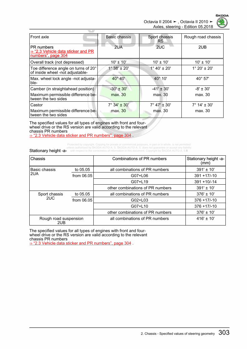
Protected by copyright. Copying for private or commercial purposes, in part or in whole, is not permitted unless authorised by ŠKODA AUTO A. S. ŠKODA AUTO A. S. does not guarantee or accept any liability
with respect to the correctness of information in this document. Copyright by ŠKODA AUTO A. S.�
Front axle Basic chassis Sport chassisRS
Rough road chassis
PR numbers⇒ “2.3 Vehicle data sticker and PRnumbers”, page 304
2UA 2UC 2UB
Overall track (not depressed) 10' ± 10' 10' ± 10' 10' ± 10'Toe difference angle on turns of 20°of inside wheel -not adjustable-
1° 38' ± 20' 1° 40' ± 20' 1° 20' ± 20'
Max. wheel lock angle -not adjusta‐ble-
40° 40' 40° 10' 40° 57'
Camber (in straightahead position) -30' ± 30' -41' ± 30' -8' ± 30'Maximum permissible difference be‐tween the two sides
max. 30 max. 30 max. 30
Castor 7° 34' ± 30' 7° 47' ± 30' 7° 14' ± 30'Maximum permissible difference be‐tween the two sides
max. 30 max. 30 max. 30
The specified values for all types of engines with front and four-wheel drive or the RS version are valid according to the relevantchassis PR numbers⇒ “2.3 Vehicle data sticker and PR numbers”, page 304 .
Stationary height -a-
Chassis Combinations of PR numbers Stationary height -a-(mm)
Basic chassis2UA
to 05.05 all combinations of PR numbers 391' ± 10'from 06.05 G07+L06 391 +17/-10
G07+L19 391 +10/-14other combinations of PR numbers 391' ± 10'
Sport chassis2UC
to 05.05 all combinations of PR numbers 376' ± 10'from 06.05 G02+L03 376 +17/-10
G07+L10 376 +17/-10other combinations of PR numbers 376' ± 10'
Rough road suspension2UB
all combinations of PR numbers 416' ± 10'
The specified values for all types of engines with front and four-wheel drive or the RS version are valid according to the relevantchassis PR numbers⇒ “2.3 Vehicle data sticker and PR numbers”, page 304 .
Octavia II 2004 ➤ , Octavia II 2010 ➤Axles, steering - Edition 05.2018
2. Chassis - Specified values of steering geometry 303

Protected by copyright. Copying for private or commercial purposes, in part or in whole, is not permitted unless authorised by ŠKODA AUTO A. S. ŠKODA AUTO A. S. does not guarantee or accept any liability
with respect to the correctness of information in this document. Copyright by ŠKODA AUTO A. S.�
2.2 Rear axle - Specified values of steeringgeometry
The stationary heights specified in the table apply for the dimen‐sion -a-.
♦ Technical data applies to the unladen weight of the vehicleready for driving (full fuel tank and reservoir for the washer fluidreservoir and headlight washer system, spare wheel, tool kit,jack and without driver).
Rear axle front and four-wheel drive
Basic chassis Sport chassis RS Rough road chas‐sis
PR numbers⇒ “2.3 Vehicle data stickerand PR numbers”, page 304
2UA 2UC 2UC 2UB
The allocation of the adjusting values to the relevant running gear occurs viathe PR No. of the front axle damping
Overall track (for specifiedcamber)
+10' ± 10' +10' ± 10' +10' ± 10' +10' ± 10'
Maximum permissible devia‐tion from the running direction
max. 20 max. 20 max. 20 max. 20
Camber -1 ° 45 '± 30' 1) until01/2005
-1 ° 45 '± 30' 1)until 01/2005
-1° 45' ± 30' -1 ° 45 '± 30' 1) until01/2005
-1° 20' ± 30' as of02.2005
-1° 20' ± 30' as of02.2005
-1° 20' ± 30' as of02.2005
Maximum permissible differ‐ence between the two sides
max. 30 max. 30 max. 30 max. 30
Stationary height -a- in mm: 398 ± 10 2)
394 ± 10 3)386 ± 10 2)
380 ± 10 3)380' ± 10' 419' ± 10'
The specified values for all types of engines with front and four-wheel drive or the RS version are valid according to the relevantchassis PR numbers⇒ “2.3 Vehicle data sticker and PR numbers”, page 304 .1) The value -1°20' ± 30' can be used for vehicles as of 02.2005.2) The values are valid up to 12.2005.3) The values are valid as of 01.2006.
2.3 Vehicle data sticker and PR numbersChassis, spring system and damping are identified by PR num‐bers.The type of chassis is identified by a chassis PR number on thevehicle data sticker -3-.The springs of the vehicle are identified by a PR number -2- onthe vehicle data sticker.
Octavia II 2004 ➤ , Octavia II 2010 ➤Axles, steering - Edition 05.2018
304 Rep. gr.44 - Wheels, tyres, vehicle geometry

Protected by copyright. Copying for private or commercial purposes, in part or in whole, is not permitted unless authorised by ŠKODA AUTO A. S. ŠKODA AUTO A. S. does not guarantee or accept any liability
with respect to the correctness of information in this document. Copyright by ŠKODA AUTO A. S.�
The damping of the vehicle is identified by a PR number on thevehicle data sticker -3-.Example of a vehicle data sticker1 - L02 - Spring system2 - G02 - Damping3 - 2UA - ChassisThe PR numbers are required to determine the nominal valuesfor the vehicle.The vehicle data sticker is located on the luggage compartmentfloor and in the Service Schedule.
Octavia II 2004 ➤ , Octavia II 2010 ➤Axles, steering - Edition 05.2018
2. Chassis - Specified values of steering geometry 305

Protected by copyright. Copying for private or commercial purposes, in part or in whole, is not permitted unless authorised by ŠKODA AUTO A. S. ŠKODA AUTO A. S. does not guarantee or accept any liability
with respect to the correctness of information in this document. Copyright by ŠKODA AUTO A. S.�
3 Axle alignment⇒ “3.1 General points”, page 306⇒ “3.2 Measurement preliminaries”, page 307⇒ “3.3 Axle alignment”, page 309⇒ “3.4 Overview of the work sequence for the axle alignment”,page 311⇒ “3.5 Check transversal inclination of the vehicle straight-aheadposition ”, page 312⇒ “3.6 Adjusting camber at front wheels”, page 312⇒ “3.7 Adjust the camber on the rear axle”, page 315⇒ “3.8 Adjust the track on the front axle”, page 317⇒ “3.9 Adjust the track on the rear axle”, page 318⇒ “3.10 Check position of steering wheel, align if necessary”, page318
3.1 General pointsThe vehicle must only be aligned using an alignment gauge re‐leased by the manufacturer.Before the axle alignment and the adjustment of the steering ge‐ometry, lock the steering wheel in the middle position of the heightadjustment of steering wheel.You should align both the front and rear axles during each axlealignment procedure.Otherwise correct vehicle driving behaviour cannot be guaran‐teed!
Note
♦ Only perform the appropriate axle alignment after 1 000 to 2000 km to allow the rubber-metal bearings, the coil springs andother axle components to fully settle.
♦ One cause of vibration in the vehicle can be a residual unbal‐ance which is too high and/or off-centre runout of the wheels.
♦ During adjustment work try to approximate the nominal values.
If the fitting position of the rear axle and hence the running direc‐tion of the vehicle are not considered this could result in a skewedsteering wheel.
Octavia II 2004 ➤ , Octavia II 2010 ➤Axles, steering - Edition 05.2018
306 Rep. gr.44 - Wheels, tyres, vehicle geometry

Protected by copyright. Copying for private or commercial purposes, in part or in whole, is not permitted unless authorised by ŠKODA AUTO A. S. ŠKODA AUTO A. S. does not guarantee or accept any liability
with respect to the correctness of information in this document. Copyright by ŠKODA AUTO A. S.�
Caution
On vehicles with the ESP system, the steering wheel must notbe offset, except when a new steering column is installed.The steering wheel position is defined by stamped lines on thesteering wheel as well as on the steering column ⇒ Body Work;Rep. gr. 69 .This position must not be changed! Otherwise the central po‐sition of the gear rack cannot be guaranteed!Mark the opposite position of the steering wheel and shaft witha line, as long as this position is not factory-marked.Steering columns supplied as spare parts do not have dottingmarks. These steering columns must be marked after the axlealignment and a subsequent test drive.A skewed steering wheel must be corrected in the straighta‐head position by adjusting the lengths of the track rods⇒ “3.8 Adjust the track on the front axle”, page 317 .If the steering wheel is offset, the null balance of the steeringangle sender - G85- must always be carried out with the diag‐nostic unit - VAS- ⇒ Vehicle diagnostic tester.
3.2 Measurement preliminaries• Determine the chassis version according to the vehicle data
sticker⇒ “2.3 Vehicle data sticker and PR numbers”, page 304 .
• Check the wheel suspension, wheel bearing of the vehicle,steering and steering linkage for impermissible play and dam‐age, if necessary repair.
• Before the axle alignment and the adjustment of the steeringgeometry, lock the steering wheel in the middle position of theheight adjustment of steering wheel.
• Check rim runout compensation (compensation). Otherwisethe measuring result is inaccurate and a correct toe-in adjust‐ment is not possible!
• Tyres pumped up to nominal value ⇒ Maintenance ; Booklet Octavia II or label on the fuel-tank cap.
• The tyre tread depth on an axle must have a difference ofmaximum 2 mm.
• The vehicle has an unladen weight.• Fuel tank must be full ⇒ page 308 .• Spare wheel and tool kit at corresponding fitting location of the
vehicle.• The reservoir for the washer fluid reservoir must be full.• Vehicle must be aligned perfectly, with the springs having
been repeatedly deflected and having returned to their originalposition.
• Make sure that during alignment no sliding base and no rotat‐ing plate touch the limit stop.
Unladen weight:Technical data apply for the unladen weight of the vehicle readyfor driving - full fuel tank and washer fluid/headlight cleaning sys‐tem reservoir, spare wheel and jack (if the vehicle was fitted atthe factory with them), tool kit and without driver). The spare
Octavia II 2004 ➤ , Octavia II 2010 ➤Axles, steering - Edition 05.2018
3. Axle alignment 307

Protected by copyright. Copying for private or commercial purposes, in part or in whole, is not permitted unless authorised by ŠKODA AUTO A. S. ŠKODA AUTO A. S. does not guarantee or accept any liability
with respect to the correctness of information in this document. Copyright by ŠKODA AUTO A. S.�
wheel, tool kit and jack must be located in the position prescribedby the vehicle manufacturer.
Note
If the corresponding unladen weight cannot be achieved (e.g. avehicle with a breakdown set or a vehicle with a fuel tank whichis not completely full), the vehicle load must be set as follows:
– Load the vehicle with a corresponding weight.– Determine the fuel volume in the fuel tank on the fuel gauge
display.– Place a weight above the fuel tank according to the following
table:
Fuel gauge Weight (kg)Reserve 371/4 331/2 223/4 11Fuel tank full 0
Note
♦ Use as weight e.g. plastic tanks filled with water or canisters.1 litre of water = 1 kg.
♦ When fitting the weight onto the rear seat pay special attentionso that the seat upholsteries are not dirty or damaged.
WARNING
• The measuring device must be positioned and adjusted incompliance with the specifications; observe the manufac‐turer's instructions!
If necessary obtain information on your alignment gauge fromthe manufacturer.In the course of time the alignment platform and alignmentgauge/alignment computer may deviate from their original ad‐justment/setting.Alignment platform and alignment gauge/alignment computershould be inspected at least once a year within the scope ofservicing and if necessary adjusted!Handle these highly sensitive devices carefully and conscien‐tiously.To this end comply with the instructions of the alignment gaugemanufacturer.
– Perform a rim runout compensation.
Octavia II 2004 ➤ , Octavia II 2010 ➤Axles, steering - Edition 05.2018
308 Rep. gr.44 - Wheels, tyres, vehicle geometry

Protected by copyright. Copying for private or commercial purposes, in part or in whole, is not permitted unless authorised by ŠKODA AUTO A. S. ŠKODA AUTO A. S. does not guarantee or accept any liability
with respect to the correctness of information in this document. Copyright by ŠKODA AUTO A. S.�
– Brake pedal load e.g. -V.A.G 1869/2 -– Secure the brake pedal with the brake pedal load.
3.3 Axle alignmentIt is necessary to perform an axle alignment in the event of:♦ incorrect driving behaviour.♦ damage caused by accident and if parts have been replaced
⇒ page 309♦ Components were removed ⇒ page 309♦ Tyres wear on one side.Vehicles with aluminium assembly carrierReplace components
Front axle: Chassis alignment re‐quired
Rear axle: Chassis alignment re‐quired
Component replaced Yes No Component replaced Yes NoSuspension link X 1) Bottom suspension arm X
Rubber-metal bearingfor track control arm
X 1) Top suspension arm X
Wheel bearing housing X Track rod for rear axle X Track rod/track-rod ends X Wheel bearing housing X Steering gear X Assembly carrier X Assembly carrier X 1) Coil spring XSuspension strut X Shock absorber XConsole for engine-gear‐box assembly carrier
X Anti-roll bar X
Anti-roll bar X 1) Trailing arm X
1) Precondition: The aluminium assembly carrier and consoleswere fixed before removal⇒ “2.2 Fixing the assembly carrier and the console, aluminiumassembly carrier”, page 14 .
Vehicles with aluminium assembly carrier:Removing and installing part of the axle
Front axle: Chassis alignment re‐quired
Rear axle: Chassis alignment re‐quired
Part of the axle removedand installed
Yes No Part of the axle removedand installed
Yes No
Suspension link X 1) Bottom suspension arm X
Wheel bearing housing X Top suspension arm X Track rod/track-rod ends X Track rod for rear axle X
Octavia II 2004 ➤ , Octavia II 2010 ➤Axles, steering - Edition 05.2018
3. Axle alignment 309
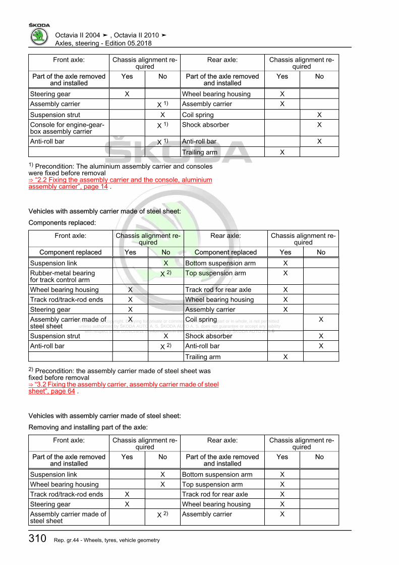
Protected by copyright. Copying for private or commercial purposes, in part or in whole, is not permitted unless authorised by ŠKODA AUTO A. S. ŠKODA AUTO A. S. does not guarantee or accept any liability
with respect to the correctness of information in this document. Copyright by ŠKODA AUTO A. S.�
Front axle: Chassis alignment re‐quired
Rear axle: Chassis alignment re‐quired
Part of the axle removedand installed
Yes No Part of the axle removedand installed
Yes No
Steering gear X Wheel bearing housing X Assembly carrier X 1) Assembly carrier X
Suspension strut X Coil spring XConsole for engine-gear‐box assembly carrier
X 1) Shock absorber X
Anti-roll bar X 1) Anti-roll bar X Trailing arm X
1) Precondition: The aluminium assembly carrier and consoleswere fixed before removal⇒ “2.2 Fixing the assembly carrier and the console, aluminiumassembly carrier”, page 14 .
Vehicles with assembly carrier made of steel sheet:Components replaced:
Front axle: Chassis alignment re‐quired
Rear axle: Chassis alignment re‐quired
Component replaced Yes No Component replaced Yes NoSuspension link X Bottom suspension arm X Rubber-metal bearingfor track control arm
X 2) Top suspension arm X
Wheel bearing housing X Track rod for rear axle X Track rod/track-rod ends X Wheel bearing housing X Steering gear X Assembly carrier X Assembly carrier made ofsteel sheet
X Coil spring X
Suspension strut X Shock absorber XAnti-roll bar X 2) Anti-roll bar X Trailing arm X
2) Precondition: the assembly carrier made of steel sheet wasfixed before removal⇒ “3.2 Fixing the assembly carrier, assembly carrier made of steelsheet”, page 64 .
Vehicles with assembly carrier made of steel sheet:Removing and installing part of the axle:
Front axle: Chassis alignment re‐quired
Rear axle: Chassis alignment re‐quired
Part of the axle removedand installed
Yes No Part of the axle removedand installed
Yes No
Suspension link X Bottom suspension arm X Wheel bearing housing X Top suspension arm X Track rod/track-rod ends X Track rod for rear axle X Steering gear X Wheel bearing housing X Assembly carrier made ofsteel sheet
X 2) Assembly carrier X
Octavia II 2004 ➤ , Octavia II 2010 ➤Axles, steering - Edition 05.2018
310 Rep. gr.44 - Wheels, tyres, vehicle geometry

Protected by copyright. Copying for private or commercial purposes, in part or in whole, is not permitted unless authorised by ŠKODA AUTO A. S. ŠKODA AUTO A. S. does not guarantee or accept any liability
with respect to the correctness of information in this document. Copyright by ŠKODA AUTO A. S.�
Front axle: Chassis alignment re‐quired
Rear axle: Chassis alignment re‐quired
Part of the axle removedand installed
Yes No Part of the axle removedand installed
Yes No
Suspension strut X Coil spring XAnti-roll bar X 2) Shock absorber X Anti-roll bar X Trailing arm X
2) Precondition: the assembly carrier made of steel sheet wasfixed before removal⇒ “3.2 Fixing the assembly carrier, assembly carrier made of steelsheet”, page 64 .
3.4 Overview of the work sequence for theaxle alignment
The following sequence of work steps must always be respected!1 - Determine what chassis has been mounted in the vehicle.
This information can be found on the vehicle data sticker⇒ “2.3 Vehicle data sticker and PR numbers”, page 304 .
2 - Perform a rim runout compensation.3 - Deflect the vehicle.4 - Position brake pedal load , e.g. -V.A.G 1869/2- .5 - Measure vehicle height
⇒ “3.5 Check transversal inclination of the vehicle straight-ahead position ”, page 312 .
6 - Before the axle alignment and the adjustment of the steeringgeometry, lock the steering wheel in the middle position ofthe height adjustment of steering wheel.
7 - Set the centre position of the gear rack at the steering wheeland fix the steering wheel (an even clearance circle to bothsides is assured by means of the centre position of the gearrack). If the steering wheel is off straight, it must be posi‐tioned straight at the end of the chassis alignment.
8 - Check camber on front axle, if necessary adjust⇒ “3.6 Adjusting camber at front wheels”, page 312 .
9 - Check camber on rear axle, if necessary adjust⇒ “3.7 Adjust the camber on the rear axle”, page 315 .
10 - Check toe on rear axle, if necessary adjust⇒ “3.9 Adjust the track on the rear axle”, page 318 .
11 - Check the castor on the front axle.12 - Check the toe on the front axle, if necessary adjust
⇒ “3.8 Adjust the track on the front axle”, page 317 .
Note
The following always applies! Always check the transversal incli‐nation of the vehicle before adjustment if one of the measuringvalues is outside the tolerance.
Octavia II 2004 ➤ , Octavia II 2010 ➤Axles, steering - Edition 05.2018
3. Axle alignment 311

Protected by copyright. Copying for private or commercial purposes, in part or in whole, is not permitted unless authorised by ŠKODA AUTO A. S. ŠKODA AUTO A. S. does not guarantee or accept any liability
with respect to the correctness of information in this document. Copyright by ŠKODA AUTO A. S.�
3.5 Check transversal inclination of the ve‐hicle “straight-ahead position”
It is possible the vehicle is skew if the measured values lie outsidethe tolerance.RHD vehicles or e. g. vehicles with an automatic gearbox may beslightly skew.This is normal and is due to the fitting location of the assembliesand the related transfer of weight.– Check absolutely the left and right dimension -a- on the front
and rear axle.Dimension -a-:⇒ “2 Chassis - Specified values of steering geometry”,page 302 .– Correct possible deviations of nominal value.Balance the difference on the front axle by placing weights on therelevant suspension strut dome in the engine compartment.Balance the difference on the rear axle by placing weights in theluggage compartment on the relevant side.Suitable weights are e.g. sand bags approx. 10 kg.
3.6 Adjusting camber at front wheels⇒ “3.6.1 Adjust the camber on the front axle, aluminium assemblycarrier”, page 312⇒ “3.6.2 Adjusting the camber on the front axle - assembly carriermade of steel sheet”, page 314
3.6.1 Adjust the camber on the front axle, alu‐minium assembly carrier
Move assembly carrier (looking in direction of travel) only to theleft or right, never to the front or to the rear!– Remove the noise insulation.– Release screws -1- for the console attachment/assembly car‐
rier to the body on both sides.– Only the specified value for the camber can be set by moving
the assembly carrier -2- with the consoles.
Note
Assembly carrier should only be moved to the left or right, on noaccount in the direction of travel or opposite the direction of travel.
– Screw the assembly carrier and the consoles with new boltsto the body and tighten with the torquing angle.
After moving the assembly carrier and also the steering gear, theclearance between the universal joint of the steering column andthe cutout of the bulkhead plenum chamber must be checked.Left-hand drive
Octavia II 2004 ➤ , Octavia II 2010 ➤Axles, steering - Edition 05.2018
312 Rep. gr.44 - Wheels, tyres, vehicle geometry

Protected by copyright. Copying for private or commercial purposes, in part or in whole, is not permitted unless authorised by ŠKODA AUTO A. S. ŠKODA AUTO A. S. does not guarantee or accept any liability
with respect to the correctness of information in this document. Copyright by ŠKODA AUTO A. S.�
– Remove nuts -arrows- and remove the footwell trim.
Now there must be at least a circular clearance of 5 mm betweenthe universal joint -2- and the cutout of the bulkhead plenumchamber.Right-hand drive
– Remove the fixing nut -arrow A- and the expansion clamp-arrow B- of the footwell covering.
– Unclip footwell panelling in -arrow direction C-.
Now there must be at least a circular clearance of 5 mm betweenthe universal joint -2- and the cutout of the bulkhead plenumchamber.Continued for all vehiclesInstallation is carried out in the reverse order.Tightening torques - summaries of components
Note
Replace bolts / nuts that are tightened at an angle of rotation, aswell as replacement components after removal.
♦ ⇒ “2.1 Assembly overview - subframe, aluminium subframe”,page 10
♦ Noise insulation ⇒ Body work assembly; Rep. gr. 50
Octavia II 2004 ➤ , Octavia II 2010 ➤Axles, steering - Edition 05.2018
3. Axle alignment 313
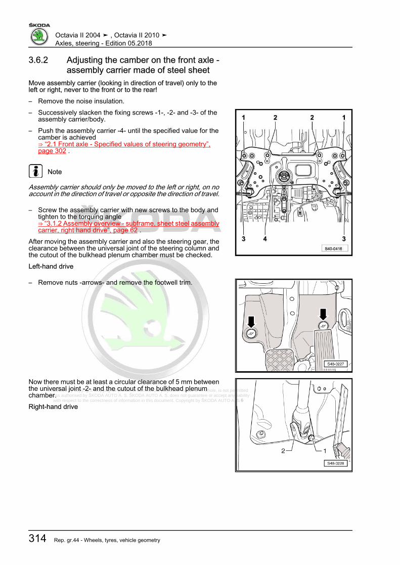
Protected by copyright. Copying for private or commercial purposes, in part or in whole, is not permitted unless authorised by ŠKODA AUTO A. S. ŠKODA AUTO A. S. does not guarantee or accept any liability
with respect to the correctness of information in this document. Copyright by ŠKODA AUTO A. S.�
3.6.2 Adjusting the camber on the front axle -assembly carrier made of steel sheet
Move assembly carrier (looking in direction of travel) only to theleft or right, never to the front or to the rear!– Remove the noise insulation.– Successively slacken the fixing screws -1-, -2- and -3- of the
assembly carrier/body.– Push the assembly carrier -4- until the specified value for the
camber is achieved⇒ “2.1 Front axle - Specified values of steering geometry”,page 302 .
Note
Assembly carrier should only be moved to the left or right, on noaccount in the direction of travel or opposite the direction of travel.
– Screw the assembly carrier with new screws to the body andtighten to the torquing angle⇒ “3.1.2 Assembly overview - subframe, sheet steel assemblycarrier, right hand drive”, page 62 .
After moving the assembly carrier and also the steering gear, theclearance between the universal joint of the steering column andthe cutout of the bulkhead plenum chamber must be checked.Left-hand drive
– Remove nuts -arrows- and remove the footwell trim.
Now there must be at least a circular clearance of 5 mm betweenthe universal joint -2- and the cutout of the bulkhead plenumchamber.Right-hand drive
Octavia II 2004 ➤ , Octavia II 2010 ➤Axles, steering - Edition 05.2018
314 Rep. gr.44 - Wheels, tyres, vehicle geometry
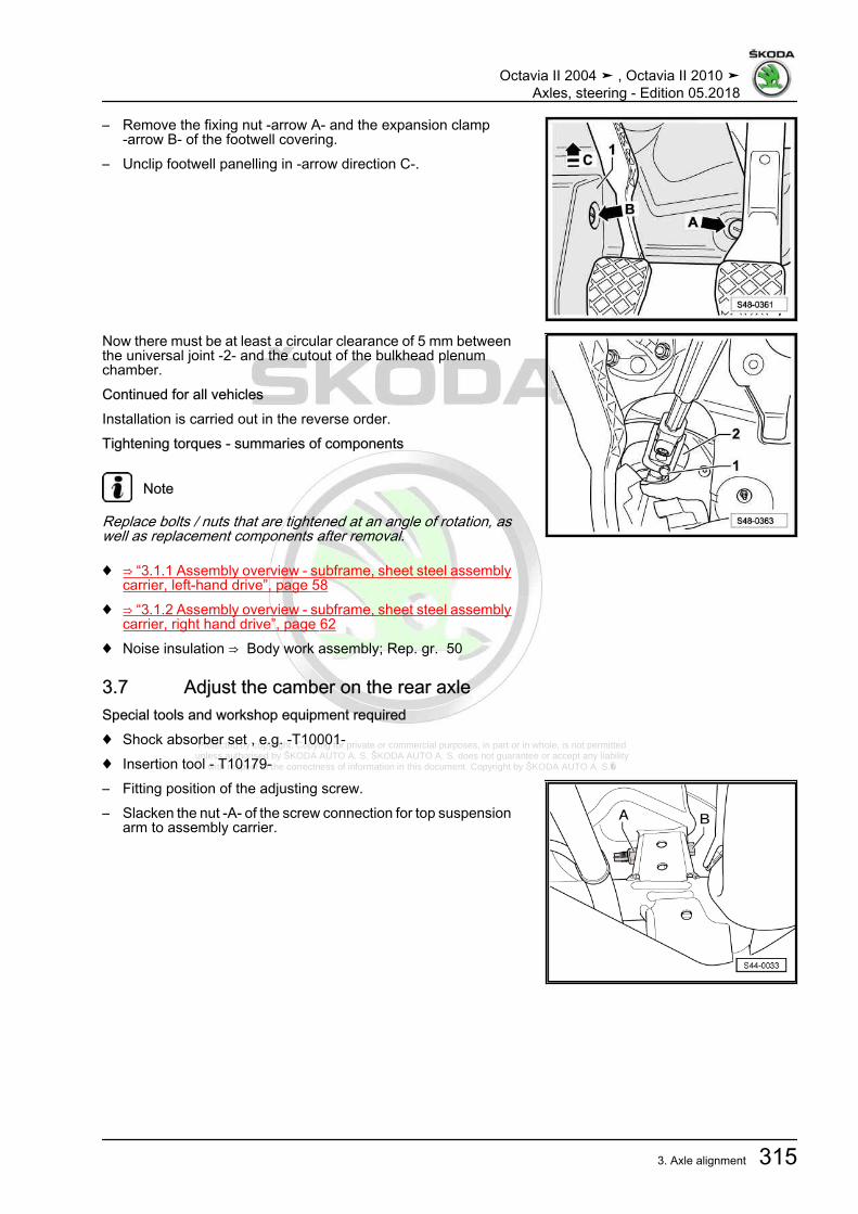
Protected by copyright. Copying for private or commercial purposes, in part or in whole, is not permitted unless authorised by ŠKODA AUTO A. S. ŠKODA AUTO A. S. does not guarantee or accept any liability
with respect to the correctness of information in this document. Copyright by ŠKODA AUTO A. S.�
– Remove the fixing nut -arrow A- and the expansion clamp-arrow B- of the footwell covering.
– Unclip footwell panelling in -arrow direction C-.
Now there must be at least a circular clearance of 5 mm betweenthe universal joint -2- and the cutout of the bulkhead plenumchamber.Continued for all vehiclesInstallation is carried out in the reverse order.Tightening torques - summaries of components
Note
Replace bolts / nuts that are tightened at an angle of rotation, aswell as replacement components after removal.
♦ ⇒ “3.1.1 Assembly overview - subframe, sheet steel assemblycarrier, left-hand drive”, page 58
♦ ⇒ “3.1.2 Assembly overview - subframe, sheet steel assemblycarrier, right hand drive”, page 62
♦ Noise insulation ⇒ Body work assembly; Rep. gr. 50
3.7 Adjust the camber on the rear axleSpecial tools and workshop equipment required♦ Shock absorber set , e.g. -T10001-♦ Insertion tool - T10179-– Fitting position of the adjusting screw.– Slacken the nut -A- of the screw connection for top suspension
arm to assembly carrier.
Octavia II 2004 ➤ , Octavia II 2010 ➤Axles, steering - Edition 05.2018
3. Axle alignment 315
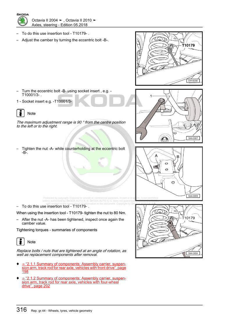
Protected by copyright. Copying for private or commercial purposes, in part or in whole, is not permitted unless authorised by ŠKODA AUTO A. S. ŠKODA AUTO A. S. does not guarantee or accept any liability
with respect to the correctness of information in this document. Copyright by ŠKODA AUTO A. S.�
– To do this use insertion tool - T10179- .– Adjust the camber by turning the eccentric bolt -B-.
– Turn the eccentric bolt -B- using socket insert , e.g. -T10001/3- .
1 - Socket insert e.g. -T10001/3-
Note
The maximum adjustment range is 90 ° from the centre positionto the left or to the right.
– Tighten the nut -A- while counterholding at the eccentric bolt-B-.
– To do this use insertion tool - T10179- .When using the insertion tool - T10179- tighten the nut to 80 Nm.– After the nut -A- has been tightened, inspect once again the
camber value.Tightening torques - summaries of components
Note
Replace bolts / nuts that are tightened at an angle of rotation, aswell as replacement components after removal.
♦ ⇒ “2.1.1 Summary of components: Assembly carrier, suspen‐sion arm, track rod for rear axle, vehicles with front drive”, page198
♦ ⇒ “2.1.2 Summary of components: Assembly carrier, suspen‐sion arm, track rod for rear axle, vehicles with four-wheeldrive”, page 202
Octavia II 2004 ➤ , Octavia II 2010 ➤Axles, steering - Edition 05.2018
316 Rep. gr.44 - Wheels, tyres, vehicle geometry

Protected by copyright. Copying for private or commercial purposes, in part or in whole, is not permitted unless authorised by ŠKODA AUTO A. S. ŠKODA AUTO A. S. does not guarantee or accept any liability
with respect to the correctness of information in this document. Copyright by ŠKODA AUTO A. S.�
Component Tightening torqueTop wishbone using the insertion tool - T10179- 80 Nm
3.8 Adjust the track on the front axle– Release nut -3- while counterholding the track rod end -2-.– Pull off the spring strap clip -1- from the bellows.– Adjust track by turning the left and/or right track rod.
Note
♦ Turning the track rods and tightening the counternuts must becarried out in such a way that the difference of the visiblethread lengths on the left -L1- and the right -L2- of the trackrod does not exceed 2 mm.
♦ A greater difference is noticeable because of incorrect axlemeasurement. This influences the tyre life and the driving be‐haviour deteriorates.
♦ Check that the bellows have not become twisted after turningthe track rods!
♦ Twisted bellows wear fast.
– Tighten counternut with socket insert while doing so counter‐hold on the track rod end.
– Check the track value once again.If the measured toe value lies within tolerance then the adjust‐ment is OK.– Fit spring strap clip onto the bellows.Vehicles with ESP– Follow the notes ⇒ page 307 .Continued for all vehicles– Perform basic setup of the steering angle encoder - G85- using
the diagnosis device - VAS- ⇒ Vehicle diagnostic testerTightening torques - summaries of components
Note
Replace bolts / nuts that are tightened at an angle of rotation, aswell as replacement components after removal.
♦ ⇒ “2.6 Repairing steering box”, page 380
Octavia II 2004 ➤ , Octavia II 2010 ➤Axles, steering - Edition 05.2018
3. Axle alignment 317
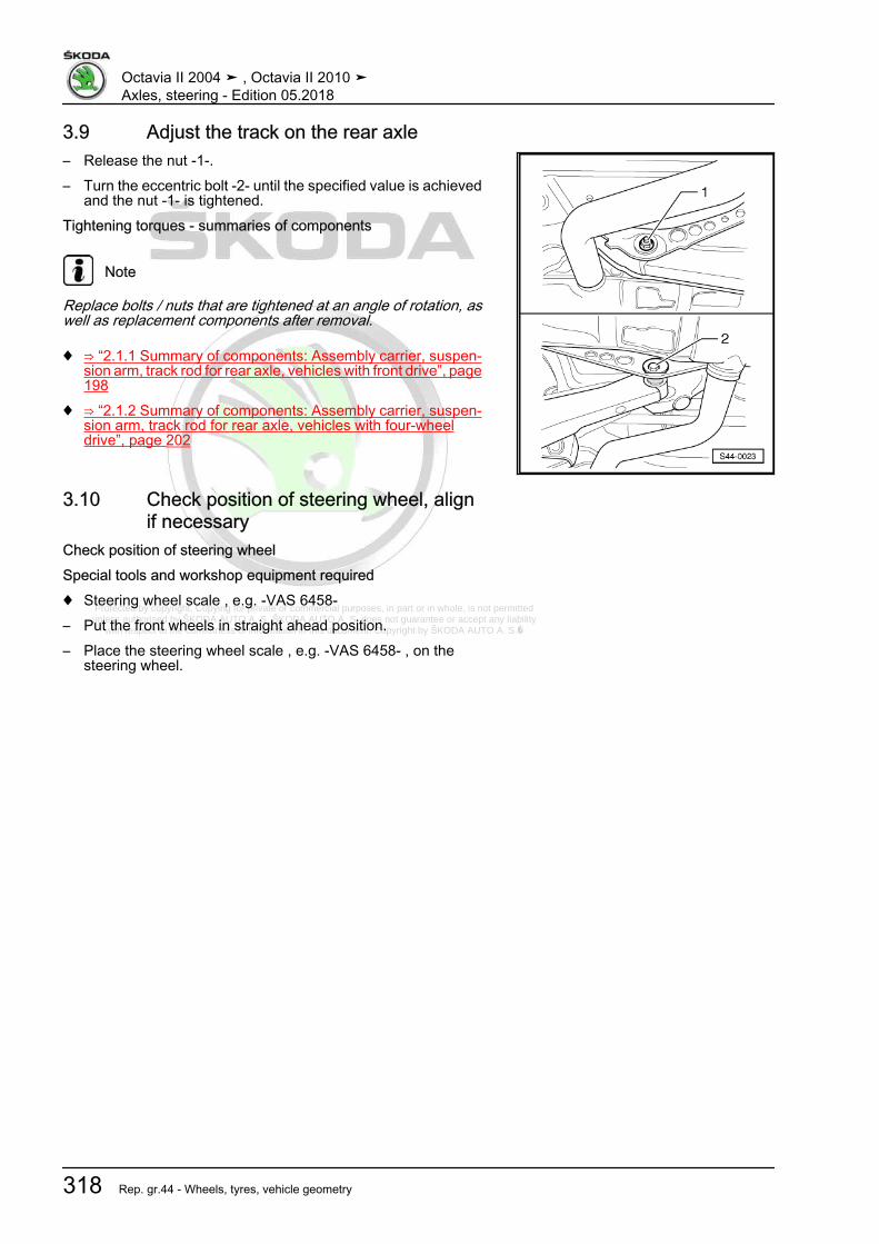
Protected by copyright. Copying for private or commercial purposes, in part or in whole, is not permitted unless authorised by ŠKODA AUTO A. S. ŠKODA AUTO A. S. does not guarantee or accept any liability
with respect to the correctness of information in this document. Copyright by ŠKODA AUTO A. S.�
3.9 Adjust the track on the rear axle– Release the nut -1-.– Turn the eccentric bolt -2- until the specified value is achieved
and the nut -1- is tightened.Tightening torques - summaries of components
Note
Replace bolts / nuts that are tightened at an angle of rotation, aswell as replacement components after removal.
♦ ⇒ “2.1.1 Summary of components: Assembly carrier, suspen‐sion arm, track rod for rear axle, vehicles with front drive”, page198
♦ ⇒ “2.1.2 Summary of components: Assembly carrier, suspen‐sion arm, track rod for rear axle, vehicles with four-wheeldrive”, page 202
3.10 Check position of steering wheel, alignif necessary
Check position of steering wheelSpecial tools and workshop equipment required♦ Steering wheel scale , e.g. -VAS 6458-– Put the front wheels in straight ahead position.– Place the steering wheel scale , e.g. -VAS 6458- , on the
steering wheel.
Octavia II 2004 ➤ , Octavia II 2010 ➤Axles, steering - Edition 05.2018
318 Rep. gr.44 - Wheels, tyres, vehicle geometry
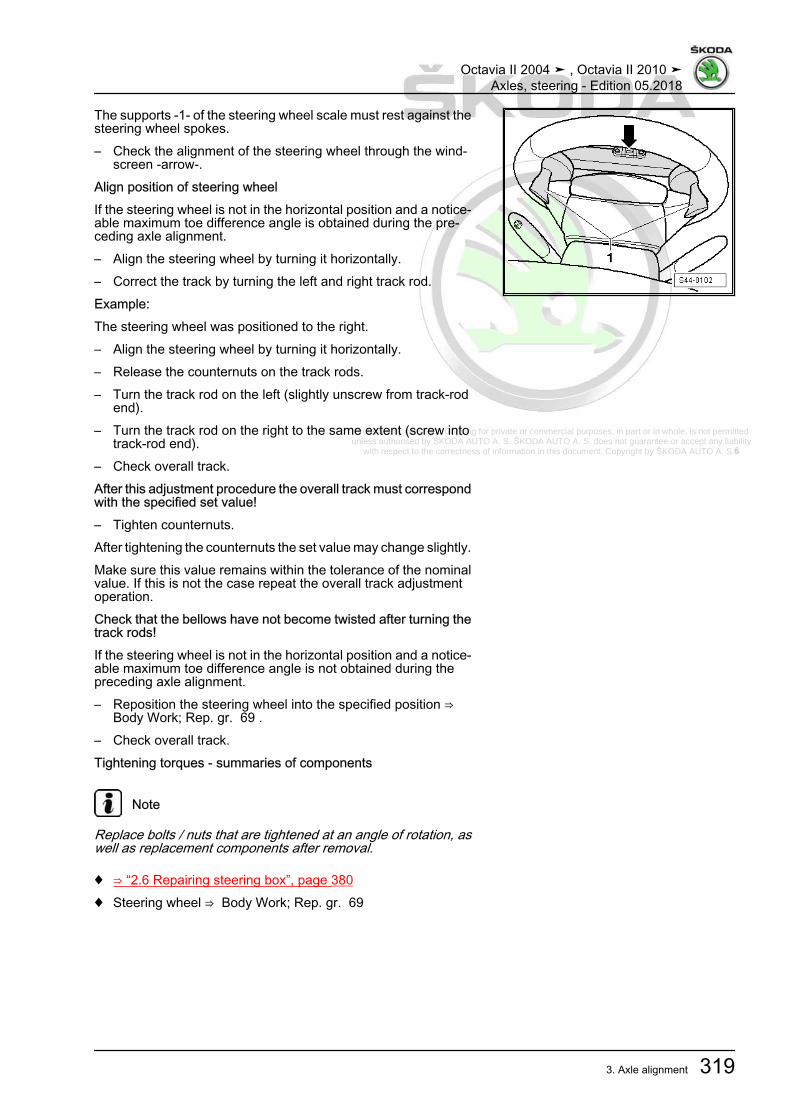
Protected by copyright. Copying for private or commercial purposes, in part or in whole, is not permitted unless authorised by ŠKODA AUTO A. S. ŠKODA AUTO A. S. does not guarantee or accept any liability
with respect to the correctness of information in this document. Copyright by ŠKODA AUTO A. S.�
The supports -1- of the steering wheel scale must rest against thesteering wheel spokes.– Check the alignment of the steering wheel through the wind‐
screen -arrow-.Align position of steering wheelIf the steering wheel is not in the horizontal position and a notice‐able maximum toe difference angle is obtained during the pre‐ceding axle alignment.– Align the steering wheel by turning it horizontally.– Correct the track by turning the left and right track rod.Example:The steering wheel was positioned to the right.– Align the steering wheel by turning it horizontally.– Release the counternuts on the track rods.– Turn the track rod on the left (slightly unscrew from track-rod
end).– Turn the track rod on the right to the same extent (screw into
track-rod end).– Check overall track.After this adjustment procedure the overall track must correspondwith the specified set value!– Tighten counternuts.After tightening the counternuts the set value may change slightly.Make sure this value remains within the tolerance of the nominalvalue. If this is not the case repeat the overall track adjustmentoperation.Check that the bellows have not become twisted after turning thetrack rods!If the steering wheel is not in the horizontal position and a notice‐able maximum toe difference angle is not obtained during thepreceding axle alignment.– Reposition the steering wheel into the specified position ⇒
Body Work; Rep. gr. 69 .– Check overall track.Tightening torques - summaries of components
Note
Replace bolts / nuts that are tightened at an angle of rotation, aswell as replacement components after removal.
♦ ⇒ “2.6 Repairing steering box”, page 380♦ Steering wheel ⇒ Body Work; Rep. gr. 69
Octavia II 2004 ➤ , Octavia II 2010 ➤Axles, steering - Edition 05.2018
3. Axle alignment 319

Protected by copyright. Copying for private or commercial purposes, in part or in whole, is not permitted unless authorised by ŠKODA AUTO A. S. ŠKODA AUTO A. S. does not guarantee or accept any liability
with respect to the correctness of information in this document. Copyright by ŠKODA AUTO A. S.�
48 – Steering1 Steering column⇒ “1.1 Summary of components - steering column”, page 320⇒ “1.2 Check the steering column for damage”, page 326⇒ “1.3 Observe handling and transportation of the steering col‐umn”, page 326⇒ “1.4 Removing and installing steering column”, page 328⇒ “1.5 Removing and installing holder for steering column andfrequency link”, page 349
1.1 Summary of components - steering col‐umn
⇒ “1.1.1 Overview of components - steering column, left-handdrive up to CW 44/2008”, page 320⇒ “1.1.2 Steering column summary of components, right-handdrive to CW 44/2008”, page 322⇒ “1.1.3 Summary of components - steering column, left-handdrive from CW 45/2008”, page 324⇒ “1.1.4 Steering column summary of components, right-handdrive from CW 45/2008”, page 325
1.1.1 Overview of components - steering column, left-hand drive up to CW44/2008
Note
♦ ⇒ “1.5.1 Removing and installing holder for steering column and frequency link, left-hand drive”,page 349
♦ Observe handling and transportation of the steering column⇒ “1.3 Observe handling and transportation of the steering column”, page 326 .
♦ Self-locking nuts must always be replaced.♦ Always replace corroded self-locking nuts and screws.
Octavia II 2004 ➤ , Octavia II 2010 ➤Axles, steering - Edition 05.2018
320 Rep. gr.48 - Steering

Protected by copyright. Copying for private or commercial purposes, in part or in whole, is not permitted unless authorised by ŠKODA AUTO A. S. ŠKODA AUTO A. S. does not guarantee or accept any liability
with respect to the correctness of information in this document. Copyright by ŠKODA AUTO A. S.�
1 - Screw❑ 20 Nm
2 - Frequency link❑ Removing and installing
⇒ “1.5.1 Removing andinstalling holder forsteering column and fre‐quency link, left-handdrive”, page 349
3 - Central pipe4 - Support
❑ Removing and installing⇒ “1.5.1 Removing andinstalling holder forsteering column and fre‐quency link, left-handdrive”, page 349
5 - Screw❑ M8 x 30❑ 20 Nm
6 - Steering column❑ Removing and installing
⇒ “1.4.1 Removing andinstalling steering col‐umn - left-hand drive, upto CW 44/2008”,page 328
❑ check for damage⇒ “1.2 Check the steer‐ing column for damage”,page 326
❑ Observe handling andtransportation⇒ “1.3 Observe handlingand transportation of thesteering column”, page 326
7 - Grip8 - Screw
❑ M6 x 10❑ 3 Nm
9 - Screw❑ replace after each removal❑ ⇒ Electronic Catalogue of Original Parts❑ 30 Nm
10 - Frequency link❑ Removing and installing
⇒ “1.5.1 Removing and installing holder for steering column and frequency link, left-hand drive”,page 349
11 - Screw❑ M8 x 94❑ 20 Nm
12 - Screw❑ M8 x 48❑ 25 Nm
Octavia II 2004 ➤ , Octavia II 2010 ➤Axles, steering - Edition 05.2018
1. Steering column 321

Protected by copyright. Copying for private or commercial purposes, in part or in whole, is not permitted unless authorised by ŠKODA AUTO A. S. ŠKODA AUTO A. S. does not guarantee or accept any liability
with respect to the correctness of information in this document. Copyright by ŠKODA AUTO A. S.�
13 - Screw❑ M8 x 85❑ 20 Nm
14 - Screw❑ 8 Nm
1.1.2 Steering column summary of components, right-hand drive to CW 44/2008
Note
♦ Observe handling and transportation of the steering column⇒ “1.3 Observe handling and transportation of the steering column”, page 326 .
♦ Self-locking nuts must always be replaced.♦ Always replace corroded self-locking nuts and screws.
1 - Screw❑ 20 Nm
2 - Frequency link❑ Removing and installing
⇒ “1.5.2 Removing andinstalling holder forsteering column and fre‐quency link, right-handdrive”, page 352
3 - Central pipe4 - Support
❑ Removing and installing⇒ “1.5.2 Removing andinstalling holder forsteering column and fre‐quency link, right-handdrive”, page 352
5 - Screw❑ M8 x 30❑ 20 Nm
6 - Steering column❑ Removing and installing
⇒ “1.4.2 Removing andinstalling steering col‐umn, right-hand drivevehicles to CW44/2008”, page 333
❑ check for damage⇒ “1.2 Check the steer‐ing column for damage”,page 326
❑ Observe handling andtransportation⇒ “1.3 Observe handlingand transportation of thesteering column”, page 326
Octavia II 2004 ➤ , Octavia II 2010 ➤Axles, steering - Edition 05.2018
322 Rep. gr.48 - Steering

Protected by copyright. Copying for private or commercial purposes, in part or in whole, is not permitted unless authorised by ŠKODA AUTO A. S. ŠKODA AUTO A. S. does not guarantee or accept any liability
with respect to the correctness of information in this document. Copyright by ŠKODA AUTO A. S.�
7 - Grip8 - Screw
❑ M6 x 10❑ 3 Nm
9 - Crash bar❑ for brake pedal❑ Assignment ⇒ Electronic Catalogue of Original Parts
10 - Crash bar❑ for the clutch pedal❑ Assignment ⇒ Electronic Catalogue of Original Parts
11 - Screw❑ replace after each removal❑ ⇒ Electronic Catalogue of Original Parts❑ 30 Nm
12 - Screw❑ M8 x 30❑ 20 Nm
13 - Screw❑ M8 x 94❑ 20 Nm
14 - Frequency link❑ Removing and installing
⇒ “1.5.2 Removing and installing holder for steering column and frequency link, right-hand drive”,page 352
15 - Screw❑ M8 x 48❑ 25 Nm
16 - Screw❑ M8 x 85❑ 20 Nm
17 - Screw❑ 8 Nm
Octavia II 2004 ➤ , Octavia II 2010 ➤Axles, steering - Edition 05.2018
1. Steering column 323

Protected by copyright. Copying for private or commercial purposes, in part or in whole, is not permitted unless authorised by ŠKODA AUTO A. S. ŠKODA AUTO A. S. does not guarantee or accept any liability
with respect to the correctness of information in this document. Copyright by ŠKODA AUTO A. S.�
1.1.3 Summary of components - steering column, left-hand drive from CW45/2008
Note
♦ Observe handling and transportation of the steering column⇒ “1.3 Observe handling and transportation of the steering column”, page 326 .
♦ Always replace corroded self-locking nuts and screws.
1 - Central pipe2 - Steering column
❑ Removing and installing⇒ “1.4.3 Removing andinstalling steering col‐umn - left-hand drive,from CW 45/2008”,page 339
❑ check for damage⇒ “1.2 Check the steer‐ing column for damage”,page 326
❑ Observe handling andtransportation⇒ “1.3 Observe handlingand transportation of thesteering column”,page 326
3 - Crash bar❑ for brake pedal❑ Assignment ⇒ Electron‐
ic Catalogue of OriginalParts
4 - Screw❑ M8 x 30❑ 20 Nm
5 - Crash bar❑ for the clutch pedal❑ Assignment ⇒ Electron‐
ic Catalogue of OriginalParts
6 - Screw❑ M8 x 35❑ replace after each removal❑ 30 Nm
Octavia II 2004 ➤ , Octavia II 2010 ➤Axles, steering - Edition 05.2018
324 Rep. gr.48 - Steering
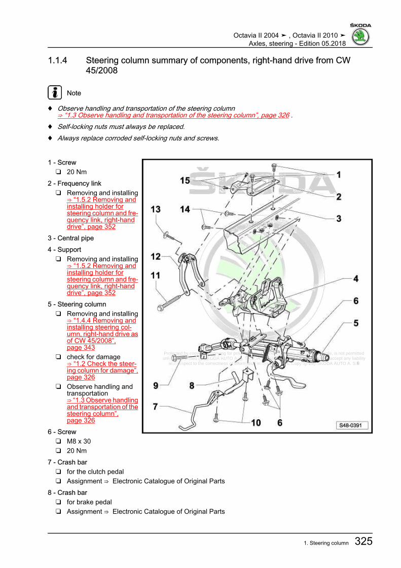
Protected by copyright. Copying for private or commercial purposes, in part or in whole, is not permitted unless authorised by ŠKODA AUTO A. S. ŠKODA AUTO A. S. does not guarantee or accept any liability
with respect to the correctness of information in this document. Copyright by ŠKODA AUTO A. S.�
1.1.4 Steering column summary of components, right-hand drive from CW45/2008
Note
♦ Observe handling and transportation of the steering column⇒ “1.3 Observe handling and transportation of the steering column”, page 326 .
♦ Self-locking nuts must always be replaced.♦ Always replace corroded self-locking nuts and screws.
1 - Screw❑ 20 Nm
2 - Frequency link❑ Removing and installing
⇒ “1.5.2 Removing andinstalling holder forsteering column and fre‐quency link, right-handdrive”, page 352
3 - Central pipe4 - Support
❑ Removing and installing⇒ “1.5.2 Removing andinstalling holder forsteering column and fre‐quency link, right-handdrive”, page 352
5 - Steering column❑ Removing and installing
⇒ “1.4.4 Removing andinstalling steering col‐umn, right-hand drive asof CW 45/2008”,page 343
❑ check for damage⇒ “1.2 Check the steer‐ing column for damage”,page 326
❑ Observe handling andtransportation⇒ “1.3 Observe handlingand transportation of thesteering column”,page 326
6 - Screw❑ M8 x 30❑ 20 Nm
7 - Crash bar❑ for the clutch pedal❑ Assignment ⇒ Electronic Catalogue of Original Parts
8 - Crash bar❑ for brake pedal❑ Assignment ⇒ Electronic Catalogue of Original Parts
Octavia II 2004 ➤ , Octavia II 2010 ➤Axles, steering - Edition 05.2018
1. Steering column 325

Protected by copyright. Copying for private or commercial purposes, in part or in whole, is not permitted unless authorised by ŠKODA AUTO A. S. ŠKODA AUTO A. S. does not guarantee or accept any liability
with respect to the correctness of information in this document. Copyright by ŠKODA AUTO A. S.�
9 - Screw❑ replace after each removal❑ ⇒ Electronic Catalogue of Original Parts❑ 30 Nm
10 - Screw❑ M8 x 30❑ 20 Nm
11 - Screw❑ M8 x 94❑ 20 Nm
12 - Frequency link❑ Removing and installing
⇒ “1.5.2 Removing and installing holder for steering column and frequency link, right-hand drive”,page 352
13 - Screw❑ M8 x 48❑ 25 Nm
14 - Screw❑ M8 x 85❑ 20 Nm
15 - Screw❑ 8 Nm
1.2 Check the steering column for damageVisual inspection– Inspecting parts of the steering column for damage.Check function– Check whether the steering column turns freely without jerk‐
ing.– Check if the steering column is adjustable in longitudinal di‐
rection as well as in height and is easy to operate withouthooking.
1.3 Observe handling and transportation ofthe steering column
WARNING
♦ The correct handling of the steering column must abso‐lutely be respected.
♦ The incorrect handling of the steering column can lead todamages of the steering column and therefore to a risk ofsafety.
Octavia II 2004 ➤ , Octavia II 2010 ➤Axles, steering - Edition 05.2018
326 Rep. gr.48 - Steering

Protected by copyright. Copying for private or commercial purposes, in part or in whole, is not permitted unless authorised by ŠKODA AUTO A. S. ŠKODA AUTO A. S. does not guarantee or accept any liability
with respect to the correctness of information in this document. Copyright by ŠKODA AUTO A. S.�
Observe correct handling and transportation of the steering col‐umn♦ Always transport the steering column with both hands.♦ Always take hold of the steering column at the casing and in
the area of the top universal joint.
Incorrect handling of the steering columnThe transportation of the following parts leads to pre-damage ofthe steering column:1 - Clamping lever2 - Counterweight springs3 - Deformation element
Incorrect handling of the steering column with safety riskThe following handlings lead to damage of the universal jointbushing of the lower steering column bearing:♦ Transporting the steering column with one hand at the cardan
shaft.♦ Bending of the drive shaft over 90°.
Octavia II 2004 ➤ , Octavia II 2010 ➤Axles, steering - Edition 05.2018
1. Steering column 327

Protected by copyright. Copying for private or commercial purposes, in part or in whole, is not permitted unless authorised by ŠKODA AUTO A. S. ŠKODA AUTO A. S. does not guarantee or accept any liability
with respect to the correctness of information in this document. Copyright by ŠKODA AUTO A. S.�
1.4 Removing and installing steering col‐umn
⇒ “1.4.1 Removing and installing steering column - left-handdrive, up to CW 44/2008”, page 328⇒ “1.4.2 Removing and installing steering column, right-handdrive vehicles to CW 44/2008”, page 333⇒ “1.4.3 Removing and installing steering column - left-handdrive, from CW 45/2008”, page 339⇒ “1.4.4 Removing and installing steering column, right-handdrive as of CW 45/2008”, page 343
1.4.1 Removing and installing steering col‐umn - left-hand drive, up to CW 44/2008
RemovingThe steering column is supplied as a spare part in the form of acomplete assembly. Repairs are not allowed!The ignition lock housing can be modified ⇒ Electrical System;Rep. gr. 94 .The switched on the steering column can be re-installed ⇒ Elec‐trical system; Rep. gr. 94 .
WARNING
Before working on the electrical system and the removal of thesteering wheel the following conditions must be fulfilled:♦ Every mechanic must discharge him/herself of electro‐
static. This is done by touching an earthed metal part, suchas e.g. a water pipes, heating pipes, metal brackets or alift platform.
Failure to comply with these precautions may lead to a subse‐quent failure of the ELV control unit - J764- !♦ Disconnect battery earth strap ⇒ Electrical System; Rep.
gr. 27 .♦ The wheels must be in the straight-ahead position.
Failure to comply with these precautions may lead to subse‐quent failure of the airbag system!
– Put the front wheels in straight ahead position.– Press the adjusting lever for steering column downwards.– Press the steering column downwards, pull it towards you and
lock with the adjusting lever (the lever upwards).– Remove airbag and steering wheel ⇒ Body Work; Rep. gr.
69 .– Remove bottom steering column trim panel ⇒ Body Work;
Rep. gr. 70 .– Remove storage compartment on the driver's side.– Removing dash panel insert ⇒ Electrical System; Rep. gr.
90 .– Disconnect the plug from the steering column electronics con‐
trol unit -J527- ⇒ Electrical System; Rep. gr. 94 .
Octavia II 2004 ➤ , Octavia II 2010 ➤Axles, steering - Edition 05.2018
328 Rep. gr.48 - Steering

Protected by copyright. Copying for private or commercial purposes, in part or in whole, is not permitted unless authorised by ŠKODA AUTO A. S. ŠKODA AUTO A. S. does not guarantee or accept any liability
with respect to the correctness of information in this document. Copyright by ŠKODA AUTO A. S.�
– Disconnect the plug from the immobilizer reading coil (removelock cylinder from steering lock housing) ⇒ Electrical System;Rep. gr. 94 .
Note
The steering lock must not be moved unless the lock cylinder isremoved, otherwise it would block completely. The blocked steer‐ing lock must be replaced
– After disconnecting the plug from the immobilizer reading coil,re-install the lock cylinder into the steering lock housing ⇒ Electrical System; Rep. gr. 94 .
– Remove crash strut for clutch pedal -1-.– Remove crash strut for brake pedal (if present).
– Remove earth line -1- from the steering column.– Unclip cable guide -2-.
– Remove fixing nuts -arrows- and remove footwell covering.
Octavia II 2004 ➤ , Octavia II 2010 ➤Axles, steering - Edition 05.2018
1. Steering column 329

Protected by copyright. Copying for private or commercial purposes, in part or in whole, is not permitted unless authorised by ŠKODA AUTO A. S. ŠKODA AUTO A. S. does not guarantee or accept any liability
with respect to the correctness of information in this document. Copyright by ŠKODA AUTO A. S.�
– Remove screw -1- and pull off the universal joint -2- from thesteering gear in -direction of arrow-.
Caution
If the universal coupling is detached from the steering gear, donot carry out any of the following work♦ Reconnecting battery♦ Switch on the ignition♦ Rotating the steering gear♦ Rotating the steering column
You must observe these points because if you do not, irrepar‐able damage may result.
– First remove the fixing screw -arrow- for the fuse holder andthen the screws -1-.
– Carefully remove steering column from the top.Observe handling and transportation of the steering column⇒ “1.3 Observe handling and transportation of the steering col‐umn”, page 326 .InstallingThe ignition lock housing can be modified ⇒ Electrical System;Rep. gr. 94 .When replacing the steering column, refit the steering columnswitches ⇒ Electrical System; Rep. gr. 94 .– Hook the steering column with the hangers at the holder for
steering column.
– Align steering column to the holder for steering column andposition.
When doing so the studs -arrows A- of the holder for steeringcolumn and the holes -arrows B- of the steering column must bepositioned to each other and put into each other.The correct fitting location of the steering column to the holder forsteering column is only guaranteed as such.
– Install strut for clutch pedal -1-.– Install crash strut for brake pedal (if present).
Note
The crash struts for the brake and clutch pedal are screwed withthe steering column at the holder for steering column.
Octavia II 2004 ➤ , Octavia II 2010 ➤Axles, steering - Edition 05.2018
330 Rep. gr.48 - Steering

Protected by copyright. Copying for private or commercial purposes, in part or in whole, is not permitted unless authorised by ŠKODA AUTO A. S. ŠKODA AUTO A. S. does not guarantee or accept any liability
with respect to the correctness of information in this document. Copyright by ŠKODA AUTO A. S.�
– Tighten the screws -1- of the steering column.– Tighten the fixing screw -arrow- for the fuse holder ⇒ Electrical
System; Rep. gr. 97 .
– Fit the universal joint -2- against the -direction of arrow- on thesteering pinion.
– Tighten new screw -1-.
Octavia II 2004 ➤ , Octavia II 2010 ➤Axles, steering - Edition 05.2018
1. Steering column 331

Protected by copyright. Copying for private or commercial purposes, in part or in whole, is not permitted unless authorised by ŠKODA AUTO A. S. ŠKODA AUTO A. S. does not guarantee or accept any liability
with respect to the correctness of information in this document. Copyright by ŠKODA AUTO A. S.�
– Clip in cable guide -2- at steering column.– Screw the earth line -1- to the steering column.– Fit the plug onto the steering column electronics control unit -
J527- ⇒ Electrical System; Rep. gr. 94 .– Fit the plug onto the immobilizer reading coil (remove lock cyl‐
inder from steering lock housing) ⇒ Electrical System; Rep.gr. 94 .
Note
The steering lock must not be moved unless the lock cylinder isremoved, otherwise it would block completely. The blocked steer‐ing lock must be replaced
– After fitting the plug onto the immobilizer reading coil, re-installthe lock cylinder into the steering lock housing ⇒ ElectricalSystem; Rep. gr. 94 .
– Install bottom steering column trim panel ⇒ Body Work; Rep.gr. 70 .
– Install steering wheel and airbag ⇒ Body Work; Rep. gr. 69 .– Installing dash panel insert ⇒ Electrical System; Rep. gr. 90 .– Install storage compartment on the driver's side.– Perform basic setting of the steering angle sender - G85-
⇒ Vehicle diagnostic tester.After the following installation work the basic setting of the steer‐ing angle sender - G85- must be checked:♦ if the steering angle encoder - G85- was removed or replaced
1)
♦ after removal or replacement of the steering column♦ after removal or replacement of the ignition lock housing with
steering column switch 1)
♦ after removal or replacement of the steering gear♦ if the steering wheel was offset1) Only applies for vehicles with the sender fitted between thesteering wheel and the steering column switch.Tightening torques - summaries of components
Note
Replace bolts / nuts that are tightened at an angle of rotation, aswell as replacement components after removal.
♦ ⇒ “1.1.1 Overview of components - steering column, left-handdrive up to CW 44/2008”, page 320
♦ Airbag and steering wheel ⇒ Body Work; Rep. gr. 69♦ Top and bottom steering column trim panel ⇒ Body Work;
Rep. gr. 70♦ Storage area on the driver's side ⇒ Body Work; Rep. gr. 70♦ Dash panel insert ⇒ Electrical System; Rep. gr. 90♦ Steering column control ⇒ Electrical System; Rep. gr. 94
Octavia II 2004 ➤ , Octavia II 2010 ➤Axles, steering - Edition 05.2018
332 Rep. gr.48 - Steering
Protected by copyright. Copying for private or commercial purposes, in part or in whole, is not permitted unless authorised by ŠKODA AUTO A. S. ŠKODA AUTO A. S. does not guarantee or accept any liability
with respect to the correctness of information in this document. Copyright by ŠKODA AUTO A. S.�
♦ Switch unit ⇒ Electrical system; Rep. gr. 94
1.4.2 Removing and installing steering col‐umn, right-hand drive vehicles to CW44/2008
RemovingThe steering column is supplied as a spare part in the form of acomplete assembly. Repairs are not allowed!The ignition lock housing can be modified ⇒ Electrical System;Rep. gr. 94 .The switched on the steering column can be re-installed ⇒ Elec‐trical system; Rep. gr. 94 .
WARNING
Before working on the electrical system and the removal of thesteering wheel the following conditions must be fulfilled:♦ Every mechanic must discharge him/herself of electro‐
static. This is done by touching an earthed metal part, suchas e.g. a water pipes, heating pipes, metal brackets or alift platform.
Failure to comply with these precautions may lead to a subse‐quent failure of the ELV control unit - J764- !♦ Disconnect battery earth strap ⇒ Electrical System; Rep.
gr. 27 .♦ The wheels must be in the straight-ahead position.
Failure to comply with these precautions may lead to subse‐quent failure of the airbag system!
– Put the front wheels in straight ahead position.– Press the adjusting lever for steering column downwards.– Press the steering column downwards, pull it towards you and
lock with the adjusting lever (the lever upwards).– Remove airbag and steering wheel ⇒ Body Work; Rep. gr.
69 .– Remove bottom steering column trim panel ⇒ Body Work;
Rep. gr. 70 .– Disconnect the plug from the steering column electronics con‐
trol unit -J527- ⇒ Electrical System; Rep. gr. 94 .– Disconnect the plug from the immobilizer reading coil (remove
lock cylinder from steering lock housing) ⇒ Electrical System;Rep. gr. 94 .
Note
The steering lock must not be moved unless the lock cylinder isremoved, otherwise it would block completely. The blocked steer‐ing lock must be replaced
– After disconnecting the plug from the immobilizer reading coil,re-install the lock cylinder into the steering lock housing ⇒ Electrical System; Rep. gr. 94 .
Octavia II 2004 ➤ , Octavia II 2010 ➤Axles, steering - Edition 05.2018
1. Steering column 333

Protected by copyright. Copying for private or commercial purposes, in part or in whole, is not permitted unless authorised by ŠKODA AUTO A. S. ŠKODA AUTO A. S. does not guarantee or accept any liability
with respect to the correctness of information in this document. Copyright by ŠKODA AUTO A. S.�
– Remove bottom part of the dash panel and the damping trimpanel ⇒ Body work; Rep. gr. 70 .
– Remove right footwell vent ⇒ Heating, Air Conditioning; Rep.gr. 80 .
– Remove the earth line -arrow A- from the steering column.– Remove the cable guide -arrow B- from the steering column.
– Unclip cable duct -1- from the steering column -arrows-.
– Unscrew the screw of the damping trim panel on the centreconsole -arrow- and pull off the trim panel.
– Remove the fixing nut -arrow A- and the expansion clamp-arrow B- of the footwell covering.
– Unclip the footwell covering in -direction of arrow C- and re‐move.
Octavia II 2004 ➤ , Octavia II 2010 ➤Axles, steering - Edition 05.2018
334 Rep. gr.48 - Steering

Protected by copyright. Copying for private or commercial purposes, in part or in whole, is not permitted unless authorised by ŠKODA AUTO A. S. ŠKODA AUTO A. S. does not guarantee or accept any liability
with respect to the correctness of information in this document. Copyright by ŠKODA AUTO A. S.�
– Remove screw -1- and pull off the universal joint -2- from thesteering gear in -direction of arrow-.
Caution
If the universal coupling is detached from the steering gear, donot carry out any of the following work♦ Reconnecting battery♦ Switch on the ignition♦ Rotating the steering gear♦ Rotating the steering column
You must observe these points because if you do not, irrepar‐able damage may result.
– Remove the crash strut for the clutch pedal -3- and the brakepedal -4- (if present), while doing so slacken the screws -1- forthe steering column.
– Unscrew the fixing screws -2- for the steering column, hold thesteering column by hand.
– Unhook the steering column from the holder of the steeringcolumn towards you and carefully pull out.
Observe handling and transportation of the steering column⇒ “1.3 Observe handling and transportation of the steering col‐umn”, page 326 .InstallingThe ignition lock housing can be modified ⇒ Electrical System;Rep. gr. 94 .When replacing the steering column, refit the steering columnswitches ⇒ Electrical System; Rep. gr. 94 .– Hook the steering column on the hangers at the holder for the
steering column.
– Align and position the steering column in the holder for thesteering column in such a way that the locking bolts-arrows A- of the holder for the steering column lock into theopenings of the steering column -arrows B-.
The correct fitting location of the steering column to the holder forsteering column is only guaranteed as such.
Octavia II 2004 ➤ , Octavia II 2010 ➤Axles, steering - Edition 05.2018
1. Steering column 335
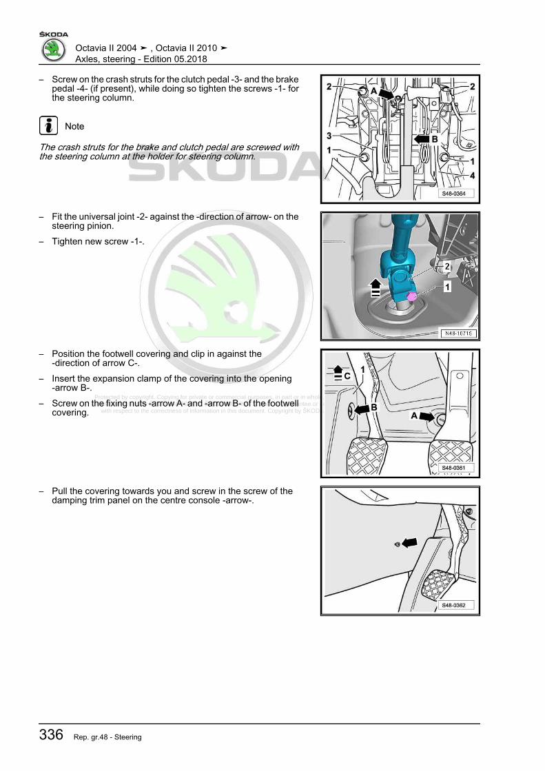
Protected by copyright. Copying for private or commercial purposes, in part or in whole, is not permitted unless authorised by ŠKODA AUTO A. S. ŠKODA AUTO A. S. does not guarantee or accept any liability
with respect to the correctness of information in this document. Copyright by ŠKODA AUTO A. S.�
– Screw on the crash struts for the clutch pedal -3- and the brakepedal -4- (if present), while doing so tighten the screws -1- forthe steering column.
Note
The crash struts for the brake and clutch pedal are screwed withthe steering column at the holder for steering column.
– Fit the universal joint -2- against the -direction of arrow- on thesteering pinion.
– Tighten new screw -1-.
– Position the footwell covering and clip in against the-direction of arrow C-.
– Insert the expansion clamp of the covering into the opening-arrow B-.
– Screw on the fixing nuts -arrow A- and -arrow B- of the footwellcovering.
– Pull the covering towards you and screw in the screw of thedamping trim panel on the centre console -arrow-.
Octavia II 2004 ➤ , Octavia II 2010 ➤Axles, steering - Edition 05.2018
336 Rep. gr.48 - Steering

Protected by copyright. Copying for private or commercial purposes, in part or in whole, is not permitted unless authorised by ŠKODA AUTO A. S. ŠKODA AUTO A. S. does not guarantee or accept any liability
with respect to the correctness of information in this document. Copyright by ŠKODA AUTO A. S.�
– Clip cable duct -1- onto steering column -arrows-.
Octavia II 2004 ➤ , Octavia II 2010 ➤Axles, steering - Edition 05.2018
1. Steering column 337

Protected by copyright. Copying for private or commercial purposes, in part or in whole, is not permitted unless authorised by ŠKODA AUTO A. S. ŠKODA AUTO A. S. does not guarantee or accept any liability
with respect to the correctness of information in this document. Copyright by ŠKODA AUTO A. S.�
– Attach the cable guide to the steering column -arrow B-.– Screw the earth line -arrow A- onto the steering column.– Install right footwell vent ⇒ Heating, Air Conditioning; Rep. gr.
80 .– Insert the damping trim panel and install the bottom part of the
dash panel ⇒ Body Work; Rep. gr. 70 .– Remove the lock cylinder from the steering lock housing and
fit the plug onto the immobilizer reading coil ⇒ Electrical Sys‐tem; Rep. gr. 94 .
Note
The steering lock must not be moved unless the lock cylinder isremoved, otherwise it would block completely. The blocked steer‐ing lock must be replaced
– Install lock cylinder.– Fit the plug onto the steering column electronics control unit -
J527- ⇒ Electrical System; Rep. gr. 94 .– Install bottom steering column trim panel ⇒ Body Work; Rep.
gr. 70 .– Install steering wheel and airbag ⇒ Body Work; Rep. gr. 69 .– Perform basic setting of the steering angle sender - G85-
⇒ Vehicle diagnostic tester.After the following installation work the basic setting of the steer‐ing angle sender - G85- must be checked:♦ if the steering angle encoder - G85- was removed or replaced
1)
♦ after removal or replacement of the steering column♦ after removal or replacement of the ignition lock housing with
steering column switch 1)
♦ after removal or replacement of the steering gear♦ if the steering wheel was offset1) Only applies for vehicles with the sender fitted between the steering wheel andthe steering column switch (2nd generation power-assisted steering).
Tightening torques - summaries of components
Note
Replace bolts / nuts that are tightened at an angle of rotation, aswell as replacement components after removal.
♦ ⇒ “1.1.2 Steering column summary of components, right-handdrive to CW 44/2008”, page 322
♦ Airbag and steering wheel ⇒ Body Work; Rep. gr. 69♦ Top and bottom steering column trim panel ⇒ Body Work;
Rep. gr. 70♦ Footwell vent ⇒ Heating, Air Conditioning; Rep. gr. 87♦ Steering column control ⇒ Electrical System; Rep. gr. 94♦ Switch unit ⇒ Electrical system; Rep. gr. 94
Octavia II 2004 ➤ , Octavia II 2010 ➤Axles, steering - Edition 05.2018
338 Rep. gr.48 - Steering

Protected by copyright. Copying for private or commercial purposes, in part or in whole, is not permitted unless authorised by ŠKODA AUTO A. S. ŠKODA AUTO A. S. does not guarantee or accept any liability
with respect to the correctness of information in this document. Copyright by ŠKODA AUTO A. S.�
1.4.3 Removing and installing steering col‐umn - left-hand drive, from CW 45/2008
RemovingThe steering column is supplied as a spare part in the form of acomplete assembly. Repairs are not allowed!The ignition lock housing can be modified ⇒ Electrical System;Rep. gr. 94 .When replacing the steering column, refit the steering columnswitches ⇒ Electrical System; Rep. gr. 94 .
WARNING
Before working on the electrical system and the removal of thesteering wheel the following conditions must be fulfilled:♦ Every mechanic must discharge him/herself of electro‐
static. This is done by touching an earthed metal part, suchas e.g. a water pipes, heating pipes, metal brackets or alift platform.
Failure to comply with these precautions may lead to a subse‐quent failure of the ELV control unit - J764- !♦ Disconnect battery earth strap ⇒ Electrical System; Rep.
gr. 27 .♦ The wheels must be in the straight-ahead position.
Failure to comply with these precautions may lead to subse‐quent failure of the airbag system!
– Put the front wheels in straight ahead position.– Press the adjusting lever for steering column downwards.– Press the steering column downwards, pull it towards you and
lock with the adjusting lever (the lever upwards).– Remove airbag and steering wheel ⇒ Body Work; Rep. gr.
69 .– Removing top and bottom steering column trim ⇒ Body Work;
Rep. gr. 70 .– Disconnect the plug from the steering column electronics con‐
trol unit -J527- ⇒ Electrical System; Rep. gr. 94 .– Disconnect the plug from the immobilizer reading coil (remove
lock cylinder from steering lock housing) ⇒ Electrical System;Rep. gr. 94 .
Note
The steering lock must not be moved unless the lock cylinder isremoved, otherwise it would block completely. The blocked steer‐ing lock must be replaced
– After disconnecting the plug from the immobilizer reading coil,re-install the lock cylinder into the steering lock housing ⇒ Electrical System; Rep. gr. 94 .
– Remove bottom part of the dash panel and the damping trimpanel ⇒ Body work; Rep. gr. 70 .
Octavia II 2004 ➤ , Octavia II 2010 ➤Axles, steering - Edition 05.2018
1. Steering column 339
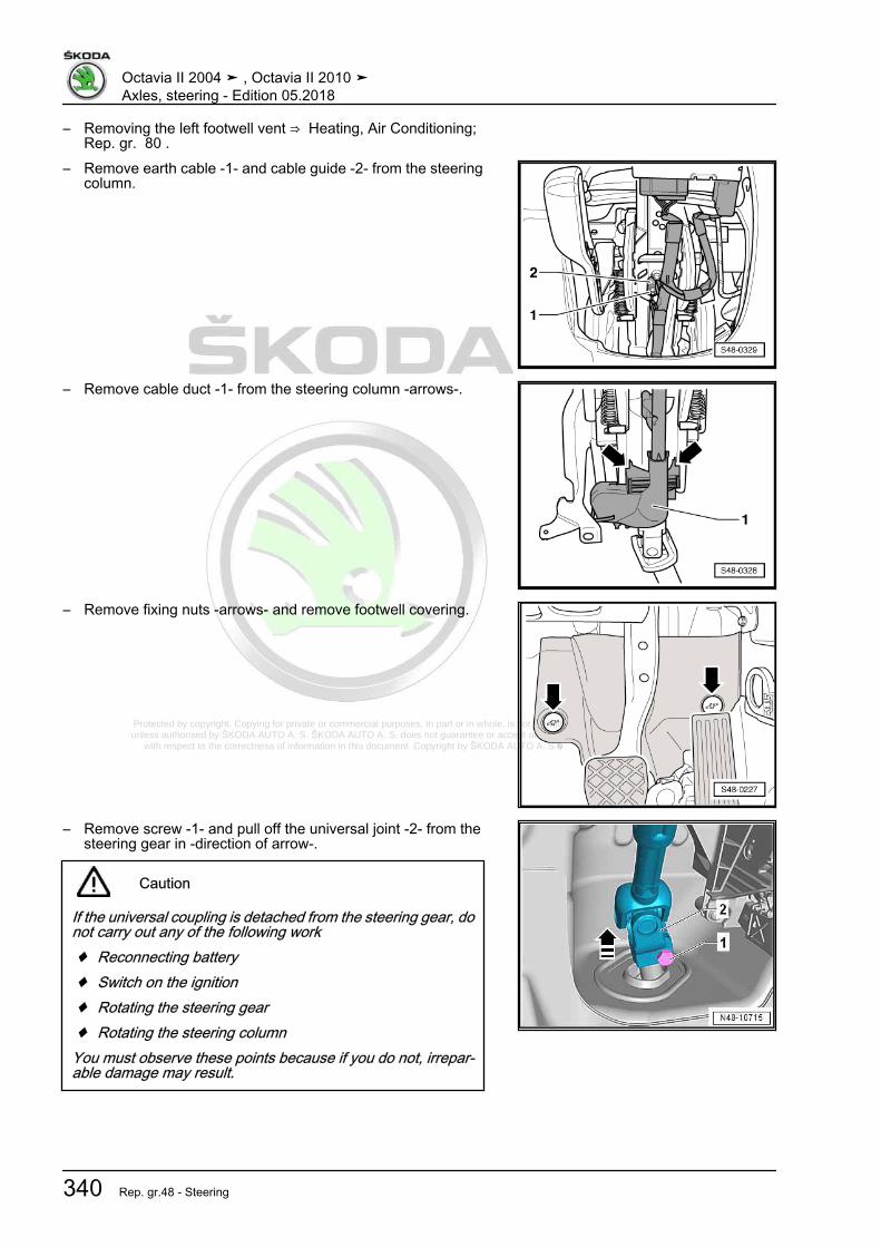
Protected by copyright. Copying for private or commercial purposes, in part or in whole, is not permitted unless authorised by ŠKODA AUTO A. S. ŠKODA AUTO A. S. does not guarantee or accept any liability
with respect to the correctness of information in this document. Copyright by ŠKODA AUTO A. S.�
– Removing the left footwell vent ⇒ Heating, Air Conditioning;Rep. gr. 80 .
– Remove earth cable -1- and cable guide -2- from the steeringcolumn.
– Remove cable duct -1- from the steering column -arrows-.
– Remove fixing nuts -arrows- and remove footwell covering.
– Remove screw -1- and pull off the universal joint -2- from thesteering gear in -direction of arrow-.
Caution
If the universal coupling is detached from the steering gear, donot carry out any of the following work♦ Reconnecting battery♦ Switch on the ignition♦ Rotating the steering gear♦ Rotating the steering column
You must observe these points because if you do not, irrepar‐able damage may result.
Octavia II 2004 ➤ , Octavia II 2010 ➤Axles, steering - Edition 05.2018
340 Rep. gr.48 - Steering

Protected by copyright. Copying for private or commercial purposes, in part or in whole, is not permitted unless authorised by ŠKODA AUTO A. S. ŠKODA AUTO A. S. does not guarantee or accept any liability
with respect to the correctness of information in this document. Copyright by ŠKODA AUTO A. S.�
– Remove fixing screws -2- and -3- for steering column andcrash strut for brake pedal ⇒ Item 3 (page 324) (if present).
– Remove fixing screw -4- for steering column and crash strutfor clutch pedal ⇒ Item 5 (page 324) (if present).
– Hold steering column and remove fixing screw -1-.– Carefully remove the steering column in direction of the vehi‐
cle interior.Observe handling and transportation of the steering column⇒ “1.3 Observe handling and transportation of the steering col‐umn”, page 326 .InstallingThe ignition lock housing can be modified ⇒ Electrical System;Rep. gr. 94 .When replacing the steering column, refit the steering columnswitches ⇒ Electrical System; Rep. gr. 94 .– Position the steering column on the holder (central pipe).
– Fix the steering column on the holder (central pipe) with screw-1-.
.– Insert the screw -4- into the crash strut for clutch pedal
⇒ Item 5 (page 324) (if present) and attach the steering col‐umn.
– Insert the screws -2- and -3- into the crash strut for brake pedal⇒ Item 3 (page 324) (if present) and attach the steering col‐umn.
– Tighten screws -1- and -2- and while doing so, check if thesteering column lies flush at the holder for steering column(central pipe).
– Tighten screws -3- and -4-.
– Fit the universal joint -2- against the -direction of arrow- on thesteering pinion.
– Tighten new screw -1-.
Octavia II 2004 ➤ , Octavia II 2010 ➤Axles, steering - Edition 05.2018
1. Steering column 341

Protected by copyright. Copying for private or commercial purposes, in part or in whole, is not permitted unless authorised by ŠKODA AUTO A. S. ŠKODA AUTO A. S. does not guarantee or accept any liability
with respect to the correctness of information in this document. Copyright by ŠKODA AUTO A. S.�
– Install cable duct -1- on steering column -arrows-.
– Position cable guide -2- on steering column and screw onearth cable -1-.
– Fit the plug onto the steering column electronics control unit -J527- ⇒ Electrical System; Rep. gr. 94 .
– Fit the plug onto the immobilizer reading coil (remove lock cyl‐inder from steering lock housing) ⇒ Electrical System; Rep.gr. 94 .
Note
The steering lock must not be moved unless the lock cylinder isremoved, otherwise it would block completely. The blocked steer‐ing lock must be replaced
– After fitting the plug onto the immobilizer reading coil, re-installthe lock cylinder into the steering lock housing ⇒ ElectricalSystem; Rep. gr. 94 .
– Install footwell vent driver's side ⇒ Heating, Air Conditioning;Rep. gr. 80 .
– Install bottom and top steering column trim ⇒ Body Work; Rep.gr. 70 .
– Install steering wheel and airbag ⇒ Body Work; Rep. gr. 69 .– Install the damping trim panel and the bottom part of the dash
panel ⇒ Body Work; Rep. gr. 70 .
Octavia II 2004 ➤ , Octavia II 2010 ➤Axles, steering - Edition 05.2018
342 Rep. gr.48 - Steering
Protected by copyright. Copying for private or commercial purposes, in part or in whole, is not permitted unless authorised by ŠKODA AUTO A. S. ŠKODA AUTO A. S. does not guarantee or accept any liability
with respect to the correctness of information in this document. Copyright by ŠKODA AUTO A. S.�
– Install footwell covering and fasten with nuts -arrows-.– Perform basic setting of the steering angle sender - G85-
⇒ Vehicle diagnostic tester.After the following installation work the basic setting of the steer‐ing angle sender - G85- must be checked:♦ if the steering angle sender - G85- was removed or replaced
1);♦ after removal or replacement of the steering column;♦ after removal or replacement of the ignition lock housing with
steering column switch 1);♦ after removal or replacement of the steering gear;♦ if the steering wheel was offset.1) Only applies for vehicles with the sender fitted between thesteering wheel and the steering column switch.♦ ⇒ “1.4.3 Removing and installing steering column - left-hand
drive, from CW 45/2008”, page 339♦ Airbag and steering wheel ⇒ Body Work; Rep. gr. 69♦ Top and bottom steering column trim panel ⇒ Body Work;
Rep. gr. 70♦ Left footwell vent on the driver side ⇒ Heating, Air Condition‐
ing; Rep. gr. 87♦ Steering column control ⇒ Electrical System; Rep. gr. 94♦ Switch unit ⇒ Electrical system; Rep. gr. 94
1.4.4 Removing and installing steering col‐umn, right-hand drive as of CW 45/2008
RemovingThe steering column is supplied as a spare part in the form of acomplete assembly. Repairs are not allowed!The ignition lock housing can be modified ⇒ Electrical System;Rep. gr. 94 .The switched on the steering column can be re-installed ⇒ Elec‐trical system; Rep. gr. 94 .
WARNING
Before working on the electrical system and the removal of thesteering wheel the following conditions must be fulfilled:♦ Every mechanic must discharge him/herself of electro‐
static. This is done by touching an earthed metal part, suchas e.g. a water pipes, heating pipes, metal brackets or alift platform.
Failure to comply with these precautions may lead to a subse‐quent failure of the ELV control unit - J764- !♦ Disconnect battery earth strap ⇒ Electrical System; Rep.
gr. 27 .♦ The wheels must be in the straight-ahead position.
Failure to comply with these precautions may lead to subse‐quent failure of the airbag system!
Octavia II 2004 ➤ , Octavia II 2010 ➤Axles, steering - Edition 05.2018
1. Steering column 343
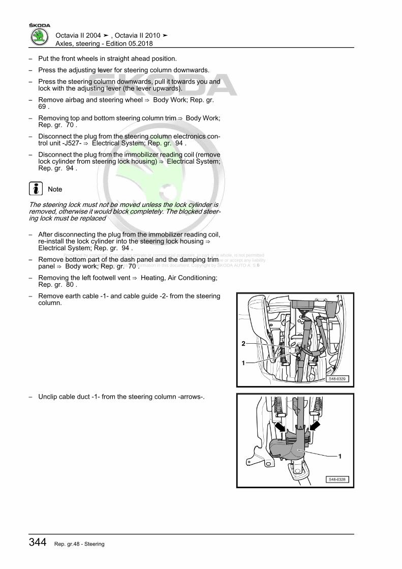
Protected by copyright. Copying for private or commercial purposes, in part or in whole, is not permitted unless authorised by ŠKODA AUTO A. S. ŠKODA AUTO A. S. does not guarantee or accept any liability
with respect to the correctness of information in this document. Copyright by ŠKODA AUTO A. S.�
– Put the front wheels in straight ahead position.– Press the adjusting lever for steering column downwards.– Press the steering column downwards, pull it towards you and
lock with the adjusting lever (the lever upwards).– Remove airbag and steering wheel ⇒ Body Work; Rep. gr.
69 .– Removing top and bottom steering column trim ⇒ Body Work;
Rep. gr. 70 .– Disconnect the plug from the steering column electronics con‐
trol unit -J527- ⇒ Electrical System; Rep. gr. 94 .– Disconnect the plug from the immobilizer reading coil (remove
lock cylinder from steering lock housing) ⇒ Electrical System;Rep. gr. 94 .
Note
The steering lock must not be moved unless the lock cylinder isremoved, otherwise it would block completely. The blocked steer‐ing lock must be replaced
– After disconnecting the plug from the immobilizer reading coil,re-install the lock cylinder into the steering lock housing ⇒ Electrical System; Rep. gr. 94 .
– Remove bottom part of the dash panel and the damping trimpanel ⇒ Body work; Rep. gr. 70 .
– Removing the left footwell vent ⇒ Heating, Air Conditioning;Rep. gr. 80 .
– Remove earth cable -1- and cable guide -2- from the steeringcolumn.
– Unclip cable duct -1- from the steering column -arrows-.
Octavia II 2004 ➤ , Octavia II 2010 ➤Axles, steering - Edition 05.2018
344 Rep. gr.48 - Steering

Protected by copyright. Copying for private or commercial purposes, in part or in whole, is not permitted unless authorised by ŠKODA AUTO A. S. ŠKODA AUTO A. S. does not guarantee or accept any liability
with respect to the correctness of information in this document. Copyright by ŠKODA AUTO A. S.�
– Remove the screw of the damping trim panel on the centreconsole -arrow- and pull off the trim panel.
– Remove the fixing nut -arrow A- and the expansion clamp-arrow B- of the footwell covering.
– Unclip the footwell covering in -direction of arrow C- and re‐move.
– Remove screw -1- and pull off the universal joint -2- from thesteering gear in -direction of arrow-.
Caution
If the universal coupling is detached from the steering gear, donot carry out any of the following work♦ Reconnecting battery♦ Switch on the ignition♦ Rotating the steering gear♦ Rotating the steering column
You must observe these points because if you do not, irrepar‐able damage may result.
– Remove fixing screws -3- and -4- for steering column.– Remove fixing screws -1- and -2- for steering column, hold
steering column.
Octavia II 2004 ➤ , Octavia II 2010 ➤Axles, steering - Edition 05.2018
1. Steering column 345

Protected by copyright. Copying for private or commercial purposes, in part or in whole, is not permitted unless authorised by ŠKODA AUTO A. S. ŠKODA AUTO A. S. does not guarantee or accept any liability
with respect to the correctness of information in this document. Copyright by ŠKODA AUTO A. S.�
– Slightly lower the steering column -1- and carefully pull out ofthe guide of the holder for the steering column in the directionof the vehicle interior.
Observe handling and transportation of the steering column⇒ “1.3 Observe handling and transportation of the steering col‐umn”, page 326 .InstallingThe ignition lock housing can be modified ⇒ Electrical System;Rep. gr. 94 .When replacing the steering column, refit the steering columnswitches ⇒ Electrical System; Rep. gr. 94 .
– Hook the steering column -1- with hanger onto the guide of theholder for the steering column -arrow-.
– Attach the steering column to the holder with screws -1- and-2-.
– Attach the steering column with screws -3- and -4-.– Tighten screws -1- and -2- and while doing so, check if the
steering column lies flush at the holder for steering column.– Tighten screws -3- and -4-.
– Connect the universal joint -2- to the steering gear and screwin screw -1-.
Octavia II 2004 ➤ , Octavia II 2010 ➤Axles, steering - Edition 05.2018
346 Rep. gr.48 - Steering

Protected by copyright. Copying for private or commercial purposes, in part or in whole, is not permitted unless authorised by ŠKODA AUTO A. S. ŠKODA AUTO A. S. does not guarantee or accept any liability
with respect to the correctness of information in this document. Copyright by ŠKODA AUTO A. S.�
– Position the footwell covering and clip in against the-direction of arrow C-.
– Insert the expansion clamp of the covering into the opening-arrow B-.
– Screw on the fixing nuts -arrow A- and -arrow B- of the footwellcovering.
– Pull the covering towards you and screw in the screw of thedamping trim panel on the centre console -arrow-.
– Clip cable duct -1- onto steering column -arrows-.
Octavia II 2004 ➤ , Octavia II 2010 ➤Axles, steering - Edition 05.2018
1. Steering column 347
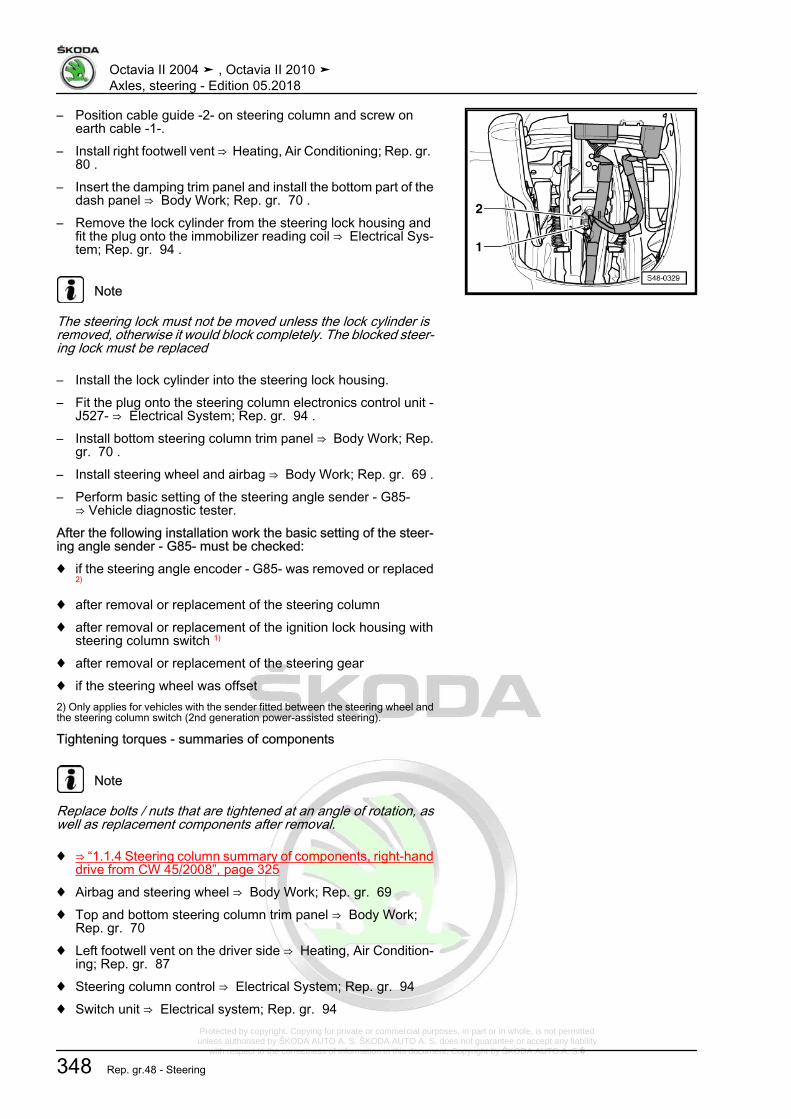
Protected by copyright. Copying for private or commercial purposes, in part or in whole, is not permitted unless authorised by ŠKODA AUTO A. S. ŠKODA AUTO A. S. does not guarantee or accept any liability
with respect to the correctness of information in this document. Copyright by ŠKODA AUTO A. S.�
– Position cable guide -2- on steering column and screw onearth cable -1-.
– Install right footwell vent ⇒ Heating, Air Conditioning; Rep. gr. 80 .
– Insert the damping trim panel and install the bottom part of thedash panel ⇒ Body Work; Rep. gr. 70 .
– Remove the lock cylinder from the steering lock housing andfit the plug onto the immobilizer reading coil ⇒ Electrical Sys‐tem; Rep. gr. 94 .
Note
The steering lock must not be moved unless the lock cylinder isremoved, otherwise it would block completely. The blocked steer‐ing lock must be replaced
– Install the lock cylinder into the steering lock housing.– Fit the plug onto the steering column electronics control unit -
J527- ⇒ Electrical System; Rep. gr. 94 .– Install bottom steering column trim panel ⇒ Body Work; Rep.
gr. 70 .– Install steering wheel and airbag ⇒ Body Work; Rep. gr. 69 .– Perform basic setting of the steering angle sender - G85-
⇒ Vehicle diagnostic tester.After the following installation work the basic setting of the steer‐ing angle sender - G85- must be checked:♦ if the steering angle encoder - G85- was removed or replaced
2)
♦ after removal or replacement of the steering column♦ after removal or replacement of the ignition lock housing with
steering column switch 1)
♦ after removal or replacement of the steering gear♦ if the steering wheel was offset2) Only applies for vehicles with the sender fitted between the steering wheel andthe steering column switch (2nd generation power-assisted steering).
Tightening torques - summaries of components
Note
Replace bolts / nuts that are tightened at an angle of rotation, aswell as replacement components after removal.
♦ ⇒ “1.1.4 Steering column summary of components, right-handdrive from CW 45/2008”, page 325
♦ Airbag and steering wheel ⇒ Body Work; Rep. gr. 69♦ Top and bottom steering column trim panel ⇒ Body Work;
Rep. gr. 70♦ Left footwell vent on the driver side ⇒ Heating, Air Condition‐
ing; Rep. gr. 87♦ Steering column control ⇒ Electrical System; Rep. gr. 94♦ Switch unit ⇒ Electrical system; Rep. gr. 94
Octavia II 2004 ➤ , Octavia II 2010 ➤Axles, steering - Edition 05.2018
348 Rep. gr.48 - Steering

Protected by copyright. Copying for private or commercial purposes, in part or in whole, is not permitted unless authorised by ŠKODA AUTO A. S. ŠKODA AUTO A. S. does not guarantee or accept any liability
with respect to the correctness of information in this document. Copyright by ŠKODA AUTO A. S.�
1.5 Removing and installing holder forsteering column and frequency link
⇒ “1.5.1 Removing and installing holder for steering column andfrequency link, left-hand drive”, page 349⇒ “1.5.2 Removing and installing holder for steering column andfrequency link, right-hand drive”, page 352
1.5.1 Removing and installing holder forsteering column and frequency link, left-hand drive
Removing– Remove steering column:for vehicles up to CW 44/2008⇒ “1.4.1 Removing and installing steering column - left-handdrive, up to CW 44/2008”, page 328for vehicles as of CW 45/2008⇒ “1.4.3 Removing and installing steering column - left-handdrive, from CW 45/2008”, page 339– Removing the dash panel ⇒ Body Work; Rep. gr. 70 .– Remove bulkhead plenum chamber ⇒ Body Work; Rep. gr.
66 .– Remove screw -arrow- in the plenum chamber.
– Unscrew fixing screw -arrow- of holder for steering column/frequency link.
Octavia II 2004 ➤ , Octavia II 2010 ➤Axles, steering - Edition 05.2018
1. Steering column 349

Protected by copyright. Copying for private or commercial purposes, in part or in whole, is not permitted unless authorised by ŠKODA AUTO A. S. ŠKODA AUTO A. S. does not guarantee or accept any liability
with respect to the correctness of information in this document. Copyright by ŠKODA AUTO A. S.�
– Screw out the fixing screws -1- of the frequency link.– Remove frequency link.
– Unscrew screws -arrow- below the holder.
– Remove screws -arrows- from holder at central pipe.
Note
The central pipe in the illustration is removed for purposes of clearpresentation.
– Remove holder for steering column.Installing– Position holder for steering column at central pipe.– Tighten the screws to the prescribed tightening torque.
– Screw frequency link outside the vehicle.– Respect dimension -a- = 167 mm.– Position frequency strut at central pipe.
Octavia II 2004 ➤ , Octavia II 2010 ➤Axles, steering - Edition 05.2018
350 Rep. gr.48 - Steering
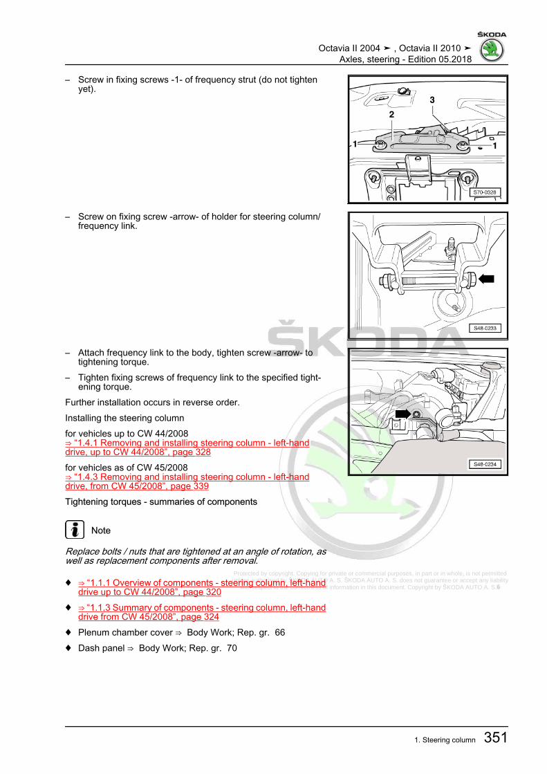
Protected by copyright. Copying for private or commercial purposes, in part or in whole, is not permitted unless authorised by ŠKODA AUTO A. S. ŠKODA AUTO A. S. does not guarantee or accept any liability
with respect to the correctness of information in this document. Copyright by ŠKODA AUTO A. S.�
– Screw in fixing screws -1- of frequency strut (do not tightenyet).
– Screw on fixing screw -arrow- of holder for steering column/frequency link.
– Attach frequency link to the body, tighten screw -arrow- totightening torque.
– Tighten fixing screws of frequency link to the specified tight‐ening torque.
Further installation occurs in reverse order.Installing the steering columnfor vehicles up to CW 44/2008⇒ “1.4.1 Removing and installing steering column - left-handdrive, up to CW 44/2008”, page 328for vehicles as of CW 45/2008⇒ “1.4.3 Removing and installing steering column - left-handdrive, from CW 45/2008”, page 339Tightening torques - summaries of components
Note
Replace bolts / nuts that are tightened at an angle of rotation, aswell as replacement components after removal.
♦ ⇒ “1.1.1 Overview of components - steering column, left-handdrive up to CW 44/2008”, page 320
♦ ⇒ “1.1.3 Summary of components - steering column, left-handdrive from CW 45/2008”, page 324
♦ Plenum chamber cover ⇒ Body Work; Rep. gr. 66♦ Dash panel ⇒ Body Work; Rep. gr. 70
Octavia II 2004 ➤ , Octavia II 2010 ➤Axles, steering - Edition 05.2018
1. Steering column 351
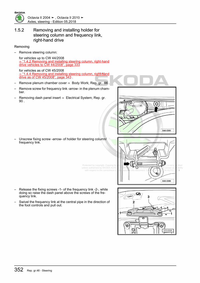
Protected by copyright. Copying for private or commercial purposes, in part or in whole, is not permitted unless authorised by ŠKODA AUTO A. S. ŠKODA AUTO A. S. does not guarantee or accept any liability
with respect to the correctness of information in this document. Copyright by ŠKODA AUTO A. S.�
1.5.2 Removing and installing holder forsteering column and frequency link,right-hand drive
Removing– Remove steering column:
for vehicles up to CW 44/2008⇒ “1.4.2 Removing and installing steering column, right-handdrive vehicles to CW 44/2008”, page 333for vehicles as of CW 45/2008⇒ “1.4.4 Removing and installing steering column, right-handdrive as of CW 45/2008”, page 343 .
– Remove plenum chamber cover ⇒ Body Work; Rep. gr. 66 .– Remove screw for frequency link -arrow- in the plenum cham‐
ber.– Removing dash panel insert ⇒ Electrical System; Rep. gr.
90 .
– Unscrew fixing screw -arrow- of holder for steering column/frequency link.
– Release the fixing screws -1- of the frequency link -2-, whiledoing so raise the dash panel above the screws of the fre‐quency link.
– Swivel the frequency link at the central pipe in the direction ofthe foot controls and pull out.
Octavia II 2004 ➤ , Octavia II 2010 ➤Axles, steering - Edition 05.2018
352 Rep. gr.48 - Steering

Protected by copyright. Copying for private or commercial purposes, in part or in whole, is not permitted unless authorised by ŠKODA AUTO A. S. ŠKODA AUTO A. S. does not guarantee or accept any liability
with respect to the correctness of information in this document. Copyright by ŠKODA AUTO A. S.�
– Unscrew screws -arrow- below the holder.
– Remove screws -arrows- from holder at central pipe.
Note
The central pipe in the illustration is removed for purposes of clearpresentation.
– Remove holder for steering column.Installing
– Position the holder for the steering column at the central pipeand screw on the screws -arrows-.
– Screw on the screws -arrows- below the holder.
Octavia II 2004 ➤ , Octavia II 2010 ➤Axles, steering - Edition 05.2018
1. Steering column 353

Protected by copyright. Copying for private or commercial purposes, in part or in whole, is not permitted unless authorised by ŠKODA AUTO A. S. ŠKODA AUTO A. S. does not guarantee or accept any liability
with respect to the correctness of information in this document. Copyright by ŠKODA AUTO A. S.�
– Screw frequency link outside the vehicle.– Respect dimension -a- = 167 mm.– Insert the frequency link in the area above the foot controls.– Swivel the frequency link on the central pipe upwards.
– Slightly screw on the fixing screws -1- of the frequency link-2-, while doing carefully raise the dash panel above thescrews of the frequency link.
– Screw on fixing screw -arrow- of holder for steering column/frequency link.
Octavia II 2004 ➤ , Octavia II 2010 ➤Axles, steering - Edition 05.2018
354 Rep. gr.48 - Steering

Protected by copyright. Copying for private or commercial purposes, in part or in whole, is not permitted unless authorised by ŠKODA AUTO A. S. ŠKODA AUTO A. S. does not guarantee or accept any liability
with respect to the correctness of information in this document. Copyright by ŠKODA AUTO A. S.�
– Attach frequency link to the body, tighten screw -arrow- totightening torque.
– Tighten fixing screws of frequency link to the specified tight‐ening torque.
– Install the plenum chamber cover ⇒ Body Work; Rep. gr. 66 .– Installing dash panel insert ⇒ Electrical System; Rep. gr. 90 .– Install the steering column:
for vehicles up to CW 44/2008⇒ “1.4.2 Removing and installing steering column, right-handdrive vehicles to CW 44/2008”, page 333for vehicles as of CW 45/2008⇒ “1.4.4 Removing and installing steering column, right-handdrive as of CW 45/2008”, page 343
Tightening torques - summaries of components
Note
Replace bolts / nuts that are tightened at an angle of rotation, aswell as replacement components after removal.
♦ ⇒ “1.1.2 Steering column summary of components, right-handdrive to CW 44/2008”, page 322
♦ ⇒ “1.1.4 Steering column summary of components, right-handdrive from CW 45/2008”, page 325
♦ Plenum chamber cover ⇒ Body Work; Rep. gr. 66♦ Dash panel insert ⇒ Electrical System; Rep. gr. 90
Octavia II 2004 ➤ , Octavia II 2010 ➤Axles, steering - Edition 05.2018
1. Steering column 355

Protected by copyright. Copying for private or commercial purposes, in part or in whole, is not permitted unless authorised by ŠKODA AUTO A. S. ŠKODA AUTO A. S. does not guarantee or accept any liability
with respect to the correctness of information in this document. Copyright by ŠKODA AUTO A. S.�
2 Steering gear⇒ “2.1 Summary of components - steering gear”, page 356⇒ “2.2 Removing and installing steering gear”, page 361⇒ “2.3 Removing and installing bellows”, page 372⇒ “2.4 Removing and installing track rod”, page 375⇒ “2.5 Removing and installing track rod ends”, page 379⇒ “2.6 Repairing steering box”, page 380
2.1 Summary of components - steering gear⇒ “2.1.1 Summary of components - steering gear, left-hand drive,aluminium assembly carrier”, page 356⇒ “2.1.2 Summary of components - steering gear, right-handdrive, aluminium assembly carrier”, page 358⇒ “2.1.3 Summary of components - steering gear, left-hand drive,sheet steel assembly carrier”, page 359⇒ “2.1.4 Summary of components - steering gear, right-handdrive, sheet steel assembly carrier”, page 360
2.1.1 Summary of components - steering gear, left-hand drive, aluminium as‐sembly carrier
Octavia II 2004 ➤ , Octavia II 2010 ➤Axles, steering - Edition 05.2018
356 Rep. gr.48 - Steering

Protected by copyright. Copying for private or commercial purposes, in part or in whole, is not permitted unless authorised by ŠKODA AUTO A. S. ŠKODA AUTO A. S. does not guarantee or accept any liability
with respect to the correctness of information in this document. Copyright by ŠKODA AUTO A. S.�
1 - Universal joint2 - Screw
❑ M8 x 32❑ replace after each re‐
moval❑ Tightening torque
⇒ “2.1 Summary of com‐ponents - steeringgear”, page 356
3 - Electrical line4 - Power-steering gear
❑ with power steeringcontrol unit - J500-
❑ can be checked in theguided fault detectionsystem with ⇒ Vehiclediagnostic tester
Vehicles from CW 22/09❑ The 3rd generation
power-assisted steering❑ The steering angle
sender - G85- is integra‐ted in the steering gearand cannot be replacedseparately
❑ with three point fixing atassembly carrier
5 - Wheel bearing housing6 - Nut
❑ self-locking❑ replace after each re‐
moval❑ 20 Nm + 90°
7 - Assembly carrier with consoles8 - Screw
❑ M10 x 76❑ replace after each removal❑ 50 Nm + 90°
9 - Protection plate10 - Screw
❑ 6 Nm
Octavia II 2004 ➤ , Octavia II 2010 ➤Axles, steering - Edition 05.2018
2. Steering gear 357

Protected by copyright. Copying for private or commercial purposes, in part or in whole, is not permitted unless authorised by ŠKODA AUTO A. S. ŠKODA AUTO A. S. does not guarantee or accept any liability
with respect to the correctness of information in this document. Copyright by ŠKODA AUTO A. S.�
2.1.2 Summary of components - steering gear, right-hand drive, aluminium as‐sembly carrier
1 - Universal joint2 - Screw
❑ M8 x 32❑ replace after each re‐
moval❑ Tightening torque
⇒ “2.1 Summary of com‐ponents - steeringgear”, page 356
3 - Electrical line4 - Protection plate5 - Screw
❑ 6 Nm6 - Power-steering gear
❑ with power steeringcontrol unit - J500-
❑ can be checked in theguided fault detectionsystem with ⇒ Vehiclediagnostic tester
Vehicles from CW 22/2008❑ The 3rd generation
power-assisted steering❑ The steering angle
sender - G85- is integra‐ted in the steering gearand cannot be replacedseparately
❑ with three point fixing atassembly carrier
7 - Wheel bearing housing8 - Nut
❑ self-locking❑ replace after each removal❑ 20 Nm + 90°
9 - Screw❑ M10 x 76❑ replace after each removal❑ 50 Nm + 90°
10 - Assembly carrier with consoles11 - Wheel bearing housing
Octavia II 2004 ➤ , Octavia II 2010 ➤Axles, steering - Edition 05.2018
358 Rep. gr.48 - Steering

Protected by copyright. Copying for private or commercial purposes, in part or in whole, is not permitted unless authorised by ŠKODA AUTO A. S. ŠKODA AUTO A. S. does not guarantee or accept any liability
with respect to the correctness of information in this document. Copyright by ŠKODA AUTO A. S.�
2.1.3 Summary of components - steering gear, left-hand drive, sheet steel as‐sembly carrier
1 - Universal joint2 - Screw
❑ M8 x 32❑ replace after each re‐
moval❑ Tightening torque
⇒ “2.1 Summary of com‐ponents - steeringgear”, page 356
3 - Electrical line4 - Power-steering gear
❑ The 3rd generationpower-assisted steering
❑ with power-assistedsteering control unit -J500-
❑ The steering anglesender - G85- is integra‐ted in the steering gearand cannot be replacedseparately
❑ check in the targetedfault finding ⇒ Vehiclediagnostic tester
❑ after installing a newpower-steering gear,adapt the steering anglesender - G85- ⇒ Vehiclediagnostic tester
❑ adapt the power-assis‐ted steering control unit- J500- after installing anew power-steeringgear ⇒ Vehicle diagnos‐tic tester
5 - Wheel bearing housing6 - Nut
❑ self-locking❑ replace after each removal❑ 20 Nm + 90°
7 - Assembly carrier made of steel sheet8 - Screw
❑ M10 x 76❑ replace after each removal❑ 50 Nm + 90°
9 - Protection plate10 - Screw
❑ 6 Nm
Octavia II 2004 ➤ , Octavia II 2010 ➤Axles, steering - Edition 05.2018
2. Steering gear 359

Protected by copyright. Copying for private or commercial purposes, in part or in whole, is not permitted unless authorised by ŠKODA AUTO A. S. ŠKODA AUTO A. S. does not guarantee or accept any liability
with respect to the correctness of information in this document. Copyright by ŠKODA AUTO A. S.�
2.1.4 Summary of components - steering gear, right-hand drive, sheet steel as‐sembly carrier
1 - Universal joint2 - Screw
❑ M8 x 32❑ replace after each re‐
moval❑ Tightening torque
⇒ “2.1 Summary of com‐ponents - steeringgear”, page 356
3 - Electrical line4 - Protection plate5 - Screw
❑ 6 Nm6 - Power-steering gear
❑ with power steeringcontrol unit - J500-
❑ can be checked in theguided fault detectionsystem with ⇒ Vehiclediagnostic tester
❑ The 3rd generationpower-assisted steering
❑ The steering anglesender - G85- is integra‐ted in the steering gearand cannot be replacedseparately
❑ with three point fixing atassembly carrier
❑ after installing a newpower-steering gear,adapt the steering anglesender - G85- ⇒ Vehiclediagnostic tester
❑ adapt the power-assisted steering control unit - J500- after installing a new power-steering gear ⇒ Vehiclediagnostic tester
7 - Wheel bearing housing8 - Nut
❑ self-locking❑ replace after each removal❑ 20 Nm + 90°
9 - Screw❑ M10 x 76❑ replace after each removal❑ 50 Nm + 90°
10 - Assembly carrier made of steel sheet11 - Wheel bearing housing
Octavia II 2004 ➤ , Octavia II 2010 ➤Axles, steering - Edition 05.2018
360 Rep. gr.48 - Steering

Protected by copyright. Copying for private or commercial purposes, in part or in whole, is not permitted unless authorised by ŠKODA AUTO A. S. ŠKODA AUTO A. S. does not guarantee or accept any liability
with respect to the correctness of information in this document. Copyright by ŠKODA AUTO A. S.�
2.2 Removing and installing steering gear⇒ “2.2.1 Removing and installing steering gear, left-hand drive,aluminium assembly carrier”, page 361⇒ “2.2.2 Removing and installing steering gear, right-hand drive,aluminium assembly carrier”, page 364⇒ “2.2.3 Removing and installing steering gear, left-hand drive,sheet steel assembly carrier”, page 368⇒ “2.2.4 Removing and installing steering gear, right-hand drive,sheet steel assembly carrier”, page 370
2.2.1 Removing and installing steering gear,left-hand drive, aluminium assemblycarrier
Removing– Disconnect battery ⇒ Electrical System; Rep. gr. 27 .– Remove noise insulation ⇒ Body Work; Rep. gr. 50 .Vehicles up to CW 21/2009 (2nd generation power-assistedsteering)– Remove screws -arrows- from the heat shield.– Remove assembly carrier from vehicle.
– Release screws -1-, - 2-, -3- and -4-.Vehicles as of CW 22/2009 (3rd generation power-assisted steer‐ing)
Octavia II 2004 ➤ , Octavia II 2010 ➤Axles, steering - Edition 05.2018
2. Steering gear 361

Protected by copyright. Copying for private or commercial purposes, in part or in whole, is not permitted unless authorised by ŠKODA AUTO A. S. ŠKODA AUTO A. S. does not guarantee or accept any liability
with respect to the correctness of information in this document. Copyright by ŠKODA AUTO A. S.�
– Release screws -1- and - 2- for steering gear.Continued for all vehicles– Remove assembly carrier with steering gear
⇒ “2.5.1 Removing and installing assembly carrier with steer‐ing gear, aluminium assembly carrier, left-hand drive”,page 24 .
– Remove fixing screws for steering gear.– Remove the steering gear from the assembly carrier.InstallingInstallation is carried out in the reverse order.The threaded bushings of the steering gear must fit in the holesof the consoles.
Note
♦ Coat the sealing sleeve on the steering gear with lubricant,e.g. lubricating soap, before installing the steering gear.
♦ When positioning the steering gear on the drive shaft makesure the seal on the steering gear is not damaged or twistedand rests flush against the body. Otherwise this could causewater penetration and noise.
♦ Make sure all sealing surfaces are clean.
– Position the steering gear on the assembly carrier so that thethreaded bushings lock into the openings of the assembly car‐rier.
Vehicles up to CW 21/2009 (2nd generation power-assistedsteering)
– Screw in new screws -1-, -2-, -3- and -4- and tighten to therecommended tightening torque.
Octavia II 2004 ➤ , Octavia II 2010 ➤Axles, steering - Edition 05.2018
362 Rep. gr.48 - Steering

Protected by copyright. Copying for private or commercial purposes, in part or in whole, is not permitted unless authorised by ŠKODA AUTO A. S. ŠKODA AUTO A. S. does not guarantee or accept any liability
with respect to the correctness of information in this document. Copyright by ŠKODA AUTO A. S.�
– Screw the heat shield to the assembly carrier.Vehicles as of CW 22/2009 (3rd generation power-assisted steer‐ing)
Octavia II 2004 ➤ , Octavia II 2010 ➤Axles, steering - Edition 05.2018
2. Steering gear 363

Protected by copyright. Copying for private or commercial purposes, in part or in whole, is not permitted unless authorised by ŠKODA AUTO A. S. ŠKODA AUTO A. S. does not guarantee or accept any liability
with respect to the correctness of information in this document. Copyright by ŠKODA AUTO A. S.�
– Screw in new screws -1- and - 2- for steering gear.Continued for all vehicles– Install assembly carrier with steering gear
⇒ “2.5.1 Removing and installing assembly carrier with steer‐ing gear, aluminium assembly carrier, left-hand drive”,page 24 .
– Connect battery ⇒ Electrical System; Rep. gr. 27 .
Note
Observe the instructions after reattaching the battery ⇒ ElectricalSystem; Rep. gr. 27 .
Vehicles up to CW 21/2009 (2nd generation power-assistedsteering)– Perform basic setting of the steering angle sender - G85- with
the ⇒ Vehicle diagnostic tester.Continued for all vehiclesIf a new steering gear is installed, perform the basic setting of thepower-assisted steering control unit - J500- and the steering an‐gle sender - G85 - with the ⇒ Vehicle diagnostic tester
Note
It is necessary to perform an axle alignment in the event of:⇒ “3.3 Axle alignment”, page 309
– Perform a test drive– Check the steering wheel position during the test drive.
Note
If after the test drive and with the wheels pointing straight aheadthe steering wheel is off straight, perform an axle alignment⇒ “3.3 Axle alignment”, page 309 .
Tightening torques - summaries of components
Note
Replace bolts / nuts that are tightened at an angle of rotation, aswell as replacement components after removal.
♦ ⇒ “2.1.1 Summary of components - steering gear, left-handdrive, aluminium assembly carrier”, page 356
2.2.2 Removing and installing steering gear,right-hand drive, aluminium assemblycarrier
Removing– Disconnect battery ⇒ Electrical System; Rep. gr. 27 .– Remove noise insulation ⇒ Body Work; Rep. gr. 50 .
Octavia II 2004 ➤ , Octavia II 2010 ➤Axles, steering - Edition 05.2018
364 Rep. gr.48 - Steering

Protected by copyright. Copying for private or commercial purposes, in part or in whole, is not permitted unless authorised by ŠKODA AUTO A. S. ŠKODA AUTO A. S. does not guarantee or accept any liability
with respect to the correctness of information in this document. Copyright by ŠKODA AUTO A. S.�
Vehicles up to CW 21/2008 (2nd generation power-assistedsteering)– Remove screws -arrows- from the heat shield.– Remove assembly carrier from vehicle.
– Release screws -1-, - 2-, -3- and -4-.Vehicles as of CW 22/2008 (3rd generation power-assisted steer‐ing)
Octavia II 2004 ➤ , Octavia II 2010 ➤Axles, steering - Edition 05.2018
2. Steering gear 365

Protected by copyright. Copying for private or commercial purposes, in part or in whole, is not permitted unless authorised by ŠKODA AUTO A. S. ŠKODA AUTO A. S. does not guarantee or accept any liability
with respect to the correctness of information in this document. Copyright by ŠKODA AUTO A. S.�
– Release screws -1- and - 2- for steering gear.Continued for all vehicles– Remove assembly carrier with steering gear
⇒ “2.5.2 Removing and installing assembly carrier with steer‐ing gear, aluminium assembly carrier right-hand drive”,page 29 .
– Release fixing screws for steering gear.– Remove the steering gear from the assembly carrier.InstallingInstallation is carried out in the reverse order.The threaded bushings of the steering gear must fit in the holesof the consoles.
Note
♦ Coat the sealing sleeve on the steering gear with lubricant,e.g. lubricating soap, before installing the steering gear.
♦ When positioning the steering gear on the drive shaft makesure the seal on the steering gear is not damaged or twistedand rests flush against the body. Otherwise this could causewater penetration and noise.
♦ Make sure all sealing surfaces are clean.
– Position the steering gear on the assembly carrier so that thethreaded bushings lock into the openings of the assembly car‐rier.
Vehicles up to CW 21/2008 (2nd generation power-assistedsteering)
– Screw in new screws -1-, -2-, -3- and -4- and tighten to therecommended tightening torque.
Octavia II 2004 ➤ , Octavia II 2010 ➤Axles, steering - Edition 05.2018
366 Rep. gr.48 - Steering

Protected by copyright. Copying for private or commercial purposes, in part or in whole, is not permitted unless authorised by ŠKODA AUTO A. S. ŠKODA AUTO A. S. does not guarantee or accept any liability
with respect to the correctness of information in this document. Copyright by ŠKODA AUTO A. S.�
– Screw the heat shield to the assembly carrier.Vehicles as of CW 22/2008 (3rd generation power-assisted steer‐ing)
Octavia II 2004 ➤ , Octavia II 2010 ➤Axles, steering - Edition 05.2018
2. Steering gear 367

Protected by copyright. Copying for private or commercial purposes, in part or in whole, is not permitted unless authorised by ŠKODA AUTO A. S. ŠKODA AUTO A. S. does not guarantee or accept any liability
with respect to the correctness of information in this document. Copyright by ŠKODA AUTO A. S.�
– Screw in new screws -1- and - 2- for steering gear.Continued for all vehicles– Install assembly carrier with steering gear
⇒ “2.5.2 Removing and installing assembly carrier with steer‐ing gear, aluminium assembly carrier right-hand drive”,page 29 .
– Connect battery ⇒ Electrical System; Rep. gr. 27 .
Note
Observe the instructions after reattaching the battery ⇒ ElectricalSystem; Rep. gr. 27 .
Vehicles up to CW 21/2008 (2nd generation power-assistedsteering)– Perform basic setting of the steering angle sender - G85- with
the ⇒ Vehicle diagnostic tester.Continued for all vehiclesIf a new steering gear is installed, perform the basic setting of thepower-assisted steering control unit - J500- and the steering an‐gle sender - G85 - with the ⇒ Vehicle diagnostic tester
Note
It is necessary to perform an axle alignment in the event of:⇒ “3.3 Axle alignment”, page 309
– Perform a test drive– Check the steering wheel position during the test drive.
Note
If after the test drive and with the wheels pointing straight aheadthe steering wheel is off straight, perform an axle alignment⇒ “3.3 Axle alignment”, page 309 .
Tightening torques - summaries of components
Note
Replace bolts / nuts that are tightened at an angle of rotation, aswell as replacement components after removal.
♦ ⇒ “2.1.2 Summary of components - steering gear, right-handdrive, aluminium assembly carrier”, page 358
2.2.3 Removing and installing steering gear,left-hand drive, sheet steel assemblycarrier
Removing– Disconnect battery ⇒ Electrical System; Rep. gr. 27 .– Remove assembly carrier
⇒ “3.5.1 Removing and installing assembly carrier with steer‐
Octavia II 2004 ➤ , Octavia II 2010 ➤Axles, steering - Edition 05.2018
368 Rep. gr.48 - Steering

Protected by copyright. Copying for private or commercial purposes, in part or in whole, is not permitted unless authorised by ŠKODA AUTO A. S. ŠKODA AUTO A. S. does not guarantee or accept any liability
with respect to the correctness of information in this document. Copyright by ŠKODA AUTO A. S.�
ing gear, sheet steel assembly carrier, left-hand drive”,page 75 .
– Remove screws for steering gear -1- and -2- from assemblycarrier.
– Raise the steering gear until the threaded bushings of thesteering gear are pushed out of the assembly carrier.
– Raise the steering gear.InstallingInstallation is carried out in the reverse order.The threaded bushings of the steering gear must fit in the holesof the assembly carrier.
Note
♦ Coat the sealing sleeve on the steering gear with lubricant,e.g. lubricating soap, before installing the steering gear.
♦ After positioning the steering gear on the drive shaft make surethe seal on the steering gear is not bent on the assembly plateand correctly seals the footwell opening. Otherwise this couldcause water penetration and/or noise.
♦ Make sure all sealing surfaces are clean.
– Position the steering gear on the assembly carrier so that thethreaded bushings lock into the openings of the assembly car‐rier.
Octavia II 2004 ➤ , Octavia II 2010 ➤Axles, steering - Edition 05.2018
2. Steering gear 369

Protected by copyright. Copying for private or commercial purposes, in part or in whole, is not permitted unless authorised by ŠKODA AUTO A. S. ŠKODA AUTO A. S. does not guarantee or accept any liability
with respect to the correctness of information in this document. Copyright by ŠKODA AUTO A. S.�
– Screw in the new screws for the steering gear -1- and -2- andtighten to the specified tightening torque.
– Install the assembly carrier on the body⇒ “3.5.1 Removing and installing assembly carrier with steer‐ing gear, sheet steel assembly carrier, left-hand drive”,page 75
Note
Make sure the steering gear boot is neither damaged nor twisted.
– Connect battery ⇒ Electrical System; Rep. gr. 27 .
Note
Observe the instructions after reattaching the battery ⇒ ElectricalSystem; Rep. gr. 27 .
Note
It is necessary to perform an axle alignment in the event of:⇒ “3.3 Axle alignment”, page 309 .
– Perform a test drive– Check the steering wheel position during the test drive.
Note
If after the test drive and with the wheels pointing straight aheadthe steering wheel is off straight, perform an axle alignment⇒ “3.3 Axle alignment”, page 309 .
If a new steering gear is installed, perform the basic setting of thepower-assisted steering control unit - J500- and the steering an‐gle sender - G85 - with the ⇒ Vehicle diagnostic testerTightening torques - summaries of components
Note
Replace bolts / nuts that are tightened at an angle of rotation, aswell as replacement components after removal.
♦ ⇒ “2.1.3 Summary of components - steering gear, left-handdrive, sheet steel assembly carrier”, page 359
2.2.4 Removing and installing steering gear,right-hand drive, sheet steel assemblycarrier
Removing– Disconnect battery ⇒ Electrical System; Rep. gr. 27 .– Remove assembly carrier
⇒ “2 Front axle with aluminium assembly carrier”, page 10
Octavia II 2004 ➤ , Octavia II 2010 ➤Axles, steering - Edition 05.2018
370 Rep. gr.48 - Steering

Protected by copyright. Copying for private or commercial purposes, in part or in whole, is not permitted unless authorised by ŠKODA AUTO A. S. ŠKODA AUTO A. S. does not guarantee or accept any liability
with respect to the correctness of information in this document. Copyright by ŠKODA AUTO A. S.�
– Remove screws for steering gear -1- and -2- from assemblycarrier.
– Raise the steering gear until the threaded bushings of thesteering gear are pushed out of the assembly carrier.
– Raise the steering gear.InstallingInstallation is carried out in the reverse order.The threaded bushings of the steering gear must fit in the holesof the assembly carrier.
Note
♦ Coat the sealing sleeve on the steering gear with lubricant,e.g. lubricating soap, before installing the steering gear.
♦ After positioning the steering gear on the drive shaft make surethe seal on the steering gear is not bent on the assembly plateand correctly seals the footwell opening. Otherwise this couldcause water penetration and/or noise.
♦ Make sure all sealing surfaces are clean.
– Position the steering gear on the assembly carrier so that thethreaded bushings lock into the openings of the assembly car‐rier.
Octavia II 2004 ➤ , Octavia II 2010 ➤Axles, steering - Edition 05.2018
2. Steering gear 371

Protected by copyright. Copying for private or commercial purposes, in part or in whole, is not permitted unless authorised by ŠKODA AUTO A. S. ŠKODA AUTO A. S. does not guarantee or accept any liability
with respect to the correctness of information in this document. Copyright by ŠKODA AUTO A. S.�
– Screw in the new screws for the steering gear -1- and -2- andtighten to the specified tightening torque.
– Install the assembly carrier on the body⇒ “2 Front axle with aluminium assembly carrier”, page 10
Note
Make sure the steering gear boot is neither damaged nor twisted.
– Connect battery ⇒ Electrical System; Rep. gr. 27 .
Note
Observe the instructions after reattaching the battery ⇒ ElectricalSystem; Rep. gr. 27 .
Note
It is necessary to perform an axle alignment in the event of:⇒ “3.3 Axle alignment”, page 309 .
– Perform a test drive– Check the steering wheel position during the test drive.
Note
If after the test drive and with the wheels pointing straight aheadthe steering wheel is off straight, perform an axle alignment⇒ “3.3 Axle alignment”, page 309 .
If a new steering gear is installed, perform the basic setting of thepower-assisted steering control unit - J500- and the steering an‐gle sender - G85 - with the ⇒ Vehicle diagnostic testerTightening torques - summaries of components
Note
Replace bolts / nuts that are tightened at an angle of rotation, aswell as replacement components after removal.
♦ ⇒ “2.1.4 Summary of components - steering gear, right-handdrive, sheet steel assembly carrier”, page 360
2.3 Removing and installing bellowsSpecial tools and workshop equipment required♦ Clamp pliers for steering gear e.g. -VAS 6199-♦ Hose strap pliers , e.g. -V.A.G 1275-
Octavia II 2004 ➤ , Octavia II 2010 ➤Axles, steering - Edition 05.2018
372 Rep. gr.48 - Steering

Protected by copyright. Copying for private or commercial purposes, in part or in whole, is not permitted unless authorised by ŠKODA AUTO A. S. ŠKODA AUTO A. S. does not guarantee or accept any liability
with respect to the correctness of information in this document. Copyright by ŠKODA AUTO A. S.�
Removing
Caution
If bellows are defective humidity and dirt penetrates into thesteering gear. In the area of the serration on the gear rack, atangible grease film must be present. If the grease film is notpresent, the steering gear must be replaced.Replace the steering gear in the event of:♦ Corrosion♦ Damage♦ Wear♦ Soiling on the steering rack
– Turn steering wheel to the straight ahead position.– Remove wheel.– Clean outside of steering gear in the area of the bellows.
Octavia II 2004 ➤ , Octavia II 2010 ➤Axles, steering - Edition 05.2018
2. Steering gear 373

Protected by copyright. Copying for private or commercial purposes, in part or in whole, is not permitted unless authorised by ŠKODA AUTO A. S. ŠKODA AUTO A. S. does not guarantee or accept any liability
with respect to the correctness of information in this document. Copyright by ŠKODA AUTO A. S.�
While doing so, no dirt must get into the steering gear through thedefective bellows.– Mark the position of the nut -3- on the track rod.– Remove track-rod end
⇒ “2.5 Removing and installing track rod ends”, page 379 .– Clean outside of steering box in vicinity of boot.
Note
While doing so, no dirt must get into the steering gear through thedefective bellows.
– Use the hose clip pliers - V.A.G 1275- to remove the springclip -1-.
– Remove warm-type clamp.– Remove bellows from the steering gear housing and track rod.
Note
♦ If corrosion, damage, wear or traces of dirt are visible on thegear rack, the steering gear must be replaced completely.
♦ If no grease film is visible on the gear rack, the steering gearmust also be replaced completely.
Installing
Caution
The gear rack must not be greased.
– Turn steering wheel to the straight ahead position.– Slide new clamps and bellows onto the track rod.– Install the tie rod end
⇒ “2.5 Removing and installing track rod ends”, page 379 .– Lightly grease the sealing surfaces of the bellows to the track
rod with grease from the repair kit.
– Slide bellows -2-, as shown in the illustration, onto the trackrod -1-.
Octavia II 2004 ➤ , Octavia II 2010 ➤Axles, steering - Edition 05.2018
374 Rep. gr.48 - Steering

Protected by copyright. Copying for private or commercial purposes, in part or in whole, is not permitted unless authorised by ŠKODA AUTO A. S. ŠKODA AUTO A. S. does not guarantee or accept any liability
with respect to the correctness of information in this document. Copyright by ŠKODA AUTO A. S.�
– Secure spring clip -1- onto the bellows with the hose bindingclaw e.g. -V.A.G 1275- .
– Lightly grease the sealing surfaces of the bellows on the steer‐ing gear housing with grease from the repair kit.
– Slide bellows onto the steering gear housing up to the stop.
– Clamp new warm-type clamp with clamp pliers for steeringgear e.g. -VAS 6199- at the steering gear as far as shown inthe figure.
Further installation occurs in reverse order.After installing, perform axle alignment⇒ “3.3 Axle alignment”, page 309 .– Perform basic setting of the steering angle sender - G85- with
the ⇒ Vehicle diagnostic tester.– Perform basic setting of the steering ⇒ Vehicle diagnostic test‐
er.Tightening torques - summaries of components
Note
Replace bolts / nuts that are tightened at an angle of rotation, aswell as replacement components after removal.
♦ ⇒ “2.6 Repairing steering box”, page 380
2.4 Removing and installing track rodSpecial tools and workshop equipment required♦ Open-jawed wrench 38 , e.g. -V.A.G 1923-♦ Hose strap pliers , e.g. -V.A.G 1275-♦ Clamp pliers for steering gear e.g. -VAS 6199-♦ Ball joint extractor - 3287A-Removing track rod:– Turn steering wheel to the straight ahead position.– Remove wheel.– Clean outside of steering gear in the area of the bellows.
Octavia II 2004 ➤ , Octavia II 2010 ➤Axles, steering - Edition 05.2018
2. Steering gear 375

Protected by copyright. Copying for private or commercial purposes, in part or in whole, is not permitted unless authorised by ŠKODA AUTO A. S. ŠKODA AUTO A. S. does not guarantee or accept any liability
with respect to the correctness of information in this document. Copyright by ŠKODA AUTO A. S.�
– Release nut -3- while counterholding the track rod end -2-.
– Loosen nut from track rod end -2-, but do not unscrew yet.
Note
To protect the thread, screw the nut a couple of thread turns ontothe stud of the track rod end.
– Press the track rod end off the wheel-bearing housing with theball joint extractor - 3287A- .
– Push track rod end off wheel bearing housing and remove nut.– Use the hose clip pliers - V.A.G 1275- to remove the spring
clip -1-.– Remove warm-type clamp.– Remove bellows from the steering gear housing and track rod.– Release the spring clip with the hose binding claw - V.A.G
1275- from the bellows and slide the spring clip onto the trackrod.
– Remove the clamp on the steering gear and push the bellowsfrom the steering gear onto the tie rod.
Octavia II 2004 ➤ , Octavia II 2010 ➤Axles, steering - Edition 05.2018
376 Rep. gr.48 - Steering
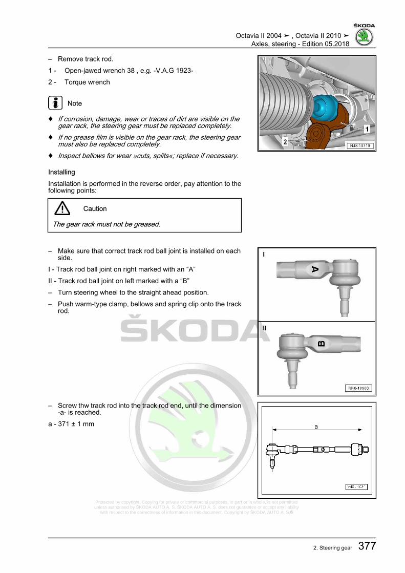
Protected by copyright. Copying for private or commercial purposes, in part or in whole, is not permitted unless authorised by ŠKODA AUTO A. S. ŠKODA AUTO A. S. does not guarantee or accept any liability
with respect to the correctness of information in this document. Copyright by ŠKODA AUTO A. S.�
– Remove track rod.1 - Open-jawed wrench 38 , e.g. -V.A.G 1923-2 - Torque wrench
Note
♦ If corrosion, damage, wear or traces of dirt are visible on thegear rack, the steering gear must be replaced completely.
♦ If no grease film is visible on the gear rack, the steering gearmust also be replaced completely.
♦ Inspect bellows for wear »cuts, splits«; replace if necessary.
InstallingInstallation is performed in the reverse order, pay attention to thefollowing points:
Caution
The gear rack must not be greased.
– Make sure that correct track rod ball joint is installed on eachside.
I - Track rod ball joint on right marked with an “A”II - Track rod ball joint on left marked with a “B”– Turn steering wheel to the straight ahead position.– Push warm-type clamp, bellows and spring clip onto the track
rod.
– Screw thw track rod into the track rod end, until the dimension-a- is reached.
a - 371 ± 1 mm
Octavia II 2004 ➤ , Octavia II 2010 ➤Axles, steering - Edition 05.2018
2. Steering gear 377

Protected by copyright. Copying for private or commercial purposes, in part or in whole, is not permitted unless authorised by ŠKODA AUTO A. S. ŠKODA AUTO A. S. does not guarantee or accept any liability
with respect to the correctness of information in this document. Copyright by ŠKODA AUTO A. S.�
– Installing track rod.1 - Open-jawed wrench 38 , e.g. -V.A.G 1923-2 - Torque wrench– Lightly grease the sealing surfaces of the bellows to the track
rod with grease from the repair kit.
– Slide bellows -2-, as shown in the illustration, onto the trackrod -1-.
– Secure spring clip -1- onto the bellows with the hose bindingclaw e.g. -V.A.G 1275- .
– Lightly grease the sealing surfaces of the bellows on the steer‐ing gear housing with grease from the repair kit.
– Slide bellows onto the steering gear housing up to the stop.
Octavia II 2004 ➤ , Octavia II 2010 ➤Axles, steering - Edition 05.2018
378 Rep. gr.48 - Steering
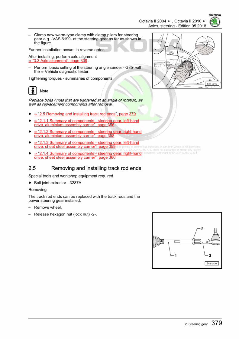
Protected by copyright. Copying for private or commercial purposes, in part or in whole, is not permitted unless authorised by ŠKODA AUTO A. S. ŠKODA AUTO A. S. does not guarantee or accept any liability
with respect to the correctness of information in this document. Copyright by ŠKODA AUTO A. S.�
– Clamp new warm-type clamp with clamp pliers for steeringgear e.g. -VAS 6199- at the steering gear as far as shown inthe figure.
Further installation occurs in reverse order.After installing, perform axle alignment⇒ “3.3 Axle alignment”, page 309 .– Perform basic setting of the steering angle sender - G85- with
the ⇒ Vehicle diagnostic tester.Tightening torques - summaries of components
Note
Replace bolts / nuts that are tightened at an angle of rotation, aswell as replacement components after removal.
♦ ⇒ “2.5 Removing and installing track rod ends”, page 379♦ ⇒ “2.1.1 Summary of components - steering gear, left-hand
drive, aluminium assembly carrier”, page 356♦ ⇒ “2.1.2 Summary of components - steering gear, right-hand
drive, aluminium assembly carrier”, page 358♦ ⇒ “2.1.3 Summary of components - steering gear, left-hand
drive, sheet steel assembly carrier”, page 359♦ ⇒ “2.1.4 Summary of components - steering gear, right-hand
drive, sheet steel assembly carrier”, page 360
2.5 Removing and installing track rod endsSpecial tools and workshop equipment required♦ Ball joint extractor - 3287A-RemovingThe track rod ends can be replaced with the track rods and thepower steering gear installed.– Remove wheel.– Release hexagon nut (lock nut) -2-.
Octavia II 2004 ➤ , Octavia II 2010 ➤Axles, steering - Edition 05.2018
2. Steering gear 379

Protected by copyright. Copying for private or commercial purposes, in part or in whole, is not permitted unless authorised by ŠKODA AUTO A. S. ŠKODA AUTO A. S. does not guarantee or accept any liability
with respect to the correctness of information in this document. Copyright by ŠKODA AUTO A. S.�
– Loosen nut from track rod end, but do not unscrew yet.
Note
To protect the thread, screw the nut a couple of thread turns ontothe stud of the track rod end.
– Remove the steering joint/track rod from the wheel-bearinghousing with the ball joint extractor - 3287A- .
– Unscrew nut for suspension link/track rod.– Pull track rod end out of the steering arm.
– Unscrew track rod end -3- from track rod -1-.The surrounding components are not shown to simplify the illus‐trations.InstallingInstallation is performed in the reverse order, pay attention to thefollowing points:
– Make sure that correct track rod ball joint is installed on eachside.
I - Track rod ball joint on right marked with an “A”II - Track rod ball joint on left marked with a “B”– Screw track rod ball joint onto track rod as far as previously
applied mark and secure with lock nut.– Insert track rod ball joint into wheel bearing housing.– Bolt track rod ball joint with new nut.– Carry out axle alignment ⇒ “3.3 Axle alignment”, page 309 .Tightening torques - summaries of components
Note
Replace bolts / nuts that are tightened at an angle of rotation, aswell as replacement components after removal.
♦ ⇒ “2.5 Removing and installing track rod ends”, page 379♦ ⇒ “2.1.1 Summary of components - steering gear, left-hand
drive, aluminium assembly carrier”, page 356♦ ⇒ “2.1.2 Summary of components - steering gear, right-hand
drive, aluminium assembly carrier”, page 358♦ ⇒ “2.1.3 Summary of components - steering gear, left-hand
drive, sheet steel assembly carrier”, page 359♦ ⇒ “2.1.4 Summary of components - steering gear, right-hand
drive, sheet steel assembly carrier”, page 360
2.6 Repairing steering box
Octavia II 2004 ➤ , Octavia II 2010 ➤Axles, steering - Edition 05.2018
380 Rep. gr.48 - Steering

Protected by copyright. Copying for private or commercial purposes, in part or in whole, is not permitted unless authorised by ŠKODA AUTO A. S. ŠKODA AUTO A. S. does not guarantee or accept any liability
with respect to the correctness of information in this document. Copyright by ŠKODA AUTO A. S.�
1 - Right track rod end❑ Marked with “A”
⇒ page 380❑ Removing and installing
⇒ “2.5 Removing and in‐stalling track rod ends”,page 379
❑ Assignment ⇒ Electron‐ic Catalogue of OriginalParts
2 - Nut❑ When tightening the nut,
the track rod end mustbe counterheld with awrench.
❑ 70 Nm3 - Spring strap clamp4 - Collar
❑ check for damage❑ must not be twisted after
setting the wheel toe❑ Removing and installing
⇒ “2.3 Removing and in‐stalling bellows”,page 372
5 - Clamp❑ replace after each re‐
moval❑ tensioning ⇒ page 375
6 - Track rod❑ Removing and installing
⇒ “2.4 Removing and in‐stalling track rod”,page 375
❑ 100 Nm7 - Screw
❑ 6 Nm8 - Seal9 - Heat shield10 - Steering gear
❑ with power steering control unit - J500-❑ can be checked in the guided fault detection system with ⇒ Vehicle diagnostic tester❑ Removing and installing ⇒ “2.2 Removing and installing steering gear”, page 361
Right-hand drive as of CW 22/2008 and left-hand drive as of CW 22/2009❑ The 3rd generation power-assisted steering❑ The steering angle sender - G85- is integrated into the steering gear and cannot be replaced separately.❑ with three point fixing at assembly carrier❑ Assignment ⇒ Electronic Catalogue of Original Parts
11 - Left track rod end❑ Marked with “B” ⇒ page 380❑ Removing and installing ⇒ “2.5 Removing and installing track rod ends”, page 379❑ Assignment ⇒ Electronic Catalogue of Original Parts
Octavia II 2004 ➤ , Octavia II 2010 ➤Axles, steering - Edition 05.2018
2. Steering gear 381

Protected by copyright. Copying for private or commercial purposes, in part or in whole, is not permitted unless authorised by ŠKODA AUTO A. S. ŠKODA AUTO A. S. does not guarantee or accept any liability
with respect to the correctness of information in this document. Copyright by ŠKODA AUTO A. S.�
12 - Support❑ not present on vehicles with 3rd generation steering gear
13 - Rubber bearing❑ not present on vehicles with 3rd generation steering gear
14 - Clamp with nuts❑ replace if thread is damaged❑ not present on vehicles with 3rd generation steering gear
Octavia II 2004 ➤ , Octavia II 2010 ➤Axles, steering - Edition 05.2018
382 Rep. gr.48 - Steering
Related Documents