SKH Humidifier-200611 SKH High-Pressure Atomizer Installation Instructions and User Manual Read and save this manual 4011008

Welcome message from author
This document is posted to help you gain knowledge. Please leave a comment to let me know what you think about it! Share it to your friends and learn new things together.
Transcript
SKH Humidifier-200611
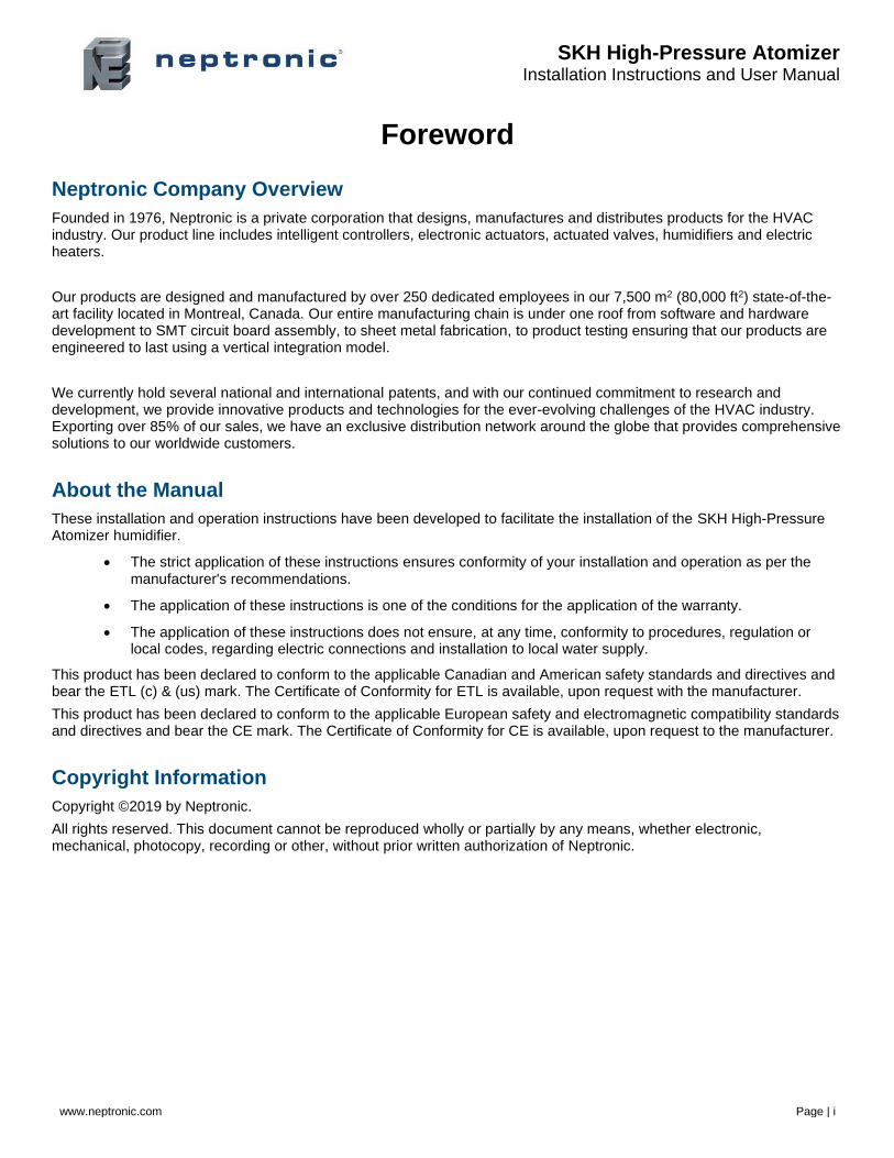
SKH High-Pressure Atomizer
Installation Instructions and User Manual
Read and save this manual
4011008
SKH High-Pressure Atomizer Installation Instructions and User Manual
www.neptronic.com Page | i
Foreword
Neptronic Company Overview
Founded in 1976, Neptronic is a private corporation that designs, manufactures and distributes products for the HVAC industry. Our product line includes intelligent controllers, electronic actuators, actuated valves, humidifiers and electric heaters.
Our products are designed and manufactured by over 250 dedicated employees in our 7,500 m2 (80,000 ft2) state-of-the-art facility located in Montreal, Canada. Our entire manufacturing chain is under one roof from software and hardware development to SMT circuit board assembly, to sheet metal fabrication, to product testing ensuring that our products are engineered to last using a vertical integration model.
We currently hold several national and international patents, and with our continued commitment to research and development, we provide innovative products and technologies for the ever-evolving challenges of the HVAC industry. Exporting over 85% of our sales, we have an exclusive distribution network around the globe that provides comprehensive solutions to our worldwide customers.
About the Manual
These installation and operation instructions have been developed to facilitate the installation of the SKH High-Pressure Atomizer humidifier.
• The strict application of these instructions ensures conformity of your installation and operation as per the manufacturer's recommendations.
• The application of these instructions is one of the conditions for the application of the warranty.
• The application of these instructions does not ensure, at any time, conformity to procedures, regulation or local codes, regarding electric connections and installation to local water supply.
This product has been declared to conform to the applicable Canadian and American safety standards and directives and bear the ETL (c) & (us) mark. The Certificate of Conformity for ETL is available, upon request with the manufacturer.
This product has been declared to conform to the applicable European safety and electromagnetic compatibility standards and directives and bear the CE mark. The Certificate of Conformity for CE is available, upon request to the manufacturer.
Copyright Information
Copyright ©2019 by Neptronic.
All rights reserved. This document cannot be reproduced wholly or partially by any means, whether electronic, mechanical, photocopy, recording or other, without prior written authorization of Neptronic.
SKH High-Pressure Atomizer Installation Instructions and User Manual
www.neptronic.com Page | ii
Health and Safety Instructions
General
This manual has been written to ensure correct, safe and sustainable operation of the SKH High-Pressure Atomiser and is intended for use by engineers and technical personnel trained by or their official agents. This manual must be read thoroughly before specifying, designing, installing or operating a SKH High-Pressure Atomizer. Please retain for reference and contact Neptronic should you have any questions.
The triangular symbol with the word WARNING: is used to designate danger of severe or lethal consequence.
The circular symbol with the word CAUTION: is used to designate danger of injury, or to warn of the hazardous operating condition, or other relevant information.
Electrical Warning Message
WARNING
• Risk of electric shock. Do not access. Disconnect SKH High-Pressure Atomizer before opening the access door.
• All work concerned with electrical installation MUST only be performed by skilled and qualified technical personnel (such as an electrician or a technician with appropriate training). The customer is always responsible for ensuring the suitability of the technical personnel.
• Please observe the local regulations concerning the provision of electrical installations.
Health & Safety
Installation, maintenance, repair work or de-commissioning should only be carried out by appropriately qualified technical personnel. Any risks or hazards relating to the system, including during installation and maintenance, should be identified by a qualified Health & Safety representative who shall be responsible for introducing effective control measures, as necessary. The customer is responsible for ensuring that the installation of the equipment complies with all local regulations.
CAUTION: Maintenance personnel must be trained by Neptronic or their official agent, and it is the customer’s responsibility to ensure their suitability. Failure to use a qualified personnel may lead to a hazardous operating condition.
WARNING: Danger of Electrocution! Danger of contact with live parts when the unit is open. Always isolate all water and electrical supplies to the system before commencing any maintenance or repair. Isolate power and water immediately if there is any sign of water leaking from the unit.
Protective Equipment
Please refer to the Health and Safety Executive for recommendations about Personal Protective Equipment and information on the Control of Substances Hazardous to Health (COSHH).
SKH High-Pressure Atomizer Installation Instructions and User Manual
www.neptronic.com Page | iii
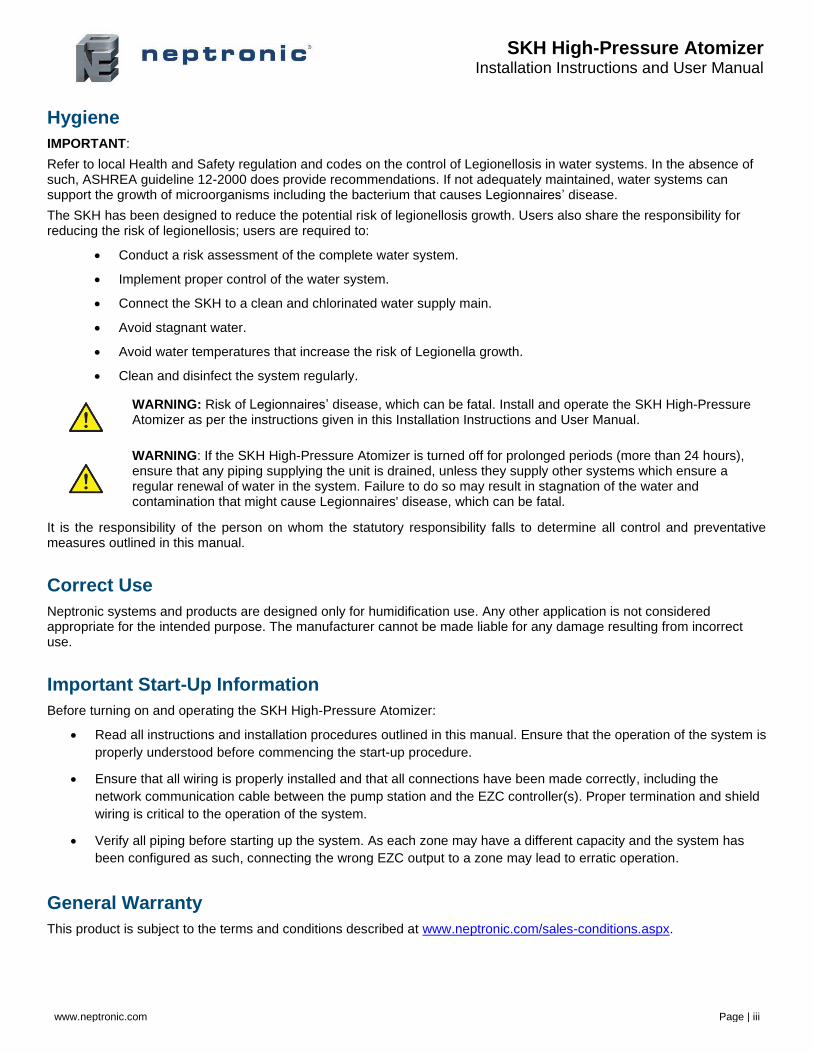
Hygiene
IMPORTANT:
Refer to local Health and Safety regulation and codes on the control of Legionellosis in water systems. In the absence of such, ASHREA guideline 12-2000 does provide recommendations. If not adequately maintained, water systems can support the growth of microorganisms including the bacterium that causes Legionnaires’ disease.
The SKH has been designed to reduce the potential risk of legionellosis growth. Users also share the responsibility for reducing the risk of legionellosis; users are required to:
• Conduct a risk assessment of the complete water system.
• Implement proper control of the water system.
• Connect the SKH to a clean and chlorinated water supply main.
• Avoid stagnant water.
• Avoid water temperatures that increase the risk of Legionella growth.
• Clean and disinfect the system regularly.
WARNING: Risk of Legionnaires’ disease, which can be fatal. Install and operate the SKH High-Pressure Atomizer as per the instructions given in this Installation Instructions and User Manual.
WARNING: If the SKH High-Pressure Atomizer is turned off for prolonged periods (more than 24 hours), ensure that any piping supplying the unit is drained, unless they supply other systems which ensure a regular renewal of water in the system. Failure to do so may result in stagnation of the water and contamination that might cause Legionnaires' disease, which can be fatal.
It is the responsibility of the person on whom the statutory responsibility falls to determine all control and preventative measures outlined in this manual.
Correct Use
Neptronic systems and products are designed only for humidification use. Any other application is not considered appropriate for the intended purpose. The manufacturer cannot be made liable for any damage resulting from incorrect use.
Important Start-Up Information
Before turning on and operating the SKH High-Pressure Atomizer:
• Read all instructions and installation procedures outlined in this manual. Ensure that the operation of the system is
properly understood before commencing the start-up procedure.
• Ensure that all wiring is properly installed and that all connections have been made correctly, including the
network communication cable between the pump station and the EZC controller(s). Proper termination and shield
wiring is critical to the operation of the system.
• Verify all piping before starting up the system. As each zone may have a different capacity and the system has
been configured as such, connecting the wrong EZC output to a zone may lead to erratic operation.
General Warranty
This product is subject to the terms and conditions described at www.neptronic.com/sales-conditions.aspx.
SKH High-Pressure Atomizer Installation Instructions and User Manual
www.neptronic.com Page | iv
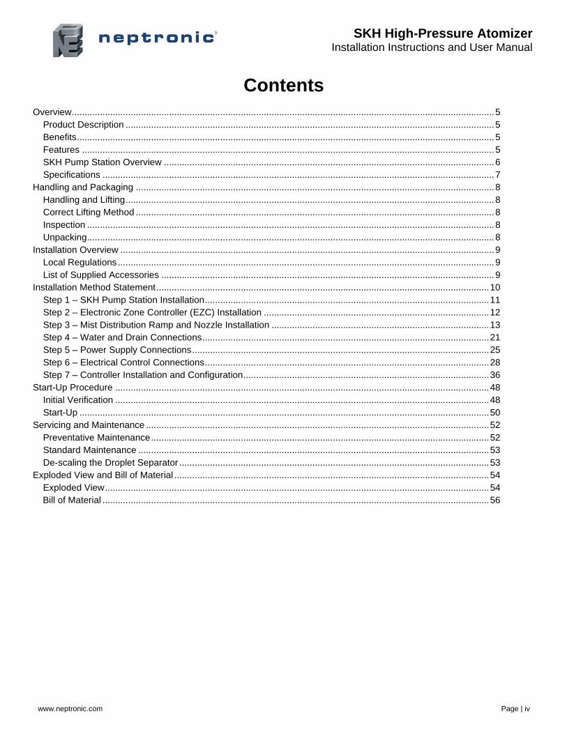
Contents
Overview ..................................................................................................................................................................... 5
Product Description ................................................................................................................................................ 5
Benefits ................................................................................................................................................................... 5
Features ................................................................................................................................................................. 5
SKH Pump Station Overview ................................................................................................................................. 6
Specifications ......................................................................................................................................................... 7
Handling and Packaging ............................................................................................................................................ 8
Handling and Lifting ................................................................................................................................................ 8
Correct Lifting Method ............................................................................................................................................ 8
Inspection ............................................................................................................................................................... 8
Unpacking ............................................................................................................................................................... 8
Installation Overview .................................................................................................................................................. 9
Local Regulations ................................................................................................................................................... 9
List of Supplied Accessories .................................................................................................................................. 9
Installation Method Statement .................................................................................................................................. 10
Step 1 – SKH Pump Station Installation ............................................................................................................... 11
Step 2 – Electronic Zone Controller (EZC) Installation ........................................................................................ 12
Step 3 – Mist Distribution Ramp and Nozzle Installation ..................................................................................... 13
Step 4 – Water and Drain Connections ................................................................................................................ 21
Step 5 – Power Supply Connections .................................................................................................................... 25
Step 6 – Electrical Control Connections ............................................................................................................... 28
Step 7 – Controller Installation and Configuration ................................................................................................ 36
Start-Up Procedure .................................................................................................................................................. 48
Initial Verification .................................................................................................................................................. 48
Start-Up ................................................................................................................................................................ 50
Servicing and Maintenance ...................................................................................................................................... 52
Preventative Maintenance .................................................................................................................................... 52
Standard Maintenance ......................................................................................................................................... 53
De-scaling the Droplet Separator ......................................................................................................................... 53
Exploded View and Bill of Material ........................................................................................................................... 54
Exploded View ...................................................................................................................................................... 54
Bill of Material ....................................................................................................................................................... 56

SKH High-Pressure Atomizer Installation Instructions and User Manual
www.neptronic.com Page | 5
Overview
Product Description
The SKH High-Pressure Atomizer uses water through a high-pressure system to produce a fine mist with a droplet size of less than 20µm. The ambient air absorbs the fine mist, and the SKH adapts to seasonal changes to provide direct evaporative cooling in summer and humidification in winter. Additionally, the SKH provides BACnet MS/TP communication, multi-zone operation (up to 10 zones) and remote connection to the entire system from any zone.
Benefits
• Very low energy consumption
• Free cooling up to 21.5°F (12°C)
• Hygienic operation
• Environmentally friendly
• Low pressure drop
• All parts in contact with water are made of stainless steel and designed for life
Features
The following are the features of the SKH High-Pressure Atomizer:
• 5 microns PP pre-filter and silver ion dosing cartridges prevent microbial growth
• BACnet communication (optional)
• Master/Slave configuration for up to 4 pump stations
• User-friendly, menu-driven LCD (128 x 64)
• Real-time clock and SD card for schedule, trending, and history log
• Firmware upgrade using an SD card
• Water overflow outlet (optional)
SKH High-Pressure Atomizer Installation Instructions and User Manual
www.neptronic.com Page | 6
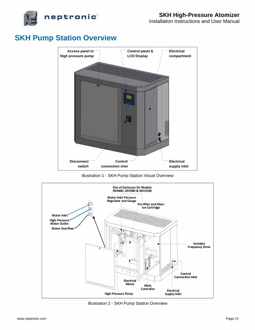
SKH Pump Station Overview
Control panel &
LCD Display
Disconnect
switch
Electrical
supply inlet
Control
connection inlet
Access panel to
High pressure pump
Electrical
compartment
Illustration 1 - SKH Pump Station Visual Overview
Out of Enclosure for Models SKH600, SKH900 & SKH1200
Water Inlet PressureRegulator and Gauge
Pre-filter and Silver Ion Cartridge
Variable Frequency Drive
Control Connection Inlet
Electrical Supply Inlet
Main Controller
High-Pressure Pump
Electrical Motor
Water Inlet
High-Pressure Water Outlet
Water Overflow
Illustration 2 - SKH Pump Station Overview
SKH High-Pressure Atomizer Installation Instructions and User Manual
www.neptronic.com Page | 7
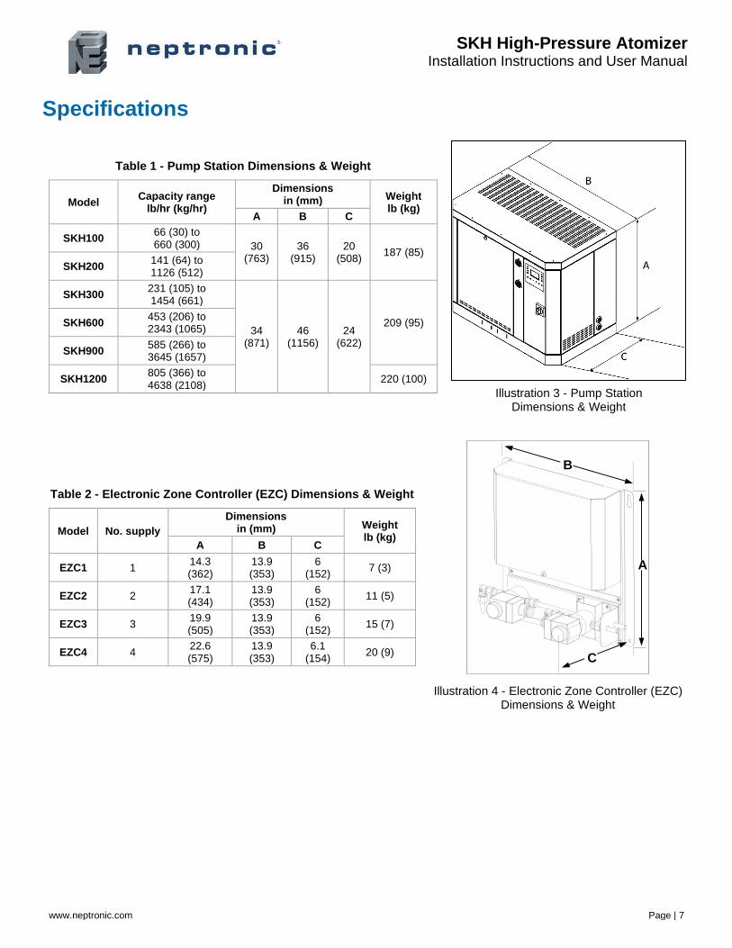
Specifications
Table 1 - Pump Station Dimensions & Weight
Model Capacity range
lb/hr (kg/hr)
Dimensions in (mm) Weight
lb (kg) A B C
SKH100 66 (30) to 660 (300) 30
(763) 36
(915) 20
(508) 187 (85)
SKH200 141 (64) to 1126 (512)
SKH300 231 (105) to 1454 (661)
34 (871)
46 (1156)
24 (622)
209 (95) SKH600 453 (206) to 2343 (1065)
SKH900 585 (266) to 3645 (1657)
SKH1200 805 (366) to 4638 (2108)
220 (100)
Illustration 3 - Pump Station Dimensions & Weight
Table 2 - Electronic Zone Controller (EZC) Dimensions & Weight
Model No. supply
Dimensions in (mm) Weight
lb (kg) A B C
EZC1 1 14.3 (362)
13.9 (353)
6 (152)
7 (3)
EZC2 2 17.1 (434)
13.9 (353)
6 (152)
11 (5)
EZC3 3 19.9 (505)
13.9 (353)
6 (152)
15 (7)
EZC4 4 22.6 (575)
13.9 (353)
6.1 (154)
20 (9)
Illustration 4 - Electronic Zone Controller (EZC) Dimensions & Weight
B
A
C
SKH High-Pressure Atomizer Installation Instructions and User Manual
www.neptronic.com Page | 8
Handling and Packaging
Handling and Lifting
Lifting or Handling MUST be carried out by trained and qualified personnel. Ensure that the lifting operation has been properly planned, assessed for risk and that the equipment is checked by a qualified Health & Safety representative, and effective control measures are in place.
It is the customer’s responsibility to ensure that the operators are trained in handling heavy goods and to enforce the relevant lifting regulations.
The SKH High-Pressure Atomizer MUST always be handled and lifted with care and should remain in its original packaging for as long as possible before installation.
The SKH High-Pressure Atomizer package may be carried using a forklift from the underside. Caution should be exercised to ensure balanced load before lifting.
Correct Lifting Method
Any personnel handling or lifting the SKH High-Pressure Atomizer must follow the Lifting Operations and Lifting Equipment Regulations 1998 and Approved Code of Practice L113. The regulation imposes duties on employers and self-employed persons and authorities who have control, to any extent of lifting equipment.
Refer to Dimensions and Weights as indicated on the nameplate and the submittal drawing for system dry weights.
Inspection
Upon receipt, and once packaging material is removed, carry out an inspection to ensure that no damage occurred during transit. Report any damage immediately to your Neptronic representative.
Unpacking
The SKH pump station is delivered in a crate. The Electronic Zone Controller, Mist Distribution Ramps, and the Nozzles are delivered in a carton.
SKH High-Pressure Atomizer Installation Instructions and User Manual
www.neptronic.com Page | 9
Installation Overview
WARNING: Failure to observe manufacturer's installation recommendations voids the manufacturer’s warranty.
Local Regulations
Lifting or Handling MUST be carried out by trained and qualified personnel. Ensure that the lifting operation has been properly planned, assessed for risk and that the equipment is checked by a qualified Health & Safety representative, and that effective control measures are in place.
It is the customer’s responsibility to ensure that the operators are trained in handling heavy goods and to enforce the relevant lifting regulations.
The SKH pump station MUST always be handled and lifted with care and should remain in its original packaging for as long as possible before installation.
The SKH pump station package may be carried using a forklift from the bottom. Caution should be exercised to ensure a balanced load before lifting.
List of Supplied Accessories
• Water filter assembly
• 5 microns PP pre-filter
• Silver ion dosing anti-bacterial cartridges or UV light (depending on model)
• Installation Instructions and User Manual

SKH High-Pressure Atomizer Installation Instructions and User Manual
www.neptronic.com Page | 10
Installation Method Statement
Step 1 – SKH Pump Station Installation Step 2 – Electronic Zone Controller (EZC) Installation Step 3 – Mist Distribution Ramp and Nozzle Installation Step 4 – Water and Drain Connections Step 5 – Power Supply Connections Step 6 – Electrical Control Connections Step 7 – Controller Installation and Configuration
Installation
Step 1: SKH Pump Station Installation
Step 5: Power Supply Connections
Water Overflow
Stainless steelpipingStainless steel
piping
Step 3: Mist Distribution Installation
Installation
Step 2: EZCZone Station
Step 4: Water & Drain
Step 6: Control Connections
Water Inlet
Illustration 5 - Installation Steps
SKH High-Pressure Atomizer Installation Instructions and User Manual
www.neptronic.com Page | 11
Step 1 – SKH Pump Station Installation
General Recommendations
WARNING: Risk of electric shock. Disconnect the appliance from the electric supply before commencing installation.
CAUTION: Risk of injury. The SKH pump station is heavy; It MUST always be handled and lifted with care.
Location
Consider the following points before deciding the location for the pump station:
• Plan a location that is easy to access to permit an easy inspection and servicing of the pump station.
• Do not install the pump station where the failure of the appliance could cause damage to the building structure or other expensive equipment.
• Ensure that the location is ventilated appropriately and that the ambient temperature is less than 86°F (30°C).
Positioning
• There is no required minimum safety clearance.
• Provide a minimum clearance of 47" (1.20 m) on the front of the pump station, in order to permit access to connections and allow for servicing.
• It is recommended (but not mandatory) to allow some clearance on both sides and on the top of the SKH pump station for ease of service.
• The SKH pump station must be floor mounted.
Floor Mounting
• Provide a level, solid foundation for the SKH pump station.
• Ensure that the floor beneath the SKH pump station is waterproof to withstand any water spillage during servicing or if a problem occurs.
• Ensure that the SKH pump station is provided with adjustable legs to ensure proper level from the ground.
• Allow some space beneath the pump station for the drain pan connection, located below the bottom plate.
SKH High-Pressure Atomizer Installation Instructions and User Manual
www.neptronic.com Page | 12
Step 2 – Electronic Zone Controller (EZC) Installation
WARNING: Risk of electric shock. Disconnect the appliance from the electric supply before commencing installation.
Location
• Plan a location that is easy to access and permits an easy inspection and servicing of the EZC zone controller.
• Do not install the EZC zone controller where failure of the valve could cause damage to the building structure or to other expensive equipment.
• Ensure that the location is ventilated appropriately and that the ambient temperature is less than 86°F (30°C).
Positioning • There is no minimum clearance required for safety purposes.
• Provide a minimum clearance of 31" (0.80 m) on the front of the EZC zone controller, in order to permit access to connections and allow for servicing.
• It is recommended (but not mandatory) to allow some clearance on both sides and on the top of the EZC zone controller for ease of service.
Wall Mounting • Use the keyholes located on the back of the EZC zone controller.
• Check the solidity of the chosen support or wall (brick, concrete, or stud partition wall) on which the EZC zone controller is mounted.
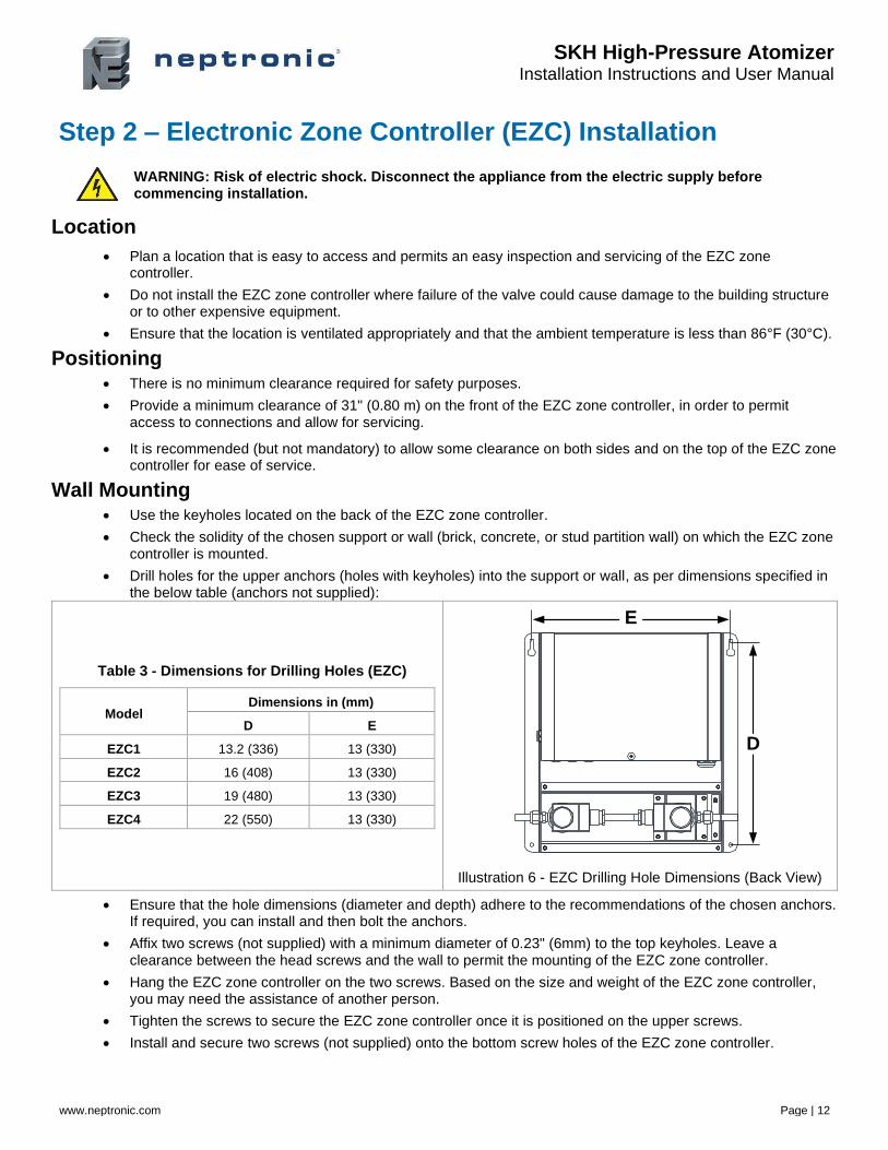
• Drill holes for the upper anchors (holes with keyholes) into the support or wall, as per dimensions specified in the below table (anchors not supplied):
Table 3 - Dimensions for Drilling Holes (EZC)
Model Dimensions in (mm)
D E
EZC1 13.2 (336) 13 (330)
EZC2 16 (408) 13 (330)
EZC3 19 (480) 13 (330)
EZC4 22 (550) 13 (330)
Illustration 6 - EZC Drilling Hole Dimensions (Back View)
• Ensure that the hole dimensions (diameter and depth) adhere to the recommendations of the chosen anchors. If required, you can install and then bolt the anchors.
• Affix two screws (not supplied) with a minimum diameter of 0.23" (6mm) to the top keyholes. Leave a clearance between the head screws and the wall to permit the mounting of the EZC zone controller.
• Hang the EZC zone controller on the two screws. Based on the size and weight of the EZC zone controller, you may need the assistance of another person.
• Tighten the screws to secure the EZC zone controller once it is positioned on the upper screws.
• Install and secure two screws (not supplied) onto the bottom screw holes of the EZC zone controller.
D
E
SKH High-Pressure Atomizer Installation Instructions and User Manual
www.neptronic.com Page | 13
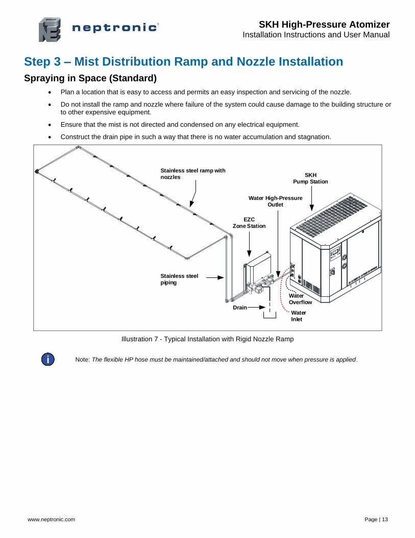
Step 3 – Mist Distribution Ramp and Nozzle Installation
Spraying in Space (Standard)
• Plan a location that is easy to access and permits an easy inspection and servicing of the nozzle.
• Do not install the ramp and nozzle where failure of the system could cause damage to the building structure or to other expensive equipment.
• Ensure that the mist is not directed and condensed on any electrical equipment.
• Construct the drain pipe in such a way that there is no water accumulation and stagnation.
Stainless steel ramp with nozzles
Stainless steelpiping
EZC Zone Station
DrainWater Inlet
Water Overflow
Water High-Pressure Outlet
SKH Pump Station
Illustration 7 - Typical Installation with Rigid Nozzle Ramp
Note: The flexible HP hose must be maintained/attached and should not move when pressure is applied.
SKH High-Pressure Atomizer Installation Instructions and User Manual
www.neptronic.com Page | 14
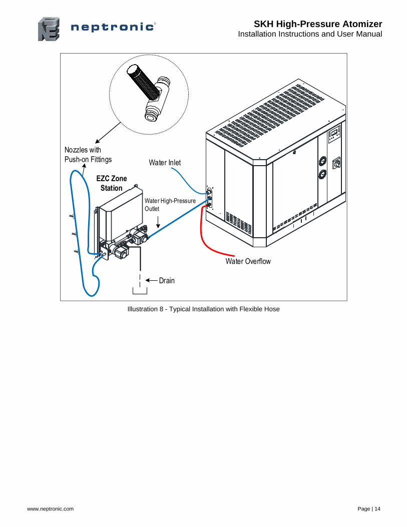
Water Overflow
Water Inlet
Water High-Pressure
Outlet
EZC Zone
Station
Nozzles with
Push-on Fittings
Drain
Illustration 8 - Typical Installation with Flexible Hose
SKH High-Pressure Atomizer Installation Instructions and User Manual
www.neptronic.com Page | 15
Spraying in Space with MDU
• Plan a location that is easy to access and permits an easy inspection and servicing.
• Do not install the MDU where failure of the system could cause damage to the building structure or to other expensive equipment.
• Ensure that the mist is not directed and condensed on any equipment, particularly electrical equipment.
• Construct the drain pipe in such a way that there is no water accumulation and stagnation.
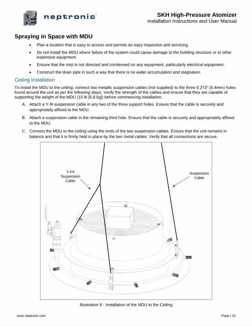
Ceiling Installation
To install the MDU to the ceiling, connect two metallic suspension cables (not supplied) to the three 0.213” (5.4mm) holes found around the unit as per the following steps. Verify the strength of the cables and ensure that they are capable of supporting the weight of the MDU (15 lb [6.8 kg]) before commencing installation.
A. Attach a Y-fit suspension cable in any two of the three support holes. Ensure that the cable is securely and
appropriately affixed to the MDU.
B. Attach a suspension cable in the remaining third hole. Ensure that the cable is securely and appropriately affixed
to the MDU.
C. Connect the MDU to the ceiling using the ends of the two suspension cables. Ensure that the unit remains in
balance and that it is firmly held in place by the two metal cables. Verify that all connections are secure.
Y-Fit
Suspension
Cable
Suspension
Cable
Illustration 9 - Installation of the MDU to the Ceiling
SKH High-Pressure Atomizer Installation Instructions and User Manual
www.neptronic.com Page | 16
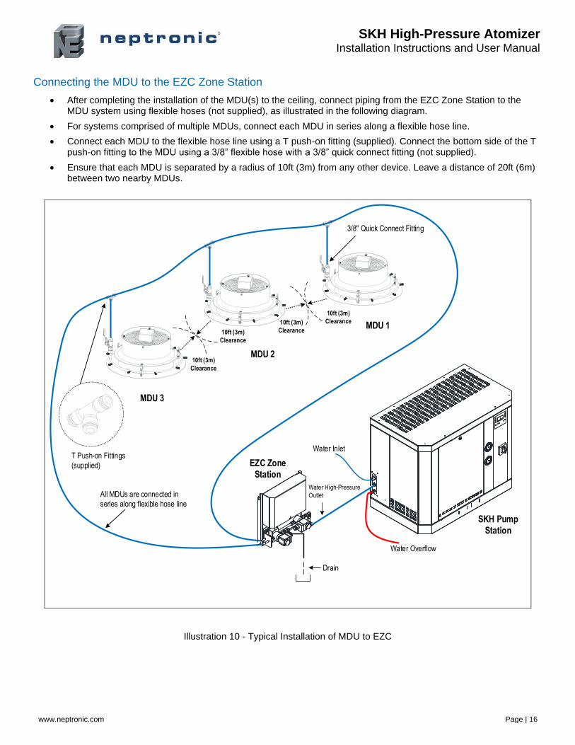
Connecting the MDU to the EZC Zone Station
• After completing the installation of the MDU(s) to the ceiling, connect piping from the EZC Zone Station to the MDU system using flexible hoses (not supplied), as illustrated in the following diagram.
• For systems comprised of multiple MDUs, connect each MDU in series along a flexible hose line.
• Connect each MDU to the flexible hose line using a T push-on fitting (supplied). Connect the bottom side of the T push-on fitting to the MDU using a 3/8” flexible hose with a 3/8” quick connect fitting (not supplied).
• Ensure that each MDU is separated by a radius of 10ft (3m) from any other device. Leave a distance of 20ft (6m) between two nearby MDUs.
Water Overflow
Water Inlet
Water High-Pressure
Outlet
EZC Zone
Station
T Push-on Fittings
(supplied)
SKH Pump
Station
10ft (3m)
Clearance
10ft (3m)
Clearance
10ft (3m)
Clearance
10ft (3m)
Clearance
MDU 3
MDU 2
MDU 1
All MDUs are connected in
series along flexible hose line
3/8" Quick Connect Fitting
Drain
Illustration 10 - Typical Installation of MDU to EZC
SKH High-Pressure Atomizer Installation Instructions and User Manual
www.neptronic.com Page | 17
Spraying in Duct
• Plan a location that is easy to access and permits an easy inspection and servicing of the nozzle.
• Do not install the ramp and nozzle where failure of the system could cause damage to the building structure or to other expensive equipment.
• Ensure that the mist is not directed and condensed on any electrical equipment.
• Construct the drain pipe in such a way that there is no water accumulation and stagnation.
• The wet section of the duct must be constructed in stainless steel in order to prevent corrosion and must be equipped with a pan drain outlet in order to remove any water residue.
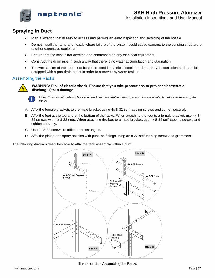
Assembling the Racks
WARNING: Risk of electric shock. Ensure that you take precautions to prevent electrostatic discharge (ESD) damage.
Note: Ensure that tools such as a screwdriver, adjustable wrench, and so on are available before assembling the racks.
A. Affix the female brackets to the male bracket using 4x 8-32 self-tapping screws and tighten securely.
B. Affix the feet at the top and at the bottom of the racks. When attaching the feet to a female bracket, use 4x 8-32 screws with 4x 8-32 nuts. When attaching the feet to a male bracket, use 4x 8-32 self-tapping screws and tighten securely.
C. Use 2x 8-32 screws to affix the cross angles.
D. Affix the piping and spray nozzles with push-on fittings using an 8-32 self-tapping screw and grommets.
The following diagram describes how to affix the rack assembly within a duct:
Illustration 11 - Assembling the Racks
2x 8-32 Screws
1x 8-32 Self
Tapping
Screw
4x 8-32 Self Tapping
Screws4x 8-32 Nuts4x 8-32 Self Tapping
Screws4x 8-32 Nuts
4x 8-32 Screws
S te p AS te p B
S te p CS te p D
Male bracket
Female bracket
4x 8-32 Self
Tapping
Screws
SKH High-Pressure Atomizer Installation Instructions and User Manual
www.neptronic.com Page | 18
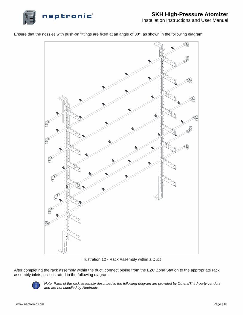
Ensure that the nozzles with push-on fittings are fixed at an angle of 30°, as shown in the following diagram:
Illustration 12 - Rack Assembly within a Duct
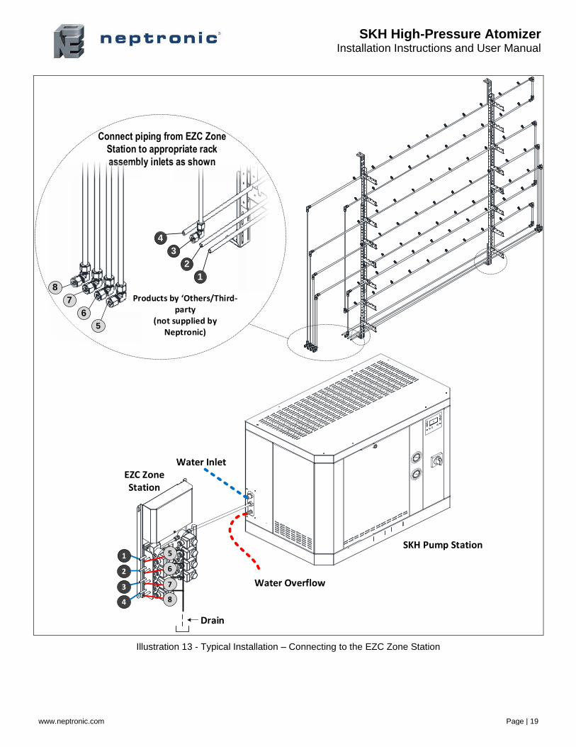
After completing the rack assembly within the duct, connect piping from the EZC Zone Station to the appropriate rack assembly inlets, as illustrated in the following diagram:
Note: Parts of the rack assembly described in the following diagram are provided by Others/Third-party vendors and are not supplied by Neptronic.
SKH High-Pressure Atomizer Installation Instructions and User Manual
www.neptronic.com Page | 19
Water Inlet
Water Overflow
1
2
3
4
EZC Zone Station
SKH Pump Station
Connect piping from EZC Zone
Station to appropriate rack
assembly inlets as shown
2
3
1
4
7
8
5
6
Products by Others/Third-party
(not supplied by Neptronic)
Drain
5
6
7
8
Illustration 13 - Typical Installation – Connecting to the EZC Zone Station
SKH High-Pressure Atomizer Installation Instructions and User Manual
www.neptronic.com Page | 20
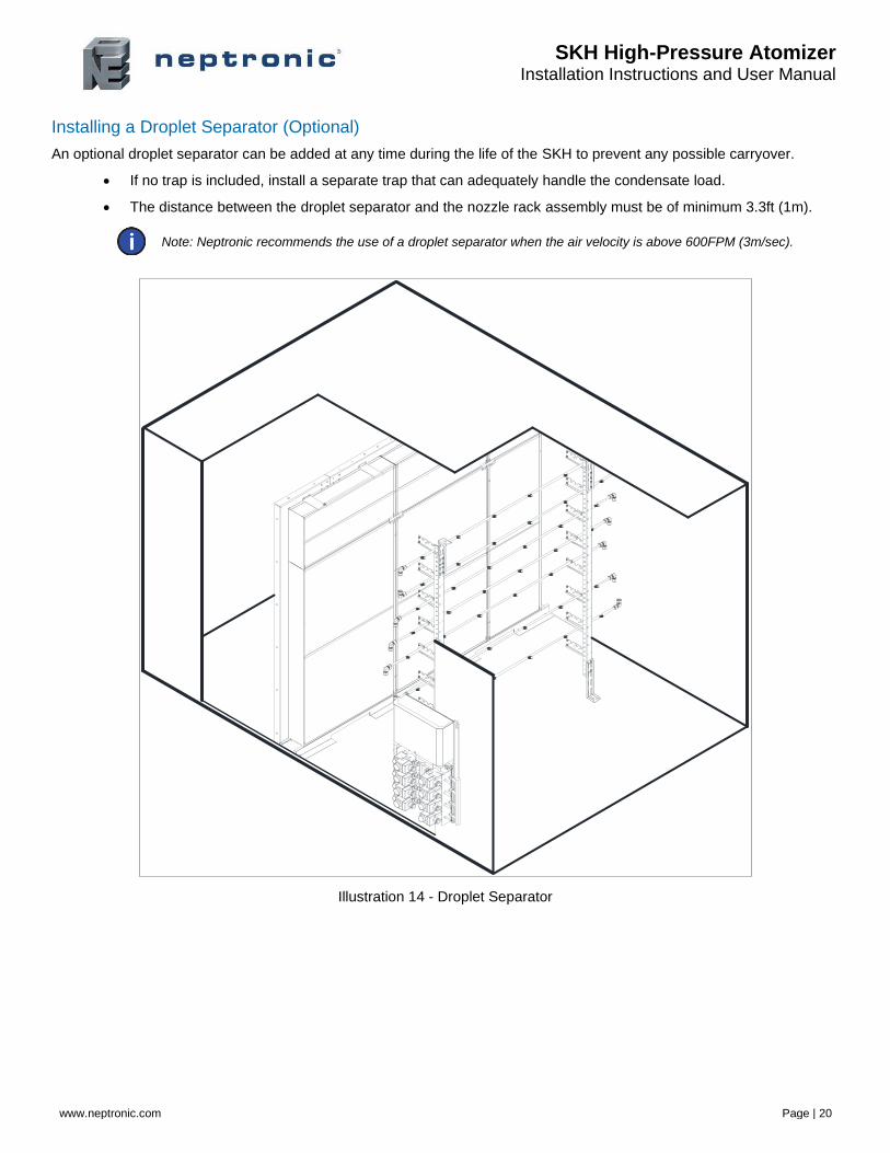
Installing a Droplet Separator (Optional)
An optional droplet separator can be added at any time during the life of the SKH to prevent any possible carryover.
• If no trap is included, install a separate trap that can adequately handle the condensate load.
• The distance between the droplet separator and the nozzle rack assembly must be of minimum 3.3ft (1m).
Note: Neptronic recommends the use of a droplet separator when the air velocity is above 600FPM (3m/sec).
Illustration 14 - Droplet Separator
SKH High-Pressure Atomizer Installation Instructions and User Manual
www.neptronic.com Page | 21
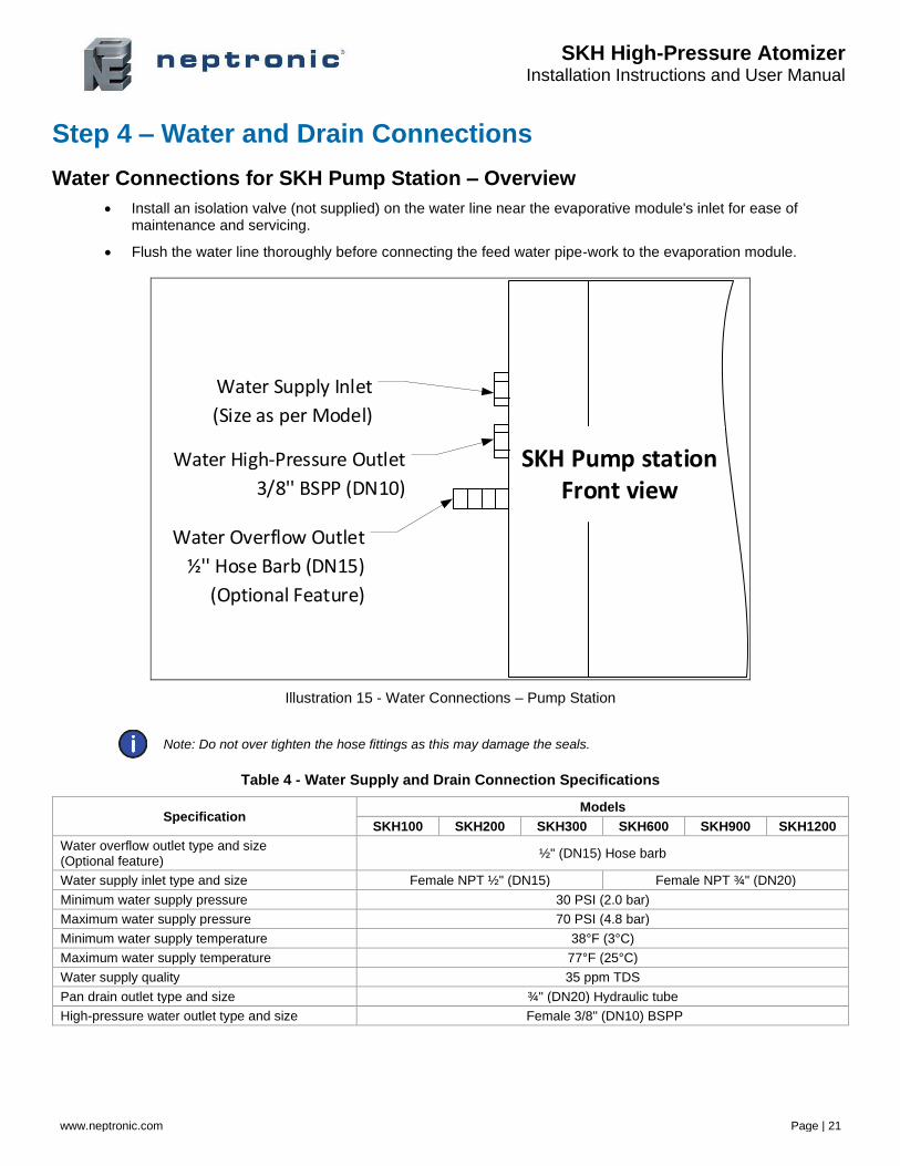
Step 4 – Water and Drain Connections
Water Connections for SKH Pump Station – Overview
• Install an isolation valve (not supplied) on the water line near the evaporative module's inlet for ease of maintenance and servicing.
• Flush the water line thoroughly before connecting the feed water pipe-work to the evaporation module.
Water Supply Inlet
(Size as per Model)
Water High-Pressure Outlet
3/8'' BSPP (DN10)
Water Overflow Outlet
½'' Hose Barb (DN15)
(Optional Feature)
SKH Pump stationFront view
Illustration 15 - Water Connections – Pump Station
Note: Do not over tighten the hose fittings as this may damage the seals.
Table 4 - Water Supply and Drain Connection Specifications
Specification Models
SKH100 SKH200 SKH300 SKH600 SKH900 SKH1200
Water overflow outlet type and size (Optional feature)
½" (DN15) Hose barb
Water supply inlet type and size Female NPT ½" (DN15) Female NPT ¾" (DN20)
Minimum water supply pressure 30 PSI (2.0 bar)
Maximum water supply pressure 70 PSI (4.8 bar)
Minimum water supply temperature 38°F (3°C)
Maximum water supply temperature 77°F (25°C)
Water supply quality 35 ppm TDS
Pan drain outlet type and size ¾" (DN20) Hydraulic tube
High-pressure water outlet type and size Female 3/8" (DN10) BSPP
SKH High-Pressure Atomizer Installation Instructions and User Manual
www.neptronic.com Page | 22
Water Supply
• Connect the female NPT connection of the water supply inlet of the humidifier to a clean drinking water supply.
• The SKH is capable of operating with water qualities such as reverse osmosis (RO) or tap water.
• If the humidifier is connected to hard water, it results in scale build-up and clogging of the spray nozzles, resulting in frequent replacement of nozzles. Furthermore, most of the minerals contained in the water are sprayed into the air.
• If the supplied water is treated with reverse osmosis or deionization filtration, control the total dissolved solid contents in the water, as there is no need for ultra-pure water.
• Ensure that the conductivity of water is between 1.92 and 5.12 PPM (30 and 80 µS/cm) at 68°F (20°C).
High-Pressure Water Outlet
• Connect the high-pressure water outlet from the SKH pump station to the high-pressure water inlet on the EZC controller using a flexible hose (not supplied), in order to dampen vibrations.
• Use a 3/8" (DN10) flexible high-pressure nylon hose or a high-pressure hydraulic hose (not supplied). The hose must use stainless steel quick connect fittings with one male 3/8" (DN10) BSPP and one male ¼" (DN8) BSPP fitting (not supplied).
• Connect the male 3/8" (DN10) BSPP fitting of the hose to the female 3/8" (DN10) BSPP fitting of the high-pressure water outlet of the pump station.
• Connect the male ¼" (DN8) BSPP fitting of the hose to the female ¼" (DN8) BSPP fitting of the high-pressure water inlet of the EZC controller.
Note: Ensure that the rating of the flexible hose is appropriate for the operating pressure (1000PSI / 70 bar).
Water Drain
• Connect a ¾" (DN20) flexible hose (not supplied) to the ¾" (DN20) pan drain outlet tube, located below the base of the SKH pump station, and direct it to the main building open drain.
WARNING: Risk of flooding. Never connect drains to closed pipework.
Water Overflow (Optional Feature)
• Connect the ½" (DN15) hose barb fitting of the water overflow outlet, located on the side of the SKH pump station, to a ½" (DN15) flexible hose (not supplied).
• Do not combine the overflow and drain to a common pipe if you plan to drain the water. Install two independent traps for drain and overflow.
• Re-circulate the overflowing water as required by making appropriate connections.
SKH High-Pressure Atomizer Installation Instructions and User Manual
www.neptronic.com Page | 23
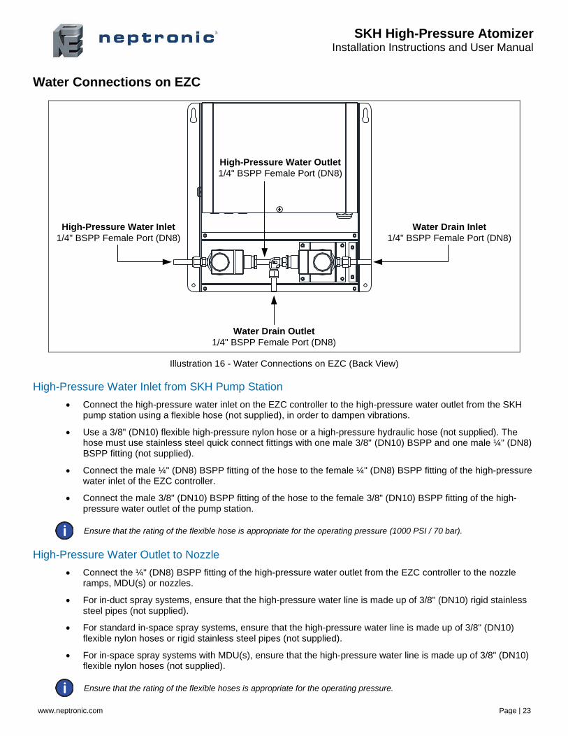
Water Connections on EZC
High-Pressure Water Outlet
1/4" BSPP Female Port (DN8)
High-Pressure Water Inlet
1/4" BSPP Female Port (DN8)
Water Drain Outlet
1/4" BSPP Female Port (DN8)
Water Drain Inlet
1/4" BSPP Female Port (DN8)
Illustration 16 - Water Connections on EZC (Back View)
High-Pressure Water Inlet from SKH Pump Station
• Connect the high-pressure water inlet on the EZC controller to the high-pressure water outlet from the SKH pump station using a flexible hose (not supplied), in order to dampen vibrations.
• Use a 3/8" (DN10) flexible high-pressure nylon hose or a high-pressure hydraulic hose (not supplied). The hose must use stainless steel quick connect fittings with one male 3/8" (DN10) BSPP and one male ¼" (DN8) BSPP fitting (not supplied).
• Connect the male ¼" (DN8) BSPP fitting of the hose to the female ¼" (DN8) BSPP fitting of the high-pressure water inlet of the EZC controller.
• Connect the male 3/8" (DN10) BSPP fitting of the hose to the female 3/8" (DN10) BSPP fitting of the high-pressure water outlet of the pump station.
Ensure that the rating of the flexible hose is appropriate for the operating pressure (1000 PSI / 70 bar).
High-Pressure Water Outlet to Nozzle
• Connect the ¼" (DN8) BSPP fitting of the high-pressure water outlet from the EZC controller to the nozzle ramps, MDU(s) or nozzles.
• For in-duct spray systems, ensure that the high-pressure water line is made up of 3/8" (DN10) rigid stainless steel pipes (not supplied).
• For standard in-space spray systems, ensure that the high-pressure water line is made up of 3/8" (DN10) flexible nylon hoses or rigid stainless steel pipes (not supplied).
• For in-space spray systems with MDU(s), ensure that the high-pressure water line is made up of 3/8" (DN10) flexible nylon hoses (not supplied).
Ensure that the rating of the flexible hoses is appropriate for the operating pressure.
SKH High-Pressure Atomizer Installation Instructions and User Manual
www.neptronic.com Page | 24
Water Drain
• Connect a ¼" (DN8) flexible hose (not supplied) to the ¼" (DN8) BSPP fitting of the water drain outlet, located below the EZC controller, and direct it to a main building open drain.
• If an in-duct spray system is used, connect the ¼" (DN8) BSPP fitting of the water drain inlet to the nozzle rack assembly using a 3/8" (DN10) rigid stainless steel pipe with compression fittings (not supplied).
• If a standard in-space spray system is used, connect the ¼" (DN8) BSPP fitting of the water drain inlet to the nozzles using a 3/8" (DN10) flexible nylon hose with quick connect fittings or a 3/8" (DN10) rigid stainless steel pipe with compression fittings (not supplied).
• If an in-space spray system with MDU is used, connect the ¼" (DN8) BSPP fitting of the water drain inlet to the MDU(s) using a 3/8" (DN10) flexible nylon hose with quick connect fittings (not supplied).
WARNING: Risk of flooding. Never connect drains to closed pipework.
SKH High-Pressure Atomizer Installation Instructions and User Manual
www.neptronic.com Page | 25
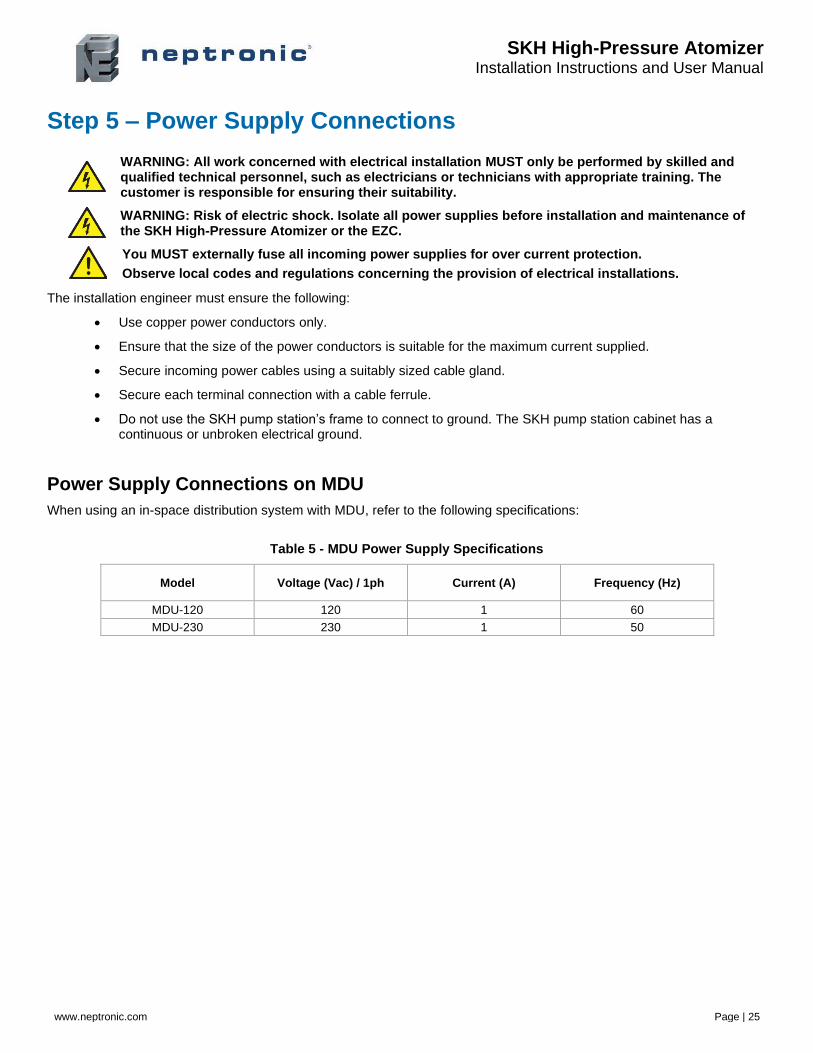
Step 5 – Power Supply Connections
WARNING: All work concerned with electrical installation MUST only be performed by skilled and qualified technical personnel, such as electricians or technicians with appropriate training. The customer is responsible for ensuring their suitability.
WARNING: Risk of electric shock. Isolate all power supplies before installation and maintenance of the SKH High-Pressure Atomizer or the EZC.
You MUST externally fuse all incoming power supplies for over current protection.
Observe local codes and regulations concerning the provision of electrical installations.
The installation engineer must ensure the following:
• Use copper power conductors only.
• Ensure that the size of the power conductors is suitable for the maximum current supplied.
• Secure incoming power cables using a suitably sized cable gland.
• Secure each terminal connection with a cable ferrule.
• Do not use the SKH pump station’s frame to connect to ground. The SKH pump station cabinet has a continuous or unbroken electrical ground.
Power Supply Connections on MDU
When using an in-space distribution system with MDU, refer to the following specifications:
Table 5 - MDU Power Supply Specifications
Model Voltage (Vac) / 1ph Current (A) Frequency (Hz)
MDU-120 120 1 60
MDU-230 230 1 50

SKH High-Pressure Atomizer Installation Instructions and User Manual
www.neptronic.com Page | 26
Power Supply Connections on SKH Pump Station
1 phase
L/L1 N/L2
GND
1ph(by others)
No
t u
sed
Disconnect switch
3 phases
L1 L2 L3
GND
3ph(by others)
Disconnect switch
Illustration 17 - Power Supply Connections on SKH Pump Station
Table 6 - SKH Pump Station Power Supply Specifications
Phase Voltage (V)
Models
SKH100 SKH200 SKH300 SKH600 SKH900 SKH1200
Current (A)
1 Phase 208 - 240 6.0 8.7 N/A N/A N/A N/A
3 Phase
208 - 240 6.0 8.7 12.3 18.3 23.5 23.5
380 - 480 3.1 4.4 6.2 9.2 11.8 11.8
575 - 600 2.3 3.5 4.9 7.3 9.4 9.4
Power
HP 2 3 5 7.5 10 10
kW 1.5 2.25 3.75 5.6 7.5 7.5
SKH High-Pressure Atomizer Installation Instructions and User Manual
www.neptronic.com Page | 27
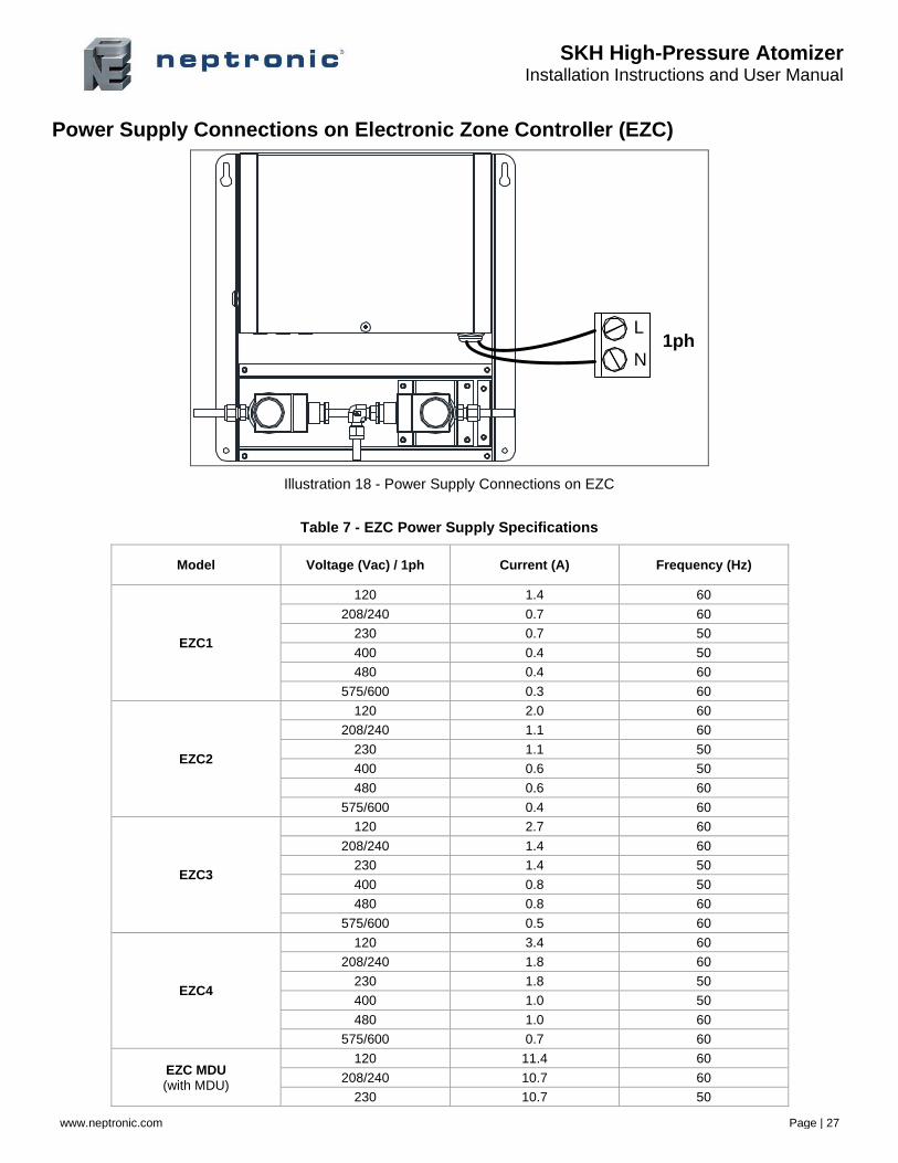
Power Supply Connections on Electronic Zone Controller (EZC)
L
N1ph
Illustration 18 - Power Supply Connections on EZC
Table 7 - EZC Power Supply Specifications
Model Voltage (Vac) / 1ph Current (A) Frequency (Hz)
EZC1
120 1.4 60
208/240 0.7 60
230 0.7 50
400 0.4 50
480 0.4 60
575/600 0.3 60
EZC2
120 2.0 60
208/240 1.1 60
230 1.1 50
400 0.6 50
480 0.6 60
575/600 0.4 60
EZC3
120 2.7 60
208/240 1.4 60
230 1.4 50
400 0.8 50
480 0.8 60
575/600 0.5 60
EZC4
120 3.4 60
208/240 1.8 60
230 1.8 50
400 1.0 50
480 1.0 60
575/600 0.7 60
EZC MDU (with MDU)
120 11.4 60
208/240 10.7 60
230 10.7 50
SKH High-Pressure Atomizer Installation Instructions and User Manual
www.neptronic.com Page | 28
Step 6 – Electrical Control Connections
WARNING: All work concerned with electrical installation MUST only be performed by skilled and qualified technical personnel, such as electricians or technicians with appropriate training. The customer is responsible for ensuring their suitability.
WARNING: Risk of electric shock. Isolate all power supplies before installation and maintenance of the SKH High-Pressure Atomizer.
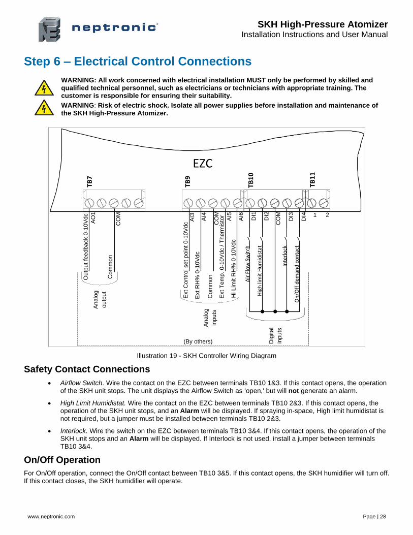
Illustration 19 - SKH Controller Wiring Diagram
Safety Contact Connections
• Airflow Switch. Wire the contact on the EZC between terminals TB10 1&3. If this contact opens, the operation of the SKH unit stops. The unit displays the Airflow Switch as ‘open,' but will not generate an alarm.
• High Limit Humidistat. Wire the contact on the EZC between terminals TB10 2&3. If this contact opens, the operation of the SKH unit stops, and an Alarm will be displayed. If spraying in-space, High limit humidistat is not required, but a jumper must be installed between terminals TB10 2&3.
• Interlock. Wire the switch on the EZC between terminals TB10 3&4. If this contact opens, the operation of the SKH unit stops and an Alarm will be displayed. If Interlock is not used, install a jumper between terminals TB10 3&4.
On/Off Operation
For On/Off operation, connect the On/Off contact between TB10 3&5. If this contact opens, the SKH humidifier will turn off. If this contact closes, the SKH humidifier will operate.
1
TB7
TB9
TB1
1
2
Analo
g
outp
ut
Outp
ut
fee
dback 0
-10V
dc
Com
mon
AO
1
CO
M
Ext C
on
trol set p
oin
t 0-1
0V
dc
Ext
RH
% 0
-10V
dc
Com
mon
Ext T
em
p. 0-1
0V
dc /
Therm
isto
r
Hi Lim
it R
H%
0-1
0V
dc
Analo
g
inputs
AI3
AI4
CO
M
AI5
AI6
Air
Flo
w S
wit
ch
Hig
h li
mit
Hu
mid
ista
t
Inte
rlo
ck
On
/Off
de
man
d c
on
tact
CO
M
DI1
DI2
DI3
DI4
Dig
ital
inputs
(By others)
EZC
TB1
0
SKH High-Pressure Atomizer Installation Instructions and User Manual
www.neptronic.com Page | 29
Modulating Operation
Analog – External Signal
Irrespective of the source of the control signal (BMS, room or duct humidistat, room or duct thermostat, or a combination), the external control signal should be connected on the EZC between terminals TB9 1&3. These analog inputs are configurable at step 4A “Source” and 4B ‘’Signal’’ of the Controls menu (see page 43).
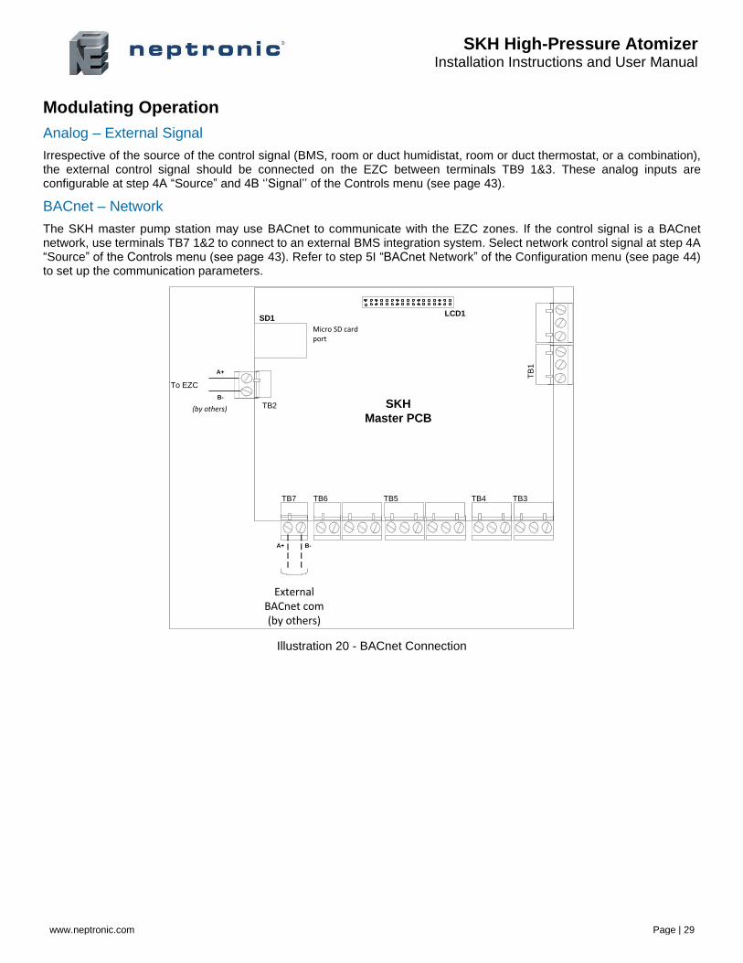
BACnet – Network
The SKH master pump station may use BACnet to communicate with the EZC zones. If the control signal is a BACnet network, use terminals TB7 1&2 to connect to an external BMS integration system. Select network control signal at step 4A “Source” of the Controls menu (see page 43). Refer to step 5I “BACnet Network” of the Configuration menu (see page 44) to set up the communication parameters.
Illustration 20 - BACnet Connection
To EZC
TB5TB6TB7 TB4 TB3
TB
1
SD1LCD1
Micro SD card port
SKH
Master PCB
A+
B-
TB2(by others)
A+ B-
External BACnet com(by others)
SKH High-Pressure Atomizer Installation Instructions and User Manual
www.neptronic.com Page | 30
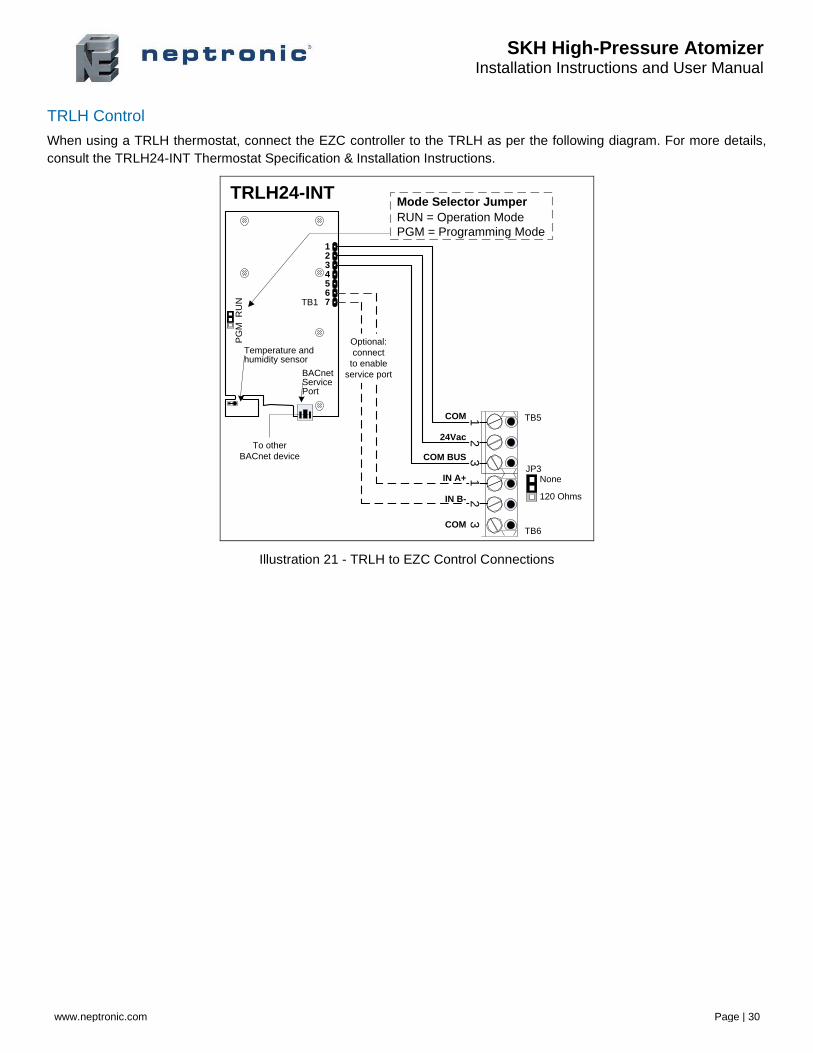
TRLH Control
When using a TRLH thermostat, connect the EZC controller to the TRLH as per the following diagram. For more details,
consult the TRLH24-INT Thermostat Specification & Installation Instructions.
TB1
PG
MR
UN
1234567
TRLH24-INT
Temperature and humidity sensor
BACnetServicePort
12
3
24Vac
COM
COM BUS
IN B-
IN A+
COM
31
2Optional:
connect
to enable
service port
To other
BACnet device
TB6
TB5
JP3None
120 Ohms
Mode Selector Jumper
RUN = Operation Mode
PGM = Programming Mode
Illustration 21 - TRLH to EZC Control Connections
SKH High-Pressure Atomizer Installation Instructions and User Manual
www.neptronic.com Page | 31
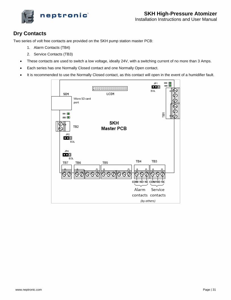
Dry Contacts
Two series of volt free contacts are provided on the SKH pump station master PCB:
1. Alarm Contacts (TB4)
2. Service Contacts (TB3)
• These contacts are used to switch a low voltage, ideally 24V, with a switching current of no more than 3 Amps.
• Each series has one Normally Closed contact and one Normally Open contact.
• It is recommended to use the Normally Closed contact, as this contact will open in the event of a humidifier fault.
SKH High-Pressure Atomizer Installation Instructions and User Manual
www.neptronic.com Page | 32
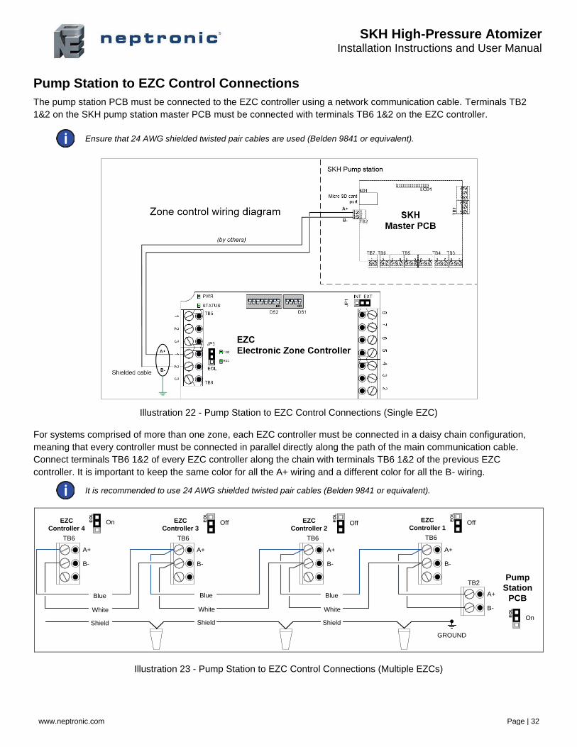
Pump Station to EZC Control Connections
The pump station PCB must be connected to the EZC controller using a network communication cable. Terminals TB2
1&2 on the SKH pump station master PCB must be connected with terminals TB6 1&2 on the EZC controller.
Ensure that 24 AWG shielded twisted pair cables are used (Belden 9841 or equivalent).
Illustration 22 - Pump Station to EZC Control Connections (Single EZC)
For systems comprised of more than one zone, each EZC controller must be connected in a daisy chain configuration,
meaning that every controller must be connected in parallel directly along the path of the main communication cable.
Connect terminals TB6 1&2 of every EZC controller along the chain with terminals TB6 1&2 of the previous EZC
controller. It is important to keep the same color for all the A+ wiring and a different color for all the B- wiring.
It is recommended to use 24 AWG shielded twisted pair cables (Belden 9841 or equivalent).
EO
L
EO
L
EO
L
Shield
White
Blue
Shield
White
Blue
Shield
White
Blue
EO
L
A+
Pump
Station
PCB
EO
L
GROUND
B-
A+
B-
A+
B-
A+
B-
A+
B-
TB2
TB6TB6 TB6 TB6
EZC
Controller 4
EZC
Controller 3
EZC
Controller 2
EZC
Controller 1On
On
OffOffOff
Illustration 23 - Pump Station to EZC Control Connections (Multiple EZCs)
SKH High-Pressure Atomizer Installation Instructions and User Manual
www.neptronic.com Page | 33
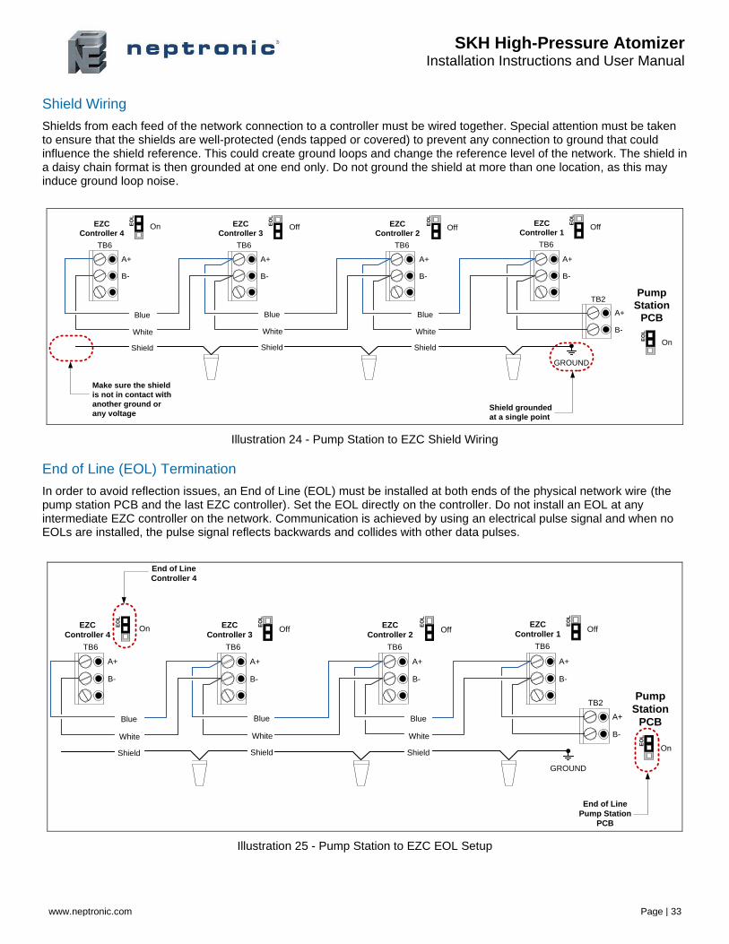
Shield Wiring
Shields from each feed of the network connection to a controller must be wired together. Special attention must be taken to ensure that the shields are well-protected (ends tapped or covered) to prevent any connection to ground that could influence the shield reference. This could create ground loops and change the reference level of the network. The shield in a daisy chain format is then grounded at one end only. Do not ground the shield at more than one location, as this may induce ground loop noise.
EO
L
EO
L
EO
L
Shield
White
Blue
Shield
White
Blue
Shield
White
Blue
EO
L
A+
Pump
Station
PCB
EO
L
GROUND
B-
A+
B-
A+
B-
A+
B-
A+
B-
TB2
TB6TB6 TB6 TB6
EZC
Controller 4
EZC
Controller 3
EZC
Controller 2
EZC
Controller 1
Shield grounded
at a single point
Make sure the shield
is not in contact with
another ground or
any voltage
On
On
OffOffOff
Illustration 24 - Pump Station to EZC Shield Wiring
End of Line (EOL) Termination
In order to avoid reflection issues, an End of Line (EOL) must be installed at both ends of the physical network wire (the pump station PCB and the last EZC controller). Set the EOL directly on the controller. Do not install an EOL at any intermediate EZC controller on the network. Communication is achieved by using an electrical pulse signal and when no EOLs are installed, the pulse signal reflects backwards and collides with other data pulses.
EO
L
EO
L
EO
L
Shield
White
Blue
Shield
White
Blue
Shield
White
Blue
EO
L
A+
Pump
Station
PCB
EO
L
GROUND
B-
A+
B-
A+
B-
A+
B-
A+
B-
TB2
TB6TB6 TB6 TB6
EZC
Controller 4
EZC
Controller 3
EZC
Controller 2
EZC
Controller 1
End of Line
Pump Station
PCB
End of Line
Controller 4
On
On
OffOffOff
Illustration 25 - Pump Station to EZC EOL Setup
SKH High-Pressure Atomizer Installation Instructions and User Manual
www.neptronic.com Page | 34
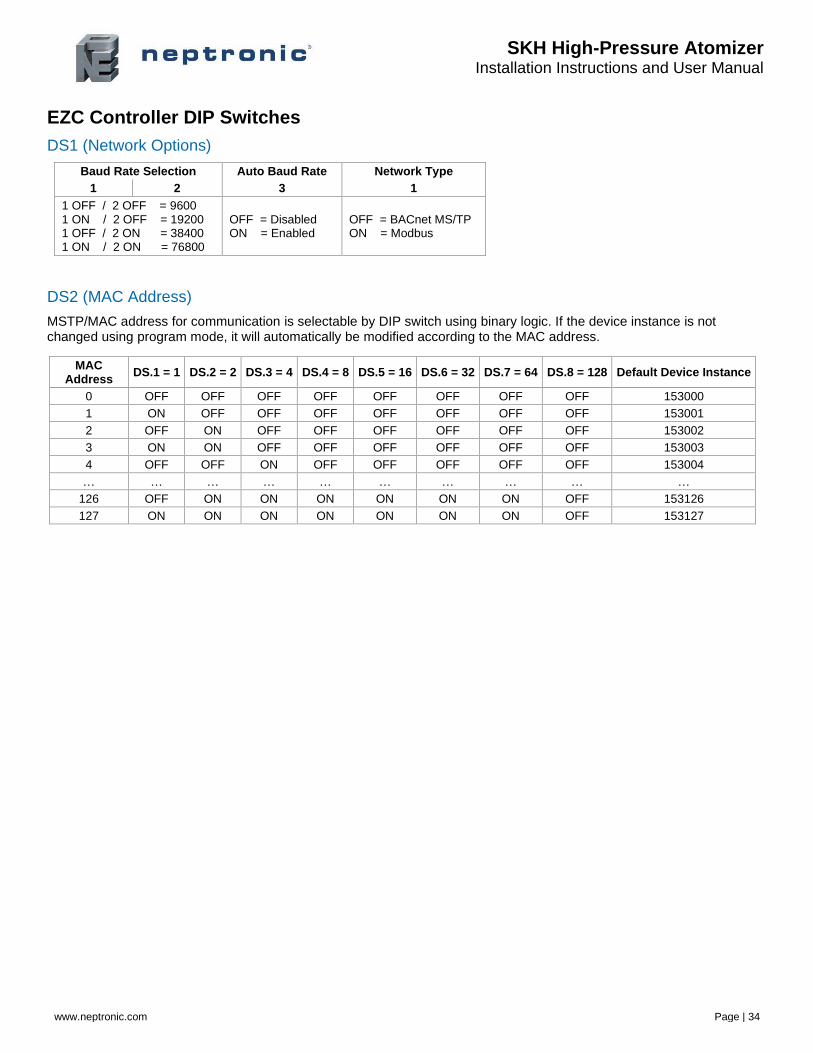
EZC Controller DIP Switches
DS1 (Network Options)
Baud Rate Selection Auto Baud Rate Network Type
1 2 3 1
1 OFF / 2 OFF = 9600 1 ON / 2 OFF = 19200 1 OFF / 2 ON = 38400 1 ON / 2 ON = 76800
OFF = Disabled ON = Enabled
OFF = BACnet MS/TP ON = Modbus
DS2 (MAC Address)
MSTP/MAC address for communication is selectable by DIP switch using binary logic. If the device instance is not changed using program mode, it will automatically be modified according to the MAC address.
MAC Address
DS.1 = 1 DS.2 = 2 DS.3 = 4 DS.4 = 8 DS.5 = 16 DS.6 = 32 DS.7 = 64 DS.8 = 128 Default Device Instance
0 OFF OFF OFF OFF OFF OFF OFF OFF 153000
1 ON OFF OFF OFF OFF OFF OFF OFF 153001
2 OFF ON OFF OFF OFF OFF OFF OFF 153002
3 ON ON OFF OFF OFF OFF OFF OFF 153003
4 OFF OFF ON OFF OFF OFF OFF OFF 153004
… … … … … … … … … …
126 OFF ON ON ON ON ON ON OFF 153126
127 ON ON ON ON ON ON ON OFF 153127
SKH High-Pressure Atomizer Installation Instructions and User Manual
www.neptronic.com Page | 35
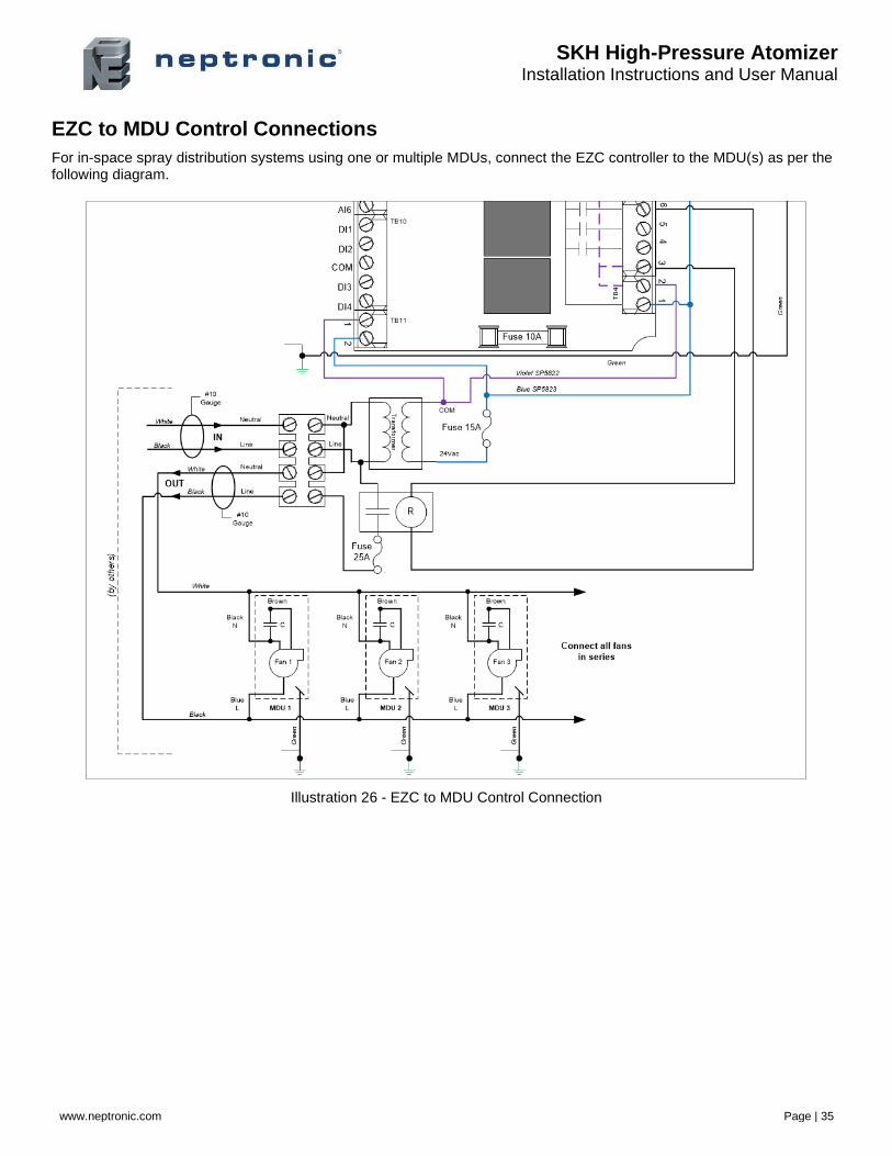
EZC to MDU Control Connections
For in-space spray distribution systems using one or multiple MDUs, connect the EZC controller to the MDU(s) as per the following diagram.
Illustration 26 - EZC to MDU Control Connection
SKH High-Pressure Atomizer Installation Instructions and User Manual
www.neptronic.com Page | 36
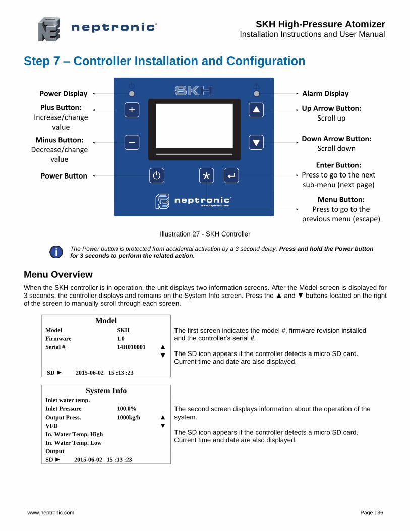
Step 7 – Controller Installation and Configuration
Alarm DisplayPower Display
Plus Button:Increase/change
value
Minus Button:Decrease/change
value
Power Button
Up Arrow Button:Scroll up
Down Arrow Button:Scroll down
Enter Button:Press to go to the next sub-menu (next page)
Menu Button:Press to go to the
previous menu (escape)
Illustration 27 - SKH Controller
The Power button is protected from accidental activation by a 3 second delay. Press and hold the Power button for 3 seconds to perform the related action.
Menu Overview
When the SKH controller is in operation, the unit displays two information screens. After the Model screen is displayed for 3 seconds, the controller displays and remains on the System Info screen. Press the ▲ and ▼ buttons located on the right of the screen to manually scroll through each screen.
Model
The first screen indicates the model #, firmware revision installed and the controller’s serial #. The SD icon appears if the controller detects a micro SD card. Current time and date are also displayed.
Model SKH
Firmware 1.0
Serial # 14H010001 ▲
▼
SD ► 2015-06-02 15 :13 :23
System Info
The second screen displays information about the operation of the system. The SD icon appears if the controller detects a micro SD card. Current time and date are also displayed.
Inlet water temp.
Inlet Pressure 100.0%
Output Press. 1000kg/h ▲
VFD ▼
In. Water Temp. High
In. Water Temp. Low
Output
SD ► 2015-06-02 15 :13 :23
SKH High-Pressure Atomizer Installation Instructions and User Manual
www.neptronic.com Page | 37
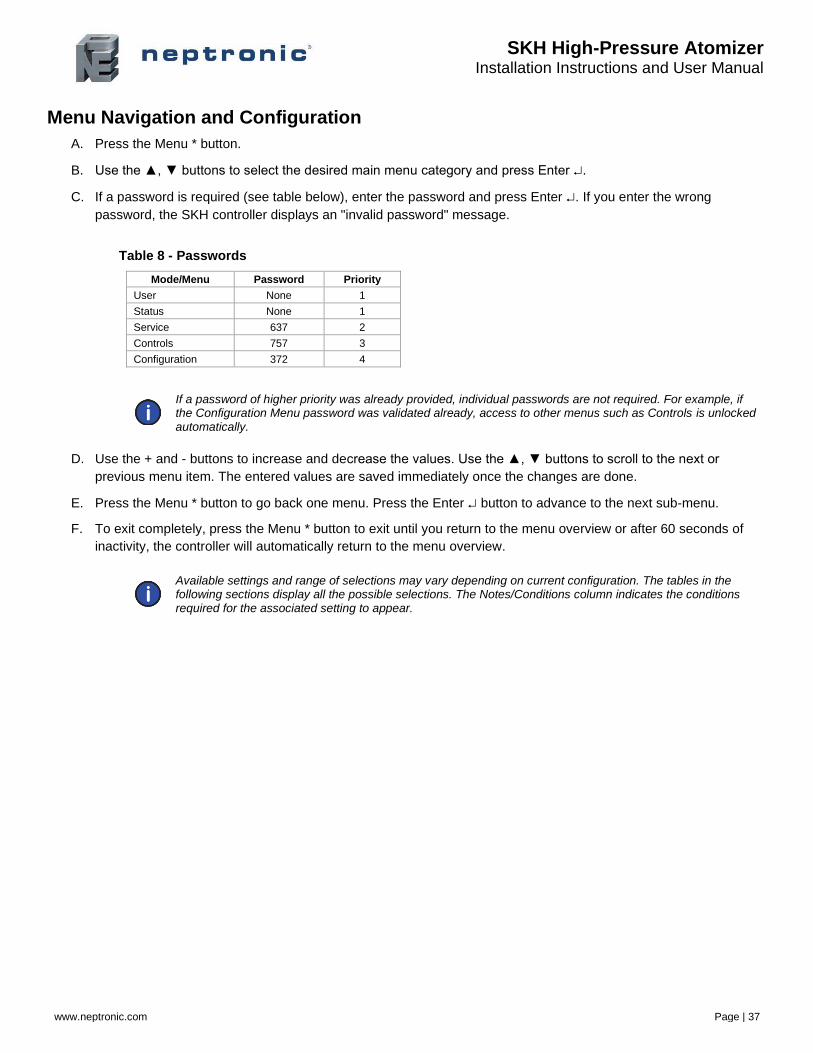
Menu Navigation and Configuration
A. Press the Menu * button.
B. Use the ▲, ▼ buttons to select the desired main menu category and press Enter .
C. If a password is required (see table below), enter the password and press Enter . If you enter the wrong
password, the SKH controller displays an "invalid password" message.
Table 8 - Passwords
Mode/Menu Password Priority
User None 1
Status None 1
Service 637 2
Controls 757 3
Configuration 372 4
If a password of higher priority was already provided, individual passwords are not required. For example, if the Configuration Menu password was validated already, access to other menus such as Controls is unlocked automatically.
D. Use the + and - buttons to increase and decrease the values. Use the ▲, ▼ buttons to scroll to the next or
previous menu item. The entered values are saved immediately once the changes are done.
E. Press the Menu * button to go back one menu. Press the Enter button to advance to the next sub-menu.
F. To exit completely, press the Menu * button to exit until you return to the menu overview or after 60 seconds of
inactivity, the controller will automatically return to the menu overview.
Available settings and range of selections may vary depending on current configuration. The tables in the following sections display all the possible selections. The Notes/Conditions column indicates the conditions required for the associated setting to appear.
SKH High-Pressure Atomizer Installation Instructions and User Manual
www.neptronic.com Page | 38
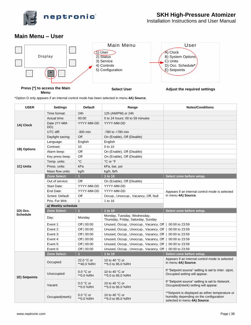
Main Menu – User
Main Menu
1) User
2) Status
3) Service
4) Controls
5) Configuration
Disp lay
*
User
A) Clock
B) System Options
C) Units
D) Occ. Schedule*
E) Setpoints
Press [*] to access the Main
MenuSelect User Adjust the required settings
*Option D only appears if an internal control mode has been selected in menu 4A) Source.
USER Settings Default Range Notes/Conditions
1A) Clock
Time format: 24h 12h (AM/PM) or 24h
Actual time: 00:00 0 to 24 hours: 00 to 59 minutes
Date (YY-MM-DD):
YYYY-MM-DD YYYY-MM-DD
UTC diff: -300 min -780 to +780 min
Daylight saving: Off On (Enable), Off (Disable)
1B) Options
Language: English English
Contrast: 10 0 to 10
Alarm beep: Off On (Enable), Off (Disable)
Key press beep: Off On (Enable), Off (Disable)
1C) Units
Temp. units: °C °C or °F
Press. units: kPa kPa, bar, psi
Mass flow units: kg/h kg/h, lb/h
1D) Occ. Schedule
Zone Select: 1 1 to 10 Select zone before setup.
Out of service: Off On (Enable), Off (Disable)
Appears if an internal control mode is selected in menu 4A) Source.
Start Date: YYYY-MM-DD YYYY-MM-DD
End Date: YYYY-MM-DD YYYY-MM-DD
Sched. Default: Off Occup., Unoccup., Vacancy, Off, Null
Prio. For Writ. 1 1 to 16
a) Weekly schedule
Zone Select: 1 1 to 10 Select zone before setup.
Day: Monday Monday, Tuesday, Wednesday, Thursday, Friday, Saturday, Sunday
Event 1: Off | 00:00 Unused, Occup., Unoccup., Vacancy, Off | 00:00 to 23:59
Event 2: Off | 00:00 Unused, Occup., Unoccup., Vacancy, Off | 00:00 to 23:59
Event 3: Off | 00:00 Unused, Occup., Unoccup., Vacancy, Off | 00:00 to 23:59
Event 4: Off | 00:00 Unused, Occup., Unoccup., Vacancy, Off | 00:00 to 23:59
Event 5: Off | 00:00 Unused, Occup., Unoccup., Vacancy, Off | 00:00 to 23:59
Event 6: Off | 00:00 Unused, Occup., Unoccup., Vacancy, Off | 00:00 to 23:59
1E) Setpoints
Zone Select: 1 1 to 10 Select zone before setup.
Occupied: 22.0 °C or **40.0 %RH
10 to 40 °C or **5.0 to 95.0 %RH
Appears if an internal control mode is selected in menu 4A) Source. If “Setpoint source” setting is set to Inter. stpnt, Occupied setting will appear. If “Setpoint source” setting is set to Network, Occupied(ntwrk) setting will appear. **Setpoint is displayed as either temperature or humidity depending on the configuration selected in menu 4A) Source.
Unoccupied: 0.0 °C or **0.0 %RH
10 to 40 °C or **5.0 to 95.0 %RH
Vacant: 0.0 °C or **0.0 %RH
10 to 40 °C or **5.0 to 95.0 %RH
Occupied(ntwrk): 0.0 °C or **0.0 %RH
10 to 40 °C or **5.0 to 95.0 %RH
SKH High-Pressure Atomizer Installation Instructions and User Manual
www.neptronic.com Page | 39
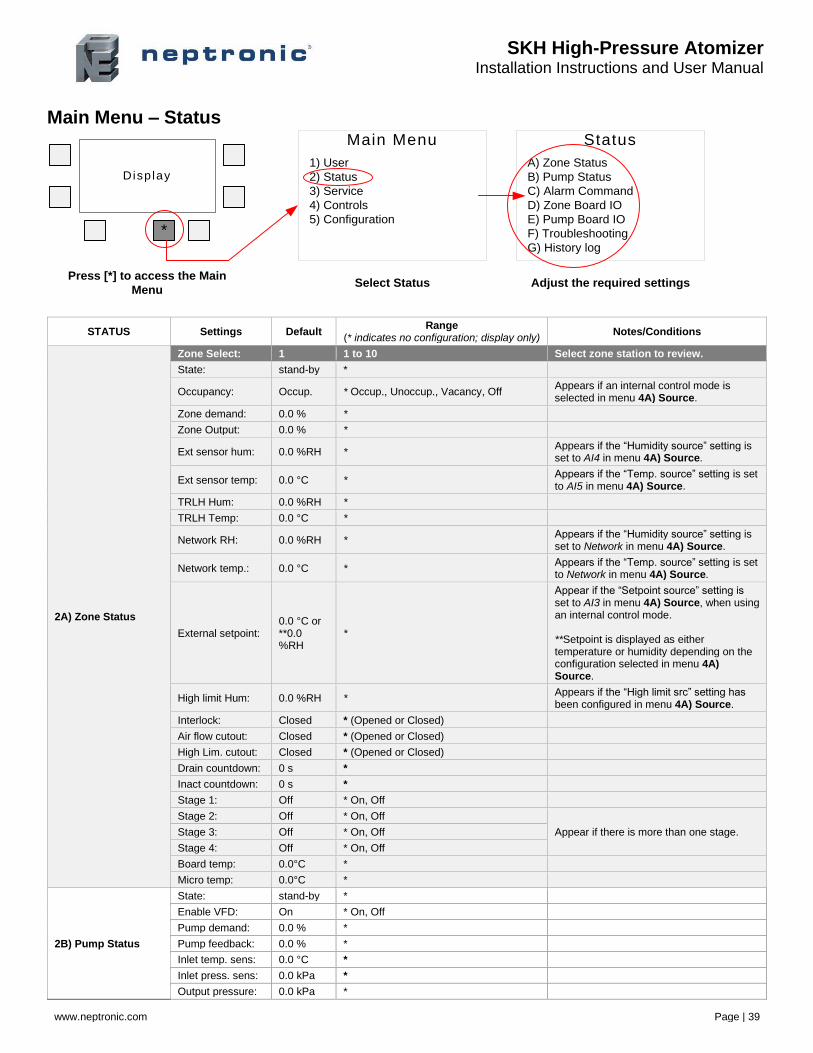
Main Menu – Status Main Menu
1) User
2) Status
3) Service
4) Controls
5) Configuration
Disp lay
*
Status
A) Zone Status
B) Pump Status
C) Alarm Command
D) Zone Board IO
E) Pump Board IO
F) Troubleshooting
G) History log
Press [*] to access the Main
MenuSelect Status Adjust the required settings
STATUS Settings Default Range
(* indicates no configuration; display only) Notes/Conditions
2A) Zone Status
Zone Select: 1 1 to 10 Select zone station to review.
State: stand-by *
Occupancy: Occup. * Occup., Unoccup., Vacancy, Off Appears if an internal control mode is selected in menu 4A) Source.
Zone demand: 0.0 % *
Zone Output: 0.0 % *
Ext sensor hum: 0.0 %RH * Appears if the “Humidity source” setting is set to AI4 in menu 4A) Source.
Ext sensor temp: 0.0 °C * Appears if the “Temp. source” setting is set to AI5 in menu 4A) Source.
TRLH Hum: 0.0 %RH *
TRLH Temp: 0.0 °C *
Network RH: 0.0 %RH * Appears if the “Humidity source” setting is set to Network in menu 4A) Source.
Network temp.: 0.0 °C * Appears if the “Temp. source” setting is set to Network in menu 4A) Source.
External setpoint: 0.0 °C or **0.0 %RH
*
Appear if the “Setpoint source” setting is set to AI3 in menu 4A) Source, when using an internal control mode. **Setpoint is displayed as either temperature or humidity depending on the configuration selected in menu 4A) Source.
High limit Hum: 0.0 %RH * Appears if the “High limit src” setting has been configured in menu 4A) Source.
Interlock: Closed * (Opened or Closed)
Air flow cutout: Closed * (Opened or Closed)
High Lim. cutout: Closed * (Opened or Closed)
Drain countdown: 0 s *
Inact countdown: 0 s *
Stage 1: Off * On, Off
Stage 2: Off * On, Off
Appear if there is more than one stage. Stage 3: Off * On, Off
Stage 4: Off * On, Off
Board temp: 0.0°C *
Micro temp: 0.0°C *
2B) Pump Status
State: stand-by *
Enable VFD: On * On, Off
Pump demand: 0.0 % *
Pump feedback: 0.0 % *
Inlet temp. sens: 0.0 °C *
Inlet press. sens: 0.0 kPa *
Output pressure: 0.0 kPa *
SKH High-Pressure Atomizer Installation Instructions and User Manual
www.neptronic.com Page | 40
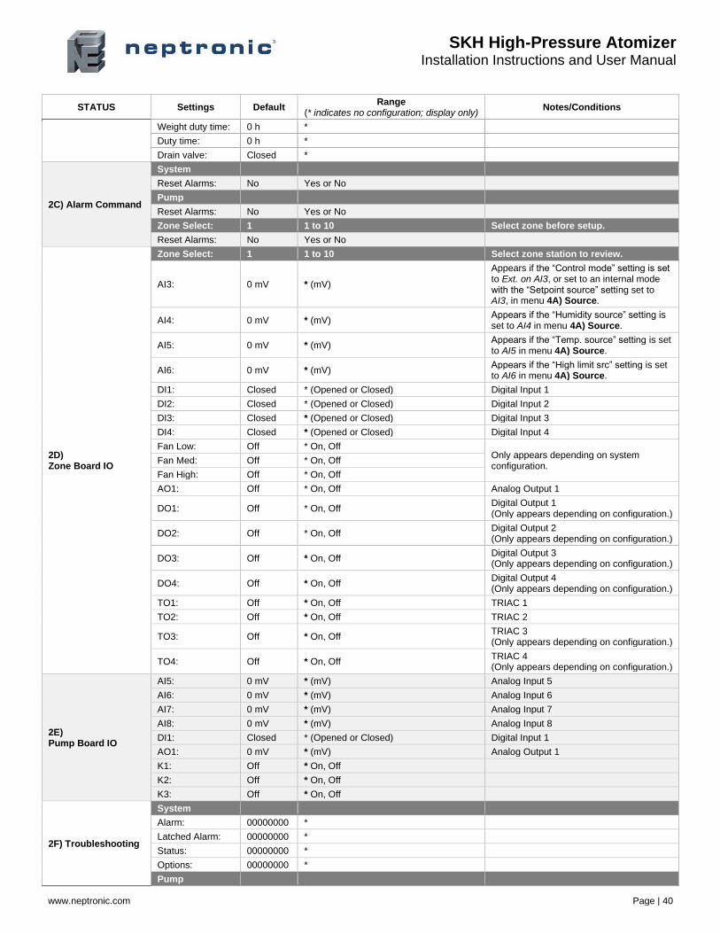
STATUS Settings Default Range
(* indicates no configuration; display only) Notes/Conditions
Weight duty time: 0 h *
Duty time: 0 h *
Drain valve: Closed *
2C) Alarm Command
System
Reset Alarms: No Yes or No
Pump
Reset Alarms: No Yes or No
Zone Select: 1 1 to 10 Select zone before setup.
Reset Alarms: No Yes or No
2D) Zone Board IO
Zone Select: 1 1 to 10 Select zone station to review.
AI3: 0 mV * (mV)
Appears if the “Control mode” setting is set to Ext. on AI3, or set to an internal mode with the “Setpoint source” setting set to AI3, in menu 4A) Source.
AI4: 0 mV * (mV) Appears if the “Humidity source” setting is set to AI4 in menu 4A) Source.
AI5: 0 mV * (mV) Appears if the “Temp. source” setting is set to AI5 in menu 4A) Source.
AI6: 0 mV * (mV) Appears if the “High limit src” setting is set to AI6 in menu 4A) Source.
DI1: Closed * (Opened or Closed) Digital Input 1
DI2: Closed * (Opened or Closed) Digital Input 2
DI3: Closed * (Opened or Closed) Digital Input 3
DI4: Closed * (Opened or Closed) Digital Input 4
Fan Low: Off * On, Off Only appears depending on system configuration.
Fan Med: Off * On, Off
Fan High: Off * On, Off
AO1: Off * On, Off Analog Output 1
DO1: Off * On, Off Digital Output 1 (Only appears depending on configuration.)
DO2: Off * On, Off Digital Output 2 (Only appears depending on configuration.)
DO3: Off * On, Off Digital Output 3 (Only appears depending on configuration.)
DO4: Off * On, Off Digital Output 4 (Only appears depending on configuration.)
TO1: Off * On, Off TRIAC 1
TO2: Off * On, Off TRIAC 2
TO3: Off * On, Off TRIAC 3 (Only appears depending on configuration.)
TO4: Off * On, Off TRIAC 4 (Only appears depending on configuration.)
2E) Pump Board IO
AI5: 0 mV * (mV) Analog Input 5
AI6: 0 mV * (mV) Analog Input 6
AI7: 0 mV * (mV) Analog Input 7
AI8: 0 mV * (mV) Analog Input 8
DI1: Closed * (Opened or Closed) Digital Input 1
AO1: 0 mV * (mV) Analog Output 1
K1: Off * On, Off
K2: Off * On, Off
K3: Off * On, Off
2F) Troubleshooting
System
Alarm: 00000000 *
Latched Alarm: 00000000 *
Status: 00000000 *
Options: 00000000 *
Pump
SKH High-Pressure Atomizer Installation Instructions and User Manual
www.neptronic.com Page | 41
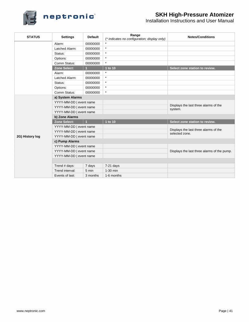
STATUS Settings Default Range
(* indicates no configuration; display only) Notes/Conditions
Alarm: 00000000 *
Latched Alarm: 00000000 *
Status: 00000000 *
Options: 00000000 *
Comm Status: 00000000 *
Zone Select: 1 1 to 10 Select zone station to review.
Alarm: 00000000 *
Latched Alarm: 00000000 *
Status: 00000000 *
Options: 00000000 *
Comm Status: 00000000 *
2G) History log
a) System Alarms
YYYY-MM-DD | event name Displays the last three alarms of the system.
YYYY-MM-DD | event name
YYYY-MM-DD | event name
b) Zone Alarms
Zone Select: 1 1 to 10 Select zone station to review.
YYYY-MM-DD | event name Displays the last three alarms of the selected zone.
YYYY-MM-DD | event name
YYYY-MM-DD | event name
c) Pump Alarms
YYYY-MM-DD | event name
Displays the last three alarms of the pump. YYYY-MM-DD | event name
YYYY-MM-DD | event name
Trend # days: 7 days 7-21 days
Trend interval: 5 min 1-30 min
Events of last: 3 months 1-6 months
SKH High-Pressure Atomizer Installation Instructions and User Manual
www.neptronic.com Page | 42
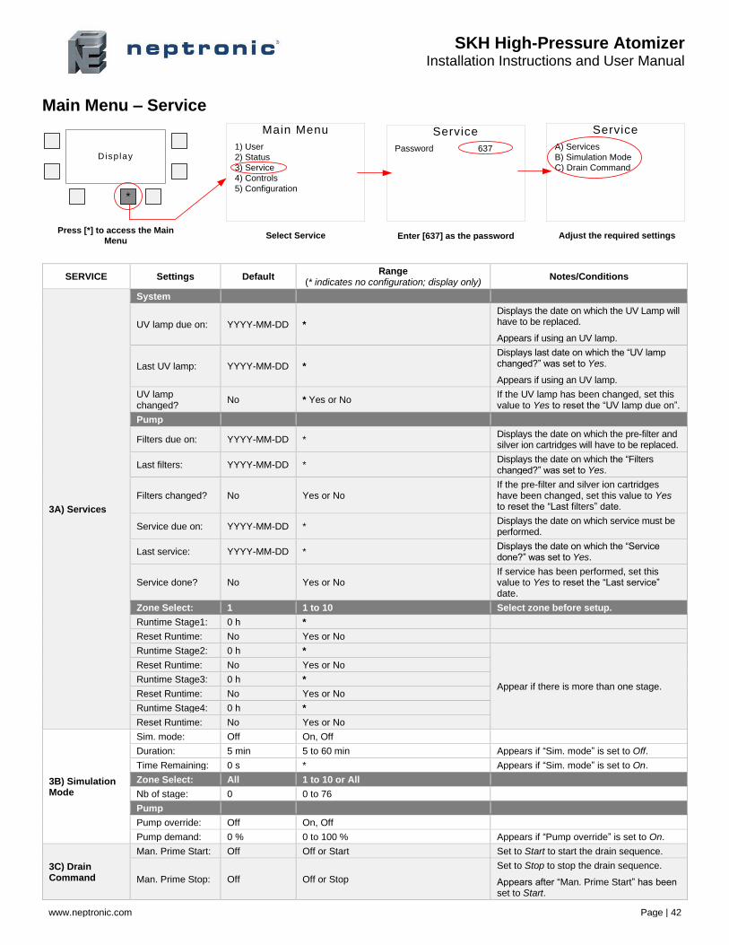
Main Menu – Service
Main Menu
1) User
2) Status
3) Service
4) Controls
5) Configuration
Disp lay
*
Service
A) Services
B) Simulation Mode
C) Drain Command
Press [*] to access the Main
MenuSelect Service Adjust the required settings
Service
Password 637
Enter [637] as the password
SERVICE Settings Default Range
(* indicates no configuration; display only) Notes/Conditions
3A) Services
System
UV lamp due on: YYYY-MM-DD *
Displays the date on which the UV Lamp will have to be replaced.
Appears if using an UV lamp.
Last UV lamp: YYYY-MM-DD *
Displays last date on which the “UV lamp changed?” was set to Yes.
Appears if using an UV lamp.
UV lamp changed?
No * Yes or No If the UV lamp has been changed, set this value to Yes to reset the “UV lamp due on”.
Pump
Filters due on: YYYY-MM-DD * Displays the date on which the pre-filter and silver ion cartridges will have to be replaced.
Last filters: YYYY-MM-DD * Displays the date on which the “Filters changed?” was set to Yes.
Filters changed? No Yes or No If the pre-filter and silver ion cartridges have been changed, set this value to Yes to reset the “Last filters” date.
Service due on: YYYY-MM-DD * Displays the date on which service must be performed.
Last service: YYYY-MM-DD * Displays the date on which the “Service done?” was set to Yes.
Service done? No Yes or No If service has been performed, set this value to Yes to reset the “Last service” date.
Zone Select: 1 1 to 10 Select zone before setup.
Runtime Stage1: 0 h *
Reset Runtime: No Yes or No
Runtime Stage2: 0 h *
Appear if there is more than one stage.
Reset Runtime: No Yes or No
Runtime Stage3: 0 h *
Reset Runtime: No Yes or No
Runtime Stage4: 0 h *
Reset Runtime: No Yes or No
3B) Simulation Mode
Sim. mode: Off On, Off
Duration: 5 min 5 to 60 min Appears if “Sim. mode” is set to Off.
Time Remaining: 0 s * Appears if “Sim. mode” is set to On.
Zone Select: All 1 to 10 or All
Nb of stage: 0 0 to 76
Pump
Pump override: Off On, Off
Pump demand: 0 % 0 to 100 % Appears if “Pump override” is set to On.
3C) Drain Command
Man. Prime Start: Off Off or Start Set to Start to start the drain sequence.
Man. Prime Stop: Off Off or Stop
Set to Stop to stop the drain sequence.
Appears after “Man. Prime Start” has been set to Start.
SKH High-Pressure Atomizer Installation Instructions and User Manual
www.neptronic.com Page | 43
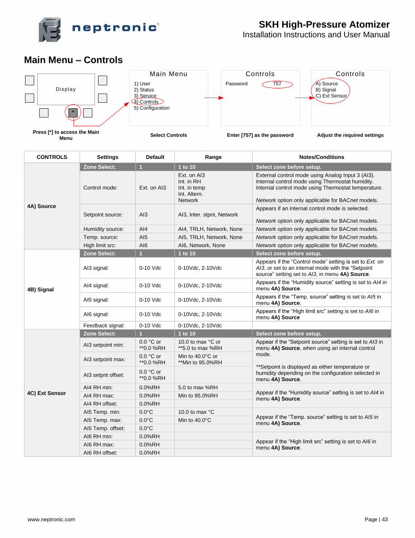
Main Menu – Controls
Main Menu
1) User
2) Status
3) Service
4) Controls
5) Configuration
Disp lay
*
Controls
Password 757
Controls
A) Source
B) Signal
C) Ext Sensor
Press [*] to access the Main
MenuSelect Controls Enter [757] as the password Adjust the required settings
CONTROLS Settings Default Range Notes/Conditions
4A) Source
Zone Select: 1 1 to 10 Select zone before setup.
Control mode: Ext. on AI3
Ext. on AI3 Int. in RH Int. in temp Int. Altern. Network
External control mode using Analog Input 3 (AI3). Internal control mode using Thermostat humidity. Internal control mode using Thermostat temperature. Network option only applicable for BACnet models.
Setpoint source: AI3 AI3, Inter. stpnt, Network Appears if an internal control mode is selected. Network option only applicable for BACnet models.
Humidity source: AI4 AI4, TRLH, Network, None Network option only applicable for BACnet models.
Temp. source: AI5 AI5, TRLH, Network, None Network option only applicable for BACnet models.
High limit src: AI6 AI6, Network, None Network option only applicable for BACnet models.
4B) Signal
Zone Select: 1 1 to 10 Select zone before setup.
AI3 signal: 0-10 Vdc 0-10Vdc, 2-10Vdc Appears if the “Control mode” setting is set to Ext. on AI3, or set to an internal mode with the “Setpoint source” setting set to AI3, in menu 4A) Source.
AI4 signal: 0-10 Vdc 0-10Vdc, 2-10Vdc Appears if the “Humidity source” setting is set to AI4 in menu 4A) Source.
AI5 signal: 0-10 Vdc 0-10Vdc, 2-10Vdc Appears if the “Temp. source” setting is set to AI5 in menu 4A) Source.
AI6 signal: 0-10 Vdc 0-10Vdc, 2-10Vdc Appears if the “High limit src” setting is set to AI6 in menu 4A) Source
Feedback signal: 0-10 Vdc 0-10Vdc, 2-10Vdc
4C) Ext Sensor
Zone Select: 1 1 to 10 Select zone before setup.
AI3 setpoint min: 0.0 °C or **0.0 %RH
10.0 to max °C or **5.0 to max %RH
Appear if the “Setpoint source” setting is set to AI3 in menu 4A) Source, when using an internal control mode. **Setpoint is displayed as either temperature or humidity depending on the configuration selected in menu 4A) Source.
AI3 setpoint max: 0.0 °C or **0.0 %RH
Min to 40.0°C or **Min to 95.0%RH
AI3 setpnt offset: 0.0 °C or **0.0 %RH
AI4 RH min: 0.0%RH 5.0 to max %RH Appear if the “Humidity source” setting is set to AI4 in menu 4A) Source.
AI4 RH max: 0.0%RH Min to 95.0%RH
AI4 RH offset: 0.0%RH
AI5 Temp. min: 0.0°C 10.0 to max °C Appear if the “Temp. source” setting is set to AI5 in menu 4A) Source.
AI5 Temp. max: 0.0°C Min to 40.0°C
AI5 Temp. offset: 0.0°C
AI6 RH min: 0.0%RH Appear if the “High limit src” setting is set to AI6 in menu 4A) Source.
AI6 RH max: 0.0%RH
AI6 RH offset: 0.0%RH
SKH High-Pressure Atomizer Installation Instructions and User Manual
www.neptronic.com Page | 44
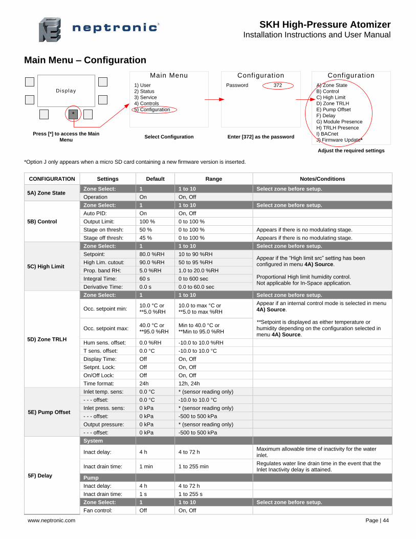
Main Menu – Configuration
Main Menu
1) User
2) Status
3) Service
4) Controls
5) Configuration
Disp lay
*
Configuration
Password 372
Configuration
A) Zone State
B) Control
C) High Limit
D) Zone TRLH
E) Pump Offset
F) Delay
G) Module Presence
H) TRLH Presence
I) BACnet
J) Firmware Update*
Press [*] to access the Main
MenuSelect Configuration Enter [372] as the password
Adjust the required settings
*Option J only appears when a micro SD card containing a new firmware version is inserted.
CONFIGURATION Settings Default Range Notes/Conditions
5A) Zone State Zone Select: 1 1 to 10 Select zone before setup.
Operation On On, Off
5B) Control
Zone Select: 1 1 to 10 Select zone before setup.
Auto PID: On On, Off
Output Limit: 100 % 0 to 100 %
Stage on thresh: 50 % 0 to 100 % Appears if there is no modulating stage.
Stage off thresh: 45 % 0 to 100 % Appears if there is no modulating stage.
5C) High Limit
Zone Select: 1 1 to 10 Select zone before setup.
Setpoint: 80.0 %RH 10 to 90 %RH Appear if the “High limit src” setting has been configured in menu 4A) Source. Proportional High limit humidity control. Not applicable for In-Space application.
High Lim. cutout: 90.0 %RH 50 to 95 %RH
Prop. band RH: 5.0 %RH 1.0 to 20.0 %RH
Integral Time: 60 s 0 to 600 sec
Derivative Time: 0.0 s 0.0 to 60.0 sec
5D) Zone TRLH
Zone Select: 1 1 to 10 Select zone before setup.
Occ. setpoint min: 10.0 °C or **5.0 %RH
10.0 to max °C or **5.0 to max %RH
Appear if an internal control mode is selected in menu 4A) Source. **Setpoint is displayed as either temperature or humidity depending on the configuration selected in menu 4A) Source.
Occ. setpoint max: 40.0 °C or **95.0 %RH
Min to 40.0 °C or **Min to 95.0 %RH
Hum sens. offset: 0.0 %RH -10.0 to 10.0 %RH
T sens. offset: 0.0 °C -10.0 to 10.0 °C
Display Time: Off On, Off
Setpnt. Lock: Off On, Off
On/Off Lock: Off On, Off
Time format: 24h 12h, 24h
5E) Pump Offset
Inlet temp. sens: 0.0 °C * (sensor reading only)
- - - offset: 0.0 °C -10.0 to 10.0 °C
Inlet press. sens: 0 kPa * (sensor reading only)
- - - offset: 0 kPa -500 to 500 kPa
Output pressure: 0 kPa * (sensor reading only)
- - - offset: 0 kPa -500 to 500 kPa
5F) Delay
System
Inact delay: 4 h 4 to 72 h Maximum allowable time of inactivity for the water inlet.
Inact drain time: 1 min 1 to 255 min Regulates water line drain time in the event that the Inlet Inactivity delay is attained.
Pump
Inact delay: 4 h 4 to 72 h
Inact drain time: 1 s 1 to 255 s
Zone Select: 1 1 to 10 Select zone before setup.
Fan control: Off On, Off
SKH High-Pressure Atomizer Installation Instructions and User Manual
www.neptronic.com Page | 45
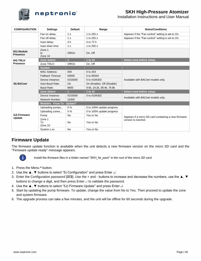
CONFIGURATION Settings Default Range Notes/Conditions
Fan on delay: 1 s 1 to 255 s Appears if the “Fan control” setting is set to On.
Fan off delay: 1 s 1 to 255 s Appears if the “Fan control” setting is set to On.
Inact delay: 4 h 4 to 72 h
Inact drain time: 1 s 1 to 255 s
5G) Module Presence
Zone 1 to Zone 10
Off/On On, Off
5H) TRLH Presence
Zone Select: 1 1 to 10 Select zone before setup.
Zone TRLH: Off/On On, Off
5I) BACnet
System
MAC Address: 000 0 to 254
Available with BACnet models only.
Fallback Timeout: 00000 0 to 65534
Device Instance: 0153000 0 to 4194302
Auto Baud Rate: On On (Enable), Off (Disable)
Baud Rate: 9600 9.6k, 19.2k, 38.4k, 76.8k
Zone Select: 1 1 to 10 Select zone before setup.
Device Instance: 0153000 0 to 4194302 Available with BACnet models only.
Network Number: 15300
5J) Firmware Update
Modules From To Update?
Uploading pumps... 0 % 0 to 100% update progress
Appears if a micro SD card containing a new firmware version is inserted.
Uploading zones... 0 % 0 to 100% update progress
Pump No Yes or No
Zone 1 To Zone 10
No Yes or No
System x.xx No Yes or No
Firmware Update
The firmware update function is available when the unit detects a new firmware version on the micro SD card and the "Firmware update ready" message appears.
Install the firmware files in a folder named “SKH_fw_pack” in the root of the micro SD card.
1. Press the Menu * button.
2. Use the ▲, ▼ buttons to select “5) Configuration” and press Enter .
3. Enter the Configuration password [372]. Use the + and - buttons to increase and decrease the numbers, use the ▲, ▼
buttons to change a digit, and then press Enter to validate the password.
4. Use the ▲, ▼ buttons to select “5J) Firmware Update” and press Enter .
5. Start by updating the pump firmware. To update, change the value from No to Yes. Then proceed to update the zone
and system firmware.
6. The upgrade process can take a few minutes, and the unit will be offline for 60 seconds during the upgrade.
SKH High-Pressure Atomizer Installation Instructions and User Manual
www.neptronic.com Page | 46
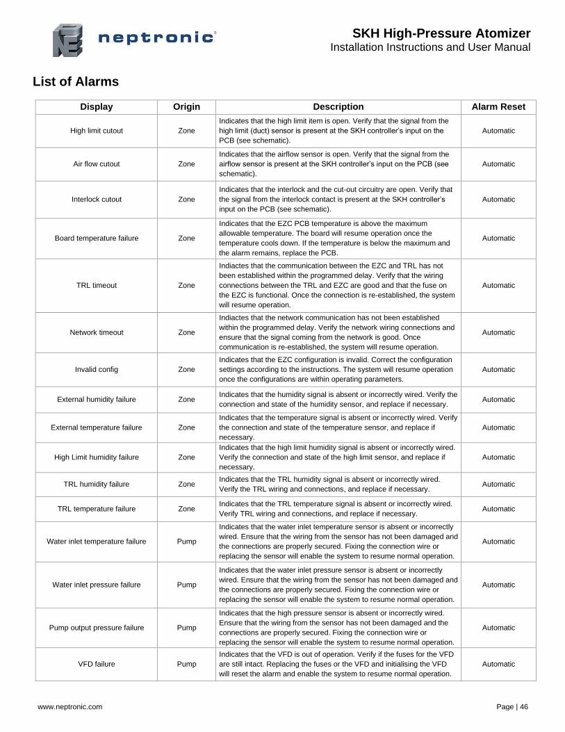
List of Alarms
Display Origin Description Alarm Reset
High limit cutout Zone
Indicates that the high limit item is open. Verify that the signal from the
high limit (duct) sensor is present at the SKH controller’s input on the
PCB (see schematic).
Automatic
Air flow cutout Zone
Indicates that the airflow sensor is open. Verify that the signal from the
airflow sensor is present at the SKH controller’s input on the PCB (see
schematic).
Automatic
Interlock cutout Zone
Indicates that the interlock and the cut-out circuitry are open. Verify that
the signal from the interlock contact is present at the SKH controller’s
input on the PCB (see schematic).
Automatic
Board temperature failure Zone
Indicates that the EZC PCB temperature is above the maximum
allowable temperature. The board will resume operation once the
temperature cools down. If the temperature is below the maximum and
the alarm remains, replace the PCB.
Automatic
TRL timeout Zone
Indiactes that the communication between the EZC and TRL has not
been established within the programmed delay. Verify that the wiring
connections between the TRL and EZC are good and that the fuse on
the EZC is functional. Once the connection is re-established, the system
will resume operation.
Automatic
Network timeout Zone
Indiactes that the network communication has not been established
within the programmed delay. Verify the network wiring connections and
ensure that the signal coming from the network is good. Once
communication is re-established, the system will resume operation.
Automatic
Invalid config Zone
Indicates that the EZC configuration is invalid. Correct the configuration
settings according to the instructions. The system will resume operation
once the configurations are within operating parameters.
Automatic
External humidity failure Zone Indicates that the humidity signal is absent or incorrectly wired. Verify the
connection and state of the humidity sensor, and replace if necessary. Automatic
External temperature failure Zone
Indicates that the temperature signal is absent or incorrectly wired. Verify
the connection and state of the temperature sensor, and replace if
necessary.
Automatic
High Limit humidity failure Zone
Indicates that the high limit humidity signal is absent or incorrectly wired.
Verify the connection and state of the high limit sensor, and replace if
necessary.
Automatic
TRL humidity failure Zone Indicates that the TRL humidity signal is absent or incorrectly wired.
Verify the TRL wiring and connections, and replace if necessary. Automatic
TRL temperature failure Zone Indicates that the TRL temperature signal is absent or incorrectly wired.
Verify TRL wiring and connections, and replace if necessary. Automatic
Water inlet temperature failure Pump
Indicates that the water inlet temperature sensor is absent or incorrectly
wired. Ensure that the wiring from the sensor has not been damaged and
the connections are properly secured. Fixing the connection wire or
replacing the sensor will enable the system to resume normal operation.
Automatic
Water inlet pressure failure Pump
Indicates that the water inlet pressure sensor is absent or incorrectly
wired. Ensure that the wiring from the sensor has not been damaged and
the connections are properly secured. Fixing the connection wire or
replacing the sensor will enable the system to resume normal operation.
Automatic
Pump output pressure failure Pump
Indicates that the high pressure sensor is absent or incorrectly wired.
Ensure that the wiring from the sensor has not been damaged and the
connections are properly secured. Fixing the connection wire or
replacing the sensor will enable the system to resume normal operation.
Automatic
VFD failure Pump
Indicates that the VFD is out of operation. Verify if the fuses for the VFD
are still intact. Replacing the fuses or the VFD and initialising the VFD
will reset the alarm and enable the system to resume normal operation.
Automatic

SKH High-Pressure Atomizer Installation Instructions and User Manual
www.neptronic.com Page | 47
Display Origin Description Alarm Reset
Water inlet temperature too high Pump
Indicates that the water inlet temperature is above the maximum
temperature of 55°C (131°F). The system will resume operation once the
water is cooled down.
Automatic
Water inlet temperature too low Pump
Indicates that the water inlet temperature is below the minimum
temperature of 2°C (36°F). The system will resume operation once the
water is warmer.
Automatic
Water inlet pressure too low Pump
Indicates that the water inlet pressure is below the minimum pressure of
207 kPa (30 PSI). Verify the water supply. The system will resume
operation once the water pressure is between 207 kPa (30 PSI) and 483
kPa (70 PSI).
Automatic
Water inlet pressure too high Pump
Indicates that the water inlet pressure is above the maximum pressure of
483 kPa (70 PSI). Verify the water supply pressure and the low-pressure
regulator. The system will resume operation once the water pressure is
between 207 kPa (30 PSI) and 483 kPa (70 PSI).
Automatic
Pump output pressure too low Pump
Indicates that the high pressure value is below the minimum pressure.
Ensure that the water distribution rack or piping is not leaking. Ensure
that none of the solenoids valves from the EZC are letting water go to
the drain. If this is the case, clean or change the faulty valve. The system
will resume operation once the pump pressure is between 3447 kPa
(500 PSI) and 7584 kPa (1100 PSI).
Automatic
Pump output pressure too high Pump
Indicates that the high pressure value is above the maximum pressure.
Ensure that the piping and the nozzle are not blocked. If this is the case,
replace the blocked nozzles and clean the blocked piping. Ensure that all
the solenoids on the EZC valve are functioning properly. The system will
resume operation once the pump pressure is between 3447 kPa (500
PSI) and 7584 kPa (1100 PSI).
Automatic
Pressure Timeout Pump
Indicates that pressurisation has not been performed within the
programmed delay (30sec). This value can be adjusted based on the
size of the distribution system. See description from Pump output
pressure too low alarm if troubleshooting is required.
Automatic
Invalid configuration Pump Indicates that the pump station configuration is invalid. Correct the
configuration settings according to the instructions. The system will
resume operation once the configuration is within operating parameters.
Automatic
Filter service due Pump Indicates that the pre-filter and silver ion cartridges need to be replaced.
The alarm will reset automatically once the service counter is reset. Automatic
Pump service due Pump Indicates that the pump requires servicing. The alarm will reset
automatically once the service counter is reset. Automatic
Pump timeout System pump
Indicates that the communication between the SKH Slave PCB and
Master PCB has not been established within the programmed delay.
Verify that the wiring connections coming from the PCBs in the pump
station are good. Once connection is re-established, the system will
resume operation.
Automatic
Zone timeout System pump
Indicates that the communication between the EZC PCB and SKH
Master PCB has not been established within the programmed delay.
Verify that the wiring connections coming from the EZC are good. Once
connection is re-established, the system will resume operation.
Automatic
Service warning System pump Indicates that the system will require service soon.
See Servicing and Maintenance section. Manual
Service alarm System pump Indicates that the system requires service.
See Servicing and Maintenance section. Manual
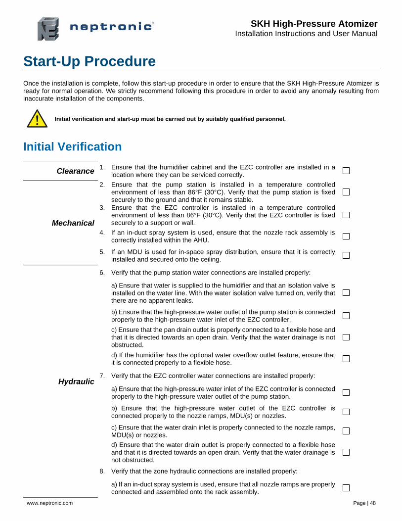
SKH High-Pressure Atomizer Installation Instructions and User Manual
www.neptronic.com Page | 48
Start-Up Procedure
Once the installation is complete, follow this start-up procedure in order to ensure that the SKH High-Pressure Atomizer is ready for normal operation. We strictly recommend following this procedure in order to avoid any anomaly resulting from inaccurate installation of the components.
Initial verification and start-up must be carried out by suitably qualified personnel.
Initial Verification
Clearance 1. Ensure that the humidifier cabinet and the EZC controller are installed in a
location where they can be serviced correctly.
Mechanical
2. Ensure that the pump station is installed in a temperature controlled environment of less than 86°F (30°C). Verify that the pump station is fixed securely to the ground and that it remains stable.
3. Ensure that the EZC controller is installed in a temperature controlled environment of less than 86°F (30°C). Verify that the EZC controller is fixed securely to a support or wall.
4. If an in-duct spray system is used, ensure that the nozzle rack assembly is correctly installed within the AHU.
5. If an MDU is used for in-space spray distribution, ensure that it is correctly installed and secured onto the ceiling.
Hydraulic
6. Verify that the pump station water connections are installed properly:
a) Ensure that water is supplied to the humidifier and that an isolation valve is installed on the water line. With the water isolation valve turned on, verify that there are no apparent leaks.
b) Ensure that the high-pressure water outlet of the pump station is connected properly to the high-pressure water inlet of the EZC controller.
c) Ensure that the pan drain outlet is properly connected to a flexible hose and that it is directed towards an open drain. Verify that the water drainage is not obstructed.
d) If the humidifier has the optional water overflow outlet feature, ensure that it is connected properly to a flexible hose.
7. Verify that the EZC controller water connections are installed properly:
a) Ensure that the high-pressure water inlet of the EZC controller is connected properly to the high-pressure water outlet of the pump station.
b) Ensure that the high-pressure water outlet of the EZC controller is connected properly to the nozzle ramps, MDU(s) or nozzles.
c) Ensure that the water drain inlet is properly connected to the nozzle ramps, MDU(s) or nozzles.
d) Ensure that the water drain outlet is properly connected to a flexible hose and that it is directed towards an open drain. Verify that the water drainage is not obstructed.
8. Verify that the zone hydraulic connections are installed properly:
a) If an in-duct spray system is used, ensure that all nozzle ramps are properly connected and assembled onto the rack assembly.
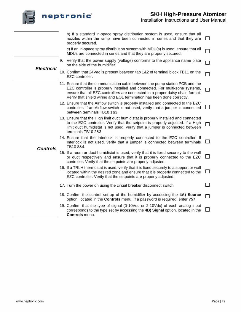
SKH High-Pressure Atomizer Installation Instructions and User Manual
www.neptronic.com Page | 49
b) If a standard in-space spray distribution system is used, ensure that all nozzles within the ramp have been connected in series and that they are properly secured.
c) If an in-space spray distribution system with MDU(s) is used, ensure that all MDUs are connected in series and that they are properly secured.
Electrical
9. Verify that the power supply (voltage) conforms to the appliance name plate on the side of the humidifier.
10. Confirm that 24Vac is present between tab 1&2 of terminal block TB11 on the EZC controller.
Controls
11. Ensure that the communication cable between the pump station PCB and the EZC controller is properly installed and connected. For multi-zone systems, ensure that all EZC controllers are connected in a proper daisy chain format. Verify that shield wiring and EOL termination has been done correctly.
12. Ensure that the Airflow switch is properly installed and connected to the EZC controller. If an Airflow switch is not used, verify that a jumper is connected between terminals TB10 1&3.
13. Ensure that the High limit duct humidistat is properly installed and connected to the EZC controller. Verify that the setpoint is properly adjusted. If a High limit duct humidistat is not used, verify that a jumper is connected between terminals TB10 2&3.
14. Ensure that the Interlock is properly connected to the EZC controller. If Interlock is not used, verify that a jumper is connected between terminals TB10 3&4.
15. If a room or duct humidistat is used, verify that it is fixed securely to the wall or duct respectively and ensure that it is properly connected to the EZC controller. Verify that the setpoints are properly adjusted.
16. If a TRLH thermostat is used, verify that it is fixed securely to a support or wall located within the desired zone and ensure that it is properly connected to the EZC controller. Verify that the setpoints are properly adjusted.
17. Turn the power on using the circuit breaker disconnect switch.
18. Confirm the control set-up of the humidifier by accessing the 4A) Source option, located in the Controls menu. If a password is required, enter 757.
19. Confirm that the type of signal (0-10Vdc or 2-10Vdc) of each analog input corresponds to the type set by accessing the 4B) Signal option, located in the Controls menu.
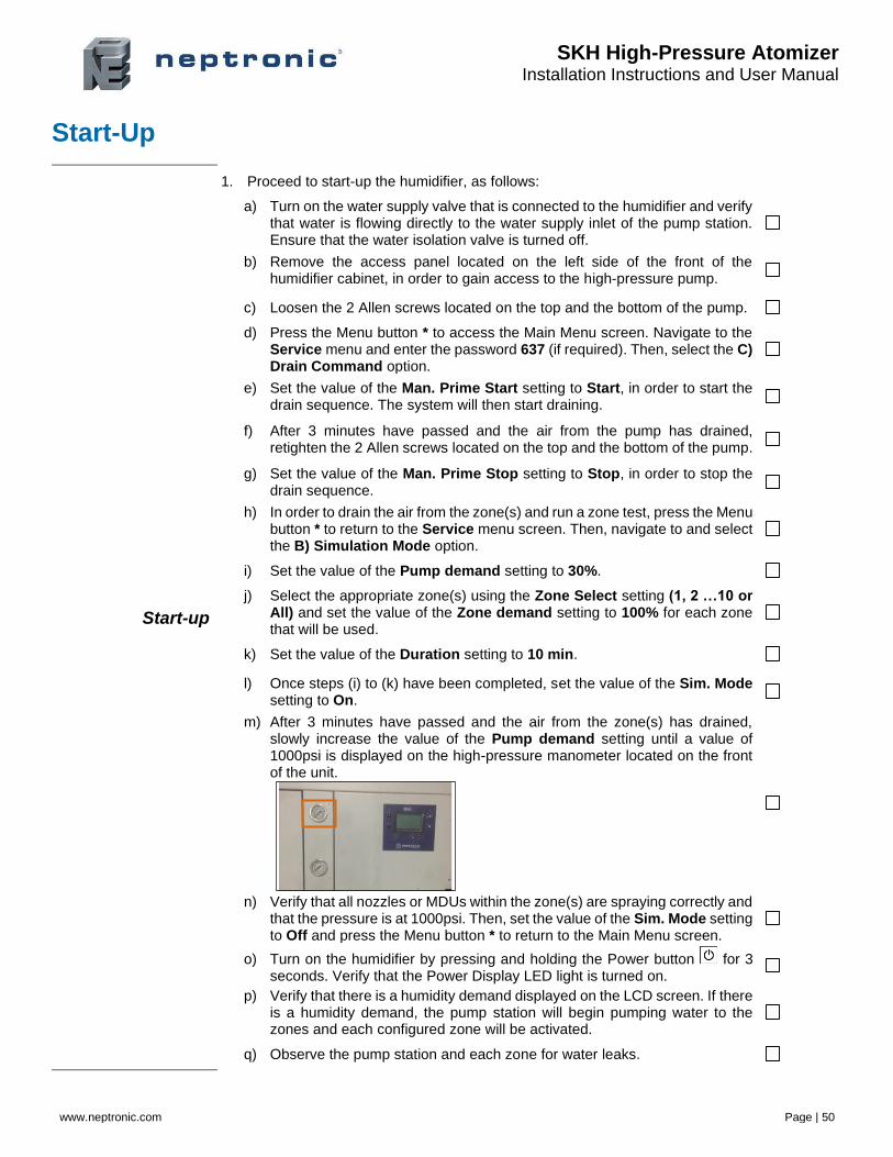
SKH High-Pressure Atomizer Installation Instructions and User Manual
www.neptronic.com Page | 50
Start-Up
Start-up
1. Proceed to start-up the humidifier, as follows:
a) Turn on the water supply valve that is connected to the humidifier and verify that water is flowing directly to the water supply inlet of the pump station. Ensure that the water isolation valve is turned off.
b) Remove the access panel located on the left side of the front of the humidifier cabinet, in order to gain access to the high-pressure pump.
c) Loosen the 2 Allen screws located on the top and the bottom of the pump.
d) Press the Menu button * to access the Main Menu screen. Navigate to the Service menu and enter the password 637 (if required). Then, select the C) Drain Command option.
e) Set the value of the Man. Prime Start setting to Start, in order to start the drain sequence. The system will then start draining.
f) After 3 minutes have passed and the air from the pump has drained, retighten the 2 Allen screws located on the top and the bottom of the pump.
g) Set the value of the Man. Prime Stop setting to Stop, in order to stop the drain sequence.
h) In order to drain the air from the zone(s) and run a zone test, press the Menu button * to return to the Service menu screen. Then, navigate to and select the B) Simulation Mode option.
i) Set the value of the Pump demand setting to 30%.
j) Select the appropriate zone(s) using the Zone Select setting (1, 2 …10 or All) and set the value of the Zone demand setting to 100% for each zone that will be used.
k) Set the value of the Duration setting to 10 min.
l) Once steps (i) to (k) have been completed, set the value of the Sim. Mode setting to On.
m) After 3 minutes have passed and the air from the zone(s) has drained, slowly increase the value of the Pump demand setting until a value of 1000psi is displayed on the high-pressure manometer located on the front of the unit.
n) Verify that all nozzles or MDUs within the zone(s) are spraying correctly and that the pressure is at 1000psi. Then, set the value of the Sim. Mode setting to Off and press the Menu button * to return to the Main Menu screen.
o) Turn on the humidifier by pressing and holding the Power button for 3 seconds. Verify that the Power Display LED light is turned on.
p) Verify that there is a humidity demand displayed on the LCD screen. If there is a humidity demand, the pump station will begin pumping water to the zones and each configured zone will be activated.
q) Observe the pump station and each zone for water leaks.
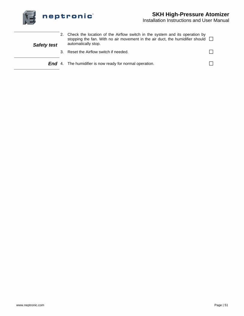
SKH High-Pressure Atomizer Installation Instructions and User Manual
www.neptronic.com Page | 51
Safety test
2. Check the location of the Airflow switch in the system and its operation by stopping the fan. With no air movement in the air duct, the humidifier should automatically stop.
3. Reset the Airflow switch if needed.
End 4. The humidifier is now ready for normal operation.
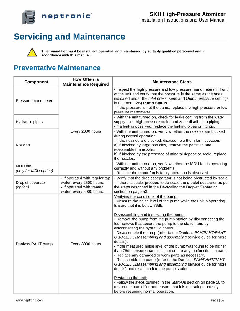
SKH High-Pressure Atomizer Installation Instructions and User Manual
www.neptronic.com Page | 52
Servicing and Maintenance
This humidifier must be installed, operated, and maintained by suitably qualified personnel and in accordance with this manual.
Preventative Maintenance
Component How Often is
Maintenance Required Maintenance Steps
Pressure manometers
Every 2000 hours
- Inspect the high pressure and low pressure manometers in front of the unit and verify that the pressure is the same as the ones indicated under the Inlet press. sens and Output pressure settings in the menu 2B) Pump Status. - If the pressure is not the same, replace the high pressure or low pressure manometer.
Hydraulic pipes - With the unit turned on, check for leaks coming from the water supply inlet, high-pressure outlet and zone distribution piping. - If a leak is observed, replace the leaking pipes or fittings.
Nozzles
- With the unit turned on, verify whether the nozzles are blocked during normal operation. - If the nozzles are blocked, disassemble them for inspection: a) If blocked by large particles, remove the particles and reassemble the nozzles. b) If blocked by the presence of mineral deposit or scale, replace the nozzles.
MDU fan (only for MDU option)
- With the unit turned on, verify whether the MDU fan is operating correctly and without any problems. - Replace the motor fan is faulty operation is observed.
Droplet separator (option)
- If operated with regular tap water, every 2500 hours. - If operated with treated water, every 5000 hours.
- Verify that the droplet separator is not being obstructed by scale. - If there is scale, proceed to de-scale the droplet separator as per the steps described in the De-scaling the Droplet Separator section on page 53.
Danfoss PAHT pump Every 8000 hours
Verifying the conditions of the pump: - Measure the noise level of the pump while the unit is operating. Ensure that it is below 76db. Disassembling and inspecting the pump: - Remove the pump from the pump station by disconnecting the four screws that secure the pump to the station and by disconnecting the hydraulic hoses. - Disassemble the pump (refer to the Danfoss PAH/PAHT/PAHT G 10-12.5 Disassembling and assembling service guide for more details). - If the measured noise level of the pump was found to be higher than 76db, ensure that this is not due to any malfunctioning parts. - Replace any damaged or worn parts as necessary. - Reassemble the pump (refer to the Danfoss PAH/PAHT/PAHT G 10-12.5 Disassembling and assembling service guide for more details) and re-attach it to the pump station. Restarting the unit: - Follow the steps outlined in the Start-Up section on page 50 to restart the humidifier and ensure that it is operating correctly before resuming normal operation.
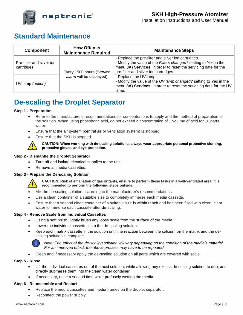
SKH High-Pressure Atomizer Installation Instructions and User Manual
www.neptronic.com Page | 53
Standard Maintenance
Component How Often is
Maintenance Required Maintenance Steps
Pre-filter and silver ion cartridges
Every 1500 hours (Service alarm will be displayed)
- Replace the pre-filter and silver ion cartridges. - Modify the value of the Filters changed? setting to Yes in the menu 3A) Services, in order to reset the servicing date for the pre-filter and silver ion cartridges.
UV lamp (option)
- Replace the UV lamp. - Modify the value of the UV lamp changed? setting to Yes in the menu 3A) Services, in order to reset the servicing date for the UV lamp.
De-scaling the Droplet Separator Step 1 - Preparation
• Refer to the manufacturer's recommendations for concentrations to apply and the method of preparation of the solution. When using phosphoric acid, do not exceed a concentration of 1 volume of acid for 10 parts water.
• Ensure that the air system (central air or ventilation system) is stopped.
• Ensure that the SKH is stopped.
CAUTION: When working with de-scaling solutions, always wear appropriate personal protective clothing, protective gloves, and eye protection.
Step 2 - Dismantle the Droplet Separator
• Turn off and isolate electrical supplies to the unit.
• Remove all media cassettes.
Step 3 - Prepare the De-scaling Solution
CAUTION: Risk of emanation of gas irritants, ensure to perform these tasks in a well-ventilated area. It is recommended to perform the following steps outside.
• Mix the de-scaling solution according to the manufacturer's recommendations.
• Use a clean container of a suitable size to completely immerse each media cassette.
• Ensure that a second clean container of a suitable size is within reach and has been filled with clean, clear water to immerse each cassette after de-scaling.
Step 4 - Remove Scale from Individual Cassettes
• Using a soft brush, lightly brush any loose scale from the surface of the media.
• Lower the individual cassettes into the de-scaling solution.
• Keep each matrix cassette in the solution until the reaction between the calcium on the matrix and the de-scaling solution is complete.
Note: The effect of the de-scaling solution will vary depending on the condition of the media’s material. For an improved effect, the above process may have to be repeated.
• Clean and if necessary apply the de-scaling solution on all parts which are covered with scale.
Step 5 - Rinse
• Lift the individual cassettes out of the acid solution, while allowing any excess de-scaling solution to drip, and directly submerse them into the clean water container.
• If necessary, rinse a second time while profusely wetting the media.
Step 6 - Re-assemble and Restart
• Replace the media cassettes and media frames on the droplet separator.
• Reconnect the power supply.
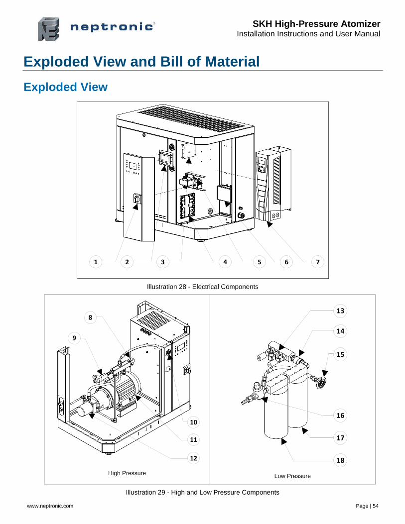
SKH High-Pressure Atomizer Installation Instructions and User Manual
www.neptronic.com Page | 54
Exploded View and Bill of Material
Exploded View
1 2 3 4 5 6 7
Illustration 28 - Electrical Components
9
8
10
11
12
High Pressure
13
14
15
16
17
18
Low Pressure
Illustration 29 - High and Low Pressure Components
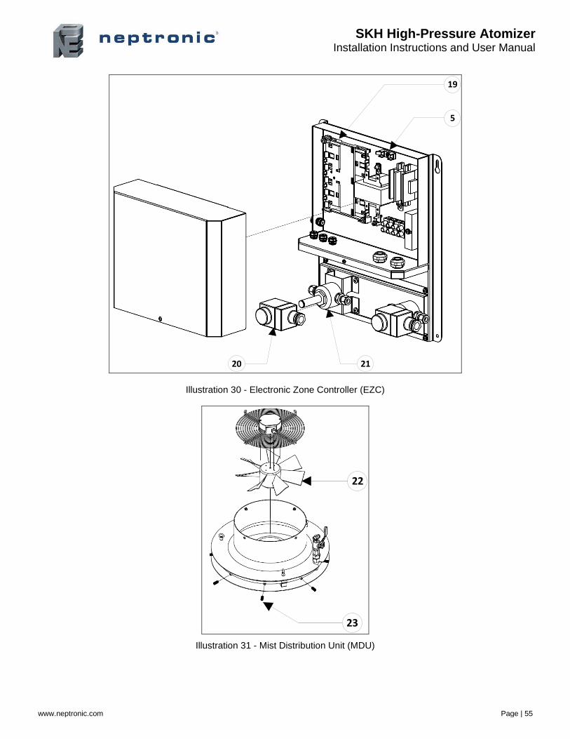
SKH High-Pressure Atomizer Installation Instructions and User Manual
www.neptronic.com Page | 55
5
19
2120
Illustration 30 - Electronic Zone Controller (EZC)
23
22
Illustration 31 - Mist Distribution Unit (MDU)
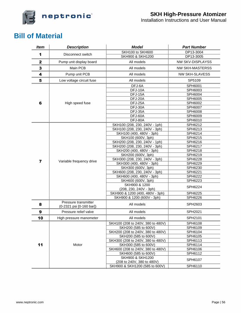
SKH High-Pressure Atomizer Installation Instructions and User Manual
www.neptronic.com Page | 56
Bill of Material
Item Description Model Part Number
1 Disconnect switch SKH100 to SKH600 DP13-3004
SKH900 & SKH1200 DP13-3005
2 Pump unit display board All models NW SKV-DISPLAYSS
3 Main PCB All models NW SKH-MASTERSS
4 Pump unit PCB All models NW SKH-SLAVESS
5 Low voltage circuit fuse All models SP5109
6 High speed fuse
DFJ-6A SPH6001
DFJ-10A SPH6003
DFJ-15A SPH6004
DFJ-20A SPH6005
DFJ-25A SPH6002
DFJ-30A SPH6007
DFJ-35A SPH6008
DFJ-60A SPH6009
DFJ-80A SPH6010
7 Variable frequency drive
SKH100 (208, 230, 240V - 1ph) SPH6212
SKH100 (208, 230, 240V - 3ph) SPH6213
SKH100 (400, 480V - 3ph) SPH6214
SKH100 (600V, 3ph) SPH6215
SKH200 (208, 230, 240V - 1ph) SPH6216
SKH200 (208, 230, 240V - 3ph) SPH6217
SKH200 (400, 480V - 3ph) SPH6218
SKH200 (600V, 3ph) SPH6219
SKH300 (208, 230, 240V - 3ph) SPH6228
SKH300 (400, 480V - 3ph) SPH6229
SKH300 (600V, 3ph) SPH6230
SKH600 (208, 230, 240V - 3ph) SPH6221
SKH600 (400, 480V - 3ph) SPH6222
SKH600 (600V, 3ph) SPH6223
SKH900 & 1200 (208, 230, 240V - 3ph)
SPH6224
SKH900 & 1200 (400, 480V - 3ph) SPH6225
SKH900 & 1200 (600V - 3ph) SPH6226
8 Pressure transmitter
(0-2321 psi [0-160 bar]) All models SPH2603
9 Pressure relief valve All models SPH2021
10 High pressure manometer All models SPH2101
11 Motor
SKH100 (208 to 240V, 380 to 480V) SPH6108
SKH200 (585 to 600V) SPH6109
SKH200 (208 to 240V, 380 to 480V) SPH6104
SKH200 (585 to 600V) SPH6105
SKH300 (208 to 240V, 380 to 480V) SPH6113
SKH300 (585 to 600V) SPH6114
SKH600 (208 to 240V, 380 to 480V) SPH6106
SKH600 (585 to 600V) SPH6112
SKH900 & SKH1200 (208 to 240V, 380 to 480V)
SPH6107
SKH900 & SKH1200 (585 to 600V) SPH6110
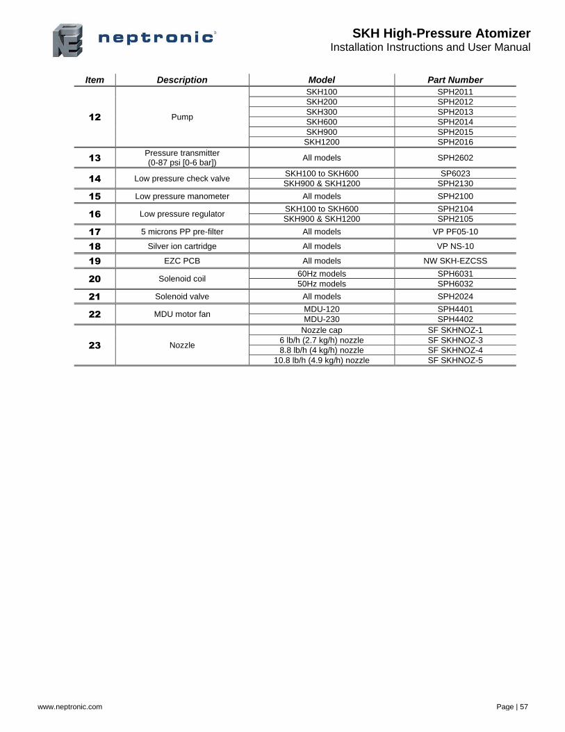
SKH High-Pressure Atomizer Installation Instructions and User Manual
www.neptronic.com Page | 57
Item Description Model Part Number
12 Pump
SKH100 SPH2011
SKH200 SPH2012
SKH300 SPH2013
SKH600 SPH2014
SKH900 SPH2015
SKH1200 SPH2016
13 Pressure transmitter (0-87 psi [0-6 bar])
All models SPH2602
14 Low pressure check valve SKH100 to SKH600 SP6023
SKH900 & SKH1200 SPH2130
15 Low pressure manometer All models SPH2100
16 Low pressure regulator SKH100 to SKH600 SPH2104
SKH900 & SKH1200 SPH2105
17 5 microns PP pre-filter All models VP PF05-10
18 Silver ion cartridge All models VP NS-10
19 EZC PCB All models NW SKH-EZCSS
20 Solenoid coil 60Hz models SPH6031
50Hz models SPH6032
21 Solenoid valve All models SPH2024
22 MDU motor fan MDU-120 SPH4401
MDU-230 SPH4402
23 Nozzle
Nozzle cap SF SKHNOZ-1
6 lb/h (2.7 kg/h) nozzle SF SKHNOZ-3
8.8 lb/h (4 kg/h) nozzle SF SKHNOZ-4
10.8 lb/h (4.9 kg/h) nozzle SF SKHNOZ-5

Notes
400 Lebeau blvd, Montreal, Qc, H4N 1R6, Canada
www.neptronic.com Toll-free in North America: 1-800-361-2308
Tel.: (514) 333-1433 Fax: (514) 333-3163
Customer service fax: (514) 333-1091 Monday to Friday: 8:00am to 5:00pm (Eastern Time)
Related Documents