• NUMECA International • • av Franklin Roosevelt 5 • B - 1050 Brussels • 22-Jan-12 Page 1 Wind Turbine

Welcome message from author
This document is posted to help you gain knowledge. Please leave a comment to let me know what you think about it! Share it to your friends and learn new things together.
Transcript
• NUMECA International • • av Franklin Roosevelt 5 • B - 1050 Brussels • 22-Jan-12 Page 1
Wind Turbine

• NUMECA International • • av Franklin Roosevelt 5 • B - 1050 Brussels • 22-Jan-12 Page 2
1 2
4
Content
Configuration...
CAD Import & Mesh…
Results…
5 Conclusions
3 Computation…
0 Introduction

• NUMECA International • • av Franklin Roosevelt 5 • B - 1050 Brussels • 22-Jan-12 Page 3
Introduction

• NUMECA International • • av Franklin Roosevelt 5 • B - 1050 Brussels • 22-Jan-12 Page 4
0 Introduction
This document presents the result of a Wind Turbine flow simulation using FINE™/Turbo, the Numeca FLOW
INTEGRATED ENVIRONMENT dedicated to rotating-machinery flow analysis including wind turbines.
The 3 bladed NREL S809 wind turbine is presented in 3D, 2.5D and 2D configurations
The geometry is generated from XYZ coordinates data points. The data is then imported directly into the mesh
generator IGG™ and AutoGrid™.
The mesh is generated using IGG™, interactive and automated grid generator and AutoGrid V5, the automated mesh
generator for rotating machinery.
The RANS solver EURANUS of FINE™/Turbo is used for 3D, 2.5D and 2D flow computations
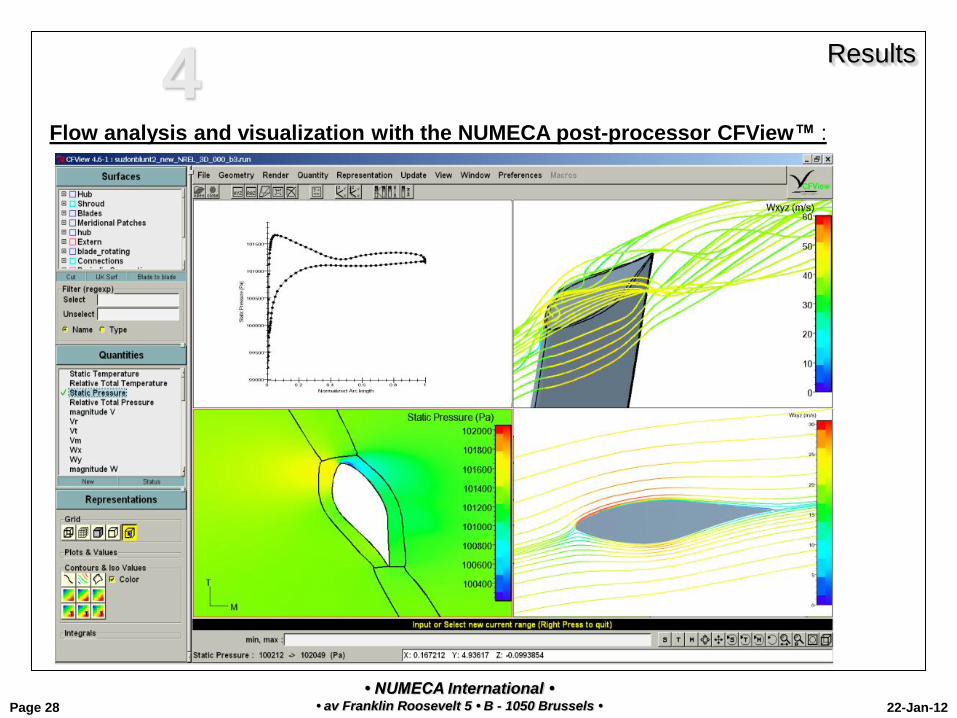
CFView™, the NUMECA flow analysis and visualization tool provides all type of qualitative and quantitative data for
detailed 2D/3D post-processing.
This benchmarking report aims to present the whole CFD chain process in FINE/Turbo applied to wind turbine flow.
Upon request more detailed simulation and flow analysis can be presented.

• NUMECA International • • av Franklin Roosevelt 5 • B - 1050 Brussels • 22-Jan-12 Page 5
0 Introduction
Flow analysis
Initial Geometry
IGG™, AutoGrid™ Mesh Generators
Euranus Multi-stage flow solver
FINE™/Turbo
Boundary Conditions
CFView™ Post-processor
FINE™/Turbo
• NUMECA International • • av Franklin Roosevelt 5 • B - 1050 Brussels • 22-Jan-12 Page 6
Configuration

• NUMECA International • • av Franklin Roosevelt 5 • B - 1050 Brussels • 22-Jan-12 Page 7
Blade Tip
Configuration
3D NREL S809 Geometry 1
3 blades turbine
External boundary
Hub Area

• NUMECA International • • av Franklin Roosevelt 5 • B - 1050 Brussels • 22-Jan-12 Page 8
Configuration
2D Geometry
NREL S809 1
2 D geometry is expressed in cartesian frame.
No rotation effect is taken into account.
The flow conditions respect the flow at 47% span of the 3D blade.
• NUMECA International • • av Franklin Roosevelt 5 • B - 1050 Brussels • 22-Jan-12 Page 9
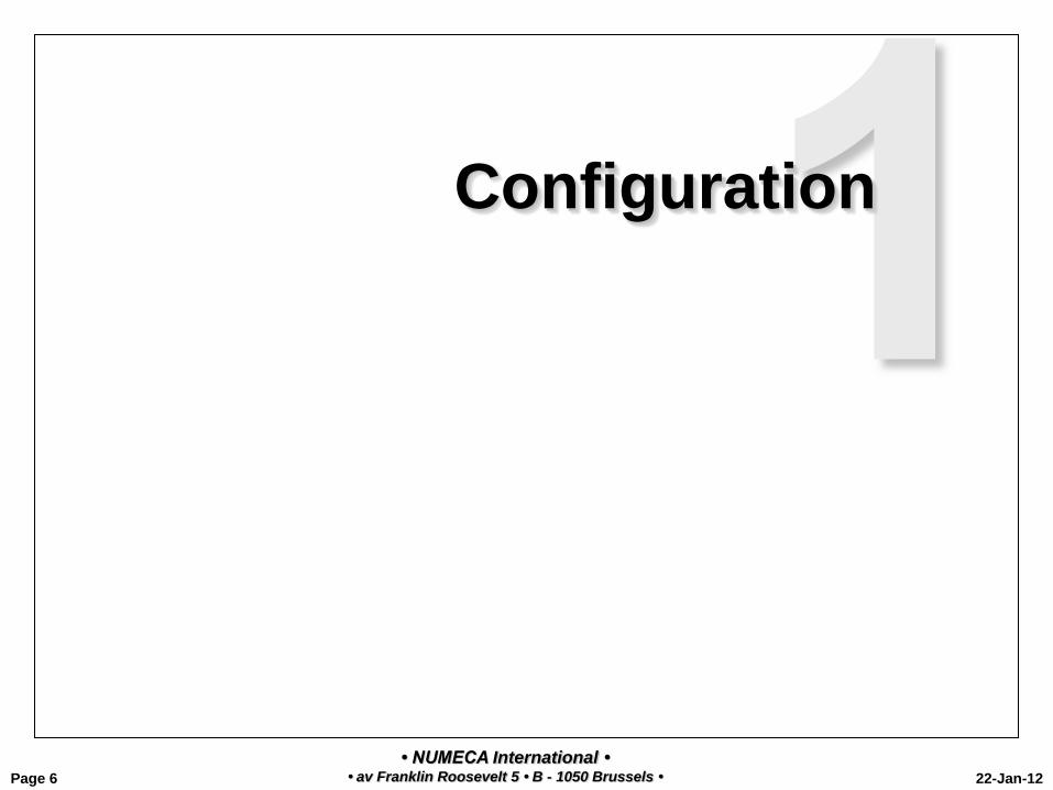
Configuration
2.5D Geometry 1 3 blades Turbine
Only one periodic passage is shown here
2.5D geometry represents a 2-D case in cylindrical frame with an arbitrary periodic boundary at a given spanwise position (47%
span in this study).
• NUMECA International • • av Franklin Roosevelt 5 • B - 1050 Brussels • 22-Jan-12 Page 10
CAD Preparation
&
Mesh

• NUMECA International • • av Franklin Roosevelt 5 • B - 1050 Brussels • 22-Jan-12 Page 11
2 CAD Preparation and Mesh
Summary
Characteristics :
• The geometry definition in a set of points of the NREL S809 airfoil (2D)
• The 3D blade is defined by two surfaces defining the pressure and the suction sides. The pressure side and the suction side are defined by a set of airfoils of the blade at several spanwise location. Each airfoil is defined by a set of points.
• The geometry can also directly be imported in AutoGrid™ V5 from CAD definition in IGES or Parasolid or CATIA V5 format
• The meshes have been automatically generated using the mesh generator IGG™ (2D) and AutoGrid™ V5 (2.5D and 3D);
• The 3D mesh include the external boundary located at 1 blade radius from the blade tip.
• In order to obtain y+ ~ 1, the first cell thickness next to the wall is: 2 X 10⁻⁵ m.
Mesh Meshing Process Number of cells
2D 10 seconds 36 920
2.5D 30 seconds 191 035
3D 11 minutes 16 seconds 2 065 404

• NUMECA International • • av Franklin Roosevelt 5 • B - 1050 Brussels • 22-Jan-12 Page 12
2 CAD Preparation
ASCII data point, IGES, Parasolid or CATIA Direct Import

• NUMECA International • • av Franklin Roosevelt 5 • B - 1050 Brussels • 22-Jan-12 Page 13
2 CAD Preparation and MESHING 3D Configuration
• Linking the geometry to the mesh generator AutoGrid V5
• Starting the mesh generation

• NUMECA International • • av Franklin Roosevelt 5 • B - 1050 Brussels • 22-Jan-12 Page 14
3D Meshing Process
2

• NUMECA International • • av Franklin Roosevelt 5 • B - 1050 Brussels • 22-Jan-12 Page 15
5 Block Mesh in main channel and 7 blocks in the external area.
Blocks in the main channel:
4 H blocks around the skin topology block
1 Skin Topology block (C-block) around the blade with blunt TE
Blocks in the external area
5 blocks as the extension of the main channel blocks
2 blocks as the extension of the wind turbine blade: 1 H block in the center and C-block around the H-block
2 3D Mesh
Topology
Fully matching connection between all blocks
Non-matching or matching connection at the periodic faces

• NUMECA International • • av Franklin Roosevelt 5 • B - 1050 Brussels • 22-Jan-12 Page 16
2 3D MESH
The blade surface mesh
Blade Tip
Hub Area

• NUMECA International • • av Franklin Roosevelt 5 • B - 1050 Brussels • 22-Jan-12 Page 18
MESHING
2D Geometry
NREL S809
Automatic mesh generation and geometry creation tasks on similar geometries using scripts.
Meshing time 10 seconds
2

• NUMECA International • • av Franklin Roosevelt 5 • B - 1050 Brussels • 22-Jan-12 Page 19
2D Meshing Process
2
• NUMECA International • • av Franklin Roosevelt 5 • B - 1050 Brussels • 22-Jan-12 Page 20
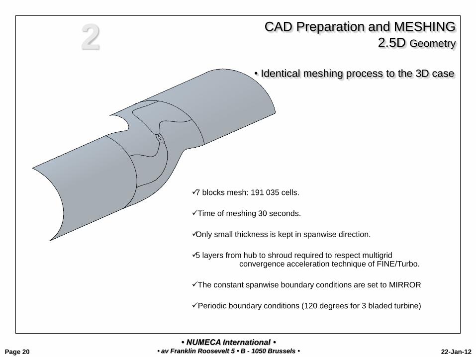
CAD Preparation and MESHING
2.5D Geometry 2
• Identical meshing process to the 3D case
7 blocks mesh: 191 035 cells.
Time of meshing 30 seconds.
Only small thickness is kept in spanwise direction.
5 layers from hub to shroud required to respect multigrid convergence acceleration technique of FINE/Turbo.
The constant spanwise boundary conditions are set to MIRROR
Periodic boundary conditions (120 degrees for 3 bladed turbine)

• NUMECA International • • av Franklin Roosevelt 5 • B - 1050 Brussels • 22-Jan-12 Page 21
2.5D Mesh 2

• NUMECA International • • av Franklin Roosevelt 5 • B - 1050 Brussels • 22-Jan-12 Page 22
2.5D Meshing Process
2

• NUMECA International • • av Franklin Roosevelt 5 • B - 1050 Brussels • 22-Jan-12 Page 23
Computation

• NUMECA International • • av Franklin Roosevelt 5 • B - 1050 Brussels • 22-Jan-12 Page 24
Computation Flow Physics et Models (1) 3
Flow setting, computation running and monitoring are realized using the NUMECA Flow Integrated Environment GUI FINE™
• NUMECA International • • av Franklin Roosevelt 5 • B - 1050 Brussels • 22-Jan-12 Page 25
Computation Flow Physics et Models (2) 3
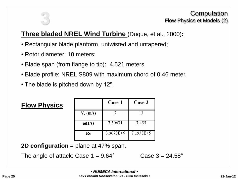
Three bladed NREL Wind Turbine (Duque, et al., 2000):
• Rectangular blade planform, untwisted and untapered;
• Rotor diameter: 10 meters;
• Blade span (from flange to tip): 4.521 meters
• Blade profile: NREL S809 with maximum chord of 0.46 meter.
• The blade is pitched down by 12º.
Flow Physics
2D configuration = plane at 47% span.
The angle of attack: Case 1 = 9.64° Case 3 = 24.58°
• NUMECA International • • av Franklin Roosevelt 5 • B - 1050 Brussels • 22-Jan-12 Page 26
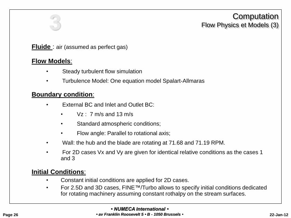
Computation Flow Physics et Models (3) 3
Fluide : air (assumed as perfect gas)
Flow Models:
• Steady turbulent flow simulation
• Turbulence Model: One equation model Spalart-Allmaras
Boundary condition:
• External BC and Inlet and Outlet BC:
• Vz : 7 m/s and 13 m/s
• Standard atmospheric conditions;
• Flow angle: Parallel to rotational axis;
• Wall: the hub and the blade are rotating at 71.68 and 71.19 RPM.
• For 2D cases Vx and Vy are given for identical relative conditions as the cases 1 and 3
Initial Conditions:
• Constant initial conditions are applied for 2D cases.
• For 2.5D and 3D cases, FINE™/Turbo allows to specify initial conditions dedicated for rotating machinery assuming constant rothalpy on the stream surfaces.

• NUMECA International • • av Franklin Roosevelt 5 • B - 1050 Brussels • 22-Jan-12 Page 27
Results
• NUMECA International • • av Franklin Roosevelt 5 • B - 1050 Brussels • 22-Jan-12 Page 28
Flow analysis and visualization with the NUMECA post-processor CFView™ :
Results 4
• NUMECA International • • av Franklin Roosevelt 5 • B - 1050 Brussels • 22-Jan-12 Page 29
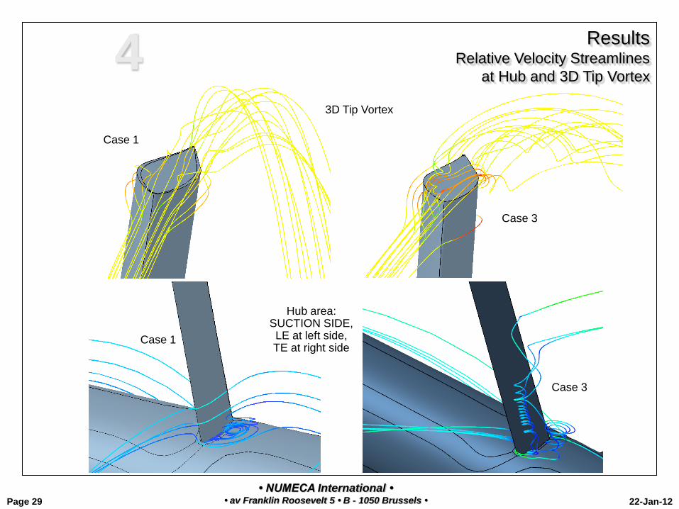
Results Relative Velocity Streamlines
at Hub and 3D Tip Vortex 4
Hub area: SUCTION SIDE, LE at left side, TE at right side
3D Tip Vortex
Case 1
Case 3
Case 1
Case 3

• NUMECA International • • av Franklin Roosevelt 5 • B - 1050 Brussels • 22-Jan-12 Page 30
Results Relative Velocity Streamlines
at Hub Area 4
Hub Area: Pressure side TE at left side LE at right side
The wake from flow near the hub area
Flow direction Flow direction
Case 1
Case 3
Case 1
Case 3
• NUMECA International • • av Franklin Roosevelt 5 • B - 1050 Brussels • 22-Jan-12 Page 31
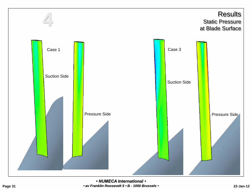
Results Static Pressure
at Blade Surface 4
Case 1 Case 3
Pressure Side
Suction Side
Pressure Side
Suction Side

• NUMECA International • • av Franklin Roosevelt 5 • B - 1050 Brussels • 22-Jan-12 Page 32
Results 2D streamlines
Case 1
3D
2.5D
2D
4
• NUMECA International • • av Franklin Roosevelt 5 • B - 1050 Brussels • 22-Jan-12 Page 33
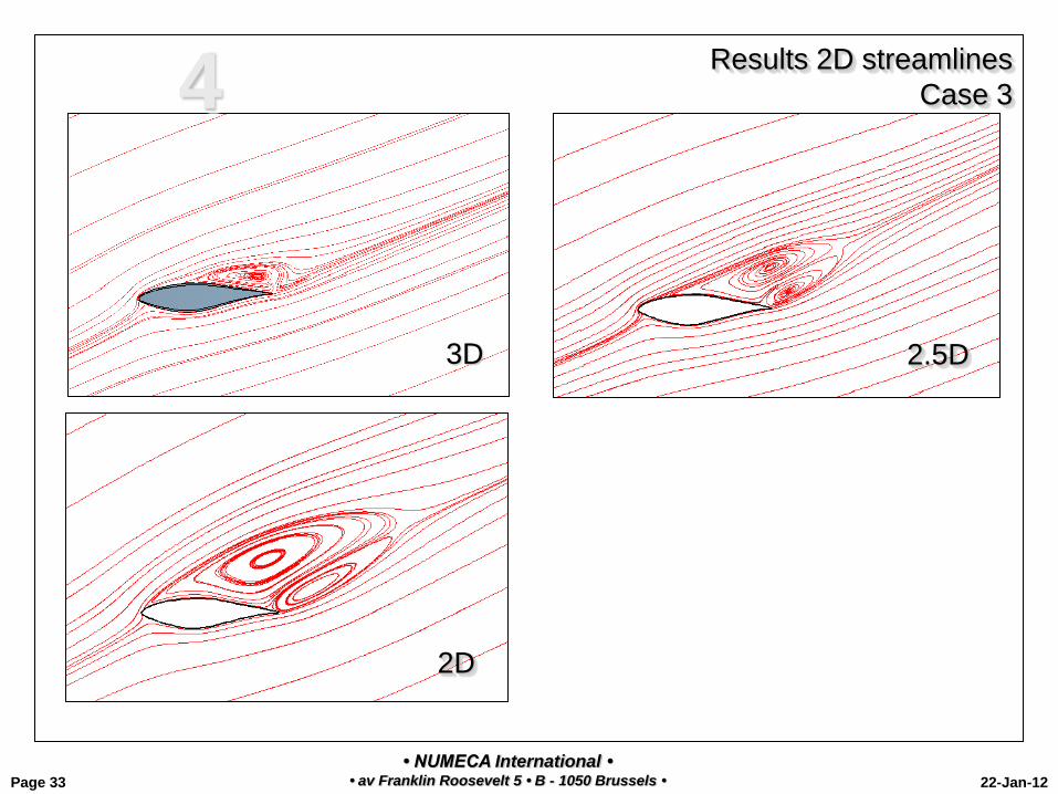
Results 2D streamlines
Case 3
2.5D
2D
3D
4
• NUMECA International • • av Franklin Roosevelt 5 • B - 1050 Brussels • 22-Jan-12 Page 34
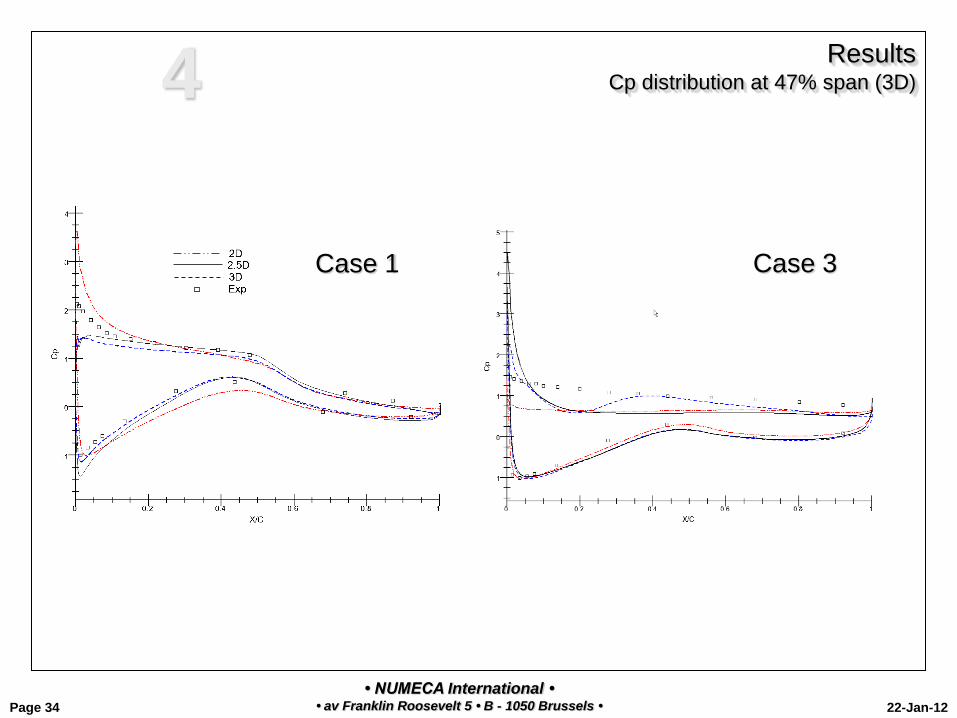
Results Cp distribution at 47% span (3D)
Case 1
Case 3
4

• NUMECA International • • av Franklin Roosevelt 5 • B - 1050 Brussels • 22-Jan-12 Page 35
4 Results
CASE 3 - Static Pressure distribution at 47% span (3D)
2.5D
2D
3D

• NUMECA International • • av Franklin Roosevelt 5 • B - 1050 Brussels • 22-Jan-12 Page 36
4 Results
CASE 3 – Velocity distribution at 47% span (3D)
2.5D
2D
3D
• NUMECA International • • av Franklin Roosevelt 5 • B - 1050 Brussels • 22-Jan-12 Page 37
Conclusions

• NUMECA International • • av Franklin Roosevelt 5 • B - 1050 Brussels • 22-Jan-12 Page 38
5 Conclusions
Conclusions
Highly complex flow around the blade is observed in 3D flow simulation.
In Case 3 the flow close to the hub creates 3D vortex flow that propagates in spanwise direction toward the
tip. While in Case 1 the vortex flow stays close to the hub.
The 2D streamlines show that Case 1 does not present separation while a strong separation is well generated
in the Case 3.
The Cp distribution along the blade for all cases is in good agreement with the experimental result.
Similar qualitative agreement are observed for the 2D, 2.5D and 3D (at 47% spanwise section) (pressure,
velocity distribution, streamlines).
Flow analysis in 2D, 2.5D and 3D configurations are treated by one single tool only, FINE/Turbo, ensuring
quick turn-around time in wind turbine design cycle.
• NUMECA International • • av Franklin Roosevelt 5 • B - 1050 Brussels • 22-Jan-12 Page 39
Annex
ADDITIONAL INFORMATION

• NUMECA International • • av Franklin Roosevelt 5 • B - 1050 Brussels • 22-Jan-12 Page 40
6 FLOW MODEL & TURBULENCE MODELS SELECTION
in FINE GUI

• NUMECA International • • av Franklin Roosevelt 5 • B - 1050 Brussels • 22-Jan-12 Page 41
6 WALL FUNCTION SET-UP
in FINE GUI in case High-Reynolds k-e turbulence model

• NUMECA International • • av Franklin Roosevelt 5 • B - 1050 Brussels • 22-Jan-12 Page 42
6 TRANSITION SET-UP
in FINE GUI

• NUMECA International • • av Franklin Roosevelt 5 • B - 1050 Brussels • 22-Jan-12 Page 43
FINETM/Design3D: Introduction
Optimization Process
AutoBlade Parametric Blade Modeler
Design3D Blade Optimization
FINE/Turbo CFD system for turbomachinery
FINE/Design3D
- Geometrical / Mechanical Constraints
- Design / Optimization Targets
Optimized
3D Blade
Initial Geometry Initial
3D Blade
6

• NUMECA International • • av Franklin Roosevelt 5 • B - 1050 Brussels • 22-Jan-12 Page 44
FINETM/Design3D: Introduction (cont’d)
Optimization Process 6
AutoBlade™
Parametric Blade Modeller
AutoBlade™
Fitting
Parameterisation of existing geometries
Design 3D
Optimisation Artificial Neural
Network + Genetic Algorithm and
Gradient App.
FINE™/Design 3D
Design 3D
Database generation
Related Documents