российский морской регистр судоходства RUSSIAN MARITIME REGISTER OF SH IPPING ПРИЛОЖЕНИЕ К ПРАВИЛАМ И РУКОВОДСТВАМ РОССИЙСКОГО МОРСКОГО РЕГИСТРА СУДОХОДСТВА ПРОЦЕДУРНЫЕ ТРЕБОВАНИЯ, УНИФИЦИРОВАННЫЕ ИНТЕРПРЕТАЦИИ И РЕКОМЕНДАЦИИ МЕЖДУНАРОДНОЙ АССОЦИАЦИИ КЛАССИФИКАЦИОННЫХ ОБЩЕСТВ SUPPLEMENT ТО RULES AND GUIDELINES OF RUSSIAN MARITIME REGISTER OF SHIPPING I ACS PROCEDURAL REQUIREMENTS, UNIFIED INTERPRETATIONS AND RECOMMENDATIONS ND No. 2-020101-121-R-E 2019 сертификат на продукцию

Welcome message from author
This document is posted to help you gain knowledge. Please leave a comment to let me know what you think about it! Share it to your friends and learn new things together.
Transcript
российский морской регистр судоходства
RUSSIAN MARITIME REGISTER OF SHIPPING
ПРИЛОЖЕНИЕ К ПРАВИЛАМ И РУКОВОДСТВАМ РОССИЙСКОГО МОРСКОГО РЕГИСТРА СУДОХОДСТВА
ПРОЦЕДУРНЫЕ ТРЕБОВАНИЯ, УНИФИЦИРОВАННЫЕ ИНТЕРПРЕТАЦИИ
И РЕКОМЕНДАЦИИ МЕЖДУНАРОДНОЙ АССОЦИАЦИИ
КЛАССИФИКАЦИОННЫХ ОБЩЕСТВ
SUPPLEMENT ТО RULES AND GUIDELINES OF RUSSIAN MARITIME REGISTER OF SHIPPING
I ACS PROCEDURAL REQUIREMENTS, UNIFIED INTERPRETATIONS AND RECOMMENDATIONS
N D N o . 2 -0 2 0 1 0 1 -1 2 1-R -E
2019
сертификат на продукцию
СОДЕРЖАНИЕCONTENTS
Номер документа Document number
Процедурные требования МАКО IACS Procedural Requirements
Название документа Document name
ПримечаниеNote
1. PR No. 38 (Rev.2 Mar 2019)
Procedure for calculation and verification of Document isthe Energy Efficiency Design Index (EEDI) applied from
1 July 2019
Применение: Руководство по применению положений международной конвенции МАРПОЛ 73/78, часть VI, пункт 2.6.20.
Application: Guidelines on the Application of Provisions of the International Convention MARPOL 73/78, Part VI, para 2.6.20.
Унифицированные интерпретации МАКО IACS Unified Interpretations
Номер документа Название документа ПримечаниеDocument number Document name Note
1. SC 191 (Rev.8 Apr 2019) IACS Unified Interpretations (Ul) SC 191 forthe application of amended SOLAS regulation 11-1/3-6 (resolution MSC.151(78)) and revised Technical provisions for means of access for Inspections (resolution MSC.158(78))
Document is applied for ships contracted for construction from July 2019
Применение: Правила классификации и постройки морских судов (2017), часть III, пункт 7.14.2. Application: Rules for the Classification and Construction of Sea-Going Ships (2017), Part III, para 7.14.2.
2. SC 226 (Rev.1 Dec 2012) IACS Unified Interpretations (Ul) onthe application of SOLAS regulations to conversions of Single-Hull Oil Tankers to Double-Hull Oil Tankers or Bulk Carriers
Document is applied from 1 January 2014
Применение: Правила классификации и постройки морских судов (2017), часть I, пункт 3.1.3. Application: Rules for the Classification and Construction of Sea-Going Ships (2017), Part I, para 3.1.3.
3. SC 244 (Rev.1 Nov 2012) Load testing of hooks for primary release Document is(Corr.1 Nov2015) of lifeboats and rescue boats applied from
1 January 2014
Применение: Правила по оборудованию морских судов (2017), часть II, пункт 1.3.2.1.Application: Rules for the Equipment of Sea-Going Ships (2017), Part II, para 1.3.2.1.
4. SC 249 (Rev.1 Feb 2013) Implementation of SOLAS 11-1, Regulation 3-5 Document isand MSC.1/Circ.1379 applied from
1 July 2013Применение: Правила технического наблюдения за постройкой судов и изготовлением материалов
и изделий для судов, часть V, пункт 19.1.7.Application: Rules for Technical Supervision during Construction of Ships and Manufacture of Materials
and Products for Ships, Part V, para 19.1.7.
5. MPC2 (Rev. 1 Aug 2015) Operational manuals for oil discharge monitoring Document isand control systems applied from
1 July 2016Применение: Правила технического наблюдения за постройкой судов и изготовлением материалов
и изделий для судов, часть V, пункт 19.7.2.1.Application: Rules for Technical Supervision during Construction of Ships and Manufacture of Materials
and Products for Ships, Part V, para 19.7.2.1.
6. МРС6 (Rev. 1 Aug 2015) Calculation of aggregate capacity of SBT Document is
Применение:
applied from 1 July 2016
Руководство по применению положений международной конвенции МАРПОЛ 73/78, часть II, пункт 3.5.1.1.
Application: Guidelines on the Application of Provisions of the International Convention MARPOL 73/78,part VI, para 3.5.1.1.
7. MODU 1 (Rev.1 Oct 2015) IACS Unified Interpretations for the application Document is
Применение:
of MODU Code Chapter 2 paragraphs 2.1,2.2, applied from 2.3, 2.4 and revised technical provisions for means 1 January 2017 of access for inspections (resolution MSC.158(78))
Правила классификации, постройки и оборудования плавучих буровых установок
Application:и морских стационарных платформ (2014), часть III, пункт 9.3.1.1.Rules for the Classification, Construction and Equipment of Mobile Offshore Drilling Units and Fixed Offshore Platforms (2014), Part III, para 9.3.1.1.
Рекомендации MAKO IACS Recommendations
Номер документа Название документаDocument number Document name
1. Rec. No. 10 (Rev.3 October 2016, Corr. 1 Dec. 2016) Anchoring, Mooring and Towing Equipment Применение: Правила классификации и постройки морских судов (2018), часть III «Устройства,
оборудование и снабжение» (пункт 4.2.3)Application: Rules for the Classification and Construction of Sea-Going Ships (2018), Part III «Equipment,
Arrangements and Outfit» (para 4.2.3)
2. Rec. No. 47 (Rev.8 October 2017) Shipbuilding and Repair Quality StandardПрименение: Правила классификационных освидетельствований судов в эксплуатации (2018),
часть I (пункт 5.13), приложение 2 (пункт 5.1.12), приложение 3 (пункт 7).Правила технического наблюдения за постройкой судов и изготовлением материалов и изделий для судов, часть I, приложение 3 (пункт 7.4)
Application: Rules for the Classification Surveys of Ships in Service (2018), Part I (para 5.13), Appendix 2 (para 5.1.12), Appendix 3 (para 7).Rules for Technical Supervision during Construction of Ships and Manufacture of Materialsand Products for Ships, Part I, Appendix 3 (para 7.4)
3. Rec. No. 55 (Rev.1 June 2016) General Cargo Ships - Guidance for Surveys,Assessment and Repair of Hull Structure
Применение: Правила классификационных освидетельствований судов в эксплуатации (2017), часть I (пункт 5.13), приложение 2 (пункт 5.1.12), приложение 3 (пункт 6).Методические рекомендации по техническому наблюдению за ремонтом морских судов с Приложениями (2016), Приложение 1.
Application: Rules for the Classification Surveys of Ships in Service (2017), Part I (para 5.13), Appendix 2(para 5.1.12), Appendix 3 (para 6).
4. Rec. No. 76 (Corr.1 Sept 2007) IACS Guidelines for Surveys, Assessment and Repair of HullStructure - Bulk Carriers
Применение: Правила классификационных освидетельствований судов в эксплуатации (2017), часть I (пункт 5.13), приложение 2 (пункт 5.1.12), приложение 3 (пункт 2).Методические рекомендации по техническому наблюдению за ремонтом морских судов с Приложениями (2016), Приложение 1.
Application: Rules for the Classification Surveys of Ships in Service (2017), Part I (para 5.13), Appendix 2(para 5.1.12), Appendix 3 (para 2).
5. Rec. No. 96 (April 2007, Rev.1 May 2019) Double Hull Oil Tankers - Guidelines for Surveys,Assessment and Repair of Hull Structures
Применение: Правила классификационных освидетельствований судов в эксплуатации (2019), приложение 3 (пункт 10).
Application: Rules for the Classification Surveys of Ships in Service (2019), Appendix 3 (para 10).6. Rec. No. 132 (Dec 2013) Human Element Recommendations for structural design of
lighting, ventilation, vibration, noise, access & egress arrangements
Применение: Руководство по освидетельствованию условий труда и отдыха моряков насоответствие требованиям Конвенции 2006 года о труде в морском судоходстве (2016), пункты 2.1.22, 4.7.3.Руководство по освидетельствованию жилых помещений экипажа (2015), пункты 2.1.16, 4.1.2.8.
Application: Guidelines on On-board Maritime Labour Convention, 2006 (MLC) Inspection (2016),paras 2.1.22, 4.7.3.Guidelines on On-board Inspection for Crew Accomodation (2015), paras 2.1.16, 4.1.2.8.
7. Rec. No. 142 (June 2016) LNG Bunkering GuidelinesПрименение: Правила классификации и постройки морских судов (2017), часть XVII, пункт 11.2.2. Application: Rules for the Classification and Construction of Sea-Going Ships (2017), Part XVII,
para 11.2.2.8. Rec. No. 146 (Aug 2016) Risk assessment as required by the IGF CodeПрименение: Правила классификации и постройки морских судов (2017), часть XVII, пункт 9.1.4.19. Application: Rules for the Classification and Construction of Sea-Going Ships (2017), Part XVII,
para 9.1.4.19.9. Rec. No.149 (May 2017) Guidance for applying the requirements of 15.4.1.2 and
5.4.1.3 of the IGC Code (on ships constructed on or after 1 July 2016)
Применение: Правила классификации и постройки судов для перевозки сжижженных газов наливом (2019), часть VI, пункт 3.20.2.
Application: Rules for the Classification and Construction of Ships Carrying Liquefied Gases in Bulk(2019), Part VI, para 3.20.2.
10. Rec. No. 150 (May 2017) Vapour pockets not in communication with cargo tankvapour/liquid domes on liquefied gas carriers
Применение: Правила классификации и постройки судов для перевозки сжижженных газов наливом (2019), часть VI, пункт 3.16.11.
Application: Rules for the Classification and Construction of Ships Carrying Liquefied Gases in Bulk(2019), Part VI, para 3.16.11.
11. Rec. No. 151 (July 2017) Recommendation for petroleum fuel treatment systems formarine diesel engines
Применение: Правила классификации и постройки морских судов (2019), часть VIII, пункт 13.8.1. Application: Rules for the Classification and Construction of Sea-Going Ships (2019), Part VIII,
para 13.8.1.
IACSINTERNATIONAL ASSOCIATION OF CLASSIFICATION SOCIETIES
GENERAL DRY CARGO SHIPS
Guidelines forSurveys, Assessment and Repair of Hull Structure
(1999)(Rev.1 June 2016)
IACS -International Association of Classification Societies, 1999 (Rev.1 June 2016)
All rights reserved.
Except as permitted under current legislation no part of this work may be photocopied, stored in a retrieval system, published, performed in public, adapted, broadcast, transmitted, recorded or reproduced in any form or by any means, without prior permission of the copyright owner.
Where IACS has granted written permission for any part of this publication to be quoted such quotation must include acknowledgment to IACS.
Enquiries should be addressed to The Secretary General The Permanent Secretary. International Association of Classification Societies Ltd.
Permanent Secretariat 36 Broadway LondonUnited Kingdom SWIH OBH
T: +44 (0)20 7976 0660 F: +44 (0)20 7808 1100
email: [email protected] website: www.iacs.ora.uk
5 Old Queen Street,London, SW1H0JA Telephone: +АЛ (0)171 976 0660 Fax: +'M-(0)171 976 OHO INTERNET: [email protected]
TERMS AND CONDITIONS
-The International Association of Classification Societies (IACS), its Member Societies and IACS Ltd, and their directors, officers, members, employees and agents (on behalf of whom this notice is issued) shall be under no liability or responsibility in contact or negligence or otherwise howsoever to any person in respect of any information or advice expressly or impliedly given in this document, or in respect of any inaccuracy herein or omission herefrom or in respect of any act or omission which has caused or contributed to this document being issued with the information or advice it contains (if any).
Without derogating from the generality of the foregoing, neither the International Association of Classification Societies (IACS) nor IACS Ltd, nor its Member Societies and their officers, members, employees or agents shall be liable in negligence or otherwise howsoever for any direct, indirect or consequential loss to any person caused by or arising from any information, advice, inaccuracy or omission being given or contained herein or any act or omission causing or contributing to any such information, advice, inaccuracy or omission being given or contained herein.-
Anv dispute concerning the provision of material herein is subject to the exclusive jurisdiction of the English courts and will be governed bv English Law.
Published in 1999 for the International Association of Classification Societies.
casnHsrrs
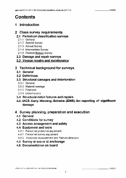
Contents1 Introduction
2 Class survey requirements2.1 Periodical classification surveys
2.1.1 General2.1.2 Special Survey2.1.3 Annual Survey2.1.4 Intermediate Survey2.1.5 Drvdock Bottom Survey
2.2 Damage and repair surveys2.3 Voyage repairs and maintenance
3 Technical background for surveys3.1 General3.2 Definitions3.3 Structural damages and deterioration
3.3.1 General3.3.2 Material wastage3.3.3 Fractures3.3.4 Deformations
3.4 Structural detail failures and repairs3.5 I ACS Early Warning Scheme (EWS) for reporting of s ignificant
damage
4 Survey planning, preparation and execution4.1 General4.2 Conditions for survey4.3 Access arrangement and safety4.4 Equipment and tools
4.4.1 Personnel protective equipment4.4.2 Personnel survey equipment4.4.3 Thickness measurement and fracture detection
4.5 Survey at sea or at anchorage4.6 Documentation on board
INTERNATIQNALASSQCIATIQN OF CLASSIFICATION SOCIETIES CONTENTS
1

IACSGENERALDRYCARGOSFrTFRa ШЕГ I^roRSUE^E^AS^SaVEOTA^I^AEOFHUlXSIRLUrLIRE CONTENTS
5 Structural detail failures and repairs5.1 General5.2 Catalogue of structural detail failures and repairs
Part 1 Cargo hold regionArea 1 Upper deck structure Area 2 Side structure Area 3 Transverse bulkhead structure Area 4 Tween deck structure Area 5 Double bottom structure
Part 2 Fore and aft end regionsArea 1 Fore end structure Area 2 Aft end structureArea 3 Stern frame, rudder arrangement and propeller shaft support
Part 3 Machinery and accommodation spacesArea 1 Engine room structure Area 2 Accommodation structure
INTERNATIONAL ASSOCIATION OF CLASSIFICATION SOCIETIES contents
2
IACSGHSERALDKY CARGO SRTFS ОТ У1ГМ 1ЬШ£ГОЕ8ШУеЖ AS^^ENTiTOREPAIRQFHLIL&TRLUIM: 1 INTRODUCTEON
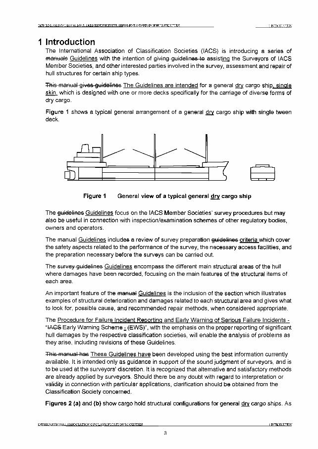
1 In tro d u c tio nThe International Association of Classification Societies (IACS) is introducing a series of manuals Guidelines with the intention of giving guidelines to assisting the Surveyors of IACS Member Societies, and other interested parties involved in the survey, assessment and repair of hull structures for certain ship types.
This manual gives guidelines The Guidelines are intended for a general dry cargo ship, single skin, which is designed with one or more decks specifically for the carriage of diverse forms of dry cargo.
Figure 1 shows a typical general arrangement of a general dry cargo ship with single tween deck.
Figure 1 General view of a typical general dry cargo ship
The guidelines Guidelines focus on the IACS Member Societies’ survey procedures but may also be useful in connection with inspection/examination schemes of other regulatory bodies, owners and operators.
The manual Guidelines includes a review of survey preparation guidelines criteria which cover the safety aspects related to the performance of the survey, the necessary access facilities, and the preparation necessary before the surveys can be carried out.
The survey guidelines Guidelines encompass the different main structural areas of the hull where damages have been recorded, focusing on the main features of the structural items of each area.
An important feature of the manual Guidelines is the inclusion of the section which illustrates examples of structural deterioration and damages related to each structural area and gives what to look for, possible cause, and recommended repair methods, when considered appropriate.
The Procedure for Failure Incident Reporting and Early Warning of Serious Failure Incidents - “IACS Early Warning Scheme - {EWS}”, with the emphasis on the proper reporting of significant hull damages by the respective classification societies, will enable the analysis of problems as they arise, including revisions of these Guidelines.
This manual has These Guidelines have been developed using the best information currently available. It is intended only as guidance in support of the sound judgment of surveyors, and is to be used at the surveyors' discretion. It is recognized that alternative and satisfactory methods are already applied by surveyors. Should there be any doubt with regard to interpretation or validity in connection with particular applications, clarification should be obtained from the Classification Society concerned.
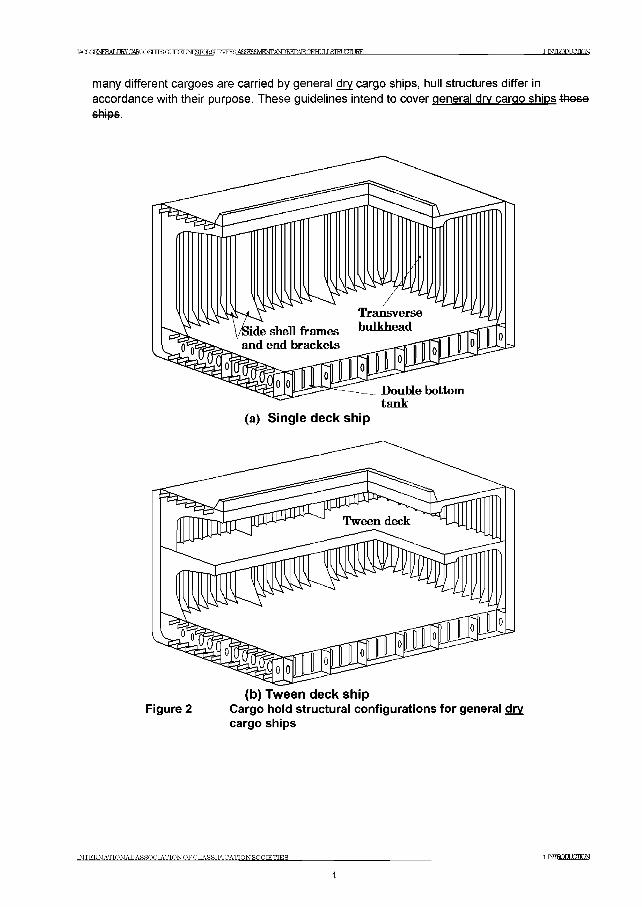
Figures 2 (a) and (b) show cargo hold structural configurations for general dry cargo ships. As
INTERNATIONAL ASSOCIATION OFCLASSIFICATION SOCIETIES 1 ISnEODUECKN
3
T A (T )O H sE R A L D R Y C A R fiO SRTFR ( I t m E T IN E fiT O R S T JRVRYS А Я Й Р У Ш Е Ж А Ш 1 ^ А Е О Е Н и ] Х 8 Ш 1 Х Г Ш К Е 1 INTRODUCTLON
many different cargoes are carried by general dry cargo ships, hull structures differ in accordance with their purpose. These guidelines intend to cover general dry cargo ships theseships
Figure 2 Cargo hold structural configurations for general dry cargo ships
IN TE R N A TIO N A L A SS O C IA TIO N O F C L A S SIF IC A T IO N SO C IE T IE S TMRQDLCIKN4
TACSOENERAT .Ш У C A RG O SHTFS ОТ ЛПЕГ IN E S ro R S U R V E Y R А Я Й Р У Ш Е О Т А ^ 1 ^ А Е О Е Н и ] Х 8 Ш 1 Х Т 1 1 Н Е 2ClJg[JRWEB3UIREMENrS
2 Class survey requirements2.1 Periodical classification surveys
2.1.1 GeneralFor Class the programme of periodical hull surveys is of prime importance as far as structural assessment of the cargo holds, and the adjacent tanks is concerned. The programme of periodical hull surveys consists of Annual, Intermediate, and Special Surveys. The Purpose of the Annual and Intermediate Surveys is to confirm that the general condition of the vessel is maintained at a satisfactory level. The Special Surveys of the hull structure are carried out at five year intervals with the purpose of establishing the condition of the structure to confirm that the structural integrity is satisfactory in accordance with the Classification Requirements, and will remain fit for its intended purpose until the next Special Survey, subject to proper maintenance and operation. The Special Surveys are also aimed at detecting possible damage and to establish the extent of any deterioration.
The Annual, Intermediate, and Special Surveys are briefly introduced in the following 2.1.2- 2.1.4. The surveys are carried out taking into account in accordance with the requirements specified in the Unified Requirements Z7 and Z7.1. alongside the Rules and Regulations of each IACS Member Society.
2.1.2 Special SurveyThe Special Survey concentrates on examination in association with thickness determination. The report of the thickness measurement is recommended to be retained on board. Protective coating condition will be recorded for particular attention during the survey cycle. From 1991 it is a requirement for new ships to apply a protective coating to the structure in water ballast tanks which form part of the hull boundary.
2.1.3 Annual SurveyAt Annual Surveys overall survey is required. For saltwater ballast tanks, examinations may be required as a consequence of the Intermediate or Special Surveys.
2.1.4 Intermediate SurveyAt Intermediate Surveys, in addition to the surveys required for Annual Surveys, examination of cargo holds and ballast tanks is required depending on the ship’s age.
2.1.5 Drvdock Bottom SurveyDrydock Bottom Surveys are requested twice during the Special Survey interval and they should be generally carried out in dry dock. In some cases it may be possible to replace one Drydock Bottom Survey in dry dock with an In-Water Survey. This will depend on the survey requirements of the relevant Classification Society.
2.2 Damage and repair surveysDamage surveys are occasional surveys which are, in general, outside the programme of Periodical hull surveys and are requested as a result of hull damage or other defects. It is the responsibility of the owner or his representative to inform the Classification Society concerned when such damage or defect could impair the structural capability or watertight integrity of the hull. The damages should be inspected and assessed by the Society’s surveyors and the relevant repairs, if needed, are to be performed. In certain cases,
INTERNATIONAL ASSOCIATION OFCLASSIFICATTONSOCIETIES 2 CLASS SURVEY RETIREMENTS
5
IACSGENEEALDRY CARGO SRTFR Of У1ГМ INESroRSLKVEYR АЯЙРУШЕЖА^БЕРА1ЕОРНт8Ш1ХТ11НЕ гСЗЗШУЕУБВЭШЕМЕКГЭ
depending on the extent, type and location of the damage, permanent repairs may be deferred to coincide with the planned periodical survey.In cases of repairs intended to be carried out by riding crew during voyage, complete procedure including all necessary surveys is to be submitted to and agreed upon by the Classification Society reasonably in advance.
2.3 Voyage repairs and maintenanceWhere repairs to hull, machinery or equipment, which affect or may affect classification, are to be carried out by a riding crew during a voyage they are to be planned in advance. A complete repair procedure including the extent of proposed repair and the need for surveyor’s attendance during the voyage is to be submitted to and agreed upon by the Surveyor reasonably in advance. Failure to notify the Classification Society, in advance of the repairs, may result in suspension of the vessel’s class. The above is not intended to include maintenance and overhaul to hull, machinery and equipment in accordance with manufacturers’ recommended procedures and established marine practice and which does not require the Classification Society’s approval; however, any repair as a result of such maintenance and overhauls which affects or may affect classification is to be noted in the ship’s log and submitted to the attending Surveyor for use in determining further survey requirements.See IACS Unified Requirement Z13, available on the IACS website: www.iacs.org.uk
INTERNATIONAL ASSOCIATION OFCLASSIFICATIONSOCIETIES 2 аАдй8ШУЕУ1?ЕЩНЕМЕ6
ЖБШЧЕЕАТ .ПКУСАШОЖШЗСТ ПЛИ 1NFSRTR.S[ JRVFYS А5Ж^М^7Г AMDREPAIRCFHC IT J ЯГИ ГЛТ IRE ЗЖЕШЖ,ВАШЖХЖ)РШ8итаЕ¥8
3 Technical background for surveys3.1 General
3.1.1 The purpose of carrying out the periodical hull surveys is to detect possible structural defects and damages and to establish the extent of any deterioration. To help achieve this and to identify key locations on the hull structure that might warrant special attention, knowledge of any historical problems of the particular ship or other ships of a similar class is to be considered if available. In addition to the periodical surveys, occasional surveys of damages and repairs are carried out. Records of typical occurrences and chosen solutions should be available in the ship's history file.
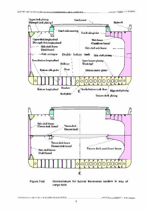
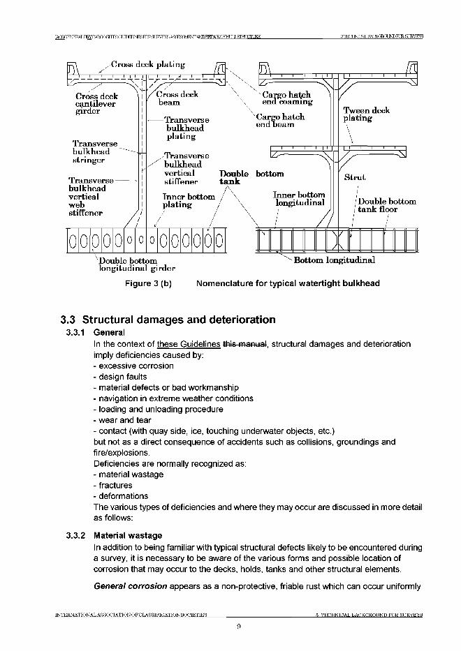
3.2 Definitions3.2.1 For clarity of definition and reporting of survey data, it is recommended that standard
nomenclature for structural elements be adopted. Typical sections in way of cargo holds are illustrated in Figures 3 (a) and (b). These figures show the generally accepted nomenclature.The terms used in these guidelines Guidelines are defined as follows:(a) Ballast Tank is a tank which is being used primarily for salt water ballast.(b) Spaces are separate compartments including holds and tanks.(c) Overall Inspection is an inspection intended to report on the overall condition of the
hull structure and determine the extent of additional close-up inspections.(d) Close-up Inspection is an inspection where the details of structural components
are within the close visual inspection range of the surveyors, i.e. normally within reach of hand.
(e) Transverse Section includes all longitudinal members such as plating, longitudinals and girders at the deck, side, bottom and inner bottom. For transversely framed vessels, a transverse section includes adjacent frames and their end connections in wav of transverse sections.
(f) Representative Spaces are those which are expected to reflect the condition of other spaces of similar type and service and with similar corrosion protection systems. When selecting representative spaces, account should be taken of the service and repair history on board.
(g) Transition Region is a region where discontinuity in longitudinal structure occurs, e.g. at forward bulkhead of engine room, collision bulkhead and bulkheads of deep cargo tanks in cargo hold region.
(h) Suspect Areas are locations showing Substantial Corrosion and/or are considered by the Surveyor to be prone to rapid wastage.
(j) Substantial Corrosion is an extent of corrosion such that assessment of corrosion pattern indicates a wastage in excess of 75% of allowable margins, but within acceptable limits.
(j) Coating condition is defined as follows:GOOD_______ condition with only minor spot rusting;FAIR_________condition with local breakdown at edges of stiffeners and weld
connections and/or light rusting over 20% or more of areas under consideration, but less than as defined for POOR condition;
POOR_______ condition with general breakdown of coating over 20% ormore of areas or hard scale at 10% or more of areas under consideration.
INTERNATIONAL ASSOCIATION OF CLASSIFICATION SOCIETIES 3 TECHNICAL BACKGROUND FOR SURVEYS
7
TACROFNFKAT.nRY ТГ ТГПЕГ INTOShTRST IF?VRVR АСЯРУЩЯМГ ANDBEPAIRCFHr ТГ I STRUCTURE я т-ЯКППАТ .ТШЖШХМРКК 9JRVEYS
U pper deck plating (Strength deck plating )
Hatch coverBulw ark
[\\
V •U pper deck longitudinal (Strength d a k longitudinal)
------------Side shell fram e(H old fram e)
H atch side coam ing ,H atch side girder
W eb beam (Cantilever beam )
| Side shell w eb fra m e--------
S id e s tr in g e r Double bottom tank Side shell plating -
Bottom bngitudinal
K eel plate
^ D ou b le bottom tank flo o r / та1 !йЬе11 pla
Bottom shell plating
<L
Figure 3 (a) Nomenclature for typical transverse section in way of cargo hold
INTERNATIONAL ASSOCIATION OF CLASSIFICATION SOCIETIES 3 TECHNICAL BACKGROUND FOR SURVEYS
IACSGENEEALDEV CARGO SRTFS ОТ 1 Ш Ш Ю ? Я JRWSAS^WFW/WDREPAEQFHLIL&TRLUTURE 3 TECHNICAL BACKGRQUNDKR SURVEYS
P v-Cross deck plating
Cross deck cantilever girder
Transversebulkheadstringer
Transverse—bulkheadverticalwebstiffener
H I П Г
=-----v |
oc) 0 ( ) 0 ‘) 0 (> 0 (ж ) 0 0
/Cross deck beam
Transverse bulkhead plating
^Transverse bulkhead vertical stiffener
Inner bottom plating
................. . l I l
Cargo hatch endheam
i 1 i 1T—i i i i i i
Double bottom tank
Inner bottom longitudinal
N/) \
T--- 1--- 1----1--- г M
Tween deck plating
3
Strut
/Double bottom tank floor
longitudinal girder
Figure 3 (b)
^ Bottom longitudinal
Nomenclature for typical watertight bulkhead
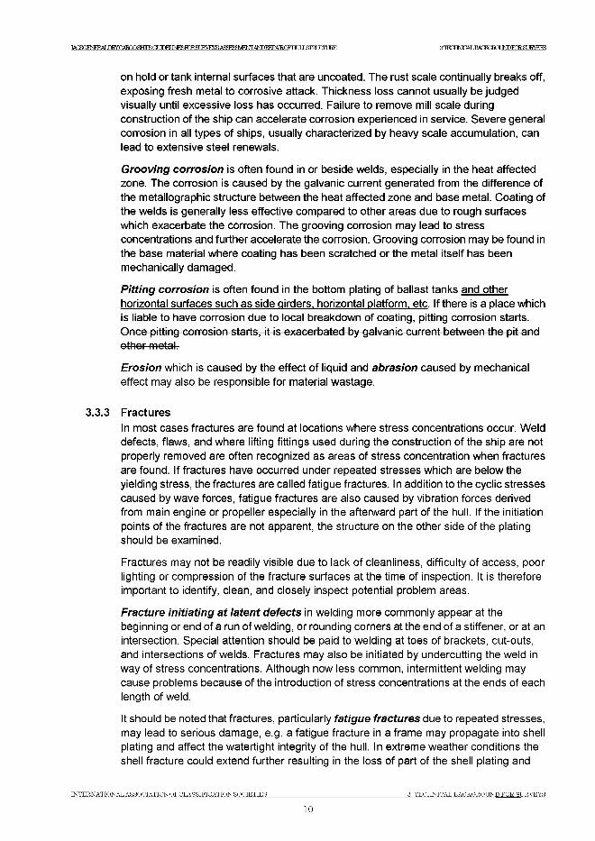
3.3 Structural damages and deterioration3.3.1 General
In the context of these Guidelines this manual, structural damages and deterioration imply deficiencies caused by:- excessive corrosion- design faults- material defects or bad workmanship- navigation in extreme weather conditions- loading and unloading procedure- wear and tear- contact (with quay side, ice, touching underwater objects, etc.)but not as a direct consequence of accidents such as collisions, groundings and fire/explosions.Deficiencies are normally recognized as:- material wastage- fractures- deformationsThe various types of deficiencies and where they may occur are discussed in more detail as follows:
3.3.2 Material wastage
In addition to being familiar with typical structural defects likely to be encountered during a survey, it is necessary to be aware of the various forms and possible location of corrosion that may occur to the decks, holds, tanks and other structural elements.
General corrosion appears as a non-protective, friable rust which can occur uniformly
INTERNATIONAL ASSOCIATION OFCLASSIFICATIONSOCIETIES 3 TECHNICAL BACKGROUND FOR SURVEYS
9
TACSGIFNFRAT .nRYOAmOSHIFSGil M M INFSTORfl М М Ж Afm^M FNTANDRFPAlR.Om I Г ЯГИ ТПТ № з ж а д .т ж ж и г о т а м м ж
on hold or tank internal surfaces that are uncoated. The rust scale continually breaks off, exposing fresh metal to corrosive attack. Thickness loss cannot usually be judged visually until excessive loss has occurred. Failure to remove mill scale during construction of the ship can accelerate corrosion experienced in service. Severe general corrosion in all types of ships, usually characterized by heavy scale accumulation, can lead to extensive steel renewals.
Grooving corrosion is often found in or beside welds, especially in the heat affected zone. The corrosion is caused by the galvanic current generated from the difference of the metallographic structure between the heat affected zone and base metal. Coating of the welds is generally less effective compared to other areas due to rough surfaces which exacerbate the corrosion. The grooving corrosion may lead to stress concentrations and further accelerate the corrosion. Grooving corrosion may be found in the base material where coating has been scratched or the metal itself has been mechanically damaged.
Pitting corrosion is often found in the bottom plating of ballast tanks and other horizontal surfaces such as side girders, horizontal platform, etc. If there is a place which is liable to have corrosion due to local breakdown of coating, pitting corrosion starts. Once pitting corrosion starts, it is exacerbated by galvanic current between the pit and other metal.
Erosion which is caused by the effect of liquid and abrasion caused by mechanical effect may also be responsible for material wastage.
3.3.3 Fractures
In most cases fractures are found at locations where stress concentrations occur. Weld defects, flaws, and where lifting fittings used during the construction of the ship are not properly removed are often recognized as areas of stress concentration when fractures are found. If fractures have occurred under repeated stresses which are below the yielding stress, the fractures are called fatigue fractures. In addition to the cyclic stresses caused by wave forces, fatigue fractures are also caused by vibration forces derived from main engine or propeller especially in the afterward part of the hull. If the initiation points of the fractures are not apparent, the structure on the other side of the plating should be examined.
Fractures may not be readily visible due to lack of cleanliness, difficulty of access, poor lighting or compression of the fracture surfaces at the time of inspection. It is therefore important to identify, clean, and closely inspect potential problem areas.
Fracture initiating at latent defects in welding more commonly appear at the beginning or end of a run of welding, or rounding corners at the end of a stiffener, or at an intersection. Special attention should be paid to welding at toes of brackets, cut-outs, and intersections of welds. Fractures may also be initiated by undercutting the weld in way of stress concentrations. Although now less common, intermittent welding may cause problems because of the introduction of stress concentrations at the ends of each length of weld.
It should be noted that fractures, particularly fatigue fractures due to repeated stresses, may lead to serious damage, e.g. a fatigue fracture in a frame may propagate into shell plating and affect the watertight integrity of the hull. In extreme weather conditions the shell fracture could extend further resulting in the loss of part of the shell plating and
INTERNATIONAL ASSOCIATION OF CLASSIFICATION SOCIETIES 3 TECHNICAL BACKGROUND FOR SURVEYS
10
IACSQENERALIHy CARGO SHTFR (ГГУГГМ JNESroRSLRVEYS A^a^M^TTANDREPAIRCFHr IT J ЯП?! ПТШ Е ЗЖЕШЖ,ВДС!ЕЙЖСШКЖ8иЕУЕУ5
consequent flooding of cargo hold.
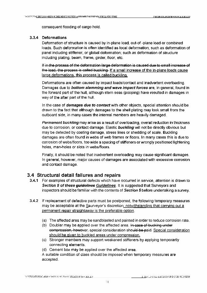
3.3.4 DeformationsDeformation of structure is caused by in-plane load, out-of -plane load or combined loads. Such deformation is often identified as local deformation, such as deformation of panel including stiffener, or global deformation; such as deformation of structure including plating, beam, frame, girder, floor, etc.
If in the process of the deformation large deformation is caused due to small increase of the load, the process is called buckling. If a small increase of the in-plane loads cause large deformations, this process is called buckling.
Deformations are often caused by impact loads/contact and inadvertent overloading. Damages due to bottom slamming and wave impact forces are, in general, found in the forward part of the hull, although stern seas (pooping) have resulted in damages in way of the after part of the hull.
In the case of damages due to contact with other objects, special attention should be drawn to the fact that although damages to the shell plating may look small from the outboard side, in many cases the internal members are heavily damaged.
Permanent buckling may arise as a result of overloading, overall reduction in thickness due to corrosion, or contact damage. Elastic buckling will not be directly obvious but may be detected by coating damage, stress lines or shedding of scale. Buckling damages are often found in webs of web frames or floors. In many cases this is due to corrosion of webs/floors, too wide a spacing of stiffeners or wrongly positioned lightening holes, man-holes or slots in webs/floors.
Finally, it should be noted that inadvertent overloading may cause significant damages. In general, however, major causes of damages are associated with excessive corrosion and contact damage.
3.4 Structural detail failures and repairs3.4.1 For examples of structural defects which have occurred in service, attention is drawn to
Section 5 of these guidelines Guidelines. It is suggested that Surveyors and inspectors should be familiar with the contents of Section 5 before undertaking a survey.
3.4.2 If replacement of defective parts must be postponed, the following temporary measures may be acceptable at the Ssurveyor’s discretion; notwithstanding that carrying out a permanent repair straightaway is the preferable option.
(a) The affected area may be sandblasted and painted in order to reduce corrosion rate.(b) Doubler may be applied over the affected area. In case of bucking under
compression, however, special consideration should be paid. Special consideration should be given to buckled areas under compression.
(c) Stronger members may support weakened stiffeners by applying temporarily connecting elements.
(d) Cement box may be applied over the affected area.A suitable condition of class should be imposed when temporary measures are accepted.
INTERNATIONAL ASSOCIATION OFCLASSIFICATIONSOCIETIES 3 TECHNICAL BACKGROUND FOR SURVEYS
11
3mE BAC!EgaOJNDKRgURVEYSTATSCFNFRAT .myCARCOSHTPSCr ЯПИINFSEORfl IRVEYS Afl3ra3HEWANDREPATROFHT JT J ЯШШШКЕ
3.5 IACS Early W arning Scheme (EWS) for reporting of s ignif icant hull damage
3t5t4— IACS has organised and set up a system to permit the collection, and disseminationamongst Member Societies of information (while excluding a ship's identity) on major hull damages.
3.5r2—The principal purpose of the IACS Early Warning Scheme is to enable a Classification Society with experience of a specific damage to make this information available to the other societies so that action can be implemented to avoid repetition of damage to hulls where similar structural arrangements are employed.
3.5.3—These guidelines have incorporated the experience gained from IACS EWS reporting.
INTERNATIONAL ASSOCIATION OFCLASSIFICATION SOCIETIES 3 TECHNICAL BACKGROUND FOR SURVEYS
12
IA C S G E N E R A L D R Y C A R G O SR T FS ОТ Ш Е Г I N E S r o R S t TRVFYR A ^F T ^M R N JT A N riR E P A IR Q F H L IF J ATRT TTTT IRE 4 S L I R m A N W E M ^ D J A N D E M n 7TTON
4 Survey planning, preparation and execution4.1 General
4.1.1 The owner should be aware of the scope of the forth coming survey and instruct those responsible, such as the master or the superintendent, to prepare necessary arrangements. If there is any doubt, the Classification Society concerned is to be consulted.
4.1.2 Survey execution will naturally be heavily influenced by the type of survey to be carried out. The scope of survey will have to be determined prior to the execution.
4.1.3 When deemed prudent and/or required by virtue of the periodic classification survey conducted, the surveyor should study the ship's structural arrangements and review the ship's operating and survey history and those of sister ships, where possible, to determine any known potential problem areas particular to the class of the ship. Sketches of typical structural elements should be prepared in advance so that any defects and/or ultrasonic thickness measurements can be recorded rapidly and accurately.
4.2 Conditions for survey4.2.1 The owner is to provide the necessary facilities for a safe execution of the survey.
4.2.2 Tanks and spaces are to be safe for access, i.e. gas freed (marine chemist certificate), ventilated, etc.
4.2.3 Tanks and spaces are to be sufficiently clean and free from water, scale, dirt, oil residues, etc. and sufficient illumination is to be provided, to reveal corrosion, deformation, fractures, damages or other structural deterioration. In particular this applies to areas which are subject to thickness measurement.
4.3 Access arrangem ent and safety4.3.1 In accordance with the intended survey, measures are to be provided to enable the hull
structure to be examined in a safe and practical way.
4.3.2 In accordance with the intended survey in cargo holds and salt water ballast tanks a secure and acceptable means of access is to be provided. This can consist of permanent staging, temporary staging or ladders, lifts and movable platforms, or other equivalent means.
4.3.3 In addition, particular attention should be given to the following guidance:(a) Prior to entering tanks and other enclosed spaces, e.g. chain lockers, void spaces, it
is necessary to ensure that the oxygen content is to be tested and confirmed as safe. A responsible member of the crew should remain at the entrance to the space and if possible communication links should be established with both the bridge and engine room. Adequate lighting should be provided in addition to a hand held torch (flashlight).
(b) In tanks where the structure has been coated and recently deballasted, a thin slippery film may often remain on the surfaces. Care should be taken when inspecting such spaces.
INTERNATIONAL ASSOCIATION OFCLASSIFICATIONSOCIETIES 4 SURVEY PLANNING,PREPARATION AND EXECUTION
13
T A fS O F M ^ A L D K Y C A R G O S H T F R O T О Т Т РП Ы РЯ Г О В Я К У К У Я A R S F H aV K N T A N D B F P A T R O F H I Я J ,STRI П П JRF) 4HnRVFyFTANNN0.H?FPARATO4JANDEXEnjnDN
(c) The removal of scale can be extremely difficult. The removal of scale by hammering may cause sheet scale to fall. When using a chipping or scaling hammer care should be taken to protect eyes, and where possible safety glasses should be worn.
If the structure is heavily scaled then it may be necessary to request de-scaling before conducting a satisfactory visual examination.
(d) Owners or their representatives have been known to request that a survey be carried out from the top of the cargo during discharging operations. For safety reason, surveys must not to be carried out during discharging operations in the hold.
(e) When entering a cargo hold or tank the bulkhead vertical ladders should be examined prior to descending to ensure that they are in good condition and rungs are not missing or loose. If holds are being entered when the hatch covers are in the closed position, then adequate lighting should be arranged in the holds. One person at a time should descend or ascend the ladder.
(f) If a portable ladder is used for survey purposes, the ladder should be in good condition and fitted with adjustable feet, to prevent it from slipping. Two crew members should be in attendance in order that the base of the ladder is adequately supported during use. The remains of cargo, in particular fine dust, on the tank top should be brushed away as this can increase the possibility of the ladder feet slipping.
(g) If an extending/articulated ladder (frame walk) is used to enable the examination of upper portions of cargo structure, the ladder should incorporate a hydraulic locking system and a built in safety harness. Regular maintenance and inspection of the ladder should be confirmed prior to its use.
(h) If a hydraulic arm vehicle (“Cherry Picker”) is used to enable the examination of the upper parts of the cargo hold structure, the vehicle should be operated by qualified personnel and there should be evidence that the vehicle has been properly maintained. The standing platform should be fitted with a safety harness. For those vehicles equipped with a self leveling platform, care should be taken that the locking device is engaged after completion of maneuvering to ensure that the platform is fixed.
(i) Staging is the most common means of access provided especially where repairs or renewals are being carried out. It should always be correctly supported and fitted with handrails. Planks should be free from splits and lashed down. Staging erected hastily by inexperienced personnel should be avoided.
(j) I n double bottom tanks there will often be a build up of mud on the bottom of the tank and this should be removed, in particular in way of tank boundaries, suction and sounding pipes, to enable a clear assessment of the structural condition.
4.4 Equipm ent and tools14.4.1 Personal protective equipment
The following protective clothing and equipment to be worn as applicable during the surveys:(a) Working clothes. Working clothes should be of a low flammablility type and be
easily visible.(b) Head protection. Hard hat (metal hats are not allowed) shall always be worn
outside office building/unit accommodations.(c) Hand and arm protection: Various types of gloves are available for use, and these
INTERNATIONAL ASSOCIATION OF CLASSIFICATION SOCIETIES 4 SURVEY PLANNING.PREPARATION AND EXECUTION
14
TACSGIFNFRAT .ГКУПАтОЯНтЯГЯ ЛПЕГ МОЮТСЯ ЮТЖ Afa^MFNTANDRFPAlR.OFHl ЛI ЯГИ ТПТ № 4 Я м т а л ANNINT, HTFPARATlCNANDEXFn ЛТПЧГ
should be used during all types of surveys. Rubber/plastic gloves may be necessary when working in cargo holds.
(d) Foot protection: Safety shoes or boots with steel toe caps and non slip soles shall always be worn outside office buildings/unit accommodations. Special footwear may be necessary on slippery surfaces or in areas with chemical residues.
(e) Ear protection: Ear muffs or ear plugs are available and should be used when working in noisy areas. As a general rule, you need ear protection if you have to shout to make yourself understood by someone standing close to you.
(f) Eye protection: Goggles should always be used when there is danger of solid particles or dust getting into the eyes. Protection against welding arc flashes and ultraviolet light should also be considered.
(g) Breathing protection: Dust masks shall be used for protection against the inhalation of harmful dusts, paint spraying and sand blasting. Gas masks and filters should be used by personnel working for short periods in an atmosphere polluted by gases or vapour.(Self-contained breathing apparatus: Surveyors shall not enter spaces where such equipment is necessary due to unsafe atmosphere. Only those who are specially trained and familiar with such equipment should use it and only in case of emergency).
(h) Lifejacket: Recommended to be used when embarking/disembarking ships offshore, from/to pilot boat.
4.4.2 Personnel survey equipment2
The following survey equipment is to be used as applicable during the surveys:(a) Torches: Torches (Flashlights) approved by a competent authority for use in a
flammable atmosphere shall be used in gas dangerous areas. A high intensity beam type is recommended for in-tank inspections. Torches are recommended to be fitted with suitable straps so that both hands may be free.
(b) Hammer. In addition to its normal purposes the hammer is recommended for use during surveys inside units, tanks etc. as it may be most useful for the purpose of giving distress signal in case of emergency.
(c) Oxygen analyser/Multigas detector. For verification of acceptable atmosphere prior to tank entry, pocket size instruments which give an audible alarm when unacceptable limits are reached are recommended. Such equipment shall have been approved by national authorities.
(d) Safety belts and lines: Safety belts and lines should be worn where high risk of falling down from more than 3 meters is present.
(e) Radiation meter. For the purpose of detection of ionizing radiation (X or gamma rays) caused by radiographic examination, a radiation meter of the type which gives an audible alarm upon detection of radiation is recommended.
1+2 Reference should also be made to IACS PR37 and IACS Recommendation 72.
INTERNATIONAL ASSOCIATION (^CLASSIFICATION SOCIETIES 4 SURVEY PLANNING.PREPARATION AND EXECUTION
15
IA C S G E N E E A L D R Y C A R G O SRTFR ОТ m E T T N E fiF O R S T J E V E Y S A S ^ S a V E O T A ^ E E P A R O F H U L L S I E U e T ^ 4 SURYEYPLASNING. HffiPARATICNAND INBOUnQN
4.4.3 Thickness measurement and fracture detection
(a) Thickness measurement is to comply with the requirements of the Classification Society concerned. Thickness measurement should be carried out at points that adequately represent the nature and extent of any corrosion or wastage of the respective structure (plate, web, etc.).
(b) Thickness measurement is normally carried out by means of ultrasonic test equipment. The accuracy of the equipment is to be proven as required.
(c) The thickness measurement is to be carried out by a qualified company certified by the relevant Classification Society.
(d) One or more of the following fracture detection procedures may be required if deemed necessary and should be operated by experienced qualified technicians:- radiographic equipment- ultrasonic equipment- magnetic particle equipment- dye penetrant
4.5 Survey at sea or anchorage24.5.1 Voyage surveys may be accepted provided the survey party is given the necessary
assistance from the shipboard personnel. The necessary precautions and procedures for carrying out the survey are to be in accordance with 4.1 to 4.4 inclusive. Ballasting systems must be secured at all times during tank surveys.
4.5.2 A communication system is to be arranged between the survey party in the spaces under examination and the responsible officer on deck.
4.6 Documentation on board
4.6.1 The following documentation is recommended to be placed on board and maintained and updated by the owner for the life of the ship in order to be readily available for the survey party.
4.6.2 Survey Report File: This file includes Reports of Surveys and Thickness Measurement Report.
4.6.3 Supporting Documents: It is recommended that the following additional documentation be placed on board, including any other information that will assist the inspection.(a) Main structural plans of cargo holds and ballast tanks,(b) Previous repair history,(c) Cargo and ballast history,(d) Inspection and action taken by ship's personnel with reference to:
- structural deterioration in general- leakages in bulkheads and piping- condition of coating or corrosion protection, if any
4.6.4 Prior to inspection, it is recommended that the documents on board the vessel be reviewed as a basis for the current survey.
3 Reference mav also be made to IACS UR Z7.1
INTERNATIONAL ASSOCIATION OF CLASSIFICATION SOCIETIES 4 SURVEY PLANNING,PREPARATION AND EXECUTION
16
TACSGE^ИlALERYCARQOgHIFSGUЮEЦNESPIЖgL^RVEта ASa^M^TTANDREPAIROFHr IT J ЯП?! PU RE 5 STRUCTURAL DETATL FAILURES AND REPATRS
5 Structural detail failures and repairs5.1 General
5.1.1 The catalogue of structural detail failures and repairs contained in this section of the Guidelines collates data supplied by the IACS Member Societies and is intended to provide guidance when considering similar cases of damage and failure. The proposed repairs reflect the experience of the surveyors of the Member Societies, but it is realized that other satisfactory alternative methods of repair may be available. However, in each case the repairs are to be completed to the satisfaction of the Classification Society Surveyor concerned.
5.2 Catalogue of structural detail failures and repairs5.2.1 The catalogue has been sub-divided into parts and areas to be given particular attention
during the surveys:
Part 1 Cargo hold regionArea 1 Upper deck structure Area 2 Side structure Area 3 Transverse bulkhead structure Area 4 Tween deck structure Area 5 Double bottom structure
Part 2 Fore and aft end regionsArea 1 Fore end structure Area 2 Aft end structureArea 3 Stern frame, rudder arrangement and propeller shaft support
Part 3 Machinery and accommodation spacesArea 1 Engine room structure Area 2 Accommodation structure
t n te r n a tto n a l A s s o c ia t io n o f c l a s s if ic a t io n s o c ie t ie s Я STRUCTURAL DETATT, FATTIIRES AND REPATRS
17
IAGSr^NERALDRYCARTXjSHTPSa ШЕГ INESKRSLKVEYS AS^SaVEOTA^I^AEOFHLIlXSIRlXTLIRE РЖГ1
Part 1 C argo hold region
Contents
Area 1 Area 2 Area 3 Area 4 Area 5
Upper deck structure Side structureTransverse bulkhead structure Tween deck structure Double bottom structure
INTERNATIONAL ASSOCIATION OF CLASSIFICATION SOCIETIES___________________________________________________________________________________________________ PARTI
18
IAGSr^NERALDRYCARTXjSHTPSa ШЕГ INESFORST TRVEYR А5Ж¥^ЕЖЖТ)КЕРАТРО^НГ ТГ Т .STRUCTURE PARTI
Area 1 Upper deck structure
Contents
1 General
2 What to look for - On-deck inspection2.1 Material wastage2.2 Deformations2.3 Fractures
3 What to look for - Under-deck inspection3.1 Material wastage3.2 Deformations3.3 Fractures
4 General comments on repair4.1 Material wastage4.2 Deformations4.3 Fractures4.4 Miscellaneous
Figures and/or Photographs - Area 1No. Title
Photograph 1 Heavy corrosion of hatch coamingPhotoaraph 2 Heavy corrosion of hatch coaminaPhotoaraph 3 Fractures at the hatch cornerPhotoaraph 4 Corrosion at the too of the hatch coamina
Examples of structural detail failures and repairs - Area 1Example No. Title
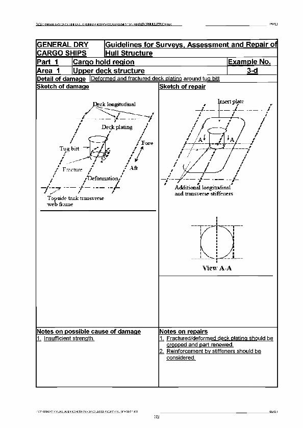
1 Buckling of deck plating of transverse framing system2 Fractures at main cargo hatch corner3-a Fracture of welded seam between thick plate and thin plate at cross deck3-b Plate buckling in thin plate near thick plate at cross deck3-c Overall buckling of cross deck plating3-d Deformed and fractured deck olatina around tua bitt4 Buckling of web beam5-a Fractures in the web or in the deck at the toes of the longitudinal hatch
coaming termination bracket (discontinuous longitudinal hatch coaming)5-b Fractures in continuous longitudinal hatch coaming extension bracket5-c Fracture in access hole of lonaitudinal hatch coamina6 Fractures in web of transverse hatch coaming stay7-a Fractures in hatch coaming top plate at the termination of rail for hatch cover7-b Fractures in hatch coaming top plate at the termination of rail for hatch cover8 Fractures in hatch coaming top plate around resting pad9 Fracture in deck plating at the pilot ladder access of bulwarks
INTERNATIONAL ASSOCIATION OF CLASSIFICATION SOCIETIES
19AREAl
IACSC£NEEALDE?Y САШР ЯНТРЯ fЯ ШЕГ Ib^roRSUE^EYSAS^SSVlFWANDT^PAIROFHUILSiraXTLEE PARTI
1 General1.1 Deck structures outside hatches is are subjected to longitudinal hull girder bending, caused
by cargo distribution and wave actions. Moreover deck structures may be subjected to severe loads due to green seas on deck, excessive deck cargo or improper handling of cargo. Certain areas of the deck may also be subjected to additional compressive stresses caused by slamming or bow flare effect at the fore ship in heavy weather.
1.2 The cross deck structure between the cargo hatches is subjected to transverse compression from the sea pressure on the ship sides and in-plane bending due to torsion distortion of the hull girders under wave action. In association with this, the area around the corner of a main cargo hatch is subjected to high cyclical stress due to the combined effect of hull girder bending moment and transverse and torsional loading.
1.3 Discontinuous cargo hatch side coamings are subjected to considerable longitudinal bending stresses although not taken into account in the strength of hull girders. This will cause additional stresses at the mid length of hatches and stress concentrations at the termination of the side coaming extensions. Continuous cargo hatch side coamings are included in the strength of hull girders and are subjected to high longitudinal bending stress at the top of the coaming amidships. Terminations of continuous side coamings at the fore and aft ends are particularly vulnerable to stress concentrations.
1.4 Hatch cover operations in combination with poor maintenance can result in damage to the cleats and gasket, etc. This can result in the loss of weathertight integrity of the hold spaces. Damage to the covers can also be sustained by overloading when carrying deck cargoes.
1.5 The marine environment, the humid atmosphere due to vaporization from cargo in the cargo hold, and high temperatures on deck and hatch cover plating, from the sun and heat, may result in severe corrosion of plating and stiffeners making the structure more vulnerable to the exposures described above.
1.6 Bulwarks are provided for the protection of crew and cargoes, and lashing of cargoes on deck. Although bulwarks are not taken into account in the strength of hull girders, they are subjected to considerable longitudinal bending stresses. Therefore bulwarks may suffer fractures and corrosion, especially at the termination of bulwarks, such as at pilot ladder access or expansion joints. The fractures may propagate to deck plating and cause serious damage.
1.7 The deterioration of various fittings on deck, such as ventilators, air pipes and sounding pipes, may result in serious problems regarding weather/watertightness and/or firefighting.
1.8 If the ship is assigned timber freeboards, fittings for stowage of timber deck cargo have to be inspected in accordance with ILLC 1966. Deterioration of the fittings may cause cargoes to shift resulting in serious damage to the ship.
2 What to look for - On-deck inspection2.1 Material wastage
2.1.1 The general condition with regard to corrosion of the deck structure, the cargo hatch coamings and the hatch covers may be observed by visual inspection. Special attention
INTERNATIONAL ASSOCIATION OF CLASSIFICATION SOCIETIES
20AREAl

TACSGiFNFFALJSYGARQOSHIFROr Ш И МОЮ ТСЯ TM ^A SaS3№ N TA N nR FPA lR .O FH l ЛI ЯГИ Н П iRFl PARTI
should be paid to areas where pipes, e.g. fire main, hydraulic pipes, pipes for compressed air, are fitted close to the plating, making proper maintenance of the protective coating difficult to carry out.
2.1.2 Grooving corrosion may occur at the transition between the thicker deck plating outside the line of cargo hatches and the thinner cross deck plating, especially when the difference in plate thickness is large. The difference in plate thickness causes water to gather in this area resulting in corrosion ambience which may subsequently lead to grooving.
2.1.3 Pitting corrosion may occur throughout the cross deck strip plating and on hatch covers. The combination of accumulated water with scattered residue of certain cargoes may create a corrosive reaction.
2.1.4 Wastage/corrosion may seriously affect the integrity of the steel hatch covers, and also the additional moving parts, e.g. cleats, pot-lifts, roller wheels, etc. In some ships pontoon hatch covers together with tarpaulins are used. The tarpaulins are liable to tear due to deck cargo, such as timbers, and cause heavy corrosion to the hatch covers.
2.2 Deformations2.2.1 Plate buckling (between stiffeners) may occur in areas subjected to in-plane
compressive stresses, particularly if corrosion is evident. Special attention should be paid to areas where the compressive stresses are perpendicular to the direction of the stiffening system. Such areas may be in the foreship where deck longitudinals are terminated and replaced by transverse beams (See Example 1), but also in the cross deck strips between hatches when longitudinal stiffening is applied (See Examples 3-b and 3-c).
2.2.2 Deformed structures may be observed in areas of the deck, hatch coamings and hatch covers where cargo has been handled/loaded or mechanical equipment, e.g. hatch covers, has been operated. Also in other areas, in particular exposed deck forward, deformation may be a result when of green seas loads on the deck have been suffered.
2.2.3 Sagging plate panel may have been caused by lateral overloading as a consequence of excessive deck cargo, improper distribution /support of deck cargoes, sea water on deck in heavy weather, or a combination of these factors. It is essential that an under-deck inspection is also carried out to assess the extent of such damage (See Example 4).
2.2.4 Deformed/twisted exposed structures above deck, such as side-coaming brackets, may result from impact of cargo or cargo handling machinery due to improper handling. Such damages may also be caused by sea water on deck in heavy weather.
2.3 Fractures2.3.1 Fractures in areas of structural discontinuity and stress concentration will normally be
detected by close-up inspection. Special attention should be given to the structures at cargo hatches in general and to corners of deck openings in particular.
2.3.2 Fractures initiated in the deck plating outside the line of hatches (See Example 2), may develop across the deck, with the most serious consequences. Also fractures initiated in the deck plating of the cross deck strip, in particular at the transition between the thicker
INTERNATIONAL ASSOCIATION OF CLASSIFICATION SOCIETIES
21AREAl
I^SGmEI^ERYCARQOSHIPSGimEriNF^RlRar JRVEYfl ASa^HENTANDREPATROFTir JT J Я1БШШБЕ PARTI
deck plating outside the line of cargo hatches and the thinner cross deck plating (See Example 3-a), may have serious consequences if not repaired immediately.
2.3.3 Other fractures that may occur in the deck plating at hatches and in connected coamings can result/originate from:(a) Fillet weld connection of the coaming to the deck, particularly at a radiused rounded
hatch coaming plate at the hatch corner plating.(b) Welded attachment and shedder plate close to or on the free edge of the hatch
corner plating.(c) The geometry of the corners of the hatch openings.(d) The termination of the side coaming extension brackets (See Examples 5-a and
5-b).(e) Grooving caused by wire ropes of cargo gear.(f) Wasted plating.(g) Attachments, cut-outs and notches for securing devices, and operating mechanisms
for opening/closing hatch covers at the top of the coaming and/or coaming top bar, if any, at the mid-length of the hatch (See Examples 7-a and 7-b).
(h) Hatch coaming stays supporting the hatch cover resting pads in case of deck loads on the hatch covers and the connection of resting pad to the top of the coaming as well as the supporting structures (See Example 8).
2.3.4 Fractures in deck plating often occur at the termination of bulwarks, such as pilot ladder recess, due to stress concentration. The fractures may propagate themselves resulting in serious casualty when the deck is subject to high longitudinal bending stress.
3 What to look for - Under-deck inspection3.1 Material wastage
3.1.1 The level of wastage of under-deck stiffeners/structures may have to be established by means of thickness measurements. As mentioned previously the combination of the effects from the marine environment and the local atmosphere will give rise to high corrosion rates.
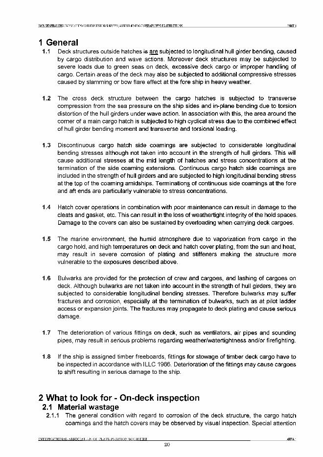
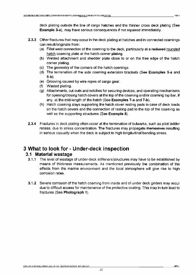
3.1.2 Severe corrosion of the hatch coaming from inside and of under deck girders may occur due to difficult access for maintenance of the protective coating. This may in turn lead to fractures (See Photograph 1).
INTERNATIONAL ASSOCIATION OF CLASSIFICATION SOCIETIES
22AREA1
IACSGENERALDRY CARGOSHTPfi ОТ ЛПЕГ 1ЫЕБГОЕЭ1ЖЕЖА£Ж83\ФЖАШ1МЖОЕНт81ШЖЕЕ PARTI
Photograph 1 Heavy corrosion of hatch coaming
Photograph 2 Heavy corrosion of hatch coaming
INTERNATIONAL ASSOCIATION OF CLASSIFICATION SOCIETIES
23AREAl
IACSGENERALDRY CARGOSHTPS ОТ ЛТЖГ INESPORH 1НУЕЖАЗЖ331\/ЕОТАШ1ИШ^ОРНШ1,д1Б11ЖДЖ PARTI
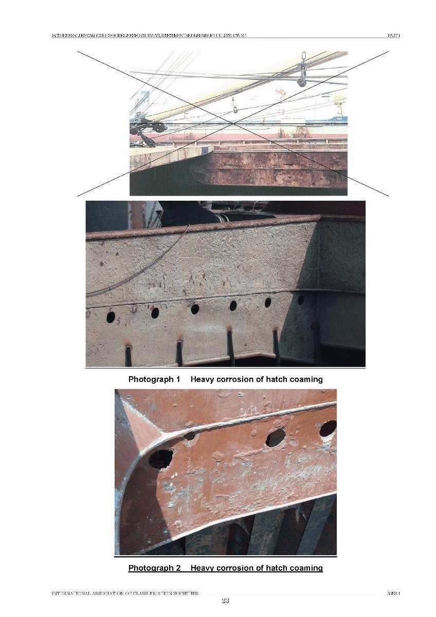
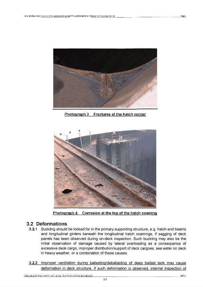
Photograph 4 Corrosion at the top of the hatch coaming
3.2 Deformations3.2.1 Buckling should be looked for in the primary supporting structure, e.g. hatch end beams
and longitudinal girders beneath the longitudinal hatch coamings, if sagging of deck panels has been observed during on-deck inspection. Such buckling may also be the initial observation of damage caused by lateral overloading as a consequence of excessive deck cargo, improper distribution/support of deck cargoes, sea water on deck in heavy weather, or a combination of these causes.
3.2.2 Improper ventilation during ballasting/deballastinq of deep ballast tank may cause deformation in deck structure. If such deformation is observed, internal inspection of
IN T E R N A T IO N A L A S S O C IA T IO N O F C L A S S IF IC A T IO N SO C IE T IE S __________________________________________________________________________________________________________AREA1
24
IAGSt^NEEALDRYCARTXjHHTPSa ШЕГ INESFORSC TRVEVR АЯЙРУШРЖ ANDREPAIRQFHIT T ATRT TTTT TRK PARTI
deep ballast tank should be carried out in order to confirm the nature and the extent of damage.
3.3 Fractures3.3.1 Fractures in the connection between the transverse bulkheads, girders/stiffeners and the
deck plating may occur. This is often associated with a reduction in area of the connection due to corrosion.
3.3.2 Fractures in the primary supporting structure, e.g. hatch end beams may be found in the weld connections at the ends of the beams/girders.
4 General comments on repair4.1 Material wastage
4.1.1 In the case of grooving corrosion at the transition between the thicker deck plating outside the me line of cargo hatches and the cross deck plating, consideration should be given to the renewal of part of, or the entire width, of the adjacent cross deck plating.
4.1.2 In the case of pitting corrosion throughout the cross deck strip plating, consideration should be given to renewal of part of or the entire cross deck plating.
4.1.3 When heavy wastage is encountered on under-deck structure, the whole or part of the structure may be cropped and renewed depending on the permissible diminution levels applied by the Classification Society concerned.
4.1.4 For wastage of cargo hatch covers a satisfactory thickness determination is to be carried out and the plating and stiffeners are to be cropped and renewed as appropriate depending on the extent of the wastage.
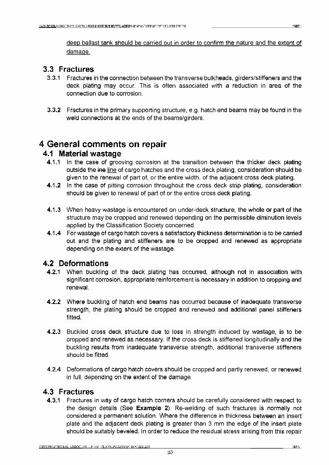
4.2 Deformations4.2.1 When buckling of the deck plating has occurred, although not in association with
significant corrosion, appropriate reinforcement is necessary in addition to cropping and renewal.
4.2.2 Where buckling of hatch end beams has occurred because of inadequate transverse strength, the plating should be cropped and renewed and additional panel stiffeners fitted.
4.2.3 Buckled cross deck structure due to loss in strength induced by wastage, is to be cropped and renewed as necessary. If the cross deck is stiffened longitudinally and the buckling results from inadequate transverse strength, additional transverse stiffeners should be fitted.
4.2.4 Deformations of cargo hatch covers should be cropped and partly renewed, or renewed in full, depending on the extent of the damage.
4.3 Fractures4.3.1 Fractures in way of cargo hatch corners should be carefully considered with respect to
the design details (See Example 2). Re-welding of such fractures is normally not considered a permanent solution. Where the difference in thickness between an insert plate and the adjacent deck plating is greater than 3 mm the edge of the insert plate should be suitably beveled. In order to reduce the residual stress arising from this repair
INTERNATIONAL ASSOCIATION OF CLASSIFICATION SOCIETIES
25AREAl
K C S G E N E R A L D R Y G A R G P R H T P S O T Л Г И I N F S T O R H К У К У Я A R S F H aV lF N T A N n B F P A 1 R .0 F H I Я ,T M П И К Е PART 1
situation, the welding sequence and procedure is to be carefully monitored and low hydrogen electrodes should be used for welding the insert plate to the adjoining structure. Where welded shedder plates are fitted into the corners of the hatch coamings the deck connection should be left unwelded.
4.3.2 In the case of fractures at the transition between the thicker deck plating outside the line of cargo hatches and the cross deck plating, consideration should be given to renewal of part or the entire width of the adjacent cross deck plating, possibly with increased thickness (See Example 3-a).
4.3.3 When fractures have occurred in the connection of transverse bulkheads to the cross deck structure, consideration should be given to renewing and re-welding the connecting structure beyond the damaged area with the aim of increasing the area of the connection which may be achieved bv installation of additional brackets or increasing the brackets size.
4.3.4 Fractures of hatch end beams should be repaired by renewing the damaged structure, and by full penetration welding to the deck.
4.3.5 Tо reduce the possibility of future fractures in cargo hatch coamings the following details should be observed:(a) Cut-outs and other discontinuities at the top of coamings and/or coaming top bar
should have rounded corners (preferably elliptical or circular in shape) (See Example 7-b).Any local reinforcement should be given a tapered transition in the longitudinal direction and the rate of taper should not exceed 1 in 3 (See Example 7-a).
(b) Fractures, which occur in the fillet weld connections to the deck of fadiused rounded coaming plates at the corners, should be repaired by replacing existing fillet welds with full penetration welding using low hydrogen electrodes or equivalent. If the fractures are extensive and recurring, the coamings should be redesigned modified to form square c o rn e r with the longitudinal side coamings extending in the form of tapered brackets. Continuation brackets also to be arranged transversely in line with the hatch end coamings and the under-deck transverse.
(c) Cut-outs and drain holes are to be avoided in the hatch side coaming extension brackets. For fractured brackets, see Examples 5-a and 5-b.
4.3.6 For cargo hatch covers, fractures of a minor nature may be veed-out and welded. For more extensive fractures, the structure should be cropped and partly renewed.
4.3.7 For fractures (and heavy corrosion) at the end of bulwarks an attempt should be made to modify the design in order to reduce the stress concentration in connection with general cropping and renewal (See Example 9).
4.4 Miscellaneous4.4.1 Ancillary equipment such as cleats, rollers etc. on cargo hatch covers is to be renewed
when damaged or corroded.
INTERNATIONAL ASSOCIATION OF CLASSIFICATION SOCIETIES
26AREAl
TAHSORNJKRAT ,Ш УНАТ?ПОЯНТРЯОГ ТГПЕГ JN B S ro R S L R V F ^ R A ffF H F M F N T A b D T ^ P A I R O F H U lX S IR rT U R E РЖГ1
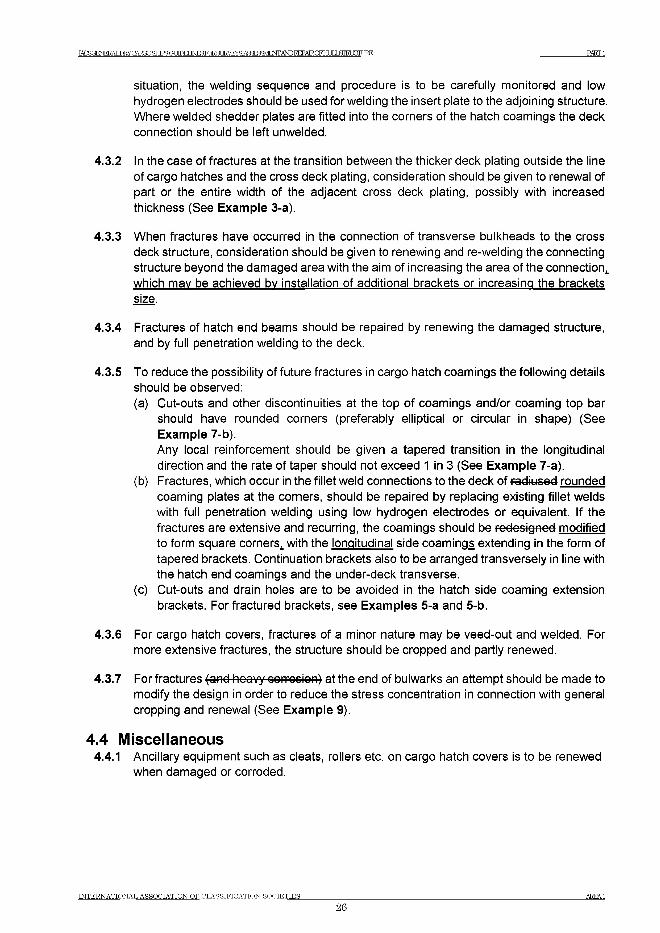
GENERAL DRY Guidelines for Surveys, Assessment and Repair CARGO SHIPS |h u II Structure_____________________ ____________Part 1 Cargo hold region Example No.Area 1 Upper deck structure 1Detail of damage |Buckling of deck plating of transverse framing systemSketch of damage Sketch of repair
of
Notes on possible cause of damage1. Excessive compressive stress due to
slamming or bow flare effect.2. Insufficient longitudinal stiffening of deck
plating.
Notes on repairs1. Buckled plating should be cropped and
renewed. Longitudinal internal stiffeners should be provided.(Instead of longitudinal stiffeners, renewal by thicker deck plating can be accepted.)
2. Stress concentration may occur at the end of sniped stiffener resulting in fatigue fracture. For locations where high cyclic stress may occur, appropriate connection such as lug-connection should be considered.
INTERNATIONAL ASSOCIATION OF CLASSIFICATION SOCIETIES_______________
27AREA.1
TAHfiOENJERAT ,Ш У С Ж Ю Я Н Т Р Я Г ? Г ТГПЕГINESTCTR.ST JRVRYS. Л Я Ж ^ М Е Ж Ж Р Б Е Р А Е О Р Н О Ь Б Т Ш Ж Д Ж P A C T 1
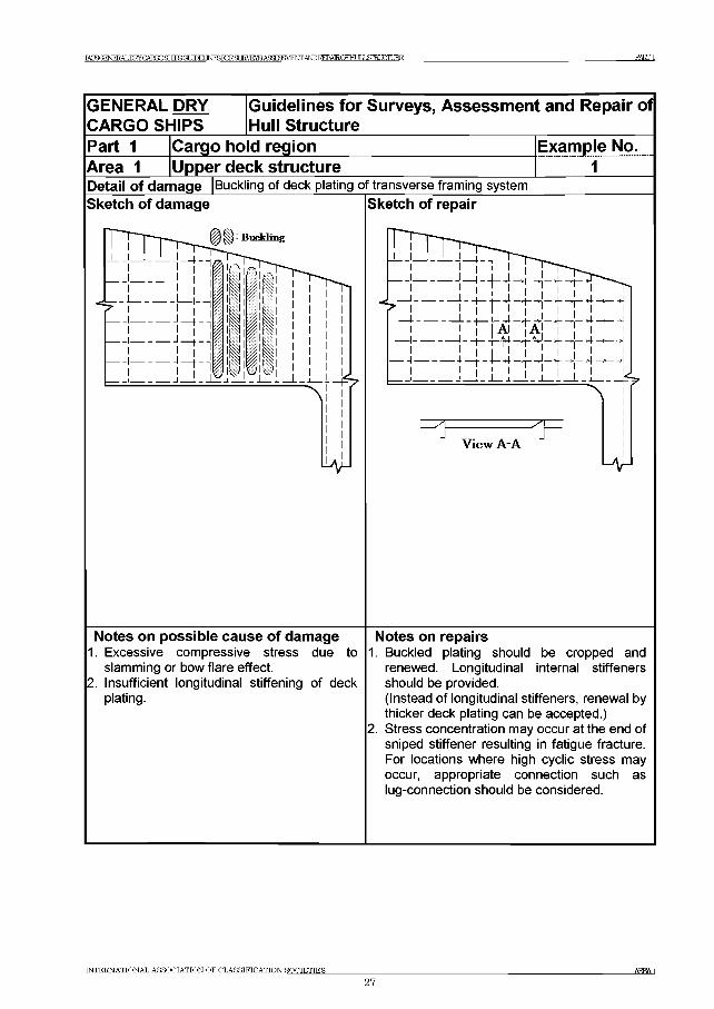
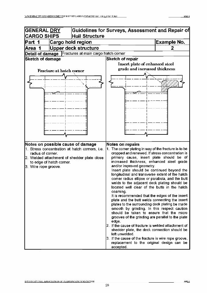
GENERAL DRY G uidelines fo r Surveys, Assessm ent and Repair CARGO SHIPS Ih u II S tructure___________________________________Part 1 Cargo hold region Exam ple No.Area 1 Upper deck structure 2Detail of damage |Fractures at main cargo hatch cornerSketch of damage
Fracture at hatch comer
Sketch of repairInsert plate of enhanced steel grade and increased thickness
Of
Notes on possible cause of damage1. Stress concentration at hatch corners, i.e.
radius of corner.2. Welded attachment of shedder plate close
to edge of hatch corner.3. Wire rope groove.
Notes on repairs1. The comer plating in way of the fracture is to be
cropped and renewed. If stress concentration is primary cause, insert plate should be of increased thickness, enhanced steel grade and/or improved geometry.Insert plate should be continued beyond the longitudinal and transverse extent of the hatch comer radius ellipse or parabola, and the butt welds to the adjacent deck plating should be located well clear of the butts in the hatch coaming.It is recommended that the edges of the insert plate and the butt welds connecting the insert plates to the surrounding deck plating be made smooth by grinding. In this respect caution should be taken to ensure that the micro grooves of the grinding are parallel to the plate edge.
2. If the cause of fracture is welded attachment of shedder plate, the deck connection should be left unwelded.
3. If the cause of the fracture is wire rope groove, replacement to the original design can be accepted.
INTERNATIONAL ASSOCIATION OF CLASSIFICATION SOCIETIES
28AREA1
IACSGENERAT .ГКУПАТУПЯНТРЙГЛ ПГИ INRSRTRFl TRVRVR АЯЧ^УМ^ГГ ANDREPAIRCFHLIJ ЯГИ ГПТ IRE PARTI
GENERAL DRY Guidelines for Surveys, Assessment and RepairCARGO SHIPS Hull StructurePart 1 Cargo ho d region Example No.Area 1 Upper deck structure 3-a
of
Detail of damage Sketch of damage
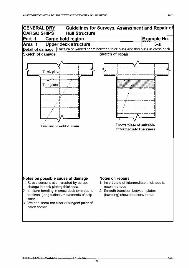
Fracture of welded seam between thick plate and thin plate at cross deckSketch of repair
Notes on possible cause of damage1. Stress concentration created by abrupt
change in deck plating thickness.2. In-plane bending in cross deck strip due to
torsional (longitudinal) movements of ship sides.
3. Welded seam not clear of tangent point of hatch corner.
intermediate thickness
Notes on repairs1. Insert plate of intermediate thickness is
recommended.2. Smooth transition between plates
(beveling) should be considered.
INTERNATIONAL ASSOCIATION OF CLASSIFICATION SOCIETIES
29A R E A l
TAfKTffNFKAT .nRYCARmSHTPSamEUNESFCRgr IRVFVS A<4^^4FNTANnREPATRr)FHr TT J ЯШ Ж Е Е PARTI
GENERAL DRY CARGO SHIPS
Guidelines for Surveys, Assessment and Repair of Hull Structure
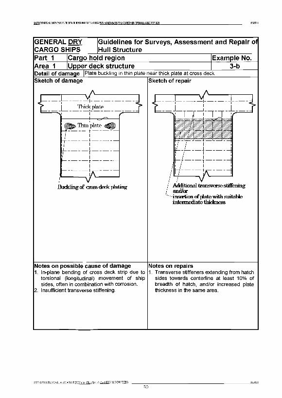
Part 1 Cargo hold region Example No.Area 1 Upper deck structure 3-bDetail of damage |Plate buckling in thin plate near thick plate at cross deckSketch of damage
Buckling of cross deck plating
Sketch of repair
Additional transverse stiffening and/orinsertion of plate with suitable intirnuxliate thickness
Notes on possible cause of damage1. In-plane bending of cross deck strip due to
torsional (longitudinal) movement of ship sides, often in combination with corrosion.
2. Insufficient transverse stiffening.
Notes on repairs1. Transverse stiffeners extending from hatch
sides towards centerline at least 10% of breadth of hatch, and/or increased plate thickness in the same area.
INTERNATIONAL ASSOCIATION OF OLASRTFTCATION SOCIETIES________________
30AREA1

I^SGmH?ALERYCARX)SEiIPSGUDELJNF^KlRar JRVEYS АдЮЯЯМЕЖАЬРКЕРА^^ PARTI
GENERAL DRY iGuidelines for Surveys, Assessment and Repair ofCARGO SHIPS |Hull StructurePart 1 Cargo hold region Example No.Area 1 Upper deck structure 3-cDetail of damage |Overall buckling of cross deck platingSketch of damage
л Л XjHuds:plate j Thinplate^
Budding of cross deck plating
Sketch of repair
Repair A_____Z J Z Z .I
Additional transverse stiffening
; i a M ' x t 'I— ■к ч — l-
I Insertion of plate of i-increased tbi^Vnugg-f-------V , i '/*
Notes on possible cause of damage1. Transverse compression of deck due to sea
load.2. Insufficient transverse stiffening.
Notes on repairs1. Repair A
Plating of original thickness in combination with additional transverse stiffening.Repair В
2. Insertion of plating of increased thickness.
INTERNATIONAL ASSOCIATION OF CLASSIFICATION SOCIETIES_____________________________________________________________________________________AREA1
31
IACSOFNFRAT ,nRYCARQOSEiIPSGUDELJNF T )R IRVEYS ASa^MFNTANnRKPATRrFHT IT J ДТНЦСПТ JRE PARTI
INTERNATIONAL ASSOCIATION OF CLASSIFICATION SOCIETIES
32AREA1
Ж1
GENERAL DRY CARGO SHIPS
jGuidelines for Surveys, Assessment and Repair of Hull Structure
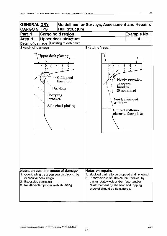
Part 1 Cargo hold region Example No.Area 1 [Upper deck structureDetail of damage |Buckling of web beamSketch of damage
Upper deck plating
Sketch of repair
nLi L J J J Ji i i i iliкi i i i l __
i X u N A -A/ Newly providedA _ \ Tripping
bracketl (Both sides)\Newly providedstiffener
— \Shifted stiffenercloser to face plate
\ _
Notes on possible cause of damage1. Overloading by green sea on deck or by
excessive deck cargo.2. Excessive corrosion.3. Insufficient/improperweb stiffening.
Notes on repairs1. Buckled part is to be cropped and renewed.2. If corrosion is not the cause, renewal by
thicker plate (web and/or face) and/or reinforcement by stiffener and tripping bracket should be considered.
INTERNATIONAL ASSOCIATION OR CLASSIFICATION SOCIETIES_______________з е Г
are ai
TACSOENERAT .ШУНАРПОЯНТРЯОГ ШЕГ INESK>RSLKVEVS А Я Й Р У Ш Е Ж А Ш ^ А Е О Е Н т З Ш и Ж Д Ж PARTI
GENERAL DRY CARGO SHIPS
Guidelines for Surveys, Assessm ent and Repair of Hull Structure
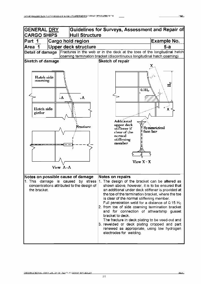
Part 1 Cargo ho d region Example No.Area 1 Upper deck structure 5-aDetail of damage Fractures in the web or in the deck at the toes of the longitudinal hatch
coaming termination bracket (discontinuous longitudinal hatch coaming)Sketch of damage Sketch of repair
Notes on possible cause of damage1. This damage is caused by stress
concentrations attributed to the design of the bracket.
Notes on repairs1. The design of the bracket can be altered as
shown above, however, it is to be ensured that an additional under deck stiffener is provided at the toe of the termination bracket, where the toe is clear of the normal stiffening member.Full penetration weld for a distance of 0.15 He
2. from toe of side coaming termination bracket and for connection of athwartship gusset bracket to deck.The fracture in deck plating to be veed-out and
3. rewelded or deck plating cropped and part renewed as appropriate, using low hydrogen electrodes for welding.
INTERNATIONAL ASSOCIATION OF CLASSIFICATION SOCIETIES
34A R E A l
TAHfiOENJERAT .Ш У О А Ш О Я Н Г Р Й О Г ТГПЕГ ШЯУЛЯЯ IR V E Y S A S ^ S a V J F X T A N D H EPA TR O EH T I J Л Щ Ц С Т Ш Е PARTI
GENERAL DRY CARGO SHIPS
Guidelines for Surveys, Assessm ent and Repair of Hull Structure
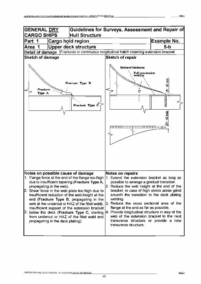
Part 1 Cargo ho d region Example No.Area 1 Upper deck structure 5-bDetail of damage Fractures in continuous longitudinal hatch coaming extension bracketSketch of damage
Notes on possible cause of damage1. Flange force at the end of the flange too high
due to insufficient tapering (Fracture Type A, propagating in the web).
2. Shear force in the web plate too high due to insufficient reduction of the web height at the end (Fracture Type B, propagating in the web at the undercut or HAZ of the fillet weld). Insufficient support of the extension bracket
3. below the deck (Fracture Type C, starting from undercut or HAZ of the fillet weld and propagating in the deck plating).
Sketch of repair
Notes on repairs1. Extend the extension bracket as long as
possible to arrange a gradual transition.2. Reduce the web height at the end of the
bracket; in case of high stress areas grind smooth the transition to the deck plating welding.
3. Reduce the cross sectional area of the flange at the end as far as possible.
4. Provide longitudinal structure in way of the web of the extension bracket to the next transverse structure or provide a new transverse structure.
INTERNATIONAL ASSOCIATION OF CLASSIFICATION SOCIETIES
35AREAl
IACSOFNFRAT .nRYCARQOSEilPSGUDELJNF^KlRar 1RVEYS А Я Я ^ М ^ А ^ Е Е Р А Е С Р Н Ц 1 1 ^ 1 Ш Ж 1 Е Ж PARTI
GENERAL DRY [Guidelines for Surveys, Assessm ent and Repair of CARGO SHIPS Hull StructurePart 1Area 1
Cargo hold regionUpper deck structure
Example No.5-c
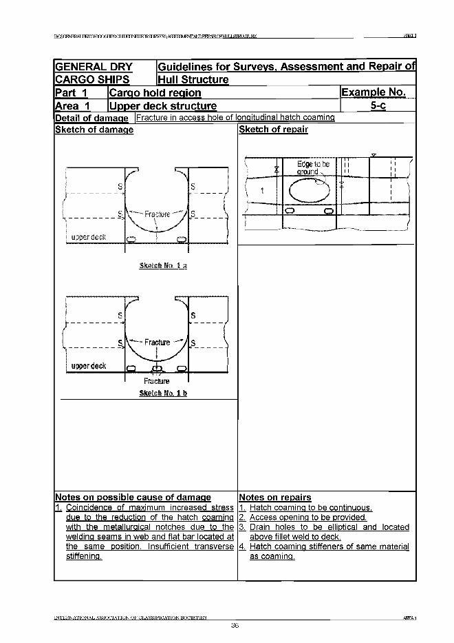
Detail of damage |Fracture in access hole of longitudinal hatch coamingSketch of damage
7 я
upper deck
s Sf
ъ V ~~ Fracture ' у
_Q
Sieteh no. 1 a
Fra dure Sketch Wo. 1 b
Sketch of repair
1
1 3[Edge to be around
I III i I
1 i (i ii i /
L1 О ::-------------j_L_y
1 r11
О... о .
______ \
Notes on possible cause of damage1 Coincidence of maximum increased stress
due to the reduction of the hatch coaming with the metallurgical notches due to the welding seams in web and flat bar located at the same position. Insufficient transverse stiffening.
Notes on repairsL. Hatch coaming to be continuous.Z Access opening to be provided.Z Drain holes to be elliptical and located
above fillet weld to deck.4 Hatch coaming stiffeners of same material
as coaming.
INTERNATIONAL ASSOCIATION OF CLASSIFICATION SOCIETIES_______________________________________________________________________________________________ AREA1
36
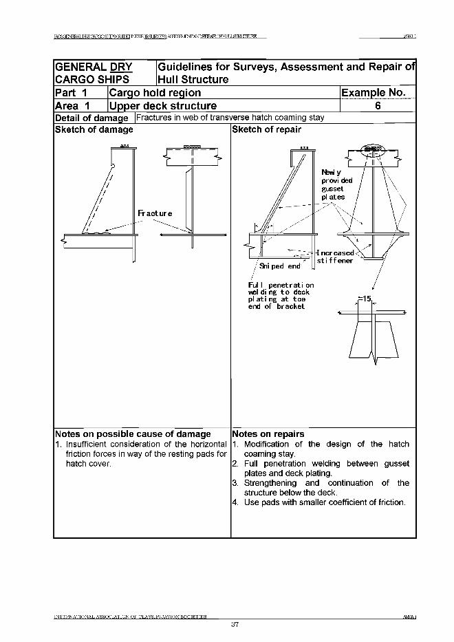
TAHSOENJERAT ,Ш УПАТ?ПОЯНТРЯГ?Г Т Е М IN E S F O R S U K V E Y S A S ^ S a V J E N T A N D R E P A IR O F H U L L S IR IX T U R E РЖГ1
GENERAL DRY CARGO SHIPS
Guidelines for Surveys, Assessm ent and Repair of Hull Structure
Part 1 Cargo hold regionArea 1 [Upper deck structure
Example No.
Detail of damage |Fractures in web of transverse hatch coaming staySketch of damage
E 3
Fracture
Sketch of repair
Ful I p e n e tra ti on wel di ng t o deck p la t in g a t to e end o f b racket
-15
Notes on possible cause of damage1. Insufficient consideration of the horizontal
friction forces in way of the resting pads for hatch cover.
Notes on repairs1. Modification of the design of the hatch
coaming stay.2. Full penetration welding between gusset
plates and deck plating.3. Strengthening and continuation of the
structure below the deck.4. Use pads with smaller coefficient of friction.
INTERNATIONAL ASSOCIATION OF CLASSIFICATION SOCIETIES_______________________________________________________________________________________________ AKEAl
37
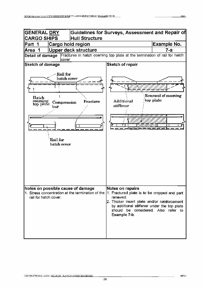
TAOROENERAT T W C A R O O S H T P R O T Т Е М IN E fiF O R R T IKVEYS. А Р Ж ^ Ш Е Ж А Ш ^ А Е О Р Н т З Т Ш Ж Д Ж PART1
GENERAL DRY CARGO SHIPS
Guidelines for Surveys, Assessm ent and Repair of Hull Structure
Part 1Area 1
Cargo ho d regionUpper deck structure
Example No. .......... 7-a........
Detail of damage Fractures in hatch coaming top plate at the termination of rail for hatch cover
Sketch of damage
R ail for hatch cover
H atchCompression Fracture bar
^ = ------------------ / ----------------- -
-> \+ I . 1 1 1 +
R ail for hatch cover
Sketch of repair
i. V,►....... ~л___________ 2" T
Renew al o f coam ing A dditional t°P platestiffener
1 1У//Ш//////ШШ////////////////А
, / 'T T П — 1 J _____L +-------------- у ж т ж ш » . т „а --------------
Notes on possible cause of damage1. Stress concentration at the termination of the
rail for hatch cover.
Notes on repairs1. Fractured plate is to be cropped and part
renewed.2. Thicker insert plate and/or reinforcement
by additional stiffener under the top plate should be considered. Also refer to Example 7-b.
INTERNATIONAL ASSOCIATION OF CLASSIFICATION SOCIETIES_______________________________________________________________________________________________ AKEA1
38
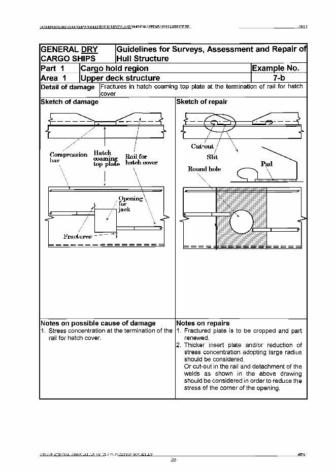
TArSOFNFKAT .nRYCARmSHTPROT НТЖГ INESKHSUKVFNS A ff^ F M ^ A lS D I^ A IR C F H L ^ PARTI
GENERAL DRY CARGO SHIPS
iGuidelines for Surveys, Assessm ent and Repair of Hull Structure
Part 1 Cargo hold region Example No.Area 1 [Upper deck structure 7-bDetail of damage Fractures in hatch coaming top plate at the termination of rail for hatch
coverSketch of damage
£
£
A}
Compression Hatch t> -i f Ьяг coam ingtop plate hatch cover
Cut-out j S lit
Pad
Notes on possible cause of damage1. Stress concentration at the termination of the
rail for hatch cover.
Notes on repairs1. Fractured plate is to be cropped and part
renewed.2. Thicker insert plate and/or reduction of
stress concentration adopting large radius should be considered.Or cut-out in the rail and detachment of the welds as shown in the above drawing should be considered in order to reduce the stress of the corner of the opening.
INTERNATIONAL ASSOCIATION OF CLASSIFICATION SOCIETIES_______________________________________________________________________________________________ AREAl
39
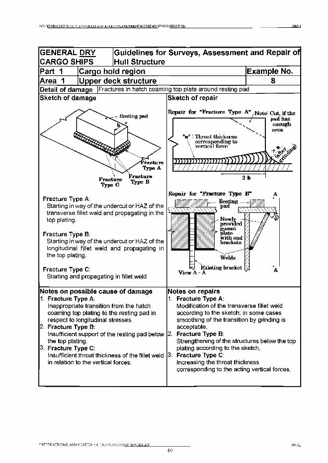
IACSCENERAT,ШУПАТ?ГЮ SHIPS G L F ^ NTERTORST TFA/FYR A fiq ^M F W A N D R E P A IR n ^ ТГ J .ЧШиСТШЕ PARTI
GENERAL DRY Guidelines for Surveys, Assessm ent and RepairCARGO SHIPS Hull StructurePart 1 Cargo ho d region Example No.Area 1 Upper deck structure 8
Of
Detail of damage Sketch of damage
Fractures in hatch coaming top plate around resting pad Sketch of repair
Repair for "Fracture Type A" Not& Cut,if the
^ /
//
/ pad has enough area
' "a " ■ Throat thickness 4 n v \ corresponding to < \ vertical force k
V'N
____
ш ш ш м т ш Ш Ш Л / Д Мч т и т , 777777777 77777О к
Fracture Type A:Starting in way of the undercut or HAZ of the transverse fillet weld and propagating in the top plating.
Fracture Type B:Starting in way of the undercut or HAZ of the longitudinal fillet weld and propagating in the top plating.
Repair for "Fracture Type B'Resting
pad k \ 4 \ ^ \ \ \ \ V ,Newly providedgusset Plate
Ш withwith end brackets
Welds
Fracture Type C:Starting and propagating in fillet weld
View A - AExisting bracket
Notes on possible cause of damage1. Fracture Type A:
Inappropriate transition from the hatch coaming top plating to the resting pad in respect to longitudinal stresses.
2. Fracture Type B:Insufficient support of the resting pad below 2. the top plating.
3. Fracture Type C:Insufficient throat thickness of the fillet weld 3. in relation to the vertical forces.
Notes on repairs 1. Fracture Type A:
Modification of the transverse fillet weld according to the sketch; in some cases smoothing of the transition by grinding is acceptable.Fracture Type B:Strengthening of the structures below the top plating according to the sketch.Fracture Type C:Increasing the throat thickness corresponding to the acting vertical forces.
INTERNATIONAL ASSOCIATION OF CLASSIFICATION SOCIETIES_______________________________________________________________________________________________ AREA1
40
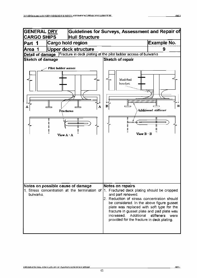
TAfSOFNFRAT TIRYCAROOSHIPRCff ТЮИINFSFnRfl IRVEYS ASa^^FWANDEEPATROPHT IJ Ш Ш 1 В Е PARTI
GENERAL DRY CARGO SHIPS
iGuidelines for Surveys, Assessm ent and Repair of Hull Structure
Part 1 Cargo hold region Example No.Area 1 |Upper deck structureDetail of damage |Fracture in deck plating at the pilot ladder access of bulwarksSketch of damage
Pilot ladder access
в
X
гFractures
_L
V
View A - A
Sketch of repair
View В - В
Notes on possible cause of damage1. Stress concentration at the termination of
bulwarks.
Notes on repairs1. Fractured deck plating should be cropped
and part renewed.2. Reduction of stress concentration should
be considered. In the above figure gusset plate was replaced with soft type for the fracture in gusset plate and pad plate was increased. Additional stiffeners were provided for the fracture in deck plating.
INTERNATIONAL ASSOCIATION OF CLASSIFICATION SOCIETIES
41
1АС5<ИЕКУСАЕт£ИР5аШЕГМТОЯГ]НУАЯаШЕЖАЬЮТЖРАТК01;ЬтаХТШНК PARTI
Area 2 Side structure
Contents
1 General
2 What to look for - Internal inspection2.1 Material wastage2.2 Deformations2.3 Fractures
3 What to look for - External inspection3.1 Material wastage3.2 Deformations3.3 Fractures
4 General comments on repair4.1 Material wastage4.2 Deformations4.3 Fractures
Figures and/or Photographs - Area 2No. Title
Figure 1 Potential problem areasPhotograph 1 Leakage from side shell plating due to heavy corrosionPhotograph 2 Timber carrier carriers listing due to ingress of water
Examples of structural detail failures and repairs - Area 2Example No. Title
1 Fracture in side shell frame at lower bracket2 Fractures in side shell frame/lower bracket and side shell plating near tank
top3 Adverse effect of corrosion on the frame of forward/afterward hold4 Fractures at the supporting brackets in way of collision bulkhead7 (with no
side shell panting stringers fitted in hold)5 Fractures in way of continuation/extension brackets in aftermost hold at
the engine room bulkhead6 Fracture in way of continuation/extension brackets at the end of deep
cargo tank
INTERNATIONAL ASSOCIATION OFCLASSIFICATTONSOCIETIES AREA 2
42
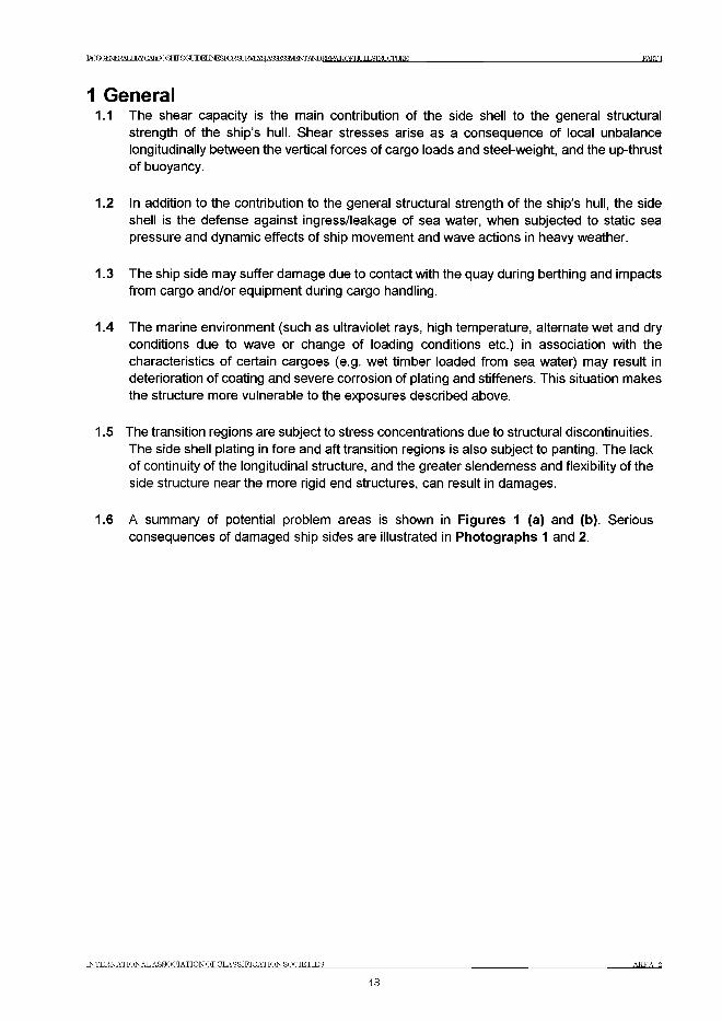
IACSGFNFKAT ТКУСАЯГЮЙНТРЯСЯ ТЮИ INFSFnRfT TRVTCYS АРйгеШЕЖАЬЮБЕРАТРСРНТ IT J ЯШРСЩ Ш PARTI
1 General1.1 The shear capacity is the main contribution of the side shell to the general structural
strength of the ship’s hull. Shear stresses arise as a consequence of local unbalance longitudinally between the vertical forces of cargo loads and steel-weight, and the up-thrust of buoyancy.
1.2 In addition to the contribution to the general structural strength of the ship’s hull, the side shell is the defense against ingress/leakage of sea water, when subjected to static sea pressure and dynamic effects of ship movement and wave actions in heavy weather.
1.3 The ship side may suffer damage due to contact with the quay during berthing and impacts from cargo and/or equipment during cargo handling.
1.4 The marine environment (such as ultraviolet rays, high temperature, alternate wet and dry conditions due to wave or change of loading conditions etc.) in association with the characteristics of certain cargoes (e.g. wet timber loaded from sea water) may result in deterioration of coating and severe corrosion of plating and stiffeners. This situation makes the structure more vulnerable to the exposures described above.
1.5 The transition regions are subject to stress concentrations due to structural discontinuities. The side shell plating in fore and aft transition regions is also subject to panting. The lack of continuity of the longitudinal structure, and the greater slenderness and flexibility of the side structure near the more rigid end structures, can result in damages.
1.6 A summary of potential problem areas is shown in Figures 1 (a) and (b). Serious consequences of damaged ship sides are illustrated in Photographs 1 and 2.
INTERNATIONAL ASSOCIATION OFCLASSIFICATIONSOCIETIES AREA 2
43
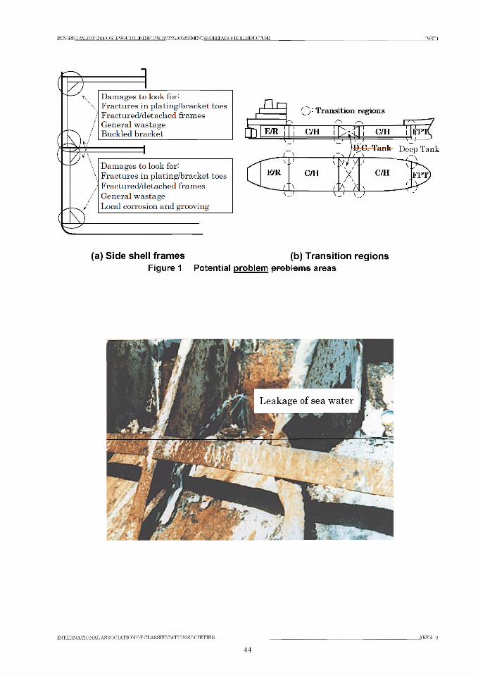
Ж Б С Е № Ж Ь Р К У CARGO ЯНТРЯ ОТ ЛРЕГ PART1
3Damages to look for- Fractures in plating/bracket toes Fract ured/det ached frames General wastage Buckled bracket
1
Damages to look for- Fractures in plating/bracket toes Fractured/detached frames General wastage Local corrosion and grooving
(a) Side shell frames (b) Transition regionsFigure 1 Potential problem problems areas
INTERNATIONAL ASSOCIATION OF CLASSIFICATION SOCIETIES AREA 2
44
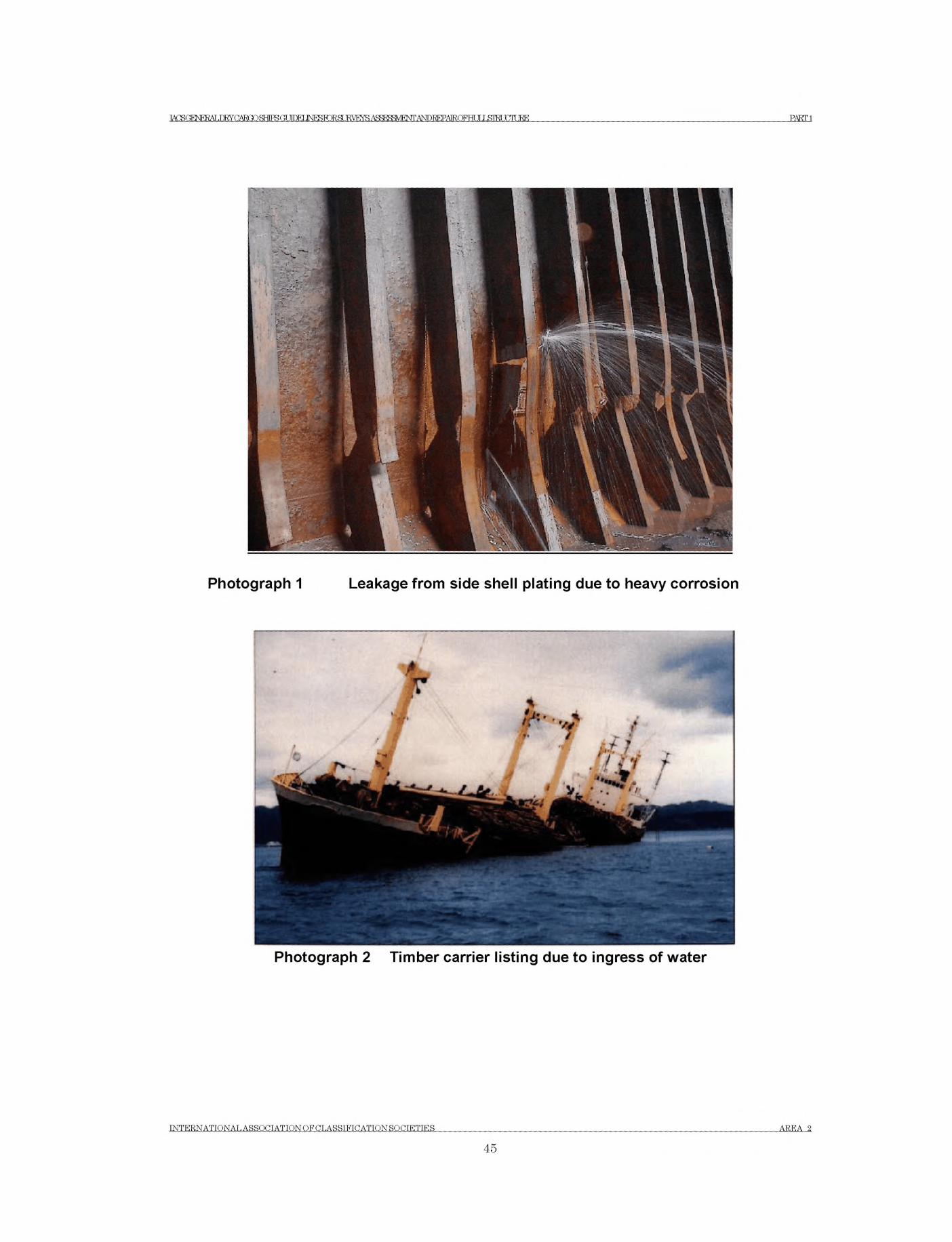
lACSGENERALmYCAROOSHTPSCT ЛПЕГ INESraSLIRVEYS А8£ШУ1Н^АШ№АМ:ЕНШЬТШ1ТЦНЕ PARTI
Photograph 1 Leakage from side shell plating due to heavy corrosion
Photograph 2 Timber carrier listing due to ingress of water
INTERNATIONAL ASSOCIATION OF CLASSIFICATION SOCIETIES AREA 2
45
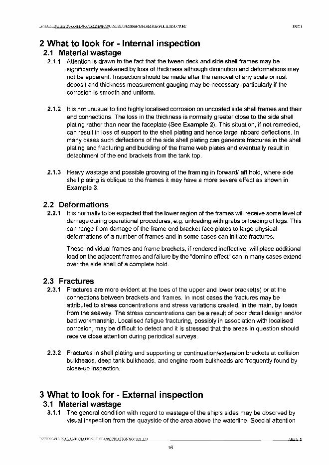
TATSOFMFK АТ ТШСЛЖГ) ЯНТРЯ (ГГ ТГПЕГ INFSTOR. ЯГ JRVRYR АЯЯгеШЕЖА^ЕЕРАТКОЕНГ IJ £ Щ О Ш Е PART1
2 What to look for - Internal inspection2.1 Material wastage
2.1.1 Attention is drawn to the fact that the tween deck and side shell frames may be significantly weakened by loss of thickness although diminution and deformations may not be apparent. Inspection should be made after the removal of any scale or rust deposit and thickness measurement gauging may be necessary, particularly if the corrosion is smooth and uniform.
2.1.2 It is not unusual to find highly localised corrosion on uncoated side shell frames and their end connections. The loss in the thickness is normally greater close to the side shell plating rather than near the faceplate (See Example 2). This situation, if not remedied, can result in loss of support to the shell plating and hence large inboard deflections. In many cases such deflections of the side shell plating can generate fractures in the shell plating and fracturing and buckling of the frame web plates and eventually result in detachment of the end brackets from the tank top.
2.1.3 Heavy wastage and possible grooving of the framing in forward/ aft hold, where side shell plating is oblique to the frames it may have a more severe effect as shown in Example 3.
2.2 Deformations2.2.1 It is normally to be expected that the lower region of the frames will receive some level of
damage during operational procedures, e.g. unloading with grabs or loading of logs. This can range from damage of the frame end bracket face plates to large physical deformations of a number of frames and in some cases can initiate fractures.
These individual frames and frame brackets, if rendered ineffective, will place additional load on the adjacent frames and failure by the “domino effect” can in many cases extend over the side shell of a complete hold.
2.3 Fractures2.3.1 Fractures are more evident at the toes of the upper and lower bracket(s) or at the
connections between brackets and frames. In most cases the fractures may be attributed to stress concentrations and stress variations created, in the main, by loads from the seaway. The stress concentrations can be a result of poor detail design and/or bad workmanship. Localised fatigue fracturing, possibly in association with localised corrosion, may be difficult to detect and it is stressed that the areas in question should receive close attention during periodical surveys.
2.3.2 Fractures in shell plating and supporting or continuation/extension brackets at collision bulkheads, deep tank bulkheads, and engine room bulkheads are frequently found by close-up inspection.
3 What to look for - External inspection3.1 Material wastage
3.1.1 The general condition with regard to wastage of the ship’s sides may be observed by visual inspection from the quayside of the area above the waterline. Special attention
INTERNATIONAL ASSOCIATION OFCLASSIFICATIONSOCIETIES AREA 2
46
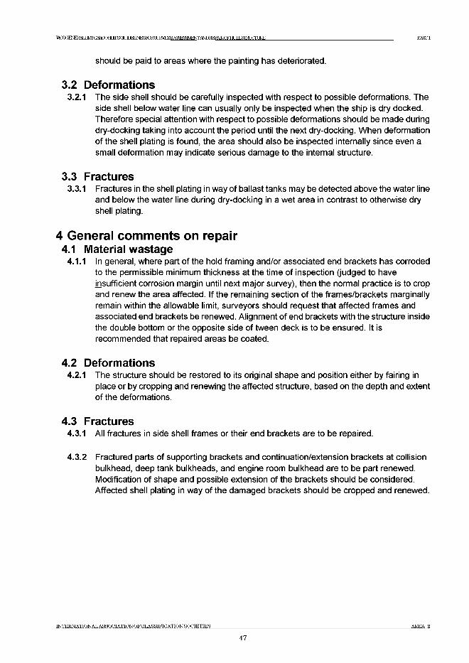
1ACSGENERAT .nRYCARQOailPSGUDELJNF^KlRar JRVEYfi A5^«HEWANDREPATRrFHr IT J ДТШ Ж ВЕ PARTI
should be paid to areas where the painting has deteriorated.
3.2 Deformations3.2.1 The side shell should be carefully inspected with respect to possible deformations. The
side shell below water line can usually only be inspected when the ship is dry docked. Therefore special attention with respect to possible deformations should be made during dry-docking taking into account the period until the next dry-docking. When deformation of the shell plating is found, the area should also be inspected internally since even a small deformation may indicate serious damage to the internal structure.
3.3 Fractures3.3.1 Fractures in the shell plating in way of ballast tanks may be detected above the water line
and below the water line during dry-docking in a wet area in contrast to otherwise dry shell plating.
4 General comments on repair4.1 Material wastage
4.1.1 In general, where part of the hold framing and/or associated end brackets has corroded to the permissible minimum thickness at the time of inspection (judged to have insufficient corrosion margin until next major survey), then the normal practice is to crop and renew the area affected. If the remaining section of the frames/brackets marginally remain within the allowable limit, surveyors should request that affected frames and associated end brackets be renewed. Alignment of end brackets with the structure inside the double bottom or the opposite side of tween deck is to be ensured. It is recommended that repaired areas be coated.
4.2 Deformations4.2.1 The structure should be restored to its original shape and position either by fairing in
place or by cropping and renewing the affected structure, based on the depth and extent of the deformations.
4.3 Fractures4.3.1 All fractures in side shell frames or their end brackets are to be repaired.
4.3.2 Fractured parts of supporting brackets and continuation/extension brackets at collision bulkhead, deep tank bulkheads, and engine room bulkhead are to be part renewed. Modification of shape and possible extension of the brackets should be considered. Affected shell plating in way of the damaged brackets should be cropped and renewed.
INTERNATIONAL ASSOCIATION OF CLASSIFICATION SOCIETIES AREA 2
47
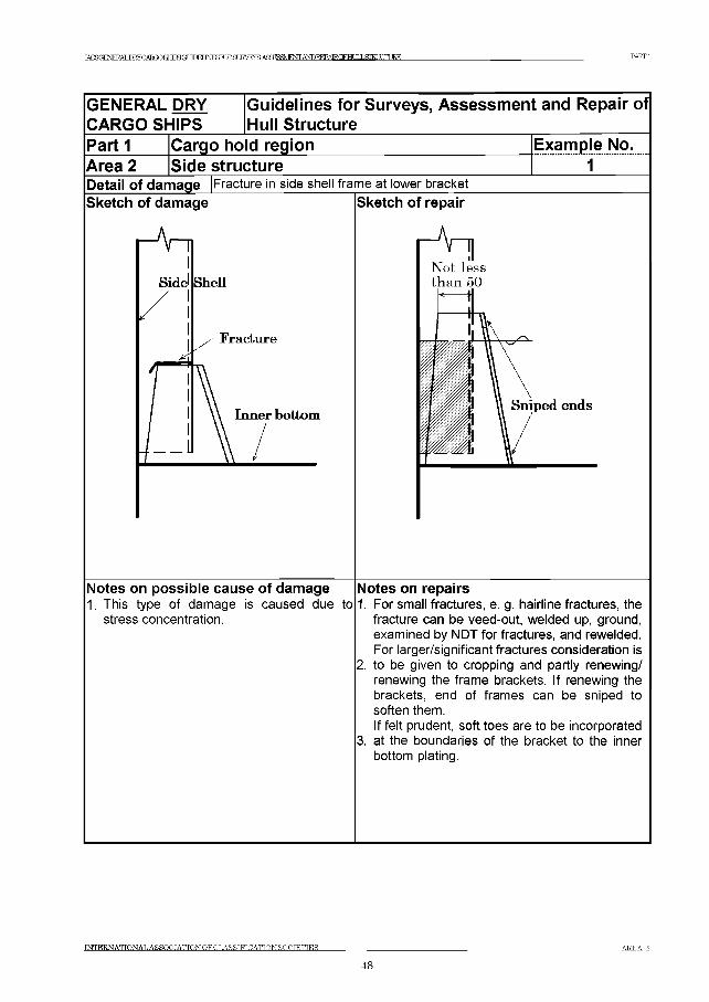
TAOROFNPRAT ,ТШСЛШР ЯНТРЯ (ГГ М М IN E S ro R S U K V F N S A 5 ^ S 3 V E O T A ^ I № ^ 0 F H U I L S I E 1 X T U R E P A R T I
GENERAL DRY Guidelines for Surveys, Assessment and Repair ofCARGO SHIPS Hull StructureP a rti Cargo ho d region Example No.Area 2 Side structure 1Detail of damage Sketch of damage
Fracture in side shell frame at lower bracket Sketch of repair
Notes on possible cause of damage1. This type of damage is caused due to
stress concentration.
Notes on repairs1. For small fractures, e. g. hairline fractures, the
fracture can be veed-out, welded up, ground, examined by NDT for fractures, and rewelded. For larger/significant fractures consideration is
2. to be given to cropping and partly renewing/ renewing the frame brackets. If renewing the brackets, end of frames can be sniped to soften them.If felt prudent, soft toes are to be incorporated
3. at the boundaries of the bracket to the inner bottom plating.
INTERNATIONAL A SS O C IA T IO N O F C LA SS IF IC A TIO N SO CIE TIES A R E A 2
48
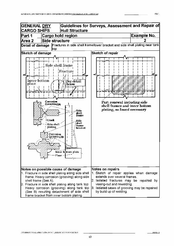
TAfSaFNFRAT .TW^ATWa^CMlEUNF^RlRFI JRVEYS ASa^MFNTANDEEPATRrFHT IT J 5ЯШЖЕЕ PARTI
GENERAL DRY CARGO SHIPS
iGuidelines for Surveys, Assessment and Repair of Hull Structure
Part 1 Cargo hold region Example No.Area 2 Side structureDetail of damage Fractures in side shell frame/lower bracket and side shell plating near tank
top___________________Sketch of damage
1—I—I—I—I—Лл I I i I гi — i— i— i— !— !— i— i— i— i-j ! _ [ _ ! Side shell frame ] ]| | | | | j jFracture ] 1
. . -I— U-A— 1— LI I IInner bottom plate
Inner bottom plate rloor
Sketch of repair1—I—I—I—Лл
Part renewal including side shell frames and inner bottom plating, as found necessary
Notes on possible cause of damage1. Fracture in side shell plating along side shell
frame: Heavy corrosion (grooving) along side shell frame (See A).
2. Fracture in side shell plating along tank top: Heavy corrosion (grooving) along tank top (See B) resulting detachment of side shell frame bracket from inner bottom plating.
Notes on repairs1. Sketch of repair applies when damage
extends over several frames.2. Isolated fractures may be repaired by
veeing-out and rewelding.3. Isolated cases of grooving may be repaired
by build up of welding.
INTERNATIONAL ASSOCIATION OF CLASSIFICATIONSOCIETIES AREA 2
49
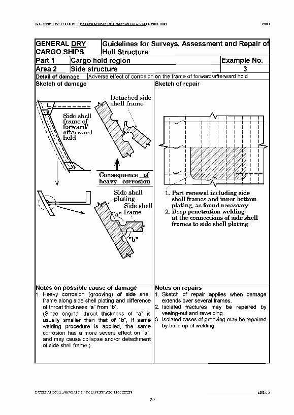
]КЖЯШ<ШЖСШЮтЖЯт¥1ШВКЖЯ IRVEYS AfiFTSFMFhTr andt?fpatrcfhliuisieixttjbe PARTI
GENERAL DRY Guidelines for Surveys, Assessment and Repair of CARGO SHIPS Ih u II Structure____________________ _____________P arti Cargo hold region Example No.Area 2 Side structure 3Detail of damage Sketch of damage
|Adverse effect of corrosion on the frame of forward/afterward hoicT Sketch of repair
D etach ed side
Notes on possible cause of damage1. Heavy corrosion (grooving) of side shell
frame along side shell plating and difference of throat thickness “a” from “b”.(Since original throat thickness of “a” is usually smaller than that of “b”, if same welding procedure is applied, the same corrosion has a more severe effect on “a”, and may cause collapse and/or detachment of side shell frame.)
1. Part renew al including side shell fram es and inner bottom plating, as found necessary
2 . Deep penetration w eldingat th e connections o f side sh ell fram es to side sh ell plating
Notes on repairs1. Sketch of repair applies when damage
extends over several frames.2. Isolated fractures may be repaired by
veeing-out and rewelding.3. Isolated cases of grooving may be repaired
by build up of welding.
INTERNATIONAL ASSOCIATION OFCLASSIFICATIONSOCIETIES AREA 2
60
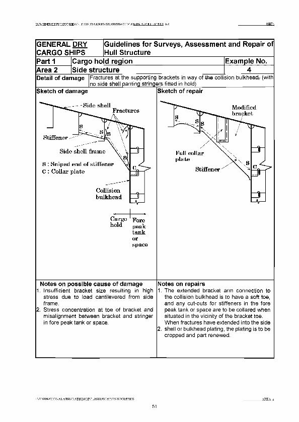
TAfKCFNFRAT I W C A F O O S H T P S q I M № S R T R . 3 Ш У Я А Я Й Р У Ш Е О Т А Ш 1 ^ А 1 Е 0 Е Н и 1 Ь 8 Ш 1 Х Т и К ^ PARTI
GENERAL DRY CARGO SHIPS
Guidelines for Surveys, Assessment and Repair of Hull Structure
P a rti Cargo ho d region Example No.Area 2 Side structure 4Detail of damage Fractures at the supporting brackets in way of the collision bulkhead7 (with
no side shell panting stringers fitted in hold)Sketch of damage
tankorspace
Notes on possible cause of damage1. Insufficient bracket size resulting in high
stress due to load cantilevered from side frame.
2. Stress concentration at toe of bracket and misalignment between bracket and stringer in fore peak tank or space.
Sketch of repair
Notes on repairs1. The extended bracket arm connection to
the collision bulkhead is to have a soft toe, and any cut-outs for stiffeners in the fore peak tank or space are to be collared when situated in the vicinity of the bracket toe. When fractures have extended into the side
2. shell or bulkhead plating, the plating is to be cropped and part renewed.
INTERNATIONAL ASSOCIATION OFCLASSIFICATIONSOCIETIES A R E A 2
51
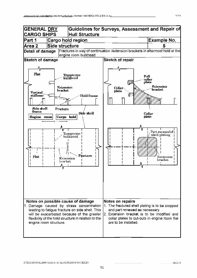
TAOROFNPRAT .TTRYCARGOSHIPRCff М М I N E S r o R S U R V E Y S A S ^ S a V J F ^ A ^ R E P A I R O F H t X L S m ГЛ Т JRE P A R T I
GENERAL DRY CARGO SHIPS
Guidelines for Surveys, Assessm ent and Repair of Hull Structure
Part 1 Cargo ho d region Example No.Area 2 Side structure 5Detail of damage Fractures in way of continuation /extension brackets in aftermost hold at the
engine room bulkheadSketch of damage
Notes on possible cause of damage1. Damage caused by stress concentration
leading to fatigue fracture on side shell. This will be exacerbated because of the greater flexibility of the hold structure in relation to the engine room structure.
Sketch of repair
Notes on repairs1. The fractured shell plating is to be cropped
and part renewed as necessary.2. Extension bracket is to be modified and
collar plates to cut-outs in engine room flat are to be installed.
INTERNATIONAL ASSOCIATION OFCLASSIFICATIONSOCIETIES AREA 2
52
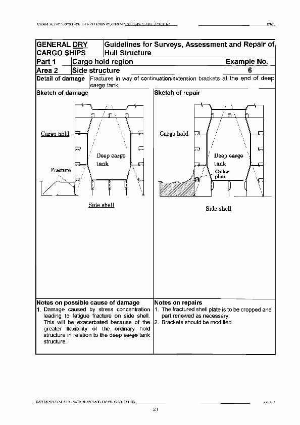
TACROENERAT .ШУГ:АТ?ПОЯНТРЯСа ТГПЕГ J^ ro R S m V E y S A S ^ W F ^ ^ D R E P A E Q F H L IL & T R L I^ T U R E PARTI
GENERAL DRY CARGO SHIPS
Guidelines for Surveys, Assessment and Repair of Hull Structure
Part 1Area 2
Cargo ho d regionSide structure
Example No. 6
Detail of damage Fractures in way of continuation/extension brackets at the end o f deep cargo tank__________
Sketch of damage
Cargo hold
1 i / л \ :°i
Side shell
Sketch of repair
Cargo hold
Side shell
Notes on possible cause of damage1. Damage caused by stress concentration
leading to fatigue fracture on side shell. This will be exacerbated because of the greater flexibility of the ordinary hold structure in relation to the deep cargo tank structure.
Notes on repairs1. The fractured shell plate is to be cropped and
part renewed as necessary.2. Brackets should be modified.
INTERNATIONAL ASSOCIATION OF CLASSIFICATION SOCIETIES AREA 2
53
TAreOFNFKAT .nRYCARmSHTPRa ТЮИ № !Ю ?.Я IRVRYS Afl3TC3VlEOTANDIMATROEHr JT J Я1ЖХЖ1КЕ PARTI
Area 3 Transverse bulkhead structure
Contents
1 General
2 What to look for2.1 Material wastage2.2 Deformations2.3 Fractures
3 General comments on repair3.1 Material wastage3.2 Deformations3.3 Fractures
Figures and/or Photographs - Area 3No. Title
Figure 1 Transverse bulkhead - Potential problems problem areas
Examples o f structura l detail fa ilures and repairs - Area 3Example No. Title
1 Corrosion along inner bottom or tween deck plating2 Shear buckling in transverse bulkhead
INTERNATIONAL ASSOCIATION OF CLASSIFICATION SOCIETIES AREA Я
54
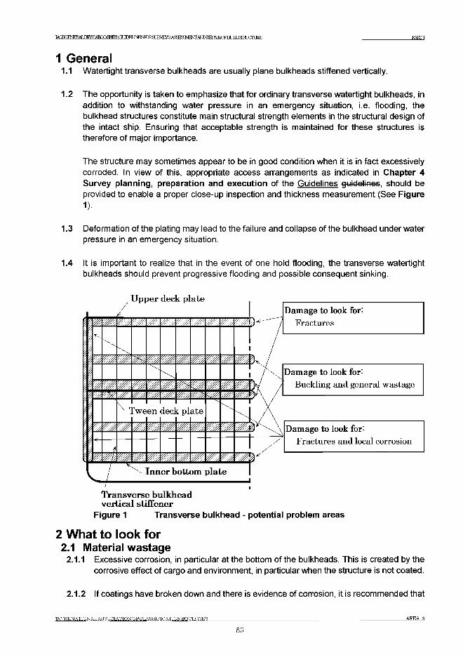
IACS<^E^ERYCARmgMPSrODFI INFUKlRfl IRVRYS АдЗГСЗИЕЖАкГОЕЕРАТЕПЕНГ ТГ J Я Щ Ж Е Е P A R T I
1 General1.1 Watertight transverse bulkheads are usually plane bulkheads stiffened vertically.
1.2 The opportunity is taken to emphasize that for ordinary transverse watertight bulkheads, in addition to withstanding water pressure in an emergency situation, i.e. flooding, the bulkhead structures constitute main structural strength elements in the structural design of the intact ship. Ensuring that acceptable strength is maintained for these structures is therefore of major importance.
The structure may sometimes appear to be in good condition when it is in fact excessively corroded. In view of this, appropriate access arrangements as indicated in Chapter 4 Survey planning, preparation and execution of the Guidelines guidelines, should be provided to enable a proper close-up inspection and thickness measurement (See Figure1).
1.3 Deformation of the plating may lead to the failure and collapse of the bulkhead under water pressure in an emergency situation.
1.4 It is important to realize that in the event of one hold flooding, the transverse watertight bulkheads should prevent progressive flooding and possible consequent sinking.
U pper deck plate
Ш,mШ W//AW/AУ///ЛШW/лWMINII Ш,m.Шm Шу/,yZvy/#///у/шI 1
шгЩШ ШW,m,У/Ж- - m■
m,w/л ■
Ш'/ж%
\r I'ween dec]t piate
Ш m * Ш./ж.wmV',w\Щl i Шmm mmmШ
Damage to look for:Fractures
Damage to look for:Buckling and general wastage
Damage to look for:Fractures and local corrosion
Inner bottom p la te
Transverse bulkhead vertica l stiffener
Figure 1 Transverse bulkhead - potential problem areas
2 What to look for2.1 Material wastage
2.1.1 Excessive corrosion, in particular at the bottom of the bulkheads. This is created by the corrosive effect of cargo and environment, in particular when the structure is not coated.
2.1.2 If coatings have broken down and there is evidence of corrosion, it is recommended that
INTERNATIONAL ASSOCIATION OFCLASSIFICATIONSOCIETIES AREA 3
55
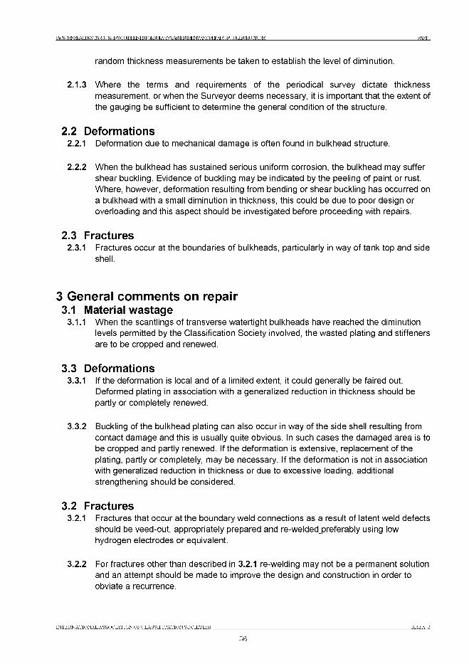
IACSGENERALDRY CARGO SHTPR ОТ ШЕГ I^ roR S U E ^ E ^ A S ^ S a V E O T A ^ I^ A E O F H U IL S IR L U rL IR E P A R T I
random thickness measurements be taken to establish the level of diminution.
2.1.3 Where the terms and requirements of the periodical survey dictate thickness measurement, or when the Surveyor deems necessary, it is important that the extent of the gauging be sufficient to determine the general condition of the structure.
2.2 Deformations2.2.1 Deformation due to mechanical damage is often found in bulkhead structure.
2.2.2 When the bulkhead has sustained serious uniform corrosion, the bulkhead may suffer shear buckling. Evidence of buckling may be indicated by the peeling of paint or rust. Where, however, deformation resulting from bending or shear buckling has occurred on a bulkhead with a small diminution in thickness, this could be due to poor design or overloading and this aspect should be investigated before proceeding with repairs.
2.3 Fractures2.3.1 Fractures occur at the boundaries of bulkheads, particularly in way of tank top and side
shell.
3 General comments on repair3.1 Material wastage
3.1.1 When the scantlings of transverse watertight bulkheads have reached the diminution levels permitted by the Classification Society involved, the wasted plating and stiffeners are to be cropped and renewed.
3.3 Deformations3.3.1 If the deformation is local and of a limited extent, it could generally be faired out.
Deformed plating in association with a generalized reduction in thickness should be partly or completely renewed.
3.3.2 Buckling of the bulkhead plating can also occur in way of the side shell resulting from contact damage and this is usually quite obvious. In such cases the damaged area is to be cropped and partly renewed. If the deformation is extensive, replacement of the plating, partly or completely, may be necessary. If the deformation is not in association with generalized reduction in thickness or due to excessive loading, additional strengthening should be considered.
3.2 Fractures3.2.1 Fractures that occur at the boundary weld connections as a result of latent weld defects
should be veed-out, appropriately prepared and re-welded_preferably using low hydrogen electrodes or equivalent.
3.2.2 For fractures other than described in 3.2.1 re-welding may not be a permanent solution and an attempt should be made to improve the design and construction in order to obviate a recurrence.
IN T E R N A T IO N A L A S S O C IA T IO N O F C L A S S IF IC A T IO N S O C IE T IE S A R E A 3
56
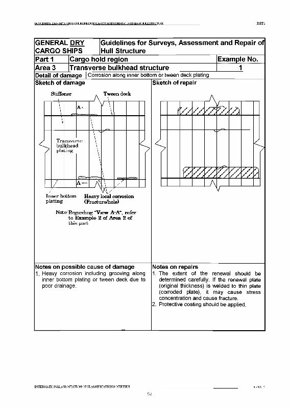
IACSQEERALIЖCAЮOfflSGUЮEЦNEБKEgJWF!Y PARTI
GENERAL DRY CARGO SHIPS
(Guidelines for Surveys, Assessment and Repair of Hull Structure
Part 1 Cargo hold region Example No.АгеаЗ Transverse bulkhead structure 1Detail of damage | Corrosion along inner bottom or tween deck platingSketch of damage
Stiffener Tween deck
\\ VTrabulpla
m sve]khea<t in g
™se1
\<
/ LzInner bottom Heavy local corrosion plating (Fraeture/hole)
Notfr Regarding "View ЛЛ", refer to Example 2 o f Area 2 of this part
Sketch of repair
(ZZ7ZZ22ZZZXA
A
/
Notes on possible cause of damage1. Heavy corrosion including grooving along
inner bottom plating or tween deck due to poor drainage.
Notes on repairs1. The extent of the renewal should be
determined carefully. If the renewal plate (original thickness) is welded to thin plate (corroded plate), it may cause stress concentration and cause fracture.
2. Protective coating should be applied.
T N T FR N A T T O N A T . A S S O C IA T IO N O F O I .A S S IF IO A T IO N S O O T F T T F S
57
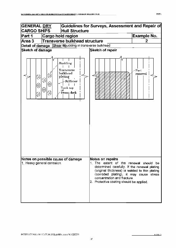
IACSQEERALIЖCAЮOШIFSQUDE]LJNESRЖgJWF!Y /*т£М№ПШЕВШтШШВ321№ PARTI
GENERAL DRY CARGO SHIPS
iGuidelines for Surveys, Assessment and Repair of Hull Structure
Area 3Part 1 Cargo hold region
Transverse bulkhead structureExample No.
2Detail of damage |Shear Bbuckling in transverse bulkheadSketch of damage
V
@
A
i— гB u ck lin g
I I T r a n sv e rs e b u lk h e a d p la t in g
S t iffe n e r I I
T a n k to po r
/ tw e e n d e ck
Sketch of repair
Notes on possible cause of damage1. Heavy general corrosion.
Notes on repairs1. The extent of the renewal should be
determined carefully. If the renewal plating (original thickness) is welded to thin plating (corroded plating), it may cause stress concentration and fracture.
2. Protective coating should be applied.
INTERNA TION A L ASSOCIA TIO N O FC LA SSIFIC A T IO N SO C IE T IE S AREA 3
58

IACSGENERALDRY CARGO SHTPR ОТ ШЕГ I^roRSUE^E^AS^SaVEOTA^I^AEOFHUILSIRLUrLIRE PARTI
Area 4 Tw een deck structure
Contents
1 General
2 What to look for
2.1 Material wastage
2.2 Deformations
2.3 Fractures
3 General comments on repair
3.1 Material wastage
3.2 Deformations
3.3 Fractures
Examples of structural detail failures and repairs - Area 4Example No. Title
1 Sagging of deck panel/buckling of cantilever beam
IN T E R N A T IO N A L A SS O C IA T IO N O F C L A SS IFIC A T IO N SO C IE T IE S A R E A 4
59
IACSGENERAT .Ш У СА тО К Н ГРЯ а ТЮИINFSFnRfl IRVEYS АЯЖ ^МЕЖ АЬШ ^ДТКОРНГ JT J Я1Ж 1Ж ДЖ PARTI
1 General1.1 A main design principle of the tween deck is to provide easy access to cargo stowed on and
underneath the deck. Therefore obstructions such as hatch coamings and deep under deck supporting girders, are usually avoided. The tween deck’s main structure consists of cantilever beams supported only by the ship’s side structure and cantilever girders supported only by the transverse bulkhead structure (cantilever girders). In some cases the structure may be additionally supported by pillars.
1.2 The design of the tween deck makes it particularly vulnerable to excess loads of cargo and cargo inertia forces in extreme weather conditions.
2 What to look for2.1 Material wastage
2.1.1 Heavy wastage along the boundaries at ship’s sides and at transverse bulkheads may occur as a result of seawater accumulated from wet cargo due to poor drainage. Such damages are related to those suffered at the lower end of side structures and transverse bulkhead structures (See Area 2, Example 2 and Area 3, Example 1).
2.2 Deformations2.2.1 Deformed structure may be observed near hatch openings where cargo and/ or hatch
cover pontoons may have bumped into the structure during lift on or lift off operations.
2.2.2 Sagging of plate panels may be caused by lateral overloading as a consequence of excessive cargo loads, improper distribution /support of cargo loads, excessive inertia forces imposed by the cargo in extreme weather conditions, or a combination of these causes. It is essential that an under-deck inspection also be carried out to assess the extent of such damage (See Example 1). If the tween deck is supported by pillars, excessive loads could be transmitted to the double bottom structure (inner bottom plating, floors, girders) which could be damaged. Therefore inspection of double bottom tanks may be necessary (See Area 5, Example 2).
2.3 Fractures2.3.1 Fatigue fractures are not a common problem on tween decks due to the generally low
level of dynamic forces. Fractures may, however, occur in combination with corrosion and deformations described above.
3 General comments on repair3.1 Material wastage
3.1.1 Where parts of the tween deck plating have corroded to the permissible minimum thickness the normal practice is to crop and renew the area affected. Surveyors should request that adjacent areas that remain marginally within the allowable limit should also be renewed. It is recommended that repaired areas be coated.
3.2 Deformations3.2.1 For deformations caused by abusive handling or obvious overloading, the damaged
INTERNATIONALASSOCIATION OF CLASSIFICATION SOCIETIES AREA 4
60
IACSGENERALDRY CARGO SHTPR (ГГ ШЕГ I^ roR S U E ^ E ^ A S ^ S a V E O T A ^ I^ A E O F H U IL S IR L U rL IR E PARTI
structure should be cropped and renewed to original scantlings.
3.2.2 If the cause of the deformations is not clear and design weakness is suspected, an appropriate reinforcement is to be considered in addition to cropping and renewal of the damaged part.
3.3 Fractures3.3.1 The proposed repair for corrosion and deformations described above also apply when
associated fractures occur.
IN T E R N A T IO N A L A S S O C IA T IO N O F C L A S S IF IC A T IO N S O C IE T IE S A R E A 4
61
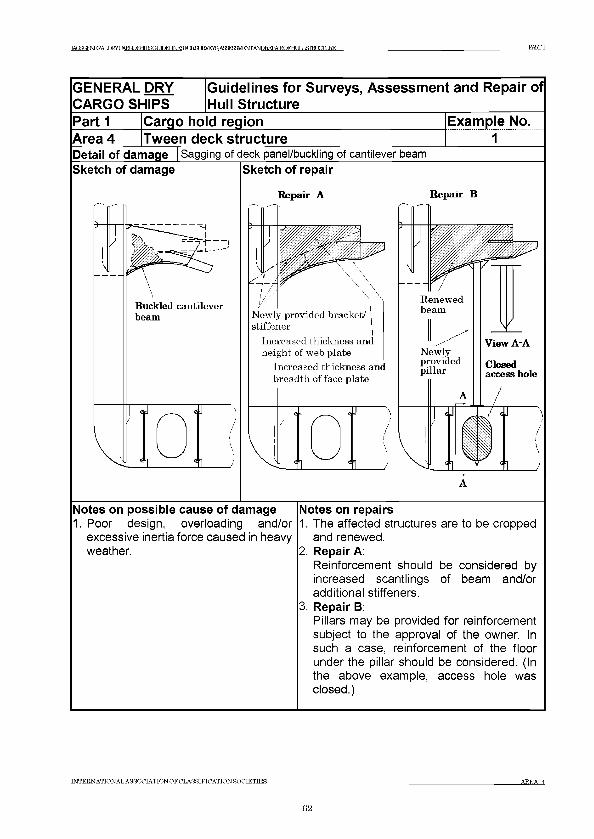
IACSGFMFFAT .TWnARGOaJPSGUnn INFKEnRfl- TRVEYR Af^i^MFWAMDEEPAIRriFHT ТГ J Я Л ТО Ш Е PARTI
GENERAL DRY Guidelines for Surveys, Assessment and Repair ofCARGO SHIPS Hull StructurePart 1 Cargo ho d region Example No.Area 4 Tween deck structure 1Detail of damage Sketch of damage
Sagging of deck panel/buckling of cantilever beam Sketch of repair
Repair A Repair В
Notes on possible cause of damage1. Poor design, overloading and/or
excessive inertia force caused in heavy weather.
Notes on repairs1. The affected structures are to be cropped
and renewed.2. Repair A:
Reinforcement should be considered by increased scantlings of beam and/or additional stiffeners.
3. Repair B:Pillars may be provided for reinforcement subject to the approval of the owner. In such a case, reinforcement of the floor under the pillar should be considered. (In the above example, access hole was closed.)
INTERNATTONAL ASSOCIATION OFCLASSIFICATION SOCIETIES AREA 4
62

IACS( NERALDRYCARGOSHTPS( ТГПКГ МГСГОР.ЯГ IRVE^ASSRSH ENTANDREPAIR.OFHI Я J .STRUCTURE PARTI
Area 5 Double bottom structure
Contents
1 General
2 What to look for - Tank top inspection
2.1 Material wastage
2.2 Deformations
2.3 Fractures
3 What to look for - Double bottom tank inspection
3.1 Material wastage
3.2 Deformations
3.3 Fractures
4 What to look for - External bottom inspection
4.1 Material wastage
4.2 Deformations
4.3 Fractures
5 General comments on repair
5.1 Material wastage
5.2 Deformations
5.3 Fractures
Figures and/or Photographs - Area 5No. Title
Photograph 1corrosion affectina inner bottom Dlatina
Photograph 2olatina
Photograph 3bottom olatina
Photoaraoh 4 Groovina corrosion of weldina of bottom DlatinaPhotoaraoh 5 Section of the aroovina shown in Photoaraoh 4
Examples of structural detail failures and repairs - Area 5Example No. Title
1 Fractures in inner bottom plating around container bottom pocket2 Dented inner bottom plating and buckled/fractured floor under pillar3-a Fractures at the connection of bottom/inner bottom longitudinal to floor
stiffener3-b Fractures at the connection of bottom/inner bottom longitudinal to floor
stiffener4 Fractures and buckling in way of a cut-out for the passage of a longitudinal
T N T ER N A T IO N A L A SS O C IA T IO N O FC L A S SIF IC A T IO N SO C IE T IE S
63A REA В
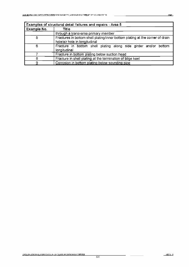
IACS(NEEDRYGAEODSHIPS(j[ EUbroRSLIEEYSASSaVEOTA№I?EPAIROFHLI]XS]ElXTLEE PARTI
Examples of structural detail failures and repairs - Area 5Example No. Title
through a transverse primary member5 Fractures in bottom shell plating/inner bottom plating at the corner of drain
hole/air hole in longitudinal6 Fracture in bottom shell plating along side girder and/or bottom
longitudinal7 Fracture in bottom plating below suction head8 Fracture in shell plating at the termination of bilge keel9 Corrosion in bottom plating below sounding oioe
INTERNATIONALASSOCIATIONOFCLASSTFTCATIONSOCIETIES64
AREA 5

JAGSGENERALDRYCAEQDSTTTPSGl JIDEI INFlSTOR.Sf FM^AS^^/E^AbDI^AROFELILL&TEOSTLlRE PARTI
1 General1.1 Double bottom structure is subjected to longitudinal hull girder bending, caused by cargo
distribution and wave action. It is also subjected to longitudinal and transverse local bending due to the effects of cargo load from the inside in association with the counteracting forces from the outside. The double bottom structure is also subjected to the effects of cargo loading and unloading. The double bottom structure forward may also be subjected to increased dynamic forces due to slamming.
2 What to look for - Tank top inspection2.1 Material wastage
2.1.1 The general condition with regard to corrosion of the tank top structure may be observed by visual inspection. The level of wastage of tank top plating may have to be established by means of thickness measurement. Special attention should be given to the intersection of the tank top with the side shell and transverse bulkheads where water may have accumulated and consequently accelerated the rate of corrosion.
2.1.2 When the tank top plating has been covered with dunnage or ceiling the plating may have suffered heavy corrosion, due to high humidity, and lack of proper maintenance (See Photograph 1).
2.1.3 The bilge wells should be cleaned and inspected closely since heavy pitting corrosion may have occurred due to accumulated water in the wells. Special attention should be paid to the plating in way of the bilge suction and sounding pipes.
2.1.4 Special attention should also be paid to areas where pipes penetrate the tank top.
Photograph 1Fractured inner bottom plating due to heavy corrosion on both s ides
INTERNATIONAL ASSOCIATION OFCLASSIFICATION SOCIETIES65
AREA 5
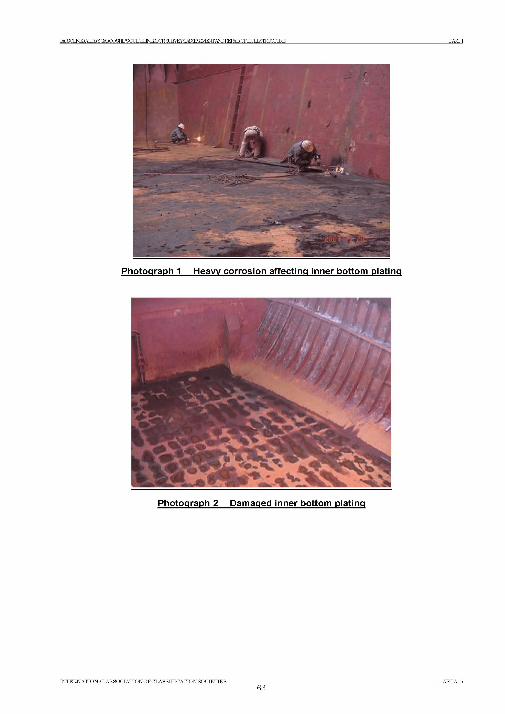
LS<IiH4MlDKYCABX>SHIPS<IiLTOEUMroRSL!RYEYASS!MjI4n'AKEPARCFHLTIX&TRLUrLIKE PARTI
INTERNATIONAL AS SOCIATIONOFCLASSIFICATION SOCIETIES66
AREA

IA C S G E N E R A L D K Y C A R G O S H T P S ОТ T irM IN E S F O R S t I R V E ^ A S ^ S ^ E O T A ^ I M m O F H L l L S I K b T U R E PARTI
Photograph 3 Repairs of damaged inner bottom plating
2.2 Deformations2.2.1 Buckling of the tank top plating may occur between longitudinals in areas subject to
in-plane transverse compressive stresses or between floors in areas subject to in-plane longitudinal compressive stresses.
2.2.2 Deformed structures may be observed in areas of the tank top due to overloading of cargo, impact of cargo during loading/unloading operations, or the use of mechanical unloading equipment.
2.2.3 Deformations may also occur at the heel of pillars fitted to support the tween deck structure (See Example 2).
2.2.4 Whenever deformations are observed on the tank top, further inspection in the double bottom tanks is imperative in order to determine the extent of the damage. The deformation may cause the breakdown of coating, if fitted, within the double bottom, which in turn may lead to accelerated corrosion rate in these unprotected areas.
2.3 Fractures2.3.1 Fractures will normally be found by close-up inspection paying particular attention to the
boundary connections of the tank top and to penetrations through the tank top (See Example 1).
2.3.2 Fractures that extend through the thickness of the plating or through the boundary welds may be observed during pressure testing of the double bottom tanks.
INTERNATIONAL ASSOCIATION OFCLASSIFICATION SOCIETIES_________________67
IACSGENE^ALERYCARQOSHIPSa ЛПКГ INESFCRSLKVEYS АЯЯ^МЕЖАЬЮ1И^ТКОРНГ IJ STRUCTURE______________________________________________________________________PARTI
3 What to look for - Double bottom tank inspection3.1 Material wastage
3.1.1 The level of wastage of double bottom internal structure (longitudinals, frames, floors, girders, etc.) may have to be established by means of thickness measurements. The combined effects of the marine environment, the carriage of seawater ballast, cyclical loading etc. may result in high corrosion rates.
3.1.2 If the protective coating is not properly maintained, structure in the ballast tank may suffer heavy corrosion. Upper part of the structure of double bottom tanks usually has more severe corrosion than the lower part.
3.1.3 Corrosion in the structure of ballast tanks near heated fuel tanks may be accelerated by the high temperature due to heated fuel oil. The rate of corrosion depends on several factors such as:- Temperature and heat input to the ballast tank.- Condition of original coating and its maintenance. (It is preferable for applying the
protective coating of ballast tank at the building of the ship, and for subsequent maintenance, that the stiffeners on the boundaries of the fuel tank be fitted within the fuel tank instead of the ballast tank).
- Ballasting frequency and operations.- Age of ship and associated stress levels as corrosion reduces the thickness of the
structural elements and can result in fracturing and buckling.
3.1.4 Shell plating localized wear is caused by erosion and cavitation of the fluid flowing through the suction head. In addition, the suction head will be positioned in the lowest part of the tank and water/mud will cover the area even when the tank is empty. The condition of the shell plating may be established by feeling by hand beneath the suction head. When in doubt, the lower part of the suction head should be removed and thickness measurements taken. If the vessel is docked, the thickness can be measured from below. If the distance between the suction head and the underlying shell plating is too small to permit access, the suction head should be dismantled. The shell plating below the sounding pipe should also be carefully examined. When a striking plate has not been fitted or is worn out, heavy corrosion can be caused by the striking of the weight of the sounding tape (See Example 2 in Part 3).
3.2 Deformations3.2.1 Deformations may occur due to the overloading of the cargo, dynamic forces due to
slamming in the forward part of the vessel, or from the impact of cargo loading/unloading. Special attention should be paid to those areas of deformation identified during the tank top or external bottom inspections. Deformations in the structure not only reduce the strength of the structure but may also cause breakdown of the coating, leading to accelerated corrosion.
3.3.2 In general, the termination of the longitudinal structural members at the collision bulkhead and engine room forward bulkhead is prone to fractures. In order to avoid stress concentration due to discontinuity appropriate stiffeners are to be provided in the opposite space. If such stiffeners are not provided, or are deficient due to corrosion or misalignment, fractures may occur at the terminations.
INTERNATIONALASSOCIATIONOFCLASSIFICATION SOCIETIES AREA 568
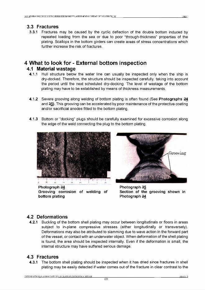
IACSGENERALDRY CARGQSHTPS ОТ ЛТЖГ М Щ Щ ВДЕЖА£Ж83У1ЕЖАШ1МЖОЕНт81ШЖДЖ PART 1
3.3 Fractures3.3.1 Fractures may be caused by the cyclic deflection of the double bottom induced by
repeated loading from the sea or due to poor “through-thickness” properties of the plating. Scallops in the bottom girders can create areas of stress concentrations which further increase the risk of fractures.
4 What to look for - External bottom inspection4.1 Material wastage
4.1.1 Hull structure below the water line can usually be inspected only when the ship is dry-docked. Therefore, the structure should be inspected carefully, taking into account the period until the next scheduled dry-docking. The level of wastage of the bottom plating may have to be established by means of thickness measurements.
4.1.2 Severe grooving along welding of bottom plating is often found (See Photographs 24 and 35). This grooving can be accelerated by poor maintenance of the protective coating and/or sacrificial anodes fitted to the bottom plating.
4.1.3 Bottom or “docking” plugs should be carefully examined for excessive corrosion along the edge of the weld connecting the plug to the bottom plating.
Photograph 24Grooving corrosion of welding of bottom plating
Photograph 35Section of the grooving shown in Photograph 24
4.2 Deformations4.2.1 Buckling of the bottom shell plating may occur between longitudinals or floors in areas
subject to in-plane compressive stresses (either longitudinally or transversely). Deformations may also be attributed to slamming due to wave action in the forward part of the vessel, or contact with an underwater object. When deformation of the shell plating is found, the area should be inspected internally. Even if the deformation is small, the internal structure may have suffered serious damage.
4.3 Fractures4.3.1 The bottom shell plating should be inspected when it has dried since fractures in shell
plating may be easily detected if water comes out of the fracture in clear contrast to the
INTERN ATIONAL AS SOCIATION OF C LASSIFIC ATION SOCIETIE S69
AREA 5
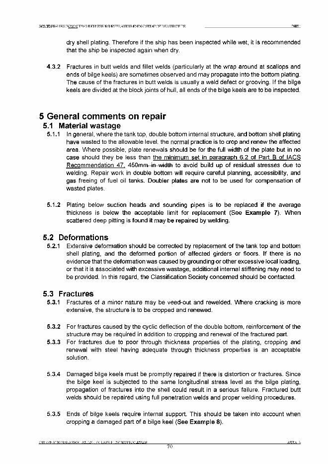
IAOSOENER АЬРЕУСАТУПЯНТРЯЯГ!ЮЕТ Ш И В Я JRVEYS ASaSgVEOTAW BEPAEOFHmSIHiailiE PART 1
dry shell plating. Therefore if the ship has been inspected while wet, it is recommended that the ship be inspected again when dry.
4.3.2 Fractures in butt welds and fillet welds (particularly at the wrap around at scallops and ends of bilge keels) are sometimes observed and may propagate into the bottom plating. The cause of the fractures in butt welds is usually a weld defect or grooving. If the bilge keels are divided at the block joints of hull, all ends of the bilge keels are to be inspected.
5 General comments on repair5.1 Material wastage
5.1.1 In general, where the tank top, double bottom internal structure, and bottom shell plating have wasted to the allowable level, the normal practice is to crop and renew the affected area. Where possible, plate renewals should be for the full width of the plate but in no case should they be less than the minimum set in paragraph 6.2 of Part В of IACS Recommendation 47, 450mm in width to avoid build up of residual stresses due to welding. Repair work in double bottom will require careful planning, accessibility, and gas freeing of fuel oil tanks. Doubler plates are not to be used for compensation of wasted plates.
5.1.2 Plating below suction heads and sounding pipes is to be replaced if the average thickness is below the acceptable limit for replacement (See Example 7). When scattered deep pitting is found it may be repaired by welding.
5.2 Deformations5.2.1 Extensive deformation should be corrected by replacement of the tank top and bottom
shell plating, and the deformed portion of affected girders or floors. If there is no evidence that the deformation was caused by grounding or other excessive local loading, or that it is associated with excessive wastage, additional internal stiffening may need to be provided. In this regard, the Classification Society concerned should be contacted.
5.3 Fractures5.3.1 Fractures of a minor nature may be veed-out and rewelded. Where cracking is more
extensive, the structure is to be cropped and renewed.
5.3.2 For fractures caused by the cyclic deflection of the double bottom, reinforcement of the structure may be required in addition to cropping and renewal of the fractured part.
5.3.3 For fractures due to poor through thickness properties of the plating, cropping and renewal with steel having adequate through thickness properties is an acceptable solution.
5.3.4 Damaged bilge keels must be promptly repaired if there is distortion or fractures. Since the bilge keel is subjected to the same longitudinal stress level as the bilge plating, propagation of fractures into the shell could result in a serious failure. Fractured butt welds should be repaired using full penetration welds and proper welding procedures.
5.3.5 Ends of bilge keels require internal support. This should be taken into account when cropping a damaged part of a bilge keel (See Example 8).
IN T E R N A T IO N A L A S SOOT ATTON O F C L A S S IF IC ATTON S O C IE T IE S70
A R E A В
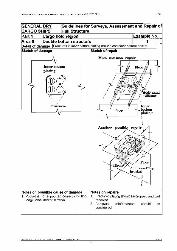
I^ S G E N E I^E R Y C A R m S E ilP S G U D E U I^K m S U R V F ^S ASa^aHEWANDRERATR.rFHT IT J Я ТШ СТШ Е PARTI
GENERAL DRY CARGO SHIPS
iGuidelines for Surveys, Assessment and Repair of Hull Structure
Part 1 Cargo hold region Example No.Area 5 Double bottom structure 1Detail of damage |Fractures in inner bottom plating around container bottom pocket Sketch of damage |Sketch of repair
Most common repair
Notes on possible cause of damage1. Pocket is not supported correctly by floor,
longitudinal and/or stiffener.
Notes on repairs1. Fractured plating should be cropped and part
renewed.2. Adequate reinforcement should be
considered.
INTERNATIONAL AS SOCIATIONOFCT.ASSIFICATION SOCIETIES71
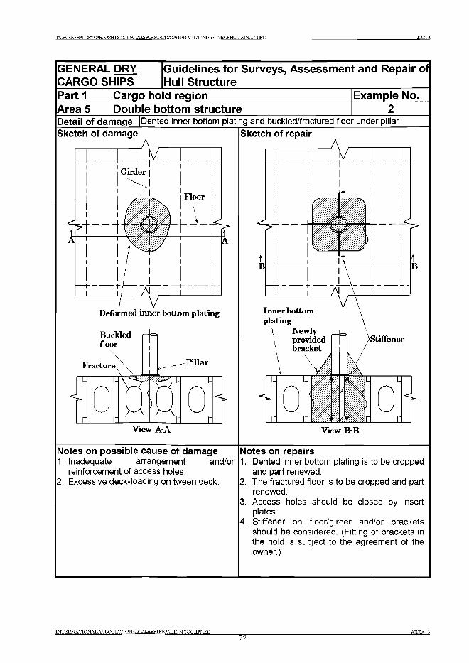
^^(^NEEALIHyCARQOSHTPSa MMINESTORSTIRVRYS. А5Ж?ШЕОТА^1^АТКОРНт81Ж1Ж1КЕ PART 1
GENERAL DRY CARGO SHIPS
Guidelines for Surveys, Assessm ent and Repair of Hull Structure
Part 1 Cargo hold region Example No.Area 5 Double bottom structureDetail of damage Sketch of damage
Dented inner bottom plating and buckled/fractured floor under pillar Sketch of repair
Notes on possible cause of damage1. Inadequate arrangement and/or
reinforcement of access holes.2. Excessive deck-loading on tween deck.
View B-B
Notes on repairs1. Dented inner bottom plating is to be cropped
and part renewed.2. The fractured floor is to be cropped and part
renewed.3. Access holes should be closed by insert
plates.4. Stiffener on floor/girder and/or brackets
should be considered. (Fitting of brackets in the hold is subject to the agreement of the owner.)
INTERNATIONAL AS SOOT ATIONOFCLASSIFICATTONSOOTETTER_________________72
A R E A В
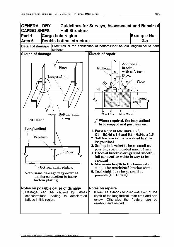
TAOSCFNERAT . Ш У С Ж Ю Я Н Т Р Я О Г Ш Е Г № Й Ю Р Я т Е Ж № Е 8 3 > / т Г Ш )Ш Ш а {Ц З Ш £ 1 Ш Ш т PARTI
GENERAL DRY Guidelines for Surveys, Assessment and Repair ofCARGO SHIPS Hull StructureP a rti Cargo ho d region Example No.Area 5 Double bottom structure 3-aDetail of damage Fractures at the connection of bottom/inner bottom longitudinal to floor
stiffenerSketch of damage Sketch of repair
Floor
Longitudinal
v v
Stiffener
Bottom shell plating
j f- W here required, the longitudinal to be cropped and part renewed
Longitudinal
N otc: sam e dam age m ay occur at sim ilar connection to inner bottom plating
Notes on possible cause of damage1. Damage can be caused by stress
concentrations leading to accelerated fatigue in this region.
1. For a slope at toes m ax. 1= 3,R1 = (b l-h ) x 1 .6 and R2 = (b2_h) x 1.6
2. Soft toe bracket to be welded first to longitudinal
3. Scallop in bracket to be as sm all as possible, recom m ended m ax. 35 mm
4. I f toes o f brackets are ground smooth, full penetration welds in way to be provided
5. M aximum length to thickness ratio = 50 = 1 for unstiffened bracket edge
6. Toe height, h, to be as sm all as possible (10 - 15 mm)
Notes on repairs1. If fracture extends to over one third of the
depth of the longitudinal, then crop and part renew. Otherwise the fracture can be veed-out and welded.
INTERNATTONALASSOCIATIONOFCLASSIFICATTONSOCIETIES73
AREA 5
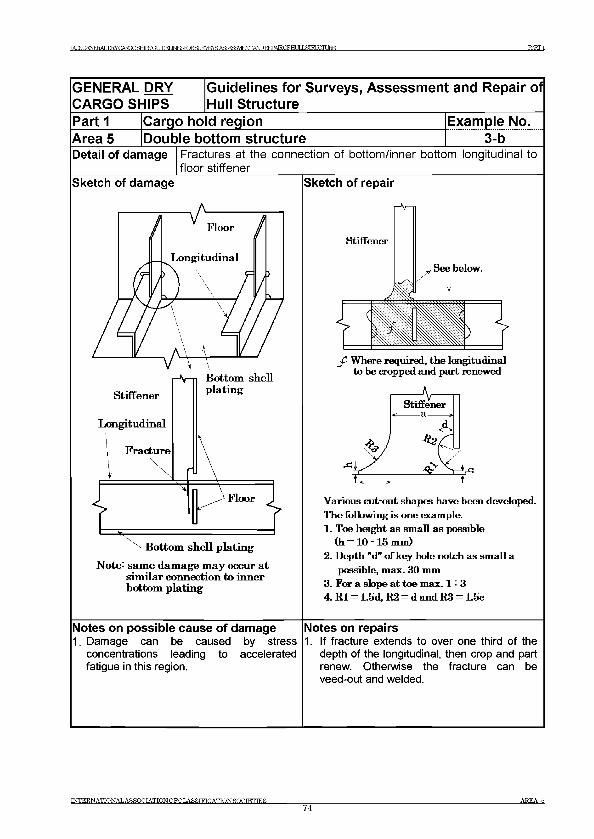
TACSOFNFRAT .nRYCARCOSHTPSCt Л П Е Г Ib^roRSUE^EYSAS^SSVEOTA^EEPAIR0FH[J]X3iraXTUF?E PARTI
GENERAL DRY Guidelines for Surveys, Assessment and Repair ofCARGO SHIPS Hull StructureP a rti Cargo ho d region Example No.Area 5 Double bottom structure 3-bDetail of damage Fractures at the connection of bo ttom /inner bottom longitudinal to
floo r stiffenerSketch of damage Sketch of repair
N ote: sam e dam age m ay occur at sim ilar connection to inner bottom plating
Notes on possible cause of damage1. Damage can be caused by stress
concentrations leading to accelerated fatigue in this region.
Various cut out, shapes have been developed. The following is one example.1. Toe height as sm all as possible
(h = 10 - 15 mm)2. Depth "d" of key hole notch as sm all a
possible, max. 30 mm3. For a slope at toe max. 1 : 34. R l = 1.5d, E2 = d and R3 = 1.5c
Notes on repairs1. If fracture extends to over one third of the
depth of the longitudinal, then crop and part renew. Otherwise the fracture can be veed-out and welded.
INTERNATIONALASSOCIATIONOFCLASSTFTCATIONSOCIETIES74
AREA 5
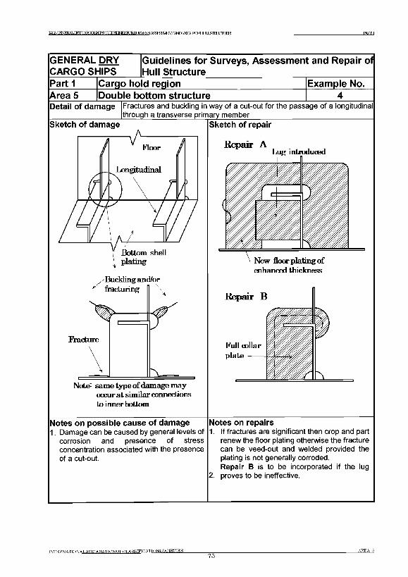
IACS( IERALJIgGAE03SEfflSGUPEUNF13R~)RSr TRVEYS А Я а ^ Ш Е Ж А Ы Р Е Е Р А Т К О Р Н Г JT J Д Т Ш Ж В Е PARTI
GENERAL DRY CARGO SHIPS
iGuidelines for Surveys, Assessment and Repair of Hull Structure
P artiArea 5
Cargo hold region Example No. 4|le bottom structure___________________ ______ 4______
Fractures and buckling in way of a cut-out for the passage of a longitudinal through a transverse primary member ____________________
CI/A^U / \ f ■
Detail of damage
Sketch of damage
occur at similar connections to inner bottom
Sketch of repair
Notes on possible cause of damage1. Damage can be caused by general levels of
corrosion and presence of stress concentration associated with the presence of a cut-out.
Notes on repairs1. If fractures are significant then crop and part
renew the floor plating otherwise the fracture can be veed-out and welded provided the plating is not generally corroded.Repair В is to be incorporated if the lug
2. proves to be ineffective.
INTERNATIONAL ASSOCIATIONOFCLASSTFICATION SOCIETIES75
a r e a 6
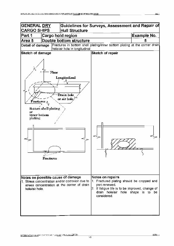
IACSC£NEEALDRYCAR(X)SHIPSGLin"M INF£FORR[ IRVFYR A^^ /lRNTTANDREFAIRrFHr ТГ T .STRUCTURE PARTI
GENERAL DRY CARGO SHIPS
jGuidelines for Surveys, Assessment and Repair of Hull Structure
Part 1 Cargo hold region ExampleNo.Area 5 Double bottom structureDetail of damage Fractures in bottom shell plating/inner bottom plating at the corner drain
hole/air hole in longitudinalSketch of damage
Floor
Longitudinal
/ ----7------ ' \ * 7/)
Bottom shell plating orinner bottom plating
Fractures
Sketch of repair
Notes on possible cause of damage1. Stress concentration and/or corrosion due to
stress concentration at the corner of drain hole/air hole.
Notes on repairs1. Fractured plating should be cropped and
part renewed.2. If fatigue life is to be improved, change of
drain hole/air hole shape is to be considered.
INTERNA TION A L AS SO C IA T IO N O FC L AFSTETCATION SO C IETIES
76a r e a б
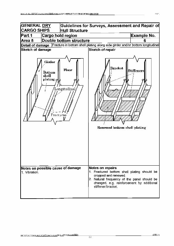
]ACSGENERALDRYGARGPSlHlIPSGODEUNESroRgURVEYSA£Hi VENTANDEEPAlRQFHLILLgIRLUrLEE PARTI
GENERAL DRY CARGO SHIPS
Guidelines for Surveys, Assessment and Repair of Hull Structure
P artiArea 5
Cargo hold regionDouble bottom structure
Example No. 6
Detail of damage |Fracture in bottom shell plating along side girder and/or bottom longitudinalSketch of damage Sketch of repair
Bracket
I
\ r ~
Stiffeners
> / f 5\_______ / ъ—l_____ / i__
Renewed bottom shell plating
Notes on possible cause of damage1. Vibration.
Notes on repairs1. Fractured bottom shell plating should be
cropped and renewed.2. Natural frequency of the panel should be
changed, e.g. reinforcement by additional stiffener/bracket.
TNTERNATTONAT.ASSOCTATTONOFnT.ARSTFTriATION SOCIETIES77
a r e a 5
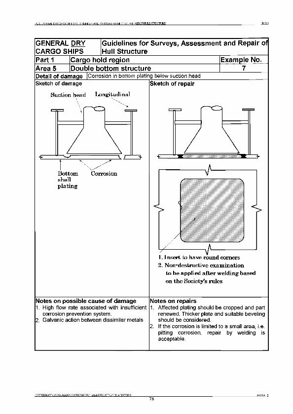
TACSOFNFRAT . Ш У С А Р П О Я Н Т Р Я О Г Л П Е Г Ib^roRS№^YSAS^SSVJFWANDT?№AIR0FH[JIL3iraXniJRE PARTI
GENERAL DRY CARGO SHIPS
Guidelines for Surveys, Assessment and Repair of Hull Structure
Area 5Part 1 Cargo ho d region
Double bottom structureExample No.............7.........
Detail of damage |Corrosion in bottom plating below suction headSketch o f damage Sketch of repair
Suction head Longitudinal
B ottom Corrosionshellplating
-E 3-
2 . N on-destructive exam inationto be applied after w elding based on th e Society’s rules
Notes on possible cause of damage1. High flow rate associated with insufficient
corrosion prevention system.2. Galvanic action between dissimilar metals
Notes on repairs1. Affected plating should be cropped and part
renewed. Thicker plate and suitable beveling should be considered.
2. If the corrosion is limited to a small area, i.e. pitting corrosion, repair by welding is acceptable.
INTERNATIONAL AS SOCIATIONOFCLASSIFICATION SOCIETIES78
AREA 5
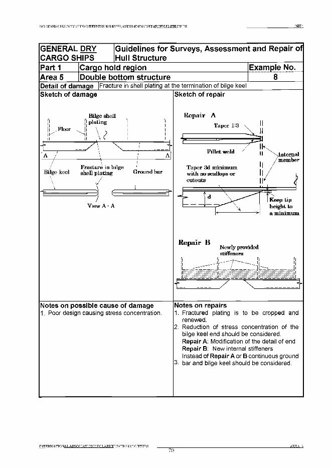
IAGSr^NERALDRYCARTXjSHTPSa m E TJ^roR SLIR VE ySAS^W FN T /W r)R E PA IRQ FH U [LSrR ir,T r JRE P-ARTl
GENERAL DRY Guidelines for Surveys, Assessm ent and Repair ofCARGO SHIPS Hull StructureP a r t i Cargo ho d region Example No.Area 5 Double bottom structure 8Detail of damage Sketch of damage
Fracture in shell plating at the termination of bilge keelSketch of repair
View A - A
Repair A
Repair ВNewly provided stiffeners
-E
Notes on possible cause of damage1. Poor design causing stress concentration.
Notes on repairs1. Fractured plating is to be cropped and
renewed.2. Reduction of stress concentration of the
bilge keel end should be considered. Repair A: Modification of the detail of end Repair B: New internal stiffeners Instead of Repair A or В continuous ground
3. bar and bilge keel should be considered.
TN TE RN ATTON AT.A SSO OTA TTON OFC T.A SSTFTC ATIO N SOC IETIE S79
A R EA В
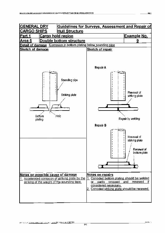
TAf5y?FNFEALE^CAB3DSHIPSGr И Л И INF RTR T 1RVFTYR A H S3VlENrAlSDBEPAlRnPHr ТГ J Э Д 1 Ж PARTI
GENERAL DRY [Guidelines for Surveys, Assessment and RepairofCARGO SHIPS iHull StructureP artiArea 5
Cargo hold regionDouble bottom structure
Detail of damage |Corrosion in bottom plating below sounding pipe
Example No.
Sketch of damage Sketch of repair
R epair A
Renewal of striking plate
Repair by welding
R epair В
Renewal of striking plate
/Renewal ofbottom plate
h k
Notes on possible cause of damage1 Accelerated corrosion of striking plate by the
Notes on repairs
striking of the weight of the sounding tape.1. Corroded bottom plating should be welded
or partly cropped and renewed if considered necessary.
Z Corroded striking plate should be renewed.
t n t e r n a tto n a la s s o c ia t io n o fo t .a h r tf ic a t io n s o c ie t ies
80AREA 5
TACSOFNFRAT .TIRYGAEODSJFSGUroELJNESRIRgUKVEYS AfiFR:t:M; ANDREPAIRCyffl I J ЯПД ГЛШЕ PART 2
Part 2 Fore and aft end regions
ContentsArea 1 - Fore end structureArea 2 - Aft end structureArea 3 - Stern frame, rudder arrangement and propeller shaft supports
A rea 1 Fore End S tructure
Contents
1 General
2 What to look for2.1 Material wastage2.2 Deformations2.3 Fractures
3 General comments on repair3.1 Material wastage3.2 Deformations3.3 Fractures
Figures and/or Photographs - Area 1No. Title
Figure 1 Fore end structure - Potential problem areas
Examples of structural detail failures and repairs - Area 1Example No. Title
1 Fracture and deformation of bow transverse web in way of cut-outs for side longitudinals
2 Fracture at toe of web frame bracket connection to stringer platform bracket3 Fracture in side shell plating in way of chain locker4 Deformation of forecastle deck5 Deformation of side shell plating in way of forecastle space6 Fracture in forecastle deck plating at bulwark
INTERNATIONAL ASSOCIATIONOFCLASSIFICATIONSOCIETIES A REA 1
81
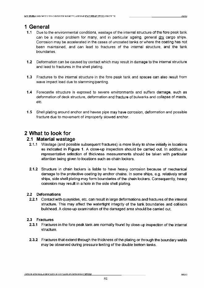
IACSGm ER AT.Tm CATm SHTFRg ТГГМ J^ ro R S L IR V E yS A S ^W F ^^D R E P A IR Q F H U [I,S TR L U rL IR E PART 2
1 General1.1 Due to the environmental conditions, wastage of the internal structure of the fore peak tank
can be a major problem for many, and in particular ageing, general dry cargo ships. Corrosion may be accelerated in the cases of uncoated tanks or where the coating has not been maintained, and can lead to fractures of the internal structure, and the tank boundaries.
1.2 Deformation can be caused by contact which may result in damage to the internal structure and lead to fractures in the shell plating.
1.3 Fractures to the internal structure in the fore peak tank and spaces can also result from wave impact load due to slamming/panting.
1.4 Forecastle structure is exposed to severe environments and suffers damage, such as deformation of deck structure, deformation and fracture of bulwarks and collapse of masts, etc.
1.5 Shell plating around anchor and hawse pipe may have corrosion, deformation and possible fracture due to movement of improperly stowed anchor.
2 What to look for2.1 Material wastage
2.1.1 Wastage (and possible subsequent fractures) is more likely to show initially in locations as indicated in Figure 1. A close-up inspection should be carried out. In addition, a representative selection of thickness measurements should be taken with particular attention being given to locations such as chain lockers.
2.1.2 Structure in chain lockers is liable to have heavy corrosion because of mechanical damage to the protective coating by anchor chains. In some ships, e.g. relatively small ships, side shell plating may form boundaries of the chain lockers. Consequently, heavy corrosion may result in a hole in the side shell plating.
2.2 Deformations2.2.1 Contact with quaysides, etc. can result in large deformations and fractures of the internal
structure. This may affect the watertight integrity of the tank boundaries and collision bulkhead. A close-up examination of the damaged area should be carried out.
2.3 Fractures2.3.1 Fractures in the fore peak tank are normally found by close-up inspection of the internal
structure.
2.3.2 Fractures that extend through the thickness of the plating or through the boundary welds may be observed during pressure testing of the double bottom tanks.
INTERNATIONAL AS SOCIATIONOFCLASSIFICATIONSOCIETIES A R E A 1
82
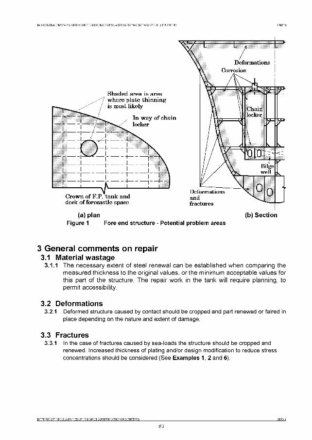
IACSGENERALDKY CARGO SETFS (Tt ШЕГ I^roR S U E ^E ^A S ^S a V E O T A ^I^A E O F H U IL S IR L U rL IR E PART 2
(a) plan (b) SectionFigure 1 Fore end structure - Potential problem areas
3 G e n e ra l c o m m e n ts on re p a ir3.1 Material wastage
3.1.1 The necessary extent of steel renewal can be established when comparing the measured thickness to the original values, or the minimum acceptable values for this part of the structure. The repair work in the tank will require planning, to permit accessibility.
3.2 Deformations3.2.1 Deformed structure caused by contact should be cropped and part renewed or faired in
place depending on the nature and extent of damage.
3.3 Fractures3.3.1 In the case of fractures caused by sea-loads the structure should be cropped and
renewed. Increased thickness of plating and/or design modification to reduce stress concentrations should be considered (See Examples 1, 2 and 6).
IN TE R N A TIO N A L A S S O C IA T IO N O F C L A SSIF IC A T IO N SO CIE TIES AREA1
83
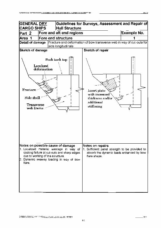
PART 2
GENERAL DRY CARGO SHIPS
Guidelines for Surveys, Assessment and Repair of Hull Structure
Part 2 Fore and aft end regions Example No.Area 1 Fore end structure 1Detail of damage Fracture and deformation of bow transverse web in way of cut-outs for
side longitudinalsSketch of damage
Fracture
Side shell
Transverse web fram e
Sketch of repair
Insert p late w ith increased thickness and/or additional stiffen ing
Notes on possible cause of damage1. Localized material wastage in way of
coating failure at cut-outs and sharp edges due to working of the structure.
2. Dynamic seaway loading in way of bow flare.
Notes on repairs1. Sufficient panel strength to be provided to
absorb the dynamic loads enhanced by bow flare shape.
INTERNATIONALASSOCIATION OFCILASSIFICATION SOCTETTER AKEA1
84
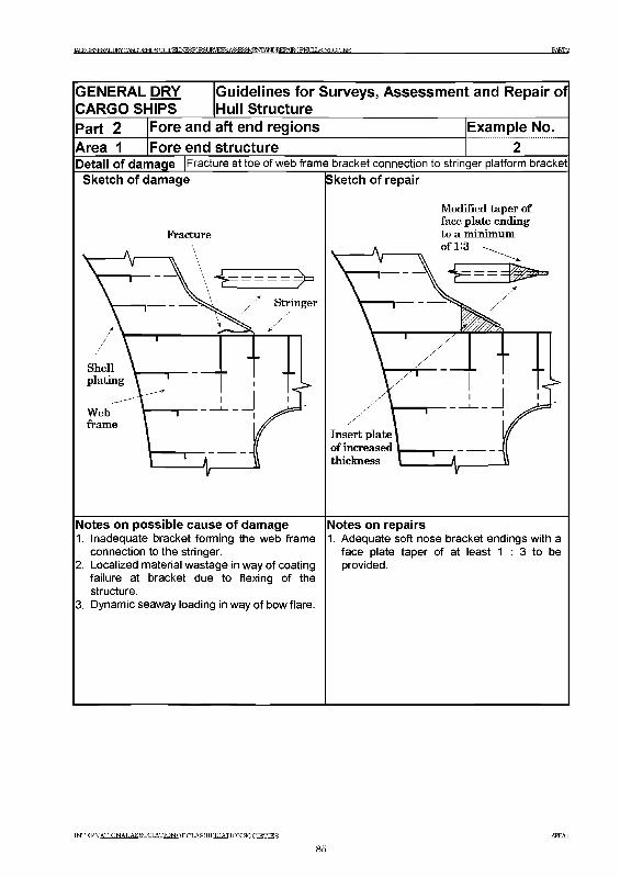
1АС8СИчМ1/ЦД0МЮШ1гаСОРШНЕБ1;СК£О!УЕУ§А£££Е£МИчЛ,АШ1СТА1КСРН1ЦЛ1Ж1Ж]КЕ РАКГ2
GENERAL DRY CARGO SHIPS
Guidelines for Surveys, Assessment and Repair of Hull Structure
Part 2 Fore and aft end regions Example No.Area 1 Fore end structureDetail of damage |Fracture at toe of web frame bracket connection to stringer platform bracket
Sketch of damage (Sketch of repair
Fracture
Webframe
Modified taper of face plate ending to a minimum of 1:3
Insert plate of increased thickness
Notes on possible cause of damage1. Inadequate bracket forming the web frame
connection to the stringer.2. Localized material wastage in way of coating
failure at bracket due to flexing of the structure.
3. Dynamic seaway loading in way of bow flare.
Notes on repairs1. Adequate soft nose bracket endings with a
face plate taper of at least 1 : 3 to be provided.
MTERNATIONALASSOCIATIONOFOT.ASSIFICATIONSOOTETTFS AKEA1
85
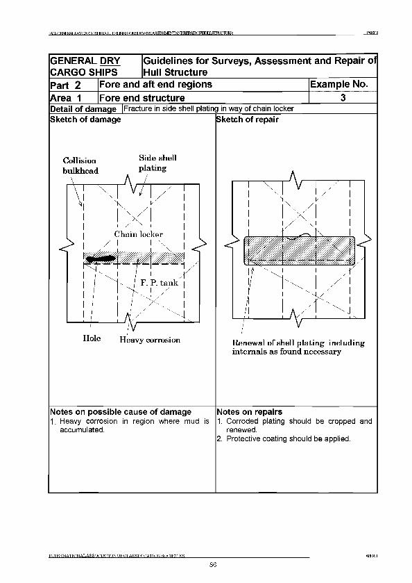
TACSOFNFRAT ,TmCARmafflSGUDEUN^KRSURVF^S AffEgMENTANDREPATROFTir JT J .STRUCTURE PART 2
GENERAL DRY CARGO SHIPS
Guidelines for Surveys, Assessment and Repair of Hull Structure
Part 2 Fore and aft end regions Example No.Area 1 Fore end structureDetail of damage |Fracture in side shell plating in way of chain lockerSketch of damage
Collisionbulkhead
Sketch of repair
Side shell plating
Renew al o f shell plating including internals as found necessary
Notes on possible cause of damage1. Heavy corrosion in region where mud is
accumulated.
Notes on repairs1. Corroded plating should be cropped and
renewed.2. Protective coating should be applied.
INTERNATTONALASSOCTATTONOFCLASSIFICATION SOCIETIES AREA1
86
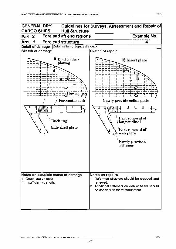
ЖS( ERALIЖCAЮOШSQUDEЦ RЖЭJ{VEта■ASЖЗgVlENГAФFEPAlRCFHLIЦlSIEIIЛlJБE PART 2
GENERAL DRY CARGO SHIPS
Guidelines for Surveys, Assessment and Repair of Hull Structure
Part 2 Fore and aft end regionsArea 1 Fore end structure
Example No. 4
Detail of damage Deformation of forecastle deckSketch of damage
§ -Dent in deck plating
2 -
Buckling
Side shell plate
Sketch of repair
•Insert plate
Newly provide collar plate
4 u 4 Т Г3
Part renewal of longitudinal
Part renewal of web plate
Newly provided stiffener
Notes on possible cause of damage1. Green sea on deck.2. Insufficient strength.
Notes on repairs1. Deformed structure should be cropped and
renewed.2. Additional stiffeners on web of beam should
be considered for reinforcement.
INTERNATIONAL ASSOCIATIONOFCT.A SSIFICATION SOCIETIES AKEA1
87
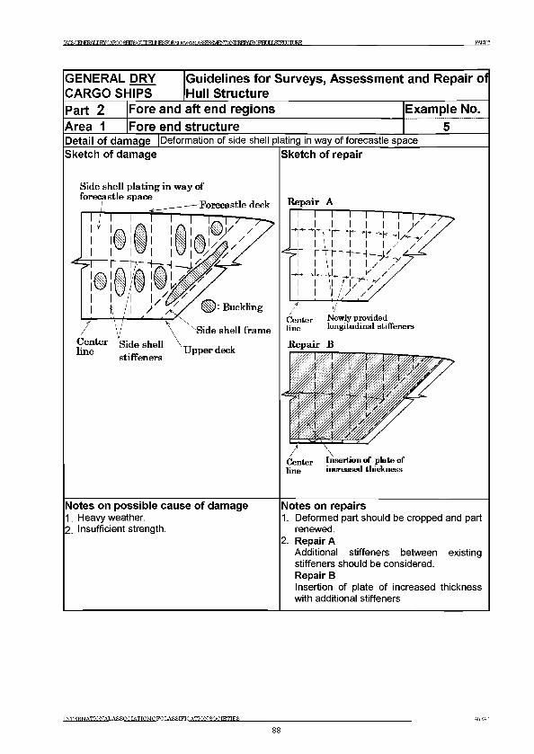
TArSOFNFKAT JOTCARnOSHTHSa ТЮИ INFSRTRHT TRVFYR АЯЯ^ШЕЖА^^АТКОРНГ JT J lELCTURE PART 2
GENERAL DRY CARGO SHIPS
Guidelines for Surveys, Assessment and Repair of Hull Structure
Part 2 Fore and aft end regions Example No.Area 1 Fore end structureDetail of damage |Deformation of side shell plating in way of forecastle space Sketch of damage Sketch of repair
Side shell plating in way of
Notes on possible cause of damage1. Heavy weather.2. Insufficient strength.
Repair A
pne longitudinal stiffeners
Repair В
line increased thickness
Notes on repairs1. Deformed part should be cropped and part
renewed.2. Repair A
Additional stiffeners between existing stiffeners should be considered.Repair ВInsertion of plate of increased thickness with additional stiffeners
INTERNATIONALASSOCIATION OFCLASSIFICATION SOCIETIES AREA!
88
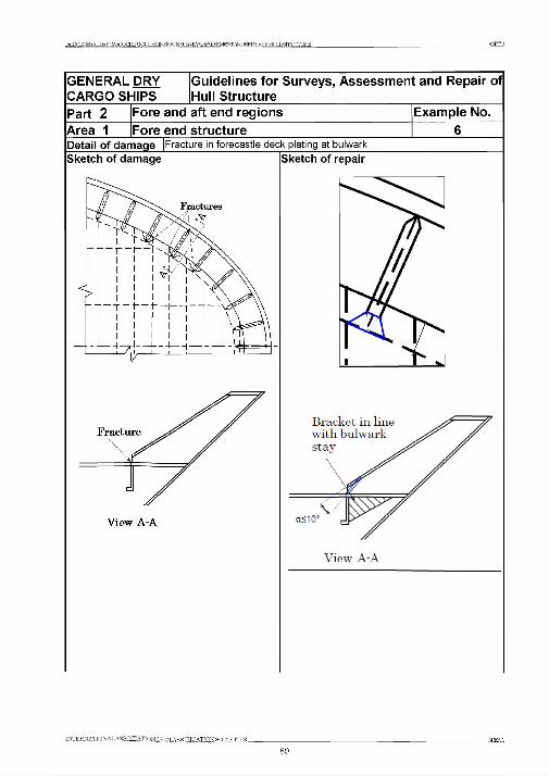
ТАГЯГЗФГОАТ .ШУСАШОЯНТЯЧПТ ИЛИ INBSRTRSi 1КУЕУЯ АЯ^ШЕЖАШМЖОРШГ1 т а ХПТ Ш PART 2
GENERAL DRY CARGO SHIPS
Guidelines for Surveys, Assessment and Repair of Hull Structure
Part 2 Fore and aft end regions Example No.Area 1 Fore end structure 6Detail of damage |Fracture in forecastle deck plating at bulwark
Sketch of damage Sketch of repair
INTERNATIONAL AS SQCIATIONOFOT.AHSTFICATIONSOOTETTES
89AREAl
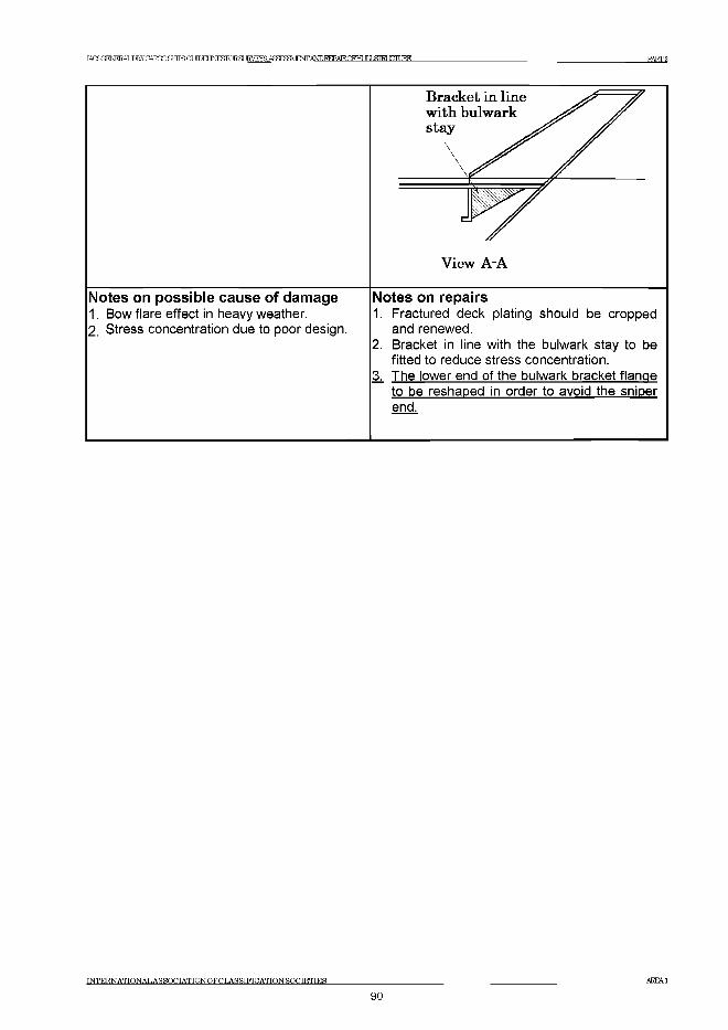
IACSGENEEALDRY CARGO SRTFS ОТ 1 Ш Ш Ю ? Я JRVEYSAS^SSVlFWA^EEPAIROFHUILSiraXTURE PART 2
Notes on possible cause of damage1. Bow flare effect in heavy weather.2. Stress concentration due to poor design.
Notes on repairs1. Fractured deck plating should be cropped
and renewed.2. Bracket in line with the bulwark stay to be
fitted to reduce stress concentration.3;. The lower end of the bulwark bracket flange
to be reshaped in order to avoid the sniper end.
INTERNATIONAL AS SOCIATIONOFCLASSIFICATIONSOCIETIES AREA1
90
IACSGENERALDKY CARGO SRTFS ОТ ШЕГ I^roRSUE^E^AS^SaVEOTA^I^AEOFHUILSIRLUrLIRE РАЕГ2
A re a 2 A ft en d s tru c tu re
Contents
1 General
2 What to look for2.1 Material wastage2.2 Deformations2.3 Fractures
3 General comments on repair3.1 Material wastage3.2 Deformations3.3 Fractures
Figures and/or Photographs - Area 2No. Title
Figure 1 Aft end structure - Potential problem areas
Examples of structural detail failures and repairs - Area 2Example No. Title
1 Fractures in longitudinal bulkhead in way of rudder trunk2 Fractures at the connection of floors and girder/side brackets3-a Fractures in flat where rudder carrier is installed in steering gear room3-b Fractures in steering gear foundation brackets and deformed deck plate3^c Stern frame, rudder arrangement and propeller shaft support
IN TE R N A TIO N A L A S S O C IA T IO N O F C L A SSIF IC A T IO N SO CIE TIES91
AREA2
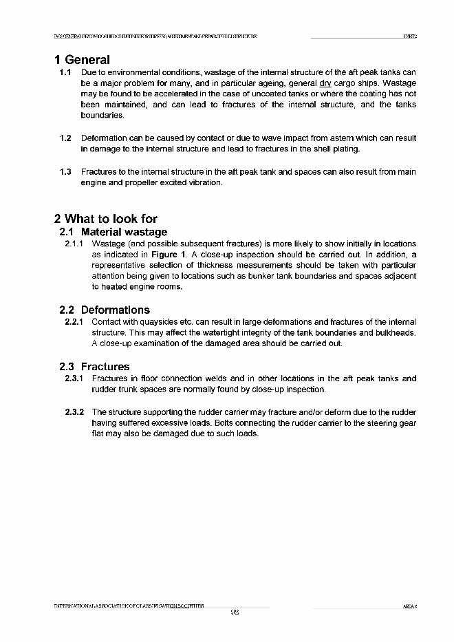
IACSGENERAI ,TWCARm^MR3GUDEUNESKRSURVF^S АдягеШЕЖАЬЮКЕРАТКОРНГ JT J glMJCTURE PART2
1 General1.1 Due to environmental conditions, wastage of the internal structure of the aft peak tanks can
be a major problem for many, and in particular ageing, general dry cargo ships. Wastage may be found to be accelerated in the case of uncoated tanks or where the coating has not been maintained, and can lead to fractures of the internal structure, and the tanks boundaries.
1.2 Deformation can be caused by contact or due to wave impact from astern which can result in damage to the internal structure and lead to fractures in the shell plating.
1.3 Fractures to the internal structure in the aft peak tank and spaces can also result from main engine and propeller excited vibration.
2 What to look for2.1 Material wastage
2.1.1 Wastage (and possible subsequent fractures) is more likely to show initially in locations as indicated in Figure 1. A close-up inspection should be carried out. In addition, a representative selection of thickness measurements should be taken with particular attention being given to locations such as bunker tank boundaries and spaces adjacent to heated engine rooms.
2.2 Deformations2.2.1 Contact with quaysides etc. can result in large deformations and fractures of the internal
structure. This may affect the watertight integrity of the tank boundaries and bulkheads. A close-up examination of the damaged area should be carried out.
2.3 Fractures2.3.1 Fractures in floor connection welds and in other locations in the aft peak tanks and
rudder trunk spaces are normally found by close-up inspection.
2.3.2 The structure supporting the rudder carrier may fracture and/or deform due to the rudder having suffered excessive loads. Bolts connecting the rudder carrier to the steering gear flat may also be damaged due to such loads.
INTERNATIONAL AS SOCIATIONOFCLASSIFICATTON SOCIETIES92
AREA 2
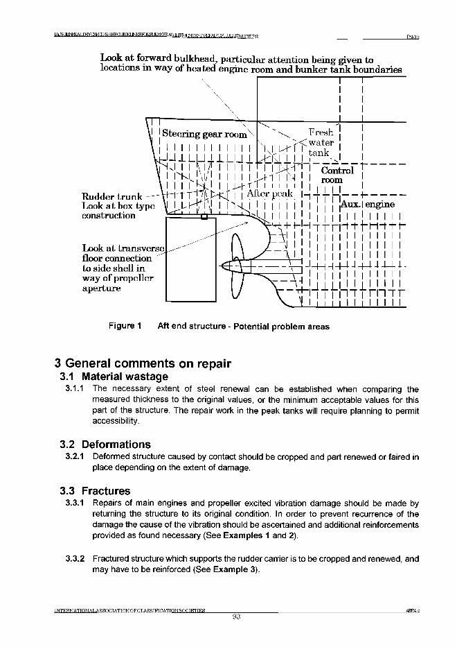
I A C S Q E ^ № A L J Д g G A E O Э S f f lS G U Ю l^ I N F lЯ Ю R a Ж V E Y S A Я Ч F ^ / IB W A ^ Г О R E P A I R O F 'R Г I T .c m q ПГГ IRE PART2
Look at forward bulkhead, particular attention being given to locations in way of heated engine room and bunker tank boundaries
Rudder trunk Look at box type construction
Look at transverse floor connection to side shell in way of propeller aperture
Figure 1 Aft end structure - Potential problem areas
3 General comments on repair3.1 Material wastage
3.1.1 The necessary extent of steel renewal can be established when comparing the measured thickness to the original values, or the minimum acceptable values for this part of the structure. The repair work in the peak tanks will require planning to permit accessibility.
3.2 Deformations3.2.1 Deformed structure caused by contact should be cropped and part renewed or faired in
place depending on the extent of damage.
3.3 Fractures3.3.1 Repairs of main engines and propeller excited vibration damage should be made by
returning the structure to its original condition. In order to prevent recurrence of the damage the cause of the vibration should be ascertained and additional reinforcements provided as found necessary (See Examples 1 and 2).
3.3.2 Fractured structure which supports the rudder carrier is to be cropped and renewed, and may have to be reinforced (See Example 3).
INTERNATIONALASSOCIATIONOFCLASSIFICATTON SOCIETIES93
AREA 2
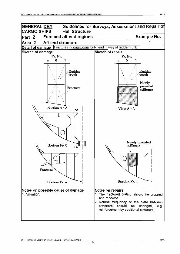
IACSCFNFFAT ,nRYCARQOafflSGUDELJNF^KlRar 1RVEYS А Я Я ^ Ш Е Ж А Ш ^ А Т К О Р Н Г П Я Ш Ж Е PART2
GENERAL DRY CARGO SHIPS
Guidelines for Surveys, Assessment and Repair of Hull Structure
Part 2Area 2
Fore and aft end regionsAft end structure
Example No............. 1..........
Detail of damage |Fractures in longitudinal bulkhead in way of rudder trunkSketch of damage
Fr. No. a 0 1
Sketch of repairFr. No.
a 0 1
N ew ly provided
Notes on possible cause of damage1. Vibration.
Notes on repairs1. The fractured plating should be cropped
and renewed.2. Natural frequency of the plate between
stiffeners should be changed, e.g. reinforcement by additional stiffeners.
INTERNATIONALASSOCTATTONOFCLASSIFICATTONSOCIETIES_________________94
AREA 2
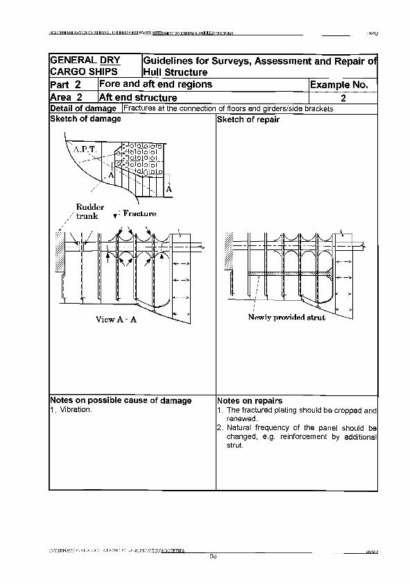
] Ж Б ( Ж 1 Е Б А Ш ^ С А Е О Э а Ш 5 а и Ю И INRSRj R.3J?VEYR А 5 Я ^ М Р 7 \ Г Г AMnRFPATROFHl Т Т I -<?П?Г Т П Т IRE PART2
INTERNATIONAL AS SOCIATIONOFCLASSIFICATIQN SOCIETIES_________________95
AREA2
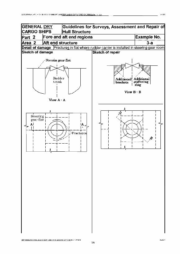
IACSGENEEALDRY CARGO SFTTFS Ot MM INFSroRST IRVEYS A5lSRS VlENTANDEEPATR.nFHT ТГ ,T ЯГКТ ГТГТ JRE PART2
GENERAL DRY CARGO SHIPS
Guidelines for Surveys, Assessment and Repair of Hull Structure
Part 2 Fore and aft end regions Example No.Area 2 Aft end structure 3-aDetail of damage Fractures in flat where rudder carrier is installed in steering gear roomSketch of damage
Steerin gear flat
View A - A
Sketch of repair
Additional1 Additional brackets stiffening
I nng
View В - В
INTERNATIONALASSOCIATIONOFCLASSIFICATION SOCIETIES96
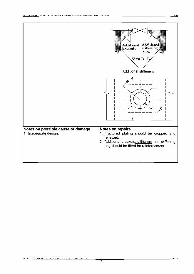
IACS<^E^ERYCARmafflSGUDEUI^KmSURVF^S АЯвгеШЕЖАЬЮКЕРАТКОЕНГ JT J ЯШШШКЕ PART2
IN T E R N A T IO N A L A S S O C IA T IO N O F C L A S S IF IC A T IO N S O C IE T IE S97
AREA2
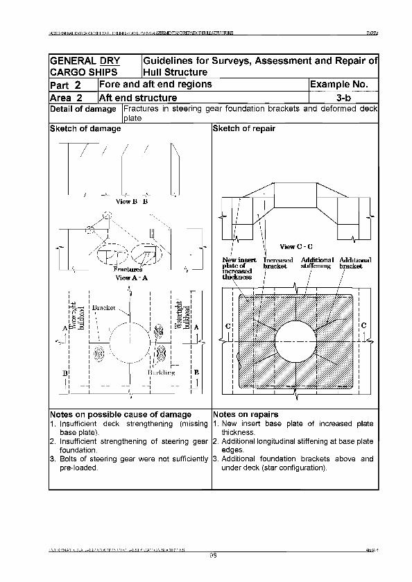
TAOROENERAT ,ТШСЛШР SETFS О Т Ш Е Г INESroRSUKVEYS А Я . д ^ Ш Е Ж А Ш 1 ^ А Е 0 Е Н и ] Х 8 Ш 1 Х Т ( Д ? Е PART2
GENERAL DRY Guidelines for Surveys, Assessment and Repair of CARGO SHIPS Hull StructurePart 2 Fore and aft end regions Example No.Area 2 Aft end structure 3-bDetail of damage Fractures in steering gear foundation brackets and deform ed deck
plateSketch of damage
View В - В
Notes on possible cause of damage1. Insufficient deck strengthening (missing
base plate).2. Insufficient strengthening of steering gear
foundation.3. Bolts of steering gear were not sufficiently
pre-loaded.
Sketch of repair
New insert Increased Additional Additional plate of bracket stiffening bracket increased j j jthickness / /
Notes on repairs1. New insert base plate of increased plate
thickness.2. Additional longitudinal stiffening at base plate
edges.3. Additional foundation brackets above and
under deck (star configuration).
INTERNATIONALASSOCIATIONOFCLASSIFICATION SOCIETIES98
A REA 2
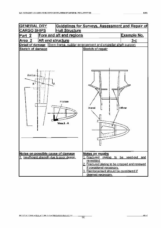
IACSGENER АТ т к у П AROQ SEIFS СОПЕГ TMFSF1R яг tr\7FVS дяятадУ1^^АШБЕРА1К.г^нг тг I .ftri ГЛТ EE PART2
GENERAL DRYCARGO SHIPS
Guidelines for Surveys. Assessment and Repair ofHull Structure
Part 2 Fore and aft end regions Example No.Area 2 Aft end structure 3-cDetail of damage IStern frame, rudder arrangement and propeller shaft support Sketch of damage ISketch of repair
Notes on possible cause of damage1 Insufficient strength due to poor design.
Notes on repairs1. Fractured plating to be veed-out and
re-welded.2. Fractured plating to be cropped and renewed
if considered necessary.3. Reinforcement should be considered if _^deemed_necessa^________________
INTERNATTONAT.ASSOCIATTONOFCT.ASSIFICATION SOCIETIES___________________________________________________________________________________AREA299
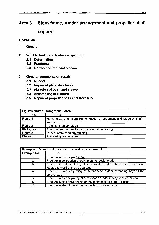
TACSOFNFKAT .ТШХЗАИОО SHIPS GUIDET INFSPORST JRVHYS А Я ЯгеШ ЕЖ А ^1М А ТК П ЕН Т IT J STRLXTITIRE PART2
Area 3 Stern frame, rudder arrangement and propeller shaft
support
Contents
1 General
2 What to look for - Drydock inspection2.1 Deformation2.2 Fractures2.3 Corrosion/Erosion/Abrasion
3 General comments on repair3.1 Rudder3.2 Repair of plate structures3.3 Abrasion of bush and sleeve3.4 Assembling of rudders3.5 Repair of propeller boss and stern tube
Figures and/or Photographs - Area 3No. Title
Figure 1 Nomenclature for stern frame, rudder arrangement and propeller shaft support
Figure 2 Potential problem areasPhotograph 1 Fractured rudder due to corrosion in rudder platingFigure 3 Rudder stock repair by weldingDiagram 1 Preheating temperature
Examples of structural detail failures and repairs - Area 3Example No. Title
1 Fracture in rudder plate stock2 Fracture in connection of palm plate to rudder blade3 Fracture in rudder plating of semi-spade rudder (short fracture with end
located forward of the vertical web)4 Fracture in rudder plating of semi-spade rudder extending beyond the
vertical web5 Fracture in rudder plating of semi-spade rudder in way of pintle cut-out6 Fracture in side shell plating at the connection to propeller boss7 Fracture in stern tube at the connection to stern frame
INTERNATIONAL AS SOCIATIONOFCLASSIFICATION SOCIETIES100
AREA3
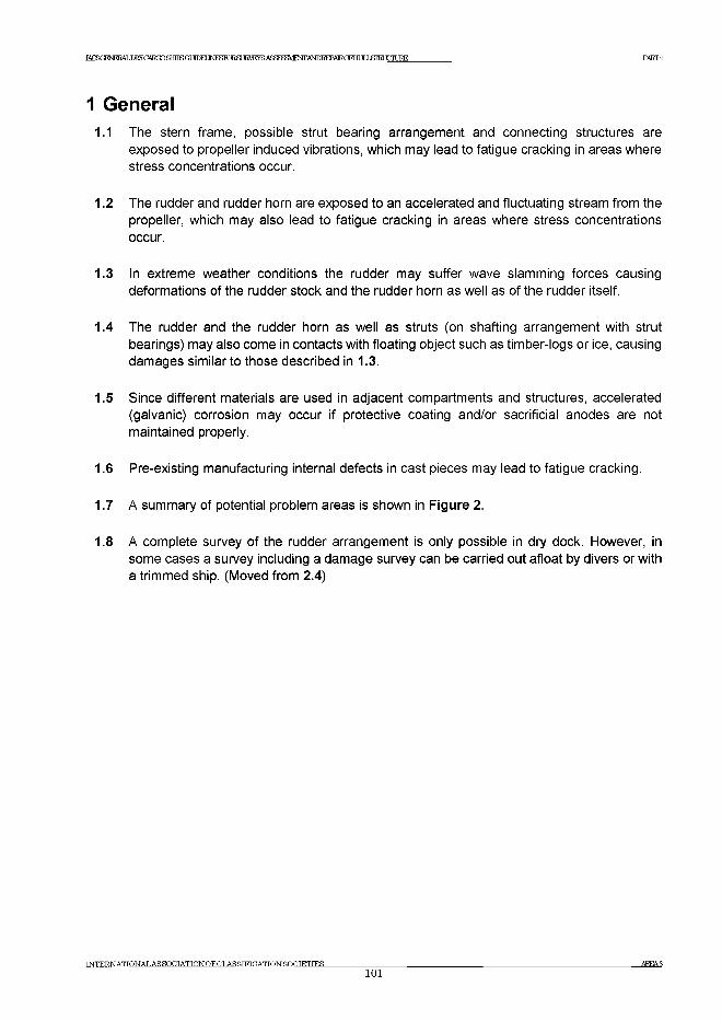
IACSCFNFRAT ,nRYCARQOafflSGUDELJNF^KlRar JRVEYS АЯЯ^ШЕЖАМРЕЕРДТКОРНГ JT J ЯШШШКЕ РАКГ2
1 General1.1 The stern frame, possible strut bearing arrangement and connecting structures are
exposed to propeller induced vibrations, which may lead to fatigue cracking in areas where stress concentrations occur.
1.2 The rudder and rudder horn are exposed to an accelerated and fluctuating stream from the propeller, which may also lead to fatigue cracking in areas where stress concentrations occur.
1.3 In extreme weather conditions the rudder may suffer wave slamming forces causing deformations of the rudder stock and the rudder horn as well as of the rudder itself.
1.4 The rudder and the rudder horn as well as struts (on shafting arrangement with strut bearings) may also come in contacts with floating object such as timber-logs or ice, causing damages similar to those described in 1.3.
1.5 Since different materials are used in adjacent compartments and structures, accelerated (galvanic) corrosion may occur if protective coating and/or sacrificial anodes are not maintained properly.
1.6 Pre-existing manufacturing internal defects in cast pieces may lead to fatigue cracking.
1.7 A summary of potential problem areas is shown in Figure 2.
1.8 A complete survey of the rudder arrangement is only possible in dry dock. However, in some cases a survey including a damage survey can be carried out afloat by divers or with a trimmed ship. (Moved from 2.4)
TNTERNATTONALASSOCIATIONOFCLASSTFTCATIONSOCIETIES101
AKEA3
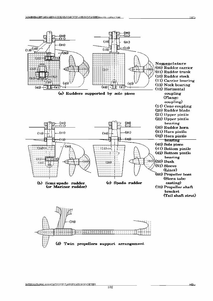
IACSGENEEALIHy CARGO SHTFR С?ГУГГМ M^roRSLEVEyS AS^^^^D R EPA R O F H L IL & T R L T T U R E РАКГ2
(b) Semi-spade rudder (or Mariner rudder)
(c) Spade rudder
(Flange coupling)
(14) Cone coupling(20) Rudder blade(21) Upper pintle(22) Upper pintle
bearing(30) Rudder horn(31) Horn pintle(32) Horn pintle
bearing(40) Sole piece(41) Bottom pintle(42) Bottom pintle
bearing(50) Bush(51) Sleeve
(liner)(60) Propeller boss
(Stern tube casting)
(70) Propeller shaft bracket(Tail shaft strut)
INTERN ATTONALASSOCT ATTON OFOT .ASSTFTC ATTON SOCIETIES102
AREA3
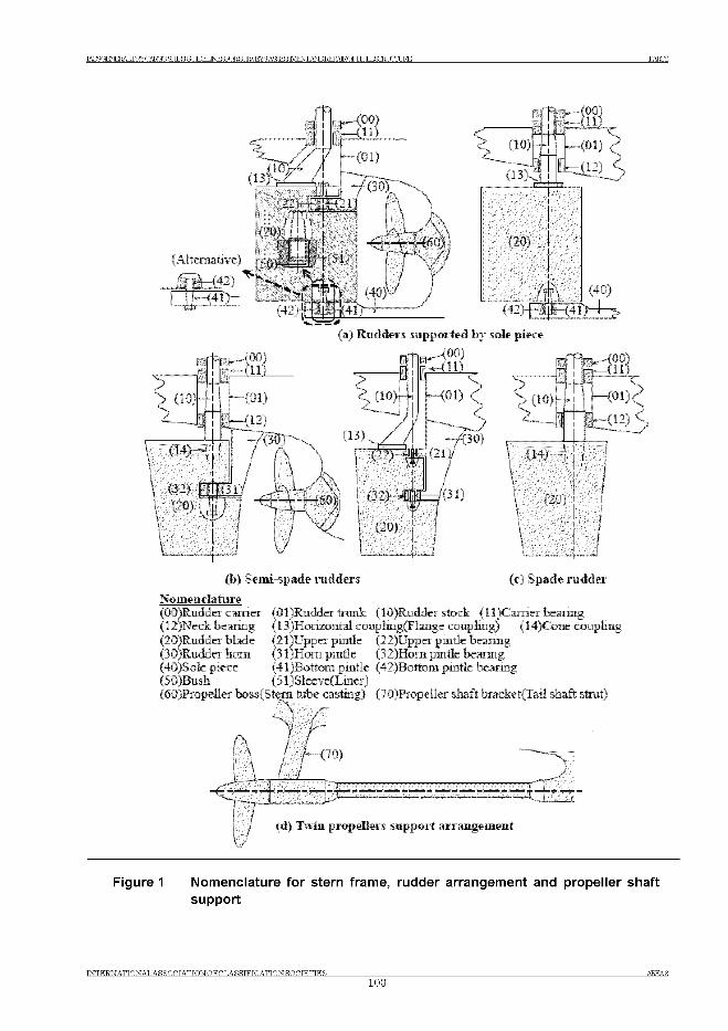
РАЕГ2IACSGENERALDKY CARGO SETFS ОТ ШЕГ I^roRSUE^E^AS^SaVEOTA^I^AEOFHUILSIRLUrLIRE
-- JjTU(b # ! u
i -'Г■ ж и u lJ
-(01) -(12) 4
Ж ; (40)
(42 )^ |jfc-i;4 i>
(10)'Z ,
t=|F?|*-(00)1 - i l l )
Ж ,
#3)1
(a.) Rudders supported by sole piece
(00)
-(01)
Lrr_<12>
ЧГПнЖ т_g ! г * ( l l )
< (10M4i
(13),
fz (22)
1 (32)
i (20)
( - 1/
<oi) <J
4зЬ)
> (10)1™#!
тП Я ^кЧ 00)п . [ р - ,11ч
401)?
/(31)
4 .!JVT
U4) # / ;
! !I )
(20) ] i‘ УУУууЛ -.у-у-Х \ I
I
(b) Sem i-spade rudders (c) Spade rudder
N om enclature(DC tRudder earner (Ql)Rudder trunk {10)Rudder stock (11 )Camer bearing(12)Neck bearmg (13^Horizontal coupliiig(Flange coupling) (14)Cone coupling(20)Rudder blade (2 l)Upper pintle {22)Upper pmtle bearing(30)Rudder horn (3 l)Hom puirle {32)Horu pmtle bearing(40)Sole piece (41)Bottoin pmtle {42JBottom pintle bearmg(50 sBush {51 )Sleeve(Liuer)(60 iPropeller bossfStem tube casting) {70)Propeller shaft bracket(Tail shaft strut")
l - V / ' j f
/ (d) Twiii propellers support arrangem ent
Figure 1 Nomenclature for stern frame, rudder arrangement and propeller shaft support
IN T E R N A T IO N A L A S S O C IA T IO N O F C L A S S IF IC A T IO N S O C IE T IE S AREA3103
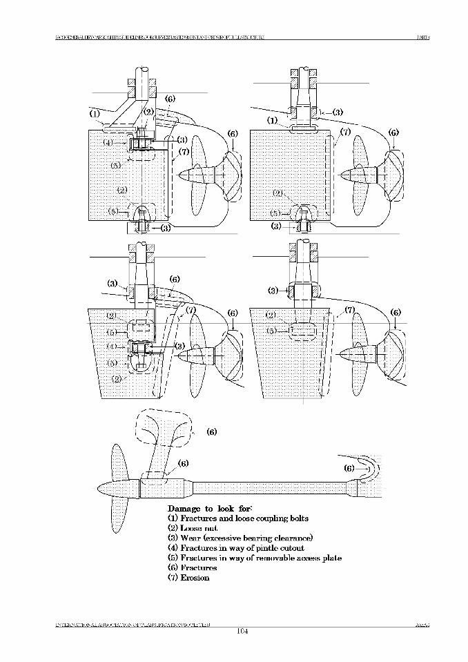
IACSGENEEALDRY CARGO SRTFR (IT ШЕГ I^ r o R S U E ^ E ^ A S ^ S a V E O T A ^ I^ A E O F H U IL S IR L U rL IR E РАКГ2
(5) Fractures in way o f removable access plate(6) Fractures(7) Erosion
IN T E R N A T IO N A L A S S O C IA T IO N O F C L A S S IF IC A T IO N S O C IE T IE S104
AREA3
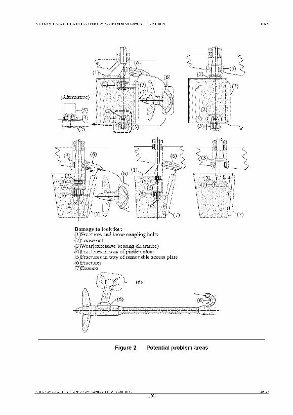
IACSGE^ИЖJDRYCARШglгШ^GLШEЦMSГОRgL]RVEYSASЖЭЭVlENTA^JDEEPAlROFHLILLgГRlXTL]RE РАКГ2
Damage to look for:(1) Fractures and loose coupling bolts(2) Loose nut(3) Wear( excessive bearing clearance)(4) Fractures in way of pmtle cutout(5) Fractures in way- of removable access plate(6) Fractures(7) Erosion
h"'— (6)
&
■m —-G N
Figure 2 Potential problem areas
INTERNATIONAL AS SOCIATIONOFCLASSIFICATION SOCIETIES AREA3105
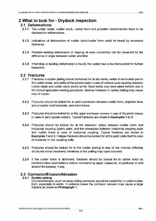
IA C S < ™ H ^ T W C A R m ^ M R 3 G U D E U N f^ T O ^ a r 1RVEYS A fla^M ^JTA N D EEPA TR rFH T IT J .STRUCTURE PART2
2 What to look for - Drydock inspection2.1 Deformations
2.1.1 The rudder blade, rudder stock, rudder horn and propeller boss/brackets have to be checked for deformations.
2.1.2 Indications of deformation of rudder stock/rudder horn could be found by excessive clearance.
2.1.3 Possible twisting deformation or slipping of cone connection can be observed by the difference in angle between rudder and tiller.
2.1.4 If bending or twisting deformation is found, the rudder has to be dismounted for further inspection.
2.2 Fractures2.2.1 Fractures in rudder plating should be looked for at slot welds, welds of removable part to
the rudder blade, and welds of the access plate in case of vertical cone coupling between rudder blade and rudder stock and/or pintle. Such welds may have latent defects due to the limited applicable welding procedure. Serious fractures in rudder plating may cause loss of rudder.
2.2.2 Fractures should be looked for at weld connection between rudder horn, propeller boss and propeller shaft brackets, and stern frame.
2.2.3 Fractures should be looked for at the upper and lower corners in way of the pintle recess in case of semi-spade rudders. Typical fractures are shown in Examples 3 to 5.
2.2.4 Fractures should be looked for at the transition radius between rudder stock and horizontal coupling (palm) plate, and the connection between horizontal coupling plate and rudder blade in case of horizontal coupling. Typical fractures are shown in Examples 1 and 2. Fatigue fractures should be looked for at the palm plate itself in case of loosened or lost coupling bolts.
2.2.5 Fractures should be looked for in the rudder plating in way of the internal stiffening structures since (resonant) vibrations of the plating may have occurred.
2.2.6 If the rudder stock is deformed, fractures should be looked for in rudder stock by nondestructive examinations before commencing repair measures, in particular in and around the keyway, if any.
2.3 Corrosion/Erosion/Abrasion2.3.1 Rudder plating
Corrosion/erosion (such as deep pitting corrosion) should be looked for in rudder/rudder horn, especially in welds. In extreme cases the corrosion /erosion may cause a large fracture as shown in Photograph 1.
INTERNATIONAL AS SOCIATIONOFCLASSIFICATIONSOCIETIES106
AREA3
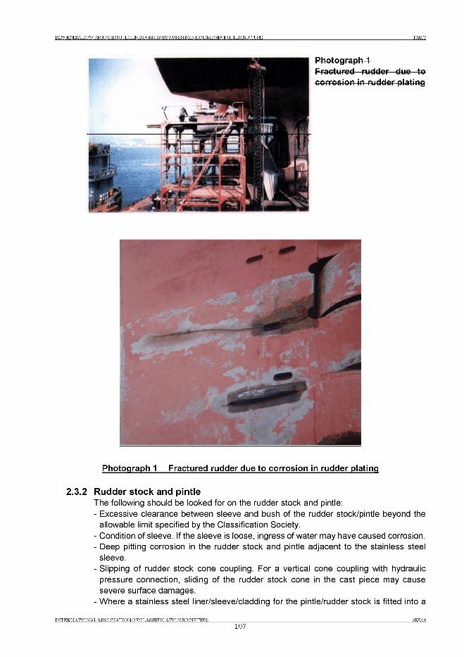
IACSGE№^DRYCARmSfTrFBGl JIDEI INFlSTOR.Sf А 8 Ж ^ / Е ^ Ж Р 1 ^ А Е О Р Е т & Т Е т Г 1 3 К Е PART2
Photograph 1 Fractured rudder due to corrosion in rudder plating
2.3.2 Rudder stock and pintleThe following should be looked for on the rudder stock and pintle:- Excessive clearance between sleeve and bush of the rudder stock/pintle beyond the
allowable limit specified by the Classification Society.- Condition of sleeve. If the sleeve is loose, ingress of water may have caused corrosion.- Deep pitting corrosion in the rudder stock and pintle adjacent to the stainless steel
sleeve.- Slipping of rudder stock cone coupling. For a vertical cone coupling with hydraulic
pressure connection, sliding of the rudder stock cone in the cast piece may cause severe surface damages.
- Where a stainless steel liner/sleeve/cladding for the pintle/rudder stock is fitted into a
INTERNATIONAL ASSOCIATION OFCLASSIFICATION SOCIETIES107
AREA 8
IA C fiOFN RRA T ,Ш УПАТ?ГГ)ЯНТРЙГ?Г ТГПЕГ IN F S T O R S T IRVEYSAS^SaVENTANDEEPATR.nFHT ТГ ,Т .ST R U C T U R E PART2
stainless steel bush, an additional check should be made for crevice corrosion.
3 General comments on repair3.1 Rudder
3.1.1 Rudder stock with deformation(a) If the rudder stock is twisted due to excessive forces such as contact or grounding
and has no additional damages (fractures etc.) or other significant deformation, the stock usually can be used. The need for repair or heat treatment of the stock will depend on the amount of twist in the stock according to the requirements of the Classification Society. The keyway, if any, has to be milled in a new position.
(b) Rudder stocks with bending deformations, not having any fractures, may be repaired depending on the size of the deformation either by warm or by cold straightening in an approved workshop according to a procedure approved by the Classification Society. In the case of warm straightening, as a guideline, the temperature should usually not exceed the heat treatment temperature of 530-580°C.
(c) In the case of fractures on a rudder stock with deformations, the stock may be used again depending on the nature and extent of the fractures. If a welding repair is considered acceptable, the fractures are to be removed by machining/grinding and the welding is to be based on an approved welding procedure together with post weld heat treatment as required by the Classification Society.
3.1.2 Repair of rudder stocks/pintles by weld claddingRudder stocks and/or pintles may be repaired by welding replacing wasted material by similar weld material. After removal of the wasted area (corrosion, scratches, etc.) by machining and/or grinding the build-up welding has to be carried out by an automatic spiral welding according to an approved welding procedure. The welding has to be extended over the area of large bending moments (rudder stocks). In special cases post weld heat treatment has to be carried out according to the requirements of the Classification Society. After final machining, a sufficient number of layers of welding material have to remain on the rudder stock/pintle. A summary of the most important steps and conditions of this repair is shown in the Figure 3.
In the case of rudder stocks with bending loads, fatigue fractures in way of the transition radius between the rudder stock and the horizontal coupling plate cannot be repaired by local welding. A new rudder stock with a modified transition geometry has to be manufactured, as a rule (See Example 1). In exceptional cases a welding repair can be carried out based on an approved welding procedure. Measures have to be taken to avoid a coincidence of the metallurgical notch of the heat affected zone with the stress concentration in the radius’ area. Additional surveys of the repair (including non-destructive fracture examination) have to be carried out at reduced intervals.
INTERNATIONALASSOCIATIONOFCLASSIFICATION SOCIETIES108
AREA3
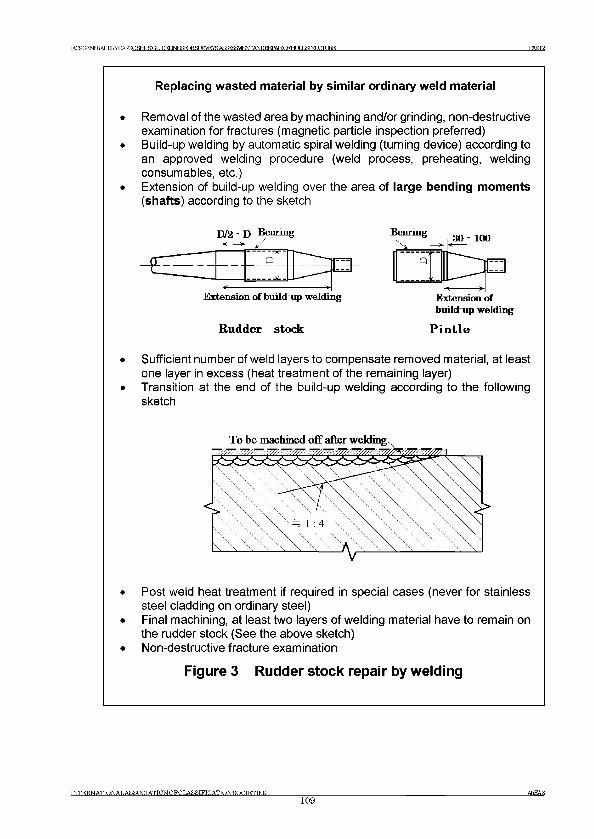
IACSGENERAT ШУГАЖГ) SHTFR О Г Т Г Г М INFfiFORfl IRVRYS А < ¥ Ю Ш 1 ^ А Ш К Е Р А Е < Ж 1 [ IJ Я Г И Г П Т IRE PART2
Replacing wasted material by similar ordinary weld material
• Removal of the wasted area by machining and/or grinding, non-destructive examination for fractures (magnetic particle inspection preferred)
• Build-up welding by automatic spiral welding (turning device) according to an approved welding procedure (weld process, preheating, welding consumables, etc.)
• Extension of build-up welding over the area of large bending moments (shafts) according to the sketch
Extension of build-up welding Utipnmnn 0fbuild-up welding
R udder stock P in t le
• Sufficient number of weld layers to compensate removed material, at least one layer in excess (heat treatment of the remaining layer)
• Transition at the end of the build-up welding according to the following sketch
• Post weld heat treatment if required in special cases (never for stainless steel cladding on ordinary steel)
• Final machining, at least two layers of welding material have to remain on the rudder stock (See the above sketch)
• Non-destructive fracture examination
Figure 3 Rudder stock repair by welding
INTERNATIONAL AS SOCTATIONOFCLASSIFICATTONSOCIETIES109
AREA3
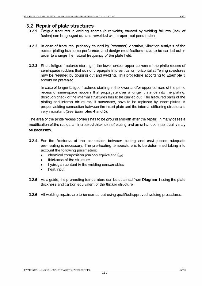
IACSGENERALDKY CARGO SRTFS (ГГ ШЕГ I^roRSUE^E^AS^SaVEOTA^I^AEOFHUILSIRLUrLIRE РАЕГ2
3.2 Repair of plate structures3.2.1 Fatigue fractures in welding seams (butt welds) caused by welding failures (lack of
fusion) can be gouged out and rewelded with proper root penetration.
3.2.2 In case of fractures, probably caused by (resonant) vibration, vibration analysis of the rudder plating has to be performed, and design modifications have to be carried out in order to change the natural frequency of the plate field.
3.2.3 Short fatigue fractures starting in the lower and/or upper corners of the pintle recess of semi-spade rudders that do not propagate into vertical or horizontal stiffening structures may be repaired by gouging out and welding. This procedure according to Example 3 should be preferred.
In case of longer fatigue fractures starting in the lower and/or upper corners of the pintle recess of semi-spade rudders that propagate over a longer distance into the plating, thorough check of the internal structures has to be carried out. The fractured parts of the plating and internal structures, if necessary, have to be replaced by insert plates. A proper welding connection between the insert plate and the internal stiffening structure is very important (See Examples 4 and 5).
The area of the pintle recess corners has to be ground smooth after the repair. In many cases a modification of the radius, an increased thickness of plating and an enhanced steel quality may be necessary.
3.2.4 For the fractures at the connection between plating and cast pieces adequate pre-heating is necessary. The pre-heating temperature is to be determined taking into account the following parameters:• chemical composition (carbon equivalent Ceq)• thickness of the structure• hydrogen content in the welding consumables• heat input
3.2.5 As a guide, the preheating temperature can be obtained from Diagram 1 using the plate thickness and carbon equivalent of the thicker structure.
3.2.6 All welding repairs are to be carried out using qualified/approved welding procedures.
IN T E R N A T IO N A L A S S O C IA T IO N O F C L A S S IF IC A T IO N S O C IE T IE Sno
AREA3
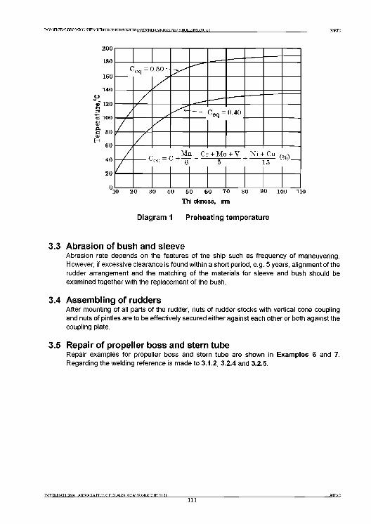
изси'игАшстсиюоашвашм^ Р А К Г2
Diagram 1 Preheating temperature
3.3 Abrasion of bush and sleeveAbrasion rate depends on the features of the ship such as frequency of maneuvering.
However, if excessive clearance is found within a short period, e.g. 5 years, alignment of the
rudder arrangement and the matching of the materials for sleeve and bush should be
examined together with the replacement of the bush.
3.4 Assembling of ruddersAfter mounting of all parts of the rudder, nuts of rudder stocks with vertical cone coupling
and nuts of pintles are to be effectively secured either against each other or both against the
coupling plate.
3.5 Repair of propeller boss and stern tubeRepair examples for propeller boss and stern tube are shown in Exam ples 6 and 7.
Regarding the welding reference is made to 3.1.2, 3 .2 .4 and 3.2.5.
TNTER.N ATTON ALAS SOOT ATTON OFCLASSIFICATION SOCIETIES111
AKEA3
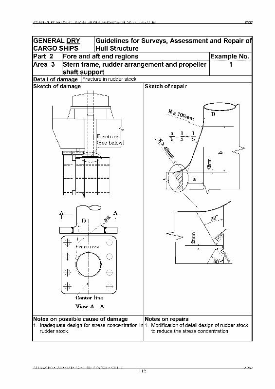
ЕЖГ2
GENERAL DRY CARGO SHIPS
Guidelines for Surveys, Assessment and Repair of Hull Structure
Part 2 Fore and aft end regions Example No.Area 3 Stern frame, rudder arrangement and propeller ________ shaft support__________Detail of damage |Fracture in rudder stock
1
Sketch of damage
Center line
View A - A
Sketch of repair
Notes on possible cause of damage1. Inadequate design for stress concentration in
rudder stock.
Notes on repairs1. Modification of detail design of rudder stock
to reduce the stress concentration.
INTERNATIONAL AS SOCIATIONOFCLASSIFICATION SOCIETIES
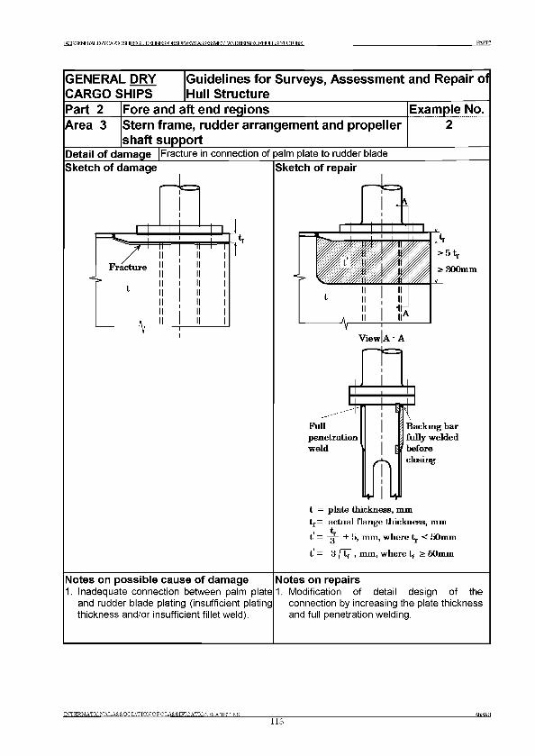
ТАГгаТРМтеАТ -TWnARnOSHIFSGUnH INERTORSI TRVRVR AfifT^^ff^ANDBEPAlRnPHI TTIflIRLCITJRE PART2
GENERAL DRY CARGO SHIPS
Guidelines for Surveys, Assessment and Repair of Hull Structure
Part 2 Fore and aft end regions Example No.Area 3 Stern frame, rudder arrangement and propeller
shaft support________________________________Detail of damage Sketch of damage
Fracture in connection of palm plate to rudder blade Sketch of repair
t = plate thickness, mm tj = actual flange thickness, mm , t.
t = -ту—I- 5, mm, where lf < 50mm
t = 3 f tJ , mm, where tf ^ 50mm
Notes on possible cause of damage1. Inadequate connection between palm plate
and rudder blade plating (insufficient plating thickness and/or insufficient fillet weld).
Notes on repairs1. Modification of detail design of the
connection by increasing the plate thickness and full penetration welding.
INTERNATIONAL AS SOCIATIONOFCLASSIFICATIQN SOCIETIES_________________________________________________________________________________________________AREA3113
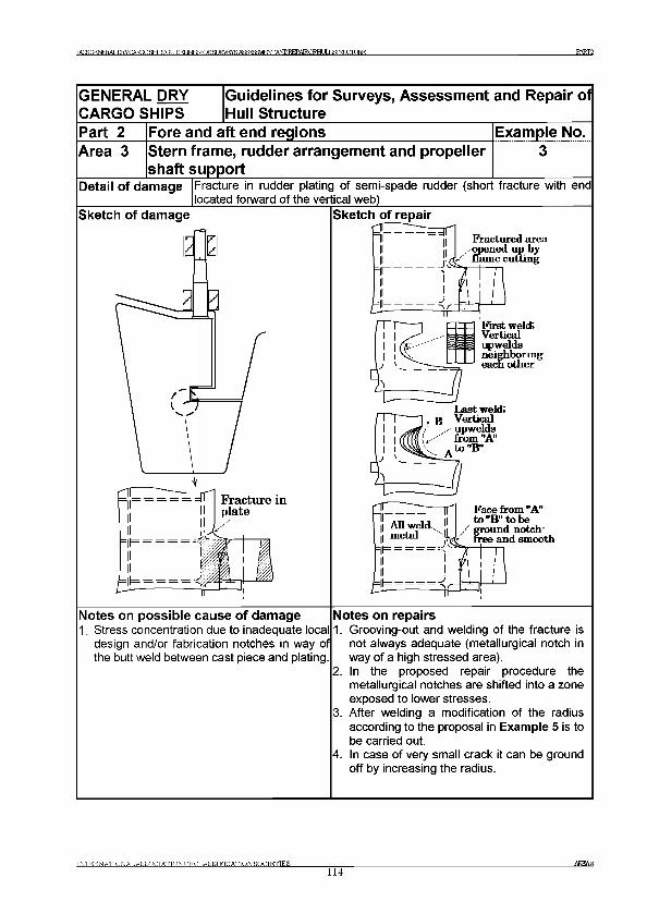
TAOROFNERAT Ж CARGO RHTFS Of JTTM INESroRSUKVEYS А Я Я ^ Я Я У В Ф Г Г ANDREPA1RCFHUIJ Я М 1 Ж Ж Е PART2
GENERAL DRY CARGO SHIPS
Guidelines for Surveys, Assessment and Repair of Hull Structure
Part 2 Fore and aft end regions Example No.Area 3 Stern frame, rudder arrangement and propeller
shaft support________________________________Detail of damage Fracture in rudder plating of semi-spade rudder (short fracture with end
located forward of the vertical web)___________________________________Sketch of damage Sketch of repair
Notes on possible cause of damage1. Stress concentration due to inadequate local
design and/or fabrication notches in way of the butt weld between cast piece and plating
Notes on repairs1. Grooving-out and welding of the fracture is
not always adequate (metallurgical notch in way of a high stressed area).
2. In the proposed repair procedure the metallurgical notches are shifted into a zone exposed to lower stresses.
3. After welding a modification of the radius according to the proposal in Example 5 is to be carried out.
4. In case of very small crack it can be ground off by increasing the radius.
INTERNATIONAL AS SOCIATIONOFCLASSIFICATIONSOCIETIES114
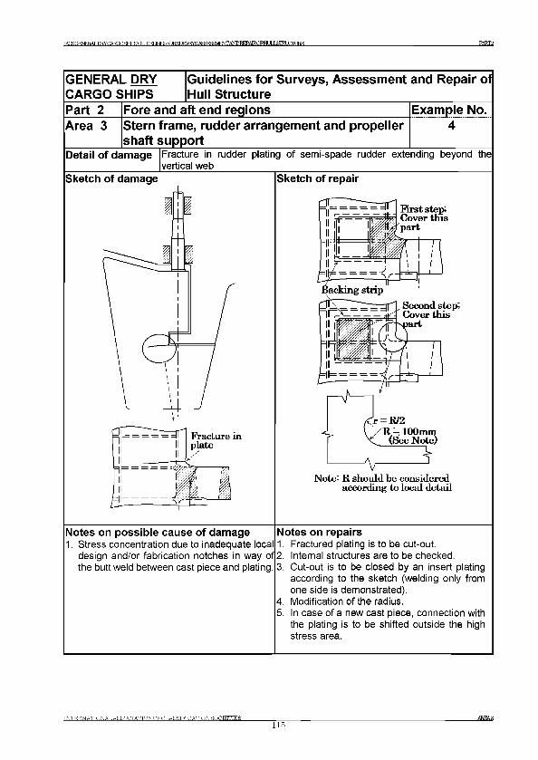
TAOROFNERAT ,ТШСЛШР SRTFS О Т ШЕГ INESFORST JRVEYS ASRFgM^ANDKEPATROFHI IT J ЯТШ7ГГ Ш PART2
GENERAL DRY CARGO SHIPS
Guidelines for Surveys, Assessment and Repair of Hull Structure
Part 2 Fore and aft end regions Example No.Area 3 Stern frame, rudder arrangement and propeller
shaft support________________________________Detail of damage Fracture in rudder plating of semi-spade rudder extending beyond the
vertical webSketch of damage Sketch of repair
Note: R should be considered according to local detail
Notes on possible cause of damage1. Stress concentration due to inadequate local
design and/or fabrication notches in way of the buttweld between cast piece and plating.
Notes on repairs1. Fractured plating is to be cut-out.2. Internal structures are to be checked.3. Cut-out is to be closed by an insert plating
according to the sketch (welding only from one side is demonstrated).
4. Modification of the radius.5. In case of a new cast piece, connection with
the plating is to be shifted outside the high stress area.
INTERNATIONAL AS SOCIATIONOFCLASSIFICATION SOCIETIES115
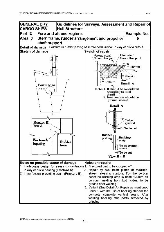
1АС8СМЕЕА1ЛДСМЮШ1В30СШЕ1]ЫЕЗКЖ£О1ЕУЕУ5А8Ж£ДУ|Е1чТГАМРЕЕРА1ЕС8ЭДиЦ)Ш1и1Т-ЕЕ РАКГ2
GENERAL DRY CARGO SHIPS
Guidelines for Surveys, Assessment and Repair of Hull Structure
Part 2 Fore and aft end regions Example No.Area 3 Stern frame, rudder arrangement and propeller
shaft support______________________________Detail of damage |Fracture in rudder plating of semi-spade rudder in way of pintle cutout
Sketch of repairSecond step; /F irst step; Cover this part / Cover this part
Sketch of damage
Note: l. R should be considered according to local detail
2. New contour should be ground smooth.
D etail A
Rudderplating /Backing
strip
egroiith|J_ smoot
"To be cut View В - В
Notes on possible cause of damage1. Inadequate design for stress concentration
in way of pintle bearing (Fracture A).2. Imperfection in welding seam (Fracture B).
Notes on repairs1. Fractured part to be cropped off.2. Repair by two insert plates of modified,
stress releasing contour. For the vertical seam no backing strip is used 100mm off contour, welding from both sides, to be ground after welding.
3. Variant (See Detail A): Repair as mentionedunder 2 with the use of backing strip for the compete complete vertical seam. After welding backing strip partly removed by grinding.______________________________
INTERNATIONALASSOCIATIONOFCLASSIFICATIONSOCIETIES__________________116
AKEA3

BCSGENERALnWCAKO DfHIBGUDEUNESKKSUR PARK
GENERAL DRY CARGO SHIPS
Guidelines for Surveys, Assessment and Repair of Hull Structure
Part 2 Fore and aft end regions Example No.Area 3 Stern frame, rudder arrangement and propeller
shaft support6
Detail of damage |Fracture in side shell plating at the connection to propeller boss
Sketch of damage Sketch of repair
Notes on possible cause of damage1. Fatigue fracture due to vibration.
Notes on repairs1. Fractured side shell plating is to be cropped
and part renewed.2. Additional stiffeners are to be provided.3. Collar plate is to be provided.
INTERNATIONALASSOCIATION OFCLASSIFICATION SOCIETIES117
AREA3
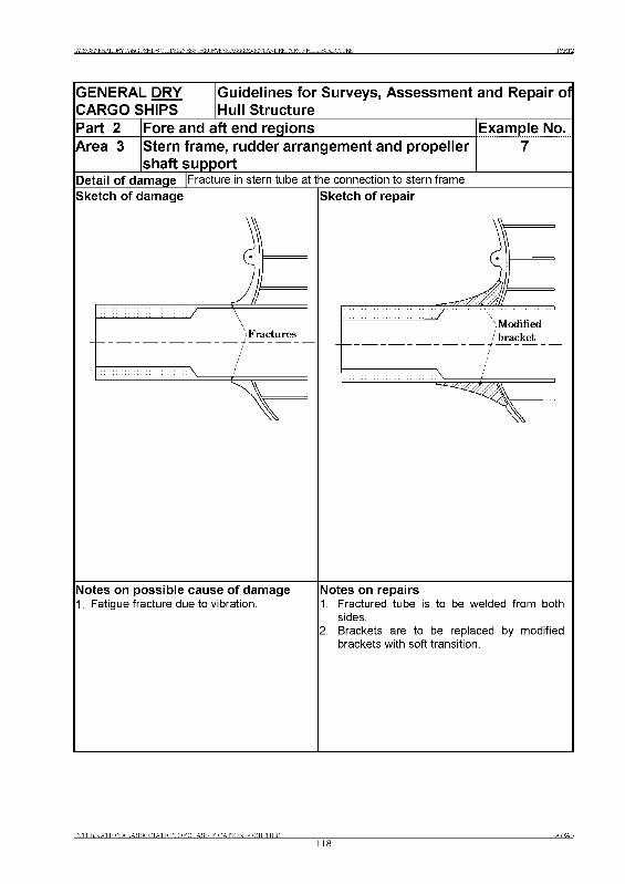
ЕЖГ2
GENERAL DRY CARGO SHIPS
Guidelines for Surveys, Assessment and Repair of Hull Structure
Part 2 Fore and aft end regions Example No.Area 3 Stern frame, rudder arrangement and propeller ________ shaft support______________________________Detail of damage |Fracture in stern tube at the connection to stern frameSketch of damage Sketch of repair
Notes on possible cause of damage1. Fatigue fracture due to vibration.
Notes on repairs1. Fractured tube is to be welded from both
sides.2. Brackets are to be replaced by modified
brackets with soft transition.
INTERNATIONAL AS SOCIATIONOFCLASSIFICATION SOCIETIES
TAOROFNFRAT .D RY 0 AROO RHTFR ОТ ТГПЕГ Д Ы ге К Ж Я Г JRVEYS A S ^ S a V J E N T A ^ R E P A T R Q F H U L L g lR L U rU R E Р А К Г З
Part 3 Machinery and accommodation spaces
Area 1 Engine room structure Area 2 Accommodation structure
Area 1 Engine room structure
Contents
1 General
2 What to look for2.1 Material wastage2.2 Fractures
3 General comments on repair3.1 Fractures
Examples of structural detail failures and repairs - Area 1
Example No. Title
1 Fractures in brackets at main engine foundation2 Corrosion in bottom plating under sounding pipe in way of bilge storage tank
in enaine room3 Corrosion in bottom plating under inlet/suction pipe in way of bilge storage
tank in enaine room
INTERNATIONAL ASSOCIATION OF CLASSIFICATION SOCIETIES
119AREA 1
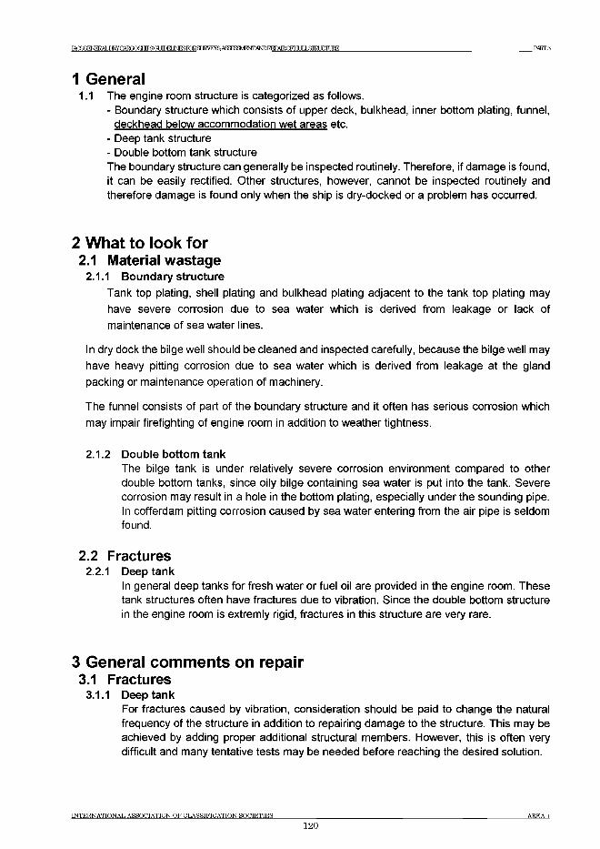
IA C S(^ E^ER Y C A R m gH IFSG m EIiN ESP^ SU R V EY S ASa^M^TTANDREPAIRCFHr IT J ЯГЕГ HTTJRE PART3
1 General1.1 The engine room structure is categorized as follows.
- Boundary structure which consists of upper deck, bulkhead, inner bottom plating, funnel, deckhead below accommodation wet areas etc.
- Deep tank structure- Double bottom tank structureThe boundary structure can generally be inspected routinely. Therefore, if damage is found, it can be easily rectified. Other structures, however, cannot be inspected routinely and therefore damage is found only when the ship is dry-docked or a problem has occurred.
2 What to look for2.1 Material wastage
2.1.1 Boundary structure
Tank top plating, shell plating and bulkhead plating adjacent to the tank top plating may have severe corrosion due to sea water which is derived from leakage or lack of maintenance of sea water lines.
In dry dock the bilge well should be cleaned and inspected carefully, because the bilge well may have heavy pitting corrosion due to sea water which is derived from leakage at the gland packing or maintenance operation of machinery.
The funnel consists of part of the boundary structure and it often has serious corrosion which may impair firefighting of engine room in addition to weather tightness.
2.1.2 Double bottom tankThe bilge tank is under relatively severe corrosion environment compared to other double bottom tanks, since oily bilge containing sea water is put into the tank. Severe corrosion may result in a hole in the bottom plating, especially under the sounding pipe. In cofferdam pitting corrosion caused by sea water entering from the air pipe is seldom found.
2.2 Fractures2.2.1 Deep tank
In general deep tanks for fresh water or fuel oil are provided in the engine room. These tank structures often have fractures due to vibration. Since the double bottom structure in the engine room is extremly rigid, fractures in this structure are very rare.
3 General comments on repair3.1 Fractures
3.1.1 Deep tankFor fractures caused by vibration, consideration should be paid to change the natural frequency of the structure in addition to repairing damage to the structure. This may be achieved by adding proper additional structural members. However, this is often very difficult and many tentative tests may be needed before reaching the desired solution.
INTERNATIONAL ASSOCIATION OF CLASSIFICATION SOCIETIES
120AREA 1
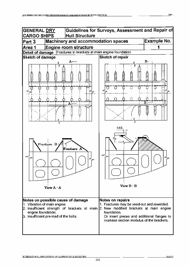
РАКГЗ
GENERAL DRY CARGO SHIPS
Guidelines for Surveys, Assessm ent and Repair of Hull Structure
Part 3 Machinery and accom m odation spaces Example No.Area 1 Enqine room structure 1Detail of damage Fractures in brackets at main engine foundationSketch of damage
I I I I ,t A
j k _ j k _ _ 6 _ _ 6 _ _ 6 _ . 6 A.i / '
Jr N
View A - A
Sketch of repairB*
i i\ к| |\ 1f il, $ \ \ _* Z£ к
H 't f+ t6 6 6__6__6__ 6-
N
r
6 Л
w
=15
View В - В
Notes on possible cause of damage1. Vibration of main engine.2. Insufficient strength of brackets at main
engine foundation.3. Insufficient pre-load of the bolts.
Notes on repairs1. Fractures may be veed-out and rewelded.2. New modified brackets at main engine
foundation.Or insert pieces and additional flanges to increase section modulus of the brackets.
INTERNATIONAL ASSOCIATION OF CLASSIFICATION SOCIETIES_____________________________________________________________________________________________ AREA 1
121
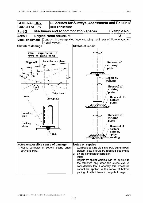
TAOROFNERAT Ж CARGO SHIPS GODEUNESroRSUEVEYR ARRERRYl^ANDREPAIRQFHULLSI^^ РАКГЗ
GENERAL DRY CARGO SHIPS
Guidelines for Surveys, Assessment and Repair of Hull Structure
Part 3Area 1
Machinery and accommodation spacesEngine room structure
Example No.............2...........
Detail of damage Corrosion in bottom plating under sounding pipe in way of bilge storage tank in engine room______
Sketch of damage
Soundingpipe
Strikingplate
Sketch of repair
Renew al o fstrikingplate
Repair by welding
R enew al o fstrikingplate
Renew al ofbottomplate
R enew al o fstrikingplate
R enew al o f bottom plate by spigot
^.welding
Notes on possible cause of damage1. Heavy corrosion of bottom plating under
sounding pipe.
Notes on repairs1. Corroded striking plating should be renewed.
Bottom plate should be repaired depending2. on the condition of corrosion.
(Note)Repair by spigot welding can be applied to the structure only when the stress level is considerably low. Generally this procedure cannot be applied to the repair of bottom plating of ballast tanks in cargo hold region.
INTERNATIONAL ASSOCIATION OF CLASSIFICATION SOCIETIES______________________________________________________________________________________ AREA 1
122
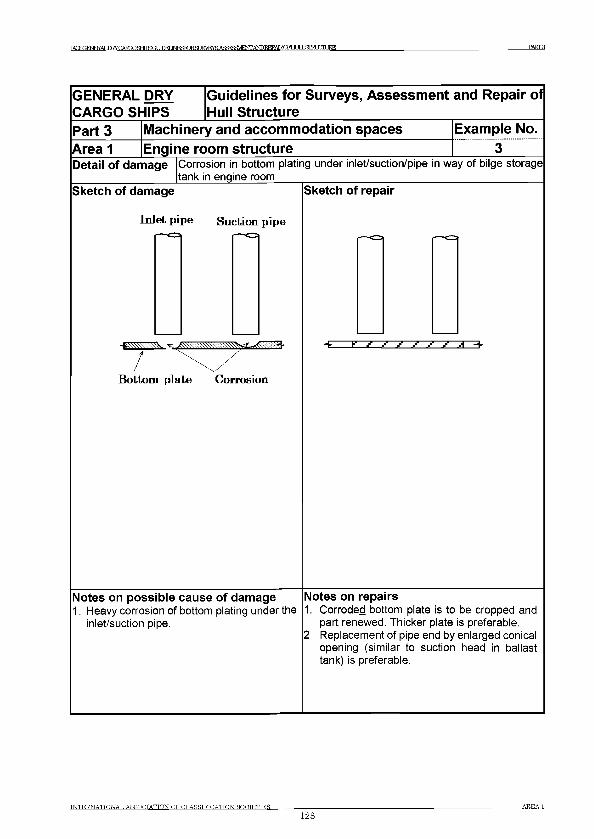
TATSffFNFRAT ,nRYCAT?fr)gHIFSGUDEIJNF^KlRar 1RVEYS А Я Я ^ Ш Е Ж А Ш Е Е Р А Е С Р Ш 1 Ь & т а 1 Ж Д Ж PART3
GENERAL DRY CARGO SHIPS
Guidelines for Surveys, Assessment and Repair of Hull Structure
Part 3 Machinery and accommodation spaces Example No.Area 1 Engine room structureDetail of damage Corrosion in bottom plating under inlet/suction/pipe in way of bilge storage
tank in engine roomSketch of damage
Inlet pipe Suction pipe
B ottom plate Corrosion
Sketch of repair
Notes on possible cause of damage1. Heavy corrosion of bottom plating under the
inlet/suction pipe.
Notes on repairs1. Corroded bottom plate is to be cropped and
part renewed. Thicker plate is preferable.2 Replacement of pipe end by enlarged conical
opening (similar to suction head in ballast tank) is preferable.
INTERNATIONAL ASSOCIATION OF CLASSIFICATION SOCIETIES_________________123
AREA 1
IA C S G E N E R A L D R Y C A R G O SE T F S O t Ш Е Г J ^ r o R S U E ^ E ^ A S ^ S a V E O T A ^ I ^ A E O F H U l X S I R L U r L I R E P A R T 3
Area 2 Accommodation structure
C ontents
1 General/General comments to repair
Figures and/or Photographs - Area 42No. Title
Photograph 1 Corroded accommodation house structure
IN T E R N A T IO N A L A S S O C IA T IO N O F C L A S S IF IC A T IO N S O C IE T IE S A R E A 2
124
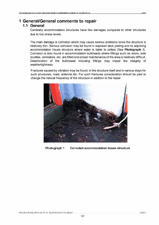
IACSGE№^DRYCARmSfTrFBGl JIDET INESTOR.Sf К Ж ^ А ^ ^ ^ / Е ^ Ж Р 1 ^ А Е 0 Р Е т & Т Е т [ Ш Е PART 8
1 General/General comments to repair1.1 G eneral
Generally accommodation structures have few damages compared to other structures
due to low stress levels.
The main damage is corrosion which may cause serious problems since the structure is
relatively thin. Serious corrosion may be found in exposed deck plating and its adjoining
accommodation house structure where water is liable to collect (See Photograph 1). Corrosion is also found in accommodation bulkheads where fittings such as doors, side
scuttles, ventilators, etc. are fitted and proper maintenance of the area is relatively difficult.
Deterioration of the bulkheads including fittings may impair the integrity of
weathertightness.
Fractures caused by vibration may be found, in the structure itself and in various stays for
such structures, mast, antenna etc. For such fractures consideration should be paid to
change the natural frequency of the structure in addition to the repair.
Photograph 1 Corroded accommodation house structure
INTERNATIONAL ASSOCIATION OF CLASSIFICATION SOCIETIES AREA 2
125
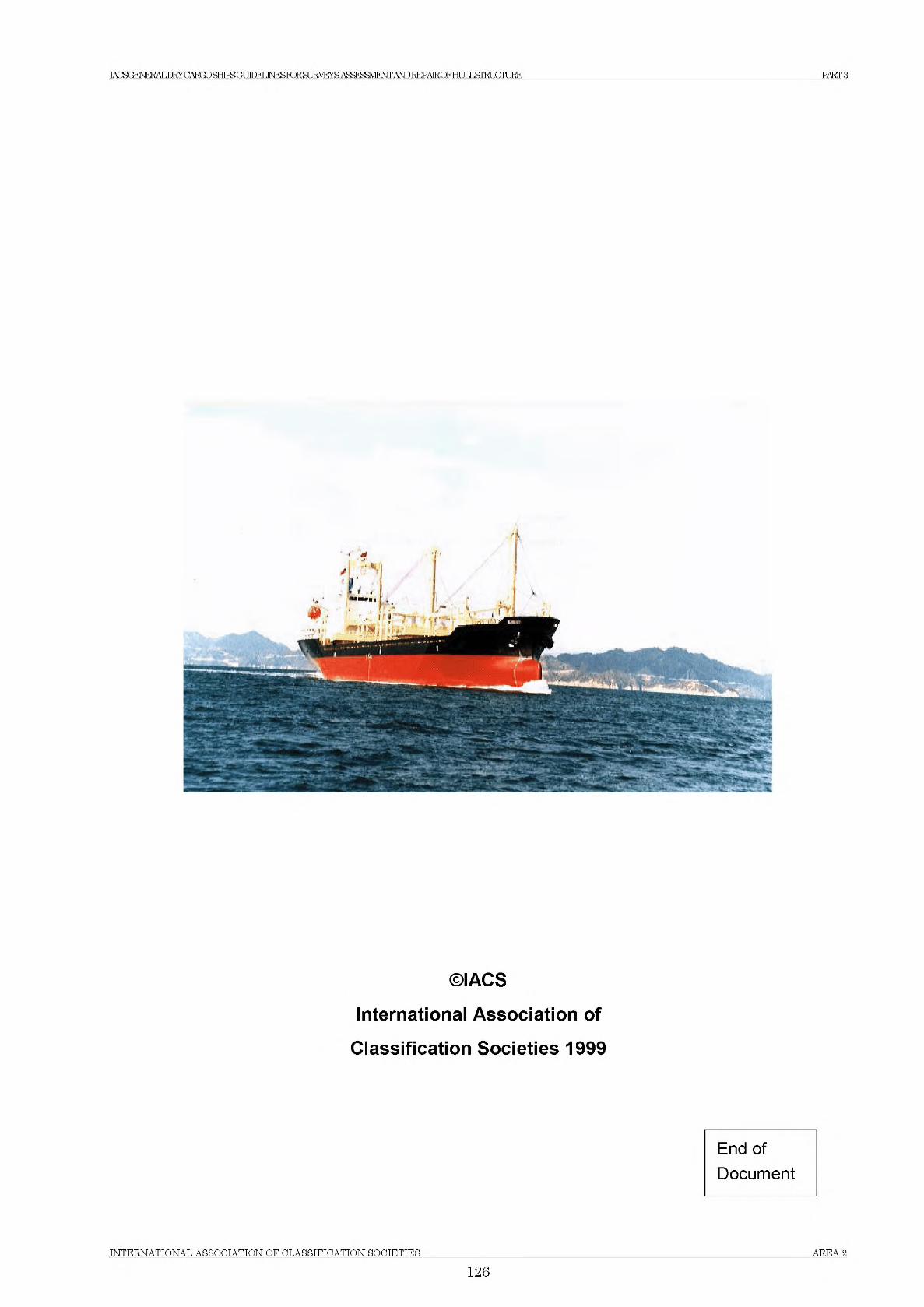
IACSGEm^DRYCARGOSfTrFBGl JIDET INESTOR.Sf FM^AS^^/E^AbDI^AROFELILL&TEOSTLlRE PARTS
©IACS
International Association of
Classification Societies 1999
End of
Document
INTERNATIONAL ASSOCIATION OF CLASSIFICATION SOCIETIES AREA 2
126

No.76
No.76 IACS G uidelines fo r Surveys, Assessm ent and (1Rev4] Repair o f Hull S tructure - Bulk CarriersJuly 2001)(Rev. 2 June 2004)(Corr.1 Sept 2007)
IACS Rec. 2004/Corr.1 2007
IACSIN TERNATIONAL ASSOCIATION
OF CLASSIFICATION SOCIETIES
BULK CARRIERS
Guidelines for Surveys, Assessment and Repair of Hull Structure
Copyright© IACS - the International A ssociation o f Classification Societies and the
International A ssociation o f Classification Societies Limited.
All rights reserved.
Except as permitted under current English legislation no part of this work may be photocopied, stored in a retrieval system, published, performed in public, adapted, broadcast, transmitted, recorded or reproduced in any form or by means, without prior permission of the copyright owner.
Where IACS has granted written permission for any part of this publication to be quoted such quotation must include acknowledgement to IACS.
Enquiries should be addressed to the Permanent Secretary:
International Association of Classification Societies Ltd,36 Broadway, □London, SW1H OBH Telephone: 020 7976 0660Fax: 020 7808 1100Email: [email protected]
With regard to information published on this website and where the copyright resides with IACS and IACS Ltd., permission is hereby granted for use, as above.
Terms and ConditionsThe International Association of Classification Societies (IACS), its Member Societies and IACS Ltd. and their directors, officers, members, employees and agents (on behalf of whom this notice is issued) shall be under no liability or responsibility in contract or negligence or otherwise howsoever to any person in respect of any information or advice expressly or impliedly given in this document, or in respect of any inaccuracy herein or omission herefrom or in respect of any act or omission which has caused or contributed to this document being issued with the information or advice it contains (if any).Without derogating from the generality of the foregoing, neither the International Association of Classification Societies (IACS) nor IACS Ltd. nor its Member Societies nor their directors, officers, members, employees or agents shall be liable in contract or negligence or otherwise howsoever for any direct, indirect or consequential loss to any person caused by or arising from any information, advice, inaccuracy or omission given or contained herein or any act or omission causing or contributing to any such information, advice, inaccuracy or omission given or contained herein.
Any dispute concerning the provision of material herein is subject to the exclusive jurisdiction of the English courts and will be governed by English Law.
B U L K C A RR IER S: G U D E L J N E S K R S U R № y . A S S E S S M E N I'A N i:) R[ P A IR O T I H Jl ] .S T R U C T U R E OONIENIS
C ontents
1 Introduction
2 Class survey requirements2.1 General2.2 Annual Surveys2.3 Intermediate Surveys2.4 Special Surveys2.5 Bottom surveys2.6 Damage and repair surveys
3 Technical background for surveys3.1 General3.2 Definitions3.3 Structural damages and deterioration3.4 Structural detail failures and repairs3.5 IACS Early Warning Scheme (EWS) for reporting of significant damage
4 Survey planning, preparation and execution4.1 General4.2 Survey Programme4.3 Principles for Planning Document4.4 Conditions for survey4.5 Access arrangement and safety4.6 Personal equipment4.7 Thickness measurement and fracture detection4.8 Survey at sea or at anchorage4.9 Documentation on board
5 Structural detail failures and repairs5.1 General5.2 Catalogue of structural detail failures and repairs
Part 1 Cargo hold regionArea 1 Deck structure Area 2 Topside tank structure Area 3 Side structureArea 4 Transverse bulkheads including stool structure Area 5 Double bottom including hopper tank structure
Part 2 Fore and aft end regionsArea 1 Fore end structure Area 2 Aft end structureArea 3 Stern frame, rudder arrangement and propeller shaft
support
INTERNATIONAL ASSOCIATION OF CLASSIFICATION SOCIETIES OONIENIS
1
B^Q\lMERS:GljroELJNESroRSL]RVEY.ASSESaVIENrANDREPAlROFtMLSroUCIlJRE CONTENTS
Part 3 Machinery and accommodation spaces Area 1 Engine room structure Area 2 Accommodation structure
INTERNATIONAL ASSOCIATION OF CLASSIFICATION SOCIETIES CONTENTS
2
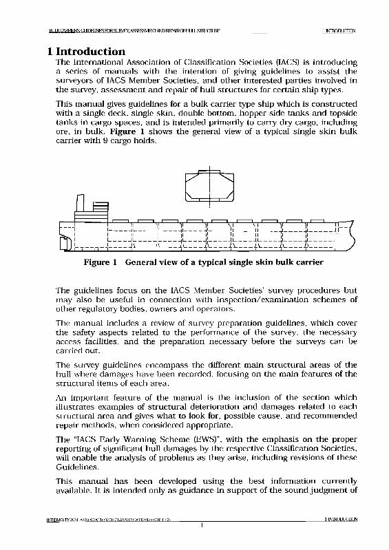
BULK GM^RERSGUEHINESFDRSURVKY ASSESSMENT AND REPAIR n F H lII.S M J Q U R E 1 Г О Ю Ш С П Ш
1 IntroductionThe International Association of Classification Societies (IACS) is introducing a series of manuals with the intention of giving guidelines to assist the surveyors of IACS Member Societies, and other interested parties involved in the survey, assessment and repair of hull structures for certain ship types.This manual gives guidelines for a bulk carrier type ship which is constructed with a single deck, single skin, double bottom, hopper side tanks and topside tanks in cargo spaces, and is intended primarily to carry dry cargo, including ore, in bulk. Figure 1 shows the general view of a typical single skin bulk carrier with 9 cargo holds.
Figure 1 General view o f a typical single skin bulk carrier
The guidelines focus on the IACS Member Societies’ survey procedures but may also be useful in connection with inspection/examination schemes of other regulatory bodies, owners and operators.The manual includes a review of survey preparation guidelines, which cover the safety aspects related to the performance of the survey, the necessary access facilities, and the preparation necessary before the surveys can be carried out.The survey guidelines encompass the different main structural areas of the hull where damages have been recorded, focusing on the main features of the structural items of each area.An important feature of the manual is the inclusion of the section which illustrates examples of structural deterioration and damages related to each structural area and gives what to look for, possible cause, and recommended repair methods, when considered appropriate.The “IACS Early Warning Scheme (EWS)”, with the emphasis on the proper reporting of significant hull damages by the respective Classification Societies, will enable the analysis of problems as they arise, including revisions of these Guidelines.This manual has been developed using the best information currently available. It is intended only as guidance in support of the sound judgment of
TNTRRNATIONAI. ASSOCIATION OF CLASSIFICATION SOCIFTIES__________________________________________________________________ 1 INITOUUCIION
\ . I /
-~~~__

BUIXQV R RE R SG Oim iN ESF^SU R V FY ASSESSMENT AND REPAIR CFHI IT ЯТШСШКЕ 1 INiroDUCDCN
surveyors, and is to be used at the surveyors' discretion. It is recognized that alternative and satisfactory methods are already applied by surveyors. Should there be any doubt with regard to interpretation or validity in connection with particular applications, clarification should be obtained from the Classification Society concerned.Figure 2 shows a typical cargo hold structural arrangement in way of cargo hold region.
.ASSIFICATION SOCIETIES2
1 М Ш 1 С П Ш
BULK CARRIERS: GUDELJNESroRSL]RVEY.ASSES3VIE№ AND REPAROFl-LlLLSroUCILlRE 2 CLASS SURVEy REQUIREMENTS
2 Class survey requirements2.1 General
2.1.1 The programme of periodical surveys is of prime importance as a means for assessment of the structural condition of the hull, in particular, the structure of cargo holds and adjacent tanks. The programme consists of Special (or Renewal) Surveys carried out at five-year interval with Annual and Intermediate Surveys carried out in between Special Surveys.
2.1.2 Since 1991, it has been a requirement for new bulk carriers to apply a protective coating to the structure in water ballast tanks which form part of the hull boundary, and, since 1993, to part of the side shell and transverse watertight bulkheads structures in way of the cargo holds.
2.1.3 The International Maritime Organization (IMO), in 1997 SOLAS Conference, adopted structural survivability standards for new and existing bulk carriers carrying the high density cargoes. All new single side skin bulk carriers, defined as ships built on or after 1st July 1999, are required to have sufficient strength to withstand the flooding of any one cargo hold taking dynamic effects into account. All existing single side skin bulk carriers, defined as ships built before 1 July 1999, must comply with the relevant IACS criteria for assessing the vertically corrugated transverse watertight bulkhead between the first two cargo holds and the double bottom in way of the first cargo hold with the first cargo hold assumed flooded. The relevant IMO adopted standards, IACS UR S I9 and S22 for existing ships, and recommended standards, IACS UR S I7, S18 and S20 for new ships, and the extent of possible repairs and/or reinforcements of vertically corrugated transverse watertight bulkheads on existing bulk carriers are freely available at IACS web site www.iacs.org.uk.
2.1.4From 1 July 2001, bulk carriers of 20,000 DWT and above, to which the Enhanced Survey Programme (ESP) requirements apply, starting with the 3rd Special Survey, all Special and Intermediate hull classification surveys are to be carried out by at least two exclusive surveyors. Further, one exclusive surveyor is to be on board while thickness measurements are taken to the extent necessary to control the measurement process.
2.1.5 The detailed survey requirements complying with ESP are specified in the Rules and Regulations of each IACS Member Society.
2.1.6 The ESP is based on two principal criteria: the condition of the coating and the extent of structural corrosion. Of primary importance is when a coating has been found to be in a “poor” condition (more than 20% breakdown of the coating or the formation of hard scale in 10 % more of the area) or when a structure has been found to be substantially corroded (i.e. a wastage between 75 % and 100 % of the allowable diminution for the structural member in question.).
t n t f r n a t io n a l a s s o c i a t i o n o f c l a s s i f i c a t i o n s o c i e t i e s
32 OASSSURVEyREQUIREMENTS
B U U C C A R R IE D (X H E E U N E S T O R S U W E y . A S S E S S M E N T A N D K E P A IR C F E IL IL L S IK L IC IU R E 2 O A S S S U R V E Y R E Q U IR E M E N T S
2.2 Annual Surveys2.2.1 The purpose of an Annual Survey is to confirm that the general
condition of the hull is maintained at a satisfactory level.
2.2.2 As the ship ages, cargo holds are required to be subjected to more extensive overall and close-up examinations at Annual Surveys.
2.2.3 In addition, overall and close-up examinations may be required for ballast tanks as a consequence of either the coating deteriorating to a poor condition or the structure being found to be substantially corroded at previous Intermediate or Special Surveys.
2.3 Intermediate Surveys2.3.1 The Intermediate Survey replaces the second or third Annual Survey in
each five year Special Survey cycle and requires that, in addition to the Annual Survey requirements, extended overall and close-up examinations including thickness measurements of cargo holds and ballast tanks used primarily for salt water ballast, are carried out.
2 . 3 . 2 The survey also includes re-examination and thickness measurements of any suspect areas which have substantially corroded or are known to be prone to rapid wastage.
2.3.3 Areas in ballast tanks and cargo holds found suspect at the previous Special Survey are subject to overall and close-up surveys, the extent of which becomes progressively more extensive commensurate with the age of the vessel.
2.3.4 As of 1 July 2001, for bulk carriers exceeding 15 years of age, the requirements of the Intermediate Survey are to be of the same extent as the previous Special Survey, except for pressure testing of cargo/ballast holds and ballast tanks which is not required unless deemed necessary by the attending surveyor.
2.4 Special Surveys2.4.1 The Special (or Renewal) Surveys of the hull structure are carried out at
five-year intervals for the purpose of establishing the condition of the structure to confirm that the structural integrity is satisfactory in accordance with the Classification Requirements, and will remain fit for its intended purpose for another five-year period, subject to proper maintenance and operation of the ship and to periodical surveys carried out at the due dates.
2.4.2 The Special Survey concentrates on close-up examination in association with thickness determination and is aimed at detecting fractures, buckling, substantial corrosion and other types of structural deterioration.
2.4.3 Thickness measurements are to be carried out upon agreement with the
t m t f r n a t io n a l a s s o c i a t i o n o f c l a s s i f i c a t i o n s o c i e t i e s
42 a A S S S U R V E Y R E P U IR E M E N I S
B IJL K C A R R IF R S : G U ID E L IN E S F O R S U W E Y . A S S F S P M F N T A N D R E P M R O F H I ПI .STR I О Т ]RF. 2 CLASSSURVEYREOUREMENIS
Classification Society concerned in conjunction with the Special Survey. The Special Survey may be commenced at the 4th Annual Survey and be progressed with a view to completion by the 5th anniversary date.
2.4.4 Deteriorated protective coating in salt water ballast spaces and structural areas showing substantial corrosion and/or considered by the surveyor to be prone to rapid wastage will be recorded for particular attention during the following survey cycle, if not repaired at the survey.
2 .5 Drydocking (Bottom) Surveys2.5.1 A Drydocking Survey is required in conjunction with the Special
Survey to examine the external underwater part of the ship and related items. Two Bottom surveys are required to be carried out during the five year period of validity of SOLAS Cargo Ship Safety Construction (SC) Certificate, and the maximum interval between any two successive Bottom Survey is not to exceed three years.
2.5.2 From 1 July 2002, for bulk carriers of 15 years of age and over, inspection of the outside of the ship’s bottom is to be carried out with the ship in dry dock. For bulk carriers less than 15 years of age, alternative inspections of the ship’s bottom not conducted in conjunction with the Special Survey may be carried out with the ship afloat. Inspection of the ship afloat is only to be carried out when the conditions are satisfactorily and the proper equipment and suitably qualified staff are available.
2 .6 Damage and repair surveys2.6.1 Damage surveys are occasional surveys which are, in general, outside
the programme of periodical hull surveys and are requested as a result of hull damage or other defects. It is the responsibility of the owner or owner’s representative to inform the Classification Society concerned when such damage or defect could impair the structural capability or watertight integrity of the hull. The damages should be inspected and assessed by the Society’s surveyors and the relevant repairs, if needed, are to be performed. In certain cases, depending on the extent, type and location of the damage, permanent repairs may be deferred to coincide with the planned periodical survey.
Any damage in association with wastage over the allowable limits (including buckling, grooving, detachment or fracture), or extensive areas of wastage over the allowable limits, which affects or, in the opinion of the surveyor, will affect the vessel’s structural watertight or weathertight integrity, is to be promptly and thoroughly repaired. Areas to be considered to are to include:Side shell frames, their end attachments and adjacent shell plating, deck structure and deck plating, watertight bulkheads, and hatch covers and coamings.
Ш1ЕЕ1 iaTTONAI. association of ct.asstficationsocieties
52 CLASSSUKVFy RFOl HRFMFNTS
B U L K C A R R IE 1 & G U ID E L IN E S F O R S U I M ^ . A S S E S S M E N T A N D K E P A IR O E 'H U L L S T R U C T U R E 2 O A S S S U R V E y R E Q U IR E M E N T S
2.6.2 In cases of repairs intended to be carried out by riding crew during voyage, the complete procedure of the repair, including all necessary surveys, is to be submitted to and agreed upon by the Classification Society reasonably in advance.
2.6.3 IACS Unified Requirement Z 13 “Voyage Repairs and Maintenance” provides useful guidance for repairs to be carried out by a riding crew during a voyage.
2.6.4 For locations of survey where adequate repair facilities are not available, consideration may be given to allow the vessel to proceed directly to a repair facility. This may require discharging the cargo and/or temporary repairs for the intended voyage. A suitable condition of class will be imposed when temporary measures are accepted.
IfflEEMATlQHALASSOCIATlON, .ASSIFICATION SOCIETIES6
2 a ASS SURVEY RTOLJIREMENIS
B U L K CARRIERS GUEBJNESroRSURVEY. ASSESSMENT AND REPAIROFFIULLSIRUCILIRE 3 T E C H N IC A L B \C K G R O U N D F O R S U W E Y S
3 Technical background for surveys3.1 General
3.1.1 The purpose of carrying out the periodical hull surveys is to detect possible structural defects and damages and to establish the extent of any deterioration. To help achieve this and to identify key locations on the hull structure that might warrant special attention, knowledge of any historical problems of the particular ship or other ships of a similar class is to be considered if available. In addition to the periodical surveys, occasional surveys of damages and repairs are carried out. Records of typical occurrences and chosen solutions should be available in the ship's history file.
3 .2 D efinitions3.2.1 For clarity of definition and reporting of survey data, it is recommended
that standard nomenclature for structural elements be adopted. Typical sections in way of cargo holds are illustrated in Figures 3 (a) and (b). These figures show the generally accepted nomenclature.The terms used in these guidelines are defined as follows.(a) Ballast Tank is a tank which is used primarily for salt water ballast.(b) Spaces are separate compartments including holds and tanks.(c) Overall examination is an examination intended to report on the
overall condition of the hull structure and determine the extent of additional close-up examinations.
(d) Close-up examination is an examination where the details of structural components are within the close visual examination range of the surveyors, i.e. normally within reach of hand.
(e) Transverse Section includes all longitudinal members such as plating, longitudinals and girders at the deck, side, bottom and inner bottom, hopper side tanks and top wing tanks.
(f) Representative Spaces are those which are expected to reflect the condition of other spaces of similar type and service and with similar corrosion protection systems. When selecting representative spaces, account should be taken of the service and repair history on board.
(g) Suspect Areas are locations showing Substantial Corrosion and/or are considered by the surveyor to be prone to rapid material wastage.
(h) Substantial Corrosion is an extent of corrosion such that assessment of corrosion pattern indicates a material wastage in excess of 75 per cent of allowable margins, but within acceptable limits.
(i) Coating Condition is defined as follows:Good - condition with only minor spot rusting.Fair - condition with local breakdown at edges of stiffeners and
weld connections and/or light rusting over 20 per cent or more of areas under consideration, but less than as defined for Poor condition.
Poor - condition with general breakdown of coating over 20 per cent or more of areas or hard scale at 10 per cent or more of
INTERNATIONAL ASSOCIATION OF CLASS1F1CAT10NS0C1ET1ES
73 TECHNICAL BACKGROUND FOR SURVEYS
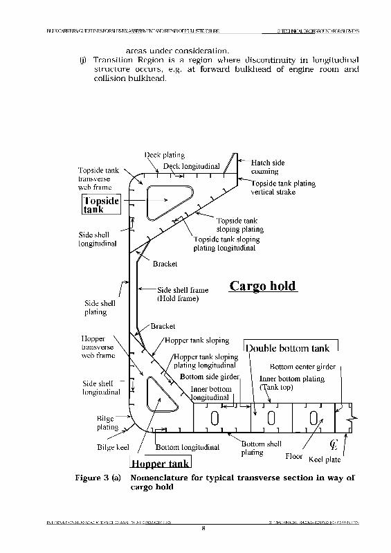
B l l K C A RR IER S: G l^ E U N E S r o R S U IA C T .A S S K S S V IF N T A N D R E ^P A IR O F H I IL .S T R l 1 С Л 1RR 3 T E C H N IC A L E A C K G R D U N D FD R SL IR V E A S
areas under consideration.(j) Transition Region is a region where discontinuity in longitudinal
structure occurs, e.g. at forward bulkhead of engine room and collision bulkhead.
Topside tank transverse web frame
eck plating
Deck longitudinal "1----Г---П=5Ч— I— I—
Side shell longitudinal
rSide shell plating
Hopper transverse web frame
Side shell ~ t ] longitudinal ^
Bilgeplating
Bilge keel
Hatch side coaming
Topside tank plating vertical strake
Topside tank sloping plating
Topside tank sloping plating longitudinal
Bracket
"Side shell frame (Hold frame)
Cargo hold
Bracket
Hopper tank sloping
opper tank sloping plating longitudinal
Bottom side girder
Inner bottom
Double bottom tank
Bottom center girder
Inner bottom plating (Tank top)
I— j i< J j
n Гг J1 Jr
j
и1 1 1
l1J
1l
__J/h ___
Bottom longitudinal
Hopper tank
Bottom shell
P'ati"8 Floor
Figure 3 (a) Nomenclature for typical transverse section in way cargo hold
o f
INTERNATIONAL ASSOCIATION OF CLASSIFICATION SOCIETIES
83 TECHNICAL BACKGROUND FOR SURVEYS
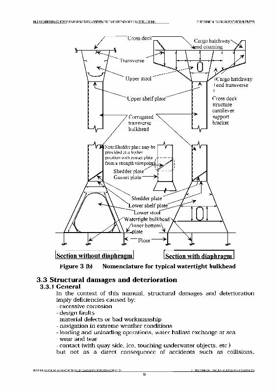
B^CARRERSGmELJNESroRSUIACTASSRSSMFNTWDREPAlROFtMLSIRUCILlRE 3 TECHNICAL BACKGROUND FORSUIMflS
Section without diaphragm Section with diaphragmFigure 3 (b) Nomenclature for typical watertight bulkhead
3.3 Structural damages and deterioration3.3.1 General
In the context of this manual, structural damages and deterioration imply deficiencies caused by:- excessive corrosion- design faults- material defects or bad workmanship- navigation in extreme weather conditions-loading and unloading operations, water ballast exchange at sea- wear and tear- contact (with quay side, ice, touching underwater objects, etc.)but not as a direct consequence of accidents such as collisions,
INTERNATIONAL ASSOCIATION OF CLASSIFICATION SOCIETIES
93 TECHNICAL BACKGROUND FOR SURVEYS
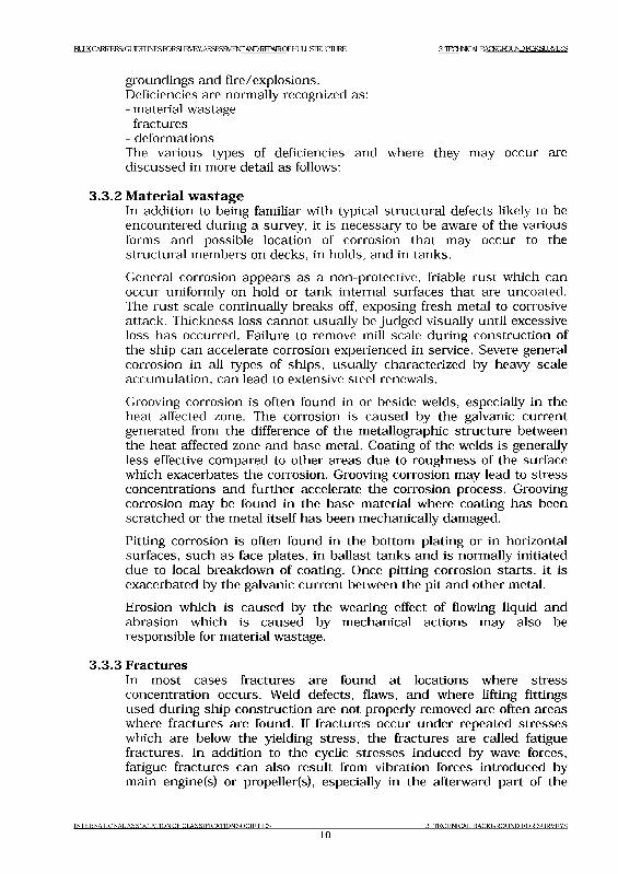
B l lX C A lM E R S iG U D E I lN E S r o R S IJ R V E Y .A S S E S a V IE N r A N D R E P A lR O F l- lL lL L S ro i J C I lJ R E 3 T E C H N IC A L m C K G r o iJ N D r o R S U R V E V S
groundings and fire/explosions.Deficiencies are normally recognized as:- material wastage- fractures- deformationsThe various types of deficiencies and where they may occur are discussed in more detail as follows:
3.3.2 M aterial w astageIn addition to being familiar with typical structural defects likely to be encountered during a survey, it is necessary to be aware of the various forms and possible location of corrosion that may occur to the structural members on decks, in holds, and in tanks.General corrosion appears as a non-protective, friable rust which can occur uniformly on hold or tank internal surfaces that are uncoated. The rust scale continually breaks off, exposing fresh metal to corrosive attack. Thickness loss cannot usually be judged visually until excessive loss has occurred. Failure to remove mill scale during construction of the ship can accelerate corrosion experienced in service. Severe general corrosion in all types of ships, usually characterized by heavy scale accumulation, can lead to extensive steel renewals.Grooving corrosion is often found in or beside welds, especially in the heat affected zone. The corrosion is caused by the galvanic current generated from the difference of the metallographic structure between the heat affected zone and base metal. Coating of the welds is generally less effective compared to other areas due to roughness of the surface which exacerbates the corrosion. Grooving corrosion may lead to stress concentrations and further accelerate the corrosion process. Grooving corrosion may be found in the base material where coating has been scratched or the metal itself has been mechanically damaged.Pitting corrosion is often found in the bottom plating or in horizontal surfaces, such as face plates, in ballast tanks and is normally initiated due to local breakdown of coating. Once pitting corrosion starts, it is exacerbated by the galvanic current between the pit and other metal.Erosion which is caused by the wearing effect of flowing liquid and abrasion which is caused by mechanical actions may also be responsible for material wastage.
3.3.3 FracturesIn most cases fractures are found at locations where stress concentration occurs. Weld defects, flaws, and where lifting fittings used during ship construction are not properly removed are often areas where fractures are found. If fractures occur under repeated stresses which are below the yielding stress, the fractures are called fatigue fractures. In addition to the cyclic stresses induced by wave forces, fatigue fractures can also result from vibration forces introduced by main engine(s) or propeller(s), especially in the afterward part of the
INTERNATIONAL ASSOCIATIONOFCLASSIFICATIONSOCIETIES
103 TECHNICAL BACKGROUND FOR SURVEYS
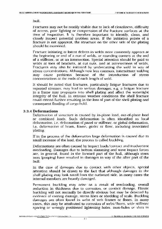
B U U < C A ir a 3 S G L I l E B J N E S r o R S L l R V E Y . A S S E S S M E N T A N D R E P A 1 R C F H U L S IR L IC IL 1 R E 3 T IP INK Л1T W KC. I Q JNIЖ Ж SI JIAT YS
hull.Fractures may not be readily visible due to lack of cleanliness, difficulty of access, poor lighting or compression of the fracture surfaces at the time of inspection. It is therefore important to identify, clean, and closely inspect potential problem areas. If the initiation points of a fracture is not apparent, the structure on the other side of the plating should be examined.Fracture initiating at latent defects in welds more commonly appears at the beginning or end of a run of welds, or rounding corners at the end of a stiffener, or at an intersection. Special attention should be paid to welds at toes of brackets, at cut-outs, and at intersections of welds. Fractures may also be initiated by undercutting the weld in way of stress concentrations. Although now less common, intermittent welding may cause problems because of the introduction of stress concentrations at the ends of each length of weld.It should be noted that fractures, particularly fatigue fractures due to repeated stresses, may lead to serious damages, e.g. a fatigue fracture in a frame may propagate into shell plating and affect the watertight integrity of the hull. In extreme weather conditions the shell fracture could extend further resulting in the loss of part of the shell plating and consequent flooding of cargo hold.
3.3.4 D eform ationsDeformation of structure is caused by in-plane load, out-of-plane load or combined loads. Such deformation is often identified as local deformation, i.e. deformation of panel or stiffener, or global deformation, i.e. deformation of beam, frame, girder or floor, including associated plating.If in the process of the deformation large deformation is caused due to small increase of the load, the process is called buckling.Deformations are often caused by impact loads/contact and inadvertent overloading. Damages due to bottom slamming and wave impact forces are, in general, found in the forward part of the hull, although stern seas (pooping) have resulted in damages in way of the after part of the hull.In the case of damages due to contact with other objects, special attention should be drawn to the fact that although damages to the shell plating may look small from the outboard side, in many cases the internal members are heavily damaged.Permanent buckling may arise as a result of overloading, overall reduction in thickness due to corrosion, or contact damage. Elastic buckling will not normally be directly obvious but may be detected by evidence of coating damage, stress lines or shedding of scale. Buckling damages are often found in webs of web frames or floors. In many cases, this may be attributed to corrosion of webs/floors, wide stiffener spacing or wrongly positioned lightening holes, man-holes or slots in
INTERNATIONAL ASSOCIATION OF CLASSIFICATION SOCIETIES
113 TECHNICAL BACKGROUND FOR SURVEYS
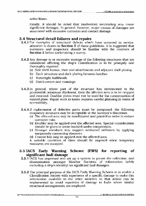
B U X C A R R IE R S G L T O E U N E S ro R S U K y E y , A S S E S S M E N T A N D R E P A IR O F E IU L L S T R U C T U R E 3 'IH:HNK_AU)A(XC.№XJNDIORStJI^YS
webs/floors.Finally, it should be noted that inadvertent overloading may cause significant damages. In general, however, major causes of damages are associated with excessive corrosion and contact damage.
3 .4 Structural detail failures and repairs3.4.1 For examples of structural defects which have occurred in service,
attention is drawn to Section 5 of these guidelines. It is suggested that surveyors and inspectors should be familiar with the contents of Section 5 before undertaking a survey.
3.4.2 Any damage to or excessive wastage of the following structures that are considered affecting the ship’s Classification is to be promptly and thoroughly repaired:(a) Side shell frames, their end attachments and adjacent shell plating(b) Deck structure and deck plating between hatches(c) Watertight bulkheads(d) Hatch covers and coamings
3.4.3 In general, where part of the structure has deteriorated to the permissible minimum thickness, then the affected area is to be cropped and renewed. Doubler plates must not be used for the compensation of wasted plate. Repair work in tanks requires careful planning in terms of accessibility.
3.4.4 If replacement of defective parts must be postponed, the following temporary measures may be acceptable at the surveyor’s discretion:(a) The affected area may be sandblasted and painted in order to reduce
corrosion rate.(b) Doubler may be applied over the affected area. Special consideration
should be given to areas buckled under compression.(c) Stronger members may support weakened stiffeners by applying
temporarily connecting elements.(d) Cement box may be applied over the affected area.A suitable condition of class should be imposed when temporary measures are accepted.
3 .5 IACS Early Warning Schem e (EWS) for reporting o f sign ificant hull damage
3.5.1 IACS has organised and set up a system to permit the collection, and dissemination amongst Member Societies of information (while excluding a ship's identity) on significant hull damages.
3.5.2 The principal purpose of the IACS Early Warning Scheme is to enable a Classification Society with experience of a specific damage to make this information available to the other societies so that action can be implemented to avoid repetition of damage to hulls where similar structural arrangements are employed.
INTERNATIONAL ASSOCIATION OF CLASSIFICATION SOCIETIES12
3 TECHNICAL BACKGROUND FOR SURVEYS

BULK CARRIERS: GUIDELINES FORSUKVEY. ASSESSMENT AND REPMROF HULL STRUCTURE 3 TECHNICAL BACKGROUND FORSUKYEYS
3.5.3 These guidelines incorporated the experience gained from IACS EWS Scheme.
IN T E R N A T IO N A L A S S O C I A T I O N O F C L A S S I F I C A T I O N S O C I E T I E S
133 T E C H N IC A L B A C K G R O U N D F O R S U R V E Y S
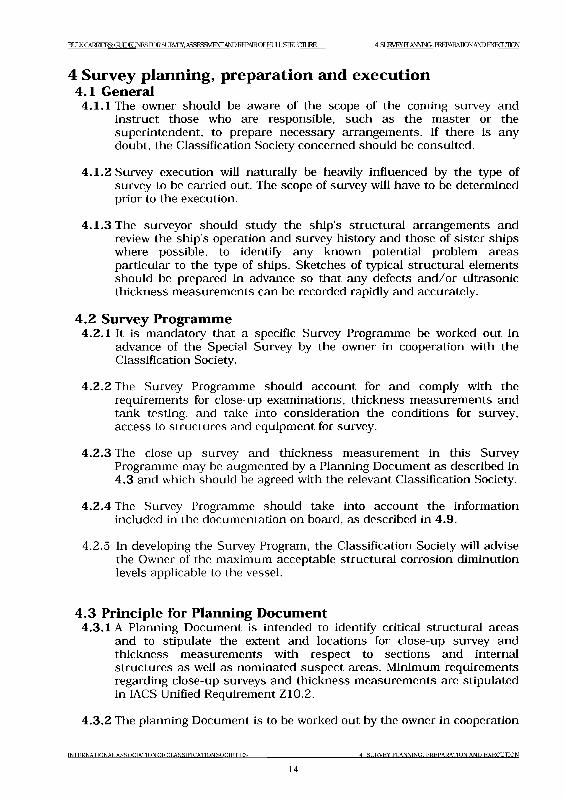
BUU< CARRIERS CODELJNESroRSURyEY.ASSESSME№ AND REPAIROF HULL STRUCTURE 4 SURVEYPLANNING. PREPARAIDN AND EXECUHCN
4 Survey planning, preparation and execution4.1 General
4.1.1 The owner should be aware of the scope of the coming survey and instruct those who are responsible, such as the master or the superintendent, to prepare necessary arrangements. If there is any doubt, the Classification Society concerned should be consulted.
4.1.2 Survey execution will naturally be heavily influenced by the type of survey to be carried out. The scope of survey will have to be determined prior to the execution.
4.1.3 The surveyor should study the ship’s structural arrangements and review the ship’s operation and survey history and those of sister ships where possible, to identify any known potential problem areas particular to the type of ships. Sketches of typical structural elements should be prepared in advance so that any defects and/or ultrasonic thickness measurements can be recorded rapidly and accurately.
4 .2 Survey Programme4.2.1 It is mandatory that a specific Survey Programme be worked out in
advance of the Special Survey by the owner in cooperation with the Classification Society.
4.2.2 The Survey Programme should account for and comply with the requirements for close-up examinations, thickness measurements and tank testing, and take into consideration the conditions for survey, access to structures and equipment for survey.
4.2.3 The close-up survey and thickness measurement in this Survey Programme may be augmented by a Planning Document as described in4.3 and which should be agreed with the relevant Classification Society.
4.2.4 The Survey Programme should take into account the information included in the documentation on board, as described in 4.9.
4.2.5 In developing the Survey Program, the Classification Society will advise the Owner of the maximum acceptable structural corrosion diminution levels applicable to the vessel.
4 .3 Principle for Planning D ocum ent4.3.1 A Planning Document is intended to identify critical structural areas
and to stipulate the extent and locations for close-up survey and thickness measurements with respect to sections and internal structures as well as nominated suspect areas. Minimum requirements regarding close-up surveys and thickness measurements are stipulated in IACS Unified Requirement Z10.2.
4.3.2 The planning Document is to be worked out by the owner in cooperation
INTERNATIONAL ASSOCIATION OF CLASSIFICATION SOCIETIES 4 SURVEY PLANNING. PREPARATION AND EXECUTION
14
BUJCQy^H^GUimiNESimSJWFV ASSFSSM^ANDIMWROFHUIlSim^IJRE 4 S U R V E Y F 1 A N N N G , PR E PA R A T IO N A N D EX E C U T IO N
with the relevant Classification Society well in advance of the survey.
4 .3 .3 The basis for nomination of spaces and areas in 4.3.1 above is a technical assessment and consideration of possible deterioration where the following elements on the particular ship are taken into account:(a) Design features such as extent of high tensile steel and local details;(b) Former history available at owner’s and the relevant Classification
Society’s offices with respect to material wastage, fractures, deformations and repairs for the particular ship as well as similar vessels.
(c) Information from same offices with respect to type of cargo, use of different spaces for cargo/ballast, protection of spaces and condition of coating, if any.
4.3.4 The Planning Document is to contain relevant information pertaining to at least the following information:(a) Main particulars(b) Main structural plans (scanding drawings), including
informationregarding use of high tensile steels
(c) Plan of tanks/holds(d) List of tanks/holds with information on use, protection
and condition of coating(e) Conditions for survey (e.g. information regarding hold
and tank cleaning, gas freeing, ventilation, lighting, etc)(f) Provisions and methods for access(g) Equipment for surveys(h) Corrosion risk nomination of holds and tanks(i) Design related damages on the particular ship, and
similar vessels, where available.(j) Selected holds and tanks and areas for close-up survey(k) Selected sections for thickness measurements(l) Acceptable corrosion allowance(m) Damage experience related to the ship in question
4 .4 C onditions for survey4.4.1 The owner is to provide the necessary facilities for a safe execution of
the survey.
4 .4 .2 Tanks and spaces are to be safe for access, i.e. gas freed (marine chemist certificate), ventilated, illuminated, etc.
4 .4 .3 Tanks and spaces are to be sufficiently clean and free from water, scale, dirt, oil residues, etc. and sufficient illumination is to be provided, to reveal corrosion, deformation, fractures, damages or other structural deterioration. In particular this applies to areas which are subject to thickness measurement.
INTERNATIONAL ASSOCIATION OF CLASSIFICATION SOCIETIES 4 SURVEY PLANNING. PREPARATION AND EXECUTION
15
IMJIK( AI^I'.l«:C.UIIJI']lNI«IORStJIA/| YASSI?javlENrANDREPAlROFHI III SIM KTII IRF. 4 S U R V E Y F 1 A N N N G . PR E PA R A T IO N A N D E X E C U H C N
4 .5 A ccess arrangem ent and safety4.5.1 In accordance with the intended survey, measures are to be provided to
enable the hull structure to be examined and thickness measurement carried out in a safe and practical way.
4.5.2 For close-up surveys in a cargo hold and salt water ballast tanks, one or more of the following means for access, acceptable to the Surveyor, are to be provided:
a) permanent staging and passages through structures;b) temporary staging, e.g. ladders and passages through
structures;c) lifts and movable platforms; andd) other equivalent means.
4.5.3 In addition, particular attention should be given to the following guidance:(a) Prior to entering tanks and other closed spaces, e.g. chain lockers,
void spaces, it is necessary to ensure that the oxygen content is to be tested and confirmed as safe. A responsible member of the crew should remain at the entrance to the space and if possible communication links should be established with both the bridge and engine room. Adequate lighting should be provided in addition to a hand held torch (flashlight).
(b) In tanks where the structure has been coated and recently deballasted, a thin slippery film may often remain on the surfaces. Care should be taken when inspecting such spaces.
(c) The removal of scale may be extremely difficult. The removal of scale by hammering may cause sheet scale to fall, and in cargo holds this may result in residues of cargo falling from above. When using a chipping or scaling hammer care should be taken to protect eyes, and where possible safety glasses should be worn.If the structure is heavily scaled then it may be necessary to request de-scaling before conducting a satisfactory visual examination.
(d) Owners or their representatives have been known to request that a survey be carried out from the top of the cargo during discharging operations. For safety reason, surveys must not to be carried out during discharging operations in the hold.
(e) In bulk carriers fitted with vertical ballast trunks connecting the topside and lower hopper tanks, the trunks and associated hull structure are normally surveyed in conjunction with the tanks. Space within the trucks is very limited and access is by ladder or individual rungs which can become heavily corroded and in some cases detached or missing. Care needs to be taken when descending these trunks.
(f) When entering a cargo hold or tank the bulkhead vertical ladders should be examined prior to descending to ensure that they are in good condition and rungs are not missing or loose. If holds are being entered when the hatch covers are in the closed position, then adequate lighting should be arranged in the holds. One person at a
INTERNATIONAL ASSOCIATION OF Cl.ASSIFICATION SOCIETIES 4 SURVEY PLANNING. PREPARATION AND EXECUTION
16
BULK CARRIERS: GUDEUNESroRSU№Ey.ASSES3VIE№ AND RE^MROF HULL SIRLJCIURE 4 SURVEY FLANMNG, PREPARATION AND EXECUIICN
time should descend or ascend the ladder.(g) Sloping (“Australian Style”) bulkhead ladders are prone to cargo
handling damage and it is not uncommon to find platforms and ladders in poor condition with rails and stanchions missing or loose.
(h) If a portable ladder is used for survey purposes, the ladder should be in good condition and fitted with adjustable feet, to prevent it from slipping. Two crew members should be in attendance in order that the base of the ladder is adequately supported during use. The remains of cargo, in particular fine dust, on the tank top should be brushed away as this can increase the possibility of the ladder feet slipping.
(i) If an extending/articulated ladder (frame walk) is used to enable the examination of upper portions of cargo hold structure, the ladder should incorporate a hydraulic locking system and a built in safety harness. Regular maintenance and inspection of the ladder should be confirmed prior to its use.
(j) If a hydraulic arm vehicles (“Cherry Picker”) is used to enable the examination of the upper parts of the cargo hold structure, the vehicle should be operated by qualified personnel and there should be evidence that the vehicle has been properly maintained. The standing platform should be fitted with a safety harness. For those vehicles equipped with a self leveling platform, care should be taken that the locking device is engaged after completion of maneuvering to ensure that the platform is fixed.
(k) Staging is the most common means of access provided especially where repairs or renewals are being carried out. It should always be correctly supported and fitted with handrails. Planks should be free from splits and lashed down. Staging erected hastily by inexperienced personnel should be avoided. In topside and lower hopper tanks it may be necessary to arrange staging to provide close-up examination of the upper parts of the tank particularly the transverse web frames, especially where protective coatings have broken down or have not been applied.
(l) In double bottom tanks there will often be a build up of mud on the bottom of the tank and this should be removed, in particular in way of tank boundaries, suction and sounding pipes, to enable a clear assessment of the structural condition.
4 .6 Personal equipm ent4.6.1 The following protective clothing and equipment to be worn as
applicable during the surveys:(a) Working clothes: Working clothes should be of a low flammability
type and be easily visible.(b) Head protection: Hard hat (metal hats are not allowed) shall always
be worn outside office building/unit accommodations.(c) Hand and arm protection: Various types of gloves are available for
use, and these should be used during all types of surveys. Rubber/plastic gloves may be necessary when working in cargo holds.
INTERNATIONAL ASSOCIATION OF CLASSIFICATION SOCIETIES 4 SURVEY PLANNING. PREPARATION AND EXECUTION
17
B ^ C A R R E R S G M J E L J N E S r o R S U I A ^ Y .A S S E S a V I E N r A N D R E P A lR C F H L lL S I H U C I U R E 4 St ЛАТУ И ANNING. И4 PAIWIION AND IX I Ш И Ш
(d) Foot protection: Safety shoes or boots with steel toe caps and non slip soles shall always be worn outside office buildings/unit accommodations. Special footwear may be necessary on slippery surfaces or in areas with chemical residues.
(e) Ear protection: Ear muffs or ear plugs are available and should be used when working in noisy areas. As a general rule, you need ear protection if you have to shout to make yourself understood by someone standing close to you.
(f) Eye protection: Goggles should always be used when there is danger of getting solid particles or dust into the eyes. Protection against welding arc flashes and ultraviolet light should also be considered.
(g) Breathing protection: Dust masks shall be used for protection against the breathing of harmful dusts, paint spraying and sand blasting. Gas masks and filters should be used by personnel working for short periods in an atmosphere polluted by gases or vapour.(Self-contained breathing apparatus: Surveyors shall not enter spaces where such equipment is necessary due to unsafe atmosphere. Only those who are specially trained and familiar with such equipment should use it and only in case of emergency).
(h) Lifejacket: Recommended used when embarking/disembarkingships offshore, from/to pilot boat.
4.6.2 The following survey equipment is to be used as applicable during thesurveys:(a) Torches: Torches (Flashlights) approved by a competent authority
for use in a flammable atmosphere shall be used in gas dangerous areas. High intensity beam type is recommended for in-tank inspections. Torches are recommended to be fitted with suitable straps so that both hands may be free.
(b) Hammer: In addition to its normal purposes the hammer is recommended for use during surveys inside units, tanks etc. as it may be most useful for the purpose of giving distress signal in case of emergency.
(c) Oxygen analyser/Multigas detector: For verification of acceptable atmosphere prior to tank entry, pocket size instruments which give audible alarm when unacceptable limits are reached are recommended. Such equipment shall have been approved by national authorities.
(d) Safety belts and lines: Safety belts and lines should be worn where high risk of falling down from more than 3 meters is present.
(e) Radiation meter: For the purpose of detection of ionizing radiation (X or gamma rays) caused by radiographic examination, radiation meter of the type which gives audible alarm upon detection of radiation is recommended.
4 .7 T hickness m easurem ent and fracture d etection4.7.1 Thickness measurement is to comply with the requirements of the
Classification Society concerned. Thickness measurement should be
INTERNATIONAL ASSOCIATION OF CLASSIFICATION SO CIETIES 4 SURVEY PLANNING, PREPARATION AND EXECUTION
18
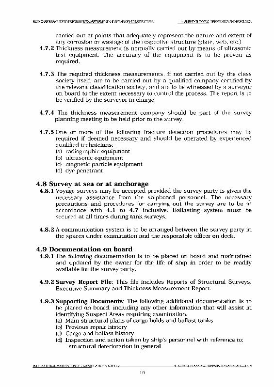
BULK CARRIERS: GUIDELINES FORSUWEy. ASSESSMENT AND REPMROF HI ПI .STRI О Т ]RF. 4 SURVEY HANNING. PREPARAIDN AND ЕХЕСШ1Ш
carried out at points that adequately represent the nature and extent of any corrosion or wastage of the respective structure (plate, web, etc.)
4.7.2 Thickness measurement is normally carried out by means of ultrasonic test equipment. The accuracy of the equipment is to be proven as required.
4.7.3 The required thickness measurements, if not carried out by the class society itself, are to be carried out by a qualified company certified by the relevant classification society, and are to be witnessed by a surveyor on board to the extent necessary to control the process. The report is to be verified by the surveyor in charge.
4.7.4 The thickness measurement company should be part of the survey planning meeting to be held prior to the survey.
4.7.5 One or more of the following fracture detection procedures may be required if deemed necessary and should be operated by experienced qualified technicians:(a) radiographic equipment(b) ultrasonic equipment(c) magnetic particle equipment(d) dye penetrant
4 .8 Survey at sea or at anchorage4.8.1 Voyage surveys may be accepted provided the survey party is given the
necessary assistance from the shipboard personnel. The necessary precautions and procedures for carrying out the survey are to be in accordance with 4.1 to 4.7 inclusive. Ballasting system must be secured at all times during tank surveys.
4.8.2 A communication system is to be arranged between the survey party in the spaces under examination and the responsible officer on deck.
4 .9 D ocum entation on board4.9.1 The following documentation is to be placed on board and maintained
and updated by the owner for the life of ship in order to be readily available for the survey party.
4.9.2 Survey Report File: This file includes Reports of Structural Surveys, Executive Summary and Thickness Measurement Report.
4.9.3 Supporting Documents: The following additional documentation is to be placed on board, including any other information that will assist in identifying Suspect Areas requiring examination.(a) Main structural plans of cargo holds and ballast tanks(b) Previous repair history(c) Cargo and ballast history(d) Inspection and action taken by ship's personnel with reference to:
- structural deterioration in general
INTERNATIONAL ASSOCIATION OF CLASSIFICATION SOCIETIES 4 SURVEY PLANNING. PREPARATION AND EXECUTION
19
B^Q\lMERS:GIJ3ELJNESroRSL]RVEY.ASSESaVIENrANDREPAlROFtMLSroUCIlJRE 4 SURVEY HANNING. PREPARATION AND EXECUTION
- leakages in bulkheads and piping- condition of coating or corrosion protection, if any
(e) Survey Planning Document according to principles given in 4 .3
4 .9 .4 Prior to inspection, the completeness of the documentation onboard, and its contents as a basis for the survey should be examined.
INTERNATIONAL A SSO C IA TIO N OF CLA SSIFICA TIO N SO C IE T IE S 4 SURVEY PLANNING, PREPA RA TION AND EX E C U T IO N
20
B U U < C A R R IE D С Ш Д Д ^ Е З Г О К З и К У Е У , AS S E S S M E N T A N D R E P A IR C F H U L S IR L IC IL IR E 5 STRUCTURAL DETAIL FAILURES AND REPAIRS
5 Structural detail failures and repairs5.1 General
5.1.1 The catalogue o f structural detail failures and repairs contained in this section of the Guidelines collates data supplied by the IACS Member Societies and is intended to provide guidance when considering similar cases of damage and failure. The proposed repairs reflect the experience of the surveyors of the Member Societies, but it is realized that other satisfactory alternative methods of repair may be available. However, in each case the repairs are to be completed to the satisfaction of the Classification Society surveyor concerned.
5 .2 Catalogue o f structural detail failures and repairs5.2.1 The catalogue has been sub-divided into parts and areas to be given
particular attention during the surveys:
Part 1 Cargo hold regionArea 1 Deck structure Area 2 Topside tank structure Area 3 Side structureArea 4 Transverse bulkheads including stool structure Area 5 Double bottom including hopper tank structure
Part 2 Fore and aft end regionsArea 1 Fore end structure Area 2 Aft end structureArea 3 Stern frame, rudder arrangement and propeller shaft
support
Part 3 M achinery and accom m odation spacesArea 1 Engine room structure Area 2 Accommodation structure
INTERNATIONAL ASSOCIATION! 'g ri a^s if io a t io n S o c i e t i e s
215 STRUCTURAL DETAIL FAILURES AND REPAIRS
BULK CARRIER S- G IЮК1 INKSFOR SI IRVEY. ASSESSMENT ANDREPAIROFHULL STRUCTURE PARTI
Part 1 Cargo hold region
Contents
Area 1 Deck structureArea 2 Topside tank structureArea 3 Side structureArea 4 Transverse bulkheads including stool structureArea 5 Double bottom including hopper tank structure
IN T E R N A T IO N A L A S S O C IA T IO N O F C L A S S IF IC A T IO N S O C IE T IE S
22PARTI
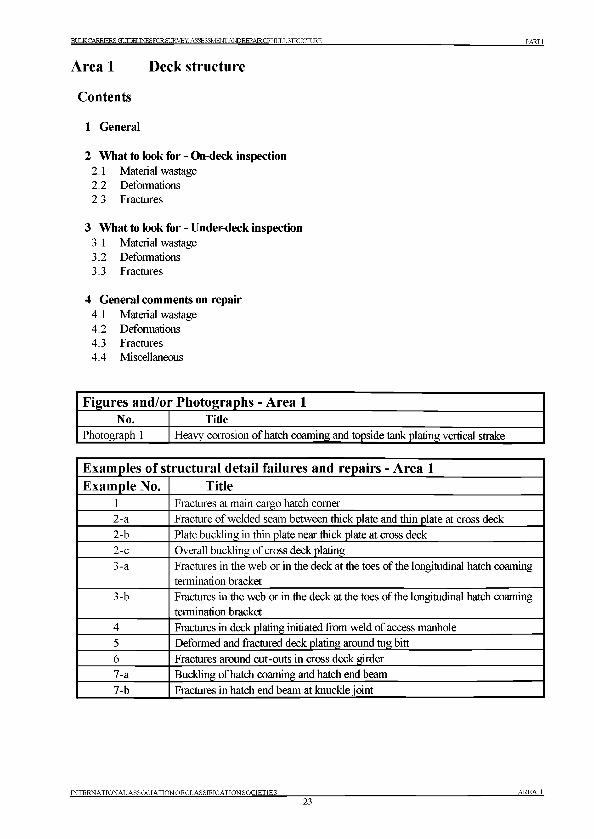
BULK CARRIER S' GT ТТРЕГ .TNESFORSURVEY. ASSESSMENT ANDREPAIROFHULL STRUCTURE PARTI
Area 1 Deck structure
Contents
1 General
2 What to look for - On-deck inspection2.1 Material wastage2.2 Deformations2.3 Fractures
3 What to look for - Under-deck inspection3.1 Material wastage3.2 Deformations3.3 Fractures
4 General comments on repair4.1 Material wastage4.2 Deformations4.3 Fractures4.4 Miscellaneous
Figures and/or Photographs - Area 1No. Title
Photograph 1 Heavy corrosion of hatch coaming and topside tank plating vertical strake
Examples of structural detail failures and repairs - Area 1Example No. Title
l Fractures at main cargo hatch comer2-a Fracture of welded seam between thick plate and thin plate at cross deck
2-b Plate buckling in thin plate near thick plate at cross deck
2-c Overall buckling of cross deck plating3-a Fractures in the web or in the deck at the toes of the longitudinal hatch coaming
termination bracket3-b Fractures in the web or in the deck at the toes of the longitudinal hatch coaming
termination bracket
4 Fractures in deck plating initiated from weld of access manhole5 Deformed and fractured deck plating around tug bitt
6 Fractures around cut-outs in cross deck girder
7-a Buckling of hatch coaming and hatch end beam
7-b Fractures in hatch end beam at knuckle joint
INTERNATIONAL ASSOCIATIONOFCLASSIFICATIONSOCIETIES23
AREA 1
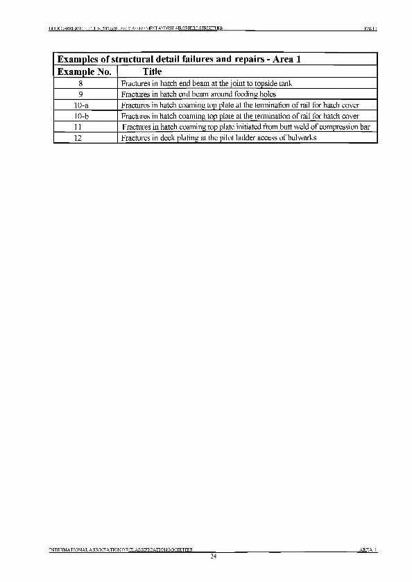
BULK CARRIER Я • GT ТЮИ .TNES FOR SURVEY. ASSESSMENT AND REPAIR OF HULL STRUCTURE PARTI
Examples of structural detail failures and repairs - Area 1Example No. Title
8 Fractures in hatch end beam at the joint to topside tank9 Fractures in hatch end beam around feeding holes
10-a Fractures in hatch coaming top plate at the termination of rail for hatch cover
10-b Fractures in hatch coaming top plate at the termination of rail for hatch cover11 Fractures in hatch coaming top plate initiated from butt weld of compression bar
12 Fractures in deck plating at the pilot ladder access of bulwarks
IN TE R N A TIO N A L A SS O C IA TIO N O F C LA SSIFIC A TIO N SO CIE TIES24
A R E A 1
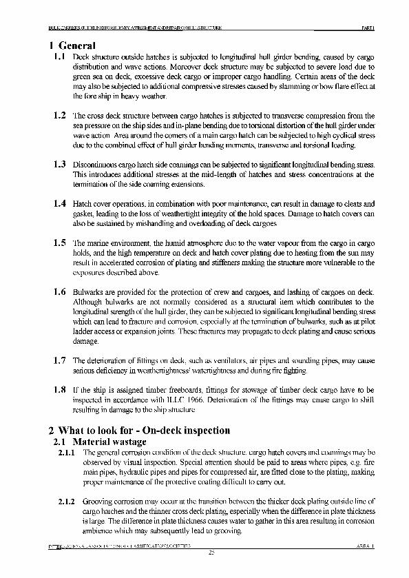
BULK CARRIERS:G[ ШРХ.ТЫНЯЮК S[ JR VEY. ASSESSMENT ANDREPAIROFFlULLSTRUCrURE PARTI
1 General1.1 Deck structure outside hatches is subjected to longitudinal hull girder bending, caused by cargo
distribution and wave actions. Moreover deck structure may be subjected to severe load due to green sea on deck, excessive deck cargo or improper cargo handling. Certain areas of the deck may also be subjected to additional compressive stresses caused by slamming or bow flare effect at the fore ship in heavy weather.
1.2 The cross deck structure between cargo hatches is subjected to transverse compression from the sea pressure on the ship sides and in-plane bending due to torsional distortion of the hull girder under wave action. Area around the comers of a main cargo hatch can be subjected to high cyclical stress due to the combined effect of hull girder bending moments, transverse and torsional loading.
1.3 Discontinuous cargo hatch side coamings can be subjected to significant longitudinal bending stress. This introduces additional stresses at the mid-length of hatches and stress concentrations at the termination of the side coaming extensions.
1.4 Hatch cover operations, in combination with poor maintenance, can result in damage to cleats and gasket, leading to the loss of weathertight integrity of the hold spaces. Damage to hatch covers can also be sustained by mishandling and overioading of deck cargoes.
1.5 The marine environment, the humid atmosphere due to the water vapour from the cargo in cargo holds, and the high temperature on deck and hatch cover plating due to heating from the sun may result in accelerated corrosion of plating and stiffeners making the structure more vulnerable to the exposures described above.
1.6 Bulwarks are provided for the protection of crew and cargoes, and lashing of cargoes on deck. Although bulwarks are not normally considered as a structural item which contributes to the longitudinal strength of the hull girder, they can be subjected to significant longitudinal bending stress which can lead to fracture and corrosion, especially at the termination of bulwarks, such as at pilot ladder access or expansion joints. These fractures may propagate to deck plating and cause serious damage.
1.7 The deterioration of fittings on deck, such as ventilators, air pipes and sounding pipes, may cause serious deficiency in weathertightness/ watertightness and during fire fighting.
1.8 If the ship is assigned timber freeboards, fittings for stowage of timber deck cargo have to be inspected in accordance with ILLC 1966. Deterioration of the fittings may cause cargo to shift resulting in damage to the ship structure.
2 W hat to look for - On-deck inspection2.1 Material wastage
2.1.1 The general corrosion condition of the deck structure, cargo hatch covers and coamings may be observed by visual inspection. Special attention should be paid to areas where pipes, e.g. fire main pipes, hydraulic pipes and pipes for compressed air, are fitted close to the plating, making proper maintenance of the protective coating difficult to carry out.
2.1.2 Grooving corrosion may occur at the transition between the thicker deck plating outside line of cargo hatches and the thinner cross deck plating, especially when the difference in plate thickness is large. The difference in plate thickness causes water to gather in this area resulting in corrosion ambience which may subsequently lead to grooving.
IN TE R N A TION A L A SS O C IA TIO N O FC LA SSIFIC A TIO N SO CIE TIES25
A R E A 1
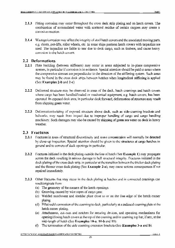
BULKCARRIRRSGimR.TNRSFORSIIRVEY.ASSESSMENTANDREPAIROFHULLSmUCTURE PARTI
2.1.3 Pitting corrosion may occur throughout the cross deck strip plating and on hatch covers. The combination of accumulated water with scattered residue of certain cargoes may create a corrosive reaction.
2.1.4 Wastage/corrosion may affect the integrity of steel hatch covers and the associated moving parts, e.g. cleats, pot-lifts, roller wheels, etc. In some ships pontoon hatch covers with tarpaulins are used. The tarpaulins are liable to tear due to deck cargo, such as timbers, and cause heavy corrosion to the hatch covers.
2.2 Deformations2.2.1 Plate buckling (between stiffeners) may occur in areas subjected to in-plane compressive
stresses, in particular if corrosion is in evidence. Special attention should be paid to areas where the compressive stresses are perpendicular to the direction of the stiffening system. Such areas may be found in the cross deck strips between hatches when longitudinal stiffening is applied (See Examples 2-b and 2-c).
2.2.2 Deformed structure may be observed in areas of the deck, hatch coamings and hatch covers where cargo has been handled/loaded or mechanical equipment, e.g. hatch covers, has been operated. In exposed deck area, in particular deck forward, deformation of structure may result from shipping green water.
2.2.3 Deformation/twisting of exposed structure above deck, such as side-coaming brackets and bulwarks, may result from impact due to improper handling of cargo and cargo handling machinery. Such damages may also be caused by shipping of green sea water on deck in heavy weather.
2.3 Fractures2.3.1 Fractures in areas of structural discontinuity and stress concentration will normally be detected
by close-up inspection. Special attention should be given to the structures at cargo hatches in general and to comers of deck openings in particular.
2.3.2 Fractures initiated in the deck plating outside the line of hatch (See Example 1) may propagate across the deck resulting in serious damage to hull structural integrity. Fractures initiated in the deck plating of the cross deck strip, in particular at the transition between the thicker deck plating and the thinner cross deck plating (See Example 2-a), may cause serious consequences if not repaired immediately.
2.3.3 Other fractures that may occur in the deck plating at hatches and in connected coamings can result/originate from:(a) The geometry of the comers of the hatch openings.(b) Grooving caused by wire ropes of cargo gear.(c) Welded attachment and shedder plate close to or on the free edge of the hatch comer
plating.(d) Fillet weld connection of the coaming to deck, particularly at a radiused coaming plate at the
hatch comer plating.(e) Attachments, cut-outs and notches for securing devices, and operating mechanisms for
opening/closing hatch covers at the top of the coaming and/or coaming top bar, if any, at the mid-length of hatch (See Examples 10-a, 10-b and 11).
(f) The termination of the side coaming extension brackets (See Examples 3-a and b).
INTERNATIONAL ASSOCIATIONOFCLASSIFICATIONSOCIETIES26
A R E A 1
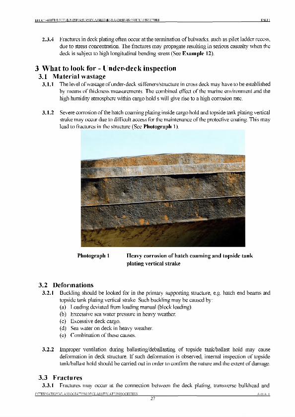
ВТ Я,К CARRIERS: GUTOELINESFORSURVEY. ASSESSMENT ANDREPAIROFHULL STRUCTURE PARTI
2.3.4 Fractures in deck plating often occur at the termination of bulwarks, such as pilot ladder recess, due to stress concentration. The fractures may propagate resulting in serious casualty when the deck is subject to high longitudinal bending stress (See Example 12).
3 W hat to look for - Under-deck inspection3.1 Material wastage
3.1.1 The level of wastage of under-deck stiffener s/structure in cross deck may have to be established by means of thickness measurements. The combined effect of the marine environment and the high humidity atmosphere within cargo hold s will give rise to a high corrosion rate.
3.1.2 Severe corrosion of the hatch coaming plating inside cargo hold and topside tank plating vertical strake may occur due to difficult access for the maintenance of the protective coating. This may lead to fractures in the structure (See Photograph 1).
Photograph 1 Heavy corrosion of hatch coaming and topside tank plating vertical strake
3.2 Deformations3.2.1 Buckling should be looked for in the primary supporting structure, e.g. hatch end beams and
topside tank plating vertical strake. Such buckling may be caused by:(a) Loading deviated from loading manual (block loading).(b) Excessive sea water pressure in heavy weather.(c) Excessive deck cargo.(d) Sea water on deck in heavy weather.(e) Combination of these causes.
3.2.2 Improper ventilation during ballasting/deballasting of topside tank/ballast hold may cause deformation in deck structure. If such deformation is observed, internal inspection of topside tank/ballast hold should be carried out in order to confirm the nature and the extent of damage.
3.3 Fractures3.3.1 Fractures may occur at the connection between the deck plating, transverse bulkhead and
IN TE R N A TION A L A SSO C IA TIO N OF C LASSIFICATION SOCIETIES27
A R E A 1
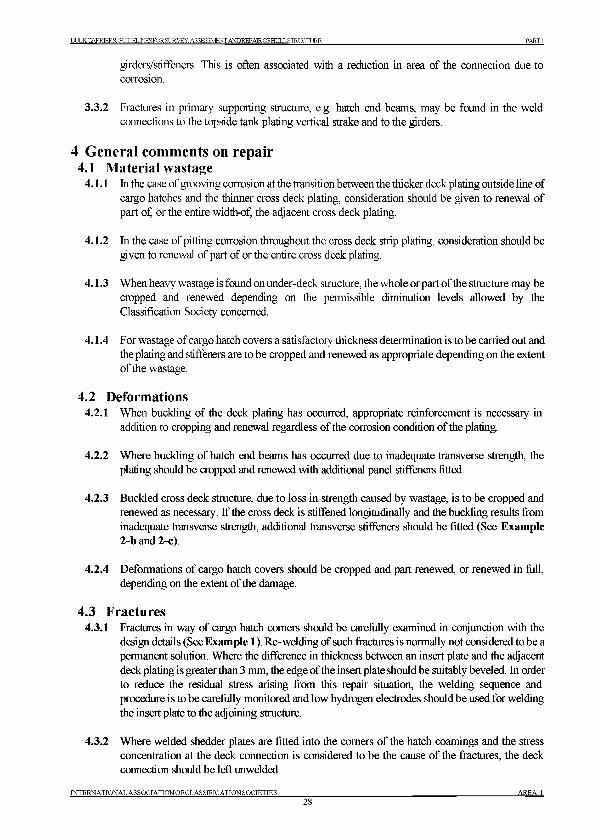
BULK CARRERS:GUTOELINESFORSURVEY. ASSESSMENT AND REPAIR OFHULL STRUCTURE PARTI
girders/stiffeners. This is often associated with a reduction in area of the connection due to corrosion.
3.3.2 Fractures in primary supporting structure, e.g. hatch end beams, may be found in the weld connections to the topside tank plating vertical strake and to the girders.
4 General comments on repair4.1 Material wastage
4.1.1 In the case of grooving corrosion at the transition between the thicker deck plating outside line of cargo hatches and the thinner cross deck plating, consideration should be given to renewal of part of, or the entire width-of, the adjacent cross deck plating.
4.1.2 In the case of pitting corrosion throughout the cross deck strip plating, consideration should be given to renewal of part of or the entire cross deck plating.
4.1.3 When heavy wastage is found onunder-deck structure, the whole or part of the structure may be cropped and renewed depending on the permissible diminution levels allowed by the Classification Society concerned.
4.1.4 For wastage of cargo hatch covers a satisfactory thickness determination is to be carried out and the plating and stiffeners are to be cropped and renewed as appropriate depending on the extent of the wastage.
4.2 Deformations4.2.1 When buckling of the deck plating has occurred, appropriate reinforcement is necessary in
addition to cropping and renewal regardless of the corrosion condition of the plating.
4.2.2 Where buckling of hatch end beams has occurred due to inadequate transverse strength, the plating should be cropped and renewed with additional panel stiffeners fitted.
4.2.3 Buckled cross deck structure, due to loss in strength caused by wastage, is to be cropped and renewed as necessary. If the cross deck is stiffened longitudinally and the buckling results from inadequate transverse strength, additional transverse stiffeners should be fitted (See Example 2-b and 2-c).
4.2.4 Deformations of cargo hatch covers should be cropped and part renewed, or renewed in full, depending on the extent of the damage.
4.3 Fractures4.3.1 Fractures in way of cargo hatch comers should be carefully examined in conjunction with the
design details (See Example 1). Re-welding of such fractures is normally not considered to be a permanent solution. Where the difference in thickness between an insert plate and the adjacent deck plating is greater than 3 mm, the edge of the insert plate should be suitably beveled. In order to reduce the residual stress arising from this repair situation, the welding sequence and procedure is to be carefully monitored and low hydrogen electrodes should be used for welding the insert plate to the adjoining structure.
4.3.2 Where welded shedder plates are fitted into the comers of the hatch coamings and the stress concentration at the deck connection is considered to be the cause of the fractures, the deck connection should be left unwelded
INTERNATIONAL ASSOCIATIONOFCLASSIFICATIONSOCIETIES28
AREA 1
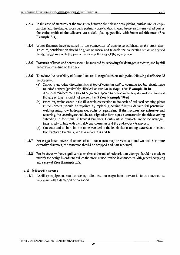
BULK CARRIER S: GT ЛПКГ .TNESFOR SI JR VEY. ASSESSMENT АЮ КЕРАКОРН Ш Ь STRUCTURE PARTI
4.3.3 In the case of fractures at the transition between the thicker deck plating outside line of cargo hatches and the thinner cross deck plating, consideration should be given to renewal of part or the entire width of the adjacent cross deck plating, possibly with increased thickness (See Example 2-a).
4.3.4 When fractures have occurred in the connection of transverse bulkhead to the cross deck structure, consideration should be given to renew and re-weld the connecting structure beyond the damaged area with the aim of increasing the area of the connection.
4.3.5 Fractures of hatch end beams should be repaired by renewing the damaged structure, and by full penetration welding to the deck.
4.3.6 To reduce the possibility of future fractures in cargo hatch coamings the following details should be observed:(a) Cut-outs and other discontinuities at top of coaming and/ or coaming top bar should have
rounded comers (preferably elliptical or circular in shape) (See Example 10-b).Any local reinforcement should be given a tapered transition in the longitudinal direction and the rate of taper should not exceed 1 in 3 (See Example 10-a).
(b) Fractures, which occur in the fillet weld connection to the deck of radiused coaming plates at the comers, should be repaired by replacing easting fillet welds with full penetration welding using low hydrogen electrodes or equivalent. If the fractures are extensive and recurring, the coamings should be redesigned to form square comers with the side coaming extending in the form of tapered brackets. Continuation brackets are to be arranged transversely in line with the hatch end coamings and the under-deck transverse.
(c) Cut-outs and drain holes are to be avoided in the hatch side coaming extension brackets. For fractured brackets, see Examples 3 a and b.
4.3.7 For cargo hatch covers, fractures of a minor nature may be veed-out and welded. For more extensive fractures, the structure should be cropped and part renewed.
4.3.8 For fractures without significant corrosion at the end of bulwarks, an attempt should be made to modify the design in order to reduce the stress concentration in connection with general cropping and renewal (See Example 12).
4.4 Miscellaneous4.4.1 Ancillary equipment such as cleats, rollers etc. on cargo hatch covers is to be renewed as
necessary when damaged or corroded.
IN TE R N A TIO N A L A SS O C IA TIO N O FC LA SSIFIC A TIO N SO CIE TIES29
A R E A 1
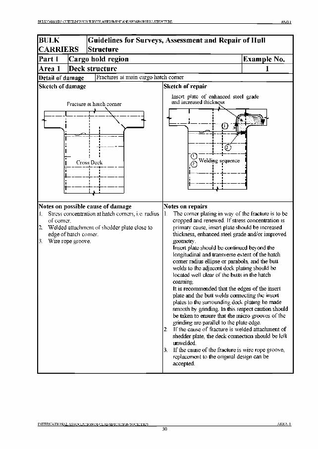
BULK CARRIERS ПТ TTPFJ .TNESFORSURVEY. ASSESSMENT ANDREPAIROFHULLSTRUCnJRE PARTI
BULKCARRIERS
Guidelines for Surveys, Assessment and Repair of Hull Structure
Part 1 Cargo hold region Example No.Area 1 Deck structureDetail of damage Fractures at main cargo hatch comer
Sketch of damage Sketch of repair
Fracture at hatch comer
Notes on possible cause of damage1. Stress concentration at hatch comers, i. e. radius
of comer.2. Welded attachment of shedder plate close to
edge of hatch comer.3. Wire rope groove.
Insert plate of enhanced steel grade and increased thickness
Notes on repairs1. The comer plating in way of the fracture is to be
cropped and renewed. If stress concentration is primary cause, insert plate should be increased thickness, enhanced steel grade and/or improved geometry.Insert plate should be continued beyond the longitudinal and transverse extent of the hatch comer radius ellipse or parabola, and the butt welds to the adjacent deck plating should be located well clear of the butts in the hatch coaming.It is recommended that the edges of the insert plate and the butt welds connecting the insert plates to the surrounding deck plating be made smooth by grinding. In this respect caution should be taken to ensure that the micro grooves of the grinding are parallel to the plate edge.
2. If the cause of fracture is welded attachment of shedder plate, the deck connection should be left unwelded.
3. If the cause of the fracture is wire rope groove, replacement to the original design can be accepted.
INTERNATIONAL ASSOCIATIONOFCLASSffICATIONSOCIETIES30
AREA 1
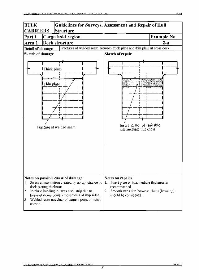
BULK CARRIER S' GT JTPKf .TNESFORSURVEY. ASSESSMENT ANDREPAIROFHULL STRUCTURE PARTI
BULKCARRIERS
Guidelines for Surveys, Assessment and Repair of Hull Structure
Part 1 Cargo hold region Example No.Area 1 Deck structure 2-aDetail of damage Fractures of welded seam between thick plate and thin plate at cross deck
Sketch of damage
------------1------------- Г*----------------1----------- ----------- 1------------- H*--------------- 1------------■
* 9 1 Thick plate 1 - i : i
■ T ---------
Fracture at welded seam
Sketch o f repair
= И
Insert plate o f suitable intermediate thickness
Notes on possible cause of damage1. Stress concentration created by abrupt change in
deck plating thickness.2. In-plane bending in cross deck strip due to
torsional (longitudinal) movements of ship sides.3. Welded seam not clear of tangent point of hatch
comer.
Notes on repairs1. Insert plate of intermediate thickness is
recommended.2. Smooth transition between plates (beveling)
should be considered.
INTERNATIONAL ASSOCT ATIONOFCLASSIFICATIONSOCIETIES____________31
AREA 1
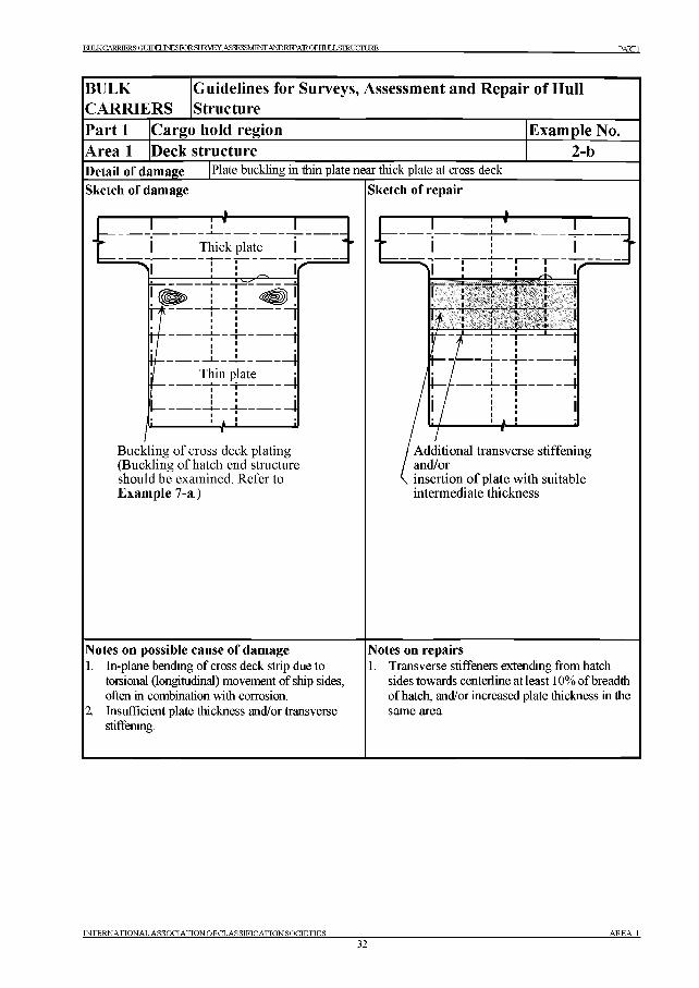
BULKCARRTRRSGT тюга .TNESFORSURVEY, ASSESSMENT ANDREPAIROFHULLSmUCrUE^ PARTI
BULKCARRIERS
Guidelines for Surveys, Assessment and Repair of Hull Structure
Part 1 Cargo hold region Example No.Area 1 Deck structure 2-bDetail of damage Plate buckling in thin plate near thick plate at cross deck
Sketch of damage Sketch of repair
Ч-
Buckling o f cross deck plating (Buckling o f hatch end structure should be examined. Refer to Exam ple 7-a.)
Notes on possible cause o f damage1. In-plane bending of cross deck strip due to
torsional (longitudinal) movement of ship sides, often in combination with corrosion.
2. Insufficient plate thickness and/or transverse stiffening.
Notes on repairs1. Transverse stiffeners extending from hatch
sides towards centerline at least 10% of breadth of hatch, and/or increased plate thickness in the same area.
IN T E R N A T IO N A L A S S O C IA T IO N O F C L A S S IF IC A T IO N S O C IE T IE S
32A R E A 1
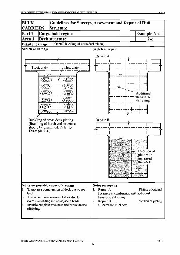
BULK CARRIERS: GUDELINESFORSURVEY. АБЗЕ^БМЕЖ А Ю REPAIROFHIILL STRUCTURE PARTI
BULKCARRIERS
Guidelines for Surveys, Assessment and Repair of Hull Structure
Part 1 Cargo hold region Example No.Area 1 Deck structure 2-cDetail of damage Overall buckling of cross deck plating
Sketch of damage Sketch of repair
Repair A
17.L.T7 :-----Г| —
i- i - 4| j " Additionalj | transverse
j | ■ stiffening
: i , ! !Buckling of cross deck plating (Buckling of hatch end structure should be examined. Refer to Example 7-a.)
Repair В+
Notes on possible cause of damage1 Transverse compression of deck due to sea
load.Transverse compression of deck due to excessive loading in two adjacent holds. Insufficient plate thickness and/or transverse stiffening.
^ j |
j -1 -^ Insertion of------ 1 I 'plate with
I i increased- r - p - thickness
t i 1— t :i~—
Notes on repairs1. Repair A Plating of original
thickness in combination with additional transverse stiffening.
2. Repair В Insertion of platingof increased thickness.
IN TE R N A TION A L A SSO C IA T IO N O F C L A SS ffIC A T IO N S O C IE T IE S_____________33
A R E A 1
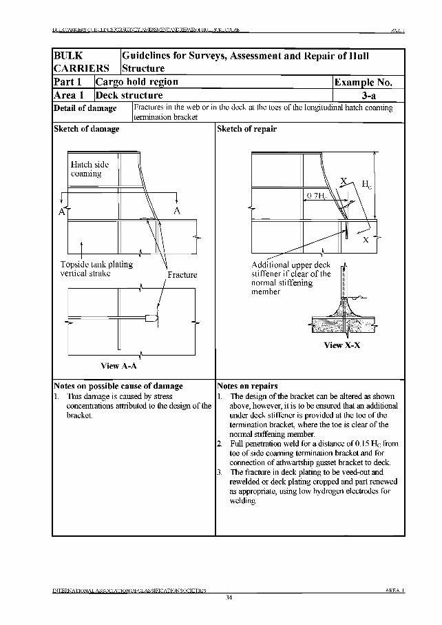
BULK CARRIER S' GT 1ЮЕГ .TNESFORSURVEY. ASSESSMENT ANDREPAIROFH1XL STRUCTURE PARTI
BULKCARRIERS
Guidelines for Surveys, Assessment and Repair of Hull Structure
Part 1 Cargo hold region Example No.Area 1 Deck structure 3-aDetail of damage Fractures in the web or in the deck at the toes of the longitudinal hatch coaming
termination bracket
Sketch of damage
Hatch side coaming
1A
Topside tank plating vertical strake Fracture
View A-A
Sketch of repair
Additional upper deck stiffener if clear o f the normal stiffening member
Jn / и / и
LView X-X
Notes on possible cause o f damage1. This damage is caused by stress
concentrations attributed to the design of the bracket.
Notes on repairs1. The design of the bracket can be altered as shown
above, however, it is to be ensured that an additional under deck stiffener is provided at the toe of the termination bracket, where the toe is clear of the normal stiffening member.
2. Full penetration weld for a distance of 0.15 He from toe of side coaming termination bracket and for connection of athwartship gusset bracket to deck.
3. The fracture in deck plating to be veed-out and rewelded or deck plating cropped and part renewed as appropriate, using low hydrogen electrodes for welding.
INTERNATIONAL ASSOCIATIONOFCLASSIFICATIONSOCIETIES_____________34
AREA 1
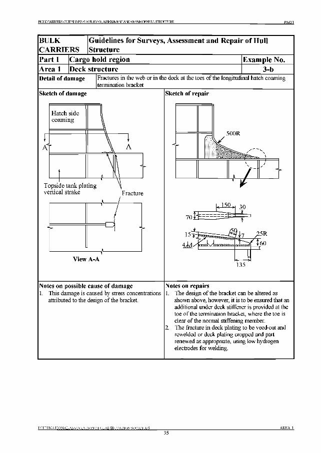
BUIXCARRTERS-ГтТ ПРИ .TNESFORSURVEY.ASSESSMEmANDREPAIROFHULLSTRUCrURE PARTI
BULKCARRIERS
Guidelines for Surveys, Assessment and Repair of Hull Structure
Part 1 Cargo hold region Example No.Area 1 Deck structure 3-bDetail of damage Fractures in the web or in the deck at the toes of the longitudinal hatch coaming
termination bracket
Sketch of damage Sketch of repair
135
Notes on possible cause of damage1. This damage is caused by stress concentrations
attributed to the design of the bracket.
Notes on repairs1. The design of the bracket can be altered as
shown above, however, it is to be ensured that an additional under deck stiffener is provided at the toe of the termination bracket, where the toe is clear of the normal stiffening member.
2. The fracture in deck plating to be veed-out and rewelded or deck plating cropped and part renewed as appropriate, using low hydrogen electrodes for welding.
IN T E R N A T IO N A L A S S O C IA T IO N O F C L A S S IF IC A T IO N S O C IE T IE S
35AREA 1
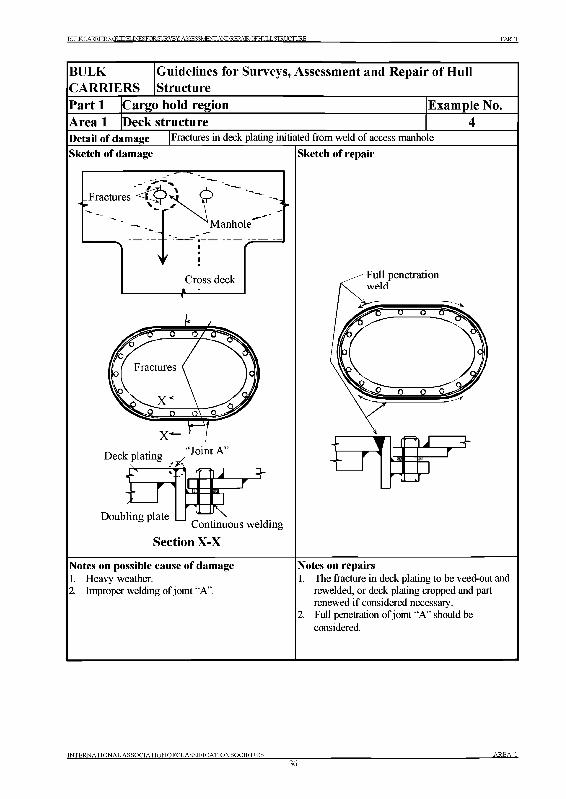
BULKCARRTKR S- ГтТ утрм .t nesfo rsu rvey . assessm en t a n d r e p a ir o f h u l l structure PARTI
BULK
C A R R IE R S
G uidelines for Surveys, A ssessm ent and R epair o f H ull Structure
P art 1 C argo hold region E xam ple No.
A rea 1 D eck structureDetail of damage Fractures in deck plating initiated from weld of access manhole
Sketch of damage
Notes on possible cause of damage Notes on repairs1. Heavy weather. 1. The fracture in deck plating to be veed-out and2. Improper welding of j oint “A”. rewelded, or deck plating cropped and part
renewed if considered necessary.2. Full penetration of joint “A” should be
considered.
Sketch of repair
JZZZ3-w
INTERNATIONAL ASSOCIATIONOFCLASSIFICATIONSOCIETIES_____________36
A R EA 1.
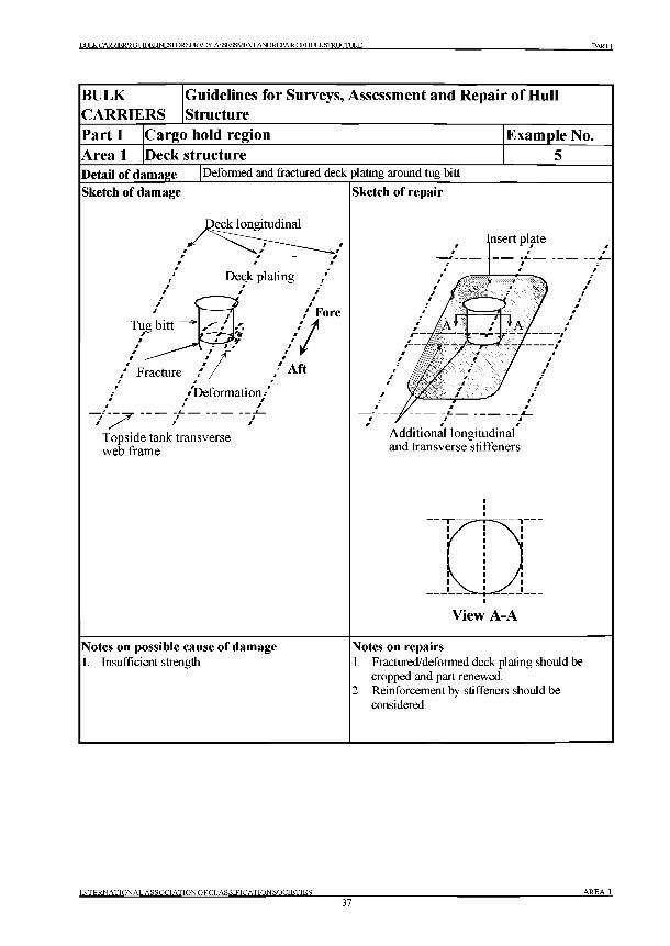
BULKCARRIERS-ГЯ 1ТПЕГ .TNESFORSURVEY. ASSESSMENT ANDREPAIROFHULL STRUCTURE PARTI
INTERNATIONAL ASSOCIATIONOFCLASSIFICATIONSOCIETIES37
AREA 1
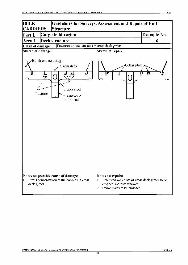
BULKCARRTRRSG11ТПЕГ .TNESFORSURVEY, ASSESSMENT ANDREPAIROFHULLSTRUCTURE PARTI
INTERNATIONAL ASSOCIATIONOFCLASSIFICATIONSOCIETIES38
AREA 1
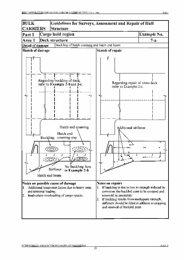
BULK CARRIER S' GT ТТПЕ1 .TNESFOR SURVEY. ASSESSMENT AND REPAIR QFHULL STRUCTURE PARTI
BULKCARRIERS
Guidelines for Surveys, Assessment and Repair of Hull Structure
Part 1 Cargo hold region Example No.Area 1 Deck structure 7-aDetail of damage Buckling of hatch coaming and hatch end beam
Sketch of damage Sketch of repair
T“! ГТRegarding buckling of deck, refer to Example 2-b and 2-c
iRegarding repair of cross refer to Example 2-c.
deck,
Hatch end beam
Notes on possible cause of damage1. Additional transverse forces due to heavy seas,
and torsional loading.2. Inadvertent overloading of cargo spaces.
Notes on repairs1. If buckling is due to loss in strength induced by
corrosion, the buckled zone to be cropped and renewed as necessary.If buckling results from inadequate strength, stiffeners should be fitted in addition to cropping and renewal of buckled zone.
INTERNATIONAL ASSOCIATIONOFCLASSffICATIONSOCIETIES____________39
A R E A 1
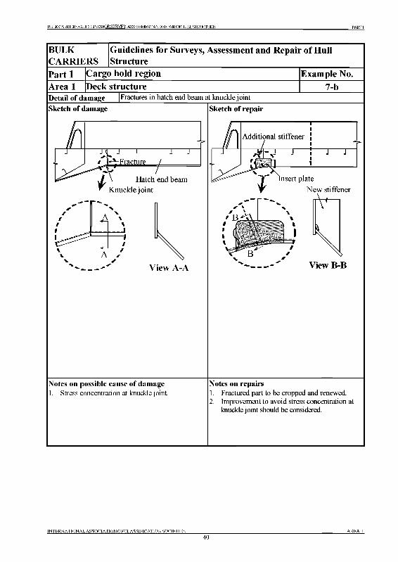
BULKCARRIERS:GUeELINESFORSURVEY.ASSESSMENTANDREPAIROFHULLSTRUCroRE PARTI
INTERNATIONAL ASSOCIATIONOFCLASSIFICATIONSOCIETIES40
AR EA 1
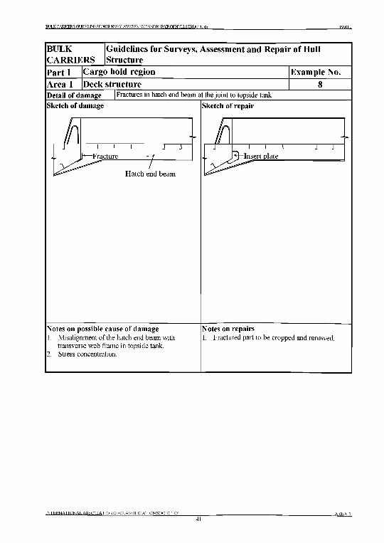
BULK CARRIERS С,1 1ЮЕТ .TNESFORSURVEY. ASSESSMENT ANDKEPAIROFHULLSTRUCniRF. PARTI
INTERNATIONAL ASSOCIATION OF CL AS SIFICATION SOCIETIES41
a r e a 1
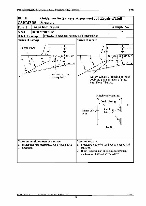
BULK CARR TKR S' GTУ Т П И .TNESFORSURVEY. ASSESSMENT AND REPAIROFHULL STRUCTURE PARTI
INTERNATIONAL ASSOCIATIONOFCLASSIFICATIONSOCIETIES____________42
AREA 1
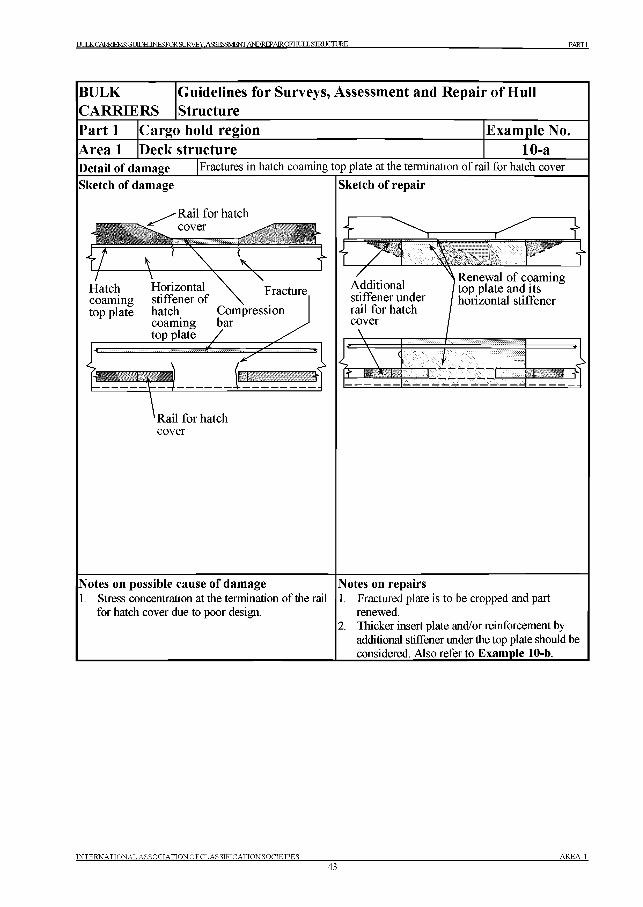
BULKCARRIRRSG11ТПЕГ .TNRSFOR St TRVEY. ASSESSMENT A^REPAIROFHLILL STRUCTURE PARTI
BULKCARRIERS
Guidelines for Surveys, Assessment and Repair of Hull Structure
Part 1 Cargo hold region Example No.Area 1 Deck structure 10-aDetail of dam age Fractures in hatch coaming top plate at the termination of rail for hatch cover
Sketch of dam age
Я
Rail for hatch coverzs: ^
Hatch Horizontal coaming stiffener o f top plate hatch Compression
coaming bartop plate /
Fracture
"2 :
'R ail for hatchcover
Sketch of rep a ir
Additional stiffener under rail for hatch cover
Renewal o f coaming top plate and its horizontal stiffener
т Ш 1 Г 1 1 : F_______=1__________________
Notes on possible cause of dam age1. Stress concentration at the termination of the rail
for hatch cover due to poor design.
Notes on repairs1. Fractured plate is to be cropped and part
renewed.2. Thicker insert plate and/or reinforcement by
additional stiffener under the top plate should be considered. Also refer to Example 10-b._____
INTERNATIONAL ASSOCIATIONOFCLASSIFICATIONSOCIETIES___________43
AREA 1
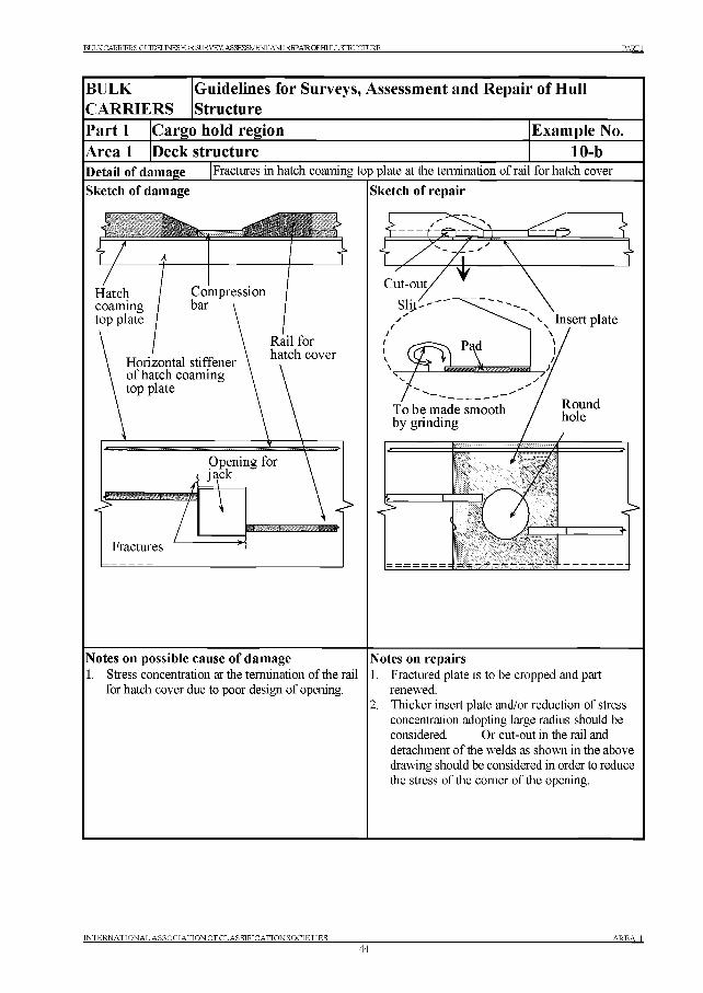
BULK CARRIER S- GT TTDKT .TNF.SFOR SI JR VEY. ASSESSMENT ANDREPAROFHULL STRUCTURE PARTI
BULK Guidelines for Surveys, Assessment and Repair of HullCARRIERS StructurePart 1 Cargo hold region Example No.Area 1 Deck structure 10-bDetail of damage Fractures in hatch coaming top plate at the termination of rail for hatch cover
Sketch of damage
Notes on possible cause of damage1. Stress concentration at the termination of the rail
for hatch cover due to poor design of opening.
Sketch of repair
Notes on repairs1. Fractured plate is to be cropped and part
renewed.2. Thicker insert plate and/or reduction of stress
concentration adopting large radius should be considered. Or cut-out in the rail and detachment of the welds as shown in the above drawing should be considered in order to reduce the stress of the comer of the opening.
INTERNATIONAL ASSOCIATION OF CL AS SIFICATION SOCIETIES44
AREA 1
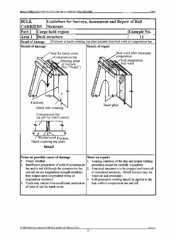
BULK CARRIER S' GT УЮЕГ .TNF.SFOR SI IRVEY. ASSESSMENT ANDREPAIROF HULL STRUCTURE PARTI
BULKCARRIERS
Guidelines for Surveys, Assessment and Repair of Hull Structure
Part 1 Cargo hold region Example No.Area 1 Deck structure 11Detail of damage Fractures in hatch coaming top plate initiated from butt weld of compression bar
Sketch of damage
Rail for hatch cover ■Compression bar
/Starting point ^ of fracture
(See “Detail”)
Fractures
Hatch side coaming
Sketch of repair
Compression bar (or rail for hatch cover)
4l
Welded joint FractureHatch coaming top plate
Detail
Notes on possible cause of damage1. Heavy weather2. Insufficient preparation of weld of compression
bar and/or rail (Although the compression bar and rail are not longitudinal strength members, they subject same longitudinal stress as longitudinal members)
3. Crack may initiate from insufficient penetration of weld of rail for hatch cover.
Notes on repairs1. Loading condition of the ship and proper welding
procedure should be carefully considered.2. Fractured structure is to be cropped and renewed
if considered necessary. (Small fracture may be veed-out and rewelded.)
3. Full penetration welding should be applied to the butt weld of compression bar and rail.
INTERNATIONAL ASSOCIATIONOFCLASSIFICATIONSOCIETIES________________________________________________________________________________ AREA 145
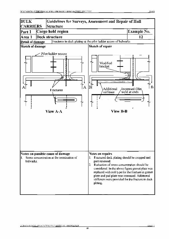
BULKCARRTKR S- ГтТ тюкг .t n e s f o r s u r v e y . a s s e s s m e n t a n d r e p a ir o f h u l l st r u c t u r e PARTI
BULKCARRIERS
Guidelines for Surveys, Assessment and Repair of Hull Structure
Part 1 Cargo hold region Example No.Area 1 Deck structure 12Detail of damage Fractures in deck plating at the pilot ladder access of bulwarks
Sketch of damage
jS ' Pilot ladder access-------------------------- ir
mFractures
_\______
VD
View A-A
Sketch of repair
Modifiedbracket
В
5
^Additional /Increased fillet 'stiffener / weld at ends
В
TG D
View B-B
Notes on possible cause of damage1. Stress concentration at the termination of
bulwarks.
Notes on repairs1. Fractured deck plating should be cropped and
part renewed.2. Reduction of stress concentration should be
considered. In the above figure gusset plate was replaced with soft type for the fracture in gusset plate and pad plate was increased. Additional stiffeners were provided for the fracture in deck plating.
IN TE R N A TION A L A SS O C IA TIO N O FC LA SSIFIC A TIO N SO CIE TIES_____________46
A R E A 1
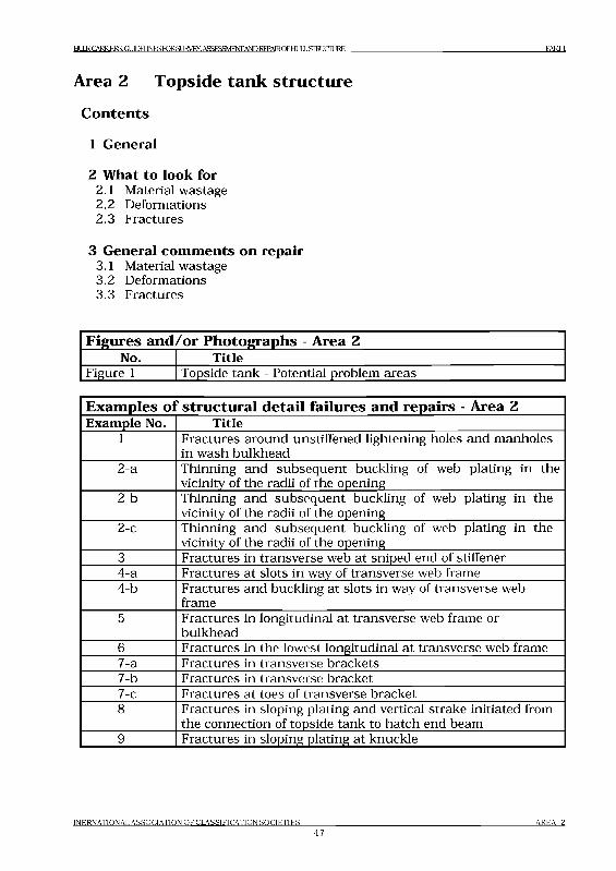
BULK CARRIERS: GUDELJNESroRSURVFY ASSESSMENT AND REPMROFHULL STRUCTURE PARTI
Area 2 Topside tank structure
Contents
1 General
2 What to look for2.1 Material wastage2.2 Deformations2.3 Fractures
3 General comments on repair3.1 Material wastage3.2 Deformations3.3 Fractures
Figures and /or Photographs - Area 2No. Title
Figure 1 Topside tank - Potential problem areas
Exam ples ol structural detail failures and repairs - Area 2Example No. Title
1 Fractures around unstiffened lightening holes and manholes in wash bulkhead
2-a Thinning and subsequent buckling of web plating in the vicinity of the radii of the opening
2-b Thinning and subsequent buckling of web plating in the vicinity of the radii of the opening
2-c Thinning and subsequent buckling of web plating in the vicinity of the radii of the opening
3 Fractures in transverse web at sniped end of stiffener4-a Fractures at slots in way of transverse web frame4-b Fractures and buckling at slots in way of transverse web
frame5 Fractures in longitudinal at transverse web frame or
bulkhead6 Fractures in the lowest longitudinal at transverse web frame7-a Fractures in transverse brackets7-b Fractures in transverse bracket7-c Fractures at toes of transverse bracket8 Fractures in sloping plating and vertical strake initiated from
the connection of topside tank to hatch end beam9 Fractures in sloping plating at knuckle
I N E R N A T I O N A L A S S O C I A T I O N O F C L A S S I F I C A T I O N S O C I E T I E S
47A R E A 2
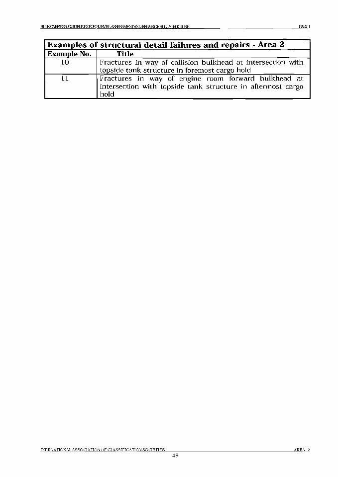
BULK CARRIERS GUIDELINES FDR SURVEY. ASSESSMENT AND REPAIROF HULL STRICTURE PARTI
Examples of structural detail failures and repairs - Area 2Example No. Title
10 Fractures in way of collision bulkhead at intersection with topside tank structure in foremost cargo hold
11 Fractures in way of engine room forward bulkhead at intersection with topside tank structure in aftermost cargo hold
INERNATIONAL ASSOCIATION OF CLASSIFICATION SOCIETIES
48AREA 2
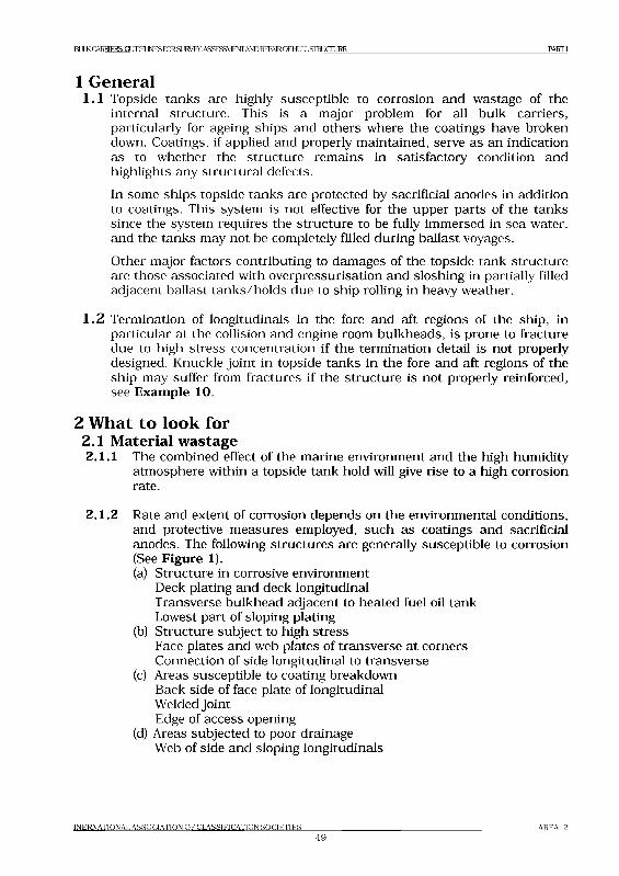
BULK CARRIERS: GUTOEUNESroRSURVEY. ASSESSMENT AND REPMROFHULLSIRJCIURE P A R T I
1 General1.1 Topside tanks are highly susceptible to corrosion and wastage of the
internal structure. This is a major problem for all bulk carriers, particularly for ageing ships and others where the coatings have broken down. Coatings, if applied and properly maintained, serve as an indication as to whether the structure remains in satisfactory condition and highlights any structural defects.In some ships topside tanks are protected by sacrificial anodes in addition to coatings. This system is not effective for the upper parts of the tanks since the system requires the structure to be fully immersed in sea water, and the tanks may not be completely filled during ballast voyages.Other major factors contributing to damages of the topside tank structure are those associated with overpressurisation and sloshing in partially filled adjacent ballast tanks/holds due to ship rolling in heavy weather.
1.2 Termination of longitudinals in the fore and aft regions of the ship, in particular at the collision and engine room bulkheads, is prone to fracture due to high stress concentration if the termination detail is not properly designed. Knuckle joint in topside tanks in the fore and aft regions of the ship may suffer from fractures if the structure is not properly reinforced, see Exam ple 10.
2 What to look for2.1 Material w astage2.1.1 The combined effect of the marine environment and the high humidity
atmosphere within a topside tank hold will give rise to a high corrosion rate.
2.1.2 Rate and extent of corrosion depends on the environmental conditions, and protective measures employed, such as coatings and sacrificial anodes. The following structures are generally susceptible to corrosion (See Figure 1).(a) Structure in corrosive environment
Deck plating and deck longitudinalTransverse bulkhead adjacent to heated fuel oil tank Lowest part of sloping plating
(b) Structure subject to high stressFace plates and web plates of transverse at corners Connection of side longitudinal to transverse
(c) Areas susceptible to coating breakdown Back side of face plate of longitudinal Welded jointEdge of access opening
(d) Areas subjected to poor drainage Web of side and sloping longitudinals
INERNATIONAL ASSOCIATION OF CLASSIFICATION SOCIETIES49
AREA 2
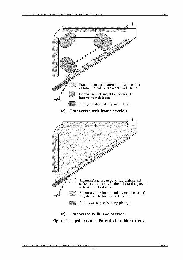
ВШ< CARRIERS: (XTOEUNESroRSLJRyEY. ASSESSMENT AmRgAIROFHLmSIKJCIUEE PARTI
(a)
( ] : I'racture/corrosion around the connectionof longitudinal to transverse web frame
: Corrosion/buckling at the comer of transverse web frame
( ) : Pitting/wastage of sloping plating
Transverse web frame section
(b) Transverse bulkhead section
Figure 1 Topside tank - Potential problem areas
INERNATIONAL ASSOCIATION OF CLASSIFICATION SOCIETIES___________________________________________________________________ AREA 250
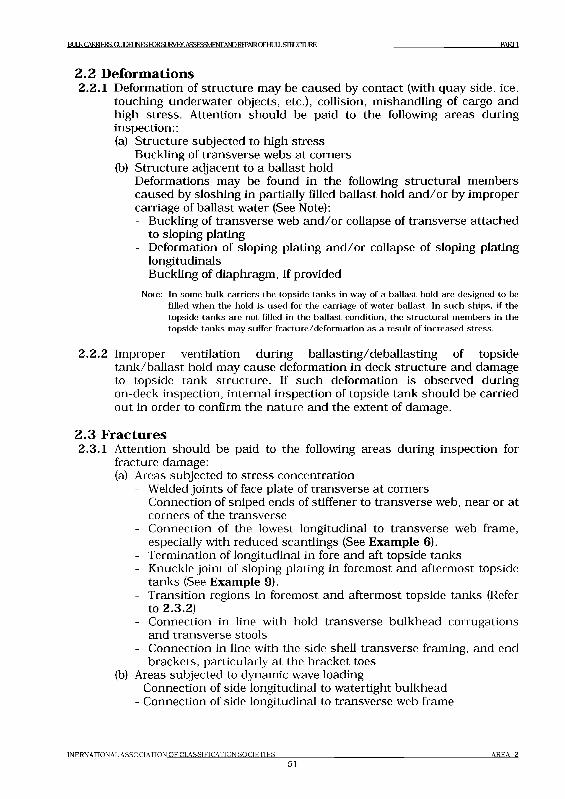
BULK CARRIERS GQEBJNESKRSUR№Y,ASSESSMENT AND REPMRCFHULLSIHJaiJRE PARTI
2 .2 Deform ations2.2.1 Deformation of structure may be caused by contact (with quay side, ice,
touching underwater objects, etc.), collision, mishandling of cargo and high stress. Attention should be paid to the following areas during inspection::(a) Structure subjected to high stress
Buckling of transverse webs at corners(b) Structure adjacent to a ballast hold
Deformations may be found in the following structural members caused by sloshing in partially filled ballast hold and/or by improper carriage of ballast water (See Note):- Buckling of transverse web and/or collapse of transverse attached
to sloping plating- Deformation of sloping plating and/or collapse of sloping plating
longitudinals- Buckling of diaphragm, if provided
Note: In som e bu lk carriers the top sid e tan k s in w ay o f a ballast hold are designed to be filled w h en the hold is u sed for the carriage o f w ater ballast. In s u ch sh ips, if the top sid e tan k s are n ot filled in the ba llast cond ition , the structu ra l m em bers in the top sid e tan k s m ay su ffer fra ctu re /d e form a tion as a result o f increased stress.
2.2.2 Improper ventilation during ballasting/deballasting of topside tank/ballast hold may cause deformation in deck structure and damage to topside tank structure. If such deformation is observed during on-deck inspection, internal inspection of topside tank should be carried out in order to confirm the nature and the extent of damage.
2 .3 Fractures2.3.1 Attention should be paid to the following areas during inspection for
fracture damage:(a) Areas subjected to stress concentration
- Welded joints of face plate of transverse at corners- Connection of sniped ends of stiffener to transverse web, near or at
corners of the transverse- Connection of the lowest longitudinal to transverse web frame,
especially with reduced scantlings (See Example 6).- Termination of longitudinal in fore and aft topside tanks- Knuckle joint of sloping plating in foremost and aftermost topside
tanks (See Example 9).- Transition regions in foremost and aftermost topside tanks (Refer
to 2.3.2)- Connection in line with hold transverse bulkhead corrugations
and transverse stools- Connection in line with the side shell transverse framing, and end
brackets, particularly at the bracket toes(b) Areas subjected to dynamic wave loading
- Connection of side longitudinal to watertight bulkhead- Connection of side longitudinal to transverse web frame
I N E R N A T I O N A L A S S O C I A T I O N O F C L A S S I F I C A T I O N S O C I E T I E S
51A R E A 2
BULK CARRIERS: GLmEUNESroRSUKVEY. ASSESSMENT AND REPMROFHULLSIRJCIURE PARTI
2.3.2 The termination of the following structural members at the collision bulkhead or engine room forward bulkhead is prone to fracture damage due to discontinuity of the structure:- Topside tank sloping plating- Topside tank plating vertical strake- Fore peak tank top plating (Boatswain’s store deck plating)- Longitudinal bulkhead of fuel tank in engine roomIn order to avoid stress concentration due to discontinuity appropriate stiffeners are to be provided in the opposite space. If such stiffeners are not provided, or are deficient due to corrosion or misalignment, fractures may occur at the terminations.
3 General comments on repair3.1 Material w astage
3.1.1 If the corrosion is caused by high stress concentration, renewal with original thickness is not sufficient to avoid reoccurrence.Renewal with increased thickness and/or appropriate reinforcement should be considered in conjunction with appropriate corrosion protective measures.
3 .2 Deform ations3.2.1 The cause of damage should always be identified. If the damage is due to
negligence in operation, the ship representative should be notified. If the deformation is caused by inadequate structural strength, appropriate reinforcement should be considered. Where the deformation is related to corrosion, appropriate corrosion protective measures should be considered.
3 .3 Fractures3.3.1 If the cause of the fracture is fatigue under the action of cyclic wave
loading, consideration should be given to the improvement of structural detail design, such as provision of soft toe bracket, to reduce stress concentration. If the fatigue fracture is vibration related, the damage is usually associated with moderate stress levels at high cycle rate, improvement of structural detail may not be effective. In this case, measures for increasing structural damping and avoidance of resonance, such as providing additional stiffening, may be considered.Where fracture occurs due to material under excessive stress, indicating inadequate structural strength, renewal with thicker plate and/or providing appropriate reinforcement should be considered.Where fracture is found in the transition region, measures for reducing the stress concentration due to structural discontinuity should be considered.
I N E R N A T I O N A L A S S O C I A T I O N O F C L A S S I F I C A T I O N S O C I E T I E S
52A R E A 2
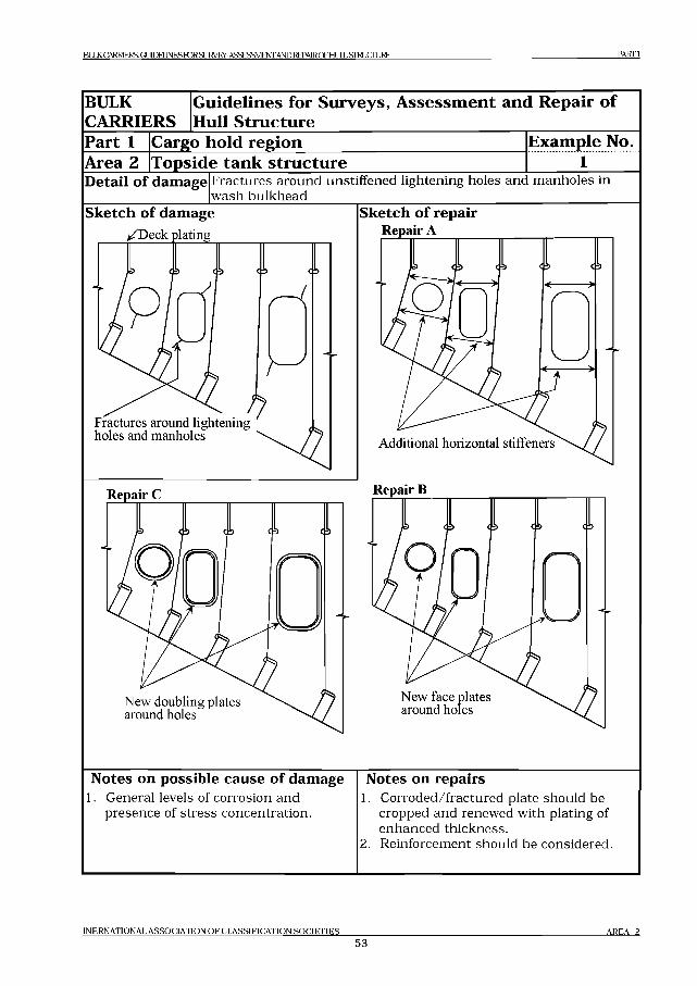
BULK CARRIERS: GUTOEUNESroRSUKVEY. ASSESSMENT AND REPAIROFHULL STRUCTURE PARTI
BULKCARRIERS
Guidelines for Surveys, Assessment and Repair of Hull Structure
Part 1Area 2
Cargo hold regionTopside tank structure
Example No.........i.......
Detail of damage Fractures around unstiffened lightening holes and manholes in wash bulkhead
Sketch of damagei/Deck plating
/ ?Fractures around lightening holes and manholes
Repair C
New doubling plates around holes
Sketch of repair Repair A
Additional horizontal stiffeners
Repair В
New face plates around holes
Notes on possible cause of damage1. General levels of corrosion and
presence of stress concentration.
Notes on repairs1. Corroded/fractured plate should be
cropped and renewed with plating of enhanced thickness.
2. Reinforcement should be considered.
INERNATIONAL ASSOCIATION OF CLASSIFICATION SOCIETIES______
5 3AREA 2
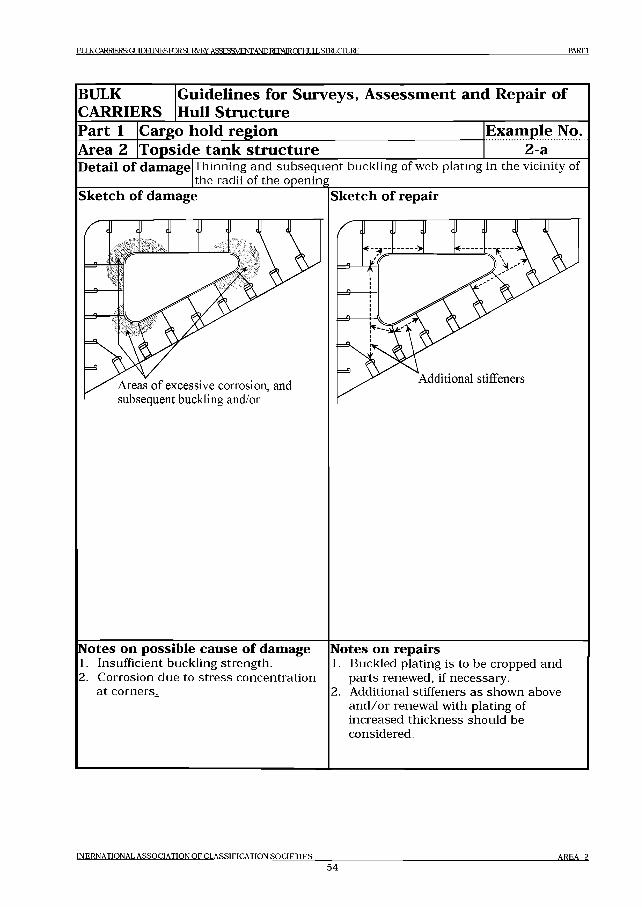
BULK CARRIERS: GUIDELINES FORSUKVEY. A S S E ^M F M A m R E P A IR O F H U L L S T O C T L JE E PA R TI
BULKCARRIERS
Guidelines for Surveys, Assessment and Repair of Hull Structure
Part 1Area 2
Cargo hold regionTopside tank structure
Example No.2 a
Detail of damage Thinning and subsequent buckling of web plating in the vicinity of the radii of the opening_____________________________________________
Sketch of damage
Areas o f excessive corrosion, and subsequent buckling and/or
Sketch of repair
Additional stiffeners
Notes on possible cause of damage1. Insufficient buckling strength.2. Corrosion due to stress concentration
at corners.
Notes on repairs1. Buckled plating is to be cropped and
parts renewed, if necessary.2. Additional stiffeners as shown above
and /or renewal with plating of increased thickness should be considered.
INERNATIONAL ASSOCIATION OF CLASSIFICATION SOCIETIES
5 4AREA 2
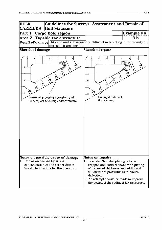
BULK CARRIERS: GUIDELINES FORSURVEy. A S S K ^ M F M A m R E P A IR O F H U L L S T O C IL JR E PARTI
BULKCARRIERS
Guidelines for Surveys, Assessment and Repair of Hull Structure
Part 1 Cargo hold region Example No.Area 2 Topside tank structure 2-bDetail of damage Thinning and subsequent buckling of web plating in the vicinity of
the radii of the openingSketch of damage
Areas o f excessive corrosion, and subsequent buckling and/or fracture
Enlarged radius of the opening
Notes on possible cause of damage1. Corrosion caused by stress
concentration at the corner due to insufficient radius for the openings
Notes on repairs1. Corroded/buckled plating is to be
cropped and parts renewed with plating of increased thickness and additional stiffeners are preferable to minimize deflection.
2. An attempt should be made to improve the design of the radius if felt necessary.
INERNATIQNAL ASSOCIATION OF CLASSIFICATION SOCIETIES5 5
AREA 2
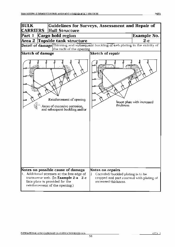
B U L K C A R R IE R S : G U D E U N E S r o R S U № E y .A S S E S 3 V I E № A N D R E P M R O F U U L L S I R L J C IU R E P A R T I
BULK Guidelines for Surveys, Assessment and Repair ofCARRIERS Hull StructurePart 1 Cargo hold region Example No.Area 2 Topside tank structure 2-cDetail of damage Thinning and subsequen t buckling of web plating in the vicinity of
the radii of the openingSketch of damage
Notes on possible cause of damage1. Additional stresses a t the free edge of
transverse web. (In Exam ple 2-a - 2 -c face plate is provided for the reinforcem ent of the opening.)
Sketch of repair
Notes on repairs1. Corroded/buckled plating is to be
cropped and part renewed with plating of increased thickness.
IN ER N A TIO N A L A SS O C IA T IO N O F C L A SSIFIC A T IO N S O C IE T IE S
56A REA 2
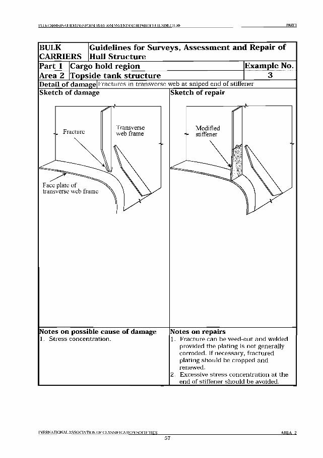
BULK CARRIERS: (XTOEU N ESroRSU K V EY . ASSESSMENT AND REPAIROFHULL STRUCTURE PARTI
BULKCARRIERS
Guidelines for Surveys, Assessment and Repair of Hull Structure
Part 1Area 2
Cargo hold regionTopside tank structure
Example No.........з ......
D etail o f damage Fractures in transverse web at sniped end of stiffenerSketch of damage
Face plate of transverse web frame
Sketch of repair
r -----------------------
Modified4- stiffener
jx/
Notes on possible cause o f damage1. Stress concentration.
Notes on repairs1. Fracture can be veed-out and welded
provided the plating is not generally corroded. If necessary, fractured plating should be cropped and renewed.
2. Excessive stress concentration at the end of stiffener should be avoided.
INERNATIQNAL ASSOCIATION OF CLASSIFICATION SQCIETIF.S______
57AREA 2
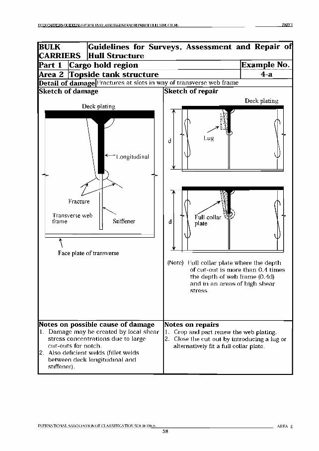
BULK CARRIERS: G U D EU N E SroR SU R V E Y , ASSESSMENT AND R EPA IRCFH LILLSiraJCIU RE PARTI
BULKCARRIERS
Guidelines for Surveys, Assessment and Repair of Hull Structure
Part 1Area 2
Cargo hold regionTopside tank structure
Example No.4-a
D etail o f damage Fractures at slots in way of transverse web frameSketch o f damage
Deck plating
Face plate o f transverse
Sketch o f repairDeck plating
(Note) Full collar plate where the depth of cut-out is more than 0.4 times the depth of web frame (0.4d) and in an areas of high shear stress
Notes on possible cause o f damage1. Damage may be created by local shear
stress concentrations due to large cut-outs for notch.
2. Also deficient welds (fillet welds between deck longitudinal and stiffener).
Notes on repairs1. Crop and part renew the web plating.2. Close the cut-out by introducing a lug or
alternatively fit a full collar plate.
INERNATIONAL ASSOCIATION OF CLASSIFICATION SOCIETIES
58AREA 2
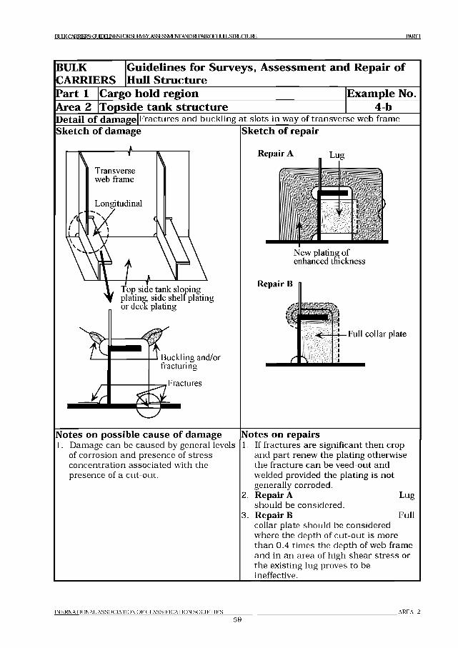
I3ULK CARRIERS: GUIDELINES K^SUI^/rY. ASSESSMENT AND RTPAlRCFHLlLLSIMJCnjRE PARTI
BULKCARRIERS
Guidelines for Surveys, Assessment and Repair of Hull Structure
Part 1 Cargo hold region Example No.Area 2 Topside tank structure 4 bD etail of damage Fractures and buckling at slots in way of transverse web frameSketch o f damage Sketch o f repair
Repair A Lug
(>
N ew plating o f enhanced thickness
Repair В
Full collar plate
Notes on possible cause o f damage1. Damage can be caused by general levels
of corrosion and presence of stress concentration associated with the presence of a cut-out.
Notes on repairs1. If fractures are significant then crop
and part renew the plating otherwise the fracture can be veed-out and welded provided the plating is not generally corroded.
2. R ep air Ashould be considered.
Lug
3 . R ep air В Fullcollar plate should be considered where the depth of cut-out is more than 0.4 times the depth of web frame and in an area of high shear stress or the existing lug proves to be ineffective.
IN E R N A T IO N A L A S S O C IA T IO N O F C L A S S IF IC A T IO N S O C I E T I E S _________
59A R E A 2
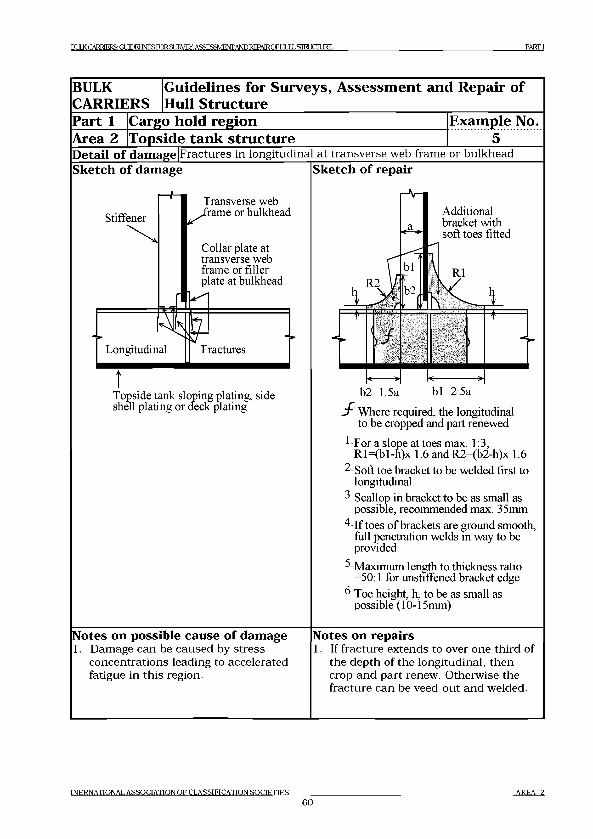
BULK CARRIERS: GUIDELINES FORSUKVEy. A S S R ^M FM A m R E PA IR O FH L lL Sim C T U K E Р А К Г 1
BULKCARRIERS
Guidelines for Surveys, Assessment and Repair of Hull Structure
Part 1Area 2
Cargo hold regionTopside tank structure
Example No..........5.........
Detail of damage Fractures in longitudinal at transverse web frame or bulkhead Sketch of damage |Sketch of repair
tTopside tank sloping plating, side shell plating or deck plating
Notes on possible cause of damage1. Damage can be caused by stress
concentrations leading to accelerated fatigue in this region.
sf'- Where required, the longitudinal to be cropped and part renewed
1 For a slope at toes max. 1:3, R l=(bl-n)x 1.6 and R2=(b2-h)x 1.6
2 Soft toe bracket to be welded first to longitudinal
3 Scallop in bracket to be as small as possible, recommended max. 35mm
4 If toes of brackets are ground smooth, full penetration welds in way to be provided
5 Maximum length to thickness ratio =50:1 for unstiffened bracket edge
6 Toe height, h, to be as small as possible (10-15mm)
Notes on repairs1. If fracture extends to over one third of
the depth of the longitudinal, then crop and part renew. Otherwise the fracture can be veed-out and welded.
INERNATIONAL ASSOCIATION OF CLASSIFICATION SOCIETIES______6 0
AREA 2
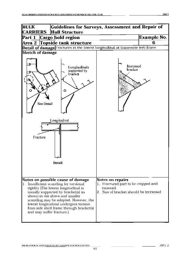
EOK CARRIERS: GUIDELINES FDR SUFVEY. ASSESSMENT AND REPMRCFHULLSIMJCIURE PARTI
BULK Guidelines for Surveys, Assessment and Repair ofCARRIERS Hull StructurePart 1 Cargo hold region Example No.Area 2 Topside tank structure 6D etail of damage Fractures in the lowest longitudinal at transverse web frameSketch o f damage
Longitudinal
Fracture
Detail
Notes on possible cause o f damage1. Insufficient scantling for torsional
rigidity (The lowest longitudinal is usually supported by bracket(s) as shown in the above and smaller scantling may be adopted. However, the lowest longitudinal undergoes torsion from side shell frame through bracket(s) and may suffer fracture.)
Notes on repairs1. Fractured part to be cropped and
renewed.2. Size of bracket should be increased
INERNATIONAL ASSOCIATION OF CLASSIFICATION SOCIETIES
61AREA 2
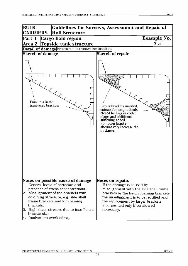
B m <CA RRD 3RS:G LJD EIlN ESroRSL]RV EY .A SSES3V IE№A N D REPA lRO Fl-lLlLLSIRLICIU RE PARTI
BULKCARRIERS
Guidelines for Surveys, Assessment and Repair of Hull Structure
Part 1 Cargo hold regionArea 2 |Topside tank structure
Example No.7 a
D etail o f damage Fractures in transverse bracketsSketch of damage
Fractures in the transverse brackets
Sketch of repair
Larger brackets inserted, cutouts for longitudinals closed by lugs or collar plates and additional stiffening added.For lower bracket alternatively increase the thickness
Notes on possible cause o f damage1. General levels of corrosion and
presence of stress concentrations. Misalignment of the brackets with adjoining structure, e.g. side shell frame brackets and /or coaming brackets.High shear stresses due to insufficient bracket size.
4. Inadvertent overloading._______________
2 .
3.
Notes on repairs1. If the damage is caused by
misalignment with the side shell frame brackets or the hatch coaming brackets the misalignment is to be rectified and the replacement by larger brackets incorporated only if considered necessary.
INERNATIONAL ASSOCIATION OF CLASSIFICATION SOCIETIES
62AREA 2
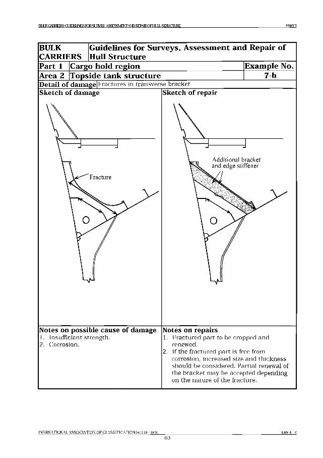
BULKCARB3ERSGOEBJNESKRSUR№Y ASSFSSMFNT AND REPAIR О Г1 И Л1 ,STRUCTURE PARTI
BULK Guidelines for Surveys, Assessment and Repair ofCARRIERS Hull StructurePart 1 Cargo hold region Example No.Area 2 Topside tank structure 7 bD etail o f damage Fractures in transverse bracketSketch of damage
Notes on possible cause o f damage1. Insufficient strength.2. Corrosion.
Sketch of repair
Notes on repairs1. Fractured part to be cropped and
renewed.2. If the fractured part is free from
corrosion, increased size and thickness should be considered. Partial renewal of the bracket may be accepted depending on the nature of the fracture.
INERNATIONAL ASSOCIATION OF CLASSIFICATION SQCIETIF.S
63AREA 2
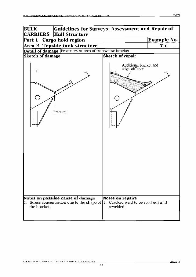
BULK CARRIERS: GUTOEUNESroRSUEVEY. ASSESSMENT AND REPAIROFH11L STRIC TU R E PARTI
BULKCARRIERS
Guidelines for Surveys, Assessment and Repair of Hull Structure
Part 1 Cargo hold regionArea 2 [Topside tank structure
Example No. ........ 7 c.......
D etail o f damage Fractures at toes of transverse bracketSketch of damage Sketch of repair
Notes on possible cause o f damage1. Stress concentration due to the shape
the bracket.of
Notes on repairs1. Cracked weld to be veed-out and
rewelded.
IN E R N A T IO N A L A S S O C IA T IO N O F C L A S S IF IC A T IO N S O C I E T I E S
6 4A R E A 2
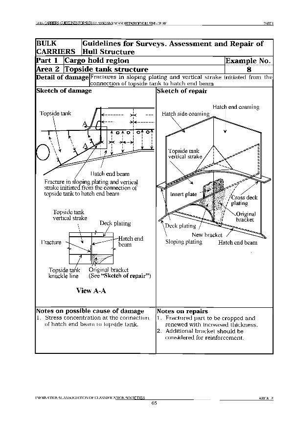
BULK CARRIERS: GUDEUNES FORSUIA'EY. ASSESSMENT AND RFPATR Р Е Н Т ITT STTRI1 Г Т П IKK PARTI
BULKCARRIERS
Guidelines for Surveys, Assessment and Repair of Hull Structure
Part 1Area 2
Cargo hold regionTopside tank structure
Example No.............8............
Detail of damage Fractures in sloping plating and vertical strake initiated from the connection of topside tank to hatch end beam___________________
Sketch of damage
Topside tank
Hatch end beamFracture in sloping plating and vertical strake initiated from the connection of topside tank to hatch end beam
Topside tank vertical strake
Deck plating
Fracture
Topside ti knuckle line
■Hatch end beam
Original bracket (See “Sketch of repair”)
View A-A
Sketch of repair
Hatch side coamingHatch end coaming
\Deck plating
New bracket Sloping plating Hatch end beam
Notes on possible cause of damage1. Stress concentration at the connection
of hatch end beam to topside tank.
Notes on repairs1. Fractured part to be cropped and
renewed with increased thickness.2. Additional bracket should be
considered for reinforcement.
IN E R N A T IQ N A L A S S O C IA T IO N O F C L A S S IF IC A T IO N S O C IF .T IK S ________
65A R E A 2

В Ш < CARRIERS G m JElJN ES FOR S U IM ^ . ASSESSMENT AND REPAIROFElLlLLSIElJCnjRE P A R T I
BULKCARRIERS
Guidelines for Surveys, Assessment and Repair of Hull Structure
Part 1 Cargo hold regionArea 2 [Topside tank structure
Example No..........9.........
Detail of damage Fractures in sloping plating at knuckleSketch of damage Sketch of repair
Notes on possible cause of damage1. Insufficient strength.2. Additional stress induced by knuckle.
Insert plate provided between new additional bracket and adjacent original transverse web frame
View A-A
Notes on repairs1. Knuckle part should be reinforced
appropriately.
IN ER N A TIO N A L A SS O C IA T IO N O F C L A SSIFIC A T IO N S O C IE T IE S ________
66AREA 2
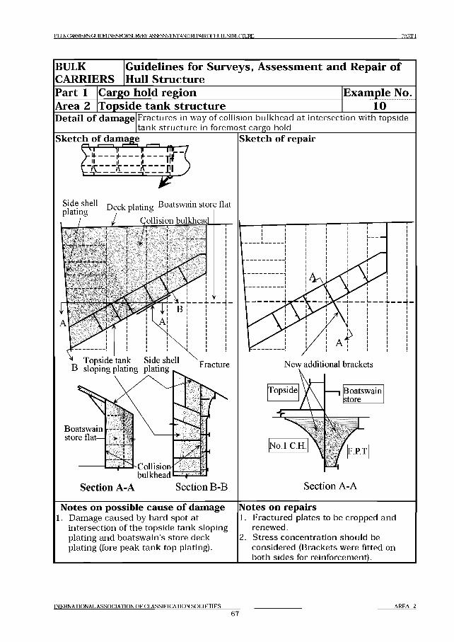
BULK CARRIERS: G U D E U N E S ro R S U №E y .A S S E S 3 V IE № AND REPM ROFHULLSIRLICIURE P A R T I
BULKCARRIERS
Guidelines for Surveys, Assessment and Repair of Hull Structure
Part 1Area 2
Cargo hold regionTopside tank structure
Example No......... io.......
D etail o f damage Fractures in way of collision bulkhead at intersection with topside tank structure in foremost cargo hold______________________________
Sketch of damageiageK\ l 1 Не ди f f Tft1 (
Sketch of repair
New additional brackets
Notes on possible cause o f damage1. Damage caused by hard spot at
intersection of the topside tank sloping plating and boatswain’s store deck plating (fore peak tank top plating).
Notes on repairs1. Fractured plates to be cropped and
renewed.2. Stress concentration should be
considered (Brackets were fitted on both sides for reinforcement).
INERNATIONAL ASSOCIATION OF CLASSIFICATION SOCIETIES______67
AREA 2
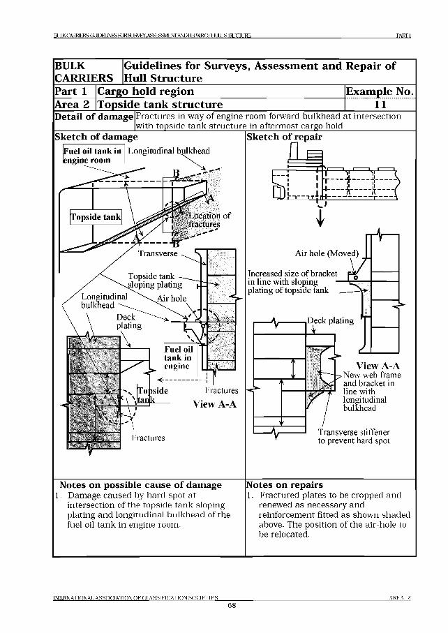
BULK CARRIERS: GUTOEUNESroRSUKVEy. ASSESSMENT AND REPAIROFHULL STRUCTURE PA RTI
BULKCARRIERS
Guidelines for Surveys, Assessment and Repair of Hull Structure
Part 1Area 2
Cargo hold regionTopside tank structure
Example No. ............1 1 ...........
D etail o f damage Fractures in way of engine room forward bulkhead at intersection with topside tank structure in aftermost cargo hold_______________
Sketch o f damageLongitudinal bulkheadFuel oil tank in
engine room
Topside tank Location o f j fractures
Transverse ^ t\"
Deckplating
\ /
>
\
У( N
= л :1
Fuel oil tank in engine
<----------------!Topside
.tan кFractures
View A-A
Fractures
Sketch of repair
Increased size o f bracket in line with sloping plating o f topside tank
View A-ANew web frame and bracket in line with longitudinal bulkhead
Transverse stiffener to prevent hard spot
Notes on possible cause o f damage1. Damage caused by hard spot at
intersection of the topside tank sloping plating and longitudinal bulkhead of the fuel oil tank in engine room.
Notes on repairs1. Fractured plates to be cropped and
renewed as necessary and reinforcement fitted as shown shaded above. The position of the air-hole to be relocated.
IN E R N A T IO N A L A S S O C IA T IO N O F C L A S S IF IC A T IO N S O C I E T I E S
68A R E A 2
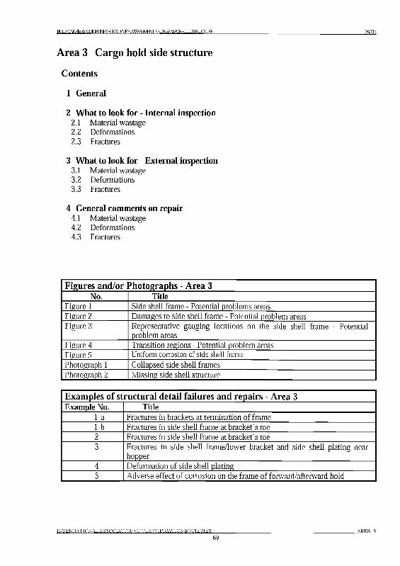
BlXKCARRERSGUDEIJ№SFmS№VEY.ASSESgvA№REPARCmiI5™CIllRE PARTI
Area 3 Cargo hold side structure
Contents
1 General
2 What to look for - Internal inspection2.1 Material wastage2.2 Deformations2.3 Fractures
3 What to look for - External inspection3.1 Material wastage3.2 Deformations3.3 Fractures
4 General comments on repair4.1 Material wastage4.2 Deformations4.3 Fractures
Figures and/or Photographs - Area 3No. Title
Figure 1 Side shell frame - Potential problems areasFigure 2 Damages to side shell frame - Potential problem areasFigure 3 Representative gauging locations on the side shell frame - Potential
problem areasFigure 4 Transition regions - Potential problem areasFigure 5 Uniform corrosion of side shell fram e
Photograph 1 Collapsed side shell framesPhotograph 2 Missing side shell structure
Examples of structural detail failures and repairs - Area 3Example No. Title
1-a Fractures in brackets at termination of frame1-b Fractures in side shell frame at bracket’s toe2 Fractures in side shell frame at bracket’s toe3 Fractures in side shell frame/lower bracket and side shell plating near
hopper4 Deformation of side shell plating5 Adverse effect of corrosion on the frame of forward/afterward hold
INTERNATIONAL ASSOCIATION OFCLASSIFICATIONSOCIETIES6 9
AREA 3
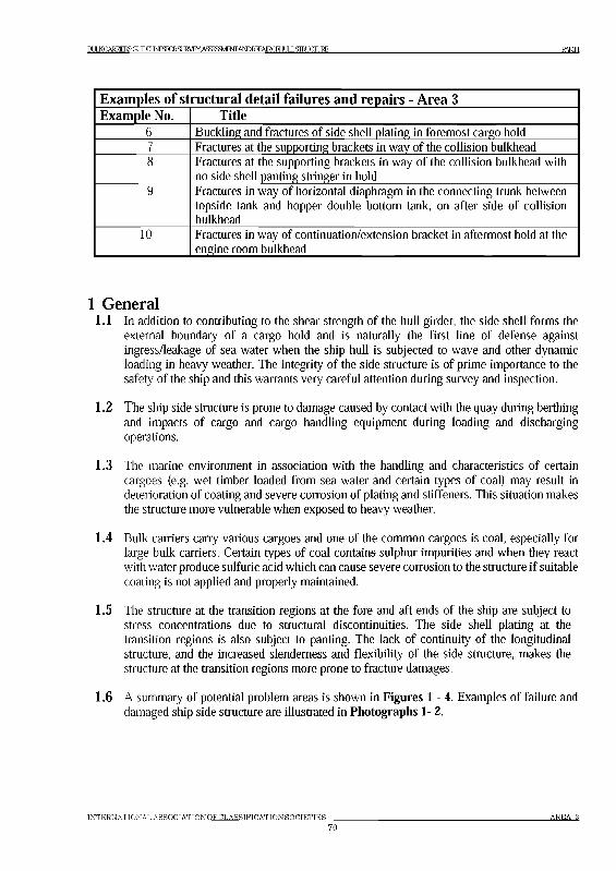
BULKCARKERS: GtJDELl FCRSJRVEY. S5jS3VlENrANDREPAIRCFHULLSIRXIITJRE Ш !
Examples of structural detail failures and repairs - Area 3Example No. Title
6 Buckling and fractures of side shell plating in foremost cargo hold7 Fractures at the supporting brackets in way of the collision bulkhead8 Fractures at the supporting brackets in way of the collision bulkhead with
no side shell panting stringer in hold9 Fractures in way of horizontal diaphragm in the connecting trunk between
topside tank and hopper double bottom tank, on after side of collision bulkhead
10 Fractures in way of continuation/extension bracket in aftermost hold at the engine room bulkhead
1 General1.1 In addition to contributing to the shear strength of the hull girder, the side shell forms the
external boundary of a cargo hold and is naturally the first line of defense against ingress/leakage of sea water when the ship hull is subjected to wave and other dynamic loading in heavy weather. The integrity of the side structure is of prime importance to the safety of the ship and this warrants very careful attention during survey and inspection.
1.2 The ship side structure is prone to damage caused by contact with the quay during berthing and impacts of cargo and cargo handling equipment during loading and discharging operations.
1.3 The marine environment in association with the handling and characteristics of certain cargoes (e.g. wet timber loaded from sea water and certain types of coal) may result in deterioration of coating and severe corrosion of plating and stiffeners. This situation makes the structure more vulnerable when exposed to heavy weather.
1.4 Bulk carriers carry various cargoes and one of the common cargoes is coal, especially for large bulk carriers. Certain types of coal contains sulphur impurities and when they react with water produce sulfuric acid which can cause severe corrosion to the structure if suitable coating is not applied and properly maintained.
1.5 The structure at the transition regions at the fore and aft ends of the ship are subject to stress concentrations due to structural discontinuities. The side shell plating at the transition regions is also subject to panting. The lack of continuity of the longitudinal structure, and the increased slenderness and flexibility of the side structure, makes the structure at the transition regions more prone to fracture damages.
1.6 A summary of potential problem areas is shown in Figures 1-4. Examples of failure and damaged ship side structure are illustrated in Photographs 1-2.
INTERNATIONAL ASSOCIATIONOFCLASSIFICATIONSOCIETIES7 0
a r e a з
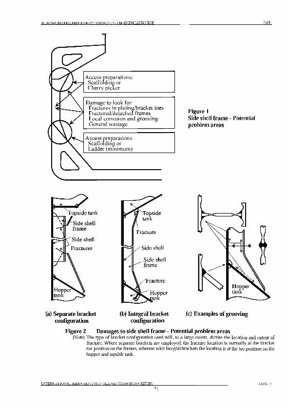
B U m C A R R E R S G m E I J N E S F m S № W .A S S E S M M A N D № P A l R C f H X L S r a J C I l J R E PARTI
Figure 1Side shell frame - Potential problem areas
(a) Separate bracket (b) Integral bracket (c) Examples of groovingconfiguration configuration
Figure 2 Damages to side shell frame - Potential problem areas(Note) The type o f bracket configuration used will, to a large extent, dictate the location and extent of
fracture. W here separate brackets are employed, the fracture location is normally at the bracket toe position on the frames, whereas with integral brackets the location is at the toe position on the hopper and topside tank.
IN T E R N A T IO N A L A S S O C IA T IO N O F C L A S S IF IC A T IO N S O C IE T IE S
7 1
AREA 3
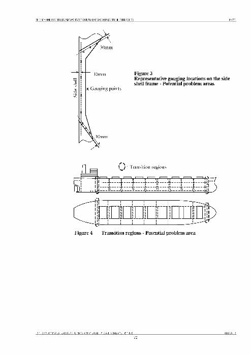
BU«CARRERS:GLPEIJ№SFmS№W.ASSESgvAmRffAlRCFblJLLSIRUCIllRE PARTI
Figure 3Representative gauging locations on the side shell frame - Potential problem areas
l ! : Transition regions
ft
1Ё - til
Figure 4 Transition regions - Potential problem area
INTERNATIONAL ASSOCIATION OFCLASSIFICATIONSOCIETIES72
AREA 3
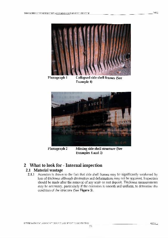
BU«CARRlERSGmEIl«FmS№W.ASSESSME№A№REPAlRCFHIXLSraJCIURE PARTI
Photograph 1 Collapsed side shell frames (See Example 4)
Photograph 2 Missing side shell structure (See Examples 4 and 5)
2 What to look for - Internal inspection2.1 Material wastage
2.1.1 Attention is drawn to the fact that side shell frames may be significantly weakened by loss of thickness although diminution and deformations may not be apparent. Inspection should be made after the removal of any scale or rust deposit. Thickness measurements may be necessary, particularly if the corrosion is smooth and uniform, to determine the condition of the structure (See Figure 5).
INTERNATIONAL ASSOCIATION OFCLASSIFICATIONSOCIETIES7 3
AREA 3
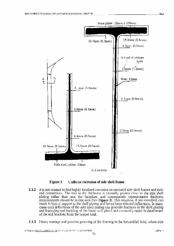
В1ХКСАНЕЕН5:СШЕЦ№5РШ5ШЛ‘ВсЯуЖГАШ№РАЕСРЬЦХ51ШС111НЕ PARTI
F a ce p la te : 2 2 m m x 150 m m
1 5 .7 m m (6 .3 m m )
1 5 .5 m m (3 .5 m m )
5 .1 m m (5 .9 m m )
4 .9 m m (6 .1 m m )
4 .4 m m (6 .6 m m )
1 5 .5 m m (3 .5 m m )
t 1S id e s h e ll p la te : 19m m
1 5 .2 m m (6 .8 m m )
4 .5 m m (6 .5 m m )
A c tu a l th ick n e ssL o ss
/ /3 .8 m m (7 .2 m m )
W e b : 11m m
5 .1 m m (5 .9 m m )
5 .5 m m (5 .5 m m )
A -A s e c t io n
Figure 5 Uniform corrosion of side shell frame
2.1.2 It is not unusual to find highly localised corrosion on uncoated side shell frames and their end connections. The loss in the thickness is normally greater close to the side shell plating rather than near the faceplate, and consequently representative thickness measurements should be in that area (See Figure 3). This situation, if not remedied, can result in loss of support to the shell plating and hence large inboard deflections. In many cases such deflections of the side shell plating can generate fractures in the shell plating and fracturing and buckling of the frame web plates and eventually result in detachment of the end brackets from the hopper tank.
2.1.3 Heavy wastage and possible grooving of the framing in the forward/aft hold, where side
IN T E R N A T IO N A L A S S O C IA T IO N O F C L A S S IF IC A T IO N S O C IE T IE S
7 4
a r e a 3
BIXKCARRlE]S(IJmiNESiqSIJA.ASaS3VBSirA№l№«CFHIXLSimgi™ ш
shell plating is oblique to frames, may result in fracture and buckling of the shell plating as shown in Example 5.
2.1.4 Pitting corrosion may be found under coating blisters which need to be removed before inspection.It should be noted that the middle part of a frame may be wasted even if the upper and / or lower parts of the frame are not.The following should be considered (and may be included as a surveyor's checklist):• Hold Frame scantling drawings for each hold and allowable diminution level• Repair history of Hold Frames• Previous thickness measurement reports.• Diminution of Hold Frames would normally be equal or greater than that of transverse cargo
hold bulkheads.• Note history of cargoes carried, especially that of coal or similar corrosive cargo.• Record of any coating previously applied.• Safe means of survey access (staging / cherry picker / portable ladder etc.)
Visual examination should take account of the following:• The diminution of the face plate can be an indication of diminution level on the webs.• Thickness of the Web may be estimated from edge condition of scallops.• Fillet welding between Web and Shell plate and heat affected zone• Fillet welding between Web and Face plate and heat affected zone• Fillet welding between Upper Bracket and Top side tank, between Lower Bracket and Bilge
Hopper Tank and heat affected zone• Scallop at Upper and Lower part of Web
Experience with Bulk Carriers 1 0 0 ,000 dwt and above has shown that side shell fram es in N o .3 hold are
more susceptible to dam ages. Therefore it is recom m ended that side shell fram es in this hold are specially
considered.
2.2 Deformations2.2.1 It is normally to be expected that the lower region of the frames will receive some level of
damage during operational procedures, e.g. when unloading with the aid of grabs and bulldozers or during loading of logs. This can range from damage of the side frame end bracket face plates to large physical deformations of a number of frames and in some cases can initiate fractures.
These individual frames and frame brackets, if rendered ineffective, will place additional load on the adjacent frames and failure by the “domino effect” can in many cases extend over the side shell of a complete hold.
2.3 Fractures2.3.1 Fractures are more evident at the toes of the upper and lower bracket(s) or at the
connections between brackets and frames. In most cases the fractures may be attributed to stress concentrations and stress variations created, in the main, by loads from the seaway. The stress concentrations can be a result of poor detail design and/or bad workmanship. Localised fatigue fracturing, possibly in association with localised corrosion, may be difficult to detect and it is stressed that the areas in question should receive close attention during periodical surveys.
2.3.2 Fractures are more often found at the boundary structure of a cargo/ballast hold than other cargo holds. This area should be subjected to close-up examination.
2.3.3 Fractures in shell plating and supporting or continuation/extension brackets at collision bulkhead and engine room forward bulkhead are frequently found by close-up examination.
IN T E R N A T IO N A L A S S O C IA T IO N O F C L A S S IF IC A T IO N S O C IE T IE S
7 5
A R E A 3
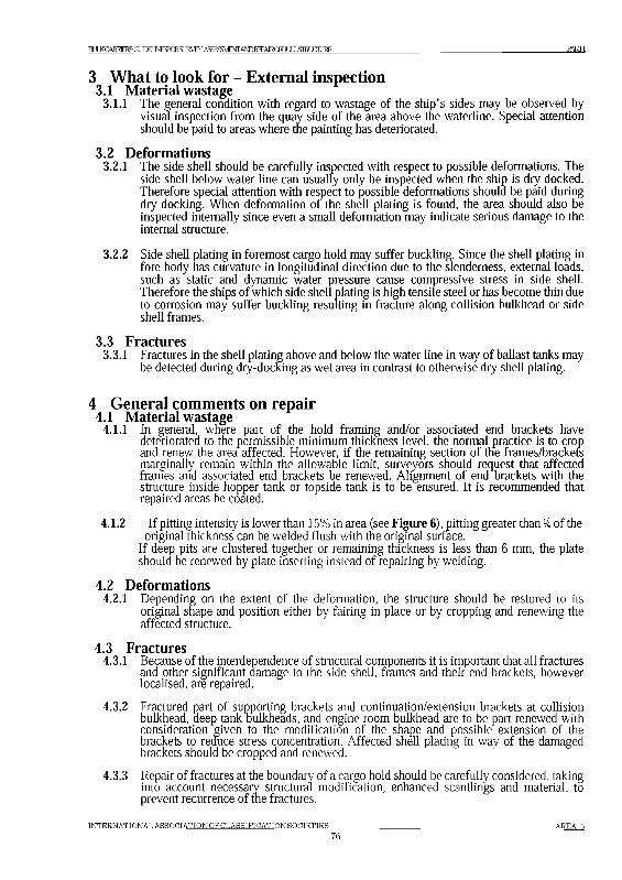
BUmCARRERSGUDEIJNESFmSLlRVEY.ASSESavlEMANDREPAIRCFH HI ЯШ HIT1RF. PARTI
3 What to look for - External inspection3.1 Material wastage
3.1.1 The general condition with regard to wastage of the ship’s sides may be observed by visual inspection from the quay side of the area above the waterline. Special attention should be paid to areas where the painting has deteriorated.
3.2 Deformations3.2.1 The side shell should be carefully inspected with respect to possible deformations. The
side shell below water line can usually only be inspected when the ship is dry docked. Therefore special attention with respect to possible deformations should be paid during dry-docking. When deformation of the shell plating is found, the area should also be inspected internally since even a small deformation may indicate serious damage to the internal structure.
3.2.2 Side shell plating in foremost cargo hold may suffer buckling. Since the shell plating in fore body has curvature in longitudinal direction due to the slenderness, external loads, such as static and dynamic water pressure cause compressive stress in side shell. Therefore the ships of which side shell plating is high tensile steel or has become thin due to corrosion may suffer buckling resulting in fracture along collision bulkhead or side shell frames.
3.3 Fractures3.3.1 Fractures in the shell plating above and below the water line in way of ballast tanks may
be detected during dry-docking as wet area in contrast to otherwise dry shell plating.
4 General comments on repair4.1 Material wastage
4.1.1 In general, where part of the hold framing and/or associated end brackets have deteriorated to the permissible minimum thickness level, the normal practice is to crop and renew the area affected. However, if the remaining section of the frames/brackets marginally remain within the allowable limit, surveyors should request that affected frames and associated end brackets be renewed. Alignment of end brackets with the structure inside hopper tank or topside tank is to be ensured. It is recommended that repaired areas be coated.
4.1.2 If pitting intensity is lower than 15% in area (see Figure 6), pitting greater than lk of the original thickness can be welded flush with the original surface.
If deep pits are clustered together or remaining thickness is less than 6 mm, the plate should be renewed by plate inserting instead of repairing by welding.
4.2 Deformations4.2.1 Depending on the extent of the deformation, the structure should be restored to its
original shape and position either by fairing in place or by cropping and renewing the affected structure.
4.3 Fractures4.3.1 Because of the interdependence of structural components it is important that all fractures
and other significant damage to the side shell, frames and their end brackets, however localised, are repaired.
4.3.2 Fractured part of supporting brackets and continuation/extension brackets at collision bulkhead, deep tankTulkheads, and engine room bulkhead are to be part renewed with consideration given to the modification of the shape and possible extension of the brackets to reduce stress concentration. Affected shell plating in way of the damaged brackets should be cropped and renewed.
4.3.3 Repair of fractures at the boundary of a cargo hold should be carefully considered, taking into account necessary structural modification, enhanced scantlings and material, to prevent recurrence of the fractures.
INTERNATIONAL ASSOCIATION OFCLASSIFICATIONSOCIETIES7 6
AREA 3
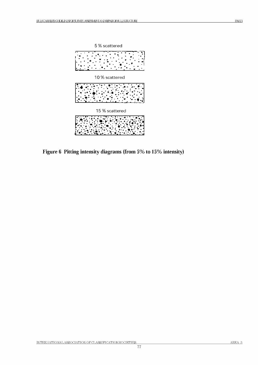
BUIXCARRERS: GUDEUNESFCRSURWY, ASSESSMENT AND REPAIRCFHULLSIRUCIURE PARTI
5 % s c a t te re d
1 0 % s c a t te re d
15 % s c a t te re d
Figure 6 Pitting intensity diagrams (from 5% to 15% intensity)
INTERNATIONAL ASSOCIATION OF CLASSIFICATIONSOCIETIES77
AREA 3
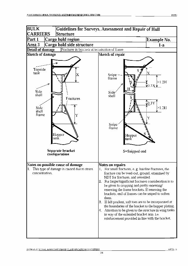
BL^CARl«S(IJmiNESICRSUKVEY.ASSESWfl,A№REPAlR(miLSraJCIURE PARTI
BULKCARRIERS
Guidelines for Surveys, Assessment and Repair of Hull Structure
Part 1 Cargo hold regionArea 3 |Cargo hold side structure
Example No.1-a
Detail of damage Fractures in brackets at termination of frame
Sketch of damage
Topsidetank
Sideshellframe
Separate bracket configuration
Sketch of repair
Snipeframe
>1.2H
>1.2H
Snipeframe
S=Snipped end
Notes on possible cause of damage1. This type of damage is caused due to stress
concentration.
Notes on repairs1. For small fractures, e. g. hairline fractures, the
fracture can be veed-out, ground, examined by NDT for fractures, and rewelded.
2. For larger/significant fractures consideration is to be given to cropping and partly renewing/ renewing the frame brackets. If renewing the brackets, end of frames can be sniped to soften them.
3. If felt prudent, soft toes are to be incorporated at the boundaries of the bracket to the hopper plating.
4. Attention to be given to the structure in wing tanks in way of the extended bracket arm. i.e. reinforcement provided in line with the bracket.
INTERNATIONAL ASSOCIATION OF CLASSIFICATION SOCIETIES AREA 3
78
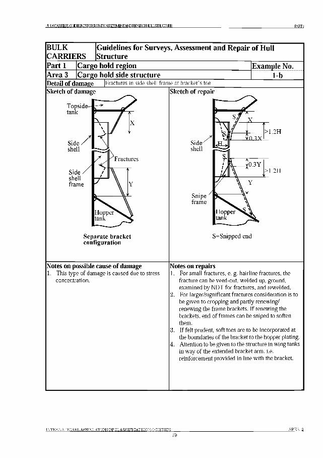
BIXKCARl«S:GUCmNESiq^SIJA^.ASSESWfl,A№l№«CFHLJLLSraJCIURE PARTI
BULKCARRIERS
Guidelines for Surveys, Assessment and Repair of Hull Structure
Part 1Area 3
Cargo hold regionCargo hold side structure
Example No.......... i-b.......
Detail of damage Fractures in side shell frame at bracket’s toe
Sketch of damage
Topside tank
Sideshellframe
Separate bracket configuration
Sketch of repair
>1.2H
>1.2H
Snipeframe
S=Snipped end
Notes on possible cause of damage1. This type of damage is caused due to stress
concentration.
Notes on repairs1. For small fractures, e. g. hairline fractures, the
fracture can be veed-out, welded up, ground, examined by NDT for fractures, and rewelded.
2. For larger/significant fractures consideration is to be given to cropping and partly renewing/ renewing the frame brackets. If renewing the brackets, end of frames can be sniped to soften them.
3. If felt prudent, soft toes are to be incorporated at the boundaries of the bracket to the hopper plating.
4. Attention to be given to the structure in wing tanks in way of the extended bracket arm. i.e. reinforcement provided in line with the bracket.
INTERNATIONAL ASSOCIATION OFCLASSIFICATIONSOCIETIES
79
AREA 3
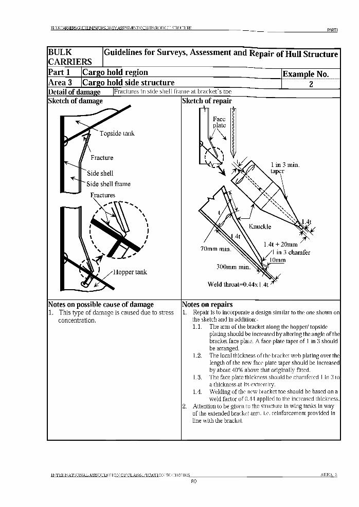
BU«C™MSGmEIJNESF^SUIMY.ASSESMMAND№PAlRCFblJLLSIRUCIllREPARTI
BULKCARRIERS
Guidelines for Surveys, Assessment and Repair o f Hull Structure
Part 1 Cargo hold regionArea 3 Cargo hold side structure
Example No....... 2...
Detail of damage Fractures in side shell frame at bracket’s toe
Sketch of damage
Topside tank
Side shell
Side shell frame
Fractures
Hopper tank
Sketch of repairЛ и rfln
1 in 3 min. taper
70mm min.
300mm min.
Weld throat=0.44xl.4t
Notes on possible cause of damage1. This type of damage is caused due to stress
concentration.
Notes on repairs1. Repair is to incorporate a design similar to the one shown on
the sketch and in addition:-1.1. The arm of the bracket along the hopper/ topside
plating should be increased by altering the angle of the bracket face plate. A face plate taper of 1 in 3 should be arranged.
1.2. The local thickness of the bracket web plating over the length of the new face plate taper should be increased by about 40% above that originally fitted.
1.3. The face plate thickness should be chamfered 1 in 3 to a thickness at its extremity.
1.4. Welding of the new bracket toe should be based on a weld factor of 0.44 applied to the increased thickness.
2. Attention to be given to the structure in wing tanks in way of the extended bracket arm. i.e. reinforcement provided in line with the bracket.
INTERNATIONAL ASSOCIATION OFCLA SSIFICATION SOCIETIES
80AREA 3
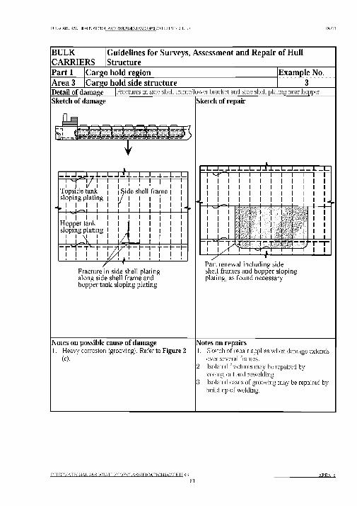
BULKCARRESGUCEUNESKRSLIRVEYASSFSSVIENT AWRTT’ATRQHULLSrRUCIIJRE PARTI
BULKCARRIERS
Guidelines for Surveys, Assessment and Repair of Hull Structure
Part 1 Cargo hold region Example No.Area 3 Cargo hold side structure 3Detail of damage |Fractures in side shell frame/lower bracket and side shell plating near hopper
Sketch of damage
T
|_l__ l_J._r.L_l___U?_L_I__ i__ u_ J__ i_i 4 ^ i 7 1— i— i— 1—1—i—I— 1— l_I I v I I I 1 ■
Topside tank | | Side shell framesloping plating I I / I
I I I I I Г I* I ----1----1---1---L-
I I I IH opper tank sloping plating
i I \i i i
i i i i i11
' +-i— i - t - i — |_ i i i i i i4 ' 1 1 ! ' '
Fracture in side shell plating along side shell fram e and hopper tank sloping plating
Sketch of repair
-1__1— L — J— 1__ l - f l - l __1__L _ L _ L1 4 - 0 1 1 1 i— i— i— i— i— Г" 1 1 1 1 1 1 1 1 1 1 1 1 1 1 1 1 1 1 1 1 1 1 1 1 1 1 1 1 1 1 1 1 1 1 1 1 1 1 1 1 1 1 1 1 1 1 1 1
__l____ 1 ^-vl____ 1____ 1____ 1____ 1____ 1____ 1__ 1 1 11 Ч-Г------11 1 1 1 1 1 1 1 1 1 1 1 1 U l
l l 1 1 1 1 I- 1 1 1 1 1 1 1 1 1 1 1 1 1 1 1 1 1 1 1 1 1 1 1 1 I I 1 1 I I I I i t I
—1----1—l l l l 1 1 l l i i
T T F tl— 1— 1“ Т “ Г “1— гj4 . . . . . У f i — г!— ! —г a i— i— i— ! i i
Part renewal including side shell frames and hopper sloping plating, as found necessary
Notes on possible cause of damage1. Heavy corrosion (grooving). Refer to Figure 2
(c).
Notes on repairs1. Sketch of repair applies when damage extends
over several frames.2. Isolated fractures may be repaired by
veeing-out and rewelding.3. Isolated cases of grooving may be repaired by
build up of welding.
INTERNATIONAL ASSOCIATION OFCLASSIFICATIONSOCIETIES
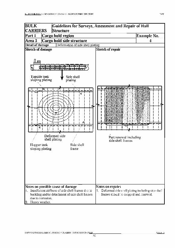
BlXKCARRERSGUDEIJ№SFmS№W.ASSESgv^AmREPARCmiLSraJCIlJRE PARTI
BULKCARRIERS
Guidelines for Surveys, Assessment and Repair of Hull Structure
Part 1 Cargo hold region Example No.Area 3 Cargo hold side structureDetail of damage |D eform ation o f side shell pla ting
Sketch of damage
| - U ' KJ
/ V V \} l Tx NI\ v
b 1 ( 1 iV,D I\ l \ i \ 4 4 J ' / i /
\ 1'S. T " t " I
l /Т— I__ L----1 — I— f— I— I- 4 i— I—
I 'S'. !/ ! if j ; ! / I IDeformed side shell plating
Hopper tank sloping plating
Side shell frame
Sketch of repair
_L Л1__L —J__I___111-1___I-I I I I I I I
4 L J _
Part renewal including side shell frames
Notes on possible cause of damage1. Insuffic ien t stiffness o f side shell fram es due to
buck ling and /or de tachm ent o f s ide shell fram es
due to corrosion .
2 . H eavy w eather.
Notes on repairs1. D eform ed side shell p la ting includ ing side shell
fram es should be cropped and renew ed.
IN T E R N A T IO N A L A S S O C IA T IO N O F C L A S S IF IC A T IO N S O C IE T IE S
82A R E A 3
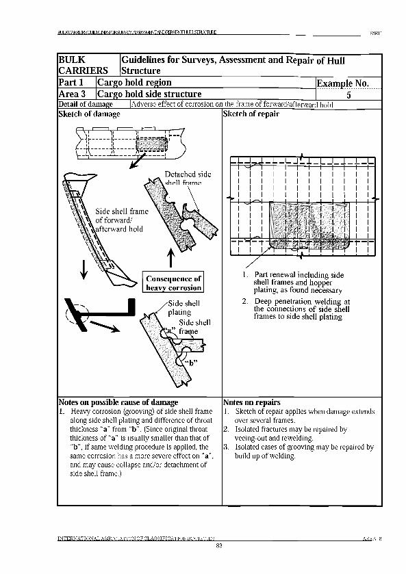
BL^CARRBS(IJmiNESiq^SIJA^.ASaS3vBStrA№REPAlRCFHIXL5imJURE PARTI
BULKCARRIERS
Guidelines for Surveys, Assessment and Repair of Hull Structure
Part 1Area 3
Cargo hold regionCargo hold side structure
Detail of damage |Adverse effect of corrosion on the frame of forward/afterward hold
Example No............. 5.......
Sketch of damage Sketch of repair
v n |i r w
Н £ | Э ' )Detached side
, sbpli tramp
Side shell frame \ of forward/
Consequence of heavy corrosion
Side shell plating
Side shell frame
- |__U J— L - -J L T _L J - l - i - I
■ г Ч -Ч Ч гi ! y n -
—r— I— I----1 - t i - r— i— I— r I
1. Part renewal including side shell frames and hopper plating, as found necessary
2. Deep penetration welding at the connections of side shell frames to side shell plating
Notes on possible cause of damageHeavy corrosion (grooving) of side shell frame along side shell plating and difference of throat thickness “a” from “b”. (Since original throat thickness of “a” is usually smaller than that of “b”, if same welding procedure is applied, the same corrosion has a more severe effect on “a”, and may cause collapse and/or detachment of side shell frame.)
Notes on repairs1. Sketch of repair applies when damage extends
over several frames.2. Isolated fractures may be repaired by
veeing-out and rewelding.3. Isolated cases of grooving may be repaired by
build up of welding.
INTERNATIONAL ASSOCIATION OFCLASSIFICATIONSOCIETIES8 3
AREA 3
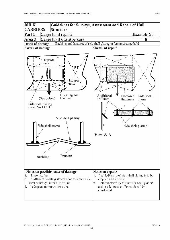
BU«CARRERS:GLPEIJ№SFmSLRVEY.ASSESMMAND№PAlRCFblJLLSIRUCIllRE PARTI
BULKCARRIERS
Guidelines for Surveys, Assessment and Repair of Hull Structure
Part 1Area 3
Cargo hold regionCargo hold side structure
Example No..............6.......
Detail of damage |Buckling and fractures of side shell plating in foremost cargo hold
Sketch of damage
Buckling and (See below) fracture
Side shell plating i.w.o. No.l C.H.
Side shell plating
Side shell frame
Buckling Fracture
Sketch of repair
Г ---- --- -
---------------- j
л
/ \
/ \ aLI
Additionalstiffener
\ /V
/ \/ ' \
Increased Side shell thickness frame
Side shell plating
View A-A
Notes on possible cause of damage1. Heavy weather.2. Insufficient buckling strength due to high tensile
steel or heavy uniform corrosion.3. Inadequate transition structure.
Notes on repairs1. Buckled/fractured side shell plating is to be
cropped and renewed.2. Reinforcement by thicker side shell plating
and/or additional stiffeners should be considered.
INTERNATIONAL ASSOCIATION OFCLASSIFICATIONSOCIETIES84
AREA 3
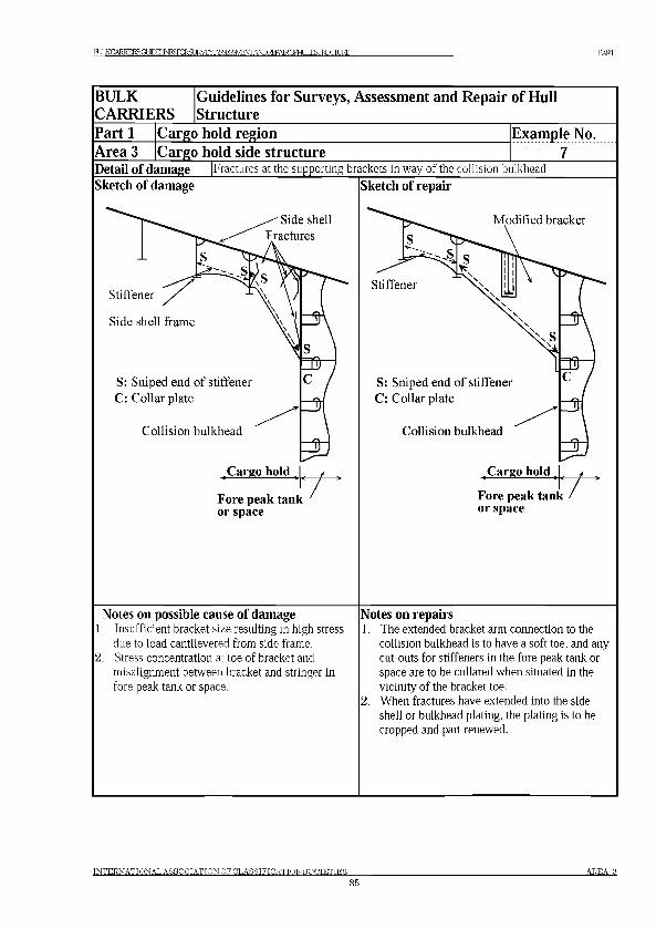
BL«CARRlERSGUDEIJ№SKES№W.ASSESgv^AmRffARCmJLLSIRUCIllRE PARTI
BULKCARRIERS
Guidelines for Surveys, Assessment and Repair of Hull Structure
Part 1Area 3
Cargo hold regionCargo hold side structure
Example No............. 7.......
Detail of damage |Fractures at the supporting brackets in way of the collision bulkhead
Sketch of damage Sketch of repair
Notes on possible cause of damage1. Insufficient bracket size resulting in high stress
due to load cantilevered from side frame.2. Stress concentration at toe of bracket and
misalignment between bracket and stringer in fore peak tank or space.
Notes on repairs1. The extended bracket arm connection to the
collision bulkhead is to have a soft toe, and any cut-outs for stiffeners in the fore peak tank or space are to be collared when situated in the vicinity of the bracket toe.
2. When fractures have extended into the side shell or bulkhead plating, the plating is to be cropped and part renewed.
INTERNATIONAL ASSOCIATION OFCLASSIFICATIONSOCIETIES85
AREA 3
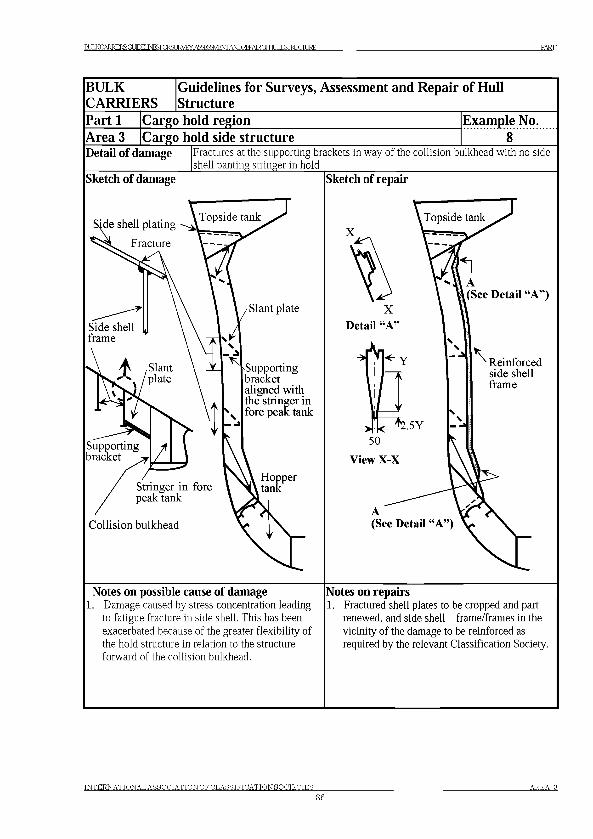
BU«CARRlERSGmEIJNESFmSUIMY.ASSESMMAND№PAlRCFblJLLSIRUCIllRE PARTI
BULKCARRIERS
Guidelines for Surveys, Assessment and Repair of Hull Structure
Part 1Area 3
Cargo hold regionCargo hold side structure
Example No..............8.......
Detail of damage Fractures at the supporting brackets in way of the collision bulkhead with no side shell panting stringer in hold
Sketch of damage
•Supporting bracket aligned with the stringer in fore peak tank
Collision bulkhead
Sketch of repair
XA\ A(See Detail “A”)
4 Reinforced side shell frame
(See Detail “A”)
Notes on possible cause of damage1. Damage caused by stress concentration leading
to fatigue fracture in side shell. This has been exacerbated because of the greater flexibility of the hold structure in relation to the structure forward of the collision bulkhead.
Notes on repairs1. Fractured shell plates to be cropped and part
renewed, and side shell frame/frames in the vicinity of the damage to be reinforced as required by the relevant Classification Society.
INTERNATIONAL ASSOCIATION OFCLASSIFICATIONSOCIETIES86
AREA 3

BLCARlMS(MM№S[SURVEY.ASMjNrANDREPAlRgJHLlLLSIHXIlJRE PARTI
BULKCARRIERS
Guidelines for Surveys, Assessment and Repair of Hull Structure
Part 1Area 3
Cargo hold regionCargo hold side structure
Example No............. 9.......
Detail of damage Fractures in way of horizontal diaphragm in the connecting trunk between topside tank and hopper double bottom tank, on after side of collision bulkhead________
Sketch of damage Sketch of repair
Notes on possible cause of damage1. Damage caused by stress concentration resulting
from the discontinuity created by the trunk and diaphragm structure. This has been exacerbated because of the greater flexibility of the hold structure in relation to the trunk and structure forward of the collision bulkhead.
Notes on repairs1. Diaphragm to be removed permanently and
fractured shell plated cropped and part renewed, or veed and weld as necessary in way of damage. Brackets with softened to toes are to be fitted on forward side of collision bulkhead in way of stringers/flats to align with inboard side of trunk in order to remove hard-spots.
INTERNATIONAL ASSOCIATION OFCLASSIFICATIONSOCIETIES8 7
AREA 3
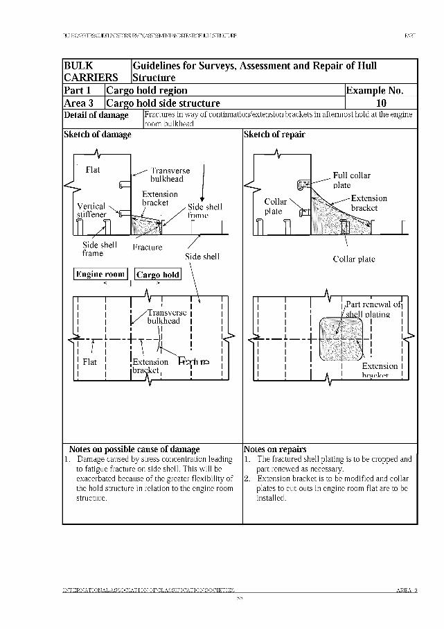
B U «C A R R E R S:G L PE IJ№SFm SL R V E Y .A SSE SM M A N D №PA lR C FblJL L SIR U C IllR E PARTI
BULKCARRIERS
Guidelines for Surveys, Assessment and Repair of Hull Structure
Part 1Area 3
Cargo hold regionCargo hold side structure
Example No. ............i o ......
Detail of damage Fractures in way of continuation/extension brackets in aftermost hold at the engine room bulkhead
Sketch of damage Sketch of repair
Collar plate
Engine room Cargo hold
■V
I-
/Part renewal of
/ 711_T__ 1 \
_i__7-V
!< *
Extensionh r a r U p t
Notes on possible cause of damage1. Damage caused by stress concentration leading
to fatigue fracture on side shell. This will be exacerbated because of the greater flexibility of the hold structure in relation to the engine room structure.
Notes on repairs1. The fractured shell plating is to be cropped and
part renewed as necessary.2. Extension bracket is to be modified and collar
plates to cut-outs in engine room flat are to be installed.
INTERNATIONAL ASSOCIATION OFCLASSIFICATIONSOCIETIES AREA 3
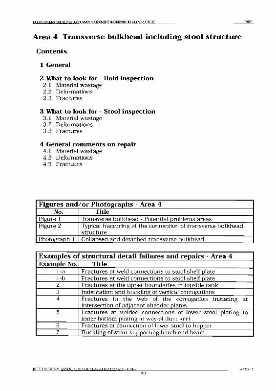
EULKCARRIERS: GUIDELINES FORSUKVEY, ASSESSMENT AND REPAIROF HLLLSIMJCHJRE P A R T I
Area 4 Transverse bulkhead including stool structure
C ontents
1 General
2 What to look for - Hold inspection2.1 Material wastage2.2 Deformations2.3 Fractures
3 What to look for - Stool inspection3.1 Material wastage3.2 Deformations3.3 Fractures
4 General comments on repair4.1 Material wastage4.2 Deformations4.3 Fractures
Figures and /or Photographs - Area 4No. Title
Figure 1 Transverse bulkhead - Potential problems areasFigure 2 Typical fracturing at the connection of transverse bulkhead
structurePhotograph 1 Collapsed and detached transverse bulkhead
Exam ples ol ‘ structural detail failures and repairs - Area 4Example No. Title
1-a Fractures at weld connections to stool shelf plate1-b Fractures at weld connections to stool shelf plate2 Fractures at the upper boundaries to topside tank3 Indentation and buckling of vertical corrugations4 Fractures in the web of the corrugation initiating at
intersection of adjacent shedder plates5 Fractures at welded connections of lower stool plating to
inner bottom plating in way of duct keel6 Fractures at connection of lower stool to hopper7 Buckling of strut supporting hatch end beam
INTERNATIONAL ASSOCIATION OF CLASSIFICATION SOCIETIES89
AREA 4
BUJ< CARRIERS GLTOEIINESroRSURVEY. ASSESSMENTAND REPAIROFEILJLL STRUCTURE P A R T I
1 General1.1 The transverse bulkheads at the ends of dry cargo holds are mainly
ordinary watertight bulkheads serving two main functions:(a) As main transverse strength elements in the structural design of the
ship.(b) As subdivision to prevent progressive flooding in an emergency
situation.
1 .2 The transverse bulkheads at the ends of a combined ballast/ cargo hold are deep tank bulkheads which, in addition to the functions given in 1.1, are designed to withstand the water pressure from a hold fully filled with water ballast.
1 .3 The bulkheads are commonly constructed as vertically corrugated with a lower stool, and with or without an upper stool (See Chapter 3 Technical background for surveys - Figure 3 (b)). Other constructions may be:Plane bulkhead plating with one sided vertical stiffeners.Double plated bulkhead with internal stiffening, with or without stool(s).
1 .4 Dry cargo holds, not designed as ballast holds, may sometimes be partially filled with water ballast in order to achieve a satisfactory air draught at the loading/discharging berths.The filling is restricted to a level that corresponds to the dry cargo hold scantlings, in particular the transverse bulkheads scantlings, and must only be carried out in port. In no case should these cargo holds be partially filled during voyage to save time at the berth. Such filling at sea may cause sloshing resulting in catastrophic failure such as indicated in Photograph 1.
1 .5 Heavy corrosion may lead to collapse of the structure under extreme load, such as indicated in Photograph 1 if it is not rectified properly.
1 .6 A summary of potential problem areas is shown in Figure 1. It is emphasised that appropriate access arrangement as indicated in Chapter 4 Survey planning, preparation and execution of the guidelines, should be provided to enable a proper close-up inspection and thickness measurement as necessary.
INTERNATIONAL A SSO C IA T IO N O F C LA SSIFICATION S O C IE T IE S
90AREA 4
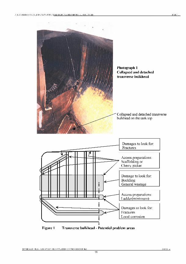
BULK CARRIERS:GUroKUNESFORSURVEY.ASSESSMENTANDREPAIROFHULL STRUCTURE PART 1
Photograph 1 Collapsed and detached transverse bulkhead
Collapsed and detached transverse bulkhead on the tank top
Figure 1 Transverse bulkhead - Potential problem areas
INTERNATIONAL ASSOCIATIONOFCLASSIFICATIONSOCIETIES91
AREA 4
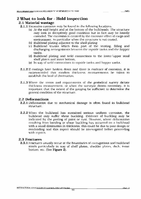
B U L K C A RR IER S: G U D E L JN E S ro R S IJ R V E Y .A S S E S S V D iN T A N D R E P A lR O F b lU L L S ro iJ C IL lR E P A R T I
2 What to look for - Hold inspection2.1 Material w astage
2.1.1 Excessive corrosion may be found in the following locations.(a) At the mid-height and at the bottom of the bulkheads. The structure
may look in deceptively good condition but in fact may be heavily corroded. The corrosion is created by the corrosive effect of cargo and environment, in particular when the structure is not coated.
(b) Bulkhead plating adjacent to the shell plating(c) Bulkhead trunks which form part of the venting, filling and
discharging arrangements between the topside tanks and the hopper tanks.
(d) Bulkhead plating and weld connections to the lower/upper stool shelf plates and inner bottom.
(e) In way of weld connections to topside tanks and hopper tanks.
2.1.2 If coatings have broken down and there is evidence of corrosion, it is recommended that random thickness measurements be taken to establish the level of diminution.
2.1.3 Where the terms and requirements of the periodical survey dictate thickness measurement, or when the surveyor deems necessary, it is important that the extent of the gauging be sufficient to determine the general condition of the structure.
2 .2 Deform ations2.2.1 Deformation due to mechanical damage is often found in bulkhead
structure.
2.2.2 When the bulkhead has sustained serious uniform corrosion, the bulkhead may suffer shear buckling. Evidence of buckling may be indicated by the peeling of paint or rust. However, where deformation resulting from bending or shear buckling has occurred on a bulkhead with a small diminution in thickness, this could be due to poor design or overloading and this aspect should be investigated before proceeding with repairs.
2 .3 Fractures2.3.1 Fractures usually occur at the boundaries of corrugations and bulkhead
stools particularly in way of shelf plates, shedder plates, deck, inner bottom, etc. (See Figure 2).
INTERNATIONAL A SSOCIATION O F C LA SSIFICATION S O C IE T IE S
92AREA 4
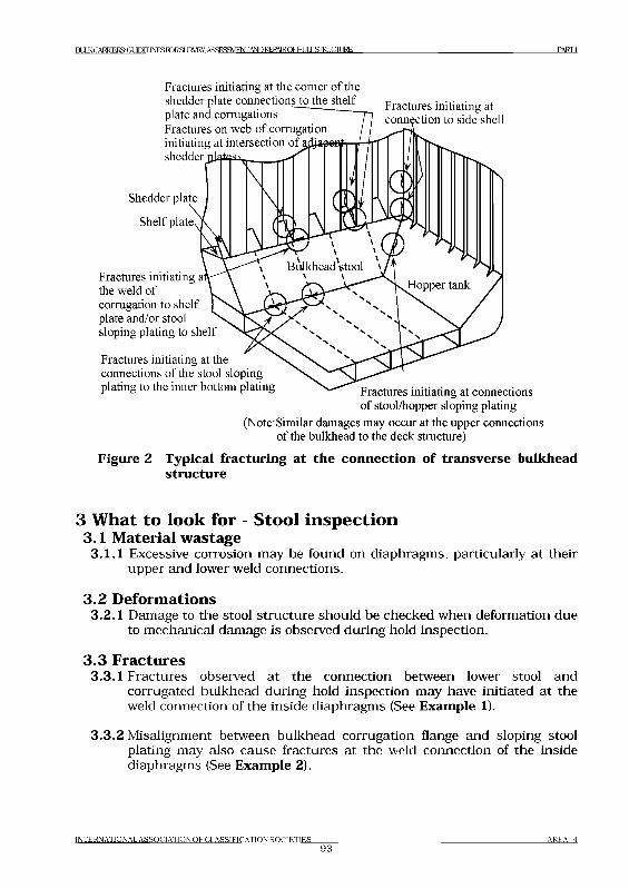
BULX CARRIERS: GUDELJNESroRSIJRVEY.ASSESSVlENr AND REPA1ROFHULL STOUCIURE PARTI
Fractures initiating at the corner of the shedder plate connections to the shelf plate and corrugations ,Fractures on web of corrugation /initiating at intersection of afeafeff shedder plates \
Fractures initiating at connection to side shell
Shedder plate
Shelf plate
Fractures initiating ai the weld of corrugation to shelf plate and/or stool sloping plating to shelf
Fractures initiating at the connections of the stool slopingplating to the inner bottom plating ^ Fractures initiating at connections
of stool/hopper sloping plating (Note: Similar damages may occur at the upper connections
of the bulkhead to the deck structure)
Figure 2 Typical fracturing at the connection o f transverse bulkhead structure
3 What to look for - Stool inspection3.1 Material w astage
3.1.1 Excessive corrosion may be found on diaphragms, particularly at their upper and lower weld connections.
3 .2 D eform ations3.2.1 Damage to the stool structure should be checked when deformation due
to mechanical damage is observed during hold inspection.
3 .3 Fractures3.3.1 Fractures observed at the connection between lower stool and
corrugated bulkhead during hold inspection may have initiated at the weld connection of the inside diaphragms (See Example 1).
3.3.2 Misalignment between bulkhead corrugation flange and sloping stool plating may also cause fractures at the weld connection of the inside diaphragms (See Example 2).
I N T E R N A T I O N A L A S S O C I A T I O N O F C L A S S I F I C A T I O N S O C I E T I E S
93A R E A 4
B U L K C A RR IER S: G U D E I lN E S ro R S L ]R V E Y .A S S E S 3 V IE № A N D R E P A lR O F b lL lL L S ro iJC IL lR E P A R T I
4 General comments on repair4.1 Material w astage
4.1.1 When the reduction in thickness of plating and stiffeners has reached the diminution levels permitted by the Classification Society involved, the wasted plating and stiffeners are to be cropped and renewed.
4 .2 D eform ations4.2.1 If the deformation is local and of a limited extent, it could generally be
faired out. Deformed plating in association with a generalized reduction in thickness should be partly or completely renewed.
4.2.2 Buckling of the bulkhead plating can also occur in way of the side shell resulting from contact damage and this is usually quite obvious. In such cases the damaged area is to be cropped and partly renewed. If the deformation is extensive, replacement of the plating, partly or completely, may be necessary. If the deformation is not in association with generalized reduction in thickness or due to excessive loading, additional strengthening should be considered.
4 .3 Fractures4.3.1 Fractures that occur at the boundary weld connections as a result of
latent weld defects should be veed-out, appropriately prepared and re-welded preferably using low hydrogen electrodes or equivalent.
4.3.2 For fractures other than those described in 4.3.1, re-welding may not be a permanent solution and an attempt should be made to improve the design and construction in order to obviate a recurrence. Typical examples of such cases are as follows:(a) Fractures in the weld connections o f the stool plating to the
shelf plate in way o f the scallops in the stool’s internal structureThe scallops should be closed by fitting over-lap collar plates and the stool weld connections repaired as indicated in 4.3.1. The over lap collar should have a full penetration weld connection to the stool and shelf plate and should be completed using low hydrogen electrodes prior to welding the collar to the stool diaphragm/bracket.
(b) Fractures in the weld connections o f the corrugations and/or stool plate to the shelf plate resulting from misalignment o f the stool plate and the flange o f the corrugation (Similarly misalignment o f the stool plate with the double bottom floor)It is recommended that the structure be released, the misalignment rectified, and the stool, floor and corrugation weld connection appropriately repaired as indicated in 4.3.1. Other remedies to such damages include fitting of brackets in the stool in line with the webs of the corrugations. In such cases both the webs of the corrugations and the brackets underneath are to have full penetration welds and the brackets are to be arranged without scallops. However, in many cases this may prove difficult to attain.
(c) Fractures in the weld connections o f the corrugation to the
I N T E R N A T I O N A L A S S O C I A T I O N O F C L A S S I F I C A T I O N S O C I E T I E S
94A R E A 4
BUKCAKRTRRS- пт ТГПИ INJFSHDR.q TWFY А5^Р5УМНУГ ANDREPMRQFHI IT T STRUCTURE P A R T I
lower shelf plate resulting from fractured welding o f the adjacent shedder plateIt is recommended that suitable scallops be arranged in the shedder plate in way of the connection, and the weld connections of the corrugations be repaired as indicted in 4 .3 .1 .
(d) Fractures in the weld connections o f the corrugations to the hopper tank, topside tank or to the deck in the vicinity o f the hatchway openingIt is recommended that the weld connection be repaired as indicated in 4.3.1 and, where possible, additional stiffening be fitted inside the tanks to align with the flanges of the corrugations, or on the under deck clear of the tanks.
I N T E R N A T I O N A L A S S O C I A T I O N O F C L A S S I F I C A T I O N S O C I E T I E S
95A R E A 4

EULKCARR1ERS GUDEUNESFORSl 1RVFY. ASSF.SSMI NI'AND Rl PAIROL IIUI J.SIl^t JCIURI PARTI
BULK
CARRIERS
G uidelines for Surveys, A ssessm en t and Repair o f
Hull Structure
Part 1 Cargo hold region Exam ple No.
Area 4 T ransverse bulkhead and assoc ia ted
structure in cargo hold
1-a
Detail o f d^magel Fractures at weld connections to stool shelf plateSketch o f damage
/"bulkhead ^ corrugation
Shelf plate
Fractures
M
Shedderplate
7M M
Shelfplate
Stool slopingFractures plating
Sketch o f repair
Edges prepared and full penetration welded, on both sides of shelf plate
Vertical stiffener added where there is indication of buckling
\ ---
New sloping plate insert of increased thickness
eldedplate collar
View A-A
Notes on possible cause o f damage1. Stress concentrations at welds
adjacent to the scallops.Inadequate welding area connecting corrugation flange to shelf plate or similarly sloping stool plating to shelf plate.Inadequate thickness of sloping plating in relation to corrugation flange thickness.Stress concentration at knuckle of corrugation where web is not supported by bracket inside the stool.
2.
3.
Notes on repairs1. Fractures to be veed-out and
rewelded.2. Reductions in stress concentration by
fitting welded plate collars in way of the scallop.
3. Where necessary an insert plate to be arranged in stool plating an d /o r diaphragm.
I N T E R N A T I O N A L A S S O C I A T I O N O F C L A S S I F I C A T I O N S O C I E T I E S
96A R E A 4
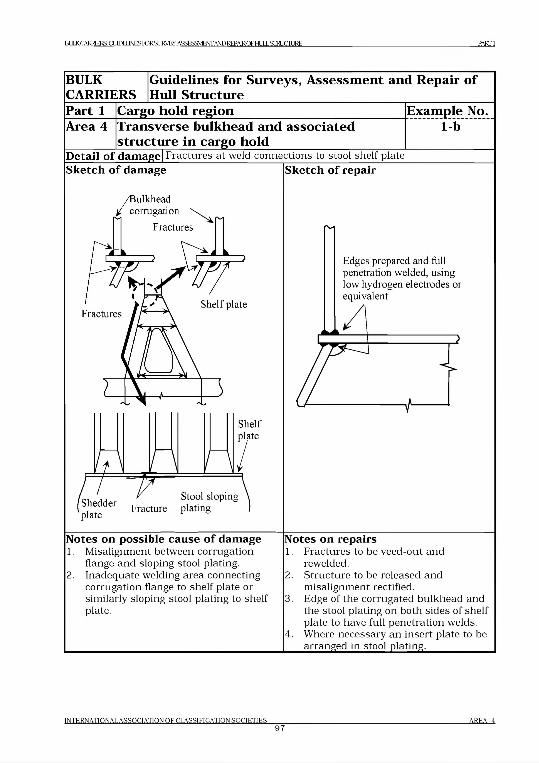
B^CAlMERSGimELJNESroRSL]IACT.ASSESa\4EmAmREPAlROFtMLSroUCILlRE PARTI
BULKCARRIERS
Guidelines for Surveys, Assessment and Repair of Hull Structure
Part 1 Cargo hold region Example No.Area 4 Transverse bulkhead and associated
structure in cargo hold1-b
Detail o f damage| Fractures at weld connections to stool shelf plate
Sketch o f damage Sketch o f repair
Notes on possible cause of damage1. Misalignment between corrugation
flange and sloping stool plating.2. Inadequate welding area connecting
corrugation flange to shelf plate or similarly sloping stool plating to shelf plate.
Notes on repairs1. Fractures to be veed-out and
rewelded.2. Structure to be released and
m isalignment rectified.3. Edge of the corrugated bulkhead and
the stool plating on both sides of shelf plate to have full penetration welds.
4. Where necessary an insert plate to bearranged in stool plating._____________
INTERNATIONAL ASSOCIATION O F CLASSIFICATIQN SQCIETIES97
AREA 4
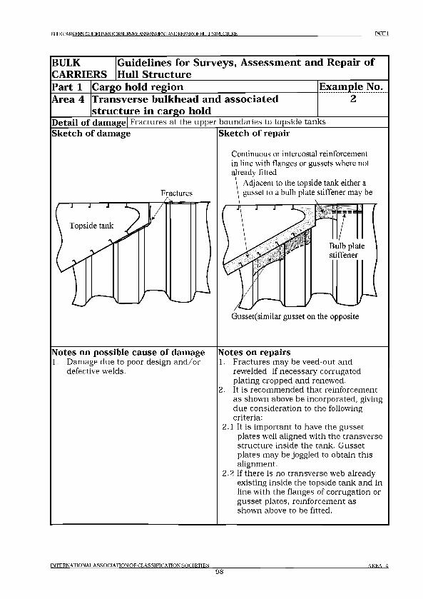
R IД KCARRIF.RS: GI Ю Н INFS TORSI IRVEY. ASSESSMENT AND REPAIR OF HI Д J „STRI1СП ]RF, PART1
BULKCARRIERS
Guidelines for Surveys, Assessment and Repair of Hull Structure
Part 1 Cargo hold region Example No.Area 4 Transverse bulkhead and associated
structure in cargo holdDetail of damage Fractures at the upper boundaries to topside tanks Sketch of damage Sketch of repair
Fractures
Notes on possible cause of damage1. Damage due to poor design and/or
defective welds.
Continuous or intercostal reinforcement in line with flanges or gussets where not
Gusset(similar gusset on the opposite
Notes on repairs1. Fractures may be veed-out and
rewelded. If necessary corrugated plating cropped and renewed.
2. It is recommended that reinforcement as shown above be incorporated, giving due consideration to the following criteria:
2.1 It is important to have the gusset plates well aligned with the transverse structure inside the tank. Gusset plates may be joggled to obtain this alignment.
2.2 If there is no transverse web already existing inside the topside tank and in line with the flanges of corrugation or gusset plates, reinforcement as shown above to be fitted.
IN TER N A TIO N A L A S S O C IA T IO N O F C L A S S IF IC A T IO N S O C IE T IE S
98A R E A 4
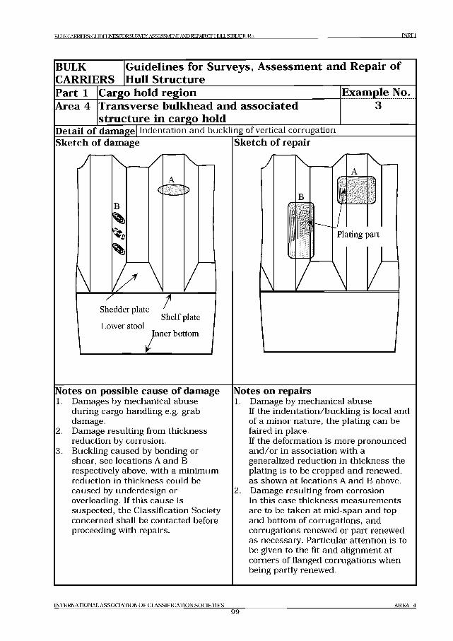
BULK CARRIERS: G l Ю И INFSTORSURVEY. ASSESSMENT AND REPAIR O F HI Д J „STM ICIL1RE P A R T I
BULKCARRIERS
Guidelines for Surveys, Assessment and Repair of Hull Structure
Part 1 Cargo hold region Example No.Area 4 Transverse bulkhead and associated
structure in cargo holdDetail of damage Indentation and buckling of vertical corrugationSketch of damage Sketch of repair
Notes on possible cause of damage1. Damages by mechanical abuse
during cargo handling e.g. grab damage.
2. Damage resulting from thickness reduction by corrosion.
3. Buckling caused by bending or shear, see locations A and В respectively above, with a minimum reduction in thickness could be caused by underdesign or overloading. If this cause is suspected, the Classification Society concerned shall be contacted before proceeding with repairs.
Notes on repairs1. Damage by mechanical abuse
If the indentation/buckling is local and of a minor nature, the plating can be faired in place.If the deformation is more pronounced and /or in association with a generalized reduction in thickness the plating is to be cropped and renewed, as shown at locations A and В above.
2. Damage resulting from corrosionIn this case thickness measurements are to be taken at mid-span and top and bottom of corrugations, and corrugations renewed or part renewed as necessary. Particular attention is to be given to the fit and alignment at corners of flanged corrugations when being partly renewed.
IN T E R N A T IO N A L A S S O C IA T IO N O F C L A S S IF IC A T IO N S O C I E T I E S
99A R E A 4
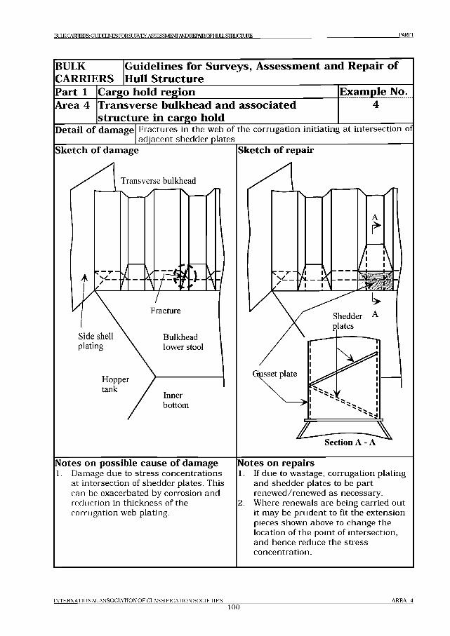
BULK CARRIERS: GUIDELINES FORSURVEY. ASSESSM ENT AND REPAIROFHI III S IM P I JRF. PARTI
BULKCARRIERS
Guidelines for Surveys, Assessment and Repair of Hull Structure
Part 1 Cargo hold region Example No.Area 4 Transverse bulkhead and associated
structure in cargo holdDetail o f damage Fractures in the web of the corrugation initiating at intersection of
adjacent shedder platesSketch o f damage Sketch o f repair
Notes on possible cause o f damage1. Damage due to stress concentrations
at intersection of shedder plates. This can be exacerbated by corrosion and reduction in thickness of the corrugation web plating.
Notes on repairs1. If due to wastage, corrugation plating
and shedder plates to be part renewed/renewed as necessary.
2. Where renewals are being carried out it may be prudent to fit the extension pieces shown above to change the location of the point of intersection, and hence reduce the stress concentration.
IN T E R N A T IO N A L A S S O C IA T IO N O F C L A S S IF IC A T IO N S O C I E T I E S
tooA R E A 4
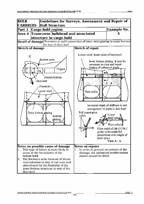
PARTI
BULKCARRIERS
Guidelines for Surveys, Assessment and Repair of Hull Structure
Part 1 Cargo hold region Example No.Area 4 Transverse bulkhead and associated
structure in cargo hold5
Detail of damage Fractures at weld connection of lower stool plating to inner bottom in way of duct keel
Sketch of damage Sketch of repair
Lower stool: Insert plate of increased
Inner bottom plating: It may be necessary to crop and insert plating of enhanced grade
\ V Г<А
. <- ' A
r ^'Plate collar
v, A
7 y '
V ^________ J------- 1 J
Increased depth of stiffener to suit arrangement of pipes in duct keel
Full penetration welds Lower
T stool spaGg;
' “ nPlate collars!!
Fillet weld of DB OT/WT girder to be made full penetration over length of stool space
View A - A
Notes on possible cause of damage1. This type of failure is more likely to
occur at the boundaries of the ballast hold.
2. The fractures arise because of stress concentration in way of cut-outs and exacerbated by the flexibility of the inner bottom structure in way of the duct keel.
Notes on repairs1. In order to prevent recurrence of the
damage, the additional reinforcement shown should be fitted.
IN TER N A TIO N A L A S S O C IA T IO N O F C L A S S IF IC A T IO N S O C IE T IE S
101A R EA 4
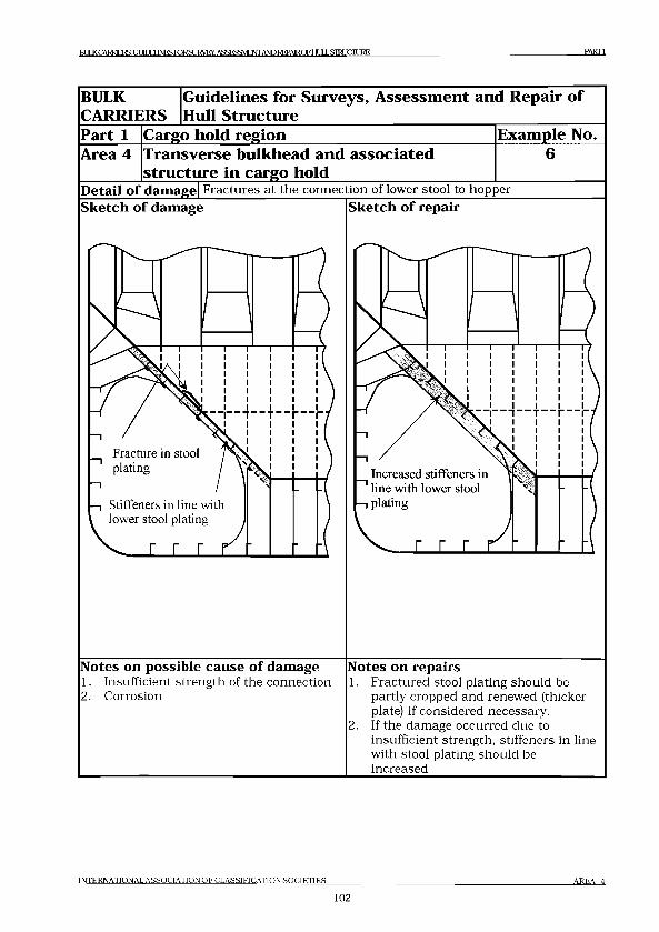
raJKrARWElSGmMlNESroRSUl^EY.AS£ESSMENrANDREPAlRnFHJI.SiraiCIURE PARTI
BULKCARRIERS
Guidelines for Surveys, Assessment and Repair of Hull Structure
Part 1 Cargo hold region Example No.Area 4 Transverse bulkhead and associated
structure in cargo holdDetail o f damage Fractures at the connection of lower stool to hopper Sketch o f damage Sketch o f repair
Notes on possible cause o f damage1. Insufficient strength of the connection2. Corrosion
Notes on repairs1. Fractured stool plating should be
partly cropped and renewed (thicker plate) if considered necessary.
2. If the damage occurred due to insufficient strength, stiffeners in line with stool plating should be increased.
INTERNATIONAL ASSOCIATION OF CLASSIFICATION SOCIF.TIF.S AREA 4
102
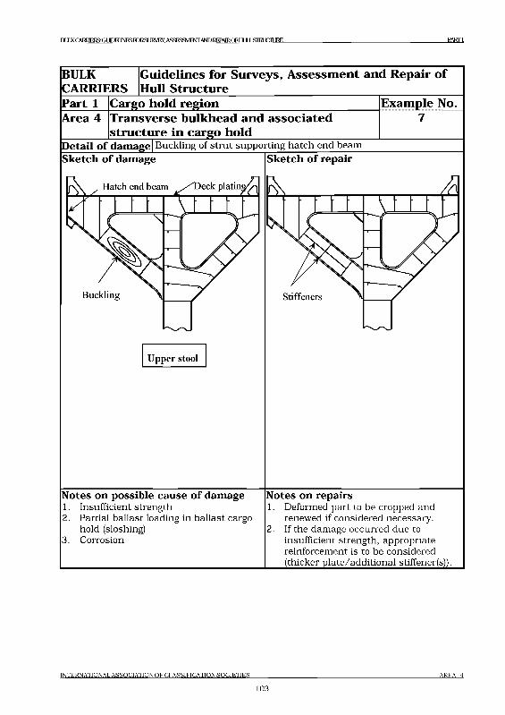
I а Л К ( AI^RIERS: GLlITJt J INI« НГ JR SlJI^Vt CY. ASS1Ж М 1N IANI3 REPAIRC3FI H Jl i . S11Д X: IT_1RE PARTI
BULK G uidelines for Surveys, A ssessm ent and Repair o fCARRIERS Hull Structure
Part 1 Cargo hold region Example No.
Area 4 Transverse bulkhead and associated structure in cargo hold
7
Detail o f damage! B uckling of stru t supporting hatch end beam
Upper stool
Notes on possible cause o f damage1. Insufficient strength2. Partial ballast loading in ballast cargo
hold (sloshing)3. Corrosion
Notes on repairs1. Deformed part to be cropped and
renewed if considered necessary.2. If the dam age occurred due to
insufficient strength, appropriate reinforcem ent is to be considered (thicker p late/additional stiffener(s)).
I N T E R N A T I O N A L A S S O C I A T I O N O F C L A S S I F I C A T I O N S O C I E T I E S A R E A 4
1 0 3
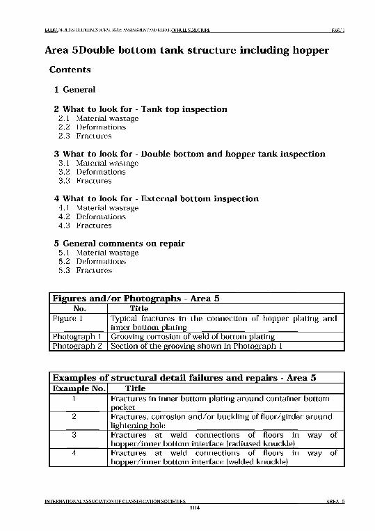
B^CAlMERSiGimELJNESroRSUIACT.ASSESaMENTANDREPAlROFtllLSIRUCmRE PA R TI
Area 5 Double bottom tank structure including hopper
Contents
1 General
2 What to look for - Tank top inspection2.1 Material wastage2.2 Deformations2.3 Fractures
3 What to look for - Double bottom and hopper tank inspection3.1 Material wastage3.2 Deformations3.3 Fractures
4 What to look for - External bottom inspection4.1 Material wastage4.2 Deformations4.3 Fractures
5 General com m ents on repair5.1 Material wastage5.2 Deformations5.3 Fractures
Figures and/or Photographs - Area 5No. Title
Figure 1 Typical fractures in the connection of hopper plating and inner bottom plating
Photograph 1 Grooving corrosion of weld of bottom platingPhotograph 2 Section of the grooving shown in Photograph 1
Examples of structural detail failures and repairs - Area 5Example No. Title
1 Fractures in inner bottom plating around container bottom pocket
2 Fractures, corrosion and/or buckling of floor/girder around lightening hole
3 Fractures at weld connections of floors in way of hopper/inner bottom interface (radiused knuckle)
4 Fractures at weld connections of floors in way of hopper/inner bottom interface (welded knuckle)
INTERNATIONAL ASSOCIATION O F CLASSIFICATION SO CIETIES104
AREA 5
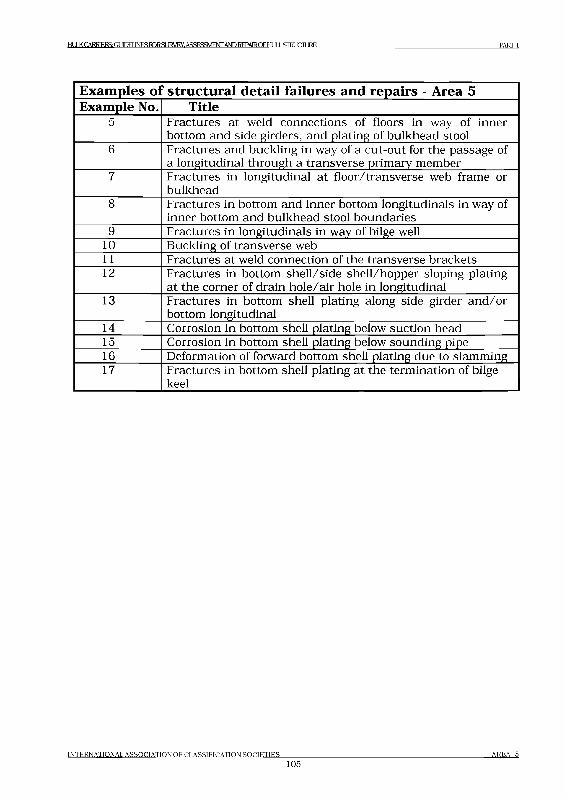
BULK CARRIERS: GUDEIlNESroRSLlRVEY,ASSES3VIE№ AND REPA1ROF HULL STOUCIL1RE PARTI
Exam ples ol ' structural detail failures and repairs - Area 5Example No. Title
5 Fractures at weld connections of floors in way of inner bottom and side girders, and plating of bulkhead stool
6 Fractures and buckling in way of a cut-out for the passage of a longitudinal through a transverse primary member
7 Fractures in longitudinal at floor/transverse web frame or bulkhead
8 Fractures in bottom and inner bottom longitudinals in way of inner bottom and bulkhead stool boundaries
9 Fractures in longitudinals in way of bilge well10 Buckling of transverse web11 Fractures at weld connection of the transverse brackets12 Fractures in bottom shell/side shell/hopper sloping plating
at the corner of drain hole/air hole in longitudinal13 Fractures in bottom shell plating along side girder and/or
bottom longitudinal14 Corrosion in bottom shell plating below suction head15 Corrosion in bottom shell plating below sounding pipe16 Deformation of forward bottom shell plating due to slamming17 Fractures in bottom shell plating at the termination of bilge
keel
INTERNATIONAL A SS O C IA TIO N O F C LA SSIFIC A TIO N SO C IE T IE S105
A R EA 5
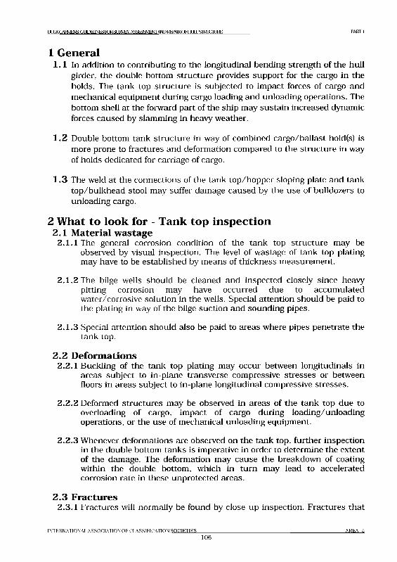
I >1Л К CARRTF.RS:Gl JIDEIINFSFORSI IRVFY ASSESSfylFATTANI) REPAIR PI T II Jl L SI Ю Л IJRE PARTI
1 General1.1 In addition to contributing to the longitudinal bending strength of the hull
girder, the double bottom structure provides support for the cargo in the holds. The tank top structure is subjected to impact forces of cargo and mechanical equipment during cargo loading and unloading operations. The bottom shell at the forward part of the ship may sustain increased dynamic forces caused by slamming in heavy weather.
1.2 Double bottom tank structure in way of combined cargo/ballast hold(s) is more prone to fractures and deformation compared to the structure in way of holds dedicated for carriage of cargo.
1.3 The weld at the connections of the tank top/hopper sloping plate and tank top/bulkhead stool may suffer damage caused by the use of bulldozers to unloading cargo.
2 What to look for - Tank top inspection2.1 Material w astage
2.1.1 The general corrosion condition of the tank top structure may be observed by visual inspection. The level of wastage of tank top plating may have to be established by means of thickness measurement.
2.1.2 The bilge wells should be cleaned and inspected closely since heavy pitting corrosion may have occurred due to accumulated water/corrosive solution in the wells. Special attention should be paid to the plating in way of the bilge suction and sounding pipes.
2.1.3 Special attention should also be paid to areas where pipes penetrate the tank top.
2 .2 D eform ations2.2.1 Buckling of the tank top plating may occur between longitudinals in
areas subject to in-plane transverse compressive stresses or between floors in areas subject to in-plane longitudinal compressive stresses.
2.2.2 Deformed structures may be observed in areas of the tank top due to overloading of cargo, impact of cargo during loading/unloading operations, or the use of mechanical unloading equipment.
2.2.3 Whenever deformations are observed on the tank top, further inspection in the double bottom tanks is imperative in order to determine the extent of the damage. The deformation may cause the breakdown of coating within the double bottom, which in turn may lead to accelerated corrosion rate in these unprotected areas.
2 .3 Fractures2.3.1 Fractures will normally be found by close-up inspection. Fractures that
I N T E R N A T I O N A L A S S O C I A T I O N O F C L A S S I F I C A T I O N S O C I E T I E S
106A R E A 5
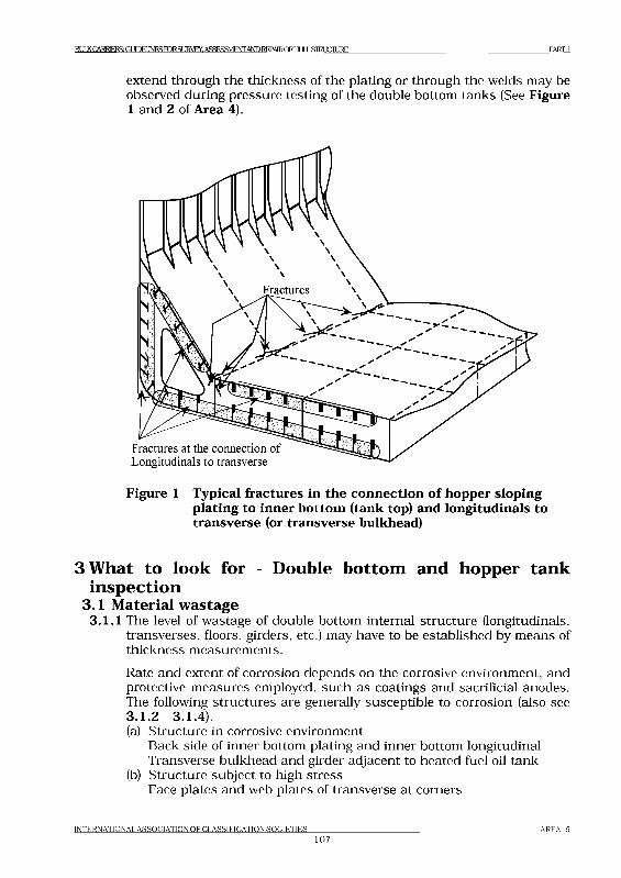
ВЕШ CARRIERS: GLEEUNESroRSLIRVEY, ASSESSMENT AND REPAIROFHULL STRUCTURE P A R Q
extend through the thickness of the plating or through the welds may be observed during pressure testing of the double bottom tanks (See Figure 1 and 2 of Area 4).
Figure 1 Typical fractures in the connection o f hopper sloping plating to inner bottom (tank top) and longitudinals to transverse (or transverse bulkhead)
3What to look for - Double bottom and hopper tank inspection
3.1 Material w astage3.1.1 The level of wastage of double bottom internal structure (longitudinals,
transverses, floors, girders, etc.) may have to be established by means of thickness measurements.Rate and extent of corrosion depends on the corrosive environment, and protective measures employed, such as coatings and sacrificial anodes. The following structures are generally susceptible to corrosion (also see3.1.2 3.1.4).(a) Structure in corrosive environment
Back side of inner bottom plating and inner bottom longitudinal Transverse bulkhead and girder adjacent to heated fuel oil tank
(b) Structure subject to high stressFace plates and web plates of transverse at corners
I N T E R N A T I O N A L A S S O C I A T I O N O F C L A S S I F I C A T I O N S O C I E T I E S
10 7A R E A 5
I M K C A R R 1 E 1 S G U ID E L IN E S T O R S U R V E X A S S E S S M E N T A N D R E P A IR O F H L 1 L L S IR L IC IL IR E P A R T I
Connection of longitudinal to transverse(c) Areas susceptible to coating breakdown
Back side of face plate of longitudinal Welded jointEdge of access opening
(d) Areas subject to poor drainage Web of side longitudinals
3.1.2 If the protective coating is not properly maintained, structure in the ballast tank may suffer severe localised corrosion. In general, structure at the upper part of the double bottom tank usually has more severe corrosion than that at the lower part. Transverse webs in the hopper tanks may suffer severe corrosion at their corners where high shearing stresses occur, especially where collar plate is not fitted to the slot of the longitudinal.
3.1.3 The high temperature due to heated fuel oil may accelerate corrosion of ballast tank structure near heated fuel tanks. The rate of corrosion depends on several factors such as:- Temperature and heat input to the ballast tank.- Condition of original coating and its maintenance. (It is preferable for
applying the protective coating of ballast tank at the building of the ship, and for subsequent maintenance, that the stiffeners on the boundaries of the fuel tank be fitted within the fuel tank instead of the ballast tank).
- Ballasting frequency and operations.- Age of ship and associated stress levels as corrosion reduces the
thickness of the structural elements and can result in fracturing and buckling.
3.1.4 Shell plating below suction head often suffers localized wear caused by erosion and cavitation of the fluid flowing through the suction head. In addition, the suction head will be positioned in the lowest part of the tank and water/mud will cover the area even when the tank is empty. The condition of the shell plating may be established by feeling by hand beneath the suction head. When in doubt, the lower part of the suction head should be removed and thickness measurements taken. If the vessel is docked, the thickness can be measured from below. If the distance between the suction head and the underlying shell plating is too small to permit access, the suction head should be dismanded. The shell plating below the sounding pipe should also be carefully examined. When a striking plate has not been fitted or is worn out, heavy corrosion can be caused by the striking of the weight of the sounding tape (See Example 2 in Part 3).
3.2 Deformations3.2.1 Where deformations are identified during tank top inspection (See 2.2)
and external bottom inspection (See 4.2), the deformed areas should be subjected to in tank inspection to determine the extent of the damage to
I N T E R N A T I O N A L A S S O C I A T I O N O F C L A S S I F I C A T I O N S O C I E T I E S
108A R E A 5
BULK CARRIERS- Г Л Т Л И INFS FDR Я IKVRY ASSFSSMENTANDREPAlRCyHI И ] STRtJCIURE Р А К Г 1
the coating and internal structure.Deformations in the structure not only reduce the structural strength but may also cause breakdown of the coating, leading to accelerated corrosion.
3.3 Fractures3.3.1 Fractures will normally be found by close-up inspection.
3.3.2 Fractures may occur in way of the welded or radiused knuckle between the inner bottom and hopper sloping plating if the side girder in the double bottom is not in line with the knuckle and also when the floors below have a large spacing, or when corner scallops are created for ease of fabrication. The local stress variations due to the loading and subsequent deflection may lead to the development of fatigue fractures which can be categorised as follows (See Figure 1).(a) Parallel to the knuckle weld for those knuckles which are welded and
not radiused.(b) In the inner bottom and hopper plating and initiated at the centre of
a radiused knuckle.(c) Extending in the hopper web plating and floor weld connections
starting at the corners of scallops, where such exist, in the underlying hopper web and floor.
(d) Extending in the web plate as in (c) above but initiated at the edge of a scallop.
3.3.3 The fractures in way of connection of inner bottom plating/hopper sloping plating to stool may be caused by the cyclic deflection of the inner bottom induced by repeated loading from the sea or due to poor “through-thickness” properties of the inner bottom plating. Scallops in the underlying girders can create stress concentrations which further increase the risk of fractures. These can be categorised as follows (See Figure 1 and Examples).(a) In way of the intersection between inner bottom and stool. These
fractures often generate along the edge of the welded joint above the centre line girder, side girders, and sometimes along the duct keel sides.
(b) Fractures in the inner bottom longitudinals and the bottom longitudinals in way of the intersection with the watertight floors below the transverse bulkhead stools in way of the ballast hold, especially in way of suction wells.
(c) Fractures at the connection between the longitudinals and the vertical stiffeners or brackets on the floors, as well as at the corners of the duct keel.
(d) Lamellar tearing of the inner bottom plate below the weld connection with the stool in the ballast hold caused by large bending stresses in the connection when in heavy ballast condition. The size of stool and lack of full penetration welds could also be a contributory factor, as well as poor “through-thickness” properties of the tank top plating.
I N T E R N A T I O N A L A S S O C I A T I O N O F C L A S S I F I C A T I O N S O C I E T I E S
109A R E A 5
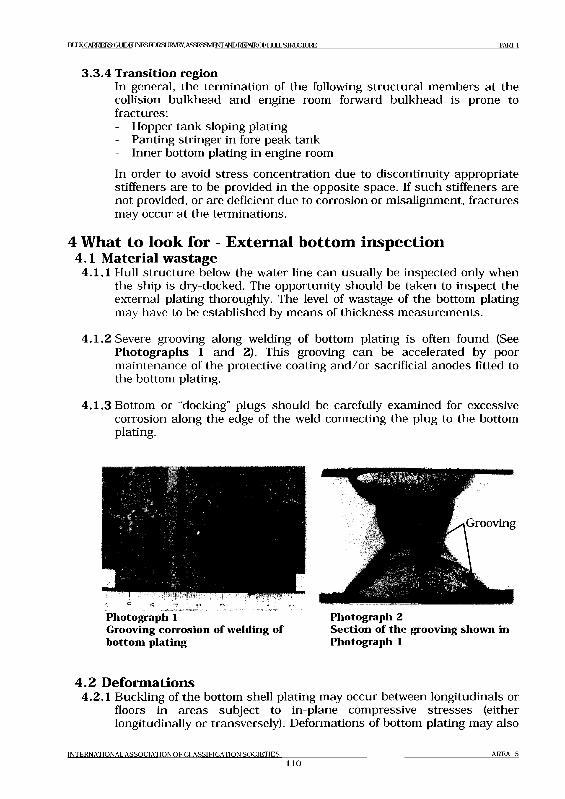
B U L K C A R R IE R S: G lT O E U N E S ro R S U R V E Y . A S S E S S M E N T A N D R E P A IR O F F IL 1L L S IR L IC IL IR E P A R T 1
3.3.4 Transition regionIn general, the termination of the following structural members at the collision bulkhead and engine room forward bulkhead is prone to fractures:- Hopper tank sloping plating- Panting stringer in fore peak tank- Inner bottom plating in engine roomIn order to avoid stress concentration due to discontinuity appropriate stiffeners are to be provided in the opposite space. If such stiffeners are not provided, or are deficient due to corrosion or misalignment, fractures may occur at the terminations.
4 What to look for - External bottom inspection4.1 Material w astage
4.1.1 Hull structure below the water line can usually be inspected only when the ship is diy-docked. The opportunity should be taken to inspect the external plating thoroughly. The level of wastage of the bottom plating may have to be established by means of thickness measurements.
4.1.2 Severe grooving along welding of bottom plating is often found (See Photographs 1 and 2). This grooving can be accelerated by poor maintenance of the protective coating and/or sacrificial anodes fitted to the bottom plating.
4.1.3 Bottom or “docking” plugs should be carefully examined for excessive corrosion along the edge of the weld connecting the plug to the bottom plating.
Photograph 1Grooving corrosion o f welding of bottom plating
Photograph 2Section o f the grooving shown in Photograph 1
4 .2 D eform ations4.2.1 Buckling of the bottom shell plating may occur between longitudinals or
floors in areas subject to in-plane compressive stresses (either longitudinally or transversely). Deformations of bottom plating may also
I N T E R N A T I O N A L A S S O C I A T I O N O F C L A S S I F I C A T I O N S O C I E T I E S
noA R E A 5
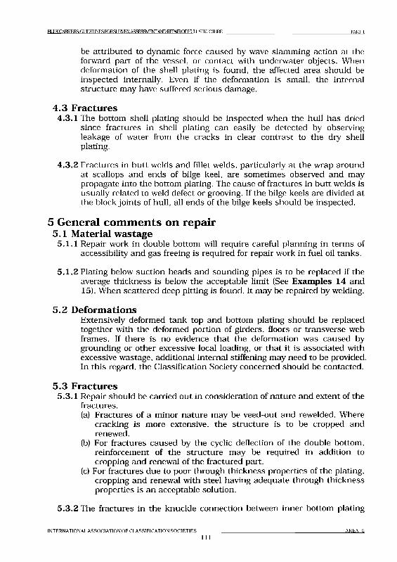
B l lX CARRIERS: GUDEIlNESroRSL]RVEY.ASSES3VIE№ AND REPAlROFblULLSroiJCILlRE PARTI
be attributed to dynamic force caused by wave slamming action at the forward part of the vessel, or contact with underwater objects. When deformation of the shell plating is found, the affected area should be inspected internally. Even if the deformation is small, the internal structure may have suffered serious damage.
4.3 Fractures4.3.1 The bottom shell plating should be inspected when the hull has dried
since fractures in shell plating can easily be detected by observing leakage of water from the cracks in clear contrast to the dry shell plating.
4.3.2 Fractures in butt welds and fillet welds, particularly at the wrap around at scallops and ends of bilge keel, are sometimes observed and may propagate into the bottom plating. The cause of fractures in butt welds is usually related to weld defect or grooving. If the bilge keels are divided at the block joints of hull, all ends of the bilge keels should be inspected.
5 General comments on repair5.1 Material wastage
5.1.1 Repair work in double bottom will require careful planning in terms of accessibility and gas freeing is required for repair work in fuel oil tanks.
5 .1 .2 Plating below suction heads and sounding pipes is to be replaced if the average thickness is below the acceptable limit (See Examples 14 and 15). When scattered deep pitting is found, it may be repaired by welding.
5.2 DeformationsExtensively deformed tank top and bottom plating should be replaced together with the deformed portion of girders, floors or transverse web frames. If there is no evidence that the deformation was caused by grounding or other excessive local loading, or that it is associated with excessive wastage, additional internal stiffening may need to be provided. In this regard, the Classification Society concerned should be contacted.
5.3 Fractures5.3.1 Repair should be carried out in consideration of nature and extent of the
fractures.(a) Fractures of a minor nature may be veed-out and re welded. Where
cracking is more extensive, the structure is to be cropped and renewed.
(b) For fractures caused by the cyclic deflection of the double bottom, reinforcement of the structure may be required in addition to cropping and renewal of the fractured part.
(c) For fractures due to poor through thickness properties of the plating, cropping and renewal with steel having adequate through thickness properties is an acceptable solution.
5.3.2 The fractures in the knuckle connection between inner bottom plating
I N T E R N A T I O N A L A S S O C I A T I O N O F C L A S S I F I C A T I O N S O C I E T I E S
111A R E A 5
BLlKCARRlERS:GUDELJNESroRSURVEY, ASSESSMENT ANDREPA1ROFHLILLSIHUCIURE PARTI
and hopper sloping plating should be repaired as follows.(a) Where the fracture is confined to the weld, the weld is to be veed-out
and renewed using full penetration welding, with low hydrogen electrodes or equivalent.
(b) Where the fracture has extended into the plating of any tankboundary, then the fractured plating is to be cropped, and partrenewed.
(c) Where the fracture is in the vicinity of the knuckle, the cornerscallops in floors and transverses are to be omitted, or closed bywelded collars. The sequence of welding is important, in this respect every effort should be made to avoid the creation of locked in stresses due to the welding process.
(d) Where the floor spacing is 2.0m or greater, brackets are to be arranged either in the vicinity of, or mid-length between, floors in way of the intersection. The brackets are to be attached to the adjacent inner bottom and hopper longitudinals. The thickness of the bracket is to be in accordance with the Rules of the Classification Society concerned.
(e) If the damage is confined to areas below the ballast holds and the knuckle connection is of a radiused type, then in addition to rectifying the damage (i.e. weld or crop and renew), consideration is to be given to fitting further reinforcement, e.g. longitudinals or scarfing brackets, in the vicinity of the upper tangent point of the radius.
5.3.3 The fractures in the connection between inner bottom plating/hoppersloping plating and stool should be repaired as follows.(a) Fractures in way of section of the inner bottom and bulkhead stool in
way of the double bottom girders can be veed out and welded. However, reinforcement of the structure may be required, e.g. by fitting additional double bottom girders on both sides affected girder or equivalent reinforcement. Scallops in the floors should be closed and air holes in the non-watertight girders re-positioned.If the fractures are as a result of differences in the thickness of adjacent stool plate and the floor below the inner bottom, then it is advisable to crop and part renew the upper part of the floor with plating having the same thickness and mechanical properties as the adjacent stool plating.If the fractures are as a result of misalignment between the stool plating and the double bottom floors, the structure should be released with a view to rectifying the misalignment.
(b) Fractures in the inner bottom longitudinals and the bottom longitudinals in way of the intersection with watertight floors are to be cropped and partly renewed. In addition, brackets with soft toes are to be fitted in order to reduce the stress concentrations at the floors or stiffener.
(c) Fractures at the connection between the longitudinals and the vertical stiffeners or brackets are to be cropped and longitudinal part
INTERNATIONAL ASSOCIATION OF CLASSIFICATION SOCIETIES112
AREA 5
В ТШ CARRIERS GLTOEUNESroRSLIRyEY. ASSESSMENT AND REPAIROFHULL STRUCTURE PARTI
renewed if the fractures extend to over one third of the depth of the longitudinal. If fractures are not extensive these can be veed out and welded. In addition, reinforcement should be provided in the form of modification to existing bracket toes or the fitting of additional brackets with soft toes in order to reduce the stress concentration.
(d) Fractures at the corners of the transverse diaphragm/stiffeners are to be cropped and renewed. In addition, scallops are to be closed by overlap collar plates. To reduce the probability of such fractures recurring, consideration is to be given to one of the following reinforcements or modifications.- The fitting of short intercostal girders in order to reduce the
deflection at the problem area.- The depth of transverse diaphragm/stiffener at top of duct keel is
to be increased as far as is practicable to suit the arrangement of pipes.
(e) Lamellar tearing may be eliminated through improving the type and quality of the weld, i.e. full penetration using low hydrogen electrodes and incorporating a suitable weld throat.Alternatively the inner bottom plating adjacent to and in contact with the stool plating is substituted with plating of “Z” quality steel which has good “through-thickness” properties.
5.3.4 Bilge keel should be repaired as follows.(a) Fractures or distortion in bilge keels must be promptly repaired.
Fractured butt welds should be repaired using full penetration welds and proper welding procedures. The bilge keel is subjected to the same level of longitudinal hull girder stress as the bilge plating, fractures in the bilge keel can propagate into the shell plating.
(b) Termination of bilge keel requires proper support by internal structure. This aspect should be taken into account when cropping and renewing damaged parts of a bilge keel (See Example 17).
I N T E R N A T I O N A L A S S O C I A T I O N O F C L A S S I F I C A T I O N S O C I E T I E S
113A R E A 5
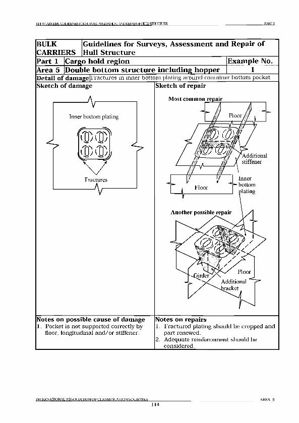
P A R T 1R l Д K C A R R IF R S : G t 1 Ш I N F S m R S U R V E Y . A S S E S S M E N T A N D R E P A IR O F H l Д J .S T R U C T U R E
BULKCARRIERS
Guidelines for Surveys, Assessment and Repair of Hull Structure
Part 1 Cargo hold region Example No.Area 5 Double bottom structure including hopper 1Detail o f damage Fractures in inner bottom plating around container bottom pocketSketch o f damage Sketch o f repair
Notes on possible cause o f damage1. Pocket is not supported correctly by
floor, longitudinal and/or stiffener.
Notes on repairs1. Fractured plating should be cropped and
part renewed.2. Adequate reinforcement should be
considered.
IN TER N A TIO N A L A S S O C IA T IO N O F C L A SSIFIC A T IO N S O C IE T IE S
114A R EA 5
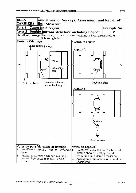
BULKCARR1ERS: GUDEIINES R3RSURVEY, ASSFSSMENTANDKEPAIROF HULL STRUCTURE PART 1
BULKCARRIERS
Guidelines for Surveys, Assessment and Repair of Hull Structure
Part 1 Cargo hold region Example No.Area 5 Double bottom structure including Ь о ш э е г 2Detail o f damage Fractures, corrosion and/or buckling of floor/girder around
lightening holeSketch o f damage
Inner bottom plating
I
Bottom plating Fm* ur?'and/or buckling
Sketch o f repair
Repair A
3 J ]
й aDoubling plate
Repair В
Face plate
Section A-A
J J A J
0 D
] __ /A 11—
Notes on possible cause o f damage1. Insufficient strength due to lightening
hole.2. Fracture, corrosion an d /o r buckling
around lightening hole due to high stress.
Notes on repairs1. Fractured, corroded an d /o r buckled
plating should be cropped and renewed if considered necessary.
2. Appropriate reinforcement should be considered.
INTERNATIONAL ASSOCIATION OF CLASSIFICATION SOCIETIES
1 1 5
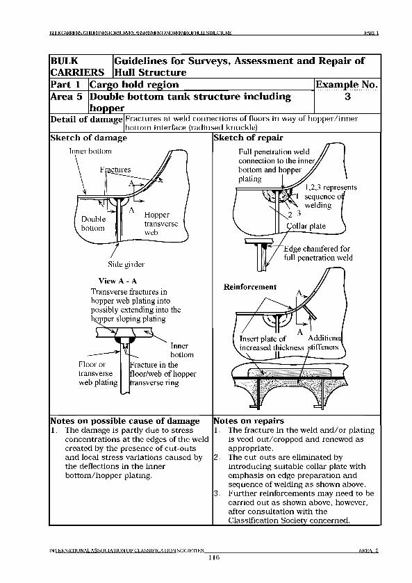
IT U K C A R R lE R S G L l IE E L I N E S ro R S L I R y E Y . A S S E S S M E N T A N D R E P A IR O F Н Ш . S I R ! I C I I IR E P A R T 1
BULKCARRIERS
Guidelines for Surveys, Assessment and Repair of Hull Structure
Part 1Area 5
Cargo hold regionDouble bottom tank structure including hopper____________________________
Example No..............3 ............
Detail o f damage Fractures at weld connections of floors in way of hopper/inner bottom interface (radiused knuckle)
Sketch o f damage
View A - ATransverse fractures in hopper web plating into possibly extending into the topper sloping plating
£
Floor or transverse web plating
Inner bottom
Fracture in the floor/web of hopper transverse ring
Sketch o f repairFull penetration weld connection to the inner/ bottom and hopperplating
1,2,3 represents
Reinforcement
Notes on possible cause o f damage1. The damage is partly due to stress
concentrations at the edges of the weld created by the presence of cut-outs and local stress variations caused by the deflections in the inner bottom/hopper plating.
Notes on repairs1. The fracture in the weld and/or plating
is veed-out/cropped and renewed as appropriate.The cut-outs are eliminated by introducing suitable collar plate with emphasis on edge preparation and sequence of welding as shown above. Further reinforcements may need to be carried out as shown above, however, after consultation with the Classification Society concerned._______
2.
3.
IN TER N A TIO N A L A S S O C IA T IO N O F C L A SSIFIC A T IO N S O C IE T IE S
116AREA 5
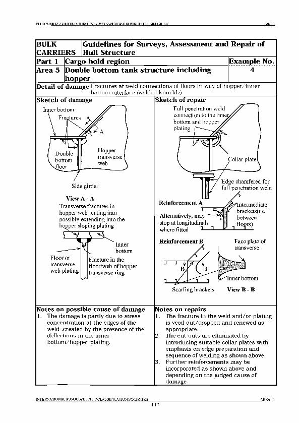
R l I I К C A R R IE R S : G I И Л И I N F S P D R S I1 R V F Y A S S F S S M F N T A N D R F P A l R n F l-И Л 1 S I R ! C T I IR E PARTI
BULKCARRIERS
Guidelines for Surveys, Assessment and Repair of Hull Structure
Part 1 Cargo hold region Example No.Area 5 Double bottom tank structure including
hopper4
Detail o f damage Fractures at weld connections of floors in way of hopper/inner bottom interface (welded knuckle)
Sketch o f damage Sketch o f repairFull penetration weld connection to the inne; bottom and hopper^ plating
dge chamfered for full penetration weld
View A - ATransverse fractures in hopper web plating into possibly extending into the hopper sloping plating
Inner bottom
Floor or transverse web plating
Fracture in the floor/web of hopper transverse ring
Reinforcement A J
Alternatively, may stop at longitudinals where fitted -*■
Intermediate brackets(i.e. between
1 floors)
Reinforcement В Face plate of transverse
Scarfing brackets View В - В
Notes on possible cause o f damage1. The damage is partly due to stress
concentration at the edges of the weld .created by the presence of the deflections in the inner bottom/hopper plating.
Notes on repairs1. The fracture in the weld and/or plating
is veed-out/cropped and renewed as appropriate.
2. The cut-outs are eliminated by introducing suitable collar plates with emphasis on edge preparation and sequence of welding as shown above.
3. Further reinforcements may be incorporated as shown above and depending on the judged cause of damage.
IN TER N A TIO N A L A S S O C IA T IO N O F C L A S S IF IC A T IO N S O C IE T IE S
117AREA 5
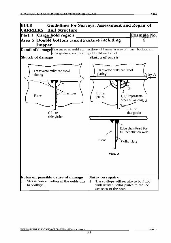
R1 JKCABiaERSGLIlEBJNESroRSURVEY. ASSESSMENT ANDRFPAIROFHm.SITillCnjRE PART 1
BULKCARRIERS
Guidelines for Surveys, Assessment and Repair of Hull Structure
Part 1Area 5
Cargo hold regionDouble bottom tank structure including hopper
Example No............ 5 ...........
Detail o f damage Fractures at weld connections of floors in way of inner bottom and side girders, and plating of bulkhead stool_______________________
Sketch o f damage
Transverse bulkhead stool plating
Sketch o f repair
Transverse bulkhead stool plating
Collarplates
^View A
C.L. or side girder
1,2,3 represents order of welding J
C.L. or side girder
Floor
Edge chamfered for full penetration weld
Collar plate
View A
Notes on possible cause o f damage1. Stress concentration at the welds due
to scallops.
Notes on repairs1. The scallops will require to be fitted
with welded collar plates to reduce stresses in the area.
IN TER N A TIO N A L A S S O C IA T IO N O F C L A S S IF IC A T IO N S O C IE T IE S
118A REA 5
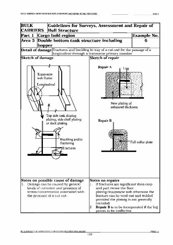
B U L K C A R R IE D G U n T E U N E S ro R S U R V E Y , A S S E S S M E N T A N D R E P A IR O F H U L L S T R U C T U R E P A R T I
BULKCARRIERS
G uidelines for Surveys, A ssessm ent and Repair o f
Hull Structure
Part 1
Area 5
Cargo hold region
Double bottom tank structure including hopper
Example No.
............6 ............
Detail o f damage Fractures and buckling in way of a cut-out for the passage of a longitudinal through a transverse primary member___________
Sketch o f damage Sketch o f repair
Repair A n L„ g
New plating of enhanced thickness
Repair В
к .\C
_ L
'Full collar plate
Notes on possible cause o f damage1. Damage can be caused by general
levels of corrosion and presence of stress concentration associated with the presence of a cut-out.
Notes on repairs1. If fractures are significant then crop
and part renew the floor plating/transverse web otherwise the fracture can be veed-out and welded provided the plating is not generally corroded.
2. Repair В is to be incorporated if the lug proves to be ineffective.
I N T E R N A T I O N A L A S S O C I A T I O N O F C L A S S I F I C A T I O N S O C I E T I E S ___________________________________________________________________________________________ A R E A 5
119
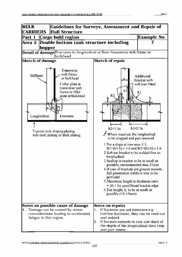
Ш К CARRIERS: G IЖ 3H1NISI O R SI JRVI vY ASSFSFMFNT AND REPAIR O E IIIIII. STRl К 7 П IRK PARTI
BULKCARRIERS
Guidelines for Surveys, Assessment and Repair of Hull Structure
Part 1 Cargo hold region Example No.Area 5 Double bottom tank structure including
hopper____________________________Detail of damage F ractures in longitudinal a t floor/transverse web frame or
bulkheadSketch of damage
Stiffener
N
Longitudinal
Transverse ^ web frame
or bulkhead
Collar plate at transverse web frame or filler plate at bulkhead
Fractures
Topside tank sloping plating, side shell plating or deck plating
Sketch of repair
S '.Where required, the longitudinal to be cropped and part renewed
1 .For a slope at toes max. 1:3, R l=(bl-h) x 1.6 and R2=(b2-h) x 1.6
2. Soft toe bracket to be welded first to longitudinal
3. Scallop in bracket to be as small as possible, recommended max.35mm
4.If toes of brackets are ground smooth, full penetration welds in way to be provided
5, Maximum length to thickness ratio = 50:1 for unstiffened bracket edge
6, Toe height, h, to be as small as possible (10-15mm)
Notes on possible cause of damage1. Damage can be caused by stress
concentrations leading to accelerated fatigue in th is region.
Notes on repairs1. If fractures are not extensive e.g.
hairline fractures, they can be veed-out and welded.
2. If fracture extends to over one third of the depth of the longitudinal then crop and part renew.
IN TER N A TIO N A L A S S O C IA T IO N O F C L A S S IF IC A T IO N S O C IE T IE S
120A R EA 5

ra JK C A I^ ,R S G m M lN E S ro R S U l^E Y .A S £ E S S M E N rA N D R E P A lR n F H JI.S ira iC IU R E PARTI
BULKCARRIERS
Guidelines for Surveys, Assessment and Repair of Hull Structure
Part 1Area 5
Cargo hold regionDouble bottom tank structure including hopper
Example No............ 8............
Detail of damage F ractures in bottom and inner bottom longitudinals in way of inner bottom and bulkhead stool boundaries
Sketch of damage Sketch of repair
Notes on possible cause of damage1. Damage can be caused by stress
concentration leading to accelerated fatigue in th is region.
£ :Where required the longitudinal to be cropped and part renewed
Notes on repairs1. If fractures are not extensive e.g.
hairline fractures then these can be veed-out and welded.
2. If fracture extended to over one third of the depth of the longitudinal depth then crop and part renew.
IN T ER N A TIO N A L A S S O C IA T IO N O F C L A SSIFIC A T IO N S O C IE T IE S
121A R EA 5
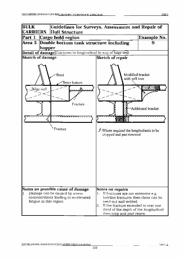
BULK CARRIERS GUIDELINES FORSURVEY. ASSESSMENT AND REPAIR D FHI11 .SERI 1 С П IRF, PART 1
BULKCARRIERS
Guidelines for Surveys, Assessment and Repair of Hull Structure
Part 1Area 5
Cargo hold regionDouble bottom tank structure including hopper____________________________
Example No..........9.........
Detail of damage F ractures in longitudinal in way of bilge wellSketch of damage Sketch of repair
Stool \ Modified bracket with soft toes
‘Fracture / : Where required the longitudinals to be cropped and part renewed
Notes on possible cause of damage1. Damage can be caused by stress
concentrations leading to accelerated fatigue in th is region.
Notes on repairs1. If fractures are not extensive e.g.
hairline fractures then these can be veed-out and welded.
2. If the fracture extended to over one third of the depth of the longitudinal then crop and part renew.
IN T ER N A TIO N A L A S S O C IA T IO N O F C L A SSIFIC A T IO N S O C IE T IE S
122A R E A 5

BULK CARRIED GUnTEUNESroRSURVEY, ASSESSMENTAND REPAIR OF HULL STRUCTURE PARTI
BULKCARRIERS
Guidelines for Surveys, Assessment and Repair of Hull Structure
Part 1 Cargo hold region Example No.Area 5 Double bottom tank structure including
hopper10
Detail of dam age|Buckling of transverse webSketch of damage Sketch of repair
Notes on possible cause of damage1. Insufficient buckling strength of
transverse web plating.2. Corrosion of high stress area.
Notes on repairs1. If the buckling occurred without
significant corrosion, adequate reinforcement is to be carried out.
2. If the buckling occurred due to corrosion of high stress (shear stress) area, damaged area is to be cropped and part renewed. Adequate reinforcement and protective measures should be considered.
INTERNATIONAL ASSO CIA TIO N O F C LA SSIFICATION SO C IE T IE S
123AREA 5
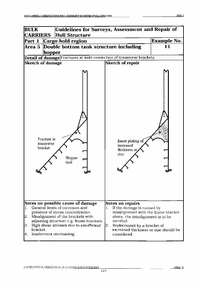
Rl I I К CARRIERS: Г,1 Л Г Н IN FStO RSU K V EY ASSFSSM FNT A NDREPAIRDFUIЛ I STRl JCIURE PART 1
BULKCARRIERS
Guidelines for Surveys, Assessment and Repair of Hull Structure
Part 1 Cargo hold region Example No.Area 5 Double bottom tank structure including
hopper11
Detail of damage Fractures at weld connection of transverse bracketsSketch of damage
Notes on possible cause of damage1. General levels of corrosion and
presence of stress concentration.2. Misalignment of the brackets with
adjoining structure e.g. frame brackets.3. High shear stresses due to insufficient
bracket.4. Inadvertent overloading.
Sketch of repair
Notes on repairs1. If the damage is caused by
misalignment with the frame bracket above, the misalignment is to be rectified.
2. Replacement by a bracket of increased thickness or size should be considered.
IN T E R N A T IO N A L A S S O C IA T IO N O F C L A S S IF IC A T IO N S O C I F T I F S
1 2 4A R E A 5

R IД KCARRIF.RS: Gt Ю Н INFS FORSLJRyEY. ASSESSMENT AND REPAIROFHI Д I „STM 1 С П ]RE PART 1
BULKCARRIERS
Guidelines for Surveys, Assessment and Repair of Hull Structure
Part 1 Cargo hold regionArea 5 Double bottom tank structure including
hopper
Example No.12
Detail of damage F ractures in bottom she ll/s ide she ll/hopper sloping plating a t the corner d rain h o le /a ir hole in longitudinal________________________
Sketch of damage
Drain hole or air hole
Bottom shell plating inner bottom plating or hopper sloping plating
Fractures
Sketch of repair
S
S
Notes on possible cause of damage1. S tress concentration a n d /o r corrosion
due to s tress concentration a t the corner of d rain ho le /a ir hole.
Notes on repairs1. F ractured plating should be cropped
and part renewed.2. If fatigue life is to be improved,
change of d rain ho le /a ir hole shape is to be considered.
IN TER N A TIO N A L A S S O C IA T IO N O F C L A SSIFIC A T IO N S O C IE T IE S
125A R EA 5
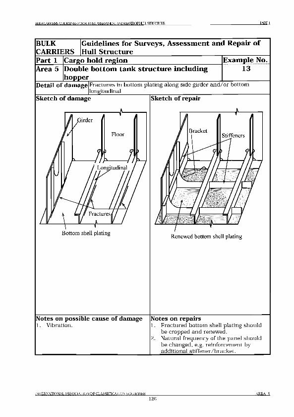
Bt Д К CARRIERS: GI ITOEUNESroRSLIRyEY- ASSKSSVIFNT AND REPAIR OF HI LLSIRUCIURE PARTI
BULKCARRIERS
Guidelines for Surveys, Assessment and Repair of Hull Structure
Part 1 Cargo hold region Example No.Area 5 Double bottom tank structure including
hopper13
Detail of damage Fractures in bottom plating along side girder a n d /o r bottom longitudinal________
Sketch of damage
Bottom shell plating
Sketch of repair
Renewed bottom shell plating
Notes on possible cause of damage1. Vibration.
Notes on repairs1. F ractured bottom shell plating should
be cropped and renewed.2. N atural frequency of the panel should
be changed, e.g. reinforcem ent by additional stiffener/bracket.
IN T ER N A TIO N A L A S S O C IA T IO N O F C L A SSIFIC A T IO N S O C IE T IE S
126A R EA 5
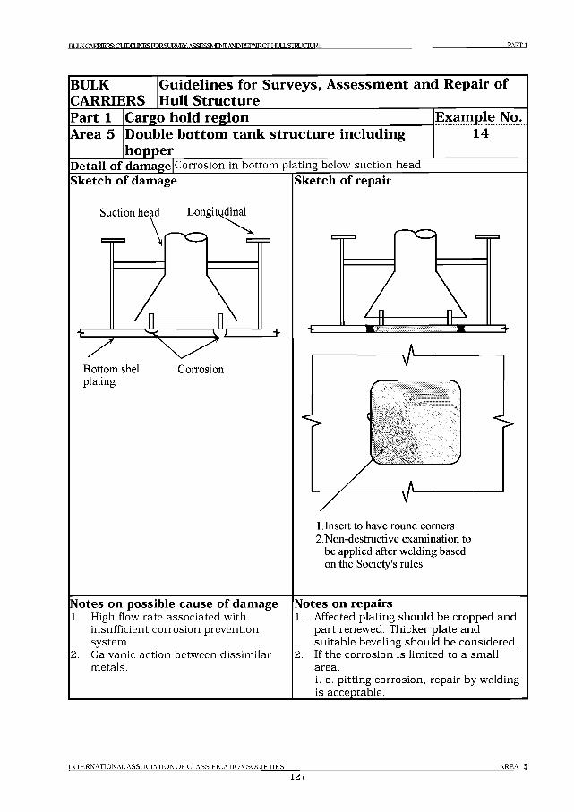
PART 1
BULKCARRIERS
Guidelines for Surveys, Assessment and Repair of Hull Structure
Part 1 Cargo hold region Example No.Area 5 Double bottom tank structure including
hopper14
Detail of damage Corrosion in bottom plating below suction headSketch o f damage
Suction head Longitudinal
Bottom shell Corrosionplating
Sketch o f repair
1 Insert to have round comers 2.Non-destructive examination to
be applied after welding based on the Society's rules
N otes on possible cause o f damage1. High flow rate associated with
insufficient corrosion prevention system.
2. Galvanic action between dissimilar metals.
N otes on repairs1. Affected plating should be cropped and
part renewed. Thicker plate and suitable beveling should be considered.
2. If the corrosion is limited to a small area,i. e. pitting corrosion, repair by welding is acceptable.___________________________
IN T E R N A T IO N A L A S S O C IA T IO N O F C L A S S IF IC A T IO N S O C I E T I E S
127A R E A 5
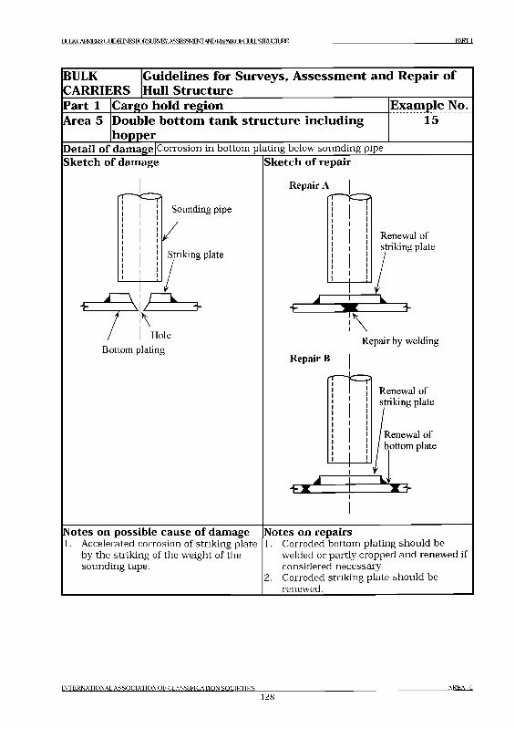
IMKCARRESGLTOElINESroRSURVEXASSESSMEOTAND REPAIRCFI-IULL STRUCTURE PARTI
BULKCARRIERS
Guidelines for Surveys, Assessment and Repair of Hull Structure
Part 1 Cargo hold region Example No.Area 5 Double bottom tank structure including
hopper15
Detail of damage|Corrosion in bottom plating below sounding pipeSketch of damage Sketch of repair
Sounding pipe
Striking plate
-E
Bottom plating
ъ
Repair A
Renewal of striking plate
Repair by welding
Repair В
im Renewal of striking plate
Renewal of bottom plate
-E
Notes on possible cause of damage1. Accelerated corrosion of striking plate
by the striking of the weight of the sounding tape.
Notes on repairs1. Corroded bottom plating should be
welded or partly cropped and renewed if considered necessary.
2. Corroded striking plate should be renewed.
INTERNATIONAL ASSOCIATION O F C LASSIFICATION SO C IE T IE S
128AREA 5
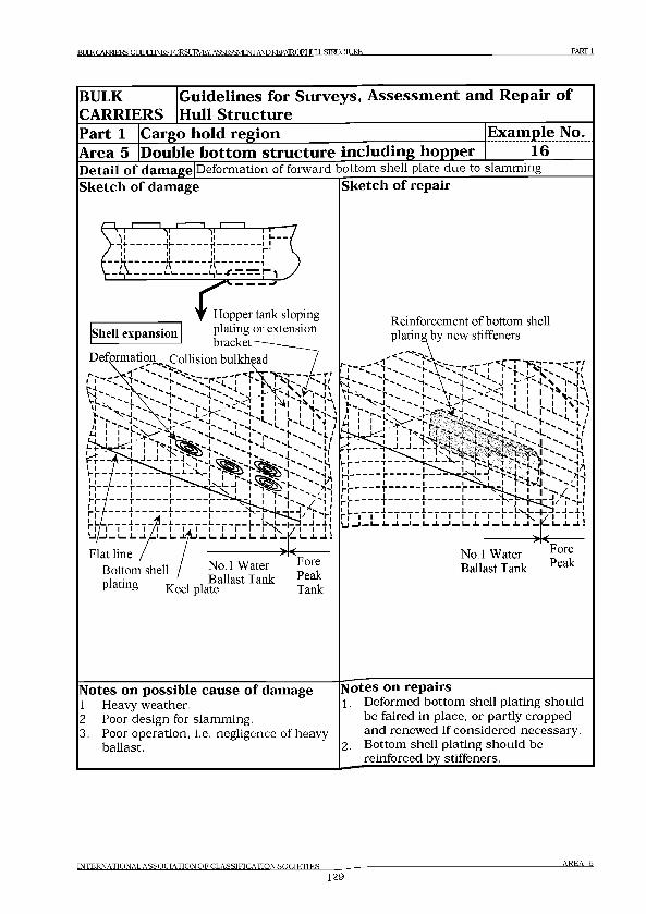
R1Л К CARRIERS: GI UDEUNESroRSUKVEY. ASSESSMENT AND REPAm OF HLU STRUCTURE PART 1
BULK
CARRIERS
G uidelines for Surveys, A sse ssm en t and R epair o f
Hull S tructure
Part 1 Cargo hold reg ion E xam ple No.
Area 5 D ouble b o tto m stru ctu re in c lu d in g hopper 16Detail of damage Deformation of forward bottom shell plate due to slamming Sketch of damage Sketch of repair
Notes on possible cause of damage1. Heavy weather.2. Poor design for slamming.3. Poor operation, i.e. negligence of heavy
ballast.
Notes on repairs1 . Deformed bottom shell plating should
be faired in place, or partly cropped and renewed if considered necessary.
2. Bottom shell plating should be reinforced by stiffeners.
INTERNATIONAL ASSOCIATION OF CLASSIFICATION SOCIETIES AREA 5
129
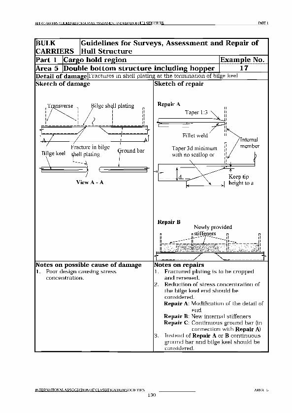
RI ILK CARRIERS: GI1Ш INFS FORSUKVEY. ASSESSMENT AND REPAIROFHI Д J .STRUCTURE PART 1
BULK
CARRIERS
G uidelines for Surveys, A sse ssm en t and R epair o f
Hull S tructure
Part 1 Cargo hold reg ion E xam ple No.
Area 5 |Double b o tto m stru ctu re in c lu d in g hopper 17Detail of damage|Fractures in shell plating at the termination of bilge keel Sketch of damage Sketch of repair
Repair A
Taper 3d minimum
Internalmember
with no scallop or
,___________\ __________ К fr = = *
Keep tipL ^ > height to a
Repair ВNewly provided
n n stiffeners p p
ii j!Notes on possible cause of damage1. Poor design causing stress
concentration.
f - - ' ~ 7 " Ч , , .............. jNotes on repairs1. Fractured plating is to be cropped
and renewed.2. Reduction of stress concentration of
the bilge keel end should be considered.Repair A: Modification of the detail of
endRepair B: New internal stiffeners Repair C: Continuous ground bar (in
connection with Repair A)3. Instead of Repair A or В continuous
ground bar and bilge keel should be considered.
INTERNATIONAL ASSOCIATION OF CLASSIFICATION SOCIETIES130
AREA 5
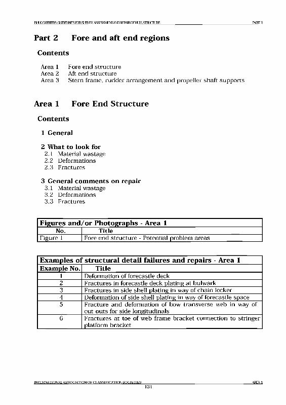
ВЕЖ CARRIERS GLJEIEIMS FOR SUIMjY, ASSESSMENT AND REPAIROFHIJLLSIRJCIIJRE PART 2
Part 2 Fore and aft end regions
C ontents
Area 1 Fore end structure Area 2 Aft end structureArea 3 Stern frame, rudder arrangement and propeller shaft supports
Area 1 Fore End Structure
C ontents
1 General
2 What to look for2.1 Material wastage2.2 Deformations2.3 Fractures
3 General comments on repair3.1 Material wastage3.2 Deformations3.3 Fractures
Figures and /or Photographs - Area 1No. Title
Figure 1 Fore end structure - Potential problem areas
Exam ples ol “ structural detail failures and repairs - Area 1Example No. Title
1 Deformation of forecastle deck2 Fractures in forecastle deck plating at bulwark3 Fractures in side shell plating in way of chain locker4 Deformation of side shell plating in way of forecastle space5 Fracture and deformation of bow transverse web in way of
cut-outs for side longitudinals6 Fractures at toe of web frame bracket connection to stringer
platform bracket
INTERNATIONAL ASSOCIATION OF CLASSIFICATION SOCIETIES131
AREA 1
IM K Q V R I^ jlS G O IE J N E S B ^ S L IlM jY . ASSESSMENT AND REPAIRCFHLILLSIHJCnjRE PART 2
1 General1.1 Due to the high humidity salt water environment, wastage of the internal
structure in the fore peak ballast tank can be a major problem for many, and in particular ageing ships. Corrosion of structure may be accelerated where the tank is not coated or where the protective coating has not been properly maintained, and can lead to fractures of the internal structure and the tank boundaries.
1.2 Deformation can be caused by contact which can result in damage to the internal structure leading to fractures in the shell plating.
1.3 Fractures of internal structure in the fore peak tank and spaces can also result from wave impact load due to slamming and panting.
1.4 Forecasde structure is exposed to green water and can suffers damage such as deformation of deck structure, deformation and fracture of bulwarks and collapse of mastT etc.
1.5 Shell plating around anchor and hawse pipe may suffer corrosion, deformation and possible fracture due to movement of improperly stowed anchor.
2 What to look for2.1 Material wastage
2.1.1 Wastage (and possible subsequent fractures) is more likely to be initiated at the locations as indicated in Figure 1 and particular attention should be given to these areas. A close-up inspection should be carried out with selection of representative thickness measurements to determine the extent of corrosion.
2.1.2 Structure in chain locker is liable to have heavy corrosion due to mechanical damage of te-the protective coating caused by the action of anchor chains. In some ships, especially smaller ships, the side shell plating may form boundaries of the chain locker and heavy corrosion may consequently result in holes in the side shell plating.
2.2 Deformations2.2.1 Contact with quay sides and other objects can result in large
deformations and fractures of the internal structure. This may affect the watertight integrity of the tank boundaries and collision bulkhead. A close-up examination of the damaged area should be carried out to determine the extent of the damage.
2.3 Fractures2.3.1 Fractures in the fore peak tank are normally found by close-up
inspection of the internal structure.
2.3.2 Fractures are often found in transition region and reference should be made to Part 1, Area 2 and 3.
INTERNATIONAL ASSOCIATION OF CLASSIFICATION SOCIETIES132
AREA 1
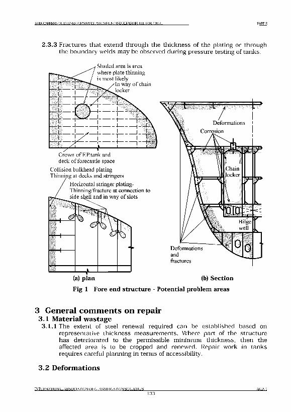
Bm<CARRE[S:GmELJNESroRSL]IA^Y.ASSESaVIENrANDREPAlROFtM LSIRJCIURE PART 2
2.3.3 Fractures that extend through the thickness of the plating or through the boundary welds may be observed during pressure testing of tanks.
Shaded area is area where plate thinning is most likely
'In way of chain locker
Crown of F.P.tank and deck of forecastle space
Collision bulkhead plating- Thinning at decks and stringers
Horizontal stringer plating- Thinning/fracture at connection to
and in way of slots
(a) plan (b) SectionFig 1 Fore end structure - Potential problem areas
3 General comments on repair3.1 Material wastage
3.1.1 The extent of steel renewal required can be established based on representative thickness measurements. Where part of the structure has deteriorated to the permissible minimum thickness, then the affected area is to be cropped and renewed. Repair work in tanks requires careful planning in terms of accessibility.
3.2 Deformations
INTERNATIONAL ASSOCIATION OF CLASSIFICATION SOCIETIES1 3 3
AREA1
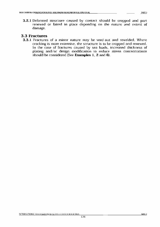
BULK C A RRIERS (XIIDE11NES F O R S L JIM iy .A S SE SSM EN rA I^O R EPA IR O FFIU LL S T R IC T U R E P A R T 2
3.2.1 Deformed structure caused by contact should be cropped and part renewed or faired in place depending on the nature and extent of damage.
3.3 Fractures3.3.1 Fractures of a minor nature may be veed-out and re welded. Where
cracking is more extensive, the structure is to be cropped and renewed. In the case of fractures caused by sea loads, increased thickness of plating and/or design modification to reduce stress concentrations should be considered (See Examples 1, 2 and 6).
INTERNATIONAL ASSOCIATION OF CLASSIFICATION SOCIETIES
134AREA 1
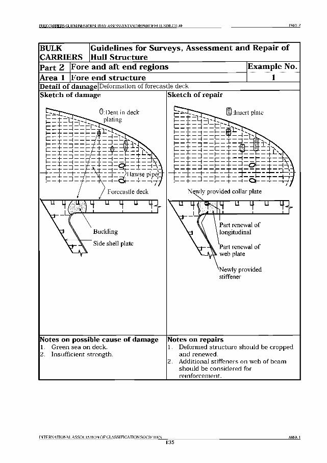
BULK CARRIERS G U D E nN E S T O R S U IV E y . ASSESSMENT AND REPAIROFH11L STRUCTURE PART 2
BULK Guidelines for Surveys, Assessment and Repair of CARRIERS Hull StructurePart 2 Fore and aft end regions Example No.Area 1 Fore end structure 1Detail o f damage Deformation of forecastle deckSketch o f damage
0 Dent in deck1= Z £ Z
X L^H aw se pipeX
/ / Forecastle deck
Sketch o f repair
i z z p z 3 z z z z ± z z j z z t z z z 3 ^ v
j_ = = i ^ _ = i= ё = н :щN^wly provided collar plate
V 4“ ) 4 u H u 4 -j- V 4 ^ tK 14 u 4 u 4 4 -
у \\ Buckling
\ Side shell plate
V J f / v ------------ '-------------\ \ \ \ Part renewal of
V \ \ l°ng'tudinal
V j- \ Part renewal of V- Д Л web plate
'Newly provided stiffener
Notes on possible cause o f damage1. Green sea on deck.2. Insufficient strength.
Notes on repairs1. Deformed structure should be cropped
and renewed.2. Additional stiffeners on web of beam
should be considered for reinforcement.
IN T E R N A T IO N A L A S S O C IA T IO N O F C L A S S IF IC A T IO N S O C I E T I E S
135AREA 1
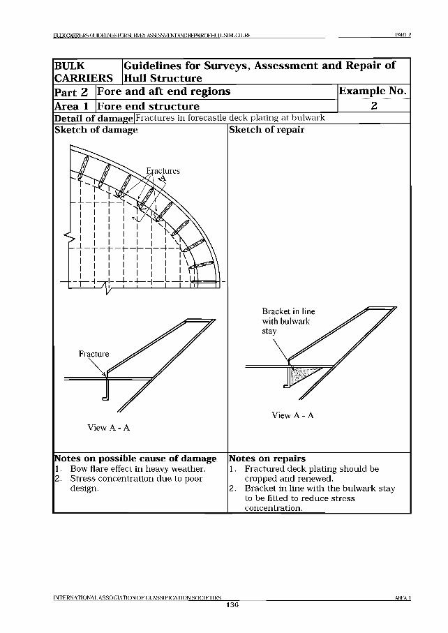
BULK CARRIERS: (X TO EU N ESroRSU RV EY , ASSESSMENT AND R E PM R O FH U L L SIR JC IU R E PART 2
BULKCARRIERS
Guidelines for Surveys, Assessment and Repair of Hull Structure
Part 2Area 1
Fore and aft end regionsFore end structure
Example No.
Detail o f damage Fractures in forecastle deck plating at bulwarkSketch o f damage
actures
Fracture
View A - A
Sketch o f repair
Bracket in line with bulwark stay
View A - A
Notes on possible cause o f damage1. Bow flare effect in heavy weather.2. Stress concentration due to poor
design.
Notes on repairs1. Fractured deck plating should be
cropped and renewed.2. Bracket in line with the bulwark stay
to be fitted to reduce stress concentration.
IN T E R N A T IO N A L A S S O C IA T IO N O F C L A S S IF IC A T IO N S O C I E T I E S
136AREA 1
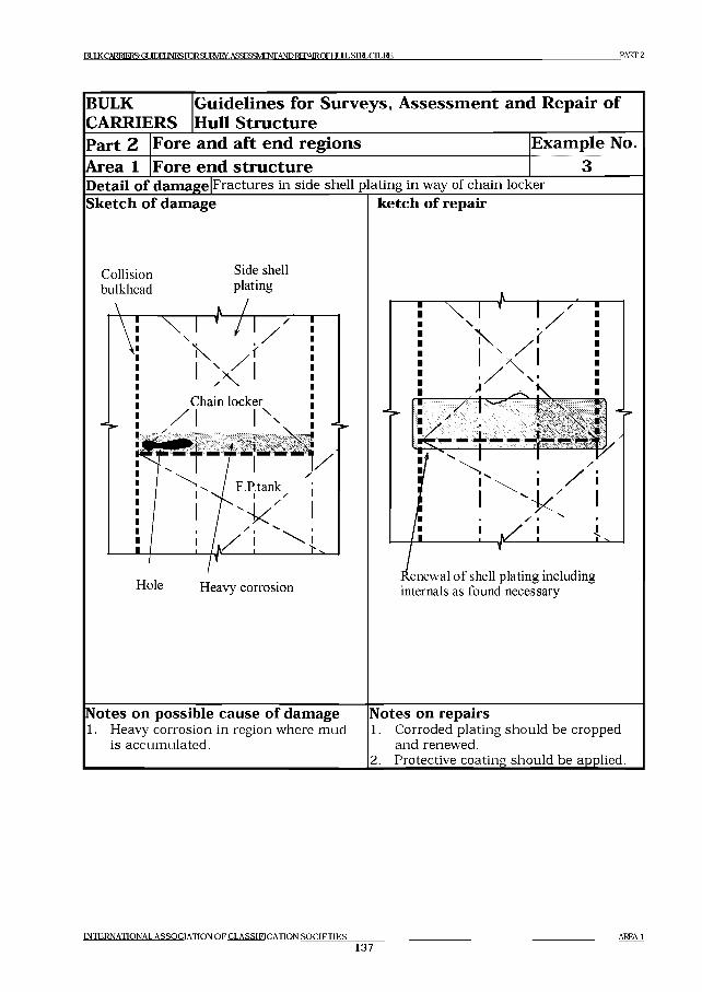
E O K CARRIERS: GLIIEELINESK3^SLII^/EY. ASSESSMENTAND REPAIR O F HULL S IM JC IU R E PART 2
IN T E R N A T IO N A L A S S O C IA T IO N O F C L A S S IF IC A T IO N S O C I E T I E S
137AREA 1
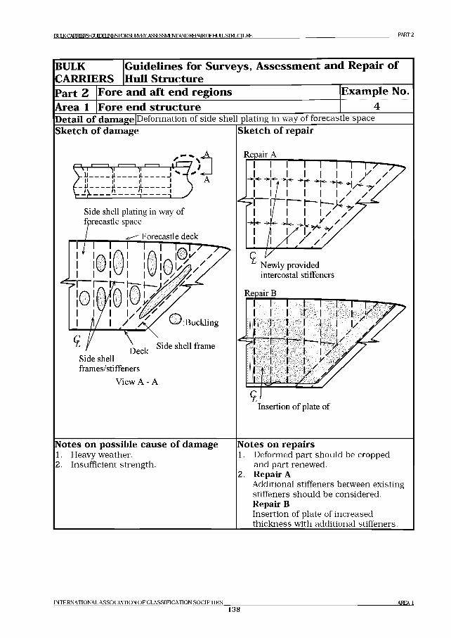
IM K C A R R IE I^ GUIDELINES K K SU lM jY .A S SESSM EN TA N D R EPA lR O F HULL S IF IJC IU R E PART 2
BULKCARRIERS
Guidelines for Surveys, Assessment and Repair of Hull Structure
Part 2Area 1
Fore and aft end regionsFore end structure
Example No........... 4.........
Detail o f damage Deformation of side shell plating in way of forecastle space Sketch o f damage Sketch o f repair
, ------ т-------- v■ U---------|L---------- |L------------1II ,1 ,1 I
Side shell plating in way of forecastle space
Forecastle deck
<L! \Deck
Side shell frames/stiffeners
View A - A
Buckling
Side shell frame
Repair A
Newly provided intercostal stiffeners
Repair В
Insertion o f plate o f
Notes on possible cause o f damage1. Heavy weather.2. Insufficient strength.
Notes on repairs1. Deformed part should be cropped
and part renewed.2. Repair A
Additional stiffeners between existing stiffeners should be considered. Repair ВInsertion of plate of increased thickness with additional stiffeners.
IN T E R N A T IO N A L A S S O C IA T IO N O F C L A S S IF IC A T IO N S O C I E T I E S
138AREA 1
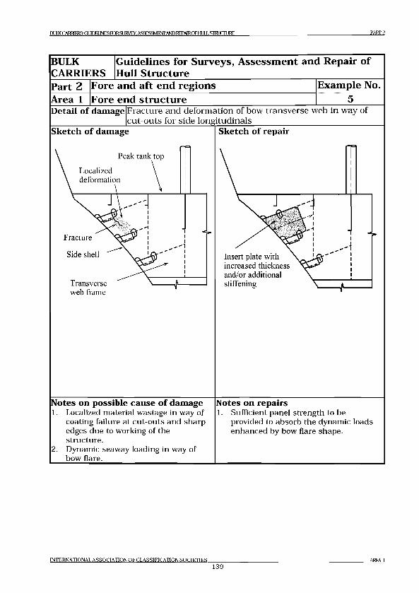
E O K CARRIERS (XBDELjNESK^SUW EY. ASSESSMENT AND REPAIR OF EIIJLLSIEIJCIIJRE PART 2
BULKCARRIERS
Guidelines for Surveys, Assessment and Repair of Hull Structure
Part 2Area 1
Fore and aft end regionsFore end structure
Example No.
Detail of damage Fracture and deformation of bow transverse web in way of cut-outs for side longitudinals_________________________
Sketch of damage Sketch of repair
Notes on possible cause of damage1. Localized material wastage in way of
coating failure at cut-outs and sharp edges due to working of the structure.
2. Dynamic seaway loading in way of bow flare.
Notes on repairs1. Sufficient panel strength to be
provided to absorb the dynamic loads enhanced by bow flare shape.
IN TER N A TIO N A L A SS O C IA T IO N Q F C L A S S IF IC A T IO N S O C IE T IE S
139AREA 1
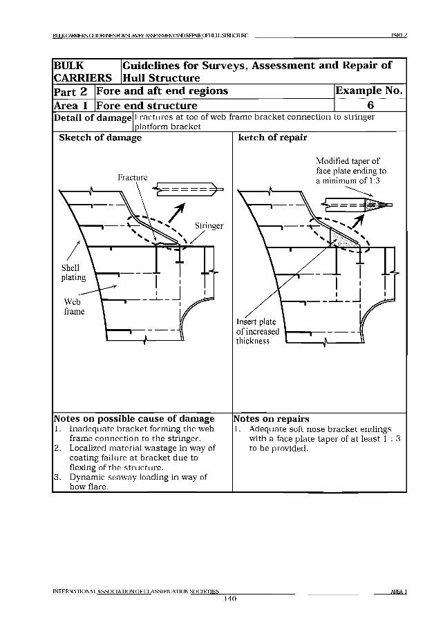
В Е Ж CARRIERS (X IID E L lN E SroR SL IIM jy . ASSESSMENT AND REPAIRQFHULLSIELJCILIKE PART 2
BULKCARRIERS
Guidelines for Surveys, Assessment and Repair of Hull Structure
Part 2Area 1
Fore and aft end regionsFore end structure
Example No.
Detail o f damage Fractures at toe of web frame bracket connection to stringer platform bracket_____
Sketch o f damage
Webframe
ketch o f repair
Modified taper of face plate ending to a minimum of 1:3
Insertof increased thickness 1-----------
Notes on possible cause o f damage1. Inadequate bracket forming the web
frame connection to the stringer. Localized material wastage in way of coating failure at bracket due to flexing of the structure.Dynamic seaway loading in way of bow flare.
2 .
3.
Notes on repairs1. Adequate soft nose bracket endings
with a face plate taper of at least 1 : 3 to be provided.
IN T E R N A T IO N A L A S S O C IA T IO N O F C L A S S IF IC A T IO N S O C I E T I E S
1 4 0AREA 1
BULXCARRlElSGmEI^roRSUia^.AS£ESSMEOTAmREPAlROFHULLSimCM^ PART 2
Area 2 Aft end structure
C ontents
1 General
2 What to look for2.1 Material wastage2.2 Deformations2.3 Fractures
3 General comments on repair3.1 Material wastage3.2 Deformations3.3 Fractures
Figures and /or Photographs - Area 2No. Title
Figure 1 Aft end structure - Potential problem areas
Exam ples ol structural detail failures and repairs - Area 2Example No. Title
l Fractures in longitudinal bulkhead in way of rudder trunk2 Fractures at the connection of floors and girder/side
brackets3-a Fractures in flat where rudder carrier is installed in steering
gear room3-b Fractures in steering gear foundation brackets and deformed
deck plate
INTERNATIONAL A S S O C IA TIO N O F C LA SSIFIC A TIO N SO C IE T IE S1 4 1
AREA 2
BULK CARRIERS GUIDELINES roRSURVEY, ASSESSMENTAND REPAIROFHLlLLSIRL)CIIJRE PART 2
1 General1.1 Due to the high humidity salt water environment, wastage of the internal
structure in the aft peak ballast tank can be a major problem for many, and in particular ageing, ships. Corrosion of structure may be accelerated where the tank is not coated or where the protective coating has not been properly maintained, and can lead to fractures of the internal structure and the tank boundaries.
1.1 Deformation can be caused by contact or wave impact action from astern (which can result in damage to the internal structure leading to fractures in the shell plating.
1.3 Fractures to the internal structure in the aft peak tank and spaces can also result from main engine and propeller excited vibration.
2 What to look for2.1 Material w astage
2.1.1 Wastage (and possible subsequent fractures) is more likely to be initiated at in the locations as indicated in Figure 1. A close-up inspection should be carried out with selection of representative thickness measurements to determine the extent of corrosion.Particular attention should be given to bunker tank boundaries and spaces adjacent to heated engine room.
2 .2 D eform ations2.2.1 Contact with quay sides and other objects can result in large
deformations and fractures of the internal structure. This may affect the watertight integrity of the tank boundaries and bulkheads. A close-up examination of the deformed area should be carried out to determine the extent of the damage.
2 .3 Fractures2.3.1 Fractures in weld at floor connections and other locations in the aft
peak tank and rudder trunk space can normally only be found by close- up inspection.
2.3.2 The structure supporting the rudder carrier may fracture and/or deform due to excessive load on the rudder. Bolts connecting the rudder carrier to the steering gear flat may also suffer damage under such load.
INTERNATIONAL ASSO CIA TIO N O F CLASSIFICATION S O C IE T IE S
1 4 2
AREA 2
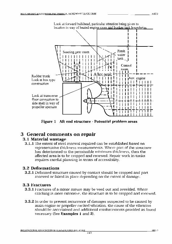
B llK CARRIERS GUDEIlNESroRSLlRVEY,ASSES3VENT AND REPAIROFI-IULLSIRLJCILIRE PART 2
Look at forward bulkhead, particular attention being given to location in way of heated engine room and bunker tank boundaries
Rudder trunk Look at box type construction
Look at transverse floor connection to side shell in way of propeller aperture
Control I room |
. . . i i After,peak И I f и — 1--------. 1 > Н Я l I I 'H J 1 И I I I I I I I |Aux. engine t^T-i I Г ...1 , I . Г ч -j^i I I I I I | ! | | I I I I I I I I
■' ' ; f !d” t T r n f T f - n - r r r
f\ f ! i !!!!!!!!!!!!!
\ ! | i i 11 i i i i i/ \T T L J _ l il i 1 1 l 1 1
lJ v \ ! ! 1111- 1 ~r 1 1 1■ 111111
11 11
Г П Т Г....
Figure 1 Aft end structure - Potential problem areas
3 General comments on repair3.1 Material wastage3.1.1 The extent of steel renewal required can be established based on
representative thickness measurements. Where part of the structure has deteriorated to the permissible minimum thickness, then the affected area is to be cropped and renewed. Repair work in tanks requires careful planning in terms of accessibility.
3.2 Deformations3.2.1 Deformed structure caused by contact should be cropped and part
renewed or faired in place depending on the extent of damage.
3.3 Fractures3.3.1 Fractures of a minor nature may be veed-out and rewelded. Where
cracking is more extensive, the structure is to be cropped and renewed.
3.3.2 In order to prevent recurrence of damages suspected to be caused by main engine or propeller excited vibration, the cause of the vibration should be ascertained and additional reinforcements provided as found necessary (See Examples 1 and 2).
INTERNATIONAL ASSOCIATION OF CLASSIFICATION SOCIETIES1 4 3
AREA 2
B^QraiERS:GimELJNESroRSL]RVEY.ASSESaVIENTANDREPAlROFtM LSroUCIlJRE PART 2
3.3.3 In the case of fractures caused by sea loads, increased thickness of plating and/or design modifications to reduce stress concentrations should be considered.
3.3.4 Fractured structure which supports rudder carrier is to be cropped, and renewed, and may have to be reinforced (See Examples 3-a and 3-b).
INTERNATIONAL A SS O C IA TIO N O F C LA SSIFIC A TIO N S O C IE T IE S1 4 4
AREA 2
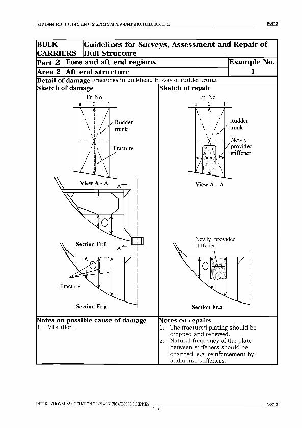
EULKCATC3ERS GUEBJNESroRSURVEY. ASSESSMENT AND R FPA IR O FH JI.SraU C IU R E PART 2
BULK
CARRIERS
G uidelines for Surveys, A sse ssm en t and Repair o f
Hull S tructure
Part 2 Fore and aft end reg ion s E xam ple No.
Area 2 Aft end stru ctu reDetail of damage Fractures in bulkhead in way of rudder trunkSketch of damage Sketch of repair
Fr. No. a 0 1
Fr. No. a 0 1
Rudder ^ trunk
Newly / provided stiffener
View A - A
Newly provided
Notes on possible cause of damage1. Vibration.
Notes on repairs1. The fractured plating should be
cropped and renewed.2. Natural frequency of the plate
between stiffeners should be changed, e.g. reinforcement by additional stiffeners.
INTERNATIONAL ASSOCIATION OF CLASSIFICATION SOCIF.TIF,S145
AREA 2
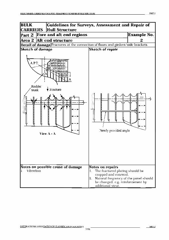
га IК CARRIERS: Gl 1DF1INFS FOR SIIRVEY. ASSFSSMFLTT AND RFPA1R OF [ IIJILSIEI JCIIJRI PART 2
BULK
CARRIERS
G uid elin es for S urveys, A sse ssm en t and R epair o f
Hull S tructure
Part 2 Fore and aft en d reg ion s E xam ple No.
Area 2 Aft en d stru ctu reDetail of damage F ractu res a t th e co n n ec tio n o f floors a n d g ir d e r s /s id e b rack ets
Sketch of damage Sketch of repair
JolOlQjjOiOt© 1 _Ле+оТо1о|о|
"I O 0|0|Q|0|0|
, Rudder .trunk | : Fracture
View A - ANewly provided angle
Notes on possible cause of damage1. V ibration.
Notes on repairs1. The fractured p lating sh o u ld be
cropped an d renew ed.2. N atural frequency o f th e pan el sh o u ld
be ch an ged , e.g . rein forcem ent by add ition al stru t.
IN TER N A TIO N A L A S S Q C IA T IO N O F C L A S S IF IC A T IO N S O C IE T IE S
146AREA 2
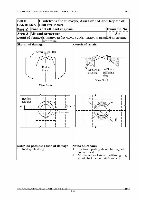
BULKCARRERSCLmEUNESroRSLIRVEY. ASSESSMENT ANEIREPAIROFELULLSroLICTTO PART 2
BULK
CARRIERSG uidelines for Surveys, A ssessm en t and Repair o f
Hull Structure
Part 2 Fore and aft end regions Exam ple No.
Area 2 Aft end structure 3 aDetail of damage Fractures in flat where rudder carrier is installed in steering
________________|gear room_________Sketch of damage
/ Steering gear flat
Ruddertrunk
IView A - A
Sketch of repair
Additional ' Additional brackets | stiffening
ring
View В - В
Notes on possible cause of damage1. Inadequate design .
Notes on repairs1. Fractured plating sh ou ld be cropped
and renew ed.2. Additional brackets and stiffening ring
sh o u ld be fitted for reinforcem ent.
IN TE R N A TIO N A L A S S O C IA T IO N O F C L A SS IF IC A T IO N S O C IE T IE S ___________________________________________________________________________________ AREA 21 4 7
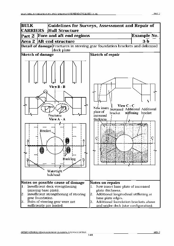
BULK CARRIERS: GUIDELINES FORSURVEY. ASSESSMENT AND REPAIR OF HI Д J ,S 1 R IP I ]RF, PART 2
BULK
CARRIERS
G uidelines for Surveys, A sse ssm en t and Repair o f
Hull S tru ctu re
Part 2 Fore and a ft en d reg ion s E xam ple No.
Area 2 Aft en d stru ctu re 3 bDetail of damage Fractures in steering gear foundation brackets and deformed
deck plate_________Sketch of damage
/ / / / \
View В - В
к
Fractures View A - A
Watertight ■ bulkhead
Sketch of repair
Ni plate of increased thickness
View C - Cinsert increased Additional Additional
bracket stiffening bracket
i
- r(~\n- F - H -------------
1 i
i / i
1 i
— h i i
J lY .-- -----------1----------/ 1 ---------)
1 / 1
1 / 1
1 / 1
\ !
^ 1 l
1
, - k ^ N' i i
i i
i i
V:--------\------------- 1-------------
i Ih iУ. Т Ч . 1
1 1
1 1
1 1
------------- 1------------- 1---------у
i
Notes on possible cause of damage1. Insufficient deck strengthening
(missing base plate).2. Insufficient strengthening of steering
gear foundation.3. Bolts of steering gear were not
sufficiently pre-loaded.______________
Notes on repairs1. New insert base plate of increased
plate thickness.2. Additional longitudinal stiffening at
base plate edges.3. Additional foundation brackets above
and under deck (star configuration).
INTERNATIONAL ASSOCIATION O F CLASSIFICATION SOCIETIES148
AREA 2
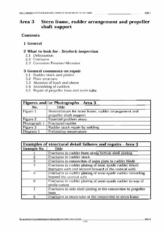
ВЕШ CARRIERS GLEEUNESroRSLIRVEY, ASSESSMENT AND REPAIROFHULL STRUCTURE PART 2
Area 3 Stern frame, rudder arrangement and propeller shaft support
Contents
1 General
2 What to look for - Drydock inspection2.1 Deformation2.2 Fractures2.3 Corrosion/Erosion/Abrasion
3 General comments on repair3.1 Rudder stock and pintles3.2 Plate structure3.3 Abrasion of bush and sleeve3.4 Assembling of rudders3.5 Repair of propeller boss and stern tube
Figures and/or Photographs - Area 3No. Title
Figure 1 Nomenclature for stern frame, rudder arrangement and propeller shaft support
Figure 2 Potential problem areasPhotograph 1 Fractured rudderFigure 3 Rudder stock repair by weldingDiagram 1 Preheating temperature
Examples ol? structural detail failures and repairs - Area 3Example No. Title
1 Fractures in rudder horn along bottom shell plating2 Fractures in rudder stock3 Fractures in connection of palm plate to rudder blade4 Fractures in rudder plating of semi-spade rudder (short
fractures with end located forward of the vertical web)5 Fractures in rudder plating of semi-spade rudder extending
beyond the vertical web6 Fractures in rudder plating of semi-spade rudder in way of
pintle cutout7 Fractures in side shell plating at the connection to propeller
boss8 Fractures in stern tube at the connection to stern frame
INTERNATIONAL A S S O C IA TIO N O F C LA SSIFIC A TIO N SO C IE T IE S1 4 9
AREA 3
1МКСАВШЭ^СШД№5ГОК31ЛМЖ ASSESSMENTAND REPA1ROFHULSIRLICIL1RE PART 2
1 General1.1 The stern frame, possible strut bearing arrangement and connecting
structures are exposed to propeller induced vibrations, which may lead to fatigue cracking in areas where stress concentrations occur.
1.2 The rudder and rudder horn are exposed to accelerated and fluctuating stream from the propeller, which may also lead to fatigue cracking in areas where stress concentrations occur.
1.3 In extreme weather conditions the rudder may suffer wave slamming forces causing deformations of rudder stock and rudder horn as well as of the rudder itself.
1.4 Rudder and rudder horn as well as struts (on shafting arrangement with strut bearings) may also come in contact with floating object such as timber-log or ice causing damages similar to those described in 1.3.
1.5 Since different materials are used in adjacent compartments and structures, accelerated (galvanic) corrosion may occur if protective coating and/or sacrificial anodes are not maintained properly.
1.6 Pre-existing manufacturing internal defects in cast pieces may lead to fatigue cracking.
1.7 A summary of potential problem areas is shown in Figure 2.
1.8 A complete survey of the rudder arrangement is only possible in drydock. However, in some cases a survey including a damage survey can be carried out afloat by divers or with a trimmed ship.
INTERNATIONAL A S S O C IA TIO N O F C LA SSIFIC A TIO N SO C IE T IE S1 5 0
A R E A 3
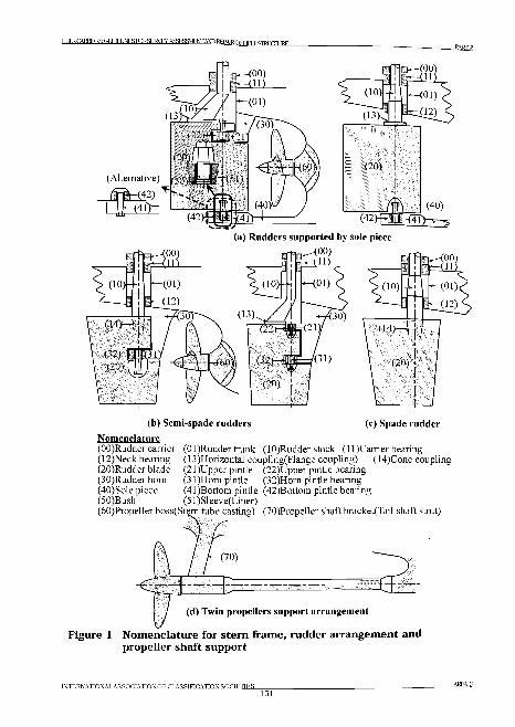
BULK ( ARRTFRS: ОТIOELINES FORSLJRVEY, ASSRSSMFNT AND RRPATR OP ][ j .SIRUCXTJRE
(a) Rudders supported by sole piece
Nomenclature(OO)Rudder carrier (Ol)Rudder trunk (lO)Rudder stock (ll)Carrier bearing (12)Neck bearing (13)Horizontal coupling(Flange coupling) (14)Cone coupling (20)Rudder blade (2 l)Upper pintle (22)Upper pintle bearing (30)Rudder horn (3 l)H om pintle (32)Horn pintle bearing(40)Sole piece (4 l)Bottom pintle (42)Bottom pintle bearing(50)Bush (51)Sleeve(Liner)
Figure 1 Nomenclature for stern frame, rudder arrangement and propeller shaft support
INTERNATIONAL ASSOCIATION OF CLASSIFICATION SOCIETIES1 5 1
AREA 3
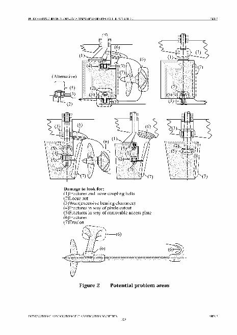
B^QraiERS:GimELJNESroRSL]RVEY.ASSESaVIENTANDREPAlROFtMLSroUCIlJRE PART 2
Damage to look for:(1) Fractures and loose coupling bolts(2) Loose nut(3) W ear(excessive bearing clearance)(4) Fractures in way o f pintle cutout(5) Fractures in way o f removable access plate(6) Fractures(7) Erosion
INTERNATIONAL ASSOCIATION O F CLASSIFICATION SOCIETIES1 5 2
AREA 3
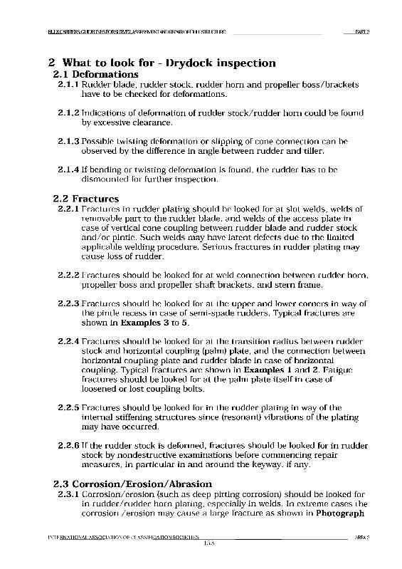
В Ц и < С А В Ш Э ^ С Ш Д Ю 5 Г О К З и 1 Д ^ , ASSESSMENT AND REPAIRCFHLILLSIRLICILIRE PART 2
2 What to look for - Drydock inspection2.1 D eform ations
2.1.1 Rudder blade, rudder stock, rudder horn and propeller boss/b rackets have to be checked for deformations.
2.1.2 Indications of deformation of rudder s tock /rudder horn could be found by excessive clearance.
2.1.3 Possible twisting deformation or slipping of cone connection can be observed by the difference in angle between rudder and tiller.
2.1.4 If bending or twisting deformation is found, the rudder has to be dism ounted for further inspection.
2 .2 Fractures2.2.1 F ractures in rudder plating should be looked for a t slot welds, welds of
removable part to the rudder blade, and welds of the access plate in case of vertical cone coupling between rudder blade and rudder stock an d /o r pintle. Such welds may have latent defects due to the limited applicable welding procedure. Serious fractures in rudder plating may cause loss of rudder.
2 .2 .2 Fractures should be looked for a t weld connection between rudder horn, propeller boss and propeller shaft brackets, and stern frame.
2.2.3 F ractures should be looked for a t the upper and lower corners in way of the pintle recess in case of sem i-spade rudders. Typical fractures are shown in Examples 3 to 5.
2.2.4 Fractures should be looked for a t the transition radius between rudder stock and horizontal coupling (palm) plate, and the connection between horizontal coupling plate and rudder blade in case of horizontal coupling. Typical fractures are shown in Examples 1 and 2. Fatigue fractures should be looked for a t the palm plate itself in case of loosened or lost coupling bolts.
2.2.5 Fractures should be looked for in the rudder plating in way of the internal stiffening structu res since (resonant) vibrations of the plating may have occurred.
2.2.6 If the rudder stock is deformed, fractures should be looked for in rudder stock by nondestructive exam inations before commencing repair m easures, in particular in and around the keyway, if any.
2 .3 C orrosion/Erosion/A brasion2.3.1 Corrosion/erosion (such as deep pitting corrosion) should be looked for
in rudder/rudder horn plating, especially in welds. In extreme cases the corrosion /erosion may cause a large fracture as shown in Photograph
INTERNATIONAL A SS O C IA TIO N O F C LA SSIFIC A TIO N SO C IE T IE S153
AREA 3
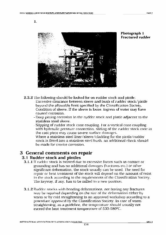
IMKCARRIEKSGUEBJNESroRSIJRVEY. ASSESSMENTAND I EPAIRCFHLILLSIWXTIJRE PART2
1.
2.3 .2 The following should be looked for on rudder stock and pintle:- Excessive clearance between sleeve and bush of rudder stock/pin tle
beyond the allowable limit specified by the Classification Society.- Condition of sleeve. If the sleeve is loose, ingress of water may have
caused corrosion.- Deep pitting corrosion in the rudder stock and pintle adjacent to the
stainless steel sleeve.- Slipping of rudder stock cone coupling. For a vertical cone coupling
with hydraulic pressure connection, sliding of the rudder stock cone in the cast piece may cause severe surface damages.
- Where a stainless steel liner/sleeve/cladding for the p in tle /rudder stock is fitted into a stainless steel bush, an additional check should be made for crevice corrosion.
3 General comments on repair3.1 Rudder stock and pintles
3.1.1 If rudder stock is twisted due to excessive forces such as contact or grounding and has no additional damages (fractures etc.) or other significant deformation, the stock usually can be used. The need for repair or heat treatm ent of the stock will depend on the am ount of twist in the stock according to the requirem ents of the Classification Society. The key way, if any, has to be milled in a new position.
3 .1 .2 Rudder stocks with bending deformations, not having any fractures may be repaired depending on the size of the deformation either by warm or by cold straightening in an approved workshop according to a procedure approved by the Classification Society. In case of warm straightening, as a guideline, the tem perature should usually not exceed the heat treatm ent tem perature of 530-580°C.
INTERNATIONAL ASSOCIATIONOFCLASSIFICATIONSOCIETIES154
AREA 3
I а Л К CU ill 3t J INI« Н Г JRSlJI^Vt CY, ASSIЖ М 1 NIANI3 R[ J AIRC Л [ H Jl i .Sll^t X:n_lRE PART 2
3.1.3 In case of fractures on a rudder stock with deformations, the stock may be used again depending on the nature and extent of the fractures. If a welding repair is considered acceptable, the fractures are to be removed by m achining/grinding and the welding is to be based on an approved welding procedure together with post weld heat treatm ent as required by the Classification Society.
3.1.4 Rudder stocks a n d /o r pindes may be repaired by welding replacing wasted m aterial by similar weld m aterial provided its chemical composition is suitable for welding, i.e. the carbon content m ust usually not exceed 0.25%. The welding procedures are to be identified in function of the carbon equivalent (Ceq). After removal of the wasted area (corrosion, scratches, etc.) by m achining a n d /o r grinding the build-up welding has to be carried out by an autom atic spiral welding according to an approved welding procedure. The welding has to be extended over the area of large bending m om ents (rudder stocks). In special cases post weld heat treatm ent has to be carried out according to the requirem ents of the Classification Society. After final machining, a sufficient num ber of layers of welding m aterial have to rem ain on the rudder stock/pintle. A sum m ary of the m ost im portant steps and conditions of th is repair is shown in the Figure 3.
3.1.5 In case of rudder stocks with bending loads, fatigue fractures in way of the transition radius between the rudder stock and the horizontal coupling plate can not be repaired by local welding. A new rudder stock with a modified transition geometry has to be m anufactured, as a rule (See Example 1). In exceptional cases a welding repair can be carried out based on an approved welding procedure. M easures have to be taken to avoid a coincidence of the metallurgical notch of the heat affected zone with the stress concentration in the rad ius’ area.Additional surveys of the repair (including non-destructive fracture examination) have to be carried out in reduced intervals.
INTERNATIONAL A S S O C IA TIO N O F C LA SSIFIC A TIO N SO C IE T IE S155
AREA3
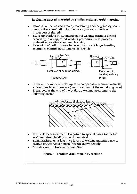
BULK CARRIERS: GUIDELINES TORSLIRVIУ ASSI «SMI 'NI’AND kl PAIRQE' I lUIJSIl^t JCIURI PART 2
Replacing wasted material by similar ordinary weld material
• Removal of the wasted area by m achining a n d /o r grinding, nondestructive examination for fractures (magnetic particle inspection preferred)
• Build-up welding by autom atic spiral welding (turning device) according to an approved welding procedure (weld process, preheating, welding consum ables, etc.)
• Extension of build-up welding over the area of large bending moments (shafts) according to the sketch
Extension of build-up welding Extension ofbuild-up welding
Rudder stock Pintle
• Sufficient num ber of weld layers to com pensate removed material, a t least one layer in excess (heat treatm ent of the remaining layer)
• Transition a t the end of the build-up welding according to the following sketch
• Post weld heat treatm ent if required in special cases (never for stainless steel cladding on ordinary steel)
• Final machining, a t least two layers of welding m aterial have to rem ain on the rudder stock (See the above sketch)
• Non destructive fracture examination
Figure 3 Rudder stock repair by welding
INTERNATIONAL ASSOCIATION OF CLASSIFICATION SOCIETIES156
A R E A 3
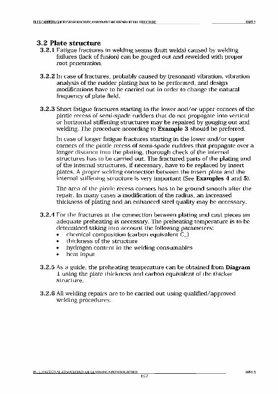
Е Й Х К CARRIERS: GUIDEI INIIS [QRSURVI У ASSI«SMI 'NIANEI kl PAIROE' I H Jl i .SIRUCIURE PART 2
3 .2 Plate structure3.2.1 Fatigue fractures in welding seam s (butt welds) caused by welding
failures (lack of fusion) can be gouged out and rewelded with proper root penetration.
3.2.2 In case of fractures, probably caused by (resonant) vibration, vibration analysis of the rudder plating has to be performed, and design modifications have to be carried out in order to change the natural frequency of plate field.
3.2.3 Short fatigue fractures starting in the lower a n d /o r upper corners of the pintle recess of sem i-spade rudders th a t do not propagate into vertical or horizontal stiffening structu res may be repaired by gouging out and welding. The procedure according to Example 3 should be preferred.
In case of longer fatigue fractures starting in the lower a n d /o r upper corners of the pintle recess of sem i-spade rudders th a t propagate over a longer distance into the plating, thorough check of the internal structu res has to be carried out. The fractured parts of the plating and of the internal structures, if necessary, have to be replaced by insert plates. A proper welding connection between the insert plate and the internal stiffening structu re is very im portant (See Examples 4 and 5).The area of the pintle recess corners has to be ground sm ooth after the repair. In many cases a modification of the radius, an increased thickness of plating and an enhanced steel quality may be necessary.
3.2.4 For the fractures a t the connection between plating and cast pieces an adequate preheating is necessary. The preheating tem perature is to be determined taking into account the following param eters:• chemical composition (carbon equivalent Ceq)• thickness of the structure• hydrogen content in the welding consum ables• heat input
3.2.5 As a guide, the preheating tem perature can be obtained from Diagram 1 using the plate thickness and carbon equivalent of the thicker structure.
3.2.6 All welding repairs are to be carried out using qualified/approved welding procedures.
INTERNATIONAL ASSOCIATION OF CLASSIFICATION SOCIETIES157
A R E A 3
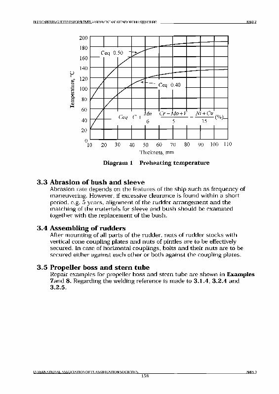
BllKCAlMERSiGl^ElJNESroRSLlRVEY.ASSESaVDiNTANDRE^AlRCFHLILLSIRtJCILlRE PART 2
T h ick n e ss , m m
Diagram 1 Preheating temperature
3 .3 Abrasion o f bush and sleeveAbrasion rate depends on the features of the ship such as frequency of maneuvering. However, if excessive clearance is found within a short period, e.g. 5 years, alignment of the rudder arrangem ent and the m atching of the m aterials for sleeve and bush should be examined together with the replacem ent of the bush.
3 .4 A ssem bling o f ruddersAfter m ounting of all parts of the rudder, n u ts of rudder stocks with vertical cone coupling plates and n u ts of pintles are to be effectively secured. In case of horizontal couplings, bolts and their n u ts are to be secured either against each other or both against the coupling plates.
3 .5 Propeller boss and stern tubeRepair examples for propeller boss and stern tube are shown in Examples 7and 8. Regarding the welding reference is made to 3 .1 .4 , 3 .2 .4 and 3 .2 .5 .
INTERNATIONAL ASSOCIATION OF CLASSIFICATION SOCIETIES158
AREA 3
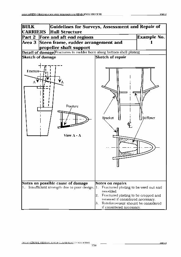
H lIKPA RRFI^G lltrH INKS roRSURVEY. ASSESSMENTAND RFPAIRCFHULSIRUCIURE PART 2
BULK
CARRIERS
G uid elin es for Surveys, A sse ssm en t and R epair o f
Hull S tru ctu re
Part 2 Fore and a ft en d reg ion s E xam ple No.
Area 3 S tern fram e, rudder arrangem ent and
propeller sh a ft supportDetail o f damage Fractures in rudder horn along bottom shell plating Sketch o f damage jSketch o f repair
View A - A
Notes on possible cause o f damage1. Insufficient strength due to poor design.
Notes on repairs1. Fractured plating to be veed-out and
rewelded.2. Fractured plating to be cropped and
renewed if considered necessary.3. Reinforcement should be considered
if considered necessary.____________
INTERNATIONAL ASSOCIATION OF CLASSIFICATION SOCIETIES159
AREA 3

Rl HKCARRIERSGI HDFIlNESroRSURVEY. ASSESSMENT ANDRFPAIROFHLILLSIHLICHJRE PART 2
INTERNATIONAL ASSOCIATION OF CLASSIFICATION SOCIETIES160
AREA 3
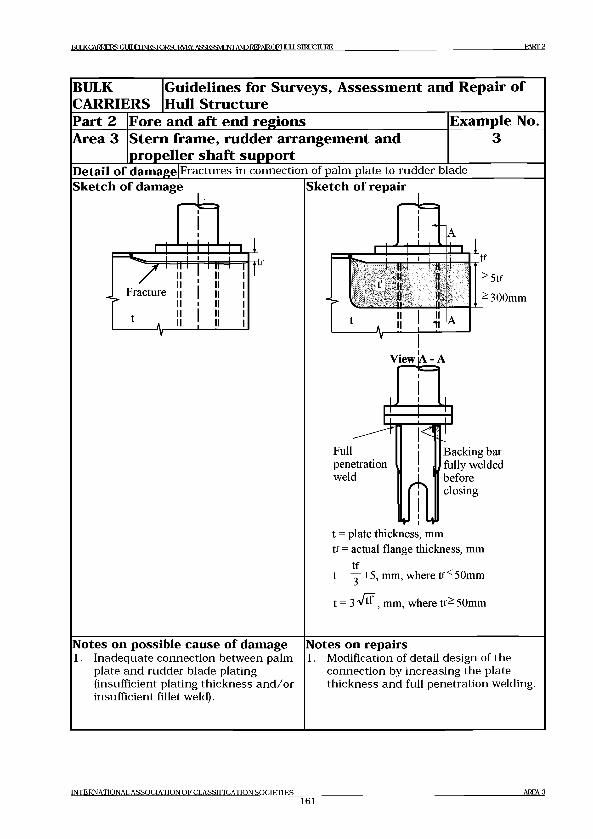
Н Л KCARRIERSOIlLHINESroRSURVEY. ASSESSMENTAND RFPAIROF HULLSIRUCIURE PART 2
BULK
CARRIERS
G uid elin es for Surveys, A sse ssm en t and R epair o f
Hull S tru ctu re
Part 2 Fore and a ft en d reg ion s E xam ple No.
Area 3 S tern fram e, rudder arrangem ent and
propeller sh a ft supportDetail o f damage Fractures in connection of palm plate to rudder bladeSketch o f damage
- U
11 ■ 1 1 1 1 11
Fracture
t
Sketch o f repair- U
l И IIИ II
-------U------- IL
tf
-5 tf
-300mm
ViewjA - A
Fullpenetrationweld
Backing bar fully welded before closing
t = plate thickness, mm tf = actual flange thickness, mm
tft = ~ + 5 , nun, where t f - 50mm
t = 3 ^ t f , mm, where t f - 50mm
Notes on possible cause o f damage1. Inadequate connection between palm
plate and rudder blade plating (insufficient plating thickness and /o r insufficient fillet weld).
Notes on repairs1. Modification of detail design of the
connection by increasing the plate thickness and full penetration welding.
INTERNATIONAL ASSOCIATION OF CLASSIFICATION SOCIETIES161
AREA 3
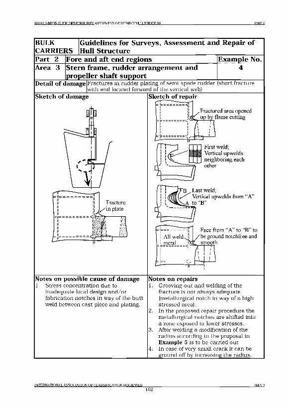
BULK CARRIERS: GLTOlJJNESroRSLIRyEY, ASSESSMENT AND REPA1ROFI-ILILL STRUCTURE PART 2
BULK
CARRIERS
G uidelines for Surveys, A ssessm en t and Repair o f
Hull Structure
Part 2 Fore and aft end regions
Stern fram e, rudder arrangem ent and
propeller sh aft support
Exam ple No.
Area 3
Detail o f damage Fractures in rudder plating of semi-spade rudder (short fracture with end located forward of the vertical web)___________________
Sketch o f damage Sketch o f repair
.Fractured area opened u|3 by flame cutting
First weld; Vertical upwelds neighboring each other
f Last weld;Vertical upwelds from “A’'
toFace from “A” to “B ^i| /b e ground notchfree and
/ dC _ syiooth
Notes on possible cause o f damage1. Stress concentration due to
inadequate local design and /o r fabrication notches in way of the bu tt weld between cast piece and plating.
Notes on repairs1. Grooving-out and welding of the
fracture is not always adequate (metallurgical notch in way of a high stressed area).In the proposed repair procedure the metallurgical notches are shifted into a zone exposed to lower stresses. After welding a modification of the radius according to the proposal in Example 5 is to be carried out.In case of very small crack it can be ground off by increasing the radius.
2.
3.
4.
INTERNATIONAL ASSOCIATION OF CLASSIFICATION SOCIETIES162
AREA 3

И I К CARRIERS: Gl Ю 1 INI « RPR SI 1RVFY ASSI SSMIN I'ANL) REPAIR OF HI III. STRl XIIIJRI PART 2
GENERAL
CARGO SHIPS
G uid elin es for S urveys, A sse ssm en t and R epair
o f Hull S tru ctu re
Part 2 Fore and a ft en d reg ion s E xam ple No.
Area 3 S tern fram e, rudder arrangem ent and
propeller sh a ft supportDetail o f damage Fractures in rudder plating of semi-spade rudder extending beyond
the vertical webSketch o f damage Sketch o f repair
according to local detail
Notes on possible cause o f damage1. Stress concentration due to
inadequate local design and/or fabrication notches in way of the butt weld between cast piece and plating.
Notes on repairs1. Fractured plating is to be cut-out.2. Internal structures are to be checked.3. Cut-out is to be closed by an insert
plating according to the sketch (welding only from one side is demonstrated).
4. Modification of the radius.5. In case of a new cast piece, connection
with the plating is to be shifted outside the high stress area.
INTERNATIONAL ASSOCIATION OF CLASSIFICATION SOCIFTIF,S163
AREA 3
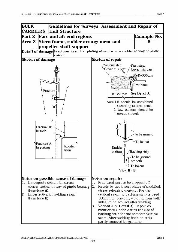
BULK CARRIERS: GUDEUNFS TORSI IRVEY. ASSESSMENT AND REPAIR OF HI Д J „STM 1СП ]RF, PART 2
BULK
CARRIERS
G uidelines for Surveys, A sse ssm en t and R epair o f
Hull S tructure
Part 2 Fore and aft en d reg ion s E xam ple No.
Area 3 S tern fram e, rudder arrangem ent and
propeller sh a ft support
6
Detail o f damage F ractures in rudder plating of sem i-spade rudder in way of pintle cu tou t
Sketch o f repairSketch o f damage'Second step; \£over this p^rt
/First step; Cover this part
R=350mm See Detail A' - ^ y ^ 1-----------1
Note:l.R should be considered according to local detail
2.New contour should be ground smooth
To be ground
~To be cut
Rudder -iplating /B acking strip
^ т ^ Т о be ground J £ smooth
To be cut View В - В
Notes on possible cause o f damageInadequate design for stress concentration in way of pintle bearing (Fracture A).Imperfection in welding seam (Fracture B).
2 .
Notes on repairs1. F ractured part to be cropped off.2. Repair by two insert plates of modified,
stress releasing contour. For the vertical seam no backing strip is used 100mm off contour, welding from both sides, to be ground after welding.
3. V ariant (See Detail A): Repair asm entioned under 2 with the use of backing strip for the compete vertical seam. After welding backing strip partly removed by grinding.___________
INTERNATIONAL ASSOCIATION O F CLASSIFICATION SOCIETIES164
AREA 3
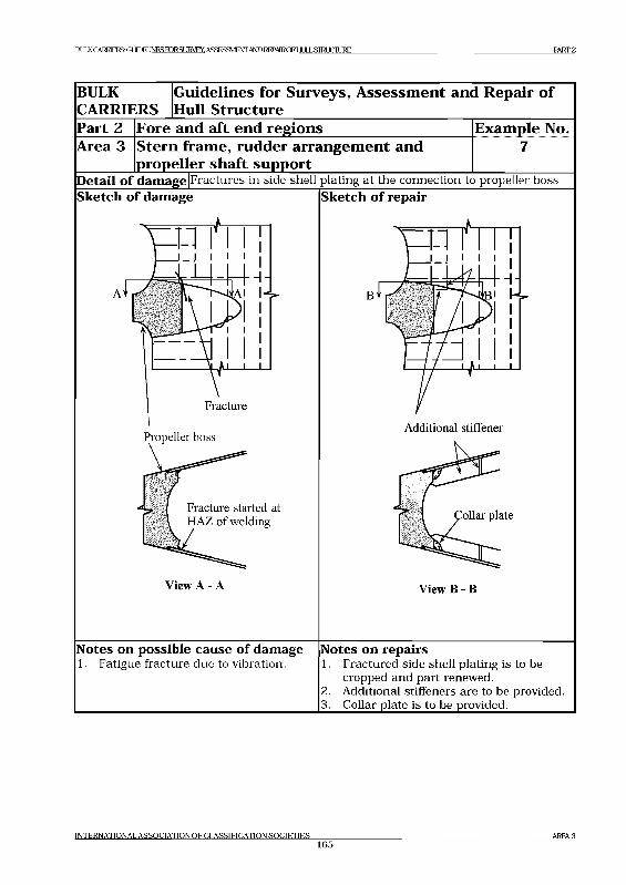
EiLILKCAERD^KSGLEElJNESroRSLIRyEY, ASSESSMENTAND REPAIROFI-IULL STRUCTURE PART 2
BULKCARRIERS
G uidelines for Surveys, A ssessm ent and Repair o f Hull Structure
Part 2 Fore and aft end regionsЖ. .ЖЖ-Д. ж. ж. Ж-ж. ж
Stern frame, rudder arrangem ent and propeller shaft support
Example No.Area 3
Detail o f da*Tmge|Fractures jn side shell plating at the connection to propeller boss Sketch o f damage Sketch o f repair
Notes on possible cause o f damage1. Fatigue fracture due to vibration.
Notes on repairs1. Fractured side shell plating is to be
cropped and part renewed.2. Additional stiffeners are to be provided.3. Collar plate is to be provided._________
INTERNATIONAL ASSOCIATION OF CLASSIFICATION SOCIETIES165
AREA 3
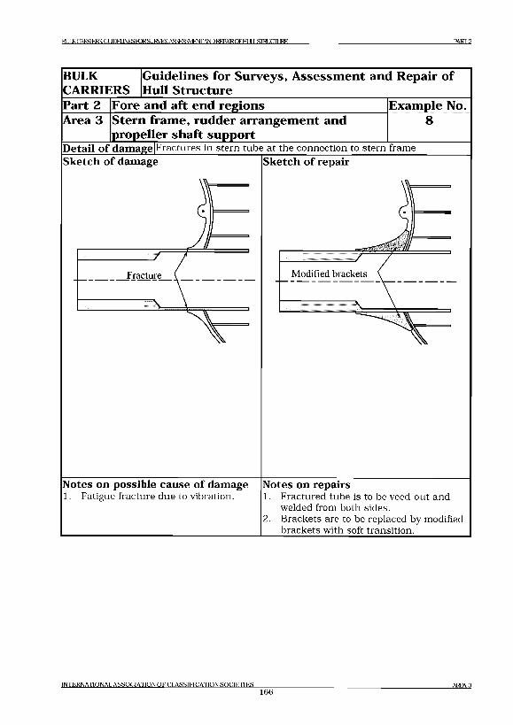
BULKCARRlERS:GUDEUNESroRSURVEY, ASSESSMENT AND REPAIROFHULLSIRLJCIURE PART 2
BULK
CARRIERSG uidelines for Surveys, A ssessm en t and Repair o f
Hull Structure
Part 2 Fore and aft end regions Exam ple No.
Area 3 S tern fram e, rudder arrangem ent and
propeller sh a ft support8
Detail o f dam agejFractures in stern tube at the connection to stern frame Sketch o f damage Sketch o f repair
Notes on possible cause o f damage1. Fatigue fracture due to vibration.
Notes on repairs1. Fractured tube is to be veed-out and
welded from both sides.Brackets are to be replaced by modified brackets with soft transition.
INTERNATIONAL ASSOCIATION O F CLASSIFICATION SOCIETIES166
A R E A 3
1ACS GENERAL CARX) SHIPS GU1DE11NES FDR SURVEY. ASSESSMENT AND REPMRCFHULLSIRLJCnjRE PART 3
Part 3 Machinery and accommodation spaces
C ontents
Area 1 Engine room structure Area 2 Accommodation structure
Area 1 Engine room structure
C ontents
1 General
2 What to look for - Engine room inspection2.1 Material wastage
2.2 Fractures
3 What to look for - Tank inspection3.1 Material wastage
3.2 Fractures
4 General comments on repair4.1 Material wastage
4.2 Fractures
Exam ples ol* structural detail failures and repairs - Area 1Example No. Title
1 Fractures in brackets a t main engine foundation2 Corrosion in bottom plating under sounding pipe in way of
bilge storage tank3 Corrosion in bottom plating under inlet/suction pipe in way of
bilge storage tank
INTERNATIONAL A SS O C IA TIO N O F C LA SSIFIC A TIO N SO C IE T IE S
167A R EA 1
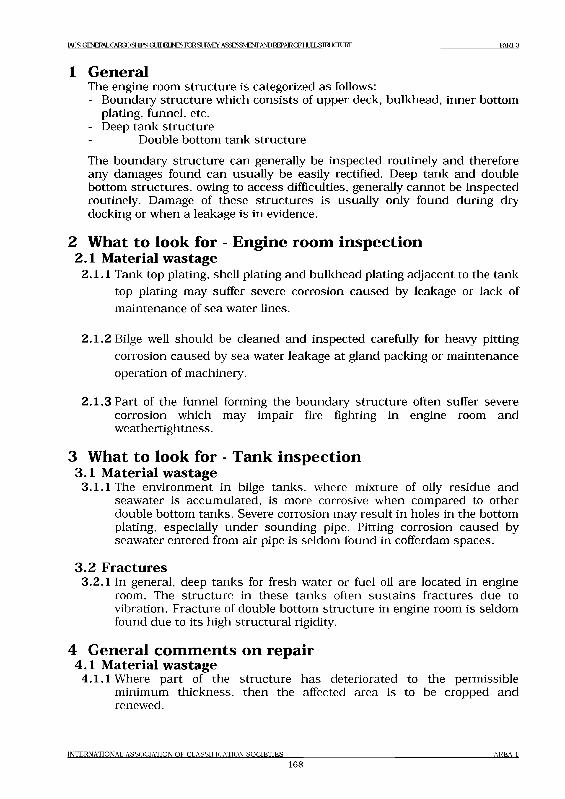
1ACS GENERAL CARX) SHIPS GU1DE11NES FDR SURVEY. ASSESSMENT AND REPA1ROF HULL SIRLOLIFE MRT3
1 GeneralThe engine room structu re is categorized as follows:- Boundary structu re which consists of upper deck, bulkhead, inner bottom
plating, funnel, etc.- Deep tank structure
Double bottom tank structure
The boundary structu re can generally be inspected routinely and therefore any damages found can usually be easily rectified. Deep tank and double bottom structures, owing to access difficulties, generally cannot be inspected routinely. Damage of these structu res is usually only found during dry docking or when a leakage is in evidence.
2 What to look for - Engine room inspection2.1 Material w astage
2.1.1 Tank top plating, shell plating and bulkhead plating adjacent to the tank
top plating may suffer severe corrosion caused by leakage or lack of
m aintenance of sea water lines.
2 .1 .2 Bilge well should be cleaned and inspected carefully for heavy pitting
corrosion caused by sea water leakage a t gland packing or m aintenance
operation of machinery.
2 .1 .3 Part of the funnel forming the boundary structu re often suffer severe corrosion which may impair fire fighting in engine room and w eathertightness.
3 What to look for - Tank inspection3.1 Material w astage
3.1.1 The environment in bilge tanks, where mixture of oily residue and seawater is accum ulated, is more corrosive when compared to other double bottom tanks. Severe corrosion may result in holes in the bottom plating, especially under sounding pipe. Pitting corrosion caused by seawater entered from air pipe is seldom found in cofferdam spaces.
3 .2 Fractures3.2.1 In general, deep tanks for fresh water or fuel oil are located in engine
room. The structure in these tanks often susta ins fractures due to vibration. Fracture of double bottom structure in engine room is seldom found due to its high structural rigidity.
4 General comments on repair4.1 Material w astage
4.1.1 Where part of the structure has deteriorated to the permissible minimum thickness, then the affected area is to be cropped and renewed.
INTERNATIONAL A SS O C IA TIO N O F C LA SSIFIC A TIO N SO C IE T IE S
168a r e a i

IACS GENERAL CARGO SJSGlJDEIlNESroRSURVlSY.ASSES3VIE№ AND REPMROFHULL STOUCIURE PART 3
Repair work in double bottom will require careful planning in term s of accessibility and gas freeing is required for repair work in fuel oil tanks.
4 .2 Fractures4.2.1 For fatigue fractures caused by vibration, in additional to the normal
repair of the fractures, consideration should be given to modification of the natu ral frequency of the structu re to avoid resonance. This may be achieved by providing additional structu ral reinforcement, however, in m any cases, a num ber of tentative tests may be required to reach the desired solution.
INTERNATIONAL A SS O C IA TIO N O F C LA SSIFIC A TIO N SO C IE T IE S
169A R EA 1
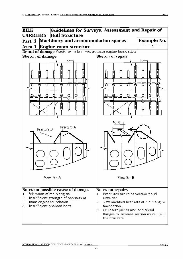
IACS GFNFRM CARX) SHIPS: G HTHINFSPDRSIIRVFY ASSESSMENTANDRFPAIROFHIЛ LSIKLOIJRE PART .4
BILK
CARRIERSGuidelines for Surveys, Assessment and Repair of Hull Structure
Part 3 Machinery and accommodation spaces Example No.Area 1 Engine room structure 1Detail o f damage F ractu res in brackets a t m ain engine foundation
Sketch o f damage Sketch o f repair
Notes on possible cause o f damage1. V ibration of m ain engine.2. Insufficient s treng th of b rackets a t
m ain engine foundation.3. Insufficient pre-load bolts.
Notes on repairs1. F ractu res are to be veed-out and
rewelded.2. New modified b rackets a t m ain engine
foundation.3. Or in sert pieces and additional
flanges to increase section m odulus of the brackets.
INTERNATIONAL ASSOCIATION OF CLASSIFICATION SOCIETIES
170
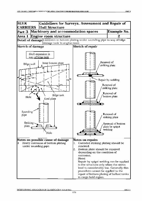
TAGS GENERAL CARGO SHIPS: GUIDELINES TOR St IRVEY. ASSESSMENT AND RFPAIR OF HI 1LSIRLOURE PART 3
BULK
CARRIERS
G uidelines for Surveys, A sse ssm en t and R epair o f
Hull S tructure
Part 3 M achinery and a cco m m o d a tio n sp a ces E xam ple No.
Area 1 E ngine room stru ctu reDetail of damage Corrosion in bottom plating under sounding pipe in way of bilge
storage tank in engine room________________________________Sketch of damage
Shell expansion in wav of bilge tank
Bilge well Inner bottom plate
Bilge tank „ Keel plate
r-USounding " pipe
Striking ■ plate
Hole
Sketch of repair
Renewal of striking plate
Repair by welding
Renewal of striking plate
Renewal of bottom plate
Renewal of striking plate
Renewal of bottom plate by spigot welding
Notes on possible cause of damage1. Heavy corrosion of bottom plating
under sounding pipe.
Notes on repairs1. Corroded striking plating should be
renewed.2. Bottom plate should be repaired
depending on the condition of corrosion.(Note)Repair by spigot welding can be applied to the structure only when the stress level is considerably low. Generally this procedure cannot be applied to the repair of bottom plating of ballast tanks in cargo hold region._________________
INTERNATIONAL ASSOCIATION OF CLASSIFICATION SOCIETIES
171AREA 1
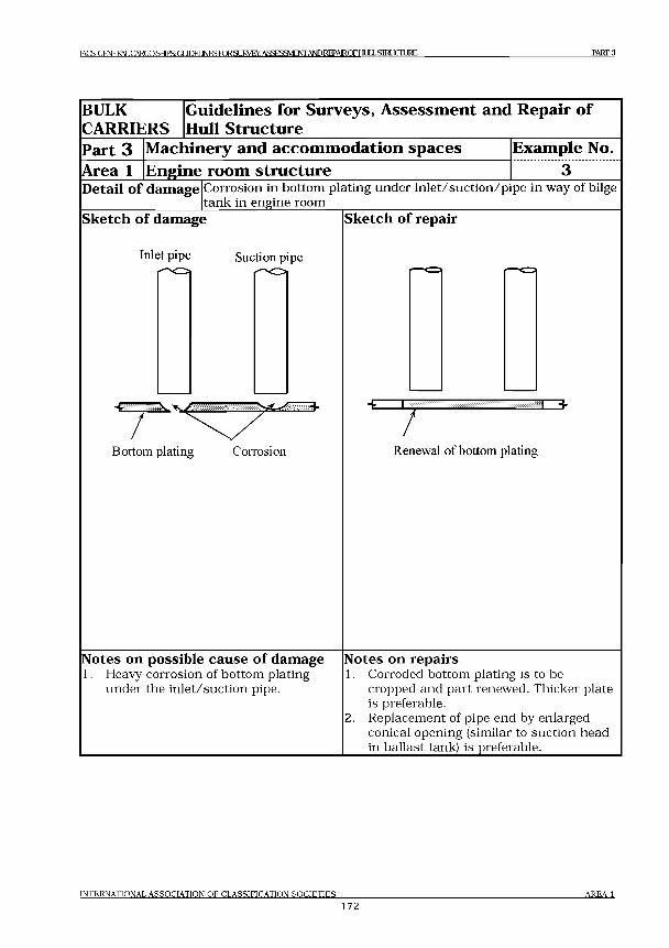
IACS GENERAL CARGO SHIPS: Gt 1Ш INFS FOR.4 1RVFY. ASSESSMENTANDRFPAIROFHULLSIKLOLIRE MRT3
BULK
CARRIERS
G u id e lin es for S u rv ey s, A sse s sm e n t and R epair o f
H ull S tru c tu re
Part 3
Area 1
M ach in ery and a c c o m m o d a tio n sp a c e s
E n g in e room str u c tu r e
E xam p le No.
Detail of damage Corrosion in bottom plating under in let/suction /p ipe in way of bilge tank in engine room
Sketch of damage
Inlet pipe Suction pipe
Bottom plating Corrosion
Sketch of repair
Ч- l
7E 3
Renewal of bottom plating
Notes on possible cause of damage1. Heavy corrosion of bottom plating
under the in let/suction pipe.
Notes on repairs1. Corroded bottom plating is to be
cropped and part renewed. Thicker plate is preferable.
2. Replacement of pipe end by enlargedconical opening (similar to suction head in ballast tank) is preferable.___________
INTERNATIONAL ASSOCIATION OF CLASSIFICATION SOCIETIES
172AREA 1
IACS GENERALCARXIMS: GUIDELINESroRSLIRVEY.ASSESaVIENrANDREPMROFHULLSroUCIURE PART 3
Area 2 Accommodation structure
Contents
1 General
Figures and/or Photographs - Area 1No. T itle
Photograph 1 Corroded accommodation house side structure
INTERNATIONAL ASSOCIATION OF CLASSIFICATION SOCIETIES AREA 2173
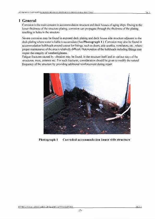
IACS GENERAL CARGO SHIPS: GIЮЕГ .TNESFORSURVEY. ASSESSMENT AND REPAIRCF HULL STRUCTURE Part 3
1 GeneralCorrosion is the main concern in accommodation structure and deck houses of aging ships. Owing to the lesser thickness of the structure plating, corrosion can propagate through the thickness of the plating resulting in holes in the structure.
Severe corrosion may be found in exposed deck plating and deck house side structure adjacent to the deck plating where water is liable to accumulate (See Photograph 1 ). Corrosion may also be found in accommodation bulkheads around cutout for fittings, such as doors, side scuttles, ventilators, etc., where proper maintenance of the area is relatively difficult. Deterioration of the bulkheads including fittings may impair the integrity of weathertightness.Fatigue fractures caused by vibration may be found, in the structure itself and in various stays of the structures, mast, antenna etc. For such fractures, consideration should be given to modify the natural frequency of the structure by providing additional reinforcement during repair.
Photograph 1 Corroded accomm odation house side structure
INTERNATIONAL ASSOCIATION OF CLASSIFICATION SOCIETIES A R E A 2
174

No. 96
No.96(Apr 2007)
(Rev.1 Mav 2019')
Double Hull Oil Tankers - Guidelines for Surveys
Assessment and Repair of Hull Structures
IACS Rec. 2019

No. 96
IACSINTERNATIONAL ASSOCIATION OF CLASSIFICATION SOCIETIES
DOUBLE HULL OIL TANKERS
Guidelines for Surveys, Assessment and Repair of Hull Structures
IACS Rec. 2019
No. 96
Copyright© IACS - the International Association of Classification Societies and the International Association of Classification Societies Limited, 2007.
All rights reserved.
Except as permitted undercurrent English legislation no part o f this work may be photocopied, stored in a retrieval system, published, performed in public, adapted, broadcast, transmitted, recorded or reproduced in any form or by means, w ithout prior permission o f the copyright owner.
Where IACS has granted written permission for any part o f this publication to be quoted such quotation must include acknowledgement to IACS.
Enquiries should be addressed to the Permanent Secretary:
International Association o f Classification Societies Ltd,36 Broadway London, SW1H OBH Telephone: 020 7976 0660 Fax: 020 7808 1100Email: [email protected]
Terms and Conditions
The International Association o f Classification Societies (IACS), its Member Societies and IACS Ltd. and their directors, officers, members, employees and agents (on behalf o f whom this notice is issued) shall be under no liability or responsibility in contract or negligence or otherwise howsoeverto any person in respect o f any information or advice expressly or impliedly given in this document, or in respect of any inaccuracy herein or omission herefrom or in respect o f any act or omission which has caused or contributed to this document being issued with the information or advice it contains (if any). Without derogating from the generality o f the foregoing, neither the International Association o f Classification Societies (IACS) nor IACS Ltd. nor its Member Societies nor their directors, officers, members, employees or agents shall be liable in contract or negligence or otherwise howsoever for any direct, indirect or consequential loss to any person caused by or arising from any information, advice, inaccuracy or omission given or contained herein or any act or omission causing or contributing to any such information, advice, inaccuracy or omission given or contained herein.
Any dispute concerning the provision o f material herein is subject to the exclusive jurisdiction o f the English courts and will be governed by English Law.
Note: Cover photo used with the kind permission o f Novoship___________________________________
IACS Rec. 2019
DOUBLE HX ILT KEI QUEELJNESICR9JRVEYSA££ESMjNrANDEEPAlROFHLILLSIRLUrUI ES
Contents
1 Introduction
2 Classification survey requirements2.1 General2.2 Annual Surveys2.3 Intermediate Surveys2.4 Special Surveys2.5 Drydocking (Bottom) Surveys2.6 Damage and Repair Surveys
3 Technical background for surveys3.1 General3.2 Definitions3.3 Structural Load Descriptions3.4 Structural defects, damages and deterioration3.5 Structural detail failures and repairs
4 Survey planning, preparation and execution4.1 General4.2 Survey Programme4.3 Survey Planning Meeting4.4 Conditions for survey4.5 Access arrangement and safety4.6 Use of Boats and Rafts4.7 Personal equipment4.8 Thickness measurement and fracture detection4.9 Survey at sea or at anchorage4.10 Documentation on board4.11 Reporting and Evaluation of Survey
5 Structural detail failures and repairs5.1 General5.2 Actions to be taken by the Classification Society when Fatigue Failures have
been Identified5.3 Catalogue of structural detail failures and repairs
1 Bilge Hopper2 Wing Ballast Tank3 Bottom Ballast Tank4 Web Frames in Cargo Tanks5 Transverse Bulkhead in Cargo Tank6 Deck Structure7 Fore and Aft End Regions8 Machinery and Accommodation Spaces
INTER NA TION A L ASSOC IA TIO N O FCT, A RRTFTC ATTON SO C IETIES
CO N T E N T S
1
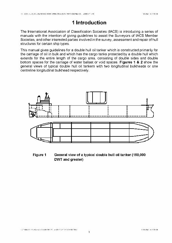
D Q LBIEH LILQ ILTi^K ERSa У Т Р Е Т INFSTORSLKVEYS A S a S S V lE N rA N D R E P A R O F IO X S ^ C IU ^ 1 IN T R O D U C T IO N
1 IntroductionThe International Association of Classification Societies (IACS) is introducing a series of manuals with the intention of giving guidelines to assist the Surveyors of IACS Member Societies, and other interested parties involved in the survey, assessment and repair of hull structures for certain ship types.
This manual gives guidelines for a double hull oil tanker which is constructed primarily for the carriage of oil in bulk and which has the cargo tanks protected by a double hull which extends for the entire length of the cargo area, consisting of double sides and double bottom spaces for the carriage of water ballast or void spaces. Figures 1 & 2 show the general views of typical double hull oil tankers with two longitudinal bulkheads or one centreline longitudinal bulkhead respectively.
Figure 1 General view of a typical double hull oil tanker (150,000
DWT and greater)
IN T E R N A T IO N A L A SS O C IA T IO N O F C L A S S IF IC A T IO N S O C IE T IE S
1IN T R O D U C T IO N
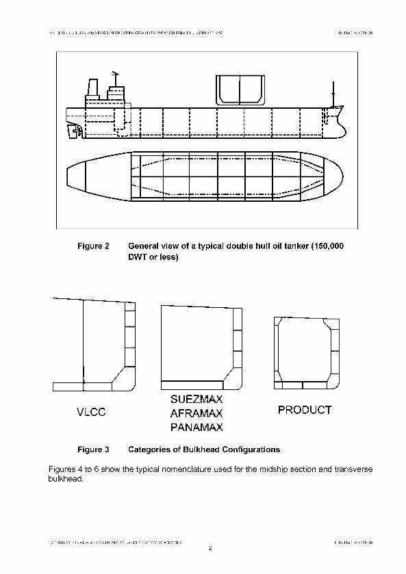
DQLBIEHLILQILTi^KERSa УЮЕГINFSTORSURVEYS ASasgVENTA^I^AtROFHIXLS^CIURES 1 INTRODUCTION
Figure 2 General view of a typical double hull oil tanker (150,000
DWT or less)
SUE2MAXVLCC AFRAMAX PRODUCT
PANAMAX
Figure 3 Categories of Bulkhead Configurations
Figures 4 to 6 show the typical nom enclature used fo r the m idship section and transverse bulkhead.
INTERNATIONAL ASSOCIATIONOFCLASSIFICATION SOCIETIES2
1 INTRODUCTION
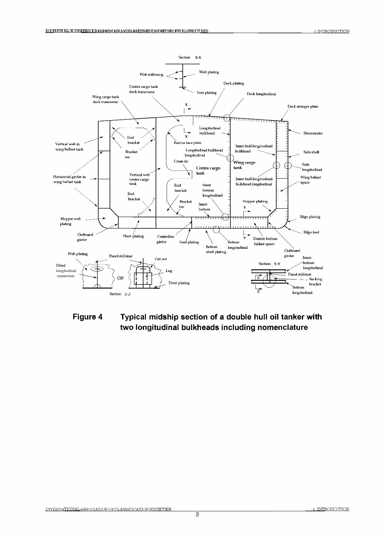
ГО 1ВГЕНГ ЛХ(Ж^ТАЬЖЕ1 (Х1ШРТ]ЫРЯТ018иЕ1УЕта.ДЯ^Г?:Я^РЖ ANDTMWRQPHT ¥ J ЯШГ TTTITJRES 1 INTRODUCTION
Section X-X
Web stiffening
Centre cargo tank deck transverse
Wing cargo tank deck transverse
Vertical web in wing ballast tank
Horizontal girder in wing ballast tank
Hopper web plating
Web plating
Face plating
Deck plating
Deck longitudinal
Longitudinal bulkhead longitudinal
Cross tie
Deck stringer plate
Longitudinal bulkhead
Centre cargo tank
Inner bottom longitudinal
Inner bottom
i i i i'N i i i i i M
M ) I I I I l'- ' Г М I I I
Inner hull longitudinal bulkhead
Cl)w .Wing cargo tank
Inner hull longitudinal bulkhead longitudinal
Sheerstrake
Side shell
Sidelongitudinal
Wing ballast space
Hopper plating Y
Outboardgirder
Web plating
Floor plating
Fittedlongitudinalconnection
Panel stiffener
OR
Section Z-Z
Centrelinegirder Keel plating
Cut out
Bottom longitudinal shell plating Outboard
^Аег InnerSection Y-Y /^bottom
longitudinalPanel stiffener
------ Backingbracket
Bottom longitudinal
-
Figure 4 Typical midship section of a double hull oil tanker withtwo longitudinal bulkheads including nomenclature
INTERNATIONAL ASSOCIATIONOFCLASSIFICATION SOCIETIES3
1 INTRODUCTION
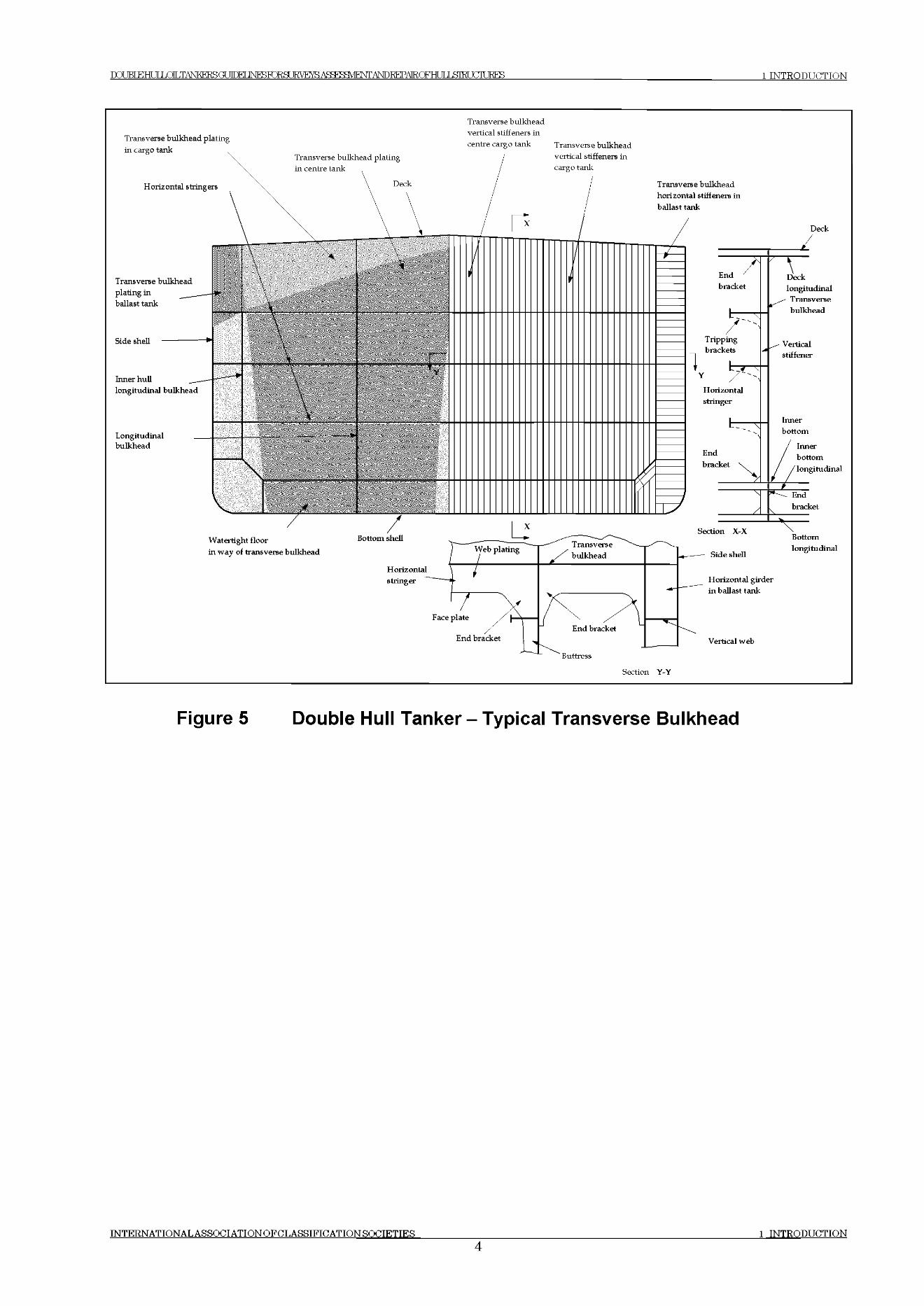
DQLBIEHLILQILTi^KERSa ЛПЕГ JNFKTORSLIRVE^AS^MENri^DREPAIRQFHLILSIEUaiURES 1 INTRODT JCTTON
Transverse bulkhead
Figure 5 Double Hull Tanker-Typ ical Transverse Bulkhead
INTERNATTONAL ASSOCIATION OFCLASSTFTCATION SOCIETIES 1 INTRODUCTION
4
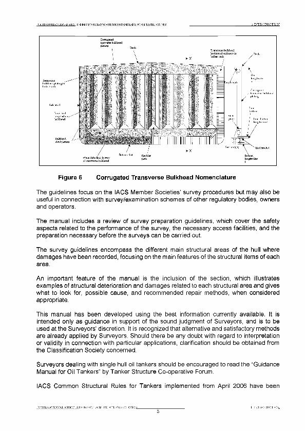
1 IN T R O D U C T IO NDQLBIEHULLQILT^KEESGUTrKr INFSTORSURVEYS ASEESSVTENT ANDREPAtROFH ТГ ,T ,STRI KTTURES
Transverse bulkhead plating u ballast tank
Corrugated tranverse bulkhead plating
Corrugatednsverse bulkhead
plating
Bottom shell Shedder Watertight floor in way plateof transverse bulkhead
Figure 6 Corrugated Transverse Bulkhead Nomenclature
The guidelines focus on the IACS Member Societies’ survey procedures but may also be useful in connection with survey/examination schemes of other regulatory bodies, owners and operators.
The manual includes a review of survey preparation guidelines, which cover the safety aspects related to the performance of the survey, the necessary access facilities, and the preparation necessary before the surveys can be carried out.
The survey guidelines encompass the different main structural areas of the hull where damages have been recorded, focusing on the main features of the structural items of each area.
An important feature of the manual is the inclusion of the section, which illustrates examples of structural deterioration and damages related to each structural area and gives what to look for, possible cause, and recommended repair methods, when considered appropriate.
This manual has been developed using the best information currently available. It is intended only as guidance in support of the sound judgment of Surveyors, and is to be used at the Surveyors' discretion. It is recognized that alternative and satisfactory methods are already applied by Surveyors. Should there be any doubt with regard to interpretation or validity in connection with particular applications, clarification should be obtained from the Classification Society concerned.
Surveyors dealing with single hull oil tankers should be encouraged to read the “Guidance Manual for Oil Tankers” by Tanker Structure Co-operative Forum.
IACS Common Structural Rules for Tankers implemented from April 2006 have been
IN T E R N A T IO N A L A SS O C IA T IO N O F C L A S S IF IC A T IO N SO C IE T IE S 1 IN T R O D U C T IO N
5

DOT JKTEHT11 ЛОТ .TANKFRRCT ЛПЕГ JNESRIRgUKVE А5Я??:Я^РМГ ANDEEPAtROFHf IT IffTRT FTTURES 1 INTRODUCTION
developed in response to a consistent and persistent call from industry for an increased standard of structural safety. This has been achieved through enhancing the design basis and applying engineering first principles. The development of the CSR for Tankers included review of existing Rules, new development using a first principle approach, application of the net thickness philosophy, an enhanced design environment and a longer life i.e. 25 years North Atlantic. These Rules are applicable to double hull oil tankers exceeding a length of 150 metres.
Note: Throughout this document reference is made to various IACS Unified Requirements (UR), Procedural Requirements (PR) and Recommendations. All URs and PRs and key recommendations are available from the IACS website (http://www.iacs.ora.uk).
IN T E R N A T IO N A L A S S Q C IA T IQ N Q F C L A S S IF IC A T IQ N SO C IE T IE S
61 IN T R O D U C T IO N
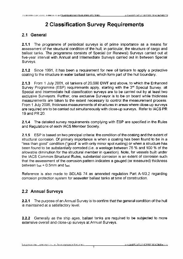
Г О В Т к н и г LOLTANKERSOr Т Г Г К Г INFBFj RH 2 C L A S S IF IC A T IO N SU R V EY R E Q U IR E M E N T S
2 Classification Survey Requirements
2.1 General
2.1.1 The programme of periodical surveys is of prime importance as a means for assessment of the structural condition of the hull, in particular, the structure of cargo and ballast tanks. The programme consists of Special (or Renewal) Surveys carried out at five-year interval with Annual and Intermediate Surveys carried out in between Special Surveys.
2.1.2 Since 1991, it has been a requirement for new oil tankers to apply a protective coating to the structure in water ballast tanks, which form part of the hull boundary.
2.1.3 From 1 July 2001, oil tankers of 20,000 DWT and above, to which the Enhanced Survey Programme (ESP) requirements apply, starting with the 3rd Special Survey, all Special and Intermediate hull classification surveys are to be carried out by at least two exclusive Surveyors. Further, one exclusive Surveyor is to be on board while thickness measurements are taken to the extent necessary to control the measurement process. From 1 July 2005, thickness measurements of structures in areas where close-up surveys are required are to be carried out simultaneously with close-up surveys. Refer to IACS PR 19 and PR 20.
2.1.4 The detailed survey requirements complying with ESP are specified in the Rules and Regulations of each IACS Member Society.
2.1.5 ESP is based on two principal criteria: the condition of the coating and the extent of structural corrosion. Of primary importance is when a coating has been found to be in a “ less than good” condition (“good” is with only minor spot rusting) or when a structure has been found to be s u b stan tia lly corroded (i.e. a wastage between 75 % and 100 % of the allowable diminution for the structural member in question). Note, for vessels built under the IACS Common Structural Rules, substantial corrosion is an extent of corrosion such that the assessment of the corrosion pattern indicates a gauged (or measured) thickness between W + 0.5mm and W
Reference is also made to SOLAS 74 as amended regulation Part A-1/3.2 regarding corrosion protection system for seawater ballast tanks at time of construction.
2.2 Annual Surveys
2.2.1 The purpose of an Annual Survey is to confirm that the general condition of the hull is maintained at a satisfactory level.
2.2.2 Generally as the ship ages, ballast tanks are required to be subjected to more extensive overall and close-up surveys at Annual Surveys.
IN T E R N A T IO N A L A SS O C IA T IO N O F C L A S S IF IC A T IO N ROCTETTES
72 C L A S S IF IC A T IO N SU R V EY R E Q U IR E M E N T S

PqjBI£HU IiX ^TA N K FT^G U nTFI ] Ы Я 1 Ж Ж З и Н У Е т а А Ж Р ? Я Ш Ф Л ,Д 1 ^ 1 С Т А 1 1 Ю К Н и 1 _ Ь 8 Ш У П Ш Е 5 2 C L A S S IF IC A T IO N SU R V E Y R E Q U IR E M E N T S
2.2.3 In addition, a Ballast Tank is to be examined at annual intervals where:a. a hard protective coating has not been applied from the time of construction, orb. a soft coating has been applied, orc. substantial corrosion is found within the tank at a previous survey, ord. the hard protective coating is found to be in less than GOOD condition and the hard
protective coating is not repaired to the satisfaction of the Surveyor at a previous survey.
2.3 Intermediate Surveys
2.3.1 The Intermediate Survey may be held at or between the second or third Annual Survey in each five year Special Survey cycle. Those items, which are additional to the requirements of the Annual Surveys, may be surveyed either at or between the 2nd and 3rd Annual Survey. The intermediate survey contains requirements for extended overall and close-up surveys including thickness measurements of cargo and ballast tanks.
2.3.2 Areas in ballast tanks and cargo tanks found suspect at the previous surveys are subject to overall and close-up surveys, the extent of which becomes progressively more extensive commensurate with the age of the vessel.
2.3.3 For oil tankers exceeding 10 years of age, the requirements of the Intermediate Survey are to be of the same extent as the previous Special Survey. However, pressure testing of cargo and ballast tanks and the requirements for longitudinal strength evaluation of Hull Girder are not required unless deemed necessary by the attending Surveyor.
2.4 Special Surveys
2.4.1 The Special (or Renewal) Surveys of the hull structure are carried out at five-year intervals for the purpose of establishing the condition of the structure to confirm that the structural integrity is satisfactory in accordance with the Classification Requirements, and will remain fit for its intended purpose for another five-year period, subject to proper maintenance and operation of the ship and to periodical surveys carried out at the due dates.
2.4.2 The Special Survey concentrates on close-up surveys in association with thickness measurements and is aimed at detecting fractures, buckling, corrosion and other types of structural deterioration. See Figure 7.
2.4.3 Thickness measurements are to be carried out upon agreement with the Classification Society concerned in conjunction with the Special Survey.
The Special Survey may be commenced at the 4th Annual Survey and be progressed with a view to completion by the 5th anniversary date.
2.4.4 Deteriorated protective coating in le s s th an g o o d condition in salt water ballast spaces and structural areas showing substantial corrosion and/or considered by the Surveyor to be prone to rapid wastage will be recorded for particular attention during the
INTERNATIONA!. ASSOCIATION OF CLASSIFICATION HOCTETTES 2 C L A S S IF IC A T IO N SU R V EY R E Q U IR E M E N T S
Г О В Т к н и г LOLTANKERSOr Т Г Г К Г IM ^ ro R S U E ^ E ^ A S ^ B a V E N T A ^ I^ A E O F H U ]X S im (^ ]R E S 2 C L A S S IF IC A T IO N SU R V EY R E Q U IR E M E N T S
following survey cycle, if not repaired at the special survey.
2.5 Drydocking (Bottom) Surveys
2.5.1 There is to be a minimum of two examinations of the outside of the ship’s bottom and related items during each five-year special survey period. One such examination is to be carried out in conjunction with the special survey. In all cases the interval between any two such examinations is not to exceed 36 months. An extension of examination of the ship’s bottom of 3 months beyond the due date can be granted in exceptional circumstances. Refer to IACS Unified Requirement Z3.
2.5.2 For oil tankers of 15 years of age and over, survey of the outside of the ship’s bottom is to be carried out with the ship in dry dock. For oil tankers less than 15 years of age, alternative surveys of the ship’s bottom not conducted in conjunction with the Special Survey may be carried out with the ship afloat. Survey of the ship afloat is only to be carried out when; the conditions are satisfactorily and the proper equipment and suitably qualified staff are available.
2.6 Damage and repair surveys
2.6.1 Damage surveys are occasional surveys, which are, in general, outside the programme of periodical hull surveys and are requested as a result of hull damage or other defects. It is the responsibility of the owner or owner’s representative to inform the Classification Society concerned when such damage or defect could impair the structural capability or watertight integrity of the hull. The damages should be inspected and assessed by the Society’s Surveyors and the relevant repairs, if needed, are to be performed. In certain cases, depending on the extent, type and location of the damage, permanent repairs may be deferred to coincide with the planned periodical survey.
Any damage in association with wastage over the allowable limits (including buckling,
grooving, detachment or fracture), or extensive areas of wastage over the allowable limits,
which affects or, in the opinion of the Surveyor, will affect the vessel’s structural watertight
or weathertight integrity, is to be promptly and thoroughly repaired. Areas to be considered
to are to include:
- bottom structure and bottom plating;
- side structure and side plating;
- deck structure and deck plating;- watertight or oiltight bulkheads.
2.6.2 In cases of repairs intended to be carried out by riding crew during voyage, the complete procedure of the repair, including all necessary surveys, is to be submitted to and agreed upon by the Classification Society reasonably in advance.
2.6.3 IACS Unified Requirement Z13 “Voyage Repairs and Maintenance” provides useful guidance for repairs to be carried out by a riding crew during a voyage.
IN T E R N A T IO N A L A SS O C IA T IO N O F C L A S S IF IC A T IO N S O C IE T IE S
9Я CT.ASSTFTCATTON SU R V EY R E Q U IR E M E N T S

D(XBIEELILLOE,TANKERSai ШЕГ М ^ГОЕбШ А^БА^^^/Е^ГЖ РЬЕРАЕОРЖ ЕЬ&ТЕЮ СШ КЕБ 2 CLASSIFICATION SURVEY REQUIREMENTS
2.6.4 For locations of survey where adequate repair facilities are not available, consideration may be given to allow the vessel to proceed directly to a repair facility. This may require discharging the cargo and/or temporary repairs for the intended voyage. A suitable condition of class will be imposed when temporary measures are accepted.
: ;
WlfcM the cat до asea : Two transverse sections. i Ai least one seeniofi should be «■ itbLu 0.?L amidships i
Ail wind and w ater tHaiest tide the]) pl*iinsbetween ballast arid hilly loaded water fine i withai the cargo атта
Selected wind sml w ilcr ягакеЯ side shell planinjjbetween ballast and fiillv loaded water line (outside the eaigo area.
Eaeb deek plate wnnin ike еатцо area.
Figure 7 Example of Transverse Sections of Shell Plating and Main Deck Thickness Measurement Requirements for an oil tanker 15 years of age.
INTERNATIONAL ASSOCIATION OF CLASSIFICATION SOCIETIES10
Я CLASSIFICATION SURVEY REQUIREMENTS
T O TRT FHT ТГ Ю Т Ь Т Ш К Е Е й а 1 Г Г М .TNRSTOSURVEYS A^^VJENTANDREPAIROFHI Я J £ Ш Г Л Т E ES 3 T E C H N IC A L B A C K G R O U N D F O R SU R V EY S
3 Technical Background for Surveys
3.1 General
3.1.1 The purpose of carrying out a structural survey of any tank is to determine the
extent of corrosion wastage and structural defects present in the tank. To help achieve this
and to identify key locations in the tank that might warrant special attention, the Surveyor
should be familiar with the service record of the tank and any historical problems of the
particular vessel or other vessels of a similar class.
An experienced Surveyor will be aware of typical structural defects likely to be
encountered and some knowledge of the contributing factors to corrosion (including the
effectiveness of corrosion control systems) will assist him in assessing the corrosion
patterns he finds.
3.2 Definitions
3.2.1 For clarity of definition and reporting of survey data, it is recommended that standard nomenclature for structural elements be adopted. A typical midship section is illustrated in Figures 4 to 6. These figures show the generally accepted nomenclature.
The terms used in these guidelines are defined as follows:(a) A Ballast Tank is a tank, which is used solely for the carriage of salt water ballast.
(b) A Combined Cargo/Ballast Tank is a tank, which is used for the carriage of cargo,
or ballast water as a routine part of the vessel’s operation and will be treated as a
Ballast Tank. Cargo tanks in which water ballast might be carried only in exceptional
cases per MARPOL 1/13(3) are to be treated as cargo tanks.(c) An Overall Survey is a survey intended to report on the overall condition of the hull
structure and determine the extent of additional Close-up Surveys.(d) A Close-up Survey is a survey where the details of structural components are within
the close visual inspection range of the Surveyor, i.e. normally within reach of hand.(e) A Transverse Section includes all longitudinal members such as plating,
longitudinals and girders at the deck, sides, bottom, inner bottom and longitudinal
bulkheads.
(f) Representative Tanks are those, which are expected to reflect the condition of other
tanks of similar type and service and with similar corrosion prevention systems.
When selecting Representative Tanks account is to be taken of the service and repair
history onboard and identifiable Critical Structural Areas and/or Suspect Areas.
N o te : C ritica l S tru c tu ra l A re a s are locations, which have been identified from calculations
to require monitoring or from the service history of the subject ship or from similar or
sister ships (if available) to be sensitive to cracking, buckling or corrosion, which
would impair the structural integrity of the ship. For additional details refer to Annex I
of IACS Unified Requirement Z10.4.
IN T E R N A T IO N A L A S S O C IA T IO N O F C L A S S IF IC A T IO N S O C IE T IE S
11Я T E C H N IC A L Б А С К О , R O U N D FO R SU R V EY S
TO TRT FHT ТГ Ю Д Л Ж К Е Е й а Ш Е Г M ^R ^SU R V E Y SA CSF1^M^^ANDEEPAIR0FHT ТГ ,Т ,?Ш FTURES 3 T E C H N IC A L B A C K G R O U N D F O R SU R V EY S
(g) Suspect Areas are locations showing Substantial Corrosion and/or are considered by
the Surveyor to be prone to rapid wastage.
(h) Substantial Corrosion is an extent of corrosion such that assessment of corrosion
pattern indicates a wastage in excess of 75% of allowable margins, but within
acceptable limits.
For vessels built under the IACS Common Structural Rules, substantial corrosion is
an extent of corrosion such that the assessment of the corrosion pattern indicates a
gauged (or measured) thickness between W + 0.5mm and W
(i) A Corrosion Prevention System is normally considered a full hard coating. Hard
Protective Coating is usually to be epoxy coating or equivalent. Other coating systems
may be considered acceptable as alternatives provided that they are applied and
maintained in compliance with the manufacturer’s specification.
(j) Coating condition is defined as follows:
• GOOD condition with only minor spot rusting,
• FAIR condition with local breakdown at edges of stiffeners and weld
connections and/or light rusting over 20% or more of areas under
consideration, but less than as defined for POOR condition,
• POOR condition with general breakdown of coating over 20% or more, or
hard scale at 10% or more, of areas under consideration.
R e fe re n c e is m a d e to IA C S R e c o m m e n d a tio n N o .8 7 “G u id e lin e s fo r C o a tin g
M a in te n a n c e & R e p a irs fo r B a lla s t T a n ks a n d C o m b in e d C a rg o / B a lla s t T a n k s o n O il
T a n k e rs ” w hich co n ta in s c la rification o f th e ab o ve .
(k) Cargo Area is that part of the ship which contains cargo tanks, slop tanks and
cargo/ballast pump-rooms, cofferdams, ballast tanks and void spaces adjacent to
cargo tanks and also deck areas throughout the entire length and breadth of the part
of the ship over the above mentioned spaces.
(l) Special consideration or specially considered (in connection with close-up
surveys and thickness measurements) means sufficient close-up survey and
thickness measurements are to be taken to confirm the actual average condition of
the structure under the coating.
(m) A Prompt and Thorough Repair is a permanent repair completed at the time of
survey to the satisfaction of the Surveyor, therein removing the need for the imposition
of any associated condition of class c lassif ication, or recommendation.
3.3 Structural Load Descriptions
(a) Structural Aspects
A tanker must maintain its structural integrity and water tight envelope when exposed to
internal static and dynamic liquid loads, including sloshing loads, to external hydrostatic
and dynamic sea loads, and to longitudinal hull girder bending. Longitudinally stiffened
plate is typically the primary structure of a tanker. This stiffened plate is supported by web
frames, girders and bulkheads. The hydrostatic and hydrodynamic pressures flow from the
IN T E R N A T IO N A L A S S O C IA T IO N O F C L A S S IF IC A T IO N S O C IE T IE S
123 T E C H N IC A L B A C K G R O U N D F O R SU R V EY S

Г О МЕНЯЮДЛШКЕЕ&ПГУГГКГJM^TORSURVEYS A ^^vIE ^A ^I^A E O FH U lXSIE lJC m R E S 3 T E C H N IC A L B A C K G R O U N D F O R SU R V EY S
plate through the stiffeners into the web frames, girders and bulkheads where they balance
other loads or contribute to accelerations.
Most loads are cyclic with many different frequencies. The cyclic loads affecting fatigue are
described in section 3.4.3. The following describe the loads that the major structural
elements must resist.
(b) Tank Bottom Structures
The bottom structure must resist the axial loads from hull girder bending plus local bending
from cargo, ballast and seawater pressure and structural loads from adjacent tanks. The
hull girder bending loads are generally the highest midships and combine with the
hydrostatic loads to generate the maximum stresses. The hydrostatic loads on the bottom
are the highest in the vessel but are generally varying less than the side shell frame
external wave loads.
(c) Side Shell, Longitudinal and Transverse Bulkheads
The side shell, longitudinal and transverse bulkheads maintain each tank's integrity and
resist hydrostatic pressures as well as internal sloshing and external wave loads. The side
shell and longitudinal bulkheads are also the webs of the hull girder and transmit the shear
loads from tank to tank and along the length of the vessel. These members also contribute
somewhat to resisting the longitudinal bending near the deck and bottom. The transverse
bulkheads transmit the transverse shear loads and maintains the hull girder's form along
with the transverse web frame rings.
The girders, stringers and vertical web frames that support the bulkheads resist bending
and shear loads as they transmit the local pressure loads into the hull girder.
The hydrostatic loading increases linearly with depth and is often balanced with a liquid on
the opposite side of the structure. The wave loading on the ship is cyclic and is the primary
cause of the vessel fatigue, see section 3.4.3.
(d) Deckhead Structures
The main load on the deck is axial due to hull girder bending and transverse due to tank
loading and waves. The axial stresses in the deck are the highest in the vessel as the
upper deck is farthest from the neutral axis. While local loads are generally small on a
tanker deck, equipment foundation loads, green water on deck and sloshing loads must be
considered.
3.4 Structural defects, damages and deterioration
3.4.1 GeneralIn the context of this manual, structural damages and deterioration imply deficiencies
INTERNATIONA!. ASSOCIATION OF CLASSIFICATION HOCTFTTFS13
3 T E C H N IC A L B A C K G R O U N D F O R SU R V E Y S

DOUBLE HLJLLOILTAInKERS О Т Ш К Г JNFSKR9JRШ S^m/Ш Ш Ш )Ш Ш CFmJLl£Ш JJ2JШ ES 3 T E C H N IC A L B A C K G R O U N D F O R SU R V EY S
caused by:- excessive corrosion- design faults- material defects or bad workmanship- weld defects- buckling- fatigue- navigation in extreme weather conditions- loading and unloading operations, water ballast exchange at sea- wear and tear- contact (with quayside, ice, lightering service, touching underwater objects, etc.) but not
as a direct consequence of accidents such as collisions, groundings and fire/explosions.
Deficiencies are normally recognized as:- material wastage- fractures- deformations
The various types of deficiencies and where they may occur are discussed in more detail in subsequent sections.
3.4.2 Structural DefectsStructural defects include weld defects, buckling and fractures, see also 3.4.3 Fatigue.
Fractures initiating at latent defects in welding more commonly appear at the beginning or
end of a run, or rounding corners at the end of a stiffener or at an intersection. Special
attention should be paid to welding at toes of brackets and cut-outs or intersections of
welds. Fractures may also be initiated by undercutting in way of stress concentrations.
Corrosion of welds may be rapid because of the influence of the deposited metal or the
heat affected zone, and this may lead to stress concentrations.
Permanent buckling may arise as a result of overloading, overall reduction in thickness
due to corrosion, or damage. Elastic buckling will not be directly obvious but may be
detected by coating damage, stress lines or shedding of scale.
Some fractures may not be readily visible due to lack of cleanliness, difficulty of access,
poor lighting or compression of the fracture surfaces at the time of survey. It is therefore
important to identify and closely inspect potential problem areas. Fractures will normally
initiate at notches, stress concentrations or weld defects. Where these initiation points are
not apparent on one side, the structure on the other side of the plating should be
examined.
The following areas where structural defects might occur should have special attention at
the survey:
(a) Cargo Tanks
TNTERNAHONAT. ASSOnTATTON OF CT.ASSTFTDATTON НОЛТЕТТЕЯ14
3 TE CH N IC A T . BAOKO,ROUND F O R SU R V E Y S
DCUBIEHUILOILTANKEESa ПГМ JNFSFCRgURVF S AffFF^FNTANDBEPAlRCFHr IJ ЯШТ HTTJRES 3 TECHNICAL BACKGROUND FOR SURVEYS
i. Main deck deckhead: corrosion and fractures.
ii. Buckling in web plate of the underdeck web frame and fractures at end of bracket
toes.
iii. Transverse bulkhead horizontal stringers: fractures in way of cut-outs and at end
bracket toe connections to inner hull and longitudinal bulkhead.
iv. Longitudinal bulkhead transverse web frames: fractures at end bracket toe
connection to inner bottom.
v. Necking effect of longitudinal web plating at longitudinal bulkhead plating.
vi. For plane transverse bulkheads, transverse bulkhead vertical stiffeners connected
to inner bottom: for vertically corrugated bulkheads, corrugation connection to
lower shelf plate and bulkhead plating connection to inner bottom: fractures caused
by misalignment and excessive fit-up gap.
vii. Transverse bulkheads at the forward and after boundaries of the cargo space:
fractures in way of inner bottom.
viii. Pitting and grooving of inner bottom plating.
(b) Double Hull Ballast Spaces
i. Main deck deckhead: corrosion and fractures.
ii. Inner hull plate and stiffener: coating breakdown.
iii. Buckling of the web plate in the upper and lower part of the web frame.
iv. Fractures at the side shell longitudinal connection to web frames due to fatigue.
v. Corrosion and fractures at knuckle joints in inner hull at forward and after parts of
ship.
vi. Corrosion and fractures at the juncture where the sloped inner hull is connected to
the inner bottom.
vii. Fractures at side and inner hull longitudinal connections to transverse bulkheads
due to fatigue and/or high relative deflections.
viii. Inner bottom deckhead corrosion at inner bottom.
ix. Bottom corrosion wastage.
x. Cracks at inner bottom longitudinal connection to double bottom floor web plating.
xi. Fractures at inner bottom and bottom longitudinal; connection to transverse
watertight floor due to high relative defections.
3.4.3 FatigueFatigue is the most common cause of cracking in the structure of large tankers. The cracks
generally develop at structural intersections of structural members or discontinuities where
detailed design has led to a stress raiser such as a hot spot. Other reasons maybe related
to material or welding defects, or some other type of notch.
Fatigue failures are caused by repeated cyclical stresses that individually would not be
sufficient to cause failure but can initiate cracks, in particular in way of built in defects,
which can grow to sufficient size to become significant structural failures. Typical cyclic
loading mechanisms are:
INTERNATIONAL ARROOTATTON OF C!LARRTFTOATTON HOCTETTER15
3 TEOHNTOAT. ВАСКОROUND FOR SURVEYS
ТОМЕНЯЮ1ЬТАЫКЕ1^а JM^RBSURVE^Aca^^FNTAlSDREPAIRCFHri JKirarnO?ES 3 TECHNICAL BACKGROUND FOR SURVEYS
- hull girder wave bending moments and shear forces;- local pressure variation;- cargo or ballast internal pressure variation.
If the crack remains undetected and unrepaired it can grow to a size where it can cause sudden fracture. However, it is unusual for a fatigue crack to lead directly to a catastrophic failure.
Fatigue failures can generally be considered to have three stages:• Initiation• Stable crack growth• Unstable crack growth
In order to develop structural designs that will minimise the amount of fatigue cracking, and ensure that fatigue cracking does not cause a structural failure, it will be necessary to carry out greater investigation of fatigue strength than has traditionally been the case for large tankers.
Fatigue strength can be calculated using 2 methods:• Compare calculated numbers of cyclic stress ranges with established fatigue
criteria (S-N data).• Calculate crack growth rates based on above stress range data and material
properties.
(a) Typical Locations for High Sensitivity to Fatigue Failure
The following areas are considered to be prone to fatigue failure on double hull oil tankers:• Side shell area below the load and ballast waterlines. These areas are subjected to the
highest cycle loading through the ship’s life due to the passage of waves along the side of the ship.
• Deck plating at connection to primary supporting members.• Connection between transverse bulkheads to the upper and lower bulkhead stools.• Connection between lower hopper sloping plating and inner bottom plating.
Where dynamic stresses are prevalent, the use of symmetrical profiles, such as "T” - section, will substantially reduce fatigue damage caused by biaxial bending on asymmetrical profiles.
The fatigue fractures in side longitudinal connections of higher tensile construction in certain single hull VLCCs has now been well documented, and design details in way of these connections to increase fatigue life are now incorporated by many Shipyards as standard in double hull designs.
These details include the incorporation of soft-toed panel stiffeners with either soft-toed
INTERNATIONAL ASSOCIATION OF CLASSIFICATION HOCTETTES16
3 TECHNICAL BACKGROUND FOR SURVEYS
Г О Т В Г Н Н Г ТГ Ю Д . Т А М К Е Е ? Я П Г Т Г П Я Т M^RIRSURVEra.AffTpl3^VtF>niAlsroBEEMlCFHr IJ Я Ш Т Г Ж Ж Е В 8 TECHNICAL BACKGROUND FOR SURVEYS
backing brackets or reversed radii at the heel of the panel stiffener.
It is therefore important that due consideration be given to this detail and other areas of potential problems at the design stage to reduce the risk of fatigue cracking during service.
(b) The Effect of Higher Tensile Steel
The higher yield strength of HTS has enabled a structure to be designed with higher stresses resulting in lighter scantlings. This does, however, also lead to an increase in the dynamic stress range. The fatigue damage is proportional to the stress range cubed, and HTS materials in welded connections have similar fatigue properties as mild steel. Therefore, it follows that the risk of high-cycle fatigue damage may increase for welded HTS connections in tankers when the increased strength capabilities are utilised.
The use of lighter scantlings often leads to higher deflections, which are particularly important at the side shell connections. In some HTS designs it is possible, that the deflections of the side shell web frames may be larger than in Mild Steel designs, due to the ability of the HTS material to accept higher stress levels in combination with structural arrangement such as wider web frame spacing and lack of cross ties. Such deflections add to the stress levels in the longitudinals at the intersections between the longitudinals and the transverse bulkheads, the additions being proportional to the deflections.
The notch toughness properties of all HTS used in the ship are verified by testing whereas mild steel А-grade is not. The notch toughness is an important parameter in the evaluation of resistance to brittle fracture. However, this would not have significant effect on the risk of crack initiation or the stable crack growth, but would have significant effect on the final unstable crack propagation.
The above factors have to be considered when designs of HTS are made, and today it is normal practice to improve the detail design in order to reduce the stress concentrations in areas where calculations show that high dynamic stress levels are expected. The shipside is particularly prone to high-cycle fatigue damage.
The overall effect when the higher strength of HTS is utilized for such locations, can be to significantly increase the risk of fatigue damage. By improving the detail design, it will usually be possible to obtain a fatigue life comparable to that for ordinary mild steel designs.
For locations where cracking is due to low-cycle fatigue, the use of HTS in local details may be very beneficial for the fatigue strength. This is the case for areas, which are subject to large static stress variations due to loading and unloading, such as the connection between the hopper plating and the double bottom plating. For such locations, local details with HTS will experience less plastic strains, and the low cycle fatigue strength therefore be increased compared with mild steel details. Nevertheless it should be
INTRRNATTONAT. ASSOnTATTON OF CT.ASSTFTDATTON НОЛТЕТТЕЯ17
3 TECHNICAL BACKGROUND FOR SURVEYS
DCUBIEHLJILOIT .TANKKRfiOT JITW 1 Ш Ш 1 а Ш Е т А £ № Я М Ш т )Ш Ш 0 Р т ]1 1 3 Ш и 2 й Ш 8 3 TECHNICAL BACKGROUND FOR SURVEYS
checked whether wave induced loads are marginal or not.
3.4.4 Typical Corrosion PatternsIn addition to being familiar with typical structural defects likely to be encountered during a survey, it is necessary to be aware of the various forms and possible locations of corrosion that may occur to the structural members on decks and in tanks.
The main types of corrosion patterns, which may be identified, include the following:
(a) General CorrosionGeneral corrosion appears as non-protective, friable rust, which can occur uniformly on tank internal surfaces that are uncoated. The rust scale continually breaks off, exposing fresh metal to corrosive attack. Thickness loss cannot usually be judged visually until excessive loss has occurred. Failure to remove mill scale during construction of the ship can accelerate corrosion experienced in service. Severe general corrosion in all types of ships, usually characterized by heavy scale accumulation, can lead to extensive steel renewals.
(b) Grooving CorrosionGrooving corrosion is often found in or beside welds, especially in the heat affected zone. This corrosion is sometimes referred to as 'inline pitting attack' and can also occur on vertical members and flush sides of bulkheads in way of flexing. The corrosion is caused by the galvanic current generated from the difference of the metallographic structure between the heat affected zone and base metal. Coating of the welds is generally less effective compared to other areas due to roughness of the surface, which exacerbates the corrosion. Grooving corrosion may lead to stress concentrations and further accelerate the corrosion process. Grooving corrosion may be found in the base material where coating has been scratched or the metal itself has been mechanically damaged. An example of grooving corrosion is shown in Figure 8.
INTERNATIONAL ASSOCIATION OF CLASSIFICATION ROCTETTES18
3 TECHNICAL BACKGROUND FOR SURVEYS
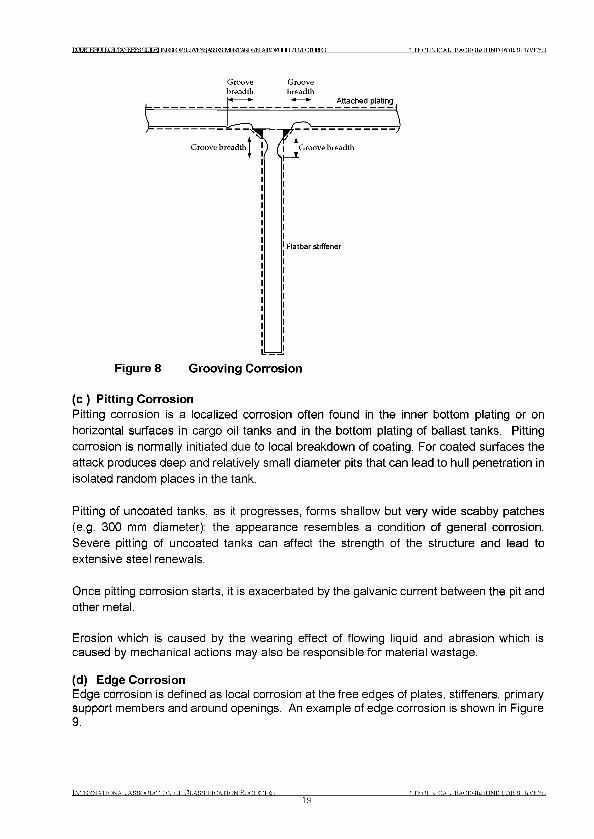
TO JRTEHr LQILTANKEEgaJIDEr JNFKKKaJRVEYSA0? ^ ^ ^ ТГ J ДШГ HTTJRES 3 T E C H N IC A L B A C K G R O U N D F O R SU R V E Y S
Groove Groovebreadth breadth
( c ) Pitting CorrosionPitting corrosion is a localized corrosion often found in the inner bottom plating or on horizontal surfaces in cargo oil tanks and in the bottom plating of ballast tanks. Pitting corrosion is normally initiated due to local breakdown of coating. For coated surfaces the attack produces deep and relatively small diameter pits that can lead to hull penetration in isolated random places in the tank.
Pitting of uncoated tanks, as it progresses, forms shallow but very wide scabby patches (e.g. 300 mm diameter); the appearance resembles a condition of general corrosion. Severe pitting of uncoated tanks can affect the strength of the structure and lead to extensive steel renewals.
Once pitting corrosion starts, it is exacerbated by the galvanic current between the pit and other metal.
Erosion which is caused by the wearing effect of flowing liquid and abrasion which is caused by mechanical actions may also be responsible for material wastage.
(d) Edge CorrosionEdge corrosion is defined as local corrosion at the free edges of plates, stiffeners, primary support members and around openings. An example of edge corrosion is shown in Figure 9.
Tnternattonat. Assootatton o f Ct.asstftoatton Яостеттея19
Я TEOHNTOAT, B A C K G R O U N D F O R SU R V EY S
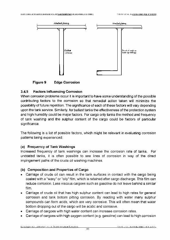
ГО IBT КНГ JTI jQTT,TANKFR>GUfnPT JNFKFORfl JRVRYSASSRF MFI TT ANDKFPATRQFHT IJ ЯП?! HITJRFS 3 T E C H N IC A L BA C K G R O U N D F O R SU R V E Y S
Figure 9 Edge Corrosion
3.4.5 Factors Influencing Corrosion
When corrosion problems occur it is important to have some understanding of the possible contributing factors to the corrosion so that remedial action taken will minimize the possibility of future repetition. The significance of each of these factors will vary depending upon the tank service. Similarly, for ballast tanks the effectiveness of the protection system and high humidity could be major factors. For cargo only tanks the method and frequency of tank washing and the sulphur content of the cargo could be factors of particular significance.
The following is a list of possible factors, which might be relevant in evaluating corrosion patterns being experienced:
(a) Frequency of Tank Washings
Increased frequency of tank washings can increase the corrosion rate of tanks. For uncoated tanks, it is often possible to see lines of corrosion in way of the direct impingement paths of the crude oil washing machines.
(b) Composition and Properties of Cargo
• Carriage of crude oil can result in the tank surfaces in contact with the cargo being coated with a "waxy" or "oily" film, which is retained after cargo discharge. This film can reduce corrosion. Less viscous cargoes such as gasoline do not leave behind a similar film.
• Carriage of crude oil that has high sulphur content can lead to high rates for general corrosion and tank bottom pitting corrosion. By reacting with water many sulphur compounds can form acids, which are very corrosive. This will often mean that water bottom dropping out of the cargo will be acidic and corrosive.
• Carriage of cargoes with high water content can increase corrosion rates.• Carriage of cargoes with high oxygen content (e.g. gasoline) can lead to high corrosion
TNTERNATTONAT. ASSOOTATTON OF CT.ASSTFTOATTON ROfiTETTES20
Я TEOHNTOAT, BACKGROUND FOR SURVEYS
DOUBLE Ht JT J PIT TANKFKSGUIDFl J N F I ^ K g j R V E r a A f f i^ M F ^ A I ^ I M M l C F ^ IT J Я Ш Г Г П Е Е З 3 TECHNICAL BACKGROUND FOR SURVEYS
rates.• Carriage of cargoes with low pH values (acidic) can lead to high corrosion rates.
(c) Time in Ballast
• For ballast tanks where the coating has started to fail, corrosion increases with the time in ballast.
(d) Microbial Induced Corrosion
• Microbial influenced corrosion is the combination of the normal galvanic corrosion processes and the microbial metabolism. The presence of microbial metabolites generates corrosive environments, which promote the normal galvanic corrosion.
• For tanks that remain filled with contaminated ballast water for a long time, the potential for microbial induced corrosion, in the form of grooving or pitting, is increased. The microbes could penetrate pinholes and accelerate the coating breakdown and corrosion in the infected areas. Proper procedures, such as flushing with clean (open sea) salt water, will help reduce the potential for this type of corrosion.
• Cargo oil often contains residual water, which may contain microbes leading to microbial induced corrosion attacks in the tank bottom or other locations where the water may collect.
• Biocide shock treatment to exterminate the microbes is a method that could be used in cargo and ballast tanks. In addition clean water flushing at regular intervals will help reduce the potential of microbial induced corrosion. Proper maintenance of coating integrity, or blasting and coating the uncoated surfaces, would be an effective method to deal with microbial induced corrosion.
(e) Humidity of Empty Tank
Empty tanks, e.g. segregated ballast tanks during laden voyages, can have high humidity and are thus susceptible to general atmospheric corrosion, especially if corrosion control is by anodes which are ineffective during these periods.
During prolonged periods, when the tanks are left empty, such as lay-ups, maintenance of low humidity atmosphere in the tanks should be considered to minimise corrosion.
(f) Temperature of Cargo in Adjacent Bunker or Cargo Tanks
Carriage of heated cargoes may lead to increased general corrosion rates at the ballast tank side of a heated cargo tank/unladen ballast tank bulkhead. This may also apply for tanks adjacent to heated bunker tanks.
(g) Coating Breakdown
Intact coatings prevent corrosion of the steel surface.
However:• A local absence of coating (due to coating depletion, deterioration, damage, etc.) can
TNTERNATTONAT. A SSOnTA TTO N O F CT.ASSTFTDATTON Я О П Т Е Т Т Е Я
21Я Т Е Л Н Ш Л А Т . В А Л К О Т Ю Т Ш П F O R SU R V E Y S

TYIIRTEHT IT LOILTANKEESOJITEr JNFI^^gjRVEraAffi^MF^AI^IMMlCFHr JT J Я П З HTTJRES 3 TECHNICAL BACKGROUND FOR SURVEYS
result in corrosion rates similar or greater than those of unprotected steel.• Holidays or localized breakdown in coating can lead to pitting corrosion rates higher
than for unprotected steel.
Periodic surveys at appropriate intervals and repair of coating as required are effective in minimising corrosion damage.
(h) Locations and Density of Anodes
• Anodes immersed in bottom water can afford protection against bottom corrosion.• Anodes are not effective in reducing underdeck corrosion rates.• Properly designed systems with high current densities may afford greater protection
against corrosion.• Electrical isolation or coatings, oily films, etc., on anodes can make anodes inoperative;
abnormally low wastage rates of anodes may indicate this condition.
(i) Structural Design of Tank
• High velocity drainage effects can lead to increased erosion in the vicinity of cut-outs and some other structural details for uncoated surfaces.
• Horizontal internals and some details can trap water and lead to higher corrosion rates for uncoated surfaces.
• Less rigid designs, such as decreased scantlings and increased stiffener spacing, may lead to increased corrosion due to flexure effects, causing shedding of scale or loss of coating.
• Sloping tank bottoms (e.g. as with double bottom tanks) to facilitate drainage may reduce bottom corrosion by permitting full stripping of bottom waters.
(j) Gas Inerting
• Decreased oxygen content of ullage due to gas inerting may reduce corrosion of overhead surfaces.
• Sulphur oxides from flue gas inerting can lead to accelerated corrosion due to formation of corrosive sulphuric acid.
(k) Navigational Route
• Solar heating of one side of a ship due to the navigational route can lead to increased corrosion of affected wing tanks.
• Anodes used to protect ballast tanks on voyages of short duration may not be effective due to insufficient anode polarisation period when high corrosion may occur.
(l) Accelerated structural corrosion in water ballast and cargo tanks
A limited but significant number of double hull tankers have been found to be suffering from accelerated corrosion in areas of their cargo and ballast tanks. It is now generally agreed that the “thermos bottle effect”, in which heated cargoes retain their loading temperatures for much longer periods, promotes an environment within the cargo and
t n t k r n a tto n a t . As s o c ia t io n o f Cl a s s if ic a t io n s o c ie t ie s
22Д TEOHNTOAT. ВАГЖПВОТШП FOR STTRWYR
IXUBIEHUILOILTANKERSnr Ш Е Г JNF^RЯ9JBШ 5J^№Sam^Ш iШ Ш CFШ JLl^Ш JJJIШ ES 3 T E C H N IC A L B A C K G R O U N D T O R SU R V EY S
ballast tanks that is more aggressive from the viewpoint of corrosion (as temperatures rise, corrosion activity increases - warm humid salt laden atmospheres in ballast tanks, acidic humid conditions in upper cargo tank vapour spaces and warm water and steel eating microbes on cargo tank bottom areas - all factors which promote corrosion).
If corrosion remains undetected during surveys, loss of tank integrity and oil leakage into the double hull spaces may occur (increased pollution and explosion risk). In the worst cases, corrosion can lead to a major structural failure of the hull.
3.4.6 Items for Special Attention of the SurveyorTaking into account all the possible factors, which might be relevant to a particular tank, the Surveyor should pay special attention to the following areas when looking for signs of serious corrosion:• Horizontal surfaces such as bottom plating, face plates and stringers, particularly
towards the after end of the structural element. The wastage may take the form of general corrosion or pitting. Accelerated local corrosion often occurs at the after bays and particularly in way of suctions.
• Deck heads and ullage spaces in uncoated ballast or cargo/ballast tanks (where anodes may not be effective) or non-inerted cargo tanks.
• Structure in way of lightening holes or cut-outs where accelerated corrosion may be experienced due to erosion caused by local drainage and flow patterns. Grooving may also take place on both horizontal and vertical surfaces.
• Areas in way of stress concentrations such as at toes of brackets, ends of stiffeners and around openings.
• Surfaces close to high pressure washing units where localised wastage may occur due to direct jet impingement.
• Bulkhead surfaces in ballast tanks adjacent to heated cargo or bunkers.• Areas in way of local coating breakdown.• One of the most effective means for preventing corrosion is to protect the hull structure
with an efficient coating system. In double hulled tankers, the spaces most at risk from the effects of corrosion are the seawater ballast tanks and the underdeck structure and bottom areas within the cargo oil tanks.
3.4.7 Corrosion Trends in Tank Spaces
Depending on the tank function and location in the tank, some structural components are more susceptible to corrosion than others.
The following are some phenomena of corrosion observed in each type of tank space:
(a) Water Ballast Tank
• Necking occurs at the junction of the longitudinal bulkhead plating and longitudinals. The deflection of the bulkhead plating and longitudinals due to reverse, cyclic loading from cargo oil and water ballast plus the accumulated mixtures of water, mud and scale
INTERNATTONAT. ASSOnTATTON OF CLASSIFICATION НОЛТЕТТЕЯ23
Я ТЕЛНШЛАТ. BAEKOROTIND FOR SURVEYS
ТОМЕНЯЮ1ЬТАЫКЕ1а JMRBRVEAca FNTAlSDiraMlCFHri JKiraxniJRE 3 TECHNICAL BACKGROUND FOR SURVEYS
at their junctures accelerates the corrosion rate. As the steel thins and weakens, the flexing consequently increases and hence corrosion accelerates (see Figure 10). The similar necking effect could also occur in the transverse bulkhead plating and stiffeners, or in the inner bottom plating and longitudinals inside the double bottom space. In the coated water ballast tanks, the plating is the principally affected area due to local corrosion in way of coating failure.
• Corrosion reduces not only the strength capability but also the stiffness (to resist the deflection) of the structural components as corrosion progresses during tanker ageing. The deflection tends to crack the hard scale formation on the steel surface and to expose the fresh steel to the water. Since the loading on corroded structural components remains unchanged, as the structure becomes weaker, the deflection becomes larger and the corrosion rate accelerates.
• For partially filled ballast tanks, the water level is constantly surging in the splash zone due to the ship motions. This accelerates coating breakdown in coated ballast tanks.
• If the intake ballast water is contaminated, the lower part of the ballast tank and bottom plating in particular, might be subjected to microbial influenced corrosion, particularly in the stagnant zone due to poor drainage and mud accumulation. The by-products released by the growing sulphate reducing bacteria can be acidic, which may penetrate and destroy coating, leading to accelerated corrosion in the infected areas.
(b) Cargo Oil TanksResidual water settling out from cargo oil can cause the pitting and grooving corrosion in the upper surface of horizontal structural components particularly on the inner bottom plating at the aft end of tanks where water accumulates due to the ship's normal trimming by the stern. In cases where the inner bottom plating has been protected with a hard coating, local breakdown of this barrier coating can lead to accelerated pitting corrosion where residual water has been lying.
Pitting corrosion to the inner bottom plating within cargo tanks can lead to cargo leakage into the double bottom spaces (giving increased risk of explosion and pollution during ballasting operations) whilst corrosion to the under deck structure within the cargo tank area can lead to a reduction in longitudinal strength which gives rise to the possibility of a more serious structural failure occurring.
One of the best methods of preventing corrosion within these spaces is that protective coatings be applied to the underdeck and inner bottom plating areas. In addition to protecting the steel structure in these areas, this measure would also enable easier and more effective surveys and surveys to be carried out ‘in service’.
IN T E R N A T IO N A L A S S O C IA T IO N O F C L A S S IF IC A T IO N S O C IE T IE S
24Я T E C H N IC A L BACK C,RO UN D FO R SU R V E Y S
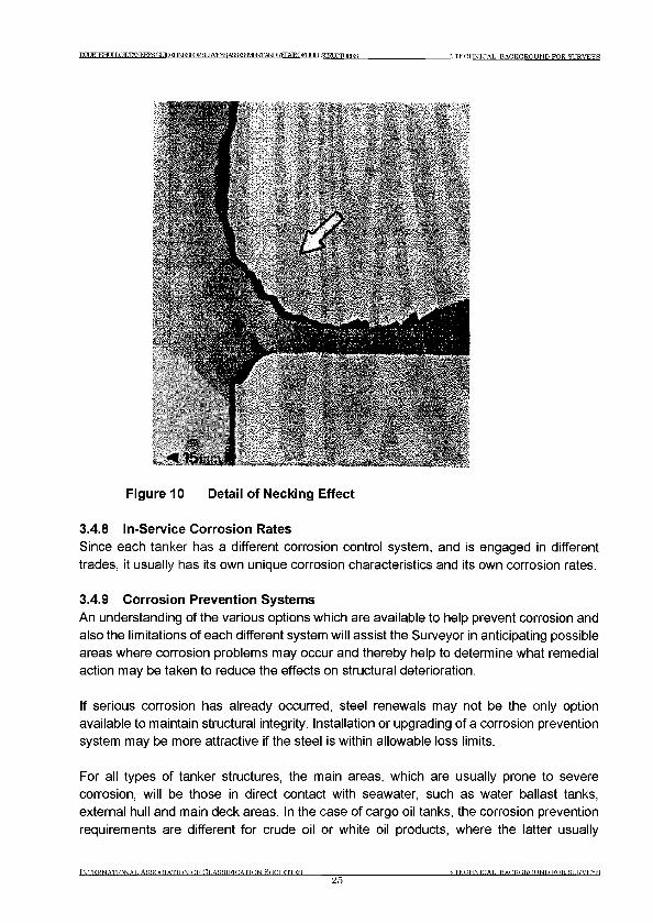
TYIIRTEHT IT LOE,TANKEESGUinFI JNFI^KgjRVEraAffi^MFlxrrANnTM^AIRCyHr ТГ J Я Ш Т Г Т [ JRFS 3 TECHNICAL BACKGROUND FOR SURVEYS
Figure 10 Detail of Necking Effect
3.4.8 In-Service Corrosion Rates
Since each tanker has a different corrosion control system, and is engaged in different trades, it usually has its own unique corrosion characteristics and its own corrosion rates.
3.4.9 Corrosion Prevention Systems
An understanding of the various options which are available to help prevent corrosion and also the limitations of each different system will assist the Surveyor in anticipating possible areas where corrosion problems may occur and thereby help to determine what remedial action may be taken to reduce the effects on structural deterioration.
If serious corrosion has already occurred, steel renewals may not be the only option available to maintain structural integrity. Installation or upgrading of a corrosion prevention system may be more attractive if the steel is within allowable loss limits.
For all types of tanker structures, the main areas, which are usually prone to severe corrosion, will be those in direct contact with seawater, such as water ballast tanks, external hull and main deck areas. In the case of cargo oil tanks, the corrosion prevention requirements are different for crude oil or white oil products, where the latter usually
INTERNATIONAL ASSOCIATION OF CLASSIFICATION HOCTETTES25
3 TECHNICAL ВАСКО,ROUND FOR SURVEYS
T O TRTFHT TTXOILTANKEF^r? Т Г Г И INFSFraSURKEVS A g^m FN TA ^EEPA EO FH U lX SIElX TLIE^ES 3 T E C H N IC A L B A C K G R O U N D F O R SURVEYS
requires full protection of the internal surfaces with a coating system that will be compatible with the cargo being carried and whose main function is to prevent contamination between different grades.
In general, the most common form of corrosion prevention system used in tanker structures will be the application of paint (hard) coatings to either internal or external steel works in various forms to suit the type and extent of prevention required. The basic function of a hard coating, such as paint, is to block access of water and oxygen to the steel structure itself. It follows therefore that its contact with the steel should be as good as practically achievable, i.e. it must be firmly adherent, otherwise there will always be a possibility that rust - hydrated iron oxide - will form beneath the paint and eventually rupture the paint film.
Maintaining this corrosion prevention system throughout the lifespan of the vessel is therefore an important feature in the initial choice of materials and will also be a measure of the continuing structural integrity of the vessel itself.
Potential corrosion of the internal structure in water ballast tanks is by far the most serious aspect of tanker maintenance and the prevention systems normally associated with these spaces can generally be grouped under three categories, i.e.
• Hard coatings (epoxy, vinyl, zinc silicate, bitumastic, etc.);• Soft Coatings;• Cathodic protection (zinc/aluminium anodes) (Note: Not subject to Classification
Surveys).
The following text gives a brief description of each type of system but is not intended as an exhaustive evaluation.
(a) Hard Coatings
The very nature of this form of corrosion prevention system is to form a protective barrier on the steel surface, which will provide a semi-permeable membrane to protect against the elements of corrosion. Any subsequent breakdown of this 'barrier' will, however, allow the normal corrosion process to take place, and usually at a much more accelerated rate due to the limited surface area being exposed.
This problem is, therefore, very similar to that of local pitting corrosion, where, if early action is not taken, the overall integrity of the structure will be put at risk.
Further increases in the extent of breakdown of this 'barrier' will, however, reach a stage where the system is no longer considered effective and general corrosion of the structure is taking place.
If properly applied on blast-cleaned surfaces, recognised coating types, such as those on
IN T E R N A T IO N A L A S S O C IA T IO N O F (C L A SSIFIC A T IO N S O C IE T IE S
263 T E C H N IC A L B A C K G R O U N D FOR. SU R V EY S
ТОМ ЕН HmiLTANIFa^GUrTraM^raiSURVE^Aca^^FNrAlSDREPAIROPHriJKirarni^ 3 TECHNICAL BACKGROUND FOR SURVEYS
an epoxy basis, should obtain a durability of at least 10 years service life.
Sacrificial type coatings such as inorganic zinc provide 'metal' that is anodic to the steel surface and will protect the steel cathodically.
(b) Soft Coatings
The effectiveness of these types of protective coatings is usually much more difficult to judge, especially those relying on chemical reactions with the steel surface.
By their very nature, the effective life of some of the protection systems is usually restricted to about one to three years only, before further maintenance and touch-up is required. Visual assessment of their existing condition can also be very difficult and somewhat misleading, especially if these have been used to cover-up already severely corroded areas of the structure.
Other typical problems that have been found with the use of soft coatings for ballast tank protection have been in respect to:• Their 'greasy' nature, which makes physical survey very difficult, and may adversely
impact safety.• Their 'oily' base, which can contaminate the discharge of ballast water.• Potential sagging of thick coatings attached to hot surfaces.• Some vegetable based coatings are incompatible with sacrificial anodes.• When exposed to mineral oil, some lanolin-based coatings go into an emulsion state
requiring removal for hot-work or pollution risk.• Soft coatings on horizontal surfaces will be damaged whenever any mucking out of
sediment is carried out in the ballast tank.• In the event of hot-work/welding on the outside or inside of coated plates, careful
removal of the soft coating is necessary to prevent the risk of fires or explosions due to the potential build-up of gas when the coating is heated.
Much of the success with these soft coatings has usually been in connection with void spaces or water ballast tanks where there is a long retention time of the ballast (as in semi-submersibles). However, regular changes of ballast water, as in tanker operations, has the effect of depleting the amount of soft protection on the internal surfaces. For this reason, these protection systems should really be regarded as temporary and should be subjected to more regular and comprehensive thickness gauging and close-up surveys than that considered for hard coatings.
(c) Cathodic Protection (Sacrificial Anodes)
The principle of cathodic protection is to sacrifice the anodes in preference to the surrounding steel structures, and, therefore, relies entirely on these areas being immersed in seawater before this action can take place.
INTERNATTONAT. А Я Я О Л Т А Т Т О Ы OF CLASSIFICATION SOCIETIES27
■A TECHNTCAT. В А Л К О Т Ю Т Ш П FOR SURVEYS
IXUBIEHLJILOILTANKERSnr У Г Г К Г Ш m XL9JH Ш & A S№ SM W № )Ш Ш 0Fm JLLSШ JJ2йШ S 3 TECHNICAL BACKGROUND FOR SURVEYS
Anode material is generally zinc. Other types of materials, for example aluminium, are limited because of the danger of sparks when dropped or struck, although these materials do offer better current output for the same weight. The use of anodes of aluminium have an installation height restriction in cargo tanks equivalent to a potential energy of 275 Joules which effectively limits their use to bottom structure and requires that falling objects do not strike them.
The consumption rates and replacement of depleted anodes will not always be a true indication of the effectiveness of the corrosion protection system. Only regular and comprehensive visual and gauging surveys of the structure will give a correct assessment of effectiveness. Sacrificial anodes used as backup protection to a hard coating system do, however, have the benefit of controlling the accelerated rates of corrosion in way of any breakdown, but, again will only be effective when immersed in seawater. Recoating of any breakdown areas may still be required, but probably at a later date than without these back-up anodes.
(d) Selection of Corrosion Prevention System
The choice of Corrosion Prevention systems for water ballast tanks has, in the past, been determined by either the Shipowner or Shipbuilder. IACS UR Z8 requires coating in ballast tanks on new vessels. The continued effectiveness of these corrosion prevention systems must be monitored throughout the service life of the ship by regular assessment of the condition of the steel structure, which is being protected.
For hard coating prevention systems applied at new building, this thickness determination need only be monitored in way of any localised breakdown where accelerated corrosion of the exposed steel structure may be anticipated.
With soft coatings, semi-hard coatings or sacrificial anodes, more frequent and extensive gauging surveys will be needed to assess the overall wastage rates in these tanks, and will generally be more difficult to survey in the later stages of the ship's service life.
In view of the importance of preserving this structural integrity, effective maintenance programs should be set up from commencement of service to repair and replace the corrosion prevention system as it deteriorates.
3.4.10 FracturesIn most cases fractures are found at locations where stress concentration occurs. Weld defects, flaws, and where lifting fittings used during ship construction are not properly removed are often areas where fractures are found. If fractures occur under repeated stresses, which are below the yielding stress, the fractures are called fatigue fractures. In addition to the cyclic stresses induced by wave forces, fatigue fractures can also result from vibration forces introduced by main engine(s) or propeller(s), especially in the aft part of the hull.
Tn t e r n a h o n a t . Asso c ia tio n o f Ct.asstftcatton Нолтеттея28
Я Т Е Л Н Ш Л А Т , В А Л К О Т Ю Т Ш П FOR SURVEYS
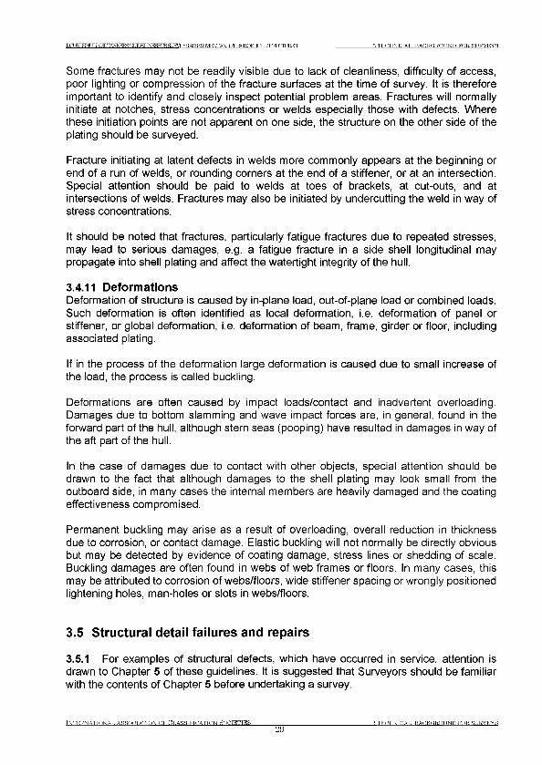
DOUBLE HLJLLOILTAInKERS ПТ ШКГ JNraKBSUEVEYS A^^^MENTANDBEPAlROFHr ТГ T .9Ш FTГ TRTC 3 TECHNICAL BACKGROUND FOR SURVEYS
Some fractures may not be readily visible due to lack of cleanliness, difficulty of access, poor lighting or compression of the fracture surfaces at the time of survey. It is therefore important to identify and closely inspect potential problem areas. Fractures will normally initiate at notches, stress concentrations or welds especially those with defects. Where these initiation points are not apparent on one side, the structure on the other side of the plating should be surveyed.
Fracture initiating at latent defects in welds more commonly appears at the beginning or end of a run of welds, or rounding corners at the end of a stiffener, or at an intersection. Special attention should be paid to welds at toes of brackets, at cut-outs, and at intersections of welds. Fractures may also be initiated by undercutting the weld in way of stress concentrations.
It should be noted that fractures, particularly fatigue fractures due to repeated stresses, may lead to serious damages, e.g. a fatigue fracture in a side shell longitudinal may propagate into shell plating and affect the watertight integrity of the hull.
3.4.11 DeformationsDeformation of structure is caused by in-plane load, out-of-plane load or combined loads. Such deformation is often identified as local deformation, i.e. deformation of panel or stiffener, or global deformation, i.e. deformation of beam, frame, girder or floor, including associated plating.
If in the process of the deformation large deformation is caused due to small increase of the load, the process is called buckling.
Deformations are often caused by impact loads/contact and inadvertent overloading. Damages due to bottom slamming and wave impact forces are, in general, found in the forward part of the hull, although stern seas (pooping) have resulted in damages in way of the aft part of the hull.
In the case of damages due to contact with other objects, special attention should be drawn to the fact that although damages to the shell plating may look small from the outboard side, in many cases the internal members are heavily damaged and the coating effectiveness compromised.
Permanent buckling may arise as a result of overloading, overall reduction in thickness due to corrosion, or contact damage. Elastic buckling will not normally be directly obvious but may be detected by evidence of coating damage, stress lines or shedding of scale. Buckling damages are often found in webs of web frames or floors. In many cases, this may be attributed to corrosion of webs/floors, wide stiffener spacing or wrongly positioned lightening holes, man-holes or slots in webs/floors.
3.5 Structural detail failures and repairs
3.5.1 For examples of structural defects, which have occurred in service, attention is drawn to Chapter 5 of these guidelines. It is suggested that Surveyors should be familiar with the contents of Chapter 5 before undertaking a survey.
INTERNATIONAL ASSOCIATION OF CLASSIFICATION SOCIETIES29
Я TECHNICAL BACKGROUND FOR SURVEYS

DOUBLE HU1XOILTANKERB Ot Ш К Г JNFSKR9JRШ S^m/Ш Ш Ш )Ш Ш CFmJLl£Ш JJ2JШ ES 3 TECHNICAL BACKGROUND FOR SURVEYS
3.5.2 For Classification requirements related to prompt and thorough repairs refer to2.6.1
3.5.3 In general, where part of the structure has deteriorated to the permissible minimum thickness, then the affected area is to be cropped and renewed. Generally doubler plates should not be used for the compensation of wasted plate. Repair work in tanks requires careful planning in terms of accessibility. Refer to Part В of IACS Recommendation 47, Shipbuilding and Repair Quality Standard.
3.5.4 If replacement of defective parts must be postponed, temporary measures may be acceptable at the Surveyor’s discretion and a suitable condition of class will be imposed.
INTERNATIONAL ASSOCIATION OF CLASSIFICATION SOCIETIES30
Я TECHNICAL ВАСКО,ROUND FOR. SURVEYS
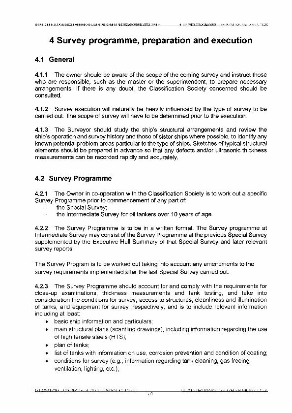
Г Р IRT FTHTIT JOT TANKFKSGUIHFI ]ЫРККЖШКУЕУ^Я^МФЛ1 A№)E^\IROFHLJILS™XTIURES 4 SURVEY PROGRAMME. PREPARATION AND EXECUTION
4 Survey programme, preparation and execution
4.1 General
4.1.1 The owner should be aware of the scope of the coming survey and instruct those who are responsible, such as the master or the superintendent, to prepare necessary arrangements. If there is any doubt, the Classification Society concerned should be consulted.
4.1.2 Survey execution will naturally be heavily influenced by the type of survey to be carried out. The scope of survey will have to be determined prior to the execution.
4.1.3 The Surveyor should study the ship’s structural arrangements and review the ship’s operation and survey history and those of sister ships where possible, to identify any known potential problem areas particular to the type of ships. Sketches of typical structural elements should be prepared in advance so that any defects and/or ultrasonic thickness measurements can be recorded rapidly and accurately.
4.2 Survey Programme
4.2.1 The Owner in co-operation with the Classification Society is to work out a specific Survey Programme prior to commencement of any part of:
the Special Survey;the Intermediate Survey for oil tankers over 10 years of age.
4.2.2 The Survey Programme is to be in a written format. The Survey programme at Intermediate Survey may consist of the Survey Programme at the previous Special Survey supplemented by the Executive Hull Summary of that Special Survey and later relevant survey reports.
The Survey Program is to be worked out taking into account any amendments to the survey requirements implemented after the last Special Survey carried out.
4.2.3 The Survey Programme should account for and comply with the requirements for close-up examinations, thickness measurements and tank testing, and take into consideration the conditions for survey, access to structures, cleanliness and illumination of tanks, and equipment for survey, respectively, and is to include relevant information including at least:
• basic ship information and particulars;• main structural plans (scantling drawings), including information regarding the use
of high tensile steels (HTS);• plan of tanks;• list of tanks with information on use, corrosion prevention and condition of coating;• conditions for survey (e.g., information regarding tank cleaning, gas freeing,
ventilation, lighting, etc.);
Tn te r .n attonat , As s o c ia t io n o f Cl a s s if ic a t io n s o c ie t ie s31
4 SURVEY PROGRAMME PREPARATION AND EXECUTION

1ХШ1ЕНЦЦХ^ТАЫКЕ1^0иПЖ]ЫР}ЯКУЯ IRVF^ AЯ:Г?:ШFЖA^JDFEPA1ЮFEЮ]XSДЮCШJБ^ 4 SURVEY PROGRAMME. PREPARATION AND EXECUTION
• provisions and methods for access to structures;• equipment for surveys;• nomination of tanks and areas for close-up survey;• nominations of sections for thickness measurement;• nomination of tanks for tank testing;• damage experience related to the ship in question.
4.2.4 In developing the Survey Programme, the following documentation is to be collected and consulted with a view to selecting tanks, areas, and structural elements to be examined:
• survey status and basic ship information;• documentation on-board, as described in 4.10;• main structural plans (scantlings drawings), including information regarding the use
of high tensile steels (HTS);• relevant previous survey and inspection reports from both Classification Society
and the Owner;• information regarding the use of the ship’s tanks, typical cargoes and other relevant
data;• information regarding corrosion prevention level on the new-building;• information regarding the relevant maintenance level during operation.
4.2.5 In developing the Survey Programme, the Classification Society will advise the Owner of the maximum acceptable structural corrosion diminution levels applicable to the vessel.
4.2.6 Minimum requirements regarding close-up surveys and thickness measurements are stipulated in IACS Unified Requirement Z10.4.
4.3 Survey Planning Meeting
4.3.1 Prior to the commencement of any part of the Special Survey and Intermediate Survey a survey planning meeting is to be held between the attending Surveyor(s), the Owner’s Representative in attendance and the TM company representative, where involved.
4.4 Conditions for survey
4.4.1 The owner is to provide the necessary facilities for a safe execution of the survey.
4.4.2 Tanks and spaces are to be safe for access, i.e. gas freed, ventilated and illuminated.
4.4.3 In preparation for survey and thickness measurements and to allow for a thorough
INTERNATIONAL ASSOCIATION OF CLASSIFICATION ЯОЛТЕТТЕЯ32
4 SURVEY PROGRAMME PREPARATION AND EXECUTION
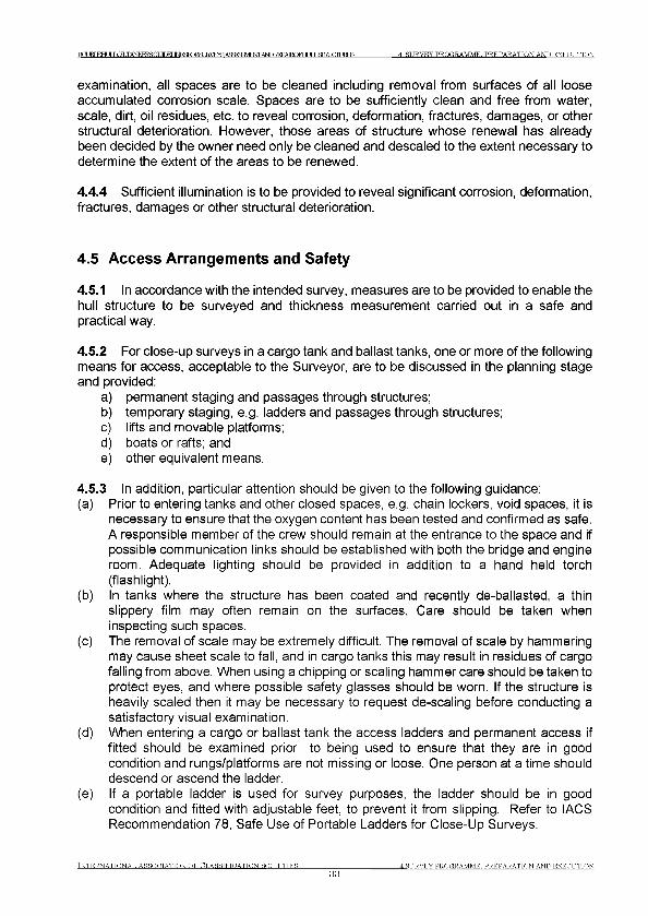
TXUBL£HULLaLTANKERSa П Г М 1 № У ^ К Ж 8 и В У Е Ж А Я ; :Г?:Ш Р Ж А Ь Г О Б Е Р А 1 Ю Е Е Ю ] Х 5 Д Ю С Л и Е Е 5 4 SU R V E Y PR O G R A M M E . P R E P A R A T IO N A N D E X E C U T IO N
examination, all spaces are to be cleaned including removal from surfaces of all loose accumulated corrosion scale. Spaces are to be sufficiently clean and free from water, scale, dirt, oil residues, etc. to reveal corrosion, deformation, fractures, damages, or other structural deterioration. However, those areas of structure whose renewal has already been decided by the owner need only be cleaned and descaled to the extent necessary to determine the extent of the areas to be renewed.
4.4.4 Sufficient illumination is to be provided to reveal significant corrosion, deformation, fractures, damages or other structural deterioration.
4.5 Access Arrangements and Safety
4.5.1 In accordance with the intended survey, measures are to be provided to enable the hull structure to be surveyed and thickness measurement carried out in a safe and practical way.
4.5.2 For close-up surveys in a cargo tank and ballast tanks, one or more of the following means for access, acceptable to the Surveyor, are to be discussed in the planning stage and provided:
a) permanent staging and passages through structures;b) temporary staging, e.g. ladders and passages through structures;c) lifts and movable platforms;d) boats or rafts; ande) other equivalent means.
4.5.3 In addition, particular attention should be given to the following guidance:(a) Prior to entering tanks and other closed spaces, e.g. chain lockers, void spaces, it is
necessary to ensure that the oxygen content has been tested and confirmed as safe. A responsible member of the crew should remain at the entrance to the space and if possible communication links should be established with both the bridge and engine room. Adequate lighting should be provided in addition to a hand held torch (flashlight).
(b) In tanks where the structure has been coated and recently de-ballasted, a thin slippery film may often remain on the surfaces. Care should be taken when inspecting such spaces.
(c) The removal of scale may be extremely difficult. The removal of scale by hammering may cause sheet scale to fall, and in cargo tanks this may result in residues of cargo falling from above. When using a chipping or scaling hammer care should be taken to protect eyes, and where possible safety glasses should be worn. If the structure is heavily scaled then it may be necessary to request de-scaling before conducting a satisfactory visual examination.
(d) When entering a cargo or ballast tank the access ladders and permanent access if fitted should be examined prior to being used to ensure that they are in good condition and rungs/platforms are not missing or loose. One person at a time should descend or ascend the ladder.
(e) If a portable ladder is used for survey purposes, the ladder should be in good condition and fitted with adjustable feet, to prevent it from slipping. Refer to IACS Recommendation 78, Safe Use of Portable Ladders for Close-Up Surveys.
IN T E R N A T IO N A L A SS O C IA T IO N O F C L A S S IF IC A T IO N S O C IE T IE S
334 SU R V EY PR O G R A M M E PR E P A R A T IO N AND E X E C U T IO N
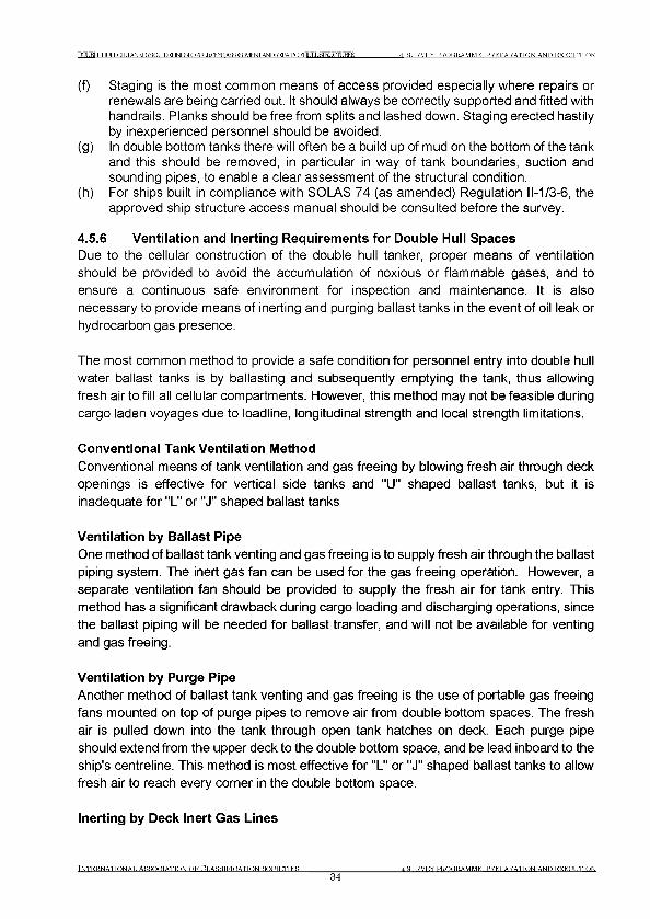
DOUBT Е Н Г JT LOLTANKERSOr ITDF1 1 М ^ Г О Е 8 Ц Е ^ Е ^ А З ^ Б Э У Е О Т А ^ 1 М 3А 1 Е О Г Н Ц 1 Ь 8 1 Ш С П 1 Ш Е 8 4 SU R V EY PR O G R A M M E . P R E P A R A T IO N A N D E X E C U T IO N
(f) Staging is the most common means of access provided especially where repairs or renewals are being carried out. It should always be correctly supported and fitted with handrails. Planks should be free from splits and lashed down. Staging erected hastily by inexperienced personnel should be avoided.
(g) In double bottom tanks there will often be a build up of mud on the bottom of the tank and this should be removed, in particular in way of tank boundaries, suction and sounding pipes, to enable a clear assessment of the structural condition.
(h) For ships built in compliance with SOLAS 74 (as amended) Regulation 11-1/3-6, the approved ship structure access manual should be consulted before the survey.
4.5.6 Ventilation and Inerting Requirements for Double Hull SpacesDue to the cellular construction of the double hull tanker, proper means of ventilation should be provided to avoid the accumulation of noxious or flammable gases, and to ensure a continuous safe environment for inspection and maintenance. It is also necessary to provide means of inerting and purging ballast tanks in the event of oil leak or hydrocarbon gas presence.
The most common method to provide a safe condition for personnel entry into double hull water ballast tanks is by ballasting and subsequently emptying the tank, thus allowing fresh air to fill all cellular compartments. However, this method may not be feasible during cargo laden voyages due to loadline, longitudinal strength and local strength limitations.
Conventional Tank Ventilation Method
Conventional means of tank ventilation and gas freeing by blowing fresh air through deck openings is effective for vertical side tanks and "U" shaped ballast tanks, but it is inadequate for "L" or "J" shaped ballast tanks
Ventilation by Ballast Pipe
One method of ballast tank venting and gas freeing is to supply fresh air through the ballast piping system. The inert gas fan can be used for the gas freeing operation. However, a separate ventilation fan should be provided to supply the fresh air for tank entry. This method has a significant drawback during cargo loading and discharging operations, since the ballast piping will be needed for ballast transfer, and will not be available for venting and gas freeing.
Ventilation by Purge Pipe
Another method of ballast tank venting and gas freeing is the use of portable gas freeing fans mounted on top of purge pipes to remove air from double bottom spaces. The fresh air is pulled down into the tank through open tank hatches on deck. Each purge pipe should extend from the upper deck to the double bottom space, and be lead inboard to the ship's centreline. This method is most effective for "L" or "J" shaped ballast tanks to allow fresh air to reach every corner in the double bottom space.
Inerting by Deck Inert Gas Lines
INTRRNATTONAT. ASSOnTATTON OF CT.ASSTFTDATTON Я О Л Т Е Т Т Е Я34
4 SURVEY PROGRAMME. PREPARATION AND EXECUTION
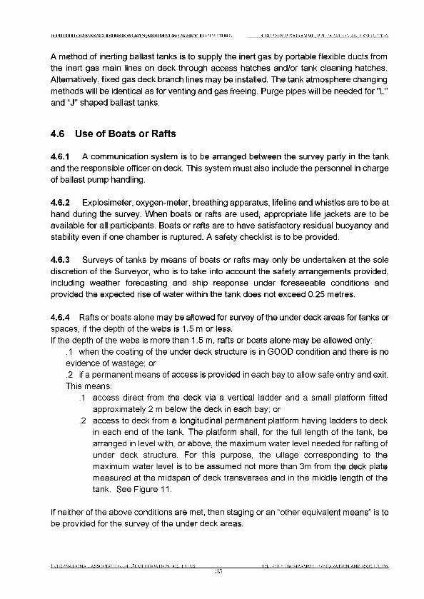
DOJBIEHUU ОТ TANKFKSGUIHFI ]ЫРККЖШКУЕУ^Я^МФЛ1 A^ICTAIRQFHUr J ,STRI JCTTT JRFS 4 SU R V EY PR O G R A M M E . P R E P A R A T IO N A N D E X E C U T IO N
A method of inerting ballast tanks is to supply the inert gas by portable flexible ducts from the inert gas main lines on deck through access hatches and/or tank cleaning hatches. Alternatively, fixed gas deck branch lines may be installed. The tank atmosphere changing methods will be identical as for venting and gas freeing. Purge pipes will be needed for "L" and “J" shaped ballast tanks.
4.6 Use of Boats or Rafts
4.6.1 A communication system is to be arranged between the survey party in the tank and the responsible officer on deck. This system must also include the personnel in charge of ballast pump handling.
4.6.2 Explosimeter, oxygen-meter, breathing apparatus, lifeline and whistles are to be at hand during the survey. When boats or rafts are used, appropriate life jackets are to be available for all participants. Boats or rafts are to have satisfactory residual buoyancy and stability even if one chamber is ruptured. A safety checklist is to be provided.
4.6.3 Surveys of tanks by means of boats or rafts may only be undertaken at the sole discretion of the Surveyor, who is to take into account the safety arrangements provided, including weather forecasting and ship response under foreseeable conditions and provided the expected rise of water within the tank does not exceed 0.25 metres.
4.6.4 Rafts or boats alone may be allowed for survey of the under deck areas for tanks or spaces, if the depth of the webs is 1.5 m or less.If the depth of the webs is more than 1.5 m, rafts or boats alone may be allowed only:
.1 when the coating of the under deck structure is in GOOD condition and there is no evidence of wastage; or.2 if a permanent means of access is provided in each bay to allow safe entry and exit. This means:
.1 access direct from the deck via a vertical ladder and a small platform fitted approximately 2 m below the deck in each bay; or
.2 access to deck from a longitudinal permanent platform having ladders to deck in each end of the tank. The platform shall, for the full length of the tank, be arranged in level with, or above, the maximum water level needed for rafting of under deck structure. For this purpose, the ullage corresponding to the maximum water level is to be assumed not more than 3m from the deck plate measured at the midspan of deck transverses and in the middle length of the tank. See Figure 11.
If neither of the above conditions are met, then staging or an “other equivalent means” is to be provided for the survey of the under deck areas.
IN T E R N A T IO N A L A SS O C IA T IO N O F C L A S S IF IC A T IO N S O C IE T IE S
354 SU R V EY PR O G R A M M E PR E P A R A T IO N AND E X E C U T IO N
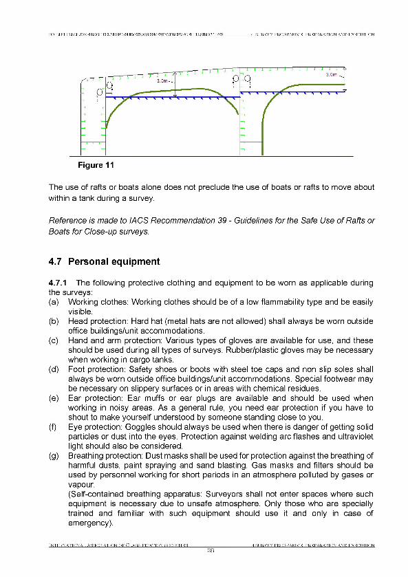
D(XBIEELILLOE,TANKERBai WEГ М ^ Г О Е б Ш А ^ Б А ^ ^ ^ / Е ^ Г Ж Р Ь Е Р А Е О Р Ж Е Ь & Т Е Ю С Ш К Е Б 4 SURVEY PROGRAMME. PREPARATION AND EXECUTION
The use of rafts or boats alone does not preclude the use of boats or rafts to move about
within a tank during a survey.
Reference is made to I ACS Recommendation 39 - Guidelines for the Safe Use of Rafts or Boats for Close-up surveys.
4.7 Personal equipment
4.7.1 The following protective clothing and equipment to be worn as applicable duringthe surveys:(a) Working clothes: Working clothes should be of a low flammability type and be easily
visible.(b) Head protection: Hard hat (metal hats are not allowed) shall always be worn outside
office buildings/unit accommodations.(c) Hand and arm protection: Various types of gloves are available for use, and these
should be used during all types of surveys. Rubber/plastic gloves may be necessary when working in cargo tanks.
(d) Foot protection: Safety shoes or boots with steel toe caps and non slip soles shall always be worn outside office buildings/unit accommodations. Special footwear may be necessary on slippery surfaces or in areas with chemical residues.
(e) Ear protection: Ear muffs or ear plugs are available and should be used when working in noisy areas. As a general rule, you need ear protection if you have to shout to make yourself understood by someone standing close to you.
(f) Eye protection: Goggles should always be used when there is danger of getting solid particles or dust into the eyes. Protection against welding arc flashes and ultraviolet light should also be considered.
(g) Breathing protection: Dust masks shall be used for protection against the breathing of harmful dusts, paint spraying and sand blasting. Gas masks and filters should be used by personnel working for short periods in an atmosphere polluted by gases or vapour.(Self-contained breathing apparatus: Surveyors shall not enter spaces where such equipment is necessary due to unsafe atmosphere. Only those who are specially trained and familiar with such equipment should use it and only in case of emergency).
INTERNATIONAL ASSOCIATION OF CLASSIFICATION SOCIETIES
364 SURVEY PROGRAMME PREPARATION AND EXECUTION
Г О JRT ЕНГ I J ОТ .TANKFRSGUfnPT 1ЫР}ЯКЖ8иЕ1УЕ^АЯйР?ЯУ1РТ>|Л1 ANDFEPAIROFHf TTI .НП?Г TTHURES 4 SURVEY PROGRAMME. PREPARATION AND EXECUTION
(h) Lifejacket: Recommended to be used when embarking/disembarking ships offshore from/to pilot boat.
4.7.2 The following survey equipment is to be used as applicable during the surveys:(a) Torches: Torches (Flashlights) approved by a competent authority for use in a
flammable atmosphere shall be used in gas dangerous areas. High intensity beam type is recommended for in-tank surveys. Torches are recommended to be fitted with suitable straps so that both hands may be free.
(b) Hammer: In addition to its normal purposes the hammer is recommended for use during surveys inside tanks etc. as it may be most useful for the purpose of giving distress signal in case of emergency.
(c) Oxygen analyser/Multigas detector: For verification of acceptable atmosphere prior to tank entry, pocket size instruments which give audible alarm when unacceptable limits are reached are recommended. Such equipment shall have been approved by national authorities.
(d) Safety belts and lines: Safety belts and lines should be worn where high risk of falling down from more than 3 metres is present.
4.8 Thickness measurement and fracture detection
4.8.1 Thickness measurement is to comply with the requirements of the Classification Society concerned. Thickness measurement should be carried out at points that adequately represent the nature and extent of any corrosion or wastage of the respective structure (plate, web, etc.). Thickness measurements of structures in areas where close-up surveys are required shall be carried out simultaneously with the close-up surveys.
4.8.2 Thickness measurement is normally carried out by means of ultrasonic test equipment. The accuracy of the equipment is to be proven as required.
4.8.3 Thickness measurements required, if not carried out by the Society itself are to be witnessed by a Surveyor on board to the extent necessary to control the process.
4.8.4 A thickness measurement report is to be prepared. The report is to give the location of measurements, the thickness measured as well as corresponding original thickness. Furthermore, the report is to give the date when the measurements were carried out, type of measurement equipment, names of personnel and their qualifications and has to be signed by the operator. Upon completion of the thickness measurements onboard, the Surveyor should verify and keep a copy of the preliminary thickness measurement report signed by the operator until such time as the final report is received. The Surveyor is to review the final thickness measurement report and countersign the cover sheet.
4.8.5 The thickness measurement company should be part of the survey planning meeting to be held prior to the survey.
4.8.6 One or more of the following fracture detection procedures may be required if deemed necessary and should be operated by experienced qualified technicians:
Tn te r .n attonat , a ss o c ia t io n o f Cl a s s if ic a t io n s o c ie t ie s37
4 SURVEY PROGRAMME PREPARATION AND EXECUTION
Г О JBT ЕНГ JT LOLTANKERSGUfnPT ]ЫР)ЯКЖ8иКУЕ^АЯйР?ЯУ1Р^ АЬЮТМ^АКОРНЦ^ЗПЮСТиБЕЗ 4 SURVEY PROGRAMME. PREPARATION AND EXECUTION
(a) radiographic equipment(b) ultrasonic equipment(c) magnetic particle equipment(d) dye penetrant
4.9 Survey at sea or at anchorage
4.9.1 Voyage surveys may be accepted provided the survey party is given the necessary assistance from the shipboard personnel. The necessary precautions and procedures for carrying out the survey are to be in accordance with 4.1 to 4.8 inclusive. Ballast, cargo and inert gas piping systems must be secured at all times during tank surveys.
4.9.2 A communication system is to be arranged between the survey party in the spaces under examination and the responsible officer on deck.
4.10 Documentation on board
4.10.1 The following documentation is to be placed on board and maintained and updated by the owner for the life of ship in order to be readily available for the survey party.
4.10.2 Survey Report File: This file includes Reports of Structural Surveys, Executive Hull Summary and Thickness Measurement Reports.
4.10.3 Supporting Documents: The following additional documentation is to be placed on board, including any other information that will assist in identifying Suspect Areas requiring examination:
• Survey Programme as required by 4.2 until such time as the Special Survey or Intermediate Survey, as applicable, has been completed;
• main structural plans of cargo and ballast tanks;• previous repair history;• cargo and ballast history;• extent of use of inert gas plant and tank cleaning procedures;• surveys by ship's personnel;• structural deterioration in general;• leakage in bulkheads and piping;• condition of coating or corrosion prevention system, if any;• any other information that will help identify Suspect Areas requiring survey.
4.10.4 Prior to survey, the completeness of the documentation onboard, and its contents as a basis for the survey should be examined.
TNTERNATTONAT, ASSOOTATTON OF ОТ.ARRTRTCATTON ROCTETTER38
4 SURVEY PROGRAMME. PREPARATION AND EXECUTION

Г О JRT ЕНГ I LOLTANKERSOff TfTIFT INFIF^RTR,*? TRVEYR ДЬЮ1^РА1ЕЮЕЕЮ]Х5ДЮСЛиЕЕ5 4 SURVEY PROGRAMME. PREPARATION AND EXECUTION
4.11 Reporting and Evaluation of Survey
4.11.1 The data and information on the structural condition of the vessel collected during the survey is to be evaluated for acceptability and continued structural integrity of the vessel.
4.11.2 In case of oil tankers of 130 m in length and upwards (as defined in the International Convention on Load Lines in force), the ship’s longitudinal strength is to be evaluated by using the thickness of structural members measured, renewed and reinforced, as appropriate, during the special survey carried out after the ship reached 10 years of age in accordance with the criteria for longitudinal strength of the ship’s hull girder for oil tankers.
4.11.3 The final result of evaluation of the ship’s longitudinal strength required in 4.11.2, after renewal or reinforcement work of structural members, if carried out as a result of initial evaluation, is to be reported as a part of the Executive Hull Summary.
4.11.4 As a principle, for oil tankers subject to ESP, the Classification Society Surveyor is to include the following content in his report for survey of hull structure and piping systems, as relevant for the survey.
.1 General
1.1 A survey report is to be generated in the following cases:• In connection with commencement, continuation and / or completion of
periodical hull surveys, i.e. annual, intermediate and special surveys, as relevant.
• When structural damages / defects have been found.• When repairs, renewals or modifications have been carried out.• When condition of class (recommendation) has been imposed or deleted.
1.2 The purpose of reporting is to provide:• Evidence that prescribed surveys have been carried out in accordance with
applicable classification rules.• Documentation of surveys carried out with findings, repairs carried out and
condition of class (recommendation) imposed or deleted.• Survey records, including actions taken, which shall form an auditable
documentary trail. Survey reports are to be kept in the survey report file required to be on board.
• Information for planning of future surveys.• Information which may be used as input for maintenance of classification
rules and instructions.
.2 Extent of Survey
The extent of the survey in the report is to include the following:• Identification of compartments where an overall survey has been carried out.
t n t t c r n a t t o n a t , A s s o o t a t t o n o f O t.a r s t f t c a t t o n s o o t e t t e s
394 SU R V EY PR O G R A M M E . PR E P A R A T IO N A ND E X E C U T IO N
IXXBLEHUrLQILT^KERSa MM IM^TORSUE^E^ASSf^MW ANDEFPAIRQFHLJILSrRr XCTUKES 4 SURVEY PROGRAMME. PREPARATION AND EXECUTION
• Identification of locations, in each tank, where a close-up survey has been carried out, together with information of the means of access used.
• Identification of locations, in each tank, where thickness measurement has been carried out.
• For areas in tanks where protective coating is found to be in GOOD condition and the extent of close-up survey and / or thickness measurement has been specially considered, structures subject to special consideration are to be identified.
• Identification of tanks subject to tank testing.• Identification of cargo piping on deck, including crude oil washing (COW)
piping, and cargo and ballast piping within cargo and ballast tanks, pump rooms, pipe tunnels and void spaces, examined and where operational test to working pressure has been carried out.
.3 Result of the survey
Type, extent and condition of protective coating in each tank, as relevant (rated GOOD, FAIR or POOR).Structural condition of each compartment with information on the following, asrelevant:Identification of findings, such as:
• Corrosion with description of location, type and extent;• Areas with substantial corrosion;• Cracks / fractures with description of location and extent;• Buckling with description of location and extent;• Indents with description of location and extent;• Identification of compartments where no structural damages/defects are found.
The report may be supplemented by sketches/photos.Evaluation result of longitudinal strength of the hull girder of oil tankers of 130 m in length and upwards and over 10 years of age. The following data is to be included, as relevant:
• Measured and as-built transverse sectional areas of deck and bottom flanges;• Diminution of transverse sectional areas of deck and bottom flanges;• Calculation of the transverse section modulus of hull girder, as relevant;• Details of renewals or reinforcements carried out, as relevant (as per 4.2).
.4 Actions taken with respect to findingsWhenever the attending Surveyor is of the opinion that repairs are required, each item to be repaired is to be identified in a numbered list. Whenever repairs are carried out, details of the repairs effected are to be reported by making specific reference to relevant items in the numbered list.Repairs carried out are to be reported with identification of:
• Compartment• Structural member
Tn t e r n a t t o n a t , A r r o h t a t t o n o f C t .a r s t e t o a t t o n r o h t e t t e r
404 SURVEY PROGRAMME. PREPARATION AND EXECUTION
ГО ВТ книг LOLTANKERSOr ТГГКГ IM^roRSUE^E^AS^BaVENTA^I^AEOFHU]XSim(^]RES 4 SURVEY PROGRAMME. PREPARATION AND EXECUTION
• Repair method (i.e. renewal or modification)• Repair extent• NDT / Tests
For repairs not completed at the time of survey, condition of class (recommendation) is to be imposed with a specific time limit for the repairs. In order to provide correct and proper information to the Surveyor attending for survey of the repairs, condition of class (recommendation) is to be sufficiently detailed with identification of each item to be repaired.For identification of extensive repairs, reference may be given to the survey report.
4.11.5 An Executive Hull Summary of the survey and results is to be issued to the Owner and placed on board the vessel for reference at future surveys. The Executive Hull Summary is to be endorsed by the Classification Society's head office or regional managerial office.
INTERNATIONAL ASSOCIATION OF CLASSIFICATION SOCIETIES41
4 SURVEY PROGRAMME PREPARATION AND EXECUTION

DOJBT FTHTIT JO T .TANPCFPSGUmFI ITIЯШГ ГЛТЕЕЗ 5 STRUCTURAL DETAIL FAILURES AND REPAIRS
5 Structural detail failures and repairs
5.1 General
5.1.1 The catalogue of structural detail failures and repairs contained in this section of the Guidelines collates data supplied by the IACS Member Societies and is intended to provide guidance when considering similar cases of damage and failure. The proposed repairs reflect the experience of the Surveyors of the Member Societies, but it is realized that other satisfactory alternative methods of repair may be available. However, in each case the repairs are to be completed to the satisfaction of the Classification Society Surveyor concerned. Identified reoccurring failures after repairs may require further investigation.
5.2 Actions to be taken by the Classification Society when Fatigue Failures have been Identified
5.2.1 Whenever a fatigue failure has been identified on a ship a detailed structural survey with close-up examination of similar locations on that ship should be carried out.
5.2.2 Assessment of fatigue failures should be carried out by the Classification Society when fatigue failures are identified in the cargo area in the following cases:
a. Ships 5 years of age and less.b. Ships 10 years of age and less when the fatigue failure occurs in the structural
details, which are present in a large number onboard the ship or when the fatigue failure may have serious consequences.
c. When similar fatigue failures have been identified on sister ships 10 years of age and less.
In ships more than 10 years of age fatigue failure assessment may be waived at the discretion of the Classification Society.
5.2.3 Assessment of fatigue failure implies structural analysis to be carried out with a scope of:
a. The possible cause of failure;b. The need for proactive repairs, reinforcements and/or modifications;c. The most effective and practical repair;d. The need for detailed structural surveys on sister/similar ships as defined in IACS
Procedural Requirement No. 2.
The structural analysis may be carried out by means of simple beam or finite element analysis.
5.2.4 The proactive measures identified in the structural assessment are to be carried out to the satisfaction of the Classification Society.
INTERNATIONAL ASSOCIATION OF CLASSIFICATION SOCIETIES42
5 STRUCTURAL PET ATT. FAILURES AND REPAIRS
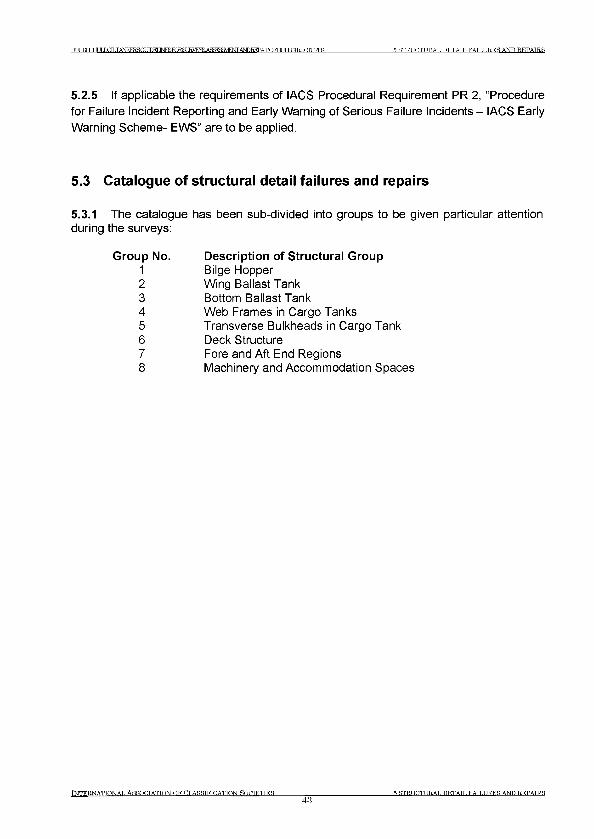
T O JBT EHULLOILTANKEESa УГГКГ INFSTORSUEftTEraASSreEM^F A ^ ^ A R O ra U lX S IE U C IU R E S 5 ST R U C T U R A L D E T A IL F A IL U R E S AND R E P A IR S
5.2.5 If applicable the requirements of IACS Procedural Requirement PR 2, “Procedure for Failure Incident Reporting and Early Warning of Serious Failure Incidents - IACS Early Warning Scheme- EWS” are to be applied.
5.3 Catalogue of structural detail failures and repairs
5.3.1 The catalogue has been sub-divided into groups to be given particular attention during the surveys:
Group No.12345678
Description of Structural GroupBilge HopperWing Ballast TankBottom Ballast TankWeb Frames in Cargo TanksTransverse Bulkheads in Cargo TankDeck StructureFore and Aft End RegionsMachinery and Accommodation Spaces
I n t e r n a t i o n a l A s s o c i a t i o n o f C l a s s i f i c a t i o n S o c i e t i e s
435 STRUCTURAL DETATT. FAILURES AND REPAIRS
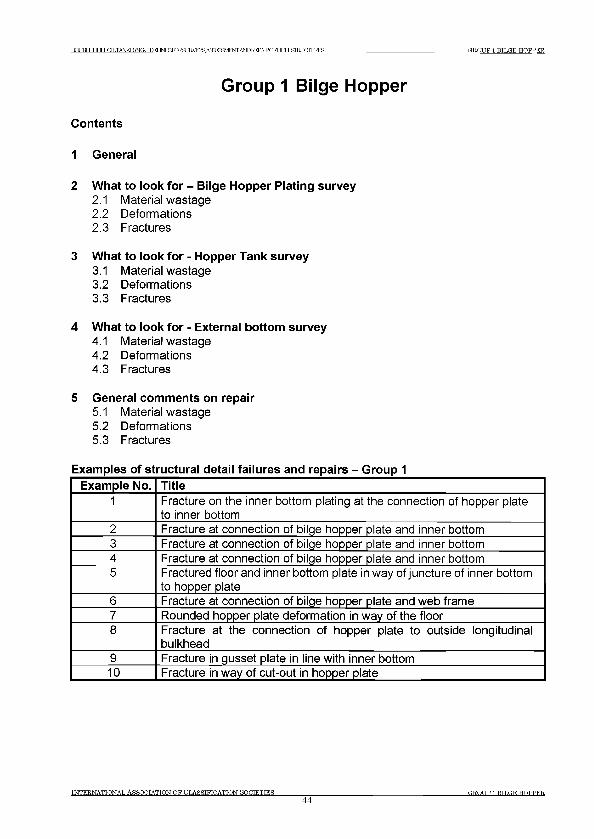
ТОМ КНИГ LCaLTANESERSGLItlM 1МР^ГОЕ8ШУЕЖА^^ШЕЖ^ТОЮАЕОГНи1Ь&ТШСтаЕЗ GROUP 1 BILGE HOPPER
Group 1 Bilge Hopper
Contents
1 General
2 What to look for - Bilge Hopper Plating survey2.1 Material wastage2.2 Deformations2.3 Fractures
3 What to look for - Hopper Tank survey3.1 Material wastage3.2 Deformations3.3 Fractures
4 What to look for - External bottom survey4.1 Material wastage4.2 Deformations4.3 Fractures
5 General comments on repair5.1 Material wastage5.2 Deformations5.3 Fractures
Examples of structural detail failures and repairs - Group 1
Example No. Title1 Fracture on the inner bottom plating at the connection of hopper plate
to inner bottom2 Fracture at connection of bilge hopper plate and inner bottom3 Fracture at connection of bilge hopper plate and inner bottom4 Fracture at connection of bilge hopper plate and inner bottom5 Fractured floor and inner bottom plate in way of juncture of inner bottom
to hopper plate6 Fracture at connection of bilge hopper plate and web frame7 Rounded hopper plate deformation in way of the floor8 Fracture at the connection of hopper plate to outside longitudinal
bulkhead9 Fracture in gusset plate in line with inner bottom10 Fracture in way of cut-out in hopper plate
t n t e r .n a t t o n a t . A s s o c i a t i o n o f c t .a s s t f t d a t t o n н о л т е т т е я
44ER.OTIP 1 BTTflE HOPPER
Г О В Т к н и г LOLTANKERSOr 1 Г П Е Г 1 М Р ^ Г О Е 8 Ш У Е Ж А ^ ^ Ш Е Ж ^ Т О Ю А Е О Г Н и 1 Ь & Т Ш С т а Е З G R O U P 1 B IL G E H O P P E R
1 General
1.1 The bilge hopper together with the double bottom and double side tanks and spaces, protect the cargo tanks or spaces, and are not to be used for the carriage of oil cargoes.
1.2 In addition to general corrosion, the welds and connections of the tank top/hopper sloping plating may be prone to fatigue.
1.3 The bilge hopper contributes to the longitudinal hull girder strength and supports the double bottom and double side construction.
1.4 Weld defects and/or misalignment between hopper plate, inner bottom and longitudinal girder may lead to problems in view of the stress concentrations at this juncture. This may also be the case at the upper end of the hopper plate connection with the inner hull longitudinal bulkhead and horizontal girder.
2 What to look for - Bilge Hopper Plating survey
2.1 Material wastage
2.1.1 The general corrosion condition of the bilge hopper structure may be observed by visual survey. The level of wastage of bilge hopper plating may have to be established by means of thickness measurement.
2.2 Deformations
2.2.1 Buckling of the bilge hopper plating may occur between longitudinals in areas subject to in-plane transverse compressive stresses or between floors in areas subject to in-plane longitudinal compressive stresses.
2.2.2 Whenever deformations are observed on the bilge hopper, further survey in the double bottom tanks is imperative in order to determine the extent of the damage. The deformation may cause the breakdown of coating within the double bottom, which in turn may lead to accelerated corrosion rate in these unprotected areas.
2.3 Fractures
2.3.1 Fractures will normally be found by close-up survey. Fractures that extend through the thickness of the plating or through the welds may be observed during pressure testing of the double bottom tanks.
IN T E R N A T IO N A L A SS O C IA T IO N O F C L A S S IF IC A T IO N S O C IE T IE S
45O,ROT IP 1 ВТРОЕ HOPPER.
m IRT FTHTIT LOLTANKERSGT ТГПГСГ INFSFDRHIRVF^ AbTOREPAIROF^ ITT ЯШТТГПТЕЕБ GROUP 1 BILGE HOPPER
3 What to look for - Hopper Tank survey
3.1 Material wastage
3.1.1 The level of wastage of hopper side internal structure (longitudinals, transverses, floors, girders, etc.) may have to be established by means of thickness measurements.
Rate and extent of corrosion depends on the corrosive environment, and protective measures employed, such as coatings and sacrificial anodes. The following structures are generally susceptible to corrosion (also see 3.1.2 - 3.1.3),
(a) Structure in corrosive environment:- Transverse bulkhead and girder adjacent to heated fuel oil or cargo oil tanks.
(b) Structure subject to high stress:- Face plates and web plates of transverse at corners;- Connection of longitudinal to transverse.
(c) Areas susceptible to coating breakdown- Back side of face plate of longitudinal;- Welded joint;- Edge of access opening.
(c) Areas subject to poor drainage:- Web of side longitudinals.
3.1.2 If the protective coating is not properly maintained, structure in the ballast tank may suffer severe localised corrosion. Transverse webs in the hopper tanks may suffer severe corrosion at their corners where high shearing stresses occur, especially where collar plate is not fitted to the slot of the longitudinal.
3.1.3 The high temperature due to heated cargo oil tanks may accelerate corrosion of ballast tank structure near heated cargo oil tanks. The rate of corrosion depends on several factors such as:
• Temperature and heat input to the ballast tank.• Condition of original coating and its maintenance.• Ballasting frequency and operations.• Age of ship and associated stress levels as corrosion reduces the thickness of the
structural elements and can result in fracturing and buckling.
3.2 Deformations
3.2.1 Where deformations are identified during bilge hopper plating survey (See 2.2) and external bottom survey (See 4.2), the deformed areas should be subjected to in tank survey to determine the extent of the damage to the coating and internal structure.
Deformations in the structure not only reduce the structural strength but may also cause breakdown of the coating, leading to accelerated corrosion.
IN T E R N A T IO N A L A SS O C IA T IO N O F (C L A SSIFIC A T IO N S O C IE T IE S
46(TROTTP 1 В Т Р О Е H O P P E R
IX X B L E H L IL Q IL T ^K E R S a М М INTCTORSLIKVEU SAqcrem Fy^/^ICTA^^^ G R O U P 1 B IL G E H O P P E R
3.3 Fractures
3.3.1 Fractures will normally be found by close-up survey.
3.3.2 Fractures may occur in way of the welded or radiused knuckle between the inner bottom and hopper sloping plating if the side girder in the double bottom is not in line with the knuckle and also when the floors below have a large spacing, or when corner scallops are created for ease of fabrication. The local stress variations due to the loading and subsequent deflection may lead to the development of fatigue fractures which can be categorised as follows:
(a) Parallel to the knuckle weld for those knuckles which are welded and not radiused.
(b) In the inner bottom and hopper plating and initiated at the centre of a radiused knuckle.
(c) Extending in the hopper web plating and floor weld connections starting at the corners of scallops, where such exist, in the underlying hopper web and floor.
(d) Extending in the web plate as in (c) above but initiated at the edge of a scallop.
3.3.3 The fractures in way of connection of inner bottom plating/hopper sloping plating to stool may be caused by the cyclic deflection of the inner bottom induced by repeated loading from the sea or due to poor “through-thickness” properties of the inner bottom plating. Scallops in the underlying girders can create stress concentrations which further increase the risk of fractures. These can be categorised as follows: (See also Examples of Structure Detail Failures of this Group).
(a) In way of the intersection between inner bottom and stool. These fractures often generate along the edge of the welded joint above the centre line girder, side girders, and sometimes along the duct keel sides.
(b) Fractures in the inner bottom longitudinals and the bottom longitudinals in way of the intersection with the watertight floors below the transverse bulkhead stools.
(c) Fractures at the connection between the longitudinals and the vertical stiffeners or brackets on the floors.
(d) Lamellar tearing of the inner bottom plate below the weld connection with a lower stool caused by high bending stresses. The size of stool and lack of full penetration welds could also be a contributory factor, as well as poor “through-thickness” properties of the tank top plating.
3.3.4 Transition regionIn general, the termination of the following structural members at the collision bulkhead and engine room forward bulkhead is prone to fractures:
• Flopper tank sloping plating• Panting stringer in fore peak tank• Inner bottom plating in engine room
IN T E R N A T IO N A L A S S O C IA T IO N O F C L A S S IF IC A T IO N S O C IE T IE S
47G R O U P 1 B IL G E H O P P E R
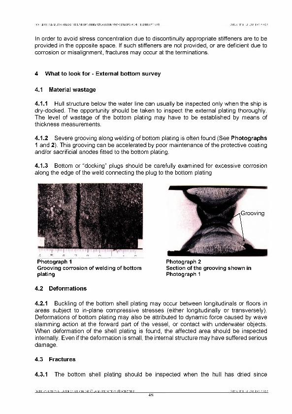
D(XBIEELILLOE,TANKERBai WEГ М ^ Г О Е 5 Ш А ^ Б А ^ ^ ^ / Е ^ Г Ж Р 1 Е Р А Е 0 1 Ш [ Ь & т 1 С 1 Ш Е В GROUP 1 BILGE HOPPER
In order to avoid stress concentration due to discontinuity appropriate stiffeners are to be provided in the opposite space. If such stiffeners are not provided, or are deficient due to corrosion or misalignment, fractures may occur at the terminations.
4 What to look for - External bottom survey
4.1 Material wastage
4.1.1 Hull structure below the water line can usually be inspected only when the ship is dry-docked. The opportunity should be taken to inspect the external plating thoroughly. The level of wastage of the bottom plating may have to be established by means of thickness measurements.
4.1.2 Severe grooving along welding of bottom plating is often found (See Photographs 1 and 2). This grooving can be accelerated by poor maintenance of the protective coating and/or sacrificial anodes fitted to the bottom plating.
4.1.3 Bottom or “docking” plugs should be carefully examined for excessive corrosion along the edge of the weld connecting the plug to the bottom plating
Photograph 1Grooving corros ion o f weld ing o f bottom plating
4.2 Deformations
Photograph 2Section o f the grooving shown in Photograph 1
4.2.1 Buckling of the bottom shell plating may occur between longitudinals or floors in areas subject to in-plane compressive stresses (either longitudinally or transversely). Deformations of bottom plating may also be attributed to dynamic force caused by wave slamming action at the forward part of the vessel, or contact with underwater objects. When deformation of the shell plating is found, the affected area should be inspected internally. Even if the deformation is small, the internal structure may have suffered serious damage.
4.3 Fractures
4.3.1 The bottom shell plating should be inspected when the hull has dried since
INTERNATIONAL ASSOCTATTON OF CT.ASSTFTCATTON HOCTETTES48
(TROTIP 1 BTT.ITE HOPPER.
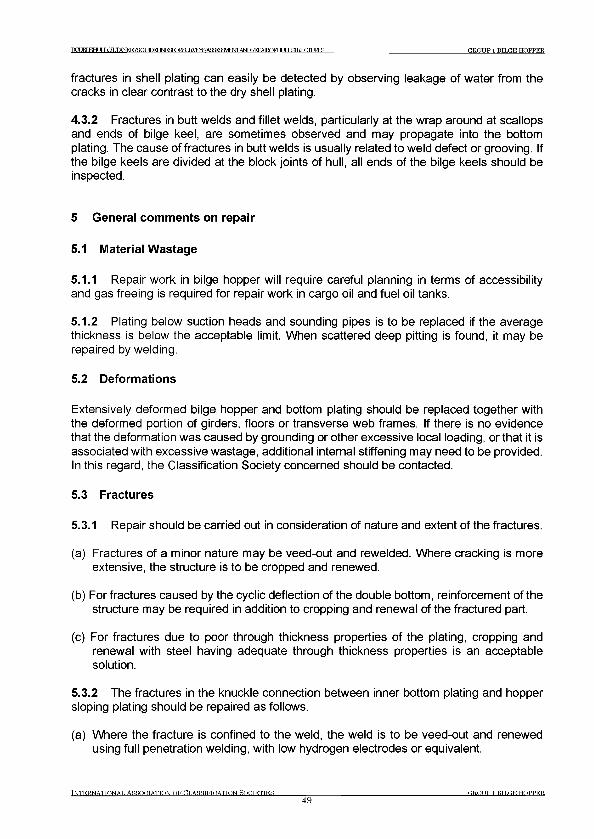
DGUKTEHt IT LOLTANPCFPSGUinFI ]Ы Р К К Ж Ш К У Е У ^Я ^ М Ф Л 1 А Ш Е Ш Ж О т ИIЯШТ FTTURES GROUP 1 BILGE HOPPER
fractures in shell plating can easily be detected by observing leakage of water from the cracks in clear contrast to the dry shell plating.
4.3.2 Fractures in butt welds and fillet welds, particularly at the wrap around at scallops and ends of bilge keel, are sometimes observed and may propagate into the bottom plating. The cause of fractures in butt welds is usually related to weld defect or grooving. If the bilge keels are divided at the block joints of hull, all ends of the bilge keels should be inspected.
5 General comments on repair
5.1 Material Wastage
5.1.1 Repair work in bilge hopper will require careful planning in terms of accessibility and gas freeing is required for repair work in cargo oil and fuel oil tanks.
5.1.2 Plating below suction heads and sounding pipes is to be replaced if the average thickness is below the acceptable limit. When scattered deep pitting is found, it may be repaired by welding.
5.2 Deformations
Extensively deformed bilge hopper and bottom plating should be replaced together with the deformed portion of girders, floors or transverse web frames. If there is no evidence that the deformation was caused by grounding or other excessive local loading, or that it is associated with excessive wastage, additional internal stiffening may need to be provided. In this regard, the Classification Society concerned should be contacted.
5.3 Fractures
5.3.1 Repair should be carried out in consideration of nature and extent of the fractures.
(a) Fractures of a minor nature may be veed-out and rewelded. Where cracking is more extensive, the structure is to be cropped and renewed.
(b) For fractures caused by the cyclic deflection of the double bottom, reinforcement of the structure may be required in addition to cropping and renewal of the fractured part.
(c) For fractures due to poor through thickness properties of the plating, cropping and renewal with steel having adequate through thickness properties is an acceptable solution.
5.3.2 The fractures in the knuckle connection between inner bottom plating and hopper sloping plating should be repaired as follows.
(a) Where the fracture is confined to the weld, the weld is to be veed-out and renewed using full penetration welding, with low hydrogen electrodes or equivalent.
INTERNATIONAL ASSOCIATION OF CLASSIFICATION SOCIETIES4 9
GROUP 1 BILGE HOPPER
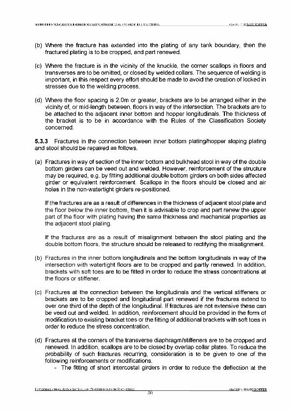
T O JRT ЕНГ I J DILTANKERSGUIEELINESroR^ IRVRVS AflfTOFMEOTA^IM^AIRQFTOXSIEUCniJRES G R O U P 1 BTLGE HOPPER
(b) Where the fracture has extended into the plating of any tank boundary, then the fractured plating is to be cropped, and part renewed.
(c) Where the fracture is in the vicinity of the knuckle, the corner scallops in floors and transverses are to be omitted, or closed by welded collars. The sequence of welding is important, in this respect every effort should be made to avoid the creation of locked in stresses due to the welding process.
(d) Where the floor spacing is 2.0m or greater, brackets are to be arranged either in the vicinity of, or mid-length between, floors in way of the intersection. The brackets are to be attached to the adjacent inner bottom and hopper longitudinals. The thickness of the bracket is to be in accordance with the Rules of the Classification Society concerned.
5.3.3 Fractures in the connection between inner bottom plating/hopper sloping platingand stool should be repaired as follows.
(a) Fractures in way of section of the inner bottom and bulkhead stool in way of the double bottom girders can be veed out and welded. However, reinforcement of the structure may be required, e.g. by fitting additional double bottom girders on both sides affected girder or equivalent reinforcement. Scallops in the floors should be closed and air holes in the non-watertight girders re-positioned.
If the fractures are as a result of differences in the thickness of adjacent stool plate and the floor below the inner bottom, then it is advisable to crop and part renew the upper part of the floor with plating having the same thickness and mechanical properties as the adjacent stool plating.
If the fractures are as a result of misalignment between the stool plating and the double bottom floors, the structure should be released to rectifying the misalignment.
(b) Fractures in the inner bottom longitudinals and the bottom longitudinals in way of the intersection with watertight floors are to be cropped and partly renewed. In addition, brackets with soft toes are to be fitted in order to reduce the stress concentrations at the floors or stiffener.
(c) Fractures at the connection between the longitudinals and the vertical stiffeners or brackets are to be cropped and longitudinal part renewed if the fractures extend to over one third of the depth of the longitudinal. If fractures are not extensive these can be veed out and welded. In addition, reinforcement should be provided in the form of modification to existing bracket toes or the fitting of additional brackets with soft toes in order to reduce the stress concentration.
(d) Fractures at the corners of the transverse diaphragm/stiffeners are to be cropped and renewed. In addition, scallops are to be closed by overlap collar plates. To reduce the probability of such fractures recurring, consideration is to be given to one of the following reinforcements or modifications.
- The fitting of short intercostal girders in order to reduce the deflection at the
t n t e r n a t t o n a t . A s s o c i a t i o n o f п т .а н я т к т л а т т о м я о п т т с т т е я
50GROUP 1 BTTXTE HOPPER.
РаМЕН0ШЭ1ЬТЖКЕБ8Г?Г УГГКГ INFRFjRH JRVF^AS^^E^iWr)^PAIRQFHUILSIEUOIURES GROUP 1 BILGE HOPPER
problem area.
(e) Lamellar tearing may be eliminated through improving the type and quality of the weld, i.e. full penetration using low hydrogen electrodes and incorporating a suitable weld throat.
Alternatively the inner bottom plating adjacent to and in contact with the lower stool plating is substituted with plating of “Z” quality steel, which has good “through-thickness” properties.
5.3.4 Bilge keel should be repaired as follows:
(a) Fractures or distortion in bilge keels must be promptly repaired. Fractured butt welds should be repaired using full penetration welds and proper welding procedures. The bilge keel is subjected to the same level of longitudinal hull girder stress as the bilge plating, fractures in the bilge keel can propagate into the shell plating.
(b) Termination of bilge keel requires proper support by internal structure. This aspect should be taken into account when cropping and renewing damaged parts of a bilge keel.
t n t e r n a t t o n a t , a s s o o t a t t o n o f C l a s s i f i c a t i o n S o o t e t t e r
51GROUP 1 BILGE HOPPER

РСХЖРНТ JT LOLTANKERBflr УГГКГ IN F ^roR S U E ^E ^A S ^B aV E N TA ^E E PA IR O FH I JT J ,G M JCTTT JRES GROUP 1 BILGE HOPPER
Group 1 Bilge Hopper
Tn t e r n a t t o n a t , A s s o c i a t i o n o f C l a s s i f i c a t i o n S o c i e t i e s
52G R O U P 1 BTTGE H O PPE R .
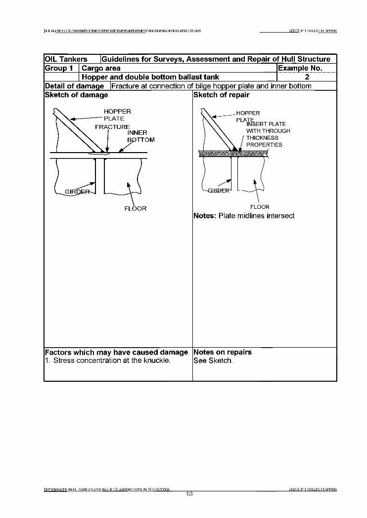
Г О JRT К Н И Г J О Т . Т А М С Р Р Я О Г Л Г И TNFT^RTRf? Т К У Р У Р A 5 ^ ^ M ^ A b T O R E P A IR O F H r ITIД 1 Ш Ж К Е З GROUP 1 BILGE HOPPER
I n t e r n a t i o n a l A s s o c i a t i o n o f C l a s s i f i c a t i o n s o c i e t i e s
53GROUP 1 BTTjGE HOPPER
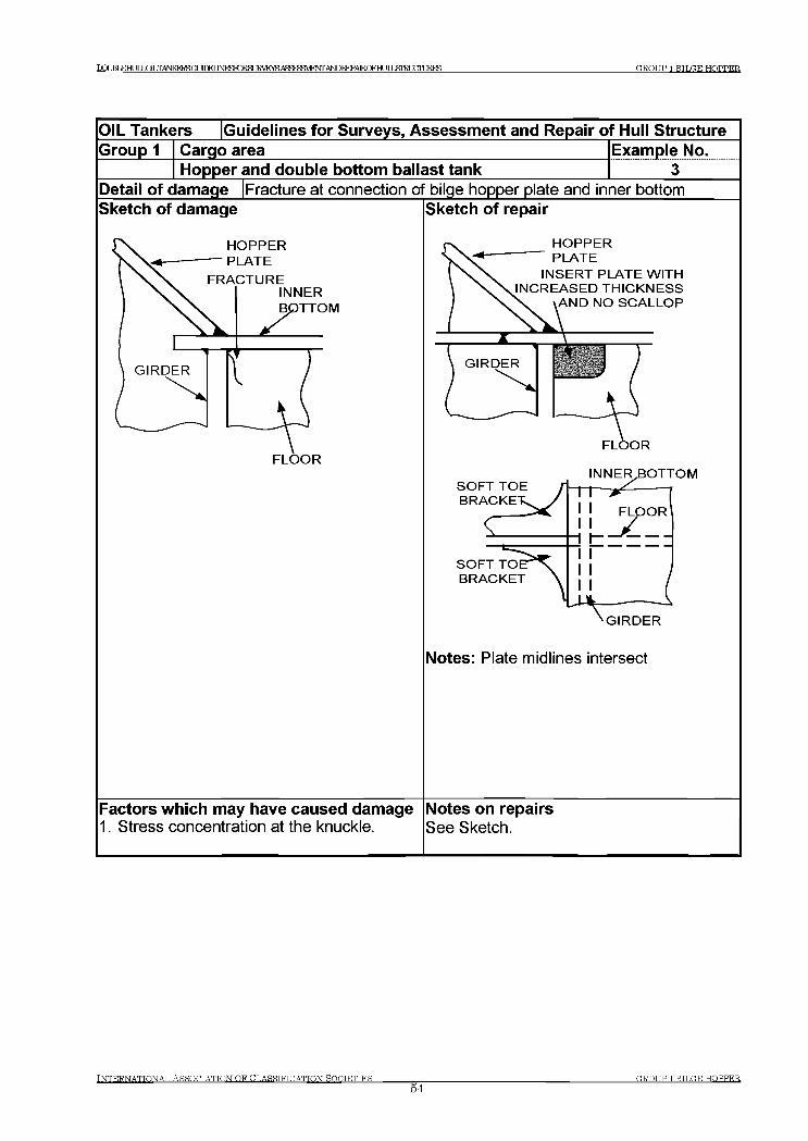
PCI JRT EHI IT LOT .TANKFRSGUfnPT INRSIO^SUElVE^SAffTpFHVIF^ANDFEPAIROFHLJIIЯШТ O U R E S GROUP 1 BILGE HOPPER
INTERNATIONAL ASSOCIATION OF CLASSIFICATION fiOCTETTES54
GROUP 1 ВТРОЕ HOPPER
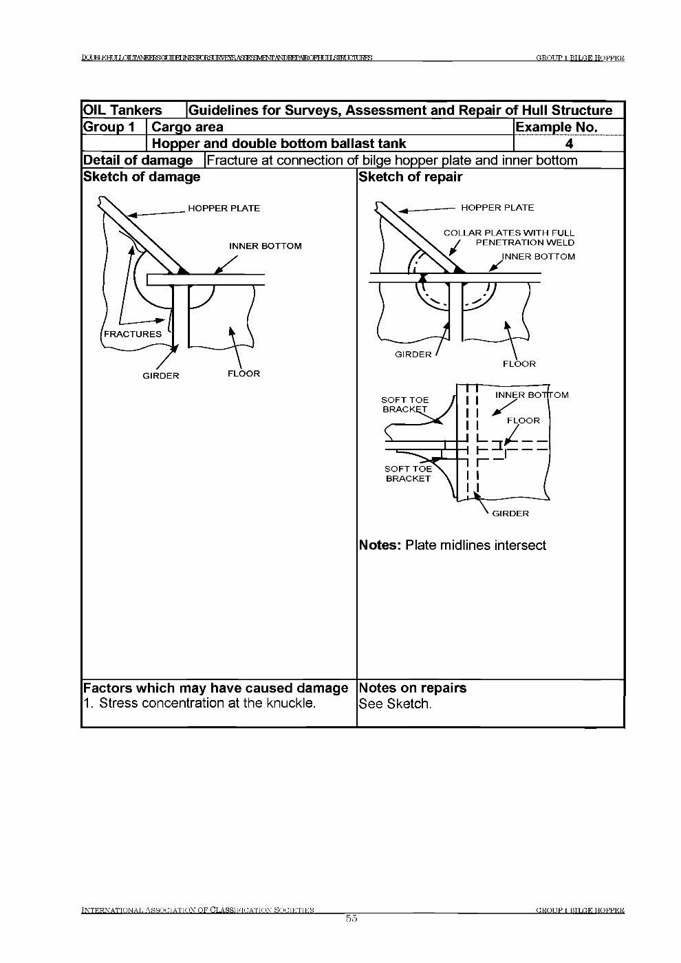
DCfJKTEHI IT TANFO^I^GUfTraiNRSlO^SUElVE^SAffTpFHVIF^Alsroi^Al^Fra^JKirayTlLEES GROUP 1 BILGE HOPPER
OIL Tankers [Guidelines for Surveys, Assessment and Repair of Hull StructureGroup 1 Cargo area
Hopper and double bottom ballast tankExample No.............. 4 ......
Detail of damage |Fracture at connection о bilge hopper plate and inner bottomSketch of damage Sketch of repair
Notes: Plate midlines intersect
Factors which may have caused damage Notes on repairs1. Stress concentration at the knuckle. See Sketch.
I N T E R N A T I O N A L A S S O C I A T IO N O F C L A S S I F I C A T I O N S O C I E T I E S55
GROUP 1 BTLGE HOPPER
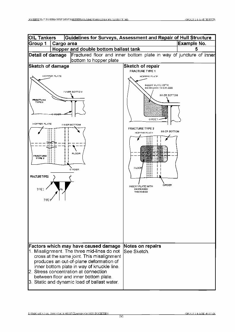
GROUP 1 BILGE HOPPERP a JBT Е Н Г lULQLTANKERSGT Т Г Г И 1и г е Ю К 8Ш \ Ц У 5А ^ ^ Ш Е Ж ; Т О Ю А ^ Г Ш 1Ь & Т Ш С Т Ш Е З
OIL Tankers G uidelines fo r Surveys, Assessm ent and Repair of Hull StructureG roup 1 Cargo area Exam ple No.
Hopper and double bottom ballast tank 5Detail o f dam age Fractured floor and inner bottom plate in way of juncture of inner
bottom to hopper plateSketch of dam age
H O P P E R P L A T E
H O P P E R P L A T E IN N E R B O T T O M
TYPE 1'
Sketch o f repairFRACTURE TYPE 1
HOPPER PLATE
INSERT PLATE WITH INCREASED THICKNESS
INNER BOTTOM
FRACTURE TYPE 2
HOPPER PLATEINNER BOTTOM
INSERT PLATE WITH INCREASED THICKNESS
Factors w hich may have caused dam age1. Misalignment. The three mid-lines do not
cross at the same joint. This misalignment produces an out-of-plane deformation of inner bottom plate in way of knuckle line.
2. Stress concentration at connection between floor and inner bottom plate.
3. Static and dynamic load of ballast water.
Notes on repairsSee Sketch.
INTERNATIONAL ASSOCIATION OF CLASSIFICATION SOCIETIES____________56
O, ROT IP 1 BTLC,E HOPPER.
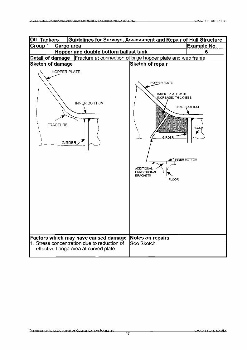
DCUBT Е Н Г ТГ LOILTANKERSOT УГГКГ INraTORSUE E AqSf MW A I AEOFHUIXSIRUCIURES GROUP 1 BILGE HOPPED.
INTERNATIONAL ASSOCIATION OF CLASSIFICATION SOCIETIES57
GROUP 1 BTTUE HOPPER
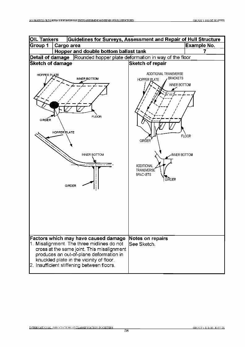
DOT IRT КНИГ LOLTANIKFRSGUmPT I N F O R M JR V E raA ^FJ^^FW A N D FE PA IR O FH f TTI5ЛКГ FTTURES GROUP 1 BILGE HOPPER
O IL Tankers [Guidelines fo r Surveys, Assessm ent and Repair o f Hull StructureG roup 1 Cargo area Exam ple No.
Hopper and double bottom ballast tankDetail o f dam age |Rounded hopper plate deformation in way of the floorSketch o f dam age
INNER BOTTOM
GIRDER
Sketch o f repair
ADDITIONAL TRANSVERSE
HOPPER BRACKETS
FLOOR
INNER BOTTOM
ADDITIONALTRANSVERSEBRACKETS
Factors w hich may have caused dam age1. Misalignment. The three midlines do not
cross at the same joint. This misalignment produces an out-of-plane deformation in knuckled plate in the vicinity of floor.
2. Insufficient stiffening between floors.
Notes on repairsSee Sketch.
INTERNATIONAL ASSOCIATION OF CLASSIFICATION SOCIETIES____________58
GROUP 1 BTLGE HOPPER
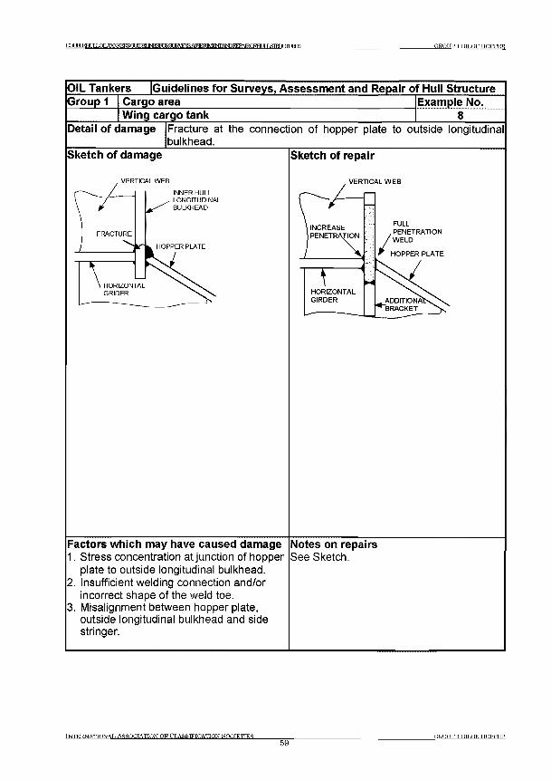
DOtMEHT I Ш 1 Ь т 1 К Е Б 5 д Ш Ж Д ^ К т а 8 Ш \ ^ ^ Е ^ М ^ А Ы Р К Е Р А Т Е Ю Р Н Т 115 Ш7 Г Г Т Ш г а Б GROUP 1 BILGE HOPFF1R
OIL Tankers [Guidelines for Surveys, Assessm ent and Repair of Hull StructureGroup 1 Cargo area Example No.
Wing cargo tank 8Detail o f damage Fracture at the connection of hopper plate to outside longitudinal
bulkhead.Sketch of damage
VERTICAL WEB
INNER HULLLONGITUDINALBULKHEAD
Sketch of repair
VERTICAL WEB
FULLPENETRATIONWELD
HOPPER PLATE
Factors which may have caused damage1. Stress concentration at junction of hopper
plate to outside longitudinal bulkhead.2. Insufficient welding connection and/or
incorrect shape of the weld toe.3. Misalignment between hopper plate,
outside longitudinal bulkhead and side stringer.
Notes on repairsSee Sketch.
INTERNATTONAT. ASSOCIATION OF CLASSIFICATION SOCIETIES_____________59
GROUP 1 BTLGE HOPPER
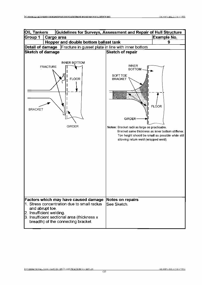
P q JRT К Н И Г L O L T A N K F K S G U in F I ] Ы Я 1 Ж Ж З и Н У Е т а А Ж Р ? Я Ш Ф Л ,Д Ь Ш Ж Р А 1 1 Ю Г Н Г IT IЯ 1 Н 1 Ж Е Е Б GROUP 1 BILGK HOPPER
O IL Tankers [Guidelines fo r Surveys, Assessm ent and Repair o f Hull StructureG roup 1 Cargo area Exam ple No.
Hopper and double bottom ballast tankDetail o f dam age |Fracture in gusset plate in line with inner bottomSketch o f dam age Sketch o f repair
INNER BOTTOM
Factors w hich m ay have caused dam age1. Stress concentration due to small radius
and abrupt toe.2. Insufficient welding.3. Insufficient sectional area (thickness x
breadth) of the connecting bracket.
Notes: Bracket radii as large as practicable.Bracket same thickness as inner bottom stiffener. Toe height should be small as possible while still allowing return weld (wrapped weld).
Notes on repairsSee Sketch.
Tnter.nattonat, Assootatton of Classification Rootettes
60GROUP 1 HUGE HOPPER
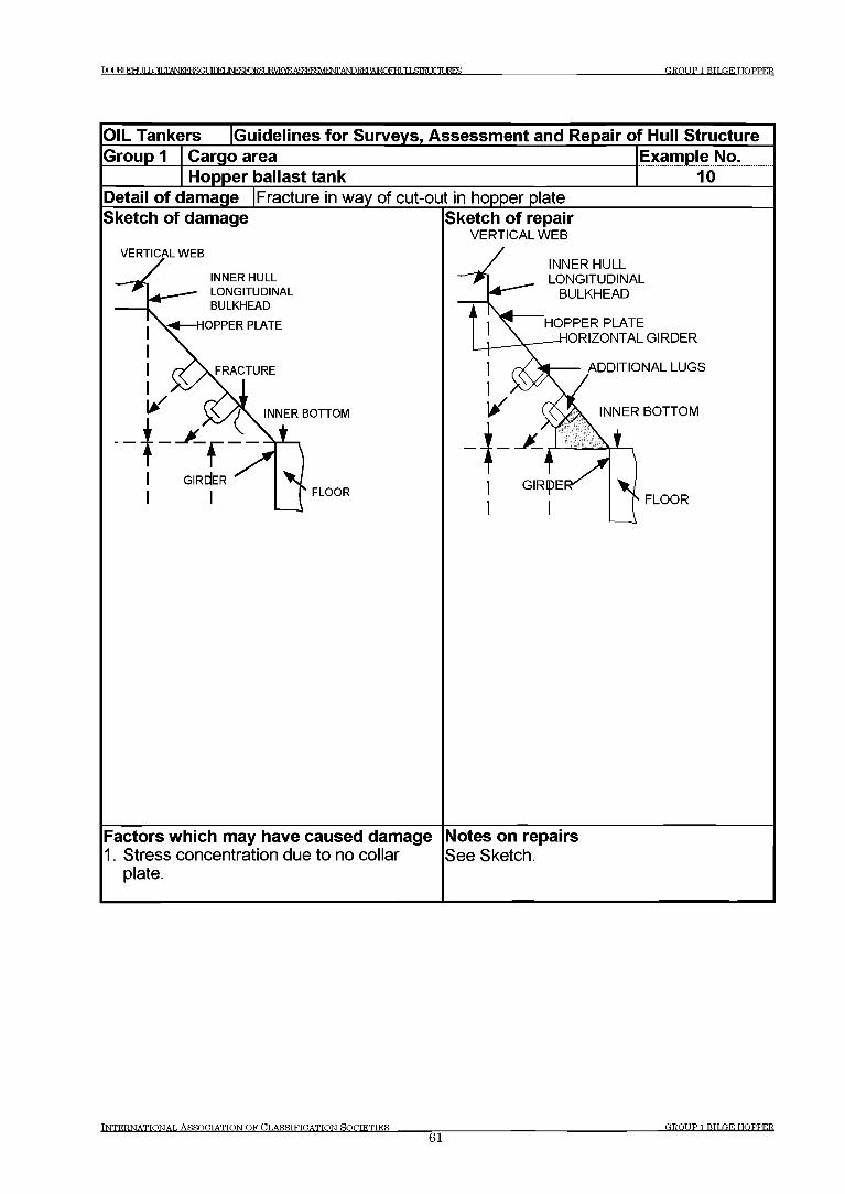
DC1IRTEHT ТГ L O T .TA N K FR SG U inFl ] Ы Я 1 Ж Ж З и Н У Е т а А Ж Р ? Я Ш Ф Л ,Д Ь Ш Ж Р А 1 1 Ю Р тН Г И I $Ш FTTURES GROUP 1 BILGE HOPPER
OIL Tankers Guidelines for Surveys, Assessm ent and Repair of Hull StructureGroup 1 Cargo area Example No.
Hopper ballast tank 10Detail o f damage Fracture in way of cut-out in hopper plateSketch of damage
VERTICAL WEB
INNER HULL LONGITUDINAL BULKHEAD
HOPPER PLATE
FRACTURE
INNER BOTTOM
L
FLOOR
Sketch of repairVERTICAL WEB
INNER HULL LONGITUDINAL
BULKHEAD
HOPPER PLATEORIZONTAL GIRDER
ADDITIONAL LUGS
INNER BOTTOM
FLOOR
Factors which may have caused damage1. Stress concentration due to no collar
plate.
Notes on repairsSee Sketch.
TNTKRNATTONAT. ASSOCTATTON OF CLASSIFICATION SOCIETIES___________61
GROUP 1 BILGE HOPPER
PqjBI£HULmLTANPCFT^GUinFI 1ЫГСЖЖШКУЕУ5АсЯтеМФЛ^ ИIЯШТ mURES GROUP 2 WING BALLAST TANK
Group 2 Wing Ballast Tank
Contents
1 General
2 What to look for
2.1 Material wastage2.2 Deformations2.3 Fractures
3 General comments on repair
3.1 Material wastage3.2 Deformations3.3 Fractures
Examples of structural detail failures and repairs - Group 2
Example No. Title1 Crack in way of connection of longitudinals to transverse bulkhead2 Crack in way of connection of longitudinals to transverse webs3 Fracture in way of web and flat bar stiffener at cut outs for
longitudinal stiffener connections4 Fracture in way of web and flat bar stiffener at cut outs for longitudinal
stiffener connections as Example 3 but with faceplate attached to underside of web. Flat bar lap welded.
5 Buckling in way of side web panels above hopper horizontal girder6 Panels of side horizontal girders in way of transverse bulkhead7 Fracture at connection of horizontal stringers to transverse web
frames and horizontal girders
INTERNATIONAL ASSOCIATIONOFCLASSTFICATIONSOCIETIES62
GROUP WING BALLAST TANK
Т П М к н и г LOILTANKERSUt 1 Г П Е Г INreTORSUEVEYSASSrecMTNF A^REPAIRQFEMXSIEUCIURES GROUP 2 WING BALLAST TANK
1 General
1.1 Wing Ballast tanks are highly susceptible to corrosion and wastage of the internal structure. This is a potential problem for all double hull tankers, particularly for ageing ships and others where the coatings have broken down. Coatings, if applied and properly maintained, serve as an indication as to whether the structure remains in satisfactory condition and highlights any structural defects.
In some ships wing ballast tanks are protected by sacrificial anodes in addition to coatings. This system is not effective for the upper parts of the tanks since the system requires the structure to be fully immersed in seawater, and the tanks may not be completely filled during ballast voyages.
1.2 Termination of longitudinals in the fore and aft regions of the ship, in particular at the collision and engine room bulkheads, is prone to fracture due to high stress concentration if the termination detail is not properly designed.
2 What to look for
2.1 Material wastage
2.1.1 The combined effect of the marine environment, high humidity atmosphere as well as adjacent heated cargo tanks within wing ballast tank will give rise to a high corrosion rate.
2.1.2 Rate and extent of corrosion depends on the environmental conditions, and protective measures employed, such as coatings and sacrificial anodes. The following structures are generally susceptible to corrosion.
(a) Structure in corrosive environment:- Deck plating and deck longitudinal- Transverse bulkhead adjacent to heated fuel oil tank
(b) Structure subject to high stress:- Connection of side longitudinal to transverse
(c) Areas susceptible to coating breakdown:- Back side of faceplate of longitudinal- Welded joint- Edge of access opening
INTERNATIONAL ASSOCIATIONOFCLASSIFICATIONSOCIETIES63
GROUP 2 WTNO BALLAST TANK
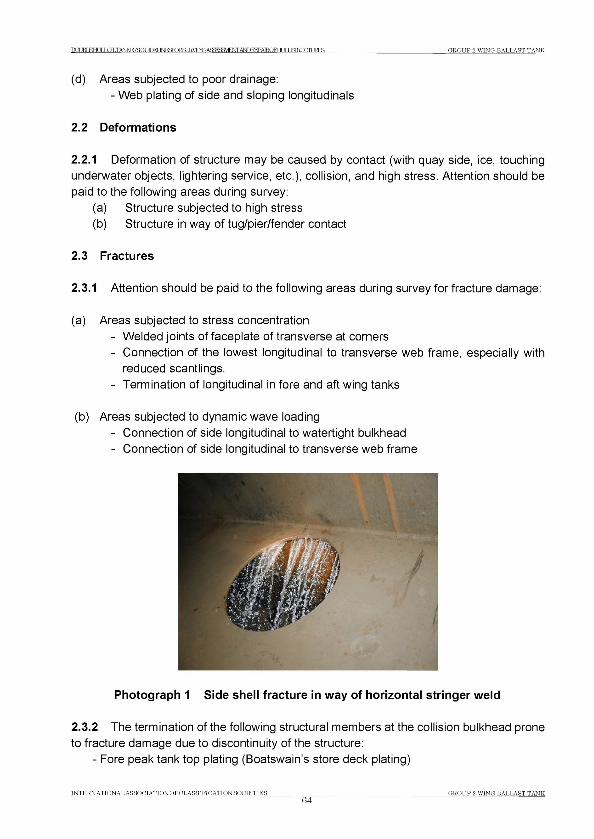
DCQBLEHLXLOLTANKERSOr Л Г К Г INFTT€RSURVEYSA£^£^E^ANDREPAIRQFHUU^gIH О Т JRES TROUP 2 WING BALLAST TANK
(d) Areas subjected to poor drainage:- Web plating of side and sloping longitudinals
2.2 Deformations
2.2.1 Deformation of structure may be caused by contact (with quay side, ice, touching underwater objects, lightering service, etc.), collision, and high stress. Attention should be paid to the following areas during survey:
(a) Structure subjected to high stress(b) Structure in way of tug/pier/fender contact
2.3 Fractures
2.3.1 Attention should be paid to the following areas during survey for fracture damage:
(a) Areas subjected to stress concentration- Welded joints of faceplate of transverse at corners- Connection of the lowest longitudinal to transverse web frame, especially with
reduced scantlings.- Termination of longitudinal in fore and aft wing tanks
(b) Areas subjected to dynamic wave loading- Connection of side longitudinal to watertight bulkhead- Connection of side longitudinal to transverse web frame
Photograph 1 Side shell fracture in way of horizontal stringer weld
2.3.2 The termination of the following structural members at the collision bulkhead prone to fracture damage due to discontinuity of the structure:
- Fore peak tank top plating (Boatswain’s store deck plating)
INTERNATIONAL ASSOCIATIONOFCLASSIFICATION SOCIETIES64
CROUP 2 WING BALLAST TANK

TO TRT ИНГ ТГ LOILTANKERSGt ШЕГ IM^TORSLE^raA^SFy^FWAlSDI^Al^Fra JTIЯТМ FTTURES GROUP 2 WING BALLAST TANK
In order to avoid stress concentration due to discontinuity appropriate stiffeners are to be provided in the opposite space. If such stiffeners are not provided, or are deficient due to corrosion or misalignment, fractures may occur at the terminations.
3 General comments on repair
3.1 Material wastage
3.1.1 If the corrosion is caused by high stress concentration, renewal with original thickness is not sufficient to avoid reoccurrence. Renewal with increased thickness and/or appropriate reinforcement should be considered in conjunction with appropriate corrosion protective measures.
3.2 Deformations
3.2.1 Any damage affecting classification should be reported to the classification society. If the deformation is considered to be related to inadequate structural strength, appropriate reinforcement should be carried out. Where the deformation is related to corrosion, appropriate corrosion prevention measures should be considered. Where the deformation is related to mechanical damages the structure is to be repaired as original.
3.3 Fractures
3.3.1 If the cause of the fracture is fatigue under the action of cyclic wave loading, consideration should be given to the improvement of structural detail design, such as provision of soft toe bracket, to reduce stress concentration. If the fatigue fracture is vibration related, the damage is usually associated with moderate stress levels at high cycle rate, improvement of structural detail may not be effective. In this case, avoidance of resonance, such as providing additional stiffening, may be considered.
Where fracture occurs due to material under excessive stress, indicating inadequate structural strength, renewal with thicker plate and/or providing appropriate reinforcement should be considered.
INTERNATIONAL ASSOCIATIONOFCLASSIFICATION SOCIETIES65
GROUP 2 WING BALLAST TANK

T O TRT КНИГ LOILTANKERSOT УГПЕГ INraTO RSU E^E^AS^BaV EN TA^REPAIRO FHr ТГ I .STRT ТГГТURES GROUP 2 WING BALLAST TANK
Group 2 Wing Ballast Tank
OIL Tankers |Guidelines for Surveys, Assessment and Repair of Hull StructureGroup 2 Cargo area
Wing ballast tankExample No..............1.......
Detail of damage |Crack in way of connection of longitudinals to transverse bulkhead Sketch of damage ISketch of repair
Factors which may have caused damage1. Asymmetrical connection of bracket
without backing bracket.2. Relative deflection of adjoining
transverse web against transverse bulkhead.
3. Additional biaxial bending stresses due to asymmetry of the angle bar longitudinal instead of symmetric T section.
4. Dynamic load in the vicinity of the water line.
5. Large upstand at bracket toe.
Notes on repairsSee Sketch.
INTERNATIONAL ASSOCIATIONOFCLASSIFICATION SOCIETIES66
GROUP 2 WING BALLAST TANK
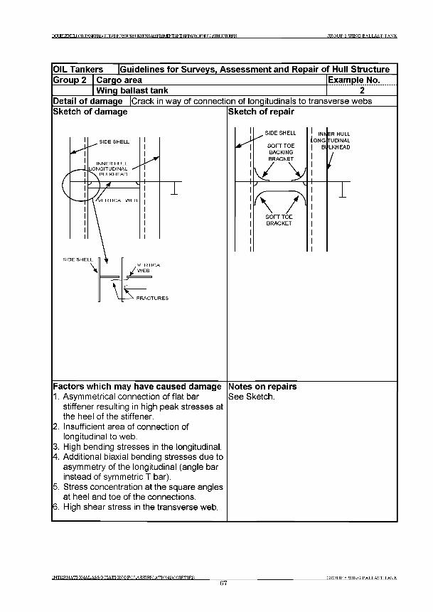
DCXM EHIЛI OH ,TANKFRF»GI ТПТЕГ JNFSRTR511RVEYR ASFJ&MFNT ANDREPATROFHT ЯI ЯШТ О Т IRES GROUP 2 W ING RALLAST TANK
OIL Tankers Guidelines for Surveys, Assessm ent and Repair of Hull StructureGroup 2 Cargo area Example No.
Wing ballast tank 2Detail o f damage Crack in way of connection of longitudinals to transverse websSketch of damage Sketch of repair
Factors which may have caused damage1. Asymmetrical connection of flat bar
stiffener resulting in high peak stresses at the heel of the stiffener.
2. Insufficient area of connection of longitudinal to web.
3. High bending stresses in the longitudinal.4. Additional biaxial bending stresses due to
asymmetry of the longitudinal (angle bar instead of symmetric T bar).
5. Stress concentration at the square angles at heel and toe of the connections.
6. High shear stress in the transverse web.
Notes on repairsSee Sketch.
INTERNATIONAL ASSOCIATIONOFCLASSTFTCATION SOCIETIES67
GROUP 2 WING BALLAST TANK
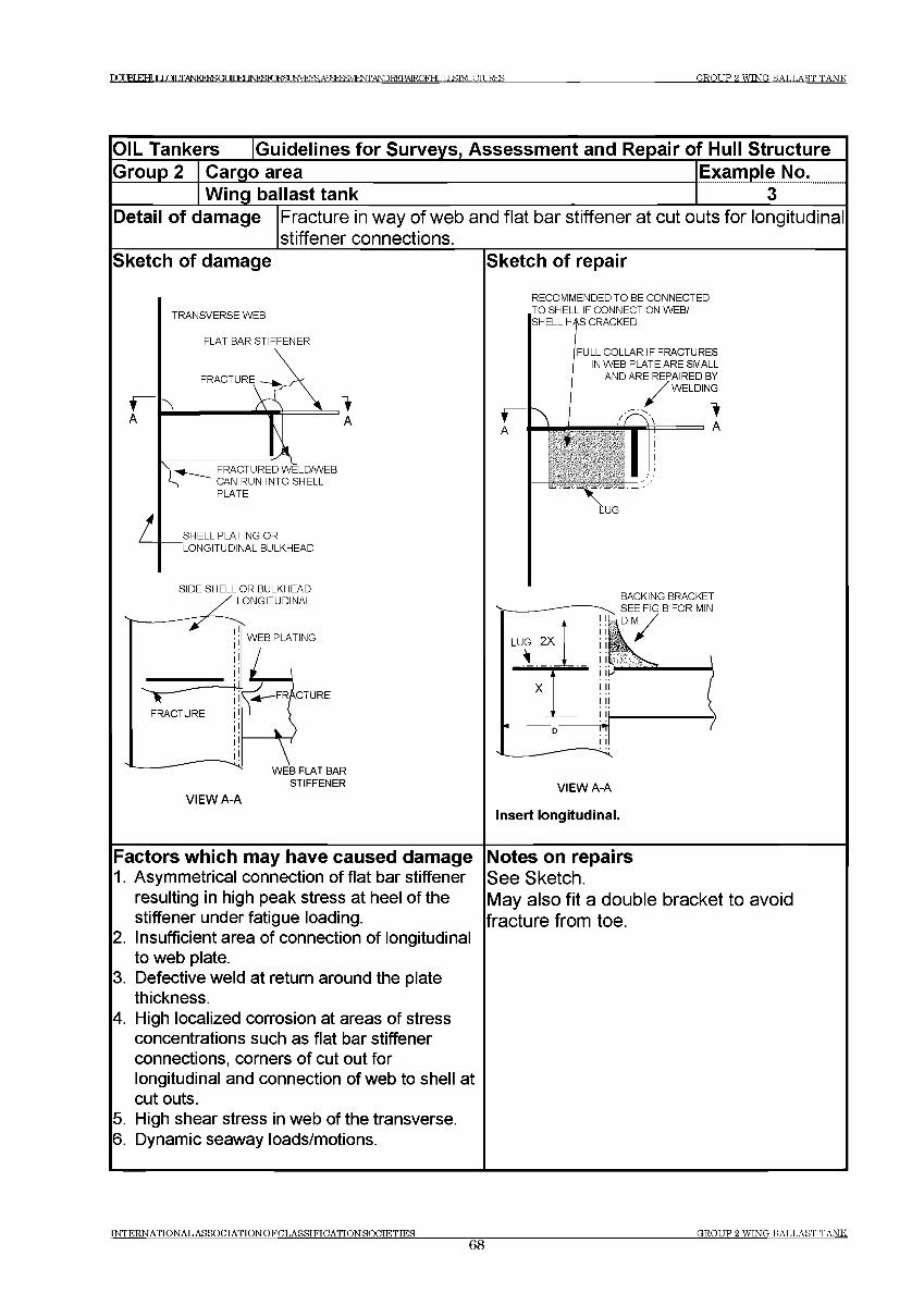
D O J B L E H I I J О Т T A N K F R B G U r T W I N F K I O ^ M V E ^ A S ^ ^ E ^ i W D ^ P A I R Q F H U I L S I E U a i U R E S GROUP 2 WING BALLAST TANK
OIL Tankers [Guidelines for Surveys, Assessment and Repair of Hull StructureGroup 2 Cargo area
Wing ballast tankExample No........... з ....
Detail of damage Fracture in way of web and flat bar stiffener at cut outs for longitudinal stiffener connections.
Sketch of damage Sketch of repair
TRANSVERSE WEB
RECOMMENDED TO BE CONNECTED TO SHELL IF CONNECTION WEB/ SHELL HAS CRACKED.
FLAT BAR STIFFENER
SHELL PLATING OR LONGITUDINAL BULKHEAD
FULL COLLAR IF FRACTURES IN WEB PLATE ARE SMALL
AND ARE REPAIRED BY WELDING
Iii
A
SIDE SHELL OR BULKHEAD
VIEW A-A
BACKING BRACKET
VIEW A-A
Insert longitudinal.
Factors which may have caused damage1. Asymmetrical connection of flat bar stiffener
resulting in high peak stress at heel of the stiffener under fatigue loading.
2. Insufficient area of connection of longitudinal to web plate.
3. Defective weld at return around the plate thickness.
4. High localized corrosion at areas of stress concentrations such as flat bar stiffener connections, corners of cut out for longitudinal and connection of web to shell at cut outs.
5. High shear stress in web of the transverse.6. Dynamic seaway loads/motions.
Notes on repairsSee Sketch.May also fit a double bracket to avoid fracture from toe.
INTERNATIONAL ASSOCIATIONOFCLASSIFICATTONSOCIETIES68
GROUP 2 WING BALLAST TANK

TO TRT К Н И Г LOILTANKERSGt 1Г П Е Г JNF^TORSLIRVE^AS^^E^iTOICTAIROFHLJIL&TEUaiURES GROUP 2 WING BALLAST TANK
OIL Tankers [Guidelines for Surveys, Assessment and Repair of Hull StructureGroup 2 Cargo area
Wing ballast tankExample No...............4.......
Detail of damage Fracture in way of web and flat bar stiffener at cut outs for longitudinal stiffener connections as Example 3 but with faceplate attached to underside of web. Flat bar lap welded.______________________
Sketch of damage
L
TRANSVERSE WEB
\
AFRACTURED WELD/WEB
' CAN RUN INTO SHELL PLATE
SHELL PLATING OR
"LONGITUDINAL BULKHEAD
SIDE SHELL OR BULKHEAD ' LONGITUDINAL
WEB PLATING
WEB FLAT BAR STIFFENER
VIEW A-A
Sketch of repair
RECOMMENDED TO BE CONNECTED TO SHELL IF CONNECTION WEB/ SHELL HAS CRACKED.
FULL COLLAR IF FRACTURES IN WEB PLATE ARE SMALL
AND ARE REPAIRED BY /W E L D IN G
a:
BACKING BRACKET
WEB STIFFENER
VIEW A-A
Insert web plate.
Factors which may have caused damage1. Asymmetrical connection of flat bar stiffener
resulting in high peak stress at heel of the stiffener under fatigue loading.
2. Fabricated longitudinal with welding onto exposed edge of the web resulting in poor fatigue strength of the connection of the longitudinal to the flat bar.
3. Insufficient area of connection of longitudinal to web plate.Defective weld at return around the plate thickness.High localized corrosion at areas of stress concentrations such as flat bar stiffener connections, corners of cut out for longitudinal and connection of lug to shell at cut outs.
6. High shear stress in web of the transverse.7. Dynamic seaway loads/motions.
Notes on repairsSee Sketch.1. May also fit a double bracket to avoid
fracture from toe.
INTERNATIONAL ASSOCIATIONOFCLASSIFICATIONSOCIETIES___________________________________________________ GROUP 2 WTNG BALLAST TANK69
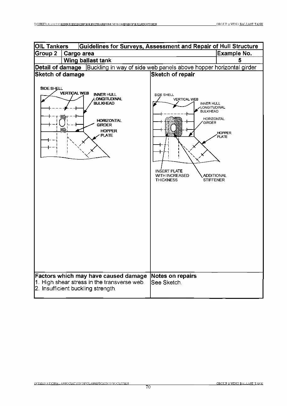
ГРУНТ КНИГ LQTLTANKERSOT УГПЕГ INFSlOiSLIEflE»^ ТГ T ,STRI TOTURES G R O U P 2 W IN G B A L L A S T T A N K
IN T E R N A T IO N A L A S S O C IA T IO N O F C L A S S IF IC A T T O N S O C IE T IE S70
G R O U P 2 W IN G B A L L A S T T A N K
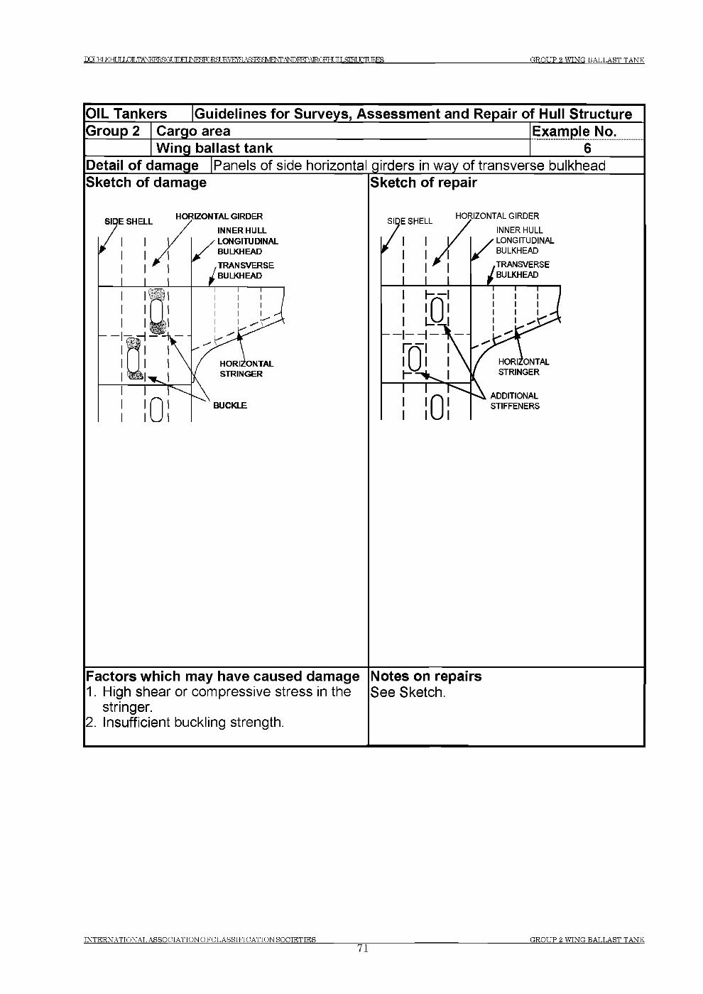
D C m E H IX L O IL T A N K F R S G t JTTM IM ^roR SU E ^E ^A S^B aV E tSfT A N D E E P A IR O FH r ТГ Г ,STRI TGTURES G R O U P 2 W IN G B A L L A S T T A N K
OIL Tankers Guidelines for Surveys, Assessment and Repair of Hull StructureGroup 2 Cargo area Example No.
Wing ballast tank 6Detail of damage Panels of side horizontal girders in way of transverse bulkheadSketch of damage Sketch of repair
Factors which may have caused damage1. High shear or compressive stress in the
stringer.2. Insufficient buckling strength.
Notes on repairsSee Sketch.
I N T E R N A T I O N A L A S S O C I A T IO N O F C L A S S I F IC A T IO N S O C I E T I E S __________________________________________________________________________________ G R O U P 2 W IN G B A L L A S T T A N K71
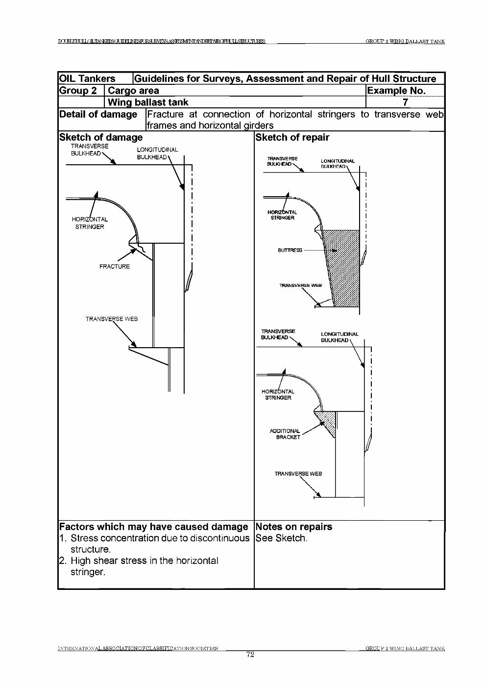
DaiRfFTHTir LOLTANKERSOT П Г М INF RZRgURVE Acf}^^f^n,AI ICTAI FHf TTIЯ Ш Т HTURES GROUP 2 WING BATJAST TANK
OIL Tankers [Guidelines for Surveys, Assessment and Repair of Hull StructureGroup 2 Cargo area
Wing ballast tankExample No.............. 7......
Detail of damage Fracture at connection of horizontal stringers to transverse web frames and horizontal girders______________________________
Sketch of damageTRANSVERSE BULKHEAD
LONGITUDINAL BULKHEAD
TRANSVERSE WEB
Sketch of repair
Factors which may have caused damage1. Stress concentration due to discontinuous
structure.2. High shear stress in the horizontal
stringer.
Notes on repairsSee Sketch.
I N T E R N A T I O N A L A S S O C I A T IO N O F C L A S S I F IC A T T O N S O C IE T IE S __________________________________________________________________________________G R O U P 2 W IN G B A L L A S T T A N K
72
Т О М К Н И Г LCaLTANESERSGLnTM 1 М Р ^ Г О Е 8 Ш У Е Ж А ^ ^ Ш Е Ж ^ Т О Ю А Е О Г Н и 1 Ь & Т Ш С т а Е З G R O U P 3 BO T T O M BA LLA ST TA N K
Group 3 Bottom Ballast Tank
Contents
1 General
2 What to look for - Tank Top survey
2.1 Material wastage2.2 Deformations2.3 Fractures
3 What to look for - Double Bottom survey
3.1 Material wastage3.2 Deformations3.3 Fractures
4 What to look for - External Bottom survey4.1 Material wastage4.2 Deformations4.3 Fractures
5 General comments on repair
5.1 Material wastage5.2 Deformations5.3 Fractures
Examples of structural detail failures and repairs - Group 3Example No. Title
1 Cracks in way of longitudinals connected to watertight floors2 Fracture in way of stiffeners at connection of inner bottom and
bottom shell to transverse bulkhead and floors3 Connection of longitudinals to ordinary floors4 Connection of longitudinals to ordinary floors5 Panels of bottom girders in way of openings6 Cut-outs on floors7 Fractured stiffener connection to bottom and inner bottom
longitudinals
TNTERNATTONAT. ASSOETATTON O F CT.ASSTFTCATTON HOETETTES
73E.ROT IP 3 BOTTOM BAT.T.AST TANK
Г О В Т к н и г LOLTANKERSOr 1 Г П Е Г 1 М Р ^ Г О Е 8 Ш У Е Ж А Я Я Р Ш У 1 Р М ,А Ш Ж Р А Ж ) К Н и 1 Ь & Т Е и С П 1 Д ? Е 8 G R O U P 3 BO T T O M BA LLA ST TA N K
1 General
1.1 In addition to contributing to the longitudinal bending strength of the hull girder, the double bottom structure provides support for the cargo in the tanks. The bottom shell at the forward part of the ship may sustain increased dynamic forces caused by slamming in heavy weather.
2 What to look for - Tank Top survey
2.1 Material wastage
2.1.1 The general corrosion condition of the tank top structure may be observed by visual survey. The level of wastage of tank top plating may have to be established by means of thickness measurement. Special attention should be paid to areas where pipes, e.g. cargo piping, heating coils, etc are fitted close to the tank top plating, making proper maintenance of the protective coating difficult to carry out.
2.1.2 Grooving corrosion is often found in or beside welds, especially in the heat affected zone. The corrosion is caused by the galvanic current generated from the difference of the metallographic structure between the heat affected zone and base metal. Coating of the welds is generally less effective compared to other areas due to roughness of the surface, which exacerbates the corrosion. Grooving corrosion may lead to stress concentrations and further accelerate the corrosion process. Grooving corrosion may be found in the base material where coating has been scratched or the metal itself has been mechanically damaged.
2.1.3 On uncoated areas or where the coating has broken down, pitting corrosion may occur in the tank top plating within cargo tanks. If not properly maintained, this may lead to cargo leakage into the double bottom ballast spaces.
2.2 Deformations
2.2.1 Buckling of the tank top plating may occur between longitudinals in areas subject to in-plane transverse compressive stresses or between floors in areas subject to in-plane longitudinal compressive stresses.
2.2.2 Whenever deformations are observed on the tank top, further survey in the double bottom tanks is imperative in order to determine the extent of the damage. The deformation may cause the breakdown of coating within the double bottom, which in turn may lead to accelerated corrosion rate in these unprotected areas.
IN T E R N A T IO N A L A SS O C IA T IO N O F C L A S S IF IC A T IO N ROCTETTES
74G R O U P 3 B O T T O M BA LLA ST TA N K
Т П М к н и г LOLTANKERSCff У Г Г М INFSTORST JRVRYR AS BMNTANDREPAIROFHr ТГ T .9Ш TTTT ШЯ GROUP 3 BOTTOM BALLAST TANK
2.3 Fractures
2.3.1 Fractures will normally be found by close-up survey. Fractures that extend through the thickness of the plating or through the welds may be observed during pressure testing of the double bottom tanks.
3 What to look for - Double Bottom survey
3.1 Material wastage
3.1.1 The level of wastage of double bottom internal structure (longitudinals, transverses, floors, girders, etc.) may have to be established by means of thickness measurements. Rate and extent of corrosion depends on the corrosive environment, and protective measures employed, such as coatings and sacrificial anodes. The following structures are generally susceptible to corrosion (also see 3.1.2 - 3.1.4),
(a) Structure in corrosive environment:- Transverse bulkhead and girder adjacent to heated fuel oil tank.- Under side of inner bottom plating and attached longitudinals if the cargo tank
above is heated.
(b) Structure subject to high stress- Face plates and web plates of transverse at corners
c) Areas susceptible to coating breakdown- Back side of faceplate of longitudinal- Welded joint- Edge of access opening
3.1.2 If the protective coating is not properly maintained, structure in the ballast tank may suffer severe localised corrosion. In general, structure at the upper part of the double bottom tank usually has more severe corrosion than that at the lower part.
3.1.3 The high temperature due to heated cargoes may accelerate corrosion of ballast tank structure near these heated tanks. The rate of corrosion depends on several factors such as:
- Temperature and heat input to the ballast tank.- Condition of original coating and its maintenance.- Ballasting frequency and operations.- Age of ship and associated stress levels as corrosion reduces the thickness of the
structural elements and can result in fracturing and buckling.
INTERNATIONAL ASSOCIATION OF CLASSIFICATION SOCIETIES75
OROT IP 3 BOTTOM BALLAST TANK
Т П В Т к н и г LOLTANKERSOr Т Г Г К Г IM roRSUE E AS^BaVENT.ANDIEPAEOFHr JTI £Ш JGIURES GROUP 3 BOTTOM ВАТ JA S T TANK
3.1.4 Shell plating below suction head often suffers localized wear caused by erosion and cavitation of the fluid flowing through the suction head. In addition, the suction head will be positioned in the lowest part of the tank and water/mud will cover the area even when the tank is empty. The condition of the shell plating may be established by feeling by hand beneath the suction head. When in doubt, the lower part of the suction head should be removed and thickness measurements taken. If the vessel is docked, the thickness can be measured from below. If the distance between the suction head and the underlying shell plating is too small to permit access, the suction head should be dismantled. The shell plating below the sounding pipe should also be carefully examined. When a striking plate has not been fitted or is worn out, heavy corrosion can be caused by the striking of the weight of the sounding tape.
3.2 Deformations
3.2.1 Where deformations are identified during tank top survey (See 2.2) and external bottom survey (See 4.2), the deformed areas should be subjected to internal survey to determine the extent of the damage to the coating and internal structure.
Deformations in the structure not only reduce the structural strength but may also cause breakdown of the coating, leading to accelerated corrosion.
3.3 Fractures
3.3.1 Fractures will normally be found by close-up survey.
(a) Fractures in the inner bottom longitudinals and the bottom longitudinals in way of the intersection with the watertight floors below the transverse bulkhead stools.
(b) Lamellar tearing of the inner bottom plate below the weld connection with the stool in the cargo oil tank caused by large bending stresses in the connection when in heavy ballast condition. The size of stool and lack of full penetration welds could also be a contributory factor, as well as poor “through-thickness” properties of the tank top plating.
3.3.2 Transition region
In general, the termination of the following structural members at the collision bulkhead and engine room forward bulkhead may be prone to fractures:
- Hopper tank sloping plating- Panting stringer in fore peak tank- Inner bottom plating in engine room
In order to avoid stress concentration due to discontinuity appropriate stiffeners are to be provided in the opposite space. If such stiffeners are not provided, or are deficient due to corrosion or misalignment, fractures may occur at the terminations.
TNTERNATTONAT. ASSOCTATTON O F CIT.ASSTFTOATTON ROOTETTES
7 6GROUP 3 BOTTOM BALLAST TANK
Г О В Т к н и г LOLTANKERSOr 1 Г П Е Г 1 М Р ^ Г О Е 8 Ш У Е Ж А ^ ^ Ш Е Ж ^ Т О Ю А Е О Г Н и 1 Ь & Т Ш С т а Е З G R O U P 3 B O T T O M BA LLA ST T A NK
4 What to look for - External Bottom survey
4.1 Material wastage
4.1.1 Hull structure below the water line can usually be surveyed only when the ship is dry-docked. The opportunity should be taken to inspect the external plating thoroughly. The level of wastage of the bottom plating may have to be established by means of thickness measurements.
4.1.2 Severe grooving along welding of bottom plating is often found (See also Photographs 1 and 2 in Group 1). This grooving can be accelerated by poor maintenance of the protective coating and/or sacrificial anodes fitted to the bottom plating.
4.1.3 Bottom or “docking” plugs should be carefully examined for excessive corrosion along the edge of the weld connecting the plug to the bottom plating.
4.2 Deformations
4.2.1 Buckling of the bottom shell plating may occur between longitudinals or floors in areas subject to in-plane compressive stresses (either longitudinally or transversely). Deformations of bottom plating may also be attributed to dynamic force caused by wave slamming action at the forward part of the vessel, or contact with underwater objects. When deformation of the shell plating is found, the affected area should be surveyed internally. Even if the deformation is small, the internal structure may have suffered serious damage.
4.3 Fractures
4.3.1 The bottom shell plating should be surveyed when the hull has dried since fractures in shell plating can easily be detected by observing leakage of water from the cracks in clear contrast to the dry shell plating.
4.3.2 Fractures in butt welds and fillet welds, particularly at the wrap around at scallops and ends of bilge keel, are sometimes observed and may propagate into the bottom plating. The cause of fractures in butt welds is usually related to weld defect or grooving. If the bilge keels are divided at the block joints of hull, all ends of the bilge keels should be surveyed.
IN T E R N A T IO N A L A S S O C IA T IO N O F C L A S S IF IC A T IO N S O C IE T IE S
77GROT TP Я B O T T O M BAT L A S T TA NK
DqjBLEHI Я JOT .TANKFRSGUfnPT INFSRIRgUKVEra Д Я й Р Я Я У 1 Р ^ Д Ь Ю 1 ^ А 1 Е Ю Е Н Г И I Я Ш Т FTTURES G R O U P 3 BO T T O M BA LLA ST TA N K
5 General comments on repair
5.1 Material wastage
5.1.1 Repair work in double bottom will require careful planning in terms of accessibility and gas freeing is required for repair work in cargo oil tanks.
5.1.2 Plating below suction heads and sounding pipes is to be replaced if the average thickness is below the acceptable limit. When scattered deep pitting is found, it may be repaired by welding.
5.2 Deformations
Extensively deformed tank top and bottom plating should be replaced together with the deformed portion of girders, floors or transverse web frames. If there is no evidence that the deformation was caused by grounding or other excessive local loading, or that it is associated with excessive wastage, additional internal stiffening may need to be provided. In this regard, the Classification Society concerned should be contacted.
5.3 Fractures
5.3.1 Repair should be carried out in consideration of nature and extent of the fractures.
(a) Fractures of a minor nature may be veed-out and rewelded. Where cracking is more extensive, the structure is to be cropped and renewed.
(b) For fractures caused by the cyclic deflection of the double bottom, reinforcement of the structure may be required in addition to cropping and renewal of the fractured part.
(c) For fractures due to poor through thickness properties of the plating, cropping and renewal with steel having adequate through thickness properties is an acceptable solution.
TNTERNATTONAT, ASSOOTATTON O F О Т .ARRTRTCATTON Й О С Т Е Т Т Е Я
78G R O U P Я B O T T O M BAT,T,AST TA NK

IXXBIEHULIOILTANKERSGt 1 Ю Е Г INEHTORRT IRVEYH ASaSgVEWTANDBEPAlROFH 11 ,S M У О Г С JRES__________________________________________ G R O U P 3 B O T T O M BAT .LA ST T A N K
G roup 3 Bottom B allast Tank
OIL Tankers [Guidelines for Surveys, Assessment and Repair of Hull StructureGroup 3 Cargo area Example No.__________ Bottom ballast tank___________________________________ ________\Detail o f damage |Cracks in way of longitudinals connected to watertight floors^Sketch of damage
TRANSVERSEBULKWEAD
Л
FRACTURES*a
A
INNER BOTTOM
/WATERTIGHTFLOOR
BOTTOM SHELL
Sketch of repair
SO FTTO E BRACKET i
! И
BULKHEAD
/INNERBOTTOM
L <
S O F T T O E ^ I |
N t
/ у 1 SOFT TOE J> BACKING
BRACKET
__________ ____ iBOTTOM SHELL
Factors which may have caused damage1. Asymmetrical connection of bracket in
association with a backing bracket, which is too small.
2. Relative deflection between adjacent floor and transverse bulkhead.
3. Inadequate shape of the brackets.4. High stresses in the inner bottom
longitudinal and the floor stiffener.
Notes on repairsSee Sketch.
INTERNATTONAT, ASSOCIATTON OF CT.ASRTFTGATTON HOGTETTES79
G R O U P 3 B O T T O M RAT P A R T T A N K
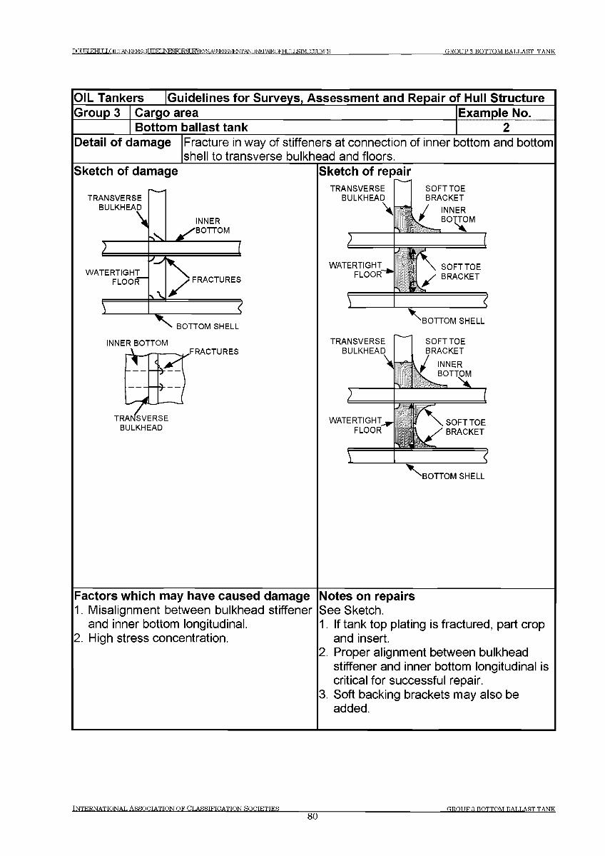
ПЛПКГКННГ LOTT TANKFRSGT УГПЕГ INFfiTORSURVRYS AS BSVEtSfrANDEEPAIROFHr TT T ,STEI TGTURES GROUP 3 BOTTOM BALLAST TANK
OIL Tankers [Guidelines for Surveys, Assessment and Repair of Hull StructureGroup 3 Cargo area
Bottom ballast tankExample No...................2.........
Detail of damage Fracture in way of stiffeners at connection of inner bottom and bottomshell to transverse bulkhead and floors.
Sketch of damage Sketch of repairTRANSVERSE
BULKHEAD
4—5*"
SOFTTOE BRACKET
/ INNER
)
WATERTIGHTtT \ SOFTTOE
FLOOR'"* BRACKET
>________ _______________ {4
x BOTTOM SHELL
INNER BOTTOM TRANSVERSEBULKHEAD
\
SOFTTOE BRACKET
INNER\ BOTTOM
> J 1 /СWATERTIGHT — / \ SOFTTOE
FLOOR \ У BRACKET
\ _____________ix BOTTOM SHELL
Factors which may have caused damage1. Misalignment between bulkhead stiffener
and inner bottom longitudinal.2. High stress concentration.
Notes on repairsSee Sketch.1. If tank top plating is fractured, part crop
and insert.2. Proper alignment between bulkhead
stiffener and inner bottom longitudinal is critical for successful repair.
3. Soft backing brackets may also be added.
INTERNATIONAL ASSOCIATION OF CLASSIFICATION SOCTETTES80
GROUP 3 BOTTOM BALLAST TANK
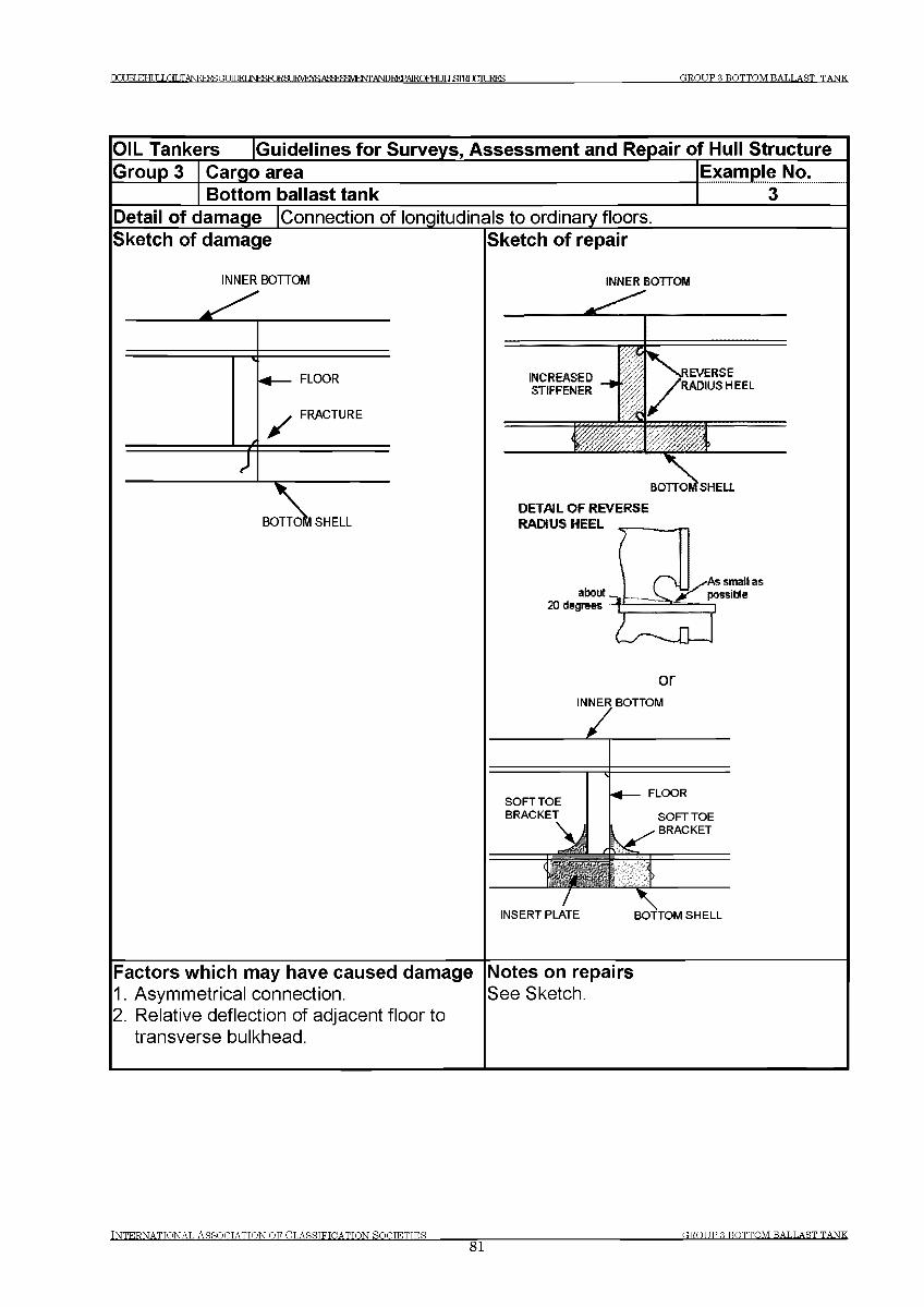
IXXJBIEHUL^ILTANKFRSGT ШТ^]ЫРК10^8иЕ1УЕ^АЯйР?ЯУ1Р^ДЬЮ1ЕРА1ЕОГНГ iriftlRITTItEES GROUP 3 BOTTOM RAT Л .AST TANK
OIL Tankers [Guidelines for Surveys, Assessment and Repair of Hull StructureGroup 3 Cargo area
Bottom ballast tankExample No........... з .....
Detail of damage [Connection of longitudinals to ordinary floorsSketch of damage Sketch of repair
INNER BOTTOM INNER BOTTOM
DETAIL OF REVERSE RADIUS HEEL
orINNER BOTTOM
Factors which may have caused damage Notes on repairs1. Asymmetrical connection. See Sketch.2. Relative deflection of adjacent floor to
transverse bulkhead.
INTERNATIONAL ASSOCIATION OF CLASSIFICATION fiOCTETTES81
GROUP 3 BOTTOM BALLAST TANK
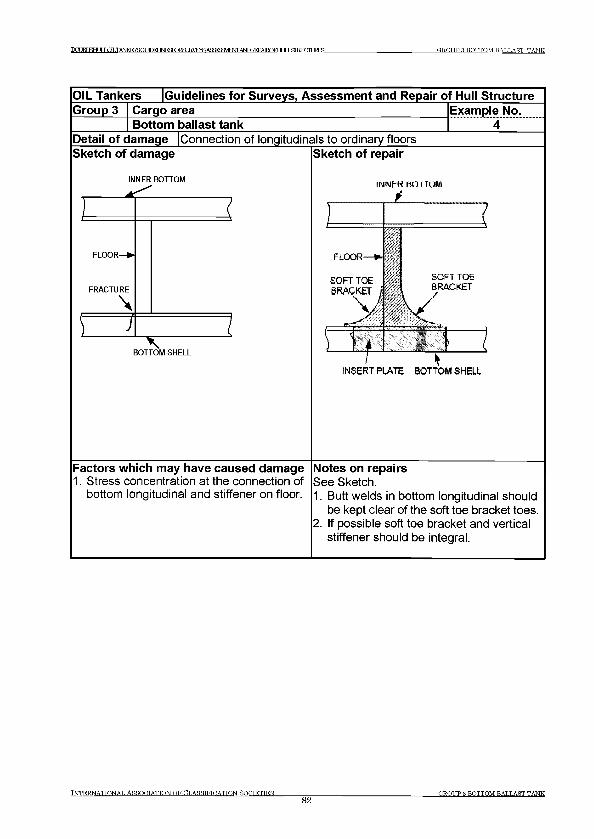
Г О JRT Е Н Г IT IXiLTANKFRSGUfnPT 1 Ы Р } Я К Ж 8 и Е 1 У Е ^ А Я й Р ? Я У 1 Р ^ Al^FEPAIROFFff ТГ T Я Ш Г TTHURES G R O U P 3 B O T T O M BA LLA ST TA NK
OIL Tankers Guidelines for Surveys, Assessment and Repair of Hull StructureGroup 3 Cargo area Example No.
Bottom ballast tank 4Detail of damage (Connection of longitudinals to ordinary floorsSketch of damage
INNER BOTTOM
FRACTURE
\□
^ ----BOTTOM SHELL
Sketch of repair
INNfcK BO I IQ M
INSERT PLATE BOTTOM SHELL
Factors which may have caused damage1. Stress concentration at the connection of
bottom longitudinal and stiffener on floor.
Notes on repairsSee Sketch.1. Butt welds in bottom longitudinal should
be kept clear of the soft toe bracket toes.2. If possible soft toe bracket and vertical
stiffener should be integral.
TNTKRNATTONAT. ASSOnTATTONOF CT.ASSTFTOATTON ROOTETTES_____________
82OR.OTIP Я BO T T O M BAT.T.AST TA N K
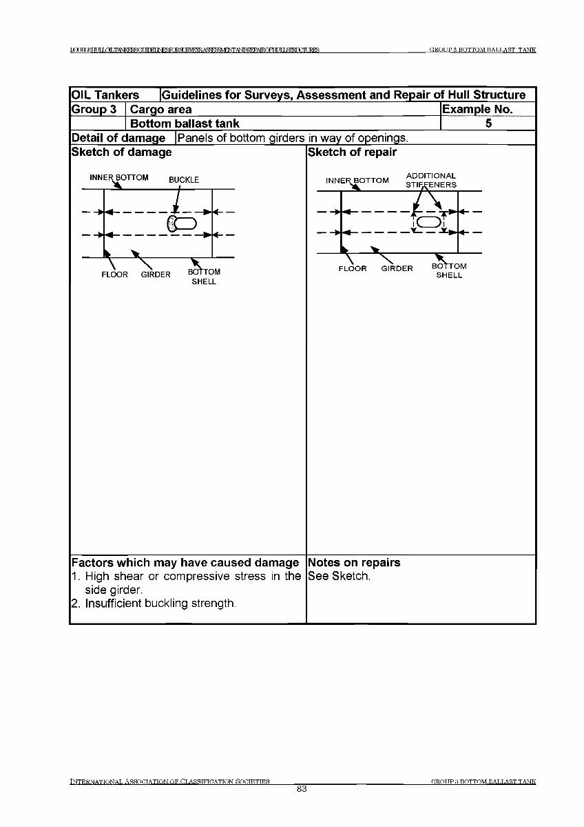
GROUP 3 BOTTOM BALLAST TANKp g JRT К Н И Г Ш И .TANKFRGGUIHFIINESFORH т а Ж Д Я ^ М М О Т ) К Е Р А Е О т IT IЯ Ш Г PURES
OIL Tankers [Guidelines for Surveys, Assessment and Repair of Hull StructureGroup 3 Cargo area
Bottom ballast tankExample No............. 5......
Detail of damage |Panels of bottom girders in way of openingsSketch of damage Sketch of repair
Factors which may have caused damage Notes on repairs1. High shear or compressive stress in the See Sketch.
side girder.2. Insufficient buckling strength.
INTERNATIONAL ASSOCIATION OF CLASSIFICATION SOCIETIES83
GROUP Я BOTTOM BALLAST TANK
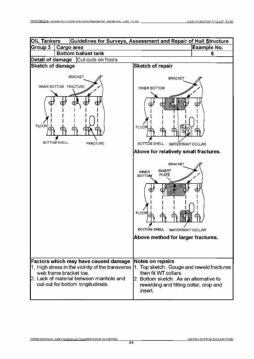
GROUP 3 BOTTOM BALLAST TANKDCUBIEHULLOTT TANKFRSGf ШЕГ JNF^TORSLIRVUSAS^^E^iTOREPAIRQFHLJILSIEUaiURES
OIL Tankers [Guidelines for Surveys, Assessment and Repair of Hull StructureGroup 3 Cargo area
Bottom ballast tankExample No................... 6........
Detail of damage |Cut-outs on floorsSketch of damage
BRACKET
INNER BOTTOM FRACTURE
BOTTOM SHELL FRACTURE
Sketch of repair
BRACKET
INNER BOTTOM
# GiJJ $ #
FLOOR
iв о ттб м SHELL WATERTIGHT COLLAR
Above for relatively small fractures.
INNERBOTTOM
BRACKET
INSERT PLATE
BOTTOM SHELL WATERTIGHT COLLAR
Above method for larger fractures.
Factors which may have caused damage1. High stress in the vicinity of the transverse
web frame bracket toe.2. Lack of material between manhole and
cut-out for bottom longitudinals.
Notes on repairs1. Top sketch: Gouge and reweld fractures
then fit WT collars.2. Bottom sketch: As an alternative to
rewelding and fitting collar, crop and insert.
INTERNATIONAL ASSOCIATION OF CLASSIFICATION SOCIETIES84
GROUP Я BOTTOM BALLAST TANK
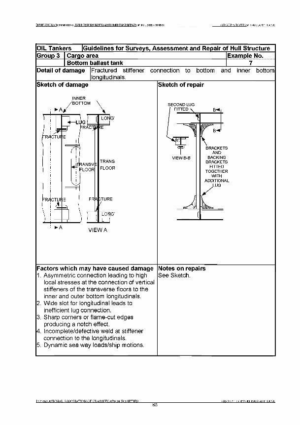
р а м К Н И Г LOT .TANKFRSOT Л Г М INRSRmgUKVEYS ANDREPAIROFra JTI 5Л К Г Ш Ж Е Б GROUP 3 BOTTOM BALLAST TANK
OIL Tankers [Guidelines for Surveys, Assessm ent and Repair of Hull StructureGroup 3 Cargo area Example No.
Bottom ballast tankDetail o f damage Fractured stiffener connection to bottom and inner bottom
longitudinals._______Sketch of damage Sketch of repair
IN N ER
SECO ND LUG FITTED \
BRACKETSAND
BACKINGBRACKETS
FITTEDTOGETHER
WITHADDITIONAL
LUG
Factors which may have caused damage1. Asymmetric connection leading to high
local stresses at the connection of vertical stiffeners of the transverse floors to the
Notes on repairsSee Sketch.
inner and outer bottom longitudinals.2. Wide slot for longitudinal leads to
inefficient lug connection.3. Sharp corners or flame-cut edges
producing a notch effect.4. Incomplete/defective weld at stiffener
connection to the longitudinals.5. Dynamic sea way loads/ship motions.
INTERNATIONAL ASSOCIATION OF CLASSIFICATION SOCIETIES_____________85
GROUP 3 BOTTOM BALLAST TANK
DCUBL£HULLC3LTANKEFfia ТГПРГ IN FO RM IRVF^ AbTOREPAIROFra ITIЯШГ mURES GROUP 4 WEB FRAMES IN TANKS
Group 4 Web Frames in Cargo Tanks
Contents
1 General
2 What to look for - Web Frame survey
2.1 Material wastage2.2 Deformations2.3 Fractures
3 General comments on repair
3.1 Material wastage3.2 Deformations3.3 Fractures
Examples of structural detail failures and repairs - Group 4Example No. Title
1 Fracture at toe of web frame bracket connection to inner bottom2 Cross ties and their end connections3 Buckled transverse web plates in way of cross tie4 Cut-outs around transverse bracket end5 Fracture in way of connection of transverse web tripping brackets to
longitudinal6 Tripping brackets modification of the bracket toe
t n t e r n a t t o n a t . As s o c ia t io n o f C t.a sst ft c a t t o n s o c t e t t e s
86G R O U P 4 W EB FR A M E S TN TA N K S
Т О М К НГ1 Г LOLTANKERBftr У Г Г М INFSTORSURVRYS, AgSFHFMFNT ANDREPAIROFHr ТГ T £Ш TGTURES GROUP 4 WEB FRAMES IN TANKS
1 General
1.1 The web frame is the support for the transfer of the loads from the longitudinals. This structure has critical points at the intersections of the longitudinals, openings for access through the web frames and critical intersections such as found at the hopper knuckles as well as any bracket terminations. See also Figures 3 and 4 in Chapter 1 Introduction.
1.2 Depending upon the design or size of tanker web frames include deck transverse, vertical webs on longitudinal bulkheads and cross ties.
2 What to look for - Web Frame survey
2.1 Material wastage
2.1.1 The general condition with regard to wastage of the web frames may be observed by visual survey during the overall and close up surveys.
Attention is drawn to the fact that web frames may be significantly weakened by loss of thickness although diminution and deformations may not be apparent. Survey should be made after the removal of any scale, oil or rust deposit. Where the corrosion is smooth and uniform the diminution may not be apparent and thickness measurements would be necessary, to determine the condition of the structure.
2.1.2 Pitting corrosion may be found under coating blisters, which need to be removed before inspection. Pitting may also occur on horizontal structures, in way of sediments and in way of impingement from tank cleaning machines.
2.2 Deformations
2.2.1 Deformations may occur in web frames in way of excessive corrosion especially in way of openings in the structure. However, where deformation resulting from bending or shear buckling has occurred with a small diminution in thickness, this could be due to overloading and this aspect should be investigated before proceeding with repairs.
2.3 Fractures
2.3.1 Fractures may occur in way of discontinuities in the faceplates and at bracket terminations as well as in way of openings in structure. Fractures may also occur in way of cut outs for longitudinals.
TNTERNATTONAT. ASSOETATTON O F C LA S S IF IC A T IO N HOETETTES
8 7ER.OTIP 4 WEB FRAMER TN TANKS
ГО TRT КНИГ LOT .TANKFRSGf MM JNF TORSLIRVE .A?: ¥MFT^/TOICTAEQFH^ G R O U P 4 W EB FR A M E S IN T A N K S
3 General comments on repair
3.1 Material wastage
3.1.1 When the reduction in thickness of plating and stiffeners has reached the diminution levels permitted by the Classification Society involved, the wasted plating and stiffeners are to be cropped and renewed.
3.2 Deformations
3.2.1 Depending on the extent of the deformation, the structure should be restored to its original shape and position either by fairing in place and if necessary fitting additional panel stiffeners and/or by cropping and renewing the affected structure.
3.3 Fractures
3.3.1 Because of the interdependence of structural components it is important that all fractures and other significant damage to the frames and their brackets, however localised, are repaired.
3.3.2 Repair of fractures at the boundary of a cargo tanks to ballast tanks should be carefully considered, taking into account necessary structural modification, enhanced scantlings and material, to prevent recurrence of the fractures.
INTERNATIONAL ASSOCIATION OF CLASSIFICATION SOCIETIES88
GROUP 4 WEB FRAMES IN TANKS
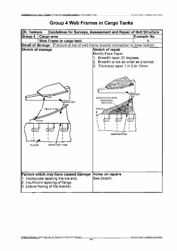
1 Х Х В 1 Е Н Ш Х Е Л Ш К Т ^ ( Т Т 1 Ю Е Г JNESFORST 1RVEVSA5SFFFMINr/№T?FPATROFHrITI»SIKTГ П Т 1RFS GROUP 4 W EB FR AM ES TN TAN K S
G roup 4 W eb Fram es in Cargo Tanks
OIL Tankers (Guidelines for Surveys, Assessment and Repair of Hull StructureGroup 4 Cargo area Example No.
Web Frame in cargo tank 1Detail of damage |Fracture at toe of web frame bracket connection to inner bottom.Sketch of damage
INNER BOTTOM
Sketch of repairModify Face Taper1. Breadth taper 20 degrees.2. Breadth at toe as small as practical.3. Thickness taper 1 in 3 to 10mm.
INNER BOTTOM
Factors which may have caused damage1. Inadequate tapering the toe end.2. Insufficient tapering of flange.3. Lateral flexing of the bracket.
Notes on repairsSee Sketch.
INTERNATTONAT. AS SO C IATIO N O F CT.ASSTFTDATTON HOETETTES
89ER.OTIP 4 W EB FR AM ES TN TAN K S
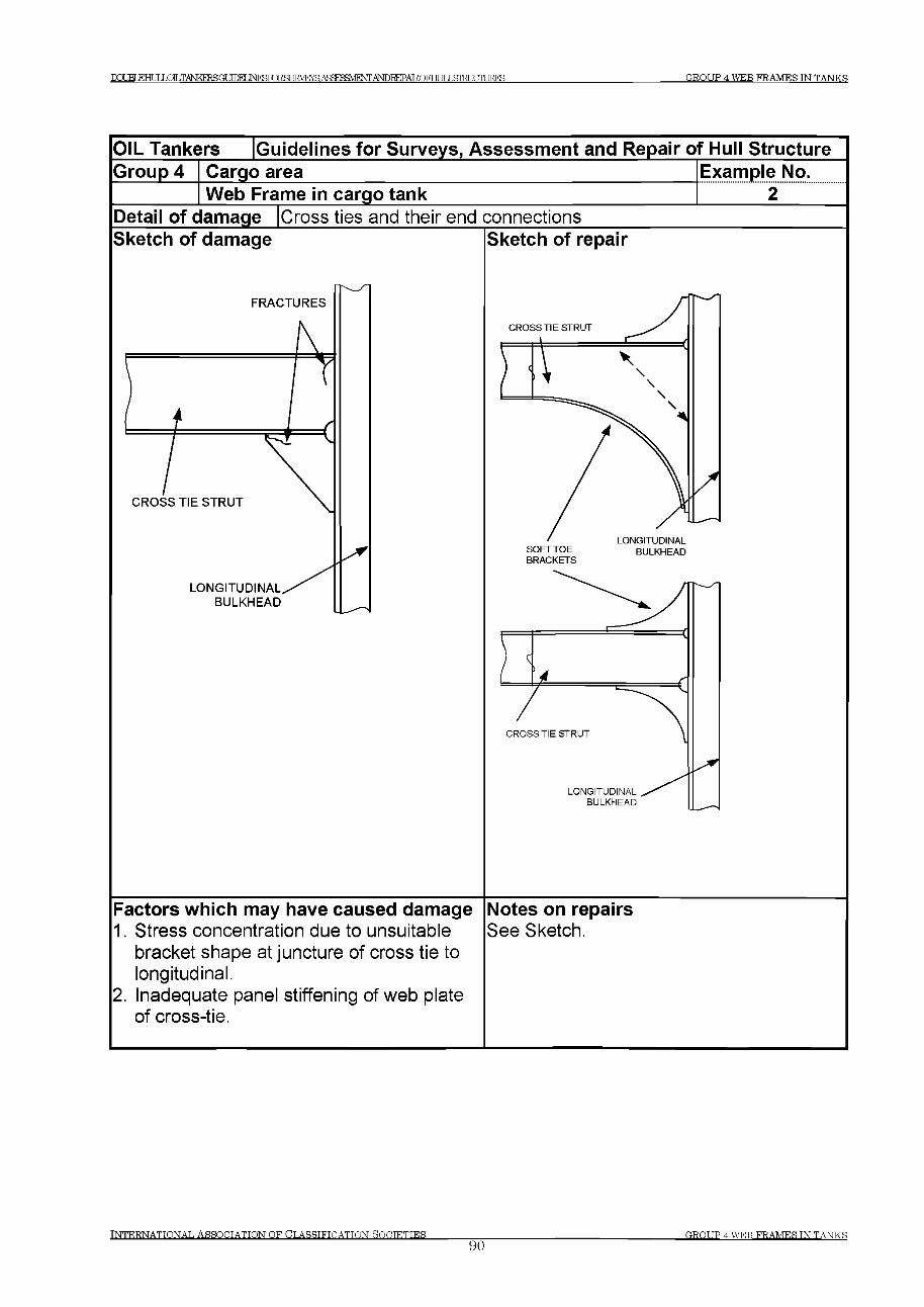
DOJELEHULLiDILTANKEESa УГГКГ INTOTORSLEVEraASSF^M^rrAIvroiCTAIROFHUILSIEIJCILEES G R O U P 4 W EB F R A M E S IN T A N K S
IN T E R N A T IO N A L A S S O C IA T IO N O F C L A S S IF IC A T IO N S O C IE T IE S ________________90
G R O U P 4 W E B F R A M E S IN T A N K S
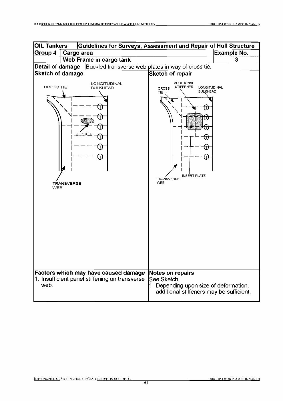
D3UBL£HULmLTANKERSa П Г М INFynQ SUE VE SASfTpFHVIF AlsroiEPAIROFHf ТГ T Я Г И Т Г Т Ц Е Е Б GROUP 4 WEB FRAMES IN TANKS
OIL Tankers |Guidelines for Surveys, Assessment and Repair of Hull StructureGroup 4 Cargo area
Web Frame in cargo tankExample No........... з ....
Detail of damage |Buckled transverse web plates in way of cross tieSketch of damage Sketch of repair
L O N G IT U D IN A LC R O S S T IE B U L K H E A D
ADDITIONAL
Factors which may have caused damage Notes on repairs1. Insufficient panel stiffening on transverse See Sketch.
web. 1. Depending upon size of deformation, additional stiffeners may be sufficient.
INTERNATIONAL ASSOCIATION OF CLASSIFICATION SOCIETIES91
GROT JP 4 WEB FRAMES TN TANKS
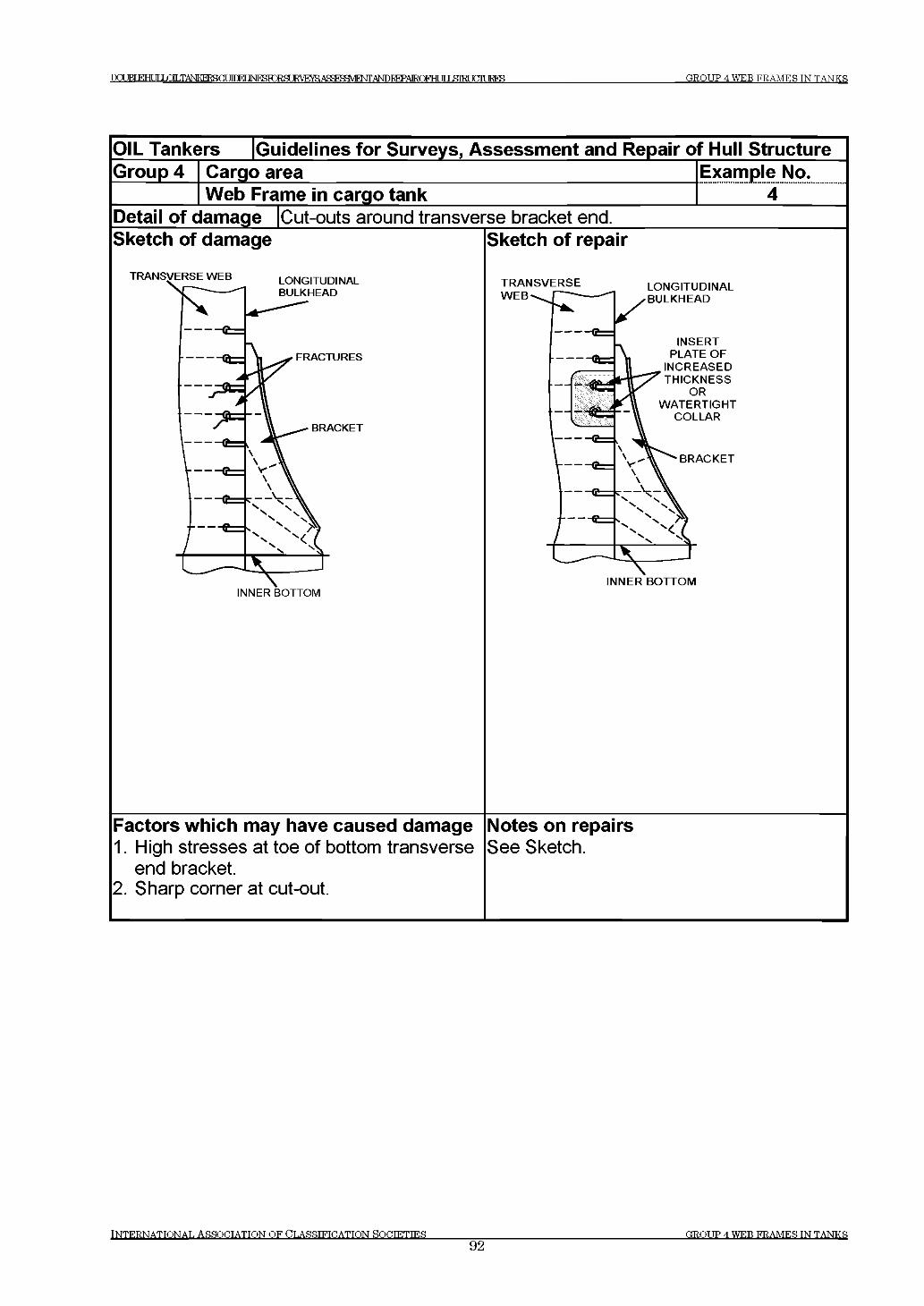
DOJBT FTHT JT LOLTANKERSGUinFI 1 Ы Г С Ж Ж З Ш У Е Ж А сУ г е :М ^ ТГI Я 1 М mURES GROUP 4 WEB F R A M E S IN T A N K S
OIL Tankers [Guidelines for Surveys, Assessment and Repair of Hull StructureGroup 4 Cargo area
Web Frame in cargo tankExample No...............4 .......
Detail of damage |Cut-outs around transverse bracket end.Sketch of damage Sketch of repair
TR A N S V E R S E LO N G ITUDINAL
Factors which may have caused damage1. High stresses at toe of bottom transverse
end bracket.2. Sharp corner at cut-out.
Notes on repairsSee Sketch.
INTERNATIONAL ASSOCIATION OF CLASSIFICATION SOCTETTES____________92
GROUP 4 WEB FRAMES IN TANKS
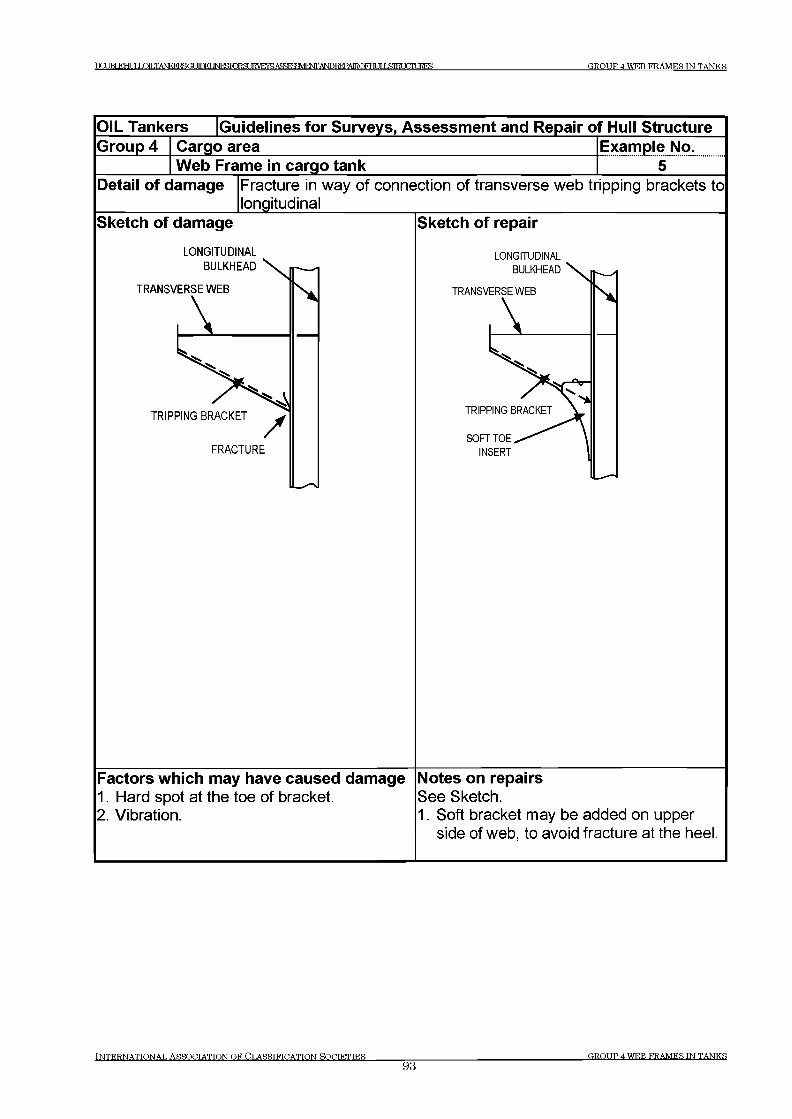
DCUBLEHUT J ОТ .TANKFRSGUfnPT ]NF)SF2RSURVEYS.Afl:FS3V1F^ IT 1 FTTURES GROUP 4 WTCB FRAMF1S IN TANKS
O IL Tankers G uidelines fo r Surveys, Assessm ent and Repair o f Hull StructureG roup 4 Cargo area Exam ple No.
W eb Fram e in cargo tank 5Detail o f dam age Fracture in way of connection of transverse web tripping brackets to
longitudinalSketch o f dam age
LONGITUDINAL
Sketch o f repair
LONGITUDINAL
Factors w hich m ay have caused dam age1. Hard spot at the toe of bracket.2. Vibration.
Notes on repairsSee Sketch.1. Soft bracket may be added on upper
side of web, to avoid fracture at the heel.
TNTERNATTONAT. ASSOETATTON OF CLASSIFICATION SOCIETIES____________93
OR.OTIP 4 WEB FRAMES TN TANKS
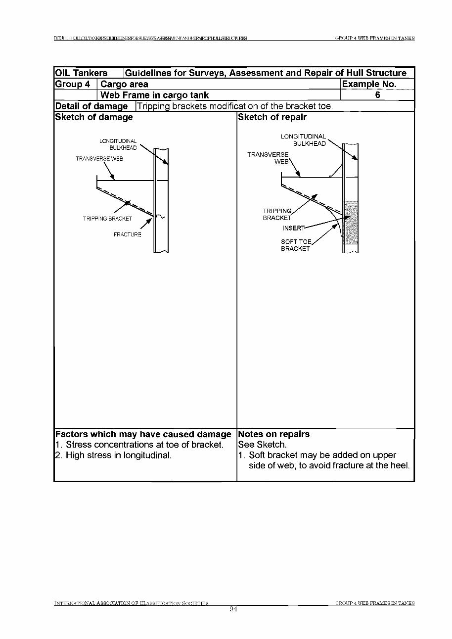
DCmEHULLOILTANKERSGr УГПЕГ №ЯЮТ?Я TRVEVR АдЯГСШЕМГ АМПЕЕРАЕОЕНЦТI5ЯКГ HITIRFS G R O U P 4 W E B F R A M E S IN T A N K S
OIL Tankers Guidelines for Surveys, Assessment and Repair of Hull StructureGroup 4 Cargo area Example No.
Web Frame in cargo tank 6Detail of damage |Tripping brackets modification of the bracket toe.Sketch of damage
LONGITUDINAL
Sketch of repair
LONGITUDINAL
Factors which may have caused damage1. Stress concentrations at toe of bracket.2. High stress in longitudinal.
Notes on repairsSee Sketch.1. Soft bracket may be added on upper
side of web, to avoid fracture at the heel
IN T E R N A T IO N A L A S S O C IA T IO N O F C L A S S IF IC A T IO N S O C IE T IE S ________________94
G R O U P 4 W E B F R A M E S IN T A N K S
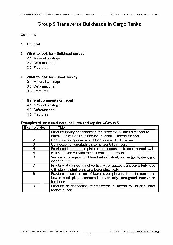
Г Р М К Н П Г IHLTANKERBGf П Г М INFSFORSt JRVF^AffFF^t^TTANDREPAIROFHr TTIЯ Ш Г Г Л Т 1RFS G R O U P 5 T R A N SV E R S E B U L K H E A D S TN CA RG O TA N K S
Group 5 Transverse Bulkheads in Cargo Tanks
Contents
1 General
2 What to look for - Bulkhead survey
2.1 Material wastage2.2 Deformations2.3 Fractures
3 What to look for - Stool survey
3.1 Material wastage3.2 Deformations3.3 Fractures
4 General comments on repair
4.1 Material wastage4.2 Deformations4.3 Fractures
Examples of structural detail failures and repairs - Group 5Example No. Title
1 Fracture in way of connection of transverse bulkhead stringer to transverse web frames and longitudinal bulkhead stringer
2 Horizontal stringer in way of longitudinal BHD cracked3 Connection of longitudinals to horizontal stringers4 Fractured inner bottom plate at the connection to access trunk wall5 Bulkhead vertical web to deck and inner bottom6 Vertically corrugated bulkhead without stool, connection to deck and
inner bottom7 Fracture at connection of vertically corrugated transverse bulkhead
with stool to shelf plate and lower stool plate8 Fracture at connection of lower stool plate to inner bottom tank.
Lower stool plate connected to vertically corrugated transverse bulkhead
9 Fracture at connection of transverse bulkhead to knuckle inner bottom/girder
TNTERNATTONAT, ASSOETATTON O F CT.ASSTFTDATTON SOETETTES
95ER.OTIP R TRANSVERSE Щ П . К Н Е А П Н TN E A R E D TAN K S
IXXJBLEHUIiX^TANKEI^GUirM ]ЫР)ЯКЖ8иКУЕЖ AbTOFEPAIRQFFff ТГ T ЯП?Г FTTURES GROUP 5 TRANSVERSE BTTT.KHEADS IN CARGO TANKS
1 General
1.1 The transverse bulkheads at the ends of cargo tanks are oiltight bulkheads serving two main functions:(a) As main transverse strength elements in the structural design of the ship.(b) They are essentially deep tank bulkheads, which, in addition to the functions given in (a) above, are designed to withstand the head pressure of the full tank.
1.2 The bulkheads may be constructed as vertically corrugated with a lower stool, and with or without an upper stool. Alternatively plane bulkhead plating with one sided vertical stiffeners and horizontal stringers.
1.3 Heavy corrosion may lead to collapse of the structure under extreme load, if it is not rectified properly.
1.4 It is emphasised that appropriate access arrangement as indicated in Chapter
4 Survey Programme, Preparation and Execution of the guidelines should be provided to enable a proper close-up survey and thickness measurement as necessary.
2 What to look for - Bulkhead survey
2.1 Material wastage
2.1.1 Excessive corrosion may be found in the following locations:(a) Bulkhead plating adjacent to the longitudinal bulkhead plating.(b) Bulkhead plating and weld connections to the lower/upper stool shelf plates and inner bottom.
2.1.2 If coatings have broken down and there is evidence of corrosion, it is recommended that random thickness measurements be taken to establish the level of diminution.
2.1.3 When the periodical survey requires thickness measurements, or when the Surveyor deems necessary, it is important that the extent of the gauging be sufficient to determine the general condition of the structure.
2.2 Deformations
2.2.1 When the bulkhead has sustained serious uniform corrosion, the bulkhead may suffer shear buckling. Evidence of buckling may be indicated by the peeling of paint or rust. However, where deformation resulting from bending or shear buckling has occurred on a
INTERNATIONAL ASSOOTATTON OF ОТ.ARRTETCATTON ROCTETTER96
GROT TP 5 TRANSVERSE BULKHEADS TN PARROT TANKS
1 Х Д ^ Ш Н 1 Д ^ Х Я Ь Т А 1 чЖ Е 1 ^ а 1 Ж Е Ц Ы Е Б К З ^ IRVRra А Я й Р ? Я У 1 Р ^ AbTOFEPAIROFHr ТГ T Я Ш Г mURES GROUP 5 TRANSVERSE BULKHEADS IN CARGO TANKS
bulkhead with a small diminution in thickness, this could be due to overloading and this aspect should be investigated before proceeding with repairs.
2.3 Fractures
2.3.1 Fractures usually occur at the boundaries of corrugations and bulkhead stools particularly in way of shelf plates, deck, inner bottom, etc.
3 What to look for - Stool survey
3.1 Material wastage
3.1.1 Excessive corrosion may be found on diaphragms, particularly at their upper and lower weld connections.
3.2 Fractures
3.2.1 Fractures observed at the connection between lower stool and corrugated bulkhead during stool survey may have initiated at the weld connection of the inside diaphragms (See Example 7).
3.2.2 Misalignment between bulkhead corrugation flange and sloping stool plating may also cause fractures at the weld connection of the inside diaphragms.
4 General comments on repair
4.1 Material wastage
4.1.1 When the reduction in thickness of plating and stiffeners has reached the diminution levels permitted by the Classification Society involved, the wasted plating and stiffeners are to be cropped and renewed.
4.2 Deformations
4.2.1 If the deformation is local and of a limited extent, it could generally be faired out. Deformed plating in association with a generalized reduction in thickness should be partly or completely renewed.
TNTERNATTONAT, ASSOCIATION OF CLASSIFICATION SOCIETIES97
GROUP 5 TRANSVERSE BULKHEADS IN CARGO TANKS

Т О Т К Г КНИГ LOLTANKERBGr УГГКГ INFfiTORSURVEYSAgsreyM^TTrA^REP^ G R O U P 5 T R A N SV E R S E B U L K H E A D S IN CA RG O TA N K S
4.3 Fractures
4.3.1 Fractures that occur at the boundary weld connections as a result of latent weld defects should be veed-out, appropriately prepared and re-welded preferably using low hydrogen electrodes or equivalent.
4.3.2 For fractures other than those described in 4.3.1, re-welding may not be a permanent solution and an attempt should be made to improve the design and construction in order to avoid a recurrence. Typical examples of such cases are as follows:
(a) Fractures in the weld connections of the stool plating to the shelf plate in way of the scallops in the stool’s internal structure. The scallops should be closed by fitting lapped collar plates and the stool weld connections repaired as indicated in 4.3.1. The lapped collar plates should have a full penetration weld connection to the stool and shelf plate and should be completed using low hydrogen electrodes prior to welding the collar to the stool diaphragm/bracket.
(b) Fractures in the weld connections of the corrugations and/or stool plate to the shelf plate resulting from misalignment of the stool plate and the flange of the corrugation (Similarly misalignment of the stool plate with the double bottom floor).
It is recommended that the structure be cut free, the misalignment rectified, and the stool, floor and corrugation weld connection appropriately repaired as indicated in 4.3.1, Other remedies to such damages include fitting of brackets in the stool in line with the webs of the corrugations. In such cases both the webs of the corrugations and the brackets underneath are to have full penetration welds and the brackets are to be arranged without scallops. However, in many cases this may prove difficult to attain.
(c) Fractures in the weld connections of the corrugations to the hopper tank.
It is recommended that the weld connection be repaired as indicated in 4.3.1 and, where possible, additional stiffening be fitted inside the tanks to align with the flanges of the corrugations.
Tn t e r n a t t o n a t . As s o c ia t io n o f C l a s s i f t h a t t o n s o o t e t t e s
98G R O U P 5 T R A N SV E R S E B U L K H E A D S TN CA RG O TA N K S
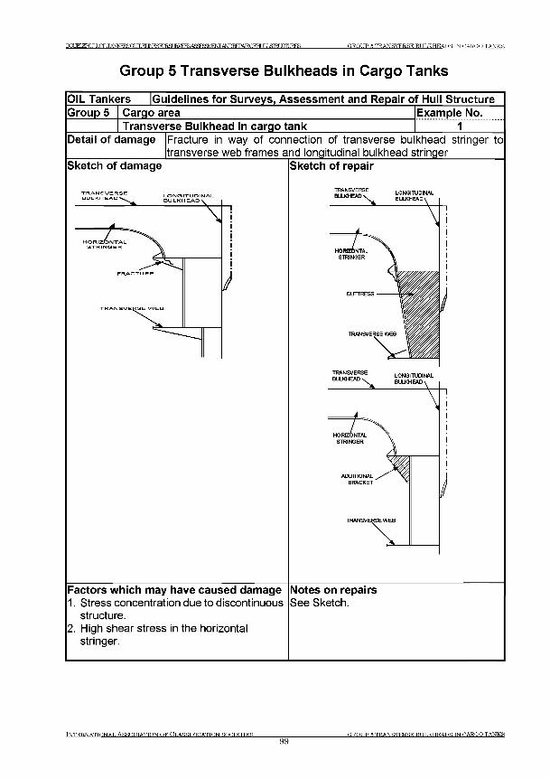
ГРУНТ КНИГ LOILTANKERSGt 1ГПЕГ М ^ГО ЕЗШ Ж таА Я ЙРУ Ш РТчГГД ^ЕЕРАЕО РИ ТГ Г ,STRI KTTURES GROUP 5 TRANSVERSE BULKHEADS TN CARGO TANKS
G roup 5 Transverse B ulkheads in C argo Tanks
OIL Tankers [Guidelines for Surveys, Assessment and Repair of Hull StructureGroup 5 Cargo area
Transverse Bulkhead in cargo tankExample No.............. 1.......
Detail of damage Fracture in way of connection of transverse bulkhead stringer to transverse web frames and longitudinal bulkhead stringer_______
Sketch of damage Sketch of repair
Factors which may have caused damage Notes on repairs1. Stress concentration due to discontinuous See Sketch.
structure.2. High shear stress in the horizontal
stringer.
TNTER.NATTONAT. ASSOETATTON O F CT.ASSTFTDATTON SO C IE T IE S
99ER.OTIP R TRANSVERSE BULKHEADS TN CARGO TANKS
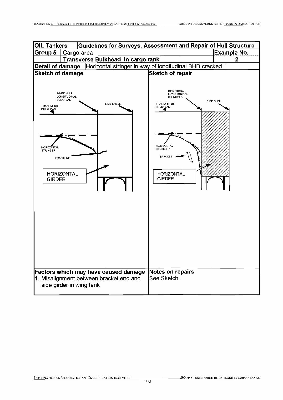
DCOBIEHUILOILTANKEKSa MM JNF^TORSLIRVETffiA^F!¥M^srrA^ICTAIRQFHUILSIKJCr[UE?ES GROUP 5 TRANSVERSE BULKHEADS IN CARGO TANKS
INTERNATIONAL ASSOCIATION OF CLASSIFICATION SOCIETIES_______________100
GROUP 5 TRANSVERSE BULKHEADS TN CARGO TANKS
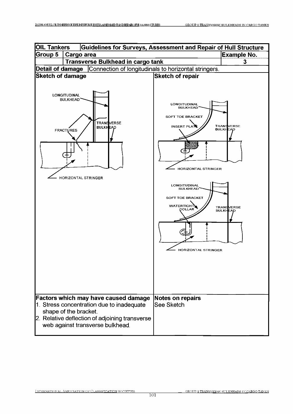
DCtJKTEHI IT IXfl.TANFO^^GUfTraiNRSlO^SUKVEraAfiFrSFM^WAbroFEPAIROFHrTrT^n^rTTTJRES GROUP 5 TRANSVERSE BULKHEADS IN CARGO TANKS
OIL Tankers [Guidelines for Surveys, Assessment and Repair of Hull StructureGroup 5 Cargo area
Transverse Bulkhead in cargo tankExample No..................з........
Detail of damage [Connection of longitudinals to horizontal stringersSketch of damage
LONGITUDINALBULKHEAD
HORIZONTAL STRINGER
Sketch of repair
L O N G IT U D IN A L B U L K H E A D
S O F T T O E B R A C K E T
H O R IZ O N T A L S T R I N G E R
Factors which may have caused damage1. Stress concentration due to inadequate
shape of the bracket.2. Relative deflection of adjoining transverse
web against transverse bulkhead.
Notes on repairsSee Sketch
INTERNATIONAL ASSOCIATION OF CLASSIFICATION ROCTETTES_____________101
GROUP 5 TRANSVERSE BULKHEADS TN CARGO TANKS
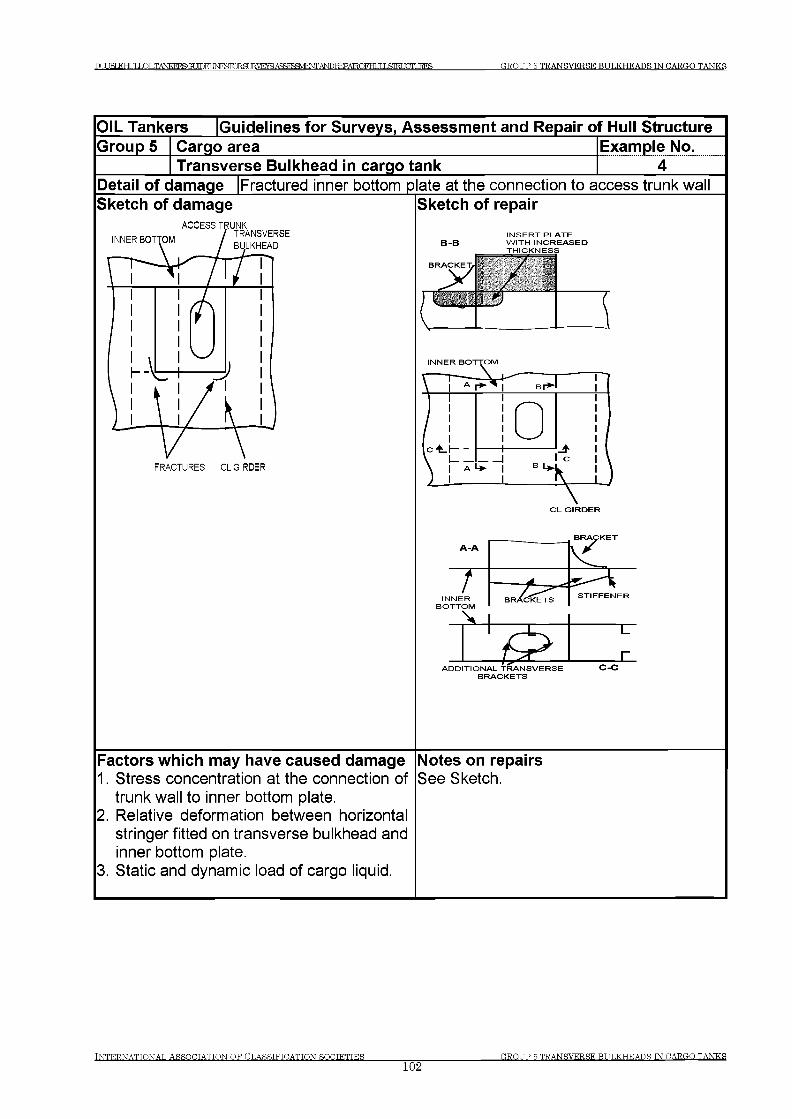
I)rjJBLEHLILLOILTKEI?SGU[r)Er 1Ш Ю Р Я TRVRYS А Я Я г а Я М Н ч Г Г A№)KEPAIRQFHUILSIRLniUE?ES GROUP 5 TRANSVERSE BULKHEADS IN CARGO TANKS
OIL Tankers [Guidelines fo r Surveys, Assessm ent and Repair o f Hull StructureG roup 5 Cargo area Exam ple No.
Transverse Bulkhead in cargo tankDetail o f dam age Fractured inner bottom p ate at the connection to access trunk wallSketch of dam age Sketch o f repair
BRACKETA-A \ V
/ >/
INNERBOTTOM
BRACKETS STIFFENER
S EADDITIONAL TRANSVERSE
BRACKETS
Factors w hich may have caused dam age Notes on repairs1. Stress concentration at the connection of See Sketch,
trunk wall to inner bottom plate.2. Relative deformation between horizontal
stringer fitted on transverse bulkhead and inner bottom plate.
3. Static and dynamic load of cargo liquid.
и
и
INTERNATIONAL ASSOCIATION OF CLASSIFICATION ROGTETTER102
GROUP 5 TR ANSVERSE BULKHEADS IN CARGO TANKS
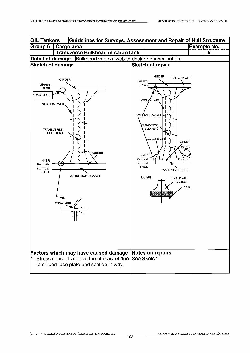
DOM FTHT JT LOLTANPCFT GUinFI 1 Ы Я 1 Ж Ж З и Н У Е т а А Ж Р ? Я Ш Ф 7 Г А М Р Ж Р А 1 1 Ю Г Н Г И IЯ Ш Т FTTURES GROUP 5 TRANSVERSE BULKHEADS IN CARGO TANKS
I N T E R N A T I O N A L A S S O C I A T I O N O F C L A S S I F I C A T I O N S O C I E T I E S ____________________
103GROUP 5 TRANSVERSE BULKHEADS IN CARGO TANKS

РОПВТЕНиГ LOLTANKERSGr М М IN F S F C R S U E flE ^ ^ fa ^ H E ^ G R O U P 5 T R A N S V E R S E B U L K H E A D S TN C A R G O T A N K S
OIL Tankers [Guidelines for Surveys, Assessment and Repair of Hull StructureGroup 5 Cargo area
Transverse Bulkhead in cargo tankExample No..............6......
Detail of damage Vertically corrugated bulkhead without stool, connection to deck and inner bottom
Sketch of damage Sketch of repair
V E R T IC A L L Y -----C O R R U G A T E DB U L K H E A D
Factors which may have caused damage Notes on repairs1. Stress concentration due to unsupported See Sketch,
corrugation web.2. High through thickness stress, lamellar
tearing.3. Weld details and dimensions.4. Misalignment between face of corrugation
and floor underneath.5. Cut-outs and scallops or air holes
increasing the stress in the floor.6. Insufficient through thickness properties
of inner bottom plate.
IN TER N ATTO N AT. ASSOOTATTON O F CT.ASSTFTDATTON SOCTETTES
104G R O U P 5 TR AN SVER SE Ш Т Т . К Н Е А Л Я Ш CARGO T A N K S
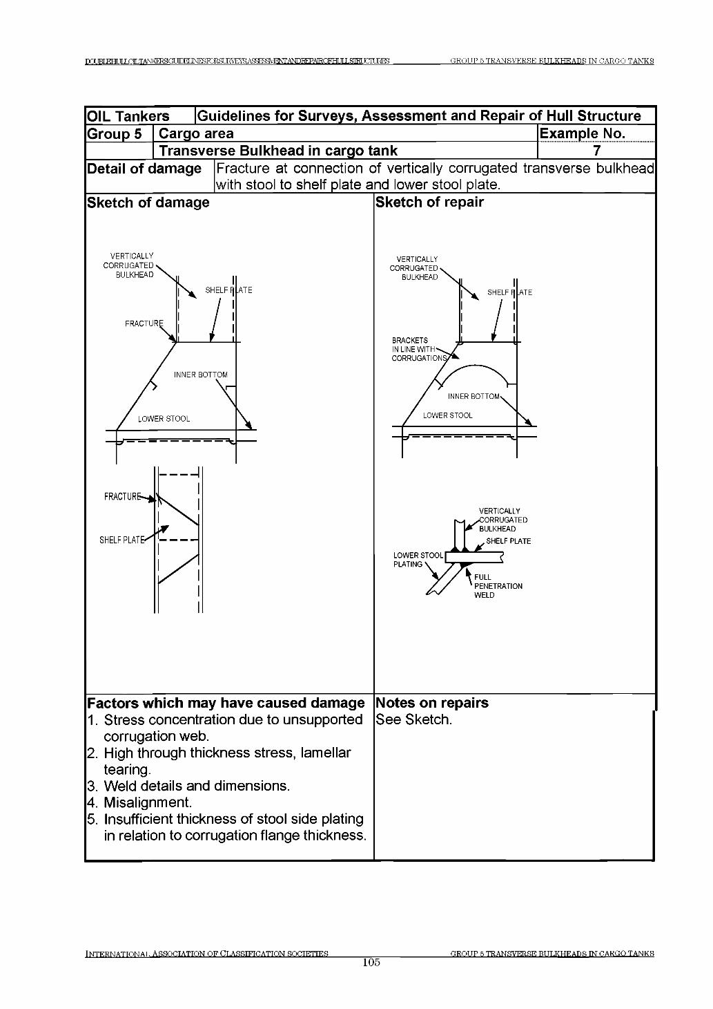
п а т о г е н п г т ш т TANKERS М М INFSPjRSLRVEyS- AS^WHNT^DREPAIRQFHLJILSM JCTTT JRFS GROUP 5 TRANSVERSE BULKHEADS TN CARGO TANKS
OIL Tankers [Guidelines for Surveys, Assessment and Repair of Hull StructureGroup 5 Cargo area
Transverse Bulkhead in cargo tankExample No.......................7 ..........
Detail of damage Fracture at connection of vertically corrugated transverse bulkhead with stool to shelf plate and lower stool plate.____________________
Sketch of damage
VERTICALLY
Sketch of repair
VERTICALLY
Factors which may have caused damage1. Stress concentration due to unsupported
corrugation web.2. High through thickness stress, lamellar
tearing.3. Weld details and dimensions.4. Misalignment.5. Insufficient thickness of stool side plating
in relation to corrugation flange thickness.
Notes on repairsSee Sketch.
In t e r n a t io n a l ASSOCIATION OF CLASSIFICATION SOCIETIES______________105
GROUP 5 TRANSVERSE BULKHEADS TN CARGO TANKS
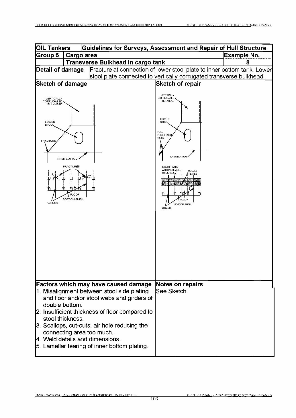
DOUBT ЕНГ JT LOLTANKERSCff УГГКГ INraTORSUE^E^AS^BaVENTA^I^AEOFHUlXS^CmRES GROUP 5 TRANSVERSE BULKHEADS IN CARGO TANKS
OIL Tankers [Guidelines for Surveys, Assessment and Repair of Hull StructureGroup 5 Cargo area
Transverse Bulkhead in cargo tankExample No.......................8 ..........
Detail of damage Fracture at connection of lower stool plate to inner bottom tank. Lower stool plate connected to vertically corrugated transverse bulkhead.
Sketch of damage Sketch of repair
VERTICALLYCORRUGATED
BULKHEAD
LOWERSTOOL
FRACTURE/ l J
7 ^ “INNER BOTTOM S
VERTICALLY
FRACTURES
GIRDER
Factors which may have caused damage1. Misalignment between stool side plating
and floor and/or stool webs and girders of double bottom.
2. Insufficient thickness of floor compared to stool thickness.
3. Scallops, cut-outs, air hole reducing the connecting area too much.
4. Weld details and dimensions.5. Lamellar tearing of inner bottom plating.
GIRDER
Notes on repairsSee Sketch.
INTERNATIONAL ASSOCIATION OF CLASSIFICATION SOCIETIES106
GROUP 5 TRANSVERSE BULKHEADS IN CARGO TANKS
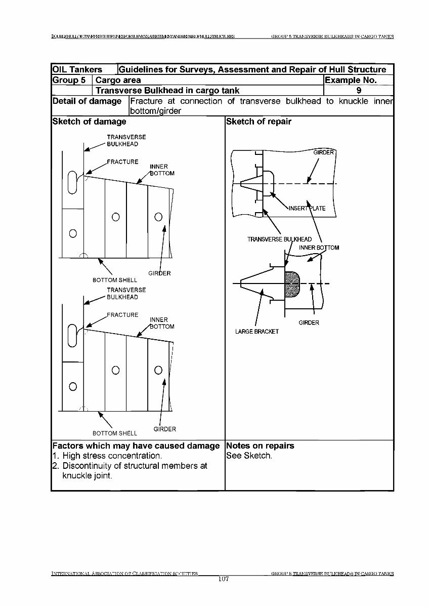
DCIIKTEHT IT LOT.TANKFRSGtЛПЕГ]^^RIRSLIRVEYS АЕЕГОЕМФЛ1 АКРЕЕРАРЮЕга TTIЯТЕГ FTTURES GROUP 5 TRANSVERSE BULKHEADS TN CARGO TANKS
OIL Tankers Guidelines for Surveys, Assessment and Repair of Hull StructureGroup 5 Cargo area Example No.
Transverse Bulkhead in cargo tank 9Detail of damage Fracture at connection of transverse bulkhead to knuckle inner
bottom/girderSketch of damage
TRANSVERSEBULKHEAD
INNERОТТОМ
GIRDERBOTTOM SHELL
TRANSVERSE BULKHEAD
INNERОТТОМ
BOTTOM SHELLGIRDER
Sketch of repair
TOM
GIRDERLARGE BRACKET
Factors which may have caused damage1. High stress concentration.2. Discontinuity of structural members at
knuckle joint.
Notes on repairsSee Sketch.
INTERNATION AL ASSO CIATIO N OF CLASSIFICATION SOCIETIES_________________107
GROUP 5 TRANSVERSE BULKHEADS TN CARGO TANKS
РСШ1ЕНЦ11Г^ТАЫКЕ1^СОТЖГ 1ЫГСЖЖШКУЕУ5АСЯ ^ Я ^ JT J,STRUCTURES GROUP 6 DECK STRUCTURE
Group 6 Deck Structure
Contents
1 General
2 What to look for on deck
2.1 Material wastage2.2 Deformations2.3 Fractures
3 What to look for underdeck
3.1 Material wastage3.2 Deformations3.3 Fractures
4 General comments on repair
4.1 Material wastage4.2 Deformations4.3 Fractures4.4 Miscellaneous
Examples of structural detail failures and repairs - Group 6Example No. Title
1 Deformed and fractured deck plating around tug bitt2 Fracture at ends of deck transverse3 Fractured deck longitudinal tripping bracket at intercostals deck
girders4 Fractured deck plating in crane pedestal support (midships)5 Fractured deck plating in way of deck pipe support stanchions
(midships)
INTERNATIONAL ASSOCIATION OF CLASSIFICATION SOCIETIES108
GROUP 6 DECK STRUCTURE
Т О М КНИГ LOLTANKERBftr УГГКГ INraTORSUKVEraAqSFl^F^A^ GROUP 6 DECK STRUCTURE
1 General
1.1 Deck structure is subjected to longitudinal hull girder bending, caused by cargo distribution and wave actions. Moreover deck structure may be subjected to severe load due to green sea on deck. Certain areas of the deck may also be subjected to additional compressive stresses caused by slamming or bow flare effect at the fore ship in heavy weather.
1.2 The marine environment, the humid atmosphere due to the water vapour from the cargo in cargo tanks, sulphur contained in the cargo and the high temperature on deck plating due to heating from the sun may result in accelerated corrosion of plating and stiffeners making the structure more vulnerable to the exposures described above.
2 What to look for on deck
2.1 Material wastage
2.1.1 General corrosion of the deck structure may be observed by visual inspection. Special attention should be paid to areas where pipes, e.g. cargo piping, COW piping, fire main pipes, hydraulic pipes, etc are fitted close to the plating, making proper maintenance of the protective coating difficult to carry out.
2.1.2 Grooving corrosion is often found in or beside welds, especially in the heat affected zone. This corrosion is sometimes referred to as 'inline pitting attack' and can also occur on vertical members and flush sides of bulkheads in way of flexing. The corrosion is caused by the galvanic current generated from the difference of the metallographic structure between the heat affected zone and base metal. Coating of the welds is generally less effective compared to other areas due to roughness of the surface, which exacerbates the corrosion. Grooving corrosion may lead to stress concentrations and further accelerate the corrosion process. Grooving corrosion may be found in the base material where coating has been scratched or the metal itself has been mechanically damaged.
2.1.3 Pitting corrosion may occur throughout the deck plating. The combination of accumulated water with scattered residue of certain cargoes may create a corrosive reaction.
2.2 Deformations
2.2.1 Plate buckling (between stiffeners) may occur in areas subjected to in-plane compressive stresses, in particular if corrosion is in evidence. Special attention should be paid to areas where the compressive stresses are perpendicular to the direction of the stiffening system.
INTERNATIONAL ASSOCIATION OF CLASSIFICATION SOCIETIES109
GROUP 6 DECK STRUCTURE
Г О ВТ кн иг LOLTANKERSCT 1ГПЕГ 1М Р^ГОЕ8Ш УЕЖ А^^Ш ЕЖ ^ТОЮ АЕОГНи1Ь&ТШ СтаЕЗ GROUP 6 DECK STRUCTURE
2.2.2 Deformed structure may be observed in areas of the deck plating. In exposed deck area, in particular deck forward, deformation of structure may result from shipping green water.
2.3 Fractures
2.3.1 Fractures in areas of structural discontinuity and stress concentration will normally be detected by close-up survey. Special attention should be given to the structures at cargo hatches in general and to corners of deck openings in particular.
2.3.2 Fractures initiated in the deck plating may propagate across the deck resulting in serious damage to hull structural integrity.
2.3.3 Main deck areas subject to high concentration of stress especially in way of bracket toe and heel connections of the loading/discharge manifold supports to main deck are to be close up examined for possible fractures. Similarly the main deck in way of the areas of the stanchion supports to main deck of the hose saddles should be close up examined for possible fractures due to the restraints caused by the long rigid hose saddle structure.
3 What to look for underdeck
3.1 Material wastage
3.1.1 The level of wastage of under-deck stiffeners may have to be established by means of thickness measurements. The combined effect of the marine environment and the high humidity atmosphere within wing ballast tanks and cargo tanks will give rise to a high corrosion rate.
3.2 Deformations
3.2.1 Buckling should be looked for in the primary supporting structure. Such buckling may be caused by:
(a) Loading deviated from loading manual.(b) Excessive sea water pressure in heavy weather.(c) Sea water on deck in heavy weather.(d) Combination of these causes.
3.2.2 Improper ventilation during ballasting/de-ballasting of ballast tanks or venting of cargo tanks may cause deformation in deck structure. If such deformation is observed, internal survey of the affected tanks should be carried out in order to confirm the nature and the extent of damage.
INTERNATIONAL ASSOCIATION OF CLASSIFICATION SOCIETIESno
O,ROT IP fi DECK STRUCTURE
IXU BLEH LlLQ ILTiW EESG U irFr JN F^T O R SL IRV E^A S^^E^iTO REPA IRQ FH LJILSIEU aiU R ES GROUP 6 DECK STRUCTURE
3.3 Fractures
3.3.1 Fractures may occur at the connection between the deck plating, transverse bulkhead and girders/stiffeners. This is often associated with a reduction in area of the connection due to corrosion.
3.3.2 Fatigue fractures may also occur in way of the underdeck longitudinals bracket toes directly beneath deck handling cranes, if fitted. Fractures may initiate at the deck longitudinal flange at the termination of the bracket toe and propagated through the deck longitudinal web plate. The crack may also penetrate the deck plating if allowed to propagate.
4 General comments on repair
4.1 Material wastage
4.1.1 In the case of grooving corrosion at the transition between two plate thicknesses consideration should be given to renewal of part of, or the entire deck plate.
4.1.2 In the case of pitting corrosion on the deck plating, consideration should be given to renewal of part of or the entire affected deck plate.
4.1.3 When heavy wastage is found on under-deck structure, the whole or part of the structure may be cropped and renewed depending on the permissible diminution levels allowed by the Classification Society concerned.
4.2 Deformations
4.2.1 When buckling of the deck plating has occurred, appropriate reinforcement is necessary in addition to cropping and renewal regardless of the corrosion condition of the plating.
4.3 Fractures
4.3.1 Fractured areas in the main deck plating should be cropped and inserted using good marine practice. The cause of the fracture should be determined because other measures in addition to cropping and inserting may be needed to prevent re-occurrence.
INTERNATIONAL ASSOCIATION OF CLASSIFICATION SOCIETIES111
O,R OT IP fi DECK STRUCT! TRE
DOUBT К Н И Г LQTLTANKERSUT JTDET INESTORSURVEYSAgSEgMENT ANDREPATROFHT TT T .9Ш ТГГТТ TRES GROUP 6 DECK STRUCTURE
4.4 Miscellaneous
4.4.1 Main deck plating in way of miscellaneous equipment such as cleats, chocks, rollers, hose rails, mooring winches, etc. should be examined for possible defects.
INTERNATIONAL ASSOCIATION OF CLASSIFICATION SOCIETIES
112GROUP 6 DECK STRUCTURE
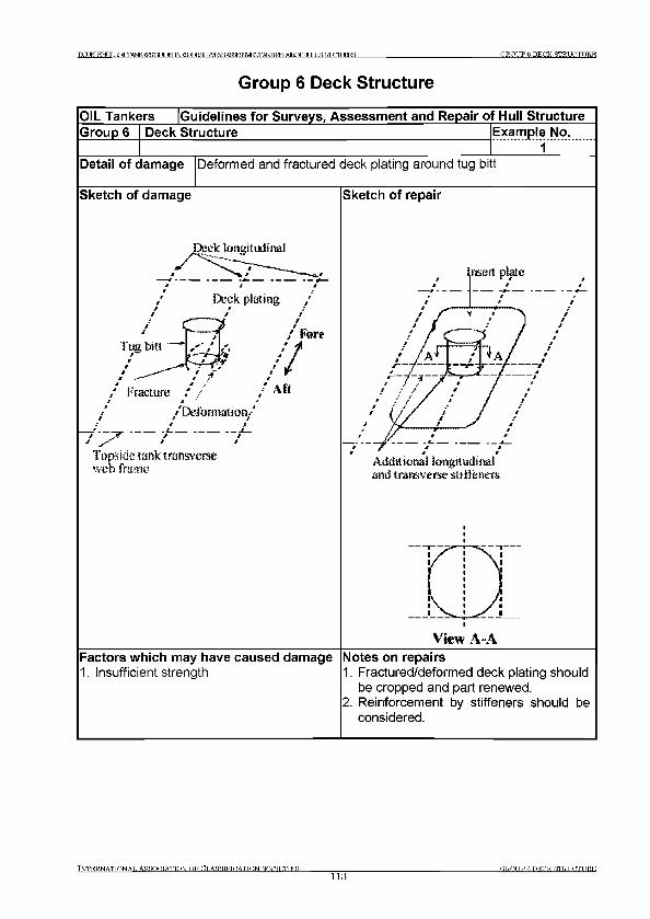
GROUP в DECK STRUCTUREDCXJBLEHUIJ О Т .TANKFRSGUfnPT INFISIO^SURVEYS TT15 П К Г HTURES
G roup 6 Deck Structure
TNTERNATTONAT. ASROCTATTON OF CT.ASSTFTDATTON SOOTETTES113
G R O U P 6 D E C K ST R U C T U R E
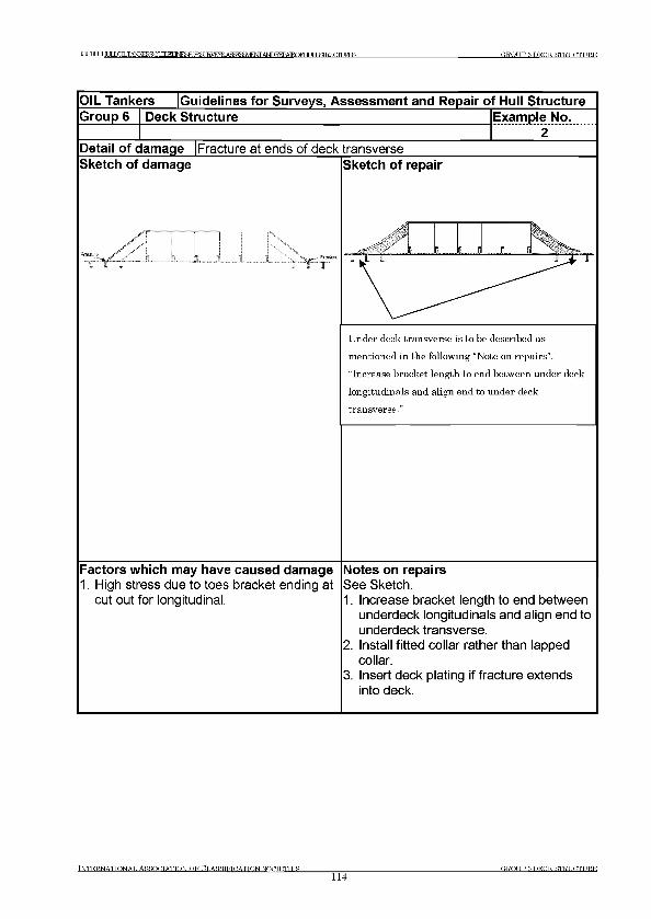
D C m ^ H U IIO L T A N K E R Sfa УГГКГ №ЦГОЕ8ШУЕЖАЯЙРУШР>7Г ANDREPAIROFHr ТГТ ЯШТ m U R E S G R O U P 6 D E C K ST R U C T U R E
OIL Tankers [Guidelines for Surveys, Assessment and Repair of Hull StructureGroup 6 Deck Structure Example No.
Detail of damage Fracture at ends of deck transverseSketch of damage Sketch of repair
if I г 15 J
U nder deck transverse is to be described as
m en tion ed in the follow ing “N ote on repairs” .
“Increase bracket length to en d betw een under deck
lon g itu d in als and align en d to u n d er deck
tran sverse .”
Factors which may have caused damage1. High stress due to toes bracket ending at
cut out for longitudinal.
Notes on repairsSee Sketch.1. Increase bracket length to end between
underdeck longitudinals and align end to underdeck transverse.
2. Install fitted collar rather than lapped collar.
3. Insert deck plating if fracture extends into deck.
Tn t e r .n a t t o n a t , a s s o c i a t i o n o f C t.a s s t f t o a t t o n s o c t e t t e s ________________114
G R O U P 6 D E C K ST R U C T U R E
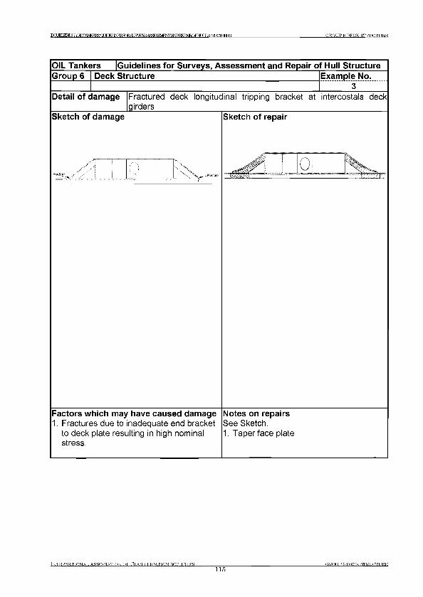
DC* JRT EHt IT LHLTANKERSGT JfDFT JNTCRRDRSt JRVF1YS ASFFS^ENTANDIEPATROFHt Я15>IRT SCREES GROUP 6 DECK STRUCTURE
OIL Tankers Guidelines for Surveys, Assessment and Repair of Hull StructureGroup 6 Deck Structure Example No.
3Detail of damage Fractured deck longitudinal tripping bracket at
girdersintercostals deck
Sketch of damage Sketch of repair
L 4.! U i 1
Factors which may have caused damage1. Fractures due to inadequate end bracket
to deck plate resulting in high nominal stress.
Notes on repairsSee Sketch.1. Taper face plate
IN T E R N A T IO N A L A S S O C IA T IO N O F C L A S S IF IC A T IO N S O C IE T IE S
115GROUP в DECK STRUCTURE
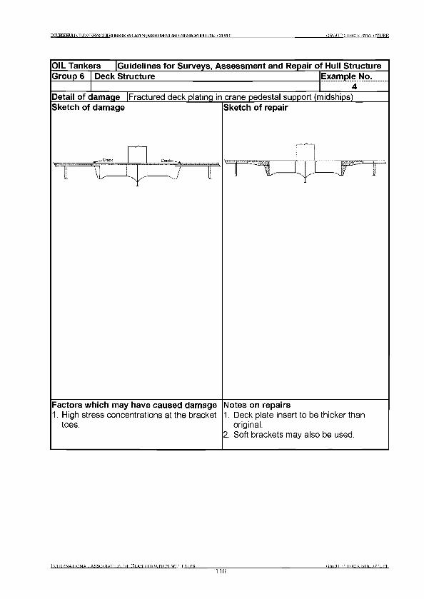
G R O U P в D E C K ST R U C T U R EI)CmLEHULI/JlLTi№ERgGUIDFI ]ЦРККЖ8иЕ1УЕ^АЯйР?ЯУ1Р^ДЬЮ1^А1ЕЮЕНГ JTI5ПКГ FTTURES
OIL Tankers Guidelines for Surveys, Assessment and Repair of Hull StructureGroup 6 Deck Structure Example No.
4Detail of damage |Fractured deck plating in crane pedestal support (midships)Sketch of damage
-r_^-Crask Crack-—*
Sketch of repair
L \ L — ^ — J / l Н Г " ' J - ^
Factors which may have caused damage1. High stress concentrations at the bracket
toes.
Notes on repairs1. Deck plate insert to be thicker than
original.2. Soft brackets may also be used.
INTERNATIONAL ASSOCIATION OF CLASSIFICATION SOCIETIES116
GROUP в DECK STRUCTURE
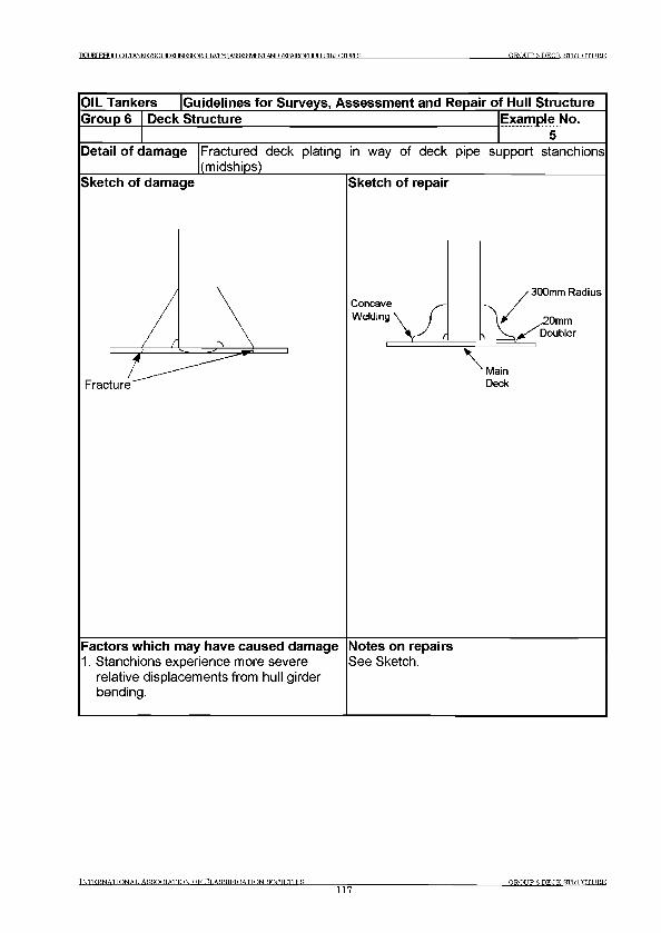
GROUP 6 DECK STRUCTUREDCTJBLEHt JT JO T .TANKFRSGUfnPT INRSR^SURV Era ANDIEPAIROFHf TTIЯШТ FTTURES
I n t e r n a t i o n a l A s s o c i a t i o n o f C l a s s i f i c a t i o n s o c i e t i e s
117GROUP в DECK STRUCTURE
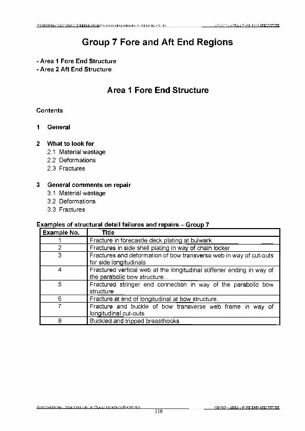
T O JBT Е Н Г JU^ILTANKERSGt У Т Г М INBSroRSLHVRYR А ^ ^ М Р К Т Ж Р Е Е Р А ^ Г ) Г Н Г ТГ Т .STRUCTURES G R O U P 7 A R E A 1 F O R E E N D STRUCTURE
Group 7 Fore and Aft End Regions
- Area 1 Fore End Structure
- Area 2 Aft End Structure
A rea 1 Fore End Structure
Contents
1 General
2 What to look for
2.1 Material wastage2.2 Deformations2.3 Fractures
3 General comments on repair
3.1 Material wastage3.2 Deformations3.3 Fractures
Examples of structural detail failures and repairs - Group 7Example No. Title
1 Fracture in forecastle deck plating at bulwark2 Fractures in side shell plating in way of chain locker3 Fractures and deformation of bow transverse web in way of cut-outs
for side longitudinals4 Fractured vertical web at the longitudinal stiffener ending in way of
the parabolic bow structure.5 Fractured stringer end connection in way of the parabolic bow
structure6 Fracture at end of longitudinal at bow structure.7 Fracture and buckle of bow transverse web frame in way of
longitudinal cut-outs8 Buckled and tripped breasthooks
Tn t e r .n a t t o n a t , A s s o c i a t i o n o f O t.a s s t f t o a t t o n r o e t e t t e s
118OR.OTIP 7 AREA 1 FORE END STRUCTURE
IXXJBIEHUUX^TANKFRSGT ЛТЖГ ]NFKW~)R51 IRVEYS ASSFSFMFNT A^REPAIROFHJIUffl^CIURES G R O U P 7 A R E A 1 F O R E E N D ST R U C T U R E
1 General
1.1 Due to the high humidity salt water environment, wastage of the internal structure in the forepeak ballast tank can be a major problem for many, and in particular ageing ships. Corrosion of structure may be accelerated where the tank is not coated or where the protective coating has not been properly maintained, and can lead to fractures of the internal structure and the tank boundaries.
1.2 Deformation can be caused by contact, which can result in damage to the internal structure leading to fractures in the shell plating.
1.3 Fractures of internal structure in the fore peak tank and spaces can also result from wave impact load due to slamming and panting.
1.4 Forecastle structure is exposed to green water and can suffer damage such as deformation of deck structure, deformation and fracture of bulwarks and collapse of mast, etc.
1.5 Shell plating around anchor and hawse pipe may suffer corrosion, deformation and possible fracture due to movement of improperly stowed anchor.
2 What to look for
2.1 Material wastage
2.1.1 Wastage (and possible subsequent fractures) is more likely to be initiated at the locations as indicated in Figure 1 and particular attention should be given to these areas. A close-up survey should be carried out with selection of representative thickness measurements to determine the extent of corrosion.
2.1.2 Structure in chain locker is liable to have heavy corrosion due to mechanical damage to the protective coating caused by the action of anchor chains. In some ships, especially smaller ships, the side shell plating may form boundaries of the chain locker and heavy corrosion may consequently result in holes in the side shell plating.
2.2 Deformations
2.2.1 Contact with quay sides and other objects can result in large deformations and fractures of the internal structure. This may affect the watertight integrity of the tank boundaries and collision bulkhead. A close-up survey of the damaged area should be carried out to determine the extent of the damage.
TNTERNATTONAT. ASSOOTATTON O F CT.ASSTFTDATTON S O C IE T IE S
119O RO TJP 7 AREA 1 F O R E E N D ST R U C T U R E
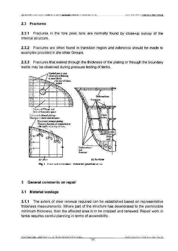
РСТБТКНПГ LOLTANKERSGr УТГМ INFSFORSr GROUP 7 AREA 1 FORE END STRUCTURE
2.3 Fractures
2.3.1 Fractures in the fore peak tank are normally found by close-up survey of the internal structure.
2.3.2 Fractures are often found in transition region and reference should be made to examples provided in the other Groups.
2.3.3 Fractures that extend through the thickness of the plating or through the boundary welds may be observed during pressure testing of tanks.
Fig 1 Fore end structu re - Potential problem a re a s
3 General comments on repair
3.1 Material wastage
3.1.1 The extent of steel renewal required can be established based on representative thickness measurements. Where part of the structure has deteriorated to the permissible minimum thickness, then the affected area is to be cropped and renewed. Repair work in tanks requires careful planning in terms of accessibility.
Tn t e r n a t t o n a t , A r r o h t a t t o n o f c l a s s i f i c a t i o n e o o t e t t e r
120OR.OTTP 7 AREA 1 F O R E E N D ST R U C T U R E
Г О В Т к н и г LOLTANKERSGr У Т Г М JN F ^ T O R S L IR V E ^A S ^^ E ^i^ I^ A E Q F H L JIL & T E U aiU R E S G R O U P 7 A R E A 1 F O R E E N D ST R U C T U R E
3.2 Deformations
3.2.1 Deformed structure caused by contact should be cropped and part renewed or faired in place depending on the nature and extent of damage.
3.3 Fractures
3.3.1 Fractures of a minor nature may be veed-out and rewelded. Where cracking is more extensive, the structure is to be cropped and renewed. In the case of fractures caused by sea loads, increased thickness of plating and/or design modification to reduce stress concentrations should be considered (See Examples 1 and 5).
IN T E R N A T IO N A L A SS O C IA T IO N O F C L A S S IF IC A T IO N S O C IE T IE S
121O,ROT IP 7 AREA 1 FORE END STRUCTURE
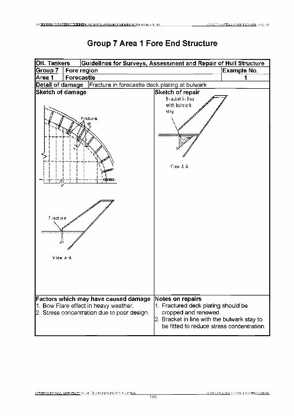
DCUBLEHQLL0ILTiWKER4(~ff TTTW JN T O T O R SL IR V E ^A S^^E ^iW D R E P A IR Q m ТГ T .GTRT Т Г Г Т Т TRTC G R O U P 7 A R E A 1 F O R E E N D ST R U C T U R E
G roup 7 A rea 1 Fore End Structure
OIL Tankers Guidelines for Surveys, Assessment and Repair of Hull StructureGroup 7 Fore region Example No.Area 1 Forecastle 1Detail of damage Fracture in forecastle deck plating at bulwarkSketch of damage
Fractures a-
- ■ r ^ 4 ± ±
f r a d u r e
V tew A -A
Sketch of repairЁ racket in Sine with bulwark stay
V ie w A -A
Factors which may have caused damage1. Bow Flare effect in heavy weather.2. Stress concentration due to poor design.
Notes on repairs1. Fractured deck plating should be
cropped and renewed.2. Bracket in line with the bulwark stay to
be fitted to reduce stress concentration.
IN T E R N A T IO N A L ARROOTATTON O F C L A S S IF IC A T IO N HOOTETTER________________
122GROT TP 7 AREA 1 F O R E E N D ST R U C T U R E
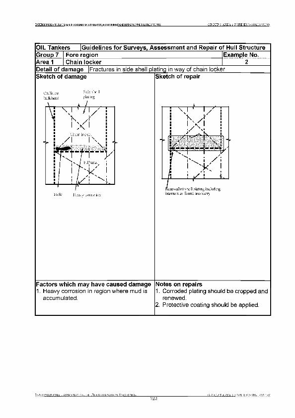
D O M FTHT JT LOLTANKFKSGUrnFI 1 Ы Р К К Ж Ш К У Е У ^ с Я ^ М Ф Л ,А Ь Ю Б ! Е Р А Е О Р Н и 1 Ь & т а : ( Ж Д ? Е 8 G R O U P 7 A R E A 1 F O R E E N D ST R U C T U R E
i n t e r n a t i o n a l A s s o c i a t i o n o f C l a s s i f i c a t i o n s o c i e t i e s
123G R O U P 7 A REA 1 F O R E E N D ST R U C T U R E

DC* JRTEHT Л J jOfT .TAN{FRSGfJTDEriNFSFO ?Я JRVEYS AffFK?M;NrANDT?FPATR.OFHf ЯISTRI HIT IRES GROUP 7 AREA 1 TORE END STRUCTURE
OIL Tankers Guidelines for Surveys, Assessment and Repair of Hull StructureGroup 7 Fore region Example No.Area 1 Forepeak ballast tank 3Detail of damage Fractures and deformation of bow transverse webs in way of cut-outs
for side longitudinalsSketch of damage Sketch of repair
Insert piute v.iLii increased Lmeк ness atidw addiUiMiaJ sn ill-nine
Factors which may have caused damage1. Localized material wastage in way of
coating failure at cut-outs and sharp edges due to working of the structure.
2. Dynamic seaway loading in way of bow flare.
Notes on repairs1. Sufficient panel strength to be provided
to absorb the dynamic loads enhanced by bow flare shape.
IN T E R N A T IO N A L A SS O C IA T IO N O F C L A S S IF IC A T IO N ROOTETTES
124OROT IP 7 AREA 1 F O R E E N D ST R U C T U R E
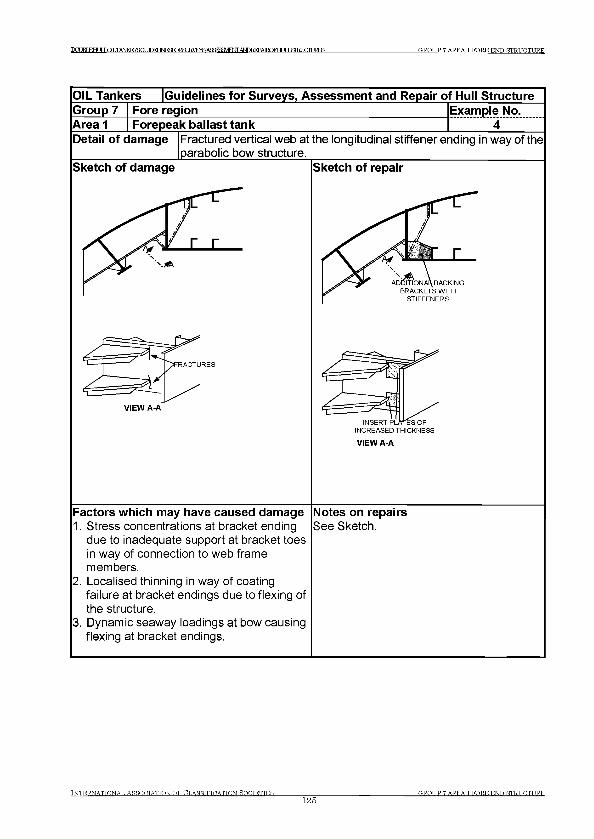
PCI JRT EHI IT LOT .TANKFRSGUTDFT 1 Ы Р } Я К Ж 8 и Е 1 У Е ^ А Я й Я 5 3 У 1 Е Ж А Ы П Т М 3А Т Н О К Н Г Я I Я Ш Г OURES GROUP 7 AREA 1 TORE END STRUCTURE
OIL Tankers Guidelines for Surveys, Assessment and Repair of Hull StructureGroup 7 Fore region Example No.Area 1 Forepeak ballast tank 4Detail of damage Fractured vertical web at the longitudinal stiffener ending in way of the
parabolic bow structure.Sketch of damage Sketch of repair
ADDITIONAL BACKING BRACKETS WITH
STIFFENERS
INSERT PLATES OF INCREASED THICKNESS
VIEW A-A
Factors which may have caused damage1. Stress concentrations at bracket ending
due to inadequate support at bracket toes in way of connection to web frame members.
2. Localised thinning in way of coating failure at bracket endings due to flexing of the structure.
3. Dynamic seaway loadings at bow causing flexing at bracket endings.
Notes on repairsSee Sketch.
IN T E R N A T IO N A L ASSOCIATION OF C L A S S IF IC A T IO N S O C IE T IE S ________________
125G R O U P 7 A REA 1 F O R E E N D ST R U C T U R E

DOUBLEHIJT LOLTANKERBOr УТГМ JNF^TORSLIRVE^.A«F^¥MFT^/WDREPAIR.OFHLJILS GROUP 7 AREA 1 FORE END STRUCT! IRE
OIL Tankers Guidelines for Surveys, Assessment and Repair of Hull StructureGroup 7 Fore region Example No.Area 1 Forepeak ballast tank 5Detail of damage Fractured stringer end connection in way of the parabolic bow
structureSketch of damage
4VIEWA-A
Sketch of repair
ERT PLATE
MODIFIED FACE FLAT- CONNECTION
VIEWB-B
Factors which may have caused damage1. High stress concentration of stringer to
stiff girder/deep web intersection due to discontinuity of faceplate.
2. Localised thinning in way of coating failure at stringer connection due to flexing of the structure.
3. Dynamic seaway loadings at bow causing flexing in way of detail.
Notes on repairsSee Sketch.
INTERNATIONAL ASSOCIATION OF CLASSIFICATION SOCIETIES________________126
GROUP 7 AREA 1 FORE END STRUCTURE
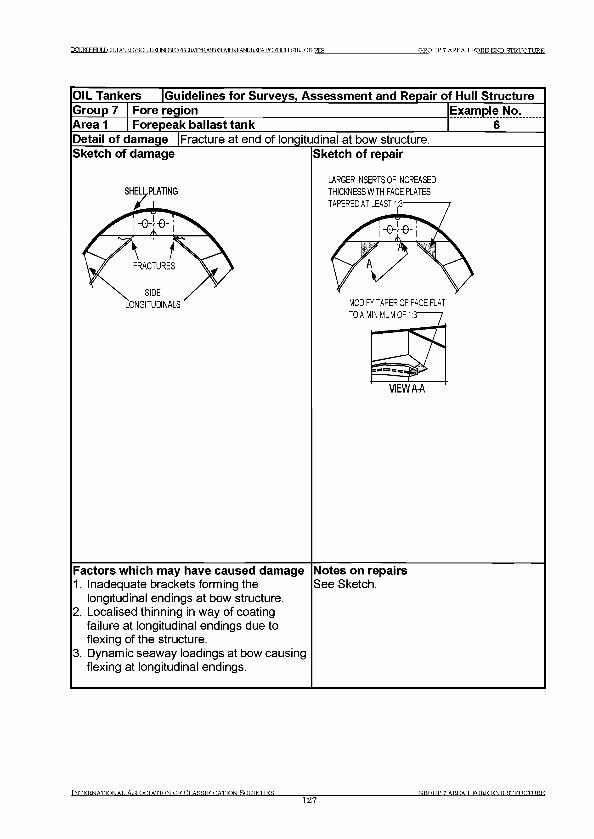
IXXBl^HULLDILTAISKERSOr ТЮБ! INESTORST JRVF^ ASSFSSVENTTANDREPATROFHT ЯI ,STRT TOTURES GROUP 7 AREA 1 FORE ENT) STRUCTURE
OIL Tankers Guidelines for Surveys, Assessment and Repair of Hull StructureGroup 7 Fore region Example No.Area 1 Forepeak ballast tank 6Detail of damage Fracture at end of longitudinal at bow structure.Sketch of damage
SHELLPLATING
Sketch of repair
LARGER INSERTS OF INCREASED THICKNESS WITH FACE PLATES TAPERED AT LEAST 1;3- - - - - - - - - - -
MODIFY TAPER OF FACE FLAT TOA MINIMUM OF 1:3—
VIEWA-A
Factors which may have caused damage1. Inadequate brackets forming the
longitudinal endings at bow structure.2. Localised thinning in way of coating
failure at longitudinal endings due to flexing of the structure.
3. Dynamic seaway loadings at bow causing flexing at longitudinal endings.
Notes on repairsSee Sketch.
INTERNATIONAL ASSOCIATION OF CLASSIFICATION SOCIETIES127
О ROT TP 7 AREA 1 FORK ENT) STRUCTURE
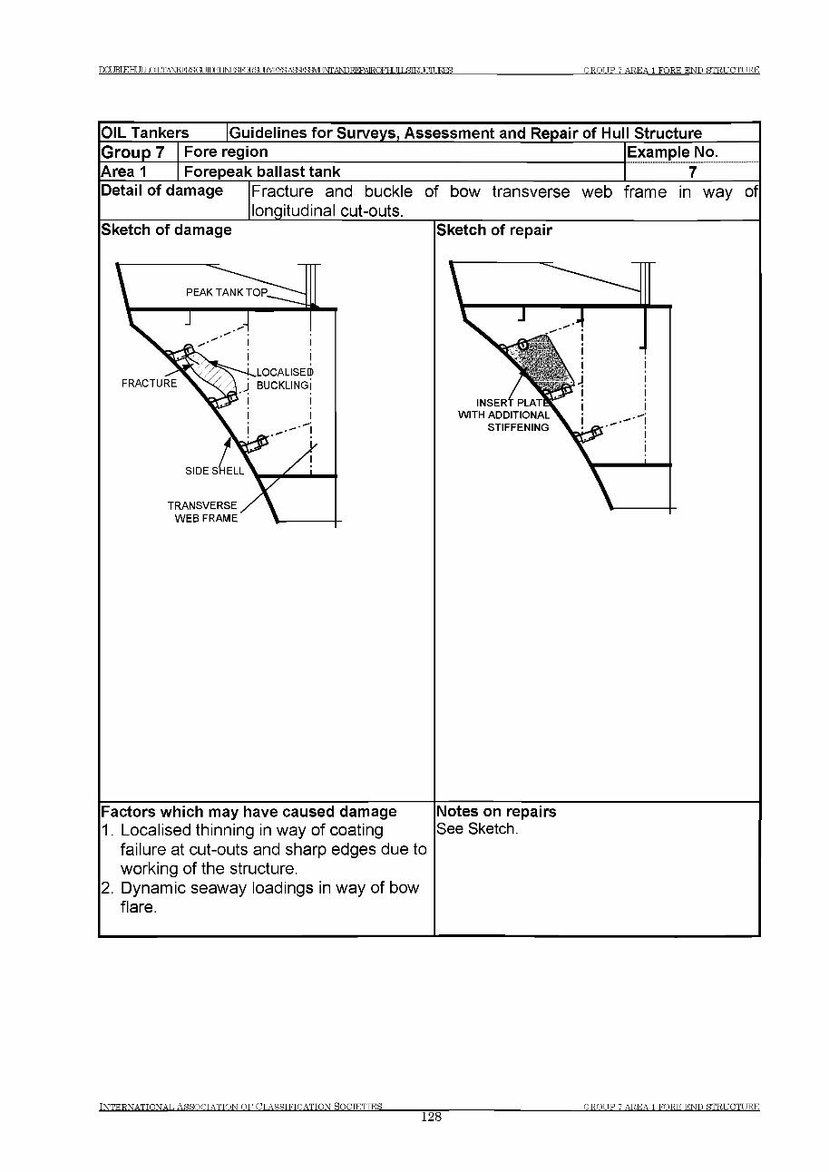
ГРТКГЕНГТГ1 OILTANKERSOT ПРЕТ IM^TORSLIE^E^AS^BaVEtSrrANDEEPAIRQFHr IT T .GTRT ТГГТТ TRTC G R O U P 7 A R E A 1 F O R E E N D S T R U C T U R E
IN T E R N A T IO N A L A S S O C IA T IO N O F C L A S S IF IC A T IO N S O C IE T IE S128
G R O U P 7 A R E A 1 FO R K E N D S T R U C T U R E
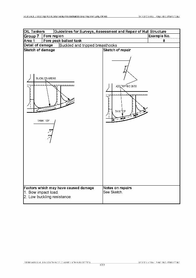
Г О ВТ к н и г LOILTANKERSGt УТГМ JN F ^ T O R S L IR V E ^A S ^ ^E ^i^I^A E Q F H L J IL & T E U a iU R E S G R O U P 7 A R E A 1 F O R E E N D ST R U C T U R E
OIL Tankers [Guidelines for Surveys, Assessment and Repair of Hull Structure
Group 7 Fore region
Area 1 Fore peak ballast tank
Example No.
8Detail of damage |Buckled and tripped breasthooksSketch of damage Sketch of repair
Factors which may have caused damage Notes on repairs1. Bow impact load. See Sketch.2. Low buckling resistance.
IN T E R N A T IO N A L A S S O C IA T IO N O F C L A S S IF IC A T IO N S O C IE T IE S129
O,ROT IP 7 A R E A 1 F O R E E N D S T R U C T U R E
ТОМ КНИГ LaLTANKFRSOr ЛТМ 1МгеТОЕ8ШУЕЖАсЕгеЕМФЛ,АЬЮ№^ 3GIURE5 GROUP 7 AREA 2 AFT END STRUCTURE
Area 2 Aft End Structure
Contents
1 General
2 What to look for2.1 Material wastage2.2 Deformations2.3 Fractures
3 General comments on repair3.1 Material wastage3.2 Deformations3.3 Fractures
Examples of structural detail failures and repairs - Group 7Example No. Title
9 Fractures in bulkhead in way of rudder trunk10 Fractures at the connection of floors and girders/side brackets11 Machinery space outside engine room12 Machinery space outside engine room
Tn t e r n a t t o n a t , a s h o g t a t t o n o f (Tl a s s t f t o a t t o n S o c i e t i e s
130GROUP 7 AREA 2 AFT END STRUCTURE
Г О ВТ книг LOLTANKERBCa JTTM IM ^TORSU KVEraAgsreEM ^/^ ТГ Т £Ш TGTURES G R O U P 7 A R E A 2 A FT E N D ST R U C T U R E
1 General
1.1 Due to the high humidity salt water environment, wastage of the internal structure in the aft peak ballast tank can be a major problem for many, and in particular ageing, ships. Corrosion of structure may be accelerated where the tank is not coated or where the protective coating has not been properly maintained, and can lead to fractures of the internal structure and the tank boundaries.
1.2 Deformation can be caused by contact or wave impact action from astern (which can result in damage to the internal structure leading to fractures in the shell plating).
1.3 Fractures to the internal structure in the aft peak tank and spaces can also result from main engine and propeller excited vibration.
2 What to look for
2.1 Material wastage
2.1.1 Wastage (and possible subsequent fractures) is more likely to be initiated at in the locations as indicated in Figure 1. A close-up survey should be carried out with selection of representative thickness measurements to determine the extent of corrosion. Particular attention should be given to bunker tank boundaries and spaces adjacent to heated engine room.
2.2 Deformations
2.2.1 Contact with quay sides and other objects can result in large deformations and fractures of the internal structure. This may affect the watertight integrity of the tank boundaries and bulkheads. A close-up examination of the deformed area should be carried out to determine the extent of the damage.
2.3 Fractures
2.3.1 Fractures in weld at floor connections and other locations in the aft peak tank and rudder trunk space can normally only be found by close-up survey.
2.3.2 The structure supporting the rudder carrier may fracture and/or deform due to excessive load on the rudder. Bolts connecting the rudder carrier to the steering gear flat may also suffer damage under such load.
Tn t e r n a t t o n a t . A s s o c i a t i o n o f Ut.a s s t f t u a t t o n Ho g t e t t e s
131G R O U P 7 AREA 2 AFT E N D ST R U C T U R E
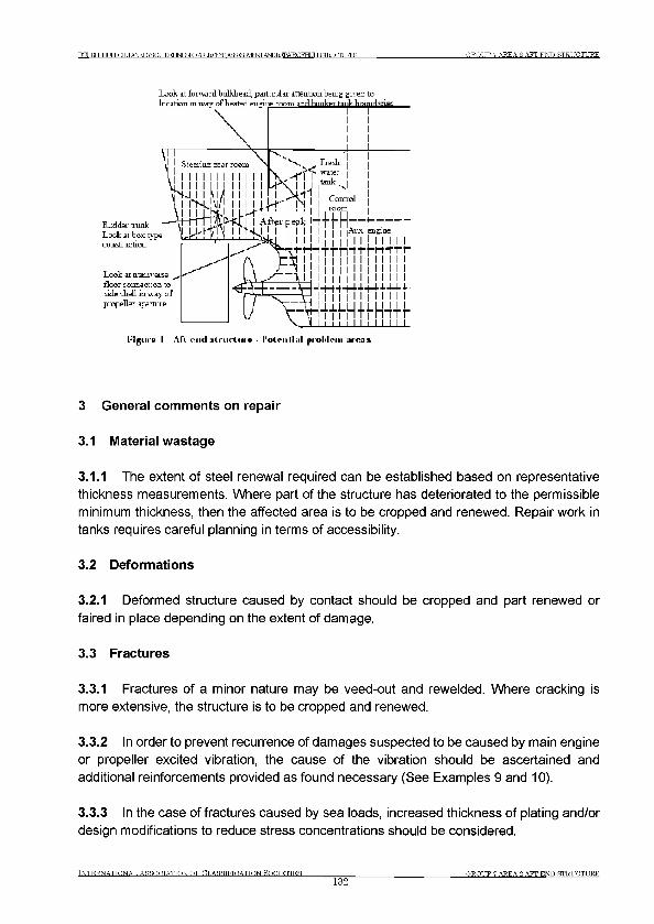
PCX TRT книг LOLTANKERSOr ТГГКГ JNF^TORSLIRVE^AS^^E^iW )REPAIRQFHLir J £Ш JCTTT JRES G R O U P 7 A REA 2 A FT E N D ST R U C T U R E
R id d e l tluiL Look at box typ coubtmction
Look -at traiuve floor cauz ct'o: side -JjeJI i t i ’ivi; propella: apartn
И pure I Aft -cmicI siruriu ie - PoLnilhil | н о М е ш ureas
3 General comments on repair
3.1 Material wastage
3.1.1 The extent of steel renewal required can be established based on representative thickness measurements. Where part of the structure has deteriorated to the permissible minimum thickness, then the affected area is to be cropped and renewed. Repair work in tanks requires careful planning in terms of accessibility.
3.2 Deformations
3.2.1 Deformed structure caused by contact should be cropped and part renewed or faired in place depending on the extent of damage.
3.3 Fractures
3.3.1 Fractures of a minor nature may be veed-out and rewelded. Where cracking is more extensive, the structure is to be cropped and renewed.
3.3.2 In order to prevent recurrence of damages suspected to be caused by main engine or propeller excited vibration, the cause of the vibration should be ascertained and additional reinforcements provided as found necessary (See Examples 9 and 10).
3.3.3 In the case of fractures caused by sea loads, increased thickness of plating and/or design modifications to reduce stress concentrations should be considered.
IN T E R N A T IO N A L ASSOOTATTON OF CT.ASSTFTOATTON Н О П Т Е Т Т Е Я
132(TROT TP 7 AREA 9. AFT E N D ST R U C T U R E
ГО ВТ книг LOILTANKERSGt 1ГПЕГ JN F^TO RSLIRVE^A S^^E^i^I^A EQ FH LJILSIEU aiU RES G R O U P 7 A R E A 2 A F T E N D S T R U C T U R E
3.3.4 Fractured structure which supports rudder carrier is to be cropped, and renewed, and may have to be reinforced (See Examples 11 and 12).
I N T E R N A T I O N A L A S S O C I A T I O N O F C L A S S I F I C A T I O N S O C T E T T E S
133G R O U P 7 A R E A 2 A F T E N D S T R U C T U R E
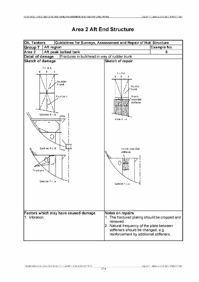
Г О ВТ книг LOILTANKERSGt 1ГПЕГ JNF^TORSLIRVE^AS^^E^i^I^AEQFHLJIL&TEUaiURES G R O U P 7 A R E A 2 A F T E N D ST R U C T U R E
Area 2 Aft End Structure
OIL Tankers Guidelines fo r Surveys, Assessment and Repair of Hull StructureG roup 7 Aft region Example No.Area 2 Aft peak ballast tank 9Detail of damage |Fractures in bulkhead in way of rudder trunk
Fradure
Sedion F r. a
Sketch of repair
New!y provided stiffen er
Sedion F r. a
Factors which may have caused damage1. Vibration.
Notes on repairs1. The fractured plating should be cropped and
renewed.2. Natural frequency of the plate between
stiffeners should be changed, e.g. reinforcement by additional stiffeners.
INTERNATIONAL ASSOOTATTON OF CT.ASSTFTCATTON ЯОСТЕТТЕЯ______________134
O,ROT IP 7 AREA Я AFT E N D ST R U C T U R E
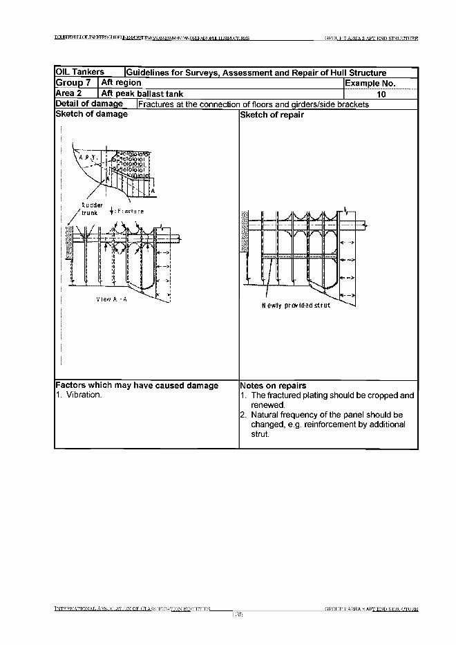
Г О Л В Г E H I JT L H L T A N K E R S G I Л П Е Г I M ^ K ^ S U R V F IY K A 5 S F ^M jN T A N D T ? F P A lR .O F F ir Т Г T PHRT У П Т 1 К Е Ч GROUP 7 AREA Я AFT END STRUCTURE
IN T E R N A T IO N A L A S S O C IA T IO N O F C L A S S IF IC A T IO N ROOTETTES135
GROUP 7 AREA ?. AFT END STRUCTURE
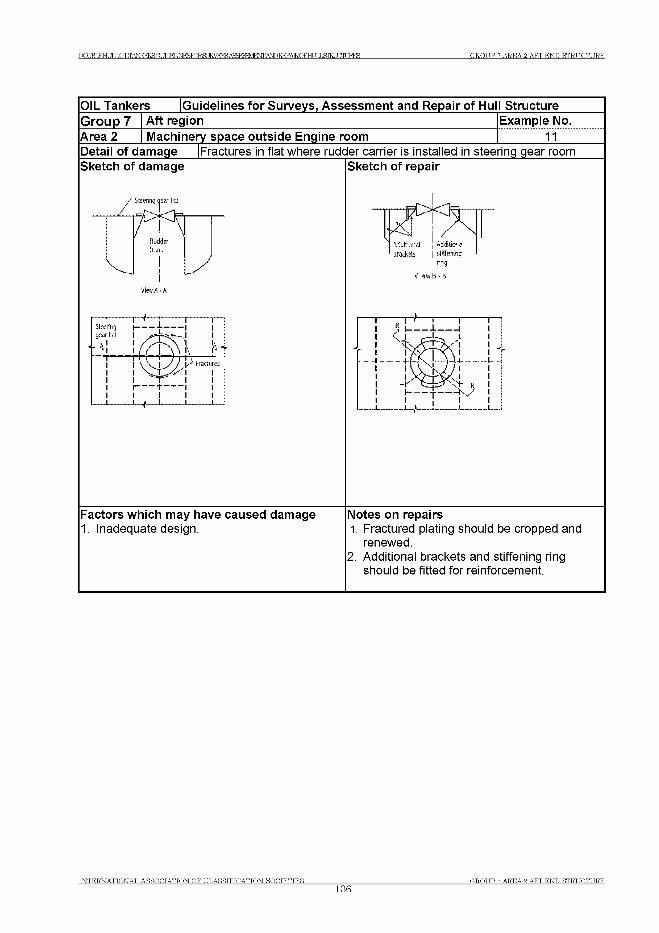
Г О ВТ к н и г LOILTANKERSGf 1ГПЕГ JN F ^ T O R S L IR V E ^A S ^ ^E ^i^I^A E Q F H L J IL & T E U a iU R E S G R O U P 7 A R E A 2 A F T E N D ST R U C T U R E
IN T E R N A T IO N A L A S S O C IA T IO N O F C L A S S IF IC A T IO N SOCTETTES__________________136
G R O U P 7 A R EA 2 AFT E N D ST R U C T U R E
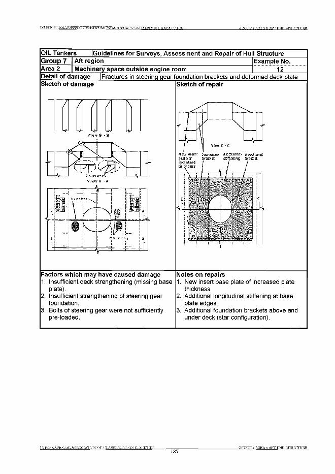
DCUBLEH LILOILTiW EPRa М М IM ^roRSURyEYR AS^BSVEtSfrANDEEPAIROFHr ТТ Т .GTRT ТГГТТ TRTC G R O U P 7 A R E A 2 A F T E N D ST R U C T U R E
OIL Tankers [Guidelines fo r Surveys, Assessment and Repair of Hull StructureGroup 7Area 2
Aft regionMachinery space outside engine room
Example No.12
Detail of damage Sketch of damage
Fractures in steering gear foundation brackets and deformed deck plateSketch of repair
“ 7 / / / \
view a - a
View C -1
Mew insert increase!; Ariiitionai Additions*
Factors which may have caused damage1. Insufficient deck strengthening (missing base
plate).2. Insufficient strengthening of steering gear
foundation.3. Bolts of steering gear were not sufficiently
pre-loaded.
Notes on repairs1. New insert base plate of increased plate
thickness.2. Additional longitudinal stiffening at base
plate edges.3. Additional foundation brackets above and
under deck (star configuration).
IN T E R N A T IO N A L A S S O C IA T IO N O F C L A S S IF IC A T IO N S O C IE T IE S137
OR.OTIP 7 AREA 9. AFT END STRUCTURE
Т О М КНИГ LOLTANKERBftr УГГКГ INFlSTORSCJE^^AS^BaVENfrANDEEPAIROFHI JT J .STRUCTURES G R O U P 8 A R E A 1 E N G IN E R O O M ST R U C T U R E
Group 8 Machinery and Accommodation Spaces
- Area 1 Engine Room Structure- Area 2 Accommodation Structure
Area 1 Engine Room Structure
Contents
1 General
2 What to look for - Engine room survey2.1 Material wastage2.2 Fractures
3 What to look for - Tank survey3.1 Material wastage3.2 Fractures
4 General comments on repair4.1 Material wastage4.2 Fractures
Examples of structural detail failures and repairs - Group 8Example No. Title
1 Fractures in brackets at main engine foundation2 Corrosion in bottom plating under sounding pipe in way of bilge
storage tank in engine room3 Corrosion in bottom plating under inlet/suction/pipe in way of bilge
tank in engine room
IN T E R N A T IO N A L A S S O C IA T IO N O F C L A S S IF IC A T IO N S O C IE T IE S
138G R O U P 8 AREA 1 E N G IN E R O O M ST R U C T U R E
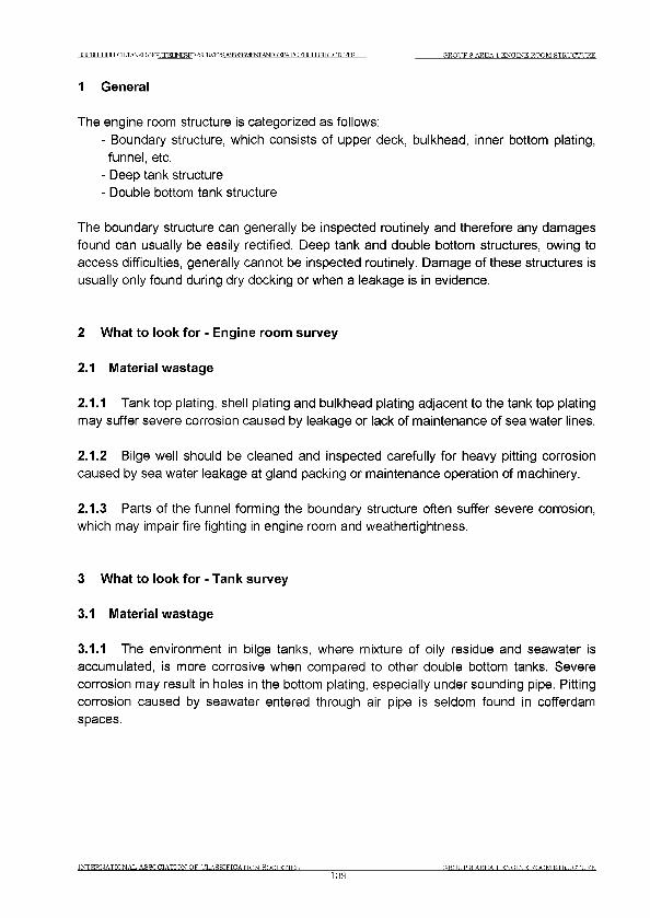
Т О М К Н Т Т Г LOILTANKERSGr У Г Г К Г INFSPORg 1 Н У Р Ж А Ч = : т Р Т ^ ^ Ж Р А Е 0 Г Н и 1 Ь & Т Ш С т а ^ GROUP 8 AREA 1 ENGINE ROOM STRUCTURE
1 General
The engine room structure is categorized as follows:- Boundary structure, which consists of upper deck, bulkhead, inner bottom plating,
funnel, etc.- Deep tank structure- Double bottom tank structure
The boundary structure can generally be inspected routinely and therefore any damages found can usually be easily rectified. Deep tank and double bottom structures, owing to access difficulties, generally cannot be inspected routinely. Damage of these structures is usually only found during dry docking or when a leakage is in evidence.
2 What to look for - Engine room survey
2.1 Material wastage
2.1.1 Tank top plating, shell plating and bulkhead plating adjacent to the tank top plating may suffer severe corrosion caused by leakage or lack of maintenance of sea water lines.
2.1.2 Bilge well should be cleaned and inspected carefully for heavy pitting corrosion caused by sea water leakage at gland packing or maintenance operation of machinery.
2.1.3 Parts of the funnel forming the boundary structure often suffer severe corrosion, which may impair fire fighting in engine room and weathertightness.
3 What to look for - Tank survey
3.1 Material wastage
3.1.1 The environment in bilge tanks, where mixture of oily residue and seawater is accumulated, is more corrosive when compared to other double bottom tanks. Severe corrosion may result in holes in the bottom plating, especially under sounding pipe. Pitting corrosion caused by seawater entered through air pipe is seldom found in cofferdam spaces.
INTERNATIONAL ASSOCIATION OF CLASSIFICATION SOCIETIES139
(TRO UP 8 AREA 1 E N G IN E R O O M ST R U C T U R E

Т О М КНИГ IjOLTANKERSOr TTW INFSFnRflT TRVRYR АЯЯгеЯУШЖА^КЕРА^^ G R O U P 8 A R E A 1 E N G IN E R O O M ST R U C T U R E
3.2 Fractures
3.2.1 In general, deep tanks for fresh water or fuel oil are located in engine room. The structure in these tanks often sustains fractures due to vibration. Fracture of double bottom structure in engine room is seldom found due to its high structural rigidity.
4 General comments on repair
4.1 Material wastage
4.1.1 Where part of the structure has deteriorated to the permissible minimum thickness, then the affected area is to be cropped and renewed. Repair work in double bottom will require careful planning in terms of accessibility and gas freeing is required for repair work in fuel oil tanks.
4.2 Fractures
4.2.1 For fatigue fractures caused by vibration, in addition to the normal repair of the fractures, consideration should be given to modification of the natural frequency of the structure to avoid resonance. This may be achieved by providing additional structural reinforcement, however, in many cases, a number of tentative tests may be required to reach the desired solution.
IN T E R N A T IO N A L A S S O C IA T IO N O F C L A S S IF IC A T IO N ROCTETTES
140C R O U P S AREA 1 E N G IN E R O O M ST R U C T U R E
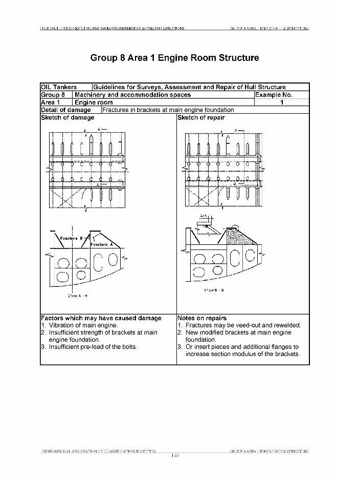
Г О В Т к н и г LOILTANKERSGt 1 Г П Е Г 1 М Р ^ Г О Е 8 Ш У Е Ж А ^ ^ Ш Е Ж ^ Т О Ю А Е О Г Н и 1 Ь & Т Ш С т а Е З G R O U P 8 A R E A 1 E N G I N E R O O M S T R U C T U R E
Group 8 Area 1 Engine Room Structure
OIL Tankers Guidelines fo r Surveys, Assessment and Repair of Hull StructureGroup 8 Machinery and accommodation spaces Example No.Area 1 Engine room 1Detail of damage |Fractures in brackets at main engine foundationSketch of damage
\VF racb Jre В -ft
О 0 ojJo _C)_
Sketch of repair
Factors which may have caused damage1. Vibration of main engine.2. Insufficient strength of brackets at main
engine foundation.3. Insufficient pre-load of the bolts.
Notes on repairs1. Fractures may be veed-out and rewelded.2. New modified brackets at main engine
foundation.3. Or insert pieces and additional flanges to
increase section modulus of the brackets.
IN T E R N A T I O N A L A S S O C IA T I O N O F C L A S S I F I C A T IO N S O C I E T I E S __________________
141O,ROT IP 8 AREA 1 ENOTNE ROOM STRUCTURE
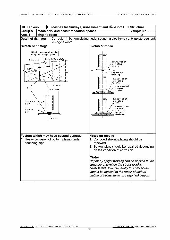
T O IRT КНИГ LOTT .TANKFRSGT УГТКТ INFlSTORSUE^E^AS^BaVEtSfTANDEEPAIROFHr IT T ,ЭТКГ TGTURES GROUP 8 AREA 1 ENGINE ROOM STRUCTURE
OIL Tankers Guidelines fo r Surveys, Assessment and Repair of Hull StructureGroup 8 Machinery and accommodation spaces Example No.Area 1 Engine room 2Detail of damage Corrosion in bottom plating under sounding pipe in way of bilge storage tank
in engine roomSketch of damage
S h e ll e x p a n s io n inw a y of b i lg e ta n k
i l g s w e l li n n e r P o t t o m
S t n k sn g
Plata
Sketch of repair
|гТ=П
/R e n e w a l o f
s t r i k i n g
p l a t e
R. e p a i r b y
w e l d i n g
R e n e w a l o f
s t r i k i n g / plate
L L
R e n e w a I o f
b o t t o m p i a t e
R e n e w a l o f
s t r i k i n g o p i a t e
* R e n e w a l o f . b o t t o m
/ p l a t e b y
З Ц у * s p i g o t ^ ^ 3 . w e l d i n g
Factors which may have caused damage1. Heavy corrosion of bottom plating under
sounding pipe.
Notes on repairs1. Corroded striking plating should be
renewed.2. Bottom plate should be repaired depending
on the condition of corrosion.
(Note):Repair by spigot welding can be applied to the structure only when the stress level is considerably low. Generally this procedure cannot be applied to the repair of bottom plating of ballast tanks in cargo tank region.
IN T E R N A T IO N A L A S S O C IA T IO N O F C L A S S IF IC A T IO N HOCTETTES__________________142
(TROT TP S A REA 1 E N CTNE R O O M ST R U C T U R E
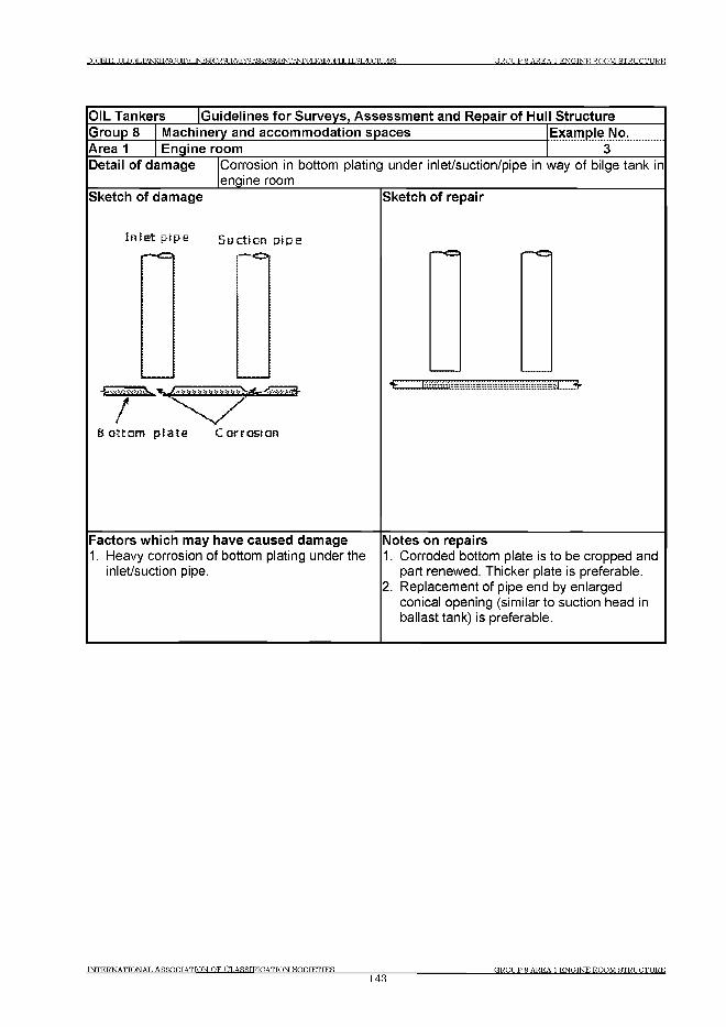
DCUBLEHT JT LOILTANKERSGt MMINESTORST J R V F ^ A S ^ ^ E M ’iTOREPAIRQFHLJIL&TRUGfIURES G R O U P 8 A R E A 1 E N G IN E R O O M ST R U C T U R E
OIL Tankers Guidelines fo r Surveys, Assessment and Repair of Hull StructureGroup 8 Machinery and accommodation spaces Example No.Area 1 Engine room 3Detail of damage Corrosion in bottom plating under inlet/suction/pipe in way of bilge tank in
engine roomSketch of damage
In le t p ip e S u c tio n p ip e
B o tto m p la te C o rro s io n
Sketch of repair
£ Z H 113-
Factors which may have caused damage1. Heavy corrosion of bottom plating under the
inlet/suction pipe.
Notes on repairs1. Corroded bottom plate is to be cropped and
part renewed. Thicker plate is preferable.2. Replacement of pipe end by enlarged
conical opening (similar to suction head in ballast tank) is preferable.
T N T E R N A T T O N A T . A S S O C TA TTO N O F O T.ASSTFTCATTQN HOCTETTES________________
143Г,ROT TP 8 A REA 1 ENO.TNE R O O M ST R U C T U R E
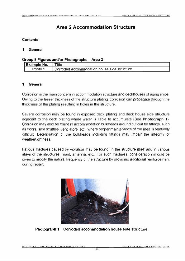
DQUBLEHLXLOLTANKERSOr ЛГКГINFKKHSUKVEYS А ЗаВ ЗУ Е ^А ^Е Е РА Е О Е В ^]Х 51Е 11Л 1Ж Е З П} R O U P 8 A R E A 2 A C C O M M O D A T IO N ST R U C T U R E
Area 2 Accom m odation Structure
Contents
1 General
Group 8 Figures and/or Photographs - Area 2Example No. Title
Photo 1 Corroded accommodation house side structure
1 General
Corrosion is the main concern in accommodation structure and deckhouses of aging ships. Owing to the lesser thickness of the structure plating, corrosion can propagate through the thickness of the plating resulting in holes in the structure.
Severe corrosion may be found in exposed deck plating and deck house side structure adjacent to the deck plating where water is liable to accumulate (See Photograph 1). Corrosion may also be found in accommodation bulkheads around cut-out for fittings, such as doors, side scuttles, ventilators, etc., where proper maintenance of the area is relatively difficult. Deterioration of the bulkheads including fittings may impair the integrity of weathertightness.
Fatigue fractures caused by vibration may be found, in the structure itself and in various stays of the structures, mast, antenna, etc.. For such fractures, consideration should be given to modify the natural frequency of the structure by providing additional reinforcement during repair.
Photograph 1 Corroded accommodation house side structure
TNTER.NATTONAT, ASSOCIATION OF (CLASSIFICATION SOCIETIES G R O U P S AREA Я ACCOMMODATION STRUCTURE
144
No.132
No.132(Dec2013)
Human Element Recommendations for structural design of lighting, ventilation, vibration, noise, access and egress arrangementsTable of Contents
Section 1 - Introduction
1.1 Scope and objectives
1.2 Application
1.3 Definitions
1.4 Recommendation overview
Section 2 - The Human Element
2.1 Regulatory expectations
2.2 Human Element Considerations
Section 3 - Rationale for considering the Human Element in the design of lighting, ventilation, vibration, noise, access and egress arrangements
3.1 General
3.2 Lighting3.2.1 Task requirements3.2.2 Ergonomic design principles3.2.3 Conditions3.2.4 Implications for structures
3.3 Ventilation3.3.1 Task requirements3.3.2 Ergonomic design principles3.3.3 Conditions3.3.4 Implications for structures
3.4 Vibration3.4.1 Task requirements3.4.2 Ergonomic design principles3.4.3 Conditions3.4.4 Implications for structures
3.5 Noise3.5.1 Task requirements3.5.2 Ergonomic design principles3.5.3 Conditions3.5.4 Implications for structures
Page 1 of 43 IACS Rec. 2013
No.132
No.132(cont)
3.6 Access and Egress3.6.1 Task requirements3.6.2 Ergonomic design principles3.6.3 Conditions3.6.4 Implications for structures
Section 4 - Ergonomic Structural Arrangement Recommendations
4.1 General
4.2 Lighting Design4.2.1 Aims4.2.2 Application4.2.3 Locations4.2.4 Structural Arrangements
4.3 Ventilation Design4.3.1 Aims4.3.2 Application4.3.3 Locations4.3.4 Structural Arrangements
4.4 Vibration Design4.4.1 Aims4.4.2 Application4.4.3 Locations4.4.4 Structural Arrangements
4.5 Noise Design4.5.1 Aims4.5.2 Application4.5.3 Locations4.5.4 Structural Arrangements
4.6 Access and Egress Design4.6.1 Aims4.6.2 Application4.6.3 Locations4.6.4 Structural Arrangements
Annex A - Recommended Measurement Values1.1 General1.2 Lighting1.3 Ventilation1.4 Vibration1.5 Access
Annex В - Relevant Standards, Guidelines and Practices2.1 Lighting2.2 Ventilation2.3 Vibration2.4 Noise2.5 Access
Page 2 of 43 IACS Rec. 2013

No.132
No.132(cont)
Section 1 - Introduction
1.1 Scope and objectives
The objectives of this recommendation are to summarise information for human element and ergonomics during the structural design and arrangement of ships, including:
a) Stairs, vertical ladders, ramps, walkways and work platforms used for permanent means of access and/or for inspection and maintenance operations according to 9.2.1.1 and 9.3.1 of IMO Resolution MSC.296(87).
b) Structural arrangements to facilitate the provision of adequate lighting, ventilation, and to reduce noise and vibration in manned spaces according to 9.2.1.2, 9.3.2, and 9.3.3 of IMO Resolution MSC.296(87).
c) Structural arrangements to facilitate the provision of adequate lighting and ventilation in tanks or closed spaces for the purpose of inspection, survey and maintenance according to 9.2.1.3 and 9.3.4 of IMO Resolution MSC.296(87).
d) Structural arrangements to facilitate emergency egress of inspection personnel or ships’ crew from tanks, holds, voids according to 9.2.1.4 and 9.3.5 of IMO ResolutionMSC.296(87).
1.2 Application
This document is an IACS non mandatory recommendation on human element considerations during the structural design and arrangement of ships under the scope and objectives specified in 1.1 above. In addition, this document also provides information for industry best practices regarding human element considerations for design of lighting, ventilation, vibration, noise, access & egress.
1.3 Definitions
Ergonomics: ‘Ergonomics is the scientific discipline concerned with the understanding of interactions among humans and other elements of a system, and the profession that applies theory, principles, data, and methods to design in order to optimize human well-being and overall system performance.’ (Source: International Ergonomics Association, 2013)
Human element: ‘A complex multi-dimensional issue that affects maritime safety, security and marine environmental protection. It involves the entire spectrum of human activities performed by ships’ crews, shore-based management, regulatory bodies, recognised organizations, shipyards, legislators, and other relevant parties, all of whom need to cooperate to address human element issues effectively.’ (Source: IMO Resolution A.947(23))
1.4 Recommendation overview
This document is laid out in a number of sections and annexes with the purpose of presenting clear guidance on applying good ergonomic practice for design for lighting, ventilation, vibration, noise, access & egress.
• Section 2 - The purpose of this section is to explain why the human element isincreasingly seen as an important topic and how the regulations that govern shipping are increasingly putting more emphasis on the human element.
Page 3 of 43 IACS Rec. 2013
No.132
No.132(cont)
Section 3 - The purpose of this section is to present a rationale for why the human element should be considered for the recommendation criteria - lighting, ventilation, vibration, noise, access and egress arrangements - and how this will have an implication for structures.
Section 4 - The purpose of this section is to present more detailed structural arrangement recommendations for each of the criteria - lighting, ventilation, vibration, noise, access and egress arrangements.
Annex A - The Annex provides designers with measurement values for some of the criteria that can aid designers when applying design recommendations. They provide the designer with additional information that can assist in making design judgements.
Annex В - The Annex presents a list of relevant standards that bear some relation to good ergonomic practice.
Page 4 of 43 IACS Rec. 2013
No.132
No.132(cont)
Section 2 - The Human Element
2.1 Regulatory expectations
The regulations that govern the marine industry are gradually putting more emphasis on the human element. In general, the interest in the ‘people aspects’ of regulations is increasing due to the many rapid changes in the marine environment.
IMO Resolution A.947(23): Human Element Vision, Principles and Goals for the Organization
The IMO (according to Resolution A.947(23)) refers to the human element as:
“A complex multi-dimensional issue that affects maritime safety, security and marine environmental protection. It involves the entire spectrum of human activities performed by ships’ crews, shore-based management, regulatory bodies, recognized organizations, shipyards, legislators, and other relevant parties, all of whom need to co-operate to address human element issues effectively.”
In other words, anything that influences the interaction between a human and any other human, system or machine onboard ship, while accounting for the capabilities and limitations of the human, the system, and the environment.
IMO Resolution A.947(23) further states “the need for increased focus on human-related activities in the safe operation of ships, and the need to achieve and maintain high standards of safety, security and environmental protection for the purpose of significantly reducing maritime casualties”; and that “human element issues have been assigned high priority in the work program of the Organization because of the prominent role of the human element in the prevention of maritime casualties.”
ILO Maritime Labour Convention
The ILO’s Maritime Labour Convention (MLC), 2006, provides comprehensive rights and protection at work for the world’s seafarer population. It sets out new requirements specifically relating to the working and living conditions on board ships.
Aimed at seafarer health, personal safety and welfare in particular, the new MLC has specific requirements in Regulation 3.1 and Standard A3.1 for accommodation design and construction, especially in relation to living accommodation, sanitary facilities, lighting, noise, vibration, heating and ventilation.
2.2 Human Element Considerations
The human element in a maritime sense can be thought of as including the following;
a) Design and Layout Considerations
Design and layout considers the integration of personnel with equipment, systems and interfaces. Examples of interfaces include: controls, displays, alarms, video-display units, computer workstations, labels, ladders, stairs, and overall workspace arrangement.
It is important for designers and engineers to consider personnel’s social, psychological, and physiological capabilities, limitations and needs that may impact work performance. Hardware and software design, arrangement, and orientation should be compatible with personnel
Page 5 of 43 I ACS Rec. 2013
No.132
No.132(cont)
capabilities, limitations, and needs. Workplace design includes the physical design and arrangement of the workplace and its effect on safety and performance of personnel.
In addition, designers and engineers should be aware of the cultural and regional influences on personnel’s behavioural patterns and expectations. This includes, for example, understanding that different cultural meanings with regard to colour exist, or that bulky clothing is needed when using equipment in cold weather. Awareness of potential physical differences (e.g., male/female, tall/short, North American versus South-East Asian) is needed so that the design, arrangement, and orientation of the work environment reflects the full range of personnel.
If these factors are not considered, the workplace design may increase the likelihood of human error. Additional training, operations, and maintenance manuals, and more detailed written procedures cannot adequately compensate for human errors induced by poor design.
b) Ambient Environmental Considerations
This addresses the habitability and occupational health characteristics related to human whole-body vibration, noise, indoor climate and lighting. Substandard physical working conditions undermine effective performance of duties, causing stress and fatigue. Examples of poor working conditions include poor voice communications due to high noise workplaces or physical exhaustion induced by high temperatures. Ambient environmental considerations also include appropriate design of living spaces that assist in avoidance of, and recovery from, fatigue.
c) Considerations Related to Human Capabilities and Limitations
Personnel readiness and fitness-for-duty are essential for vessel safety. This is particularly so as tasks and equipment increase in complexity, requiring ever-greater vigilance, skills, competency and experience. The following factors should be considered when selecting personnel for a task:
• Knowledge, skills, and abilities that stem from an individual’s basic knowledge, general training, and experience
• Maritime-specific or craft-specific training and abilities (certifications and licenses) and vessel specific skills and abilities
• Bodily dimensions and characteristics of personnel such as stature, shoulder breadth, eye height, functional reach, overhead reach, weight, and strength
• Physical stamina; capabilities, and limitations, such as resistance to and freedom from fatigue; visual acuity; physical fitness and endurance; acute or chronic illness; and substance dependency
• Psychological characteristics, such as individual tendencies for risk taking, risk tolerance, and resistance to psychological stress.
d) Management and Organizational Considerations
This factor considers management and organizational considerations that impact safety throughout a system lifecycle. The effective implementation of a well-designed safety policy, that includes ergonomics, creates an environment that minimizes risks. Commitment of top management is essential if a safety policy is to succeed. Management’s commitment can be demonstrated by:
Page 6 of 43 IACS Rec. 2013
No.132
No.132(cont)
Uniformly enforced management rules for employee conduct
Easy-to-read and clear management policies
Allocation of sufficient funds in the owner/operator’s budget for operations and for safety programs, including ergonomics, to be properly integrated and implemented
Work schedules arranged to minimize employee fatigue
Creation of a high-level management safety position which includes the authority to enforce a safety policy that includes ergonomics
Positive reinforcement of employees who follow company safety regulations
Company commitment to vessel installation maintenance.
Page 7 of 43 IACS Rec. 2013
No.132
No.132(cont)
Section 3 - Rationale for considering the Human Element in the design of lighting, ventilation, vibration, noise, access and egress arrangements
3.1 General
3.1.1 The design of the on board working environment for the ship’s crew should consider environmental factors such as lighting, ventilation, vibration and noise. Insufficient attention paid to the physical working conditions can have an effect on task performance, health and safety and well-being.
3.1.2 The design of stairs, vertical ladders, ramps, walkways and work platforms used for permanent means of access should facilitate safe movement within or among working or habitability areas. Insufficient attention paid to access arrangements can have an effect on task performance and safety. Insufficient attention paid to egress arrangements can have an effect on safe evacuation during an emergency.
3.1.3 The following headings are applied to each of the criteria addressed in this recommendation to give the rationale for what needs to be considered from a human element perspective;
- Task requirements- Ergonomic design principles- Conditions- Implications for structures
3.2 Lighting
3.2.1 Task requirements
• The lighting of crew spaces should facilitate visual task performance as well as the movement of crew members within or between working or habitability areas. It should also aid in the creation of an appropriate aesthetic visual environment. Lighting design involves integrating these aspects to provide adequate illumination for the safety and well-being of crew as well as affording suitable task performance.
• In order to facilitate operation, inspection, and maintenance tasks in normally occupied spaces and inspection, survey and maintenance tasks in closed spaces, the design of lighting should promote;
- task performance, by providing adequate illumination for the performance of the range of tasks associated with the space
- safety, by allowing people enough light to detect hazards or potential hazards- visual comfort and freedom from eye strain.
3.2.2 Ergonomic design principles
• In order to facilitate the task requirements identified above, the following design principles are identified as needing to be achieved for lighting design. These design principles are based on good ergonomic practice and will form the basis for the development of the structural arrangement recommendations.
• The design of lighting should;
- provide adequate illumination for the performance of the range of tasks associated with the space
Page 8 of 43 I ACS Rec. 2013
No. 132
No.132(cont)
be suitable for normal conditions and any additional emergency conditionsprovide uniform illumination as far as practicableavoid glare and reflectionsavoid bright spots and shadowsbe free of perceived flickerbe easily maintained and operatedbe durable under the expected area of deployment
3.2.3 Conditions
• The provision of adequate lighting is dependent on several factors which need to be taken into account. These include;
- Time of day and external light characteristics- Differing proximity to deadlights, windows, doors
3.2.4 Implications for structures
• In order to address the design principles outlined above, there are several implications for the structural arrangements. These implications with regard to structures will address;
- Positioning of luminaires- Overhead arrangements (stringers, pipes and ductwork, cable trays)- Positioning of switches and controls- Provision and position of windows providing natural light- Control of natural and artificial sources of glare- Supply of power- Constrained space lighting (permanent or intrinsically safe portable lighting)
3.3 Ventilation
3.3.1 Task requirements
• In order to facilitate operation, inspection and maintenance tasks in manned spaces, the ventilation system is to be suitable to maintain operator vigilance, comfort, provide thermal protection (from heat and cold) and to aid safe and efficient operations.
• In order to facilitate periodic inspections, survey and maintenance in tanks or closed spaces the means of ventilation is to ensure the safety of personnel in enclosed spaces from poor or dangerous air quality.
3.3.2 Ergonomic design principles
• In order to facilitate the task requirements identified above, the following design principles are identified as needing to be achieved for ventilation / indoor climate design. These design principles are based on accepted ergonomic practice and will form the basis for the development of the structural arrangement recommendations.
• Indoor climate should be designed to;
- provide adequate heating and/or cooling for onboard personnel- provide uniform temperatures (gradients)- maintain comfortable zones of relative humidity- provide fresh air (air exchange) as part of heated or cooled return air
Page 9 of 43 IACS Rec. 2013
No.132
No.132(cont)
- provide clean filtered air, free of fumes, particles or airborne pathogens- monitor gas concentration (CO, C 02, 0 2 etc.)- be easily adjustable by onboard personnel- minimise contribution of ventilation noise to living and work spaces- provide sufficient velocity to maintain exchange rates whilst not being noisy or annoying- provide means to use natural ventilation- provide/assess safe air quality while working in enclosed spaces
• Additionally, the design of the ventilation system should give consideration to keep the structural integrity for purposes of fire insulation
3.3.3 Conditions
• Ventilation provisions should accommodate and take into account the following factors;
- extremes of external environmental conditions (highs and lows of temperature and humidity)
- expected human occupancy of work and living spaces- operating components that contribute heat to a living or working space- entry into confined spaces for the purpose of inspection
3.3.4 Implications for structures
• In order to address the design principles outlined above, there are several implications for the structural arrangements. These implications with regard to structures will include;
- exterior ambient conditions (sizing the HVAC system)- indoor air quality (particulate, smoke, 0 2, C 02, other gases)- Ventilation capacity and air flow- Water stagnation- Bio-organisms and toxins- Pipe and ductwork condensate- Inspection access, maintenance access- Noise and vibration control- Energy efficiency
3.4 Vibration
3.4.1 Task requirements
• In order to facilitate operation, inspection and maintenance tasks in manned spaces, the level of vibration is to be such that it does not introduce injury or health risks to shipboard personnel.
• Additionally, consideration will be made for the impact of vessel motion on human comfort.
• These considerations extend to living and work tasks occurring in habitability and work spaces as well as infrequently occupied spaces such as tanks and small holds entered for the purpose of maintenance or inspection.
3.4.2 Ergonomic design principles
Page 10 of 43 I ACS Rec. 2013
No.132
No.132(cont)
In order to facilitate the task requirements identified above, the following design principles were identified as needing to be considered in vibration control. Vessel design should;
protect onboard personnel from harmful levels of vibration protect onboard personnel from levels of vibration impairing job performance protect onboard personnel from levels of vibration that interferes with sleep or comfort provide protection from both continuous exposure and shock (high peak values)
3.4.3 Conditions
• Vibration control provisions should accommodate and take into account the following factors;
- Continuous service output of prime mover(s)- Equipment operation (such as thrusters, air compressors and auxiliary generators)- Course, speed and water depth- Rudder conditions- Sea conditions- Loading conditions
3.4.4 Implications for structures
• In order to meet the design principles outlined above, there are several implications for the structural arrangements to reduce vibration. The implications with regard to structures will address;
- Machinery excitation (main mover)- Rotating components (turbines)- Pumps- Refrigeration- Air compressors- Shafting excitation- Propeller blade tip/hull separation- Cavitation- Thrusters and azipods- Hull and structure response to vibration.- Resonance of structures- Location of safety rails, hand holds, seating devices, means to secure loose stock or
rolling stock in relation to ship motion
3.5 Noise
3.5.1 Task requirements
• Depending on the level and other considerations, noise can contribute to hearing loss, interfere with speech communications, mask audio signals, interfere with thought processes, disrupt sleep, distract from productive task performance, and induce or increase human fatigue.
• In order to facilitate operation, inspection and maintenance tasks in manned spaces, the level of noise should to be such that it;
- does not impair hearing either permanently or temporarily,- is not at levels which interfere with verbal communication
Page 11 of 43 I ACS Rec. 2013
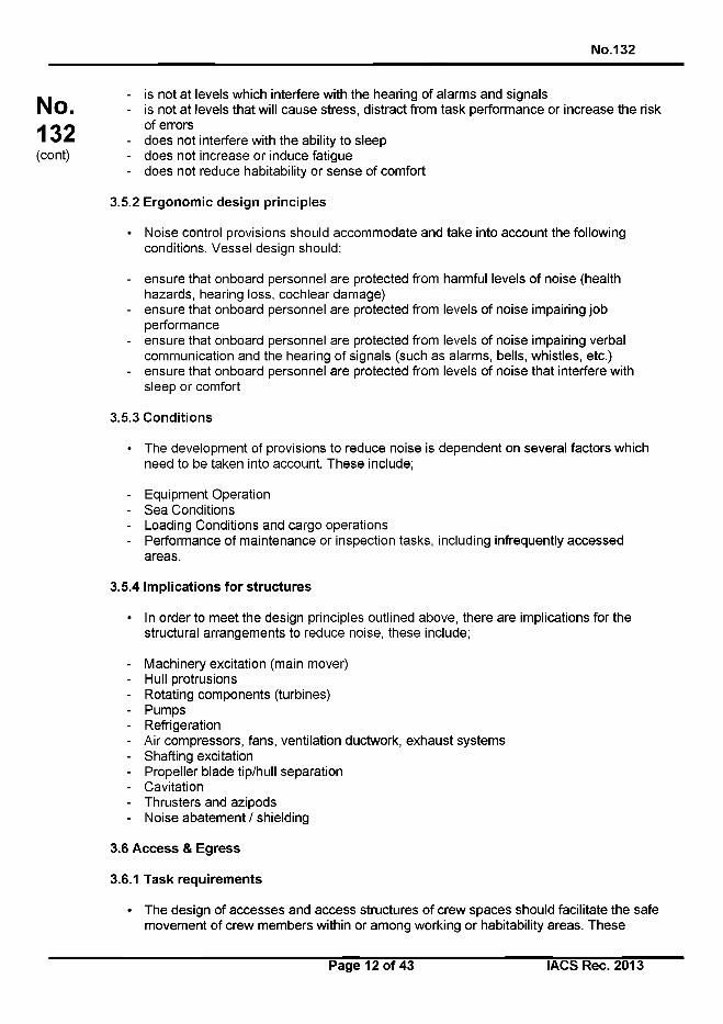
No.132
No.132(cont)
- is not at levels which interfere with the hearing of alarms and signals- is not at levels that will cause stress, distract from task performance or increase the risk
of errors- does not interfere with the ability to sleep- does not increase or induce fatigue- does not reduce habitability or sense of comfort
3.5.2 Ergonomic design principles
• Noise control provisions should accommodate and take into account the following conditions. Vessel design should;
- ensure that onboard personnel are protected from harmful levels of noise (health hazards, hearing loss, cochlear damage)
- ensure that onboard personnel are protected from levels of noise impairing job performance
- ensure that onboard personnel are protected from levels of noise impairing verbal communication and the hearing of signals (such as alarms, bells, whistles, etc.)
- ensure that onboard personnel are protected from levels of noise that interfere with sleep or comfort
3.5.3 Conditions
• The development of provisions to reduce noise is dependent on several factors which need to be taken into account. These include;
- Equipment Operation- Sea Conditions- Loading Conditions and cargo operations- Performance of maintenance or inspection tasks, including infrequently accessed
areas.
3.5.4 Implications for structures
• In order to meet the design principles outlined above, there are implications for the structural arrangements to reduce noise, these include;
- Machinery excitation (main mover)- Hull protrusions- Rotating components (turbines)- Pumps- Refrigeration- Air compressors, fans, ventilation ductwork, exhaust systems- Shafting excitation- Propeller blade tip/hull separation- Cavitation- Thrusters and azipods- Noise abatement / shielding
3.6 Access & Egress
3.6.1 Task requirements
• The design of accesses and access structures of crew spaces should facilitate the safe movement of crew members within or among working or habitability areas. These
Page 12 of 43 I ACS Rec. 2013
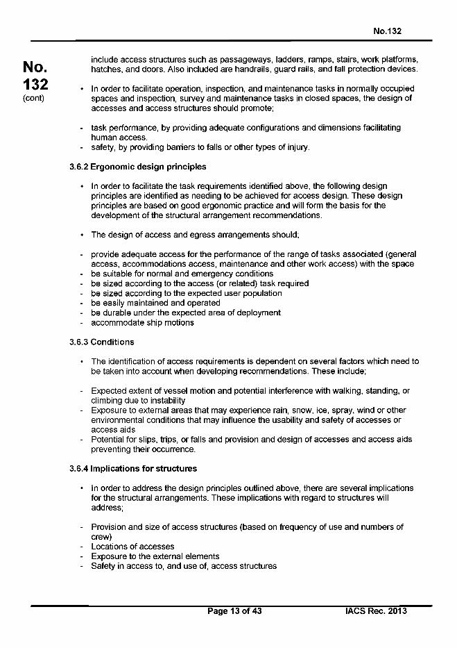
No.132
include access structures such as passageways, ladders, ramps, stairs, work platforms, hatches, and doors. Also included are handrails, guard rails, and fall protection devices.
• In order to facilitate operation, inspection, and maintenance tasks in normally occupied spaces and inspection, survey and maintenance tasks in closed spaces, the design of accesses and access structures should promote;
- task performance, by providing adequate configurations and dimensions facilitating human access.
- safety, by providing barriers to falls or other types of injury.
3.6.2 Ergonomic design principles
• In order to facilitate the task requirements identified above, the following design principles are identified as needing to be achieved for access design. These design principles are based on good ergonomic practice and will form the basis for the development of the structural arrangement recommendations.
• The design of access and egress arrangements should;
- provide adequate access for the performance of the range of tasks associated (general access, accommodations access, maintenance and other work access) with the space
- be suitable for normal and emergency conditions- be sized according to the access (or related) task required- be sized according to the expected user population- be easily maintained and operated- be durable under the expected area of deployment- accommodate ship motions
3.6.3 Conditions
• The identification of access requirements is dependent on several factors which need to be taken into account when developing recommendations. These include;
- Expected extent of vessel motion and potential interference with walking, standing, or climbing due to instability
- Exposure to external areas that may experience rain, snow, ice, spray, wind or other environmental conditions that may influence the usability and safety of accesses or access aids
- Potential for slips, trips, or falls and provision and design of accesses and access aids preventing their occurrence.
3.6.4 Implications for structures
• In order to address the design principles outlined above, there are several implications for the structural arrangements. These implications with regard to structures will address;
- Provision and size of access structures (based on frequency of use and numbers of crew)
- Locations of accesses- Exposure to the external elements- Safety in access to, and use of, access structures
No.132(cont)
Page 13 of 43 IACS Rec. 2013
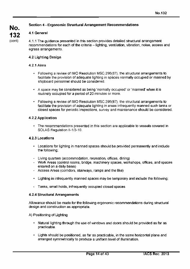
No.132
No.132(cont)
Section 4 - Ergonomic Structural Arrangement Recommendations
4.1 General
4.1.1 The guidance presented in this section provides detailed structural arrangement recommendations for each of the criteria - lighting, ventilation, vibration, noise, access and egress arrangements.
4.2 Lighting Design
4.2.1 Aims
• Following a review of IMO Resolution MSC.296(87), the structural arrangements to facilitate the provision of adequate lighting in spaces normally occupied or manned by shipboard personnel should be considered.
• A space may be considered as being ‘normally occupied’ or ‘manned’ when it is routinely occupied for a period of 20 minutes or more.
• Following a review of IMO Resolution MSC.296(87), the structural arrangements to facilitate the provision of adequate lighting in areas infrequently manned such tanks or closed spaces for periodic inspections, survey and maintenance should be considered.
4.2.2 Application
• The recommendations presented in this section are applicable to vessels covered in SOLAS Regulation 11-1/3-10.
4.2.3 Locations
• Locations for lighting in manned spaces should be provided permanently and include the following;
- Living quarters (accommodation, recreation, offices, dining)- Work Areas (control rooms, bridge, machinery spaces, workshops, offices, and spaces
entered on a daily basis)- Access Areas (corridors, stairways, ramps and the like)
• Lighting in infrequently manned spaces may be temporary and include the following;
- Tanks, small holds, infrequently occupied closed spaces
4.2.4 Structural Arrangements
Allowance should be made for the following ergonomic recommendations during structural design and construction as appropriate.
A) Positioning of Lighting
• Natural lighting through the use of windows and doors should be provided as far as practicable.
• Lights should be positioned, as far as practicable, in the same horizontal plane and arranged symmetrically to produce a uniform level of illumination.
Page 14 of 43 IACS Rec. 2013
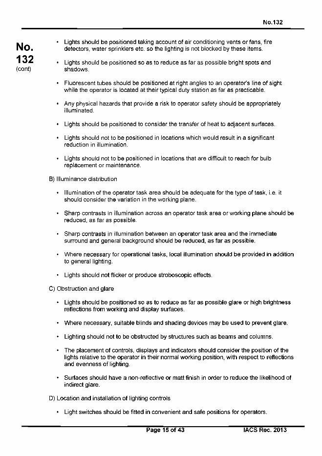
No.132
Lights should be positioned taking account of air conditioning vents or fans, fire detectors, water sprinklers etc. so the lighting is not blocked by these items.
Lights should be positioned so as to reduce as far as possible bright spots and shadows.
Fluorescent tubes should be positioned at right angles to an operator’s line of sight while the operator is located at their typical duty station as far as practicable.
Any physical hazards that provide a risk to operator safety should be appropriately illuminated.
Lights should be positioned to consider the transfer of heat to adjacent surfaces.
Lights should not to be positioned in locations which would result in a significant reduction in illumination.
Lights should not to be positioned in locations that are difficult to reach for bulb replacement or maintenance.
B) Illuminance distribution
• Illumination of the operator task area should be adequate for the type of task, i.e. it should consider the variation in the working plane.
• Sharp contrasts in illumination across an operator task area or working plane should be reduced, as far as possible.
• Sharp contrasts in illumination between an operator task area and the immediate surround and general background should be reduced, as far as possible.
• Where necessary for operational tasks, local illumination should be provided in addition to general lighting.
• Lights should not flicker or produce stroboscopic effects.
C) Obstruction and glare
• Lights should be positioned so as to reduce as far as possible glare or high brightness reflections from working and display surfaces.
• Where necessary, suitable blinds and shading devices may be used to prevent glare.
• Lighting should not to be obstructed by structures such as beams and columns.
• The placement of controls, displays and indicators should consider the position of the lights relative to the operator in their normal working position, with respect to reflections and evenness of lighting.
• Surfaces should have a non-reflective or matt finish in order to reduce the likelihood of indirect glare.
D) Location and installation of lighting controls
• Light switches should be fitted in convenient and safe positions for operators.
No.132(cont)
Page 15 of 43 I ACS Rec. 2013

No.132
• The mounting height of switches should be such that personnel can reach switches with ease.
E) Location and installation of electrical outlets
• Outlets should be installed where local lighting is provided, for e.g. in accommodation areas, work spaces and internal and external walkways.
• Provision is to be made for temporary lighting where necessary for inspection, survey and maintenance.
4.3 Ventilation Design
4.3.1 Aims
• Following a review of IMO Resolution MSC.296(87), the structural arrangements to facilitate the provision of adequate ventilation in spaces normally occupied or manned by shipboard personnel should be considered.
• A space may be considered as being ‘normally occupied’ or ‘manned’ when it is routinely occupied for a period of 20 minutes or more.
• Following a review of IMO Resolution MSC.296(87), the structural arrangements to facilitate the provision of adequate ventilation in areas infrequently manned such tanks or closed spaces for periodic inspections, survey and maintenance should be considered.
4.3.2 Application
• The recommendations presented in this section are applicable to vessels covered in SOLAS Regulation 11-1/3-10.
4.3.3 Locations
• Locations for ventilation in manned spaces should be provided permanently and include the following;
- Living quarters (accommodation, recreation, offices, dining)- Work Areas (control rooms, bridge, machinery spaces, offices, spaces and voids
entered)
• Locations for ventilation in infrequently manned spaces should be temporary and include the following;
- Tanks, small holds, infrequently occupied closed/enclosed spaces
4.3.4 Structural Arrangements
Allowance should be made for the following ergonomic recommendations during structuraldesign and construction as appropriate.
A) Ship ventilation design
No.132(cont)
Page 16 of 43 IACS Rec. 2013
No.132
Natural ventilation design should be established by consideration of compartment layouts and specifications. Typical natural ventilation devices include mushroom ventilators, gooseneck ventilators, ventilators with weather proof covers etc.
In general, HVAC (heating, ventilation and air conditioning) systems should be provided in spaces normally occupied during operation.
For areas infrequently occupied (such as tanks or holds) means of air quality sampling (such as portable C 02 densitometer) should be provided.
Means to ventilate prior to entry of infrequently visited places should be provided.
Adequate ventilation should be provided for inspection, survey, maintenance and repair within the voids of double-bottom and double-sided hulls.
B) Location and installation of ventilation
• The design of air ducts should facilitate reduced wind resistance and noise. Ductwork (particularly elbows and vents) should not contribute excess noise to a work or living space.
• Ductwork should not to interfere with the use of means of access such as stairs, ladders, walkways or platforms.
• Ductwork and vents should not be positioned to discharge directly on people occupying the room in their nominal working or living locations, for example, directed at a berth, work console, or work bench.
• Manholes and other accesses should be provided for accessibility and ventilation to points within.
• Fire dampers should be applied to contain the spread of fire, per statutory requirements.
• Ventilation penetrations through watertight subdivision bulkheads are not recommended unless accepted per statutory requirements. Ventilation dampers are to be visible (via inspection ports or other means).
• Ventilation fans for cargo spaces should have feeders separate from those for accommodations and machinery spaces.
• It is recommended that air Intakes for ventilation systems are located to minimise the introduction of contaminated air from sources such as for example, exhaust pipes and incinerators.
• Extractor grilles should be located to avoid short-circuits between inlets and outlets and to support even distribution of air throughout a work space.
4.4 Vibration Design
4.4.1 Aims
• Following a review of IMO Resolution MSC.296(87), the structural arrangements to minimize vibration in spaces normally occupied or manned by shipboard personnel should be considered.
No.132(cont)
Page 17 of 43 IACS Rec. 2013
No.132
No.132(cont)
• A space may be considered as being ‘normally occupied’ or ‘manned’ when it is routinely occupied for a period of 20 minutes or more.
4.4.2 Application
• The recommendations presented in this section are applicable to vessels covered in SOLAS Regulation 11-1/3-10.
4.4.3 Locations
• Locations in which vibration should be minimized include the following;
- Living quarters (accommodation, recreation, offices, dining)- Work Areas (such as control rooms, bridge, machinery spaces, offices, spaces and
voids entered)
4.4.4 Structural Arrangements
Allowance should be made for the following ergonomic recommendations during structural design and construction as appropriate.
A) General
• Vibration levels should be at or below the acceptable ergonomic standards for spaces normally occupied by the crew. In general, ISO 6954:2000 may be used as a guideline to evaluate the vibration performance in the spaces normally occupied by the crew.
• Generally, many alternative measures are applicable to reduce vibration, including but not limited to:
1 Resonance avoidance with a combination of appropriate selection of main engine and its revolution, number of propeller blades and structural natural frequencies;
2 To avoid resonance, addition of mass or reduction in scantlings to achieve lower structural natural frequencies. Or conversely, reduction of mass or structural reinforcement to increase natural frequencies;
3 Reduction of exciting force by for e.g. application of various kinds of dampers, compensators and balancers; and
4 Structural reinforcement to increase rigidity and reduce structural response, or conversely, where structural rigidity is reduced specifically to reduce structural responses.
• Due to the variety of effective measures that can be taken and the complex nature of vibration phenomena, it is not possible to apply simple prescriptive formulae for scantling calculation.
• Structural measures are mainly prescribed in the following sections, but other measures as stated in 1-4 above may be considered as effective alternatives.
B) Vibration reduction design
• Vibration level in the spaces normally occupied during operation should be estimated by an appropriate method, such as estimation based on empirical statistics and/or
Page 18 of 43 IACS Rec. 2013
No.132
application of analytical tools. When a vibration level exceeding the acceptable ergonomic standards is envisaged, suitable countermeasures should be taken.
• In general, natural frequencies should be calculated using theoretical formulae in way of local panels and stiffeners in the spaces close to the main exciting sources, i.e. propeller and main engine. These local scantlings should be decided so that the estimated natural frequencies are apart from the exciting frequencies adequately to avoid resonance.
• For heavy equipment or machinery in the spaces close to the main exciting sources, suitable measures should be taken at the deck structure underneath the equipment or machinery to reduce vibration.
C) Anti-vibration design in structural arrangements
• Vibration should be controlled at the source as far as possible.
• To prevent hull girder vibration, the following measures are recommended for consideration;
• selection of hull forms, girders and other ship structures with consideration to vibration control;
• selection of main machinery with inertia force and moment balanced;• adjusting natural frequency (the natural frequency of hull girder increases as the
number of bulkheads increases).
• To prevent vibration of the local structure, the following measures are recommended for consideration;
• line (mainly the ship tail shape) and propeller design modification;• adjustment of general arrangements, such as cabin arrangement, weight
distribution, location of main machinery;• adjustment and modification of local structures, such as superstructure, aft
structures, bottom frame structure in engine room;• other damping measures, such as vibration isolators, nozzle propeller.
D) Anti-vibration design of engine room, engine, propeller and thrusters
• Consideration should be paid to the vibration response of main machinery base and shafting.
• Consideration of control of vibration from the engine room should include installing bracings at the top and front of diesel engines and increasing the stiffness and natural frequency of the machine base to reduce the vibration of the base.
• Bow thruster induced vibration should be minimized by following good acoustic design practices relative to the design of the propeller and the location and placement of the thruster itself. Supply of resilient supported tunnels (tunnel within a tunnel), bubbly air injectors, and tunnels coated with a decoupling material can be considered.
• Propeller induced vibration should be minimized by following good acoustic design practices relative to the design of the propeller and the location and placement in relation to the hull.
No.132(cont)
Page 19 of 43 I ACS Rec. 2013
No.132
No.132(cont)
Stern shape should be optimized and considered through theoretical calculation and model testing so as to improve the wake. The gap between the shell and the propeller should be appropriate to reduce the exciting force. Damping treatments can be applied to shell plates with severe vibration.
E) Anti-vibration design of superstructure
• Preventing vibration along the longitudinal area of the superstructure should beconsidered by increasing the shear and strut stiffness of the superstructure. To achieve this, the following measures are recommended;
• Superstructure side wall can be vertically aligned,• The internal longitudinal bulkhead can be set up with more than four (4) tiers of
superstructure,• Strong girders or other strong elements can be provided under the main deck,• The transverse bulkhead and the front bulkhead of superstructure can be
vertically aligned as much as possible, otherwise large connection brackets should be provided,
• The superstructure aft bulkhead of each superstructure deck can be aligned vertically with the main hull transverse bulkheads as far as possible, otherwise strong beams under the main deck should be provided.
• To control vibration of outfitting, dimensions and the means of fixing and strengthening at the point of mounting can be considered.
• To prevent vibration of high web girder, the following should be considered;
• Increase dimension of longitudinals and face plate,• Increase the stiffness of face plate stiffeners,• Add horizontal stiffener.
F) Anti-vibration installation design
• Sources of vibration (engines, fans, rotating equipment), to the extent possible, should be isolated from work and living spaces (use of isolation mounts or other means can be considered).
• Hull borne vibration in living and work areas can be attenuated by the provision of vibration absorbing deck coverings or by other means.
4.5 Noise Design
4.5.1 Aims
• Following a review of IMO Res. MSC.337(91) Code on Noise Levels On Board Ships, the structural arrangements to minimize noise in spaces normally occupied or manned by shipboard personnel should be considered.
• A space may be considered as being ‘normally occupied’ or ‘manned’ when it is routinely occupied for a period of 20 minutes or more.
4.5.2 Application
• The recommendations presented in this section are applicable to vessels covered by SOLAS Regulation 11-1/3-10.
Page 20 of 43 IACS Rec. 2013
No.132
No.132(cont)
4.5.3 Locations
• Locations in which noise should be minimized include the following;
- Living quarters (accommodation, recreation, offices, dining)- Work Areas (such as control rooms, bridge, machinery spaces, living quarters and
offices)
4.5.4 Structural Arrangements
Allowance should be made for the following ergonomic recommendations during structural design and construction as appropriate.
A) General
• Sources of noise (engines, fans, rotating equipment), to the extent possible, should be isolated and located away from work and living spaces (through use of isolation mounts or other means).
• If necessary hull borne noise transmitted through the steel structure may be attenuated by the provision of noise absorbing deck coverings.
• Noise for typical underway conditions should be specified for the following areas:
• In living quarters• In open engineering and mechanical spaces• In offices, the bridge, engineering offices
• Noise on the hull from the propeller tips, athwart thrusters, or azipods should be designed to minimize structure borne noise to accommodations and work areas.
• Specific noise levels are to be obtained from the revised IMO Code on Noise Aboard ships (Resolution MSC.337(91)).
• To reduce noise transmitted to accommodation cabins, the crew accommodations areas are usually arranged in the middle or rear of the superstructure or on the poop deck and above.
B) Noise sources and propagation
• Ship noise can be divided into airborne noise and structure borne noise according to the nature of the sound source. It consists of main machinery noise, auxiliary machinery noise, propeller noise, hull vibration noise and ventilation system noise.
• There are three main routes of transmission of ship noise;
• airborne noise radiated directly to the air by main or auxiliary machinery system;• structure borne noise spread along the hull structure through mechanical vibration
and radiated outward;• fan noise and air-flow noise transmitted through the pipeline of the ventilation
system.
C) Mechanical vibration induced noise control
Page 21 of 43 IACS Rec. 2013
No.132
• Mechanical vibrations are the largest source of noise. Methods relating to anti-vibration design in the structural arrangements are also useful for vibration induced noise control, including the following;
- Reducing the noise level of the various noise sources;- Using vibration isolator for main and auxiliary machinery to reduce the noise;- Improving the machine's static and dynamic balance;- Installing soundproof cover with sound-absorbing lining for machines.
D) Noise control of ventilation system
• Fans with relative low pressure may be used to reduce noise when the flow resistance of ventilation ducts is low. Low flow resistance can be achieved by rational division of the ventilation system, reasonable determination of ability of ventilation and the ducts layout, adoption of reasonable duct type and provision of suitable materials.
• Fans and central air conditioners may be installed in a separate acoustic room or the damper elastomeric gasket or silencer box.
• Ventilation ducts can be encased in damping material if necessary. Penetration of compartments with a low-noise requirement by main air tubes may be avoided.
• Ventilation inlet, outlet, and diffuser elements can be provided that are designed for noise abatement to reduce ventilation terminal noise.
• If needed, an appropriate muffler can be used based on the estimated frequency range of the noise.
E) Noise Prevention/Mitigation
• The statements that follow should be considered in the context of the prevention and mitigation of human whole body vibration, which also have a noise reducing effect.
• Different treatments may be needed to reduce airborne sources, structureborne sources, airborne paths, structureborne paths, HVAC induced noise, etc. Each treatment type depends on an understanding of the prevailing airborne or structureborne noise components (e.g., low frequency or high frequency). A thorough understanding of the source, amount of noise, the noise’s components, and the noise’s path(s) is essential for cost effective noise abatement/treatment. Listed below, are summarized some of the more common noise control treatment methods,
• Selection of equipment that by its design or quality are lower noise and/or vibration.
• Reduction of vibration by mechanically isolating machinery from supporting structure.
• Use of two layers of vibration isolation mounts under machinery with seismic based mounts between the machinery and the ship’s structure.
• Reduce vibration energy in structures. Pumpable material used as ballast can also be used as damping in voids and tanks.
• An air bubble curtain can be considered to shield the vessel’s hull from water borne noise.
• A decoupling material can be applied to the exterior (wet side) plating in order to reduce the radiation efficiency of the structure.
No.132(cont)
Page 22 of 43 I ACS Rec. 2013
No.132
No.132(cont)
The airborne source level and airborne path are the most critical factors affecting noise within a machinery space itself and in the compartments directly adjacent to the machinery space. Structureborne sources and the structureborne path carry acoustical energy everywhere else on the vessel.
Depending on the level of treatment, secondary structureborne noise (a combination of the airborne source level and the response of the structure inside the machinery space itself) may also be important in spaces remote from the machinery itself.
F) Noise modelling
• A technique becoming more common among designers is noise or acoustical modelling. In these models, it is essential that the factors related to the source-path receiver be very well understood.
• Noise/acoustical models should include the following components:
Source, acoustic path, and receiver space descriptionSources - machinery source descriptions (e.g., noise and vibration levels, sizeand mass, location, and foundation parameters)Sources - propulsor source description (e.g., number of propellers (impellers), number of blades, RPM, clearance between hull and tips of propeller, vessel design speed)Sources - HVAC source description (e.g., fan parameters (flow rate, power, and pressure), duct parameter, louver geometry, and receiver room sound absorption quality)Path - Essential parameters for sound path description include hull structure sizes and materials, (damping) loss factors, insulation and joiner panel parameters. Receiver - Receiver space modelling is characterized by the hull structure forming the compartment of interest, insulation/coatings, and joiner panels.
4.6 Access & Egress Design
4.6.1 Aims
• Following a review of IMO Resolution MSC.296(87), the design of stairs, vertical ladders, ramps, walkways and work platforms used for permanent means of access and/or for inspection and maintenance operations should be considered.
• Following a review of IMO Resolution MSC.296(87), the structural arrangements to facilitate emergency egress of inspection personnel or ships’ crew from tanks, holds, voids etc. is to be considered.
4.6.2 Application
• The recommendations presented in this section are applicable to vessels covered in SOLAS Regulation 11-1/3-10.
4.6.3 Locations
• Locations for provision of access aids in manned spaces should be provided permanently and include the following;
- Living quarters (accommodation, recreation, offices, dining)
Page 23 of 43 IACS Rec. 2013
No.132
No.132(cont)
- Work Areas (control rooms, bridge, machinery spaces, offices, spaces and voids entered)
- Access to deck areas, muster stations, work platforms associated to periodic inspection, operation, or maintenance
- Locations for access in infrequently manned spaces may be temporary and include the following;
Tanks, small holds, infrequently occupied closed spaces
4.6.4 Structural Arrangements
A) Stairs
General Principles
The following are general recommendations to consider for stairs design:
- Stairs are appropriate means for changing from one walking surface to another when the change in vertical elevation is greater than 600 mm (23.5 in.).
- Stairs should be provided in lieu of ladders or ramps in accommodations spaces, office spaces, or to the navigation bridge.
- The angle of inclination should be sufficient to provide the riser height and tread depth that follows, a minimum angle of 38 degrees and maximum angle of 45 degrees is recommended.
- Stairs exposed to the elements should have additional slip resistance due to potential exposure to water and ice.
- Stairs should be used in living quarters instead of inclined ladders.- No impediments or tripping hazards should intrude into the climbing spaces of stairs (for
example, electrical boxes, valves, actuators, or piping).- No impediments or tripping hazards should impede access to stair landings (for
example, piping runs over the landing or coamings/retention barriers).- Stairs running fore and aft in a ship are preferable but athwartship stairs are allowed.
Stair Landings
The following are recommendations to consider during the design of stair landings:
• A clear landing at least as wide as the tread width and a minimum of 915 mm (36 in.) long should be provided at the top and bottom of each stairway.
• An intermediate landing should be provided at each deck level serviced by a stair, or a maximum of every 3500 mm (140 in.) of vertical travel for stairs with a vertical rise of 6100 mm (240 in.).
• Any change of direction in a stairway should be accomplished by means of an intermediate landing at least as wide as the tread width and a minimum of 915 mm (36 in.) long.
• Stairways should have a maximum angle of inclination from the horizontal of 45 degrees.
• Where stairs change directions, intermediate landings along paths for evacuating personnel on stretchers should be 1525 mm (60 in.) or greater in length to accommodate rotating the stretcher.
Stair Risers and Treads
The following are recommendations to consider during the design of stair risers and treads:
Page 24 of 43 I ACS Rec. 2013
No.132
A riser height should be no more than 230 mm (9 in.) and a tread depth of 280 mm (11 in.), including a 25 mm (1 in.) tread nosing (step overhang).For stairs the depth of the tread and the height of riser should be consistent Minimum tread width on one-way (where there is expected to be only one person transiting, ascending or descending stairway) stairs should be at least 700 mm (27.5 in.)Minimum tread width on two-way (where there may be two persons, ascending and descending, or passing in opposite directions) stairs should be at least 900 mm (35.5 in.)Once a minimum tread width has been established at any deck in that stair run, it should not decrease in the direction of egressNosings should have a non-slip/skid surface that should have a coefficient of friction (COF) of 0.6 or greater measured when wet.
Headroom
• Clear headroom (free height) maintained in all stairs is recommended to be at least 2130 mm (84 in.).
Design Load
• It is recommended that stairways should be built to carry five times the normal anticipated live load, but less than a 544-kg (1000-lb) moving concentrated load.
Stair Handrails
The following are recommendations to consider during the design of stair risers and treads:
• Stairs with three or more steps should be provided with handrails.• A single-tier handrail to maintain balance while going up or down the stairs should be
installed on the bulkhead side(s) of stairs.• A two-tier handrail to maintain balance and prevent falls from stairs should be installed
on non-enclosed sides of stairs.• Handrails should be constructed with a circular cross section with a diameter of 40 mm
(1.5 in.) to 50 mm (2.0 in.).• Square or rectangular handrails should not be fitted to stairs.• The height of single tier handrails should be 915 mm (36 in.) to 1000 mm (39 in.) from
the top of the top rail to the surface of the tread.• Two-tier handrails should be two equally-spaced courses of rail with the vertical height
of the top of the top rail 915 mm (36 in.) to 1000 mm (39 in.) above the tread at its nosing.
• A minimum clearance of 75 mm (3 in.) should be provided between the handrail and bulkhead or other obstruction.
B) Walkways and Ramps
General Principles
The following are general recommendations to consider for walkways and ramps:
• Guard rails should be provided at the exposed side of any walking or standing surface that is 600 mm (23.5 in.) or higher above the adjacent surface and where a person could fall from the upper to the lower surface.
• Ramps should be used with changes in vertical elevations of less than 600 mm (23.5 in.).
No.132(cont)
Page 25 of 43 IACS Rec. 2013
No.132
Ramps should be provided with a non-skid surface that should have a coefficient of friction (COF) of 0.6 or greater measured when wet.Headroom in all walkways should be > 2130 mm (84 in.).Toeboards should be provided on elevated walkways, platforms, and ramps. No impediments or tripping hazards should intrude into the transit space (for example, electrical boxes, valves, actuators, or piping).No impediments or tripping hazards should impede use of a walkway or ramp (for example, piping runs, hatch covers, deck impediments (e.g., through bolts) or combings/retention barriers).The maximum opening in a walkway grating under which the presence of persons is expected should be less than 22 mm (0.9 in.).The maximum opening in a walkway grating under which the presence of persons is not expected should be less than 35 mm (1.7 in.).Toeboards should have a height of 100 mm (4.0 in.) and have no more than a 6 mm (0.25 in.) clearance between the bottom edge of the toeboard and the walking surface.
C) Vertical Ladders
General Principles
The following are general recommendations to consider for the design of vertical ladders:
• Vertical ladders should be provided whenever operators or maintainers must change elevation abruptly by more than 300 mm (12.0 in.).
• Vertical ladders should not be located within 1.83 m (6 ft.) of other nearby potential fall points (including the deck edge, cargo holds and lower decks) without additional fall protection, such as guardrails.
• Vertical ladders should be provided with skid/slip resistant on the rungs that should have a coefficient of friction (COF) of 0.6 or greater measured when wet.
• The angle of inclination for vertical ladders should be 80 to 90 degrees.• Permanent vertical ladders should be attached to a permanent structure.• The maximum distance from the ladder’s centreline to any object that must be reached
by personnel from the ladder should not exceed 965 mm (38.0 in.).• Vertical ladders should be located so as not to interfere with the opening and closing of
hatches, doors, gratings, or other types of access.• No impediments should intrude into the climbing space (for examples, electrical boxes,
valves, actuators, or piping).• Overhead clearance above vertical ladder platforms should be a minimum of 2130 mm
(84.0 in.)• There should be at least 750 mm (29.5 in.) clearance in front of the ladder (climbing
space).• There should be between 175 mm (7.0 in.) to 200 mm (8.0 in.) clearance behind the
ladder (toe space).• A means of access to a cellular cargo space should be provided using staggered
lengths of ladder. No single length is to exceed 6.0 m (91.5 ft) in length.
Rung Design
• Rungs should be equally spaced along the entire height of the ladder.• If square bar is used for the rung, it should be fitted to form a horizontal step with the
edges pointing upward.• Rungs should also be carried through the side stringers and attached by double
continuous welding.• Ladder rungs should be arranged so a rung is aligned with any platform or deck that an
operator or maintainer will be stepping to or from.
No.132(cont)
Page 26 of 43 IACS Rec. 2013
No.132
• Ladder rungs should be slip resistant or of grid/mesh construction.
Provision of Platforms
• When the height of a vertical ladder exceeds 6.0 m (19.5 ft), an intermediate or linking platform should be used.
• If a work task requires the use of two hands, working from a vertical ladder is not appropriate. The work area should be provided with a work platform that provides a flat, stable standing surface.
Vertical ladders as Means of Access
• Where vertical ladders lead to manholes or passageways, horizontal or vertical handles or grab bars should be provided. Handrails or grab bars should extend at least 1070 mm (42.0 in.) above the landing platform or access/egress level served by the ladder.
Safety Cages
• Safety cages should be used on vertical ladders over 4.5 m (15.0 ft) in height.• Climber safety rails or cables should be used on vertical ladders in excess of 6.1 m
(20.0 ft).
D) Work Platforms
General Principles
• Work platforms should be provided at locations where personnel must perform tasks that cannot be easily accomplished by reaching from an existing standing surface.
• Work platforms exposed to the elements should have additional slip resistance due to potential exposure to water and ice.
• Work platforms more than 600 mm (23.5 in.) above the surrounding surface should be provided with guard rails and hand rails.• Work platforms should be of sufficient size to accommodate the task and allow for
placement of any required tools, spare parts or equipment.
No.132(cont)
E) Egress
• Doors, hatches, or scuttles used as a means of escape should be capable of being operated by one person, from either side, in both light and dark conditions. Doors should be designed to prevent opening and closing due to vessel motion and should be operable with one hand.
• Doors (other than emergency exit) used solely by crew members should have a clear opening width of at least 710 mm (28 in.) The distance from the deck to the top of the door should be at least 1980 mm (78 in.).
• The method of opening a means of escape should not require the use of keys or tools. Doors in accommodation spaces (with the exception of staterooms), stairways, stair towers, passageways, or control spaces, should open in the direction of escape or exit.
• The means of escape should be marked from both the inside and outside.• Deck scuttles that serve as a means of escape should be fitted with a release
mechanism that does not require use of a key or a tool, and should have a holdback device to hold the scuttle in an open position.Deck scuttles that serve as a means of escape should have the following dimensions:i) Round - 670 mm (26.5 in.) or greater in diameterii) Rectangular - 670 mm (26.5 in.) by 330 mm (13 in.) or greater
Page 27 of 43 IACS Rec. 2013
No.132
No.132(cont)
Annex A - Recommended Measurement Values
1.1 General
The recommendations in the following section outline measurement values for lighting, ventilation, vibration and access from a best practice ergonomics perspective. The information provided can assist designers when applying structural arrangement guidance.
See the IMO Code on Noise Aboard ships (IMO Resolution MSC.337(91)) for recommended shipboard noise levels guidance.
1.2 Lighting
The following tables give details of recommended illuminance levels in Lux which support task performance, safety and visual comfort for the operator. Emergency lighting is covered in SOLAS and IMO Resolutions and has not been considered in the below table. Lighting measurements should be made with the probe approximately 800 mm (32 inches).
Page 28 of 43 IACS Rec. 2013

No.132
N o.132(cont)
Table 1 - Lighting for Crew Accommodations Spaces
SpaceIlluminance
Level in Lux
SpaceIlluminance
Level in Lux
Entrances and PassagewaysInterior Walkways, Passageways, Stairways and Access Ways
100Exterior Walkways, Passageways, Stairways and Access Ways (night)
100
Corridors in Living quarters and work areas 100 Stairs, escalators 150
Muster Area 200Cabins, Staterooms, Berthing and Sanitary Spaces*
General Lighting 150 Bath/Showers (General Lighting) 200
Reading and Writing (Desk or Bunk Light) 500 All other Areas within Sanitary
Space (e.g., Toilets) 200
Mirrors (Personal Grooming) 500 Light during sleep periods <30Dining Spaces
Mess Room and Cafeteria | 300 | Snack or Coffee Area | 150Recreation Spaces
Lounges 200 Gymnasiums 300Library 500 Bulletin Boards/Display Areas 150
Multimedia Resource Centre 300 All other Recreation Spaces (e.g., Game Rooms) 200
TV Room 150 Training/Transit Room Office/Meeting rooms 500
Medical, Dental and First Aid CentreDispensaryHospital/ward 500 Wards
- General Lighting- Critical Examination- Reading
Hospital/ward
150500300
500
Medical and Dental Treatment/ Examination RoomHospital/ward
500
Medical Waiting Areas 200
Laboratories 500 Other Medical & Dental Spaces 300
*Note: If there is any opportunity for light to enter cabins or staterooms at the times of day or night when people sleep (e.g., portlights, transoms, etc.), the maximum lighting levels should be 30 Lux.
Page 29 of 43 IACS Rec. 2013
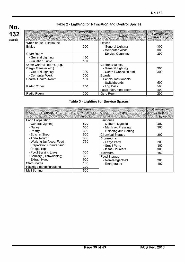
No.132
N o.132(cont)
Table 2 - Lighting for Navigation and Control Spaces
S p a c e
Illu m in a n c e
L e v e l
in L ux
S p a c eIllu m in a n c e
L e v e l in Lux
Wheelhouse, Pilothouse, OfficesBridge 300 - General Lighting 300
- Computer Work 300Chart Room - Service Counters 300
- General Lighting 150- On Chart Table 500
Other Control Rooms (e.g., Control StationsCargo Transfer etc.) - General Lighting 300
- General Lighting 300 - Control Consoles and 300- Computer Work 300 Boards,
Central Control Room 500 Panels, Instruments- Switchboards 500
Radar Room 200 - Log Desk 500Local Instrument room 400
Radio Room 300 Gyro Room 200
Table 3 - Lighting for Service Spaces
S p a c e
Illu m in a n c e
L e v e l
in L ux
S p a c e
Illu m in a n c e
L e v e l
in L ux
Food Preparation Laundries- General Lighting 500 - General Lighting 300- Galley 500 - Machine, Pressing, 300- Pantry 300 Finishing and Sorting- Butcher Shop 500 Chemical Storage 300- Thaw Room 300 Storerooms- Working Surfaces, Food 750 - Large Parts 200
Preparation Counter and - Small Parts 300Range Tops - Issue Counters 300
- Food Serving Lines 300 Elevators 150- Scullery (Dishwashing) 300 Food Storage- Extract Hood 500 - Non-refrigerated 200
Store rooms 100 - Refrigerated 100Package handling/cutting 300Mail Sorting 500
Page 30 of 43 IACS Rec. 2013
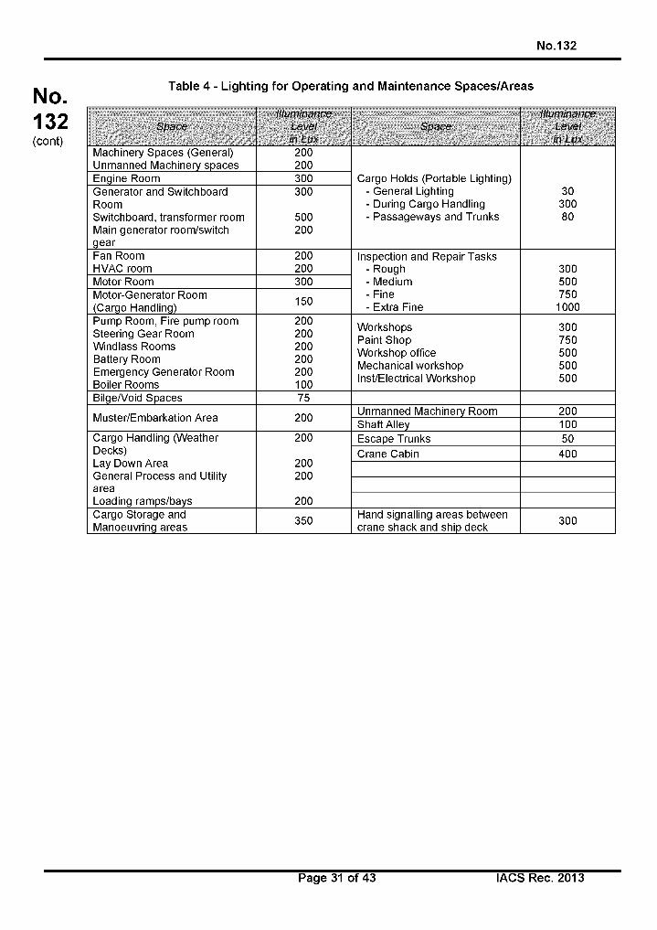
No.132
N o.132(cont)
Table 4 - Lighting for Operating and Maintenance Spaces/Areas
SpaceIlluminance
Level in Lux
SpaceIlluminance
Level in Lux
Machinery Spaces (General) Unmanned Machinery spaces
200200
Cargo Holds (Portable Lighting)- General Lighting- During Cargo Handling- Passageways and Trunks
3030080
Engine Room 300Generator and Switchboard RoomSwitchboard, transformer room Main generator room/switch gear
300
500200
Fan Room HVAC room
200200
Inspection and Repair Tasks- Rough- Medium- Fine- Extra Fine
3005007501000
Motor Room 300Motor-Generator Room (Cargo Handling) 150
Pump Room, Fire pump room Steering Gear Room Windlass Rooms Battery RoomEmergency Generator Room Boiler Rooms
200200200200200100
Workshops Paint Shop Workshop office Mechanical workshop Inst/Electrical Workshop
300750500500500
Bilge/Void Spaces 75
Muster/Embarkation Area 200 Unmanned Machinery Room 200Shaft Alley 100
Cargo Handling (Weather Decks)Lay Down AreaGeneral Process and UtilityareaLoading ramps/bays
200
200200
200
Escape Trunks 50Crane Cabin 400
Cargo Storage and Manoeuvring areas 350 Hand signalling areas between
crane shack and ship deck 300
Page 31 of 43 IACS Rec. 2013
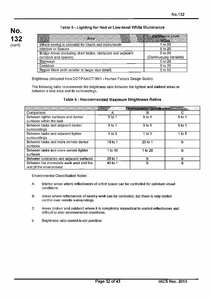
No.132
N o.132(cont)
Table 5 - Lighting for Red or Low-level White Illuminance
P Area Illuminance Level in Lux
Where seeing is essential for charts and instruments 1 to 20Interiors or Spaces 5 to 20Bridge Areas (including chart tables, obstacles and adjacent corridors and spaces)
0 to 20(Continuously Variable)
Stairways 5 to 20Corridors 5 to 20Repair Work (with smaller to larger size detail) 5 to 55
Brightness (Adopted from DOT/FAA/CT-96/1 - Human Factors Design Guide).
The following table recommends the brightness ratio between the lightest and darkest areas or between a task area and its surroundings.
Table 6 - Recommended Maximum Brightness Ratios
environmental c-iassmca ддд^ |||||||||||||||||||||||||||||В31 ..
Comparison A В cBetween lighter surfaces and darker surfaces within the task
5 to 1 5 to 1 5 to 1
Between tasks and adjacent darker surroundings
3 to 1 3 to 1 5 to 1
Between tasks and adjacent lighter surroundings
1 to 3 1 to 3 1 to 5
Between tasks and more remote darker surfaces
10 to 1 20 to 1 b
Between tasks and more remote lighter surfaces
1 to 10 1 to 20 b
Between luminaries and adjacent surfaces 20 to 1 b bBetween the immediate work area and the rest of the environment
40 to 1 b b
Environmental Classification Notes:
A Interior areas where reflectances of entire space can be controlled for optimum visual conditions.
В Areas where reflectances of nearby work can be controlled, but there is only limited control over remote surroundings.
C Areas (indoor and outdoor) where it is completely impractical to control reflectances and difficult to alter environmental conditions.
b Brightness ratio control is not practical.
Page 32 of 43 I ACS Rec. 2013
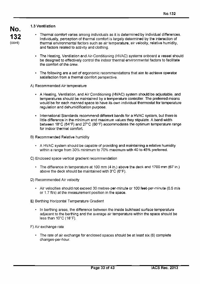
No.132
No.132(cont)
1.3 Ventilation
• Thermal comfort varies among individuals as it is determined by individual differences. Individually, perception of thermal comfort is largely determined by the interaction of thermal environmental factors such as air temperature, air velocity, relative humidity, and factors related to activity and clothing.
• The Heating, Ventilation and Air-Conditioning (HVAC) systems onboard a vessel should be designed to effectively control the indoor thermal environmental factors to facilitate the comfort of the crew.
• The following are a set of ergonomic recommendations that aim to achieve operator satisfaction from a thermal comfort perspective.
A) Recommended Air temperature
• A Heating, Ventilation, and Air Conditioning (HVAC) system should be adjustable, and temperatures should be maintained by a temperature controller. The preferred means would be for each manned space to have its own individual thermostat for temperature regulation and dehumidification purpose.
• International Standards recommend different bands for a HVAC system, but there is little difference in the minimum and maximum values they stipulate. A band width between 18°C (64°F) and 27°C (80°F) accommodates the optimum temperature range for indoor thermal comfort.
B) Recommended Relative humidity
• A HVAC system should be capable of providing and maintaining a relative humidity within a range from 30% minimum to 70% maximum with 40 to 45% preferred.
C) Enclosed space vertical gradient recommendation
• The difference in temperature at 100 mm (4 in.) above the deck and 1700 mm (67 in.) above the deck should be maintained with 3°C (6°F).
D) Recommended Air velocity
• Air velocities should not exceed 30 metres-per-minute or 100 feet-per-minute (0.5 m/s or 1.7 ft/s) at the measurement position in the space.
E) Berthing Horizontal Temperature Gradient
• In berthing areas, the difference between the inside bulkhead surface temperature adjacent to the berthing and the average air temperature within the space should be less than 10°C(18°F).
F) Air exchange rate
• The rate of air exchange for enclosed spaces should be at least six (6) complete changes-per-hour.
Page 33 of 43 IACS Rec. 2013
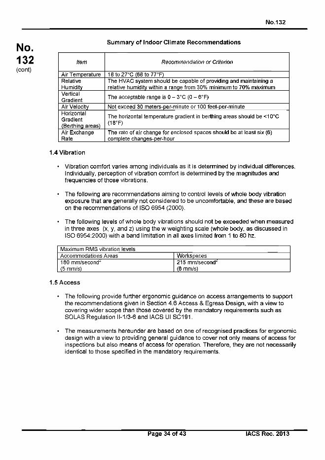
No.132
No.132(cont)
Summary of Indoor Climate Recommendations
Item R ecom m endation o r Criterion
Air Temperature 18 to 27°C (68 to 77°F)RelativeHumidity
The HVAC system should be capable of providing and maintaining a relative humidity within a range from 30% minimum to 70% maximum
VerticalGradient
The acceptable range is 0 - 3°C (0 - 6°F)
Air Velocity Not exceed 30 meters-per-minute or 100 feet-per-minuteHorizontal Gradient (Berthing areas)
The horizontal temperature gradient in berthing areas should be <10°C (18°F)
Air Exchange Rate
The rate of air change for enclosed spaces should be at least six (6) complete changes-per-hour
1.4 Vibration
• Vibration comfort varies among individuals as it is determined by individual differences. Individually, perception of vibration comfort is determined by the magnitudes and frequencies of those vibrations.
• The following are recommendations aiming to control levels of whole body vibration exposure that are generally not considered to be uncomfortable, and these are based on the recommendations of ISO 6954 (2000).
• The following levels of whole body vibrations should not be exceeded when measured in three axes (x, y, and z) using the w weighting scale (whole body, as discussed in ISO 6954:2000) with a band limitation in all axes limited from 1 to 80 hz.
Maximum RMS vibration levelsAccommodations Areas Workspaces180 mm/second^ 215 mm/second^(5 mm/s) (6 mm/s)
1.5 Access
• The following provide further ergonomic guidance on access arrangements to support the recommendations given in Section 4.6 Access & Egress Design, with a view to covering wider scope than those covered by the mandatory requirements such as SOLAS Regulation 11-1/3-6 and IACS III SC191.
• The measurements hereunder are based on one of recognised practices for ergonomic design with a view to providing general guidance to cover not only means of access for inspections but also means of access for operation. Therefore, they are not necessarily identical to those specified in the mandatory requirements.
Page 34 of 43 IACS Rec. 2013
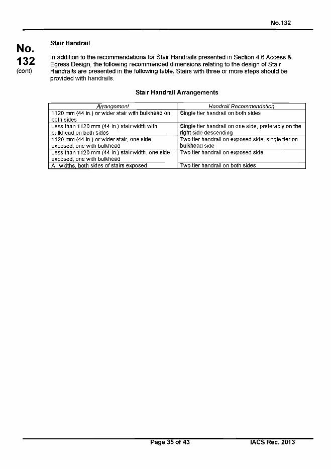
No.132
No.132(cont)
Stair Handrail
In addition to the recommendations for Stair Handrails presented in Section 4.6 Access & Egress Design, the following recommended dimensions relating to the design of Stair Handrails are presented in the following table. Stairs with three or more steps should be provided with handrails.
Stair Handrail Arrangements
A rranqem ent H andrail R ecom m endation
1120 mm (44 in.) or wider stair with bulkhead on both sides
Single tier handrail on both sides
Less than 1120 mm (44 in.) stair width with bulkhead on both sides
Single tier handrail on one side, preferably on the right side descending
1120 mm (44 in.) or wider stair, one side exposed, one with bulkhead
Two tier handrail on exposed side, single tier on bulkhead side
Less than 1120 mm (44 in.) stair width, one side exposed, one with bulkhead
Two tier handrail on exposed side
All widths, both sides of stairs exposed Two tier handrail on both sides
Page 35 of 43 I ACS Rec. 2013
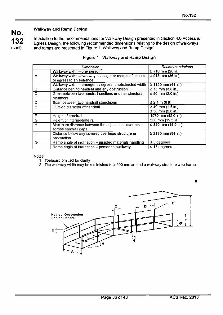
No.132
N o.132(cont)
Walkway and Ramp Design
In addition to the recommendations for Walkway Design presented in Section 4.6 Access & Egress Design, the following recommended dimensions relating to the design of walkways and ramps are presented in Figure 1 ‘Walkway and Ramp Design’.
Figure 1 Walkway and Ramp Design
Dimension Recommendations
AWalkway width - one person2 >710 mm (28 in.)Walkway width - two-way passage, or means of access or egress to an entrance
>915 mm (36 in.)
Walkway width - emergency egress, unobstructed width >1120 mm (44 in.)В Distance behind handrail and any obstruction > 75 mm (3.0 in.)C Gaps between two handrail sections or other structural
members< 50 mm (2.0 in.)
D Span between two handrail stanchions < 2.4 m (8 ft)E Outside diameter of handrail > 40 mm (1.5 in.)
< 50 mm (2.0 in.)F Height of handrail 1070 mm (42.0 in.)G Height of intermediate rail 500 mm (19.5 in.)H Maximum distance between the adjacent stanchions
across handrail gaps< 350 mm (14.0 in.)
I Distance below any covered overhead structure or obstruction
> 2130 mm (84 in.)
© Ramp angle of inclination - unaided materials handling < 5 degreesRamp angle of inclination - personnel walkway < 15 degrees
Notes:1 Toeboard omitted for clarity2 The walkway width may be diminished to > 500 mm around a walkway structure web frames
Page 36 of 43 I ACS Rec. 2013
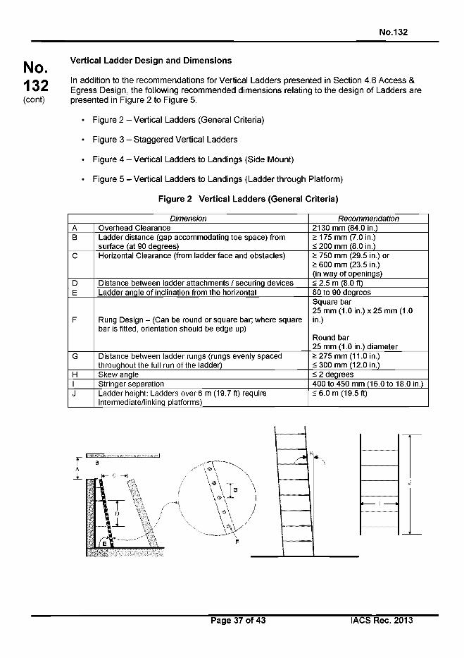
No.132
No.132(cont)
Vertical Ladder Design and Dimensions
In addition to the recommendations for Vertical Ladders presented in Section 4.6 Access & Egress Design, the following recommended dimensions relating to the design of Ladders are presented in Figure 2 to Figure 5.
• Figure 2 - Vertical Ladders (General Criteria)
• Figure 3 - Staggered Vertical Ladders
• Figure 4 - Vertical Ladders to Landings (Side Mount)
• Figure 5 - Vertical Ladders to Landings (Ladder through Platform)
Figure 2 Vertical Ladders (General Criteria)
Dimension RecommendationA Overhead Clearance 2130 mm (84.0 in.)В Ladder distance (gap accommodating toe space) from
surface (at 90 degrees)>175 mm (7.0 in.) < 200 mm (8.0 in.)
C Horizontal Clearance (from ladder face and obstacles) > 750 mm (29.5 in.) or> 600 mm (23.5 in.)(in way of openings)
D Distance between ladder attachments / securing devices < 2.5 m (8.0 ft)E Ladder angle of inclination from the horizontal 80 to 90 degrees
F Rung Design - (Can be round or square bar; where square bar is fitted, orientation should be edge up)
Square bar25 mm (1.0 in.) x 25 mm (1.0 in.)
Round bar25 mm (1.0 in.) diameter
G Distance between ladder rungs (rungs evenly spaced throughout the full run of the ladder)
> 275 mm (11.0 in.) < 300 mm (12.0 in.)
H Skew angle < 2 degreesI Stringer separation 400 to 450 mm (16.0 to 18.0 in.)J Ladder height: Ladders over 6 m (19.7 ft) require
intermediate/linking platforms)< 6.0 m (19.5 ft)
Page 37 of 43 IACS Rec. 2013
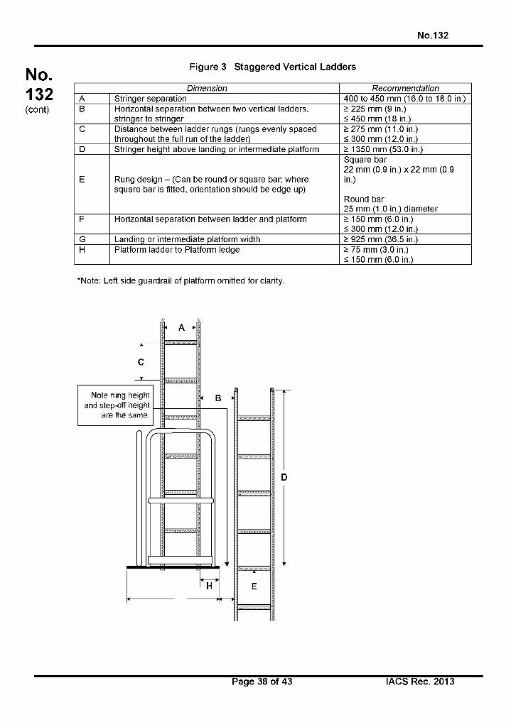
No.132
N o.132(cont)
Figure 3 Staggered Vertical Ladders
Dimension RecommendationA Stringer separation 400 to 450 mm (16.0 to 18.0 in.)В Horizontal separation between two vertical ladders,
stringer to stringer> 225 mm (9 in.)< 450 mm (18 in.)
C Distance between ladder rungs (rungs evenly spaced throughout the full run of the ladder)
> 275 mm (11.0 in.) < 300 mm (12.0 in.)
D Stringer height above landing or intermediate platform > 1350 mm (53.0 in.)
E Rung design - (Can be round or square bar; where square bar is fitted, orientation should be edge up)
Square bar22 mm (0.9 in.) x 22 mm (0.9 in.)
Round bar25 mm (1.0 in.) diameter
F Horizontal separation between ladder and platform > 150 mm (6.0 in.)< 300 mm (12.0 in.)
G Landing or intermediate platform width > 925 mm (36.5 in.)H Platform ladder to Platform ledge > 75 mm (3.0 in.)
< 150 mm (6.0 in.)
*Note: Left side guardrail of platform omitted for clarity.
Page 38 of 43 IACS Rec. 2013
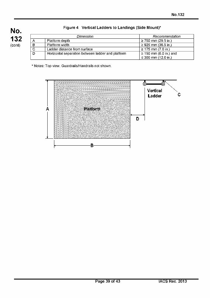
No.132
N o.132(cont)
Figure 4 Vertical Ladders to Landings (Side Mount)*
Dimension RecommendationA Platform depth > 750 mm (29.5 in.)В Platform width > 925 mm (36.5 in.)C Ladder distance from surface > 175 mm (7.0 in.)D Horizontal separation between ladder and platform > 150 mm (6.0 in.) and
< 300 mm (12.0 in.)
* Notes: Top view. Guardrails/Handrails not shown.
Page 39 of 43 IACS Rec. 2013
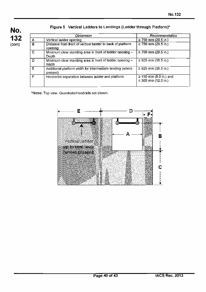
No.132
N o.132(cont)
Figure 5 Vertical Ladders to Landings (Ladder through Platform)*
Dimension RecommendationA Vertical ladder opening > 750 mm (29.5 in.)В Distance from front of vertical ladder to back of platform
opening> 750 mm (29.5 in.)
C Minimum clear standing area in front of ladder opening - Depth
> 750 mm (29.5 in.)
D Minimum clear standing area in front of ladder opening - Width
> 925 mm (36.5 in.)
E Additional platform width for intermediate landing (where present)
> 925 mm (36.5 in.)
F Horizontal separation between ladder and platform > 150 mm (6.0 in.) and < 300 mm (12.0 in.)
*Notes: Top view. Guardrails/Handrails not shown.
Page 40 of 43 IACS Rec. 2013
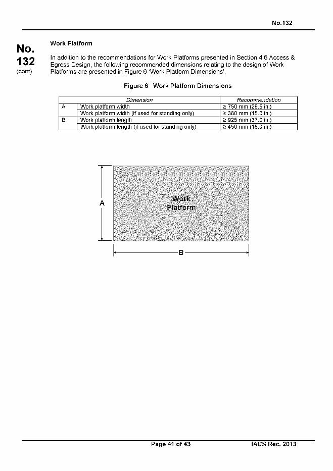
No.132
No.132(cont)
Work Platform
In addition to the recommendations for Work Platforms presented in Section 4.6 Access & Egress Design, the following recommended dimensions relating to the design of Work Platforms are presented in Figure 6 ‘Work Platform Dimensions’.
Figure 6 Work Platform Dimensions
Dimension RecommendationA Work platform width > 750 mm (29.5 in.)
Work platform width (if used for standing only) > 380 mm (15.0 in.)В Work platform length > 925 mm (37.0 in.)
Work platform length (if used for standing only) > 450 mm (18.0 in.)
WorkPlatform
В
Page 41 of 43 IACS Rec. 2013
No.132
No.132(cont)
Annex В - Relevant Standards, Guidelines and Practices
This Annex presents a list of standards and guidance documents used by industry in relation to lighting, ventilation, vibration, noise and access in the context of their effects on human working onboard ships.
2.1 Lighting
• ASTM F1166 2007 Standard Practice for Human Engineering Design for Marine Systems, Equipment and Facilities
• IESNA RP-12-97, Recommended Practice for Marine Lighting
• ISO 8995:2000 (CIES 008/E), Lighting of indoor work places
• ILO Maritime Labour Convention
• JIS F 8041: Recommended Levels of illumination and Methods of illumination Measurement for Marine Use
2.2 Ventilation
• ANSI/ASHRAE (15) (2010). Practices for Measuring, Testing, Adjusting, and Balancing Shipboard HVAC&R Systems
• ANSI/ASHRAE 55a, (2010). Thermal environmental conditions for human occupancy
• ANSI/ASHRAE 62.1 (2010) Ventilation for Acceptable Indoor Air Quality
• ISO 7547:2008 Ships and marine technology - Air-conditioning and ventilation of accommodation spaces - Design conditions and basis of calculations
• ISO 7726 (E), (1998), Ergonomics of the thermal environment - Instruments for measuring physical quantities
2.3 Vibration
• ISO 2631-1:1997, Mechanical Vibration and Shock - Evaluation of Human Exposure to Whole Body Vibration - Part 1: General Requirements
• ISO 2631-2:2003, Mechanical Vibration and Shock - Evaluation of Human Exposure to Whole Body Vibration - Part 2: Vibration in Buildings.
• ISO 6954:2000, Mechanical Vibration and Shock - Guidelines for the Measurement, Reporting and Evaluation of Vibration with Regard to Habitability on Passenger and Merchant Ships.
• ISO 8041:2005, Human response to vibration - Measuring instrumentation.
2.4 Noise
• IMO Resolution MSC.337(91), Code on Noise Levels on Board Ships
• IMO Resolution A.468(XII), Code on Noise Levels on Board Ships
Page 42 of 43 I ACS Rec. 2013
No.132
No.132(cont)
2.5 Access
• American Society for Testing and Materials (ASTM) F1166 2007 Standard Practice for Human Engineering Design for Marine Systems, Equipment and Facilities
• IACS (2002). Recommendation No. 78 — Safe Use of Portable Ladders for Close-up Surveys
IACS (2005). Recommendation No. 90 - Ship Structure Access Manual
IACS (1992). Recommendation No. 91 - Guidance for Approval/Acceptance of Alternative Means of Access
IACS, Unified Interpretations (Ul) SC191 for the application of amended SOLAS regulation 11-1/3-6 (IMO Resolution MSC.151 (78)) and revised Technical provisions for means of access for inspections (IMO Resolution MSC.158 (78))
IMO Maritime Safety Committee Resolution MSC.133 (76) Adoption of Amendments to the Technical Provisions for Means of Access for Inspections
IMO Maritime Safety Committee Resolution MSC.134 (76) Adoption of Amendments to the International Convention for the Safety of Life At Sea
IMO Maritime Safety Committee Resolution MSC.158 (78) (adopted 20 May 2004), Amendments to the Technical Provisions for Means of Access for Inspections
End of Document
Page 43 of 43 IACS Rec. 2013
No.142
No.142(June2016)
IACS
LNG BUNKERING GUIDELINES
Page 1 of 67 IACS Rec. 2016
No.142
No. Table of Contents 142(cont) ChaPter 1 General
Section 1 Application
1.1 Introduction
1.2 Purpose
1.3 LNG Bunkering process and guideline structure
1.4 Applicability
1.5 LNG Bunker Management Plan (LNGBMP)
Section 2 Definitions, applicable standards and rules
2.1 Terms and definitions
2.2 Standards and rules
Section 3 Bunkering methods
3.1 Description of typical ship bunkering arrangements
3.2 Examples of ship bunkering arrangements
Section 4 Responsibilities during LNG bunkering
4.1 Responsibilities during planning stage
4.2 Responsibilities during bunkering operations
4.3 Crew and Personnel Training and LNG awareness
Section 5 Technical requirements for bunkering systems
5.1 General
5.2 Loading arms and hoses arrangements
5.3 Couplings and connecting flanges
5.4 Leakage detection
5.5 ESD systems
5.6 Emergency Release Coupling (ERC)
Page 2 of 67 lACSRec. 2016
No.142
No. 5.7 Communication systems
142 5.8 Bunkering transfer rate
(cont) 5.9 Vapour return line
5.10 Lighting
Page 3 of 67 I ACS Rec. 2016
No.142
No. Chapter 2 Risk Assessment
142 Section 1 LNG Bunkering operations risk assessment
(cont) 1.1 General
1.2 Risk assessment approach
1.3 Risk criteria
1.4 Guidance on a typical Risk Assessment for LNG bunkering operations
Section 2 Safety and security zones
2.1 General
2.2 Hazardous area classification
2.3 Safety zones
2.4 Security zones
Page 4 of 67 I ACS Rec. 2016
No.142
No. Chapter 3 Functional and General Requirements for LNG Bunkering Operation
142 Section 1 Pre-bunkering phase
(cont) 1.1 Definition
1.2 Goal
1.3 Functional requirements
1.4 General requirements
1.5 Preparation for bunker transfer
1.6 Pre-bunkering checklist
1.7 Connection of the transfer system
Section 2 Bunkering phase
2.1 Definition
2.2 Goal
2.3 Functional requirements
2.4 General requirements
Section 3 Bunkering completion phase
3.1 Definition
3.2 Goal
3.3 Functional requirements
3.4 Draining, purging and inerting sequence
3.5 Post-bunkering documentation
Page 5 of 67 I ACS Rec. 2016
No.142
No. Annex: Guidance on HAZID and HAZOP for LNG bunkering operations
142 Section 1 HAZID for LNG bunkering
(cont) 1.1 Objectives
1.2 Scope
1.3 Process
1.4 Technique
1.5 Guidewords
Section 2 HAZOP for LNG bunkering operations
2.1 Definition
2.2 Process
2.3 Scope
Page 6 of 67 I ACS Rec. 2016

N o .142
No. Chapter 1 - General 142(cont)
Section 1 Application
Section 2 Definitions, applicable standards and rules
Section 3 Bunkering methods
Section 4 Responsibilities during LNG bunkering
Section 5 Technical requirements for bunkering systems
Page 7 o f 67 lA C S R e c . 2016
No.142
No.142(cont)
Section 1 - Application1.1 Introduction
LNG bunkering is developing worldwide in line with the increase of use of natural gas as a fuel compliant with environmental legislation.
This guideline provides recommendations for the responsibilities, procedures and equipment required for LNG bunkering operations and sets harmonised minimum baseline recommendations for bunkering risk assessment, equipment and operations.
These guidelines do not consider commercial aspects of the bunker transfer such as Bunker Delivery Notes and measurement of quantity or quality of LNG.
1.2 Purpose
The purpose of these guidelines is mainly to define and cover the additional risks associated with bunkering LNG and to propose a methodology to deal with those additional risks in order to provide a similar level of safety as is achieved for traditional oil fuel bunkering operations.
This document is designed to complement the requirements from the existing applicable guidelines and regulations, such as port and terminal checklists, operator’s procedures, industry guidelines and local regulations. This guide provides guidance to clarify the gaps that have been identified in the existing guidance and regulations. In particular, the following items are covered:
• The responsibility of different parties involved in the LNG transfer,
• The LNG bunkering process,
• SIMOPS
• Safety distances,
• QRA and HAZID
1.3 LNG Bunkering process and guideline structure
LNG bunkering is the process of transferring LNG fuel to a ship from a bunkering facility.
The sequence for a bunkering operation carried out between two parties for the first time is described in the following diagram; the references identify the applicable sections of the guideline.
Page 8 of 67 I ACS Rec. 2016
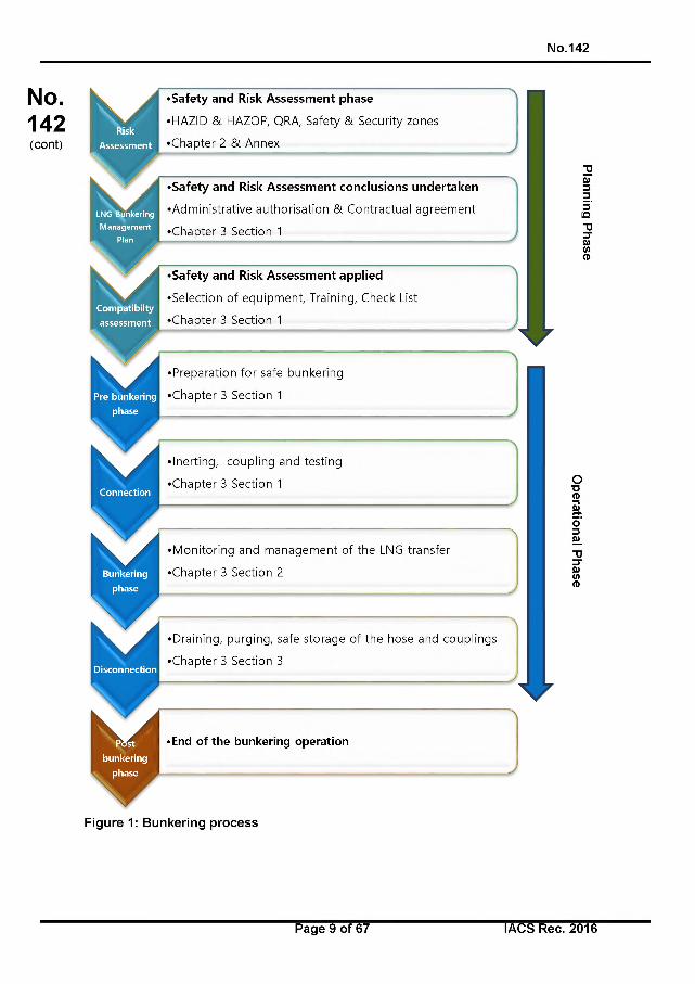
No.142
No.142(cont)
•Safety and Risk Assessment phase
•HAZID & HAZOP, QRA, Safety & Security zones
•Chapter 2 & Annex
•Safety and Risk Assessment conclusions undertaken
•Administrative authorisation & Contractual agreement
•Chapter 3 Section 1
•Safety and Risk Assessment applied
•Selection of equipment, Training, Check List
•Chapter 3 Section 1
•Preparation for safe bunkering
•Chapter 3 Section 1
•Inerting, coupling and testing
•Chapter 3 Section 1
•Monitoring and management of the LNG transfer
•Chapter 3 Section 2
•Draining, purging, safe storage of the hose and couplings
•Chapter 3 Section 3
• End of the bunkering operation
0)33з'IQ
О■D(D
Figure 1: Bunkering process
Page 9 of 67 I ACS Rec. 2016
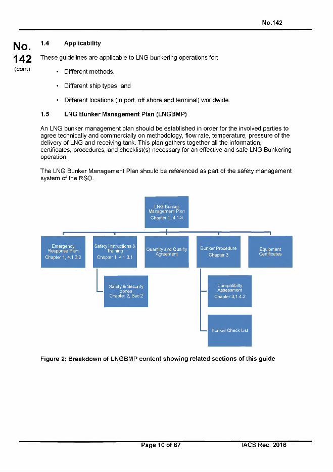
No.142
No.142(cont)
1.4 Applicability
These guidelines are applicable to LNG bunkering operations for:
• Different methods,
• Different ship types, and
• Different locations (in port, off shore and terminal) worldwide.
1.5 LNG Bunker Management Plan (LNGBMP)
An LNG bunker management plan should be established in order for the involved parties to agree technically and commercially on methodology, flow rate, temperature, pressure of the delivery of LNG and receiving tank. This plan gathers together all the information, certificates, procedures, and checklist(s) necessary for an effective and safe LNG Bunkering operation.
The LNG Bunker Management Plan should be referenced as part of the safety management system of the RSO.
Figure 2: Breakdown of LNGBMP content showing related sections of this guide
Page 10 of 67 IACS Rec. 2016
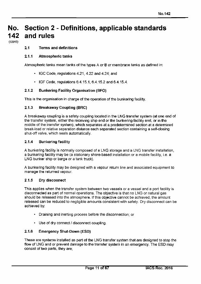
No.142
No. Section 2 - Definitions, applicable standards142 and rules(cont)
2.1 Terms and definitions
2.1.1 Atmospheric tanks
Atmospheric tanks mean tanks of the types A or В or membrane tanks as defined in:
• IGC Code, regulations 4.21, 4.22 and 4.24; and
• IGF Code, regulations 6.4.15.1, 6.4.15.2 and 6.4.15.4.
2.1.2 Bunkering Facility Organisation (BFO)
This is the organisation in charge of the operation of the bunkering facility.
2.1.3 Breakaway Coupling (BRC)
A breakaway coupling is a safety coupling located in the LNG transfer system (at one end of the transfer system, either the receiving ship end or the bunkering facility end, or in the middle of the transfer system), which separates at a predetermined section at a determined break-load or relative separation distance each separated section containing a self-closing shut-off valve, which seals automatically.
2.1.4 Bunkering facility
A bunkering facility is normally composed of a LNG storage and a LNG transfer installation, a bunkering facility may be (a stationary shore-based installation or a mobile facility, i.e. a LNG bunker ship or barge or a tank truck).
A bunkering facility may be designed with a vapour return line and associated equipment to manage the returned vapour.
2.1.5 Dry disconnect
This applies when the transfer system between two vessels or a vessel and a port facility is disconnected as part of normal operations. The objective is that no LNG or natural gas should be released into the atmosphere. If this objective cannot be achieved, the amount released can be reduced to negligible amounts consistent with safety. Dry disconnect can be achieved by:
• Draining and inerting process before the disconnection; or
• Use of dry connect / disconnect coupling.
2.1.6 Emergency Shut-Down (ESD)
These are systems installed as part of the LNG transfer system that are designed to stop the flow of LNG and or prevent damage to the transfer system in an emergency. The ESD may consist of two parts, they are;
Page 11 of 67 IACS Rec. 2016
No.142
No.142(cont)
• ESD - stage 1, is a system that shuts the LNG transfer process down in a controlled manner when it receives inputs from one or more of the following; transfer personnel, high or low level LNG tank pressure alarms, cables or other means designed to detect excessive movement between transfer vessels or vessel and an LNG bunkering facility, or other alarms.
• ESD - stage 2, is a system that activates decoupling of the transfer system between the transfer vessels or between a vessel and an LNG bunkering facility. The decoupling mechanism contains quick acting valves designed to contain the contents of the LNG transfer line (dry break) during decoupling.
2.1.7 Emergency Release Coupling (ERC)
The ERC is normally linked to the ESD system where this may be referred to as ESD2 as per SIGTTO “ESD arrangements & linked ship/shore systems for liquefied gas carriers”.
An emergency release coupling is activated:
• By excessive forces applied to the predetermined section, or
• By manual or automated control, in case of emergency.
2.1.8 Emergency Release System (ERS)
A system that provides a positive means of quick release of the transfer system and safe isolation of receiving vessel from the supply source.
2.1.9 Flash Gas
Boil-off Gas instantly generated during LNG transfer due to the warmer temperature of the receiving ship tanks, sudden pressure drop or friction.
2.1.10 HAZOP
A structured and systematic examination of a planned or existing process or operation in order to identify and evaluate problems that may represent risks to personnel or equipment, or prevent efficient operation. A HAZOP is a qualitative technique based on guide-words and is carried out by a multi-disciplinary team of experts during a set of meetings.
2.1.11 HAZID
Hazard identification exercise, there are a number of recognised methods for the formal identification of hazards. For example: a brainstorming exercise using checklists where the potential hazards in an operation are identified and gathered in a risk register these will then be assessed and managed as required.
2.1.12 Hazardous zones
Bunkering-related hazardous zone means any hazardous area zone 1 or zone 2 defined for:
• The receiving ship in accordance with IGF Code1, regulation 12.5;
1The IGF Code adopted by Resolution MSC.391(95)
Page 12 of 67 IACS Rec. 2016
No.142
No.142(cont)
The bunkering ship in accordance with IGC Code2, regulation 1.2.24 and where gas may be present as a result of the bunkering operation; and
The bunkering shore facility or truck tanker facility in accordance with I EC 60079- 10- 1.
2.1.13 IAPH
International Association of Ports and Harbours.
2.1.14 IGC Code
International Code for the Construction and Equipment of Ships Carrying Liquefied Gases in Bulk (Gas Carrier Code). The revised IGC Code was adopted by Resolution MSC.370(93). It will enter into force on 1 July 2016.
2.1.15 IGF Code
International Code of Safety for Ships using Gases or other Low-Flashpoint Fuels. IGF Code refers to Resolution MSC.391(95). It will enter into force on 1 January 2017.
2.1.16 LNG Bunkering
The process of transferring LNG to be used as fuel on board the receiving ship.
2.1.17 Vapour return line
A vapour return line is a connection between the bunkering facility and the receiving ship to allow excess vapour generated during the bunkering operation to be returned to the bunkering facility and remove any need to vent to atmosphere. It is used to control the pressure in the receiving tank due to the liquid transfer, flash gas and boil-off gas generation.
2.1.18 LNG transfer system
A system consisting of all equipment contained between the manifold used to deliver LNG bunker (and to handle vapour return) and the manifold receiving the LNG (and delivering vapour return) including but not limited to:
• Loading arms and supporting structures,
• LNG articulated rigid piping,
• Hoses, swivels, valves, couplings,
• Emergency Release Coupling (ERC),
• Insulating flanges,
• Quick connect / disconnect couplings (QC/DC),
• Handling system and its control / monitoring system,
2The IGC Code adopted by Resolution MSC.370(93)
Page 13 of 67 IACS Rec. 2016
No.142
No.142(cont)
• Communication system,
• ESD Ship/Shore Link or Ship/Ship Link used to connect the supplying and receiving ESD systems.
It can also include the compressors or blowers intended for the boil-off gas handling system where provided depending on the design of the transfer system. However, liquefaction systems used to maintain pressure in the bunker vessel tanks are not to be considered as part of the LNG transfer system.
2.1.19 MARVS
Maximum Allowable Relief Valve Setting.
2.1.20 MSC
Maritime Safety Committee of the IMO.
2.1.21 Person in Charge (PIC)
The Person in Charge (PIC) is a person who is responsible for the overall management of the bunkering operation. The PIC may also be referred to as Person in Overall Advisory Control (POAC).
2.1.22 PPE
Personal Protective Equipment.
2.1.23 Qualitative Risk Assessment (QuaiRA)
A risk assessment method using relative measure of risk value based on ranking or separation into descriptive categories such as low, medium, high; not important, important, very important; or on a scale, for example from 1 to 10 or 1 to 5.
2.1.24 Quantitative Risk Assessment (QRA)
This is a formalised statistical risk assessment method for calculating a numerical risk level for comparison with defined regulatory risk criteria.
2.1.25 Receiving Ship
Receiving ship is the ship that receives LNG fuel.
2.1.26 Receiving Ship Operator (RSO)
The receiving ship operator (RSO) is the company responsible for the operation of the receiving ship, in particular during the bunkering operations.
2.1.27 Risk
A combination of the likelihood of an event and the consequences if the event occurs.
Page 14 of 67 IACS Rec. 2016
No.142
No.142(cont)
2.1.28 Risk matrix
A risk matrix is a tool for displaying combinations of likelihood and consequence, used as the basis for risk determination. Multiple consequence categories can be included: impact on people, assets, environment and reputation. Plotting the intersection of the two considerations on the matrix provides an estimate of the risk. Acceptable levels of risk are normally shown by color coding the boxes.
2.1.29 Safety zone
The safety zone is a zone around the bunkering facility, the bunkering station of the receiving ship and the LNG transfer system.
The purpose of the zone is to set an area that is put in place during LNG bunkering and within which only essential authorised and qualified personnel are allowed and potential ignition sources are controlled.
2.1.30 Security zone
The Security Zone is the area around the bunkering facility and receiving ship where ship traffic and other activities are monitored (and controlled) to prevent entry and provide a ‘stand-off distance during the bunkering operation; this will be larger than the safety zone.
The security zone may also be referred to as the “exclusion zone”.
The security zone is site dependent and is often determined by the Port Authorities.
2.1.31 SIGTTO
Society of International Gas Tanker and Terminal Operators.
2.1.32 Simultaneous Operations (SIMOPS)
Carrying out LNG bunkering operations concurrently with any other transfers between ship and shore (or between ships if ship-to-ship bunkering method is used). This includes loading or unloading cargo operations, dangerous goods loading or unloading and any kind of other goods loading or unloading (i.e. stores and provisions), passenger embarkation/disembarkation, chemical and other low flash product handling, bunkering of fuels other than LNG, and any other activity that can impact or distract from bunkering operations (e.g. cargo movements on board, heli-ops, etc.).
Special attention is to be paid to any of the above activities occurring within the bunkering safety zone as well as any on board testing that may impact on the bunker operation.
2.1.33 STCW Code
IMO Code for Seafarers’ Training, Certification and Watchkeeping.
2.1.34 Independent Type А, В, C and Membrane tank
These tank types are defined in the IGC and IGF Code.
Page 15 of 67 I ACS Rec. 2016
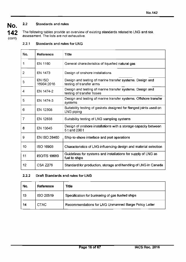
No.142
No.142(cont)
2.2 Standards and rules
The following tables provide an overview of existing standards related to LNG and risk assessment. The lists are not exhaustive.
2.2.1 Standards and rules for LNG
No. Reference Title
1 EN 1160 General characteristics of liquefied natural gas
2 EN 1473 Design of onshore installations
3 EN ISO 16904:2016
Design and testing of marine transfer systems. Design and testing of transfer arms
4 EN 1474-2 Design and testing of marine transfer systems. Design and testing of transfer hoses
5 EN 1474-3 Design and testing of marine transfer systems. Offshore transfer systems
6 EN 12308 Suitability testing of gaskets designed for flanged joints used on LNG piping
7 EN 12838 Suitability testing of LNG sampling systems
8 EN 13645 Design of onshore installations with a storage capacity between 5 t and 2001
9 EN ISO 28460 Ship-to-shore interface and port operations
10 ISO 16903 Characteristics of LNG influencing design and material selection
11 ISO/TS 18683 Guidelines for systems and installations for supply of LNG as fuel to ships
12 CSA Z276 Standard for production, storage and handling of LNG in Canada
2.2.2 Draft Standards and rules for LNG
No. Reference Title
13 ISO 20519 Specification for bunkering of gas fuelled ships
14 CTAC Recommendations for LNG Unmanned Barge Policy Letter
Page 16 of 67 I ACS Rec. 2016

No.142
No.142(cont)
2.2.3 Standards for Risk Analysis
No. Reference Title
15 ISO/IEC Guide 73 Risk Management - Vocabulary
16 ISO/TS 16901 Guidance on performing risk assessments in the design of onshore LNG installations including the ship/shore interface
17 ISO 31000 Risk Management - Principles and Guidelines
18 ISO 31010 Risk Management - Guidelines on principles and implementation of risk management
2.2.4 Other standards & guidelines
No. Reference Title
19 SGMF Gas as a marine fuel - Bunkering safety guidelines
20 IEC 60079 Explosive Atmosphere Standards
21 I EC 60092-502 Electrical installations in ships - Tankers - Special features
22 EN13463-1 Non electric equipment for use in potentially explosive atmospheres
23 SIGTTO ESD arrangements & linked ship/shore systems for liquefied gas carriers
24USCG (CG- OES) Policy Letter No. 01-15
Guidelines for Liquefied Natural Gas Fuel Transfer Operations and Training of Personnel on Vessels using Natural Gas as Fuel (19 Feb 2015)
25USCG (CG- OES) Policy Letter No. 02-15
Guidelines Related to Vessels and Waterfront Facilities Conducting Liquefied Natural Gas (LNG) Marine Fuel Transfer (Bunkering) Operations (19 Feb 2015)
26USCG CG-521 Policy Letter 01- 12
Equivalency Determination: Design Criteria for Natural Gas Fuel Systems
27 NFPA 52 Vehicular Gaseous Fuel Systems Code
28 NFPA 59A Standard for the Production, Storage, and Handling of LNG
29 49CFR 193 Liquefied Natural Gas Facilities: Federal Safety Standards (DOT)
Page 17 of 67 IACS Rec. 2016
No.142
No.142(cont)
Section 3 - Bunkering methods3.1 Description of typical ship bunkering arrangements
Four methods of bunker supply are detailed in the following sections.
The duration of the bunkering will depend mainly on the transfer rate from the bunkering facility; different pump sizes or pressurised supply can be selected depending on the specific needs. Other parameters influencing the duration include the testing procedures, BOG and flash gas handling, purging and draining method and pre- and post-bunkering procedures.
3.1.1 Ship-to-ship LNG bunkering
LNG bunker ships are a common solution when there is a significant volume of LNG to be transferred. Current capacities of LNG bunker ships, in operation and under construction, are in the range of a few hundred to several thousand cubic meters.
The bunker ship is loaded either in a purpose-built, small-scale terminal, a standard LNG terminal adapted for small scale LNG carriers or ship-to-ship bunkering from a larger LNG carrier.
3.1.2 Truck-to-ship LNG bunkering
LNG bunkering operations are carried out from standardised LNG trucks (typically about 40 cubic meter capacity). More than one truck may be required to bunker a single ship, depending on the required bunker volume.
The LNG bunkering operation duration is dependent on the transfer capacity of the truck which is relatively small. Depending on the shore side arrangement it may be possible to increase the bunker rate to some extent by simultaneous bunkering from multiple trucks via a common manifold or using a permanently installed buffer station on the quay side.
This LNG bunkering method is recognised to be flexible as it offers the possibility for many different ships to be bunkered in different port locations. Depending on the port arrangement it may be possible to park the trucks close to the bunker station on the receiving ship allowing short hoses to be used, this potentially reduces the heat flux into the LNG, minimises the pressure drop and also reduces the size of a potential spill if the hose is damaged.
This method is recognised as most suitable where the amount of LNG to be transferred is less than 200 cubic meters and when the commercial operation of the ship allows a sufficient duration for bunkering.
In some cases, LNG trucks may bunker Ro-Ro ferries directly from the ship’s main open cargo deck to the bunker station. This bunkering method derives from normal practices of oil fuel bunkering methods used in Ro-Ro ferries.
3.1.3 Terminal (or shore-based facility) to ship LNG bunkering
A permanent bunkering facility may be used by ships such as short sea shipping ferries, ro- ro ships, OSV and IWW vessels.LNG bunkering takes place through a rigid cryogenic pipe and a flexible hose or loading arm for final connection with the ship. The tanks for the storage of the LNG should generally be as close as possible to the bunkering terminal.
Page 18 of 67 IACS Rec. 2016
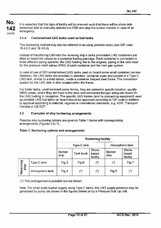
No.142
No.142(cont)
It is expected that this type of facility will be manned such that there will be shore side personnel able to manually activate the ESD and stop the bunker transfer in case of an emergency.
3.1.4 Containerised LNG tanks used as fuel tanks
This bunkering method may also be referred to as using portable tanks (see IGF code18.4.6.3 and 18.4.6.4).
Instead of transferring LNG into the receiving ship’s tanks pre-loaded LNG containers are lifted on board the vessel as a complete fuelling package. Each container is connected to three different piping systems: the LNG fuelling line to the engines, piping to the vent mast for the pressure relief valves (PRV) of each container and the inert gas system.
In case of use of ISO containerised LNG tanks used on board some small container carriers (feeders), the LNG tanks are provided in standard container sizes and consist of a Type C LNG tank, similar to a road tanker, inside a container shaped steel frame. The connection system for the LNG tank is also located within the frame.
For trailer tanks, used on-board some ferries, they are parked in specific location, usually IMDG areas, where they are fixed to the deck and connected through adequate hoses for the LNG fuelling in navigation. The specific LNG trailers (and its connecting equipment) used as portable LNG fuel tanks on board should be approved according to IGF code in addition to approval according to national, regional or international standards, e.g. ADR, Transport Canada or US DOT.
3.2 Examples of ship bunkering arrangements
Possible ship bunkering options are given in Table 1 below with corresponding arrangements (Figures 3 to 7).
Table 1: Bunkering options and arrangements
Bunkering facility
Type C tank Atmospheric tank
Bunkership T ank truck
Shore-basedfacility
Bunkership
Shore-basedfacility
Rec
eivi
ngsh
ip
Type C tank Fig.3 Fig.6 (*) (*) Fig.7
Atmospheric tank Fig.4 C) (*) Fig.5 (*)
(*) This arrangement is possible but not shown.
Note: For small scale bunker supply using Type C tanks, the LNG supply pressure may be generated by pump (as shown in the figures below) or by a Pressure Built Up unit.
Page 19 of 67 I ACS Rec. 2016
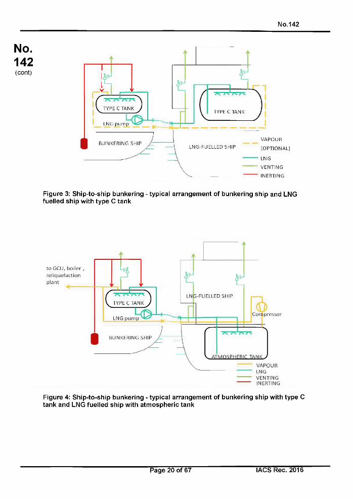
No.142
Figure 3: Sh ip-to-ship bunkering - typical arrangem ent o f bunkering ship and LNG fuelled ship w ith type C tank
Figure 4: Sh ip-to-ship bunkering - typical arrangem ent o f bunkering ship w ith type C tan k and LNG fuelled ship w ith atm ospheric tank
Page 20 o f 67 IACS Rec. 2016
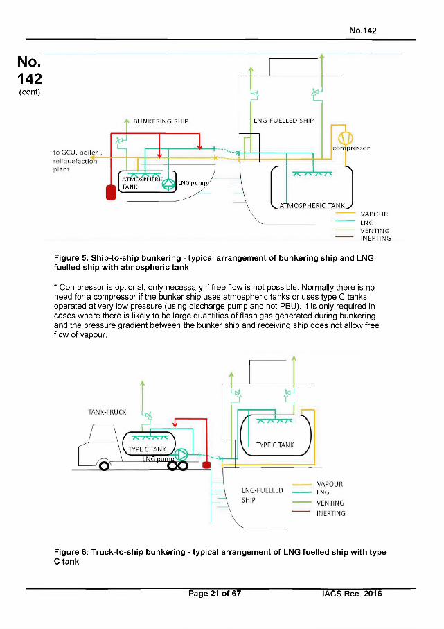
No.142
VENTIIMGINERTING
Figure 5: Ship-to-ship bunkering - typical arrangement of bunkering ship and LNG fuelled ship with atmospheric tank
* Compressor is optional, only necessary if free flow is not possible. Normally there is no need for a compressor if the bunker ship uses atmospheric tanks or uses type C tanks operated at very low pressure (using discharge pump and not PBU). It is only required in cases where there is likely to be large quantities of flash gas generated during bunkering and the pressure gradient between the bunker ship and receiving ship does not allow free flow of vapour.
Figure 6: Truck-to-ship bunkering - typical arrangement of LNG fuelled ship with type C tank
Page 21 of 67 I ACS Rec. 2016
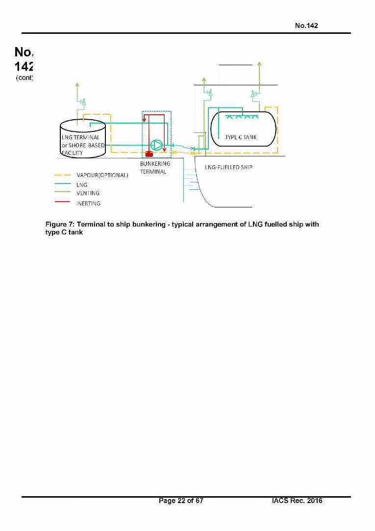
No.142
Figure 7: Terminal to ship bunkering - typical arrangement of LNG fuelled ship with type C tank
Page 22 of 67 IACS Rec. 2016
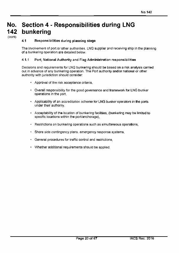
No.142
No. Section 4 - Responsibilities during LNG 142 bunkering(cont)
4.1 Responsibilities during planning stage
The involvement of port or other authorities, LNG supplier and receiving ship in the planning of a bunkering operation are detailed below.
4.1.1 Port, National Authority and Flag Administration responsibilities
Decisions and requirements for LNG bunkering should be based on a risk analysis carried out in advance of any bunkering operation. The Port authority and/or national or other authority with jurisdiction should consider:
• Approval of the risk acceptance criteria,
• Overall responsibility for the good governance and framework for LNG bunker operations in the port,
• Applicability of an accreditation scheme for LNG bunker operators in the ports under their authority,
• Acceptability of the location of bunkering facilities, (bunkering may be limited to specific locations within the port/anchorage),
• Restrictions on bunkering operations such as simultaneous operations,
• Shore side contingency plans, emergency response systems,
• General procedures for traffic control and restrictions,
• Whether additional requirements should be applied.
Page 23 of 67 IACS Rec. 2016
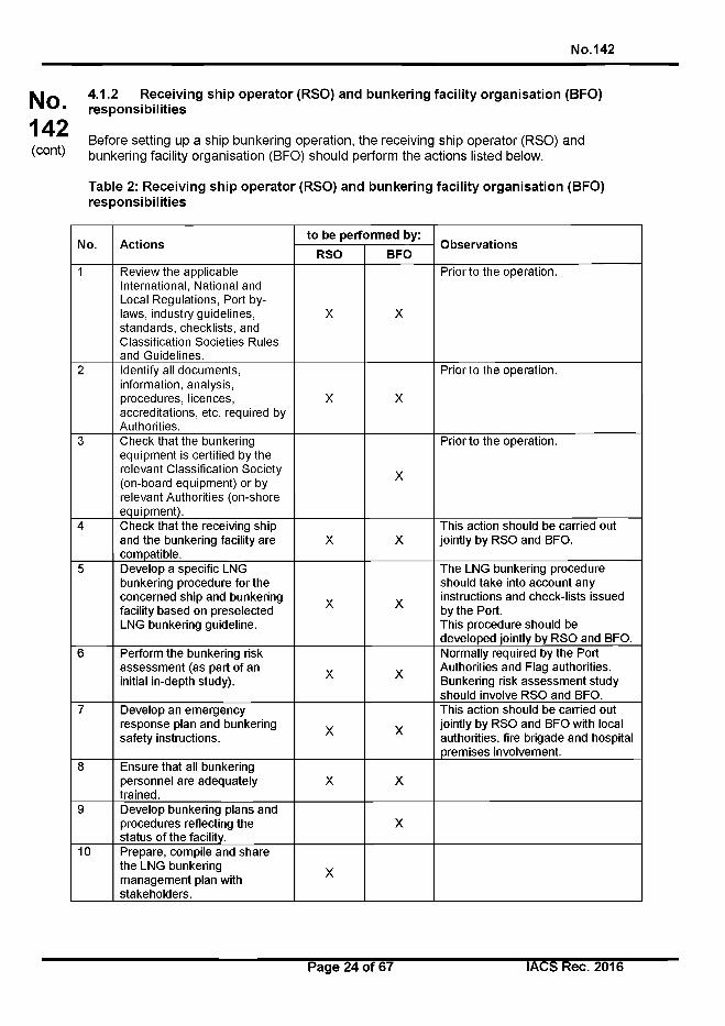
No.142
No.142(cont)
4.1.2 Receiving ship operator (RSO) and bunkering facility organisation (BFO) responsibilities
Before setting up a ship bunkering operation, the receiving ship operator (RSO) and bunkering facility organisation (BFO) should perform the actions listed below.
Table 2: Receiving ship operator (RSO) and bunkering facility organisation (BFO) responsibilities
No. Actionsto be performed by:
ObservationsRSO BFO
1 Review the applicable International, National and Local Regulations, Port bylaws, industry guidelines, standards, checklists, and Classification Societies Rules and Guidelines.
X X
Prior to the operation.
2 Identify all documents, information, analysis, procedures, licences, accreditations, etc. required by Authorities.
X X
Prior to the operation.
3 Check that the bunkering equipment is certified by the relevant Classification Society (on-board equipment) or by relevant Authorities (on-shore equipment).
X
Prior to the operation.
4 Check that the receiving ship and the bunkering facility are compatible.
X XThis action should be carried out jointly by RSO and BFO.
5 Develop a specific LNG bunkering procedure for the concerned ship and bunkering facility based on preselected LNG bunkering guideline.
X X
The LNG bunkering procedure should take into account any instructions and check-lists issued by the Port.This procedure should be developed jointly by RSO and BFO.
6 Perform the bunkering risk assessment (as part of an initial in-depth study). X X
Normally required by the Port Authorities and Flag authorities. Bunkering risk assessment study should involve RSO and BFO.
7 Develop an emergency response plan and bunkering safety instructions. X X
This action should be carried out jointly by RSO and BFO with local authorities, fire brigade and hospital premises involvement.
8 Ensure that all bunkering personnel are adequately trained.
X X
9 Develop bunkering plans and procedures reflecting the status of the facility.
X
10 Prepare, compile and share the LNG bunkering management plan with stakeholders.
X
Page 24 of 67 I ACS Rec. 2016
No.142
No.142(cont)
4.1.3 LNG Bunker Management Plan (LNGBMP)
A bunker management plan should be compiled to allow for easy availability of all relevant documentation for communication between the receiving vessel and the BFO and if applicable the terminal and/or third parties.
The Bunker Management plan should be stored and maintained by both RSO and BFO. For onboard bunkering this may not be the best scenario and should include the following aspects:
• Description of LNG, its handling hazards as a liquid or as a gas, including frostbite and asphyxiation, necessary safety equipment, personal protection equipment (PPE) and description of first aid measures
• Description of the dangers of asphyxiation from inert gas on the ship
• Bunkering safety instructions and emergency response plan
• Description of the bunker facility LNG tank measurement and instrumentation system for level, pressure, and temperature control
• Definition of the operating envelope for which safe LNG bunkering operations can be undertaken in reference to temperature, pressure, maximum flow, weather and mooring restrictions etc.
• A procedure for the avoidance of stratification and potential rollover, including comparison of the relative temperature and density of the remaining LNG in the receiving tank and that in the bunker provider tank and action to be taken to promote mixing during bunkering
• The description of all risk mitigation measures to comply with during an LNG bunkering
• The description of the hazardous areas, safety zone, and security zone and a description of the requirements in the zones to be complied with by the receiving vessel, the bunkering facilities, and if applicable the terminal and third parties
• Descriptions and diagrams of the bunker facility LNG bunkering system, including, but not limited to, the following as applicable:
• Recirculating and vapour return line system• LNG fuel tank cooling down procedure• Procedure for collapsing the pressure of the receiving tank before and during
bunkering• LNG fuel tank pressure relief valve• Ventilation and inlet/outlet location• Inerting system and components• Boil-off gas compressor or reliquefaction system• Gas detection system including locations of detectors and alarms• List of alarms or safety indication systems linked to the gas fuel installation• LNG transfer line and connectors• Emergency Shutdown System description• Communication systems and controls protocol
Page 25 of 67 I ACS Rec. 2016
No.142
No.142(cont)
In addition to the above list of description and schematic drawings, the LNGBMP should include:
• Documents/reports on periodic inspections of the BFO LNG installation (components), and safety equipment.
• A checklist to verify that the ship’s crew have received proper training for bunkering LNG.
• Bunkering safety instructions and safety management plan, (see below).
4.1.3.1 Bunkering safety instructions
RSO and BFO specific safety instructions should be prepared by both parties based on the conclusions and outputs of the LNG Bunkering Operations Risk Assessment (see Chapter 2 Sec 1 and Annex).The specific LNG Bunkering safety instructions should cover at least:
• Sudden change of ambient / sea conditions,
• Breaching of safety and security zones,
• Loss of power (receiving ship or bunkering facility),
• Loss of monitoring / control / safety systems (ESD),
• Loss of communication, and
• Abnormal operating parameters.
In addition, the safety instructions for LNG bunkering may contain technical, RSO and BFO company-internal and operational regulations. The safety instructions should identify conditions under which bunkering will be stopped and in each case the actions required/conditions to be reinstated before the bunkering operation can be restarted
4.1.3.2 Emergency Response Plan
An Emergency Response Plan should be prepared to address cryogenic hazards, potential cold burn injuries to personnel and firefighting techniques for controlling, mitigating and elimination of a gas cloud fire, jet fire and/or a LNG pool fire.
The Emergency Response Plan should cover all emergency situations identified in the LNG Bunkering Operations Risk Assessment and may designate responsibilities for local authorities, hospitals, local fire brigades, PIC, Master and selected personnel from the bunkering facility. As a minimum, the following situations should be covered where appropriate:
• LNG leakage and spill on the receiving ship, on the bunkering facility or from the LNG transfer system
• Gas detection
• Fire in the bunkering area
• Unexpected movement of the vessel due to failure or loosening of mooring lines
• Unexpected moving of the truck tanker
Page 26 of 67 IACS Rec. 2016
No.142(cont) 4 2
Unexpected venting on the receiving ship or on the bunkering facility
Loss of power
Responsibilities during bunkering operations
No.142
The involvement of port, national and/or other LNG supplier, receiving ship and specific individuals in the different phases of LNG bunkering are indicated below. In some situations there may be no port authority with direct responsibility for oversight of the bunkering operation (for example when the port/terminal is owned and managed by the BFO or RSO) in those cases the responsibilities listed in 4.1.1 and 4.2.1 should be adopted by either the BFO or the RSO.
4.2.1 Port Authorities general responsibilities
Port Authority regulations and procedures may impose requirements or criteria for:
• Accreditation of the BFO,
• Qualification of the PIC,
• Mooring of the receiving ship and bunker facility, industry standards may be referenced (e.g. OCIMF Effective Mooring 3rd Edition 2010),
• Immobilisation / braking of the tank truck,
• Establishment of a Safety zone / Security zone in way of the bunkering area,
• Simultaneous operations,
• Spatial planning and approval of bunker locations,
• Enforcement,
• Use of checklists,
• Environmental protection (Releases of NG, purging),
• Approval of safety and emergency response plans,
• Bunkering risk assessment, and
• Conditions in which LNG bunkering operations are allowed: weather conditions, sea state, wind speed and visibility.
4.2.2 LNG Bunkering facilities organisation (BFO) responsibilities
The LNG bunkering facilities organisation should be responsible for the operation of the LNG bunkering installations including:
• Planning of the specific operation (liaising with the RSO),
• Operation of the facility in line with plans and procedures; and
• Maintenance of the bunkering equipment.
Page 27 of 67 IACS Rec. 2016
No.142
No.142(cont)
4.2.3 Receiving ship operator (RSO)
Receiving ship operator has responsibilities for bunkering operation including:
• Informing the BFO and the Port Authority in advance for necessary preparation of the bunkering operation; and
• Attending the pre-bunkering meeting to ensure: compatibility with local requirements for equipment, quantity and flow rate of LNG to be bunkered, and coordination of crew and safety communication systems and procedures.
4.2.4 Master
The master of the receiving ship retains overall control for the safe operation of the ship throughout the bunkering operation. If the bunkering operation deviates from the planned and agreed process the master retains the right to terminate the process.
The master has overall responsibility for the following aspects of the bunkering operation. However, these tasks may be delegated to the PIC or other responsible crew member but the overall responsibility should be retained by the master:
• Approving the quantity of LNG to be bunkered
• Approving the composition, temperature and delivery pressure of LNG that is available from the bunkering facility operator. (Aspects of this may have been agreed prior to the bunkering operation as part of the LNG supply contract)
• Ensuring that the approved safe bunkering process is followed including compliance with any environmental protection requirements required by international, national or local port regulations
• Agreeing in writing the transfer procedure, including cooling down and if necessary, gassing up; the maximum transfer rate at all stages and volume to be transferred
• Completing and signing the bunkering checklist
4.2.5 Person in Charge (PIC)
A person in charge of the bunkering operation (PIC) should be agreed by the receiving ship and the bunkering facility. It is noted that in case of ship-to-ship transfer the role of PIC should be undertaken by either the Master or Chief Engineer of the receiving ship, or the Master of the bunker ship, for other bunker transfer methods a person of equivalent authority should be selected. In the case of distinct Master and PIC, the division of responsibilities between the two parties should be agreed before commencing bunkering operations.
The PIC should have an appropriate level of competence and be accepted to operate in the bunkering location. This may require authorisation or certification to act as PIC for bunkering operations, issued by the Port Authority or other Authority with jurisdiction over the bunkering location. The PIC should have adequate education, training and authorisation to ensure safe bunkering operations.
The PIC should be responsible for the bunkering operation and for the personnel involved, in all aspects of the bunkering operation, in particular safety, until completion.
Page 28 of 67 I ACS Rec. 2016
No.142
No.142(cont)
The PIC should ensure that:
• Relevant approved procedures are properly applied; and
• Safety standards are complied with, in particular within the hazardous zone and safety zone.
To achieve this, the PIC should be responsible for:
• Ensuring that company specific operating procedures are followed, and that the operation is conducted in compliance with all applicable port regulatory requirements;
• Ensuring that all required reports are made to the appropriate Authorities;
• Conducting a pre-operation safety meeting with the responsible officers of both the bunkering facility and the receiving ship;
• Ensuring that all bunkering documentation is completed (checklists, bunker delivery note, etc.);
• Agreeing the mooring arrangement and where applicable nominated Mooring Master during the operation;
• Ensuring all safeguards and risk prevention measures are in place prior to initiating the fuel flow;
• Being familiar with the results of the location risk assessment and ensuring that all specific risk mitigation means are in place and operating (water curtain, fire protection, etc.);
• The activation of Emergency Procedures related to the bunkering system operation;
• Ensuring operation will remain within the accepted environmental window for the duration of bunkering;
• Ensuring safe procedures are followed and the connection of liquid and vapour transfer hoses and associated ERS is successfully completed;
• Ensuring the safe procedures are followed and purging and leak testing of the bunkering system prior to transfer is successfully completed;
• Monitoring fuel transfer and discharge rates including vapour management;
• Monitoring climatic conditions throughout operation;
• Monitoring mooring arrangement integrity (in communication with mooring master);
• Monitoring communications throughout the operation;
• Ensuring the safe procedures are followed for drainage and purging of the bunkering system prior to disconnection;
• Supervising disconnection of liquid and vapour hoses/pipes;
Page 29 of 67 IACS Rec. 2016
No.142
Supervising unmooring and separation of ships or in the case of truck bunkering, departure of the truck; and
Supervising deployment/return of fenders and/or additional support utility to the bunker ship.
Crew and Personnel Training and LNG awareness
General LNG bunkering operational training
The RSO is responsible for ensuring that the personnel on board the receiving ship involved in the bunkering operation should be suitably trained and certified by a recognised organisation, to fulfil requirements according to STCW.7/Circ.23 “Interim guidance on training for seafarers on board ships using gases or other low flashpoint fuels”.
Reference is also made to Resolution MSC.396(95) - (adopted on 11 June 2015) on AMENDMENTS TO THE INTERNATIONAL CONVENTION ON STANDARDS OF TRAINING, CERTIFICATION AND WATCHKEEPING FOR SEAFARERS (STCW), 1978,AS AMENDED and corresponding sections to Parts A and В of the 1978 STCW Convention containing training and qualifications of personnel that work on ships subject to the IGF Code.
The BFO is responsible for ensuring that all bunkering facility personnel involved with the bunkering operations are suitably trained and certified as required by the regulations governing the bunkering method.
• For ship-to-ship bunkering these are the requirements of STCW Regulation V/1-2 - “Mandatory minimum requirements for the training and qualifications of masters, officers and ratings on liquefied gas tankers” and equivalent requirements as provided by the governing authority for the inland waterway where the vessel is operating.
• For truck-to-ship or shore based terminal-to-ship bunkering these are the requirements of the local authorities governing activities within the port area. The personnel to be trained include but are not limited to personnel involved in LNG bunkering, personnel from authorities and emergency response services.
The person in charge (PIC) is to be trained in all aspects involving LNG. For the introduction of LNG bunkering operations within Port, sufficient training courses should be introduced in order to provide adequate competency to the role of PIC. This is especially the case with the development of novel bunkering systems or methods. The responsibility for verifying that the PIC is adequately trained falls on the RSO and BFO, the responsibility for certifying the PIC may be taken by the port authority.
4.3.2 Specific LNG bunkering safety training
Each bunkering method introduces different hazards. Specific training should be developed, based on the different possible failure scenarios and external events identified during the risk assessment study. Specific safety instructions as defined in 4.1.3.1 should be prepared based on the conclusions and outputs of the LNG Bunkering Risk Assessment.
The specific LNG Bunkering safety training should cover at least:
• Sudden change of ambient / sea conditions,
No.142(cont)
4.3
4.3.1
Page 30 of 67 IACS Rec. 2016

No.142
No.142(cont)
Loss of power (receiving ship or bunkering facility),
Loss of monitoring / control / safety systems (ESD),
Loss of communication,
Abnormal operating parameters, and
Rapid situation assessment technique with focus of restabilising unstable situations.
Page 31 of 67 IACS Rec. 2016
No.142
No. Section 5 - Technical requirements for 142 bunkering systems(cont)
5.1 General
The LNG / vapour transfer system should be designed and the bunkering procedure carried out so as to avoid the release of LNG or natural gas. The transfer system should be designed such that leakage from the system cannot cause danger to personnel, the receiving ship, the bunkering facility or the environment when the system is well maintained and properly used. Where any spillage of LNG can occur provisions should be taken protect personnel, ship’s structure and equipment from cryogenic hazards. The consequences of other natural gas fuel related hazards (such as flammability) should be limited to a minimum through the arrangement of the transfer system and the corresponding equipment.
Specific means should be provided to purge the lines efficiently without release of natural gas with all purged gasses either retained by the receiving ship or returned to the bunkering facility.
Accidental leakage from the LNG / vapour transfer systems including the connections with the receiving ship bunkering manifold and with the bunkering facility should be detected by appropriate means.
5.2 Loading arms and hoses arrangements
5.2.1 Transfer installation
Arrangements should be made for:
• Purging and inerting the bunkering lines (or between designated ESD valves for systems with long LNG transfer lines) prior to the LNG transfer,
• Draining, purging and inerting the transfer system after completion of the LNG transfer.
LNG and vapour transfer systems (loading arm and/or flexible hose) should be fit for marine LNG bunkering operations. Design should be according to Tables 1 and 2 in ISO/TS 18683. The hoses and loading arms should be specially designed and constructed for the transfer products (LNG and Nitrogen) with a minimum temperature of-196°C.
Pressure relief devices should be provided so that the hose or loading arm is not overpressurised in the event that liquid is trapped between its isolating valves (for example if the ERS is activated).
Hoses, loading arms and parts of the ship manifold should be designed for loads which may be experienced during operation such as self-weight (including fully loaded), loads due to relative motion between receiving ship and bunker supplier, and loads due to any lifting equipment used to handle the hose. The loading arms and parts of the ships manifold may also need to be designed to support the weight of an emergency release coupling.
Care should be taken when choosing the transfer system particularly with regards to:
• Potential movements between the receiving ship and the bunkering facility,
Page 32 of 67 I ACS Rec. 2016
No.142(cont)
No.142
• Operating envelope of transfer system,• Minimum bending radius allowed for hoses,
• ESD system functionality,
• Means of purging and draining the transfer lines,
• Material selection and structural support,
• Type of connectors,
• Electrical insulation,
• Continuity of earthing system,
• System design to address potential surge pressures developed during an ESD,
• Flash gas handling system, and
• Arrangements for pressure relief.
5.2.2 Hoses
Hoses should comply with appropriate recognized standards such as EN 1474-2, EN 12434 or BS 4089.Transfer hose manufacturer’s instructions, regarding testing and number of temperature and pressure operating cycles before removal from service, should be strictly followed.
Depending on which party owns the bunkering hose, a document should be included in the LNG Bunker management plan and a copy kept by the receiving ship containing the following information as applicable:
• Hose identification number
• Date of initial entry into service
• Initial test certificate and all subsequent test reports and certificates
The cryogenic hose should be subjected to hydrostatic testing once a year, if any defects appears during this inspection, the hose should be replaced. In addition the manufacturer of these hoses may lay down requirements relating to service life, inspection and maintenance. The manufacturer’s instructions should be followed.
5.2.3 Lifting and supporting devices
The lifting devices, where fitted, should be of suitable capacity to handle the LNG transfer hoses and associated equipment.Hoses should be suitably supported in such a way that the allowable bending radius is satisfied. They should normally not lie directly on the ground and should be arranged with enough slack to allow for all possible movements between the receiving ship and the bunkering facility.
Lifting and supporting devices should be suitably electrically insulated and should not impair the operation of any emergency release coupling or other safety devices.
Page 33 of 67 IACS Rec. 2016
No.142
No.142(cont)
5.3 Couplings and connecting flanges
5.3.1 General
The use of dry disconnect couplings is recommended for day-to-day bunkering operations using small hose diameters that will require several connections and disconnections.
5.3.2 Standard
An ISO standard for LNG bunkering connections is currently under development within TC8 WG8. In the meantime, couplings used for LNG Bunkering operation should be designed according to the requirements in ISO EN 16904:2016 and 1474-3 or any other applicable standards.
5.3.3 Isolation flange
The bunker transfer system should contain an isolation flange/of a non-electrically conductive material to prevent stray currents between the bunkering facility and the receiving ship. The isolation flange is generally fitted at the receiving ship end of the transfer system.
5.3.4 Spool piece
When spool pieces are used to connect to different sizes and geometries of connectors, they should be installed and tested as part of the preparation for bunkering. The leak testing would be applicable to ensure that the arrangement including spool piece is fully inerted and gas tight before transfer.
5.4 Leakage detection
As a minimum, in an enclosed or semi enclosed bunker station (on the receiving ship) or discharging station (of the bunker facility), the following safety devices should be in place:
• Gas detector(s), in suitable location(s) taking into consideration the rate of dispersion of cold vapour in the space, or temperature detection sensor(s), installed in the drip trays, or any combination to immediately detect leakage.
• CCTV is recommended to observe the bunkering operation from the bridge or operation control room. The CCTV should provide images of the bunker connection and also if possible the bunker hose such that movement of transfer system during bunkering are visible. CCTV is particularly recommended for enclosed bunker stations. Where CCTV is not provided, a permanent watch should be maintained from a safe location.
Gas detectors should be connected to the ESD system for monitoring leakage detection on the receiving ship.
Consideration may be given to the use of thermal imaging equipment or other suitable technology for leakage detection, especially in semi-enclosed bunkering stations.
A gas dispersion analysis will aid in identifying the critical locations and the extent of the LEL range where gas detectors should be fitted to enable early detection of any leakage.
Page 34 of 67 IACS Rec. 2016
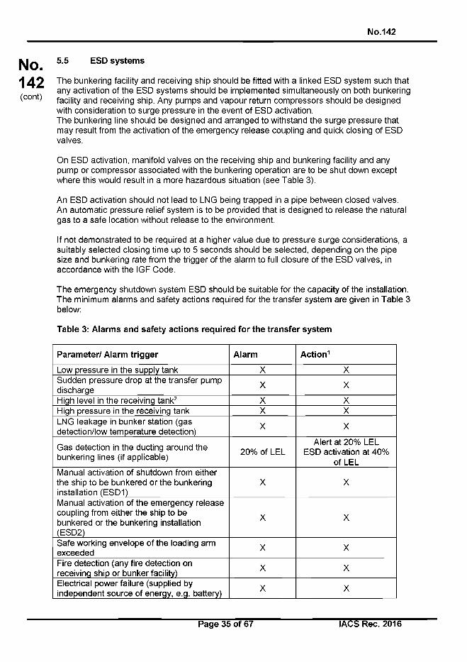
No.142
No.142(cont)
5.5 ESD systems
The bunkering facility and receiving ship should be fitted with a linked ESD system such that any activation of the ESD systems should be implemented simultaneously on both bunkering facility and receiving ship. Any pumps and vapour return compressors should be designed with consideration to surge pressure in the event of ESD activation.The bunkering line should be designed and arranged to withstand the surge pressure that may result from the activation of the emergency release coupling and quick closing of ESD valves.
On ESD activation, manifold valves on the receiving ship and bunkering facility and any pump or compressor associated with the bunkering operation are to be shut down except where this would result in a more hazardous situation (see Table 3).
An ESD activation should not lead to LNG being trapped in a pipe between closed valves.An automatic pressure relief system is to be provided that is designed to release the natural gas to a safe location without release to the environment.
If not demonstrated to be required at a higher value due to pressure surge considerations, a suitably selected closing time up to 5 seconds should be selected, depending on the pipe size and bunkering rate from the trigger of the alarm to full closure of the ESD valves, in accordance with the IGF Code.
The emergency shutdown system ESD should be suitable for the capacity of the installation. The minimum alarms and safety actions required for the transfer system are given in Table 3 below:
Table 3: Alarms and safety actions required for the transfer system
Parameter/ Alarm trigger Alarm Action1
Low pressure in the supply tank X XSudden pressure drop at the transfer pump discharge X X
High level in the receiving tank2 X XHigh pressure in the receiving tank X XLNG leakage in bunker station (gas detection/low temperature detection) X X
Gas detection in the ducting around the bunkering lines (if applicable) 20% of LEL
Alert at 20% LEL ESD activation at 40%
of LELManual activation of shutdown from either the ship to be bunkered or the bunkering installation (ESDI)
X X
Manual activation of the emergency release coupling from either the ship to be bunkered or the bunkering installation(ESD2)
X X
Safe working envelope of the loading arm exceeded X X
Fire detection (any fire detection on receiving ship or bunker facility) X X
Electrical power failure (supplied by independent source of energy, e.g. battery) X X
Page 35 of 67 I ACS Rec. 2016
No.142
No.142(cont)
Notes:
1. Alert is to be made at both the delivery and receiving ends of the transfer system to clearly identify the reasons for the ESD activation.
X = Audible/visual alert to be made at bunker station/discharging station and ESD system to be activated.
2. Where the parameter that triggers the ESD is such that closure of vapour connectionvalves and shut down of vapour return compressors would increase the potential hazard (for example a receiving tank high level alarm) these are to remain open/active where appropriate._______________________________________________________
The manual activation position for the ESD system should be outside the bunker station and should have a clear view of the manifold area (the ‘clear view’ may be provided via CCTV).
LNG bunker transfer should not be resumed until the transfer system and associated safety systems (fire detection, etc.) are returned to normal operation condition.All electrical components of the emergency release coupling actuator and of the ESD systems that are considered as provided by the ship side should be type approved/certified by the classification society. When the ESD hardware and components are part of the onshore facility they should be designed and tested according to the industry standards.
Page 36 of 67 IACS Rec. 2016
No.142(cont)
No.142
5.6 Emergency Release Coupling (ERC)
5.6.1 General
Transfer arms and hoses should be fitted with an emergency release coupling (ERC) designed to minimize the release of LNG on emergency disconnection. The emergency release coupling may be designed for:
• Manual or automatic activation, and
• Activation as a result of excessive forces i.e. automatic disconnection in case the safe working envelope of the transfer system is exceeded.
The breakaway coupling (BRC) should be subjected to a type test to confirm the values of axial and shear forces at which it automatically separates. For an emergency release coupling (ERC), the tightness of the self-closing shut-off valves after separation should be checked.
The ERC coupling should be designed and installed so that, in the worst allowable conditions for current, waves and wind declared in the bunkering conditions, it will not be subjected to excessive axial and shear forces likely to result in the loss of tightness or opening of the coupling. When the Safe working envelope of the transfer system is exceeded, the ERC system should be triggered.
Means should be provided in order to avoid a pressure surge in the bunker hose after release of the ERC when the connecting end of the hose is fitted with a dry disconnect coupling type.Full operating instructions, testing and inspection schedules, necessary records and any limitations of all emergency release systems should be detailed in the ship's operating manuals.
5.6.2 ERC Activation
Where manual activation type ERC is fitted, the means of remotely operating the ERC should be positioned in a suitability protected area both on bunkering facility and receiving ship allowing visual monitoring of the bunkering system operation. A physical ESD link should bond the two parties. This does not apply to a dry breakaway coupling as this is a passive component which cannot be remotely activated.
5.6.3 Hose Handling after ERC Release
An integrated hose/support handling system should be in place, capable of handling and controlling the bunker transfer hoses after release of the ERC. In addition, it should be capable of absorbing all shock loadings imposed by the release of ERC during maximum capacity transfer conditions.
The system should ensure that, as far as practicable, upon release the hoses, couplings and supports do not contact the metal structure of the ship and bunkering facility, thereby reducing the risk of sparking at the contact point, injury to personnel or mechanical damage.
5.7 Communication systems
A communication system with back-up should be provided between the bunkering facility and the receiving ship.
Page 37 of 67 IACS Rec. 2016
No.142
No.142(cont)
The components of the communication system located in hazardous and safety zones should be type approved according to I EC 60079.
5.8 Bunkering transfer rate
The maximum LNG transfer rate from the BFO should be adjusted, taking into consideration:
• Maximum allowable flow rate of the bunker station manifold,
• Maximum allowable cooling down rate acceptable regarding induced thermal stresses in the LNG receiving ship piping and tank,
• Management of the flash gas generated during bunkering,
• Temperature of the LNG supplied from the bunkering facility,
• Temperature of the LNG remaining in the receiving ship tank, and
• Pressure in both bunkering facility tank and receiving ship tank.
Adequate provisions should be made for the management of the flash gas generated during the bunkering operation, without release to the atmosphere. This may be done by:
• Considering the capacity of the available vapour spaces and allowable pressure build-up of both ships, or
• Burning additional volumes in boilers, gas combustion units or gas engines, or
• Cooling the vapour space to control the pressure by using LNG spray in the receiving tank, or
• Reliquefaction.
The LNG velocity in the piping system should not exceed 12.0 m/sec under the rated equipment capacity in order to avoid the generation of static electricity, additional heat, and consecutive boil off gas due to nonlinear flow.
5.9 Vapour return line
Vapour return line(s) may be used in order to control the pressure in the receiving tank or to reduce the time required for bunkering (refer to 2.4.6 of Chapter 3). This is particularly applicable to atmospheric pressure fuel storage tanks (type A, prismatic type В or membrane tanks). The most relevant factors that will affect the amount of flash gas generation in a typical bunkering operation are as follows:
• Cool down of the transfer system
• Difference in the conditions prevailing between the bunkering facility tanks and the receiving tanks (particularly the temperature of the receiving tank)
• Transfer rates (ramp up, full flow, ramp down/topping up)
• Heat gain in pipe line between bunkering facility tank and receiving ship tank
• Pumping energy
Page 38 of 67 IACS Rec. 2016
No.142
| ^ q 5.10 Lighting
142 Lighting should illuminate the bunker station area, and if installed in a hazardous area should be compliant with applicable hazardous area equipment requirements. Lighting
(corn) should adequately illuminate the bunkering operation work area especially:
• LNG bunker hose(s),
• Connection and couplings on both receiving ship and bunkering facility,
• ESD system call points,
• Communication systems,
• Fire-fighting equipment,
• Passage ways / gangways intended to be used by the personnel in charge of the bunkering operation, and
• Vent mast(s).
Page 39 of 67 IACS Rec. 2016
N o .142
No. Chapter 2 - Risk Assessment 142(cont)
Section 1 LNG Bunkering operations risk assessment
Section 2 Safety and security zones
Page 40 o f 67 IACS Rec. 2016
No.142
No. Section 1 - LNG Bunkering operations risk 142 assessment(cont)
1.1 General
A bunkering operations risk assessment should be undertaken in accordance with ISO/TS 18683. This technical specification is specific to the supply of LNG as fuel to ships and refers to recognised standards that provide detailed guidance on the use and application of risk assessment. The objectives of the bunkering operations risk assessment are to:
• Demonstrate that risks to people and the environment have been eliminated where possible, and if not, mitigated as necessary, and
• Provide insight and information to help set the required safety zone and security zone around the bunkering operation.
In order to meet these objectives, as a minimum, the bunkering operations risk assessment should cover the following operations:
• Preparations before and on ship’s arrival, approach and mooring
• Preparation, testing and connection of equipment
• LNG transfer and boil-off gas (BOG) management
• Completion of bunker transfer and disconnection of equipment
• Simultaneous operations (SIMOPS) as noted in 1.3.3
1.2 Risk assessment approach
1.2.1 Qualitative Risk Assessment (QuaiRA)
A Qualitative Risk Assessment (QuaiRA) should be undertaken prior to introduction of a new bunkering operation procedure that follows the guidance in this document and the guidance given in ISO/TS 18683 guidelines.
Provided the bunkering operation is one of the three standard bunkering scenarios below, and guidance in this document and ISO/TS 18683 is followed, i.e. there are no deviations from the functional requirements, , then the qualitative approach (i.e. QuaiRA) is sufficient to meet the objectives of the bunkering operations risk assessment.
Standard bunkering is characterised by three bunkering scenarios, as noted in ISO/TS 18683:
1. Shore-to-ship (that is, LNG transfer from an onshore facility to a gas fuelled ship)
2. Truck-to-ship (that is, LNG transfer from a road truck to a gas fuelled ship)
3. Ship-to-ship (that is, LNG transfer from a ship, such as a bunker barge, to a gas fuelled ship)
Page 41 of 67 I ACS Rec. 2016
No.142
No.142(cont)
1.2.2 Quantitative Risk Assessment (QRA)
As a supplement to the QuaiRA, a Quantitative Risk Assessment (QRA) may be required where:
1. bunkering is not of a standard type (as described above);
2. design, arrangements and operations differ from the guidance given in this document; and
3. bunkering is undertaken alongside other transfer operations (SIMOPS), see 1.3.3.
A QRA is also appropriate where further insight is required to: judge the overall level of risk (since this is not typically provided by a QuaiRA); appraise design options and mitigation alternatives; and/or to support a reduced safety zone and/or security zone.
The requirement for a QRA (in addition to a QuaiRA) is normally determined by the Administration or Port Authority based on the conclusions and outcomes of the QuaiRA and accepted by the concerned parties.
1.2.3 Risk Assessment Minimum Scope for LNG bunkering
Whether only a QuaiRA is required or both a QuaiRA and QRA are required, as a minimum the risk assessment should detail:
a. How the bunkering operation could potentially cause harm. That is, systematic identification of potential accidents/incidents that could result in fatality or injury or damage to the environment;
b. The potential severity of harm. That is, the worst case consequences of the accidents/incidents identified in ‘a’, in terms of single and multiple fatalities and environmental damage caused;
c. The likelihood of harm. That is, the probability or frequency with which the worst case consequences might occur;
d. A measure of risk, where risk is a combination of (b) and (c); and
e. How the functional requirements are met.
In addition, the risk assessment should help identify the scenarios to be used to determine the safety zone; and as a minimum, consider SIMOPS within the safety zone.
A typical approach to QuaiRA and QRA is described in ISO/TS 18683. These approaches or similarly established approaches should be used provided they cover items (a) to (e) above.
Regardless of the approach used, the risk assessment should be carried out by a team of suitably qualified and experienced individuals with collective knowledge of, and expertise in: risk assessment application; engineering design; emergency response, and bunkering operations.
Page 42 of 67 IACS Rec. 2016
No.142
No.142(cont)
1.3 Risk criteria
Examples of qualitative and quantitative risk criteria are outlined in ISO/TS 18683. In addition, guidance on selection of appropriate criteria may be given by government organisations. Furthermore, many industry organisations, such as the international oil companies, have specific risk criteria extensively used to demonstrate safe onshore and offshore operations to governments and regulators.
Although criteria from different sources may appear similar, it is important to note that there are no universally agreed risk criteria: there are differences between governments, regulators and organisations. Therefore, prior to the commencement of the risk assessment, risk criteria should be agreed with appropriate stakeholders, in particular the port and regulatory authorities, the Administration and the ship operator.
1.3.1 Risk Levels in Qualitative Risk Assessment (Q uaiR A )
Risk levels in qualitative risk assessments are commonly incorporated within a risk matrix and indicate a level of risk associated with a specific combination of consequence and likelihood. For example, the risk may be:
1. Sufficiently ‘low’ that it need not be reduced further,
2. At a level where mitigation should be considered and implemented if practicable, or
3. At a ‘high’ level where mitigation is required to reduce it.
An important point to note is that the risk level is indicative of one or more but not all potential accidents/incidents. That is, the assessment does not provide a collective or overall indication of the risk level from all potential accidents/incidents; rather it provides a relative ranking of the accidents/incidents considered. If the overall risk level is required then this can be determined using QRA.
1.3.2 Risk Criteria in Quantitative Risk Assessment (QRA)
Risk criteria in quantitative risk assessments commonly refer to individual risk and societal risk (or group risk), and these are related to fatality or some other measure of harm. Where a significant number of people are exposed to the bunkering operations then both should be assessed. This is because the risk to any individual may be ‘low’ but the risk of harming many people in a single accident/incident might be sufficient to warrant risk reduction. Stakeholders should consider what constitutes a significant number of people to require assessment of societal risk. Dependent upon specifics this might be exposure of ten or more people.
It is important to note that the criteria are typically expressed on a per annum basis (i.e. per year). For hazards that are present for a relatively short time (over a year) the per annum criteria may not be appropriate. This is because the risk is not spread uniformly across the year but peaks intermittently, and for long periods of time it does not exist. As such, if this is not recognised then proposed risk mitigation may not offer the protection envisaged. As a guide, per annum criteria may not be appropriate for a hazard present less than a third of the year.
Page 43 of 67 I ACS Rec. 2016
No.142
No.142(cont)
1.3.3 Risk assessment for simultaneous operations (SIMOPS)
Where it is proposed to carry out bunkering operations concurrently with other operations that may impact or be impacted by the bunkering then further risk assessment should be carried out to demonstrate that the required level of safety can be maintained.Note: Risk assessment for simultaneous operations should be considered when the following operations are intended to be carried out simultaneously with the bunkering operations:
• Cargo handling
• Ballasting operations
• Passenger embarking / disembarking
• Dangerous goods loading / unloading and any kind of other goods loading or unloading (i.e. stores and provisions)
• Chemical products handling
• Other low-flash point products handling
• Bunkering of fuels other than LNG
Simultaneous operations should be investigated for any of the above activities occurring within the safety zone calculated as described in 2.3.
Any simultaneous shipboard technical operations such as testing systems that might affect the stability of the receiving ship, for example, changes to the mooring situation, testing of power generations systems or fire-fighting systems, are not to be carried out during LNG bunkering operations.
Page 44 of 67 IACS Rec. 2016
No.142
No.142(cont)
1.4 Guidance on a typical Risk Assessment for LNG bunkering operations
The scale of risk assessment required for the bunkering process will depend on the bunkering method and equipment used with additional, more detailed, levels of risk assessment potentially required where novel procedures and/or equipment are selected.
It is generally expected that the risk assessment activities will be broken into two main parts, a higher level HAZID activity followed by a more detailed HAZOP activity. It is recommended that both of these activities are conducted with professional guidance to ensure an appropriately detailed risk assessment outcome is achieved.
Where designs or operational methods are modified after the risk assessment(s) have been conducted this may result in the risk assessments needing to be revised accordingly.
1.4.1 HAZID
The hazard identification process should provide sufficient detail for an operator to fully understand the nature of each hazard and to identify the controls necessary for the management of each hazard. The outcomes of the HAZID include risk rankings and recommendations for additional safeguards and analysis.
As a minimum, the HAZID should include the scope as described in the ISO/TS 18683.
Guidance for conducting a HAZID for LNG bunkering operation is detailed in the Annex of this guideline.
1.4.2 HAZOP
The HAZOP study is a structured and methodical examination of a planned process or operation in order to identify causes and consequences from a deviation to ensure the ability of equipment to perform in accordance with the design intent. It aims to ensure that appropriate safeguards are in place to help prevent accidents. Guidewords are used in combination with process conditions to systematically consider all credible deviations from normal conditions.
Guidance for conducting a HAZOP for LNG bunkering operation is detailed in the Annex of this guideline.
Page 45 of 67 I ACS Rec. 2016
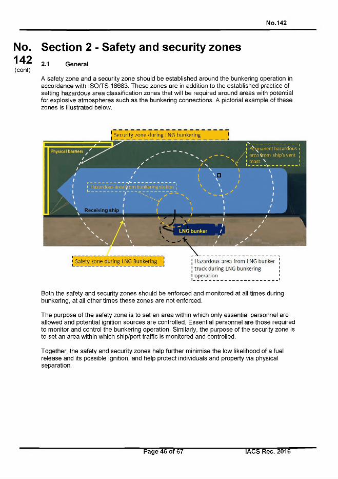
No.142
No.142(cont)
Section 2 - Safety and security zones2.1 General
A safety zone and a security zone should be established around the bunkering operation in accordance with ISO/TS 18683. These zones are in addition to the established practice of setting hazardous area classification zones that will be required around areas with potential for explosive atmospheres such as the bunkering connections. A pictorial example of these zones is illustrated below.
; Safety zone during LNG Bunkering iI_________________________________________________________________J
Hazardous area from LNG bunker
truck during LNG bunkering
operation
Both the safety and security zones should be enforced and monitored at all times during bunkering, at all other times these zones are not enforced.
The purpose of the safety zone is to set an area within which only essential personnel are allowed and potential ignition sources are controlled. Essential personnel are those required to monitor and control the bunkering operation. Similarly, the purpose of the security zone is to set an area within which ship/port traffic is monitored and controlled.
Together, the safety and security zones help further minimise the low likelihood of a fuel release and its possible ignition, and help protect individuals and property via physical separation.
Page 46 o f 67 IACS Rec. 2016
No.142
No.142(cont)
2.2 Hazardous area classification
Bunkering-related hazardous areas means any hazardous area zone 1 and zone 2 defined for:
• The receiving ship in accordance with IGF Code, regulation 12.5,
• The bunkering ship in accordance with IGC Code, regulation 1.2.24, and
Example minimum hazardous zone sizes include:
• Areas on open deck, or semi-enclosed spaces on deck, within 3 m of any gas tank outlet, gas or vapour outlet, bunker / supply manifold valve, other gas valve, gas pipe flange and gas tank openings for pressure release,
• Areas on the open deck within spillage coamings surrounding gas bunker / supply manifold valves and 3 m beyond these, up to a height of 2.4 m above the deck,
• Semi-enclosed bunkering stations, and
• Areas within 1.5 m surrounding spaces listed above.
The bunkering-related hazardous area also includes areas around the truck, LNG bunker vessel or shore-based bunkering facility. Depending on the outcomes of the risk assessment and the specific details of the bunkering process (equipment and transfer flow rates and pressures) the size of these areas may be increased.
In the hazardous area, only electrical equipment certified in accordance with I EC 60079 is permitted. Other electrical equipment should be de-energised prior to the bunkering operations. Attention is drawn to the following equipment, which is not intrinsically safe and should therefore be disabled, except if otherwise justified:
• The radar equipment, which may emit high power densities,
• Other electrical equipment of the ship, such as radio equipment and satellite communication equipment, when they may cause arcing.
Page 47 of 67 IACS Rec. 2016
No.142
No.142(cont)
2.3 Safety zones
In the safety zone, the following restrictions normally apply during the bunkering operations, except if otherwise justified by the safety analysis or agreed by the Local Port Authorities or National Administration:
• Smoking is not permitted.
• Naked lights, mobile phones, cameras and other non-certified portable electrical equipment are strictly prohibited.
• Cranes and other lifting appliances not essential to the bunkering operation are not to be operated.
• No vehicle (except the tank truck) should be present in the safety zone.
• No ship or craft should normally enter the safety zone, except if duly authorised by the Port Authorities.
• Other possible sources of ignition should be eliminated.
• Access to the safety zone is restricted to the authorised staff, provided they are fitted with personal protective equipment (PPE) with anti-static properties and portable gas detector.
2.3.1 Determination of the safety zone distance
There are two different approaches which are outlined in the following paragraphs.
2.3.1.1 Deterministic approach
The safety zone should be set based upon the flammable extent of a maximum credible release scenario. In ISO/TS 18683 this approach to setting the safety zone is referred to as the ‘deterministic approach’. Specific requirements for the determination of the safety zone may be set by national and local authorities.
The flammable extent is the distance at which the lower flammable limit (LFL) is reached as the vapour/gas (from the released fuel) disperses in the atmosphere. For LNG, the LFL is approximately 5% of natural gas in air.
As a minimum, the following information should be taken into account in the maximum credible release scenario:
• The physical properties of the released fuel.
• Weather conditions at the bunkering location; wind speed, humidity, air temperature and the temperature of the surface upon which the fuel leaks. The chosen conditions should reflect the worst-case conditions that result in the greatest distance to LFL.
• Roughness of the surface over which the vapour/gas disperses, (i.e. land or water).
• Structures and physical features that that could significantly increase or decrease dispersion distances.
Page 48 of 67 I ACS Rec. 2016
No.142
No.142(cont)
• Release rate, release orientation, available inventory and rate of vapour generation.
In addition, release height is to be considered as this can significantly affect the extent of the calculated safety zone. The vertical extent of the safety zone may require special consideration, especially in cases where persons can be at elevated positions, such as located in cabins many metres above the bunker station.
Large objects, such as buildings and ships, and topography, such as cliffs and sloping ground, can constrain or direct dispersion. This should be recognised in setting the safety zone. Failure to do this can result in inappropriate safety zones that include areas that would not be affected by any release of natural gas or exclude areas that would be affected if there was a release. In certain cases, advanced modelling techniques, such as computational fluid dynamics (CFD) might be required to justify the zone’s shape and extent.
Regardless of the technique(s) used in setting the safety zone it should be applied by a suitably qualified and experienced individual.
ISO/TS 18683 provides two examples of a maximum credible release scenario, where the one resulting in the greatest LFL extent is used to set the safety zone:
a. A release of the ‘trapped inventory’ between emergency shutdown valves in the liquid bunkering line (i.e. bunker hose), and
b. A ‘continuous release’ from an instrument connection where emergency valves do not close to isolate the release and delivery pressure is maintained.
To set the safety zone either:
• The ISO/TS 18683 release cases as described above should be used (i.e. ‘a’ and‘b’), or
• A maximum credible release scenario should be used that has been identified and justified using the risk assessment method described in ISO/TS 18683. This option allows for consideration of mitigation measures and other factors specific to the bunkering operation.
2.3.1.2 Probabilistic approach
An alternative approach to setting the safety zone should use quantitative risk assessment (QRA) whereby consideration is given within a predefined scenario to a representative set of potential releases and the likelihood with which they occur. This approach is often referred to as the “probabilistic” or “risk based” approach.
In theory, this approach could lead to a safety zone of less than the hazardous area or even 0 metres. This is not acceptable. The Safety Zone should at least extend beyond the hazardous areas and/or the minimum distance defined by the authorities from any part of the bunkering installation.
A key feature of QRA is that it accounts for both the consequence and likelihood of releases and can consider the location of people, the probability of ignition, and the effectiveness of mitigation measures and other emergency actions. As such, it can provide increased understanding of those releases that contribute most to the risk, and this can be useful in identifying and testing the suitability of mitigation measures, and optimizing zone extent. If this approach is selected then it is important that appropriate risk criteria are used.
Page 49 of 67 IACS Rec. 2016
No.142
No.142(cont)
2.4 Security zones
A security zone should be set based upon ship/port operations. In setting the zone consideration should be given to activities and installations that could endanger the bunkering operation or exacerbate an emergency situation. For example, consideration of the following is required when setting the security zone:
• Other ship/ship movements
• Surrounding road traffic, industrial plants, factories and public facilities
• Crane and other loading/unloading operations
• Construction and maintenance works
• Utilities and telecommunication activities and infrastructure
Many of the above are considered in the risk assessment described in this document. Therefore, to help inform setting of the zone, reference should be made to this risk assessment.
Page 50 of 67 IACS Rec. 2016
N o .142
No.142(cont)
Chapter 3 - Functional and General Requirements for LNG Bunkering Operation
Section 1 Pre-bunkering phase
Section 2 Bunkering phase
Section 3 Bunkering completion phase
Page 51 of 67 IACS Rec. 2016
No.142
No.142(cont)
Section 1 - Pre-bunkering phase1.1 Definition
The pre-bunkering phase starts from the first communication between receiving ship and bunkering facility for ordering a bunker of LNG, and ends with the physical connection of the bunker line to the bunker station.
1.2 Goal
The goal of the pre-bunkering phase is the preparation and the completion of a safe connection between the transfer systems of the bunkering facility and the receiving ship.
1.3 Functional requirements
The following functional requirements should be considered during the pre-bunkering phase:
• The risk assessment has been conducted and the findings have been implemented.
• An LNG Bunker Management Plan has been established and is applicable to the ship.
• A compatibility check demonstrates that the safety and bunkering systems of the bunkering facility and the ship to be bunkered match.
• The necessary authorities have been informed regarding the LNG bunkering operation.
• The permission for the transfer operation is available from the relevant authority.
• The boundary conditions such as transfer rate, boil-off handling and loading limit have been agreed between the supplier and the ship to be bunkered.
• Initial checks of the bunkering and safety system are conducted to ensure a safe transfer of LNG during the bunkering phase.
1.4 General requirements
1.4.1 Personnel on duty
During the transfer operation, personnel in the safety zone should be limited to essential staff only. All staff engaged in duties or working in the vicinity of the operations should wear appropriate personal protective equipment (PPE) and an individual portable gas detector as required by the LNG Bunker Management Plan.
1.4.2 Compatibility assessment (prior to confirming the bunkering operation)
A compatibility assessment of the bunkering facility and receiving ship should be undertaken prior to confirming the bunkering operation to identify any aspects that require particular management.
The compatibility assessment should be undertaken with the assistance of an appropriate Checklist to be completed and agreed by Master(s) and PIC prior to engaging in the bunkering operation.
Page 52 of 67 I ACS Rec. 2016
No.142
No.142(cont)
As a minimum, compatibility of the following equipment and installation should be checked prior to engaging further in any LNG bunkering operation:
• Communication system (hardware, software if any and language) between the PIC, ship’s crew and BFO personnel
• ESD system
• Bunker connection
• Emergency release system (ERS) or coupling (ERC)
• Vapour return line when appropriate
• Nitrogen lines availability and connection
• Mooring equipment
• Bunker Station location
• Transfer system sizing and loading on manifold
• Location of ERS
• Closure speed of valves
• HAZOP results as applicable
1.5 Preparation for bunker transfer
1.5.1 Environmental conditions
The environmental conditions (weather (especially lightening), sea state, temperature, and visibility limitation such as fog or mist) should be acceptable in terms of safety for all the parties involved.
1.5.2 Mooring
1.5.2.1 Mooring condition of receiving ship
The ship should be securely moored to the bunker supplier to prevent excessive relative movement during the bunkering operation.
1.5.2.2 Mooring condition of bunker ship
For ship-to-ship bunkering the bunker ship should be securely moored according to the result of the compatibility check, so that excessive movements and overstressing of the bunkering connections can be avoided. Refer to 1.7.3 below. For the mooring of the bunker ship the limiting conditions should be considered such as weather, tide, strong wind and waves.
1.5.2.3 Parking condition of truck LNG tanker(s)
The truck LNG tanker(s) should be securely parked, to prevent unintended movements.
Page 53 of 67 IACS Rec. 2016
No.142
No.142(cont)
All ignition sources linked to the truck are to be managed in accordance with the bunkering management plan/procedure taking into account Hazardous areas and Safety Zones. Any situation whereby this requirement cannot be met, special consideration must be provided (i.e. non-standard) to ensure the risk of ignition is managed to Al_ARP.
In any case, the truck engine should not be running during connection and disconnection of the transfer system.
1.5.3 Communication
Communication should be satisfactorily established between the bunkering facility and the receiving ship prior to any transfer operation. If they are to be used, visible signals should be agreed by and clear to all the personnel involved in the LNG bunkering operation.
In case of communication failure, bunkering operations should be stopped and not resumed until communication is re-established.
1.5.4 Agreement of the transfer conditions
The following should be agreed before commencing the bunker transfer:
• Transfer time, temperature and pressure of the delivered LNG, pressure inside the receiving ship tank, delivery line measurement, vapour return line measurement (if any) should be agreed and checked prior to engaging in any LNG Bunkering Operation.
• The maximum LNG temperature that the receiving ship can handle should be stated by the receiving ship in order to avoid excessive boil-off generation.
• Liquid levels, temperature and pressure for the LNG bunker tanks of the receiving ship should be checked and noted on the bunkering checklist.
• The maximum loading level and transfer rate, including cool down and topping up should be agreed upon. This includes the pressure capacity of pumps and relieving devices in the connected transfer system. The filling limit of the receiving tank depends on MARVS (as per IGC / IGF codes) and accounts for the possible expansion of cold LNG.
The agreed transfer conditions should be included in the LNG Bunker Management Plan.
1.5.5 Individual safety equipment in place (PPE)
All personnel involved in the LNG bunkering operation should properly wear adequate Personal Protective Equipment (PPE). It should be ensured that all the PPEs have been checked for compliance and are ready and suitable for use.
1.5.6 Protection of the hull plate, shell side and ship structure
Protection from cryogenic brittle fracture of the receiving ship deck and structure caused by leakage of LNG should be fitted as per IGF code requirements.
When appropriate one or more of the following protective measures may be utilised:
• A water curtain may be installed to protect the ship’s hull.
Page 54 of 67 IACS Rec. 2016
No.142
No.142(cont)
A cover of suitable material grade to withstand LNG temperatures may be installed underneath the transfer hose to protect deck plating.
A drip tray of suitable material grade to withstand LNG temperatures may be fitted below the pipe coupling to collect LNG spill.
It is recommended that spill protection is also provided for the BFO equipment, this may be governed by local regulations for truck-to-ship bunkering and shore based facilities.
1.5.7 Safety zone requirements and mark out
• The boundaries of the safety zone associated with bunker station and BFO connection should be clearly marked out.
• Any non-EX equipment installed in hazardous areas and/or in safety zone, such as the bunker station, should be electrically isolated before the bunkering operation commences and throughout the bunkering process until such time as the area is free of any gas leak hazard. Any such arrangement where there is non-Ex rated equipment installed in a hazardous zone should be subject to special consideration by the classification society.
• Radio communications equipment not needed during bunkering and cell phones should be switched off as appropriate.
1.5.8 Electric isolation
A single isolation flange should be provided, in each arm or hose of the transfer system, between the receiving ship manifold and the bunker pipeline. The installation should not permit shorting out of this insulation for example by, leaving the flange resting in stainless steel drip tray. This flange prevents galvanic current flow between the receiving ship and the bunkering facility. Steel to steel contact between receiving ship and bunkering facility e.g. via mooring lines, ladders, gangways, chains for fender support etc. should be avoided through the use of insulation. Bunker hoses/pipes should be supported and isolated to prevent electrical contact with the receiving ship.
When bunkering from trucks, the truck should be grounded to an earthing point at the quay to prevent static electricity build up. Where approval has been given for the bunkering truck to be parked on the deck of the ship then the truck should be grounded to the receiving ship.
Ship-shore bonding cables/straps should not be used unless required by national or local regulations.
If national or local regulations require a bonding cable/strap to be used, the circuit continuity should be made via a ‘certified safe’ switch (e.g. one housed inside a flame proof enclosure) and the connection on board the receiving ship should be in a location remote safe area from the hazardous area. The switch should not be closed until the bonding cable/strap has been connected, and it should be opened prior to disconnection of the bonding strap.
1.5.9 ERS
Simulated testing of all types of coupling having the function of ERC within the ERS should be performed according to a recognised standard. Testing records should be retained with the bunkering operator or organisation responsible for such equipment ready for immediate inspection by authorities. Any transfer /support system should be proved operational (if
Page 55 of 67 IACS Rec. 2016
No.142
No.142(cont)
necessary by inspection of marine loading arm or supported hose) and be confirmed as part of the pre-transfer checklist.
Testing of the system prior to each bunkering operation should prove all components are satisfactory, with the exception of actually releasing the ERC. The system used to link the ERS system with the ships’ ESDI trip circuit should be tested and proved operational.
1.5.10 Emergency Release Coupling (Break away coupling)
The disconnection can be triggered manually or automatically. In either case, activation of the ERS system should trigger activation of the ESD (ESDI) before release of the ERC (ESD2).
Where applicable, step-by-step operating instructions should be permanently affixed to the ERC equipment and all personnel involved in its operations should be trained and made familiar with its correct use. Additionally, clear procedures should be in place identifying the process for authorisation to remotely activate the ERC.
In the event of ESD2 activation, i.e. breakaway coupling sudden release triggered due to emergency event or overstress on the transfer line induced by ship movement, the backlashing hoses can damage hull structure and injure personnel in the absence of an appropriate supporting arrangement. This supporting arrangement, if fitted, should not prevent the correct operation of the breakaway coupling, any relative motion between the receiving ship and the bunkering facility should act directly on the ERC to ensure its correct operation if the event of vessel drift or unexpected truck movement.
Routine inspection and testing of the release equipment is required, responsibility for this testing will depend on agreements between the BFO and RSO.
1.5.11 ESD testing
The bunkering facility and receiving ship should both test their emergency shutdown systems not more than 24 hours before bunkering operations commence. The PIC should then be advised of the successful completion of these tests. These tests should be documented in accordance with the bunkering procedure.
1.5.12 Visual inspection of bunker hose or arm before physical connection
Bunker hoses and connecting systems should be visually examined for wear and tear, physical damage and cleanliness. If any defects are found during this inspection, the bunkering operation is cancelled until the transfer hose is replaced.
1.5.13 Liquid and gas leakage detection systems activated
The gas detection system as described in Chapter 1, 5.4 should be activated. Temperature sensor(s) should be installed in the bunker station below the drip tray and their temperature calibration(s) should be checked. Their function should also be tested.
1.5.14 Preparation of the transfer system
The piping at the bunkering facility should be inerted and cooled down (as far as practicable) prior to the connection with the ship to be bunkered. If this operation may cause any specific hazards when connecting to the transfer line it should be carried out after the connection has been carried out. The specific cooling down procedure for the transfer system in terms of cooling down rate should be observed with special care regarding the potential for induced
Page 56 of 67 IACS Rec. 2016
No.142
No.142(cont)
thermal stresses and damage and leaks that may occur. Connections to the bunkering facility and the receiving ship should be visually checked and if necessary retightened.During this operation there should be no release of any LNG or natural gas.
1.6 Pre-bunkering checklist
The LNG Bunker Management Plan should include a checklist to be used during LNG bunkering operation by all involved personnel. This checklist should be elaborated once the full agreement on: procedures to apply, equipment to be used, quantity and quality of LNG to bunker, and training is obtained by all involved parties.
At the time of writing this guideline a LNG bunkering operation checklist is under development within ISO and IMO. In the meantime the LNG Bunkering operation specific checklist should be therefore adapted from the examples checklists for truck-to-ship, shore- to-ship and ship-to-ship LNG bunkering that have been elaborated by WPCI and IAPH. These can be downloaded from: www.lnabunkerina.ora.
1.7 Connection of the transfer system
1.7.1 Connecting
Equipment utilised with the transfer system such as couplings and hoses should be approved and tested both before and after installation. For emergency release coupling requirements (ERC), see Chapter 1, 5.6.
The transfer system should be connected such that all the forces acting during the transfer operation are within the operating range.
1.7.2 Condition of flange and sealing surfaces prior to connection
During connecting of the transfer system, humidity at the flange mating surfaces should be avoided and it should be ensured that all mating surfaces are clean. When necessary, compressed air should be used for cleaning the contact surface of flanges and seals before physical connection and clamping of the couplings. Heating of the connections to dry them prior to connecting may be considered in some circumstances.
1.7.3 Minimum bending radius of the hose
Hoses should be suitably supported in a manner that the minimum acceptable bending radius according to the qualification standard of the hose is not exceeded. Equipment utilised with the transfer system such as hose rests, saddles, and guidance systems (as applicable) should be approved and tested.A LNG transfer hose should normally not lie directly on the deck plate and should be isolated thermally from the deck. As a minimum, suitable protection such as wooden boards should also be provided to avoid damage from friction on the quay.
The hose arrangement should be so designed with enough slack to allow for all possible movements between the receiving ship and the bunkering facility.
1.7.4 Transfer line purging
After connection of the transfer system it should be purged to ensure that no oxygen or humidity remains in the transfer system. Nitrogen should be used for purging of any parts of the system that will be cooled to cryogenic temperatures during the bunkering operation.
Page 57 of 67 IACS Rec. 2016
No.142
No.142(cont)
Attention is drawn to quantity of the inert gas used for purging / inerting, which may result in high inert gas content in the LNG tank of the receiving ship, which may affect the proper operation of engines. A typical purging sequence of the transfer line involves the injection of five (5) times the volume of the bunker line. The volume of inert gas required may be minimised by the design of the transfer system (i.e. using shorter lengths of hose).
1.7.5 Transfer line pressure testing
During inerting of the transfer system the leak test according to the bunkering procedure should be carried out. As a minimum, a leak test of the connection points and flanges in the system from the bunkering facility up to the ESD valve on the receiving ship should be performed prior to any transfer operation.
Page 58 of 67 IACS Rec. 2016
No.142
No.142(cont)
Section 2 - Bunkering phase2.1 Definition
The bunkering phase begins after the physical connection between the bunkering facility and the receiving ship’s bunker station has been safely completed with the opening of the LNG transfer valve from the bunker ship, the truck tanker or the onshore bunkering facility.
It continues with the cooling down of the transfer line followed by the LNG bunker transfer and ends at the end of the topping up phase and the closure of the LNG valve from the bunkering facility.
2.2 Goal
Transfer of the required quantity of LNG without release of LNG and/or natural gas to the surrounding environment in a safe and efficient operation.
2.3 Functional requirements
• During the whole transfer process a suitable ESD and ERS system should be provided for the transfer system.
• After connection of the transfer system a suitable cooling down procedure should be carried out in accordance with the specification of the transfer system and the receiving tank supplier requirements.
• Flash gas or boil-off gas will not be released to atmosphere during normal transfer operations.
• Bunker lines, transfer system and tank condition should be continuously monitored for the duration of the transfer operation.
2.4 General requirements
2.4.1 ERS
The ERS control signals and actuators should be checked and tested and should be ready for use.
The mechanical release mechanism of the ERS system should be proven operational and ready for use before fuel bunkering operation commences.
2.4.2 ESD connection testing
It should be ensured that a linked ESD system connected, tested and ready for use is available. There are two phases of testing Warm ESD testing and Cold ESD testing.
Page 59 of 67 IACS Rec. 2016
No.142
No.142(cont)
2.4.2.1 Warm ESD Testing
The ESD system should be tested following completion of manifold connection & ESD link. The testing should take place between the receiving ship and the bunkering facility prior to commencement of operation (warm ESDI) to confirm that the systems are compatible and correctly connected. The initiation of the warm ESDI signal should be done from either one of the receiving ship or the bunkering facility.
2.4.3 Cool down of transfer system
As far as practicable, cooling down of the transfer lines should be carried out according to the requirements of the transfer system and according to the bunkering procedure with special care regarding the potential leaks that may occur as components shrink as they are cooled. Connections to the bunkering facility and the receiving ship should be monitored and, if necessary, tightened.
If a pump is used to deliver the required pressure for the tank to be filled, it is necessary to cool it to operating temperature before starting. This is done by filling the pump circuit with liquid from the tank.
2.4.3.1 Cold ESD Testing
Following the successful completion of cool down operation the cold test should be carried out as far as practicable to ensure that the ESD valves operate correctly in cold conditions before initiating the main LNG bunker transfer.
2.4.4 Main bunker transfer
After proper cooling down of the transfer system and a stable condition of the system the transfer rate can be increased to the agreed amount according to the bunkering procedure. The transfer process should be continuously monitored with regard to the operating limits of the system.
If there are any deviations from the operation limits of the system the transfer of LNG should be immediately stopped.
2.4.5 Monitoring pressure and temperature
Receiving tank pressure and temperature should be monitored and controlled during the bunkering process to prevent over pressurisation and subsequent release of natural gas or liquid natural gas through the tank pressure relief valve and the vent mast.
2.4.6 Vapour management
The vapour management methodology will vary depending on tank type, system type and system condition, but should be agreed on during the compatibility check.For atmospheric tanks a vapour return line may be used but also other systems like reliquefaction units or pressurised auxiliary systems can also be used to regulate the pressure of the return vapour.
If the receiving tank is a Type C tank, the above remains valid. An alternative practise of LNG bunkering widely used, especially in a truck-to-ship bunkering situation or when no vapour return line is available, is to spray LNG into the top of the receiving tank through diffusers in order to cool the vapour space. As a result the tank pressure will be reduced and
Page 60 of 67 IACS Rec. 2016

No.142
No.142(cont)
therefore the pressure increase due to flash gas can be contained and managed for the duration of the LNG bunkering.
2.4.7 Topping up of the tank
The topping up of the tank should be carefully surveyed by the Person in Charge and/or the Chief Engineer surveying the filling up of the LNG tank(s). The LNG fuel transfer flow rate should be slowed with an appropriate declining value when the receiving tank LNG level approaches the agreed loading limit. The loading limit of the tank and the tank pressure should be paid special attention by the PIC during this operational step. The opening of the tank’s Pressure Relief Valve (PRV) due to overpressure in tank, for example following overfilling, should be avoided.
2.4.8 Selection of measurement equipment
The impact on the safety of the transfer system by any equipment used for the measurement of LNG quantity during the bunkering operation should be considered. The measurement method selected, and the equipment used (flow meters, etc.), should minimise disruption to the flow of LNG to prevent pressure surge, excess flash gas generation, or pressure losses in the transfer system.
Page 61 of 67 IACS Rec. 2016
No.142
No.142(cont)
Section 3 - Bunkering completion phase
3.1 Definition
The post bunkering phase begins once the bunker transfer (final topping up phase) has been completed and the bunkering facility LNG delivering valve has been closed. It ends once the receiving ship and bunkering facility have safely separated and all required documentation has been completed.
3.2 Goal
This phase should secure a safe separation of the transfer systems of the receiving ship and bunkering facility without release of LNG or excess vapour to the surrounding environment.
3.3 Functional requirements
The following functional requirements should be considered during the Post Bunkering Phase:
• The draining, purging and inerting sequences as described in 3.4 below for the different bunkering cases are fulfilled without release of excess natural gas to the atmosphere.
• The securing and safe storage of transfer system equipment is ensured.
• The unmooring operation and separation of ship(s) is completed safely.
3.4 Draining, purging and inerting sequence
This part of the process is intended to ensure that the transfer system is in a safe condition before separation, the couplings should not be separated unless there is an inert atmosphere on both sides of the coupling.
The details of this process will be design dependent but should include the following steps:
• Shut down of the supply.
• Safe isolation of the supply.
• Draining of any remaining LNG out of the transfer system.
• Purging of natural gas from the transfer system.
• Safe separation of the transfer system coupling(s).
• Safe storage of the transfer system equipment in a manner that the introduction of moisture or oxygen into the system.
3.4.1 LNG Bunkering from Truck LNG Tank
The process of purging and inerting will follow the general outline described above, all purged gasses are generally returned to the receiving ship tank.
Page 62 of 67 I ACS Rec. 2016
No.142
No.142(cont)
3.4.2 LNG Bunkering from Bunker ship
The process of purging and inerting will follow the general outline described above, all purged gasses are generally returned to the bunker ship tank.
3.4.3 LNG Bunkering from shore based terminal
The process of purging and inerting will follow the general outline described above, all purged gasses are generally returned to the shore facility.
3.4.4 LNG Bunkering using portable tanks
The method for safe disconnection of portable tanks will vary depending on the specific design of the system. The general principles remain the same:
• All pipe connections to be isolated at the delivery and receiving ends.
• The connecting hose(s) should be purged and inerted to below the lower flammable limit to prevent risk of ignition and minimise release of natural gas during disconnection.
• Hoses and connections should be securely blanked or otherwise protected to avoid introduction of moisture and oxygen into the system.
3.5 Post-bunkering documentation
Upon completion of bunkering operations the checklist in the LNG bunkering management plan (as described in the pre-bunkering section above) should be completed to document that the operation has been concluded in accordance with the agreed safe procedure. The vessel PIC should receive and sign a Bunker Delivery Note for the fuel delivered, the details of the bunker delivery note are specified in the annex to part C-1 of IGF Code.
Page 63 of 67 IACS Rec. 2016

No.142
No. Annex: Guidance on HAZID and HAZOP for 142 LNG bunkering operations(cont)
This annex presents the minimum scope for Risk Analysis related to LNG Bunkering.
Section 1 - HAZID for LNG bunkering1.1 Objectives
The principal objectives of the HAZID should identify:
• Hazards and how they can be realised (i.e. the accident scenarios);
• The consequences that may result;
• Existing measures/safeguards that minimise leaks, ignition and potential consequences, and maximise spill containment; and
• Recommendations to eliminate or minimise risks.
1.2 Scope
As a minimum the HAZID should include the scope as described in Chapter 2. It may be complemented with an HAZOP (Hazard and Operability) assessment after all safeguards have been implemented.
1.3 Process
The HAZID process should be carried out in accordance with a recognised process using appropriately experienced subject matter experts. It is recommended that professional guidance is sought to ensure that the process is carried out to an adequate and appropriate level of detail.
The outcomes of the HAZID include hazard rankings and recommendations for additional safeguards and analysis. This may include detailed analysis or studies to establish that the measure in place meet the acceptance criteria agreed by the Administration.
1.4 Technique
To facilitate the HAZID process, the bunkering process may be divided into smaller steps each of which are then addressed systematically.
It is recommended that the following list is used to structure the HAZID exercise for LNG bunkering:
• Preparation (compatibility, testing, mooring)
• Connection
• Inerting of relevant pipe sections
• Cooling down
Page 64 o f 67 IACS Rec. 2016
No.142
No.142(cont)
• T ransfer start
• Transfer at nominal flow
• Transfer stop including topping-up
• Draining & purging
• Inerting
• Disconnection
• Commissioning
• Security
1.5 Guidewords
To guide and help the HAZID workshop process,
• Leakage
• Rupture
• Corrosion
• Impact
• Fire/Explosion
• Structural integrity
• Mechanical failure
• Control/electrical failure
• Human error
• Manufacturing defects
• Material selection
• Flange or connector failure
• BOG management during bunkering
• Control failure
• ESD valves control failure
• ERC actuator failure
• ERC spring failure causing not closing •
the following guidewords may be used:
Loss of containment (piping, valves)
Cryogenic leaks (minor, major)
Hose damage
Hose rupture
Major structural damage
Gas leak
Gas dispersion
Gas in air intake
Potential fire & explosion
Cooling down operation wrong
Excessive transfer rate
Hydraulic Power Unit failure
Communication failure
Black out
Relative motions of vessels
SIMOPS
Unexpected venting
Harsh weather
Page 65 of 67 IACS Rec. 2016
No.142
No. Section 2 - HAZOP for LNG bunkering 142 operations(cont)
2.1 Definition
The HAZOP study is a structured and methodical examination of a planned process or operation in order to identify causes and consequences from a deviation to ensure the ability of equipment to perform in accordance with the design intent. It aims to ensure that appropriate safeguards are in place to help prevent accidents. Guidewords are used in combination with process conditions to systematically consider all credible deviations from normal conditions.
2.2 Process
The HAZOP should be realised with a focus on the LNG bunkering, storage and delivery to the engines. The operational modes for the receiving ship to be considered are:
• Start-up
• Normal Operations
• Normal Shutdown, and
• Emergency Shutdown
2.3 Scope
The HAZOP should review the following cases but not limited to:
• Joining together of the emergency shutdown systems of the Bunkering Facility, Receiving Ship and transfer system
• Emergency procedures in the event of abnormal operations
• Leakage from hoses
• Overpressure of the containment system
• Emergency unmooring
• Emergency venting of LNG or vapour
• Additional protection for the ship’s hull in case of fuel leakage in way of the manifolds
• Emergency shut down and quick release protocol
• Requirements for outside assistance such as tugs
• Loss of power
The following should be analysed:
Page 66 o f 67 IACS Rec. 2016
No.142
No.142(cont)
• Connection
• Inerting of relevant pipe sections
• Cooling down
• T ransfer start
• Transfer at nominal flow
• Transfer stop including topping-up
• Draining
• Inerting
• Disconnection
• Fatigue, stress and human errors
It is recommended that emergency disconnection at the receiving ship's manifold should be addressed by the bunkering operations risk assessment in order for any potential impact of the system within the receiving ship's bunker station lay-out to be identified and additional mitigation or support utilities to be incorporated as appropriate.
Both HAZID and HAZOP processes will produce a list of recommendations and an action plan. These action plans will address each recommendation developed and provides a means for tracking the hazards for assessment and implementation.
End of Document
Page 67 o f 67 IACS Rec. 2016
No.146
No.146(Aug2016)
Risk assessment as required by the IGF Code
1.1 General
To help eliminate or mitigate risks a risk assessment is required by the IGF Code1. In this regard it requires that the risk assessment is undertaken using acceptable and recognised techniques, and the risks and their mitigation are documented to the satisfaction of the Administration.
It is recognised that there are many acceptable and recognised techniques and means to document a risk assessment. As such, it is not the intent of this document to limit a risk assessment to a particular technique or means of documentation. This document does, however, describe recommended practice and examples to help satisfy the IGF Code.
1.2 Risk assessment - Objective
The objective or goal of the risk assessment, as noted in the IGF Code, is to help “eliminate or mitigate any adverse effect to the persons on board, the environment or the ship’2. That is, to eliminate or mitigate unwanted events related to the use of low-flashpoint fuels that could harm individuals, the environment or the ship.
1.3 Risk assessment - Scope
The IGF Code requires the risk assessment to cover the use of low-flashpoint fuel3. This is taken to mean assessment of the supply of such fuel to consumers and covers:
• equipment installed on board to receive, store, condition as necessary and transfer fuel to one or more engines, boilers or other fuel consumers;Such equipment includes manifolds, valves, pipes/lines, tanks, pumps/compressors, heat exchangers and process instrumentation from the bunker manifold(s) to delivery of fuel to the consumers.
• equipment to control the operation;For example, pressure and temperature regulators and monitors, flow controllers, signal processors and control panels.
• equipment to detect, alarm and initiate safety actions;For example, detectors to identify fuel releases and subsequent fires, and to initiate shutdown of the fuel supply to consumers.
• equipment to vent, contain or handle operations outside of that intended (i.e. outside of process norms);For example, vent lines, masts and valves, overflow tanks, secondary containment, and ventilation arrangements.
• fire-fighting appliances and arrangements to protect surfaces from fire, fuel contact and escalation of fire;For example, water sprays, water curtains and fire dampers.
1. International Code of Safety for Ships Using Gases or Other Low-Flashpoint Fuels (IGF Code) - as adopted at MSC 95 (June 2015).
2. IGF Code (ref 1 of this document), Part A, Chapter 4.1.3. IGF Code (ref 1 of this document), Part A, Chapter 4.2, Paragraph 4.2.1.
Page 1 of 24 I ACS Rec. 2016
No.146
No.146(cont)
equipment to purge and inert fuel lines;For example, equipment to store and supply nitrogen for the purposes of purging/inerting bunker lines, and equipment used for the saife transfer/disposal of fuel.
structures and constructions to house equipment;For example, fuel storage hold spaces, tank connection spaces and fuel preparation rooms.
In agreement with stakeholders (e.g. the Administration) the scope can exclude items that have been previously subjected to a risk assessment, provided there are no changes to ‘context of use’ and mitigation measures taken as a result of previous risk assessment are to be included. This can help reduce assessment time and effort.
The term ‘context of use’ (used above) refers to differences, such as differences in design or arrangement, installed location, mode of operation, use of surrounding spaces, and the number and type of persons exposed. For example, if an item is located on a cargo ship on- deck, it is a change to the ‘context of use’ if the same item is then installed below deck on a passenger ship. In addressing ‘context of use’ it is important to recognise that these ‘differences’ can significantly decrease or increase risk resulting in the need for fewer, more, changed or alternative means to eliminate or mitigate the risks.
With regards to liquefied natural gas (LNG), the IGF Code states that risk assessment “need only be conducted where explicitly required by paragraphs 5.10.5, 5.12.3, 6.4.1.1, 6.4.15.4.7.2, 8.3.1.1, 13.4.1, 13.7 and 15.8.1.10 as well as by paragraphs 4.4 and 6.8 of the annex”. Hence, the IGF Code allows the scope of the risk assessment to be limited to these paragraphs. It is important to note that there are differences of opinion on the scope of risk assessment required by these paragraphs. Therefore, the views of stakeholders and approval by the Administration should be sought when finalising the scope of the risk assessment.
The risk assessment includes consideration of bunkering equipment installed on board but does not cover the bunkering operation of: ship arrival, approach and mooring, preparation, testing and connection, fuel transfer, and completion and disconnection. Bunkering of fuel is the subject of separate assessment as per 180ЯС18683 and reference should be made to appropriate and specific guidance.
The IGF Code requires that consideration is given to physical layout, operation and maintenance. Typically, the risks associated with maintenance are controlled by job specific risk assessments before the activity is undertaken. Therefore, consideration of maintenance is taken to mean high-level consideration of design and arrangements to facilitate a safe and appropriate working environment. This requires consideration of, for example, equipment isolation, ventilation of spaces, emergency evacuation, heating and lighting, and access to equipment. The purpose of this is to minimise the likelihood of unwanted events resulting in harm during maintenance. In addition, the purpose is to minimise the likelihood of unwanted events after maintenance, as a result of deficient work where a contributory cause was ‘a poor working environment’.
The assessment should also appreciate potential systems integration issues such as equipment control and connection compatibility. This is particularly important where a number of stakeholders are involved in separate elements of design, supply, construction and installation.
4. IGF Code (ref 1 of this document), Part A-1, Chapter 4.2, Paragraph 4.2.2.
Page 2 of 24 I ACS Rec. 2016
No.146
No.146(cont)
Occupational risks can be excluded from the risk assessment. They are an important safety consideration and are expected to be covered by the safety management system of the ship.
The scope should obviously cover the design and arrangement as installed on board. Therefore, where the risk assessment is undertaken prior to finalising the design, it may require revision to ensure that the risks remain ‘mitigated as necessary’.
The IGF Code makes no reference to periodic update of the risk assessment. This should be undertaken where changes to the design/arrangement and/or its operation have been made, and in response to changes in performance of equipment and controls. This helps ensure the risks are ‘mitigated as necessary’ through-out the life of the fuel system.
The final scope of the risk assessment should be agreed with appropriate stakeholders (e.g. the Administration) and guided by applicable classification rules and the IGF Code.
1.4 Risk assessment - Approach
I MO has published guidance on formal safety assessment (FSA) and this provides useful information on risk assessment approaches and criteria5. The purpose of the guidance is to help evaluate new regulations on maritime safety and protection of the environment. In this regard, assessment is focused on risk quantification and cost benefit analysis to inform decision-making. As such, it is a useful reference to IMO’s views on risk assessment and criteria. However, the IGF Code does not require a quantitative measure of risk to people, the environment or assets from the use of fuel. The risk assessment is simply required to provide information to help determine if further measures are needed to ‘eliminate’ risks or to ensure they are ‘mitigated as necessary’. Therefore, a qualitative or semi-quantitative approach to the risk assessment is appropriate (i.e. Qualitative Risk Assessment, QuaIRA6). That is not to say that a fully quantitative approach is inappropriate or that circumstances might not favour its use (i.e. Quantitative Risk Assessment, QRA). What is important is that the risk assessment is of sufficient depth to help demonstrate that risks have been ‘eliminated’ or ‘mitigated as necessary’.
As a minimum, the risk assessment should detail:
A. how the low-flashpoint fuel could potentially cause harm - Hazard identification;That is, systematic identification of unwanted events that could result in, for example, major injuries or fatality, damage to the environment, and/or loss of structural strength or integrity of the ship.
B. the potential severity of harm - Consequence analysis;That is, the potential severity of harm (i.e. consequences) expressed in terms of, for example, major injuries, single and multiple fatalities, adverse environmental impact, and structural/ship damage sufficient to compromise safe operations.
C. the likelihood of harm - Likelihood analysis;That is, the probability or frequency with which harm might occur.
D. a measure of risk - Risk analysis;That is, a combination of consequence (B) and likelihood (C).
5. Revised Guidelines for formal safety assessment for use in the I MO rule-making process. MSC-MEPC.2/Circ.12, 8th July 2013.
6. Where some form of quantification occurs, then the approach is semi-quantitative. However, such approaches are often referred to as qualitative and this term is used throughout this document.
Page 3 of 24 I ACS Rec. 2016
No.146
No.146(cont)
E. judgements on risk acceptance - Risk assessment.The measure of risk (D) should be compared against criteria to judge if the risk has been ‘mitigated as necessary’.
Acceptable and recognised techniques to address the requirements noted above (i.e. A-D) are described in, for example, ISO 310107, ISO 177768, ISO 169019, NORSOK Z-01310, CPR 12E11, and publications by COPS12 and HSE13, etc.
The following sub-section, A1.4.1, outlines an approach to meeting the above requirements.
1.4.1 An approach to satisfying the IGF Code requirements - Qualitative Risk Assessment (QuaIRA)
A. Hazard identification
1. Divide the fuel system into discrete parts with respects to equipment function and location.This promotes systematic consideration of each part of the system and helps identify specific causes of unwanted events related to a particular item, activity or section. A typical division of the system might be, for example: (a) the bunker station and fuel lines to the storage tank; (b) the fuel storage hold space; (c) the tank connection space; (d) the fuel preparation room; and (e) the fuel lines and valves ‘regulating’ fuel delivery to the engine.
2. Develop a set of guidewords/phrases and example causes that could result in unwanted events (e.g. a release of fuel or fuel system failure resulting in loss of power). The guidewords/phrases and example causes are used as prompts. A typical, but not exhaustive list of prompts is given in Appendix 1.
3. By reference to design and arrangement information, location plans, process flow diagrams, mitigation measures and planned emergency actions use the prompts to identify potential causes of unwanted events (e.g. fuel releases and loss of power).The prompts are used to stimulate discussion and ideas within a workshop led by a facilitator and attended by subject matter experts (SMEs).
4. Record the potential causes of unwanted events and mitigation measuresAn example of a record sheet or worksheet is given in Appendix 2. This worksheet is also used to record steps В to E below, and forms part of the overall documentation of the risk assessment.
7. Risk management: Risk assessment techniques. IEC/ISO 31010:2009.8. Petroleum and natural gas industries - Offshore production installations - Guidelines on tools and techniques for hazard
identification and risk assessment. EN ISO 17776:2002.9. Guidance on performing risk assessment in the design of onshore LNG installations including the ship/shore interface.
ISO/TS 16901:2015.10. Risk and emergency preparedness assessment. NORSOK Standard Z-013, Edition 3, October 2010.11. Methods for determining and processing probabilities. CPR 12E, 1997/2005.12. e.g. Guidelines for chemical process quantitative risk analysis. Centre for Chemical Process Safety, American Institute of
Chemical Engineers, Second Edition, 2000.13. e.g. Marine risk assessment. Health & Safety Executive, 2001.
Page 4 of 24 I ACS Rec. 2016

No.146
No.146(cont)
B. Consequence analysis
5. For each identified cause, estimate the potential consequences in terms of, for example, major injuries, single and multiple fatalities, adverse environmental impact and damage sufficient to compromise safe operations.The potential consequences can be estimated by the SMEs using judgement and reference to: (a) the fuel’s properties/hazards; (b) the release location; (c) dispersion/leak pathways; (d) location and ‘strength’ of ignition sources; (e) proximity of vulnerable receptors; (f) generic or (if commissioned) specific fire and explosion modelling; and (f) expected effectiveness of existing/planned mitigation measures. The properties and hazards of liquefied natural gas (LNG) noted in (a) are summarised in Appendix 3.
6. Categorise the consequence estimates.The consequences can be categorised by the SMEs to provide an indication of severity. For example, categories for harm to persons can distinguish between major injury, single fatality and multiple fatalities. Example consequence categories are given in Appendix 4.
C. Likelihood analysis
7. Estimate the annual likelihood of occurrence of ‘cause and consequence’.Likelihood can be estimated by the SMEs (ora suitably qualified individual) for each ‘cause-consequence’ pair or a grouping of causes with the same consequence. The estimation can be informed by reference to accident and near-miss reports, accident and equipment release data, analogy to accidents in similar or other industries and consideration of the reliability and effectiveness of mitigation measures. It is not always apparent if the likelihood of a ‘cause-consequence’ combination is credible (i.e. reasonably foreseeable). As a guide, an unwanted event may be considered credible if: (a) it has happened before and it could happen again; (b) it has not happened but is considered possible with an annual likelihood of 1 in a million or more; and (c) it is planned for, that is, emergency actions cover such a situation or maintenance is undertaken to prevent it. A guide to the likelihood of releases relevant to LNG equipment and operations is given in Appendix 5.
8. Categorise the likelihood estimates.Likelihood can be categorised by the SMEs (ora suitably qualified individual) to provide an indication of accident/incident occurrence or other unwanted event occurrence. Example likelihood categories are given in Appendix 4.
D. Risk analysis
9. Estimate the risk.Risk can be estimated by the SMEs (or a suitably qualified individual) by combining the consequence and likelihood categories to provide a risk rating. For example, if a ‘cause- consequence’ pair is categorised as, say ‘A ’, and associated ‘likelihood’ as, say ‘1’, then the risk rating is ‘A1’. An example of a risk rating scheme is given in Appendix 4.
E. Risk assessment
10. Judge if the risk has been ‘mitigated as necessary’.The estimated risk can be compared against risk criteria embedded within a risk matrix. The matrix shows the risk rating (with respects to consequence and likelihood) and the criteria illustrate whether the risk has been ‘mitigated as necessary’. An example of a risk rating scheme and its associated risk criteria are given in Appendix 4.
Page 5 of 24 I ACS Rec. 2016

No.146
No.146(cont)
With respects to D and E above, it is important to note that there are no universally agreed risk rating schemes or risk criteria: there are differences between governments, regulators and organisations. Therefore, prior to the commencement of the risk assessment, risk rating/criteria should be agreed with appropriate stakeholders (e.g. the Administration).
It should also be recognised that the risk rating of individual or grouped ‘cause-consequence’ pairs does not provide an indication of the collective (overall) risk from all potential ‘cause- consequence’ pairs. If the overall risk level is required then this can be determined using QRA.
Practically, the risk rating is an indication that additional or alternative mitigation measures:
• must be provided; or
• must be considered and implemented if practical and cost effective; or
• need not be considered further, beyond accepted good practice of reducing risk where practicable.
In each of the steps above many assumptions are made and there is uncertainty. Therefore, it is good practice for SMEs to list assumptions and ‘test’ the sensitivity of results to changes in any of these steps. For example, a change to an assigned consequence or likelihood category could alter the risk rating and the judgement on whether a risk is ‘mitigated as necessary’.
1.4.1.1 Mitigated as necessary
The phrase ‘mitigated as necessary’ is used in the IGF Code and is akin to the phrase ‘As Low As Reasonably Practicable’, commonly referred to as ALARP. Essentially, a risk is considered ALARP if all reasonably practicable mitigation measures have been implemented. This means that additional or alternative measures have been identified and implemented unless they are demonstrated as impractical or the cost of implementation is disproportionate to the reduction in risk. This concept of ALARP is established practice in many industries and recognised as best practice by I MO14.
Where ‘mitigated as necessary’ is not proven then the SMEs should consider additional and/or alternative mitigation measures15 and re-evaluate the risk. The risk cannot be ‘accepted’ until ‘m itigated as necessary’ is achieved. In this regard, additional study can be undertaken to help the SMEs decide if existing, additional or alternative measures can provide ‘mitigated as necessary’.
14. Revised Guidelines for formal safety assessment for use in the I MO rule-making process. MSC-MEPC.2/Circ.12, 8th July 2013.
15. Within the IGF Code, measures to reduce likelihood and measures to reduce consequences are both understood to be mitigation measures (i.e. they mitigate the risk). To align with the IGF Code this understanding is maintained within this document. It is recognised that in many other industries it is common to use the terms ‘prevention measures’ and ‘mitigation measures’, where the former reduces likelihood and the latter reduces consequences. Prevention and mitigation measures are often referred to as ‘safeguards’ or ‘barriers’.
Page 6 of 24 I ACS Rec. 2016
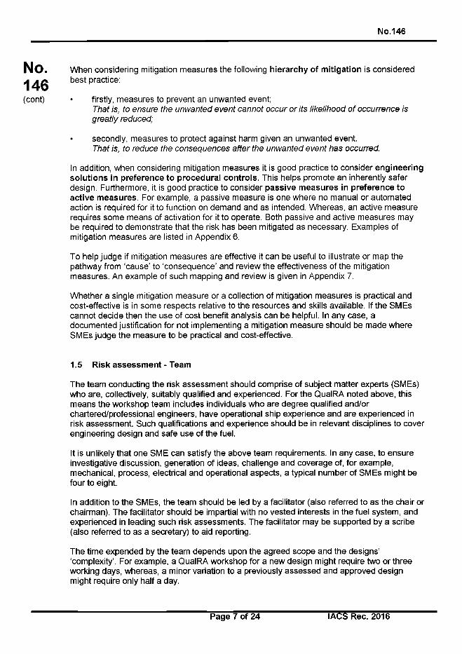
No.146
No.146(cont)
When considering mitigation measures the following h ie ra rchy o f m itiga tion is considered best practice:
• firstly, measures to prevent an unwanted event;T h a t is, to e n s u re th e u n w a n te d e v e n t c a n n o t o c c u r o r its lik e lih o o d o f o c c u rre n c e is
g re a tly re d u c e d ;
• secondly, measures to protect against harm given an unwanted event.T h a t is, to re d u c e th e c o n s e q u e n c e s a f te r th e u n w a n te d e v e n t h a s o ccu rred .
In addition, when considering mitigation measures it is good practice to consider eng ineering so lu tio n s in p re ference to p rocedura l con tro ls . This helps promote an inherently safer design. Furthermore, it is good practice to consider passive m easures in p re ference to active m easures. For example, a passive measure is one where no manual or automated action is required for it to function on demand and as intended. Whereas, an active measure requires some means of activation for it to operate. Both passive and active measures may be required to demonstrate that the risk has been mitigated as necessary. Examples of mitigation measures are listed in Appendix 6.
To help judge if mitigation measures are effective it can be useful to illustrate or map the pathway from ‘cause’ to ‘consequence’ and review the effectiveness of the mitigation measures. An example of such mapping and review is given in Appendix 7.
Whether a single mitigation measure or a collection of mitigation measures is practical and cost-effective is in some respects relative to the resources and skills available. If the SMEs cannot decide then the use of cost benefit analysis can be helpful. In any case, a documented justification for not implementing a mitigation measure should be made where SMEs judge the measure to be practical and cost-effective.
1.5 Risk assessment - Team
The team conducting the risk assessment should comprise of subject matter experts (SMEs) who are, collectively, suitably qualified and experienced. For the QuaIRA noted above, this means the workshop team includes individuals who are degree qualified and/or chartered/professional engineers, have operational ship experience and are experienced in risk assessment. Such qualifications and experience should be in relevant disciplines to cover engineering design and safe use of the fuel.
It is unlikely that one SME can satisfy the above team requirements. In any case, to ensure investigative discussion, generation of ideas, challenge and coverage of, for example, mechanical, process, electrical and operational aspects, a typical number of SMEs might be four to eight.
In addition to the SMEs, the team should be led by a facilitator (also referred to as the chair or chairman). The facilitator should be impartial with no vested interests in the fuel system, and experienced in leading such risk assessments. The facilitator may be supported by a scribe (also referred to as a secretary) to aid reporting.
The time expended by the team depends upon the agreed scope and the designs’ ‘complexity’. For example, a QuaIRA workshop for a new design might require two or three working days, whereas, a m inor variation to a previously assessed and approved design might require only half a day.
Page 7 of 24 I ACS Rec. 2016
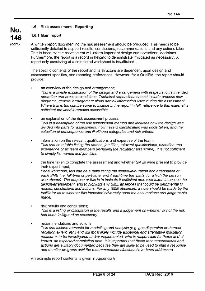
No.146
1.6 Risk assessment - Reporting
1.6.1 Main report
A written report documenting the risk assessment should be produced. This needs to be sufficiently detailed to support results, conclusions, recommendations and any actions taken. This is because the assessment will inform important design and operational decisions. Furthermore, the report is a record in helping to demonstrate ‘mitigated as necessary’. A report only consisting of a completed worksheet is insufficient.
The specific contents of the report and its structure are dependent upon design and assessment specifics, and reporting preferences. However, for a QuaIRA, the report should provide:
• an overview of the design and arrangement;This is a s im p le e x p la n a tio n o f th e d e s ig n a n d a r ra n g e m e n t w ith re s p e c ts to its in te n d e d
o p e ra tio n a n d p ro c e s s co n d ition s. T e c h n ic a l a p p e n d ic e s s h o u ld in c lu d e p ro c e s s flo w
d ia g ra m s , g e n e ra l a r ra n g e m e n t p la n s a n d a ll in fo rm a tio n u s e d d u rin g th e a s s e s s m e n t.
W h e re th is is to o c u m b e rs o m e to in c lu d e in th e re p o rt in full, re fe re n c e to th is m a te r ia l is
su ffic ie n t p ro v id e d it re m a in s a c c e s s ib le .
• an explanation of the risk assessment process;T h is is a d esc rip tio n o f th e risk a s s e s s m e n t m e th o d a n d in c lu d e s h o w th e d e s ig n w a s
d iv id e d in to p a rts fo r a s s e s s m e n t, h o w h a z a r d id e n tifica tio n w a s u n d e rta k e n , a n d th e
s e le c tio n o f c o n s e q u e n c e a n d lik e lih o o d c a te g o r ie s a n d r is k crite ria .
• information on the relevant qualifications and expertise of the team;T h is c a n b e a ta b le lis ting th e n a m e s , jo b titles, re le v a n t q u a lifica tio n s , e x p e rtis e a n d
e x p e r ie n c e o f a ll te a m m e m b e rs (inc lu d in g th e fa c ilita to r a n d sc rib e ). It is n o t su ffic ien t
to s im p ly lis t n a m e s a n d jo b titles.
• the time taken to complete the assessment and whether SMEs were present to provide their expert input;F o r a w o rksh o p , th is c a n b e a ta b le lis ting th e s c h e d u le /d u ra tio n a n d a tte n d a n c e o f
e a c h S M E (i.e . fu ll-tim e o r p a rt-tim e , a n d i f p a r t-t im e th e ‘p a r ts ’ fo r w h ich th e p e rs o n
w a s a b s e n t). T h e p u rp o s e o f th is is to in d ic a te i f su ffic ie n t tim e w a s ta k e n to a s s e s s th e
d e s ig n /a rra n g e m e n t, a n d to h ig h lig h t a n y S M E a b s e n c e s th a t c o u ld b e d e tr im e n ta l to
resu lts , co n c lu s io n s a n d ac tio n s . F o r a n y S M E a b s e n c e s , a n o te s h o u ld b e m a d e b y th e
fa c ilita to r a s to w h e th e r th is im p a c te d a d v e rs e ly u p o n th e a s s u m p tio n s a n d ju d g e m e n ts
m a d e .
• risk results and conclusions;This is a lis ting o r d is cu ss io n o f th e re su lts a n d a ju d g e m e n t o n w h e th e r o r n o t th e risk
h a s b e e n ‘m itig a te d a s n e c e s s a ry ’.
• recommendations and actions.T h is c a n in c lu d e re q u e s ts fo r m o d e llin g a n d a n a ly s is (e .g . g a s d is p e rs io n o r th e rm a l
ra d ia tio n ex te n t, e tc .) a n d w ill m o s t lik e ly in c lu d e a d d itio n a l a n d a lte rn a tiv e m itig a tio n
m e a s u re s to b e in v e s tig a te d a n d /o r im p le m e n te d , w h o is re s p o n s ib le fo r th e s e an d , i f
kn o w n , a n e x p e c te d c o m p le tio n d a te . It is im p o rta n t th a t th e s e re c o m m e n d a tio n s a n d
a c tio n s a re s u ita b ly d o c u m e n te d b e c a u s e th e y a re lik e ly to b e u s e d to p la n a re s p o n s e
a n d m o n ito r p ro g re s s until th e re c o m m e n d a tio n s /a c tio n s h a v e b e e n a d d re s s e d .
An example report contents is given in Appendix 8.
No.146(cont)
Page 8 of 24 I ACS Rec. 2016
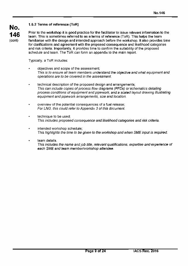
No.146
No.146(cont)
1.6.2 Terms of reference (ToR)
Prior to the workshop it is good practice for the facilitator to issue relevant information to the team. This is sometimes referred to as a terms of reference (ToR). This helps the team familiarise with the design and intended approach before the workshop. It also provides time for clarifications and agreement with the proposed consequence and likelihood categories and risk criteria. Importantly, it provides time to confirm the suitability of the proposed schedule and team. The ToR can form an appendix to the main report.
Typically, a ToR includes:
objectives and scope of the assessment;This is to e n s u re a ll te a m m e m b e rs u n d e rs ta n d th e o b jec tive a n d w h a t e q u ip m e n t a n d
o p e ra tio n s a re to b e c o v e re d in th e asse ssm en t.
technical description of the proposed design and arrangements;This ca n inc lu d e co p ies o f p ro c e s s flow d ia g ra m s (P F D s ) o r sc h e m a tic s d etailing
p ro c e s s conditions o f e q u ip m e n t a n d p ip ew o rk , a n d a s c a le d la y o u t d raw in g illustrating
e q u ip m e n t a n d p ip e w o rk a rra n g e m e n ts , s ize a n d location .
overview of the potential consequences of a fuel release;F o r L N G , this c o u ld re fe r to A p p e n d ix 3 o f th is d ocum en t.
technique to be used;This in c lu d es p ro p o s e d c o n s e q u e n c e a n d lik e lih o o d c a te g o rie s a n d risk criteria.
intended workshop schedule;This h igh lights th e tim e to b e g iv e n to th e w o rksho p a n d w h e n S M E in p u t is requ ired .
team details.This in c lu d es th e n a m e a n d jo b title, re le v a n t q ualifications, ex p e rtis e a n d e x p e rie n c e o f
e a c h S M E a n d te a m m e m b e r/w o rk s h o p a tte n d e e .
Page 9 of 24 I ACS Rec. 2016
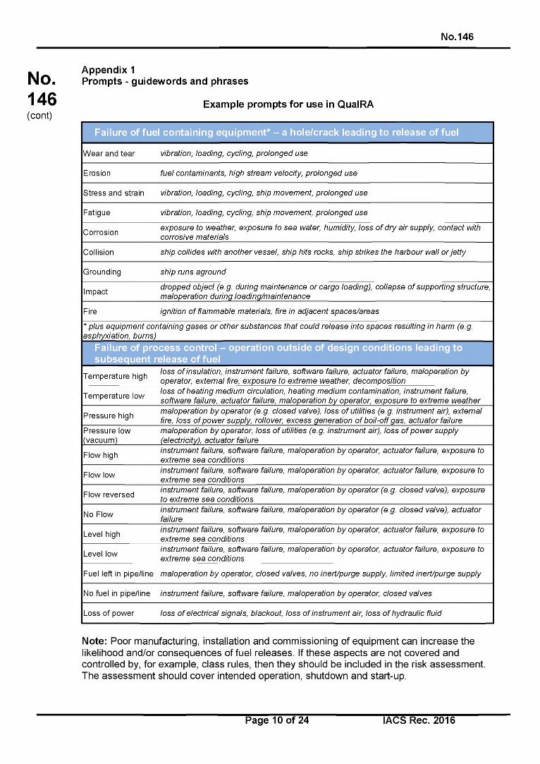
No.146
No.146(cont)
Appendix 1Prompts - guidewords and phrases
Example prompts for use in QuaIRA
Failure of fuel containing equipment* - a hole/crack leading to release of fuel
Wear and tear vibration, loading, cycling, p ro lo n g ed use
Erosion fu e l contam inants, high stream velocity, p ro lo n ged use
Stress and strain vibration, loading, cycling, ship m o vem ent, p ro lo n ged use
Fatigue vibration, loading, cycling, ship m o vem ent, p ro lo n ged use
Corrosionexpo sure to w eather, exposure to s e a water, hum idity, loss o f d ry a ir supply, contact with
corrosive m ateria ls
Collision ship collides with a n o th e r vessel, ship hits rocks, ship strikes the h arb o u r w all o r je tty
Grounding ship runs agro u nd
Impactd ro pp ed ob ject (e.g . during m a in ten a n c e o r cargo loading), co llapse o f supporting structure,
m alo p eration during lo a d in g /m a in te n a n c e
Fire ignition o f flam m ab le m ateria ls , fire in ad jacen t s p ac es /a re as
* plus eq u ip m en t contain ing g ase s o r o th er substances that could re le a s e into sp aces resu lting in h arm (e.g.
asphyxiation , burns)
Failure of process control - operation outside of design conditions leading to subsequent release of fuel
Temperature highloss o f insulation, ins tru m en t failure, so ftw are failure, ac tu a to r failure, m alo p eration by
operator, ex tern a l fire, exp o su re to ex tre m e w eather, decom position
Temperature lowloss o f h ea tin g m ed iu m circulation, h ea tin g m ed iu m contam ination , ins tru m en t failure,
so ftw are failure, ac tu a to r failure, m alo p eration b y operator, expo sure to ex tre m e w e a th e r
Pressure highm alo p eration b y o p e ra to r (e .g . c lo sed valve), loss o f utilities (e .g . ins tru m en t air), ex terna l
fire, loss o f p o w e r supply, rollover, excess gen era tion o f bo il-o ff g as, ac tu a to r failure
Pressure low (vacuum)
m alo p eration b y operator, loss o f utilities (e .g . instrum ent air), loss o f p o w e r supply
(electricity), ac tu a to r failure
Flow highins trum ent failure, so ftw are failure, m alo p eration b y operator, a c tu a to r failure, expo sure to
ex tre m e s e a conditions
Flow lowins trum ent failure, so ftw are failure, m alo p eration b y operator, a c tu a to r failure, expo sure to
ex tre m e s e a conditions
Flow reversedins trum ent failure, so ftw are failure, m alo p eration b y o p e ra to r (e .g . c lo sed va lve), exposure
to ex tre m e s e a conditions
No Flowins trum ent failure, so ftw are failure, m alo p eration b y o p e ra to r (e .g . c lo sed va lve), ac tu a to r
failure
Level highins trum ent failure, so ftw are failure, m alo p eration b y operator, a c tu a to r failure, expo sure to
ex tre m e s e a conditions
Level lowins trum ent failure, so ftw are failure, m alo p eration b y operator, a c tu a to r failure, expo sure to
ex tre m e s e a conditions
Fuel left in pipe/line m alo p eration b y operator, c lo sed valves, no ine rt/pu rg e supply, lim ited ine rt/pu rg e supply
No fuel in pipe/line ins trum ent failure, so ftw are failure, m a lo p eration b y operator, c lo sed valves
Loss of power loss o f e lectrica l signals, b lackout, loss o f ins tru m en t air, loss o f hydrau lic fluid
Note: Poor manufacturing, installation and commissioning of equipment can increase the likelihood and/or consequences of fuel releases. If these aspects are not covered and controlled by, for example, class rules, then they should be included in the risk assessment. The assessment should cover intended operation, shutdown and start-up.
Page 10 of 24 I ACS Rec. 2016
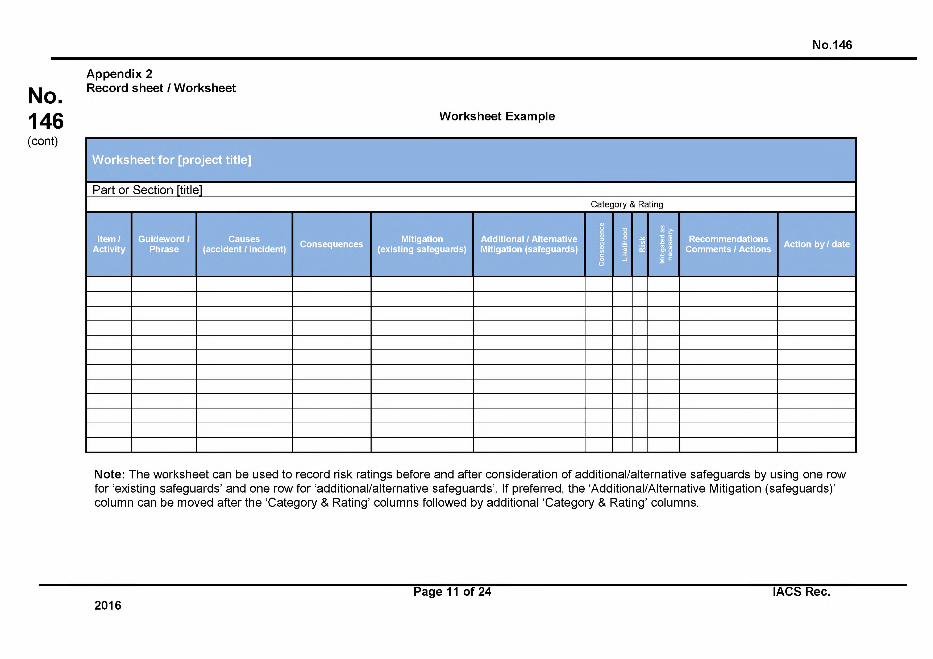
A pp e n d ix 2Record sheet / W orksheet
N o.146
No.146(cont)
W orkshee t Exam ple
W orkshee t fo r [p ro je c t title ]
Part or Section [titlelCategory & Rating
Item / Activity
Guideword / Phrase
Causes(accident / incident)
ConsequencesMitigation
(existing safeguards)Additional / Alternative Mitigation (safeguards)
Co
ns
eq
ue
nc
e
Lik
eli
ho
od
Ris
k
Mit
iga
ted
as
ne
ce
ss
ary
Recommendations Comments / Actions
Action by / date
Note: The worksheet can be used to record risk ratings before and after consideration of additional/alternative safeguards by using one row for ‘existing safeguards’ and one row for ‘additional/alternative safeguards’. If preferred, the ‘Additional/Alternative Mitigation (safeguards)’ column can be moved after the ‘Category & Rating’ columns followed by additional ‘Category & Rating’ columns.
2016Page 11 o f 24 IACS Rec.
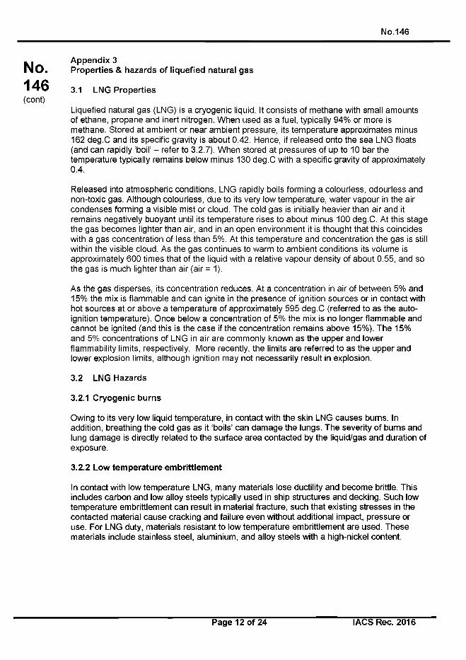
N o.146
No.146(cont)
A p p e n d ix 3P roperties & hazards o f lique fied natura l gas
3.1 LNG P roperties
Liquefied natural gas (LNG) is a cryogenic liquid. It consists of methane with small amounts of ethane, propane and inert nitrogen. When used as a fuel, typically 94% or more is methane. Stored at ambient or near ambient pressure, its temperature approximates minus 162 deg.C and its specific gravity is about 0.42. Hence, if released onto the sea LNG floats (and can rapidly ‘boil’ - refer to 3.2.7). When stored at pressures of up to 10 bar the temperature typically remains below minus 130 deg.C with a specific gravity of approximately0.4.
Released into atmospheric conditions, LNG rapidly boils forming a colourless, odourless and non-toxic gas. Although colourless, due to its very low temperature, water vapour in the air condenses forming a visible mist or cloud. The cold gas is initially heavier than air and it remains negatively buoyant until its temperature rises to about minus 100 deg.C. At this stage the gas becomes lighter than air, and in an open environment it is thought that this coincides with a gas concentration of less than 5%. At this temperature and concentration the gas is still within the visible cloud. As the gas continues to warm to ambient conditions its volume is approximately 600 times that of the liquid with a relative vapour density of about 0.55, and so the gas is much lighter than air (air = 1).
As the gas disperses, its concentration reduces. At a concentration in air of between 5% and 15% the mix is flammable and can ignite in the presence of ignition sources or in contact with hot sources at or above a temperature of approximately 595 deg.C (referred to as the autoignition temperature). Once below a concentration of 5% the mix is no longer flammable and cannot be ignited (and this is the case if the concentration remains above 15%). The 15% and 5% concentrations of LNG in air are commonly known as the upper and lower flammability limits, respectively. More recently, the limits are referred to as the upper and lower explosion limits, although ignition may not necessarily result in explosion.
3.2 LNG Hazards
3.2.1 C ryogen ic bu rns
Owing to its very low liquid temperature, in contact with the skin LNG causes burns. In addition, breathing the cold gas as it ‘boils’ can damage the lungs. The severity o f burns and lung damage is directly related to the surface area contacted by the liquid/gas and duration of exposure.
3.2.2 Low tem pera tu re em brittlem en t
In contact with low temperature LNG, many materials lose ductility and become brittle. This includes carbon and low alloy steels typically used in ship structures and decking. Such low temperature embrittlement can result in material fracture, such that existing stresses in the contacted material cause cracking and failure even w ithout additional impact, pressure or use. For LNG duty, materials resistant to low temperature embrittlement are used. These materials include stainless steel, aluminium, and alloy steels with a high-nickel content.
Page 12 of 24 I ACS Rec. 2016
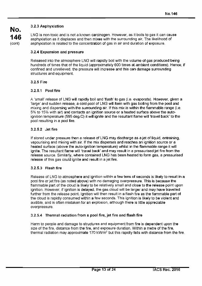
No. 146
No.146(cont)
3.2.3 Asphyxiation
LNG is non-toxic and is not a known carcinogen. However, as it boils to gas it can cause asphyxiation as it displaces and then mixes with the surrounding air. The likelihood of asphyxiation is related to the concentration of gas in air and duration of exposure.
3.2.4 Expansion and pressure
Released into the atmosphere LNG will rapidly boil with the volume of gas produced being hundreds of times that of the liquid (approximately 600 times at ambient conditions). Hence, if confined and unrelieved, the pressure will increase and this can damage surrounding structures and equipment.
3.2.5 Fire
3.2.5.1 Pool fire
A ‘small’ release of LNG will rapidly boil and ‘flash’ to gas (i.e. evaporate). However, given a ‘large’ and sudden release, a cold pool of LNG will form with gas boiling from the pool and mixing and dispersing with the surrounding air. If this mix is within the flammable range (i.e. 5% to 15% with air) and contacts an ignition source or a heated surface above the autoignition temperature (595 deg.C) it will ignite and the resultant flame will ‘travel back’ to the pool resulting in a pool fire.
3.2.5.2 Jet fire
If stored under pressure then a release of LNG may discharge as a je t of liquid, entraining, vapourising and mixing with air. If the mix disperses and reaches an ignition source or a heated surface (above the auto-ignition temperature) whilst in the flammable range it will ignite. The resultant flame will ‘travel back’ and may result in a pressurised je t fire from the release source. Similarly, where contained LNG has been heated to form gas, a pressurised release of this gas could ignite and result in a je t fire.
3.2.5.3 Flash fire
Release of LNG to atmosphere and ignition within a few tens of seconds is likely to result in a pool fire or je t fire (as noted above) with no damaging overpressure. This is because the flammable part of the cloud is likely to be relatively small and close to the release point upon ignition. However, if ignition is delayed, the gas cloud will be larger and may have travelled further from the release point. Ignition will then result in a flash fire as the flammable part of the cloud is rapidly consumed within a few seconds. This ignition is likely to be violent and audible, and is often mistaken for an explosion, although there is little appreciable overpressure.
3.2.5.4 Thermal radiation from a pool fire, jet fire and flash fire
Harm to people and damage to structures and equipment from fire is dependent upon the size of the fire, distance from the fire, and exposure duration. Within a metre of the fire, thermal radiation may approximate 170 kW/m2 but this rapidly falls with distance from the fire.
Page 13 of 24 I ACS Rec. 2016
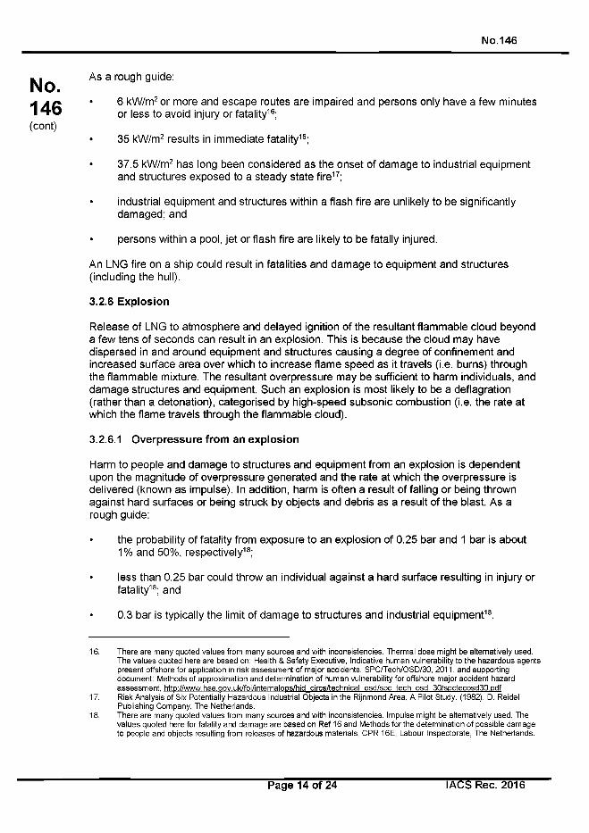
No.146
No.146(cont)
As a rough guide:
• 6 kW/m2 or more and escape routes are impaired and persons only have a few minutes or less to avoid injury or fatality16;
• 35 kW/m2 results in immediate fatality16;
• 37.5 kW/m2 has long been considered as the onset of damage to industrial equipment and structures exposed to a steady state fire17;
• industrial equipment and structures within a flash fire are unlikely to be significantly damaged; and
• persons within a pool, je t or flash fire are likely to be fatally injured.
An LNG fire on a ship could result in fatalities and damage to equipment and structures (including the hull).
3.2.6 Explosion
Release of LNG to atmosphere and delayed ignition of the resultant flammable cloud beyond a few tens of seconds can result in an explosion. This is because the cloud may have dispersed in and around equipment and structures causing a degree of confinement and increased surface area over which to increase flame speed as it travels (i.e. burns) through the flammable mixture. The resultant overpressure may be sufficient to harm individuals, and damage structures and equipment. Such an explosion is most likely to be a deflagration (rather than a detonation), categorised by high-speed subsonic combustion (i.e. the rate at which the flame travels through the flammable cloud).
3.2.6.1 Overpressure from an explosion
Harm to people and damage to structures and equipment from an explosion is dependent upon the magnitude of overpressure generated and the rate at which the overpressure is delivered (known as impulse). In addition, harm is often a result of falling or being thrown against hard surfaces or being struck by objects and debris as a result of the blast. As a rough guide:
• the probability of fatality from exposure to an explosion of 0.25 bar and 1 bar is about1% and 50%, respectively18;
• less than 0.25 bar could throw an individual against a hard surface resulting in injury or fatality18; and
• 0.3 bar is typically the limit of damage to structures and industrial equipment18.
16. There are many quoted values from many sources and with inconsistencies. Thermal dose might be alternatively used. The values quoted here are based on: Health & Safety Executive, Indicative human vulnerability to the hazardous agents present offshore for application in risk assessment of major accidents, SPC/Tech/OSD/30, 2011, and supporting document: Methods of approximation and determination of human vulnerability for offshore major accident hazard assessment, http://www.hse.aov.uk/foi/internaloDs/hid circs/technical osd/soc tech osd 30/spctecosd30.pdf
17. Risk Analysis of Six Potentially Hazardous Industrial Objects in the Rijnmond Area, A Pilot Study. (1982). D. Reidel Publishing Company, The Netherlands.
18. There are many quoted values from many sources and with inconsistencies. Impulse might be alternatively used. The values quoted here for fatality and damage are based on Ref 16 and Methods for the determination of possible damage to people and objects resulting from releases of hazardous materials, CPR 16E, Labour Inspectorate, The Netherlands.
Page 14 of 24 I ACS Rec. 2016
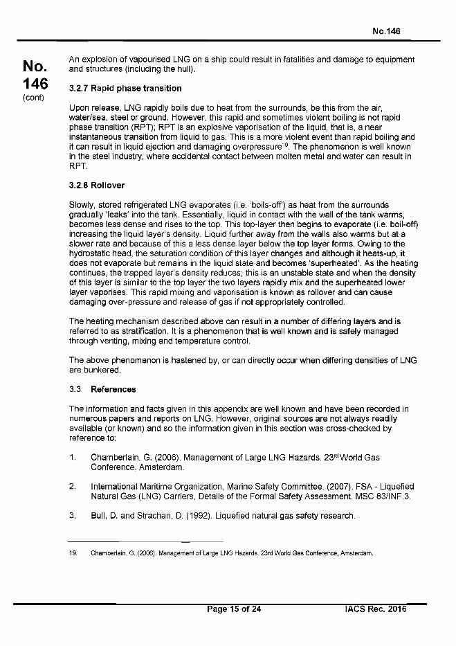
No. 146
No.146(cont)
An explosion of vapourised LNG on a ship could result in fatalities and damage to equipment and structures (including the hull).
3.2.7 Rapid phase transition
Upon release, LNG rapidly boils due to heat from the surrounds, be this from the air, water/sea, steel or ground. However, this rapid and sometimes violent boiling is not rapid phase transition (RPT); RPT is an explosive vaporisation of the liquid, that is, a near instantaneous transition from liquid to gas. This is a more violent event than rapid boiling and it can result in liquid ejection and damaging overpressure19. The phenomenon is well known in the steel industry, where accidental contact between molten metal and water can result in RPT.
3.2.8 Rollover
Slowly, stored refrigerated LNG evaporates (i.e. ‘boils-off’) as heat from the surrounds gradually ‘leaks’ into the tank. Essentially, liquid in contact with the wall of the tank warms, becomes less dense and rises to the top. This top-layer then begins to evaporate (i.e. boil-off) increasing the liquid layer’s density. Liquid further away from the walls also warms but at a slower rate and because of this a less dense layer below the top layer forms. Owing to the hydrostatic head, the saturation condition of this layer changes and although it heats-up, it does not evaporate but remains in the liquid state and becomes ‘superheated’. As the heating continues, the trapped layer’s density reduces; this is an unstable state and when the density of this layer is similar to the top layer the two layers rapidly mix and the superheated lower layer vaporises. This rapid mixing and vaporisation is known as rollover and can cause damaging over-pressure and release of gas if not appropriately controlled.
The heating mechanism described above can result in a number of differing layers and is referred to as stratification. It is a phenomenon that is well known and is safely managed through venting, mixing and temperature control.
The above phenomenon is hastened by, or can directly occur when differing densities of LNG are bunkered.
3.3 References
The information and facts given in this appendix are well known and have been recorded in numerous papers and reports on LNG. However, original sources are not always readily available (or known) and so the information given in this section was cross-checked by reference to:
1. Chamberlain, G. (2006). Management of Large LNG Hazards. 23rd World Gas Conference, Amsterdam.
2. International Maritime Organization, Marine Safety Committee. (2007). FSA - Liquefied Natural Gas (LNG) Carriers, Details of the Formal Safety Assessment. MSC 83/INF.3.
3. Bull, D. and Strachan, D. (1992). Liquefied natural gas safety research.
19. Chamberlain, G. (2006). Management of Large LNG Hazards. 23rd World Gas Conference, Amsterdam.
Page 15 of 24 I ACS Rec. 2016
No.146
No.146(cont)
4. Sheats, D. & Capers, M. (1999). Density Stratification in LNG Storage. Cold Facts, 15/2.
5. Bashiri, A. & Fatehnejad, L. (2006). Modeling and Simulation of Rollover in LNG Storage Tanks. 23rd World Gas Conference, Amsterdam.
Reference can also be made to ISGOTT (International Safety Guide for Oil Tankers and Terminals) Publication (2009) - Report on the Effects of Fire on LNG Carrier Containment Systems.
Page 16 of 24 I ACS Rec. 2016
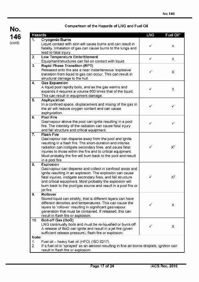
No.146
No.146(cont)
Comparison of the Hazards of LNG and Fuel Oil
Hazards LNG Fuel Oil11. Cryogenic Burns
Liquid contact with skin will cause burns and can result in fatality. Inhalation of gas can cause burns to the lungs and lead to fatal injury.
X X
2. Low Temperature EmbrittlementEquipment/structures can fail on contact with liquid.
X X
3. Rapid Phase Transition (RPT)Released onto the sea a near instantaneous ‘explosive’ transition from liquid to gas can occur. This can result in structural damage to the hull.
X X
4. Gas ExpansionA liquid pool rapidly boils, and as the gas warms and expands it requires a volume 600 times that of the liquid. This can result in equipment damage.
X X
5. AsphyxiationIn a confined space, displacement and mixing of the gas in the air will reduce oxygen content and can cause asphyxiation.
X X
6. Pool FireGas/vapour above the pool can ignite resulting in a pool fire. The intensity of the radiation can cause fatal injury and fail structure and critical equipment.
X X
7. Flash FireGas/vapour can disperse away from the pool and ignite resulting in a flash fire. The short-duration and intense radiation can instigate secondary fires, and cause fatal injuries to those within the fire and to critical equipment. Most probably the fire will burn back to the pool and result in a pool fire.
X X2
8. ExplosionGas/vapour can disperse and collect in confined areas and ignite resulting in an explosion. The explosion can cause fatal injuries, instigate secondary fires, and fail structure and critical equipment. Most probably the explosion will burn back to the pool/gas source and result in a pool fire or je t fire.
X X2
9. RolloverStored liquid can stratify, that is different layers can have different densities and temperatures. This can cause the layers to ‘rollover’ resulting in significant gas/vapour generation that must be contained. If released, this can result in flash fire or explosion.
X X
10. Boil-off Gas (BoG)LNG continually boils and must be re-liquefied or burnt-off. A release of BoG can ignite and result in a je t fire (given sufficient release pressure), flash fire or explosion.
X X
Note:1. Fuel oil - heavy fuel oil (HFO) (ISO 8217).2. If a fuel oil is ‘sprayed’ as an aerosol resulting in fine air-borne droplets, ignition can
result in flash fire or explosion.
Page 17 of 24 I ACS Rec. 2016
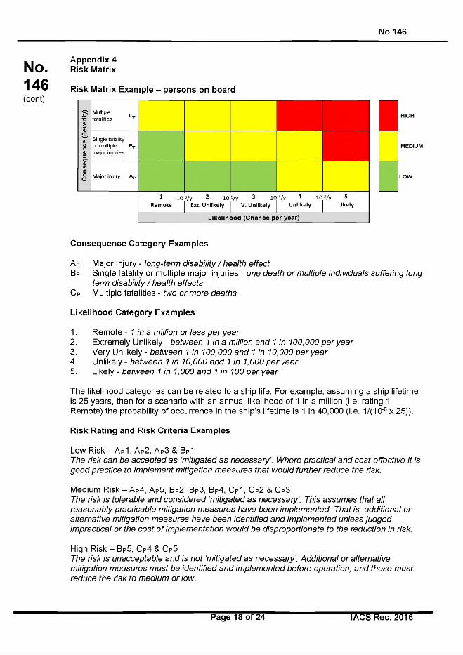
N o.146
No.146(cont)
Appendix 4 Risk Matrix
Risk Matrix Example - persons on board
HIGH
MEDIUM
LOW
Consequence Category Examples
A P Major injury - lo n g -te rm d is a b ility / h e a lth e ffe c t
Bp Single fatality or multiple major injuries - o n e d e a th o r m u ltip le in d iv id u a ls su ffe r in g lo n g
te rm d is ab ility / h e a lth e ffe c ts
Cp Multiple fatalities - tw o o r m o re d e a th s
Likelihood Category Examples
1. Remote - 1 in a m illion o r le s s p e r y e a r
2. Extremely Unlikely - b e tw e e n 1 in a m illion a n d 1 in 1 0 0 ,0 0 0 p e r y e a r
3. Very Unlikely - b e tw e e n 1 in 1 0 0 ,0 0 0 a n d 1 in 1 0 ,0 0 0 p e r y e a r
4 . Unlikely - b e tw e e n 1 in 1 0 ,0 0 0 a n d 1 in 1 ,0 0 0 p e r y e a r
5. Likely - b e tw e e n 1 in 1 ,0 0 0 a n d 1 in 1 0 0 p e r y e a r
The likelihood categories can be related to a ship life. For example, assuming a ship lifetime is 25 years, then for a scenario with an annual likelihood of 1 in a million (i.e. rating 1 Remote) the probability of occurrence in the ship’s lifetime is 1 in 40,000 (i.e. 1/(1 O'6 x 25)).
Risk Rating and Risk Criteria Examples
Low R is k -A p 1 , A P2, Ap3 & BP1T h e risk c a n b e a c c e p te d a s ‘m itig a te d a s n e c e s s a ry ’. W h e re p ra c tic a l a n d c o s t-e ffe c tiv e it is
g o o d p ra c tic e to im p le m e n t m itig a tio n m e a s u re s th a t w o u ld fu r th e r re d u c e th e risk.
Medium Risk — Ap4, Ap5, Bp2, В р З , Bp4, Cp1, Cp2 & Cp3T h e risk is to le ra b le a n d c o n s id e re d ‘m itig a te d a s n e c e s s a ry ’. T h is a s s u m e s th a t a ll
re a s o n a b ly p ra c tic a b le m itig a tio n m e a s u re s h a v e b e e n im p le m e n te d . T h a t is, a d d itio n a l o r
a lte rn a tiv e m itig a tio n m e a s u re s h a v e b e e n id e n tifie d a n d im p le m e n te d u n le s s ju d g e d
im p ra c tic a l o r th e c o s t o f im p le m e n ta tio n w o u ld b e d is p ro p o rtio n a te to th e re d u c tio n in risk.
High Risk - Bp5, Cp4 & Cp5T h e risk is u n a c c e p ta b le a n d is n o t ‘m itig a te d a s n e c e s s a ry ’. A d d itio n a l o r a lte rn a tiv e
m itig a tio n m e a s u re s m u s t b e id e n tif ie d a n d im p le m e n te d b e fo re o p e ra tio n , a n d th e s e m u s t
re d u c e th e risk to m e d iu m o r low .
Page 18 of 24 lA C SR ec. 2016
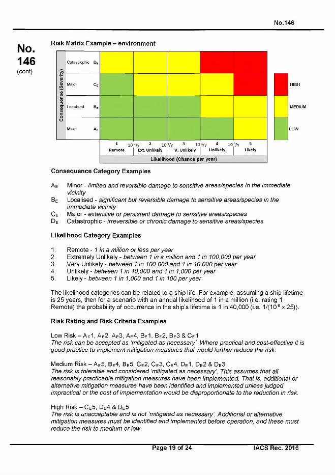
No.146
No.146(cont)
Risk Matrix Example - environment
Co
nseq
uen
ce (
Sev
erity
)Catastrophic DE
Major CE
Localised BE
Minor A e
1 10 Remote
6/y 2 10 Ext. U n like ly
5/y 3 io
V. U n like ly
4/y 4 io
U n like lyVv 5
Likely
Likelihood (Chance per year)
Consequence Category Examples
| | HIGH
MEDIUM
LOW
A e Minor - lim ite d a n d re v e rs ib le d a m a g e to s e n s itiv e a r e a s /s p e c ie s in th e im m e d ia te
vic in ity
Be Localised - s ig n ific a n t b u t re v e rs ib le d a m a g e to s e n s itiv e a r e a s /s p e c ie s in th e
im m e d ia te v ic in ity
C e Major - e x te n s iv e o r p e rs is te n t d a m a g e to s e n s itiv e a r e a s /s p e c ie s
De Catastrophic - irre v e rs ib le o r c h ro n ic d a m a g e to s e n s itiv e a re a s /s p e c ie s
Likelihood Category Examples
1. Remote - 1 in a m illion o r le s s p e r y e a r
2. Extremely Unlikely - b e tw e e n 1 in a m illion a n d 1 in 1 0 0 ,0 0 0 p e r y e a r
3. Very Unlikely - b e tw e e n 1 in 1 0 0 ,0 0 0 a n d 1 in 1 0 ,0 0 0 p e r y e a r
4. Unlikely - b e tw e e n 1 in 1 0 ,0 0 0 a n d 1 in 1 ,0 0 0 p e r y e a r
5. Likely - b e tw e e n 1 in 1 ,0 0 0 a n d 1 in 1 0 0 p e r y e a r
The likelihood categories can be related to a ship life. For example, assuming a ship lifetime is 25 years, then for a scenario with an annual likelihood of 1 in a million (i.e. rating 1 Remote) the probability of occurrence in the ship’s lifetime is 1 in 40,000 (i.e. 1/(1 O'6 x 25)).
Risk Rating and Risk Criteria Examples
Low Risk — Ae 1, Ae2, Ae3, Ae4, Be1, Be2, Be3 & C e1T h e ris k c a n b e a c c e p te d a s ‘m itig a te d a s n e c e s s a ry ’. W h e re p ra c tic a l a n d c o s t-e ffe c tiv e it is
g o o d p ra c tic e to im p le m e n t m itig a tio n m e a s u re s th a t w o u ld fu rth e r re d u c e th e risk.
Medium Risk — Ae5, Be4, Be5, Ce2, Ce3, Ce4, De1, De2 & De3 T h e risk is to le ra b le a n d c o n s id e re d ‘m itig a te d a s n e c e s s a ry ’. T h is a s s u m e s th a t a ll
re a s o n a b ly p ra c tic a b le m itig a tio n m e a s u re s h a v e b e e n im p le m e n te d . T h a t is, a d d itio n a l o r
a lte rn a tiv e m itig a tio n m e a s u re s h a v e b e e n id e n tifie d a n d im p le m e n te d u n le s s ju d g e d
im p ra c tic a l o r th e c o s t o f im p le m e n ta tio n w o u ld b e d is p ro p o rtio n a te to th e re d u c tio n in risk.
High Risk - Ce5, De4 & De5T h e ris k is u n a c c e p ta b le a n d is n o t ‘m itig a te d a s n e c e s s a ry ’. A d d itio n a l o r a lte rn a tiv e
m itig a tio n m e a s u re s m u s t b e id e n tif ie d a n d im p le m e n te d b e fo re o p e ra tio n , a n d th e s e m u s t
re d u c e th e risk to m e d iu m o r low .
Page 19 of 24 I ACS Rec. 2016
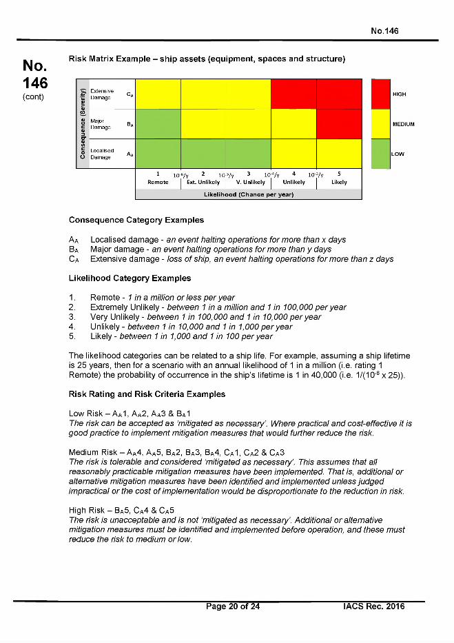
No.146
No.146(cont)
Risk Matrix Example - ship assets (equipment, spaces and structure)
Ц HIGH
MEDIUM
LOW
Consequence Category Examples
А д Localised damage - a n e v e n t h a ltin g o p e ra tio n s fo r m o re th a n x d a y s
Ba Major damage - a n e v e n t h a ltin g o p e ra tio n s fo r m o re th a n у d a y s
Ca Extensive damage - lo s s o f sh ip , a n e v e n t h a ltin g o p e ra tio n s fo r m o re th a n z d a y s
Likelihood Category Examples
1. Remote - 1 in a m illion o r le s s p e r y e a r
2. Extremely Unlikely - b e tw e e n 1 in a m illion a n d 1 in 1 0 0 ,0 0 0 p e r y e a r
3. Very Unlikely - b e tw e e n 1 in 1 0 0 ,0 0 0 a n d 1 in 1 0 ,0 0 0 p e r y e a r
4 . Unlikely - b e tw e e n 1 in 1 0 ,0 0 0 a n d 1 in 1 ,0 0 0 p e r y e a r
5. Likely - b e tw e e n 1 in 1 ,0 0 0 a n d 1 in 1 0 0 p e r y e a r
The likelihood categories can be related to a ship life. For example, assuming a ship lifetime is 25 years, then for a scenario with an annual likelihood of 1 in a million (i.e. rating 1 Remote) the probability of occurrence in the ship’s lifetime is 1 in 40,000 (i.e. 1/(1 O'6 x 25)).
Risk Rating and Risk Criteria Examples
Low Risk - А д 1 , Aa2, Aa3 & BA1T h e ris k c a n b e a c c e p te d a s ‘m itig a te d a s n e c e s s a ry ’. W h e re p ra c tic a l a n d c o s t-e ffe c tiv e it is
g o o d p ra c tic e to im p le m e n t m itig a tio n m e a s u re s th a t w o u ld fu rth e r re d u c e th e risk.
Medium Risk-AA4, А д 5 , В д 2 , В д З , В д 4 , С д 1 , С д 2 & С д ЗT h e ris k is to le ra b le a n d c o n s id e re d ‘m itig a te d a s n e c e s s a ry ’. T h is a s s u m e s th a t a ll
re a s o n a b ly p ra c tic a b le m itig a tio n m e a s u re s h a v e b e e n im p le m e n te d . T h a t is, a d d itio n a l o r
a lte rn a tiv e m itig a tio n m e a s u re s h a v e b e e n id e n tifie d a n d im p le m e n te d u n le s s ju d g e d
im p ra c tic a l o r th e c o s t o f im p le m e n ta tio n w o u ld b e d is p ro p o rtio n a te to th e re d u c tio n in risk.
High Risk - В д 5 , С д 4 & С д 5T h e ris k is u n a c c e p ta b le a n d is n o t ‘m itig a te d a s n e c e s s a ry ’. A d d itio n a l o r a lte rn a tiv e
m itig a tio n m e a s u re s m u s t b e id e n tif ie d a n d im p le m e n te d b e fo re o p e ra tio n , a n d th e s e m u s t
re d u c e th e risk to m e d iu m o r low .
Page 20 of 24 I ACS Rec. 2016
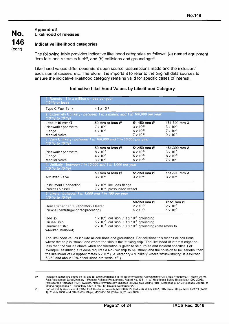
No.146
No.146(cont)
Appendix 5 Likelihood of releases
Indicative likelihood categories
The following table provides indicative likelihood categories as follows: (a) named equipment item fails and releases fuel20, and (b) collisions and groundings21.
Likelihood values differ dependent upon source, assumptions made and the inclusion/ exclusion of causes, etc. Therefore, it is important to refer to the original data sources to ensure the indicative likelihood category remains valid for specific cases of interest.
Indicative Likelihood Values by Likelihood Category
1. Remote -1 in a million or less per year (10'6/y or less)
Type C Fuel Tank <1 x 10'6
2. Extremely Unlikely(1 0 rB/ y to 10r5/y )
b e tw e e n 1 in a m il l io n a n d 1 in 1 0 0 ,0 0 0 p e r y e a r
Leak > 10 mm 0 50 mm or less 0 51-150 mm 0 151-300 mm 0Pipework / per metre FlangeManual Valve
7 x 10 '6 4 x 10 '6
3 x 10'6 5 x 10'6 7 x 10'6
3 x 10⁻⁶ 7 x 10⁻⁶ 9 x 10⁻⁶
3. Very Unlikely - b e tw e e n 1 in 1 0 0 ,0 0 0 a n d 1 in 1 0 ,0 0 0 p e r y e a r
(1 0 r6! y to 1 а 4/ у )
50 mm or less 0 51-150 mm 0 151-300 mm 0Pipework / per metre FlangeManual Valve
8 x 10"5 4 x 10"5 3 x 10"5
4 x 10'55 x 10"5 5 x 1 0 s
3 x 10⁻⁵ 8 x 10⁻⁵ 7 x 10⁻⁵
4. Unlikely - b e tw e e n 1 in 1 0 ,0 0 0 a n d 1 in 1 ,0 0 0 p e r y e a r
( 1 а 4/ у to 10r3/y )
I Actuated Valve50 mm or less 0 51-150 mm 0 151-300 mm 0 I3 x 10'4 3 x 10'4 3 x 10'4
Instrument Connection 3 x 1 0 '4 includes flangeProcess Vessel______________7x10~4 pressurised vessel5. Likely - b e tw e e n 1 in 1 ,0 0 0 a n d 1 in 1 0 0 p e r y e a r
(1 0 -V y to 10r2/y )
50-150 mm 0 >151 mm 0Heat Exchanger / Evaporator / Heater 2 x 10'3 2 x 10'3Pumps (centrifugal or reciprocating) 5 x 10'3 1 x 10'3
Ro-Pax 1 x 1 0 '2 collision / 1 x 1 0 2 groundingCruise Ship 5 x 1 0 '3 collision / 1 x 1 0 '2 groundingContainer Ship 2 x 1 0 -2 collision / 7 x 1 0 -3 grounding (data refers towrecked/stranded)
The likelihood values include all collisions and groundings. For collisions this means all collisions where the ship is ‘struck’ and where the ship is the ‘striking ship’. The likelihood of interest might be less than the values above when consideration is given to ship, route and incident specifics. For example, assuming a release requires a Ro-Pax ship to be ‘struck’ and the collision to be ‘serious’ then the likelihood value approximates 5 x 10'4 (i.e. category 4 ‘Unlikely’ where ’struck/striking’ is assumed 50/50 and about 10% of collisions are 'serious'21).
20. Indicative values are based on (a) and (b) and summarised in (c): (a) International Association of Oil & Gas Producers. (1 March 2010). Risk Assessment Data Directory - Process Release Frequencies, Report No. 434 - 1; (b) Health and Safety Executive. (1992-2006). Hydrocarbon Releases (HCR) System, https://www.hse.gov.uk/hcr3/; (c) LNG as a Marine Fuel - Likelihood of LNG Releases. Journal of Marine Engineering & Technology (JMET), Vol. 12, Issue 3, September 2013.
21. Formal Safety Assessment (FSA): FSA Container Vessels, MSC 83/21/2 (Table 3), 3 July 2007; FSA Cruise Ships, MSC 85/17/1 (Table 1), 21 July 2008; and FSA RoPax Ships, MSC 85/17/2 (Table 1), 21 July 2008.
Page 21 of 24 I ACS Rec. 2016
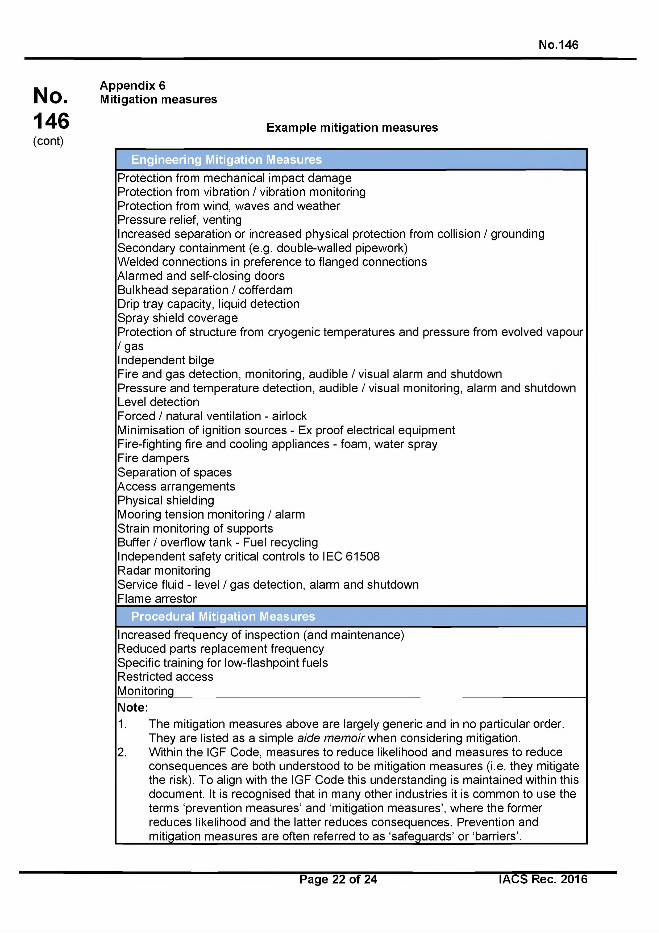
No.146
No.146(cont)
Appendix 6 Mitigation measures
Exam ple m itig a tio n m easures
E ng ineering M itiga tion M easures
Protection from mechanical impact damage Protection from vibration / vibration monitoring Protection from wind, waves and weather Pressure relief, ventingIncreased separation or increased physical protection from collision / grounding Secondary containment (e.g. double-walled pipework)Welded connections in preference to flanged connectionsAlarmed and self-closing doorsBulkhead separation / cofferdamDrip tray capacity, liquid detectionSpray shield coverageProtection of structure from cryogenic temperatures and pressure from evolved vapour/g a sIndependent bilgeFire and gas detection, monitoring, audible / visual alarm and shutdown Pressure and temperature detection, audible / visual monitoring, alarm and shutdown Level detectionForced / natural ventilation - airlockMinimisation of ignition sources - Ex proof electrical equipmentFire-fighting fire and cooling appliances - foam, water sprayFire dampersSeparation of spacesAccess arrangementsPhysical shieldingMooring tension monitoring / alarmStrain monitoring of supportsBuffer / overflow tank - Fuel recyclingIndependent safety critical controls to I EC 61508Radar monitoringService fluid - level / gas detection, alarm and shutdown Flame arrestor
P rocedura l M itiga tion M easures
Increased frequency of inspection (and maintenance)Reduced parts replacement frequency Specific training for low-flashpoint fuels Restricted accessMonitoring_____________________________________________________________________
Note:
1. The mitigation measures above are largely generic and in no particular order. They are listed as a simple a id e m e m o ir when considering mitigation.
2. Within the IGF Code, measures to reduce likelihood and measures to reduceconsequences are both understood to be mitigation measures (i.e. they mitigate the risk). To align with the IGF Code this understanding is maintained within this document. It is recognised that in many other industries it is common to use the terms ‘prevention measures’ and ‘mitigation measures’, where the former reduces likelihood and the latter reduces consequences. Prevention and mitigation measures are often referred to as ‘safeguards’ or ‘barriers’.__________
Page 22 of 24 I ACS Rec. 2016
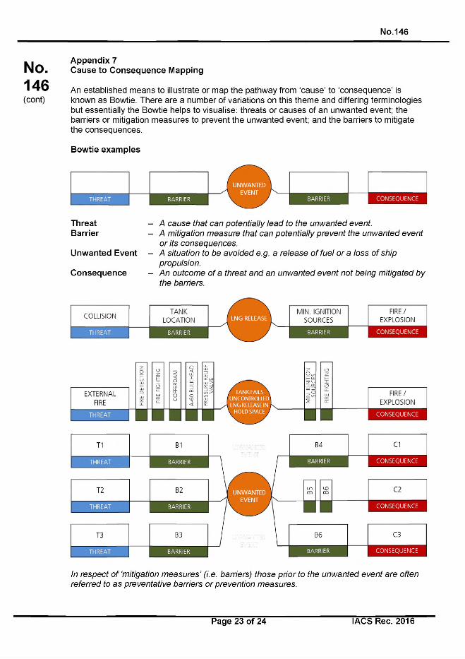
No.146
No.146(cont)
Appendix 7Cause to Consequence Mapping
An established means to illustrate or map the pathway from ‘cause’ to ‘consequence’ is known as Bowtie. There are a number of variations on this theme and differing terminologies but essentially the Bowtie helps to visualise: threats or causes of an unwanted event; the barriers or mitigation measures to prevent the unwanted event; and the barriers to mitigate the consequences.
Bowtie examples
ThreatBarrier
Unwanted Event
Consequence
A c a u s e th a t c a n p o te n tia lly le a d to th e u n w a n te d e v e n t.
A m itig a tio n m e a s u re th a t c a n p o te n tia lly p re v e n t th e u n w a n te d e v e n t
o r its c o n s e q u e n c e s .
A s itu a tio n to b e a v o id e d e .g . a re le a s e o f fu e l o r a loss o f sh ip
p ro p u ls io n .
A n o u tc o m e o f a th re a t a n d a n u n w a n te d e v e n t n o t b e in g m it ig a te d b y
th e b arrie rs .
COLLISIONTANK
LOCATION
T H R E A T B A R R IE R -ШMIN. IGNITION
SOURCESFIRE/
EXPLOSION
B A R R IE R C O N S E Q U E N C E
In re s p e c t o f ‘m itig a tio n m e a s u r e s ’ (i.e . b a rrie rs ) th o s e p r io r to th e u n w a n te d e v e n t a re o ften
re fe rre d to a s p re v e n ta tiv e b a rr ie rs o r p re v e n tio n m e a s u re s .
Page 23 of 24 I ACS Rec. 2016
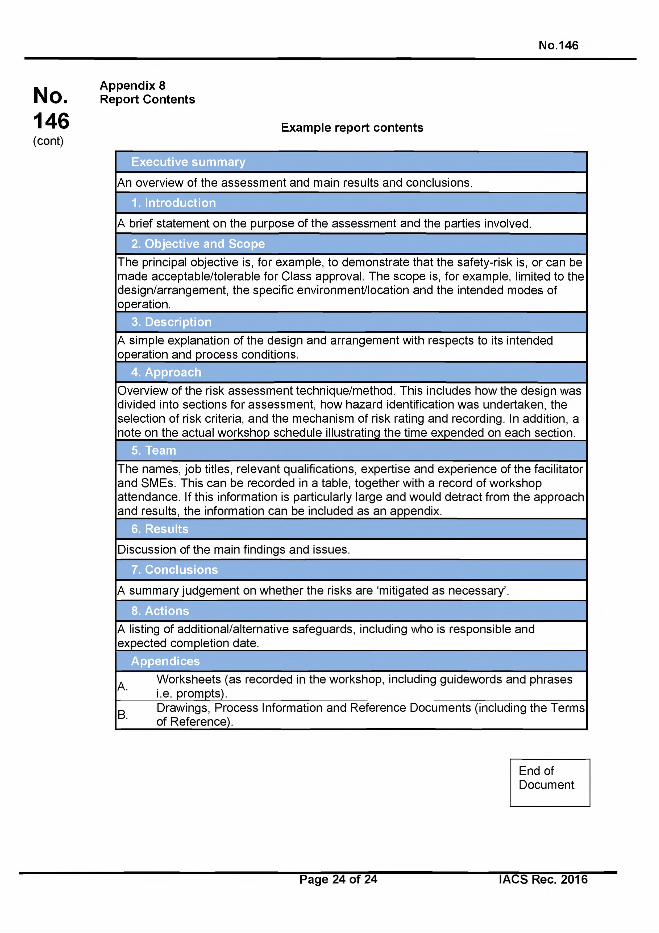
No.146
No.146(cont)
Appendix 8 Report Contents
Example report contents
|A brief statement on the purpose of the assessment and the parties involved.
2. O b jective and Scope
The principal objective is, for example, to demonstrate that the safety-risk is, or can be made acceptable/tolerable for Class approval. The scope is, for example, limited to the design/arrangement, the specific environment/location and the intended modes of operation._______________________________________________________________________
3. D escrip tion
|A simple explanation of the design and arrangement with respects to its intended [operation and process conditions.___________________________________________
4. A pproach
Overview of the risk assessment technique/method. This includes how the design was divided into sections for assessment, how hazard identification was undertaken, the selection of risk criteria, and the mechanism of risk rating and recording. In addition, a note on the actual workshop schedule illustrating the time expended on each section.
5. Team
The names, job titles, relevant qualifications, expertise and experience of the facilitator and SMEs. This can be recorded in a table, together with a record of workshop attendance. If this information is particularly large and would detract from the approach and results, the information can be included as an appendix.________________________
6. R esults
|Discussion of the main findings and issues.
|A listing of additional/alternative safeguards, including who is responsible and lexpected completion date._________ _____________________________________
A ppend ices
Worksheets (as recorded in the workshop, including guidewords and phrasesi.e. prompts)._________________________ ___________________________________Drawings, Process Information and Reference Documents (including the Terms of Reference).____________________________________________________________
End of Document
Page 24 of 24 I ACS Rec. 2016
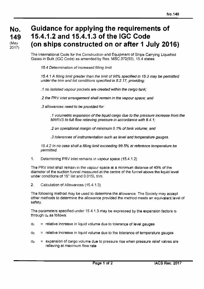
No. 149
No.149(May2017)
Guidance for applying the requirements of15.4.1.2 and 15.4.1.3 of the IGC Code(on ships constructed on or after 1 July 2016)
The International Code for the Construction and Equipment of Ships Carrying Liquefied Gases in Bulk (IGC Code) as amended by Res. MSC.370(93), 15.4 states:
1 5 .4 D e te rm in a tio n o f in c re a s e d filling lim it
1 5 .4 .1 A filling lim it g re a te r th a n th e lim it o f 9 8 % s p e c ifie d in 1 5 .3 m a y b e p e rm itte d
u n d e r th e trim a n d lis t c o n d itio n s s p e c if ie d in 8 .2 .1 7 , p ro v id in g :
. 1 n o is o la te d v a p o u r p o c k e ts a re c re a te d w ith in th e c a rg o tank;
.2 th e P R V in le t a r ra n g e m e n t s h a ll re m a in in th e v a p o u r s p a c e ; a n d
.3 a llo w a n c e s n e e d to b e p ro v id e d for:
. 1 v o lu m e tr ic e x p a n s io n o f th e liq u id c a rg o d u e to th e p re s s u re in c re a s e fro m th e
M A R V S to fu ll f lo w re lie v in g p re s s u re in a c c o rd a n c e w ith 8 .4 .1 ;
.2 a n o p e ra tio n a l m a rg in o f m in im u m 0 .1 % o f ta n k vo lu m e ; a n d
.3 to le ra n c e s o f in s tru m e n ta tio n s u c h a s le v e l a n d te m p e ra tu re g a u g e s .
1 5 .4 .2 In n o c a s e s h a ll a filling lim it e x c e e d in g 9 9 .5 % a t re fe re n c e te m p e ra tu re b e
p e rm itte d .
1. Determining PRV inlet remains in vapour space (15.4.1.2)
The PRV inlet shall remain in the vapour space at a minimum distance of 40% of the diameter of the suction funnel measured at the centre of the funnel above the liquid level under conditions of 15° list and 0.015L trim.
2. Calculation of Allowances (15.4.1.3)
The following method may be used to determine the allowance. The Society may accept other methods to determine the allowance provided the method meets an equivalent level of safety.
The parameters specified under 15.4.1.3 may be expressed by the expansion factors с и through с ц as follows:
с и = relative increase in liquid volume due to tolerance of level gauges
0 2 = relative increase in liquid volume due to the tolerance of temperature gauges
а з = expansion of cargo volume due to pressure rise when pressure relief valves arerelieving at maximum flow rate
Page 1 of 2 IACS Rec. 2017
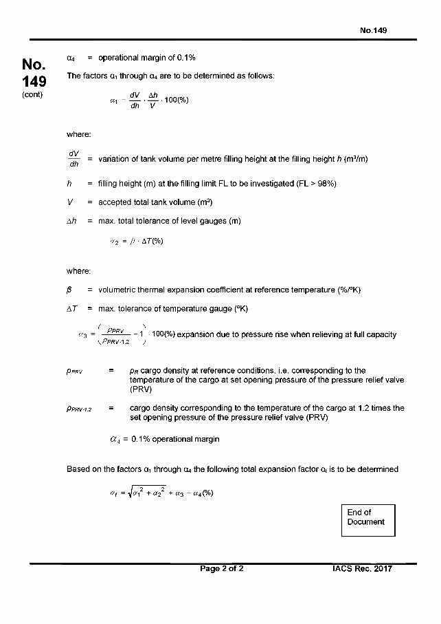
с ц = operational margin of 0.1%
The factors с и through 0 4 are to be determined as follows:
No. 149
No.149(cont) d V Ah
а л = ---------- 1 0 0 (%)1 dh V
where:
= variation of tank volume per metre filling height at the filling height h (m3/m)
h = filling height (m) at the filling limit FL to be investigated (FL > 98%)
V = accepted total tank volume (m3)
A h = max. total tolerance of level gauges (m)
« 2 = P • AT(%)
where:
/3 = volumetric thermal expansion coefficient at reference temperature (%/°K)
A T = max. tolerance of temperature gauge (°K)
a 3 = Pp r v ----- 1 - 1 0 0 (%) expansion due to pressure rise when relieving at full capacity\PRRVA2 )
P p r v = P r cargo density at reference conditions, i.e. corresponding to thetemperature of the cargo at set opening pressure of the pressure relief valve (PRV)
P p r v -1.2 = cargo density corresponding to the temperature of the cargo at 1.2 times theset opening pressure of the pressure relief valve (PRV)
Ct4 = 0.1 % operational margin
Based on the factors с и through a4 the following total expansion factor at is to be determined
I о 2a( = у a -1 + ct? 2 "T a 3 + a 4 (%)
End of Document
Page 2 of 2 IACS Rec. 2017
No.150
No.150(May2017)
Vapour pockets not in communication with cargo tank vapour / liquid domes on liquefied gas carriers
The International Code for the Construction and Equipment o f Ships Carrying Liquefied Gases in Bulk (IGC Code) as amended by Res. MSC.370(93), 8.2.17 states:
P R V s s h a ll b e c o n n e c te d to th e h ig h e s t p a r t o f th e c a rg o ta n k a b o v e d e c k le v e l. P R V s
s h a ll b e p o s it io n e d o n th e c a rg o ta n k s o th a t th e y w ill re m a in in th e v a p o u r p h a s e a t th e
filling lim it (F L ) a s d e fin e d in c h a p te r 15, u n d e r c o n d itio n s o f 1 5 ° lis t a n d 0 .0 1 5 L trim ,
w h e re L is d e fin e d in 1 .2 .3 1 .
Under normal operating conditions, the vapour space is continuous and in communication with the vapour/liquid domes where the vapour line and cargo tank pressure relief valves (PRVs) are located. However, due to the geometry of the tank there may be times when a vapour pocket can be formed in a cargo tank on a liquefied gas carrier which is not in communication with the vapour/liquid domes. The vast majority o f these conditions occur in a dynamic condition and are dissipated by the motion o f the ship. However, there can be situations where the pocket exists in a static condition, for instance, due to damage to the ship caused by an accident such as grounding or collision. Even though the IGC Code states that the PRVs should be in the vapour phase under conditions of 15° list and 0.015L trim and presumes that no isolated vapour pockets are formed within this range in principle, this scenario can occur at other trim and list values based upon the filling level o f the tank since the ship is designed to survive a damage condition up to 30° of list.
In this condition, there is the potential for liquid build-up in the vapour/liquid domes caused by a pressure differential between the isolated vapour pocket and the vapour/liquid domes resulting in a possible overflow of cargo liquid into the vapour line or into the tank PRVs.
Even though the likelihood of this situation occurring may be minimal, the consequences could be quite severe and lead up to the loss of the ship. Owners/operators of liquefied gas carriers, in consultation with the cargo containment system/cargo handling system designers, are recommended to develop emergency procedures to mitigate the risks to the vessel caused by isolated vapour pockets. These procedures should identify the condition when isolated vapour pockets can be present and contain measures to reduce or eliminate them and/or mitigate their consequences such as cargo jettisoning, transfer of cargo between tanks, and cargo vapourization/utilization based upon different scenarios following the accident, including, but not limited to, loss of power, limited ability to reduce angle o f heel or trim.
These emergency procedures are not a substitute for requirement 15.4.1.1 when determining the increased filling limits.
End of Document
Page 1 o f 1 IACS Rec. 2017
No.151
No. Recommendation for petroleum fuel treatment 151 systems for marine diesel engines(July 2017)
I Recommendation for the treatment of fuel oil on board ships
1 Application
The following requirements should apply to fuel treatment systems for oil fuelled machinery on board ships. The aim of these recommendations is to improve the operational safety of the vessel by improving reliability of the oil fuelled machinery. The requirements cover the complete fuel oil treatment system, from the fuel bunker connection through to the interface with the oil fuelled machinery; this includes fuel tanks, the fuel cleaning equipment and the fuel conditioning equipment.
This recommendation recognizes a disparity between the quality of fuel bunkered and delivered in accordance with ISO 8217 (latest revision), and the fuel quality requirements typically specified by marine diesel engine manufacturers. The performance of the system and equipment contained therein is fundamental to reducing the level of contaminants to within the oil fuelled machinery manufacturers specifications.
2 Definitions
2.1 A service tank is a fuel oil tank which contains only fuel of a quality ready for use, i.e. fuel of a grade and quality that meet the specification required by the equipment manufacturer.
2.2 Fuel oil means petroleum fuels for use in marine diesel engines.
2.3 Fuel oil treatment system means a system intended for:
- Cleaning of the fuel oil by removal of water, catalyst fines, water bound ash constituents (e.g. sodium) and particulate matter,
- Conditioning of the fuel oil to ensure efficient combustion.
2.4 Oil fuelled machinery means all machinery combusting fuel oil, including main and auxiliary engines, boilers, gas turbines.
3 System level requirements
3.1 Functional requirements
The fuel oil treatment system should reduce the level of contaminants and condition the fuel such that it ensures the fuel is ready for use by the oil-fuelled machinery and that it has no detrimental effect on the reliability and safety of such machinery.
3.2 Performance requirements
3.2.1 The capacity and arrangements of the fuel oil treatment system should be suitable for ensuring availability of treated fuel oil for the Maximum Continuous Rating (MCR) of the propulsion plant and normal operating load at sea of the generator plant.
Page 1 of 11 IACS Rec. 2017

No.151
No.151(cont)
3.2.2 The capacity and arrangements of the fuel oil treatment system should be determined on the basis of the requirements of the oil fuelled machinery manufacturer and the types of fuel: Residual Marine Fuel (RMF), Distillate Marine Fuel (DMF) to be bunkered to the ship.
3.2.3 The fuel oil treatment system should be provided with redundancy so that failure of one system will not render the other system(s) inoperative. Arrangements should ensure that any single failure in the system will not interrupt the supply o f clean fuel to machinery used for propulsion and electrical generating purposes where the fuel conditioning system is installed between fuel oil service tanks and the inlet to the combustion system.
3.2.4 Main bunker tanks should be arranged to limit the need to mix newly bunkered fuel with fuel already on-board. When mixing of fuel oil is necessary, a compatibility test should be performed prior to transfer.
3.2.5 The fuel oil at engine inlet should be of properties recommended by the engine manufacturer.
3.2.6 The maximum amount of water reaching the engine should be 0.3 % v/v or according to engine maker’s recommendations.
3.2.7 The maximum amount of catalyst fines reaching the engine should be 10 ppm Al+Si and in some instances this might rise to 15 ppm however every attempt must be made to reduce the catalyst to the lowest possible levels. Note: Particle size has a significant influence on the capacity of the centrifugal separators to lower the level of catalyst fines in the fuel, with particles of 2 microns or less being particularly difficult to remove. The presence of particles of 2 microns size or lower may cause difficulties in achieving the 10 ppm limit. Engine manufacturer recommendations should also be referred to for any further system specific recommendations.
3.3 System interfaces
3.3.1 Bunkered fuels should meet the requirements o f ISO 8217 (latest revision) or an oil- fuelled machinery consumer manufacturers’ specification.
3.3.2 Locations of sampling points
3.3.2.1 The fuel oil treatment system should be provided with sampling points.
3.3.2.2 The sampling points should meet the requirements of MEPC.1/Circ.864 ‘Guidelines for on board sampling and verification o f the sulphur content o f the fuel oil used on board ships’ and should be located as follows:
. 1 after the transfer pump discharge,
.2 before and after the fuel cleaning equipment, and
.3 after the fuel oil service tank, before any fuel change over valve,
.4 before fuel enters the oil fuelled machinery.
3.3.2.3 Sampling points should be provided at locations within the fuel oil system that enable samples of fuel oil to be taken in a safe manner.
Page 2 of 11 IACS Rec. 2017
No.151
No.151(cont)
3.3.2.4 The position of a sampling point should be such that the sample of the fuel oil is representative of the fuel oil quality passing that location within the system.
3.3.2.5 The sampling points should be located in positions as far removed as possible from any heated surface or electrical equipment so as to preclude impingement of fuel oil onto such surfaces on equipment under all operating conditions.
3.4 Verification requirements
3.4.1 Approval
3.4.1.1 Plans and documents demonstrating compliance with the requirements included in section 3.4 should be submitted for consideration.
3.4.2 Shipboard verification
3.4.2.1 The fuel oil treatment system should be inspected by the Surveyor after installation on board to confirm that the arrangement, installation and workmanship are in accordance with the equipment specification and the requirements of this REC.
3.4.2.2 The fuel oil treatment system should be provided with sampling cocks located in convenient positions e.g. at the transfer pump from the bunker tanks, before and after the centrifuges and after the service tank.
3.4.2.3 Diagram of sampling points showing sampling points location should be retained on board the ship and should be presented to the surveyor during regular surveys.
3.4.2.4 Records of fuel sample analysis according to ISO 8217 (latest revision) should be retained on board the ship and should be presented to the surveyor during regular surveys.
3.4.2.5 It is recommended that a drip sample of fuel should be taken during bunkering at the bunker manifold in accordance with ISO 3170 or 3171 and ISO 13739, where applicable.
3.4.2.6 It is recommended that once a new bunker has started to be used, a fuel system audit is performed by a responsible person on board, taking fuel samples from before and after the treatment plant and at the engine fuel rail.
4 Equipment level requirements
4.1 Fuel tanks
4.1.1 Functional requirements
4.1.1.1 Settling and service tanks for fuel oil should be designed and constructed in such a way as to direct water and sludge towards a drainage outlet.
4.1.1.2 If settling tanks are not provided, the fuel oil bunker (storage) and daily service tanks should be designed and constructed in such a way as to direct water and sludge towards a drainage outlet.
4.1.2 Performance requirements
4.1.2.1 Fuel should be maintained at a temperature commensurate with the needs of system equipment to function in accordance with manufacturers’ requirements.
Page 3 of 11 IACS Rec. 2017
No.151
No.151(cont)
4.1.2.2 A temperature controller o f PID type should be fitted to ensure that the fuel is maintained at the temperature required for optimum system performance.
4.1.3 Equipment interfaces
4.1.3.1 Open drains for removing the water from fuel tanks should be fitted with valves or cocks of the self-closing type.
4.1.3.2 A tank drain cock should not be considered as a sampling point.
4.1.3.3 Fuel suction points should be located at an appropriate distance above the tank drain point to prevent accumulated water and sludge being drawn into the fuel oil treatment system (e.g. a minimum 5% of the tank volume is below the suction of the high suction pipe).
4.1.3.4 It is recommended that at least one low suction point and one high suction point be provided on the settling and service tank.
4.1.4 Equipment Operations
4.1.4.1 Provision should be made for collecting the discharge from the fuel oil tank bottom drain valves. Appropriate access should be provided for personnel to enable tank maintenance operations to be conducted safely.
4.1.5 Physical characteristics
4.1.5.1 Fuel settling tanks and Fuel service tank bottoms should slope towards the drainage outlet.
4.1.5.2 The internal surfaces of the bottoms of heavy fuel oil settling tanks and daily service tanks should be such that the passage of sludge to the lowest part of the tank is not restricted.
4.1.5.3 The materials and/or their surface treatment used for the storage and distribution of fuel oil should be selected such that they do not introduce contamination or modify the properties of the fuel.
4.1.5.4 The Service tank overflow return line to the settling tank should be drawn from near the bottom of the service tank to the top of the settling tank to ensure any accumulating sediment in the service tank bottom is minimised.
4.1.6 Verification requirements
4.1.6.1 Approval
.1 Plans and documents demonstrating compliance with the requirements o f section4.1 should be submitted for consideration.
4.1.6.2 Factory acceptance testing
.1 The sampling device should be o f an approved type.
Page 4 of 11 IACS Rec. 2017
No.151(cont)
No.151
4.2 Fuel temperature management equipment
4.2.1 Functional requirements
4.2.1.1 Heaters and coolers should safely manage the temperature of fuel oil, commensurate with the needs of the system design from storage to combustion machinery fuel rail. Cold Filter Plugging points and Cloud Points as well as the pour point for DMF fuels need to be considered in light of the ship’s intended operating area and ambient temperatures.
4.2.1.2 When the engines are using low viscosity DMF (~ 2,0 - 3,0 cSt at 40 °C) it is recommended to install a cooler to the Fuel oil return line to ensure that minimum fuel injection viscosity specified by the equipment manufacturers can be maintained.
4.2.1.3 Fuel heater control should be able to respond quickly to sudden fuel flow changes to avoid overheating, for example, during the discharge cycles of the centrifugal separators.
4.2.1.4 The presence on board of spare heaters and coolers should be considered.
4.2.2 Performance requirements
4.2.2.1 Where heating or cooling of the fuel oil is required for the efficient functioning o f the fuel oil treatment system, a minimum of two heating or cooling units should be provided. Each heating or cooling unit should be of sufficient capacity to maintain the required temperature of the fuel oil for the required delivery flow rate.
4.2.2.2 Automatic viscosity controllers should be maintained as the primary means to control required injection viscosity with manual temperature control being only a secondary back up options. This will ensure that the broadening range of fuel formulations to meet the lower sulphur limits for both inside and outside ECA-SOx operations is addressed smoothly and not overlooked by the crew.
4.2.3 Equipment interfaces
4.2.3.1 Heaters and coolers should be located to avoid oil spray or oil leakages onto hot surfaces or other sources of ignition, or onto rotating machinery parts. Where necessary, shielding should be provided.
4.2.3.2 Heaters and coolers should be located to allow easy access for routine maintenance.
4.2.4 Verification requirements
4.2.4.1 Approval
.1 Plans and documents demonstrating compliance with the requirements o f section4.2 should be submitted for consideration.
4.2.4.2 Factory acceptance testing
.1 Heaters and coolers should be manufactured under survey according to the Society requirements. As an alternative, heaters and coolers may be manufactured and tested under an Alternative Certification Scheme, see UR Z26.
Page 5 of 11 IACS Rec. 2017

No.151
No.4.2.4.3 Shipboard verification
151.1 Satisfactory heater or cooler operation should be verified according to the Society
requirements after installation on board.(cont)
4.3 Pumps
4.3.1 Functional requirements
4.3.1.1 Fuel pumps should be capable of pumping all grades of fuel expected within thesection of fuel system to which they are fitted.
4.3.2 Performance requirements
4.3.2.1 Fuel pump capacity should ensure that fuel flow rate through the fuel system issufficient to maintain the installed oil-fuelled machinery’s fuel consumption during normal operation, according to SOLAS Regulation 11-1/26.3.
4.3.3 Equipment interfaces
4.3.3.1 Fuel pumps should be protected from coarse and abrasive solids entering the pump. The degree to which such solids are filtered should be in accordance with the pump manufacturer’s instructions.
4.3.3.2 Pumps should be located to allow easy access for routine inspection and maintenance.
4.3.4 Verification requirements
4.3.4.1 Approval
.1 Plans and documents demonstrating compliance with the requirements o f section4.3 should be submitted for consideration.
4.3.4.2 Factory acceptance testing
.1 Fuel pumps should be manufactured under survey according to the Societyrequirements. As an alternative, pumps may be manufactured and tested under an Alternative Certification Scheme, see UR Z26.
4.3.4.3 Shipboard verification
.1 Satisfactory fuel pump operation should be verified according to the Society requirements after installation on board.
4.4 Filters
4.4.1 Functional requirements
4.4.1.1 Fuel filters should reduce the level of contaminants in the fuel in order to minimise wear or other damage to functional elements of the fuel system e.g. pumps and oil fuelled machinery.
Page 6 of 11 IACS Rec. 2017
No.151
No.151(cont)
4.4.2 Performance requirements
4.4.2.1 Fuel filters should reduce the level of contaminants in the fuel to a level commensurate with the downstream equipment manufacturers’ requirements.
4.4.3 Equipment interfaces
4.4.3.1 Filters should be located to avoid oil spray or oil leakages onto hot surfaces or other sources of ignition, or onto rotating machinery parts. Where necessary, shielding should be provided.
4.4.3.2 Filters should be located to allow easy access for routine maintenance.
4.4.3.3 The arrangements of filters should be such that any unit can be cleaned without interrupting the supply of filtered oil to the combustion system.
4.4.3.4 The design of filter and strainer arrangements should be such as to avoid the possibility of them being opened inadvertently when under pressure.
4.4.4 Equipment Operations
4.4.4.1 The design and construction of fuel filters should facilitate their safe maintenance and replacement of filter elements.
4.4.5 Physical characteristics
4.4.5.1 Filters should be fitted in the fuel oil supply lines to each oil engine and gas turbine to ensure that only suitably filtered oil is fed to the combustion system.
4.4.6 Verification requirements
4.4.6.1 Factory acceptance testing
.1 The manufacturer should verify and document that each fuel filter meets the declared performance specifications.
4.4.6.2 Shipboard verification
.1 Maintenance records for fuel oil filters should be available to the surveyor during regular ship surveys.
.2 Documentation should be available to the surveyor which demonstrates that the correct fuel oil filter cleaning procedures and prescribed associated equipment is available.
4.5 Centrifugal Separators
4.5.1 Functional requirements
4.5.1.1 Where necessary to ensure reliable operation of main propulsion machinery and all auxiliary machinery essential to the propulsion and the safety of the ship, centrifugal separators should remove water and particulates that would otherwise cause excessive wear or other related failures of the oil fuelled machinery.
Page 7 of 11 IACS Rec. 2017
No.151
No.151(cont)
4.5.2 Performance requirements
4.5.2.1 The total installed capacity of centrifugal separators should be determined as part of the overall system design in order to achieve the oil fuelled machinery manufacturers requirements for fuel quality. However, a minimum of two separators, each of a capacity to ensure reliable operation of the fuel oil fuelled machinery, should be fitted, and arranged so that they can be operated in parallel to address the removal of gross contamination of water and abrasives.
4.5.2.2 The performance of the separator should not be impaired by any equipment upstream or downstream of it in the system as recommended by the separator manufactures.
4.5.3 Equipment interfaces
4.5.3.1 Centrifugal separators should be located to avoid oil spray or oil leakages onto hot surfaces or other sources of ignition, or onto rotating machinery parts. Where necessary, shielding should be provided.
4.5.3.2 Centrifugal separators should be located to allow easy access for routine maintenance.
4.5.4 Equipment Operations
4.5.4.1 The design and construction of centrifugal separators should facilitate their maintenance in a safe manner.
4.5.5 Verification requirements
4.5.5.1 Approval
.1 Centrifugal separators should be certified for a flow rating in accordance with a recognised standard, e.g. CEN Workshop Agreement (CWA) 15375 (latest revision).
.2 Centrifugal separators should meet the safety requirements of a recognised standard, e.g. EN 12547, Centrifuges — Common safety requirements.
4.5.5.2 Factory acceptance testing
.1 Final testing of centrifugal separators should be conducted in the presence of a surveyor. As an alternative, separators may be manufactured and tested under an Alternative Certification Scheme, see UR Z26.
4.5.5.3 Shipboard verification
.1 Verification of correct operation of centrifugal separators should be conducted after installation on-board.
.2 Maintenance records of centrifugal separators should be available to Surveyors during regular surveys.
Page 8 of 11 IACS Rec. 2017
No.151
No.151(cont)
II Tests procedures to confirm the ability of RMF fuel oil pumps operation with marine fuels with low viscosity
5 Application
5.1 The following requirements should be applied to the fuel oil pumps used in the fuel oil treatment and transfer systems when operating in Emissions Control Areas.
5.2 The requirements are applied to:
- Primary essential services fuel oil pumps (main and stand-by) used in all services that need to be maintained in continuous operation. These include: separator fuel oil supply pumps; booster pumps, feeder pumps, fuel valve cooling pumps, (in systems which use fuel oil for this service).
- Fuel pumps that are not required to be in continuous operation, e.g. fuel oil transfer pumps.
6 Fuel oil pump arrangements
For ships intending to use RMF and/or DMF in non-restricted areas and marine fuels with a sulphur content not exceeding 0.10 % m/m and minimum viscosity of 2,0 cSt in emission control areas, the pump arrangements should be according to MSC.1/Circ.1467 in compliance with SOLAS regulation II-I/26.3.4. (See also IACS Ul SC255).
7 Tests procedures to confirm the ability of HFO fuel oil pumps operation with marine fuels with a sulphur content of 0.10% and a minimum viscosity of 2,0 cSt
7.1 Type testing
7.1.1 Each type of fuel oil pump intended for use in a fuel oil system on board a ship should be subjected to type testing in accordance with the requirements of the Classification Society.
7.1.2 Tests carried out for a particular type of pump will be accepted for all pumps of the same type built by both Licensors and Licensees.
7.2 Running test
7.2.1 A running test should be carried out with a minimum or lower viscosity fuel oil with a sulphur content of 0.10 % m/m or less specified in ISO 8217 (latest edition) Specifications for Marine Fuels; recommended fuel oil viscosity value for the test should be 2,0 cSt at the fuel pump.
7.2.2 The lubricity of fuel oil for running test should be less than 520 pm as determined by a high-frequency reciprocating rig test according to ISO 12156-1.
7.2.3 The running test should be conducted for a minimum of 250 hours for pumps for both continuous and non-continuous operation and at a discharge pressure equal to the nominal pump pressure rating.
Page 9 of 11 IACS Rec. 2017
No. 151
No.151(cont)
7.2.4 During the running test the following data should be verified:
- volume rate of flow Q [m3/h]
- delivery head H [m]
- pump power input P [ к Щ
- speed of rotation n [min-1]
7.2.5 During the running test, the pump should be checked for smooth running (for example VDI Regulation 2056 “Criteria for the assessment vibration in machines” could be used as a basis for acceptance) and bearing temperature. The assessment should be based on international standard or a Classification Society’s requirements. This may be based on the pump manufacturer’s in-house testing procedures in agreement with the Society.
7.3 Pumps suitability
7.3.1 All elastomeric components in the fuel oil system (e.g. diaphragms) should be made of fluoro-rubber or other material suitable for use with marine fuels according to MSC.1/Circ.1321.
7.3.2 Displacement pumps should be fitted with relief valves. The discharge from the relief valve is normally to be led back to suction side of the pump.
7.3.3 The maximum amount of catalyst fines reaching the engine should be 10 ppm Al+Si and in some instances this might rise to 15 ppm however every attempt must be made to reduce the catalyst to the lowest possible levels. Note: Particle size has a significant influence on the capacity of the centrifugal separators to lower the level of catalyst fines in the fuel, with particles of 2 microns or less being particularly difficult to remove. The presence of particles of 2 microns size or lower may cause difficulties in achieving the 10 ppm limit. Engine manufacturer recommendations should also be referred to for any further system specific recommendations.
7.3.4 Dedicated continuous monitoring of the quantity of catfines between the pump and the service tank outlet should be considered. If continuous monitoring of catfines is not implemented, and the fuel type used is RMF, then weekly sampling and analysing of catfine level at service tank outlet is recommended to ensure that catfine level doesn’t exceed maximum level.
7.3.5 Compatibility test kits, approved or recommended by the fuel oil manufacturer, should be used when bunkering two or more different fuel types, e.g. a high sulphur and low 0,10 % m/m sulphur fuel.
7.3.6 An automated fuel oil changeover valve/system or manual valve/system that can provide for timed changeover of fuel oil from one type to another should be provided and done in accordance with the engine manufacturers’ recommendation.
7.3.7 Each vessel or installation should have established procedures for fuel oil changeover and crew should be trained how to do it safely.
Page 10 o f 11 IACS Rec. 2017
No. 151
No.151(cont)
7.4 Verification requirements for pump design and test documentation
7.4.1 All types of fuel oil pumps used for operation with low-sulphur fuel oil installed onboard should be tested and the evidence of test should be kept on-board.
7.4.2 The scope of design documentation supplied by the pump manufacturer and kept on board should include:
- Pump(s) arrangement drawing, pump installation diagram with position and characteristics of sensors/monitoring system details,
- List of components with characteristics of materials critical for reliable operation of pump,
- Sealing arrangements,
- Reliability and life cycle data,
- Operational manual with performance and life cycle guidance,
- Test programme of the pump(s) for class survey.
7.4.3 The following certificates are required to be submitted and attached to the pump documentation:
7.4.3.1 The running test certificate containing:
- Manufacturer details,
- The test stand location and accreditation - approval details,
- Pump type and serial number,
- Duration of test,
- Viscosity of used medium,
- Parameters as mentioned in 7.2,
- Minimum operating temperature,
- Result of running test,
7.4.3.2 Hydraulic test certificate.
7.4.3.3 Materials certificates.
End of Document
Page 11 of 11 IACS Rec. 2017
НД 2-020101-121-R-E
Related Documents