Gas Line Sizing When sizing Gas piping systems certain factors must be considered. They are: Z It shall provid e sufficient gas to meet the maximum demand of the gas equipment. Piping must be sized to supply enou gh fuel for all appliances to operate at the same time. Z Maximum gas demand shall be determined by adding all of the equipment Btu ratings from appliances connected on the system. Z Gas piping should be sized in accordance with the tables in the Standard Gas Code or by other engineering methods approved by local Authority Having Jurisdiction.

Welcome message from author
This document is posted to help you gain knowledge. Please leave a comment to let me know what you think about it! Share it to your friends and learn new things together.
Transcript
8/3/2019 Sizing & Installation of Gas Piping
http://slidepdf.com/reader/full/sizing-installation-of-gas-piping 1/15
Gas Line Sizing
When sizing Gas piping systems certain factors must be considered.
They are:
Z It shall provide sufficient gas to meet the maximum demand of thegas equipment. Piping must be sized to supply enough fuel for all appliances to operate at the same time.
Z Maximum gas demand shall be determined by adding all of theequipment Btu ratings from appliances connected on the system.
Z Gas piping should be sized in accordance with the tables in theStandard Gas Code or by other engineering methods approved bylocal Authority Having Jurisdiction.
8/3/2019 Sizing & Installation of Gas Piping
http://slidepdf.com/reader/full/sizing-installation-of-gas-piping 2/15
Use of Code Book Sizing Tables
How to size gas piping.
Z The Gas Code contains sizing tables and information that must be usedto size most gas systems. Some large commercial and industrial systemsfall outside the scope of this book and must be sized by other engineering practices. There are software programs available that willdesign and size fuel gas piping systems.
Z When sizing piping you must first determine the gas pressure at point of delivery. Calling the gas supplier is the quickest way of checking gas
pressure at the meter. You must know this information to use thecorrect sizing table in the Gas Code. The gas pressure delivered toresidential buildings systems is 1/2 pounds per square inch (psi) or less.Since most gas appliances operate on 1/4 pounds pressure (psi) this ismore than enough. In most cases high pressure (2 psi and up) is reserved
for commercial and industrial applications. The supplier marks the meter to alert of high pressure.
8/3/2019 Sizing & Installation of Gas Piping
http://slidepdf.com/reader/full/sizing-installation-of-gas-piping 3/15
Use of Code Book Sizing Tables
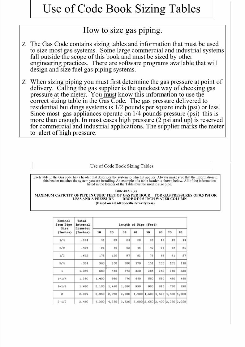
Each table in the Gas code has a header that describes the system to which it applies. Always make sure that the information inthis header matches the system you are installing. An example of a table header is shown below. All of the information
listed in the Header of the Table must be used to size pipe.
Table 402.3.(2)
MAXIMUM CAPICITY OF PIPE IN CUBIC FEET OF GAS PER HOUR FOR GAS PRESSURES OF 0.5 PSI OR LESS AND A PRESSURE DROP OF 0.5-INCH WATER COLUMN
(Based on a 0.60 Specific Gravity Gas)
8/3/2019 Sizing & Installation of Gas Piping
http://slidepdf.com/reader/full/sizing-installation-of-gas-piping 4/15
Use of Code Book Sizing Tables
The sizing tables are based on a number of factors. The main factor is gas pressure of the
system. The tables cover pressures up to 50 pounds(psi) for schedule 40 pipe materialsand up to 5 pound for semi-rigid tubing and Corrugated Stainless Steel Tubing (CSST)The table on the previous page is for gas pressure of 0.5 pounds(1/2 psi). This is acommon pressure for residential systems.
You will notice on the table also that the words Water Column is used in the headers abovethe tables. One inch of water column is equal to .036 psi. When 1/2 pound pressure isdelivered to the meter you have 14 inches of water column. The tables listed in the GasCode show pressure drop of the gas pressure in water column or in pounds per square
foot (psi) or a certain percentage of pressure. Pressure drop is the loss of pressure of the gas as it travels through the system. It is caused by friction on the interior surface of the pipe, fittings etc.. For instance the table header shown below has a pressure drop of 0.5 inch water column. Since one inch of water column is equal to .036 psi or less than4% of a pound of pressure You see that this is a very small loss.
You also see a Specific Gravity of .60 . Specific Gravity is the weight of a volume of gascompared to the weight of the same amount of air. Natural gas is always 0.60 SpecificGravity.
8/3/2019 Sizing & Installation of Gas Piping
http://slidepdf.com/reader/full/sizing-installation-of-gas-piping 5/15
Use of Code Book Sizing Tables
Z When determining the total load of the systems you need to know the type appliances
to be connected. Gas appliance manufacturers always attach a metal plate in a visible
location on each appliance. This data plate shows the Btu input rate (the maximum gas
demand). Btu is the abbreviation for British thermal unit, the quantity of heat required
to raise the temperature of 1 pound of water 1 degree Fahrenheit. While the appliances
are rated in Btu, the gas code tables list the size of piping in cubic feet per hour (cfh).
So you’ll have to convert each Btu input rating to cubic feet of gas before sizing the
distribution piping.
Z You can assume that each cubic foot of natural gas releases 1,000 Btu per hour.Some gas has Btu ratings that vary slightly, but 1,000 Btu per cubic foot is generally a
safe assumption. Assume you’re sizing pipe for a gas range with a maximum demand of
68,000 Btu per hour. Divide the value in Btu by 1,000 to find the demand in cubic feet
per hour:
Example - 68,000 Btu ÷ 1,000 = 68 cfh

8/3/2019 Sizing & Installation of Gas Piping
http://slidepdf.com/reader/full/sizing-installation-of-gas-piping 6/15
Gas Piping Problem
Z Now lets work through sizing a sample gas piping system. Remember the thing you
must know is the pressure of the gas delivered by the supplier to the meter (This will
tell you which table to use), Total of the Btuh for all the appliances connected to thesystem and the distance gas will travel through the pipe to the farthest appliance
connected.
Z For this problem we will use the following factors:
Z Size pipe in Sections 1-7 on the piping diagram using the specifications listed in the
next paragraph.
Z Gas is delivered at 0.5 (1/2) pound pressure with a pressure drop of 0.5 water column.
The gas delivered has a 0.60 Specific Gravity. Use the Typical Piping Plan shown on
the next slide to determine the size of all natural gas piping in the system.

8/3/2019 Sizing & Installation of Gas Piping
http://slidepdf.com/reader/full/sizing-installation-of-gas-piping 7/15
Gas Piping ProblemZ The other factor one must know to properly size a system is the distance the
gas must travel (in feet) through the pipe from the point of delivery to the
most remote appliance. This is called sizing by the “Longest Length
Method”. When the footage is determined, it will be the only distance usedto size piping in that system. For instance if a furnace is the most remote
appliance and the pipe length is 50 feet then you would use the table column
listed under 50 feet to size all pipes. If you distance exceeds the amount of
footage listed in a column you must use the next column to size your pipes.
For example if you had 44 feet you would go to the next column which is 50
feet and use the values listed under that column.

8/3/2019 Sizing & Installation of Gas Piping
http://slidepdf.com/reader/full/sizing-installation-of-gas-piping 8/15
Sizing 0.5 PSI Gas Piping System

8/3/2019 Sizing & Installation of Gas Piping
http://slidepdf.com/reader/full/sizing-installation-of-gas-piping 9/15
Use of Code Book Sizing Tables
How to size gas piping.
Table 402.3.(2)
MAXIMUM CAPICITY OF PIPE IN CUBIC FEET OF GAS PER HOUR FOR GAS PRESSURES OF 0.5 PSI OR LESSAND A PRESSURE DROP OF 0.5-INCH WATER COLUMN
(Based on a 0.60 Specific Gravity Gas)
Si i 2 i t

8/3/2019 Sizing & Installation of Gas Piping
http://slidepdf.com/reader/full/sizing-installation-of-gas-piping 10/15
Sizing a 2-psi system

8/3/2019 Sizing & Installation of Gas Piping
http://slidepdf.com/reader/full/sizing-installation-of-gas-piping 11/15
Gas Piping Sizing Table 2 psi SystemSizing table 2 psi system

8/3/2019 Sizing & Installation of Gas Piping
http://slidepdf.com/reader/full/sizing-installation-of-gas-piping 12/15
Gas Piping Sizing Table 2 psi System(Tubing size from regulator to appliance cut off)

8/3/2019 Sizing & Installation of Gas Piping
http://slidepdf.com/reader/full/sizing-installation-of-gas-piping 13/15
Gas Piping Sizing Table 5 psi System

8/3/2019 Sizing & Installation of Gas Piping
http://slidepdf.com/reader/full/sizing-installation-of-gas-piping 14/15
Gas Piping Sizing Table 5 psi System(Tubing size from regulator to appliance cut off)

8/3/2019 Sizing & Installation of Gas Piping
http://slidepdf.com/reader/full/sizing-installation-of-gas-piping 15/15
Course Complete
****Congratulations, You have
completed this course. Make sure you
complete the next page. It certifies the
completion of this course andone
(1)hour of credit.
Click Here
Related Documents