22 (22) SIXTH FRAMEWORK PROGRAMME PRIORITY 6.1 Project no. 502587 Project acronym: CHRISGAS Project title: Clean Hydrogen-rich Synthesis gas Instrument: IP Thematic Priority: Sustainable Energy Systems Publishable Final Activity Report Project Period: Project Co-ordinator 1 st September 2004 – 28 th February 2010 Dr Sune Bengtsson (Linnæus University) Duration: 5½ years Date of preparation: 28 th February 2010 (Revised September 2010)

Welcome message from author
This document is posted to help you gain knowledge. Please leave a comment to let me know what you think about it! Share it to your friends and learn new things together.
Transcript

22 (22)
SIXTH FRAMEWORK PROGRAMME
PRIORITY 6.1
Project no. 502587
Project acronym: CHRISGAS
Project title: Clean Hydrogen-rich Synthesis gas Instrument: IP Thematic Priority: Sustainable Energy Systems
Publishable Final Activity Report Project Period: Project Co-ordinator
1st September 2004 – 28th February 2010 Dr Sune Bengtsson (Linnæus University) Duration: 5½ years
Date of preparation: 28th February 2010 (Revised September 2010)
2 (22)
Introduction Renewable energy technologies are vital for our future. To combat the climate change we need to reduce the use of fossil fuel in the transport sector and develop technologies for the production of vehicle fuel based on renewable energy sources. The primary aim of the CHRISGAS project at its onset was to demonstrate within a five year period an energy-efficient and cost effective method to produce hydrogen-rich gases from biomass, which could be transformed into renewable automotive fuels such as FT-diesel, DME and hydrogen. The process was planned for demonstration at Växjö Värnamo Biomass Gasification Centre (VVBGC) in Sweden, after modification to the world’s first complete IGCC demonstration plant for biomass. Unfortunately these demonstration activities could not take place within the time frame of the CHRISGAS project as the rebuild and demonstration plant testing require additional funding outside CHRISGAS. Nevertheless significant basic engineering work and a number of highly successful gasification test runs have been performed at the existing IGCC plant at VVBGC during 2006 & 2007 certifying that the existing plant has maintained good operational standards over the seven years in which it was mothballed. Certain engineering and other project activities have continued during 2008 and 2009 to enable a realisation of the rebuild and testing as soon as possible after the CHRISGAS project has ended. The R&D activities covering the whole value chain from biomass to syngas, and parallel to the work at the VVBGC plant, were intensified during the last 18 months of the CHRISGAS project. The project’s R&D activities included biomass logistics; biomass drying integration; pressurised fuel feeding, gasification; hot synthesis gas characterisation; high temperature filtration/cleaning; catalytic steam reforming; and shift gas catalyst characterisation. Several important and significant results were achieved within CHRISGAS
• A new piston feeder for biomass to a gasifier was developed and commercialized. This significantly reduces the consumption of inert gas.
• A modified hot gas filter with new features was successfully pilot tested. • Important knowledge on oxygen/steam-blown biomass CFB gasification, catalytic reforming and
WGS process was developed, as well as within other key areas of the thermo-chemical conversion process.
• A special GIS application tool BIORAISE was developed and made available to the public • Investment and production costs of complete BTL-plants based on gasification
Thus the results of the CHRISGAS project will contribute to the reduction of greenhouse gases and pollutant emissions, increase the security of energy supplies and increase the use of renewable energy in the transport sector when the studied technologies are introduced commercilally Furthermore at the close of the project (February 2010) it can be reported that the journal “Biomass and Bioenergy” has been approached and has reacted positively to a proposal to publish the results and findings of CHRISGAS as a special issue/edition. 15 papers have been written and the process of peer review is presently ongoing. This presentation of work devoted to CHRISGAS is expected to be ready for publication around autumn 2010 and can be considered a major achievement for dissemination purposes; again demonstrating the importance and significance of this EU project.

3 (22)
CHRIGAS is funded through the EC 6th Framework Programme and by the Swedish Energy Agency. It started 1st September 2004 and ran for ran for 5½ years. 20 partners representing industry and research from 7 EU member states participated in the project.
Overview of Project Objectives The medium-to-long term research objective of the project was to develop a process to produce a clean hydrogen-rich synthesis gas as a first step towards a new renewable energy carrier both for mainly transport applications. This objective was expected to be achieved at the end of the proposed tests, i.e. by the end of the project. It was expected that this research would deliver results towards the production of commercial quality hydrogen, vehicle fuel and others, which would be widely exploited after 2010. Within the original time frame of the CHRISGAS project, the primary objective was to demonstrate at a scale of 18 MW thermal, the manufacture of a clean synthesis gas with high hydrogen content. The process is based on gasification of biomass, followed by gas upgrading by hot gas cleaning to remove particulates, and by steam reforming of tar and light hydrocarbons and water gas shift to further enhance the hydrogen yield. The overall objectives of the CHRISGAS project further included:
• To demonstrate the conversion of a solid biofuel into a medium calorific value gas by gasification at elevated pressure using a steam and oxygen mixture.
• To demonstrate purification of the generated gas at high temperature, e.g. in a high temperature filter, and by catalytic or thermal steam reforming of tars, methane and other light hydrocarbons, to generate a raw synthesis gas consisting mainly of carbon monoxide (CO) and hydrogen (H2) as energy carriers.
• To operate and gather data on different types of solid biofuel feedstocks and to potentially test some of these at the Värnamo site.
Unfortunately these goals became unfeasible within the original five year time frame of CHRISGAS due to funding from the Swedish Energy Agency (STEM) conditionally being put on hold in December 2007. This was due to insufficient industrial participation; both with regard to co-financing and commercialisation undertaking. This issue is considered to be due to the risk factor for this type of long-term project, when market
CHRISGAS Partners Country Linnaeus University (formerly Växjö University) Sweden Catator Sweden Centro de Investigaciones Energéticas Medioambientales y Tecnológicas Spain Cornelissen Consulting Service Netherlands ENI S.p.A. Italy Forschungszentrum Jülich Germany KS Ducente Sweden Kungl Tekniska Högskolan Sweden Linde - Linde Engineering Division Germany Pall Filtersystems Germany Perstorp Oxo Sweden S.E.P. Scandinavian Energy Project Sweden Södra Sweden TK Energi Denmark TPS Termiska Processer Sweden TU Delft Netherlands Università di Bologna Italy Valutec Finland Växjö Energi AB Sweden Växjö Värnamo Biomass Gasification Centre Sweden
4 (22)
introduction and investment recovery is not possible within a ten-year time frame. A report published by the Biofuel Technology Platform calls this effect the “death valley” of technology development. Nevertheless with the funding hitherto a start had made on advanced detailed engineering work, and the plant had been able to operate during autumn 2007 where the gasification tests provided highly promising results. When announcing STEM’s decision in December 2007, Thomas Korsfeldt, General Director of STEM said,
"It should be underlined that it is not the technology of the project that is under question...”
At the time of writing intensive efforts are still being pursued to resolve the financing situation and thus enable the rebuild and demonstration activities to be fully carried out at the VVBGC plant. As a result of the delays associated with financing the rebuild for the demonstration project in Värnamo, the objectives of the project were shifted to perform further system research at the available laboratory pilot plants within the CHRISGAS consortium, namely those at TU Delft and KTH and further system studies. The results and findings from this additional work are expected to support a realization of a large pilot scale or commercial demonstration of the CHRISGAS BtL process.
Further objectives of CHRISGAS included: • To conduct desktop studies, based mainly on experimental results obtained in the project, of the
conditioning of the produced gas to a quality suitable for manufacture of a variety of other potential products.
• To test and develop a biomass piston feeding device to potentially be installed for the Värnamo gasification pilot as a commercial unit at a later stage.
• To conduct desktop studies of the production of automotive fuels from various biofuels, at the scale and cost representative of typical biomass fuel chains in various regions in Europe.
• To conduct desktop studies to estimate the socio-economic impact of the introduction of BtL production plants related the social effects such as jobs created directly and indirectly at the plant location and in the fuel supply area.
• Disseminate the scientific and technical results through scientific publications, conference presentations as well as through workshops.
It is the opinion of the CHRISGAS consortium that the above objectives of the project have been met and will contribute to the generation, exploitation and dissemination of new knowledge and to the implementation of EU research policy, as well as to the development of energy and associated policies.

5 (22)
Achievements and Findings of Work Conducted within CHRISGAS: Pilot Plant Modifications and Alterations During the first three years of the CHRISGAS project intense activities took place at the Värnamo pilot plant where the important demonstration of syngas production based on biomass gasification was planned to take place. The responsible partner for most of these activities was VVBGC, the owner of the plant. Several other partners DUC, LIN, SEP and TPS also participated. During the CHRISGAS project a pilot plant status review was conducted by DUC. This was followed up by a conceptual engineering design study performed in a co-operation with several partners, and Basic Engineering work (mostly funded outside the project by STEM) of the planned rebuild was completed using an external engineering consultant, Carl Bro. In parallel to these activities VVBGC was staffed and the requisite environmental permit for the rebuilt plant was obtained from the regional authorities. With additional funding from STEM some important investment decisions were made including commissioning and installation of a new process control system, erection of a new storage tank for liquid nitrogen and a project consulting company (Sweco) for the detailed engineering was hired. Activities during 2008 and 2009 at the Värnamo pilot activities have continued at a much lower level and work has concentrated on trying to find a solution for the requisite industrial participation and this has led to short term conservation for certain equipment. During 2009 interest increased within industry for gasification processes and promising negotiations with new industrial partners started. A legal framework for a post-CHRISGAS project was completed. Based on this, a new application for funding to STEM was made in autumn led to a decision by STEM to recommence project activities again. A decision on complete financing is expected during 2010. Pilot Verification Work The demonstration and verification on a pilot scale of the CHRISGAS hydrogen-rich syngas generation technology chain is a cornerstone in the project. The impact of produced steam-oxygen blown biomass-derived syngas on downstream cleaning and upgrading units need to be established in tests on a representative scale. As a result of the Värnamo large IGCC pilot unit not being available for demonstration due to lack of financing for the required rebuild to syngas version the developed alternative was to test the whole process scheme in two pilots being available at partners laboratory premises. The partners in this joint work were KTH, TUD, BOL and LNU. Two steam-O2 blown pilot gasification test rigs were involved in this research: 1) a 10kWth pressurized bubbling bed gasifier including gas cleanup and a reformer at partner KTH, and 2) a 100 kWth atmospheric circulating fluidized bed gasifier, including hot gas ceramic filter unit (from PALL) a catalytic reformer and a catalytic water gas shift reactor at TUD.
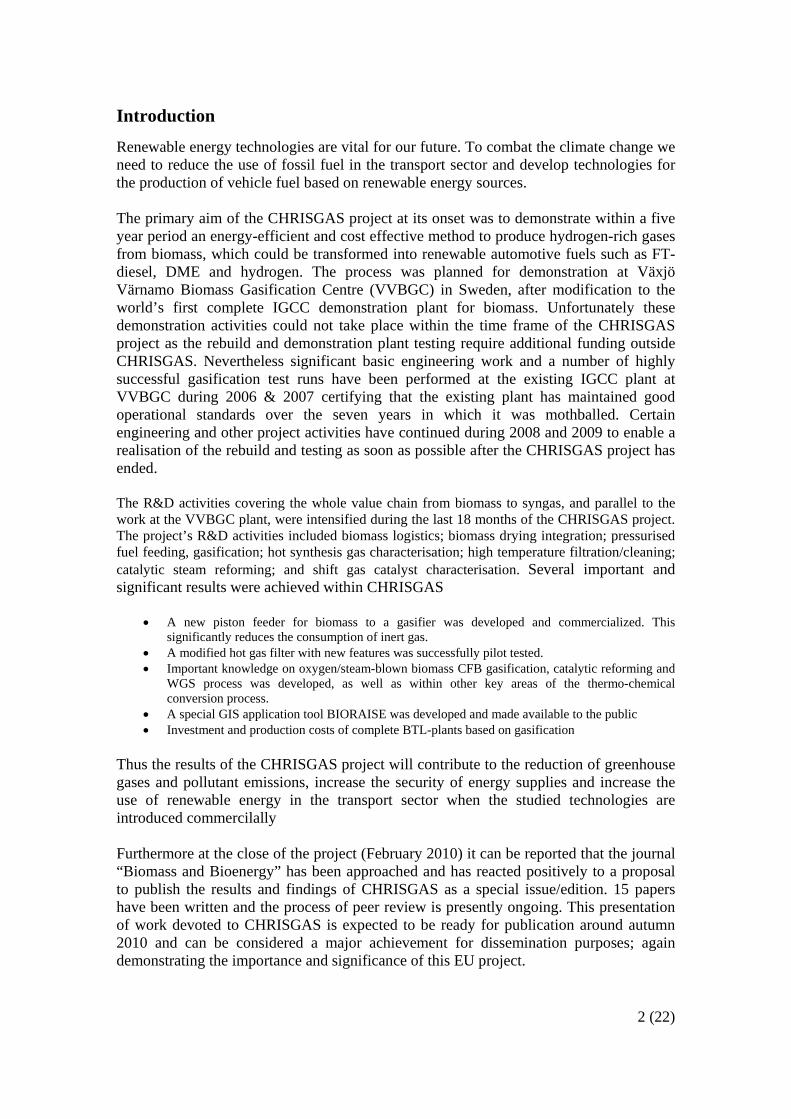
KTH gasified birch at pressures of 10 and 15 atm with steam and the derived raw syngas has been catalytically reformed at temperatures in the range 850-950°C. Haldor-Topsoe A/S provided the reforming catalyst (~9 kg). The bed material used was MgO (magnesite). A typical result is shown below (representative gas composition), together with a photo of part of the set up.
6 (22)
20 20.2 20.4 20.6 20.8 21 21.2 21.40
10
20
30
40
50
60
70Steam (-4.5 kg/h) gasification, Birch ~2 kg/h, magnesite, 7-8 bar, -850°C
Hour
Con
cent
ratio
n, d
ry (%
) CO2
H2CO
CH4
C2H2 + C2H4
Gas composition, excluding water, before reforming (left); and reformer (right).
The observed CH4 concentrations were in-line with those indicated by the methanisation equilibrium (see equation below) at the respective pressure and temperatures.
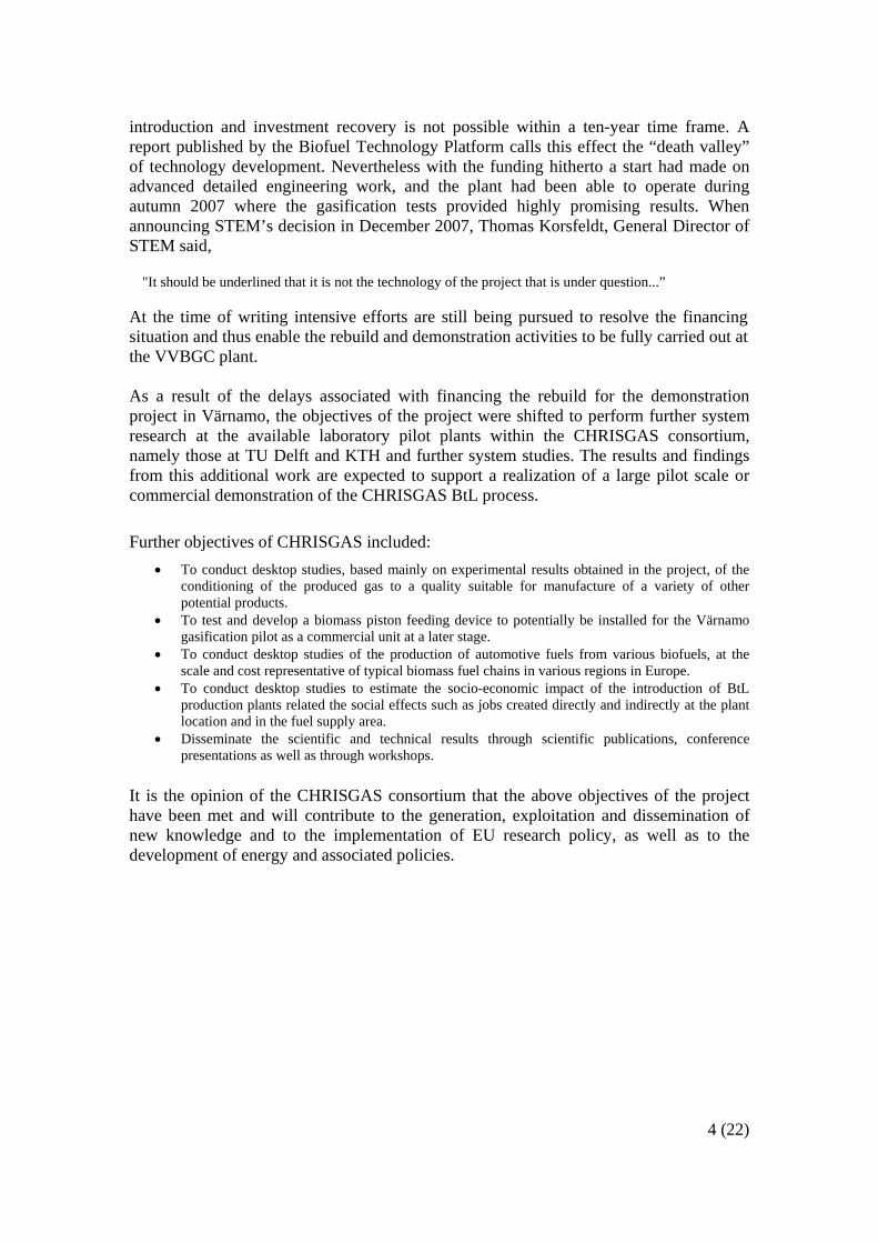
TUD operated their CFB gasifier on woody fuel and miscanthus, the latter as a representative species for “demanding” and more “contaminated” agricultural fuel. Regarding the integration with the reforming unit, the gasification of woody residues (B-wood, demolition wood) with a higher sulphur content (H2S ≈ 100 ppm in the inlet gas) required 1000°C to reach 90 % conversion (versus 77% at 975°C). Under both process conditions a feed gas with a syngas concentration (CO + H2) > 70 % on dry and N2 free bases was obtained demonstrating the possibility to run the process with great advantage in terms of efficiency and fuel production as compared to the thermal partial oxidation option. Furthermore, using miscanthus as fuel producing a gas with an H2S content ≥ 200 ppm, a 52 % methane conversion was obtained at 1050°C (with a CO + H2 concentration = 63 %). Therefore, using miscanthus, there is still an advantage of a catalytic process, however, this needs to be evaluated in the long term considering the catalyst deactivation risk due to the presence of higher sulphur and alkali concentration of the gas. Tests including a water-gas-shift (WGS) reactor exposing it to the upstream upgraded gas were also performed together with LNU.
Picture (left) and process schematic of the 100 kWth integrated CFB gasification test rig at TUD.
7 (22)
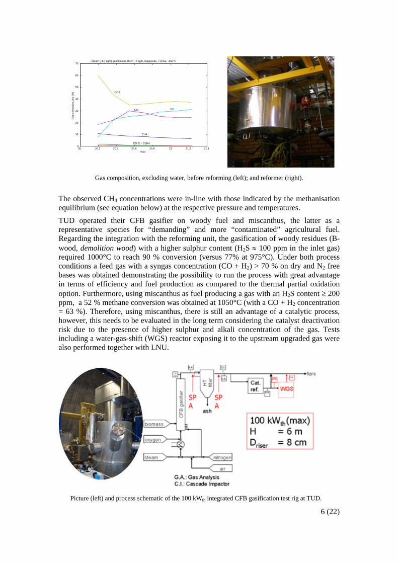
a b
(a)Methane conversion obtained by reforming of TUD supplied de-dusted raw Syngas on Ni catalyst, case B-wood gasification, and (b) and Miscanthus gasification.
A modelling package, CSFMBTM (with many references to larger fluidized bed gasifiers) was purchased and applied for the TUD gasifier; model runs have been made and compared with some detailed riser measurements. The modelling has also been made for the Värnamo gasifier, for which data was made available related to air blown gasification tests in 2007. Fuel Supply and Management The assessment of biomass resources including quantification, logistics and pre-treatment is very important in successful bioenergy projects. New methodologies have been developed and implemented for this purpose by CMA and “potential” and “available” agricultural and forestry residues have been assessed in 12 European countries including France, Italy, Portugal, Spain and Greece (southern EU countries); Austria, Germany and Poland (central EU countries); and Sweden, Finland, Norway and Denmark (northern EU countries). Based on such methodology, a computer GIS based tool has also been created and made available on internet (www.bioraise.ciemat.es/). This tool, BIORAISE, has been designed for the calculation of agricultural and forest biomass resources and costs existing around selected locations in the above mentioned southern EU countries. The most suitable areas in terms of biomass availability for biomass hydrogen plants have been sought and the logistics and pre-treatment issues have also been investigated for such areas. In Sweden the area around Värnamo and a further two areas in Spain have been studied in detail. These sites are Lerma (northern Spain) and Écija (southern Spain). The biomass available within a radius of 100km from the considered locations has been estimated on 1,48M t/y (o.d.b) and 1,58 (o.d.b) Mt/y for Lerma and Écija, respectively. The chains for 1M t/y biomass delivery to the considered plants have been defined and their economies evaluated. In the availability assessment made by LNU it was found that a 400 000 ton/a DME-plant could be supported by forest residues feedstock within a radius of 150 km around Värnamo or Växjö. In southern sites, biomass is assumed to be transported by road as bales, chips or loose material (depending on the type of biomass) from the production place to the plant. At the plant, biomass is dried (if required), milled, homogenised (blended) and, finally, pelletised before being fed into the gasifier. The average costs including harvesting,

8 (22)
transport and pre-treatment were estimated in some 64 €/t (pellet 10% moisture content w.b.) It was concluded that in southern EU countries it is possible to find locations with good availabilities of biomass resources (around 1 Million odt/yr) in areas of 100 km radius. However, most available resources are agricultural residues such as straw, corn stover, olive branches, husks etc. Such biomass materials exhibit more severe conditions in the gasification reactors than wood, being more prone for sintering and corrosion. For that reason the installation of a large centralized pre-treatment plant with the aim of blending and pelletizing the agricultural residues with small proportions of wood residues has been proposed. The key issue of the pelletizing plant is to create a more uniform feedstock for the gasifier in terms of size, density, moisture content and, as much as possible, also in terms of chemical composition, so that the gasifier operation and the gas composition will be as constant as possible. Biomass Drying Before gasification biomass needs to be dried to below 15 % moisture (approx.) content to achieve high efficiency. In this work both on-site drying at the gasification plant and off-site drying, i.e. in the forest or on the filed, was considered. An experimental batch drying equipment was designed and built at LNU in order to experimentally investigate and determine optimal drying conditions for different biomass products. A drying simulation model was developed in order to evaluate the different drying parameters influence on drying. A number of drying techniques and their integration with the gasification process was also evaluated. Design criteria for engineering were developed based on the experimental results and a preliminary design and cost estimate of a full scale bed dryer was made. The main conclusions were:
• The biomasses mean particle size and size distribution influence the width of the drying zone. An important experimental observation is that the width of the drying zone varies over a cross-section of the bed.
• The experimental batch-wise bed drying developed is a feasible method to produce necessary basic data for design of a dryer.
It was also was shown that the bed dryer is the most appropriate equipment to dry fuel with air at lower temperature levels since a high pressure drop can be avoided despite high volume flows of the drying medium. There is enough low grade heat available in the gasification and DME-process to dry most of the fuel needed on-site, but not all fuel has to be dried on-site. Off-site drying should be used where it is possible. Sources of waste heat can be found and recovered in most industrial sites. It was found
• There is enough low temperature energy available for drying in the gasification/DME-synthesis process.
• The bed dryer is the best and most economical type of dryer when the temperature of the heat source is low.
All relevant data is summarised and the design of a full-scale dryer has been presented together with cost estimations: The cost for a 40 ton /h dryer being estimated to be 6 M€. Pressurised Fuel Feeding
The state-of-the- art fuel feeding is based a look-hopper system consuming large quantities of inert gas. The objectives of this work were to obtain technical qualification of a proposed alternative concept using a piston or plug feeder, to build and test a

9 (22)
triple-step plug prototype and make a design data report for a full-scale triple-step plug prototype with a capacity up to 6 000 kg/h. All the work in this work area was performed by TKE. Work included proof of concept design and construction; a laboratory prototype testing was performed with a feeding capacity of 30-200 kg/h and the triple-step prototype was designed thereafter, manufactured and tested successfully. This led to the engineering of a full-scale unit. The final task was then expanded with the design, construction and test of an up-scaled plug feeder. The results of the work were two satisfactory working feeders and data for designing a full scale feeder. The full scale feeder is approximately 15 % bigger than the up-scaled feeder build in this project. The main difference between the prototype and the final version is the hydraulic system. The power consumption of the feeder will be approximately 1% of the heating value of the biomass. The developed plug feeder has successfully been commercialized by TKE. Two units have been supplied to North American projects, of which one has been operating for more than half a year.
Gasification Gasification is the central theme in the project and joint research was performed on the steam/oxygen blown fluidized bed gasification. Focus topics of this comprehensive work were known specific process risk areas; like the potential of bed agglomeration, sulphur species in the raw product gas, main product gas specification (hydrogen yield optimization and hydrocarbon conversion) and tars. The partners involved in this work were TUD, KTH and TPS. At TPS a 50 kWth atmospheric bubbling fluidized bed gasifier was operated, see Figure below for a process schematic. The main focus of the work concentrated on interaction of bed materials with the mineral matter in the fuels. Three natural mineral bed materials were tested: a silica sand (Danish “Fylesand”), olivine and magnesite (MgO). While the silica containing first two bed materials showed agglomeration with the agricultural fuels (miscanthus and straw), no agglomeration was found for the challenging fuels with magnesite used as bed material.
a b
(a) 50kWth BFB gasifier at TPS, and (b) sintering of olivine during gasification.

10 (22)
KTH investigated different sorbents for sulphur species. Both in-bed downstream locations were tested using their gasification pilot rig. From literature and through thermodynamic equilibrium calculations it was concluded that CuO/Cu, seems to be a promising candidate for efficient sulphur capture. The most important evaluation criterion is the capability to reduce the H2S levels down to a few ppm, combined with a good and lasting regenerability. Subsequent tests at bench-scale showed that it can be problematic to run the gasifier with copper powder sorbent directly in the bed due to bed sintering (see Figure below). Downstream usage of modified copper containing species did not present such problems. It was shown that with a novel copper based sulphur sorbent material it was possible to reduce the H2S content in biomass derived raw gas down to a few ppm. Future research has to prove that this material is stable enough and can be regenerated successfully. KTH also presented a correlation for hydrocarbons, useful for quick estimation of higher hydrocarbon contents related to methane content.
a b
(a) 5 kWth BFB gasifier at KTH, and (b) and SEM picture of sintered in-bed Copper sorbent. At TUD about 70 tests were performed on the 100 kWth CFB (Circulating Fluidized Bed) integrated gasifier, almost all of these were steam/oxygen blown. The test facility is shown in the Figure below. Variation of bed material appeared to be most interesting, as magnesite was shown to be advantageous (Siedlecki et al., 2009) in view of an increased hydrogen yield, H2:CO ratio, hydrocarbon and tar reduction as well as agglomeration suppression. Even a very problematic fuel like straw was successfully gasified using magnesite as bed material with addition of some kaolinite (an alkali getter). The increased H2 yields and H2:CO ratio of ~2 in combination with decreased tar levels (of the order of ~2 g/mn
3 dry gas basis) has potentially great impact on the process lay out of a near future plant. A fluidized bed biomass gasification to syngas process route will need less extensive catalytic treatment, especially for reaching higher hydrogen contents via water-gas-shift.

11 (22)
(a) 100 kWth CFB gasifier. (b) a highlight of the research: tar reduction by utilization of magnesite as bed material.
Gas Characterization The important work of this area has been the characterisation of the gaseous and aerosol particle trace components that are present in the gasifier raw gas but which are not normally analysed using the bulk gas and contaminant analysis methodology affordable and commonly used for normal gasification research. The characterisation includes identification and quantification of the corrosive/toxic particulate or gaseous species harmful to materials and catalysts used in the downstream treatment of the hot gas, as well as development and specification a gas sampling methodology that can be applied at large scale pressurised gasifiers.
Methods for identification and quantification of potentially detrimental species have been developed and tested in laboratory scale. These methods have then been successfully implemented in order to characterise inorganic vapours, gases, particles and tars in pilot scale fluid bed gasifiers. The inorganic content of four agreed and specified fuels was determined and the release of different inorganic trace compounds (Cl, S, P, and alkali species) during thermal conversion was investigated in a laboratory-scale fluidised bed (FB) gasifier at FZJ. The gas was analysed at different temperatures using a high-pressure mass spectrometer (HPMS). Various sorbents for alkali species were selected based on thermodynamic calculations. The results were validated through, sorption experiments using sorbent beds and the HPMS. A method for high temperature sampling and on-line characterisation of particulates has also been developed. The method has been evaluated in a laboratory-scale reactor at LNU, and used for measurements at pilot scale FB gasifiers at TPS, TUD as well as Chalmers (with assistance of SEP). Heated impactor measurements were performed at the CFB gasifier at TUD. Particle formation, transport and transformation have also been studied in conjunction with the measurements at TUD and Chalmers, as well as in the laboratory at LNU. A method solid phase adsorption (SPA) previously developed at KTH has been used for analysis and quantification of tar hydrocarbons at the gasifiers at KTH and TUD. A
12 (22)
method for measurement of heavy tars based on collection in hot filters and adsorbents has been developed and a sampler prototype has been built and tested off and on-line. Major and minor gaseous components have been analysed and the influence of bed materials and additives has been investigated at TUD. At TUD’s CFB gasifier a heated impactor was used, and the samples were analysed using SEM-EDX. In addition influence of fuel and hot gas filter operation was investigated at TUD using the high temperature sampling method developed at LNU, combined with elementary analysis using PIXE. Hot Gas Filtration The major objective of this gas characterisation work was to investigate and optimise the hot gas filtration unit design and performance in a biomass fuelled steam/oxygen gasification gas environment to improve removal efficiency, dust cake cleaning and related issues. Thereby feasible operating conditions can be recommended for a filter to be installed in the large pilot demonstration plant at Värnamo. The types of filters primarily foreseen have been ceramic candle filters of partner PALL with special innovative features of back pulsing, potentially also featuring tar cracking. A small lab filter of this type was tested in the TUD 100 kWth atmospheric CFB test rig in the final year of the project. Two different types of ceramic candle filters (three in the large unit) were tested (DS, DSN) in several measurement campaigns at TUD using steam/oxygen blown CFB gasification of both woody and agricultural fuels with the use of different bed materials/additives. The temperatures of the filtration started at about 600 oC, but most tests were carried out at temperatures well above 800 oC. Problems identified were increasing pressure drops at the high temperatures, especially with the upstream use of magnesite, blocking the filter membrane pores partially. This was later solved by optimizing the cleaning. Some problems of filter cracking were also observed due to partial membrane pore blocking (magnesite fines); other failures probably due to chemical interaction of ash with the filter top layer. Heated impactor measurements were performed around the filter unit at TUD. Detailed characterizations of the fly ashes (hopper samples, impactor stages) and cakes on cut candle parts using SEM-EDX and XRD/XRF were made. In addition influence of fuel and hot gas filter operation was investigated at TUD using the high temperature sampling method developed at LNU, combined with elementary analysis using PIXE. Moreover, catalytic candle tests were performed using the impregnated candle type of filter in a separate small-scale set up with two different Ni impregnation loadings for hydrocarbon reforming. Good conversions were attained with synthetic gases resembling steam/O2 blown derived syngas using naphthalene as model component. Finally, a simple model for the filtration and catalytic conversion was made, which compared well with the measurements performed on the small-scale. Steam Reforming To produce a syngas to produce vehicle fuels the raw gas from a biomass gasifier must be reformed for the conversion of hydrocarbons to CO and H2. The reforming process will convert not only light hydrocarbons such as CH4 to CO and H2 but also and more easily tars. Either a thermo-chemical method (partial oxidation) or a less energy consuming catalytic autothermal steam reforming method (ATR) can be used. The attention in CHRISGAS was particularly focused on the catalytic ATR method, due to the possibility to increase the syngas yield by approximately 13 % as compared to the POX process.

13 (22)
ATR is working at 1000°C, while partial oxidation needs 1300°C, also resulting in less use of oxygen. Two different commercial catalysts were tested for the reforming of methane and compared with the monolith. The kinetic parameters for the methane conversion have been developed. These are in line with the literature data (Ea 70-100 kJ/mol). Catalyst A showed the highest activity. Catalyst A and B behaved similarly in tar reforming: a tars concentration below 500 mg/Nm3 of dry gas was obtained in the outlet gas with inlet gas concentrations between 2000 and 7000 mg/Nm3. Also results from a third commercial catalyst similar to catalyst A is presented in the work. No large differences in the tar conversion was found between catalyst A and B, however, catalyst B deactivated using biomass A. The catalyst A has been tested with different types of biomass and sulphur concentration at 900°C. High activity was found with wood A, while with wood B the conversion decreased by changing the sulphur concentration, and was below 60 % at a sulphur concentration of 100 ppm, and decreased below 30 % with 200 ppm of sulphur and using miscanthus or straw. Initially some deactivation also occurred using catalyst A with all the fuels used, while continuous deactivation was observed with straw. The preliminary tests in transient regime (start up, shut down) indicated no deactivation due to the changing conditions. Modelling of both the partial oxidation and ATR with regard to the burner zone was made at TPS. For this purpose integrated CFD and Chemkin models were applied. By changing the profile of the burner the temperature and methane concentration profiles were developed. A flat flame resulted in the most homogeneous profile with a fast homogenisation of the temperature after the burner at a temperature between 1300 and1400 K. For this case the profile of the methane conversion confirmed the homogeneity of the radial concentration profile with a slight difference close to the reactor wall.
dCH4/dt = kp(CH4) E (kJ/mol) K (0) Type A 77 6,7 E+03 Type B 85 1,4 E+04 Monolith catalyst 95 3,3 E+5
C onversion o f met hane o ver cat alyst T yp e A
0102030405060708090
100
0 500 1000 1500H 2S in the gas (mg/ m3)
Met
hane
con
vers
ion
(%)
Biomass ABarkM iscanthusStraw

14 (22)
Case 1 Case 2 Case 3 A reformer using a monolith catalyst is an alternative to a packed bed ATR, more resistant to fouling and particulates and could work directly after a cyclone without prior filtration. Theory indicates that the temperature will decrease of about 50°C per percentage decrease of methane concentration. Computations also indicate that a reduction of the methane concentration from 10 to about 1-2 vol.-% calls for a minimum of two monolithic stages with the addition of oxygen in between. Tests with the monolith catalyst showed that the methane conversion is instantaneous and substantial. However, the long-term effects on the monolith catalysts are not known and increasing reaction inhibition due to carbon precipitation has been a problem. Different monoliths have been tested successfully in laboratory using Ni/M and Pt/M bimetallic active phases to improve the resistance to sulphur and carbon deactivation. At TUD Ni/M. was tested for the reforming. Ni/M performed better than commercial catalyst, even at lower temperatures (>50 °C; both with wood-B and miscanthus giving H2eq (CO+H2) concentration above 70 and 65 % respectively on dry and N2 free basis. To assess the deactivation and perform in-depth characterization both commercial and catalysts developed by BOL were studied under increasing complexity of deactivation: model conditions (exposure of the samples to an aerosol containing K2SO4, KCl, ZnCl2 and to fly ash); deactivation by sulphur, by steam and at high temperature under real-like conditions; exposure to the gas generated by the TUD gasifier - both before and after the hot gas filter; and catalytic tests in the bench-scale reformer placed downstream the TUD gasifier.
Case 1 Case 2 Case 3
Conv. CH4Conv. CH4
Ni NiM
Conv. CH4Conv. CH4
Ni NiM
15 (22)
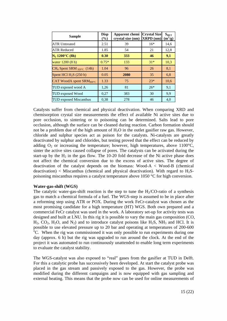
Catalysts suffer from chemical and physical deactivation. When comparing XRD and chemisorption crystal size measurements the effect of available Ni active sites due to pore occlusion, to sintering or to poisoning can be determined. Salts lead to pore occlusion, although the surface can be cleaned during reaction. Carbon formation should not be a problem due of the high amount of H2O in the outlet gasifier raw gas. However, chloride and sulphur species act as poison for the catalysts. Ni-catalysts are greatly deactivated by sulphur and chlorides, but testing proved that the effect can be reduced by adding O2 or increasing the temperature; however, high temperatures, above 1100°C, sinter the active sites caused collapse of pores. The catalysts can be activated during the start-up by the H2 in the gas flow. The 10-20 fold decrease of the Ni active phase does not affect the chemical conversion due to the excess of active sites. The degree of deactivation of the catalyst depends on the biomass: Wood-A < Wood-B (chemical deactivation) < Miscanthus (chemical and physical deactivation). With regard to H2S-poisoning miscanthus requires a catalyst temperature above 1050 °C for high conversion. Water-gas-shift (WGS) The catalytic water-gas-shift reaction is the step to tune the H2/CO-ratio of a synthesis gas to match a chemical formula of a fuel. The WGS-step is assumed to be in place after a reforming step using ATR or POX. During the work FeCr-catalyst was chosen as the most promising candidate for a high temperature (HT) WGS. Both own prepared and a commercial FeCr catalyst was used in the work. A laboratory set-up for activity tests was designed and built at LNU. In this rig it is possible to vary the main gas composition (CO, H2, CO2, H2O, and N2) and to introduce catalyst poisons like H2S, NH3 and HCl. It is possible to use elevated pressure up to 20 bar and operating at temperatures of 200-600 oC. When the rig was commissioned it was only possible to run experiments during one day (approx. 6 h) but the rig was upgraded to run around the clock. At the end of the project it was automated to run continuously unattended to enable long term experiments to evaluate the catalyst stability. The WGS-catalyst was also exposed to “real” gases from the gasifier at TUD in Delft. For this a catalytic probe has successively been developed. At start the catalyst probe was placed in the gas stream and passively exposed to the gas. However, the probe was modified during the different campaigns and is now equipped with gas sampling and external heating. This means that the probe now can be used for online measurements of
Sample Disp (%)
Apparent chemi crystal size (nm)
Crystal Size XRPD (nm)
SBET (m2/g)
ATR Untreated 2.51 39 16* 14,6 ATR Reduced 1.85 54 21 12,8 N2 1200°C (8h) 0.30 333 46 9,1
water 1200 (8 h) 0.75* 133 31* 10,3
CH4 Spent SRM 920°C (14h) 1.04 96 26 8,1
Spent HCl H2S (250 h) 0.05 2080 35 6,8
CAT WoodA spent SRM800°C 1.33 75 23* 10,6
TUD exposed wood A 1,26 81 26* 9,1
TUD exposed Wood 0,27 383 30 9,9 TUD exposed Miscanthus 0,38 278 46 4,0

16 (22)
the catalyst activity in a gasification rig. The spent catalyst from the laboratory and the real gas experiments was characterized by various techniques at BOL. The figure above shows XPRD patterns of spent catalyst samples. From the first part of the laboratory investigation, information on the catalyst activation process and the catalyst activity was obtained. From the second part, long time stability data, in the presence of catalyst poisons, was obtained. The intention with the real gas exposure experiments was to confirm the results from the laboratory investigation and to see if there were unexpected deviations. The first part, the passive exposure experiments, showed, according to the characterization, similar results to the laboratory investigation concerning the formation of the active crystalline phase (magnetite). The crystallinity was not so well developed in the real gas exposed samples due to low temperature (approx 300 oC) at the sampling point. The catalyst activation temperature must be at least 350 oC, and this led to the implementation of external heating in the catalytic probe.
0
10
20
30
40
50
60
70
80
90
100
0 12 24 36 48 60 72Time (hours)
CO
con
vers
ion
(%)
H2S injection started
Effect of 150 ppm H2S addition. The CO conversion during 66 hours at SV 11700 h-1.
22 24 26 28 30 32 34 36 38 40
Delft 2b
Delft 2a
VXU HCl
VXU NH3
VXU H2S
Tem
pera
ture
(°C
)
2θ (°CuKα)
O
VXU no poison
10 20 30 40 50 60 70 80
Delft 2b
Delft 2a+ * Fe3O4 + Fe2O3 o carbon
VXU fresh
VXU HCl
VXU H2S
VXU NH3 O
*
**
****
*
*
D
etec
tor S
igna
l (a.
u.)
2θ (°Cu Kα)
*
O
VXU no poison
17 (22)
In the prolonged laboratory exposures, the presence of catalyst poisons affected the activity of the FeCr catalyst. A decrease in activity is obtained on exposure to H2S, NH3 and HCl. However, the activity is just initially somewhat reduced; the remaining activity is stable in long term experiments (50-100 h). This means that the FeCr catalyst most likely will work well in the gas mixture obtained from gasified biomass. Conclusions in summary from the combined work were:
• FeCr is a suitable catalyst for industrial production of hydrogen rich synthesis gas from gasified biomass.
• The effect of the catalyst poison can be compensated by adding more catalyst (double amount).
• The inlet working temperature should be at least 350 oC. • Pressurizing will not affect the equilibrium, but increases the capacity of the
reactor at constant catalyst volume. • Only a HT-shift step is needed for methanol, DME, FT or methane synthesis.
Ancillary and Novel Processes
The objective of this work area was to study innovative gas separation, gas cleaning and upgrading systems that has not yet been developed sufficiently to either motivate their testing at pilot scale within the time frame of this project or were in a development stage where the available data did not allow their evaluation, but where some attractive merits and features motivated further development.
CMA initially made some tests on the WGS reaction in a packed bed using a commercial WGS catalysts (Fe-Cr-based) and a novel Pt-based catalyst provided by CAT. Results proved that both types of commercial and prepared high temperature WGS catalysts (Fe-Cr- and Pt-based) are able to convert more than 90% of the CO content of the gas stream into CO2 and H2 under realistic operating conditions and therefore can be regarded as preliminary suitable to be used at the large Värnamo pilot scale.
Further work at CMA dealt with separation of hydrogen using membranes. In a dedicated test unit built for the purpose of this testing both locally prepared membranes and a pre-commercial prototype membrane were tested. The prepared membranes showed very poor hydrogen selectivity, while permeation studies conducted with the pre-commercial membrane showed that by means of a membrane reactor it is possible to completely separate hydrogen from the other gas components and produce pure hydrogen as a permeate stream.
CMA has also studied the advantages of using a WGS membrane reactor over a traditional fixed bed reactor, in terms of potential for producing a high purity hydrogen stream. The experimental device included a Pd-based membrane and a commercial high temperature Fe-Cr-based catalyst. The results proved that it is feasible to produce pure hydrogen as the permeate stream, even in the case of complex reaction system (H2/CO/CO2/H2O) under WGS conditions mixtures. When increasing the pressure the permeation is enhanced. This pushes the reaction towards further product formation, due to the removal of the reaction product hydrogen, and hence increasing carbon monoxide conversion.
18 (22)
Process System Studies/System Studies Process system studies were performed by primarily TPS, LIN and CCS. Other partners providing work in this area were ENI, SEP and DUC. In the CHRISGAS project, where a theoretical gasification model should support experimental results and at the same time support engineering activities and scaling criteria the core-annulus mode was identified as the best way to model a CFB gasifier. This approach relies on semi-empirical relations, and is only valid within a reasonable range around the original data. On a higher level of abstraction a mass- and energy balance model was made. This model contained both the gasifier and the gas cleaning section. This model was used to create input data for the design of fuel synthesis plants. Two studies were performed by LIN with regard to an air separation unit and an acid gas removal unit. Further system studies were related to the synthesis of Fischer-Tropsch diesel, methanol, DME and hydrogen production. The investment costs for the different fuel synthesis sections were calculated for a plant of approximately 40 ton/hr dry biomass input (230.5 MWth). The investment cost of Fischer-Tropsch diesel synthesis section was calculated by ENI and the other three fuels by CCS. This means that the basis of the cost calculation and the assumptions that lead to the investment cost of the plant section are different. Table 14.1 Investment costs for different fuel synthesis sections (230.5 MWth biomass input)
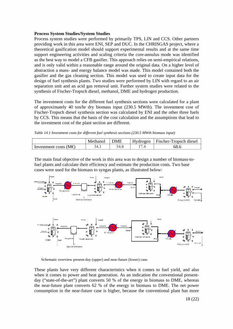
Methanol DME Hydrogen Fischer-Tropsch diesel Investment costs (M€) 34.1 54.8 17.4 68.6 The main final objective of the work in this area was to design a number of biomass-to-fuel plants and calculate their efficiency and estimate the production costs. Two base cases were used for the biomass to syngas plants, as illustrated below:
Schematic overview present-day (upper) and near-future (lower) case.
These plants have very different characteristics when it comes to fuel yield, and also when it comes to power and heat generation. As an indication the conventional present-day (“state-of-the-art”) plant converts 50 % of the energy in biomass to DME, whereas the near-future plant converts 62 % of the energy in biomass to DME. The net power consumption in the near-future case is higher, because the conventional plant has more
19 (22)
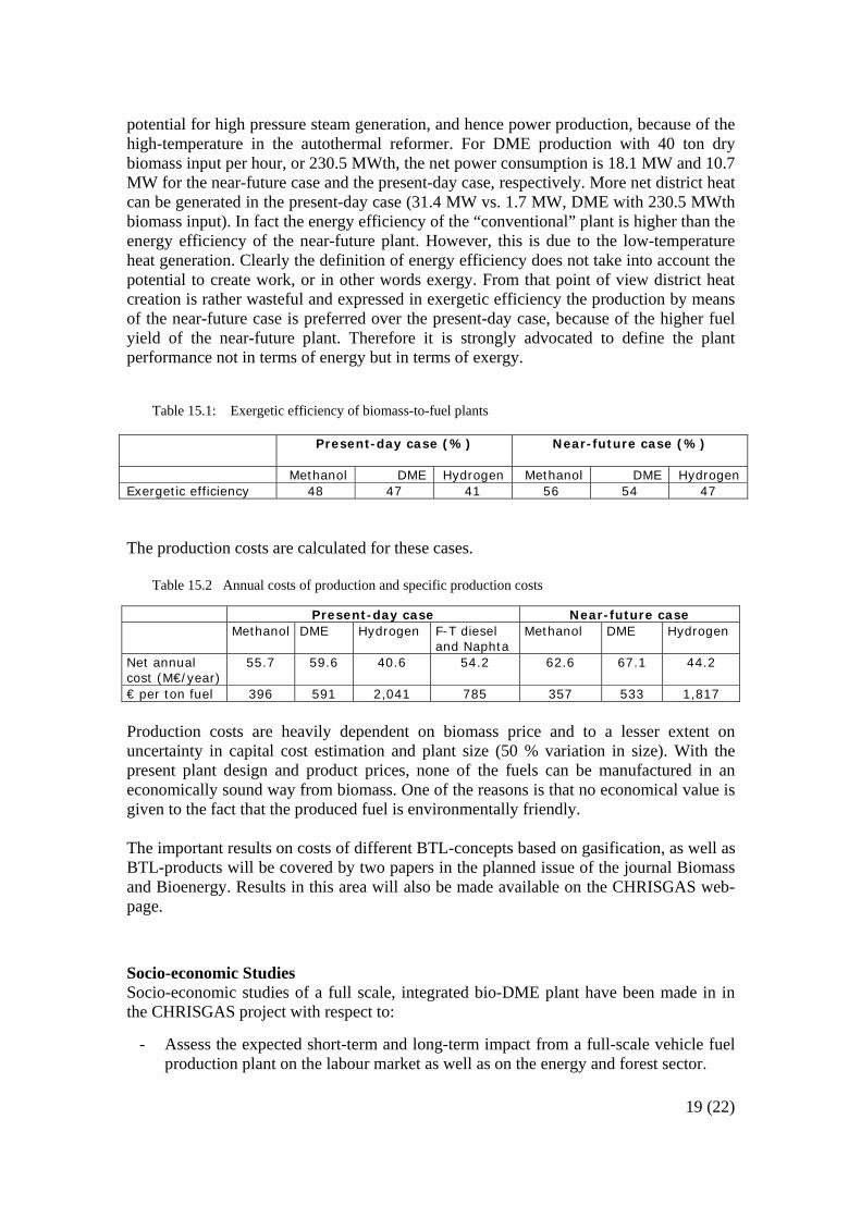
potential for high pressure steam generation, and hence power production, because of the high-temperature in the autothermal reformer. For DME production with 40 ton dry biomass input per hour, or 230.5 MWth, the net power consumption is 18.1 MW and 10.7 MW for the near-future case and the present-day case, respectively. More net district heat can be generated in the present-day case (31.4 MW vs. 1.7 MW, DME with 230.5 MWth biomass input). In fact the energy efficiency of the “conventional” plant is higher than the energy efficiency of the near-future plant. However, this is due to the low-temperature heat generation. Clearly the definition of energy efficiency does not take into account the potential to create work, or in other words exergy. From that point of view district heat creation is rather wasteful and expressed in exergetic efficiency the production by means of the near-future case is preferred over the present-day case, because of the higher fuel yield of the near-future plant. Therefore it is strongly advocated to define the plant performance not in terms of energy but in terms of exergy.
Table 15.1: Exergetic efficiency of biomass-to-fuel plants
Present-day case (%)
Near-future case (%)
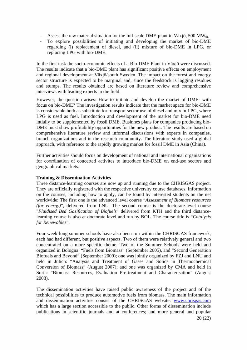
Methanol DME Hydrogen Methanol DME Hydrogen Exergetic efficiency 48 47 41 56 54 47 The production costs are calculated for these cases.
Table 15.2 Annual costs of production and specific production costs
Present-day case Near-future case Methanol DME Hydrogen F-T diesel
and Naphta Methanol DME Hydrogen
Net annual cost (M€/year)
55.7 59.6 40.6 54.2 62.6 67.1 44.2
€ per ton fuel 396 591 2,041 785 357 533 1,817 Production costs are heavily dependent on biomass price and to a lesser extent on uncertainty in capital cost estimation and plant size (50 % variation in size). With the present plant design and product prices, none of the fuels can be manufactured in an economically sound way from biomass. One of the reasons is that no economical value is given to the fact that the produced fuel is environmentally friendly. The important results on costs of different BTL-concepts based on gasification, as well as BTL-products will be covered by two papers in the planned issue of the journal Biomass and Bioenergy. Results in this area will also be made available on the CHRISGAS web-page.
Socio-economic Studies Socio-economic studies of a full scale, integrated bio-DME plant have been made in in the CHRISGAS project with respect to:
- Assess the expected short-term and long-term impact from a full-scale vehicle fuel production plant on the labour market as well as on the energy and forest sector.
20 (22)
- Assess the raw material situation for the full-scale DME-plant in Växjö, 500 MWth, - To explore possibilities of initiating and developing the market of bio-DME
regarding (i) replacement of diesel, and (ii) mixture of bio-DME in LPG, or replacing LPG with bio-DME.
In the first task the socio-economic effects of a Bio-DME Plant in Växjö were discussed. The results indicate that a bio-DME plant has significant positive effects on employment and regional development at Växjö/south Sweden. The impact on the forest and energy sector structure is expected to be marginal and, since the feedstock is logging residues and stumps. The results obtained are based on literature review and comprehensive interviews with leading experts in the field.
However, the question arises: How to initiate and develop the market of DME- with focus on bio-DME? The investigation results indicate that the market space for bio-DME is considerable both as substitute for transport sector use of diesel and mix in LPG, where LPG is used as fuel. Introduction and development of the market for bio-DME need intially to be supplemented by fossil DME. Businnes plans for companies producing bio-DME must show profitability opportunities for the new product. The results are based on comprehensive literature review and informal discussions with experts in companies, branch organizations and in the research community. The literature study used a global approach, with reference to the rapidly growing market for fossil DME in Asia (China). Further activities should focus on development of national and international organisations for coordination of concerted activites to introduce bio-DME on end-use sectors and geographical markets. Training & Dissemination Activities Three distance-learning courses are now up and running due to the CHRISGAS project. They are officially registered with the respective university course databases. Information on the courses, including how to apply, can be found by interested students on the net worldwide: The first one is the advanced level course “Assessment of Biomass resources (for energy)”, delivered from LNU. The second course is the doctorate-level course "Fluidised Bed Gasification of Biofuels" delivered from KTH and the third distance-learning course is also at doctorate level and run by BOL. The course title is “Catalysis for Renewables”. Four week-long summer schools have also been run within the CHRISGAS framework, each had had different, but positive aspects. Two of them were relatively general and two concentrated on a more specific theme. Two of the Summer Schools were held and organized in Bologna: “Fuels from Biomass” (September 2005), and “Second Generation Biofuels and Beyond” (September 2009); one was jointly organized by FZJ and LNU and held in Jülich: “Analysis and Treatment of Gases and Solids in Thermochemical Conversion of Biomass” (August 2007); and one was organized by CMA and held in Soria: “Biomass Resources, Evaluation Pre-treatment and Characterisation” (August 2008). The dissemination activities have raised public awareness of the project and of the technical possibilities to produce automotive fuels from biomass. The main information and dissemination activities consist of the CHRISGAS website: www.chrisgas.com which has a large section accessible to the public. Other forms of dissemination include publications in scientific journals and at conferences; and more general and popular
21 (22)
project presentation activities aimed at a broader public including continuous updates on the website. A general “flyer” and a more technical “Intermediate Report” are also available to the public; either by downloading from the CHRISGAS request or upon request from the Co-ordination office. The Intermediate Report summarises the main results of the project in the first three years and is aimed at a broad technical-oriented audience such as: engineers with a general interest in the state-of-the-art and new developments in the biomass-to automotive fuel sector and/or; to teachers/lecturers/ students in technical subjects at the higher secondary school or first year university level. This enables the public to have access to as many results as possible from the CHRISGAS project. Also and particularly noteworthy the internationally renowned journal Biomass and Bioenergy has been approached and has reacted positively to publishing a Special Edition of its journal incorporating the findings and results of the work undergone in CHRISGAS. This Special Edition devoted solely to CHRISGAS, and incorporating 17 technical and scientific papers will be published before the year end and can be considered a major achievement for dissemination purposes. Finally, inter alia three workshops have been organised within the project time frame: These have been were aimed at utilities and industry in general was planned within the project. The first was organized in connection with the “World Bioenergy” conference in Jönköping, May/June 2006. The theme was “Biofuel Supply including Logistics and Quality as seen from a Regional Perspective”. The second workshop, entitled “Workshop on Vehicle Fuels from Biomass: System and Supply Aspects” took place 26th May as one of the side/pre events to the World Bioenergy 2008 Conference in Jönköping, Sweden. This focused on the optimisation of fuel and energy supply to gain climate benefits and was aimed primarily at fuel suppliers and producers as well as to persons in the position to plan the logistic system. The third workshop held in February 2010, constituted the final event within the project and presented the research results on the whole process chain from biomass resources, pressurised gasification and other thermo-chemical processing to final syngas, as well as plant cost comparisons including synthesis of vehicle fuels for three full scale production capacities.
Contact Information For more information on CHRISGAS visit the project web site: http://www.chrisgas.com or contact the Project Co-ordinator at Linnaeus University:
Dr Sune Bengtsson (Project Co-ordinator) Linnaeus University 351 95 Växjö, Sweden Phone: +46 470 70 88 23 Mobile: +46 70 668 88 23 Fax: +46 470 70 87 56
Email: [email protected]
22 (22)
Annex 1 – Accessible Information and Reports/Deliverables to be available for download to the general public through the CHRISGAS website
CHRISGAS Flyer
CHRISGAS General PowerPoint Presentation Downloadable PPT presentation in several languages including English, Danish, Dutch, German, Italian, Spanish and Swedish
CHRISGAS Project Progress Reports (Annual)
The CHRISGAS Intermediate Report (April 2008) - 56-pages on overall presentations and summary of the project achievements - This is aimed for a non-specialist but technically reasonably skilled audience
Downloadable PowerPoint Presentations from various CHRISGAS workshops organised in association with VEAB This includes 13 presentations from the 3rd and final workshop held in February 2010 and covers the whole process chain from biomass resources, pressurised gasification and other thermo-chemical processing to final syngas, as well as plant cost comparisons including synthesis of vehicle fuels for three full scale production capacities.
Information, including contact details, for the three Distance Learning courses which are now up and running due to the CHRISGAS project: “Assessment of Biomass resources (for energy)” (Masters Level course from Linnaeus University) "Fluidised Bed Gasification of Biofuels" (PhD course from The Royal Institute of Technology KTH) “Catalysis for Renewables” (PhD course from Bologna University)
Technical Reports/Deliverables to be available for download: “Budgetary Assessment of- Post CHRISGAS Transportation Fuel Installation: Part 1 Methanol Catalyst Poisons: A Literature Study” R
Cornelissen, M Rep & S Clevers (CCS) “Feasibility Study of Bio-methanol at Värnamo” by G Huisman and J Brinkert (CCS) “Biomass Resources and Costs in the Nordic and the Central EU Countries” by K Nordenstaaf & T Thörnqvist (LNU) “Biomass Resources and Costs in Spain and Southern European Countries” by L S Esteban, P Ciria, E Maletta, R García and J Carrasco (CMA) “Report on Fuel Supply Logistics and Costs for Typical Fuel Chains in Southern European Countries” by L S Esteban, R García, P Pérez, M Fernández and J Carrasco (CMA) “Regional Amount of Forest Fuel in Sweden” by B Nilsson and T Thörnqvist ( LNU) “Logistics Availability and Cost for Stump Harvesting in Sweden” by B Nilsson and T Thörnqvist (LNU) “Report on the Evaluation of Suitable Drying Processes and their Integration with the Gasification Process” by O Thorson and O Wennberg (SEP) “Report on the Experimental Result and Evaluation of Drying at Low Temperature in a Stationary Bed” by P Bengtsson (LNU) and O Wennberg
(SEP) “Design Studies of Bed Drying by Mathematical Modeling” by P Bengtsson (LNU) and J Claesson (Chalmers University) “TUD Report on First Oxygen-steam Blown 100 kWth CFB Gasification Tests with Measurements of Major/Minor Gaseous Species (especially Nitrogen, Sulphur Species) and Initial Solid Sample Characterization Results” by M. Siedlecki and W de Jong (TUD) “Characterisation of Biofuels” by D Porbatzki and M Müller (FZJ) “First Data of “Basic” MS Release Investigations on Biofuels” by D Porbatzki and M Müller (FZJ) “MS Characterisation on Hot Gas Chemistry” by D Porbatzki, M Stemmler and M Müller (FZJ) “Final Reports on Gas Contaminants from Fuel Bound Sources” by D Porbatzki and M Müller (FZJ) “Literature and State of the Art Review (Re: Methane Steam Reforming)”by N Padban and V Becher (TPS) “Literature and State of the Art Review (Re: Gas Upgrading by Reforming)” by S Albertazzi (BOL), F Basile (BOL), J Brandin (LNU), J Einvall
(LNU), E Gustafsson (LNU), C Hulterberg (CAT), M Sanati (LNU), F Trifirò (BOL) “Preliminary Evaluation Of Alternative Active Phases” by S Albertazzi (BOL), F Basile (BOL), J Brandin (LNU), J Einvall (LNU), C Hulterberg
(CAT), M Sanati (LNU), F Trifirò (BOL) “Report On Catalytic Water Gas Shift Studies” by H Abdulhamid (LNU), S Albertazzi (BOL), F Basile(BOL), J Brandin (CAT), M Sanati (LNU) and F Trifirò (BOL) “Scale-Up and Assessment of Water Gas Shift Unit” by J Brandin, J Einvall, C Parsland (LNU) “State of the Art Review on Separation of Hydrogen by Membranes and WGS catalysts” by J Sanchez, M Marono and A Cabanillas (CMA) “State of the Art Review (Re: CFB Modelling)” by B Zethraeus (LNU) and T Lixin (TPS) “Cost Estimate for a Biomass Plant with a fuel Input of 20 to 80~dry tonnes/hr” by GH Huisman, J Brinkert, GLMA. van Rens and RL Cornelissen
(CCS) “Extended Gasification to Liquid Product Mass and Energy Balance Model” by GH Huisman, J Brinkert, GLMA van Rens and RL Cornelissen
(CCS) “Report on the Co and Poly-generation Potential when Co-localising with a Municipal Co-generation Plant” by J Rodin and O Wennberg (SEP) “Socio-economic Effects of a Bio-DME Plant in Växjö” by A Baudin and H-O Nordvall (LNU) “How to Initiate and Develop the Market of DME – With Focus on Bio-DME?” by A Baudin and H-O Nordvall (LNU)
Related Documents


![Galileo App SIXTH FRAMEWORK PROGRAMME – PRIORITY [4] [Aeronautics and Space] SPECIFIC SUPPORT ACTION PROJECT Janusz B. Zieliński Polish Space Office Space.](https://static.cupdf.com/doc/110x72/56649f305503460f94c4ac0b/galileo-app-sixth-framework-programme-priority-4-aeronautics-and-space.jpg)