Order no.: FDK:521H0721 SFIDK.PS.029.W3.02 SITRANS F US SONOFLO Ultrasonic flowmeter Sensor type SONO 3300 CT Transmitter SONO 3000 CT [ ] 22.16 98.02 Type approval of the measuring system: TS 27.01-076 *085R9405* Handbook Edition 09/2006 - Revision 03 s Technical Documentation (handbooks, instructions, manuals etc.) for the complete product range SITRANS F can be found on the internet/intranet via the following link: English: http://www4.ad.siemens.de/WW/view/en/10806951/133300

Welcome message from author
This document is posted to help you gain knowledge. Please leave a comment to let me know what you think about it! Share it to your friends and learn new things together.
Transcript

Order no.: FDK:521H0721
SFIDK.PS.029.W3.02
SITRANS F US SONOFLOUltrasonic flowmeterSensor type SONO 3300 CTTransmitter SONO 3000 CT
[ ]
22.1698.02
Type approval of the measuring system:
TS 27.01-076
*085R9405*
HandbookEdition 09/2006 - Revision 03
s
Technical Documentation (handbooks, instructions, manuals etc.) for the complete productrange SITRANS F can be found on the internet/intranet via the following link:
English: http://www4.ad.siemens.de/WW/view/en/10806951/133300
SFIDK.PS.029.W3.02
SITRANS F US SONOFLO
2
1. Introduction1.1 Product introduction .......................................................................................................................... 31.2 Precision measuring system ............................................................................................................ 31.3 Approvals .......................................................................................................................................... 31.4 Handling ............................................................................................................................................. 31.5 System description (CT) .................................................................................................................. 41.5.1 Flow sensor SONO 3300 CT ........................................................................................................... 41.5.2 Transmitter SONO 3000 CT, IP67, for wall mounting ...................................................................... 41.5.3 Transmitter SONO 3000 CT, IP65, for wall mounting ...................................................................... 41.5.4 Transmitter SONO 3000 CT, IP20, front of panel ............................................................................ 41.5.5 Union connection .............................................................................................................................. 4
2. Mode of operation ............................................................................................................................. 52.1 Function ............................................................................................................................................. 5
3. Technical data ................................................................................................................................... 83.1 Flow sensor SONO 3300 CT ........................................................................................................... 83.2 Permissible pressure and temperature ............................................................................................ 83.3 Corrosion .......................................................................................................................................... 83.4 Coaxial cable ..................................................................................................................................... 93.5 Transmitter SONO 3000 CT - General data .................................................................................... 93.5.1 Enclosure IP67, wall mounting ....................................................................................................... 103.5.2 Enclosure IP20, front of panel ........................................................................................................ 103.5.3 Enclosure IP65, wall mounting ....................................................................................................... 10
4. Measuring accuracy ....................................................................................................................... 114.1 Accuracy of SONO CT .................................................................................................................. 11
5. Dimensions and weight ................................................................................................................... 125.1 Dimensions of flow sensor SONO 3300 CT .................................................................................. 125.2 Weight of flow sensor SONO 3300 CT .......................................................................................... 125.3 Transmitter SONO 3000 CT, IP67, wall mounting ......................................................................... 135.4 Transmitter SONO 3000 CT, IP65, wall mounting ......................................................................... 135.5 Transmitter SONO 3000 CT, IP20, front of panel .......................................................................... 13
6. Project guidance ............................................................................................................................. 146.1 Mounting of the flow sensor SONO 3300 CT ................................................................................ 146.2 Mounting the flow sensor SONO 3300 CT .................................................................................... 156.3 Sizing table OIML R75 approvals ................................................................................................... 166.4 Sizing table PTB approvals ............................................................................................................. 16
7. Installation ....................................................................................................................................... 177.1 Installation of sensor ....................................................................................................................... 177.2 Installation of wall bracket for the SONO 3000 CT transmitter ..................................................... 18
8. Electrical connection ....................................................................................................................... 198.1 Transmitter SONO 3000 CT, IP67, wall mounting ......................................................................... 198.2 Transmitter SONO 3000 CT, IP65 and IP20 ................................................................................. 208.3 Frequency output with a load > 10kW ........................................................................................... 218.4 Relay mode for transmitter IP67 .................................................................................................... 218.5 Relay mode for transmitter IP65 and IP20 .................................................................................... 218.6 PTB transmitter in IP65 version for wall mounting ......................................................................... 228.7 IP65 wall mounting box connection ................................................................................................ 228.8 Installation of SENSORPROM memory unit .................................................................................. 23
9. Commissioning ................................................................................................................................ 249.1 Keypad and display layout .............................................................................................................. 249.2 Keypad ............................................................................................................................................ 249.3 Display ............................................................................................................................................. 249.4 Menu build-up .................................................................................................................................. 259.5 Submenus for BASIC SETTINGS .................................................................................................. 269.6 MENU BUILD-UP ............................................................................................................................ 279.7 Submenus for SENSOR CHARACTERISTICS ............................................................................. 319.8 Factory settings .............................................................................................................................. 329.9 Start-up ............................................................................................................................................ 329.10 Factory settings and measuring ranges ........................................................................................ 33
10. Trouble shooting .............................................................................................................................. 3410.1 Trouble shooting .............................................................................................................................. 3410.2 Fault location guide ......................................................................................................................... 3510.3 Service mode .................................................................................................................................. 36
11. Calibration/sealing ........................................................................................................................... 3711.1 Calibration ....................................................................................................................................... 3711.2 Data label ........................................................................................................................................ 3811.3 Verification sealing ........................................................................................................................... 3911.4 User sealing (General) ................................................................................................................... 4011.4.1 Transmitter SONO 3000 CT, IP67 ................................................................................................. 4011.4.2 Transmitter SONO 3000 CT, IP65 ................................................................................................. 4011.4.3 Transmitter SONO 3000 CT, IP20 ................................................................................................. 4011.4.4 Sensor SONO 3300 CT with sealed transducers ......................................................................... 40
12. Ordering .......................................................................................................................................... 4112.1 Selection and ordering data ............................................................................................................ 41
Contents
SITRANS F US SONOFLO
SFIDK.PS.029.W3.02 3
1.1 Product introduction
1. Introduction
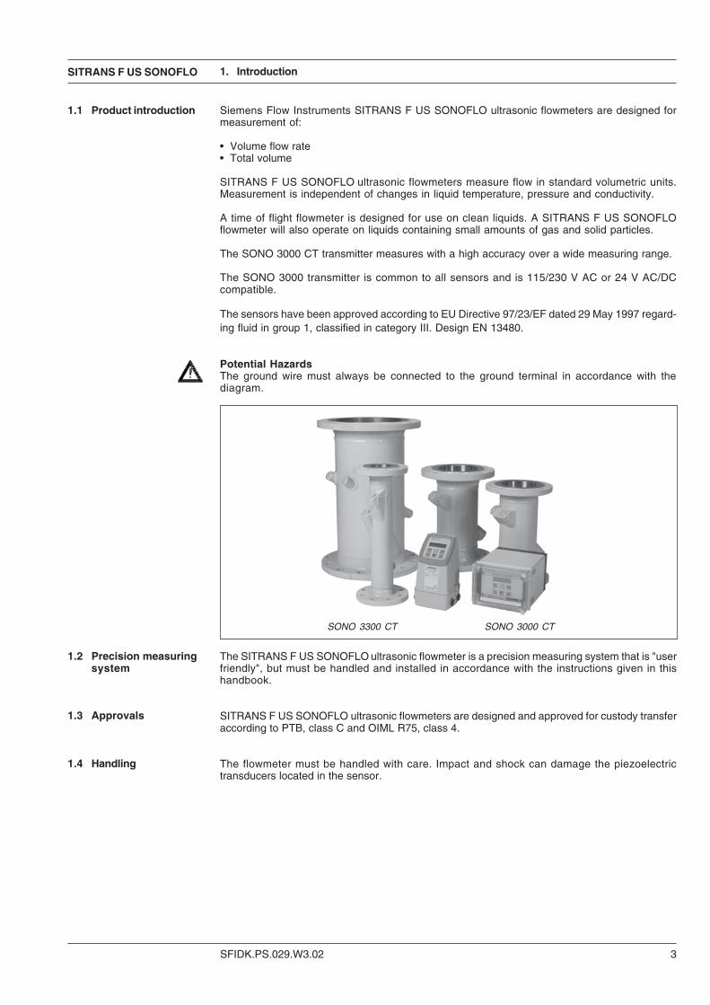
Siemens Flow Instruments SITRANS F US SONOFLO ultrasonic flowmeters are designed formeasurement of:
• Volume flow rate• Total volume
SITRANS F US SONOFLO ultrasonic flowmeters measure flow in standard volumetric units.Measurement is independent of changes in liquid temperature, pressure and conductivity.
A time of flight flowmeter is designed for use on clean liquids. A SITRANS F US SONOFLOflowmeter will also operate on liquids containing small amounts of gas and solid particles.
The SONO 3000 CT transmitter measures with a high accuracy over a wide measuring range.
The SONO 3000 transmitter is common to all sensors and is 115/230 V AC or 24 V AC/DCcompatible.
The sensors have been approved according to EU Directive 97/23/EF dated 29 May 1997 regard-ing fluid in group 1, classified in category III. Design EN 13480.
SONO 3300 CT SONO 3000 CT
1.2 Precision measuringsystem
1.3 Approvals
1.4 Handling
The SITRANS F US SONOFLO ultrasonic flowmeter is a precision measuring system that is "userfriendly", but must be handled and installed in accordance with the instructions given in thishandbook.
SITRANS F US SONOFLO ultrasonic flowmeters are designed and approved for custody transferaccording to PTB, class C and OIML R75, class 4.
The flowmeter must be handled with care. Impact and shock can damage the piezoelectrictransducers located in the sensor.
Potential HazardsThe ground wire must always be connected to the ground terminal in accordance with thediagram.

SFIDK.PS.029.W3.02
SITRANS F US SONOFLO
4
1.5 System description(CT)
The SONO CT flowmeter consists of a sensor type SONO 3300 CT, a transmitter type SONO 3000CT and coaxial cables.
1.5.1 Flow sensorSONO 3300 CT
The SONO 3300 CT is a 2-track direct shotsensor type.It is available with pipe dimensions DN 50 toDN 1200 (flow rate from 3 to 40,700 m3/h).
1.5.2 TransmitterSONO 3000 CT,IP67, for wallmounting
The transmitter type SONO 3000 CT is avail-able in wall mounting enclosure IP67 and in115/230 V AC.Approvals: PTB, class C and OIML R75,class 4.
1. Introduction
1.5.3 TransmitterSONO 3000 CT,IP65, for wallmounting
The SONO 3000 CT transmitter is available inwall mounting enclosure IP65 and in 115/230V AC or 24 V AC/DC.Approvals: PTB, class C.
1.5.4 TransmitterSONO 3000 CT,IP20, front of panel
The SONO 3000 CT transmitter is available as“front of panel”-enclosure IP20 and in 115/230V AC.Approvals: PTB, class C.
4 coaxial cables with plug-in/union connec-tions between sensor and transmitter.
1.5.5 Union connection

SITRANS F US SONOFLO
SFIDK.PS.029.W3.02 5
2. Mode of operation
2.1 Function Direct signal processingIn the SITRANS F US SONOFLO ultrasonic flowmeter program the signal is sent directly andwithout deflection to the bore wall from the transmitter to the receiver. The advantage gainedsending signals from point to point is an extremely good signal strength for the signal processingavoiding a suddenly flowmeter stop.
Physical principle
A sound wave traveling in the same direction as the liquid flow arrives at point B from point A ina shorter time than the sound wave traveling against the direction of flow (from point B to A).The difference in sound transit time indicates the flow velocity in the pipe.Since delay time is measured at short intervals both in and against flow direction, viscosity andtemperature have no influence on measurement accuracy.
Measuring principleIn SITRANS F US SONOFLO flowmeters the two ultrasonic transducers are placed at an angleθ in relation to the pipe axis. The transducers function as transmitters and receivers of theultrasonic signals. Measurement is performed by determining the time the ultrasonic signal takesto travel with and against the flow. The principle can be expressed as follows:
v = K x (tA,B – tB,A) / (tA,B x tB,A) = K x ∆ t/t²
v = Average flow velocityt = Transit timeK = Proportional flow factor
This measuring principle offers the advantage that it is independent of variations in the actualsound velocity of the liquid, i.e. independent of the temperature. Proportional factor K isdetermined by wet calibration.
Velocity distribution along sound path
SFIDK.PS.029.W3.02
SITRANS F US SONOFLO
6
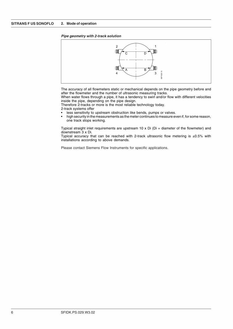
Pipe geometry with 2-track solution
The accuracy of all flowmeters static or mechanical depends on the pipe geometry before andafter the flowmeter and the number of ultrasonic measuring tracks.When water flows through a pipe, it has a tendency to swirl and/or flow with different velocitiesinside the pipe, depending on the pipe design.Therefore 2-tracks or more is the most reliable technology today.2-track systems offer• less sensitivity to upstream obstruction like bends, pumps or valves.• high security in the measurements as the meter continues to measure even if, for some reason,
one track stops working.
Typical straight inlet requirements are upstream 10 x Di (Di = diameter of the flowmeter) anddownstream 3 x Di.Typical accuracy that can be reached with 2-track ultrasonic flow metering is ±0.5% withinstallations according to above demands.
Please contact Siemens Flow Instruments for specific applications.
2. Mode of operation
SITRANS F US SONOFLO
SFIDK.PS.029.W3.02 7
2. Mode of operation
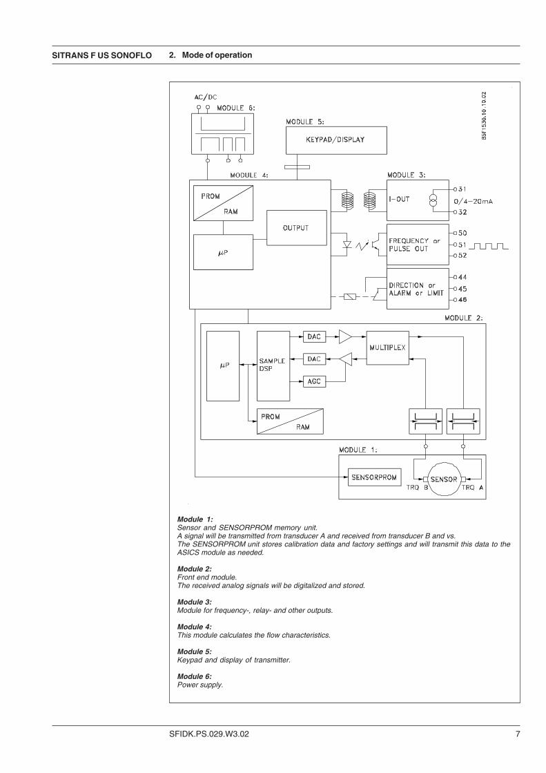
Module 1:Sensor and SENSORPROM memory unit.A signal will be transmitted from transducer A and received from transducer B and vs.The SENSORPROM unit stores calibration data and factory settings and will transmit this data to theASICS module as needed.
Module 2:Front end module.The received analog signals will be digitalized and stored.
Module 3:Module for frequency-, relay- and other outputs.
Module 4:This module calculates the flow characteristics.
Module 5:Keypad and display of transmitter.
Module 6:Power supply.
SFIDK.PS.029.W3.02
SITRANS F US SONOFLO
8
Description 2-track sensor with flanges and integrated transducers
Nominal size DN 50, DN 65, DN 80, DN 100, DN 125, DN 150, DN 200,DN 250, DN 300, DN 350, DN 400, DN 500, DN 600,DN 700, DN 800, DN 900, DN 1000, DN 1200
Liquid temperature −10 °C to +200 °C depending on approval
Ambient temperature −10 °C to +160 °C depending on approval
Storage: −40 °C to +85 °C
Enclosure Standard version IP67
Process connections PN 10 (DN 500 to DN 1200)PN designated PN 16 (DN 50 to DN 1200)EN 1092-1, type 11, B
PN 25 (DN 200 to DN 1000)
PN 40 (DN 50 to DN 500)
Transducers Integrated version welded into pipe
Materials:Pipe DN 50 to DN 150: Steel W1.1131 GS-16Mn5
DN 200 to DN 1200: Steel EN 1.0345 P235GH
Flange DN 50 to DN 1200: Steel group 1E1, EN 1.0038 S235JRG2
Transducers Stainless steel
Material certificate The sensor is supplied as standard with a Siemens FlowInstruments certificate of conformity.Material certificate on wetted parts on request
NDT examination report Available on request
Max. flow velocity 10 m/s
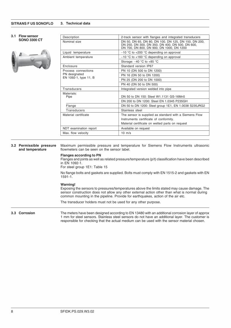
3.1 Flow sensorSONO 3300 CT
3. Technical data
3.2 Permissible pressureand temperature
Maximum permissible pressure and temperature for Siemens Flow Instruments ultrasonicflowmeters can be seen on the sensor label.
Flanges according to PNFlanges and joints as well as related pressure/temperature (p/t) classification have been describedin EN 1092-1.For steel group 1E1: Table 15
No flange bolts and gaskets are supplied. Bolts must comply with EN 1515-2 and gaskets with EN1591-1.
Warning!Exposing the sensors to pressures/temperatures above the limits stated may cause damage. Thesensor construction does not allow any other external action other than what is normal duringcommon mounting in the pipeline. Provide for earthquakes, action of the air etc.
The transducer holders must not be used for any other purpose.
3.3 Corrosion The meters have been designed according to EN 13480 with an additional corrosion layer of approx1 mm for steel sensors. Stainless steel sensors do not have an additional layer. The customer isresponsible for checking that the actual medium can be used with the sensor material chosen.
SITRANS F US SONOFLO
SFIDK.PS.029.W3.02 9
Terminalconnection
Analog output Individually galvanically isolated,isolation voltage 500 V 31 and 32
Measurement of: Volume flow
Current 0 - 20 mA or 4 - 20 mA
Load < 800 ohm
Time constant 5 s
Frequency/pulse output Individually galvanically isolated, 50, 51 and 52isolation voltage 500 V
Measurement of Volume flow
Frequency 0-1/1-10 kHz
Time constant 5 s
Pulse width 0.5 ms, 5 ms, 20 ms, 50 ms, 100 ms, 200 ms,500 ms
Active: Output mode 24 - 30 V DC/max. 25 mA, (50 µs to 5 s)
(50 ms E.Mech., max. 75 mA if F < 1 Hz)
24 - 30 V DC/max, 50 mA, (500 Hz to 10 kHz)
Passive: Output mode 5 - 30 V DC
Max. current 200 mA
Output mode Output can be either active or passivedepending on electrical connection
Relay Change-over relay (error indication, 44, 45 and 46flow direction, sound velocity limit)
Load 42 V, 0.5 A
Time constant/Hysteresis 5 s/0.5 % F.S.O.
Cut off: Low flow 0.8 % F.S.O.
Internal counters (totalizers) Two internal counters. Selectable uni- orbidirectional counting (Net flow)
Measurement of Total volume
Display Back-lit with alphanumerical text, 2 x 16 digitsfor indication of: measured values, totalization,settings, error codes and alarms
CE-mark EMC Emission ImmunityEN 61000-6-4 EN 61000-6-2
Low voltage According to EN 61010-1
3.5 Transmitter SONO3000 CT - Generaldata
3. Technical data
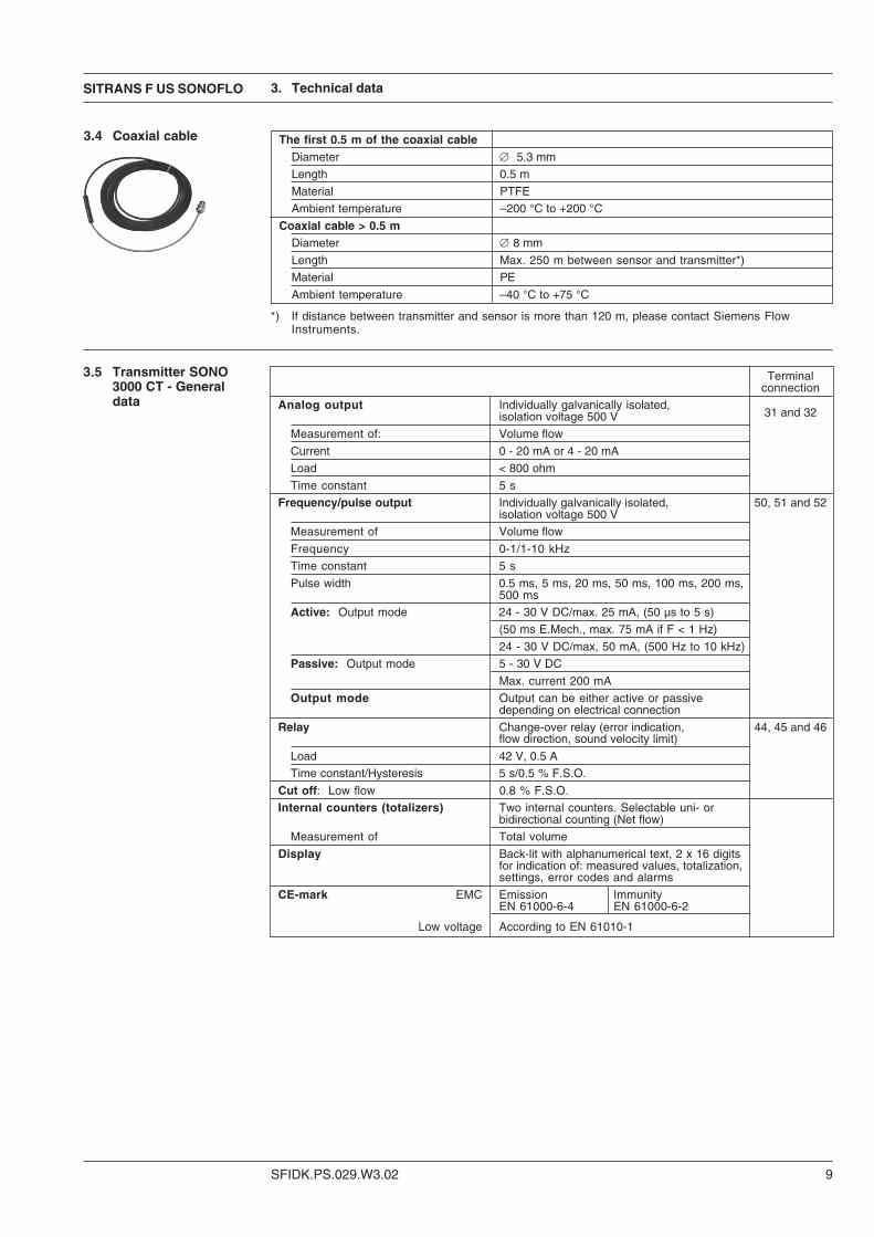
The first 0.5 m of the coaxial cableDiameter ∅ 5.3 mm
Length 0.5 m
Material PTFE
Ambient temperature –200 °C to +200 °C
Coaxial cable > 0.5 mDiameter ∅ 8 mm
Length Max. 250 m between sensor and transmitter*)
Material PE
Ambient temperature –40 °C to +75 °C
3.4 Coaxial cable
*) If distance between transmitter and sensor is more than 120 m, please contact Siemens FlowInstruments.
SFIDK.PS.029.W3.02
SITRANS F US SONOFLO
10
3. Technical data
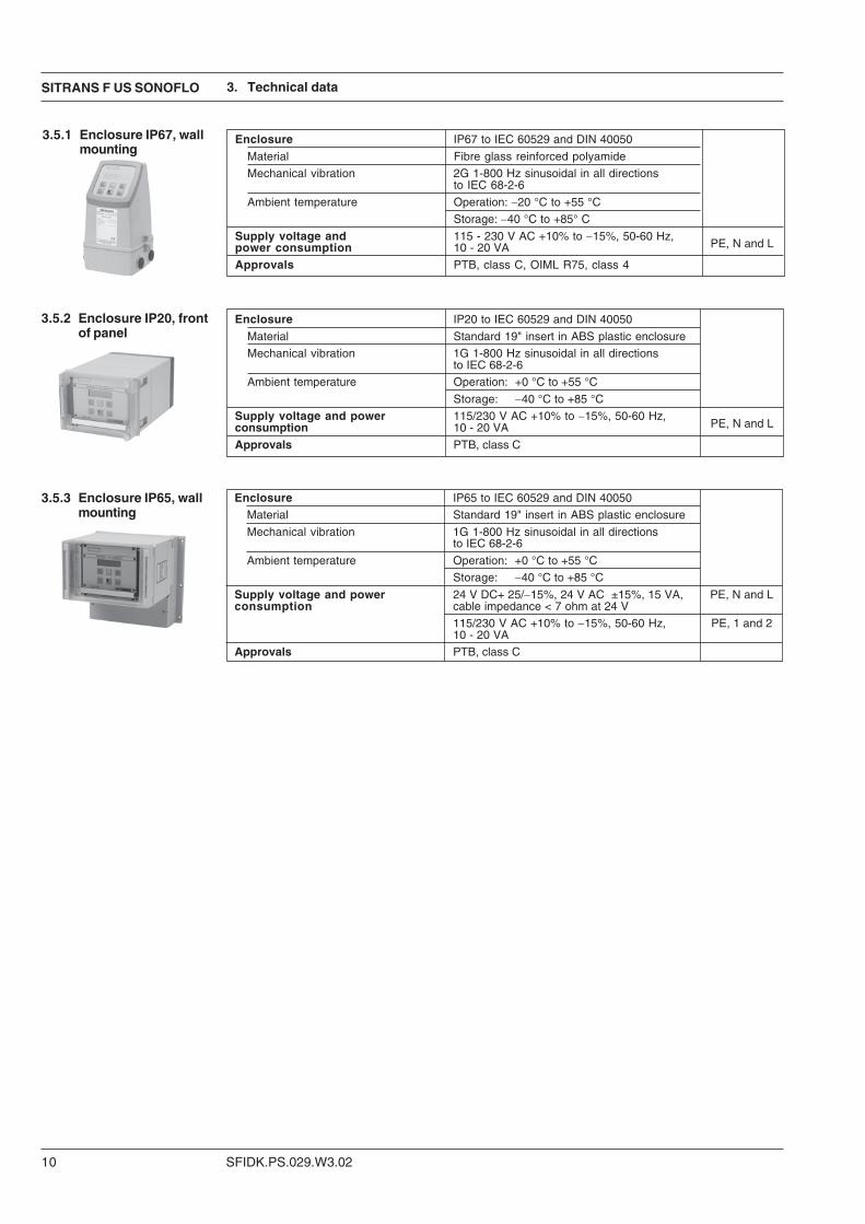
Enclosure IP20 to IEC 60529 and DIN 40050
Material Standard 19" insert in ABS plastic enclosure
Mechanical vibration 1G 1-800 Hz sinusoidal in all directionsto IEC 68-2-6
Ambient temperature Operation: +0 °C to +55 °C
Storage: −40 °C to +85 °C
Supply voltage and power 115/230 V AC +10% to −15%, 50-60 Hz,consumption 10 - 20 VA PE, N and L
Approvals PTB, class C
Enclosure IP65 to IEC 60529 and DIN 40050
Material Standard 19" insert in ABS plastic enclosure
Mechanical vibration 1G 1-800 Hz sinusoidal in all directionsto IEC 68-2-6
Ambient temperature Operation: +0 °C to +55 °C
Storage: −40 °C to +85 °C
Supply voltage and power 24 V DC+ 25/−15%, 24 V AC ±15%, 15 VA, PE, N and Lconsumption cable impedance < 7 ohm at 24 V
115/230 V AC +10% to −15%, 50-60 Hz, PE, 1 and 210 - 20 VA
Approvals PTB, class C
3.5.3 Enclosure IP65, wallmounting
3.5.2 Enclosure IP20, frontof panel
3.5.1 Enclosure IP67, wallmounting
Enclosure IP67 to IEC 60529 and DIN 40050
Material Fibre glass reinforced polyamide
Mechanical vibration 2G 1-800 Hz sinusoidal in all directionsto IEC 68-2-6
Ambient temperature Operation: −20 °C to +55 °C
Storage: −40 °C to +85° C
Supply voltage and 115 - 230 V AC +10% to −15%, 50-60 Hz,power consumption 10 - 20 VA PE, N and L
Approvals PTB, class C, OIML R75, class 4
SITRANS F US SONOFLO
SFIDK.PS.029.W3.02 11
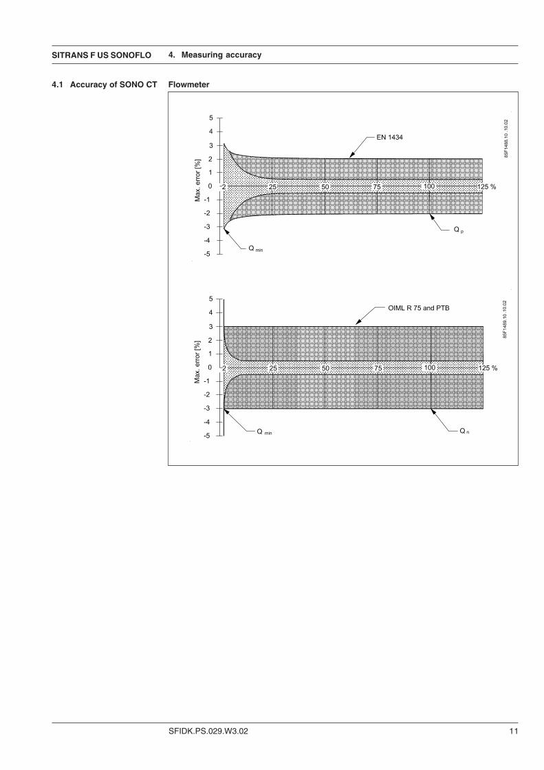
Flowmeter4.1 Accuracy of SONO CT
4. Measuring accuracy
SFIDK.PS.029.W3.02
SITRANS F US SONOFLO
12
5. Dimensions and weight
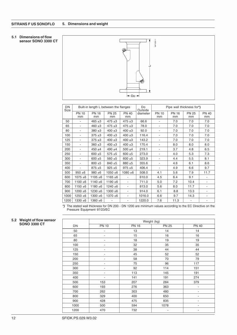
DN Built-in length L between the flanges Do Pipe wall thickness for*)Size Outside
PN 10 PN 16 PN 25 PN 40 diameter PN 10 PN 16 PN 25 PN 40mm mm mm mm mm mm mm mm
50 - 465 ±3 475 ±3 475 ±3 66.6 - 7.0 7.0 7.0
65 - 460 ±3 475 ±3 475 ±3 78.0 - 7.0 7.0 7.0
80 - 380 ±3 400 ±3 400 ±3 92.0 - 7.0 7.0 7.0
100 - 375 ±3 400 ±3 400 ±3 116.4 - 7.0 7.0 7.0
125 - 375 ±3 400 ±3 400 ±3 143.2 - 7.0 7.0 7.0
150 - 360 ±3 400 ±3 400 ±3 170.4 - 8.0 8.0 8.0
200 - 450 ±4 490 ±4 500 ±4 219.1 - 3.7 4.8 6.5
250 - 600 ±5 575 ±5 600 ±5 273.0 - 4.0 5.3 7.3
300 - 600 ±5 560 ±5 600 ±5 323.9 - 4.4 5.5 8.1
350 - 800 ±5 840 ±5 880 ±5 355.6 - 4.6 6.1 8.6
400 - 875 ±5 925 ±5 975 ±5 406.4 - 4.9 6.6 9.7
500 950 ±6 980 ±6 1050 ±6 1080 ±6 508.0 4.1 5.6 7.9 11.7
600 1075 ±6 1105 ±6 1165 ±6 - 610.0 4.5 6.4 9.1 -
700 1100 ±6 1140 ±6 1190 ±6 - 711.0 5.0 7.2 10.4 -
800 1150 ±6 1180 ±6 1240 ±6 - 813.0 5.6 8.0 11.7 -
900 1200 ±6 1230 ±6 1300 ±6 - 914.0 6.1 8.8 13.3 -
1000 1250 ±6 1300 ±6 1370 ±6 - 1016.0 6.6 9.7 14.3 -
1200 1330 ±6 1360 ±6 - - 1220.0 7.6 11.3 - -
5.1 Dimensions of flowsensor SONO 3300 CT
Weight (kg)DN PN 10 PN 16 PN 25 PN 40
50 - 13 14 14
65 - 15 16 16
80 - 18 19 19
100 - 32 35 35
125 - 38 44 44
150 - 45 52 52
200 - 58 70 79
250 - 75 96 117
300 - 92 114 151
350 - 113 145 191
400 - 141 191 274
500 153 207 284 379
600 193 276 363 -
700 262 303 480 -
800 329 400 650 -
900 428 475 835 -
1000 500 594 1078 -
1200 470 732 - -
5.2 Weight of flow sensorSONO 3300 CT
*) The stated wall thickness for DN 200 - DN 1200 are minimum values according to the EC Directive on thePressure Equipment 97/23/EC
SITRANS F US SONOFLO
SFIDK.PS.029.W3.02 13
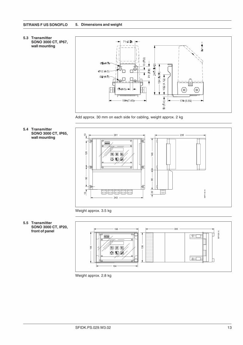
5.3 TransmitterSONO 3000 CT, IP67,wall mounting
Add approx. 30 mm on each side for cabling, weight approx. 2 kg
5.4 TransmitterSONO 3000 CT, IP65,wall mounting
5.5 TransmitterSONO 3000 CT, IP20,front of panel
5. Dimensions and weight
Weight approx. 3.5 kg
Weight approx. 2.8 kg
SFIDK.PS.029.W3.02
SITRANS F US SONOFLO
14
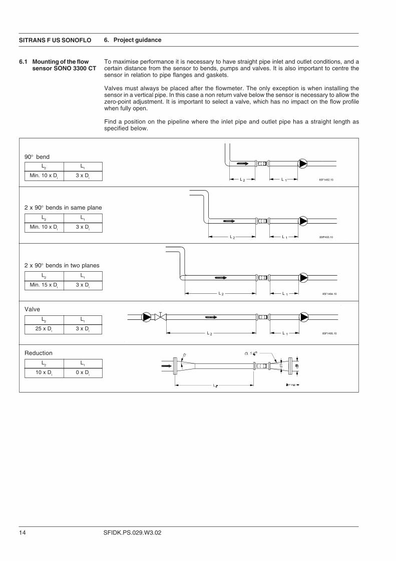
6.1 Mounting of the flowsensor SONO 3300 CT
L2 L1
Min. 10 x Di 3 x Di
90° bend
L2 L1
Min. 10 x Di 3 x Di
L2 L1
Min. 15 x Di 3 x Di
2 x 90° bends in two planes
2 x 90° bends in same plane
L2 L1
25 x Di 3 x Di
Valve
L2 L1
10 x Di 0 x Di
Reduction
To maximise performance it is necessary to have straight pipe inlet and outlet conditions, and acertain distance from the sensor to bends, pumps and valves. It is also important to centre thesensor in relation to pipe flanges and gaskets.
Valves must always be placed after the flowmeter. The only exception is when installing thesensor in a vertical pipe. In this case a non return valve below the sensor is necessary to allow thezero-point adjustment. It is important to select a valve, which has no impact on the flow profilewhen fully open.
Find a position on the pipeline where the inlet pipe and outlet pipe has a straight length asspecified below.
6. Project guidance
SITRANS F US SONOFLO
SFIDK.PS.029.W3.02 15
6. Project guidance
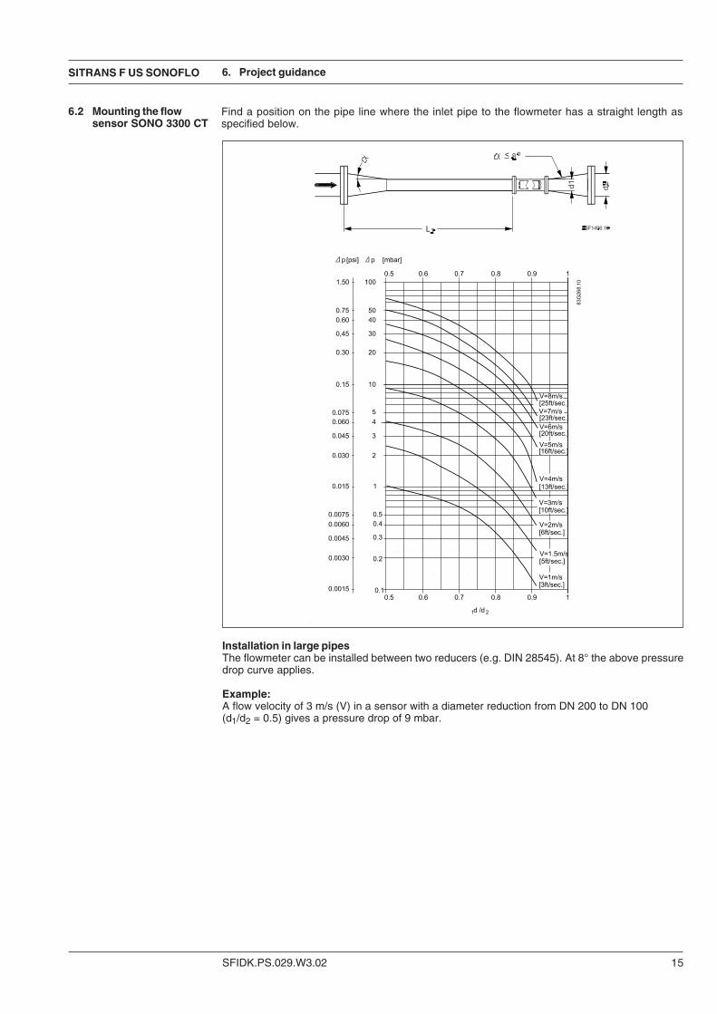
6.2 Mounting the flowsensor SONO 3300 CT
Find a position on the pipe line where the inlet pipe to the flowmeter has a straight length asspecified below.
Installation in large pipesThe flowmeter can be installed between two reducers (e.g. DIN 28545). At 8° the above pressuredrop curve applies.
Example:A flow velocity of 3 m/s (V) in a sensor with a diameter reduction from DN 200 to DN 100(d1/d2 = 0.5) gives a pressure drop of 9 mbar.
SFIDK.PS.029.W3.02
SITRANS F US SONOFLO
16
Lowest possible Highest possibleselection selection
DN Qmin. Qn Qmin. Qnnominal diameter in in in in
mm m3/h m3/h m3/h m3/h50 0.3 15 1.7 8465 0.5 25 2.8 14080 0.8 40 3.8 192
100 1.4 70 6.5 324125 2.0 100 9.8 490150 2.6 130 14.0 720200 3.8 190 24.0 1215250 4.8 240 38.0 1917300 5.4 270 40.0 2000350 6.6 330 40.0 2000400 8.4 420 40.0 2000500 13.0 660 40.0 2000600 20.0 980 40.0 2000700 28.0 1400 40.0 2000
6. Project guidance
6.3 Sizing table OIML R75approvals
Dynamic range
6.4 Sizing table PTBapprovals
DN Minimum flow Maximum flownominal diameter (velocity 0.04 m/s) (velocity 10 m/s)
mm m3/h m3/h50 0.3 8465 0.5 14080 0.8 192
100 1.2 324125 2.0 490150 3.0 720200 5.0 1.215250 8.0 1.917300 11.0 2.740350 13.0 3.261400 17.0 4.309500 28.0 7.069600 40.0 9.923700 55.0 13.854800 72.0 18.096900 92.0 22.9021000 113.0 28.2741200 163.0 40.715
The dynamic range varies depending on the Qn set between: 1:250 and 1:280 but at last 1:10.
The dynamic range is always 1:50.Dynamic range
SITRANS F US SONOFLO
SFIDK.PS.029.W3.02 17
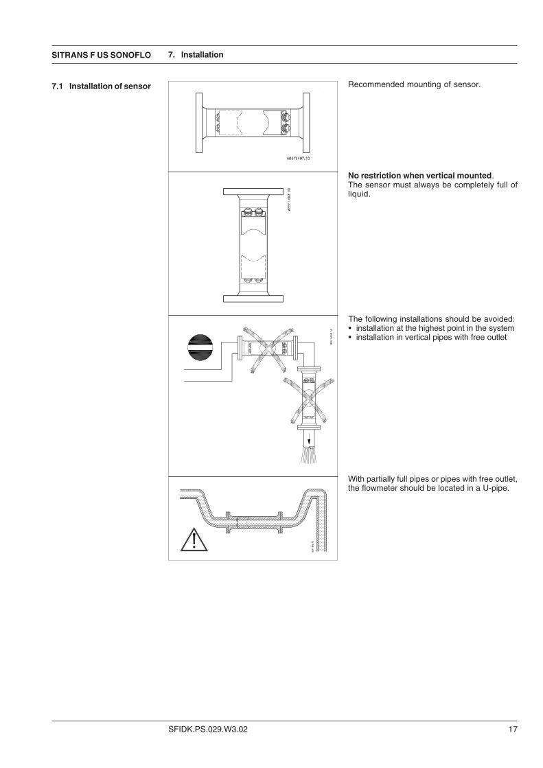
With partially full pipes or pipes with free outlet,the flowmeter should be located in a U-pipe.
The following installations should be avoided:• installation at the highest point in the system• installation in vertical pipes with free outlet
Recommended mounting of sensor.
7. Installation
No restriction when vertical mounted.The sensor must always be completely full ofliquid.
7.1 Installation of sensor
SFIDK.PS.029.W3.02
SITRANS F US SONOFLO
18
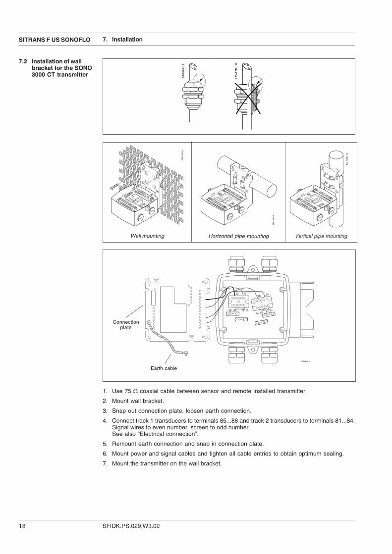
7.2 Installation of wallbracket for the SONO3000 CT transmitter
1. Use 75 Ω coaxial cable between sensor and remote installed transmitter.
2. Mount wall bracket.
3. Snap out connection plate, loosen earth connection.
4. Connect track 1 transducers to terminals 85...88 and track 2 transducers to terminals 81...84.Signal wires to even number, screen to odd number.See also “Electrical connection”.
5. Remount earth connection and snap in connection plate.
6. Mount power and signal cables and tighten all cable entries to obtain optimum sealing.
7. Mount the transmitter on the wall bracket.
7. Installation
Vertical pipe mountingHorizontal pipe mounting
Connectionplate
Earth cable
Wall mounting
SITRANS F US SONOFLO
SFIDK.PS.029.W3.02 19
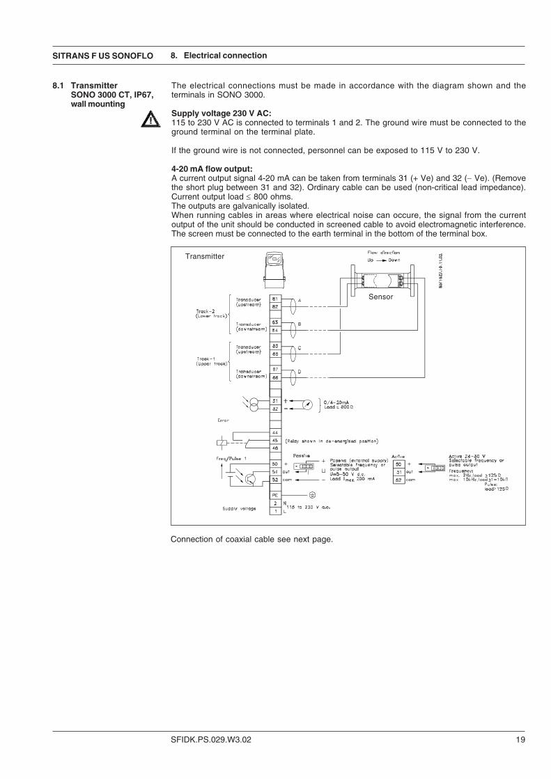
8.1 TransmitterSONO 3000 CT, IP67,wall mounting
The electrical connections must be made in accordance with the diagram shown and theterminals in SONO 3000.
Supply voltage 230 V AC:115 to 230 V AC is connected to terminals 1 and 2. The ground wire must be connected to theground terminal on the terminal plate.
If the ground wire is not connected, personnel can be exposed to 115 V to 230 V.
4-20 mA flow output:A current output signal 4-20 mA can be taken from terminals 31 (+ Ve) and 32 (− Ve). (Removethe short plug between 31 and 32). Ordinary cable can be used (non-critical lead impedance).Current output load ≤ 800 ohms.The outputs are galvanically isolated.When running cables in areas where electrical noise can occure, the signal from the currentoutput of the unit should be conducted in screened cable to avoid electromagnetic interference.The screen must be connected to the earth terminal in the bottom of the terminal box.
8. Electrical connection
Connection of coaxial cable see next page.
Transmitter
Sensor
SFIDK.PS.029.W3.02
SITRANS F US SONOFLO
20
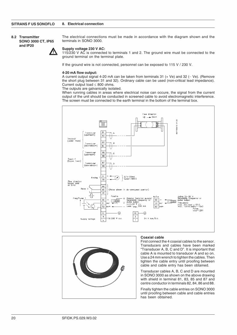
8.2 TransmitterSONO 3000 CT, IP65and IP20
8. Electrical connection
The electrical connections must be made in accordance with the diagram shown and theterminals in SONO 3000.
Supply voltage 230 V AC:115/230 V AC is connected to terminals 1 and 2. The ground wire must be connected to theground terminal on the terminal plate.
If the ground wire is not connected, personnel can be exposed to 115 V / 230 V.
4-20 mA flow output:A current output signal 4-20 mA can be taken from terminals 31 (+ Ve) and 32 (− Ve). (Removethe short plug between 31 and 32). Ordinary cable can be used (non-critical lead impedance).Current output load ≤ 800 ohms.The outputs are galvanically isolated.When running cables in areas where electrical noise can occure, the signal from the currentoutput of the unit should be conducted in screened cable to avoid electromagnetic interference.The screen must be connected to the earth terminal in the bottom of the terminal box.
Coaxial cableFirst connect the 4 coaxial cables to the sensor.Transducers and cables have been marked“Transducer A, B, C and D”. It is important thatcable A is mounted to transducer A and so on.Use a 24 mm wrench to tighten the cables. Thentighten the cable entry until proofing betweencable and cable entry has been obtained.
Transducer cables A, B, C and D are mountedin SONO 3000 as shown on the above drawingwith shield in terminal 81, 83, 85 and 87 andcentre conductor in terminals 82, 84, 86 and 88.
Finally tighten the cable entries on SONO 3000until proofing between cable and cable entrieshas been obtained.
SITRANS F US SONOFLO
SFIDK.PS.029.W3.02 21
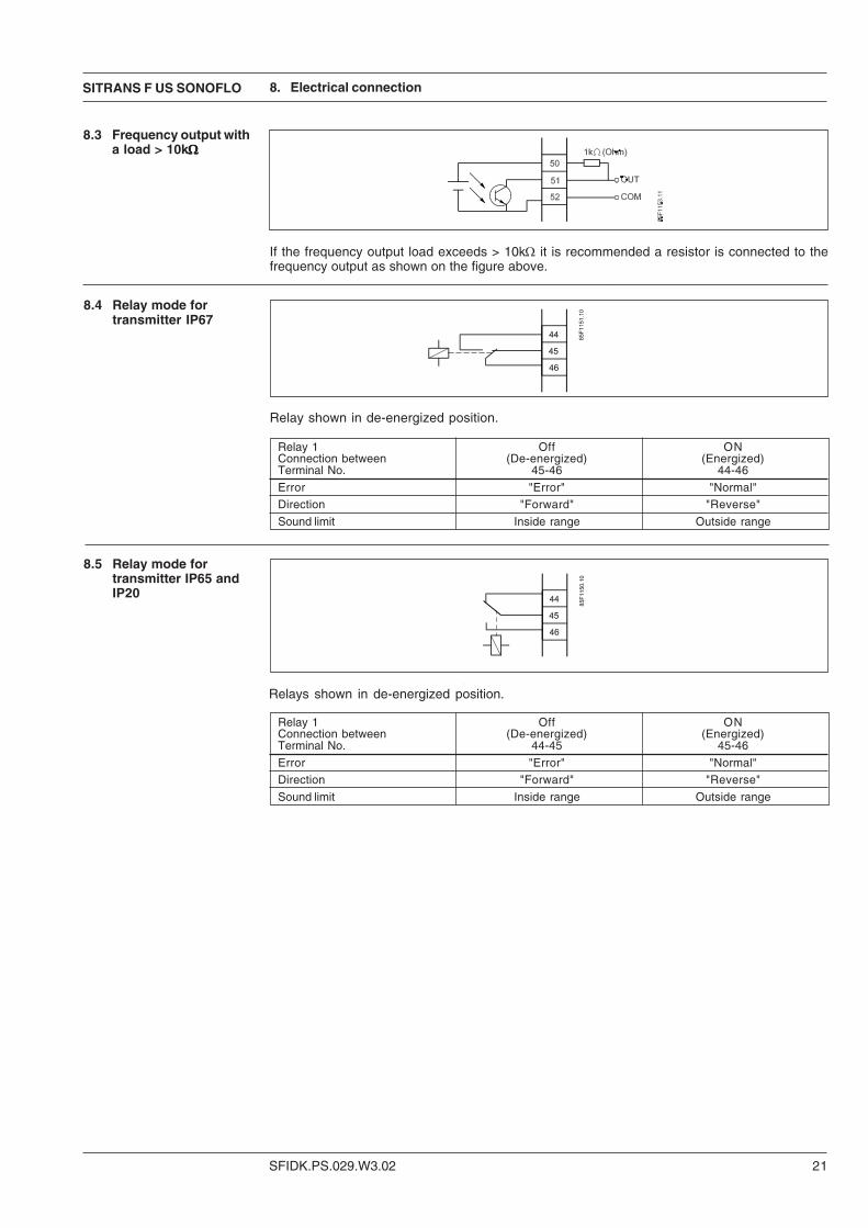
8.4 Relay mode fortransmitter IP67
Relay shown in de-energized position.
Relay 1 Off ONConnection between (De-energized) (Energized)Terminal No. 45-46 44-46
Error "Error" "Normal"
Direction "Forward" "Reverse"
Sound limit Inside range Outside range
8.5 Relay mode fortransmitter IP65 andIP20
Relays shown in de-energized position.
8.3 Frequency output witha load > 10kΩΩΩΩΩ
If the frequency output load exceeds > 10kΩ it is recommended a resistor is connected to thefrequency output as shown on the figure above.
Relay 1 Off ONConnection between (De-energized) (Energized)Terminal No. 44-45 45-46
Error "Error" "Normal"
Direction "Forward" "Reverse"
Sound limit Inside range Outside range
8. Electrical connection
SFIDK.PS.029.W3.02
SITRANS F US SONOFLO
22
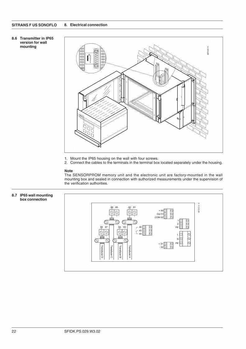
8.6 Transmitter in IP65version for wallmounting
1. Mount the IP65 housing on the wall with four screws.2. Connect the cables to the terminals in the terminal box located separately under the housing.
NoteThe SENSORPROM memory unit and the electronic unit are factory-mounted in the wallmounting box and sealed in connection with authorized measurements under the supervision ofthe verification authorities.
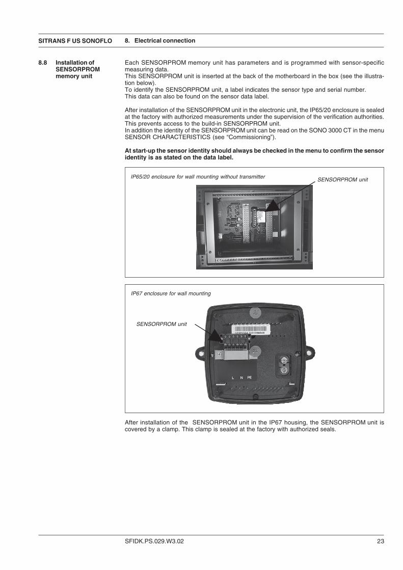
8.7 IP65 wall mountingbox connection
8. Electrical connection
SITRANS F US SONOFLO
SFIDK.PS.029.W3.02 23
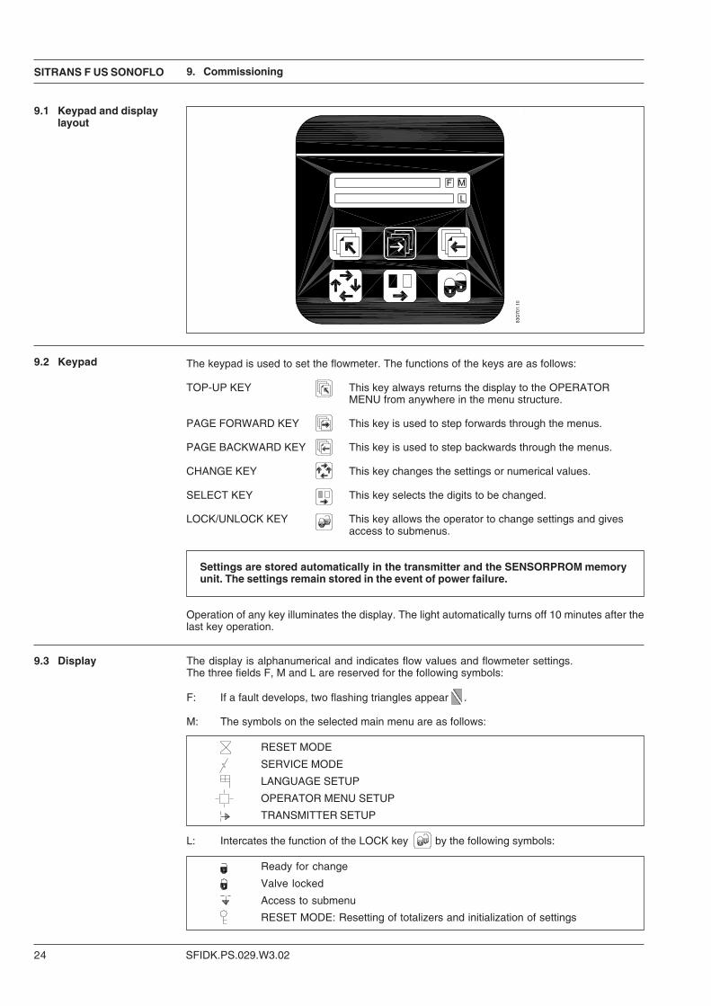
8.8 Installation ofSENSORPROMmemory unit
Each SENSORPROM memory unit has parameters and is programmed with sensor-specificmeasuring data.This SENSORPROM unit is inserted at the back of the motherboard in the box (see the illustra-tion below).To identify the SENSORPROM unit, a label indicates the sensor type and serial number.This data can also be found on the sensor data label.
After installation of the SENSORPROM unit in the electronic unit, the IP65/20 enclosure is sealedat the factory with authorized measurements under the supervision of the verification authorities.This prevents access to the build-in SENSORPROM unit.In addition the identity of the SENSORPROM unit can be read on the SONO 3000 CT in the menuSENSOR CHARACTERISTICS (see “Commissioning”).
At start-up the sensor identity should always be checked in the menu to confirm the sensoridentity is as stated on the data label.
8. Electrical connection
IP65/20 enclosure for wall mounting without transmitter
IP67 enclosure for wall mounting
After installation of the SENSORPROM unit in the IP67 housing, the SENSORPROM unit iscovered by a clamp. This clamp is sealed at the factory with authorized seals.
SENSORPROM unit
SENSORPROM unit
SFIDK.PS.029.W3.02
SITRANS F US SONOFLO
24
9. Commissioning
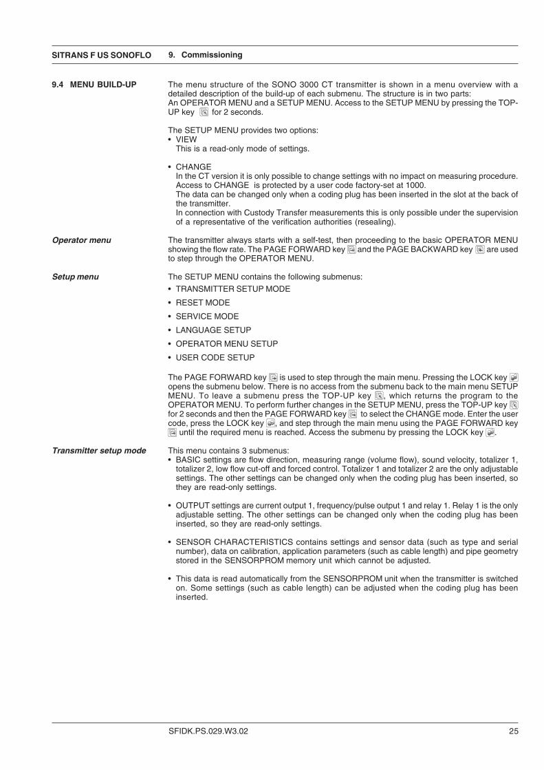
The keypad is used to set the flowmeter. The functions of the keys are as follows:
TOP-UP KEY This key always returns the display to the OPERATORMENU from anywhere in the menu structure.
PAGE FORWARD KEY This key is used to step forwards through the menus.
PAGE BACKWARD KEY This key is used to step backwards through the menus.
CHANGE KEY This key changes the settings or numerical values.
SELECT KEY This key selects the digits to be changed.
LOCK/UNLOCK KEY This key allows the operator to change settings and givesaccess to submenus.
Settings are stored automatically in the transmitter and the SENSORPROM memoryunit. The settings remain stored in the event of power failure.
Operation of any key illuminates the display. The light automatically turns off 10 minutes after thelast key operation.
9.2 Keypad
9.1 Keypad and displaylayout
9.3 Display The display is alphanumerical and indicates flow values and flowmeter settings.The three fields F, M and L are reserved for the following symbols:
F: If a fault develops, two flashing triangles appear .
M: The symbols on the selected main menu are as follows:
RESET MODE
SERVICE MODE
LANGUAGE SETUP
OPERATOR MENU SETUP
TRANSMITTER SETUP
L: Intercates the function of the LOCK key by the following symbols:
Ready for change
Valve locked
Access to submenu
RESET MODE: Resetting of totalizers and initialization of settings
SITRANS F US SONOFLO
SFIDK.PS.029.W3.02 25
9. Commissioning
9.4 MENU BUILD-UP
Operator menu
Setup menu
Transmitter setup mode
The menu structure of the SONO 3000 CT transmitter is shown in a menu overview with adetailed description of the build-up of each submenu. The structure is in two parts:An OPERATOR MENU and a SETUP MENU. Access to the SETUP MENU by pressing the TOP-UP key for 2 seconds.
The SETUP MENU provides two options:• VIEW
This is a read-only mode of settings.
• CHANGEIn the CT version it is only possible to change settings with no impact on measuring procedure.Access to CHANGE is protected by a user code factory-set at 1000.The data can be changed only when a coding plug has been inserted in the slot at the back ofthe transmitter.In connection with Custody Transfer measurements this is only possible under the supervisionof a representative of the verification authorities (resealing).
The transmitter always starts with a self-test, then proceeding to the basic OPERATOR MENUshowing the flow rate. The PAGE FORWARD key and the PAGE BACKWARD key are usedto step through the OPERATOR MENU.
The SETUP MENU contains the following submenus:
• TRANSMITTER SETUP MODE
• RESET MODE
• SERVICE MODE
• LANGUAGE SETUP
• OPERATOR MENU SETUP
• USER CODE SETUP
The PAGE FORWARD key is used to step through the main menu. Pressing the LOCK key opens the submenu below. There is no access from the submenu back to the main menu SETUPMENU. To leave a submenu press the TOP-UP key , which returns the program to theOPERATOR MENU. To perform further changes in the SETUP MENU, press the TOP-UP key for 2 seconds and then the PAGE FORWARD key to select the CHANGE mode. Enter the usercode, press the LOCK key , and step through the main menu using the PAGE FORWARD key
until the required menu is reached. Access the submenu by pressing the LOCK key .
This menu contains 3 submenus:• BASIC settings are flow direction, measuring range (volume flow), sound velocity, totalizer 1,
totalizer 2, low flow cut-off and forced control. Totalizer 1 and totalizer 2 are the only adjustablesettings. The other settings can be changed only when the coding plug has been inserted, sothey are read-only settings.
• OUTPUT settings are current output 1, frequency/pulse output 1 and relay 1. Relay 1 is the onlyadjustable setting. The other settings can be changed only when the coding plug has beeninserted, so they are read-only settings.
• SENSOR CHARACTERISTICS contains settings and sensor data (such as type and serialnumber), data on calibration, application parameters (such as cable length) and pipe geometrystored in the SENSORPROM memory unit which cannot be adjusted.
• This data is read automatically from the SENSORPROM unit when the transmitter is switchedon. Some settings (such as cable length) can be adjusted when the coding plug has beeninserted.
SFIDK.PS.029.W3.02
SITRANS F US SONOFLO
26
9. Commissioning
Reset mode In this menu the totalizers can be reset, the flowmeter zero point adjusted and the factory settingsre-established.In the CT version these settings can only be changed, adjusted or reset when the coding plug hasbeen inserted, so they are read-only settings.
Service mode In SERVICE MODE the outputs can be set to fixed values (forced outputs) for testing. On leavingSERVICE MODE all settings made in SERVICE MODE are cancelled. See “Trouble shooting”, formore information on this menu.In the CT version these settings can only be changed, adjusted or reset when the coding plug hasbeen inserted, so they are read-only settings.
Language setup In this menu the menu language is selected. The factory setting is English, German or French.
Operator menu setup Here the information accessible to the operator in the OPERATOR MENU is selected.
User code setup The user code can be changed in this menu.The code is factory-set at 1000. If the user code is lost, the factory setting can be re-established asfollows: Switch off supply voltage, press the TOP-UP key while switching on the supplyvoltage. Release the key after ROM and RAM tests are completed. The user code is now reset at1000.
If the transmitter is left in TRANSMITTER SETUP for more than 10 minutes without key operation,the transmitter automatically reverts to OPERATOR MENU.
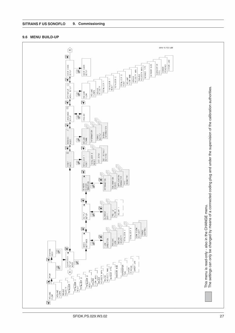
9.5 Submenus for The below figure gives an overview of the menu structure. Below is a more detailed descriptionBASIC SETTINGS of the submenus. Use the menu block diagram to step through to required submenu.
SITRANS F US SONOFLO
SFIDK.PS.029.W3.02 27
9. Commissioning
Thi
s m
enu
is r
ead-
only
- a
lso
in t
he C
HA
NG
E m
enu.
The
set
tings
can
onl
y be
cha
nged
by
mea
ns o
f a c
onne
cted
cod
ing
plug
and
und
er th
e su
perv
isio
n of
the
calib
ratio
n au
thor
ities
.
9.6 MENU BUILD-UP

SFIDK.PS.029.W3.02
SITRANS F US SONOFLO
28
The measuring range for sound velocity is set by entering the minimum and maxiumum soundvelocity. If no other limits are defined for sound velocity the measuring range is set using standardvalues. Error relay and error indication are activated when the sound velocity is outside the limitsstated.In the CT version these settings can only be changed, adjusted or reset when the coding plug hasbeen inserted, so they are read-only settings.
Totalizers The two internal totalizers are not approved for custody transfer, so they can be changed via thedisplay.
Sound velocity
9. Commissioning
Flow direction Here it is possible to select the flow direction. The factory setting is positive.In the CT version these settings can only be changed, adjusted or reset when the coding plug hasbeen inserted, so they are read-only settings.
Volume flow Use this menu to select the unit for measuring volume flow and the limit of the measuring range(Qn). The application parameters for the selection are choosen from the product selectorwww.pia-selector.com or from the Siemens catalog FI01.For unspecified measurements select the factory setting for the unit, m3/h, and set a standardvalue depending on the nominal diameter as the measuring range limit (Qn) (see “Projectguidance”).The Qn value selected corresponds to 100% flow and is based on the limits of all outputs.In the CT version these settings can only be changed, adjusted or reset when the coding plug hasbeen inserted, so they are read-only settings.
SITRANS F US SONOFLO
SFIDK.PS.029.W3.02 29
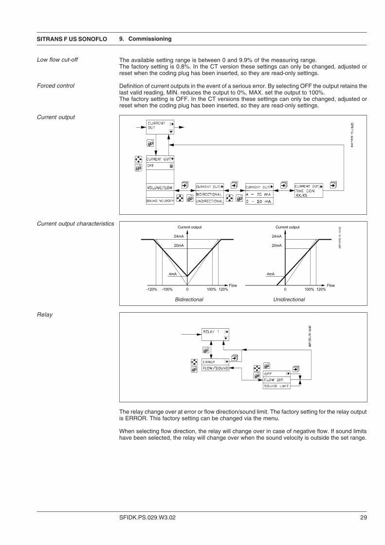
Current output
Current output characteristics
Relay
The relay change over at error or flow direction/sound limit. The factory setting for the relay outputis ERROR. This factory setting can be changed via the menu.
When selecting flow direction, the relay will change over in case of negative flow. If sound limitshave been selected, the relay will change over when the sound velocity is outside the set range.
9. Commissioning
Bidirectional Unidirectional
The available setting range is between 0 and 9.9% of the measuring range.The factory setting is 0.8%. In the CT version these settings can only be changed, adjusted orreset when the coding plug has been inserted, so they are read-only settings.
Definition of current outputs in the event of a serious error. By selecting OFF the output retains thelast valid reading, MIN. reduces the output to 0%, MAX. set the output to 100%.The factory setting is OFF. In the CT versions these settings can only be changed, adjusted orreset when the coding plug has been inserted, so they are read-only settings.
Low flow cut-off
Forced control
SFIDK.PS.029.W3.02
SITRANS F US SONOFLO
30
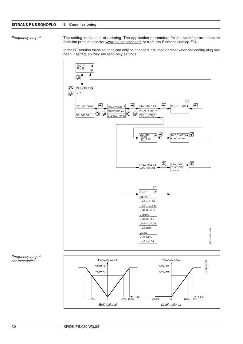
Frequency output The setting is choosen at ordering. The application parameters for the selection are choosenfrom the product selector www.pia-selector.com or from the Siemens catalog FI01.
In the CT version these settings can only be changed, adjusted or reset when the coding plug hasbeen inserted, so they are read-only settings.
Frequency outputcharacteristics
9. Commissioning
Bidirectional Unidirectional
SITRANS F US SONOFLO
SFIDK.PS.029.W3.02 31
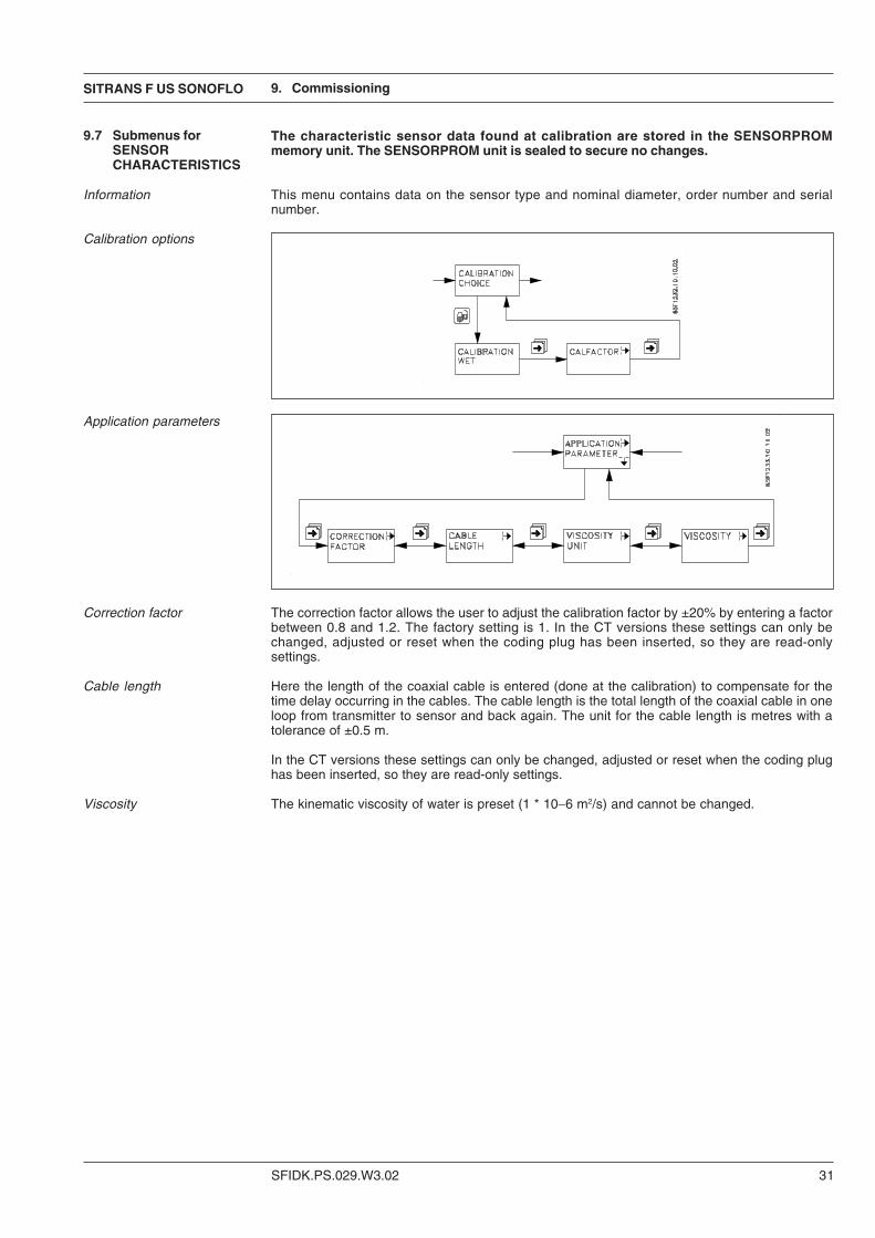
The characteristic sensor data found at calibration are stored in the SENSORPROMmemory unit. The SENSORPROM unit is sealed to secure no changes.
Information This menu contains data on the sensor type and nominal diameter, order number and serialnumber.
Calibration options
Application parameters
Correction factor The correction factor allows the user to adjust the calibration factor by ±20% by entering a factorbetween 0.8 and 1.2. The factory setting is 1. In the CT versions these settings can only bechanged, adjusted or reset when the coding plug has been inserted, so they are read-onlysettings.
Cable length Here the length of the coaxial cable is entered (done at the calibration) to compensate for thetime delay occurring in the cables. The cable length is the total length of the coaxial cable in oneloop from transmitter to sensor and back again. The unit for the cable length is metres with atolerance of ±0.5 m.
In the CT versions these settings can only be changed, adjusted or reset when the coding plughas been inserted, so they are read-only settings.
Viscosity The kinematic viscosity of water is preset (1 * 10−6 m2/s) and cannot be changed.
9. Commissioning
9.7 Submenus forSENSORCHARACTERISTICS
SFIDK.PS.029.W3.02
SITRANS F US SONOFLO
32
On start-up the flowmeter uses settings in the SENSORPROM memory unit. The factory settings,their range and the available settings are shown in the table in section "Project guidance".
If a setting range is exceeded, the cursor moves to the first digit in the display and flashesto indicate that the setting is invalid. The selected setting cannot be locked until a validvalue is selected.
1. Switch on the SONO 3000 CT transmitter. The meter will automatically run through a self-testroutine. During the self-test the display will show the texts ROM TEST, RAM TEST andINITIALIZING. The self-test is completed when the display shows the volume flow rate.
2. The three mode symbols must not light up. If the error symbol is flashing, refer to the section"Trouble shooting".
3. Refer to corresponding menus for setting of TOTALIZER, RELAY, LANGUAGE and possiblyUSER CODE.
4. Go back to the basic settings using the key. The transmitter is now operating.
9. Commissioning
9.8 Factory settings
9.9 Start-up
SITRANS F US SONOFLO
SFIDK.PS.029.W3.02 33
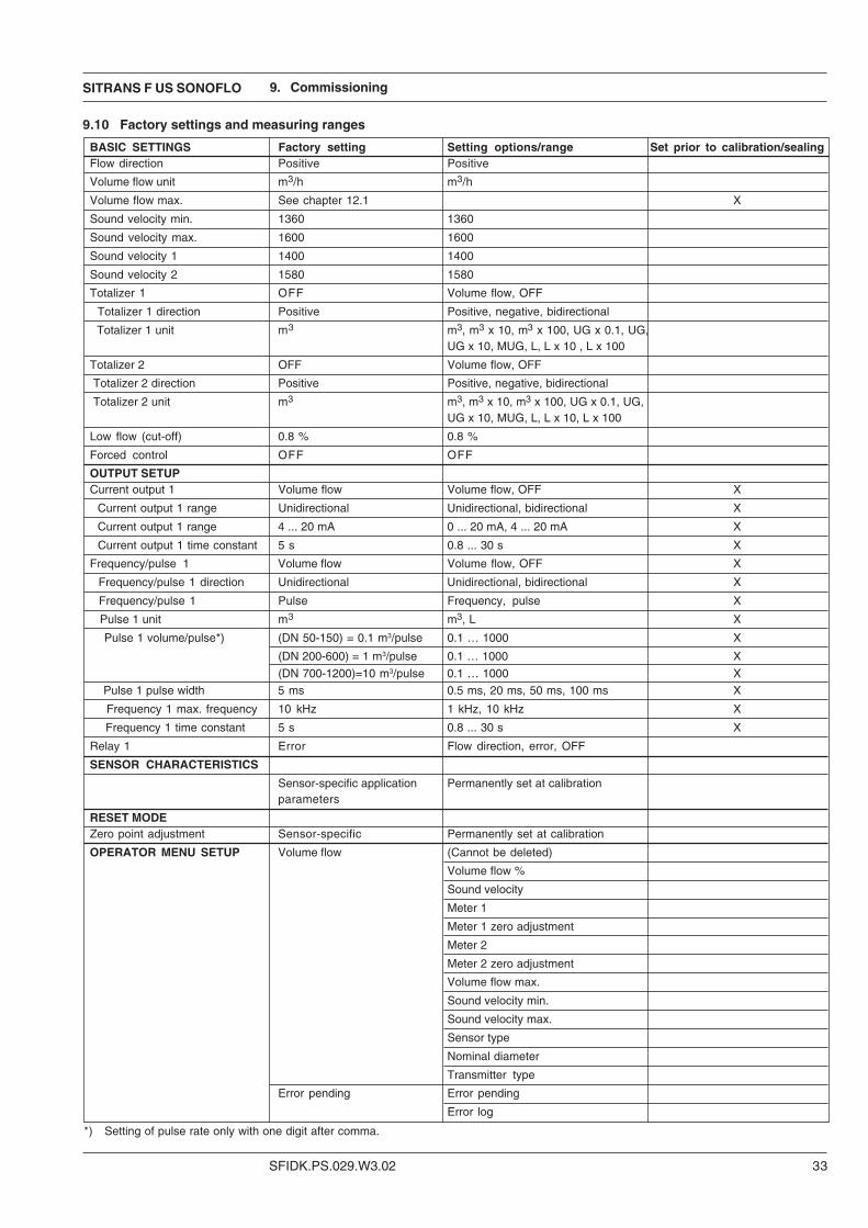
9.10 Factory settings and measuring ranges
BASIC SETTINGS Factory setting Setting options/range Set prior to calibration/sealingFlow direction Positive Positive
Volume flow unit m3/h m3/h
Volume flow max. See chapter 12.1 X
Sound velocity min. 1360 1360
Sound velocity max. 1600 1600
Sound velocity 1 1400 1400
Sound velocity 2 1580 1580
Totalizer 1 OFF Volume flow, OFF
Totalizer 1 direction Positive Positive, negative, bidirectional
Totalizer 1 unit m3 m3, m3 x 10, m3 x 100, UG x 0.1, UG,UG x 10, MUG, L, L x 10 , L x 100
Totalizer 2 OFF Volume flow, OFF
Totalizer 2 direction Positive Positive, negative, bidirectional
Totalizer 2 unit m3 m3, m3 x 10, m3 x 100, UG x 0.1, UG,UG x 10, MUG, L, L x 10, L x 100
Low flow (cut-off) 0.8 % 0.8 %
Forced control OFF OFF
OUTPUT SETUPCurrent output 1 Volume flow Volume flow, OFF X
Current output 1 range Unidirectional Unidirectional, bidirectional X
Current output 1 range 4 ... 20 mA 0 ... 20 mA, 4 ... 20 mA X
Current output 1 time constant 5 s 0.8 ... 30 s X
Frequency/pulse 1 Volume flow Volume flow, OFF X
Frequency/pulse 1 direction Unidirectional Unidirectional, bidirectional X
Frequency/pulse 1 Pulse Frequency, pulse X
Pulse 1 unit m3 m3, L X
Pulse 1 volume/pulse*) (DN 50-150) = 0.1 m3/pulse 0.1 … 1000 X
(DN 200-600) = 1 m3/pulse 0.1 … 1000 X
(DN 700-1200)=10 m3/pulse 0.1 … 1000 X
Pulse 1 pulse width 5 ms 0.5 ms, 20 ms, 50 ms, 100 ms X
Frequency 1 max. frequency 10 kHz 1 kHz, 10 kHz X
Frequency 1 time constant 5 s 0.8 ... 30 s X
Relay 1 Error Flow direction, error, OFF
SENSOR CHARACTERISTICS
Sensor-specific application Permanently set at calibrationparameters
RESET MODEZero point adjustment Sensor-specific Permanently set at calibration
OPERATOR MENU SETUP Volume flow (Cannot be deleted)
Volume flow %
Sound velocity
Meter 1
Meter 1 zero adjustment
Meter 2
Meter 2 zero adjustment
Volume flow max.
Sound velocity min.
Sound velocity max.
Sensor type
Nominal diameter
Transmitter type
Error pending Error pending
Error log
*) Setting of pulse rate only with one digit after comma.
9. Commissioning
SFIDK.PS.029.W3.02
SITRANS F US SONOFLO
34
The transmitter is self-monitoring and registers the following faults:
1. Faults related to the ultrasonic signals and the application.
2. Cable fault on sensor cable or current output loop.
3. Operation and setting faults.
4. Internal faults in transmitter.
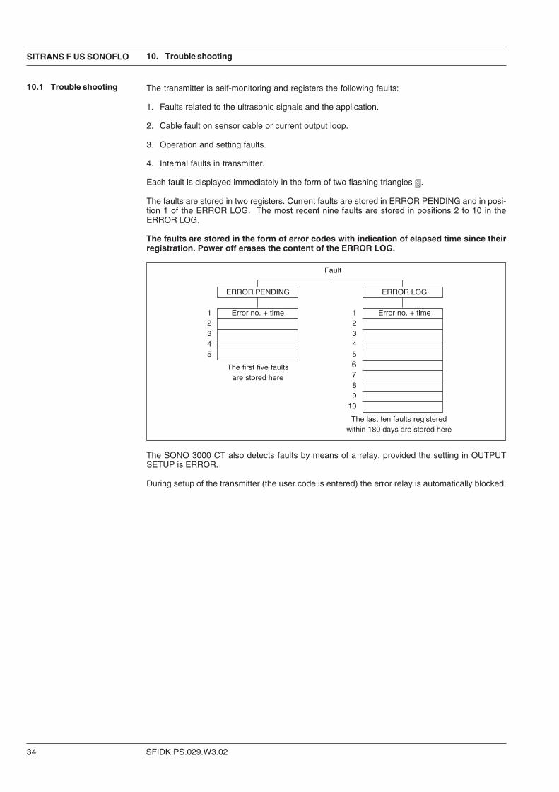
Each fault is displayed immediately in the form of two flashing triangles .
The faults are stored in two registers. Current faults are stored in ERROR PENDING and in posi-tion 1 of the ERROR LOG. The most recent nine faults are stored in positions 2 to 10 in theERROR LOG.
The faults are stored in the form of error codes with indication of elapsed time since theirregistration. Power off erases the content of the ERROR LOG.
The SONO 3000 CT also detects faults by means of a relay, provided the setting in OUTPUTSETUP is ERROR.
During setup of the transmitter (the user code is entered) the error relay is automatically blocked.
Fault
ERROR PENDING ERROR LOG
1 Error no. + time 1 Error no. + time2 23 34 45 5
The first five faults 6
are stored here 789
10
The last ten faults registeredwithin 180 days are stored here
10. Trouble shooting
10.1 Trouble shooting
SITRANS F US SONOFLO
SFIDK.PS.029.W3.02 35
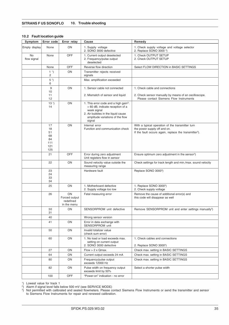
10.2 Fault location guideSymptom Error code Error relay Cause Remedy
Empty display None ON 1. Supply voltage 1. Check supply voltage and voltage selector2. SONO 3000 defective 2. Replace SONO 3000 3)
No None OFF 1. Current output deselected 1. Check OUTPUT SETUPflow signal 2. Frequency/pulse output 2. Check OUTPUT SETUP
deselected
None OFF Reverse flow direction Select FLOW DIRECTION in BASIC SETTINGS
1 1) ON Transmitter rejects received2 signals
5 1) Max. amplification exceeded6
9 ON 1. Sensor cable not connected 1. Check cable and connections1011 2. Mismatch of sensor and liquid 2. Check sensor manually by means of an oscilloscope.12 Please contact Siemens Flow Instruments
13 1) ON 1. This error code and a high gain2).14 > 60 dB, indicate reception of a
week signal2. Air bubbles in the liquid cause
amplitude variations of the flowsignal
17 ON Internal error With a typical operation of the transmitter turn18 Function and communication check the power supply off and on.51 If the fault occurs again, replace the transmitter3).6884
111121125
21 OFF Error during zero adjustment Ensure optimum zero adjustment in the sensor3)Unit registers flow in sensor
22 ON Sound velocity value outside the Check settings for track length and min./max. sound velocitymeasuring range
23 Hardware fault Replace SONO 30003)243334
25 ON 1. Motherboard defective 1. Replace SONO 30003)2. Supply voltage too low 2. Check supply voltage
26 ON Fatal measuring error Remove the cause of additional error(s) andForced output this code will disappear as well
redefinedin the menu
30 ON SENSORPROM unit defective Remove SENSORPROM unit and enter settings manually3)31
40 Wrong sensor version
41 ON Error in data exchange withSENSORPROM unit
50 ON Invalid totalizer value(check sum error)
60 ON 1. No load or load exceeds max. 1. Check cables and connectionssetting on current output
2. SONO 3000 defective 2. Replace SONO 30003)
27 ON Flow > 2 x Qmax. Check max. setting in BASIC SETTINGS
64 ON Current output exceeds 24 mA Check max. setting in BASIC SETTINGS
80 ON Frequency/pulse output Check max. setting in BASIC SETTINGSexceeds 12000 Hz
82 ON Pulse width on frequency output Select a shorter pulse widthexceeds limit by 50%
100 OFF “Power-on” indication - no error
1) Lowest value for track 12) Alarm if signal level falls below 500 mV (see SERVICE MODE)3) Not permitted with calibrated and sealed flowmeters. Please contact Siemens Flow Instruments or send the transmitter and sensor
to Siemens Flow Instruments for repair and renewed calibration.
10. Trouble shooting

SFIDK.PS.029.W3.02
SITRANS F US SONOFLO
36
10.3 Service mode This menu contains 4 submenus: VOLUME FLOW, INFORMATION, FORCED OUTPUT andSIGNAL INFORMATIONIn the CT version these settings can only be changed when the coding plug has been inserted,so they are read-only values.Please contact the nearest Siemens Flow Instruments distributor.
Volume flow Indication of time in operation and identification data and error log of the measuring system.
Information Indication of time in operation and identification data and error log of the unit.
Forced output Use this menu for forced control of outputs using fixed values. In the CT version these settings canonly be changed, adjusted or reset when the coding plug has been inserted, so they are read-only values.
Signal information In this menu and its six submenus it is possible to read data relating to time, flow, signalrecognition, signal quality and sensor.For further information see the following section and the detailed menu overview on the followingpage.
Track 1/2 Each of the 2 submenus has three further submenus:
• TIME/FLOWHere it is possible to read the average transit time, transit time difference, flow velocity andsound velocity (FLOW VELOCITY) in each track.
• SIGNAL RECOGNITIONHere it is possible to read factors for recognition (detection) of ultrasonic signals as acoefficient between 0 and 1. A figure close to 1 denotes good signal recognition.The DETECTION COEFFICIENT states the quality of transit time determination.The CROSS DETECTION COEFFICIENT states the qualitiy of transit time differencedetermination.
• SIGNALHere it is possible to read signal gain, signal level and signal/noise ratio (noise difference).GAIN can be between 5 and 60. The typical value for water is between 5 and 30. TheSIGNAL LEVEL (amplitude) should be between 375 and 750 mV. A value less than 700mV indicates variations in signal amplitude caused by variation of the acoustic attenuationdue to air or gas bubbles. The value for the S/N RATIO should be between 1 and 40. Thetypical value for water is between 20 and 35.
10. Trouble shooting
SITRANS F US SONOFLO
SFIDK.PS.029.W3.02 37
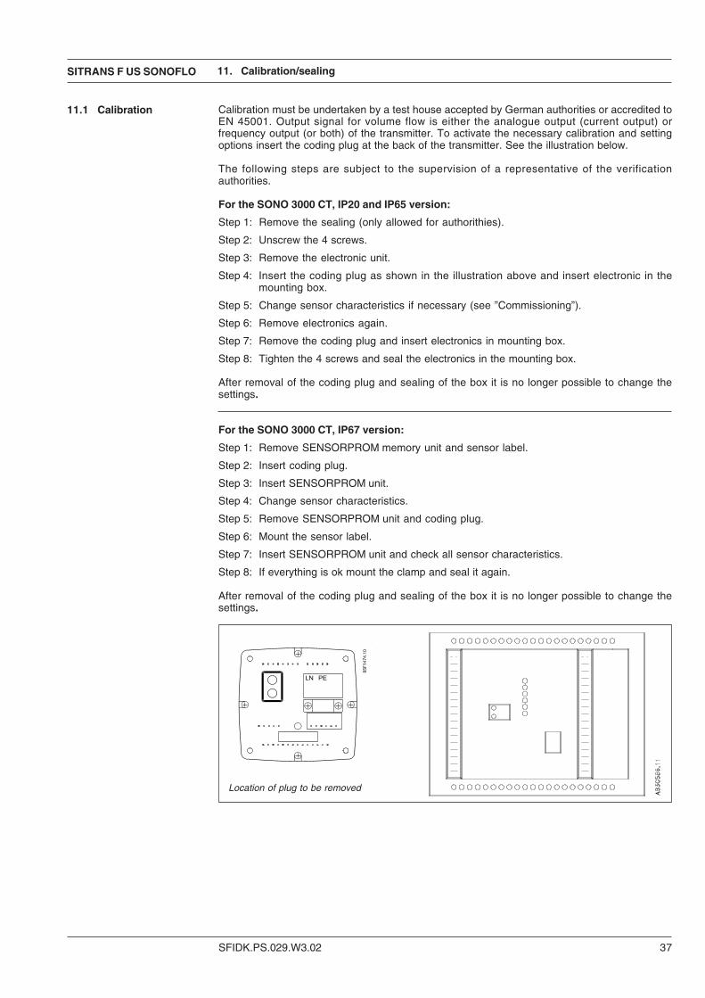
Calibration must be undertaken by a test house accepted by German authorities or accredited toEN 45001. Output signal for volume flow is either the analogue output (current output) orfrequency output (or both) of the transmitter. To activate the necessary calibration and settingoptions insert the coding plug at the back of the transmitter. See the illustration below.
The following steps are subject to the supervision of a representative of the verificationauthorities.
For the SONO 3000 CT, IP20 and IP65 version:
Step 1: Remove the sealing (only allowed for authorithies).
Step 2: Unscrew the 4 screws.
Step 3: Remove the electronic unit.
Step 4: Insert the coding plug as shown in the illustration above and insert electronic in themounting box.
Step 5: Change sensor characteristics if necessary (see ”Commissioning”).
Step 6: Remove electronics again.
Step 7: Remove the coding plug and insert electronics in mounting box.
Step 8: Tighten the 4 screws and seal the electronics in the mounting box.
After removal of the coding plug and sealing of the box it is no longer possible to change thesettings.
For the SONO 3000 CT, IP67 version:
Step 1: Remove SENSORPROM memory unit and sensor label.
Step 2: Insert coding plug.
Step 3: Insert SENSORPROM unit.
Step 4: Change sensor characteristics.
Step 5: Remove SENSORPROM unit and coding plug.
Step 6: Mount the sensor label.
Step 7: Insert SENSORPROM unit and check all sensor characteristics.
Step 8: If everything is ok mount the clamp and seal it again.
After removal of the coding plug and sealing of the box it is no longer possible to change thesettings.
11.1 Calibration
11. Calibration/sealing
Location of plug to be removed
SFIDK.PS.029.W3.02
SITRANS F US SONOFLO
38
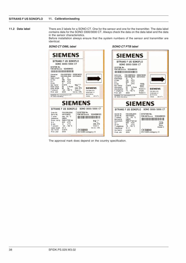
There are 2 labels for a SONO CT. One for the sensor and one for the transmitter. The data labelcontains data for the SONO 3300/3000 CT. Always check the data on the data label and the datain the sensor characteristics.Before installation always ensure that the system numbers of the sensor and transmitter areidentical.
11.2 Data label
11. Calibration/sealing
SONO CT OIML label SONO CT PTB label
The approval mark does depend on the country specification.
SITRANS F US SONOFLO
SFIDK.PS.029.W3.02 39
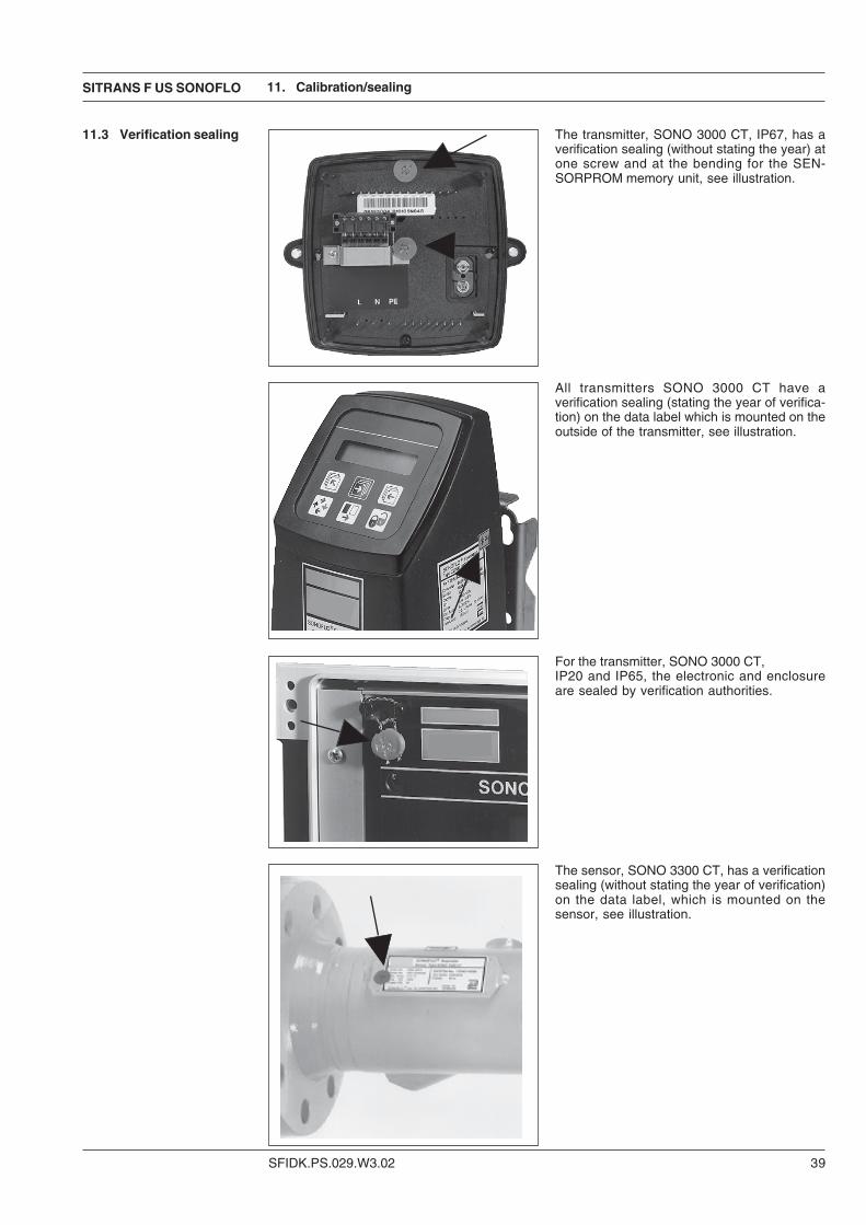
The transmitter, SONO 3000 CT, IP67, has averification sealing (without stating the year) atone screw and at the bending for the SEN-SORPROM memory unit, see illustration.
All transmitters SONO 3000 CT have averification sealing (stating the year of verifica-tion) on the data label which is mounted on theoutside of the transmitter, see illustration.
For the transmitter, SONO 3000 CT,IP20 and IP65, the electronic and enclosureare sealed by verification authorities.
The sensor, SONO 3300 CT, has a verificationsealing (without stating the year of verification)on the data label, which is mounted on thesensor, see illustration.
11.3 Verification sealing
11. Calibration/sealing
SFIDK.PS.029.W3.02
SITRANS F US SONOFLO
40
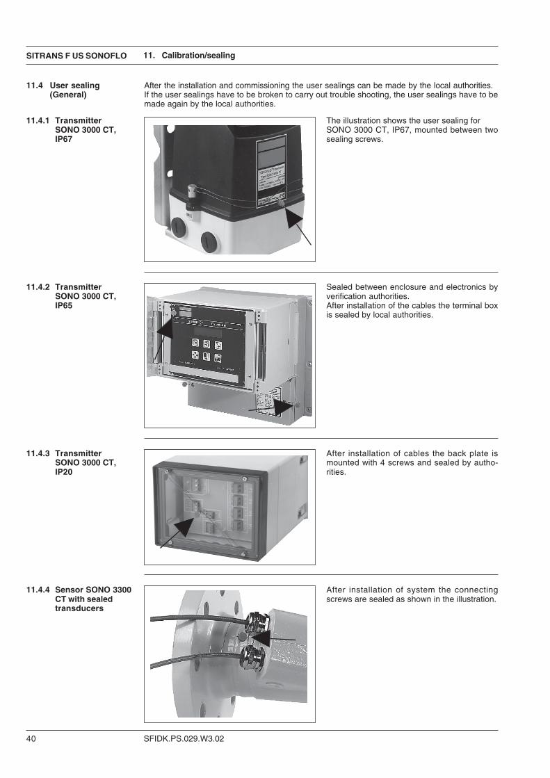
After the installation and commissioning the user sealings can be made by the local authorities.If the user sealings have to be broken to carry out trouble shooting, the user sealings have to bemade again by the local authorities.
The illustration shows the user sealing forSONO 3000 CT, IP67, mounted between twosealing screws.
Sealed between enclosure and electronics byverification authorities.After installation of the cables the terminal boxis sealed by local authorities.
After installation of cables the back plate ismounted with 4 screws and sealed by autho-rities.
After installation of system the connectingscrews are sealed as shown in the illustration.
11.4 User sealing(General)
11.4.1 TransmitterSONO 3000 CT,IP67
11.4.2 TransmitterSONO 3000 CT,IP65
11.4.3 TransmitterSONO 3000 CT,IP20
11.4.4 Sensor SONO 3300CT with sealedtransducers
11. Calibration/sealing
SITRANS F US SONOFLO
SFIDK.PS.029.W3.02 41
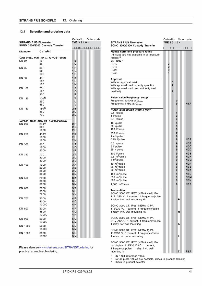
12.1 Selection and ordering data
12. Ordering
Order-No. Order codeSITRANS F US Flowmeter 7ME 3 3 1 0 -SONO 3000/3300 Custody Transfer
Diameter Qn [m3/h]
Cast steel, mat. no 1.1131/GS-16Mn5DN 50 151) 1 B
36 1 C
DN 65 251) 1 F60 1 G120 1 H
DN 80 401) 1 K100 1 L180 1 M
DN 100 701) 1 P180 1 Q300 1 R
DN 125 1001) 1 T250 1 U450 1 V
DN 150 1501) 2 B360 2 C720 2 D
Carbon steel, mat. no 1.0345/P235GHDN 200 2501) 2 F
600 2 G1000 2 H
DN 250 4001) 2 K1000 2 L1800 2 M
DN 300 600 2 P1500 2 Q2000 2 R
DN 350 720 2 T2000 2 U3000 2 V
DN 400 1000 3 A2000 3 B2500 3 C3600 3 D
DN 500 2000 3 K3000 3 L6000 3 M
DN 600 2000 3 T3500 3 U7200 3 V
DN 700 2000 4 F4000 4 G10000 4 H
DN 800 2000 4 P4500 4 Q12000 4 R
DN 900 5000 5 C12000 5 D
DN 1000 5000 5 L15000 5 M
DN 1200 6000 5 U18000 5 V
-0 -0
Please also see www.siemens.com/SITRANSFordering forpractical examples of ordering.
Order-No. Order codeSITRANS F US Flowmeter 7ME 3 3 1 0 -SONO 3000/3300 Custody Transfer
Flange norm and pressure rating(All sizes are not available in all pressureratings)3)
EN 1092-1PN10 BPN16 CPN25 DPN40 E
ApprovalWithout approval mark 0With approval mark (county specific) 1With approval mark and authority seal(verified) 2
Pulse value/Frequency setupFrequency: 10 kHz at Qnom 0Frequency: 1 kHz at Qnom 9 N 1 A
Pulse value (pulse width 5 ms) 2)
0.1 l/pulse 11 l/pulse 22.5 l/pulse 3
10 l/pulse 450 l/pulse 5100 l/pulse 6
250 l/pulse 71 m3/pulse 80.25 l/pulse 9 N 0 A
0.5 l/pulse 9 N 0 B5 l/ pulse 9 N 0 C25 l/ pulse 9 N 0 D
500 l/pulse 9 N 0 E2.5 m3/pulse 9 N 0 F5 m3/pulse 9 N 0 G
10 m3/pulse 9 N 0 H25 m3/pulse 9 N 0 J50 m3/pulse 9 N 0 K
100 m3/pulse 9 N 0 L250 m3/pulse 9 N 0 M500 m3/pulse 9 N 0 N
1,000 m3/pulse 9 N 0 P
TransmitterSONO 3000 CT, IP67 (NEMA 4X/6) PA,115...230 V, 1 current, 1 frequency/pulse,1 relay, incl. wall mounting kit B
SONO 3000 CT, IP65 (NEMA 4) PA,115/230 V, 1 current, 1 frequency/pulse,1 relay, incl. wall mounting kit H
SONO 3000 CT, IP65 (NEMA 4) PA,24 V AC/DC, 1 current, 1 frequency/pulse,1 relay, for wall mounting K
SONO 3000 CT, IP20 (NEMA 1) PA,115/230 V, 1 current, 1 frequency/pulse,1 relay, for panel mounting L
SONO 3000 CT, IP67 (NEMA 4X/6) PA,no display, 115/230 V AC, 1 current,1 frequency/pulse, 1 relay, incl. wallmounting kit Z P 1 A1) EN 1434 reference value2) Not all pulse values are possible, check in product selector3) Check in product selector
SFIDK.PS.029.W3.02
SITRANS F US SONOFLO
42
12. Ordering
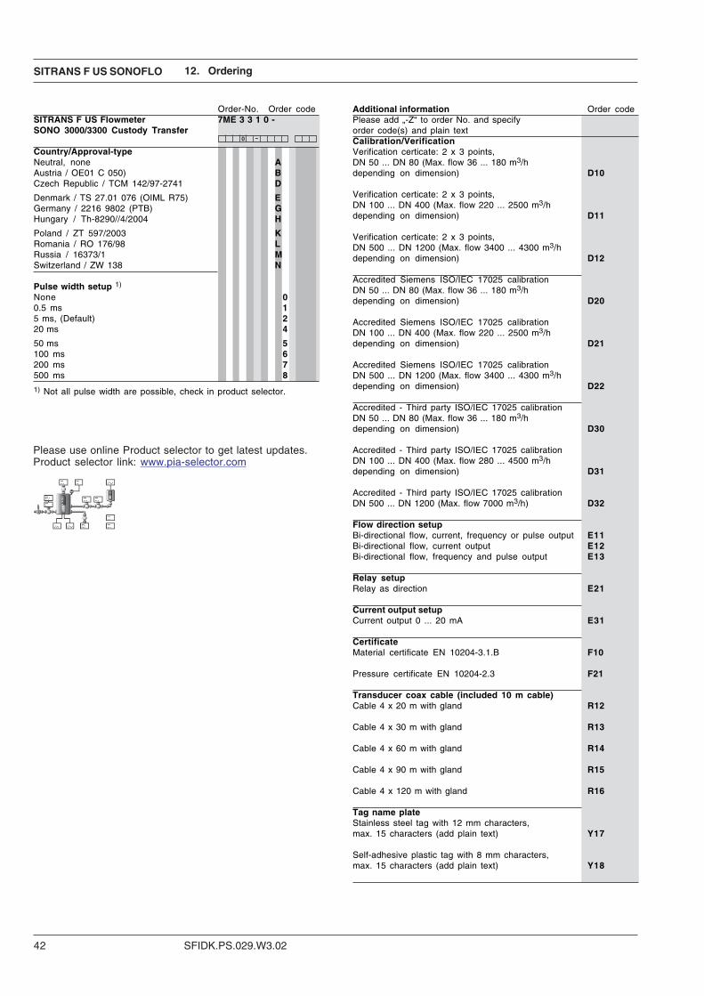
Please use online Product selector to get latest updates.Product selector link: www.pia-selector.com
Order-No. Order codeSITRANS F US Flowmeter 7ME 3 3 1 0 -SONO 3000/3300 Custody Transfer
Country/Approval-typeNeutral, none AAustria / OE01 C 050) BCzech Republic / TCM 142/97-2741 D
Denmark / TS 27.01 076 (OIML R75) EGermany / 2216 9802 (PTB) GHungary / Th-8290//4/2004 H
Poland / ZT 597/2003 KRomania / RO 176/98 LRussia / 16373/1 MSwitzerland / ZW 138 N
Pulse width setup 1)
None 00.5 ms 15 ms, (Default) 220 ms 4
50 ms 5100 ms 6200 ms 7500 ms 8
-0
Additional information Order codePlease add „-Z“ to order No. and specifyorder code(s) and plain textCalibration/VerificationVerification certicate: 2 x 3 points,DN 50 ... DN 80 (Max. flow 36 ... 180 m3/hdepending on dimension) D10
Verification certicate: 2 x 3 points,DN 100 ... DN 400 (Max. flow 220 ... 2500 m3/hdepending on dimension) D11
Verification certicate: 2 x 3 points,DN 500 ... DN 1200 (Max. flow 3400 ... 4300 m3/hdepending on dimension) D12
Accredited Siemens ISO/IEC 17025 calibrationDN 50 ... DN 80 (Max. flow 36 ... 180 m3/hdepending on dimension) D20
Accredited Siemens ISO/IEC 17025 calibrationDN 100 ... DN 400 (Max. flow 220 ... 2500 m3/hdepending on dimension) D21
Accredited Siemens ISO/IEC 17025 calibrationDN 500 ... DN 1200 (Max. flow 3400 ... 4300 m3/hdepending on dimension) D22
Accredited - Third party ISO/IEC 17025 calibrationDN 50 ... DN 80 (Max. flow 36 ... 180 m3/hdepending on dimension) D30
Accredited - Third party ISO/IEC 17025 calibrationDN 100 ... DN 400 (Max. flow 280 ... 4500 m3/hdepending on dimension) D31
Accredited - Third party ISO/IEC 17025 calibrationDN 500 ... DN 1200 (Max. flow 7000 m3/h) D32
Flow direction setupBi-directional flow, current, frequency or pulse output E11Bi-directional flow, current output E12Bi-directional flow, frequency and pulse output E13
Relay setupRelay as direction E21
Current output setupCurrent output 0 ... 20 mA E31
CertificateMaterial certificate EN 10204-3.1.B F10
Pressure certificate EN 10204-2.3 F21
Transducer coax cable (included 10 m cable)Cable 4 x 20 m with gland R12
Cable 4 x 30 m with gland R13
Cable 4 x 60 m with gland R14
Cable 4 x 90 m with gland R15
Cable 4 x 120 m with gland R16
Tag name plateStainless steel tag with 12 mm characters,max. 15 characters (add plain text) Y17
Self-adhesive plastic tag with 8 mm characters,max. 15 characters (add plain text) Y18
1) Not all pulse width are possible, check in product selector.

SITRANS F US SONOFLO
SFIDK.PS.029.W3.02 43

We have checked the contents of this manual for agreement with the hardware andsoftware described. Since deviations cannot be precluded entirely, we cannot guaranteefull agreement. However, the data in this manual are reviewed regularly and anynecessary corrections included in subsequent editions. Suggestions for improvementare always welcomed.
Technical data subject to change without prior notice.
The reproduction, transmission or use of this document or its contents is not permitted withoutexpress written authority.Offenders will be liable for damages. All rights, including rights created by patent grant orregistration of a utility model or design, are reserved.
Copyright © Siemens AG 09.2006 All Rights Reserved
Siemens Flow Instruments A/SNordborgvej 81DK-6430 Nordborg
Order no.: FDK:521H0721-03Printed in: Denmark
Related Documents