International Explosives Safety Symposium San Diego, California, August 2018 Siting Assessment for Sounding Rocket Missions Jon Chrostowski & Ron Lambert; ACTA Inc.; 2790 Skypark Drive: Suite 310, Torrance, CA. 90505 Keywords: Keywords: explosives safety siting, solid rocket motors, sympathetic detonation ABSTRACT This paper documents the development of explosives safety analyses to support site plans for pre-launch operations involving multi-stage sounding rockets. During ground processing, rocket stages are transported, tested and mated together prior to launch and an Explosives Safety Site Plan (ESSP) that evaluates Quantity-Distance requirements must be developed and approved. This paper focuses on estimating the Net Explosive Weight (NEW) associated with sounding rockets that may include multiple Hazard Division (HD) propellants. The paper shows comparisons between NEW based on DoD Explosives Standards (DoD 6055.09-M) mixing rules and NEW based on shock and gas physics analyses that account for actual propellant material properties as well as the dimensions/geometry of the motor stages. INTRODUCTION The U.S. sounding rocket program has been active for 50+ years (over 700 launches) using a variety of rocket configurations/stages/sizes. Prior to launch, a multi-stage sounding rocket motors is transported, processed, tested and integrated prior to mating it with the payload. Because sounding rocket stages may utilize different types of propellant to provide thrust and control, an explosives safety site plan (ESSP) is required to provide assurance that related workers and unrelated personnel are not exposed to undue hazards and risks. Typically, the ESSP is developed using DoD Explosives Safety Standard, DoD 6055.09-M [1] to determine safe separation distances based on Quantity- Distance (QD) tables depending on an Exposed Site’s (ES’s) exposure type (e.g., Intermagazine, Intraline, Public Transportation, Inhabited Building). For multi-stage sounding rockets that use different Hazard Division (HD) propellants in close proximity to HD 1.1 (mass detonating) material, DoD 6055.09-M mixing rules state that the Net Explosive Weight (NEW) is the sum of all HD’s and shall be considered HD 1.1 “unless technical justification is provided to reduce the amount”. The mixing rule requirement can be restrictive, prevent operations and require mitigation (e.g., reduce explosives quantity, change proposed operations, move exposed personnel, harden structures). To demonstrate this issue, we use a generic two- stage sounding rocket. GENERIC SOUNDING ROCKET Figure 1 shows a generic two-stage sounding rocket configuration assembled for a proposed launch; note that a payload (instrument package) is attached to the front end of the Stage 2 motor. Assume the Stage 1 solid propellant rocket motor has a hazard classification of HD 1.3 (mass fire) with two small spin motors attached at its top end for spin-stabilization that are classified as HD 1.1 (mass detonation hazard). Assume that the generic Stage 2 solid propellant rocket motor is also classified as HD 1.3. Table 1 shows a breakdown of propellant weights and the associated hazard divisions for the generic sounding rocket.

Welcome message from author
This document is posted to help you gain knowledge. Please leave a comment to let me know what you think about it! Share it to your friends and learn new things together.
Transcript
International Explosives Safety Symposium San Diego, California, August 2018
Siting Assessment for Sounding Rocket Missions
Jon Chrostowski & Ron Lambert; ACTA Inc.;
2790 Skypark Drive: Suite 310, Torrance, CA. 90505
Keywords:
Keywords: explosives safety siting, solid rocket motors, sympathetic detonation
ABSTRACT
This paper documents the development of explosives safety analyses to support site plans for pre-launch operations
involving multi-stage sounding rockets. During ground processing, rocket stages are transported, tested and mated
together prior to launch and an Explosives Safety Site Plan (ESSP) that evaluates Quantity-Distance requirements
must be developed and approved. This paper focuses on estimating the Net Explosive Weight (NEW) associated with
sounding rockets that may include multiple Hazard Division (HD) propellants. The paper shows comparisons between
NEW based on DoD Explosives Standards (DoD 6055.09-M) mixing rules and NEW based on shock and gas physics
analyses that account for actual propellant material properties as well as the dimensions/geometry of the motor stages.
INTRODUCTION
The U.S. sounding rocket program has been active for 50+ years (over 700 launches) using a variety of rocket
configurations/stages/sizes. Prior to launch, a multi-stage sounding rocket motors is transported, processed, tested
and integrated prior to mating it with the payload. Because sounding rocket stages may utilize different types of
propellant to provide thrust and control, an explosives safety site plan (ESSP) is required to provide assurance that
related workers and unrelated personnel are not exposed to undue hazards and risks. Typically, the ESSP is developed
using DoD Explosives Safety Standard, DoD 6055.09-M [1] to determine safe separation distances based on Quantity-
Distance (QD) tables depending on an Exposed Site’s (ES’s) exposure type (e.g., Intermagazine, Intraline, Public
Transportation, Inhabited Building).
For multi-stage sounding rockets that use different Hazard Division (HD) propellants in close proximity to HD 1.1
(mass detonating) material, DoD 6055.09-M mixing rules state that the Net Explosive Weight (NEW) is the sum of
all HD’s and shall be considered HD 1.1 “unless technical justification is provided to reduce the amount”. The mixing
rule requirement can be restrictive, prevent operations and require mitigation (e.g., reduce explosives quantity, change
proposed operations, move exposed personnel, harden structures). To demonstrate this issue, we use a generic two-
stage sounding rocket.
GENERIC SOUNDING ROCKET
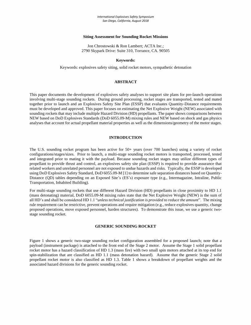
Figure 1 shows a generic two-stage sounding rocket configuration assembled for a proposed launch; note that a
payload (instrument package) is attached to the front end of the Stage 2 motor. Assume the Stage 1 solid propellant
rocket motor has a hazard classification of HD 1.3 (mass fire) with two small spin motors attached at its top end for
spin-stabilization that are classified as HD 1.1 (mass detonation hazard). Assume that the generic Stage 2 solid
propellant rocket motor is also classified as HD 1.3. Table 1 shows a breakdown of propellant weights and the
associated hazard divisions for the generic sounding rocket.
2
a. Sounding Rocket on Pad.
b. Two Stage Sounding Rocket.
c. Stage 1 Sounding Rocket Motor.
Figure 1. Sounding Rocket View.
1st Stage
2nd Stage
Stabilization Spin Motors (2x)
1st Stage
2st Stage
Payload
Payload

3
Table 1. Generic Sounding Rocket Propellant Weight Breakdown.
Rocket Stage Component Hazard Division Approx. Propellant Weight (lb)
Stage 1 Propellant HD 1.3 1,500
Spin Motors (2) HD 1.1 2 each
Stage 2 Propellant HD 1.3 1,000
Total ~2,502
ROCKET-SPECIFIC PHYSICS ASSESSMENTS
Detonation Analysis
A previous study found that an Orion 50SXLT motor with HD 1.3 HTPB (hydroxyl-terminated polybutadiene)
composite propellant is incapable of sustaining a detonation from an impinging shock wave. Our generic Stage 1/2
motors are also assumed to contain HD 1.3 HTPB propellants, and have ammonium perchlorate, aluminum and total
solids loading percentages similar to the Orion motor propellant. HTPB explosive response studies have indicated
there is very little effect on the overall yield of HTPB propellants with modest variations in the ingredients. The
sounding rocket Stage 1/2 propellants are therefore expected to respond in a manner very similar to the Orion motor
propellant and other typical HTPB propellants when subjected to explosive shock loading. Since the Stage 1/2
sounding rocket motors are much smaller in diameter than a 50-inch diameter Orion 50 series motor, their sizes are
even further below their critical geometry for sustained detonation than an Orion 50. As such they are expected to
have an even more benign response to shock loading.
The two HD 1.1 spin motors mounted on the forward end of the Stage 1 motor are assumed to be separated from the
propellant by its steel case, which is thicker at the forward end. This is illustrated in Figure 2, which shows a quarter-
section view of the Stage 1 case and propellant truncated to remove the aft portion of the motor. The steel case
thickness over the rest of the motor length is only half the thickness between the spin motors and the Stage 1 propellant.
The extra steel thickness is typically intended to increase structural strength near the forward joint, but it has the added
benefit of providing additional shielding of the Stage 1 propellant from a shock wave due to a spin motor detonation.
Furthermore, each spin motor is assumed to have approximately 2 lb of high explosives (HE) material, which is far
less than that used in a typical large scale critical diameter test in sizes applicable to HTPB propellants. For these
reasons, it is apparent from the outset that a spin detonation would be very unlikely to produce a full reactive yield of
the entire Stage 1 HD 1.3 propellant grain.
Figure 2. Stage 1 Case and Propellant Truncated Quarter Section Dimensions.
Stage 1 Case, cm
Stage 1 Propellant, cm
0.0 20.0 40.0 60.0 80.0 100.0 120.0 140.0
25.0
20.0
15.0
25.0
20.0
15.0
10.0
5.0
0.0

4
A 3D view of the Stage 1 model as input to CTH [2] is shown in Figure 3. CTH is a family of codes developed at
Sandia National Laboratories (SNL) for the purpose of modeling complex multi-dimensional, multi-material problems
that are characterized by large deformations and/or strong shocks. A two-step, second-order accurate Eulerian solution
algorithm is used to solve the mass, momentum, and energy conservation equations. CTH includes models for material
strength, fracture, porous materials, and high explosive detonation and initiation1.
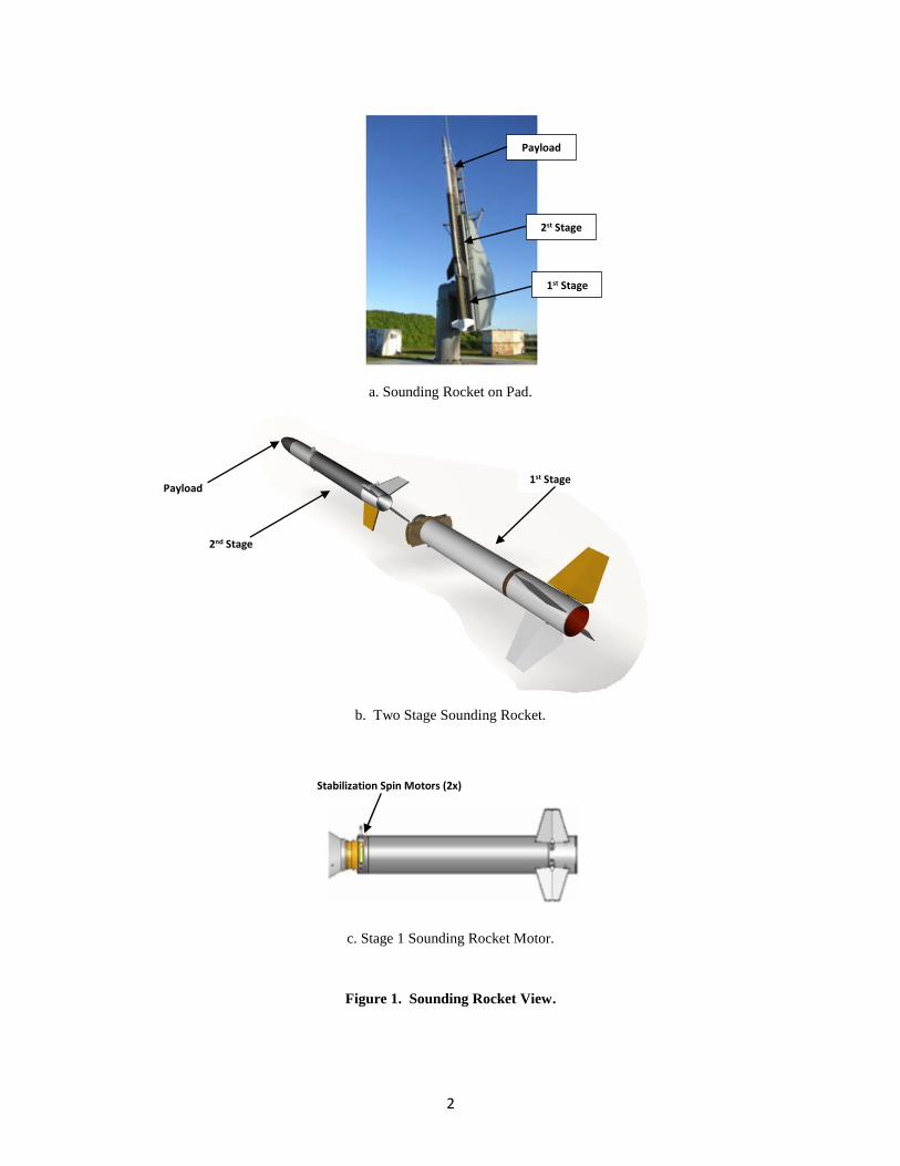
A cross-sectional model of the Stage 1 motor as input to CTH is shown in Figure 4. The model was constructed in
three-dimensional rectangular coordinates with the x-axis aligned with the vehicle center axis. The model was quarter-
sectioned and reflected about the x-y and x-z planes for economy of computational resources. This required that both
of the spin motors behave in equal and opposite manners, which is a conservative assumption that effectively treats
two spin motors as detonating simultaneously, despite the low probability of such an event. The Stage 1 motor length
is truncated to remove part of the aft end which was not evaluated. The simulation was performed for both 100% and
120% of the spin motor HE mass, using a 72-core high performance computational system.
Figure 3. Stage 1 Spin Motor Model Geometry.
The black dots shown in Figure 4 across the Stage 1 propellant represent a vertically aligned planar grid (in the x-y
plane) of Lagrange tracer points at which pressure histories were recorded. This vertically aligned grid coincides with
the x-axis along the center of the motor. Similar grids of tracers were inserted along the x-axis with horizontal
alignments (in the x-z plane) and at a 45-degree angle from the horizontal plane. Tracers were also inserted in the spin
motor casing to track case fragment imparted velocities. CTH employs mesh refinement to automatically adjust
computational cell sizes, thereby allowing for improved tradeoffs between processing time and computational
accuracy.
The Stage 1 propellant reaction models (CTH’s PMOD) were based on HD 1.3 propellants developed by Sandia
National Laboratories that contain Equation of State (EOS) models for both the propellant solid-phase and the gas-
phase reaction products. PMOD as implemented in CTH has been validated for HD 1.3 propellants against data from
pin timing tests, lab scale tests of propellant shock initiation, lab scale attenuator tests with aluminum disks between
an explosive and the propellant, and mid-scale unconfined shock initiation blast tests. The Stage 1 spin motor is
assumed to contain a nitroglycerin/nitrocellulose double base HD 1.1 propellant. Due to uncertainties in this
formulation behavior, a more energetic Composition B Grade A explosive was conservatively used in place of the
double base material for the CTH model, with a 17% increase in the magnitude of the mechanical detonation energy
and a 13% increase in shock velocity.
1 A complete discussion of CTH, material models and equations of state used to model the thermodynamic behavior
including phase changes, nonlinear behavior and fracture is documented in a separate report.
5
Figure 4. Stage 1 CTH Model (cross-sectional view).
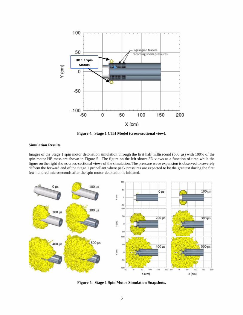
Simulation Results
Images of the Stage 1 spin motor detonation simulation through the first half millisecond (500 µs) with 100% of the
spin motor HE mass are shown in Figure 5. The figure on the left shows 3D views as a function of time while the
figure on the right shows cross-sectional views of the simulation. The pressure wave expansion is observed to severely
deform the forward end of the Stage 1 propellant where peak pressures are expected to be the greatest during the first
few hundred microseconds after the spin motor detonation is initiated.
Figure 5. Stage 1 Spin Motor Simulation Snapshots.
6
Shock pressure histories at 2-cm intervals along horizontal lines above the Stage 1 motor axis are shown in Figure 6
for rows of pressure tracers located 2, 5 and 8 cm vertically below the top of Stage 1, respectively. These are for the
propellant mass equal to 100% of the ~2 lb propellant mass in each spin motor. As seen in these figures, the peak
shock pressures decay with distance away from the forward end of the Stage 1 motor.
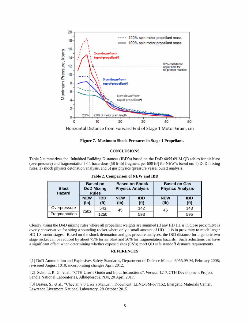
Maximum pressures recorded at the locations indicated in Figure 6 are shown in Figure 7 for 100% and 120%
propellant mass. The peak pressures in these figures are seen to generally decrease with increasing horizontal distance
from the Stage 1 motor forward end and increasing vertical distance from the top of the motor.
In a previous analysis using shock Hugoniot (i.e., shock pressure versus shock velocity) data and 60-inch critical
diameter data for an HTPB composite propellant very similar to the Stage 1 propellant, the 95% confidence lower
limit of the shock pressure threshold for prompt reaction was estimated to be 12 kbars. This shock pressure limit may
be used as a criterion for the Stage 1 propellant to contribute to the total blast yield.
Although the limit is exceeded only near the top of the propellant, the limit was conservatively applied to the entire
cross section of the propellant grain length, including portions closer to the center bore with lower pressures that are
unlikely to support prompt reaction. Comparing the maximum shock pressures recorded within the propellant, as
shown in Figure 7, with the conservatively estimated 12-kbar limit for prompt reaction, it appears that shock pressures
do not exceed this limit beyond a distance from the forward end of approximately 7 cm or 2.2% of the total propellant
grain length. Although the limit is exceeded only near the top of the propellant, the limit is conservatively applied to
the entire cross section at 2.2% of the propellant grain length, including portions closer to the center bore with lower
pressures that are unlikely to support prompt reaction.
With this conservative assumption, the total Stage 1 propellant reacting promptly is 2.2% of 1500 lb, or 33.5 lb. Using
a TNT equivalency factor of 1.2, a high-end estimate of the total yield contribution of the Stage 1 propellant is (33.5
lb) X (1.2 lb TNT/lb propellant) = 40.3 lb TNT. Including the yield of two spin motors, with a TNT equivalency factor
of 1.25, the total yield is 40.3 lb TNT + (2 lb propellant /spin motor) x (2 spin motors) x (1.25 lb TNT/lb propellant)
= 45 lb TNT. This is the total expected yield from a spin motor detonation, including the yield from both the spin
motor propellant and that of the host Stage 1.
Also included is the yield from the second spin motor, though it is unlikely to react sympathetically. The shock
pressures are too low and isolated from the Stage 1 propellant to cause more than a small fraction of the Stage 1
propellant to react promptly so as to contribute to the total blast yield. Since the adjacent 2nd Stage motor is much
further than the host Stage 1 from the center of the explosion, they are not expected to contribute any additional yield.
Pressurized Motor Burst
If a motor stage ignites it may quickly build up internal gas pressure due to a clogged nozzle, and the entire motor
may burst, producing an explosive-like blast yield.
To be conservative, the entire internal volume, V, of the Stage 1 casing was used, 0.54 m3 (19.1ft3). Assuming the
maximum motor operating pressure is 1500 psia at a temperature of about 100° F, and using a conservative factor of
safety of 5, a high-end estimate of the burst pressure P (failure of the casing) is assumed to be 7500 psi (3.1E7 Pa).
An estimate of the absolute stored energy, U, assuming an isentropic expansion is:
where 𝑃𝑎𝑡𝑚 is the atmospheric pressure and γ is the specific heat ratio. A value for γ of 1.20 was computed for the
Stage 1 propellant using Cheetah version 8.0 [3] for an initial gas pressure of 3.1E7 Pa. The resulting energy released
from a Bursting Stage 1 motor is (110 MJ) X (0.527 lb TNT/MJ) = 46 lb TNT. This is a high-end estimate with much
conservatism built in.

7
a) 2-cm intervals, 2-cm down from top of propellant
b) 2-cm intervals, 5-cm down from top of propellant
c) 2-cm intervals, 8-cm down from top of propellant
Figure 6. Shock Pressure Histories in Propellant (100% mass).
2 cm down from top of propellant
5 cm down from top of propellant
8 cm down from top of propellant
8
Figure 7. Maximum Shock Pressures in Stage 1 Propellant.
CONCLUSIONS
Table 2 summarizes the Inhabited Building Distances (IBD’s) based on the DoD 6055.09-M QD tables for air blast
(overpressure) and fragmentation [< 1 hazardous (58 ft-lb) fragment per 600 ft2] for NEW’s based on: 1) DoD mixing
rules, 2) shock physics detonation analysis, and 3) gas physics (pressure vessel burst) analysis.
Table 2. Comparison of NEW and IBD
Blast
Hazard
Based on DoD Mixing
Rules
Based on Shock Physics Analysis
Based on Gas Physics Analysis
NEW (lb)
IBD (ft)
NEW (lb)
IBD (ft)
NEW (lb)
IBD (ft)
Overpressure 2502
543 45 142 46 143
Fragmentation 1250 593 595
Clearly, using the DoD mixing rules where all propellant weights are summed (if any HD 1.1 is in close proximity) is
overly conservative for siting a sounding rocket where only a small amount of HD 1.1 is in proximity to much larger
HD 1.3 motor stages. Based on the shock detonation and gas pressure analyses, the IBD distance for a generic two
stage rocket can be reduced by about 75% for air blast and 50% for fragmentation hazards. Such reductions can have
a significant effect when determining whether exposed sites (ES’s) meet QD safe standoff distance requirements.
REFERENCES
[1] DoD Ammunition and Explosives Safety Standards, Department of Defense Manual 6055.09-M, February 2008;
re-issued August 1010; incorporating changes April 2012.
[2] Schmitt, R. G., et al., “CTH User’s Guide and Input Instructions”, Version 12.0, CTH Development Project,
Sandia National Laboratories, Albuquerque, NM, 20 April 2017.
[3] Bastea, S., et al., “Cheetah 8.0 User’s Manual”, Document: LLNL-SM-677152, Energetic Materials Center,
Lawrence Livermore National Laboratory, 28 October 2015.
Related Documents