COMMISSIONED REPORT For further information on this report please contact: Caroline Read or Caroline Stanton Scottish Natural Heritage Scottish Natural Heritage 2 Anderson Place 27 Ardconnel Terrace Edinburgh Inverness EH6 5NP IV2 3AE [email protected] [email protected] Part I of this report was commissioned in November 2000 by Scottish Natural Heritage, The Highland Council and Highlands and Islands Enterprise. Part II is a supplementary piece of work commissioned in January 2002 by Scottish Natural Heritage. This report should be quoted as: Turnbull Jeffrey Partnership (2002). Siting and Design Guidelines for Mobile Telecommunications Developments in the Highlands and Islands. Scottish Natural Heritage Commissioned Report No. F00AA508. This report or any part of it should not be reproduced without the permission of Scottish Natural Heritage and its partners which will not be unreasonably withheld. The views expressed by the author(s) of this report should not be taken as the views and policies of Scottish Natural Heritage or of its partners. © Scottish Natural Heritage 2002. Siting and Design Guidelines for Mobile Telecommunications Developments in the Highlands and Islands Report No. F00AA508

Welcome message from author
This document is posted to help you gain knowledge. Please leave a comment to let me know what you think about it! Share it to your friends and learn new things together.
Transcript
C O M M I S S I O N E D R E P O R T
For further information on this report please contact:
Caroline Read or Caroline StantonScottish Natural Heritage Scottish Natural Heritage2 Anderson Place 27 Ardconnel TerraceEdinburgh InvernessEH6 5NP IV2 [email protected] [email protected]
Part I of this report was commissioned in November 2000 by Scottish Natural Heritage, The Highland Council and Highlands and Islands Enterprise. Part II is a supplementary
piece of work commissioned in January 2002 by Scottish Natural Heritage.
This report should be quoted as:
Turnbull Jeffrey Partnership (2002). Siting and Design Guidelines for Mobile Telecommunications Developments in the Highlands and Islands.
Scottish Natural Heritage Commissioned Report No. F00AA508.
This report or any part of it should not be reproduced without the permission of Scottish Natural Heritage and its partners which will notbe unreasonably withheld. The views expressed by the author(s) of this report should not be taken as the views and policies of ScottishNatural Heritage or of its partners.
© Scottish Natural Heritage 2002.
Siting and Design Guidelines for
Mobile Telecommunications
Developments in the
Highlands and Islands
Report No. F00AA508


Background
Part I of this study was commissioned in November 2000 by Scottish Natural Heritage, The HighlandCouncil and Highlands and Islands Enterprise. The study reviewed the landscape, visual and naturalheritage impacts of existing telecommunications developments and developed best practice guidelines inconsultation with a number of mobile telecommunications operators and their agents. The study alsoconsidered current planning and development control processes.
Part II was commissioned, as a supplementary study, in January 2002 by Scottish Natural Heritage toinvestigate the potential future impacts which may be likely as a result of a significant increase in thenumber of telecommunications developments.
Main Findings
The main factors which determine the visual and landscape character impacts of any proposed mobiletelecommunications developments are: the character of the landscape and how it is considered; and thesiting and design of the mast, ancillary equipment and associated infrastructure including access tracks,fences and power source.
When selecting a radio base station site or assessing a selected site the following should be considered:
• the more simple and compact the layout of the radio base station the better;• the more features which can be concealed from significant viewpoints the better;• it is important to assess the relative advantages and disadvantages of mast sharing, site sharing and
new site alternatives; and• avoid developing masts within or on the edge of areas which possess qualities of ‘wildness’.
For further information on this project contact:Caroline Read, 2 Anderson Place, Edinburgh EH6 5NP, 0131 446 2400.
Caroline Stanton, 27 Ardconnel Terrace, Inverness IV2 3AE, 01463 [email protected]
For further information on the SNH Research & Technical Support Programme contact:[email protected]
Siting and Design Guidelines for Mobile TelecommunicationsDevelopments in the Highlands and Islands
Report No: F00AA508Contractors: Part I Turnbull Jeffrey Partnership
Part II horner+maclennan for Derek Lovejoy Partnership
C O M M I S S I O N E D R E P O R T
Summary


Contents
Summary
Part ISiting and Design Guidelines for Mobile TelecommunicationsDevelopments in the Highlands and Islands
1. Introduction 1
1.1 The study 11.2 The need for siting and design guidelines 11.3 Existing guidance 2
2. Background to Mobile Telecommunications 5
2.1 History and development of mobile telecommunications 5in the highlands
2.2 Previous legislation 52.3 Current legislation 52.4 Background to technical issues 6
3. Mobile Telecommuncations Equipment 8
3.1 Infrastructure requirements 83.2 Infrastructure which will always be required 93.3 Infrastructure which may be required in certain situations 123.4 Examples of masts currently available 133.5 Infrastructure sharing 143.6 Other infrastructure which may be required 153.7 Infrastructure implications arising from the introduction of 16
3G technology3.8 Equipment erection, maintenance and decommissioning 16
4. Landscape, Visual and Ecological Impacts 20
4.1 The issues 20
5. Siting and Design Guidelines 23
5.1 Operators’ siting considerations 235.2 First principals 235.3 Individual mast siting 245.4 Radio base station equipment 285.5 Mast sharing 355.6 Site sharing 365.7 Multiple masts 375.8 Assessing the impacts of proposed radio base station developments 37
Appendices (Par t I ) 41I Histor y and Development of Mobile 41
Telecommunications in the Highlands and IslandsII Legislation Prior to 2001 43
Scottish Natural Heritage Commissioned Report No. F00AA508

I I I Current Legislation 45IV Technical Issues 47V Site Selection by Operators 50
VI Vodafone and Cellnet Requirements 51VII NPPG 19 and PAN 62: Summar y of Issues 52
VIII Radio Base Station Assessment Proforma 57
Additional Appendix (available as a separate unpublished document)
IX Field Sur vey Records of Radio Base Stations Visited 60
Part IIThe Cumulative Impacts of Mobile Telecommunications Developments in the Highlands and Islands
1. Introduction 63
2. Background 64
3. Stage 1: Review 66
4. Stage 2: Analysis 72
5. Stage 3: Best Practice Guidance 78
6. Conclusion 84
Appendices (Par t I I ) 86I Sur vey Records 86
Abbreviations and Acronyms 87
References 88
Scottish Natural Heritage Commissioned Report No. F00AA508
PART I
Siting and Design Guidelines for
Mobile Telecommunications Developments
in the Highlands and Islands
Scottish Natural Heritage Commissioned Report No. F00AA508

Acknowledgements
A draft copy of this document was distributed to the following consultees:
Hutchison 3G UK Ltd. (now 3)One2One (now T-Mobile UK)Vodafone Ltd.BT Cellnet (now O2)OrangeCrown Castle International Ltd.James BarrScottish and Southern Energy
The comments received have been incorporated in this document and Scottish Natural Heritage, the Highland Council and Highlands and Islands Enterprise wish to acknowledge the assistance and advice provided.
Scottish Natural Heritage Commissioned Report No. F00AA508

1. Introduction
This chapter explains the commissioning details, the need
for the study, and the purpose of this document.
1.1 The study
The Turnbull Jeffrey Partnership (TJP) was commissioned by
Scottish Natural Heritage (SNH), The Highland Council
(THC) and Highlands and Islands Enterprise (HIE) in
November 2000 to prepare these Siting and Design
Guidelines for Mobile Telecommunications Developments
in the Highlands and Islands of Scotland.
This document addresses siting and design issues in terms
of the landscape, visual and ecological impacts of
mobile telecommunications developments and broadcast
sites and it does not address any other environmental
impacts which may arise from mobile telecommunications
developments.
Although this report is intended primarily to assist
Planning Officers and SNH Area Officers in assessing proposed mobile telecommunications developments
it is likely also to be of interest to mobile telecommunications operators and could potentially have a much
wider readership.
1.2 The need for sit ing and design guidelines
The telecommunications industry worldwide is in a period of rapid expansion and innovation with
increasing competition. The Scottish Executive Development Department (SEDD), through their National
Planning Policy Guideline NPPG 19: Radio Telecommunications (NPPG 19), recognises that Scotland
must have an advanced telecommunications network of the highest quality in order to maintain and
improve its position in the global market and to help reduce the disadvantages of a peripheral location in
Europe. This is particularly important for rural areas such as the Highlands and Islands. However mobile
telecommunications is one sector of the industry which raises natural heritage issues.
Until recently, most mobile telecommunications sites (ie those that are not located in National Scenic Areas
(NSAs) and masts less than 15m in height) have been developed under Permitted Development
Notification procedures, often taking little account of environmental factors. The result has been that many
mobile telecommunications installations have had an adverse impact on the landscape of the Highlands
and Islands. The purpose of this document is not to justify, explain or criticise past development nor to
quantify the level of impact of existing radio base stations: rather, existing radio base stations have been
studied with the intention of informing these guidelines to aid future development.
Scottish Natural Heritage Commissioned Report No. F00AA508
1

In areas of the Highlands and Islands the population istoo low and the terrain too extensive to justify much inthe way of improved wire/fibre optic based services andbroadband access will almost certainly come from awireless signal. Third and subsequent generation servicesmay be the primary means of broadband access in theHighlands and Islands in the future.
SNH, THC and HIE recognise the considerableeconomic benefits coming to the Highlands and Islandsof Scotland from the provision of a high qualitytelecommunications service. It is, however, alsorecognised that future expansion of mobiletelecommunications infrastructure has the potential toresult in adverse environmental impacts and that thispotential is of concern to a wide range of publicagencies and organisations as well as to members of thegeneral public.
Given the inevitability of this continuing expansion, thechanging technologies associated with new communications media and the recent changes to legislation,SNH, THC and HIE all consider it to be vital to establish clear siting and design guidelines to ensure thatfuture development results in acceptable environmental impacts.
Various documents providing broad policy and guidance relating to the siting and design of mobiletelecommunications exist: NPPG 19; PAN 62; The Highland Structure Plan; mobile telecommunicationsoperators’ handbooks; and Scottish Natural Heritage’s Landscape Character Assessments. It is intendedthat these guidelines will complement this suite of information.
1.3 Existing guidance
National Planning Policy Guidance (NPPG 19)
It is the aim of the Scottish Executive Development Department (SEDD), as defined in the NationalPlanning Policy Guideline 19: Radio Telecommunications (NPPG 19) published in July 2001, that mobiletelecommunications equipment “should become an accepted and unobtrusive feature of urban and ruralareas”. NPPG 19 recognises that siting and design are key issues and that telecommunicationsdevelopments should be sited and designed to minimise their visual impact. Key issues arising from NPPG19 are summarised in Appendix VII.
Planning Advice Note (PAN 62)
A Planning Advice Note (PAN 62) was published by the Scottish Executive Development Department inSeptember 2001. Key issues arising from PAN 62 are set out in Appendix VII.
Scottish Natural Heritage Commissioned Report No. F00AA508
2

PAN 62 recognises that radio telecommunications havean important role to play in supporting the further socialand economic development of Scotland and notes “thechallenge is to ensure that radio telecommunicationsdevelopment can be made an accepted and unobtrusivefeature of urban and rural areas, through high standardsof siting and design and sensitive, imaginative andcreative design solutions”.
PAN 62 gives good practice advice on the process ofsite selection and design.
The Highland Structure Plan December 1999,Approved March 2001
The Highland Structure Plan (THSP) Policy G2
states that:
“Proposed Developments will be assessed on the extentto which they: are compatible with service provision(water and sewerage, drainage, roads, schools,electricity); are accessible by public transport, cycling, walking as well as car; maximise energy efficiencyin terms of location, layout and design, including the utilisation of renewable sources of energy; areaffected by significant risk from environmental hazards including flooding, coastal erosion, land instabilityand radon gas, unless adequate protective measures are incorporated, or the development is of atemporary nature; are affected by safeguard zones where there is a significant risk of disturbance andhazard from industrial installations, including noise, dust, smells, electro-magnetism, radioactivity andsubsidence; make use of brownfield sites, existing buildings and recycled materials; impact on individualand community residential amenity; impact on non-renewable resources such as mineral deposits ofpotential commercial value, prime quality or locally important agricultural land, or approved routes forroad and rail links”.
THSP Policy G3 states that:
“Where environmental and/or socio economic impacts of proposed developments are likely to besignificant by virtue of nature, size or location, The Council will require the preparation by developers ofappropriate impact assessments. Developments that will have significant adverse effects will only beapproved if no reasonable alternatives exist, if there is demonstrable over-riding strategic benefit or ifsatisfactory overall mitigating measures are incorporated”.
THSP Policy U4 states that:
“The council will give favourable consideration to proposals for the erection of radio masts and othertelecommunications structures provided there is compliance with Strategic Policy G2 and that:
• existing masts or other structure cannot be shared;
Scottish Natural Heritage Commissioned Report No. F00AA508
3

• existing services are not interfered with;• there is no discernable risk to public health;• the operator is licensed (except in domestic circumstances);• the proposal forms part of a network (except in domestic circumstances); and• redundant masts and equipment are removed (without prejudice to their possible re-use elsewhere)”.
Mobile telecommunications operators’ handbooks
Most mobile telecommunications operators have produced their own handbooks which address thegeneral issues of siting and design.
Landscape Character Assessments published by SNH
This series of documents covers the whole of Scotland including the Highlands and Islands area. Theyhighlight the key landscape characteristics to which a development should relate and provide outlineguidance for general development. In some cases they also provide specific guidance for mobiletelecommunications development in relation to the specific Landscape Character Types of the Highlandsand Islands.
Siting and Design Guidelines for Mobile Telecommunications in the Highlands and Islands
The Highland Council, Scottish Natural Heritage andHighlands and Islands Enterprise are keen to ensure thatfuture mobile telecommunications installations aredesigned and located in a manner which is appropriateto the different landscape character areas of the region.These guidelines have been prepared to assist inachieving this aim.
It is recognised that the main factors which determine thevisual and landscape character impacts of any proposedmobile telecommunications development are:
• the character of the landscape and how it isexperienced; and
• the siting and design of the mast, ancillaryequipment and associated infrastructure includingaccess tracks, fences and power source.
Scottish Natural Heritage Commissioned Report No. F00AA508
4

2. Background to Mobile Telecommunications
This chapter provides a summary of the background tomobile telecommunications in the Highlands and Islands,identifies the key points in relation to both existing andproposed legislation and provides an introduction to thetechnical issues.
2.1 History and development of mobile telecommunications in the Highlands and Islands
Appendix I sets out a summary of the history anddevelopment of mobile telecommunications in the contextof the Highlands and Islands and provides the followingkey information:
• details of the 1996 expansion programme; and• predicted environmental impacts of the expansion
programme.
2.2 Previous legislation
Appendix II provides an overview of the legislation which was in force at the time of undertaking thestudy. The key issues in that legislation were:
• operators had the right to install apparatus on land which was:
i) private, with the prior agreement of the owner;ii) private by means of compulsory purchase order; andiii) in the public highway under the Public Utilities Street Works Act 1950.
• ground based masts under 15m high were classed as Permitted Development and did not require anindividual planning application unless they supported microwave antennas and were located in anNSA; and
• under the 1984 Telecommunications Act the Telecommunications Code placed certain amenityobligations on operators when using their permitted development rights.
2.3 Current legislation
Appendix III provides an overview of the legislation which was introduced in July 2001. The mainimplications of this legislation for future mobile telecommunications developments in terms of siting anddesign issues are:
• planning permission will be required for all ground based masts erected for the support of antennas;
Scottish Natural Heritage Commissioned Report No. F00AA508
5

• an increase in the number of designated areas within which Permitted Development Rights (PDR) are
restricted;
• tighter controls placed on PDR for apparatus, including antennas and equipment housing, on buildings
and other structures; and
• a requirement to give planning authorities 28 days notice of the installation of equipment housing and
antennas under PDR.
2.4 Background to technical issues
Appendix IV describes the technical issues of mobile telecommunications in more detail. The key issues
are summarised below.
First Generation System (1G)
The analogue system, or Total Access Communications System (TACS), known also as 1G, was
introduced with the issue of two licences to Vodafone and BT Cellnet in 1984. This system had few
features other than allowing users to make and receive phone calls and, at first, only high power handsets
for use in cars were available which meant that fewer radio base stations were required than are needed
today.
TACS had limitations and the Group Special Mobile (GSM) system was developed to replace it. BT
Cellnet shut down its TACS network at the end of 2000 while Vodafone’s was decommissioned in April
2001.
Second Generation System (2G)
The development of the first digital system, GSM, known also as 2G represented a significant change in
mobile telecommunications towards a system capable of carrying both voice and data, and offered
performance improvements over 1G. Vodafone’s 2G services were launched in 1993 and those of
BT Cellnet in 1994 with One2One and Orange entering the market, using the Personal Communications
Network (PCN) which operates at different frequencies to GSM, in 1993 and 1994 respectively.
By the mid 1990s user demand for hand held units, with lower powered batteries, and an increase in the
number of users meant that additional radio base stations were required (each base station being capable
of handling only a limited number of simultaneous calls).
For example, Orange launched its service in 1994 with just under 1500 sites, anticipating expansion to
3000. Customer demands and expectations, together with operational performance of sites, or lack of
performance, has meant that the number of sites continues to grow towards 10,000.
GSM and PCN has limitations in as much as the data transfer rate is slow and operators believe, due to
the success of the internet, that there is a demand for higher speed data transfer services and for a single
solution which will eventually meet all communication needs.
Scottish Natural Heritage Commissioned Report No. F00AA508
6

Third Generation System (3G)
The Third Generation System, 3G, known as UniversalMobile Telecommunications System (UMTS) which it isintended will be adopted globally (2G systems varyworld-wide) is capable of very high data transfer ratesand an improvement over 2G is that the range ofservices which it can carry will be greater.
The four existing 2G operators in the UK, together with afifth, Hutchison 3G, have been awarded licences tooperate their 3G systems from 2001. The licencesrequire that all five operators provide service to 80% ofthe UK population by the end of 2007. Under the termsof these licences none of the operators are obliged toprovide coverage for the Highlands and Islands as theycould achieve the 80% threshold by concentrating on justthe main population centres across the UK. The preciseimplications in terms of the requirements for additionalradio base stations are as yet unknown but it is safe toassume that additional radio base stations will berequired given that the 2G and 3G systems are likely tooperate in tandem for some time. However, in the short to medium term 3G coverage is likely to berestricted to the more populated areas of the UK.
It is also likely that 3G radio base stations will require to be located at much more frequent intervals thanthose for 2G, although operators will utilise their existing infrastructure wherever technically possible.Predicted cell sizes are between 2–4km for rural areas and 0.5–1km for more heavily urbanised areas.3G operators estimate that approximately 50,000 sites will be required by 2003 (over an existing totalof 22,500) and NPPG 19 speculates that this total may grow ultimately to 80,000. However, as can beseen from the 2G forecasts, these predictions may be totally out-stripped in reality.
Scottish Natural Heritage Commissioned Report No. F00AA508
7

3. Mobile Telecommunications Equipment
This chapter describes the radio base station
infrastructure required by mobile telecommunications
operators, explains which elements can be shared,
outlines the current situation regarding site and mast
sharing and highlights some issues regarding future site
and mast sharing, construction, maintenance and
decommissioning considerations.
3.1 Infrastructure requirements
The Mobile Telecommunications Programme
Environmental Study Report (EDAW 1996) describes the
original typical requirements of Vodafone and BT Cellnet
and these are summarised in Appendix VI. It should be
noted that the Vodafone/BT Cellnet joint project shared
much of the ancillary kit and that much of Vodafone’s
network has been constructed using a methodology
which negates the need for permanent generators,
access tracks and overhead power lines. Photographic examples throughout this document illustrate that
there is no ‘typical’ requirement and that the sites developed vary considerably in format with PCN and
GSM operators generally choosing different equipment.
The basic infrastructure requirements for a single operator’s radio base station are as follows:
• a site and/or structure;
• control equipment and housing;
• antenna and cable connection;
• a link to the fixed line network; and
• an electricity supply and electrical cabinet.
Other equipment and structures which may be required in certain locations includes:
• microwave dish or dishes;
• a maintenance ladder;
• a cable ladder;
• a perimeter fence;
• an access track; and
• liquid petroleum gas (LPG) power generator.
The illustration overleaf shows how these elements may combine to transform a basic radio base station
into a complex development.
Scottish Natural Heritage Commissioned Report No. F00AA508
8

While different mast designs and antenna configurations are available, not all are interchangeable or, ifthey are, there may be other consequences to take into account.
For example, a very slim mast supporting an omnidirectional antenna system will not have the sameoperational characteristics as a fully sectored antenna array which has to be supported by a largerstructure. For an omnidirectional antenna system:
• the geographical spread of coverage would be less;• building penetration would be weaker;• interference within vehicles would be greater; and• call handling capacity would be more limited.
To overcome the deficiencies there might be a requirement for a greater number of masts and/or forgreater mast height.
3.2 Infrastructure which wil l always be required
Site or structure
A number of options exist for the siting of radiotelecommunications developments. The complete radiobase station can be located at roof level on an existingbuilding (in both urban and rural situations) with controlequipment located in a cabin at roof level. Existingbuildings (or restored ruins) can also be used to bothmount equipment (antenna, microwave dish) and tohouse the control equipment.
In certain situations, existing electricity pylons can beused to mount antenna and microwave dishes withground based control equipment in a cabin adjacent.
Scottish Natural Heritage Commissioned Report No. F00AA508
9
Roof mounted equipment
Simple structure.............................................................................................................................basic radio base station
Radio base station with overhead electricity supply.................equipment compound..........................................and access track

Where no existing structures exist, a new structure in the form of a mast will be required.
Two basic design alternatives for masts are currently utilised: the lattice mast and the monopole (this is theterm in general use to describe all columnar-type masts). Cable stayed masts have not been widely utilisedto date for mobile telecommunication masts.
The latt ice mast
The lattice mast comes in a variety of detail designs and sizes depending on the location and the needsof the operator(s). The design of lattice masts is beginning to evolve as some operators try to improve itsvisual appearance in response to environmental concerns.
The monopole
The monopole comes in one basic design, but has been developed by some operators to concealantenna and to mimic other vertical features in the landscape such as flagpoles, telegraph poles, lampposts and coniferous trees. Some operators now can also use real trees to take equipment.
Scottish Natural Heritage Commissioned Report No. F00AA508
10
Lattice mast Monopole
Omnidirectional antenna Cross polar antenna Panel antenna Concealed antenna

Antenna and cable connection
Antenna design alternatives include: omnidirectional antenna, typically mounted on lattice masts; crosspolar antenna, typically mounted on lattice masts or monopoles; panel antenna, typically mounted onlattice masts; and concealed antenna within monopole structures serving different purposes. Each of thesehas a different appearance, and some are illustrated on page 10.
Control equipment
The equipment cabin houses the control equipment and,currently, most commonly needs to be located no furtherthan 30m from the mast. Some operators incorporate theelectrical cabinet within the equipment cabin while othersdo not. In addition to ‘off the peg’ steel or glassreinforced plastic (GRP) cabins, control equipment canbe housed in purpose built structures or in restored ruinsand can be semi concealed by being recessed into hillslopes.
Link to the fixed l ine network
The radio base station is linked to a Mobile Telephone Exchange (MTX) which is linked to the PublicSwitched Telephone Network (PSTN) thereby enabling access to the national and international Networks.The link between the radio base station and the MTX is provided by either:
• a communications cable (ie fibre optic) utilising the fixed line network; or• where there is a direct ‘line of sight’ between the radio base station and another installation (another
radio base station or relay station) in the network.
An electricity supply and electrical cabinet
The electricity supply may be from the National Grid via below ground or overhead lines. An electricalequipment cabinet will also be required and may be a stand alone structure or built in to the control
Scottish Natural Heritage Commissioned Report No. F00AA508
11
Control equipment cabin
Green cabin with integral cabinets; grey cabin with standalone cabinet
Overhead electricity supply

equipment housing. Alternatively, where no source ofelectricity exists, an on-site generator or renewableenergy source will be required.
3.3 Infrastructure which may be required in cer tain situations
Microwave dish
Where it is not possible to link to the fixed line
telecommunications network, microwave dishes will be
required to link the radio base station to the mobile
telecommunications exchange (MTX). A direct link is only
possible where a direct ‘line of sight’ exists between the
radio base station and the MTX. Where this line of sight
does not exist, base stations can be linked by microwave
dishes before being linked by a fixed line to the MTX.
Alternatively, intermediate relay stations can be used to
establish a connection between the radio base station
and the MTX. Microwave dishes vary in diameter
commonly between 0.4–1.2m with the dish size being
dictated by the distance between sites.
Maintenance ladder
The maintenance ladder is an optional structure
associated with lattice masts although it is often required
for health and safety reasons where it is impossible for a
moveable access platform to gain access to repair or
maintain antennas. The ladder is generally incorporated
into the centre of the mast. Monopoles do not include
maintenance ladders.
Cable ladders
The connection from the mast mounted equipment to the
ground based control equipment can either be directly
from the mast (below or above ground) or via a cable
ladder. Columnar mast connections tend to be below
ground and the cables are concealed within the shaft of
the mast. Lattice mast cables are visible on the mast and
can be connected to the control equipment either
‘directly’ (where the equipment cabin is immediately
Scottish Natural Heritage Commissioned Report No. F00AA508
12
On site generator
Microwave dish
Maintenance ladders
Cable ladder

adjacent to the mast) or ‘indirectly’ (where the mast and cabin are not immediately adjacent to each
other). Where the connection is ‘indirect’ the cables may be buried below ground or be housed on cable
ladders of various lengths.
Perimeter fence
Where existing radio base stations have perimeterfencing, this varies from simple post and wire, to timberpost and rail in rural situations to chainlink securityfencing in urban and peri urban areas. On some sitesfencing is essential in order to comply with health andsafety at work legislation. In addition, fences are oftenrequired to prevent access to equipment cabins whichcontain very sensitive and expensive equipment.
Access track
Where radio base stations are located adjacent toexisting roads or tracks it may be necessary to constructa hard standing for maintenance vehicles. Where radiobase stations are remote from existing roads, accesstracks for construction and/or maintenance may berequired. It is possible to provide construction andmaintenance access by ATV and in some circumstancesconstruction materials may be transported to site byhelicopter with ATV access for labour and other materialsbeing required. Where an electricity generator forms partof the development access and parking will be requiredfor fuel tankers as well as for maintenance vehicles.
3.4 Examples of masts currently available
Many different mast designs are currently available and the design of masts is continuing to evolve. Someexamples of the types of lattice mast currently in use are shown below.
Scottish Natural Heritage Commissioned Report No. F00AA508
13
Typical post and rail fence
Access track
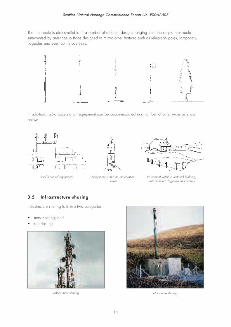
The monopole is also available in a number of different designs ranging from the simple monopolesurmounted by antennas to those designed to mimic other features such as telegraph poles, lampposts,flagpoles and even coniferous trees.
In addition, radio base station equipment can be accommodated in a number of other ways as shownbelow.
3.5 Infrastructure sharing
Infrastructure sharing falls into two categories:
• mast sharing; and• site sharing.
Scottish Natural Heritage Commissioned Report No. F00AA508
14
Roof mounted equipment Equipment within an observationtower
Equipment within a restored building, with antenna disguised as chimney
Monopole sharingLattice mast sharing

Some existing infrastructure is shared by two or moreoperators with some of the largest hilltop masts,developed originally for the emergency services,providing sites for mobile telecommunications operators’equipment. In some circumstances two or more mastsmay be located on a single site with several userssharing the electricity supply and access but no otherfacilities.
The infrastructure which can be shared by operatorscomprises:
• accommodation (the site) including perimeter fencing;• electricity transmission lines but not the electrical
cabinet;• masts and maintenance ladders (if structurally
capable of taking more than one operator’sequipment);
• the ground based control equipment housing(although in practice operators tend to prefer to usetheir own cabins); and
• cable ladders (in circumstances where the site hasbeen laid out with this objective in mind).
The infrastructure which cannot be shared, is largely dependent on the technical requirements ofoperators, and comprises:
• base transceiver equipment (control equipment);• antennas;• cable links to the fixed line network;• electrical cabinets; and• microwave dishes.
3.6 Other infrastructure which may be required
Relay stations
Where no direct ‘line of sight’ or cable connection ispossible between a radio base station and the mobiletelecommunications exchange a relay station, or stations,will be required. These are typically timber postssurmounted by microwave dish(es). Microwave relaystations can also be positioned on existing structures suchas buildings and electricity pylons.
Scottish Natural Heritage Commissioned Report No. F00AA508
15
Site sharing and mast sharing
Relay station

3.7 Infrastructure implications arising from the introduction of 3G technology
It is inevitable that more infrastructure will be requiredgiven that the 2G system will continue to operate at leastuntil the expiry of existing licences. Until 3G coverage iscomplete, 2G systems will still be required.
The precise infrastructure requirements are not likely todiffer significantly from 2G although the radio basestations will be sited at closer distances with cell sizes ofbetween 2–4km in rural areas and 0.5–1km in moreheavily urbanised areas.
The introduction of 3G is likely to have seriousimplications in terms of the numbers of masts and sites required as operators with existing 2G infrastructureare likely to wish to reserve additional capacity on their sites and masts for their own 3G infrastructurerather than negotiate site sharing with other operators’ 2G infrastructure. Recent changes to legislationmeans that mast heights will now tend to be of greatly varying heights, balancing operationalrequirements with environmental criteria; rather than the standard 15m which has been common in thepast, as this was the threshold for Permitted Development Rights. Operators can, however, be expected touse existing telecommunications sites whenever available.
In summary, more radio base stations will inevitably be required in the future but the true volume of this isnot yet known. Similarly, it is unclear as to when the ‘roll out’ of 3G might occur in the Highlands andIslands of Scotland as the licence requirements, to provide coverage to 80% of the population by 2007,may mean that areas of low population density will not be provided with 3G coverage until some timeafter this date.
3.8 Equipment erection, maintenance and decommissioning
In addition to there being a variety of different equipment required for radio base station developmentsthere are also variables in terms of constructionoperations and maintenance requirements.
Access
Access for construction and maintenance will bedependent on the location of the radio base station andwill take one of the following formats:
• directly from existing road or pre existing trackconstructed for other purposes;
• directly from existing mobile telecommunicationsaccess track;
• via an extension to existing mobiletelecommunications access track;
• via a new access track;
Scottish Natural Heritage Commissioned Report No. F00AA508
16
Illustration provided by Hutchison 3G
Access directly from trunk road

• access using ATV with no track; and• construction access using helicopter and ATV with
ATV access for maintenance with no track.
It should also be noted that maintenance access can alsobe on foot although there are Health and Safetyrestrictions in regards to the transport of tools andequipment.
Construction
The materials required for construction will vary depending on the precise nature of the development butare likely to include the following:
• the equipment and structures of the radio base station including all foundations (concrete ready mixedor mixed on site), plant and ancillary structures; and
• materials for access track construction including geotextile membranes, roadstone, drainage pipes.
Works will also vary in regards to:
• the extent of the site;• delineation of the construction area;• preparatory works;• platform construction or use of exposed rock;• plant and access required to install underground electrical supply;• depth and backfill of trenches;• vehicles required to import and export materials, labour required, noise and dust (in some
circumstances); and• construction period and reinstatement of disturbed areas.
Scottish Natural Heritage Commissioned Report No. F00AA508
17
Access via existing metalled track
New access track over flat moorland Mast close to road – access on foot or by ATV

Mobile Telecommunications Radio Base Station
equipment which wil l always be required
equipment which may be required
Scottish Natural Heritage Commissioned Report No. F00AA508
18
Equipment which can be shared by more than one operator
Equipment which cannot be shared by more than one operator
Roof site/building
PylonMonopole
location, height,design, colour
Lattice mastlocation, height,design, colour
Antenna andcable
connectiontype; underground,
overgroundconnection
Equipment cabinsize, materials, colour, integral
cabinet
Link to fixedline network
by cable, bymicrowave to MTX,
via relay station
Electricity supplyand generator
underground,overhead
Cabinetintegral or
stand alone, size,colour
Microwavedish
number, size,colour, position
Maintenanceladder
mass, position
Cable ladderheight, length,
mass
Perimeterfence
type, height,design, colour
Access trackroute, materials,
constructionmethod,
(borrow pits), maintenance

Maintenance considerations
Maintenance considerations include frequency of visits (including fuel deliveries to electricity generators)and means of access which may be of particular concern if more than one operator is using an ATV overhill ground as a means of access resulting in erosion and damage to vegetation.
Decommissioning considerations
All 2G and 3G licences under the new legislation require that radio base stations and their associatedinfrastructure be removed and the area reinstated to the satisfaction of the Planning Authority when theequipment is no longer required or on expiry of the licence.
The nature of decommissioning will essentially be dependent on the type of site but is likely to includeremoval of all equipment, breaking out of foundations and removal of all materials arising from site.Access track, fencing and powerline removal and reinstatement will also be likely to be required in areaswhere no continued use is being made of such facilities by other operators/users.
Summar y
The diagram opposite summarises the equipment required, the design options and other considerations formobile telecommunications radio base stations.
Scottish Natural Heritage Commissioned Report No. F00AA508
19

4. Landscape, Visual and Ecological Impacts
This chapter acts as an overview of the issues related tomobile telecommunications development in the Highlandsand Islands of Scotland by:
• explaining the issues which require to be understoodin order to assess the natural heritage impact of aproposed development; and
• introducing the assessment of landscape, visual andecological impacts.
4.1 The issues
In order to undertake an assessment of the likely naturalheritage impacts of proposed mobile telecommunicationsdevelopments it is necessary first to understand thecontext in which such development will be located andthen to understand the nature of the proposeddevelopment.
The key issue concerning mobile telecommunications inrelation to their landscape and visual impacts is sitingbecause a well designed mast of an appropriate colour cannot rectify poor siting.
Although mobile telecommunications masts generally tend to be utilitarian in their appearance it is clearthat some are less visually intrusive and incongruous than others. This primarily relates to their form, withlattice masts of tapering design generally appearing to be more elegant than those with a parallelstructure. Tapering masts also appear to be more anchored to the ground and more visually stable as aresult. That said, the introduction of large pieces of equipment close to the top of the mast detract from thisimpression.
In addition to location and overall design, the colour and materials of a mast are important in determiningwhether a mobile telecommunications radio base station will catch the eye or not.
Understanding the character of the landscape
The impacts of a proposed radio base station development will be dependent on how the character ofthe development relates (influenced by siting and design) to the key characteristics of the landscape inwhich it is to be situated.
The national programme of Landscape Character Assessment (LCA) undertaken by SNH describes the keycharacteristics intrinsic to each landscape character type at a regional level and these documents shouldbe consulted prior to considering landscape character issues at the local level.
Scottish Natural Heritage Commissioned Report No. F00AA508
20

LCAs do not place value on one type of landscape overanother. In some locations, however, the value of specificaspects of certain landscapes are recognised bydesignation (National Scenic Areas, Areas of GreatLandscape Value, National Parks). Such designations donot preclude telecommunications developments; but it willneed to be demonstrated that a development does notaffect the integrity of the designated landscape.
Understanding the issues which influence visualef fects
In selecting or assessing a site for telecommunicationsdevelopment it is important that an understanding isgained of who will see the development and from whereit is likely to be seen. This is likely to include localpeople in their houses or places of work; locals andvisitors travelling by sea, rail, road or on foot; or peoplevisiting outdoor sites such as picnic areas, places ofinterest such as monuments, ‘beauty spots’ and the like.
To assess the significance of the impact of telecommunications developments on people, it is necessary toestablish the level of intervisibility between the development(s) and these ‘receptors’. This can only beaccurately determined in the field although some indication of the likely prominence of such developmentcan be ascertained through the use of computer software which analyses intervisibility.
The distance over which a telecommunications development may be visible will vary depending onweather conditions and season (changing colour of the landscape and quality of light) and will alsodepend on the character of both the development and the landscape in which it is situated.
Understanding nature conser vation issues
The significance of potential impacts of a proposed radiobase station development on ecological interests will bedependent on the inherent value of any natureconservation resource likely to be affected.
The first step in gaining an understanding of theecological context of a proposed development will be tocollect data relating to designated sites and nondesignated sites which are of nature conservation valuesranging from international importance to localimportance.
It should be recognised that radio base stationdevelopments and their ancillary structures, especiallytracks, may have the potential to cause both direct andindirect effects on sites of ecological interest which arenot in the immediate vicinity of a development site.
Scottish Natural Heritage Commissioned Report No. F00AA508
21

Understanding the proposed development
In order to assess the landscape, visual and ecological impacts of a proposed radio base station it willbe necessary to fully understand the nature of the proposed development.
The level of understanding of the proposed development will be dependent on familiarity with thetechnology combined with the quality of information provided by operators. It is important that thetechnology is understood and the potential impact of using a 2G site for additional 3G use, or futuresharing with another operator, is considered from the outset. The introduction of 3G could have significantramifications in terms of future cumulative landscape, visual and ecological impacts due to the likelihoodof a considerable number of new radio base stations, shared sites and mast shares being required.
The level of information provided by the operator will be crucial in facilitating an accurate assessment ofthe likely impacts of any proposed radio base station. Appendix VII provides a checklist of the informationwhich should be required from a mobile telecommunications operator. This checklist reflects therequirements of NPPG 19 which lists information which should be provided by operators and exceeds thelevel of information which was required to be provided along with permitted development notifications.The purpose of this checklist is to assist Planning Officers and SNH Area Officers to assess proposedtelecommunications developments.
Scottish Natural Heritage Commissioned Report No. F00AA508
22

5. Sit ing and Design Guidelines
This chapter summarises the key issues influencingoperators’ choice of development, highlights ‘firstprinciples’ in relation to location issues and describesbasic principles of siting and design to be considered interms of landscape, visual and ecological impacts inrelation to a range of typical examples of Highland andIsland landscape character types.
5.1 Operators’ sit ing considerations
Appendix V presents an overview of the operators’ siteselection process and the technical factors to beconsidered such as:
• most suitable location for effectivecoverage/capacity of network;
• availability of site;• mast height and design; • number of antenna required; and• amenity considerations.
It should be remembered that the operator’s optimum site need not be the only option to provideacceptable coverage.
5.2 First principles
When selecting a radio base station site or assessing a selected site the following considerations shouldalways be borne in mind:
• even in circumstances where development of the operator’s selected site will result in an acceptablelevel of impact on visual, landscape and ecological resources there may well be a better site in thelocality;
• it may be preferable to install radio base station equipment on an existing structure (building,pylon or existing mast) rather than introduce a new mast structure;
• it may be better to accept an additional structure in the form of an intermediate relay station ifthis facilitates a better radio base station location being developed in terms of impacts on landscape,visual and ecological resources;
• the entire radio base station and ancillary features must be considered as a whole and, in mostcircumstances, the more simple and compact the layout of the radio base station the better;
• in general, the more features which can be concealed from significant viewpoints the better;• in locations where existing radio base station masts exist, ensure that lessons are learned from the
siting and design of these existing examples and that any new radio base station builds onthese lessons;
• the relative advantages and disadvantages of mast sharing, site sharing and new site alternativesshould always be assessed;
Scottish Natural Heritage Commissioned Report No. F00AA508
23
• no hard and fast rules can be applied: each and every proposed location must be considered on
its own merits in its specific context; and• avoid developing masts within or on the edge of areas which possess qualities of ‘wildness’ or ‘wild
land’.
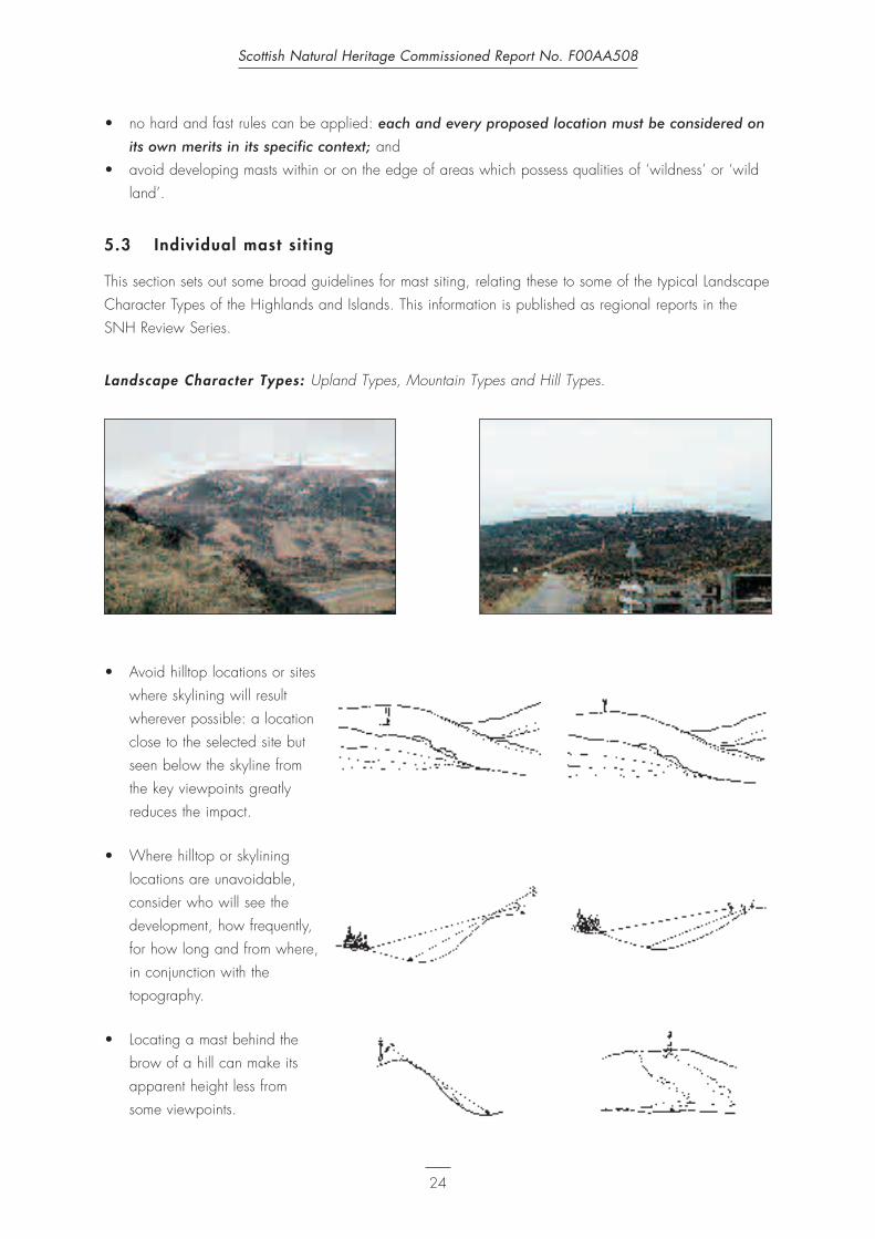
5.3 Individual mast sit ing
This section sets out some broad guidelines for mast siting, relating these to some of the typical LandscapeCharacter Types of the Highlands and Islands. This information is published as regional reports in theSNH Review Series.
Landscape Character Types: Upland Types, Mountain Types and Hill Types.
• Avoid hilltop locations or siteswhere skylining will resultwherever possible: a locationclose to the selected site butseen below the skyline fromthe key viewpoints greatlyreduces the impact.
• Where hilltop or skylininglocations are unavoidable,consider who will see thedevelopment, how frequently,for how long and from where,in conjunction with thetopography.
• Locating a mast behind thebrow of a hill can make itsapparent height less fromsome viewpoints.
Scottish Natural Heritage Commissioned Report No. F00AA508
24

• When selecting hillsidelocations, consider whetherthe development will bebackclothed for all potentialviewers.
• Take best advantage of thecombination of topographyand vegetation.
• Locate masts on natural sites(localised level areas onhillsides) to minimise the needfor levelling and the potentialfor erosion.
• Try to link to existing built/vertical features so that theradio base station appearsless incongruous in thelandscape.
Landscape Character Types: Moorland Types
• Relate the development toexisting built features in thelandscape rather than intro-ducing new focal points.
• Take advantage of localtopographical variations toconceal ancillary equipment.
Scottish Natural Heritage Commissioned Report No. F00AA508
25
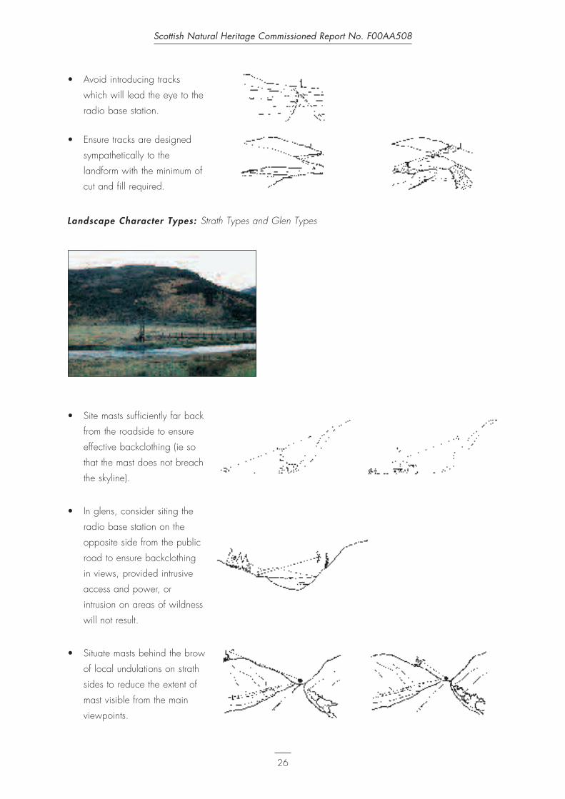
• Avoid introducing tracks
which will lead the eye to the
radio base station.
• Ensure tracks are designed
sympathetically to the
landform with the minimum of
cut and fill required.
Landscape Character Types: Strath Types and Glen Types
• Site masts sufficiently far back
from the roadside to ensure
effective backclothing (ie so
that the mast does not breach
the skyline).
• In glens, consider siting the
radio base station on the
opposite side from the public
road to ensure backclothing
in views, provided intrusive
access and power, or
intrusion on areas of wildness
will not result.
• Situate masts behind the brow
of local undulations on strath
sides to reduce the extent of
mast visible from the main
viewpoints.
Scottish Natural Heritage Commissioned Report No. F00AA508
26

• Avoid locations where mastswould dominate in enclosedglens.
• Consider the cumulativeimpact of repeated masts inprominent locations visiblefrom roads running throughglens – not only thoseintervisible but also thoseseen sequentially.
General guidance applicable over the Highlands and Islands
• Avoid locations close to roadcorridors where no screeningtrees or scrub exist unlessthere is a relationship to otherroadside furniture orstructures.
• Avoid locations on the outsideof bends where a mast wouldform a focal point for driverstravelling in both directionsand where a location outwiththe main corridor of visionwould render the mast lessconspicuous.
• Take advantage of roadsidevegetation.
• Take best advantage of anyexisting vertical structures inroadside locations.
Scottish Natural Heritage Commissioned Report No. F00AA508
27
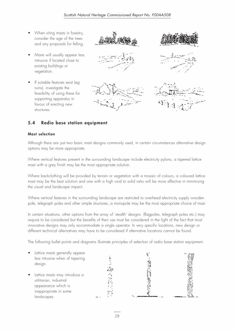
• When siting masts in forestry,consider the age of the treesand any proposals for felling.
• Masts will usually appear lessintrusive if located close toexisting buildings orvegetation.
• If suitable features exist (egruins), investigate thefeasibility of using these forsupporting apparatus infavour of erecting newstructures.
5.4 Radio base station equipment
Mast selection
Although there are just two basic mast designs commonly used, in certain circumstances alternative designoptions may be more appropriate.
Where vertical features present in the surrounding landscape include electricity pylons, a tapered latticemast with a grey finish may be the most appropriate solution.
Where backclothing will be provided by terrain or vegetation with a mosaic of colours, a coloured latticemast may be the best solution and one with a high void to solid ratio will be more effective in minimisingthe visual and landscape impact.
Where vertical features in the surrounding landscape are restricted to overhead electricity supply woodenpole, telegraph poles and other simple structures, a monopole may be the most appropriate choice of mast.
In certain situations, other options from the array of ‘stealth’ designs (flagpoles, telegraph poles etc.) mayrequire to be considered but the benefits of their use must be considered in the light of the fact that mostinnovative designs may only accommodate a single operator. In very specific locations, new design ordifferent technical alternatives may have to be considered if alternative locations cannot be found.
The following bullet points and diagrams illustrate principles of selection of radio base station equipment.
• Lattice masts generally appearless intrusive when of taperingdesign.
• Lattice masts may introduce autilitarian, industrialappearance which isinappropriate in somelandscapes.
Scottish Natural Heritage Commissioned Report No. F00AA508
28

• Lattice masts with a grey finishmay be the best solution forskylining situations although itshould be acknowledged thata galvanised finish may behighly reflective untilweathering occurs and getdarker over time.
• Lattice masts with a grey finishmay be the best solutionwhere the backcloth includesrock outcrops, cliffs or screeof predominantly grey tones.
• Grey lattice masts may be thebest solution wherebackclothed by deciduouswoodland but breaking theskyline. Monopoles painted inan appropriate colour may bemore appropriate where thereis a woodland backdrop andno skylining.
• In urban and peri urbansituations consider the use ofmonopoles with or without‘lighting brackets’.
• Innovative masts in the form offlagpoles may be appropriatein locations adjacent to ruralhotels or visitor centers.
The site
• Keep the layout of groundbased equipment as simpleas possible (particularly inmast/ site share situations).
Scottish Natural Heritage Commissioned Report No. F00AA508
29

Control equipment and housing
• Equipment housing need notbe located adjacent to themast (separation distances of100m plus are possible,although a larger cable willbe required to reduce signalloss): look for the bestlocation.
• Use cabins with integralcabinets wherever possible;use the smallest size of cabinpossible; reference to otherstructures in the surroundingarea should be made toinform any decision relatingto the siting, character anddesign of a purpose builtstructure.
Antenna and cable connection
• Omnidirectional antenna maybe the least visually intrusivesolution for a lattice mast fora single user – where multipleomnidirectional antenna areused, those located atvariable levels add visualclutter to the mast structure.
• For monopoles, antenna which appear to be integral to the mast or are capable of being housedwithin the mast structure (eg flagpole/lighting column designs) will present a more simple form.
• Undergrounding of cables will almost always be the best option unless vegetation is of significantnature conservation value or detrimental hydrological impacts would result.
Link to the fixed l ine network
• Wherever possible, a direct connection to the fixed line network will be preferable to the introductionof microwave dishes and relay stations although operator’s requirements to retain control of thetransmission of the signal may mean that the link has to be via microwave dish as this can be morereliable and cost effective.
Scottish Natural Heritage Commissioned Report No. F00AA508
30

Electricity supply
• If the nearest availableelectrical supply is remoteand no overhead lines exist inthe locality, explorerenewable energy options orconsider the use of an on sitegenerator subject to noiseand tanker accessconsiderations.
• Remember that the generatorneed not be locatedimmediately adjacent to themast although power loss canoccur if the generator isremote from the base station:select the best possible site.
• Avoid introducing anoverhead electrical supplywhich will break the skyline.
• Consider full or partialundergrounding of electricitysupply.
• Select a route for theoverhead electrical supplywhich relates to the landscapecharacteristics, to ‘fit’ the lie ofthe land and not lead theviewer’s eye to the mast.
Microwave dish
• The smaller the dish and thefewer of these mounted onsingle masts, the better (ingeneral, the dish size isdictated by the distancebetween sites).
• Painting the dishes whiterenders them highly reflectiveand they become visible overlong distances especiallywhen seen against a hill orwooded backcloth.
• Generally paint the dish thesame colour as the mast.
Scottish Natural Heritage Commissioned Report No. F00AA508
31

Maintenance ladders
• Avoid the use of maintenance ladders wherever possible – where necessary, locate the ladder so thatit appears to form part of the mast and of a minimal mass rather than appearing as an additionalstructure.
Cable ladders
• Cable ladders can addsignificantly to the adversevisual impact of a radio basestation and should beavoided wherever possibleexcept in situations where theground based equipment iscompletely concealed fromview. If cable ladders must beused, ensure they can beshared and design them to beas simple and as low aspossible.
Perimeter fencing and walls
• The need for fencing shouldbe carefully considered. Ifthere is a need to enclose thesite, the design of fencingand gates should reflect thecharacter of existing fences,walls and gates thelandscape in which the radiobase station is located.
Colour
• Use a consistent colourscheme for all componentstructures of the radio basestation. Ensure that equipmentfinishes and colours do notvary and result in visualconfusion.
• Where considering paintedfinishes remember seasonalchanges – assess the colourof the surroundings andchoose a colour whichcompliments these at mosttimes, accepting that it maynot exactly match in any oneseason.
Scottish Natural Heritage Commissioned Report No. F00AA508
32
Unsympathetic corrugated iron fence
Visual confusion results from use of several colours

• In skylining situations, mastsshould generally be light greyin colour.
• Camouflage paint finishes willonly be successful if customdesigned and applied welland where the mast is seenagainst a backcloth oflandcover from most keyviewpoints.
• Increasing the void:solid ratio of lattice masts, so that they appear as light as possible, will be moresuccessful in minimising their impact than applying colour in an attempt to mimic background tones.
• In peri urban situations, monopoles should be finished to blend in with other vertical features (iepainted the same colour as adjacent structures such as lamp posts).
• Where backclothing is moorland, a recessive shade of brown will generally be the most appropriate.
• Green paint finishes rarelysucceed in matching thegreens of nature and colourselection should reflect surrounding shades in aneutral fashion rather thanattempt to mimic these.
• In some situations where themast will be seen against avariety of backdrops it maybe preferable to create apositive image with acontrasting colour rather thanattempting to camouflage themast.
• Any paint finish employedshould be matt to reducereflectivity.
• White colour of microwave dishes and antenna usually draws attention to the mast.
Access
General guidance relating to access tracks can be obtained in the publication ‘Vehicular Tracks in UplandScotland’ (CCS 1978) and it is anticipated that SNH will soon be in a position to provide furtherguidance on completion of an intended research project into the subject.
Scottish Natural Heritage Commissioned Report No. F00AA508
33
Green mast in skylining situation
Unsuccessful attempt to mimic grassland colour

Where sites are located close to the existing road network or rural tracks, it may be possible to provideconstruction and maintenance access directly off the carriageway or track with only either a hard standingor a short length of access track being required. In these circumstances, the landscape, ecological andvisual impacts are likely to be insignificant.
The following points should be considered:
• it is important to recognise that for some radio base stations access on foot/helicopter formaintenance purposes may be the only acceptable option in environmental terms;
• the adverse impacts of radio base station developments can be reduced if alternative forms of accesscan be utilised (via the sea, helicopter, on foot or by ATV);
• temporary methods of construction such as floating or rafted tracks which can be removed oncompletion of construction should be considered;
• on sites where the maintenance ofexisting hydrological patterns isimportant, single or multiple culvertsmay be required to maintain waterflows below tracks lying onembankment or at grade. Water-proof membranes may be necessaryto retain hydrological patterns onthe uphill side of tracks where thecross section is in cutting;
• the routing of access tracks shouldbe designed sensitively to reflect thecharacter and be sympathetic to thetopography of the locality;
• ensure that the access track doesnot draw the eye to the base stationitself;
• where tracks are to be surfaced,ensure that materials with recessivecolours similar to the surroundingground cover are used; and
• minimise the length and width of allaccess tracks while ensuring that themost appropriate route is selected.
Scottish Natural Heritage Commissioned Report No. F00AA508
34

5.5 Mast sharing
The issues of mast height and design have relevance to the situation of mast sharing. The principaloperator will usually occupy the prime site, at the top of the mast, with later operators taking lower siteswhich provide reduced areas of coverage, possibly necessitating additional masts to provide infill.Alternatively, to ensure that subsidiary operators attain good coverage without the need for infill masts, theexisting mast may have to be extended (if the structural design of the mast allows this) or a new, tallerreplacement mast installed.
Each operator’s equipment must have a vertical separation of a minimum of 1m between antennas whichmeans that mast heights may have to be increased by as much as 3m per additional operator dependingon mast design, strength, loading etc.
As operators cannot usually share equipment, additional cabins and cabinets will also be required.However, replacement, shared cabins should also be considered.
Some advantages of mast sharing are:
• retention of just a single vertical feature in the landscape;• ground based apparatus contained within a single compound;• shared electricity supply (no additional overhead lines/generators); and• shared access if by existing track.
Potential disadvantages of mast sharing include:
• increased height of mast;
• potential for visually confusing clutter of ground based equipment if not shared and of contrasting formand colours and if equipment housing is poorly sited within the compounds;
• additional antennas, microwave dishes and cabling adding to the bulk of the structure and renderingit more visible;
• potential for disturbance to vegetation if ATV access or a need for formal access track formaintenance purposes;
• additional operators willmean additional equipment,giving rise to potential for acluttered appearance;
• increased mast height mayrender the mast more visible;
Scottish Natural Heritage Commissioned Report No. F00AA508
35

• mast sharing may bepreferable to an additionalmast in close proximity; and
• mast sharing rather thanproliferation is often the bestsolution in simple and largescale landscapes (egmoorland).
5.6 Site sharing
Where it is not possible for existing masts to accommodate additional equipment, or where is consideredthat an increase in height of a single mast is not a viable or preferred solution, existing sites may beshared provided sufficient land has been acquired by the primary operator.
Site sharing may have certain advantages such as:
• ground based apparatus contained within a single compound;• shared electricity supply (no additional overhead lines/generators); and• shared access if by existing track.
Potential disadvantages of site sharing include:
• twin masts being moreprominent in the landscapethan a single vertical feature ifthe masts are not in closeproximity;
• visual confusion if masts are of different types (ie one lattice, one columnar), designs, height,proportions, colour;
• potential for visually confusing clutter of ground based equipment if finishes are of different colours;
• potential for disturbance to vegetation if ATV access or need for formal access track;
• site sharing may not be thebest option where othervertical features are locatedat some distance from eachother as this will result in acontrast of landscape pattern;
Scottish Natural Heritage Commissioned Report No. F00AA508
36
Double mast seen as single feature
Double mast seen as separate feature

• in site sharing situations mastsof similar appearance shouldbe used to minimise visualconfusion;
• in some situations, such assimple open landscapes, itmay be preferable to groupmasts together rather thanhave them dispersed;
• in other situations dispersalmay be more fitting to theintrinsic landscape character;and
• it may be preferable to groupthe masts closely together sothat they ‘read’ as a simplefeature.
5.7 Multiple masts
The ongoing programme of 2G mast installation, together with the future roll out of 3G infrastructure willresult in many more radio base stations being required in the Highlands and Islands.
When undertaking assessments for proposed masts, the potential impact of future development shouldalso be considered:
• establish whether future mast sharing is a viable option; • establish whether the site is large enough to permit site sharing (if this is considered appropriate); and• establish whether 2G and 3G infrastructure can be shared.
Scottish Natural Heritage Commissioned Report No. F00AA508
37

5.8 Assessing the impacts of proposed radio base station developments
In assessing the impacts of proposed radio base stations the following key questions should be addressed.
Landscape character
• Referring to the Landscape Character Assessment(available from SNH), which Landscape CharacterType(s) will be affected by the proposeddevelopment?
• What are the key characteristics of these LandscapeCharacter Types?
• How might the proposed development affect thesecharacteristics?
• What are the key forces for change for theLandscape Character Types likely to be affected? Aremobile telecommunications developments discussedspecifically in the Landscape Character Assessmentsor does the general guidance provide assistance?
• Referring to the Landscape Character Assessments,how is the landscape valued?
• Is the quality of remoteness listed as a keycharacteristic?
• Are there other built features in the vicinity? If so, dothese include existing mobile telecommunicationsradio base stations, electricity pylons, telegraphpoles overhead electricity lines or other verticalfeatures?
• Is the development located in a designated area orwill it be visible from a designated area?
• If so, for which characteristics or qualities is thelandscape designated? Will the development affectthe integrity of this designation? Will this depend on siting and design and if so, how?
• Which elements of the proposal are likely to have the most significant impacts on landscapecharacter? Can these be modified to reduce the level of impact to an acceptable level?
• Should an alternative site be considered?
Visual ef fects
• What are the key characteristics affecting how the landscape is experienced (topography, vegetation,access etc)?
• Who will mainly see the radio base station (residents, visitors, tourists, workers)?• How will these people see the radio base station (from isolated locations, from a distance, from close
range, while moving through the landscape etc)?• Which elements of the proposal are likely to have the most significant visual impacts? Is the overall
structure likely to appear visually light, elegant and balanced or unbalanced, heavy in structure orappear industrial in image?
Scottish Natural Heritage Commissioned Report No. F00AA508
38

• Can the proposed development be modified to reduce the level of impact to an acceptable level?• Should an alternative site be considered?
Ecology
• Is the development located in a designated area?• If so, for what nature conservation interests is the area designated?• Is the development located in an area of regional or local nature conservation value?• Will any nature conservation interests be adversely affected by the proposed development?• Which elements of the proposal are likely to have the most significant impacts on ecological interests?• Can these be modified to reduce the level of impact to an acceptable level?• Should an alternative site be considered?
The development: single masts
• How will the scale and form of the proposed development relate to any existing vertical features(natural and man-made) in the landscape?
• How will the scale of the proposed development relate to the perceived scale of the landscape itself ifno vertical features exist?
• Will it, for example, diminish the apparent scale of mountains by acting as a reference feature of aknown size?
• Will the proposed radio base station be located on the skyline or be a focal point from mainviewpoints? Are alternative sites available? Is it feasible to relocate the development?
• Will the proposed radio base station be perceived as a single, individual element or will it be soclosely located to other radio base stations that these will be perceived collectively as one elementfrom significant viewpoints? If the latter, would this result in visual confusion and if so, would analternative site be preferable? Are alternative sites available? Is it feasible to relocate the mast? Ismast sharing an option?
• Will the ancillary features be prominent and result in significant adverse impacts? If so are theremitigating measures which could be undertaken to render these features less prominent and to reducetheir impacts to an acceptable level?
The development: mast sharing
• Will mast sharing require increased mast height? By how much as a minimum?• If so will additional unacceptable impacts accrue from an increase in mast height in relation to the
scale of the landscape? If so, would an alternative site be more acceptable? Is there an alternativesite available?
• Will the additional ancillary features be prominent and result in significant adverse impacts? If so, arethere mitigating measures which could be adopted to render these less prominent and to reduce theimpacts to an acceptable level?
The development: site sharing and multiple masts in close proximity
• Will the addition of a further vertical feature in the landscape give rise to visual confusion or increasethe level of impact by being seen as one of a series of such features while moving through thelandscape?
Scottish Natural Heritage Commissioned Report No. F00AA508
39

• Will the proposed radio base station be perceived as a single element or will it be so closely locatedto other radio base stations that these are perceived as one element, or as a group feature?
• Would it be preferable to have a new taller mast to provide accommodation for all operators withequipment in the vicinity?
• If other radio base stations exist, will a further mast ‘swing the balance’ to the extent that thesebecome key characteristics in the landscape and change the intrinsic character of the landscape?Will the resultant effect be a change in character to one with an industrial appearance?
Scottish Natural Heritage Commissioned Report No. F00AA508
40

6. Appendices
Appendix I History and Development of Mobile Telecommunications in the Highlands and Islands
This appendix provides a summary of the history and development of mobile telecommunications in thecontext of the Highlands and Islands.
Early in 1996 the then Scottish Secretary, Michael Forsyth, announced a proposed developmentprogramme for the expansion of the mobile telecommunications network in the Highlands and Islands. Thiswas made possible by a successful application, by Highlands and Islands Enterprise (HIE), to the EUObjective One Programme which secured funding to the value of £3.8m. HIE contributed £200,000 tothe programme and this public package secured a joint Cellnet and Vodafone investment of £42m.Neither Cellnet nor Vodafone were prepared to invest independently due to the relatively low populationdensity of the Highlands and Islands combined with the mountainous terrain for which it is difficult toprovide radio coverage.
The programme required an expanded network of approximately 250 transmission sites withapproximately 40% of these being anticipated as being on ‘greenfield’ sites with the remainder being onsites shared with, for example, the emergency services. The majority of these new sites were to be mast-based and developed under Permitted Development Rights.
The proposed expansion was designed to provide services to 95% of the population and ‘in-car’coverage to 90% of the A and B roads in Highland Region.
As a condition of the provision of funding by the EU, HIE was obliged to supply information relating to theprincipal characteristics of the project and descriptions of the predicted environmental impacts during theconstruction and operation phases.
In 1996 HIE commissioned a study of the proposed development programme for a major expansion ofthe mobile telecommunications network across the HIE area. This study had three specific objectives:
• to identify site specific and programme wide environmental impacts which could be expected to resultfrom the proposed development programme;
• to identify those areas of the current telecommunications regulatory process in which the considerationof environmental issues could be improved upon; and
• to prepare practical and commercially viable environmental management guidelines based on areview of best practice and the identified environmental impacts, to be used by thetelecommunications companies in the implementation of the telecommunications expansionprogramme.
The study identified the principal environmental impacts of the HIE Programme as:
• visual impact is likely to be the principal source of site specific environmental concern, particularlywith respect to the amenity of scenic areas and local properties;
• landscape impacts could be significant, particularly within National Scenic Areas and in otherdesignated landscape areas where development potentially compromises ‘wild land’ characteristics;
Scottish Natural Heritage Commissioned Report No. F00AA508
41

• the environmental impact of any new access roads may be significant and the need for these shouldbe minimised;
• cumulative impacts are most likely to be significant in terms of the number of designated sites affectedby the Programme, and through any co-location of masts at relatively close proximity to or, particularly,within scenic areas;
• site specific construction and operational impacts of masts and related infrastructure located indesignated sites for nature conservation, including disturbance to wildlife at critical periods (egbreeding times); and
• the environmental impact from electro-magnetic radiation is likely to be insignificant.
Most of the identified site-specific environmental impacts can be mitigated by careful siting of masts. Forthe most sensitive sites the use of appropriate design and construction techniques can play a key role inreducing environmental impacts. Increased opportunities for widespread consultation ahead of and inconnection with applications for telecommunications developments will help to improve the avoidance ormitigation of environmental impacts.
A set of guidelines were developed in discussion with HIE, Vodafone and Cellnet which reflect the uniquenature of the environment, economy and communities of the Highlands and Islands.
Scottish Natural Heritage Commissioned Report No. F00AA508
42

Appendix II Legislation Prior to 2001
This Appendix and the one following provide an overview of the legislation relating to mobiletelecommunications developments which has particular relevance in the context of this report. Appendix IIoutlines legislation prior to 2001 – much of which is still in force today – and Appendix III describes thekey provisions of recent (post-2001) legislation.
Prior to 2001 the following two bodies of inter-related legislation were of particular relevance in the sitingand design of mobile telecommunications developments:
• The Telecommunications Act 1984 and its related Code and Licences; and • The Town and Country Planning (General Permitted Development) (Scotland) Order 1992 and the
Town and Country Planning (General Development Procedure) (Scotland) Order 1992. (Both StatutoryInstruments of the 1972 Town and Country Planning (Scotland) Act).
In July 1980, the then Industrial Secretary Sir Keith Joseph, announced the Government’s intention torestructure the General Post Office (GPO) and relax the monopoly over terminal equipment and valueadded services. The following year the British Telecommunications Act received Royal assent and thisformalised the split between postal services (Royal Mail) and telecommunications services (British Telecom– BT). From this date, independent suppliers of telephones were permitted to enter the market.
The Government issued a White Paper in July 1982, proposing the sale of 51% of BT and the creation ofa regulatory body, the Office of Telecommunications (OFTEL).
In May 1983, the Government granted Telecom Securicor Cellular Radio Ltd (Cellnet) an OperatingLicence for cellular telecommunications and granted a second Operating Licence to a subsidiary of RacalElectronics plc, trading under the name of Vodafone.
The 1984 Act defined the Telecommunications Code which laid down the conditions under whichTelecommunications Code Systems Operators are required to operate as part of their licence. Operatorsincluded: Cellnet, Vodafone, Mercury, One2One, Orange, Norweb and BT. Operators’ licencescontained different conditions (largely because they used different systems) and this led to inconsistencies.
Where developments did not require a full planning application, some licences nevertheless requiredoperators to notify the planning authority, which then had 28 days to respond or to impose conditionsupon the installation.
Such licence conditions required that the operator must install the apparatus ‘…in accordance with such ofthese conditions as are reasonable in all the circumstances of the case taking into account the desirabilityof protecting the visual amenity of the locality, the technical requirements of the licensee’s system and thecost of installation’.
The key clauses of the 1984 Act which are summarised in the Scottish Office Circular 5/1992 Annex Dare:
• operators had the right to install apparatus on private land with the prior agreement of the occupier;
Scottish Natural Heritage Commissioned Report No. F00AA508
43

• operators’ activities should not interfere with access to other land, without the agreement of theoccupier;
• operators had the right to apply to the Courts for a compulsory purchase order to install theirapparatus on land where prior agreement with the occupier was not forthcoming;
• operators had the powers to carry out works in the street and install apparatus in, on, or under thestreet (subject to Public Utilities Street Works Act 1950);
• operators had the right to fly lines over any land without the occupier’s consent (although anytermination points require consent);
• operators were required to obtain the agreement of water and sewerage companies prior to theplacing of telecommunications apparatus within conduits under these companies’ control;
• owners or occupiers of land could object to overhead apparatus where such apparatus was at least3m above ground;
• operators were required to fix a notice giving details of how and where to object to the installation ofsuch overhead apparatus;
• operators had the right to require the occupier of land to lop a tree if it overhung the street andinterfered with telecommunications apparatus;
• provision was made to require an operator to alter or remove apparatus in the way of development;• operators had to remove apparatus when it is no longer required; and• provision was made for when a local authority, public utility or another code system operator wanted
to alter the apparatus of a code system operator in the course of any street works.
The 1992 Town and Country Planning Orders gave wide Permitted Development rights toTelecommunications Code System Operators for the installation of masts and their infrastructure. Thefollowing restrictions applied however:
• the total height of the whole apparatus was not to be more than 15m above the ground; and• it was not permitted to install a microwave* antenna in an NSA.
*Note
‘microwave’ is defined as being over 1000MHz so Vodafone and Cellnet’s digital Global System for Mobile (GSM)
antennas which operate at 900MHz fulfilled the PD requirements and could be installed in an NSA as long as the
other conditions mentioned above were complied with.
Scottish Natural Heritage Commissioned Report No. F00AA508
44

Appendix III Current Legislation
Permitted Development Rights
Class 67 of the Town and Country (General Permitted Development) (Scotland) Order 1992 (as amendedby the Town and Country Planning (General Permitted Development) (Scotland) Amendment (No. 2) Order2001) grants limited permitted development rights to telecommunications developments. An overview ofthe key provisions is set out below:
• all ground based masts (irrespective of height) require planning permission;• within limits, some telecommunications developments on buildings or other structures are classed as
permitted development. In summary, this includes the following:
• on buildings over 15m in height – 8 antennas all of which neither exceed 2.8m in height or1.3m
wide nor when measured together with any supporting structure exceed 4m in height; or• on buildings not over 15m in height – either 4 antennas all of which neither exceed 0.9m in any
direction nor when measured together with any supporting structure exceed 4m in height or, 8 antennas all of which neither exceed 0.5m in any direction nor when measured together with
any supporting structure exceed 4m in height; and
• on a dwelling house, 2 antennas all of which neither exceed 0.5m in any direction nor project above the highest part of the roof.
• detailed permitted development limits are also set out for radio equipment housing (either on theground or on a building), small antennas and access tracks;
• there are no permitted development rights in certain designated sites and areas, including:conservation areas (whether or not covered by an Article 4 Direction removing class 67 as permitteddevelopment); NSAs; National Parks; historic gardens or designed landscapes; SSSIs; European Sites(nature conservation); category A listed buildings (or their setting); scheduled ancient monument (or itssetting) unless:
• the development is carried out in an emergency; or• the development comprises not more than 2 small antennas on any part of a dwelling house that
does not face a road.
Conditions applying to Permitted Development
Class 67 of the Town and Country Planning (General Permitted Development) (Scotland) Order 1992 (as amended by the Town and Country Planning (General Permitted Development) (Scotland) Amendment(No. 2) Order 2001) sets out the following conditions on permitted development.
All permitted development proposals involving the construction or installation of one or more antennas will:
• require to be notified to the local planning authority 28 days before development commences (unless in an emergency) including a description (with specifications) of the apparatus and a plan showing the development’s location and layout (this applies to equipment housing as well);
Scottish Natural Heritage Commissioned Report No. F00AA508
45

• require the submission of a detailed description of the equipment and its location and a declaration that the proposed equipment and installation complies with International Commission on Non-Ionising Radiation Protection (ICNIRP) public exposure guidelines; and
• all permitted development proposals are subject to the condition that any antenna or supporting apparatus shall so far as is practicable be sited so as to minimise its effect on the externalappearance of the building.
In exercising Permitted Development, operators are required to fulfil the Telecommunications Code.
Other information requirements
Developers will be expected to provide supporting information and details on the siting and design of thedevelopment proposals. Assessment and evaluation of the potential impact of proposals upon landscapecharacter and visual amenity should accompany this information.
Scottish Natural Heritage Commissioned Report No. F00AA508
46

Appendix IV Technical Issues
Current systems
Prior to 1992, mobile telecommunications operated utilising
analogue technology known as the Total Access Communications
System (TACS). Equipment for the analogue network tended to be
concentrated around the major centres of population and along
the major transport arteries. The operators were anxious to provide
the maximum coverage in the minimum period of time and tended
to seek planning permission for tall masts, often on high ground,
transmitting signals over the maximum area.
The reasons for additional mobile telecommunications radio base station sites being required to provide
coverage for the digital system in the Highlands and Islands were:
• digital technology uses telephones with smaller battery packs which operate at lower power levels
with an ability to transmit power over shorter distances;
• digital technology, although providing many enhanced features and benefits over analogue, has
limitations which reduce the distance over which the radio signal can be used; and
• to provide coverage to the maximum area (ie not restricted to areas of high population/transport
networks).
Vodafone and Cellnet which were granted licences in 1983 operate the digital Global System for Mobile
(GSM) which is internationally recognised and enables users to use handsets throughout Western Europe.
This system utilises the 900MHz frequency which is not recognised as being microwave in the context of
planning legislation (microwave being defined as being over 1000MHz).
Mercury, One2One and Orange use the Personal Communications Network (PCN) which is two way
radio technology with higher frequencies (1800MHz) and digital technology. PCN provides greater
capacity within the cells but covers smaller areas so more radio base stations are required. PCN is
recognised as a microwave system in the context of planning legislation. In 1997 an additional radio
spectrum at 1800MHz was allocated to Vodafone and Cellnet.
For each of the operators it is only possible to provide for a limited number of simultaneous mobile
telephone conversations at one time without the introduction of cell planning or splitting of existing cells.
For example, Vodafone’s frequency range actually lies between 890 and 995MHz within which they are
allocated 55 duplex channels, allowing 55 simultaneous telephone conversations. Increased capacity is
provided by subdividing cells (introducing more radio base stations) and operating each of these on a
discreet part of the radio spectrum at a reduced power level. For example, where an existing cell
provides say 55 channels (simultaneous telephone conversations), the capacity can be increased by
subdividing the cell into 7 sub cells to provide say 15 voice channels in each sub cell or 105 channels in
total.
Scottish Natural Heritage Commissioned Report No. F00AA508
47
Analogue coverage with digital infill.

Cell planning
Geographical areas are divided into smaller areas, or cells, which represent the area of coverage
possible from a radio base station located within the cell. Cell planning considers the following
restrictions:
• the area is determined by the number of calls anticipated as
there is a limit to the number of radio channels allocated to each
cell;
• the same radio channel cannot be used in adjacent cells
otherwise interference between calls might result; and
• adjacent radio channels within the spectrum cannot be used in
the same cell otherwise interference and noise might occur
during calls.
Limits for cell sizes vary but can be as large as a 15km radius in areas of flat terrain where population
levels are low and as small as 0.5km radius in densely populated areas.
The system is designed to provide continuous call coverage for
mobile users and for this reason the signal coverage from each
radio base station requires to overlap with adjacent cells in order
that calls can be routed via the radio base station with the strongest
signal. This is one factor for the siting of a radio base station as, if it
is located too far from adjacent cells the call cannot be re-routed
and will be ‘dropped’.
As the number of users of the network increases, additional capacity is provided for by cell splitting which
is employed in urban areas to cope with high use demand and increased levels of signal loss due to the
density of buildings. In rural areas, fewer radio base stations are required due to lower numbers of users
and less obstruction to the signal from buildings. In the Highlands and Islands, and other areas of
mountainous terrain, topography plays its part in signal obstruction. If good coverage is to be achieved it
is inevitable that, in some areas, masts will require to be located in prominent hilltop locations or a higher
density of masts at lower locations will be required.
Future systems (3G technology)
The cell size for 3G for rural areas is envisaged to be 2–4km across and for more heavily urbanised
areas 0.5–1km across. The reasons for the small cell size include the facts that:
• 3G operates at a much lower power output than previous systems (handsets and base stations) while
seeking to maintain high data transfer rates;
• 3G operates at higher frequency (2100khz) which means the signal travels less distance; and
• the need to minimise interference between cells results in the need for a large number of small cells.
Scottish Natural Heritage Commissioned Report No. F00AA508
48

The standard equipment, for example, for Hutchison 3G will be:
• 3 antenna of 1.7m length, usually mounted at a height of 10–20m depending on the surroundingtopography;
• 2–3 microwave dishes for communication between base stations;• an equipment cabin of around 5m3; and• a power source.
Hutchison 3G will also have larger sites called Transmission High Sites which collect all the signals fromthe individual base station in an area to transfer into the communications ring which will generally be alarge fibre optic cable. These Transmission High Sites require taller towers or buildings with up to twenty0.6m diameter microwave dishes.
2G and 3G can share a site although there are specified distance thresholds between the differentoperators.
Scottish Natural Heritage Commissioned Report No. F00AA508
49

Appendix V Site Selection by Operators
This appendix describes the process of site selection by operators.
Radio base station sites are initially selected by the operatorsthrough computer simulation which provides a cell site co-ordinateto identify the optimum location from the point of view of service.This also generally informs on the height of the mast required, thetype of antenna and may also identify a number of options. Specificsiting of the equipment at a given location is subject to a variety oftechnical, operational, amenity and environmental considerationsand thus the radio base station may be constructed in a locationdifferent from that predicted by the computer simulation.
The area which can be served by a radio base station depends on a number of factors:
• the higher the mast the greater the coverage although the further one is from the mast, the weaker thesignal;
• the presence or absence of obstructions which can causeshadowing;
• the presence or absence of materials which may causereflection; and
• the presence or absence of materials which may causeattenuation.
Clearly these factors influence both the mast height and the choice of site. Higher masts mean greatercoverage per mast and a consequent requirement for fewer masts. In rural locations reflection by buildingmaterials is less likely to influence mast location than in urban areas but shadowing and attenuation areboth likely to influence both mast height and location and it should be understood that even if locations inwoodland or forestry are possible, the antenna will always require be visible above the tree canopy.
Scottish Natural Heritage Commissioned Report No. F00AA508
50
Mast height influences the radius ofcoverage
Shadowing by topographical features
Reflection by building materials
Attenuation by vegetation

Appendix VI Vodafone and Cellnet Requirements
This appendix summarises the radio base station requirements identified for Vodafone and Cellnet in1995 (EDAW Report).
• The size of the compound will be minimised to the area of the equipment cabin and mast. A site witha 12m mast would typically require a site compound with an area of about 36 square metres (9 x4m). A single foundation base of reinforced concrete will be provided, and ducts for electricity andBT will be provided. Security measures will be incorporated in the design and the outer fence will bestock proof if necessary. Typically there will be no external lighting.
• The equipment cabin would be formed of GRP (or similar) for robustness, security and durability.Where environmental considerations demand sensitive planning and design, the cabin can bepainted or clad to give the appearance of a traditional building or to aid its assimilation into thelandscape. The cabin can be delivered to the site in a prefabricated form to ease assembly andinstallation or in a component form in order to overcome any potential site access restrictions withprefabricated delivery. For technical reasons, the radio equipment should be sited close to the aerialsystem (usually within 30m).
• The masts will be of lattice design, and provision is to be made for extending the masts at a laterdate. Masts can be within a woodland area provided that the aerials are above the trees and notobstructed by foliage. Vodafone reported that they have been advised that approximately half of theproposed new ‘greenfield’ sites could require masts higher than 12m to cope with surroundingafforestation. Generally the height of masts depend on the radio frequency used and the localtopography. The higher the aerials, the more vulnerable it becomes to the elements and the greaterthe losses of the signal in the cable connecting the aerial to the transmitter. System designers thereforehave an incentive to keep the height of the support structures to a minimum. Both Cellnet andVodafone will each be providing two omnidirectional antennas and shared microwave dishes.
• All equipment will be served by one 63 amp supply, under one meter. A mains failure relay is to belinked to either operator’s central switch centre. Electrical hazard warning labels are to be installed onall distribution equipment.
Scottish Natural Heritage Commissioned Report No. F00AA508
51
Appendix VII NPPG 19 and PAN 62: Summary of Issues
This appendix summarises the main issues arising from the NPPG 19 and PAN 62.
In November 2000 a Consultation Paper on Proposed Changes to Permitted Development Arrangementsfor Telecommunications Developments and Draft National Planning Policy Guideline (NPPG) was issued.
In July 2001 the National Planning Policy Guideline 19: Radio Telecommunications was published.
NPPG 19
The NPPG sets out general principles for siting and design of mobile telecommunications apparatus:
• expansion must be undertaken in a manner that keeps environmental impact to a minimum;• the aim is that equipment should become an accepted and unobtrusive feature in urban and rural
areas;• operators should always be consulted during the preparation of local plans and supplementary
guidance;• operators should seek to ensure that replacement or upgraded equipment is less visually intrusive than
that which currently exists;• operators should consider replacing existing equipment of concern to the local community with a more
environmentally friendly solution;• planning authorities should encourage designs which will result in the minimum of environmental
impact;• planning authorities and the operators should establish an informed working relationship;• planning authorities should identify a member of staff as the first point of contact and for liaison
generally, and become familiar with the types of equipment being used and keep in touch with futuretrends;
• they should also be aware of the obligations that licences place on the operators in terms of meetingreasonable customer demands and service provision, plus the technical requirements and constraintsunder which the industry operates;
• planning authorities should not question the need for service provision nor seek to prevent competitionbetween operators, but determine on planning grounds;
• generally, for appropriate new buildings and structures, planning authorities should encourage designswhich would allow new telecommunications infrastructure to be installed within or on them withminimum environmental impact;
• operators should ensure that staff or their agents are fully conversant with Scottish legislation, policyand procedure as well as being familiar with the site for which planning permission is being sought;
• design professionals should be engaged as appropriate;• network roll out plans should be discussed with planning authorities taking into account wishes for
commercial confidentiality; and• operators and planning authorities should be able to identify locations where special care will be
required.
The NPPG states that siting and design are key issues and that more environmentally sensitive solutionscan be achieved through greater use of smaller, less visually intrusive and lower powered equipment. Theneed to consider all the component parts of telecommunications developments is stressed and thatequipment be so sited as to minimise its visual impact.
Scottish Natural Heritage Commissioned Report No. F00AA508
52

The NPPG recognises that a range of design and camouflage techniques exist and recommends thatoperators and planning authorities should discuss different options and opportunities to design equipmentas a positive feature.
In respect of equipment on buildings, the NPPG states that such equipment should be sympathetic to thearchitectural form and designed and positioned as sensitively as possible.
The NPPG states that telecommunications apparatus must be sited carefully in rural areas and notes thesignificance of breaching skylines and disturbing habitats. Further, the NPPG recognises thattelecommunications apparatus located in a prominent position can change the character and detract fromthe quality of the landscape and that cumulative impact can also be of concern.
The NPPG requires planning authorities to be aware of the implications of preventing coverage in an areaand to explore solutions such as: disguising the antennas; site and equipment sharing; minimising mastsize; and avoiding hill top sites or skyline if at all possible. Reference should be made to the LandscapeCharacter Assessments published by Scottish Natural Heritage.
Site and mast sharing is recognised as being an option to be encouraged if it presents the bestenvironmental solution although it is acknowledged that in some circumstances two masts might bepreferable to one larger mast.
The NPPG states that operators’ applications for planning permission should be accompanied bysupporting material which presents the proposal in its full context. This would include:
• a description of how the proposed equipment fits into the operator’s wider network;• a consideration of the siting and design options which satisfy the operational requirements, and the
reasons for the chosen solution;• details of the design, including height, materials and all components of the proposal;• details of any proposed landscaping and screen planting;• information on the method and timing of construction, particularly in sensitive rural areas;• how the cumulative effects involving equipment already on site or nearby were considered; and• further information in some circumstances on the visual impact (eg a photomontage) to show the
proposed equipment in its wider setting – very exceptionally a landscape or visual impact assessmentmay be needed.
The NPPG recognises that cumulative effects may need to be considered regarding infrastructure alreadyon site and in the near vicinity.
PAN 62
PAN 62 was published in September 2001 by the Scottish Executive Development Department. It givesadvice on the process of site selection and design and illustrates how the equipment can be sensitivelyinstalled. It also explains why additional base stations are needed to serve the growth in customerdemand and in response to changing technological requirements, including the third generation of mobilephones.
Scottish Natural Heritage Commissioned Report No. F00AA508
53

General principles for siting and design in PAN 62 include the following:
Minimising contrast
• minimising contrast between equipment and people’s expectations of a particular scene; and• minimising contrast between equipment and its immediate setting or background by:
• selecting a shape and material appropriate to the character of the area;• keeping the shape simple with clean lines;• developing a composition where the properties seem in proportion and balanced;• minimising the number of separate visual elements in a base station; and • using regularity, order and symmetry in positioning equipment.
The series of options
Small scale equipment
• paint them to be sympathetic to their setting; • place them in areas of shadow on elevations such as under eaves or plinths; • avoid clutter; • avoid positions that lie across or cut into architectural detail; and • ensure that cable runs are unseen wherever possible.
Concealing and disguising
• install inside buildings behind screening;• incorporate into flagpoles or sculptural elements attached to buildings;• disguise as street furniture, such as street lighting or hidden behind street signs;• attach antennas to trees with rubber ties;• disguise as artificial trees (with care); and• disguise as/conceal within public work of art.
Mast sharing
• mast sharing may have less impact than an additional mast; • mast sharing can result in larger, more visually intrusive installations;• mast sharing may be constrained because:
• existing masts would not provide suitable coverage due to their height and locations;• there would be radio frequency interference; or• the mast is not strong enough.
Site sharing
• site sharing will appear more visually acceptable if the masts and other base station elements –equipment housing, power supply, access tracks and fencing – appear as a single group;
• landscape and visual assessment techniques may help in deciding which approach minimises thelandscape and visual impact.
Scottish Natural Heritage Commissioned Report No. F00AA508
54

Installations on existing buildings and other structures
The aim is that equipment on a building or other structure should:
• be coloured to match the background;• be in proportion to the size of the building or structure;• relate to the architectural form; • have a minimal impact on the roof line;• respect important views or skylines; and • avoid a visually damaging cumulative effect.
Ground based masts
• locate where there are already engineered forms and structures;• locate within trees or use other landscape features to help conceal;• use simple structures; and• colour grey or leave unpainted with galvanised finish when silhouetted against the sky. Paint brown or
green when backclothed by the ground or vegetation.
Other base station components
Equipment housing
• paint to blend in with background;• disguise as street furniture;• design to be a positive feature that compliments the urban landscape;• in rural areas screen with planting or rocky outcrops; and• consider placing partially or completely underground.
Equipment compound
• form and colour should be appropriate to the setting;• in rural areas there may be no need for fencing or a post and wire fence may suffice;• security measures should be appropriate to circumstances; and• the impact can be reduced if the compound is not surfaced or by using natural surface materials
which match the landscape character.
Power supply
• options include overhead lines, underground lines, generator, solar, wind or hydro power.
Access tracks
• access tracks can sometimes be more prominent than masts;• locating a mast next to an existing track is preferable; • the impact of a new access track can be reduced by:
Scottish Natural Heritage Commissioned Report No. F00AA508
55

• relating it to field boundaries and other features;
• following the boundaries of natural vegetation;
• avoiding adverse impact on sensitive archaeological sites; and
• using appropriate materials.
Siting and design
Urban areas
Areas that already have engineered forms and structures may offer the best opportunity for siting
equipment. Less visually sensitive areas where the use of standard equipment may be more readily
acceptable include:
• industrial areas;
• large traffic junctions;
• land adjacent to railways;
• landfill sites;
• waste water treatment sites; and
• on or near electricity pylons, water towers, floodlighting towers and gasometers.
Rural areas
It is best practice to avoid prominent locations visible from visitor attractions, scenic viewpoints, or the
main line of vision from a road. If unavoidable, then it is preferable that equipment is disguised and
concealed. A landscape architect can advise on:
• areas to avoid;
• the location with the minimum landscape impact; and
• mitigation measures to reduce the landscape impact.
People use familiar features to gauge the scale of a landscape, but some landscapes can seem larger
than they really are because of a lack of scale indicators. A new radio telecommunication installation
could act as a scale indicator and reduce the sense of space. Disguising and concealing techniques are
appropriate for such areas. If a new mast is unavoidable its impact can be minimised by making it slim
and simple in form.
Natural heritage
The key natural heritage issue will be the equipment’s landscape impact. Other important issues are:
• loss of habitat;
• disturbance to wildlife;
• indirect habitat damage;
• impact on earth heritage.
Scottish Natural Heritage Commissioned Report No. F00AA508
56

Appendix VIII Radio Base Station Assessment Proforma
Assessment of proposed radio base station development
1. Notif ication/Planning Application
Type of submission Date received by SNH
Assessed by SNH Area Date for response to THCofficer
Has the operator provided an adequate description of how the proposed apparatus fits into the operator’s wider network?
Has the operator provided an adequate description of the steps taken to consider the options for satisfying the operational requirements and the reasons for the chosen site and design of the installation?
Has the operator provided adequate details of the design, including the height, materials etc?
Has the operator provided confirmation that the site will be operated to meet ICNIPR public exposure guidelines?
Has the operator provided details of any proposed landscaping and screen planting?
Has the operator provided further information on the visual impacts such as photomontage to show the proposed equipment in its wider setting.Is such information required?
Has a Landscape and Visual Assessment been undertaken by the operator?Is such an assessment considered to be necessary?
2. Site Identif ication
SNH Reference No. Operator’s Reference No.
SNH Reference Name Operator’s Reference Name
Descriptive address Operator(append OS map) Operator’s Agent
Operator’s OS Reference
3. Proposed Site
Complete this column for new sites only Complete this column for shared sites only
Are there other existing sites Original operator(s)in the vicinity which provide responsible for constructionsimilar area coverage?
If yes, provide details. Principal operator
If no, is there likely to be Secondary operatordemand by further operators?
If yes, can this site/support Other operatorsstructure accommodate other operators?
If yes, describe likely Describe the implications of implications of future mast/ this proposal for existing site sharing if known. equipment.
Scottish Natural Heritage Commissioned Report No. F00AA508
57

Assessment of proposed radio base station development (cont.)
4. Proposed Equipment
Support structure (tick as Roof mountedappropriate) and describe Existing buildingthe structure including Existing mastheight, dimensions of main Lattice mastsupport(s), colour, height of Columnar mastexisting mast if mast share Pylonrequires greater height and Otherpresence or absence of cable ladder).
Antenna type(s) (tick as Omnidirectionalappropriate) and describe Cross polarno, no. per level and Panel heights, cable connection concealed(via cable ladder, underground, overground).
Describe control equipment cabin(s) (size, materials, colour, integral cabinet, concealed, visible).
Link to fixed line network Cable connection(tick as appropriate) and Microwave connection to describe. MTX
Connection via relay station
Electricity supply (tick as Overhead, wood poleappropriate and describe, Below groundincluding electricity cabinet On site generatorsize, location, colour).
Describe perimeter fence if any.
Describe proposed access arrangements.
Describe earthworks/screen planting proposed (if any).
5. Site Knowledge
Is a site visit required? Yes/No Date of site visit
6. Landscape Context
SNH Landscape Character Type (cross refer to report no. and list 5-8 key landscape characteristics, describe guidance provided).
Is the site in, visible from, or likely to affect any designated areas? If so describe the designations and likely impacts.
Scottish Natural Heritage Commissioned Report No. F00AA508
58

Assessment of proposed radio base station development (cont.)
Topography Flat Vegetation in the vicinity None(tick as appropriate). Rolling (tick as appropriate) Coniferous plantation
Undulating Mixed/broadleaved Hilly woodlandMountainous Hedgerow treesGlen Other issues (comment on Strath harvesting period/Lochside restructuring/age/maturity Coastal etc)
Presence of development. Within urban area Vegetation on the site/ ArableOn urban fringe along access route Improved grasslandIndustrial area Unimproved grasslandIsolated buildings MoorlandRural/adjacent to transport Semi-natural vegetationcorridor Ancient woodlandRural/remote Planted woodlandPylons and power lines ForestryWood pole overhead lines Other (specify)Wind farmsOther
Nearest road (no/or Distance to nearest roaddescribe).
Nature of main viewpoints Dwellings Background view for main Industrial buildings(n = near Places of work viewpoints Housing/mixed townscapem= medium Trunk roads Farm buildingsd = distant) A roads Coniferous plantation
B roads Mixed/broadleaved Minor roads woodland/treesTracks Arable/improved grasslandRailway Unimproved grasslandCampsite MoorlandPicnic site Vegetation with rocks/scree Viewpoint visibleOther outdoor sites (specify) Other (specify)
Describe the overall character of the development. If a mast is proposed is it likely to appear distinctly industrial/rural, Aesthetically light/heavy, Aesthetically balance/unbalanced, Simple/complex.
Will the development appearfitting or incongruous?
Describe which elements of the proposal are likely to result in the most significant impacts.
Scottish Natural Heritage Commissioned Report No. F00AA508
59

Assessment of proposed radio base station development (cont.)
Can these be modified to reduce the impact to an acceptable level?
Should alternative sites be explored?
For mast sharing, site sharing, multiple masts: describe the overall impacts on the landscape.
Appendix IX Field Survey Records of Radio Base Stations Visited
This Appendix is available as a separate unpublished document.
For further information please contact:
Caroline ReadScottish Natural Heritage2 Anderson PlaceEdinburghEH6 5NP0131 446 [email protected]
Scottish Natural Heritage Commissioned Report No. F00AA508
60
PART II
The Cumulative Impacts of
Mobile Telecommunications Developments
in the Highlands and Islands
Supplementary s tudy carr ied out by
horner+maclennanfor Derek Lovejoy Par tnership
Scottish Natural Heritage Commissioned Report No. F00AA508

1. Introduction
Scottish Natural Heritage (SNH) commissioned horner + maclennan (h+m), as nominated sub-consultantsto Derek Lovejoy Partnership Ltd, in January 2002 to undertake a study into the potential cumulativeimpacts which may be likely to be accrued from the completion of Second Generation (2G) roll out, andthe introduction of Third Generation (3G) roll out, of radio base stations in the Highlands and Islands ofScotland.
This study is a follow-on to the study commissioned by SNH in 2001 entitled ‘Siting and DesignGuidelines for Mobile Telecommunications in the Highlands and Islands’ (hereafter referred to as ‘theoriginal study’ and ‘the original report’), which commented on the draft National Planning PolicyGuideline 19 (NPPG 19) and Planning Advice Note 62 (PAN 62).
Scottish Natural Heritage Commissioned Report No. F00AA508
63

2. Background
The project required that the cumulative impacts of mobile development be examined in relation toLandscape Character Types (LCTs).
Cumulative impacts, in this instance, may be defined as impacts which increase in relation to successiveor gradual additions to the mobile telephone network physical infrastructure; numerous radio base stations(RBSs) may have an impact on the landscape as collective features as well as individually and, whentravelling, the presence of successive visible RBSs along a route will have a perceived cumulative impacteven in circumstances where no more than one RBS is visible at any time.
LCTs are distinct types of landscape which are relatively homogenous in character. They are generic innature but wherever they occur in different parts of the country they share broadly similar combinations ofgeology, topography, drainage patterns, vegetation and historical land use and settlement patterns.Different LCTs have different capacities to accommodate different types of development depending on thecharacteristics or elements which combine to make a distinctive LCT.
The study was commissioned in anticipation of a large number of forthcoming mast proposals for theHighlands and Islands and the subsequent need to provide strategic guidance for operators.
As noted in the original study many current masts are the result of a previous, laissez faire planningregime. New planning regulations may effect a positive shift in terms of both the siting and the design ofnew masts. The aim of this supplementary report is to provide guidance to minimise the overall impact ofan increased number of masts throughout the Highlands and Islands.
The brief for the project included three stages of work:
Stage 1: ReviewStage 2: Analysis; andStage 3: Best Practice Guidelines
Stage 1: Review
This stage of the project was undertaken to illustrate the different types of multiple developments whichmight result in cumulative impacts in a range of both road types and LCTs.
Eight road-based study areas were examined to assess the impacts of the existing mobiletelecommunications infrastructure – in particular radio base stations (RBSs) but also other infrastructure suchas relay stations and mobile telephone exchanges (MTXs). The surveys were carried out along a numberof routes where 2G roll out by the four current operators was thought to be almost complete.
Undertaking these studies helped in gaining an appreciation of the impacts of sequences of masts alonglinear routes through different LCTs in as much as it was possible to make comment on the likelihood of thedifferent LCTs being able to accommodate additional RBSs and on where any additional RBSs might bestbe situated. This assisted in the formulation of the guidance set out in Section 5.
Scottish Natural Heritage Commissioned Report No. F00AA508
64
Stage 2: Analysis
This stage required consultation with mobile telecommunications operators and other interestedorganisations.
The outputs of this part of the study were envisaged as being a short report describing the issues relatingto future 3G development, including a description of the technical issues which constrain site selection,site and mast sharing and mast design, and a description of the possible options available to steer orcontrol future mobile telecommunications development in the Highlands and Islands.
Stage 3: Best Practice Guidelines
This part of the study was envisaged as involving the exploration of possible solutions in terms ofminimising the cumulative impacts of the completion of 2G roll out and 3G roll out, relating these back toSNH Landscape Character Types (LCTs) in broad terms.
Changes to the brief
Revisions requested by SNH to reduce the cost of the study included:
• removing the review of LCTs and relying on site specific assessment; and• reporting Stages 1 and 2 findings at a meeting rather than producing maps and written reports.
Although h+m understood the rationale behind the removal of the requirement to formally report Stages 1and 2, this report includes such reportage simply because it was considered that the study should betransparent and that presentation of the findings of Stage 1 enabled such transparency. In addition, it wasconsidered important to formally report the findings of Stage 2 because consultations with the operatorsrevealed that the cause for concern in terms of 3G roll out in the Highlands and Islands may beconsiderably less than was previously anticipated and described in the original report.
Scottish Natural Heritage Commissioned Report No. F00AA508
65

3. Stage 1: Review
Site sur veys
Eight routes were selected in consultation with SNH to give a representative cross section of LCTs typicalof the Highlands and Islands. These routes included areas in the south of Scotland with characteristicswhich exist in the landscape of the Highlands and Islands. The objective was to obtain an understandingof what the final 2G ‘picture’ might be in the Highlands and Islands.
These routes were:
Route 1 A831 and A833 Drumnadrochit/Cannich/Kiltarlity loop;Route 2 A68 Dalkeith to Lauder;Route 3 A58/A822 Crieff to Dunkeld;Route 4 M90 Perth to Kinross;Route 5 A939 Grantown on Spey to Cock Bridge;Route 6 A836 Bonar Bridge to Tongue;Route 7 A9 Inverness to Aviemore; andRoute 8 A832/A890/A87 Garve, Achnasheen, Eilean Donan to Invermoriston.
It was intended that 2 assessors would undertake the site survey work but the timescale for reporting theproject, combined with the remoteness and length of some of the routes selected, precluded all sites beingassessed by two assessors. The following sites were surveyed by a single surveyor:
• route 2;• route 6; and• route 8.
It was also intended that routes should be surveyed in both directions to give a full picture of the impactsof masts. However, route 8 was surveyed only in one direction because of its length (153km).
The surveys were undertaken in mixed weather and visibility conditions and it should be stressed that therecording of RBSs is related to these conditions and to whether the routes were surveyed by one or twoassessors and thus may not necessarily present a comprehensive picture.
Such possible inaccuracies do not, however, give less credence to the findings of this part of the study asconditions will vary every time a route is driven and it is recognised that, amongst the general public therewill, inevitably, be some confusion relating to the function of distant upstanding man-made features (egRBSs may be confused with pylons).
It should be noted that the surveys were undertaken by Chartered Landscape Architects experienced inassessing the landscape and visual impacts of different types of development and that the purpose of thesurveys was to make professional judgements on these impacts. These judgements may not be those heldby members of the public – eg where the surveys report ‘visual uncertainty’ this means that it was unclearto the surveyors whether an upstanding feature was a RBS or a pylon or some other feature; this may notbe an issue of great concern to members of the public.
Scottish Natural Heritage Commissioned Report No. F00AA508
66

The full field survey records and accompanying maps are available as separate unpublished documents –see Appendix 1 of this report.
The summary findings of the survey are reported in the tables below using the following abbreviations:
LCTs = SNH Landscape Character Types;c/w = clockwise travelling direction;ac/w = anticlockwise travelling direction;N–S = north to south travelling direction; andS–N = south to north travelling direction.
Route 1 A831 and A833 Drumnadrochit/Cannich/Kiltarl i ty Loop
Length of No. of LCTs No. of masts Average % of route % of route 1 % of route 2 % of route route visible distance no masts mast visible masts visible 3+ masts
between visible visiblemasts
67km 12 10 c/w 6.8km 83 c/w 11.5 c/w (300m) nil8 ac/w 89.5 ac/w 10.5 ac/w nil nil
Comments:The perception of the presence of masts on this route is that they are relatively infrequent, with long stretches of
route (up to 10km) with no views of masts. Those which are most prominent are historic masts on prominent sites
which, while now also accommodating mobile phone equipment, were constructed for the emergency services.
Views of masts are constrained by the terrain and vegetation (most of the route lies in LCTs ‘Wooded Glen’ and
‘Narrow Farmed Strath’) which results in the majority of views being of an intermittent nature, over short stretches of
the route. Provided future masts are located at low level and within, or adjacent to, areas of deciduous woodland
or forestry, they should be accommodated quite easily. The exception to this will be in areas of LCT ‘Rocky
Moorland Plateau’ where little vegetation exists. In this LCT, future equipment should be located on existing masts
where possible (even if this results in an increase in mast height) or on sites adjacent to, but at lower elevation than
existing masts. In such circumstances, efforts should be made to ensure that mast design is the same as that of
existing masts (unless these are entirely unacceptable).
Scottish Natural Heritage Commissioned Report No. F00AA508
67

Route 2: A68 Dalkeith to Lauder
Length of No. of LCTs No. of masts Average % of route % of route 1 % of route 2 % of route route visible distance no masts mast visible masts visible 3+ masts
between visible visiblemasts
18.3km 12 8 (inc. group 3.9km 66 NW–SE 18 NW–SE 11 NW–SE NW–SEof 3) NW–SE 59 SE–NW 24 SE–NW 6 SE–NW 11SE–NW
10 + 2 distant (Inc group of 3)
SE–NW
Comments:
The central section of this route is dominated by the presence of the windfarms at Soutra and it is significant tonote that no masts were observed over this section. This may be accounted for by the dominance of the windfarmsalthough weather conditions and visibility at the time of survey were very poor. The masts at the northern end ofthe route are relatively well sited in relation to surrounding topography and vegetation (LCT ‘Lowland Hills andRidges’). The masts in LCTs ‘Plateaux Grassland’ and ‘Rolling Farmland’ are particularly prominent although thoselocated close to existing woodland are considerably better sited than the triple masts at site 4. The triple mast siteis dominant in views as it is a head-on view travelling north and the fact that each mast is different from the nextincreases the impact of the group. The average distance between masts is the distance which is likely to berequired for 3G cell sizes and it is interesting to note that in this type of landscape views of these are intermittentbut the duration of mast views and the distances between these views are much greater than those of the LCTs inthe Route 1 study area. Any future masts in the landscape types through which this route passes would best belocated on existing masts or on site shares at lower elevation than the existing masts, with efforts being made toensure that any new mast is a design ‘twin’ of the existing (unless this is entirely unacceptable).
Route 3: A85, A82 Creif f to Dunkeld
Length of No. of LCTs No. of masts Average % of route % or route 1 % of route 2 % of route route visible distance no masts mast visible masts visible 3+ masts
between visible visiblemasts
35km 7 8 W–E 4km 93 W–E 7 W–E nil W–E nil
8 E–W 83 E–W 7 E–W 2 E–W nil
Comments:
Although the masts over this route are fairly evenly spaced (with the exception the central section of approximately8km where there are no visible masts), this is not reflected in the incidences of duration of sightings (mast sightingsin both directions of travel are much more sporadic that their even physical distribution would suggest). This is truealso of the 2 masts at the western end of the route although these are located in a different LCT (‘Lowland Hills’) tothose at the eastern end of the route. On the whole, masts along this route are relatively well sited and views ofthem tend to be from the immediate vicinity. This is due, in part, to the LCTs ‘Upper Highland Glens’ and MidHighland Glens’, which are capable of accommodating masts at low level with relative ease. This is less true of‘Lowland Hills’ although the existing masts benefit from local topographical features and vegetation. Future masts inthe ‘Highland Glen’ LCTs should be capable of being accommodated with limited cumulative impact being accruedalthough mast share and site share would be recommended to maximise the lengths of route with no mast views.
Scottish Natural Heritage Commissioned Report No. F00AA508
68

Route 4: M90 Per th to Kinross
Length of No. of LCTs No. of masts Average % of route % of route 1 % of route 2 % of route route visible distance no masts mast visible masts visible 3+ masts
between visible visiblemasts
24km 11 19 N–S 3km 65 N–S N–S 10 N–S 21 N–S19 S–N 81 S–N 10 S–N 0 S–N 19 S–N
Comments:
Although this route has a very high percentage of its length travelling north with no masts visible, the perception is
that there are many. This is because a high proportion of the route (around 20% for both directions) has three or
more masts visible. This perception is exacerbated by the fact that most of the masts visible on this route are very
close to the motorway and, while these are seen for relatively short periods, they are seen at close range and
usually with equipment cabins visible. This route is perhaps not easily comparable with any route in the Highlands
and Islands except, perhaps, the A9 (although the LCTs are obviously very different) but it does give a good
indication of how frequent 3G masts might be likely to be. The presence of manmade structures around the M90
possibly make it easier to accept the presence of so many masts (even when these are of many and varied
designs) but on the A9 between Perth and Inverness and further north, there is very little ‘roadside’ clutter and
masts will be very difficult to accommodate without significant adverse cumulative impacts. Methods to minimise
this will be by exploiting the presence of overhead electricity transmission line towers which are approximately
parallel to the A9 over much of its length, by maximising the use of existing masts and by ensuring that a uniform
mast design is adopted wherever feasible.
Route 5: Grantown on Spey to Cock Bridge
Length of No. of LCTs No. of masts Average % of route % or route 1 % of route 2 % of route route visible distance no masts mast visible masts visible 3+ masts
between visible visiblemasts
45km 9 SE–NW 5.3km 90 NW–SE 10 NW–SE nil nil7 NW–SE 79 SE–NW 17 SE–NW 5 SE–NW 3 SE–NW
(Inc double site)
Comments:
The perception is that there are very few masts on this route. This is due mainly to the fact that two extensive
sections of the route either side of Tomintoul have no views of any masts. Those masts which are visible at the north
western end of the route are seen at some distance and those at the south eastern end are viewed in the context of
the clutter of man-made structures at the Lecht ski slope. Additional masts can probably be accommodated in the
vicinity of the ski slope, on the emergency services site (1) and in the ‘Strath’ type LCTs around Grantown on Spey
and at Tomintoul provided these are located at low level and sited in association with existing woodland, forestry
or buildings. Any masts proposed for the ‘Upland Hills and Glens’ type LCT would be likely to be highly prominent
almost wherever they might be sited but sites on the lower slopes where back clothing could be achieved for the
majority of sites would be preferred. Again a mast of uniform design would reduce the visual uncertainty (ie more
attention being given to an object due to not being familiar with what that object is).
Scottish Natural Heritage Commissioned Report No. F00AA508
69

Route 6: A836 Bonar Bridge to Tongue
Length of No. of LCTs No. of masts Average % of route % of route 1 % of route 2 % of route route visible distance no masts mast visible masts visible 3+ masts
between visible visiblemasts
68.75 5 plus S–N 10.25km 78.83 S–N 18.97 S–N 2.2 S–N nil‘Coniferous 8 N–S 81.8 N–S 17.1 N–S 1.1 N–S nilWoodland’
Comments:
On this route, the perception is that there are few masts in the landscape. This is due to the fact that over an
extensive central section no masts are visible combined with the fact that many portions of the route only have long
range views to distant masts. In general, the RBSs are relatively well sited and manage, on the whole, to take
advantage of the screening qualities of existing forestry plantations or the back clothing properties of rocky
hillsides. Future 2G masts along this route could be accommodated by mast or site sharing. For 3G, existing masts
or site sharing should be a priority with infill masts, to provide network coverage, being of a design which
matches, for example, masts 5, 6 , 7 and 8. Siting of such masts will be quite difficult over the northern section
(‘Sweeping Moorland’), given the scarcity of woodland and forestry cover and the absence of upstanding man-
made features – existing individual masts in this area tend to be much more prominent than those to the south.
Route 7: A9 Inverness to Aviemore
Length of No. of LCTs No. of masts Average % of route % of route 1 % of route 2 % of route route visible distance no masts mast visible masts visible 3+ masts
between visible visiblemasts
48km 11 11 SE–NW 4.3km 75.5 SE–NW 21 SE–NW 2 SE–NW 1.5 SE–NW14 NW–SE 66 NW–SE 26.NW–SE 1.5 NW–SE 5 NW–SE
Comments:
Driving this route, the perception is that there are a lot of masts at particular points on the route, most notably at
the Slocht where multiple masts are visible in conjunction with pylon lines, and at Bogbain where the bulky radio
transmitter is seen in the foreground with a tall mast on the Black Isle being visible in the distance. Over other
lengthy sections of the route there are long range views of distant masts, particularly when travelling north, which
combine with intermittent short range views (over short distances) to road side masts. This route has a number of
masts located close to the road and, in general these have been well sited and are not visible from any great
distance due to either back-clothing or concealment by vegetation. Sections of the route where it will be difficult to
accommodate further masts are those areas around the Slocht where the route passed through LCTs ‘Rolling
Uplands’ and ‘Uplands and Glens Strathdearn Hills’. Elsewhere the presence of roadside vegetation and/or man
made structures will assist in absorbing further masts without undue cumulative impacts.
Scottish Natural Heritage Commissioned Report No. F00AA508
70
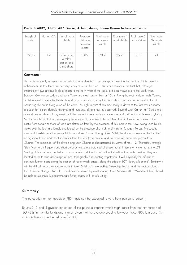
Route 8 A832, A890, A87 Gar ve, Achnnasheen, Ei lean Donan to Invermoriston
Length of No. of LCTs No. of masts Average % of route % or route 1 % of route 2 % of route route visible distance no masts mast visible masts visible 3+ masts
between visible visiblemasts
153km 12 17 including 7.85 73.7 25.25 1.05 nila relay
station and a site share
Comments:
This route was only surveyed in an anti-clockwise direction. The perception over the first section of this route (to
Achnasheen) is that there are not very many masts in the area. This is due mainly to the fact that, although
intermittent views are available of masts to the north west of the road, principal views are to the south west.
Between Glencarron Lodge and Loch Carron no masts are visible for 15km. Along the south side of Loch Carron,
a distant mast is intermittently visible and mast 5 comes as something of a shock on rounding a bend to find it
occupying the entire foreground of the view. The high impact of this mast really is down to the fact that no masts
are seen for a considerable distance and then one, distant mast is observed. Beyond Loch Carron, a 10km stretch
of road has no views of any masts until the descent to Auchentyre commences and a distant mast is seen skylining.
Mast 7 which is a historic, emergency services mast, is located above Eilean Donan Castle and views of the
castle from certain sections of road are detracted from by the presence of this mast in the view. Along Loch Duich,
views over the loch are largely unaffected by the presence of a high level mast in Rattagan Forest. The second
mast which exists near the viewpoint is not visible. Passing through Glen Shiel, the driver is aware of the fact that
no significant man-made features (other than the road) are present and no masts are seen until just south of
Cluanie. The remainder of the drive along Loch Cluanie is characterised by views of mast 12. Thereafter, through
Glen Moriston, infrequent and short duration views are obtained of single masts. In terms of future masts, the LCT
‘Rolling Hills’ can be expected to accommodate additional masts without significant impacts provided they are
located so as to take advantage of local topography and existing vegetation. It will physically be difficult to
construct further masts along the section of route which passes along the edge of LCT ‘Rocky Moorland’. Similarly it
will be difficult to accommodate masts in Glen Shiel (LCT ‘Interlocking Sweeping Peaks’) and the section along
Loch Cluanie (‘Rugged Massif’) would best be served by mast sharing. Glen Moriston (LCT ‘Wooded Glen’) should
be able to successfully accommodate further masts with careful siting.
Summar y
The perception of the impacts of RBS masts can be expected to vary from person to person.
Routes 2, 3 and 4 give an indication of the possible impacts which might result from the introduction of 3G RBSs in the Highlands and Islands given that the average spacing between these RBSs is around 4kmwhich is likely to be the cell size for 3G.
Scottish Natural Heritage Commissioned Report No. F00AA508
71

4. Stage 2: Analysis
Sur vey findings
The eight surveys undertaken were informative in developing a greater understanding of the links between
multiple development and cumulative impact in a range of different LCTs.
Each of the routes surveyed demonstrated key issues in relation to the cumulative impacts of RBS
developments including the following:
Route 1 Complex topography and significant areas of vegetation physically screen views and reduce the
perception of their presence in the landscape (RBSs are visible for over 10% of this route in both
directions but the perception of their presence is much less).
Route 2 Other memorable features in the landscape reduce the perception of the impacts of RBSs (Soutra
windfarms is the most dominant element along this route although RBSs are visible in series or in
groups for up to 25% travelling north).
Route 3 Even and frequent spacing of RBSs does not necessarily mean that they will be perceived as
regular features in the landscapes with complex topography (RBSs on this route are at 4km
spacing but sightings of them are sporadic and limited to less than 10% of the route).
Route 4 Cumulative impacts of multiple RBSs are proportionally higher than the duration of their visibility
would suggest compared to series of RBSs (this route has up to 65% of its length with no RBSs
visible but a up to 21% with 3 or more masts visible).
Route 5 Long sections of route with no RBSs visible reduce the perception of the presence of RBSs
overall (two extensive sections of route with no masts visible meant that although RBSs were
visible for approximately 20% of the route’s length, the overall impression was of less).
Route 6 The presence of vegetation is crucial, particularly in landscapes where the topography is simple,
in reducing the perception of the presence of groups of RBSs or series of RBSs (the central and
southern sections of this route accommodate existing masts reasonably well, compared to the
northerly, almost tree-less section).
Route 7 Siting close to roads and other infrastructure can be preferable to hilltop locations (the addition
of further RBSs close to the A9 has not significantly increased the perception of the presence of
longstanding hill top RBSs whereas further RBS development in skylining situations has resulted in
cumulative impact).
Route 8 Siting RBSs – series of masts and groups of masts – outwith the panorama of principle views
substantially reduces the perception of their presence in the landscape (although there are a
number of masts over the first section of this route, views are directed away from them –
whereas the single mast at the end of Loch Carron draws the eye towards it).
Scottish Natural Heritage Commissioned Report No. F00AA508
72

The perception of the impacts of RBSs can be expected to vary from person to person and is likely to beinfluenced by such factors as:
• familiarity with the route and the surrounding landscape;• expectations of the area (especially for remote areas of the Highlands and Islands);• purpose of the trip;• type of road and speed of driving (related to the purpose of the trip: it should be noted that all of the
surveys were undertaken driving at speeds considerably less than the roads’ design speeds);• sensitivity to the presence of RBS (the surveyors undertaking the study, SNH area officers and
Highland Council Planning officers can be expected to have a heightened awareness of RBSs);• the presence of other, similar, features such a electricity pylons and an ability to distinguish between
these and RBS, particularly at distance; and• sensitivity to network coverage (ie how important continuous, or near continuous, service is to the
individual).
All of the above being equal, cumulative impacts of RBSs would be dependant on the frequency andduration of visibility which would be related to the:
• character of the landscape in which the RBSs are situated; • the character of the landscape through which the observer is travelling; and to • visibility (influenced by weather conditions, direction of view, time of day etc.).
Routes 2, 3 and 4 give an indication of the possible cumulative impacts of 3G RBSs in rural situationsgiven that the average spacing between these RBSs is between 2 and 4km which is the anticipatedrequired spacing for 3G equipment in such locations. Impacts are, of course, not wholly dependant onspacing of equipment but are influenced by the character of the landscape in which they are located,whether they are visible in series, in groups etc.
One of the principal findings of the survey works was that, from a route driving, or cumulative,perspective the proliferation of different mast designs existing is a matter of concern which relates to anambiguity regarding the purpose of these structures. It is considered that ambiguity of function leads tomore concentrated attention being afforded to a feature and that it may be possible to reduce thecumulative impacts of RBSs by attending to this issue.
By way of comparison, there is no such ambiguity in relation to electricity pylons or wood poles. They arelinked by overhead lines, are known features in the landscape, their purpose is understood and thefrequency of their presence is, generally, accepted albeit that their adverse visual impact and impact onlandscape character is also acknowledged.
The main emphasis of the original report was on the siting and design of RBSs on a site by site basis butthis study has revealed that there may be merits in taking a more holistic view to ensure that RBSs becomeaccepted and unobtrusive features of urban and rural areas which is the aim set out in PAN 62.
Siting nevertheless remains a critical issue. Furthermore, the detailed design of RBSs needs to beconsidered from a wider perspective than is currently, perhaps, the case.
Scottish Natural Heritage Commissioned Report No. F00AA508
73

Consultations
The following were contacted for consultation purposes:
• O2 – formerly known as BT Cellnet;• Hutchison 3G – to be known as 3;• T-Mobile UK – formerly known as One2One;• Orange;• Vodafone;• Scottish and Southern Electricity (SSE) (owners of telecommunications infrastructure which is made
available to operators); and• Crown Castle International (owners of telecommunications infrastructure which is made available to
operators).
Consultees’ responses
The consultees responded to questions concerning 3G equipment and roll out, site selection, mast sharing,site sharing and mast design and this information has greatly assisted the development of a betterappreciation of the differences between 2G and 3G infrastructure requirements and has thus made itpossible to improve the level of understanding of the possible future cumulative impacts of 3G roll out.
Likely scenarios regarding 3G roll out in the Highlands and Islands
It seems unlikely that the roll out of 3G and service availability will extend through the Highlands andIslands to the extent that it will in other areas of the UK. This is due, in part, to unknown demand but alsoto simple economics: the Highlands and Islands have 2G coverage as a direct result of ERDF assistancewhich made it possible for Vodafone and Cellnet (now O2) to install their infrastructure in an area whichwas financially unviable for them without grant aid. Furthermore because of the higher frequency bandutilised and the subsequent requirement for reduced distances between masts, 3G technology will beharder to link with a continuous coverage in the more remote, mountain landscapes.
Operators have conceeded that they are unlikely to roll out 3G in the Highlands and Islands other than atmajor towns and on important transport links, because their alternative 2.5G GPRS network will be ableto provide many of the services of 3G. The installation of 2.5G simply means that existing 2G RBSs willbe converted and that there will be no change to the appearance of the 2G RBSs. 2.5G will providesome but not all of the services of 3G – e.g. data transfer will not be as fast.
The operators’ 3G licences require them to cover 80% of the UK population by 2007. However, it isunderstood that this figure could be achieved without providing any coverage in Scotland.
Hutchison 3G have confirmed that their 3G network will be in place in Aviemore and Inverness by mid-2003.
SSE have expressed a view that the foregoing may well be correct and, further commented, that it wastheir understanding that operators had delayed their 3G roll out by about 2 years.
Scottish Natural Heritage Commissioned Report No. F00AA508
74

3G equipment requirements
The precise equipment requirements for 3G seem to differ between operators but the main issue is that all3G RBSs will need to be located at much closer intervals than 2G RBSs. It is thought that 3G may requirea minimum of a doubling of masts in the Highlands and Islands and this is only on the basis that existing2G RBSs are too far apart to supply 3G coverage and ignoring the fact that 2G coverage remainsincomplete.
Hutchison 3G’s cell size for 3G is likely to be between 2–4km whereas Vodafone consider that a cell sizeof between 3.5–6.5km is likely for rural areas, with the cell size for low population densities such as theHighlands and Islands being likely to fall at the upper end of the size range.
Mast height also seems to vary from operator to operator with Hutchison 3G estimating a minimum mastheight of 25m (for technical reasons) and Vodafone quoting a mast height of between 15–20m.
The basic equipment will not vary significantly in visual terms from the appearance of 2G RBS but willdepend on how many operators are located on one site.
The route survey undertaken revealed that operators are making efforts on remote routes to install their 2Ginfrastructure on existing masts and it is likely that all operators will try to maximise mast or site sharing for3G.
Site selection
The main issues constraining site selection for operators for both 2G and 3G RBS sites are those ofeconomics and technical feasibility namely:
• will the site provide the coverage required?• is it commercially viable?• is it acquirable?• is there access to build the site and to maintain it?• can power be provided at a reasonable cost?• can it be linked to the network at reasonable cost?
Operators identify broad sites for optimum coverage and then try to find a visually/environmentallyacceptable location within the area. Where there is an existing mast, all operators report that they willactively explore the possibility of mast sharing or site sharing. This is a requirement of their licences andcan result in substantial development cost savings – a fact which is of particular relevance in theHighlands and Islands where revenue from users is significantly lower than more populated areas of theU.K.
In circumstances where there is a particularly sensitive issue relating to siting and design, operators haveconfirmed that they have either employed specialist environmental advice, or that they would in future.
Mast sharing
None of the operators reported any technical difficulties in relation to mast sharing in terms of either2G/3G sharing or 3G/3G sharing other than those already known for 2G/2G sharing ie:
Scottish Natural Heritage Commissioned Report No. F00AA508
75
• 1m vertical separation between equipment mounted on the mast (meaning, generally, a 5m extensionto existing masts);
• inability of monopoles to take equipment for more than one operator/service without the size of thestructure being dramatically increased; and
• structural capabilities of the mast (especially in the Highlands and Islands with high wind loadings);
All telecommunications operators are required to consider mast sharing wherever practical as part of theirservice agreements. A number have entered into agreements with at least one other operator to mastshare on sites in the Highlands and Islands. Orange and T-Mobile UK for example currently have a jointbuild programme in the Highlands and Islands. In addition, operators will continue to use third partiessuch as Crown Castle International.
Site sharing
None of the operators reported any technical difficulties in relation to site sharing and all operatorsacknowledged the merits of site sharing where mast sharing was either impractical or not desirable forreasons of visual impact and impacts on landscape character.
Crown Castle International suggested that they could, perhaps in conjunction with Highland Council, havea role in creating suitable sharing opportunities by developing, or adding to, existing mountain refuges/emergency and/or visitor centres to incorporate communications development in areas where there isalready development, often with power and access. This would not only assist in minimising the impact oftelecommunications development but could be harnessed to the improvements of facilities for theenjoyment of visitors and locals alike.
Mast design
The operators use a small range of suppliers but there is a myriad of designs available. The majortechnical factors in mast selection are weather (wind loadings) and weight of equipment.
In terms of specific design development of masts for 3G in the Highlands and Islands, none of theoperators reported any significant work being undertaken in this area at present and Hutchison 3Greported that such design development would be undertaken only if and when it was required for their3G roll out programme.
Alternative support structures are being explored by most of the operators and these include electricitypylon mounting although SSE are still investigating the use of pylons with regards to protecting theelectricity network against surges if lightning strikes an antenna. SSE confirm that each pylon can take onlyone operator and that the electricity supply for the RBS has to be taken from the nearest low voltagetransformer which may be remote from the RBS site.
O2 have confirmed that while pylon mounting is feasible there are restrictions in terms of the distanceswhich must be maintained between the electricity cables and the telecommunications equipment whichmeans that only the larger electricity pylons are suitable for equipment mounting.
Vodafone have indicated that direct mountings onto rock faces is not a viable or practical option due tothe International Commission on Non-ionising Radiation Protection (ICNIRP) requirement to have anexclusion zone surrounding their equipment.
Scottish Natural Heritage Commissioned Report No. F00AA508
76

Vodafone have trialed the technology to mount equipment on live trees and have taken this one stepfurther by entering into a contract grow agreement with Bellwood to produce trees specifically to beplanted in locations where a new copse of trees (with one tree taking the equipment) might be morevisually acceptable than a conventional mast. Hutchison 3G are also looking at this option although theyhave encountered networking difficulties as well as height problems. It might be a viable solution for asmall number of sites.
Future development in the Highlands and Islands
The following important issues have arisen with regard to the completion of 2G and the roll out of 3G:
• 3G may not be rolled out in the Highlands and Islands to the extent that it will in the central belt ofScotland;
• the nature of GPRS technology means that operators’ 2.5G networks will be able to provide many ofthe services of 3G, albeit at slower data transfer rates and it seems unlikely that 3G coverage will beprovided in the Highlands and Islands except possibly at major towns and along major transport links;
• Hutchison 3G anticipate providing 3G coverage along the A9 and up to Inverness; • 2G roll out is near completion and operators seem to be attempting to maximise mast and site sharing
in order to complete their networks; and• while Hutchison 3G (as the only operator with no 2G infrastructure on which to build) have
permission to roam the O2 network for a limited period, and while the Stewart Report recommendsroaming, there are major legal issues relating to roaming within the UK – Offtel is exploring this issuewhich is potentially anti-competitive and could hinder network development.
Planning policy
Policies covered in The Highland Council Structure Plan Written Statement were referred to previously inthe original report.
Options to steer or control future development in the Highlands and Islands
Notwithstanding the fact that 3G may not happen in the Highlands and Islands outwith Inverness and theA9 corridor, some key issues require to be addressed in relation to the completion of the 2G networks,the possible ‘infill’ of additional 2G masts if user demand increases and for a predicted limited roll out of3G:
• the first step in minimising cumulative impacts will be to ensure that there is free and open dialoguebetween the operators and the Planning Authorities and Scottish Natural Heritage as advisors toPlanning Authorities on natural heritage issues;
• operators should provide Planning Authorities with as much information as possible with regard to theirwider network plans;
• it is incumbent on operators to undertake their own assessment of the likely visual and landscapeimpacts and to put forward proposals for the best feasible site; and
• the situation regarding roaming should be monitored and, if this is to prove a viable alternative toadditional RBSs (more likely in rural areas with less demand on the individual networks), dueconsideration given to it.
Scottish Natural Heritage Commissioned Report No. F00AA508
77

5. Stage 3: Best Practice Guidance
In order to minimise the cumulative impacts of future RBSs the following broad recommendations aremade.
Consideration should be given toindividual mast applications on asite specific basis and to theimplications on the wider networkof RBSs. The planning outcomefor a single application(granting/ refusal of permission)can have knock on effects for thesiting of other RBSs which couldmean a series of less than ideallocations being developed.
Mast sharing should beencouraged where it will meanthat the existing mast can bedismantled and replaced with amore elegant structure.
Mast sharing may present furtheropportunities to improvescreening of ancillary equipment.
Careful consideration should begiven to the benefits of mastsharing in circumstances wherean increase in height or bulk ofan existing mast would have lessimpact than the introduction of asecond mast.
There will be circumstances wherea second, or even a third, lowlevel mast will be preferable butthese circumstances are likely tobe where masts are located inareas where existing vegetationand good back clothing exist.
Scottish Natural Heritage Commissioned Report No. F00AA508
78

Where site sharing isrecommended, operators shouldbe encouraged to install a ‘twin’design which matches the existingmast as closely as possible. It islikely that there will be fewcircumstances where the existingmast is of such unacceptabledesign that the introduction of asecond similar mast will not bepreferred over the introduction ofa contrasting mast.
Masts of simple, uniform designshould be utilised.
Mast design should be considered with the following priorities:
• individual sites;• groups of sites within different
LCTs; and• series of sites along transport
corridors.
Mast designs of differingappearance in urban and peri-urban situations will almostalways be required to ensure thebest ‘local fit’ and different mastdesigns are more readily accept-able in areas where a widerange of man-made structuresexists.
Scottish Natural Heritage Commissioned Report No. F00AA508
79

In locations where electricity
pylons exist, site sharing may be
less acceptable – RBSs of
different operators being located
at similar centres to the electricity
pylons will generally minimise
‘overlapping’ (and the
appearance of greater bulk) and
result in the RBSs being seen as
part of the linear pattern
established by the electricity
pylons.
The use of pylons where these
coincide with Operators’ network
requirements and where there is a
Low Voltage electricity supply to
hand should be explored – this
may be relevant to much of the
A9 corridor.
Planning Advice Note 62 and the original report provide further guidance with regard to siting and
design of mobile telecommunications’ developments.
Broad LCT-related guidance
In terms of the LCTs which exist in the Highlands and Islands, it is difficult to give precise advice, over and
above the broad guidelines outlined above, which could be applied in all circumstances in different LCTs.
However, some additional broad guidance and comment relating to some typical Highland and Island
LCTs is provided below. The extent of the study precluded providing advice for each and every LCT in the
Highlands and Islands and the guidance below relates to the Ross and Cromarty Landscape Character
Assessment LCTs – many of which can be found in other parts of the Highlands and Islands.
Smooth Moorland
The key characteristics of this LCT are open space; simple composition; vastness; absence of human
activity; and sense of remoteness.
Clearly the introduction of man made elements such as RBSs will compromise these key characteristics.
Site selection should aim to locate masts adjacent to any existing man made features and to take
advantage of back clothing by adjacent ‘Undulating Moorland’ or ‘Sloping Terraced Moorland’. Mast
design, site layout and access tracks should be of simple and uniform design with development
concentrated to minimise the cumulative impact of dispersed development.
Scottish Natural Heritage Commissioned Report No. F00AA508
80

Undulating Moorland
The key characteristics of this LCT are irregular topography; absence of human activity; sense of vastness;barrenness and remoteness.
Again, the introduction of mobile telecommunications infrastructure will tend to dilute these characteristics.Site selection should aim to locate RBSs adjacent to any existing features, including buildings, ruins etc.,and multiple mast developments should either be located close together to be ‘read’ as a singledevelopment or sufficiently far apart to be ‘read’ as single items in the landscape as opposed toscattered, cluttered development. Site location should also take advantage of the local variations intopography with RBSs relating to, for example, local depressions. Mast design, site layout and accesstracks should be of a simple and uniform design.
Sloping Terrace Moorland
The key characteristics of this LCT are smaller-scale terraces; asymmetrical form; lack of human activity;and sense of remoteness.
The most significant influence of the introduction of RBSs in this LCT is the potential to interfere withdominant downward visual forces. RBSs should, therefore be located on the lower slopes, away fromskylining ridges. Again, mast design, site layout and access should be of simple, uniform design.
Rocky Moorland
This LCT has key characteristics including scattered rocks, boulders and rock outcrops; sense of enclosurecontrasting with openness; occasional narrow river gorges; uninhabited; few particular focal points.
RBSs will introduce foci where none may exist at present and the choice of location of any mobiletelecommunications development will be important. Sites where back clothing can be obtained will bepreferred. SNH’s LCA guidance states that ‘several new elements can visually reinforce the complex natureof the character type. If continually supplemented they may create a chaotic and confusing pattern’. It willtherefore be critical to assess proposed RBSs on a case by case basis, ensuring that multiple locationsserve to reinforce the inherent complexity and safeguarding a ‘threshold’ beyond which visual confusionwill result. RBSs, site layout and access tracks should be of simple form and design.
Cnocan
Key characteristics in this LCT are sheltered, deep lochans; patches of green moorland; scrub woodland;occasional isolated houses or scattered development; exposed grey and reflective crystalline rock; andhighly complex, random patterns.
Potential exists in this LCT to take advantage of existing point features (eg isolated houses, copses, treesetc.) by locating RBSs close to these and to maximise the back clothing properties of woodland and rockyslopes. SNH’s LCA guidance suggests that grouping of development to create a distinct group and patternof its own is an acceptable solution in this LCT. In this case, masts and site layout should be of uniformdesign, creating a repetitive pattern of similar elements.
Scottish Natural Heritage Commissioned Report No. F00AA508
81

Rugged Mountain Massif
The key characteristics of this LCT are angular, jagged skyline; broad bulk base of individual mountainmasses; steep slopes; corries, deep valleys and narrow mountain lochs; basin shaped lochans; and senseof remoteness.
For 3G mobile telecommunications development, it would appear that the upper reaches of the this LCTare unlikely to be affected. However, SNH’s LCA guidance highlights the importance of visual link fromlow lying ground upslope to the mountain peaks. Where RBSs are to be located on the lower slopes, theyshould either be sufficiently distant from each other to allow this visual flow to remain or they should beclustered close together as described above.
Rounded Hil ls
This LCT has key characteristics including wide open concave and convex slopes with simple lines; senseof grandeur; vast in scale; smooth texture; deep gullies; interlocking spurs and meandering rivers; lack ofhuman activity; coniferous woodland plantations; and reservoirs.
The successful location of RBSs in this LCT will depend on the application of the broad siting and designprinciples set out in the original report (back clothing, locating masts over the top of ridges etc.) and, formultiple masts, it is suggested that uniformity should be adhered to in the design of structures and sites toensure they are in keeping with the simple lines and character of the hill masses within this LCT.
Narrow Farmed Strath
Key characteristics present in this LCT include narrow sinuous channels; sense of enclosure and isolation;restricted views; visually prominent components; regular pattern of fields and trees; seasonal variation;traditional estates; and sense of history and past occupation.
The impacts of RBSs in this LCT are likely to be of short-term duration due to the sinuous nature of the LCTand the roads within it. None the less, the basic siting and design principals outlined in the original reportshould be adhered to ensure that impacts are minimised.
Wide Farmed Strath
This LCT has key characteristics including wide, flat strath floor; strong definition between the strath andsides and the floor; central visual focus; sense of enclosure; blocks of woodland; range of textures andpatterns; riparian woodland; and large estate houses, old walled enclosures and entrance gates, maturewoodland and agricultural buildings.
A key consideration in siting RBSs in this LCT will be to avoid impinging on the central visual focus bysiting masts on the strath sides, taking advantage of the screening effects of woodland.
Forest Edge Farming
This LCT possesses key characteristics which include semi-improved and improved pasture; stronggeometric pattern of enclosures lined by stone walls, gorse hedges and hedgerow trees; sense of
Scottish Natural Heritage Commissioned Report No. F00AA508
82

enclosure; diversity of features; seasonal contrast; changes in colour and texture which accentuate thepattern of enclosures; high voltage lines and pylons; large estate houses, old walled enclosures andentrance gates, mature woodland and agricultural buildings; woodland and trees comprising small estatecopses, shelterbelts and hedgerow trees; and a patchwork of open and enclosed space.
The fact that pylons and overhead electricity lines are mentioned as a key characteristic in this LCTsuggests that multiple mast siting should attempt to mimic this pattern with regular, linear spacing whileavoiding views of overlapping RBSs and pylons. The presence of significant woodland tracts wouldindicate that good siting may be achieved by utilising the screening and back clothing properties ofblocks of vegetation.
Linear Crofting
The key characteristics of this LCT include gently sloping land; narrow strips along coastal edges; strongregular pattern of clearly ordered crofting strips extending from the upper moorland down to the coastaledge; series of parallel lines illustrating the slope of the topography; access roads, power lines andclumps of trees; limited visibility; views directed along or diagonally across the linear crofting strips;remnants of past woodland stands; and ruined traditional buildings, abandoned crofts and drainagesystems.
The proliferation of ruined and abandoned croft buildings in this LCT would suggest that there is scope tohouse RBS equipment within restored buildings to minimise the impact of such development on this LCT.Where vegetation exists, opportunities to screen or backcloth freestanding RBSs should be exploited.
Scattered Crofting
This LCT possesses key characteristics including complex pattern of crofting overlain on variable relief;diverse mix of components such as small houses, scrub and trees, field boundaries, outbuildings, roadsand power lines; extent of visibility is variable; narrow roads winding though the undulations; constantvariation of direction and elevation; and some broad-leaved woodland.
Again, there will be scope in this LCT to re-use abandoned and derelict croft buildings to house RBSs.SNH’s LCA guidance states that, in this LCT, it is important to plan strategically and to consider how anindividual change will affect the complex relationship between different components of this LCT. Ingeneral, RBSs will have less impact if they are located in a close relationship with existing structures orclumps of woodland.
Harbour Sett lement
The key characteristics of this LCT include surrounding steep slopes; semi-enclosure; simple visualcomposition; backcloth to settlement; and jetty area and sea are the main focus.
In this LCT, the back clothing properties of the hillside behind the settlement should be exploited tobackcloth any RBS. Where existing features such as lamp-posts and telegraph poles exist, RBSs shouldgenerally be of monopole construction with equipment housed in cabinets painted in an appropriatecolour for the locality.
Scottish Natural Heritage Commissioned Report No. F00AA508
83
6. Conclusion
The Stage 1 Review was undertaken to establish the current picture in relation to RBS developments andtheir cumulative impact on LCTs which are similar to those found in the Highlands and Islands.
Analysis of the findings of the surveys of the eight routes examined assisted in the development of a betterunderstanding in relation to the cumulative impacts of radio base station developments; each of the routesstudied highlighted some key issues in relation to cumulative impacts.
Key issues which were identified during Stage 2 Analysis included the following factors which reduce theperception of series or groups of RBSs in the landscape:
• complex topography and significant areas of vegetation;• other memorable features in the landscape;• long sections of route with no RBSs visible;• the presence of vegetation, particularly in landscapes where the topography is simple; and• siting RBSs outwith the panorama of principle views.
Other issues identified which relate to the perception of RBSs include:
• even and frequent spacing of RBSs does not necessarily mean that they will be perceived as regularfeatures in the landscapes with complex topography;
• cumulative impacts of multiple RBSs are proportionally higher than the duration of their visibility wouldsuggest compared to series of RBSs; and
• siting close to roads and other infrastructure can be preferable to hilltop locations.
Consultations with operators and owners of telecommunications structures assisted in the development of agreater understanding of the technical requirements for 3G RBSs and helped improve the level ofunderstanding of the possible future cumulative impacts of 3G roll out if and when it occurs in areas of theHighlands and Islands.
Key information identified during these consultations, which assisted in the formulation of the siting anddesign guidance set out in Section 5 of this report, included:
• likely scenarios regarding 3G roll out in the Highlands and Islands;• 3G equipment requirements;• site selection criteria;• mast sharing issues;• site sharing issues; and • masts design.
These consultations also revealed that 3G roll out is unlikely to happen in the Highlands and Islands to theextent that it will in other parts of the country but, nonetheless the guidance described in the main reportand in Section 5 of this report should assist in the siting and design of future RBS developments.
Scottish Natural Heritage Commissioned Report No. F00AA508
84
The following key issues require to be addressed in relation to completion of the 2G network, the possibleinfill of additional 2G RBSs if user demand increases and a limited roll out of 2G along major routes andin major settlements:
• establish free and open dialogue between operators, the Planning Authorities and Scottish NaturalHeritage as advisors to the Planning Authority;
• provision to Planning Authorities by operators of as much information as possible with regard to widernetwork plans;
• operators should undertake their own assessments of the likely impacts (including cumulative impacts)and put forward proposals for the best possible site; and
• the potential for roaming should be explored dependant on the findings of Offtel’s investigations inlight of the Stewart Report.
Scottish Natural Heritage Commissioned Report No. F00AA508
85
Appendix I Survey Records
This Appendix is available as a separate unpublished document.
For further information please contact:
Caroline ReadScottish Natural Heritage2 Anderson PlaceEdinburghEH6 5NP0131 446 [email protected]
Scottish Natural Heritage Commissioned Report No. F00AA508
86

ABBREVIATIONS and ACRONYMS
1G First Generation telecomms technology and equipment
2G Second Generation telecomms technology and equipment
2.5G Telecomms technology which is inbetween 2G and 3G
3G Third Generation telecomms technology and equipment
ATV All Terrain Vehicle
EDAW Environmental agency with offices in UK and abroad
ERDF European Regional Development Fund
GRP Glass Reinforced Plastic
GSM Group Special Mobile
HIE Highlands and Islands Enterprise
ICNIRP International Commission on Non-Ionising Radiation Protection
IEGMP Independent Expert Group on Mobile Phones
LCA Landscape Character Assessment
LCT Landscape Character Type
LPG Liquid Petroleum Gas
MTX Mobile Telephone Exchange
NPPG National Planning Policy Guideline
NSA National Scenic Area
OFTEL Office of Telecommunications
PAN Planning Advice Note
PCN Personal Communications Network
PD Permitted Development
PDR Permitted Development Rights
PSTN Public Switched Telephone Network
RBS Radio Base Station
SEDD Scottish Executive Development Department
SNH Scottish Natural Heritage
SSSI Site of Special Scientific Interest
TACS Total Access Communications System
THC The Highland Council
UMTS Universal Mobile Telecommunications Systems
Scottish Natural Heritage Commissioned Report No. F00AA508
87
REFERENCES
CCS 1978 Vehicular Tracks in Upland Scotland
EDAW 1996 Mobile Telecommuncations Programme Environmental Study Report
Hutchison 3G Hutchison 3G UK Planning and Environmental Handbook(end 2002)
IEGMP 2000 Report on Mobile Phones and Health (The Stewart Report) http://www.iegmp.org.uk/report/text.htm
SEDD 2000 Consultation on proposed changes to Permitted Development arrangements for telecommunications developments
SEDD 2001 National Planning Policy Guideline (NPPG) 19: Radio Telecommunications
SEDD 2001 Planning Advice Note (PAN) 62: Radio Telecommunications
THC 1999 The Highland Structure Plan (Approved March 2001)
T-Mobile 2002 The T-Mobile Network – Facts about base stations and transmitters
Vodafone 2001 Where do we go from here? Environmental and Planning Handbook
Statutor y Instruments and Acts
Statutory Instrument 1992 No. 223 (S.17) The Town and Country Planning (General PermittedDevelopment) (Scotland) Order 1992
Statutory Instrument 1992 No. 2084 (S.213) The Town and Country Planning (General PermittedDevelopment) (Scotland) Amendment (No.2) Order 1992
Scottish Statutory Instrument 2001 No. 244 The Town and Country Planning (General PermittedDevelopment) (Scotland) Amendment Order 2001
Scottish Statutory Instrument 2001 No. 245 The Town and Country Planning (General DevelopmentProcedure) (Scotland) Order 2001
Town and Country Planning Act (Scotland) 1972
Telecommunications Act 1994
Public Utilities Street Works Act 1950
Useful websites
http://www.scotland.gov.uk/planning
http://www.hmso.gov.uk/legislation/scotland
http://www.hmso.gov.uk/si
Scottish Natural Heritage Commissioned Report No. F00AA508
88
Related Documents