Document Number: M1800, Revision 7 Issue Date: 1/15/2020 Supersedes: 5/17/2016 Central Technical Support Number: 1-877-OPW-TECH (877-679-8324) Calls outside US and Canada: 1-708-485-4200 Fax: 1 (800) 421-3297 Hours: Monday through Friday, 7:00 am to 6:00 pm, US CST www.opwglobal.com SiteSentinel ® Integra 100™/500™ Automatic Tank Gauge System Installation Manual

Welcome message from author
This document is posted to help you gain knowledge. Please leave a comment to let me know what you think about it! Share it to your friends and learn new things together.
Transcript
Document Number: M1800, Revision 7 Issue Date: 1/15/2020
Supersedes: 5/17/2016
Central Technical Support Number: 1-877-OPW-TECH (877-679-8324) Calls outside US and Canada: 1-708-485-4200 Fax: 1 (800) 421-3297 Hours: Monday through Friday, 7:00 am to 6:00 pm, US CST
www.opwglobal.com
SiteSentinel® Integra 100™/500™ Automatic Tank Gauge System Installation Manual

Doc. #: M1800, Rev. 7 Page 2 of 101
www.opwglobal.com
2020 Delaware Capital Formation, Inc. All Rights Reserved. DOVER and the DOVER logo are registered trademarks of Delaware Capital Formation, Inc., a wholly owned subsidiary of Dover Corporation.
Listings and Certifications

Doc. #: M1800, Rev. 06
Page 3 of 101
www.opwglobal.com
Table of Contents
1 Applicable Warnings and Cautions ................................................................................................................................... 8 1.1 Technican Certifications ............................................................................................................................................... 8
1.1.1 Installer Safety .................................................................................................................................................... 8 1.1.2 Precision Leak Test ............................................................................................................................................ 9 1.1.3 Prior to Initial Inspection ...................................................................................................................................... 9 1.1.4 Initial Inspection .................................................................................................................................................. 9
2 SiteSentinel® Integra™ ATG Console ............................................................................................................................. 10 2.1.1 Blank Door Unit (only for Integra 500) ............................................................................................................... 10
2.2 Console Specifications ............................................................................................................................................... 11 2.3 Console Installation .................................................................................................................................................... 11 2.4 Console Wiring ........................................................................................................................................................... 13
2.4.1 Petro-Net™ Wiring (only for Integra 500) .......................................................................................................... 13 2.4.2 Wireless Connections (only for Integra 500) ...................................................................................................... 13 2.4.3 Ethernet Connections to VSmart (only for Integra 500) ..................................................................................... 13 2.4.4 RS-232 Communications Conduits ................................................................................................................... 14
2.5 Wireless Petro-Net Installation with VSmart Indoors .................................................................................................. 15 2.6 Petro-Net Over Ethernet Option with VSmart ............................................................................................................. 16 2.7 Field Wiring Diagram for Integra 100 .......................................................................................................................... 18 2.8 Field Wiring Diagram for Integra 500 .......................................................................................................................... 20
2.8.1 Console Board Inputs ....................................................................................................................................... 22 2.9 Main Board DIP-Switch Configuration ........................................................................................................................ 23
3 External Printer ............................................................................................................................................................... 24
4 VSmart Module (only for Integra 500) ............................................................................................................................. 26 4.1 VSmart Specifications ................................................................................................................................................ 26 4.2 VSmart Module Installation ........................................................................................................................................ 27
4.2.1 Probe & Sensor Conduits .................................................................................................................................. 27 4.2.2 Circuit Breaker Conduits ................................................................................................................................... 27
4.3 External VSmart Module Wiring ................................................................................................................................. 28

Doc. #: M1800, Rev. 06
Page 4 of 101
www.opwglobal.com
4.3.1 VSmart Addressing ........................................................................................................................................... 28 4.4 VSmart Capabilies ..................................................................................................................................................... 29
5 Line Interface Module LIM (only for Integra 500) ............................................................................................................ 30 5.1 LIM Specifications ...................................................................................................................................................... 30 5.2 LIM Installation ........................................................................................................................................................... 30 5.3 LIM Wiring .................................................................................................................................................................. 31
5.3.1 Variable Speed Control for FE Petro ................................................................................................................. 32 5.3.2 Typical FE Petro Wiring Connections ................................................................................................................ 32 5.3.3 Variable Speed Control Wiring for Red Jacket .................................................................................................. 33 5.3.4 Typical Red Jacket Wiring Connections ............................................................................................................ 33 5.3.5 LIM Addressing ................................................................................................................................................. 33
6 OM4 Module (only for Integra 500) ................................................................................................................................. 34 6.1 Cautions! .................................................................................................................................................................... 34 6.2 OM4 Specifications .................................................................................................................................................... 35 6.3 OM4 Wiring ................................................................................................................................................................ 35 6.4 OM4 Addressing ........................................................................................................................................................ 35
7 Tank Alert (Overfill Alarm) .............................................................................................................................................. 36 7.1 Tank Alert Wiring ....................................................................................................................................................... 36
8 Tank & Pre-Installation Preparation ................................................................................................................................ 37 8.1 Waterproof Electrical Connections ............................................................................................................................. 37 8.2 Probe-Cable Seal-Offs ............................................................................................................................................... 38 8.3 Probe Placement ....................................................................................................................................................... 39 8.4 Probe Installation in Underground Storage Tanks ...................................................................................................... 40
8.4.1 Calculating Product Offset ................................................................................................................................ 41
9 Rigid Probe Installation ................................................................................................................................................... 42 9.1 Adaptor Collar & Riser Cap ........................................................................................................................................ 42 9.2 Probe Floats .............................................................................................................................................................. 42 9.3 Multi-drop Installation ................................................................................................................................................. 42 9.4 Rigid Probe Specification ........................................................................................................................................... 43
Doc. #: M1800, Rev. 06
Page 5 of 101
www.opwglobal.com
9.5 Model 924B Probe ..................................................................................................................................................... 44 9.5.1 Model 924B Specifications ................................................................................................................................ 44
10 Flex Probe Installation .................................................................................................................................................... 46 10.1 Model 7100V Flex Probe (only for Integra 500) ....................................................................................................... 46 10.2 Model 7100V Flex Probe Specifications .................................................................................................................. 46 10.3 Flex Probe Installation ............................................................................................................................................. 47
10.3.1 Flex Probe Length Determination ...................................................................................................................... 47 10.3.2 Flex Probe Installation Preparations ................................................................................................................. 47 10.3.3 Flex Probe Determination Worksheet ................................................................................................................ 48 10.3.4 Flex Probe Wiring ............................................................................................................................................. 49 10.3.5 Installing the Flex Probe .................................................................................................................................... 49 10.3.6 Finishing the Flex Probe Installation.................................................................................................................. 49
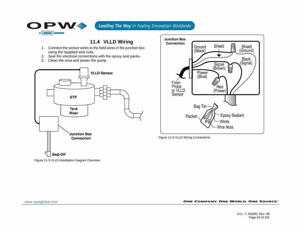
11 Model 327 Volumetric Line Leak Detector (VLLD) Sensor (only for Integra 500) ............................................................ 50 11.1 VLLD Specifications ................................................................................................................................................ 50 11.2 Prior to Installation .................................................................................................................................................. 50 11.3 VLLD Installation ..................................................................................................................................................... 51 11.4 VLLD Wiring ............................................................................................................................................................ 53
12 Sensor Technology Overview ......................................................................................................................................... 54 12.1.1 OPW Smart Sensors ......................................................................................................................................... 54
12.2 IntelliSense™ Technology ...................................................................................................................................... 54 12.3 Multi-drop Installation .............................................................................................................................................. 54 12.4 Interstitial Sensor .................................................................................................................................................... 55
12.4.1 Interstitial Sensor Installation ............................................................................................................................ 55 12.5 Wet Well Monitoring, Single-Wall Tank ................................................................................................................... 56
Appendix A: OPW Smart Sensors .......................................................................................................................................... 57 Interstitial Level Sensor Float Switch .................................................................................................................................. 57 Single-Level Sump Sensor ................................................................................................................................................. 58
Single-Level Sump Sensor Installation ........................................................................................................................... 58 Liquid-Only Float Sensor .................................................................................................................................................... 59
Liquid-Only Float Sensor Installation .............................................................................................................................. 59
Doc. #: M1800, Rev. 06
Page 6 of 101
www.opwglobal.com
Discriminating Dispenser Pan Sensor ................................................................................................................................ 60 Discriminating Dispenser Pan Sensor Installation ........................................................................................................... 60
Discriminating STP Sump Sensor....................................................................................................................................... 61 Discriminating STP Sump Sensor Installation ................................................................................................................. 61
Hydrocarbon Vapor Sensor ................................................................................................................................................ 62 Hydrocarbon Vapor Sensor Installation .......................................................................................................................... 62
Discriminating Interstitial Sensor ........................................................................................................................................ 63 Discriminating Interstitial Sensor Installation ................................................................................................................... 63
Interstitial Hydrocarbon Liquid Sensor with Water Indicator ................................................................................................ 64 Hydrocarbon Liquid Sensor with Water Indicator ................................................................................................................ 65 Dual-Float Dispenser Sump Sensor ................................................................................................................................... 66 Dual-Float STP Sump Sensor ............................................................................................................................................ 67 Dual-Float Brine Sensors ................................................................................................................................................... 68
Dual-Float Brine Sensor (D-10) ...................................................................................................................................... 68 Dual-Float Brine Sensor (D-20B) .................................................................................................................................... 69
Universal Reservoir Sensor ................................................................................................................................................ 70 Density Measurement Sensor (DMS) ................................................................................................................................. 71
DMS Installation ............................................................................................................................................................. 72 Tank Thresholds ............................................................................................................................................................. 72 DMS Configuration & Preliminary Calibration ................................................................................................................. 72
Appendix B: Existing OPW/EECO Equipment ........................................................................................................................ 73 Model 924A Probes ............................................................................................................................................................ 73 Model EECO Probes .......................................................................................................................................................... 74 ........................................................................................................................................................................................... 74
Appendix C: Smart Module (only for Integra 500) ................................................................................................................... 75
Appendix D: Maintenance Kit ................................................................................................................................................. 76
Appendix E: Model 924B Probe Part Numbers ....................................................................................................................... 77
Appendix F: Output Relay Installation Report ......................................................................................................................... 78
Appendix G: Sensor Labels .................................................................................................................................................... 80

Doc. #: M1800, Rev. 06
Page 7 of 101
www.opwglobal.com
Appendix H: Model 924B Installation Records ........................................................................................................................ 83
Appendix J: Flex Probe Specifications ................................................................................................................................... 84
Appendix K: 7100V Flex Probe Installation Records............................................................................................................... 87
Appendix L: Non-Smart Sensors (only for Integra 500) .......................................................................................................... 88 Hydrocarbon Liquid/Water Sensor ...................................................................................................................................... 88 Hydrocarbon Vapor Sensor ................................................................................................................................................ 89
Hydrocarbon Vapor Sensor Installation .......................................................................................................................... 89 Combo Single-Level / Hydrocarbon Liquid Sump Sensor ................................................................................................... 91 Combo Dual-Level/Hydrocarbon Liquid Sump Sensor ........................................................................................................ 92 Single-Level Sump Sensor ................................................................................................................................................. 94 Dual-Level Reservoir Sensor .............................................................................................................................................. 95 Hydrocarbon Liquid Sump Sensor ...................................................................................................................................... 96 Interstitial Optical Liquid Sensor ......................................................................................................................................... 98
Appendix M: Declaration of Conformity .................................................................................................................................. 99
Index .................................................................................................................................................................................... 101

Doc. #: M1800, Rev. 06
Page 8 of 101
www.opwglobal.com
1 Applicable Warnings and Cautions The inside of the SiteSentinel® Integra™ console contains high-voltage circuitry; therefore, ONLY certified technicians should be allowed to access the console.
Only certified OPW technicians are authorized to install and program this automatic tank gauge system. Failure to comply could result in voided warranty.
The Integra console has two (2) lithium batteries, which may require periodic replacement.
CAUTION: The coin cell battery may explode if mistreated. Do not
recharge, disassemble or dispose of in fire. Replace battery with
Panasonic or Matsushita Electric Part Number CR-2032 ONLY. Use
of another battery may present a risk of fire or explosion.
CAUTION: The rechargeable battery used in this device may
present a risk of fire or chemical burn if mistreated. Do not
disassemble, heat above 60°C or incinerate. Replace the battery
with OPW Part Number 20-8344 ONLY. Use of another battery may
present a risk of fire or explosion.
CAUTION: Dispose of used battery promptly. Keep away from
children. Do not disassemble and do not dispose of in fire.
CAUTION: The console may remain powered via the backup battery
even though the line power has been removed.
CAUTION: A readily accessible external disconnect device must be
installed for any permanently connected equipment!
CAUTION: A readily accessible electrical outlet should be installed
near any equipment requiring access via a plug connection!
1.1 Technican Certifications All installers must work with an OPW certified technician in order to ensure requirements of intrinsically safe devices are met and must strictly obey the instructions in this manual to perform a safe installation.
Please note that there are several types of OPW Certified ATG technicians.
• SiteSentinel® iSite™
• SiteSentinel® Integra 100™
• SiteSentinel® Integra 500™ (including LLD and ACR)
• SiteSentinel® iTouch™
The OPW certified technician must assume 100% responsibility for all pipe fitters, electricians and any additional contractor hired.
CAUTION: Improper installation may endanger installers and users
of this equipment and could result in environment or equipment
damage. Read the following instructions carefully!
1.1.1 Installer Safety
Installation must be in accordance with the U.S. National Electrical Code (NFPA No. 70) and the Automotive and Marine Service Station Code (NFPA No. 30A).
For installations outside the United States, ensure that the installation adheres to all applicable local codes.
When installing in a hazardous area as defined by the NEC, only intrinsically safe devices can be installed in or above the Class 1, Division 1 and 2 Hazardous Area.
The installer is responsible to investigate and follow any local codes.

Doc. #: M1800, Rev. 06
Page 9 of 101
www.opwglobal.com
NOTE: Local codes may dictate specific installation requirements.
Installation is subject to approval by the local authority having
jurisdiction at the site.
1.1.2 Precision Leak Test
A third-party precision leak test should be performed on each tank and product line (especially older ones) before installing the Integra console. This test ensures that leak data generated by the system is accurate and reliable. A pressurized precision leak test can be performed on a tank after the probe has been installed, but pressure must NOT exceed 5 psi (0.34 bar).
NOTE: Most regulatory agencies will accept the ATG tank test as the
acceptance test on new tank installations; please confirm this with
your local agency before testing any tank.
1.1.3 Prior to Initial Inspection
Please refer to the initial Site Survey form and compare equipment shipped equipment to the site survey.
NOTE: Not all Site Survey questions will require an answer; for all
unanswered questions, please respond with “N/A”. Do not leave any
field empty!
1.1.4 Initial Inspection
All packed items should be thoroughly inspected for damage that may have occurred during shipping.
The console Data Sheet, which can be downloaded from the OPW Global website at www.opwglobal.com, provides specific details regarding the Integra tank gauge system. Store the data sheet and OPW Manual CD in a secure location.
Please find the appropriate field wiring diagram in the product box, or it can also be downloaded from the OPW website at
www.opwglobal.com, and give the field wiring diagram to your installer or electrician.
Doc. #: M1800, Rev. 06
Page 10 of 101
www.opwglobal.com
2 SiteSentinel® Integra™ ATG Console
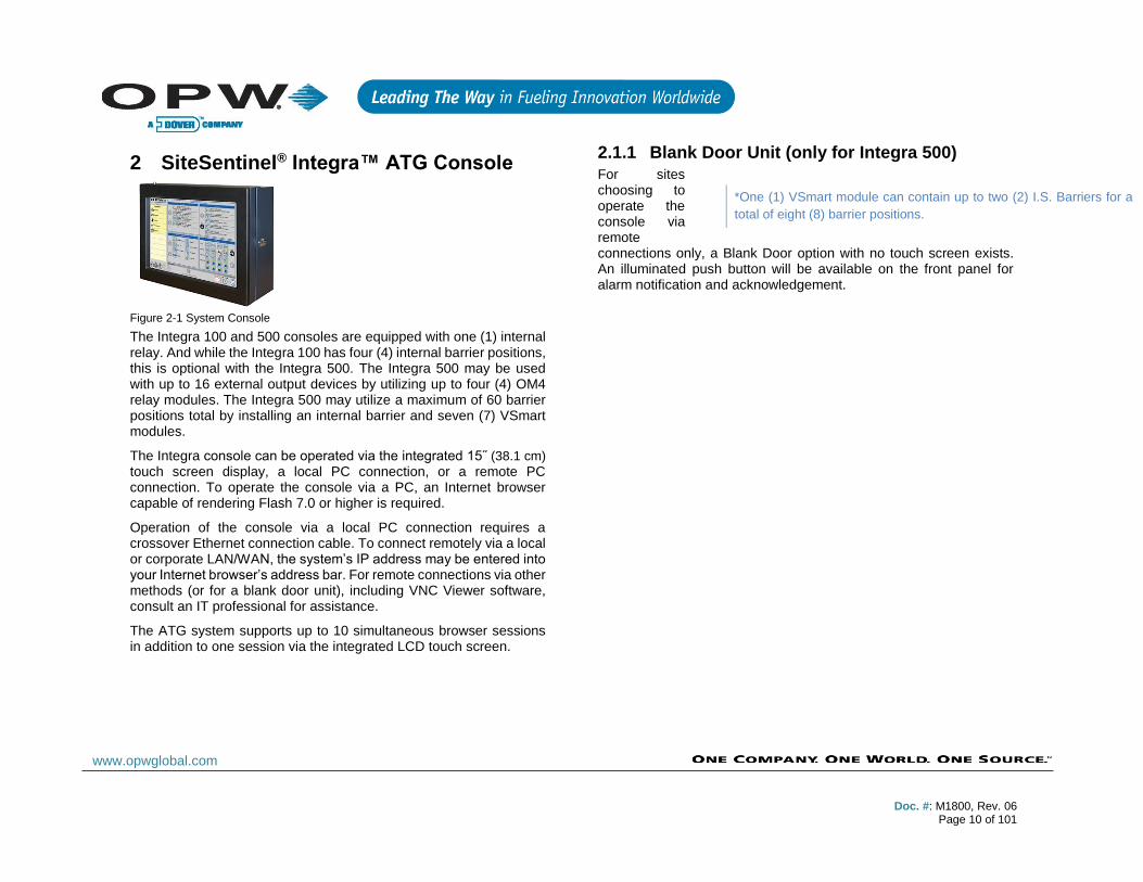
Figure 2-1 System Console
The Integra 100 and 500 consoles are equipped with one (1) internal relay. And while the Integra 100 has four (4) internal barrier positions, this is optional with the Integra 500. The Integra 500 may be used with up to 16 external output devices by utilizing up to four (4) OM4 relay modules. The Integra 500 may utilize a maximum of 60 barrier positions total by installing an internal barrier and seven (7) VSmart modules.
The Integra console can be operated via the integrated 15˝ (38.1 cm)
touch screen display, a local PC connection, or a remote PC connection. To operate the console via a PC, an Internet browser capable of rendering Flash 7.0 or higher is required.
Operation of the console via a local PC connection requires a crossover Ethernet connection cable. To connect remotely via a local or corporate LAN/WAN, the system’s IP address may be entered into your Internet browser’s address bar. For remote connections via other methods (or for a blank door unit), including VNC Viewer software, consult an IT professional for assistance.
The ATG system supports up to 10 simultaneous browser sessions in addition to one session via the integrated LCD touch screen.
2.1.1 Blank Door Unit (only for Integra 500)
For sites choosing to operate the console via remote connections only, a Blank Door option with no touch screen exists. An illuminated push button will be available on the front panel for alarm notification and acknowledgement.
*One (1) VSmart module can contain up to two (2) I.S. Barriers for a
total of eight (8) barrier positions.
Doc. #: M1800, Rev. 06
Page 11 of 101
www.opwglobal.com
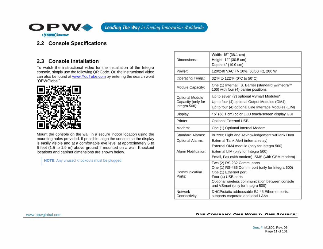
2.2 Console Specifications
2.3 Console Installation To watch the instructional video for the installation of the Integra console, simply use the following QR Code. Or, the instructional video can also be found at www.YouTube.com by entering the search word “OPWGlobal”.
Mount the console on the wall in a secure indoor location using the mounting holes provided. If possible, align the console so the display is easily visible and at a comfortable eye level at approximately 5 to 6 feet (1.5 to 1.9 m) above ground if mounted on a wall. Knockout locations and cabinet dimensions are shown below.
NOTE: Any unused knockouts must be plugged.
Dimensions:
Width: 15” (38.1 cm)
Height: 12” (30.5 cm)
Depth: 4” (10.0 cm)
Power: 120/240 VAC +/- 10%, 50/60 Hz, 200 W
Operating Temp.: 32F to 122F (0C to 50C)
Module Capacity: One (1) Internal I.S. Barrier (standard w/Integra™ 100) with four (4) barrier positions
Optional Module Capacity (only for Integra 500):
Up to seven (7) optional VSmart Modules*
Up to four (4) optional Output Modules (OM4)
Up to four (4) optional Line Interface Modules (LIM)
Display: 15” (38.1 cm) color LCD touch-screen display GUI
Printer: Optional External USB
Modem: One (1) Optional Internal Modem
Standard Alarms:
Optional Alarms:
Alarm Notification:
Buzzer; Light and Acknowledgement w/Blank Door
External Tank Alert (internal relay)
External OM4 module (only for Integra 500)
External LIM (only for Integra 500)
Email, Fax (with modem), SMS (with GSM modem)
Communication Ports:
Two (2) RS-232 Comm. ports
One (1) RS-485 Comm. port (only for Integra 500)
One (1) Ethernet port
Four (4) USB ports
Optional wireless communication between console and VSmart (only for Integra 500)
Network Connectivity:
DHCP/static addressable RJ-45 Ethernet ports, supports corporate and local LANs
Doc. #: M1800, Rev. 06
Page 12 of 101
www.opwglobal.com
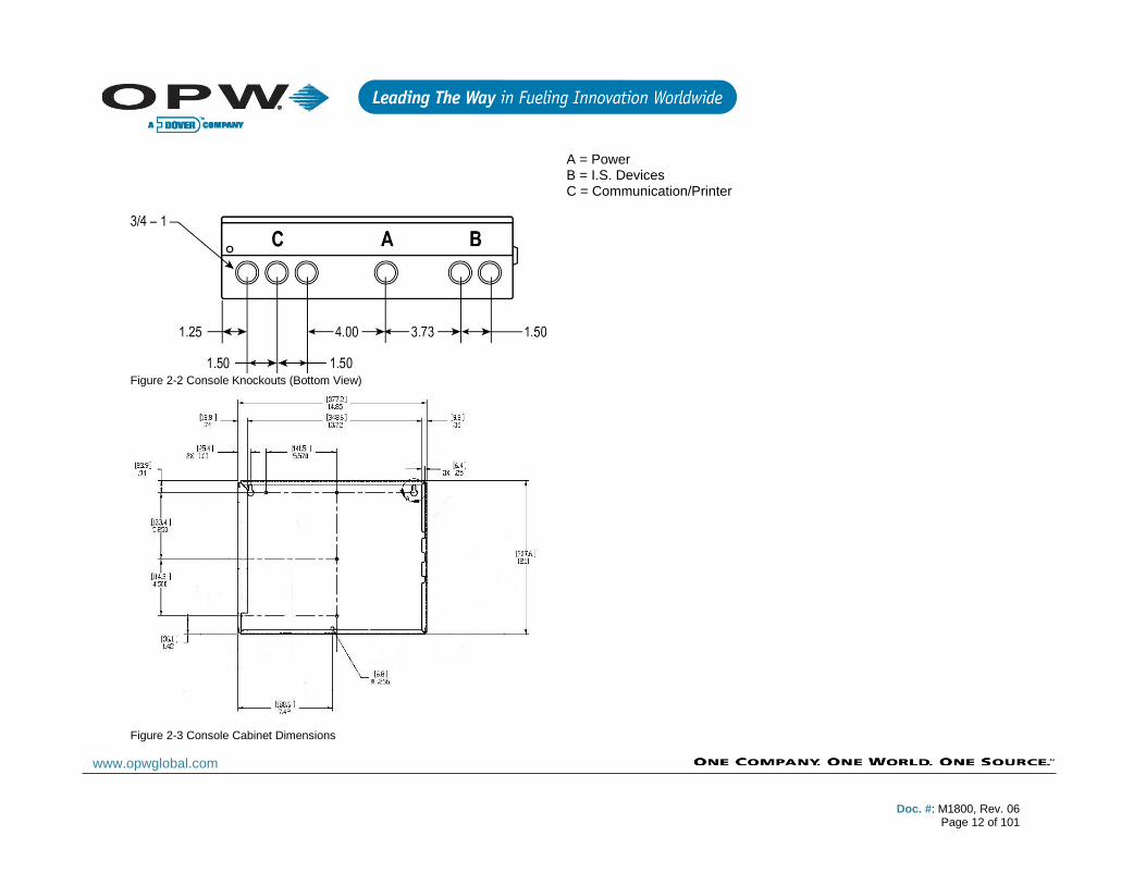
Figure 2-2 Console Knockouts (Bottom View)
Figure 2-3 Console Cabinet Dimensions
A = Power B = I.S. Devices C = Communication/Printer

Doc. #: M1800, Rev. 06
Page 13 of 101
www.opwglobal.com
2.4 Console Wiring For console power wiring, please refer to the appropriate field wiring diagram. See Sections 2.7 and 2.8 for the type of console being installed.
The console must share the same phase with all other OPW ATG components. Use knockouts “A” in Diagram 2-2 to route three (3) (14 AWG minimum) stranded copper wires for Line, Neutral and Ground. A fourth wire (12 AWG minimum) is needed if the console is equipped with an internal I.S. barrier, which is always needed with Integra 100 consoles.
2.4.1 Petro-Net™ Wiring (only for Integra 500)
Wired RS-485 Petro-Net™ connections can be used for communications among the VSmart module, OM4 and the console. For this type of connection, a single run of twisted-pair wiring (10 twists per foot) is required. Polarity must always be observed for Petro-Net connections.
NOTE: Twisted-pair wiring is available from OPW as Part No. 12-
1029.
When connecting via Petro-Net, the twisted-pair wiring is connected to positions 7 and 8 of the RS-485 terminal block (J21) at each module. Petro-Net™ connections can be wired parallel, meaning that modules may be connected to each other in various combinations as long as one module in the chain is connected to the console.
NOTE: Petro-Net™ connections must be made with twisted-pair
wiring. The use of conduit is recommended for protecting Petro-
Net™ wires, and may be required per NEC depending upon
application. If conduit is not used, bushings must be installed in the
cabinet knockouts to protect wiring and seal the enclosures.
2.4.2 Wireless Connections (only for Integra 500)
Wireless connections can also be used for communications between the VSmart module and the console. For this type of connection, a wireless modem is connected to the VSmart module, and a second modem is wired to the console’s RS-485 port. The VSmart modems must be within a clear line-of-sight. See figure in Section 2.5. Also, please refer to the M00-20-7074 Wireless Petro-Net Manual.
NOTE: Wireless connections are not viable options at all installation
sites due to the presence of interference or line-of-site obstacles.
Test kits are available, but A SITE SURVEY IS STRONGLY
RECOMMENDED BEFORE COMMITTING TO WIRELESS
INSTALLATIONS.
2.4.3 Ethernet Connections to VSmart (only for Integra 500)
When equipped with the optional VSmart LAN capability, Ethernet connections are the only option for establishing communications between the console and VSmart. For this type of connection, an Ethernet cable is run between devices at a maximum length of 300 feet (92 m). This distance can be extended through the use of hubs and routers.
NOTE: If more than 6 feet (1.85 m) of cable is required, the use of
conduit to protect the cable is recommended.
NOTE: The VSmart module must be ordered with this option.
An Ethernet connection can also be established between the console and a VSmart Module using an existing network. To make this connection, simply connect the console to one node on the network and the VSmart Module to another node. See figure in Section 2.6.
NOTE: You will likely require the site’s IT personnel with this type of
installation.
Doc. #: M1800, Rev. 06
Page 14 of 101
www.opwglobal.com
2.4.4 RS-232 Communications Conduits
If a terminal or PC located more than 6 feet (1.8 m) from the console is to be connected, conduit must be installed to accommodate the RS-232 cable.
NOTE: The maximum runs for serial communication cable is 50 feet
(15.24 m).

Doc. #: M1800, Rev. 06
Page 15 of 101
www.opwglobal.com
2.5 Wireless Petro-Net Installation with VSmart Indoors
NOTE1: Directional antenna may be substituted for omni-directional antenna depending upon site conditions. NOTE2: It is highly recommended that all wireless Petro-Net installations are subjected to a site survey prior to installation to identify potential interference problems. NOTE3: VSmart Module is NEMA 4-rated, and may, therefore, be mounted outdoors.
Doc. #: M1800, Rev. 06
Page 16 of 101
www.opwglobal.com
2.6 Petro-Net Over Ethernet Option with VSmart

Doc. #: M1800, Rev. 06
Page 17 of 101
www.opwglobal.com
NOTE1: As an alternative to a directly connected one-to-one Ethernet connections, hubs, switches or routers may be employed. NOTE2: It is very important that the subnet is used for the Integra and for the VSmarts(s) are the same. NOTE3: VSmart Module is NEMA 4-rated, and may, therefore, be mounted outdoors.

Doc. #: M1800, Rev. 06
Page 18 of 101
www.opwglobal.com
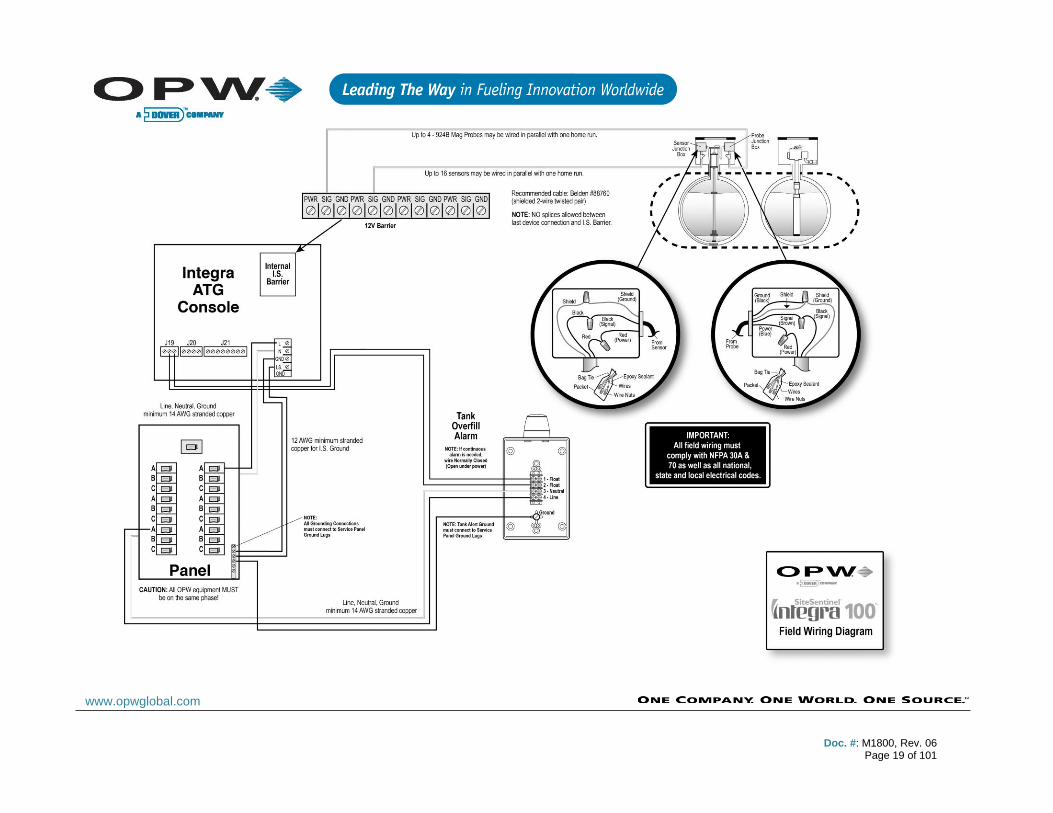
2.7 Field Wiring Diagram for Integra 100
Doc. #: M1800, Rev. 06
Page 19 of 101
www.opwglobal.com

Doc. #: M1800, Rev. 06
Page 20 of 101
www.opwglobal.com
2.8 Field Wiring Diagram for Integra 500

Doc. #: M1800, Rev. 06
Page 21 of 101
www.opwglobal.com
Doc. #: M1800, Rev. 06
Page 22 of 101
www.opwglobal.com
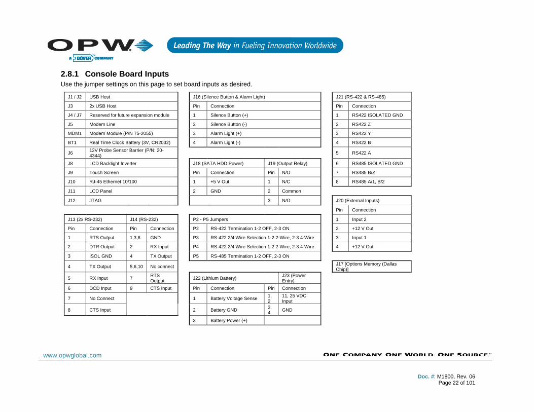
2.8.1 Console Board Inputs
Use the jumper settings on this page to set board inputs as desired.
J1 / J2 USB Host
J16 (Silence Button & Alarm Light)
J21 (RS-422 & RS-485)
J3 2x USB Host
Pin Connection
Pin Connection
J4 / J7 Reserved for future expansion module
1 Silence Button (+)
1 RS422 ISOLATED GND
J5 Modem Line
2 Silence Button (-)
2 RS422 Z
MDM1 Modem Module (P/N 75-2055)
3 Alarm Light (+)
3 RS422 Y
BT1 Real Time Clock Battery (3V, CR2032)
4 Alarm Light (-)
4 RS422 B
J6 12V Probe Sensor Barrier (P/N: 20-4344)
5 RS422 A
J8 LCD Backlight Inverter
J18 (SATA HDD Power) J19 (Output Relay)
6 RS485 ISOLATED GND
J9 Touch Screen
Pin Connection Pin N/O
7 RS485 B/Z
J10 RJ-45 Ethernet 10/100
1 +5 V Out 1 N/C
8 RS485 A/1, B/2
J11 LCD Panel
2 GND 2 Common
J12 JTAG
3 N/O
J20 (External Inputs)
Pin Connection
J13 (2x RS-232) J14 (RS-232)
P2 - P5 Jumpers
1 Input 2
Pin Connection Pin Connection
P2 RS-422 Termination 1-2 OFF, 2-3 ON
2 +12 V Out
1 RTS Output 1,3,8 GND
P3 RS-422 2/4 Wire Selection 1-2 2-Wire, 2-3 4-Wire
3 Input 1
2 DTR Output 2 RX Input
P4 RS-422 2/4 Wire Selection 1-2 2-Wire, 2-3 4-Wire
4 +12 V Out
3 ISOL GND 4 TX Output
P5 RS-485 Termination 1-2 OFF, 2-3 ON
4 TX Output 5,6,10 No connect
J17 [Options Memory (Dallas Chip)]
5 RX Input 7 RTS Output
J22 (Lithium Battery) J23 (Power Entry)
6 DCD Input 9 CTS Input
Pin Connection Pin Connection
7 No Connect
1 Battery Voltage Sense
1, 2
11, 25 VDC Input
8 CTS Input
2 Battery GND 3, 4
GND
3 Battery Power (+)
Doc. #: M1800, Rev. 06
Page 23 of 101
www.opwglobal.com
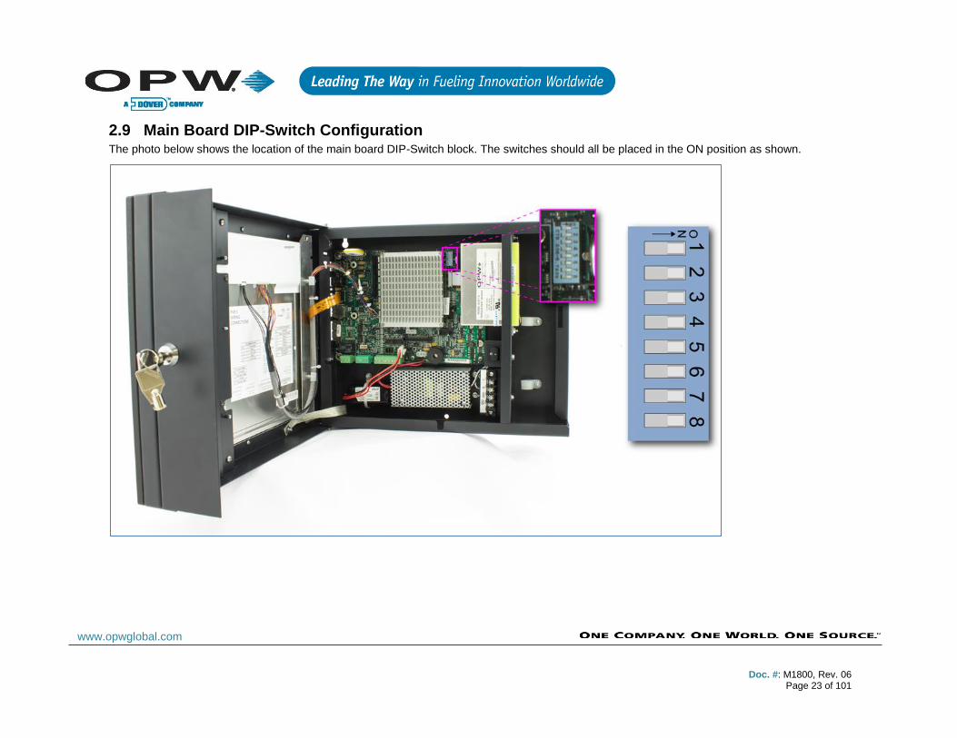
2.9 Main Board DIP-Switch Configuration The photo below shows the location of the main board DIP-Switch block. The switches should all be placed in the ON position as shown.

Doc. #: M1800, Rev. 06
Page 24 of 101
www.opwglobal.com
3 External Printer
To watch the instructional video for the installation of the External Printer, simply use the following QR Code. Or, the instructional video can also be found at www.YouTube.com by entering the search word “OPWGlobal”.
An external thermal printer option is available for the SiteSentinel® Integra™ console. The printer will be used for printing the various reports available with the tank gauge system. In order to securely affix the external printer, use wall-mounting brackets.
1. Using an external wall-mounting bracket, mark the locations of the screw holes and attach the hanger screws.
2. Next, install the wall-mounting bracket on the external thermal printer.
3. Remove the side tabs from the external printer to allow for power cord and USB cord routing.
4. Mount the external thermal printer to the wall by hanging the printer on the screws.
5. Connect the USB cord from the external thermal printer to the USB port on the main board located on the inside of the Integra console.
NOTE: Any available internal USB port may be used for the printer;
however, only the external USB port nearest the wall may be used
for the printer connection.
6. Dress all power and communication cables between the external printer and the Integra console with cable ties.
7. Plug in the power connector of the external thermal printer.
Figure 3-1 Install Hanger Screws
Figure 3-2 Install Mounting Bracket

Doc. #: M1800, Rev. 06
Page 25 of 101
www.opwglobal.com
Figure 3-3 Install External Thermal Printer
Figure 3-4 Connect Printer USB to Integra Main Board
Figure 3-5 Do Not Use This USB Port

Doc. #: M1800, Rev. 06
Page 26 of 101
www.opwglobal.com
4 VSmart Module (only for Integra 500)
Figure 4-1 VSmart Module (Inside)
The VSmart module is where all monitored devices (probes, sensors, and line-leak detectors) are physically connected to the system through Intrinsically Safe (IS) barriers. A VSmart module houses up to two (2) I.S. barriers; each I.S. barrier has four (4) channel inputs. Each I.S. barrier supports up to 64 peripheral devices; thereby, allowing for a maximum of 128 devices per module. The number of devices that can be connected to each channel of the VSmart module depends on the type of device.
NOTE: Conduit is recommended for Petro-Net™ connections
between VSmart Modules and consoles, but it is not required.
Part numbers for the barriers:
P/N: 20-4344 12V Barrier for VSmart 924/924B probes and standard and multi-drop sensors (Green Label)
P/N: 20-4345 24V Barrier for VSmart Flex probes and EECO probes (Orange Label)
4.1 VSmart Specifications
*Maximum I.S. Wiring Length is the maximum length of cable to be
used to connect all probes or sensors on an individual channel. The
length includes run of cable from an I.S. Barrier to each probe or
sensor board in the string.
**Maximum Petro-Net extension using RS-485 is the maximum
length of Petro-Net cable to be used to connect all Petro-Net devices.
Dimensions:
Width: 11.3” (28.7 cm)
Height: 5.6” (14.2 cm)
Depth: 5.8” (14.7 cm)
Standard Voltage Supply: 105 to 265 VAC, 50-60 Hz
Power Consumption: 60 watts maximum
Temperature Range: -40F to 158F (-40°C to 70°C)
Device Capacity: Up to two (2) I.S. Barriers
Up to eight (8) Barrier Positions
Maximum Total-Run I.S. Wiring Length*:
1,000’ when using Belden 88760
500’ when using Belden 88761 (22-AWG)
Non-Intelligent Sensor Wiring Requirements:
14- to 18-AWG oil-and-gas resistant (TFFN, THHN or THWN)
Petro-Net™ Communication Wiring Requirement:
18-AWG, twisted pair, oil-and-gas resistant
(TFFN, THHN, THWN)
Maximum Petro-Net™ Extension using RS485:
5,000’ (1.5 km)**
Doc. #: M1800, Rev. 06
Page 27 of 101
www.opwglobal.com
4.2 VSmart Module Installation The VSmart module must be mounted on a wall using only the mounting tabs provided. Module knockouts and mounting dimensions are shown in drawings below.
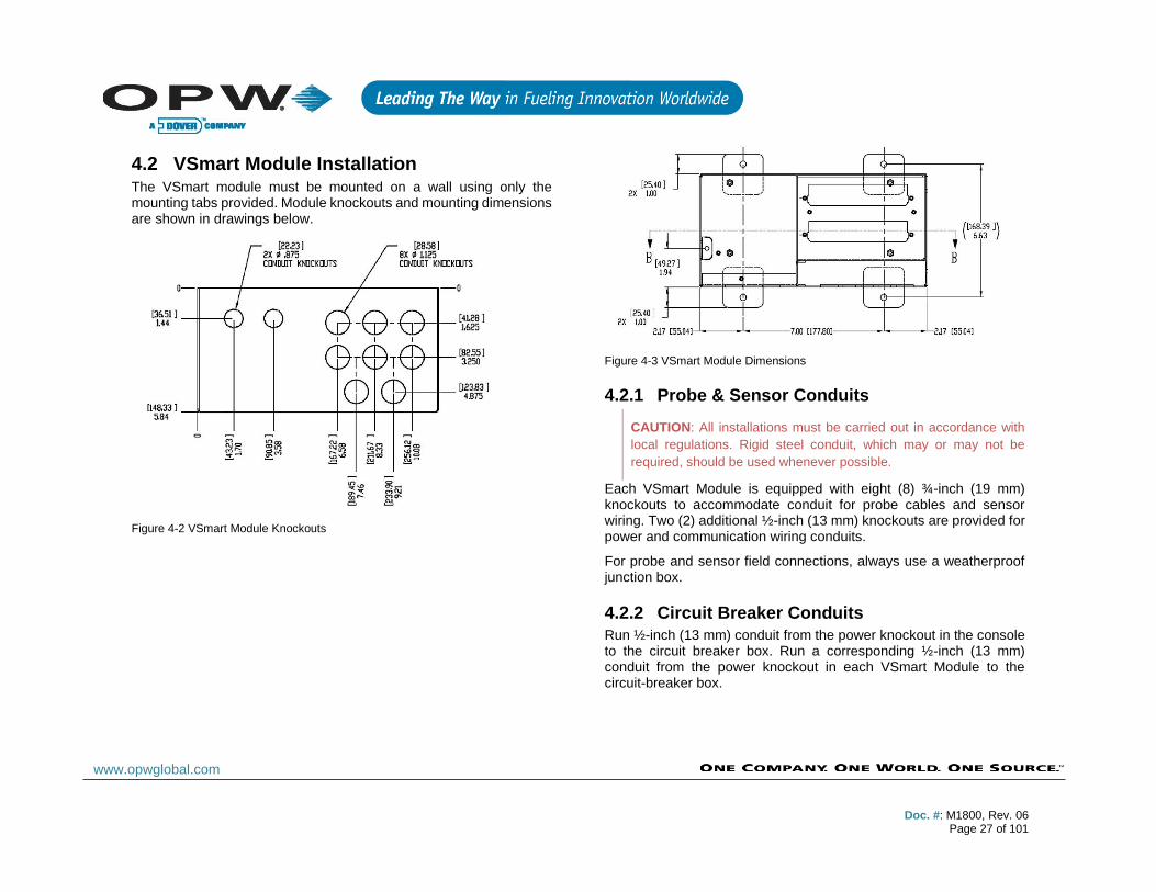
Figure 4-2 VSmart Module Knockouts
Figure 4-3 VSmart Module Dimensions
4.2.1 Probe & Sensor Conduits
CAUTION: All installations must be carried out in accordance with
local regulations. Rigid steel conduit, which may or may not be
required, should be used whenever possible.
Each VSmart Module is equipped with eight (8) ¾-inch (19 mm) knockouts to accommodate conduit for probe cables and sensor wiring. Two (2) additional ½-inch (13 mm) knockouts are provided for power and communication wiring conduits.
For probe and sensor field connections, always use a weatherproof junction box.
4.2.2 Circuit Breaker Conduits
Run ½-inch (13 mm) conduit from the power knockout in the console to the circuit breaker box. Run a corresponding ½-inch (13 mm) conduit from the power knockout in each VSmart Module to the circuit-breaker box.
Doc. #: M1800, Rev. 06
Page 28 of 101
www.opwglobal.com
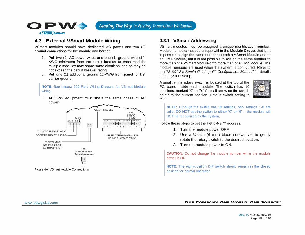
4.3 External VSmart Module Wiring VSmart modules should have dedicated AC power and two (2) ground connections for the module and barrier.
1. Pull two (2) AC power wires and one (1) ground wire (14-AWG minimum) from the circuit breaker to each module; multiple modules may share same circuit as long as they do not exceed the circuit breaker rating.
2. Pull one (1) additional ground 12-AWG from panel for I.S. barrier ground.
NOTE: See Integra 500 Field Wiring Diagram for VSmart Module
wiring.
3. All OPW equipment must share the same phase of AC power.
Figure 4-4 VSmart Module Connections
4.3.1 VSmart Addressing
VSmart modules must be assigned a unique identification number. Module numbers must be unique within the Module Group; that is, it is possible assign the same number to both a VSmart Module and to an OM4 Module, but it is not possible to assign the same number to more than one VSmart Module or to more than one OM4 Module. The module numbers are used when the system is configured. Refer to the “M1801 SiteSentinel® Integra™ Configuration Manual” for details about system setup.
A small, white rotary switch is located at the top of the PC board inside each module. The switch has 10 positions, marked “0” to “9.” A small arrow on the switch points to the current position. Default switch setting is “1.”
NOTE: Although the switch has 10 settings, only settings 1-8 are
valid. DO NOT set the switch to either “0” or “9” – the module will
NOT be recognized by the system.
Follow these steps to set the Petro-Net™ address:
1. Turn the module power OFF.
2. Use a ¼-inch (6 mm) blade screwdriver to gently
rotate the rotary switch to the desired location.
3. Turn the module power to ON.
CAUTION: Do not change the module number while the module
power is ON.
NOTE: The eight-position DIP switch should remain in the closed
position for normal operation.

Doc. #: M1800, Rev. 06
Page 29 of 101
www.opwglobal.com
4.4 VSmart Capabilies Consult the following table for capabilities of the VSmart Module in connection with various peripheral devices.
I.S. Barrier Capacity [up to two (2) I.S. Barriers per VSmart Module, four (4) positions per Barrier]
Maximum per
Channel Maximum per I.S.
Barrier
Sensors: 16 64
924B Probes: 4 16
AST (Flex) / UST (924) / EECO*:
1 4
VLLD Sensors: 3 12
Connecting multiple peripheral devices to each channel of the VSmart module is accomplished by making multi-drop connections (wired in parallel). Each type of sensor or probe that is connected to a module is detected via IntelliSense™ Technology.
*NOTE: 24V barrier is required for Flex and EECO probes.
For more information on the VSmart’s Multi-Drop Capabilities, use the following QR Code to watch the instructional video. Or, the instructional video can also be found at www.YouTube.com by entering the search word “OPWGlobal”.
Doc. #: M1800, Rev. 06
Page 30 of 101
www.opwglobal.com
5 Line Interface Module LIM (only for Integra 500)
The LIM is an external device that controls and monitors submersible turbine pump (STP) activities by monitoring the input/output status of the dispenser hook signals and STP relays.
Each Line Interface Module (LIM) (maximum of four (4) per system) will monitor up to four (4) STP motors per module (for a total of 16 STPs per system). In the case of manifold submersible pumps, only one (1) LLD sensor is installed, but the manifold will require one LIM position for each submersible pump.
Typically, the dispenser sends a “hook signal” (110 VAC) to the submersible pump controller. A LIM functions by intercepting this hook signal and communicates via Petro-Net with the console. The LIM sends a 110/220 signal to the STP controller to turn the submersible pump ON, unless an alarm condition is detected, then no signal is sent. An HV feedback signal confirms that the submersible pump is turned ON.
The LIM works in conjunction with the console to test the lines during periods of inactivity to constantly monitor the site for leaks in the line(s).
5.1 LIM Specifications
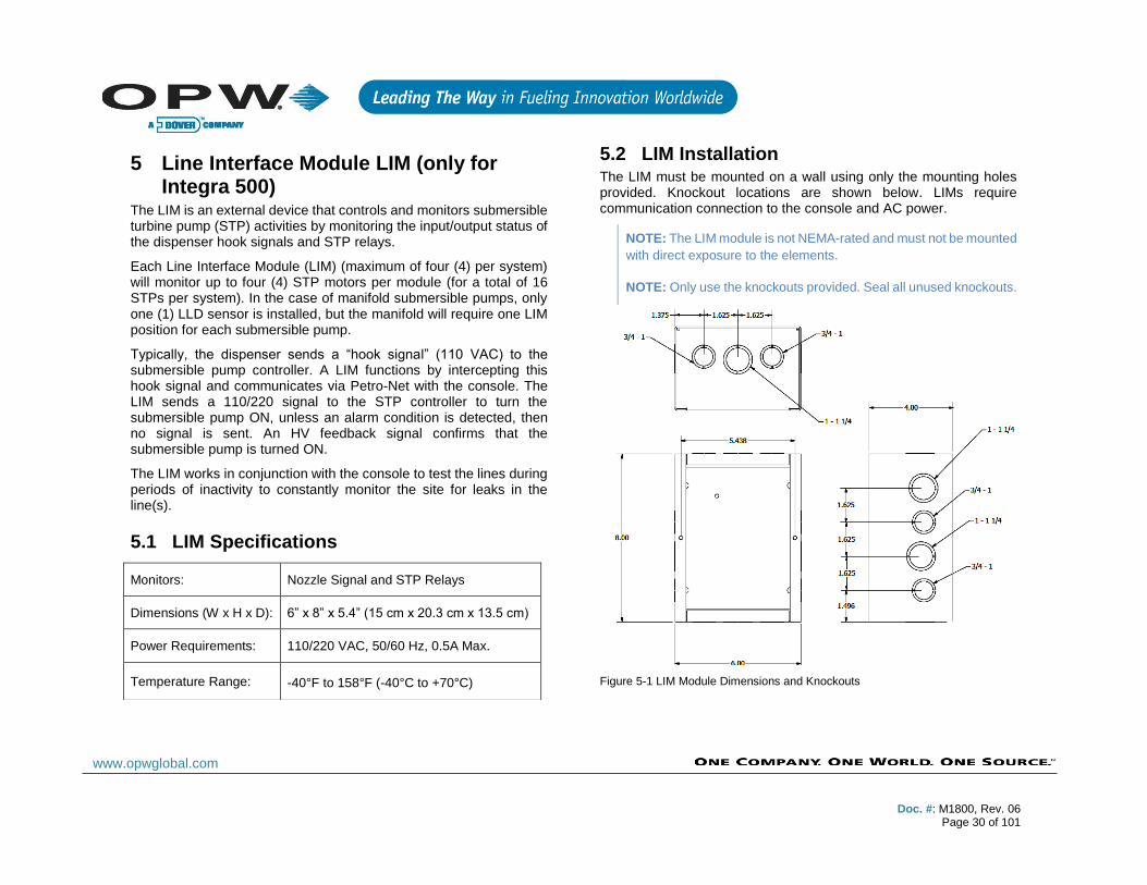
5.2 LIM Installation The LIM must be mounted on a wall using only the mounting holes provided. Knockout locations are shown below. LIMs require communication connection to the console and AC power.
NOTE: The LIM module is not NEMA-rated and must not be mounted
with direct exposure to the elements.
NOTE: Only use the knockouts provided. Seal all unused knockouts.
Figure 5-1 LIM Module Dimensions and Knockouts
Monitors: Nozzle Signal and STP Relays
Dimensions (W x H x D): 6” x 8” x 5.4” (15 cm x 20.3 cm x 13.5 cm)
Power Requirements: 110/220 VAC, 50/60 Hz, 0.5A Max.
Temperature Range: -40°F to 158°F (-40°C to +70°C)
Doc. #: M1800, Rev. 06
Page 31 of 101
www.opwglobal.com
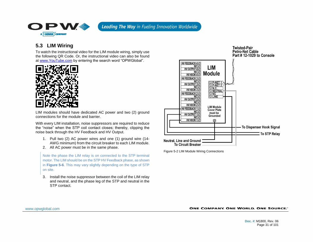
5.3 LIM Wiring To watch the instructional video for the LIM module wiring, simply use the following QR Code. Or, the instructional video can also be found at www.YouTube.com by entering the search word “OPWGlobal”.
LIM modules should have dedicated AC power and two (2) ground connections for the module and barrier.
With every LIM installation, noise suppressors are required to reduce the “noise” when the STP coil contact closes; thereby, clipping the noise back through the HV Feedback and HV Output.
1. Pull two (2) AC power wires and one (1) ground wire (14-AWG minimum) from the circuit breaker to each LIM module.
2. All AC power must be in the same phase.
Note the phase the LIM relay is on connected to the STP terminal
motor. The LIM should be on the STP HV Feedback phase, as shown
in Figure 5-6. This may vary slightly depending on the type of STP
on site.
3. Install the noise suppressor between the coil of the LIM relay and neutral, and the phase leg of the STP and neutral in the STP contact.
Figure 5-2 LIM Module Wiring Connections

Doc. #: M1800, Rev. 06
Page 32 of 101
www.opwglobal.com
5.3.1 Variable Speed Control for FE Petro
Figure 5-3 FE Petro Wiring for Variable Speed Control
5.3.2 Typical FE Petro Wiring Connections
Figure 5-4 FE Petro Wiring Connections

Doc. #: M1800, Rev. 06
Page 33 of 101
www.opwglobal.com
5.3.3 Variable Speed Control Wiring for Red Jacket
Figure 5-5 Red Jacket Wiring for Variable Speed Control
5.3.4 Typical Red Jacket Wiring Connections
Figure 5-6 Red Jacket Wiring Connections
5.3.5 LIM Addressing
LIM modules must be assigned a unique identification number. Module numbers must be unique within the Module Group; that is, it is possible assign the same number to both a LIM Module and to an OM4 Module, but it is not possible to assign the same number to more than one LIM Module or to more than one OM4 Module. The module numbers are used when the system is configured. Refer to the “M1801 SiteSentinel® Integra™ Configuration Manual” for details about system setup
A small, white rotary switch is located at the top of the PC board inside each module. The switch has 10 positions, marked “0” to “9.” A small arrow on the switch points to the current position. Default switch setting is “1.”
NOTE: Although the switch has 10 settings, only settings 1-8 are
valid. DO NOT set the switch to either “0” or “9” – the module will
NOT be recognized by the system.
Follow these steps to set the Petro-Net™ address:
1. Turn the module power OFF.
2. Use a ¼-inch (6 mm) blade screwdriver to gently
rotate the rotary switch to the desired location.
3. Turn the module power to ON.
CAUTION: Do not change the module number while the LIM module
power is ON.

Doc. #: M1800, Rev. 06
Page 34 of 101
www.opwglobal.com
6 OM4 Module (only for Integra 500)
Figure 6-1 OM4 Module Dimensions and Knockouts
The OM4 Output Module expands the Integra’s capabilities by allowing you to connect as many as 16 relay-activated output devices to the ATG controller.
The OM4 Output Module communicates with the controller via Petro-Net. Up to four OM4 Output Modules can be connected for a total of 16 output devices.
A common Output Module application is used to turn OFF a submersible pump when low product is detected in the tank, or is used to activate an audible alarm when high product is detected in a tank.
NOTE: The LIM module is not NEMA-rated and must not be mounted
with direct exposure to the elements.
The OM4 for the Integra console derives its power from a 12 VAC power transformer source that is supplied with the unit.
Reference the “M1801 SiteSentinel® Integra™ Configuration Manual” to program the alarms or events and associate them with the Output Module relays.
6.1 Cautions!
Do NOT connect the OM4 Output Module directly to a submersible
pump!
Output relays in the OM4 Output Module are not intrinsically safe!
DO NOT place probe and/or sensor wiring in conduit that contains
wiring for devices connected to the OM4 Output Module.
The OM4 output Module controls pumps INDIRECTLY, through
relays or contactors. High voltages exist inside the OM4 Output
Module.
Only qualified technicians should open the unit.
Before working on the OM4 Output Module, disconnect all power,
including power to and from the relays.
Field Wiring Rating: 600V Type RH. TW, RFH-2 or equivalent
Power Requirements: 12 VAC, 0.5A Max.
Dimensions: 6" W x 6" H x 4” D (15 cm x 15 cm x 10 cm)
Temperature Rating: 32°F – 104°F (0°C – 40°C)
Relay Output Rating: 5A @ 110/240 VAC; 5A @ 24 VDC
Certifications: Electronic Testing Labs Canada (cETL) Electronic Testing Labs (ETL)
Doc. #: M1800, Rev. 06
Page 35 of 101
www.opwglobal.com
6.2 OM4 Specifications
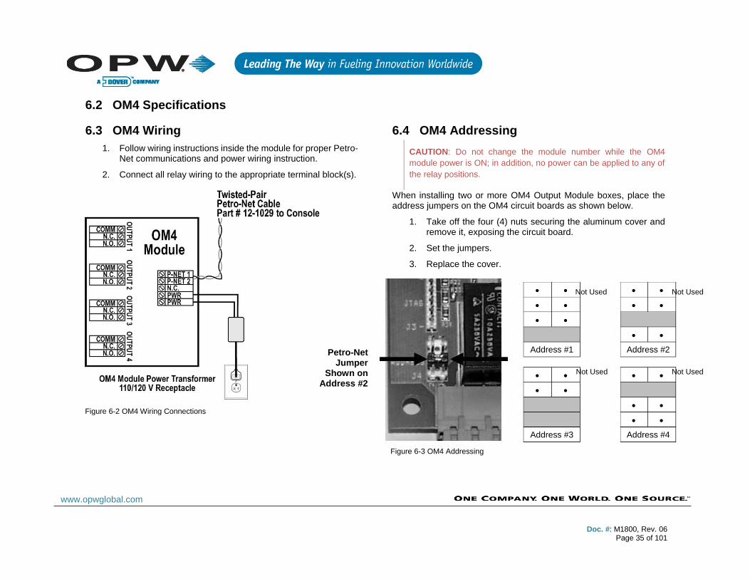
6.3 OM4 Wiring
1. Follow wiring instructions inside the module for proper Petro-Net communications and power wiring instruction.
2. Connect all relay wiring to the appropriate terminal block(s).
6.4 OM4 Addressing
CAUTION: Do not change the module number while the OM4
module power is ON; in addition, no power can be applied to any of
the relay positions.
When installing two or more OM4 Output Module boxes, place the address jumpers on the OM4 circuit boards as shown below.
1. Take off the four (4) nuts securing the aluminum cover and remove it, exposing the circuit board.
2. Set the jumpers.
3. Replace the cover.
Petro-Net Jumper
Shown on Address #2
• • • •
• • • •
• •
• •
Address #1 Address #2
• • • •
• •
• •
• •
Address #3 Address #4
Not Used
Not Used
Not Used
Not Used
Figure 6-2 OM4 Wiring Connections
Figure 6-3 OM4 Addressing
Doc. #: M1800, Rev. 06
Page 36 of 101
www.opwglobal.com
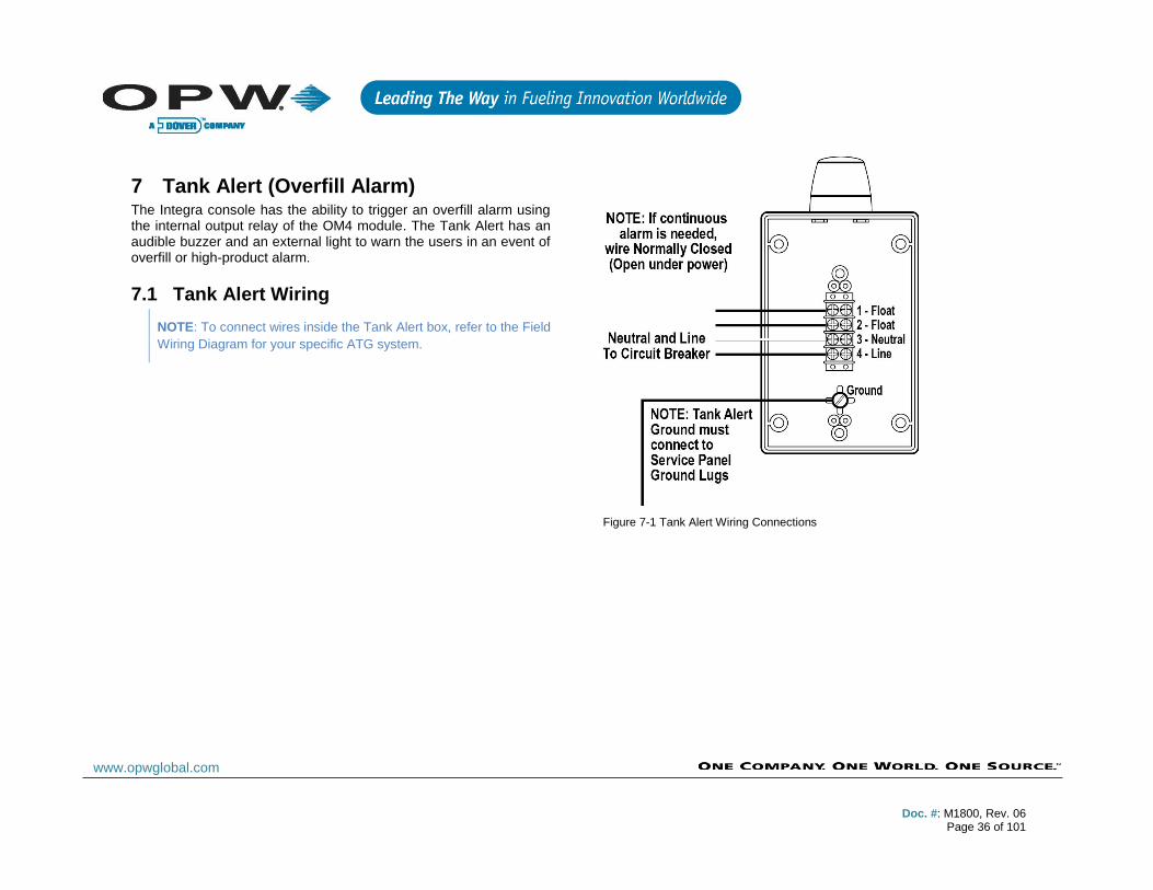
7 Tank Alert (Overfill Alarm) The Integra console has the ability to trigger an overfill alarm using the internal output relay of the OM4 module. The Tank Alert has an audible buzzer and an external light to warn the users in an event of overfill or high-product alarm.
7.1 Tank Alert Wiring
NOTE: To connect wires inside the Tank Alert box, refer to the Field
Wiring Diagram for your specific ATG system.
Figure 7-1 Tank Alert Wiring Connections

Doc. #: M1800, Rev. 06
Page 37 of 101
www.opwglobal.com
8 Tank & Pre-Installation Preparation
8.1 Waterproof Electrical Connections To watch the instructional video for the use of the Epoxy packs, simply use the following QR Code. Or, the instructional video can also be found at www.YouTube.com by entering the search word “OPWGlobal”.
Figure 8-1 Waterproof Electrical Connections
It is VERY important to seal all probe and sensor connections in the junction box to prevent corrosion of the wires.
1. Twist bare ends of wires together.
2. Secure the connection with a wire nut.
CAUTION: DO NOT use electrical tape on any connections! Tape
prevents proper sealing of the epoxy.
3. Waterproof the connections with the supplied SCOTCHCAST™ epoxy resin Insulating Resin Seal packs. They are provided to seal the electrical connections from moisture and water and prevent corrosion of the connections. Install one for each cable connection.
4. Bend the seal pack until the barrier between the two resins weakens.
5. Force the clear and the black resins together and mix thoroughly.
6. Move the mixture to one end of pack, then clip the other end.
7. Insert wires, wire nuts and the cable insulation end into the seal pack.
8. Work the resin mixture into the ends of the wire nuts and around both cable jackets.
• Secure the seal pack around the cables with a tie
wrap and cable tie.
Doc. #: M1800, Rev. 06
Page 38 of 101
www.opwglobal.com
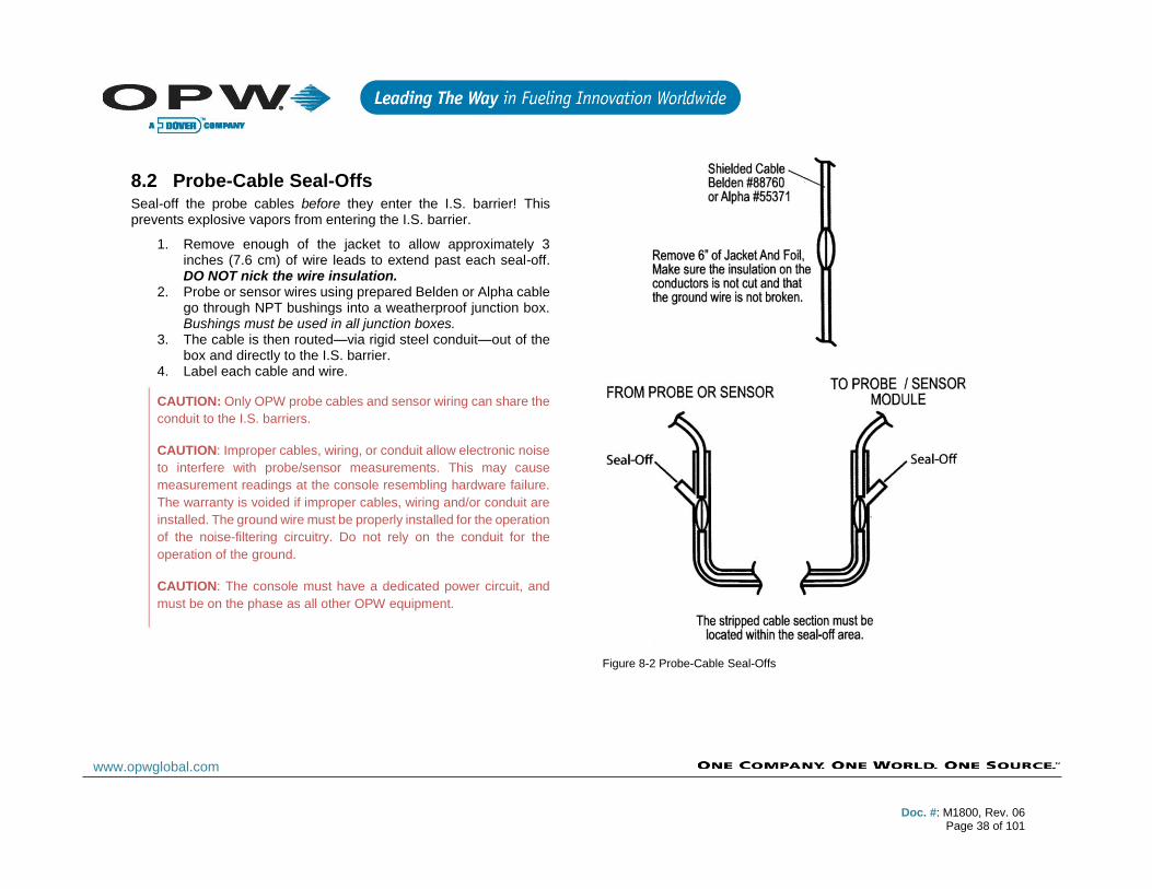
8.2 Probe-Cable Seal-Offs Seal-off the probe cables before they enter the I.S. barrier! This prevents explosive vapors from entering the I.S. barrier.
1. Remove enough of the jacket to allow approximately 3 inches (7.6 cm) of wire leads to extend past each seal-off. DO NOT nick the wire insulation.
2. Probe or sensor wires using prepared Belden or Alpha cable go through NPT bushings into a weatherproof junction box. Bushings must be used in all junction boxes.
3. The cable is then routed—via rigid steel conduit—out of the box and directly to the I.S. barrier.
4. Label each cable and wire.
CAUTION: Only OPW probe cables and sensor wiring can share the
conduit to the I.S. barriers.
CAUTION: Improper cables, wiring, or conduit allow electronic noise
to interfere with probe/sensor measurements. This may cause
measurement readings at the console resembling hardware failure.
The warranty is voided if improper cables, wiring and/or conduit are
installed. The ground wire must be properly installed for the operation
of the noise-filtering circuitry. Do not rely on the conduit for the
operation of the ground.
CAUTION: The console must have a dedicated power circuit, and
must be on the phase as all other OPW equipment.
Figure 8-2 Probe-Cable Seal-Offs
Doc. #: M1800, Rev. 06
Page 39 of 101
www.opwglobal.com
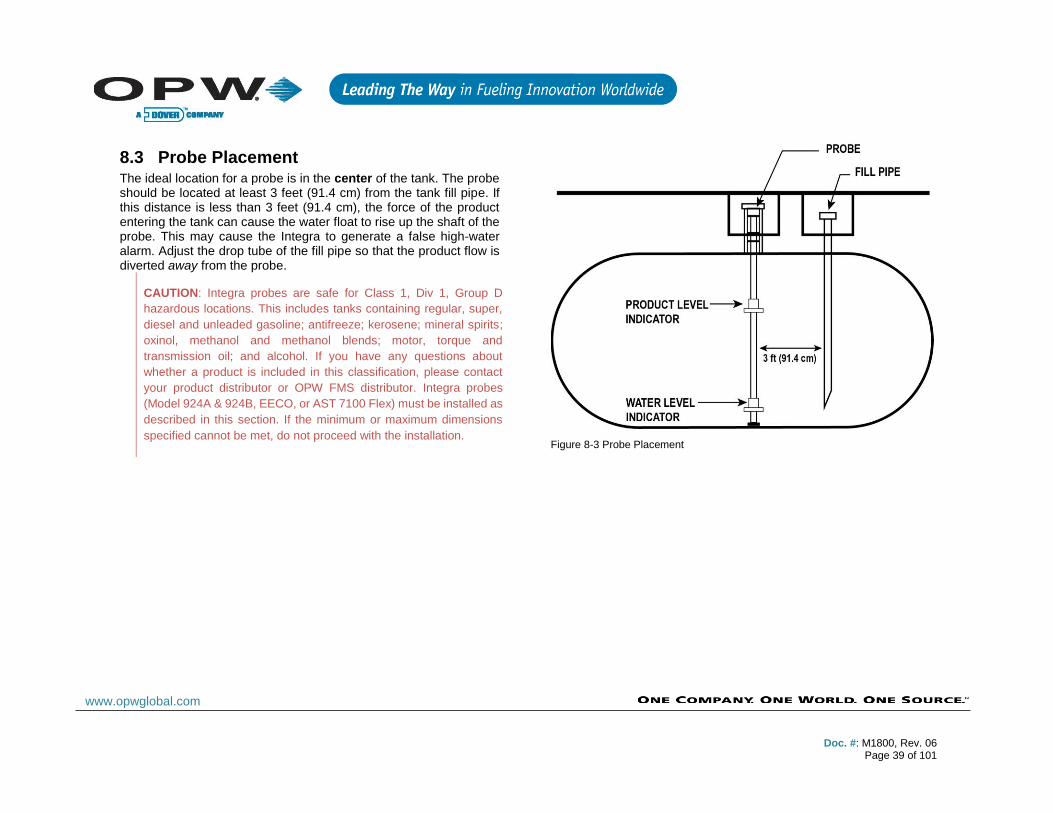
8.3 Probe Placement The ideal location for a probe is in the center of the tank. The probe should be located at least 3 feet (91.4 cm) from the tank fill pipe. If this distance is less than 3 feet (91.4 cm), the force of the product entering the tank can cause the water float to rise up the shaft of the probe. This may cause the Integra to generate a false high-water alarm. Adjust the drop tube of the fill pipe so that the product flow is diverted away from the probe.
CAUTION: Integra probes are safe for Class 1, Div 1, Group D
hazardous locations. This includes tanks containing regular, super,
diesel and unleaded gasoline; antifreeze; kerosene; mineral spirits;
oxinol, methanol and methanol blends; motor, torque and
transmission oil; and alcohol. If you have any questions about
whether a product is included in this classification, please contact
your product distributor or OPW FMS distributor. Integra probes
(Model 924A & 924B, EECO, or AST 7100 Flex) must be installed as
described in this section. If the minimum or maximum dimensions
specified cannot be met, do not proceed with the installation.
Figure 8-3 Probe Placement
Doc. #: M1800, Rev. 06
Page 40 of 101
www.opwglobal.com
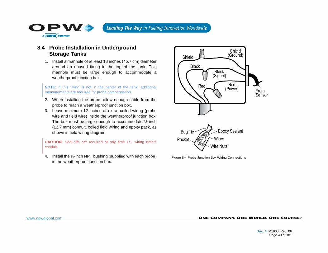
8.4 Probe Installation in Underground Storage Tanks
1. Install a manhole of at least 18 inches (45.7 cm) diameter
around an unused fitting in the top of the tank. This
manhole must be large enough to accommodate a
weatherproof junction box.
NOTE: If this fitting is not in the center of the tank, additional
measurements are required for probe compensation.
2. When installing the probe, allow enough cable from the
probe to reach a weatherproof junction box.
3. Leave minimum 12 inches of extra, coiled wiring (probe
wire and field wire) inside the weatherproof junction box.
The box must be large enough to accommodate ½-inch
(12.7 mm) conduit, coiled field wiring and epoxy pack, as
shown in field wiring diagram.
CAUTION: Seal-offs are required at any time I.S. wiring enters
conduit.
4. Install the ½-inch NPT bushing (supplied with each probe)
in the weatherproof junction box.
Figure 8-4 Probe Junction Box Wiring Connections
Doc. #: M1800, Rev. 06
Page 41 of 101
www.opwglobal.com
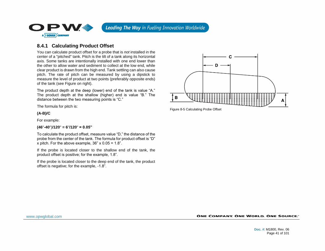
8.4.1 Calculating Product Offset
You can calculate product offset for a probe that is not installed in the center of a "pitched" tank. Pitch is the tilt of a tank along its horizontal axis. Some tanks are intentionally installed with one end lower than the other to allow water and sediment to collect at the low end, while clear product is drawn from the high end. Tank settling can also cause pitch. The rate of pitch can be measured by using a dipstick to measure the level of product at two points (preferably opposite ends) of the tank (see Figure on right).
The product depth at the deep (lower) end of the tank is value “A.” The product depth at the shallow (higher) end is value “B.” The distance between the two measuring points is “C.”
The formula for pitch is:
(A-B)/C
For example:
(46"-40")/120" = 6"/120" = 0.05”
To calculate the product offset, measure value “D,” the distance of the probe from the center of the tank. The formula for product offset is “D” x pitch. For the above example, 36” x 0.05 = 1.8”.
If the probe is located closer to the shallow end of the tank, the product offset is positive; for the example, 1.8”.
If the probe is located closer to the deep end of the tank, the product offset is negative; for the example, -1.8”.
Figure 8-5 Calculating Probe Offset

Doc. #: M1800, Rev. 06
Page 42 of 101
www.opwglobal.com
9 Rigid Probe Installation
NOTE: TLMB probes do not work with an Integra 100™ or 500™
console; even if you are upgrading from an EECO console to an
Integra™ console, a TLMB probe it will not work.
9.1 Adaptor Collar & Riser Cap A modified adaptor collar and riser cap (OPW Model 62M) is required for each probe. These collar and riser cap kits are available from OPW Fuel Management System.
1. Install the modified adaptor collar onto the riser pipe.
2. Next, screw in the OPW-supplied bushing (62 mm) with
the probe into the 3/8-inch NPT hole in the riser cap.
3. After the probe is lowered into the tank, snap the cap into
place.
9.2 Probe Floats There are three types of floats used with the probes: Product, Water for Diesel, and Water for Gasoline.
Note that the two types of water floats are NOT interchangeable. Because diesel is denser than gasoline, the water/diesel floats are heavier than the water/gasoline floats. If the wrong water float is installed in a diesel tank, it does not sink through the product to the water below. As a result, the tank will have unusually high water measurements and possibly erratic product measurements as the water float interferes with the product float.
NOTE: Water float assembly for flexible AST probes is only available
for use in 4-inch (10.2 cm) riser installations.
9.3 Multi-drop Installation The Integra’s internal barrier and optional VSmart Module allows for the ability to multi-drop the sensors and probes. When using this installation method, follow the below directions to ensure approved wiring.
Sensors and probes cannot be multi-dropped from the same I.S. Channel; therefore, you must run sensors and probes to different channels on the barrier.
Seal packs are required with all wiring applications in the field. Weatherproof junction boxes are REQUIRED with ALL I.S. field connections.
Figure 9-1 Multi-drop Probes on I.S. Barrier
Doc. #: M1800, Rev. 06
Page 43 of 101
www.opwglobal.com
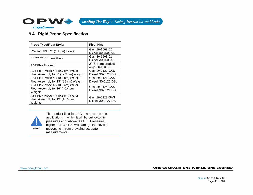
9.4 Rigid Probe Specification
Probe Type/Float Style: Float Kits
924 and 924B 2” (5.1 cm) Floats: Gas: 30-1509-02 Diesel: 30-1509-01
EECO 2” (5.1 cm) Floats: Gas: 30-1503-02 Diesel: 30-1503-01
AST Flex Probes: 2” (5.1 cm) product only: 30-1503-01
AST Flex Probe 4” (10.2 cm) Water Float Assembly for 7” (17.9 cm) Weight:
Gas: 30-0120-GAS Diesel: 30-0120-DSL
AST Flex Probe 4” (10.2 cm) Water Float Assembly for 13” (33 cm) Weight:
Gas: 30-0121-GAS Diesel: 30-0121-DSL
AST Flex Probe 4” (10.2 cm) Water Float Assembly for 16” (40.6 cm) Weight:
Gas: 30-0124-GAS Diesel: 30-0124-DSL
AST Flex Probe 4” (10.2 cm) Water Float Assembly for 19” (48.3 cm) Weight:
Gas: 30-0127-GAS Diesel: 30-0127-DSL
The product float for LPG is not certified for applications in which it will be subjected to pressures at or above 300PSI. Pressures higher than 300PSI will damage the device, preventing it from providing accurate measurements.
Doc. #: M1800, Rev. 06
Page 44 of 101
www.opwglobal.com
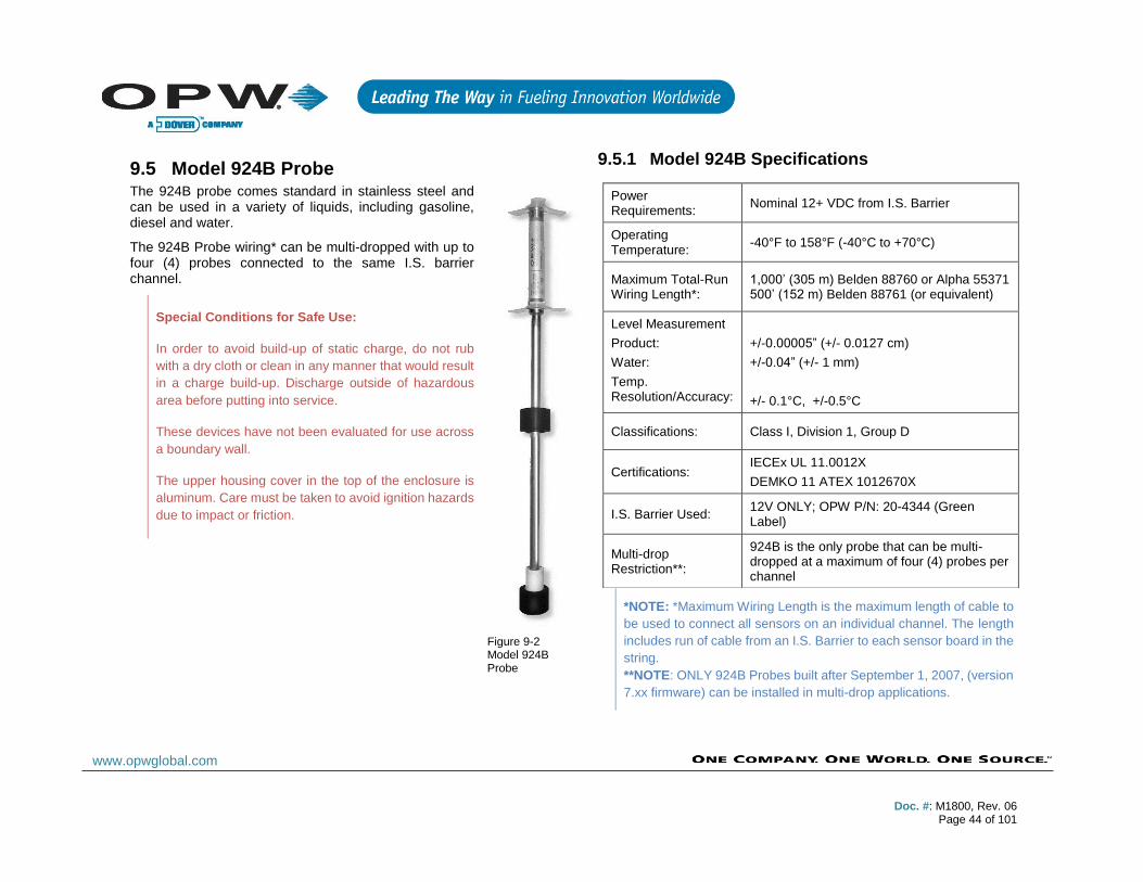
9.5 Model 924B Probe The 924B probe comes standard in stainless steel and can be used in a variety of liquids, including gasoline, diesel and water.
The 924B Probe wiring* can be multi-dropped with up to four (4) probes connected to the same I.S. barrier channel.
Special Conditions for Safe Use:
In order to avoid build-up of static charge, do not rub
with a dry cloth or clean in any manner that would result
in a charge build-up. Discharge outside of hazardous
area before putting into service.
These devices have not been evaluated for use across
a boundary wall.
The upper housing cover in the top of the enclosure is
aluminum. Care must be taken to avoid ignition hazards
due to impact or friction.
9.5.1 Model 924B Specifications
*NOTE: *Maximum Wiring Length is the maximum length of cable to
be used to connect all sensors on an individual channel. The length
includes run of cable from an I.S. Barrier to each sensor board in the
string.
**NOTE: ONLY 924B Probes built after September 1, 2007, (version
7.xx firmware) can be installed in multi-drop applications.
Power Requirements:
Nominal 12+ VDC from I.S. Barrier
Operating Temperature:
-40°F to 158°F (-40°C to +70°C)
Maximum Total-Run Wiring Length*:
1,000’ (305 m) Belden 88760 or Alpha 55371 500’ (152 m) Belden 88761 (or equivalent)
Level Measurement
Product:
Water:
Temp. Resolution/Accuracy:
+/-0.00005” (+/- 0.0127 cm)
+/-0.04” (+/- 1 mm)
+/- 0.1°C, +/-0.5°C
Classifications: Class I, Division 1, Group D
Certifications: IECEx UL 11.0012X
DEMKO 11 ATEX 1012670X
I.S. Barrier Used: 12V ONLY; OPW P/N: 20-4344 (Green Label)
Multi-drop Restriction**:
924B is the only probe that can be multi-dropped at a maximum of four (4) probes per channel
Figure 9-2 Model 924B Probe
Doc. #: M1800, Rev. 06
Page 45 of 101
www.opwglobal.com
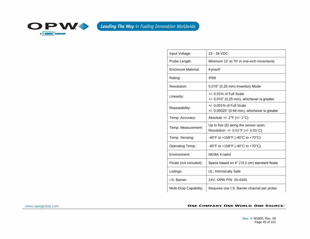
Input Voltage: 23 - 28 VDC
Probe Length: Minimum 12’ to 70’ in one-inch increments
Enclosure Material: Kynar®
Rating: IP68
Resolution: 0.010” (0.25 mm) Inventory Mode
Linearity: +/- 0.01% of Full Scale
+/- 0.010” (0.25 mm), whichever is greater
Repeatability: +/- 0.001% of Full Scale
+/- 0.00025” (0.64 mm), whichever is greater
Temp. Accuracy: Absolute +/- 2°F (+/- 1°C)
Temp. Measurement: Up to five (5) along the sensor span;
Resolution: +/- 0.01°F (+/- 0.01°C)
Temp. Sensing: -40°F to +158°F (-40°C to +70°C)
Operating Temp.: -40°F to +158°F (-40°C to +70°C)
Environment: NEMA 4-rated
Floats (not included): Specs based on 4” (10.2 cm) standard floats
Listings: UL; Intrinsically Safe
I.S. Barrier: 24V; OPW P/N: 20-4345
Multi-Drop Capability: Requires one I.S. Barrier channel per probe
Doc. #: M1800, Rev. 06
Page 46 of 101
www.opwglobal.com
10 Flex Probe Installation
10.1 Model 7100V Flex Probe (only for Integra 500)
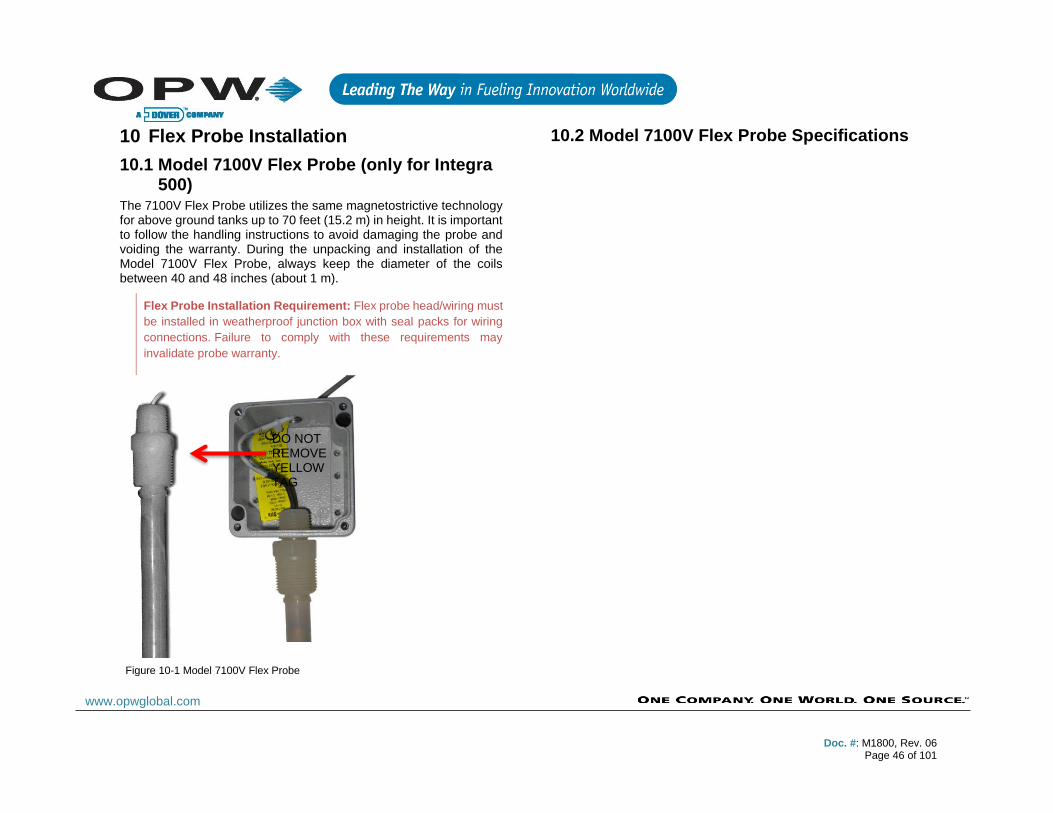
The 7100V Flex Probe utilizes the same magnetostrictive technology for above ground tanks up to 70 feet (15.2 m) in height. It is important to follow the handling instructions to avoid damaging the probe and voiding the warranty. During the unpacking and installation of the Model 7100V Flex Probe, always keep the diameter of the coils between 40 and 48 inches (about 1 m).
Flex Probe Installation Requirement: Flex probe head/wiring must
be installed in weatherproof junction box with seal packs for wiring
connections. Failure to comply with these requirements may
invalidate probe warranty.
10.2 Model 7100V Flex Probe Specifications
DO NOT REMOVE YELLOW TAG
Figure 10-1 Model 7100V Flex Probe

Doc. #: M1800, Rev. 06
Page 47 of 101
www.opwglobal.com
10.3 Flex Probe Installation Proper operation of the ATG system using the flex probe depends on the correct sizing of the probe. If the probe is too long, it will touch the bottom of the tank and bow, causing either inaccurate or lost readings. If it is too short, product measurement range will be compromised.
NOTE: Each Flex Probe is custom made to fit a particular tank. They
are not returnable if an error is made in determining the correct
length.
10.3.1 Flex Probe Length Determination
1. The flex probe mounts to the tank with a ¾-inch NPT
male thread. Obtain the proper fittings to adapt the
tank opening to a ¾-inch NPT female thread. Do not
use the tank’s vent opening to install the flex probe.
2. Temporarily install this hardware in the tank opening.
3. Using a plumb bob or measuring tape measure the
distance (in inches) from the top of the ¾-inch NPT
flange to the bottom of the tank. Save this
measurement, which will be Total Height (TH).
4. Flex probes are ordered by overall length (OAL).
Overall length is the distance from the top of the ¾-
inch NPT wiring bushing to the tip of the probe. OAL
(inches) = 1.5 + (TH x .993)
• If cable runs to 750 feet (229 m) use Belden #88761
• If cable runs to 1,000 feet (305 m) use Belden #8760, #88760 or #8761
NOTE: Some electrical codes require intrinsically safe wiring to have
a blue jacket.
10.3.2 Flex Probe Installation Preparations
1. Measure the product level in the tank. Keep tank out
of service to prevent product level from changing.
2. Make note of the probe information found on the
probe serial number tag.
3. Locate standard plumbing fittings that will adapt your
tank opening to the ¾-inch NPT required for the
probe.
4. Wipe any excess sealant from the inside of the fittings
to prevent any from getting on the probe shaft during
installation.
CAUTION: Do not remove yellow tag; refer to image in Section 10.1.
Figure 10-2 Flex Probe Installation Diagram
Doc. #: M1800, Rev. 06
Page 48 of 101
www.opwglobal.com
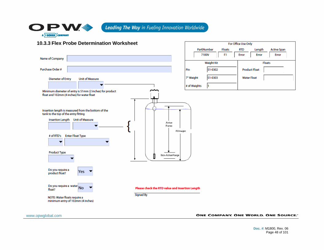
10.3.3 Flex Probe Determination Worksheet
Doc. #: M1800, Rev. 06
Page 49 of 101
www.opwglobal.com
10.3.4 Flex Probe Wiring
1. Run one data cable for each probe. No splices are
allowed between probe junction box and console.
Multiple flex-probe cables are allowed in one conduit.
Use labels to mark TANK # on each cable at the
console.
2. Leave 16-inches (40.6 cm) in length of extra cable
inside the probe junction box.
3. Install fiber dam and sealing compound in all vapor
seal-off fittings. Installing Adaptor, Float, Weight on
the Probe.
4. Carry the probe to the top of the tank in its rolled-up
state. Do not remove the tie wraps.
5. Carry the floats and remaining installation
components to the top of the tank.
6. Cut only the tie wrap (Labeled #1) that is securing the
tip of the probe to the rest of the coil. This should
provide enough length to install the float and related
hardware (see Section 9.5.2).
7. Assemble the remaining adaptor hardware that the
float will not fit through and slide this adaptor
assembly onto probe. Do not apply thread sealant at
this time.
8. Install the product float on the probe shaft with the
magnet towards the bottom of the probe.
9. Install the weight on the probe shaft with the recess
toward the bottom of the probe.
10. Install the weight-retaining pin through the hole in the
tip of the probe.
10.3.5 Installing the Flex Probe
1. Position the coiled probe over your shoulder so that
the coil is vertical with the float in front of you.
2. While holding the adapter hardware, carefully feed
the weight and floats into the tank opening. Be careful
not to scratch the probe shaft during the installation.
3. Cut the next tie wrap (Labeled #2) and continue
feeding the probe into the tank.
4. While slowly uncoiling probe, continue cutting the tie
wraps in order until the probe is fully installed in the
tank.
5. Hand-tighten the probe head into the still loose
threaded adaptor hardware. Thread sealant is not
required on the nylon probe bushing.
6. Install the rest of the adaptor to the tank using a
minimal amount of thread sealant.
NOTE: Nylon probe bushing is easily cross-threaded.
10.3.6 Finishing the Flex Probe Installation
1. Connect the probe wiring bushing ½-inch NPT to the
junction box using a short length [18 inches (45.7 cm)
max] of flex conduit.
2. Connect the probe to the cable in the junction box and
console (as shown in image from Section 9.4).
3. Verify that the probe is operating correctly at the
console.
4. Waterproof the probe connections at the junction box
with the epoxy seal-pack and close the junction box.

Doc. #: M1800, Rev. 06
Page 50 of 101
www.opwglobal.com
11 Model 327 Volumetric Line Leak Detector (VLLD) Sensor (only for Integra 500)
OPW P/N: 30-3251
Figure 11-1 Model 327 VLLD Sensor
Designed to detect a leak in pressurized product piping by monitoring flow when the submersible pump is running and no one is dispensing fuel. The sensor utilizes an internal flow meter to detect and measure flow and provides an alarm condition if a leak is detected. An alarm condition will also occur if the cable is broken. The use of this sensor requires the addition of an external Line Interface Module (LIM) for up to four (4) STPs.
NOTE: VLLD sensors may be multi-dropped (maximum three (3)
VLLD sensors). Cannot be multi-dropped with OPW probes/sensors
on same I.S. channel.
11.1 VLLD Specifications
*Maximum Wiring Length is the maximum length of cable to be used
to connect all sensors on an individual channel. The length includes
run of cable from I.S. Barrier to each sensor board in the string.
11.2 Prior to Installation
Lock-out and tag-out the STP breaker and confirm all circuits are de-
energized.
Completely barricade your work area.
Adhere to OSHA Confined-Space Entry (CSE) protocol.
Depressurize the product line.
Keep plenty of fuel-absorbent material in the sump surrounding area.
Primary Use: Pressurized Product Lines
Location: Submersible Pump Leak Detector Port
Alternate Location: Sensor Adaptor Fitting
Detects: Product Flow
Operating Temperature: -40°F to 158°F (-40°C to +70°C)
Connections: Blue = Power, Brown = Signal, Black and Shield = Ground
Multi-Drop Restriction: 3 per 12 V I.S. Barrier channel (12 per barrier)
Maximum Total-Run Wiring Length*:
1,000’ when using Belden 88760
500’ when using Belden 88761 (22-AWG)
Doc. #: M1800, Rev. 06
Page 51 of 101
www.opwglobal.com
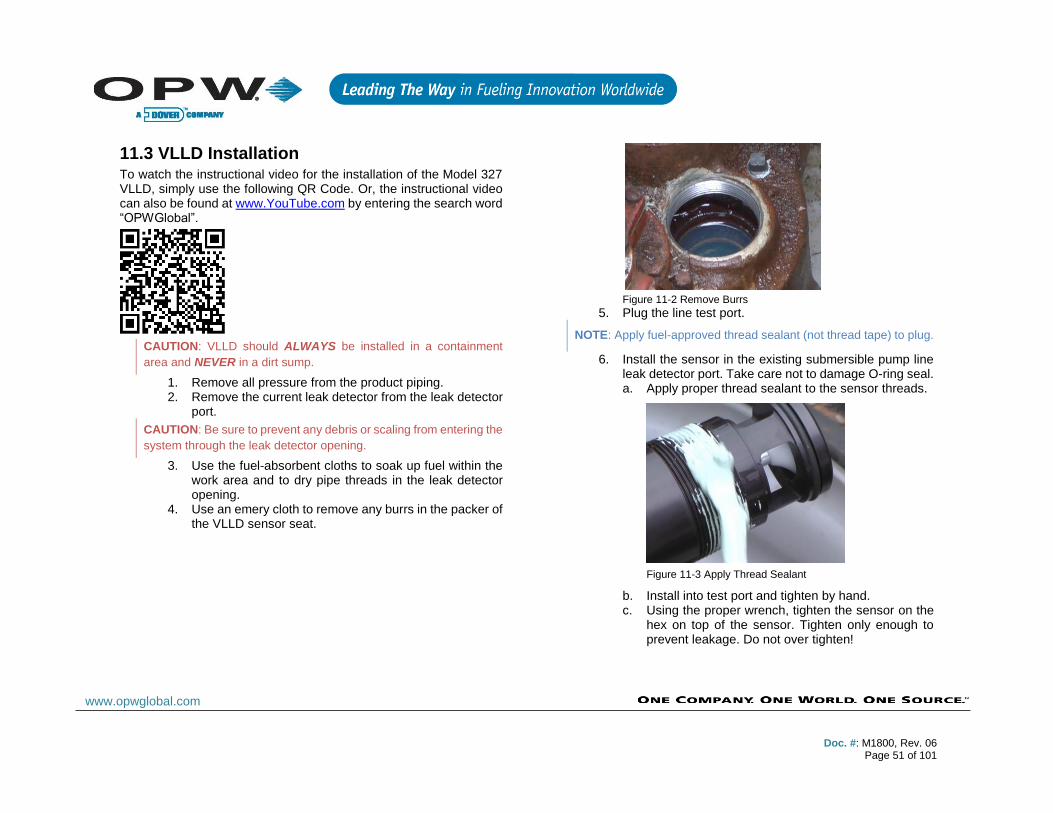
11.3 VLLD Installation To watch the instructional video for the installation of the Model 327 VLLD, simply use the following QR Code. Or, the instructional video can also be found at www.YouTube.com by entering the search word “OPWGlobal”.
CAUTION: VLLD should ALWAYS be installed in a containment
area and NEVER in a dirt sump.
1. Remove all pressure from the product piping. 2. Remove the current leak detector from the leak detector
port.
CAUTION: Be sure to prevent any debris or scaling from entering the
system through the leak detector opening.
3. Use the fuel-absorbent cloths to soak up fuel within the work area and to dry pipe threads in the leak detector opening.
4. Use an emery cloth to remove any burrs in the packer of the VLLD sensor seat.
Figure 11-2 Remove Burrs
5. Plug the line test port.
NOTE: Apply fuel-approved thread sealant (not thread tape) to plug.
6. Install the sensor in the existing submersible pump line leak detector port. Take care not to damage O-ring seal. a. Apply proper thread sealant to the sensor threads.
Figure 11-3 Apply Thread Sealant
b. Install into test port and tighten by hand. c. Using the proper wrench, tighten the sensor on the
hex on top of the sensor. Tighten only enough to prevent leakage. Do not over tighten!

Doc. #: M1800, Rev. 06
Page 52 of 101
www.opwglobal.com
Figure 11-4 Tighten Sensor
Doc. #: M1800, Rev. 06
Page 53 of 101
www.opwglobal.com
11.4 VLLD Wiring 1. Connect the sensor wires to the field wires in the junction box
using the supplied wire nuts. 2. Seal the electrical connections with the epoxy seal packs. 3. Clean the area and power the pump.
Figure 11-5 VLLD Installation Diagram Overview
Figure 11-6 VLLD Wiring Connections

Doc. #: M1800, Rev. 06
Page 54 of 101
www.opwglobal.com
12 Sensor Technology Overview
The OPW smart sensors have the ability to monitor all contained areas of the fuel-storage system: tank interstice, piping sumps, STP containment sumps, dispenser sumps/pans and monitoring wells. Sensors connected to the I.S. barrier are automatically detected and identified by the console.
12.1.1 OPW Smart Sensors
For specific sensor descriptions and specifications, please see Appendix A.
• Interstitial Level Sensor Float Switch
• Single-Level Sump Sensor
• Liquid-Only Float Sensor
• Discriminating Dispenser Pan Sensor
• Discriminating STP Sump Sensor
• Hydrocarbon Vapor Sensor
• Discriminating Interstitial Sensor
• Interstitial Hydrocarbon Liquid Sensor with Water Indicator
• Hydrocarbon Liquid Sensor with Water Indicator
• Dual-Float Dispenser Sump Sensor
• Dual-Float Brine Sensor
12.2 IntelliSense™ Technology This technology allows the Integra and I.S. barrier to automatically detect sensor connection, sensor type and sensor status. IntelliSense will minimize user entry error and identify hardware issues with minimal troubleshooting.
12.3 Multi-drop Installation The Integra’s internal barrier and optional VSmart Module allows for the ability to multi-drop the sensors and probes. When using this installation method; follow the below directions to ensure approved wiring.
NOTE: Sensors and probes cannot be multi-dropped from the same
I.S. Channel; therefore, you must run sensors and probes to different
channels on the barrier.
NOTE: Seal packs are required with all wiring applications in the
field. Weatherproof junction boxes are REQUIRED with ALL I.S. field
connections.
Figure 12-1 Multi-drop Sensor on I.S. Barrier
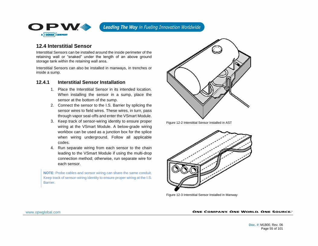
Doc. #: M1800, Rev. 06
Page 55 of 101
www.opwglobal.com
12.4 Interstitial Sensor Interstitial Sensors can be installed around the inside perimeter of the retaining wall or “snaked” under the length of an above ground storage tank within the retaining wall area.
Interstitial Sensors can also be installed in manways, in trenches or inside a sump.
12.4.1 Interstitial Sensor Installation
1. Place the Interstitial Sensor in its intended location.
When installing the sensor in a sump, place the
sensor at the bottom of the sump.
2. Connect the sensor to the I.S. Barrier by splicing the
sensor wires to field wires. These wires, in turn, pass
through vapor seal-offs and enter the VSmart Module.
3. Keep track of sensor-wiring identity to ensure proper
wiring at the VSmart Module. A below-grade wiring
workbox can be used as a junction box for the splice
when wiring underground. Follow all applicable
codes.
4. Run separate wiring from each sensor to the chain
leading to the VSmart Module if using the multi-drop
connection method; otherwise, run separate wire for
each sensor.
NOTE: Probe cables and sensor wiring can share the same conduit.
Keep track of sensor-wiring identity to ensure proper wiring at the I.S.
Barrier.
Figure 12-2 Interstitial Sensor Installed in AST
Figure 12-3 Interstitial Sensor Installed in Manway
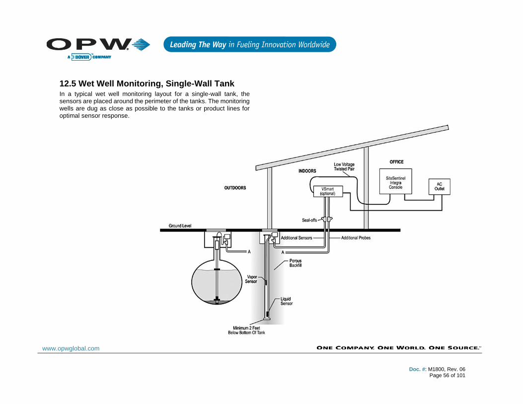
Doc. #: M1800, Rev. 06
Page 56 of 101
www.opwglobal.com
12.5 Wet Well Monitoring, Single-Wall Tank In a typical wet well monitoring layout for a single-wall tank, the sensors are placed around the perimeter of the tanks. The monitoring wells are dug as close as possible to the tanks or product lines for optimal sensor response.
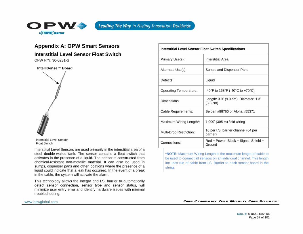
Doc. #: M1800, Rev. 06
Page 57 of 101
www.opwglobal.com
Appendix A: OPW Smart Sensors
Interstitial Level Sensor Float Switch OPW P/N: 30-0231-S
Interstitial Level Sensors are used primarily in the interstitial area of a steel double-walled tank. The sensor contains a float switch that activates in the presence of a liquid. The sensor is constructed from chemical-resistant non-metallic material. It can also be used in sumps, dispenser pans and other locations where the presence of a liquid could indicate that a leak has occurred. In the event of a break in the cable, the system will activate the alarm.
This technology allows the Integra and I.S. barrier to automatically detect sensor connection, sensor type and sensor status, will minimize user entry error and identify hardware issues with minimal troubleshooting.
Interstitial Level Sensor Float Switch Specifications
Primary Use(s): Interstitial Area
Alternate Use(s): Sumps and Dispenser Pans
Detects: Liquid
Operating Temperature: -40°F to 168°F (-40°C to +70°C)
Dimensions: Length: 3.9” (9.9 cm); Diameter: 1.3” (3.3 cm)
Cable Requirements: Belden #88760 or Alpha #55371
Maximum Wiring Length*: 1,000’ (305 m) field wiring
Multi-Drop Restriction: 16 per I.S. barrier channel (64 per barrier)
Connections: Red = Power, Black = Signal, Shield = Ground
*NOTE: Maximum Wiring Length is the maximum length of cable to
be used to connect all sensors on an individual channel. This length
includes run of cable from I.S. Barrier to each sensor board in the
string.
IntelliSense™ Board
Interstitial Level Sensor Float Switch

Doc. #: M1800, Rev. 06
Page 58 of 101
www.opwglobal.com
Single-Level Sump Sensor OPW P/N: 30-0231-L
Single-Level Sump Sensor
The Single-Level Sump Sensor is designed to detect the presence of liquid in sumps, dispenser pans, and other locations where the presence of a liquid could indicate that a leak has occurred.
The sensor contains a normally closed float switch that activates in the presence of liquid. In the event of a break in the cable, the system will activate the alarm.
Single-Level Sump Sensor Installation
1. Check that the sump is dry. 2. Position the sensor on the bottom of the sump/pan and
secure the sensor wire to an existing pipe or bracket with a tie wrap.
3. Connect the sensor wires to the field wires in the junction box using the supplied wire nuts.
4. Seal the electrical connections with the epoxy seal packs.
*NOTE: Maximum Wiring Length is the maximum length of cable to
be used to connect all sensors on an individual channel. This length
includes run of cable from I.S. Barrier to each sensor board in the
string.
Single-Level Sump Sensor Specifications
Detects: Liquid
Cable Requirements: Belden #88760 or Alpha #55371
Operating Temperature: -40°F to 158°F (-40°C to +70°C)
Dimensions: Length: 3.75” (9.5 cm), Diameter: 2.9” (7.4 cm)
Maximum Wiring Length*: 1,000’ (305 m) field wiring
Multi-Drop Restriction: 16 per I.S. barrier channel (64 per barrier)
Connections: Red = Power, Black = Signal, Shield = Ground

Doc. #: M1800, Rev. 06
Page 59 of 101
www.opwglobal.com
Liquid-Only Float Sensor OPW P/N: 30-0230-S
Liquid-only Float Switch
Designed to detect the presence of fluid in the interstitial space of a steel double-walled tank or a containment sump. The sensor, which utilizes float technology, activates on the presence of water or fuel and provides an alarm condition. An alarm condition will also occur if the cable is broken.
Liquid-Only Float Sensor Installation
1. Check that the sump is dry. 2. Position the sensor approximately ½-inches (1.3 cm)
above the bottom of the sump/pan and secure sensor wire to an existing pipe or bracket with a tie wrap.
3. Connect the sensor wires to the field wires in the junction box using the supplied wire nuts.
4. Seal the electrical connections with the epoxy seal packs.
Liquid-Only Float Sensor
Primary Use(s): STP Sumps and Dispenser Pans
Alternate Use(s): Use Steel Tank Interstitial
Detects: Liquid
Operating Temperature: -40°F to 158°F (-40°C to +70°C)
Dimensions: Length: 3.5” (8.9 cm), Width: 1.43” (3.6 cm)
Cable Requirements: Belden #88760 or Alpha #55371
Maximum Wiring Length*: 1,000’ (305 m) field wiring
Multi-Drop Restrictions: 16 per I.S. barrier channel (64 per barrier)
Connections: Red = Power, Black = Signal, Shield = Ground
*NOTE: Maximum Wiring Length is the maximum length of cable to
be used to connect all sensors on an individual channel. This length
includes run of cable from I.S. Barrier to each sensor board in the
string.
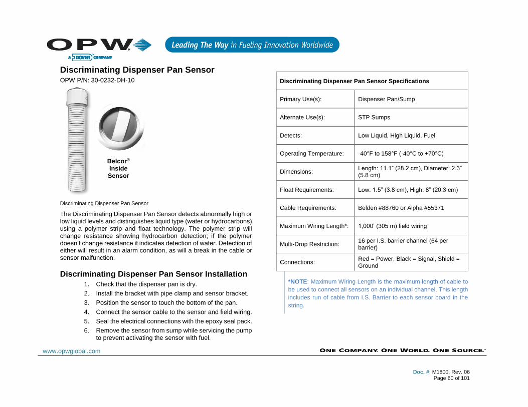
Doc. #: M1800, Rev. 06
Page 60 of 101
www.opwglobal.com
Discriminating Dispenser Pan Sensor OPW P/N: 30-0232-DH-10
Discriminating Dispenser Pan Sensor
The Discriminating Dispenser Pan Sensor detects abnormally high or low liquid levels and distinguishes liquid type (water or hydrocarbons) using a polymer strip and float technology. The polymer strip will change resistance showing hydrocarbon detection; if the polymer doesn’t change resistance it indicates detection of water. Detection of either will result in an alarm condition, as will a break in the cable or sensor malfunction.
Discriminating Dispenser Pan Sensor Installation
1. Check that the dispenser pan is dry.
2. Install the bracket with pipe clamp and sensor bracket.
3. Position the sensor to touch the bottom of the pan.
4. Connect the sensor cable to the sensor and field wiring.
5. Seal the electrical connections with the epoxy seal pack.
6. Remove the sensor from sump while servicing the pump to prevent activating the sensor with fuel.
Discriminating Dispenser Pan Sensor Specifications
Primary Use(s): Dispenser Pan/Sump
Alternate Use(s): STP Sumps
Detects: Low Liquid, High Liquid, Fuel
Operating Temperature: -40°F to 158°F (-40°C to +70°C)
Dimensions: Length: 11.1” (28.2 cm), Diameter: 2.3” (5.8 cm)
Float Requirements: Low: 1.5” (3.8 cm), High: 8” (20.3 cm)
Cable Requirements: Belden #88760 or Alpha #55371
Maximum Wiring Length*: 1,000’ (305 m) field wiring
Multi-Drop Restriction: 16 per I.S. barrier channel (64 per barrier)
Connections: Red = Power, Black = Signal, Shield = Ground
*NOTE: Maximum Wiring Length is the maximum length of cable to
be used to connect all sensors on an individual channel. This length
includes run of cable from I.S. Barrier to each sensor board in the
string.
Belcor® Inside Sensor
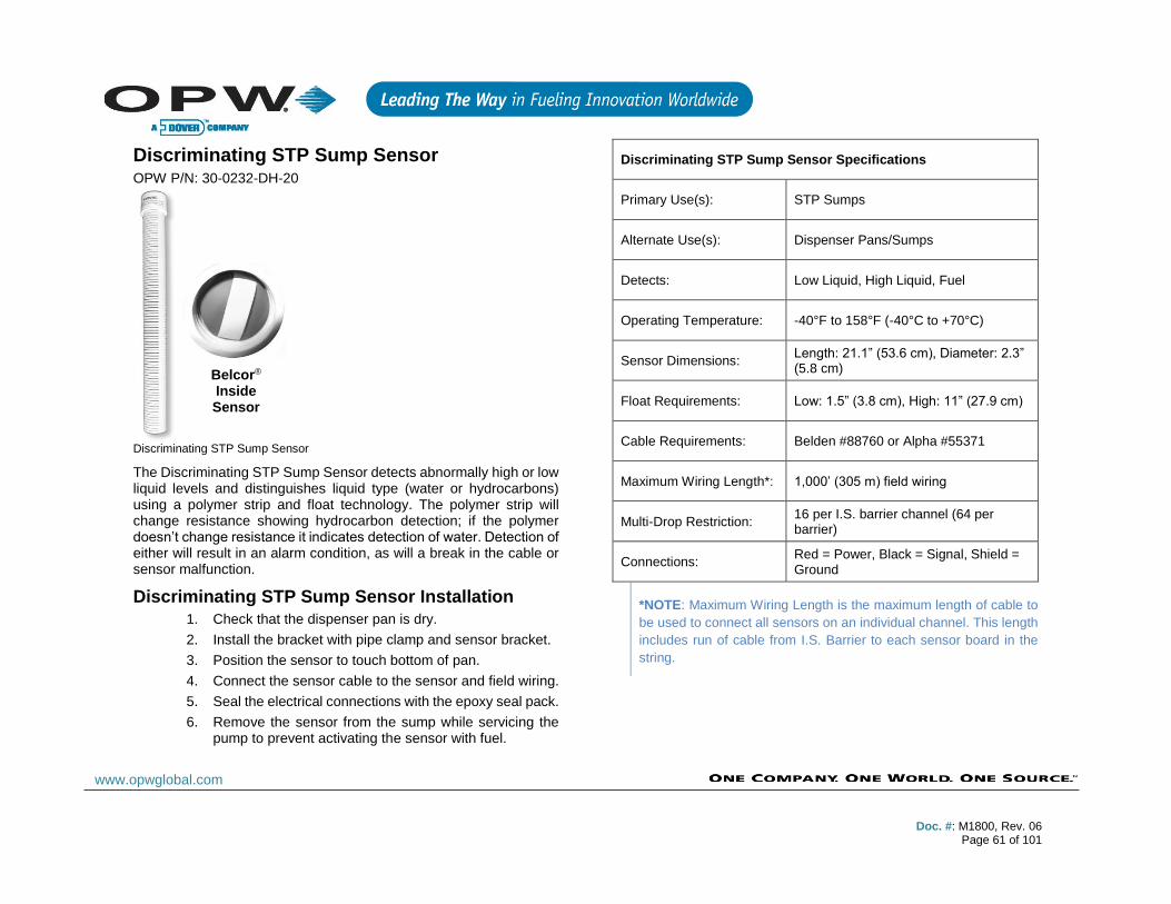
Doc. #: M1800, Rev. 06
Page 61 of 101
www.opwglobal.com
Discriminating STP Sump Sensor OPW P/N: 30-0232-DH-20
Discriminating STP Sump Sensor
The Discriminating STP Sump Sensor detects abnormally high or low liquid levels and distinguishes liquid type (water or hydrocarbons) using a polymer strip and float technology. The polymer strip will change resistance showing hydrocarbon detection; if the polymer doesn’t change resistance it indicates detection of water. Detection of either will result in an alarm condition, as will a break in the cable or sensor malfunction.
Discriminating STP Sump Sensor Installation
1. Check that the dispenser pan is dry.
2. Install the bracket with pipe clamp and sensor bracket.
3. Position the sensor to touch bottom of pan.
4. Connect the sensor cable to the sensor and field wiring.
5. Seal the electrical connections with the epoxy seal pack.
6. Remove the sensor from the sump while servicing the pump to prevent activating the sensor with fuel.
Discriminating STP Sump Sensor Specifications
Primary Use(s): STP Sumps
Alternate Use(s): Dispenser Pans/Sumps
Detects: Low Liquid, High Liquid, Fuel
Operating Temperature: -40°F to 158°F (-40°C to +70°C)
Sensor Dimensions: Length: 21.1” (53.6 cm), Diameter: 2.3” (5.8 cm)
Float Requirements: Low: 1.5” (3.8 cm), High: 11” (27.9 cm)
Cable Requirements: Belden #88760 or Alpha #55371
Maximum Wiring Length*: 1,000’ (305 m) field wiring
Multi-Drop Restriction: 16 per I.S. barrier channel (64 per barrier)
Connections: Red = Power, Black = Signal, Shield = Ground
*NOTE: Maximum Wiring Length is the maximum length of cable to
be used to connect all sensors on an individual channel. This length
includes run of cable from I.S. Barrier to each sensor board in the
string.
Belcor® Inside Sensor
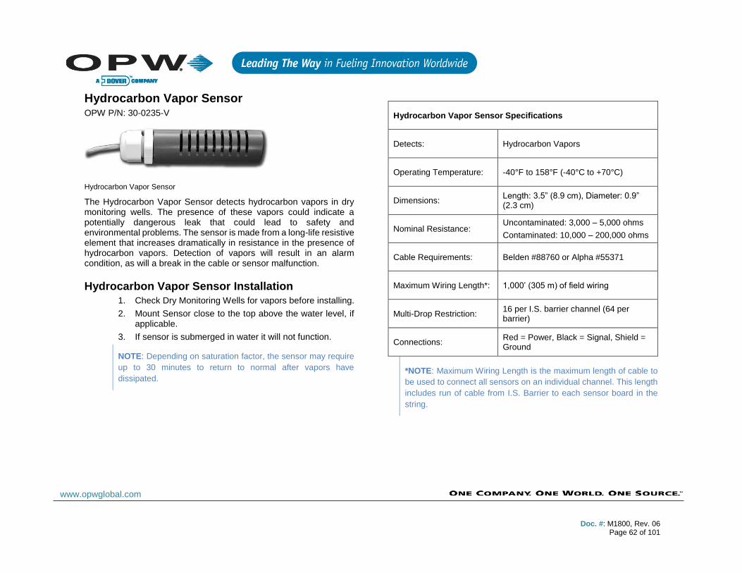
Doc. #: M1800, Rev. 06
Page 62 of 101
www.opwglobal.com
Hydrocarbon Vapor Sensor OPW P/N: 30-0235-V
Hydrocarbon Vapor Sensor
The Hydrocarbon Vapor Sensor detects hydrocarbon vapors in dry monitoring wells. The presence of these vapors could indicate a potentially dangerous leak that could lead to safety and environmental problems. The sensor is made from a long-life resistive element that increases dramatically in resistance in the presence of hydrocarbon vapors. Detection of vapors will result in an alarm condition, as will a break in the cable or sensor malfunction.
Hydrocarbon Vapor Sensor Installation
1. Check Dry Monitoring Wells for vapors before installing.
2. Mount Sensor close to the top above the water level, if applicable.
3. If sensor is submerged in water it will not function.
NOTE: Depending on saturation factor, the sensor may require
up to 30 minutes to return to normal after vapors have
dissipated.
Hydrocarbon Vapor Sensor Specifications
Detects: Hydrocarbon Vapors
Operating Temperature: -40°F to 158°F (-40°C to +70°C)
Dimensions: Length: 3.5” (8.9 cm), Diameter: 0.9” (2.3 cm)
Nominal Resistance: Uncontaminated: 3,000 – 5,000 ohms
Contaminated: 10,000 – 200,000 ohms
Cable Requirements: Belden #88760 or Alpha #55371
Maximum Wiring Length*: 1,000’ (305 m) of field wiring
Multi-Drop Restriction: 16 per I.S. barrier channel (64 per barrier)
Connections: Red = Power, Black = Signal, Shield = Ground
*NOTE: Maximum Wiring Length is the maximum length of cable to
be used to connect all sensors on an individual channel. This length
includes run of cable from I.S. Barrier to each sensor board in the
string.

Doc. #: M1800, Rev. 06
Page 63 of 101
www.opwglobal.com
Discriminating Interstitial Sensor OPW P/N: 30-0236-LW
Discriminating Interstitial Sensor
The Discriminating Interstitial Sensor utilizes a solid-state optical technology to detect the presence of fluid in the annular space of a tank, and conductive probes to distinguish fluid type (water or hydrocarbons). Detection of liquid will result in an alarm condition, as will a break in the cable or sensor malfunction.
Discriminating Interstitial Sensor Installation
1. Measure the length of the annular space-monitoring
pipe from top to bottom and subtract ½-inches (1.3
cm) for a total measurement to be used for sensor
placement.
2. Measure from the sensor tip along the sensor cable
the length calculated and mark with tape or marker.
3. Position the sensor into the monitoring pipe until the
tape mark is even with the top of the pipe.
4. The sensor should not touch the bottom of the
monitoring tube to prevent false alarms.
5. Connect the sensor wires to the field wires in the
junction box using the supplied wire nuts.
6. Seal the electrical connections with the epoxy seal
pack.
Discriminating Interstitial Sensor Specifications
Primary Use(s): Interstitial Space
Alternate Use(s): Dispenser Pans and STP Sumps
Detects: Liquids (Fuel and Water)
Operating Temperature: -40°F to 158°F (-40°C to +70°C)
Dimensions: Length: 3.22” (8.2 cm)
Width: 1.1” x .62” (2.8 cm x 1.6 cm)
Required Cable: Belden #88760 or Alpha #55371
Maximum Wiring Length*:
1,000’ (305 m) field wiring
Multi-Drop Restriction: 16 per I.S. barrier channel (64 per barrier)
Connections: Red = Power, Black = Signal, Shield = Ground
*NOTE: Maximum Wiring Length is the maximum length of cable to
be used to connect all sensors on an individual channel. This length
includes run of cable from I.S. Barrier to each sensor board in the
string.

Doc. #: M1800, Rev. 06
Page 64 of 101
www.opwglobal.com
Interstitial Hydrocarbon Liquid Sensor with Water Indicator OPW P/N: 30-0234-HW-01
Interstitial Hydrocarbon Liquid Sensor Installation
The Interstitial Hydrocarbon Liquid/Water Sensor is designed for use in the interstitial area of a fiberglass double-walled tank. The hydrocarbon liquid/water sensor contains a carbon/polymer material that changes its resistance when exposed to liquid hydrocarbons.
Additionally, it contains a conductive strip to detect the presence of water, providing the ability to discriminate between hydrocarbon liquid and water. In the event of a break in the cable, the system will activate the alarm.
Interstitial Hydrocarbon Liquid/Water Sensor Specifications
Detects: Liquid hydrocarbons/water
Operating Temperature: -40°F to 158°F (-40°C to +70°C)
Dimensions: Length: 13.8” (35 cm), Width: 1.0” (2.5 cm)
Nominal Resistance: Uncontaminated: 1000-3000 ohms Contaminated: 10,000-200,000 ohms
Cable Requirements: Belden #88760 or Alpha #55371
Maximum Wiring Length*: 1,000’ (305 m) field wiring
Multi-Drop Restriction: 16 per I.S. barrier channel 64 per barrier)
Connections Red = Power, Black = Signal, Shield: = Ground
*NOTE: Maximum Wiring Length is the maximum length of cable to
be used to connect all sensors on an individual channel. This length
includes run of cable from I.S. Barrier to each sensor board in the
string.
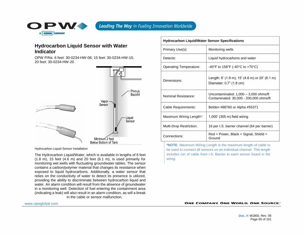
Doc. #: M1800, Rev. 06
Page 65 of 101
www.opwglobal.com
Hydrocarbon Liquid Sensor with Water Indicator OPW P/Ns: 6 feet: 30-0234-HW-06; 15 feet: 30-0234-HW-15; 20 feet: 30-0234-HW-20
Hydrocarbon Liquid Sensor Installation
The Hydrocarbon Liquid/Water, which is available in lengths of 6 feet (1.8 m), 15 feet (4.6 m) and 20 feet (6.1 m), is used primarily for monitoring wet wells with fluctuating groundwater tables. The sensor contains a carbon/polymer material that changes its resistance when exposed to liquid hydrocarbons. Additionally, a water sensor that relies on the conductivity of water to detect its presence is utilized, providing the ability to discriminate between hydrocarbon liquid and water. An alarm condition will result from the absence of groundwater in a monitoring well. Detection of fuel entering the containment area (indicating a leak) will also result in an alarm condition, as will a break
in the cable or sensor malfunction.
*NOTE: Maximum Wiring Length is the maximum length of cable to
be used to connect all sensors on an individual channel. This length
includes run of cable from I.S. Barrier to each sensor board in the
string.
Hydrocarbon Liquid/Water Sensor Specifications
Primary Use(s): Monitoring wells
Detects: Liquid hydrocarbons and water
Operating Temperature: -40°F to 158°F (-40°C to +70°C)
Dimensions: Length: 6’ (1.9 m), 15’ (4.6 m) or 20’ (6.1 m)
Diameter: 0.7” (1.8 cm)
Nominal Resistance: Uncontaminated: 1,000 – 3,000 ohms/ft Contaminated: 30,000 - 200,000 ohms/ft
Cable Requirements: Belden #88760 or Alpha #55371
Maximum Wiring Length*: 1,000’ (305 m) field wiring
Multi-Drop Restriction: 16 per I.S. barrier channel (64 per barrier)
Connections: Red = Power, Black = Signal, Shield = Ground
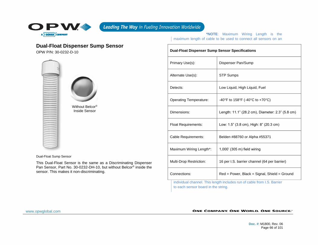
Doc. #: M1800, Rev. 06
Page 66 of 101
www.opwglobal.com
Dual-Float Dispenser Sump Sensor OPW P/N: 30-0232-D-10
Dual-Float Sump Sensor
This Dual-Float Sensor is the same as a Discriminating Dispenser Pan Sensor, Part No. 30-0232-DH-10, but without Belcor® inside the sensor. This makes it non-discriminating.
*NOTE: Maximum Wiring Length is the
maximum length of cable to be used to connect all sensors on an
individual channel. This length includes run of cable from I.S. Barrier
to each sensor board in the string.
Dual-Float Dispenser Sump Sensor Specifications
Primary Use(s): Dispenser Pan/Sump
Alternate Use(s): STP Sumps
Detects: Low Liquid, High Liquid, Fuel
Operating Temperature: -40°F to 158°F (-40°C to +70°C)
Dimensions: Length: 11.1” (28.2 cm), Diameter: 2.3” (5.8 cm)
Float Requirements: Low: 1.5” (3.8 cm), High: 8” (20.3 cm)
Cable Requirements: Belden #88760 or Alpha #55371
Maximum Wiring Length*: 1,000’ (305 m) field wiring
Multi-Drop Restriction: 16 per I.S. barrier channel (64 per barrier)
Connections: Red = Power, Black = Signal, Shield = Ground
Without Belcor® Inside Sensor
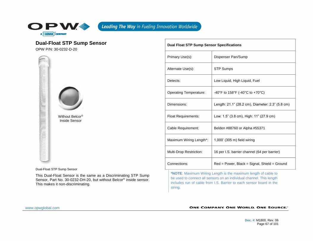
Doc. #: M1800, Rev. 06
Page 67 of 101
www.opwglobal.com
Dual-Float STP Sump Sensor OPW P/N: 30-0232-D-20
Dual-Float STP Sump Sensor
This Dual-Float Sensor is the same as a Discriminating STP Sump Sensor, Part No. 30-0232-DH-20, but without Belcor® inside sensor. This makes it non-discriminating.
*NOTE: Maximum Wiring Length is the maximum length of cable to
be used to connect all sensors on an individual channel. This length
includes run of cable from I.S. Barrier to each sensor board in the
string.
Dual Float STP Sump Sensor Specifications
Primary Use(s): Dispenser Pan/Sump
Alternate Use(s): STP Sumps
Detects: Low Liquid, High Liquid, Fuel
Operating Temperature: -40°F to 158°F (-40°C to +70°C)
Dimensions: Length: 21.1” (28.2 cm), Diameter: 2.3” (5.8 cm)
Float Requirements: Low: 1.5” (3.8 cm), High: 11” (27.9 cm)
Cable Requirement: Belden #88760 or Alpha #55371
Maximum Wiring Length*: 1,000’ (305 m) field wiring
Multi-Drop Restriction: 16 per I.S. barrier channel (64 per barrier)
Connections: Red = Power, Black = Signal, Shield = Ground
Without Belcor® Inside Sensor
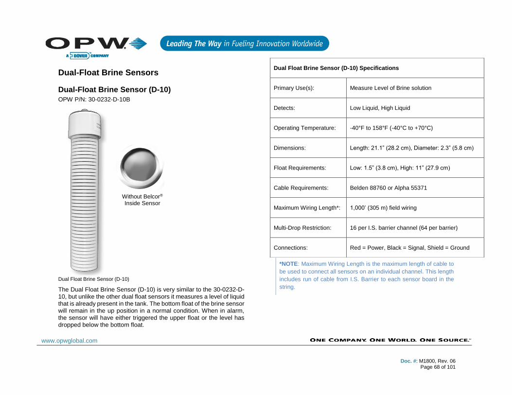
Doc. #: M1800, Rev. 06
Page 68 of 101
www.opwglobal.com
Dual-Float Brine Sensors
Dual-Float Brine Sensor (D-10)
OPW P/N: 30-0232-D-10B
Dual Float Brine Sensor (D-10)
The Dual Float Brine Sensor (D-10) is very similar to the 30-0232-D-10, but unlike the other dual float sensors it measures a level of liquid that is already present in the tank. The bottom float of the brine sensor will remain in the up position in a normal condition. When in alarm, the sensor will have either triggered the upper float or the level has dropped below the bottom float.
*NOTE: Maximum Wiring Length is the maximum length of cable to
be used to connect all sensors on an individual channel. This length
includes run of cable from I.S. Barrier to each sensor board in the
string.
Dual Float Brine Sensor (D-10) Specifications
Primary Use(s): Measure Level of Brine solution
Detects: Low Liquid, High Liquid
Operating Temperature: -40°F to 158°F (-40°C to +70°C)
Dimensions: Length: 21.1” (28.2 cm), Diameter: 2.3” (5.8 cm)
Float Requirements: Low: 1.5” (3.8 cm), High: 11” (27.9 cm)
Cable Requirements: Belden 88760 or Alpha 55371
Maximum Wiring Length*: 1,000’ (305 m) field wiring
Multi-Drop Restriction: 16 per I.S. barrier channel (64 per barrier)
Connections: Red = Power, Black = Signal, Shield = Ground
Without Belcor® Inside Sensor

Doc. #: M1800, Rev. 06
Page 69 of 101
www.opwglobal.com
Dual-Float Brine Sensor (D-20B)
Part No. 30-0232-D-20B
Dual-Float Brine Sensor (D-20B)
The Dual Float Brine Sensor (D-20B) is very similar to the 30-0232-D-20, but unlike the other dual float sensors it measures a level of liquid that is already present in the tank. The bottom float of the brine sensor will remain in the up position in a normal condition. When in alarm, the sensor will have either triggered the upper float or the level has dropped below the bottom float.
*NOTE: Maximum Wiring Length is the maximum length of cable to
be used to connect all sensors on an individual channel. This length
includes run of cable from I.S. Barrier to each sensor board in the
string.
Dual Float Brine Sensor (D-20B) Specifications
Primary Use(s): Measure Level of Brine solution
Detects: Low Liquid, High Liquid
Operating Temperature: -40°F to 158°F (-40°C to +70°C)
Dimensions: Length: 21.1” (28.2 cm), Diameter: 2.3” (5.8 cm)
Float Requirements: Low: 1.5” (3.8 cm), High: 11” (27.9 cm)
Cable Requirements: Belden #88760 or Alpha #55371
Maximum Wiring Length*: 1,000’ (305 m) field wiring
Multi-Drop Restriction: 16 per I.S. barrier channel (64 per barrier)
Connections: Red = Power, Black = Signal, Shield = Ground
Without Belcor® Inside Sensor
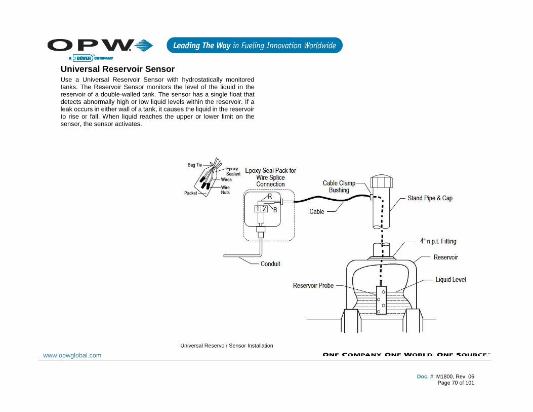
Doc. #: M1800, Rev. 06
Page 70 of 101
www.opwglobal.com
Universal Reservoir Sensor Use a Universal Reservoir Sensor with hydrostatically monitored tanks. The Reservoir Sensor monitors the level of the liquid in the reservoir of a double-walled tank. The sensor has a single float that detects abnormally high or low liquid levels within the reservoir. If a leak occurs in either wall of a tank, it causes the liquid in the reservoir to rise or fall. When liquid reaches the upper or lower limit on the sensor, the sensor activates.
Universal Reservoir Sensor Installation
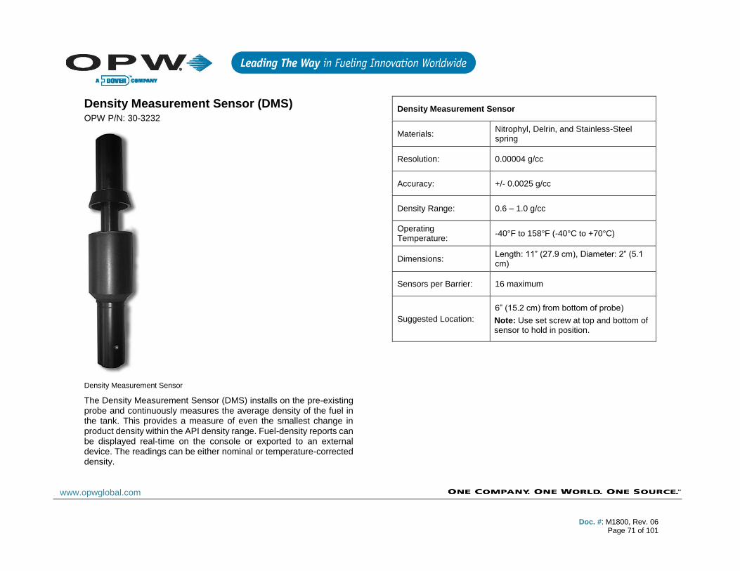
Doc. #: M1800, Rev. 06
Page 71 of 101
www.opwglobal.com
Density Measurement Sensor (DMS) OPW P/N: 30-3232
Density Measurement Sensor
The Density Measurement Sensor (DMS) installs on the pre-existing probe and continuously measures the average density of the fuel in the tank. This provides a measure of even the smallest change in product density within the API density range. Fuel-density reports can be displayed real-time on the console or exported to an external device. The readings can be either nominal or temperature-corrected density.
Density Measurement Sensor
Materials: Nitrophyl, Delrin, and Stainless-Steel spring
Resolution: 0.00004 g/cc
Accuracy: +/- 0.0025 g/cc
Density Range: 0.6 – 1.0 g/cc
Operating Temperature:
-40°F to 158°F (-40°C to +70°C)
Dimensions: Length: 11” (27.9 cm), Diameter: 2” (5.1 cm)
Sensors per Barrier: 16 maximum
Suggested Location:
6” (15.2 cm) from bottom of probe)
Note: Use set screw at top and bottom of sensor to hold in position.
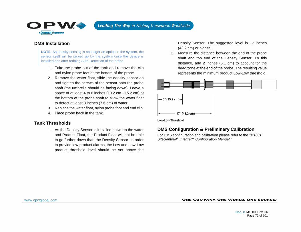
Doc. #: M1800, Rev. 06
Page 72 of 101
www.opwglobal.com
DMS Installation
NOTE: As density sensing is no longer an option in the system, the
sensor itself will be picked up by the system once the device is
installed and after redoing Auto-Detection of the probe.
1. Take the probe out of the tank and remove the clip
and nylon probe foot at the bottom of the probe.
2. Remove the water float, slide the density sensor on
and tighten the screws of the sensor onto the probe
shaft (the umbrella should be facing down). Leave a
space of at least 4 to 6 inches (10.2 cm - 15.2 cm) at
the bottom of the probe shaft to allow the water float
to detect at least 3 inches (7.6 cm) of water.
3. Replace the water float, nylon probe foot and end clip.
4. Place probe back in the tank.
Tank Thresholds
1. As the Density Sensor is installed between the water
and Product Float, the Product Float will not be able
to go further down than the Density Sensor. In order
to provide low-product alarms, the Low and Low-Low
product threshold level should be set above the
Density Sensor. The suggested level is 17 inches
(43.2 cm) or higher.
2. Measure the distance between the end of the probe
shaft and top end of the Density Sensor. To this
distance, add 2 inches (5.1 cm) to account for the
dead zone at the end of the probe. The resulting value
represents the minimum product Low-Low threshold.
Low-Low Threshold
DMS Configuration & Preliminary Calibration
For DMS configuration and calibration please refer to the “M1801 SiteSentinel® Integra™ Configuration Manual.”

Doc. #: M1800, Rev. 06
Page 73 of 101
www.opwglobal.com
Appendix B: Existing OPW/EECO Equipment
Model 924A Probes
CAUTION: CANNOT BE MULTI-DROPPED ON
VSMART.
The Model 924A Probe utilizes magnetostrictive technology to derive accurate product and water levels. It is primarily used in underground storage tanks for inventory and leak detection. Two floats can be fitted to the probe shaft; the product float sits on top of the product and the water float (optional) sinks through the product and sits on top of the water at the bottom of the tank.
Five temperature sensors reside in the probe shaft for measuring product temperature at different levels in the tank. They are located at positions of approximately 20%, 40%, 60% and 80% of the tank’s volume. The sensors feed the data of the temperature of the fuel to the console. The console software is then able to make the calculations to produce a net corrected product volume.
924A Probe Specifications
Operating Temperature: -40°F to 158°F (-40°C to +70°C)
Head Dimensions: ≈ 2.2” (5.6 cm) x 7.5” (19.1 cm)
Required Cable: 6’ (1.8 m), gas/oil-resistant cable
Power Supply: Must be by provided by OPW's I.S. Barrier
Certifications: Division I Group D Group IIA
Linearity: +/- 0.040” (1.01 mm) over entire length
Hysteresis: +/- 0.004” (0.1 mm)
Temperature Resolution: +/- 0.1°C, +/- 1°C
I.S. Barrier: 24V; OPW P/N: 4344
Installation: Requires one (1) I.S. Barrier position per probe
Model 924A Probe
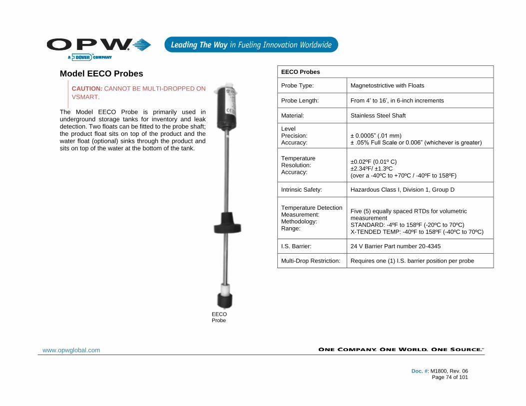
Doc. #: M1800, Rev. 06
Page 74 of 101
www.opwglobal.com
Model EECO Probes
CAUTION: CANNOT BE MULTI-DROPPED ON
VSMART.
The Model EECO Probe is primarily used in underground storage tanks for inventory and leak detection. Two floats can be fitted to the probe shaft; the product float sits on top of the product and the water float (optional) sinks through the product and sits on top of the water at the bottom of the tank.
EECO Probes
Probe Type: Magnetostrictive with Floats
Probe Length: From 4’ to 16’, in 6-inch increments
Material: Stainless Steel Shaft
Level Precision: Accuracy:
± 0.0005” (.01 mm) ± .05% Full Scale or 0.006” (whichever is greater)
Temperature Resolution: Accuracy:
±0.02ºF (0.01º C) ±2.34ºF/ ±1.3ºC (over a -40ºC to +70ºC / -40ºF to 158ºF)
Intrinsic Safety: Hazardous Class I, Division 1, Group D
Temperature Detection Measurement: Methodology: Range:
Five (5) equally spaced RTDs for volumetric measurement STANDARD: -4ºF to 158ºF (-20ºC to 70ºC) X-TENDED TEMP: -40ºF to 158ºF (-40ºC to 70ºC)
I.S. Barrier: 24 V Barrier Part number 20-4345
Multi-Drop Restriction: Requires one (1) I.S. barrier position per probe
EECO Probe
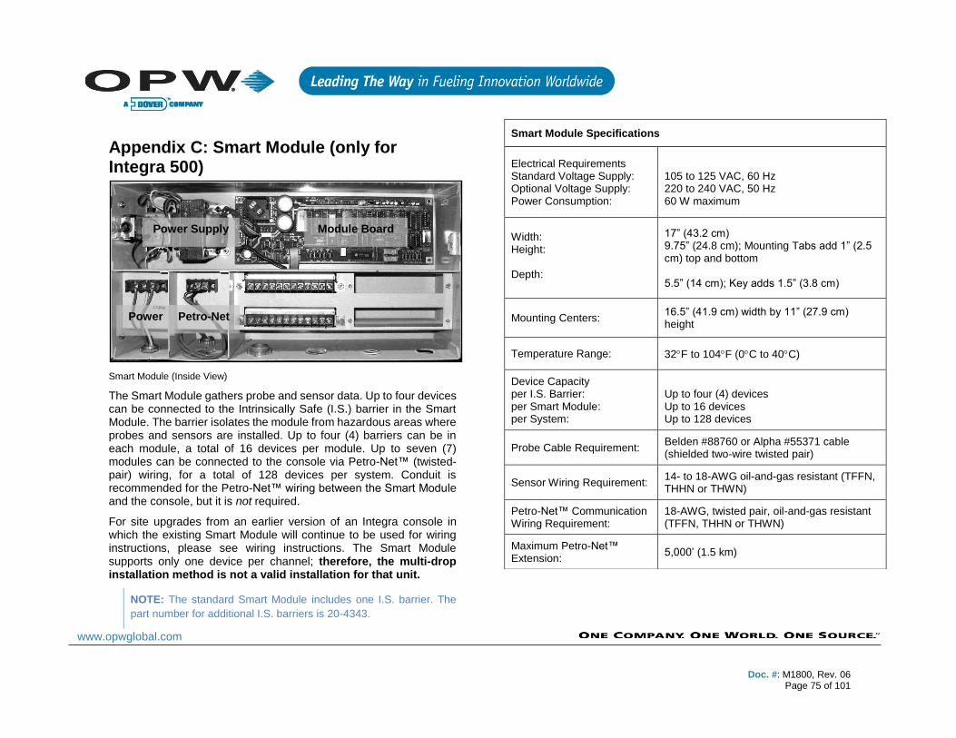
Doc. #: M1800, Rev. 06
Page 75 of 101
www.opwglobal.com
Appendix C: Smart Module (only for Integra 500)
Smart Module (Inside View)
The Smart Module gathers probe and sensor data. Up to four devices can be connected to the Intrinsically Safe (I.S.) barrier in the Smart Module. The barrier isolates the module from hazardous areas where probes and sensors are installed. Up to four (4) barriers can be in each module, a total of 16 devices per module. Up to seven (7) modules can be connected to the console via Petro-Net™ (twisted-pair) wiring, for a total of 128 devices per system. Conduit is recommended for the Petro-Net™ wiring between the Smart Module and the console, but it is not required.
For site upgrades from an earlier version of an Integra console in which the existing Smart Module will continue to be used for wiring instructions, please see wiring instructions. The Smart Module supports only one device per channel; therefore, the multi-drop installation method is not a valid installation for that unit.
NOTE: The standard Smart Module includes one I.S. barrier. The
part number for additional I.S. barriers is 20-4343.
Smart Module Specifications
Electrical Requirements Standard Voltage Supply: Optional Voltage Supply: Power Consumption:
105 to 125 VAC, 60 Hz 220 to 240 VAC, 50 Hz 60 W maximum
Width: Height: Depth:
17” (43.2 cm) 9.75” (24.8 cm); Mounting Tabs add 1” (2.5 cm) top and bottom 5.5” (14 cm); Key adds 1.5” (3.8 cm)
Mounting Centers: 16.5” (41.9 cm) width by 11” (27.9 cm) height
Temperature Range: 32F to 104F (0C to 40C)
Device Capacity per I.S. Barrier: per Smart Module: per System:
Up to four (4) devices Up to 16 devices Up to 128 devices
Probe Cable Requirement: Belden #88760 or Alpha #55371 cable (shielded two-wire twisted pair)
Sensor Wiring Requirement: 14- to 18-AWG oil-and-gas resistant (TFFN, THHN or THWN)
Petro-Net™ Communication Wiring Requirement:
18-AWG, twisted pair, oil-and-gas resistant (TFFN, THHN or THWN)
Maximum Petro-Net™ Extension:
5,000’ (1.5 km)
Power Supply Module Board
Power Petro-Net

Doc. #: M1800, Rev. 06
Page 76 of 101
www.opwglobal.com
Appendix D: Maintenance Kit OPW P/N: 20-4407 The Hardware Maintenance Kit includes a USB key and a USB mouse. The two (2) USB devices can be plugged into either of the external USB ports on the left-hand side of the console. The two devices can be used in the event of system failure or when retrieving key troubleshooting files.
USB Mouse
USB Key
The USB mouse will be used in the event of the touchscreen losing calibration, not being calibrated or touchscreen failure. This will allow the navigation of the mouse to get the screen back into working order.
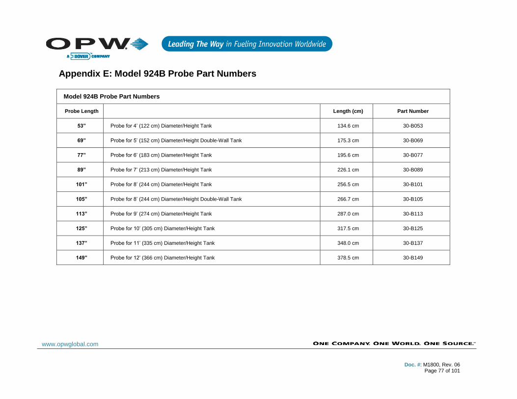
Doc. #: M1800, Rev. 06
Page 77 of 101
www.opwglobal.com
Appendix E: Model 924B Probe Part Numbers
Model 924B Probe Part Numbers
Probe Length Length (cm) Part Number
53” Probe for 4’ (122 cm) Diameter/Height Tank 134.6 cm 30-B053
69” Probe for 5’ (152 cm) Diameter/Height Double-Wall Tank 175.3 cm 30-B069
77” Probe for 6’ (183 cm) Diameter/Height Tank 195.6 cm 30-B077
89” Probe for 7’ (213 cm) Diameter/Height Tank 226.1 cm 30-B089
101” Probe for 8’ (244 cm) Diameter/Height Tank 256.5 cm 30-B101
105” Probe for 8’ (244 cm) Diameter/Height Double-Wall Tank 266.7 cm 30-B105
113” Probe for 9’ (274 cm) Diameter/Height Tank 287.0 cm 30-B113
125” Probe for 10’ (305 cm) Diameter/Height Tank 317.5 cm 30-B125
137” Probe for 11’ (335 cm) Diameter/Height Tank 348.0 cm 30-B137
149” Probe for 12’ (366 cm) Diameter/Height Tank 378.5 cm 30-B149

Doc. #: M1800, Rev. 06
Page 78 of 101
www.opwglobal.com
Appendix F: Output Relay Installation Report
Output Location: Internal/External OM4, LIM
Output Controls: External Alarm, Dispenser etc.
Normally Open/Normally Closed
Integra Internal Relay Output 1
OM4 1 Position 1
OM4 1 Position 2
OM4 1 Position 3
OM4 1 Position 4
OM4 2 Position 1
OM4 2 Position 2
OM4 2 Position 3
OM4 2 Position 4
OM4 3 Position 1
OM4 3 Position 2
OM4 3 Position 3

Doc. #: M1800, Rev. 06
Page 79 of 101
www.opwglobal.com
OM4 3 Position 4
OM4 4 Position 1
OM4 4 Position 2
OM4 4 Position 3
OM4 4 Position 4
LIM 1 Position 1
LIM 2 Position 1
LIM 3 Position 1
LIM 4 Position 1
Doc. #: M1800, Rev. 06
Page 80 of 101
www.opwglobal.com
Appendix G: Sensor Labels
Installed Sensor Labels Description (Location, e.g., Sump, Sensor #, etc.)
Place Label Here
Place Label Here
Doc. #: M1800, Rev. 06
Page 81 of 101
www.opwglobal.com
Installed Sensor Labels Description (Location, e.g., Sump, Sensor #, etc.)
Place Label Here
Place Label Here
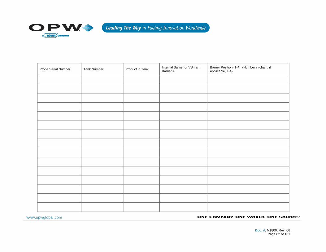
Doc. #: M1800, Rev. 06
Page 82 of 101
www.opwglobal.com
Probe Serial Number Tank Number Product in Tank Internal Barrier or VSmart Barrier #
Barrier Position (1-4) (Number in chain, if applicable, 1-4)
Doc. #: M1800, Rev. 06
Page 83 of 101
www.opwglobal.com
Appendix H: Model 924B Installation Records
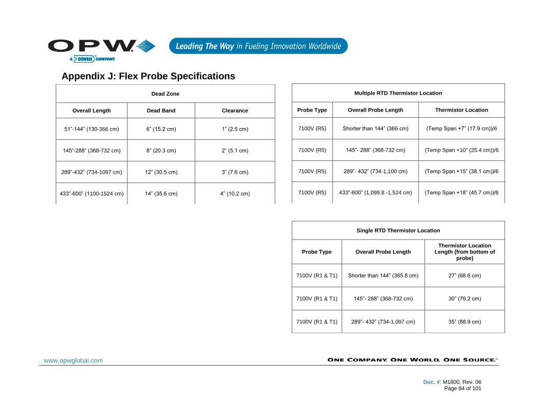
Doc. #: M1800, Rev. 06
Page 84 of 101
www.opwglobal.com
Appendix J: Flex Probe Specifications
Dead Zone
Overall Length Dead Band Clearance
51”-144” (130-366 cm) 6” (15.2 cm) 1” (2.5 cm)
145”-288” (368-732 cm) 8” (20.3 cm) 2” (5.1 cm)
289”-432” (734-1097 cm) 12” (30.5 cm) 3” (7.6 cm)
433”-600” (1100-1524 cm) 14” (35.6 cm) 4” (10.2 cm)
Multiple RTD Thermistor Location
Probe Type Overall Probe Length Thermistor Location
7100V (R5) Shorter than 144” (366 cm) (Temp Span +7” (17.9 cm))/6
7100V (R5) 145”- 288” (368-732 cm) (Temp Span +10" (25.4 cm))/6
7100V (R5) 289”- 432” (734-1,100 cm) (Temp Span +15” (38.1 cm))/6
7100V (R5) 433”-600” (1,099.8 -1,524 cm) (Temp Span +18” (45.7 cm))/6
Single RTD Thermistor Location
Probe Type Overall Probe Length Thermistor Location
Length (from bottom of probe)
7100V (R1 & T1) Shorter than 144” (365.8 cm) 27” (68.6 cm)
7100V (R1 & T1) 145”- 288” (368-732 cm) 30” (76.2 cm)
7100V (R1 & T1) 289”- 432” (734-1,097 cm) 35” (88.9 cm)

Doc. #: M1800, Rev. 06
Page 85 of 101
www.opwglobal.com
7100V (R1 & T1) 433”- 600” (1,100 -1,524 cm) 38” (96.5 cm)
Flex Probe Catalog Number (Example: 7100V030R1XF1L049)
7100 Model Number
V Flexible PVDF Tube w/Male NPT PVDF Connector & 2’ (61 cm) Teflon® Cable
030 Temperature Span (in)
R1 Number of Thermistors
X Standard
F1 Number of Floats
Doc. #: M1800, Rev. 06
Page 86 of 101
www.opwglobal.com
L048 Overall Length
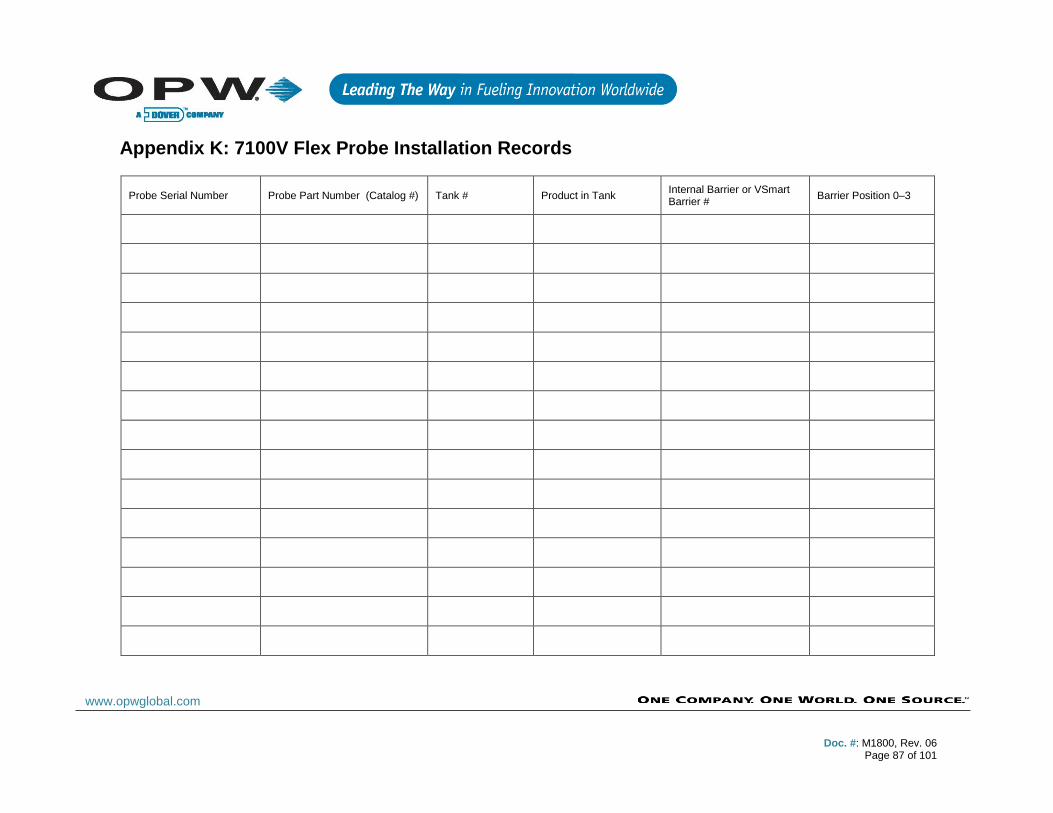
Doc. #: M1800, Rev. 06
Page 87 of 101
www.opwglobal.com
Appendix K: 7100V Flex Probe Installation Records
Probe Serial Number Probe Part Number (Catalog #) Tank # Product in Tank Internal Barrier or VSmart Barrier #
Barrier Position 0–3
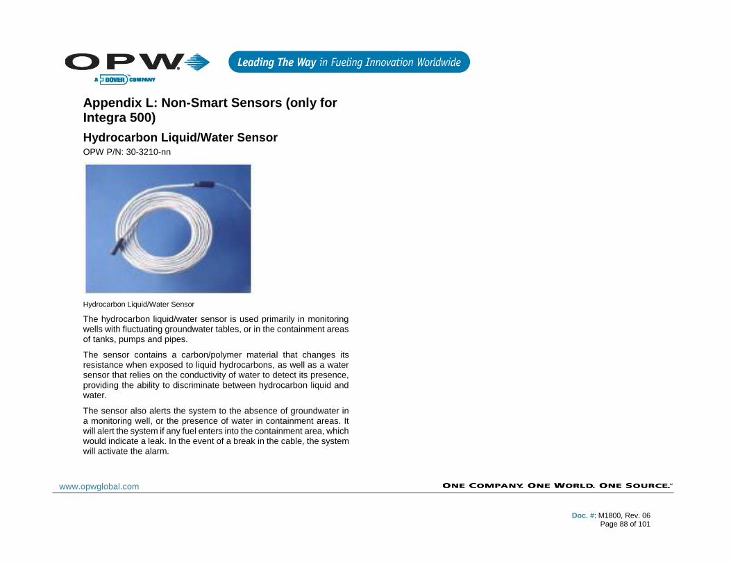
Doc. #: M1800, Rev. 06
Page 88 of 101
www.opwglobal.com
Appendix L: Non-Smart Sensors (only for Integra 500)
Hydrocarbon Liquid/Water Sensor OPW P/N: 30-3210-nn
Hydrocarbon Liquid/Water Sensor
The hydrocarbon liquid/water sensor is used primarily in monitoring wells with fluctuating groundwater tables, or in the containment areas of tanks, pumps and pipes.
The sensor contains a carbon/polymer material that changes its resistance when exposed to liquid hydrocarbons, as well as a water sensor that relies on the conductivity of water to detect its presence, providing the ability to discriminate between hydrocarbon liquid and water.
The sensor also alerts the system to the absence of groundwater in a monitoring well, or the presence of water in containment areas. It will alert the system if any fuel enters into the containment area, which would indicate a leak. In the event of a break in the cable, the system will activate the alarm.
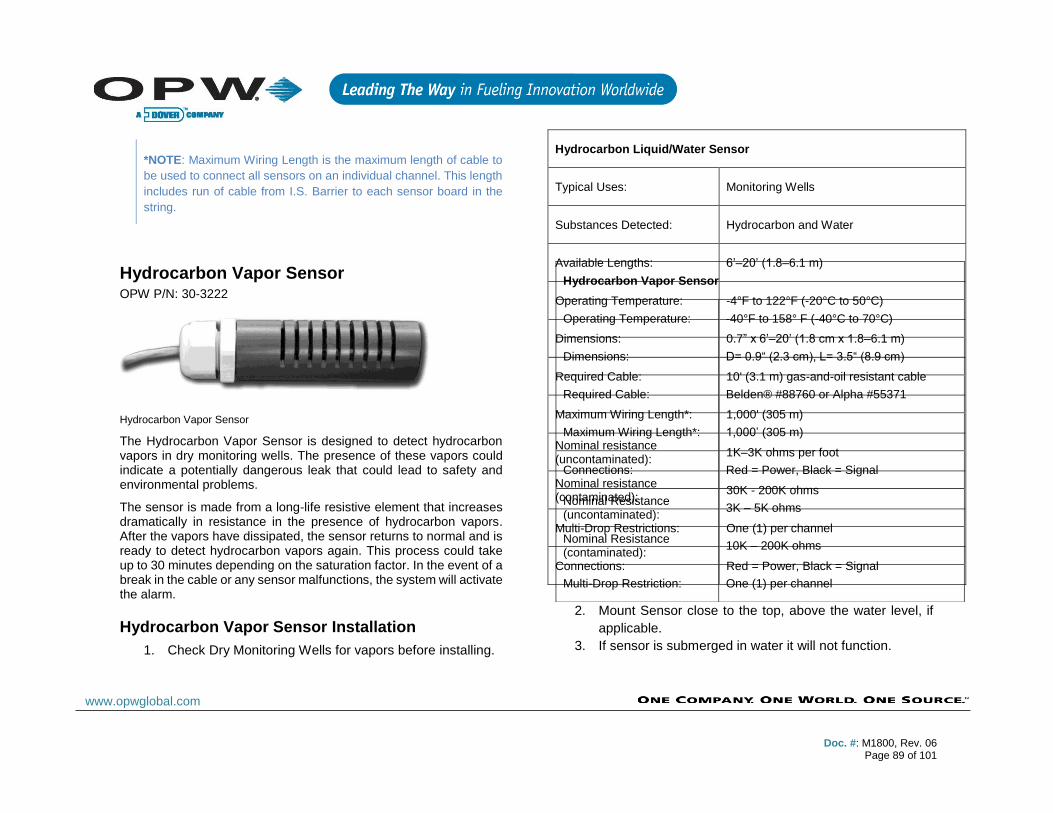
Doc. #: M1800, Rev. 06
Page 89 of 101
www.opwglobal.com
*NOTE: Maximum Wiring Length is the maximum length of cable to
be used to connect all sensors on an individual channel. This length
includes run of cable from I.S. Barrier to each sensor board in the
string.
Hydrocarbon Vapor Sensor OPW P/N: 30-3222
Hydrocarbon Vapor Sensor
The Hydrocarbon Vapor Sensor is designed to detect hydrocarbon vapors in dry monitoring wells. The presence of these vapors could indicate a potentially dangerous leak that could lead to safety and environmental problems.
The sensor is made from a long-life resistive element that increases dramatically in resistance in the presence of hydrocarbon vapors. After the vapors have dissipated, the sensor returns to normal and is ready to detect hydrocarbon vapors again. This process could take up to 30 minutes depending on the saturation factor. In the event of a break in the cable or any sensor malfunctions, the system will activate the alarm.
Hydrocarbon Vapor Sensor Installation
1. Check Dry Monitoring Wells for vapors before installing.
2. Mount Sensor close to the top, above the water level, if
applicable.
3. If sensor is submerged in water it will not function.
Hydrocarbon Liquid/Water Sensor
Typical Uses: Monitoring Wells
Substances Detected: Hydrocarbon and Water
Available Lengths: 6’–20’ (1.8–6.1 m)
Operating Temperature: -4°F to 122°F (-20°C to 50°C)
Dimensions: 0.7” x 6’–20’ (1.8 cm x 1.8–6.1 m)
Required Cable: 10' (3.1 m) gas-and-oil resistant cable
Maximum Wiring Length*: 1,000' (305 m)
Nominal resistance (uncontaminated):
1K–3K ohms per foot
Nominal resistance (contaminated):
30K - 200K ohms
Multi-Drop Restrictions: One (1) per channel
Connections: Red = Power, Black = Signal
Hydrocarbon Vapor Sensor
Operating Temperature: -40°F to 158° F (-40°C to 70°C)
Dimensions: D= 0.9“ (2.3 cm), L= 3.5“ (8.9 cm)
Required Cable: Belden® #88760 or Alpha #55371
Maximum Wiring Length*: 1,000’ (305 m)
Connections: Red = Power, Black = Signal
Nominal Resistance (uncontaminated):
3K – 5K ohms
Nominal Resistance (contaminated):
10K – 200K ohms
Multi-Drop Restriction: One (1) per channel

Doc. #: M1800, Rev. 06
Page 90 of 101
www.opwglobal.com
*NOTE: Maximum Wiring Length is the maximum length of cable to
be used to connect all sensors on an individual channel. This length
includes run of cable from I.S. Barrier to each sensor board in the
string.
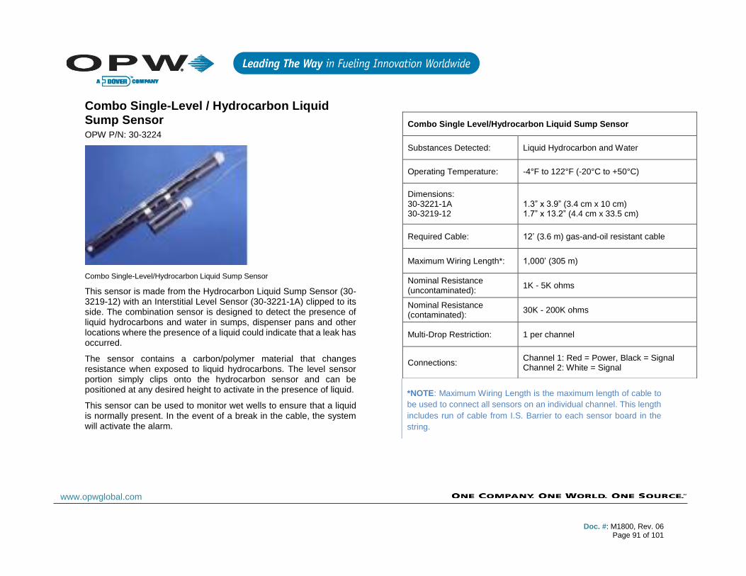
Doc. #: M1800, Rev. 06
Page 91 of 101
www.opwglobal.com
Combo Single-Level / Hydrocarbon Liquid Sump Sensor OPW P/N: 30-3224
Combo Single-Level/Hydrocarbon Liquid Sump Sensor
This sensor is made from the Hydrocarbon Liquid Sump Sensor (30-3219-12) with an Interstitial Level Sensor (30-3221-1A) clipped to its side. The combination sensor is designed to detect the presence of liquid hydrocarbons and water in sumps, dispenser pans and other locations where the presence of a liquid could indicate that a leak has occurred.
The sensor contains a carbon/polymer material that changes resistance when exposed to liquid hydrocarbons. The level sensor portion simply clips onto the hydrocarbon sensor and can be positioned at any desired height to activate in the presence of liquid.
This sensor can be used to monitor wet wells to ensure that a liquid is normally present. In the event of a break in the cable, the system will activate the alarm.
*NOTE: Maximum Wiring Length is the maximum length of cable to
be used to connect all sensors on an individual channel. This length
includes run of cable from I.S. Barrier to each sensor board in the
string.
Combo Single Level/Hydrocarbon Liquid Sump Sensor
Substances Detected: Liquid Hydrocarbon and Water
Operating Temperature: -4°F to 122°F (-20°C to +50°C)
Dimensions: 30-3221-1A 30-3219-12
1.3” x 3.9” (3.4 cm x 10 cm) 1.7” x 13.2” (4.4 cm x 33.5 cm)
Required Cable: 12’ (3.6 m) gas-and-oil resistant cable
Maximum Wiring Length*: 1,000’ (305 m)
Nominal Resistance (uncontaminated):
1K - 5K ohms
Nominal Resistance (contaminated):
30K - 200K ohms
Multi-Drop Restriction: 1 per channel
Connections: Channel 1: Red = Power, Black = Signal Channel 2: White = Signal
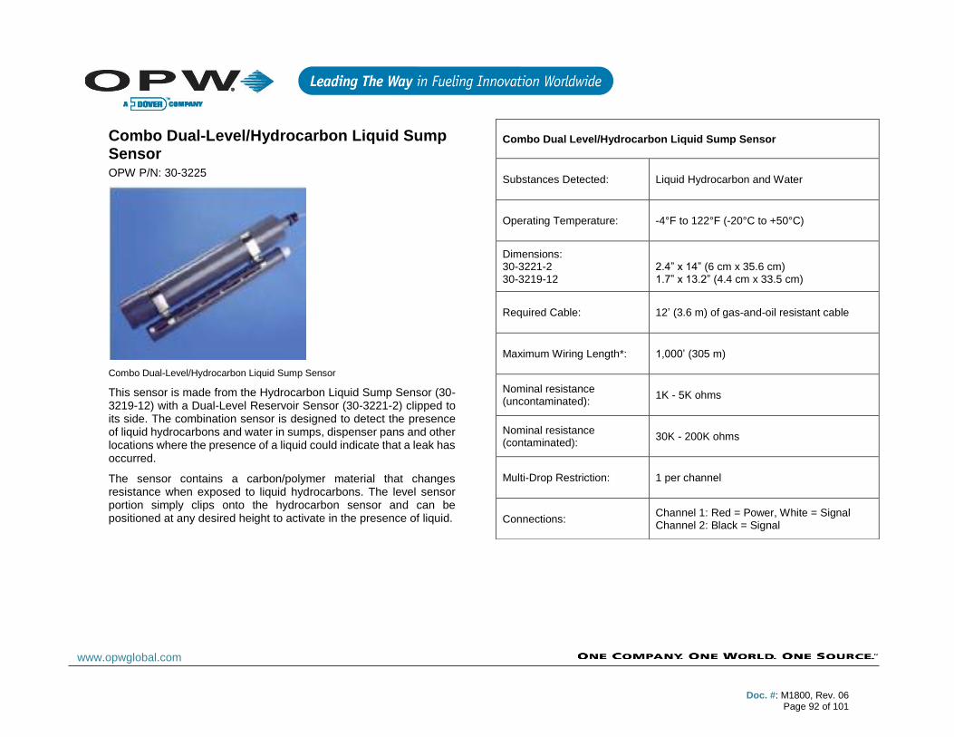
Doc. #: M1800, Rev. 06
Page 92 of 101
www.opwglobal.com
Combo Dual-Level/Hydrocarbon Liquid Sump Sensor OPW P/N: 30-3225
Combo Dual-Level/Hydrocarbon Liquid Sump Sensor
This sensor is made from the Hydrocarbon Liquid Sump Sensor (30-3219-12) with a Dual-Level Reservoir Sensor (30-3221-2) clipped to its side. The combination sensor is designed to detect the presence of liquid hydrocarbons and water in sumps, dispenser pans and other locations where the presence of a liquid could indicate that a leak has occurred.
The sensor contains a carbon/polymer material that changes resistance when exposed to liquid hydrocarbons. The level sensor portion simply clips onto the hydrocarbon sensor and can be positioned at any desired height to activate in the presence of liquid.
Combo Dual Level/Hydrocarbon Liquid Sump Sensor
Substances Detected: Liquid Hydrocarbon and Water
Operating Temperature: -4°F to 122°F (-20°C to +50°C)
Dimensions: 30-3221-2 30-3219-12
2.4” x 14” (6 cm x 35.6 cm) 1.7” x 13.2” (4.4 cm x 33.5 cm)
Required Cable: 12’ (3.6 m) of gas-and-oil resistant cable
Maximum Wiring Length*: 1,000’ (305 m)
Nominal resistance (uncontaminated):
1K - 5K ohms
Nominal resistance (contaminated):
30K - 200K ohms
Multi-Drop Restriction: 1 per channel
Connections: Channel 1: Red = Power, White = Signal Channel 2: Black = Signal

Doc. #: M1800, Rev. 06
Page 93 of 101
www.opwglobal.com
*NOTE: Maximum Wiring Length is the maximum length of cable to
be used to connect all sensors on an individual channel. This length
includes run of cable from I.S. Barrier to each sensor board in the
string.
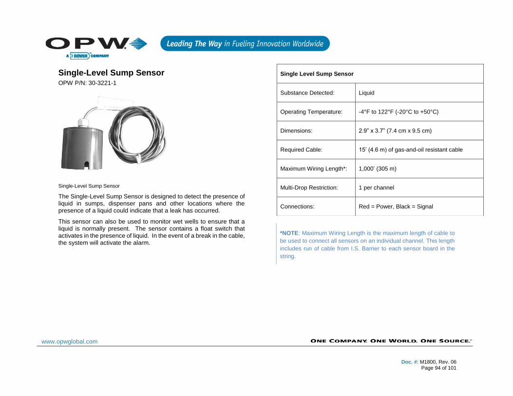
Doc. #: M1800, Rev. 06
Page 94 of 101
www.opwglobal.com
Single-Level Sump Sensor OPW P/N: 30-3221-1
Single-Level Sump Sensor
The Single-Level Sump Sensor is designed to detect the presence of liquid in sumps, dispenser pans and other locations where the presence of a liquid could indicate that a leak has occurred.
This sensor can also be used to monitor wet wells to ensure that a liquid is normally present. The sensor contains a float switch that activates in the presence of liquid. In the event of a break in the cable, the system will activate the alarm.
*NOTE: Maximum Wiring Length is the maximum length of cable to
be used to connect all sensors on an individual channel. This length
includes run of cable from I.S. Barrier to each sensor board in the
string.
Single Level Sump Sensor
Substance Detected: Liquid
Operating Temperature: -4°F to 122°F (-20°C to +50°C)
Dimensions: 2.9” x 3.7” (7.4 cm x 9.5 cm)
Required Cable: 15’ (4.6 m) of gas-and-oil resistant cable
Maximum Wiring Length*: 1,000’ (305 m)
Multi-Drop Restriction: 1 per channel
Connections: Red = Power, Black = Signal

Doc. #: M1800, Rev. 06
Page 95 of 101
www.opwglobal.com
Dual-Level Reservoir Sensor Part # 30-3221-2
Dual-Level Reservoir Sensor
The Dual-Level Reservoir Sensor is designed for use in the brine-filled reservoir of the interstitial area of a double-walled tank. This sensor contains a dual-level float switch that detects level changes of fluid in the reservoir of the tank. The sensor expects the liquid to be at a constant level. The system will activate the alarm when the brine level in the interstitial space either rises or falls.
It can also be used in other areas (such as dispenser containment pans) that are normally dry and will give a low-level warning followed by a high-level alarm. In the event of a break in the cable, the system will activate the alarm.
*NOTE: Maximum Wiring Length is the maximum length of cable to
be used to connect all sensors on an individual channel. This length
includes run of cable from I.S. Barrier to each sensor board in the
string.
Dual Level Reservoir Sensor
Substance Detected: Liquid
Operating Temperature: -4°F to 122°F (-20°C to +50°C)
Dimensions: 2.4” x 14” (6 cm x 35.6 cm)
Required Cable: 15’ (4.6 m) gas-and-oil resistant cable
Maximum Wiring Length*: 1,000’ (305 m)
Multi-Drop Restriction: 1 per channel
Connections: Red = Power, White = Signal
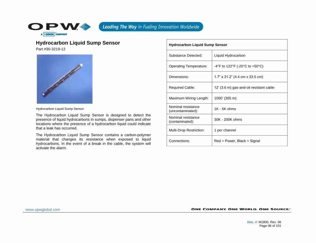
Doc. #: M1800, Rev. 06
Page 96 of 101
www.opwglobal.com
Hydrocarbon Liquid Sump Sensor Part #30-3219-12
Hydrocarbon Liquid Sump Sensor
The Hydrocarbon Liquid Sump Sensor is designed to detect the presence of liquid hydrocarbons in sumps, dispenser pans and other locations where the presence of a hydrocarbon liquid could indicate that a leak has occurred.
The Hydrocarbon Liquid Sump Sensor contains a carbon-polymer material that changes its resistance when exposed to liquid hydrocarbons. In the event of a break in the cable, the system will activate the alarm.
Hydrocarbon Liquid Sump Sensor
Substance Detected: Liquid Hydrocarbon
Operating Temperature: -4°F to 122°F (-20°C to +50°C)
Dimensions: 1.7” x 31.2” (4.4 cm x 33.5 cm)
Required Cable: 12’ (3.6 m) gas-and-oil resistant cable
Maximum Wiring Length: 1000’ (305 m)
Nominal resistance (uncontaminated):
1K - 5K ohms
Nominal resistance (contaminated):
30K - 200K ohms
Multi-Drop Restriction: 1 per channel
Connections: Red = Power, Black = Signal

Doc. #: M1800, Rev. 06
Page 97 of 101
www.opwglobal.com
*NOTE: Maximum Wiring Length is the maximum length of cable to
be used to connect all sensors on an individual channel. This length
includes run of cable from I.S. Barrier to each sensor board in the
string.

Doc. #: M1800, Rev. 06
Page 98 of 101
www.opwglobal.com
Interstitial Optical Liquid Sensor Part #30-3223
Interstitial Optical Liquid Sensor
The Interstitial Optical Liquid Sensor is used primarily to monitor the interstitial area of double-walled tanks. This sensor incorporates a long-life optical prism and can also be used in sumps, dispenser pans and other locations where the presence of a liquid could indicate that a leak has occurred.
The sensor does not differentiate between water and hydrocarbon liquid. In the event of a break in the cable, the system will activate the alarm.
*NOTE: Maximum Wiring Length is the maximum length of cable to
be used to connect all sensors on an individual channel. This length
includes run of cable from I.S. Barrier to each sensor board in the
string.
Interstitial Optical Liquid Sensor
Substance Detected: Liquid
Operating Temperature: -4°F to 122°F (-20°C to +50°C)
Dimensions: 0.7” x 2.8” (1.8 cm x 7 cm)
Required Cable: 20’ (6 m) gas-and-oil resistant cable
Maximum Wiring Length*: 1,000’ (305 m)
Multi-Drop Restriction: 1 per channel
Connections: Red = Power, White = Signal, Black = Ground

Doc. #: M1800, Rev. 06
Page 99 of 101
www.opwglobal.com
Appendix M: Declaration of Conformity
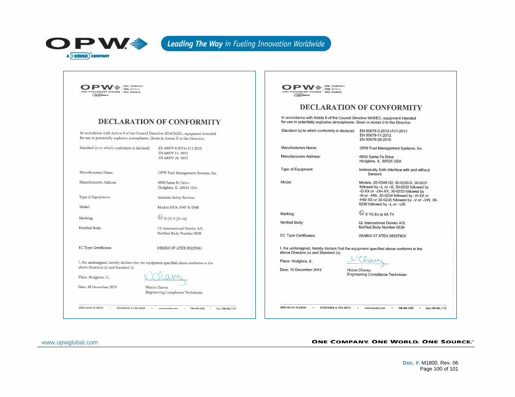
Doc. #: M1800, Rev. 06
Page 100 of 101
www.opwglobal.com
Doc. #: M1800, Rev. 06
Page 101 of 101
www.opwglobal.com
Index
Adapter Collar & Riser Cap .............................................................38 Alpha 55371 ....................................................................................39 Belcor ........................................................................................59, 60 Belden 88760 ..................................39, 56, 57, 58, 59, 60, 61, 62, 79 Belden 88761 ..................................................................................39 Blank Door .......................................................................................10 Calculating Product Offset ...............................................................37 Circuit Breaker Conduit ................................................................23 Communications Conduit ................................................................13 Density Measurement Sensor ................................................64, 65 DHCP ..............................................................................................10 Discriminating Dispenser Pan Sensor ......................59, 60, 61, 62 Discriminating Interstitial Sensor .....................................................56 Double-Wall Tank ............................................................................70 Dual-Float Brine Sensors ................................................................62 Dual-Float STP Sump Sensor .........................................................60 Ethernet Connection ........................................................................12 Flex Probe ...............................................................38, 40, 41, 43, 76 Hydrocarbon Liquid with Water Indicator ..................................47, 58 Hydrocarbon Vapor Sensor .............................................................79 I/O Module ................................................................................24, 29 Installation Procedure ......................................................................65 Intellisense Technology ...................................................................47
IntelliSense™............................................................................ 25, 47 Interstitial Hydrocarbon Liquid with ................................................. 65 Interstitial Level Sensor-Float Switch.............................................. 50 Interstitial Sensor ............................................................................ 48 Model 7100V Flex Probes .............................................................. 40 Model 924 & B Probes .............................................................. 66, 67 Model 924B Probe .................................................................... 39, 70 Multi-drop Installation................................................................ 38, 47 Petro-Net ............................................................................ 12, 22, 68 Printer ............................................................................................. 10 Probe & Sensor Conduit ................................................................. 23 Probe Floats ................................................................................... 38 Probe Installation in an Underground Tank .................................... 36 Probe Placement ............................................................................ 35 RS-485...................................................................................... 10, 12 Sensors..................................................................................... 38, 47 Single-Level Sump Sensor ............................................................. 51 SITE SURVEY ................................................................................ 12 Smart Module ................................................................................ 68 Tank Thresholds ............................................................................. 65 VSmart Module ........................................... 22, 23, 24, 29, 34, 39, 48 Wireless Connection ....................................................................... 12
Related Documents