Islamic University of Gaza (IUG) Faculty of Engineering Computer Engineering Department Digital Systems Design Lab ECOM 4111 Eng. Asma Obeid Lab 1 Lab Policy & Tools September 8, 2012

Welcome message from author
This document is posted to help you gain knowledge. Please leave a comment to let me know what you think about it! Share it to your friends and learn new things together.
Transcript

Islamic University of Gaza (IUG)Faculty of Engineering
Computer Engineering Department
Digital Systems Design LabECOM 4111
Eng. Asma Obeid
Lab 1
Lab Policy & Tools
September 8, 2012
[Pick the date] Page 2
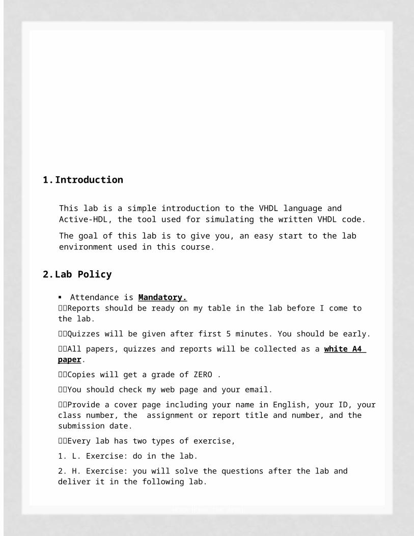
1. Introduction
This lab is a simple introduction to the VHDL language and Active-HDL, the tool used for simulating the written VHDL code.
The goal of this lab is to give you, an easy start to the lab environment used in this course.
2. Lab Policy
Attendance is Mandatory.Reports should be ready on my table in the lab before I come to the lab. Quizzes will be given after first 5 minutes. You should be early. All papers, quizzes and reports will be collected as a white A4 paper. Copies will get a grade of ZERO . You should check my web page and your email.Provide a cover page including your name in English, your ID, your class number, the assignment or report title and number, and the submission date.Every lab has two types of exercise, 1. L. Exercise: do in the lab. 2. H. Exercise: you will solve the questions after the lab and deliver it in the following lab. (The HWs will be delivered in lab only!)
Grades:Lab exercises 10Lab Assignment (Lab HW) 15Lab Quizzes 10Attendance 10Mid term exam (practical) 20Final Exam 40Sum 105
3. Essential definitions

[Pick the date] Page 3
VHDL :Very high speed integrated circuit (VHSIC) Hardware Description Language which is a programming language that describes a logic circuit by function, data flow behavior, and/or structure. BLOCKS: which are the basic building units of a VHDL design. Within these design blocks a logic circuit of function can be easily described.ENTITY: block that describes the interface for the design. The interface defines the input and output 1ogic signals of the circuit being designed. ARCHITECTURE: block describes the internal operation of the design. Within these blocks are numerous other functional blocks used to build the design elements of the logic circuit being created.SIMULATION: is a bare bones type of test to see if the basic logic works according to design and concept. SYNTHESIS: allows timing factors and other influences of actual field programmable gate array (FPGA) devices to effect the simulation thereby doing a more thorough type of check before the design is committed to the FPGA or similar device.
4. Getting Start1) Starting Active-HDL
Note: The version that will be used in lab is Active-HDL 8.1To start the program, go to the Start/Programs >> Aldec >> Active-HDL 8.1. The Active-HDL should start loading, which is indicated by The Active-HDL Welcome screen.
When the loading process finishes, the following dialog appears

[Pick the date] Page 4
The Getting Started Window.
Select the Create new workspace option and click the OK button
2) Creating a New Workspace & Adding a new Design In the first wizard dialog, you should specify the name, in this case “Lab_0”, and location of the workspace you are creating. By default, a new design is added to this workspace.

[Pick the date] Page 5
The new Workspace wizard
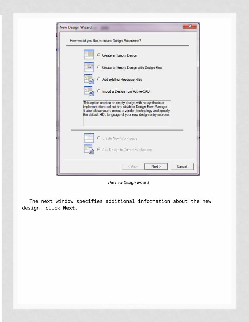
3) Creating a New DesignAfter that, select the Create an empty design option from the New Design Wizard, and then click Next.
The new Design wizard
The next window specifies additional information about the new design, click Next.
[Pick the date] Page 6
The Property page
4) Entering the Design Name The following window is the New Design Wizard, in which you should specify the name and location of this design. For example, First Design.

[Pick the date] Page 7
The new Design wizard
Finally, the last window gives a summary of this process, click Finish.

[Pick the date] Page 8
5) Design BrowserThe Design Browser is a window showing the design contents. As a result of the previous operations it will display the following contents:
The Design Browser Window
As you can see in the figure above, the design name is Design_0. In order to add a VHDL source file right click on the Add New File item, select New and then VHDL Source.

[Pick the date] Page 9
Create new source file
The New Source File wizard starts, click Next.
The New Source File wizard
Type the name of the source file, as an example: NorGate, press Next, then Finish.

[Pick the date] Page 10
Then, you will get this window of editor.
Write your code that describes your design.

[Pick the date] Page 11
Entity Syntax
Compile the source file by choosing the Compile option from the shortcut menu. To invoke the menu, click with the right mouse button over the file name or press F11.

[Pick the date] Page 12
After successful compilation, the “ ” icon will appear close to the file name along with the “ “sign allowing the expansion of the design structure.
If the source file contains an error, the sign appears at the file name. Erroneous line is underlined and the VHDL console window displays the error description.
Here, we get an error (note the red writing in the console window). Also note the underlined line, you can find and solve the error. The error is that I’ve named the architecture as behavior and end it with another name which is NorGate. According to the note above, you can see the sign.

[Pick the date] Page 13
Now I will correct the error and the compile.
The Design Browser Window after Compile Command
The window shows an entity-architecture pair.
6) Simulation, getting startTo begin a simulation, you have to generate a test file that is called a “TestBench”. This could be done by right click to the entity-architecture pair, in this case the norgate(behavior), select from the menu Generate TestBench.

[Pick the date] Page 14
Follow the wizard by pressing Next.

[Pick the date] Page 15

[Pick the date] Page 16
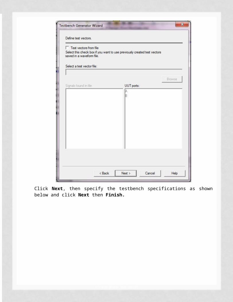
Click Next, then specify the testbench specifications as shown below and click Next then Finish.
[Pick the date] Page 17
This wizard offers you a template for the desired testbench all you have to do is to write a simulation process that tests the behavior of the design. This testbench appears under the Structure tab of the Design Browser window as follows.

[Pick the date] Page 18
Compile the testbench file.
After compiling testbench file
After successful compilation you have to initialize the simulator first, using the Initialize Simulation option from the Simulation menu.

[Pick the date] Page 19
After the simulator has been initialized, you have to open a new Waveform window. Click the New Waveform toolbar button . The new Waveform window appears.
The Waveform Viewer Window.
To add signals to the simulator, use the drag-and-drop method. Open the Structure tab of the Design Browser window, select the testbench file just

[Pick the date] Page 20
created and while holding down the left button, drag it to the right-section of the waveform window and then release the mouse button. This is a standard drag-and-drop operation.
Adding Signals From Design Browser Window
If you want to delete a signal, select it and press the Del button.
Active-HDL allows inspection of simulation results in the tabled format with delta time precision. The List Viewer window enables signal values monitoring without the ability to force signals with the desired values. To open the Viewer window click the New List toolbar button . The window below will appear as a result.

[Pick the date] Page 21
The List Viewer Window
The List Viewer window is an interactive display which mirrors all simulation actions and results.
7) Lets’ simulate
Perform several simulation steps by clicking the Run button. You will receive the following results on the Waveform tab.
The Simulation Results
Choose End Simulation from the Simulation menu. Save the waveform under the file name: Waveform Editor 1.awf.
To display the results in the tabled format and monitor delta time changes switch to the opened List Viewer window. The results should be displayed in the similar manner.
Simulation results in the List Viewer
5. Lab. Exercises

[Pick the date] Page 22
L.Exercise: Nor gate
The NOR gate in figure (1) can be implemented as an OR gate followed by an inverter
NOR GateNOR-NOT Implementation.
The ENTITY construct
VHDL files are basically divided into two parts, the entity and the architecture. We will start with the entity and deal with the architecture.The entity is basically where the circuits (in & out) ports are defined. There is a multitude of I/O ports available, but this lab will only deal with the two most usual ones, the INput and OUTput ports. (Other types of ports are for example the INOUT and BUFFER ports.)
The entity of the circuit in figure (1) should look something like below. Please notice that comments in the code are made with a double-dash (--).
entity NorGate is port ( A: IN BIT; B: IN BIT; Q: OUT BIT);
end NorGate;
Now that we have defined the I/O interface to the rest of the world for the NOR gate, we should move on to the architecture of the circuit.
The ARCHITECTURE construct

[Pick the date] Page 23
While the entity was comparable to figure (1), the architecture is comparable to figure (2). The entity told us nothing about how the circuit was implemented, this is taken care of by the architecture part of the VHDL code.The architecture of the NOR gate matching the entity above could then be written as something like this...
architecture behavior of NorGate isSIGNAL temp: BIT ;begin
temp <= A OR B; -- The OR-OperationQ <= NOT temp; -- The inverter
end behavior; Your first complete VHDL file
All VHDL files start with an entity and then are followed by (at least) one architecture. More pieces of architecture are possible for one entity.
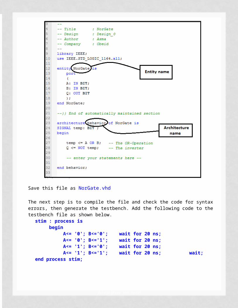
The complete VHDL file will look as below:

[Pick the date] Page 24
Save this file as NorGate.vhd
The next step is to compile the file and check the code for syntax errors, then generate the testbench. Add the following code to the testbench file as shown below.
stim : process isbegin
A<= '0'; B<='0'; wait for 20 ns;A<= '0'; B<='1'; wait for 20 ns;A<= '1'; B<='0'; wait for 20 ns;A<= '1'; B<='1'; wait for 20 ns; wait;
end process stim;
[Pick the date] Page 25
After compiling the testbench, The Simulation Result will be as shown below
Simulation results
Simulation results in the List Viewer
Note: Do not worry about what the code means, you will be familiar with this code in the following labs.

[Pick the date] Page 26
H.Exercise
Do the same steps but this time with XOR gate. Using Entity, Architecture, testbench. The code should be tidy and readable Use comments.
Related Documents