C H A P T E R -1 Cisco IOS Enterprise VPN Configuration Guide 78-6342-05 B0 3 Site-to-Site and Extranet VPN Business Scenarios This chapter explains the basic tasks for configuring IP-based, site-to-site and extranet Virtual Private Networks (VPNs) on a Cisco IOS VPN gateway using generic routing encapsulation (GRE) and IPSec tunneling protocols. Basic security , Network Address Translation (NA T), Encryption, Cisco IOS weighted fair queuing (WFQ), and extended access lists for basic traffic filtering are configured. Note This chapter describes basic features and configurations used in a site-to-site VPN scenario. Some Cisco IOS security software features not described in this document can be used to increase performance and scalability of your VPN. For up-to-date Cisco IOS security software features documentation, refer to the Cisco IOS Security Configuration Guide and the Cisco IOS Security Command Reference publication. To access the publication, log on to Cisco.com, and select the following links under “Service & Support”: Technical Documents: Cisco IOS Software: Cisco IOS Release 12.2: Configuration Guides and Command References. This chapter includes the following sections: Scenario Descriptions, page 3-2 • Step 1—Conf iguring the Tunnel, page 3-8 • Step 2—Configuring Network Address Translat ion, page 3-15

Welcome message from author
This document is posted to help you gain knowledge. Please leave a comment to let me know what you think about it! Share it to your friends and learn new things together.
Transcript

8/6/2019 Site-To-Site and Extranet VPN
http://slidepdf.com/reader/full/site-to-site-and-extranet-vpn 1/74
C H A P T E R
-1
Cisco IOS Enterprise VPN Configuration Guide
78-6342-05 B0
3
Site-to-Site and Extranet VPNBusiness Scenarios
This chapter explains the basic tasks for configuring IP-based, site-to-site and
extranet Virtual Private Networks (VPNs) on a Cisco IOS VPN gateway usinggeneric routing encapsulation (GRE) and IPSec tunneling protocols. Basic
security, Network Address Translation (NAT), Encryption, Cisco IOS weighted
fair queuing (WFQ), and extended access lists for basic traffic filtering are
configured.
Note This chapter describes basic features and configurations used in asite-to-site VPN scenario. Some Cisco IOS security software
features not described in this document can be used to increase
performance and scalability of your VPN. For up-to-date Cisco IOS
security software features documentation, refer to the Cisco IOS
Security Configuration Guide and the Cisco IOS Security Command
Reference publication. To access the publication, log on to
Cisco.com, and select the following links under “Service &
Support”: Technical Documents: Cisco IOS Software: Cisco IOS
Release 12.2: Configuration Guides and Command References.
This chapter includes the following sections:
Scenario Descriptions, page 3-2
• Step 1—Configuring the Tunnel, page 3-8
• Step 2—Configuring Network Address Translation, page 3-15

8/6/2019 Site-To-Site and Extranet VPN
http://slidepdf.com/reader/full/site-to-site-and-extranet-vpn 2/74
Chapter
-2
Cisco IOS Enterprise VPN Configuration Guide
78-6342-05 B0
• Step 3—Configuring Encryption and IPSec, page 3-20
• Step 4—Configuring Quality of Service, page 3-46
• Step 5—Configuring Cisco IOS Firewall Features, page 3-58
• Comprehensive Configuration Examples, page 3-64
Note Throughout this chapter, there are numerous configuration examples
and sample configuration outputs that include unusable IPaddresses. Be sure to use your own IP addresses when configuring
your Cisco IOS VPN gateway.
Scenario DescriptionsThis section includes the following topics:
• Site-to-Site Scenario, page 3-3
• Extranet Scenario, page 3-5
• Configuring a GRE Tunnel, page 3-10
• Configuring an IPSec Tunnel, page 3-14
• Configuring Static Inside Source Address Translation, page 3-18
• Verifying Static Inside Source Address Translation, page 3-19
• Configuring IKE Policies, page 3-22
• Verifying IKE Policies, page 3-30
• Configuring IPSec and IPSec Tunnel Mode, page 3-34
• Configuring Crypto Maps, page 3-37• Configuring Network-Based Application Recognition, page 3-48
• Configuring Weighted Fair Queuing, page 3-52
• Verifying Weighted Fair Queuing, page 3-53
• Configuring Class-Based Weighted Fair Queuing, page 3-53
• Verifying Class-Based Weighted Fair Queuing, page 3-58
• Creating Extended Access Lists Using Access List Numbers, page 3-61

8/6/2019 Site-To-Site and Extranet VPN
http://slidepdf.com/reader/full/site-to-site-and-extranet-vpn 3/74
-3
Cisco IOS Enterprise VPN Configuration Guide
78-6342-05 B0
Chapter
• Verifying Extended Access Lists, page 3-62
• Applying Access Lists to Interfaces, page 3-62
• Verifying Extended Access Lists Are Applied Correctly, page 3-63
Site-to-Site Scenario
Figure 3-1 shows a headquarters network providing a remote office access to thecorporate intranet. In this scenario, the headquarters and remote office are
connected through a secure GRE tunnel that is established over an IP
infrastructure (the Internet). Employees in the remote office are able to access
internal, private web pages and perform various IP-based network tasks.
Note Although the site-to-site VPN scenario in this chapter is configured
with GRE tunneling, a site-to-site VPN can also be configured withIPSec only tunneling.
Figure 3-1 Site-to-Site VPN Business Scenario
Figure 3-2 shows the physical elements of the scenario. The Internet provides the
core interconnecting fabric between the headquarters and remote office routers.Both the headquarters and remote office are using a Cisco IOS VPN gateway
(either a Cisco 7100 series with an Integrated Service Module (ISM) or VPN
Accelerator Module (VAM), a Cisco 7200 series with an Integrated Service
Adaptor (ISA) or VAM, a Cisco 2600 series, or a Cisco 3600 series router).
Note VAM information and documentation can be found in the VPN
Acceleration Module Installation and Configuration document.
CorporateIntranet
Headquarters gateway(hq-sanjose)
Remote office gateway(ro-rtp)
Remoteofficenetwork
Internet
Serial line Serial line
GRE+IPSec tunnel
2 3 2 4 4
8/6/2019 Site-To-Site and Extranet VPN
http://slidepdf.com/reader/full/site-to-site-and-extranet-vpn 4/74
Chapter
-4
Cisco IOS Enterprise VPN Configuration Guide
78-6342-05 B0
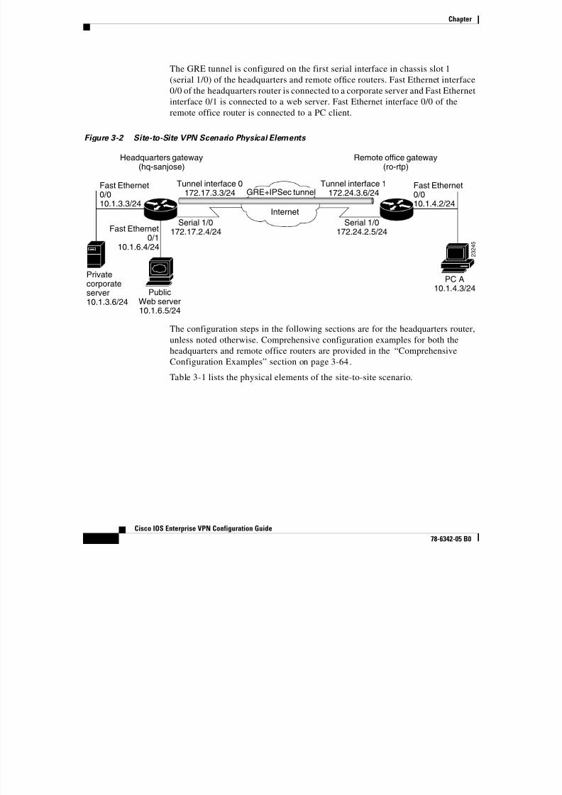
The GRE tunnel is configured on the first serial interface in chassis slot 1
(serial 1/0) of the headquarters and remote office routers. Fast Ethernet interface0/0 of the headquarters router is connected to a corporate server and Fast Ethernet
interface 0/1 is connected to a web server. Fast Ethernet interface 0/0 of the
remote office router is connected to a PC client.
Figure 3-2 Site-to-Site VPN Scenario Physical Elements
The configuration steps in the following sections are for the headquarters router,
unless noted otherwise. Comprehensive configuration examples for both the
headquarters and remote office routers are provided in the “Comprehensive
Configuration Examples” section on page 3-64.
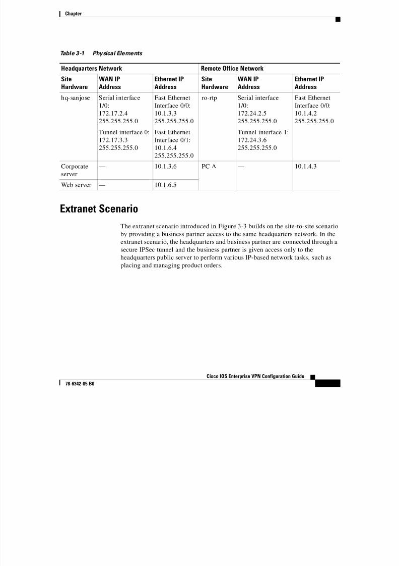
Table 3-1 lists the physical elements of the site-to-site scenario.
Fast Ethernet0/010.1.3.3/24
Fast Ethernet0/010.1.4.2/24
Fast Ethernet0/1
10.1.6.4/24
Headquarters gateway(hq-sanjose) Remote office gateway(ro-rtp)
Internet
Serial 1/0172.17.2.4/24
PublicWeb server10.1.6.5/24
Privatecorporateserver10.1.3.6/24
Tunnel interface 0172.17.3.3/24
Tunnel interface 1172.24.3.6/24
Serial 1/0172.24.2.5/24
PC A10.1.4.3/24
2 3 2 4 5
GRE+IPSec tunnel
8/6/2019 Site-To-Site and Extranet VPN
http://slidepdf.com/reader/full/site-to-site-and-extranet-vpn 5/74
-5
Cisco IOS Enterprise VPN Configuration Guide
78-6342-05 B0
Chapter
Extranet Scenario
The extranet scenario introduced in Figure 3-3 builds on the site-to-site scenario
by providing a business partner access to the same headquarters network. In the
extranet scenario, the headquarters and business partner are connected through a
secure IPSec tunnel and the business partner is given access only to the
headquarters public server to perform various IP-based network tasks, such as
placing and managing product orders.
Table 3-1 Physical Elements
Headquarters Network Remote Office Network
SiteHardware
WAN IPAddress
Ethernet IPAddress
SiteHardware
WAN IPAddress
Ethernet IPAddress
hq-sanjose Serial interface
1/0:
172.17.2.4255.255.255.0
Tunnel interface 0:
172.17.3.3
255.255.255.0
Fast Ethernet
Interface 0/0:
10.1.3.3255.255.255.0
Fast Ethernet
Interface 0/1:
10.1.6.4
255.255.255.0
ro-rtp Serial interface
1/0:
172.24.2.5255.255.255.0
Tunnel interface 1:
172.24.3.6
255.255.255.0
Fast Ethernet
Interface 0/0:
10.1.4.2255.255.255.0
Corporate
server
— 10.1.3.6 PC A — 10.1.4.3
Web server — 10.1.6.5

8/6/2019 Site-To-Site and Extranet VPN
http://slidepdf.com/reader/full/site-to-site-and-extranet-vpn 6/74
Chapter
-6
Cisco IOS Enterprise VPN Configuration Guide
78-6342-05 B0
Figure 3-3 Extranet VPN Business Scenario
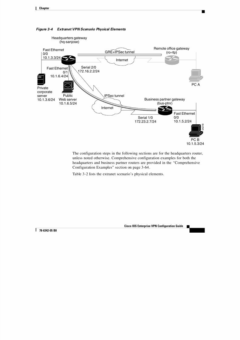
Figure 3-4 shows the physical elements of the scenario. As in the site-to-site
business scenario, the Internet provides the core interconnecting fabric between
the headquarters and business partner routers. Like the headquarters office, the
business partner is also using a Cisco IOS VPN gateway (either a Cisco 7100
series with an Integrated Service Module (ISM) or a VPN Accelerator Module
(VAM), a Cisco 7200 series with an Integrated Service Adaptor (ISA) or VAM, ora Cisco 3600 series concentrator).
Note VAM information and documentation can be found in the VPN
Acceleration Module Installation and Configuration document.
The IPSec tunnel between the two sites is configured on the second serial
interface in chassis slot 2 (serial 2/0) of the headquarters router and the first serial
interface in chassis slot 1 (serial 1/0) of the business partner router. Fast Ethernet
interface 0/0 of the headquarters router is still connected to a private corporate
server and Fast Ethernet interface 0/1 is connected to a public server. Fast Ethernet
interface 0/0 of the business partner router is connected to a PC client.
CorporateIntranet
Headquarters gateway(hq-sanjose)
Remote office gateway(ro-rtp)
Remoteofficenetwork
Internet
Serial line Serial line
2 4 2 1
9
Business partner gateway(bus-ptnr)
Internet
Serial line
Serial line
IPSec tunnel
Businesspartner
network
GRE+IPSec tunnel
8/6/2019 Site-To-Site and Extranet VPN
http://slidepdf.com/reader/full/site-to-site-and-extranet-vpn 7/74
-7
Cisco IOS Enterprise VPN Configuration Guide
78-6342-05 B0
Chapter
Figure 3-4 Extranet VPN Scenario Physical Elements
The configuration steps in the following sections are for the headquarters router,
unless noted otherwise. Comprehensive configuration examples for both the
headquarters and business partner routers are provided in the “Comprehensive
Configuration Examples” section on page 3-64.
Table 3-2 lists the extranet scenario’s physical elements.
PC A
Fast Ethernet0/010.1.3.3/24
Fast Ethernet0/110.1.6.4/24
Fast Ethernet0/010.1.5.2/24
Headquarters gateway(hq-sanjose)
Remote office gateway(ro-rtp)
Business partner gateway
(bus-ptnr)
Internet
Internet
Serial 2/0172.16.2.2/24
Serial 1/0172.23.2.7/24
PublicWeb server
10.1.6.5/24
Privatecorporateserver10.1.3.6/24
PC B10.1.5.3/24
IPSec tunnel
2 4 2 1 8
GRE+IPSec tunnel

8/6/2019 Site-To-Site and Extranet VPN
http://slidepdf.com/reader/full/site-to-site-and-extranet-vpn 8/74
Chapter
-8
Cisco IOS Enterprise VPN Configuration Guide
78-6342-05 B0
Step 1—Configuring the TunnelTunneling provides a way to encapsulate packets inside of a transport protocol.
Tunneling is implemented as a virtual interface to provide a simple interface for
configuration. The tunnel interface is not tied to specific “passenger” or
“transport” protocols, but rather, it is an architecture that is designed to provide
the services necessary to implement any standard point-to-point encapsulation
scheme. Because tunnels are point-to-point links, you must configure a separate
tunnel for each link.
Table 3-2 Physical Elements
Headquarters Network Business Partner Network
SiteHardware
WAN IPAddress
Ethernet IPAddress
SiteHardware
WAN IPAddress
Ethernet IPAddress
hq-sanjose Serial interface
2/0:
172.16.2.2255.255.255.0
Fast Ethernet
Interface 0/0:
10.1.3.3255.255.255.0
Fast Ethernet
Interface 0/1:
10.1.6.4
255.255.255.0
bus-ptnr Serial interface
1/0:
172.23.2.7255.255.255.0
Fast Ethernet
Interface 0/0:
10.1.5.2255.255.255.0
Corporate
server
— 10.1.3.6 PC B — 10.1.5.3
Web server — 10.1.6.51
1. The inside local IP address of the headquarters network public server (10.1.6.5) is translated to inside global IP address
10.2.2.2 in the “Step 2—Configuring Network Address Translation” section on page 3-15.

8/6/2019 Site-To-Site and Extranet VPN
http://slidepdf.com/reader/full/site-to-site-and-extranet-vpn 9/74
-9
Cisco IOS Enterprise VPN Configuration Guide
78-6342-05 B0
Chapter
Tunneling has the following three primary components:
• Passenger protocol, which is the protocol you are encapsulating (AppleTalk,Banyan VINES, Connectionless Network Service [CLNS], DECnet, IP, or
Internetwork Packet Exchange [IPX]).
• Carrier protocol, such as the generic routing encapsulation (GRE) protocol or
IPSec protocol.
• Transport protocol, such as IP, which is the protocol used to carry the
encapsulated protocol.Figure 3-5 illustrates IP tunneling terminology and concepts.
Figure 3-5 IP Tunneling Terminology and Concepts
This section contains the following topics:
• Configuring a GRE Tunnel
• Configuring an IPSec Tunnel
802.3 802.2 Payload
PayloadEthernet IP GRE
Normal packet
Tunnel packet
Passenger protocol
Encapsulation protocol
Transport protocol
2 4 2 1 7

8/6/2019 Site-To-Site and Extranet VPN
http://slidepdf.com/reader/full/site-to-site-and-extranet-vpn 10/74
Chapter
-10
Cisco IOS Enterprise VPN Configuration Guide
78-6342-05 B0
Configuring a GRE Tunnel
GRE is capable of handling the transportation of multiprotocol and IP multicast
traffic between two sites, which only have IP unicast connectivity. The importance
of using tunnels in a VPN environment is based on the fact that IPSec encryption
only works on IP unicast frames. Tunneling allows for the encryption and the
transportation of multiprotocol traffic across the VPN since the tunneled packets
appear to the IP network as an IP unicast frame between the tunnel endpoints. If
all connectivity must go through the home gateway router, tunnels also enable theuse of private network addressing across a service provider’s backbone without
the need for running the Network Address Translation (NAT) feature.
Network redundancy (resiliency) is an important consideration in the decision to
use GRE tunnels, IPSec tunnels, or tunnels which utilize IPSec over GRE. GRE
can be used in conjunction with IPSec to pass routing updates between sites on an
IPSec VPN. GRE encapsulates the clear text packet, then IPSec (in transport or
tunnel mode) encrypts the packet.This packet flow of IPSec over GRE enablesrouting updates, which are generally multicast, to be passed over an encrypted
link. IPSec alone can not achieve this, because it does not support multicast.
Using redundant GRE tunnels protected by IPSec from a remote router to
redundant headquarter routers, routing protocols can be employed to delineate the
“primary” and “secondary” headquarter routers. Upon loss of connectivity to the
primary router, routing protocols will discover the failure and route to the
secondary gateway, thereby providing network redundancy.
It is important to note that more than one router must be employed at HQ to
provide resiliency. For VPN resilience, the remote site should be configured with
two GRE tunnels, one to the primary HQ VPN router, and the other to the backup
HQ VPN router.
This section contains basic steps to configure a GRE tunnel and includes the
following tasks:
• Configuring the Tunnel Interface, Source, and Destination
• Verifying the Tunnel Interface, Source, and Destination
8/6/2019 Site-To-Site and Extranet VPN
http://slidepdf.com/reader/full/site-to-site-and-extranet-vpn 11/74
-11
Cisco IOS Enterprise VPN Configuration Guide
78-6342-05 B0
Chapter
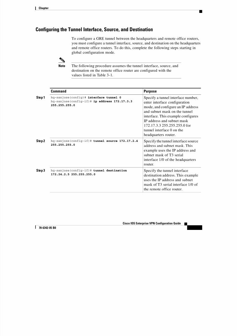
Configuring the Tunnel Interface, Source, and Destination
To configure a GRE tunnel between the headquarters and remote office routers,
you must configure a tunnel interface, source, and destination on the headquarters
and remote office routers. To do this, complete the following steps starting in
global configuration mode.
Note The following procedure assumes the tunnel interface, source, and
destination on the remote office router are configured with the
values listed in Table 3-1.
Command Purpose
Step 1 hq-sanjose(config)# interface tunnel 0
hq-sanjose(config-if)# ip address 172.17.3.3
255.255.255.0
Specify a tunnel interface number,
enter interface configurationmode, and configure an IP address
and subnet mask on the tunnel
interface. This example configures
IP address and subnet mask
172.17.3.3 255.255.255.0 for
tunnel interface 0 on the
headquarters router.
Step 2 hq-sanjose(config-if)# tunnel source 172.17.2.4
255.255.255.0
Specify the tunnel interface source
address and subnet mask. This
example uses the IP address and
subnet mask of T3 serial
interface 1/0 of the headquarters
router.
Step 3 hq-sanjose(config-if)# tunnel destination172.24.2.5 255.255.255.0 Specify the tunnel interface
destination address. This example
uses the IP address and subnet
mask of T3 serial interface 1/0 of
the remote office router.
8/6/2019 Site-To-Site and Extranet VPN
http://slidepdf.com/reader/full/site-to-site-and-extranet-vpn 12/74
Chapter
-12
Cisco IOS Enterprise VPN Configuration Guide
78-6342-05 B0
Note When configuring GRE, you must have only Cisco routers or accessservers at both ends of the tunnel connection.
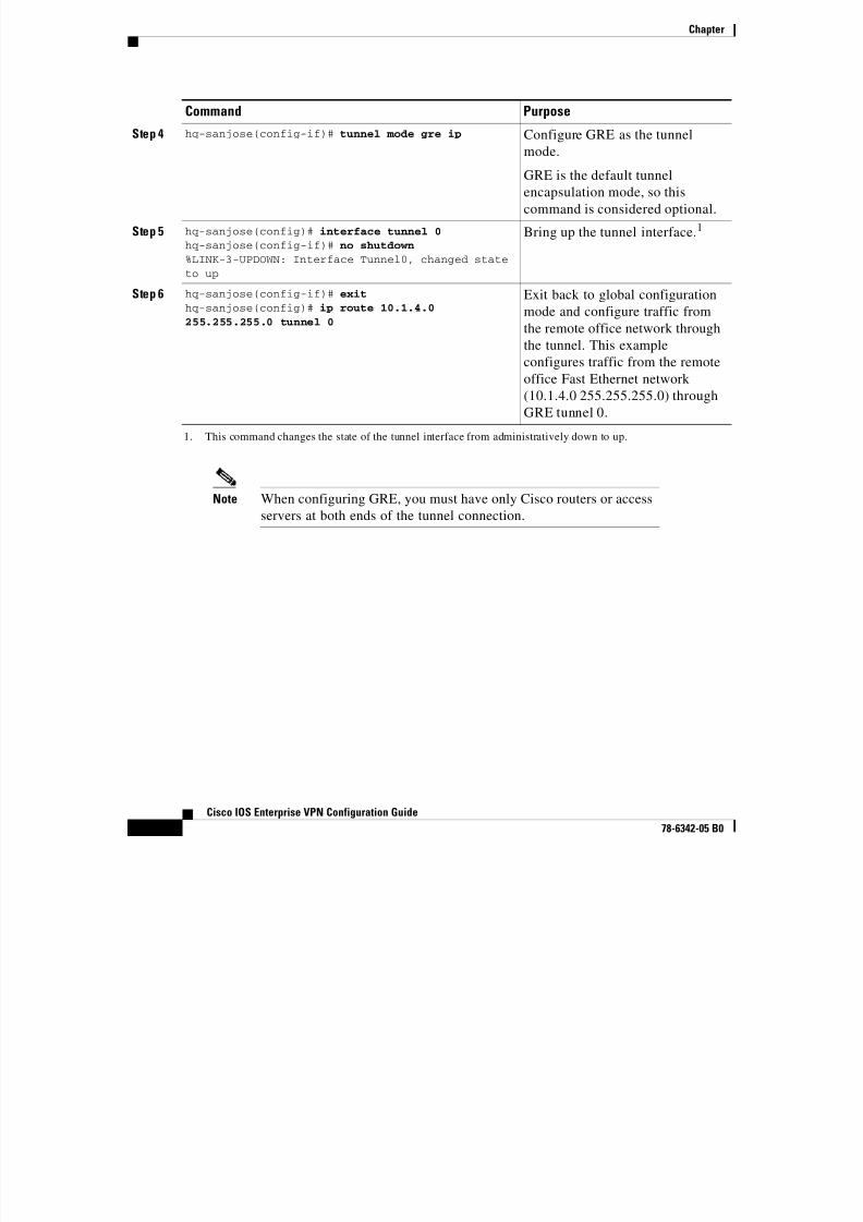
Step 4 hq-sanjose(config-if)# tunnel mode gre ip Configure GRE as the tunnel
mode.
GRE is the default tunnel
encapsulation mode, so this
command is considered optional.
Step 5 hq-sanjose(config)# interface tunnel 0
hq-sanjose(config-if)# no shutdown
%LINK-3-UPDOWN: Interface Tunnel0, changed stateto up
Bring up the tunnel interface.1
Step 6 hq-sanjose(config-if)# exit
hq-sanjose(config)# ip route 10.1.4.0
255.255.255.0 tunnel 0
Exit back to global configuration
mode and configure traffic from
the remote office network through
the tunnel. This example
configures traffic from the remote
office Fast Ethernet network (10.1.4.0 255.255.255.0) through
GRE tunnel 0.
1. This command changes the state of the tunnel interface from administratively down to up.
Command Purpose
8/6/2019 Site-To-Site and Extranet VPN
http://slidepdf.com/reader/full/site-to-site-and-extranet-vpn 13/74
-13
Cisco IOS Enterprise VPN Configuration Guide
78-6342-05 B0
Chapter
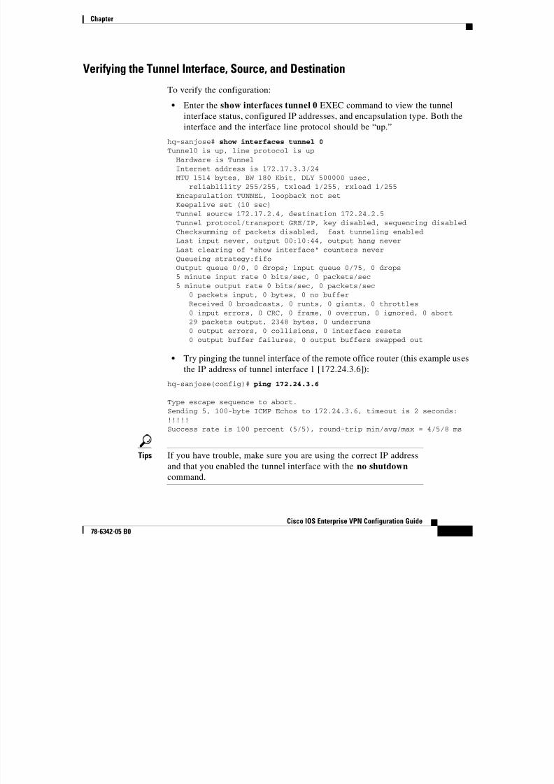
Verifying the Tunnel Interface, Source, and Destination
To verify the configuration:
• Enter the show interfaces tunnel 0 EXEC command to view the tunnel
interface status, configured IP addresses, and encapsulation type. Both the
interface and the interface line protocol should be “up.”
hq-sanjose# show interfaces tunnel 0
Tunnel0 is up, line protocol is up
Hardware is TunnelInternet address is 172.17.3.3/24MTU 1514 bytes, BW 180 Kbit, DLY 500000 usec,
reliablility 255/255, txload 1/255, rxload 1/255Encapsulation TUNNEL, loopback not setKeepalive set (10 sec)Tunnel source 172.17.2.4, destination 172.24.2.5Tunnel protocol/transport GRE/IP, key disabled, sequencing disabledChecksumming of packets disabled, fast tunneling enabled
Last input never, output 00:10:44, output hang neverLast clearing of "show interface" counters neverQueueing strategy:fifoOutput queue 0/0, 0 drops; input queue 0/75, 0 drops5 minute input rate 0 bits/sec, 0 packets/sec5 minute output rate 0 bits/sec, 0 packets/sec
0 packets input, 0 bytes, 0 no bufferReceived 0 broadcasts, 0 runts, 0 giants, 0 throttles0 input errors, 0 CRC, 0 frame, 0 overrun, 0 ignored, 0 abort
29 packets output, 2348 bytes, 0 underruns0 output errors, 0 collisions, 0 interface resets0 output buffer failures, 0 output buffers swapped out
• Try pinging the tunnel interface of the remote office router (this example uses
the IP address of tunnel interface 1 [172.24.3.6]):
hq-sanjose(config)# ping 172.24.3.6
Type escape sequence to abort.Sending 5, 100-byte ICMP Echos to 172.24.3.6, timeout is 2 seconds:!!!!!Success rate is 100 percent (5/5), round-trip min/avg/max = 4/5/8 ms
Tips If you have trouble, make sure you are using the correct IP address
and that you enabled the tunnel interface with the no shutdown
command.
Ch t
8/6/2019 Site-To-Site and Extranet VPN
http://slidepdf.com/reader/full/site-to-site-and-extranet-vpn 14/74
Chapter
-14
Cisco IOS Enterprise VPN Configuration Guide
78-6342-05 B0
Configuring an IPSec Tunnel
IPSec can be configured in tunnel mode or transport mode. IPSec tunnel mode can
be used as an alternative to a GRE tunnel, or in conjunction with a GRE tunnel.
In IPSec tunnel mode, the entire original IP datagram is encrypted, and it becomes
the payload in a new IP packet. This mode allows a network device, such as a
router, to act as an IPSec proxy. That is, the router performs encryption on behalf
of the hosts. The source router encrypts packets and forwards them along the
IPSec tunnel. The destination router decrypts the original IP datagram andforwards it on to the destination system. Tunnel mode protects against traffic
analysis; with tunnel mode, an attacker can only determine the tunnel endpoints
and not the true source and destination of the packets passing through the tunnel,
even if they are the same as the tunnel endpoints.
Note IPSec tunnel mode configuration instructions are described in detail
in the “Configuring IPSec and IPSec Tunnel Mode” section onpage 3-34.
In IPSec transport mode, only the IP payload is encrypted, and the original IP
headers are left intact. (See Figure 3-6.) This mode has the advantage of adding
only a few bytes to each packet. It also allows devices on the public network to
see the final source and destination of the packet. With this capability, you can
enable special processing in the intermediate network based on the information inthe IP header. However, the Layer 4 header will be encrypted, limiting the
examination of the packet. Unfortunately, by passing the IP header in the clear,
transport mode allows an attacker to perform some traffic analysis. (See the
“Defining Transform Sets and Configuring IPSec Tunnel Mode” section on
page 3-36 for an IPSec transport mode configuration example.)
Chapter

8/6/2019 Site-To-Site and Extranet VPN
http://slidepdf.com/reader/full/site-to-site-and-extranet-vpn 15/74
-15
Cisco IOS Enterprise VPN Configuration Guide
78-6342-05 B0
Chapter
Figure 3-6 IPSec in Tunnel and Transport Modes
Step 2—Configuring Network Address Translation
Note NAT is used if you have conflicting private address spaces in the
extranet scenario. If you have no conflicting private address spaces,
proceed to the “Step 3—Configuring Encryption and IPSec” section
on page 3-20.
Network Address Translation (NAT) enables private IP internetworks with
addresses that are not globally unique to connect to the Internet by translating
those addresses into globally routable address space. NAT is configured on the
router at the border of a stub domain (referred to as the inside network ) and a
public network such as the Internet (referred to as the outside network ). NAT
translates the internal local addresses to globally unique IP addresses before
IP HDR
2 3 2 4 6
Data
EncryptedTunnel mode
IP HDR Data
Encrypted
IPSec HDRNew IP HDR
IP HDR Data
Transport mode
DataIPSec HDRIP HDR
Chapter
8/6/2019 Site-To-Site and Extranet VPN
http://slidepdf.com/reader/full/site-to-site-and-extranet-vpn 16/74
Chapter
-16
Cisco IOS Enterprise VPN Configuration Guide
78-6342-05 B0
sending packets to the outside network. NAT also allows a more graceful
renumbering strategy for organizations that are changing service providers orvoluntarily renumbering into classless interdomain routing (CIDR) blocks.
This section only explains how to configure static translation to translate internal
local IP addresses into globally unique IP addresses before sending packets to an
outside network, and includes the following tasks:
• Configuring Static Inside Source Address Translation
• Verifying Static Inside Source Address Translation
Static translation establishes a one-to-one mapping between your internal local
address and an inside global address. Static translation is useful when a host on
the inside must be accessible by a fixed address from the outside.
Note For detailed, additional configuration information on NAT—for
example, instructions on how to configure dynamic
translation—refer to the “Configuring IP Addressing” chapter in the
Network Protocols Configuration Guide, Part 1. NAT is also
described in RFC 1631.
NAT uses the following definitions:
• Inside local address—The IP address that is assigned to a host on the inside
network. The address is probably not a legitimate IP address assigned by theNetwork Information Center (NIC) or service provider.
• Inside global address—A legitimate IP address (assigned by the NIC or
service provider) that represents one or more inside local IP addresses to the
outside world.
• Outside local address—The IP address of an outside host as it appears to the
inside network. Not necessarily a legitimate address, it was allocated from
address space routable on the inside.
• Outside global address—The IP address assigned to a host on the outside
network by the host owner. The address was allocated from a globally
routable address or network space.
Figure 3-7 illustrates a router that is translating a source address inside a network
to a source address outside the network.
Chapter
8/6/2019 Site-To-Site and Extranet VPN
http://slidepdf.com/reader/full/site-to-site-and-extranet-vpn 17/74
-17
Cisco IOS Enterprise VPN Configuration Guide
78-6342-05 B0
Chapter
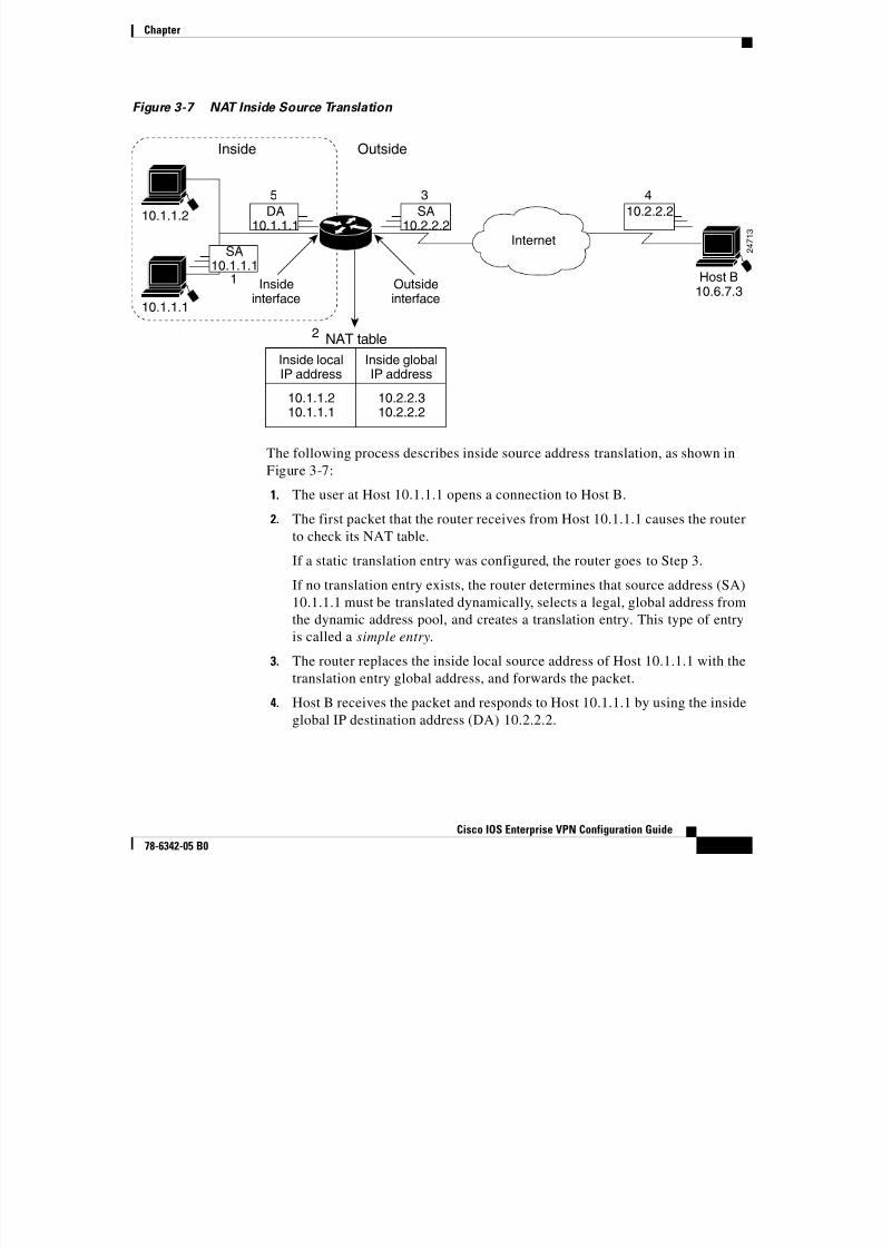
Figure 3-7 NAT Inside Source Translation
The following process describes inside source address translation, as shown in
Figure 3-7:
1. The user at Host 10.1.1.1 opens a connection to Host B.
2. The first packet that the router receives from Host 10.1.1.1 causes the router
to check its NAT table.
If a static translation entry was configured, the router goes to Step 3.
If no translation entry exists, the router determines that source address (SA)
10.1.1.1 must be translated dynamically, selects a legal, global address from
the dynamic address pool, and creates a translation entry. This type of entry
is called a simple entry.
3. The router replaces the inside local source address of Host 10.1.1.1 with the
translation entry global address, and forwards the packet.
4. Host B receives the packet and responds to Host 10.1.1.1 by using the inside
global IP destination address (DA) 10.2.2.2.
10.1.1.2
Host B10.6.7.3
10.1.1.1
Internet
Inside
Insideinterface
Outsideinterface
Outside
10.1.1.210.1.1.1
10.2.2.310.2.2.2
Inside localIP address
NAT table
Inside globalIP address
1
3
2 4 7 1 3
SA10.2.2.2
5
DA10.1.1.1
SA10.1.1.1
4
10.2.2.2
2
Chapter

8/6/2019 Site-To-Site and Extranet VPN
http://slidepdf.com/reader/full/site-to-site-and-extranet-vpn 18/74
p
-18
Cisco IOS Enterprise VPN Configuration Guide
78-6342-05 B0
5. When the router receives the packet with the inside global IP address, it
performs a NAT table lookup by using the inside global address as a key. Itthen translates the address to the inside local address of Host 10.1.1.1 and
forwards the packet to Host 10.1.1.1.
6. Host 10.1.1.1 receives the packet and continues the conversation. The router
performs Steps 2 through 5 for each packet.
This section contains the following topics:
• Configuring Static Inside Source Address Translation
• Verifying Static Inside Source Address Translation
Configuring Static Inside Source Address Translation
To configure static inside source address translation, complete the following steps
starting in global configuration mode:
Command Purpose
Step 1 hq-sanjose(config)# ip nat inside source static
10.1.6.5 10.2.2.2
Establish static translation
between an inside local address
and an inside global address. This
example translates inside local
address 10.1.6.5 (the server) to
inside global address 10.2.2.2.
Step 2 hq-sanjose(config)# interface fastethernet 0/1 Specify the inside interface. This
example specifies Fast Ethernet
interface 0/1 on the headquarters
router.
Step 3 hq-sanjose(config-if)# ip nat inside Mark the interface as connected tothe inside.
Step 4 hq-sanjose(config-if)# interface serial 2/0 Specify the outside interface. This
example specifies serial interface
2/0 on the headquarters router.
Step 5 hq-sanjose(config-if)# ip nat outside Mark the interface as connected to
the outside.
Chapter
8/6/2019 Site-To-Site and Extranet VPN
http://slidepdf.com/reader/full/site-to-site-and-extranet-vpn 19/74
-19
Cisco IOS Enterprise VPN Configuration Guide
78-6342-05 B0
The previous steps are the minimum you must configure for static inside source
address translation. You could configure multiple inside and outside interfaces.
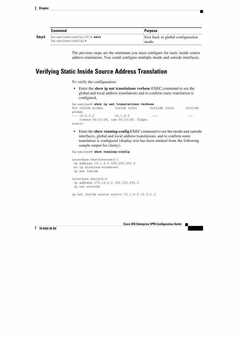
Verifying Static Inside Source Address Translation
To verify the configuration:
• Enter the show ip nat translations verbose EXEC command to see the
global and local address translations and to confirm static translation is
configured.
hq-sanjose# show ip nat translations verbosePro Inside global Inside local Outside local Outsideglobal--- 10.2.2.2 10.1.6.5 --- ---
create 00:10:28, use 00:10:28, flags:static
• Enter the show running-config EXEC command to see the inside and outside
interfaces, global and local address translations, and to confirm static
translation is configured (display text has been omitted from the following
sample output for clarity).
hq-sanjose# show running-config
interface FastEthernet0/1ip address 10.1.6.5 255.255.255.0no ip directed-broadcastip nat inside
interface serial2/0ip address 172.16.2.2 255.255.255.0ip nat outside
ip nat inside source static 10.1.6.5 10.2.2.2
Step 6 hq-sanjose(config-if)# exit
hq-sanjose(config)#Exit back to global configuration
mode.
Command Purpose
Chapter

8/6/2019 Site-To-Site and Extranet VPN
http://slidepdf.com/reader/full/site-to-site-and-extranet-vpn 20/74
-20
Cisco IOS Enterprise VPN Configuration Guide
78-6342-05 B0
Step 3—Configuring Encryption and IPSecIPSec is a framework of open standards, developed by the Internet Engineering
Task Force (IETF), that provides data confidentiality, data integrity, and data
authentication between participating peers. IPSec provides these security services
at the IP layer; it uses IKE to handle negotiation of protocols and algorithms based
on local policy, and to generate the encryption and authentication keys to be used
by IPSec. IPSec can be used to protect one or more data flows between a pair of
hosts, between a pair of security gateways, or between a security gateway and ahost.
IKE is a hybrid security protocol that implements Oakley and SKEME key
exchanges inside the Internet Security Association and Key Management Protocol
(ISAKMP) framework. While IKE can be used with other protocols, its initial
implementation is with the IPSec protocol. IKE provides authentication of the
IPSec peers, negotiates IPSec security associations, establishes IPSec keys, and
provides IKE keepalives. IPSec can be configured without IKE, but IKE enhancesIPSec by providing additional features, flexibility, ease of configuration for the
IPSec standard, and keepalives, which are integral in achieving network resilience
when configured with GRE.
Certification authority (CA) interoperability is provided by the ISM in support of
the IPSec standard. It permits Cisco IOS devices and CAs to communicate so that
your Cisco IOS device can obtain and use digital certificates from the CA.
Although IPSec can be implemented in your network without the use of a CA,using a CA provides manageability and scalability for IPSec.
The CA must be properly configured to issue certificates. You must also configure
the peers to obtain certificates from the CA. Configure this certificate support as
described in the “Configuring Certification Authority Interoperability” chapter of
the Security Configuration Guide.
Chapter

8/6/2019 Site-To-Site and Extranet VPN
http://slidepdf.com/reader/full/site-to-site-and-extranet-vpn 21/74
-21
Cisco IOS Enterprise VPN Configuration Guide
78-6342-05 B0
To provide encryption and IPSec tunneling services on a Cisco IOS VPN gateway,
you must complete the following tasks:
• Configuring IKE Policies
• Verifying IKE Policies
• Configuring IPSec and IPSec Tunnel Mode
• Configuring Crypto Maps
Note You can configure a static crypto map, create a dynamic crypto map,
or add a dynamic crypto map into a static crypto map. Refer to the
“Configuring Crypto Maps” section on page 3-37.
Optionally, you can configure CA interoperability. This guide does not explain
how to configure CA interoperability on your Cisco IOS VPN gateway. Refer to
the “IP Security and Encryption” part of the Security Configuration Guide and the
Security Command Reference publications for detailed information on
configuring CA interoperabilty.
Note This section only contains basic configuration information for
enabling encryption and IPSec tunneling services. Refer to the “IP
Security and Encryption” part of the Security Configuration
Guide and the Security Command Reference publications fordetailed configuration information on IPSec, IKE, and CA.
Refer to the Integrated Service Adapter and Integrated Service
Module Installation and Configuration publication for detailed
configuration information on the ISM.
Chapter
8/6/2019 Site-To-Site and Extranet VPN
http://slidepdf.com/reader/full/site-to-site-and-extranet-vpn 22/74
-22
Cisco IOS Enterprise VPN Configuration Guide
78-6342-05 B0
This section contains the following topics:
• Configuring IKE Policies
• Verifying IKE Policies
• Configuring IPSec and IPSec Tunnel Mode
• Configuring Crypto Maps
Configuring IKE PoliciesInternet Key Exchange (IKE) is enabled by default. IKE does not have to be
enabled for individual interfaces, but is enabled globally for all interfaces in the
router. You must create IKE policies at each peer. An IKE policy defines a
combination of security parameters to be used during the IKE negotiation.
You can create multiple IKE policies, each with a different combination of
parameter values. If you do not configure any IKE policies, the router uses thedefault policy, which is always set to the lowest priority, and which contains each
parameter default value.
For each policy that you create, you assign a unique priority (1 through 10,000,
with 1 being the highest priority). You can configure multiple policies on each
peer—but at least one of these policies must contain exactly the same encryption,
hash, authentication, and Diffie-Hellman parameter values as one of the policies
on the remote peer. If you do not specify a value for a parameter, the default valueis assigned.
IKE keepalives (or “hello packets”) are required to detect a loss of connectivity,
providing network resiliency. If your HQ employs more than two routers and
utilizes IPSec, you can specify the length of keepalive packets or use the default
time period of 10 seconds. To specify the interval length at which keepalive
packets are to be sent, use the cry isakmp keepalive command, as exemplified
in Step 2 of the “Creating IKE Policies” section on page 3-23.
Note The default policy and the default values for configured policies do
not show up in the configuration when you issue a
show running-config EXEC command. Instead, to see the default
policy and any default values within configured policies, use the
show crypto isakmp policy EXEC command.
Chapter
8/6/2019 Site-To-Site and Extranet VPN
http://slidepdf.com/reader/full/site-to-site-and-extranet-vpn 23/74
-23
Cisco IOS Enterprise VPN Configuration Guide
78-6342-05 B0
This section contains basic steps to configure IKE policies and includes the
following tasks:
• Creating IKE Policies
• Additional Configuration Required for IKE Policies
• Configuring Pre-shared Keys
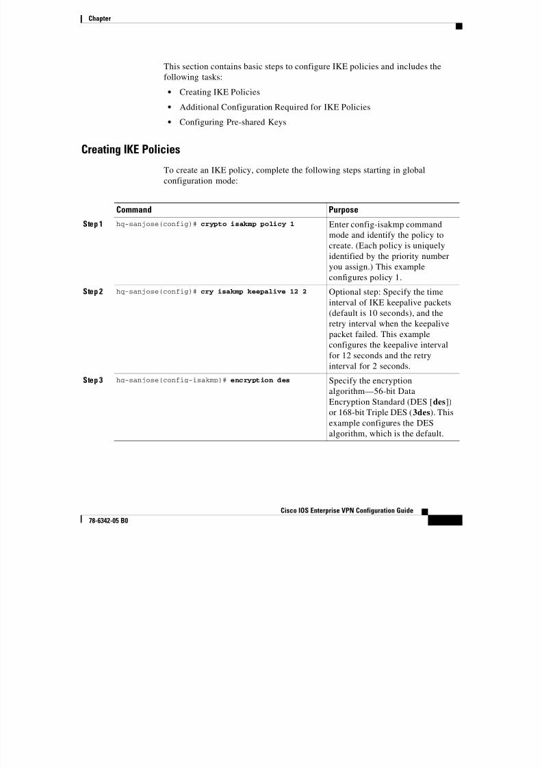
Creating IKE Policies
To create an IKE policy, complete the following steps starting in global
configuration mode:
Command Purpose
Step 1 hq-sanjose(config)# crypto isakmp policy 1 Enter config-isakmp command
mode and identify the policy tocreate. (Each policy is uniquely
identified by the priority number
you assign.) This example
configures policy 1.
Step 2 hq-sanjose(config)# cry isakmp keepalive 12 2 Optional step: Specify the time
interval of IKE keepalive packets
(default is 10 seconds), and theretry interval when the keepalive
packet failed. This example
configures the keepalive interval
for 12 seconds and the retry
interval for 2 seconds.
Step 3 hq-sanjose(config-isakmp)# encryption des Specify the encryption
algorithm—56-bit DataEncryption Standard (DES [des])
or 168-bit Triple DES (3des). This
example configures the DES
algorithm, which is the default.
Chapter
8/6/2019 Site-To-Site and Extranet VPN
http://slidepdf.com/reader/full/site-to-site-and-extranet-vpn 24/74
-24
Cisco IOS Enterprise VPN Configuration Guide
78-6342-05 B0
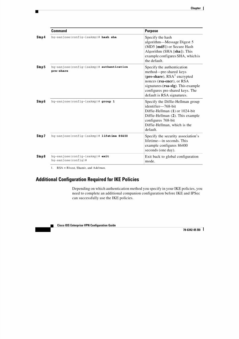
Additional Configuration Required for IKE Policies
Depending on which authentication method you specify in your IKE policies, you
need to complete an additional companion configuration before IKE and IPSec
can successfully use the IKE policies.
Step 4 hq-sanjose(config-isakmp)# hash sha Specify the hashalgorithm—Message Digest 5
(MD5 [md5]) or Secure Hash
Algorithm (SHA [sha]). This
example configures SHA, which is
the default.
Step 5 hq-sanjose(config-isakmp)# authentication
pre-share
Specify the authentication
method—pre-shared keys(pre-share), RSA1 encrypted
nonces (rsa-encr), or RSA
signatures (rsa-slg). This example
configures pre-shared keys. The
default is RSA signatures.
Step 6 hq-sanjose(config-isakmp)# group 1 Specify the Diffie-Hellman group
identifier—768-bitDiffie-Hellman (1) or 1024-bit
Diffie-Hellman (2). This example
configures 768-bit
Diffie-Hellman, which is the
default.
Step 7 hq-sanjose(config-isakmp)# lifetime 86400 Specify the security association’s
lifetime—in seconds. Thisexample configures 86400
seconds (one day).
Step 8 hq-sanjose(config-isakmp)# exit
hq-sanjose(config)#Exit back to global configuration
mode.
1. RSA = Rivest, Shamir, and Adelman.
Command Purpose
Chapter
8/6/2019 Site-To-Site and Extranet VPN
http://slidepdf.com/reader/full/site-to-site-and-extranet-vpn 25/74
-25
Cisco IOS Enterprise VPN Configuration Guide
78-6342-05 B0
Each authentication method requires an additional companion configuration as
follows:
• RSA signatures method:
If you specify RSA signatures as the authentication method in a policy, you
must configure the peers to obtain certificates from a certification authority
(CA). (And, of course, the CA must be properly configured to issue the
certificates.) Configure this certificate support as described in the
“Configuring Certification Authority Interoperability” chapter of the Security
Configuration Guide.
The certificates are used by each peer to securely exchange public keys. (RSA
signatures require that each peer has the remote peer’s public signature key.)
When both peers have valid certificates, they will automatically exchange
public keys with each other as part of any IKE negotiation in which RSA
signatures are used.
• RSA encrypted nonces method:
If you specify RSA encrypted nonces as the authentication method in a
policy, you need to ensure that each peer has the other peers’ public keys.
Unlike RSA signatures, the RSA encrypted nonces method does not use
certificates to exchange public keys. Instead, you ensure that each peer has
the others’ public keys by doing the following:
– Manually configure RSA keys as described in the “Configuring Internet
Key Exchange Security Protocol” chapter of the Security Configuration
Guide.
– Ensure that an IKE exchange using RSA signatures has already occurred
between the peers. (The peers’ public keys are exchanged during the
RSA-signatures-based IKE negotiations.)
To make this happen, specify two policies: a higher-priority policy with
RSA encrypted nonces, and a lower-priority policy with RSA signatures.When IKE negotiations occur, RSA signatures will be used the first time
because the peers do not yet have each others’ public keys. Then, future
IKE negotiations will be able to use RSA-encrypted nonces because the
public keys will have been exchanged.
Of course, this alternative requires that you have CA support configured.
Chapter

8/6/2019 Site-To-Site and Extranet VPN
http://slidepdf.com/reader/full/site-to-site-and-extranet-vpn 26/74
-26
Cisco IOS Enterprise VPN Configuration Guide
78-6342-05 B0
• Pre-shared keys authentication method:
If you specify pre-shared keys as the authentication method in a policy, youmust configure these pre-shared keys as described in the “Configuring
Pre-shared Keys” section on page 3-26.”
• Digital certificate authentication method:
If you specify digital certificates as the authentication method in a policy, the
CA must be properly configured to issue certificates. You must also configure
the peers to obtain certificates from the CA. Configure this certificate support
as described in the “Configuring Certification Authority Interoperability”
chapter of the Security Configuration Guide.
Digital certificates simplify authentication. You need only enroll each peer
with the CA, rather than manually configuring each peer to exchange keys.
Cisco recommends using digital certificates in a network of more than 50
peers. Third party CAs include Microsoft, Verisign, Baltimore, and Entrust.
If RSA encryption is configured and signature mode is negotiated, the peer willrequest both signature and encryption keys. Basically, the router will request as
many keys as the configuration will support. If RSA encryption is not configured,
it will just request a signature key.
Configuring Pre-shared Keys
To configure pre-shared keys, perform these steps at each peer that usespre-shared keys in an IKE policy:
Step 1 Set each peer ISAKMP identity. Each peer identity should be set to either its host
name or by its IP address. By default, a peer identity is set to its IP address.
Step 2 Specify the shared keys at each peer. Note that a given pre-shared key is shared
between two peers. At a given peer, you could specify the same key to share with
multiple remote peers; however, a more secure approach is to specify different
keys to share between different pairs of peers.
Note The following procedure is based on the “Site-to-Site Scenario”
section on page 3-3. However, the same configuration commands
can be used in an extranet scenario.
Chapter
8/6/2019 Site-To-Site and Extranet VPN
http://slidepdf.com/reader/full/site-to-site-and-extranet-vpn 27/74
-27
Cisco IOS Enterprise VPN Configuration Guide
78-6342-05 B0
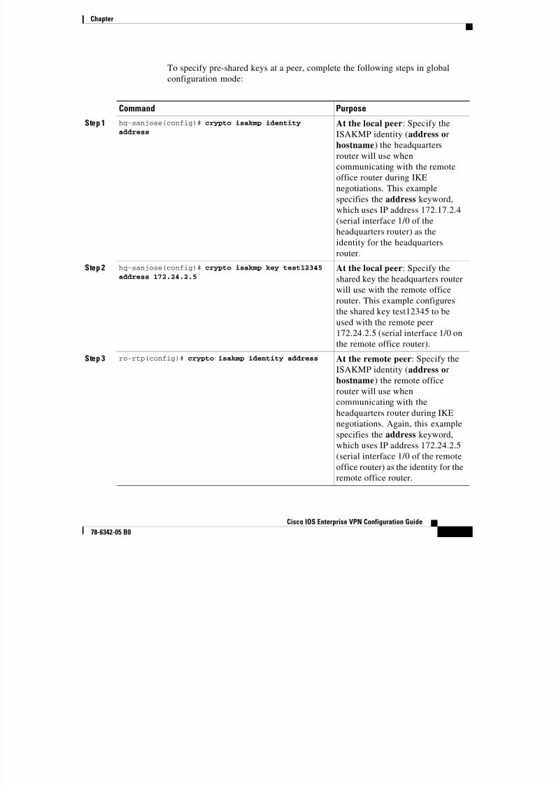
To specify pre-shared keys at a peer, complete the following steps in global
configuration mode:
Command Purpose
Step 1 hq-sanjose(config)# crypto isakmp identity
address
At the local peer: Specify the
ISAKMP identity (address or
hostname) the headquarters
router will use when
communicating with the remoteoffice router during IKE
negotiations. This example
specifies the address keyword,
which uses IP address 172.17.2.4
(serial interface 1/0 of the
headquarters router) as the
identity for the headquartersrouter.
Step 2 hq-sanjose(config)# crypto isakmp key test12345
address 172.24.2.5
At the local peer: Specify the
shared key the headquarters router
will use with the remote office
router. This example configures
the shared key test12345 to be
used with the remote peer172.24.2.5 (serial interface 1/0 on
the remote office router).
Step 3 ro-rtp(config)# crypto isakmp identity address At the remote peer: Specify the
ISAKMP identity (address or
hostname) the remote office
router will use when
communicating with theheadquarters router during IKE
negotiations. Again, this example
specifies the address keyword,
which uses IP address 172.24.2.5
(serial interface 1/0 of the remote
office router) as the identity for the
remote office router.
Chapter
8/6/2019 Site-To-Site and Extranet VPN
http://slidepdf.com/reader/full/site-to-site-and-extranet-vpn 28/74
-28
Cisco IOS Enterprise VPN Configuration Guide
78-6342-05 B0
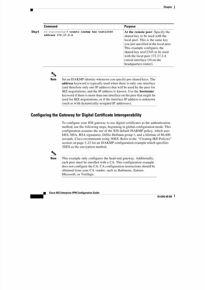
Note Set an ISAKMP identity whenever you specify pre-shared keys. The
address keyword is typically used when there is only one interface
(and therefore only one IP address) that will be used by the peer for
IKE negotiations, and the IP address is known. Use the hostname keyword if there is more than one interface on the peer that might be
used for IKE negotiations, or if the interface IP address is unknown
(such as with dynamically-assigned IP addresses).
Configuring the Gateway for Digital Certificate Interoperability
To configure your IOS gateway to use digital certificates as the authentication
method, use the following steps, beginning in global configuration mode. This
configuration assumes the use of the IOS default ISAKMP policy, which uses
DES, SHA, RSA signatures, Diffie-Hellman group 1, and a lifetime of 86,400
seconds. Cisco recommends using 3DES. Refer to the “Creating IKE Policies”
section on page 3-23 for an ISAKMP configuration example which specifies
3DES as the encryption method.
Note This example only configures the head-end gateway. Additionally,
each peer must be enrolled with a CA. This configuration example
does not configure the CA. CA configuration instructions should be
obtained from your CA vendor, such as Baltimore, Entrust,
Microsoft, or VeriSign.
Step 4 ro-rtp(config)# crypto isakmp key test12345
address 172.17.2.4At the remote peer: Specify theshared key to be used with the
local peer. This is the same key
you just specified at the local peer.
This example configures the
shared key test12345 to be used
with the local peer 172.17.2.4
(serial interface 1/0 on theheadquarters router).
Command Purpose
Chapter

8/6/2019 Site-To-Site and Extranet VPN
http://slidepdf.com/reader/full/site-to-site-and-extranet-vpn 29/74
-29
Cisco IOS Enterprise VPN Configuration Guide
78-6342-05 B0
Command Purpose
Step 1 hq-sanjose(config)# crypto ca identity name Declares a CA. The name should
be the domain name of the CA.
This command puts you into the
ca-identity configuration mode.
Step 2 hq-sanjose(config)# enrollment url url Specifies the URL of the CA. (The
URL should include any
nonstandard cgi-bin script
location.)
Step 3 hq-sanjose(config)# enrollment mode ra (Optional) Specifies RA mode if
your CA system provides a
registration authority (RA).
The Cisco IOS software
automatically determines themode—RA or non-RA; therefore,
if RA mode is used, this
subcommand is written to
NVRAM during "write memory."
Step 4 hq-sanjose(ca-identity)# query url url Specifies the location of the LDAP
server if your CA system provides
an RA and supports the LDAPprotocol.
Step 5 hq-sanjose(ca-identity)# enrollment retry period minutes
(Optional) Specifies that other
peer certificates can still be
accepted by your router even if the
appropriate CRL is not accessible
to your router.
Step 6 hq-sanjose(ca-identity)# enrollment retry count number
(Optional) Specifies how many
times the router will continue to
send unsuccessful certificate
requests before giving up. By
default, the router will never give
up trying.
Chapter
8/6/2019 Site-To-Site and Extranet VPN
http://slidepdf.com/reader/full/site-to-site-and-extranet-vpn 30/74
-30
Cisco IOS Enterprise VPN Configuration Guide
78-6342-05 B0
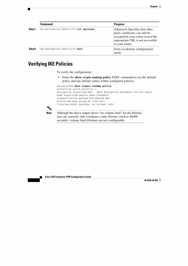
Verifying IKE Policies
To verify the configuration:
• Enter the show crypto isakmp policy EXEC command to see the default
policy and any default values within configured policies.
hq-sanjose# show crypto isakmp policy
Protection suite priority 1encryption algorithm:DES - Data Encryption Standard (56 bit keys)hash algorithm:Secure Hash Standardauthentication method:Pre-Shared KeyDiffie-Hellman group:#1 (768 bit)lifetime:86400 seconds, no volume limit
Note Although the above output shows “no volume limit” for the lifetime,
you can currently only configure a time lifetime (such as 86400
seconds); volume limit lifetimes are not configurable.
Step 7 hq-sanjose(ca-identity)# crl optional (Optional) Specifies that otherpeers certificates can still be
accepted by your router even if the
appropriate CRL is not accessible
to your router.
Step 8 hq-sanjose(ca-identity)# exit Exits ca-identity configuration
mode.
Command Purpose
Chapter
8/6/2019 Site-To-Site and Extranet VPN
http://slidepdf.com/reader/full/site-to-site-and-extranet-vpn 31/74
-31
Cisco IOS Enterprise VPN Configuration Guide
78-6342-05 B0
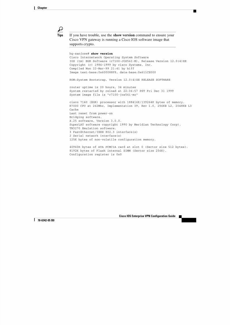
Tips If you have trouble, use the show version command to ensure yourCisco VPN gateway is running a Cisco IOS software image that
supports crypto.
hq-sanjose# show version
Cisco Internetwork Operating System SoftwareIOS (tm) EGR Software (c7100-JOS56I-M), Release Version 12.0(4)XECopyright (c) 1986-1999 by cisco Systems, Inc.
Compiled Mon 22-Mar-99 21:41 by biffImage text-base:0x600088F8, data-base:0x611CE000
ROM:System Bootstrap, Version 12.0(4)XE RELEASE SOFTWARE
router uptime is 20 hours, 34 minutesSystem restarted by reload at 22:36:57 PST Fri Dec 31 1999System image file is "c7100-jos56i-mz"
cisco 7140 (EGR) processor with 188416K/139264K bytes of memory.R7000 CPU at 262Mhz, Implementation 39, Rev 1.0, 256KB L2, 2048KB L3CacheLast reset from power-onBridging software.X.25 software, Version 3.0.0.SuperLAT software copyright 1990 by Meridian Technology Corp).TN3270 Emulation software.3 FastEthernet/IEEE 802.3 interface(s)
2 Serial network interface(s)125K bytes of non-volatile configuration memory.
40960K bytes of ATA PCMCIA card at slot 0 (Sector size 512 bytes).8192K bytes of Flash internal SIMM (Sector size 256K).Configuration register is 0x0
Chapter
8/6/2019 Site-To-Site and Extranet VPN
http://slidepdf.com/reader/full/site-to-site-and-extranet-vpn 32/74
-32
Cisco IOS Enterprise VPN Configuration Guide
78-6342-05 B0
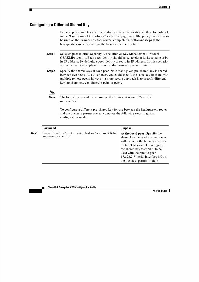
Configuring a Different Shared Key
Because pre-shared keys were specified as the authentication method for policy 1
in the “Configuring IKE Policies” section on page 3-22, (the policy that will also
be used on the business partner router) complete the following steps at the
headquarters router as well as the business partner router:
Step 1 Set each peer Internet Security Association & Key Management Protocol
(ISAKMP) identity. Each peer identity should be set to either its host name or by
its IP address. By default, a peer identity is set to its IP address. In this scenario,
you only need to complete this task at the business partner router.
Step 2 Specify the shared keys at each peer. Note that a given pre-shared key is shared
between two peers. At a given peer, you could specify the same key to share with
multiple remote peers; however, a more secure approach is to specify different
keys to share between different pairs of peers.
Note The following procedure is based on the “Extranet Scenario” section
on page 3-5.
To configure a different pre-shared key for use between the headquarters router
and the business partner router, complete the following steps in global
configuration mode:
Command Purpose
Step 1 hq-sanjose(config)# crypto isakmp key test67890
address 172.23.2.7
At the local peer: Specify the
shared key the headquarters router
will use with the business partner
router. This example configuresthe shared key test67890 to be
used with the remote peer
172.23.2.7 (serial interface 1/0 on
the business partner router).
Chapter
8/6/2019 Site-To-Site and Extranet VPN
http://slidepdf.com/reader/full/site-to-site-and-extranet-vpn 33/74
-33
Cisco IOS Enterprise VPN Configuration Guide
78-6342-05 B0
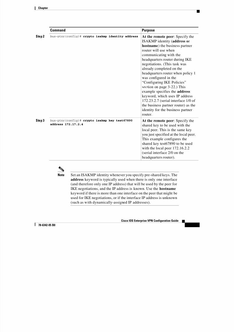
Note Set an ISAKMP identity whenever you specify pre-shared keys. The
address keyword is typically used when there is only one interface
(and therefore only one IP address) that will be used by the peer for
IKE negotiations, and the IP address is known. Use the hostname
keyword if there is more than one interface on the peer that might be
used for IKE negotiations, or if the interface IP address is unknown
(such as with dynamically-assigned IP addresses).
Step 2 bus-ptnr(config)# crypto isakmp identity address At the remote peer: Specify theISAKMP identity (address or
hostname) the business partner
router will use when
communicating with the
headquarters router during IKE
negotiations. (This task was
already completed on theheadquarters router when policy 1
was configured in the
“Configuring IKE Policies”
section on page 3-22.) This
example specifies the address
keyword, which uses IP address
172.23.2.7 (serial interface 1/0 of
the business partner router) as the
identity for the business partner
router.
Step 3 bus-ptnr(config)# crypto isakmp key test67890
address 172.17.2.4
At the remote peer: Specify the
shared key to be used with the
local peer. This is the same key
you just specified at the local peer.
This example configures the
shared key test67890 to be used
with the local peer 172.16.2.2
(serial interface 2/0 on the
headquarters router).
Command Purpose
Chapter
8/6/2019 Site-To-Site and Extranet VPN
http://slidepdf.com/reader/full/site-to-site-and-extranet-vpn 34/74
-34
Cisco IOS Enterprise VPN Configuration Guide
78-6342-05 B0
Configuring IPSec and IPSec Tunnel Mode
After you have configured a different shared key, configure IPSec at each
participating IPSec peer. This section contains basic steps to configure IPSec and
includes the following tasks:
• Creating Crypto Access Lists
• Verifying Crypto Access Lists
• Defining Transform Sets and Configuring IPSec Tunnel Mode• Verifying Transform Sets and IPSec Tunnel Mode
Note IKE uses User Datagram Protocol (UDP) port 500. The IPSec
encapsulating security payload (ESP) and authentication header
(AH) protocols use IP protocol numbers 50 and 51. Ensure that your
access lists are configured so that IP protocol 50, 51, and UDP port
500 traffic is not blocked at interfaces used by IPSec. In some cases,
you might need to add a statement to your access lists to explicitly
permit this traffic. Crypto access lists use the same format as
standard access lists. However, the permit command instructs the
router to encrypt data, and the deny command instructs the router to
allow unencrypted data.
Creating Crypto Access Lists
Crypto access lists are used to define which IP traffic will be protected by crypto
and which traffic will not be protected by crypto. (These access lists are not the
same as regular access lists, which determine what traffic to forward or block at
an interface.) For example, you can create access lists to protect all IP traffic
between the headquarters router and business partner router.The access lists themselves are not specific to IPSec. It is the crypto map entry
referencing the specific access list that defines whether IPSec processing is
applied to the traffic matching a permit in the access list.
Chapter

8/6/2019 Site-To-Site and Extranet VPN
http://slidepdf.com/reader/full/site-to-site-and-extranet-vpn 35/74
-35
Cisco IOS Enterprise VPN Configuration Guide
78-6342-05 B0
To create a crypto access list, enter the following command in global
configuration mode:
Verifying Crypto Access Lists
To verify the configuration:
• Enter the show access-lists 111 EXEC command to see the access list
attributes.
hq-sanjose# show access-lists 111
Extended IP access list 111permit ip host 10.2.2.2 host 10.1.5.3
Tips If you have trouble, make sure you are specifying the correct access
list number.
Command Purpose
hq-sanjose(config)# access-list 111 permit
ip host 10.2.2.2 host 10.1.5.3
Specify conditions to determine which IP packets
are protected.1 (Enable or disable crypto for traffic
that matches these conditions.) This example
configures access list 111 to encrypt all IP traffic
between the headquarters server (translated insideglobal IP address 10.2.2.2) and PC B (IP address
10.1.5.3) in the business partner office.
We recommend that you configure “mirror image”
crypto access lists for use by IPSec and that you
avoid using the any keyword.
1. You specify conditions using an IP access list designated by either a number or a name. The access-list command designates
a numbered extended access list; the ip access-list extended command designates a named access list.
Chapter
8/6/2019 Site-To-Site and Extranet VPN
http://slidepdf.com/reader/full/site-to-site-and-extranet-vpn 36/74
-36
Cisco IOS Enterprise VPN Configuration Guide
78-6342-05 B0
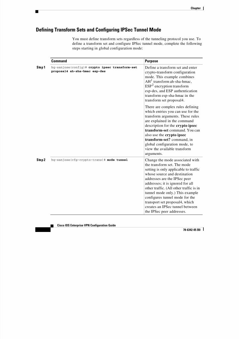
Defining Transform Sets and Configuring IPSec Tunnel Mode
You must define transform sets regardless of the tunneling protocol you use. To
define a transform set and configure IPSec tunnel mode, complete the following
steps starting in global configuration mode:
Command Purpose
Step 1 hq-sanjose(config)# crypto ipsec transform-set
proposal4 ah-sha-hmac esp-des
Define a transform set and enter
crypto-transform configurationmode. This example combines
AH1 transform ah-sha-hmac,
ESP2 encryption transform
esp-des, and ESP authentication
transform esp-sha-hmac in the
transform set proposal4.
There are complex rules definingwhich entries you can use for the
transform arguments. These rules
are explained in the command
description for the crypto ipsec
transform-set command. You can
also use the crypto ipsec
transform-set? command, inglobal configuration mode, to
view the available transform
arguments.
Step 2 hq-sanjose(cfg-crypto-trans)# mode tunnel Change the mode associated with
the transform set. The mode
setting is only applicable to traffic
whose source and destinationaddresses are the IPSec peer
addresses; it is ignored for all
other traffic. (All other traffic is in
tunnel mode only.) This example
configures tunnel mode for the
transport set proposal4, which
creates an IPSec tunnel between
the IPSec peer addresses.
Chapter
8/6/2019 Site-To-Site and Extranet VPN
http://slidepdf.com/reader/full/site-to-site-and-extranet-vpn 37/74
-37
Cisco IOS Enterprise VPN Configuration Guide
78-6342-05 B0
Note AH and ESP can be used independently or together, although for
most applications just one of them is sufficient. For both of these
protocols, IPSec does not define the specific security algorithms to
use, but rather, provides an open framework for implementing
industry-standard algorithms.
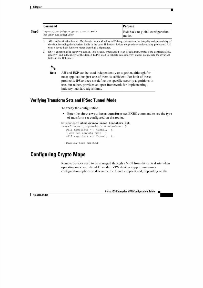
Verifying Transform Sets and IPSec Tunnel Mode
To verify the configuration:
• Enter the show crypto ipsec transform-set EXEC command to see the type
of transform set configured on the router.
hq-sanjose# show crypto ipsec transform-set
Transform set proposal4: { ah-sha-hmac }will negotiate = { Tunnel, },{ esp-des esp-sha-hmac }will negotiate = { Tunnel, },
-Display text omitted-
Configuring Crypto Maps
Remote devices need to be managed through a VPN from the central site when
operating on a centralized IT model. VPN devices support numerous
configuration options to determine the tunnel endpoint and, depending on the
Step 3 hq-sanjose(cfg-crypto-trans)# exithq-sanjose(config)#
Exit back to global configurationmode.
1. AH = authentication header. This header, when added to an IP datagram, ensures the integrity and authenticity of
the data, including the invariant fields in the outer IP header. It does not provide confidentiality protection. AH
uses a keyed-hash function rather than digital signatures.
2. ESP = encapsulating security payload. This header, when added to an IP datagram, protects the confidentiality,
integrity, and authenticity of the data. If ESP is used to validate data integrity, it does not include the invariant
fields in the IP header.
Command Purpose
Chapter

8/6/2019 Site-To-Site and Extranet VPN
http://slidepdf.com/reader/full/site-to-site-and-extranet-vpn 38/74
-38
Cisco IOS Enterprise VPN Configuration Guide
78-6342-05 B0
method chosen, these options may impact the manageability of the network. Refer
to the “Dynamic versus Static Crypto Maps” section on page 2-7 for a discussion
of when to use static or dynamic crypto maps.
To be the most effective in managing remote devices, you must use static
cryptographic maps at the site where your management applications are located.
Dynamic cryptographic maps can be used at the headend for ease of
configuration. Dynamic maps, however, accept only incoming IKE requests, and
because dynamic maps cannot initiate an IKE request, it is not always guaranteed
that a tunnel exists between the remote device and the headend site. Static
cryptographic map configuration includes the static IP addresses of the remote
peers. Thus, remote sites must use static IP addresses to support remote
management.
For IPSec to succeed between two IPSec peers, both peer crypto map entries must
contain compatible configuration statements.
When two peers try to establish a security association (SA), they must each have
at least one crypto map entry that is compatible with one of the other peer cryptomap entries. For two crypto map entries to be compatible, they must meet the
following minimum criteria:
• The crypto map entries must contain compatible crypto access lists (for
example, mirror image access lists). In the case where the responding peer is
using dynamic crypto maps, the entries in the local crypto access list must be
“permitted” by the peer crypto access list.
• The crypto map entries must each identify the other peer (unless theresponding peer is using dynamic crypto maps).
• The crypto map entries must have at least one transform set in common.
When IKE is used to establish SAs, the IPSec peers can negotiate the settings they
will use for the new SAs. This means that you can specify lists (such as lists of
acceptable transforms) within the crypto map entry.
After you have completed configuring IPSec at each participating IPSec peer,configure crypto map entries and apply the crypto maps to interfaces.
The task of configuring IPSec at each peer can be eased by utilizing dynamic
crypto maps. By configuring the head-end gateway with a dynamic map, and the
peers with a static map, the peer will be permitted to establish an IPSec security
association even though the router does not have a crypto map entry specifically
configured to meet all of the remote peer requirements.
Chapter
8/6/2019 Site-To-Site and Extranet VPN
http://slidepdf.com/reader/full/site-to-site-and-extranet-vpn 39/74
-39
Cisco IOS Enterprise VPN Configuration Guide
78-6342-05 B0
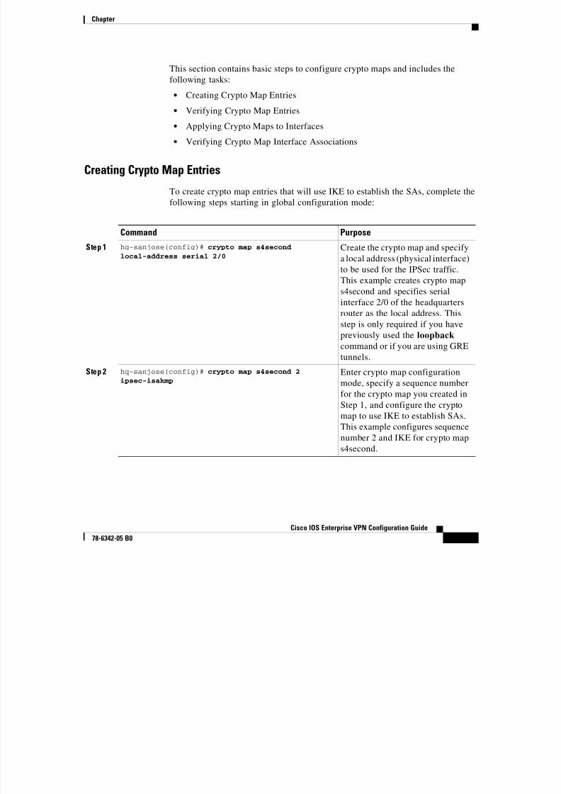
This section contains basic steps to configure crypto maps and includes the
following tasks:
• Creating Crypto Map Entries
• Verifying Crypto Map Entries
• Applying Crypto Maps to Interfaces
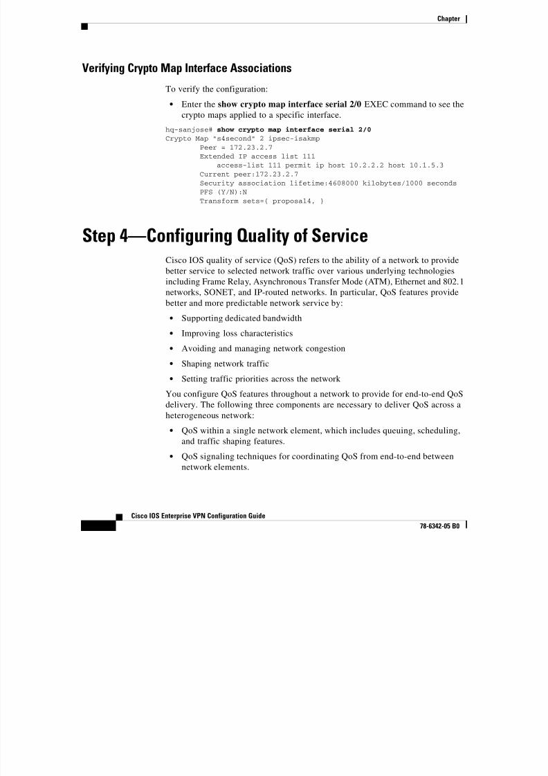
• Verifying Crypto Map Interface Associations
Creating Crypto Map Entries
To create crypto map entries that will use IKE to establish the SAs, complete the
following steps starting in global configuration mode:
Command Purpose
Step 1 hq-sanjose(config)# crypto map s4secondlocal-address serial 2/0 Create the crypto map and specify
a local address (physical interface)
to be used for the IPSec traffic.
This example creates crypto map
s4second and specifies serial
interface 2/0 of the headquarters
router as the local address. This
step is only required if you have
previously used the loopback
command or if you are using GRE
tunnels.
Step 2 hq-sanjose(config)# crypto map s4second 2
ipsec-isakmp
Enter crypto map configuration
mode, specify a sequence number
for the crypto map you created in
Step 1, and configure the crypto
map to use IKE to establish SAs.
This example configures sequence
number 2 and IKE for crypto map
s4second.
Chapter

8/6/2019 Site-To-Site and Extranet VPN
http://slidepdf.com/reader/full/site-to-site-and-extranet-vpn 40/74
-40
Cisco IOS Enterprise VPN Configuration Guide
78-6342-05 B0
To create dynamic crypto map entries that will use IKE to establish the SAs,complete the following steps, starting in global configuration mode:
Step 3 hq-sanjose(config-crypto-map)# match address 111 Specify an extended access list.This access list determines which
traffic is protected by IPSec and
which traffic is not be protected by
IPSec. This example configures
access list 111, which was created
in the “Creating Crypto Access
Lists” section on page 3-34.
Step 4 hq-sanjose(config-crypto-map)# set peer
172.23.2.7
Specify a remote IPSec peer (by
host name or IP address). This is
the peer to which IPSec protected
traffic can be forwarded. This
example specifies serial interface
1/0 (172.23.2.7) on the business
partner router.
Step 5 hq-sanjose(config-crypto-map)# set transform-set
proposal4
Specify which transform sets are
allowed for this crypto map entry.
List multiple transform sets in
order of priority (highest priority
first). This example specifies
transform set proposal4, which
was configured in the “Defining
Transform Sets and Configuring
IPSec Tunnel Mode” section on
page 3-36.
Step 6 hq-sanjose(config-crypto-map)# exit
hq-sanjose(config)#Exit back to global configuration
mode.
Command Purpose
Command Purpose
Step 1 hq-sanjose(config)# crypto dynamic-map dynamic-map-name dynamic-seq-num
Creates a dynamic crypto map
entry.
Chapter
8/6/2019 Site-To-Site and Extranet VPN
http://slidepdf.com/reader/full/site-to-site-and-extranet-vpn 41/74
-41
Cisco IOS Enterprise VPN Configuration Guide
78-6342-05 B0
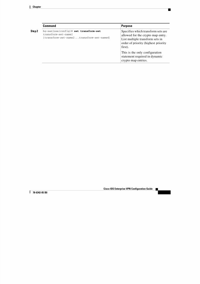
Step 2 hq-sanjose(config)# set transform-set transform-set-name1 [transform-set-name2...transform-set-name6 ]
Specifies which transform sets areallowed for the crypto map entry.
List multiple transform sets in
order of priority (highest priority
first).
This is the only configuration
statement required in dynamic
crypto map entries.
Command Purpose
Chapter
8/6/2019 Site-To-Site and Extranet VPN
http://slidepdf.com/reader/full/site-to-site-and-extranet-vpn 42/74
-42
Cisco IOS Enterprise VPN Configuration Guide
78-6342-05 B0
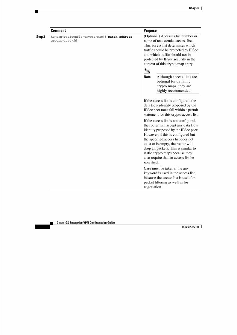
Step 3 hq-sanjose(config-crypto-map)# match address access-list-id (Optional) Accesses list number or
name of an extended access list.
This access list determines which
traffic should be protected by IPSec
and which traffic should not be
protected by IPSec security in the
context of this crypto map entry.
Note Although access-lists are
optional for dynamic
crypto maps, they are
highly recommended.
If the access list is configured, the
data flow identity proposed by theIPSec peer must fall within a permit
statement for this crypto access list.
If the access list is not configured,
the router will accept any data flow
identity proposed by the IPSec peer.
However, if this is configured but
the specified access list does notexist or is empty, the router will
drop all packets. This is similar to
static crypto maps because they
also require that an access list be
specified.
Care must be taken if the any
keyword is used in the access list,because the access list is used for
packet filtering as well as for
negotiation.
Command Purpose
Chapter

8/6/2019 Site-To-Site and Extranet VPN
http://slidepdf.com/reader/full/site-to-site-and-extranet-vpn 43/74
-43
Cisco IOS Enterprise VPN Configuration Guide
78-6342-05 B0
Verifying Crypto Map Entries
To verify the configuration:
• Enter the show crypto map EXEC command to see the crypto map entriesconfigured on the router.
In the following example, peer 172.23.2.7 is the IP address of the remote
IPSec peer. “Extended IP access list 111” lists the access list associated with
the crypto map. “Current peer” indicates the current IPSec peer.
“Security-association lifetime” indicates the lifetime of the SA.
Step 4 hq-sanjose(config-crypto-map)# set peer {hostname | ip-address} (Optional) Specifies a remote IPSec
peer. Repeat for multiple remote
peers.
This is rarely configured in dynamic
crypto map entries. Dynamic crypto
map entries are often used for
unknown remote peers.
Step 5 hq-sanjose(config-crypto-map)# setsecurity-association lifetime seconds secondsand/orset security-association lifetime kilobytes kilobytes
(Optional) If you want the securityassociations for this crypto map to
be negotiated using shorter IPSec
security association lifetimes than
the globally specified lifetimes,
specify a key lifetime for the crypto
map entry.
Step 6 hq-sanjose(config-crypto-map)# exithq-sanjose(config)#
Exit back to global configurationmode.
Command Purpose
Chapter

8/6/2019 Site-To-Site and Extranet VPN
http://slidepdf.com/reader/full/site-to-site-and-extranet-vpn 44/74
-44
Cisco IOS Enterprise VPN Configuration Guide
78-6342-05 B0
“PFS N” indicates that IPSec will not negotiate perfect forward secrecy when
establishing new SAs for this crypto map. “Transform sets” indicates the
name of the transform set that can be used with the crypto map.
hq-sanjose# show crypto map
Crypto Map: “s4second” idb: Serial2/0 local address: 172.16.2.2Crypto Map “s4second” 2 ipsec-isakmp
Peer = 172.23.2.7Extended IP access list 111
access-list 111 permit ipsource: addr = 10.2.2.2/255.255.255.0
dest: addr = 10.1.5.3/255.255.255.0SCurrent peer: 172.23.2.7Security-association lifetime: 4608000 kilobytes/3600 secondsPFS (Y/N): NTransform sets={proposal4,}
-Display text omitted-
Tips If you have trouble, make sure you are using the correct IPaddresses.
Applying Crypto Maps to Interfaces
You need to apply a crypto map set to each interface through which IPSec traffic
will flow. Applying the crypto map set to an interface instructs the router to
evaluate all the interface traffic against the crypto map set, and to use the specified
policy during connection or SA negotiation on behalf of traffic to be protected by
crypto.
To apply a crypto map set to an interface, complete the following steps starting in
global configuration mode:
Command Purpose
Step 1 hq-sanjose(config)# interface serial 2/0 Specify a physical interface on
which to apply the crypto map and
enter interface configuration
mode. This example specifies
serial interface 2/0 on the
headquarters router.
Chapter
8/6/2019 Site-To-Site and Extranet VPN
http://slidepdf.com/reader/full/site-to-site-and-extranet-vpn 45/74
-45
Cisco IOS Enterprise VPN Configuration Guide
78-6342-05 B0
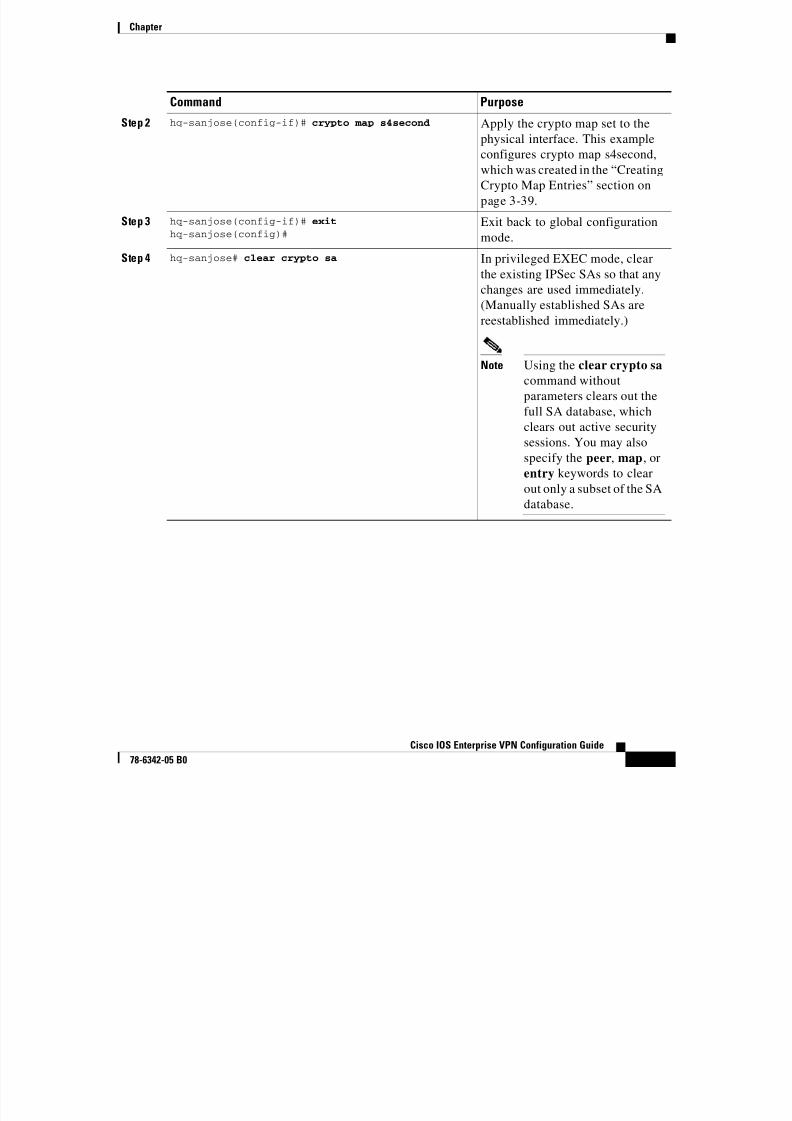
Step 2 hq-sanjose(config-if)# crypto map s4second Apply the crypto map set to thephysical interface. This example
configures crypto map s4second,
which was created in the “Creating
Crypto Map Entries” section on
page 3-39.
Step 3 hq-sanjose(config-if)# exit
hq-sanjose(config)#Exit back to global configuration
mode.Step 4 hq-sanjose# clear crypto sa In privileged EXEC mode, clear
the existing IPSec SAs so that any
changes are used immediately.
(Manually established SAs are
reestablished immediately.)
Note Using the clear crypto sa
command without
parameters clears out the
full SA database, which
clears out active security
sessions. You may also
specify the peer, map, or
entry keywords to clear
out only a subset of the SA
database.
Command Purpose
Chapter
8/6/2019 Site-To-Site and Extranet VPN
http://slidepdf.com/reader/full/site-to-site-and-extranet-vpn 46/74
-46
Cisco IOS Enterprise VPN Configuration Guide
78-6342-05 B0
Verifying Crypto Map Interface Associations
To verify the configuration:
• Enter the show crypto map interface serial 2/0 EXEC command to see the
crypto maps applied to a specific interface.
hq-sanjose# show crypto map interface serial 2/0
Crypto Map "s4second" 2 ipsec-isakmpPeer = 172.23.2.7Extended IP access list 111
access-list 111 permit ip host 10.2.2.2 host 10.1.5.3Current peer:172.23.2.7Security association lifetime:4608000 kilobytes/1000 secondsPFS (Y/N):NTransform sets={ proposal4, }
Step 4—Configuring Quality of ServiceCisco IOS quality of service (QoS) refers to the ability of a network to provide
better service to selected network traffic over various underlying technologies
including Frame Relay, Asynchronous Transfer Mode (ATM), Ethernet and 802.1
networks, SONET, and IP-routed networks. In particular, QoS features provide
better and more predictable network service by:
• Supporting dedicated bandwidth
• Improving loss characteristics
• Avoiding and managing network congestion
• Shaping network traffic
• Setting traffic priorities across the network
You configure QoS features throughout a network to provide for end-to-end QoS
delivery. The following three components are necessary to deliver QoS across aheterogeneous network:
• QoS within a single network element, which includes queuing, scheduling,
and traffic shaping features.
• QoS signaling techniques for coordinating QoS from end-to-end between
network elements.
Chapter
8/6/2019 Site-To-Site and Extranet VPN
http://slidepdf.com/reader/full/site-to-site-and-extranet-vpn 47/74
-47
Cisco IOS Enterprise VPN Configuration Guide
78-6342-05 B0
• QoS policing and management functions to control and administer
end-to-end traffic across a network.
Not all QoS techniques are appropriate for all network routers. Because edge
routers and backbone routers in a network do not necessarily perform the same
operations, the QoS tasks they perform might differ as well.
In general, edge routers perform the following QoS functions:
• Packet classification and prioritization
• Admission control, such as queuing and policing
• Bandwidth management
In general, backbone routers perform the following QoS functions:
• Congestion management
• Congestion avoidance
Cisco IOS QoS service models, features, and sample configurations are explained
in detail in the Quality of Service Solutions Configuration Guide and the Qualityof Service Solutions Command Reference. Refer to these two publications as you
plan and implement a QoS strategy for your VPN, because there are various QoS
service models and features that you can implement on your VPN.
This section contains basic steps to configure QoS weighted fair queuing (WFQ),
which applies priority (or weights) to identified traffic on the GRE tunnel you
configured in the “Step 1—Configuring the Tunnel” section on page 3-8. This
section also contains basic steps to configure Network-Based ApplicationRecognition (NBAR), which is a classification engine that recognizes a wide
variety of applications, including web-based and other protocols that utilize
dynamic TCP/UDP port assignments.
This section includes the following topics:
• Configuring Network-Based Application Recognition
• Configuring Weighted Fair Queuing
• Verifying Weighted Fair Queuing
• Configuring Class-Based Weighted Fair Queuing
• Verifying Class-Based Weighted Fair Queuing
Chapter
C fi i N k B d A li i R i i

8/6/2019 Site-To-Site and Extranet VPN
http://slidepdf.com/reader/full/site-to-site-and-extranet-vpn 48/74
-48
Cisco IOS Enterprise VPN Configuration Guide
78-6342-05 B0
Configuring Network-Based Application Recognition
Network-Based Application Recognition (NBAR) adds intelligent network
classification to network infrastructures. NBAR is a classification engine that
recognizes a wide variety of applications, including web-based and other
protocols that utilize dynamic TCP/UDP port assignments. When an application
is recognized and classified by NBAR, a network can invoke services for that
specific application. NBAR ensures that network bandwidth is used efficiently by
working with QoS features.
Your interface to NBAR is through the modular QoS command-line interface
(MQC). MQC provides a model for QoS configuration under IOS. MQC provides
a clean separation between the specification of a classification policy and the
specification of other policies that act based on the results of the applied
classification.
Configuring a QoS policy typically requires the configuration of traffic classes,
the configuration of policies that will be applied to those traffic classes, and the
attaching of policies to interfaces using the commands in the sections that follow.
The following tasks are required to configure NBAR:
• Configuring a Class Map
• Verifying a Class Map Configuration
• Configuring a Policy Map
• Attaching a Policy Map to an Interface
• Verifying a Policy Map Configuration
Note You must enable Cisco Express Forwarding (CEF) before you
configure NBAR. For more information on CEF, refer to the
Cisco IOS Release 12.0 configuration guide titled Cisco IOS
Switching Services Configuration Guide.
Configuring a Class Map
Use the class-map configuration command to define a traffic class and the match
criteria that will be used to identify traffic as belonging to that class. Match
statements can include criteria such as protocol, ACL, IP precedence value, or
Chapter
i t f id tifi Th t h it i i d fi d ith f th t h
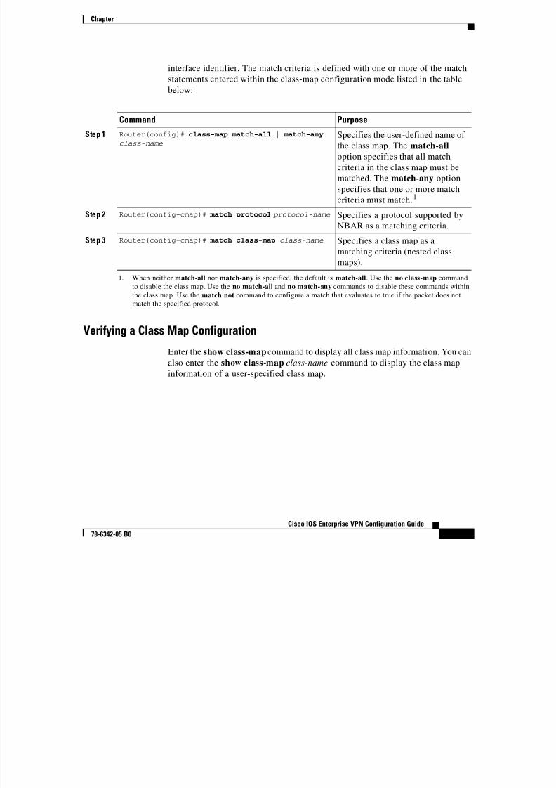
8/6/2019 Site-To-Site and Extranet VPN
http://slidepdf.com/reader/full/site-to-site-and-extranet-vpn 49/74
-49
Cisco IOS Enterprise VPN Configuration Guide
78-6342-05 B0
interface identifier. The match criteria is defined with one or more of the match
statements entered within the class-map configuration mode listed in the table
below:
Verifying a Class Map Configuration
Enter the show class-map command to display all class map information. You can
also enter the show class-map class-name command to display the class map
information of a user-specified class map.
Command Purpose
Step 1 Router(config)# class-map match-all | match-anyclass-name
Specifies the user-defined name of
the class map. The match-all
option specifies that all match
criteria in the class map must bematched. The match-any option
specifies that one or more match
criteria must match.1
1. When neither match-all nor match-any is specified, the default is match-all. Use the no class-map command
to disable the class map. Use the no match-all and no match-any commands to disable these commands within
the class map. Use the match not command to configure a match that evaluates to true if the packet does not
match the specified protocol.
Step 2 Router(config-cmap)# match protocol protocol-name Specifies a protocol supported by
NBAR as a matching criteria.
Step 3 Router(config-cmap)# match class-map class-name Specifies a class map as a
matching criteria (nested classmaps).
Chapter
Configuring a Policy Map

8/6/2019 Site-To-Site and Extranet VPN
http://slidepdf.com/reader/full/site-to-site-and-extranet-vpn 50/74
-50
Cisco IOS Enterprise VPN Configuration Guide
78-6342-05 B0
Configuring a Policy Map
Use the policy-map configuration command to specify the QoS policies to applyto traffic classes defined by a class map. QoS policies that can be applied to traffic
classification are listed in the table below.
Use the no policy-map command to deconfigure the policy map. Use the no
bandwidth, no police, no set, and no random-detect commands to disable thesecommands within the policy map.
Attaching a Policy Map to an Interface
Use the service-policy interface configuration command to attach a policy map to
an interface and to specify the direction in which the policy should be applied (on
either packets coming into the interface or packets leaving the interface).
Command Purpose
Step 1 Router(config)# policy-map policy-name User specified policy map name.
Step 2 Router(config-pmap)# class class-name Specifies the name of a previouslydefined class map.
Step 3 Router(config-pmap-c)# bandwidth kbps Specifies a minimum bandwidth
guarantee to a traffic class.
Step 4 Router(config-pmap-c)# police bps conform transmit exceed drop
Specifies a maximum bandwidth
usage by a traffic class.
Step 5 Router(config-pmap-c)# set ip precedence {0-7} Specifies the IP precedence of packets within a traffic class.
Step 6 outer(config-pmap-c)# set qos-group {0-99} Specifies a QoS-group value to
associate with the packet.
Step 7 Router(config-pmap-c)# random-detect Enables weighted random early
detection (WRED) drop policy for
a traffic class which has a
bandwidth guarantee.
Step 8 Router(config-pmap-c)# queue-limit packets Specifies maximum number of
packets queued for a traffic class
(in the absence of random-detect).
Chapter
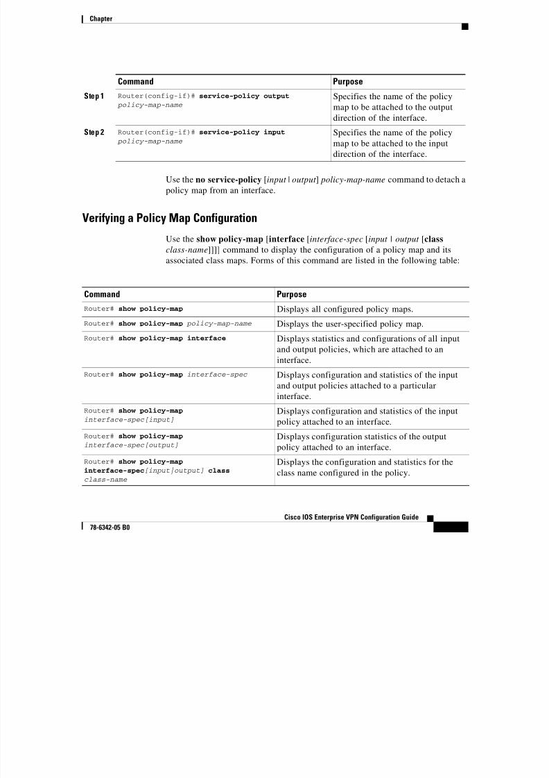
8/6/2019 Site-To-Site and Extranet VPN
http://slidepdf.com/reader/full/site-to-site-and-extranet-vpn 51/74
-51
Cisco IOS Enterprise VPN Configuration Guide
78-6342-05 B0
Use the no service-policy [input | output ] policy-map-name command to detach a
policy map from an interface.
Verifying a Policy Map Configuration
Use the show policy-map [interface [interface-spec [input | output [class
class-name]]]] command to display the configuration of a policy map and itsassociated class maps. Forms of this command are listed in the following table:
Command Purpose
Step 1 Router(config-if)# service-policy output
policy-map-nameSpecifies the name of the policy
map to be attached to the output
direction of the interface.
Step 2 Router(config-if)# service-policy input
policy-map-nameSpecifies the name of the policy
map to be attached to the input
direction of the interface.
Command Purpose
Router# show policy-map Displays all configured policy maps.
Router# show policy-map policy-map-name Displays the user-specified policy map.Router# show policy-map interface Displays statistics and configurations of all input
and output policies, which are attached to an
interface.
Router# show policy-map interface-spec Displays configuration and statistics of the input
and output policies attached to a particular
interface.
Router# show policy-map
interface-spec[input]Displays configuration and statistics of the input
policy attached to an interface.
Router# show policy-map
interface-spec[output]Displays configuration statistics of the output
policy attached to an interface.
Router# show policy-map
interface-spec[input|output] class class-name
Displays the configuration and statistics for the
class name configured in the policy.
Chapter
Configuring Weighted Fair Queuing

8/6/2019 Site-To-Site and Extranet VPN
http://slidepdf.com/reader/full/site-to-site-and-extranet-vpn 52/74
-52
Cisco IOS Enterprise VPN Configuration Guide
78-6342-05 B0
Configuring Weighted Fair Queuing
Weighted Fair Queuing (WFQ) provides traffic priority management that
automatically sorts among individual traffic streams without requiring that you
first define access lists. WFQ can also manage duplex data streams such as those
between pairs of applications, and simplex data streams such as voice or video.
There are two categories of WFQ sessions: high bandwidth and low bandwidth.
Low-bandwidth traffic has effective priority over high-bandwidth traffic, and
high-bandwidth traffic shares the transmission service proportionally according
to assigned weights.
When WFQ is enabled for an interface, new messages for high-bandwidth traffic
streams are discarded after the configured or default congestive messages
threshold has been met. However, low-bandwidth conversations, which include
control message conversations, continue to enqueue data. As a result, the fair
queue may occasionally contain more messages than its configured threshold
number specifies.
With standard WFQ, packets are classified by flow. Packets with the same source
IP address, destination IP address, source Transmission Control Protocol (TCP)
or User Datagram Protocol (UDP) port, or destination TCP or UDP port belong to
the same flow. WFQ allocates an equal share of the bandwidth to each flow.
Flow-based WFQ is also called fair queuing because all flows are equally
weighted.
To configure fair queuing on an interface, complete the following steps starting in
global configuration mode:
Command Purpose
Step 1 hq-sanjose(config)# interface serial 1/0 Specify an interface and enter
interface configuration mode. This
example specifies serial interface
1/0 on the headquarters router.
Step 2 hq-sanjose(config-if)# fair-queue Configure fair queuing on the
interface.
Step 3 hq-sanjose(config-if)# exit
hq-sanjose(config)#Exit back to global configuration
mode.
Chapter
Verifying Weighted Fair Queuing
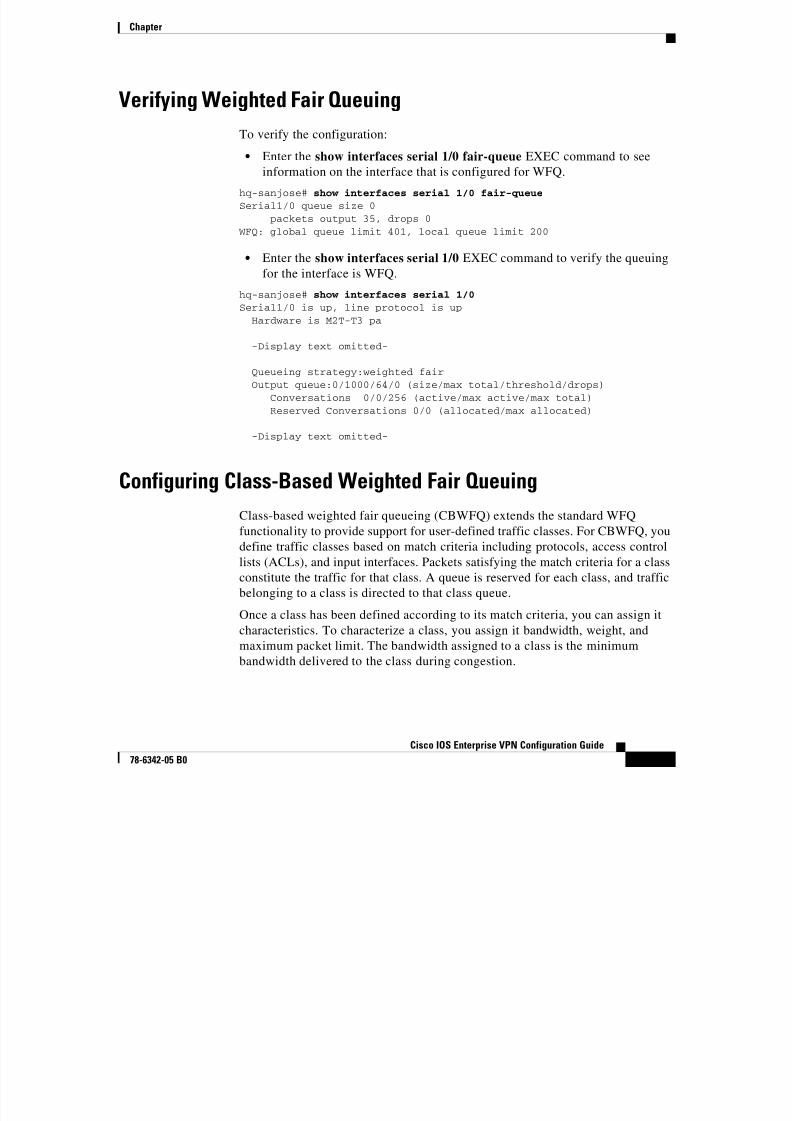
8/6/2019 Site-To-Site and Extranet VPN
http://slidepdf.com/reader/full/site-to-site-and-extranet-vpn 53/74
-53
Cisco IOS Enterprise VPN Configuration Guide
78-6342-05 B0
Verifying Weighted Fair Queuing
To verify the configuration:
• Enter the show interfaces serial 1/0 fair-queue EXEC command to see
information on the interface that is configured for WFQ.
hq-sanjose# show interfaces serial 1/0 fair-queue
Serial1/0 queue size 0packets output 35, drops 0
WFQ: global queue limit 401, local queue limit 200
• Enter the show interfaces serial 1/0 EXEC command to verify the queuing
for the interface is WFQ.
hq-sanjose# show interfaces serial 1/0
Serial1/0 is up, line protocol is upHardware is M2T-T3 pa
-Display text omitted-
Queueing strategy:weighted fairOutput queue:0/1000/64/0 (size/max total/threshold/drops)
Conversations 0/0/256 (active/max active/max total)Reserved Conversations 0/0 (allocated/max allocated)
-Display text omitted-
Configuring Class-Based Weighted Fair Queuing
Class-based weighted fair queueing (CBWFQ) extends the standard WFQ
functionality to provide support for user-defined traffic classes. For CBWFQ, you
define traffic classes based on match criteria including protocols, access control
lists (ACLs), and input interfaces. Packets satisfying the match criteria for a class
constitute the traffic for that class. A queue is reserved for each class, and traffic
belonging to a class is directed to that class queue.
Once a class has been defined according to its match criteria, you can assign it
characteristics. To characterize a class, you assign it bandwidth, weight, and
maximum packet limit. The bandwidth assigned to a class is the minimum
bandwidth delivered to the class during congestion.
Chapter
To characterize a class, you also specify the queue limit for that class, which is

8/6/2019 Site-To-Site and Extranet VPN
http://slidepdf.com/reader/full/site-to-site-and-extranet-vpn 54/74
-54
Cisco IOS Enterprise VPN Configuration Guide
78-6342-05 B0
y p y q
the maximum number of packets allowed to accumulate in the class queue.
Packets belonging to a class are subject to the bandwidth and queue limits thatcharacterize the class.
After a queue has reached its configured queue limit, enqueuing of additional
packets to the class causes tail drop or packet drop to take effect, depending on
how class policy is configured.
Tail drop is used for CBWFQ classes unless you explicitly configure policy for a
class to use weighted random early detection (WRED) to drop packets as a means
of avoiding congestion. Note that if you use WRED packet drop instead of tail
drop for one or more classes comprising a policy map, you must ensure that
WRED is not configured for the interface to which you attach that service policy.
Note Although CBWFQ supports the use of WRED, this guide does not
include WRED configuration procedures. For more information on
using WRED with CBWFQ, refer to the Cisco IOS Release 12.2 Configuration Guide Master Index. To access this document, go to
Cisco.com and select the following links: Technical Documents:
Cisco IOS Software: Cisco IOS Release 12.2: Cisco IOS Release
12.2 Master Indexes.
If a default class is configured, all unclassified traffic is treated as belonging to
the default class. If no default class is configured, then by default the traffic thatdoes not match any of the configured classes is flow classified and given
best-effort treatment. Once a packet is classified, all of the standard mechanisms
that can be used to differentiate service among the classes apply.
Flow classification is standard WFQ treatment. That is, packets with the same
source IP address, destination IP address, source Transmission Control Protocol
(TCP) or User Datagram Protocol (UDP) port, or destination TCP or UDP port are
classified as belonging to the same flow. WFQ allocates an equal share of bandwidth to each flow. Flow-based WFQ is also called fair queueing because all
flows are equally weighted.
For CBWFQ, which extends the standard WFQ, the weight specified for the class
becomes the weight of each packet that meets the match criteria of the class.
Packets that arrive at the output interface are classified according to the match
criteria filters you define, then each one is assigned the appropriate weight.
Chapter
The weight for a packet belonging to a specific class is derived from the

8/6/2019 Site-To-Site and Extranet VPN
http://slidepdf.com/reader/full/site-to-site-and-extranet-vpn 55/74
-55
Cisco IOS Enterprise VPN Configuration Guide
78-6342-05 B0
bandwidth you assigned to the class when you configured it; in this sense the
weight for a class is user-configurable.
After a packet's weight is assigned, the packet is enqueued in the appropriate class
queue. CBWFQ uses the weights assigned to the queued packets to ensure that the
class queue is serviced fairly.
The following tasks are required to configure CBWFQ:
• Defining a Class Map
• Configuring Class Policy in the Policy Map (Tail Drop)
• Attaching the Service Policy and Enabling CBWFQ
Note Attaching a service policy to an interface disables WFQ on that
interface if WFQ is configured for the interface. For this reason, you
should ensure that WFQ is not enabled on such an interface. For
additional information on WFQ, see the "Configuring Weighted FairQueueing" chapter of the Cisco IOS Release 12.0 Quality of Service
Solutions Configuration Guide.
Defining a Class Map
To create a class map containing match criteria against which a packet is checkedto determine if it belongs to a class, and to effectively create the class whose
policy can be specified in one or more policy maps, use the first command in
global configuration mode to specify the class-map name. Then use one of the
following commands in class-map configuration mode:
Command Purpose
Step 1 hq-sanjose(config)# class-map class-map-name Specifies the name of the class
map to be created.
Step 2 hq-sanjose(config-cmap)# match access-groupaccess-group
Specifies the name of the
numbered ACL against whose
contents packets are checked to
determine if they belong to the
class.
Chapter
Command Purpose
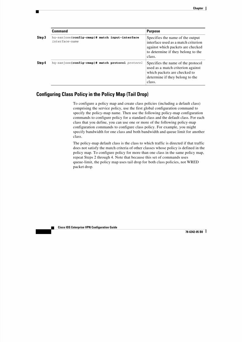
8/6/2019 Site-To-Site and Extranet VPN
http://slidepdf.com/reader/full/site-to-site-and-extranet-vpn 56/74
-56
Cisco IOS Enterprise VPN Configuration Guide
78-6342-05 B0
Configuring Class Policy in the Policy Map (Tail Drop)
To configure a policy map and create class policies (including a default class)
comprising the service policy, use the first global configuration command tospecify the policy-map name. Then use the following policy-map configuration
commands to configure policy for a standard class and the default class. For each
class that you define, you can use one or more of the following policy-map
configuration commands to configure class policy. For example, you might
specify bandwidth for one class and both bandwidth and queue limit for another
class.
The policy-map default class is the class to which traffic is directed if that trafficdoes not satisfy the match criteria of other classes whose policy is defined in the
policy map. To configure policy for more than one class in the same policy map,
repeat Steps 2 through 4. Note that because this set of commands uses
queue-limit, the policy map uses tail drop for both class policies, not WRED
packet drop.
Step 3 hq-sanjose(config-cmap)# match input-interface interface-name Specifies the name of the outputinterface used as a match criterion
against which packets are checked
to determine if they belong to the
class.
Step 4 hq-sanjose(config-cmap)# match protocol protocol Specifies the name of the protocol
used as a match criterion against
which packets are checked todetermine if they belong to the
class.
p
Chapter
To attach a service policy to an interface and enable CBWFQ on the interface, you
t t li Y fi l li i f l
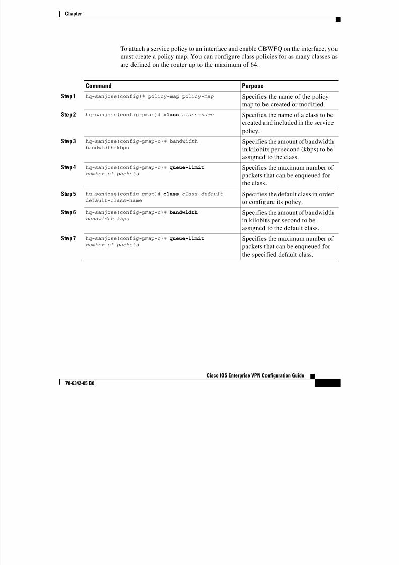
8/6/2019 Site-To-Site and Extranet VPN
http://slidepdf.com/reader/full/site-to-site-and-extranet-vpn 57/74
-57
Cisco IOS Enterprise VPN Configuration Guide
78-6342-05 B0
must create a policy map. You can configure class policies for as many classes as
are defined on the router up to the maximum of 64.
Command Purpose
Step 1 hq-sanjose(config)# policy-map policy-map Specifies the name of the policy
map to be created or modified.
Step 2 hq-sanjose(config-pmap)# class class-name Specifies the name of a class to be
created and included in the servicepolicy.
Step 3 hq-sanjose(config-pmap-c)# bandwidthbandwidth-kbps
Specifies the amount of bandwidth
in kilobits per second (kbps) to be
assigned to the class.
Step 4 hq-sanjose(config-pmap-c)# queue-limit number-of-packets
Specifies the maximum number of
packets that can be enqueued for
the class.
Step 5 hq-sanjose(config-pmap)# class class-default default-class-name
Specifies the default class in order
to configure its policy.
Step 6 hq-sanjose(config-pmap-c)# bandwidth bandwidth-kbps
Specifies the amount of bandwidth
in kilobits per second to be
assigned to the default class.
Step 7 hq-sanjose(config-pmap-c)# queue-limit number-of-packets
Specifies the maximum number of packets that can be enqueued for
the specified default class.
Chapter
Attaching the Service Policy and Enabling CBWFQ
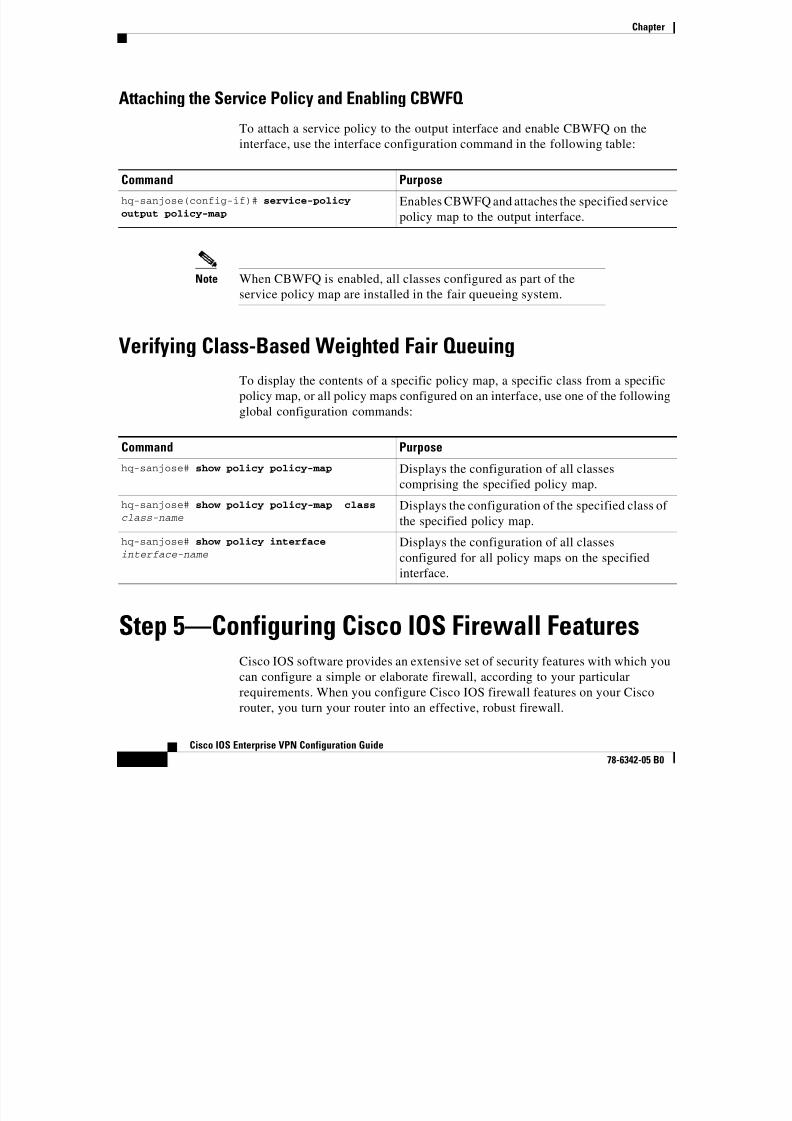
8/6/2019 Site-To-Site and Extranet VPN
http://slidepdf.com/reader/full/site-to-site-and-extranet-vpn 58/74
-58
Cisco IOS Enterprise VPN Configuration Guide
78-6342-05 B0
To attach a service policy to the output interface and enable CBWFQ on theinterface, use the interface configuration command in the following table:
Note When CBWFQ is enabled, all classes configured as part of the
service policy map are installed in the fair queueing system.
Verifying Class-Based Weighted Fair QueuingTo display the contents of a specific policy map, a specific class from a specific
policy map, or all policy maps configured on an interface, use one of the following
global configuration commands:
Step 5—Configuring Cisco IOS Firewall FeaturesCisco IOS software provides an extensive set of security features with which you
can configure a simple or elaborate firewall, according to your particular
requirements. When you configure Cisco IOS firewall features on your Cisco
router, you turn your router into an effective, robust firewall.
Command Purpose
hq-sanjose(config-if)# service-policy
output policy-map
Enables CBWFQ and attaches the specified service
policy map to the output interface.
Command Purpose
hq-sanjose# show policy policy-map Displays the configuration of all classescomprising the specified policy map.
hq-sanjose# show policy policy-map class
class-nameDisplays the configuration of the specified class of
the specified policy map.
hq-sanjose# show policy interface interface-name
Displays the configuration of all classes
configured for all policy maps on the specified
interface.
Chapter
Cisco IOS firewall features are designed to prevent unauthorized, external
individuals from gaining access to your internal network and to block attacks on
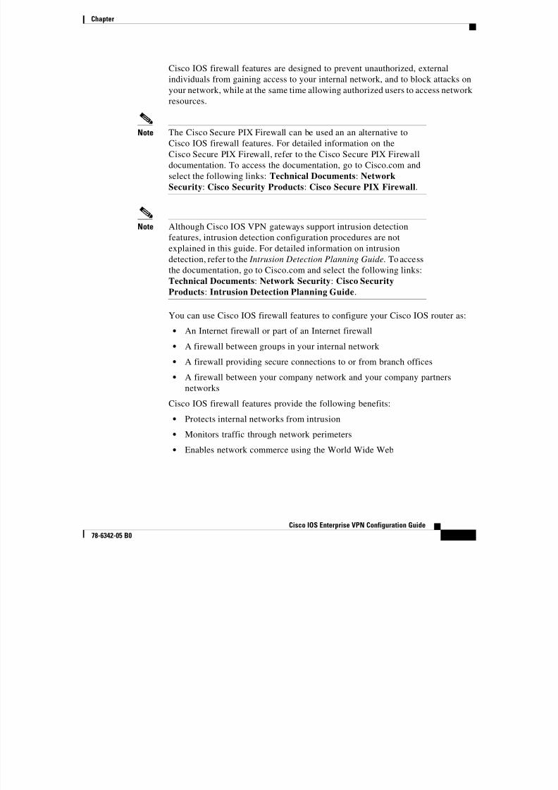
8/6/2019 Site-To-Site and Extranet VPN
http://slidepdf.com/reader/full/site-to-site-and-extranet-vpn 59/74
-59
Cisco IOS Enterprise VPN Configuration Guide
78-6342-05 B0
individuals from gaining access to your internal network, and to block attacks on
your network, while at the same time allowing authorized users to access network resources.
Note The Cisco Secure PIX Firewall can be used an an alternative to
Cisco IOS firewall features. For detailed information on the
Cisco Secure PIX Firewall, refer to the Cisco Secure PIX Firewall
documentation. To access the documentation, go to Cisco.com and
select the following links: Technical Documents: Network
Security: Cisco Security Products: Cisco Secure PIX Firewall.
Note Although Cisco IOS VPN gateways support intrusion detection
features, intrusion detection configuration procedures are not
explained in this guide. For detailed information on intrusiondetection, refer to the Intrusion Detection Planning Guide. To access
the documentation, go to Cisco.com and select the following links:
Technical Documents: Network Security: Cisco Security
Products: Intrusion Detection Planning Guide.
You can use Cisco IOS firewall features to configure your Cisco IOS router as:
• An Internet firewall or part of an Internet firewall• A firewall between groups in your internal network
• A firewall providing secure connections to or from branch offices
• A firewall between your company network and your company partners
networks
Cisco IOS firewall features provide the following benefits:
• Protects internal networks from intrusion
• Monitors traffic through network perimeters
• Enables network commerce using the World Wide Web
Chapter
At a minimum, you must configure basic traffic filtering to provide a basic
firewall. You can configure your Cisco IOS gateway to function as a firewall by

8/6/2019 Site-To-Site and Extranet VPN
http://slidepdf.com/reader/full/site-to-site-and-extranet-vpn 60/74
-60
Cisco IOS Enterprise VPN Configuration Guide
78-6342-05 B0
firewall. You can configure your Cisco IOS gateway to function as a firewall by
using the following Cisco IOS security features:• Static access lists and static or dynamic extended access lists
• Lock-and-key (dynamic extended access lists)
• Reflective access lists
• TCP intercept
• Context-based access control
• Security server support
• Network address translation
• Cisco Encryption Technology
• IPSec network security
• Neighbor router authentication
• Event logging
• User authentication and authorization
Note Refer to the “Traffic Filtering and Firewalls” part of the Security
Configuration Guide and the Security Command Reference for
advanced firewall configuration information. To access thedocumentation, go to Cisco.com and select the following links:
Technical Documents: Cisco IOS Software: Release 12.2:
Configuration Guides and Command References:
This section explains how to configure an extended access list, which is a
sequential collection of permit and deny conditions that apply to an IP address.
This section includes the following topics:• Creating Extended Access Lists Using Access List Numbers
• Verifying Extended Access Lists
• Applying Access Lists to Interfaces
• Verifying Extended Access Lists Are Applied Correctly
Chapter
N t Th t d d li t fi ti l i d i thi ti i

8/6/2019 Site-To-Site and Extranet VPN
http://slidepdf.com/reader/full/site-to-site-and-extranet-vpn 61/74
-61
Cisco IOS Enterprise VPN Configuration Guide
78-6342-05 B0
Note The extended access list configuration explained in this section is
different from the crypto access list configuration explained in the
“Creating Crypto Access Lists” section on page 3-34. Crypto access
lists are used to define which IP traffic is or is not protected by
crypto, while an extended access list is used to determine which IP
traffic to forward or block at an interface.
The simplest connectivity to the Internet is to use a single device to provide the
connectivity and firewall function to the Internet. With everything being in asingle device, it is easy to address translation and termination of the VPN tunnels.
Complexity arises when you need to add extra VPN gateways to the network. This
normally leads people into building a network where the corporate network
touches the Internet through a network called the DMZ, or demilitarized zone.
Creating Extended Access Lists Using Access List NumbersTo create an extended access list that denies and permits certain types of traffic,
complete the following steps starting in global configuration mode:
Command Purpose
Step 1 hq-sanjose(config)#access-list 102 deny tcp any
any Define access list 102 andconfigure the access list to deny all
TCP traffic.
Step 2 hq-sanjose(config)# access-list 102 deny udp any
any
Configure access list 102 to deny
all UDP traffic.
Step 3 hq-sanjose(config)# access-list 102 permit ip
any any
Configure access list 102 to permit
all IP traffic.
Chapter
Verifying Extended Access Lists

8/6/2019 Site-To-Site and Extranet VPN
http://slidepdf.com/reader/full/site-to-site-and-extranet-vpn 62/74
-62
Cisco IOS Enterprise VPN Configuration Guide
78-6342-05 B0
To verify the configuration:
Enter the show access-lists 102 EXEC command to display the contents of the
access list.
hq-sanjose# show access-list 102
Extended IP access list 102deny tcp any anydeny udp any any
permit ip any any
Applying Access Lists to Interfaces
After you create an access list, you can apply it to one or more interfaces. Access
lists can be applied on either outbound or inbound interfaces.
To apply an access list inbound and outbound on an interface, complete thefollowing steps starting in global configuration mode:
Command Purpose
Step 1 hq-sanjose(config)# interface serial 1/0 Specify serial interface 1/0 on the
headquarters router and enter
interface configuration mode.Step 2 hq-sanjose(config-if)# ip access-group 102 in Configure access list 102 inbound
on serial interface 1/0 on the
headquarters router.
Step 3 hq-sanjose(config-if)# ip access-group 102 out Configure access list 102
outbound on serial interface 1/0 on
the headquarters router.
Step 4 hq-sanjose(config-if)# exit
hq-sanjose(config)#Exit back to global configuration
mode.
Chapter
For inbound access lists, after receiving a packet, the Cisco IOS software checks
the source address of the packet against the access list. If the access list permits
8/6/2019 Site-To-Site and Extranet VPN
http://slidepdf.com/reader/full/site-to-site-and-extranet-vpn 63/74
-63
Cisco IOS Enterprise VPN Configuration Guide
78-6342-05 B0
the address, the software continues to process the packet. If the access list rejectsthe address, the software discards the packet and returns an “icmp host
unreachable” message.
For outbound access lists, after receiving and routing a packet to a controlled
interface, the software checks the destination address of the packet against the
access list. If the access list permits the address, the software transmits the packet.
If the access list rejects the address, the software discards the packet and returns
an “ICMP Host Unreachable” message.When you apply an access list that has not yet been defined to an interface, the
software acts as if the access list has not been applied to the interface and will
accept all packets. Be aware of this behavior if you use undefined access lists as
a means of security in your network.
Verifying Extended Access Lists Are Applied CorrectlyTo verify the configuration:
• Enter the show ip interface serial 1/0 EXEC command to confirm the access
list is applied correctly (inbound and outbound) on the interface.
hq-sanjose# show ip interface serial 1/0
Serial1/0 is up, line protocol is up
Internet address is 172.17.2.4Broadcast address is 255.255.255.255Address determined by setup commandPeer address is 172.24.2.5MTU is 1500 bytesHelper address is not setDirected broadcast forwarding is disabledOutgoing access list is 102Inbound access list is 102
-Display text omitted-
Tips If you have trouble, ensure that you specified the correct interface
when you applied the access list.
Chapter
Comprehensive Configuration Examples
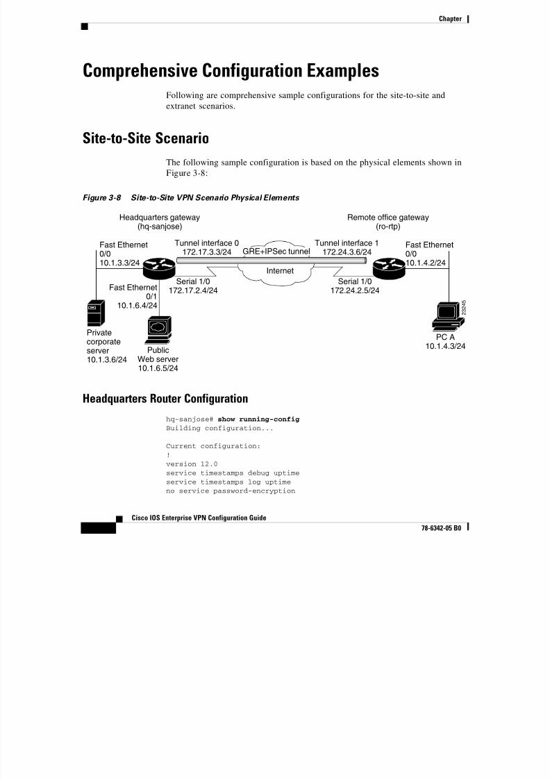
8/6/2019 Site-To-Site and Extranet VPN
http://slidepdf.com/reader/full/site-to-site-and-extranet-vpn 64/74
-64
Cisco IOS Enterprise VPN Configuration Guide
78-6342-05 B0
Following are comprehensive sample configurations for the site-to-site and
extranet scenarios.
Site-to-Site Scenario
The following sample configuration is based on the physical elements shown in
Figure 3-8:
Figure 3-8 Site-to-Site VPN Scenario Physical Elements
Headquarters Router Configuration
hq-sanjose# show running-config
Building configuration...
Current configuration:!version 12.0service timestamps debug uptimeservice timestamps log uptimeno service password-encryption
Fast Ethernet0/010.1.3.3/24
Fast Ethernet0/010.1.4.2/24
Fast Ethernet0/1
10.1.6.4/24
Headquarters gateway(hq-sanjose)
Remote office gateway(ro-rtp)
Internet
Serial 1/0172.17.2.4/24
PublicWeb server10.1.6.5/24
Privatecorporateserver10.1.3.6/24
Tunnel interface 0
172.17.3.3/24
Tunnel interface 1
172.24.3.6/24
Serial 1/0172.24.2.5/24
PC A10.1.4.3/24
2 3 2 4 5
GRE+IPSec tunnel
Chapter
!hostname hq-sanjose!

8/6/2019 Site-To-Site and Extranet VPN
http://slidepdf.com/reader/full/site-to-site-and-extranet-vpn 65/74
-65
Cisco IOS Enterprise VPN Configuration Guide
78-6342-05 B0
boot system flash bootflash:boot bootldr bootflash:c7100-boot-mz.120-1.1.Tboot config slot0:hq-sanjose-cfg-smallno logging buffered!crypto isakmp policy 1authentication pre-sharelifetime 84600crypto isakmp key test12345 address 172.24.2.5!crypto ipsec transform-set proposal1 ah-sha-hmac esp-des esp-sha-hmac mode transport!!crypto map s1first local-address Serial1/0crypto map s1first 1 ipsec-isakmpset peer 172.24.2.5set transform-set proposal1 match address 101!interface Tunnel0bandwidth 180ip address 172.17.3.3 255.255.255.0no ip directed-broadcasttunnel source 172.17.2.4tunnel destination 172.24.2.5
crypto map s1first!interface FastEthernet0/0ip address 10.1.3.3 255.255.255.0no ip directed-broadcastno keepalivefull-duplexno cdp enable!
Chapter
interface FastEthernet0/1ip address 10.1.6.4 255.255.255.0no ip directed-broadcast
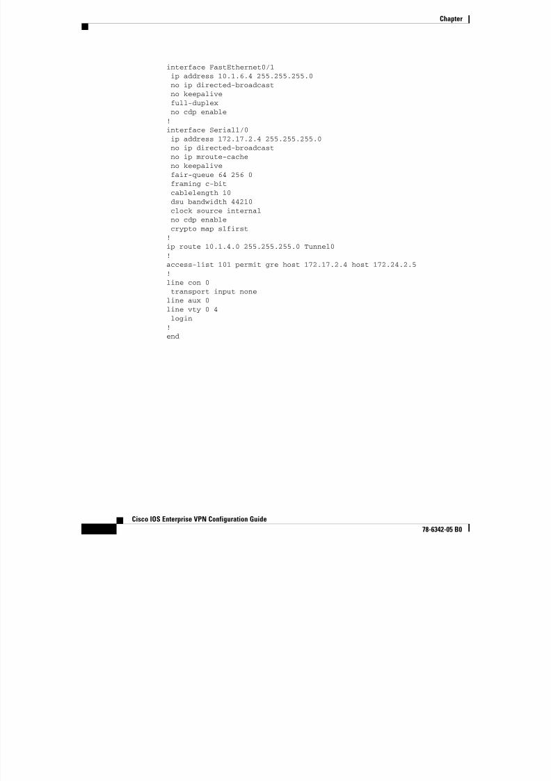
8/6/2019 Site-To-Site and Extranet VPN
http://slidepdf.com/reader/full/site-to-site-and-extranet-vpn 66/74
-66
Cisco IOS Enterprise VPN Configuration Guide
78-6342-05 B0
no keepalivefull-duplexno cdp enable!interface Serial1/0ip address 172.17.2.4 255.255.255.0no ip directed-broadcastno ip mroute-cacheno keepalivefair-queue 64 256 0framing c-bitcablelength 10dsu bandwidth 44210clock source internalno cdp enablecrypto map s1first!ip route 10.1.4.0 255.255.255.0 Tunnel0!access-list 101 permit gre host 172.17.2.4 host 172.24.2.5!line con 0transport input noneline aux 0line vty 0 4login
!end
Chapter
Remote Office Router Configuration
show running-config
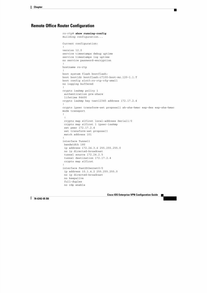
8/6/2019 Site-To-Site and Extranet VPN
http://slidepdf.com/reader/full/site-to-site-and-extranet-vpn 67/74
-67
Cisco IOS Enterprise VPN Configuration Guide
78-6342-05 B0
ro-rtp#show running config
Building configuration...
Current configuration:!version 12.0service timestamps debug uptimeservice timestamps log uptimeno service password-encryption
!hostname ro-rtp!boot system flash bootflash:boot bootldr bootflash:c7100-boot-mz.120-1.1.Tboot config slot0:ro-rtp-cfg-smallno logging buffered!crypto isakmp policy 1
authentication pre-sharelifetime 84600crypto isakmp key test12345 address 172.17.2.4!crypto ipsec transform-set proposal1 ah-sha-hmac esp-des esp-sha-hmac mode transport!!crypto map s1first local-address Serial1/0
crypto map s1first 1 ipsec-isakmpset peer 172.17.2.4set transform-set proposal1 match address 101!interface Tunnel1bandwidth 180ip address 172.24.3.6 255.255.255.0no ip directed-broadcast
tunnel source 172.24.2.5tunnel destination 172.17.2.4crypto map s1first!interface FastEthernet0/0ip address 10.1.4.2 255.255.255.0no ip directed-broadcastno keepalivefull-duplexno cdp enable
Chapter
!interface Serial1/0ip address 172.24.2.5 255.255.255.0

8/6/2019 Site-To-Site and Extranet VPN
http://slidepdf.com/reader/full/site-to-site-and-extranet-vpn 68/74
-68
Cisco IOS Enterprise VPN Configuration Guide
78-6342-05 B0
no ip directed-broadcastno ip mroute-cacheno keepalivefair-queue 64 256 0framing c-bitcablelength 10dsu bandwidth 44210clock source internalno cdp enable
crypto map s1first!ip route 10.1.3.0 255.255.255.0 Tunnel1ip route 10.1.6.0 255.255.255.0 Tunnel1!access-list 101 permit gre host 172.24.2.5 host 172.17.2.4!line con 0transport input noneline aux 0line vty 0 4login!end
Chapter
Extranet Scenario
Th f ll i l fi i i b d h h i l l h i

8/6/2019 Site-To-Site and Extranet VPN
http://slidepdf.com/reader/full/site-to-site-and-extranet-vpn 69/74
-69
Cisco IOS Enterprise VPN Configuration Guide
78-6342-05 B0
The following sample configuration is based on the physical elements shown inFigure 3-9:
Figure 3-9 Extranet VPN Scenario Physical Elements
Headquarters Router Configuration
hq-sanjose# show running-config
Building configuration...
Current configuration:!version 12.0service timestamps debug uptimeservice timestamps log uptime
no service password-encryption
PC A
Fast Ethernet0/0
10.1.3.3/24
Fast Ethernet0/1
10.1.6.4/24
Fast Ethernet0/010.1.5.2/24
Remote office gateway(ro-rtp)
Business partner gateway(bus-ptnr)
Internet
Internet
Serial 2/0172.16.2.2/24
Serial 1/0172.23.2.7/24
PublicWeb server10.1.6.5/24
Private
corporateserver10.1.3.6/24
PC B10.1.5.3/24
IPSec tunnel
2 4 2
1 8
GRE+IPSec tunnel
Chapter
!hostname hq-sanjose!
b t t fl h b tfl h
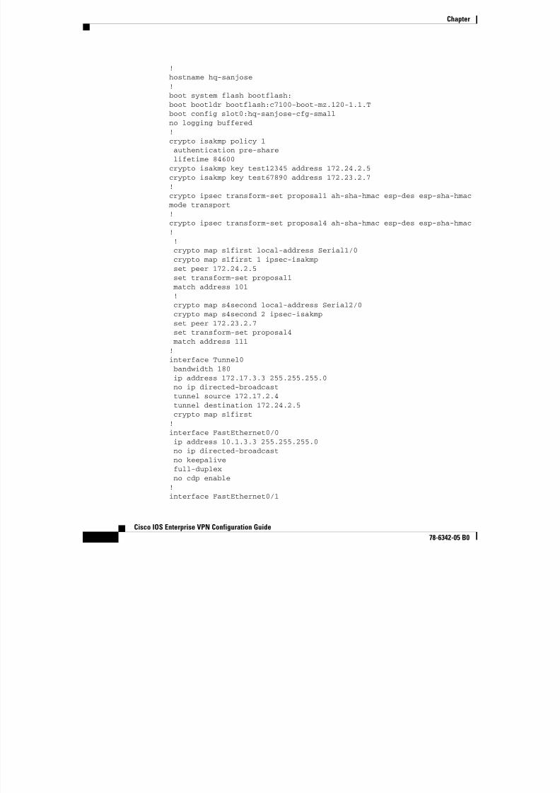
8/6/2019 Site-To-Site and Extranet VPN
http://slidepdf.com/reader/full/site-to-site-and-extranet-vpn 70/74
-70
Cisco IOS Enterprise VPN Configuration Guide
78-6342-05 B0
boot system flash bootflash:boot bootldr bootflash:c7100-boot-mz.120-1.1.Tboot config slot0:hq-sanjose-cfg-smallno logging buffered!crypto isakmp policy 1authentication pre-sharelifetime 84600crypto isakmp key test12345 address 172.24.2.5
crypto isakmp key test67890 address 172.23.2.7!crypto ipsec transform-set proposal1 ah-sha-hmac esp-des esp-sha-hmac mode transport!crypto ipsec transform-set proposal4 ah-sha-hmac esp-des esp-sha-hmac!!crypto map s1first local-address Serial1/0crypto map s1first 1 ipsec-isakmpset peer 172.24.2.5set transform-set proposal1 match address 101!crypto map s4second local-address Serial2/0crypto map s4second 2 ipsec-isakmpset peer 172.23.2.7
set transform-set proposal4 match address 111!interface Tunnel0bandwidth 180ip address 172.17.3.3 255.255.255.0no ip directed-broadcasttunnel source 172.17.2.4tunnel destination 172.24.2.5
crypto map s1first!interface FastEthernet0/0ip address 10.1.3.3 255.255.255.0no ip directed-broadcastno keepalivefull-duplexno cdp enable!
interface FastEthernet0/1
Chapter
ip address 10.1.6.4 255.255.255.0no ip directed-broadcastip nat inside
no keepalive

8/6/2019 Site-To-Site and Extranet VPN
http://slidepdf.com/reader/full/site-to-site-and-extranet-vpn 71/74
-71
Cisco IOS Enterprise VPN Configuration Guide
78-6342-05 B0
no keepalivefull-duplexno cdp enable!interface Serial1/0ip address 172.17.2.4 255.255.255.0no ip directed-broadcastno ip mroute-cacheno keepalive
fair-queue 64 256 0framing c-bitcablelength 10dsu bandwidth 44210clock source internalno cdp enablecrypto map s1first!interface Serial2/0ip address 172.16.2.2 255.255.255.0no ip directed-broadcast
Chapter
ip nat outsideno ip mroute-cacheno keepalive
fair-queue 64 256 0

8/6/2019 Site-To-Site and Extranet VPN
http://slidepdf.com/reader/full/site-to-site-and-extranet-vpn 72/74
-72
Cisco IOS Enterprise VPN Configuration Guide
78-6342-05 B0
fair queue 64 256 0framing c-bitcablelength 10dsu bandwidth 44210clock source internalno cdp enablecrypto map s4second!router bgp 10
network 10.2.2.2 mask 255.255.255.0network 172.16.2.0 mask 255.255.255.0!ip route 10.1.4.0 255.255.255.0 Tunnel0!ip nat inside source static 10.1.6.5 10.2.2.2!access-list 101 permit gre host 172.17.2.4 host 172.24.2.5access-list 111 permit ip host 10.2.2.2 host 10.1.5.3!line con 0transport input noneline aux 0line vty 0 4login!end
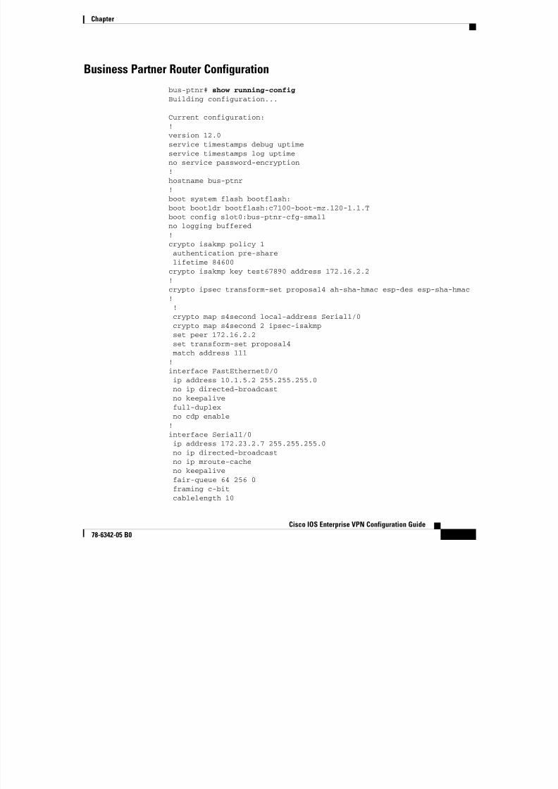
8/6/2019 Site-To-Site and Extranet VPN
http://slidepdf.com/reader/full/site-to-site-and-extranet-vpn 73/74
Chapter
dsu bandwidth 44210clock source internalno cdp enable
crypto map s4second
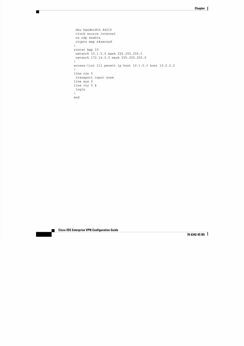
8/6/2019 Site-To-Site and Extranet VPN
http://slidepdf.com/reader/full/site-to-site-and-extranet-vpn 74/74
-74
Cisco IOS Enterprise VPN Configuration Guide
78-6342-05 B0
yp p!router bgp 10network 10.1.5.0 mask 255.255.255.0network 172.16.2.0 mask 255.255.255.0!access-list 111 permit ip host 10.1.5.3 host 10.2.2.2!line con 0
transport input noneline aux 0line vty 0 4login!end
Related Documents