SITE SOLUTIONS for Wireless Infrastructure

Welcome message from author
This document is posted to help you gain knowledge. Please leave a comment to let me know what you think about it! Share it to your friends and learn new things together.
Transcript

SITE SOLUTIONSfor Wireless Infrastructure

Performance-Driven Technology for Cellular Networks
ONE SOURCE.GLOBAL SITE SOLUTIONS™
Amphenol is a leading global solutions providerfor wireless infrastructure systems. Whether it’s acomplex base station, a small DAS network or anIn-Building System, we supply over 6,000products with best-in-class performance.
With Amphenol, OEMs and operators have theconvenience of a one-stop shop, not only forquality antennas, but for transmission lineproducts like feeder cable, hybrid fiber, surgearrestors and connectors as well as RF peripheralslike TMAs, combiners, couplers and splitters. Allproducts support next generation wirelesscommunication systems.
Amphenol offers years of expertise in productdesign, development and engineering along withan unparalleled commitment to customer service.
ContentsSite Solutions for Wireless Infrastructure
Contents
6
12
16
25
28
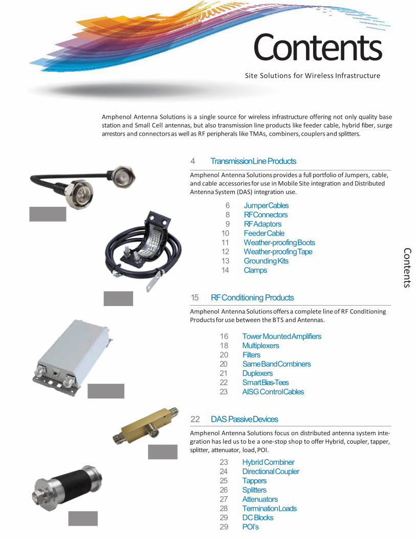
Amphenol Antenna Solutions is a single source for wireless infrastructure offering not only quality basestation and Small Cell antennas, but also transmission line products like feeder cable, hybrid fiber, surgearrestors and connectorsas well as RF peripherals like TMAs, combiners,couplers and splitters.
4 TransmissionLineProductsAmphenol Antenna Solutionsprovides a full portfolio of Jumpers, cable, and cable accessoriesfor use in Mobile Site integration and Distributed Antenna System (DAS) integration use.
6 JumperCables8 RFConnectors9 RFAdaptors
10 FeederCable11 Weather-proofingBoots12 Weather-proofingTape13 GroundingKits14 Clamps
15 RF Conditioning ProductsAmphenol Antenna Solutions offers a complete line of RF Conditioning Productsfor use between the BTS and Antennas.
16 Tower MountedAmplifiers18 Multiplexers20 Filters20 Same BandCombiners21 Duplexers22 SmartBias-Tees23 AISG ControlCables
22 DAS PassiveDevicesAmphenol Antenna Solutions focus on distributed antenna system inte-gration has led us to be a one-stop shop to offer Hybrid, coupler, tapper,splitter, attenuator, load,POI.
23 HybridCombiner24 DirectionalCoupler25 Tappers26 Splitters27 Attenuators28 TerminationLoads29 DCBlocks29 POI’s
www.amphenol.com.tr [email protected]
Transmission Line Products
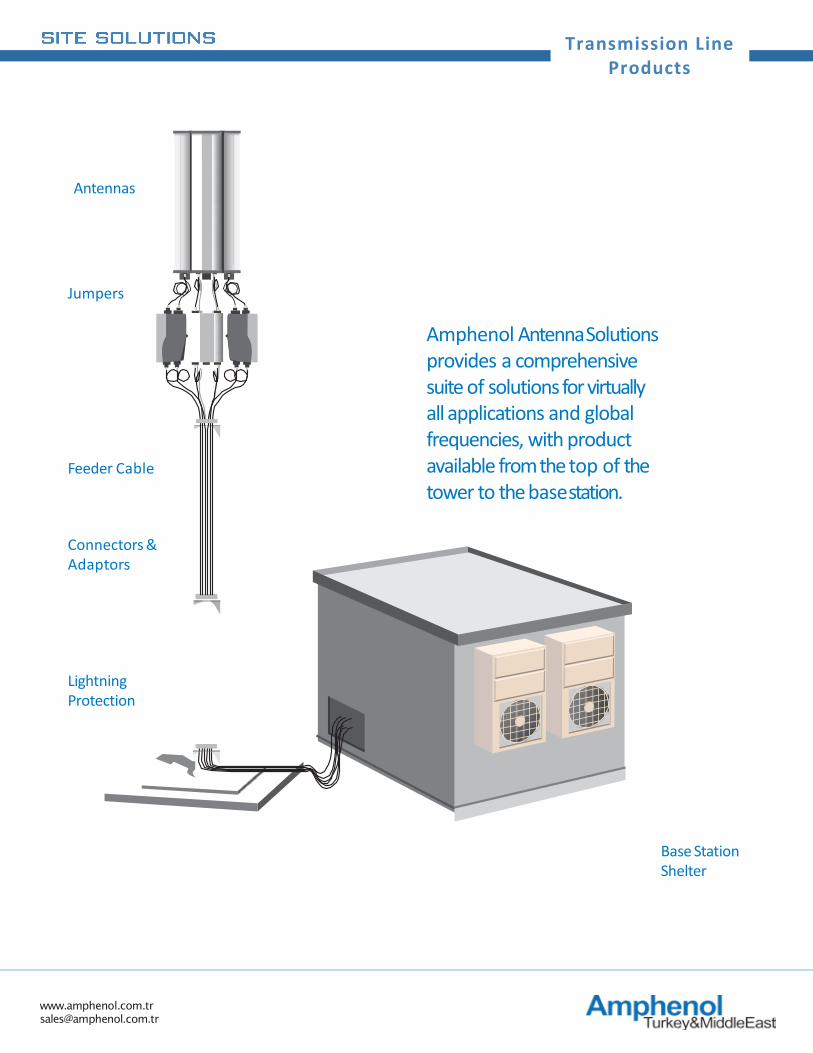
Antennas
Lightning Protection
Connectors & Adaptors
Feeder Cable
Jumpers
Base Station Shelter
Amphenol AntennaSolutions provides a comprehensive suite of solutions for virtually all applications and global frequencies, with product available from the top of the tower to the basestation.
www.amphenol.com.tr [email protected]
Transmission Line Products
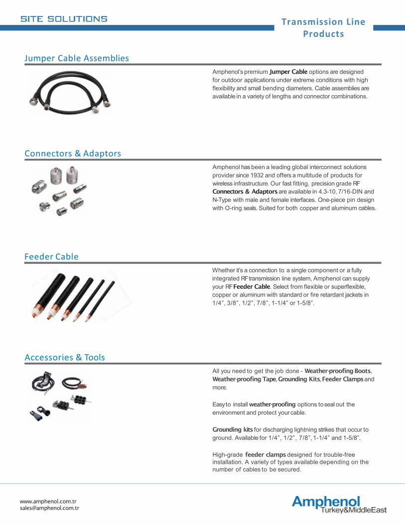
All you need to get the job done - Weather-proofing Boots, Weather-proofing Tape, Grounding Kits, Feeder Clamps and more.
Easy to install weather-proofing options toseal out the environment and protect yourcable.
Grounding kits for discharging lightning strikes that occur to ground. Available for 1/4”, 1/2”, 7/8”,1-1/4” and 1-5/8”.
High-grade feeder clamps designed for trouble-free installation. A variety of types available depending on the number of cables to be secured.
Accessories & Tools
Whether it’s a connection to a single component or a fully integrated RF transmission line system, Amphenol can supply your RF Feeder Cable. Select from flexible or superflexible, copper or aluminum with standard or fire retardant jackets in 1/4”, 3/8”, 1/2”, 7/8”, 1-1/4” or 1-5/8”.
Feeder Cable
Amphenol’s premium Jumper Cable options are designed for outdoor applications under extreme conditions with high flexibility and small bending diameters. Cable assemblies are available in a variety of lengths and connector combinations.
Jumper Cable Assemblies
Amphenol has been a leading global interconnect solutions provider since 1932 and offers a multitude of products for wireless infrastructure. Our fast fitting, precision grade RF Connectors & Adaptors are available in 4.3-10, 7/16-DIN and N-Type with male and female interfaces. One-piece pin design with O-ring seals. Suited for both copper and aluminum cables.
Connectors & Adaptors
www.amphenol.com.tr [email protected]
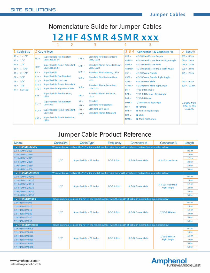
Jumper Cables
1 Cable Size 2 Cable Type 3 & 4 Connector A & Connector B 5 Length11 = 1 - 1/4”
FLS =
FLR =
HF =
HFF =
HFL =
HFR =
HFV =
HFS =
HLF =
HLR =
HRS =
Superflexible Fire Resistant Low Loss, LSZH
Superflexible Flame Retardant Low Loss, LSZH
SuperflexibleSuperflexible Fire Resistant
Superflexible Low Loss
Superflexible Flame Retardant
Superflexible improved VSWR
Superflexible Fire Resistant, LSZH
Superflexible Fire Resistant Low Loss
Superflexible Flame Retardant Low Loss
Superflexible Flame Retardant, LSZH
LFS =
LRS =
SFS =
SLF =
SLR =
SRS =
ST =
STF =
STL =
STR =
Standard Fire ResistantLow Loss, LSZH
Standard Flame Retardant Low Loss, LSZH
Standard Fire Resistant, LSZH
Standard Fire ResistantLow Loss
Standard Flame Retardant Low Loss
Standard Flame Retardant, LSZH
StandardStandard Fire Resistant
Standard Low Loss
Standard Flame Retardant
4HF = 4.3-10 Hand Screw Female 005 = 0.5 m
12 = 1/2” 4HFR = 4.3-10 Hand Screw Female Right Angle 010 = 1.0 m
14 = 1/4” 4HM = 4.3-10 Hand Screw Male 015 = 1.5 m
15 = 1 - 5/8” 4HMR = 4.3-10 Hand Screw Male Right Angle 020 = 2.0 m
21 = 2 - 1/4” 4SF = 4.3-10 Screw Female 025 = 2.5 m
38 = 3/8” 4SFR = 4.3-10 Screw Female Right Angle ...
58 = 5/8” 4SM = 4.3-10 Screw Male 095 = 9.5 m
78 = 7/8” 4SMR = 4.3-10 Screw Male Right Angle 100 = 10.0 m
K4 = KSR400 D F = 7/16-DIN Female
DFR = 7/16-DIN Female Right Angle
DM = 7/16-DIN Male
DMR = 7/16-DIN Male RightAngle Lengths fromN F =NFR =
N FemaleN Female Right Angle
0.5m to 10mavailable
NM = N MaleNMR = N Male Right Angle
Nomenclature Guide for Jumper Cables12 HF 4SMR 4SMR xxx
1 2 3 4 5
Model Cable Size Cable Type Frequency Connector A Connector B Length12HF4SM4SMxxx When ordering, replace the “x” in the model number with the length of cable in meters. See examples below:12HF4SM4SM005
1/2” Superflexible - PE Jacket DC-3.8 GHz 4.3-10 Screw Male 4.3-10 Screw Male
0.5 m12HF4SM4SM010 1.0 m12HF4SM4SM015 1.5 m12HF4SM4SM020 2.0 m12HF4SM4SM030 3.0 m12HF4SM4SM050 5.0 m12HF4SM4SMRxxx When ordering, replace the “x” in the model number with the length of cable in meters. See examples below:12HF4SM4SMR005
1/2” Superflexible - PE Jacket DC-3.8 GHz 4.3-10 Screw Male 4.3-10 Screw Male Right Angle
0.5 m12HF4SM4SMR010 1.0 m12HF4SM4SMR015 1.5 m12HF4SM4SMR020 2.0 m12HF4SM4SMR030 3.0 m12HF4SM4SMR050 5.0 m12HF4SMDMxxx When ordering, replace the “x” in the model number with the length of cable in meters. See examples below:12HF4SMDM005
1/2” Superflexible - PE Jacket DC-3.8 GHz 4.3-10 Screw Male 7/16-DIN Male
0.5 m12HF4SMDM010 1.0 m12HF4SMDM015 1.5 m12HF4SMDM020 2.0 m12HF4SMDM030 3.0 m12HF4SMDM050 5.0 m12HF4SMDMRxxx When ordering, replace the “x” in the model number with the length of cable in meters. See examples below:12HF4SMDMR005
1/2” Superflexible - PE Jacket DC-3.8 GHz 4.3-10 Screw Male 7/16-DIN Male Right Angle
0.5 m12HF4SMDMR010 1.0 m12HF4SMDMR015 1.5 m12HF4SMDMR020 2.0 m12HF4SMDMR030 3.0 m12HF4SMDMR050 5.0 m
Jumper Cable Product Reference
www.amphenol.com.tr [email protected]
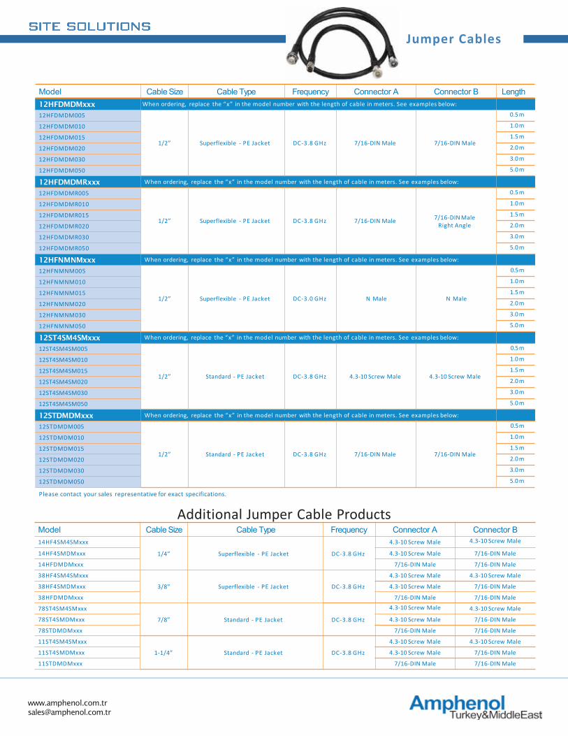
Jumper Cables
Model Cable Size Cable Type Frequency Connector A Connector B Length12HFDMDMxxx When ordering, replace the “x” in the model number with the length of cable in meters. See examples below:
12HFDMDM005
1/2” Superflexible - PE Jacket DC-3.8 GHz 7/16-DIN Male 7/16-DIN Male
0.5 m
12HFDMDM010 1.0 m
12HFDMDM015 1.5 m
12HFDMDM020 2.0 m
12HFDMDM030 3.0 m
12HFDMDM050 5.0 m
12HFDMDMRxxx When ordering, replace the “x” in the model number with the length of cable in meters. See examples below:
12HFDMDMR005
1/2” Superflexible - PE Jacket DC-3.8 GHz 7/16-DIN Male 7/16-DIN Male Right Angle
0.5 m
12HFDMDMR010 1.0 m
12HFDMDMR015 1.5 m
12HFDMDMR020 2.0 m
12HFDMDMR030 3.0 m
12HFDMDMR050 5.0 m
12HFNMNMxxx When ordering, replace the “x” in the model number with the length of cable in meters. See examples below:
12HFNMNM005
1/2” Superflexible - PE Jacket DC-3.0 GHz N Male N Male
0.5m
12HFNMNM010 1.0 m
12HFNMNM015 1.5 m
12HFNMNM020 2.0 m
12HFNMNM030 3.0 m
12HFNMNM050 5.0 m
12ST4SM4SMxxx When ordering, replace the “x” in the model number with the length of cable in meters. See examples below:
12ST4SM4SM005
1/2” Standard - PE Jacket DC-3.8 GHz 4.3-10 Screw Male 4.3-10 Screw Male
0.5m
12ST4SM4SM010 1.0 m
12ST4SM4SM015 1.5 m
12ST4SM4SM020 2.0 m
12ST4SM4SM030 3.0 m
12ST4SM4SM050 5.0 m
12STDMDMxxx When ordering, replace the “x” in the model number with the length of cable in meters. See examples below:
12STDMDM005
1/2” Standard - PE Jacket DC-3.8 GHz 7/16-DIN Male 7/16-DIN Male
0.5m
12STDMDM010 1.0 m
12STDMDM015 1.5 m
12STDMDM020 2.0 m
12STDMDM030 3.0 m
12STDMDM050 5.0 m
Please contact your sales representative for exact specifications.
Additional Jumper Cable ProductsModel Cable Size Cable Type Frequency Connector A Connector B14HF4SM4SMxxx
1/4” Superflexible - PE Jacket DC-3.8 GHz
4.3-10 Screw Male 4.3-10 Screw Male
14HF4SMDMxxx 4.3-10 Screw Male 7/16-DIN Male
14HFDMDMxxx 7/16-DIN Male 7/16-DIN Male
38HF4SM4SMxxx
3/8” Superflexible - PE Jacket DC-3.8 GHz
4.3-10 Screw Male 4.3-10 Screw Male
38HF4SMDMxxx 4.3-10 Screw Male 7/16-DIN Male
38HFDMDMxxx 7/16-DIN Male 7/16-DIN Male
78ST4SM4SMxxx
7/8” Standard - PE Jacket DC-3.8 GHz
4.3-10 Screw Male 4.3-10 Screw Male
78ST4SMDMxxx 4.3-10 Screw Male 7/16-DIN Male
78STDMDMxxx 7/16-DIN Male 7/16-DIN Male
11ST4SM4SMxxx
1-1/4” Standard - PE Jacket DC-3.8 GHz
4.3-10 Screw Male 4.3-10 Screw Male
11ST4SMDMxxx 4.3-10 Screw Male 7/16-DIN Male
11STDMDMxxx 7/16-DIN Male 7/16-DIN Male

www.amphenol.com.tr [email protected]
Connectors
1 Product Type 2 For Cable Size 3 For Cable Type 4 Connector Type
A C = RF Connectors 11 = 1 - 1/4” HF = Superflexible 4SF = 4.3-10 Screw Female 4PMR = 4.3-10 Push/Pull Male Right Angle
12 = 1/2” ST = Standard 4SFR = 4.3-10 Screw Female Right Angle D F = 7/16-DIN Female
14 = 1/4” SWA = Smooth Wall Aluminum
4HF = 4.3-10 Hand Screw Female DFR = 7/16-DIN Female Right Angle
15 = 1 - 5/8” 00 = No additionaltype designation
4HFR = 4.3-10 Hand Screw Female Right Angle
DM = 7/16-DIN Male
21 = 2 - 1/4” 4HM = 4.3-10 Hand Screw Male DMR = 7/16-DIN Male Right Angle
38 = 3/8” 4HMR = 4.3-10 Hand Screw Male Right Angle
N F = N Female
58 = 5/8” 4SM = 4.3-10 Screw Male NFR = N Female Right Angle
78 = 7/8” 4SMR = 4.3-10 Screw Male Right Angle NM = N Male
L3 = LMR300 4PF = 4.3-10 Push/Pull Female NMR = N Male Right Angle
L4 = LMR400 4PFR = 4.3-10 Push/Pull Female Right Angle
THMR = T N C Type HandScrew Male Right Angle
K4 = KSR400 4PM = 4.3-10 Push/Pull Male
Model Cable Size Cable Type Frequency Connector Type Installation TypeAC-12HF-4SM-F
1/2”
Superflexible - PE Jacket
DC-3.8 GHz 4.3-10 Screw Male Assembly
AC-12HF-4SM-MM DC-6 GHz 4.3-10 Screw Male Assembly
AC-12HF-4SMR DC-3.8 GHz 4.3-10 Screw Male Right Angle Assembly
AC-12HF-4SF DC-3.8 GHz 4.3-10 Screw Female Assembly
AC-12HF-DM DC-3 GHz 7/16-DIN Male Assembly
AC-12HF-DMR DC-3 GHz 7/16-DIN Male Right Angle Assembly
AC-12HF-NM DC-3 GHz N Male Assembly
AC-12ST-4SM
Standard - PE Jacket
DC-6 GHz 4.3-10 Screw Male Assembly
AC-12ST-DM DC-3 GHz 7/16-DIN Male Assembly
AC-12ST-DMR DC-3 GHz 7/16-DIN Male Assembly
AC-12ST-NM DC-3 GHz N Male Assembly
AC-12ST-NMR DC-3 GHz N Male Right Angle Assembly
AC-12ST-NF DC-3 GHz N Female Assembly
AC-78ST-DM
7/8”
DC-3 GHz 7/16-DIN Male Assembly
AC-78ST-DF DC-3 GHz 7/16-DIN Female Assembly
AC-78ST-NM DC-3 GHz N Female Assembly
AC-11ST-DM 1 - 1/4” DC-3 GHz 7/16-DIN Female Assembly
Nomenclature Guide for RFConnectors
AC - 12 SW A - 4HMR1 2 3 4
RF Connector Product Reference
www.amphenol.com.tr [email protected]
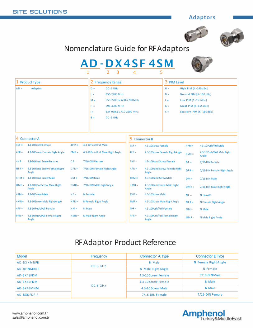
Adaptors
Nomenclature Guide for RFAdaptors
AD - DX4SF 4SM1 2 3 4 5
RF Adaptor Product ReferenceModel Frequency Connector A Type Connector BTypeAD-DXNMNFR
DC-3 GHzN Male N Female Right Angle
AD-DHNMRNF N Male Right Angle N Female
AD-BX4SFDM
DC-6 GHz
4.3-10 Screw Female 7/16-DIN Male
AD-BX4SFNM 4.3-10 Screw Female N Male
AD-BX4SMNM 4.3-10 Screw Male N Male
AD-BXDFDF-F 7/16-DIN Female 7/16-DIN Female
1 Product Type 2 Frequency Range 3 PIM LevelAD = Adaptor D = DC-3 GHz H = High PIM [≥ -149 dBc]
L = 350-2700 MHz N = Normal PIM [≤ -150 dBc]
M = 555-2700 or 698-2700 MHz L = Low PIM [≤ -153 dBc]
H = 698-4000 MHz G = Great PIM [≤ -155 dBc]
I = 824-960 & 1710-2690 MHz X = Excellent PIM [≤ -160 dBc]
B = DC-6 GHz
4 Connector A 5 Connector B4SF = 4.3-10 Screw Female 4PM = 4.3-10 Push/Pull Male 4SF = 4.3-10 Screw Female 4PM = 4.3-10 Push/Pull Male
4FR = 4.3-10 Screw Female RightAngle PMR = 4.3-10 Push/Pull Male RightAngle 4FR = 4.3-10 Screw Female RightAngle PMR = 4.3-10 Push/Pull MaleRight Angle
4HF = 4.3-10 Hand Screw Female D F = 7/16-DIN Female 4HF = 4.3-10 Hand Screw Female D F = 7/16-DIN Female
HFR = 4.3-10 Hand Screw FemaleRight Angle
DFR = 7/16-DIN Female RightAngle HFR = 4.3-10 Hand Screw FemaleRight Angle DFR = 7/16-DIN Female RightAngle
4HM = 4.3-10 Hand Screw Male DM = 7/16-DIN Male 4HM = 4.3-10 Hand Screw Male DM = 7/16-DIN Male
HMR = 4.3-10 HandScrew Male Right Angle
DMR = 7/16-DIN Male RightAngle HMR = 4.3-10 HandScrew Male Right Angle DMR = 7/16-DIN Male RightAngle
4SM = 4.3-10 Screw Male N F = N Female 4SM = 4.3-10 Screw Male N F = N Female
4MR = 4.3-10 Screw Male RightAngle NFR = N Female Right Angle 4MR = 4.3-10 Screw Male RightAngle NFR = N Female Right Angle
4PF = 4.3-10 Push/Pull Female NM = N Male 4PF = 4.3-10 Push/Pull Female NM = N Male
PFR = 4.3-10 Push/Pull FemaleRight Angle
NMR = N Male Right Angle PFR = 4.3-10 Push/Pull FemaleRight Angle NMR = N Male Right Angle
www.amphenol.com.tr [email protected]
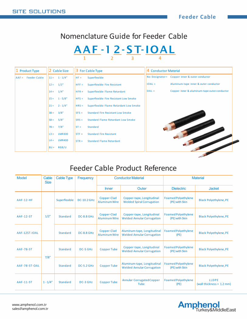
Feeder Cable
1 Product Type 2 Cable Size 3 For Cable Type 4 Conductor Material
AAF = Feeder Cable 11 = 1 - 1/4” HF = Superflexible No Designator = Copper inner & outer conductor
12 = 1/2” HFF = Superflexible Fire Resistant IOAL = Aluminum-tape inner & outer conductor
14 = 1/4” HFR = Superflexible Flame Retardant OAL = Copper inner & aluminum-tape outer conductor
15 = 1 - 5/8” HFS = Superflexible Fire Resistant Low Smoke
21 = 2 - 1/4” HRS = Superflexible Flame Retardant Low Smoke
38 = 3/8” SFS = Standard Fire Resistant Low Smoke
58 = 5/8” SRS = Standard Flame Retardant Low Smoke
78 = 7/8” ST = Standard
L3 = LMR300 STF = Standard Fire Resistant
L4 = LMR400 STR = Standard Flame Retardant
8U = RG8/U
Nomenclature Guide for Feeder Cable
AAF -1 2- S T- IOAL1 2 3 4
Model Cable Size
Cable Type Frequency Conductor Material Material
Inner Outer Dielectric Jacket
AAF-12-HF
1/2”
Superflexible DC-10.2 GHz Copper-Clad AluminumWire
Copper-tape, Longitudinal Welded Spiral Corrugation
Foamed Polyethylene (PE) with Skin Black Polyethylene, PE
AAF-12-ST Standard DC-8.8 GHz Copper-Clad AluminumWire
Copper-tape, Longitudinal Welded Annular Corrugation
Foamed Polyethylene (PE) with Skin Black Polyethylene, PE
AAF-12ST-IOAL Standard DC-8.8 GHz Copper-Clad AluminumWire
Aluminum-tape, Longitudinal Welded Annular Corrugation
Foamed Polyethylene (PE) Black Polyethylene, PE
AAF-78-ST
7/8”
Standard DC-5 GHz Copper Tube Copper-tape, Longitudinal Welded Annular Corrugation
Foamed Polyethylene (PE) with Skin Black Polyethylene, PE
AAF-78-ST-OAL Standard DC-5.2 GHz Copper Tube Aluminum-tape, Longitudinal Welded Annular Corrugation
Foamed Polyethylene (PE) with Skin Black Polyethylene, PE
AAF-11-ST 1 - 1/4” Standard DC-3 GHz Copper Tube Annular CorrugatedCopper Tube
Foamed Polyethylene (PE)
LLDPE(wall thickness > 1.2 mm)
Feeder Cable Product Reference
www.amphenol.com.tr [email protected]
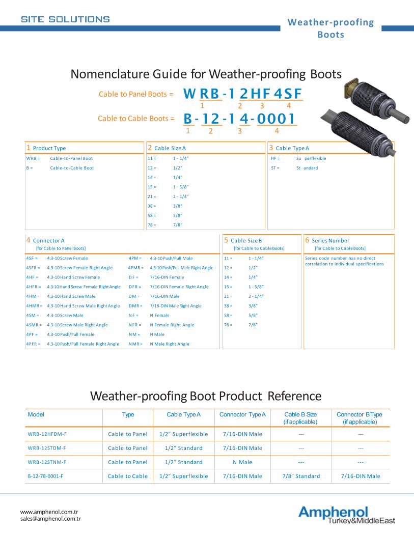
Weather-proofingBoots
1 Product Type 2 Cable Size A 3 Cable Type AWRB = Cable-to-Panel Boot 11 = 1 - 1/4” HF = Su perflexible
B = Cable-to-Cable Boot 12 = 1/2” ST = St andard
14 = 1/4”
15 = 1 - 5/8”
21 = 2 - 1/4”
38 = 3/8”
58 = 5/8”
78 = 7/8”
4 Connector A[for Cable to Panel Boots]
5 Cable Size B[for Cable to CableBoots]
6 Series Number[for Cable to CableBoots]
4SF = 4.3-10 Screw Female 4PM = 4.3-10 Push/Pull Male 11 = 1 - 1/4” Series code number has no direct correlation to individual specifications
4SFR = 4.3-10 Screw Female Right Angle 4PMR = 4.3-10 Push/Pull Male Right Angle 12 = 1/2”
4HF = 4.3-10 Hand Screw Female D F = 7/16-DIN Female 14 = 1/4”
4HFR = 4.3-10 Hand Screw Female Right Angle DFR = 7/16-DIN Female Right Angle 15 = 1 - 5/8”
4HM = 4.3-10 Hand Screw Male DM = 7/16-DIN Male 21 = 2 - 1/4”
4HMR = 4.3-10 Hand Screw Male Right Angle DMR = 7/16-DIN Male Right Angle 38 = 3/8”
4SM = 4.3-10 Screw Male N F = N Female 58 = 5/8”
4SMR = 4.3-10 Screw Male Right Angle NFR = N Female Right Angle 78 = 7/8”
4PF = 4.3-10 Push/Pull Female NM = N Male
4PFR = 4.3-10 Push/Pull Female Right Angle NMR = N Male Right Angle
W RB -1 2HF 4SF
Model Type Cable TypeA Connector TypeA Cable B Size (if applicable)
Connector BType (if applicable)
WRB-12HFDM-F Cable to Panel 1/2” Superflexible 7/16-DIN Male --- ---
WRB-12STDM-F Cable to Panel 1/2” Standard 7/16-DIN Male --- ---
WRB-12STNM-F Cable to Panel 1/2” Standard N Male --- ---
B-12-78-0001-F Cable to Cable 1/2” Superflexible 7/16-DIN Male 7/8” Standard 7/16-DIN Male
Nomenclature Guide for Weather-proofing Boots
Weather-proofing Boot Product Reference
1 2 3 4
B - 12 -1 4- 0001
Cable to Panel Boots =
Cable to Cable Boots =1 2 3 4
www.amphenol.com.tr [email protected]
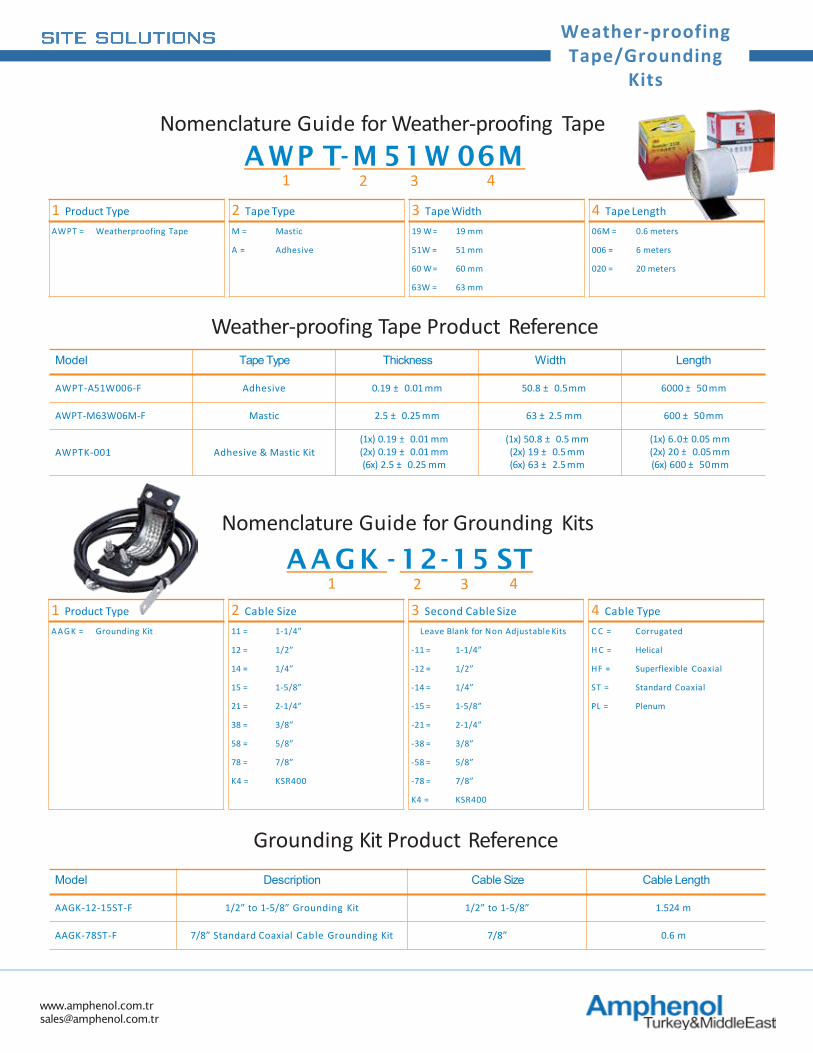
Weather-proofing Tape/Grounding
Kits
1 Product Type 2 Tape Type 3 Tape Width 4 Tape LengthAWPT = Weatherproofing Tape M = Mastic 19 W= 19 mm 06M = 0.6 meters
A = Adhesive 51W = 51 mm 006 = 6 meters
60 W= 60 mm 020 = 20 meters
63W = 63 mm
Model Tape Type Thickness Width Length
AWPT-A51W006-F Adhesive 0.19 ± 0.01 mm 50.8 ± 0.5mm 6000 ± 50 mm
AWPT-M63W06M-F Mastic 2.5 ± 0.25 mm 63 ± 2.5 mm 600 ± 50mm
AWPTK-001 Adhesive & Mastic Kit(1x) 0.19 ± 0.01 mm(2x) 0.19 ± 0.01 mm(6x) 2.5 ± 0.25 mm
(1x) 50.8 ± 0.5 mm(2x) 19 ± 0.5 mm(6x) 63 ± 2.5 mm
(1x) 6.0± 0.05 mm(2x) 20 ± 0.05 mm(6x) 600 ± 50mm
Weather-proofing Tape Product Reference
1 Product Type 2 Cable Size 3 Second Cable Size 4 Cable TypeAAGK = Grounding Kit 11 = 1-1/4” Leave Blank for Non Adjustable Kits C C = Corrugated
12 = 1/2” -11 = 1-1/4” H C = Helical
14 = 1/4” -12 = 1/2” HF = Superflexible Coaxial
15 = 1-5/8” -14 = 1/4” ST = Standard Coaxial
21 = 2-1/4” -15 = 1-5/8” PL = Plenum
38 = 3/8” -21 = 2-1/4”
58 = 5/8” -38 = 3/8”
78 = 7/8” -58 = 5/8”
K4 = KSR400 -78 = 7/8”
K4 = KSR400
Nomenclature Guide for Grounding KitsAAGK - 12-15 ST
1 2 3 4
Grounding Kit Product ReferenceModel Description Cable Size Cable Length
AAGK-12-15ST-F 1/2” to 1-5/8” Grounding Kit 1/2” to 1-5/8” 1.524 m
AAGK-78ST-F 7/8” Standard Coaxial Cable Grounding Kit 7/8” 0.6 m
Nomenclature Guide for Weather-proofing TapeAWP T-M 51W 06M
1 2 3 4
www.amphenol.com.tr [email protected]
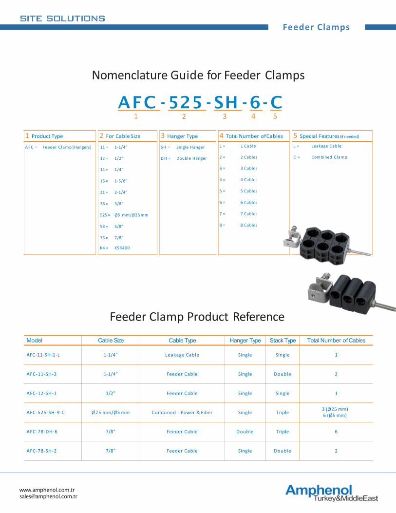
Feeder Clamps
1 Product Type 2 For Cable Size 3 Hanger Type 4 Total Number ofCables 5 Special Features (if needed)
AFC = Feeder Clamp [Hangers] 11 = 1-1/4” SH = Single Hanger 1 = 1 Cable L = Leakage Cable
12 = 1/2” D H = Double Hanger 2 = 2 Cables C = Combined Clamp
14 = 1/4” 3 = 3 Cables
15 = 1-5/8” 4 = 4 Cables
21 = 2-1/4” 5 = 5 Cables
38 = 3/8” 6 = 6 Cables
525 = Ø5 mm/Ø25 mm 7 = 7 Cables
58 = 5/8” 8 = 8 Cables
78 = 7/8”
K4 = KSR400
Nomenclature Guide for Feeder Clamps
AFC - 525 - SH - 6- C1 2 3 4 5
Model Cable Size Cable Type Hanger Type Stack Type Total Number of Cables
AFC-11-SH-1-L 1-1/4” Leakage Cable Single Single 1
AFC-11-SH-2 1-1/4” Feeder Cable Single Double 2
AFC-12-SH-1 1/2” Feeder Cable Single Single 1
AFC-525-SH-9-C Ø25 mm/Ø5 mm Combined - Power & Fiber Single Triple 3 (Ø25 mm)6 (Ø5 mm)
AFC-78-DH-6 7/8” Feeder Cable Double Triple 6
AFC-78-SH-2 7/8” Feeder Cable Single Double 2
Feeder Clamp Product Reference
www.amphenol.com.tr [email protected]
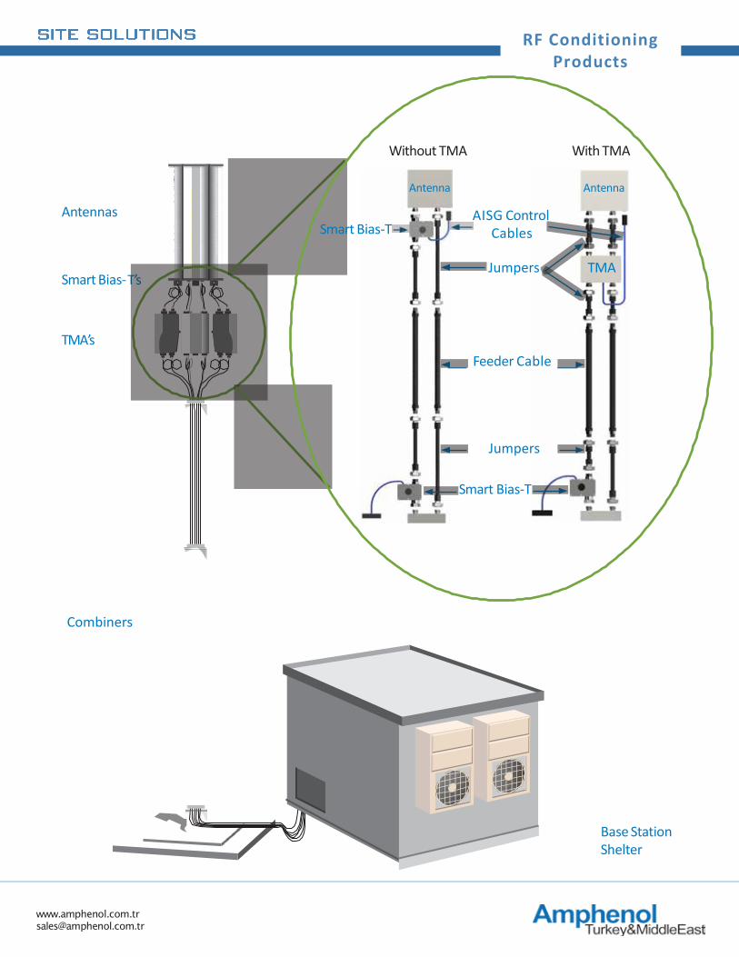
RF Conditioning Products
Antennas
Combiners
TMA’s
Smart Bias-T’s
Base Station Shelter
Without TMA With TMA
Smart Bias-T
TMAJumpers
Feeder Cable
AISG Control Cables
Jumpers
Smart Bias-T
AntennaAntenna
www.amphenol.com.tr [email protected]
RF Conditioning Products
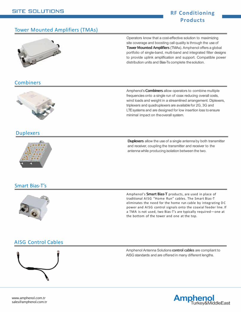
Operators know that a cost-effective solution to maximizing site coverage and boosting call quality is through the use of Tower Mounted Amplifiers (TMAs). Amphenol offers a globalportfolio of single-band, multi-band and integrated filter designsto provide uplink amplification and support. Compatible powerdistribution units and Bias-Ts complete thesolution.
Tower Mounted Amplifiers (TMAs)
Amphenol’s Smart Bias-T products, are used in place of traditional AISG “Home Run” cables. The Smart Bias-T eliminates the need for the home run cable by integrating D C power and AISG control signals onto the coaxial feeder line. If a TMA is not used, two Bias-T’s are typically required—one at the bottom of the tower and one at the top.
Smart Bias-T’s
Amphenol’s Combiners allow operators to combine multiple frequencies onto a single run of coax reducing overall costs, wind loads and weight in a streamlined arrangement. Diplexers, triplexers and quadruplexers are available for 2G, 3G andLTE systems and are designed for low insertion loss to ensure minimal impact on theoverall system.
Combiners
Amphenol Antenna Solutions control cables are compliant to AISG standards and are offered in many different lengths.
AISG Control Cables
Duplexers allow the use of a single antenna by both transmitter and receiver, coupling the transmitter and receiver to the antenna while producing isolation between the two.
Duplexers
www.amphenol.com.tr [email protected]
TMA’s
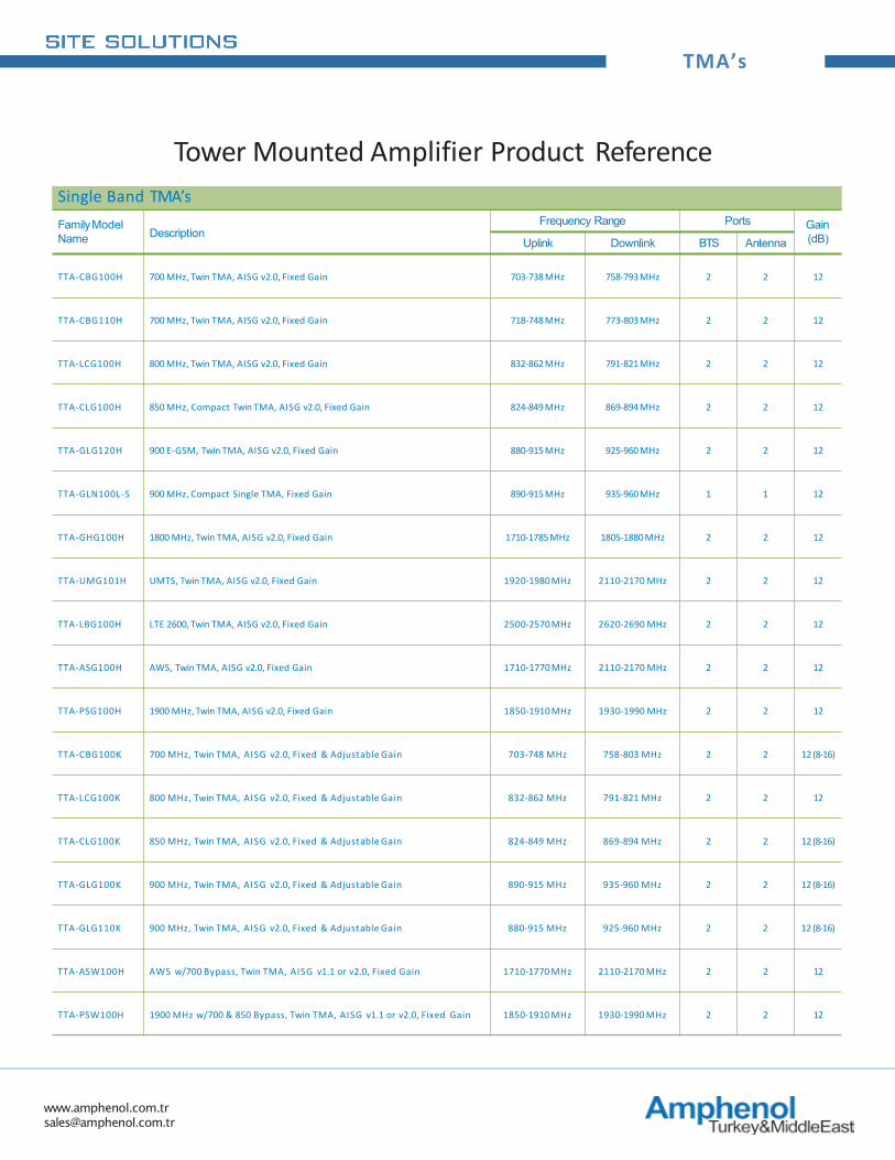
Single Band TMA’sFamilyModel Name Description
Frequency Range Ports Gain (dB)Uplink Downlink BTS Antenna
TTA-CBG100H 700 MHz, Twin TMA, AISG v2.0, Fixed Gain 703-738 MHz 758-793 MHz 2 2 12
TTA-CBG110H 700 MHz, Twin TMA, AISG v2.0, Fixed Gain 718-748 MHz 773-803 MHz 2 2 12
TTA-LCG100H 800 MHz, Twin TMA, AISG v2.0, Fixed Gain 832-862 MHz 791-821 MHz 2 2 12
TTA-CLG100H 850 MHz, Compact Twin TMA, AISG v2.0, Fixed Gain 824-849 MHz 869-894 MHz 2 2 12
TTA-GLG120H 900 E-GSM, Twin TMA, AISG v2.0, Fixed Gain 880-915 MHz 925-960 MHz 2 2 12
TTA-GLN100L-S 900 MHz, Compact Single TMA, Fixed Gain 890-915 MHz 935-960 MHz 1 1 12
TTA-GHG100H 1800 MHz, Twin TMA, AISG v2.0, Fixed Gain 1710-1785 MHz 1805-1880 MHz 2 2 12
TTA-UMG101H UMTS, Twin TMA, AISG v2.0, Fixed Gain 1920-1980 MHz 2110-2170 MHz 2 2 12
TTA-LBG100H LTE 2600, Twin TMA, AISG v2.0, Fixed Gain 2500-2570 MHz 2620-2690 MHz 2 2 12
TTA-ASG100H AWS, Twin TMA, AISG v2.0, Fixed Gain 1710-1770 MHz 2110-2170 MHz 2 2 12
TTA-PSG100H 1900 MHz, Twin TMA, AISG v2.0, Fixed Gain 1850-1910 MHz 1930-1990 MHz 2 2 12
TTA-CBG100K 700 MHz, Twin TMA, AISG v2.0, Fixed & Adjustable Gain 703-748 MHz 758-803 MHz 2 2 12 (8-16)
TTA-LCG100K 800 MHz, Twin TMA, AISG v2.0, Fixed & Adjustable Gain 832-862 MHz 791-821 MHz 2 2 12
TTA-CLG100K 850 MHz, Twin TMA, AISG v2.0, Fixed & Adjustable Gain 824-849 MHz 869-894 MHz 2 2 12 (8-16)
TTA-GLG100K 900 MHz, Twin TMA, AISG v2.0, Fixed & Adjustable Gain 890-915 MHz 935-960 MHz 2 2 12 (8-16)
TTA-GLG110K 900 MHz, Twin TMA, AISG v2.0, Fixed & Adjustable Gain 880-915 MHz 925-960 MHz 2 2 12 (8-16)
TTA-ASW100H AWS w/700 Bypass, Twin TMA, AISG v1.1 or v2.0, Fixed Gain 1710-1770 MHz 2110-2170 MHz 2 2 12
TTA-PSW100H 1900 MHz w/700 & 850 Bypass, Twin TMA, AISG v1.1 or v2.0, Fixed Gain 1850-1910 MHz 1930-1990 MHz 2 2 12
Tower Mounted Amplifier Product Reference
www.amphenol.com.tr [email protected]
TMA’s
RF Conditioning Products
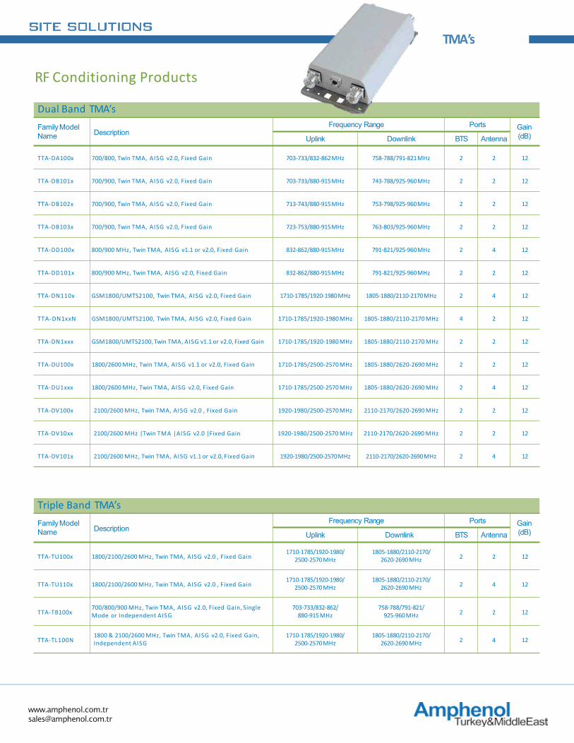
Dual Band TMA’sFamilyModel Name Description
Frequency Range Ports Gain (dB)Uplink Downlink BTS Antenna
TTA-DA100x 700/800, Twin TMA, AISG v2.0, Fixed Gain 703-733/832-862MHz 758-788/791-821MHz 2 2 12
TTA-DB101x 700/900, Twin TMA, AISG v2.0, Fixed Gain 703-733/880-915MHz 743-788/925-960MHz 2 2 12
TTA-DB102x 700/900, Twin TMA, AISG v2.0, Fixed Gain 713-743/880-915MHz 753-798/925-960MHz 2 2 12
TTA-DB103x 700/900, Twin TMA, AISG v2.0, Fixed Gain 723-753/880-915MHz 763-803/925-960MHz 2 2 12
TTA-DD100x 800/900 MHz, Twin TMA, AISG v1.1 or v2.0, Fixed Gain 832-862/880-915MHz 791-821/925-960MHz 2 4 12
TTA-DD101x 800/900 MHz, Twin TMA, AISG v2.0, Fixed Gain 832-862/880-915MHz 791-821/925-960MHz 2 2 12
TTA-DN110x GSM1800/UMTS2100, Twin TMA, AISG v2.0, Fixed Gain 1710-1785/1920-1980MHz 1805-1880/2110-2170MHz 2 4 12
TTA-DN1xxN GSM1800/UMTS2100, Twin TMA, AISG v2.0, Fixed Gain 1710-1785/1920-1980 MHz 1805-1880/2110-2170 MHz 4 2 12
TTA-DN1xxx GSM1800/UMTS2100, Twin TMA, AISG v1.1 or v2.0, Fixed Gain 1710-1785/1920-1980 MHz 1805-1880/2110-2170 MHz 2 2 12
TTA-DU100x 1800/2600 MHz, Twin TMA, AISG v1.1 or v2.0, Fixed Gain 1710-1785/2500-2570 MHz 1805-1880/2620-2690 MHz 2 2 12
TTA-DU1xxx 1800/2600 MHz, Twin TMA, AISG v2.0, Fixed Gain 1710-1785/2500-2570 MHz 1805-1880/2620-2690 MHz 2 4 12
TTA-DV100x 2100/2600 MHz, Twin TMA, AISG v2.0 , Fixed Gain 1920-1980/2500-2570 MHz 2110-2170/2620-2690 MHz 2 2 12
TTA-DV10xx 2100/2600 MHz |Twin TMA |AISG v2.0 |Fixed Gain 1920-1980/2500-2570 MHz 2110-2170/2620-2690 MHz 2 2 12
TTA-DV101x 2100/2600 MHz, Twin TMA, AISG v1.1 or v2.0, Fixed Gain 1920-1980/2500-2570MHz 2110-2170/2620-2690MHz 2 4 12
Triple Band TMA’sFamilyModel Name Description
Frequency Range Ports Gain (dB)Uplink Downlink BTS Antenna
TTA-TU100x 1800/2100/2600 MHz, Twin TMA, AISG v2.0 , Fixed Gain1710-1785/1920-1980/
2500-2570 MHz1805-1880/2110-2170/
2620-2690 MHz 2 2 12
TTA-TU110x 1800/2100/2600 MHz, Twin TMA, AISG v2.0 , Fixed Gain1710-1785/1920-1980/
2500-2570 MHz1805-1880/2110-2170/
2620-2690 MHz 2 4 12
TTA-TB100x700/800/900 MHz, Twin TMA, AISG v2.0, Fixed Gain, Single Mode or Independent AISG
703-733/832-862/880-915 MHz
758-788/791-821/925-960 MHz 2 2 12
TTA-TL100N1800 & 2100/2600 MHz, Twin TMA, AISG v2.0, Fixed Gain, Independent AISG
1710-1785/1920-1980/2500-2570 MHz
1805-1880/2110-2170/2620-2690 MHz 2 4 12
www.amphenol.com.tr [email protected]
Multiplexers
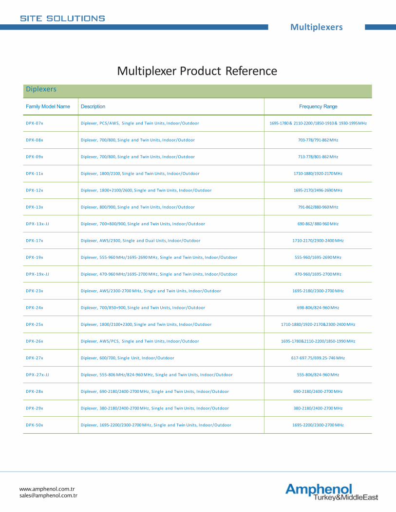
Diplexers
Family Model Name Description Frequency Range
DPX-07x Diplexer, PCS/AWS, Single and Twin Units, Indoor/Outdoor 1695-1780 & 2110-2200 /1850-1910 & 1930-1995MHz
DPX-08x Diplexer, 700/800, Single and Twin Units, Indoor/Outdoor 703-778/791-862MHz
DPX-09x Diplexer, 700/800, Single and Twin Units, Indoor/Outdoor 713-778/801-862MHz
DPX-11x Diplexer, 1800/2100, Single and Twin Units, Indoor/Outdoor 1710-1880/1920-2170MHz
DPX-12x Diplexer, 1800+2100/2600, Single and Twin Units, Indoor/Outdoor 1695-2170/2496-2690MHz
DPX-13x Diplexer, 800/900, Single and Twin Units, Indoor/Outdoor 791-862/880-960MHz
DPX-13x-JJ Diplexer, 700+800/900, Single and Twin Units, Indoor/Outdoor 690-862/ 880-960 MHz
DPX-17x Diplexer, AWS/2300, Single and Dual Units, Indoor/Outdoor 1710-2170/2300-2400 MHz
DPX-19x Diplexer, 555-960 MHz/1695-2690 MHz, Single and Twin Units, Indoor/Outdoor 555-960/1695-2690 MHz
DPX-19x-JJ Diplexer, 470-960 MHz/1695-2700 MHz, Single and Twin Units, Indoor/Outdoor 470-960/1695-2700 MHz
DPX-23x Diplexer, AWS/2300-2700 MHz, Single and Twin Units, Indoor/Outdoor 1695-2180/2300-2700 MHz
DPX-24x Diplexer, 700/850+900, Single and Twin Units, Indoor/Outdoor 698-806/824-960 MHz
DPX-25x Diplexer, 1800/2100+2300, Single and Twin Units, Indoor/Outdoor 1710-1880/1920-2170&2300-2400 MHz
DPX-26x Diplexer, AWS/PCS, Single and Twin Units, Indoor/Outdoor 1695-1780&2110-2200/1850-1990 MHz
DPX-27x Diplexer, 600/700, Single Unit, Indoor/Outdoor 617-697.75/699.25-746 MHz
DPX-27x-JJ Diplexer, 555-806 MHz/824-960 MHz, Single and Twin Units, Indoor/Outdoor 555-806/824-960 MHz
DPX-28x Diplexer, 690-2180/2400-2700 MHz, Single and Twin Units, Indoor/Outdoor 690-2180/2400-2700 MHz
DPX-29x Diplexer, 380-2180/2400-2700 MHz, Single and Twin Units, Indoor/Outdoor 380-2180/2400-2700 MHz
DPX-50x Diplexer, 1695-2200/2300-2700 MHz, Single and Twin Units, Indoor/Outdoor 1695-2200/2300-2700 MHz
Multiplexer Product Reference
www.amphenol.com.tr [email protected]
Multiplexers
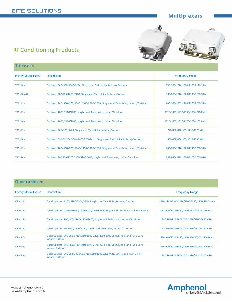
Triplexers
Family Model Name Description Frequency Range
TPX-10x Triplexer, 800+900/1800/2100, Single and Twin Units, Indoor/Outdoor 790-960/1710-1880/1920-2170 MHz
TPX-10x-JJ Triplexer, 380-960/1800/2100, Single and Twin Units, Indoor/Outdoor 380-960/1710-1880/1920-2200 MHz
TPX-11x Triplexer, 700+800+900/1800+2100/2300+2600, Single and Twin Units, Indoor/Outdoor 690-960/1695-2200/2300-2700 MHz
TPX-12x Triplexer, 1800/2100/2600, Single and Twin Units, Indoor/Outdoor 1710-1880/1920-2200/2300-2700 MHz
TPX-16x Triplexer, 1800/2100/2600, Single and Twin Units, Indoor/Outdoor 1710-1880/1920-2170/2300-2690 MHz
TPX-17x Triplexer, 800/900/AWS, Single and Twin Units, Indoor/Outdoor 790-862/880-960/1710-2170 MHz
TPX-18x Triplexer, 690-862/880-960/1695-2700 MHz, Single and Twin Units, Indoor/Outdoor 690-862/880-960/1695-2700 MHz
TPX-19x Triplexer, 700+800+900/1800/2100+2300+2600, Single and Twin Units, Indoor/Outdoor 690-960/1710-1880/1920-2700 MHz
TPX-20x Triplexer, 600-900/1700-2200/2300-2600, Single and Twin Units, Indoor/Outdoor 555-960/1695-2200/2300-2700 MHz
Quadruplexers
Family Model Name Description Frequency Range
QPX-11x Quadruplexer, 1800/2100/2300/2600, Single and Twin Units, Indoor/Outdoor 1710-1880/1920-2170/2300-2390/2500-2690 MHz
QPX-12x Quadruplexer, 700+800+900/1800/2100/2300+2600, Single and Twin Units, Indoor/Outdoor 698-960/1710-1880/1920-2170/2300-2690 MHz
QPX-13x Quadruplexer, 800/900/1800+2100/2600, Single and Twin Units, Indoor/Outdoor 790-862/880-960/1710-2170/2500-2690 MHz
QPX-14x Quadruplexer, 800/900/1800/2100, Single and Twin Units, Indoor/Outdoor 790-862/880-960/1710-1880/1920-2170 MHz
QPX-50x Quadruplexer, 690-960/1710-1880/1920-2200/2300-2700 MHz, Single and Twin Units, Indoor/Outdoor 690-960/1710-1880/1920-2200/2300-2700 MHz
QPX-51x Quadruplexer, 690-960/1710-1880/1920-2170/2270-2700 MHz, Single and Twin Units, Indoor/Outdoor 690-960/1710-1880/1920-2200/2270-2700 MHz
QPX-52x Quadruplexer, 690-862/880-960/1710-1880/1920-2200 MHz, Single and Twin Units, Indoor/Outdoor 690-862/880-960/1710-1880/1920-2200 MHz
RF Conditioning Products
www.amphenol.com.tr [email protected]
Filters / Same Band Combiners
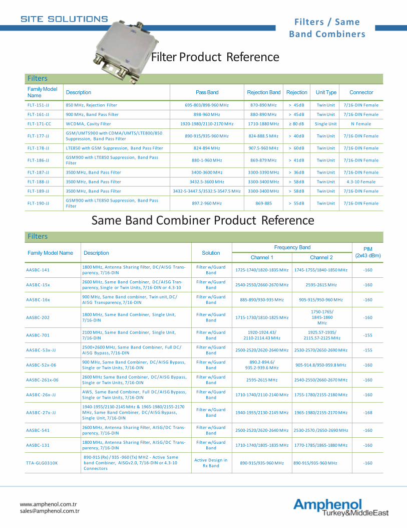
FiltersFamilyModel Name Description Pass Band Rejection Band Rejection Unit Type Connector
FLT-151-JJ 850 MHz, Rejection Filter 695-803/898-960 MHz 870-890 MHz > 45dB Twin Unit 7/16-DIN Female
FLT-161-JJ 900 MHz, Band Pass Filter 898-960 MHz 880-890 MHz > 45dB Twin Unit 7/16-DIN Female
FLT-171-CC WCDMA, Cavity Filter 1920-1980/2110-2170 MHz 1710-1880 MHz ≥ 80 dB Single Unit N Female
FLT-177-JJ GSM/UMTS900 with CDMA/UMTS/LTE800/850Suppression, Band Pass Filter 890-915/935-960 MHz 824-888.5 MHz > 40dB Twin Unit 7/16-DIN Female
FLT-178-JJ LTE850 with GSM Suppression, Band Pass Filter 824-894 MHz 907.5-960 MHz > 60dB Twin Unit 7/16-DIN Female
FLT-186-JJ GSM900 with LTE850 Suppression, Band Pass Filter 880-1-960 MHz 869-879 MHz > 41dB Twin Unit 7/16-DIN Female
FLT-187-JJ 3500 MHz, Band Pass Filter 3400-3600 MHz 3300-3390 MHz > 36dB Twin Unit 7/16-DIN Female
FLT-188-JJ 3500 MHz, Band Pass Filter 3432.5-3600 MHz 3300-3400 MHz > 58dB Twin Unit 4.3-10 Female
FLT-189-JJ 3500 MHz, Band Pass Filter 3432-5-3447.5/3532.5-3547.5 MHz 3300-3400 MHz > 58dB Twin Unit 7/16-DIN Female
FLT-190-JJ GSM900 with LTE850 Suppression, Band Pass Filter 897.2-960 MHz 869-885 > 55dB Twin Unit 7/16-DIN Female
Same Band Combiner Product ReferenceFilters
Family Model Name Description SolutionFrequency Band PIM
(2x43 dBm)Channel 1 Channel 2
AASBC-141 1800 MHz, Antenna Sharing Filter, DC/AISG Trans-parency, 7/16-DIN
Filter w/Guard Band 1725-1740/1820-1835 MHz 1745-1755/1840-1850 MHz -160
AASBC-15x 2600 MHz, Same Band Combiner, DC/AISG Tran-parency, Single or Twin Units, 7/16-DIN or 4.3-10
Filter w/Guard Band 2540-2550/2660-2670 MHz 2595-2615 MHz -160
AASBC-16x 900 MHz, Same Band combiner, Twin unit, DC/ AISG Transparency, 7/16-DIN
Filter w/Guard Band 885-890/930-935 MHz 905-915/950-960 MHz -160
AASBC-202 1800 MHz, Same Band Combiner, Single Unit, 7/16-DIN
Filter w/Guard Band 1715-1730/1810-1825 MHz
1750-1765/1845-1860
MHz-160
AASBC-701 2100 MHz, Same Band Combiner, Single Unit, 7/16-DIN
Filter w/Guard Band
1920-1924.43/2110-2114.43 MHz
1925.57-1935/2115.57-2125 MHz -155
AASBC-53x-JJ 2500+2600 MHz, Same Band Combiner, Full DC/ AISG Bypass, 7/16-DIN
Filter w/Guard Band 2500-2520/2620-2640 MHz 2530-2570/2650-2690 MHz -155
AASBC-52x-06 900 MHz, Same Band Combiner, DC/AISG Bypass, Single or Twin Units, 7/16-DIN
Filter w/Guard Band
890.2-894.6/935.2-939.6 MHz 905-914.8/950-959.8 MHz -160
AASBC-261x-06 2600 MHz Same Band Combiner, DC/AISG Bypass, Single or Twin Units, 7/16-DIN
Filter w/Guard Band 2595-2615 MHz 2540-2550/2660-2670 MHz -160
AASBC-26x-JJ AWS, Same Band Combiner, Full DC/AISG Bypass, Single or Twin Units, 7/16-DIN
Filter w/Guard Band 1710-1740/2110-2140 MHz 1755-1780/2155-2180 MHz -160
AASBC-27x-JJ1940-1955/2130-2145 MHz & 1965-1980/2155-2170MHz, Same Band Combiner, DC/AISG Bypass, Single Unit, 7/16-DIN
Filter w/Guard Band 1940-1955/2130-2145 MHz 1965-1980/2155-2170 MHz -168
AASBC-541 2600 MHz, Antenna Sharing Filter, AISG/DC Trans-parency, 7/16-DIN
Filter w/Guard Band 2500-2520/2620-2640 MHz 2530-2570 /2650-2690 MHz -160
AASBC-131 1800 MHz, Antenna Sharing Filter, AISG/DC Trans-parency, 7/16-DIN
Filter w/Guard Band 1710-1740/1805-1835 MHz 1770-1785/1865-1880 MHz -160
TTA-GLG0310K890-915 (Rx) / 935 -960 (Tx) MHZ - Active Sameband Combiner, AISGv2.0, 7/16-DIN or 4.3-10 Connectors
Active Design in Rx Band 890-915/935-960 MHz 890-915/935-960 MHz -160
Filter Product Reference
www.amphenol.com.tr [email protected]
DuplexersSmart Bias-T’s
AISG Control Cables
Smart Bias-T’s
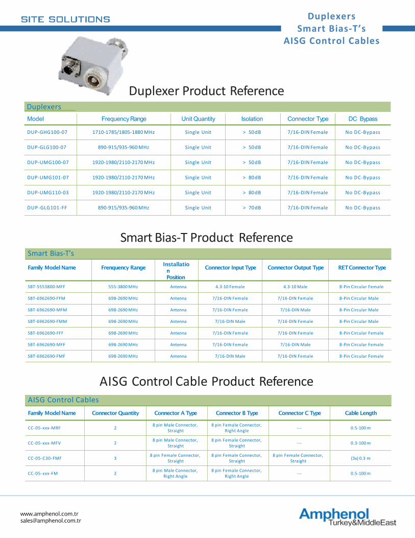
Family ModelName Frenquency RangeInstallation Position
Connector InputType Connector Output Type RET ConnectorType
SBT-5553800-MFF 555-3800 MHz Antenna 4.3-10 Female 4.3-10 Male 8-Pin Circular Female
SBT-6962690-FFM 698-2690 MHz Antenna 7/16-DIN Female 7/16-DIN Female 8-Pin Circular Male
SBT-6962690-MFM 698-2690 MHz Antenna 7/16-DIN Female 7/16-DIN Male 8-Pin Circular Male
SBT-6962690-FMM 698-2690 MHz Antenna 7/16-DIN Male 7/16-DIN Female 8-Pin Circular Male
SBT-6962690-FFF 698-2690 MHz Antenna 7/16-DIN Female 7/16-DIN Female 8-Pin Circular Female
SBT-6962690-MFF 698-2690 MHz Antenna 7/16-DIN Female 7/16-DIN Male 8-Pin Circular Female
SBT-6962690-FMF 698-2690 MHz Antenna 7/16-DIN Male 7/16-DIN Female 8-Pin Circular Female
Smart Bias-T Product Reference
AISG Control CablesFamily ModelName Connector Quantity Connector A Type Connector B Type Connector C Type Cable Length
CC-05-xxx-MRF 2 8 pin Male Connector, Straight
8 pin Female Connector, Right Angle --- 0.5-100 m
CC-05-xxx-MFV 2 8 pin Male Connector, Straight
8 pin Female Connector, Straight --- 0.3-100 m
CC-05-C30-FMF 3 8 pin Female Connector, Straight
8 pin Female Connector, Straight
8 pin Female Connector, Straight (3x) 0.3 m
CC-05-xxx-FM 2 8 pin Male Connector, Right Angle
8 pin Female Connector, Right Angle --- 0.5-100 m
AISG Control Cable Product Reference
DuplexersModel Frequency Range Unit Quantity Isolation Connector Type DC Bypass
DUP-GHG100-07 1710-1785/1805-1880 MHz Single Unit > 50dB 7/16-DIN Female No DC-Bypass
DUP-GLG100-07 890-915/935-960 MHz Single Unit > 50dB 7/16-DIN Female No DC-Bypass
DUP-UMG100-07 1920-1980/2110-2170 MHz Single Unit > 50dB 7/16-DIN Female No DC-Bypass
DUP-UMG101-07 1920-1980/2110-2170 MHz Single Unit > 80dB 7/16-DIN Female No DC-Bypass
DUP-UMG110-03 1920-1980/2110-2170 MHz Single Unit > 80dB 7/16-DIN Female No DC-Bypass
DUP-GLG101-FF 890-915/935-960 MHz Single Unit > 70dB 7/16-DIN Female No DC-Bypass
Duplexer Product Reference
www.amphenol.com.tr [email protected]
DAS Passive Devices
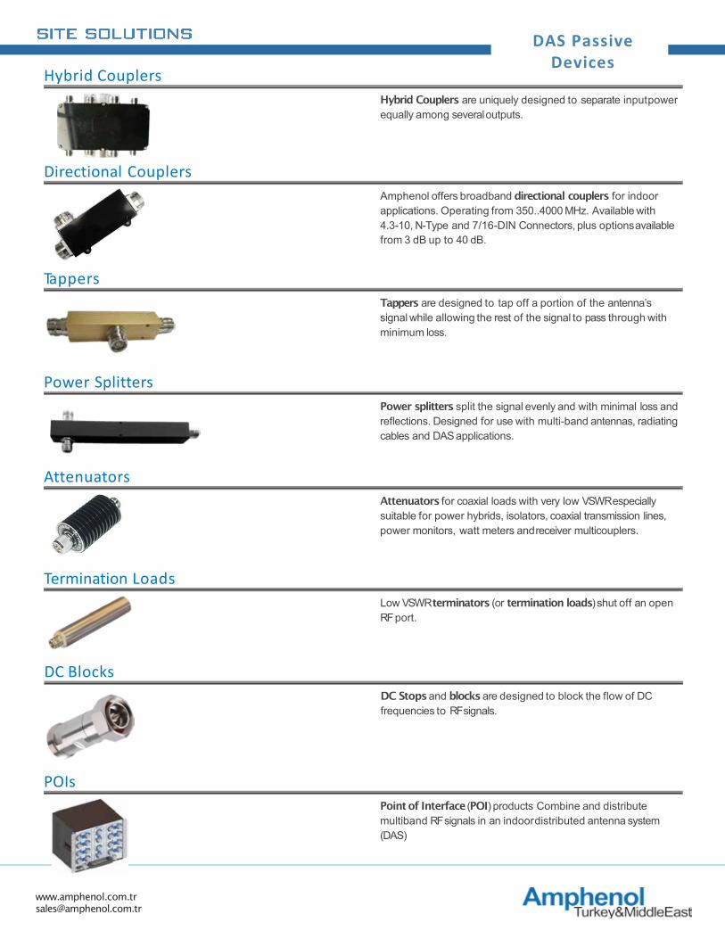
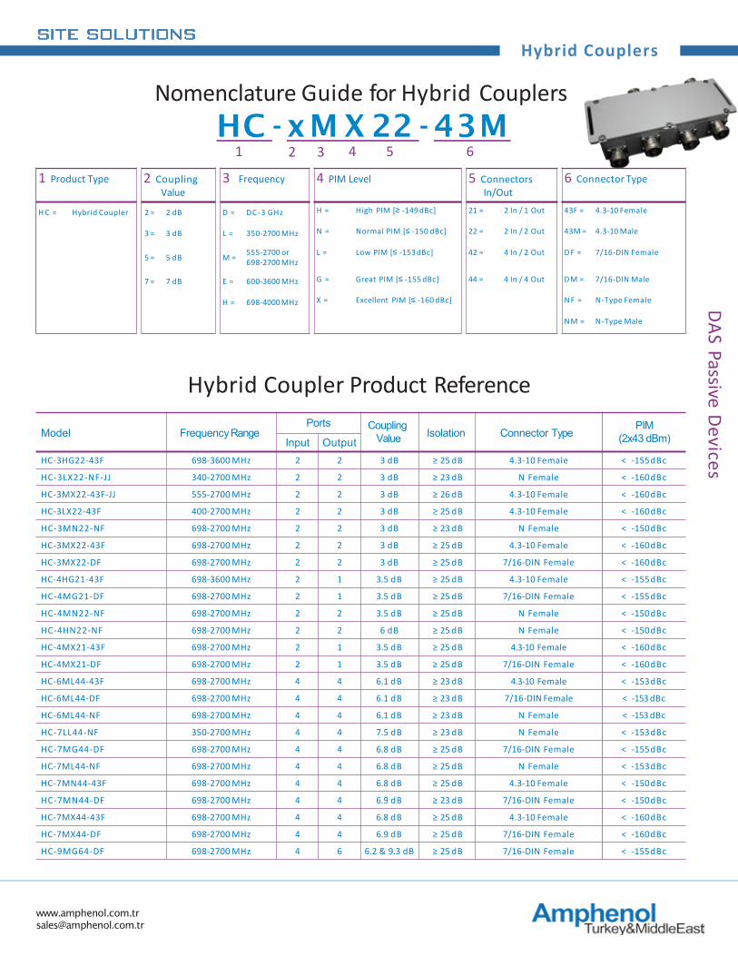
Hybrid Couplers are uniquely designed to separate inputpower equally among severaloutputs.
Hybrid Couplers
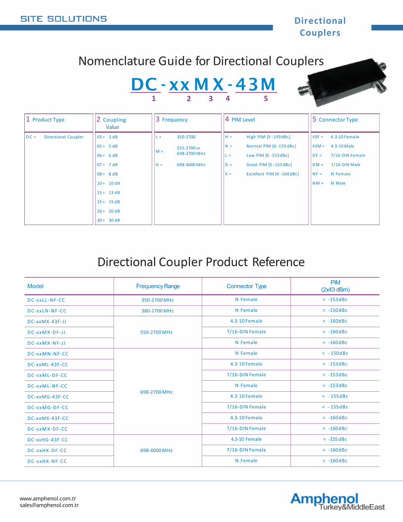
Amphenol offers broadband directional couplers for indoor applications. Operating from 350..4000 MHz. Available with 4.3-10, N-Type and 7/16-DIN Connectors, plus optionsavailable from 3 dB up to 40 dB.
Directional Couplers
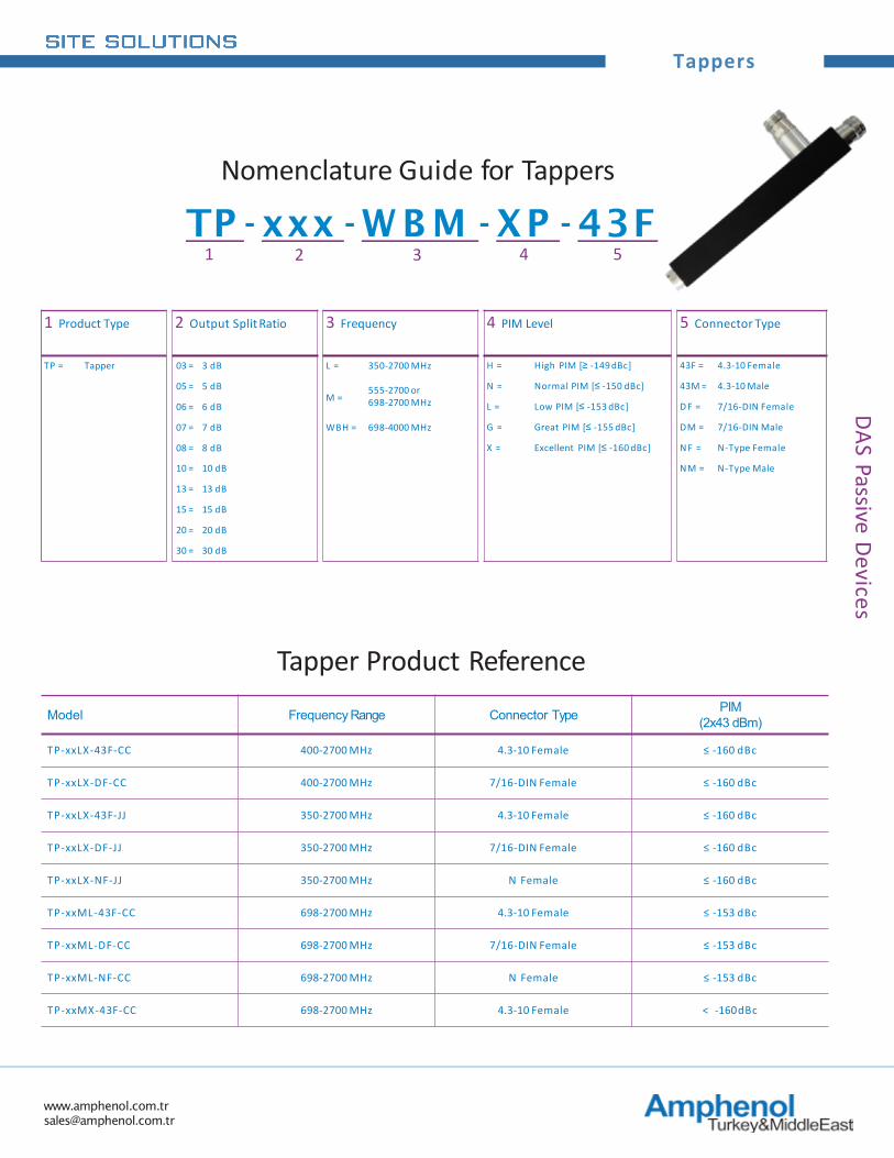
Tappers are designed to tap off a portion of the antenna’s signal while allowing the rest of the signal to pass through with minimum loss.
Tappers
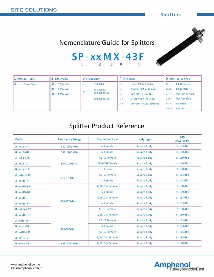
Power splitters split the signal evenly and with minimal loss and reflections. Designed for use with multi-band antennas, radiating cables and DASapplications.
Power Splitters
Attenuators for coaxial loads with very low VSWR especially suitable for power hybrids, isolators, coaxial transmission lines, power monitors, watt meters andreceiver multicouplers.
Attenuators
Low VSWR terminators (or termination loads) shut off an open RFport.
Termination Loads
Point of Interface (POI) products Combine and distribute multiband RF signals in an indoordistributed antenna system (DAS)
POIs
DC Stopsand blocks are designed to block the flow of DC frequencies to RFsignals.
DC Blocks
www.amphenol.com.tr [email protected]
Hybrid CouplersDAS Passive
Devices
1 Product Type 2 Coupling Value
3 Frequency 4 PIM Level 5 Connectors In/Out
6 Connector Type
H C = Hybrid Coupler 2 = 2 dB D = DC-3 GHz H = High PIM [≥ -149 dBc] 21 = 2 In / 1 Out 43F = 4.3-10 Female
3 = 3 dB L = 350-2700 MHz N = Normal PIM [≤ -150 dBc] 22 = 2 In / 2 Out 43M = 4.3-10 Male
5 = 5 dB M = 555-2700 or698-2700 MHz
L = Low PIM [≤ -153 dBc] 42 = 4 In / 2 Out D F = 7/16-DIN Female
7 = 7 dB E = 600-3600 MHz G = Great PIM [≤ -155 dBc] 44 = 4 In / 4 Out DM = 7/16-DIN Male
H = 698-4000 MHz X = Excellent PIM [≤ -160 dBc] N F = N-Type Female
NM = N-Type Male
Nomenclature Guide for Hybrid CouplersHC - xM X 22 - 43M
1 2 3 4 5 6
Model FrequencyRangePorts Coupling
Value Isolation Connector TypePIM
(2x43 dBm)Input OutputHC-3HG22-43F 698-3600 MHz 2 2 3 dB ≥ 25 dB 4.3-10 Female < -155dBc
HC-3LX22-NF-JJ 340-2700 MHz 2 2 3 dB ≥ 23 dB N Female < -160dBc
HC-3MX22-43F-JJ 555-2700 MHz 2 2 3 dB ≥ 26 dB 4.3-10 Female < -160dBc
HC-3LX22-43F 400-2700 MHz 2 2 3 dB ≥ 25 dB 4.3-10 Female < -160dBc
HC-3MN22-NF 698-2700 MHz 2 2 3 dB ≥ 23 dB N Female < -150dBc
HC-3MX22-43F 698-2700 MHz 2 2 3 dB ≥ 25 dB 4.3-10 Female < -160dBc
HC-3MX22-DF 698-2700 MHz 2 2 3 dB ≥ 25 dB 7/16-DIN Female < -160dBc
HC-4HG21-43F 698-3600 MHz 2 1 3.5 dB ≥ 25 dB 4.3-10 Female < -155dBc
HC-4MG21-DF 698-2700 MHz 2 1 3.5 dB ≥ 25 dB 7/16-DIN Female < -155dBc
HC-4MN22-NF 698-2700 MHz 2 2 3.5 dB ≥ 25 dB N Female < -150dBc
HC-4HN22-NF 698-2700 MHz 2 2 6 dB ≥ 25 dB N Female < -150dBc
HC-4MX21-43F 698-2700 MHz 2 1 3.5 dB ≥ 25 dB 4.3-10 Female < -160dBc
HC-4MX21-DF 698-2700 MHz 2 1 3.5 dB ≥ 25 dB 7/16-DIN Female < -160dBc
HC-6ML44-43F 698-2700 MHz 4 4 6.1 dB ≥ 23 dB 4.3-10 Female < -153dBc
HC-6ML44-DF 698-2700 MHz 4 4 6.1 dB ≥ 23 dB 7/16-DIN Female < -153 dBc
HC-6ML44-NF 698-2700 MHz 4 4 6.1 dB ≥ 23 dB N Female < -153 dBc
HC-7LL44-NF 350-2700 MHz 4 4 7.5 dB ≥ 23 dB N Female < -153dBc
HC-7MG44-DF 698-2700 MHz 4 4 6.8 dB ≥ 25 dB 7/16-DIN Female < -155dBc
HC-7ML44-NF 698-2700 MHz 4 4 6.8 dB ≥ 25 dB N Female < -153dBc
HC-7MN44-43F 698-2700 MHz 4 4 6.8 dB ≥ 25 dB 4.3-10 Female < -150dBc
HC-7MN44-DF 698-2700 MHz 4 4 6.9 dB ≥ 23 dB 7/16-DIN Female < -150dBc
HC-7MX44-43F 698-2700 MHz 4 4 6.8 dB ≥ 25 dB 4.3-10 Female < -160dBc
HC-7MX44-DF 698-2700 MHz 4 4 6.9 dB ≥ 25 dB 7/16-DIN Female < -160dBc
HC-9MG64-DF 698-2700 MHz 4 6 6.2 & 9.3 dB ≥ 25 dB 7/16-DIN Female < -155dBc
Hybrid Coupler Product Reference
www.amphenol.com.tr [email protected]
Directional Couplers
1 Product Type 2 Coupling Value
3 Frequency 4 PIM Level 5 Connector Type
D C = Directional Coupler 03 = 3 dB L = 350-2700 H = High PIM [≥ -149 dBc] 43F = 4.3-10 Female
05 = 5 dBM =
555-2700 or698-2700 MHz
N = Normal PIM [≤ -150 dBc] 43M = 4.3-10 Male
06 = 6 dB L = Low PIM [≤ -153 dBc] D F = 7/16-DIN Female
07 = 7 dB H = 698-4000 MHz G = Great PIM [≤ -155 dBc] DM = 7/16-DIN Male
08 = 8 dB X = Excellent PIM [≤ -160 dBc] N F = N Female
10 = 10 dB NM = N Male
13 = 13 dB
15 = 15 dB
20 = 20 dB
30 = 30 dB
DC - xx M X - 43M1 2 3 4 5
Model Frequency Range Connector Type PIM(2x43 dBm)
DC-xxLL-NF-CC 350-2700 MHz N Female < -153dBc
DC-xxLN-NF-CC 380-2700 MHz N Female < -150dBc
DC-xxMX-43F-JJ
550-2700 MHz
4.3-10 Female < -160dBc
DC-xxMX-DF-JJ 7/16-DIN Female < -160dBc
DC-xxMX-NF-JJ N Female < -160dBc
DC-xxMN-NF-CC
698-2700 MHz
N Female < - 150dBc
DC-xxML-43F-CC 4.3-10 Female < -153dBc
DC-xxML-DF-CC 7/16-DIN Female < -153dBc
DC-xxML-NF-CC N Female < -153dBc
DC-xxMG-43F-CC 4.3-10 Female < - 155dBc
DC-xxMG-DF-CC 7/16-DIN Female < - 155dBc
DC-xxMX-43F-CC 4.3-10 Female < -160dBc
DC-xxMX-DF-CC 7/16-DIN Female < -160dBc
DC-xxHG-43F-CC
698-4000 MHz
4.3-10 Female < -155 dBc
DC-xxHX-DF-CC 7/16-DIN Female < -160dBc
DC-xxHX-NF-CC N Female < -160dBc
Nomenclature Guide for Directional Couplers
Directional Coupler Product Reference
www.amphenol.com.tr [email protected]
TappersDAS Passive
Devices
1 Product Type 2 Output Split Ratio 3 Frequency 4 PIM Level 5 Connector Type
TP = Tapper 03 = 3 dB L = 350-2700 MHz H = High PIM [≥ -149 dBc] 43F = 4.3-10 Female
05 = 5 dBM =
555-2700 or698-2700 MHz
N = Normal PIM [≤ -150 dBc] 43M = 4.3-10 Male
06 = 6 dB L = Low PIM [≤ -153 dBc] D F = 7/16-DIN Female
07 = 7 dB WBH = 698-4000 MHz G = Great PIM [≤ -155 dBc] DM = 7/16-DIN Male
08 = 8 dB X = Excellent PIM [≤ -160 dBc] N F = N-Type Female
10 = 10 dB NM = N-Type Male
13 = 13 dB
15 = 15 dB
20 = 20 dB
30 = 30 dB
Nomenclature Guide for Tappers
TP - xxx - W B M - XP - 43F1 2 3 4 5
Model Frequency Range Connector Type PIM(2x43 dBm)
TP-xxLX-43F-CC 400-2700 MHz 4.3-10 Female ≤ -160 dBc
TP-xxLX-DF-CC 400-2700 MHz 7/16-DIN Female ≤ -160 dBc
TP-xxLX-43F-JJ 350-2700 MHz 4.3-10 Female ≤ -160 dBc
TP-xxLX-DF-JJ 350-2700 MHz 7/16-DIN Female ≤ -160 dBc
TP-xxLX-NF-JJ 350-2700 MHz N Female ≤ -160 dBc
TP-xxML-43F-CC 698-2700 MHz 4.3-10 Female ≤ -153 dBc
TP-xxML-DF-CC 698-2700 MHz 7/16-DIN Female ≤ -153 dBc
TP-xxML-NF-CC 698-2700 MHz N Female ≤ -153 dBc
TP-xxMX-43F-CC 698-2700 MHz 4.3-10 Female < -160dBc
Tapper Product Reference
www.amphenol.com.tr [email protected]
Splitters
1 Product Type 2 Split Value 3 Frequency 4 PIM Level 5 Connector TypeSP = Power Splitter 02 = 2 Way Split L = 350-2700 H = High PIM [≥ -149 dBc] 43F = 4.3-10 Female
03 = 3 Way SplitM =
555-2700 or698-2700 MHz
N = Normal PIM [≤ -150 dBc] 43M = 4.3-10 Male
04 = 4 Way Split L = Low PIM [≤ -153 dBc] D F = 7/16-DIN Female
H = 698-4000 MHz G = Great PIM [≤ -155 dBc] DM = 7/16-DIN Male
X = Excellent PIM [≤ -160 dBc] N F = N Female
NM = N Male
SP - xx M X -43F1 2 3 4 5
Model FrequencyRange Connector Type Body Type PIM(2x43 dBm)
SP-xxLL-NF 350-2700 MHz N Female Square Body ≤ -153 dBc
SP-xxLN-NF 380-2700 MHz N Female Square Body ≤ -150 dBc
SP-xxLX-43F
400-2700 MHz
4.3-10 Female Square Body ≤ -160 dBc
SP-xxLX-DF 7/16-DIN Female Square Body ≤ -160 dBc
SP-xxLX-NF N Female Square Body ≤ -160 dBc
SP-xxML-43F555-2700 MHz
4.3-10 Female Square Body ≤ -153 dBc
SP-xxML-NF N Female Square Body ≤ -153 dBc
SP-xxMN-DF
698-2700 MHz
7/16-DIN Female Square Body ≤ -150 dBc
SP-xxMN-NF N Female Square Body ≤ -150 dBc
SP-xxML-DF 7/16-DIN Female Square Body ≤ -153 dBc
SP-xxML-NF N Female Square Body ≤ -153 dBc
SP-xxMX-43F 4.3-10 Female Square Body ≤ -160 dBc
SP-xxMX-DF 7/16-DIN Female Square Body ≤ -160 dBc
SP-xxHL-43F
698-3800 MHz
4.3-10 Female Square Body ≤ -153 dBc
SP-xxHL-NF N Female Square Body ≤ -153 dBc
SP-xxHG-43F 4.3-10 Female Square Body ≤ -155 dBc
SP-xxHG-DF 7/16-DIN Female Square Body ≤ -155 dBc
SP-xxHX-DF 698-4000 MHz 7/16-DIN Female Square Body ≤ -160 dBc
Nomenclature Guide for Splitters
Splitter Product Reference
www.amphenol.com.tr [email protected]
AttenuatorsDAS Passive
Devices
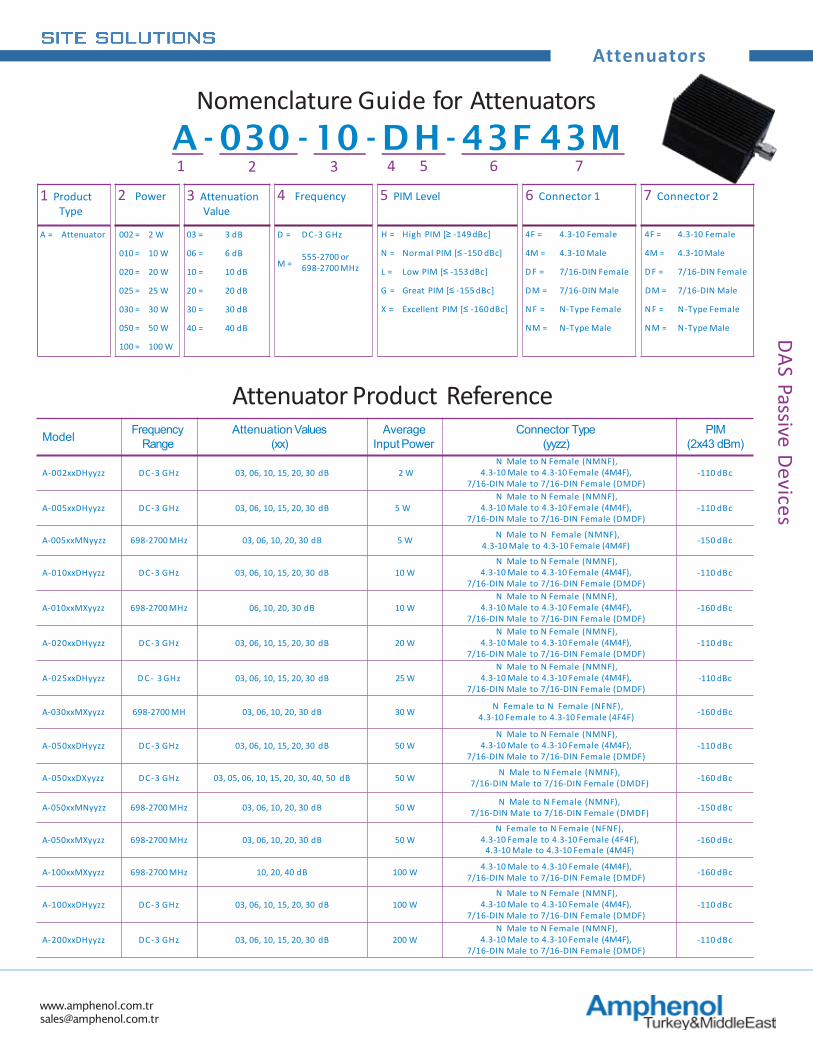
1 Product Type
2 Power 3 Attenuation Value
4 Frequency 5 PIM Level 6 Connector 1 7 Connector 2
A = Attenuator 002 = 2 W 03 = 3 dB D = DC-3 GHz H = High PIM [≥ -149 dBc] 4F = 4.3-10 Female 4F = 4.3-10 Female
010 = 10 W 06 = 6 dBM =
555-2700 or698-2700 MHz
N = Normal PIM [≤ -150 dBc] 4M = 4.3-10 Male 4M = 4.3-10 Male
020 = 20 W 10 = 10 dB L = Low PIM [≤ -153 dBc] D F = 7/16-DIN Female D F = 7/16-DIN Female
025 = 25 W 20 = 20 dB G = Great PIM [≤ -155 dBc] DM = 7/16-DIN Male DM = 7/16-DIN Male
030 = 30 W 30 = 30 dB X = Excellent PIM [≤ -160 dBc] N F = N-Type Female N F = N-Type Female
050 = 50 W 40 = 40 dB NM = N-Type Male NM = N-Type Male
100 = 100 W
Nomenclature Guide for AttenuatorsA - 030 - 10 - DH - 43F 43M1 2 3 4 5 6 7
Model Frequency Range
AttenuationValues (xx)
Average Input Power
Connector Type (yyzz)
PIM(2x43 dBm)
A-002xxDHyyzz DC-3 GHz 03, 06, 10, 15, 20, 30 dB 2 WN Male to N Female (NMNF),
4.3-10 Male to 4.3-10 Female (4M4F), 7/16-DIN Male to 7/16-DIN Female (DMDF)
-110 dBc
A-005xxDHyyzz DC-3 GHz 03, 06, 10, 15, 20, 30 dB 5 WN Male to N Female (NMNF),
4.3-10 Male to 4.3-10 Female (4M4F), 7/16-DIN Male to 7/16-DIN Female (DMDF)
-110 dBc
A-005xxMNyyzz 698-2700 MHz 03, 06, 10, 20, 30 dB 5 W N Male to N Female (NMNF), 4.3-10 Male to 4.3-10 Female (4M4F) -150 dBc
A-010xxDHyyzz DC-3 GHz 03, 06, 10, 15, 20, 30 dB 10 WN Male to N Female (NMNF),
4.3-10 Male to 4.3-10 Female (4M4F), 7/16-DIN Male to 7/16-DIN Female (DMDF)
-110 dBc
A-010xxMXyyzz 698-2700 MHz 06, 10, 20, 30 dB 10 WN Male to N Female (NMNF),
4.3-10 Male to 4.3-10 Female (4M4F), 7/16-DIN Male to 7/16-DIN Female (DMDF)
-160 dBc
A-020xxDHyyzz DC-3 GHz 03, 06, 10, 15, 20, 30 dB 20 WN Male to N Female (NMNF),
4.3-10 Male to 4.3-10 Female (4M4F), 7/16-DIN Male to 7/16-DIN Female (DMDF)
-110 dBc
A-025xxDHyyzz D C - 3 GHz 03, 06, 10, 15, 20, 30 dB 25 WN Male to N Female (NMNF),
4.3-10 Male to 4.3-10 Female (4M4F), 7/16-DIN Male to 7/16-DIN Female (DMDF)
-110 dBc
A-030xxMXyyzz 698-2700 MH 03, 06, 10, 20, 30 dB 30 W N Female to N Female (NFNF), 4.3-10 Female to 4.3-10 Female (4F4F) -160 dBc
A-050xxDHyyzz DC-3 GHz 03, 06, 10, 15, 20, 30 dB 50 WN Male to N Female (NMNF),
4.3-10 Male to 4.3-10 Female (4M4F), 7/16-DIN Male to 7/16-DIN Female (DMDF)
-110 dBc
A-050xxDXyyzz DC-3 GHz 03, 05, 06, 10, 15, 20, 30, 40, 50 dB 50 W N Male to N Female (NMNF),7/16-DIN Male to 7/16-DIN Female (DMDF) -160 dBc
A-050xxMNyyzz 698-2700 MHz 03, 06, 10, 20, 30 dB 50 W N Male to N Female (NMNF),7/16-DIN Male to 7/16-DIN Female (DMDF) -150 dBc
A-050xxMXyyzz 698-2700 MHz 03, 06, 10, 20, 30 dB 50 WN Female to N Female (NFNF),
4.3-10 Female to 4.3-10 Female (4F4F),4.3-10 Male to 4.3-10 Female (4M4F)
-160 dBc
A-100xxMXyyzz 698-2700 MHz 10, 20, 40 dB 100 W 4.3-10 Male to 4.3-10 Female (4M4F), 7/16-DIN Male to 7/16-DIN Female (DMDF) -160 dBc
A-100xxDHyyzz DC-3 GHz 03, 06, 10, 15, 20, 30 dB 100 WN Male to N Female (NMNF),
4.3-10 Male to 4.3-10 Female (4M4F), 7/16-DIN Male to 7/16-DIN Female (DMDF)
-110 dBc
A-200xxDHyyzz DC-3 GHz 03, 06, 10, 15, 20, 30 dB 200 WN Male to N Female (NMNF),
4.3-10 Male to 4.3-10 Female (4M4F), 7/16-DIN Male to 7/16-DIN Female (DMDF)
-110 dBc
Attenuator Product Reference
www.amphenol.com.tr [email protected]
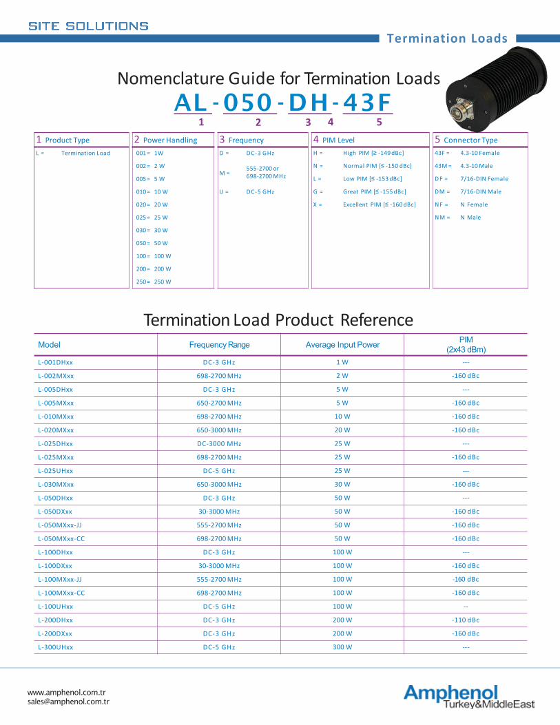
Termination Loads
1 Product Type 2 Power Handling 3 Frequency 4 PIM Level 5 Connector TypeL = Termination Load 001 = 1W D = DC-3 GHz H = High PIM [≥ -149 dBc] 43F = 4.3-10 Female
002 = 2 WM =
555-2700 or698-2700 MHz
N = Normal PIM [≤ -150 dBc] 43M = 4.3-10 Male
005 = 5 W L = Low PIM [≤ -153 dBc] D F = 7/16-DIN Female
010 = 10 W U = DC-5 GHz G = Great PIM [≤ -155 dBc] DM = 7/16-DIN Male
020 = 20 W X = Excellent PIM [≤ -160 dBc] N F = N Female
025 = 25 W NM = N Male
030 = 30 W
050 = 50 W
100 = 100 W
200 = 200 W
250 = 250 W
AL - 050 - DH- 43F1 2 3 4 5
Model Frequency Range Average Input Power PIM(2x43 dBm)
L-001DHxx DC-3 GHz 1 W ---
L-002MXxx 698-2700 MHz 2 W -160 dBc
L-005DHxx DC-3 GHz 5 W ---
L-005MXxx 650-2700 MHz 5 W -160 dBc
L-010MXxx 698-2700 MHz 10 W -160 dBc
L-020MXxx 650-3000 MHz 20 W -160 dBc
L-025DHxx DC-3000 MHz 25 W ---
L-025MXxx 698-2700 MHz 25 W -160 dBc
L-025UHxx DC-5 GHz 25 W ---
L-030MXxx 650-3000 MHz 30 W -160 dBc
L-050DHxx DC-3 GHz 50 W ---
L-050DXxx 30-3000 MHz 50 W -160 dBc
L-050MXxx-JJ 555-2700 MHz 50 W -160 dBc
L-050MXxx-CC 698-2700 MHz 50 W -160 dBc
L-100DHxx DC-3 GHz 100 W ---
L-100DXxx 30-3000 MHz 100 W -160 dBc
L-100MXxx-JJ 555-2700 MHz 100 W -160 dBc
L-100MXxx-CC 698-2700 MHz 100 W -160 dBc
L-100UHxx DC-5 GHz 100 W --
L-200DHxx DC-3 GHz 200 W -110 dBc
L-200DXxx DC-3 GHz 200 W -160 dBc
L-300UHxx DC-5 GHz 300 W ---
Nomenclature Guide for Termination Loads
Termination Load Product Reference
www.amphenol.com.tr [email protected]
DC Blocks & POI’sDAS Passive
Devices
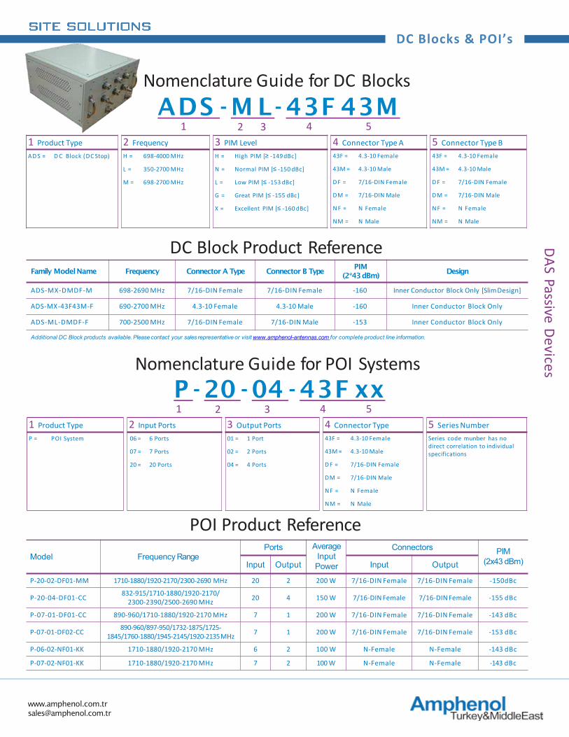
Model Frequency RangePorts Average
Input Power
Connectors PIM(2x43 dBm)Input Output Input Output
P-20-02-DF01-MM 1710-1880/1920-2170/2300-2690 MHz 20 2 200 W 7/16-DIN Female 7/16-DIN Female -150dBc
P-20-04-DF01-CC 832-915/1710-1880/1920-2170/2300-2390/2500-2690 MHz 20 4 150 W 7/16-DIN Female 7/16-DIN Female -155 dBc
P-07-01-DF01-CC 890-960/1710-1880/1920-2170 MHz 7 1 200 W 7/16-DIN Female 7/16-DIN Female -143 dBc
P-07-01-DF02-CC 890-960/897-950/1732-1875/1725-1845/1760-1880/1945-2145/1920-2135MHz 7 1 200 W 7/16-DIN Female 7/16-DIN Female -153 dBc
P-06-02-NF01-KK 1710-1880/1920-2170 MHz 6 2 100 W N-Female N-Female -143 dBc
P-07-02-NF01-KK 1710-1880/1920-2170 MHz 7 2 100 W N-Female N-Female -143 dBc
POI Product Reference
Family ModelName Frequency Connector A Type Connector B TypePIM
(2*43dBm)Design
ADS-MX-DMDF-M 698-2690 MHz 7/16-DIN Female 7/16-DIN Female -160 Inner Conductor Block Only [SlimDesign]
ADS-MX-43F43M-F 690-2700 MHz 4.3-10 Female 4.3-10 Male -160 Inner Conductor Block Only
ADS-ML-DMDF-F 700-2500 MHz 7/16-DIN Female 7/16-DIN Male -153 Inner Conductor Block Only
Additional DC Block products available. Please contact your sales representative or visit www.amphenol-antennas.com for complete product line information.
DC Block Product Reference
1 Product Type 2 Frequency 3 PIM Level 4 Connector Type A 5 Connector Type BAD S = D C Block (DC Stop) H = 698-4000 MHz H = High PIM [≥ -149 dBc] 43F = 4.3-10 Female 43F = 4.3-10 Female
L = 350-2700 MHz N = Normal PIM [≤ -150 dBc] 43M = 4.3-10 Male 43M = 4.3-10 Male
M = 698-2700 MHz L = Low PIM [≤ -153 dBc] D F = 7/16-DIN Female D F = 7/16-DIN Female
G = Great PIM [≤ -155 dBc] DM = 7/16-DIN Male DM = 7/16-DIN Male
X = Excellent PIM [≤ -160 dBc] N F = N Female N F = N Female
NM = N Male NM = N Male
Nomenclature Guide for DC BlocksADS -M L- 43F 43M
1 2 3 4 5
1 Product Type 2 Input Ports 3 Output Ports 4 Connector Type 5 Series NumberP = POI System 06 = 6 Ports 01 = 1 Port 43F = 4.3-10 Female Series code munber has no
direct correlation to individual specifications07 = 7 Ports 02 = 2 Ports 43M = 4.3-10 Male
20 = 20 Ports 04 = 4 Ports D F = 7/16-DIN Female
DM = 7/16-DIN Male
N F = N Female
NM = N Male
Nomenclature Guide for POI SystemsP - 20 - 04 - 43F xx1 2 3 4 5

www.amphenol.com.trwww.amphenol-middle-east.com
amphenol.com.br
Related Documents