Site Management Plan 229 HOMER STREET SITE NYSDEC SITE NUMBER C905044 OLEAN, NEW YORK 2558 Hamburg Turnpike, Suite 300, Buffalo, New York 14218 | phone: (716) 856-0599 | fax: (716) 856-0583 December 2018 0311-018-001 Prepared For: Homer Street Properties, LLC Prepared By: In Association With:

Welcome message from author
This document is posted to help you gain knowledge. Please leave a comment to let me know what you think about it! Share it to your friends and learn new things together.
Transcript

Site Management Plan 229 HOMER STREET SITE NYSDEC SITE NUMBER C905044 OLEAN, NEW YORK
2558 Hamburg Turnpike, Suite 300, Buffalo, New York 14218 | phone: (716) 856-0599 | fax: (716) 856-0583
December 2018 0311-018-001
Prepared For:
Homer Street Properties, LLC
Prepared By: In Association With:
BROWNFIELD CLEANUP PROGRAM
SITE MANAGEMENT PLAN
229 HOMER STREET SITE
NYSDEC SITE NUMBER: C905044 CITY OF OLEAN, CATTARAUGUS COUNTY, NEW YORK
December 2018 0311-018-001
Prepared for:
HOMER STREET PROPERTIES, LLC 221 Homer Street
Olean, New York 14760
Prepared By: Benchmark Environmental Engineering & Science, PLLC 2558 Hamburg Turnpike, Suite 300 Buffalo, NY 14218 (716) 856-0599
In Association With:
TurnKey Environmental Restoration, LLC 2558 Hamburg Turnpike, Suite 300 Buffalo, NY 14218 (716) 856-0635
Revisions to Final Approved Site Management Plan:
Revision # Submitted Date Summary of Revision DEC Approval Date
Bn v i ronme talng i neeri n gc ence,i
n
SITE MANAGEMENT PLAN
229 HOMER STREET SITE
Table of Contents
0311-018-001
i
T KB
LIST OF ACRONYMS
EXECUTIVE SUMMARY
1.0 INTRODUCTION ...................................................................................................... 1
1.1 General .........................................................................................................................1
1.2 Revisions ......................................................................................................................2 1.3 Notifications .................................................................................................................2
2.0 SUMMARY OF PREVIOUS INVESTIGATION & REMEDIAL ACTIONS ....................... 4
2.1 Site Location and Description ......................................................................................4 2.2 Physical Setting ............................................................................................................4
2.2.1 Land Use ......................................................................................................................................... 4 2.2.2 Geology ............................................................................................................................................. 4 2.2.3 Hydrogeology ..................................................................................................................................... 5
2.3 Investigation History ....................................................................................................6 2.4 Remedial Action Objectives ........................................................................................9 2.5 Remedial Action Summary ........................................................................................10
2.6 Remaining Contamination .........................................................................................12 2.6.1 Soil ................................................................................................................................................. 12 2.6.2 Groundwater ................................................................................................................................... 12 2.6.3 Soil Vapor ..................................................................................................................................... 13
3.0 INSTITUTIONAL & ENGINEERING CONTROL PLAN ............................................ 14
3.1 General .......................................................................................................................14 3.2 Institutional Controls .................................................................................................14 3.3 Engineering Controls .................................................................................................15
3.3.1 Site Cover System ............................................................................................................................ 15 3.3.2 Air Sparging/Soil Vapor Extraction System ................................................................................. 16 3.3.3 Active Subslab Depressurization System(s) ..................................................................................... 17 3.3.4 Criteria for Completion of Remediation/Termination of Remedial Systems ...................................... 17
3.3.4.1 Site Cover System ........................................................................................................... 18 3.3.4.2 AS/SVE System ......................................................................................................... 18 3.3.4.3 Active Subslab Depressurization (ASD) System(s) ........................................................ 18
4.0 MONITORING AND SAMPLING PLAN .................................................................... 19
4.1 General .......................................................................................................................19 4.2 Site-Wide Inspection ..................................................................................................20 4.3 Treatment System Monitoring and Sampling ............................................................21
4.3.1 Remedial System Monitoring ........................................................................................................... 21 4.3.1.1 Air Sparging/Soil Vapor Extraction System ................................................................ 21 4.3.1.2 ASD System(s) .............................................................................................................. 21
4.3.2 Remedial System Sampling .............................................................................................................. 22 4.3.2.1 AS/SVE System ......................................................................................................... 22
4.4 Post-Remediation Media Monitoring and Sampling .................................................23
SITE MANAGEMENT PLAN
229 HOMER STREET SITE
Table of Contents
0311-018-001
ii
T KB
4.4.1 Post AS/SVE Treatment Soil Sampling ....................................................................................... 23 4.4.2 Groundwater Sampling ................................................................................................................... 24 4.4.3 Monitoring and Sampling Protocol .................................................................................................. 26
5.0 OPERATION & MAINTENANCE PLAN .................................................................. 27
5.1 General .......................................................................................................................27 5.2 Remedial System Performance Criteria .....................................................................27 5.3 Operation and Maintenance of SVE System .............................................................28
5.3.1 General ........................................................................................................................................... 28 5.3.2 System Start-Up and Testing .......................................................................................................... 29 5.3.3 Routine System Operation and Maintenance ................................................................................... 30 5.3.4 System Monitoring Devices and Alarms .......................................................................................... 30
6.0 PERIODIC ASSESSMENTS/EVALUATIONS ............................................................. 32
6.1 Climate Change Vulnerability Assessment ...............................................................32 6.2 Green Remediation Evaluation ..................................................................................33
6.2.1 Timing of Green Remediation Evaluations ...................................................................................... 33 6.2.2 Remedial Systems ............................................................................................................................ 33 6.2.3 Building Operations ........................................................................................................................ 34
6.3 Remedial System Optimization .................................................................................34
7.0 REPORTING REQUIREMENTS ............................................................................... 36
7.1 Site Management Reports ..........................................................................................36
7.2 Periodic Review Report .............................................................................................38 7.2.1 Certification of Institutional and Engineering Controls .................................................................... 40
7.3 Corrective Measures Work Plan ................................................................................41 7.4 Remedial Site Optimization Report ...........................................................................41
8.0 REFERENCES ........................................................................................................ 42
SITE MANAGEMENT PLAN
229 HOMER STREET SITE
Table of Contents
0311-018-001 T KB
LIST OF TABLES
Table 1 Notifications Table 2A Unrestricted Use SCO Exceedances- Test Pits Soil Analytical Summary Table 2B Unrestricted Use SCO Exceedances- Soil Boring Analytical Summary Table 3 Summary of Groundwater Analytical Data Table 4A Summary of Soil Vapor Assessment Analytical Data
Table 4B Comparison of Soil Vapor Assessment Analytical Data to NYSDOH Decision Matrices 1 and 2
Table 5 Remedial System Monitoring Requirements and Schedule Table 6 Remedial System Sampling Requirements and Schedule Table 7 Post Remediation Sampling Requirements and Schedule Table 8 Monitoring Well Construction Details Table 9 Schedule of Interim Monitoring/Inspection Reports
LIST OF FIGURES
Figure 1 Site Location and Vicinity Map Figure 2 Site Plan (Aerial) Figure 3 Survey/Tax Parcel Map Figure 4 Geologic Cross-Section A-A’ Figure 5A Isopotential Map (December 2015) Figure 5B Isopotential Map (August 2018) Figure 6 Abandoned Subsurface Piping and GCS Removal Map Figure 7 Air Sparge and Soil Vapor Extraction System Layout Figure 8 Air Sparge and Soil Vapor Extraction System Schematic and Well Details Figure 9 Site Cover System and Details Figure 10 Remaining Contamination above Unrestricted SCOs
SITE MANAGEMENT PLAN
229 HOMER STREET SITE
Table of Contents
0311-018-001 T KB
APPENDICES
Appendix A List of Site Contacts Appendix B Excavation Work Plan Appendix C Responsibilities of Owner and Remedial Party Appendix D Environmental Easement Appendix E Soil Boring Logs and Monitoring Well Construction Logs Appendix F Field Operating Procedures Appendix G Quality Assurance Project Plan Appendix H Health and Safety Plan Appendix I Site Management Forms Appendix J Remedial Systems O&M Manuals Appendix K Remedial System Optimization Table of Contents

SITE MANAGEMENT PLAN
229 HOMER STREET SITE
List of Acronyms
0311-018-001
T KB
AS Air Sparging ASP Analytical Services Protocol BCA Brownfield Cleanup Agreement BCP Brownfield Cleanup Program CERCLA Comprehensive Environmental Response, Compensation, and Liability Act CAMP Community Air Monitoring Plan C/D Construction and Demolition CFR Code of Federal Regulation CLP Contract Laboratory Program COC Certificate of Completion CO2 Carbon Dioxide CP Commissioner Policy DER Division of Environmental Remediation EC Engineering Control ECL Environmental Conservation Law ELAP Environmental Laboratory Approval Program ERP Environmental Restoration Program GHG Green House Gas GWE&T Groundwater Extraction and Treatment HASP Health and Safety Plan IC Institutional Control NYSDEC New York State Department of Environmental Conservation NYSDOH New York State Department of Health NYCRR New York Codes, Rules, and Regulations O&M Operations and Maintenance OM&M Operation, Maintenance and Monitoring OSHA Occupational Safety and Health Administration OU Operable Unit PID Photoionization Detector PRP Potentially Responsible Party PRR Periodic Review Report QA/QC Quality Assurance/Quality Control QAPP Quality Assurance Project Plan RAO Remedial Action Objective RAWP Remedial Action Work Plan RCRA Resource Conservation and Recovery Act RI/FS Remedial Investigation/Feasibility Study ROD Record of Decision

SITE MANAGEMENT PLAN
229 HOMER STREET SITE
List of Acronyms
0311-018-001
T KB
RP Remedial Party RSO Remedial System Optimization SAC State Assistance Contract SCG Standards, Criteria, and Guidelines SCO Soil Cleanup Objective SMP Soil Management Plan SOP Standard Operating Procedures SOW Statement of Work SPDES State Pollutant Discharge Elimination System SSD Sub-slab Depressurization SVE Soil Vapor Extraction SVI Soil Vapor Intrusion SVMS Soil Vapor Mitigation System TAL Target Analyte List TCL Target Compound List TCLP Toxicity Characteristic Leachate Procedure USEPA United States Environmental Protection Agency UST Underground Storage Tank VCA Voluntary Cleanup Agreement VCP Voluntary Cleanup Program
SITE MANAGEMENT PLAN 229 HOMER STREET SITE
BCP SITE NO.C905044
0311-018-001
ES-1
T KB
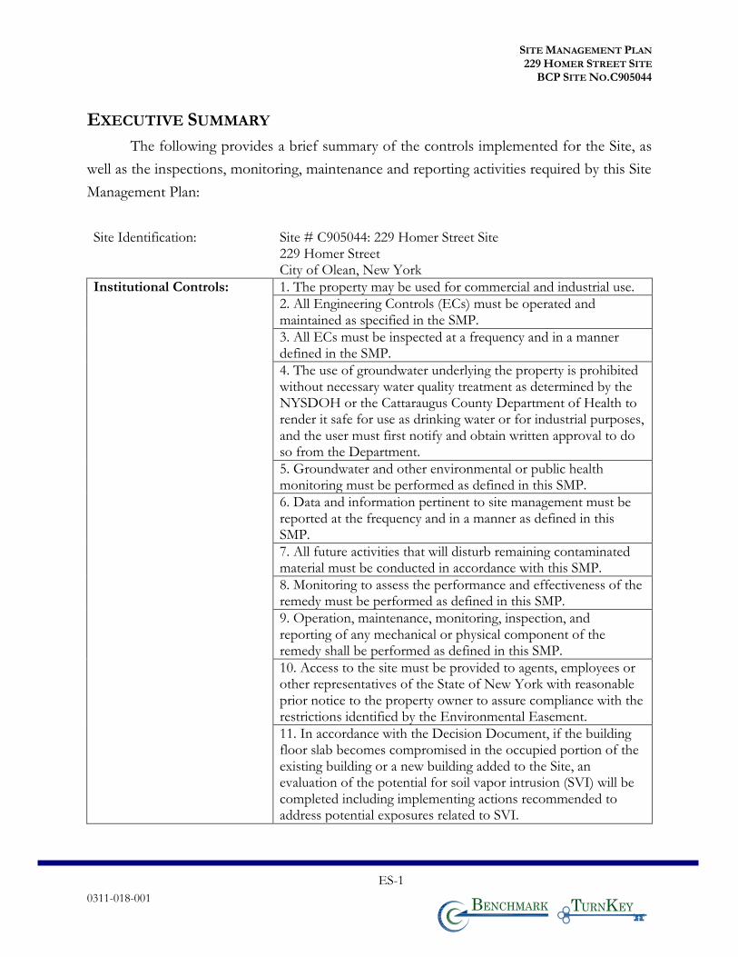
EXECUTIVE SUMMARY
The following provides a brief summary of the controls implemented for the Site, as
well as the inspections, monitoring, maintenance and reporting activities required by this Site
Management Plan:
Site Identification: Site # C905044: 229 Homer Street Site 229 Homer Street City of Olean, New York
Institutional Controls: 1. The property may be used for commercial and industrial use.
2. All Engineering Controls (ECs) must be operated and maintained as specified in the SMP.
3. All ECs must be inspected at a frequency and in a manner defined in the SMP.
4. The use of groundwater underlying the property is prohibited without necessary water quality treatment as determined by the NYSDOH or the Cattaraugus County Department of Health to render it safe for use as drinking water or for industrial purposes, and the user must first notify and obtain written approval to do so from the Department.
5. Groundwater and other environmental or public health monitoring must be performed as defined in this SMP.
6. Data and information pertinent to site management must be reported at the frequency and in a manner as defined in this SMP.
7. All future activities that will disturb remaining contaminated material must be conducted in accordance with this SMP.
8. Monitoring to assess the performance and effectiveness of the remedy must be performed as defined in this SMP.
9. Operation, maintenance, monitoring, inspection, and reporting of any mechanical or physical component of the remedy shall be performed as defined in this SMP.
10. Access to the site must be provided to agents, employees or other representatives of the State of New York with reasonable prior notice to the property owner to assure compliance with the restrictions identified by the Environmental Easement.
11. In accordance with the Decision Document, if the building floor slab becomes compromised in the occupied portion of the existing building or a new building added to the Site, an evaluation of the potential for soil vapor intrusion (SVI) will be completed including implementing actions recommended to address potential exposures related to SVI.
SITE MANAGEMENT PLAN 229 HOMER STREET SITE
BCP SITE NO.C905044
0311-018-001
ES-2
T KB
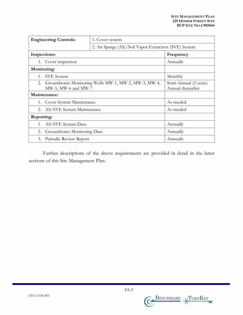
Engineering Controls: 1. Cover system.
2. Air Sparge (AS)/Soil Vapor Extraction (SVE) System
Inspections: Frequency
1. Cover inspection Annually
Monitoring:
1. SVE System Monthly
2. Groundwater Monitoring Wells MW-1, MW-2, MW-3, MW-4, MW-5, MW-6 and MW-7
Semi-Annual (2 years) Annual thereafter
Maintenance:
1. Cover System Maintenance As needed
2. AS/SVE System Maintenance As needed
Reporting:
1. AS/SVE System Data Annually
2. Groundwater Monitoring Data Annually
3. Periodic Review Report Annually
Further descriptions of the above requirements are provided in detail in the latter
sections of this Site Management Plan.
SITE MANAGEMENT PLAN 229 HOMER STREET SITE
BCP SITE NO.C905044
0311-018-001 1 T KB
1.0 INTRODUCTION
1.1 General
This Site Management Plan (SMP) is a required element of the remedial program for
the 229 Homer Street Site located in the City of Olean, New York (hereinafter referred to as
the “Site”); see Figures 1 and 2. The Site is currently in the New York State (NYS) Brownfield
Cleanup Program (BCP) (Site No. C905044), which is administered by New York State
Department of Environmental Conservation (NYSDEC).
This SMP has been prepared on behalf of Homer Street Properties, LLC (HSP) for the
229 Homer Street Site in the City of Olean, Cattaraugus County, New York. HSP elected to
pursue cleanup and redevelopment of the Site under the New York State BCP and executed a
Brownfield Cleanup Agreement (BCA) with the NYSDEC in October 2015 (BCP Site No.
C905044), which was amended in October 2017.
The boundaries of the Site are more fully described in the metes and bounds site
description that is part of the Environmental Easement provided in Appendix D.
After completion of the remedial work, some contamination was left at this site, which
is hereafter referred to as “remaining contamination.” Institutional and Engineering Controls
(ICs and ECs) have been incorporated into the Site remedy to control exposure to remaining
contamination to ensure protection of public health and the environment. An Environmental
Easement granted to the NYSDEC, and recorded with the Cattaraugus County Clerk, requires
compliance with this SMP and all ECs and ICs placed on the site.
This SMP was prepared to manage remaining contamination at the site until the
Environmental Easement is extinguished in accordance with ECL Article 71, Title 36. This
plan has been approved by the NYSDEC, and compliance with this plan is required by the
grantor of the Environmental Easement and the grantor’s successors and assigns. This SMP
may only be revised with the approval of the NYSDEC.
It is important to note that:
• This SMP details the site-specific implementation procedures that are required by the Environmental Easement. Failure to properly implement the SMP is a violation of the Environmental Easement, which is grounds for revocation of the Certificate of Completion (COC);
SITE MANAGEMENT PLAN 229 HOMER STREET SITE
BCP SITE NO.C905044
0311-018-001 2 T KB
• Failure to comply with this SMP is also a violation of Environmental Conservation Law, 6NYCRR Part 375 and the BCA (Index #C905031-08-12; Site #C905031) for the site, and thereby subject to applicable penalties.
All reports associated with the site can be viewed by contacting the NYSDEC or its
successor agency managing environmental issues in New York State. A list of contacts for
persons involved with the site is provided in Appendix A of this SMP.
This SMP was prepared by Benchmark-TurnKey on behalf of HSP in accordance with
the requirements of the NYSDEC’s DER-10 (“Technical Guidance for Site Investigation and
Remediation”), dated May 2010, and the guidelines provided by the NYSDEC. This SMP
addresses the means for implementing the ICs and/or ECs that are required by the
Environmental Easement for the Site.
1.2 Revisions
Revisions to this plan will be proposed in writing to the NYSDEC’s project manager.
Revisions will be necessary upon, but not limited to, the following occurring: a change in
media monitoring requirements, upgrades to or shut-down of a remedial system, post-remedial
removal of contaminated soil, or other significant change to the Site conditions. In accordance
with the Environmental Easement for the Site, the NYSDEC will provide a notice of any
approved changes to the SMP and append these notices to the SMP that is retained in its files.
1.3 Notifications
Notifications will be submitted by the property owner to the NYSDEC, as needed, in
accordance with NYSDEC’s DER-10 for the following reasons:
• 60-day advance notice of any proposed changes in site use that are required under the terms of the BCA, 6NYCRR Part 375 and/or Environmental Conservation Law.
• 7-day advance notice of any field activity associated with the remedial program.
• 15-day advance notice of any proposed ground-intrusive activity pursuant to the Excavation Work Plan.
SITE MANAGEMENT PLAN 229 HOMER STREET SITE
BCP SITE NO.C905044
0311-018-001 3 T KB
• Notice within 48-hours of any damage or defect to the foundation, structures, or EC that reduces or has the potential to reduce the effectiveness of an EC, and likewise, any action to be taken to mitigate the damage or defect.
• Verbal notice by noon of the following day of any emergency, such as a fire; flood; or earthquake that reduces or has the potential to reduce the effectiveness of ECs in place at the site, with written confirmation within 7 days that includes a summary of actions taken, or to be taken, and the potential impact to the environment and the public.
• Follow-up status reports on actions taken to respond to any emergency event requiring ongoing responsive action submitted to the NYSDEC within 45 days describing and documenting actions taken to restore the effectiveness of the ECs.
Any change in the ownership of the site or the responsibility for implementing this
SMP will include the following notifications:
• At least 60 days prior to the change, the NYSDEC will be notified in writing of the proposed change. This will include a certification that the prospective purchaser/Remedial Party has been provided with a copy of the Brownfield Cleanup Agreement (BCA), and all approved work plans and reports, including this SMP.
• Within 15 days after the transfer of all or part of the site, the new owner’s name, contact representative, and contact information will be confirmed in writing to the NYSDEC.
Table 1 below includes contact information for the above notification. The information
on this table will be updated as necessary to provide accurate contact information. A full listing
of site-related contact information is provided in Appendix A.
Table 1: Notifications*
Name Contact Information
NYSDEC Project Manager Anthony Lopes, P.E.
716-851-7220 [email protected]
NYSDEC Regional HW Engineer Chad Staniszewski, P.E.
716-851-7220 [email protected]
NYSDEC Site Control Kelly Lewandowski, P.E.
518-402-9543 [email protected]
* Note: Notifications are subject to change and will be updated as necessary.
SITE MANAGEMENT PLAN 229 HOMER STREET SITE
BCP SITE NO.C905044
0311-018-001 4 T KB
2.0 SUMMARY OF PREVIOUS INVESTIGATION & REMEDIAL ACTIONS
2.1 Site Location and Description
The BCP property, located at 229 Homer Street (Tax ID No. 94.032-1-2.5), is situated
in a commercial and industrial zoned area of the City of Olean, Cattaraugus County, New
York and consists of one parcel measuring approximately 3.34 acres (Refer to Figure 3). The
Site is currently improved with a one-story building (approximately 7,500 sf) in the central
portion of the Site.
The Site and surrounding area were originally developed in approximately 1890 for the
oil industry and used for refinery purposes and as a petroleum storage tank farm. The Site is
bound by Two Mile Creek and Homer Street to the northwest, a Casella Waste Management
of New York transfer station to the northeast, Southern Tier Rail Authority rail lines to the
southeast, and 251 Homer Street (a vacant parcel previously remediated under the NYSDEC
BCP) to the southwest (see Figures 1 and 2). The surface of the Site is covered with a building,
concrete, and gravel. Two Mile Creek flows off-site along the northwestern property
boundary. A drainage swale is also present on the southeastern portion of the Site.
2.2 Physical Setting
2.2.1 Land Use
The Site is zoned commercial and consists of one parcel that has been remediated
under the BCP. Access to the Site is from a single driveway from Homer Street at the
northeastern portion of the property. There are underground public sanitary and water
services at the Site serving a single, approximate 7,500-SF, single-story building.
2.2.2 Geology
The Site surface conditions include: a centrally located single-story building (7,500 SF);
two concrete pads, one east (2,000 SF) and the other west (3,000 SF) of the building; gravel
drive area around the building and leading to/from Homer Street (70,000 SF); and a drainage
SITE MANAGEMENT PLAN 229 HOMER STREET SITE
BCP SITE NO.C905044
0311-018-001 5 T KB
swale along the southeastern portion of the property parallel with the railroad that is covered
with riprap (nominally 340 feet long by 20 feet wide, 6,800 SF).
The typical subsurface profile in the northern portion of the Site consists of:
- Fill with sand and gravel ranging in thickness from grade to 4 feet below ground surface (fbgs).
- Mixtures of sand, silt, clay and/or gravel ranging in thickness between 2 to 7 fbgs.
- Sandy gravel to maximum investigation depths between 15 and 20 fbgs.
In the southern portion of the Site, the typical subsurface profile from ground surface
consists of:
- Fill with sand and gravel to 2 fbgs.
- Gravelly lean clay ranging in thickness between 2 and 10 fbgs.
- Gravelly lean clay is underlain by sandy gravel to depths of at least 15 feet.
A geologic cross section is shown in Figure 4. Site specific boring logs are provided in
Appendix E.
2.2.3 Hydrogeology
The Site topography is generally flat and is situated at an elevation of approximately
1,425 feet North American Vertical Datum (NAVD) 1988. The Site is proximate to several
waterways, including the Allegheny River (two miles south), Olean Creek (1,300 feet east), and
Two Mile Creek (immediately north of the site parallel with and on the south side of Homer
Street). Olean Creek flows to the south and enters the Allegheny River south of the Site, while
Two Mile Creek flows to the southwest and enters the Allegheny River southwest of the Site.
Groundwater flow is to the southwest eventually discharging to the Allegheny River.
Figures 5A and 5B show the groundwater isopotential maps for the Site and surrounding BCP
Site. Figure 5A presents the groundwater isopotential map from December 2015 (pre-
remediation) and Figure 5B presents the groundwater isopotential map from August 2018
(post-remediation). The average hydraulic gradient is 0.004. The water table is located
SITE MANAGEMENT PLAN 229 HOMER STREET SITE
BCP SITE NO.C905044
0311-018-001 6 T KB
approximately 10 to 15 fbgs under the Site. Groundwater monitoring well construction logs
are provided in Appendix E.
2.3 Investigation History
The following narrative provides a remedial history timeline and a brief summary of
the available project records to document key investigative and remedial milestones for the
Site. Reports referenced below are documented reference 1.
May 2008 - Phase I Environmental Site Assessment
GZA GeoEnvironmental of New York (GZA) completed a Phase I ESA in May 2008.
The Phase I ESA identified that the Site was historically occupied by a large above ground
petroleum storage tank by Socony Vacuum and/or Felmont Oil, and two tank berm areas.
The Site was identified as part of the EMLS Works #3 area.
NYSDEC Spill No. 1300860
In a letter dated April 26, 2013, NYSDEC assigned Spill Number 1300860 to the 229
Homer Street Site and adjacent Southern Tier Rail Authority property for petroleum contained
within and potentially spilled from abandoned dilapidated refinery piping associated with the
former refinery that was located in this area of the City of Olean. Petroleum contained within
piping was identified during IRM activities at 251 Homer Street (BCP Site C905037), adjacent
and to the southwest of the 229 Homer Street Site. The piping was drained, cut-off and capped
at the southern property boundary between the 229 Homer Street Site and 251 Homer Street,
indicating that the piping extends on to the 229 Homer Street Site in similar condition.
January 2015 Phase II Environmental Investigation Report
TurnKey completed a Phase II Environmental Investigation Report in January 2015.
Findings of the Phase II investigation are detailed below:
• The Site is located within the limits of the EMLS. The EMLS operated as an oil refinery under several different names from approximately 1880 to 1950s. The Site is located within the EMLS Works #3 area where oil refining and storage
SITE MANAGEMENT PLAN 229 HOMER STREET SITE
BCP SITE NO.C905044
0311-018-001 7 T KB
historically took place; based on historical aerial photographs, the area of the Site appears to be primarily an oil storage area.
• The Site historically contained aboveground storage tanks (ASTs) and berm areas similar to the adjacent 251 Homer Street. Based on historic petroleum storage/ refinery use of 229 Homer Street, which was once part of the greater refinery, it is likely that similar subsurface conditions exist at 229 Homer Street that were identified at 251 Homer Street.
• Elevated photoionization detector (PID) readings over 1,000 parts per million (ppm) and olfactory evidence of impacts (petroleum-like odors) were observed in 5 of the 12 test pits, with impacts apparent at depths ranging from 3 to 10 feet below ground surface (fbgs).
• Abandoned refinery piping was observed at two locations, TP-1 (southern portion of the Site) and TP-9 (northern portion of the Site). Light non-aqueous phase liquid (LNAPL) was also observed on the groundwater in TP-9 at approximately 5 fbgs.
• Acetone was detected at concentrations above its respective Part 375 Unrestricted Soil Cleanup Objectives (USCOs) in 4 of the 7 samples analyzed. Elevated volatile organic compound (VOC) tentatively identified compounds (TICs) were also identified in soil samples from TP-1 (23 ppm) and TP-6 (41 ppm).
Based on evidence of petroleum odors, elevated PID measurements, the presence of
abandoned piping and LNAPL, as well as elevated VOC TICs identified, significant petroleum
impacts are evident. The environmental impacts can reasonably be attributed to the historical
use of the Site as a petroleum refinery and bulk storage facility. Further Site investigation and
remediation is warranted, as NYSDEC Spill No. 1300860 will need to be addressed.
Remedial Investigation/Alternative Analysis Report for 229 Homer Street Site
TurnKey completed a remedial investigation and alternative analysis report for the Site
in 2016 (Ref. 1). The findings of the report are consistent with the foregoing and includes the
following:
Environmental Media and Analytical Data
The analytical data generated from environmental samples are discussed below.
SITE MANAGEMENT PLAN 229 HOMER STREET SITE
BCP SITE NO.C905044
0311-018-001 8 T KB
Surface Soil/Fill Results1
The surface soil/fill (0-2”) and near-surface soils (2-12”) are impacted by arsenic at
concentrations exceeding the commercial soil cleanup objectives (CSCOs) at multiple
locations across the site. No other compounds were detected above the CSCOs.
Subsurface Soil/Fill Results
Subsurface soil/fills are impacted by arsenic and polynuclear aromatic hydrocarbons
(PAHs) at concentrations exceeding the CSCOs at four locations. The subsurface soil/fills are
impacted by petroleum products which meets the definition of grossly contaminated soil
(GCS). The GCS was identified based on strong petroleum-like odors, sheen/floating product
and elevated photoionization detector readings (PID) in subsurface soil/fills in across nearly
two thirds of the site area. GCS was generally found at depths ranging from approximately 5
to 15 feet below ground surface (fbgs).
Underground Piping
Underground piping containing petroleum products was encountered in several test
pits and trenches as depicted on Figure 6. The majority of the piping was found on the
southern and eastern portions of the Site; however, additional piping was found on the
northern portion of the Site. Pipe diameters ranged between 2 and 12 inches with the majority
between 4 and 6 inches.
Groundwater
VOCs and SVOCs were predominantly reported as non-detect, trace (estimated), or
detected at concentrations below New York State Groundwater Quality Standards and
Guidance Values (GWQS/GVs). Only benzene in monitoring well MW-4 and
pentachlorophenol in well MW-3 were detected above GWQS/GVs. Gasoline range organics
(GROs) were present in all wells with the highest concentrations detected in MW-2 and the
blind duplicate for MW-3. Diesel range organics (DROs) were present in all wells with the
highest concentration detected in MW-2.
1 The surface soil results were complemented by collecting surface soil samples and near-surface soil samples in
August 2017.
SITE MANAGEMENT PLAN 229 HOMER STREET SITE
BCP SITE NO.C905044
0311-018-001 9 T KB
Total and dissolved metals detected at concentrations above GWQS/GVs include
naturally occurring minerals such as iron, manganese, magnesium, and sodium. Additionally,
total arsenic and total lead were detected slightly above GWQS/GV in MW-1, MW-2, MW-4,
and MW-5; however, dissolved arsenic and lead concentrations were not detected. Total
barium and total chromium slightly exceeded GWQS/GVs at MW-2. Dissolved barium also
slightly exceeded GWQS/GVs at MW-5.
Herbicides and PCBs were reported as non-detect. Estimated low-level concentrations
of one or more pesticides were identified in MW-1 through MW-5 at concentrations above
GWQS/GVs.
Soil Vapor Intrusion
The results of soil vapor intrusion resulted in a “no further action” determination.
However, if the occupied space in the existing building floor slab becomes compromised or a
new occupied building is planned for the Site, a soil vapor investigation is to be completed
with the intent that if SVI shows a threat to building occupants that mitigation will be
implemented.
2.4 Remedial Action Objectives
A Remedial Action Work Plan (RAWP, Ref. 3) was approved by NYSDEC in a letter
dated March 5, 2018. The remedial actions for the 229 Homer Street Site must satisfy Remedial
Action Objectives (RAOs). RAOs are site-specific statements that convey the goals for
minimizing substantial risks to public health and the environment. For the 229 Homer Street
Site, appropriate RAOs have been defined as:
Groundwater
RAOs for Public Health Protection
• Prevent ingestion of groundwater with contaminant levels exceeding
drinking water standards.
• Prevent contact with, or inhalation of volatiles, from contaminated
groundwater.
SITE MANAGEMENT PLAN 229 HOMER STREET SITE
BCP SITE NO.C905044
0311-018-001 10 T KB
RAOs for Environmental Protection
• Remove the source of ground or surface water contamination.
Soil
RAOs for Public Health Protection
• Prevent ingestion/direct contact with contaminated soil.
• Prevent inhalation of or exposure from contaminants volatilizing from
contaminants in soil.
RAOs for Environmental Protection
• Prevent migration of contaminants that would result in groundwater or
surface water contamination.
Soil Vapor
RAOs for Public Health Protection
• Mitigate impacts to public health resulting from existing, or the
potential for, soil vapor intrusion (SVI) into buildings at a site.
2.5 Remedial Action Summary
In general, remedial activities included:
1. Limited excavation and off-site disposal of GCS-impacted soil;
2. Excavation, removal and cleaning of abandoned subsurface piping;
3. In-situ treatment of GCS soil/fill using air sparging (AS) and soil vapor extraction (SVE);
4. Placement of a soil cover; and,
5. Implementation of this Site Management Plan.
The following is a summary of the remedial action completed at the Site:
• Approximately 5,815.47 tons of GCS-impacted soil/fill was excavated and loaded
by Benson Construction and Development, LLC, and transported off-site by D&H
SITE MANAGEMENT PLAN 229 HOMER STREET SITE
BCP SITE NO.C905044
0311-018-001 11 T KB
Excavating for disposal at Waste Management’s Chaffee Landfill, located in
Chaffee, NY. Figure 6 shows the approximate extents of the excavations.
• Approximately 1,946 linear feet of subsurface metallic product piping was exposed,
tapped, evacuated of contents, removed, cleaned and recycled. Two portions of
Pipe 4 on the Site were not removed from the ground as they reside beneath the
existing building (approximately 40 feet) and beneath a concrete pad (approximately
20 feet), refer to Figure 6. The ends of the Pipe 4 where not removed were capped.
Piping which extended beyond the property boundary was capped and/or grouted
at the property line. Approximate location of the removed piping is shown on
Figure 6.
• Approximately 16.74 gross tons (18.75 tons) of piping was recycled as scrap metal.
The scrap steel was transported by Benson Construction and Development, LLC
to Metallico and Ben Weitsman in Allegheny, New York. Cleaning of the pipes
generated 4 drums of pipe scale, oil and water. They were transported by
Environmental Services Group New York, Inc. (ESG) to American Recyclers
Company in Tonawanda, New York for incineration.
• Installation and operation of an AS/SVE system to address GCS in the deeper
soil/fill from approximately 5 to 15 fbgs and in the upper 5 ft of the water table
(i.e., smear zone). The air sparge portion of the system includes 53 injection wells
connected to an air compressor in a climate-controlled trailer via individual 1”
polyethylene lines. The SVE system includes 14 extraction wells connected by 2”
polyethylene lines to one of two blowers in a separate climate-controlled trailer.
Emissions from the SVE system are controlled using a biofilter contained within
an approximate 20-foot by 7-foot steel roll-off box outfitted with perforated pipe.
The biofilter has an approximate 1-foot thick gravel layer at the base of the box
overlain by approximately two feet of wood chip and compost filter medium, which
allows naturally occurring microbes to bioremediate the air stream and control the
nuisance odors from the AS/SVE system. Figure 7 presents the location of the
system components and Figure 8 presents the AS/SVE flow schematic, treatment
system and well details.
SITE MANAGEMENT PLAN 229 HOMER STREET SITE
BCP SITE NO.C905044
0311-018-001 12 T KB
• Construction and maintenance of a site cover system as shown on Figure 9. The
site cover system was installed at the Site in April and May 2018.
• Execution and recording of an Environmental Easement to restrict land use to
commercial/industrial operations and prevent future exposure to any
contamination remaining at the Site. The Environmental Easement was recorded
with the Cattaraugus County in October 2017 (see Appendix D).
• Development and implementation of this SMP for management of remaining
contamination as required by the Environmental Easement., which includes plans
for: (1) institutional and engineering controls, (2) excavation, (3) monitoring and
reporting, and, (4) operation and maintenance.
2.6 Remaining Contamination
2.6.1 Soil
The Site was remediated to remove shallow GCS, remove abandoned subsurface piping
and contents, and treat in-situ deeper GCS-impacted soil. The achieved commercial cleanup
is consistent with the intended use of the Site. Residual contamination remaining at the Site
above Unrestricted SCOs is present beneath the cover system (i.e., 1 fbgs) to the groundwater
interface (approximately 10-15 fbgs).
Figure 10 identifies the locations at the Site where contamination has been identified
at levels exceeding the Unrestricted Use SCOs after the completion of the remedial actions.
Tables 2A and 2B are a summary of the sampling data for those locations. The potential
exposure to the remaining soil contamination is mitigated by the AS/SVE System and site
cover system.
2.6.2 Groundwater
The monitoring of groundwater quality in the uppermost aquifer at the Site was
completed during the RI by sampling of groundwater from wells MW-1 to MW-5. The results
of that testing are summarized in Table 3. The only VOC that exceeded the NYS Class GA
GWQS was benzene in well MW-4 at a concentration of 1.5 micrograms per liter (ug/L) as
SITE MANAGEMENT PLAN 229 HOMER STREET SITE
BCP SITE NO.C905044
0311-018-001 13 T KB
compared to its standard of 1 ug/L. Pentachlorophenol (7.1 ug/L) in well MW-3 was the only
SVOC that exceeded its GWQS of 1 ug/L. The groundwater samples were also tested for
both total and dissolved phase metals, organochlorine pesticides, herbicides and
polychlorinated biphenyls; however, there were no significant detections. Future groundwater
monitoring will be completed in accordance with Section 4.4.2 of this SMP.
2.6.3 Soil Vapor
Four air samples were collected and analyzed during the RI. The results of the testing
are provided in Table 4A. Table 4B provides an assessment of the constituents identified in
the NYSDOH SVI Guidance matrices. Those chlorinated VOCs (cVOCs) subject to the
NYSDOH SVI Guidance were tabulated in Table 4B and compared to the respective decision
matrices provided in the Guidance2. These results indicate “No Further Action (NFA).” In
accordance with the Decision Document, if the building floor slab becomes compromised in
the occupied portion of the existing building or a new building added to the Site, an evaluation
of the potential for soil vapor intrusion (SVI) will be completed including implementing
actions recommended to address potential exposures related to SVI. SVI evaluation
requirements are further discussed in Section 3.3.4.
2 These tables were developed prior to the revised 2017 alterations to the NYSDEC decision matrices. However,
the results remain unchanged; No Further Action is the appropriate action.
SITE MANAGEMENT PLAN 229 HOMER STREET SITE
BCP SITE NO.C905044
0311-018-001 14 T KB
3.0 INSTITUTIONAL & ENGINEERING CONTROL PLAN
3.1 General
Since remaining contamination exists at the site, Institutional Controls (ICs) and
Engineering Controls (ECs) are required to protect human health and the environment. This
IC/EC Plan describes the procedures for the implementation and management of all IC/ECs
at the site. The IC/EC Plan is one component of the SMP and is subject to revision by the
NYSDEC. This plan provides:
• A description of all IC/ECs on the site;
• The basic implementation and intended role of each IC/EC;
• A description of the key components of the ICs set forth in the Environmental Easement;
• A description of the controls to be evaluated during each required inspection and periodic review;
• A description of plans and procedures to be followed for implementation of IC/ECs, such as the implementation of the Excavation Work Plan (EWP) (as provided in Appendix B) for the proper handling of remaining contamination that may be disturbed during maintenance or redevelopment work on the site; and
• Any other provisions necessary to identify or establish methods for implementing the IC/ECs required by the site remedy, as determined by the NYSDEC.
3.2 Institutional Controls
A series of ICs is required by the Decision Document to: (1) implement, maintain and
monitor Engineering Control systems; (2) prevent future exposure to remaining
contamination; and, (3) limit the use and development of the site to commercial and industrial
uses only. Adherence to these ICs on the site is required by the Environmental Easement and
will be implemented under this SMP. ICs identified in the Environmental Easement may not
be discontinued without an amendment to or extinguishment of the Environmental Easement.
The IC boundaries correspond to the Tax Map boundaries shown on Figure 3. These ICs are:
• The property may be used for commercial and/or industrial use;
• All ECs must be operated and maintained as specified in this SMP;
SITE MANAGEMENT PLAN 229 HOMER STREET SITE
BCP SITE NO.C905044
0311-018-001 15 T KB
• All ECs must be inspected at a frequency and in a manner defined in the SMP.
• The use of groundwater underlying the property is prohibited without necessary water quality treatment as determined by the NYSDOH or the Cattaraugus County Department of Health to render it safe for use as drinking water or for industrial purposes, and the user must first notify and obtain written approval to do so from the Department.
• Groundwater and other environmental or public health monitoring must be performed as defined in this SMP;
• Data and information pertinent to site management must be reported at the frequency and in a manner as defined in this SMP;
• All future activities that will disturb remaining contaminated material must be conducted in accordance with this SMP;
• Monitoring to assess the performance and effectiveness of the remedy must be performed as defined in this SMP;
• Operation, maintenance, monitoring, inspection, and reporting of any mechanical or physical component of the remedy shall be performed as defined in this SMP;
• Access to the site must be provided to agents, employees or other representatives of the State of New York with reasonable prior notice to the property owner to assure compliance with the restrictions identified by the Environmental Easement.
3.3 Engineering Controls
3.3.1 Site Cover System
Exposure to remaining contamination at the Site is prevented by a cover system placed
over the Site. This cover system is comprised of a minimum of 12 inches of clean gravel, an
existing building pad, and concrete pads. The Site cover may also consist of future site
development, such as buildings, pavement, or sidewalks. Figure 9 presents the location of the
cover system and applicable demarcation layer. The Excavation Work Plan (EWP) provided
in Appendix B outlines the procedures required to be implemented in the event the cover
system is breached, penetrated or temporarily removed, and any underlying remaining
contamination is disturbed. Procedures for the inspection of this cover are provided in the
Monitoring and Sampling Plan included in Section 4.0 of this SMP. Any work conducted
pursuant to the EWP must also be conducted in accordance with the procedures defined in a
SITE MANAGEMENT PLAN 229 HOMER STREET SITE
BCP SITE NO.C905044
0311-018-001 16 T KB
Health and Safety Plan (HASP) and associated Community Air Monitoring Plan (CAMP)
prepared for the site and provided in Appendix H.
3.3.2 Air Sparging/Soil Vapor Extraction System
Based on the presence of GCS within deeper subsurface soil/fill remaining after the
completion of shallow remedial excavation activities, an AS/SVE system has been installed
on-site. The AS portion of the system employs an air compressor to inject clean air into 53
wells installed 5 to 10 feet below the water table to promote biological activity and to strip
VOCs and the lighter or more volatile SVOCs from the smear zone. The SVE portion of the
system uses two SVE blowers to extract the air from 14 SVE wells installed in the unsaturated
(or vadose) zone that is injected into the ground by the AS wells and to promote removal of
VOCs and SVOCs from the vadose zone soils. The air extracted via the SVE blowers is treated
by passing the air stream through a biofilter to remove organics and nuisance odors prior to it
being discharged to the atmosphere. The biofilter treatment efficiency during the start-up of
the system has improved as the microorganisms have become acclimated to the organics in
the vapor stream. A removal efficiency of over 95% is observed over the four weeks the system
has been operational. Monitoring for organic vapors and odors has not shown detectable
vapors or odors at the downwind property line.
The SVE system will be operated nearly continuously to maximize organic compound
removal from the subsurface per the operational schedule described in Section 3.3.4.2.
Preliminary testing with the AS operating simultaneously with the SVE system, suggests that
the organic vapor removal rate decreased. As such, the AS system will be operational daily for
approximately 30 minutes with half of the wells operated for 15 minutes and the other half
for 15 minutes. The dissolved oxygen (DO) concentrations in the groundwater will be
monitored to ensure that aerobic conditions are present, thus supporting aerobic biologic
degradation of the organics in the groundwater. If the dissolved oxygen concentrations
indicate anaerobic conditions are present (e.g., DO less than 1.5 mg/L), the AS operations will
be increased so that the DO concentration in the groundwater are increased above 1.5 mg/L.
After such time that the SVE system mass removal rate begins tailing-off (weeks to months),
the AS system may be operated with more frequency at a rate that will be determined
SITE MANAGEMENT PLAN 229 HOMER STREET SITE
BCP SITE NO.C905044
0311-018-001 17 T KB
empirically. The optimal injection rates and pressures will be determined to maximize the
organic vapor removal rate.
Procedures for operating and maintaining the SVE system are documented in the
Operation and Maintenance Plan (Section 5.0 of this SMP) and Appendix J contains an
AS/SVE System Operations and Maintenance Manual. Figure 7 shows the location of the
AS/SVE system components installed for the site and Figure 8 shows the SVE system
construction detail and process flow schematic.
3.3.3 Active Subslab Depressurization System(s)
Currently, there is one approximate 7,500-SF building on the Site. Previous testing did
not indicate the need for an ASD System in the existing building. In accordance with the
Decision Document, if the occupied portion of the existing building floor slab is compromised
(cracked) or future building(s) are to be constructed and occupied, an evaluation of the
potential for soil vapor intrusion will be completed. Prior to making the evaluation, a work
plan will be developed and submitted to the NYSDEC and NYSDOH for approval. This work
plan will be developed in accordance with the most recent NYSDOH “Guidance for
Evaluating Vapor Intrusion in the State of New York”. Measures to be employed to mitigate
potential SVI, if warranted, will be evaluated, selected, designed, installed, and maintained
based on the SVI evaluation, the NYSDOH guidance, and construction details of the
proposed structure. Any SVI sampling results, evaluations, and follow-up actions will also be
summarized in the annual Periodic Review Report. Any future SVI sampling results,
evaluations, or other follow-up actions will be reported within 60 days of completing the work.
3.3.4 Criteria for Completion of Remediation/Termination of Remedial
Systems
Generally, remedial processes are considered completed when monitoring indicates
that the remedy has achieved the remedial action objectives identified by the decision
document. The framework for determining when remedial processes are complete is provided
in Section 6.4 of NYSDEC DER-10.
SITE MANAGEMENT PLAN 229 HOMER STREET SITE
BCP SITE NO.C905044
0311-018-001 18 T KB
3.3.4.1 Site Cover System
The Site cover system is a permanent control and the quality and integrity of this system
will be inspected at defined, regular intervals in accordance with this SMP in perpetuity or until
the Environmental Easement is extinguished with approval of the NYSDEC.
3.3.4.2 AS/SVE System
The AS/SVE system will be operated nearly continuously during the spring, summer,
fall and early winter. Once the temperature drops consistently below freezing, the AS/SVE
system will be shut-down and the system winterized to prevent damage to the underground
lines. The system will be reactivated in the spring once the temperatures are consistently above
freezing (e.g., around April 1). If the monitoring data indicates that the AS/SVE system may
no longer be required, a proposal to discontinue the system will be submitted by the remedial
party. Conditions that may warrant discontinuing the AS/SVE system include contaminant
concentrations in soil that: (1) reach levels that are consistently below the site SCGs, as
appropriate; (2) have become asymptotic to a low level over an extended period of time, as
accepted by the NYSDEC; or (3) the NYSDEC has determined that the AS/SVE system has
reached the limit of its effectiveness. Systems will remain in place and operational until
permission to discontinue their use is granted in writing by the NYSDEC.
3.3.4.3 Active Subslab Depressurization (ASD) System(s)
An ASD system(s), if required in the existing building or future new buildings, will be
installed and once proven effective, the ASD system(s) will not be discontinued unless prior
written approval is granted by the NYSDEC and NYSDOH. If the monitoring data indicates
that the ASD system(s) may no longer be required, a proposal to discontinue the ASD
system(s) will be submitted by the remedial party to the NYSDEC and NYSDOH.
SITE MANAGEMENT PLAN 229 HOMER STREET SITE
BCP SITE NO.C905044
0311-018-001 19 T KB
4.0 MONITORING AND SAMPLING PLAN
4.1 General
This Monitoring and Sampling Plan describes the measures for evaluating the overall
performance and effectiveness of the remedy. This Monitoring and Sampling Plan may only
be revised with the approval of the NYSDEC. Details regarding the sampling procedures, data
quality usability objectives, analytical methods, etc. for all samples collected as part of site
management for the site are included in the Quality Assurance Project Plan provided in
Appendix G.
This Monitoring and Sampling Plan describes the methods to be used for:
• Sampling and analysis of all appropriate media (e.g., groundwater, indoor air, soil vapor, soils);
• Assessing compliance with applicable NYSDEC standards, criteria and guidance (SCGs), particularly groundwater standards and Part 375 SCOs for soil; and
• Evaluating site information periodically to confirm that the remedy continues to be effective in protecting public health and the environment;
To adequately address these issues, this Monitoring and Sampling Plan provides
information on:
• Sampling locations, protocol and frequency;
• Information on all designed monitoring systems;
• Analytical sampling program requirements;
• Inspection and maintenance requirements for monitoring wells;
• Monitoring well decommissioning procedures; and
• Annual inspection and periodic certification.
Reporting requirements are provided in Section 7.0 of this SMP.
SITE MANAGEMENT PLAN 229 HOMER STREET SITE
BCP SITE NO.C905044
0311-018-001 20 T KB
4.2 Site-Wide Inspection
Site-wide inspections will be performed a minimum of once per year. Modification to
the frequency or duration of the inspections will require approval from the NYSDEC. Site-
wide inspections will also be performed after all severe weather conditions that may affect ECs
or monitoring devices. During these inspections, an inspection form will be completed as
provided in Appendix I – Site Management Forms. The form will compile sufficient
information to assess the following:
• Compliance with all ICs, including site usage;
• An evaluation of the condition and continued effectiveness of ECs;
• General site conditions at the time of the inspection;
• The site management activities being conducted including, where appropriate, confirmation sampling and a health and safety inspection; and
• Confirm that site records are up to date.
Inspections of all remedial components installed at the site will be conducted. A
comprehensive site-wide inspection will be conducted and documented according to the SMP
schedule, regardless of the frequency of the Periodic Review Report. The inspections will
determine and document the following:
• Whether ECs continue to perform as designed;
• If these controls continue to be protective of human health and the environment;
• Compliance with requirements of this SMP and the Environmental Easement;
• Achievement of remedial performance criteria; and
• If site records are complete and up to date; and
Inspections will also be performed in the event of an emergency. If an emergency, such
as a natural disaster or an unforeseen failure of any of the ECs occurs that reduces or has the
potential to reduce the effectiveness of ECs in place at the site, verbal notice to the NYSDEC
must be given by noon of the following day. In addition, an inspection of the Site will be
conducted within 5 days of the event to verify the effectiveness of the IC/ECs implemented
at the Site by a qualified environmental professional, as determined by the NYSDEC. Written
SITE MANAGEMENT PLAN 229 HOMER STREET SITE
BCP SITE NO.C905044
0311-018-001 21 T KB
confirmation must be provided to the NYSDEC within seven days of the event that includes
a summary of actions taken, or to be taken, and the potential impact to the environment and
the public.
4.3 Treatment System Monitoring and Sampling
4.3.1 Remedial System Monitoring
4.3.1.1 Air Sparging/Soil Vapor Extraction System
Monitoring of the AS/SVE system will be performed on a routine basis, as identified
in Table 5 - Remedial System Monitoring Requirements and Schedule (see below) when the
AS/SVE system is active per the operation schedule discussed in Section 3.3.4.2. Modification
to the frequency or sampling requirements will require approval from the NYSDEC. A visual
inspection of the complete system will be conducted during each monitoring event.
Unscheduled inspections and/or sampling may take place when a suspected failure of the
AS/SVE system has been reported or an emergency occurs that is deemed likely to affect the
operation of the system. AS/SVE system components to be monitored include, but are not
limited to, the components included in Table 5 below.
4.3.1.2 ASD System(s)
There are currently no ASD systems installed. If an ASD system is installed this SMP
will be revised to include the ASD system monitoring requirements and schedule.
SITE MANAGEMENT PLAN 229 HOMER STREET SITE
BCP SITE NO.C905044
0311-018-001 22 T KB
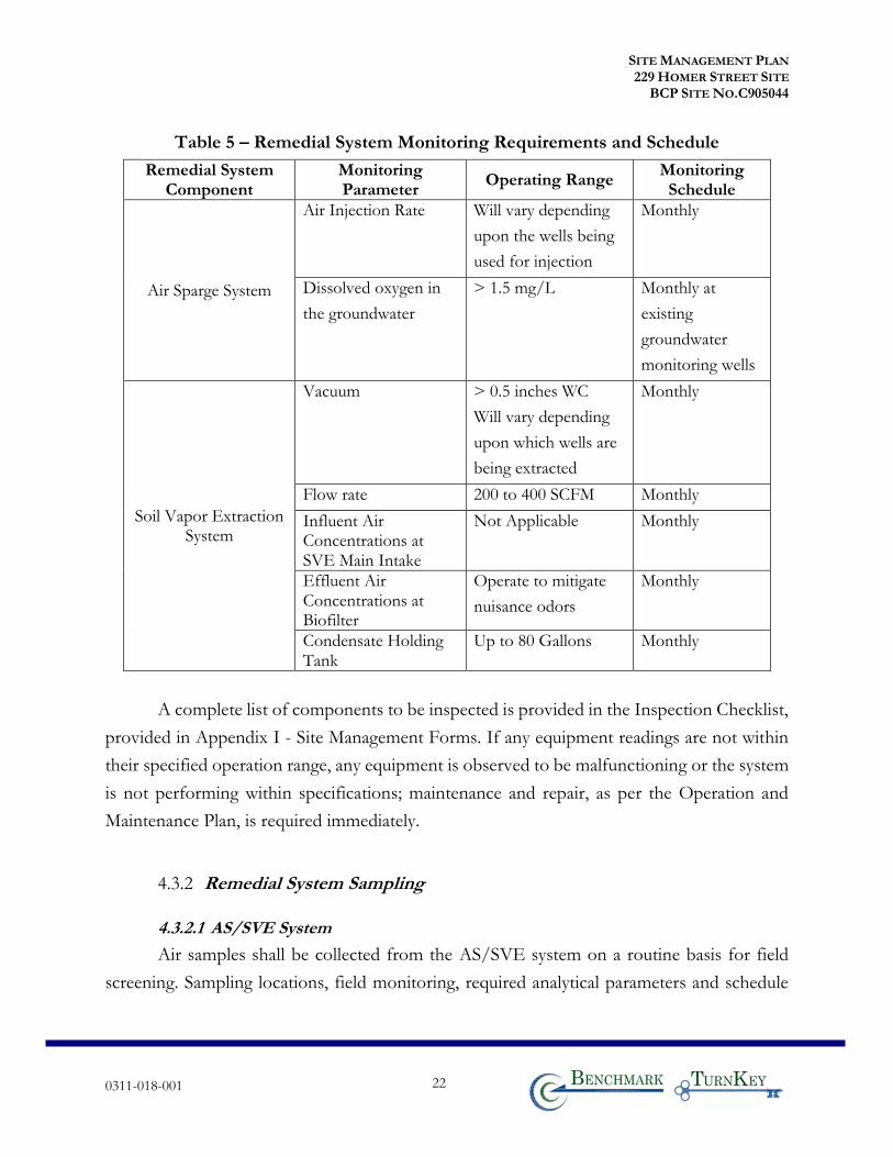
Table 5 – Remedial System Monitoring Requirements and Schedule
Remedial System Component
Monitoring Parameter
Operating Range Monitoring Schedule
Air Sparge System
Air Injection Rate Will vary depending
upon the wells being
used for injection
Monthly
Dissolved oxygen in
the groundwater
> 1.5 mg/L Monthly at
existing
groundwater
monitoring wells
Soil Vapor Extraction System
Vacuum > 0.5 inches WC
Will vary depending
upon which wells are
being extracted
Monthly
Flow rate 200 to 400 SCFM Monthly
Influent Air Concentrations at SVE Main Intake
Not Applicable Monthly
Effluent Air Concentrations at Biofilter
Operate to mitigate
nuisance odors
Monthly
Condensate Holding Tank
Up to 80 Gallons Monthly
A complete list of components to be inspected is provided in the Inspection Checklist,
provided in Appendix I - Site Management Forms. If any equipment readings are not within
their specified operation range, any equipment is observed to be malfunctioning or the system
is not performing within specifications; maintenance and repair, as per the Operation and
Maintenance Plan, is required immediately.
4.3.2 Remedial System Sampling
4.3.2.1 AS/SVE System
Air samples shall be collected from the AS/SVE system on a routine basis for field
screening. Sampling locations, field monitoring, required analytical parameters and schedule
SITE MANAGEMENT PLAN 229 HOMER STREET SITE
BCP SITE NO.C905044
0311-018-001 23 T KB
are provided in Table 6 – Remedial System Sampling Requirements and Schedule below.
Modification to the frequency or sampling requirements will require approval from the
NYSDEC.
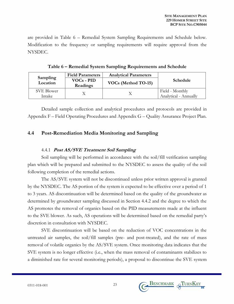
Table 6 – Remedial System Sampling Requirements and Schedule
Sampling Location
Field Parameters Analytical Parameters
Schedule VOCs - PID Readings
VOCs (Method TO-15)
SVE Blower Intake
X X Field - Monthly Analytical - Annually
Detailed sample collection and analytical procedures and protocols are provided in
Appendix F – Field Operating Procedures and Appendix G – Quality Assurance Project Plan.
4.4 Post-Remediation Media Monitoring and Sampling
4.4.1 Post AS/SVE Treatment Soil Sampling
Soil sampling will be performed in accordance with the soil/fill verification sampling
plan which will be prepared and submitted to the NYSDEC to assess the quality of the soil
following completion of the remedial actions.
The AS/SVE system will not be discontinued unless prior written approval is granted
by the NYSDEC. The AS portion of the system is expected to be effective over a period of 1
to 3 years. AS discontinuation will be determined based on the quality of the groundwater as
determined by groundwater sampling discussed in Section 4.4.2 and the degree to which the
AS promotes the removal of organics based on the PID measurements made at the influent
to the SVE blower. As such, AS operations will be determined based on the remedial party’s
discretion in consultation with NYSDEC.
SVE discontinuation will be based on the reduction of VOC concentrations in the
untreated air samples, the soil/fill samples (pre- and post-treated), and the rate of mass
removal of volatile organics by the AS/SVE system. Once monitoring data indicates that the
SVE system is no longer effective (i.e., when the mass removal of contaminants stabilizes to
a diminished rate for several monitoring periods), a proposal to discontinue the SVE system
SITE MANAGEMENT PLAN 229 HOMER STREET SITE
BCP SITE NO.C905044
0311-018-001 24 T KB
will be submitted. The proposal will include a specific soil/fill verification sampling plan,
identifying the location, depth, and number of soil/fill samples to be collected.
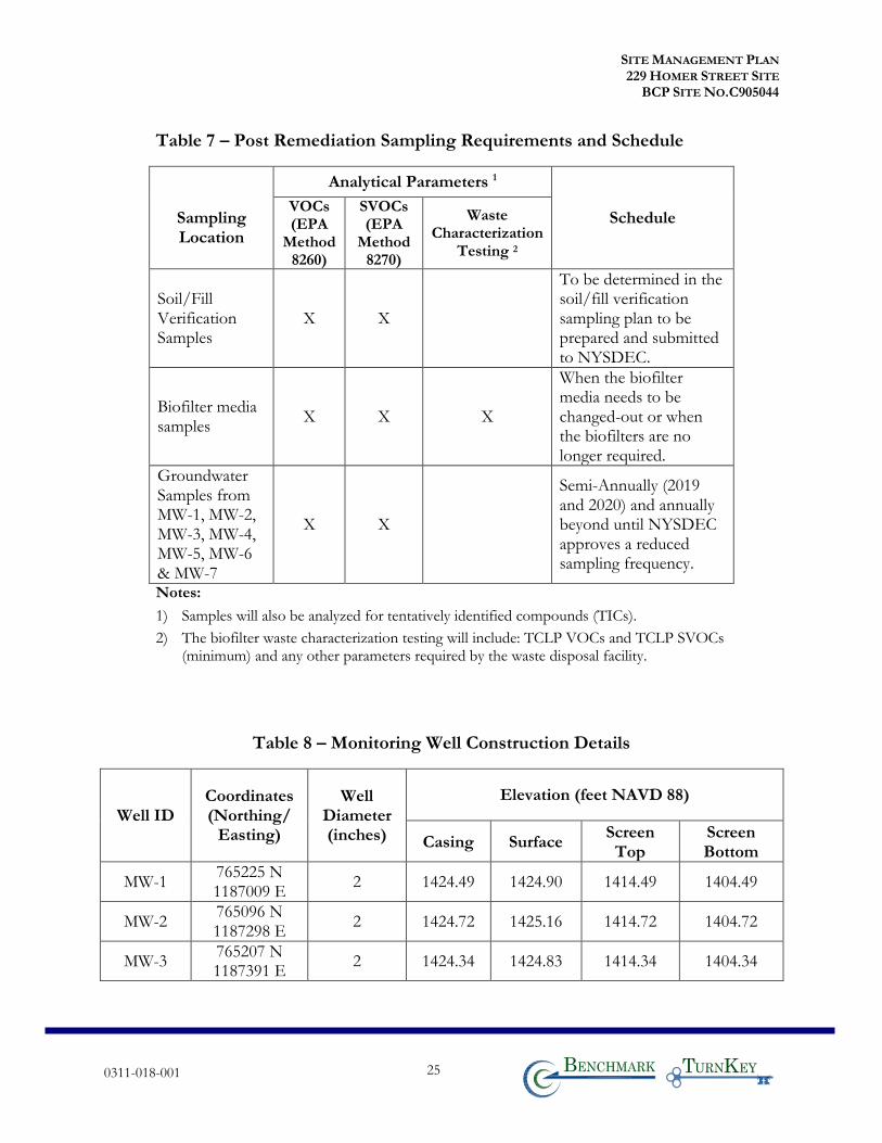
Table 7 contains the analytical sample parameters required to assess post-SVE soil
conditions.
4.4.2 Groundwater Sampling
Groundwater monitoring will be performed semi-annually for two years (2019 and
2020) and annually thereafter. Modification to the frequency or sampling requirements will
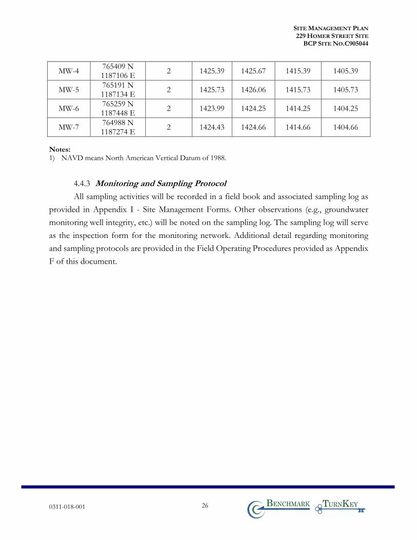
require approval from the NYSDEC. Table 8 summarizes the well identification numbers, as
well as the purpose, location, depth, diameter and screened intervals of the wells. As part of
the groundwater monitoring, seven on-site wells are sampled. Figure 5B shows the locations
of the groundwater monitoring wells and the monitoring well construction logs are included
in Appendix E.
If biofouling or silt accumulation occurs in the on-site, the wells will be physically
agitated/surged and redeveloped. Additionally, monitoring wells will be properly
decommissioned and replaced if an event renders the wells unusable.
Repairs and/or replacement of wells in the monitoring well network will be performed
based on assessments of structural integrity and overall performance. The NYSDEC will be
notified prior to any repair or decommissioning of any monitoring well for replacement, and
the repair or decommissioning and replacement process will be documented in the subsequent
Periodic Review Report. Well decommissioning without replacement will be done only with
the prior approval of the NYSDEC. Well abandonment will be performed in accordance with
NYSDEC’s guidance entitled “CP-43: Groundwater Monitoring Well Decommissioning
Procedures.” Monitoring wells that are decommissioned because they have been rendered
unusable will be replaced in kind in the nearest available location, unless otherwise approved
by the NYSDEC.
The sampling frequency may only be modified with the approval of the NYSDEC.
This SMP will be modified to reflect changes in sampling plans approved by the NYSDEC.
Deliverables for the groundwater monitoring program are specified in Section 7.0 –
Reporting Requirements.
SITE MANAGEMENT PLAN 229 HOMER STREET SITE
BCP SITE NO.C905044
0311-018-001 25 T KB
Table 7 – Post Remediation Sampling Requirements and Schedule
Sampling Location
Analytical Parameters 1
Schedule VOCs (EPA
Method 8260)
SVOCs (EPA
Method 8270)
Waste Characterization
Testing 2
Soil/Fill Verification Samples
X X
To be determined in the soil/fill verification sampling plan to be prepared and submitted to NYSDEC.
Biofilter media samples
X X X
When the biofilter media needs to be changed-out or when the biofilters are no longer required.
Groundwater Samples from MW-1, MW-2, MW-3, MW-4, MW-5, MW-6 & MW-7
X X
Semi-Annually (2019 and 2020) and annually beyond until NYSDEC approves a reduced sampling frequency.
Notes:
1) Samples will also be analyzed for tentatively identified compounds (TICs).
2) The biofilter waste characterization testing will include: TCLP VOCs and TCLP SVOCs (minimum) and any other parameters required by the waste disposal facility.
Table 8 – Monitoring Well Construction Details
Well ID Coordinates (Northing/
Easting)
Well Diameter (inches)
Elevation (feet NAVD 88)
Casing Surface Screen Top
Screen Bottom
MW-1 765225 N 1187009 E
2 1424.49 1424.90 1414.49 1404.49
MW-2 765096 N 1187298 E
2 1424.72 1425.16 1414.72 1404.72
MW-3 765207 N 1187391 E
2 1424.34 1424.83 1414.34 1404.34
SITE MANAGEMENT PLAN 229 HOMER STREET SITE
BCP SITE NO.C905044
0311-018-001 26 T KB
MW-4 765409 N 1187106 E
2 1425.39 1425.67 1415.39 1405.39
MW-5 765191 N 1187134 E
2 1425.73 1426.06 1415.73 1405.73
MW-6 765259 N 1187448 E
2 1423.99 1424.25 1414.25 1404.25
MW-7 764988 N 1187274 E
2 1424.43 1424.66 1414.66 1404.66
Notes: 1) NAVD means North American Vertical Datum of 1988.
4.4.3 Monitoring and Sampling Protocol
All sampling activities will be recorded in a field book and associated sampling log as
provided in Appendix I - Site Management Forms. Other observations (e.g., groundwater
monitoring well integrity, etc.) will be noted on the sampling log. The sampling log will serve
as the inspection form for the monitoring network. Additional detail regarding monitoring
and sampling protocols are provided in the Field Operating Procedures provided as Appendix
F of this document.
SITE MANAGEMENT PLAN 229 HOMER STREET SITE
BCP SITE NO.C905044
0311-018-001 27 T KB
5.0 OPERATION & MAINTENANCE PLAN
5.1 General
This Operation and Maintenance Plan provides a brief description of the measures
necessary to operate, monitor and maintain the mechanical components of the remedy selected
for the site. This Operation and Maintenance Plan:
• Includes the procedures necessary to allow individuals unfamiliar with the site to operate and maintain the AS/SVE system;
• Will be updated periodically to reflect changes in site conditions or the way the AS/SVE system is operated and maintained.
• An operation and maintenance plan will be provided for any ASD system.
Further detail regarding the Operation and Maintenance of the AS/SVE system is
provided in Appendix J – AS/SVE System Operation and Maintenance Manual. A copy of
this Operation and Maintenance Manual, along with the complete SMP, is maintained at the
site. This Operation and Maintenance Plan is not to be used as a stand-alone document, but
as a component document of this SMP.
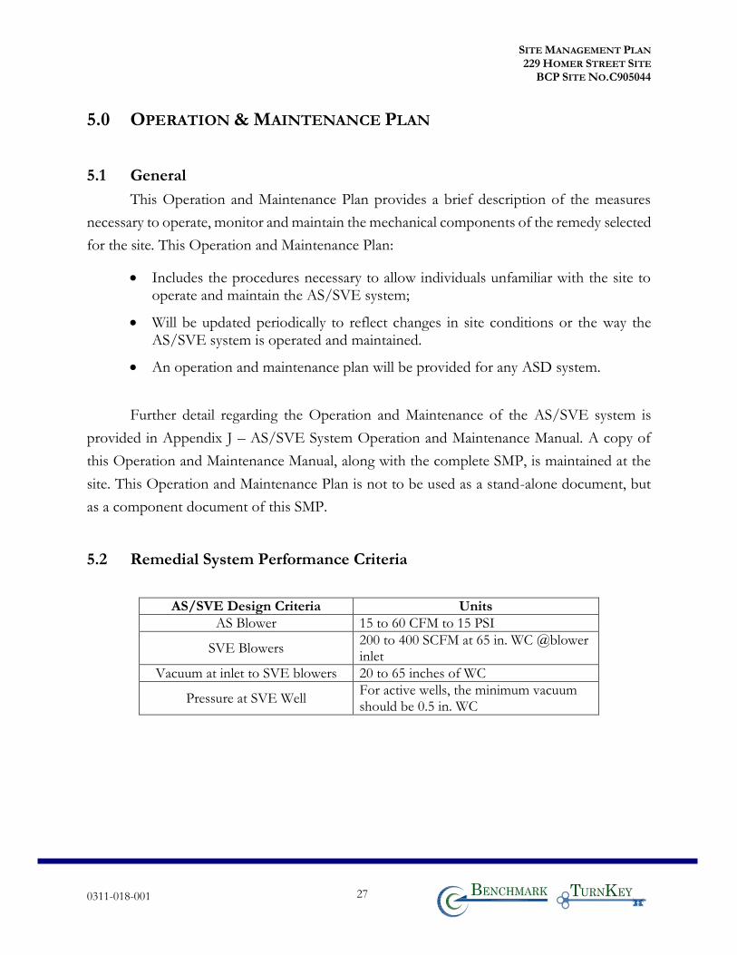
5.2 Remedial System Performance Criteria
AS/SVE Design Criteria Units
AS Blower 15 to 60 CFM to 15 PSI
SVE Blowers 200 to 400 SCFM at 65 in. WC @blower inlet
Vacuum at inlet to SVE blowers 20 to 65 inches of WC
Pressure at SVE Well For active wells, the minimum vacuum should be 0.5 in. WC
SITE MANAGEMENT PLAN 229 HOMER STREET SITE
BCP SITE NO.C905044
0311-018-001 28 T KB
5.3 Operation and Maintenance of SVE System
The following sections provide a description of the operations and maintenance of
AS/SVE system. The AS/SVE equipment layout and process and instrumentation drawings
are presented in the manufacturer’s O&M manual for the AS/SVE system, which is included
in Appendix J – SVE System Operation and Maintenance Manual.
5.3.1 General
There is one AS/SVE system in operation at the Site. The AS/SVE system is
comprised of two main components:
1. The air sparge (AS) portion of the system is constructed of a series of vertical injection wells connected individually to a 53-point manifold with solenoid valves and rotameter flow meters connected to the air compressor; thus, enabling individual operation of banks of AS wells. The AS consists of blower, motors, aftercooler, and ancillary equipment to provide the required flow rate and pressure for the injection housed inside a climate-controlled trailer; and,
2. The SVE collection system is constructed of a series of 14 vertical extraction wells and extraction well piping connected to a 14-point manifold. The SVE equipment (blowers, motors, moisture separator, and ancillary equipment) are housed in a climate-controlled trailer separate from the AS trailer.
The AS/SVE system will be operated nearly continuously during the spring, summer
fall and early winter. Once the temperature drops consistently below freezing, the AS/SVE
system will be shut-down and the system winterized to prevent damage to the underground
AS/SVE lines. The system will be reactivated in the spring once the temperatures are
consistently above freezing (e.g., around April 1). Figure 7 is a layout of the AS/SVE collection
system and well locations and Figure 8 is a process flow schematic of the AS/SVE system.
The AS portion of the system is designed to inject air into the upper 5 to 10 feet of the
water table to strip organic compounds from the smear zone into the vadose zone and to
stimulate aerobic biodegradation of the organics. Air is injected into 2” vertical PVC wells
(designated AS-1 to AS-53) via individual 1” horizontal polyethylene lines. The SVE portion
of the system is designed to extract VOCs and SVOCs from the unsaturated soil/fill in the
areas that were impacted with GCS and to collect and contain the air injected as part of the
AS. The air is extracted from 2-inch vertical PVC wells (designated as SVE-1 to SVE-14)
SITE MANAGEMENT PLAN 229 HOMER STREET SITE
BCP SITE NO.C905044
0311-018-001 29 T KB
installed in the unsaturated zone. There are two SVE blowers connected to of the SVE wells.
The extracted air is conveyed through 2-inch polyethylene piping underground to the SVE
trailer. The approximate piping network is shown on Figure 7.
The extracted air is treated in a biofilter prior to discharge to the atmosphere. The
biofilter treatment medium consists of a mixture of compost and mulch (approx. 50% each
by weight). The natural bacteria in the biofilter use the organics in the waste stream as a source
of energy. The biofilter medium needs to be maintained in a slightly wet state and needs to be
periodically mixed (fluffed-up). If significant odors are noted at the downgradient property
line, the medium may need to be replenished/replaced. Condensate water that accumulates in
the moisture separator will either be used to maintain moisture in the biofilter, and/or be
pumped through filter bags, treated with carbon and then discharged under permit to the City
of Olean Sewer system.
The mobile AS and SVE systems are housed in two individual enclosed trailers. The
SVE process vacuum is generated by two regenerative blowers each with 10-hp electric
motors. Piping from the SVE wells enters the SVE trailer and is connected to 2-inch intake
piping. Vacuum in the line is controlled via gate valves. The valves are located on each line so
that vacuum can be controlled on each well head. Inlet air is then passed through an 80-gallon
capacity moisture separator to remove excess condensate/water vapor. Intake air then passes
through the blower and is conveyed to the biofilter for treatment prior to discharge to the
atmosphere.
The AS/SVE system will be controlled by a Siemens Programmable Logic Controller
(PLC). A color touch screen interface with a built-in remote server will be used to control and
interface with the system, change set points, and view system data (flow rates, pressures,
vacuums, etc).
5.3.2 System Start-Up and Testing
The following procedure is to be used to start-up the AS/SVE system. Water levels
and dissolved oxygen concentrations are to be measured in all groundwater monitoring wells
to establish a baseline. All SVE wells are to have their valves fully open. The SVE system is to
be activated and the exhaust (prior to treatment in the biofilter) from the SVE blowers should
be monitored with a PID over a period of several days to establish quasi-steady state
SITE MANAGEMENT PLAN 229 HOMER STREET SITE
BCP SITE NO.C905044
0311-018-001 30 T KB
conditions. Once quasi-steady state conditions are established, remeasurement of the water
levels and DO concentrations is to be completed in the groundwater monitoring wells
periodically during AS/SVE operations.
While the SVE system is operating, AS operations will commence with all AS wells
having their valves fully open. Air injection is to be done into Zone 1 wells (Refer to Table I-
1 in Appendix I) for 60 minutes and subsequently Zone 2 wells for 60 minutes at a nominal
pressure of 5 psi per well and a flow rate of about 30 to 70 CFM total. The PID of the SVE
system is to be monitored simultaneously as the sparging is being completed. The intent of
the AS/SVE system is to maximize the removal of organic vapors from the ground. If the
PID measurements remain unchanged or increase during sparging, then the sparging will
continue by alternating the injection between the Zones 1 and 2 [zones may be further
subdivided into fewer AS points (e.g., 6 to 10 AS points) experimentally to further assess if
more concentrated sparging results in increased organic vapor removal].. If the PID
measurements decrease during sparging, then the sparging may be decreased provided that
aerobic conditions (i.e., greater than 1.5 mg/L DO) must be maintained in the groundwater
monitoring wells (in order that aerobic biodegradation can occur). Air sparing will be increased
or operated more frequently if DO falls below 1.5 mg/L.
5.3.3 Routine System Operation and Maintenance
The AS/SVE system is designed to require little maintenance over the expected
duration of use at the Site. The blower bearings are maintenance free. A copy of an Operations
and Maintenance Manual specific to the AS/SVE system is provided in Appendix J, which
will provide further detail on the above.
5.3.4 System Monitoring Devices and Alarms
Monitored system operating conditions which trigger an alarm condition include
moisture separator tank high level. This alarm condition automatically shuts down the SVE
blower. The SVE system includes a PLC; as described previously, all alarm conditions can be
monitored directly in the field or remotely. Based on the alarm, the remedial party will respond
and/or contact the appropriate repair vendor (e.g. electrician, mechanical repair service).

SITE MANAGEMENT PLAN 229 HOMER STREET SITE
BCP SITE NO.C905044
0311-018-001 31 T KB
Operational problems with the AS/SVE system, that require a change in the system
operation and/or temporary system shut-down for longer than 1 week will be noted in the
Periodic Review Report to be prepared for that reporting period.
SITE MANAGEMENT PLAN 229 HOMER STREET SITE
BCP SITE NO.C905044
0311-018-001 32 T KB
6.0 PERIODIC ASSESSMENTS/EVALUATIONS
6.1 Climate Change Vulnerability Assessment
Increases in both the severity and frequency of storms/weather events, an increase in
sea level elevations along with accompanying flooding impacts, shifting precipitation patterns
and wide temperature fluctuation, resulting from global climactic change and instability, have
the potential to significantly impact the performance, effectiveness and protectiveness of a
given site and associated remedial systems. Vulnerability assessments provide information so
that the site and associated remedial systems are prepared for the impacts of the increasing
frequency and intensity of severe storms/weather events and associated flooding.
This section provides a summary of vulnerability assessments that will be conducted
for the site during periodic assessments, and briefly summarizes the vulnerability of the site
and/or engineering controls to severe storms/weather events and associated flooding.
• Flood Plain: The 100-year flood plain zone is located along Two Mile Creek just north of the Site and extends up to about 25 feet onto the northwest side of the Site. The area of the remediation and the trailer locations are outside the 100-year flood zone. The depth of groundwater in the permeable upper outwash aquifer ranges from about 10 to 15 fbgs. These Site conditions are not a threat from climate change.
• Site Drainage and Storm Water Management: Other than the building and concrete pads, the Site has been covered with a crushed gravel which allows communication with the pervious sand and gravel aquifer. Surface runoff flows either to Two Mile Creek northwest adjacent to the site or the drainage swale on the southeastern portion of the site. The swale along the southeastern portion of the property parallel to the railroad was reconfigured and thus, the storm drainage has been improved. The swale had riprap added to it to secure the banks and bottom to limit erosion.
• Erosion: No areas of the Site are showing evidence of erosion. The swale along the southeastern property line had riprap added to it to limit potential erosion.
• High Wind: There are no remedial systems that are susceptible to damage from the wind itself or falling objects, such as trees or utility structures during periods of high wind.
SITE MANAGEMENT PLAN 229 HOMER STREET SITE
BCP SITE NO.C905044
0311-018-001 33 T KB
• Electricity: The AS/SVE system would be susceptible to power loss and/or dips/surges in voltage during severe weather events, including lightning strikes, and the associated impact on site equipment and operations.
• Spill/Contaminant Release: The minimal condensate water generated from the SVE system, would not be susceptible to a spill or other contaminant release due to storm-related damage caused by flooding, erosion, high winds, and/or loss of power.
6.2 Green Remediation Evaluation
NYSDEC’s DER-31 Green Remediation requires that green remediation concepts and
techniques be considered during all stages of the remedial program including site management,
with the goal of improving the sustainability of the cleanup and summarizing the net
environmental benefit of any implemented green technology. This section of the SMP
provides a summary of any green remediation evaluations to be completed for the site during
site management, and as reported in the Periodic Review Report (PRR).
• Emissions: The vapor-phase contaminants generated from the AS/SVE system are treated with a biofilter, which consisted of wood chips and a compost filter medium which allowed naturally occurring microbes to bioremediate the air stream. The use of the biofilters off-sets the use and disposal of a significant amounts of granular activated carbon.
6.2.1 Timing of Green Remediation Evaluations
For major remedial system components, green remediation evaluations and
corresponding modifications will be undertaken as part of a formal Remedial System
Optimization (RSO), or at any time that the Project Manager feels appropriate, e.g. during
significant maintenance events or in conjunction with storm recovery activities.
Modifications resulting from green remediation evaluations will be routinely
implemented and scheduled to occur during planned/routine operation and maintenance
activities. Reporting of these modifications will be presented in the PRR.
6.2.2 Remedial Systems
Remedial systems will be operated properly considering the current site conditions to
conserve materials and resources to the greatest extent possible. Consideration will be given
SITE MANAGEMENT PLAN 229 HOMER STREET SITE
BCP SITE NO.C905044
0311-018-001 34 T KB
to operating rates and use of reagents and consumables. The use of the biofilter to treat the
vapor-phase of the AS/SVE system will be continued.
6.2.3 Building Operations
The existing and future structures, including buildings and sheds, will be operated and
maintained to provide for the most efficient operation of the remedy, while minimizing energy,
waste generation, and water consumption.
6.3 Remedial System Optimization
A Remedial Site Optimization (RSO) study will be conducted any time that the
NYSDEC or the remedial party requests in writing that an in-depth evaluation of the remedy
is needed. An RSO may be appropriate if any of the following occur:
• The remedial actions have not met or are not expected to meet RAOs in the time frame estimated in the Decision Document;
• The management and operation of the remedial system is exceeding the estimated costs;
• The remedial system is not performing as expected or as designed;
• Previously unidentified source material may be suspected;
• Plume shift has potentially occurred;
• Site conditions change due to development, change of use, change in groundwater use, etc.;
• There is an anticipated transfer of the site management to another remedial party or agency; and
• A new and applicable remedial technology becomes available.
An RSO will provide a critique of a site’s conceptual model, give a summary of past
performance, document current cleanup practices, summarize progress made toward the site’s
cleanup goals, gather additional performance or media specific data and information and
provide recommendations for improvements to enhance the ability of the present system to
reach RAOs or to provide a basis for changing the remedial strategy.

SITE MANAGEMENT PLAN 229 HOMER STREET SITE
BCP SITE NO.C905044
0311-018-001 35 T KB
The RSO study will focuses on overall site cleanup strategy, process optimization, and
management with the intent of identifying impediments to cleanup and improvements to site
operations to increase efficiency, cost effectiveness, and remedial time frames. Green
remediation technology and principals are to be considered when performing the RSO.
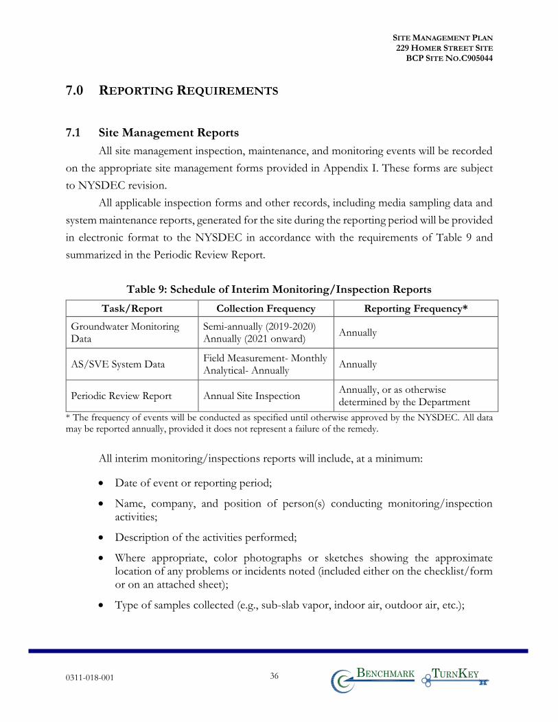
SITE MANAGEMENT PLAN 229 HOMER STREET SITE
BCP SITE NO.C905044
0311-018-001 36 T KB
7.0 REPORTING REQUIREMENTS
7.1 Site Management Reports
All site management inspection, maintenance, and monitoring events will be recorded
on the appropriate site management forms provided in Appendix I. These forms are subject
to NYSDEC revision.
All applicable inspection forms and other records, including media sampling data and
system maintenance reports, generated for the site during the reporting period will be provided
in electronic format to the NYSDEC in accordance with the requirements of Table 9 and
summarized in the Periodic Review Report.
Table 9: Schedule of Interim Monitoring/Inspection Reports
Task/Report Collection Frequency Reporting Frequency*
Groundwater Monitoring Data
Semi-annually (2019-2020) Annually (2021 onward)
Annually
AS/SVE System Data Field Measurement- Monthly Analytical- Annually
Annually
Periodic Review Report Annual Site Inspection Annually, or as otherwise determined by the Department
* The frequency of events will be conducted as specified until otherwise approved by the NYSDEC. All data may be reported annually, provided it does not represent a failure of the remedy.
All interim monitoring/inspections reports will include, at a minimum:
• Date of event or reporting period;
• Name, company, and position of person(s) conducting monitoring/inspection activities;
• Description of the activities performed;
• Where appropriate, color photographs or sketches showing the approximate location of any problems or incidents noted (included either on the checklist/form or on an attached sheet);
• Type of samples collected (e.g., sub-slab vapor, indoor air, outdoor air, etc.);
SITE MANAGEMENT PLAN 229 HOMER STREET SITE
BCP SITE NO.C905044
0311-018-001 37 T KB
• Copies of all field forms completed (e.g., well sampling logs, chain-of-custody documentation, etc.);
• Sampling results in comparison to appropriate standards/criteria;
• A figure illustrating sample type and sampling locations;
• Copies of all laboratory data sheets and the required laboratory data deliverables required for all points sampled (to be submitted electronically in the NYSDEC-identified format);
• Any observations, conclusions, or recommendations; and
• A determination as to whether contaminant conditions have changed since the last reporting event.
Routine maintenance event reporting forms will include, at a minimum:
• Date of event;
• Name, company, and position of person(s) conducting maintenance activities;
• Description of maintenance activities performed;
• Any modifications to the system;
• Where appropriate, color photographs or sketches showing the approximate location of any problems or incidents noted (included either on the checklist/form or on an attached sheet); and,
Non-routine maintenance event reporting forms will include, at a minimum:
• Date of event;
• Name, company, and position of person(s) conducting non-routine maintenance/repair activities;
• Description of non-routine activities performed;
• Where appropriate, color photographs or sketches showing the approximate location of any problems or incidents (included either on the form or on an attached sheet); and
SITE MANAGEMENT PLAN 229 HOMER STREET SITE
BCP SITE NO.C905044
0311-018-001 38 T KB
Data will be reported in digital format as determined by the NYSDEC. Currently, data
is to be supplied electronically and submitted to the NYSDEC EQuISTM database in
accordance with the requirements found at this link:
http://www.dec.ny.gov/chemical/62440.html.
7.2 Periodic Review Report
A Periodic Review Report (PRR) will be submitted to the Department beginning
approximately 18 months after the Certificate of Completion is issued. After submittal of the
initial PRR, the next PRR shall be submitted annually to the Department or at another
frequency as may be required by the Department. If the site is subdivided into separate parcels
with different ownership, a single PRR will be prepared that addresses the site described in
Appendix D -Environmental Easement. The report will be prepared in accordance with
NYSDEC’s DER-10 and submitted within 30 days of the end of each certification period.
Media sampling results will also be incorporated into the PRR. The report will include:
• Identification, assessment, and certification of all ECs/ICs required by the remedy for the site.
• Results of the required annual site inspections and severe condition inspections, if applicable.
• All applicable site management forms and other records generated for the site during the reporting period in the NYSDEC-approved electronic format, if not previously submitted.
• A summary of any discharge monitoring data and/or information generated during the reporting period, with comments and conclusions.
• Data summary tables and graphical representations of contaminants of concern by media (groundwater, soil vapor, etc.), which include a listing of all compounds analyzed, along with the applicable standards, with all exceedances highlighted. These will include a presentation of past data as part of an evaluation of contaminant concentration trends.
• Results of all analyses, copies of all laboratory data sheets, and the required laboratory data deliverables for all samples collected during the reporting period will be submitted in digital format as determined by the NYSDEC. Currently, data is supplied electronically and submitted to the NYSDEC EQuISTM database in
SITE MANAGEMENT PLAN 229 HOMER STREET SITE
BCP SITE NO.C905044
0311-018-001 39 T KB
accordance with the requirements found at this link: http://www.dec.ny.gov/chemical/62440.html.
• A site evaluation that includes the following:
o The compliance of the remedy with the requirements of the site-specific RAWP or Decision Document;
o The operation and the effectiveness of all treatment units, etc., including identification of any needed repairs or modifications;
o Any new conclusions or observations regarding site contamination based on inspections or data generated by the Monitoring and Sampling Plan for the media being monitored;
o Recommendations regarding any necessary changes to the remedy and/or Monitoring and Sampling Plan;
o Trends in contaminant levels in the affected media will be evaluated to determine if the remedy continues to be effective in achieving remedial goals as specified by the Decision Document; and,
o The overall performance and effectiveness of the remedy.
• A performance summary for all treatment systems at the site during the calendar year, including information such as:
o The number of days the system operated for the reporting period;
o The average, high, and low flows per day;
o The contaminant mass removed;
o A description of breakdowns and/or repairs along with an explanation for any significant downtime;
o A description of the resolution of performance problems;
o Alarm conditions;
o Trends in equipment failure;
o A summary of the performance, effluent and/or effectiveness monitoring; and
o Comments, conclusions, and recommendations based on data evaluation.
SITE MANAGEMENT PLAN 229 HOMER STREET SITE
BCP SITE NO.C905044
0311-018-001 40 T KB
7.2.1 Certification of Institutional and Engineering Controls
Following the last inspection of the reporting period, a Professional Engineer licensed
to practice in New York State will prepare, and include in the Periodic Review Report, the
following certification as per the requirements of NYSDEC DER-10:
“For each institutional or engineering control identified for the site, I certify that all of the following
statements are true:
• The inspection of the site to confirm the effectiveness of the institutional and engineering controls required by the remedial program was performed under my direction;
• The institutional control and/or engineering control employed at this site is unchanged from the date the control was put in place, or last approved by the Department;
• Nothing has occurred that would impair the ability of the control to protect the public health and environment;
• No new information has come to my attention, including groundwater monitoring data from wells located at the site boundary, if any, to indicate that the assumptions made in the qualitative exposure assessment of off-site contamination are no longer valid;
• Nothing has occurred that would constitute a violation or failure to comply with any site management plan for this control;
• Access to the site will continue to be provided to the Department to evaluate the remedy, including access to evaluate the continued maintenance of this control;
• Use of the site is compliant with the environmental easement;
• The engineering control systems are performing as designed and are effective;
• To the best of my knowledge and belief, the work and conclusions described in this certification are in accordance with the requirements of the site remedial program and generally accepted engineering practices; and
• The information presented in this report is accurate and complete.
I certify that all information and statements in this certification form are true. I understand that a false statement
made herein is punishable as a Class “A” misdemeanor, pursuant to Section 210.45 of the Penal Law. I,
Thomas H. Forbes, P.E., of 2558 Hamburg Turnpike, Lackawanna, New York, am certifying as
Owner’s/Remedial Party’s Designated Site Representative for the site.”
Note: every five years the following certification will be added:
• The assumptions made in the qualitative exposure assessment remain valid.
SITE MANAGEMENT PLAN 229 HOMER STREET SITE
BCP SITE NO.C905044
0311-018-001 41 T KB
The signed certification will be included in the Periodic Review Report. The Periodic
Review Report will be submitted, in electronic format, to the NYSDEC Central Office,
Regional Office in which the site is located, and the NYSDOH Bureau of Environmental
Exposure Investigation. The Periodic Review Report may need to be submitted in hard-copy
format, as requested by the NYSDEC project manager.
7.3 Corrective Measures Work Plan
If any component of the remedy is found to have failed, or if the periodic certification
cannot be provided due to the failure of an institutional or engineering control, a Corrective
Measures Work Plan will be submitted to the NYSDEC for approval. This plan will explain
the failure and provide the details and schedule for performing work necessary to correct the
failure. Unless an emergency condition exists, no work will be performed pursuant to the
Corrective Measures Work Plan until it has been approved by the NYSDEC.
7.4 Remedial Site Optimization Report
If an RSO is to be performed (see Section 6.3), upon completion of an RSO, an RSO
report must be submitted to the Department for approval. A general outline for the RSO
report is provided in Appendix K. The RSO report will document the research/ investigation
and data gathering that was conducted, evaluate the results and facts obtained, present a
revised conceptual site model and present recommendations. RSO recommendations are to
be implemented upon approval from the NYSDEC. Additional work plans, design
documents, HASPs etc., may still be required to implement the recommendations, based upon
the actions that need to be taken. A final engineering report and update to the SMP may also
be required.
The RSO report will be submitted, in electronic format, to the NYSDEC Central
Office, Regional Office in which the site is located, Site Control, and the NYSDOH Bureau
of Environmental Exposure Investigation.
SITE MANAGEMENT PLAN 229 HOMER STREET SITE
BCP SITE NO.C905044
0311-018-001 42 T KB
8.0 REFERENCES
1. TurnKey Environmental Restoration, LLC. Remedial Investigation/Alternative Analysis (RI/AA) Report. 229 Homer Street Site, BCP Site No C905044, Olean, New York. August 2016.
2. TurnKey Environmental Restoration, LLC. Revised Alternative Analysis (AA) Report. 229 Homer Street Site, BCP Site No C905044, Olean, New York. June 2017.
3. TurnKey Environmental Restoration, LLC. Remedial Action Work Plan (RAWP). 229 Homer Street Site, BCP Site No C905044, Olean, New York. February 2018.
4. New York State Department of Environmental Conservation. CP-51/Soil Cleanup Guidance. October 21, 2010.
5. New York State Department of Environmental Conservation. DER-10; Technical Guidance for Site Investigation and Remediation. May 3, 2010.
York. September 30, 2009.

SITE MANAGEMENT PLAN 229 HOMER STREET SITE
BCP SITE NO.C905044
0311-018-001 T KB
TABLES
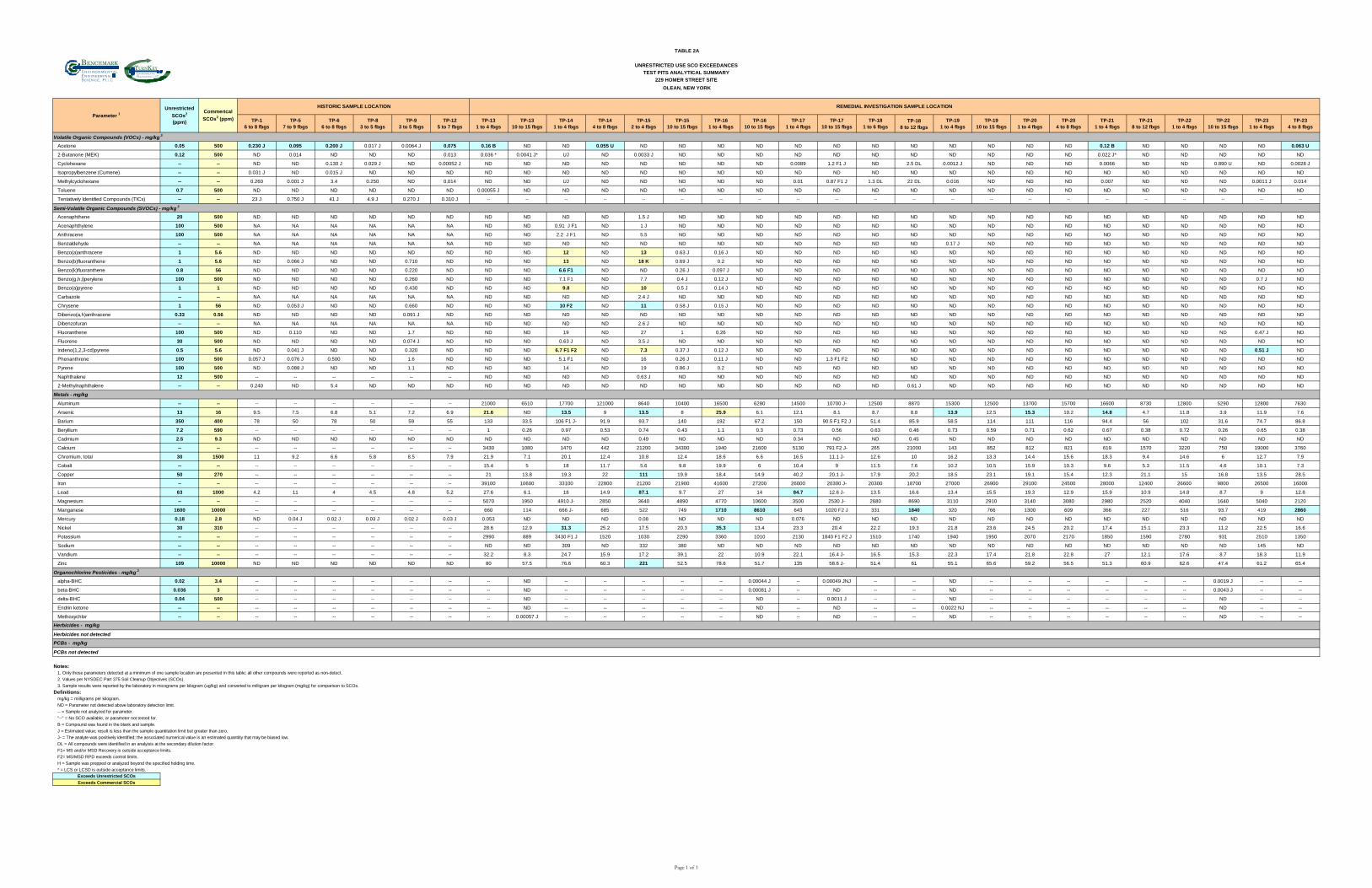
Bn v i ron m e t a ln g i n eer i n gc en ce,i
nT K
nvironmental
estoration,
TABLE 2A
UNRESTRICTED USE SCO EXCEEDANCES
TEST PITS ANALYTICAL SUMMARY
229 HOMER STREET SITE
OLEAN, NEW YORK
TP-1
6 to 8 fbgs
TP-5
7 to 9 fbgs
TP-6
6 to 8 fbgs
TP-8
3 to 5 fbgs
TP-9
3 to 5 fbgs
TP-12
5 to 7 fbgs
TP-13
1 to 4 fbgs
TP-13
10 to 15 fbgs
TP-14
1 to 4 fbgs
TP-14
4 to 8 fbgs
TP-15
2 to 4 fbgs
TP-15
10 to 15 fbgs
TP-16
1 to 4 fbgs
TP-16
10 to 15 fbgs
TP-17
1 to 4 fbgs
TP-17
10 to 15 fbgs
TP-18
1 to 6 fbgs
TP-18
8 to 12 fbgs
TP-19
1 to 4 fbgs
TP-19
10 to 15 fbgs
TP-20
1 to 4 fbgs
TP-20
4 to 8 fbgs
TP-21
1 to 4 fbgs
TP-21
8 to 12 fbgs
TP-22
1 to 4 fbgs
TP-22
10 to 15 fbgs
TP-23
1 to 4 fbgs
TP-23
4 to 8 fbgs
Volatile Organic Compounds (VOCs) - mg/kg 3
Acetone 0.05 500 0.230 J 0.095 0.200 J 0.017 J 0.0064 J 0.075 0.16 B ND ND 0.055 U ND ND ND ND ND ND ND ND ND ND ND ND 0.12 B ND ND ND ND 0.063 U
2-Butanone (MEK) 0.12 500 ND 0.014 ND ND ND 0.013 0.036 * 0.0041 J* UJ ND 0.0033 J ND ND ND ND ND ND ND ND ND ND ND 0.022 J* ND ND ND ND ND
Cyclohexane -- -- ND ND 0.130 J 0.029 J ND 0.00052 J ND ND ND ND ND ND ND ND 0.0089 1.2 F1 J ND 2.5 DL 0.0012 J ND ND ND 0.0066 ND ND 0.890 U ND 0.0028 J
Isopropylbenzene (Cumene) -- -- 0.031 J ND 0.015 J ND ND ND ND ND ND ND ND ND ND ND ND ND ND ND ND ND ND ND ND ND ND ND ND ND
Methylcyclohexane -- -- 0.260 0.001 J 3.4 0.250 ND 0.014 ND ND UJ ND ND ND ND ND 0.01 0.87 F1 J 1.3 DL 22 DL 0.016 ND ND ND 0.007 ND ND ND 0.0011 J 0.014
Toluene 0.7 500 ND ND ND ND ND ND 0.00055 J ND ND ND ND ND ND ND ND ND ND ND ND ND ND ND ND ND ND ND ND ND
Tentatively Identified Compounds (TICs) -- -- 23 J 0.750 J 41 J 4.9 J 0.270 J 0.310 J -- -- -- -- -- -- -- -- -- -- -- -- -- -- -- -- -- -- -- -- -- --
Semi-Volatile Organic Compounds (SVOCs) - mg/kg 3
Acenaphthene 20 500 ND ND ND ND ND ND ND ND ND ND 1.5 J ND ND ND ND ND ND ND ND ND ND ND ND ND ND ND ND ND
Acenaphthylene 100 500 NA NA NA NA NA NA ND ND 0.91 J F1 ND 1 J ND ND ND ND ND ND ND ND ND ND ND ND ND ND ND ND ND
Anthracene 100 500 NA NA NA NA NA NA ND ND 2.2 J F1 ND 5.5 ND ND ND ND ND ND ND ND ND ND ND ND ND ND ND ND ND
Benzaldehyde -- -- NA NA NA NA NA NA ND ND ND ND ND ND ND ND ND ND ND ND 0.17 J ND ND ND ND ND ND ND ND ND
Benzo(a)anthracene 1 5.6 ND ND ND ND ND ND ND ND 12 ND 13 0.63 J 0.16 J ND ND ND ND ND ND ND ND ND ND ND ND ND ND ND
Benzo(b)fluoranthene 1 5.6 ND 0.066 J ND ND 0.710 ND ND ND 13 ND 18 K 0.69 J 0.2 ND ND ND ND ND ND ND ND ND ND ND ND ND ND ND
Benzo(k)fluoranthene 0.8 56 ND ND ND ND 0.220 ND ND ND 6.6 F1 ND ND 0.26 J 0.097 J ND ND ND ND ND ND ND ND ND ND ND ND ND ND ND
Benzo(g,h,i)perylene 100 500 ND ND ND ND 0.260 ND ND ND 7.1 F1 ND 7.7 0.4 J 0.12 J ND ND ND ND ND ND ND ND ND ND ND ND ND 0.7 J ND
Benzo(a)pyrene 1 1 ND ND ND ND 0.430 ND ND ND 9.8 ND 10 0.5 J 0.14 J ND ND ND ND ND ND ND ND ND ND ND ND ND ND ND
Carbazole -- -- NA NA NA NA NA NA ND ND ND ND 2.4 J ND ND ND ND ND ND ND ND ND ND ND ND ND ND ND ND ND
Chrysene 1 56 ND 0.053 J ND ND 0.660 ND ND ND 10 F2 ND 11 0.58 J 0.15 J ND ND ND ND ND ND ND ND ND ND ND ND ND ND ND
Dibenzo(a,h)anthracene 0.33 0.56 ND ND ND ND 0.091 J ND ND ND ND ND ND ND ND ND ND ND ND ND ND ND ND ND ND ND ND ND ND ND
Dibenzofuran -- -- NA NA NA NA NA NA ND ND ND ND 2.6 J ND ND ND ND ND ND ND ND ND ND ND ND ND ND ND ND ND
Fluoranthene 100 500 ND 0.110 ND ND 1.7 ND ND ND 19 ND 27 1 0.26 ND ND ND ND ND ND ND ND ND ND ND ND ND 0.47 J ND
Fluorene 30 500 ND ND ND ND 0.074 J ND ND ND 0.63 J ND 3.5 J ND ND ND ND ND ND ND ND ND ND ND ND ND ND ND ND ND
Indeno(1,2,3-cd)pyrene 0.5 5.6 ND 0.041 J ND ND 0.320 ND ND ND 6.7 F1 F2 ND 7.3 0.37 J 0.12 J ND ND ND ND ND ND ND ND ND ND ND ND ND 0.51 J ND
Phenanthrene 100 500 0.057 J 0.076 J 0.500 ND 1.6 ND ND ND 5.1 F1 ND 16 0.26 J 0.11 J ND ND 1.3 F1 F2 ND ND ND ND ND ND ND ND ND ND ND ND
Pyrene 100 500 ND 0.088 J ND ND 1.1 ND ND ND 14 ND 19 0.86 J 0.2 ND ND ND ND ND ND ND ND ND ND ND ND ND ND ND
Naphthalene 12 500 -- -- -- -- -- -- ND ND ND ND 0.63 J ND ND ND ND ND ND ND ND ND ND ND ND ND ND ND ND ND
2-Methylnaphthalene -- -- 0.240 ND 5.4 ND ND ND ND ND ND ND ND ND ND ND ND ND ND 0.61 J ND ND ND ND ND ND ND ND ND ND
Metals - mg/kg
Aluminum -- -- -- -- -- -- -- -- 21000 6510 17700 121000 8640 10400 16500 6280 14500 10700 J- 12500 8870 15300 12500 13700 15700 16600 8730 12800 5290 12800 7630
Arsenic 13 16 9.5 7.5 6.8 5.1 7.2 6.9 21.6 ND 13.5 9 13.5 8 25.9 6.1 12.1 8.1 8.7 8.8 13.9 12.5 15.3 10.2 14.8 4.7 11.8 3.9 11.9 7.6
Barium 350 400 78 50 78 50 59 55 133 33.5 106 F1 J- 91.9 93.7 140 192 67.2 150 90.5 F1 F2 J 51.4 85.9 58.5 114 111 116 94.4 56 102 31.6 74.7 86.8
Beryllium 7.2 590 -- -- -- -- -- -- 1 0.26 0.97 0.53 0.74 0.43 1.1 0.3 0.73 0.56 0.63 0.46 0.73 0.59 0.71 0.62 0.67 0.38 0.72 0.26 0.65 0.38
Cadmium 2.5 9.3 ND ND ND ND ND ND ND ND ND ND 0.49 ND ND ND 0.34 ND ND 0.45 ND ND ND ND ND ND ND ND ND ND
Calcium -- -- -- -- -- -- -- -- 3430 1080 1470 442 21200 34300 1940 21600 5130 791 F2 J- 265 21000 143 852 812 821 619 1570 3220 750 19000 3760
Chromium, total 30 1500 11 9.2 6.6 5.8 8.5 7.9 21.9 7.1 20.1 12.4 10.8 12.4 18.6 6.6 16.5 11.1 J- 12.6 10 16.2 13.3 14.4 15.6 18.3 9.4 14.6 6 12.7 7.9
Cobalt -- -- -- -- -- -- -- -- 15.4 5 18 11.7 5.6 9.8 19.9 6 10.4 9 11.5 7.6 10.2 10.5 15.9 10.3 9.6 5.3 11.5 4.6 10.1 7.3
Copper 50 270 -- -- -- -- -- -- 21 13.8 19.3 22 111 19.9 18.4 14.9 40.2 20.1 J- 17.9 20.2 18.5 23.1 19.1 15.4 12.3 21.1 15 16.8 13.5 28.5
Iron -- -- -- -- -- -- -- -- 39100 10600 33100 22800 21200 21900 41600 27200 26000 20300 J- 20300 18700 27000 26900 29100 24500 28000 12400 26600 9800 26500 16000
Lead 63 1000 4.2 11 4 4.5 4.8 5.2 27.6 6.1 18 14.9 87.1 9.7 27 14 84.7 12.6 J- 13.5 16.6 13.4 15.5 19.3 12.9 15.9 10.9 14.8 8.7 9 12.8
Magnesium -- -- -- -- -- -- -- -- 5070 1950 4910 J- 2850 3640 4890 4770 10600 3500 2530 J- 2680 8690 3110 2910 3140 3080 2980 2520 4040 1640 5040 2120
Manganese 1600 10000 -- -- -- -- -- -- 660 114 666 J- 685 522 749 1710 8610 643 1020 F2 J 331 1840 320 766 1300 609 366 227 516 93.7 419 2860
Mercury 0.18 2.8 ND 0.04 J 0.02 J 0.03 J 0.02 J 0.03 J 0.053 ND ND ND 0.08 ND ND ND 0.076 ND ND ND ND ND ND ND ND ND ND ND ND ND
Nickel 30 310 -- -- -- -- -- -- 28.6 12.9 31.3 25.2 17.5 20.3 35.3 13.4 23.3 20.4 22.2 19.3 21.8 23.6 24.5 20.2 17.4 15.1 23.3 11.2 22.5 16.6
Potassium -- -- -- -- -- -- -- -- 2990 889 3430 F1 J 1520 1030 2290 3360 1010 2130 1840 F1 F2 J 1510 1740 1940 1950 2070 2170 1850 1590 2780 931 2510 1350
Sodium -- -- -- -- -- -- -- -- ND ND 309 ND 332 380 ND ND ND ND ND ND ND ND ND ND ND ND ND ND 145 ND
Vandium -- -- -- -- -- -- -- -- 32.2 8.3 24.7 15.9 17.2 39.1 22 10.9 22.1 16.4 J- 16.5 15.3 22.3 17.4 21.8 22.8 27 12.1 17.6 8.7 18.3 11.9
Zinc 109 10000 ND ND ND ND ND ND 80 57.5 76.6 60.3 221 52.5 78.6 51.7 135 58.6 J- 51.4 61 55.1 65.6 59.2 56.5 51.3 60.9 62.6 47.4 61.2 65.4
alpha-BHC 0.02 3.4 -- -- -- -- -- -- -- ND -- -- -- -- -- 0.00044 J -- 0.00049 JNJ -- -- ND -- -- -- -- -- -- 0.0019 J -- --
beta-BHC 0.036 3 -- -- -- -- -- -- -- ND -- -- -- -- -- 0.00081 J -- ND -- -- ND -- -- -- -- -- -- 0.0043 J -- --
delta-BHC 0.04 500 -- -- -- -- -- -- -- ND -- -- -- -- -- ND -- 0.0011 J -- -- ND -- -- -- -- -- -- ND -- --
Endrin ketone -- -- -- -- -- -- -- -- -- ND -- -- -- -- -- ND -- ND -- -- 0.0022 NJ -- -- -- -- -- -- ND -- --
Methoxychlor -- -- -- -- -- -- -- -- -- 0.00057 J -- -- -- -- -- ND -- ND -- -- ND -- -- -- -- -- -- ND -- --
Herbicides not detected
PCBs not detected
Notes:
1. Only those parameters detected at a minimum of one sample location are presented in this table; all other compounds were reported as non-detect.
2. Values per NYSDEC Part 375 Soil Cleanup Objectives (SCOs).
3. Sample results were reported by the laboratory in micograms per kilogram (ug/kg) and converted to milligram per kilogram (mg/kg) for comparison to SCOs.
Definitions:
mg/kg = milligrams per kilogram.
ND = Parameter not detected above laboratory detection limit.
-- = Sample not analyzed for parameter.
"--" = No SCO available, or parameter not tested for.
B = Compound was found in the blank and sample.
J = Estimated value; result is less than the sample quantitation limit but greater than zero.
J- = The analyte was positively identified; the associated numerical value is an estimated quantitiy that may be biased low.
DL = All compounds were identified in an analyisis at the secondary dilution factor.
F1= MS and/or MSD Recovery is outside acceptance limits.
F2= MS/MSD RPD exceeds control limits.
H = Sample was prepped or analyzed beyond the specified holding time.
* = LCS or LCSD is outside acceptance limits.
Exceeds Unrestricted SCOs
Exceeds Commercial SCOs
Parameter 1
Unrestricted
SCOs2
(ppm)
Commerical
SCOs2 (ppm)
HISTORIC SAMPLE LOCATION REMEDIAL INVESTIGATION SAMPLE LOCATION
Organochlorine Pesticides - mg/kg 3
Herbicides - mg/kg
PCBs - mg/kg
Page 1 of 1
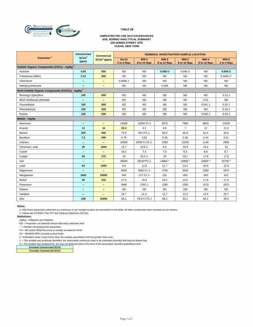
Bn v i ron m e t aln g i neer i n gc en ce,i
nT K
nvironmental
estoration,
TABLE 2B
UNRESTRICTED USE SCO EXCEEDANCES
SOIL BORING ANALYTICAL SUMMARY
229 HOMER STREET SITE
OLEAN, NEW YORK
HA-01
2 to 4 fbgs
MW-1
8 to 12 fbgs
MW-2
8 to 12 fbgs
MW-3
6 to 10 fbgs
MW-4
8 to 12 fbgs
MW-5
2 to 4 fbgs
Volatile Organic Compounds (VOCs) - mg/kg 3
Acetone 0.05 500 ND ND 0.066 U 0.046 U ND 0.054 U
2-Butanone (MEK) 0.12 500 ND ND ND ND ND 0.0049 J*
Chloroform -- -- 0.0006 J ND ND ND ND ND
Methylcyclohexane -- -- ND ND 0.026 ND ND ND
Semi-Volatile Organic Compounds (SVOCs) - mg/kg 3
Benzo(g,h,i)perylene 100 500 ND ND ND ND ND 0.12 J
Bis(2-ethylhexyl) phthalate -- -- ND ND ND ND 0.31 ND
Fluoranthene 100 500 ND ND ND ND 0.041 J 0.32 J
Phenanthrene 100 500 ND ND ND ND ND 0.16 J
Pyrene 100 500 ND ND ND ND 0.032 J 0.25 J
Metals - mg/kg
Aluminum -- -- 13500 10200 F1 J 8270 7960 8820 14200
Arsenic 13 16 22.4 4.1 8.5 7 12 11.5
Barium 350 400 79.5 59.4 F1 J- 83.9 65.8 81.4 60.6
Beryllium 7.2 590 0.76 0.53 0.38 0.38 0.43 0.61
Calcium -- -- 10300 6290 F1 F2 J- 1960 13100 1140 2900
Chromium, total 30 1500 15.7 13.6 J- 9.4 15.9 10.4 15
Cobalt -- -- 16.2 7.4 7.5 6.3 6.8 8.7
Copper 50 270 18 23.4 J- 20 19.1 17.6 17.6
Iron -- -- 29500 18100^F2 J- 14800 ^ 15800 ^ 19600 ^ 22700 ^
Lead 63 1000 9.9 11.8 11.7 14.1 10.5 15.3
Magnesium -- -- 4830 2950 F1 J- 2750 3500 2350 2870
Manganese 1600 10000 548 277 F2 J- 231 492 263 522
Nickel 30 310 27.8 24.3 18.2 15.5 17.8 17.6
Potassium -- -- 3040 1760 J- 1280 1350 1570 1970
Sodium -- -- ND ND ND 182 ND ND
Vandium -- -- 18.7 14 J- 12.7 13.3 13.4 20.7
Zinc 109 10000 64.1 79.9 F1 F2 J 66.2 52.1 54.1 45.2
Notes:
1. Only those parameters detected at a minimum of one sample location are presented in this table; all other compounds were reported as non-detect.
2. Values per NYSDEC Part 375 Soil Cleanup Objectives (SCOs).
Definitions:
mg/kg = milligrams per kilogram.
ND = Parameter not detected above laboratory detection limit.
-- = Sample not analyzed for parameter.
F1= MS and/or MSD Recovery is outside acceptance limits.
F2= MS/MSD RPD exceeds control limits.
J = Estimated value; result is less than the sample quantitation limit but greater than zero .
J- = The analyte was positively identified; the associated numerical value is an estimated quantitiy that may be biased low.
U = The analyte was analyzed for, but was not detected above the level of the associated reported quantitation limit.
Exceeds Unrestricted SCOs
Exceeds Commercial SCOs
Parameter 1
Unrestricted
SCOs2
(ppm)
Commerical
SCOs2 (ppm)
REMEDIAL INVESTIGATION SAMPLE LOCATION
Page 1 of 1
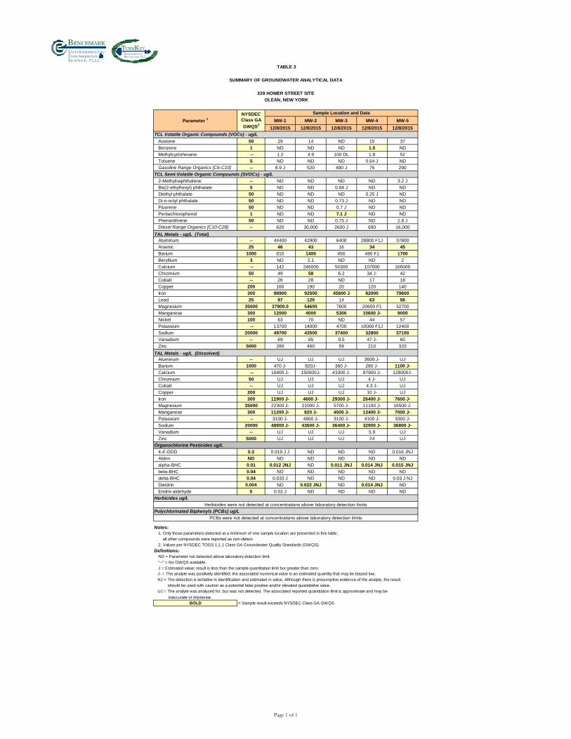
Bn v i ronm e t alng i neeri n gc ence,i
nT K
nvironmentalestoration,
TABLE 3
SUMMARY OF GROUNDWATER ANALYTICAL DATA
229 HOMER STREET SITE
OLEAN, NEW YORK
MW-1 MW-2 MW-3 MW-4 MW-5
12/8/2015 12/8/2015 12/8/2015 12/8/2015 12/8/2015
Acetone 50 29 14 ND 15 37
Benzene 1 ND ND ND 1.5 ND
Methylcyclohexane -- 1.2 4.9 100 DL 1.8 52
Toluene 5 ND ND ND 0.64 J ND
Gasoline Range Organics [C6-C10] -- 8.9 J 520 490 J 76 290
TCL Semi-Volatile Organic Compounds (SVOCs) - ug/L
2-Methylnaphthalene -- ND ND ND ND 3.2 J
Bis(2-ethylhexyl) phthalate 5 ND ND 0.68 J ND ND
Diethyl phthalate 50 ND ND ND 0.25 J ND
Di-n-octyl phthalate 50 ND ND 0.73 J ND ND
Fluorene 50 ND ND 0.7 J ND ND
Pentachlorophenol 1 ND ND 7.1 J ND ND
Phenanthrene 50 ND ND 0.75 J ND 2.8 J
Diesel Range Organics [C10-C28] -- 620 30,000 2600 J 690 16,000
TAL Metals - ug/L (Total)Aluminum -- 44400 42900 6400 28800 F1J 37800
Arsenic 25 46 43 16 34 45
Barium 1000 810 1400 450 490 F1 1700
Beryllium 3 ND 2.1 ND ND 2
Calcium -- 142 246000 50300 107000 166000
Chromium 50 49 58 6.2 34 J- 42
Cobalt -- 26 28 ND 17 18
Copper 200 160 190 20 120 140
Iron 300 98900 92500 45600 J 82000 79600
Lead 25 97 120 14 63 56
Magnesium 35000 37900.0 54600 7600 20600 F1 32700
Manganese 300 12000 4000 5300 15600 J- 9000
Nickel 100 63 70 ND 44 57
Potassium -- 13700 14000 4700 10000 F1J 12400
Sodium 20000 49700 43500 37400 32800 37100
Vanadium -- 69 65 9.5 47 J- 60
Zinc 5000 280 460 59 210 320
TAL Metals - ug/L (Dissolved)Aluminum -- UJ UJ UJ 3600 J- UJ
Barium 1000 470 J- 820J- 360 J- 280 J- 1100 J-
Calcium -- 10400 J- 150000J- 43300 J- 87900 J- 128000J-
Chromium 50 UJ UJ UJ 4 J- UJ
Cobalt -- UJ UJ UJ 4.3 J- UJ
Copper 200 UJ UJ UJ 10 J- UJ
Iron 300 11900 J- 4600 J- 29300 J- 26400 J- 7600 J-
Magnesium 35000 22300 J- 21000 J- 5700 J- 11100 J- 16500 J-
Manganese 300 11200 J- 820 J- 4500 J- 13400 J- 7000 J-
Potassium -- 3100 J- 4800 J- 3100 J- 4100 J- 3300 J-
Sodium 20000 48900 J- 43600 J- 36400 J- 32900 J- 36800 J-
Vanadium -- UJ UJ UJ 5.9 UJ
Zinc 5000 UJ UJ UJ 24 UJ
Organochlorine Pesticides ug/L
4,4'-DDD 0.3 0.019 J J ND ND ND 0.016 JNJ
Aldrin ND ND ND ND ND ND
alpha-BHC 0.01 0.012 JNJ ND 0.011 JNJ 0.014 JNJ 0.015 JNJ
beta-BHC 0.04 ND ND ND ND ND
delta-BHC 0.04 0.033 J ND ND ND 0.03 J NJ
Dieldrin 0.004 ND 0.022 JNJ ND 0.014 JNJ ND
Endrin aldehyde 5 0.02 J ND ND ND ND
Herbicides ug/L
Herbicides were not detected at concentrations above laboratory detection limits
Polychlorinated Biphenyls (PCBs) ug/L
PCBs were not detected at concentrations above laboratory detection limits
Notes:
1. Only those parameters detected at a minimum of one sample location are presented in this table;
all other compounds were reported as non-detect.
2. Values per NYSDEC TOGS 1.1.1 Class GA Groundwater Quality Standards (GWQS).
Definitions:
ND = Parameter not detected above laboratory detection limit.
"--" = No GWQS available.
J = Estimated value; result is less than the sample quantitation limit but greater than zero.
inaccurate or imprecise.
BOLD = Sample result exceeds NYSDEC Class GA GWQS
NJ = The detection is tentative in identification and estimated in value. Although there is presumptive evidence of the analyte, the result
should be used with caution as a potential false positive and/or elevated quantitative value.
UJ = The analyte was analyzed for, but was not detected. The associated reported quantitation limit is approximate and may be
Parameter 1
NYSDEC
Class GA
GWQS2
Sample Location and Date
TCL Volatile Organic Compounds (VOCs) - ug/L
J- = The analyte was positively identified; the associated numerical value is an estimated quantity that may be biased low.
Page 1 of 1
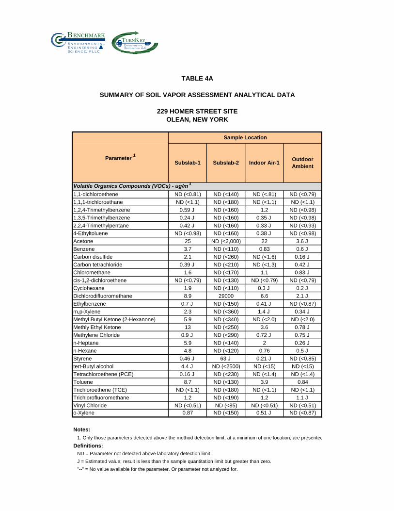
Bn v i r o n m e t a ln g i n eer i n gc e n c e,i
nT K
nvironmentalestoration,
TABLE 4A
SUMMARY OF SOIL VAPOR ASSESSMENT ANALYTICAL DATA
229 HOMER STREET SITE
OLEAN, NEW YORK
Volatile Organics Compounds (VOCs) - ug/m 3
1,1-dichloroethene ND (<0.81) ND (<140) ND (<.81) ND (<0.79)
1,1,1-trichloroethane ND (<1.1) ND (<180) ND (<1.1) ND (<1.1)
1,2,4-Trimethylbenzene 0.59 J ND (<160) 1.2 ND (<0.98)
1,3,5-Trimethylbenzene 0.24 J ND (<160) 0.35 J ND (<0.98)
2,2,4-Trimethylpentane 0.42 J ND (<160) 0.33 J ND (<0.93)
4-Ethyltoluene ND (<0.98) ND (<160) 0.38 J ND (<0.98)
Acetone 25 ND (<2,000) 22 3.6 J
Benzene 3.7 ND (<110) 0.83 0.6 J
Carbon disulfide 2.1 ND (<260) ND (<1.6) 0.16 J
Carbon tetrachloride 0.39 J ND (<210) ND (<1.3) 0.42 J
Chloromethane 1.6 ND (<170) 1.1 0.83 J
cis-1,2-dichloroethene ND (<0.79) ND (<130) ND (<0.79) ND (<0.79)
Cyclohexane 1.9 ND (<110) 0.3 J 0.2 J
Dichlorodifluoromethane 8.9 29000 6.6 2.1 J
Ethylbenzene 0.7 J ND (<150) 0.41 J ND (<0.87)
m,p-Xylene 2.3 ND (<360) 1.4 J 0.34 J
Methyl Butyl Ketone (2-Hexanone) 5.9 ND (<340) ND (<2.0) ND (<2.0)
Methly Ethyl Ketone 13 ND (<250) 3.6 0.78 J
Methylene Chloride 0.9 J ND (<290) 0.72 J 0.75 J
n-Heptane 5.9 ND (<140) 2 0.26 J
n-Hexane 4.8 ND (<120) 0.76 0.5 J
Styrene 0.46 J 63 J 0.21 J ND (<0.85)
tert-Butyl alcohol 4.4 J ND (<2500) ND (<15) ND (<15)
Tetrachloroethene (PCE) 0.16 J ND (<230) ND (<1.4) ND (<1.4)
Toluene 8.7 ND (<130) 3.9 0.84
Trichloroethene (TCE) ND (<1.1) ND (<180) ND (<1.1) ND (<1.1)
Trichlorofluoromethane 1.2 ND (<190) 1.2 1.1 J
Vinyl Chloride ND (<0.51) ND (<85) ND (<0.51) ND (<0.51)
o-Xylene 0.87 ND (<150) 0.51 J ND (<0.87)
Notes:
1. Only those parameters detected above the method detection limit, at a minimum of one location, are presented
Definitions:
ND = Parameter not detected above laboratory detection limit.
J = Estimated value; result is less than the sample quantitation limit but greater than zero.
"--" = No value available for the parameter. Or parameter not analyzed for.
Parameter 1
Sample Location
Indoor Air-1Outdoor
AmbientSubslab-1 Subslab-2
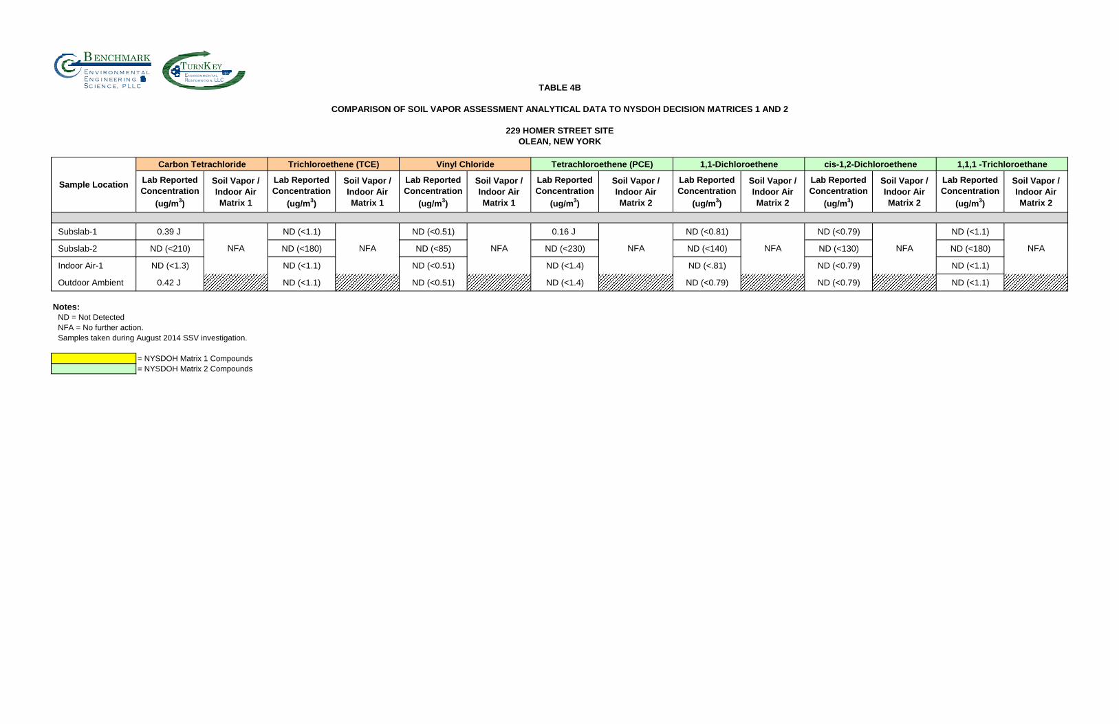
Bn v i r o n m e t a ln g i n eer i n gc e n c e,i
nT K
nvironmentalestoration,
TABLE 4B
COMPARISON OF SOIL VAPOR ASSESSMENT ANALYTICAL DATA TO NYSDOH DECISION MATRICES 1 AND 2
229 HOMER STREET SITE
OLEAN, NEW YORK
Carbon Tetrachloride Trichloroethene (TCE) Vinyl Chloride Tetrachloroethene (PCE) 1,1-Dichloroethene cis-1,2-Dichloroethene 1,1,1 -Trichloroethane
Lab Reported
Concentration
(ug/m3)
Soil Vapor /
Indoor Air
Matrix 1
Lab Reported
Concentration
(ug/m3)
Soil Vapor /
Indoor Air
Matrix 1
Lab Reported
Concentration
(ug/m3)
Soil Vapor /
Indoor Air
Matrix 1
Lab Reported
Concentration
(ug/m3)
Soil Vapor /
Indoor Air
Matrix 2
Lab Reported
Concentration
(ug/m3)
Soil Vapor /
Indoor Air
Matrix 2
Lab Reported
Concentration
(ug/m3)
Soil Vapor /
Indoor Air
Matrix 2
Lab Reported
Concentration
(ug/m3)
Soil Vapor /
Indoor Air
Matrix 2
Subslab-1 0.39 J ND (<1.1) ND (<0.51) 0.16 J ND (<0.81) ND (<0.79) ND (<1.1)
Subslab-2 ND (<210) ND (<180) ND (<85) ND (<230) ND (<140) ND (<130) ND (<180)
Indoor Air-1 ND (<1.3) ND (<1.1) ND (<0.51) ND (<1.4) ND (<.81) ND (<0.79) ND (<1.1)
Outdoor Ambient 0.42 J ND (<1.1) ND (<0.51) ND (<1.4) ND (<0.79) ND (<0.79) ND (<1.1)
Notes:ND = Not Detected
NFA = No further action.
Samples taken during August 2014 SSV investigation.
= NYSDOH Matrix 1 Compounds
= NYSDOH Matrix 2 Compounds
NFA NFA
Sample Location
NFA NFA NFA NFA NFA

SITE MANAGEMENT PLAN 229 HOMER STREET SITE
BCP SITE NO.C905044
0311-018-001 T KB
FIGURES
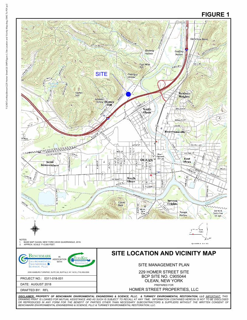
SITE
DRAFTED BY:
PROJECT NO.:
DATE:
PREPARED FOR
DISCLAIMER: PROPERTY OF BENCHMARK ENVIRONMENTAL ENGINEERING & SCIENCE, PLLC. & TURNKEY ENVIRONMENTAL RESTORATION, LLC IMPORTANT: THIS
DRAWING PRINT IS LOANED FOR MUTUAL ASSISTANCE AND AS SUCH IS SUBJECT TO RECALL AT ANY TIME. INFORMATION CONTAINED HEREON IS NOT TO BE DISCLOSED
OR REPRODUCED IN ANY FORM FOR THE BENEFIT OF PARTIES OTHER THAN NECESSARY SUBCONTRACTORS & SUPPLIERS WITHOUT THE WRITTEN CONSENT OF
BENCHMARK ENVIRONMENTAL ENGINEERING & SCIENCE, PLLC & TURNKEY ENVIRONMENTAL RESTORATION, LLC.
IN
ASSOCIATION
WITH
2558 HAMBURG TURNPIKE, SUITE 300, BUFFALO, NY 14218, (716) 856-0599
alt
C
inr
e
, P L L
g
n
eE ign ne
BENCHMARKmnivnE ro
S iec n ec
LLCRestoration,
EYTE
URNnvironmental
KSITE LOCATION AND VICINITY MAP
SITE MANAGEMENT PLAN
HOMER STREET PROPERTIES, LLC
229 HOMER STREET SITE
BCP SITE NO. C905044
OLEAN, NEW YORK
FIGURE 1
RFL
AUGUST 2018
0311-018-001
NOTES:
1. BASE MAP OLEAN, NEW YORK USGS QUADRANGLE, 2016.
2. APPROX. SCALE 1"=3,000 FEET.
N
F:\C
AD
\Tu
rn
Key\B
en
so
n\229 H
om
er Street\16-SM
P\Fig
ure 1; Site Lo
catio
n an
d V
icin
ity M
ap
.d
wg
, D
WG
To
P
DF.p
c3
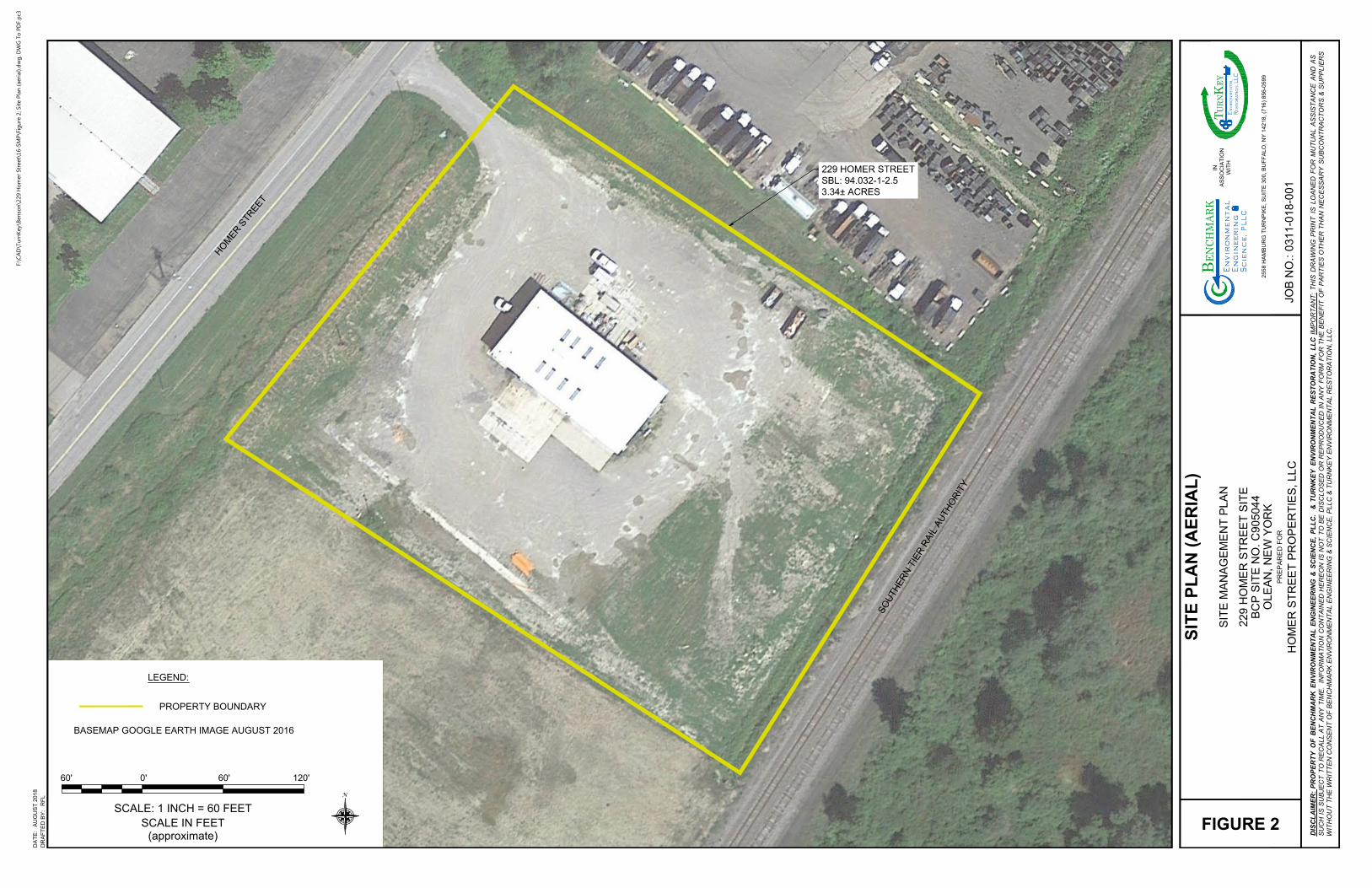
229 HOMER STREET
SBL: 94.032-1-2.5
3.34± ACRES
H
O
M
E
R
S
T
R
E
E
T
S
O
U
T
H
E
R
N
T
I
E
R
R
A
I
L
A
U
T
H
O
R
I
T
Y
LEGEND:
PROPERTY BOUNDARY
BASEMAP GOOGLE EARTH IMAGE AUGUST 2016
0'
SCALE IN FEET
(approximate)
60' 60' 120'
SCALE: 1 INCH = 60 FEET
N
DR
AF
TE
D B
Y:
DA
TE
:
PR
EP
AR
ED
F
OR
JO
B N
O.:
DIS
CL
AIM
ER
: P
RO
PE
RT
Y O
F B
EN
CH
MA
RK
E
NV
IR
ON
ME
NT
AL
E
NG
IN
EE
RIN
G &
S
CIE
NC
E, P
LL
C. &
T
UR
NK
EY
E
NV
IR
ON
ME
NT
AL
R
ES
TO
RA
TIO
N, L
LC
IM
PO
RT
AN
T: T
HIS
D
RA
WIN
G P
RIN
T IS
L
OA
NE
D F
OR
M
UT
UA
L A
SS
IS
TA
NC
E A
ND
A
S
SU
CH
IS
S
UB
JE
CT
T
O R
EC
AL
L A
T A
NY
T
IM
E. IN
FO
RM
AT
IO
N C
ON
TA
IN
ED
H
ER
EO
N IS
N
OT
T
O B
E D
IS
CL
OS
ED
O
R R
EP
RO
DU
CE
D IN
A
NY
F
OR
M F
OR
T
HE
B
EN
EF
IT
O
F P
AR
TIE
S O
TH
ER
T
HA
N N
EC
ES
SA
RY
S
UB
CO
NT
RA
CT
OR
S &
S
UP
PL
IE
RS
WIT
HO
UT
T
HE
W
RIT
TE
N C
ON
SE
NT
O
F B
EN
CH
MA
RK
E
NV
IR
ON
ME
NT
AL
E
NG
IN
EE
RIN
G &
S
CIE
NC
E, P
LL
C &
T
UR
NK
EY
E
NV
IR
ON
ME
NT
AL
R
ES
TO
RA
TIO
N, L
LC
.
25
58
H
AM
BU
RG
T
UR
NP
IK
E, S
UIT
E 3
00
, B
UF
FA
LO
, N
Y 1
42
18
, (7
16
) 8
56
-0
59
9
IN
AS
SO
CIA
TIO
N
WIT
H
al
t C
in
r
e
,P
LLgn
eE
ig
nn
e
BEN
CHM
ARK
mn
iv
nE
ro
Sie
cn
ec
LL
CR
es
to
ra
tio
n,EY
T E
URN
nv
iro
nm
en
ta
l
K
AU
GU
ST
2
01
8
RF
L
FIGURE 2
HO
ME
R S
TR
EE
T P
RO
PE
RT
IE
S, L
LC
22
9 H
OM
ER
S
TR
EE
T S
IT
E
BC
P S
IT
E N
O. C
90
50
44
OL
EA
N, N
EW
Y
OR
K
SIT
E M
AN
AG
EM
EN
T P
LA
N
SIT
E P
LA
N (A
ER
IA
L)
03
11
-0
18
-0
01
F:\C
AD
\Tu
rn
Key\B
en
so
n\229 H
om
er Street\16-SM
P\Fig
ure 2; Site P
lan
(aerial).d
wg
, D
WG
To
P
DF.p
c3
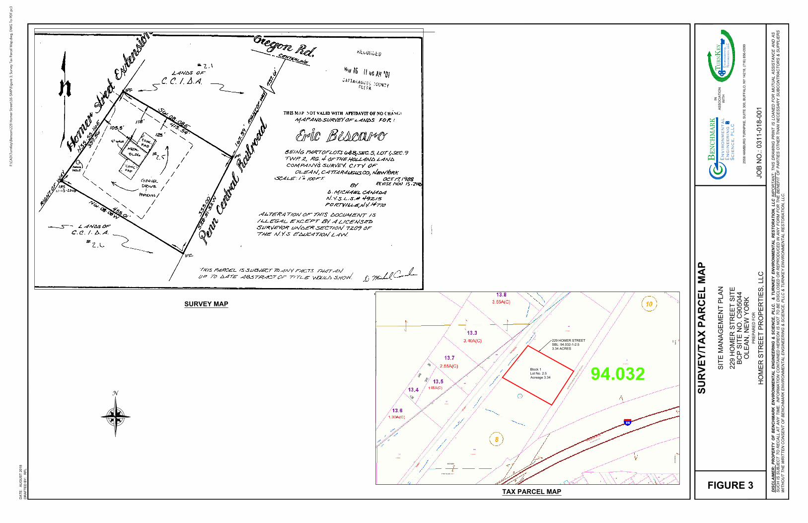
229 HOMER STREET
SBL: 94.032-1-2.5
3.34 ACRES
Block 1
Lot No. 2.5
Acreage 3.34
N
DR
AF
TE
D B
Y:
DA
TE
:
PR
EP
AR
ED
F
OR
JO
B N
O.:
DIS
CL
AIM
ER
: P
RO
PE
RT
Y O
F B
EN
CH
MA
RK
E
NV
IR
ON
ME
NT
AL
E
NG
IN
EE
RIN
G &
S
CIE
NC
E, P
LL
C. &
T
UR
NK
EY
E
NV
IR
ON
ME
NT
AL
R
ES
TO
RA
TIO
N, L
LC
IM
PO
RT
AN
T: T
HIS
D
RA
WIN
G P
RIN
T IS
L
OA
NE
D F
OR
M
UT
UA
L A
SS
IS
TA
NC
E A
ND
A
S
SU
CH
IS
S
UB
JE
CT
T
O R
EC
AL
L A
T A
NY
T
IM
E. IN
FO
RM
AT
IO
N C
ON
TA
IN
ED
H
ER
EO
N IS
N
OT
T
O B
E D
IS
CL
OS
ED
O
R R
EP
RO
DU
CE
D IN
A
NY
F
OR
M F
OR
T
HE
B
EN
EF
IT
O
F P
AR
TIE
S O
TH
ER
T
HA
N N
EC
ES
SA
RY
S
UB
CO
NT
RA
CT
OR
S &
S
UP
PL
IE
RS
WIT
HO
UT
T
HE
W
RIT
TE
N C
ON
SE
NT
O
F B
EN
CH
MA
RK
E
NV
IR
ON
ME
NT
AL
E
NG
IN
EE
RIN
G &
S
CIE
NC
E, P
LL
C &
T
UR
NK
EY
E
NV
IR
ON
ME
NT
AL
R
ES
TO
RA
TIO
N, L
LC
.
25
58
H
AM
BU
RG
T
UR
NP
IK
E, S
UIT
E 3
00
, B
UF
FA
LO
, N
Y 1
42
18
, (7
16
) 8
56
-0
59
9
IN
AS
SO
CIA
TIO
N
WIT
H
al
t C
in
r
e
,P
LLgn
eE
ig
nn
e
BEN
CHM
ARK
mn
iv
nE
ro
Sie
cn
ec
LL
CR
es
to
ra
tio
n,EY
T E
URN
nv
iro
nm
en
ta
l
K
AU
GU
ST
2
01
8
RF
L
FIGURE 3
HO
ME
R S
TR
EE
T P
RO
PE
RT
IE
S, L
LC
22
9 H
OM
ER
S
TR
EE
T S
IT
E
BC
P S
IT
E N
O. C
90
50
44
OL
EA
N, N
EW
Y
OR
K
SIT
E M
AN
AG
EM
EN
T P
LA
N
SU
RV
EY
/T
AX
P
AR
CE
L M
AP
03
11
-0
18
-0
01
SURVEY MAP
TAX PARCEL MAP
F:\C
AD
\Tu
rn
Key\B
en
so
n\229 H
om
er Street\16-SM
P\Fig
ure 3; Su
rvey Tax P
arcel M
ap
.d
wg
, D
WG
To
P
DF.p
c3
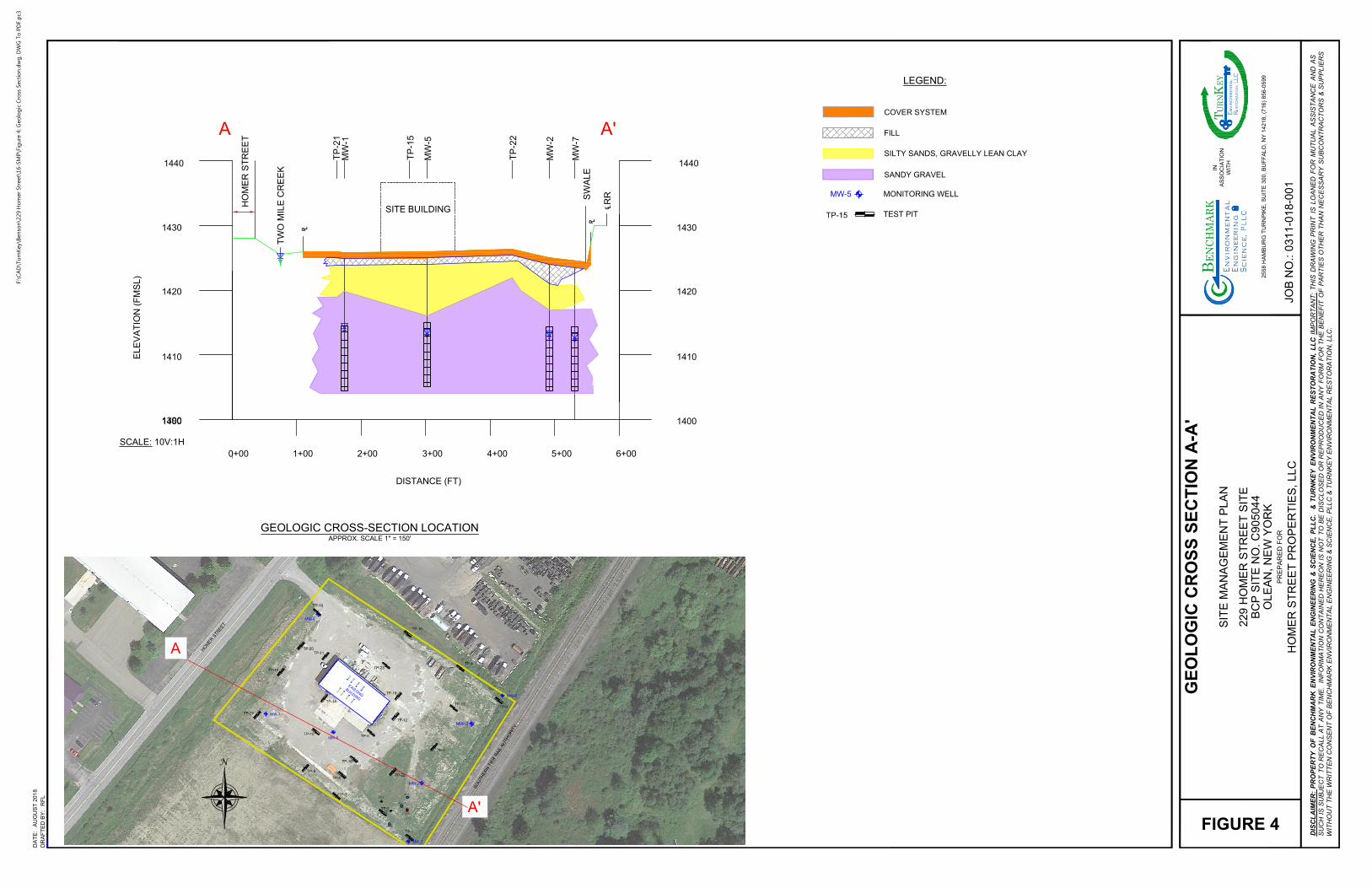
MONITORING WELL
LEGEND:
COVER SYSTEM
FILL
TEST PIT
TP-15
MW-5
SILTY SANDS, GRAVELLY LEAN CLAY
SANDY GRAVEL
0+00 1+00 2+00 3+00 4+00 5+00 6+00
13901400
1410
1420
1430
1440
SITE BUILDING
A A'
1400
1410
1420
1430
1440
SCALE: 10V:1H
ELE
VA
TIO
N (F
MS
L)
DISTANCE (FT)
HO
ME
R S
TR
EE
T
TW
O M
ILE
C
RE
EK
TP
-21
MW
-1
TP
-15
MW
-5
TP
-22
MW
-2
MW
-7
SW
ALE
RR
A'
H
O
M
E
R
S
T
R
E
E
T
S
O
U
T
H
E
R
N
T
I
E
R
R
A
I
L
A
U
T
H
O
R
I
T
Y
MW-4
MW-3
MW-2
MW-1
TP-14
TP-18
TP-20
TP-13
TP-19
TP-15
TP-16
TP-17
E
X
I
S
T
I
N
G
B
U
I
L
D
I
N
G
TP-10
TP-9
TP-6
TP-4
TP-3
TP-2
TP-1
TP-5
TP-12
TP-7
TP-11
TP-8
TP-22
TP-21
TP-23
MW-5
MW-6
MW-7
AS
AS-3
SVE
SVE
AS
AS-1
AS
AS-2
PZ-1
PZ-2
A
N
GEOLOGIC CROSS-SECTION LOCATION
APPROX. SCALE 1" = 150'
DR
AF
TE
D B
Y:
DA
TE
:
PR
EP
AR
ED
F
OR
JO
B N
O.:
DIS
CL
AIM
ER
: P
RO
PE
RT
Y O
F B
EN
CH
MA
RK
E
NV
IR
ON
ME
NT
AL
E
NG
IN
EE
RIN
G &
S
CIE
NC
E, P
LL
C. &
T
UR
NK
EY
E
NV
IR
ON
ME
NT
AL
R
ES
TO
RA
TIO
N, L
LC
IM
PO
RT
AN
T: T
HIS
D
RA
WIN
G P
RIN
T IS
LO
AN
ED
F
OR
M
UT
UA
L A
SS
IS
TA
NC
E A
ND
A
S
SU
CH
IS
S
UB
JE
CT
T
O R
EC
AL
L A
T A
NY
T
IM
E. IN
FO
RM
AT
IO
N C
ON
TA
IN
ED
H
ER
EO
N IS
N
OT
T
O B
E D
IS
CL
OS
ED
O
R R
EP
RO
DU
CE
D IN
A
NY
F
OR
M F
OR
T
HE
B
EN
EF
IT
O
F P
AR
TIE
S O
TH
ER
T
HA
N N
EC
ES
SA
RY
S
UB
CO
NT
RA
CT
OR
S &
S
UP
PL
IE
RS
WIT
HO
UT
T
HE
W
RIT
TE
N C
ON
SE
NT
O
F B
EN
CH
MA
RK
E
NV
IR
ON
ME
NT
AL
E
NG
IN
EE
RIN
G &
S
CIE
NC
E, P
LL
C &
T
UR
NK
EY
E
NV
IR
ON
ME
NT
AL
R
ES
TO
RA
TIO
N, L
LC
.
2558 H
AM
BU
RG
T
UR
NP
IK
E, S
UIT
E 300, B
UF
FA
LO
, N
Y 14218, (716) 856-0599
IN
AS
SO
CIA
TIO
N
WIT
H
al
t C
in
r
e
,P
LLgn
eE
ig
nn
e
BEN
CHM
ARK
mn
iv
nE
ro
Sie
cn
ec
LL
CR
es
to
ra
tio
n,EY
T E
URN
nv
iro
nm
en
ta
l
K
AU
GU
ST
2018
RF
L
FIGURE 4
HO
ME
R S
TR
EE
T P
RO
PE
RT
IE
S, LLC
229 H
OM
ER
S
TR
EE
T S
IT
E
BC
P S
IT
E N
O. C
905044
OLE
AN
, N
EW
Y
OR
K
SIT
E M
AN
AG
EM
EN
T P
LA
N
GE
OL
OG
IC
C
RO
SS
S
EC
TIO
N A
-A
'
0311-018-001
F:\C
AD
\Tu
rn
Key\B
en
so
n\229 H
om
er Street\16-SM
P\Fig
ure 4; G
eo
lo
gic C
ro
ss Sectio
n.d
wg
, D
WG
To
P
DF.p
c3
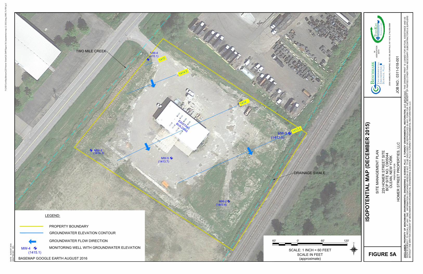
MW-3
(1413.5)
MW-2
(1413.4)
MW-1
(1414.3)
E
X
I
S
T
I
N
G
B
U
I
L
D
I
N
G
MW-5
(1413.7)
1
4
1
5
1
4
1
4
.
5
1
4
1
4
MW-4
(1415.1)
TWO MILE CREEK
DRAINAGE SWALE
1
4
1
3
.
5
LEGEND:
PROPERTY BOUNDARY
GROUNDWATER ELEVATION CONTOUR
MONITORING WELL WITH GROUNDWATER ELEVATION
GROUNDWATER FLOW DIRECTION
MW-4
(1415.1)
BASEMAP GOOGLE EARTH AUGUST 2016
0'
SCALE IN FEET
(approximate)
60' 60' 120'
SCALE: 1 INCH = 60 FEET
N
DR
AF
TE
D B
Y:
DA
TE
:
PR
EP
AR
ED
F
OR
JO
B N
O.:
DIS
CL
AIM
ER
: P
RO
PE
RT
Y O
F B
EN
CH
MA
RK
E
NV
IR
ON
ME
NT
AL
E
NG
IN
EE
RIN
G &
S
CIE
NC
E, P
LL
C. &
T
UR
NK
EY
E
NV
IR
ON
ME
NT
AL
R
ES
TO
RA
TIO
N, L
LC
IM
PO
RT
AN
T: T
HIS
D
RA
WIN
G P
RIN
T IS
L
OA
NE
D F
OR
M
UT
UA
L A
SS
IS
TA
NC
E A
ND
A
S
SU
CH
IS
S
UB
JE
CT
T
O R
EC
AL
L A
T A
NY
T
IM
E. IN
FO
RM
AT
IO
N C
ON
TA
IN
ED
H
ER
EO
N IS
N
OT
T
O B
E D
IS
CL
OS
ED
O
R R
EP
RO
DU
CE
D IN
A
NY
F
OR
M F
OR
T
HE
B
EN
EF
IT
O
F P
AR
TIE
S O
TH
ER
T
HA
N N
EC
ES
SA
RY
S
UB
CO
NT
RA
CT
OR
S &
S
UP
PL
IE
RS
WIT
HO
UT
T
HE
W
RIT
TE
N C
ON
SE
NT
O
F B
EN
CH
MA
RK
E
NV
IR
ON
ME
NT
AL
E
NG
IN
EE
RIN
G &
S
CIE
NC
E, P
LL
C &
T
UR
NK
EY
E
NV
IR
ON
ME
NT
AL
R
ES
TO
RA
TIO
N, L
LC
.
25
58
H
AM
BU
RG
T
UR
NP
IK
E, S
UIT
E 3
00
, B
UF
FA
LO
, N
Y 1
42
18
, (7
16
) 8
56
-0
59
9
IN
AS
SO
CIA
TIO
N
WIT
H
al
t C
in
r
e
,P
LLgn
eE
ig
nn
e
BEN
CHM
ARK
mn
iv
nE
ro
Sie
cn
ec
LL
CR
es
to
ra
tio
n,EY
T E
URN
nv
iro
nm
en
ta
l
K
AU
GU
ST
2
01
8
RF
L
FIGURE 5A
HO
ME
R S
TR
EE
T P
RO
PE
RT
IE
S, L
LC
22
9 H
OM
ER
S
TR
EE
T S
IT
E
BC
P S
IT
E N
O. C
90
50
44
OL
EA
N, N
EW
Y
OR
K
SIT
E M
AN
AG
EM
EN
T P
LA
N
IS
OP
OT
EN
TIA
L M
AP
(D
EC
EM
BE
R 2
01
5)
03
11
-0
18
-0
01
F:\C
AD
\Tu
rn
Key\B
en
so
n\229 H
om
er Street\16-SM
P\Fig
ure 5A
; Iso
po
ten
tial m
ap
12-2015.d
wg
, D
WG
To
P
DF.p
c3
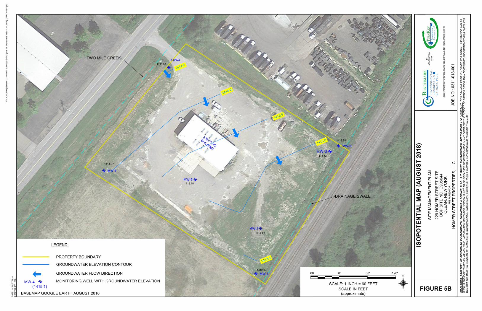
MW-3
MW-2
MW-1
E
X
I
S
T
I
N
G
B
U
I
L
D
I
N
G
MW-5
1
4
1
4
.
5
1
4
1
4
.
0
1
4
1
3
.
5
MW-4
TWO MILE CREEK
DRAINAGE SWALE
1
4
1
3
.
0
MW-6
MW-7
1414.07
1412.92
1412.84
1414.54
1413.18
1412.33
1412.74
1
4
1
2
.
5
LEGEND:
PROPERTY BOUNDARY
GROUNDWATER ELEVATION CONTOUR
MONITORING WELL WITH GROUNDWATER ELEVATION
GROUNDWATER FLOW DIRECTION
MW-4
(1415.1)
BASEMAP GOOGLE EARTH AUGUST 2016
0'
SCALE IN FEET
(approximate)
60' 60' 120'
SCALE: 1 INCH = 60 FEET
N
DR
AF
TE
D B
Y:
DA
TE
:
PR
EP
AR
ED
F
OR
JO
B N
O.:
DIS
CL
AIM
ER
: P
RO
PE
RT
Y O
F B
EN
CH
MA
RK
E
NV
IR
ON
ME
NT
AL
E
NG
IN
EE
RIN
G &
S
CIE
NC
E, P
LL
C. &
T
UR
NK
EY
E
NV
IR
ON
ME
NT
AL
R
ES
TO
RA
TIO
N, L
LC
IM
PO
RT
AN
T: T
HIS
D
RA
WIN
G P
RIN
T IS
L
OA
NE
D F
OR
M
UT
UA
L A
SS
IS
TA
NC
E A
ND
A
S
SU
CH
IS
S
UB
JE
CT
T
O R
EC
AL
L A
T A
NY
T
IM
E. IN
FO
RM
AT
IO
N C
ON
TA
IN
ED
H
ER
EO
N IS
N
OT
T
O B
E D
IS
CL
OS
ED
O
R R
EP
RO
DU
CE
D IN
A
NY
F
OR
M F
OR
T
HE
B
EN
EF
IT
O
F P
AR
TIE
S O
TH
ER
T
HA
N N
EC
ES
SA
RY
S
UB
CO
NT
RA
CT
OR
S &
S
UP
PL
IE
RS
WIT
HO
UT
T
HE
W
RIT
TE
N C
ON
SE
NT
O
F B
EN
CH
MA
RK
E
NV
IR
ON
ME
NT
AL
E
NG
IN
EE
RIN
G &
S
CIE
NC
E, P
LL
C &
T
UR
NK
EY
E
NV
IR
ON
ME
NT
AL
R
ES
TO
RA
TIO
N, L
LC
.
25
58
H
AM
BU
RG
T
UR
NP
IK
E, S
UIT
E 3
00
, B
UF
FA
LO
, N
Y 1
42
18
, (7
16
) 8
56
-0
59
9
IN
AS
SO
CIA
TIO
N
WIT
H
al
t C
in
r
e
,P
LLgn
eE
ig
nn
e
BEN
CHM
ARK
mn
iv
nE
ro
Sie
cn
ec
LL
CR
es
to
ra
tio
n,EY
T E
URN
nv
iro
nm
en
ta
l
K
AU
GU
ST
2
01
8
RF
L
FIGURE 5B
HO
ME
R S
TR
EE
T P
RO
PE
RT
IE
S, L
LC
22
9 H
OM
ER
S
TR
EE
T S
IT
E
BC
P S
IT
E N
O. C
90
50
44
OL
EA
N, N
EW
Y
OR
K
SIT
E M
AN
AG
EM
EN
T P
LA
N
IS
OP
OT
EN
TIA
L M
AP
(A
UG
US
T 2
01
8)
03
11
-0
18
-0
01
F:\C
AD
\Tu
rn
Key\B
en
so
n\229 H
om
er Street\16-SM
P\Fig
ure 5B
; Iso
po
ten
tial m
ap
8-2018.d
wg
, D
WG
To
P
DF.p
c3
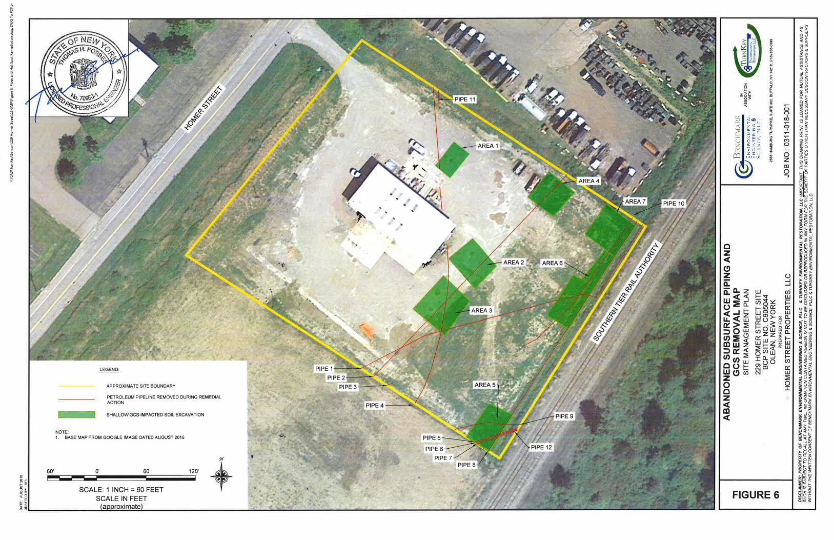
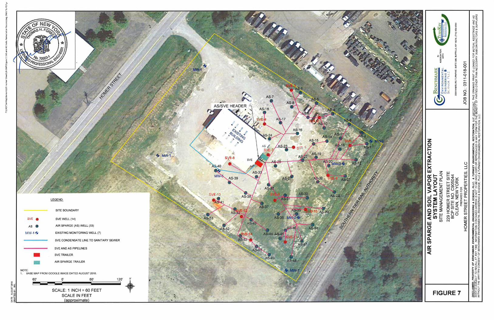
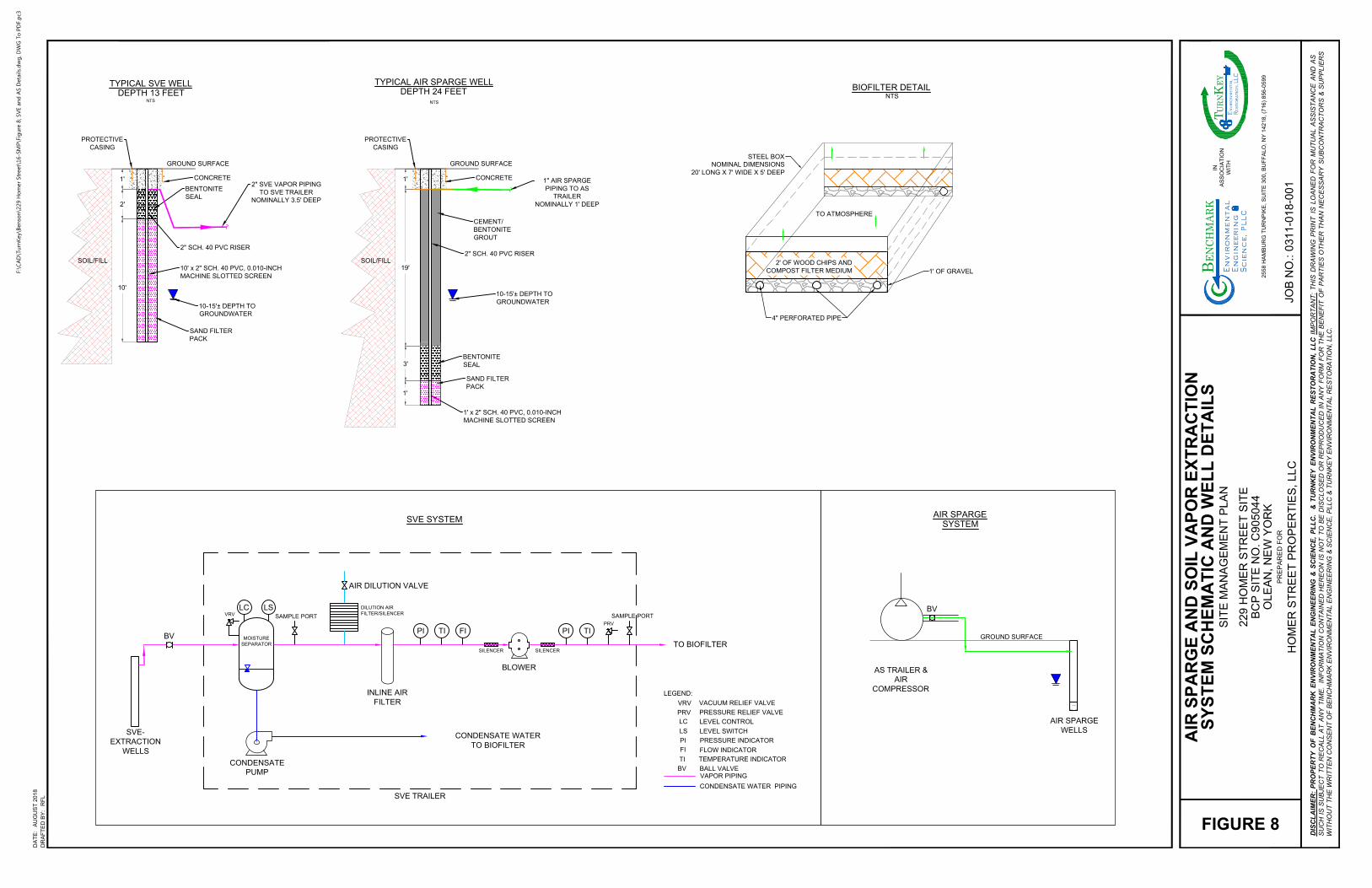
BENTONITE
SEAL
SAND FILTER
PACK
10' x 2" SCH. 40 PVC, 0.010-INCH
MACHINE SLOTTED SCREEN
10'
SOIL/FILL
TYPICAL SVE WELL
DEPTH 13 FEET
NTS
2'
GROUND SURFACE
2" SCH. 40 PVC RISER
1'
10-15'± DEPTH TO
GROUNDWATER
SAND FILTER
PACK
1' x 2" SCH. 40 PVC, 0.010-INCH
MACHINE SLOTTED SCREEN
CEMENT/
BENTONITE
GROUT
SOIL/FILL
TYPICAL AIR SPARGE WELL
DEPTH 24 FEET
NTS
GROUND SURFACE
2" SCH. 40 PVC RISER
10-15'± DEPTH TO
GROUNDWATER
19'
1'
SVE-
EXTRACTION
WELLS
BV
CONDENSATE
PUMP
LC
MOISTURE
SEPARATOR
SAMPLE PORT
PI TI FI
BLOWER
PI TI
VRV
PRV
SILENCERSILENCER
INLINE AIR
FILTER
AIR DILUTION VALVE
DILUTION AIR
FILTER/SILENCER
SVE TRAILER
TO BIOFILTER
SAMPLE PORT
LS
LEGEND:
VACUUM RELIEF VALVEVRV
PRESSURE RELIEF VALVEPRV
LEVEL SWITCHLS
LEVEL CONTROLLC
FLOW INDICATORFI
PRESSURE INDICATORPI
BV
TI
BALL VALVE
TEMPERATURE INDICATOR
AIR SPARGE
WELLS
AS TRAILER &
AIR
COMPRESSOR
SVE SYSTEM
AIR SPARGE
SYSTEM
BV
VAPOR PIPING
CONDENSATE WATER PIPING
BENTONITE
SEAL
TO ATMOSPHERE
2' OF WOOD CHIPS AND
COMPOST FILTER MEDIUM
1' OF GRAVEL
4" PERFORATED PIPE
STEEL BOX
NOMINAL DIMENSIONS
20' LONG X 7' WIDE X 5' DEEP
BIOFILTER DETAIL
NTS
GROUND SURFACE
2" SVE VAPOR PIPING
TO SVE TRAILER
NOMINALLY 3.5' DEEP
1" AIR SPARGE
PIPING TO AS
TRAILER
NOMINALLY 1' DEEP
PROTECTIVE
CASING
CONCRETE
1'
3'
PROTECTIVE
CASING
CONCRETE
CONDENSATE WATER
TO BIOFILTER
DR
AF
TE
D B
Y:
DA
TE
:
PR
EP
AR
ED
F
OR
JO
B N
O.:
DIS
CL
AIM
ER
: P
RO
PE
RT
Y O
F B
EN
CH
MA
RK
E
NV
IR
ON
ME
NT
AL
E
NG
IN
EE
RIN
G &
S
CIE
NC
E, P
LL
C. &
T
UR
NK
EY
E
NV
IR
ON
ME
NT
AL
R
ES
TO
RA
TIO
N, L
LC
IM
PO
RT
AN
T: T
HIS
D
RA
WIN
G P
RIN
T IS
L
OA
NE
D F
OR
M
UT
UA
L A
SS
IS
TA
NC
E A
ND
A
S
SU
CH
IS
S
UB
JE
CT
T
O R
EC
AL
L A
T A
NY
T
IM
E. IN
FO
RM
AT
IO
N C
ON
TA
IN
ED
H
ER
EO
N IS
N
OT
T
O B
E D
IS
CL
OS
ED
O
R R
EP
RO
DU
CE
D IN
A
NY
F
OR
M F
OR
T
HE
B
EN
EF
IT
O
F P
AR
TIE
S O
TH
ER
T
HA
N N
EC
ES
SA
RY
S
UB
CO
NT
RA
CT
OR
S &
S
UP
PL
IE
RS
WIT
HO
UT
T
HE
W
RIT
TE
N C
ON
SE
NT
O
F B
EN
CH
MA
RK
E
NV
IR
ON
ME
NT
AL
E
NG
IN
EE
RIN
G &
S
CIE
NC
E, P
LL
C &
T
UR
NK
EY
E
NV
IR
ON
ME
NT
AL
R
ES
TO
RA
TIO
N, L
LC
.
25
58
H
AM
BU
RG
T
UR
NP
IK
E, S
UIT
E 3
00
, B
UF
FA
LO
, N
Y 1
42
18
, (7
16
) 8
56
-0
59
9
IN
AS
SO
CIA
TIO
N
WIT
H
al
t C
in
r
e
,P
LLgn
eE
ig
nn
e
BEN
CHM
ARK
mn
iv
nE
ro
Sie
cn
ec
LL
CR
es
to
ra
tio
n,EY
T E
URN
nv
iro
nm
en
ta
l
K
AU
GU
ST
2
01
8
RF
L
FIGURE 8
HO
ME
R S
TR
EE
T P
RO
PE
RT
IE
S, L
LC
22
9 H
OM
ER
S
TR
EE
T S
IT
E
BC
P S
IT
E N
O. C
90
50
44
OL
EA
N, N
EW
Y
OR
K
SIT
E M
AN
AG
EM
EN
T P
LA
N
SY
ST
EM
S
CH
EM
AT
IC
A
ND
W
EL
L D
ET
AIL
S
A
IR
S
PA
RG
E A
ND
S
OIL
V
AP
OR
E
XT
RA
CT
IO
N
03
11
-0
18
-0
01
F:\C
AD
\Tu
rn
Key\B
en
so
n\229 H
om
er Street\16-SM
P\Fig
ure 8; SV
E an
d A
S D
etails.d
wg
, D
WG
To
P
DF.p
c3
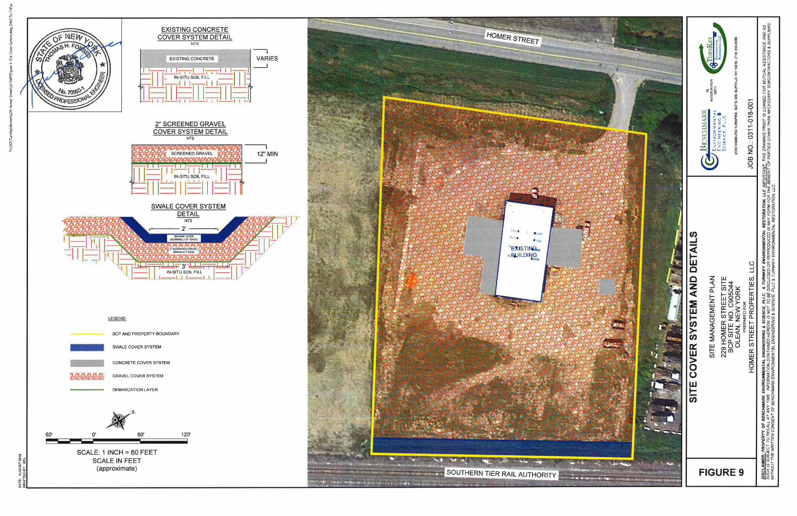
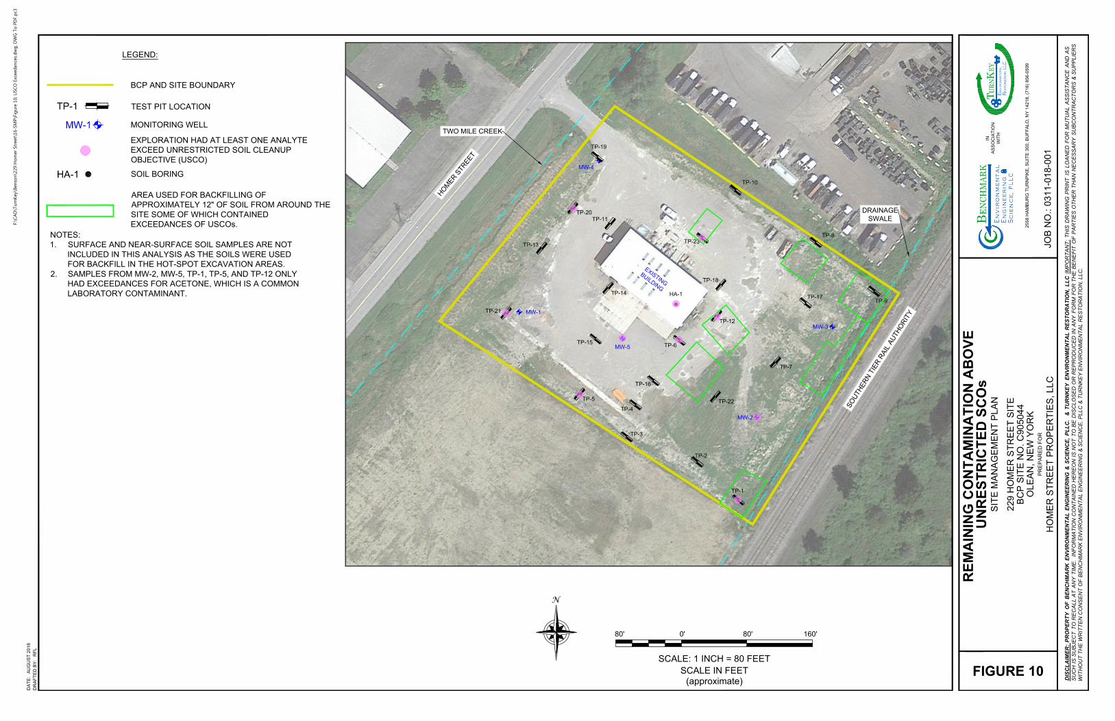
H
O
M
E
R
S
T
R
E
E
T
S
O
U
T
H
E
R
N
T
I
E
R
R
A
I
L
A
U
T
H
O
R
I
T
Y
MW-4
MW-3
MW-2
MW-1
TP-14
TP-18
TP-20
TP-13
TP-19
TP-15
TP-16
TP-17
E
X
I
S
T
I
N
G
B
U
I
L
D
I
N
G
TP-6
TP-4
TP-3
TP-2
TP-1
TP-5
TP-12
TP-7
TP-11
TP-22
TP-21
TP-23
MW-5
HA-1
TWO MILE CREEK
TP-10
TP-8
TP-9
DRAINAGE
SWALE
LEGEND:
BCP AND SITE BOUNDARY
MONITORING WELL
MW-1
TEST PIT LOCATIONTP-1
HA-1
EXPLORATION HAD AT LEAST ONE ANALYTE
EXCEED UNRESTRICTED SOIL CLEANUP
OBJECTIVE (USCO)
NOTES:
1. SURFACE AND NEAR-SURFACE SOIL SAMPLES ARE NOT
INCLUDED IN THIS ANALYSIS AS THE SOILS WERE USED
FOR BACKFILL IN THE HOT-SPOT EXCAVATION AREAS.
2. SAMPLES FROM MW-2, MW-5, TP-1, TP-5, AND TP-12 ONLY
HAD EXCEEDANCES FOR ACETONE, WHICH IS A COMMON
LABORATORY CONTAMINANT.
SOIL BORING
AREA USED FOR BACKFILLING OF
APPROXIMATELY 12" OF SOIL FROM AROUND THE
SITE SOME OF WHICH CONTAINED
EXCEEDANCES OF USCOs.
0'
SCALE IN FEET
(approximate)
80' 80' 160'
SCALE: 1 INCH = 80 FEET
N
DR
AF
TE
D B
Y:
DA
TE
:
PR
EP
AR
ED
F
OR
JO
B N
O.:
DIS
CL
AIM
ER
: P
RO
PE
RT
Y O
F B
EN
CH
MA
RK
E
NV
IR
ON
ME
NT
AL
E
NG
IN
EE
RIN
G &
S
CIE
NC
E, P
LL
C. &
T
UR
NK
EY
E
NV
IR
ON
ME
NT
AL
R
ES
TO
RA
TIO
N, L
LC
IM
PO
RT
AN
T: T
HIS
D
RA
WIN
G P
RIN
T IS
L
OA
NE
D F
OR
M
UT
UA
L A
SS
IS
TA
NC
E A
ND
A
S
SU
CH
IS
S
UB
JE
CT
T
O R
EC
AL
L A
T A
NY
T
IM
E. IN
FO
RM
AT
IO
N C
ON
TA
IN
ED
H
ER
EO
N IS
N
OT
T
O B
E D
IS
CL
OS
ED
O
R R
EP
RO
DU
CE
D IN
A
NY
F
OR
M F
OR
T
HE
B
EN
EF
IT
O
F P
AR
TIE
S O
TH
ER
T
HA
N N
EC
ES
SA
RY
S
UB
CO
NT
RA
CT
OR
S &
S
UP
PL
IE
RS
WIT
HO
UT
T
HE
W
RIT
TE
N C
ON
SE
NT
O
F B
EN
CH
MA
RK
E
NV
IR
ON
ME
NT
AL
E
NG
IN
EE
RIN
G &
S
CIE
NC
E, P
LL
C &
T
UR
NK
EY
E
NV
IR
ON
ME
NT
AL
R
ES
TO
RA
TIO
N, L
LC
.
2558
H
AM
BU
RG
T
UR
NP
IK
E, S
UIT
E 30
0, B
UF
FA
LO
, N
Y 14
218, (7
16) 856
-0
599
IN
AS
SO
CIA
TIO
N
WIT
H
al
t C
in
r
e
,P
LLgn
eE
ig
nn
e
BEN
CHM
ARK
mn
iv
nE
ro
Sie
cn
ec
LL
CR
es
to
ra
tio
n,EY
T E
URN
nv
iro
nm
en
ta
l
K
AU
GU
ST
2018
RF
L
FIGURE 10
HO
ME
R S
TR
EE
T P
RO
PE
RT
IE
S, LLC
229 H
OM
ER
S
TR
EE
T S
IT
E
BC
P S
IT
E N
O. C
905044
OLE
AN
, N
EW
Y
OR
K
SIT
E M
AN
AG
EM
EN
T P
LA
N
UN
RE
ST
RIC
TE
D S
CO
s
RE
MA
IN
IN
G C
ON
TA
MIN
AT
IO
N A
BO
VE
0311-018-001
F:\C
AD
\Tu
rn
Key\B
en
so
n\229 H
om
er Street\16-SM
P\Fig
ure 10; U
SC
O Exceed
an
ces.d
wg
, D
WG
To
P
DF.p
c3

SITE MANAGEMENT PLAN 229 HOMER STREET SITE
BCP SITE NO.C905044
0311-018-001 T KB
APPENDIX A
LIST OF SITE CONTACTS

SITE MANAGEMENT PLAN
229 HOMER STREET
Appendix A
List of Site Contacts
0311-018-001
T KB
Name Phone/Email Address Site Owner Don Benson Homer Street Properties, LLC
716-244-0999 [email protected]
Remedial Party Paul H. Werthman, P.E. Homer Street Properties, LLC
716-998-4151 [email protected]
Qualified Environmental Professional Tom H. Forbes, P.E. Michael Lesakowski
716-856-0635 [email protected] [email protected]
NYSDEC DER Project Manager Anthony Lopes
716-851-7220 [email protected]
NYSDEC Reg. HW Engineer Chad Staniszewski, P.E.
716-851-7220 [email protected]
NYSDEC Site Control Kelly A. Lewandowski, P.E.
518-402-9543 [email protected]
NYSDOH Krista Anders
518-402-7860 [email protected]
Remedial Party Attorney: The Slater Law Firm, PLLC Craig A. Slater, Esq.
716-845-6760 [email protected]

SITE MANAGEMENT PLAN 229 HOMER STREET BCP SITE NO.C905031
0311-018-001 T KB
APPENDIX B
EXCAVATION WORK PLAN
SMP – APPENDIX B: EXCAVATION WORK PLAN 229 HOMER STREET SITE
BCP SITE NO. C905044
0283-013-100 B-1 T KB
BROWNFIELD CLEANUP PROGRAM
SITE MANAGEMENT PLAN
APPENDIX B EXCAVATION WORK PLAN
229 HOMER STREET SITE
NYSDEC SITE NUMBER: C905044 CITY OF OLEAN, NEW YORK
December 2018 0311-018-001
Prepared for:
HOMER STREET PROPERTIES, LLC
221 Homer Street Olean, New York 14760
Prepared By:
Benchmark Environmental Engineering & Science, PLLC 2558 Hamburg Turnpike, Suite 300 Buffalo, NY 14218 (716)856-0599
In Association With:
TurnKey Environmental Restoration, LLC 2558 Hamburg Turnpike, Suite 300 Buffalo, NY 14218 (716)856-0635
Bn v i ronme talng i neeri n gc ence,i
n
SMP – APPENDIX B: EXCAVATION WORK PLAN 229 HOMER STREET SITE
BCP SITE NO. C905044
SITE MANAGEMENT PLAN
APPENDIX B: EXCAVATION PLAN
229 HOMER STREET SITE
Table of Contents
0311-018-001 B-2 T KB
B-1: NOTIFICATION ...................................................................................................... 3
B-2: SOIL SCREENING METHODS ................................................................................. 4
B-3: SOIL STAGING METHODS ...................................................................................... 4
B-4: MATERIALS EXCAVATION AND LOAD-OUT ........................................................... 4
B-5: MATERIALS TRANSPORT OFF-SITE ....................................................................... 5
B-6: MATERIALS DISPOSAL OFF-SITE ........................................................................... 6
B-7: MATERIALS REUSE ON-SITE ................................................................................. 6
B-8: FLUIDS MANAGEMENT .......................................................................................... 7
B-9: COVER SYSTEM RESTORATION ............................................................................. 7
B-10: BACKFILL FROM OFF-SITE SOURCES ..................................................................... 7
B-11: STORMWATER POLLUTION PREVENTION ............................................................. 8
B-12: EXCAVATION CONTINGENCY PLAN ...................................................................... 9

SMP – APPENDIX B: EXCAVATION WORK PLAN 229 HOMER STREET SITE
BCP SITE NO. C905044
0311-018-001 B-3 T KB
B-1: NOTIFICATION
At least 15 days prior to the start of any activity that is anticipated to encounter
remaining contamination, the site owner or their representative will notify the NYSDEC.
Table B1 includes contact information for the above notification. The information on this
table will be updated as necessary to provide accurate contact information. A full listing of
site-related contact information is provided in Appendix B.
Table B1: Notifications*
NYSDEC Regional HW Engineer Chad Staniszewski, P.E.
716-851-7220 [email protected]
NYSDEC Project Manager Anthony Lopes
716-851-7220 [email protected]
NYSDEC Site Control Kelly Lewandowski, P.E.
518-402-9543 [email protected]
* Note: Notifications are subject to change and will be updated as necessary.
This notification will include:
A detailed description of the work to be performed, including the location and areal extent of excavation, plans/drawings for site re-grading, intrusive elements or utilities to be installed below the soil cover, estimated volumes of contaminated soil to be excavated and any work that may impact an engineering control;
A summary of environmental conditions anticipated to be encountered in the work areas, including the nature and concentration levels of contaminants of concern, potential presence of grossly contaminated media, and plans for any pre-construction sampling;
A schedule for the work, detailing the start and completion of all intrusive work;
A summary of the applicable components of this EWP;
A statement that the work will be performed in compliance with this EWP and 29 CFR 1910.120;
A copy of the contractor’s health and safety plan (HASP), in electronic format, if it differs from the HASP provided in Appendix H of this SMP;
Identification of disposal facilities for potential waste streams; and
Identification of sources of any anticipated backfill, along with all required chemical testing results.
SMP – APPENDIX B: EXCAVATION WORK PLAN 229 HOMER STREET SITE
BCP SITE NO. C905044
0311-018-001 B-4 T KB
B-2: SOIL SCREENING METHODS
Visual, olfactory and instrument-based (e.g. photoionization detector) soil screening
will be performed by a qualified environmental professional during all excavations into known
or potentially contaminated material (remaining contamination). Soil screening will be
performed when invasive work is done and will include all excavation and invasive work
performed during development, such as excavations for foundations and utility work, after
issuance of the COC.
Soils will be segregated based on previous environmental data and screening results
into material that requires off-site disposal and material that requires testing to determine if
the material can be reused on-site as soil beneath a cover or if the material can be used as
cover soil. Further discussion of off-site disposal of materials and on-site reuse is provided in
Section B-7 of this Appendix.
B-3: SOIL STAGING METHODS
Soil stockpiles will be continuously encircled with a berm and/or silt fence. Hay bales
will be used as needed near catch basins, surface waters and other discharge points.
Stockpiles will be kept covered at all times with appropriately anchored tarps.
Stockpiles will be routinely inspected, and damaged tarp covers will be promptly replaced.
Stockpiles will be inspected at a minimum once each week and after every storm event.
Results of inspections will be recorded in a logbook and maintained at the site and available
for inspection by the NYSDEC.
B-4: MATERIALS EXCAVATION AND LOAD-OUT
A qualified environmental professional or person under their supervision will oversee
all invasive work and the excavation and load-out of all excavated material.
The owner of the property and remedial party (if applicable) and its contractors are
responsible for safe execution of all invasive and other work performed under this Plan.
The presence of utilities and easements on the site will be investigated by the qualified
environmental professional. It will be determined whether a risk or impediment to the planned
work under this SMP is posed by utilities or easements on the site.

SMP – APPENDIX B: EXCAVATION WORK PLAN 229 HOMER STREET SITE
BCP SITE NO. C905044
0311-018-001 B-5 T KB
Loaded vehicles leaving the site will be appropriately lined, tarped, securely covered,
manifested, and placarded in accordance with appropriate Federal, State, local, and NYSDOT
requirements (and all other applicable transportation requirements).
The qualified environmental professional will be responsible for ensuring that all
outbound trucks are free of loose debris before leaving the site until the activities performed
under this section are complete. Any loose debris removed or wash waters (if any) will be
collected and disposed of off-site in an appropriate manner.
Locations where vehicles enter or exit the site shall be inspected daily for evidence of
off-site soil tracking.
The qualified environmental professional will be responsible for ensuring that all egress
points for truck and equipment transport from the site are clean of dirt and other materials
derived from the site during intrusive excavation activities. Cleaning of the adjacent streets will
be performed as needed to maintain a clean condition with respect to site-derived materials.
B-5: MATERIALS TRANSPORT OFF-SITE
All transport of materials will be performed by licensed haulers in accordance with
appropriate local, State, and Federal regulations, including 6 NYCRR Part 364. Haulers will be
appropriately licensed and trucks properly placarded.
Material transported by trucks exiting the site will be secured with tight-fitting covers.
Loose-fitting canvas-type truck covers will be prohibited. If loads contain wet material capable
of producing free liquid, truck liners will be used.
Trucks will be prohibited from stopping and idling in the neighborhood outside the
project site.
Egress points for truck and equipment transport from the site will be kept clean of dirt
and other materials during site remediation and development.
Queuing of trucks will be performed on-site in order to minimize off-site disturbance.
Off-site queuing will be prohibited.
SMP – APPENDIX B: EXCAVATION WORK PLAN 229 HOMER STREET SITE
BCP SITE NO. C905044
0311-018-001 B-6 T KB
B-6: MATERIALS DISPOSAL OFF-SITE
All material excavated and removed from the site will be treated as contaminated and
regulated material and will be transported and disposed in accordance with all local, State
(including 6NYCRR Part 360) and Federal regulations. If disposal of material from this site is
proposed for unregulated off-site disposal (i.e. clean soil removed for development purposes),
a formal request with an associated plan will be made to the NYSDEC. Unregulated off-site
management of materials from this site will not occur without formal NYSDEC approval.
Off-site disposal locations for excavated soils will be identified in the pre-excavation
notification. This will include estimated quantities and a breakdown by class of disposal facility
if appropriate, i.e. hazardous waste disposal facility, solid waste landfill, petroleum treatment
facility, C/D recycling facility, etc. Actual disposal quantities and associated documentation
will be reported to the NYSDEC in the Periodic Review Report. This documentation will
include: waste profiles, test results, facility acceptance letters, manifests, bills of lading and
facility receipts.
Non-hazardous historic fill and contaminated soils taken off-site will be handled, at
minimum, as a Municipal Solid Waste per 6NYCRR Part 360-1.2. Material that does not meet
Unrestricted SCOs is prohibited from being taken to a New York State recycling facility
(6NYCRR Part 360-16 Registration Facility).
B-7: MATERIALS REUSE ON-SITE
“Reuse on-site” means reuse on-site of material that originates at the site and which
does not leave the site during the excavation.
The criteria under which soil/fill originating on-site may be used on-site are presented
below.
Excavated, On-Site Soil/Fill: Any soil that does not exhibit visual, olfactory, or other obvious signs of contamination may be reused on-site below the site cover..
The qualified environmental professional will ensure that procedures defined for
materials reuse in this SMP are followed and that unacceptable material does not remain on-
site. Contaminated on-site material, including historic fill and contaminated soil, that is
acceptable for reuse on-site will be placed below the demarcation layer or impervious surface,
and will not be reused within a cover soil layer, within landscaping berms, or as backfill for
subsurface utility lines.
SMP – APPENDIX B: EXCAVATION WORK PLAN 229 HOMER STREET SITE
BCP SITE NO. C905044
0311-018-001 B-7 T KB
Any above-grade building demolition material proposed for reuse on-site will be
sampled for asbestos and the results will be reported to the NYSDEC for acceptance.
Concrete crushing or processing on-site will not be performed without prior NYSDEC
approval. Organic matter (wood, roots, stumps, etc.) or other solid waste derived from clearing
and grubbing of the site will not be reused on-site, unless approved by NYSDEC.
B-8: FLUIDS MANAGEMENT
All liquids to be removed from the site, including but not limited to, excavation
dewatering, decontamination waters and groundwater monitoring well purge and development
waters, will be handled, transported and disposed in accordance with applicable local, State,
and Federal regulations. Dewatering, purge, and development fluids will not be recharged back
to the land surface or subsurface of the site, and will be managed off-site, unless prior approval
is obtained from NYSDEC.
Discharge of water generated during large-scale construction activities to surface waters
(i.e. a local pond, stream, or river) will be performed under a SPDES permit.
B-9: COVER SYSTEM RESTORATION
After the completion of soil removal and any other invasive activities the cover system
will be restored in a manner that complies with the Decision Document. The existing cover
system is comprised of a minimum of 12 inches of clean soil, existing building floor slab and
concrete pads. The demarcation layer, consisting of orange plastic mesh material, will be
replaced to provide a visual reference to the top of the remaining contamination zone, the
zone that requires adherence to special conditions for disturbance of remaining contaminated
soils defined in this SMP. If the type of cover system changes from that which exists prior to
the excavation (i.e., a soil cover is replaced by asphalt), this will constitute a modification of
the cover element of the remedy and the upper surface of the remaining contamination. A
figure showing the modified surface will be included in the subsequent Periodic Review Report
and in an updated SMP.
B-10: BACKFILL FROM OFF-SITE SOURCES
SMP – APPENDIX B: EXCAVATION WORK PLAN 229 HOMER STREET SITE
BCP SITE NO. C905044
0311-018-001 B-8 T KB
All materials proposed for import onto the site will be approved by the qualified
environmental professional and will be in compliance with provisions in this SMP prior to
receipt at the site. A Request to Import/Reuse Fill or Soil form, which can be found at
http://www.dec.ny.gov/regulations/67386.html, will be prepared and submitted to the
NYSDEC project manager allowing a minimum of five business days for review.
Material from industrial sites, spill sites, or other environmental remediation sites or
potentially contaminated sites will not be imported to the site, unless tested in accordance with
DER-10 and approved by the NYSDEC.
All imported soils will meet the backfill and cover soil quality standards established in
6NYCRR 375-6.7(d). Soils that meet ‘exempt’ fill requirements under 6 NYCRR Part 360, but
do not meet backfill or cover soil objectives for this site, will not be imported onto the site
without prior approval by NYSDEC. Solid waste will not be imported onto the site.
Trucks entering the site with imported soils will be securely covered with tight fitting
covers. Imported soils will be stockpiled separately from excavated materials and covered to
prevent dust releases.
B-11: STORMWATER POLLUTION PREVENTION
Barriers and hay bale checks will be installed and inspected once a week and after every
storm event. Results of inspections will be recorded in a logbook and maintained at the site
and available for inspection by the NYSDEC. All necessary repairs shall be made immediately.
Accumulated sediments will be removed as required to keep the barrier and hay bale
check functional.
All undercutting or erosion of the silt fence toe anchor or silt socks shall be repaired
immediately with appropriate backfill materials.
Manufacturer's recommendations will be followed for replacing silt fencing/silt socks
damaged due to weathering.
Erosion and sediment control measures identified in the SMP shall be observed to
ensure that they are operating correctly. Where discharge locations or points are accessible,
they shall be inspected to ascertain whether erosion control measures are effective in
preventing significant impacts to receiving waters.
Silt socks, silt fencing or hay bales will be installed strategically (e.g., downgradient)
from the construction area.
SMP – APPENDIX B: EXCAVATION WORK PLAN 229 HOMER STREET SITE
BCP SITE NO. C905044
0311-018-001 B-9 T KB
B-12: EXCAVATION CONTINGENCY PLAN
If underground tanks, subgrade piping or other previously unidentified contaminant
sources are found during post-remedial subsurface excavations or development related
construction, excavation activities will be suspended until sufficient equipment is mobilized to
address the condition.
If additional piping is encountered during future excavation work, pipe and contents
will be removed and disposed of in a manner consistent with the previous subsurface piping
remedial activities on-site; exposed subsurface piping will be traced, excavated, and disposed
of. Any solid, semi-solid and liquid pipe contents, if present, will be containerized,
characterized and disposed of off-site. If piping extends off-site, it will be cut and capped at
the property boundary and the type, condition and contents of the piping, as well as condition
of the surrounding soils, will be documented.
Sampling will be performed on product, sediment and surrounding soils, etc. as
necessary to determine the nature of the material and proper disposal method. Chemical
analysis will be performed for a full list of analytes (TAL metals; TCL volatiles and semi-
volatiles, TCL pesticides and PCBs), unless the site history and previous sampling results
provide a sufficient justification to limit the list of analytes. In this case, a reduced list of
analytes will be proposed to the NYSDEC for approval prior to sampling.
Identification of unknown or unexpected contaminated media identified by screening
during invasive site work will be promptly communicated by phone to NYSDEC’s Project
Manager. Reportable quantities of petroleum product will also be reported to the NYSDEC
spills hotline. These findings will be also included in the Periodic Review Report.

SMP – APPENDIX B: EXCAVATION WORK PLAN OLEAN REDEVELOPMENT PARCEL 1
BCP SITE NO. C905031
0283-013-100 T KB
APPENDIX C
RESPONSIBILITIES OF OWNER
& REMEDIAL PARTY
SMP – APPENDIX B: EXCAVATION WORK PLAN 229 HOMER STREET SITE
BCP SITE NO. C905044
0283-013-100
C-1
T KB
C-1: RESPONSIBILITIES
The responsibilities for implementing the Site Management Plan (“SMP”) for the 229
Homer Street Site (the “site”), number C905044, are with the site owner and remedial party
(RP) currently listed as:
Homer Street Properties, LLC, 423 West Riverside, Olean, New York 14760
Nothing on this page shall supersede the provisions of an Environmental Easement,
Consent Order, Consent Decree, agreement, or other legally binding document that affects
rights and obligations relating to the site.
C-2: SITE OWNER’S RESPONSIBILITIES:
1. The owner shall follow the provisions of the SMP as they relate to future construction and excavation at the site.
2. In accordance with a periodic time frame determined by the NYSDEC, the owner shall periodically certify, in writing, that all Institutional Controls set forth in the Environmental Easement remain in place and continue to be complied with. The owner shall provide a written certification to the RP, upon the RP’s request, in order to allow the RP to include the certification in the site’s Periodic Review Report (PRR) certification to the NYSDEC.
3. In the event the site is delisted, the owner remains bound by the Environmental Easement and shall submit, upon request by the NYSDEC, a written certification that the Environmental Easement is still in place and has been complied with.
4. The owner shall grant access to the site to the RP and the NYSDEC and its agents for the purposes of performing activities required under the SMP and assuring compliance with the SMP.
5. The owner is responsible for assuring the security of the remedial components located on its property to the best of its ability. In the event that damage to the remedial components or vandalism is evident, the owner shall notify the site’s RP and the NYSDEC in accordance with the timeframes indicated in Section 1.3 - Notifications.
6. In the event some action or inaction by the owner adversely impacts the site, the owner must notify the site’s RP and the NYSDEC in accordance with the time
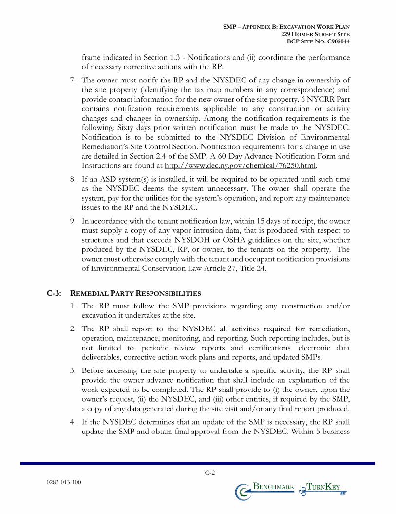
SMP – APPENDIX B: EXCAVATION WORK PLAN 229 HOMER STREET SITE
BCP SITE NO. C905044
0283-013-100
C-2
T KB
frame indicated in Section 1.3 - Notifications and (ii) coordinate the performance of necessary corrective actions with the RP.
7. The owner must notify the RP and the NYSDEC of any change in ownership of the site property (identifying the tax map numbers in any correspondence) and provide contact information for the new owner of the site property. 6 NYCRR Part contains notification requirements applicable to any construction or activity changes and changes in ownership. Among the notification requirements is the following: Sixty days prior written notification must be made to the NYSDEC. Notification is to be submitted to the NYSDEC Division of Environmental Remediation’s Site Control Section. Notification requirements for a change in use are detailed in Section 2.4 of the SMP. A 60-Day Advance Notification Form and Instructions are found at http://www.dec.ny.gov/chemical/76250.html.
8. If an ASD system(s) is installed, it will be required to be operated until such time as the NYSDEC deems the system unnecessary. The owner shall operate the system, pay for the utilities for the system’s operation, and report any maintenance issues to the RP and the NYSDEC.
9. In accordance with the tenant notification law, within 15 days of receipt, the owner must supply a copy of any vapor intrusion data, that is produced with respect to structures and that exceeds NYSDOH or OSHA guidelines on the site, whether produced by the NYSDEC, RP, or owner, to the tenants on the property. The owner must otherwise comply with the tenant and occupant notification provisions of Environmental Conservation Law Article 27, Title 24.
C-3: REMEDIAL PARTY RESPONSIBILITIES
1. The RP must follow the SMP provisions regarding any construction and/or excavation it undertakes at the site.
2. The RP shall report to the NYSDEC all activities required for remediation, operation, maintenance, monitoring, and reporting. Such reporting includes, but is not limited to, periodic review reports and certifications, electronic data deliverables, corrective action work plans and reports, and updated SMPs.
3. Before accessing the site property to undertake a specific activity, the RP shall provide the owner advance notification that shall include an explanation of the work expected to be completed. The RP shall provide to (i) the owner, upon the owner’s request, (ii) the NYSDEC, and (iii) other entities, if required by the SMP, a copy of any data generated during the site visit and/or any final report produced.
4. If the NYSDEC determines that an update of the SMP is necessary, the RP shall update the SMP and obtain final approval from the NYSDEC. Within 5 business
SMP – APPENDIX B: EXCAVATION WORK PLAN 229 HOMER STREET SITE
BCP SITE NO. C905044
0283-013-100
C-3
T KB
days after NYSDEC approval, the RP shall submit a copy of the approved SMP to the owner(s).
5. The RP shall notify the NYSDEC and the owner of any changes in RP ownership and/or control and of any changes in the party/entity responsible for the operation, maintenance, and monitoring of and reporting with respect to any remedial system (Engineering Controls). The RP shall provide contact information for the new party/entity. Such activity constitutes a Change of Use pursuant to 375-1.11(d) and requires 60-days prior notice to the NYSDEC. A 60-Day Advance Notification Form and Instructions are found at http://www.dec.ny.gov/chemical/76250.html.
6. The RP shall notify the NYSDEC of any damage to or modification of the systems as required under Section 1.3 - Notifications of the SMP.
7. The RP is responsible for the proper maintenance of any installed vapor intrusion mitigation systems associated with the site.
8. Prior to a change in use that impacts the remedial system or requirements and/or responsibilities for implementing the SMP, the RP shall submit to the NYSDEC for approval an amended SMP.
9. Any change in use, change in ownership, change in site classification (e.g., delisting), reduction or expansion of remediation, and other significant changes related to the site may result in a change in responsibilities and, therefore, necessitate an update to the SMP and/or updated legal documents. The RP shall contact the Department to discuss the need to update such documents.
Change in RP ownership and/or control and/or site ownership does not affect the
RP’s obligations with respect to the site unless a legally binding document executed by the
NYSDEC releases the RP of its obligations.
Future site owners and RPs and their successors and assigns are required to carry out
the activities set forth above.

SMP – APPENDIX B: EXCAVATION WORK PLAN 229 HOMER STREET SITE
BCP SITE NO. C905044
0311-018-001 T KB
APPENDIX D
ENVIRONMENTAL EASEMENT
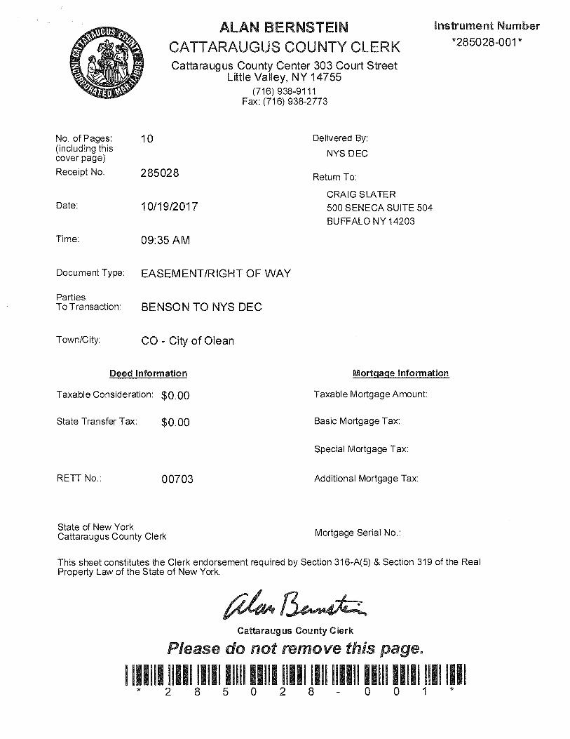
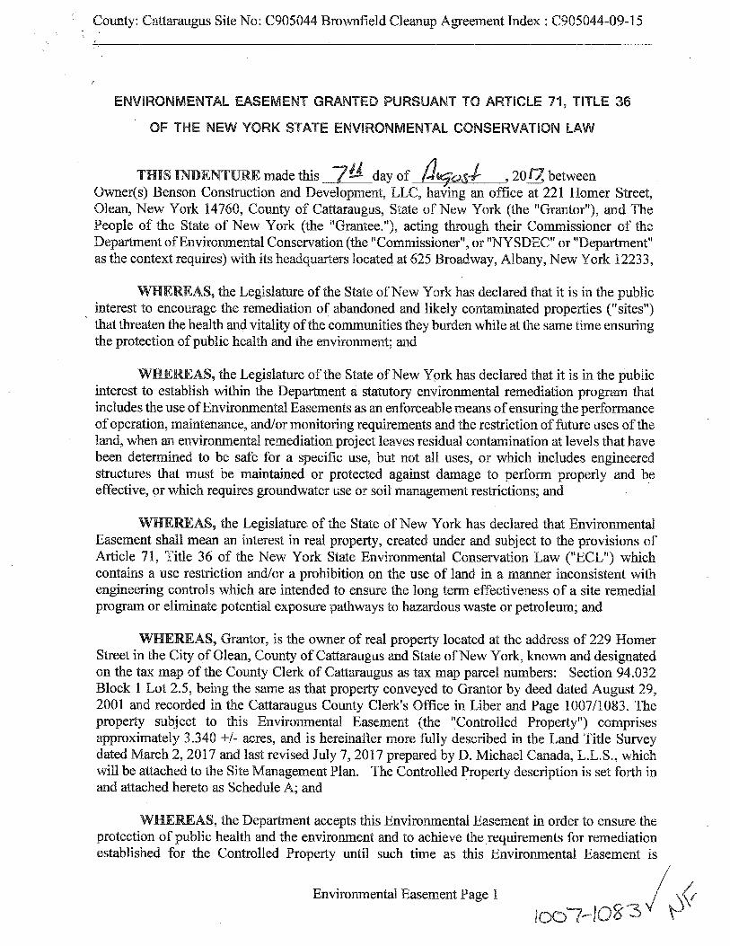
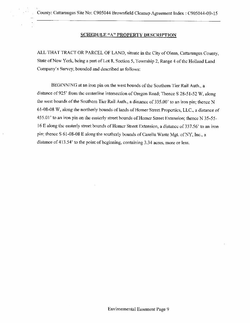
SMP – APPENDIX B: EXCAVATION WORK PLAN 229 HOMER STREET SITE
BCP SITE NO. C905044
0311-018-001 T KB
APPENDIX E
SOIL BORING LOGS &
MONITORING WELL CONSTRUCTION LOGS
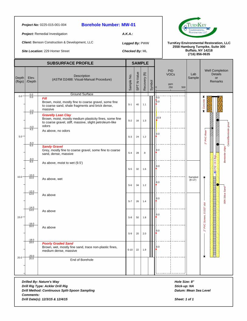
Borehole Number:
A.K.A.:
Project No:
Project:
Client:
Site Location:
Logged By:
Checked By:
Drilled By:Drill Rig Type:Drill Method:Comments:Drill Date(s):
Hole Size:Stick-up:Datum:
Sheet: 1 of 1
TurnKey Environmental Restoration, LLC2558 Hamburg Turnpike, Suite 300
Buffalo, NY 14218(716) 856-0635
SUBSURFACE PROFILE SAMPLE
Depth(fbgs)
0.0
5.0
10.0
15.0
20.0
Elev./Depth
Description(ASTM D2488: Visual-Manual Procedure)
Sam
ple
No.
SP
T N
-Val
ue
Rec
over
y (f
t)
Sym
bol
PIDVOCs Lab
Sample
Well CompletionDetails
orRemarks
MW-010225-015-001-004
Remedial Investigation
Benson Construction & Development, LLC
229 Homer Street
PWW
ML
0.00.0
-2.02.0
-4.04.0
-6.06.0
-8.08.0
-10.010.0
-12.012.0
-14.014.0
-16.016.0
-18.018.0
-20.020.0
Ground SurfaceFillBrown, moist, mostly fine to coarse gravel, some fine to coarse sand, shale fragments and brick dense, massive
Gravelly Lean ClayBrown, moist, mostly medium plasticity fines, some fine to coarse gravel, stiff, massive, slight petroleum-like odors
As above, no odors
Sandy GravelGrey, mostly fine to coarse gravel, some fine to coarse sand, dense, massive
As above, moist to wet (9.5')
As above, wet
As above
As above
As above
Poorly Graded SandBrown, wet, mostly fine sand, trace non-plastic fines, medium dense, massive
End of Borehole
S-1
S-2
S-3
S-4
S-5
S-6
S-7
S-8
S-9
S-10
40
16
24
28
32
34
26
50
20
22
1.1
1.3
1.2
.9
1.6
1.2
1.4
1.8
2.0
1.9
2500 500ppm
0.0
0.0
10.9
0.0
0.0
0.0
0.0
0.0
0.0
0.0
0.0
Sampled (8-12')
DT
W =
9.5
fb
gs
Be
nto
nite
ch
ips
Co
ncr
ete
2"
PV
C R
ise
r2
" P
VC
Scr
ee
n,
0.0
10
" sl
ot 00
N S
ilica
Sa
nd
Ce
mn
t/B
en
ton
ite g
rou
t
Nature's WayAckler Drill Rig
Continuous Split-Spoon Sampling
12/3/15 & 12/4/15
8"NA
Mean Sea Level
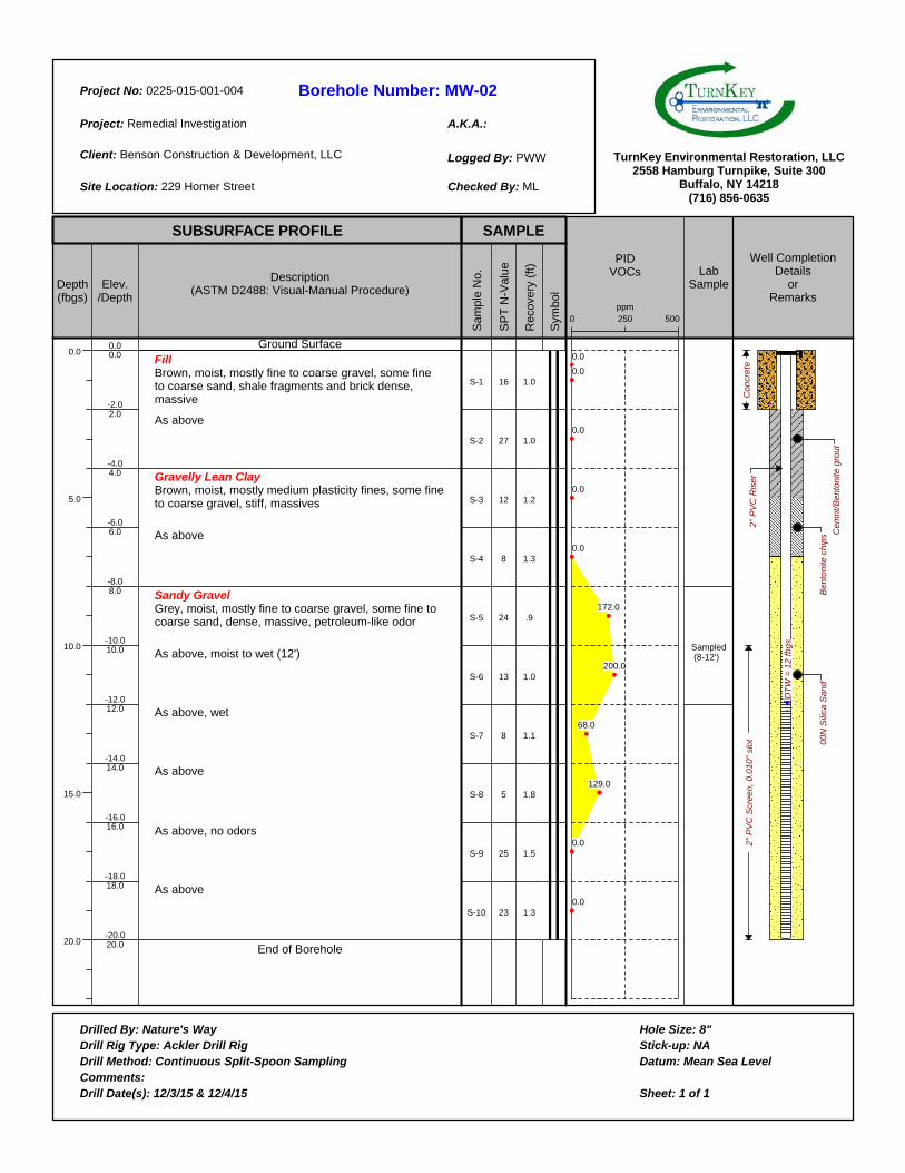
Borehole Number:
A.K.A.:
Project No:
Project:
Client:
Site Location:
Logged By:
Checked By:
Drilled By:Drill Rig Type:Drill Method:Comments:Drill Date(s):
Hole Size:Stick-up:Datum:
Sheet: 1 of 1
TurnKey Environmental Restoration, LLC2558 Hamburg Turnpike, Suite 300
Buffalo, NY 14218(716) 856-0635
SUBSURFACE PROFILE SAMPLE
Depth(fbgs)
0.0
5.0
10.0
15.0
20.0
Elev./Depth
Description(ASTM D2488: Visual-Manual Procedure)
Sam
ple
No.
SP
T N
-Val
ue
Rec
over
y (f
t)
Sym
bol
PIDVOCs Lab
Sample
Well CompletionDetails
orRemarks
MW-020225-015-001-004
Remedial Investigation
Benson Construction & Development, LLC
229 Homer Street
PWW
ML
0.00.0
-2.02.0
-4.04.0
-6.06.0
-8.08.0
-10.010.0
-12.012.0
-14.014.0
-16.016.0
-18.018.0
-20.020.0
Ground SurfaceFillBrown, moist, mostly fine to coarse gravel, some fine to coarse sand, shale fragments and brick dense, massive
As above
Gravelly Lean ClayBrown, moist, mostly medium plasticity fines, some fine to coarse gravel, stiff, massives
As above
Sandy GravelGrey, moist, mostly fine to coarse gravel, some fine to coarse sand, dense, massive, petroleum-like odor
As above, moist to wet (12')
As above, wet
As above
As above, no odors
As above
End of Borehole
S-1
S-2
S-3
S-4
S-5
S-6
S-7
S-8
S-9
S-10
16
27
12
8
24
13
8
5
25
23
1.0
1.0
1.2
1.3
.9
1.0
1.1
1.8
1.5
1.3
2500 500ppm
0.0
0.0
0.0
0.0
0.0
172.0
200.0
68.0
129.0
0.0
0.0
Sampled (8-12')
DT
W =
12
fb
gs
Be
nto
nite
ch
ips
Co
ncr
ete
2"
PV
C R
ise
r2
" P
VC
Scr
ee
n,
0.0
10
" sl
ot 00
N S
ilica
Sa
nd
Ce
mn
t/B
en
ton
ite g
rou
t
Nature's WayAckler Drill Rig
Continuous Split-Spoon Sampling
12/3/15 & 12/4/15
8"NA
Mean Sea Level
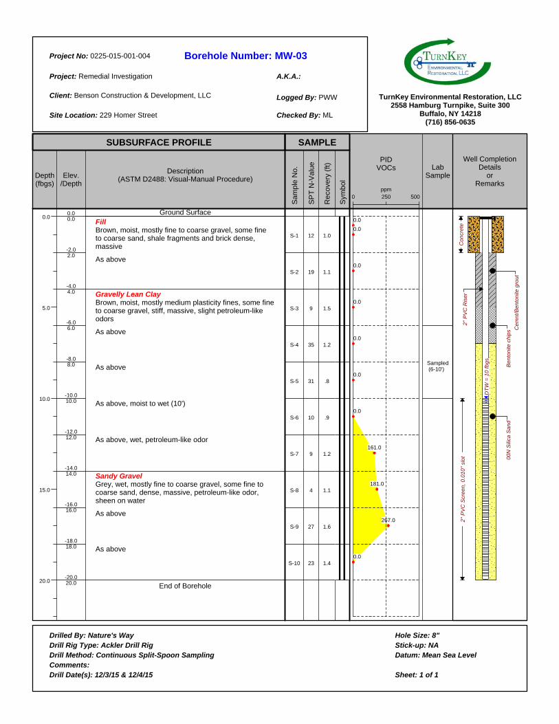
Borehole Number:
A.K.A.:
Project No:
Project:
Client:
Site Location:
Logged By:
Checked By:
Drilled By:Drill Rig Type:Drill Method:Comments:Drill Date(s):
Hole Size:Stick-up:Datum:
Sheet: 1 of 1
TurnKey Environmental Restoration, LLC2558 Hamburg Turnpike, Suite 300
Buffalo, NY 14218(716) 856-0635
SUBSURFACE PROFILE SAMPLE
Depth(fbgs)
0.0
5.0
10.0
15.0
20.0
Elev./Depth
Description(ASTM D2488: Visual-Manual Procedure)
Sam
ple
No.
SP
T N
-Val
ue
Rec
over
y (f
t)
Sym
bol
PIDVOCs Lab
Sample
Well CompletionDetails
orRemarks
MW-030225-015-001-004
Remedial Investigation
Benson Construction & Development, LLC
229 Homer Street
PWW
ML
0.00.0
-2.02.0
-4.04.0
-6.06.0
-8.08.0
-10.010.0
-12.012.0
-14.014.0
-16.016.0
-18.018.0
-20.020.0
Ground SurfaceFillBrown, moist, mostly fine to coarse gravel, some fine to coarse sand, shale fragments and brick dense, massive
As above
Gravelly Lean ClayBrown, moist, mostly medium plasticity fines, some fine to coarse gravel, stiff, massive, slight petroleum-like odors
As above
As above
As above, moist to wet (10')
As above, wet, petroleum-like odor
Sandy GravelGrey, wet, mostly fine to coarse gravel, some fine to coarse sand, dense, massive, petroleum-like odor, sheen on water
As above
As above
End of Borehole
S-1
S-2
S-3
S-4
S-5
S-6
S-7
S-8
S-9
S-10
12
19
9
35
31
10
9
4
27
23
1.0
1.1
1.5
1.2
.8
.9
1.2
1.1
1.6
1.4
2500 500ppm
0.0
0.0
0.0
0.0
0.0
0.0
0.0
161.0
181.0
267.0
0.0
Sampled (6-10')
DT
W =
10
fb
gs
Be
nto
nite
ch
ips
Co
ncr
ete
2"
PV
C R
ise
r2
" P
VC
Scr
ee
n,
0.0
10
" sl
ot 00
N S
ilica
Sa
nd
Ce
mn
t/B
en
ton
ite g
rou
t
Nature's WayAckler Drill Rig
Continuous Split-Spoon Sampling
12/3/15 & 12/4/15
8"NA
Mean Sea Level
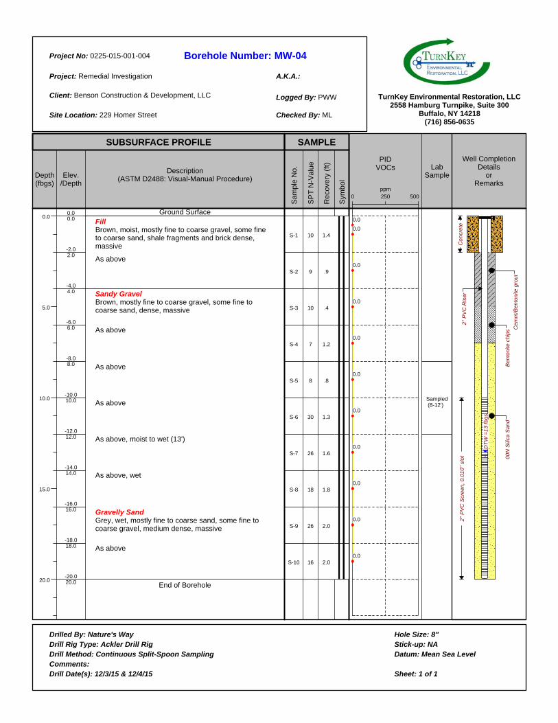
Borehole Number:
A.K.A.:
Project No:
Project:
Client:
Site Location:
Logged By:
Checked By:
Drilled By:Drill Rig Type:Drill Method:Comments:Drill Date(s):
Hole Size:Stick-up:Datum:
Sheet: 1 of 1
TurnKey Environmental Restoration, LLC2558 Hamburg Turnpike, Suite 300
Buffalo, NY 14218(716) 856-0635
SUBSURFACE PROFILE SAMPLE
Depth(fbgs)
0.0
5.0
10.0
15.0
20.0
Elev./Depth
Description(ASTM D2488: Visual-Manual Procedure)
Sam
ple
No.
SP
T N
-Val
ue
Rec
over
y (f
t)
Sym
bol
PIDVOCs Lab
Sample
Well CompletionDetails
orRemarks
MW-040225-015-001-004
Remedial Investigation
Benson Construction & Development, LLC
229 Homer Street
PWW
ML
0.00.0
-2.02.0
-4.04.0
-6.06.0
-8.08.0
-10.010.0
-12.012.0
-14.014.0
-16.016.0
-18.018.0
-20.020.0
Ground SurfaceFillBrown, moist, mostly fine to coarse gravel, some fine to coarse sand, shale fragments and brick dense, massive
As above
Sandy GravelBrown, mostly fine to coarse gravel, some fine to coarse sand, dense, massive
As above
As above
As above
As above, moist to wet (13')
As above, wet
Gravelly SandGrey, wet, mostly fine to coarse sand, some fine to coarse gravel, medium dense, massive
As above
End of Borehole
S-1
S-2
S-3
S-4
S-5
S-6
S-7
S-8
S-9
S-10
10
9
10
7
8
30
26
18
26
16
1.4
.9
.4
1.2
.8
1.3
1.6
1.8
2.0
2.0
2500 500ppm
0.0
0.0
0.0
0.0
0.0
0.0
0.0
0.0
0.0
0.0
0.0
Sampled (8-12')
DT
W =
13
fb
gs
Be
nto
nite
ch
ips
Co
ncr
ete
2"
PV
C R
ise
r2
" P
VC
Scr
ee
n,
0.0
10
" sl
ot 00
N S
ilica
Sa
nd
Ce
mn
t/B
en
ton
ite g
rou
t
Nature's WayAckler Drill Rig
Continuous Split-Spoon Sampling
12/3/15 & 12/4/15
8"NA
Mean Sea Level
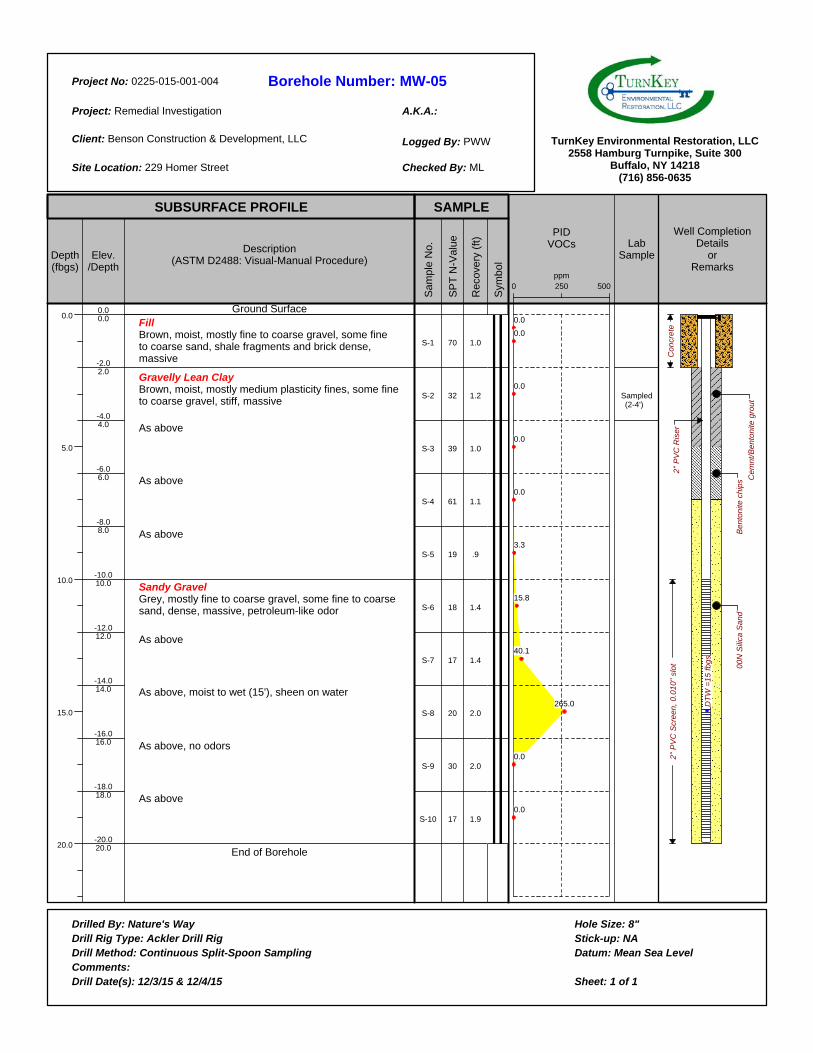
Borehole Number:
A.K.A.:
Project No:
Project:
Client:
Site Location:
Logged By:
Checked By:
Drilled By:Drill Rig Type:Drill Method:Comments:Drill Date(s):
Hole Size:Stick-up:Datum:
Sheet: 1 of 1
TurnKey Environmental Restoration, LLC2558 Hamburg Turnpike, Suite 300
Buffalo, NY 14218(716) 856-0635
SUBSURFACE PROFILE SAMPLE
Depth(fbgs)
0.0
5.0
10.0
15.0
20.0
Elev./Depth
Description(ASTM D2488: Visual-Manual Procedure)
Sam
ple
No.
SP
T N
-Val
ue
Rec
over
y (f
t)
Sym
bol
PIDVOCs Lab
Sample
Well CompletionDetails
orRemarks
MW-050225-015-001-004
Remedial Investigation
Benson Construction & Development, LLC
229 Homer Street
PWW
ML
0.00.0
-2.02.0
-4.04.0
-6.06.0
-8.08.0
-10.010.0
-12.012.0
-14.014.0
-16.016.0
-18.018.0
-20.020.0
Ground SurfaceFillBrown, moist, mostly fine to coarse gravel, some fine to coarse sand, shale fragments and brick dense, massive
Gravelly Lean ClayBrown, moist, mostly medium plasticity fines, some fine to coarse gravel, stiff, massive
As above
As above
As above
Sandy GravelGrey, mostly fine to coarse gravel, some fine to coarse sand, dense, massive, petroleum-like odor
As above
As above, moist to wet (15'), sheen on water
As above, no odors
As above
End of Borehole
S-1
S-2
S-3
S-4
S-5
S-6
S-7
S-8
S-9
S-10
70
32
39
61
19
18
17
20
30
17
1.0
1.2
1.0
1.1
.9
1.4
1.4
2.0
2.0
1.9
2500 500ppm
0.0
0.0
0.0
0.0
0.0
3.3
15.8
40.1
265.0
0.0
0.0
Sampled (2-4')
DT
W =
15
fb
gs
Be
nto
nite
ch
ips
Co
ncr
ete
2"
PV
C R
ise
r2
" P
VC
Scr
ee
n,
0.0
10
" sl
ot 00
N S
ilica
Sa
nd
Ce
mn
t/B
en
ton
ite g
rou
t
Nature's WayAckler Drill Rig
Continuous Split-Spoon Sampling
12/3/15 & 12/4/15
8"NA
Mean Sea Level
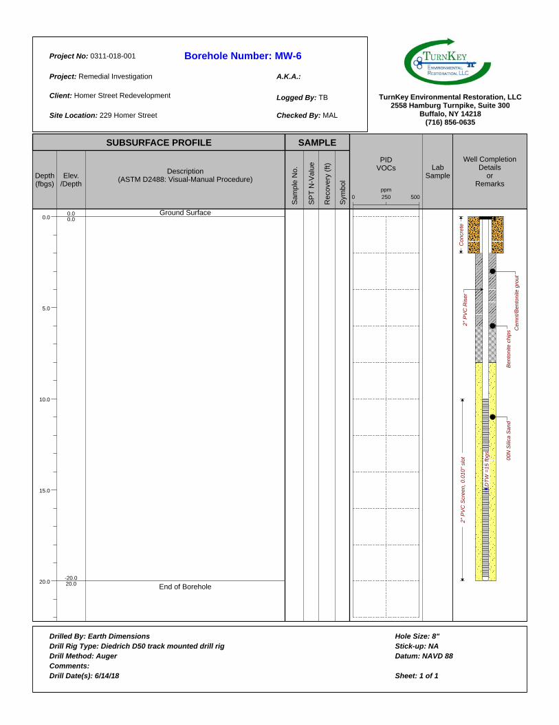
Borehole Number:
A.K.A.:
Project No:
Project:
Client:
Site Location:
Logged By:
Checked By:
Drilled By:Drill Rig Type:Drill Method:Comments:Drill Date(s):
Hole Size:Stick-up:Datum:
Sheet: 1 of 1
TurnKey Environmental Restoration, LLC2558 Hamburg Turnpike, Suite 300
Buffalo, NY 14218(716) 856-0635
SUBSURFACE PROFILE SAMPLE
Depth(fbgs)
0.0
5.0
10.0
15.0
20.0
Elev./Depth
Description(ASTM D2488: Visual-Manual Procedure)
Sa
mp
le N
o.
SP
T N
-Va
lue
Re
co
ve
ry (
ft)
Sym
bo
l
PIDVOCs Lab
Sample
Well CompletionDetails
orRemarks
MW-60311-018-001
Remedial Investigation
Homer Street Redevelopment
229 Homer Street
TB
MAL
0.00.0
-20.020.0
Ground Surface
End of Borehole
2500 500
ppm
DT
W =
15
fb
gs
Be
nto
nite
ch
ips
Co
ncr
ete
2"
PV
C R
ise
r2
" P
VC
Scr
ee
n,
0.0
10
" sl
ot 00
N S
ilica
Sa
nd
Ce
mn
t/B
en
ton
ite g
rou
t
Earth DimensionsDiedrich D50 track mounted drill rig
Auger
6/14/18
8"NA
NAVD 88
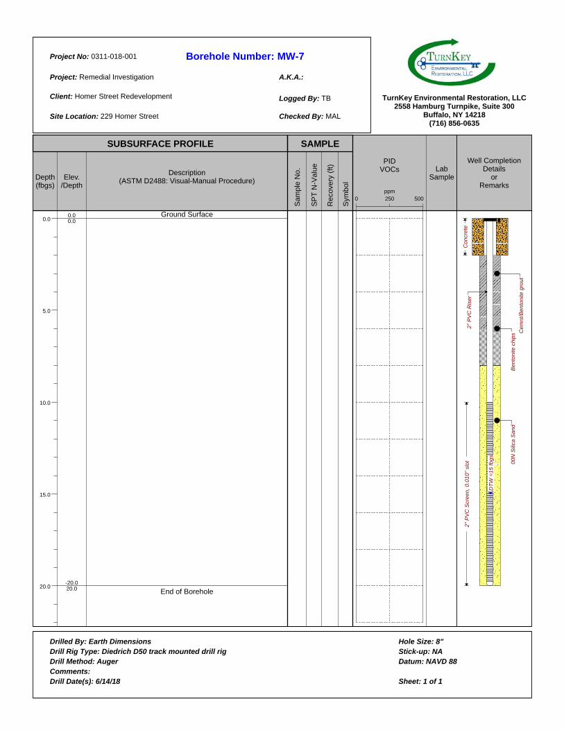
Borehole Number:
A.K.A.:
Project No:
Project:
Client:
Site Location:
Logged By:
Checked By:
Drilled By:Drill Rig Type:Drill Method:Comments:Drill Date(s):
Hole Size:Stick-up:Datum:
Sheet: 1 of 1
TurnKey Environmental Restoration, LLC2558 Hamburg Turnpike, Suite 300
Buffalo, NY 14218(716) 856-0635
SUBSURFACE PROFILE SAMPLE
Depth(fbgs)
0.0
5.0
10.0
15.0
20.0
Elev./Depth
Description(ASTM D2488: Visual-Manual Procedure)
Sa
mp
le N
o.
SP
T N
-Va
lue
Re
co
ve
ry (
ft)
Sym
bo
l
PIDVOCs Lab
Sample
Well CompletionDetails
orRemarks
MW-70311-018-001
Remedial Investigation
Homer Street Redevelopment
229 Homer Street
TB
MAL
0.00.0
-20.020.0
Ground Surface
End of Borehole
2500 500
ppm
DT
W =
15
fb
gs
Be
nto
nite
ch
ips
Co
ncr
ete
2"
PV
C R
ise
r2
" P
VC
Scr
ee
n,
0.0
10
" sl
ot 00
N S
ilica
Sa
nd
Ce
mn
t/B
en
ton
ite g
rou
t
Earth DimensionsDiedrich D50 track mounted drill rig
Auger
6/14/18
8"NA
NAVD 88

SMP – APPENDIX B: EXCAVATION WORK PLAN 229 HOMER STREET SITE
BCP SITE NO. C905044
0311-018-001 T KB
APPENDIX F
FIELD OPERATING PROCEDURES
FIELD OPERATING PROCEDURES
BENCHMARK ENVIRONMENTAL ENGINEERING & SCIENCE, PLLC
FOP
NumberDescription
004.4 Soil Vapor Sample Collection Procedure
006.0 Calibration and Maintenance of Combustible Gas/Oxygen Meter
007.0 Calibration and Maintenance of Portable Dissolved Oxygen Meter
008.0 Calibration and Maintenance of Portable Field pH/Eh Meter
009.0 Calibration and Maintenance of Portable Field Turbidity Meter
011.1 Calibration and Maintenance of Portable Photoionization Detector
012.0 Calibration and Maintenance of Portable Specific Conductance Meter
013.0 Composite Sample Collection Procedure for Non-Volatile Organic Analysis
015.0 Documentation Requirements for Drilling and Well Installation
017.0 Drill Site Selection Procedure
018.0 Drilling and Excavation Equipment Decontamination Procedures
021.0 Establishing Horizontal and Vertical Control
022.0 Groundwater Level Measurement
023.1 Groundwater Purging Procedures Prior to Sample Collection
024.1 Groundwater Sample Collection Procedures
025.0 Hand Augering Procedure
026.1 Hollow Stem Auger (HSA) Drilling Procedures
031.2 Low Flow (Minimal Drawdown) Groundwater Purging & Sampling Procedure
032.1 Management of Investigation-Derived Waste (IDW)
033.0 Monitoring Well Construction for Hollow Stem Auger Boreholes
036.0 Monitoring Well Development Procedures
037.0 Monitoring Well Retrofitting Procedures
039.1 NAPL Detection and Sample Collection Procedure
040.1 Non-Disposable and Non-Dedicated Sampling Equipment Decontamination
046.0 Sample Labeling, Storage and Shipment Procedures
047.0 Screening of Soil Samples for Organic Vapors During Drilling Activities
054.2 Soil Description Procedures Using The Visual-Manual Method
058.0 Split-Spoon Sampling Procedures
060.0 Storm Water/Sediment Sampling Procedures
063.2 Surface and Subsurface Soil Sampling Procedures
064.0 Surface Water Sampling Procedures
065.1 Test Pit Excavation and Logging Procedures
073.2 Real-Time Air Monitoring During Intrusive Activities
076.0 "Before Going Into the Field" Procedure
078.0 Geoprobe Drilling Procedures
079.0 Stockpile Sampling Procedures for Chemical Analysis
080.0 Stockpile-Borrow Source Sampling Procedures for Physical Analysis
082.0 Waste Sampling Procedures
083.0 Active Subslab Depressurization Pre-Design Testing Procedure
084.0 Calibration and Maintenance of Portable Particulate Meter
085.0 Field Quality Control Procedures
089.0 SVE System Sample Collection Procedure
090.0 Outdoor Ambient Air VOC Sample Collection Procedure
Notes:
1. FOPs are identified by the sequential FOP number and revision number. For example, FOP number 097.3 indicates FOP 9
Bn v i r o n m e t a ln g i n e e r i n gc e n c e ,i
n
Page 1 of 1

FIE
LD
OP
ER
AT
ING
PR
OC
ED
UR
ES
Soil Vapor Sample Collection Procedures
Bn v i ronme talng i neeri n gc ence,i
n
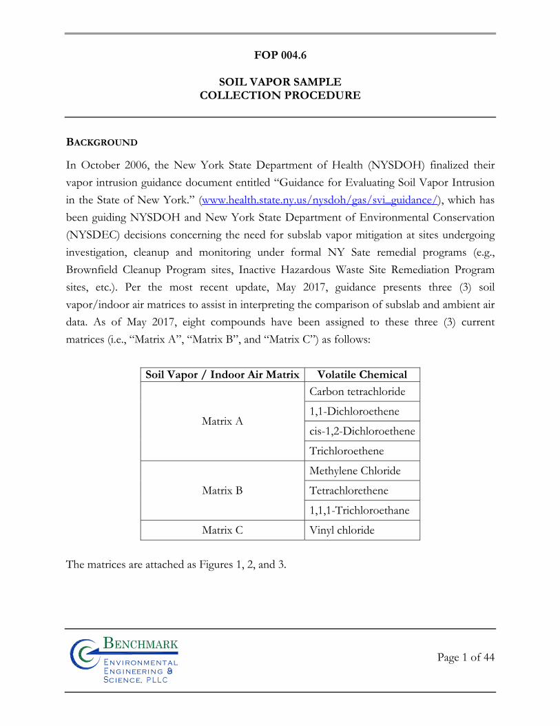
FOP 004.6
SOIL VAPOR SAMPLE
COLLECTION PROCEDURE
Page 1 of 44
Bn v i ronme talng i neeri n gc ence,i
n
BACKGROUND
In October 2006, the New York State Department of Health (NYSDOH) finalized their
vapor intrusion guidance document entitled “Guidance for Evaluating Soil Vapor Intrusion
in the State of New York.” (www.health.state.ny.us/nysdoh/gas/svi_guidance/), which has
been guiding NYSDOH and New York State Department of Environmental Conservation
(NYSDEC) decisions concerning the need for subslab vapor mitigation at sites undergoing
investigation, cleanup and monitoring under formal NY Sate remedial programs (e.g.,
Brownfield Cleanup Program sites, Inactive Hazardous Waste Site Remediation Program
sites, etc.). Per the most recent update, May 2017, guidance presents three (3) soil
vapor/indoor air matrices to assist in interpreting the comparison of subslab and ambient air
data. As of May 2017, eight compounds have been assigned to these three (3) current
matrices (i.e., “Matrix A”, “Matrix B”, and “Matrix C”) as follows:
Soil Vapor / Indoor Air Matrix Volatile Chemical
Matrix A
Carbon tetrachloride
1,1-Dichloroethene
cis-1,2-Dichloroethene
Trichloroethene
Matrix B
Methylene Chloride
Tetrachlorethene
1,1,1-Trichloroethane
Matrix C Vinyl chloride
The matrices are attached as Figures 1, 2, and 3.
FOP 004.6
SOIL VAPOR SAMPLE
COLLECTION PROCEDURE
Page 2 of 44
Bn v i ronme talng i neeri n gc ence,i
n
PURPOSE
The procedures presented herein delineate the scope of additional investigation at a building
on the project site to determine if volatile organic compounds (VOCs) detected in
groundwater and/or soil near the building are intruding into the building airspace or have
the potential, in sufficient concentrations, to adversely impact indoor air quality. The soil
vapor, subslab vapor, and ambient air monitoring procedures follow the NYSDOH Final
Soil Vapor Intrusion Guidance (October 2006) as well as USEPA Methods TO-14 and TO-
15, for volatile organic compounds (VOCs) using Summa passive canisters.
SURVEYS AND PRE-SAMPLING BUILDING PREPARATION (IF REQUIRED)
If required, a pre-sampling inspection should be performed prior to each sampling event to
identify and minimize conditions that may interfere with the proposed testing. The
inspection should evaluate the type of structure, floor layout, airflows, and physical
conditions of the building(s) being studied. This information, along with information on
sources of potential indoor air contamination, should be identified on a building inventory
form. An example of the building inventory form is attached. Items to be included in the
building inventory include the following:
Construction characteristics, including foundation cracks and utility penetrations or other openings that may serve as preferential pathways for vapor intrusion;
Presence of an attached garage;
Recent renovations or maintenance to the building (e.g., fresh paint, new carpet
or furniture);
Mechanical equipment that can affect pressure gradients (e.g., heating systems, clothes dryers or exhaust fans);
FOP 004.6
SOIL VAPOR SAMPLE
COLLECTION PROCEDURE
Page 3 of 44
Bn v i ronme talng i neeri n gc ence,i
n
Use or storage of petroleum products (e.g., fuel containers, gasoline operated equipment and unvented kerosene heaters); and
Recent use of petroleum-based finishes or products containing volatile chemicals.
Each room on the floor of the building being tested and on lower floors, if possible, should
be inspected. This is important because even products stored in another area of a building
can affect the air of the room being tested.
The presence and description of odors (e.g., solvent, moldy) and portable vapor monitoring
equipment readings (e.g., PIDs, ppb RAE, Jerome Mercury Vapor Analyzer, etc.) should be
noted and used to help evaluate potential sources. This includes taking readings near
products stored or used in the building.
Potential interference from products or activities releasing volatile chemicals may need to be
controlled. Removing the source from the indoor environment prior to testing is the most
effective means of reducing interference. Ensuring that containers are tightly sealed may be
acceptable. When testing for volatile organic compounds, containers should be tested with
portable vapor monitoring equipment to determine whether compounds are leaking. The
inability to eliminate potential interference may be justification for not testing, especially
when testing for similar compounds at low levels. The investigator should consider the
possibility that chemicals may adsorb onto porous materials and may take time to dissipate.
In some cases, the goal of the testing is to evaluate the impact from products used or stored
in the building (e.g., pesticide misapplications, school renovation projects). If the goal of the
testing is to determine whether products are an indoor volatile chemical contaminant source,
the removing these sources does not apply.
FOP 004.6
SOIL VAPOR SAMPLE
COLLECTION PROCEDURE
Page 4 of 44
Bn v i ronme talng i neeri n gc ence,i
n
Once interfering conditions are corrected (if applicable), ventilation may be needed prior to
sampling to eliminate residual contamination in the indoor air. If ventilation is appropriate, it
should be completed 24 hours or more prior to the scheduled sampling time. Where
applicable, ventilation can be accomplished by operating the building’s HVAC system to
maximize outside air intake. Opening windows and doors, and operating exhaust fans may
also help or may be needed if the building has no HVAC system.
Air samples are sometimes designed to represent typical exposure in a mechanically
ventilated building and the operation of HVAC systems during sampling should be noted on
the building inventory form (see attached sample). In general, the building’s HVAC system
should be operating under normal conditions. Unnecessary building ventilation should be
avoided within 24 hours prior to and during sampling. During colder months, heating
systems should be operating to maintain normal indoor air temperatures (i.e., 65 – 75 °F) for
at least 24 hours prior to and during the scheduled sampling time.
Depending upon the goal of the indoor air sampling, some situations may warrant deviation
from the above protocol regarding building ventilation. In such cases, building conditions
and sampling efforts should be understood and noted within the framework and scope of
the investigation.
To avoid potential interferences and dilution effects, every effort should be made to avoid
the following for 24 hours prior to sampling:
Opening any windows, fireplace dampers, openings or vents; Operating ventilation fans unless special arrangements are made; Smoking in the building; Painting; Using a wood stove, fireplace or other auxiliary heating equipment (e.g., kerosene
heater); Operating or storing automobile in an attached garage;
FOP 004.6
SOIL VAPOR SAMPLE
COLLECTION PROCEDURE
Page 5 of 44
Bn v i ronme talng i neeri n gc ence,i
n
Allowing containers of gasoline or oil to remain within the house or garage area, except for fuel oil tanks;
Cleaning, waxing or polishing furniture, floors or other woodwork with petroleum- or oil-based products;
Using air fresheners, scented candles or odor eliminators; Engaging in any hobbies that use materials containing volatile chemicals; Using cosmetics including hairspray, nail polish, nail polish removers,
perfume/cologne, etc.; Lawn mowing, paving with asphalt, or snow blowing; Applying pesticides; and Using building repair or maintenance products, such as caulk or roofing tar.
PRODUCT INVENTORY (IF REQUIRED)
If required, the primary objective of the product inventory is to identify potential air
sampling interference by characterizing the occurrence and use of chemicals and products
throughout the building, keeping in mind the goal of the investigation and site-specific
contaminants of concern. For example, it is not necessary to provide detailed information
for each individual container of like items. However, it is necessary to indicate that "20
bottles of perfume" or "12 cans of latex paint" were present with containers in good
condition. This information is used to help formulate an indoor environment profile.
An inventory should be provided for each room on the floor of the building being tested
and on lower floors, if possible. This is important because even products stored in another
area of a building can affect the air of the room being tested.
The presence and description of odors (e.g., solvent, moldy) and portable vapor monitoring
equipment readings (e.g., PIDs, ppb RAE, Jerome Mercury Vapor Analyzer, etc.) should be
noted and used to help evaluate potential sources. This includes taking readings near
products stored or used in the building. Products in buildings should be inventoried every
FOP 004.6
SOIL VAPOR SAMPLE
COLLECTION PROCEDURE
Page 6 of 44
Bn v i ronme talng i neeri n gc ence,i
n
time air is tested to provide an accurate assessment of the potential contribution of volatile
chemicals. If available, chemical ingredients of interest (e.g., analyte list) should be recorded
for each product. If the ingredients are not listed on the label, record the product's exact and
full name, and the manufacturer's name, address and telephone number, if available. In some
cases, Material Safety Data Sheets (MSDS) may be useful for identifying confounding
sources of volatile chemicals in air. Adequately documented photographs of the products
and their labeled ingredients can supplement the inventory and facilitate recording the
information.
SAMPLE LOCATIONS
The following are types of samples that are collected to investigate the soil vapor intrusion
pathway:
Subsurface vapor samples: - Soil vapor samples (i.e., soil vapor samples not beneath the foundation or slab
of a building) and - Sub-slab vapor samples (i.e., soil vapor samples immediately beneath the
foundation or slab of a building); Indoor air samples; and Outdoor air samples.
The types of samples that should be collected depend upon the specific objective(s) of the
sampling, as described below.
Soil vapor Soil vapor samples are collected to determine whether this environmental medium is contaminated, characterize the nature and extent of contamination, and identify possible sources of the contamination. Soil vapor sampling results are used when evaluating the following: - The potential for current human exposures; - The potential for future human exposures (e.g., should a building be
constructed); and
FOP 004.6
SOIL VAPOR SAMPLE
COLLECTION PROCEDURE
Page 7 of 44
Bn v i ronme talng i neeri n gc ence,i
n
- The effectiveness of measures implemented to remediate contaminated subsurface vapors.
Sub-slab vapor
Sub-slab vapor samples are collected to characterize the nature and extent of soil vapor contamination immediately beneath a building with a basement foundation and/or a slab-on-grade. Sub-slab vapor sampling results are used when evaluating the following: - Current human exposures; - The potential for future human exposures (e.g., if the structural integrity of the
building changes or the use of the building changes); and - Site-specific attenuation factors (i.e., the ratio of indoor air to sub-slab vapor
concentrations). Sub-slab vapor samples are collected after soil vapor characterization and/or other environmental sampling (e.g., soil and groundwater characterization) indicate a need. Subslab samples are typically collected concurrently with indoor and outdoor air samples. However, outside of the heating season, sub-slab vapor samples may be collected independently depending on the sampling objective (e.g., characterize the extent of subsurface vapor contamination outside of the heating season to develop a more comprehensive, focused investigation plan for the heating season).
Indoor air
Indoor air samples are collected to characterize exposures to air within a building, including those with earthen floors and crawlspaces. Indoor air sampling results are used when evaluating the following: - Current human exposures; - The potential for future exposures (e.g., if a currently vacant building should
become occupied); and - Site-specific attenuation factors (e.g., the ratio of indoor air to sub-slab vapor
concentrations). Indoor air samples are collected after subsurface vapor characterization and other environmental sampling (e.g., soil and groundwater characterization) indicate a need. When indoor air samples are collected, concurrent sub-slab vapor and
FOP 004.6
SOIL VAPOR SAMPLE
COLLECTION PROCEDURE
Page 8 of 44
Bn v i ronme talng i neeri n gc ence,i
n
outdoor air samples are collected to evaluate the indoor air results appropriately. However, indoor air and outdoor air samples, without sub-slab vapor samples, may be collected when confirming the effectiveness of a mitigation system.
In addition, site-specific situations may warrant collecting indoor air samples prior to characterizing subsurface vapors and/or without concurrent sub-slab sampling due to a need to examine immediate inhalation hazards. Examples of such situations may include, but are not limited to, the following: - In response to a spill event when there is a need to qualitatively and/or
quantitatively characterize the contamination; - If high readings are obtained in a building when screening with field
equipment (e.g., a photoionization detector (PID), an organic vapor analyzer, or an explosimeter) and the source is unknown;
- If significant odors are present and the source needs to be characterized; or - If groundwater beneath the building is contaminated, the building is prone to
groundwater intrusion or flooding (e.g., sump pit overflows), and subsurface vapor sampling is not feasible.
Outdoor air
Outdoor air samples are collected to characterize site-specific background outdoor air conditions. These samples must be collected simultaneously with indoor air samples. They may also be collected concurrently with soil vapor samples. Outdoor air sampling results are primarily used when evaluating the extent to which outdoor sources may be influencing indoor air quality. They may also be used in the evaluation of soil vapor results (i.e., to identify potential outdoor air interferences associated with the infiltration of outdoor air into the sampling apparatus while the soil vapor sample was collected).
FOP 004.6
SOIL VAPOR SAMPLE
COLLECTION PROCEDURE
Page 9 of 44
Bn v i ronme talng i neeri n gc ence,i
n
SOIL VAPOR SAMPLE COLLECTION PROCEDURES
Soil vapor probe installations (see Figure 4 attached) may be permanent, semi-permanent, or
temporary. In general, permanent installations are preferred for data consistency reasons.
Soil implants or probes should be constructed in the same manner at all sampling locations
to minimize possible discrepancies. The following procedures should be included in any
construction protocol:
Soil vapor probes should be installed using direct push technology or, if necessary to attain the desired depth, using an auger;
Porous backfill material (e.g., glass beads or coarse sand) should be used to create a sampling zone 1 to 2 feet in length;
Soil vapor probes should be fitted with inert tubing (e.g., polyethylene, stainless
steel, or Teflon®) of the appropriate size (typically 1/8 inch to 1/4 inch diameter) and of laboratory or food grade quality to the surface;
Soil vapor probes should be sealed above the sampling zone with a bentonite
slurry for a minimum distance of 3 feet to prevent outdoor air infiltration and the remainder of the borehole backfilled with clean material;
For multiple probe depths, the borehole should be grouted with bentonite
between probes to create discrete sampling zones; and
For permanent installations, a protective casing should be set around the top of the probe tubing and grouted in place to the top of bentonite to minimize infiltration of water or outdoor air, as well as to prevent accidental damage.
Soil vapor samples should be collected in the same manner at all locations to minimize
possible discrepancies. The following procedures should be included in any sampling
protocol:
At least 24 hours after the installation of permanent probes and shortly after the installation of temporary probes, one to three implant volumes (i.e., the volume of
FOP 004.6
SOIL VAPOR SAMPLE
COLLECTION PROCEDURE
Page 10 of 44
Bn v i ronme talng i neeri n gc ence,i
n
the sample probe and tube) must be purged prior to collecting the samples to ensure samples collected are representative;
Flow rates for both purging and collecting must not exceed 0.2 liters per minute
to minimize outdoor air infiltration during sampling;
The target final field vacuum after 24 hours will be approximately -5 inches of mercury. Samples with a final field vacuum of greater than -10 inches of mercury, or equal to zero, will be flagged (usability of data will depend on sample volume and reporting limits that can be achieved).
Samples must be collected, using conventional sampling methods, in an
appropriate container — one which meets the objectives of the sampling (e.g., investigation of areas where low or high concentrations of volatile chemicals are expected; to minimize losses of volatile chemicals that are susceptible to photodegradation), meets the requirements of the sampling and analytical methods (e.g., low flow rate; Summa® canisters if analyzing by using EPA Method TO-15), and is certified clean by the laboratory;
Sample size depends upon the volume of sample required to achieve minimum
reporting limit requirements; and
A tracer gas (e.g., helium, butane, or sulfur hexafluoride) must be used when collecting soil vapor samples to verify that adequate sampling techniques are being implemented (i.e., to verify infiltration of outdoor air is not occurring) (discussed later in this procedure). Once verified, continued use of the tracer gas may be reconsidered.
When soil vapor samples are collected, the following actions should be taken to document
local conditions during sampling that may influence interpretation of the results:
If sampling near a commercial or industrial building, uses of volatile chemicals during normal operations of the facility should be identified;
FOP 004.6
SOIL VAPOR SAMPLE
COLLECTION PROCEDURE
Page 11 of 44
Bn v i ronme talng i neeri n gc ence,i
n
Outdoor plot sketches should be drawn that include the site, area streets, neighboring commercial or industrial facilities (with estimated distance to the site), outdoor ambient air sample locations (if applicable), and compass orientation (north);
Weather conditions (e.g., precipitation, outdoor temperature, barometric pressure,
wind speed and direction) should be noted for the past 24 to 48 hours; and
Any pertinent observations should be recorded, such as odors and readings from field instrumentation.
The field sampling team must maintain a sample log sheet summarizing the following:
Sample identification, Date and time of sample collection, Sampling depth, Identity of samplers, Sampling methods and devices, Purge volumes, Volume of soil vapor extracted, If canisters used, the vacuum before and after samples collected, Apparent moisture content (dry, moist, saturated, etc.) of the sampling zone, and Chain of custody protocols and records used to track samples from sampling
point to analysis.
SUB-SLAB VAPOR SAMPLE COLLECTION PROCEDURES
During colder months, heating systems should be operating to maintain normal indoor air
temperatures (i.e., 65 – 75 °F) for at least 24 hours prior to and during the scheduled
sampling time. Prior to installation of the sub-slab vapor probe, the building floor should be
inspected and any penetrations (cracks, floor drains, utility perforations, sumps, etc.) should
be noted and recorded. Probes should be installed at locations where the potential for
ambient air infiltration via floor penetrations is minimal.
FOP 004.6
SOIL VAPOR SAMPLE
COLLECTION PROCEDURE
Page 12 of 44
Bn v i ronme talng i neeri n gc ence,i
n
Sub-slab vapor probe installations (see Figure 5 attached) may be permanent, semi-
permanent, or temporary. Sub-slab implants or probes should be constructed in the same
manner at all sampling locations to minimize possible discrepancies. The following
procedures should be included in any construction protocol:
Permanent recessed probes must be constructed with brass or stainless steel tubing and fittings;
Temporary probes must be constructed with polyethylene or Teflon® tubing of laboratory or food grade quality;
Tubing should not extend further than 2 inches into the sub-slab material; Coarse sand or glass beads should be added to cover about 1 inch of the probe tip
for permanent installations; and The soil vapor probe should be sealed to the surface with permagum grout,
melted beeswax, putty or other non-VOC-containing and non-shrinking products for temporary installations or cement for permanent installations.
Sub-slab vapor samples should be collected in the following manner:
After installation of the probes, one to three volumes (i.e., the volume of the sample probe and tube) must be purged prior to collecting the samples to ensure samples collected are representative;
Flow rates for both purging and collecting must not exceed 0.2 liters per minute to minimize outdoor air infiltration during sampling;
The target final field vacuum after 24 hours will be approximately -5 inches of mercury. Samples with a final field vacuum of greater than -10 inches of mercury, or equal to zero, will be flagged (usability of data will depend on sample volume and reporting limits that can be achieved).
Samples must be collected, using conventional sampling methods, in an appropriate container — one which meets the objectives of the sampling (e.g., investigation of areas where low or high concentrations of volatile chemicals are expected; to minimize losses of volatile chemicals that are susceptible to photodegradation), meets the requirements of the sampling and analytical methods (e.g., low flow rate; Summa® canisters if analyzing by using EPA Method TO-15), and is certified clean by the laboratory;
FOP 004.6
SOIL VAPOR SAMPLE
COLLECTION PROCEDURE
Page 13 of 44
Bn v i ronme talng i neeri n gc ence,i
n
Sample size depends upon the volume of sample required to achieve minimum reporting limit requirements [Section 2.9 of the Guidance], the flow rate, and the sampling duration; and
Ideally, samples should be collected over the same period of time as concurrent indoor and outdoor air samples.
When sub-slab vapor samples are collected, the following actions should be taken to
document conditions during sampling and ultimately to aid in the interpretation of the
sampling results:
If sampling within a commercial or industrial building, uses of volatile chemicals in commercial or industrial processes and/or during building maintenance, should be identified;
The use of heating or air conditioning systems during sampling should be noted; Floor plan sketches should be drawn that include the floor layout with sample
locations, chemical storage areas, garages, doorways, stairways, location of basement sumps or subsurface drains and utility perforations through building foundations, HVAC system air supply and return registers, compass orientation (north), and any other pertinent information should be completed;
If possible, photographs should accompany floor plan sketches; Outdoor plot sketches should be drawn that include the building site, area streets,
outdoor air sample locations (if applicable), compass orientation (north), footings that create separate foundation sections, and paved areas;
Weather conditions (e.g., precipitation, indoor and outdoor temperature, and barometric pressure) and ventilation conditions (e.g., heating system active and windows closed) should be reported;
Smoke tubes or other devices should be used to confirm pressure relationships and air flow patterns, especially between floor levels and between suspected contaminant sources and other areas; and
Any pertinent observations, such as spills, floor stains, smoke tube results, odors and readings from field instrumentation (e.g., vapors via PID, ppb RAE, Jerome Mercury Vapor Analyzer, etc.), should be recorded.
FOP 004.6
SOIL VAPOR SAMPLE
COLLECTION PROCEDURE
Page 14 of 44
Bn v i ronme talng i neeri n gc ence,i
n
The field sampling team must maintain a sample log sheet summarizing the following:
Sample identification, Date and time of sample collection, Sampling depth, Identity of samplers, Sampling methods and devices, Soil vapor purge volumes, Volume of soil vapor extracted, If canisters used, the vacuum before and after samples collected, Apparent moisture content (dry, moist, saturated, etc.) of the sampling zone, and Chain of custody protocols and records used to track samples from sampling
point to analysis. The following describes the subslab air sampling procedure:
1. Canisters will be supplied by the laboratory that will be conducting the analysis.
2. Sampling will take place in accordance with the project work plan sufficiently
spaced to allow locations to be modified, if necessary.
3. The number of Summa canisters required as well as the flow rate of the constant differential low volume flow controllers will be supplied by the laboratory in accordance with the project work plan.
4. The sampling program will consist of concurrently collecting and analyzing
one sub-slab vapor sample and one indoor ambient air sample (discussed in the next section). Sample locations should be selected based on the likelihood for potential continuous human occupancy during the workday (i.e., due to the size of the areas and available infrastructure), and to account for the possibility of varying foundation depths in different areas of the building. In addition, sample locations typically are based upon the results of a subsurface investigation (i.e., soil gas survey or boring advancement) conducted prior to air sample collection activities. Canisters are typically placed in areas where the highest concentrations of soil gas were observed. Indoor air sample locations
FOP 004.6
SOIL VAPOR SAMPLE
COLLECTION PROCEDURE
Page 15 of 44
Bn v i ronme talng i neeri n gc ence,i
n
preferably should be selected near the middle of the sampled room, well away from the edges where dilution is more likely to occur.
5. Collect at least one outdoor ambient air sample from a location on the
building roof or designated background area of the site positioned away from building ventilation system equipment on the highest portion of the building roof or site. See the Outdoor Ambient Air Sampling Procedure section in this procedure.
6. Field personnel should assure conservative sampling conditions prior to and
throughout the sampling event. The building should be closed (windows and doors shut) and existing building ventilation systems should be turned off 12 to 24 hours before the air sampling is scheduled to begin as well as during sample collection. Any air-handling units that may induce large pressure gradients (i.e., exhaust fans, HVAC units etc.) should also be turned off.
7. Any activity being conducted by current building tenants involving volatile
organic compounds, such as the use of lacquer thinner and cleaning solvents, prior to and/or during air sampling activities should be noted in the Project Field Book. These activities have the potential to bias the analytical results.
8. At each location, drill an approximately ¾-inch diameter hole through the
concrete slab (typically 6-8 inches thick) using a hand-held hammer drill.
9. Measure and record the concrete thickness in the Project Field Book.
10. Insert polyethylene or Teflon® tubing of laboratory or food grade quality into the drilled hole and no further than 2 inches into the subslab material.
11. Seal the tubing with an appropriately sized volatile organic compound-free
stopper (i.e., permagum grout, melted beeswax, putty, or other non-VOC-containing and non-shrinking product) into the concrete core hole and secure in-place making sure the fit is very snug. Supplement any visible gaps between the stopper and concrete slab with a VOC-free sealant, such as beeswax or bentonite slurry.
FOP 004.6
SOIL VAPOR SAMPLE
COLLECTION PROCEDURE
Page 16 of 44
Bn v i ronme talng i neeri n gc ence,i
n
12. Run the tubing assembly through a shroud (plastic pail, cardboard box, or garbage bag) creating a tight seal with the surface making sure not to disturb the seal around the tubing penetration.
13. Enrich the atmosphere of the shroud with helium. Measure and record the
helium concentration within the shroud.
14. Purge approximately 1 to 3 tubing volumes (i.e., the volume of the sample probe and tube) using a hand pump (or similar approved device) to ensure the collection of a representative sample.
15. Flow rates for both purging and sample collection must not exceed 0.2 liters
per minute to minimize outdoor air infiltration during sampling.
16. Use a portable monitoring device to analyze a sample of soil vapor for the tracer prior to and after sampling for the compounds of concern. Note that the tracer gas samples can be collected via syringe, Tedlar bag etc. They need not be collected in Summa® canisters or minicans.
17. If concentrations greater than 10% of tracer gas are observed either prior to
and/or after sampling, the probe seal should be enhanced to reduce the infiltration of outdoor air. Following enhancement of the seal, repeat steps 14 through 17 above until purged concentrations are less than 10% of the tracer gas within the shroud.
18. Following tubing purge and adequate seal integrity testing via helium tracer
gas, immediately attach a 6-liter Summa Canister fitted with a 24-hour regulator (or approved other duration) to the opposite end of the tubing. Concurrent with each subslab sample location, prepare an indoor ambient air sample by staging a second Summa Canister on a ladder (approximately 2 to 5-feet above the floor) adjacent to the sub-slab sample location.
19. All Summa Canister valves should remain closed until all subslab borings are
complete and all of the canisters in their respective positions.
FOP 004.6
SOIL VAPOR SAMPLE
COLLECTION PROCEDURE
Page 17 of 44
Bn v i ronme talng i neeri n gc ence,i
n
20. Open the valves to all of the canisters for the required collection period (i.e., 24-hours). Record initial canister pressure on the Air Canister Field Record form.
21. Following sample collection and prior to closing canister valve, record final
canister pressure on the Air Canister Field Record form. Close canister valve.
22. Collect all Summa Canisters and ship, under chain-of-custody command to an approved analytical laboratory for VOC analysis in accordance with USEPA Method TO-14 or TO-15.
23. Repair all concrete openings with a cement patch.
24. Analytical results submitted by the laboratory should be reported as
concentrations of each VOC at each location, typically in parts per billion by volume (ppbv).
INDOOR AIR SAMPLE COLLECTION PROCEDURES
During colder months, heating systems should be operating to maintain normal indoor air
temperatures (i.e., 65 – 75 °F) for at least 24 hours prior to and during the scheduled
sampling time. If possible, prior to collecting indoor samples, a pre-sampling inspection,
discussed earlier in this procedure, should be performed to evaluate the physical layout and
conditions of the building being investigated, to identify conditions that may affect or
interfere with the proposed sampling, and to prepare the building for sampling.
In general, indoor air samples should be collected in the following manner:
Sampling duration should reflect the exposure scenario being evaluated without compromising the detection limit or sample collection flow rate (e.g., an 8 hour sample from a workplace with a single shift versus a 24 hour sample from a workplace with multiple shifts). To ensure that air is representative of the locations sampled and to avoid undue influence from sampling personnel, samples should be collected for at least 1 hour. If the goal of the sampling is to
FOP 004.6
SOIL VAPOR SAMPLE
COLLECTION PROCEDURE
Page 18 of 44
Bn v i ronme talng i neeri n gc ence,i
n
represent average concentrations over longer periods, then longer duration sampling periods may be appropriate. Typically, 24 hour samples are collected from residential settings;
Personnel should avoid lingering in the immediate area of the sampling device
while samples are being collected;
Sample flow rates must conform to the specifications in the sample collection method and, if possible, should be consistent with the flow rates for concurrent outdoor air and sub-slab samples;
The target final field vacuum after 24 hours will be approximately -5 inches of mercury. Samples with a final field vacuum of greater than -10 inches of mercury, or equal to zero, will be flagged (usability of data will depend on sample volume and reporting limits that can be achieved); and
Samples must be collected, using conventional sampling methods, in an
appropriate container — one which meets the objectives of the sampling (e.g., investigation of areas where low or high concentrations of volatile chemicals are expected; to minimize losses of volatile chemicals that are susceptible to photodegradation), meets the requirements of the sampling and analytical methods (e.g., low flow rate; Summa® canisters if analyzing by using EPA Method TO-15), and is certified clean by the laboratory.
At sites with tetrachloroethene contamination, passive air monitors that are specifically
analyzed for tetrachloroethene (i.e., "perc badges") are commonly used to collect indoor and
outdoor air samples. If site characterization activities indicate that degradation products of
tetrachloroethene also represent a vapor intrusion concern, perc badges may be used to
indicate the likelihood of vapor intrusion (i.e., by using tetrachloroethene as a surrogate)
followed, as needed, by more comprehensive sampling and laboratory analyses to quantify
both tetrachloroethene and its degradation products. Perc badge samples ideally should be
collected over a twenty-four hour period, but for no less than eight hours.
FOP 004.6
SOIL VAPOR SAMPLE
COLLECTION PROCEDURE
Page 19 of 44
Bn v i ronme talng i neeri n gc ence,i
n
The following actions should be taken to document conditions during indoor air sampling
and ultimately to aid in the interpretation of the sampling results:
A product inventory survey must be completed (discussed earlier); The use of heating or air conditioning systems during sampling should be noted;
Floor plan sketches should be drawn that include the floor layout with sample
locations, chemical storage areas, garages, doorways, stairways, location of basement sumps or subsurface drains and utility perforations through building foundations, HVAC system supply and return registers, compass orientation (north), and any other pertinent information should be completed;
If possible, photographs should accompany floor plan sketches;
Outdoor plot sketches should be drawn that include the building site, area streets,
outdoor air sample locations (if applicable), compass orientation (north), footings that create separate foundation sections, and paved areas;
Weather conditions (e.g., precipitation, indoor and outdoor temperature, and
barometric pressure) and ventilation conditions (e.g., heating system active and windows closed) should be reported;
Smoke tubes or other devices should be used to confirm pressure relationships
and air flow patterns, especially between floor levels and between suspected contaminant sources and other areas; and
Any pertinent observations, such as spills, floor stains, smoke tube results, odors
and readings from field instrumentation (e.g., vapors via PID, ppb RAE, Jerome Mercury Vapor Analyzer, etc.), should be recorded.
The field sampling team must maintain a sample log sheet summarizing the following:
Sample identification, Date and time of sample collection, Sampling height,
FOP 004.6
SOIL VAPOR SAMPLE
COLLECTION PROCEDURE
Page 20 of 44
Bn v i ronme talng i neeri n gc ence,i
n
Identity of samplers, Sampling methods and devices, Depending upon the method, volume of air sampled, If canisters used, the vacuum before and after samples collected, Chain of custody protocols and records used to track samples from sampling
point to analysis. The following describes the indoor air sampling procedure:
1. Canisters will be supplied by the laboratory that will be conducting the analysis.
2. Sampling will take place in accordance with the project work plan sufficiently
spaced to allow locations to be modified, if necessary.
3. The number of Summa canisters required as well as the flow rate of the constant differential low volume flow controllers will be supplied by the laboratory in accordance with the project work plan. Indoor air sampling typically requires the continuous collection of samples over a 24-hour period.
4. The sampling program will consist of concurrently collecting and analyzing
one sub-slab vapor sample and one indoor ambient air sample. Sample locations should be selected based on the likelihood for potential continuous human occupancy during the workday (i.e., due to the size of the areas and available infrastructure), and to account for the possibility of varying foundation depths in different areas of the building. In addition, sample locations typically are based upon the results of a subsurface investigation (i.e., soil gas survey or boring advancement) conducted prior to air sample collection activities. Canisters are typically placed in areas where the highest concentrations of soil gas were observed. Indoor air sample locations preferably should be selected near the middle of the sampled room, well away from the edges where dilution is more likely to occur.
5. Collect at least one outdoor ambient air sample from a location on the
building roof or designated background area of the site positioned away from building ventilation system equipment on the highest portion of the building
FOP 004.6
SOIL VAPOR SAMPLE
COLLECTION PROCEDURE
Page 21 of 44
Bn v i ronme talng i neeri n gc ence,i
n
roof or site. See the Outdoor Ambient Air Sampling Procedure presented in this procedure.
6. Field personnel should assure conservative sampling conditions prior to and
throughout the sampling event. The building should be closed (windows and doors shut) and existing building ventilation systems should be turned off 12 to 24 hours before the air sampling is scheduled to begin as well as during sample collection. Any air-handling units that may induce large pressure gradients (i.e., exhaust fans, HVAC units etc.) should also be turned off.
7. Any activity being conducted by current building tenants involving volatile
organic compounds, such as the use of lacquer thinner and cleaning solvents, prior to and/or during air sampling activities should be noted in the Project Field Book. These activities have the potential to bias the analytical results.
8. Concurrent with each subslab sample location, prepare an indoor ambient air
sample by staging a second Summa Canister on a ladder (approximately 2 to 5-feet above the floor) adjacent to the sub-slab sample location.
9. All Summa Canister valves should remain closed until all subslab borings are
complete and all of the canisters in their respective positions.
10. Open the valves to all of the canisters for the required collection period (i.e., 24-hours). Record initial canister pressure on the Air Canister Field Record form.
11. Following sample collection and prior to closing canister valve, record final
canister pressure on the Air Canister Field Record form. Close canister valve.
12. Collect all Summa Canisters and ship, under chain-of-custody command to an approved analytical laboratory for VOC analysis in accordance with USEPA Method TO-14 or TO-15.
13. Analytical results submitted by the laboratory should be reported as
concentrations of each VOC at each location, typically in parts per billion by volume (ppbv).

FOP 004.6
SOIL VAPOR SAMPLE
COLLECTION PROCEDURE
Page 22 of 44
Bn v i ronme talng i neeri n gc ence,i
n
OUTDOOR AIR SAMPLE COLLECTION PROCEDURES
Outdoor air samples must be collected simultaneously with indoor air samples and may be
collected concurrently with subsurface vapor samples. Outdoor air samples must be
collected in the same manner as indoor samples.
The following actions should be taken to document conditions during outdoor air sampling
and ultimately to aid in the interpretation of the sampling results:
Outdoor plot sketches should be drawn that include the building site, area streets, outdoor air sample locations (if applicable), the location of potential interferences (e.g., gasoline stations, factories, lawn movers, etc.), compass orientation (north), footings that create separate foundation sections, and paved areas;
Weather conditions (e.g., precipitation, indoor and outdoor temperature, and
barometric pressure) and ventilation conditions (e.g., heating system active and windows closed) should be reported; and
Any pertinent observations, such as odors, readings from field instrumentation,
and significant activities in the vicinity (e.g., operation of heavy equipment or dry cleaners) should be recorded.
The following describes the outdoor air sampling procedure:
1. Canisters will be supplied by the laboratory that will be conducting the analysis.
2. Sampling will take place in accordance with the project work plan sufficiently
spaced to allow locations to be modified, if necessary.
3. The number of Summa canisters required as well as the flow rate of the constant differential low volume flow controllers will be supplied by the laboratory in accordance with the project work plan.
4. Sample locations typically are collected upwind of the facility.
FOP 004.6
SOIL VAPOR SAMPLE
COLLECTION PROCEDURE
Page 23 of 44
Bn v i ronme talng i neeri n gc ence,i
n
5. Collect at least one outdoor ambient air sample from a location on the
building roof or designated background area of the site positioned away from building ventilation system equipment on the highest portion of the building roof or site. Place canisters on the ground or step ladder, with a clear plastic sheet beneath to prevent contamination. Locate the sampling inlet approximately 18-inches above the ground surface.
6. Sample collection should take place on warm, dry days. If rain or high
humidity conditions develop during sampling, the sampling event should be suspended. Temperature, barometric pressure, and wind speed should be monitored during the sampling event, for use in analysis of the results.
7. The combination of sampling location, height, and meteorological conditions
will assure that sampling will measure VOCs at their highest concentrations.
8. All Summa Canister valves should remain closed until all subslab borings are complete and all of the indoor and outdoor canisters in their respective positions.
9. Open the valves to all of the canisters for the required collection period (i.e., 24-hours). Record initial canister pressure on the Air Canister Field Record form.
10. Following sample collection and prior to closing canister valve, record final canister pressure on the Air Canister Field Record form. Close canister valve.
11. Collect all Summa Canisters and ship, under chain-of-custody command to an approved analytical laboratory for VOC analysis in accordance with USEPA Method TO-14 or TO-15.
12. Air samples will be analyzed by Gas Chromatography/Mass Spectroscopy
(GC/MS) in accordance with EPA Method TO-14 or TO-15.
FOP 004.6
SOIL VAPOR SAMPLE
COLLECTION PROCEDURE
Page 24 of 44
Bn v i ronme talng i neeri n gc ence,i
n
13. Analytical results will be reported as concentrations of each VOC at each location during each sampling event, typically in parts per billion by volume (ppbv).
TRACER GAS
When collecting soil vapor samples as part of a vapor intrusion evaluation, a tracer gas
serves as a quality assurance/quality control device to verify the integrity of the soil vapor
probe seal. Without the use of a tracer, there is no way to verify that a soil vapor sample has
not been diluted by surface air.
Depending on the nature of the contaminants of concern, a number of different compounds
can be used as a tracer. Typically, sulfur hexafluoride (SF6) or helium are used as tracers
because they are readily available, have low toxicity, and can be monitored with portable
measurement devices. Butane and propane (or other gases) could also be used as a tracer in
some situations. The protocol for using a tracer gas is straightforward: simply enrich the
atmosphere in the immediate vicinity of the area where the probe intersects the ground
surface with the tracer gas, and measure a vapor sample from the probe for the presence of
high concentrations (> 10%) of the tracer. A cardboard box, a plastic pail, or even a garbage
bag can serve to keep the tracer gas in contact with the probe during the testing.
There are two basic approaches to testing for the tracer gas:
Include the tracer gas in the list of target analytes reported by the laboratory; or Use a portable monitoring device to analyze a sample of soil vapor for the tracer
prior to and after sampling for the compounds of concern. (Note that the tracer gas samples can be collected via syringe, Tedlar bag etc. They need not be collected in Summa® canisters or minicans.)
FOP 004.6
SOIL VAPOR SAMPLE
COLLECTION PROCEDURE
Page 25 of 44
Bn v i ronme talng i neeri n gc ence,i
n
The advantage of the second approach is that the real time tracer sampling results can be
used to confirm the integrity of the probe seals prior to formal sample collection. Figure 6
(attached) depicts common methods for using tracer gas. In each of the examples, a, b and c,
the tracer gas is released in the enclosure prior to initially purging the sample point. Care
should be taken to avoid excessive purging prior to sample collection. Care should also be
taken to prevent pressure build-up in the enclosure during introduction of the tracer gas.
Inspection of the installed sample probe, specifically noting the integrity of the surface seal
and the porosity of the soil in which the probe is installed, will help to determine the tracer
gas setup. Figure 6(a) may be most effective at preventing tracer gas infiltration; however, it
may not be required in some situations depending on site-specific conditions. Figures 6(b)
and 6(c) may be sufficient for probes installed in tight soils with well-constructed surface
seals. In all cases, the same tracer gas application should be used for all probes at any given
site.
Because minor leakage around the probe seal should not materially affect the usability of the
soil vapor sampling results, the mere presence of the tracer gas in the sample should not be a
cause for alarm. Consequently, portable field monitoring devices with detection limits in the
low ppm range are more than adequate for screening samples for the tracer. If high
concentrations (> 10%) of tracer gas are observed in a sample, the probe seal should be
enhanced to reduce the infiltration of ambient air.
During the initial stages of a soil vapor sampling program, tracer gas samples should be
collected at each of the sampling probes. If the results of the initial samples indicate that the
probe seals are adequate, the project manager can consider reducing the number of locations
at which tracer gas samples are employed. At a minimum, at least 10% of the subsequent
samples should be supported with tracer gas analyses. When using permanent soil vapor
probes as part of a long-term monitoring program, annual testing of the probe integrity is
recommended.
FOP 004.6
SOIL VAPOR SAMPLE
COLLECTION PROCEDURE
Page 26 of 44
Bn v i ronme talng i neeri n gc ence,i
n
QUALITY ASSURANCE / QUALITY CONTROL (QA/QC)
Extreme care should be taken during all aspects of sample collection to ensure that sampling
error is minimized and high quality data are obtained. The sampling team members should
avoid actions (e.g., fueling vehicles, using permanent marking pens, and wearing freshly dry-
cleaned clothing or personal fragrances), which can cause sample interference in the field.
Appropriate QA/QC protocols must be followed for sample collection and laboratory
analysis, such as use of certified clean sample devices, meeting sample holding times and
temperatures, sample accession, chain of custody, etc. Samples should be delivered to the
analytical laboratory as soon as possible after collection. In addition, laboratory accession
procedures must be followed including field documentation (sample collection information
and locations), chain of custody, field blanks, field sample duplicates, and laboratory
duplicates, as appropriate.
Some methods require collecting samples in duplicate (e.g., indoor air sampling using passive
sampling devices for tetrachloroethene) to assess errors. Duplicate and/or split samples
should be collected in accordance with the requirements of the sampling and analytical
methods being implemented.
For certain regulatory programs, a Data Usability Summary Report (DUSR) may be required
to determine whether or not the data, as presented, meets the site or project specific criteria
for data quality and data use. This requirement may dictate the level of QC and the category
of data deliverable to request from the laboratory. Guidance on preparing a DUSR is
available by contacting the NYSDEC's Division of Environmental Remediation.
New York State Public Health Law requires laboratories analyzing environmental samples
collected from within New York State to have current Environmental Laboratory Approval
Program (ELAP) certification for the appropriate analyte and environmental matrix

FOP 004.6
SOIL VAPOR SAMPLE
COLLECTION PROCEDURE
Page 27 of 44
Bn v i ronme talng i neeri n gc ence,i
n
combinations. If ELAP certification is not currently required for an analyte (e.g.,
trichloroethene), the analysis should be performed by a laboratory that has ELAP
certification for similar compounds in air and uses analytical methods with detection limits
similar to background (e.g., tetrachloroethene via EPA Method TO-15).
The work plan must state that all samples that will be used to make decisions on appropriate
actions to address exposures and environmental contamination will be analyzed by an
ELAP-certified laboratory. If known, the name of the laboratory should also be provided.
Similarly, the name of the laboratory that was used must be included in the report of the
sampling results. For samples collected and tested in the field for screening purposes by
using field testing technology, the qualifications of the field technician must be documented
in the work plan.
The target final field vacuum of any sample canister after 24 hours will be approximately -5
inches of mercury. Samples with a final field vacuum of greater than -10 inches of mercury,
or equal to zero, will be flagged (usability of data will depend on sample volume and
reporting limits that can be achieved).
DECISION MATRICES (FIGURES 1, 2, AND 3)
The considerations in assigning a chemical to a matrix include the following:
Human health risks, including such factors as a chemical's ability to cause cancer, reproductive, developmental, liver, kidney, nervous system, immune system or other effects, in animals and humans and the doses that may cause those effects;
The data gaps in its toxicological database;
Background concentrations of volatile chemicals in indoor air [Section 3.2.4]; and
Analytical capabilities currently available.
FOP 004.6
SOIL VAPOR SAMPLE
COLLECTION PROCEDURE
Page 28 of 44
Bn v i ronme talng i neeri n gc ence,i
n
To use the matrices accurately as a tool in the decision-making process, the following must
be noted:
The matrices are generic. As such, it may be necessary to modify recommended actions to accommodate building-specific conditions (e.g., dirt floor in basement, crawl spaces, etc.) and/or site-specific conditions (e.g., proximity of building to identified subsurface contamination) for the protection of public health. Additionally, actions more conservative than those specified within the matrix may be implemented at any time. For example, the decision to implement more conservative actions may be based on a comparison of the costs associated with resampling or monitoring to the costs associated with installation and monitoring of a mitigation system.
Indoor air concentrations detected in samples collected from the building's basement or, if the building has a slab-on-grade foundation, from the building's lowest occupied living space should be used.
Actions provided in the matrix are specific to addressing human exposures.
Implementation of these actions does not preclude the need to investigate possible sources of vapor contamination, nor does it preclude the need to remediate contaminated soil vapors or the source of soil vapor contamination.
When current exposures are attributed to sources other than vapor intrusion, the
agencies must be provided documentation (e.g., applicable environmental data, completed indoor air sampling questionnaire, digital photographs, etc.) to support a proposed action other than that provided in the matrix and to support assessment and follow-up by the agencies.
RECOMMENDED ACTIONS
Actions recommended in the matrix are based on the relationship between sub-slab vapor
concentrations and corresponding indoor air concentrations. They are intended to address
both potential and current human exposures and include the following:
FOP 004.6
SOIL VAPOR SAMPLE
COLLECTION PROCEDURE
Page 29 of 44
Bn v i ronme talng i neeri n gc ence,i
n
No further action When the volatile chemical is not detected in the indoor air sample and the concentration detected in the corresponding sub-slab vapor sample is not expected to substantially affect indoor air quality.
Identify source(s) and resample or mitigate Reasonable and practical actions are recommended to identify the source(s) affecting indoor air quality and that actions be implemented to reduce indoor air concentrations to within background ranges. The concentration detected in the indoor air sample is likely due to indoor and/or outdoor sources rather than soil vapor intrusion given the concentration detected in the sub-slab vapor sample. Resampling may be required in the event indoor and/or outdoor sources are not readily identified or confirmed to demonstrate SVI mitigation actions are not needed. Steps should be taken to identify potential source(s) and to reduce exposures accordingly (e.g., by keeping containers tightly capped or by storing volatile chemical-containing products in places where people do not spend much time, such as a garage or shed). Mitigation may be required if soil vapor intrusion cannot be ruled out.
Monitor Monitoring, including sub-slab vapor, basement air, lowest occupied living space air, and outdoor air sampling, is needed to determine whether concentrations in the indoor air or sub-slab vapor have changed. Monitoring may also be needed to determine whether existing building conditions (e.g., positive pressure HVAC systems) are maintaining the desired mitigation endpoint and to determine whether changes are needed. The type and frequency of monitoring is determined on a site-specific and building specific basis, taking into account applicable environmental data and building operating conditions.
Mitigate Mitigation is needed to minimize current or potential exposures associated with soil vapor intrusion. Methods to mitigate exposures related to soil vapor intrusion are described in Section 4 of the Guidance.
FOP 004.6
SOIL VAPOR SAMPLE
COLLECTION PROCEDURE
Page 30 of 44
Bn v i ronme talng i neeri n gc ence,i
n
TIME OF YEAR
Sub-slab vapor samples and, unless there is an immediate need for sampling, indoor air
samples are typically collected during the heating season because soil vapor intrusion is more
likely to occur when a building's heating system is in operation and air is being drawn into
the building. In general, heating systems are expected to be operating routinely from
November 15th to March 31st throughout the state. However, this timeframe may vary
depending on factors, such as the location of the site (e.g., upstate versus downstate) and the
weather conditions for a particular year.
A vapor intrusion investigation may also be conducted outside of the heating season.
However, the results may not be used to rule out exposures. For example, results indicating
"no further action" or "monitoring required" must be verified during the heating season to
ensure these actions are protective during the heating season as well.
SAMPLING ROUNDS
Investigating a soil vapor intrusion pathway usually requires more than one round of
subsurface vapor, indoor air, and/or outdoor air sampling, for reasons such as the following:
To characterize the nature and extent of subsurface vapor contamination (similar to the delineation of groundwater contamination) and to address corresponding exposure concerns;
To evaluate fluctuations in concentrations due to
- Different weather conditions (e.g., seasonal effects), - Changes in building conditions (e.g., various operating conditions of a
building's HVAC system), - Changes in source strength, or - Vapor migration or contaminant biodegradation processes (particularly when
degradation products may be more toxic than the parent compounds); or
FOP 004.6
SOIL VAPOR SAMPLE
COLLECTION PROCEDURE
Page 31 of 44
Bn v i ronme talng i neeri n gc ence,i
n
To confirm sampling results or the effectiveness of mitigation or remedial systems.
Overall, successive rounds of sampling are conducted until the following questions can be
answered:
Are subsurface vapors contaminated? If so, what are the nature and extent of contamination? What is/are the source(s) of the contamination?
What are the current and potential exposures to contaminated subsurface vapors? What actions, if any, are needed to prevent or mitigate exposures and to
remediate subsurface vapor contamination?
Toward this end, multiple rounds of sampling may be required to characterize the nature and
extent of subsurface vapor contamination such that
Both potential and current exposures are adequately addressed; Measures can be designed to remediate subsurface vapor contamination, either
directly (e.g., SVE system) or indirectly (e.g., soil excavation or groundwater remediation), given that monitoring and mitigation are considered temporary measures implemented to address exposures related to vapor intrusion until contaminated environmental media are remediated; and
The effectiveness of remedial measures can be monitored and confirmed (e.g., endpoint sampling).
ATTACHMENTS
Figure 1 Soil Vapor/Indoor Air Matrix A Figure 2 Soil Vapor/Indoor Air Matrix B Figure 3 Soil Vapor/Indoor Air Matrix C Figure 4 Schematics of a permanent soil vapor probe and permanent nested soil vapor probes Figure 5 Schematic of a sub-slab vapor probe Figure 6 Schematics of tracer gas applications Air Canister Field Record
Indoor Air Quality Questionnaire and Building Inventory
FOP 004.6
SOIL VAPOR SAMPLE
COLLECTION PROCEDURE
Page 32 of 44
Bn v i ronme talng i neeri n gc ence,i
n
REFERENCES
New York State Department of Health, Guidance for Evaluating Soil Vapor Intrusion in
the State of New York, October 2006.
New York State Department of Health, Indoor Air Sampling & Analysis Guidance.
(February 1, 2005).
Office of Solid Waste and Emergency Response (OSWER). Draft Guidance for
Evaluating the Vapor Intrusion to Indoor Air Pathway from Groundwater and Soils (Subsurface Vapor
Intrusion Guidance). November 2002.
United States Environmental Protection Agency. EPA Compendium of Methods for the
Determination of Toxic Organic Compounds in Ambient Air. 1988 - Method TO-15, Determination of Volatile Organic Compounds (VOCs) in Air Collected in
Specially Prepared Canisters and Analyzed by Gas Chromatography/Mass Spectrometry (GC/MS). Pp. 15-1 through 15-62.
- Method TO-17, Determination of Volatile Organic Compounds in Ambient Air using Active
Sampling on Sorbent Tubes. Pp. 17-1 through 17-49.
- Compendium of Methods for the Determination of Air Pollutants in Indoor Air, EPA/600/4-90-010.
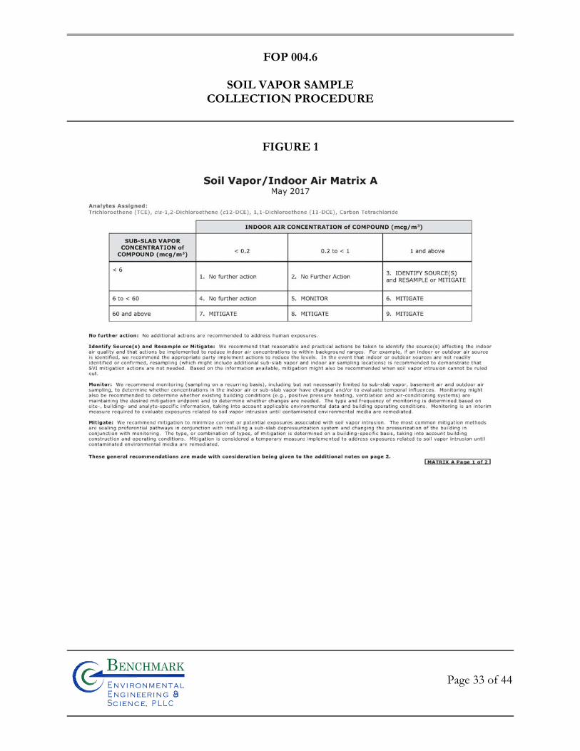
FOP 004.6
SOIL VAPOR SAMPLE
COLLECTION PROCEDURE
Page 33 of 44
Bn v i ronme talng i neeri n gc ence,i
n
FIGURE 1

FOP 004.6
SOIL VAPOR SAMPLE
COLLECTION PROCEDURE
Page 34 of 44
Bn v i ronme talng i neeri n gc ence,i
n
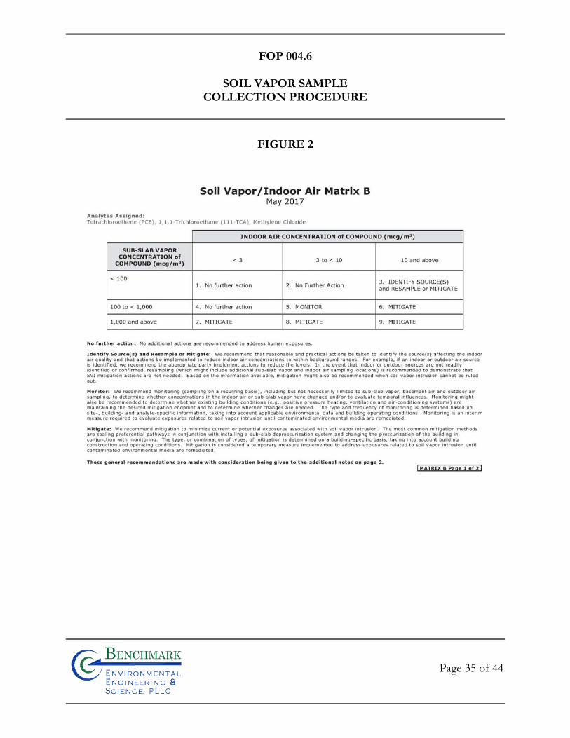
FOP 004.6
SOIL VAPOR SAMPLE
COLLECTION PROCEDURE
Page 35 of 44
Bn v i ronme talng i neeri n gc ence,i
n
FIGURE 2
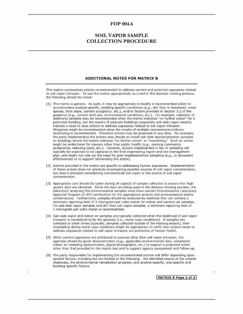
FOP 004.6
SOIL VAPOR SAMPLE
COLLECTION PROCEDURE
Page 36 of 44
Bn v i ronme talng i neeri n gc ence,i
n
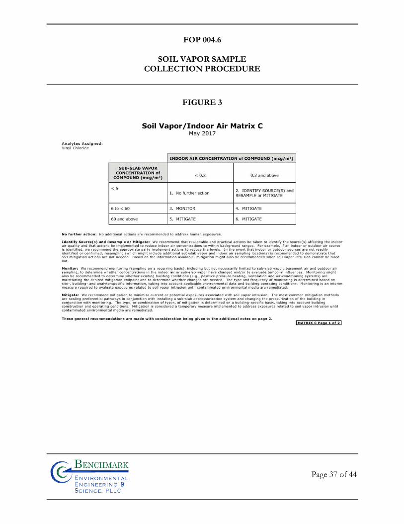
FOP 004.6
SOIL VAPOR SAMPLE
COLLECTION PROCEDURE
Page 37 of 44
Bn v i ronme talng i neeri n gc ence,i
n
FIGURE 3
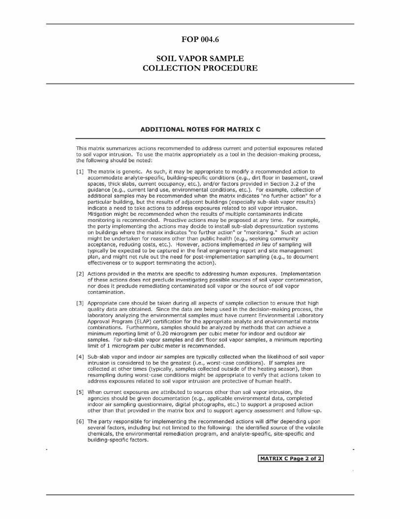
FOP 004.6
SOIL VAPOR SAMPLE
COLLECTION PROCEDURE
Page 38 of 44
Bn v i ronme talng i neeri n gc ence,i
n

FOP 004.6
SOIL VAPOR SAMPLE
COLLECTION PROCEDURE
Page 39 of 44
Bn v i ronme talng i neeri n gc ence,i
n
FIGURE 4
Schematics of a permanent soil vapor probe and permanent nested soil vapor probes
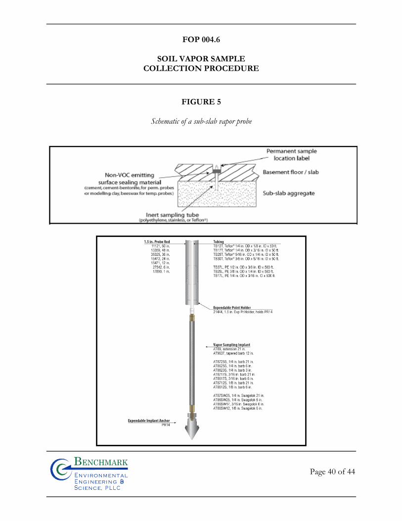
FOP 004.6
SOIL VAPOR SAMPLE
COLLECTION PROCEDURE
Page 40 of 44
Bn v i ronme talng i neeri n gc ence,i
n
FIGURE 5
Schematic of a sub-slab vapor probe
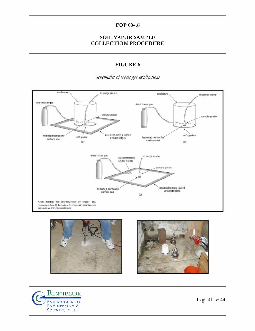
FOP 004.6
SOIL VAPOR SAMPLE
COLLECTION PROCEDURE
Page 41 of 44
Bn v i ronme talng i neeri n gc ence,i
n
FIGURE 6
Schematics of tracer gas applications
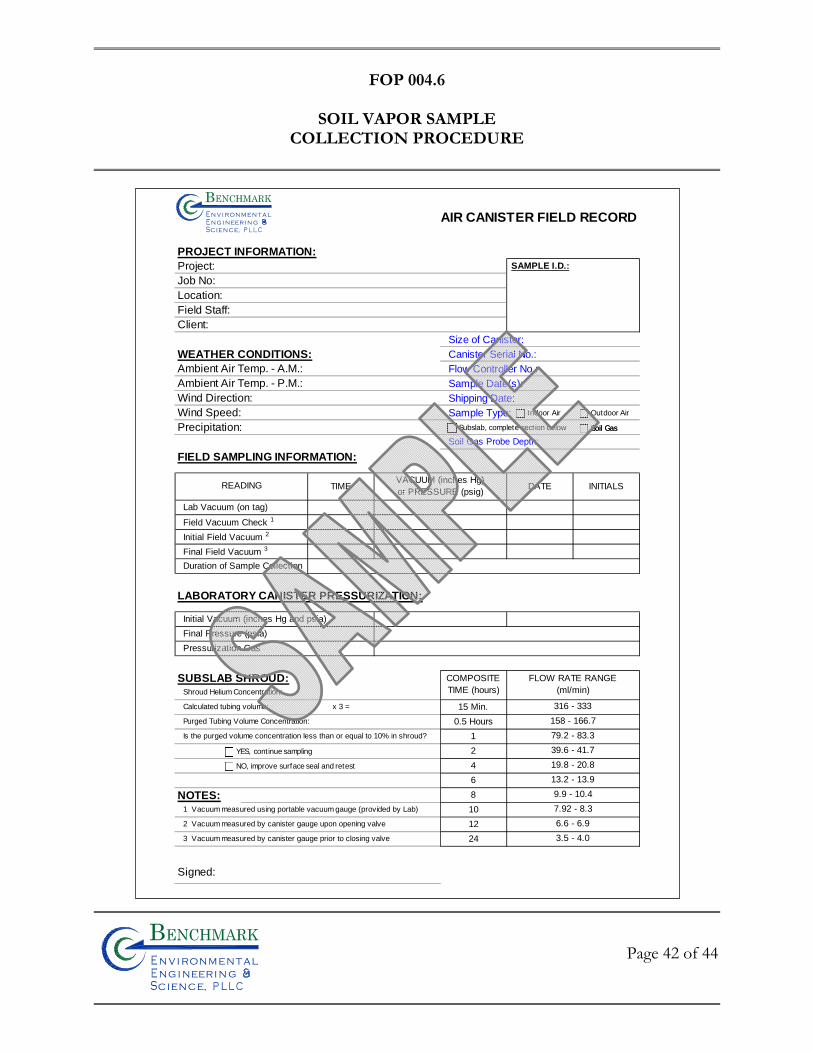
FOP 004.6
SOIL VAPOR SAMPLE
COLLECTION PROCEDURE
Page 42 of 44
Bn v i ronme talng i neeri n gc ence,i
n
AIR CANISTER FIELD RECORD
PROJECT INFORMATION:
Project: SAMPLE I.D.:
Job No:
Location:
Field Staff:
Client:
Size of Canister:
WEATHER CONDITIONS: Canister Serial No.:
Ambient Air Temp. - A.M.: Flow Controller No.:
Ambient Air Temp. - P.M.: Sample Date(s):
Wind Direction: Shipping Date:
Wind Speed: Sample Type:
Precipitation:
Soil Gas Probe Depth:
FIELD SAMPLING INFORMATION:
TIME DATE INITIALS
Lab Vacuum (on tag)
Field Vacuum Check 1
Initial Field Vacuum 2
Final Field Vacuum 3
Duration of Sample Collection
LABORATORY CANISTER PRESSURIZATION:
Initial Vacuum (inches Hg and psia)
Final Pressure (psia)
Pressurization Gas
SUBSLAB SHROUD:Shroud Helium Concentration:
Calculated tubing volume: x 3 = 15 Min.
Purged Tubing Volume Concentration: 0.5 Hours
Is the purged volume concentration less than or equal to 10% in shroud? 1
2
4
6
NOTES: 8
1 Vacuum measured using portable vacuum gauge (provided by Lab) 10
2 Vacuum measured by canister gauge upon opening valve 12
3 Vacuum measured by canister gauge prior to closing valve 24
Signed:
READING
79.2 - 83.3
VACUUM (inches Hg)
or PRESSURE (psig)
316 - 333
158 - 166.7
7.92 - 8.3
6.6 - 6.9
3.5 - 4.0
39.6 - 41.7
19.8 - 20.8
13.2 - 13.9
9.9 - 10.4
COMPOSITE
TIME (hours)
FLOW RATE RANGE
(ml/min)
Bn v i ron me t alng i neeri n gc ence,i
n
Indoor Air Outdoor Air
Subslab, complete section below Soil Gas
YES, continue sampling
NO, improve surface seal and retest
Soil Gas
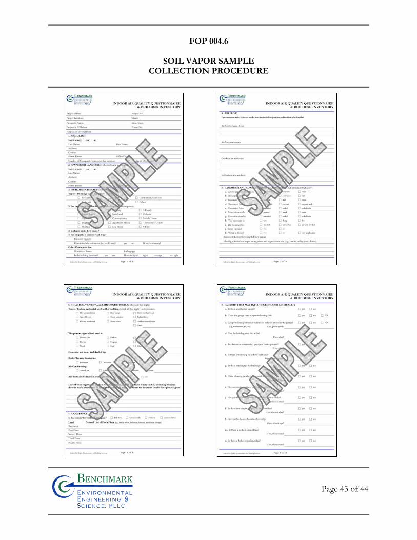
FOP 004.6
SOIL VAPOR SAMPLE
COLLECTION PROCEDURE
Page 43 of 44
Bn v i ronme talng i neeri n gc ence,i
n
FOP 004.6
SOIL VAPOR SAMPLE
COLLECTION PROCEDURE
Page 44 of 44
Bn v i ronme talng i neeri n gc ence,i
n

FIE
LD
OP
ER
AT
ING
PR
OC
ED
UR
ES
Calibration and Maintenance of
Combustible Gas/Oxygen Meter
Bn v i ronme talng i neeri n gc ence,i
n
FOP 006.0
CALIBRATION AND MAINTENANCE OF COMBUSTIBLE GAS/OXYGEN METER
Page 1 of 11
Bn v i ronme talng i neeri n gc ence,i
n
PURPOSE
This procedure presents a method for calibration of the GasTech GT402 four-gas meter.
The GasTech GT402 is a portable instrument designed primarily for detection of
combustible gases and of oxygen deficiency in ambient air and confined workspaces, such as
natural gas or depleted oxygen in utility manholes. The GasTech GT402 monitors an
environment for hydrocarbons (LEL/ppm), oxygen (O2), carbon monoxide (CO) and
hydrogen sulfide (H2S). The meter detects gas by a sample-drawing method utilizing up to
four internal sensors plugged into assigned molded flow block receptacles. During
operation, the GasTech GT402 alerts the user with visual and audible alarms whenever a
monitored gas reaches the preset alarm level. The GasTech GT402 has an internal pump
that continually draws the atmosphere sample into the external probe and hose, then into the
monitor to the sensor(s).
The information included below is equipment manufacturer- and model-specific, however,
accuracy, calibration, and maintenance procedures for this type of portable equipment are
typically similar. The information below pertains to GasTech GT402. The actual equipment
to be used in the field will be equivalent or similar. The unit selected for use in the field will
be used to measure methane gas, hydrogen sulfide gas, Lower Explosive Limit (LEL), and
percent oxygen. As always, consult the manufacturers operations manual prior to
conducting this procedure to confirm accuracy.
FOP 006.0
CALIBRATION AND MAINTENANCE OF COMBUSTIBLE GAS/OXYGEN METER
Page 2 of 11
Bn v i ronme talng i neeri n gc ence,i
n
START-UP PROCEDURE
Perform the following steps to start up the GasTech GT402 gas monitor and adjust internal
circuits to “fresh air” readings (demand zero). Read this entire section before turning on the
meter.
WARNING Perform the following start-up procedure in a “fresh air” environment only
(environment known to be free of toxic gases, combustible gases, and of normal
oxygen content).
1. If you are using Ni-Cd batteries, make sure the batteries are fully charged before you continue this procedure.
2. Press the ON/OFF button once, then release the button. The display
momentarily shows the software version of your monitor and the number of data logging hours that remain in memory. During the warm-up period, the gas readings stabilize for the installed sensors. You can hear the pump operating, and the words WARMING UP are displayed. The red LED flashes slowly during warm-up. Allow one minute for the display to stabilize and the LED to stop flashing. The GT sounds a periodic beep, and the display shows the words WARMUP COMPLETE when the meter completes initial warm-up.
WARNING Do not perform the next step in the monitoring area. This can place you in potential
danger if hazardous conditions exist.
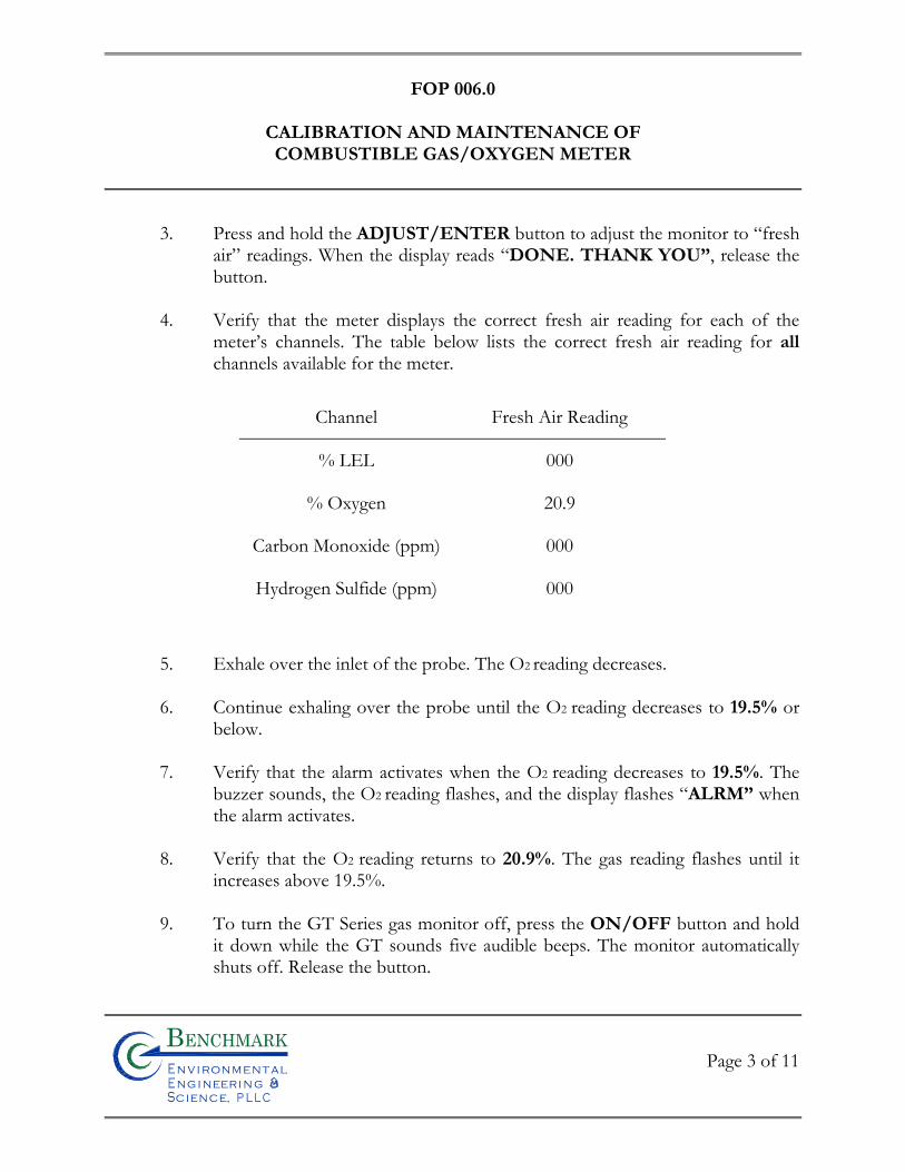
FOP 006.0
CALIBRATION AND MAINTENANCE OF COMBUSTIBLE GAS/OXYGEN METER
Page 3 of 11
Bn v i ronme talng i neeri n gc ence,i
n
3. Press and hold the ADJUST/ENTER button to adjust the monitor to “fresh air” readings. When the display reads “DONE. THANK YOU”, release the button.
4. Verify that the meter displays the correct fresh air reading for each of the
meter’s channels. The table below lists the correct fresh air reading for all channels available for the meter.
Channel Fresh Air Reading
% LEL 000
% Oxygen 20.9
Carbon Monoxide (ppm) 000
Hydrogen Sulfide (ppm) 000
5. Exhale over the inlet of the probe. The O2 reading decreases.
6. Continue exhaling over the probe until the O2 reading decreases to 19.5% or below.
7. Verify that the alarm activates when the O2 reading decreases to 19.5%. The
buzzer sounds, the O2 reading flashes, and the display flashes “ALRM” when the alarm activates.
8. Verify that the O2 reading returns to 20.9%. The gas reading flashes until it
increases above 19.5%.
9. To turn the GT Series gas monitor off, press the ON/OFF button and hold it down while the GT sounds five audible beeps. The monitor automatically shuts off. Release the button.
FOP 006.0
CALIBRATION AND MAINTENANCE OF COMBUSTIBLE GAS/OXYGEN METER
Page 4 of 11
Bn v i ronme talng i neeri n gc ence,i
n
10. If your GT uses rechargeable Ni-Cd batteries, the batteries must be fully charged before each use. When using alkaline batteries with your GT, for best possible operation you may choose to install fresh batteries before each use.
CALIBRATION PROCEDURE
Perform the following steps to calibrate the GasTech GT402 gas monitor and adjust internal
circuits to “fresh air” readings (demand zero). Read this entire section before calibrating the
meter.
CAUTION
Calibrate the GasTech GT402 gas monitor in a “fresh air” environment (known to be
of normal oxygen content and free of toxic or combustible gases). Do not begin
calibration unless you can verify that you are in a “fresh air” environment.
1. Verify that the calibrating area contains a level surface to set the meter and calibration kit accessories.
2. Turn on the meter in accordance with the Start-Up Procedure previously
discussed. Enter the Function program and verify that the Battery Capacity screen displays at least three bars. Attach the probe to the inlet fitting on the meter.
3. Carefully screw the threaded end of the regulator into the gas cylinder.
4. Attach the sample tubing over the fitting on the regulator.
5. Press the ADJUST/ENTER button. The display shows the main screen. 6. Press the RESET and BACK LITE/- buttons simultaneously three times.
The meter displays:
FOP 006.0
CALIBRATION AND MAINTENANCE OF COMBUSTIBLE GAS/OXYGEN METER
Page 5 of 11
Bn v i ronme talng i neeri n gc ence,i
n
Version N.NN
Calibrate
Setting the Zero Readings
NOTE: During a zeroing operation, an exclamation point (!) may appear at the beginning of
the second line of the display reading when the reading is centered in the zero range. The “!”
symbol represents the optimum reading.
1. Press the ADJUST/ENTER button. The GT displays:
Zero Gas
NNN PPM H2S
2. Use the FUNC./+ or BACK LITE/- buttons to adjust the display reading to 000 PPM H2S.
3. Press the ADJUST/ENTER button to save this zero setting. The GT
displays: Zero Gas
NNNN PPM COMB
4. Use the FUNC./+ or BACK LITE/- buttons to adjust the display reading to 0000 PPM COMB.
5. Press the ADJUST/ENTER button to save this zero setting. The GT
displays:
Zero Gas
NNN PPM CO
6. Use the FUNC./+ or BACK LITE/- buttons to adjust the display reading to 000 PPM CO.
FOP 006.0
CALIBRATION AND MAINTENANCE OF COMBUSTIBLE GAS/OXYGEN METER
Page 6 of 11
Bn v i ronme talng i neeri n gc ence,i
n
7. Press the ADJUST/ENTER button to save this zero setting. The GT displays:
Zero Gas
NN.N %VOL OXY
8. Attach the tubing from the regulator to the probe tube. The GT will draw gas from the gas cylinder.
9. Allow at least one minute, then use the FUNC./+ or BACK LITE/-
buttons to adjust the display reading to match the O2 value marked on the gas cylinder.
10. Press the ADJUST/ENTER button to save this setting. The GT displays:
Span Gas
NNN PPM H2S
Setting the Span Readings
1. Use the FUNC./+ or BACK LITE/- buttons to adjust the display reading to match the H2S value marked on the gas cylinder.
2. Press the ADJUST/ENTER button to save this span setting. The GT
displays: Span Gas
NNN %LEL COMB
3. Use the FUNC./+ or BACK LITE/- buttons to adjust the display reading to match the combustible gas value marked on the gas cylinder.
4. Press the ADJUST/ENTER button to save this span setting. The GT
displays: Span Gas
NNN PPM CO
FOP 006.0
CALIBRATION AND MAINTENANCE OF COMBUSTIBLE GAS/OXYGEN METER
Page 7 of 11
Bn v i ronme talng i neeri n gc ence,i
n
5. Use the FUNC./+ or BACK LITE/- buttons to adjust the display reading to match the CO value marked on the gas cylinder.
6. Press the ADJUST/ENTER button to save this span setting. The GT
displays: Span Gas
NN.N %VOL OXY
7. Disconnect the probe from the tubing leading to the regulator. The flow of gas will stop automatically.
8. Use the FUNC./+ or BACK LITE/- buttons to adjust the display reading to
20.9 %VOL OXY.
9. Press the ADJUST/ENTER button to save this span setting.
Calibration is now complete. The GT displays:
Exit
Press any Key...
Exiting Calibration Mode
1. Press any button, except the ON/OFF to exit calibration mode. 2. Unscrew the regulator from the gas cylinder.
3. Store the components of the calibration kit in the storage case.
4. The GT is now ready for normal operation.
5. Record all calibration information in the Project Field Book as well as on an
Equipment Calibration Log sheet (see attached sample).
FOP 006.0
CALIBRATION AND MAINTENANCE OF COMBUSTIBLE GAS/OXYGEN METER
Page 8 of 11
Bn v i ronme talng i neeri n gc ence,i
n
MAINTENANCE
The following are daily, monthly, quarterly, and “as required” preventive maintenance
suggestions to ensure the reliability of the GT monitor.
Daily
BATTERIES
The GT should always contain fully charged Ni-Cd batteries or sufficiently powered alkaline
batteries before each day’s use. You can verify the capacity of the batteries using the
Function program. To verify battery capacity:
1. Verify that the battery slide switch is at the proper ALK or NI-CAD setting for the type of batteries in the GT.
2. Press and hold the FUNC./+ button, for four beeps, then release the button.
If the display shows less than three bars, recharge the Ni-Cd batteries or replace the alkaline batteries as described later in this chapter.
3. Press the FUNC./+ button to return to the main display.
CALIBRATION
For optimum efficiency of the monitor, calibrate the GT before and after each use. If
multiple calibrations over a period of days indicate that only a minimum of adjustments are
required, the frequency of calibration can be changed to weekly or monthly, depending on
how often the monitor is used, and how demanding the monitoring environment is.
FOP 006.0
CALIBRATION AND MAINTENANCE OF COMBUSTIBLE GAS/OXYGEN METER
Page 9 of 11
Bn v i ronme talng i neeri n gc ence,i
n
NOTE
At the very least, “challenge” the normal operation of the oxygen (O2) sensor (if applicable)
before every use. Exhale over the inlet of the probe as you watch the display. The O2
reading should decrease. When the O2 reading decreases to 19.5%, the alarm should
activate confirming the normal operation of the O2
SAMPLE-DRAW SUBCOMPONENTS
Verify the proper operation of the flow alarm circuit by holding your finger over the inlet of
the probe for a few seconds. The pump shuts off, the PUMP OFF PRESS RESET
message appears on the display, and the audible alarm sounds if the flow alarm circuit is
operating properly.
Monthly/Quarterly
CALIBRATION
Calibrate the sensors at least every one to three months. Calibration frequency depends on
the frequency of use and also the environmental conditions in which you use the GT.
As Required
ALARM CIRCUITS
Periodically verify that all visual and audible alarms function properly.
WARNING
Verify alarm circuits in a “fresh air” environment only (environment known to be free
of combustible and toxic gases and of normal oxygen content).
FOP 006.0
CALIBRATION AND MAINTENANCE OF COMBUSTIBLE GAS/OXYGEN METER
Page 10 of 11
Bn v i ronme talng i neeri n gc ence,i
n
To verify the alarm circuits, use a concentration of the proper gas sample that is greater than
the preset warn or alarm levels. Verify that WARN or ALRM displays and the buzzer
sounds. Also, verify that the display reading in alarm flashes during the alarm sequence.
SAMPLE-DRAW SUBCOMPONENTS
Periodically check the probe, hoses, internal filter, and tubing for obstructions that can
accumulate over time. This is especially important if you use the GT in a dusty or dirty environment.
Replace the cotton and hydrophobic filter elements if they become contaminated or
discolored.
ATTACHMENTS
Equipment Calibration Log (sample)

FOP 006.0
CALIBRATION AND MAINTENANCE OF COMBUSTIBLE GAS/OXYGEN METER
Page 11 of 11
Bn v i ronme talng i neeri n gc ence,i
n
EQUIPMENT CALIBRATION
PROJECT INFORMATION:Project Name: Date:Project No.:Client: Instrument Source: BM Rental
Sp. conductance meter
Particulate meter
Oxygen
Hydrogen sulfide
Carbon monoxide
LEL
Radiation Meter
ADDITIONAL REMARKS:
PREPARED BY: DATE:
background area
open air
SETTIN
MIBK refactor =
READING
______ mS @ 25 oC
open air
STANDARD4.007.0010.01
open air zero_____ ppm Iso. Gas
zero air
open air
open air
Myron L CompanyUltra Meter 6P
Turbidity meter NTU Hach 2100PTurbidimeter
units Myron L CompanyUltra Meter 6P 606987
100970600014560
< 0.420
800
Photovac 2020 PID ED GK 301
606987
CAL. BYMAKE/MODEL SERIAL NUMBERTIME
%
uS/mS
mg/m3
ppm
uR/H
METER TYPE UNITS
PID ppm
%
ppm
pH meter
Bn v i r o n m e t a ln g i n eer i n gc e n c e,i
n

FIE
LD
OP
ER
AT
ING
PR
OC
ED
UR
ES
Calibration and Maintenance of
Portable Dissolved Oxygen Meter
Bn v i ronme talng i neeri n gc ence,i
n
FOP 007.0
CALIBRATION AND MAINTENANCE OF PORTABLE
DISSOLVED OXYGEN METER
Page 1 of 3
Bn v i ronme talng i neeri n gc ence,i
n
PURPOSE
This guideline describes a method for calibration of a portable dissolved oxygen meter. This meter measures the concentration of dissolved oxygen within a water sample. This parameter is of interest both as a general indicator of water quality, and because of its pertinence to fate and transport of organics and inorganics. This guideline presents a method for calibration of this meter, which is performed to verify instrument accuracy and function. All field instruments will be calibrated, verified and recalibrated at frequencies required by their respective operating manuals or manufacturer’s specifications, but not less than once each day that the instrument is in use. Field personnel should have access to all operating manuals for the instruments used for the field measurements. This procedure also documents critical maintenance activities for this meter.
ACCURACY
The calibrated accuracy of the dissolved oxygen meter will be within ± 1% of full-scale over the temperature range of 23° to 113° F (-5° to +45° C).
PROCEDURE
1. Calibrate the dissolved oxygen meter to ambient air based on probe temperature and true local atmospheric pressure conditions (or feet above sea level). Because procedures vary with different brands and models of meters, refer to the manufacturer’s recommended calibration procedures.
2. In the event of a failure to adequately calibrate, follow the corrective action
directed by the manufacturer. 3. If calibration cannot be achieved or maintained, obtain a replacement
instrument (rental instruments) and/or order necessary repairs/adjustment.
FOP 007.0
CALIBRATION AND MAINTENANCE OF PORTABLE
DISSOLVED OXYGEN METER
Page 2 of 3
Bn v i ronme talng i neeri n gc ence,i
n
4. Document the calibration results and related information in the Project Field Book and on an Equipment Calibration Log (see attached sample). Information will include, at a minimum:
• Time, date, and initials of the field team member performing the calibration
• The unique identifier for the meter, including manufacturer, model, and serial number
• The brand and expiration dates of calibration solutions • The calibration readings • The instrument settings (if applicable) • The approximate response time • The overall adequacy of calibration including the Pass or fail
designation in accordance with the accuracy specifications presented above
• Corrective action taken (see Step 5 above) in the event of failure to adequately calibrate
MAINTENANCE
• When not in use or between measurements, the dissolved oxygen probe will be kept immersed in or moist with deionized water.
• The meter batteries will be checked prior to each meter’s use and will be replaced
when the meter cannot be redline adjusted. • The meter response time and stability will be tracked to determine the need for
instrument maintenance. When response time becomes greater than two minutes, probe service is indicated.
ATTACHMENTS
Equipment Calibration Log (sample)
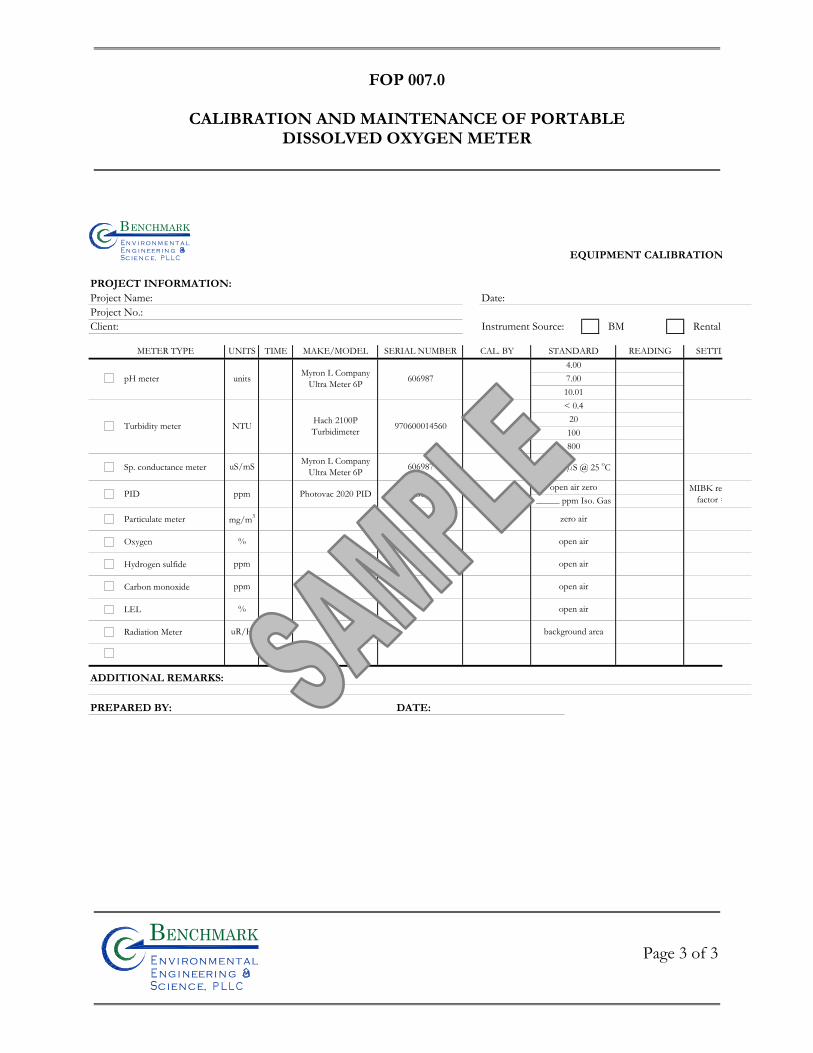
FOP 007.0
CALIBRATION AND MAINTENANCE OF PORTABLE
DISSOLVED OXYGEN METER
Page 3 of 3
Bn v i ronme talng i neeri n gc ence,i
n
EQUIPMENT CALIBRATION
PROJECT INFORMATION:Project Name: Date:Project No.:Client: Instrument Source: BM Rental
Sp. conductance meter
Particulate meter
Oxygen
Hydrogen sulfide
Carbon monoxide
LEL
Radiation Meter
ADDITIONAL REMARKS:
PREPARED BY: DATE:
background area
open air
SETTIN
MIBK refactor =
READING
______ mS @ 25 oC
open air
STANDARD4.007.0010.01
open air zero_____ ppm Iso. Gas
zero air
open air
open air
Myron L CompanyUltra Meter 6P
Turbidity meter NTU Hach 2100PTurbidimeter
units Myron L CompanyUltra Meter 6P 606987
100970600014560
< 0.420
800
Photovac 2020 PID ED GK 301
606987
CAL. BYMAKE/MODEL SERIAL NUMBERTIME
%
uS/mS
mg/m3
ppm
uR/H
METER TYPE UNITS
PID ppm
%
ppm
pH meter
Bn v i r o n m e t a ln g i n eer i n gc e n c e,i
n

FIE
LD
OP
ER
AT
ING
PR
OC
ED
UR
ES
Calibration and Maintenance of
Portable Field pH/Eh Meter
Bn v i ronme talng i neeri n gc ence,i
n
FOP 008.0
CALIBRATION AND MAINTENANCE OF PORTABLE
FIELD pH/Eh METER
Page 1 of 4
Bn v i ronme talng i neeri n gc ence,i
n
PURPOSE
This guideline describes a method for calibration of a portable pH/Eh meter. The pH/Eh meter measures the hydrogen ion concentration or acidity of a water sample (pH function), and the oxidation/reduction potential of a water sample (Eh function). Calibration is performed to verify instrument accuracy and function. All field instruments will be calibrated, verified and recalibrated at frequencies required by their respective operating manuals or manufacturer’s specifications, but not less than once each day that the instrument is in use. Field personnel should have access to all operating manuals for the instruments used for the field measurements. This procedure also documents critical maintenance activities for this meter.
ACCURACY
The calibrated accuracy of the pH/Eh meter will be:
pH ± 0.2 pH unit, over the temperature range of ± 0.2 C.
Eh ± 0.2 millivolts (mV) over the range of ± 399.9 mV, otherwise ± 2 mV.
PROCEDURE
Note: Meters produced by different manufacturers may have different calibration
procedures. These instructions will take precedence over the procedure provided herein.
This procedure is intended to be used as a general guideline, or in the absence of available
manufacturer’s instructions.
1. Obtain and active the meter to be used. As stated above, initial calibrations will be performed at the beginning of each sampling day.
FOP 008.0
CALIBRATION AND MAINTENANCE OF PORTABLE
FIELD pH/Eh METER
Page 2 of 4
Bn v i ronme talng i neeri n gc ence,i
n
2. Immerse the sensing probe in a container of certified pH 7.0 buffer solution traceable to the National Bureau of Standards.
3. Measure the temperature of the buffer solution, and adjust the temperature setting accordingly.
4. Compare the meter reading to the known value of the buffer solution while stirring. If the reading obtained by the meter does not agree with the known value of the buffer solution, recalibrate the meter according to the manufacturer’s instructions until the desired reading is obtained. This typically involves accessing and turning a dial or adjustment screw while measuring the pH of the buffer solution. The meter is adjusted until the output agrees with the known solution pH.
5. Repeat Steps 2 through 5 with a pH 4.0 and 10.0 buffer solution to provide a three-point calibration. Standards used to calibrate the pH meter will be of concentrations that bracket the expected values of the samples to be analyzed, especially for two-point calibrations (see note below).
Note: Some pH meters only allow two-point calibrations. Two-point calibrations should be within the suspected range of the groundwater to be analyzed. For example, if the groundwater pH is expected to be approximately 8, the two-point calibration should bracket that value. Buffer solutions of 7 and 10 should then be used for the two-point calibration.
6. Document the calibration results and related information in the Project Field Book and on an Equipment Calibration Log (see attached sample). Information will include, at a minimum:
• Time, date, and initials of the field team member performing the calibration
• The unique identifier for the meter, including manufacturer, model, and serial number
• The brand and expiration dates of buffer solutions • The instrument readings • The instrument settings (if applicable)
FOP 008.0
CALIBRATION AND MAINTENANCE OF PORTABLE
FIELD pH/Eh METER
Page 3 of 4
Bn v i ronme talng i neeri n gc ence,i
n
• Pass or fail designation in accordance with the accuracy specifications presented above
• Corrective action taken (see Maintenance below) in the event of failure to adequately calibrate
MAINTENANCE
• When not in use, or between measurements, keep the pH/Eh probe immersed in or moist with buffer solutions.
• Check the meter batteries at the end of each day and recharge or replace as needed. • Replace the pH/Eh probe any time that the meter response time becomes greater
than two minutes or the meeting system consistently fails to retain its calibrated accuracy for a minimum of ten sample measurements.
• If a replacement of the pH/Eh probe fails to resolve instrument response time and
stability problems, obtain a replacement instrument (rental instruments) and/or order necessary repairs/adjustment.
ATTACHMENTS
Equipment Calibration Log (sample)
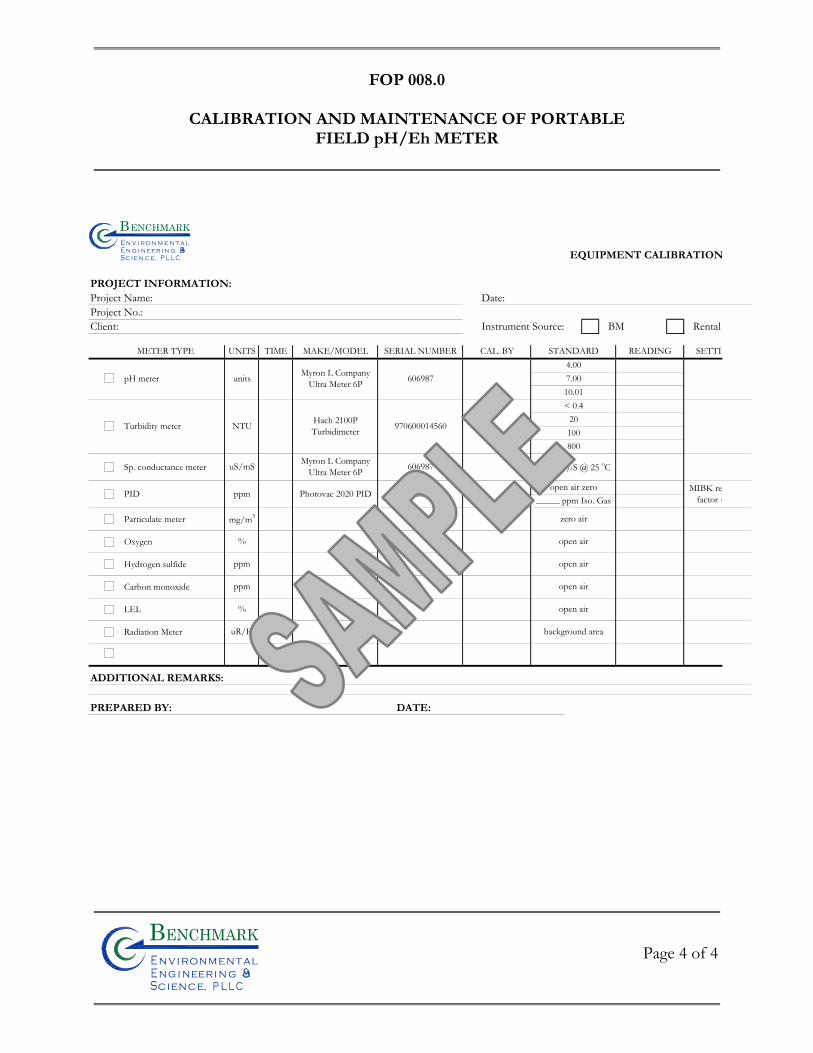
FOP 008.0
CALIBRATION AND MAINTENANCE OF PORTABLE
FIELD pH/Eh METER
Page 4 of 4
Bn v i ronme talng i neeri n gc ence,i
n
EQUIPMENT CALIBRATION
PROJECT INFORMATION:Project Name: Date:Project No.:Client: Instrument Source: BM Rental
Sp. conductance meter
Particulate meter
Oxygen
Hydrogen sulfide
Carbon monoxide
LEL
Radiation Meter
ADDITIONAL REMARKS:
PREPARED BY: DATE:
background area
open air
SETTIN
MIBK refactor =
READING
______ mS @ 25 oC
open air
STANDARD4.007.0010.01
open air zero_____ ppm Iso. Gas
zero air
open air
open air
Myron L CompanyUltra Meter 6P
Turbidity meter NTU Hach 2100PTurbidimeter
units Myron L CompanyUltra Meter 6P 606987
100970600014560
< 0.420
800
Photovac 2020 PID ED GK 301
606987
CAL. BYMAKE/MODEL SERIAL NUMBERTIME
%
uS/mS
mg/m3
ppm
uR/H
METER TYPE UNITS
PID ppm
%
ppm
pH meter
Bn v i r o n m e t a ln g i n eer i n gc e n c e,i
n

FIE
LD
OP
ER
AT
ING
PR
OC
ED
UR
ES
Calibration and Maintenance of Portable Field
Turbidity Meter
Bn v i ronme talng i neeri n gc ence,i
n
FOP 009.0
CALIBRATION AND MAINTENANCE OF PORTABLE
FIELD TURBIDITY METER
Page 1 of 7
Bn v i ronme talng i neeri n gc ence,i
n
PURPOSE
This guideline describes the method for calibration of the HACH 2100P portable field turbidity meter. Turbidity is one water quality parameter measured during purging and development of wells. Turbidity is measured as a function of the samples ability to transmit light, expressed as Nephelometric Turbidity Units (NTUs). The turbidity meter is factory calibrated and must be checked daily prior to using the meter in the field. Calibration is performed to verify instrument accuracy and function. This procedure also documents critical maintenance activities for this meter.
ACCURACY
Accuracy shall be ± 2% of reading below 499 NTU or ± 3% of reading above 500 NTU
with resolution to 0.01 NTU in the lowest range. The range key provides for automatic or
manual range selection for ranges of 0.00 to 9.99, 0.0 to 99.9 and 0 to 1000 NTU. Another
key provides for selecting automatic signal averaging. Pressing the key shall toggle signal
averaging on or off.
PROCEDURE
Calibration of the 2100P Turbidimeter is based on formazin, the primary standard for
turbidity. The instrument's electronic and optical design provides long-term stability and
minimizes the need for frequent calibration. The two-detector ratioing system compensates
for most fluctuations in lamp output. A formazin recalibration should be performed at
least once every three months, more often if experience indicates the need. During
calibration, use a primary standard such as StablCal™ Stabilized Standards or formazin
standards.
FOP 009.0
CALIBRATION AND MAINTENANCE OF PORTABLE
FIELD TURBIDITY METER
Page 2 of 7
Bn v i ronme talng i neeri n gc ence,i
n
Note: Meters produced by different manufacturers may have different calibration check
procedures. These manufacturers’ instructions will take precedence over the procedure
provided here. This procedure is intended to be used as a general guideline, or in the
absence of available manufacturer’s instructions.
Note: Because the turbidity meter measures light transmission, it is critical that the meter
and standards be cared for as precision optical instruments. Scratches, dirt, dust, etc. can all
temporarily or permanently affect the accuracy of meter readings.
Preparing StablCal Stabilized Standards in Sealed Vials
Sealed vials that have been sitting undisturbed for longer than a month must be shaken to
break the condensed suspension into its original particle size. Start at step 1 for these
standards. If the standards are used on at least a weekly interval, start at step 3.
Note: These instructions do not apply to < 0.1 NTU StablCal Standards; < 0.1 NTU
StablCal Standards should not be shaken or inverted.
1. Shake the standard vigorously for 2-3 minutes to re-suspend any particles. 2. Allow the standard to stand undisturbed for 5 minutes.
3. Gently invert the vial of StablCal 5 to 7 times.
4. Prepare the vial for measurement using traditional preparation techniques.
This usually consists of oiling the vial (see Section 2.3.2 on page 11 of the manual)
FOP 009.0
CALIBRATION AND MAINTENANCE OF PORTABLE
FIELD TURBIDITY METER
Page 3 of 7
Bn v i ronme talng i neeri n gc ence,i
n
and marking the vial to maintain the same orientation in the sample cell compartment (see Section 2.3.3 on page 12 of the manual). This step will eliminate any optical variations in the sample vial.
5. Let the vial stand for one minute. The standard is now ready for use in the
calibration procedure.
Calibration Procedure
1. Turn the meter on.
2. Shake pre-mixed formazin primary standards in accordance with the above procedure.
3. Wipe the outside of the < 0.1 NTU standard and insert the sample cell in the
cell compartment by aligning the orientation mark on the cell with the mark on the front of the cell compartment.
4. Close the lid and press I/O.
5. Press the CAL button. The CAL and S0 icons will be displayed and the 0 will
flash. The four-digit display will show the value of the S0 standard for the previous calibration. If the blank value was forced to 0.0, the display will be blank. Press the right arrow key (→) to get a numerical display.
6. Press READ. The instrument will count from 60 to 0, read the blank and use
it to calculate a correction factor for the 20 NTU standard measurement. If the dilution water is ≥ 0.5 NTU, E 1 will appear when the calibration is calculated (see Section 3.6.2.3 on page 31 of the manual). The display will automatically increment to the next standard. Remove the sample cell from the cell compartment
FOP 009.0
CALIBRATION AND MAINTENANCE OF PORTABLE
FIELD TURBIDITY METER
Page 4 of 7
Bn v i ronme talng i neeri n gc ence,i
n
Note: The turbidity of the dilution water can be “forced” to zero by pressing →
rather than reading the dilution water. The display will show “S0 NTU” and the ↑
key must be pressed to continue with the next standard.
7. Repeat steps 1 through 7 for the 20, 100 and 800 standards. 8. Following the 800 NTU standard calibration, the display will increment back
to the S0 display. Remove the sample cell from the cell compartment.
9. Press CAL to accept the calibration. The instrument will return to measurement mode automatically.
10. Document the calibration results and related information in the Project Field
Book and on an Equipment Calibration Log (see attached sample). Information will include, at a minimum:
• Time, date, and initials of the field team member performing the calibration
• The unique identifier for the meter, including manufacturer, model, and serial number
• The brand of calibration standards • The instrument readings • The instrument settings (if applicable) • Pass or fail designation in accordance with the accuracy specifications
presented above • Corrective action taken (see Maintenance below) in the event of failure
to adequately calibrate. Note: Pressing CAL completes the calculation of the calibration coefficients. If calibration errors occurred during calibration, error messages will appear after CAL is pressed. If E 1 or E 2 appear, check the standard preparation and review the calibration; repeat the calibration if necessary. If “CAL?” appears, an error may have
FOP 009.0
CALIBRATION AND MAINTENANCE OF PORTABLE
FIELD TURBIDITY METER
Page 5 of 7
Bn v i ronme talng i neeri n gc ence,i
n
occurred during calibration. If “CAL?” is flashing, the instrument is using the default calibration. NOTES
• If the I/O key is pressed during calibration, the new calibration data is lost and the old calibration will be used for measurements. Once in calibration mode, only the READ, I/O, ↑ , and →keys function. Signal averaging and range mode must be selected before entering the calibration mode.
• If E 1 or E 2 are displayed, an error occurred during calibration. Check the standard
preparation and review the calibration; repeat the calibration if necessary. Press DIAG to cancel the error message (E 1 or E 2). To continue without repeating the calibration, press I/O twice to restore the previous calibration. If “CAL?” is displayed, an error may have occurred during calibration. The previous calibration may not be restored. Either recalibrate or use the calibration as is.
• To review a calibration, press CAL and then ↑ to view the calibration standard
values. As long as READ is never pressed and CAL is not flashing, the calibration will not be updated. Press CAL again to return to the measurement mode.
MAINTENANCE
• Cleaning: Keep the turbidimeter and accessories as clean as possible and store the instrument in the carrying case when not in use. Avoid prolonged exposure to sunlight and ultraviolet light. Wipe spills up promptly. Wash sample cells with non-abrasive laboratory detergent, rinse with distilled or demineralized water, and air dry. Avoid scratching the cells and wipe all moisture and fingerprints off the cells before inserting them into the instrument. Failure to do so can give inaccurate readings. See Section 2.3.1 on page 11of the manual for more information about sample cell care.
• Battery Replacement: AA alkaline cells typically last for about 300 tests with the
signal-averaging mode off, about 180 tests if signal averaging is used. The “battery” icon flashes when battery replacement is needed. Refer to Section 1.4.2 on page 5 of the manual for battery installation instructions. If the batteries are changed within 30
FOP 009.0
CALIBRATION AND MAINTENANCE OF PORTABLE
FIELD TURBIDITY METER
Page 6 of 7
Bn v i ronme talng i neeri n gc ence,i
n
seconds, the instrument retains the latest range and signal average selections. If it takes more than 30 seconds, the instrument uses the default settings. If, after changing batteries, the instrument will not turn off or on and the batteries are good, remove the batteries and reinstall them. If the instrument still won't function, contact Hach Service or the nearest authorized dealer.
• Lamp Replacement: The procedure in Section 4.0 on page 49 of the manual explains
lamp installation and electrical connections. Use a small screwdriver to remove and install the lamp leads in the terminal block. The instrument requires calibration after lamp replacement.
ATTACHMENTS
Equipment Calibration Log (sample)

FOP 009.0
CALIBRATION AND MAINTENANCE OF PORTABLE
FIELD TURBIDITY METER
Page 7 of 7
Bn v i ronme talng i neeri n gc ence,i
n
EQUIPMENT CALIBRATION
PROJECT INFORMATION:Project Name: Date:Project No.:Client: Instrument Source: BM Rental
Sp. conductance meter
Particulate meter
Oxygen
Hydrogen sulfide
Carbon monoxide
LEL
Radiation Meter
ADDITIONAL REMARKS:
PREPARED BY: DATE:
background area
open air
SETTIN
MIBK refactor =
READING
______ mS @ 25 oC
open air
STANDARD4.007.0010.01
open air zero_____ ppm Iso. Gas
zero air
open air
open air
Myron L CompanyUltra Meter 6P
Turbidity meter NTU Hach 2100PTurbidimeter
units Myron L CompanyUltra Meter 6P 606987
100970600014560
< 0.420
800
Photovac 2020 PID ED GK 301
606987
CAL. BYMAKE/MODEL SERIAL NUMBERTIME
%
uS/mS
mg/m3
ppm
uR/H
METER TYPE UNITS
PID ppm
%
ppm
pH meter
Bn v i r o n m e t a ln g i n eer i n gc e n c e,i
n
FIE
LD
OP
ER
AT
ING
PR
OC
ED
UR
ES
Calibration and Maintenance of
Portable Photoionization Detector (PID)
Bn v i ronme talng i neeri n gc ence,i
n
FOP 011.1
CALIBRATION AND MAINTENANCE OF PORTABLE
PHOTOIONIZATION DETECTOR
Page 1 of 31
Bn v i ronme talng i neeri n gc ence,i
n
PURPOSE
This procedure describes a general method for the calibration and maintenance of a portable
photoionization detector (PID). The PID detects and initially quantifies a reading of the
volatile organic compound (VOC) concentration in air. The PID is used as a field-screening
tool for initial evaluation of soil samples and for ambient air monitoring of compounds with
ionization potentials (IP) less than the PID lamp electron voltage (eV) rating. The IP is the
amount of energy required to move an electron to an infinite distance from the nucleus thus
creating a positive ion plus an electron. It should be noted that all of the major components
of air (i.e., carbon dioxide, methane, nitrogen, oxygen etc.) have IP's above 12 eV. As a
result, they will not be ionized by the 9.8, 10.6, or 11.7 eV lamps typically utilized in field
PIDs. The response of the PID will then be the sum of the organic and inorganic
compounds in air that are ionized by the appropriate lamp (i.e., 9.8, 10.6 or 11.7 eV).
Attached to this FOP is a table summarizing common organic compounds and their
respective IPs.
Calibration is performed to verify instrument accuracy and function. All field instruments
will be calibrated, verified and recalibrated at frequencies required by their respective
operating manuals or manufacturer’s specifications, but not less than once each day that the
instrument is in use. Compound-specific calibration methods should be selected on a
project-by-project basis to increase the accuracy of the instrument. The best way to calibrate
a PID to different compounds is to use a standard of the gas of interest. However,
correction factors have been determined that enable the user to quantify a large number of
chemicals using only a single calibration gas, typically isobutylene. Field personnel should
have access to all operating manuals for the instruments used for the field measurements.
This procedure also documents critical maintenance activities for this meter.
FOP 011.1
CALIBRATION AND MAINTENANCE OF PORTABLE
PHOTOIONIZATION DETECTOR
Page 2 of 31
Bn v i ronme talng i neeri n gc ence,i
n
Note: The information included below is equipment manufacturer- and model-specific,
however, accuracy, calibration, and maintenance procedures for this type of portable
equipment are typically similar. The information below pertains to the MiniRAE 2000
Portable VOC Monitor equipped with a 10.6 eV lamp. The actual equipment to be used in
the field will be equivalent or similar. The following information is provided for general
reference; the equipment-specific manufacturer’s manual should be followed with
precedence over this FOP.
Note: The PID indicates total VOC concentration readings that are normalized to a
calibration standard, so actual quantification of individual compounds is not provided. In
addition, the PID response to compounds is highly variable, dependent on ionization
potential of the compound, and the presence or absence of other compounds.
ACCURACY
The MiniRAE 2000 is accurate to ± 2 ppm or 10% of the reading for concentrations ranging
from 0-2,000 ppm and ± 20% of the reading at concentrations greater than 2,000 ppm.
Response time is less than two seconds to 90 percent of full-scale. The operating
temperature range is 0 to 45º C and the operating humidity range is 0 to 95 % relative
humidity (non-condensing).
CALIBRATION PROCEDURE
The calibration method and correction factor, if applicable, will be selected on a project-by-project basis and confirmed with the Project Manager prior to the start of field work.
1. Calibrate all field test equipment at the beginning of each sampling day. Check and recalibrate the PID according to the manufacture’s specifications.
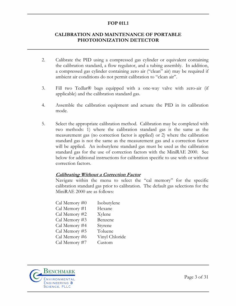
FOP 011.1
CALIBRATION AND MAINTENANCE OF PORTABLE
PHOTOIONIZATION DETECTOR
Page 3 of 31
Bn v i ronme talng i neeri n gc ence,i
n
2. Calibrate the PID using a compressed gas cylinder or equivalent containing the calibration standard, a flow regulator, and a tubing assembly. In addition, a compressed gas cylinder containing zero air (“clean” air) may be required if ambient air conditions do not permit calibration to “clean air”.
3. Fill two Tedlar® bags equipped with a one-way valve with zero-air (if
applicable) and the calibration standard gas.
4. Assemble the calibration equipment and actuate the PID in its calibration mode.
5. Select the appropriate calibration method. Calibration may be completed with two methods: 1) where the calibration standard gas is the same as the measurement gas (no correction factor is applied) or 2) where the calibration standard gas is not the same as the measurement gas and a correction factor will be applied. An isobutylene standard gas must be used as the calibration standard gas for the use of correction factors with the MiniRAE 2000. See below for additional instructions for calibration specific to use with or without correction factors.
Calibrating Without a Correction Factor Navigate within the menu to select the “cal memory” for the specific calibration standard gas prior to calibration. The default gas selections for the MiniRAE 2000 are as follows: Cal Memory #0 Isobutylene Cal Memory #1 Hexane Cal Memory #2 Xylene Cal Memory #3 Benzene Cal Memory #4 Styrene Cal Memory #5 Toluene Cal Memory #6 Vinyl Chloride Cal Memory #7 Custom
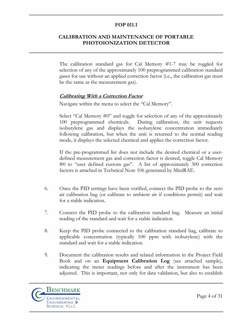
FOP 011.1
CALIBRATION AND MAINTENANCE OF PORTABLE
PHOTOIONIZATION DETECTOR
Page 4 of 31
Bn v i ronme talng i neeri n gc ence,i
n
The calibration standard gas for Cal Memory #1-7 may be toggled for selection of any of the approximately 100 preprogrammed calibration standard gases for use without an applied correction factor (i.e., the calibration gas must be the same as the measurement gas).
Calibrating With a Correction Factor
Navigate within the menu to select the “Cal Memory”.
Select “Cal Memory #0” and toggle for selection of any of the approximately 100 preprogrammed chemicals. During calibration, the unit requests isobutylene gas and displays the isobutylene concentration immediately following calibration, but when the unit is returned to the normal reading mode, it displays the selected chemical and applies the correction factor.
If the pre-programmed list does not include the desired chemical or a user-defined measurement gas and correction factor is desired, toggle Cal Memory #0 to “user defined custom gas”. A list of approximately 300 correction factors is attached in Technical Note 106 generated by MiniRAE.
6. Once the PID settings have been verified, connect the PID probe to the zero air calibration bag (or calibrate to ambient air if conditions permit) and wait for a stable indication.
7. Connect the PID probe to the calibration standard bag. Measure an initial
reading of the standard and wait for a stable indication.
8. Keep the PID probe connected to the calibration standard bag, calibrate to applicable concentration (typically 100 ppm with isobutylene) with the standard and wait for a stable indication.
9. Document the calibration results and related information in the Project Field
Book and on an Equipment Calibration Log (see attached sample), indicating the meter readings before and after the instrument has been adjusted. This is important, not only for data validation, but also to establish
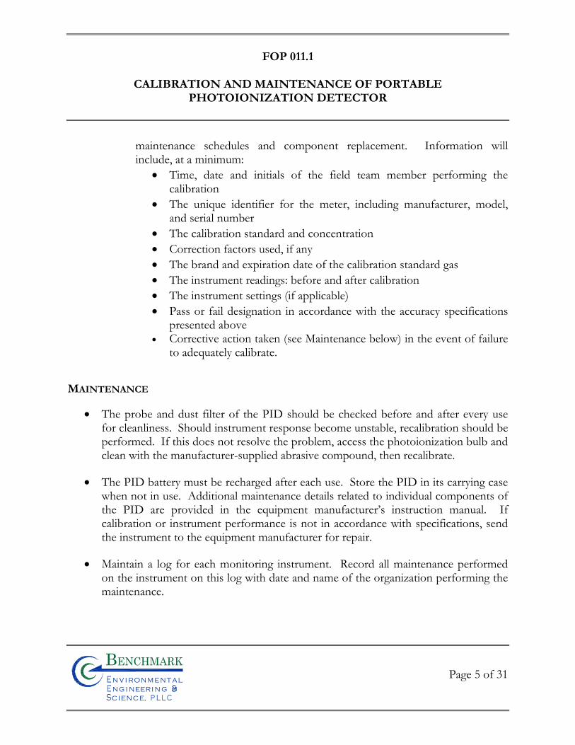
FOP 011.1
CALIBRATION AND MAINTENANCE OF PORTABLE
PHOTOIONIZATION DETECTOR
Page 5 of 31
Bn v i ronme talng i neeri n gc ence,i
n
maintenance schedules and component replacement. Information will include, at a minimum:
Time, date and initials of the field team member performing the calibration
The unique identifier for the meter, including manufacturer, model, and serial number
The calibration standard and concentration Correction factors used, if any The brand and expiration date of the calibration standard gas The instrument readings: before and after calibration The instrument settings (if applicable) Pass or fail designation in accordance with the accuracy specifications
presented above Corrective action taken (see Maintenance below) in the event of failure
to adequately calibrate.
MAINTENANCE
The probe and dust filter of the PID should be checked before and after every use for cleanliness. Should instrument response become unstable, recalibration should be performed. If this does not resolve the problem, access the photoionization bulb and clean with the manufacturer-supplied abrasive compound, then recalibrate.
The PID battery must be recharged after each use. Store the PID in its carrying case when not in use. Additional maintenance details related to individual components of the PID are provided in the equipment manufacturer’s instruction manual. If calibration or instrument performance is not in accordance with specifications, send the instrument to the equipment manufacturer for repair.
Maintain a log for each monitoring instrument. Record all maintenance performed on the instrument on this log with date and name of the organization performing the maintenance.
FOP 011.1
CALIBRATION AND MAINTENANCE OF PORTABLE
PHOTOIONIZATION DETECTOR
Page 6 of 31
Bn v i ronme talng i neeri n gc ence,i
n
ATTACHMENTS
Table 1; Summary of Ionization Potentials Equipment Calibration Log (sample) Technical Note TN-106
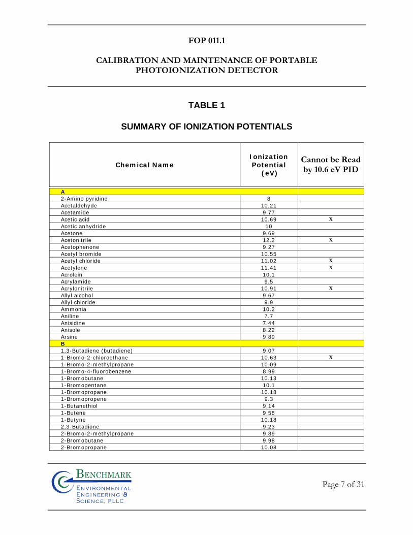
FOP 011.1
CALIBRATION AND MAINTENANCE OF PORTABLE
PHOTOIONIZATION DETECTOR
TABLE 1
SUMMARY OF IONIZATION POTENTIALS
Chemical Name Ionization Potential
(eV)
Cannot be Readby 10.6 eV PID
Page 7 of 31
Bn v i ronme talng i neeri n gc ence,i
n
A
2-Amino pyridine 8
Acetaldehyde 10.21
Acetamide 9.77
Acetic acid 10.69 X
Acetic anhydride 10
Acetone 9.69
Acetonitrile 12.2 X
Acetophenone 9.27
Acetyl bromide 10.55
Acetyl chloride 11.02 X
Acetylene 11.41 X
Acrolein 10.1
Acrylamide 9.5
Acrylonitrile 10.91 X
Allyl alcohol 9.67
Allyl chloride 9.9
Ammonia 10.2
Aniline 7.7
Anisidine 7.44
Anisole 8.22
Arsine 9.89
B
1,3-Butadiene (butadiene) 9.07
1-Bromo-2-chloroethane 10.63 X
1-Bromo-2-methylpropane 10.09
1-Bromo-4-fluorobenzene 8.99
1-Bromobutane 10.13
1-Bromopentane 10.1
1-Bromopropane 10.18
1-Bromopropene 9.3
1-Butanethiol 9.14
1-Butene 9.58
1-Butyne 10.18
2,3-Butadione 9.23
2-Bromo-2-methylpropane 9.89
2-Bromobutane 9.98
2-Bromopropane 10.08
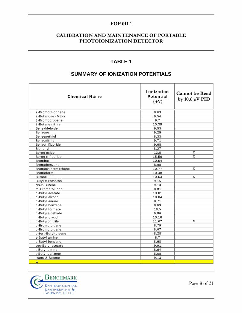
FOP 011.1
CALIBRATION AND MAINTENANCE OF PORTABLE
PHOTOIONIZATION DETECTOR
TABLE 1
SUMMARY OF IONIZATION POTENTIALS
Chemical Name Ionization Potential
(eV)
Cannot be Readby 10.6 eV PID
Page 8 of 31
Bn v i ronme talng i neeri n gc ence,i
n
2-Bromothiophene 8.63
2-Butanone (MEK) 9.54
3-Bromopropene 9.7
3-Butene nitrile 10.39
Benzaldehyde 9.53
Benzene 9.25
Benzenethiol 8.33
Benzonitrile 9.71
Benzotrifluoride 9.68
Biphenyl 8.27
Boron oxide 13.5 X
Boron trifluoride 15.56 X
Bromine 10.54
Bromobenzene 8.98
Bromochloromethane 10.77 X
Bromoform 10.48
Butane 10.63 X
Butyl mercaptan 9.15
cis-2-Butene 9.13
m-Bromotoluene 8.81
n-Butyl acetate 10.01
n-Butyl alcohol 10.04
n-Butyl amine 8.71
n-Butyl benzene 8.69
n-Butyl formate 10.5
n-Butyraldehyde 9.86
n-Butyric acid 10.16
n-Butyronitrile 11.67 X
o-Bromotoluene 8.79
p-Bromotoluene 8.67
p-tert-Butyltoluene 8.28
s-Butyl amine 8.7
s-Butyl benzene 8.68
sec-Butyl acetate 9.91
t-Butyl amine 8.64
t-Butyl benzene 8.68
trans-2-Butene 9.13
C
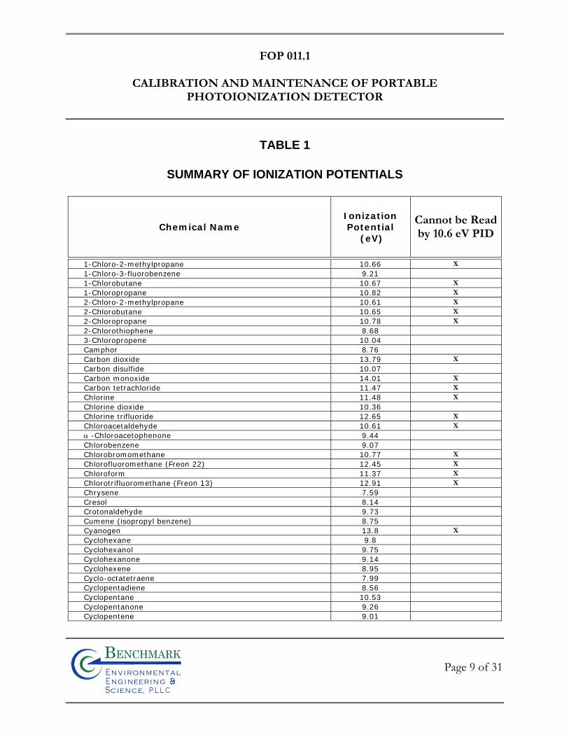
FOP 011.1
CALIBRATION AND MAINTENANCE OF PORTABLE
PHOTOIONIZATION DETECTOR
TABLE 1
SUMMARY OF IONIZATION POTENTIALS
Chemical Name Ionization Potential
(eV)
Cannot be Readby 10.6 eV PID
Page 9 of 31
Bn v i ronme talng i neeri n gc ence,i
n
1-Chloro-2-methylpropane 10.66 X
1-Chloro-3-fluorobenzene 9.21
1-Chlorobutane 10.67 X
1-Chloropropane 10.82 X
2-Chloro-2-methylpropane 10.61 X
2-Chlorobutane 10.65 X
2-Chloropropane 10.78 X
2-Chlorothiophene 8.68
3-Chloropropene 10.04
Camphor 8.76
Carbon dioxide 13.79 X
Carbon disulfide 10.07
Carbon monoxide 14.01 X
Carbon tetrachloride 11.47 X
Chlorine 11.48 X
Chlorine dioxide 10.36
Chlorine trifluoride 12.65 X
Chloroacetaldehyde 10.61 X
-Chloroacetophenone 9.44
Chlorobenzene 9.07
Chlorobromomethane 10.77 X
Chlorofluoromethane (Freon 22) 12.45 X
Chloroform 11.37 X
Chlorotrifluoromethane (Freon 13) 12.91 X
Chrysene 7.59
Cresol 8.14
Crotonaldehyde 9.73
Cumene (isopropyl benzene) 8.75
Cyanogen 13.8 X
Cyclohexane 9.8
Cyclohexanol 9.75
Cyclohexanone 9.14
Cyclohexene 8.95
Cyclo-octatetraene 7.99
Cyclopentadiene 8.56
Cyclopentane 10.53
Cyclopentanone 9.26
Cyclopentene 9.01
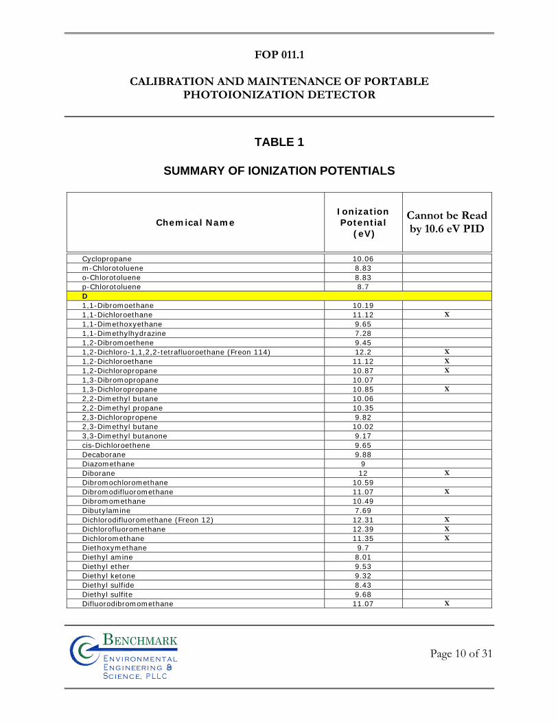
FOP 011.1
CALIBRATION AND MAINTENANCE OF PORTABLE
PHOTOIONIZATION DETECTOR
TABLE 1
SUMMARY OF IONIZATION POTENTIALS
Chemical Name Ionization Potential
(eV)
Cannot be Readby 10.6 eV PID
Page 10 of 31
Bn v i ronme talng i neeri n gc ence,i
n
Cyclopropane 10.06
m-Chlorotoluene 8.83
o-Chlorotoluene 8.83
p-Chlorotoluene 8.7
D
1,1-Dibromoethane 10.19
1,1-Dichloroethane 11.12 X
1,1-Dimethoxyethane 9.65
1,1-Dimethylhydrazine 7.28
1,2-Dibromoethene 9.45
1,2-Dichloro-1,1,2,2-tetrafluoroethane (Freon 114) 12.2 X
1,2-Dichloroethane 11.12 X
1,2-Dichloropropane 10.87 X
1,3-Dibromopropane 10.07
1,3-Dichloropropane 10.85 X
2,2-Dimethyl butane 10.06
2,2-Dimethyl propane 10.35
2,3-Dichloropropene 9.82
2,3-Dimethyl butane 10.02
3,3-Dimethyl butanone 9.17
cis-Dichloroethene 9.65
Decaborane 9.88
Diazomethane 9
Diborane 12 X
Dibromochloromethane 10.59
Dibromodifluoromethane 11.07 X
Dibromomethane 10.49
Dibutylamine 7.69
Dichlorodifluoromethane (Freon 12) 12.31 X
Dichlorofluoromethane 12.39 X
Dichloromethane 11.35 X
Diethoxymethane 9.7
Diethyl amine 8.01
Diethyl ether 9.53
Diethyl ketone 9.32
Diethyl sulfide 8.43
Diethyl sulfite 9.68
Difluorodibromomethane 11.07 X
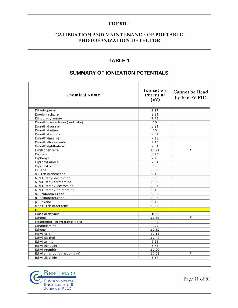
FOP 011.1
CALIBRATION AND MAINTENANCE OF PORTABLE
PHOTOIONIZATION DETECTOR
TABLE 1
SUMMARY OF IONIZATION POTENTIALS
Chemical Name Ionization Potential
(eV)
Cannot be Readby 10.6 eV PID
Page 11 of 31
Bn v i ronme talng i neeri n gc ence,i
n
Dihydropyran 8.34
Diiodomethane 9.34
Diisopropylamine 7.73
Dimethoxymethane (methylal) 10
Dimethyl amine 8.24
Dimethyl ether 10
Dimethyl sulfide 8.69
Dimethylaniline 7.13
Dimethylformamide 9.18
Dimethylphthalate 9.64
Dinitrobenzene 10.71 X
Dioxane 9.19
Diphenyl 7.95
Dipropyl amine 7.84
Dipropyl sulfide 8.3
Durene 8.03
m-Dichlorobenzene 9.12
N,N-Diethyl acetamide 8.6
N,N-Diethyl formamide 8.89
N,N-Dimethyl acetamide 8.81
N,N-Dimethyl formamide 9.12
o-Dichlorobenzene 9.06
p-Dichlorobenzene 8.95
p-Dioxane 9.13
trans-Dichloroethene 9.66
E
Epichlorohydrin 10.2
Ethane 11.65 X
Ethanethiol (ethyl mercaptan) 9.29
Ethanolamine 8.96
Ethene 10.52
Ethyl acetate 10.11
Ethyl alcohol 10.48
Ethyl amine 8.86
Ethyl benzene 8.76
Ethyl bromide 10.29
Ethyl chloride (chloroethane) 10.98 X
Ethyl disulfide 8.27
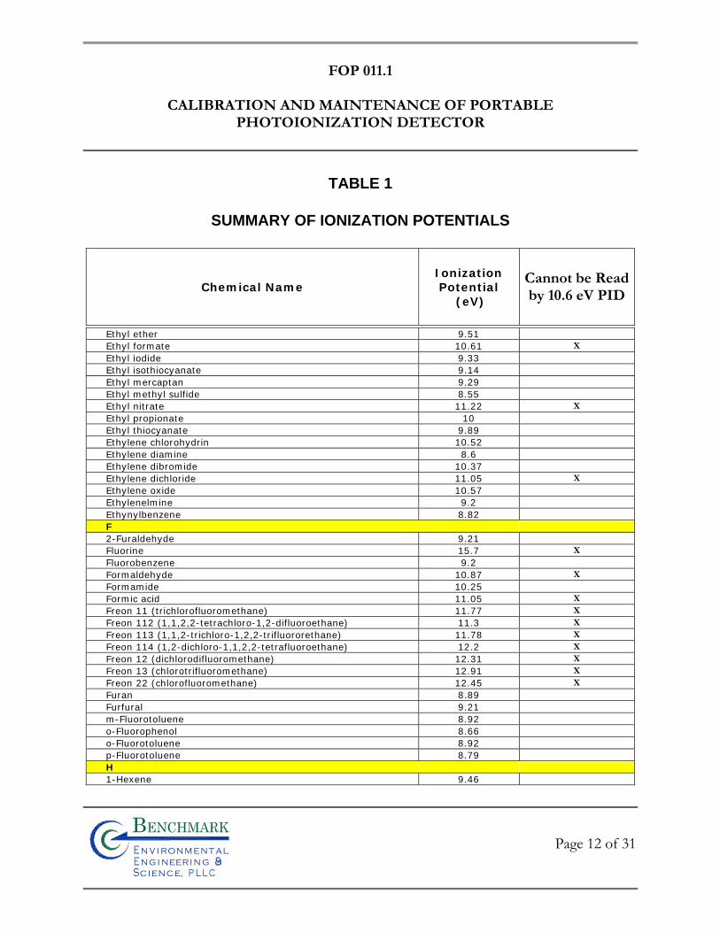
FOP 011.1
CALIBRATION AND MAINTENANCE OF PORTABLE
PHOTOIONIZATION DETECTOR
TABLE 1
SUMMARY OF IONIZATION POTENTIALS
Chemical Name Ionization Potential
(eV)
Cannot be Readby 10.6 eV PID
Page 12 of 31
Bn v i ronme talng i neeri n gc ence,i
n
Ethyl ether 9.51
Ethyl formate 10.61 X
Ethyl iodide 9.33
Ethyl isothiocyanate 9.14
Ethyl mercaptan 9.29
Ethyl methyl sulfide 8.55
Ethyl nitrate 11.22 X
Ethyl propionate 10
Ethyl thiocyanate 9.89
Ethylene chlorohydrin 10.52
Ethylene diamine 8.6
Ethylene dibromide 10.37
Ethylene dichloride 11.05 X
Ethylene oxide 10.57
Ethylenelmine 9.2
Ethynylbenzene 8.82
F
2-Furaldehyde 9.21
Fluorine 15.7 X
Fluorobenzene 9.2
Formaldehyde 10.87 X
Formamide 10.25
Formic acid 11.05 X
Freon 11 (trichlorofluoromethane) 11.77 X
Freon 112 (1,1,2,2-tetrachloro-1,2-difluoroethane) 11.3 X
Freon 113 (1,1,2-trichloro-1,2,2-trifluororethane) 11.78 X
Freon 114 (1,2-dichloro-1,1,2,2-tetrafluoroethane) 12.2 X
Freon 12 (dichlorodifluoromethane) 12.31 X
Freon 13 (chlorotrifluoromethane) 12.91 X
Freon 22 (chlorofluoromethane) 12.45 X
Furan 8.89
Furfural 9.21
m-Fluorotoluene 8.92
o-Fluorophenol 8.66
o-Fluorotoluene 8.92
p-Fluorotoluene 8.79
H
1-Hexene 9.46
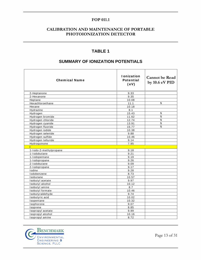
FOP 011.1
CALIBRATION AND MAINTENANCE OF PORTABLE
PHOTOIONIZATION DETECTOR
TABLE 1
SUMMARY OF IONIZATION POTENTIALS
Chemical Name Ionization Potential
(eV)
Cannot be Readby 10.6 eV PID
Page 13 of 31
Bn v i ronme talng i neeri n gc ence,i
n
2-Heptanone 9.33
2-Hexanone 9.35
Heptane 10.08
Hexachloroethane 11.1 X
Hexane 10.18
Hydrazine 8.1
Hydrogen 15.43 X
Hydrogen bromide 11.62 X
Hydrogen chloride 12.74 X
Hydrogen cyanide 13.91 X
Hydrogen fluoride 15.77 X
Hydrogen iodide 10.38
Hydrogen selenide 9.88
Hydrogen sulfide 10.46
Hydrogen telluride 9.14
Hydroquinone 7.95
I
1-Iodo-2-methylpropane 9.18
1-Iodobutane 9.21
1-Iodopentane 9.19
1-Iodopropane 9.26
2-Iodobutane 9.09
2-Iodopropane 9.17
Iodine 9.28
Iodobenzene 8.73
Isobutane 10.57
Isobutyl acetate 9.97
Isobutyl alcohol 10.12
Isobutyl amine 8.7
Isobutyl formate 10.46
Isobutyraldehyde 9.74
Isobutyric acid 10.02
Isopentane 10.32
Isophorone 9.07
Isoprene 8.85
Isopropyl acetate 9.99
Isopropyl alcohol 10.16
Isopropyl amine 8.72
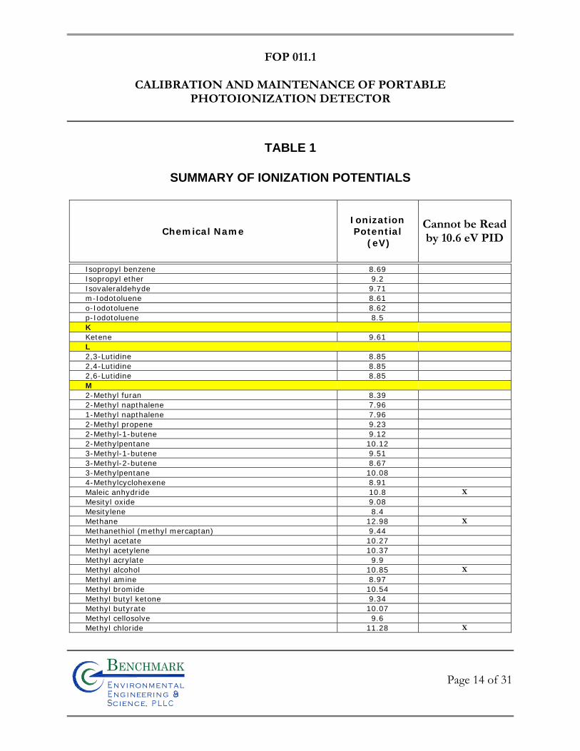
FOP 011.1
CALIBRATION AND MAINTENANCE OF PORTABLE
PHOTOIONIZATION DETECTOR
TABLE 1
SUMMARY OF IONIZATION POTENTIALS
Chemical Name Ionization Potential
(eV)
Cannot be Readby 10.6 eV PID
Page 14 of 31
Bn v i ronme talng i neeri n gc ence,i
n
Isopropyl benzene 8.69
Isopropyl ether 9.2
Isovaleraldehyde 9.71
m-Iodotoluene 8.61
o-Iodotoluene 8.62
p-Iodotoluene 8.5
K
Ketene 9.61
L
2,3-Lutidine 8.85
2,4-Lutidine 8.85
2,6-Lutidine 8.85
M
2-Methyl furan 8.39
2-Methyl napthalene 7.96
1-Methyl napthalene 7.96
2-Methyl propene 9.23
2-Methyl-1-butene 9.12
2-Methylpentane 10.12
3-Methyl-1-butene 9.51
3-Methyl-2-butene 8.67
3-Methylpentane 10.08
4-Methylcyclohexene 8.91
Maleic anhydride 10.8 X
Mesityl oxide 9.08
Mesitylene 8.4
Methane 12.98 X
Methanethiol (methyl mercaptan) 9.44
Methyl acetate 10.27
Methyl acetylene 10.37
Methyl acrylate 9.9
Methyl alcohol 10.85 X
Methyl amine 8.97
Methyl bromide 10.54
Methyl butyl ketone 9.34
Methyl butyrate 10.07
Methyl cellosolve 9.6
Methyl chloride 11.28 X
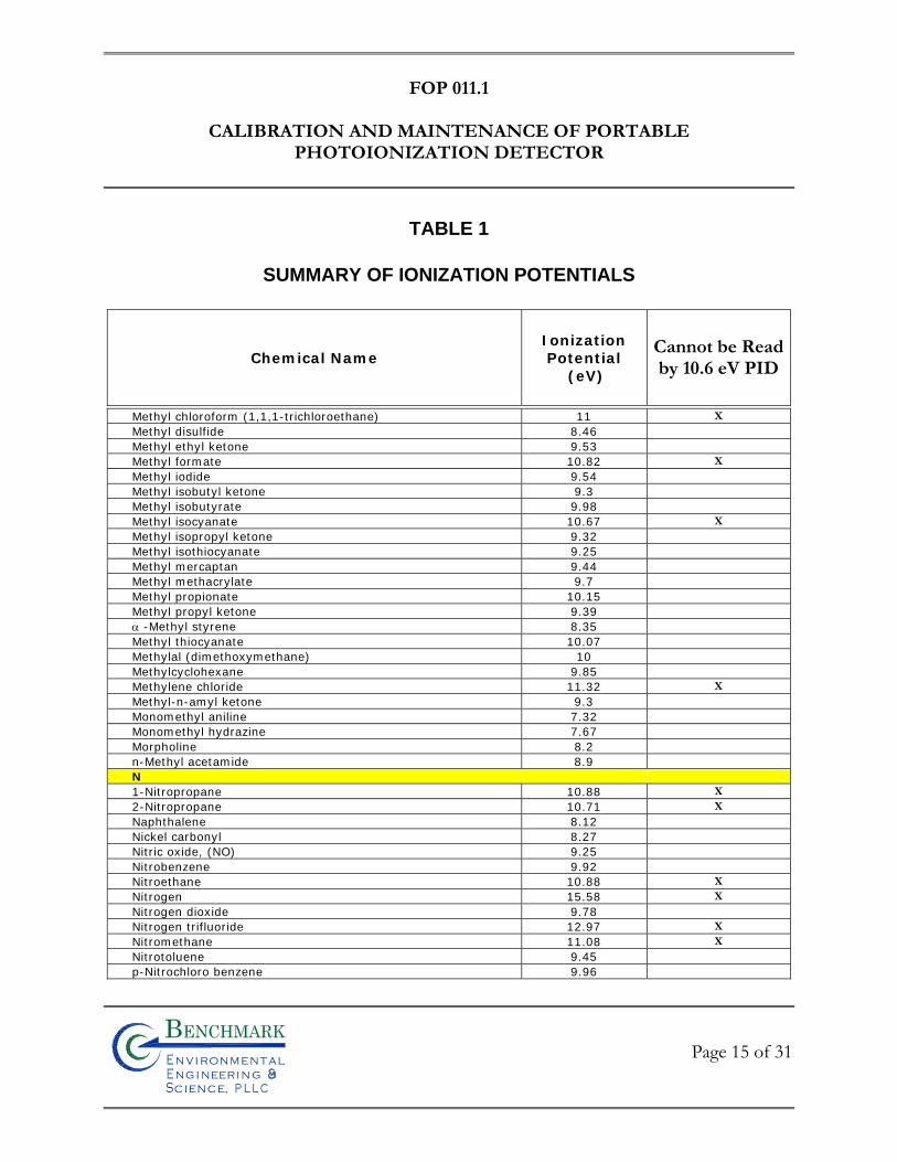
FOP 011.1
CALIBRATION AND MAINTENANCE OF PORTABLE
PHOTOIONIZATION DETECTOR
TABLE 1
SUMMARY OF IONIZATION POTENTIALS
Chemical Name Ionization Potential
(eV)
Cannot be Readby 10.6 eV PID
Page 15 of 31
Bn v i ronme talng i neeri n gc ence,i
n
Methyl chloroform (1,1,1-trichloroethane) 11 X
Methyl disulfide 8.46
Methyl ethyl ketone 9.53
Methyl formate 10.82 X
Methyl iodide 9.54
Methyl isobutyl ketone 9.3
Methyl isobutyrate 9.98
Methyl isocyanate 10.67 X
Methyl isopropyl ketone 9.32
Methyl isothiocyanate 9.25
Methyl mercaptan 9.44
Methyl methacrylate 9.7
Methyl propionate 10.15
Methyl propyl ketone 9.39
-Methyl styrene 8.35
Methyl thiocyanate 10.07
Methylal (dimethoxymethane) 10
Methylcyclohexane 9.85
Methylene chloride 11.32 X
Methyl-n-amyl ketone 9.3
Monomethyl aniline 7.32
Monomethyl hydrazine 7.67
Morpholine 8.2
n-Methyl acetamide 8.9
N
1-Nitropropane 10.88 X
2-Nitropropane 10.71 X
Naphthalene 8.12
Nickel carbonyl 8.27
Nitric oxide, (NO) 9.25
Nitrobenzene 9.92
Nitroethane 10.88 X
Nitrogen 15.58 X
Nitrogen dioxide 9.78
Nitrogen trifluoride 12.97 X
Nitromethane 11.08 X
Nitrotoluene 9.45
p-Nitrochloro benzene 9.96
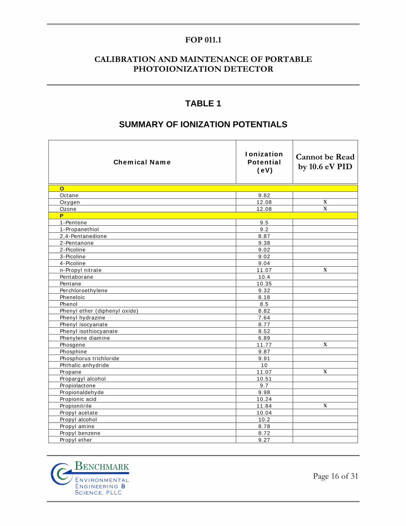
FOP 011.1
CALIBRATION AND MAINTENANCE OF PORTABLE
PHOTOIONIZATION DETECTOR
TABLE 1
SUMMARY OF IONIZATION POTENTIALS
Chemical Name Ionization Potential
(eV)
Cannot be Readby 10.6 eV PID
Page 16 of 31
Bn v i ronme talng i neeri n gc ence,i
n
O
Octane 9.82
Oxygen 12.08 X
Ozone 12.08 X
P
1-Pentene 9.5
1-Propanethiol 9.2
2,4-Pentanedione 8.87
2-Pentanone 9.38
2-Picoline 9.02
3-Picoline 9.02
4-Picoline 9.04
n-Propyl nitrate 11.07 X
Pentaborane 10.4
Pentane 10.35
Perchloroethylene 9.32
Pheneloic 8.18
Phenol 8.5
Phenyl ether (diphenyl oxide) 8.82
Phenyl hydrazine 7.64
Phenyl isocyanate 8.77
Phenyl isothiocyanate 8.52
Phenylene diamine 6.89
Phosgene 11.77 X
Phosphine 9.87
Phosphorus trichloride 9.91
Phthalic anhydride 10
Propane 11.07 X
Propargyl alcohol 10.51
Propiolactone 9.7
Propionaldehyde 9.98
Propionic acid 10.24
Propionitrile 11.84 X
Propyl acetate 10.04
Propyl alcohol 10.2
Propyl amine 8.78
Propyl benzene 8.72
Propyl ether 9.27
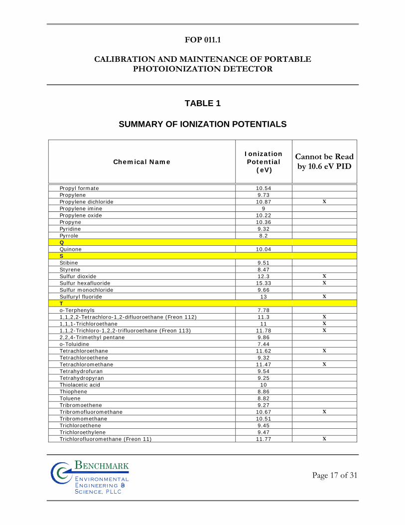
FOP 011.1
CALIBRATION AND MAINTENANCE OF PORTABLE
PHOTOIONIZATION DETECTOR
TABLE 1
SUMMARY OF IONIZATION POTENTIALS
Chemical Name Ionization Potential
(eV)
Cannot be Readby 10.6 eV PID
Page 17 of 31
Bn v i ronme talng i neeri n gc ence,i
n
Propyl formate 10.54
Propylene 9.73
Propylene dichloride 10.87 X
Propylene imine 9
Propylene oxide 10.22
Propyne 10.36
Pyridine 9.32
Pyrrole 8.2
Q
Quinone 10.04
S
Stibine 9.51
Styrene 8.47
Sulfur dioxide 12.3 X
Sulfur hexafluoride 15.33 X
Sulfur monochloride 9.66
Sulfuryl fluoride 13 X
T
o-Terphenyls 7.78
1,1,2,2-Tetrachloro-1,2-difluoroethane (Freon 112) 11.3 X
1,1,1-Trichloroethane 11 X
1,1,2-Trichloro-1,2,2-trifluoroethane (Freon 113) 11.78 X
2,2,4-Trimethyl pentane 9.86
o-Toluidine 7.44
Tetrachloroethane 11.62 X
Tetrachloroethene 9.32
Tetrachloromethane 11.47 X
Tetrahydrofuran 9.54
Tetrahydropyran 9.25
Thiolacetic acid 10
Thiophene 8.86
Toluene 8.82
Tribromoethene 9.27
Tribromofluoromethane 10.67 X
Tribromomethane 10.51
Trichloroethene 9.45
Trichloroethylene 9.47
Trichlorofluoromethane (Freon 11) 11.77 X
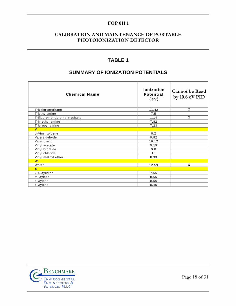
FOP 011.1
CALIBRATION AND MAINTENANCE OF PORTABLE
PHOTOIONIZATION DETECTOR
TABLE 1
SUMMARY OF IONIZATION POTENTIALS
Chemical Name Ionization Potential
(eV)
Cannot be Readby 10.6 eV PID
Page 18 of 31
Bn v i ronme talng i neeri n gc ence,i
n
Trichloromethane 11.42 X
Triethylamine 7.5
Trifluoromonobromo-methane 11.4 X
Trimethyl amine 7.82
Tripropyl amine 7.23
V
o-Vinyl toluene 8.2
Valeraldehyde 9.82
Valeric acid 10.12
Vinyl acetate 9.19
Vinyl bromide 9.8
Vinyl chloride 10
Vinyl methyl ether 8.93
W
Water 12.59 X
X
2,4-Xylidine 7.65
m-Xylene 8.56
o-Xylene 8.56
p-Xylene 8.45
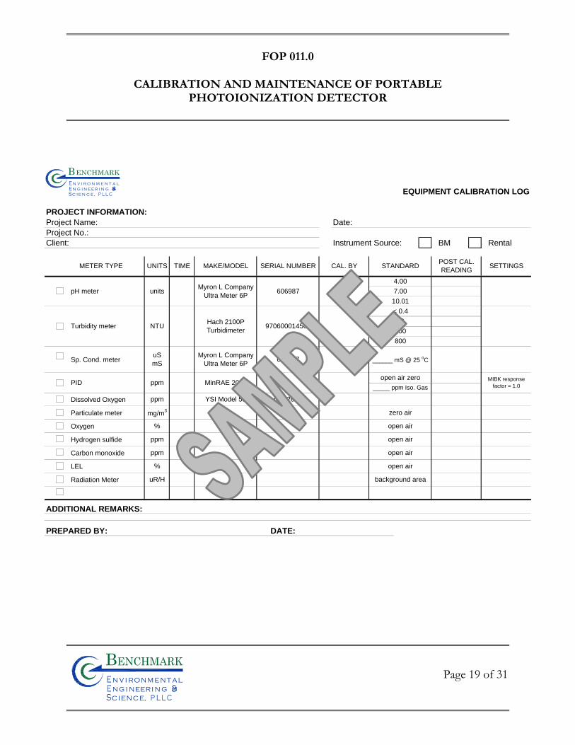
FOP 011.0
CALIBRATION AND MAINTENANCE OF PORTABLE
PHOTOIONIZATION DETECTOR
Page 19 of 31
Bn v i ronme talng i neeri n gc ence,i
n
EQUIPMENT CALIBRATION LOG
PROJECT INFORMATION:
Project Name: Date:
Project No.:
Client: Instrument Source: BM Rental
Sp. Cond. meter
Dissolved Oxygen
Particulate meter
Oxygen
Hydrogen sulfide
Carbon monoxide
LEL
Radiation Meter
ADDITIONAL REMARKS:
PREPARED BY: DATE:
uR/H
METER TYPE UNITS
PID ppm
%
ppm
pH meter
TIME
%
uS
mS
mg/m3
ppm
MAKE/MODEL SERIAL NUMBER
606987
CAL. BY
unitsMyron L Company
Ultra Meter 6P606987
100970600014560
< 0.4
20
800
open air
Myron L Company
Ultra Meter 6P
Turbidity meter NTUHach 2100P
Turbidimeter
MinRAE 2000
______ mS @ 25 oC
open air
STANDARD
4.00
7.00
10.01
open air zero
_____ ppm Iso. Gas
zero air
open air
POST CAL.
READING
MIBK response
factor = 1.0
SETTINGS
background area
open air
ppm YSI Model 55 05D2677
Bn v i r o n m e t a ln g i n ee r i n gc e n c e,i
n
Technical Note TN-106 Revised 08/2010
1RAE Systems Inc. 3775 N. First St., San Jose, CA 95134-1708 USA Phone: +1.888.723.8823 Email: [email protected] Web Site: www.raesystems.com
Correction Factors, Ionization Energies*, And Calibration Characteristics
Correction Factors and Ionization Energies RAE Systems PIDs can be used for the detection of a wide variety of gases that exhibit different responses. In general, any compound with ionization energy (IE) lower than that of the lamp photons can be measured.* The best way to calibrate a PID to different compounds is to use a standard of the gas of interest. However, correction factors have been determined that enable the user to quantify a large number of chemicals using only a single calibration gas, typically isobutylene. In our PIDs, correction factors can be used in one of three ways:
1) Calibrate the monitor with isobutylene in the usual fashion to read in isobutylene equivalents. Manually multiply the reading by the correction factor (CF) to obtain the concentration of the gas being measured.
2) Calibrate the unit with isobutylene in the usual fashion to read in isobutylene equivalents. Call up the correction factor from the instrument memory or download it from a personal computer and then call it up. The monitor will then read directly in units of the gas of interest.
3) Calibrate the unit with isobutylene, but input an equivalent, "corrected" span gas concentration when prompted for this value. The unit will then read directly in units of the gas of interest.
* The term “ionization energy” is more scientifically correct and replaces the old term “ionization potential.” High-boiling (“heavy”) compounds may not vaporize enough to give a response even when their ionization energies are below the lamp photon energy. Some inorganic compounds like H2O2 and NO2 give weak response even when their ionization energies are well below the lamp photon energy.
Example 1: With the unit calibrated to read isobutylene equivalents, the reading is 10 ppm with a 10.6 eV lamp. The gas being measured is butyl acetate, which has a correction factor of 2.6. Multiplying 10 by 2.6 gives an adjusted butyl acetate value of 26 ppm. Similarly, if the gas being measured were trichloroethylene (CF = 0.54), the adjusted value with a 10 ppm reading would be 5.4 ppm.
Example 2: With the unit calibrated to read isobutylene equivalents, the reading is 100 ppm with a 10.6 eV lamp. The gas measured is m-xylene (CF = 0.43). After downloading this factor, the unit should read about 43 ppm when exposed to the same gas, and thus read directly in m-xylene values.
Example 3: The desired gas to measure is ethylene dichloride (EDC). The CF is 0.6 with an 11.7 eV lamp. During calibration with 100 ppm isobutylene, insert 0.6 times 100, or 60 at the prompt for the calibration gas concentration. The unit then reads directly in EDC values.
Conversion to mg/m3
To convert from ppm to mg/m3, use the following formula:
Conc. (mg/m3) = [Conc.(ppmv) x mol. wt. (g/mole)] molar gas volume (L)
For air at 25 °C (77 °F), the molar gas volume is 24.4 L/mole and the formula reduces to:
Conc.(mg/m3) = Conc.(ppmv) x mol. wt. (g/mole) x 0.041
For example, if the instrument is calibrated with a gas standard in ppmv, such as 100 ppm isobutylene, and the user wants the display to read in mg/m3 of hexane, whose m.w. is 86 and CF is 4.3, the overall correction factor would be 4.3 x 86 x 0.041 equals 15.2.
Correction Factors for Mixtures The correction factor for a mixture is calculated from the sum of the mole fractions Xi of each component divided by their respective correction factors CFi:
CFmix = 1 / (X1/CF1 + X2/CF2 + X3/CF3 + ... Xi/CFi)
Thus, for example, a vapor phase mixture of 5% benzene and 95% n-hexane would have a CFmix of CFmix = 1 / (0.05/0.53 + 0.95/4.3) = 3.2. A reading of 100 would then correspond to 320 ppm of the total mixture, comprised of 16 ppm benzene and 304 ppm hexane.
Technical Note TN-106 Revised 08/2010
2RAE Systems Inc. 3775 N. First St., San Jose, CA 95134-1708 USA Phone: +1.888.723.8823 Email: [email protected] Web Site: www.raesystems.com
For a spreadsheet to compute the correction factor and TLV of a mixture see the appendix at the end of the CF table.
TLVs and Alarm Limits for Mixtures The correction factor for mixtures can be used to set alarm limits for mixtures. To do this one first needs to calculate the exposure limit for the mixture. The Threshold Limit Value (TLV) often defines exposure limits. The TLV for the mixture is calculated in a manner similar to the CF calculation:
TLV mix = 1 / (X1/TLV1 + X2/TLV2 + X3/TLV3 + ... Xi/TLVi)
In the above example, the 8-h TLV for benzene is 0.5 ppm and for n-hexane 50 ppm. Therefore the TLV of the mixture is TLVmix = 1 / (0.05/0.5 + 0.95/50) = 8.4 ppm, corresponding to 8.0 ppm hexane and 0.4 ppm benzene. For an instrument calibrated on isobutylene, the reading corrsponding to the TLV is:
Alarm Reading = TLVmix / CFmix = 8.4 / 3.2 = 2.6 ppm
A common practice is to set the lower alarm limit to half the TLV, and the higher limit to the TLV. Thus, one would set the alarms to 1.3 and 2.6 ppm, respectively.
Calibration Characteristics a) Flow Configuration. PID response is essentially
independent of gas flow rate as long as it is sufficient to satisfy the pump demand. Four main flow configurations are used for calibrating a PID:
1) Pressurized gas cylinder (Fixed-flow regulator): The flow rate of the regulator should match the flow demand of the instrument pump or be slightly higher.
2) Pressurized gas cylinder (Demand-flow regulator): A demand-flow regulator better matches pump speed differences, but results in a slight vacuum during calibration and thus slightly high readings.
3) Collapsible gas bag: The instrument will draw the calibration gas from the bag at its normal flow rate, as long as the bag valve is large enough. The bag should be filled with enough gas to allow at least one minute of flow (~ 0.6 L for a MiniRAE, ~0.3 L for MultiRAE).
4) T (or open tube) method: The T method uses a T-junction with gas flow higher than the pump draw. The gas supply is connected to one end of the T, the instrument inlet is connected to a second end of the T, and excess gas flow escapes through the third, open end of the T. To prevent ambient air mixing, a long tube should be connected to the open end, or a high excess rate should be used. Alternatively, the instrument probe can be inserted into an open tube slightly wider than the probe. Excess gas flows out around the probe.
The first two cylinder methods are the most efficient in terms of gas usage, while the bag and T methods give slightly more accurate results because they match the pump flow better.
b) Pressure. Pressures deviating from atmospheric pressure affect the readings by altering gas concentration and pump characteristics. It is best to calibrate with the instrument and calibration gas at the same pressure as each other and the sample gas. (Note that the cylinder pressure is not relevant because the regulator reduces the pressure to ambient.) If the instrument is calibrated at atmospheric pressure in one of the flow configurations described above, then 1) pressures slightly above ambient are acceptable but high pressures can damage the pump and 2) samples under vacuum may give low readings if air leaks into the sample train.
c) Temperature. Because temperature effects gas density and concentration, the temperature of the calibration gas and instrument should be as close as possible to the ambient temperature where the unit will be used. We recommend that the temperature of the calibration gas be within the instrument's temperature specification (typically 14° to 113° F or -10° to 45° C). Also, during actual measurements, the instrument should be kept at the same or higher temperature than the sample temperature to avoid condensation in the unit.
d) Matrix. The matrix gas of the calibration compound and VOC sample is significant. Some common matrix components, such as methane and water vapor can affect the VOC signal. PIDs are

Technical Note TN-106 Revised 08/2010
3RAE Systems Inc. 3775 N. First St., San Jose, CA 95134-1708 USA Phone: +1.888.723.8823 Email: [email protected] Web Site: www.raesystems.com
most commonly used for monitoring VOCs in air, in which case the preferred calibration gas matrix is air. For a MiniRAE, methane, methanol, and water vapor reduce the response by about 20% when their concentration is 15,000 ppm and by about 40% at 30,000 ppm. Despite earlier reports of oxygen effects, RAE PID responses with 10.6 eV lamps are independent of oxygen concentration, and calibration gases in a pure nitrogen matrix can be used. H2 and CO2 up to 5 volume % also have no effect.
e) Concentration. Although RAE Systems PIDs have electronically linearized output, it is best to calibrate in a concentration range close to the actual measurement range. For example, 100 ppm standard gas for anticipated vapors of 0 to 250 ppm, and 500 ppm standard for expected concentrations of 250 to 1000 ppm. The correction factors in this table were typically measured at 50 to 100 ppm and apply from the ppb range up to about 1000 ppm. Above 1000 ppm the CF may vary and it is best to calibrate with the gas of interest near the concentration of interest.
f) Filters. Filters affect flow and pressure conditions and therefore all filters to be used during sampling should also be in place during calibration. Using a water trap (hydrophobic filter) greatly reduces the chances of drawing water aerosols or dirt particles into the instrument. Regular filter replacements are recommended because dirty filters can adsorb VOCs and cause slower response time and shifts in calibration.
g) Instrument Design. High-boiling (“heavy”) or very reactive compounds can be lost by reaction or adsorption onto materials in the gas sample train, such as filters, pumps and other sensors. Multi-gas meters, including EntryRAE, MultiRAE and AreaRAE have the pump and other sensors upstream of the PID and are prone to these losses. Compounds possibly affected by such losses are shown in green in the table, and may give slow response, or in extreme cases, no response at all. In many cases the multi-gas meters can still give a rough indication of the relative concentration, without giving an accurate,
quantitative reading. The ppbRAE and MiniRAE series instruments have inert sample trains and therefore do not exhibit significant loss; nevertheless, response may be slow for the very heavy compounds and additional sampling time up to a minute or more should be allowed to get a stable reading.
Table Abbreviations: CF = Correction Factor (multiply by reading to get
corrected value for the compound when calibrated to isobutylene)
NR = No Response IE = Ionization Energy (values in parentheses are
not well established) C = Confirmed Value indicated by “+” in this
column; all others are preliminary or estimated values and are subject to change
ne = Not Established ACGIH 8-hr. TWA C## = Ceiling value, given where 8-hr.TWA is not available
Disclaimer: Actual readings may vary with age and cleanliness of lamp, relative humidity, and other factors. For accurate work, the instrument should be calibrated regularly under the operating conditions used. The factors in this table were measured in dry air at room temperature, typically at 50-100 ppm. CF values may vary above about 1000 ppm.
Updates: The values in this table are subject to change as more or better data become available. Watch for updates of this table on the Internet at http://www.raesystems.com
IE data are taken from the CRC Handbook of Chemistry and Physics, 73rd Edition, D.R. Lide (Ed.), CRC Press (1993) and NIST Standard Ref. Database 19A, NIST Positive Ion Energetics, Vers. 2.0, Lias, et.al., U.S. Dept. Commerce (1993). Exposure limits (8-h TWA and Ceiling Values) are from the 2005 ACGIH Guide to Occupational Exposure Values, ACGIH, Cincinnati, OH 2005. Equations for exposure limits for mixtures of chemicals were taken from the 1997 TLVs and BEIs handbook published by the ACGIH (1997).
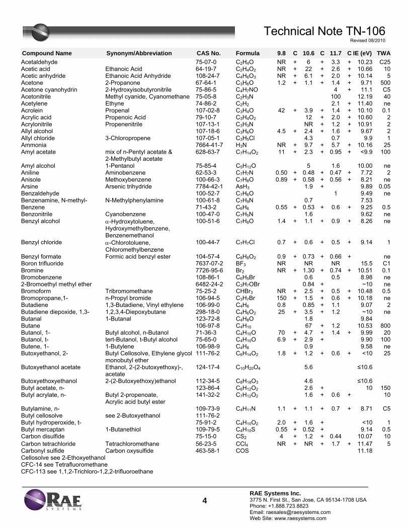
Technical Note TN-106 Revised 08/2010
4RAE Systems Inc. 3775 N. First St., San Jose, CA 95134-1708 USA Phone: +1.888.723.8823 Email: [email protected] Web Site: www.raesystems.com
Compound Name Synonym/Abbreviation CAS No. Formula 9.8 C 10.6 C 11.7 C IE (eV) TWA
Acetaldehyde 75-07-0 C2H4O NR + 6 + 3.3 + 10.23 C25Acetic acid Ethanoic Acid 64-19-7 C2H4O2 NR + 22 + 2.6 + 10.66 10Acetic anhydride Ethanoic Acid Anhydride 108-24-7 C4H6O3 NR + 6.1 + 2.0 + 10.14 5Acetone 2-Propanone 67-64-1 C3H6O 1.2 + 1.1 + 1.4 + 9.71 500Acetone cyanohydrin 2-Hydroxyisobutyronitrile 75-86-5 C4H7NO 4 + 11.1 C5Acetonitrile Methyl cyanide, Cyanomethane 75-05-8 C2H3N 100 12.19 40Acetylene Ethyne 74-86-2 C2H2 2.1 + 11.40 neAcrolein Propenal 107-02-8 C3H4O 42 + 3.9 + 1.4 + 10.10 0.1Acrylic acid Propenoic Acid 79-10-7 C3H4O2 12 + 2.0 + 10.60 2Acrylonitrile Propenenitrile 107-13-1 C3H3N NR + 1.2 + 10.91 2Allyl alcohol 107-18-6 C3H6O 4.5 + 2.4 + 1.6 + 9.67 2Allyl chloride 3-Chloropropene 107-05-1 C3H5Cl 4.3 0.7 9.9 1Ammonia 7664-41-7 H3N NR + 9.7 + 5.7 + 10.16 25Amyl acetate mix of n-Pentyl acetate &
2-Methylbutyl acetate 628-63-7 C7H14O2 11 + 2.3 + 0.95 + <9.9 100
Amyl alcohol 1-Pentanol 75-85-4 C5H12O 5 1.6 10.00 neAniline Aminobenzene 62-53-3 C7H7N 0.50 + 0.48 + 0.47 + 7.72 2Anisole Methoxybenzene 100-66-3 C7H8O 0.89 + 0.58 + 0.56 + 8.21 neArsine Arsenic trihydride 7784-42-1 AsH3 1.9 + 9.89 0.05Benzaldehyde 100-52-7 C7H6O 1 9.49 neBenzenamine, N-methyl- N-Methylphenylamine 100-61-8 C7H9N 0.7 7.53Benzene 71-43-2 C6H6 0.55 + 0.53 + 0.6 + 9.25 0.5Benzonitrile Cyanobenzene 100-47-0 C7H5N 1.6 9.62 neBenzyl alcohol α-Hydroxytoluene,
Hydroxymethylbenzene, Benzenemethanol
100-51-6 C7H8O 1.4 + 1.1 + 0.9 + 8.26 ne
Benzyl chloride α-Chlorotoluene, Chloromethylbenzene
100-44-7 C7H7Cl 0.7 + 0.6 + 0.5 + 9.14 1
Benzyl formate Formic acid benzyl ester 104-57-4 C8H8O2 0.9 + 0.73 + 0.66 + neBoron trifluoride 7637-07-2 BF3 NR NR NR 15.5 C1Bromine 7726-95-6 Br2 NR + 1.30 + 0.74 + 10.51 0.1Bromobenzene 108-86-1 C6H5Br 0.6 0.5 8.98 ne2-Bromoethyl methyl ether 6482-24-2 C3H7OBr 0.84 + ~10 neBromoform Tribromomethane 75-25-2 CHBr3 NR + 2.5 + 0.5 + 10.48 0.5Bromopropane,1- n-Propyl bromide 106-94-5 C3H7Br 150 + 1.5 + 0.6 + 10.18 neButadiene 1,3-Butadiene, Vinyl ethylene 106-99-0 C4H6 0.8 0.85 + 1.1 9.07 2Butadiene diepoxide, 1,3- 1,2,3,4-Diepoxybutane 298-18-0 C4H6O2 25 + 3.5 + 1.2 ~10 neButanal 1-Butanal 123-72-8 C4H8O 1.8 9.84Butane 106-97-8 C4H10 67 + 1.2 10.53 800Butanol, 1- Butyl alcohol, n-Butanol 71-36-3 C4H10O 70 + 4.7 + 1.4 + 9.99 20Butanol, t- tert-Butanol, t-Butyl alcohol 75-65-0 C4H10O 6.9 + 2.9 + 9.90 100Butene, 1- 1-Butylene 106-98-9 C4H8 0.9 9.58 neButoxyethanol, 2- Butyl Cellosolve, Ethylene glycol
monobutyl ether 111-76-2 C6H14O2 1.8 + 1.2 + 0.6 + <10 25
Butoxyethanol acetate Ethanol, 2-(2-butoxyethoxy)-, acetate
124-17-4 C10H20O4 5.6 ≤10.6
Butoxyethoxyethanol 2-(2-Butoxyethoxy)ethanol 112-34-5 C8H18O3 4.6 ≤10.6 Butyl acetate, n- 123-86-4 C6H12O2 2.6 + 10 150Butyl acrylate, n- Butyl 2-propenoate,
Acrylic acid butyl ester 141-32-2 C7H12O2 1.6 + 0.6 + 10
Butylamine, n- 109-73-9 C4H11N 1.1 + 1.1 + 0.7 + 8.71 C5Butyl cellosolve see 2-Butoxyethanol 111-76-2 Butyl hydroperoxide, t- 75-91-2 C4H10O2 2.0 + 1.6 + <10 1Butyl mercaptan 1-Butanethiol 109-79-5 C4H10S 0.55 + 0.52 + 9.14 0.5Carbon disulfide 75-15-0 CS2 4 + 1.2 + 0.44 10.07 10Carbon tetrachloride Tetrachloromethane 56-23-5 CCl4 NR + NR + 1.7 + 11.47 5Carbonyl sulfide Carbon oxysulfide 463-58-1 COS 11.18Cellosolve see 2-Ethoxyethanol CFC-14 see Tetrafluoromethane CFC-113 see 1,1,2-Trichloro-1,2,2-trifluoroethane
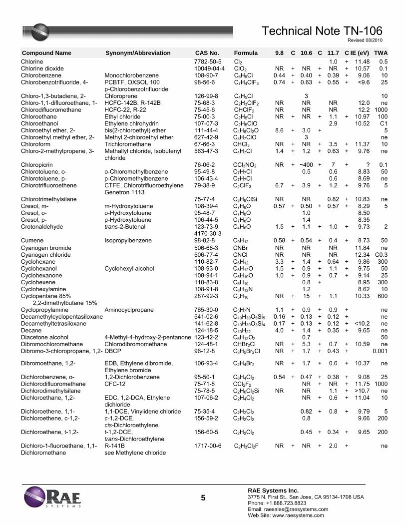
Technical Note TN-106 Revised 08/2010
5RAE Systems Inc. 3775 N. First St., San Jose, CA 95134-1708 USA Phone: +1.888.723.8823 Email: [email protected] Web Site: www.raesystems.com
Compound Name Synonym/Abbreviation CAS No. Formula 9.8 C 10.6 C 11.7 C IE (eV) TWA
Chlorine 7782-50-5 Cl2 1.0 + 11.48 0.5Chlorine dioxide 10049-04-4 ClO2 NR + NR + NR + 10.57 0.1Chlorobenzene Monochlorobenzene 108-90-7 C6H5Cl 0.44 + 0.40 + 0.39 + 9.06 10Chlorobenzotrifluoride, 4- PCBTF, OXSOL 100
p-Chlorobenzotrifluoride 98-56-6 C7H4ClF3 0.74 + 0.63 + 0.55 + <9.6 25
Chloro-1,3-butadiene, 2- Chloroprene 126-99-8 C4H5Cl 3 10Chloro-1,1-difluoroethane, 1- HCFC-142B, R-142B 75-68-3 C2H3ClF2 NR NR NR 12.0 neChlorodifluoromethane HCFC-22, R-22 75-45-6 CHClF2 NR NR NR 12.2 1000Chloroethane Ethyl chloride 75-00-3 C2H5Cl NR + NR + 1.1 + 10.97 100Chloroethanol Ethylene chlrohydrin 107-07-3 C2H5ClO 2.9 10.52 C1Chloroethyl ether, 2- bis(2-chloroethyl) ether 111-44-4 C4H8Cl2O 8.6 + 3.0 + 5Chloroethyl methyl ether, 2- Methyl 2-chloroethyl ether 627-42-9 C3H7ClO 3 neChloroform Trichloromethane 67-66-3 CHCl3 NR + NR + 3.5 + 11.37 10Chloro-2-methylpropene, 3- Methallyl chloride, Isobutenyl
chloride 563-47-3 C4H7Cl 1.4 + 1.2 + 0.63 + 9.76 ne
Chloropicrin 76-06-2 CCl3NO2 NR + ~400 + 7 + ? 0.1Chlorotoluene, o- o-Chloromethylbenzene 95-49-8 C7H7Cl 0.5 0.6 8.83 50Chlorotoluene, p- p-Chloromethylbenzene 106-43-4 C7H7Cl 0.6 8.69 neChlorotrifluoroethene CTFE, Chlorotrifluoroethylene
Genetron 1113 79-38-9 C2ClF3 6.7 + 3.9 + 1.2 + 9.76 5
Chlorotrimethylsilane 75-77-4 C3H9ClSi NR NR 0.82 + 10.83 neCresol, m- m-Hydroxytoluene 108-39-4 C7H8O 0.57 + 0.50 + 0.57 + 8.29 5Cresol, o- o-Hydroxytoluene 95-48-7 C7H8O 1.0 8.50Cresol, p- p-Hydroxytoluene 106-44-5 C7H8O 1.4 8.35Crotonaldehyde trans-2-Butenal 123-73-9
4170-30-3 C4H6O 1.5 + 1.1 + 1.0 + 9.73 2
Cumene Isopropylbenzene 98-82-8 C9H12 0.58 + 0.54 + 0.4 + 8.73 50Cyanogen bromide 506-68-3 CNBr NR NR NR 11.84 neCyanogen chloride 506-77-4 CNCl NR NR NR 12.34 C0.3Cyclohexane 110-82-7 C6H12 3.3 + 1.4 + 0.64 + 9.86 300Cyclohexanol Cyclohexyl alcohol 108-93-0 C6H12O 1.5 + 0.9 + 1.1 + 9.75 50Cyclohexanone 108-94-1 C6H10O 1.0 + 0.9 + 0.7 + 9.14 25Cyclohexene 110-83-8 C6H10 0.8 + 8.95 300Cyclohexylamine 108-91-8 C6H13N 1.2 8.62 10Cyclopentane 85%
2,2-dimethylbutane 15% 287-92-3 C5H10 NR + 15 + 1.1 10.33 600
Cyclopropylamine Aminocyclpropane 765-30-0 C3H7N 1.1 + 0.9 + 0.9 + neDecamethylcyclopentasiloxane 541-02-6 C10H30O5Si5 0.16 + 0.13 + 0.12 + neDecamethyltetrasiloxane 141-62-8 C10H30O3Si4 0.17 + 0.13 + 0.12 + <10.2 neDecane 124-18-5 C10H22 4.0 + 1.4 + 0.35 + 9.65 neDiacetone alcohol 4-Methyl-4-hydroxy-2-pentanone 123-42-2 C6H12O2 0.7 50Dibromochloromethane Chlorodibromomethane 124-48-1 CHBr2Cl NR + 5.3 + 0.7 + 10.59 neDibromo-3-chloropropane, 1,2- DBCP 96-12-8 C3H5Br2Cl NR + 1.7 + 0.43 + 0.001
Dibromoethane, 1,2- EDB, Ethylene dibromide, Ethylene bromide
106-93-4 C2H4Br2 NR + 1.7 + 0.6 + 10.37 ne
Dichlorobenzene, o- 1,2-Dichlorobenzene 95-50-1 C6H4Cl2 0.54 + 0.47 + 0.38 + 9.08 25Dichlorodifluoromethane CFC-12 75-71-8 CCl2F2 NR + NR + 11.75 1000Dichlorodimethylsilane 75-78-5 C2H6Cl2Si NR NR 1.1 + >10.7 neDichloroethane, 1,2- EDC, 1,2-DCA, Ethylene
dichloride 107-06-2 C2H4Cl2 NR + 0.6 + 11.04 10
Dichloroethene, 1,1- 1,1-DCE, Vinylidene chloride 75-35-4 C2H2Cl2 0.82 + 0.8 + 9.79 5Dichloroethene, c-1,2- c-1,2-DCE,
cis-Dichloroethylene 156-59-2 C2H2Cl2 0.8 9.66 200
Dichloroethene, t-1,2- t-1,2-DCE, trans-Dichloroethylene
156-60-5 C2H2Cl2 0.45 + 0.34 + 9.65 200
Dichloro-1-fluoroethane, 1,1- R-141B 1717-00-6 C2H3Cl2F NR + NR + 2.0 + neDichloromethane see Methylene chloride
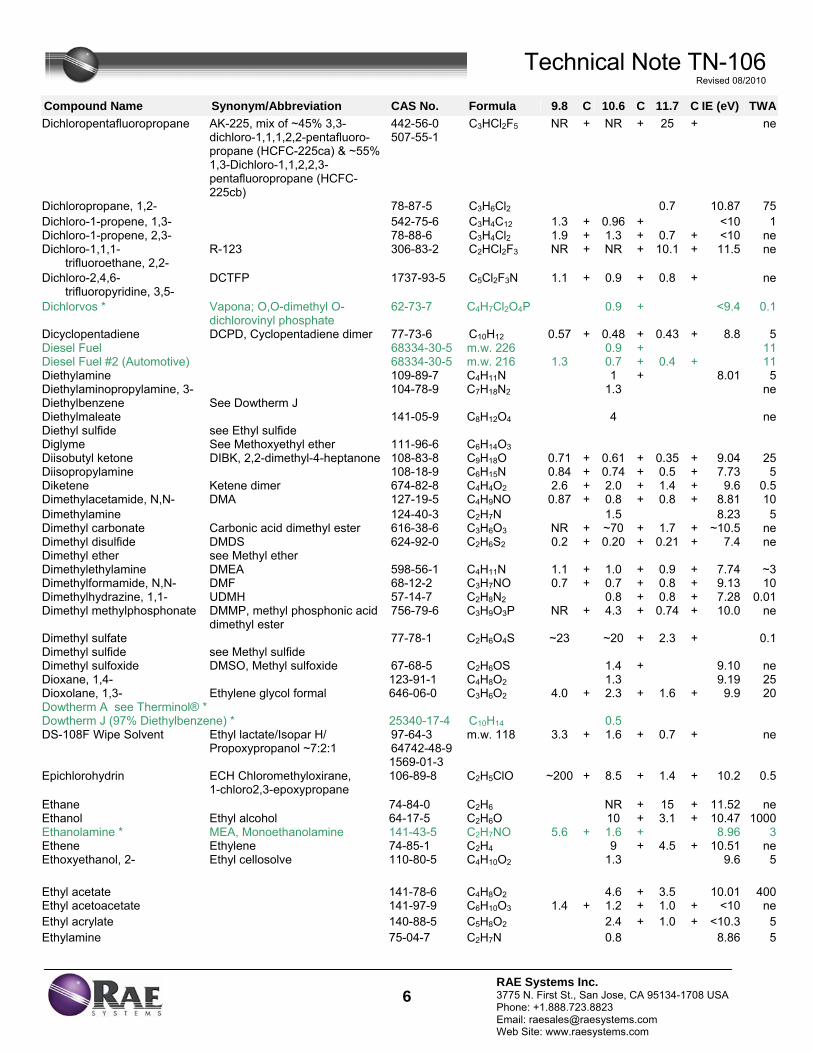
Technical Note TN-106 Revised 08/2010
6RAE Systems Inc. 3775 N. First St., San Jose, CA 95134-1708 USA Phone: +1.888.723.8823 Email: [email protected] Web Site: www.raesystems.com
Compound Name Synonym/Abbreviation CAS No. Formula 9.8 C 10.6 C 11.7 C IE (eV) TWA
Dichloropentafluoropropane AK-225, mix of ~45% 3,3-dichloro-1,1,1,2,2-pentafluoro-propane (HCFC-225ca) & ~55% 1,3-Dichloro-1,1,2,2,3-pentafluoropropane (HCFC-225cb)
442-56-0 507-55-1
C3HCl2F5 NR + NR + 25 + ne
Dichloropropane, 1,2- 78-87-5 C3H6Cl2 0.7 10.87 75Dichloro-1-propene, 1,3- 542-75-6 C3H4C12 1.3 + 0.96 + <10 1Dichloro-1-propene, 2,3- 78-88-6 C3H4Cl2 1.9 + 1.3 + 0.7 + <10 neDichloro-1,1,1- trifluoroethane, 2,2-
R-123 306-83-2 C2HCl2F3 NR + NR + 10.1 + 11.5 ne
Dichloro-2,4,6- trifluoropyridine, 3,5-
DCTFP 1737-93-5 C5Cl2F3N 1.1 + 0.9 + 0.8 + ne
Dichlorvos * Vapona; O,O-dimethyl O-dichlorovinyl phosphate
62-73-7 C4H7Cl2O4P 0.9 + <9.4 0.1
Dicyclopentadiene DCPD, Cyclopentadiene dimer 77-73-6 C10H12 0.57 + 0.48 + 0.43 + 8.8 5Diesel Fuel 68334-30-5 m.w. 226 0.9 + 11Diesel Fuel #2 (Automotive) 68334-30-5 m.w. 216 1.3 0.7 + 0.4 + 11Diethylamine 109-89-7 C4H11N 1 + 8.01 5Diethylaminopropylamine, 3- 104-78-9 C7H18N2 1.3 neDiethylbenzene See Dowtherm J Diethylmaleate 141-05-9 C8H12O4 4 neDiethyl sulfide see Ethyl sulfide Diglyme See Methoxyethyl ether 111-96-6 C6H14O3 Diisobutyl ketone DIBK, 2,2-dimethyl-4-heptanone 108-83-8 C9H18O 0.71 + 0.61 + 0.35 + 9.04 25Diisopropylamine 108-18-9 C6H15N 0.84 + 0.74 + 0.5 + 7.73 5Diketene Ketene dimer 674-82-8 C4H4O2 2.6 + 2.0 + 1.4 + 9.6 0.5Dimethylacetamide, N,N- DMA 127-19-5 C4H9NO 0.87 + 0.8 + 0.8 + 8.81 10Dimethylamine 124-40-3 C2H7N 1.5 8.23 5Dimethyl carbonate Carbonic acid dimethyl ester 616-38-6 C3H6O3 NR + ~70 + 1.7 + ~10.5 neDimethyl disulfide DMDS 624-92-0 C2H6S2 0.2 + 0.20 + 0.21 + 7.4 neDimethyl ether see Methyl ether Dimethylethylamine DMEA 598-56-1 C4H11N 1.1 + 1.0 + 0.9 + 7.74 ~3Dimethylformamide, N,N- DMF 68-12-2 C3H7NO 0.7 + 0.7 + 0.8 + 9.13 10Dimethylhydrazine, 1,1- UDMH 57-14-7 C2H8N2 0.8 + 0.8 + 7.28 0.01Dimethyl methylphosphonate DMMP, methyl phosphonic acid
dimethyl ester 756-79-6 C3H9O3P NR + 4.3 + 0.74 + 10.0 ne
Dimethyl sulfate 77-78-1 C2H6O4S ~23 ~20 + 2.3 + 0.1Dimethyl sulfide see Methyl sulfide Dimethyl sulfoxide DMSO, Methyl sulfoxide 67-68-5 C2H6OS 1.4 + 9.10 neDioxane, 1,4- 123-91-1 C4H8O2 1.3 9.19 25Dioxolane, 1,3- Ethylene glycol formal 646-06-0 C3H6O2 4.0 + 2.3 + 1.6 + 9.9 20Dowtherm A see Therminol® * Dowtherm J (97% Diethylbenzene) * 25340-17-4 C10H14 0.5 DS-108F Wipe Solvent Ethyl lactate/Isopar H/
Propoxypropanol ~7:2:1 97-64-3 64742-48-9 1569-01-3
m.w. 118 3.3 + 1.6 + 0.7 + ne
Epichlorohydrin ECH Chloromethyloxirane, 1-chloro2,3-epoxypropane
106-89-8 C2H5ClO ~200 + 8.5 + 1.4 + 10.2 0.5
Ethane 74-84-0 C2H6 NR + 15 + 11.52 neEthanol Ethyl alcohol 64-17-5 C2H6O 10 + 3.1 + 10.47 1000Ethanolamine * MEA, Monoethanolamine 141-43-5 C2H7NO 5.6 + 1.6 + 8.96 3Ethene Ethylene 74-85-1 C2H4 9 + 4.5 + 10.51 neEthoxyethanol, 2- Ethyl cellosolve 110-80-5 C4H10O2 1.3 9.6 5
Ethyl acetate 141-78-6 C4H8O2 4.6 + 3.5 10.01 400Ethyl acetoacetate 141-97-9 C6H10O3 1.4 + 1.2 + 1.0 + <10 neEthyl acrylate 140-88-5 C5H8O2 2.4 + 1.0 + <10.3 5Ethylamine 75-04-7 C2H7N 0.8 8.86 5
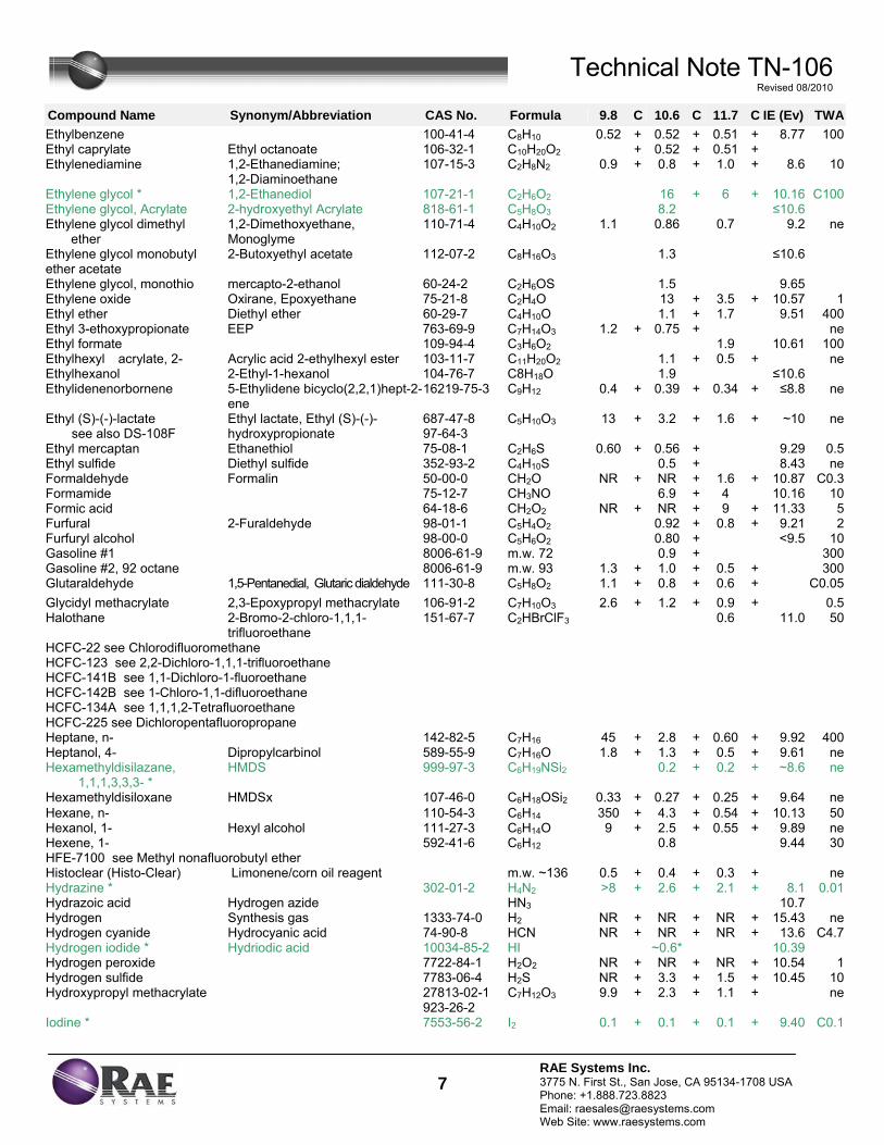
Technical Note TN-106 Revised 08/2010
7RAE Systems Inc. 3775 N. First St., San Jose, CA 95134-1708 USA Phone: +1.888.723.8823 Email: [email protected] Web Site: www.raesystems.com
Compound Name Synonym/Abbreviation CAS No. Formula 9.8 C 10.6 C 11.7 C IE (Ev) TWA
Ethylbenzene 100-41-4 C8H10 0.52 + 0.52 + 0.51 + 8.77 100Ethyl caprylate Ethyl octanoate 106-32-1 C10H20O2 + 0.52 + 0.51 +Ethylenediamine 1,2-Ethanediamine;
1,2-Diaminoethane 107-15-3 C2H8N2 0.9 + 0.8 + 1.0 + 8.6 10
Ethylene glycol * 1,2-Ethanediol 107-21-1 C2H6O2 16 + 6 + 10.16 C100Ethylene glycol, Acrylate 2-hydroxyethyl Acrylate 818-61-1 C5H8O3 8.2 ≤10.6Ethylene glycol dimethyl ether
1,2-Dimethoxyethane, Monoglyme
110-71-4 C4H10O2 1.1 0.86 0.7 9.2 ne
Ethylene glycol monobutyl ether acetate
2-Butoxyethyl acetate 112-07-2 C8H16O3 1.3 ≤10.6
Ethylene glycol, monothio mercapto-2-ethanol 60-24-2 C2H6OS 1.5 9.65Ethylene oxide Oxirane, Epoxyethane 75-21-8 C2H4O 13 + 3.5 + 10.57 1Ethyl ether Diethyl ether 60-29-7 C4H10O 1.1 + 1.7 9.51 400Ethyl 3-ethoxypropionate EEP 763-69-9 C7H14O3 1.2 + 0.75 + neEthyl formate 109-94-4 C3H6O2 1.9 10.61 100Ethylhexyl acrylate, 2- Acrylic acid 2-ethylhexyl ester 103-11-7 C11H20O2 1.1 + 0.5 + neEthylhexanol 2-Ethyl-1-hexanol 104-76-7 C8H18O 1.9 ≤10.6Ethylidenenorbornene 5-Ethylidene bicyclo(2,2,1)hept-2-
ene 16219-75-3 C9H12 0.4 + 0.39 + 0.34 + ≤8.8 ne
Ethyl (S)-(-)-lactate see also DS-108F
Ethyl lactate, Ethyl (S)-(-)-hydroxypropionate
687-47-8 97-64-3
C5H10O3 13 + 3.2 + 1.6 + ~10 ne
Ethyl mercaptan Ethanethiol 75-08-1 C2H6S 0.60 + 0.56 + 9.29 0.5Ethyl sulfide Diethyl sulfide 352-93-2 C4H10S 0.5 + 8.43 neFormaldehyde Formalin 50-00-0 CH2O NR + NR + 1.6 + 10.87 C0.3Formamide 75-12-7 CH3NO 6.9 + 4 10.16 10Formic acid 64-18-6 CH2O2 NR + NR + 9 + 11.33 5Furfural 2-Furaldehyde 98-01-1 C5H4O2 0.92 + 0.8 + 9.21 2Furfuryl alcohol 98-00-0 C5H6O2 0.80 + <9.5 10Gasoline #1 8006-61-9 m.w. 72 0.9 + 300Gasoline #2, 92 octane 8006-61-9 m.w. 93 1.3 + 1.0 + 0.5 + 300Glutaraldehyde 1,5-Pentanedial, Glutaric dialdehyde 111-30-8 C5H8O2 1.1 + 0.8 + 0.6 + C0.05Glycidyl methacrylate 2,3-Epoxypropyl methacrylate 106-91-2 C7H10O3 2.6 + 1.2 + 0.9 + 0.5Halothane 2-Bromo-2-chloro-1,1,1-
trifluoroethane 151-67-7 C2HBrClF3 0.6 11.0 50
HCFC-22 see Chlorodifluoromethane HCFC-123 see 2,2-Dichloro-1,1,1-trifluoroethane HCFC-141B see 1,1-Dichloro-1-fluoroethane HCFC-142B see 1-Chloro-1,1-difluoroethane HCFC-134A see 1,1,1,2-Tetrafluoroethane HCFC-225 see Dichloropentafluoropropane Heptane, n- 142-82-5 C7H16 45 + 2.8 + 0.60 + 9.92 400Heptanol, 4- Dipropylcarbinol 589-55-9 C7H16O 1.8 + 1.3 + 0.5 + 9.61 neHexamethyldisilazane, 1,1,1,3,3,3- *
HMDS 999-97-3 C6H19NSi2 0.2 + 0.2 + ~8.6 ne
Hexamethyldisiloxane HMDSx 107-46-0 C6H18OSi2 0.33 + 0.27 + 0.25 + 9.64 neHexane, n- 110-54-3 C6H14 350 + 4.3 + 0.54 + 10.13 50Hexanol, 1- Hexyl alcohol 111-27-3 C6H14O 9 + 2.5 + 0.55 + 9.89 neHexene, 1- 592-41-6 C6H12 0.8 9.44 30HFE-7100 see Methyl nonafluorobutyl ether Histoclear (Histo-Clear) Limonene/corn oil reagent m.w. ~136 0.5 + 0.4 + 0.3 + neHydrazine * 302-01-2 H4N2 >8 + 2.6 + 2.1 + 8.1 0.01Hydrazoic acid Hydrogen azide HN3 10.7Hydrogen Synthesis gas 1333-74-0 H2 NR + NR + NR + 15.43 neHydrogen cyanide Hydrocyanic acid 74-90-8 HCN NR + NR + NR + 13.6 C4.7Hydrogen iodide * Hydriodic acid 10034-85-2 HI ~0.6* 10.39Hydrogen peroxide 7722-84-1 H2O2 NR + NR + NR + 10.54 1Hydrogen sulfide 7783-06-4 H2S NR + 3.3 + 1.5 + 10.45 10Hydroxypropyl methacrylate 27813-02-1
923-26-2 C7H12O3 9.9 + 2.3 + 1.1 + ne
Iodine * 7553-56-2 I2 0.1 + 0.1 + 0.1 + 9.40 C0.1
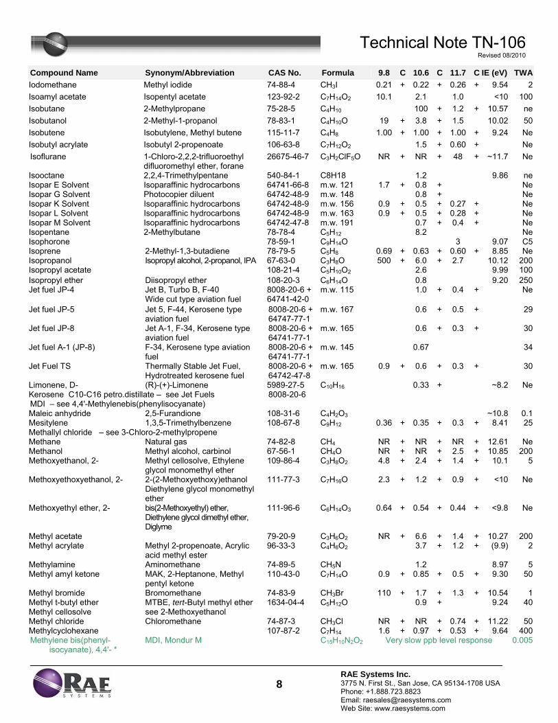
Technical Note TN-106 Revised 08/2010
8RAE Systems Inc. 3775 N. First St., San Jose, CA 95134-1708 USA Phone: +1.888.723.8823 Email: [email protected] Web Site: www.raesystems.com
Compound Name Synonym/Abbreviation CAS No. Formula 9.8 C 10.6 C 11.7 C IE (eV) TWA
Iodomethane Methyl iodide 74-88-4 CH3I 0.21 + 0.22 + 0.26 + 9.54 2Isoamyl acetate Isopentyl acetate 123-92-2 C7H14O2 10.1 2.1 1.0 <10 100Isobutane 2-Methylpropane 75-28-5 C4H10 100 + 1.2 + 10.57 neIsobutanol 2-Methyl-1-propanol 78-83-1 C4H10O 19 + 3.8 + 1.5 10.02 50Isobutene Isobutylene, Methyl butene 115-11-7 C4H8 1.00 + 1.00 + 1.00 + 9.24 NeIsobutyl acrylate Isobutyl 2-propenoate 106-63-8 C7H12O2 1.5 + 0.60 + NeIsoflurane 1-Chloro-2,2,2-trifluoroethyl
difluoromethyl ether, forane 26675-46-7 C3H2ClF5O NR + NR + 48 + ~11.7 Ne
Isooctane 2,2,4-Trimethylpentane 540-84-1 C8H18 1.2 9.86 neIsopar E Solvent Isoparaffinic hydrocarbons 64741-66-8 m.w. 121 1.7 + 0.8 + NeIsopar G Solvent Photocopier diluent 64742-48-9 m.w. 148 0.8 + NeIsopar K Solvent Isoparaffinic hydrocarbons 64742-48-9 m.w. 156 0.9 + 0.5 + 0.27 + NeIsopar L Solvent Isoparaffinic hydrocarbons 64742-48-9 m.w. 163 0.9 + 0.5 + 0.28 + NeIsopar M Solvent Isoparaffinic hydrocarbons 64742-47-8 m.w. 191 0.7 + 0.4 + NeIsopentane 2-Methylbutane 78-78-4 C5H12 8.2 NeIsophorone 78-59-1 C9H14O 3 9.07 C5Isoprene 2-Methyl-1,3-butadiene 78-79-5 C5H8 0.69 + 0.63 + 0.60 + 8.85 NeIsopropanol Isopropyl alcohol, 2-propanol, IPA 67-63-0 C3H8O 500 + 6.0 + 2.7 10.12 200Isopropyl acetate 108-21-4 C5H10O2 2.6 9.99 100Isopropyl ether Diisopropyl ether 108-20-3 C6H14O 0.8 9.20 250Jet fuel JP-4 Jet B, Turbo B, F-40
Wide cut type aviation fuel 8008-20-6 + 64741-42-0
m.w. 115 1.0 + 0.4 + Ne
Jet fuel JP-5 Jet 5, F-44, Kerosene type aviation fuel
8008-20-6 + 64747-77-1
m.w. 167 0.6 + 0.5 + 29
Jet fuel JP-8 Jet A-1, F-34, Kerosene type aviation fuel
8008-20-6 + 64741-77-1
m.w. 165 0.6 + 0.3 + 30
Jet fuel A-1 (JP-8) F-34, Kerosene type aviation fuel
8008-20-6 + 64741-77-1
m.w. 145 0.67 34
Jet Fuel TS Thermally Stable Jet Fuel, Hydrotreated kerosene fuel
8008-20-6 + 64742-47-8
m.w. 165 0.9 +
0.6 + 0.3 + 30
Limonene, D- (R)-(+)-Limonene 5989-27-5 C10H16 0.33 + ~8.2 NeKerosene C10-C16 petro.distillate – see Jet Fuels 8008-20-6 MDI – see 4,4'-Methylenebis(phenylisocyanate) Maleic anhydride 2,5-Furandione 108-31-6 C4H2O3 ~10.8 0.1Mesitylene 1,3,5-Trimethylbenzene 108-67-8 C9H12 0.36 + 0.35 + 0.3 + 8.41 25Methallyl chloride – see 3-Chloro-2-methylpropene Methane Natural gas 74-82-8 CH4 NR + NR + NR + 12.61 NeMethanol Methyl alcohol, carbinol 67-56-1 CH4O NR + NR + 2.5 + 10.85 200Methoxyethanol, 2- Methyl cellosolve, Ethylene
glycol monomethyl ether 109-86-4 C3H8O2 4.8 + 2.4 + 1.4 + 10.1 5
Methoxyethoxyethanol, 2- 2-(2-Methoxyethoxy)ethanol Diethylene glycol monomethyl ether
111-77-3 C7H16O 2.3 + 1.2 + 0.9 + <10 Ne
Methoxyethyl ether, 2- bis(2-Methoxyethyl) ether, Diethylene glycol dimethyl ether, Diglyme
111-96-6 C6H14O3 0.64 + 0.54 + 0.44 + <9.8 Ne
Methyl acetate 79-20-9 C3H6O2 NR + 6.6 + 1.4 + 10.27 200Methyl acrylate Methyl 2-propenoate, Acrylic
acid methyl ester 96-33-3 C4H6O2 3.7 + 1.2 + (9.9) 2
Methylamine Aminomethane 74-89-5 CH5N 1.2 8.97 5Methyl amyl ketone MAK, 2-Heptanone, Methyl
pentyl ketone 110-43-0 C7H14O 0.9 + 0.85 + 0.5 + 9.30 50
Methyl bromide Bromomethane 74-83-9 CH3Br 110 + 1.7 + 1.3 + 10.54 1Methyl t-butyl ether MTBE, tert-Butyl methyl ether 1634-04-4 C5H12O 0.9 + 9.24 40Methyl cellosolve see 2-Methoxyethanol Methyl chloride Chloromethane 74-87-3 CH3Cl NR + NR + 0.74 + 11.22 50Methylcyclohexane 107-87-2 C7H14 1.6 + 0.97 + 0.53 + 9.64 400Methylene bis(phenyl-
isocyanate), 4,4'- * MDI, Mondur M C15H10N2O2 Very slow ppb level response 0.005
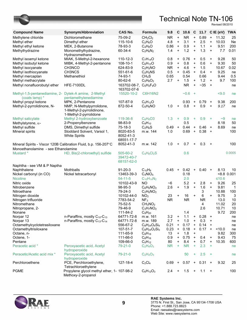
Technical Note TN-106 Revised 08/2010
9RAE Systems Inc. 3775 N. First St., San Jose, CA 95134-1708 USA Phone: +1.888.723.8823 Email: [email protected] Web Site: www.raesystems.com
Compound Name Synonym/Abbreviation CAS No. Formula 9.8 C 10.6 C 11.7 C IE (eV) TWA
Methylene chloride Dichloromethane 75-09-2 CH2Cl2 NR + NR + 0.89 + 11.32 25Methyl ether Dimethyl ether 115-10-6 C2H6O 4.8 + 3.1 + 2.5 + 10.03 NeMethyl ethyl ketone MEK, 2-Butanone 78-93-3 C4H8O 0.86 + 0.9 + 1.1 + 9.51 200Methylhydrazine Monomethylhydrazine,
Hydrazomethane 60-34-4 C2H6N2 1.4 + 1.2 + 1.3 + 7.7 0.01
Methyl isoamyl ketone MIAK, 5-Methyl-2-hexanone 110-12-3 C7H14O 0.8 + 0.76 + 0.5 + 9.28 50Methyl isobutyl ketone MIBK, 4-Methyl-2-pentanone 108-10-1 C6H12O 0.9 + 0.8 + 0.6 + 9.30 50Methyl isocyanate CH3NCO 624-83-9 C2H3NO NR + 4.6 + 1.5 10.67 0.02Methyl isothiocyanate CH3NCS 551-61-6 C2H3NS 0.5 + 0.45 + 0.4 + 9.25 neMethyl mercaptan Methanethiol 74-93-1 CH4S 0.65 0.54 0.66 9.44 0.5Methyl methacrylate 80-62-6 C5H8O2 2.7 + 1.5 + 1.2 + 9.7 100Methyl nonafluorobutyl ether HFE-7100DL 163702-08-7,
163702-07-6 C5H3F9O NR + ~35 + ne
Methyl-1,5-pentanediamine, 2- (coats lamp) *
Dytek-A amine, 2-Methyl pentamethylenediamine
15520-10-2 C6H16N2 ~0.6 + <9.0 ne
Methyl propyl ketone MPK, 2-Pentanone 107-87-9 C5H12O 0.93 + 0.79 + 9.38 200Methyl-2-pyrrolidinone, N- NMP, N-Methylpyrrolidone,
1-Methyl-2-pyrrolidinone, 1-Methyl-2-pyrrolidone
872-50-4 C5H9NO 1.0 + 0.8 + 0.9 + 9.17 ne
Methyl salicylate Methyl 2-hydroxybenzoate 119-36-8 C8H8O3 1.3 + 0.9 + 0.9 + ~9 neMethylstyrene, α- 2-Propenylbenzene 98-83-9 C9H10 0.5 8.18 50Methyl sulfide DMS, Dimethyl sulfide 75-18-3 C2H6S 0.49 + 0.44 + 0.46 + 8.69 neMineral spirits Stoddard Solvent, Varsol 1,
White Spirits 8020-83-5 8052-41-3 68551-17-7
m.w. 144 1.0 0.69 + 0.38 + 100
Mineral Spirits - Viscor 120B Calibration Fluid, b.p. 156-207°C 8052-41-3 m.w. 142 1.0 + 0.7 + 0.3 + 100Monoethanolamine - see Ethanolamine Mustard * HD, Bis(2-chloroethyl) sulfide 505-60-2
39472-40-7 68157-62-0
C4H8Cl2S 0.6 0.0005
Naphtha - see VM & P Naptha Naphthalene Mothballs 91-20-3 C10H8 0.45 + 0.42 + 0.40 + 8.13 10Nickel carbonyl (in CO) Nickel tetracarbonyl 13463-39-3 C4NiO4 0.18 <8.8 0.001Nicotine 54-11-5 C10H14N2 2.0 ≤10.6Nitric oxide 10102-43-9 NO ~6 5.2 + 2.8 + 9.26 25Nitrobenzene 98-95-3 C6H5NO2 2.6 + 1.9 + 1.6 + 9.81 1Nitroethane 79-24-3 C2H5NO2 3 10.88 100Nitrogen dioxide 10102-44-0 NO2 23 + 16 + 6 + 9.75 3Nitrogen trifluoride 7783-54-2 NF3 NR NR NR 13.0 10Nitromethane 75-52-5 CH3NO2 4 11.02 20Nitropropane, 2- 79-46-9 C3H7NO2 2.6 10.71 10Nonane 111-84-2 C9H20 1.4 9.72 200Norpar 12 n-Paraffins, mostly C10-C13 64771-72-8 m.w. 161 3.2 + 1.1 + 0.28 + neNorpar 13 n-Paraffins, mostly C13-C14 64771-72-8 m.w. 189 2.7 + 1.0 + 0.3 + neOctamethylcyclotetrasiloxane 556-67-2 C8H24O4Si4 0.21 + 0.17 + 0.14 + neOctamethyltrisiloxane 107-51-7 C8H24O2Si3 0.23 + 0.18 + 0.17 + <10.0 neOctane, n- 111-65-9 C8H18 13 + 1.8 + 9.82 300Octene, 1- 111-66-0 C8H16 0.9 + 0.75 + 0.4 + 9.43 75Pentane 109-66-0 C5H12 80 + 8.4 + 0.7 + 10.35 600Peracetic acid * Peroxyacetic acid, Acetyl
hydroperoxide 79-21-0 C2H4O3 NR + NR + 2.3 + ne
Peracetic/Acetic acid mix * Peroxyacetic acid, Acetyl hydroperoxide
79-21-0 C2H4O3 50 + 2.5 + ne
Perchloroethene PCE, Perchloroethylene, Tetrachloroethylene
127-18-4 C2Cl4 0.69 + 0.57 + 0.31 + 9.32 25
PGME Propylene glycol methyl ether, 1-Methoxy-2-propanol
107-98-2 C6H12O3 2.4 + 1.5 + 1.1 + 100
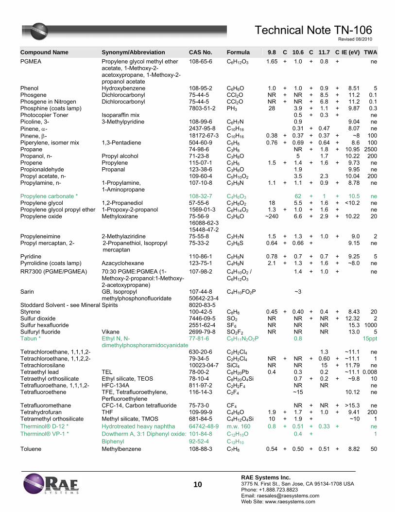
Technical Note TN-106 Revised 08/2010
10RAE Systems Inc. 3775 N. First St., San Jose, CA 95134-1708 USA Phone: +1.888.723.8823 Email: [email protected] Web Site: www.raesystems.com
Compound Name Synonym/Abbreviation CAS No. Formula 9.8 C 10.6 C 11.7 C IE (eV) TWA
PGMEA Propylene glycol methyl ether acetate, 1-Methoxy-2-acetoxypropane, 1-Methoxy-2-propanol acetate
108-65-6 C6H12O3 1.65 + 1.0 + 0.8 + ne
Phenol Hydroxybenzene 108-95-2 C6H6O 1.0 + 1.0 + 0.9 + 8.51 5Phosgene Dichlorocarbonyl 75-44-5 CCl2O NR + NR + 8.5 + 11.2 0.1Phosgene in Nitrogen Dichlorocarbonyl 75-44-5 CCl2O NR + NR + 6.8 + 11.2 0.1Phosphine (coats lamp) 7803-51-2 PH3 28 3.9 + 1.1 + 9.87 0.3Photocopier Toner Isoparaffin mix 0.5 + 0.3 + nePicoline, 3- 3-Methylpyridine 108-99-6 C6H7N 0.9 9.04 nePinene, α- 2437-95-8 C10H16 0.31 + 0.47 8.07 nePinene, β- 18172-67-3 C10H16 0.38 + 0.37 + 0.37 + ~8 100Piperylene, isomer mix 1,3-Pentadiene 504-60-9 C5H8 0.76 + 0.69 + 0.64 + 8.6 100Propane 74-98-6 C3H8 NR + 1.8 + 10.95 2500Propanol, n- Propyl alcohol 71-23-8 C3H8O 5 1.7 10.22 200Propene Propylene 115-07-1 C3H6 1.5 + 1.4 + 1.6 + 9.73 nePropionaldehyde Propanal 123-38-6 C3H6O 1.9 9.95 nePropyl acetate, n- 109-60-4 C5H10O2 3.5 2.3 10.04 200Propylamine, n- 1-Propylamine,
1-Aminopropane 107-10-8 C3H9N 1.1 + 1.1 + 0.9 + 8.78 ne
Propylene carbonate * 108-32-7 C4H6O3 62 + 1 + 10.5 nePropylene glycol 1,2-Propanediol 57-55-6 C3H8O2 18 5.5 + 1.6 + <10.2 nePropylene glycol propyl ether 1-Propoxy-2-propanol 1569-01-3 C6H14O2 1.3 + 1.0 + 1.6 + nePropylene oxide Methyloxirane 75-56-9
16088-62-3 15448-47-2
C3H6O ~240 6.6 + 2.9 + 10.22 20
Propyleneimine 2-Methylaziridine 75-55-8 C3H7N 1.5 + 1.3 + 1.0 + 9.0 2Propyl mercaptan, 2- 2-Propanethiol, Isopropyl
mercaptan 75-33-2 C3H8S 0.64 + 0.66 + 9.15 ne
Pyridine 110-86-1 C5H5N 0.78 + 0.7 + 0.7 + 9.25 5Pyrrolidine (coats lamp) Azacyclohexane 123-75-1 C4H9N 2.1 + 1.3 + 1.6 + ~8.0 neRR7300 (PGME/PGMEA) 70:30 PGME:PGMEA (1-
Methoxy-2-propanol:1-Methoxy-2-acetoxypropane)
107-98-2 C4H10O2 / C6H12O3
1.4 + 1.0 + ne
Sarin GB, Isopropyl methylphosphonofluoridate
107-44-8 50642-23-4
C4H10FO2P ~3
Stoddard Solvent - see Mineral Spirits 8020-83-5 Styrene 100-42-5 C8H8 0.45 + 0.40 + 0.4 + 8.43 20Sulfur dioxide 7446-09-5 SO2 NR NR + NR + 12.32 2Sulfur hexafluoride 2551-62-4 SF6 NR NR NR 15.3 1000Sulfuryl fluoride Vikane 2699-79-8 SO2F2 NR NR NR 13.0 5Tabun * Ethyl N, N-
dimethylphosphoramidocyanidate77-81-6 C5H11N2O2P 0.8 15ppt
Tetrachloroethane, 1,1,1,2- 630-20-6 C2H2Cl4 1.3 ~11.1 neTetrachloroethane, 1,1,2,2- 79-34-5 C2H2Cl4 NR + NR + 0.60 + ~11.1 1Tetrachlorosilane 10023-04-7 SiCl4 NR NR 15 + 11.79 neTetraethyl lead TEL 78-00-2 C8H20Pb 0.4 0.3 0.2 ~11.1 0.008Tetraethyl orthosilicate Ethyl silicate, TEOS 78-10-4 C8H20O4Si 0.7 + 0.2 + ~9.8 10Tetrafluoroethane, 1,1,1,2- HFC-134A 811-97-2 C2H2F4 NR NR neTetrafluoroethene TFE, Tetrafluoroethylene,
Perfluoroethylene 116-14-3 C2F4 ~15 10.12 ne
Tetrafluoromethane CFC-14, Carbon tetrafluoride 75-73-0 CF4 NR + NR + >15.3 neTetrahydrofuran THF 109-99-9 C4H8O 1.9 + 1.7 + 1.0 + 9.41 200Tetramethyl orthosilicate Methyl silicate, TMOS 681-84-5 C4H12O4Si 10 + 1.9 + ~10 1Therminol® D-12 * Hydrotreated heavy naphtha 64742-48-9 m.w. 160 0.8 + 0.51 + 0.33 + ne
Dowtherm A, 3:1 Diphenyl oxide: 101-84-8 C12H10O Therminol® VP-1 * Biphenyl 92-52-4 C12H10
0.4 + 1
Toluene Methylbenzene 108-88-3 C7H8 0.54 + 0.50 + 0.51 + 8.82 50
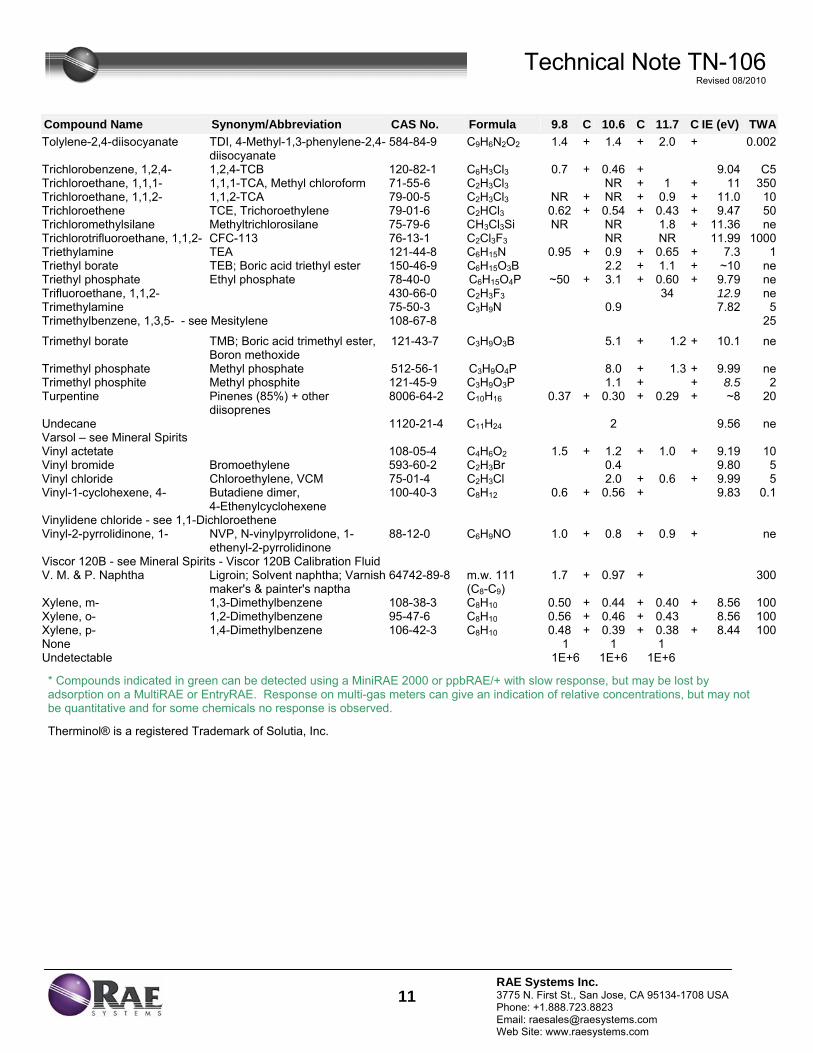
Technical Note TN-106 Revised 08/2010
11RAE Systems Inc. 3775 N. First St., San Jose, CA 95134-1708 USA Phone: +1.888.723.8823 Email: [email protected] Web Site: www.raesystems.com
Compound Name Synonym/Abbreviation CAS No. Formula 9.8 C 10.6 C 11.7 C IE (eV) TWA
Tolylene-2,4-diisocyanate TDI, 4-Methyl-1,3-phenylene-2,4-diisocyanate
584-84-9 C9H6N2O2 1.4 + 1.4 + 2.0 + 0.002
Trichlorobenzene, 1,2,4- 1,2,4-TCB 120-82-1 C6H3Cl3 0.7 + 0.46 + 9.04 C5Trichloroethane, 1,1,1- 1,1,1-TCA, Methyl chloroform 71-55-6 C2H3Cl3 NR + 1 + 11 350Trichloroethane, 1,1,2- 1,1,2-TCA 79-00-5 C2H3Cl3 NR + NR + 0.9 + 11.0 10Trichloroethene TCE, Trichoroethylene 79-01-6 C2HCl3 0.62 + 0.54 + 0.43 + 9.47 50Trichloromethylsilane Methyltrichlorosilane 75-79-6 CH3Cl3Si NR NR 1.8 + 11.36 neTrichlorotrifluoroethane, 1,1,2- CFC-113 76-13-1 C2Cl3F3 NR NR 11.99 1000Triethylamine TEA 121-44-8 C6H15N 0.95 + 0.9 + 0.65 + 7.3 1Triethyl borate TEB; Boric acid triethyl ester 150-46-9 C6H15O3B 2.2 + 1.1 + ~10 neTriethyl phosphate Ethyl phosphate 78-40-0 C6H15O4P ~50 + 3.1 + 0.60 + 9.79 neTrifluoroethane, 1,1,2- 430-66-0 C2H3F3 34 12.9 neTrimethylamine 75-50-3 C3H9N 0.9 7.82 5Trimethylbenzene, 1,3,5- - see Mesitylene 108-67-8 25
Trimethyl borate TMB; Boric acid trimethyl ester, Boron methoxide
121-43-7 C3H9O3B 5.1 + 1.2 + 10.1 ne
Trimethyl phosphate Methyl phosphate 512-56-1 C3H9O4P 8.0 + 1.3 + 9.99 neTrimethyl phosphite Methyl phosphite 121-45-9 C3H9O3P 1.1 + + 8.5 2Turpentine Pinenes (85%) + other
diisoprenes 8006-64-2 C10H16 0.37 + 0.30 + 0.29 + ~8 20
Undecane 1120-21-4 C11H24 2 9.56 neVarsol – see Mineral Spirits Vinyl actetate 108-05-4 C4H6O2 1.5 + 1.2 + 1.0 + 9.19 10Vinyl bromide Bromoethylene 593-60-2 C2H3Br 0.4 9.80 5Vinyl chloride Chloroethylene, VCM 75-01-4 C2H3Cl 2.0 + 0.6 + 9.99 5Vinyl-1-cyclohexene, 4- Butadiene dimer,
4-Ethenylcyclohexene 100-40-3 C8H12 0.6 + 0.56 + 9.83 0.1
Vinylidene chloride - see 1,1-Dichloroethene Vinyl-2-pyrrolidinone, 1- NVP, N-vinylpyrrolidone, 1-
ethenyl-2-pyrrolidinone 88-12-0 C6H9NO 1.0 + 0.8 + 0.9 + ne
Viscor 120B - see Mineral Spirits - Viscor 120B Calibration Fluid V. M. & P. Naphtha Ligroin; Solvent naphtha; Varnish
maker's & painter's naptha 64742-89-8 m.w. 111
(C8-C9) 1.7 + 0.97 + 300
Xylene, m- 1,3-Dimethylbenzene 108-38-3 C8H10 0.50 + 0.44 + 0.40 + 8.56 100Xylene, o- 1,2-Dimethylbenzene 95-47-6 C8H10 0.56 + 0.46 + 0.43 8.56 100Xylene, p- 1,4-Dimethylbenzene 106-42-3 C8H10 0.48 + 0.39 + 0.38 + 8.44 100None 1 1 1 Undetectable 1E+6 1E+6 1E+6
* Compounds indicated in green can be detected using a MiniRAE 2000 or ppbRAE/+ with slow response, but may be lost by adsorption on a MultiRAE or EntryRAE. Response on multi-gas meters can give an indication of relative concentrations, but may not be quantitative and for some chemicals no response is observed. Therminol® is a registered Trademark of Solutia, Inc.
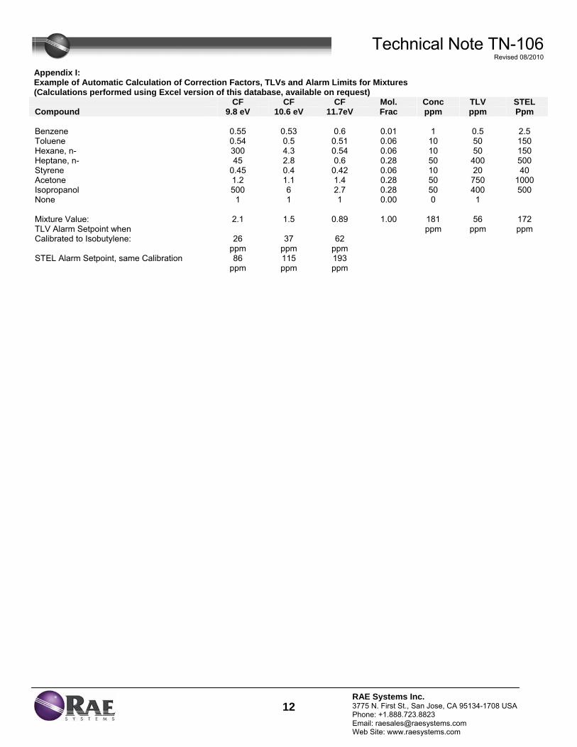
Technical Note TN-106 Revised 08/2010
12RAE Systems Inc. 3775 N. First St., San Jose, CA 95134-1708 USA Phone: +1.888.723.8823 Email: [email protected] Web Site: www.raesystems.com
Appendix I: Example of Automatic Calculation of Correction Factors, TLVs and Alarm Limits for Mixtures (Calculations performed using Excel version of this database, available on request) CF CF CF Mol. Conc TLV STEL Compound 9.8 eV 10.6 eV 11.7eV Frac ppm ppm Ppm Benzene 0.55 0.53 0.6 0.01 1 0.5 2.5 Toluene 0.54 0.5 0.51 0.06 10 50 150 Hexane, n- 300 4.3 0.54 0.06 10 50 150 Heptane, n- 45 2.8 0.6 0.28 50 400 500 Styrene 0.45 0.4 0.42 0.06 10 20 40 Acetone 1.2 1.1 1.4 0.28 50 750 1000 Isopropanol 500 6 2.7 0.28 50 400 500 None 1 1 1 0.00 0 1 Mixture Value: 2.1 1.5 0.89 1.00 181 56 172 TLV Alarm Setpoint when ppm ppm ppm Calibrated to Isobutylene: 26 37 62 ppm ppm ppm STEL Alarm Setpoint, same Calibration 86 115 193 ppm ppm ppm

FIE
LD
OP
ER
AT
ING
PR
OC
ED
UR
ES
Calibration and Maintenance of Portable Specific
Conductance Meter
Bn v i ronme talng i neeri n gc ence,i
n
FOP 012.0
CALIBRATION AND MAINTENANCE OF PORTABLE
SPECIFIC CONDUCTANCE METER
Page 1 of 5
Bn v i ronme talng i neeri n gc ence,i
n
PURPOSE
This guideline describes a method for calibration of a portable specific conductance meter.
This meter measures the ability of a water sample to conduct electricity, which is largely a
function of the dissolved solids within the water. The instrument has been calibrated by the
manufacturer according to factory specifications. This guideline presents a method for
checking the factory calibration of a portable specific conductance meter. A calibration
check is performed to verify instrument accuracy and function. All field test equipment will
be checked at the beginning of each sampling day. This procedure also documents critical
maintenance activities for this meter.
ACCURACY
The calibrated accuracy of the specific conductance meter will be within ± 1 percent of full-
scale, with repeatability of ± 1 percent. The built-in cell will be automatically temperature
compensated from at least 32º to 160° F (0° to 71°C).
PROCEDURE
Note: The information included below is equipment manufacturer- and model-specific,
however, accuracy, calibration, and maintenance procedures for this type of portable
equipment are typically similar. The information below pertains to the Myron L Company
Ultrameter Model 6P. The actual equipment to be used in the field will be equivalent or
similar.
FOP 012.0
CALIBRATION AND MAINTENANCE OF PORTABLE
SPECIFIC CONDUCTANCE METER
Page 2 of 5
Bn v i ronme talng i neeri n gc ence,i
n
1. Calibrate all field test equipment at the beginning of each sampling day. Check and recalibrate the specific conductance meter according to the manufacture’s specifications.
2. Use a calibration solution of known specific conductivity and salinity. For
maximum accuracy, use a Standard Solution Value closest to the samples to be tested.
3. Rinse conductivity cell three times with proper standard.
4. Re-fill conductivity cell with same standard.
5. Press COND or TDS, then press CAL/MCLR. The “CAL” icon will
appear on the display.
6. Press the ↑/MS or MR/↓ key to step the displayed value toward the standard’s value or hold a key down to cause rapid scrolling of the reading.
7. Press CAL/MCLR once to confirm new value and end the calibration
sequence for this particular solution type.
8. Repeat steps 1 through 7 with additional new solutions, as necessary.
9. Document the calibration results and related information in the Project Field Book and on an Equipment Calibration Log (see attached sample), indicating the meter readings before and after the instrument has been adjusted. This is important, not only for data validation, but also to establish maintenance schedules and component replacement. Information will include, at a minimum:
• Time, date and initials of the field team member performing the calibration
• The unique identifier for the meter, including manufacturer, model, and serial number
• The brand and expiration date of the calibration standards • The instrument readings: before and after calibration
FOP 012.0
CALIBRATION AND MAINTENANCE OF PORTABLE
SPECIFIC CONDUCTANCE METER
Page 3 of 5
Bn v i ronme talng i neeri n gc ence,i
n
• The instrument settings (if applicable) • The overall adequacy of calibration including the Pass or fail
designation in accordance with the accuracy specifications presented above.
• Corrective action taken (see Maintenance below) in the event of failure to adequately calibrate.
MAINTENANCE
NOTE: Ultrameters should be rinsed with clean water after use. Solvents should be
avoided. Shock damage from a fall may cause instrument failure.
Temperature Extremes
Solutions in excess of 160°F/71°C should not be placed in the cell cup area; this may cause
damage. Care should be exercised not to exceed rated operating temperature. Leaving the
Ultrameter in a vehicle or storage shed on a hot day can easily subject the instrument to over
150°F voiding the warranty.
Battery Replacement
Dry Instrument THOROUGHLY. Remove the four bottom screws. Open instrument
carefully; it may be necessary to rock the bottom slightly side to side to release it from the
RS-232 connector. Carefully detach battery from circuit board. Replace with 9-volt alkaline
battery. Replace bottom, ensuring the sealing gasket is installed in the groove of the top half
of case. Re-install screws, tighten evenly and securely.
FOP 012.0
CALIBRATION AND MAINTENANCE OF PORTABLE
SPECIFIC CONDUCTANCE METER
Page 4 of 5
Bn v i ronme talng i neeri n gc ence,i
n
NOTE: Because of nonvolatile EEPROM circuitry, all data stored in memory and all
calibration settings are protected even during power loss or battery replacement.
Cleaning Sensors
The conductivity cell cup should be kept as clean as possible. Flushing with clean water
following use will prevent buildup on electrodes. However, if very dirty samples —
particularly scaling types — are allowed to dry in the cell cup, a film will form. This film
reduces accuracy. When there are visible films of oil, dirt, or scale in the cell cup or on the
electrodes, use a foaming non-abrasive household cleaner. Rinse out the cleaner and your
Ultrameter is ready for accurate measurements.
NOTE: Maintain a log for each monitoring instrument. Record all maintenance
performed on the instrument on this log with date and name of the organization
performing the maintenance.
ATTACHMENTS
Equipment Calibration Log (sample)

FOP 012.0
CALIBRATION AND MAINTENANCE OF PORTABLE
SPECIFIC CONDUCTANCE METER
Page 5 of 5
Bn v i ronme talng i neeri n gc ence,i
n
EQUIPMENT CALIBRATION
PROJECT INFORMATION:Project Name: Date:Project No.:Client: Instrument Source: BM Rental
Sp. conductance meter
Particulate meter
Oxygen
Hydrogen sulfide
Carbon monoxide
LEL
Radiation Meter
ADDITIONAL REMARKS:
PREPARED BY: DATE:
background area
open air
SETTIN
MIBK refactor =
READING
______ mS @ 25 oC
open air
STANDARD4.007.0010.01
open air zero_____ ppm Iso. Gas
zero air
open air
open air
Myron L CompanyUltra Meter 6P
Turbidity meter NTU Hach 2100PTurbidimeter
units Myron L CompanyUltra Meter 6P 606987
100970600014560
< 0.420
800
Photovac 2020 PID ED GK 301
606987
CAL. BYMAKE/MODEL SERIAL NUMBERTIME
%
uS/mS
mg/m3
ppm
uR/H
METER TYPE UNITS
PID ppm
%
ppm
pH meter
Bn v i r o n m e t a ln g i n eer i n gc e n c e,i
n

FIE
LD
OP
ER
AT
ING
PR
OC
ED
UR
ES
Composite Sample Collection Procedure
for Non-VOC Analysis
Bn v i ronme talng i neeri n gc ence,i
n
FOP 013.0
COMPOSITE SAMPLE COLLECTION PROCEDURE FOR
NON-VOLATILE ORGANIC ANALYSIS
Page 1 of 3
Bn v i ronme talng i neeri n gc ence,i
n
PURPOSE
This guideline addresses the procedure to be used when soil samples are to be composited in
the field.
PROCEDURE
1. Transfer equal weighted aliquots of soil from individual split-spoon samples, excavator bucket, hand auger or surface soil sample location to a large precleaned stainless steel (or Pyrex glass) mixing bowl.
2. Thoroughly mix (homogenize) and break up the soil using a stainless steel
scoop or trowel.
3. Spread the composite sample evenly on a stainless steel tray and quarter the sample.
4. Discard alternate (i.e., diagonal) quarters and, using a small stainless steel
scoop or spatula, collect equal portions of subsample from the remaining two quarters until the amount required for the composite sample is acquired. Transfer these subsamples to a precleaned stainless steel (or Pyrex glass) mixing bowl and re-mix.
5. Transfer the composite sample to the laboratory provided, precleaned sample
jars. Store any excess sample from the stainless steel tray in a separate, precleaned, wide-mouth sample jar and refrigerate for future use, if applicable.
6. Decontaminate all stainless steel (or Pyrex glass) equipment in accordance
with Benchmark’s Non-disposable and Non-dedicated Sampling Equipment Decontamination procedures.
7. Prepare samples in accordance with Benchmark’s Sample Labeling, Storage
and Shipment FOP.
FOP 013.0
COMPOSITE SAMPLE COLLECTION PROCEDURE FOR
NON-VOLATILE ORGANIC ANALYSIS
Page 2 of 3
Bn v i ronme talng i neeri n gc ence,i
n
8. Record all sampling details in the Project Field Book and on the Soil/Sediment Sample Collection Summary Log (sample attached).
ATTACHMENTS
Soil/Sediment Sample Collection Summary Log (sample)
REFERENCES
Benchmark FOPs: 040 Non-disposable and Non-dedicated Sampling Equipment Decontamination 046 Sample Labeling, Storage and Shipment
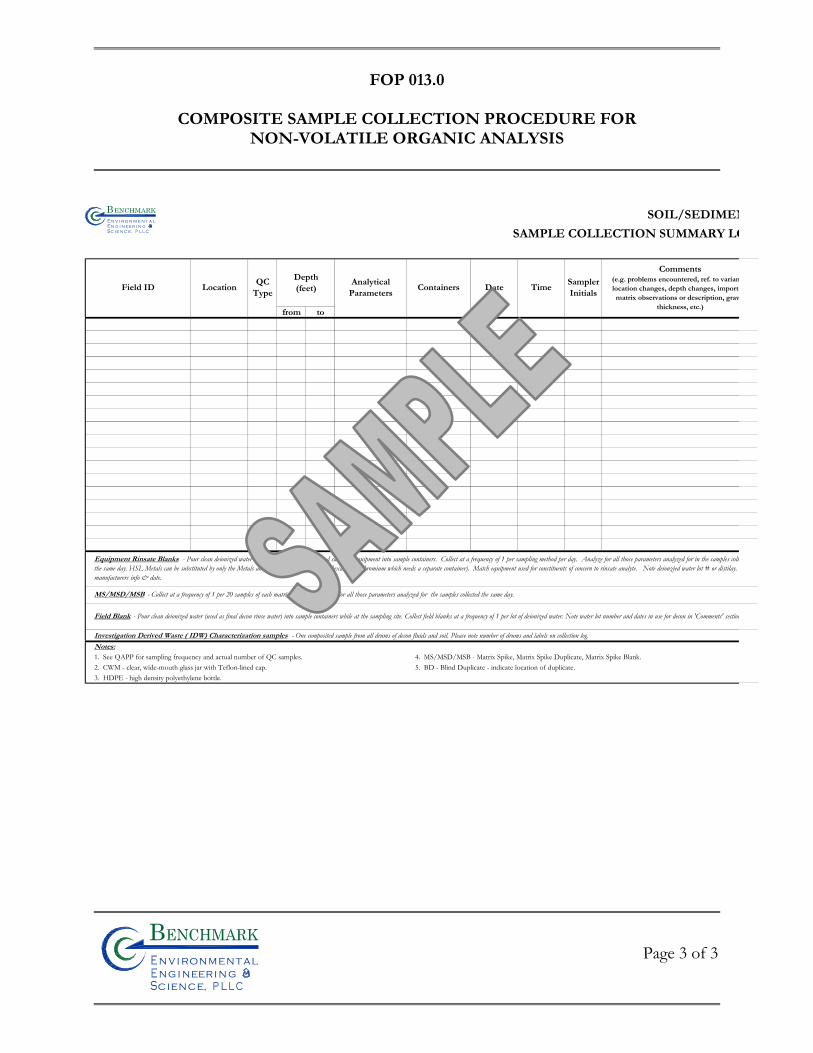
FOP 013.0
COMPOSITE SAMPLE COLLECTION PROCEDURE FOR
NON-VOLATILE ORGANIC ANALYSIS
Page 3 of 3
Bn v i ronme talng i neeri n gc ence,i
n
SOIL/SEDIMEN
SAMPLE COLLECTION SUMMARY LO
Depth(feet)
from to
Investigation Derived Waste ( IDW) Characterization samples - One composited sample from all drums of decon fluids and soil. Please note number of drums and labels on collection log.Notes:1. See QAPP for sampling frequency and actual number of QC samples. 4. MS/MSD/MSB - Matrix Spike, Matrix Spike Duplicate, Matrix Spike Blank.2. CWM - clear, wide-mouth glass jar with Teflon-lined cap. 5. BD - Blind Duplicate - indicate location of duplicate.3. HDPE - high density polyethylene bottle.
Containers Date TimeSamplerInitials
Field Blank - Pour clean deionized water (used as final decon rinse water) into sample containers while at the sampling site. Collect field blanks at a frequency of 1 per lot of deionized water. Note water lot number and dates in use for decon in 'Comments' section
MS/MSD/MSB - Collect at a frequency of 1 per 20 samples of each matrix per day. Analyze for all those parameters analyzed for the samples collected the same day.
Equipment Rinsate Blanks - Pour clean deionized water over or through decontaminated sampling equipment into sample containers. Collect at a frequency of 1 per sampling method per day. Analyze for all those parameters analyzed for in the samples collthe same day. HSL Metals can be substituted by only the Metals analyzed for that day (except Hexavalent Chromium which needs a separate container). Match equipment used for constituents of concern to rinsate analyte. Note deionzied water lot # or distilay. manufacturers info & date.
Comments(e.g. problems encountered, ref. to varianlocation changes, depth changes, importamatrix observations or description, grav
thickness, etc.)
Field ID LocationQC
TypeAnalytical
Parameters
Bn v i r o n m e t a ln g i n eer i n gc e n c e,i
n

FIE
LD
OP
ER
AT
ING
PR
OC
ED
UR
ES
Documentation Requirements for Drilling and Well
Installation
Bn v i ronme talng i neeri n gc ence,i
n
FOP 015.0
DOCUMENTATION REQUIREMENTS FOR DRILLING AND WELL
INSTALLATION
Page 1 of 11
PURPOSE
The purpose of these documentation requirements is to document the procedures used for
drilling and installing wells in order to ensure the quality of the data obtained from these
operations. Benchmark field technical personnel will be responsible for developing and
maintaining documentation for quality control of field operations. At least one field
professional will monitor each major operation (e.g. one person per drilling rig) to document
and record field procedures for quality control. These procedures provide a description of
the format and information for this documentation.
PROCEDURE
Project Field Book
Personnel assigned by the Benchmark Field Team Leader or Project Manager will maintain a
Project Field Book for all site activities. These Field Books will be started upon initiation of
any site activities to document the field investigation process. The Field Books will meet the
following criteria:
• Permanently bound, with nominal 8.5-inch by 11-inch gridded pages.
• Water resistant paper.
• Pages must be pre-numbered or numbered in the field, front and back.
Notations in the field book will be in black or blue ink that will not smudge when wet.
Information that may be recorded in the Field Book includes:
• Time and date of all entries.
FOP 015.0
DOCUMENTATION REQUIREMENTS FOR DRILLING AND WELL
INSTALLATION
Page 2 of 11
• Name and location of project site and project job number.
• Listing of key project, client and agency personnel and telephone numbers.
• Date and time of daily arrivals and departures, name of person keeping the log, names and affiliation of persons on site, purpose of visit (if applicable), weather conditions, outline of project activities to be completed.
• Details of any variations to the procedures/protocols (i.e., as presented in the Work Plan or Field Operating Procedures) and the basis for the change.
• Field-generated data relating to implementation of the field program, including sample locations, sample descriptions, field measurements, instrument calibration, etc.
• Record of all photographs taken in the field, including date, time, photographer, site location and orientation, sequential number of photograph, and roll number.
Upon completion of the site activities, all Field Books will be photocopied and both the
original and photocopied versions placed in the project files. In addition, all field notes
except those presented on specific field forms will be neatly transcribed into Field Activity
Daily Log (FADL) forms (sample attached).
Field Borehole/Monitoring Well Installation Log Form
Examples of the Field Borehole Log and Field Borehole/Monitoring Well Installation Log
forms are attached to this Field Operating Procedure. One form will be completed for every
boring by the Benchmark field person overseeing the drilling. At a minimum, these forms
will include:
• Project name, location, and number.
• Boring number.
FOP 015.0
DOCUMENTATION REQUIREMENTS FOR DRILLING AND WELL
INSTALLATION
Page 3 of 11
• Rig type and drilling method.
• Drilling dates.
• Sampling method.
• Sample descriptions, to meet the requirements of the Unified Soil Classification System (USCS) for soils and the Unified Rock Classification System (URCS) for rock.
• Results of photoionization evaluations (scan and/or headspace determinations).
• Blow counts for sampler penetration (Standard Penetration Test, N-Value).
• Drilling rate, rig chatter, and other drilling-related information, as necessary.
All depths recorded on Boring/Monitoring Well Installation Log forms will be expressed in
increments tenths of feet, and not in inches.
Well Completion Detail Form
An example of this form is attached to this Field Operating Procedure. One form will be
completed for every boring by the Benchmark field person overseeing the well installation.
At a minimum, these forms will include:
• Project name, location, and number.
• Well number.
• Installation dates.
• Dimensions and depths of the various well components illustrated in the Well Completion Detail (attached). These include the screened interval, bottom caps or plugs, centralizers, and the tops and bottoms of the various annular materials.
FOP 015.0
DOCUMENTATION REQUIREMENTS FOR DRILLING AND WELL
INSTALLATION
Page 4 of 11
• Drilling rate, rig chatter, and other drilling related information.
All depths recorded on Field Borehole/Monitoring Well Installation Logs will be expressed
in tenths of feet, and not in inches.
Daily Drilling Report Form
An example of this form is attached to this Field Operating Procedure. This form should be
used to summarize all drilling activities. One form should be completed for each rig for each
day. These forms will include summaries of:
• Footage drilled, broken down by diameter (e.g. 200 feet of 6-inch diameter hole, 50 feet of 10-inch diameter hole).
• Footage of well and screen installed, broken down by diameter.
• Quantities of materials used, including sand, cement, bentonite, centralizers, protective casings, traffic covers, etc. recorded by well or boring location.
• Active time (hours), and activity (drilling, decontamination, development, well installation, surface completions, etc.)
• Down-time (hours) and reason.
• Mobilizations and other events.
• Other quantities that will be the basis for drilling invoices.
The form should be signed daily by both the Benchmark field supervisor and the driller’s
representative, and provided to the Benchmark Field Team Leader.
FOP 015.0
DOCUMENTATION REQUIREMENTS FOR DRILLING AND WELL
INSTALLATION
Page 5 of 11
Other Project Field Forms
Well purging/well development forms, test pit logs, environmental sampling field data
sheets, water level monitoring forms, and well testing (slug test or pumping test) forms.
Refer to specific guidelines for form descriptions.
ATTACHMENTS
Field Activity Daily Log (FADL) (sample) Field Borehole Log (sample) Field Borehole/Monitoring Well Installation Log (sample) Stick-up Well/Piezometer Completion Detail (sample) Flush-mount Well/Piezometer Completion Detail (sample) Daily Drilling Report (sample)
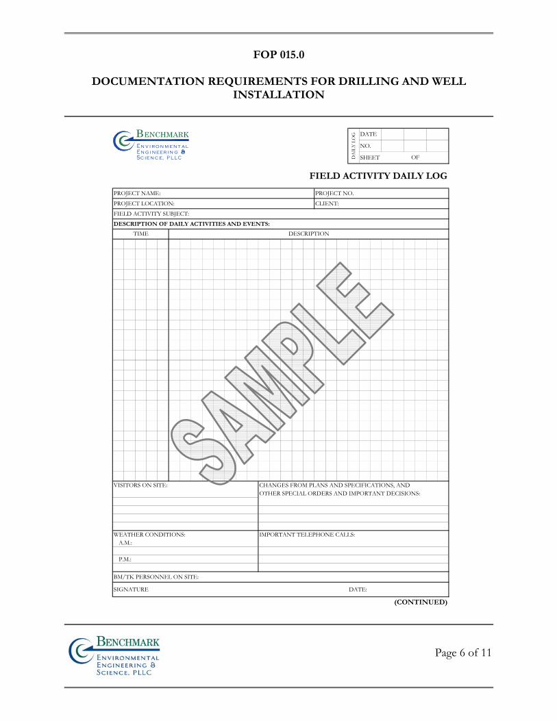
FOP 015.0
DOCUMENTATION REQUIREMENTS FOR DRILLING AND WELL
INSTALLATION
Page 6 of 11
DATE
NO.
SHEET
FIELD ACTIVITY DAILY LOG
PROJECT NAME: PROJECT NO.
PROJECT LOCATION: CLIENT:
FIELD ACTIVITY SUBJECT:
DESCRIPTION OF DAILY ACTIVITIES AND EVENTS:
VISITORS ON SITE: CHANGES FROM PLANS AND SPECIFICATIONS, ANDOTHER SPECIAL ORDERS AND IMPORTANT DECISIONS:
WEATHER CONDITIONS: IMPORTANT TELEPHONE CALLS:A.M.:
P.M.:
BM/TK PERSONNEL ON SITE:
SIGNATURE DATE:
(CONTINUED)
TIME DESCRIPTION
DA
ILY
LO
G
OF
Bn v i r o n m e t a ln g i n eer i n gc e n c e,i
n
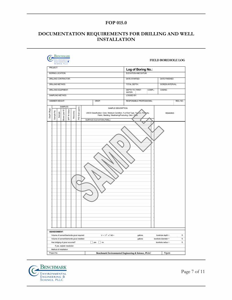
FOP 015.0
DOCUMENTATION REQUIREMENTS FOR DRILLING AND WELL
INSTALLATION
Page 7 of 11
FIELD BOREHOLE LOG
PROJECT: Log of Boring No.:BORING LOCATION: ELEVATION AND DATUM:
DRILLING CONTRACTOR: DATE STARTED: DATE FINISHED:
DRILLING METHOD: TOTAL DEPTH: SCREEN INTERVAL:
DRILLING EQUIPMENT: CASING:
SAMPLING METHOD: LOGGED BY:
HAMMER WEIGHT: DROP: RESPONSIBLE PROFESSIONAL:
SURFACE ELEVATION (FMSL):
ABANDONMENT:
Volume of cement/bentonite grout required: V = pr2 x 7.48 = gallons borehole depth = ft.
Volume of cement/bentonite grout installed: gallons borehole diameter = ft.
Has bridging of grout occurred? yes no borehole radius = ft.
If yes, explain resolution:
Method of installation:
Project No: Benchmark Environmental Engineering & Science, PLLC Figure
Dep
th (f
bgs)
FIRST: COMPL.:DEPTH TOWATER:
PID
Sca
n (p
pm)
SAMPLE DESCRIPTION
USCS Classification: Color, Moisture Condition, % of Soil Type, Texture, Plasticity,Fabric, Bedding, Weathering/Fracturing, Odor, Other
REMARKS
REG. NO.
SAMPLES
Sam
ple
No.
Blow
s (p
er 6
")
SPT
N-V
alue
Rec
over
y
Sam
ple
Bnv i ronme t alng i neeri n gc ence,i
n
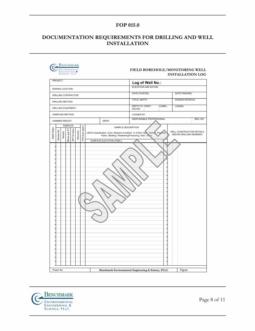
FOP 015.0
DOCUMENTATION REQUIREMENTS FOR DRILLING AND WELL
INSTALLATION
Page 8 of 11
FIELD BOREHOLE/MONITORING WELLINSTALLATION LOG
PROJECT: Log of Well No.:BORING LOCATION:
ELEVATION AND DATUM:
DRILLING CONTRACTOR:DATE STARTED: DATE FINISHED:
DRILLING METHOD:TOTAL DEPTH: SCREEN INTERVAL:
DRILLING EQUIPMENT:CASING:
SAMPLING METHOD: LOGGED BY:
HAMMER WEIGHT: DROP:RESPONSIBLE PROFESSIONAL:
SURFACE ELEVATION (FMSL):
Project No: Benchmark Environmental Engineering & Science, PLLC Figure
Dep
th (f
bgs)
FIRST: COMPL.:DEPTH TOWATER:
PID
Sca
n (p
pm)
SAMPLE DESCRIPTION
USCS Classification: Color, Moisture Condition, % of Soil Type, Texture, Plasticity, Fabric, Bedding, Weathering/Fracturing, Odor, Other
WELL CONSTRUCTION DETAILSAND/OR DRILLING REMARKS
REG. NO.
SAMPLES
Sam
ple
No.
Blow
s (p
er 6
")
SP
T N
-Val
ue
Rec
over
y
Sam
ple
Bn v i r o n m e t a ln g i n ee r i n gc e n c e,i
n
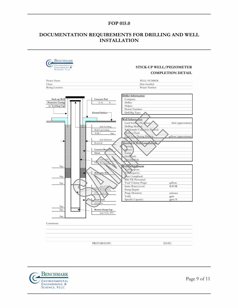
FOP 015.0
DOCUMENTATION REQUIREMENTS FOR DRILLING AND WELL
INSTALLATION
Page 9 of 11
STICK-UP WELL/PIEZOMETER
COMPLETION DETAIL
Project Name: WELL NUMBER:Client: Date Installed:Boring Location: Project Number:
Driller InformationStick-up Well Concrete Pad Company:
Protective Casing ft. by ft. Driller: w/ Locking Cap Helper:
Permit Number: Ground Surface Drill Rig Type:
Well Information Land Surface Elevation: fmsl (approximate)
inch Locking Drilling Method: Well Cap/J-plug Soil Sample Collection Method: TOR = fags Drilling Fluid:
Fluid Loss During Drilling: gallons (approximate) inch diameterBorehole Material of Well Construction
Casing: Cement/Bentonite Screen: Grout Sump:
Sand Pack: inch O.D. Annular Seal:PVC, Well Casing
fbgs Well DevelopmentWell Purpose:
Bentonite Seal Techneque(s): fbgs Date Completed:
BM/TK Personnel: fbgs Total Volume Purge: gallons
inch O.D., Static Water Level: fbTORPVC, Well Screen, Pump Depth: 0.0 -inch slot Purge Duration: minutes
Yeild: gpmSand Pack Specific Capacity: gpm/ftgrain size:
fbgs fbgs Bottom Sump Cap
inch O.D., PVC fbgs
Comments:
PREPARED BY: DATE:
Bn v i ron me t alng i neeri n gc ence,i
n
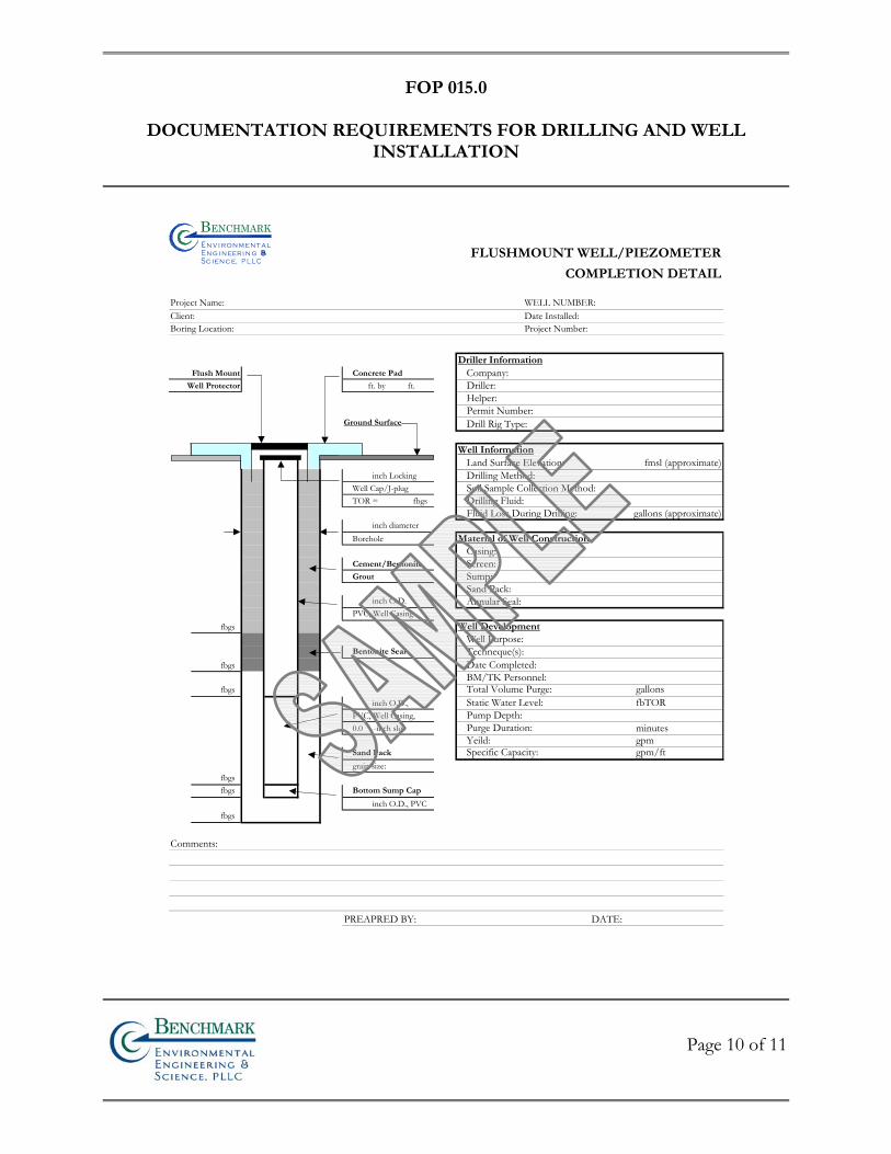
FOP 015.0
DOCUMENTATION REQUIREMENTS FOR DRILLING AND WELL
INSTALLATION
Page 10 of 11
FLUSHMOUNT WELL/PIEZOMETER
COMPLETION DETAIL
Project Name: WELL NUMBER:Client: Date Installed:Boring Location: Project Number:
Driller InformationFlush Mount Concrete Pad Company:
Well Protector ft. by ft. Driller: Helper:Permit Number:
Ground Surface Drill Rig Type:
Well Information Land Surface Elevation: fmsl (approximate)
inch Locking Drilling Method: Well Cap/J-plug Soil Sample Collection Method: TOR = fbgs Drilling Fluid:
Fluid Loss During Drilling: gallons (approximate) inch diameterBorehole Material of Well Construction
Casing: Cement/Bentonite Screen: Grout Sump:
Sand Pack: inch O.D. Annular Seal:PVC, Well Casing
fbgs Well DevelopmentWell Purpose:
Bentonite Seal Techneque(s): fbgs Date Completed:
BM/TK Personnel: fbgs Total Volume Purge: gallons
inch O.D., Static Water Level: fbTORPVC, Well Casing, Pump Depth: 0.0 -inch slot Purge Duration: minutes
Yeild: gpmSand Pack Specific Capacity: gpm/ftgrain size:
fbgs fbgs Bottom Sump Cap
inch O.D., PVC fbgs
Comments:
PREAPRED BY: DATE:
Bn v i ron me t aln g i neeri n gc ence,i
n
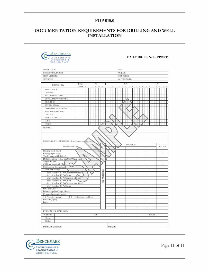
FOP 015.0
DOCUMENTATION REQUIREMENTS FOR DRILLING AND WELL
INSTALLATION
Page 11 of 11
DAILY DRILLING REPORT
CONTRACTOR: DATE:
DRILLING EQUIPMENT: PROJECT:
CREW MEMBERS: JOB NUMBER:
SITE NAME: BM PERSONNEL:
TotalHours 6
MOB / DEMOB
DRILLING
WELL INSTALLATION
DEVELOPMENT / TESTING
GROUTING
STEAM / DECON
DOWN TIME (explain below)
STANDBY (explain below)
CLEANUP
PREP FOR DRILLING
LUNCH
OTHER:
REMARKS:
DRILLING & WELL MATERIALS: Describe nature, quantity, size, etc.
Protective casing Flushmount road box
PERSONNEL TIME LOG:
Total CSSS footage
--CSSS ending depth (fbgs) --
--Auger/Bit size --
--Ending depth (fbgs) --Starting depth (fbgs)
Total footage drilled (feet)Drilling Method (HSA, air rotary, cable etc.)
CSSS starting depth (fbgs)
a.m. p.m. a.m.3 4 5 611 12 1 27 8 9 103 4 5 611 12 1 27 8 9 10
TOTALS
Cement/beontonite grout
Lockable J-plugLock
-inch Schedule 40 PVC screen, slot size =-inch Schedule 40 PVC riser
Sand pack, size =Bentonite pellets/chips, size =
-inch Schedule 40 PVC screen, slot size =-inch Schedule 40 PVC riser-inch Schedule 40 PVC screen, slot size =-inch Schedule 40 PVC riser
NAME HOURS
BM REP.
CATEGORY
DRILLER (optional):
POSITION
Observer
Drillers
ITEM OR SERVICE
QU
AN
TITI
ES
LOCATION
Bn v i r o n m e t a ln g i n e e r i n gc e n c e,i
n
FIE
LD
OP
ER
AT
ING
PR
OC
ED
UR
ES
Drill Site Selection Procedure
Bn v i ronme talng i neeri n gc ence,i
n
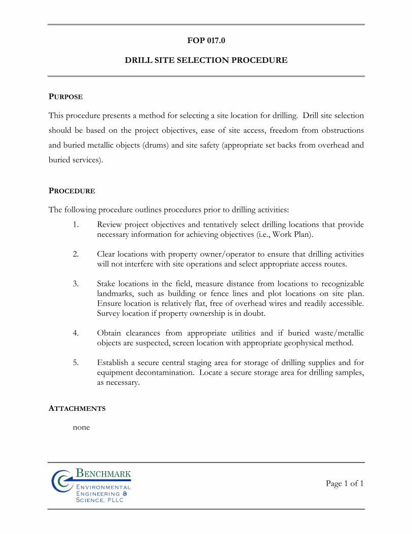
FOP 017.0
DRILL SITE SELECTION PROCEDURE
Page 1 of 1
Bn v i ronme talng i neeri n gc ence,i
n
PURPOSE
This procedure presents a method for selecting a site location for drilling. Drill site selection
should be based on the project objectives, ease of site access, freedom from obstructions
and buried metallic objects (drums) and site safety (appropriate set backs from overhead and
buried services).
PROCEDURE
The following procedure outlines procedures prior to drilling activities:
1. Review project objectives and tentatively select drilling locations that provide necessary information for achieving objectives (i.e., Work Plan).
2. Clear locations with property owner/operator to ensure that drilling activities
will not interfere with site operations and select appropriate access routes.
3. Stake locations in the field, measure distance from locations to recognizable landmarks, such as building or fence lines and plot locations on site plan. Ensure location is relatively flat, free of overhead wires and readily accessible. Survey location if property ownership is in doubt.
4. Obtain clearances from appropriate utilities and if buried waste/metallic
objects are suspected, screen location with appropriate geophysical method.
5. Establish a secure central staging area for storage of drilling supplies and for equipment decontamination. Locate a secure storage area for drilling samples, as necessary.
ATTACHMENTS
none

FIE
LD
OP
ER
AT
ING
PR
OC
ED
UR
ES
Drilling and Excavation Equipment
Decontamination Procedures
Bn v i ronme talng i neeri n gc ence,i
n
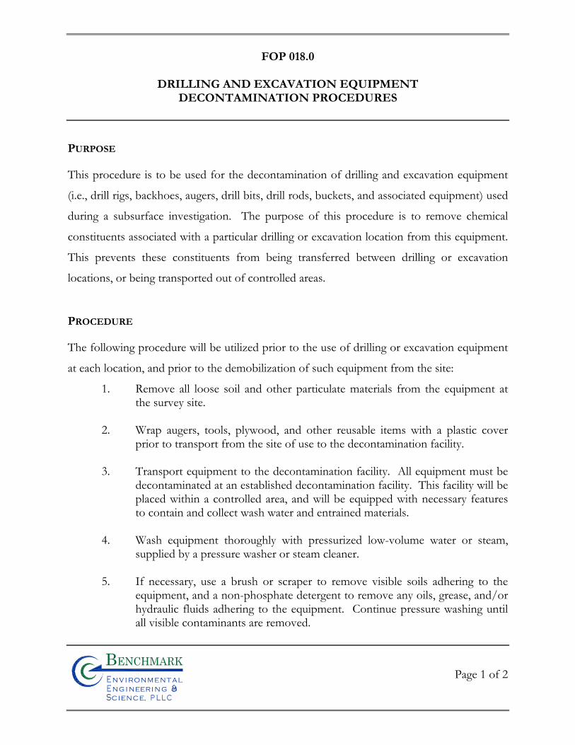
FOP 018.0
DRILLING AND EXCAVATION EQUIPMENT
DECONTAMINATION PROCEDURES
Page 1 of 2
Bn v i ronme talng i neeri n gc ence,i
n
PURPOSE
This procedure is to be used for the decontamination of drilling and excavation equipment
(i.e., drill rigs, backhoes, augers, drill bits, drill rods, buckets, and associated equipment) used
during a subsurface investigation. The purpose of this procedure is to remove chemical
constituents associated with a particular drilling or excavation location from this equipment.
This prevents these constituents from being transferred between drilling or excavation
locations, or being transported out of controlled areas.
PROCEDURE
The following procedure will be utilized prior to the use of drilling or excavation equipment
at each location, and prior to the demobilization of such equipment from the site:
1. Remove all loose soil and other particulate materials from the equipment at the survey site.
2. Wrap augers, tools, plywood, and other reusable items with a plastic cover
prior to transport from the site of use to the decontamination facility.
3. Transport equipment to the decontamination facility. All equipment must be decontaminated at an established decontamination facility. This facility will be placed within a controlled area, and will be equipped with necessary features to contain and collect wash water and entrained materials.
4. Wash equipment thoroughly with pressurized low-volume water or steam,
supplied by a pressure washer or steam cleaner.
5. If necessary, use a brush or scraper to remove visible soils adhering to the equipment, and a non-phosphate detergent to remove any oils, grease, and/or hydraulic fluids adhering to the equipment. Continue pressure washing until all visible contaminants are removed.
FOP 018.0
DRILLING AND EXCAVATION EQUIPMENT
DECONTAMINATION PROCEDURES
Page 2 of 2
Bn v i ronme talng i neeri n gc ence,i
n
6. Allow equipment to air dry.
7. Store equipment in a clean area or wrap the equipment in new plastic sheeting
as necessary to ensure cleanliness until ready for use.
8. Manage all wash waters and entrained solids as described in the Benchmark Field Operating Procedure for Management of Investigation-Derived Waste.
ATTACHMENTS
none

FIE
LD
OP
ER
AT
ING
PR
OC
ED
UR
ES
Establishing Horizontal and Vertical
Control
Bn v i ronme talng i neeri n gc ence,i
n
FOP 021.0
ESTABLISHING HORIZONTAL AND VERTICAL CONTROL
Page 1 of 2
Bn v i ronme talng i neeri n gc ence,i
n
PURPOSE
This guideline presents a method for establishing horizontal and vertical controls at a project
site. It is imperative that this procedure be performed accurately, as all topographic and site
maps, monitoring well locations and test pit locations will be based on these controls.
PROCEDURE
A. Establishing Horizontal Primary and Project Control
1. Research the State Plan Coordinate, USGS or project site applicable horizontal control monuments.
2. At the project site, recover the above-mentioned monuments, two markers minimum being recovered.
3. Establish control points on the project site by bringing in the primary control points recovered in the field.
4. All control points will be tied into a closed traverse to assure the error of closure.
5. Compute closures for obtaining degree of accuracy to adjust traverse points.
B. Establishing Vertical Primary and Project Control
1. Research project or USGS datum for recovering monument(s) for vertical control if different than those previously found.
2. Recover the monuments in the field, two markers minimum being found.
3. Set the projects benchmarks.
4. Run a level line from the monuments to the set project benchmarks and back, setting turning points on all benchmarks set on site.
FOP 021.0
ESTABLISHING HORIZONTAL AND VERTICAL CONTROL
Page 2 of 2
Bn v i ronme talng i neeri n gc ence,i
n
5. Reduce field notes and compute error of closure to adjust benchmarks set on site.
6. Prepare the recovery sketches and tabulate a list for horizontal and vertical control throughout project site.

FIE
LD
OP
ER
AT
ING
PR
OC
ED
UR
ES
Groundwater Level Measurement
Bn v i ronme talng i neeri n gc ence,i
n
FOP 022.0
GROUNDWATER LEVEL MEASUREMENT
Page 1 of 3
Bn v i ronme talng i neeri n gc ence,i
n
PURPOSE
This procedure describes the methods used to obtain accurate and consistent water level
measurements in monitoring wells, piezometers and well points. Water levels will be
measured at monitoring wells and, if practicable, in supply wells to estimate purge volumes
associated with sampling, and to develop a potentiometric surface of the groundwater in
order to estimate the direction and velocity of flow in the aquifer. Water levels in
monitoring wells will be measured using an electronic water level indicator (e-line) that has
been checked for operation prior to mobilization.
PROCEDURE
1. Decontaminate the e-line probe and a lower portion of cable following the procedures referenced in the Benchmark Field Operating Procedure for Non-Disposable and Non-Dedicated Sampling Equipment Decontamination. Store the e-line in a protected area until use. This may include wrapping the e-line in clean plastic until the time of use.
2. Unlock and remove the well protective cap or cover and place on clean plastic.
3. Lower the probe slowly into the monitoring well until the audible alarm
sounds. This indicates the depth to water has been reached.
4. Move the cable up and down slowly to identify the depth at which the alarm just begins to sound. Measure this depth against the mark on the lip of the well riser used as a surveyed reference point (typically the north side of the riser).
5. Read depth from the graduated cable to the nearest 0.01 foot. Do not use
inches. If the e-line is not graduated, use a rule or tape measure graduated in 0.01-foot increments to measure from the nearest reference mark on the e-line cable.
FOP 022.0
GROUNDWATER LEVEL MEASUREMENT
Page 2 of 3
Bn v i ronme talng i neeri n gc ence,i
n
6. Record the water level on a Water Level Monitoring Record (sample attached).
7. Remove the probe from the well slowly, drying the cable and probe with a clean paper wipe. Be sure to repeat decontamination before use in another well.
8. Replace well plug and protective cap or cover. Lock in place as appropriate.
ATTACHMENTS
Water Level Monitoring Record (sample)
REFERENCES
Benchmark FOPs: 040 Non-Disposable and Non-Dedicated Sampling Equipment Decontamination
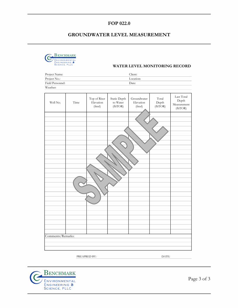
FOP 022.0
GROUNDWATER LEVEL MEASUREMENT
Page 3 of 3
Bn v i ronme talng i neeri n gc ence,i
n
WATER LEVEL MONITORING RECORD
Project Name: Client:Project No.: Location:Field Personnel: Date:Weather:
Comments/Remarks:
PREAPRED BY: DATE:
Last TotalDepth
Measurement(fbTOR)
GroundwaterElevation
(fmsl)
Static Depthto Water(fbTOR)
Well No. TimeTop of Riser
Elevation(fmsl)
TotalDepth
(fbTOR)
Bn v i r o n m e t a ln g i n ee r i n gc e n c e,i
n

FIE
LD
OP
ER
AT
ING
PR
OC
ED
UR
ES
Groundwater Purging Procedures Prior to Sample Collection
Bn v i ronme talng i neeri n gc ence,i
n
FOP 023.1
GROUNDWATER PURGING PROCEDURES PRIOR
TO SAMPLE COLLECTION
Page 1 of 8
Bn v i ronme talng i neeri n gc ence,i
n
PURPOSE
This procedure describes the methods for monitoring well/piezometer purging prior to
groundwater sample collection in order to collect representative groundwater samples. The
goal of purging is to remove stagnant, non-representative groundwater from the well and/or
prevent stagnant water from entering collected samples. Purging involves the removal of at
least three to five volumes of water in wells with moderate yields and at least one well
volume from wells with low yields (slow water level recovery).
Purge and sample wells in order of least-to-most contaminated (this is not necessary if
dedicated or disposable equipment is used). If you do not know this order, sample the
upgradient wells first, then the furthest down-gradient or side-gradient wells, and finally the
wells closest to, but down-gradient of the most contaminated area. Sampling should
commence immediately following purging or as soon as the well has adequately recharged
and not more than 24-hours following end time of evacuation.
PROCEDURE
1. Prepare the electronic water level indicator (e-line) in accordance with the procedures referenced in the Benchmark Field Operating Procedure for Groundwater Level Measurement and decontaminate the e-line probe and a lower portion of cable following the procedures referenced in the Benchmark Field Operating Procedure for Non-disposable and Non-dedicated Sampling Equipment Decontamination. Store the e-line in a protected area until use. This may include wrapping the e-line in clean plastic until the time of use.
2. Inspect the interior and exterior of the well/piezometer for signs of vandalism
or damage and record condition on the Groundwater Field Form and/or Groundwater Well Inspection Form (samples attached). Specifically, inspect

FOP 023.1
GROUNDWATER PURGING PROCEDURES PRIOR
TO SAMPLE COLLECTION
Page 2 of 8
Bn v i ronme talng i neeri n gc ence,i
n
the integrity of the following: concrete surface seal, lock, protective casing and well cover, well riser and J-plug/cap. Report any irregular findings to the Project Manager.
3. Unlock and remove the well protective cap or cover and place on clean plastic
to avoid introducing foreign material into the well.
4. Calibrate the photoionization detector (PID) in accordance with the Benchmark Field Operating Procedure for Calibration and Maintenance of Portable Photoionization Detector.
5. Monitor the well for organic vapors using a PID, as per the Work Plan. If a
reading of greater than 5 ppm is recorded, the well should be allowed to vent until levels drop below 5 ppm before proceeding with purging.
6. Lower the e-line probe slowly into the monitoring well and record the initial
water level in accordance with the procedures referenced in the Benchmark Field Operating Procedure for Groundwater Level Measurement.
7. Following static water level determinations, slowly lower the e-line to the
bottom of the well/piezometer. Record the total depth to the nearest 0.01-foot and compare to the previous total depth measurement. If a significant discrepancy exists, re-measure the total depth. Continue with purging activities observing purge water to determine whether the well/piezometer had become silted due to inactivity or damaged (i.e., well sand within purge water). Upon confirmation of the new total depth and determination of the cause (i.e., siltation or damage), notify the Project Manager following field activities.
8. Calculate the volume of water in the well based on the water level below the
top of riser and the total depth of the well using the following equation:
V = 0.0408[(B)2 x (A) – (C)]
Where,
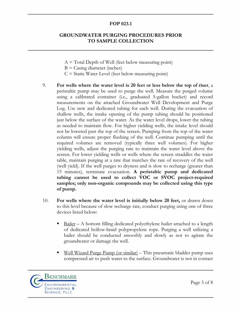
FOP 023.1
GROUNDWATER PURGING PROCEDURES PRIOR
TO SAMPLE COLLECTION
Page 3 of 8
Bn v i ronme talng i neeri n gc ence,i
n
A = Total Depth of Well (feet below measuring point) B = Casing diameter (inches) C = Static Water Level (feet below measuring point)
9. For wells where the water level is 20 feet or less below the top of riser, a
peristaltic pump may be used to purge the well. Measure the purged volume using a calibrated container (i.e., graduated 5-gallon bucket) and record measurements on the attached Groundwater Well Development and Purge Log. Use new and dedicated tubing for each well. During the evacuation of shallow wells, the intake opening of the pump tubing should be positioned just below the surface of the water. As the water level drops, lower the tubing as needed to maintain flow. For higher yielding wells, the intake level should not be lowered past the top of the screen. Pumping from the top of the water column will ensure proper flushing of the well. Continue pumping until the required volumes are removed (typically three well volumes). For higher yielding wells, adjust the purging rate to maintain the water level above the screen. For lower yielding wells or wells where the screen straddles the water table, maintain purging at a rate that matches the rate of recovery of the well (well yield). If the well purges to dryness and is slow to recharge (greater than 15 minutes), terminate evacuation. A peristaltic pump and dedicated tubing cannot be used to collect VOC or SVOC project-required samples; only non-organic compounds may be collected using this type of pump.
10. For wells where the water level is initially below 20 feet, or drawn down
to this level because of slow recharge rate, conduct purging using one of three devices listed below:
Bailer – A bottom filling dedicated polyethylene bailer attached to a length
of dedicated hollow-braid polypropylene rope. Purging a well utilizing a bailer should be conducted smoothly and slowly as not to agitate the groundwater or damage the well.
Well Wizard Purge Pump (or similar) – This pneumatic bladder pump uses
compressed air to push water to the surface. Groundwater is not in contact
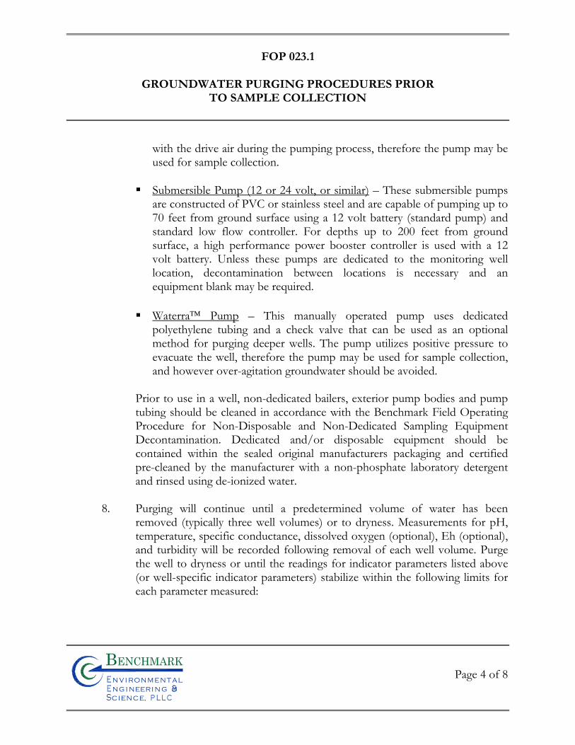
FOP 023.1
GROUNDWATER PURGING PROCEDURES PRIOR
TO SAMPLE COLLECTION
Page 4 of 8
Bn v i ronme talng i neeri n gc ence,i
n
with the drive air during the pumping process, therefore the pump may be used for sample collection.
Submersible Pump (12 or 24 volt, or similar) – These submersible pumps
are constructed of PVC or stainless steel and are capable of pumping up to 70 feet from ground surface using a 12 volt battery (standard pump) and standard low flow controller. For depths up to 200 feet from ground surface, a high performance power booster controller is used with a 12 volt battery. Unless these pumps are dedicated to the monitoring well location, decontamination between locations is necessary and an equipment blank may be required.
Waterra Pump – This manually operated pump uses dedicated
polyethylene tubing and a check valve that can be used as an optional method for purging deeper wells. The pump utilizes positive pressure to evacuate the well, therefore the pump may be used for sample collection, and however over-agitation groundwater should be avoided.
Prior to use in a well, non-dedicated bailers, exterior pump bodies and pump tubing should be cleaned in accordance with the Benchmark Field Operating Procedure for Non-Disposable and Non-Dedicated Sampling Equipment Decontamination. Dedicated and/or disposable equipment should be contained within the sealed original manufacturers packaging and certified pre-cleaned by the manufacturer with a non-phosphate laboratory detergent and rinsed using de-ionized water.
8. Purging will continue until a predetermined volume of water has been
removed (typically three well volumes) or to dryness. Measurements for pH, temperature, specific conductance, dissolved oxygen (optional), Eh (optional), and turbidity will be recorded following removal of each well volume. Purge the well to dryness or until the readings for indicator parameters listed above (or well-specific indicator parameters) stabilize within the following limits for each parameter measured:
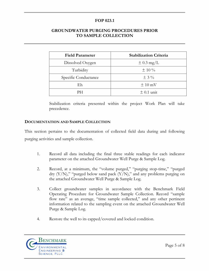
FOP 023.1
GROUNDWATER PURGING PROCEDURES PRIOR
TO SAMPLE COLLECTION
Page 5 of 8
Bn v i ronme talng i neeri n gc ence,i
n
Field Parameter Stabilization Criteria
Dissolved Oxygen ± 0.3 mg/L
Turbidity ± 10 %
Specific Conductance ± 3 %
Eh ± 10 mV
PH ± 0.1 unit
Stabilization criteria presented within the project Work Plan will take precedence.
DOCUMENTATION AND SAMPLE COLLECTION
This section pertains to the documentation of collected field data during and following
purging activities and sample collection.
1. Record all data including the final three stable readings for each indicator parameter on the attached Groundwater Well Purge & Sample Log.
2. Record, at a minimum, the “volume purged,” “purging stop-time,” “purged
dry (Y/N),” “purged below sand pack (Y/N),” and any problems purging on the attached Groundwater Well Purge & Sample Log.
3. Collect groundwater samples in accordance with the Benchmark Field
Operating Procedure for Groundwater Sample Collection. Record “sample flow rate” as an average, “time sample collected,” and any other pertinent information related to the sampling event on the attached Groundwater Well Purge & Sample Log.
4. Restore the well to its capped/covered and locked condition.
FOP 023.1
GROUNDWATER PURGING PROCEDURES PRIOR
TO SAMPLE COLLECTION
Page 6 of 8
Bn v i ronme talng i neeri n gc ence,i
n
ALTERNATIVE METHODS
Alternative purging and sampling methods and equipment, other than those described herein
are acceptable if they provide representative groundwater samples. The purging and
sampling method and equipment must not adversely affect sample integrity, chemistry,
temperature, and turbidity. In addition, alternative equipment must have minimal or no
effect on groundwater geochemistry, aquifer permeability and well materials. Equipment
materials must also minimize sorption and leaching. The field team is responsible for
documenting and describing any alternative equipment and procedures used to purge a well
and collect samples.
ATTACHMENTS
Groundwater Field Form Groundwater Well Inspection Form
REFERENCES
Benchmark FOPs: 011 Calibration and Maintenance of Portable Photoionization Detector 022 Groundwater Level Measurement
024 Groundwater Sample Collection Procedures 040 Non-disposable and Non-dedicated Sampling Equipment Decontamination
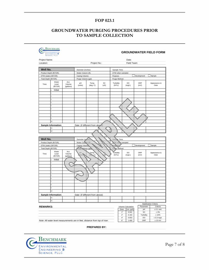
FOP 023.1
GROUNDWATER PURGING PROCEDURES PRIOR
TO SAMPLE COLLECTION
Page 7 of 8
Bn v i ronme talng i neeri n gc ence,i
n
GROUNDWATER FIELD FORM
Project Name: Date:
Location: Project No.: Field Team:
Well No. Diameter (inches): Sample Time:
Product Depth (fbTOR): Water Column (ft): DTW when sampled:
DTW (static) (fbTOR): Casing Volume: Purpose:
Total Depth (fbTOR): Purge Volume (gal): Purge Method:
Sample Information: Date: (if different from above)
Well No. Diameter (inches): Sample Time:
Product Depth (fbTOR): Water Column (ft): DTW when sampled:
DTW (static) (fbTOR): Casing Volume: Purpose:
Total Depth (fbTOR): Purge Volume (gal): Purge Method:
Sample Information: Date: (if different from above)
Stabilization Criteria
REMARKS: Volume Calculation
Note: All water level measurements are in feet, distance from top of riser.
PREPARED BY:
1.469
± 0.3 mg/L
± 10 mV
Diam. Vol. (g/ft)
1"
2"
4"
6"
0.041
0.163
Criteria
± 0.1 unit
± 3%
± 10%
Parameter
pH
SC
Turbidity
DO
ORP
0.653
DO
(mg/L)
ORP
(mV)
Appearance &
Odor
S2
S1
9
8
ORP
(mV)
DO
(mg/L)
pH
(units)
Temp.
(deg. C)
SC
(uS)
Turbidity
(NTU)Time
Water
Level
(fbTOR)
Acc.
Volume
(gallons)
3
0 Initial
1
5
6
10
2
7
Time
Water
Level
(fbTOR)
Acc.
Volume
(gallons)
pH
(units)
Temp.
(deg. C)
SC
(uS)
Turbidity
(NTU)
0 Initial
1
5
6
7
8
9
10
S1
S2
Appearance &
Odor
3
2
4
4
Bn v i ron m e t aln g i neer i n gc en ce,i
n
Development Sample
Development Sample
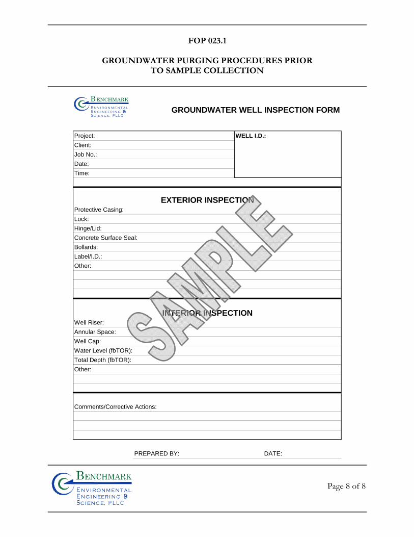
FOP 023.1
GROUNDWATER PURGING PROCEDURES PRIOR
TO SAMPLE COLLECTION
Page 8 of 8
Bn v i ronme talng i neeri n gc ence,i
n
GROUNDWATER WELL INSPECTION FORM
Project: WELL I.D.:
Client:
Job No.:
Date:
Time:
EXTERIOR INSPECTIONProtective Casing:
Lock:
Hinge/Lid:
Concrete Surface Seal:
Bollards:
Label/I.D.:
Other:
INTERIOR INSPECTIONWell Riser:
Annular Space:
Well Cap:
Water Level (fbTOR):
Total Depth (fbTOR):
Other:
Comments/Corrective Actions:
PREPARED BY: DATE:
Bn v i r o n m e t a ln g i n ee r i n gc e n c e,i
n

FIE
LD
OP
ER
AT
ING
PR
OC
ED
UR
ES
Groundwater Sample Collection Procedures
Bn v i ronme talng i neeri n gc ence,i
n
FOP 024.1
GROUNDWATER SAMPLE COLLECTION PROCEDURES
Page 1 of 10
Bn v i ronme talng i neeri n gc ence,i
n
PURPOSE
This procedure describes the methods for collecting groundwater samples from monitoring
wells and domestic supply wells following purging and sufficient recovery. This procedure
also includes the preferred collection order in which water samples are collected based on
the volatilization sensitivity or suite of analytical parameters required.
PROCEDURE
Allow approximately 3 to 10 days following well development before performing purge and
sample activities at any well location. Conversely, perform sampling as soon as practical after
sample purging at any time after the well has recovered sufficiently to sample, or within 24
hours after evacuation, if the well recharges slowly. If the well does not yield sufficient
volume for all required laboratory analytical testing (including quality control), a decision
should be made to prioritize analyses based on contaminants of concern at the site. If the
well takes longer than 24 hours to recharge, the Project Manager should be consulted. The
following two procedures outline sample collection activities for monitoring and domestic
type wells.
Monitoring Wells
1. Purge the monitoring well in accordance with the Benchmark FOPs for Groundwater Purging Procedures Prior to Sample Collection or Low Flow (Minimal Drawdown) Groundwater Purging & Sampling Procedures. Perform sampling as soon as practical after purging at any time after the well has recovered sufficiently to sample, or within 24 hours after evacuation, if the well recharges slowly. If the well does not yield sufficient volume for all required laboratory analytical testing (including quality control), a decision should be made to prioritize analyses based on contaminants of concern at the site. Analyses will be prioritized in the order of the parameters volatilization sensitivity. After volatile organics have been collected, field parameters
FOP 024.1
GROUNDWATER SAMPLE COLLECTION PROCEDURES
Page 2 of 10
Bn v i ronme talng i neeri n gc ence,i
n
must be measured from the next sample collected. If a well takes longer than 24 hours to recharge, the Project Manager should be consulted.
2. Sampling equipment that is not disposable or dedicated to the well will be decontaminated in accordance with the Benchmark Field Operating Procedure for Non-Disposable and Non-Dedicated Sampling Equipment Decontamination.
3. Calibrate all field meters (i.e., pH/Eh, turbidity, specific conductance, dissolved
oxygen, PID etc.) in accordance with the Benchmark Field Operating Procedure for Calibration and Maintenance of the specific field meter.
4. Prepare the electronic water level indicator (e-line) in accordance with the procedures
referenced in the Benchmark Field Operating Procedure for Groundwater Level Measurement and decontaminate the e-line probe and a lower portion of cable following the procedures referenced in the Benchmark Field Operating Procedure for Non-disposable and Non-dedicated Sampling Equipment Decontamination. Store the e-line in a protected area until use. This may include wrapping the e-line in clean plastic until the time of use.
5. Inspect the well/piezometer for signs of vandalism or damage and record condition
on the Groundwater Field Form (sample attached). Specifically, inspect the integrity of the following: concrete surface seal, lock, protective casing and well cover, well casing and J-plug/cap. Report any irregular findings to the Project Manager.
6. Unlock and remove the well protective cap or cover and place on clean plastic to
avoid introducing foreign material into the well.
7. Calibrate the photoionization detector (PID) in accordance with the Benchmark Field Operating Procedure for Calibration and Maintenance of Portable Photoionization Detector.
8. Monitor the well for organic vapors using a PID, as per the Work Plan. If a reading
of greater than 5 ppm is recorded, the well should be allowed to vent until levels drop below 5 ppm before proceeding with purging. Record PID measurements on a well-specific Groundwater Field Form (sample attached).
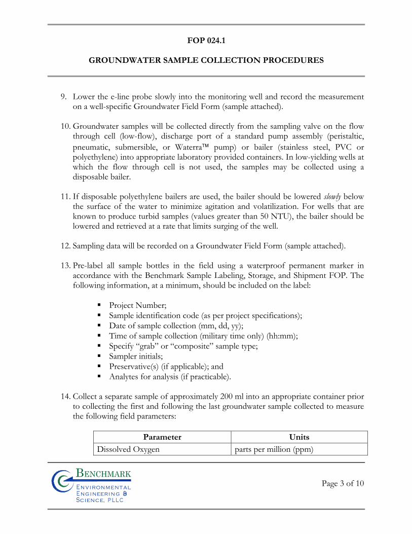
FOP 024.1
GROUNDWATER SAMPLE COLLECTION PROCEDURES
Page 3 of 10
Bn v i ronme talng i neeri n gc ence,i
n
9. Lower the e-line probe slowly into the monitoring well and record the measurement on a well-specific Groundwater Field Form (sample attached).
10. Groundwater samples will be collected directly from the sampling valve on the flow
through cell (low-flow), discharge port of a standard pump assembly (peristaltic, pneumatic, submersible, or Waterra pump) or bailer (stainless steel, PVC or polyethylene) into appropriate laboratory provided containers. In low-yielding wells at which the flow through cell is not used, the samples may be collected using a disposable bailer.
11. If disposable polyethylene bailers are used, the bailer should be lowered slowly below
the surface of the water to minimize agitation and volatilization. For wells that are known to produce turbid samples (values greater than 50 NTU), the bailer should be lowered and retrieved at a rate that limits surging of the well.
12. Sampling data will be recorded on a Groundwater Field Form (sample attached). 13. Pre-label all sample bottles in the field using a waterproof permanent marker in
accordance with the Benchmark Sample Labeling, Storage, and Shipment FOP. The following information, at a minimum, should be included on the label:
Project Number; Sample identification code (as per project specifications); Date of sample collection (mm, dd, yy); Time of sample collection (military time only) (hh:mm); Specify “grab” or “composite” sample type; Sampler initials; Preservative(s) (if applicable); and Analytes for analysis (if practicable).
14. Collect a separate sample of approximately 200 ml into an appropriate container prior
to collecting the first and following the last groundwater sample collected to measure the following field parameters:
Parameter Units
Dissolved Oxygen parts per million (ppm)
FOP 024.1
GROUNDWATER SAMPLE COLLECTION PROCEDURES
Page 4 of 10
Bn v i ronme talng i neeri n gc ence,i
n
Specific Conductance mmhos/cm or mS or mS pH pH units Temperature oC or oF Turbidity NTU Eh (optional) mV PID VOCs (optional) ppm
Record all field measurements on a Groundwater Field Form (sample attached).
15. Collect samples into pre-cleaned bottles provided by the analytical laboratory with the appropriate preservative(s) added based on the volatilization sensitivity or suite of analytical parameters required, as designated in the Sample Collection Order section below.
16. Lower the e-line probe slowly into the monitoring well and record the measurement
on a well-specific Groundwater Field Form (sample attached). 17. The samples will be labeled, stored, and shipped in accordance with the Benchmark
Field Operating Procedure for Sample Labeling, Storage, and Shipment Procedures.
Domestic Supply Wells
1. Calculate or estimate the volume of water in the well. It is desirable to purge at least one casing volume before sampling. This is controlled, to some extent, by the depth of the well, well yield and the rate of the existing pump. If the volume of water in the well cannot be calculated, the well should be purged continuously for no less than 15 minutes.
2. Connect a sampling tap to an accessible fitting between the well and the pressure tank where practicable. A hose will be connected to the device and the hose discharge located 25 to 50 feet away. The well will be allowed to pump until the lines and one well volume is removed. Flow rate will be measured with a container of known volume and a stopwatch.
FOP 024.1
GROUNDWATER SAMPLE COLLECTION PROCEDURES
Page 5 of 10
Bn v i ronme talng i neeri n gc ence,i
n
3. Place a clean piece of polyethylene or Teflon tubing on the sampling port and collect the samples in the order designated below and in the sample containers supplied by the laboratory for the specified analytes. DO NOT use standard garden hose to collect samples.
4. Sampling results and measurements will be recorded on a Groundwater Field Form
(sample attached) as described in the previous section.
5. Collect samples into pre-cleaned bottles provided by the analytical laboratory with the appropriate preservative(s) added based on the volatilization sensitivity or suite of analytical parameters required, as designated in the Sample Collection Order section below.
6. The samples will be labeled, stored, and shipped in accordance with the Benchmark
Field Operating Procedure for Sample Labeling, Storage, and Shipment Procedures.
SAMPLE COLLECTION ORDER
All groundwater samples, from monitoring wells and domestic supply wells, will be collected
in accordance with the following.
1. Samples will be collected preferentially in recognition of volatilization sensitivity. The preferred order of sampling if no free product is present is:
Field parameters Volatile Organic Compounds (VOCs) Purgeable organic carbons (POC) Purgeable organic halogens (POH) Total Organic Halogens (TOX) Total Organic Carbon (TOC) Extractable Organic Compounds (i.e., BNAs, SVOCs, etc.) Total petroleum hydrocarbons (TPH) and oil and grease PCBs and pesticides Total metals (Dissolved Metals) Total Phenolic Compounds
FOP 024.1
GROUNDWATER SAMPLE COLLECTION PROCEDURES
Page 6 of 10
Bn v i ronme talng i neeri n gc ence,i
n
Cyanide Sulfate and Chloride Turbidity Nitrate (as Nitrogen) and Ammonia Preserved inorganics Radionuclides Unpreserved inorganics Bacteria Field parameters
2. Document the sampling procedures and related information in the Project Field
Book and on a Groundwater Field Form (sample attached).
DOCUMENTATION
The three words used to ensure adequate documentation for groundwater sampling are
accountability, controllability, and traceability. Accountability is undertaken in the sampling
plan and answers the questions who, what, where, when, and why to assure that the
sampling effort meets its goals. Controllability refers to checks (including QA/QC) used to
ensure that the procedures used are those specified in the sampling plan. Traceability is
documentation of what was done, when it was done, how it was done, and by whom it was
done, and is found in the field forms, Project Field Book, and chain-of-custody forms. At a
minimum, adequate documentation of the sampling conducted in the field consists of an
entry in the Project Field Book (with sewn binding), field data sheets for each well, and a
chain-of-custody form.
As a general rule, if one is not sure whether the information is necessary, it should
nevertheless be recorded, as it is impossible to over-document one’s fieldwork. Years may go
by before the documentation comes under close scrutiny, so the documentation must be
FOP 024.1
GROUNDWATER SAMPLE COLLECTION PROCEDURES
Page 7 of 10
Bn v i ronme talng i neeri n gc ence,i
n
capable of defending the sampling effort without the assistance or translation of the
sampling crew.
The minimum information to be recorded daily with an indelible pen in the Project Field
Book and/or field data sheets includes date and time(s), name of the facility, name(s) of the
sampling crew, site conditions, the wells sampled, a description of how the sample shipment
was handled, and a QA/QC summary. After the last entry for the day in the Project Field
Book, the Field Team Leader should sign the bottom of the page under the last entry and
then draw a line across the page directly under the signature.
PRECAUTIONS/RECOMMENDATIONS
The following precautions should be adhered to prior to and during sample collection
activities:
Field vehicles should be parked downwind (to avoid potential sample contamination concerns) at a minimum of 15 feet from the well and the engine turned off prior to PID vapor analysis and VOC sample collection.
Ambient odors, vehicle exhaust, precipitation, or windy/dusty conditions can
potentially interfere with obtaining representative samples. These conditions should be minimized and should be recorded in the field notes. Shield sample bottles from strong winds, rain, and dust when being filled.
The outlet from the sampling device should discharge below the top of the
sample’s air/water interface, when possible. The sampling plan should specify how the samples will be transferred from the sample collection device to the sample container to minimize sample alterations.
FOP 024.1
GROUNDWATER SAMPLE COLLECTION PROCEDURES
Page 8 of 10
Bn v i ronme talng i neeri n gc ence,i
n
The order of sampling should be from the least contaminated to the most contaminated well to reduce the potential for cross contamination of sampling equipment (see the Sampling Plan or Work Plan).
Samples should not be transferred from one sampling container to another.
Sampling equipment must not be placed on the ground, because the ground may
be contaminated and soil contains trace metals. Equipment and supplies should be removed from the field vehicle only when needed.
Smoking and eating should not be allowed until the well is sampled and hands are
washed with soap and water, due to safety and possibly sample contamination concerns. These activities should be conducted beyond a 15-foot radius of the well.
No heat-producing or electrical instruments should be within 15 feet of the well,
unless they are intrinsically safe, prior to PID vapor analysis.
Minimize the amount of time that the sample containers remain open.
Do not touch the inside of sample bottles or the groundwater sample as it enters the bottle. Disposable gloves may be a source of phthalates, which could be introduced into groundwater samples if the gloves contact the sample.
Sampling personnel should use a new pair of disposable gloves for each well
sampled to reduce the potential for exposure of the sampling personnel to contaminants and to reduce sample cross contamination. In addition, sampling personnel should change disposable gloves between purging and sampling operations at the same well.
Sampling personnel should not use perfume, insect repellent, hand lotion, etc.,
when taking groundwater samples. If insect repellent must be used, then sampling personnel should not allow samples or sampling equipment to contact the repellent, and it should be noted in the documentation that insect repellent was used.
FOP 024.1
GROUNDWATER SAMPLE COLLECTION PROCEDURES
Page 9 of 10
Bn v i ronme talng i neeri n gc ence,i
n
Complete the documentation of the well. A completed assemblage of paperwork for a sampling event includes the completed field forms, entries in the Project Field Book (with a sewn binding), transportation documentation (if required), and possibly chain-of-custody forms.
ATTACHMENTS
Groundwater Field Form (sample)
REFERENCES
1. Wilson, Neal. Soil Water and Ground Water Sampling, 1995
Benchmark FOPs: 007 Calibration and Maintenance of Portable Dissolved Oxygen Meter 008 Calibration and Maintenance of Portable Field pH/Eh Meter 009 Calibration and Maintenance of Portable Field Turbidity Meter 011 Calibration and Maintenance of Portable Photoionization Detector 012 Calibration and Maintenance of Portable Specific Conductance Meter 022 Groundwater Level Measurement 023 Groundwater Purging Procedures Prior to Sample Collection (optional)
031 Low Flow (Minimal Drawdown) Groundwater Purging & Sampling Procedures (optional) 040 Non-Disposable and Non-Dedicated Sampling Equipment Decontamination 046 Sample Labeling, Storage and Shipment Procedures
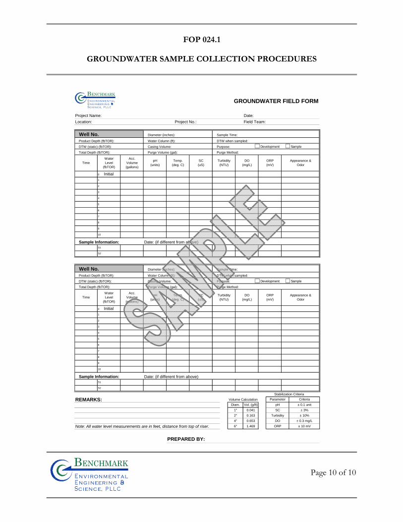
FOP 024.1
GROUNDWATER SAMPLE COLLECTION PROCEDURES
Page 10 of 10
Bn v i ronme talng i neeri n gc ence,i
n
GROUNDWATER FIELD FORM
Project Name: Date:
Location: Project No.: Field Team:
Well No. Diameter (inches): Sample Time:
Product Depth (fbTOR): Water Column (ft): DTW when sampled:
DTW (static) (fbTOR): Casing Volume: Purpose:
Total Depth (fbTOR): Purge Volume (gal): Purge Method:
Sample Information: Date: (if different from above)
Well No. Diameter (inches): Sample Time:
Product Depth (fbTOR): Water Column (ft): DTW when sampled:
DTW (static) (fbTOR): Casing Volume: Purpose:
Total Depth (fbTOR): Purge Volume (gal): Purge Method:
Sample Information: Date: (if different from above)
Stabilization Criteria
REMARKS: Volume Calculation
Note: All water level measurements are in feet, distance from top of riser.
PREPARED BY:
1.469
± 0.3 mg/L
± 10 mV
Diam. Vol. (g/ft)
1"
2"
4"
6"
0.041
0.163
Criteria
± 0.1 unit
± 3%
± 10%
Parameter
pH
SC
Turbidity
DO
ORP
0.653
DO
(mg/L)
ORP
(mV)
Appearance &
Odor
S2
S1
9
8
ORP
(mV)
DO
(mg/L)
pH
(units)
Temp.
(deg. C)
SC
(uS)
Turbidity
(NTU)Time
Water
Level
(fbTOR)
Acc.
Volume
(gallons)
3
0 Initial
1
5
6
10
2
7
Time
Water
Level
(fbTOR)
Acc.
Volume
(gallons)
pH
(units)
Temp.
(deg. C)
SC
(uS)
Turbidity
(NTU)
0 Initial
1
5
6
7
8
9
10
S1
S2
Appearance &
Odor
3
2
4
4
Bn v i ron m e t aln g i neer i n gc en ce,i
n
Development Sample
Development Sample

FIE
LD
OP
ER
AT
ING
PR
OC
ED
UR
ES
Hand Augering Procedures
Bn v i ronme talng i neeri n gc ence,i
n
FOP 025.0
HAND AUGERING PROCEDURES
Page 1 of 3
Bn v i ronme talng i neeri n gc ence,i
n
PURPOSE
This guideline presents a method for hand augering, which enables the recovery of
representative surface and shallow subsurface samples for classification and sample
collection (ASTM D1452).
PROCEDURE
1. Review project objectives and the Project Health and Safety Plan (HASP). 2. Follow Benchmark’s FOP: Drill Site Selection Procedure prior to
implementing any hand augering activity. 3. Establish a central staging area for storage of augering supplies and for
equipment decontamination (include plastic-covered work bench/table as necessary). Locate a secure storage area for augered samples.
4. Assemble auger and decontaminate in accordance with Benchmark’s FOP:
Non-Disposable and Non-Dedicated Sampling Equipment Decontamination.
5. Cover the area to be sampled with plastic sheeting, as determined by the Project Work Plan.
6. Make the auger boring through the plastic sheeting by rotating and advancing
the auger to the desired depth below ground surface.
7. Withdraw the auger from the hole and remove soil for examination, soil classification, on-site testing (if applicable) and laboratory physical/chemical sample collection (if applicable) in accordance with specific Benchmark FOPs (Soil Description Procedures Using the Unified Soil Classification System; Composite Sample Collection Procedure for Non-Volatile Organic Analysis; and/or Soil Sample Handling for VOC Analysis) and as directed by the Project Work Plan.
FOP 025.0
HAND AUGERING PROCEDURES
Page 2 of 3
Bn v i ronme talng i neeri n gc ence,i
n
8. Document all properties and sample locations in the Project Field Book and Hand Auger Borehole Log (sample attached). Specifically, total depth, borehole diameter, depth of sample collection, personnel, etc. should be recorded.
9. Place sample in appropriate container(s), label and store for future reference
or ship to laboratory for analysis in accordance with Benchmark’s Field Operating Procedure for Sample Labeling, Storage and Shipment.
10. Decontaminate auger in accordance with Benchmark’s Field Operating
Procedure for Non-Disposable and Non-Dedicated Sampling Equipment Decontamination.
11. Advance auger to next sample interval and repeat steps 7 through 12 as
necessary.
12. Backfill auger holes in accordance with approved procedures outlined in the Project Work Plan.
ATTACHMENTS
Hand Auger Borehole Log (sample)
REFERENCES
Benchmark FOPs: 013 Composite Sample Collection Procedure for Non-Volatile Organic Analysis 017 Drill Site Selection Procedure 040 Non-Disposable and Non-Dedicated Sampling Equipment Decontamination 046 Sample Labeling, Storage and Shipment
054 Soil Description Procedures Using the Unified Soil Classification System 057 Soil Sample Handling for Volatile Organic Compound Analysis – Encore Sampling
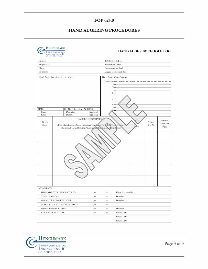
FOP 025.0
HAND AUGERING PROCEDURES
Page 3 of 3
Bn v i ronme talng i neeri n gc ence,i
n
HAND AUGER BOREHOLE LOG
Project: BOREHOLE I.D.: Project No.: Excavation Date: Client: Excavation Method: Location: Logged / Checked By:
Hand Auger Location: NOT TO SCALE Hand Auger Cross Section:
TIME BOREHOLE DIMENSIONSStart: Diameter: (approx.)End: Depth: (approx.)
Depth(fbgs)
COMMENTS:
GROUNDWATER ENCOUNTERED: yes no If yes, depth to GW:
VISUAL IMPACTS: yes no Describe:
OLFACTORY OBSERVATIONS: yes no Describe:
NON-NATIVE FILL ENCOUNTERED: yes no
OTHER OBSERVATIONS: yes no Describe:
SAMPLES COLLECTED: yes no Sample I.D.:
Sample I.D.:
Sample I.D.:
8'
10'
SamplesCollected
(fbgs)
PIDScan
(ppm)
PhotosY / N
Grade - 0'
2'
4'
6'
SAMPLE DESCRIPTION
USCS Classification: Color, Moisture Condition, % of Soil Type, Texture,Plasticity, Fabric, Bedding, Weathering/Fracturing, Odor, Other
Bn v i r o n m e t a ln g i n e e r i n gc e n c e,i
n

FIE
LD
OP
ER
AT
ING
PR
OC
ED
UR
ES
Hollow Stem Auger Drilling Procedures
Bn v i ronme talng i neeri n gc ence,i
n
FOP 026.1
HOLLOW STEM AUGER (HSA) DRILLING PROCEDURES
Page 1 of 6
Bn v i ronme talng i neeri n gc ence,i
n
PURPOSE
This guideline presents a method for drilling a borehole through unconsolidated materials,
including soils or overburden, and consolidated materials, including bedrock.
PROCEDURE
The following procedure will be used to drill a borehole for sampling and/or well
installation, using hollow-stem auger methods and equipment.
1. Follow Benchmark’s Field Operating Procedure for Drill Site Selection
Procedure prior to implementing any drilling activity. 2. Perform drill rig safety checks with the driller by completing the Drilling
Safety Checklist form (sample attached).
3. Conduct tailgate health and safety meeting with project team and drillers by completing the Tailgate Safety Meeting Form.
4. Calibrate air-monitoring equipment in accordance with the appropriate
Benchmark’s Field Operating Procedures (i.e., PID, FID, combustible gas meter) or manufacturer’s recommendations for calibration of field meters (i.e., DataRAM 4 Particulate Meter).
5. Ensure all drilling equipment (i.e., augers, rods, split-spoons) appear clean and
free of soil prior to initiating any subsurface intrusion. Decontamination of drilling equipment should be in accordance with Benchmark’s FOP: Drilling and Excavation Equipment Decontamination Procedures.
6. Mobilize the auger rig to the site and position over the borehole. 7. Level and stabilize the rig using the rig jacks, and recheck the rig location
against the planned drilling location. If necessary, raise the jacks and adjust the rig position.
FOP 026.1
HOLLOW STEM AUGER (HSA) DRILLING PROCEDURES
Page 2 of 6
Bn v i ronme talng i neeri n gc ence,i
n
8. Place a metal or plywood auger pan over the borehole location to collect the
auger cuttings. This auger pan will be equipped with a 12-inch nominal diameter hole for auger passage. As an alternative, a piece of polyethylene tarp may be used as a substitute.
9. Advance augers into the subsurface. For sampling or pilot-hole drilling,
nominal 8-inch outside diameter (OD) augers should be used. The boring diameter will be approved by the Benchmark field supervisor.
10. Collect soil samples via split spoon sampler in accordance with Benchmark’s
Field Operating Procedure for Split Spoon Sampling.
11. Check augers periodically during drilling to ensure the boring is plumb. Adjust rig position as necessary to maintain plumb.
12. Continue drilling until reaching the assigned total depth, or until auger refusal
occurs. Auger refusal is when the drilling penetration drops below 0.1 feet per 10 minutes, with the full weight of the rig on the auger bit, and a center bit (not center plug) in place.
13. Plug and abandon boreholes not used for well installation in accordance with
Benchmark’s Field Operating Procedure for Abandonment of Borehole.
OTHER PROCEDURAL ISSUES
Slip rings may be used for lifting a sampling or bit string. The string will not be permitted to extend more than 15 feet above the mast crown.
Borings will not be over drilled (rat holed) without the express permission of the
Benchmark field supervisor. All depth measurements should be accurate to the nearest 0.1 foot, to the extent practicable.
Potable water may be placed in the auger stem if critically necessary for borehole
control or to accomplish sampling objectives and must be approved by the Benchmark Project Manager and/or NYSDEC Project Manager. Upon approval,
FOP 026.1
HOLLOW STEM AUGER (HSA) DRILLING PROCEDURES
Page 3 of 6
Bn v i ronme talng i neeri n gc ence,i
n
the potable water source and quantity used will be documented in the Project Field Book and subsequent report submittal.
ATTACHMENTS
Drilling Safety Checklist (sample) Tailgate Safety Meeting Form (sample)
REFERENCES
Benchmark FOPs: 001 Abandonment of Borehole Procedures 010 Calibration and Maintenance of Portable Flame Ionization Detector 011 Calibration and Maintenance of Portable Photoionization Detector 017 Drill Site Selection Procedure 018 Drilling and Excavation Equipment Decontamination Procedures 058 Split Spoon Sampling Procedures
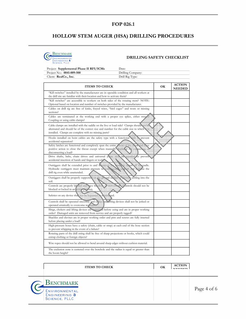
FOP 026.1
HOLLOW STEM AUGER (HSA) DRILLING PROCEDURES
Page 4 of 6
Bn v i ronme talng i neeri n gc ence,i
n
DRILLING SAFETY CHECKLIST
Project: Supplemental Phase II RFI/ICMs Date:Project No.: 0041-009-500 Drilling Company:Client: RealCo., Inc. Drill Rig Type:
OKACTION
NEEDED
OKACTION
NEEDED
Drive shafts, belts, chain drives and universal joints shall be guarded to preventaccidental insertion of hands and fingers or tools.
Outriggers shall be extended prior to and whenever the boom is raised off its cradle.Hydraulic outriggers must maintain pressure to continuously support and stabilize thedrill rig even while unattended.
Outriggers shall be properly supported on the ground surface to prevent settling into thesoil. Controls are properly labeled and have freedom of movement? Controls should not beblocked or locked in an action position.
ITEMS TO CHECK
Cable clamps are installed with the saddle on the live or load side? Clamps should not bealternated and should be of the correct size and number for the cable size to which it isinstalled. Clamps are complete with no missing parts?
Hooks installed on hoist cables are the safety type with a functional latch to preventaccidental separation?Safety latches are functional and completely span the entire throat of the hook and havepositive action to close the throat except when manually displaced for connecting ordisconnecting a load?
“Kill switches” installed by the manufacturer are in operable condition and all workers atthe drill site are familiar with their location and how to activate them?“Kill switches” are accessible to workers on both sides of the rotating stem? NOTE:Optional based on location and number of switches provided by the manufacturer.Cables on drill rig are free of kinks, frayed wires, “bird cages” and worn or missingsections?Cables are terminated at the working end with a proper eye splice, either swagedCoupling or using cable clamps?
Safeties on any device shall not be bypassed or neutralized.
Controls shall be operated smoothly and cables and lifting devices shall not be jerked oroperated erratically to overcome resistance.Slings, chokers and lifting devices are inspected before using and are in proper workingorder? Damaged units are removed from service and are properly tagged?Shackles and clevises are in proper working order and pins and screws are fully insertedbefore placing under a load?High-pressure hoses have a safety (chain, cable or strap) at each end of the hose sectionto prevent whipping in the event of a failure?Rotating parts of the drill string shall be free of sharp projections or hooks, which couldentrap clothing or foreign objects?
Wire ropes should not be allowed to bend around sharp edges without cushion material.
The exclusion zone is centered over the borehole and the radius is equal or greater thanthe boom height?
ITEMS TO CHECK
Bn v i ron m e t aln g i neer i n gc en ce,i
n
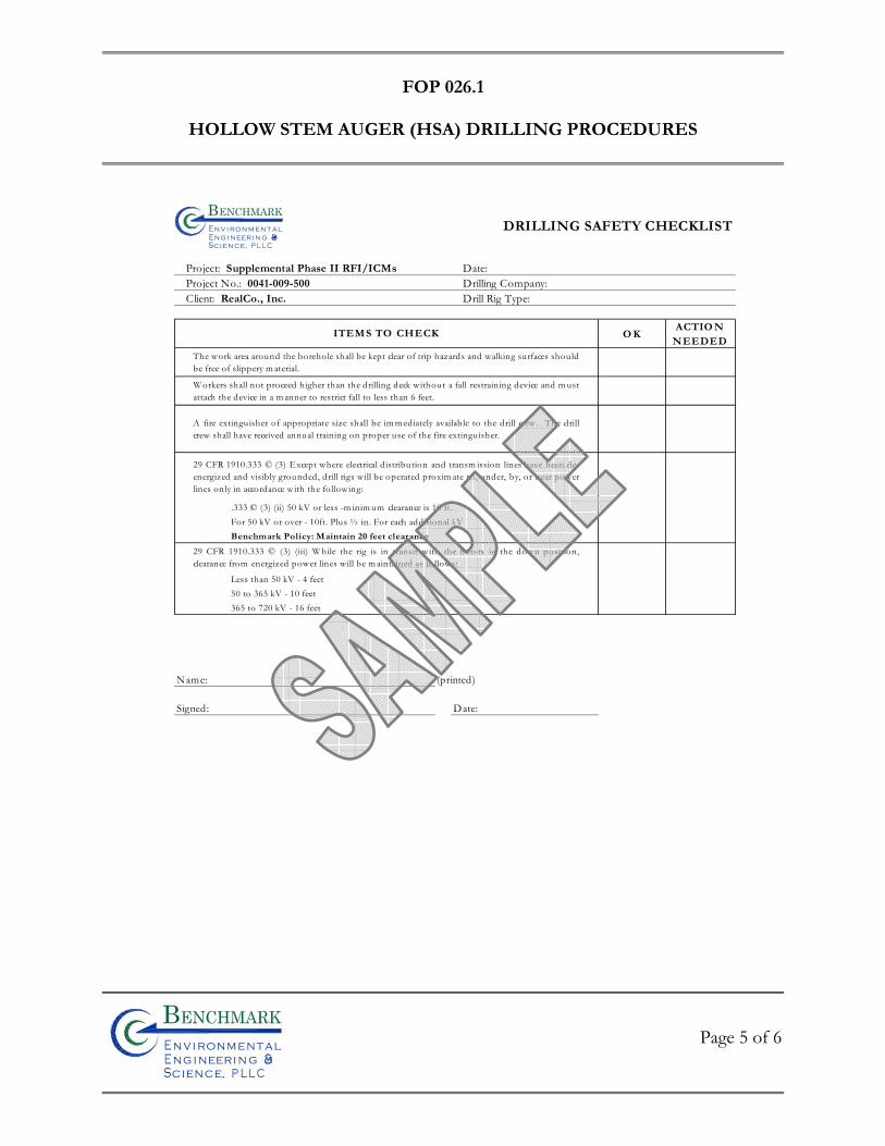
FOP 026.1
HOLLOW STEM AUGER (HSA) DRILLING PROCEDURES
Page 5 of 6
Bn v i ronme talng i neeri n gc ence,i
n
O KACTIO N
NEEDED
Less than 50 kV - 4 feet50 to 365 kV - 10 feet365 to 720 kV - 16 feet
Name: (printed)
Signed: Date:
29 CFR 1910.333 © (3) (iii) W hile the rig is in transit with the boom in the down position,clearance from energized power lines will be m aintained as follows:
The work area around the borehole shall be kept clear of trip hazards and walking surfaces should be free of slippery m aterial.
W orkers shall not proceed higher than the drilling deck without a fall restraining device and m ustattach the device in a m anner to restrict fall to less than 6 feet.
A fire extinguisher of appropriate size shall be im m ediately available to the drill crew. The drillcrew shall have received annual training on proper use of the fire extinguisher.
29 CFR 1910.333 © (3) Except where electrical distribution and transm ission lines have been de-energized and visibly grounded, drill rigs will be operated proxim ate to, under, by, or near powerlines only in accordance with the following:
ITEMS TO CHECK
.333 © (3) (ii) 50 kV or less -m inim um clearance is 10 ft.For 50 kV or over - 10ft. Plus ½ in. For each additional kVBenchmark Policy: Maintain 20 feet clearance
DRILLING SAFETY CHECKLIST
Project: Supplemental Phase II RFI/ICMs Date:Project No.: 0041-009-500 Drilling Company:Client: RealCo., Inc. Drill Rig Type:
Bn v i ron m e t aln g i neer i n gc en ce,i
n
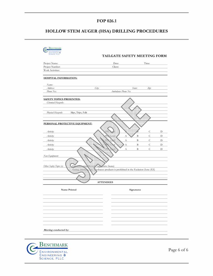
FOP 026.1
HOLLOW STEM AUGER (HSA) DRILLING PROCEDURES
Page 6 of 6
Bn v i ronme talng i neeri n gc ence,i
n
TAILGATE SAFETY MEETING FORM
Project Name: Date: Time: Project Number: Client: Work Activities:
HOSPITAL INFORMATION:
Name:Address: City: State: Zip:Phone No.: Ambulance Phone No.
SAFETY TOPICS PRESENTED:Chemical Hazards:
Physical Hazards: Slips, Trips, Falls
PERSONAL PROTECTIVE EQUIPMENT:
Activity: PPE Level: A B C D
Activity: PPE Level: A B C D
Activity: PPE Level: A B C D
Activity: PPE Level: A B C D
Activity: PPE Level: A B C D
New Equipment:
Other Safety Topic (s): Environmental Hazards (aggressive fauna)Eating, drinking, use of tobacco products is prohibited in the Exclusion Zone (EZ)
Bn v i ronme t alngi neeri n gc ence,i
n
Meeting conducted by:
Name Printed Signatures
ATTENDEES

FIE
LD
OP
ER
AT
ING
PR
OC
ED
UR
ES
Low-Flow (Minimal Drawdown)
Groundwater Purging & Sampling Procedure
Bn v i ronme talng i neeri n gc ence,i
n
FOP 031.2
LOW FLOW (MINIMAL DRAWDOWN) GROUNDWATER
PURGING & SAMPLING PROCEDURES
Page 1 of 7
Bn v i ronme talng i neeri n gc ence,i
n
PURPOSE
This procedure describes the methods used for performing low flow (minimal drawdown)
purging, also referred to as micro-purging, at a well prior to groundwater sampling to obtain
a representative sample from the water-bearing zone. This method of purging is used to
minimize the turbidity of the produced water. This may increase the representativeness of
the groundwater samples by avoiding the necessity of filtering suspended solids in the field
prior to preservation of the sample.
Well purging is typically performed immediately preceding groundwater sampling. The
sample should be collected as soon as the parameters measured in the field (i.e., pH, specific
conductance, dissolved oxygen, Eh, temperature, and turbidity) have stabilized.
PROCEDURE
Allow approximately 3 to 10 days following well development for groundwater to return to
static conditions before performing low-flow purge and sample activities at any well location.
Conversely, perform low-flow sampling as soon as purged groundwater has stabilized. If the
well does not yield sufficient volume (i.e., cannot maintain a constant water level during
purging) for low-flow purge and sampling, then an alternative method must be performed in
accordance with Benchmark’s Groundwater Purging Procedures Prior to Sample Collection
FOP.
1. Water samples should not be taken immediately following well development. Sufficient time should be allowed to stabilize the groundwater flow regime in
FOP 031.2
LOW FLOW (MINIMAL DRAWDOWN) GROUNDWATER
PURGING & SAMPLING PROCEDURES
Page 2 of 7
Bn v i ronme talng i neeri n gc ence,i
n
the vicinity of the monitoring well. This lag time will depend on site conditions and methods of installation but may exceed one week.
2. Prepare the electronic water level indicator (e-line) in accordance with the
procedures referenced in the Benchmark’s Groundwater Level Measurement FOP and decontaminate the e-line probe and a lower portion of cable following the procedures referenced in the Benchmark’s Non-disposable and Non-dedicated Sampling Equipment Decontamination FOP. Store the e-line in a protected area until use. This may include wrapping the e-line in clean plastic until the time of use.
3. Calibrate all sampling devices and monitoring equipment in accordance with
manufacturer’s recommendations, the site Quality Assurance Project Plan (QAPP) and/or Field Sampling Plan (FSP). Calibration of field instrumentation should be followed as specified in Benchmark’s Calibration and Maintenance FOP for each individual meter.
4. Inspect the well/piezometer for signs of vandalism or damage and record
condition on the Groundwater Field Form (sample attached). Specifically, inspect the integrity of the following: concrete surface seal, lock, protective casing and well cover, well casing and J-plug/cap. Report any irregular findings to the Project Manager.
5. Unlock and remove the well protective cap or cover and place on clean plastic
to avoid introducing foreign material into the well.
6. Monitor the well for organic vapors using a PID, as per the Work Plan. If a reading of greater than 5 ppm is recorded, the well should be allowed to vent until levels drop below 5 ppm before proceeding with purging.
7. Lower the e-line probe slowly into the monitoring well and record the initial
water level in accordance with the procedures referenced in Benchmark’s Groundwater Level Measurement FOP. Refer to the construction diagram for the well to identify the screened depth.
FOP 031.2
LOW FLOW (MINIMAL DRAWDOWN) GROUNDWATER
PURGING & SAMPLING PROCEDURES
Page 3 of 7
Bn v i ronme talng i neeri n gc ence,i
n
8. Decontaminate all non-dedicated pump and tubing equipment following the procedures referenced in the Benchmark’s Non-disposable and Non-dedicated Sampling Equipment Decontamination FOP.
9. Lower the purge pump or tubing (i.e., low-flow electrical submersible,
peristaltic, etc.) slowly into the well until the pump/tubing intake is approximately in the middle of the screened interval. Rapid insertion of the pump will increase the turbidity of well water, and can increase the required purge time. This step can be eliminated if dedicated tubing is already within the well.
Placement of the pump close to the bottom of the well will cause increased entrainment of solids, which may have settled in the well over time. Low-flow purging has the advantage of minimizing mixing between the overlying stagnant casing water and water within the screened interval. The objective of low-flow purging is to maintain a purging rate, which minimizes stress (drawdown) of the water level in the well. Low-flow refers to the velocity with which water enters the pump intake and that is imparted to the formation pore water in the immediate vicinity of the well screen.
10. Lower the e-line back down the well as water levels will be frequently
monitored during purge and sample activities. 11. Begin pumping to purge the well. The pumping rate should be between 100
and 500 milliliters (ml) per minute (0.03 to 0.13 gallons per minute) depending on site hydrogeology. Periodically check the well water level with the e-line adjusting the flow rate as necessary to stabilize drawdown within the well. If possible, a steady flow rate should be maintained that results in a stabilized water level (drawdown of 0.3 feet or less). If the water level exceeds 2 feet below static and declining, slow the purge rate until the water level generally stabilizes. Record each pumping rate and water level during the event. If the water level continues to drop and will not stabilize, the monitoring location is not conducive to low-flow sampling and conventional purge and sample methods should be performed.
FOP 031.2
LOW FLOW (MINIMAL DRAWDOWN) GROUNDWATER
PURGING & SAMPLING PROCEDURES
Page 4 of 7
Bn v i ronme talng i neeri n gc ence,i
n
The low flow rate determined during purging will be maintained during the collection of analytical samples. At some sites where geologic heterogeneities are sufficiently different within the screened interval, high conductivity zones may be preferentially sampled.
12. Measure and record field parameters (pH, specific conductance, Eh, dissolved
oxygen (DO), temperature, and turbidity) during purging activities. In lieu of measuring all of the parameters, a minimum subset could be limited to pH, specific conductance, and turbidity or DO. A reduction in the field parameter list must be approved by the Project Manager and/or the NYSDEC Project Manager.
Water quality indicator parameters should be used to determine purging needs prior to sample collection in each well. Stabilization of indicator parameters should be used to determine when formation water is first encountered during purging. In general, the order of stabilization is pH, temperature, and specific conductance, followed by Eh, DO and turbidity. Performance criteria for determination of stabilization should be based on water-level drawdown, pumping rate and equipment specifications for measuring indicator parameters. An in-line flow through cell to continuously measure the above parameters may be used. The in-line device should be disconnected or bypassed during sample collection.
13. Purging will continue until parameters of water quality have stabilized. Record
measurements for field indicator parameters (including water levels) at regular intervals during purging. The stability of these parameters with time can be used to guide the decision to discontinue purging. Proper adjustments must be made to stabilize the flow rate as soon as possible.
14. Record well purging and sampling data in the Project Field Book or on the
Groundwater Field Form (sample attached). Measurements should be taken approximately every three to five minutes, or as merited given the rapidity of change.
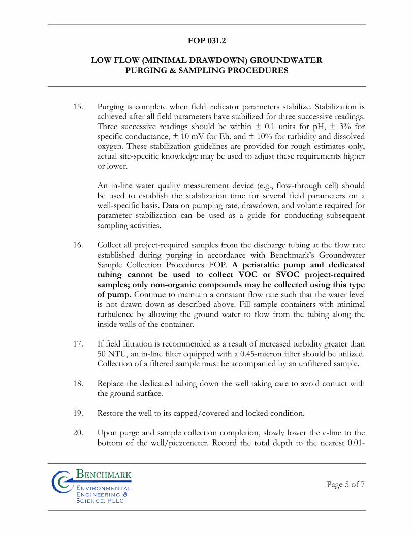
FOP 031.2
LOW FLOW (MINIMAL DRAWDOWN) GROUNDWATER
PURGING & SAMPLING PROCEDURES
Page 5 of 7
Bn v i ronme talng i neeri n gc ence,i
n
15. Purging is complete when field indicator parameters stabilize. Stabilization is achieved after all field parameters have stabilized for three successive readings. Three successive readings should be within ± 0.1 units for pH, ± 3% for specific conductance, ± 10 mV for Eh, and ± 10% for turbidity and dissolved oxygen. These stabilization guidelines are provided for rough estimates only, actual site-specific knowledge may be used to adjust these requirements higher or lower.
An in-line water quality measurement device (e.g., flow-through cell) should be used to establish the stabilization time for several field parameters on a well-specific basis. Data on pumping rate, drawdown, and volume required for parameter stabilization can be used as a guide for conducting subsequent sampling activities.
16. Collect all project-required samples from the discharge tubing at the flow rate
established during purging in accordance with Benchmark’s Groundwater Sample Collection Procedures FOP. A peristaltic pump and dedicated tubing cannot be used to collect VOC or SVOC project-required samples; only non-organic compounds may be collected using this type of pump. Continue to maintain a constant flow rate such that the water level is not drawn down as described above. Fill sample containers with minimal turbulence by allowing the ground water to flow from the tubing along the inside walls of the container.
17. If field filtration is recommended as a result of increased turbidity greater than
50 NTU, an in-line filter equipped with a 0.45-micron filter should be utilized. Collection of a filtered sample must be accompanied by an unfiltered sample.
18. Replace the dedicated tubing down the well taking care to avoid contact with
the ground surface. 19. Restore the well to its capped/covered and locked condition. 20. Upon purge and sample collection completion, slowly lower the e-line to the
bottom of the well/piezometer. Record the total depth to the nearest 0.01-
FOP 031.2
LOW FLOW (MINIMAL DRAWDOWN) GROUNDWATER
PURGING & SAMPLING PROCEDURES
Page 6 of 7
Bn v i ronme talng i neeri n gc ence,i
n
foot and compare to the previous total depth measurement. If a significant discrepancy exists, re-measure the total depth. Record observations of purge water to determine whether the well/piezometer had become silted due to inactivity or damaged (i.e., well sand within purge water). Upon confirmation of the new total depth and determination of the cause (i.e., siltation or damage), notify the Project Manager following project field activities.
ATTACHMENTS
Groundwater Field Form (sample)
REFERENCES
United States Environmental Protection Agency, 540/S-95/504, 1995. Low-Flow (Minimal Drawdown) Ground-Water Sampling Procedures.
Benchmark FOPs: 007 Calibration and Maintenance of Portable Dissolved Oxygen Meter 008 Calibration and Maintenance of Portable Field pH/Eh Meter 009 Calibration and Maintenance of Portable Field Turbidity Meter 011 Calibration and Maintenance of Portable Photoionization Detector 012 Calibration and Maintenance of Portable Specific Conductance Meter 022 Groundwater Level Measurement 024 Groundwater Sample Collection Procedures 040 Non-Disposable and Non-Dedicated Sampling Equipment Decontamination 046 Sample Labeling, Storage and Shipment Procedures
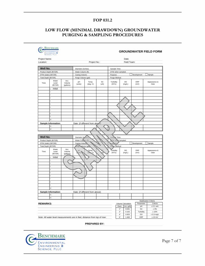
FOP 031.2
LOW FLOW (MINIMAL DRAWDOWN) GROUNDWATER
PURGING & SAMPLING PROCEDURES
Page 7 of 7
Bn v i ronme talng i neeri n gc ence,i
n
GROUNDWATER FIELD FORM
Project Name: Date:
Location: Project No.: Field Team:
Well No. Diameter (inches): Sample Time:
Product Depth (fbTOR): Water Column (ft): DTW when sampled:
DTW (static) (fbTOR): Casing Volume: Purpose:
Total Depth (fbTOR): Purge Volume (gal): Purge Method:
Sample Information: Date: (if different from above)
Well No. Diameter (inches): Sample Time:
Product Depth (fbTOR): Water Column (ft): DTW when sampled:
DTW (static) (fbTOR): Casing Volume: Purpose:
Total Depth (fbTOR): Purge Volume (gal): Purge Method:
Sample Information: Date: (if different from above)
Stabilization Criteria
REMARKS: Volume Calculation
Note: All water level measurements are in feet, distance from top of riser.
PREPARED BY:
1.469
± 0.3 mg/L
± 10 mV
Diam. Vol. (g/ft)
1"
2"
4"
6"
0.041
0.163
Criteria
± 0.1 unit
± 3%
± 10%
Parameter
pH
SC
Turbidity
DO
ORP
0.653
DO
(mg/L)
ORP
(mV)
Appearance &
Odor
S2
S1
9
8
ORP
(mV)
DO
(mg/L)
pH
(units)
Temp.
(deg. C)
SC
(uS)
Turbidity
(NTU)Time
Water
Level
(fbTOR)
Acc.
Volume
(gallons)
3
0 Initial
1
5
6
10
2
7
Time
Water
Level
(fbTOR)
Acc.
Volume
(gallons)
pH
(units)
Temp.
(deg. C)
SC
(uS)
Turbidity
(NTU)
0 Initial
1
5
6
7
8
9
10
S1
S2
Appearance &
Odor
3
2
4
4
Bn v i ron m e t aln g i neer i n gc en ce,i
n
Development Sample
Development Sample

FIE
LD
OP
ER
AT
ING
PR
OC
ED
UR
ES
Management of Investigative-Derived
Waste (IDW)
Bn v i ronme talng i neeri n gc ence,i
n
FOP 032.1
MANAGEMENT OF INVESTIGATION-DERIVED WASTE (IDW)
Page 1 of 5
Bn v i ronme talng i neeri n gc ence,i
n
PURPOSE
The purpose of these guidelines is to ensure the proper holding, storage, transportation, and
disposal of materials generated from field investigation activities that may contain hazardous
wastes. Investigation-derived waste (IDW) includes the following:
• Drill cuttings, discarded soil samples, drilling mud solids, and used sample containers.
• Well development and purge waters and discarded groundwater samples.
• Decontamination waters and associated solids.
• Soiled disposable personal protective equipment (PPE).
• Used disposable sampling equipment.
• Used plastic sheeting and aluminum foil.
• Other equipment or materials that either contain or have been in contact with
potentially impacted environmental media. Because these materials may contain regulated chemical constituents, they must be managed
as a solid waste. This management may be terminated if characterization analytical results
indicate the absence of these constituents.
PROCEDURE
1. Contain all investigation-derived wastes in Department of Transportation (DOT)-approved 55-gallon drums, roll-off boxes, or other containers suitable for the wastes.
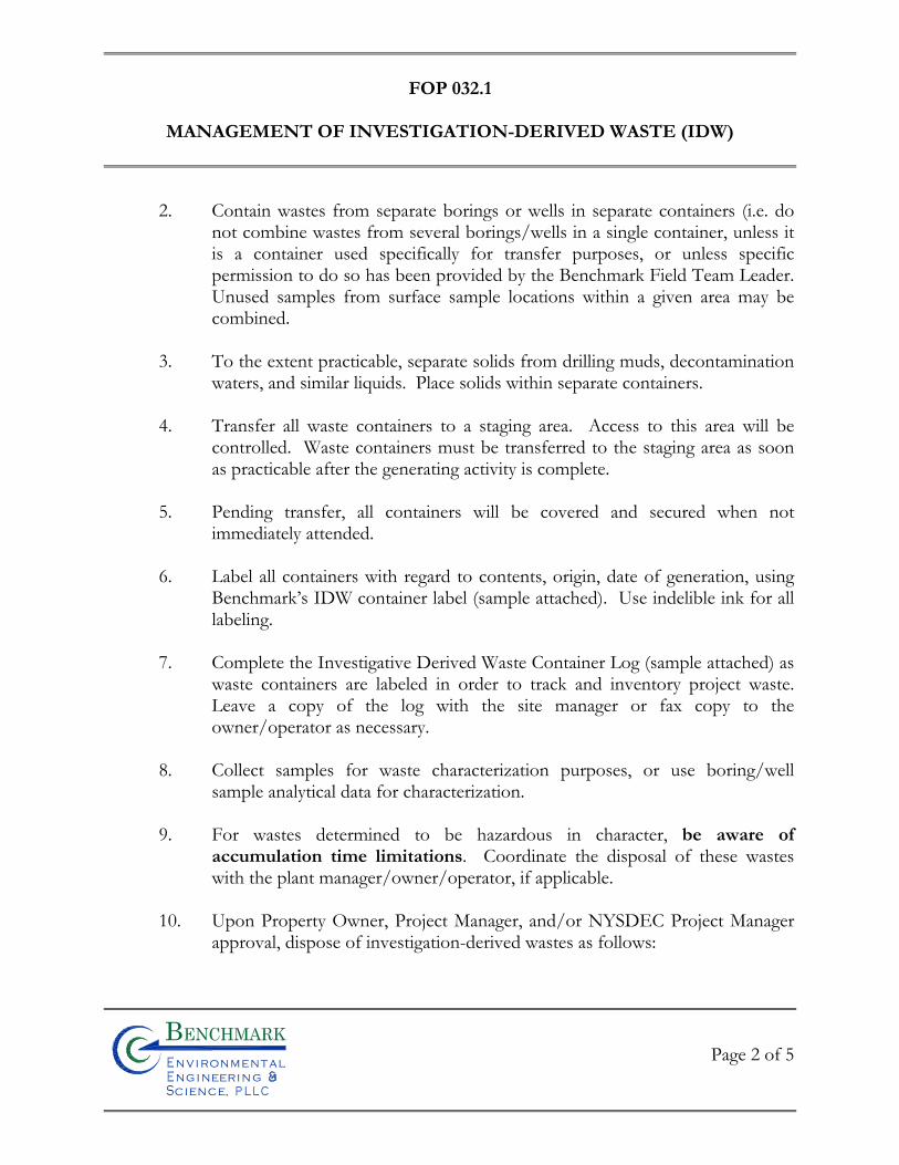
FOP 032.1
MANAGEMENT OF INVESTIGATION-DERIVED WASTE (IDW)
Page 2 of 5
Bn v i ronme talng i neeri n gc ence,i
n
2. Contain wastes from separate borings or wells in separate containers (i.e. do not combine wastes from several borings/wells in a single container, unless it is a container used specifically for transfer purposes, or unless specific permission to do so has been provided by the Benchmark Field Team Leader. Unused samples from surface sample locations within a given area may be combined.
3. To the extent practicable, separate solids from drilling muds, decontamination
waters, and similar liquids. Place solids within separate containers. 4. Transfer all waste containers to a staging area. Access to this area will be
controlled. Waste containers must be transferred to the staging area as soon as practicable after the generating activity is complete.
5. Pending transfer, all containers will be covered and secured when not
immediately attended. 6. Label all containers with regard to contents, origin, date of generation, using
Benchmark’s IDW container label (sample attached). Use indelible ink for all labeling.
7. Complete the Investigative Derived Waste Container Log (sample attached) as
waste containers are labeled in order to track and inventory project waste. Leave a copy of the log with the site manager or fax copy to the owner/operator as necessary.
8. Collect samples for waste characterization purposes, or use boring/well
sample analytical data for characterization. 9. For wastes determined to be hazardous in character, be aware of
accumulation time limitations. Coordinate the disposal of these wastes with the plant manager/owner/operator, if applicable.
10. Upon Property Owner, Project Manager, and/or NYSDEC Project Manager
approval, dispose of investigation-derived wastes as follows:
FOP 032.1
MANAGEMENT OF INVESTIGATION-DERIVED WASTE (IDW)
Page 3 of 5
Bn v i ronme talng i neeri n gc ence,i
n
• Soil, water, and other environmental media for which analysis does not detect organic constituents, and for which inorganic constituents are at levels that meet the Site’s cleanup objectives, may be spread on the Property or otherwise treated as a non-waste material. Disposal quantity and on-site location will be documented on Project Field Books and in the project report submittal.
• Soil, water, and other environmental media in which organic compounds
are detected or metals are present above the Site’s cleanup objectives will be disposed off-site in accordance with applicable state and federal regulations. Disposal quantity and off-site location will be documented on Project Field Books and in the project report submittal.
• Personal protective equipment, disposable bailers, and similar equipment
may be disposed as municipal waste, unless waste characterization results mandate otherwise.
WASTE STORAGE MANAGEMENT
Hazardous materials generated on site should be temporarily stored in a secure location that
is under the control of the owner/operator or does not allow for vandalism (i.e., within a
locked building structure or within a locked fenced in area). A waste-staging area should be
designated on-site by the Project Manager in conjunction with the owner/operator.
ATTACHMENTS
Investigation Derived Waste Container Log (sample) Investigation Derived Waste Container Label (sample)
REFERENCES
None
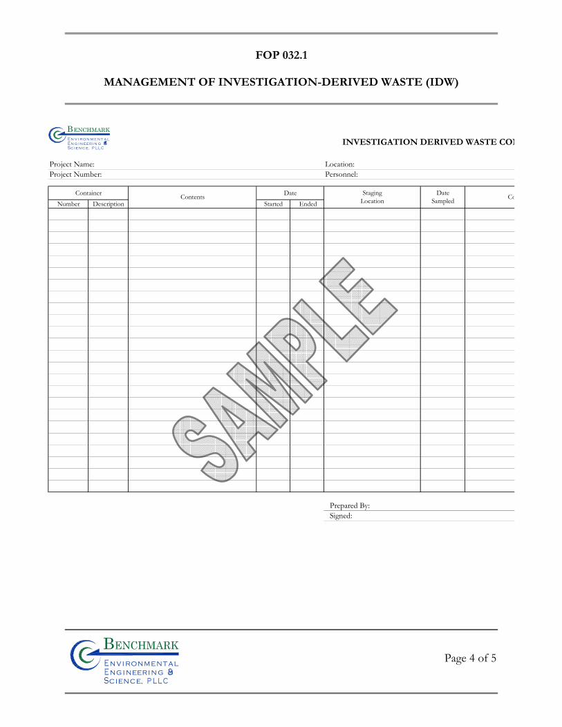
FOP 032.1
MANAGEMENT OF INVESTIGATION-DERIVED WASTE (IDW)
Page 4 of 5
Bn v i ronme talng i neeri n gc ence,i
n
INVESTIGATION DERIVED WASTE CON
Project Name: Location: Project Number: Personnel:
Container DateNumber Description Started Ended
Prepared By:Signed:
Contents StagingLocation CoDate
Sampled
Bn v i r o n m e t a ln g i n eer i n gc e n c e,i
n
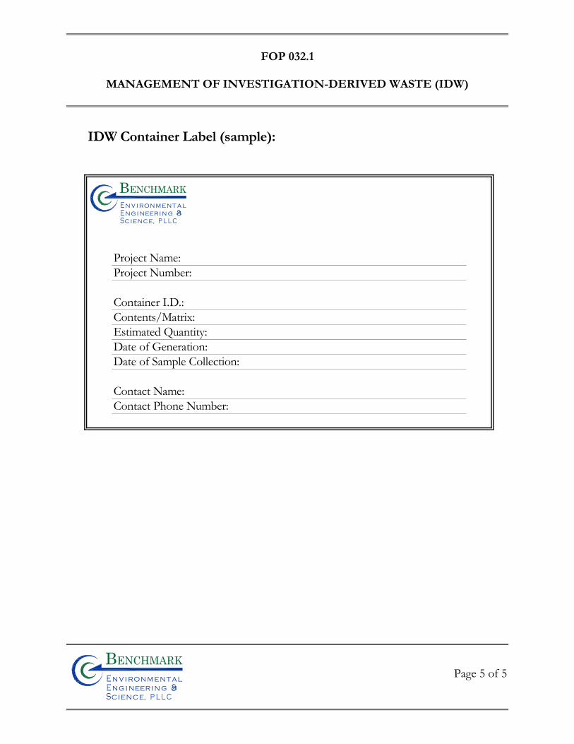
FOP 032.1
MANAGEMENT OF INVESTIGATION-DERIVED WASTE (IDW)
Page 5 of 5
Bn v i ronme talng i neeri n gc ence,i
n
IDW Container Label (sample):
Project Name:Project Number:
Container I.D.:Contents/Matrix:Estimated Quantity:Date of Generation:Date of Sample Collection:
Contact Name:Contact Phone Number:
Bn v i ronme t alng i neeri n gc ence,i
n

FIE
LD
OP
ER
AT
ING
PR
OC
ED
UR
ES
Monitoring Well Construction for
Hollow Stem Auger Boreholes
Bn v i ronme talng i neeri n gc ence,i
n
FOP 033.0
MONITORING WELL CONSTRUCTION FOR
HOLLOW STEM AUGER BOREHOLES
Page 1 of 6
Bn v i ronme talng i neeri n gc ence,i
n
PURPOSE
Wells will be installed within selected boreholes for the purpose of evaluating groundwater
characteristics. Well installation procedures depend upon the drilling method. This
procedure describes well construction and installation for boreholes drilled using the hollow
stem auger method. Refer to the Benchmark’s Hollow Stem Auger Drilling Procedures
FOP. Nominal dimensions and materials for the well are shown in the attached well
construction diagram.
PROCEDURE
1. Advance borehole in accordance with the Benchmark’s Hollow Stem Auger Drilling Procedure FOP to the required depth. The nominal inside diameter (ID) of the auger stem used should be at least 2 inches larger than the outside diameter (OD) of the riser and screen selected for the well installation. Record the monitoring well construction on the Field Borehole/Monitoring Well Installation Log (sample attached) (see Documentation Requirements for Drilling and Well Installation FOP).
2. Remove the drill rods and center bit/plug from the auger stem and verify borehole depth using weighted measuring tape.
3. In the event of an over drill (i.e. borehole depth is more than one foot greater than desired base of screen depth), use bentonite chips poured through the auger stem to seal the over drilled portion of the borehole. Be sure to note bentonite chip thickness on Field Borehole/Monitoring Well Installation Log.
4. Add a maximum of 6 inches of filter pack material through the auger stem to the base of the borehole. (Note: This step may be avoided if dense non-aqueous phase liquids are suspected to be present and it is desirable to have the screen and/or sump at the base of the borehole.)
FOP 033.0
MONITORING WELL CONSTRUCTION FOR
HOLLOW STEM AUGER BOREHOLES
Page 2 of 6
Bn v i ronme talng i neeri n gc ence,i
n
5. Measure the length of the well string (i.e. riser and screen), and lower the well string into the well assembly to the desired depth. All measurements during the well installation process will be accurate to 0.1 foot.
6. Surface pour filter pack material into the annulus between the well and the auger stem as the augers are gradually withdrawn from the borehole. Use a weighted tape to confirm that the level of sand is maintained within the augers at all times. Record material volumes used.
7. After filter pack materials are brought to the required level, surface pour bentonite chips or pellets into the annulus between the well and the auger stem to form the filter pack seal. If necessary to avoid bridging, delayed hydration (coated) pellets may be used. Record the volume of material used.
8. Allow the bentonite chips/pellets to adequately hydrate for approximately 30 to 45-minutes. Cap or cover the well top of riser.
9. Mix cement/bentonite grout to a smooth consistency using a centrifugal or
reciprocating pump. Do not hand mix. All water used must be potable quality. Record the volume of water used.
10. Fill the remaining annulus between the well and the auger stem with grout by
surface pouring or pumping, and begin withdrawal of the auger string. Periodically top the auger string off with additional grout. If groundwater is present within the annulus above the bentonite chip/pellet seal, cement/bentonite grout will be pressure tremie grouted from bottom to top in order to displace groundwater from the borehole.
11. When the auger string is withdrawn, center the upper portion of the well riser
within the borehole, and place drums or barricades around the well for protection while the grout cures. Place and lock a security cap (i.e., J-plug) in the opening of the well riser.
12. Leave the well undisturbed for at least 24 hours to allow the grout to cure. If
excessive grout fallback occurs, top off as necessary with bentonite chips or additional grout.
FOP 033.0
MONITORING WELL CONSTRUCTION FOR
HOLLOW STEM AUGER BOREHOLES
Page 3 of 6
Bn v i ronme talng i neeri n gc ence,i
n
13. Construct the surface completion as shown in the attached Typical
Monitoring Well Detail (Figure 1). Select flush completions for all locations in active operational or high traffic areas, or in other areas where an above grade completion would be undesirable. Use aboveground completions in all other areas.
14. Place a dedicated lock on the well or protective casing, and keep well locked
when not actively attended.
15. Permanently label the well with the appropriate well identifier as determined by the Project Manager or specified in the Work Plan.
16. Permanently mark a survey location on the north side at the top of the casing
with a saw cut. Survey all wells for horizontal location and elevation, using a surveyor licensed by the State of New York. Coordinates and elevations will be provided in a coordinate system consistent with previous well surveys at the Site. Information obtained will include location (x and y) of the well, and elevation (z) of the ground surface, the pad, and the top of riser.
17. Develop the well as described in the Benchmark Field Operating Procedure
for Monitoring Well Development.
18. Manage all waste materials generated during well installation and development as described in the Benchmark Field Operating Procedure for Management of Investigation Derived Waste.
ATTACHMENTS
Field Borehole/Monitoring Well Installation Log (sample) Typical Monitoring Well Detail (Figure 1)
FOP 033.0
MONITORING WELL CONSTRUCTION FOR
HOLLOW STEM AUGER BOREHOLES
Page 4 of 6
Bn v i ronme talng i neeri n gc ence,i
n
REFERENCES
Benchmark FOPs: 015 Documentation Requirements for Drilling and Well Installation 026 Hollow Stem Auger Drilling Procedures 032 Management of Investigation Derived Waste 036 Monitoring Well Development Procedures
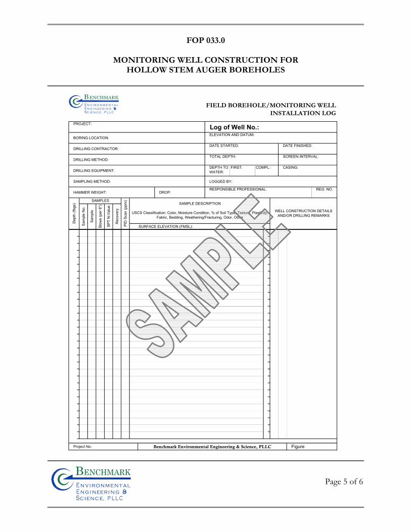
FOP 033.0
MONITORING WELL CONSTRUCTION FOR
HOLLOW STEM AUGER BOREHOLES
Page 5 of 6
Bn v i ronme talng i neeri n gc ence,i
n
FIELD BOREHOLE/MONITORING WELLINSTALLATION LOG
PROJECT: Log of Well No.:BORING LOCATION:
ELEVATION AND DATUM:
DRILLING CONTRACTOR:DATE STARTED: DATE FINISHED:
DRILLING METHOD:TOTAL DEPTH: SCREEN INTERVAL:
DRILLING EQUIPMENT:CASING:
SAMPLING METHOD: LOGGED BY:
HAMMER WEIGHT: DROP:RESPONSIBLE PROFESSIONAL:
SURFACE ELEVATION (FMSL):
Project No: Benchmark Environmental Engineering & Science, PLLC Figure
Dep
th (f
bgs)
FIRST: COMPL.:DEPTH TOWATER:
PID
Sca
n (p
pm)
SAMPLE DESCRIPTION
USCS Classification: Color, Moisture Condition, % of Soil Type, Texture, Plasticity, Fabric, Bedding, Weathering/Fracturing, Odor, Other
WELL CONSTRUCTION DETAILSAND/OR DRILLING REMARKS
REG. NO.
SAMPLES
Sam
ple
No.
Blow
s (p
er 6
")
SPT
N-V
alue
Rec
over
y
Sam
ple
Bn v i r o n m e t a ln g i n ee r i n gc e n c e,i
n
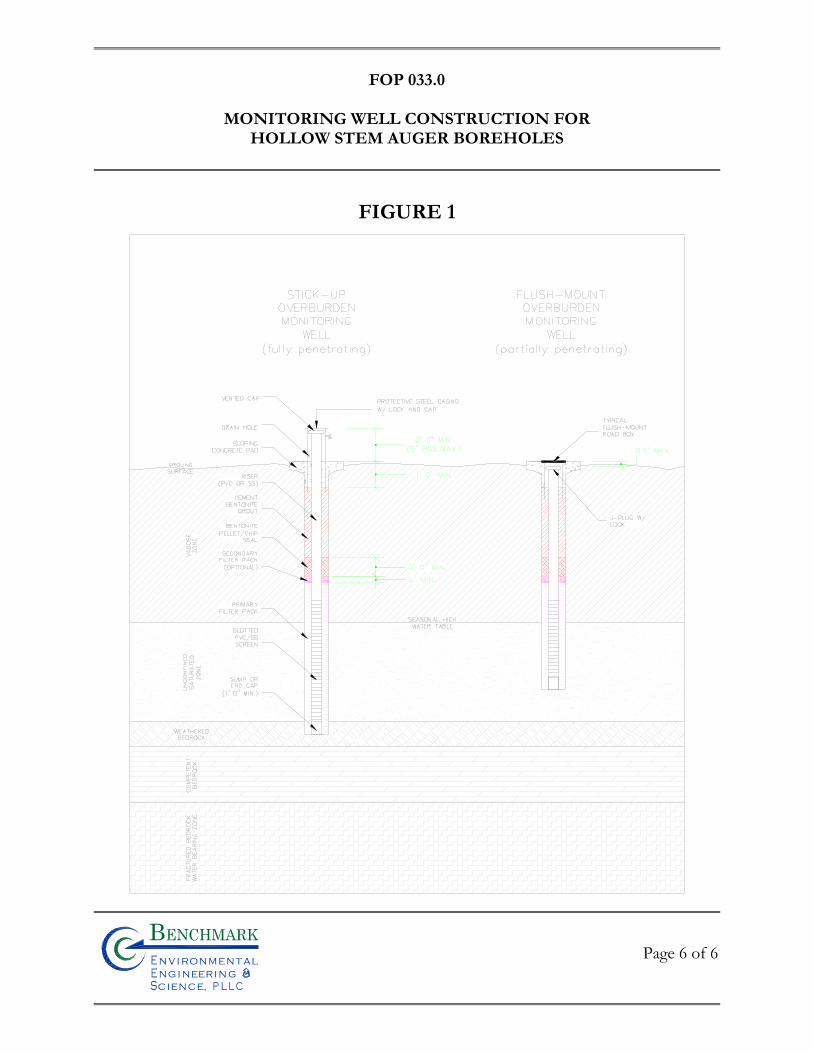
FOP 033.0
MONITORING WELL CONSTRUCTION FOR
HOLLOW STEM AUGER BOREHOLES
Page 6 of 6
Bn v i ronme talng i neeri n gc ence,i
n
FIGURE 1

FIE
LD
OP
ER
AT
ING
PR
OC
ED
UR
ES
Monitoring Well Development Procedures
Bn v i ronme talng i neeri n gc ence,i
n
FOP 036.0
MONITORING WELL DEVELOPMENT PROCEDURES
Page 1 of 3
PURPOSE
This procedure describes the methods for the development of newly installed monitoring
wells and re-development of existing monitoring wells that have been inactive for an
extended period of time (i.e., one year or more). Monitoring wells are developed after
installation in order to remove introduced water and drilling fluids, reduce the turbidity of
the water, and improve the hydraulic communication between the well and the water-bearing
formation. Well development will not commence until the annular grout seal has cured, but
will be performed within ten calendar days of well installation.
PROCEDURE
1. All well development will include surge blocking or false bailing with one or more of the following fluid removal methods. Well development activities may include:
• Bailing • Air Lifting • Submersible Pumping • Other methods as approved by the Benchmark Field Team Leader. • The appropriate water removal method will be selected based on water
level depth and anticipated well productivity.
2. Assemble and decontaminate equipment (if necessary), and place in the well. Reference the Benchmark Field Operating Procedure for Non-Disposable and Non-Dedicated Sampling Equipment Decontamination.
3. Alternate the use of agitation methods with water removal methods, using the former to suspend solids in the well water, and the latter to remove the turbid water. For example, use a vented surge block to agitate the well, moving up and down within the screened interval and then use a pump to clear the well. A bailer may be used for both purposes, by surging with the bailer (false
FOP 036.0
MONITORING WELL DEVELOPMENT PROCEDURES
Page 2 of 3
bailing) for a period within the screened interval, then bailing a volume of water from the well.
4. When using surging methods, initiate this activity gradually, with short (2 to 3 feet) strokes. After several passes across the screened interval, increase the speed and length of the surge strokes.
5. Continue development until the following objectives are achieved:
• Field parameters stabilize to the following criteria: o Dissolved Oxygen: ± 0.3 mg/L o Turbidity: ± 10% o Specific Conductance: ± 3% o ORP: ± 10 mV o pH: ± 0.1 units
• The well will generate non-turbid water during continued pumping typically less than 50 NTU.
• A minimum of 10 well volumes has been evacuated from the well. • In the case of lost water during drilling activities, the volume of water
removed exceeds twice the volume of water lost to the formation during the drilling process, as indicated by the water balance.
6. Document the development methods, volumes, field parameter measurements, and other observations on the attached Benchmark Groundwater Well Development Log (sample attached).
ATTACHMENTS
Groundwater Well Development Log (sample)
REFERENCES
Benchmark FOPs: 040 Non-Disposable and Non-Dedicated Sampling Equipment Decontamination
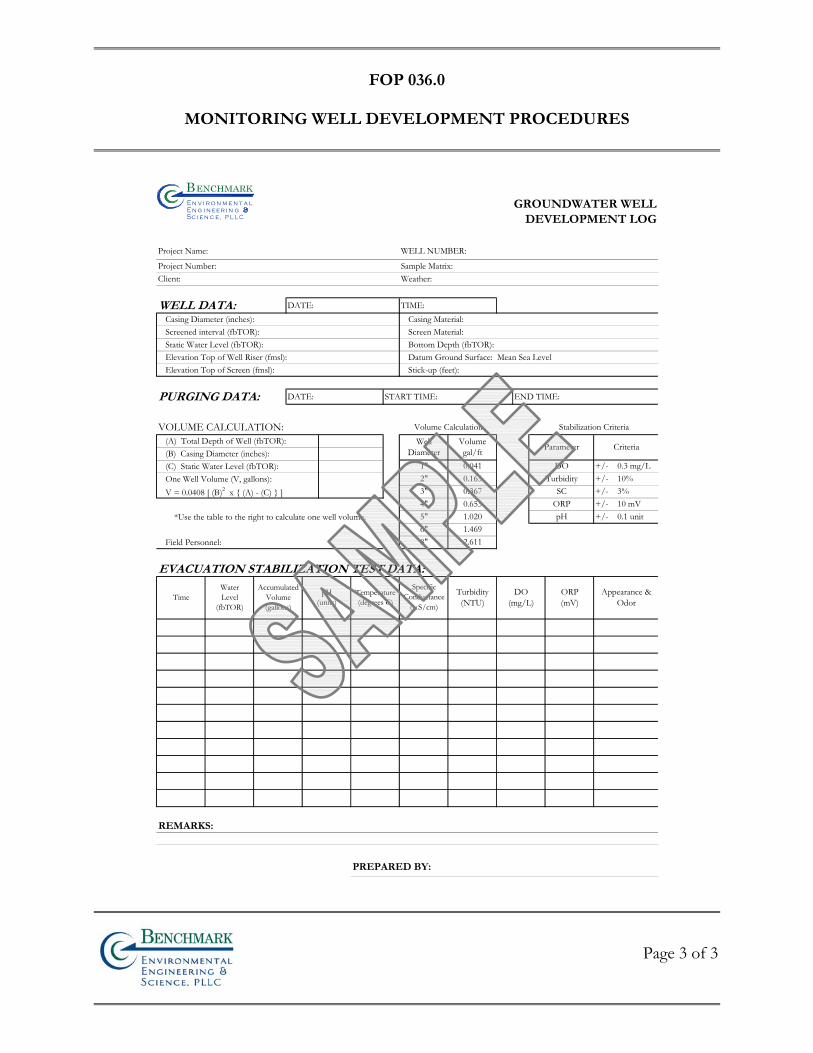
FOP 036.0
MONITORING WELL DEVELOPMENT PROCEDURES
Page 3 of 3
GROUNDWATER WELL
DEVELOPMENT LOG
Project Name: WELL NUMBER:
Project Number: Sample Matrix:Client: Weather:
WELL DATA: DATE: TIME:Casing Diameter (inches): Casing Material:Screened interval (fbTOR): Screen Material:Static Water Level (fbTOR): Bottom Depth (fbTOR):Elevation Top of Well Riser (fmsl): Datum Ground Surface: Mean Sea LevelElevation Top of Screen (fmsl): Stick-up (feet):
PURGING DATA: DATE: START TIME: END TIME:
VOLUME CALCULATION: Volume Calculation Stabilization Criteria(A) Total Depth of Well (fbTOR):(B) Casing Diameter (inches):(C) Static Water Level (fbTOR):One Well Volume (V, gallons):V = 0.0408 [ (B)2 x (A) - (C) ]
*Use the table to the right to calculate one well volume.
Field Personnel:
EVACUATION STABILIZATION TEST DATA:
REMARKS:
PREPARED BY:
ORP +/- 10 mVpH +/- 0.1 unit
4"5"6"8"
pH(units)
Temperature(degrees C)Time
SpecificConductance
(mS/cm)
WaterLevel
(fbTOR)
AccumulatedVolume(gallons)
Turbidity(NTU)
DO(mg/L)
ORP(mV)
Appearance &Odor
Parameter Criteria
DO +/- 0.3 mg/LTurbidity +/- 10%
SC +/- 3%
0.0410.1630.367
1"2"3"
1.4692.611
WellDiameter
Volumegal/ft
0.6531.020
Bn v i r o n m e t a ln g i n eer i n gc e n c e,i
n

FIE
LD
OP
ER
AT
ING
PR
OC
ED
UR
ES
Monitoring Well Retrofitting Procedures
Bn v i ronme talng i neeri n gc ence,i
n
FOP 037.0
MONITORING WELL RETROFITTING PROCEDURES
Page 1 of 1
Bn v i ronme talng i neeri n gc ence,i
n
PURPOSE
This guideline presents a method for retrofitting existing large diameter monitoring wells as a
means of reducing turbidity. The procedure is applicable to wells for which turbid
conditions interfere with the interpretation of groundwater analysis; and for which
redevelopment has not achieved a reduction in turbidity. Retrofitting is an alternative to well
replacement. Existing well diameter must be four inches or greater.
PROCEDURE
1. Insert a 2-inch I.D., 0.006-inch slotted well screen and 2-inch I.D. flush threaded riser to the bottom of the existing well. Material type and screen length should be determined on a case-by-case basis. A centralizer is positioned at the base of the screen and at the top of the riser.
2. Backfill the annulus between the two well screens with No. 1 silica sand up to
a minimum of two feet above the screen.
3. Develop filter pack with gentle pumping in accordance with Benchmark’s Monitoring Well Development FOP. Where practical, the water level should not be lowered below the top of the screen. Monitor turbidity in the field with a portable turbidimeter. The target turbidity value is 50 NTU.
REFERENCES
Benchmark FOPs: 036 Monitoring Well Development Procedures
NOTES
Note: The monitoring well retrofitting procedure may reduce well yield by compounding
well losses due to the presence of two well screens.
FIE
LD
OP
ER
AT
ING
PR
OC
ED
UR
ES
Non-Aqueous Phase Liquid (NAPL)
Detection and Sample Collection Procedure
Bn v i ronme talng i neeri n gc ence,i
n
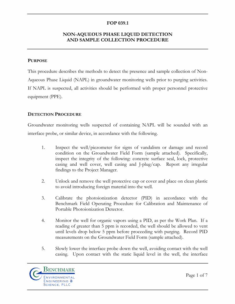
FOP 039.1
NON-AQUEOUS PHASE LIQUID DETECTION
AND SAMPLE COLLECTION PROCEDURE
Page 1 of 7
Bn v i ronme talng i neeri n gc ence,i
n
PURPOSE
This procedure describes the methods to detect the presence and sample collection of Non-
Aqueous Phase Liquid (NAPL) in groundwater monitoring wells prior to purging activities.
If NAPL is suspected, all activities should be performed with proper personnel protective
equipment (PPE).
DETECTION PROCEDURE
Groundwater monitoring wells suspected of containing NAPL will be sounded with an
interface probe, or similar device, in accordance with the following.
1. Inspect the well/piezometer for signs of vandalism or damage and record
condition on the Groundwater Field Form (sample attached). Specifically, inspect the integrity of the following: concrete surface seal, lock, protective casing and well cover, well casing and J-plug/cap. Report any irregular findings to the Project Manager.
2. Unlock and remove the well protective cap or cover and place on clean plastic
to avoid introducing foreign material into the well.
3. Calibrate the photoionization detector (PID) in accordance with the Benchmark Field Operating Procedure for Calibration and Maintenance of Portable Photoionization Detector.
4. Monitor the well for organic vapors using a PID, as per the Work Plan. If a
reading of greater than 5 ppm is recorded, the well should be allowed to vent until levels drop below 5 ppm before proceeding with purging. Record PID measurements on the Groundwater Field Form (sample attached).
5. Slowly lower the interface probe down the well, avoiding contact with the well
casing. Upon contact with the static liquid level in the well, the interface
FOP 039.1
NON-AQUEOUS PHASE LIQUID DETECTION
AND SAMPLE COLLECTION PROCEDURE
Page 2 of 7
Bn v i ronme talng i neeri n gc ence,i
n
probe will signal contact with an audible tone and/or a visible light mounted inside the reel.
Note:
If the signal is constant, the probe is in contact with groundwater; and
If the signal oscillates, the probe is in contact with NAPL.
6. Record the depth, type of liquid encountered (if applicable) and any other
related information in the Project Field Book and on a Groundwater Field Form (sample attached).
7. Slowly lower the interface probe to the well bottom. Record the depth(s) and
type(s) of any additional phases encountered.
8. Slowly raise the interface probe to the surface, avoiding contact with the well casing.
9. Place the interface probe and storage reel in a plastic bag for subsequent
decontamination in accordance with the Benchmark’s Field Operating Procedure for Non-Disposable and Non-Dedicated Sampling Equipment Decontamination.
SAMPLE COLLECTION PROCEDURE
All NAPL samples collected from groundwater monitoring wells will be collected in
accordance with the following.
1. Place plastic sheeting on the ground around the well to prevent equipment
from coming in contact with soil and also to prevent the surface transmission of NAPL.
FOP 039.1
NON-AQUEOUS PHASE LIQUID DETECTION
AND SAMPLE COLLECTION PROCEDURE
Page 3 of 7
Bn v i ronme talng i neeri n gc ence,i
n
2. All sampling personnel will don the appropriate PPE in accordance with the site health and safety plan.
3. Measure the static water level and NAPL level(s) using an interface probe as
described in the previous section.
4. Determine depth to NAPL layer and thickness. Record appropriate data in the Project Field Book and on a Groundwater Sample Collection Log form (sample attached).
DNAPL SAMPLE COLLECTION
The following procedure should be used in sampling dense, heavier than water NAPL (i.e.,
with a high specific gravity) (DNAPL).
1. Collect samples using a translucent double check valve bailer (i.e., a bailer with
a ball valve on both the top and bottom) constructed of Teflon, polyethylene or PVC which is connected to polypropylene rope for lowering into the well. All non-dedicated equipment shall be decontaminated in accordance with the Benchmark Field Operating Procedure for Non-Disposable and Non-Dedicated Sampling Equipment Decontamination.
2. Remove wrapping (i.e., aluminum foil, manufacturers packaging etc.), attach
bailer to new polypropylene rope and slowly lower the bailer until it contacts the well bottom.
3. Slowly raise and lower the bailer to create a gentle surging action thereby
inducing DNAPL into the bailer past the bottom ball valve.
4. Slowly raise the bailer to the surface. Avoid contact of the bailer line with the well casing and/or ground surface.
FOP 039.1
NON-AQUEOUS PHASE LIQUID DETECTION
AND SAMPLE COLLECTION PROCEDURE
Page 4 of 7
Bn v i ronme talng i neeri n gc ence,i
n
5. Observe the DNAPL through the translucent wall of the bailer and check if the immiscible phases have separated. If not, allow the bailer to stand upright until the phases have separated.
6. Carefully attach a bottom-emptying device with stopcock to the bottom of the
bailer and discharge the DNAPL gently down the side of the sample bottle to minimize turbulence.
7. Repeat steps 2 through 6 until a sufficient sample volume is obtained.
8. Cap the sample bottle and label, preserve and ship samples in accordance with
the Benchmark Field Operating Procedure for Sample Labeling, Storage and Shipment Procedures.
9. Place the used plastic sheeting, bailer and polyethylene rope in a plastic bag for
subsequent decontamination or disposal.
10. Document the sampling procedures and related information in the Project Field Book and on a Groundwater Sample Collection Log form (sample attached).
LNAPL SAMPLE COLLECTION
The following procedure should be used in sampling lighter than water NAPL (i.e., with a
low specific gravity) (LNAPL).
1. Collect samples using a translucent double check valve bailer (i.e., a bailer with
a ball valve on both the top and bottom) constructed of Teflon, polyethylene or PVC which is connected to polypropylene rope for lowering into the well. All non-dedicated equipment shall be decontaminated in accordance with the Benchmark Field Operating Procedure for Non-Disposable and Non-Dedicated Sampling Equipment Decontamination.
FOP 039.1
NON-AQUEOUS PHASE LIQUID DETECTION
AND SAMPLE COLLECTION PROCEDURE
Page 5 of 7
Bn v i ronme talng i neeri n gc ence,i
n
2. Remove wrapping (i.e., aluminum foil, manufacturers packaging etc.), attach bailer to new polypropylene rope and slowly lower the bailer down the well into the immiscible phase of LNAPL. Care should be taken to lower the bailer just through the LNAPL layer, but not significantly down into the underlying groundwater.
3. Slowly raise the bailer to the surface. Avoid contact of the bailer line with the
well casing and/or ground surface.
4. Observe the LNAPL through the translucent wall of the bailer and check if the immiscible phases have separated. If not, allow the bailer to stand upright until the phases have separated.
5. Carefully attach a bottom-emptying device with stopcock to the bottom of the
bailer and decant the denser groundwater portion of the bailer contents into a DOT-approved 55-gallon drum for proper disposal.
6. Discharge the LNAPL gently down the side of the sample bottle to minimize
turbulence.
7. Repeat steps 2 through 6 until a sufficient sample volume is obtained.
8. Cap the sample bottle and label, preserve and ship samples in accordance with the Benchmark Field Operating Procedure for Sample Labeling, Storage and Shipment Procedures.
9. Place the used plastic sheeting, bailer and polyethylene rope in a plastic bag for
subsequent decontamination or disposal.
10. Document the sampling procedures and related information in the Project Field Book and on a Groundwater Sample Collection Log form (sample attached).
ATTACHMENTS
FOP 039.1
NON-AQUEOUS PHASE LIQUID DETECTION
AND SAMPLE COLLECTION PROCEDURE
Page 6 of 7
Bn v i ronme talng i neeri n gc ence,i
n
Groundwater Well Purge & Sample Collection Log (sample)
REFERENCES
Benchmark FOPs: 010 Calibration and Maintenance of Portable Flame Ionization Detector 011 Calibration and Maintenance of Portable Photoionization Detector 040 Non-Disposable and Non-Dedicated Sampling Equipment Decontamination 046 Sample Labeling, Storage and Shipment Procedures
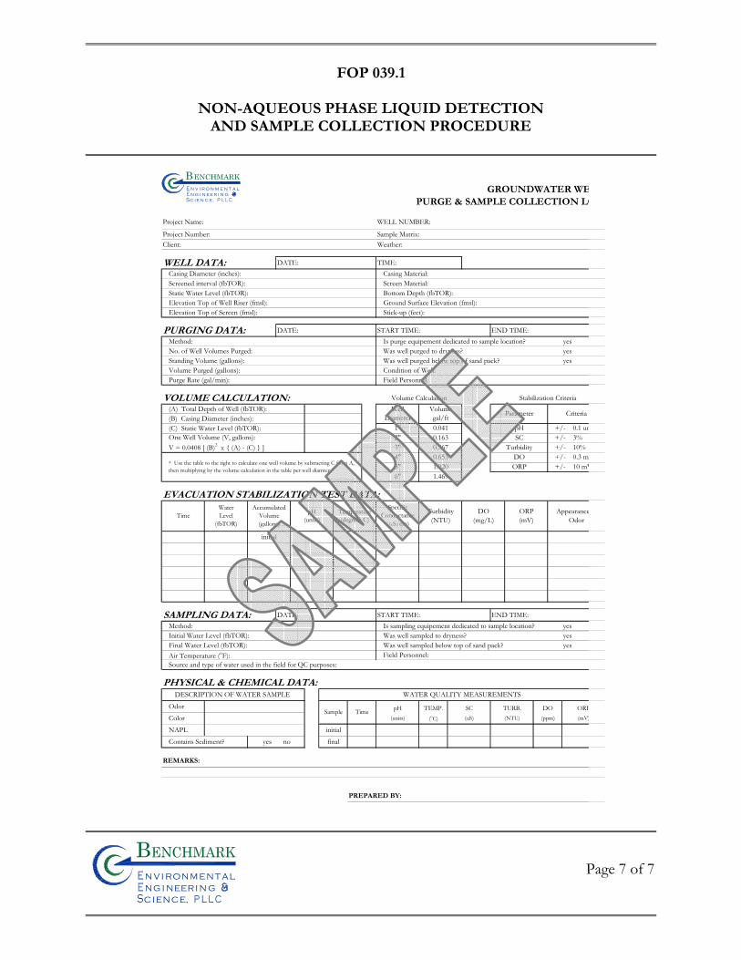
FOP 039.1
NON-AQUEOUS PHASE LIQUID DETECTION
AND SAMPLE COLLECTION PROCEDURE
Page 7 of 7
Bn v i ronme talng i neeri n gc ence,i
n
GROUNDWATER WEPURGE & SAMPLE COLLECTION LO
Project Name: WELL NUMBER:
Project Number: Sample Matrix:Client: Weather:
WELL DATA: DATE: TIME:Casing Diameter (inches): Casing Material:Screened interval (fbTOR): Screen Material:Static Water Level (fbTOR): Bottom Depth (fbTOR):Elevation Top of Well Riser (fmsl): Ground Surface Elevation (fmsl):Elevation Top of Screen (fmsl): Stick-up (feet):
PURGING DATA: DATE: START TIME: END TIME:Method: Is purge equipement dedicated to sample location? yesNo. of Well Volumes Purged: Was well purged to dryness? yesStanding Volume (gallons): Was well purged below top of sand pack? yesVolume Purged (gallons): Condition of Well:Purge Rate (gal/min): Field Personnel:
VOLUME CALCULATION: Volume Calculation Stabilization Criteria(A) Total Depth of Well (fbTOR):(B) Casing Diameter (inches):(C) Static Water Level (fbTOR):
EVACUATION STABILIZATION TEST DATA:
SAMPLING DATA: DATE: START TIME: END TIME:Method: Is sampling equipement dedicated to sample location? yesInitial Water Level (fbTOR): Was well sampled to dryness? yesFinal Water Level (fbTOR): Was well sampled below top of sand pack? yesAir Temperature (oF): Field Personnel:Source and type of water used in the field for QC purposes:
PHYSICAL & CHEMICAL DATA:DESCRIPTION OF WATER SAMPLE WATER QUALITY MEASUREMENTS
Odor pH TEMP. SC TURB. DO ORPColor (units) (oC) (uS) (NTU) (ppm) (mV)
NAPL initial
Contains Sediment? yes no final
REMARKS:
PREPARED BY:
Sample Time
Criteria
+/- 0.3 mg+/- 10%+/- 3%
WellDiameter
Volumegal/ft Parameter
1"2"3" 0.367
SC
* Use the table to the right to calculate one well volume by subtracting C from A, then multiplying by the volume calculation in the table per well diamter.
6" 1.469
0.653ORP +/- 10 mV5" 1.020
pH +/- 0.1 un
DO4"
0.0410.163
Turbidity
SpecificConductance
(mS/cm)
Turbidity(NTU)
ORP(mV)
TimeWaterLevel
(fbTOR)
AccumulatedVolume(gallons)
pH(units)
AppearanceOdor
initial
Temperature(degrees C)
One Well Volume (V, gallons):V = 0.0408 [ (B)2 x (A) - (C) ]
DO(mg/L)
Bn v i r o n m e t a ln g i n ee r i n gc e n c e,i
n

FIE
LD
OP
ER
AT
ING
PR
OC
ED
UR
ES
Non-Disposable and Non-Dedicated
Sampling Equipment Decontamination
Bn v i ronme talng i neeri n gc ence,i
n
FOP 040.1
NON-DISPOSABLE AND NON-DEDICATED
SAMPLING EQUIPMENT DECONTAMINATION
Page 1 of 4
Bn v i ronme talng i neeri n gc ence,i
n
PURPOSE
This procedure is to be used for the decontamination of non-disposable and non-dedicated
equipment used in the collection of environmental samples. The purpose of this procedure
is to remove chemical constituents from previous samples from the sampling equipment.
This prevents these constituents from being transferred to later samples, or being
transported out of controlled areas.
HEALTH AND SAFETY
Nitric acid is a strong oxidizing agent as well as being extremely corrosive to the skin and
eyes. Solvents such as acetone, methanol, hexane and isopropanol are flammable liquids.
Limited contact with skin can cause irritation, while prolonged contact may result in
dermatitis. Eye contact with the solvents may cause irritation or temporary corneal damage.
Safety glasses with protective side shields, neoprene or nitrile gloves and long-sleeve
protective clothing must be worn whenever acids and solvents are being used.
PROCEDURE – GENERAL EQUIPMENT
Bailers, split-spoons, steel or brass split-spoon liners, Shelby tubes, submersible pumps, soil
sampling knives, and similar equipment will be decontaminated as described below.
1. Wash equipment thoroughly with non-phosphate detergent and potable-
quality water, using a brush where possible to remove any particulate matter or surface film. If the sampler is visibly coated with tars or other phase-separated hydrocarbons, pre-wash with acetone or isopropanol, or by steam cleaning. Decontamination will adhere to the following procedure:
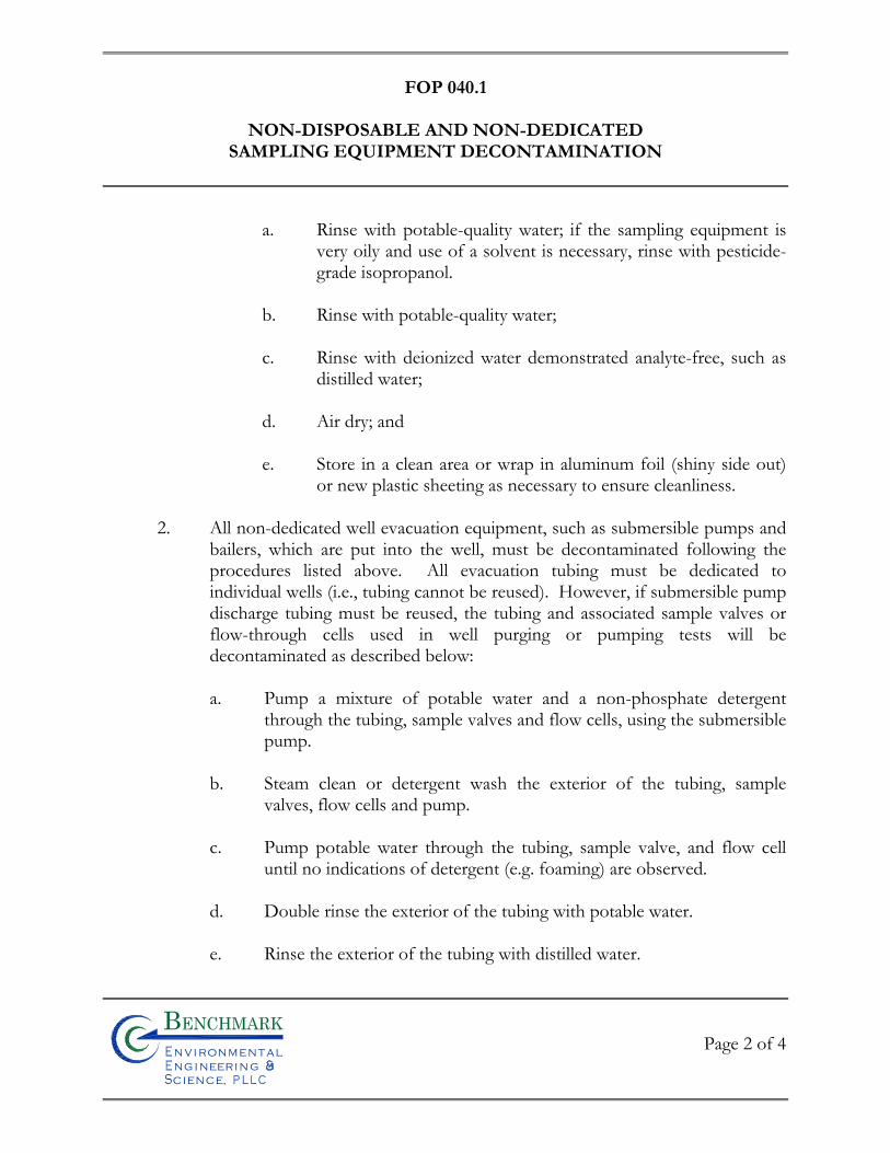
FOP 040.1
NON-DISPOSABLE AND NON-DEDICATED
SAMPLING EQUIPMENT DECONTAMINATION
Page 2 of 4
Bn v i ronme talng i neeri n gc ence,i
n
a. Rinse with potable-quality water; if the sampling equipment is very oily and use of a solvent is necessary, rinse with pesticide-grade isopropanol.
b. Rinse with potable-quality water; c. Rinse with deionized water demonstrated analyte-free, such as
distilled water; d. Air dry; and e. Store in a clean area or wrap in aluminum foil (shiny side out)
or new plastic sheeting as necessary to ensure cleanliness.
2. All non-dedicated well evacuation equipment, such as submersible pumps and bailers, which are put into the well, must be decontaminated following the procedures listed above. All evacuation tubing must be dedicated to individual wells (i.e., tubing cannot be reused). However, if submersible pump discharge tubing must be reused, the tubing and associated sample valves or flow-through cells used in well purging or pumping tests will be decontaminated as described below:
a. Pump a mixture of potable water and a non-phosphate detergent
through the tubing, sample valves and flow cells, using the submersible pump.
b. Steam clean or detergent wash the exterior of the tubing, sample
valves, flow cells and pump.
c. Pump potable water through the tubing, sample valve, and flow cell until no indications of detergent (e.g. foaming) are observed.
d. Double rinse the exterior of the tubing with potable water.
e. Rinse the exterior of the tubing with distilled water.
FOP 040.1
NON-DISPOSABLE AND NON-DEDICATED
SAMPLING EQUIPMENT DECONTAMINATION
Page 3 of 4
Bn v i ronme talng i neeri n gc ence,i
n
f. Store in a clean area or wrap the pump and tubing assembly in new
plastic sheeting as necessary to ensure cleanliness until ready for use.
3. All unused sample bottles and sampling equipment must be maintained in such a manner that there is no possibility of casual contamination.
4. Manage all waste materials generated during decontamination procedures as
described in the Benchmark Field Operating Procedure for Management of Investigation Derived Waste.
PROCEDURE – SUBMERSIBLE PUMPS
Submersible pumps used in well purging or purging tests will be decontaminated thoroughly
each day before use as well as between well locations as described below:
Daily Decontamination Procedure:
1. Pre-rinse: Operate the pump in a basin containing 8 to 10 gallons of potable water for 5 minutes and flush other equipment with potable water for 5 minutes.
2. Wash: Operate the pump in 8 to 10 gallons of non-phosphate detergent
solution (i.e., Alconox) for 5 minutes and flush other equipment with fresh detergent solution for 5 minutes.
3. Rinse: Operate the pump in a basin of potable water for 5 minutes and flush
other equipment with potable water for 5 minutes.
4. Disassemble pump.
5. Wash pump parts with a non-phosphate detergent solution (i.e., Alconox). Scrub all pump parts with a test tube brush or similar device.
FOP 040.1
NON-DISPOSABLE AND NON-DEDICATED
SAMPLING EQUIPMENT DECONTAMINATION
Page 4 of 4
Bn v i ronme talng i neeri n gc ence,i
n
6. Rinse pump with potable water.
7. Rinse the inlet screen, the shaft, the suction interconnection, the motor lead assembly, and the stator housing with distilled/deionized water.
8. Rinse the impeller assembly with 1% nitric acid (HNO3).
9. Rinse the impeller assembly with isopropanol.
10. Rinse the impeller assembly with distilled/deionized water.
Between Wells Decontamination Procedure:
1. Pre-rinse: Operate the pump in a basin containing 8 to 10 gallons of potable water for 5 minutes.
2. Wash: Operate the pump in 8 to 10 gallons of non-phosphate detergent
solution (i.e., Alconox) for 5 minutes.
3. Rinse: Operate the pump in a basin of potable water for 5 minutes.
4. Final rinse the pump in distilled/deionized water.
ATTACHMENTS
None
REFERENCES
Benchmark FOPs: 032 Management of Investigation-Derived Waste

FIE
LD
OP
ER
AT
ING
PR
OC
ED
UR
ES
Sample Labeling, Storage, and Shipment
Procedures
Bn v i ronme talng i neeri n gc ence,i
n
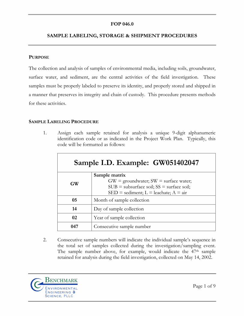
FOP 046.0
SAMPLE LABELING, STORAGE & SHIPMENT PROCEDURES
Page 1 of 9
Bn v i ronme talng i neeri n gc ence,i
n
PURPOSE
The collection and analysis of samples of environmental media, including soils, groundwater,
surface water, and sediment, are the central activities of the field investigation. These
samples must be properly labeled to preserve its identity, and properly stored and shipped in
a manner that preserves its integrity and chain of custody. This procedure presents methods
for these activities.
SAMPLE LABELING PROCEDURE
1. Assign each sample retained for analysis a unique 9-digit alphanumeric identification code or as indicated in the Project Work Plan. Typically, this code will be formatted as follows:
Sample I.D. Example: GW051402047
GW
Sample matrix GW = groundwater; SW = surface water; SUB = subsurface soil; SS = surface soil; SED = sediment; L = leachate; A = air
05 Month of sample collection
14 Day of sample collection
02 Year of sample collection
047 Consecutive sample number
2. Consecutive sample numbers will indicate the individual sample’s sequence in the total set of samples collected during the investigation/sampling event. The sample number above, for example, would indicate the 47th sample retained for analysis during the field investigation, collected on May 14, 2002.
FOP 046.0
SAMPLE LABELING, STORAGE & SHIPMENT PROCEDURES
Page 2 of 9
Bn v i ronme talng i neeri n gc ence,i
n
3. Affix a non-removable (when wet) label to each sample container. The following information will be written on the label with black or blue ink that will not smudge when wet:
• Project number
• Sample ID (see Step 1 above)
• Date of sample collection
• Time of sample collection (military time only)
• Specify “grab” or “composite” sample with an “X”
• Sampler initials
• Preservative(s) (if applicable)
• Analytes for analysis (if practicable)
4. Record all sample label information in the Project Field Book and on a Sample
Summary Collection Log (see attached samples), keyed to the sample identification number. In addition, add information regarding the matrix, sample location, depth, etc. to provide a complete description of the sample.
SAMPLE STORAGE PROCEDURE
1. Immediately after collection, placement in the proper container, and labeling, place samples to be retained for chemical analysis into resealable plastic bags.
2. Place bagged samples into an ice chest filled approximately half-full of double
bagged ice. Blue ice is not an acceptable substitute for ice.
3. Maintain samples in an ice chest or in an alternative location (e.g. sample refrigerator) as approved by the Benchmark Field Team Leader until time of shipment. Periodically drain melt-water off coolers and replenish ice as necessary.
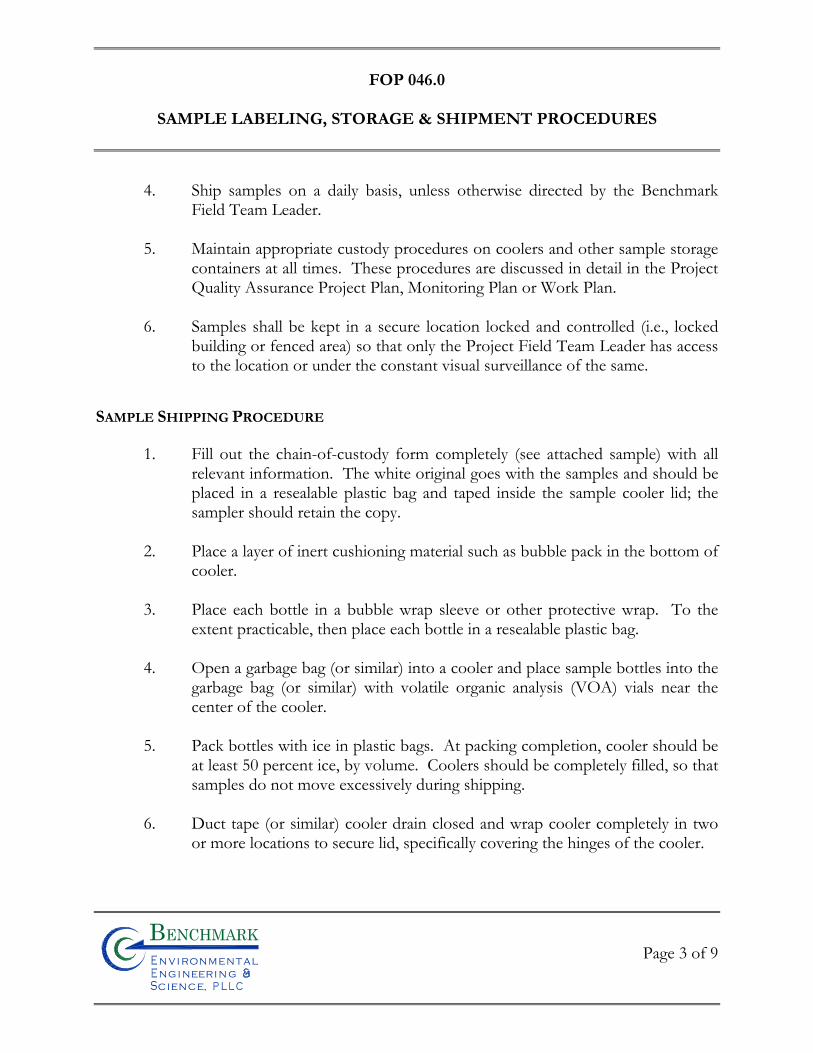
FOP 046.0
SAMPLE LABELING, STORAGE & SHIPMENT PROCEDURES
Page 3 of 9
Bn v i ronme talng i neeri n gc ence,i
n
4. Ship samples on a daily basis, unless otherwise directed by the Benchmark Field Team Leader.
5. Maintain appropriate custody procedures on coolers and other sample storage
containers at all times. These procedures are discussed in detail in the Project Quality Assurance Project Plan, Monitoring Plan or Work Plan.
6. Samples shall be kept in a secure location locked and controlled (i.e., locked
building or fenced area) so that only the Project Field Team Leader has access to the location or under the constant visual surveillance of the same.
SAMPLE SHIPPING PROCEDURE
1. Fill out the chain-of-custody form completely (see attached sample) with all relevant information. The white original goes with the samples and should be placed in a resealable plastic bag and taped inside the sample cooler lid; the sampler should retain the copy.
2. Place a layer of inert cushioning material such as bubble pack in the bottom of
cooler.
3. Place each bottle in a bubble wrap sleeve or other protective wrap. To the extent practicable, then place each bottle in a resealable plastic bag.
4. Open a garbage bag (or similar) into a cooler and place sample bottles into the
garbage bag (or similar) with volatile organic analysis (VOA) vials near the center of the cooler.
5. Pack bottles with ice in plastic bags. At packing completion, cooler should be
at least 50 percent ice, by volume. Coolers should be completely filled, so that samples do not move excessively during shipping.
6. Duct tape (or similar) cooler drain closed and wrap cooler completely in two
or more locations to secure lid, specifically covering the hinges of the cooler.
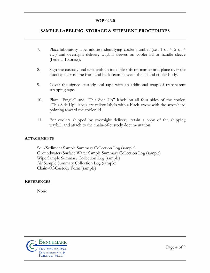
FOP 046.0
SAMPLE LABELING, STORAGE & SHIPMENT PROCEDURES
Page 4 of 9
Bn v i ronme talng i neeri n gc ence,i
n
7. Place laboratory label address identifying cooler number (i.e., 1 of 4, 2 of 4 etc.) and overnight delivery waybill sleeves on cooler lid or handle sleeve (Federal Express).
8. Sign the custody seal tape with an indelible soft-tip marker and place over the
duct tape across the front and back seam between the lid and cooler body.
9. Cover the signed custody seal tape with an additional wrap of transparent strapping tape.
10. Place “Fragile” and “This Side Up” labels on all four sides of the cooler.
“This Side Up” labels are yellow labels with a black arrow with the arrowhead pointing toward the cooler lid.
11. For coolers shipped by overnight delivery, retain a copy of the shipping
waybill, and attach to the chain-of-custody documentation.
ATTACHMENTS
Soil/Sediment Sample Summary Collection Log (sample) Groundwater/Surface Water Sample Summary Collection Log (sample) Wipe Sample Summary Collection Log (sample) Air Sample Summary Collection Log (sample) Chain-Of-Custody Form (sample)
REFERENCES
None
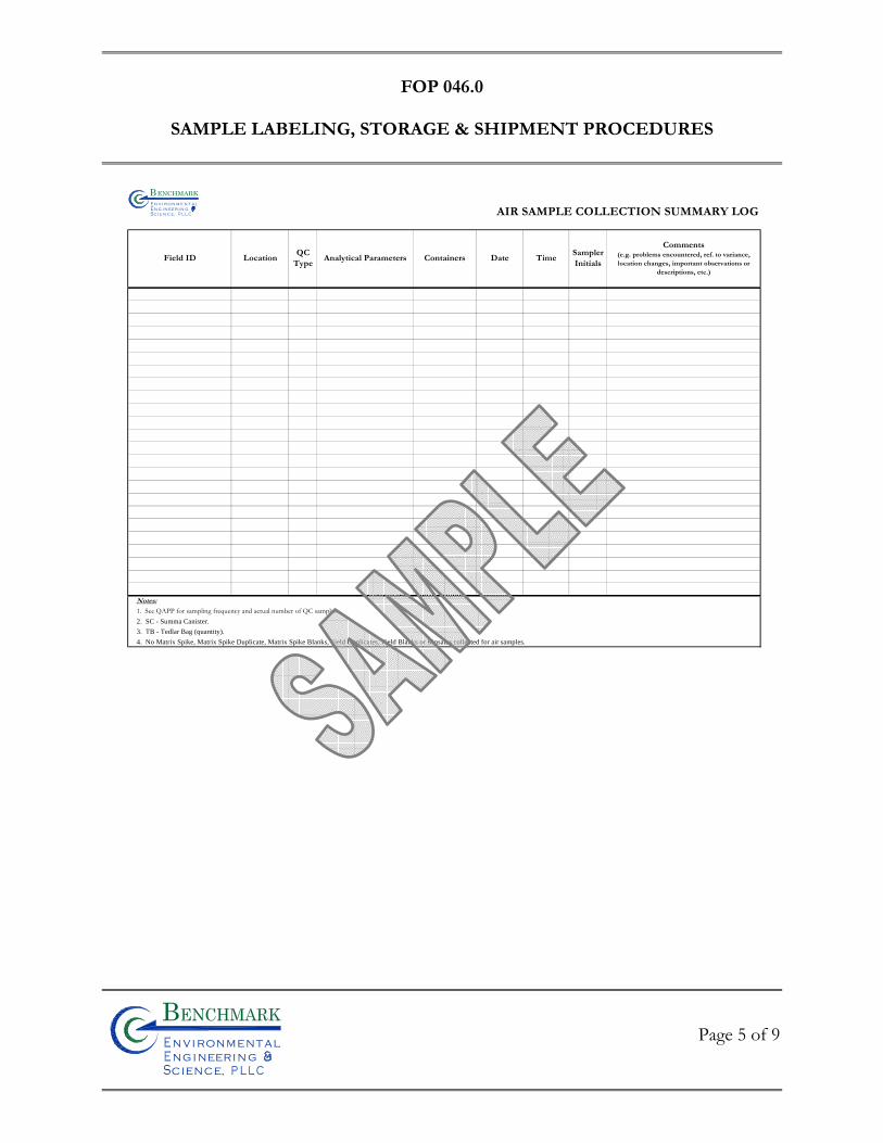
FOP 046.0
SAMPLE LABELING, STORAGE & SHIPMENT PROCEDURES
Page 5 of 9
Bn v i ronme talng i neeri n gc ence,i
n
AIR SAMPLE COLLECTION SUMMARY LOG
Notes:
1. See QAPP for sampling frequency and actual number of QC samples.2. SC - Summa Canister.
3. TB - Tedlar Bag (quantity).
4. No Matrix Spike, Matrix Spike Duplicate, Matrix Spike Blanks, Field Duplicates, Field Blanks or Rinsates collected for air samples.
SamplerInitials
Comments(e.g. problems encountered, ref. to variance, location changes, important observations or
descriptions, etc.)
Field ID LocationQC
TypeAnalytical Parameters Containers Date Time
Bn v i r o n m e t a ln g i n ee r i n gc e n c e,i
n
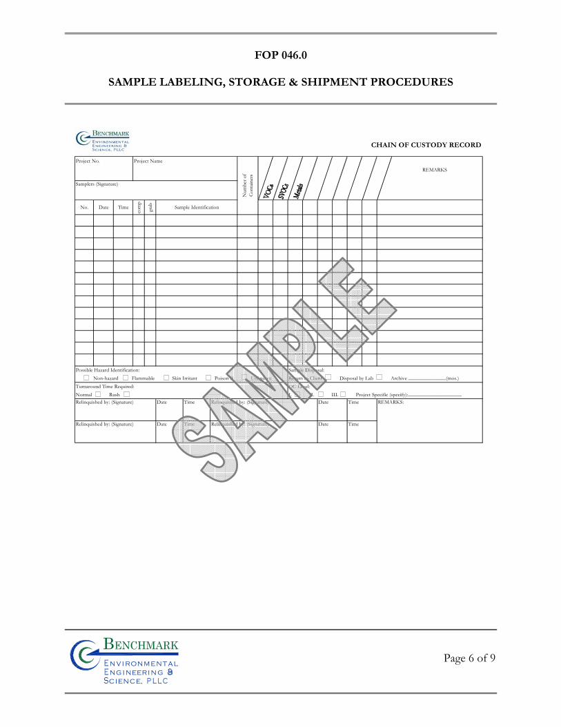
FOP 046.0
SAMPLE LABELING, STORAGE & SHIPMENT PROCEDURES
Page 6 of 9
Bn v i ronme talng i neeri n gc ence,i
n
CHAIN OF CUSTODY RECORD
Project No. Project Name
REMARKS
Samplers (Signature)
No. Date Time
com
p
grab Sample Identification
Possible Hazard Identification: Sample Disposal:Non-hazard Flammable Skin Irritant Poison B Unknown Return to Client Disposal by Lab Archive ______________(mos.)
Turnaround Time Required: QC Level:Normal Rush I. II. III. Project Specific (specify):____________________Relinquished by: (Signature) Date Time Relinquished by: (Signature) Date Time REMARKS:
Relinquished by: (Signature) Date Time Relinquished by: (Signature) Date Time
Num
ber o
fCo
ntain
ers
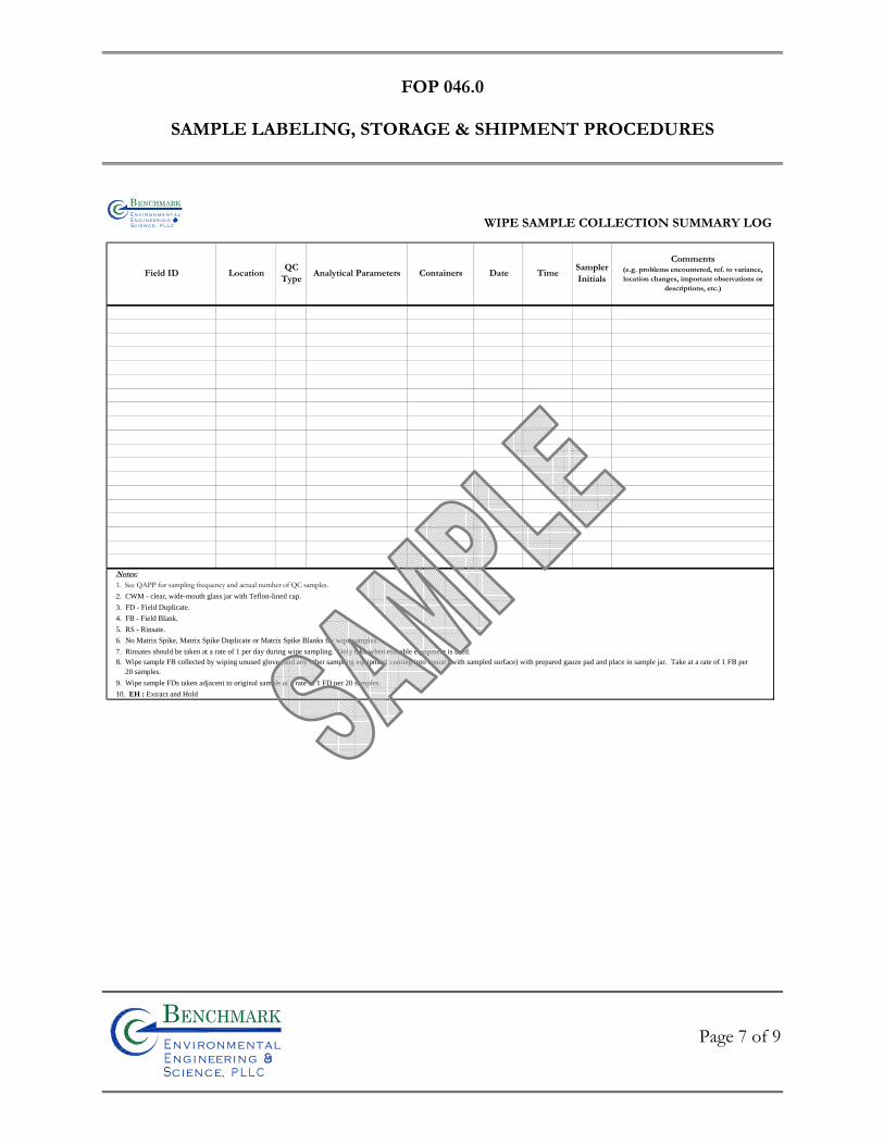
FOP 046.0
SAMPLE LABELING, STORAGE & SHIPMENT PROCEDURES
Page 7 of 9
Bn v i ronme talng i neeri n gc ence,i
n
WIPE SAMPLE COLLECTION SUMMARY LOG
Notes:
1. See QAPP for sampling frequency and actual number of QC samples.2. CWM - clear, wide-mouth glass jar with Teflon-lined cap.
3. FD - Field Duplicate.
4. FB - Field Blank.
5. RS - Rinsate.
6. No Matrix Spike, Matrix Spike Duplicate or Matrix Spike Blanks for wipe samples.
7. Rinsates should be taken at a rate of 1 per day during wipe sampling. Only take when reusable equipment is used.
9. Wipe sample FDs taken adjacent to original sample at a rate of 1 FD per 20 samples.
10. EH : Extract and Hold
8. Wipe sample FB collected by wiping unused glove (and any other sampling equipment coming into contact with sampled surface) with prepared gauze pad and place in sample jar. Take at a rate of 1 FB per 20 samples.
SamplerInitials
Comments(e.g. problems encountered, ref. to variance, location changes, important observations or
descriptions, etc.)
Field ID LocationQC
TypeAnalytical Parameters Containers Date Time
Bn v i r o n m e t a ln g i n eer i n gc e n c e,i
n
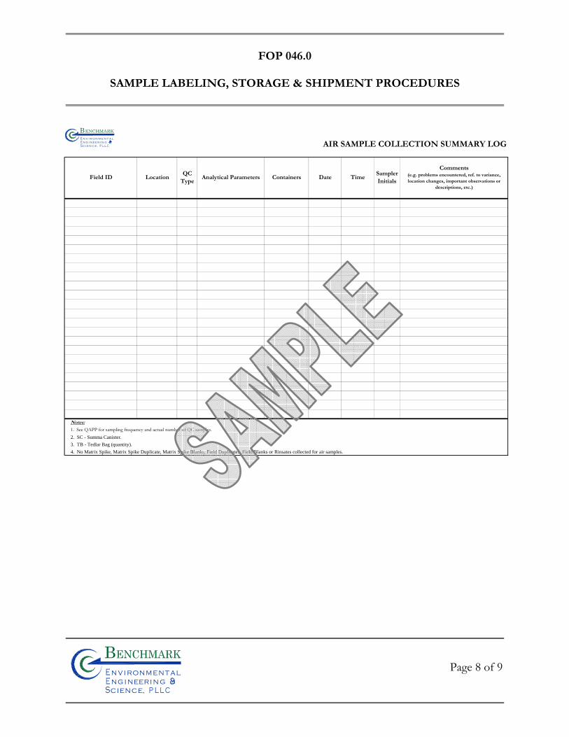
FOP 046.0
SAMPLE LABELING, STORAGE & SHIPMENT PROCEDURES
Page 8 of 9
Bn v i ronme talng i neeri n gc ence,i
n
AIR SAMPLE COLLECTION SUMMARY LOG
Notes:
1. See QAPP for sampling frequency and actual number of QC samples.2. SC - Summa Canister.
3. TB - Tedlar Bag (quantity).
4. No Matrix Spike, Matrix Spike Duplicate, Matrix Spike Blanks, Field Duplicates, Field Blanks or Rinsates collected for air samples.
SamplerInitials
Comments(e.g. problems encountered, ref. to variance, location changes, important observations or
descriptions, etc.)
Field ID LocationQC
TypeAnalytical Parameters Containers Date Time
Bn v i r o n m e t a ln g i n eer i n gc e n c e,i
n
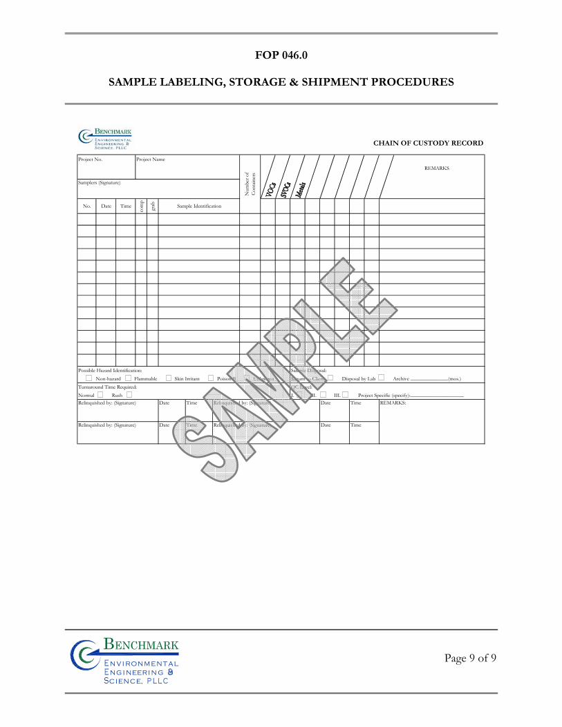
FOP 046.0
SAMPLE LABELING, STORAGE & SHIPMENT PROCEDURES
Page 9 of 9
Bn v i ronme talng i neeri n gc ence,i
n
CHAIN OF CUSTODY RECORD
Project No. Project Name
REMARKS
Samplers (Signature)
No. Date Time
com
p
grab Sample Identification
Possible Hazard Identification: Sample Disposal:Non-hazard Flammable Skin Irritant Poison B Unknown Return to Client Disposal by Lab Archive ______________(mos.)
Turnaround Time Required: QC Level:Normal Rush I. II. III. Project Specific (specify):____________________Relinquished by: (Signature) Date Time Relinquished by: (Signature) Date Time REMARKS:
Relinquished by: (Signature) Date Time Relinquished by: (Signature) Date Time
Num
ber o
fCo
ntain
ers

FIE
LD
OP
ER
AT
ING
PR
OC
ED
UR
ES
Screening of Soil Samples for Organic
Vapors During Drilling Activities
Bn v i ronme talng i neeri n gc ence,i
n
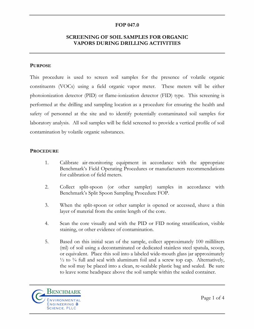
FOP 047.0
SCREENING OF SOIL SAMPLES FOR ORGANIC
VAPORS DURING DRILLING ACTIVITIES
Page 1 of 4
Bn v i ronme talng i neeri n gc ence,i
n
PURPOSE
This procedure is used to screen soil samples for the presence of volatile organic
constituents (VOCs) using a field organic vapor meter. These meters will be either
photoionization detector (PID) or flame-ionization detector (FID) type. This screening is
performed at the drilling and sampling location as a procedure for ensuring the health and
safety of personnel at the site and to identify potentially contaminated soil samples for
laboratory analysis. All soil samples will be field screened to provide a vertical profile of soil
contamination by volatile organic substances.
PROCEDURE
1. Calibrate air-monitoring equipment in accordance with the appropriate Benchmark’s Field Operating Procedures or manufacturers recommendations for calibration of field meters.
2. Collect split-spoon (or other sampler) samples in accordance with
Benchmark’s Split Spoon Sampling Procedure FOP. 3. When the split-spoon or other sampler is opened or accessed, shave a thin
layer of material from the entire length of the core. 4. Scan the core visually and with the PID or FID noting stratification, visible
staining, or other evidence of contamination.
5. Based on this initial scan of the sample, collect approximately 100 milliliters (ml) of soil using a decontaminated or dedicated stainless steel spatula, scoop, or equivalent. Place this soil into a labeled wide-mouth glass jar approximately ½ to ¾ full and seal with aluminum foil and a screw top cap. Alternatively, the soil may be placed into a clean, re-sealable plastic bag and sealed. Be sure to leave some headspace above the soil sample within the sealed container.
FOP 047.0
SCREENING OF SOIL SAMPLES FOR ORGANIC
VAPORS DURING DRILLING ACTIVITIES
Page 2 of 4
Bn v i ronme talng i neeri n gc ence,i
n
6. Place field screening sample (i.e., jar or bag) in a location where the ambient temperature is at least 70o Fahrenheit.
7. Leave the field screening sample bag for at least 30 minutes, but no more than
60 minutes.
8. Carefully remove the screw top cap from the jar and slowly insert the tip of the organic vapor meter (PID or FID) through the aluminum foil seal making the smallest hole possible. Alternatively, unseal a portion of the plastic bag just big enough to insert the probe of a calibrated PID.
9. Record the maximum reading in parts per million by volume (ppmv) on the
Field Borehole Log or Field Borehole/Monitoring Well Installation Log form (see attached samples) (see Documentation Requirements for Drilling and Well Installation FOP), at the depth interval corresponding to the depth of sample collection.
ATTACHMENTS
Field Borehole Log (sample) Field Borehole/Monitoring Well Installation Log (sample)
REFERENCES
Benchmark FOPs: 010 Calibration and Maintenance of Portable Flame Ionization Detector 011 Calibration and Maintenance of Portable Photoionization Detector 015 Documentation Requirements for Drilling and Well Installation 058 Split Spoon Sampling Procedures
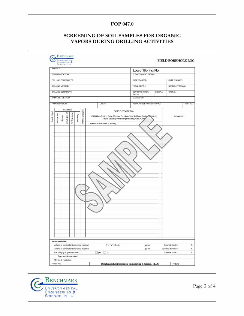
FOP 047.0
SCREENING OF SOIL SAMPLES FOR ORGANIC
VAPORS DURING DRILLING ACTIVITIES
Page 3 of 4
Bn v i ronme talng i neeri n gc ence,i
n
FIELD BOREHOLE LOG
PROJECT:Log of Boring No.:
BORING LOCATION: ELEVATION AND DATUM:
DRILLING CONTRACTOR: DATE STARTED: DATE FINISHED:
DRILLING METHOD: TOTAL DEPTH: SCREEN INTERVAL:
DRILLING EQUIPMENT: CASING:
SAMPLING METHOD: LOGGED BY:
HAMMER WEIGHT: DROP: RESPONSIBLE PROFESSIONAL:
SURFACE ELEVATION (FMSL):
ABANDONMENT:
Volume of cement/bentonite grout required: V = pr2 x 7.48 = gallons borehole depth = ft.
Volume of cement/bentonite grout installed: gallons borehole diameter = ft.
Has bridging of grout occurred? yes no borehole radius = ft.
If yes, explain resolution:
Method of installation:
Project No: Benchmark Environmental Engineering & Science, PLLC Figure
Blo
ws (
per
6")
SP
T N
-Valu
e
Recovery
Sam
ple
Depth
(fb
gs)
FIRST: COMPL.:DEPTH TO
WATER:
PID
Scan (
ppm
)
SAMPLE DESCRIPTION
USCS Classification: Color, Moisture Condition, % of Soil Type, Texture, Plasticity,
Fabric, Bedding, Weathering/Fracturing, Odor, OtherREMARKS
REG. NO.
SAMPLES
Sam
ple
No.
Bnv i ronme t alng i neeri n gc ence,i
n
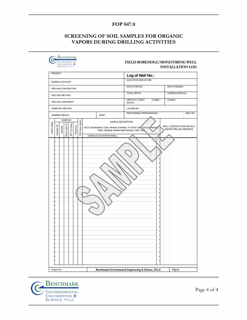
FOP 047.0
SCREENING OF SOIL SAMPLES FOR ORGANIC
VAPORS DURING DRILLING ACTIVITIES
Page 4 of 4
Bn v i ronme talng i neeri n gc ence,i
n
FIELD BOREHOLE/MONITORING WELLINSTALLATION LOG
PROJECT:Log of Well No.:
BORING LOCATION:ELEVATION AND DATUM:
DRILLING CONTRACTOR:DATE STARTED: DATE FINISHED:
DRILLING METHOD:TOTAL DEPTH: SCREEN INTERVAL:
DRILLING EQUIPMENT:CASING:
SAMPLING METHOD: LOGGED BY:
HAMMER WEIGHT: DROP:RESPONSIBLE PROFESSIONAL:
SURFACE ELEVATION (FMSL):
Project No: Benchmark Environmental Engineering & Science, PLLC Figure
Blo
ws (
pe
r 6
")
SP
T N
-Va
lue
Re
co
ve
ry
Sa
mp
le
De
pth
(fb
gs)
FIRST: COMPL.:DEPTH TO
WATER:
PID
Sca
n (
pp
m)
SAMPLE DESCRIPTION
USCS Classification: Color, Moisture Condition, % of Soil Type, Texture, Plasticity,
Fabric, Bedding, Weathering/Fracturing, Odor, Other
WELL CONSTRUCTION DETAILS
AND/OR DRILLING REMARKS
REG. NO.
SAMPLES
Sa
mp
le N
o.
Bn v i ron me t alng i neeri n gc ence,i
n

FIE
LD
OP
ER
AT
ING
PR
OC
ED
UR
ES
Soil Description Procedures Using The Visual-Manual Method
Bn v i ronme talng i neeri n gc ence,i
n
FOP 054.2
SOIL DESCRIPTION PROCEDURES
USING THE VISUAL-MANUAL METHOD
Page 1 of 22
Bn v i ronme talng i neeri n gc ence,i
n
PURPOSE
This guideline presents a means for insuring consistent and proper field identification and
description of collected soils during a project (via, split-spoon (barrel) sampler, hand auger,
test pit etc.). The lithology and moisture content of each soil sample will be physically
characterized by visual-manual observation in accordance with ASTM Method D2488,
Standard Practice for Description and Identification of Soils (Visual-Manual Procedure).
When precise classification of soils for engineering purposes is required, the procedures
prescribed in ASTM Method D2487 (Standard Practice for Classification of Soils for
Engineering Purposes [Unified Soil Classification System, USCS]) will be used. The method
of soil characterization presented herein describes soil types based on grain size, liquid and
plastic limits, and moisture content based on visual examination and manual tests. When
using this FOP to classify soil, the detail of description provided for a particular material
should be dictated by the complexity and objectives of the project. However, more often
than not, “after the fact” field information is required later in the project, therefore, every
attempt to describe the soil as completely as possibly should be made.
Intensely weathered or decomposed rock that is friable and can be reduced to gravel size or
smaller by normal hand pressure should be classified as a soil. The soil classification would
be followed by the parent rock name in parenthesis. Projects requiring depth to bedrock
determinations should always classify weathered or decomposed bedrock as bedrock (i.e.,
landfill siting). The project manager should always be consulted prior to making this
determination.
FOP 054.2
SOIL DESCRIPTION PROCEDURES
USING THE VISUAL-MANUAL METHOD
Page 2 of 22
Bn v i ronme talng i neeri n gc ence,i
n
PROCEDURE
Assemble necessary equipment and discuss program requirements with drilling contractor.
1. Calibrate air-monitoring equipment in accordance with the appropriate
Benchmark’s Field Operating Procedures or manufacturers recommendations for calibration of field meters.
2. Collect desired soil sample in accordance with appropriate Benchmark FOP
(i.e., split-spoon sampling, hand augering, test pitting etc.). 3. Shave a thin layer off the entire length of the sample to expose fresh sample.
4. Photograph and scan the sample with a photoionization detector (PID) at this
time, if applicable, in accordance with Benchmark’s Screening of Soil Samples for Organic Vapors During Drilling Activities FOP.
5. Describe the sample using terminology presented in the Descriptive Terms
section below.
6. Record all pertinent information in the Project Field Book and Field Borehole Log (sample attached) or Field Borehole/Monitoring Well Installation Log (sample attached).
7. After the sample has been described, place a representative portion of the
sample in new, precleaned jars or self-sealing plastic bags for archival purposes (if required). Label the jar or bag with the sample identification number, sample interval, date, project number and store in a secure location.
8. If the soil is to be submitted to a laboratory for analysis, collect the soil sample
with a dedicated stainless steel sampling tool, place the sample into the appropriate laboratory-supplied containers, and store in an ice-chilled cooler staged in a secure location in accordance with Benchmark’s Sample Labeling, Storage and Shipment Procedures FOP.
FOP 054.2
SOIL DESCRIPTION PROCEDURES
USING THE VISUAL-MANUAL METHOD
Page 3 of 22
Bn v i ronme talng i neeri n gc ence,i
n
9. All remaining soil from soil sample collection activities shall be containerized in accordance with Benchmark’s Management of Investigative-Derived Waste (IDW) FOP and/or the Project Work Plan.
DESCRIPTIVE TERMS
All field soil samples will be described using the Unified Soil Classification System (USCS)
presented in Figures 1 and 2 (attached). In addition to ASTM Method D2488, Method
D1586, Standard Test Method for Penetration Test and Split-Barrel Sampling of Soils (a.k.a.,
Standard Penetration Test, STP), when implemented, can also be used to classify the
resistance of soils. In certain instances, it is desirable to supplement the USCS classification
with a geologic interpretation of the soil sample that is supported by the soil descriptive
terms presented in this section. The project manager should be consulted when making any
geologic interpretation. Field test methods are provided to assist field personnel in
classifying soil and are identified by a bold blue FTM and shaded. Classification of sampled
soils will use the following ASTM descriptive terms and criteria:
• Group Name (USCS, see Figure 2)
• Group Symbol (USCS, see Figure 2) – only use if physical laboratory testing has been performed to substantiate. The USCS can be applied to most unconsolidated materials, and is represented by a two-letter symbol, except Peat (Pt). o The first letter includes: G (gravel), S (sand), M (silt), C (clay), and O (organic). o The second letter includes: P (poorly graded or uniform particle sizes), W (well
graded or diversified particle sizes), H (high plasticity), and L (low plasticity). o Examples:
GW = well graded gravels and gravel-sand mixtures, little or no fines GP = poorly graded gravels and gravel-sand mixtures, little or no fines GM = silty gravels, gravel-sand-silt mixtures
FOP 054.2
SOIL DESCRIPTION PROCEDURES
USING THE VISUAL-MANUAL METHOD
Page 4 of 22
Bn v i ronme talng i neeri n gc ence,i
n
GC = clayey gravels, gravel-sand-clay mixtures SW = well graded sands and gravelly sands, little or no fines SP = poorly graded sands and gravelly sands, little or no fines SM = silty sand, sand-silt mixtures SC = clayey sand sand-clay mixtures ML = inorganic silts, very fine sands, rock flour, silty or clayey fine sands CL = inorganic clays of low to medium plasticity, gravelly/sandy/silty/lean clays OL = organic silts and organic silty clays of low plasticity MH = inorganic silts, micaceous or diatomaceous fine sands or silts, elastic silts (very rare) CH = inorganic clays of high plasticity, fat clays OH = organic clays of medium to high plasticity Pt = peat, muck, and other highly organic soils
• Angularity (ASTM D2488; Table 1) o Angular – particles have sharp edges and relatively planar sides with
unpolished surfaces o Subangular – particles are similar to angular description but have rounded
edges o Subrounded – particles have nearly planar sides but have well-rounded corners
and edges o Rounded – particles have smoothly curved sides and no edges
• Particle Shape (ASTM D2488; Table 2) o Flat – particles with width/thickness > 3 o Elongated – particles with length/width > 3 o Flat and Elongated – particles meet criteria for both flat and elongated
• Moisture Condition (ASTM D2488; Table 3) o Dry – absence of moisture, dusty, dry to the touch o Moist – damp, but no visible water o Wet – visible free water, usually soil is below water table
• Reaction with Hydrochloric Acid (HCL) (ASTM D2488; Table 4) o None – no visible reaction
FOP 054.2
SOIL DESCRIPTION PROCEDURES
USING THE VISUAL-MANUAL METHOD
Page 5 of 22
Bn v i ronme talng i neeri n gc ence,i
n
o Weak – some reaction, with bubbles forming slowly o Strong – violent reaction, with bubbles forming immediately
• Consistency of Cohesive Soils (ASTM D2488; Table 5) o Very soft – squeezes between fingers when fist is closed; easily penetrated
several inches by fist (SPT = 2 or less) o Soft – easily molded by fingers; easily penetrated several inches by thumb
(SPT = 2 to 4) o Firm – molded by strong pressure of fingers; can be penetrated several inches
by thumb with moderate effort (SPT = 4 to 8) o Stiff – dented by strong pressure of fingers; readily indented by thumb but can
be penetrated only with great effort (SPT = 8 to 15) o Very stiff – readily indented by thumbnail (SPT = 15 to 30) o Hard – indented with difficultly by thumbnail (SPT >30)
• Cementation (ASTM D2488; Table 6) o Weak – crumbles or breaks with handling or slight finger pressure o Moderate – crumbles or breaks with considerable finger pressure o Strong – will not crumble or break with finger pressure
• Structure (Fabric) (ASTM D2488; Table 7) o Varved – alternating 1 mm to 12 mm (0.04 – 0.5 inch) layers of sand, silt and
clay o Stratified – alternating layers of varying material or color with the layers less
than 6 mm (0.23 inches) thick; note thickness o Laminated – alternating layers of varying material or color with the layers less
than 6 mm (0.23 inches) thick; note thickness o Fissured – contains shears or separations along planes of weakness o Slickensided – shear planes appear polished or glossy, sometimes striated
FOP 054.2
SOIL DESCRIPTION PROCEDURES
USING THE VISUAL-MANUAL METHOD
Page 6 of 22
Bn v i ronme talng i neeri n gc ence,i
n
o Blocky – cohesive soil that can be broken down into small angular lumps which resist further breakdown
o Lensed – inclusion of small pockets of different soils, such as small lenses of sand scattered through a mass of clay; note thickness
o Homogeneous or Massive – same color and appearance throughout
• Inorganic Fine-Grained Soil Characteristics (ASTM D2488; Table 12) Several field tests can be performed to determine the characteristics of fine-grained soils (material passing the No. 40 sieve), such as dry strength, dilatency, and toughness. These field testing methods are described below. o Dry Strength (ASTM D2488; Table 8)
FTM (Dry Strength): Select enough material and moisten with water until it can be molded or shaped without sticking to your fingers (slightly below the sticky limit) into a ball about 1 inch in diameter. From this ball, form three balls about ½ inch in diameter and allow to dry in air, or sun, or by artificial means (temperature not to exceed 60o C (140o F). Soil containing natural dry lumps about ½ inch in diameter may be used in place of molded balls, however the dry strengths are usually lower. Test the strength by crushing the dry balls or lumps between your fingers using the descriptions below.
None – the dry specimen crumbles with the slightest pressure of handling
Low – the dry specimen crumbles with some finger pressure
Medium – the dry specimen breaks into pieces or crumbles with considerable finger pressure
High – the dry specimen cannot be broken with finger pressure. The specimen will break into pieces between the thumb and a hard surface.
Very High – the dry specimen cannot be broken between the thumb and a hard surface
o Dilatency (ASTM D2488; Table 9) FTM (Dilatency): Place enough material in your hand to form a ball approximately ½ inch in diameter and moisten with water until it can be
FOP 054.2
SOIL DESCRIPTION PROCEDURES
USING THE VISUAL-MANUAL METHOD
Page 7 of 22
Bn v i ronme talng i neeri n gc ence,i
n
molded or shaped without sticking to your fingers (slightly below the sticky limit). Smooth the ball in the palm of one hand with the blade of a knife or small spatula. Shake horizontally, striking the side of the hand vigorously against the other several times. Note the reaction of water appearing on the surface of the soil. The soil is said to have given a reaction to this test if, when it is shaken, water comes to the surface of the sample producing a smooth, shiny appearance. Squeeze the sample between the thumb and forefinger and note the reaction as follows:
None – no visible change in the specimen
Slow – water slowly appears on the surface of the specimen during shaking and does not disappear or disappears slowly upon squeezing
Rapid – water quickly appears on the surface of the specimen during shaking and disappears upon squeezing
o Toughness (ASTM D2488; Table 10) FTM (Toughness): Following the dilatency test above, shape the test specimen into an elongated pat and roll by hand on a smooth surface or between palms into a thread about 1/8 inch in diameter. Fold the sample threads and re-roll repeatedly until the thread crumbles at a diameter of about 1/8 inch (e.g., near the plastic limit). Note the pressure required to roll the thread near the plastic limit as well as the strength of the thread. After the thread crumbles, lump the pieces together and knead the lump until it crumbles. Describe the toughness as follows:
Low – only slight pressure is required to roll the thread near the plastic limit. The thread and the lump are weak and very soft.
Medium – medium pressure is required to roll the thread to near the plastic limit. The thread and the lump are soft.
High – considerable pressure is required to roll the thread to near the plastic limit. The thread and the lump are firm.
Using the results of the dry strength, dilatency, and toughness test described above, classify the soil according to the following:
FOP 054.2
SOIL DESCRIPTION PROCEDURES
USING THE VISUAL-MANUAL METHOD
Page 8 of 22
Bn v i ronme talng i neeri n gc ence,i
n
Soil Symbol
Dry Strength
Dilatency Toughness
Silt (ML) None to low Slow to rapid Low or thread cannot be formed
Lean clay (CL) Medium to high None to slow Medium
Elastic Silt (MH) Low to medium None to slow Low to medium
Fat Clay (CH) High to very high None Low to medium high
• Plasticity (ASTM D2488; Table 11) Two field test methods can be used to determine plasticity of fine-grained soils (material passing the No. 40 sieve): the roll or thread test and the ribbon test. Each test is described below. FTM (Roll or Thread Test): As with the toughness test above, mix a representative portion of the soil sample with water until it can be molded or shaped without sticking to your fingers (slightly below the sticky limit). Place an elongated cylindrical sample on a nonabsorbent rolling surface (e.g., glass or was paper on a flat surface) and attempt to roll it into a thread approximately 1/8 inch in diameter. The results of this test are defined below (non-plastic to high plasticity). FTM (Ribbon Test): Form a roll from a handful of moist soil (slightly below the sticky limit) about ½ to ¾ inches in diameter and about 3 to 5 inches long. Place the material in the palm of your hand and, starting at one end, flatten the roll between your thumb and forefinger to form the longest and thinnest ribbon possible that can be supported by the cohesive properties of the material before breaking. If the soil sample holds together for a length of 6 to 10 inches without breaking, the material is considered to be both highly plastic and highly compressive (Fat Clay, CH). If the soil cannot be ribboned, it is non-plastic (Silt, ML or MH). If it can be ribboned only with difficulty into short lengths, it has low plasticity (Lean Clay, CL). Use the following terms to describe the plasticity of soil:
FOP 054.2
SOIL DESCRIPTION PROCEDURES
USING THE VISUAL-MANUAL METHOD
Page 9 of 22
Bn v i ronme talng i neeri n gc ence,i
n
o Nonplastic (ML or MH) – a 3 mm (0.12 inches) thread cannot be rolled at any water content
o Low Plasticity (CL, ML, or MH) – the thread can barely be rolled, and crumbles easily
o Medium Plasticity (CL) – the thread is easy to roll and not much time is required to reach the plastic limit before crumbling
o High Plasticity (CH) – it takes considerable time rolling and kneading to reach the plastic limit; the thread can be rolled several times before crumbling
Note: A soil with as little as 20% clay will behave as a clayey soil. A soil needs 45% to over 60% medium to coarse sand to behave as a sandy soil. In a soil with 20% clay and 80% sand, the soil will behave as a clayey soil.
• Relative Density of Cohesionless (Granular) Soils o Very loose – easily penetrated 30 cm (1.2 inches) with 13 mm (0.5 inch) rebar
pushed by hand (SPT = 0 to 4) o Loose – easily penetrated several cm with 13 mm (0.5 inch) rebar pushed by
hand (SPT = 4 to 10) o Medium dense – easily to moderately penetrated with 13 mm (0.5 inch) rebar
driven by 2.3 kg (6 pound) hammer (SPT = 10 to 30) o Dense – penetrated 0.3 m (1 foot) with difficulty using 13 mm (0.5 inch) rebar
driven by 2.3 kg (6 pound) hammer (SPT = 30 to 50) o Very dense – penetrated only a few cm with 13 mm (0.5 inch) rebar driven by
2.3 kg (6 pound) hammer (SPT = >50)
• Color (use Munsel® Color System, as necessary)
• Particle Size (see Figure 3) o Boulder – larger than a basketball o Cobble – grapefruit, orange, volleyball o Coarse Gravel – tennis ball, grape
FOP 054.2
SOIL DESCRIPTION PROCEDURES
USING THE VISUAL-MANUAL METHOD
Page 10 of 22
Bn v i ronme talng i neeri n gc ence,i
n
o Fine Gravel – pea o Coarse Sand – rock salt o Medium Sand – opening in window screen o Fine Sand – sugar, table salt o Fines (silt and clay) – cannot visually determine size (unaided)
• Gradation o Well Graded (GW, SW) – full range and even distribution of grain sizes
present o Poorly-graded (GP, SP) – narrow range of grain sizes present o Uniformly-graded (GP, SP) – consists predominantly of one grain size o Gap-graded (GP-SP) – within the range of grain sizes present, one or more
sizes are missing
• Organic Material – Organic soils usually have a dark brown to black color and may have an organic odor. Often, organic soils will change color, for example, black to brown, when exposed to the air. Some organic soils will lighten in color significantly when air-dried. Organic soils normally will not have a high toughness or plasticity. The thread of the toughness test will be spongy. o PEAT – 50 to 100 percent organics by volume, primary constituent o Organic (soil name) – 15 to 50 percent organics by volume, secondary organic
constituent o (Soil name) with some organics – 5 to 15 percent organics by volume,
additional organic constituents
• Fill Materials – All soils should be examined to see if they contain materials indicative of man-made fills. Man-made fill items should be listed in each of the soil descriptions. Common fill indicators include glass, brick, dimensioned lumber, concrete, pavement sections, asphalt, metal, plastics, plaster etc. Other items that could suggest fill include buried vegetation mats, tree limbs, stumps etc. The soil description for a fill material should be followed by the term “FILL”, i.e., for a sandy silt with some brick fragments the description would be “SANDY
FOP 054.2
SOIL DESCRIPTION PROCEDURES
USING THE VISUAL-MANUAL METHOD
Page 11 of 22
Bn v i ronme talng i neeri n gc ence,i
n
SILT (ML), with brick fragments (Fill)”. The size and distribution of fill indicators should be noted. The limits (depth range) of fill material should be determined and identified at each exploration location.
• Other Constituents/Characteristics
o Additional constituents and/or pertinent soil characteristics not included in the previous categories should be described depending on the scope and objectives of the project. Observations that may be discussed include:
Oxide staining
Odor
Origin
Presence of root cast
Presence of mica
Presence of gypsum
Presence of calcium carbonate
Percent by volume of cobbles & boulders with size description and appropriate rock classification
o Other pertinent information from the exploratory program should be recorded, if it would be useful from a biddability/constructability perspective. The conditions that should be listed include caving or sloughing, difficulty in drilling and groundwater infiltration.
SOIL DESCRIPTIONS
Generally, soil descriptions collected during most investigations are not intended for civil
engineering (construction) purposes, but rather for hydrogeologic and contaminant transport
purposes. As such, the ASTM visual-manual assessments are somewhat limited in that they
are only performed in order to indicate important information about potential hydraulic
properties of a soil. Soil descriptions should be concise, stressing major constituents and
FOP 054.2
SOIL DESCRIPTION PROCEDURES
USING THE VISUAL-MANUAL METHOD
Page 12 of 22
Bn v i ronme talng i neeri n gc ence,i
n
characteristics, and should be given in a consistent order and format. The following order is
recommended:
• Soil name. The basic name of the predominant grain size and a single-word modifier indicating the major subordinate grain size (i.e., mostly clay with some silt). The feel test can be used to determine the texture of the soil by rubbing some moist soil between your fingers; sand feels gritty, silt feels smooth, and clays feel sticky. The terms representing percentages of grain size to be used include:
o Trace – particles are present, but estimated to be less than 5% o Few – 5 to 10% o Little – 15 to 25% o Some – 30 to 45% o Mostly – 50 to 100%
• Color (using Munsell® charts, as necessary). Color is an important property in identifying organic soils, and within a given locality it may also be useful in identifying materials of similar geologic origin. It the sample contains layers or patches of varying colors (e.g., mottled), this shall be noted and all representative colors shall be described. The color shall be described for moist samples, however if the color represents a dry condition, it must be stated as such in the log. Generally, colors become darker as the moisture content increases and lighter as the soil dries. Examples include:
− Some fine-grained soils (OL, OH) with dark drab shades of brown or gray, including almost black, contain organic colloidal matter.
− In contrast, clean, bright looking shades of gray, olive green, brown, red,
yellow, and white are associated with inorganic soils.
− Gray-blue or gray- and yellow-mottled colors frequently result from poor drainage.
− Red, yellow, and yellowish brown result from the presence of iron oxides.
FOP 054.2
SOIL DESCRIPTION PROCEDURES
USING THE VISUAL-MANUAL METHOD
Page 13 of 22
Bn v i ronme talng i neeri n gc ence,i
n
− White to pink may indicate considerable silica, calcium carbonate, or aluminum compounds.
• Field moisture condition as dry, moist, or wet;
• Gradation or Plasticity. Granular soils (i.e., sands or gravels) should be described as well-graded, poorly graded, uniform, or gap-graded, depending on the gradation of the minus 3-inch fraction. Cohesive soils (i.e., silts and clays) should be described as non-plastic, low, medium, or high, depending on the results of the manual evaluation for dry strength, dilatency, toughness, and plasticity discussed previously.
• Consistency/Density. An estimate of consistency of a cohesive soil or density of a granular soil, usually based on the SPT results (see Descriptive Terms section of this FOP);
• Soil Structure or Mineralogy. Description of discontinuities, inclusions, and structures, including joints, fissures, and slickensides.
• Odor. Describe the odor if organic or unusual. Soils containing a significant amount of organic material usually have a distinctive odor of decaying vegetation. This is especially apparent in fresh samples, but if the samples are dried, the odor may often be revived by heating a moistened sample. If the odor is unusual (petroleum, chemical, etc.), it should be noted in the log.
• Other important geologic information such as consolidation, gravel size and shape, visible internal structure, root holes, mica, odors, etc.
The first step when describing soil is to determine if the sample is predominantly fine-
grained or coarse-grained (see Figures 3 and 4). Coarse-grained soils are relatively easy to
identify, however descriptions of fine-grained soils can be more difficult, requiring additional
field tests to assist the field geologist arrive at the proper soils classification (see FTMs
under Descriptive Terms above). These tests are explained in detail in the ASTM Standard
D2488 and briefly herein. Generally, the differentiation between silt and clay is based on
plasticity and “texture”. However, tests for dry strength and dilatency, along with plasticity,
FOP 054.2
SOIL DESCRIPTION PROCEDURES
USING THE VISUAL-MANUAL METHOD
Page 14 of 22
Bn v i ronme talng i neeri n gc ence,i
n
can be very helpful and are recommended in the ASTM Standard. If additional tests are
performed, in addition to plasticity, to classify the fines, record them with the soil
description on the logs. Doing this will assist the reader (i.e., Project Manager) to follow the
logic used to describe a soil (e.g., medium plasticity, low dry strength = elastic silt [MH]; not
a lean clay [CL]).
Fines described in the classification should be modified by their plasticity (e.g., non-plastic
fines, low plasticity fines, etc.) reserving the words “silt” and “clay” for the soil name.
In summary, adhering to the ASTM Standard and the guidelines outlined in this FOP will
provide uniformity in soil descriptions provided by all field personnel. Prior to mobilization
to the field, field staff should make sure to have laminated copies of the ASTM Standard
flow charts and tables as well as this FOP (as necessary). Some examples of complete soil
descriptions are as follows:
Coarse-grained Soil
POORLY GRADED FINE SAND w/ SILT: Dark grey, wet, mostly fine sand with some non-plastic fines, some iron-stained mottling, laminated, medium dense
Fine-grained Soil
LEAN CLAY: Dark reddish/brown, moist, mostly fines, medium plasticity, firm, no dilatency, medium dry strength, root holes.
Soil/Fill (option 1) – visual evidence of fill
FILL: Black, moist, mostly fines with some fine sand, slag, cinders, metal, brick, non-plastic, loose when disturbed, strong odor
FOP 054.2
SOIL DESCRIPTION PROCEDURES
USING THE VISUAL-MANUAL METHOD
Page 15 of 22
Bn v i ronme talng i neeri n gc ence,i
n
Soil/Fill (option 2) – no visual evidence of fill, suspected reworked material FILL (reworked): Black, moist, mostly fines with some fine sand and few coarse angular gravel, non-plastic, hard, loose when disturbed, mild odor
BORING AND MONITORING WELL INSTALLATION LOGS
Currently, Benchmark utilizes WinLoG software to construct subsurface logs and a template
of the log is included in this FOP as an example. One of the most important functions of a
boring/monitoring well installation log, besides transmitting the soil description, is to
indicate where the “data” (soil samples) were collected, giving the reader an idea of how
reliable or representative the description is. On each sample log, depths of attempted and
recovered or non-recovered interval are shown. Odor, if noted, should be considered
subjective and not necessarily indicative of specific compounds or concentrations.
Remember: all field logs should be NEAT, ACCURATE, and LEGIBLE. Don’t forget that
the well completion diagram completed for each well requires details of the surface
completion (i.e., flush-mount, stick-up etc.). It is the responsibility of the field staff to
double-check each log (i.e., soil names, classifications, well construction details etc.) prior to
implementing into a final report. A registered professional (i.e., professional engineer, PE or
professional geologist, PG) must review each log and will be ultimately responsible for its
content and accuracy.
REQUIRED EQUIPMENT
• Knife • Engineer’s rule/measuring tape
FOP 054.2
SOIL DESCRIPTION PROCEDURES
USING THE VISUAL-MANUAL METHOD
Page 16 of 22
Bn v i ronme talng i neeri n gc ence,i
n
• Permanent marker • Pre-cleaned wide-mouth sample jars (typically provided by the driller) • Pre-cleaned wide-mouth laboratory sample jars (provided by the laboratory) • Stainless steel sampling equipment (i.e., spoons, spatulas, bowls etc.) • 10x hand lens • Hydrochloric acid • ASTM D2488 flow charts (preferably laminated) • ASTM D2488 test procedures (Tables 1 through 12) (preferably laminated) • Camera (disposable, 35 mm or digital) • Munsell soil color chart (as necessary) • Project Field Book/field forms
ATTACHMENTS
Figure 1; Field Guide for Soil and Stratigraphic Analysis Figure 2; USCS Soil Classification Flow Chart (modified from ASTM D2488) Figure 3; Illustration of Particle Sizes Figure 4; Grain-Size Scale (Modified Wentworth Scale) Field Borehole Log (sample)
REFERENCES
American Society for Testing and Materials, 2008a. ASTM D1586: Standard Test Method for Standard Penetration Test (SPT) and Split-Barrel Sampling of Soils.
American Society for Testing and Materials, 2010. ASTM D2487: Standard Practice for
Classification of Soils for Engineering Purposes (Unified Soil Classification System). American Society for Testing and Materials, 2009a. ASTM D2488: Standard Practice for
Description and Identification of Soils (Visual-Manual Procedure).
FOP 054.2
SOIL DESCRIPTION PROCEDURES
USING THE VISUAL-MANUAL METHOD
Page 17 of 22
Bn v i ronme talng i neeri n gc ence,i
n
State of California, Department of Transportation, Engineering Service Center, Office of Structural Foundations, August 1996. Soil & Rock Logging Classification Manual (Field Guide), by Joseph C. de Larios.
Benchmark FOPs: 010 Calibration and Maintenance of Portable Flame Ionization Detector 011 Calibration and Maintenance of Portable Photoionization Detector 015 Documentation Requirements for Drilling and Well Installation 025 Hand Augering Procedures 032 Management of Investigation-Derived Waste 046 Sample Labeling, Storage and Shipment Procedures 047 Screening of Soil Samples for Organic Vapors During Drilling Activities 058 Split-Spoon Sampling Procedures 065 Test Pit Excavation and Logging Procedures
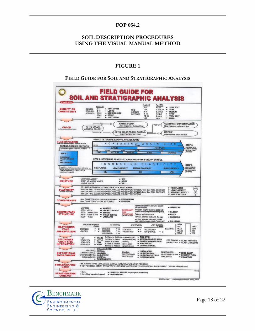
FOP 054.2
SOIL DESCRIPTION PROCEDURES
USING THE VISUAL-MANUAL METHOD
Page 18 of 22
Bn v i ronme talng i neeri n gc ence,i
n
FIGURE 1
FIELD GUIDE FOR SOIL AND STRATIGRAPHIC ANALYSIS
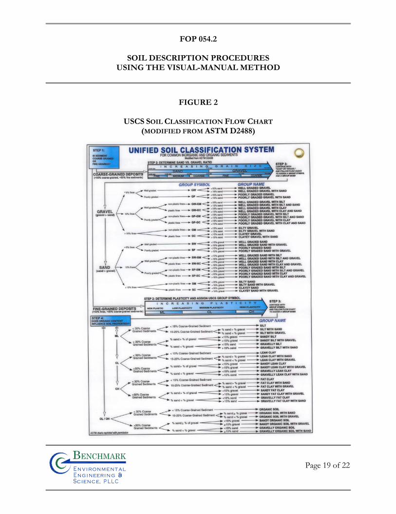
FOP 054.2
SOIL DESCRIPTION PROCEDURES
USING THE VISUAL-MANUAL METHOD
Page 19 of 22
Bn v i ronme talng i neeri n gc ence,i
n
FIGURE 2
USCS SOIL CLASSIFICATION FLOW CHART (MODIFIED FROM ASTM D2488)
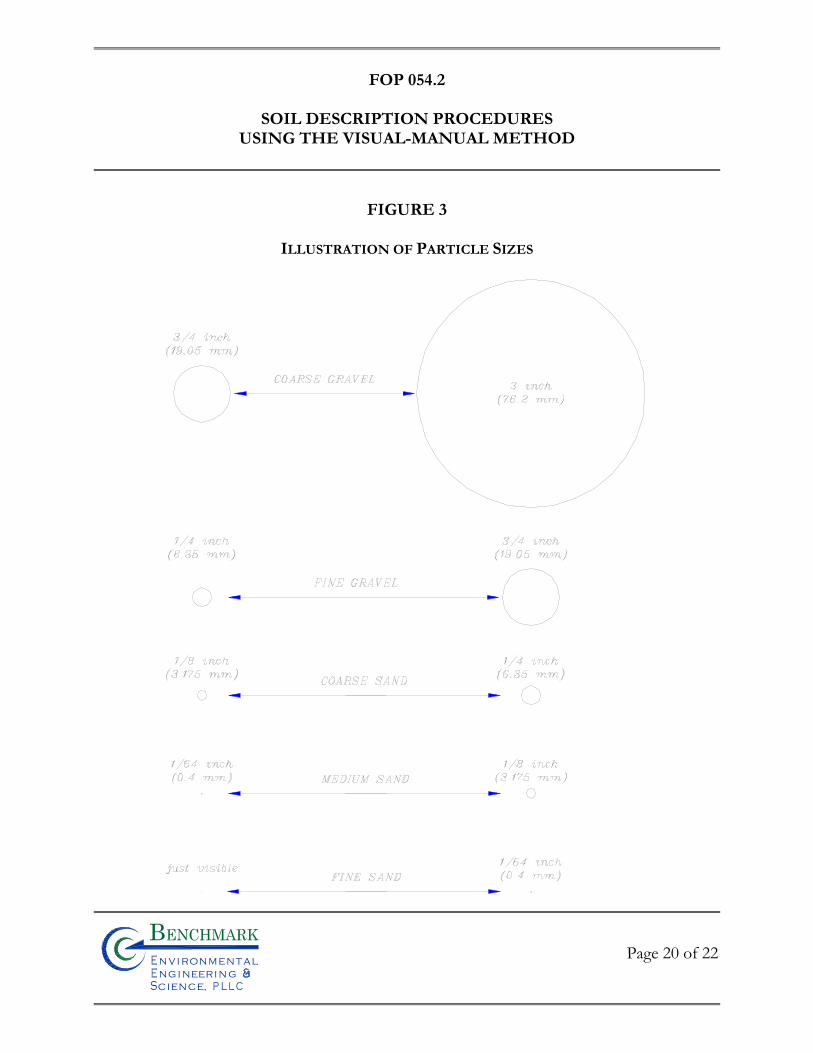
FOP 054.2
SOIL DESCRIPTION PROCEDURES
USING THE VISUAL-MANUAL METHOD
Page 20 of 22
Bn v i ronme talng i neeri n gc ence,i
n
FIGURE 3
ILLUSTRATION OF PARTICLE SIZES
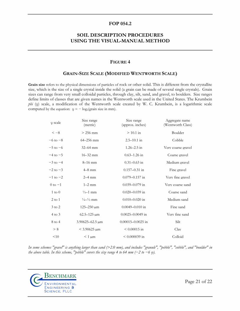
FOP 054.2
SOIL DESCRIPTION PROCEDURES
USING THE VISUAL-MANUAL METHOD
Page 21 of 22
Bn v i ronme talng i neeri n gc ence,i
n
FIGURE 4
GRAIN-SIZE SCALE (MODIFIED WENTWORTH SCALE)
Grain size refers to the physical dimensions of particles of rock or other solid. This is different from the crystallite size, which is the size of a single crystal inside the solid (a grain can be made of several single crystals). Grain sizes can range from very small colloidal particles, through clay, silt, sand, and gravel, to boulders. Size ranges define limits of classes that are given names in the Wentworth scale used in the United States. The Krumbein phi (φ) scale, a modification of the Wentworth scale created by W. C. Krumbein, is a logarithmic scale computed by the equation: φ = − log2(grain size in mm).
φ scale Size range (metric)
Size range (approx. inches)
Aggregate name (Wentworth Class)
< −8 > 256 mm > 10.1 in Boulder
−6 to −8 64–256 mm 2.5–10.1 in Cobble
−5 to −6 32–64 mm 1.26–2.5 in Very coarse gravel
−4 to −5 16–32 mm 0.63–1.26 in Coarse gravel
−3 to −4 8–16 mm 0.31–0.63 in Medium gravel
−2 to −3 4–8 mm 0.157–0.31 in Fine gravel
−1 to −2 2–4 mm 0.079–0.157 in Very fine gravel
0 to −1 1–2 mm 0.039–0.079 in Very coarse sand
1 to 0 ½–1 mm 0.020–0.039 in Coarse sand
2 to 1 ¼–½ mm 0.010–0.020 in Medium sand
3 to 2 125–250 µm 0.0049–0.010 in Fine sand
4 to 3 62.5–125 µm 0.0025–0.0049 in Very fine sand
8 to 4 3.90625–62.5 µm 0.00015–0.0025 in Silt
> 8 < 3.90625 µm < 0.00015 in Clay
<10 < 1 µm < 0.000039 in Colloid In some schemes "gravel" is anything larger than sand (>2.0 mm), and includes "granule", "pebble", "cobble", and "boulder" in the above table. In this scheme, "pebble" covers the size range 4 to 64 mm (−2 to −6 φ).
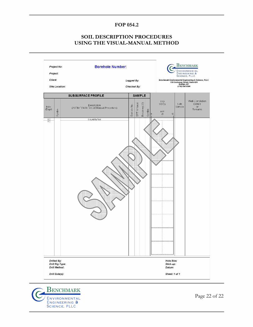
FOP 054.2
SOIL DESCRIPTION PROCEDURES
USING THE VISUAL-MANUAL METHOD
Page 22 of 22
Bn v i ronme talng i neeri n gc ence,i
n

FIE
LD
OP
ER
AT
ING
PR
OC
ED
UR
ES
Split-Spoon Sampling Procedures
Bn v i ronme talng i neeri n gc ence,i
n
FOP 058.0
SPLIT-SPOON SAMPLING PROCEDURES
Page 1 of 3
Bn v i ronme talng i neeri n gc ence,i
n
PURPOSE
This guideline presents the methods for using a split-spoon sampler for collecting soil
samples from a boring and for estimating the relative in-situ compressive strength of
subsurface materials (ASTM D 1586). Representative samples for lithologic description,
geochemical analysis, and geotechnical testing will be collected from the subsurface materials
using the split-spoon sampler.
PROCEDURE
1. Place plastic sheeting on a sturdy surface to prevent the split-spoon and its contents from coming in contact with the surface (several layers of sheeting may be placed on the surface so that they may be removed between each sample or as needed).
2. Lower the sampling string to the base of the borehole. Measure the portion
of the sampling string that extends above surrounding grade (i.e. the stickup). The depth of sampling will equal the total length of the string (sampler plus rods) minus the stickup length.
3. Measure sampling depths to an accuracy of 0.1 feet. If field measurements
indicate the presence of more than 0.3 feet of disturbed materials in the base of the borehole (i.e. slough), the sampler will be used to remove this material, after which a second sampling trip will be made.
4. Select additional sampler components as required (i.e., leaf spring core retainer
for clays or a sand trap for non-cohesive sands). If a retainer or trap is not used, a spacer ring will be used to hold the liners in position inside the sampler.
5. For driving samples, attach the drive head sub and hammer to the drill rods
without the weight resting on the rods. For pushing samples using the rig hydraulics, skip to Step 9.
FOP 058.0
SPLIT-SPOON SAMPLING PROCEDURES
Page 2 of 3
Bn v i ronme talng i neeri n gc ence,i
n
6. Mark four 6-inch intervals on the drill rods relative to a reference point on the drill rig. With the sampler resting on the bottom of the hole, drive the sampler with the 140 lb. hammer falling freely over a 30-inch fall until 24 inches have been penetrated or 50 blows applied.
7. Record the number of blows per 6 inches. Determine the “N” value by
adding the blows for the 6 to 12-inch and 12 to 18-inch intervals of each sample drive.
8. After penetration is complete, remove the sampling string. Avoid removing
sampling string by hitting up on the string with the hammer as this can cause the sample to fall from the bottom of the split-spoon sampler. The sampling string should be removed via cable lifting or rig hydraulics. If sample retention has been poor, let the sampling string rest in place for at least 3 minutes, then rotate clockwise at least 3 times before removing from the borehole.
9. For pushed samples (i.e., using rig hydraulics), mark four 6-inch intervals on
the drill rods relative to a reference point on the rig. Use the rig pull-down to press the sampler downward until 24 inches have been penetrated or no further progress can be made with the full weight of the rig on the sampler.
10. Remove the split-spoon sampler from the sampling string and place on the
plastic-covered surface.
11. Open the split-spoon sampler only when the Benchmark field geologist is prepared to describe and manage the sample.
12. Describe the sample in accordance with the Unified Soil Classification System
in accordance with the Benchmark FOP: Soil Description Procedures Using the Unified Soil Classification System (USCS).
13. Record all information in accordance with Benchmark’s FOP: Documentation
Requirements for Drilling and Well Installation.
FOP 058.0
SPLIT-SPOON SAMPLING PROCEDURES
Page 3 of 3
Bn v i ronme talng i neeri n gc ence,i
n
14. Collect a portion of the sample for field screening as described in the Benchmark FOP: Screening of Soil Samples for Organic Vapors During Drilling Activities.
15. If applicable, collect soil samples for volatile organic constituents (VOCs). If
applicable, collect sample for semi-volatile, metals, geotechnical, or other off-site analysis.
16. The samples will be labeled, stored and shipped in accordance with the
Benchmark’s FOP: Sample Labeling, Storage and Shipment Procedures.
ATTACHMENTS
none
REFERENCES
Benchmark FOPs: 015 Documentation Requirements for Drilling and Well Installation 046 Sample Labeling, Storage and Shipment Procedures 047 Screening of Soil Samples for Organic Vapors During Drilling Activities 054 Soil Description Procedures Using the Unified Soil Classification System (USCS)

FIE
LD
OP
ER
AT
ING
PR
OC
ED
UR
ES
Storm Water/Sediment Sampling Procedures
Bn v i ronme talng i neeri n gc ence,i
n
FOP 060.0
STORM WATER/SEDIMENT SAMPLING PROCEDURES
Page 1 of 6
Bn v i ronme talng i neeri n gc ence,i
n
PURPOSE
This procedure describes a method for collecting storm water/sediment samples using a
stainless steel dipper. The dipper can be used for both storm water and sediment. It should
be noted that if both storm water and sediment are to be sampled, the storm water should
be collected first to avoid water/sediment interface, which may cause substantial alteration in
sample integrity.
PROCEDURE
1. Non-disposable and non-dedicated sampling equipment will be decontaminated in accordance with the Benchmark Field Operating Procedure for Non-Disposable and Non-Dedicated Sampling Equipment Decontamination.
2. Calibrate all field meters (i.e., pH/Eh, turbidity, specific conductance,
dissolved oxygen, PID, Combustible Gas etc.) in accordance with the Benchmark Field Operating Procedure for Calibration and Maintenance of the specific field meter.
3. Wearing appropriate protective gear (i.e., latex gloves, safety glasses), as
required in the Project Health and Safety Plan, prepare sampling equipment for use.
4. Remove manhole cover using a pry bar taking or manhole cover pick taking
care not to crush your hand or fingers. 5. After opening the manhole cover, check for combustible gas using a calibrated
Combustible Gas/Oxygen Meter. In addition, measure the space for volatile organic compounds with a calibrated PID. If elevated readings are detected, precautionary measures must be taken and/or engineering controls must be implemented. Contact the Project Manager for further instruction prior to collecting the sample. If no elevated readings are detected, proceed with sampling.
FOP 060.0
STORM WATER/SEDIMENT SAMPLING PROCEDURES
Page 2 of 6
Bn v i ronme talng i neeri n gc ence,i
n
6. Collect downstream samples before upstream samples to avoid cross-
contamination.
7. Submerge a stainless steel dipper with minimal surface disturbance. (New nylon or polypropylene rope can be used to lower sampling device).
8. Allow the dipper to fill slowly and continuously. Retrieve the dipper from the
surface water with minimal disturbance.
9. Carefully transfer the water sample into pre-cleaned bottles provided by the analytical laboratory with the appropriate preservative(s) added based on the volatilization sensitivity or suite of analytical parameters required, as designated below:
• Volatile Organic Compounds (VOCs) • Total Organic Halogens (TOX) • Total Organic Carbon (TOC) • Extractable Organic Compounds (i.e., BNAs, SVOCs, etc.) • Total metals (Dissolved Metals) • Total Phenolic Compounds • Cyanide • Sulfate and Chloride • Turbidity • Nitrate and Ammonia • Radionuclides
10. Collect a separate sample of approximately 200 ml into an appropriate
container prior to collecting the first and following the last seep sample collected to measure the following field parameters:
Parameter Units
Dissolved Oxygen parts per million (ppm) Specific Conductance mmhos/cm or mS or mS
FOP 060.0
STORM WATER/SEDIMENT SAMPLING PROCEDURES
Page 3 of 6
Bn v i ronme talng i neeri n gc ence,i
n
pH pH units Temperature oC or oF Turbidity NTU Eh (optional) mV PID VOCs (optional) ppm Combustible gas Percent LEL Percent Oxygen percent Carbon Monoxide ppm Hydrogen Sulfide ppm Record all field measurements on a Storm Water Sample Collection Log form (sample attached).
11. Record all pertinent field data in the Project Field Book and on the Storm
Water Sample Collection Log form (sample attached).
12. As appropriate, repeat procedure for loose sediments. Record all pertinent field data in the Project Field Book and on the Sediment Sample Collection Log form (sample attached).
13. When possible, dedicate stainless steel dipper to sampling location. If dipper
is to be used at other sampling locations, perform proper decontamination procedures in accordance with the Benchmark Field Operating Procedure for Non-Disposable and Non-Dedicated Sampling Equipment Decontamination.
14. Label, store and ship all samples in accordance with the Benchmark Field
Operating Procedure for Sample Labeling, Storage and Shipment Procedures.
15. Decontaminate all non-disposable and non-dedicated sampling equipment upon completion of the sampling event in accordance with the Benchmark Field Operating Procedure for Non-Disposable and Non-Dedicated Sampling Equipment Decontamination.
FOP 060.0
STORM WATER/SEDIMENT SAMPLING PROCEDURES
Page 4 of 6
Bn v i ronme talng i neeri n gc ence,i
n
REQUIRED EQUIPMENT
• Personal protective equipment (PPE) (if applicable) • Water quality meters • Air quality monitoring meters • Stainless steel dipper • Camera • Cell phone • Field forms • Project Field Book
ATTACHMENTS
Storm Water Sample Collection Log (sample) Sediment Sample Collection Log (sample)
REFERENCES
Benchmark FOPs: 006 Calibration and Maintenance of Combustible Gas/Oxygen Meter 007 Calibration and Maintenance of Portable Dissolved Oxygen Meter 008 Calibration and Maintenance of Portable Field pH/Eh Meter 009 Calibration and Maintenance of Portable Field Turbidity Meter 012 Calibration and Maintenance of Portable Specific Conductance Meter 040 Non-Disposable and Non-Dedicated Sampling Equipment Decontamination 046 Sample Labeling, Storage and Shipment Procedures Notes
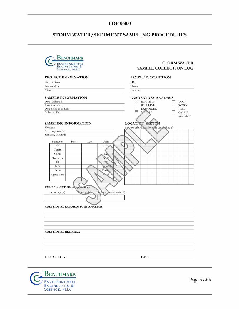
FOP 060.0
STORM WATER/SEDIMENT SAMPLING PROCEDURES
Page 5 of 6
Bn v i ronme talng i neeri n gc ence,i
n
STORM WATERSAMPLE COLLECTION LOG
PROJECT INFORMATION SAMPLE DESCRIPTIONProject Name: I.D.:Project No.: Matrix:Client: Location:
SAMPLE INFORMATION LABORATORY ANALYSISDate Collected: ROUTINE VOCsTime Collected: BASELINE SVOCsDate Shipped to Lab: EXPANDED PAHsCollected By: METALS OTHER
(see below)
SAMPLING INFORMATION LOCATION SKETCHWeather: (not to scale, dimensions are approximate)Air Temperature:Sampling Method:
EXACT LOCATION (if applicable)
Northing (ft) Easting (ft) Surface Elevation (fmsl)
ADDITIONAL LABORAOTORY ANALYSIS:
ADDITIONAL REMARKS:
PREPARED BY: DATE:
Parameter First Last UnitspH
Temp.Cond.
TurbidityEh
D.O.Odor
Appearance
ppmolfactory
visual
unitsoCmS
NTUmV
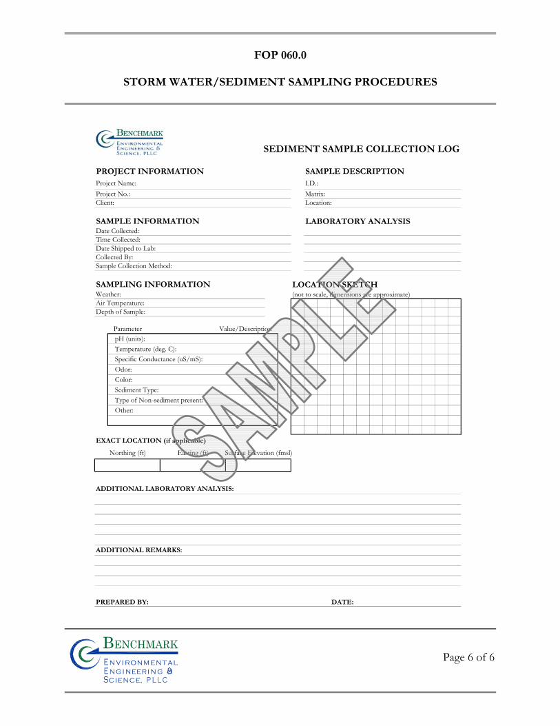
FOP 060.0
STORM WATER/SEDIMENT SAMPLING PROCEDURES
Page 6 of 6
Bn v i ronme talng i neeri n gc ence,i
n
SEDIMENT SAMPLE COLLECTION LOG
PROJECT INFORMATION SAMPLE DESCRIPTIONProject Name: I.D.:Project No.: Matrix:Client: Location:
SAMPLE INFORMATION LABORATORY ANALYSISDate Collected:Time Collected:Date Shipped to Lab:Collected By:Sample Collection Method:
SAMPLING INFORMATION LOCATION SKETCHWeather: (not to scale, dimensions are approximate)Air Temperature:Depth of Sample:
pH (units):Temperature (deg. C):Specific Conductance (uS/mS):Odor:Color:Sediment Type:Type of Non-sediment present:Other:
EXACT LOCATION (if applicable)
Northing (ft) Easting (ft) Surface Elevation (fmsl)
ADDITIONAL LABORATORY ANALYSIS:
ADDITIONAL REMARKS:
PREPARED BY: DATE:
Parameter Value/Description

FIE
LD
OP
ER
AT
ING
PR
OC
ED
UR
ES
Surface and Subsurface Soil Sampling Procedures
Bn v i ronme talng i neeri n gc ence,i
n
FOP 063.2
SURFACE AND SUBSURFACE SOIL
SAMPLING PROCEDURES
Page 1 of 7
Bn v i ronme talng i neeri n gc ence,i
n
PURPOSE
This procedure describes the methods for sampling surface soil and subsurface soil samples
for physical and chemical laboratory analysis during intrusive activities such as test pitting,
hand augering, drilling, surface soil sampling etc. Typical health and safety related issues
should be addressed in the Project Health and Safety Plan.
PRE-SAMPLING PROCEDURES
1. Review project objectives and the Project Health and Safety Plan (HASP). 2. Conduct tailgate health and safety meeting with project team and/or
subcontractor(s) by completing the Tailgate Safety Meeting Form (sample attached).
3. Calibrate air-monitoring equipment in accordance with the appropriate
Benchmark’s Field Operating Procedures or manufacturers recommendations for calibration of field meters.
4. Commence intrusive activities in accordance with specific Benchmark FOPs (test pitting, hand augering, drilling etc.) or as directed by the Project Work Plan.
5. Conduct air monitoring as required by the HASP, Project Work Plan or
Benchmark’s FOP Real-Time Air Monitoring During Intrusive Activities. Record all results on the Real Time Air Monitoring Log (sample attached).
6. Decontaminate all non-dedicated stainless steel (or Pyrex glass) equipment in
accordance with Benchmark’s Non-disposable and Non-dedicated Sampling Equipment Decontamination procedures.
7. Collect soil samples in accordance with the following sections.
FOP 063.2
SURFACE AND SUBSURFACE SOIL
SAMPLING PROCEDURES
Page 2 of 7
Bn v i ronme talng i neeri n gc ence,i
n
SURFACE SOIL/FILL SAMPLING PROCEDURES
Collection of surface soil/fill samples facilitates the evaluation of potential health risks to
current site receptors that may be exposed to soil/fill via direct contact, incidental ingestion,
or inhalation of airborne particulates. The following procedure is in accordance with
NYSDEC sampling protocol of surface soil/fill material.
1. Collect all soil samples using dedicated (or decontaminated non-dedicated) sampling tools (i.e., spoons, trowels, bowls etc.), preferably constructed of stainless steel.
2. If the sample area is vegetated, then collect the surface soil sample from 0 to 2
inches below ground surface (bgs) following removal of the sod.
3. If there is no soil present within the sample area (i.e., only slag, concrete, mixed with fines), excavate an area 12 inches by 12 inches by 6 inches deep, screen the material to less than 1/8 inch (No. 4 sieve), and submit the screened material for analysis. If there is not enough material to completely fill the sample jar, then expand the excavation 3 inches in all four directions screening the additional material. Expand the excavation in this manner until sufficient sample volume is obtained. Volatile organic analysis of surface soil/fill utilizing this method will yield negatively biased results and should not be performed.
SURFACE/SUBSURFACE SOIL SAMPLING PROCEDURES
1. Collect all soil samples using dedicated (or decontaminated non-dedicated) sampling tools (i.e., spoons, trowels, bowls etc.), preferably constructed of stainless steel.
Surface soil samples are typically collected from 0 to 6 inches below ground surface (bgs). Subsurface soils are typically sampled from varying depths greater than 6-inches bgs based on field observations and as directed by the Project Work Plan.
FOP 063.2
SURFACE AND SUBSURFACE SOIL
SAMPLING PROCEDURES
Page 3 of 7
Bn v i ronme talng i neeri n gc ence,i
n
2. Transfer samples for chemical (VOC, SVOC, Metals etc.) and physical (i.e.,
Atterberg Limits, Grain Size, Permeability etc.) analytical testing by direct grab (i.e., directly from the bucket of the excavation equipment, split-spoon sampler, hand auger etc.) using the dedicated (or decontaminated non-dedicated) sampling tools into appropriate laboratory-supplied containers and seal. The chemical or physical laboratory selected to perform the analysis should determine minimum sample volume for analysis.
3. Prepare collected samples in accordance with Benchmark’s FOP: Sample
Labeling, Storage and Shipment Procedures. Do not allow the chemical soil samples to freeze during storage and shipping. It should be noted, ice is not required for physical soil samples and all physical soil samples should be kept at the collected soil moisture by securing with a tight sealing lid. Do not allow physical soil samples to gain or lose moisture from the collected soil moisture prior to analysis.
4. Record all sampling details (i.e., depth and location) in the Project Field Book;
appropriate Benchmark log sheets depending on method of intrusion (i.e., drilling, test pitting, hand augering etc.); and on the Soil/Sediment Sample Collection Summary Log (sample attached).
PARAMETER-SPECIFIC PROCEDURES
1. Volatile Organic Compound (VOCs): Transfer sufficient soil volume to fill the laboratory-supplied container (typically 4 ounces) by packing the soil sample with the sampling tool to the top of the container leaving no headspace. At no time should a gloved hand (i.e., latex, nitrile etc.) be used to pack the sample into the sample container as the sample may be compromised via cross-contamination.
2. All Other Parameters: All other parameters include, but are not limited to,
Semi-VOCs (SVOCs), polychlorinated biphenyls (PCBs), herbicides, pesticides, total metals etc. Transfer sufficient soil volume to fill the laboratory-supplied container by packing the soil sample with the sampling
FOP 063.2
SURFACE AND SUBSURFACE SOIL
SAMPLING PROCEDURES
Page 4 of 7
Bn v i ronme talng i neeri n gc ence,i
n
tool to the top of the container. Unless otherwise indicated by the laboratory or the Project Work Plan, the sample jar for all other parameters does not have to be packed completely leaving no headspace as with the VOC containers.
ATTACHMENTS
Tailgate Safety Meeting Form (sample) Soil/Sediment Sample Collection Summary Log (sample) Real Time Air Monitoring Log (sample)
REFERENCES
Benchmark FOPs: 006 Calibration and Maintenance of Combustible Gas/Oxygen Meter 010 Calibration and Maintenance of Portable Flame Ionization Detector 011 Calibration and Maintenance of Portable Photoionization Detector 040 Non-disposable and Non-dedicated Sampling Equipment Decontamination 046 Sample Labeling, Storage and Shipment Procedures 073 Real-Time Air Monitoring During Intrusive Activities
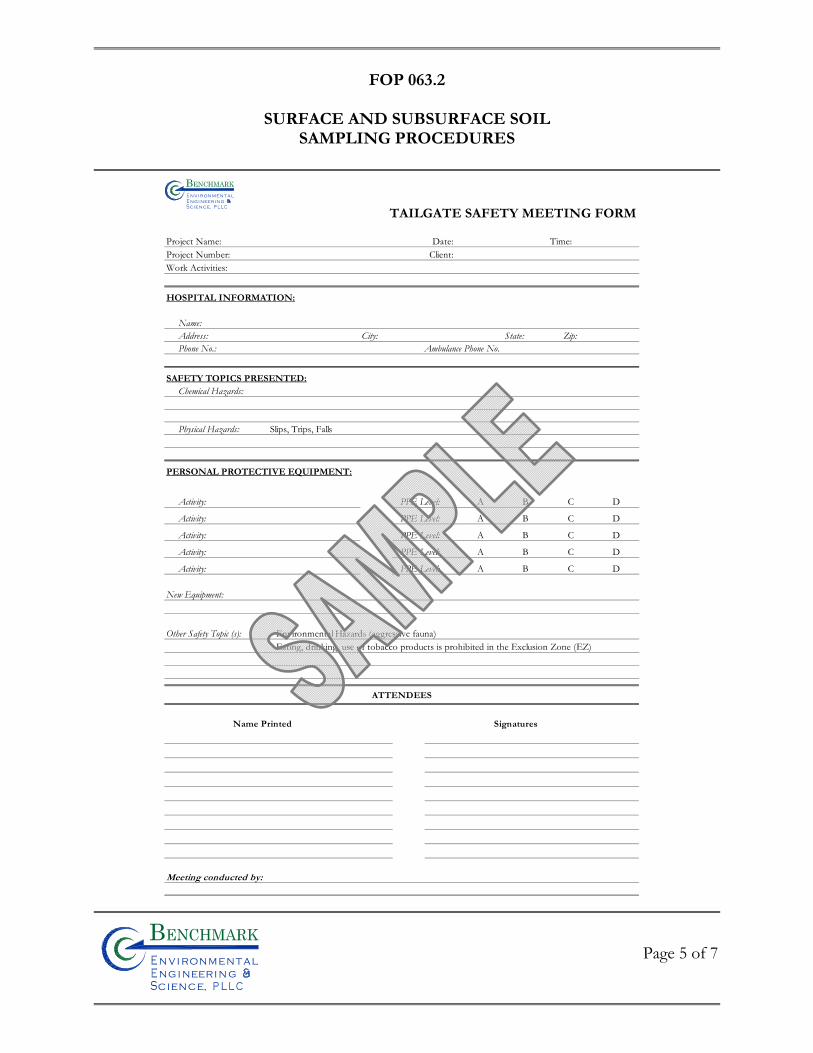
FOP 063.2
SURFACE AND SUBSURFACE SOIL
SAMPLING PROCEDURES
Page 5 of 7
Bn v i ronme talng i neeri n gc ence,i
n
TAILGATE SAFETY MEETING FORM
Project Name: Date: Time: Project Number: Client: Work Activities:
HOSPITAL INFORMATION:
Name:Address: City: State: Zip:Phone No.: Ambulance Phone No.
SAFETY TOPICS PRESENTED:Chemical Hazards:
Physical Hazards: Slips, Trips, Falls
PERSONAL PROTECTIVE EQUIPMENT:
Activity: PPE Level: A B C D
Activity: PPE Level: A B C D
Activity: PPE Level: A B C D
Activity: PPE Level: A B C D
Activity: PPE Level: A B C D
New Equipment:
Other Safety Topic (s): Environmental Hazards (aggressive fauna)Eating, drinking, use of tobacco products is prohibited in the Exclusion Zone (EZ)
Bn v i ronme t alngi neeri n gc ence,i
n
Meeting conducted by:
Name Printed Signatures
ATTENDEES
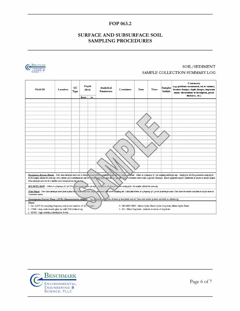
FOP 063.2
SURFACE AND SUBSURFACE SOIL
SAMPLING PROCEDURES
Page 6 of 7
Bn v i ronme talng i neeri n gc ence,i
n

FOP 063.2
SURFACE AND SUBSURFACE SOIL
SAMPLING PROCEDURES
Page 7 of 7
Bn v i ronme talng i neeri n gc ence,i
n

FIE
LD
OP
ER
AT
ING
PR
OC
ED
UR
ES
Surface Water Sampling Procedures
Bn v i ronme talng i neeri n gc ence,i
n
FOP 064.0
SURFACE WATER SAMPLING PROCEDURES
Page 1 of 5
Bn v i ronme talng i neeri n gc ence,i
n
PURPOSE
This procedure describes a method for collecting surface water samples. Sediment samples
typically are collected in conjunction with surface water samples as dictated by the site-
specific work plan. It should be noted, however, sediment sample collection procedures are
not presented herein and Benchmark’s sediment sampling FOPs 049 and 050 should be
reviewed prior to sediment sample collection. This surface water sampling method
incorporates the use of the laboratory provided sample bottle for collecting the sample,
which eliminates the need for other equipment and hence, reduces the risk of introducing
other variables into a sampling event.
PROCEDURE
1. Locate the surface water sample location. 2. Calibrate all field meters (i.e., pH/Eh, turbidity, specific conductance,
dissolved oxygen, PID etc.) in accordance with the Benchmark Field Operating Procedure for Calibration and Maintenance of the specific field meter.
3. Wearing appropriate protective gear (i.e., latex gloves, safety glasses), as
required in the Project Health and Safety Plan, prepare sample bottles for use. 4. If samples are to be collected from a stream, creek or other running water
body, collect downstream samples first to minimize impacts on sample quality.
5. Surface water samples should be collected during a dry (non-precipitation) event to avoid any dilution effect from precipitation.
6. Pre-label all sample bottles in the field using a waterproof permanent marker
in accordance with the Benchmark Sample Labeling, Storage and Shipment
FOP 064.0
SURFACE WATER SAMPLING PROCEDURES
Page 2 of 5
Bn v i ronme talng i neeri n gc ence,i
n
FOP. The following information, at a minimum, should be included on the label:
• Project Number; • Sample identification code (as per project specifications); • Date of sample collection (mm, dd, yy); • Time of sample collection (military time only) (hh:mm); • Specify “grab” or “composite” sample type; • Sampler initials; • Preservative(s) (if applicable); and • Analytes for analysis (if practicable).
7. Collect the surface water sample from the designated location by slowly
submerging each sample bottle with minimal surface disturbance. If the sample location cannot be sampled in this manner due to shallow water conditions, a small depression can be created with a standard shovel to deepen the location to facilitate sample collection by direct grab. It should be noted, prior to disturbing sediment at any location for this purpose, all required sediment samples should be collected. All sediment cuttings will be removed from the area and the surface water allowed to flow through the depression for several minutes prior to collecting samples until clear (i.e., no visible sediment).
8. Collect samples from near shore. If water body is over three feet deep, check
for stratification. Check each stratum for contamination using field measured water quality parameters. Collect samples from each stratum showing evidence of impact. If no stratum shows signs of impact, collect a composite sample having equal parts of water from each stratum.
9. Collect samples into pre-cleaned bottles provided by the analytical laboratory
with the appropriate preservative(s) added based on the volatilization sensitivity or suite of analytical parameters required, as designated below:
• Volatile Organic Compounds (VOCs) • Total Organic Halogens (TOX)
FOP 064.0
SURFACE WATER SAMPLING PROCEDURES
Page 3 of 5
Bn v i ronme talng i neeri n gc ence,i
n
• Total Organic Carbon (TOC) • Extractable Organic Compounds (i.e., BNAs, SVOCs, etc.) • Total metals (Dissolved Metals) • Total Phenolic Compounds • Cyanide • Sulfate and Chloride • Turbidity • Nitrate and Ammonia • Radionuclides
10. For pre-preserved bottles, avoid completely submerging the bottle and
overfilling to prevent preservative loss. Pre-preserved VOC vials should be filled from a second, unpreserved, pre-cleaned glass container. Never transfer samples from dissimilar bottle types (i.e., plastic to glass or glass to plastic).
11. Collect a separate sample of approximately 200 ml into an appropriate
container prior to collecting the first and following the last surface water sample collected to measure the following field parameters:
Parameter Units
Dissolved Oxygen parts per million (ppm) Specific Conductance mmhos/cm or mS or mS pH pH units Temperature oC or oF Turbidity NTU Eh (optional) mV PID VOCs (optional) ppm Record all field measurements on a Surface Water Quality Field Collection Log form (sample attached).
12. Record available information for the pond, stream or other body of water that
was sampled, such as its size, location and depth in the Project Field Book and
FOP 064.0
SURFACE WATER SAMPLING PROCEDURES
Page 4 of 5
Bn v i ronme talng i neeri n gc ence,i
n
on the Surface Water Quality Field Collection Log form (sample attached). Approximate sampling points should be identified on a sketch of the water body.
13. Label, store and ship all samples in accordance with the Benchmark Field
Operating Procedure for Sample Labeling, Storage and Shipment Procedures.
ATTACHMENTS
Surface Water Quality Field Collection Log (sample)
REFERENCES
Benchmark FOPs: 007 Calibration and Maintenance of Portable Dissolved Oxygen Meter 008 Calibration and Maintenance of Portable Field pH/Eh Meter 009 Calibration and Maintenance of Portable Field Turbidity Meter 012 Calibration and Maintenance of Portable Specific Conductance Meter 046 Sample Labeling, Storage and Shipment Procedures
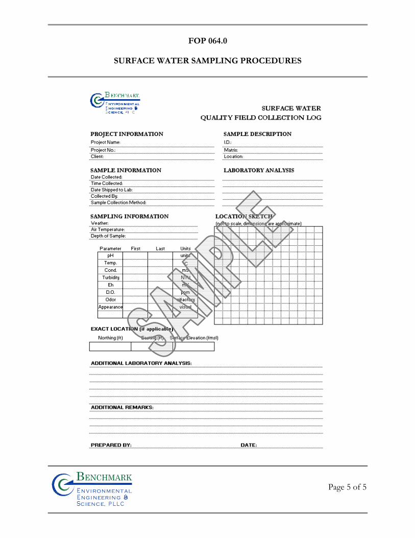
FOP 064.0
SURFACE WATER SAMPLING PROCEDURES
Page 5 of 5
Bn v i ronme talng i neeri n gc ence,i
n

FIE
LD
OP
ER
AT
ING
PR
OC
ED
UR
ES
Test Pit Excavation and Logging Procedures
Bn v i ronme talng i neeri n gc ence,i
n
FOP 065.1
TEST PIT EXCAVATION & LOGGING PROCEDURES
Page 1 of 7
Bn v i ronme talng i neeri n gc ence,i
n
PURPOSE
This procedure describes the methods for completing test pits, trenches, and other
excavations that may be performed to expose subsurface soils or materials. In most cases,
these pits will be mechanically excavated, using a backhoe, trackhoe, or other equipment.
Because pits and other excavations can represent a substantial physical hazard, it requires a
particular focus on safety procedures. The Project Health and Safety Plan identifies
practices related to excavation permits, entry, and control that must be incorporated into
excavation activities.
EXCAVATION PROCEDURE
1. Review project objectives and the Project Health and Safety Plan (HASP). 2. Perform excavation equipment safety checks with the operator. Specific
concerns should include, but not limited to, no leaking hydraulic lines, fire extinguisher on board of the excavation equipment, operator experience etc.
3. Conduct tailgate health and safety meeting with project team and excavation
operator(s) by completing the Tailgate Safety Meeting Form (sample attached).
4. Calibrate air-monitoring equipment in accordance with the appropriate Benchmark’s Field Operating Procedures or manufacturers recommendations for calibration of field meters.
5. Conduct air monitoring as required by the HASP and/or Project Work Plan.
Record all results on the Real Time Air Monitoring Log (sample attached).
6. Mobilize the excavation equipment to the site and position over the required location.
7. Select excavation locations, which provide necessary information for achieving
objectives. Check locations with owner/operator to ensure excavation
FOP 065.1
TEST PIT EXCAVATION & LOGGING PROCEDURES
Page 2 of 7
Bn v i ronme talng i neeri n gc ence,i
n
operations will not interfere with site operations, and select appropriate access routes.
8. Stake locations in the field and measure distance from locations to nearest
landmarks. Survey location, if required.
9. Obtain clearances from appropriate utilities and, if buried waste/metallic objects are suspected, screen location with appropriate geophysical methods, as necessary.
10. Decontaminate excavation equipment in accordance with Benchmark’s
Drilling and Excavation Equipment Decontamination procedures.
11. Excavate pits. In uncontrolled areas, excavate only as many test pits as can be backfilled during the same day. Generally, allow equal time for excavation and backfilling. To the extent practicable, no pits should be left open overnight in an uncontrolled area. If sudden weather changes or other unforeseen events necessitate this, pits will be covered and/or barricaded and flagged with caution/hazard tape. These pits should be backfilled as soon as possible.
12. The Benchmark field geologist or experienced professional should determine
the depth of excavation. The depth is generally limited by the safe reach of the selected equipment, but may also be limited by the stability of the excavated materials (i.e. wall stability).
13. Excavate the test pits in compliance with applicable safety regulations. In no
case should a pit deeper than 4 feet be entered without first stabilizing the sidewalls by using forms, or by terracing or sloping (2:1 slope maximum) the sidewalls.
14. Excavated spoils must be placed no closer than 2 feet from the open excavation.
15. Collect soil samples from pit sidewalls in accordance with Benchmark’s
Surface and Subsurface Soil Sampling Procedures. If the test pit is greater than 4 feet in depth, it will not be entered for sampling. In this event, collect
FOP 065.1
TEST PIT EXCAVATION & LOGGING PROCEDURES
Page 3 of 7
Bn v i ronme talng i neeri n gc ence,i
n
samples using the backhoe bucket, then fill sample containers from the center of the bucket using the stainless steel sampling equipment (i.e., spoon, spade, trowel etc.) or drive a Shelby tube or EnCore™ sampler for VOCs.
16. Record excavation observations in the Project Field Book or Test Pit
Excavation Log form (sample attached). Information recorded should include:
Physical dimension of the pit; A scaled sketch of one side of the pit showing any lithologic contacts,
zones of groundwater seepage, other special features (jointing, boulders, cobbles, zones of contamination, color abnormalities, etc.)
General information such as project number, pit designation number,
depth, date, name of responsible professional (i.e., geologist), type of excavating equipment utilized, time of excavation and backfilling, method of collecting samples and amount of sample collected (if applicable);
Rate of groundwater inflow, depth to groundwater and time of
measurement; and
Unified Soil Classification System (USCS) designation of each distinctive unit.
17. Photograph each excavation, highlighting unique or important features. Use a
ruler or other suitable item for scale. Include a label with the pit designation so the developed picture will be labeled.
18. Backfill pit to match the existing grade compacting in 2 to 3 foot lifts. Since
the excavated material should be cover soil, the excess soil will be placed back into the hole. The Benchmark Field Team Leader will provide direction on whether excavated soils may be used as fill, or these materials are to be containerized as investigation derived waste.
FOP 065.1
TEST PIT EXCAVATION & LOGGING PROCEDURES
Page 4 of 7
Bn v i ronme talng i neeri n gc ence,i
n
ATTACHMENTS
Tailgate Safety Meeting Form (sample) Real Time Air Monitoring Log (sample) Test Pit Excavation Log (sample)
REFERENCES
Benchmark FOPs: 006 Calibration and Maintenance of Combustible Gas/Oxygen Meter 010 Calibration and Maintenance of Portable Flame Ionization Detector 011 Calibration and Maintenance of Portable Photoionization Detector 018 Drilling and Excavation Equipment Decontamination 063 Surface and Subsurface Soil Sampling Procedures
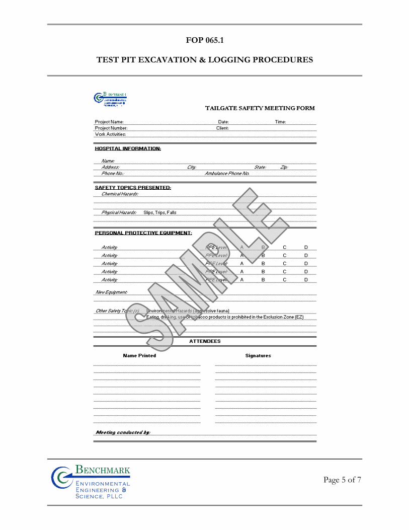
FOP 065.1
TEST PIT EXCAVATION & LOGGING PROCEDURES
Page 5 of 7
Bn v i ronme talng i neeri n gc ence,i
n
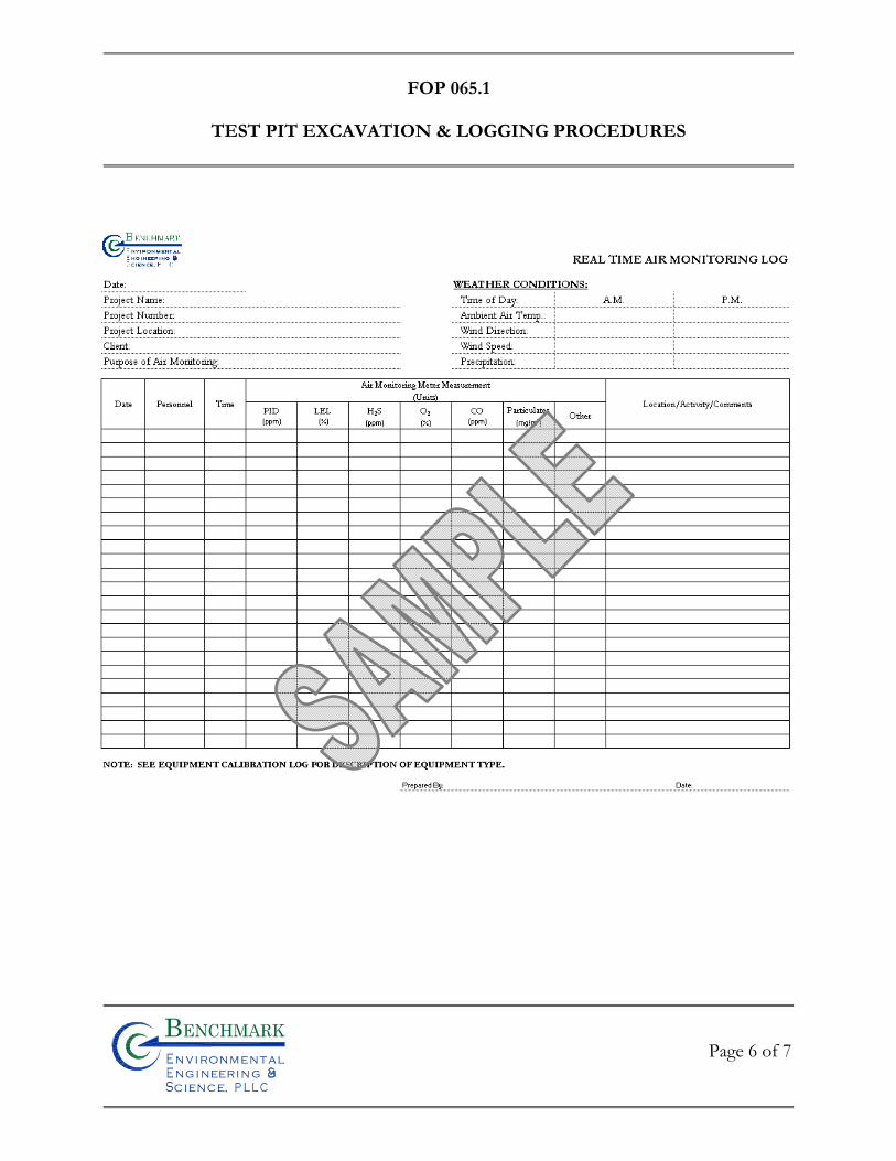
FOP 065.1
TEST PIT EXCAVATION & LOGGING PROCEDURES
Page 6 of 7
Bn v i ronme talng i neeri n gc ence,i
n
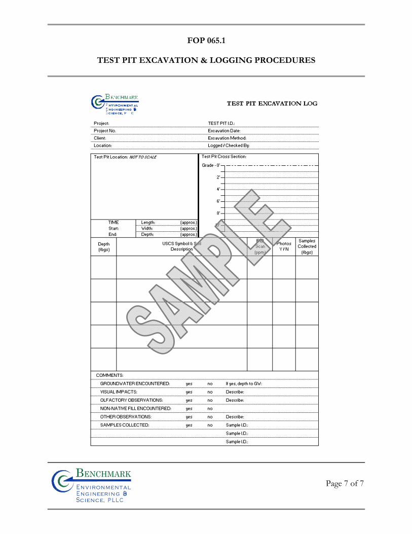
FOP 065.1
TEST PIT EXCAVATION & LOGGING PROCEDURES
Page 7 of 7
Bn v i ronme talng i neeri n gc ence,i
n

FIE
LD
OP
ER
AT
ING
PR
OC
ED
UR
ES
Real-Time Air Monitoring During Intrusive Activities
Bn v i ronme talng i neeri n gc ence,i
n
FOP 073.2
REAL-TIME AIR MONITORING DURING INTRUSIVE
ACTIVITIES PROCEDURE
Page 1 of 12
Bn v i ronme talng i neeri n gc ence,i
n
PURPOSE
This guideline presents requirements for real-time community air monitoring and required
responses during all project required intrusive activities, such as drilling, test pitting,
earthwork construction etc. This procedure is consistent with the requirements for
community air monitoring for all intrusive projects, including projects conducted at
remediation sites, as established by the New York State Department of Health (NYSDOH)
and the New York State Department of Environmental Conservation (NYSDEC).
Accordingly, it follows procedures and practices outlined under NYSDEC’s DER-10 (May
2010) Appendix 1A (NYSDOH’s Generic Community Air Monitoring Plan) and Appendix
1B (Fugitive Dust and Particulate Monitoring).
This FOP requires real-time monitoring for constituents of concern (COC) (i.e., volatile
organic compounds (VOCs), lower explosive limit (% LEL), particulates (i.e., dust) etc.) at
the upwind and downwind perimeter as well as the exclusion zone of a project site during all
intrusive activities. This FOP is not intended for use in establishing action levels for worker
respiratory protection (see Project Health and Safety Plan (HASP) for worker protection
action levels). Rather, its intent is to provide a measure of protection for the surrounding
community from potential airborne contaminant releases as a direct result of investigative
and remedial work activities. The community, as referenced in this document, includes any
off-site residences, public buildings/grounds and commercial or industrial establishments
adjacent to the project site. The action levels specified herein require increased monitoring,
corrective actions to abate emissions, and/or work shutdown. Additionally, this FOP helps
to confirm that work activities did not spread contamination off-site through via air
transport mechanisms. Community air monitoring shall be integrated with the construction
FOP 073.2
REAL-TIME AIR MONITORING DURING INTRUSIVE
ACTIVITIES PROCEDURE
Page 2 of 12
Bn v i ronme talng i neeri n gc ence,i
n
worker personal exposure-monitoring program contained in the project and site-specific
HASP.
Depending upon the nature of known or potential contaminants at each site, real-time air
monitoring for volatile organic compounds (VOCs) and/or particulate levels at the
perimeter of the exclusion zone or work area will be necessary. Most sites will involve VOC
and particulate monitoring; sites known to be contaminated with heavy metals alone may
only require particulate monitoring. If radiological contamination is a concern, additional
monitoring requirements may be necessary per consultation with appropriate
NYSDEC/NYSDOH staff.
MONITORING & MITIGATION PROCEDURE
Real-time air monitoring perimeter locations for monitoring stations will be established
based on the location of the exclusion zone (i.e., immediate work area) and wind direction.
Where wind direction is shifting or winds are calm, the downwind monitoring location will
default to the perimeter location nearest the most sensitive receptor (i.e., residential
property). All downwind receptors being equal, the downwind monitoring location will
default to the perimeter location downwind of the prevailing winds at the site. Although
additional site specific COCs may be monitored during real-time air monitoring activities,
the most common COCs are discussed in this FOP, including organic vapors (i.e., VOCs),
airborne particulates (i.e., fugitive dust) and combustible gases (i.e., methane) and oxygen.
FOP 073.2
REAL-TIME AIR MONITORING DURING INTRUSIVE
ACTIVITIES PROCEDURE
Page 3 of 12
Bn v i ronme talng i neeri n gc ence,i
n
Continuous monitoring will be required for all ground intrusive activities and during the
demolition of contaminated or potentially contaminated structures. Ground intrusive
activities include, but are not limited to, soil/waste excavation and handling, test pitting or
trenching, and the installation of soil borings or monitoring wells.
Periodic monitoring for VOCs will be required during non-intrusive activities such as the
collection of soil and sediment samples or the collection of groundwater samples from
existing monitoring wells. “Periodic” monitoring during sample collection might reasonably
consist of taking a reading upon arrival at a sample location, monitoring while opening a well
cap or overturning soil, monitoring during well baling/purging, and taking a reading prior to
leaving a sample location. In some instances, depending upon the proximity of potentially
exposed individuals, continuous monitoring may be required during sampling activities.
Examples of such situations include groundwater sampling at wells on the curb of a busy
urban street, in the midst of a public park, or adjacent to a school or residence
ORGANIC VAPORS
Volatile organic compounds (VOCs) must be monitored at the downwind perimeter of the
immediate work area (i.e., the exclusion zone) on a continuous basis or as otherwise
specified. Upwind concentrations should be measured at the start of each workday and
periodically thereafter to establish background conditions. The monitoring work should be
performed using equipment appropriate to measure the types of contaminants known or
suspected to be present. The equipment should be calibrated at least daily for the
contaminant(s) of concern or for an appropriate surrogate. The equipment should be
FOP 073.2
REAL-TIME AIR MONITORING DURING INTRUSIVE
ACTIVITIES PROCEDURE
Page 4 of 12
Bn v i ronme talng i neeri n gc ence,i
n
capable of calculating 15-minute running average concentrations, which will be compared to
the levels specified below.
If the ambient air concentration of total organic vapors at the downwind perimeter of the work area or exclusion zone exceeds 5 parts per million (ppm) above background for the 15-minute average, work activities must be temporarily halted and monitoring continued. If the total organic vapor level readily decreases (per instantaneous readings) below 5 ppm over background, work activities can resume with continued monitoring.
If total organic vapor levels at the downwind perimeter of the work area or exclusion zone persist at levels in excess of 5 ppm over background but less than 25 ppm, work activities must be halted, the source of vapors identified, corrective actions taken to abate emissions, and monitoring continued. After these steps, work activities can resume provided that the total organic vapor level 200 feet downwind of the exclusion zone or half the distance to the nearest potential receptor or residential/commercial structure, whichever is less - but in no case less than 20 feet, is below 5 ppm over background for the 15-minute average.
If the organic vapor level is above 25 ppm at the perimeter of the work area, activities must be shutdown.
All 15-minute readings must be recorded and be available for State (DEC and DOH)
personnel to review. Instantaneous readings, if any, used for decision purposes should also be recorded.
o Special Requirements for Work Within 20 Feet of Potentially Exposed Individuals
or Structures
When work areas are within 20 feet of potentially exposed populations or
occupied structures, the continuous monitoring locations for VOCs and
FOP 073.2
REAL-TIME AIR MONITORING DURING INTRUSIVE
ACTIVITIES PROCEDURE
Page 5 of 12
Bn v i ronme talng i neeri n gc ence,i
n
particulates must reflect the nearest potentially exposed individuals and the
location of ventilation system intakes for nearby structures. The use of
engineering controls such as vapor/dust barriers, temporary negative-pressure
enclosures, or special ventilation devices should be considered to prevent
exposures related to the work activities and to control dust and odors.
Consideration should be given to implementing the planned activities when
potentially exposed populations are at a minimum, such as during weekends or
evening hours in non-residential settings.
If total VOC concentrations opposite the walls of occupied structures or next
to intake vents exceed 1 ppm, monitoring should occur within the occupied
structure (s). Background readings in the occupied spaces must be taken prior
to commencement of the planned work. Any unusual background readings
should be discussed with NYSDOH prior to commencement of the work.
If total particulate concentrations opposite the walls of occupied structures or
next to intake vents exceed 150 mcg/m3, work activities should be suspended
until controls are implemented and are successful in reducing the total
particulate concentration to 150 mcg/m3 or less at the monitoring point.
Depending upon the nature of contamination and remedial activities, other
parameters (e.g., explosivity, oxygen, hydrogen SUlfide, carbon monoxide)
may also need to be monitored Response levels and actions should be pre-
determined, as necessary, for each site.
FOP 073.2
REAL-TIME AIR MONITORING DURING INTRUSIVE
ACTIVITIES PROCEDURE
Page 6 of 12
Bn v i ronme talng i neeri n gc ence,i
n
Additionally, if following the cessation of work and efforts to abate the emission
source are unsuccessful, and if sustained organic vapor levels exceed 25 ppm above
background within the 20-foot zone for more than 30 minutes, then the Major Vapor
Emission Response Plan (see below) will automatically be placed into effect.
Major Vapor Emission Response Plan
Upon activation of Major Vapor Emission Response Plan, the following activities will be
undertaken:
1. All Emergency Response Contacts as listed below and in the Site-Specific Health and Safety Plan will be contacted.
2. The local police authorities will immediately be contacted by the Site Safety
and Health Officer and advised of the situation.
3. The Site Safety and Health Officer will determine if site workers can safely undertake source abatement measures. Abatement measures may include covering the source area with clean fill or plastic sheeting, or consolidating contaminated materials to minimize surface area. The Site Safety and Health Officer will adjust worker personal protective equipment as necessary to protect workers from over-exposure to organic vapors.
The following personnel are to be notified by the Site Safety and Health Officer in the listed
sequence if the Major Vapor Emission Response Plan is activated:
Contact Phone
Police/Fire Department 911
New York State DOH (518) 402-7860
New York State DEC Region 8 (585) 226-2466, switchboard
FOP 073.2
REAL-TIME AIR MONITORING DURING INTRUSIVE
ACTIVITIES PROCEDURE
Page 7 of 12
Bn v i ronme talng i neeri n gc ence,i
n
New York State DEC Region 9 (716) 851-7220
State Emergency Response Hotline (800) 457-7362
In addition, the Site Safety and Health Officer will provide these authorities with a
description of the apparent source of the contamination and abatement measures being
taken by the contractor, if any.
AIRBORNE PARTICULATES
Fugitive dust suppression and airborne particulate monitoring shall be performed during any
intrusive activities involving disturbance or handling of site soil/fill materials. Fugitive dust
suppression techniques will include the following minimum measures:
Spraying potable water on all excessively dry work areas and roads.
All fill materials leaving the site will be hauled in properly covered containers or
haul trailers.
Additional dust suppression efforts may be required as discussed below.
Particulate concentrations should be monitored continuously at the upwind and downwind
perimeters of the exclusion zone at temporary particulate monitoring stations. The
particulate monitoring should be performed using real-time monitoring equipment capable
of measuring particulate matter less than 10 micrometers in size (PM-10) and capable of
integrating over a period of 15 minutes (or less) for comparison to the airborne particulate
action level. The equipment must be equipped with an audible alarm to indicate exceedance
FOP 073.2
REAL-TIME AIR MONITORING DURING INTRUSIVE
ACTIVITIES PROCEDURE
Page 8 of 12
Bn v i ronme talng i neeri n gc ence,i
n
of the action level. In addition, fugitive dust migration should be visually assessed during all
work activities.
If the downwind PM-10 particulate level is 100 micrograms per cubic meter (g/m3) greater than background (upwind perimeter) for the 15-minute period or if airborne dust is observed leaving the work area, then dust suppression techniques must be employed. Work may continue with dust suppression techniques provided that downwind PM-10 particulate levels do not exceed 150 g/m3 above the upwind level and provided that no visible dust is migrating from the work area.
If, after implementation of dust suppression techniques, downwind PM-10 particulate levels are greater than 150 g/m3 above the upwind level, work must be stopped and a re-evaluation of activities initiated. Work can resume provided that dust suppression measures and other controls are successful in reducing the downwind PM-10 particulate concentration to within 150 g/m3 of the upwind level and in preventing visible dust migration.
All readings must be recorded and be available for State (DEC and DOH)
personnel to review. Visual Assessment
In conjunction with the real-time monitoring program, TurnKey personnel and any
subcontractors thereof will be responsible for visually assessing fugitive dust migration from
the site. If airborne dust is observed leaving the site, the work will be stopped until
supplemental dust suppression techniques are employed in those areas.
Supplemental Dust Suppression
Supplemental dust suppression techniques may include but are not necessarily limited to the
FOP 073.2
REAL-TIME AIR MONITORING DURING INTRUSIVE
ACTIVITIES PROCEDURE
Page 9 of 12
Bn v i ronme talng i neeri n gc ence,i
n
following measures:
Reducing the excavation size, number of excavations or volume of material handled.
Restricting vehicle speeds.
Applying water on buckets during excavation and dumping.
Wetting equipment and excavation faces.
Wetting haul roads.
Restricting work during extreme wind conditions.
Use of a street sweeper on paved haul roads, where feasible.
Work can resume using supplemental dust suppression techniques provided that the
measures are successful in reducing the sustained downwind particulate concentration to
below 150 ug/m3 of the upwind level, and in preventing visible dust migration off-site.
COMBUSTIBLE GASES & OXYGEN
Ambient combustible gas and oxygen concentrations should be measured prior to
commencing intrusive activities each workday and a minimum of every 30-minutes
thereafter. Air monitoring activities should be performed using equipment appropriate to
measure combustible gases in percent lower explosive limit (LEL) and percent oxygen and
calibrated daily. All combustible gas and oxygen readings must be recorded in the Project
Field Book and/or Real-Time Air Monitoring Logs (sample attached) and, if applicable, be
made available for State (DEC and DOH) personnel to review.
FOP 073.2
REAL-TIME AIR MONITORING DURING INTRUSIVE
ACTIVITIES PROCEDURE
Page 10 of 12
Bn v i ronme talng i neeri n gc ence,i
n
Mitigation upon the detection of various action levels of organic vapors are presented below:
Combustible Gas:
If the sustained ambient air concentration of combustible gas at the downwind perimeter of the site exceeds a reading of 10 to 25% LEL, work activities must be temporarily halted and monitoring continued. If the total organic vapor level readily decreases (per instantaneous readings) below 10% LEL, work activities can resume with continued monitoring.
If sustained combustible gas levels at the downwind perimeter of the site persist
at levels in excess of 25% LEL, work activities must be halted, the source of explosion hazards identified, corrective actions taken to abate emissions and monitoring continued. Following combustible gas mitigation, work activities can resume provided that the sustained total organic vapor level 200 feet downwind of the exclusions zone or half the distance to the nearest potential receptor or residential/commercial structure, whichever is less, (but in no case less than 20 feet) is below a sustained value of 10% LEL.
Oxygen:
If the sustained ambient oxygen concentration at the downwind perimeter of the site measures a reading between 19.5% - 21% oxygen, work activities can continue with extreme caution, however attempts to determine the potential source of oxygen displacement must be conducted.
If the sustained oxygen level readily decreases below 19.5% LEL, work activities
should be discontinued and all personnel must leave the area immediately. If the sustained oxygen level at the downwind perimeter of the site persists at
levels between 21-25%, work activities can resume with caution. If the sustained oxygen level at the downwind perimeter of the site persists at
levels exceeding 25% (fire hazard potential), work activities should be discontinued and all personnel must leave the area immediately.
FOP 073.2
REAL-TIME AIR MONITORING DURING INTRUSIVE
ACTIVITIES PROCEDURE
Page 11 of 12
Bn v i ronme talng i neeri n gc ence,i
n
ATTACHMENTS
Real-Time Air Monitoring Log (sample)
REFERENCES
TurnKey FOPs: 006 Calibration and Maintenance of Combustible Gas/Oxygen Meter 010 Calibration and Maintenance of Flame Ionization Detector 011 Calibration and Maintenance of Portable Photoionization Detector 084 Calibration and Maintenance of Portable Particulate Meter
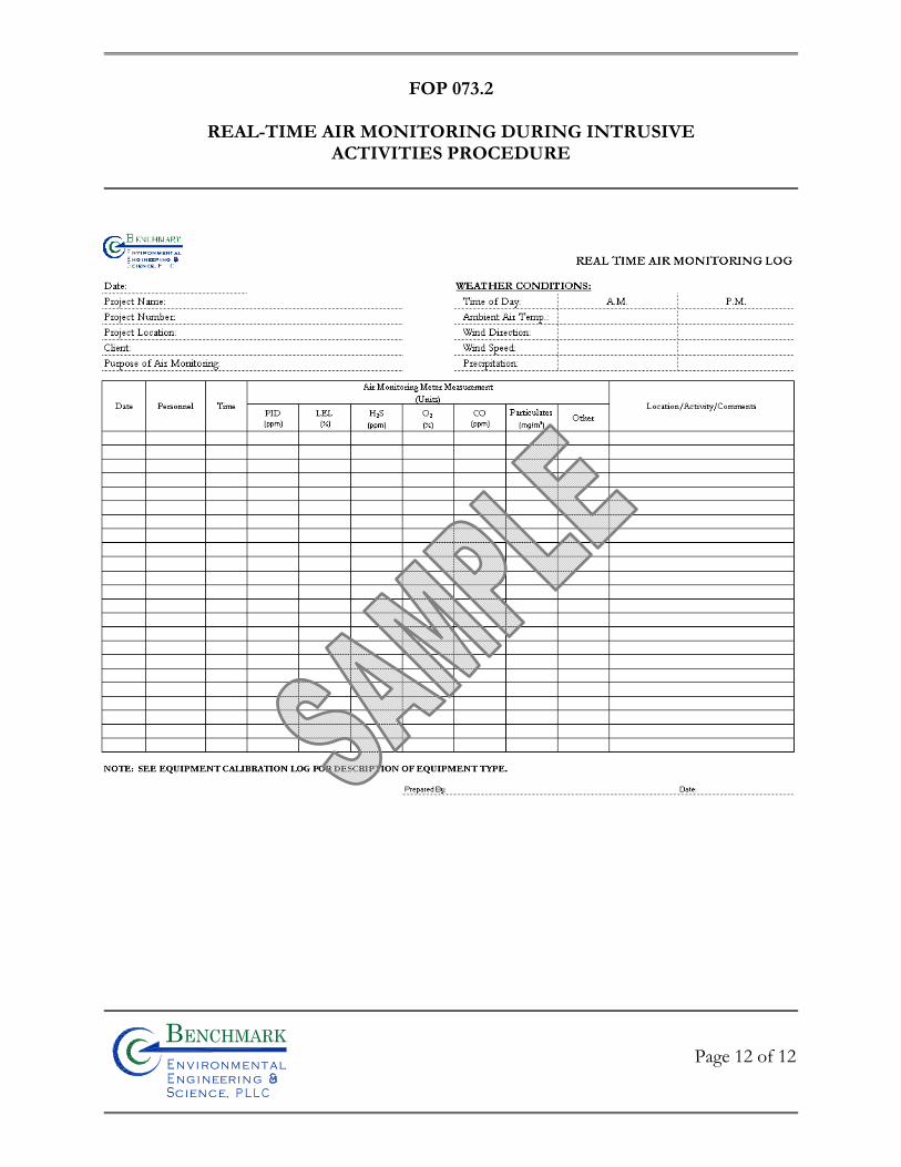
FOP 073.2
REAL-TIME AIR MONITORING DURING INTRUSIVE
ACTIVITIES PROCEDURE
Page 12 of 12
Bn v i ronme talng i neeri n gc ence,i
n

FIE
LD
OP
ER
AT
ING
PR
OC
ED
UR
ES
“Before Going Into The Field” Procedure
Bn v i ronme talng i neeri n gc ence,i
n
FOP 076.0
“BEFORE & AFTER”
PROJECT PROCEDURES FOR FIELD PERSONNEL
Page 1 of 6
Bn v i ronme talng i neeri n gc ence,i
n
PURPOSE
This procedure describes the required field and office activities to be preformed “before and after” project assignments by field personnel. Field activities may include, but are not limited to, drilling oversight, excavation contractor oversight, matrix sample collection (e.g., soil, sediment, groundwater, surface water, wipe, and/or air), third party oversight, and site reconnaissance to name a few. Office activities may include, but are not limited to, photocopying field book entries, completing all field forms, tabulating collected field and laboratory data, and preparation of report text. The primary goal of this procedure is to eliminate delays and unnecessary budgetary “strain” due to a lack of preparedness and knowledge of the site by the field team members. This procedure also seeks to streamline the preparation and transfer of field information/data from field personnel to the Project Manager upon field work completion.
PROJECT ASSIGNMENT
During the initial meeting with the Project Manager, several questions should be raised by the field team member and answered by the Project Manager. A pad of paper and pen should be in hand to record all pertinent job information. At a minimum, the following questions should be answered:
1. What is the job number? 2. Who is the client and the on-site representative (if applicable)? 3. What is the name of the project? 4. What are the job responsibilities and how should they be accomplished? 5. How much time do I have to complete the assigned tasks? 6. Are there any project required documents? What are they?
Any deviation from the above questions should be approved by the Project Manager prior to contravention, not at the end of the day or following the project completion.
FOP 076.0
“BEFORE & AFTER”
PROJECT PROCEDURES FOR FIELD PERSONNEL
Page 2 of 6
Bn v i ronme talng i neeri n gc ence,i
n
“BEFORE” CHECKLISTS
Checklists should be developed and used so that all of the required steps prior to going into the field are undertaken. A good checklist will include:
• Adequate review of the documents listed in this FOP • Any documents, equipment, and supplies presented in this FOP • Providing adequate notification to the laboratory (so that holding times are not
exceeded) and to the owner of the site and the primary regulatory agency (usually in writing) that a round of sampling is to commence in order to facilitate sampling and allow for a sampling audit or split sampling.
• Specifying and documenting the equipment maintenance and calibration
undertaken prior to going into the field relative to the sampling event.
• Checking and calibrating the equipment.
• Listing the documents, equipment, and supplies required to collect samples at the site as presented in this FOP.
Prior to going into the field, sampling personnel should reacquaint themselves with the sampling plan. The review is undertaken so that the required specific protocol such as sampling from the least to the most contaminated wells, knowing where quality control samples are to be taken, knowing the disposition of purge water, etc., is understood and followed. The amount of equipment maintenance and calibration required prior to going into the field should be clearly specified in the presampling equipment maintenance and calibration checklists, which are based on the manufacturer’s recommendations, sampling objectives, and prior experience. Maintenance and calibration performed before sampling must be

FOP 076.0
“BEFORE & AFTER”
PROJECT PROCEDURES FOR FIELD PERSONNEL
Page 3 of 6
Bn v i ronme talng i neeri n gc ence,i
n
documented to provide evidence that the equipment was adequately maintained and calibrated and to keep a permanent record of equipment servicing and performance. A list of all the documents, equipment, and supplies required for the sampling event should be prepared and used. It can be frustrating and time consuming to forget equipment and supplies, so some up-front preparation is warranted. The following sections provide a list of the documentation, equipment, and supplies, which should assist in preparing a site-specific equipment and supply checklist. Once prepared, the checklist and project requirements should be reviewed with the Project Manager.
“BEFORE” DOCUMENTATION SUMMARY
Prior to going into the field, the field team should review and understand all of the project documents including, but not limited to:
• The Health and Safety Plan (HASP) • The Site Analytical Plan (SAP), Sampling Plan, or similar document • The Quality Assurance Project Plan (QAPP) • The Work Plan • Project specific Field Operating Procedures and field forms • Site Maps • Equipment operation manuals • Chain-of-Custody forms • Shipping labels and custody seals • Any reference materials (i.e., conversion tables, volume calculation, etc.). The
Pocket Ref, Third Edition by Thomas Glover is a great source for the field. If at any time, the field team does not understand the project required protocol, procedures, sample locations, etc.; the Project Manager should be consulted for clarification.

FOP 076.0
“BEFORE & AFTER”
PROJECT PROCEDURES FOR FIELD PERSONNEL
Page 4 of 6
Bn v i ronme talng i neeri n gc ence,i
n
“BEFORE” EQUIPMENT SUMMARY
Prior to going into the field, the field team should review the following equipment checklist, noting that project specific equipment may not be included in this list:
• Water level indicator • Pumps, sample tubing, flow controllers, power cord(s), batteries, compressors,
generators, etc. • Bailers (disposable, PVC, stainless steel, glass), rope • Flow-through cell • Field meters with adequate calibration solutions (pH/Eh meter, conductivity
meter, dissolved oxygen meter, turbidity meter, batteries, etc.) • Garden hose • Explosive gas meter and/or photoionization detector (PID) with calibration
supplies • Complete set of hand tools including a sharp knife, screw drivers, pliers, hacksaw,
flashlight, large pipe wrench, hammer, bolt cutters, and replacement locks • Fish hook with weight and string • Field filtering equipment and supplies • Decontamination supplies, such as scrub brushes, Alconox®, distilled water,
potable water, 5-gallon bucket, paper towels, aluminum foil • 5-gallon bucket(s) • Measuring cup • Sample bottles/containers (with extras) and preservatives • Stainless steel spoons, trowels, shovels • Shipping containers (i.e., coolers) • Clipboard • Calculator • Water resistant clock or watch with second hand • First aid kit
FOP 076.0
“BEFORE & AFTER”
PROJECT PROCEDURES FOR FIELD PERSONNEL
Page 5 of 6
Bn v i ronme talng i neeri n gc ence,i
n
“BEFORE” SUPPLIES SUMMARY
Prior to going into the field, the field team should review the following supplies checklist, noting that project specific supplies may not be included in this list:
• Laboratory grade non-phosphate detergent (Alconox®) • Appropriate personal protective equipment appropriate to the contaminants of
concern, such as nitrile gloves, Tyvek, boots, hardhat, safety glasses, hearing protection, etc.
• Bags of ice • Plastic garbage bags • Plastic sheeting • Sufficient quantities of potable and laboratory grade deionized water for cleaning
and equipment blanks • Methanol • Isopropyl alcohol • Clean rags and paper towels • Electrical tape, duct tape, and wide transparent tape • Hand soap • Regular, ballpoint, and indelible pens • Hollow braid polyethylene rope
After providing adequate notification (lab, state and/or federal agencies), performing the presampling maintenance and calibration, obtaining the site and well keys, and packing the supplies and equipment, the field activities are ready to be performed.
“AFTER” – PROJECT FILE REVIEW & CREATION
It is the responsibility of each field crew member to review his/her own field notes and time sheet for accuracy and completeness. All errors to the field notes should be corrected, dated, and initialed for Project Manager review. Once reviewed by the field team member, the Project Field Book, all field forms, photographs, chain-of-custodies etc. must be
FOP 076.0
“BEFORE & AFTER”
PROJECT PROCEDURES FOR FIELD PERSONNEL
Page 6 of 6
Bn v i ronme talng i neeri n gc ence,i
n
photocopied, scanned (if required), downloaded, etc. and then given to the Project Manager in an organized file folder in a timely manner. Avoiding delay during this step is critical, especially when there are severe time constraints for the project.
REFERENCES
1. Wilson, Neal. Soil Water and Ground Water Sampling, 1995

FIE
LD
OP
ER
AT
ING
PR
OC
ED
UR
ES
Geoprobe Drilling Procedures
Bn v i ronme talng i neeri n gc ence,i
n
FOP 078.0
GEOPROBE DRILLING PROCEDURES
Page 1 of 6
Bn v i ronme talng i neeri n gc ence,i
n
PURPOSE
This guideline presents a method for direct-push drilling a borehole through unconsolidated
materials, including soils or overburden.
PROCEDURE
The following procedure will be used to drill a borehole for sampling and/or well
installation, using direct-push methods and equipment.
1. Follow Benchmark’s Field Operating Procedure (FOP) for Drill Site Selection
Procedure prior to implementing any drilling activity. 2. Perform drill rig safety checks with the driller by completing the Drilling
Safety Checklist form (sample attached).
3. Conduct tailgate health and safety meeting with project team and drillers by completing the Tailgate Safety Meeting Form (sample attached).
4. Calibrate air-monitoring equipment in accordance with the appropriate
Benchmark’s FOPs or manufacturers recommendations.
5. Ensure all drilling equipment (i.e., rods, 4-foot sampler, dedicated PVC sleeves) appear clean and free of soil prior to initiating any subsurface intrusion. Decontamination of drilling equipment should be in accordance with Benchmark’s Drilling and Excavation Equipment Decontamination Procedures FOP.
6. Mobilize the Geoprobe™ rig to the site and position over the borehole. 7. Level and stabilize the rig and recheck the rig location against the planned
drilling location.
FOP 078.0
GEOPROBE DRILLING PROCEDURES
Page 2 of 6
Bn v i ronme talng i neeri n gc ence,i
n
8. Fully advance the sampler into the subsurface using an ATV-mounted direct-push Geoprobe™ drill rig and 1.5-inch diameter sampler, typically 4-feet in length and fitted with a dedicated PVC sleeve, for each four-foot core of soil.
9. Retrieve the 4-foot sample core from the driller, place on a piece of
polyethylene tarp, and cut open using a sharp utility knife.
10. Visually characterize each 4-foot soil core using the Unified Soil Classification System (USCS) in accordance with Benchmark’s Soil Description Procedures Using the USCS FOP.
11. Scan each 4-foot core for total volatile organic vapors with a calibrated
Photovac 2020 PID equipped with a 10.6 eV lamp, and report any visual and/or olfactory observations. Record PID scan measurements in the Project Field Book and appropriate field forms.
12. If required, collect a representative soil sample for headspace determinations.
In general, soil samples representative of each 4-foot core interval are collected, placed in a sealable plastic bag, and kept at or near room temperature (approximately 65-70° F) for a minimum of 15 minutes prior to measurement. Record PID headspace determination measurements in the Project Field Book and appropriate field forms.
13. Check sampler and rods periodically during drilling to ensure the boring is
plumb. Adjust rig position as necessary to maintain plumb.
14. Continue drilling until reaching the assigned total depth, or until sampler refusal occurs. Sampler refusal is when the drilling penetration drops below 0.1 feet per 2 minutes, with the full weight of the rig on the sampler.
15. Plug and abandon boreholes not used for temporary well installation in
accordance with Benchmark’s Field Operating Procedure for Abandonment of Borehole. Boreholes to be used as temporary wells should be completed in accordance with Benchmark’s Temporary Well (Piezometer) Construction Procedures FOP.
FOP 078.0
GEOPROBE DRILLING PROCEDURES
Page 3 of 6
Bn v i ronme talng i neeri n gc ence,i
n
16. Decontaminate all non-dedicated drilling tools between boring locations using potable tap water and a phosphate-free detergent (i.e., Alconox™) in accordance with Benchmark’s Drilling and Excavation Equipment Decontamination Procedures FOP.
OTHER PROCEDURAL ISSUES
Borings will not be over drilled (rat holed) without the express permission of the Benchmark field supervisor. All depth measurements should be accurate to the nearest 0.1 foot, to the extent practicable.
Potable water may be placed in the sampler stem if critically necessary for
borehole control or to accomplish sampling objectives. This will be performed only with the express permission of the Benchmark field supervisor.
ATTACHMENTS
Drilling Safety Checklist (sample) Tailgate Safety Meeting Form (sample)
REFERENCES
Benchmark FOPs: 001 Abandonment of Borehole Procedures 017 Drill Site Selection Procedure 018 Drilling and Excavation Equipment Decontamination Procedures 054 Soil Description Procedures Using the USCS 077 Temporary Well (Piezometer) Construction Procedures
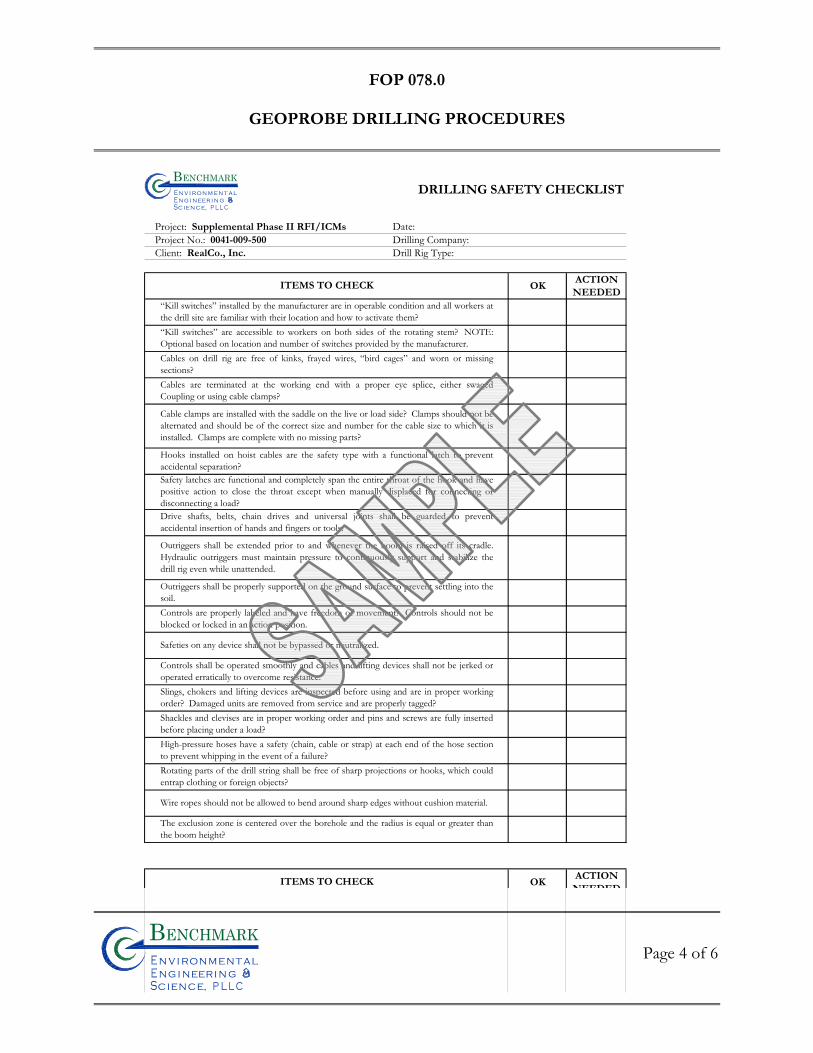
FOP 078.0
GEOPROBE DRILLING PROCEDURES
Page 4 of 6
Bn v i ronme talng i neeri n gc ence,i
n
DRILLING SAFETY CHECKLIST
Project: Supplemental Phase II RFI/ICMs Date:Project No.: 0041-009-500 Drilling Company:Client: RealCo., Inc. Drill Rig Type:
OKACTIONNEEDED
OKACTIONNEEDED
Drive shafts, belts, chain drives and universal joints shall be guarded to preventaccidental insertion of hands and fingers or tools.
Outriggers shall be extended prior to and whenever the boom is raised off its cradle.Hydraulic outriggers must maintain pressure to continuously support and stabilize thedrill rig even while unattended.
Outriggers shall be properly supported on the ground surface to prevent settling into thesoil. Controls are properly labeled and have freedom of movement? Controls should not beblocked or locked in an action position.
ITEMS TO CHECK
Cable clamps are installed with the saddle on the live or load side? Clamps should not bealternated and should be of the correct size and number for the cable size to which it isinstalled. Clamps are complete with no missing parts?
Hooks installed on hoist cables are the safety type with a functional latch to preventaccidental separation?Safety latches are functional and completely span the entire throat of the hook and havepositive action to close the throat except when manually displaced for connecting ordisconnecting a load?
“Kill switches” installed by the manufacturer are in operable condition and all workers atthe drill site are familiar with their location and how to activate them?“Kill switches” are accessible to workers on both sides of the rotating stem? NOTE:Optional based on location and number of switches provided by the manufacturer.Cables on drill rig are free of kinks, frayed wires, “bird cages” and worn or missingsections?Cables are terminated at the working end with a proper eye splice, either swagedCoupling or using cable clamps?
Safeties on any device shall not be bypassed or neutralized.
Controls shall be operated smoothly and cables and lifting devices shall not be jerked oroperated erratically to overcome resistance.Slings, chokers and lifting devices are inspected before using and are in proper workingorder? Damaged units are removed from service and are properly tagged?Shackles and clevises are in proper working order and pins and screws are fully insertedbefore placing under a load?High-pressure hoses have a safety (chain, cable or strap) at each end of the hose sectionto prevent whipping in the event of a failure?Rotating parts of the drill string shall be free of sharp projections or hooks, which couldentrap clothing or foreign objects?
Wire ropes should not be allowed to bend around sharp edges without cushion material.
The exclusion zone is centered over the borehole and the radius is equal or greater thanthe boom height?
ITEMS TO CHECK
Bn v i ron m e t aln g i neer i n gc en ce,i
n
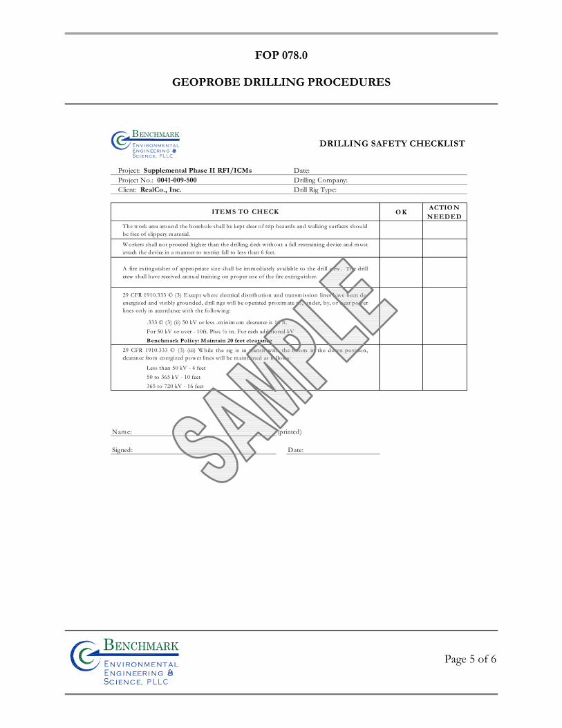
FOP 078.0
GEOPROBE DRILLING PROCEDURES
Page 5 of 6
Bn v i ronme talng i neeri n gc ence,i
n
O KACTIO N
NEEDED
Less than 50 kV - 4 feet50 to 365 kV - 10 feet365 to 720 kV - 16 feet
Name: (printed)
Signed: Date:
29 CFR 1910.333 © (3) (iii) W hile the rig is in transit with the boom in the down position,clearance from energized power lines will be m aintained as follows:
The work area around the borehole shall be kept clear of trip hazards and walking surfaces shou ld be free of slippery m aterial.
W orkers shall not proceed higher than the drilling deck without a fall restraining device and m ustattach the device in a m anner to restrict fall to less than 6 feet.
A fire extinguisher of appropriate size shall be im m ediately available to the drill crew. The drillcrew shall have received annual training on proper use of the fire extinguisher.
29 CFR 1910.333 © (3) Except where electrical distribution and transm ission lines have been de-energized and visibly grounded, drill rigs will be operated proxim ate to, under, by, or near powerlines only in accordance with the following:
ITEMS TO CHECK
.333 © (3) (ii) 50 kV or less -m inim um clearance is 10 ft.For 50 kV or over - 10ft. Plus ½ in. For each additional kVBenchmark Policy: Maintain 20 feet clearance
DRILLING SAFETY CHECKLIST
Project: Supplemental Phase II RFI/ICMs Date:Project No.: 0041-009-500 Drilling Company:Client: RealCo., Inc. Drill Rig Type:
Bn v i ron m e t aln g i neer i n gc en ce,i
n
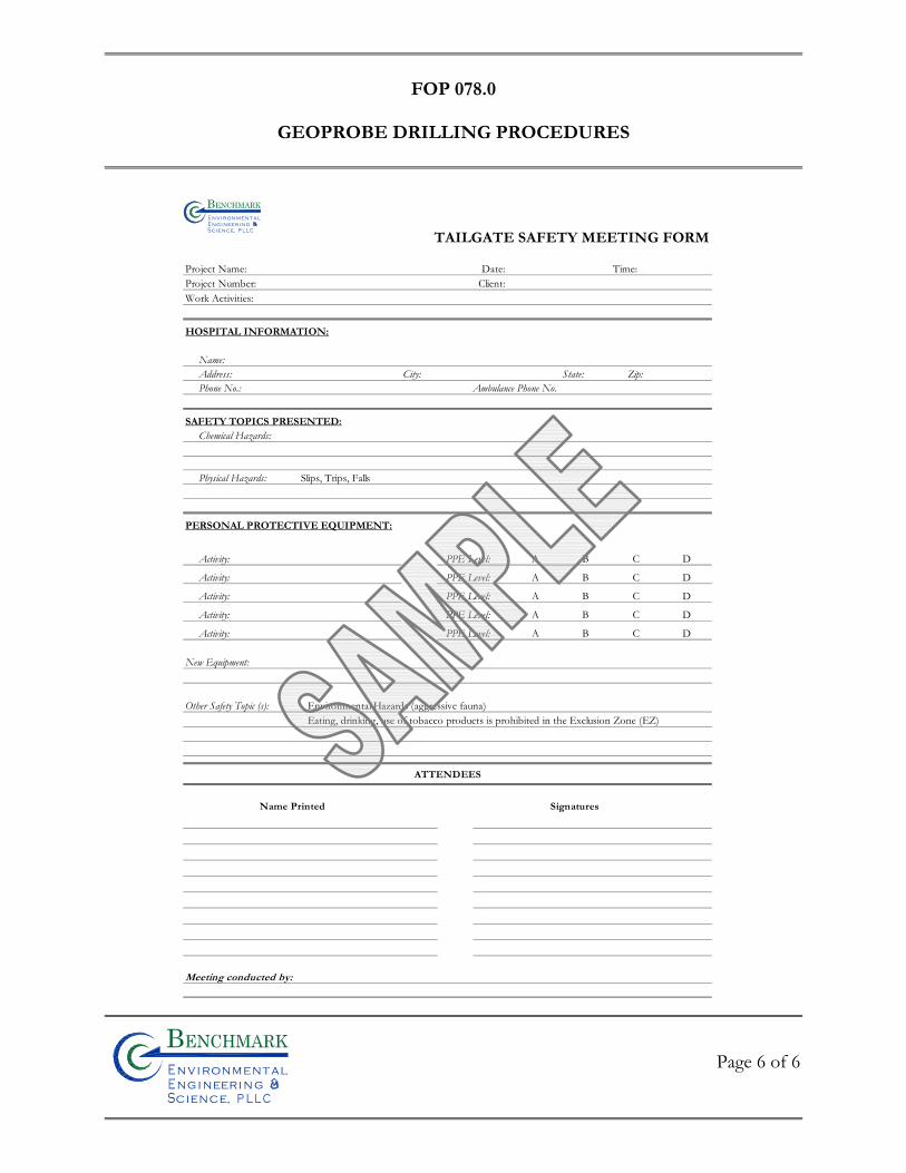
FOP 078.0
GEOPROBE DRILLING PROCEDURES
Page 6 of 6
Bn v i ronme talng i neeri n gc ence,i
n
TAILGATE SAFETY MEETING FORM
Project Name: Date: Time: Project Number: Client: Work Activities:
HOSPITAL INFORMATION:
Name:Address: City: State: Zip:Phone No.: Ambulance Phone No.
SAFETY TOPICS PRESENTED:Chemical Hazards:
Physical Hazards: Slips, Trips, Falls
PERSONAL PROTECTIVE EQUIPMENT:
Activity: PPE Level: A B C D
Activity: PPE Level: A B C D
Activity: PPE Level: A B C D
Activity: PPE Level: A B C D
Activity: PPE Level: A B C D
New Equipment:
Other Safety Topic (s): Environmental Hazards (aggressive fauna)Eating, drinking, use of tobacco products is prohibited in the Exclusion Zone (EZ)
Bn v i ronme t alngi neeri n gc ence,i
n
Meeting conducted by:
Name Printed Signatures
ATTENDEES

FIE
LD
OP
ER
AT
ING
PR
OC
ED
UR
ES
Stockpile Sampling Procedures for
Chemical Analysis
Bn v i ronme talng i neeri n gc ence,i
n
FOP 079.0
STOCKPILE SAMPLING PROCEDURES
FOR CHEMICAL ANALYSIS
Page 1 of 3
Bn v i ronme talng i neeri n gc ence,i
n
PURPOSE
This guideline presents a method for collecting representative soil samples from stockpiled
borrow source material for chemical analysis.
GENERAL
In general, off-site soil that is brought to a Site for use as supplemental fill is subject to
Quality Assurance sampling and analysis. If QA is required, all off-site soil proposed for use
as Site backfill shall be documented by the subcontractor in writing to have originated from
locations having no evidence of disposal or release of hazardous, toxic or radioactive
substances, wastes or petroleum products. If the subcontractor designates a source as
“virgin” soil, it shall be further documented in writing to be native soil material having not
supported any known past industrial or commercial development or agricultural use.
Borrow soils can be used as backfill once concentrations are confirmed to meet project
designated criteria for the Constituents of Primary Concern (COPCs) and NYSDEC TAGM
HWR-94-4046 recommended soil cleanup objectives (SCOs) or NYSDEC 6NYCRR Part
375 SCOs.
Sample collection equipment will include stainless steel mixing bowls, stainless steel mixing
spoons, and a stainless steel hand auger with extension rods or a stainless steel spade or
equivalent. It may be necessary to use a backhoe or drilling rig to facilitate sample collection.
FOP 079.0
STOCKPILE SAMPLING PROCEDURES
FOR CHEMICAL ANALYSIS
Page 2 of 3
Bn v i ronme talng i neeri n gc ence,i
n
SAMPLING PLAN
1. Virgin Sources – Virgin borrow sources will be confirmed acceptable for use as site backfill through collection of a single composite soil sample representative of the borrow pit or stockpile.
2. Non-Virgin Sources – Prior to sampling, determine the amount of soil that will be
sampled. The soil will be tested via collection of one composite sample per 250 cubic yards of material from each source area. If more than 1,000 cubic yards of soils are excavated from a given off-site source area and all samples of the first 1,000 cubic yards meet project designated criteria, the sample collection frequency may be reduced to one composite for each additional 1,000 cubic yards of soils from the same source area, up to 5,000 cubic yards. For borrow sources greater than 5,000 cubic yards, sampling frequency may be reduced to one sample per 5,000 cubic yards, providing all earlier samples meet project designated criteria. Sampling procedure for non-virgin sources is described in the next section.
SAMPLE COLLECTION AND HANDLING
The following procedure will be used to collect representative soil samples from a non-virgin
soil stockpile.
1. Using a stainless steel spade (or hand auger), a backhoe, or drilling rig, penetrate the pile to a depth of approximately 2 to 3 feet and collect four (4) representative grab samples of approximate equal volume from the top, middle, and bottom.
2. Transfer each grab into a small stainless steel mixing bowl.
3. VOC Analysis: Using a clean stainless steel spoon, transfer equal amounts
from each small mixing bowl into a laboratory-supplied, 4 oz. VOC sample jar. This should be performed by randomly transferring several small aliquots from each bowl, taking care to minimize disturbance of the soil.
FOP 079.0
STOCKPILE SAMPLING PROCEDURES
FOR CHEMICAL ANALYSIS
Page 3 of 3
Bn v i ronme talng i neeri n gc ence,i
n
4. Other COPCs: Transfer equal aliquots from each small bowl into a large mixing bowl and homogenize the sample. Fill the remaining laboratory-supplied jars with the homogenized soil for all other project required COPCs (i.e., SVOCs, PCBs, Pesticides, Herbicides, inorganics, etc.).
5. Label each set of jars with the following information:
• Project and site name • Sample Code • Project Number • Date/Time • Sample type (soil composite or grab) • Sampler’s initials • Sample Preservation • Required analysis
The sample code will consist of a unique, alphanumeric identification code keyed to the sampling location. Identify the sampling location on a field sketch.
6. Record all information associated with sample collection in the Project Field
Book.
7. Label, store, and ship the samples in accordance with the Benchmark Field Operating Procedure for Sample Labeling, Storage and Shipment Procedures.
8. Clean the sampling and mixing equipment with Alconox and deionized water
and repeat steps 1 through 7 for the remaining samples.
REFERENCES
Benchmark FOPs: 046 Sample Labeling, Storage and Shipment Procedures

FIE
LD
OP
ER
AT
ING
PR
OC
ED
UR
ES
Stockpile & Borrow Source Sampling
Procedures for Physical Analysis
Bn v i ronme talng i neeri n gc ence,i
n

FOP 080.0
STOCKPILE & BORROW SOURCE SAMPLING PROCEDURES
FOR PHYSICAL ANALYSIS
Page 1 of 5
Bn v i ronme talng i neeri n gc ence,i
n
PURPOSE
This guideline presents a method for collecting representative soil samples from stockpiled
borrow source material for physical analysis.
GENERAL
Generally, one of two methods will be utilized to collect soil samples for analysis. One
method is to collect the samples by digging a series of representative test pits at the borrow
source area and obtaining samples from those test pits. The other method involves
collecting samples from representative stockpiles (normally after the material has been
mechanically screened). Both procedures are discussed within this method.
Sample collection equipment will include stainless steel mixing bowls, stainless steel mixing
spoons, and a stainless steel hand auger with extension rods or a stainless steel spade or
equivalent. It may be necessary to use a backhoe or drilling rig to facilitate sample collection.
STOCKPILED SOIL SAMPLING METHOD
As shown in the attached Figure 1, twelve (12) samples of approximate equal volume should
be collected from the top, middle and bottom of each 1000 CY stockpile by CQA personnel
and composited in the field to give one representative aliquot per 1000 CY.
Stockpile Sampling Procedure
1. Using a shovel or backhoe, penetrate the pile to a depth of about two to three feet. 2. Collect a sample using the shovel.
FOP 080.0
STOCKPILE & BORROW SOURCE SAMPLING PROCEDURES
FOR PHYSICAL ANALYSIS
Page 2 of 5
Bn v i ronme talng i neeri n gc ence,i
n
3. Transfer the sample to a specially prepared mixing area. 4. Repeat Steps 1 through 3 at each 1,000 CY stockpile. 5. Mix subsamples using shovel into one homogenous mass and place in a properly
labeled 5-gallon bucket. Fill each bucket completely and cover. 6. Attach a label to each container and record location referencing the stockpile
identification number. The label may be made with permanent marker on the side (not top) of the container or using adhesive-back paper labels affixed to the side of the container. At a minimum, the labels should be identified with the following information:
Project Name Sample number. Initials of CQA inspector or sample collection personnel. Date of collection. Location of collection (i.e. stockpile I.D.)
7. Return remaining contents of composite sample to stockpile. 8. Deliver the samples to the laboratory for analysis as soon as possible. 9. All information pertinent to each sampling event should be recorded by sampling
personnel in the field at the time of sample collection. Each report should correspond to each stockpile and will contain the following information:
Project Name Sample number or numbers collected Field observations. Climatologic conditions. Date and time of collection. Approximate location of test pit. Name of person who collected sample.
BORROW AREA TEST PIT SAMPLING METHOD
Prior to obtaining representative soil samples, test holes should be excavated at the borrow
area to determine the actual depth and lateral extent of the borrow source soil material. A
base line should then be established and a grid system staked in the field. Five samples
FOP 080.0
STOCKPILE & BORROW SOURCE SAMPLING PROCEDURES
FOR PHYSICAL ANALYSIS
Page 3 of 5
Bn v i ronme talng i neeri n gc ence,i
n
should be collected at equidistant locations for each 5000 cubic yards (CY) of soil designated
for use in the borrow areas (at approximately mid-depth).
Borrow Area Sampling Procedure
1. Using a shovel, collect a representative sample at approximately mid-depth at each of the sampling locations representing 1000 CY of the proposed excavation area.
2. Transfer each sample into a labeled separate 5-gallon bucket. Fill each bucket completely and cover.
3. Attach a label to each container and record location referencing the established grid system in the borrow area. The label may be made with permanent marker on the side (not top) of the container or using adhesive-back paper labels affixed to the side of the container. At a minimum, the labels should be identified with the following information:
Project Name Sample number. Initials of CQA inspector or sample collection personnel. Date of collection. Location of collection (i.e. location of borrow area grid system location)
4. Deliver the samples to the laboratory for analysis as soon as possible. 5. All information pertinent to each sampling event should be recorded by sampling
personnel in the field at the time of sample collection. Each report should correspond to each test pit and will contain the following information:
Project Name Sample number or numbers collected Field observations. Climatologic conditions. Date and time of collection. Approximate location of test pit. Name of person who collected sample.
ATTACHMENTS
Figure 1; Stockpile Sampling Methodology

FOP 080.0
STOCKPILE & BORROW SOURCE SAMPLING PROCEDURES
FOR PHYSICAL ANALYSIS
Page 4 of 5
Bn v i ronme talng i neeri n gc ence,i
n
REFERENCES
None
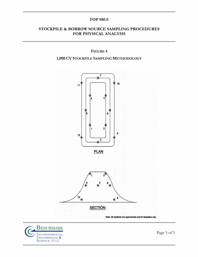
FOP 080.0
STOCKPILE & BORROW SOURCE SAMPLING PROCEDURES
FOR PHYSICAL ANALYSIS
Page 5 of 5
Bn v i ronme talng i neeri n gc ence,i
n
FIGURE 4
1,000 CY STOCKPILE SAMPLING METHODOLOGY

FIE
LD
OP
ER
AT
ING
PR
OC
ED
UR
ES
Waste Sampling Procedures
Bn v i ronme talng i neeri n gc ence,i
n
FOP 082.0
WASTE SAMPLING PROCEDURES
Page 1 of 14
PURPOSE
This guideline describes the equipment and procedures that can safely be used to collect waste samples from open and closed units.
INTRODUCTION
Hazardous wastes are regulated by the USEPA under 40 CFR Parts 260-265. Therefore, many of the methods that are used to manage, store, treat, and dispose hazardous wastes and potential hazardous wastes are of concern to both the regulators and the regulated community. Samples are often required of regulated or potentially regulated materials. While it is understood that each facility and waste stream may present its own unique sampling and analytical challenges, this procedure will list equipment and enumerate procedures that have been used by the USEPA to safely and successfully sample specific waste units.
SAFETY
Sampling of waste units should be assessed for potential hazards by both the Project Manager (PM) and the site safety officer (SSO). It is the SSOs responsibility to enforce the site Health and Safety Plan (HASP), and to ensure that procedures used during waste sampling are in accordance with current company protocol. Sampling equipment contaminated during waste sampling investigations should be cleaned with laboratory detergent and rinsed with tap water prior to returning the equipment from the field. Contaminated sampling equipment that is to be discarded must be disposed of properly in accordance with the site-specific Work Plan. It should be noted that although Benchmark does not readily perform field activities with highly hazardous materials, we do occasionally oversee contractors who do. Therefore, it is prudent on our part to recognize those situations and be prepared to ensure the activities of
FOP 082.0
WASTE SAMPLING PROCEDURES
Page 2 of 14
our subcontractors comply with the site-specific HASP as well as those procedures discussed herein. Any reference within this procedure to personal protective equipment (PPE) upgrades above a modified level C (i.e., Tyvek, nitrile gloves, and full-face respirator) relates solely to our subcontractors.
QUALITY CONTROL PROCEDURES
In some instances, special decontamination procedures will be necessary and should be developed on a case-by-case basis according to the specific material encountered. Any cleaning procedures and equipment repairs conducted in the field deviating from those specified in the associated FOPs or the site-specific Work Plan, should be discussed with the Project Manager, and thoroughly documented in the Project Field Book. All air monitoring and field analytical/screening equipment (i.e., photoionization detectors) should be checked and calibrated per manufacturer’s specifications before being used to collect any waste stream unit sample (open or closed). The Field Team Leader should record all calibration results on appropriate field forms.
WASTE UNIT TYPES
Waste management units can be generally categorized into two types: open and closed. In general, open units are larger than closed units and include waste piles and surface impoundments whereas closed units include containers and tanks as well as ancillary tank equipment. Besides containers and tanks, sumps may also be considered closed units because they are designed to collect the spillage of liquid wastes and are sometimes configured as a confined space. Although both may pose hazards, units that are open to the environment are generally less hazardous than closed units. Sampling of closed units is considered a higher hazard risk
FOP 082.0
WASTE SAMPLING PROCEDURES
Page 3 of 14
because of the potential of exposure to toxic gases and flammable/explosive atmospheres. Because closed units prevent the dilution of the wastes by environmental influences, they are more likely to contain materials that have concentrated levels of hazardous constituents. While opening closed units for sampling purposes, investigators/contractor’s shall use Level B PPE, air monitoring instruments to ensure that the working environment does not contain hazardous levels of flammable/explosive gasses or toxic vapors, and follow the appropriate safety requirements stipulated in the site-specific HASP. Buried waste materials should be located and excavated with extreme caution. Once the buried waste is uncovered, the appropriate safety and sampling procedures utilized will depend on the type of waste unit.
Open Units
While open units may contain many types of wastes and come in a variety of shapes and sizes, they can be generally regarded as either waste piles or surface impoundments. Definitions of these two types of open units from 40 CFR Part 260.10 are:
• Waste pile -- any non-containerized accumulation of solid, non-flowing hazardous waste that is used for treatment or storage and that is not a containment building.
• Surface impoundment -- "...a facility or part of a facility which is a natural topographic depression, man-made excavation, or diked area formed primarily of earthen materials (although it may be lined with man-made materials), which is designed to hold the accumulation of liquid wastes or wastes containing free liquids, and which is not an injection well. Examples of surface impoundments are holding, storage, settling and aeration pits, ponds, and lagoons."
One of the distinguishing features between waste piles and surface impoundments is the state of the waste. Waste piles typically contain solid or non-flowing materials whereas liquid wastes are usually contained in surface impoundments. The nature of the waste will also determine the mode of delivering the waste to the unit. Wastes are commonly pumped
FOP 082.0
WASTE SAMPLING PROCEDURES
Page 4 of 14
or gravity fed into impoundments while heavy equipment or trucks may be used to dump wastes in piles. Once the waste has been placed in an open unit, the state of the waste may be altered by environmental factors (e.g., temperature, precipitation, etc.).
Surface impoundments may contain several phases such as floating solids, liquid phase(s), and sludges. Waste piles are usually restricted to solids and semi-solids. All of the potential phases contained in a waste unit should be considered in developing the sample design to meet the study's objective.
Closed Units
There are a variety of designs, shapes, sizes, and functions of closed units. In addition to the challenges of the various designs and the safety requirements for sampling them, closed units are difficult to sample because they may contain liquid, solid, semi-solid/sludge, or any combination of phases. Based on the study's design, it may be necessary to obtain a cross sectional profile of the closed unit in an attempt to characterize the unit. The following are definitions of types of closed waste units described in 40 CFR Part 260.10:
• Container -- any portable device in which a material is stored, transported, treated, disposed, or otherwise handled. Examples of containers are drums, overpacks, pails, totes, and roll-offs.
• Tank -- a stationary device, designed to contain an accumulation of hazardous
waste constructed primarily of non-earthen materials, which provide structural support.
Portable tanks, tank trucks, and tank cars vary in size and may range from simple to extremely complex designs. Depending on the unit's design, it may be convenient to consider some of these storage units as tanks for sampling purposes even though they meet the definition of a container.
FOP 082.0
WASTE SAMPLING PROCEDURES
Page 5 of 14
• Ancillary equipment (tank) -- any device including, but not limited to, such devices as piping, fittings, flanges, valves, and pumps that is used to distribute, meter, or control the flow of hazardous waste from its point of generation to a storage or treatment tank(s), between hazardous waste storage and treatment tanks to a point of disposal on-site, or to a point of shipment for disposal off-site.
• Sump -- any pit or reservoir that meets the definition of a tank and those
troughs/trenches connected to it that serve to collect hazardous wastes. Note: some outdoor sumps may be considered open units/surface impoundments. Although any of the closed units may not be completely sealed and may be partially open to the environment, the unit needs to be treated as a closed unit for sampling purposes until a determination can be made. Once a closed unit is opened, a review of the proposed sampling procedures and level of protection can be performed to determined if the (PPE) is suitable for the site conditions. Samples collected from different waste units should not be composited into one sample container without additional analytical and/or field screening data to determine if the materials are compatible and will not cause an inadvertent chemical reaction.
EQUIPMENT
Selecting appropriate equipment to sample wastes is a challenging task due to the uncertainty of the physical characteristics and nature of the wastes. It may be difficult to separate, homogenize and/or containerize a waste due to its physical characteristics (viscosity, particle size, etc.). In addition, the physical characteristics of a waste may change with temperature, humidity, or pressure. Waste streams may vary depending on how and when a waste was generated, how and where it was stored/disposed, and the conditions under which it was
FOP 082.0
WASTE SAMPLING PROCEDURES
Page 6 of 14
stored/disposed. Also, the physical location of the wastes or the unit configuration may prevent the use of conventional sampling equipment. Given the uncertainties that a waste may present, it is desirable to select sampling equipment that will facilitate the collection of samples that will meet the study's objective, and that will not unintentionally bias the sample by excluding some of the sample population that is under consideration. However, due to the nature of some waste matrices or the physical constraints of some waste units, it may be necessary to collect samples knowing that a portion of the desired population was omitted due to limitations of the equipment. Any deviations from the study plan or difficulties encountered in the field concerning sample collection that may have an effect on the study's objective should be documented in a log book, reviewed with the analytical data, and presented in the report.
WASTE SAMPLING EQUIPMENT
Waste sampling equipment should be made of non-reactive materials that will neither add to nor alter the chemical or physical properties of the material that is being sampled. The attached Table 1 lists some conventional equipment for sampling waste units/phases and some potential limitations of the equipment. Another reference for selecting sampling equipment is the ASTM, Standard Guide for Selection of Sampling Equipment for Wastes and Contaminated Media Data Collection Activities, D6232-98.
WASTE SAMPLING PROCEDURES
Waste Piles
Waste piles vary in size, shape, composition, and compactness, and may vary in distribution of hazardous constituents and characteristics (strata). These variables will affect safety and access considerations. The number of samples, the type of sample(s), and the sample location(s) should be based on the study's objectives. Commonly used equipment to collect
FOP 082.0
WASTE SAMPLING PROCEDURES
Page 7 of 14
samples from waste piles are listed in Table 1. All equipment should be compatible with the waste and should have been cleaned to prevent any cross contamination of the sample. Surface Impoundments
Surface impoundments vary in size, shape, and waste content, and may vary in distribution of hazardous constituents and characteristics (strata). The number of samples, the type of sample(s), and the sample location(s) should be based on the study's objectives. Commonly used equipment to collect samples from surface impoundments are listed in Table 1. All equipment should be compatible with the waste and should have been cleaned to prevent any cross contamination of the sample.
Because of the potential danger of sampling waste units suspected of containing elevated levels of hazardous constituents, personnel should never attempt to sample surface impoundments used to manage potentially hazardous wastes from a boat. All sampling should be conducted from the banks or piers of surface impoundments. Any exception must be approved by the appropriate site safety officer and/or the Occupational Health and Safety Designee (OHSD).
Drums
Drums are the most frequent type of containers sampled by field investigators for chemical analyses and/or physical testing. Caution should be exercised by the field investigators when sampling drums because of the potential presence of explosive/flammable gases and/or toxic vapors. Therefore, the following procedures should be used when collecting samples from drums of unknown material: 1. Visually inspect all drums that are being considered for sampling for the following:
• pressurization (bulging/dimples); • crystals formed around the drum opening; • leaks, holes, stains;
FOP 082.0
WASTE SAMPLING PROCEDURES
Page 8 of 14
• labels, markings; • composition and type (steel/poly and open/bung); • condition, age, rust • sampling accessibility Drums showing evidence of pressurization and crystals should be furthered assessed to determine if remote drum opening is needed. If drums cannot be accessed for sampling, heavy equipment is usually necessary to stage drums for the sampling activities. Adequate time should be allowed for the drum contents to stabilize after a drum is handled.
2. Identify each drum that will be opened (e.g., paint sticks, spray paint, cones, etc).
LEVEL "B" PROTECTION IS REQUIRED FOR THE FOLLOWING PROCEDURES. 3. Before opening, ground each metal drum that is not in direct contact with the earth
using grounding wires, alligator clips, and a grounding rod or metal structure. If a metal drum is in an overpack drum, the metal drum should be grounded.
4. Touch the drum opening equipment to the bung or lid and allow an electrical conductive
path to form. Slowly remove the bung or drum ring and/or lid with spark resistant tools (brass/beryllium).
5. Screen drums for explosive gases and toxic vapor with air monitoring instruments as
bung or drum lid is removed. Depending on site conditions screen for one or more of the following:
• radioactivity • cyanide fumes • halogen vapors • pH • flash point (requires sample for testing) Note the state, quantity, phases, and color of the drum contents. Record all relevant results, observations, and information in a logbook.
FOP 082.0
WASTE SAMPLING PROCEDURES
Page 9 of 14
6. Select the appropriate sampling equipment based on the state of the material and the type of container. Sampling equipment should be made of non-reactive materials that will meet the study's objective(s).
7. Place oil wipe (as necessary), sampling equipment, and sample containers near drum(s) to
be sampled.
AIR MONITORING FOR TOXIC VAPORS AND EXPLOSIVE GASES AND OXYGEN DEFICIENT ATMOSPHERES SHOULD BE CONDUCTED DURING DRUM SAMPLING.
Liquids -- Slowly lower the COLIWASA or drum thief to the bottom of the container. Close the COLIWASA with the inner rod or create a vacuum with the sampler's gloved thumb on the end of the thief and slowly remove the sampling device from the drum. Release the sample from the device into the sample container. Repeat the procedure until a sufficient sample volume is obtained. Solids/Semi-Solids -- Use a push tube, bucket auger, or screw auger or if conditions permit a pneumatic hammer/drill to obtain the sample. Carefully use a clean stainless steel spoon to place the sample into container(s) for analyses. 8. Close the drums when sampling is complete. Segregate contaminated sampling
equipment and investigative derived wastes (IDW) containing incompatible materials as determined by the drum screening procedure (Step #5). At a minimum, contaminated equipment should be cleaned with laboratory detergent and rinsed with tap water prior to returning it from the field.
Tanks
Sampling tanks is considered hazardous due to the potential for them to contain large volumes of hazardous materials and therefore, appropriate safety protocols must be followed. Unlike drums, tanks may be compartmentalized or have complex designs.
FOP 082.0
WASTE SAMPLING PROCEDURES
Page 10 of 14
Preliminary information about the tank's contents and configuration should be reviewed prior to the sampling operation to ensure the safety of sampling personnel and that the study's objectives can be achieved. In addition to having discharge valves near the bottom of tanks and bulk storage units, most tanks have hatches at the top. It is desirable to collect samples from the top hatch because of the potential for the tank's contents to be stratified. Additionally, when sampling from the discharge valve, there is a possibility of a stuck or broken valve which could cause an uncontrolled release. Investigators should not utilize valves on tanks or bulk storage devices unless they are operated by the owner or operator of the facility, or a containment plan is in place should the valve stick or break. If the investigator must sample from a tank discharge valve, the valving arrangement of the particular tank must be clearly understood to insure that the compartment(s) of interest is sampled. Because of the many different types of designs and materials that may be encountered, only general sampling procedures that outline sampling a tank from the top hatch are listed below:
1. All relevant information concerning the tank such as the type of tank, the tank capacity, markings, condition, and suspected contents should be documented in a logbook.
2. The samplers should inspect the ladder, stairs, and catwalk that will be used to access
the top hatch to ensure that they will support the samplers and their equipment. LEVEL "B" PROTECTION IS REQUIRED FOR THE FOLLOWING PROCEDURES.
3. Before opening, ground each metal tank using grounding wires, alligator clips, and a grounding rod or metal structure.
FOP 082.0
WASTE SAMPLING PROCEDURES
Page 11 of 14
4. Any vents or pressure release valves should be slowly opened to allow the unit to vent to atmospheric pressure. Air monitoring for explosive/flammable gases and toxic vapors should be conducted during the venting with the results recorded in a log book. If dangerous concentrations of gases evolve from the vent or the pressure is too great, leave the area immediately.
5. Touch tank opening equipment to the bolts in the hatch lid and allow electrical
conductive path to form. Slowly remove bolts and/or hatch with spark resistant tools (brass/beryllium). If a pressure build up is encountered or detected, cease opening activities and leave the area.
6. Screen tanks for explosive/flammable gases and toxic vapors with air monitoring
instruments. Depending on the study objectives and site conditions, conduct characteristic screening (e.g., pH, halogen, etc.) as desired. Collect a small volume of sample for flash point testing, if warranted. Note the state, quantity, number of phases, and color of the tank contents. Record all relevant results, observations, and information in a logbook. Compare the screening results with any pre-existing data to determine if the tank should be sampled.
7. Select the appropriate sampling equipment based on the state of the material and the
type of tank. Sampling equipment should be constructed of non-reactive materials that will meet the study's objective(s).
8. Place oil wipe (as necessary), sampling equipment, and sample containers near
tanks(s) to be sampled.
AIR MONITORING FOR TOXIC VAPORS, EXPLOSIVE GASES AND OXYGEN
DEFICIENT ATMOSPHERES SHOULD BE CONTINUOUS DURING TANK
SAMPLING.
Liquids -- Slowly lower the bailer, bacon bomb, DipstickTM, COLIWASA, or Teflon® tubing to the desired sampling depth. (NOTE: In work areas where explosive/flammable atmospheres could occur, peristaltic pumps powered by 12 V. batteries should not be used.) Close the sampling device or create a vacuum and slowly remove the sampling device from
FOP 082.0
WASTE SAMPLING PROCEDURES
Page 12 of 14
the tank. Release the sample from the device into the sample container. Repeat the procedure until a sufficient sample volume is obtained. Solids/Semi-Solids - Use a push tube, bucket auger, screw auger, MucksuckerTM, or if
conditions permit a pneumatic hammer/drill to obtain the sample. Carefully extrude the
sample from the sampling device or use a clean stainless steel spoon to place the sample into
containers for analyses.
9. Close the tank when sampling is complete. Segregate contaminated sampling equipment and investigative derived wastes (IDW) containing incompatible materials as determined by the screening procedure (Step #6). At a minimum, contaminated equipment should be cleaned with laboratory detergent and rinsed with tap water prior to returning it from the field. IDW should be managed according to Section 5.15, and Region 4's Contaminated Media Policy.
Miscellaneous Contaminated Materials
Sampling may be required of materials or equipment (e.g., documents, building materials, equipment, etc.) to determine whether or not various surfaces are contaminated by hazardous constituents, or to evaluate the effectiveness of decontamination procedures. Wipe or swab samples may be taken on non-absorbent, smooth surfaces such as metal, glass, plastic, etc. The wipe materials must be compatible with the solvent used and the analyses to be performed, and should not come apart during use. The wipes are saturated with a solvent; methylene chloride, hexane, isopropanol or analyte free water depending on the parameters to be analyzed. The laboratory performing the analyses can provide the appropriate solvent. Wipe samples should not be collected for volatile organic compounds analysis. Sampling personnel should be aware of hazards associated with the selected solvent and should take appropriate precautions to prevent any skin contact or inhalation of these solvents. All surfaces and areas selected for sampling should be based on the study's
FOP 082.0
WASTE SAMPLING PROCEDURES
Page 13 of 14
objectives. Typically, 10 cm by 10 cm templates are prepared from aluminum foil which are secured to the surface of interest. The prepared (saturated with solvent) wipe(s) is removed from its container with tongs or gloves, and used to wipe the entire area with firm strokes using only one side of the wipe. The goal is to systematically wipe the whole area. The wipe is then folded with the sample side inward and placed into the sample container. This procedure is repeated until the area is free of visible contamination or no more wipes remain. Care should be taken to keep the sample container tightly sealed to prevent evaporation of the solvent. Samplers must also take care to not touch the used side of the wipe. For items with porous surfaces such as documents (usually business records), insulation, wood, etc., actual samples of the materials are required. It is therefore important, that during the collection and/or analyses of the sample that evidentiary material is not destroyed.
All secondary containing pails will be secured in the vehicles while transporting the samples from the field to the laboratory for analyses. In addition, each pail should indicate when protective equipment is recommended to handle the actual waste/sample material
REFERENCES
United States Environmental Protection Agency. November 2001. Environmental Investigations Standard Operating Procedures and Quality Assurance Manual. Benchmark FOPs: 011 Calibration and Maintenance of Portable Photoionization Detector 046 Sample Labeling, Storage and Shipment Procedures
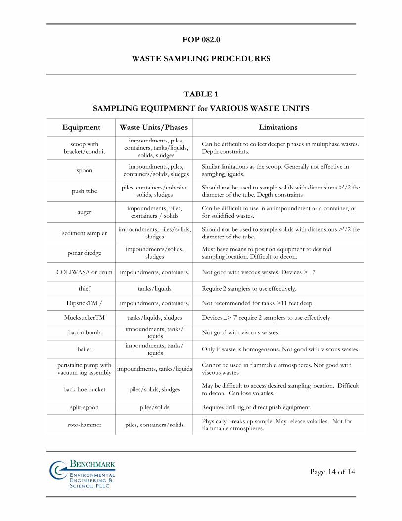
FOP 082.0
WASTE SAMPLING PROCEDURES
Page 14 of 14
TABLE 1
SAMPLING EQUIPMENT for VARIOUS WASTE UNITS
Equipment Waste Units/Phases Limitations
scoop with bracket/conduit
impoundments, piles, containers, tanks/liquids,
solids, sludges
Can be difficult to collect deeper phases in multiphase wastes. Depth constraints.
spoon impoundments, piles, containers/solids, sludges
Similar limitations as the scoop. Generally not effective in sampling liquids.
push tube piles, containers/cohesive solids, sludges
Should not be used to sample solids with dimensions >'/2 the diameter of the tube. Depth constraints
auger impoundments, piles, containers / solids
Can be difficult to use in an impoundment or a container, or for solidified wastes.
sediment sampler impoundments, piles/solids, sludges
Should not be used to sample solids with dimensions >'/2 the diameter of the tube.
ponar dredge impoundments/solids, sludges
Must have means to position equipment to desired sampling location. Difficult to decon.
COLIWASA or drum impoundments, containers, Not good with viscous wastes. Devices >_ 7'
thief tanks/liquids Require 2 samplers to use effectively.
DipstickTM / impoundments, containers, Not recommended for tanks >11 feet deep.
MucksuckerTM tanks/liquids, sludges Devices _> 7' require 2 samplers to use effectively
bacon bomb impoundments, tanks/ liquids Not good with viscous wastes.
bailer impoundments, tanks/ liquids Only if waste is homogeneous. Not good with viscous wastes
peristaltic pump with vacuum jug assembly impoundments, tanks/liquids Cannot be used in flammable atmospheres. Not good with
viscous wastes
back-hoe bucket piles/solids, sludges May be difficult to access desired sampling location. Difficult to decon. Can lose volatiles.
split-spoon piles/solids Requires drill rig or direct push equipment.
roto-hammer piles, containers/solids Physically breaks up sample. May release volatiles. Not for flammable atmospheres.

FIE
LD
OP
ER
AT
ING
PR
OC
ED
UR
ES
Active Subslab Depressurization Pre-
Design Testing Procedure
Bn v i ronme talng i neeri n gc ence,i
n
FOP 083.0
ACTIVE SUBSLAB DEPRESSURIZATION PRE-DESIGN
TESTING PROCEDURE
Page 1 of 3
Bn v i ronme talng i neeri n gc ence,i
n
BACKGROUND
The New York State Department of Health (NYSDOH) has published a draft document entitled “Guidance for Evaluating Soil Vapor Intrusion in the State of New York.” (www.health.state.ny.us/nysdoh/gas/svi_guidance/). As of February 2005, this document has been guiding NYSDOH and New York State Department of Environmental Conservation (NYSDEC) decisions concerning the need for subslab vapor mitigation at sites undergoing investigation, cleanup and monitoring under formal NY Sate remedial programs (e.g., Brownfield Cleanup Program sites, Inactive Hazardous Waste Site Remediation Program sites, etc.).
PURPOSE
This guideline presents a general description of the method for determining the number of extraction points, location and placement of these points, and the desirable sub-slab capture configuration. Extraction points are used to depressurize the subsoil in order to capture sub-slab vapors from the underlying sub-soil. This information can be used in evaluating the effectiveness of the final sub-slab depressurization and vapor capture designs.
BUILDING PREPARATION
Prior to performing the pre-design testing procedure, the building’s slab should be inspected for any cracks or deformations that may compromise the sub-slab vacuum seal. A pre-testing inspection should be performed for each test location. The inspection should evaluate the type of structure, floor layout, airflows and physical conditions of the building(s) being studied.
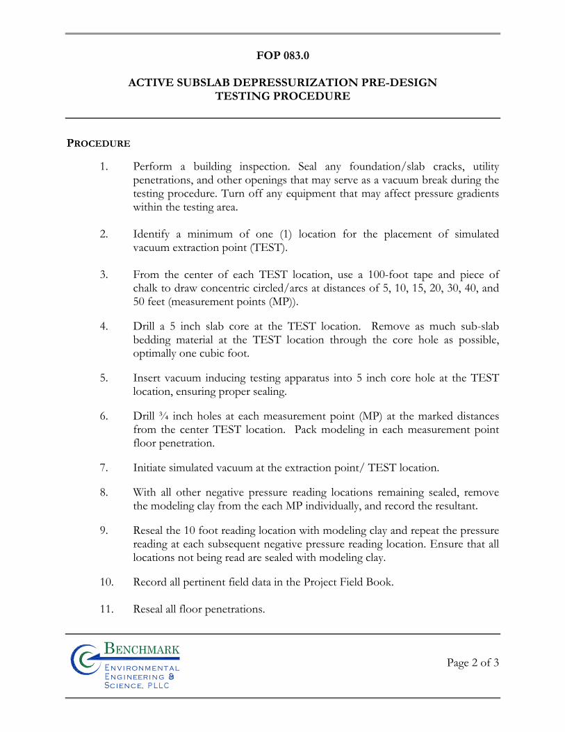
FOP 083.0
ACTIVE SUBSLAB DEPRESSURIZATION PRE-DESIGN
TESTING PROCEDURE
Page 2 of 3
Bn v i ronme talng i neeri n gc ence,i
n
PROCEDURE
1. Perform a building inspection. Seal any foundation/slab cracks, utility penetrations, and other openings that may serve as a vacuum break during the testing procedure. Turn off any equipment that may affect pressure gradients within the testing area.
2. Identify a minimum of one (1) location for the placement of simulated
vacuum extraction point (TEST). 3. From the center of each TEST location, use a 100-foot tape and piece of
chalk to draw concentric circled/arcs at distances of 5, 10, 15, 20, 30, 40, and 50 feet (measurement points (MP)).
4. Drill a 5 inch slab core at the TEST location. Remove as much sub-slab bedding material at the TEST location through the core hole as possible, optimally one cubic foot.
5. Insert vacuum inducing testing apparatus into 5 inch core hole at the TEST location, ensuring proper sealing.
6. Drill ¾ inch holes at each measurement point (MP) at the marked distances from the center TEST location. Pack modeling in each measurement point floor penetration.
7. Initiate simulated vacuum at the extraction point/ TEST location.
8. With all other negative pressure reading locations remaining sealed, remove the modeling clay from the each MP individually, and record the resultant.
9. Reseal the 10 foot reading location with modeling clay and repeat the pressure reading at each subsequent negative pressure reading location. Ensure that all locations not being read are sealed with modeling clay.
10. Record all pertinent field data in the Project Field Book. 11. Reseal all floor penetrations.
FOP 083.0
ACTIVE SUBSLAB DEPRESSURIZATION PRE-DESIGN
TESTING PROCEDURE
Page 3 of 3
Bn v i ronme talng i neeri n gc ence,i
n
REQUIRED EQUIPMENT
• Personal protective equipment (PPE) (if applicable) • 100 foot tape measure • Chalk • 4 ½ inch Husqvarna core drill • ¾ inch Hilti hammer drill • Sufficient modeling clay • Concrete sealant • Vacuum inducing apparatus (patent pending) • Micro-manometer • Camera • Cell phone • Field forms • Project Field Book
REFERENCES
New York State Department of Health, Guidance for Evaluating Soil Vapor Intrusion in the State of New York, February 2005.

FIE
LD
OP
ER
AT
ING
PR
OC
ED
UR
ES
Calibration & Maintenance of
Portable Particulate Meter
Bn v i ronme talng i neeri n gc ence,i
n
FOP 084.0
CALIBRATION AND MAINTENANCE OF PORTABLE
PARTICULATE METER
Page 1 of 8
Bn v i ronme talng i neeri n gc ence,i
n
PURPOSE
This guideline describes a method for calibration of a portable particulate meter, specifically
the Thermo Electron Corporation MIE DataRAM 4 (Model DR-4000). The DataRAM 4
measures the concentration of airborne particulate matter (liquid or solid), as well as mean
particle size, air temperature, and humidity, providing direct and continuous readout as well
as electronic recording of the information. This parameter is of interest both as a general
indicator of air quality, and because of its pertinence to community air monitoring typically
required at most construction/remediation/investigation sites. The DataRAM covers a wide
measurement range from 0.0001 mg/m3 to 400 mg/m3. With its large capacity internal data
logging capabilities with data retrieval on screen or downloaded, the DataRAM can store up
to 50,000 data points, including individual point averages, particle size, temperature, and
humidity with time stamp as well as overall average and maximum concentration.
Because the DataRAM meter must be factory calibrated once a year, this guideline presents a
method for start-up, operation, and maintenance, which is performed to verify instrument
function. All field instruments will be calibrated, verified and recalibrated at frequencies
required by their respective operating manuals or manufacturer’s specifications, but not less
than once each year. Field personnel should have access to all operating manuals for the
instruments used for the field measurements. This procedure also documents critical
maintenance activities for this meter. The user should reference the manufacturer’s
instruction manual prior to operating this unit.
ACCURACY & PRECISION
The calibrated accuracy of the DataRAM 4 particulate meter is within ± 2% of reading ±
precision over the temperature range of -4° to 158° F (-10° to 50° C) and 10 to 95% relative
humidity (non-condensing). The precision is ± 1% of reading or ± 0.001 mg/m3, whichever
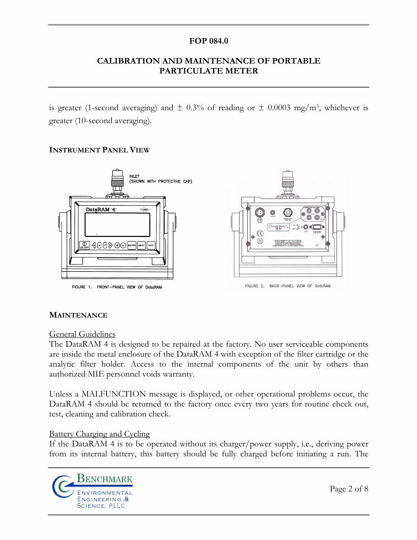
FOP 084.0
CALIBRATION AND MAINTENANCE OF PORTABLE
PARTICULATE METER
Page 2 of 8
Bn v i ronme talng i neeri n gc ence,i
n
is greater (1-second averaging) and ± 0.3% of reading or ± 0.0003 mg/m3, whichever is
greater (10-second averaging).
INSTRUMENT PANEL VIEW
MAINTENANCE
General Guidelines The DataRAM 4 is designed to be repaired at the factory. No user serviceable components are inside the metal enclosure of the DataRAM 4 with exception of the filter cartridge or the analytic filter holder. Access to the internal components of the unit by others than authorized MIE personnel voids warranty. Unless a MALFUNCTION message is displayed, or other operational problems occur, the DataRAM 4 should be returned to the factory once every two years for routine check out, test, cleaning and calibration check. Battery Charging and Cycling If the DataRAM 4 is to be operated without its charger/power supply, i.e., deriving power from its internal battery, this battery should be fully charged before initiating a run. The
FOP 084.0
CALIBRATION AND MAINTENANCE OF PORTABLE
PARTICULATE METER
Page 3 of 8
Bn v i ronme talng i neeri n gc ence,i
n
DataRAM 4 charger/power supply can be connected continuously to the instrument whether the DataRAM 4 is on or off. If the charger/power supply is not connected, the internal battery will discharge very slowly depending on storage temperature. Low storage temperature reduces battery capacity. High storage temperatures, however, reduce battery life which is of the order of 8 years at 20°C (68°F), and only 2 years at 40°C (104°F). In general, the user should maintain the battery charge as high as possible in order to extend its charge/discharge cycling capacity (this characteristic differs from that of nickel-cadmium batteries). Instrument Storage If the DataRAM 4 is to be stored for an extended period of time (i.e., 3 months or more), place the 3-position switch on the back panel in its OFF position (mid-position), in order to minimize gradual battery discharge. This will have no effect on data retention or internal clock function. It is recommended, however, that the battery be recharged every 3 months in order to prolong battery life. During storage always snap on quick-connect cap over the instrument inlet to protect the sensing optics from gradual dust contamination. Store DataRAM 4 in a dry environment. Filter Replacement To replace either of two types of filters used with DataRAM 4, place the instrument on its back rubber feet (front panel facing upward). On the bottom surface of the DataRAM, locate the large threaded plastic filter cover and holding the cross bar, rotate this cover counterclockwise. Remove cover and the filter holder within the open cavity.
HEPA Filter Cartridge Replacement The DataRAM 4 is shipped from the factory with the HEPA filter cartridge installed. This cartridge can be identified by its metallic cover. Remove this cartridge. Clean the internal black rubber gasket against which the cartridge is normally compressed. Install new HEPA-type cartridge (MIE part no. MSA-95302) by inserting its wider ridged end first. Reposition threaded plastic cover engaging threads carefully; rotate cover clockwise, hand tightening firmly. Properly dispose of used cartridge to prevent inadvertent re-use.
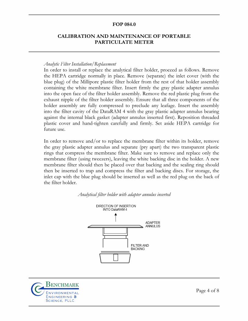
FOP 084.0
CALIBRATION AND MAINTENANCE OF PORTABLE
PARTICULATE METER
Page 4 of 8
Bn v i ronme talng i neeri n gc ence,i
n
Analytic Filter Installation/Replacement In order to install or replace the analytical filter holder, proceed as follows. Remove the HEPA cartridge normally in place. Remove (separate) the inlet cover (with the blue plug) of the Millipore plastic filter holder from the rest of that holder assembly containing the white membrane filter. Insert firmly the gray plastic adapter annulus into the open face of the filter holder assembly. Remove the red plastic plug from the exhaust nipple of the filter holder assembly. Ensure that all three components of the holder assembly are fully compressed to preclude any leafage. Insert the assembly into the filter cavity of the DataRAM 4 with the gray plastic adapter annulus bearing against the internal black gasket (adapter annulus inserted first). Reposition threaded plastic cover and hand-tighten carefully and firmly. Set aside HEPA cartridge for future use. In order to remove and/or to replace the membrane filter within its holder, remove the gray plastic adapter annulus and separate (pry apart) the two transparent plastic rings that compress the membrane filter. Make sure to remove and replace only the membrane filter (using tweezers), leaving the white backing disc in the holder. A new membrane filter should then be placed over that backing and the sealing ring should then be inserted to trap and compress the filter and backing discs. For storage, the inlet cap with the blue plug should be inserted as well as the red plug on the back of the filter holder.
Analytical filter holder with adapter annulus inserted
FOP 084.0
CALIBRATION AND MAINTENANCE OF PORTABLE
PARTICULATE METER
Page 5 of 8
Bn v i ronme talng i neeri n gc ence,i
n
Cleaning of Optical Sensing Chamber Although the DataRAM 4 incorporates filtered air shielding of the critical optical sensing surfaces, continued sampling of airborne particles at high concentrations may result in gradual build-up of contamination on those interior surfaces of the sensing chamber components. This may cause an excessively high optical background level. If this background level does becomes excessive, the DataRAM 4 will alert the user at the completion of the zeroing sequence by the display of a BACKGROUND HIGH message. If this message is presented, the DataRAM 4 can continue to be operated providing accurate measurements. However, it is then advisable to clean the front surfaces of the optical lenses within the sensing chamber at the first convenient opportunity, as described below. The tools required for this cleaning are: an intense concentrated light source (e.g., flash light) to view the inside of the sensing chamber, denatured alcohol, a soft lint-free cloth, and the special cleaning tool provided with the DataRAM 4 consisting of a cut-off cotton swab inserted in a plastic sleeve and held by a right-angle Allen wrench. Proceed as follows to clean the lens surfaces within the sensing chamber:
• Make sure to shut off power completely before proceeding with cleaning • Install the stainless steel cover on the inlet of the DataRAM 4 to protect this fitting. • Place the DataRAM 4 upside down on a table, resting the instrument on the inlet
cover and the rear protective bumper. • Unscrew the gray plastic cover of the filter cavity on the bottom surface of the
DataRAM 4. • Remove the filter cartridge from its cavity. • Carefully clean the black soft filter-sealing gasket within the filter cavity by wiping it
with the lint-free soft cloth. Use alcohol if necessary. • Shine the concentrated light source into the sensing chamber located about 3 cm (1¼
in.) beyond the soft-sealing gasket in the filter cavity. • Locate the three smaller side cavities inside the sensing chamber, identified by the
arrows on that figure (see page 6). These three cavities contain the lenses of the two sources and the common detector of the DataRAM 4. The frontal surfaces of these lenses are likely to require cleaning if the instrument indicates BACKGROUND HIGH.
• Wet the cotton swab of the lens-cleaning tool with alcohol (e.g., methanol, ethanol, or rubbing alcohol).
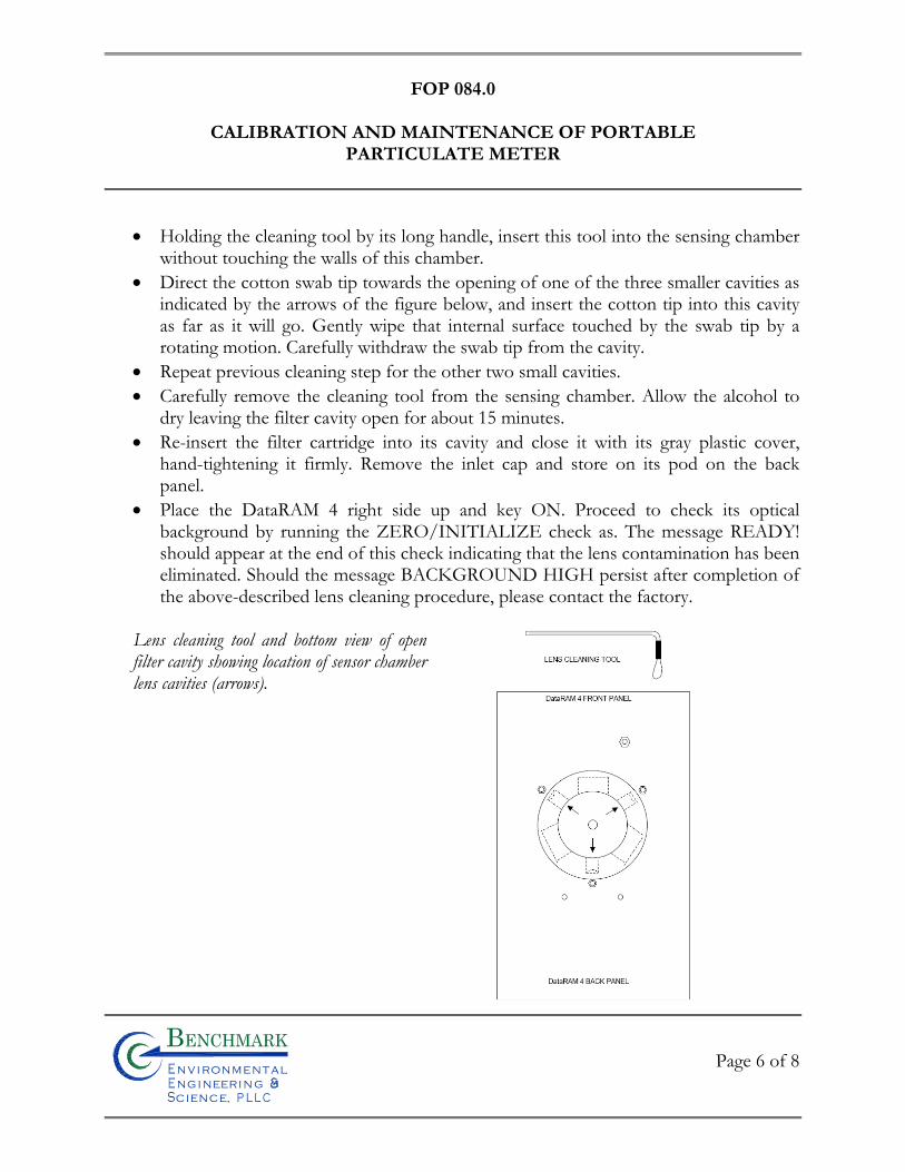
FOP 084.0
CALIBRATION AND MAINTENANCE OF PORTABLE
PARTICULATE METER
Page 6 of 8
Bn v i ronme talng i neeri n gc ence,i
n
• Holding the cleaning tool by its long handle, insert this tool into the sensing chamber without touching the walls of this chamber.
• Direct the cotton swab tip towards the opening of one of the three smaller cavities as indicated by the arrows of the figure below, and insert the cotton tip into this cavity as far as it will go. Gently wipe that internal surface touched by the swab tip by a rotating motion. Carefully withdraw the swab tip from the cavity.
• Repeat previous cleaning step for the other two small cavities. • Carefully remove the cleaning tool from the sensing chamber. Allow the alcohol to
dry leaving the filter cavity open for about 15 minutes. • Re-insert the filter cartridge into its cavity and close it with its gray plastic cover,
hand-tightening it firmly. Remove the inlet cap and store on its pod on the back panel.
• Place the DataRAM 4 right side up and key ON. Proceed to check its optical background by running the ZERO/INITIALIZE check as. The message READY! should appear at the end of this check indicating that the lens contamination has been eliminated. Should the message BACKGROUND HIGH persist after completion of the above-described lens cleaning procedure, please contact the factory.
Lens cleaning tool and bottom view of open filter cavity showing location of sensor chamber lens cavities (arrows).
FOP 084.0
CALIBRATION AND MAINTENANCE OF PORTABLE
PARTICULATE METER
Page 7 of 8
Bn v i ronme talng i neeri n gc ence,i
n
FACTORY CALIBRATION
For mass concentration measurements, each DataRAM 4 is factory calibrated against a set of
reference monitors that, in turn, are periodically calibrated against a gravimetric standard
traceable to the National Institute of Standards and Testing (NIST).
The primary factory reference method consists of generating a dust aerosol by means of a
fluidized bed generator, and injecting continuously the dust into a mixing chamber from
which samples are extracted concurrently by two reference filter collectors and by two
master real-time monitors that are used for the routine calibration of every DataRAM 4.
The primary dust concentration reference value is obtained from the weight increase of the
two filters due to the dust collected over a measured period of time, at a constant and known
flow rate. The two master real-time monitors are then adjusted to agree with the reference
mass concentration value (obtained from averaging the measurements of the two gravimetric
filters) to within ±1%.
Three primary, NIST traceable, measurements are involved in the determination of the
reference mass concentration: the weight increment from the dust collected on the filter, the
sampling flow rate, and the sampling time. Additional conditions that must be met are: a)
suspended dust concentration uniformity at all sampling inlets of the mixing chamber; b)
identical sample transport configurations leading to reference and instrument under
calibration; and c) essentially 100% collection efficiency of filters used for gravimetric
reference for the particle size range of the test dust.
FOP 084.0
CALIBRATION AND MAINTENANCE OF PORTABLE
PARTICULATE METER
Page 8 of 8
Bn v i ronme talng i neeri n gc ence,i
n
The test dust used for the MIE factory calibration of the DataRAM 4 is SAE Fine (ISO
Fine) supplied by Powder Technology, Inc. It has the following physical characteristics (as
dispersed into the mixing chamber):
• Mass median aerodynamic particle diameter: 2 to 3 μm • Geometric standard deviation of lognormal size distribution: 2.5 • Bulk density: 2.60 to 2.65 g/cm3 • Refractive index: 1.54
In addition to the mass calibration described above, the DataRAM 4 is factory calibrated
using a gas with known scattering coefficient in order to adjust the relative scattering
irradiance at the two source wavelengths.
ATTACHMENTS
None

FIE
LD
OP
ER
AT
ING
PR
OC
ED
UR
ES
Field Quality Control Procedures
Bn v i ronme talng i neeri n gc ence,i
n
FOP 085.0
FIELD QUALITY CONTROL PROCEDURES
Page 1 of 3
Bn v i ronme talng i neeri n gc ence,i
n
PURPOSE
In addition to traditional environmental samples (e.g., soil, groundwater, wipe, vapor etc.)
described in each project work plan, site-specific field quality assurance/quality control
(QA/QC) samples are typically collected and analyzed to support the required third-party
data usability assessment effort of a project. Site-specific QA/QC samples generally include
matrix spikes, matrix spike duplicates, blind duplicates (where appropriate), and trip blanks
which accompany aqueous volatile organic compound (VOC) samples only.
The number of QA/QC field samples (blind duplicate, matrix spike/matrix spike duplicate,
trip blank, field blank, or equipment blank) will be designated prior to field mobilization, but
final QC sample locations will be contingent upon field conditions. This procedure outlines
and discusses each QA/QC sample that may be required during a project.
PROCEDURE
A brief summary of each QA/QC sample identified above is presented below. Where
appropriate, the procedure to be used to collect these samples is also presented.
• Trip Blanks – A sufficient number of trip blanks for VOC analysis must be prepared by the laboratory and delivered to the sampling team prior to a sampling event, typically two or three 40-ml VOA vials with organic free reagent water. One sealed blank will be carried into the field per day along with the sample containers for each day that water matrix volatile organic samples are collected. Trip blanks will be transported and handled in the same manner as the actual samples. The results of the trip blank analysis will be reviewed to evaluate if the potential for sample contamination during transportation and handling exists. The trip blanks will be analyzed for the same VOCs (and method) as the project groundwater samples.
• Blind Duplicate – One blind duplicate must be collected and analyzed per 20 samples collected per matrix (i.e., soil, groundwater, soil vapor, etc.). The location
FOP 085.0
FIELD QUALITY CONTROL PROCEDURES
Page 2 of 3
Bn v i ronme talng i neeri n gc ence,i
n
of the sample collection point will not be disclosed to the analytical laboratory, therefore the field sample containers will be returned to the laboratory identified only as the “blind duplicate.” The well or sample location will be recorded in the Project Field Book or handheld RuggedReader® Pocket PC and on the field data sheets, and the results will be compared to review analytical precision. Sample analysis will be identical to the original sample per the project work plan. The Blind Duplicate sample must be collected simultaneously from the same source under identical conditions as the original sample.
• Matrix Spike/Matrix Spike Duplicate (MS/MSD) – A sufficient volume of sample will be collected at one sampling location per sampling event for MS/MSD analysis per matrix (i.e., soil and groundwater only). The laboratory will report the results of the MS/MSD analysis, which will be reviewed for sampling and analysis precision and accuracy. Sample analysis will be identical to the original sample per the project work plan. The MS/MSD sample must be collected simultaneously from the same source under identical conditions as the original sample.
• Equipment (Rinsate) Blank – In general, dedicated sampling equipment is used to minimize field decontamination time and avoid the need for equipment blanks; however there may be instances where the use of non-dedicated equipment cannot be avoided. An equipment blank will be collected for each day of sampling activity when non-dedicated sampling equipment is used. These equipment blank samples will be used as a QC check of the decontamination procedures for sampling equipment. Sample analysis for the equipment blank will consist of the most comprehensive parameter list used for risk assessment in which the non-dedicated equipment was used for environmental sample collection. During most projects, every effort to use dedicated sampling equipment should be made in order to minimize field decontamination time and avoid the need for equipment blanks. Equipment Blank sampling procedure is as follows:
o Non-dedicated equipment are to be decontaminated in accordance with Benchmark’s Non-disposable and Non-dedicated Sampling Equipment Decontamination procedures prior to use in the field. If organic-free
FOP 085.0
FIELD QUALITY CONTROL PROCEDURES
Page 3 of 3
Bn v i ronme talng i neeri n gc ence,i
n
deionized water (generally provided by the laboratory) is not available for decontamination, equipment will be allowed to thoroughly air dry.
o Once properly rinsed or allowed to air dry, analyte-free water (provided by the laboratory) is poured appropriately over or through the decontaminated sample collection device, collected in a sample container, and returned to the laboratory as a sample.
• Field Blank – A field blank is a sample of the unused final decontamination rinse water that is collected at the sampling site and returned to the laboratory as a sample. Sample analysis for the field blank will consist of the most comprehensive parameter list used during the investigation.
• Split Sample – A split sample is a sample that has been portioned into two or more containers from a single sample container or sample mixing container. Samples for VOC analysis should never be mixed prior to splitting.
• Blank Wipe Samples – There are two types of blank wipe samples, an equipment blank and a field blank that may be required per the project work plan, both are described below:
o Equipment Blank – Required only if reusable templates are used for wipe sample collection. The decontaminated template is wiped with a hexane saturated swab. The swab is placed in the appropriate sample container and returned to the laboratory as a sample.
o Field Blank – Clean disposable gloves are wiped with a hexane saturated swab. The swab is placed in the appropriate sample container and returned to the laboratory as a sample.
REFERENCES
Benchmark FOPs: 040 Non-disposable and Non-dedicated Sampling Equipment Decontamination
FIE
LD
OP
ER
AT
ING
PR
OC
ED
UR
ES
SVE System Sample Collection Procedure
FOP 089.0
SVE SYSTEM SAMPLE
COLLECTION PROCEDURE
Page 1 of 6
Bn v i ronme talng i neeri n gc ence,i
n
PURPOSE
Soil vapor extraction (SVE), also known as “soil venting” or “vacuum extraction”, is an in-
situ remedial technology that reduces concentrations of volatile constituents in petroleum
products adsorbed to the soils in the unsaturated (vadose) zone. In this technology, a
vacuum is applied through vertical and/or horizontal SVE wells near the source of
contamination in the soil, typically with a blower. Volatile constituents of the contaminant
mass “evaporate” and the vapors are drawn through the extraction wells. This procedure
describes the general methods for collecting extracted vapor samples from an SVE system
using a Tedlar® bag or Summa Canister.
REQUIRED EQUIPMENT
Personal protective equipment (PPE) (if applicable) New Teflon® or equivalent tubing Sample collection vessel (Tedlar® bag, Summa Canister, or equivalent) Vacuum Box (Required for sampling against negative pressure) Project field book
TEDLAR® BAG SAMPLING
Tedlar® bag sampling allows for the collection of a representative grab sample of a gaseous
media for analysis.
1. Prepare sampling equipment for use while wearing appropriate protective gear (i.e., nitrile gloves, safety glasses).
FOP 089.0
SVE SYSTEM SAMPLE
COLLECTION PROCEDURE
Page 2 of 6
Bn v i ronme talng i neeri n gc ence,i
n
2. Pre-label all sample container labels in the field using a waterproof permanent marker in accordance with the Benchmark Sample Labeling, Storage and Shipment FOP. The following information, at a minimum, should be included on the label:
Project number; Sample identification code (as per project specifications); Date of sample collection (mm, dd, yy); Time of sample collection (military time only) (hh:mm); Specify “grab” or “composite” sample type; Sampler initials; Preservative(s) (if applicable); and Analytes for analysis (if practicable).
3. Collect air sample. Sample ports for air samples may be located in areas of the SVE
system under positive or negative pressure and the sampling method will vary accordingly.
Positive Pressure
A piece of new Teflon® tubing is fitted to the SVE system sampling port and purged by slowly opening the valve on the SVE system sampling port.
Attach the Teflon® tubing to the Tedlar® bag.
Open the plastic valve on the Tedlar® bag slowly and fill the bag no more than 2/3 full. If the bags will be shipped to an analytical laboratory via air transportation, the Tedlar® bag should be only half full. Unpressurized air planes could result in full bags bursting and loss of sample.
Close the Tedlar® bag valve, then sample port valve, and disconnect the bag.
Negative Pressure
A piece of new Teflon® tubing is fitted to the SVE system sampling port and the Tedlar® bag.
Open the plastic valve on the Tedlar® bag.
Place the Tedlar® bag in an air tight vacuum box with the tubing protruding from the chamber.
FOP 089.0
SVE SYSTEM SAMPLE
COLLECTION PROCEDURE
Page 3 of 6
Bn v i ronme talng i neeri n gc ence,i
n
Connect a pump to the evacuation tube on the vacuum box.
Open the valve on the sampling port.
Turn on the pump and evacuate the chamber allowing the Tedlar® bag to expand and draw a sample into the bag through the protruding tube.
Allow the Tedlar® bag to fill no more than 2/3 full, close the sampling port, turn off the pump, and open the vacuum box and close the plastic valve on the Tedlar® bag.
4. Record all pertinent sample collection information in the Project Field Book.
5. If collected for field screening, screen the sample and record the results.
6. If collected for laboratory analysis, return the sample to the provided box or cooler, and submit samples to the laboratory under chain-of-custody command.
SUMMA CANISTER
1. Prepare sampling equipment for use while wearing appropriate protective gear (i.e., latex gloves, safety glasses).
2. Canisters will be pre-cleaned and supplied by the laboratory that will be conducting the analysis.
3. The number of Summa canisters required as well as the flow rate of the constant
differential low volume flow controllers will be supplied by the laboratory in accordance with the project work plan.
4. Label the canisters prior to sample collection.
5. Connect the Teflon® tubing to the sample port and purge by opening the valve on
the sample port.
6. Record the initial canister vacuum with the laboratory-supplied pressure gauge.
FOP 089.0
SVE SYSTEM SAMPLE
COLLECTION PROCEDURE
Page 4 of 6
Bn v i ronme talng i neeri n gc ence,i
n
7. Connect the tubing to the Summa canister.
8. Open the valve of the canister for the required collection period.
9. Following sample collection, close and cap each canister valve.
10. Record the canister vacuum following sample collection with the laboratory-supplied pressure gauge.
11. Record all pertinent field data in the Project Field Book.
12. Label, store, and ship the samples in accordance with the Benchmark Field Operating Procedure for Sample Labeling, Storage and Shipment Procedures
REFERENCES
Benchmark FOPs: 046 Sample Labeling, Storage and Shipment Procedures
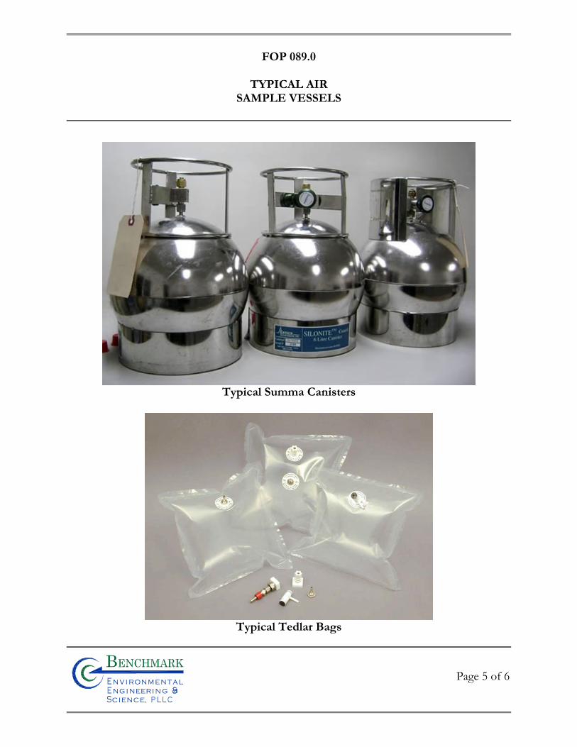
FOP 089.0
TYPICAL AIR
SAMPLE VESSELS
Page 5 of 6
Bn v i ronme talng i neeri n gc ence,i
n
Typical Summa Canisters
Typical Tedlar Bags
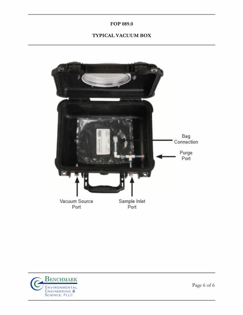
FOP 089.0
TYPICAL VACUUM BOX
Page 6 of 6
Bn v i ronme talng i neeri n gc ence,i
n

FIE
LD
OP
ER
AT
ING
PR
OC
ED
UR
ES
Outdoor Ambient Air VOC Sample
Collection Procedure
FOP 090.0
OUTDOOR AMBIENT AIR VOC SAMPLE COLLECTION PROCEDURE
Page 1 of 5
Bn v i ronme talng i neeri n gc ence,i
n
PURPOSE
This procedure describes the methods for collecting outdoor ambient air samples for volatile
organic compound (VOC) analysis via USEPA Method TO-15 using Summa® canisters (or
approved other). Typically, outdoor air samples are collected to characterize and document
site-specific VOCs that may be present in outdoor ambient air. For sample collection
associated with intrusive activities that may potentially release VOCs to the ambient air,
sample location(s) typically are collected downwind of the intrusive activity at the perimeter
of the work area and/or exclusion zone for the Site. Upwind sample location(s) may be
utilized if regional facilities (e.g. gasoline service station, factories) are located proximate to
the Site to assess off-site ambient VOC contributions (background).
SAMPLE COLLECTION PROCEDURES
The following actions should be taken to document conditions during outdoor air sampling
and ultimately to aid in the interpretation of the analytical results:
A site map should be prepared to indicate the outdoor ambient air sample locations including all site improvements (e.g., buildings, access roads, etc.), public roads/streets (if applicable), the location of potential VOC contributors (e.g., gasoline stations, factories, lawn movers, etc.), compass orientation (north), and scale.
Weather conditions (e.g., precipitation, wind speed, outdoor temperature, and
barometric pressure) should be reported on the Air Canister Field Record (sample attached); and
Any pertinent observations, such as odors, readings from field instrumentation,
and significant activities in the vicinity (e.g., operation of heavy equipment or dry cleaners) should be recorded.
FOP 090.0
OUTDOOR AMBIENT AIR VOC SAMPLE COLLECTION PROCEDURE
Page 2 of 5
Bn v i ronme talng i neeri n gc ence,i
n
The following describes the outdoor air sampling procedure:
1. Typically, a 6-liter, passivated (inert), stainless steel, evacuated sampling sphere (e.g., Summa canister) (or approved other) will be supplied by the laboratory that will be conducting the analysis. The canister should be received from the laboratory, certified clean, evacuated, and prepared for sampling.
2. Sampling will take place in accordance with the project work plan. Selected
sample locations will be sufficiently spaced to allow location(s) to be field modified, if necessary.
3. The number of Summa canisters required as well as the flow rate of the
constant differential low volume flow controllers will be supplied by the laboratory in accordance with the project work plan.
4. Prior to placement, complete an Air Canister Field Record (sample attached) of each canister, which includes: project information, field staff, weather conditions, canister serial number, flow controller number, sample date(s)/time(s), shipping date(s), canister lab vacuum, field vacuum check, initial field vacuum, final field vacuum, and duration of sample collection.
5. The pressure in the canisters must be monitored with the laboratory provided pressure gauge at the beginning and the end of the sampling period as well as before and after shipment of the canisters at the laboratory. The target final field vacuum must be approximately 5 inches of mercury. Samples with a final field vacuum of greater than 10 inches of mercury, or equal to zero, will be flagged and usability of the data will depend on the sample volume and reporting limits that can be achieved.
6. Canisters may be placed on the ground provided there is a clear plastic sheet beneath it to prevent cross contamination. The intake tubing, however, must be positioned at a height of approximately 3 to 5-feet above grade to collect air at an elevation representative of ambient air within the breathing zone. Typically, the canister is chained and locked to a secure step ladder with the intake tubing tethered to the ladder.
FOP 090.0
OUTDOOR AMBIENT AIR VOC SAMPLE COLLECTION PROCEDURE
Page 3 of 5
Bn v i ronme talng i neeri n gc ence,i
n
7. Ship the canisters to the laboratory under chain-of-custody command within
three days of sample collection so that no sample will exceed the 30-day holding time (since receipt from the lab) per USEPA TO-15.
8. Air samples will be analyzed by Gas Chromatography/Mass Spectroscopy (GC/MS) in accordance with EPA Method TO-15, or as specified. Analytical results will be reported as concentrations of each VOC at each location during each sampling event, typically in parts per billion by volume (ppbv).
9. Sample collection should take place on warm, dry days. If rain or high humidity conditions develop during sampling, the sampling event should be suspended. Temperature, barometric pressure, and wind speed should be monitored during the sampling event, for use in analysis of the results. The combination of sampling location, height, and meteorological conditions will assure that sampling will measure VOCs at their highest concentrations.
QUALITY ASSURANCE / QUALITY CONTROL (QA/QC)
Extreme care should be taken during all aspects of sample collection to ensure that sampling
error is minimized and high quality data are obtained. The sampling team members should
avoid actions (e.g., fueling vehicles, using permanent marking pens, and wearing freshly dry-
cleaned clothing or personal fragrances), which can cause sample interference in the field.
Appropriate QA/QC protocols must be followed for sample collection and laboratory
analysis, such as use of certified clean sample devices, meeting sample holding times and
temperatures, sample accession, chain of custody, etc. Samples should be delivered to the
analytical laboratory as soon as possible after collection. In addition, laboratory accession
procedures must be followed including field documentation (sample collection information
and locations), chain of custody, field blanks, field sample duplicates, and laboratory
duplicates, as appropriate.
FOP 090.0
OUTDOOR AMBIENT AIR VOC SAMPLE COLLECTION PROCEDURE
Page 4 of 5
Bn v i ronme talng i neeri n gc ence,i
n
Some methods require collecting samples in duplicate to assess errors. Duplicate and/or split
samples should be collected in accordance with the requirements of the sampling and
analytical methods being implemented.
For certain regulatory programs, a Data Usability Summary Report (DUSR) may be required
to determine whether or not the data, as presented, meets the site or project specific criteria
for data quality and data use. This requirement may dictate the level of QC and the category
of data deliverable to request from the laboratory. Guidance on preparing a DUSR is
available by contacting the NYSDEC's Division of Environmental Remediation.
New York State Public Health Law requires laboratories analyzing environmental samples
collected from within New York State to have current Environmental Laboratory Approval
Program (ELAP) certification for the appropriate analyte and environmental matrix
combinations. If ELAP certification is not currently required for an analyte (e.g.,
trichloroethene); then the analysis should be performed by a laboratory that has ELAP
certification for similar compounds in air and uses analytical methods with detection limits
similar to background (e.g., tetrachloroethene via EPA Method TO-15).
ATTACHMENTS
Air Canister Field Record (sample)
REFERENCES
United States Environmental Protection Agency. Compendium of Methods for the
Determination of Toxic Organic Compounds in Ambient Air. Second Addition (EPA/625/R-
96/010b). January 1999.
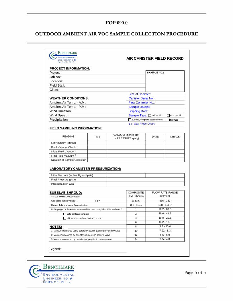
FOP 090.0
OUTDOOR AMBIENT AIR VOC SAMPLE COLLECTION PROCEDURE
Page 5 of 5
Bn v i ronme talng i neeri n gc ence,i
n
AIR CANISTER FIELD RECORD
PROJECT INFORMATION:
Project: SAMPLE I.D.:
Job No:
Location:
Field Staff:
Client:
Size of Canister:
WEATHER CONDITIONS: Canister Serial No.:
Ambient Air Temp. - A.M.: Flow Controller No.:
Ambient Air Temp. - P.M.: Sample Date(s):
Wind Direction: Shipping Date:
Wind Speed: Sample Type:
Precipitation:
Soil Gas Probe Depth:
FIELD SAMPLING INFORMATION:
TIME DATE INITIALS
Lab Vacuum (on tag)
Field Vacuum Check 1
Initial Field Vacuum 2
Final Field Vacuum 3
Duration of Sample Collection
LABORATORY CANISTER PRESSURIZATION:
Initial Vacuum (inches Hg and psia)
Final Pressure (psia)
Pressurization Gas
SUBSLAB SHROUD:Shroud Helium Concentration:
Calculated tubing volume: x 3 = 15 Min.
Purged Tubing Volume Concentration: 0.5 Hours
Is the purged volume concentration less than or equal to 10% in shroud? 1
2
4
6
NOTES: 8
1 Vacuum measured using portable vacuum gauge (provided by Lab) 10
2 Vacuum measured by canister gauge upon opening valve 12
3 Vacuum measured by canister gauge prior to closing valve 24
Signed:
READING
79.2 - 83.3
VACUUM (inches Hg)
or PRESSURE (psig)
316 - 333
158 - 166.7
7.92 - 8.3
6.6 - 6.9
3.5 - 4.0
39.6 - 41.7
19.8 - 20.8
13.2 - 13.9
9.9 - 10.4
COMPOSITE
TIME (hours)
FLOW RATE RANGE
(ml/min)
Bn v i ronme t alng i neeri n gc ence,i
n
Indoor Air Outdoor Air
Subslab, complete section below Soil Gas
YES, continue sampling
NO, improve surface seal and retest
Soil Gas

SMP – APPENDIX B: EXCAVATION WORK PLAN 229 HOMER STREET SITE
BCP SITE NO. C905044
0311-018-001 T KB
APPENDIX G
QUALITY ASSURANCE PROJECT PLAN

Bn v i ronme talng i neeri n gc ence,i
n
QUALITY ASSURANCE PROJECT PLAN
229 HOMER STREET SITE OLEAN, NEW YORK
BCP SITE NOS. C905044
August 2018 0311-018-001
Prepared for:
Homer Street Properties, LLC
Prepared By:
2558 Hamburg Turnpike, Suite 300
Buffalo, NY 14218
(716)856-0635
Bn v i ronme t alng i neeri n gc ence,i
n
QUALITY ASSURANCE PROJECT PLAN (QAPP)
229 Homer Street Site
Table of Contents
0311-018-001
i
1.0 INTRODUCTION ...................................................................................................... 1 1.1 Site Location and Description ......................................................................................1 1.2 Site Environmental History..........................................................................................1 1.3 Scope of the QAPP ......................................................................................................1
2.0 PROJECT ORGANIZATION AND RESPONSIBILITY .................................................. 5 2.1 NYSDEC and NYSDOH .............................................................................................5 2.2 Property Owner ............................................................................................................5 2.3 Project Manager ...........................................................................................................5 2.4 Field Team Leader: ......................................................................................................6 2.5 Quality Assurance (QA) Officer ..................................................................................7 2.6 Laboratory Responsibilities .........................................................................................7
3.0 QUALITY ASSURANCE OBJECTIVES FOR MEASUREMENT DATA ........................... 9 3.1 Level of QC Effort for Sample Parameters ..................................................................9
4.0 SAMPLE CUSTODY PROCEDURES .......................................................................... 11 4.1 Field Custody Procedures ..........................................................................................11
4.1.1 Sample Storage ............................................................................................................................... 11 4.1.2 Sample Custody .............................................................................................................................. 11 4.1.3 Sample Tracking ............................................................................................................................. 13
5.0 CALIBRATION PROCEDURES AND FREQUENCY ................................................... 14 5.1 Field Instrument Calibration ......................................................................................14 5.2 Preventative Maintenance ..........................................................................................14
6.0 DATA VALIDATION AND REPORTING ................................................................... 15 6.1 Data Usability Evaluation ..........................................................................................15
6.1.1 Procedures Used to Evaluate Field Data Usability ......................................................................... 15 6.1.2 Procedures Used to Evaluate Laboratory Data Usability ................................................................ 15
6.2 Data Reporting ...........................................................................................................16 6.2.1 Field Data Reporting ...................................................................................................................... 16 6.2.2 Laboratory Data Reporting ............................................................................................................. 16
7.0 CORRECTIVE ACTION ........................................................................................... 17 7.1 Field Corrective Action ..............................................................................................17 7.2 Laboratory Corrective Action ....................................................................................18 7.3 Data Validation & Assessment Corrective Action ....................................................18
Bn v i ronme t alng i neeri n gc ence,i
n
QUALITY ASSURANCE PROJECT PLAN (QAPP)
229 Homer Street Site
Table of Contents
0311-018-001
ii
LIST OF TABLES
Table 1 Sample Container, Volume, Preservative, and Holding Time Requirements
Bn v i ronme t alng i neeri n gc ence,i
n
SMP - QAPP FOR BCP ACTIVITIES 229 HOMER STREET SITE
0311-018-001
1
1.0 INTRODUCTION This Quality Assurance Project Plan (QAPP) is an appendix to the Site Management
Plan (SMP), which is required as an element of the remedial program at the 229 Homer Street
Site under the New York State (NYS) Brownfield Cleanup Program (BCP), administered by
New York State Department of Environmental Conservation (NYSDEC). The sites were
remediated in accordance with Brownfield Cleanup Agreements (BCA) Index # C905044-09,
Site C905044 which was executed in October 2015.
1.1 Site Location and Description
The Site is 3.34 acres located in the City of Olean, County of Cattaraugus, New York
and is located at 229 Homer Street Olean, New York 14760 SBL (94.032-1-2.5.) There is one
7,500 sf building on the Site. The Site is bound by Two Mile Creek and Homer Street to the
northwest, a Casella Waste Management of New York transfer station to the northeast,
Southern Tier Rail Authority rail lines to the southeast, and 251 Homer Street (a vacant parcel
mediated under the NYSDEC BCP and being redeveloped as a solar power generation facility)
to the southwest. The surface of the Site is covered with a building, concrete, and gravel. Two
Mile Creek flows off-site along the northwestern property boundary. A drainage swale is
present on the southeastern portion of the Site.
The boundaries of the site are more fully described in the Environmental Easement.
1.2 Site Environmental History
The Site and surrounding area was originally developed in approximately 1880 for the
oil industry and used for refinery purposes and as a petroleum storage tank farm. The Site is
located within the limits of the Exxon/Mobil Legacy Site (EMLS) Works #3 area. The EMLS
operated as an oil refinery under several different names from approximately 1880 to 1950s.
The Site is located within the EMLS Works #3 area where oil refining historically took place;
based on historical aerial photographs, the area of the Site appears to be primarily an oil storage
area.
• The Site historically contained aboveground storage tanks (ASTs) and berm
areas similar to the adjacent 251 Homer Street. Based on historic petroleum storage/refinery
Bn v i ronme t alng i neeri n gc ence,i
n
SMP - QAPP FOR BCP ACTIVITIES 229 HOMER STREET SITE
0311-018-001
2
use of 229 Homer Street, which was once part of the greater refinery, it is likely that similar
subsurface conditions exist at 229 Homer Street that were identified at 251 Homer Street.
SOILS
Surface Soil/Fill Results1
The surface soil/fill (0-2”) and near-surface soils (2-12”) are impacted by arsenic at
concentrations exceeding the commercial soil cleanup objectives (CSCOs) at multiple
locations across the site. No other compounds were detected above the CSCOs.
Subsurface Soil/Fill Results
Subsurface soil/fills are impacted by arsenic and polynuclear aromatic hydrocarbons
(PAHs) at concentrations exceeding the CSCOs. The subsurface soil/fills are impacted by
petroleum products which meets the definition of grossly contaminated soil (GCS). The GCS
was identified based on strong petroleum-like odors, sheen/floating product and elevated
photoionization detector readings (PID) in subsurface soil/fills in across nearly two thirds of
the site area as indicated by the pink outline shown on Figure 4. GCS was generally found at
depths ranging from approximately 5 to 15 feet below ground surface (fbgs).
UNDERGROUND PIPING
Underground piping presumably containing petroleum products associated with the
former EMLS works was encountered in several test pits and trenches as depicted on Figure
4. The majority of the piping was found on the southern and eastern portions of the Site;
however, additional piping was found on the northern portion of the Site. Pipe diameters
ranged between 2 and 12 inches with the majority between 4 and 6 inches.
GROUNDWATER
VOCs and SVOCs were predominantly reported as non-detect, trace (estimated), or
detected at concentrations below New York State Groundwater Quality Standards and
Guidance Values (GWQS/GVs). Only benzene in monitoring well MW-4 and
1 The surface soil results were complemented by collecting surface soil samples and near-surface soil samples in
August 2017.
Bn v i ronme t alng i neeri n gc ence,i
n
SMP - QAPP FOR BCP ACTIVITIES 229 HOMER STREET SITE
0311-018-001
3
pentachlorophenol in well MW-3 were detected above GWQS/GVs. Gasoline range organics
(GROs) were present in all wells with the highest concentrations detected in MW-2 and the
blind duplicate for MW-3. Diesel range organics (DROs) were present in all wells with the
highest concentration detected in MW-2.
Total and dissolved metals detected at concentrations above GWQS/GVs include
naturally occurring minerals such as iron, manganese, magnesium, and sodium. Additionally,
total arsenic and total lead were detected slightly above GWQS/GV in MW-1, MW-2, MW-4,
and MW-5; however, dissolved arsenic and lead concentrations were not detected. Total
barium and total chromium slightly exceeded GWQS/GVs at MW-2. Dissolved barium also
slightly exceeded GWQS/GVs at MW-5.
Herbicides and PCBs were reported as non-detect. Estimated low-level concentrations
of one or more pesticides were identified in MW-1 through MW-5 at concentrations
potentially above GWQS/GVs.
The visual and olfactory evidence of impact observed in the groundwater monitoring
wells is likely associated with the subsurface piping and GCS present across the Site. Removal
of these sources during planned remedial activities will mitigate these groundwater impacts.
Groundwater flows in a southwesterly direction away from Two Mile Creek.
SOIL VAPOR INTRUSION
No further action was determined from the soil vapor and indoor air analysis.
1.3 Scope of the QAPP
This QAPP was prepared to provide quality assurance (QA) guidelines to be
implemented post-remedial activities. The QAPP will assure the accuracy and precision of data
collection during post-remedial Site characterization and data interpretation. The QAPP
identifies procedures for sample collection to mitigate the potential for cross-contamination,
as well as analytical requirements necessary to allow for independent data validation. The
QAPP has been prepared in accordance with USEPA’s Requirements for Quality Assurance
Project Plans for Environmental Data Operations; the EPA Region II CERCLA Quality
Assurance Manual, and NYSDEC’s DER-10 Technical Guidance for Site Investigation and

Bn v i ronme t alng i neeri n gc ence,i
n
SMP - QAPP FOR BCP ACTIVITIES 229 HOMER STREET SITE
0311-018-001
4
Remediation (May 2010).This document may be modified for subsequent phases of
investigative work, as necessary.
The QAPP provides:
A means to communicate to the persons executing the various activities exactly
what is to be done, by whom, and when; A culmination to the planning process that ensures that the program includes
provisions for obtaining quality data (e.g., suitable methods of field operations);
A document that can be used by the Project Manager’s and QA Officer to assess if the activities planned are being implemented and their importance for accomplishing the goal of quality data;
A plan to document and track project data and results; and,
Detailed descriptions of the data documentation materials and procedures,
project files, and tabular and graphical reports.
The QAPP is primarily concerned with the quality assurance and quality control aspects
of the procedures involved in the collection, preservation, packaging, and transportation of
samples; field testing; record keeping; data management; chain-of-custody procedures;
laboratory analyses; and other necessary matters to assure that the investigation activities, once
completed, will yield data whose integrity can be defended.
QA refers to the conduct of all planned and systematic actions necessary to perform
satisfactorily all task-specific activities and to provide information and data confidence as a
result of such activities. The QA for task-specific activities includes the development of
procedures, auditing, monitoring and surveillance of the performance.
QC refers to the activity performed to determine if the work activities conform to the
requirements. This includes activities such as inspections of the work activities in the field
(e.g., verification that the items and materials installed conform to applicable codes and design
specifications). QA is an overview monitoring of the performance of QC activities through
audits rather than first time inspections.
Bn v i ronme t alng i neeri n gc ence,i
n
SMP - QAPP FOR BCP ACTIVITIES 229 HOMER STREET SITE
0311-018-001
5
2.0 PROJECT ORGANIZATION AND RESPONSIBILITY The following section provides a generic organization for sampling activities, including
roles, responsibilities, and required qualifications of these organizations.
2.1 NYSDEC and NYSDOH
It is the responsibility of the New York State Department of Environmental
Conservation (NYSDEC), in conjunction with the New York State Department of Health, to
review the project documents for completeness and conformance with the site-specific
cleanup objectives and to make a decision to accept or reject these documents based on this
review. The NYSDEC also has the responsibility and authority to review and approve all QA
documentation collected during brownfield cleanup construction and to confirm that the QA
Plan was followed.
2.2 Property Owner
The property owner (Owner), or holder of the certificate of completion (COC) will be
responsible for complying with the QA requirements as specified herein and for monitoring
and controlling the quality of the Brownfield cleanup activities either directly or through their
designated environmental consultant and/or legal counsel. The Owner will also have the
authority to select Contractor(s) to assist them in fulfilling these responsibilities. The Owner
is responsible for implementing the project, and has the authority to commit the resources
necessary to meet project objectives and requirements.
2.3 Project Manager
The Project Manager has the responsibility for ensuring that the project meets the
overall project objectives, reports directly to the Owner, coordinates with the
NYSDEC/NYSDOH Project Coordinators, and is responsible for technical and project
oversight. The PM will:
o Define project objectives and develop a detailed work plan schedule.
o Establish project policy and procedures to address the specific needs of the project as a whole, as well as the objectives of each task.

Bn v i ronme t alng i neeri n gc ence,i
n
SMP - QAPP FOR BCP ACTIVITIES 229 HOMER STREET SITE
0311-018-001
6
o Acquire and apply technical and corporate resources as needed to assure performance within budget and schedule constraints.
o Develop and meet ongoing project and/or task staffing requirements, including mechanisms to review and evaluate each task product.
o Review the work performed on each task to assure its quality, responsiveness, and timeliness.
o Review and analyze overall task performance with respect to planned requirements and authorizations.
o Review and approve all deliverables before their submission to NYSDEC.
o Develop and meet ongoing project and/or task staffing requirements, including mechanisms to review and evaluate each task product.
o Ultimately be responsible for the preparation and quality of interim and final reports.
o Represent the project team at meetings.
2.4 Field Team Leader:
The Field Team Leader (FTL) has the responsibility for implementation of specific
project tasks identified at the Site, and is responsible for the supervision of project field
personnel, subconsultants, and subcontractors. The FTL reports directly to the Project
Manager. The FTL will:
o Define daily develop work activities.
o Orient field staff concerning the project’s special considerations.
o Monitor and direct subcontractor personnel.
o Review the work performed on each task to ensure its quality, responsiveness, and timeliness.
o Assure that field activities, including sample collection and handling, are carried out in accordance with this QAPP.
Bn v i ronme t alng i neeri n gc ence,i
n
SMP - QAPP FOR BCP ACTIVITIES 229 HOMER STREET SITE
0311-018-001
7
2.5 Quality Assurance (QA) Officer
The QA Officer will have direct access to corporate executive staff as necessary, to
resolve any QA dispute, and is responsible for auditing the implementation of the QA program
in conformance with the demands of specific investigations and policies, and NYSDEC
requirements. Specific function and duties include:
o Performing QA audits on various phases of the field operations.
o Reviewing and approving QA plans and procedures.
o Providing QA technical assistance to project staff.
o Reporting on the adequacy, status, and effectiveness of the QA program on a regular basis to the Project Manager for technical operations.
o Responsible for assuring third party data review of all sample results from the analytical laboratory.
2.6 Laboratory Responsibilities
Any environmental laboratory utilized for sample analysis for this Site must be an
independent, NY State Department of Health (NYSDOH) Environmental Laboratory
Approval Program (ELAP)-certified facility approved to perform the analyses prescribed
herein.
Laboratory Director:
The Laboratory Director is a technical advisor and is responsible for summarizing and reporting overall unit performance. Responsibilities of the Laboratory Director include:
o Provide technical, operational, and administrative leadership.
o Allocation and management of personnel and equipment resources.
o Quality performance of the facility.
o Certification and accreditation activities.
o Blind and reference sample analysis.

Bn v i ronme t alng i neeri n gc ence,i
n
SMP - QAPP FOR BCP ACTIVITIES 229 HOMER STREET SITE
0311-018-001
8
Quality Assurance Manager (QA Manager): The QA Manager has the overall responsibility for data after it leaves the laboratory. The QA Manager will be independent of the laboratory but will communicate data issues through the Laboratory Director. In addition, the QA Manager will:
o Oversee laboratory QA.
o Oversee QA/QC documentation.
o Conduct detailed data review.
o Determine whether to implement laboratory corrective actions, if required.
o Define appropriate laboratory QA procedures.
o Prepare laboratory SOPs.
Bn v i ronme t alng i neeri n gc ence,i
n
SMP - QAPP FOR BCP ACTIVITIES 229 HOMER STREET SITE
0311-018-001
9
3.0 QUALITY ASSURANCE OBJECTIVES FOR MEASUREMENT DATA The overall objectives and criteria for assuring quality for this effort are discussed
below. This QAPP addresses how the acquisition and handling of samples and the review and
reporting of data will be documented. The objectives of this QAPP are to address the
following:
The procedures to be used to collect, preserve, package, and transport soil, groundwater and air samples.
Field data collection. Record keeping. Data management. Chain-of-custody procedures. Precision, accuracy, completeness, representativeness, for sample analysis and
data management under EPA analytical methods.
3.1 Level of QC Effort for Sample Parameters
Field blank, method blank, trip blank, field duplicate, laboratory duplicate, laboratory
control, standard reference materials (SRM) and matrix spike samples will be analyzed to assess
the quality of the data resulting from the field sampling and analytical programs. QC samples
are discussed below.
Field and trip blanks consisting of distilled water will be submitted to the analytical laboratories to provide the means to assess the quality of the data resulting from the field-sampling program. Field (equipment) blank samples are analyzed to check for procedural chemical constituents at the facility that may cause sample contamination. Trip blanks are used to assess the potential for contamination of samples due to contaminant migration during sample shipment and storage.
Method blank samples are generated within the laboratory and used to assess
contamination resulting from laboratory procedures.

Bn v i ronme t alng i neeri n gc ence,i
n
SMP - QAPP FOR BCP ACTIVITIES 229 HOMER STREET SITE
0311-018-001
10
Duplicate samples are analyzed to check for sampling and analytical reproducibility.
MS/MSD and MS/Duplicate samples provide information about the effect of
the sample matrix on the digestion and measurement methodology. Depending on site-specific circumstances, one MS/MSD or MS/Duplicate should be collected for every 20 or fewer investigative samples to be analyzed for organic and inorganic chemicals of a given matrix.
The general level of QC effort will be one field (blind) duplicate and one field blank
(when non-dedicated equipment is used) for every 20 or fewer investigative samples of a given
matrix. Additional sample volume will also be provided to the laboratory to allow one site-
specific MS/MSD or MS/Duplicate for every 20 or fewer investigative samples of a given
matrix. One trip blank consisting of distilled, deionized water will be included along with each
sample delivery group of aqueous VOC samples.
Bn v i ronme t alng i neeri n gc ence,i
n
SMP - QAPP FOR BCP ACTIVITIES 229 HOMER STREET SITE
0311-018-001
11
4.0 SAMPLE CUSTODY PROCEDURES Sample custody is controlled and maintained through the chain-of-custody procedures.
Chain of custody is the means by which the possession and handling of samples will be tracked
from the source (field) to their final disposition, the laboratory. A sample is considered to be
in a person’s custody if it is in the person’s possession or it is in the person's view after being
in his or her possession or it was in that person's possession and that person has locked it in
a vehicle or room. Sample containers will be cleaned and preserved at the laboratory before
shipment to the Site.
4.1 Field Custody Procedures
Sample custody is controlled and maintained through the chain-of-custody procedures.
Chain of custody is the means by which the possession and handling of samples will be tracked
from the source (field) to their final disposition, the laboratory. A sample is considered to be
in a person’s custody if it is in the person’s possession or it is in the person's view after being
in his or her possession or it was in that person's possession and that person has locked it in
a vehicle or room. Sample containers will be cleaned and preserved at the laboratory before
shipment to the Site.
4.1.1 Sample Storage
Samples are stored in secure limited-access areas. Walk-in coolers or refrigerators are
maintained at 4°C, 2°C, or as required by the applicable regulatory program. The
temperatures of all refrigerated storage areas are monitored and recorded a minimum of once
per day. Deviations of temperature from the applicable range require corrective action,
including moving samples to another storage location if necessary. Sample parameter lists,
holding times and sample container requirements are summarized on Table 1.
4.1.2 Sample Custody
Sample custody is defined by this document as when any of the following occur:
It is in someone’s actual possession. It is in someone’s view after being in his or her physical possession.

Bn v i ronme t alng i neeri n gc ence,i
n
SMP - QAPP FOR BCP ACTIVITIES 229 HOMER STREET SITE
0311-018-001
12
It was in someone’s possession and then locked, sealed, or secured in a manner
that prevents unsuspected tampering.
It is placed in a designated and secured area.
Samples are removed from storage areas by the sample custodian or analysts and
transported to secure laboratory areas for analysis. Access to the laboratory and sample
storage areas is restricted to laboratory personnel and escorted visitors only; all areas of the
laboratory are therefore considered secure. If required by the applicable regulatory program,
internal chain-of-custody is documented in a log by the person moving the samples between
laboratory and storage areas.
Laboratory documentation used to establish COC and sample identification may
include the following:
Field COC forms or other paperwork that arrives with the sample. The laboratory COC.
Sample labels or tags are attached to each sample container.
Sample custody seals.
Sample preparation logs (i.e., extraction and digestion information) recorded in
hardbound laboratory books that are filled out in legible handwriting, and signed and dated by the chemist.
Sample analysis logs (e.g., metals, GC/MS, etc.) information recorded in
hardbound laboratory books that are filled out in legible handwriting, and signed and dated by the chemist.
Sample storage log (same as the laboratory COC).
Sample disposition log, which documents sample disposal by a contracted waste
disposal company.
Bn v i ronme t alng i neeri n gc ence,i
n
SMP - QAPP FOR BCP ACTIVITIES 229 HOMER STREET SITE
0311-018-001
13
4.1.3 Sample Tracking
All samples are maintained in the appropriate coolers prior to and after analysis. The
analysts remove and return their samples as needed. Samples that require internal COC are
relinquished to the analysts by the sample custodians. The analyst and sample custodian must
sign the original COC relinquishing custody of the samples from the sample custodian to the
analyst. When the samples are returned, the analyst will sign the original COC returning
sample custody to the sample custodian. Sample extracts are relinquished to the
instrumentation analysts by the preparatory analysts. Each preparation department tracks
internal COC through their logbooks/spreadsheets.
Any change in the sample during the time of custody will be noted on the COC (e.g.,
sample breakage or depletion).
Bn v i ronme t alng i neeri n gc ence,i
n
SMP - QAPP FOR BCP ACTIVITIES 229 HOMER STREET SITE
0311-018-001
14
5.0 CALIBRATION PROCEDURES AND FREQUENCY This section describes the calibration procedures and the frequency at which these
procedures will be performed for both field and laboratory instruments.
5.1 Field Instrument Calibration
Quantitative field data to be obtained during groundwater sampling include pH,
turbidity, specific conductance, temperature, dissolved oxygen and depth to groundwater.
Quantitative water level measurements will be obtained with an electronic sounder or steel
tape, which require no calibration. Quantitative field data to be obtained during soil sampling
include screening for the presence of volatile organic constituents using a photoionization
detector (PID).
5.2 Preventative Maintenance
Each piece of field equipment is checked according to its routine maintenance schedule
and before field activities begin. Field equipment that may be used at the Site includes:
Photoionization detector (PID) Water quality meters (includes pH, turbidity, temperature, Eh, and specific
conductance)
Electric water level indicator
Field personnel will report all equipment maintenance and/or replacement needs to
the Project QA Officer and will record the information on the daily field record.
Bn v i ronme t alng i neeri n gc ence,i
n
SMP - QAPP FOR BCP ACTIVITIES 229 HOMER STREET SITE
0311-018-001
15
6.0 DATA VALIDATION AND REPORTING All data generated through field activities, or by the laboratory operation shall be
reduced and validated (as required in the SMP) before reported.
6.1 Data Usability Evaluation
If requested by the NYSDEC, data evaluation will be performed by a third party data
validator using the most current methods and quality control criteria from the USEPA’s
Contract Laboratory Program (CLP) National Functional Guidelines for Organic Data Review, and
Contract Laboratory Program, National Functional Guidelines for Inorganic Data Review.
6.1.1 Procedures Used to Evaluate Field Data Usability
The performance of all field activities, calibration checks on all field instruments at the
beginning of each day of use, manual checks of field calculations, checking for transcription
errors and review of field log books is the responsibility of the Field Team Leader.
6.1.2 Procedures Used to Evaluate Laboratory Data Usability
Data evaluation will be performed by the third party data validator using the most
current methods and quality control criteria from the USEPA’s Contract Laboratory Program
(CLP) National Functional Guidelines for Organic Data Review, and Contract Laboratory Program,
National Functional Guidelines for Inorganic Data Review. The data review guidance will be used
only to the extent that it is applicable to the SW-846 methods; SW-846 methodologies will be
followed primarily and given preference over CLP when differences occur. Also, results of
blanks, surrogate spikes, MS/MSDs, and laboratory control samples will be
reviewed/evaluated by the data validator. All sample analytical data for each sample matrix
shall be evaluated. The third party data validation expert will also evaluate the overall
completeness of the data package. Completeness checks will be administered on all data to
determine whether deliverables specified in this QAPP are present. The reviewer will
determine whether all required items are present and request copies of missing deliverables.

Bn v i ronme t alng i neeri n gc ence,i
n
SMP - QAPP FOR BCP ACTIVITIES 229 HOMER STREET SITE
0311-018-001
16
6.2 Data Reporting
6.2.1 Field Data Reporting
All field documents will be accounted for when they are completed. Accountable
documents include items such as field notebooks, sample logs, field data records, photographs,
data packages, computer disks, and reports.
6.2.2 Laboratory Data Reporting
Analytical data will be summarized in tabular format with such information as sample
identification, sample matrix description, parameters analyzed and their corresponding
detected concentrations, and the detection limit. Analytical results will be incorporated into
reports as data tables, maps showing sampling locations and analytical results, and supporting
text.
Bn v i ronme t alng i neeri n gc ence,i
n
SMP - QAPP FOR BCP ACTIVITIES 229 HOMER STREET SITE
0311-018-001
17
7.0 CORRECTIVE ACTION Corrective action is the process of identifying, recommending, approving, and
implementing measures to counter unacceptable procedures or out of quality control
performance that can affect data quality. Corrective action can occur during field activities,
laboratory analyses, data validation, and data assessment. All corrective action proposed and
implemented should be documented in the regular quality assurance reports to management.
Corrective action should be implemented only after approval by the Project Manager, or
his/her designee. If immediate corrective action is required, approvals secured by telephone
from the Project Manager should be documented in an additional memorandum.
7.1 Field Corrective Action
If errors in field procedures are discovered during the observation or review of field
activities by the Project QA Officer or his/her designee, corrective action will be initiated.
Nonconformance to the QA/QC requirements of the field operating procedures will be
identified by field audits or immediately by project staff who know or suspect that a procedure
is not being performed in accordance with the requirements. The Project QA Officer or his
designee will be informed immediately upon discovery of all deficiencies. Timely action will
be taken if corrective action is necessary.
Corrective action in the field may be needed when the sample network is changed (i.e.,
more/less samples, sampling locations other than those specified in the Work Plan, etc.) or
when sampling procedures and/or field analytical procedures require modification due to
unexpected conditions. In general, the Project Manager and QA Officer may identify the need
for corrective action. The Project Manager will approve the corrective measure that will be
implemented by the field team. It will be the responsibility of the Project Manager to ensure
that corrective action has been implemented.
If the corrective action will supplement the existing sampling using existing and
approved procedures in the QAPP, corrective action approved by the Project Manager will be
documented. If the corrective actions result in less samples (or analytical fractions), alternate
locations, etc., which may result in non-achievement of project QA objectives, it will be
necessary that all levels of project management, including the NYSDEC Project Coordinator,
concur with the proposed action.
Bn v i ronme t alng i neeri n gc ence,i
n
SMP - QAPP FOR BCP ACTIVITIES 229 HOMER STREET SITE
0311-018-001
18
Corrective actions will be implemented and documented in the project field record
book. No staff member will initiate corrective action without prior communication of findings
through the proper channels. If corrective actions are insufficient, work may be stopped by
the NYSDEC Project Coordinator.
If at any time a corrective action issue is identified which directly impacts project data
quality objectives, the NYSDEC Project Coordinator will be notified immediately.
7.2 Laboratory Corrective Action
Corrective actions may be initiated if the quality assurance goals are not achieved. The
initial step in a corrective action is to instruct the analytical laboratory to examine its
procedures to assess whether analytical or computational errors caused the anomalous result.
If no error in laboratory procedures or sample collection and handling procedures can be
identified, then the Project Manager will assess whether reanalysis or resampling is required or
whether any protocol should be modified for future sampling events.
7.3 Data Validation & Assessment Corrective Action
The need for corrective action may be identified during the data validation or
assessment processes. Potential types of corrective action may include resampling by the field
team, or reinjection/reanalysis of samples by the laboratory.
These actions are dependent upon the ability to mobilize the field team, whether the
data to be collected is necessary to meet the QA objectives (e.g., the holding time for samples
is not exceeded, etc.). If the data validator identifies a corrective action situation, the Project
Manager will be responsible for approving the corrective action implementation. All required
corrective actions will be documented by the laboratory Quality Assurance Coordinator.

Bn v i ronme t alng i neeri n gc ence,i
n
SMP - QAPP FOR BCP ACTIVITIES 229 HOMER STREET SITE
0311-018-001
TABLES
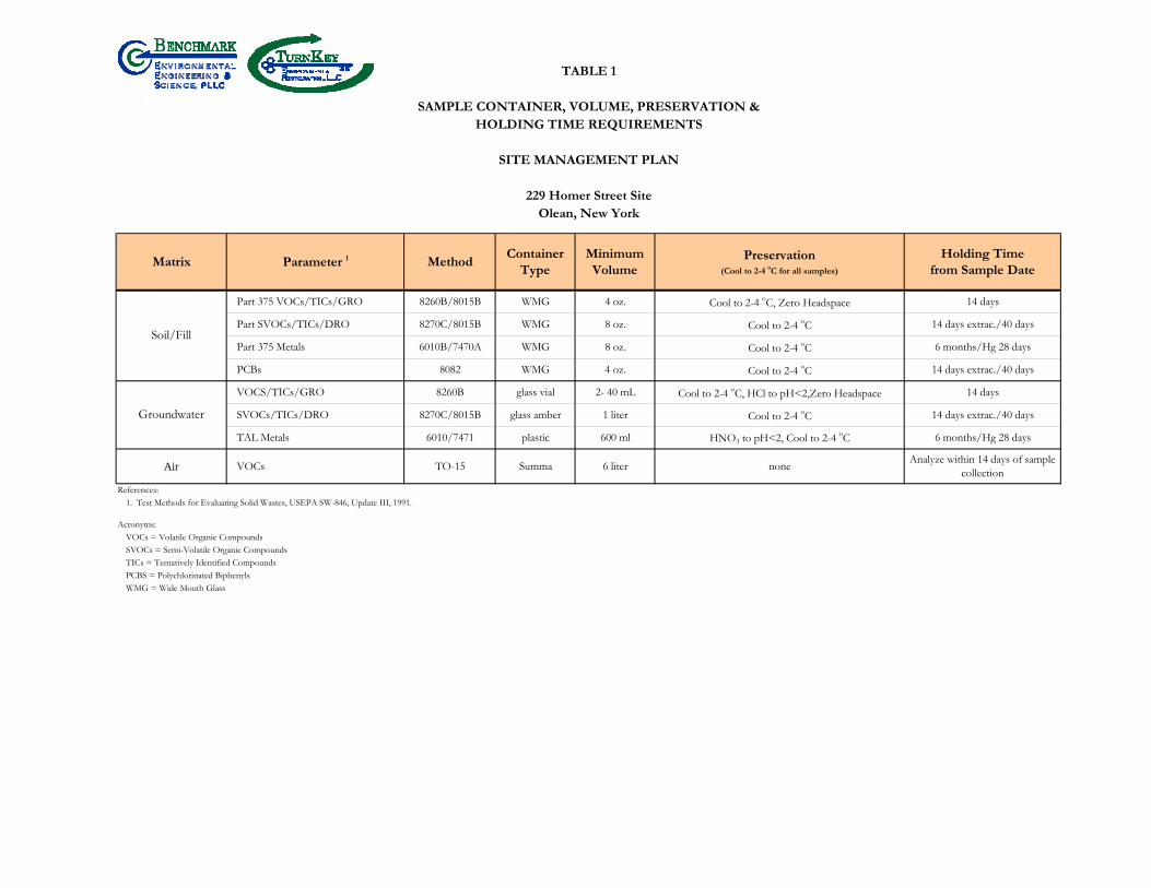
TABLE 1
SAMPLE CONTAINER, VOLUME, PRESERVATION &HOLDING TIME REQUIREMENTS
SITE MANAGEMENT PLAN
229 Homer Street SiteOlean, New York
Matrix Parameter 1 MethodContainer
TypeMinimumVolume
Preservation(Cool to 2-4 oC for all samples)
Holding Timefrom Sample Date
Part 375 VOCs/TICs/GRO 8260B/8015B WMG 4 oz. Cool to 2-4 oC, Zero Headspace 14 days
Part SVOCs/TICs/DRO 8270C/8015B WMG 8 oz. Cool to 2-4 oC 14 days extrac./40 days
Part 375 Metals 6010B/7470A WMG 8 oz. Cool to 2-4 oC 6 months/Hg 28 days
PCBs 8082 WMG 4 oz. Cool to 2-4 oC 14 days extrac./40 days
VOCS/TICs/GRO 8260B glass vial 2- 40 mL Cool to 2-4 oC, HCl to pH<2,Zero Headspace 14 days
SVOCs/TICs/DRO 8270C/8015B glass amber 1 liter Cool to 2-4 oC 14 days extrac./40 days
TAL Metals 6010/7471 plastic 600 ml HNO3 to pH<2, Cool to 2-4 oC 6 months/Hg 28 days
Air VOCs TO-15 Summa 6 liter noneAnalyze within 14 days of sample
collection
References:1. Test Methods for Evaluating Solid Wastes, USEPA SW-846, Update III, 1991.
Acronyms:VOCs = Volatile Organic CompoundsSVOCs = Semi-Volatile Organic CompoundsTICs = Tentatively Identified CompoundsPCBS = Polychlorinated BiphenylsWMG = Wide Mouth Glass
Soil/Fill
Groundwater

SMP – APPENDIX B: EXCAVATION WORK PLAN 229 HOMER STREET SITE
BCP SITE NO. C905044
0311-018-001 T KB
APPENDIX H
HEALTH & SAFETY PLAN

SITE HEALTH AND SAFETY PLAN for
SITE MANAGEMENT PLAN
229 HOMER STREET SITE
CITY OF OLEAN, CATTARAUGUS COUNTY, NEW YORK
SITE NO. 905044
August 2018 0311-018-001
Prepared for:
HOMER STREET PROPERTIES, LLC
Prepared by:
In Association With:
Bn v i ronme talng i neeri n gc ence,i
n

229 HOMER STREET SITE
HEALTH AND SAFETY PLAN FOR REMEDIAL ACTIVITIES
0225-015-002
ACKNOWLEDGEMENT
Plan Reviewed by (initial):
Corporate Health and Safety Director: Thomas H. Forbes, P.E.
Project Manager: Michael Lesakowski
Designated Site Safety and Health Officer: Mark Janus
Acknowledgement: I acknowledge that I have reviewed the information contained in this site-specific Health and Safety Plan, and understand the hazards associated with performance of the field activities described herein. I agree to comply with the requirements of this plan.
NAME (PRINT) SIGNATURE DATE
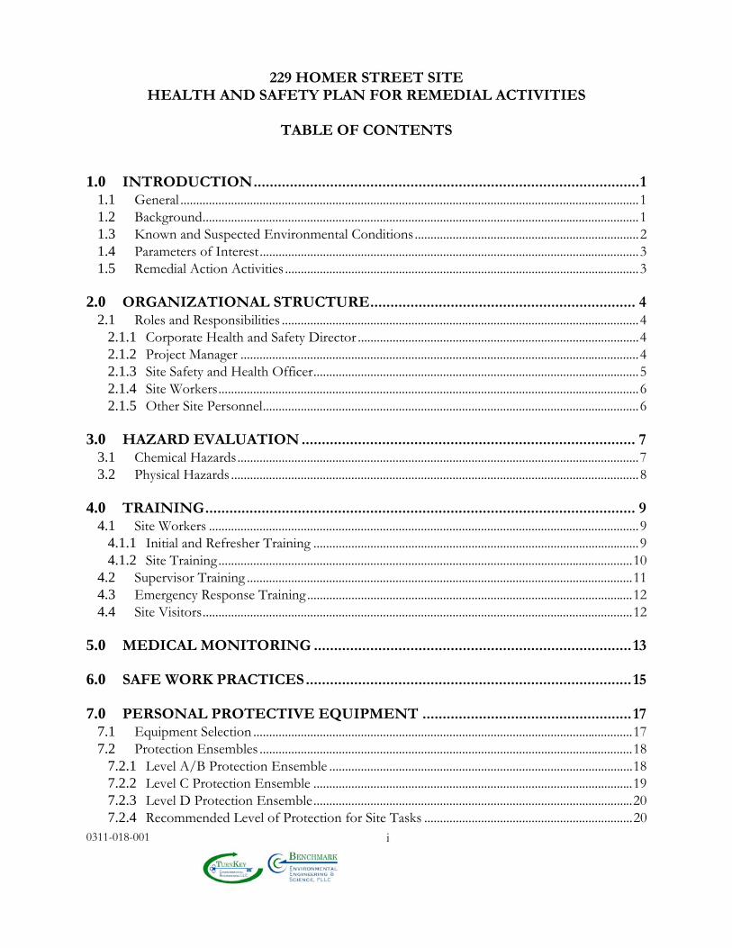
229 HOMER STREET SITE
HEALTH AND SAFETY PLAN FOR REMEDIAL ACTIVITIES
TABLE OF CONTENTS
0311-018-001
i
1.0 INTRODUCTION ................................................................................................ 1 1.1 General ................................................................................................................................................. 1 1.2 Background .......................................................................................................................................... 1 1.3 Known and Suspected Environmental Conditions ....................................................................... 2 1.4 Parameters of Interest ........................................................................................................................ 3 1.5 Remedial Action Activities ................................................................................................................ 3
2.0 ORGANIZATIONAL STRUCTURE .................................................................. 4 2.1 Roles and Responsibilities ................................................................................................................. 4
2.1.1 Corporate Health and Safety Director ......................................................................................... 4 2.1.2 Project Manager .............................................................................................................................. 4 2.1.3 Site Safety and Health Officer ....................................................................................................... 5 2.1.4 Site Workers ..................................................................................................................................... 6 2.1.5 Other Site Personnel ....................................................................................................................... 6
3.0 HAZARD EVALUATION ................................................................................... 7 3.1 Chemical Hazards ............................................................................................................................... 7 3.2 Physical Hazards ................................................................................................................................. 8
4.0 TRAINING ........................................................................................................... 9 4.1 Site Workers ........................................................................................................................................ 9
4.1.1 Initial and Refresher Training ....................................................................................................... 9 4.1.2 Site Training ................................................................................................................................... 10
4.2 Supervisor Training .......................................................................................................................... 11 4.3 Emergency Response Training ....................................................................................................... 12 4.4 Site Visitors ........................................................................................................................................ 12
5.0 MEDICAL MONITORING ............................................................................... 13
6.0 SAFE WORK PRACTICES ................................................................................. 15
7.0 PERSONAL PROTECTIVE EQUIPMENT .................................................... 17 7.1 Equipment Selection ........................................................................................................................ 17 7.2 Protection Ensembles ...................................................................................................................... 18
7.2.1 Level A/B Protection Ensemble ................................................................................................ 18 7.2.2 Level C Protection Ensemble ..................................................................................................... 19 7.2.3 Level D Protection Ensemble ..................................................................................................... 20 7.2.4 Recommended Level of Protection for Site Tasks .................................................................. 20
229 HOMER STREET SITE
HEALTH AND SAFETY PLAN FOR REMEDIAL ACTIVITIES
TABLE OF CONTENTS
0311-018-001
ii
8.0 EXPOSURE MONITORING ............................................................................ 21 8.1 General ............................................................................................................................................... 21
8.1.1 On-Site Work Zone Monitoring ................................................................................................. 21 8.1.2 On-Site Work Zone Action Levels ............................................................................................ 21 8.1.3 Community Air Monitoring Action Levels ............................................................................... 23
9.0 SPILL RELEASE/RESPONSE ......................................................................... 26 9.1 Potential Spills and Available Controls ......................................................................................... 26 9.2 Initial Spill Notification and Evaluation ........................................................................................ 27 9.3 Spill Response ................................................................................................................................... 28 9.4 Post-Spill Evaluation ........................................................................................................................ 29
10.0 HEAT/COLD STRESS MONITORING .......................................................... 30 10.1 Heat Stress Monitoring .................................................................................................................... 30 10.2 Cold Stress Monitoring .................................................................................................................... 32
11.0 WORK ZONES AND SITE CONTROL ........................................................... 35
12.0 DECONTAMINATION ..................................................................................... 37 12.1 Decontamination for Benchmark-TurnKey Employees ............................................................ 37 12.2 Decontamination for Medical Emergencies ................................................................................. 38 12.3 Decontamination of Field Equipment .......................................................................................... 38
13.0 CONFINED SPACE ENTRY ............................................................................ 39
14.0 FIRE PREVENTION AND PROTECTION ................................................... 40 14.1 General Approach ............................................................................................................................ 40 14.2 Equipment and Requirements ........................................................................................................ 40 14.3 Flammable and Combustible Substances ...................................................................................... 40 14.4 Hot Work ........................................................................................................................................... 41
15.0 EMERGENCY INFORMATION ...................................................................... 41
16.0 REFERENCES ................................................................................................... 42
229 HOMER STREET SITE
HEALTH AND SAFETY PLAN FOR REMEDIAL ACTIVITIES
TABLE OF CONTENTS
0311-018-001
iii
LIST OF TABLES
Table 1 Toxicity Data for Constituents of Potential Concern
Table 2 Potential Routes of Exposure to Constituents of Potential Concern
Table 3 Required Levels of Protection for Remedial Tasks
LIST OF FIGURES
Figure 1 Site Vicinity and Location Map
Figure 2 Site Map
ATTACHMENTS
Attachment A Emergency Response Plan
Attachment B Hot Work Permit Form
Attachment C Community Air Monitoring Plan
Health & Safety Plan for Post-Remedial Activities 229 Homer Street Site
0311-018-001
1
1.0 INTRODUCTION
1.1 General In accordance with OSHA requirements contained in 29 CFR 1910.120, this Health
and Safety Plan (HASP) describes the specific health and safety practices and procedures to
be employed by Benchmark Environmental Engineering & Science, PLLC and TurnKey
Environmental Restoration, LLC and employees (referred to jointly hereafter as “Benchmark-
TurnKey”) during post-remedial activities at the 229 Homer Street Site (Site) located at 229
Homer Street in the City of Olean, Cattaraugus County, New York. This HASP presents
procedures for Benchmark-TurnKey employees who will be involved with remaining remedial
activities; it does not cover the activities of other contractors, subcontractors or other
individuals on the Site. These firms will be required to develop and enforce their own HASPs
as discussed in Section 2.0. Benchmark-TurnKey accepts no responsibility for the health and
safety of contractor, subcontractor or other personnel.
This HASP presents information on known Site health and safety hazards using
available historical information, and identifies the equipment, materials and procedures that
will be used to eliminate or control these hazards. Environmental monitoring will be
performed during the course of field activities to provide real-time data for on-going
assessment of potential hazards.
1.2 Background
The Site property consists of one tax parcel measuring 3.34 acres (SBL: 94.032-1-2.5).
The Site is currently improved with a one-story building in the central portion of the Site.
The Site and surrounding area was originally developed in approximately 1880 for the
oil industry and used for refinery purposes and as a petroleum storage tank farm. The Site is
bound by Two Mile Creek and Homer Street to the northwest, a Casella Waste Management
of New York transfer station to the northeast, Southern Tier Rail Authority rail lines to the
southeast, and 251 Homer Street (a vacant parcel remediated under the NYSDEC BCP) to
the southwest, currently being redeveloped as a solar power generating facility.
Health & Safety Plan for Post-Remedial Activities 229 Homer Street Site
0311-018-001
2
1.3 Known and Suspected Environmental Conditions
Previous investigations have identified that the Site was historically occupied by a large
tank, used for oil storage by Socony Vacuum and/or Felmont Oil, and two tank berm areas.
The Site was identified as part of the Exxon/Mobil Legacy Site (EMLS) Works #3 area. The
tank and berm areas were removed by the 1970s.
TurnKey completed a Remedial Investigation and Alternatives Analysis Report in
2016. The findings of the report are consistent with the foregoing and include the following:
The water table exists at depths ranging from 7 to 15 feet. The groundwater
flow direction is in a southwesterly direction.
The surface soil/fill (0-2”) and near-surface soils (2-12”) are impacted by arsenic
at concentrations exceeding the commercial soil cleanup objectives (CSCOs) at
multiple locations across the site.
Subsurface soil/fills are impacted by arsenic and polynuclear aromatic
hydrocarbons (PAHs) at concentrations exceeding the CSCOs at four locations.
Subsurface soil/fill was identified as petroleum grossly contaminated soil (GCS)
based on observed petroleum-like odors, sheen/floating product and elevated
photoionization detector readings (PID) in subsurface soil/fills in across nearly
two thirds of the site area. GCS was generally found at depths ranging from
approximately 50 to 15 feet below ground surface (fbgs). It is also possible that
GCS extends beneath the existing building.
Underground piping was encountered in several test pits and trenches. The
majority of the piping was found on the southern and eastern portions of the
Site; however, additional piping was found on the northern portion of the Site.
Benzene in monitoring well MW-4 and pentachlorophenol in well MW-3 were
detected above GWQS/GVs. Gasoline organics (GROs) and Diesel range
organics (DROs) were present in all wells.
Total and dissolved metals detected at concentrations above GWQS/GVs
include naturally occurring minerals such as iron, manganese, magnesium, and
sodium. Total arsenic, total lead, and dissolved barium were also detected
slightly above GWQS/GV.
Health & Safety Plan for Post-Remedial Activities 229 Homer Street Site
0311-018-001
3
Analytical results from sub-slab and indoor air sampling identified an elevated
concentration of dichlorodifluoromethane (Freon 12).
1.4 Parameters of Interest
The RI provides a more complete description of the contamination across various Site
environmental media with the specific Constituents of Concern including:
Soil / Fill – GCS and arsenic
Groundwater – Benzene
1.5 Remedial Action Activities The Site has been remediated which included: the removal of heavily-impacted shallow
grossly contaminated oil (GCS); removal of petroleum piping to the extent feasible; installation
of a soil cover system which includes 12” minimum of clean gravel, the building concrete slab
and two concrete pads; and installation of an air sparge/soil vapor extraction system to remove
organic vapors form the vadose zone and the upper portion of the water table (smear zone).
are described below:

Health & Safety Plan for Post-Remedial Activities 229 Homer Street Site
0311-018-001
4
2.0 ORGANIZATIONAL STRUCTURE This section of the HASP describes the lines of authority, responsibility and
communication as they pertain to health and safety functions at the Site. The purpose of this
chapter is to identify the personnel who impact the development and implementation of the
HASP and to describe their roles and responsibilities. This chapter also identifies other
contractors and subcontractors involved in work operations and establish the lines of
communications among them for health and safety matters. The organizational structure
described in this chapter is consistent with the requirements of 29 CFR 1910.120(b)(2). This
section will be reviewed by the Project Manager and updated as necessary to reflect the current
organizational structure at this Site.
2.1 Roles and Responsibilities
All Benchmark-TurnKey personnel on the Site must comply with the minimum
requirements of this HASP. The specific responsibilities and authority of management, safety
and health, and other personnel on this Site are detailed in the following paragraphs.
2.1.1 Corporate Health and Safety Director
The Benchmark-TurnKey Corporate Health and Safety Director is Mr. Thomas H.
Forbes, P.E. The Corporate Health and Safety Director responsible for developing and
implementing the Health and Safety program and policies for Benchmark Environmental
Engineering & Science, PLLC and TurnKey Environmental Restoration, LLC, and consulting
with corporate management to ensure adequate resources are available to properly implement
these programs and policies. The Corporate Health and Safety Director coordinates
Benchmark-TurnKey’s Health and Safety training and medical monitoring programs and
assists project management and field staff in developing site-specific health and safety plans.
2.1.2 Project Manager
The Project Manager for this Site is Mr. Michael Lesakowski. The Project Manager
has the responsibility and authority to direct all Benchmark-TurnKey work operations at the
Site. The Project Manager coordinates safety and health functions with the Site Safety and
Health Officer, and bears ultimate responsibility for proper implementation of this HASP. He

Health & Safety Plan for Post-Remedial Activities 229 Homer Street Site
0311-018-001
5
may delegate authority to expedite and facilitate any application of the program, including
modifications to the overall project approach as necessary to circumvent unsafe work
conditions. Specific duties of the Project Manager include:
Preparing and coordinating the Site work plan.
Providing Benchmark-TurnKey workers with work assignments and overseeing their performance.
Coordinating health and safety efforts with the Site Safety and Health Officer
(SSHO). Reviewing the emergency response coordination plan to assure its effectiveness. Serving as the primary liaison with Site contractors and the property owner.
2.1.3 Site Safety and Health Officer
The Site Safety and Health Officer (SSHO) for this Site is Mr. Mark Janus. The
qualified alternate SSHO is Mr. Brock Greene. The SSHO reports to the Project Manager.
The SSHO is on-site or readily accessible to the Site during all work operations and has the
authority to halt Site work if unsafe conditions are detected. The specific responsibilities of
the SSHO are:
Managing the safety and health functions for Benchmark-TurnKey personnel on the Site.
Serving as the point of contact for safety and health matters. Ensuring that Benchmark-TurnKey field personnel working on the Site have
received proper training (per 29 CFR Part 1910.120(e)), that they have obtained medical clearance to wear respiratory protection (per 29 CFR Part 1910.134), and that they are properly trained in the selection, use and maintenance of personal protective equipment, including qualitative respirator fit testing.
Performing or overseeing Site monitoring as required by the HASP. Assisting in the preparation and review of the HASP.
Health & Safety Plan for Post-Remedial Activities 229 Homer Street Site
0311-018-001
6
Maintaining site-specific safety and health records as described in this HASP. Coordinating with the Project Manager, Site Workers, and Contractor’s SSHO as
necessary for safety and health efforts.
2.1.4 Site Workers
Site workers are responsible for: complying with this HASP or a more stringent HASP,
if appropriate (i.e., Contractor and Subcontractor’s HASP); using proper PPE; reporting
unsafe acts and conditions to the SSHO; and following the safety and health instructions of
the Project Manager and SSHO.
2.1.5 Other Site Personnel
On-Site contractors will be responsible for developing, implementing and enforcing a
Health and Safety Plan equally stringent or more stringent than Benchmark-TurnKey’s HASP.
Benchmark-TurnKey assumes no responsibility for the health and safety of anyone outside its
direct employ. Each Contractor’s HASP shall cover all non-Benchmark/TurnKey Site
personnel. Each Contractor shall assign a SSHO who will coordinate with Benchmark-
TurnKey’s SSHO as necessary to ensure effective lines of communication and consistency
between contingency plans.
In addition to Benchmark-TurnKey and Contractor personnel, other individuals who
may have responsibilities in the work zone include subcontractors and governmental agencies
performing Site inspection work (i.e., the New York State Department of Environmental
Conservation). The Contractor shall be responsible for ensuring that these individuals have
received OSHA-required training (29 CFR 1910.120(e)), including initial, refresher and site-
specific training, and shall be responsible for the safety and health of these individuals while
they are on-site.
Health & Safety Plan for Post-Remedial Activities 229 Homer Street Site
0311-018-001
7
3.0 HAZARD EVALUATION Due to the presence of certain contaminants at the Site, the possibility exists that
workers will be exposed to hazardous substances during field activities. The principal points
of exposure would be through direct contact with and incidental ingestion of soil and/or
groundwater, and through the inhalation of contaminated particles or vapors. Other points of
exposure may include direct contact with groundwater. In addition, the use of drilling and/or
medium to large-sized construction equipment (e.g., excavator) will also present conditions
for potential physical injury to workers. Further, since work will be performed outdoors, the
potential exists for heat/cold stress to impact workers, especially those wearing protective
equipment and clothing. Adherence to the medical evaluations, worker training relative to
chemical hazards, safe work practices, proper personal protection, environmental monitoring,
establishment work zones and Site control, appropriate decontamination procedures and
contingency planning outlined herein will reduce the potential for chemical exposures and
physical injuries.
3.1 Chemical Hazards
As discussed in Section 1.3, historic activities have potentially resulted in petroleum
impacts to Site soils, groundwater, and subslab vapors. Table 1 lists exposure limits for
airborne concentrations of the COPCs identified in Section 1.4 of this HASP. Brief
descriptions of the toxicology of the prevalent COPCs and related health and safety guidance
and criteria are provided below.
Benzene (CAS #71-43-2) poisoning occurs most commonly through inhalation of the vapor, however, benzene can also penetrate the skin and poison in that way. Locally, benzene has a comparatively strong irritating effect, producing erythema and burning and, in more severe cases, edema and blistering. Exposure to high concentrations of the vapor (i.e., 3,000 ppm or higher) may result in acute poisoning characterized by the narcotic action of benzene on the central nervous system. In acute poisoning, symptoms include confusion, dizziness, tightening of the leg muscles, and pressure over the forehead. Chronic exposure to benzene (i.e., long term exposure to concentrations of 100 ppm or less may lead to damage of the blood-forming system. Benzene is very flammable when exposed to heat or flame and can react vigorously with oxidizing materials.
Health & Safety Plan for Post-Remedial Activities 229 Homer Street Site
0311-018-001
8
Arsenic (CAS #7440-38-2) is a naturally occurring element and is usually found combined with one or more elements, such as oxygen or sulfur. Inhalation is a more important exposure route than ingestion. First phase exposure symptons include nausea, vomiting, diarrhea and pain in the stomach. Prolonged contact is corrosive to the skin and mucus membranes. Arsenic is considered a Group A human carcinogen by the USEPA. Exposure via inhalation is associated with an increased risk of lung cancer. Exposure via the oral route is associated with an increased risk of skin cancer.
With respect to the anticipated remedial activities discussed in Section 1.5, possible
routes of exposure to the above-mentioned contaminants are presented in Table 2. The use
of proper respiratory equipment, as outlined in Section 7.0 of this HASP, will minimize the
potential for exposure to airborne contamination. Exposure to contaminants through dermal
and other routes will also be minimized through the use of protective clothing (Section 7.0),
safe work practices (Section 6.0), and proper decontamination procedures (Section 12.0).
3.2 Physical Hazards
Field activities at the Former Doro Dry Cleaners Site may present the following
physical hazards:
The potential for physical injury during heavy construction equipment use, such as backhoes, excavators and drilling equipment.
The potential for heat/cold stress to employees during the summer/winter months
(see Section 10.0). The potential for slip and fall injuries due to rough, uneven terrain and/or open
excavations.
These hazards represent only some of the possible means of injury that may be present
during field and sampling activities at the Site. Since it is impossible to list all potential sources
of injury, it shall be the responsibility of each individual to exercise proper care and caution
during all phases of the work.
Health & Safety Plan for Post-Remedial Activities 229 Homer Street Site
0311-018-001
9
4.0 TRAINING
4.1 Site Workers
All personnel performing remedial activities at the Site (such as, but not limited to,
equipment operators, general laborers, and drillers) and who may be exposed to hazardous
substances, health hazards, or safety hazards and their supervisors/managers responsible for
the Site shall receive training in accordance with 29 CFR 1910.120(e) before they are permitted
to engage in operations in the exclusion zone or contaminant reduction zone. This training
includes an initial 40-hour Hazardous Waste Site Worker Protection Course, an 8-hour Annual
Refresher Course subsequent to the initial 40-hour training, and 3 days of actual field
experience under the direct supervision of a trained, experienced supervisor. Additional site-
specific training shall also be provided by the SSHO prior to the start of field activities. A
description of topics to be covered by this training is provided below.
4.1.1 Initial and Refresher Training
Initial and refresher training is conducted by a qualified instructor as specified under
OSHA 29 CFR 1910.120(e)(5), and is specifically designed to meet the requirements of OSHA
29 CFR 1910.120(e)(3) and 1910.120(e)(8). The training covers, as a minimum, the following
topics:
OSHA HAZWOPER regulations.
Site safety and hazard recognition, including chemical and physical hazards. Medical monitoring requirements. Air monitoring, permissible exposure limits, and respiratory protection level
classifications. Appropriate use of personal protective equipment (PPE), including chemical
compatibility and respiratory equipment selection and use. Work practices to minimize risk.
Health & Safety Plan for Post-Remedial Activities 229 Homer Street Site
0311-018-001
10
Work zones and Site control. Safe use of engineering controls and equipment. Decontamination procedures. Emergency response and escape. Confined space entry procedures. Heat and cold stress monitoring. Elements of a Health and Safety Plan. Spill containment.
Initial training also incorporates workshops for PPE and respiratory equipment use
(Levels A, B and C), and respirator fit testing. Records and certification received from the
course instructor documenting each employee’s successful completion of the training
identified above are maintained on file at Benchmark-TurnKey’s Buffalo, NY office.
Contractors and Subcontractors are required to provide similar documentation of training for
all their personnel who will be involved in on-site work activities.
Any employee who has not been certified as having received health and safety training
in conformance with 29 CFR 1910.120(e) is prohibited from working in the exclusion and
contamination reduction zones, or to engage in any on-site work activities that may involve
exposure to hazardous substances or wastes.
4.1.2 Site Training
Site workers are given a copy of the HASP and provided a site-specific briefing prior
to the commencement of work to ensure that employees are familiar with the HASP and the
information and requirements it contains. The Site briefing shall be provided by the SSHO
prior to initiating field activities and shall include:
Names of personnel and alternates responsible for Site safety and health.

Health & Safety Plan for Post-Remedial Activities 229 Homer Street Site
0311-018-001
11
Safety, health and other hazards present on the Site. The site lay-out including work zones and places of refuge. The emergency communications system and emergency evacuation procedures. Use of PPE. Work practices by which the employee can minimize risks from hazards. Safe use of engineering controls and equipment on the site. Medical surveillance, including recognition of symptoms and signs of over-
exposure as described in Chapter 5 of this HASP. Decontamination procedures as detailed in Chapter 12 of this HASP. The emergency response plan as detailed in Chapter 15 of this HASP. Confined space entry procedures, if required, as detailed in Chapter 13 of this
HASP. The spill containment program as detailed in Chapter 9 of this HASP. Site control as detailed in Chapter 11 of this HASP.
Supplemental health and safety briefings will also be conducted by the SSHO on an as-
needed basis during the course of the work. Supplemental briefings are provided as necessary
to notify employees of any changes to this HASP as a result of information gathered during
ongoing Site characterization and analysis. Conditions for which the SSHO may schedule
additional briefings include, but are not limited to: a change in Site conditions (e.g., based on
monitoring results); changes in the work schedule/plan; newly discovered hazards; and safety
incidents occurring during Site work.
4.2 Supervisor Training
On-site safety and health personnel who are directly responsible for or who supervise
the safety and health of workers engaged in hazardous waste operations (i.e., SSHO) shall
Health & Safety Plan for Post-Remedial Activities 229 Homer Street Site
0311-018-001
12
receive, in addition to the appropriate level of worker training described in Section 4.1, above,
8 additional hours of specialized supervisory training, in compliance with 29 CFR
1910.120(e)(4).
4.3 Emergency Response Training
Emergency response training is addressed in Appendix A of this HASP, Emergency
Response Plan.
4.4 Site Visitors
Each Contractor’s SSHO will provide a site-specific briefing to all Site visitors and
other non-Benchmark/TurnKey personnel who enter the Site beyond the Site entry point.
The site-specific briefing will provide information about Site hazards, the Site layout including
work zones and places of refuge, the emergency communications system and emergency
evacuation procedures, and other pertinent safety and health requirements as appropriate.
Site visitors will not be permitted to enter the exclusion zone or contaminant reduction
zones unless they have received the level of training required for Site workers as described in
Section 4.1.
Health & Safety Plan for Post-Remedial Activities 229 Homer Street Site
0311-018-001
13
5.0 MEDICAL MONITORING Medical monitoring examinations are provided to Benchmark-TurnKey employees as
stipulated under 29 CFR Part 1910.120(f). These exams include initial employment, annual
and employment termination physicals for all Benchmark-TurnKey employees involved in
hazardous waste site field operations. Post-exposure examinations are also provided for
employees who may have been injured, received a health impairment, or developed signs or
symptoms of over-exposure to hazardous substances or were accidentally exposed to
substances at concentrations above the permissible exposure limits without necessary personal
protective equipment. Such exams are performed as soon as possible following development
of symptoms or the known exposure event.
Medical evaluations are performed by Health Works, an occupational health care
provider under contract with Benchmark-TurnKey. Health Works is located in Seneca Square
Plaza, 1900 Ridge Road, West Seneca, New York 14224. The facility can be reached at (716)
823-5050 to schedule routine appointments or post-exposure examinations.
Medical evaluations are conducted according to the Benchmark-TurnKey Medical
Monitoring Program and include an evaluation of the workers’ ability to use respiratory
protective equipment. The examinations include:
Occupational/medical history review.
Physical exam, including vital sign measurement. Spirometry testing. Eyesight testing. Audio testing (minimum baseline and exit, annual for employees routinely exposed
to greater than 85db). EKG (for employees >40 yrs age or as medical conditions dictate). Chest X-ray (baseline and exit, and every 5 years). Blood biochemistry (including blood count, white cell differential count, serum
multiplastic screening).

Health & Safety Plan for Post-Remedial Activities 229 Homer Street Site
0311-018-001
14
Medical certification of physical requirements (i.e., sight, musculoskeletal,
cardiovascular) for safe job performance and to wear respiratory protection equipment.
The purpose of the medical evaluation is to determine an employee’s fitness for duty on
hazardous waste sites; and to establish baseline medical data.
In conformance with OSHA regulations, Benchmark-TurnKey will maintain and
preserve medical records for a period of 30 years following termination of employment.
Employees are provided a copy of the physician's post-exam report, and have access to their
medical records and analyses.
Health & Safety Plan for Post-Remedial Activities 229 Homer Street Site
0311-018-001
15
6.0 SAFE WORK PRACTICES All Benchmark-TurnKey employees shall conform to the following safe work practices
during all on-site work activities conducted within the exclusion and contamination reduction
zones:
Eating, drinking, chewing gum or tobacco, smoking, or any practice that increases
the probability of hand-to-mouth contact is strictly prohibited.
The hands and face must be thoroughly washed upon leaving the work area and prior to engaging in any activity indicated above.
Respiratory protective equipment and clothing must be worn by all personnel
entering the Site as required by the HASP or as modified by the Site safety officer. Excessive facial hair (i.e., beards, long mustaches or sideburns) that interferes with the satisfactory respirator-to-face seal is prohibited.
Contact with surfaces/materials either suspected or known to be contaminated will
be avoided to minimize the potential for transfer to personnel, cross contamination and need for decontamination.
Medicine and alcohol can synergize the effects of exposure to toxic chemicals. Due
to possible contraindications, use of prescribed drugs should be reviewed with the Benchmark-TurnKey occupational physician. Alcoholic beverage and illegal drug intake are strictly forbidden during the workday.
All personnel shall be familiar with standard operating safety procedures and
additional instructions contained in this Health and Safety Plan. On-site personnel shall use the “buddy” system. No one may work alone (i.e., out
of earshot or visual contact with other workers) in the exclusion zone. Personnel and equipment in the contaminated area shall be minimized, consistent
with effective Site operations. All employees have the obligation to immediately report and if possible, correct
unsafe work conditions. Use of contact lenses on-site will not be permitted. Spectacle kits for insertion into
full-face respirators will be provided for Benchmark-TurnKey employees, as
Health & Safety Plan for Post-Remedial Activities 229 Homer Street Site
0311-018-001
16
requested and required.
The recommended specific safety practices for working around the contractor’s
equipment (e.g., backhoes, bulldozers, excavators, drill rigs etc.) are as follows:
Although the Contractor and subcontractors are responsible for their equipment
and safe operation of the Site, Benchmark-TurnKey personnel are also responsible for their own safety.
Subsurface work will not be initiated without first clearing underground utility
services. Heavy equipment should not be operated within 20 feet of overhead wires. This
distance may be increased if windy conditions are anticipated or if lines carry high voltage. The Site should also be sufficiently clear to ensure the project staff can move around the heavy machinery safely.
Care should be taken to avoid overhead wires when moving heavy-equipment from
location to location. Hard hats, safety boots and safety glasses should be worn at all times in the vicinity
of heavy equipment. Hearing protection is also recommended. The work Site should be kept neat. This will prevent personnel from tripping and
will allow for fast emergency exit from the Site. Proper lighting must be provided when working at night. Construction activities should be discontinued during an electrical storm or severe
weather conditions. The presence of combustible gases should be checked before igniting any open
flame. Personnel shall stand upwind of any construction operation when not immediately
involved in sampling/logging/observing activities. Personnel will not approach the edge of an unsecured trench/excavation closer
than 2 feet.
Health & Safety Plan for Post-Remedial Activities 229 Homer Street Site
0311-018-001
17
7.0 PERSONAL PROTECTIVE EQUIPMENT
7.1 Equipment Selection
Personal protective equipment (PPE) will be donned when work activities may result
in exposure to physical or chemical hazards beyond acceptable limits, and when such exposure
can be mitigated through appropriate PPE. The selection of PPE will be based on an
evaluation of the performance characteristics of the PPE relative to the requirements and
limitations of the Site, the task-specific conditions and duration, and the hazards and potential
hazards identified at the Site.
Equipment designed to protect the body against contact with known or suspect
chemical hazards are grouped into four categories according to the degree of protection
afforded. These categories designated A through D consistent with United States
Environmental Protection Agency (USEPA) Level of Protection designation, are:
Level A: Should be selected when the highest level of respiratory, skin and eye
protection is needed.
Level B: Should be selected when the highest level of respiratory protection is needed, but a lesser level of skin protection is required. Level B protection is the minimum level recommended on initial Site entries until the hazards have been further defined by on-site studies. Level B (or Level A) is also necessary for oxygen-deficient atmospheres.
Level C: Should be selected when the types of airborne substances are known, the
concentrations have been measured and the criteria for using air-purifying respirators are met. In atmospheres where no airborne contaminants are present, Level C provides dermal protection only.
Level D: Should not be worn on any Site with elevated respiratory or skin hazards.
This is generally a work uniform providing minimal protection. OSHA requires the use of certain PPE under conditions where an immediate danger
to life and health (IDLH) may be present. Specifically, OSHA 29 CFR 1910.120(g)(3)(iii)
requires use of a positive pressure self-contained breathing apparatus, or positive pressure air-
line respirator equipped with an escape air supply when chemical exposure levels present a
Health & Safety Plan for Post-Remedial Activities 229 Homer Street Site
0311-018-001
18
substantial possibility of immediate serious injury, illness or death, or impair the ability to
escape. Similarly, OSHA 29 CFR 1910.120(g)(3)(iv) requires donning totally-encapsulating
chemical protective suits (with a protection level equivalent to Level A protection) in
conditions where skin absorption of a hazardous substance may result in a substantial
possibility of immediate serious illness, injury or death, or impair the ability to escape.
In situations where the types of chemicals, concentrations, and possibilities of contact
are unknown, the appropriate level of protection must be selected based on professional
experience and judgment until the hazards can be further characterized. The individual
components of clothing and equipment must be assembled into a full protective ensemble to
protect the worker from site-specific hazards, while at the same time minimizing hazards and
drawbacks of the personal protective gear itself. Ensemble components are detailed below for
levels A/B, C, and D protection.
7.2 Protection Ensembles
7.2.1 Level A/B Protection Ensemble
Level A/B ensembles include similar respiratory protection, however Level A provides
a higher degree of dermal protection than Level B. Use of Level A over Level B is determined
by: comparing the concentrations of identified substances in the air with skin toxicity data,
and assessing the effect of the substance (by its measured air concentrations or splash
potential) on the small area of the head and neck unprotected by Level B clothing.
The recommended PPE for level A/B is:
Pressure-demand, full-face piece self-contained breathing apparatus (MSHA/-
NIOSH approved) or pressure-demand supplied-air respirator with escape self-contained breathing apparatus (SCBA).
Chemical-resistant clothing. For Level A, clothing consists of totally-encapsulating
chemical resistant suit. Level B incorporates hooded one-or two-piece chemical splash suit.
Inner and outer chemical resistant gloves. Chemical-resistant safety boots/shoes.
Health & Safety Plan for Post-Remedial Activities 229 Homer Street Site
0311-018-001
19
Hardhat.
7.2.2 Level C Protection Ensemble
Level C protection is distinguished from Level B by the equipment used to protect the
respiratory system, assuming the same type of chemical-resistant clothing is used. The main
selection criterion for Level C is that conditions permit wearing an air-purifying device. The
device (when required) must be an air-purifying respirator (MSHA/NIOSH approved)
equipped with filter cartridges. Cartridges must be able to remove the substances encountered.
Respiratory protection will be used only with proper fitting, training and the approval of a
qualified individual. In addition, an air-purifying respirator can be used only if: oxygen content
of the atmosphere is at least 19.5% in volume; substances are identified and concentrations
measured; substances have adequate warning properties; the individual passes a qualitative fit-
test for the mask; and an appropriate cartridge/canister is used, and its service limit
concentration is not exceeded.
Recommended PPE for Level C conditions includes:
Full-face piece, air-purifying respirator equipped with MSHA and NIOSH
approved organic vapor/acid gas/dust/mist combination cartridges or as designated by the SSHO.
Chemical-resistant clothing (hooded, one or two-piece chemical splash suit or
disposable chemical-resistant one-piece suit). Inner and outer chemical-resistant gloves. Chemical-resistant safety boots/shoes. Hardhat. An air-monitoring program is part of all response operations when atmospheric
contamination is known or suspected. It is particularly important that the air be monitored
thoroughly when personnel are wearing air-purifying respirators. Continual surveillance using
direct-reading instruments is needed to detect any changes in air quality necessitating a higher
level of respiratory protection.
Health & Safety Plan for Post-Remedial Activities 229 Homer Street Site
0311-018-001
20
7.2.3 Level D Protection Ensemble
As indicated above, Level D protection is primarily a work uniform. It can be worn in
areas where only boots can be contaminated, where there are no inhalable toxic substances
and where the atmospheric contains at least 19.5% oxygen.
Recommended PPE for Level D includes:
Coveralls.
Safety boots/shoes. Safety glasses or chemical splash goggles. Hardhat. Optional gloves; escape mask; face shield.
7.2.4 Recommended Level of Protection for Site Tasks
Based upon current information regarding both the contaminants suspected to be
present at the Site and the various tasks that are included in the remedial activities, the
minimum required levels of protection for these tasks shall be as identified in Table 3.
Health & Safety Plan for Post-Remedial Activities 229 Homer Street Site
0311-018-001
21
8.0 EXPOSURE MONITORING
8.1 General
Based on the results of historic sample analysis and the nature of the proposed work
activities at the Site, the possibility exist that organic vapors and/or particulates may be
released to the air during intrusive construction activities. Ambient breathing zone
concentrations may at times, exceed the permissible exposure limits (PELs) established by
OSHA for the individual compounds (see Table 1), in which case respiratory protection will
be required. Respiratory and dermal protection may be modified (upgraded or downgraded)
by the SSHO based upon real-time field monitoring data.
8.1.1 On-Site Work Zone Monitoring
Benchmark-TurnKey personnel will conduct routine, real-time air monitoring during
all intrusive construction phases such as excavation, backfilling, drilling, etc. The work area
will be monitored at regular intervals using a photo-ionization detector (PID), combustible
gas meter and a particulate meter. Observed values will be recorded and maintained as part of
the permanent field record.
Additional air monitoring measurements may be made by Benchmark-TurnKey
personnel to verify field conditions during subcontractor oversight activities. Monitoring
instruments will be protected from surface contamination during use. Additional monitoring
instruments may be added if the situations or conditions change. Monitoring instruments will
be calibrated in accordance with manufacturer's instructions before use.
8.1.2 On-Site Work Zone Action Levels
The PID, or other appropriate instrument(s), will be used by Benchmark-TurnKey
personnel to monitor organic vapor concentrations as specified in this HASP. Combustible
gas will be monitored with the “combustible gas” option on the combustible gas meter or
other appropriate instrument(s). In addition, fugitive dust/particulate concentrations will be
monitored during major soil intrusion (viz., well/boring installation) using a real-time
particulate monitor as specified in this plan. In the absence of such monitoring, appropriate
respiratory protection for particulates shall be donned. Sustained readings obtained in the
Health & Safety Plan for Post-Remedial Activities 229 Homer Street Site
0311-018-001
22
breathing zone may be interpreted (with regard to other Site conditions) as follows for
Benchmark-TurnKey personnel:
Total atmospheric concentrations of unidentified vapors or gases ranging from 0 to 1 ppm above background on the PID) - Continue operations under Level D (see Appendix A).
Total atmospheric concentrations of unidentified vapors or gases yielding sustained
readings from >1 ppm to 5 ppm above background on the PID (vapors not suspected of containing high levels of chemicals toxic to the skin) - Continue operations under Level C (see Appendix A).
Total atmospheric concentrations of unidentified vapors or gases yielding sustained
readings of >5 ppm to 50 ppm above background on the PID - Continue operations under Level B (see Attachment 1), re-evaluate and alter (if possible) construction methods to achieve lower vapor concentrations.
Total atmospheric concentrations of unidentified vapors or gases above 50 ppm on
the PID - Discontinue operations and exit the work zone immediately.
The particulate monitor will be used to monitor respirable dust concentrations during
all intrusive activities and during handling of Site soil/fill. Action levels based on the
instrument readings shall be as follows:
Less than 50 mg/m3 - Continue field operations.
50-150 mg/m3 - Don dust/particulate mask or equivalent Greater than 150 mg/m3 - Don dust/particulate mask or equivalent. Initiate
engineering controls to reduce respirable dust concentration (viz., wetting of excavated soils or tools at discretion of Site Health and Safety Officer).
Readings from the field equipment will be recorded and documented on the
appropriate Project Field Forms. All instruments will be calibrated before use on a daily basis
and the procedure will be documented on the appropriate Project Field Forms.
Health & Safety Plan for Post-Remedial Activities 229 Homer Street Site
0311-018-001
23
8.1.3 Community Air Monitoring Action Levels
In addition to the action levels prescribed in Section 8.2.1 for Benchmark-TurnKey
personnel on-site, the following criteria shall also be adhered to for the protection of
downwind receptors consistent with NYSDOH requirements (Appendix C):
o ORGANIC VAPOR PERIMETER MONITORING:
If the sustained ambient air concentration of organic vapors at the downwind perimeter of the exclusion zone exceeds 5 ppm above background for the 15-minute average, work activities will be temporarily halted and monitoring continued. If the sustained organic vapor decreases below 5 ppm over background, work activities can resume with continued monitoring.
If the sustained ambient air concentration of organic vapors at the downwind perimeter of the exclusion zone are greater than 5 ppm over background but less than 25 ppm for the 15-minute average, activities can resume provided that: the organic vapor level 200 feet downwind of the working site or half the distance to the nearest off-site residential or commercial structure, whichever is less, but in no case less than 20 feet, is below 5 ppm over background; and more frequent intervals of monitoring, as directed by the Site Health and Safety Officer, are conducted.
If the sustained organic vapor level is above 25 ppm at the perimeter of the exclusion zone for the 15-minute average, the Site Health and Safety Officer must be notified and work activities shut down. The Site Health and Safety Officer will determine when re-entry of the exclusion zone is possible and will implement downwind air monitoring to ensure vapor emissions do not impact the nearest off-site residential or commercial structure at levels exceeding those specified in the Organic Vapor Contingency Monitoring Plan below. All readings will be recorded and will be available for New York State Department of Environmental Conservation (DEC) and Department of Health (DOH) personnel to review.
o ORGANIC VAPOR CONTINGENCY MONITORING PLAN:
If the sustained organic vapor level is greater than 5 ppm over background 200 feet downwind from the work area or half the distance to the nearest off-site residential or commercial property, whichever is less, all work activities must be halted.
Health & Safety Plan for Post-Remedial Activities 229 Homer Street Site
0311-018-001
24
If, following the cessation of the work activities or as the result of an emergency,
sustained organic levels persist above 5 ppm above background 200 feet downwind or half the distance to the nearest off-site residential or commercial property from the work area, then the air quality must be monitored within 20 feet of the perimeter of the nearest off-site residential or commercial structure (20-foot zone).
If efforts to abate the emission source are unsuccessful and if sustained organic
vapor levels approach or exceed 5 ppm above background within the 20-foot zone for more than 30 minutes, or are sustained at levels greater than 10 ppm above background for longer than one minute, then the Major Vapor Emission Response Plan (see below) will automatically be placed into effect.
o MAJOR VAPOR EMISSION RESPONSE PLAN:
Upon activation, the following activities will be undertaken:
1. All Emergency Response Contacts as listed in this Health and Safety Plan and the Emergency Response Plan (Appendix A) will be advised.
2. The local police authorities will immediately be contacted by the Site Health and Safety Officer and advised of the situation.
3. Frequent air monitoring will be conducted at 30-minute intervals within the 20-foot zone. If two sustained successive readings below action levels are measured, air monitoring may be halted or modified by the Site Health and Safety Officer.
The following personnel are to be notified in the listed sequence in the event
that a Major Vapor Emission Plan is activated:
Responsible Person
Contact Phone Number
SSHO Police 911
SSHO State Emergency Response Hotline (800) 457-7362
Additional emergency numbers are listed in the Emergency Response Plan
included as Appendix A.
Health & Safety Plan for Post-Remedial Activities 229 Homer Street Site
0311-018-001
25
o EXPLOSIVE VAPORS:
Sustained atmospheric concentrations of greater than 10% LEL in the work area - Initiate combustible gas monitoring at the downwind portion of the Site perimeter.
Sustained atmospheric concentrations of greater than 10% LEL at the downwind Site perimeter – Halt work and contact local Fire Department.
o AIRBORNE PARTICULATE COMMUNITY AIR MONITORING
Respirable (PM-10) particulate monitoring will be performed on a continuous basis at the upwind and downwind perimeter of the exclusion zone. The monitoring will be performed using real-time monitoring equipment capable of measuring PM-10 and integrating over a period of 15-minutes for comparison to the airborne particulate action levels. The equipment will be equipped with an audible alarm to indicate exceedance of the action level. In addition, fugitive dust migration will be visually assessed during all work activities. All readings will be recorded and will be available for NYSDEC and NYSDOH review. Readings will be interpreted as follows:
If the downwind PM-10 particulate level is 100 micrograms per cubic meter
(ug/m3) greater than the background (upwind perimeter) reading for the 15-minute period or if airborne dust is observed leaving the work area, then dust suppression techniques must be employed. Work may continue with dust suppression provided that the downwind PM-10 particulate levels do not exceed 150 ug/m3 above the upwind level and that visible dust is not migrating from the work area.
If, after implementation of dust suppression techniques downwind PM-10
levels are greater than 150 ug/m3 above the upwind level, work activities must be stopped and dust suppression controls re-evaluated. Work can resume provided that supplemental dust suppression measures and/or other controls are successful in reducing the downwind PM-10 particulate concentration to within 150 ug/m3 of the upwind level and in preventing visible dust migration.
Pertinent emergency response information including the telephone number of the Fire
Department is included in the Emergency Response Plan (Appendix A).
Health & Safety Plan for Post-Remedial Activities 229 Homer Street Site
0311-018-001
26
9.0 SPILL RELEASE/RESPONSE This chapter of the HASP describes the potential for and procedures related to spills
or releases of known or suspected petroleum and/or hazardous substances on the Site. The
purpose of this Section of the HASP is to plan appropriate response, control, counter-
measures and reporting, consistent with OSHA requirements in 29 CFR 1910.120(b)(4)(ii)(J)
and (j)(1)(viii). The spill containment program addresses the following elements:
Potential hazardous material spills and available controls. Initial notification and evaluation. Spill response. Post-spill evaluation.
9.1 Potential Spills and Available Controls
An evaluation was conducted to determine the potential for hazardous material and
oil/petroleum spills at this Site. For the purpose of this evaluation, hazardous materials posing
a significant spill potential are considered to be: CERCLA Hazardous Substances as identified in 40 CFR Part 302, where such
materials pose the potential for release in excess of their corresponding Reportable Quantity (RQ).
Extremely Hazardous Substances as identified in 40 CFR Part 355, Appendix A,
where such materials pose the potential for release in excess of their corresponding Reportable Quantity (RQ).
Hazardous Chemicals as defined under Section 311(e) of the Emergency Planning
and Community Right-To-Know Act of 1986, where such chemicals are present or will be stored in excess of 10,000 lbs.
Toxic Chemicals as defined in 40 CFR Part 372, where such chemicals are present
or will be stored in excess of 10,000 lbs. Chemicals regulated under 6NYCRR Part 597, where such materials pose the
potential for release in excess of their corresponding Reportable Quantity (RQ). Oil/petroleum products are considered to pose a significant spill potential whenever
Health & Safety Plan for Post-Remedial Activities 229 Homer Street Site
0311-018-001
27
the following situations occur:
The potential for a “harmful quantity” of oil (including petroleum and non-
petroleum-based fuels and lubricants) to reach navigable waters of the U.S. exists (40 CFR Part 112.4). Harmful quantities are considered by USEPA to be volumes that could form a visible sheen on the water or violate applicable water quality standards.
The potential for any amount of petroleum to reach any waters of NY State,
including groundwater, exists. Petroleum, as defined by NY State in 6NYCRR Part 612, is a petroleum-based heat source, energy source, or engine lubricant/maintenance fluid.
The potential for any release, to soil or water, of petroleum from a bulk storage
facility regulated under 6NYCRR Part 612. A regulated petroleum storage facility is defined by NY State as a site having stationary tank(s) and intra-facility piping, fixtures and related equipment with an aggregate storage volume of 1,100 gallons or greater.
The evaluation indicates that, based on Site history and decommissioning records, a
hazardous material spill and/or a petroleum product spill is not likely to occur during remedial
efforts.
9.2 Initial Spill Notification and Evaluation
Any worker who discovers a hazardous substance or oil/petroleum spill will
immediately notify the Project Manager and SSHO. The worker will, to the best of his/her
ability, report the material involved, the location of the spill, the estimated quantity of material
spilled, the direction/flow of the spill material, related fire/explosion incidents, if any, and any
associated injuries. The Emergency Response Plan presented in Attachment H2 of this HASP
will immediately be implemented if an emergency release has occurred.
Following initial report of a spill, the Project Manager will make an evaluation as to
whether the release exceeds RQ levels. If an RQ level is exceeded, the Project Manager will
notify the Site owner and NYSDEC at 1-800-457-7362 within 2 hours of spill discovery. The
Project Manager will also determine what additional agencies (e.g., USEPA) are to be

Health & Safety Plan for Post-Remedial Activities 229 Homer Street Site
0311-018-001
28
contacted regarding the release, and will follow-up with written reports as required by the
applicable regulations.
9.3 Spill Response
For all spill situations, the following general response guidelines will apply:
Only those personnel involved in overseeing or performing containment
operations will be allowed within the spill area. If necessary, the area will be roped, ribboned, or otherwise blocked off to prevent unauthorized access.
Appropriate PPE, as specified by the SSHO, will be donned before entering the
spill area. Ignition points will be extinguished/removed if fire or explosion hazards exist. Surrounding reactive materials will be removed. Drains or drainage in the spill area will be blocked to prevent inflow of spilled
materials or applied materials.
For minor spills, the Contractor will maintain a Spill Control and Containment Kit in
the Field Office or other readily accessible storage location. The kit will consist of, at a
minimum, a 50 lb. bag of “speedy dry” granular absorbent material, absorbent pads, shovels,
empty 5-gallon pails and an empty open-top 55-gallon drum. Spilled materials will be
absorbed, and shoveled into a 55-gallon drum for proper disposal (NYSDEC approval will be
secured for on-site treatment of the impacted soils/absorbent materials, if applicable).
Impacted soils will be hand-excavated to the point that no visible signs of contamination
remains, and will be drummed with the absorbent.
In the event of a major release or a release that threatens surface water, a spill response
contractor will be called to the Site. The response contractor may use heavy equipment (e.g.,
excavator, backhoe, etc.) to berm the soils surrounding the spill Site or create diversion
trenching to mitigate overland migration or release to navigable waters. Where feasible, pumps
will be used to transfer free liquid to storage containers. Spill control/cleanup contractors in
the Western New York area that may be contacted for assistance include:

Health & Safety Plan for Post-Remedial Activities 229 Homer Street Site
0311-018-001
29
The Environmental Service Group of NY, Inc.: (716) 695-6720
Environmental Products and Services, Inc.: (716) 447-4700
Op-Tech: (716) 873-7680
9.4 Post-Spill Evaluation
If a reportable quantity of hazardous material or oil/petroleum is spilled as determined
by the Project Manager, a written report will be prepared as indicated in Section 9.2. The
report will identify the root cause of the spill, type and amount of material released, date/time
of release, response actions, agencies notified and/or involved in cleanup, and procedures to
be implemented to avoid repeat incidents. In addition, all re-useable spill cleanup and
containment materials will be decontaminated, and spill kit supplies/disposable items will be
replenished.
Health & Safety Plan for Post-Remedial Activities 229 Homer Street Site
0311-018-001
30
10.0 HEAT/COLD STRESS MONITORING Since some of the work activities at the Site will be scheduled for both the summer and
winter months, measures will be taken to minimize heat/cold stress to Benchmark-TurnKey
employees. The Site Safety and Health Officer and/or his or her designee will be responsible
for monitoring Benchmark-TurnKey field personnel for symptoms of heat/cold stress.
10.1 Heat Stress Monitoring
Personal protective equipment may place an employee at risk of developing heat stress,
a common and potentially serious illnesses often encountered at construction, landfill, waste
disposal, industrial or other unsheltered sites. The potential for heat stress is dependent on a
number of factors, including environmental conditions, clothing, workload, physical
conditioning and age. Personal protective equipment may severely reduce the body’s normal
ability to maintain temperature equilibrium (via evaporation and convection), and require
increased energy expenditure due to its bulk and weight.
Proper training and preventive measures will mitigate the potential for serious illness.
Heat stress prevention is particularly important because once a person suffers from heat stroke
or heat exhaustion, that person may be predisposed to additional heat related illness. To avoid
heat stress, the following steps should be taken:
Adjust work schedules.
Modify work/rest schedules according to monitoring requirements. Mandate work slowdowns as needed. Perform work during cooler hours of the day if possible or at night if adequate
lighting can be provided. Provide shelter (air-conditioned, if possible) or shaded areas to protect personnel
during rest periods. Maintain worker’s body fluids at normal levels. This is necessary to ensure that the
cardiovascular system functions adequately. Daily fluid intake must approximately equal the amount of water lost in sweat (i.e., eight fluid ounces must be ingested for approximately every 1 lb of weight lost). The normal thirst mechanism is not
Health & Safety Plan for Post-Remedial Activities 229 Homer Street Site
0311-018-001
31
sensitive enough to ensure that enough water will be consumed to replace lost perspiration. When heavy sweating occurs, workers should be encouraged to drink more.
Train workers to recognize the symptoms of heat related illness.
Heat-Related Illness - Symptoms: Heat rash may result from continuous exposure to heat or humid air.
Heat cramps are caused by heavy sweating with inadequate electrolyte replacement.
Signs and symptoms include: muscle spasms; pain in the hands, feet and abdomen. Heat exhaustion occurs from increased stress on various body organs including
inadequate blood circulation due to cardiovascular insufficiency or dehydration. Signs and symptoms include: pale, cool, moist skin; heavy sweating; dizziness; nausea; fainting.
Heat stroke is the most serious form of heat stress. Temperature regulation fails
and the body temperature rises to critical levels. Immediate action must be taken to cool the body before serious injury and death occur. Competent medical help must be obtained. Signs and symptoms are: red, hot, usually dry skin; lack of or reduced perspiration; nausea; dizziness and confusion; strong, rapid pulse; coma.
The monitoring of personnel wearing protective clothing should commence when the
ambient temperature is 70 degrees Fahrenheit or above. For monitoring the body’s
recuperative ability to excess heat, one or more of the following techniques should be used as
a screening mechanism.
Heart rate may be measured by the radial pulse for 30 seconds as early as possible in the resting period. The rate at the beginning of the rest period should not exceed 100 beats per minute. If the rate is higher, the next work period should be shortened by 10 minutes (or 33%), while the length of the rest periods stay the same, If the pulse rate is 100 beats per minute at the beginning of the nest rest period, the following work cycle should be further shortened by 33%.
Body temperature may be measured orally with a clinical thermometer as early as
possible in the resting period. Oral temperature at the beginning of the rest period
Health & Safety Plan for Post-Remedial Activities 229 Homer Street Site
0311-018-001
32
should not exceed 99.6 degrees Fahrenheit. If it does, the next work period should be shortened by 10 minutes (or 33%), while the length of the rest period remains the same. However, if the oral temperature exceeds 99.6 degrees Fahrenheit at the beginning of the next period, the work cycle may be further shortened by 33%. Oral temperature should be measured at the end of the rest period to make sure that it has dropped below 99.6 degrees Fahrenheit. No Benchmark-TurnKey employee will be permitted to continue wearing semi-permeable or impermeable garments when his/her oral temperature exceeds 100.6 degrees Fahrenheit.
10.2 Cold Stress Monitoring
Exposure to cold conditions may result in frostbite or hypothermia, each of which
progresses in stages as shown below.
Frostbite occurs when body tissue (usually on the extremities) begins to freeze. The three states of frostbite are:
1) Frost nip - This is the first stage of the freezing process. It is charac-
terized by a whitened area of skin, along with a slight burning or painful sensation. Treatment consists of removing the victim from the cold conditions, removal of boots and gloves, soaking the injured part in warm water (102 to 108 degrees Fahrenheit) and drinking a warm beverage. Do not rub skin to generate friction/ heat.
2) Superficial Frostbite - This is the second stage of the freezing process.
It is characterized by a whitish gray area of tissue, which will be firm to the touch but will yield little pain. The treatment is identical for Frost nip.
3) Deep Frostbite - In this final stage of the freezing process the affected
tissue will be cold, numb and hard and will yield little to no pain. Treatment is identical to that for Frost nip.
Hypothermia is a serious cold stress condition occurring when the body loses heat
at a rate faster than it is produced. If untreated, hypothermia may be fatal. The stages of hypothermia may not be clearly defined or visible at first, but generally include:
1) Shivering 2) Apathy (i.e., a change to an indifferent or uncaring mood)
Health & Safety Plan for Post-Remedial Activities 229 Homer Street Site
0311-018-001
33
3) Unconsciousness 4) Bodily freezing
Employees exhibiting signs of hypothermia should be treated by medical
professionals. Steps that can be taken while awaiting help include:
1) Remove the victim from the cold environment and remove wet or frozen clothing. (Do this carefully as frostbite may have started.)
2) Perform active re-warming with hot liquids for drinking (Note: do not
give the victim any liquid containing alcohol or caffeine) and a warm water bath (102 to 108 degrees Fahrenheit).
3) Perform passive re-warming with a blanket or jacket wrapped around the
victim. In any potential cold stress situation, it is the responsibility of the Site Health and Safety
Officer to encourage the following:
Education of workers to recognize the symptoms of frostbite and hypothermia.
Workers should dress warmly, with more layers of thin clothing as opposed to one thick layer.
Personnel should remain active and keep moving. Personnel should be allowed to take shelter in a heated areas, as necessary. Personnel should drink warm liquids (no caffeine or alcohol if hypothermia has set
in). For monitoring the body’s recuperation from excess cold, oral temperature
recordings should occur:
- At the Site Safety Technicians discretion when suspicion is based on changes in a worker’s performance or mental status.
- At a workers request.
- As a screening measure, two times per shift, under unusually hazardous

Health & Safety Plan for Post-Remedial Activities 229 Homer Street Site
0311-018-001
34
conditions (e.g., wind chill less than 20 degrees Fahrenheit or wind chill less than 30 degrees Fahrenheit with precipitation).
- As a screening measure, whenever anyone worker on-site develops
hypothermia.
Any person developing moderate hypothermia (a core body temperature of 92 degrees
Fahrenheit) will not be allowed to return to work for 48 hours without the recommendation
of a qualified medical doctor.
Health & Safety Plan for Post-Remedial Activities 229 Homer Street Site
0311-018-001
35
11.0 WORK ZONES AND SITE CONTROL Work zones around the areas designated for construction activities will be established
on a daily basis and communicated to all employees and other Site users by the SSHO. It shall
be each Contractor’s Site Safety and Health Officer’s responsibility to ensure that all Site
workers are aware of the work zone boundaries and to enforce proper procedures in each
area. The zones will include:
Exclusion Zone (“Hot Zone”) - The area where contaminated materials may be
exposed, excavated or handled and all areas where contaminated equipment or personnel may travel. Flagging tape will delineate the zone. All personnel entering the Exclusion Zone must wear the prescribed level of personal protective equipment identified in Section 7.
Contamination Reduction Zone - The zone where decontamination of personnel
and equipment takes place. Any potentially contaminated clothing, equipment and samples must remain in the Contamination Reduction Zone until decontaminated.
Support Zone - The part of the site that is considered non-contaminated or “clean.”
Support equipment will be located in this zone, and personnel may wear normal work clothes within this zone.
In the absence of other task-specific work zone boundaries established by the SSHO,
the following boundaries will apply to all investigation and construction activities involving
disruption or handling of Site soils or groundwater:
Exclusion Zone: 50 foot radius from the outer limit of the sampling/construction
activity.
Contaminant Reduction Zone: 100 foot radius from the outer limit of the sampling/construction activity.
Support Zone: Areas outside the Contaminant Reduction Zone. Access of non-essential personnel to the Exclusion and Contamination Reduction
Zones will be strictly controlled by the SSHO. Only personnel who are essential to the

Health & Safety Plan for Post-Remedial Activities 229 Homer Street Site
0311-018-001
36
completion of the task will be allowed access to these areas and only if they are wearing the
prescribed level of protection. Entrance of all personnel must be approved by the SSHO.
The SSHO will maintain a Health and Safety Logbook containing the names of
Benchmark-TurnKey workers and their level of protection. The zone boundaries may be
changed by the SSHO as environmental conditions warrant, and to respond to the necessary
changes in work locations on-site.
Health & Safety Plan for Post-Remedial Activities 229 Homer Street Site
0311-018-001
37
12.0 DECONTAMINATION
12.1 Decontamination for Benchmark-TurnKey Employees
The degree of decontamination required is a function of a particular task and the
environment within which it occurs. The following decontamination procedure will remain
flexible, thereby allowing the decontamination crew to respond appropriately to the changing
environmental conditions that may arise at the Site. All Benchmark-TurnKey personnel on-
site shall follow the procedure below, or the Contractor’s procedure (if applicable), whichever
is more stringent.
Station 1 - Equipment Drop: Deposit visibly contaminated (if any) re-useable equipment used in the contamination reduction and exclusion zones (tools, containers, monitoring instruments, radios, clipboards, etc.) on plastic sheeting.
Station 2 - Boots and Gloves Wash and Rinse: Scrub outer boots and outer gloves. Deposit tape and gloves in waste disposal container.
Station 3 - Tape, Outer Boot and Glove Removal: Remove tape, outer boots and gloves. Deposit tape and gloves in waste disposal container.
Station 4 - Canister or Mask Change: If worker leaves exclusive zone to change canister (or mask), this is the last step in the decontamination procedure. Worker’s canister is exchanged, new outer gloves and boot cover donned, and worker returns to duty.
Station 5 - Outer Garment/Face Piece Removal: Protective suit removed and deposited in separate container provided by Contractor. Face piece or goggles are removed if used. Avoid touching face with fingers. Face piece and/or goggles deposited on plastic sheet. Hard hat removed and placed on plastic sheet.
Station 6 - Inner Glove Removal: Inner gloves are the last personal protective equipment to be removed. Avoid touching the outside of the gloves with bare fingers. Dispose of these gloves in waste disposal container.
Following PPE removal, personnel shall wash hands, face and forearms with absorbent
wipes. If field activities proceed for duration of 6 consecutive months or longer, shower
facilities will be provided for worker use in accordance with OSHA 29 CFR 1910.120(n).
Health & Safety Plan for Post-Remedial Activities 229 Homer Street Site
0311-018-001
38
12.2 Decontamination for Medical Emergencies
In the event of a minor, non-life threatening injury, personnel should follow the
decontamination procedures as defined, and then administer first-aid.
In the event of a major injury or other serious medical concern (e.g., heat stroke),
immediate first-aid is to be administered and the victim transported to the hospital in lieu of
further decontamination efforts unless exposure to a Site contaminant would be considered
“Immediately Dangerous to Life or Health.”
12.3 Decontamination of Field Equipment
The Contractor in accordance with his approved Health and Safety Plan in the
Contamination Reduction Zone will conduct decontamination of heavy equipment. As a
minimum, this will include manually removing heavy soil contamination, followed by steam
cleaning on an impermeable pad.
Benchmark-TurnKey personnel will conduct decontamination of all tools used for
sample collection purposes. It is expected that all tools will be constructed of nonporous,
nonabsorbent materials (i.e., metal), which will aid in the decontamination effort. Any tool or
part of a tool made of porous, absorbent material (i.e., wood) will be placed into suitable
containers and prepared for disposal.
Decontamination of bailers, split-spoons, spatula knives, and other tools used for
environmental sampling and examination shall be as follows:
Disassemble the equipment Water wash to remove all visible foreign matter. Wash with detergent. Rinse all parts with distilled-deionized water. Allow to air dry. Wrap all parts in aluminum foil or polyethylene.

Health & Safety Plan for Post-Remedial Activities 229 Homer Street Site
0311-018-001
39
13.0 CONFINED SPACE ENTRY OSHA 29 CFR 1910.146 identifies a confined space as a space that is large enough and
so configured that an employee can physically enter and do assigned work, has limited or
restricted means for entry and exit, and is not intended for continuous employee occupancy.
Confined spaces include, but are not limited to, trenches, storage tanks, process vessels, pits,
sewers, tunnels, underground utility vaults, pipelines, sumps, wells, and excavations.
Confined space entry by Benchmark-TurnKey employees is not anticipated to be
necessary to complete the remedial activities identified in Section 2.0. In the event that the
scope of work changes or confined space entry appears necessary, the Project Manager will be
consulted to determine if feasible engineering alternatives to confined space entry can be
implemented. If confined space entry by Benchmark-TurnKey employees cannot be avoided
through reasonable engineering measures, task-specific confined space entry procedures will
be developed and a confined-space entry permit will be issued through Benchmark-TurnKey’s
corporate Health and Safety Director. Benchmark-TurnKey employees shall not enter a
confined space without these procedures and permits in place.
Health & Safety Plan for Post-Remedial Activities 229 Homer Street Site
0311-018-001
40
14.0 FIRE PREVENTION AND PROTECTION
14.1 General Approach
Recommended practices and standards of the National Fire Protection Association
(NFPA) and other applicable regulations will be followed in the development and application
of Project Fire Protection Programs. When required by regulatory authorities, the project
management will prepare and submit a Fire Protection Plan for the approval of the contracting
officers, authorized representative or other designated official. Essential considerations for the
Fire Protection Plan will include:
Proper Site preparation and safe storage of combustible and flammable materials. Availability of coordination with private and public fire authorities. Adequate job-site fire protection and inspections for fire prevention. Adequate indoctrination and training of employees.
14.2 Equipment and Requirements
Fire extinguishers will be provided by each Contractor and are required on all heavy
equipment and in each field trailer. Fire extinguishers will be inspected, serviced, and
maintained in accordance with the manufacturer’s instructions. As a minimum, all
extinguishers shall be checked monthly and weighed semi-annually, and recharged if necessary.
Recharge or replacement shall be mandatory immediately after each use.
14.3 Flammable and Combustible Substances
All storage, handling or use of flammable and combustible substances will be under
the supervision of qualified persons. All tanks, containers and pumping equipment, whether
portable or stationary, used for the storage and handling of flammable and combustible liquids,
will meet the recommendations of the National Fire Protection Association.

Health & Safety Plan for Post-Remedial Activities 229 Homer Street Site
0311-018-001
41
14.4 Hot Work
If the scope of work necessitates welding or blowtorch operation, the hot work permit
presented in Appendix B will be completed by the SSHO and reviewed/issued by the Project
Manager.
15.0 EMERGENCY INFORMATION In accordance with OSHA 29 CFR Part 1910, an Emergency Response Plan is attached
to this HASP as Appendix A. The hospital route map is presented within Appendix A as
Figure 1.

Health & Safety Plan for Post-Remedial Activities 229 Homer Street Site
0311-018-001
42
16.0 REFERENCES
1. New York State Department of Environmental Conservation. DER-10; Technical Guidance for Site Investigation and Remediation. May 2010.

0311-018-001
TABLES
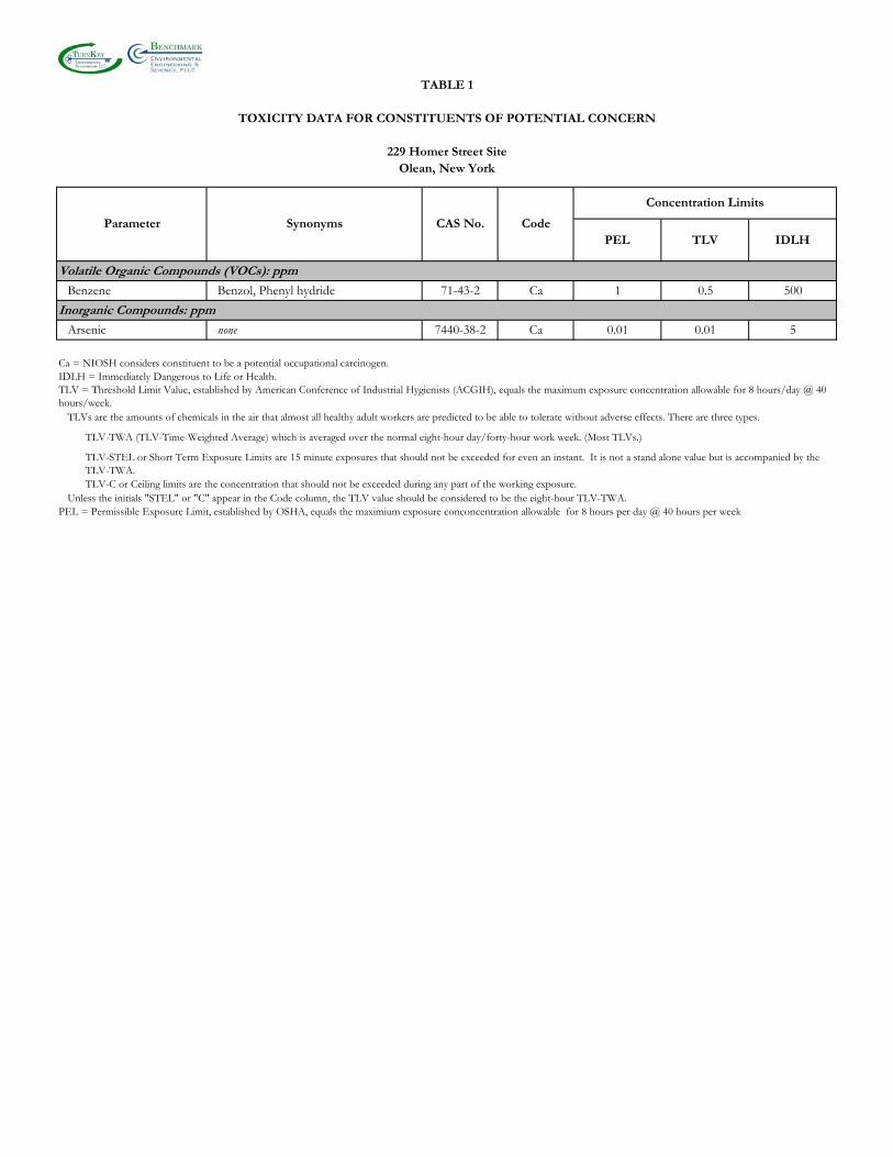
TABLE 1
TOXICITY DATA FOR CONSTITUENTS OF POTENTIAL CONCERN
229 Homer Street SiteOlean, New York
PEL TLV IDLH
Volatile Organic Compounds (VOCs): ppm
Benzene Benzol, Phenyl hydride 71-43-2 Ca 1 0.5 500
Inorganic Compounds: ppm
Arsenic none 7440-38-2 Ca 0.01 0.01 5
Ca = NIOSH considers constituent to be a potential occupational carcinogen.IDLH = Immediately Dangerous to Life or Health.
TLVs are the amounts of chemicals in the air that almost all healthy adult workers are predicted to be able to tolerate without adverse effects. There are three types.
TLV-TWA (TLV-Time-Weighted Average) which is averaged over the normal eight-hour day/forty-hour work week. (Most TLVs.)
Unless the initials "STEL" or "C" appear in the Code column, the TLV value should be considered to be the eight-hour TLV-TWA.PEL = Permissible Exposure Limit, established by OSHA, equals the maximium exposure conconcentration allowable for 8 hours per day @ 40 hours per week
TLV-C or Ceiling limits are the concentration that should not be exceeded during any part of the working exposure.
TLV-STEL or Short Term Exposure Limits are 15 minute exposures that should not be exceeded for even an instant. It is not a stand alone value but is accompanied by the TLV-TWA.
Concentration Limits
Parameter CodeSynonyms CAS No.
TLV = Threshold Limit Value, established by American Conference of Industrial Hygienists (ACGIH), equals the maximum exposure concentration allowable for 8 hours/day @ 40 hours/week.
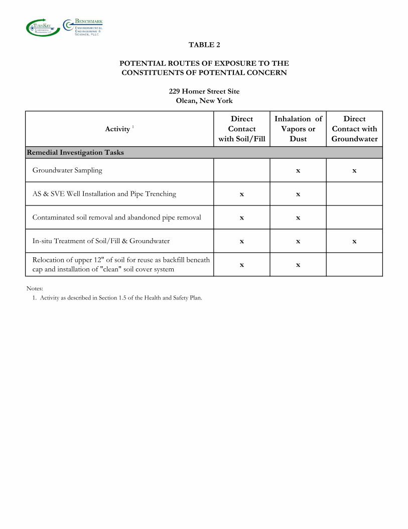
TABLE 2
POTENTIAL ROUTES OF EXPOSURE TO THECONSTITUENTS OF POTENTIAL CONCERN
229 Homer Street SiteOlean, New York
Activity 1
DirectContact
with Soil/Fill
Inhalation ofVapors or
Dust
DirectContact withGroundwater
Remedial Investigation Tasks
Groundwater Sampling x x
AS & SVE Well Installation and Pipe Trenching x x
Contaminated soil removal and abandoned pipe removal x x
In-situ Treatment of Soil/Fill & Groundwater x x x
Relocation of upper 12" of soil for reuse as backfill beneath cap and installation of "clean" soil cover system
x x
Notes:
1. Activity as described in Section 1.5 of the Health and Safety Plan.
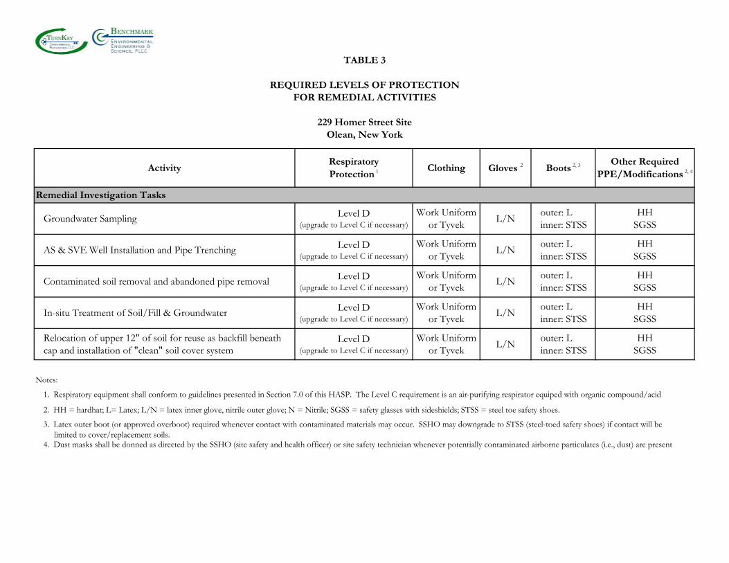
TABLE 3
REQUIRED LEVELS OF PROTECTIONFOR REMEDIAL ACTIVITIES
229 Homer Street SiteOlean, New York
ActivityRespiratoryProtection 1 Clothing Gloves 2 Boots 2, 3 Other Required
PPE/Modifications 2, 4
Remedial Investigation Tasks
Groundwater Sampling Level D(upgrade to Level C if necessary)
Work Uniform or Tyvek
L/Nouter: Linner: STSS
HHSGSS
AS & SVE Well Installation and Pipe Trenching Level D(upgrade to Level C if necessary)
Work Uniform or Tyvek
L/Nouter: Linner: STSS
HHSGSS
Contaminated soil removal and abandoned pipe removal Level D(upgrade to Level C if necessary)
Work Uniform or Tyvek
L/Nouter: Linner: STSS
HHSGSS
In-situ Treatment of Soil/Fill & Groundwater Level D(upgrade to Level C if necessary)
Work Uniform or Tyvek
L/Nouter: Linner: STSS
HHSGSS
Relocation of upper 12" of soil for reuse as backfill beneath cap and installation of "clean" soil cover system
Level D(upgrade to Level C if necessary)
Work Uniform or Tyvek
L/Nouter: Linner: STSS
HHSGSS
Notes:
2. HH = hardhat; L= Latex; L/N = latex inner glove, nitrile outer glove; N = Nitrile; SGSS = safety glasses with sideshields; STSS = steel toe safety shoes.
4. Dust masks shall be donned as directed by the SSHO (site safety and health officer) or site safety technician whenever potentially contaminated airborne particulates (i.e., dust) are present
3. Latex outer boot (or approved overboot) required whenever contact with contaminated materials may occur. SSHO may downgrade to STSS (steel-toed safety shoes) if contact will be limited to cover/replacement soils.
1. Respiratory equipment shall conform to guidelines presented in Section 7.0 of this HASP. The Level C requirement is an air-purifying respirator equiped with organic compound/acid

0311-018-001
FIGURES
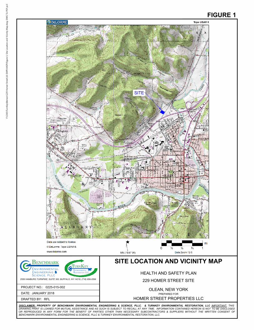
SITE
DRAFTED BY:
PROJECT NO.:
DATE:
PREPARED FOR
LLCRestoration,
alt
C
inr
e
, P L L
g
n
eE ign ne
BEY
ENCHMARKm
TE
URNnvironmental
KnivnE ro
S iec n ec
2558 HAMBURG TURNPIKE, SUITE 300, BUFFALO, NY 14218, (716) 856-0599
DISCLAIMER: PROPERTY OF BENCHMARK ENVIRONMENTAL ENGINEERING & SCIENCE, PLLC. & TURNKEY ENVIRONMENTAL RESTORATION, LLC IMPORTANT: THIS
DRAWING PRINT IS LOANED FOR MUTUAL ASSISTANCE AND AS SUCH IS SUBJECT TO RECALL AT ANY TIME. INFORMATION CONTAINED HEREON IS NOT TO BE DISCLOSED
OR REPRODUCED IN ANY FORM FOR THE BENEFIT OF PARTIES OTHER THAN NECESSARY SUBCONTRACTORS & SUPPLIERS WITHOUT THE WRITTEN CONSENT OF
BENCHMARK ENVIRONMENTAL ENGINEERING & SCIENCE, PLLC & TURNKEY ENVIRONMENTAL RESTORATION, LLC.
SITE LOCATION AND VICINITY MAP
HEALTH AND SAFETY PLAN
HOMER STREET PROPERTIES LLC
229 HOMER STREET SITE
OLEAN, NEW YORK
FIGURE 1
RFL
JANUARY 2018
0225-015-002
F:\C
AD
\Tu
rn
Key\B
en
so
n\229 H
om
er Street\16-SM
P\H
ASP
\Fig
ure 1; Site Lo
catio
n an
d V
icin
ity M
ap
.d
wg
, D
WG
To
P
DF.p
c3
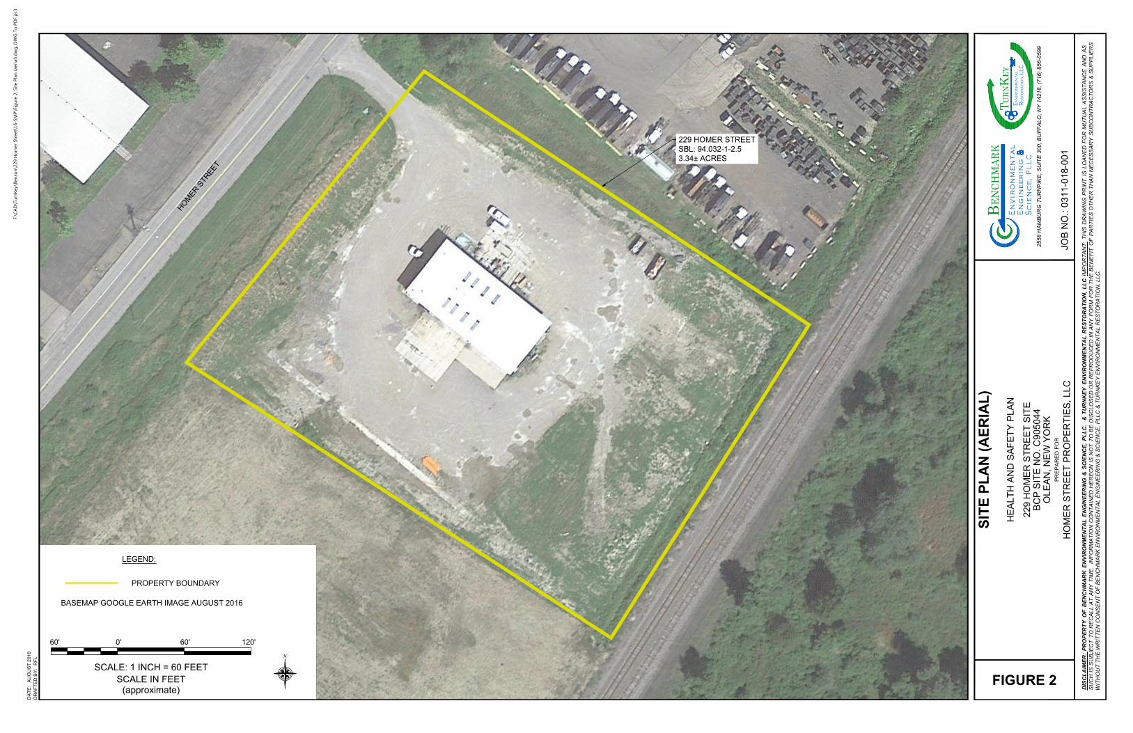
229 HOMER STREET
SBL: 94.032-1-2.5
3.34± ACRES
H
O
M
E
R
S
T
R
E
E
T
LEGEND:
PROPERTY BOUNDARY
NOTE: AERIAL IMAGE GOOGLE EARTH 8/26/16.
BASEMAP GOOGLE EARTH IMAGE AUGUST 2016
0'
SCALE IN FEET
(approximate)
60' 60' 120'
SCALE: 1 INCH = 60 FEET
N
DR
AF
TE
D B
Y:
DA
TE
:
PR
EP
AR
ED
F
OR
JO
B N
O.:
LL
CR
es
to
ra
tio
n,
al
t C
in
r
e
,P
LLgn
eE
ig
nn
e
BEY
ENCH
MAR
Km
T E
URN
nv
iro
nm
en
ta
l
Kn
iv
nE
ro
Sie
cn
ec
25
58
H
AM
BU
RG
T
UR
NP
IK
E, S
UIT
E 3
00
, B
UF
FA
LO
, N
Y 1
42
18
, (7
16
) 8
56
-0
59
9
DIS
CL
AIM
ER
: P
RO
PE
RT
Y O
F B
EN
CH
MA
RK
E
NV
IR
ON
ME
NT
AL
E
NG
IN
EE
RIN
G &
S
CIE
NC
E, P
LL
C. &
T
UR
NK
EY
E
NV
IR
ON
ME
NT
AL
R
ES
TO
RA
TIO
N, L
LC
IM
PO
RT
AN
T: T
HIS
D
RA
WIN
G P
RIN
T IS
L
OA
NE
D F
OR
M
UT
UA
L A
SS
IS
TA
NC
E A
ND
A
S
SU
CH
IS
S
UB
JE
CT
T
O R
EC
AL
L A
T A
NY
T
IM
E. IN
FO
RM
AT
IO
N C
ON
TA
IN
ED
H
ER
EO
N IS
N
OT
T
O B
E D
IS
CL
OS
ED
O
R R
EP
RO
DU
CE
D IN
A
NY
F
OR
M F
OR
T
HE
B
EN
EF
IT
O
F P
AR
TIE
S O
TH
ER
T
HA
N N
EC
ES
SA
RY
S
UB
CO
NT
RA
CT
OR
S &
S
UP
PL
IE
RS
WIT
HO
UT
T
HE
W
RIT
TE
N C
ON
SE
NT
O
F B
EN
CH
MA
RK
E
NV
IR
ON
ME
NT
AL
E
NG
IN
EE
RIN
G &
S
CIE
NC
E, P
LL
C &
T
UR
NK
EY
E
NV
IR
ON
ME
NT
AL
R
ES
TO
RA
TIO
N, L
LC
.
AU
GU
ST
2
01
8
RF
L
FIGURE 2
HO
ME
R S
TR
EE
T P
RO
PE
RT
IE
S, L
LC
22
9 H
OM
ER
S
TR
EE
T S
IT
E
BC
P S
IT
E N
O. C
90
50
44
OL
EA
N, N
EW
Y
OR
K
HE
AL
TH
A
ND
S
AF
ET
Y P
LA
N
SIT
E P
LA
N (A
ER
IA
L)
03
11
-0
18
-0
01
F:\C
AD
\Tu
rn
Key\B
en
so
n\229 H
om
er Street\16-SM
P\Fig
ure 2; Site P
lan
(aerial).d
wg
, D
WG
To
P
DF.p
c3
0311-018-001
ATTACHMENT A
EMERGENCY RESPONSE PLAN

HEALTH & SAFETY PLAN
APPENDIX A: EMERGENCY RESPONSE PLAN
EMERGENCY RESPONSE PLAN for
SITE MANAGEMENT PLAN
229 HOMER STREET SITE
OLEAN, NEW YORK August 2018 0311-018-001
Prepared by:
Benchmark Environmental Engineering & Science, PLLC In association with TurnKey Environmental Restoration, LLC
2558 Hamburg Turnpike, Suite 300
Buffalo, NY 14218 (716) 856-0599
HEALTH & SAFETY PLAN
APPENDIX A: EMERGENCY RESPONSE PLAN
229 HOMER STREET SITE
HEALTH AND SAFETY PLAN FOR SITE MANAGEMENT PLAN POST-
REMEDIAL ACTIVITIES
APPENDIX A: EMERGENCY RESPONSE PLAN
TABLE OF CONTENTS
0311-018-001
i
1.0 GENERAL ................................................................................................................ 1
2.0 PRE-EMERGENCY PLANNING ............................................................................... 2
3.0 ON-SITE EMERGENCY RESPONSE EQUIPMENT ................................................... 3
4.0 EMERGENCY PLANNING MAPS ............................................................................. 4
5.0 EMERGENCY CONTACTS ....................................................................................... 5
6.0 EMERGENCY ALERTING & EVACUATION ............................................................. 6
7.0 EXTREME WEATHER CONDITIONS ....................................................................... 8
8.0 EMERGENCY MEDICAL TREATMENT & FIRST AID .............................................. 9
9.0 EMERGENCY RESPONSE CRITIQUE & RECORD KEEPING ................................... 10
10.0 EMERGENCY RESPONSE TRAINING ..................................................................... 11
LIST OF FIGURES
Figure E-1 Hospital Route Map
HEALTH & SAFETY PLAN
APPENDIX A: EMERGENCY RESPONSE PLAN
0311-018-001
1
1.0 GENERAL
This report presents the site-specific Emergency Response Plan (ERP) referenced in
the Site Health and Safety Plan (HASP) prepared for Post-Remedial Activities (PRA) at the
229 Homer Street Site located at 229 Homer Street in Olean, New York. This appendix of
the HASP describes potential emergencies that may occur at the Site; procedures for
responding to those emergencies; roles and responsibilities during emergency response; and
training all workers must receive in order to follow emergency procedures. This ERP also
describes the provisions this Site has made to coordinate its emergency response planning
with other contractors on-site and with off-site emergency response organizations.
This ERP is consistent with the requirements of 29 CFR 1910.120(l) and provides the
following site-specific information:
Pre-emergency planning. Personnel roles, lines of authority, and communication. Emergency recognition and prevention. Safe distances and places of refuge. Evacuation routes and procedures. Decontamination procedures. Emergency medical treatment and first aid. Emergency alerting and response procedures. Critique of response and follow-up. Emergency personal protective equipment (PPE) and equipment.
HEALTH & SAFETY PLAN
APPENDIX A: EMERGENCY RESPONSE PLAN
0311-018-001
2
2.0 PRE-EMERGENCY PLANNING
This Site has been evaluated for potential emergency occurrences, based on site
hazards, the required work tasks, the site topography, and prevailing weather conditions. The
results of that evaluation indicate the potential for the following site emergencies to occur at
the locations indicated.
Type of Emergency: 1. Medical, due to physical injury
Source of Emergency:
1. Slip/trip/fall Location of Source:
1. Non-specific
HEALTH & SAFETY PLAN
APPENDIX A: EMERGENCY RESPONSE PLAN
0311-018-001
3
3.0 ON-SITE EMERGENCY RESPONSE EQUIPMENT
Emergency procedures may require specialized equipment to facilitate worker rescue,
contamination control and reduction, or post-emergency clean up. Emergency response
equipment available on the Site is listed below. The equipment inventory and storage
locations are based on the potential emergencies described above. This equipment inventory
is designed to meet on-site emergency response needs and any specialized equipment needs
that off-site responders might require because of the hazards at this Site but not ordinarily
stocked.
Any additional personal protective equipment (PPE) required and stocked for
emergency response is also listed in below. During an emergency, the Emergency Response
Coordinator (ERC) is responsible for specifying the level of PPE required for emergency
response. At a minimum, PPE used by emergency responders will comply with Section 7.0,
Personal Protective Equipment, of this HASP. Emergency response equipment is inspected
at regular intervals and maintained in good working order. The equipment inventory is
replenished as necessary to maintain response capabilities.
Emergency Equipment Quantity Location
First Aid Kit 1 Site Vehicle
Chemical Fire Extinguisher 2 (minimum) All heavy equipment and Site Vehicle
Emergency PPE Quantity Location
Full-face respirator 1 for each worker Site Vehicle
Chemical-resistant suits 4 (minimum) Site Vehicle
HEALTH & SAFETY PLAN
APPENDIX A: EMERGENCY RESPONSE PLAN
0311-018-001
4
4.0 EMERGENCY PLANNING MAPS
An area-specific map of the Site will be developed on a daily basis during
performance of field activities. The map will be marked to identify critical on-site emergency
planning information, including: emergency evacuation routes, a place of refuge, an assembly
point, and the locations of key site emergency equipment. Site zone boundaries will be
shown to alert responders to known areas of contamination. There are no major
topographical features, however the direction of prevailing winds/weather conditions that
could affect emergency response planning are also marked on the map. The map will be
posted at site-designated place of refuge and inside the Benchmark-TurnKey personnel field
vehicle.

HEALTH & SAFETY PLAN
APPENDIX A: EMERGENCY RESPONSE PLAN
0311-018-001
5
5.0 EMERGENCY CONTACTS The following identifies the emergency contacts for this ERP.
Emergency Telephone Numbers:
Project Officer: Paul H Werthman, P.E. Work: (716) 856-0599 Mobile: (716) 998-4151
Project Manager: Michael Lesakowski Work: (716) 856-0635 Mobile: (716) 818-3954
Corporate Health and Safety Director: Thomas H. Forbes, P.E.
Work: (716) 856-0599 Mobile: (716) 864-1730
Site Safety and Health Officer (SSHO): Mark Janus Work: (716) 856-0599 Mobile: (716) 200-3196
Alternate SSHO: Brock Greene Work: (716) 856-0599 Mobile: (716) 225-3314
OLEAN GENERAL HOSPITAL (ER): (716) 373-2600 FIRE: 911 AMBULANCE: 911 BUFFALO POLICE: 911 STATE EMERGENCY RESPONSE HOTLINE: (800) 457-7362 NATIONAL RESPONSE HOTLINE: (800) 424-8802 NYSDOH: (716) 847-4385 NYSDEC: (716) 851-7220 NYSDEC 24-HOUR SPILL HOTLINE: (800) 457-7252
The Site location is:
229 Homer Street Olean, New York 14760 Site Phone Number: (Insert Cell Phone or Field Trailer): Cellular Phone on-Site
HEALTH & SAFETY PLAN
APPENDIX A: EMERGENCY RESPONSE PLAN
0311-018-001
6
6.0 EMERGENCY ALERTING & EVACUATION
Internal emergency communication systems are used to alert workers to danger,
convey safety information, and maintain site control. Any effective system can be employed.
Two-way radio headsets or field telephones are often used when work teams are far from the
command post. Hand signals and air-horn blasts are also commonly used. Every system
must have a backup. It shall be the responsibility of each contractor’s Site Health and Safety
Officer to ensure all personnel entering the site understand an adequate method of internal
communication. Unless all personnel are otherwise informed, the following signals shall be
used.
1) Emergency signals by portable air horn, siren, or whistle: two short blasts, personal injury; continuous blast, emergency requiring site excavation.
2) Visual signals: hand gripping throat, out of air/cannot breathe; hands on top
of head, need assistance; thumbs up, affirmative/ everything is OK; thumbs down, no/negative; grip partner’s wrist or waist, leave area immediately.
If evacuation notice is given, site workers leave the worksite with their respective
buddies, if possible, by way of the nearest exit. Emergency decontamination procedures
detailed in Section 12.0 of the HASP are followed to the extent practical without
compromising the safety and health of site personnel. The evacuation routes and assembly
area will be determined by conditions at the time of the evacuation based on wind direction,
the location of the hazard source, and other factors as determined by rehearsals and inputs
from emergency response organizations. Wind direction indicators are located so that
workers can determine a safe up wind or cross wind evacuation route and assembly area if
not informed by the emergency response coordinator at the time the evacuation alarm
sounds. Since work conditions and work zones within the site may be changing on daily
basis, it shall be the responsibility of the construction Site Health and Safety Officer to
review evacuation routes and procedures as necessary and to inform all Benchmark-TurnKey
workers of any changes.
Personnel exiting the site will gather at a designated assembly point. To determine
that everyone has successfully exited the site, personnel will be accounted for at the assembly
site. If any worker cannot be accounted for, notification is given to the SSHO (Mark Janus

HEALTH & SAFETY PLAN
APPENDIX A: EMERGENCY RESPONSE PLAN
0311-018-001
7
or Brock Greene) so that appropriate action can be initiated. Contractors and
subcontractors on this site have coordinated their emergency response plans to ensure that
these plans are compatible and that source(s) of potential emergencies are recognized, alarm
systems are clearly understood, and evacuation routes are accessible to all personnel relying
upon them.
HEALTH & SAFETY PLAN
APPENDIX A: EMERGENCY RESPONSE PLAN
0311-018-001
8
7.0 EXTREME WEATHER CONDITIONS
In the event of adverse weather conditions, the Site Safety and Health Officer in
conjunction with the Contractor’s SSHO will determine if engineering operations can
continue without sacrificing the health and safety of site personnel. Items to be considered
prior to determining if work should continue include but are not limited to:
Potential for heat/cold stress. Weather-related construction hazards (e.g., flooding or wet conditions producing
undermining of structures or sheeting, high wind threats, etc). Limited visibility. Potential for electrical storms. Limited site access/egress (e.g., due to heavy snow)
HEALTH & SAFETY PLAN
APPENDIX A: EMERGENCY RESPONSE PLAN
0311-018-001
9
8.0 EMERGENCY MEDICAL TREATMENT & FIRST AID
Personnel Exposure:
The following general guidelines will be employed in instances where health impacts
threaten to occur acute exposure is realized:
Skin Contact: Use copious amounts of soap and water. Wash/rinse affected area for at least 15 minutes. Decontaminate and provide medical attention. Eyewash stations will be provided on site. If necessary, transport to Buffalo General Hospital.
Inhalation: Move to fresh air and, if necessary, transport to Hospital. Ingestion: Decontaminate and transport to Hospital.
Personal Injury:
Minor first-aid will be applied on-site as deemed necessary. In the event of a life
threatening injury, the individual should be transported to Hospital via ambulance. The Site
Health and Safety Officer will supply available chemical specific information to appropriate
medical personnel as requested.
First aid kits will conform to Red Cross and other applicable good health standards,
and shall consist of a weatherproof container with individually sealed packages for each type
of item. First aid kits will be fully equipped before being sent out on each job and will be
checked weekly by the SSHO to ensure that the expended items are replaced.
Directions to Olean General Hospital (see Figure E-1): The following directions describe the best route from the Site to Olean General Hospital of Olean which is 2 miles away:
Travel northeast on Homer Street (Right from Site parking lot). Turn right onto River Street. Continue straight on East Forest Avenue. Turn left onto North Union Street. Continue straight on Main Street Olean General Hospital will be on your left.

HEALTH & SAFETY PLAN
APPENDIX A: EMERGENCY RESPONSE PLAN
0311-018-001
10
9.0 EMERGENCY RESPONSE CRITIQUE & RECORD KEEPING Following an emergency, the SSHO and Project Manager shall review the
effectiveness of this Emergency Response Plan (ERP) in addressing notification, control and
evacuation requirements. Updates and modifications to this ERP shall be made accordingly.
It shall be the responsibility of each contractor to establish and assure adequate records of
the following:
Occupational injuries and illnesses. Accident investigations. Reports to insurance carrier or State compensation agencies. Reports required by the client. Records and reports required by local, state, federal and/or international agencies. Property or equipment damage. Third party injury or damage claims. Environmental testing logs. Explosive and hazardous substances inventories and records. Records of inspections and citations. Safety training.

HEALTH & SAFETY PLAN
APPENDIX A: EMERGENCY RESPONSE PLAN
0311-018-001
11
10.0 EMERGENCY RESPONSE TRAINING
Persons who enter the worksite, including visitors, shall receive a site-specific briefing
about anticipated emergency situations and the emergency procedures by the SSHO. Where
this site relies on off-site organizations for emergency response, the training of personnel in
those off-site organizations has been evaluated and is deemed adequate for response to this
site.

0311-018-001
FIGURES
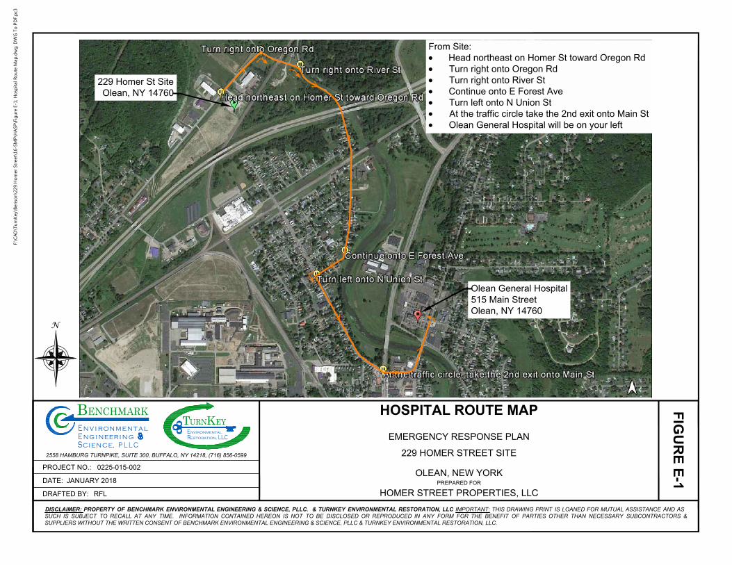
229 Homer St Site
Olean, NY 14760
Olean General Hospital
515 Main Street
Olean, NY 14760
From Site:
· Head northeast on Homer St toward Oregon Rd
· Turn right onto Oregon Rd
· Turn right onto River St
· Continue onto E Forest Ave
· Turn left onto N Union St
· At the traffic circle take the 2nd exit onto Main St
· Olean General Hospital will be on your left
N
PREPARED FOR
DRAFTED BY:
PROJECT NO.:
DATE:
LLCRestoration,
alt
C
i nr
e
, P L L
g
n
eE ign ne
BEY
ENCHMARKm
TE
URNnvironmental
KnivnE ro
S iec n ec
2558 HAMBURG TURNPIKE, SUITE 300, BUFFALO, NY 14218, (716) 856-0599
DISCLAIMER: PROPERTY OF BENCHMARK ENVIRONMENTAL ENGINEERING & SCIENCE, PLLC. & TURNKEY ENVIRONMENTAL RESTORATION, LLC IMPORTANT: THIS DRAWING PRINT IS LOANED FOR MUTUAL ASSISTANCE AND AS
SUCH IS SUBJECT TO RECALL AT ANY TIME. INFORMATION CONTAINED HEREON IS NOT TO BE DISCLOSED OR REPRODUCED IN ANY FORM FOR THE BENEFIT OF PARTIES OTHER THAN NECESSARY SUBCONTRACTORS &
SUPPLIERS WITHOUT THE WRITTEN CONSENT OF BENCHMARK ENVIRONMENTAL ENGINEERING & SCIENCE, PLLC & TURNKEY ENVIRONMENTAL RESTORATION, LLC.
FIG
UR
E E
-1
HOSPITAL ROUTE MAP
EMERGENCY RESPONSE PLAN
OLEAN, NEW YORK
229 HOMER STREET SITE
HOMER STREET PROPERTIES, LLCRFL
JANUARY 2018
0225-015-002
F:\C
AD
\Tu
rn
Key\B
en
so
n\229 H
om
er Street\16-SM
P\H
ASP
\Fig
ure E-1; H
osp
ital R
ou
te M
ap
.d
wg
, D
WG
To
P
DF.p
c3

0311-018-001
ATTACHMENT B
HOT WORK PERMIT FORM
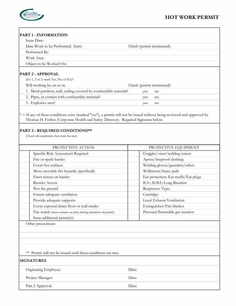
HOT WORK PERMIT
PART 1 - INFORMATIONIssue Date:
Date Work to be Performed: Start: Finish (permit terminated):
Performed By:
Work Area:
Object to be Worked On:
PART 2 - APPROVAL(for 1, 2 or 3: mark Yes, No or NA)*
Will working be on or in: Finish (permit terminated):
1. Metal partition, wall, ceiling covered by combustible material? yes no
2. Pipes, in contact with combustible material? yes no
3. Explosive area? yes no
PART 3 - REQUIRED CONDITIONS**(Check all conditions that must be met)
PROTECTIVE EQUIPMENTPROTECTIVE ACTION
* = If any of these conditions exist (marked "yes"), a permit will not be issued without being reviewed and approved by Thomas H. Forbes (Corporate Health and Safety Director). Required Signature below.
Specific Risk Assessment Required Goggles/visor/welding screen
Fire or spark barrier Apron/fireproof clothing
Cover hot surfaces Welding gloves/gauntlets/other:
Move movable fire hazards, specifically Wellintons/Knee pads
Erect screen on barrier Ear protection: Ear muffs/Ear plugs
Restrict Access B.A.: SCBA/Long Breather
Wet the ground Respirator: Type:
Ensure adequate ventilation Cartridge:
Provide adequate supports Local Exhaust Ventilation
Cover exposed drain/floor or wall cracks Extinguisher/Fire blanket
Fire watch (must remain on duty during duration of permit) Personal flammable gas monitor
Issue additional permit(s):
Other precautions:
** Permit will not be issued until these conditions are met.
SIGNATURES
Orginating Employee: Date:
Project Manager: Date:
Part 2 Approval: Date:
0311-018-001
ATTACHMENT C
NYSDOH GENERIC COMMUNITY AIR MONITORING PLAN
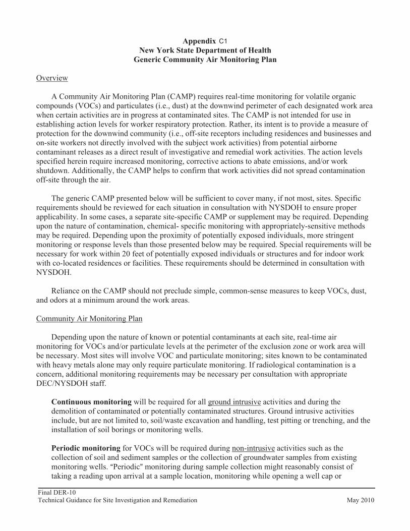
Final DER-10 Page 204 of 226 Technical Guidance for Site Investigation and Remediation May 2010
Appendix 1A New York State Department of Health
Generic Community Air Monitoring Plan
Overview
A Community Air Monitoring Plan (CAMP) requires real-time monitoring for volatile organic compounds (VOCs) and particulates (i.e., dust) at the downwind perimeter of each designated work area when certain activities are in progress at contaminated sites. The CAMP is not intended for use in establishing action levels for worker respiratory protection. Rather, its intent is to provide a measure of protection for the downwind community (i.e., off-site receptors including residences and businesses and on-site workers not directly involved with the subject work activities) from potential airborne contaminant releases as a direct result of investigative and remedial work activities. The action levels specified herein require increased monitoring, corrective actions to abate emissions, and/or work shutdown. Additionally, the CAMP helps to confirm that work activities did not spread contamination off-site through the air.
The generic CAMP presented below will be sufficient to cover many, if not most, sites. Specific requirements should be reviewed for each situation in consultation with NYSDOH to ensure proper applicability. In some cases, a separate site-specific CAMP or supplement may be required. Depending upon the nature of contamination, chemical- specific monitoring with appropriately-sensitive methods may be required. Depending upon the proximity of potentially exposed individuals, more stringent monitoring or response levels than those presented below may be required. Special requirements will be necessary for work within 20 feet of potentially exposed individuals or structures and for indoor work with co-located residences or facilities. These requirements should be determined in consultation with NYSDOH.
Reliance on the CAMP should not preclude simple, common-sense measures to keep VOCs, dust, and odors at a minimum around the work areas.
Community Air Monitoring Plan
Depending upon the nature of known or potential contaminants at each site, real-time air monitoring for VOCs and/or particulate levels at the perimeter of the exclusion zone or work area will be necessary. Most sites will involve VOC and particulate monitoring; sites known to be contaminated with heavy metals alone may only require particulate monitoring. If radiological contamination is a concern, additional monitoring requirements may be necessary per consultation with appropriate DEC/NYSDOH staff.
Continuous monitoring will be required for all ground intrusive activities and during the demolition of contaminated or potentially contaminated structures. Ground intrusive activities include, but are not limited to, soil/waste excavation and handling, test pitting or trenching, and the installation of soil borings or monitoring wells.
Periodic monitoring for VOCs will be required during non-intrusive activities such as the collection of soil and sediment samples or the collection of groundwater samples from existing monitoring wells. APeriodic@ monitoring during sample collection might reasonably consist of taking a reading upon arrival at a sample location, monitoring while opening a well cap or
C1
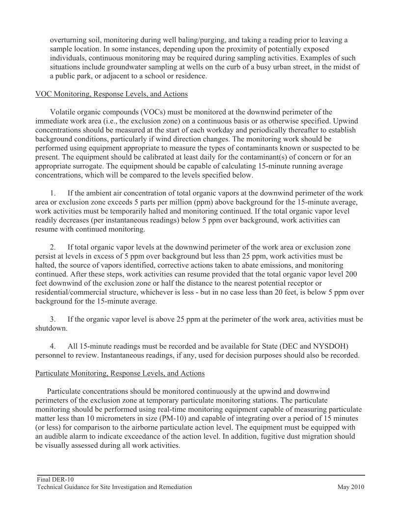
Final DER-10 Page 205 of 226 Technical Guidance for Site Investigation and Remediation May 2010
overturning soil, monitoring during well baling/purging, and taking a reading prior to leaving a sample location. In some instances, depending upon the proximity of potentially exposed individuals, continuous monitoring may be required during sampling activities. Examples of such situations include groundwater sampling at wells on the curb of a busy urban street, in the midst of a public park, or adjacent to a school or residence.
VOC Monitoring, Response Levels, and Actions
Volatile organic compounds (VOCs) must be monitored at the downwind perimeter of the immediate work area (i.e., the exclusion zone) on a continuous basis or as otherwise specified. Upwind concentrations should be measured at the start of each workday and periodically thereafter to establish background conditions, particularly if wind direction changes. The monitoring work should be performed using equipment appropriate to measure the types of contaminants known or suspected to be present. The equipment should be calibrated at least daily for the contaminant(s) of concern or for an appropriate surrogate. The equipment should be capable of calculating 15-minute running average concentrations, which will be compared to the levels specified below.
1. If the ambient air concentration of total organic vapors at the downwind perimeter of the work area or exclusion zone exceeds 5 parts per million (ppm) above background for the 15-minute average, work activities must be temporarily halted and monitoring continued. If the total organic vapor level readily decreases (per instantaneous readings) below 5 ppm over background, work activities can resume with continued monitoring.
2. If total organic vapor levels at the downwind perimeter of the work area or exclusion zone persist at levels in excess of 5 ppm over background but less than 25 ppm, work activities must be halted, the source of vapors identified, corrective actions taken to abate emissions, and monitoring continued. After these steps, work activities can resume provided that the total organic vapor level 200 feet downwind of the exclusion zone or half the distance to the nearest potential receptor or residential/commercial structure, whichever is less - but in no case less than 20 feet, is below 5 ppm over background for the 15-minute average.
3. If the organic vapor level is above 25 ppm at the perimeter of the work area, activities must be shutdown.
4. All 15-minute readings must be recorded and be available for State (DEC and NYSDOH) personnel to review. Instantaneous readings, if any, used for decision purposes should also be recorded.
Particulate Monitoring, Response Levels, and Actions
Particulate concentrations should be monitored continuously at the upwind and downwind perimeters of the exclusion zone at temporary particulate monitoring stations. The particulate monitoring should be performed using real-time monitoring equipment capable of measuring particulate matter less than 10 micrometers in size (PM-10) and capable of integrating over a period of 15 minutes (or less) for comparison to the airborne particulate action level. The equipment must be equipped with an audible alarm to indicate exceedance of the action level. In addition, fugitive dust migration should be visually assessed during all work activities.

Final DER-10 Page 206 of 226 Technical Guidance for Site Investigation and Remediation May 2010
1. If the downwind PM-10 particulate level is 100 micrograms per cubic meter (mcg/m3) greater than background (upwind perimeter) for the 15-minute period or if airborne dust is observed leaving the work area, then dust suppression techniques must be employed. Work may continue with dust suppression techniques provided that downwind PM-10 particulate levels do not exceed 150 mcg/m3
above the upwind level and provided that no visible dust is migrating from the work area.
2. If, after implementation of dust suppression techniques, downwind PM-10 particulate levels are greater than 150 mcg/m3 above the upwind level, work must be stopped and a re-evaluation of activities initiated. Work can resume provided that dust suppression measures and other controls are successful in reducing the downwind PM-10 particulate concentration to within 150 mcg/m3 of the upwind level and in preventing visible dust migration.
3. All readings must be recorded and be available for State (DEC and NYSDOH) and County Health personnel to review.
December 2009
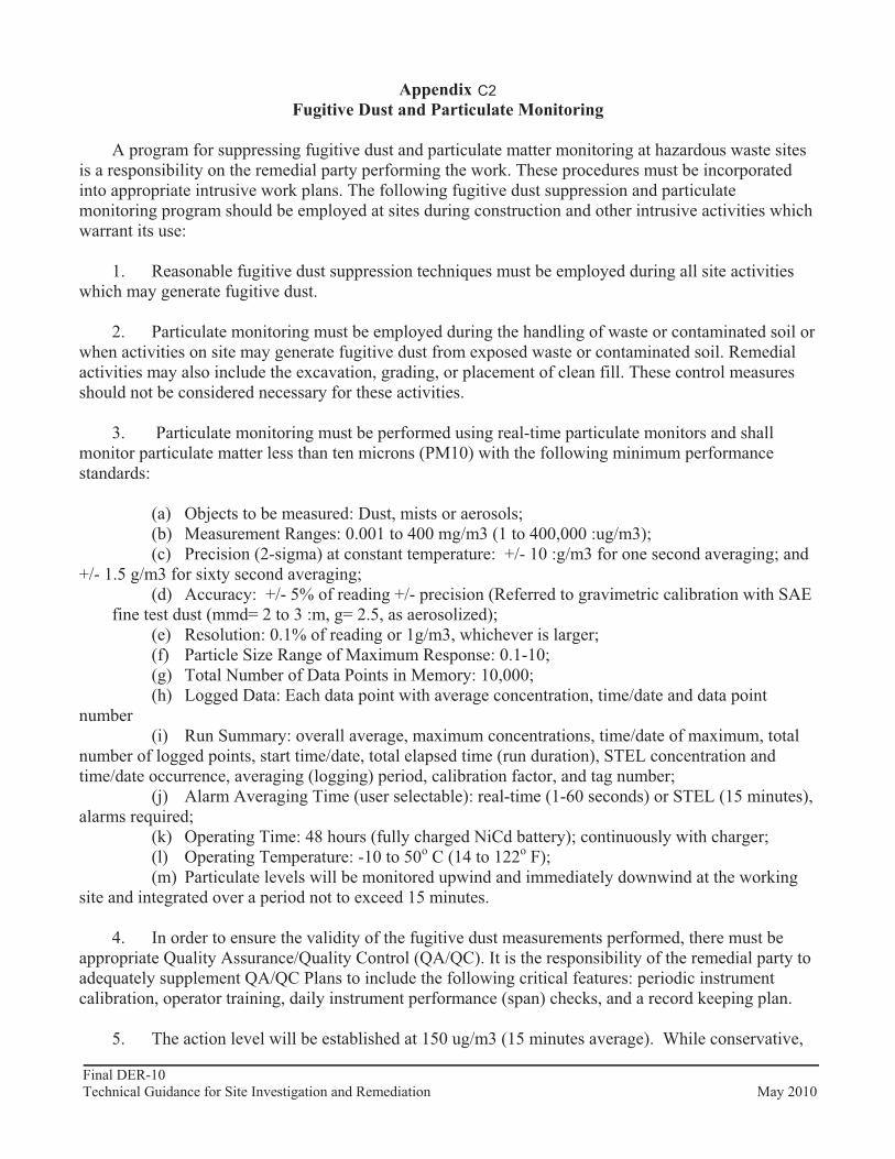
Final DER-10 Page 207 of 226 Technical Guidance for Site Investigation and Remediation May 2010
Appendix 1B Fugitive Dust and Particulate Monitoring
A program for suppressing fugitive dust and particulate matter monitoring at hazardous waste sites is a responsibility on the remedial party performing the work. These procedures must be incorporated into appropriate intrusive work plans. The following fugitive dust suppression and particulate monitoring program should be employed at sites during construction and other intrusive activities which warrant its use:
1. Reasonable fugitive dust suppression techniques must be employed during all site activities which may generate fugitive dust.
2. Particulate monitoring must be employed during the handling of waste or contaminated soil or when activities on site may generate fugitive dust from exposed waste or contaminated soil. Remedial activities may also include the excavation, grading, or placement of clean fill. These control measures should not be considered necessary for these activities.
3. Particulate monitoring must be performed using real-time particulate monitors and shall monitor particulate matter less than ten microns (PM10) with the following minimum performance standards:
(a) Objects to be measured: Dust, mists or aerosols; (b) Measurement Ranges: 0.001 to 400 mg/m3 (1 to 400,000 :ug/m3); (c) Precision (2-sigma) at constant temperature: +/- 10 :g/m3 for one second averaging; and
+/- 1.5 g/m3 for sixty second averaging; (d) Accuracy: +/- 5% of reading +/- precision (Referred to gravimetric calibration with SAE
fine test dust (mmd= 2 to 3 :m, g= 2.5, as aerosolized); (e) Resolution: 0.1% of reading or 1g/m3, whichever is larger; (f) Particle Size Range of Maximum Response: 0.1-10; (g) Total Number of Data Points in Memory: 10,000; (h) Logged Data: Each data point with average concentration, time/date and data point
number (i) Run Summary: overall average, maximum concentrations, time/date of maximum, total
number of logged points, start time/date, total elapsed time (run duration), STEL concentration and time/date occurrence, averaging (logging) period, calibration factor, and tag number;
(j) Alarm Averaging Time (user selectable): real-time (1-60 seconds) or STEL (15 minutes), alarms required;
(k) Operating Time: 48 hours (fully charged NiCd battery); continuously with charger; (l) Operating Temperature: -10 to 50o C (14 to 122o F); (m) Particulate levels will be monitored upwind and immediately downwind at the working
site and integrated over a period not to exceed 15 minutes.
4. In order to ensure the validity of the fugitive dust measurements performed, there must be appropriate Quality Assurance/Quality Control (QA/QC). It is the responsibility of the remedial party to adequately supplement QA/QC Plans to include the following critical features: periodic instrument calibration, operator training, daily instrument performance (span) checks, and a record keeping plan.
5. The action level will be established at 150 ug/m3 (15 minutes average). While conservative,
C2
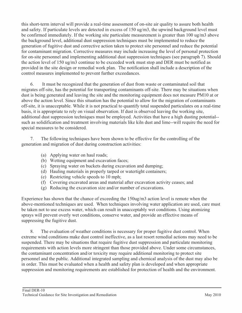
Final DER-10 Page 208 of 226 Technical Guidance for Site Investigation and Remediation May 2010
this short-term interval will provide a real-time assessment of on-site air quality to assure both health and safety. If particulate levels are detected in excess of 150 ug/m3, the upwind background level must be confirmed immediately. If the working site particulate measurement is greater than 100 ug/m3 above the background level, additional dust suppression techniques must be implemented to reduce the generation of fugitive dust and corrective action taken to protect site personnel and reduce the potential for contaminant migration. Corrective measures may include increasing the level of personal protection for on-site personnel and implementing additional dust suppression techniques (see paragraph 7). Should the action level of 150 ug/m3 continue to be exceeded work must stop and DER must be notified as provided in the site design or remedial work plan. The notification shall include a description of the control measures implemented to prevent further exceedances.
6. It must be recognized that the generation of dust from waste or contaminated soil that migrates off-site, has the potential for transporting contaminants off-site. There may be situations when dust is being generated and leaving the site and the monitoring equipment does not measure PM10 at or above the action level. Since this situation has the potential to allow for the migration of contaminants off-site, it is unacceptable. While it is not practical to quantify total suspended particulates on a real-time basis, it is appropriate to rely on visual observation. If dust is observed leaving the working site, additional dust suppression techniques must be employed. Activities that have a high dusting potential--such as solidification and treatment involving materials like kiln dust and lime--will require the need for special measures to be considered.
7. The following techniques have been shown to be effective for the controlling of the generation and migration of dust during construction activities:
(a) Applying water on haul roads; (b) Wetting equipment and excavation faces; (c) Spraying water on buckets during excavation and dumping; (d) Hauling materials in properly tarped or watertight containers; (e) Restricting vehicle speeds to 10 mph; (f) Covering excavated areas and material after excavation activity ceases; and (g) Reducing the excavation size and/or number of excavations.
Experience has shown that the chance of exceeding the 150ug/m3 action level is remote when the above-mentioned techniques are used. When techniques involving water application are used, care must be taken not to use excess water, which can result in unacceptably wet conditions. Using atomizing sprays will prevent overly wet conditions, conserve water, and provide an effective means of suppressing the fugitive dust.
8. The evaluation of weather conditions is necessary for proper fugitive dust control. When extreme wind conditions make dust control ineffective, as a last resort remedial actions may need to be suspended. There may be situations that require fugitive dust suppression and particulate monitoring requirements with action levels more stringent than those provided above. Under some circumstances, the contaminant concentration and/or toxicity may require additional monitoring to protect site personnel and the public. Additional integrated sampling and chemical analysis of the dust may also be in order. This must be evaluated when a health and safety plan is developed and when appropriate suppression and monitoring requirements are established for protection of health and the environment.

SMP – APPENDIX B: EXCAVATION WORK PLAN 229 HOMER STREET SITE
BCP SITE NO. C905044
0311-018-001 T KB
APPENDIX I
SITE MANAGEMENT FORMS
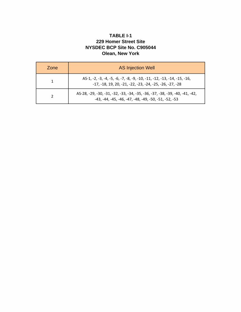
1AS‐1, ‐2, ‐3, ‐4, ‐5, ‐6, ‐7, ‐8, ‐9, ‐10, ‐11, ‐12, ‐13, ‐14, ‐15, ‐16,
‐17, ‐18, 19, 20, ‐21, ‐22, ‐23, ‐24, ‐25, ‐26, ‐27, ‐28
2AS‐28, ‐29, ‐30, ‐31, ‐32, ‐33, ‐34, ‐35, ‐36, ‐37, ‐38, ‐39, ‐40, ‐41, ‐42,
‐43, ‐44, ‐45, ‐46, ‐47, ‐48, ‐49, ‐50, ‐51, ‐52, ‐53
Zone AS Injection Well
TABLE I-1
229 Homer Street Site
NYSDEC BCP Site No. C905044
Olean, New York
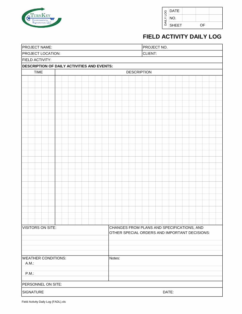
DATE
NO.
SHEET
FIELD ACTIVITY DAILY LOG
PROJECT NAME: PROJECT NO.
PROJECT LOCATION: CLIENT:
FIELD ACTIVITY:
DESCRIPTION OF DAILY ACTIVITIES AND EVENTS:
VISITORS ON SITE: CHANGES FROM PLANS AND SPECIFICATIONS, AND
OTHER SPECIAL ORDERS AND IMPORTANT DECISIONS:
WEATHER CONDITIONS: Notes:
A.M.:
P.M.:
PERSONNEL ON SITE:
SIGNATURE DATE:
TIME DESCRIPTION
DA
ILY
LO
G
OF
Field Activity Daily Log (FADL).xls
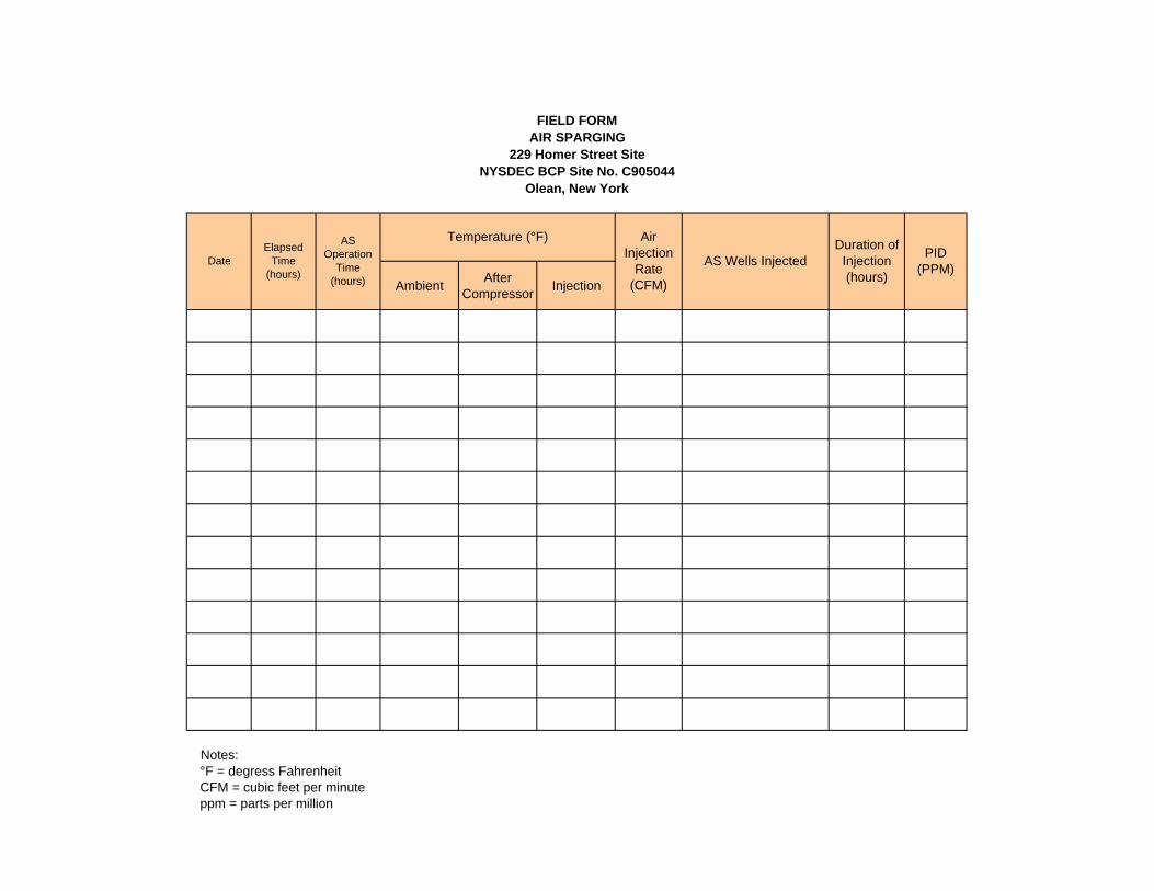
FIELD FORM
AIR SPARGING
229 Homer Street Site
NYSDEC BCP Site No. C905044
Olean, New York
AmbientAfter
CompressorInjection
Notes:
°F = degress Fahrenheit
CFM = cubic feet per minute
ppm = parts per million
Temperature (°F)
PID
(PPM)Date
Elapsed
Time
(hours)
AS
Operation
Time
(hours)
Air
Injection
Rate
(CFM)
AS Wells Injected
Duration of
Injection
(hours)

Bn v i r o n m e t a ln g i n eer i n gc en c e,i
nT K
nvironmen talestoration,
FIELD FORM
GROUNDWATER LEVELS AND DISSOLVED OXYGEN CONCENTRATIONS
229 HOMER STREET SITE
OLEAN, NEW YORK
Well Date/Time Grade
TOR
Elevation
(ft)
DTW
(fbTOR)
Water
Elevation (ft)
Dissolved
Oxygen
(mg/L)
Notes
Notes
ft = feet
fbTOR = feet below top of riser
mg/L = milligrams per liter
Elevation datum; NAVD 88
MW-1
MW-2
MW-3
MW-4
MW-7
MW-5
MW-6

229 Homer Street SiteSVE SYSTEM LOG
SHEET 1 OF 2
Date TimeInspector's
Initials
System Running on
Arrival? (Y or N)
Intake Vacuum at Knockout
(in. WC)
Air Flow Gauge
(in.WC)Velocity (FPS)
Approx Flow (CFM)
Pressure Gauge (exhaust) (in. WC)
Influent PID Reading (PPM)
Effluent PID Reading from
Biofilter (PPM)
Greased Blower?(Y or N)
Condensate Water Present
(gallons)
NOTES :
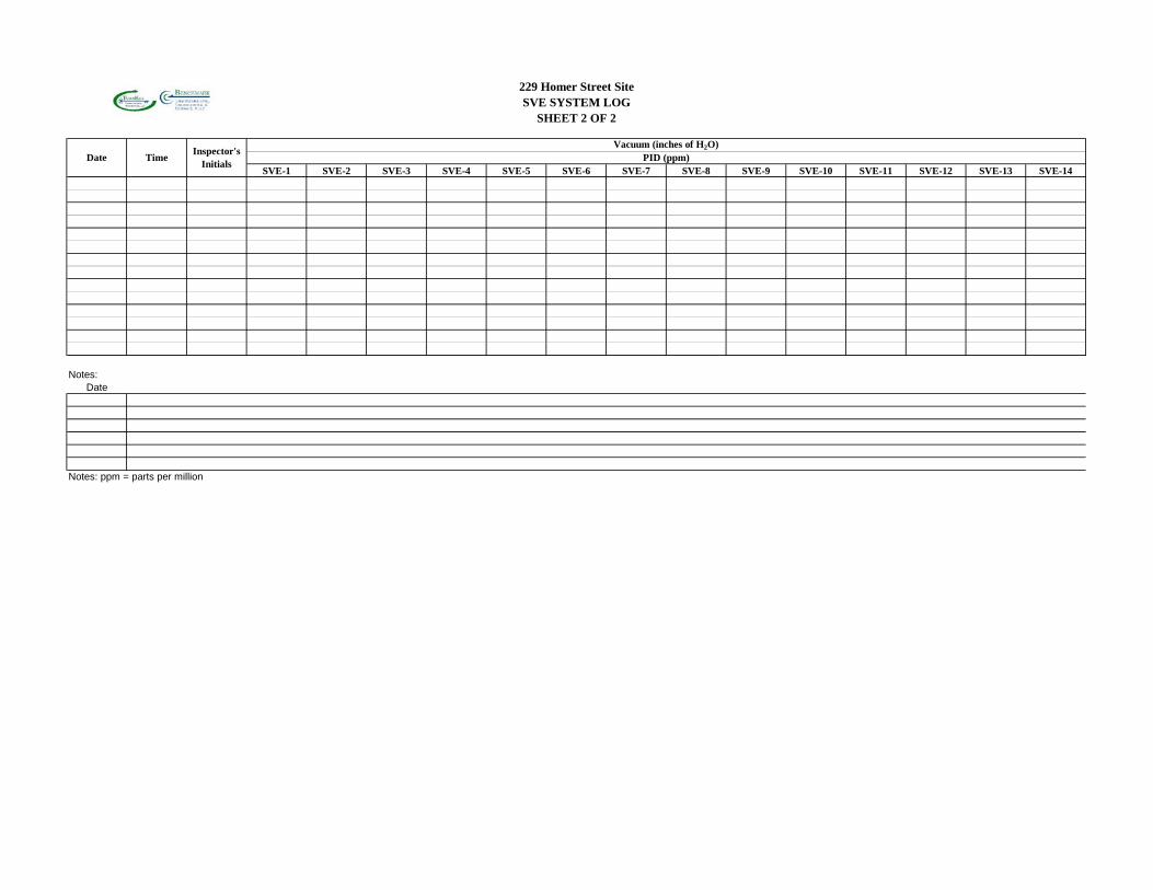
229 Homer Street SiteSVE SYSTEM LOG
SHEET 2 OF 2
SVE-1 SVE-2 SVE-3 SVE-4 SVE-5 SVE-6 SVE-7 SVE-8 SVE-9 SVE-10 SVE-11 SVE-12 SVE-13 SVE-14
Notes:
Date
Notes: ppm = parts per million
Vacuum (inches of H2O)PID (ppm)Date Time
Inspector's Initials
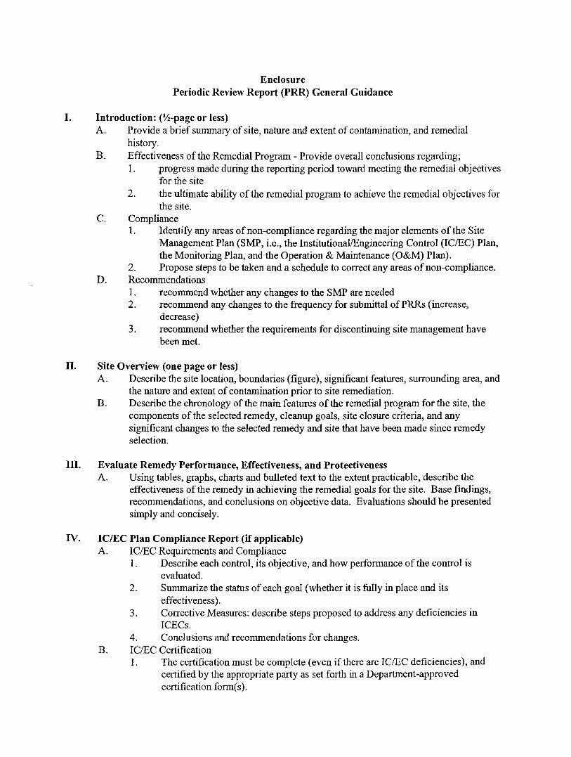
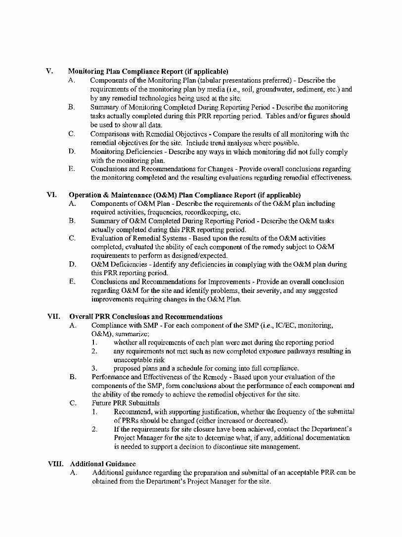

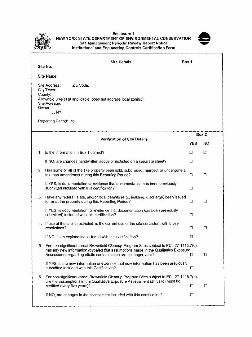
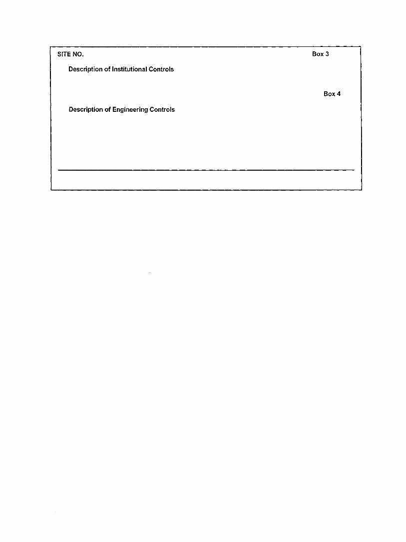
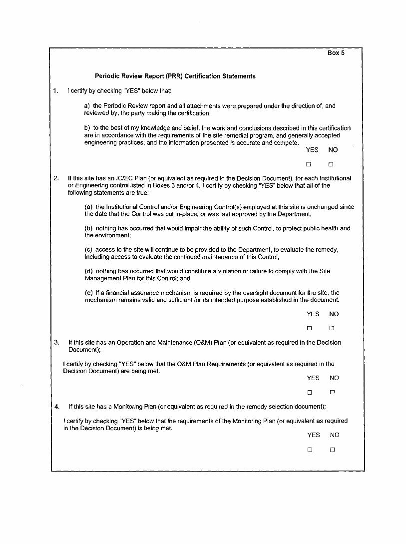
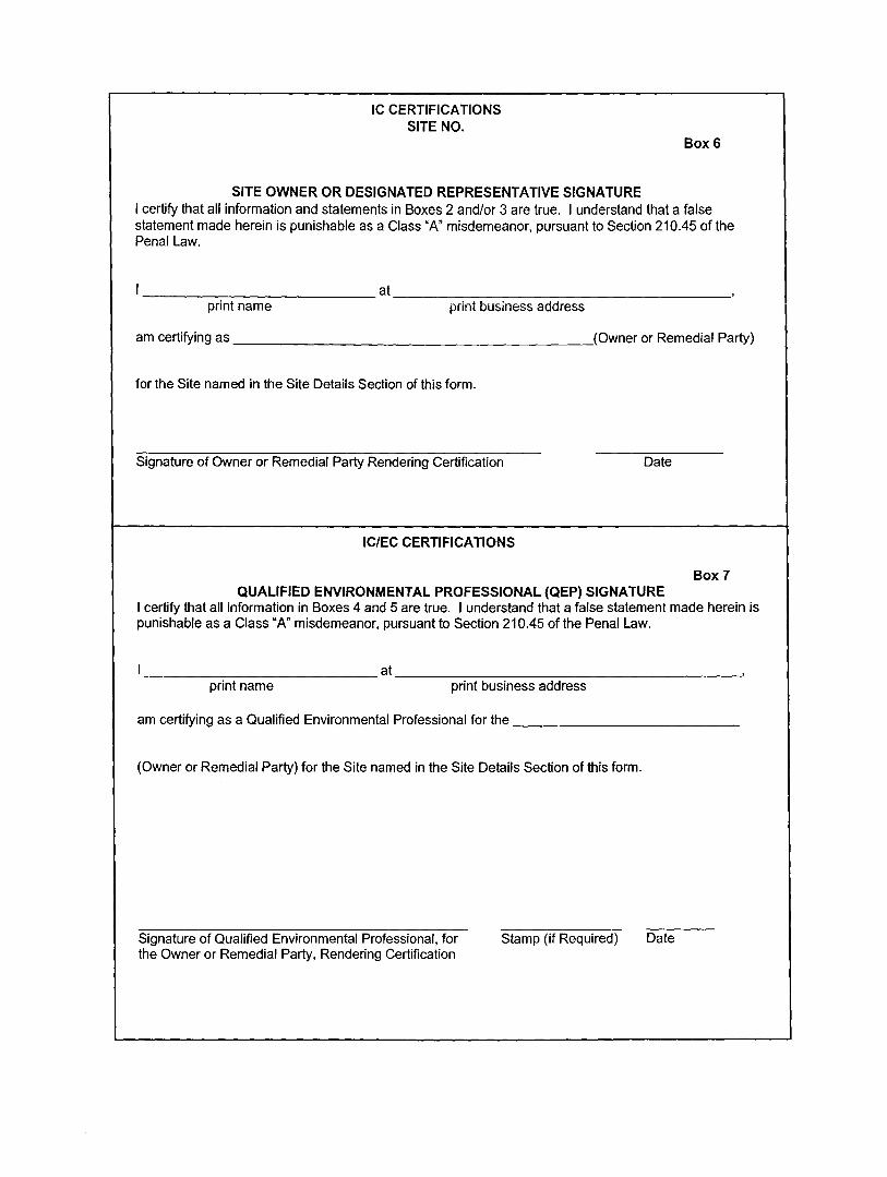

SMP – APPENDIX B: EXCAVATION WORK PLAN 229 HOMER STREET SITE
BCP SITE NO. C905044
0311-018-001 T KB
APPENDIX J
REMEDIAL SYSTEM O&M MANUALS

OPERATIONS & MAINTENANCE MANUAL
TURNKEY ENVIRONMENTAL
“HOMER 229 SPARGE SYSTEM”
2018
Provided By:
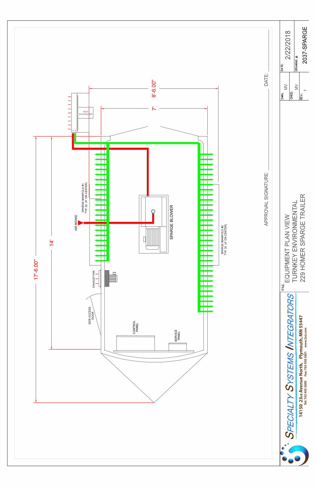
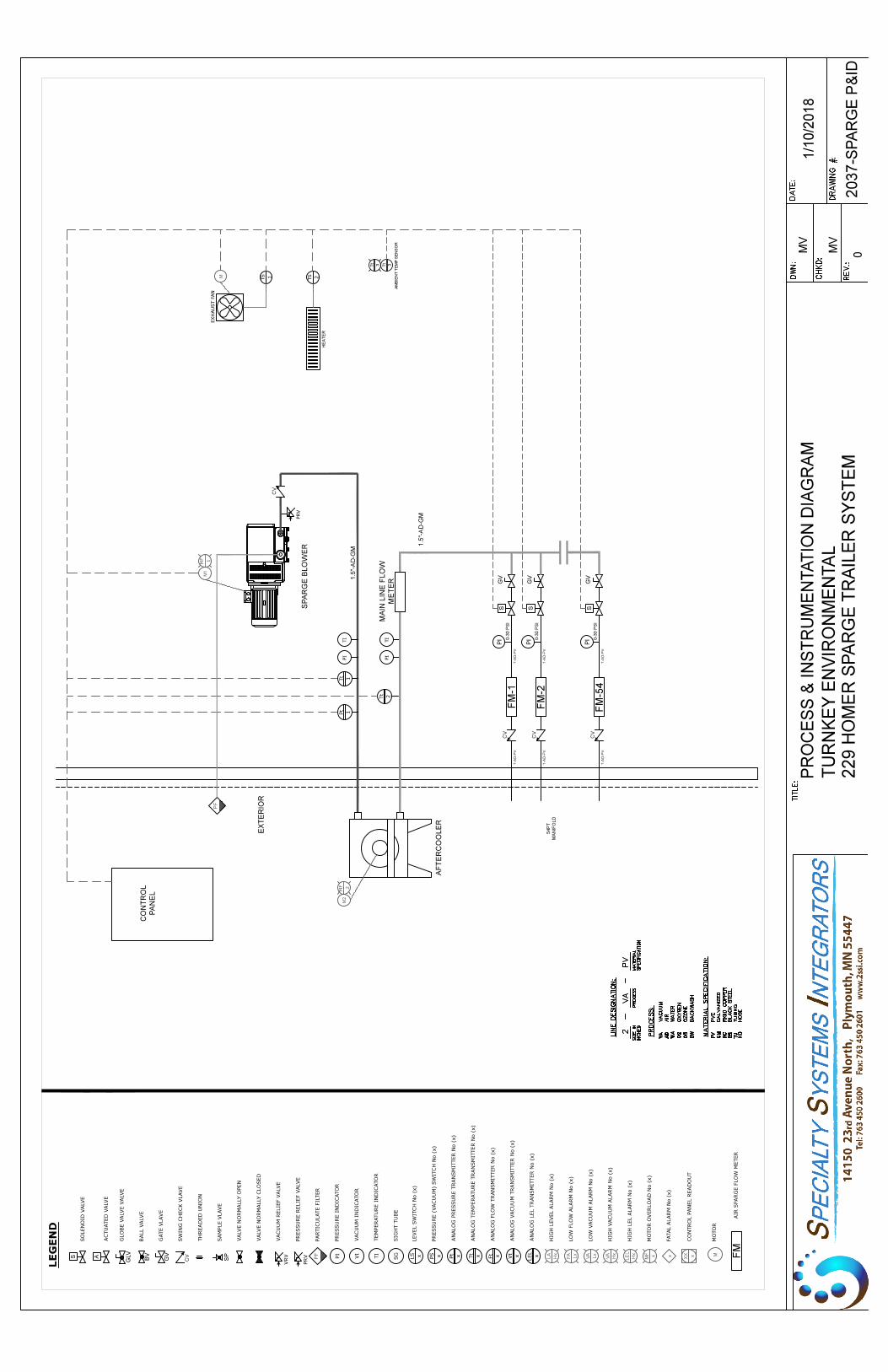
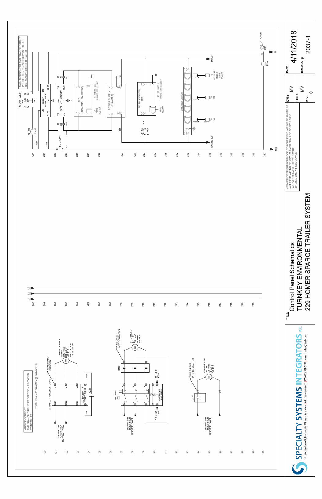
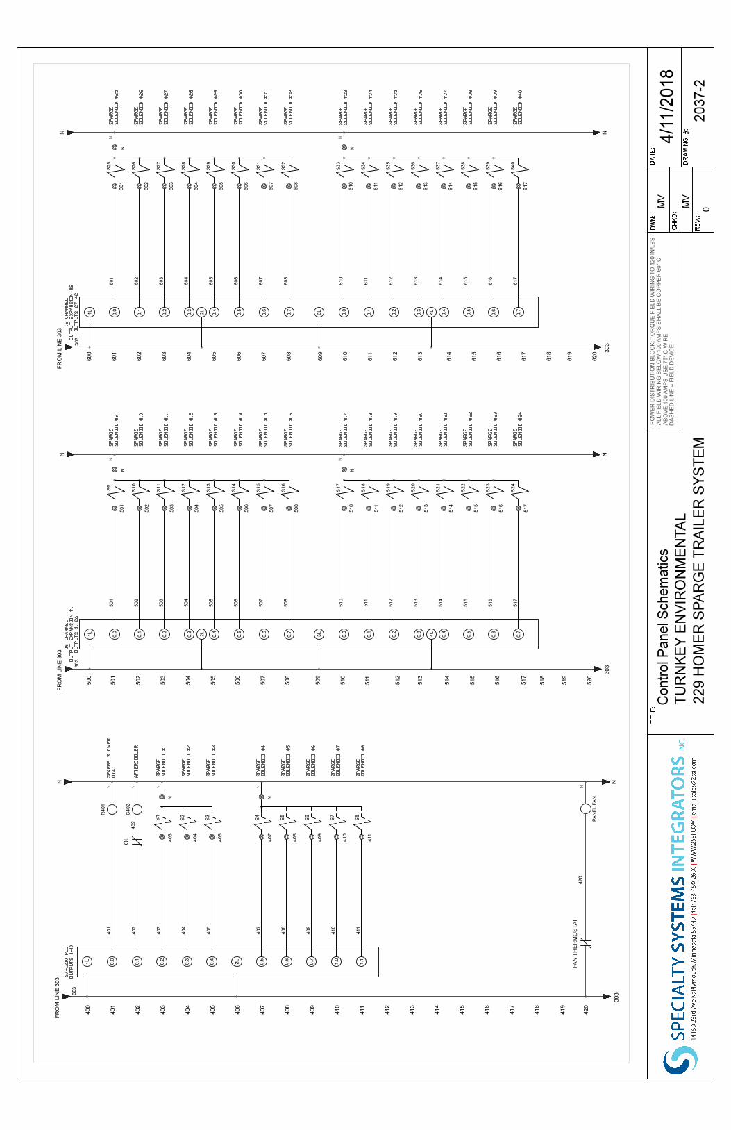
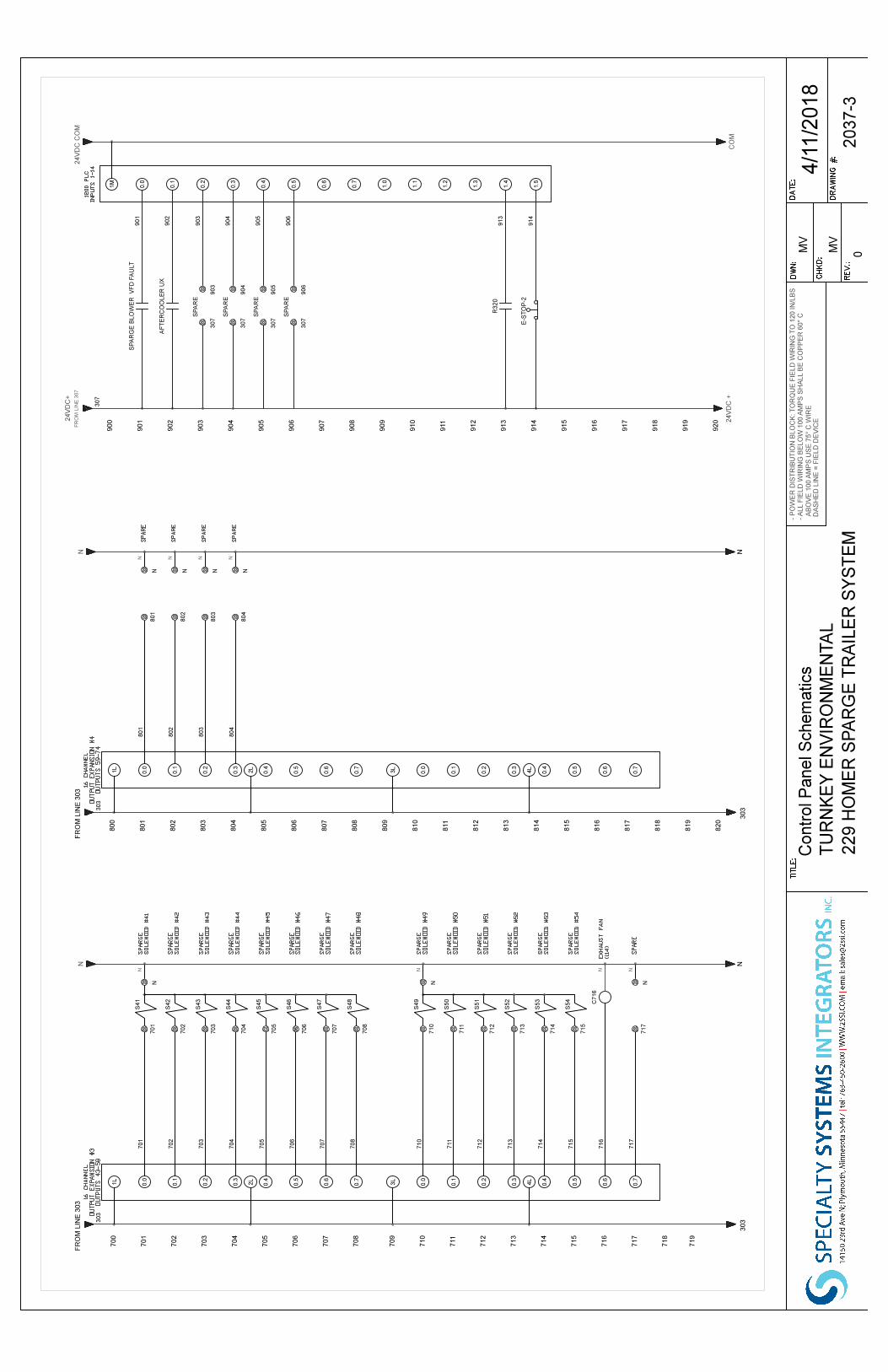
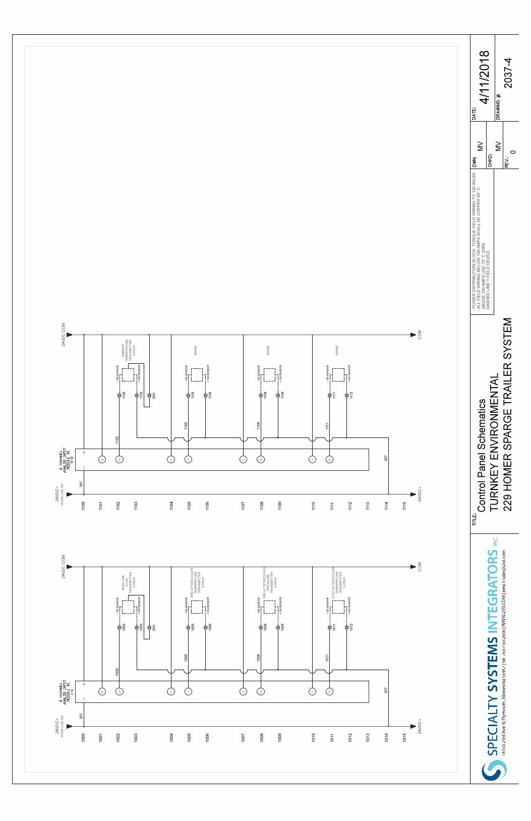

P/N 0872.918.121 / 0911
Pressure PumpsMink MM 1202, 1252, 1322 AP
Installation andOperating Instructions
Busch LLC 516 Viking Drive
Virginia Beach, VA 23452 Phone: (757) 463-7800
Fax: (757) 463-7407
Table of ContentsPreface . . . . . . . . . . . . . . . . . . . . . . . . . . . . . . . 2Product Description. . . . . . . . . . . . . . . . . . . . . . . . . 3
Use . . . . . . . . . . . . . . . . . . . . . . . . . . . . . . . . 3Principle of Operation . . . . . . . . . . . . . . . . . . . . . . 3Cooling . . . . . . . . . . . . . . . . . . . . . . . . . . . . . . 3Start Controls. . . . . . . . . . . . . . . . . . . . . . . . . . . 4
Safety . . . . . . . . . . . . . . . . . . . . . . . . . . . . . . . . 4Intended Use . . . . . . . . . . . . . . . . . . . . . . . . . . . 4Safety Notes . . . . . . . . . . . . . . . . . . . . . . . . . . . 4Noise Emission . . . . . . . . . . . . . . . . . . . . . . . . . . 4
Transport . . . . . . . . . . . . . . . . . . . . . . . . . . . . . . 4Transport in Packaging . . . . . . . . . . . . . . . . . . . . . . 4Transport without Packaging . . . . . . . . . . . . . . . . . . . 4
Storage . . . . . . . . . . . . . . . . . . . . . . . . . . . . . . . 4Short-term Storage . . . . . . . . . . . . . . . . . . . . . . . . 4Conservation . . . . . . . . . . . . . . . . . . . . . . . . . . . 4
Installation and Commissioning . . . . . . . . . . . . . . . . . . 5Installation Prerequisites . . . . . . . . . . . . . . . . . . . . . 5
Mounting Position and Space . . . . . . . . . . . . . . . . . 5Gas Inlet . . . . . . . . . . . . . . . . . . . . . . . . . . . . 5Pressure Connection . . . . . . . . . . . . . . . . . . . . . . 5Electrical Connection / Controls . . . . . . . . . . . . . . . . 5
Installation . . . . . . . . . . . . . . . . . . . . . . . . . . . . 6Mounting a NEMA-Motor with BoWex-Coupling . . . . . . . 6Mounting . . . . . . . . . . . . . . . . . . . . . . . . . . . 6Checking Synchronising Gear Oil . . . . . . . . . . . . . . . 6Connecting Electrically . . . . . . . . . . . . . . . . . . . . . 6Connecting Lines/Pipes . . . . . . . . . . . . . . . . . . . . 7Recording of Operational Parameters . . . . . . . . . . . . . 7
Operation Notes . . . . . . . . . . . . . . . . . . . . . . . . . 7Use . . . . . . . . . . . . . . . . . . . . . . . . . . . . . . 7
Maintenance . . . . . . . . . . . . . . . . . . . . . . . . . . . . 8Maintenance Schedule . . . . . . . . . . . . . . . . . . . . . . 8
Monthly: . . . . . . . . . . . . . . . . . . . . . . . . . . 8Every 3 Months: . . . . . . . . . . . . . . . . . . . . . . . 8Every 6 Months: . . . . . . . . . . . . . . . . . . . . . . 8Every Year: . . . . . . . . . . . . . . . . . . . . . . . . . 8Every 20000 Operating Hours, At the Latest after 6 Years: . 8
Changing Synchronising Gear Oil. . . . . . . . . . . . . . . . . 8Overhaul . . . . . . . . . . . . . . . . . . . . . . . . . . . . . . 8Removal from Service. . . . . . . . . . . . . . . . . . . . . . . . 9
Temporary Removal from Service. . . . . . . . . . . . . . . . . 9Recommissioning . . . . . . . . . . . . . . . . . . . . . . . . . 9Dismantling and Disposal . . . . . . . . . . . . . . . . . . . . . 9
Troubleshooting . . . . . . . . . . . . . . . . . . . . . . . . . . 10Spare Parts . . . . . . . . . . . . . . . . . . . . . . . . . . . . 13Spare Parts Kits . . . . . . . . . . . . . . . . . . . . . . . . . . 13Oil. . . . . . . . . . . . . . . . . . . . . . . . . . . . . . . . . 13EC-Declaration of Conformity . . . . . . . . . . . . . . . . . . . 14Technical Data. . . . . . . . . . . . . . . . . . . . . . . . . . . 15Busch – All over the World in Industry . . . . . . . . . . . . . . 16
Preface MM 1202, 1252, 1322 AP
page 2
PrefaceCongratulations on your purchase of the Busch compressor. Withwatchful observation of the field’s requirements, innovation and steadydevelopment Busch delivers modern vacuum and pressure solutionsworldwide.
These operating instructions contain information for
– product description,
– safety,
– transport,
– storage,
– installation and commissioning,
– maintenance,
– overhaul,
– troubleshooting and
– spare parts
of the compressor.
For the purpose of these instructions, “handling” the compressormeans the transport, storage, installation, commissioning, influence onoperating conditions, maintenance, troubleshooting and overhaul ofthe compressor.
Prior to handling the compressor these operating instructions shall beread and understood. If anything remains to be clarified please con-tact your Busch representative!
Keep these operating instructions and, if applicable, other pertinentoperating instructions available on site.

Product DescriptionUseThe compressor is intended for
– the compression
of
– air and other dry, non-aggressive, non-toxic and non-explosivegases
Conveying media with a lower or higher density than air leads to an in-creased thermal and/or mechanical load on the compressor and is per-missible only after prior consultation with Busch.
Max. allowed temperature of the inlet gas: 40 °C
The gas shall be free from vapours that would condensate under thetemperature and pressure conditions inside the compressor.
The compressor is intended for the placement in a non-potentially ex-plosive environment.
The compressor is thermally suitable for continuous operation(100 percent duty).
Max. permissible number of startings per hour: 12
The maximum allowed pressure on the pressure connection (l) is0.7 ... 2.0 barg (the nameplate of the compressor indicates the validpressure). By means of process control and/or pressure relief valves itmust be made sure that the maximum allowed pressure will not beexceeded.
As a rule ambient pressure must be present at the gas inlet. Deviationsare indicated on the nameplate of the compressor.
The safety valve (k) on the compressor protects the compressor againstoverload only. It is no pressure limiting device in terms of EN 1012-1for the pressure system. It is not designed for frequent use and musttherefore not be used as a system pressure regulating valve.
Principle of OperationThe compressor works on the claw principle.
The components are dimensioned such, that on the one hand there isnever contact between the two claws or between a claw and the cylin-der, on the other hand the gaps are small enough to keep the clear-ance loss between the chambers low.
In order to avoid the suction of dust, the compressor is equipped withan air filter (i) on the gas inlet.
In order to avoid the suction of solids, the compressor is equipped witha screen in the gas inlet.
In order to avoid reverse rotation after switching off, the compressor isequipped with a non-return valve (p).
The compressor compresses the inlet gas absolutely oil-free. A lubrica-tion of the pump chamber is neither necessary nor allowed.
CoolingThe compressor is cooled by
– radiation of heat from the surface of the compressor
– the air flow from the fan wheel of the drive motor
– the process gas
– the air flow from the fan wheel on the shaft of the compressor
MM 1202, 1252, 1322 AP Product Description
page 3
a Inlet silencerb Terminal boxc Gas inletd Oil sight glasse Oil drain plugf Eye boltg Directional arrowsh Cooling air inleti Inlet air filterj Cooling air outletk Safety valvel Pressure connectionm Covern Cylindero Rotorsp Non-return valve
Start ControlsThe compressor comes without start controls. The control of thecompressor is to be provided in the course of installation.
SafetyIntended UseDefinition: For the purpose of these instructions, “handling” thecompressor means the transport, storage, installation, commissioning,influence on operating conditions, maintenance, troubleshooting andoverhaul of the compressor.
The compressor is intended for industrial use. It shall be handled onlyby qualified personnel.
The allowed media and operational limits (! page 3: Product De-scription) and the installation prerequisites (! page 5: InstallationPrerequisites) of the compressor shall be observed both by the manu-facturer of the machinery into which the compressor is to be incorpo-rated and by the operator.
The maintenance instructions shall be observed.
Prior to handling the compressor these installation and operating in-structions shall be read and understood. If anything remains to beclarified please contact your Busch representative!
Safety NotesThe compressor has been designed and manufactured according tostate-of-the-art methods. Nevertheless, residual risks may remain.These operating instructions highlight potential hazards where appro-priate. Safety notes are tagged with one of the keywords DANGER,WARNING and CAUTION as follows:
DANGER_a
Disregard of this safety note will always lead to accidents with fa-tal or serious injuries.
WARNING_a
Disregard of this safety note may lead to accidents with fatal or se-rious injuries.
CAUTION_a
Disregard of this safety note may lead to accidents with minor inju-ries or property damage.
Noise EmissionFor the sound pressure level in free field according to EN ISO 2151! page 15: Technical Data.
CAUTION_a4
The compressor emits noise of high intensity in a narrow band.
Risk of damage to the hearing.
Persons staying in the vicinity of a non noise insulated compressorover extended periods shall wear ear protection.
TransportTransport in PackagingPacked on a pallet the compressor is to be transported with a forklift.
Transport without PackagingIn case the compressor is packed in a cardboard box with inflatedcushions:
Remove the inflated cushions from the box
In case the compressor is in a cardboard box cushioned with rolled cor-rugated cardboard:
Remove the corrugated cardboard from the box
In case the compressor is laid in foam:
Remove the foam
In case the compressor is bolted to a pallet or a base plate:
Remove the bolting between the compressor and the pal-let/base plate
In case the compressor is fastened to the pallet by means of tighteningstraps:
Remove the tightening straps
CAUTION_af
Do not walk, stand or work under suspended loads.
Make sure that the eyebolts are in faultless condition (replacedamaged, e.g. bent eyebolts with a new ones)
Make sure that the eyebolts are fully screwed in and tightened byhand
Attach lifting gear securely to the eyebolts on the synchronisinggear (f) and on the drive motor
In case the drive motor comes without an eyebolt or the eyebolt on thedrive motor is located at an unfavourable position:
Loop a belt/rope with suitable length and strength around theflange of the drive motor
Attach the lifting gear to a crane hook with safety latch
Lift the compressor with a crane
In case the compressor was bolted to a pallet or a base plate:
Remove the stud bolts from the rubber feet
StorageShort-term Storage Make sure that the gas inlet and the pressure connection are
closed (leave the provided plugs in)
Store the compressor
– if possible in original packaging,
– indoors,
– dry,
– dust free and
– vibration free
ConservationIn case of adverse ambient conditions (e.g. aggressive atmosphere, fre-quent temperature changes) conserve the compressor immediately. Incase of favourable ambient conditions conserve the compressor if astorage of more than 3 months is scheduled.
Make sure that all ports are firmly closed; seal all ports that are notsealed with PTFE-tape, gaskets or o-rings with adhesive tape
Safety MM 1202, 1252, 1322 AP
page 4
Note: VCI stands for “volatile corrosion inhibitor”. VCI-products (film,paper, cardboard, foam) evaporate a substance that condenses in mo-lecular thickness on the packed good and by its electro-chemical prop-erties effectively suppresses corrosion on metallic surfaces. However,VCI-products may attack the surfaces of plastics and elastomers. Seekadvice from your local packaging dealer! Busch uses CORTECVCI 126 R film for the overseas packaging of large equipment.
Wrap the compressor in VCI film
Store the compressor
– if possible in original packing,
– indoors,
– dry,
– dust free and
– vibration free.
For commissioning after conservation:
Make sure that all remains of adhesive tape are removed from theports
Commission the compressor as described in the chapter Installationand Commissioning (! page 5)
Installation andCommissioningInstallation Prerequisites
CAUTION_a
In case of non-compliance with the installation prerequisites, partic-ularly in case of insufficient cooling:
Risk of damage or destruction of the compressor and adjoining plantcomponents!
Risk of injury!
The installation prerequisites must be complied with.
Make sure that the integration of the compressor is carried outsuch that the essential safety requirements of the Machine Direc-tive 2006/42/EC are complied with (in the responsibility of the de-signer of the machinery into which the compressor is to beincorporated;! page 14: note in the EC-Declaration of Confor-mity)
Mounting Position and Space Make sure that the environment of the compressor is not poten-
tially explosive
Make sure that the following ambient conditions will be compliedwith:
– ambient temperature: 0 ... 40 °C
– ambient pressure: atmospheric
Make sure that the environmental conditions comply with the pro-tection class of the drive motor (according to the nameplate)
Make sure that the compressor will be placed or mounted horizon-tally
Make sure that the base for placement / mounting base is even
Make sure that in order to warrant a sufficient cooling there will bea clearance of minimum 1 m between the compressor and nearbywalls
Make sure that no heat sensitive parts (plastics, wood, cardboard,paper, electronics) will touch the surface of the compressor
Make sure that the installation space or location is vented suchthat a sufficient cooling of the compressor is warranted
CAUTION_ac
During operation the surface of the compressor may reach tempera-tures of more than 70 °C.
Risk of burns!
Make sure that the compressor will not be touched inadvertentlyduring operation, provide a guard if appropriate
Make sure that the sight glass (d, 76) of the synchronising gear willremain accessible
In case the synchronising gear oil change is planned to be carried outon location:
Make sure that the drain port (e, 80) and the filling port (72)of the synchronising gear will remain easily accessible
Gas Inlet
CAUTION_a
Intruding foreign objects or liquids can destroy the compressor.
In case the inlet gas can contain dust or other foreign solid particles:
Make sure that a suitable filter (5 micron or less) is installedupstream the compressor (included in scope of delivery)
The following guidelines for the suction line do not apply, if the air tobe compressed is taken in right at the compressor.
Make sure that the suction line fits to the gas inlet (c) of thecompressor
Make sure that the gas will be sucked through a vacuum-tightflexible hose or a pipe
In case of using a pipe:
Make sure that the pipe will cause no stress on thecompressor’s connection, if necessary use an expansion joint
Make sure that the line size of the suction line over the entirelength is at least as large as the gas inlet (c) of the compressor
In case the length of the suction line exceeds 2 m it is prudent to uselarger line sizes in order to avoid a loss of efficiency and an overload ofthe compressor. Seek advice from your Busch representative!
Make sure that the suction line does not contain foreign objects,e.g. welding scales
Pressure Connection Make sure that the pressure line fits to the pressure connection (l)
of the compressor
Make sure that the pressure connection is connected to a pres-sure-tight flexible hose or a pipe
Make sure that the pressure line is designed for 2.0 barg and250 °C
In case of using a pipe:
Make sure that the pipe will cause no stress on thecompressor’s connection, if necessary use an expansion joint
Make sure that the line size of the pressure line over the entirelength is at least as large as the pressure connection (l) of thecompressor
In case the length of the pressure line exceeds 2 m it is prudent to uselarger line sizes in order to avoid a loss of efficiency and an overload ofthe compressor. Seek advice from your Busch representative!
Make sure that the pressure line either slopes away from thecompressor or provide a liquid separator or a drip leg with a draincock, so that no liquids can back up into the compressor
Electrical Connection / Controls Make sure that the stipulations acc. to the EMC-Directive
2004/108/EC and Low-Voltage-Directive 2006/95/EC as well as
MM 1202, 1252, 1322 AP Installation and Commissioning
page 5
the EN-standards, electrical and occupational safety directives andthe local or national regulations, respectively, are complied with(this is the responsibility of the designer of the machinery intowhich the compressor is to be incorporated;! page 14: note inthe EC-Declaration of Conformity).
Make sure that the power supply for the drive motor is compatiblewith the data on the nameplate of the drive motor
Make sure that an overload protection according to EN 60204-1 isprovided for the drive motor
Make sure that the drive of the compressor will not be affected byelectric or electromagnetic disturbance from the mains; if necessaryseek advice from the Busch service
In case of mobile installation:
Provide the electrical connection with grommets that serve asstrain-relief
InstallationMounting a NEMA-Motor withBoWex-CouplingFor certain markets the compressor is available without motor, but witha NEMA-adaptor flange and a BoWex-coupling.
Remove the NEMA-adaptor flange (I) from the compressor
Pull the elastomer part (V) together with the hub (III) off the shaftof the compressor
Mount the NEMA-adaptor flange (I) on the motor (the bolts (II)are not part of the Busch scope of delivery)
Undo the cylinder screws (VI) and remove the elastomer part (V)from the hub (III)
Make sure that the parallel key is inserted into the motor shaft
Push the hub (III) onto the motor shaft such that the mountingface of the hub (III) will be located 16±1 mm before the mountingface of the NEMA-adaptor flange (I) (! sketch)
Fasten the hub (III) on the motor shaft using the set screw (IV)
Apply thread locking agent on the threads of the cylinderscrews (VI)
Mount the elastomer part (V) on the hub (III) with the cylinderscrews (VI) and tighten the cylinder screws with 14 Nm
Mount the motor on the compressor
Mounting Make sure that the installation prerequisites (! page 5) are com-
plied with
Set down or mount the compressor at its location
Checking Synchronising Gear OilThe compressor is delivered with oil filled synchronising gear.
The level shall be slightly above the middle of the sight glass (d, 76).
Check on the sight glass (d, 76) that the proper amount of oil isfilled
Connecting Electrically
WARNING_ab
Risk of electrical shock, risk of damage to equipment.
Electrical installation work must only be executed by qualified per-sonnel that knows and observes the following regulations:- IEC 364 or CENELEC HD 384 or DIN VDE 0100, respectively,- IEC-Report 664 or DIN VDE 0110,- BGV A2 (VBG 4) or corresponding national accident preventionregulation.
CAUTION_a
The connection schemes given below are typical. Depending on thespecific order or for certain markets deviating connection schemesmay apply.
Risk of damage to the drive motor!
The inside of the terminal box shall be checked for drive motor con-nection instructions/schemes.
Electrically connect the drive motor
Connect the protective earth conductor
Delta connection (low voltage):
Star connection (high voltage):
Double star connection, multi-voltage motor (low voltage):
Installation and Commissioning MM 1202, 1252, 1322 AP
page 6
III
III
IV
VVI
Star connection, multi-voltage motor (high voltage):
CAUTION_a
Operation in the wrong direction of rotation can destroy thecompressor in short time.
Prior to starting-up it must be made sure that the compressor is op-erated in the proper direction (clockwise rotating field).
Determine the intended direction of rotation with the arrow (stuckon or cast)
“Bump” the drive motor
Watch the fan wheel of the drive motor and determine the direc-tion of rotation just before the fan wheel stops
If the rotation must be changed:
Switch any two of the drive motor wires
Connecting Lines/Pipes Connect the suction line
Installation without suction line:
Make sure that the gas inlet (c) is open
Connect the pressure line
Make sure that all provided covers, guards, hoods etc. aremounted
Make sure that cooling air inlets and outlets are not covered or ob-structed and that the cooling air flow is not affected adversely inany other way
Recording of Operational ParametersAs soon as the compressor is operated under normal operatingconditions:
Measure the drive motor current and record it as reference for fu-ture maintenance and troubleshooting work
Operation NotesUse
CAUTION_a
The compressor is designed for operation under the conditions de-scribed below.
In case of disregard risk of damage or destruction of the compressorand adjoining plant components!
Risk of injury!
The compressor must only be operated under the conditions de-scribed below.
The compressor is intended for
– the compression
of
– air and other dry, non-aggressive, non-toxic and non-explosivegases
Conveying media with a lower or higher density than air leads to an in-creased thermal and/or mechanical load on the compressor and is per-missible only after prior consultation with Busch.
Max. allowed temperature of the inlet gas: 40 °C
The gas shall be free from vapours that would condensate under thetemperature and pressure conditions inside the compressor.
The compressor is intended for the placement in a non-potentially ex-plosive environment.
The compressor is thermally suitable for continuous operation(100 percent duty).
Max. permissible number of startings per hour: 12
The maximum allowed pressure on the pressure connection (l) is0.7 ... 2.0 barg (the nameplate of the compressor indicates the validpressure). By means of process control and/or pressure relief valves itmust be made sure that the maximum allowed pressure will not beexceeded.
As a rule ambient pressure must be present at the gas inlet. Deviationsare indicated on the nameplate of the compressor.
The safety valve (k) on the compressor protects the compressor againstoverload only. It is no pressure limiting device in terms of EN 1012-1for the pressure system. It is not designed for frequent use and musttherefore not be used as a system pressure regulating valve.
CAUTION_ac
During operation the surface of the compressor may reach tempera-tures of more than 70 °C.
Risk of burns!
The compressor shall be protected against contact during operation,it shall cool down prior to a required contact or heat protectiongloves shall be worn.
CAUTION_a4
The compressor emits noise of high intensity in a narrow band.
Risk of damage to the hearing.
Persons staying in the vicinity of a non noise insulated compressorover extended periods shall wear ear protection.
Make sure that all provided covers, guards, hoods etc. remainmounted
Make sure that protective devices will not be disabled
Make sure that cooling air inlets and outlets will not be covered orobstructed and that the cooling air flow will not be affected ad-versely in any other way
Make sure that the installation prerequisites (! page 5: InstallationPrerequisites) are complied with and will remain complied with,particularly that a sufficient cooling will be ensured
MM 1202, 1252, 1322 AP Installation and Commissioning
page 7
MaintenanceDANGER_age32
In case the compressor conveyed gas that was contaminated withforeign materials which are dangerous to health, harmful materialcan reside in filters.
Danger to health during inspection, cleaning or replacement of fil-ters.
Danger to the environment.
Personal protective equipment must be worn during the handlingof contaminated filters.
Contaminated filters are special waste and must be disposed ofseparately in compliance with applicable regulations.
CAUTION_ac
During operation the surface of the compressor may reach tempera-tures of more than 70 °C.
Risk of burns!
Prior to disconnecting connections make sure that the connectedpipes/lines are vented to atmospheric pressure
Maintenance ScheduleNote: The maintenance intervals depend very much on the individualoperating conditions. The intervals given below shall be considered asstarting values which should be shortened or extended as appropriate.Particularly heavy duty operation, such like high dust loads in the envi-ronment or in the process gas, other contaminations or ingress of pro-cess material, can make it necessary to shorten the maintenanceintervals significantly.
Monthly: Make sure that the compressor is shut down and locked against in-
advertent start up
Check the inlet air filter (i), if necessary replace
In case of operation in a dusty environment:
Clean as described under! page 8: Every 6 Months:
Every 3 Months: Make sure that the compressor is shut down
Check the level of the synchronising gear oil
The level shall be slightly above the middle of the sight glass (d, 76).
The level of the synchronising gear should stay constant over the life-time of the oil. If the level does fall, the gear is leaky and thecompressor requires repair (Busch service).
Every 6 Months: Make sure that the housing is free from dust and dirt, clean if nec-
essary
Make sure that the compressor is shut down and locked against in-advertent start up
Remove the acoustic enclosure
Note: Make sure that the foam mats do not get soaked with water
Clean the fan cowlings, fan wheels, the ventilation grilles and cool-ing fins
Mount the acoustic enclosure
Every Year: Make sure that the compressor is shut down and locked against in-
advertent start up
Replace the inlet air filter (i)
Check the inlet screen, clean if necessary
Note: As there is an inlet air filter upstream the inlet screen, the inletscreen should not show soiling. A soiled inlet screen indicates that thefilter is either broken through or improperly inserted.
Every 20000 Operating Hours, At the Latest after6 Years:Note: The change interval of 20000 operating hours is valid for thegear oil Busch VE 101 only. Other gear oils reduce the change interval.
Change the synchronising gear oil
Changing Synchronising Gear Oil Make sure that the compressor is shut down and locked against in-
advertent start up
Remove the eyebolt (f)
Remove the lid (424)
Undo the venting valve (72) for venting
Place a drain tray underneath the drain plug (e, 80)
Open the drain plug (e, 80) and drain the oil
Make sure that the seal ring on the drain plug (e, 80) is service-able, replace if necessary
Firmly reinsert the drain plug (e, 80) together with the seal ring
Remove the venting valve (72) completely
Fill in new gear oil until the level is slightly above the middle of thesight glass (d, 76)
Make sure that the seal ring on the venting valve (72) is undam-aged, if necessary replace the venting valve (72)
Firmly reinsert the venting valve (72) together with the seal ring
Mount the lid (424)
Reinsert the eyebolt (f)
Dispose of the used oil in compliance with applicable regulations
OverhaulCAUTION_a
In order to achieve best efficiency and a long life the compressorwas assembled and adjusted with precisely defined tolerances.
This adjustment will be lost during dismantling of the compressor.
It is therefore strictly recommended that any dismantling of thecompressor that is beyond of what is described in this manual shallbe done by Busch service.
Maintenance MM 1202, 1252, 1322 AP
page 8
72 424 615
76/77 80/81
DANGER_age32
In case the compressor conveyed gas that was contaminated withforeign materials which are dangerous to health, harmful materialcan reside in pores, gaps and internal spaces of the compressor.
Danger to health during dismantling of the compressor.
Danger to the environment.
Prior to shipping the compressor shall be decontaminated as goodas possible and the contamination status shall be stated in a “Dec-laration of Contamination” (form downloadable fromwww.busch-vacuum.com).
Busch service will only accept compressors that come with a completelyfilled in and legally binding signed “Declaration of Contamination”(form downloadable from www.busch-vacuum.com).
Removal from ServiceTemporary Removal from Service Prior to disconnecting pipes/lines make sure that all pipes/lines are
vented to atmospheric pressure
Recommissioning Observe the chapter Installation and Commissioning (! page 5)
Dismantling and Disposal
DANGER_age32
In case the compressor conveyed gas that was contaminated withforeign materials which are dangerous to health, harmful materialcan reside in pores, gaps and internal spaces of the compressor.
Danger to health during dismantling of the compressor.
Danger to the environment.
During dismantling of the compressor personal protective equip-ment must be worn.
The compressor must be decontaminated prior to disposal.
Drain the oil
Make sure that materials and components to be treated as specialwaste have been separated from the compressor
Make sure that the compressor is not contaminated with harmfulforeign material
According to the best knowledge at the time of printing of this manualthe materials used for the manufacture of the compressor involve norisk.
Dispose of the used oil in compliance with applicable regulations
Dispose of the compressor as scrap metal
MM 1202, 1252, 1322 AP Removal from Service
page 9
TroubleshootingWARNING_ab
Risk of electrical shock, risk of damage to equipment.
Electrical installation work must only be executed by qualified personnel that knows and observes the following regulations:- IEC 364 or CENELEC HD 384 or DIN VDE 0100, respectively,- IEC-Report 664 or DIN VDE 0110,- BGV A2 (VBG 4) or equivalent national accident prevention regulation.
CAUTION_ac
During operation the surface of the compressor may reach temperatures of more than 70 °C.
Risk of burns!
Let the compressor cool down prior to a required contact or wear heat protection gloves.
Problem Possible Cause Remedy
The compressor does not reach the usual pres-sure
The drive motor draws a too high current(compare with initial value after commission-ing)
Filling the system takes too long
Building up pressure in the system takes toolong
The pressure system or pressure line is notleak-tight
Check the hose or pipe connections for possi-ble leak
The pressure relief valve/regulating system ismisadjusted or defective
Adjust, repair or replace, respectively
The screen in the gas inlet (c) is partiallyclogged
Clean the screen
If cleaning is required too frequently install afilter upstream
The filter (i) on the gas inlet (c) is partiallyclogged
Clean or replace the inlet air filter (i), respec-tively
Partial clogging in the suction, discharge orpressure line
Remove the clogging
Long suction, discharge or pressure line withtoo small diameter
Use larger diameter
The valve disk of the inlet non-return valve isstuck in closed or partially open position
Disassemble the inlet, clean the screen and thevalve (p) as required and reassemble
Internal parts are worn or damaged Repair the compressor (Busch service)
The compressor does not start The drive motor is not supplied with the cor-rect voltage or is overloaded
Supply the drive motor with the correct volt-age
The drive motor starter overload protection istoo small or trip level is too low
Compare the trip level of the drive motorstarter overload protection with the data onthe nameplate, correct if necessary
In case of high ambient temperature: set thetrip level of the drive motor starter overloadprotection 5 percent above the nominal drivemotor current
One of the fuses has blown Check the fuses
The connection cable is too small or too longcausing a voltage drop at the compressor
Use sufficiently dimensioned cable
Troubleshooting MM 1202, 1252, 1322 AP
page 10
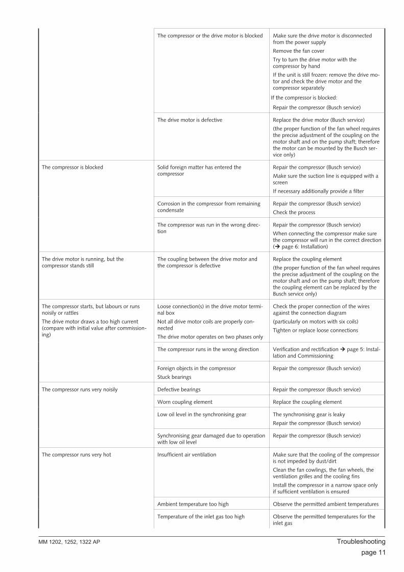
The compressor or the drive motor is blocked Make sure the drive motor is disconnectedfrom the power supply
Remove the fan cover
Try to turn the drive motor with thecompressor by hand
If the unit is still frozen: remove the drive mo-tor and check the drive motor and thecompressor separately
If the compressor is blocked:
Repair the compressor (Busch service)
The drive motor is defective Replace the drive motor (Busch service)
(the proper function of the fan wheel requiresthe precise adjustment of the coupling on themotor shaft and on the pump shaft; thereforethe motor can be mounted by the Busch ser-vice only)
The compressor is blocked Solid foreign matter has entered thecompressor
Repair the compressor (Busch service)
Make sure the suction line is equipped with ascreen
If necessary additionally provide a filter
Corrosion in the compressor from remainingcondensate
Repair the compressor (Busch service)
Check the process
The compressor was run in the wrong direc-tion
Repair the compressor (Busch service)
When connecting the compressor make surethe compressor will run in the correct direction(! page 6: Installation)
The drive motor is running, but thecompressor stands still
The coupling between the drive motor andthe compressor is defective
Replace the coupling element
(the proper function of the fan wheel requiresthe precise adjustment of the coupling on themotor shaft and on the pump shaft; thereforethe coupling element can be replaced by theBusch service only)
The compressor starts, but labours or runsnoisily or rattles
The drive motor draws a too high current(compare with initial value after commission-ing)
Loose connection(s) in the drive motor termi-nal box
Not all drive motor coils are properly con-nected
The drive motor operates on two phases only
Check the proper connection of the wiresagainst the connection diagram
(particularly on motors with six coils)
Tighten or replace loose connections
The compressor runs in the wrong direction Verification and rectification! page 5: Instal-lation and Commissioning
Foreign objects in the compressor
Stuck bearings
Repair the compressor (Busch service)
The compressor runs very noisily Defective bearings Repair the compressor (Busch service)
Worn coupling element Replace the coupling element
Low oil level in the synchronising gear The synchronising gear is leaky
Repair the compressor (Busch service)
Synchronising gear damaged due to operationwith low oil level
Repair the compressor (Busch service)
The compressor runs very hot Insufficient air ventilation Make sure that the cooling of the compressoris not impeded by dust/dirt
Clean the fan cowlings, the fan wheels, theventilation grilles and the cooling fins
Install the compressor in a narrow space onlyif sufficient ventilation is ensured
Ambient temperature too high Observe the permitted ambient temperatures
Temperature of the inlet gas too high Observe the permitted temperatures for theinlet gas
MM 1202, 1252, 1322 AP Troubleshooting
page 11

Insufficient gas transfer Provide a pressure relief valve
Mains frequency or voltage outside tolerancerange
Provide a more stable power supply
In case a pressure relief valve/regulating systemis installed:
The pressure relief valve/regulating system ismisadjusted or defective
Adjust, repair or replace, respectively
Partial clogging of filters or screens
Partial clogging in the suction, discharge orpressure line
Remove the clogging
Long suction, discharge or pressure line withtoo small diameter
Use larger diameter
Troubleshooting MM 1202, 1252, 1322 AP
page 12
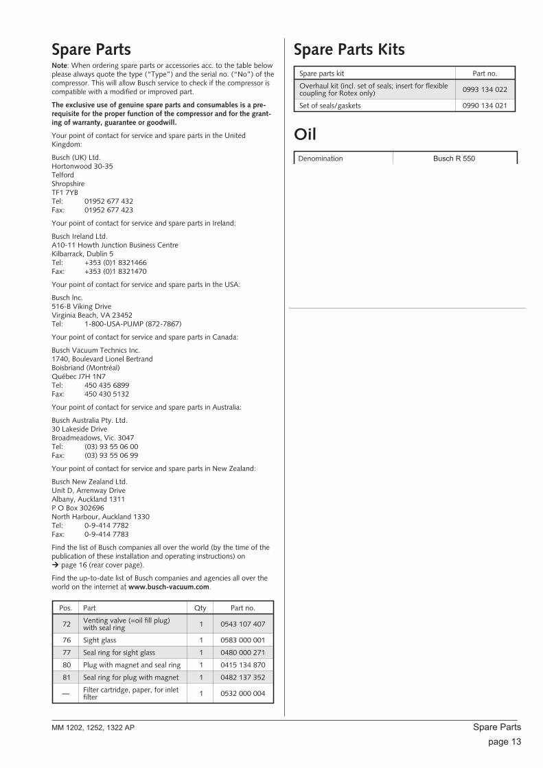
Spare PartsNote: When ordering spare parts or accessories acc. to the table belowplease always quote the type (“Type”) and the serial no. (“No”) of thecompressor. This will allow Busch service to check if the compressor iscompatible with a modified or improved part.
The exclusive use of genuine spare parts and consumables is a pre-requisite for the proper function of the compressor and for the grant-ing of warranty, guarantee or goodwill.
Your point of contact for service and spare parts in the UnitedKingdom:
Busch (UK) Ltd.Hortonwood 30-35TelfordShropshireTF1 7YBTel: 01952 677 432Fax: 01952 677 423
Your point of contact for service and spare parts in Ireland:
Busch Ireland Ltd.A10-11 Howth Junction Business CentreKilbarrack, Dublin 5Tel: +353 (0)1 8321466Fax: +353 (0)1 8321470
Your point of contact for service and spare parts in the USA:
Busch lnc.516-B Viking DriveVirginia Beach, VA 23452Tel: 1-800-USA-PUMP (872-7867)
Your point of contact for service and spare parts in Canada:
Busch Vacuum Technics Inc.1740, Boulevard Lionel BertrandBoisbriand (Montréal)Québec J7H 1N7Tel: 450 435 6899Fax: 450 430 5132
Your point of contact for service and spare parts in Australia:
Busch Australia Pty. Ltd.30 Lakeside DriveBroadmeadows, Vic. 3047Tel: (03) 93 55 06 00Fax: (03) 93 55 06 99
Your point of contact for service and spare parts in New Zealand:
Busch New Zealand Ltd.Unit D, Arrenway DriveAlbany, Auckland 1311P O Box 302696North Harbour, Auckland 1330Tel: 0-9-414 7782Fax: 0-9-414 7783
Find the list of Busch companies all over the world (by the time of thepublication of these installation and operating instructions) on! page 16 (rear cover page).
Find the up-to-date list of Busch companies and agencies all over theworld on the internet at www.busch-vacuum.com.
Pos. Part Qty Part no.
72 Venting valve (=oil fill plug)with seal ring 1 0543 107 407
76 Sight glass 1 0583 000 001
77 Seal ring for sight glass 1 0480 000 271
80 Plug with magnet and seal ring 1 0415 134 870
81 Seal ring for plug with magnet 1 0482 137 352
— Filter cartridge, paper, for inletfilter 1 0532 000 004
Spare Parts KitsSpare parts kit Part no.
Overhaul kit (incl. set of seals; insert for flexiblecoupling for Rotex only) 0993 134 022
Set of seals/gaskets 0990 134 021
OilDenomination Busch R 550
ISO-VG 100
Base Diester
Density [g/cm³] 0.96
Kinematic viscosity at 40 °C[mm²/s] 95
Kinematic viscosity at 100 °C[mm²/s] 9.5
Flashpoint [°C] 255
Pourpoint [°C] –30
Part no. 1 l packaging 0831 000 099
Part no. 5 l packaging 0831 000 100
Filling quantity, approx. [l] 1
MM 1202, 1252, 1322 AP Spare Parts page 13
porro

EC-Declaration of ConformityNote: This Declaration of Conformity and the -mark affixed to the nameplate are valid for the compressor within the Busch-scope of delivery.When this compressor is integrated into a superordinate machinery the manufacturer of the superordinate machinery (this can be the operatingcompany, too) must conduct the conformity assessment process acc. to the Directive Machinery 2006/42/EC for the superordinate machine, issuethe Declaration of Conformity for it and affix the -mark.
For maintenance of this Declaration of Conformity of compressors without a drive may only be used a drive with a written consent of Busch.
We
Busch Produktions GmbHSchauinslandstr. 179689 MaulburgGermany
declare that compressors MM 1202, 1252, 1322 AP
in accordance with the European Directives:
– “Machinery” 2006/42/EC,
– “Electrical Equipment Designed for Use within Certain Voltage Limits” (so called “Low Voltage”) 2006/95/EC,
– “Electromagnetic Compatibility” 2004/108/EC,
have been designed and manufactured to the following specifications:
Standard Title of the Standard
Harmonised Standards
EN ISO 12100-1EN ISO 12100-2
Safety of machinery - Basic concepts, general principles of design - Part 1 and 2
EN ISO 13857 Safety of machinery - Safety distances to prevent hazard zones being reached by the upper and lower limbs
EN 1012-1EN 1012-2
Compressors and vacuum pumps - Safety requirements - Part 1 and 2
EN ISO 2151 Acoustics - Noise test code for compressors and vacuum pumps - Engineering method (grade 2)
EN 60204-1 Safety of machinery - Electrical equipment of machines - Part 1: General requirements
EN 61000-6-1EN 61000-6-2
Electromagnetic compatibility (EMC) - Generic immunity standards
EN 61000-6-3EN 61000-6-4
Electromagnetic compatibility (EMC) - Generic emission standards
Manufacturer Person authorised to compilethe technical file
Dr.-Ing. Karl Busch
General director
Andrej Riwe
Technical writer
EC-Declaration of Conformity MM 1202, 1252, 1322 AP
page 14
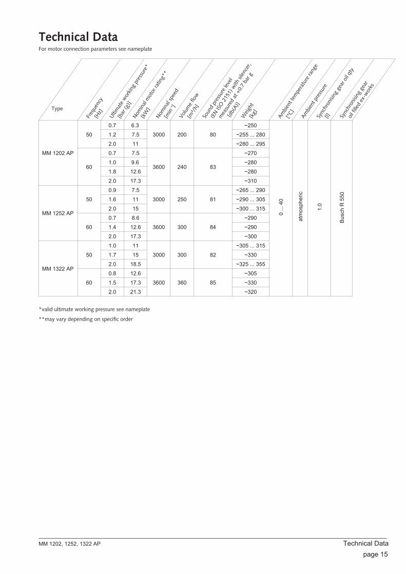
Technical DataFor motor connection parameters see nameplate
Type
Freq
uenc
y[H
z]
Ultim
ate
wor
king
pres
sure
*
[bar
(g)]
Nom
inal
mot
orra
ting*
*
[kW
]
Nom
inal
spee
d
[min
-1 ]Vo
lum
eflo
w[m
³/h]
Soun
dpr
essu
relev
el
(EN
ISO
2151
) with
silen
cer,
mea
sure
dat
+0.7
bar g
[db(
A)]
Weig
ht[k
g]
Ambi
ent t
empe
ratu
rera
nge
[°C]
Ambi
ent p
ress
ure
Sync
hron
ising
gear
oil q
ty
[l] Sync
hron
ising
gear
oil f
illed
ex-w
orks
MM 1202 AP
50
0.7 6.3
3000 200 80
~250
0...
40
atm
osph
eric
1.0
Bus
ch R
550
1.2 7.5 ~255 ... 280
2.0 11 ~280 ... 295
60
0.7 7.5
3600 240 83
~270
1.0 9.6 ~280
1.8 12.6 ~280
2.0 17.3 ~310
MM 1252 AP
50
0.9 7.5
3000 250 81
~265 ... 290
1.6 11 ~290 ... 305
2.0 15 ~300 ... 315
60
0.7 8.6
3600 300 84
~290
1.4 12.6 ~290
2.0 17.3 ~300
MM 1322 AP
50
1.0 11
3000 300 82
~305 ... 315
1.7 15 ~330
2.0 18.5 ~325 ... 355
60
0.8 12.6
3600 360 85
~305
1.5 17.3 ~330
2.0 21.3 ~320
*valid ultimate working pressure see nameplate
**may vary depending on specific order
MM 1202, 1252, 1322 AP Technical Data page 15

AustraliaBusch Australia Pty. Ltd.30 Lakeside DriveBroadmeadows, Vic. 3047Tel: (03) 93 55 06 00Fax: (03) 93 55 06 99
AustriaBusch Austria GmbHIndustriepark Nord2100 KorneuburgTel: 02262 / 756 65-0Fax: 02262 / 756 65-20
BelgiumBusch N.V./Busch SAKruinstraat 79160 LokerenTel: (0)9 / 348 47 22Fax: (0)9 / 348 65 35
BrazilBusch do Brasil Ltda.Rod. Edgard Máximo Zambotto, Km 6413240-000 Jarinú-SPTel: (55) 11-4016 1400Fax: (55) 11-4016 1077
CanadaBusch Vacuum Technics Inc.1740, Boulevard Lionel BertrandBoisbriand (Montréal)Québec J7H 1N7Tel: 450 435 6899Fax: 450 430 5132
ChinaBusch Vacuum (Shanghai) Co., Ltd18 Bin Yang Road, ShanghaiChina 200235Tel: +86 21 6436 1919Fax: +86 21 5031 5766
Czech RepublicBusch Vakuum s.r.o.Pra ákova 10619 00 Horní HeršpiceBrnoTel.: +420 543 42 48 55Fax: +420 543 42 48 56
DenmarkBusch Vakuumteknik A/SParallelvej 118680 RyTel: +45 87 88 07 77Fax: +45 87 88 07 88
FinlandBusch Vakuumteknik OySinikellonpolku 301300 VANTAATel: 09 774 60 60Fax: 09 774 60 666
FranceBusch France S.A.Parc Technologiquede Bois Chaland CE 292291029 Evry CedexTel: 01 69 89 89 89Fax: 01 60 86 16 74
GermanyDr.-Ing. K. Busch GmbHSchauinslandstr. 179689 MaulburgTel: (0 76 22) 6 81-0Fax: (0 76 22) 6 81-194e-mail: [email protected]
Busch – All over the World in Industry www.busch-vacuum.comDr.-Ing. K. Busch GmbHNiederlassung NordErnst-Abbe-Str. 1-325451 QuickbornTel: (0 41 06) 7 99 67-0Fax: (0 41 06) 7 99 67-77
Dr.-Ing. K. Busch GmbHNiederlassung WestNordring 3564807 DieburgTel: (0 60 71) 92 82-0Fax: (0 60 71) 14 71
Dr.-Ing. K. Busch GmbHNiederlassung Süd-OstGewerbestraße 390579 LangenzennTel: (09 01) 90 25-0Fax: (09 01) 90 25-25
Dr.-Ing. K. Busch GmbHAußenstelle Zella-MehlisAm Rain 1198544 Zella-MehlisTel: (0 36 82) 46 92 71Fax: (0 36 82) 46 92 73
IrelandBusch Ireland Ltd.A10-11 Howth Junction Business CentreKilbarrack, Dublin 5Tel: 00353 1 832 1466Fax: 00353 1 832 1470
ItalyBusch Italia S.r.l.Via Ettore Majorana, 1620054 Nova MilaneseTel: 0362 370 91Fax: 0362 370 999
JapanNippon Busch K.K.1-23-33, MegumigaokaHiratsuka City, KanagawaJapan 259-1220Tel: 0463-50-4000Fax: 0463-50-4004
KoreaBusch Korea Ltd.392-1 Yangji-Ri, Yangji-Myun,Yongin-si, Kyunggi-DoTel: 031) 321-8114Fax: 031) 321 4330
MalaysiaBusch (Malaysia) Sdn Bhd.6 Jalan Taboh 33/22Shah Alam Technology ParkSection 3340400 Shah AlamSelangor D. E.Tel: 03 5122 2128Fax: 03 5122 2108
NetherlandsBusch B.V.Pompmolenlaan 23447 GK WoerdenPostbus 20913440 DB WoerdenTel: (0)348 - 462300Fax: (0)348 - 422939
New ZealandBusch New Zealand Ltd.Unit D, Arrenway DriveAlbany, Auckland 1311P O Box 302696North Harbour, Auckland 1330Tel: 0-9-414 7782Fax: 0-9-414 7783
NorwayBusch Vakuumteknikk ASHestehagen 21440 DrøbakTel: 64 98 98 50Fax: 64 93 66 21
PolandBusch Polska Sp. z o.o.UI. Chopina 2787800 WtoctawekTel: (054) 2315400Fax: (054) 2327076
SingaporeBusch Vacuum Singapore Pte Ltd20 Shaw Road#01-03 Ching Shine BuildingSingapore 36 79 56Tel: (65) 6 408 0866Fax: (65) 6 288 0877
SpainBusch Ibérica S.A.C/. Penedès, 47-4908192 Sant Quirze del VallèsTel: 93 721 77 77Fax: 93 721 42 07
SwedenBusch Vakuumteknik ABBråta Industriområde435 33 MölnlyckeTel: 031 - 338 00 80Fax: 031 - 338 00 89
SwitzerlandBusch AGWaldweg 224312 MagdenTel: 061 / 845 90 90Fax: 061 / 845 90 99
TaiwanBusch Taiwan Corporation8F, No.5, Lane 155, Sec. 3, Pei Shen Rd.Shen Keng Hsiang,Taipei Hsien,Taiwan (222), R.O.CTel: (02) 2662 0775Fax: (02) 2662 0796
TurkeyVAKUTEKEmlak Kredi Ishani No: 17981130 Üsküdar-IstanbulTel: (216) 310 0573Fax: (216) 343 5126
United KingdomBusch (UK) LtdHortonwood 30-35TelfordShropshireTF1 7YBTel: 01952 677 432Fax: 01952 677 423
USABusch LLC516 Viking DriveVirginia Beach, VA 23452Tel: (757) 463-7800Fax: (757) 463-7407
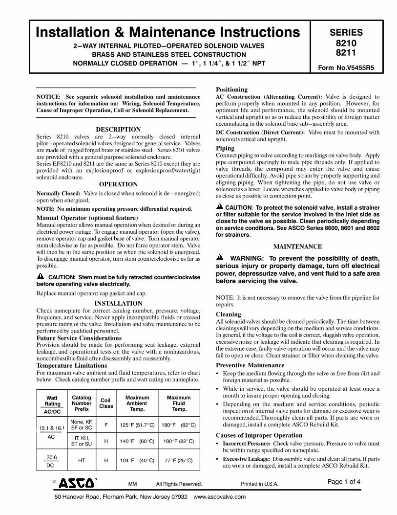
!"#$%&%'(%)
*+%,"-'.$/%0'"12%34'/5"6%!"/72%8$9%:$/;$<%+=>?@%%%%999A";B'."4.$AB'6
! CC%%%%%%%%%%%%%%D44%0E#5F;%0$;$/.$1A !/E-F$1%E-%GAHADA
!"#$%&&%$'(")*)+%'"$,"%"-,)!"#$./-$'("# 012!10
3(.4)5(67898828
:;<=>)!5?125=@)A!@B?1C;BA12=?1C)0B@15B!C)7=@710 D:EFG2=00)=5C)0?=!5@100)0?11@)HB50?2IH?!B5
5B2+=@@>)H@B01C)BA12=?!B5))J))E"K)E)EL9"K)*)E)EL:")5A?
D:EE
!"#$%&'( ( )**( +*,-.-/*( +01*2034( 32+/-11-/302( -24( 5-32/*2-26*32+/.76/302+(80.( 3280.5-/302(02'( (93.32:;()01*2034(#*5,*.-/7.*;%-7+*(08($5,.0,*.(",*.-/302;(%031(0.()01*2034(<*,1-6*5*2/=
>&)%<$?#$"!!"#$"%& '()*& +,-+"%& ,#"& (./,0& 12#3,--0& 4-2%"5& $16"#1,-7$-26.27"#,6"5&%2-"12$5&+,-+"%&5"%$81"5&92#&8"1"#,-&%"#+$4":&&;,-+"%,#"&3,5"&29&&#<88"5&92#8"5&=#,%%&2#&%6,$1-"%%&%6""-:&&&!"#$"%&'()*&&+,-+"%,#"&7#2+$5"5&/$6>&,&8"1"#,-&7<#72%"&%2-"12$5&"14-2%<#":!"#$"%&?@'()*&,15&'())&,#"&6>"&%,3"&,%&!"#$"%&'()*&"A4"76&6>"0&,#"7#2+$5"5& /$6>& ,1& "A7-2%$217#229& 2#& "A7-2%$217#229B/,6"#6$8>6%2-"12$5&"14-2%<#":
"?&<@#$"!
!0.5-11A(%10+*4'&&;,-+"&$%&4-2%"5&/>"1&%2-"12$5&$%&5"."1"#8$C"5D27"1&/>"1&"1"#8$C"5:
!"#&'((!0(5323575(0,*.-/32:(,.*++7.*(4388*.*2/3-1(.*B73.*4=
C-27-1(",*.-/0.(D0,/302-1(8*-/7.*EE,1<,-&27"#,62#&,--2/%&3,1<,-&27"#,6$21&/>"1&5"%$#"5&2#&5<#$18&,1"-"46#$4,-&72/"#&2<6,8":&F2&"18,8"&3,1<,-&27"#,62#&G27"1&6>"&+,-+"HI#"32+"&27"#,62#&4,7&,15&8,%J"6&=,%"&29&+,-+":&&F<#1&3,1<,-&27"#,62#%6"3&4-24J/$%"&,%&9,#&,%&72%%$=-":&&K2&126&92#4"&27"#,62#&%6"3:&&;,-+"/$--&6>"1&="&$1&6>"&%,3"&72%$6$21&,%&/>"1&6>"&%2-"12$5&$%&"1"#8$C"5:F2&5$%"18,8"&3,1<,-&27"#,62#I&6<#1&%6"3&42<16"#4-24J/$%"&,%&9,#&,%72%%$=-":
))H=I?!B5M))0$,4)4/#$)N,)O/&&P).,$.%-$,Q)-(/"$,.-&(-RS'#,N,O(.,)(T,.%$'"U)V%&V,),&,-$.'-%&&P6
L"7-,4"&3,1<,-&27"#,62#&4,7&8,%J"6&,15&4,7:
$!)#@FF@#$"!M>"4J& 1,3"7-,6"& 92#& 42##"46& 4,6,-28& 1<3="#I& 7#"%%<#"I& +2-6,8"I9#"N<"140I&,15&%"#+$4":&O"+"#&,77-0&$14237,6$=-"&9-<$5%&2#&"A4""57#"%%<#"&#,6$18&29&6>"&+,-+":&P1%6,--,6$21&,15&+,-+"&3,$16"1,14"&62&="7"#92#3"5&=0&N<,-$9$"5&7"#%211"-:G7/7.*()*.H36*(%02+34*.-/302+Q#2+$%$21& %>2<-5& ="& 3,5"& 92#& 7"#92#3$18& %",6& -",J,8"I& "A6"#1,--",J,8"I&,15&27"#,6$21,-&6"%6%&21&6>"&+,-+"&/$6>&,&121>,C,#52<%I121423=<%6$=-"&9-<$5&,96"#&5$%,%%"3=-0&,15&#",%%"3=-0:#*5,*.-/7.*(F353/-/302+@2#&3,A$3<3&+,-+"&,3=$"16&,15&9-<$5&6"37"#,6<#"%I&#"9"#&62&4>,#6="-2/:&&M>"4J&4,6,-28&1<3="#&7#"9$A&,15&/,66&#,6$18&21&1,3"7-,6":
<%$$)2%$'"U
=HLCH
H%$%&(U5/4N,.A.,O'W
H('&)H&%##
+%W'4/4=4N',"$)
?,4T6
+%W'4/43&/'Q
)?,4T6
&*A&%I%&JA&8'-$2%K32H3%'/%HL 3 &@*#3%M*&A=#LN &O+#3 MO@#LN
DL ,P2%K,2%HP%'/%HG , &)+#3 MJ+#LN &O+#3%MO@#LN
?+AJ
QL,P , &+)#3 M)+#LN ==#3%M@*#LN
?0+3/30232:@%( %02+/.76/302( D@1/*.2-/32:( %7..*2/E'& ;,-+"& $%& 5"%$81"5& 627"#92#3& 7#27"#-0& />"1& 32<16"5& $1& ,10& 72%$6$21:& & R2/"+"#I& 92#276$3<3&-$9"&,15&7"#92#3,14"I& 6>"&%2-"12$5&%>2<-5&="&32<16"5+"#6$4,-&,15&<7#$8>6&%2&,%&62&#"5<4"&6>"&72%%$=$-$60&29&92#"$81&3,66"#,44<3<-,6$18&$1&6>"&%2-"12$5&=,%"&%<=.,%%"3=-0&,#",:
>%(%02+/.76/302(D>3.*6/(%7..*2/E'(&;,-+"&3<%6&="&32<16"5&/$6>%2-"12$5&+"#6$4,-&,15&<7#$8>6:
?3,32:M211"46&7$7$18&62&+,-+"&,442#5$18&62&3,#J$18%&21&+,-+"&=250:&&S77-07$7"&42372<15&%7,#$18-0&62&3,-"&7$7"&6>#",5%&21-0:&P9&,77-$"5&62+,-+"& 6>#",5%I& 6>"& 42372<15& 3,0& "16"#& 6>"& +,-+"& ,15& 4,<%"27"#,6$21,-&5$99$4<-60:&S+2$5&7$7"&%6#,$1&=0&7#27"#-0&%<772#6$18&,15,-$81$18& 7$7$18:& T>"1& 6$8>6"1$18& 6>"& 7$7"I& 52& 126& <%"& +,-+"& 2#%2-"12$5&,%&,&-"+"#:&U24,6"&/#"14>"%&,77-$"5&62&+,-+"&=250&2#&7$7$18,%&4-2%"&,%&72%%$=-"&62&4211"46$21&72$16:
H=I?!B5M))?()T.($,-$)$X,)#(&,"('Q)V%&V,K)'"#$%&&)%)#$.%'",.(.)O'&$,.)#/'$%N&,)O(.)$X,)#,.V'-,)'"V(&V,Q)'")$X,)'"&,$)#'Q,)%#-&(#,)$()$X,)V%&V,)%#)T(##'N&,6)H&,%")T,.'(Q'-%&&P)Q,T,"Q'"U(")#,.V'-,)-("Q'$'("#6)0,,)=0HB)0,.',#)DYFFK)DYFE)%"Q)DYF:O(.)#$.%'",.#6
C@$!#&!@!%&
) )<=25!5ZM) )?()T.,V,"$) $X,)T(##'N'&'$P)(O)Q,%$XK#,.'(/#)'"[/.P)(.)T.(T,.$P)Q%4%U,K)$/.")(OO),&,-$.'-%&T(S,.K)Q,T.,##/.'\,)V%&V,K)%"Q)V,"$)O&/'Q)$()%)#%O,)%.,%N,O(.,)#,.V'-'"U)$X,)V%&V,6
OVF?W&&P6&$%&126&1"4"%%,#0&62&#"32+"&6>"&+,-+"&9#23&6>"&7$7"-$1"&92##"7,$#%:
%1*-232:S--&%2-"12$5&+,-+"%&%>2<-5&="&4-",1"5&7"#$25$4,--0:&F>"&6$3"&="6/""14-",1$18%&/$--&+,#0&5"7"15$18&21&6>"&3"5$<3&,15&%"#+$4"&4215$6$21%:P1&8"1"#,-I&$9&6>"&+2-6,8"&62&6>"&42$-&$%&42##"46I&%-<88$%>&+,-+"&27"#,6$21I"A4"%%$+"&12$%"&2#&-",J,8"&/$--&$15$4,6"&6>,6&4-",1$18&$%&#"N<$#"5:&P16>"&"A6#"3"&4,%"I&9,<-60&+,-+"&27"#,6$21&/$--&244<#&,15&6>"&+,-+"&3,09,$-&62&27"1&2#&4-2%":&M-",1&%6#,$1"#&2#&9$-6"#&/>"1&4-",1$18&6>"&+,-+":
?.*H*2/3H*(C-32/*2-26*
$ X""7&6>"&3"5$<3&9-2/$18&6>#2<8>&6>"&+,-+"&,%&9#""&9#23&5$#6&,1592#"$81&3,6"#$,-&,%&72%%$=-":
$ T>$-"& $1&%"#+$4"I&6>"&+,-+"&%>2<-5&="&27"#,6"5&,6& -",%6&214"&,3216>&62&$1%<#"&7#27"#&27"1$18&,15&4-2%$18:
$ K"7"15$18& 21& 6>"& 3"5$<3& ,15& %"#+$4"& 4215$6$21%I& 7"#$25$4$1%7"46$21&29&$16"#1,-&+,-+"&7,#6%&92#&5,3,8"&2#&"A4"%%$+"&/",#&$%#"4233"15"5:&F>2#2<8>-0&4-",1&,--&7,#6%:&P9&7,#6%&,#"&/2#1&2#5,3,8"5I&$1%6,--&,&4237-"6"&S!MV&L"=<$-5&X$6:
%-7+*+(08($5,.0,*.(",*.-/302
$ $260..*6/(?.*++7.*'((M>"4J&+,-+"&7#"%%<#":&Q#"%%<#"&62&+,-+"&3<%6="&/$6>$1&#,18"&%7"4$9$"5&21&1,3"7-,6":
$ &I6*++3H*(F*-J-:*'&&K$%,%%"3=-"&+,-+"&,15&4-",1&,--&7,#6%:&P9&7,#6%,#"&/2#1&2#&5,3,8"5I&$1%6,--&,&4237-"6"&S!MV&L"=<$-5&X$6:
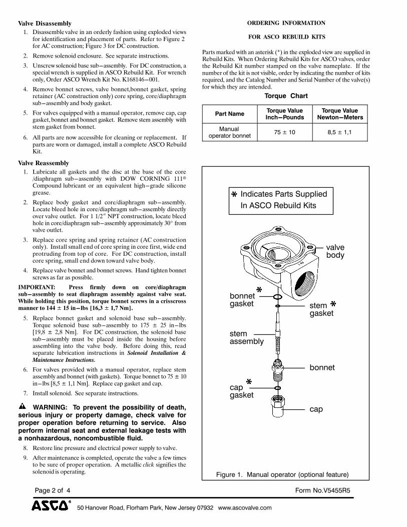
*+%,"-'.$/%0'"12%34'/5"6%!"/72%8$9%:$/;$<%+=>?@%%%999A";B'."4.$AB'6
!"#$%@%'(%%) 3'/6%8'AR*)**0*
K-1H*(>3+-++*5L1A
): K$%,%%"3=-"&+,-+"&$1&,1&2#5"#-0&9,%>$21&<%$18&"A7-25"5&+$"/%92#&$5"16$9$4,6$21&,15&7-,4"3"16&29&7,#6%:&&L"9"#&62&@$8<#"&(&92#&SM&421%6#<46$21D&@$8<#"&Y&92#&KM&421%6#<46$21:
(: L"32+"&%2-"12$5&"14-2%<#":&&!""&%"7,#,6"&$1%6#<46$21%:
Y: Z1%4#"/&%2-"12$5&=,%"&%<=.,%%"3=-0:&&@2#&KM&421%6#<46$21I&,%7"4$,-&/#"14>&$%&%<77-$"5&$1&S!MV&L"=<$-5&X$6:&&@2#&/#"14>21-0I&V#5"#&S!MV&T#"14>&X$6&O2:&X)[')\[.**):
\: L"32+"&=211"6& %4#"/%I& +,-+"&=211"6I=211"6&8,%J"6I& %7#$18#"6,$1"#&GSM&421%6#<46$21&21-0H&42#"&%7#$18I&42#"B5$,7>#,83%<=.,%%"3=-0&,15&=250&8,%J"6:
]: @2#&+,-+"%&"N<$77"5&/$6>&,&3,1<,-&27"#,62#I&#"32+"&4,7I&4,78,%J"6I&=211"6&,15&=211"6&8,%J"6:&&L"32+"&%6"3&,%%"3=-0&&/$6>%6"3&8,%J"6&9#23&=211"6:
[: S--&7,#6%&,#"&12/&,44"%%$=-"&92#&4-",1$18&2#&#"7-,4"3"16:& &P97,#6%&,#"&/2#1&2#&5,3,8"5I&$1%6,--&,&4237-"6"&S!MV&L"=<$-5X$6:
K-1H*(<*-++*5L1A
): U<=#$4,6"& ,--& 8,%J"6%& ,15& 6>"& 5$%4& ,6& 6>"& =,%"& 29& 6>"& 42#"B5$,7>#,83& %<=.,%%"3=-0& /$6>& KVT& MVLOPO^& )))%M2372<15& -<=#$4,16& 2#& ,1& "N<$+,-"16& >$8>.8#,5"& %$-$421"8#",%":
(: L"7-,4"& =250& 8,%J"6& ,15& 42#"B5$,7>#,83& %<=.,%%"3=-0:U24,6"&=-""5&>2-"&$1&42#"B5$,7>#,83&%<=.,%%"3=-0&5$#"46-02+"#&+,-+"&2<6-"6:&&@2#&)&)B("&OQF&421%6#<46$21I&-24,6"&=-""5>2-"&$1&42#"B5$,7>#,83&%<=.,%%"3=-0&,77#2A$3,6"-0&Y*#&9#23+,-+"&2<6-"6:
Y: L"7-,4"&42#"&%7#$18&,15&%7#$18&#"6,$1"#&GSM&421%6#<46$2121-0H:&&P1%6,--&%3,--&"15&29&42#"&%7#$18&$1&42#"&9$#%6I&/$5"&"157#26#<5$18&9#23&627&29&42#":&&@2#&KM&421%6#<46$21I&$1%6,--42#"&%7#$18I&%3,--&"15&52/1&62/,#5&+,-+"&=250:
\: L"7-,4"&+,-+"&=211"6&,15&=211"6&%4#"/%:&&R,15&6$8>6"1&=211"6%4#"/%&,%&9,#&,%&72%%$=-":
$C?"<#@!#'( ( ?.*++( 83.51A( 40M2( 02( 60.*N43-,O.-:5+7LP-++*5L1A( /0( +*-/( 43-,O.-:5( -++*5L1A( -:-32+/( H-1H*( +*-/=9O31*(O01432:(/O3+(,0+3/302;(/0.B7*(L022*/(+6.*M+(32(-(6.3++6.0++5-22*.(/0(QRR(_&QS(32P1L+(TQU;V(_(Q;W(!5X=
]: L"7-,4"& =211"6& 8,%J"6& ,15& %2-"12$5& =,%"& %<=.,%%"3=-0:F2#N<"& %2-"12$5& =,%"& %<=.,%%"3=-0& 62& )`]& _& (]& $1.-=%a)bI'& _& (I'& O3c:& & @2#&KM&421%6#<46$21I& 6>"&%2-"12$5&=,%"%<=.,%%"3=-0& 3<%6& ="& 7-,4"5& $1%$5"& 6>"& >2<%$18& ="92#",%%"3=-$18& $162& 6>"& +,-+"& =250:& & d"92#"& 52$18& 6>$%I& #",5%"7,#,6"& -<=#$4,6$21& $1%6#<46$21%& $1& !"#$%"&'( )%*+,##,+&"%( -
.,&%+$%,%/$()%*+01/+&"%*2
[: @2#& +,-+"%& 7#2+$5"5& /$6>& ,& 3,1<,-& 27"#,62#I& #"7-,4"& %6"3,%%"3=-0&,15&=211"6&G/$6>&8,%J"6%H:&&F2#N<"&=211"6&62&`]&_&)*$1.-=%&a'I]&_&)I)&O3c:&&L"7-,4"&4,7&8,%J"6&,15&4,7:
`: P1%6,--&%2-"12$5:&&!""&%"7,#,6"&$1%6#<46$21%:
) )<=25!5ZM) )?()T.,V,"$) $X,)T(##'N'&'$P)(O)Q,%$XK#,.'(/#) '"[/.P) (.) T.(T,.$P) Q%4%U,K) -X,-R) V%&V,) O(.T.(T,.) (T,.%$'(") N,O(.,) .,$/."'"U) $() #,.V'-,6) ) =&#(T,.O(.4)'"$,."%&)#,%$)%"Q),W$,."%&)&,%R%U,)$,#$#)S'$X%)"("X%\%.Q(/#K)"("-(4N/#$'N&,)O&/'Q6
': L"%62#"&-$1"&7#"%%<#"&,15&"-"46#$4,-&72/"#&%<77-0&62&+,-+":
b: S96"#&3,$16"1,14"&$%&4237-"6"5I&27"#,6"&6>"&+,-+"&,&9"/&6$3"%62&="&%<#"&29&7#27"#&27"#,6$21:&&S&3"6,--$4&!"#!$&%$81$9$"%&6>"%2-"12$5&$%&27"#,6$18:
"<>&<$!Y(($!G"<C@#$"!
(G"<((@)%"((<&Z[$F>((\$#)
Q,#6%&3,#J"5&/$6>&,1&,%6"#$%J&GeH&$1&6>"&"A7-25"5&+$"/&,#"&%<77-$"5&$1L"=<$-5&X$6%:&&T>"1&V#5"#$18&L"=<$-5&X$6%&92#&S!MV&+,-+"%I&2#5"#6>"&L"=<$-5&X$6&1<3="#&%6,37"5&21&6>"&+,-+"&1,3"7-,6":&&P9&6>"1<3="#&29&6>"&J$6&$%&126&+$%$=-"I&2#5"#&=0&$15$4,6$18&6>"&1<3="#&29&J$6%#"N<$#"5I&,15&6>"&M,6,-28&O<3="#&,15&!"#$,-&O<3="#&29&6>"&+,-+"G%H92#&/>$4>&6>"0&,#"&$16"15"5:
?(.]/,))HX%.$
A%.$)5%4,?(.]/,)7%&/,!"-X;A(/"Q#
?(.]/,)7%&/,5,S$(";+,$,.#
C"-S"4%'T$/"F'/%U'--$F
=*%V%&+ O2*%V%&2&
3E#S/$%&A%%C"-S"4%'T$/"F'/%M'TFE'-"4%($"FS/$N
."4.$
W-1EB"F$;%!"/F;%HSTT4E$1
W-%DHLX%0$USE41%KEF;
U'--$F;F$6
;F$6
U'--$F
B"T
B"T
#";7$F
";;$6U4<
#";7$F
#";7$F
U'1<
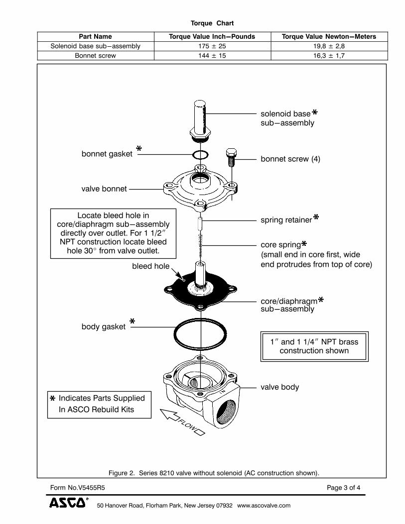
*+%,"-'.$/%0'"12%34'/5"6%!"/72%8$9%:$/;$<%+=>?@%%%999A";B'."4.$AB'6
!"#$%?%'(%)3'/6%8'AR*)**0*
?(.]/,))HX%.$
A%.$)5%4, ?(.]/,)7%&/,)!"-X;A(/"Q# ?(.]/,)7%&/,)5,S$(";+,$,.#
H'4$-'E1%U";$%;SUY";;$6U4< &=*%V%@* &>2O%V%@2O
Z'--$F%;B/$9 &))%V%&* &J2?%V%&2=
3E#S/$%@A%%H$/E$;%O@&+%."4.$%9EF5'SF%;'4$-'E1%MDL%B'-;F/SBFE'-%;5'9-NA
."4.$%U'1<
U'--$F%#";7$F
W-1EB"F$;%!"/F;%HSTT4E$1
W-%DHLX%0$USE41%KEF;
U'--$F%;B/$9%M)N
B'/$[1E"T5/"#6;SUY";;$6U4<
U'1<%#";7$F
U4$$1%5'4$
."4.$%U'--$F
;'4$-'E1%U";$;SUY";;$6U4<
;T/E-#%/$F"E-$/
B'/$%;T/E-#M;6"44%$-1%E-%B'/$%(E/;F2%9E1$$-1%T/'F/S1$;%(/'6%F'T%'(%B'/$N
&"%"-1%&%&[)"%8!P%U/";;B'-;F/SBFE'-%;5'9-
\'B"F$%U4$$1%5'4$%E-B'/$[1E"T5/"#6%;SUY";;$6U4<1E/$BF4<%'.$/%'SF4$FA%3'/%&%&[@"8!P%B'-;F/SBFE'-%4'B"F$%U4$$1
5'4$%?+#%(/'6%."4.$%'SF4$FA
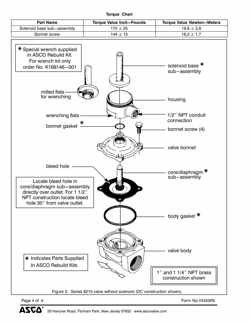
*+%,"-'.$/%0'"12%34'/5"6%!"/72%8$9%:$/;$<%+=>?@%%%999A";B'."4.$AB'6
!"#$%)%'(%%) 3'/6%8'AR*)**0*
?(.]/,))HX%.$
A%.$)5%4, ?(.]/,)7%&/,)!"-X;A(/"Q# ?(.]/,)7%&/,)5,S$(";+,$,.#
H'4$-'E1%U";$%;SUY";;$6U4< &=*%V%@* &>2O%V%@2O
Z'--$F%;B/$9 &))%V%&* &J2?%V%&2=
3E#S/$%?A%%H$/E$;%O@&+%."4.$%9EF5'SF%;'4$-'E1%MQL%B'-;F/SBFE'-%;5'9-NA
;'4$-'E1%U";$;SUY";;$6U4<
."4.$%U'1<
U'--$F%#";7$F
W-1EB"F$;%!"/F;%HSTT4E$1
W-%DHLX%0$USE41%KEF;
5'S;E-#
U'--$F%;B/$9%M)N
B'/$[1E"T5/"#6;SUY";;$6U4<
U'1<%#";7$F
U4$$1%5'4$
."4.$%U'--$F
9/$-B5E-#%(4"F; &[@"%8!P%B'-1SEFB'--$BFE'-
6E44$1%(4"F;('/%9/$-B5E-#
\'B"F$%U4$$1%5'4$%E-B'/$[1E"T5/"#6%;SUY";;$6U4<1E/$BF4<%'.$/%'SF4$FA%3'/%&%&[@"8!P%B'-;F/SBFE'-%4'B"F$%U4$$1
5'4$%?+#%(/'6%."4.$%'SF4$FA
HT$BE"4%9/$-B5%;STT4E$1
3'/%9/$-B5%7EF%'-4<'/1$/%8'A%K&JO&)JY++&
%
&"%"-1%&%&[)"%8!P%U/";;B'-;F/SBFE'-%;5'9-
E-%DHLX%0$USE41%KEFA
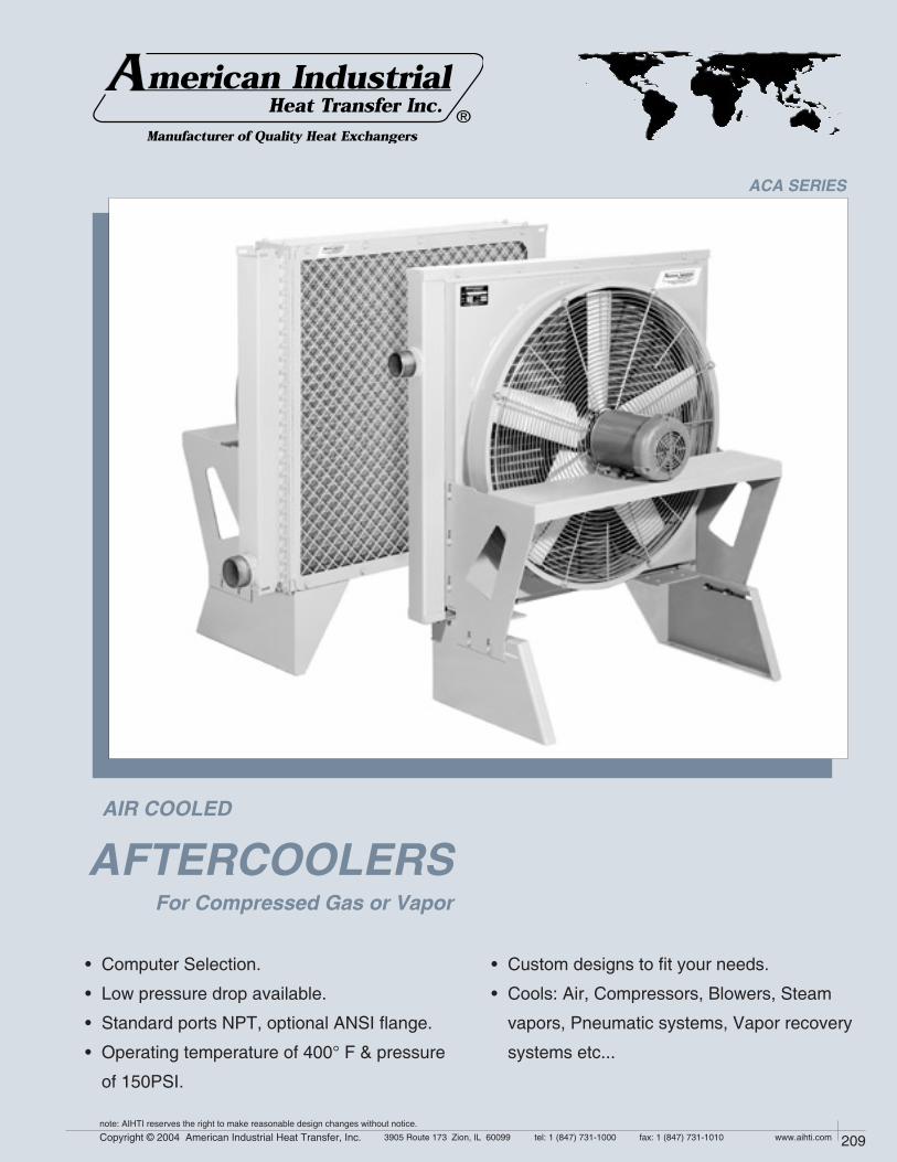
208 Copyright © 2004 American Industrial Heat Transfer, Inc. tel: 1 (847) 731-10003905 Route 173 Zion, IL 60099 www.aihti.comfax: 1 (847) 731-1010
note: AIHTI reserves the right to make reasonable design changes without notice.
209Copyright © 2004 American Industrial Heat Transfer, Inc. tel: 1 (847) 731-10003905 Route 173 Zion, IL 60099 www.aihti.comfax: 1 (847) 731-1010
note: AIHTI reserves the right to make reasonable design changes without notice.
• Computer Selection.
• Low pressure drop available.
• Standard ports NPT, optional ANSI flange.
• Operating temperature of 400° F & pressure
of 150PSI.
For Compressed Gas or Vapor
AFTERCOOLERS
ACA SERIES
• Custom designs to fit your needs.
• Cools: Air, Compressors, Blowers, Steam
vapors, Pneumatic systems, Vapor recovery
systems etc...
AIR COOLED
®

210 Copyright © 2004 American Industrial Heat Transfer, Inc. tel: 1 (847) 731-10003905 Route 173 Zion, IL 60099 www.aihti.comfax: 1 (847) 731-1010
note: AIHTI reserves the right to make reasonable design changes without notice.
211Copyright © 2004 American Industrial Heat Transfer, Inc. tel: 1 (847) 731-10003905 Route 173 Zion, IL 60099 www.aihti.comfax: 1 (847) 731-1010
note: AIHTI reserves the right to make reasonable design changes without notice.
ACA - 3181 through ACA - 4362
TANKS
State-of-the-art high temperature brazing method insures permanent bond and positive contact of tube to manifold, eliminating leaks and providing maximum service life.
Air coolers are an essential part of any compressed air system, by cooling the air, and condensing water vapor into a liquid state for removal. When air is compressed, the compression induces heat into both the air and the water entrained in the air. The American Industrial ACA series heat exchanger cools air with air, making it a simple inexpensive way to cool when compared to other water-cooled or refrigerant cooled systems. The unique compact brazed fin/tube design provides efficient cooling and low maintenance under the warmest environmental conditions. By using an ACA series air-cooled after cooler, machine tools will recieve cooler dryer air, provide longer trouble free life, experience less down time, and be cost effective to operate on a continuous basis.
Tubes
Fins
Cabinet & Pipes
Fan Guard
Manifolds
Standard Construction Materials Standard Unit Ratings
Operating Pressure
Operating Temperature
150 psig
400 oF
Consult factory for optional materials and ratings.
SUPERIOR COOLING FINS
Copper tubes are mechanically bonded to highly efficient aluminum cooling fins. Die-formed fin collars provide a durable precision fit for maximum heat transfer. Custom fin design forces air to become turbulent and carry heat away more efficiently than old flat fin designs.
Brazed Core Construction
Copper
Aluminum
Steel
Zinc Plated Steel
Steel
ACA Series construction
CONSTRUCTION MATERIALS & RATINGS

210 Copyright © 2004 American Industrial Heat Transfer, Inc. tel: 1 (847) 731-10003905 Route 173 Zion, IL 60099 www.aihti.comfax: 1 (847) 731-1010
note: AIHTI reserves the right to make reasonable design changes without notice.
211Copyright © 2004 American Industrial Heat Transfer, Inc. tel: 1 (847) 731-10003905 Route 173 Zion, IL 60099 www.aihti.comfax: 1 (847) 731-1010
note: AIHTI reserves the right to make reasonable design changes without notice.
ACA - 6301 through ACA 6602
SERVICEABLE CORE®
Core covers disassemble for easy access and cleaning. Repairable design for applications that require limited down time or in the event of a mishap requiring repair. Roller expanded tube to tube-sheet joint. 100% mechanical bond. Positive gasket seal is field replaceable for field maintenance or repair.
SUPERIOR COOLING FINS
Copper tubes are mechanically bonded to highly efficient aluminum cooling fins. Die-formed fin collars provide a durable precision fit for maximum heat transfer. Custom fin design forces air to become turbulent and carry heat away more efficiently than old flat fin designs.
Air coolers are an essential part of any compressed air system, by cooling the air, and condensing water vapor into a liquid state for removal. When air is compressed, the compression induces heat into both the air and the water entrained in the air. The American Industrial ACA series heat exchanger cools air with air, making it a simple inexpensive way to cool when compared to other water-cooled or refrigerant cooled systems. The unique compact serviceable core® design provides efficient cooling and low maintenance under the warmest environmental conditions. By using an ACA series air-cooled after cooler, machine tools will recieve cooler dryer air, provide longer trouble free life, experience less down time, and be cost effective to operate on a continuous basis.
Serviceable Core® Construction
Standard Construction Materials Standard Unit Ratings
Operating Pressure
Operating Temperature
150 psig
400 oF
Consult factory for optional materials and ratings.
Tubes
Fins
Cabinet & Pipes
Fan Guard
Manifolds
Copper
Aluminum
Steel
Zinc Plated Steel
Steel
ACA Series construction
CONSTRUCTION MATERIALS & RATINGS
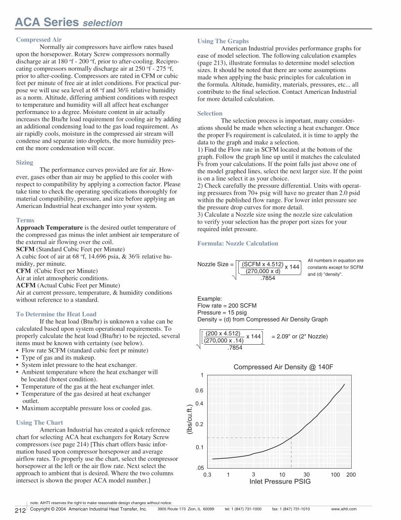
212 Copyright © 2004 American Industrial Heat Transfer, Inc. tel: 1 (847) 731-10003905 Route 173 Zion, IL 60099 www.aihti.comfax: 1 (847) 731-1010
note: AIHTI reserves the right to make reasonable design changes without notice.
213Copyright © 2004 American Industrial Heat Transfer, Inc. tel: 1 (847) 731-10003905 Route 173 Zion, IL 60099 www.aihti.comfax: 1 (847) 731-1010
note: AIHTI reserves the right to make reasonable design changes without notice.
Compressed Air
Normally air compressors have airflow rates based upon the horsepower. Rotary Screw compressors normally discharge air at 180 of - 200 of, prior to after-cooling. Recipro-cating compressors normally discharge air at 250 of - 275 of, prior to after-cooling. Compressors are rated in CFM or cubic feet per minute of free air at inlet conditions. For practical pur-pose we will use sea level at 68 of and 36% relative humidity as a norm. Altitude, differing ambient conditions with respect to temperature and humidity will all affect heat exchanger performance to a degree. Moisture content in air actually increases the Btu/hr load requirement for cooling air by adding an additional condensing load to the gas load requirement. As air rapidly cools, moisture in the compressed air stream will condense and separate into droplets, the more humidity pres-ent the more condensation will occur.
Sizing
The performance curves provided are for air. How-ever, gases other than air may be applied to this cooler with respect to compatibility by applying a correction factor. Please take time to check the operating specifications thoroughly for material compatibility, pressure, and size before applying an American Industrial heat exchanger into your system.
Terms
Approach Temperature is the desired outlet temperature of the compressed gas minus the inlet ambient air temperature of the external air flowing over the coil. SCFM (Standard Cubic Feet per Minute)A cubic foot of air at 68 of, 14.696 psia, & 36% relative hu-midity, per minute.CFM (Cubic Feet per Minute)Air at inlet atmospheric conditions.ACFM (Actual Cubic Feet per Minute)Air at current pressure, temperature, & humidity conditions without reference to a standard.
To Determine the Heat Load
If the heat load (Btu/hr) is unknown a value can be calculated based upon system operational requirements. To properly calculate the heat load (Btu/hr) to be rejected, several items must be known with certainty (see below).• Flow rate SCFM (standard cubic feet pr minute)• Type of gas and its makeup. • System inlet pressure to the heat exchanger.• Ambient temperature where the heat exchanger will be located (hotest condition).• Temperature of the gas at the heat exchanger inlet.• Temperature of the gas desired at heat exchanger outlet.• Maximum acceptable pressure loss or cooled gas.
Using The Chart
American Industrial has created a quick reference chart for selecting ACA heat exchangers for Rotary Screw compressors (see page 214) [This chart offers basic infor-mation based upon compressor horsepower and average airflow rates. To properly use the chart, select the compressor horsepower at the left or the air flow rate. Next select the approach to ambient that is desired. Where the two columns intersect is shown the proper ACA model number.]
ACA Series selection
#OMPRESSED!IR$ENSITY &
)NLET0RESSURE03)'
LBSCUFT
x 144 = 2.09" or (2" Nozzle)
x 144
Using The Graphs
American Industrial provides performance graphs for ease of model selection. The following calculation examples (page 213), illustrate formulas to determine model selection sizes. It should be noted that there are some assumptions made when applying the basic principles for calculation in the formula. Altitude, humidity, materials, pressures, etc... all contribute to the final selection. Contact American Industrial for more detailed calculation.
Selection
The selection process is important, many consider-ations should be made when selecting a heat exchanger. Once the proper Fs requirement is calculated, it is time to apply the data to the graph and make a selection. 1) Find the Flow rate in SCFM located at the bottom of the graph. Follow the graph line up until it matches the calculated Fs from your calculations. If the point falls just above one of the model graphed lines, select the next larger size. If the point is on a line select it as your choice. 2) Check carefully the pressure differential. Units with operat-ing pressures from 70+ psig will have no greater than 2.0 psid within the published flow range. For lower inlet pressure see the pressure drop curves for more detail. 3) Calculate a Nozzle size using the nozzle size calculation to verify your selection has the proper port sizes for your required inlet pressure.
Formula: Nozzle Calculation
Nozzle Size = (SCFM x 4.512) (270,000 x d) .7854
Example:Flow rate = 200 SCFMPressure = 15 psigDensity = (d) from Compressed Air Density Graph
(200 x 4.512) (270,000 x .14) .7854
All numbers in equation are constants except for SCFM and (d) "density".
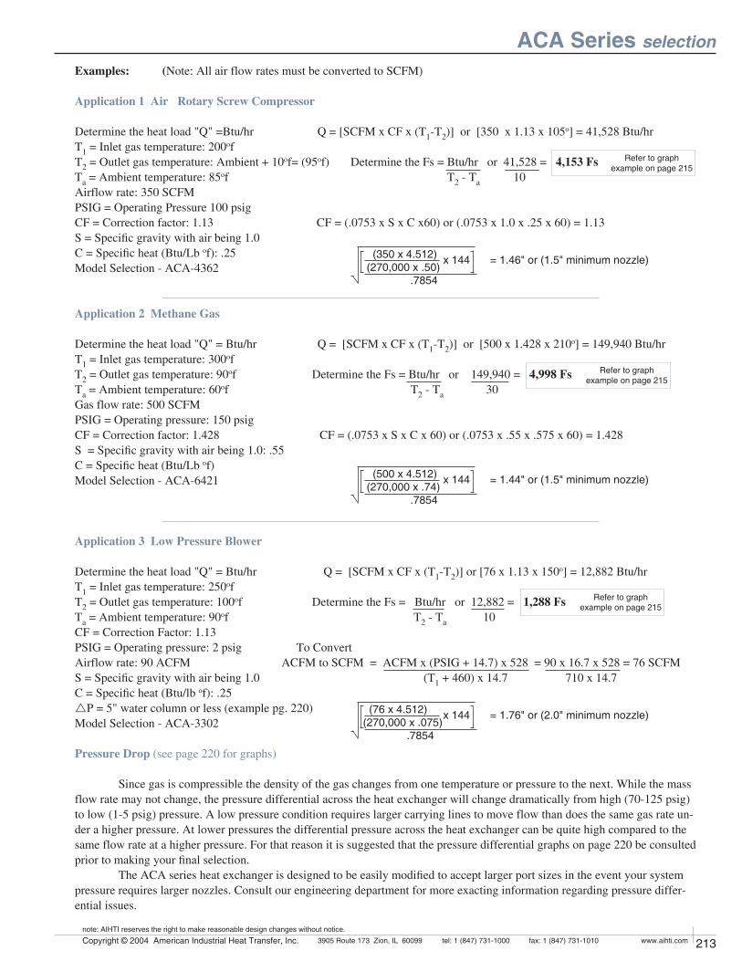
212 Copyright © 2004 American Industrial Heat Transfer, Inc. tel: 1 (847) 731-10003905 Route 173 Zion, IL 60099 www.aihti.comfax: 1 (847) 731-1010
note: AIHTI reserves the right to make reasonable design changes without notice.
213Copyright © 2004 American Industrial Heat Transfer, Inc. tel: 1 (847) 731-10003905 Route 173 Zion, IL 60099 www.aihti.comfax: 1 (847) 731-1010
note: AIHTI reserves the right to make reasonable design changes without notice.
Examples: (Note: All air flow rates must be converted to SCFM)
Application 1 Air Rotary Screw Compressor
Determine the heat load "Q" =Btu/hr Q = [SCFM x CF x (T1-T2)] or [350 x 1.13 x 105o] = 41,528 Btu/hr T1 = Inlet gas temperature: 200of T2 = Outlet gas temperature: Ambient + 10of= (95of) Determine the Fs = Btu/hr or 41,528 = 4,153 Fs
Ta = Ambient temperature: 85of T2 - Ta 10Airflow rate: 350 SCFMPSIG = Operating Pressure 100 psigCF = Correction factor: 1.13 CF = (.0753 x S x C x60) or (.0753 x 1.0 x .25 x 60) = 1.13 S = Specific gravity with air being 1.0C = Specific heat (Btu/Lb of): .25Model Selection - ACA-4362
Application 2 Methane Gas
Determine the heat load "Q" = Btu/hr Q = [SCFM x CF x (T1-T2)] or [500 x 1.428 x 210o] = 149,940 Btu/hrT1 = Inlet gas temperature: 300ofT2 = Outlet gas temperature: 90of Determine the Fs = Btu/hr or 149,940 = 4,998 Fs
Ta = Ambient temperature: 60of T2 - Ta 30Gas flow rate: 500 SCFMPSIG = Operating pressure: 150 psigCF = Correction factor: 1.428 CF = (.0753 x S x C x 60) or (.0753 x .55 x .575 x 60) = 1.428S = Specific gravity with air being 1.0: .55C = Specific heat (Btu/Lb of)Model Selection - ACA-6421
Application 3 Low Pressure Blower
Determine the heat load "Q" = Btu/hr Q = [SCFM x CF x (T1-T2)] or [76 x 1.13 x 150o] = 12,882 Btu/hrT1 = Inlet gas temperature: 250ofT2 = Outlet gas temperature: 100of Determine the Fs = Btu/hr or 12,882 = 1,288 Fs
Ta = Ambient temperature: 90of T2 - Ta 10CF = Correction Factor: 1.13PSIG = Operating pressure: 2 psig To ConvertAirflow rate: 90 ACFM ACFM to SCFM = ACFM x (PSIG + 14.7) x 528 = 90 x 16.7 x 528 = 76 SCFMS = Specific gravity with air being 1.0 (T1 + 460) x 14.7 710 x 14.7C = Specific heat (Btu/lb of): .25 rP = 5" water column or less (example pg. 220)Model Selection - ACA-3302
Pressure Drop (see page 220 for graphs) Since gas is compressible the density of the gas changes from one temperature or pressure to the next. While the mass flow rate may not change, the pressure differential across the heat exchanger will change dramatically from high (70-125 psig) to low (1-5 psig) pressure. A low pressure condition requires larger carrying lines to move flow than does the same gas rate un-der a higher pressure. At lower pressures the differential pressure across the heat exchanger can be quite high compared to the same flow rate at a higher pressure. For that reason it is suggested that the pressure differential graphs on page 220 be consulted prior to making your final selection. The ACA series heat exchanger is designed to be easily modified to accept larger port sizes in the event your system pressure requires larger nozzles. Consult our engineering department for more exacting information regarding pressure differ-ential issues.
ACA Series selection
x 144 = 1.76" or (2.0" minimum nozzle) (76 x 4.512) (270,000 x .075) .7854
x 144 = 1.44" or (1.5" minimum nozzle) (500 x 4.512) (270,000 x .74) .7854
x 144 = 1.46" or (1.5" minimum nozzle) (350 x 4.512) (270,000 x .50) .7854
Refer to graph example on page 215
Refer to graph example on page 215
Refer to graph example on page 215
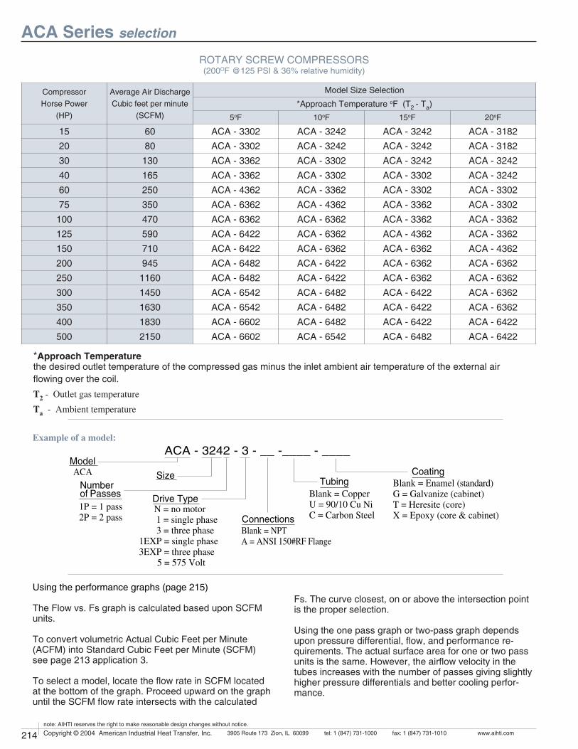
214 Copyright © 2004 American Industrial Heat Transfer, Inc. tel: 1 (847) 731-10003905 Route 173 Zion, IL 60099 www.aihti.comfax: 1 (847) 731-1010
note: AIHTI reserves the right to make reasonable design changes without notice.
215Copyright © 2004 American Industrial Heat Transfer, Inc. tel: 1 (847) 731-10003905 Route 173 Zion, IL 60099 www.aihti.comfax: 1 (847) 731-1010
note: AIHTI reserves the right to make reasonable design changes without notice.
ACA Series selection
ROTARY SCREW COMPRESSORS(200OF @125 PSI & 36% relative humidity)
*Approach Temperature
the desired outlet temperature of the compressed gas minus the inlet ambient air temperature of the external air flowing over the coil.
T2 - Outlet gas temperature
Ta - Ambient temperature
Example of a model:
!#! ?? ???? ????-ODEL
3IZE
$RIVE4YPE.UMBEROF0ASSES
!#!
#ONNECTIONS"LANK.04!!.3)2&&LANGE
4UBING
0PASS0PASS
#OATING
.NOMOTORSINGLEPHASETHREEPHASE%80SINGLEPHASE%80THREEPHASE6OLT
"LANK%NAMELSTANDARD''ALVANIZECABINET4(ERESITECORE8%POXYCORECABINET
"LANK#OPPER5#U.I##ARBON3TEEL
Using the performance graphs (page 215)
The Flow vs. Fs graph is calculated based upon SCFM units.
To convert volumetric Actual Cubic Feet per Minute (ACFM) into Standard Cubic Feet per Minute (SCFM) see page 213 application 3.
To select a model, locate the flow rate in SCFM located at the bottom of the graph. Proceed upward on the graph until the SCFM flow rate intersects with the calculated
Fs. The curve closest, on or above the intersection point is the proper selection.
Using the one pass graph or two-pass graph depends upon pressure differential, flow, and performance re-quirements. The actual surface area for one or two pass units is the same. However, the airflow velocity in the tubes increases with the number of passes giving slightly higher pressure differentials and better cooling perfor-mance.
CompressorHorse Power
(HP)
Average Air DischargeCubic feet per minute
(SCFM)
Model Size Selection
*Approach Temperature oF (T2 - Ta)
5oF 10oF 15oF 20oF
15 60 ACA - 3302 ACA - 3242 ACA - 3242 ACA - 3182
20 80 ACA - 3302 ACA - 3242 ACA - 3242 ACA - 3182
30 130 ACA - 3362 ACA - 3302 ACA - 3242 ACA - 3242
40 165 ACA - 3362 ACA - 3302 ACA - 3302 ACA - 3242
60 250 ACA - 4362 ACA - 3362 ACA - 3302 ACA - 3302
75 350 ACA - 6362 ACA - 4362 ACA - 3362 ACA - 3302
100 470 ACA - 6362 ACA - 6362 ACA - 3362 ACA - 3362
125 590 ACA - 6422 ACA - 6362 ACA - 4362 ACA - 3362
150 710 ACA - 6422 ACA - 6362 ACA - 6362 ACA - 4362
200 945 ACA - 6482 ACA - 6422 ACA - 6362 ACA - 6362
250 1160 ACA - 6482 ACA - 6422 ACA - 6362 ACA - 6362
300 1450 ACA - 6542 ACA - 6482 ACA - 6422 ACA - 6362
350 1630 ACA - 6542 ACA - 6482 ACA - 6422 ACA - 6362
400 1830 ACA - 6602 ACA - 6482 ACA - 6422 ACA - 6422
500 2150 ACA - 6602 ACA - 6542 ACA - 6482 ACA - 6422
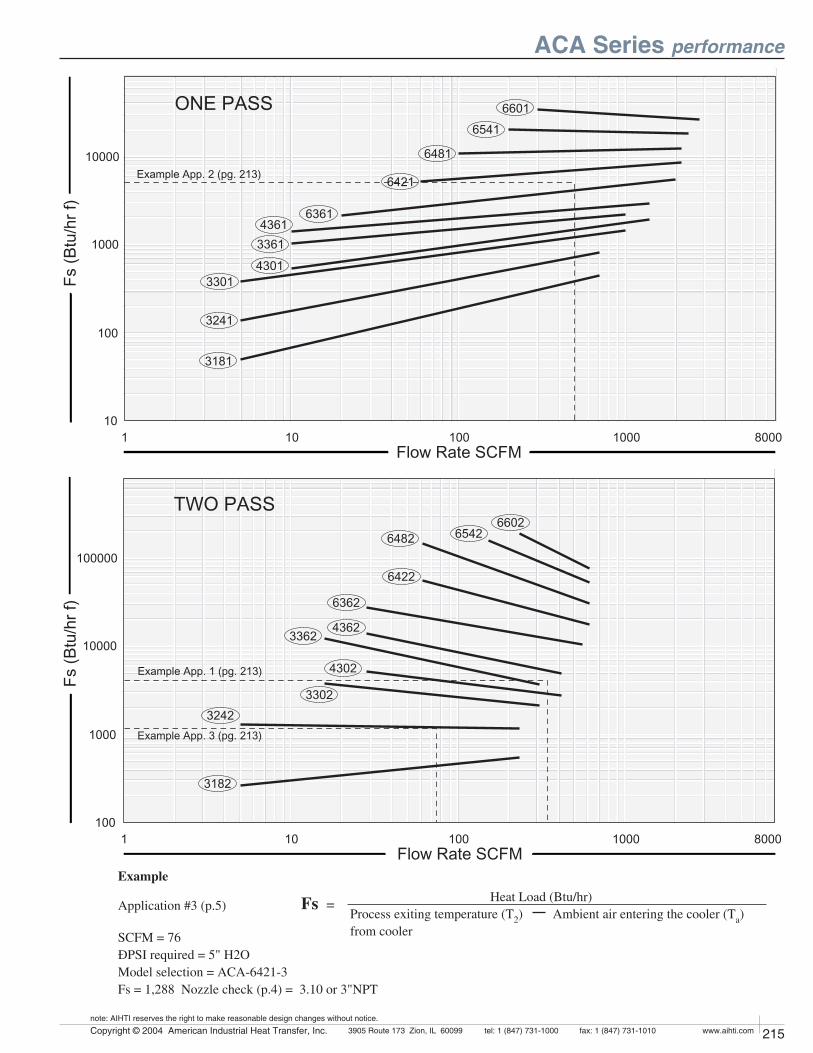
214 Copyright © 2004 American Industrial Heat Transfer, Inc. tel: 1 (847) 731-10003905 Route 173 Zion, IL 60099 www.aihti.comfax: 1 (847) 731-1010
note: AIHTI reserves the right to make reasonable design changes without notice.
215Copyright © 2004 American Industrial Heat Transfer, Inc. tel: 1 (847) 731-10003905 Route 173 Zion, IL 60099 www.aihti.comfax: 1 (847) 731-1010
note: AIHTI reserves the right to make reasonable design changes without notice.
/.%0!33
&LOW2ATE3#&-
&S"TUHRF
%XAMPLE!PPPG
47/0!33
&LOW2ATE3#&-
&S"TUHRF
%XAMPLE!PPPG
%XAMPLE!PPPG
ACA Series performance
Example
Application #3 (p.5)
SCFM = 76ÐPSI required = 5" H2OModel selection = ACA-6421-3Fs = 1,288 Nozzle check (p.4) = 3.10 or 3"NPT
Fs = Heat Load (Btu/hr)Process exiting temperature (T2) Ambient air entering the cooler (Ta) from cooler
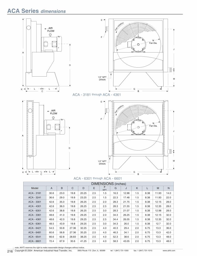
216 Copyright © 2004 American Industrial Heat Transfer, Inc. tel: 1 (847) 731-10003905 Route 173 Zion, IL 60099 www.aihti.comfax: 1 (847) 731-1010
note: AIHTI reserves the right to make reasonable design changes without notice.
217Copyright © 2004 American Industrial Heat Transfer, Inc. tel: 1 (847) 731-10003905 Route 173 Zion, IL 60099 www.aihti.comfax: 1 (847) 731-1010
note: AIHTI reserves the right to make reasonable design changes without notice.
ACA Series dimensions
ACA - 3181 through ACA - 4361
ACA - 6301 through ACA - 6601
MLKJGFNPT
EDCBA
DIMENSIONS (inches)NModel
!
+#
$
!)2&,/7
,,
&AN
RO
TATION
&
%
.&AN$IA
'"
-
*
.04$2!).
'
&AN
RO
TATION
"
&
.&AN$IA
%
.04$2!).
*
-
$
#+
!)2&,/7
!
, , ,
ACA - 3181
ACA - 3241
ACA - 3301
ACA - 4301
ACA - 6301
ACA - 3361
ACA - 4361
ACA - 6361
ACA - 6421
ACA - 6481
ACA - 6541
ACA - 6601
30.6
36.6
42.6
42.6
42.6
48.6
48.6
48.5
54.5
60.6
66.6
72.4
23.0
29.0
35.0
36.0
38.8
41.0
42.0
43.9
50.8
56.8
62.8
67.9
19.8
19.8
19.8
19.8
19.8
19.8
19.8
19.8
27.36
27.36
28.83
30.6
20.25
23.25
26.25
26.25
26.25
29.25
29.25
29.25
32.25
35.25
38.25
41.25
2.5
2.5
2.5
2.5
2.5
2.5
2.5
2.5
2.5
2.5
2.5
2.5
1.5
1.5
2.0
2.5
3.0
2.0
2.5
3.0
4.0
4.0
4.0
4.0
16.3
22.3
28.3
28.3
28.3
34.3
34.4
34.3
40.3
46.3
52.3
58.3
12.98
17.48
21.75
21.55
21.07
26.25
26.05
26.0
29.4
34.1
38.6
43.05
1.5
1.5
1.5
1.5
1.5
1.5
1.5
1.5
2.0
2.0
2.0
2.0
8.38
8.38
8.38
8.38
8.38
8.38
8.38
8.38
6.75
6.75
6.75
6.75
11.93
11.93
12.15
12.35
12.98
12.15
12.35
12.7
13.3
13.3
13.3
13.3
14.0
22.0
28.0
28.0
28.0
32.0
32.0
32.0
36.0
42.0
48.0
48.0
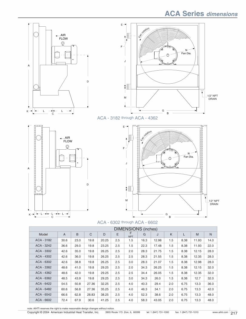
216 Copyright © 2004 American Industrial Heat Transfer, Inc. tel: 1 (847) 731-10003905 Route 173 Zion, IL 60099 www.aihti.comfax: 1 (847) 731-1010
note: AIHTI reserves the right to make reasonable design changes without notice.
217Copyright © 2004 American Industrial Heat Transfer, Inc. tel: 1 (847) 731-10003905 Route 173 Zion, IL 60099 www.aihti.comfax: 1 (847) 731-1010
note: AIHTI reserves the right to make reasonable design changes without notice.
ACA Series dimensions
ACA - 3182 through ACA - 4362
ACA - 6302 through ACA - 6602
Model MLKJGFNPT
EDCBA
DIMENSIONS (inches)
ACA - 3182
ACA - 3242
ACA - 3302
ACA - 4302
ACA - 6302
ACA - 3362
ACA - 4362
ACA - 6362
ACA - 6422
ACA - 6482
ACA - 6542
ACA - 6602
N
!
#,+ ,
!)2&,/7
$
.&AN$IA
'"
%
*
-
&
&AN
RO
TATION
.04$2!).
+
!
, , ,#
$
!)2&,/7 &A
NRO
TATION
"
&
.&AN$IA
%
*
-
'
.04$2!).
30.6
36.6
42.6
42.6
42.6
48.6
48.6
48.5
54.5
60.6
66.6
72.4
23.0
29.0
35.0
36.0
38.8
41.0
42.0
43.9
50.8
56.8
62.8
67.9
19.8
19.8
19.8
19.8
19.8
19.8
19.8
19.8
27.36
27.36
28.83
30.6
20.25
23.25
26.25
26.25
26.25
29.25
29.25
29.25
32.25
35.25
38.25
41.25
2.5
2.5
2.5
2.5
2.5
2.5
2.5
2.5
2.5
2.5
2.5
2.5
1.5
1.5
2.0
2.5
3.0
2.0
2.5
3.0
4.0
4.0
4.0
4.0
16.3
22.3
28.3
28.3
28.3
34.3
34.4
34.3
40.3
46.3
52.3
58.3
12.98
17.48
21.75
21.55
21.07
26.25
26.05
26.0
29.4
34.1
38.6
43.05
1.5
1.5
1.5
1.5
1.5
1.5
1.5
1.5
2.0
2.0
2.0
2.0
8.38
8.38
8.38
8.38
8.38
8.38
8.38
8.38
6.75
6.75
6.75
6.75
11.93
11.93
12.15
12.35
12.98
12.15
12.35
12.7
13.3
13.3
13.3
13.3
14.0
22.0
28.0
28.0
28.0
32.0
32.0
32.0
36.0
42.0
48.0
48.0
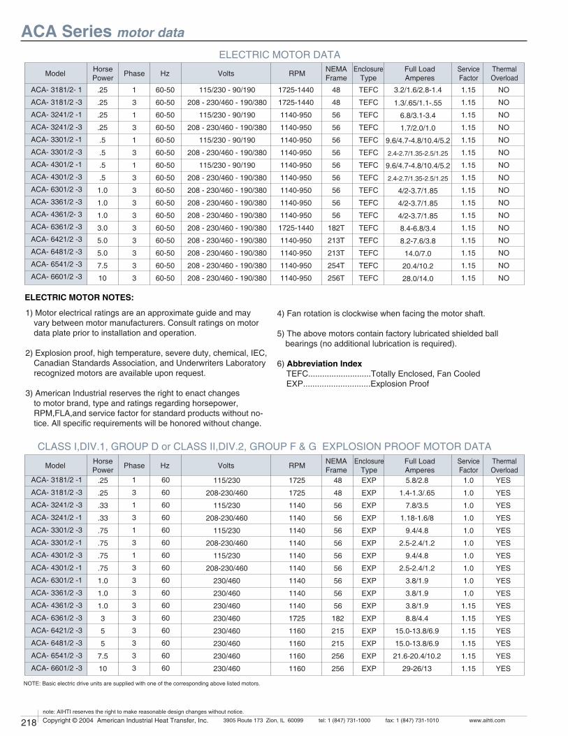
1
3
1
3
1
3
1
3
3
3
3
3
3
3
3
3
.25
.25
.25
.25
.5
.5
.5
.5
1.0
1.0
1.0
3.0
5.0
5.0
7.5
10
60-50
60-50
60-50
60-50
60-50
60-50
60-50
60-50
60-50
60-50
60-50
60-50
60-50
60-50
60-50
60-50
115/230 - 90/190
208 - 230/460 - 190/380
115/230 - 90/190
208 - 230/460 - 190/380
115/230 - 90/190
208 - 230/460 - 190/380
115/230 - 90/190
208 - 230/460 - 190/380
208 - 230/460 - 190/380
208 - 230/460 - 190/380
208 - 230/460 - 190/380
208 - 230/460 - 190/380
208 - 230/460 - 190/380
208 - 230/460 - 190/380
208 - 230/460 - 190/380
208 - 230/460 - 190/380
ACA- 3181/2- 1
ACA- 3181/2 -3
ACA- 3241/2 -1
ACA- 3241/2 -3
ACA- 3301/2 -1
ACA- 3301/2 -3
ACA- 4301/2 -1
ACA- 4301/2 -3
ACA- 6301/2 -3
ACA- 3361/2 -3
ACA- 4361/2- 3
ACA- 6361/2 -3
ACA- 6421/2 -3
ACA- 6481/2 -3
ACA- 6541/2 -3
ACA- 6601/2 -3
3.2/1.6/2.8-1.4
1.3/.65/1.1-.55
6.8/3.1-3.4
1.7/2.0/1.0
9.6/4.7-4.8/10.4/5.2
2.4-2.7/1.35-2.5/1.25
9.6/4.7-4.8/10.4/5.2
2.4-2.7/1.35-2.5/1.25
4/2-3.7/1.85
4/2-3.7/1.85
4/2-3.7/1.85
8.4-6.8/3.4
8.2-7.6/3.8
14.0/7.0
20.4/10.2
28.0/14.0
TEFC
TEFC
TEFC
TEFC
TEFC
TEFC
TEFC
TEFC
TEFC
TEFC
TEFC
TEFC
TEFC
TEFC
TEFC
TEFC
48
48
56
56
56
56
56
56
56
56
56
182T
213T
213T
254T
256T
1725-1440
1725-1440
1140-950
1140-950
1140-950
1140-950
1140-950
1140-950
1140-950
1140-950
1140-950
1725-1440
1140-950
1140-950
1140-950
1140-950
1.15
1.15
1.15
1.15
1.15
1.15
1.15
1.15
1.15
1.15
1.15
1.15
1.15
1.15
1.15
1.15
NO
NO
NO
NO
NO
NO
NO
NO
NO
NO
NO
NO
NO
NO
NO
NO
.25
.25
.33
.33
.75
.75
.75
.75
1.0
1.0
1.0
3
5
5
7.5
10
1
3
1
3
1
3
1
3
3
3
3
3
3
3
3
3
60
60
60
60
60
60
60
60
60
60
60
60
60
60
60
60
1725
1725
1140
1140
1140
1140
1140
1140
1140
1140
1140
1725
1160
1160
1160
1160
115/230
208-230/460
115/230
208-230/460
115/230
208-230/460
115/230
208-230/460
230/460
230/460
230/460
230/460
230/460
230/460
230/460
230/460
48
48
56
56
56
56
56
56
56
56
56
182
215
215
256
256
EXP
EXP
EXP
EXP
EXP
EXP
EXP
EXP
EXP
EXP
EXP
EXP
EXP
EXP
EXP
EXP
5.8/2.8
1.4-1.3/.65
7.8/3.5
1.18-1.6/8
9.4/4.8
2.5-2.4/1.2
9.4/4.8
2.5-2.4/1.2
3.8/1.9
3.8/1.9
3.8/1.9
8.8/4.4
15.0-13.8/6.9
15.0-13.8/6.9
21.6-20.4/10.2
29-26/13
YES
YES
YES
YES
YES
YES
YES
YES
YES
YES
YES
YES
YES
YES
YES
YES
1.0
1.0
1.0
1.0
1.0
1.0
1.0
1.0
1.0
1.0
1.15
1.15
1.15
1.15
1.15
1.15
ACA- 3181/2 -1
ACA- 3181/2 -3
ACA- 3241/2 -3
ACA- 3241/2 -1
ACA- 3301/2 -3
ACA- 3301/2 -1
ACA- 4301/2 -3
ACA- 4301/2 -1
ACA- 6301/2 -1
ACA- 3361/2 -3
ACA- 4361/2 -3
ACA- 6361/2 -3
ACA- 6421/2 -3
ACA- 6481/2 -3
ACA- 6541/2 -3
ACA- 6601/2 -3
218 Copyright © 2004 American Industrial Heat Transfer, Inc. tel: 1 (847) 731-10003905 Route 173 Zion, IL 60099 www.aihti.comfax: 1 (847) 731-1010
note: AIHTI reserves the right to make reasonable design changes without notice.
219Copyright © 2004 American Industrial Heat Transfer, Inc. tel: 1 (847) 731-10003905 Route 173 Zion, IL 60099 www.aihti.comfax: 1 (847) 731-1010
note: AIHTI reserves the right to make reasonable design changes without notice.
ACA Series motor data
NOTE: Basic electric drive units are supplied with one of the corresponding above listed motors.
1) Motor electrical ratings are an approximate guide and may vary between motor manufacturers. Consult ratings on motor data plate prior to installation and operation.
2) Explosion proof, high temperature, severe duty, chemical, IEC, Canadian Standards Association, and Underwriters Laboratory recognized motors are available upon request.
3) American Industrial reserves the right to enact changes to motor brand, type and ratings regarding horsepower, RPM,FLA,and service factor for standard products without no-tice. All specific requirements will be honored without change.
4) Fan rotation is clockwise when facing the motor shaft.
5) The above motors contain factory lubricated shielded ball bearings (no additional lubrication is required).
6) Abbreviation Index
TEFC...........................Totally Enclosed, Fan Cooled EXP.............................Explosion Proof
ELECTRIC MOTOR NOTES:
CLASS I,DIV.1, GROUP D or CLASS II,DIV.2, GROUP F & G EXPLOSION PROOF MOTOR DATAThermalOverload
Service FactorRPMHzPhase Volts Full Load
AmperesHorsePowerModel NEMA
FrameEnclosure
Type
ELECTRIC MOTOR DATAThermalOverload
Service FactorRPMHzPhase Volts Full Load
AmperesHorsePowerModel NEMA
FrameEnclosure
Type
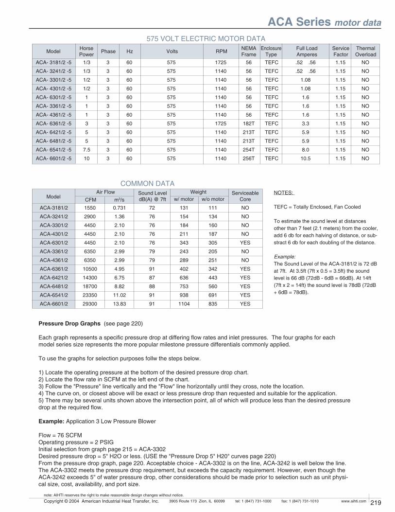
1550
2900
4450
4450
4450
6350
6350
10500
14300
18700
23350
29300
0.731
1.36
2.10
2.10
2.10
2.99
2.99
4.95
6.75
8.82
11.02
13.83
NO
NO
NO
NO
YES
NO
NO
YES
YES
YES
YES
YES
72
76
76
76
76
79
79
91
87
88
91
91
111
134
160
187
305
205
251
342
443
560
691
835
131
154
184
211
343
243
289
402
636
753
938
1104
218 Copyright © 2004 American Industrial Heat Transfer, Inc. tel: 1 (847) 731-10003905 Route 173 Zion, IL 60099 www.aihti.comfax: 1 (847) 731-1010
note: AIHTI reserves the right to make reasonable design changes without notice.
219Copyright © 2004 American Industrial Heat Transfer, Inc. tel: 1 (847) 731-10003905 Route 173 Zion, IL 60099 www.aihti.comfax: 1 (847) 731-1010
note: AIHTI reserves the right to make reasonable design changes without notice.
ACA Series motor data
COMMON DATASound LeveldB(A) @ 7ft
Air FlowCFM m3/sModel
ServiceableCore
NOTES:
TEFC = Totally Enclosed, Fan Cooled
To estimate the sound level at distances other than 7 feet (2.1 meters) from the cooler, add 6 db for each halving of distance, or sub-stract 6 db for each doubling of the distance.
Example:The Sound Level of the ACA-3181/2 is 72 dB at 7ft. At 3.5ft (7ft x 0.5 = 3.5ft) the sound level is 66 dB (72dB - 6dB = 66dB). At 14ft (7ft x 2 = 14ft) the sound level is 78dB (72dB + 6dB = 78dB).
ACA-3181/2
ACA-3241/2
ACA-3301/2
ACA-4301/2
ACA-6301/2
ACA-3361/2
ACA-4361/2
ACA-6361/2
ACA-6421/2
ACA-6481/2
ACA-6541/2
ACA-6601/2
Weight
575 VOLT ELECTRIC MOTOR DATAThermalOverload
Service FactorRPMHzPhase Volts Full Load
AmperesHorsePowerModel NEMA
FrameEnclosure
TypeACA- 3181/2 -5
ACA- 3241/2 -5
ACA- 3301/2 -5
ACA- 4301/2 -5
ACA- 6301/2 -5
ACA- 3361/2 -5
ACA- 4361/2 -5
ACA- 6361/2 -5
ACA- 6421/2 -5
ACA- 6481/2 -5
ACA- 6541/2 -5
ACA- 6601/2 -5
1/3
1/3
1/2
1/2
1
1
1
3
5
5
7.5
10
3
3
3
3
3
3
3
3
3
3
3
3
60
60
60
60
60
60
60
60
60
60
60
60
575
575
575
575
575
575
575
575
575
575
575
575
1725
1140
1140
1140
1140
1140
1140
1725
1140
1140
1140
1140
56
56
56
56
56
56
56
182T
213T
213T
254T
256T
.52 .56
.52 .56
1.08
1.08
1.6
1.6
1.6
3.3
5.9
5.9
8.0
10.5
1.15
1.15
1.15
1.15
1.15
1.15
1.15
1.15
1.15
1.15
1.15
1.15
TEFC
TEFC
TEFC
TEFC
TEFC
TEFC
TEFC
TEFC
TEFC
TEFC
TEFC
TEFC
w/ motor w/o motor
Pressure Drop Graphs (see page 220)
Each graph represents a specific pressure drop at differing flow rates and inlet pressures. The four graphs for each model series size represents the more popular milestone pressure differentials commonly applied.
To use the graphs for selection purposes follw the steps below.
1) Locate the operating pressure at the bottom of the desired pressure drop chart.2) Locate the flow rate in SCFM at the left end of the chart.3) Follow the "Pressure" line vertically and the "Flow" line horizontally until they cross, note the location.4) The curve on, or closest above will be exact or less pressure drop than requested and suitable for the application.5) There may be several units shown above the intersection point, all of which will produce less than the desired pressure drop at the required flow.
Example: Application 3 Low Pressure Blower
Flow = 76 SCFMOperating pressure = 2 PSIGInitial selection from graph page 215 = ACA-3302Desired pressure drop = 5" H2O or less. (USE the "Pressure Drop 5" H20" curves page 220)From the pressure drop graph, page 220. Acceptable choice - ACA-3302 is on the line, ACA-3242 is well below the line. The ACA-3302 meets the pressure drop requirement, but exceeds the capacity requirement. However, even though the ACA-3242 exceeds 5" of water pressure drop, other considerations should be made prior to selection such as unit physi-cal size, cost, availability, and port size.
NO
NO
NO
NO
NO
NO
NO
NO
NO
NO
NO
NO
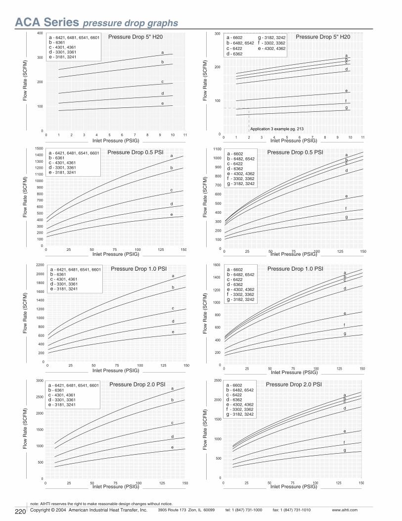
220 Copyright © 2004 American Industrial Heat Transfer, Inc. tel: 1 (847) 731-10003905 Route 173 Zion, IL 60099 www.aihti.comfax: 1 (847) 731-1010
note: AIHTI reserves the right to make reasonable design changes without notice.
221Copyright © 2004 American Industrial Heat Transfer, Inc. tel: 1 (847) 731-10003905 Route 173 Zion, IL 60099 www.aihti.comfax: 1 (847) 731-1010
note: AIHTI reserves the right to make reasonable design changes without notice.
ACA Series pressure drop graphs
A
B
C
D
E
A B C D E
Pressure Drop 0.5 PSI
A
B
C
D
E
A B C D E
Pressure Drop 5" H20
ABC
D
E
FG
A B C D
G F E
!PPLICATIONEXAMPLEPG
Pressure Drop 5" H20
ABC
D
A B C D E F G
E
F
G
Pressure Drop 0.5 PSI
A
B
C
D
E
A B C D E
A
C
D
E
F
G
B
A B C D E F G
Pressure Drop 1.0 PSI Pressure Drop 1.0 PSI
A
B
C
D
E
A B C D E
ABC
D
E
F
G
A B C D E F G
Pressure Drop 2.0 PSI Pressure Drop 2.0 PSI
Flow
Rat
e (S
CFM
)
Inlet Pressure (PSIG)
Flow
Rat
e (S
CFM
)Fl
ow R
ate
(SC
FM)
Flow
Rat
e (S
CFM
)Fl
ow R
ate
(SC
FM)
Inlet Pressure (PSIG)
Inlet Pressure (PSIG)
Inlet Pressure (PSIG)
Inlet Pressure (PSIG)
Inlet Pressure (PSIG)
Flow
Rat
e (S
CFM
)Fl
ow R
ate
(SC
FM)
Inlet Pressure (PSIG)
Inlet Pressure (PSIG)
Flow
Rat
e (S
CFM
)
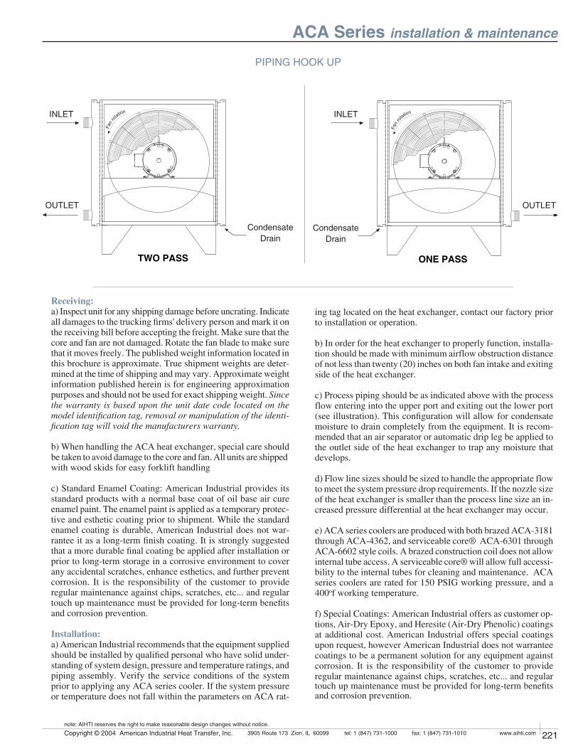
220 Copyright © 2004 American Industrial Heat Transfer, Inc. tel: 1 (847) 731-10003905 Route 173 Zion, IL 60099 www.aihti.comfax: 1 (847) 731-1010
note: AIHTI reserves the right to make reasonable design changes without notice.
221Copyright © 2004 American Industrial Heat Transfer, Inc. tel: 1 (847) 731-10003905 Route 173 Zion, IL 60099 www.aihti.comfax: 1 (847) 731-1010
note: AIHTI reserves the right to make reasonable design changes without notice.
ACA Series installation & maintenance
Receiving:
a) Inspect unit for any shipping damage before uncrating. Indicate all damages to the trucking firms' delivery person and mark it on the receiving bill before accepting the freight. Make sure that the core and fan are not damaged. Rotate the fan blade to make sure that it moves freely. The published weight information located in this brochure is approximate. True shipment weights are deter-mined at the time of shipping and may vary. Approximate weight information published herein is for engineering approximation purposes and should not be used for exact shipping weight. Since
the warranty is based upon the unit date code located on the
model identification tag, removal or manipulation of the identi-
fication tag will void the manufacturers warranty.
b) When handling the ACA heat exchanger, special care should be taken to avoid damage to the core and fan. All units are shipped with wood skids for easy forklift handling
c) Standard Enamel Coating: American Industrial provides its standard products with a normal base coat of oil base air cure enamel paint. The enamel paint is applied as a temporary protec-tive and esthetic coating prior to shipment. While the standard enamel coating is durable, American Industrial does not war-rantee it as a long-term finish coating. It is strongly suggested that a more durable final coating be applied after installation or prior to long-term storage in a corrosive environment to cover any accidental scratches, enhance esthetics, and further prevent corrosion. It is the responsibility of the customer to provide regular maintenance against chips, scratches, etc... and regular touch up maintenance must be provided for long-term benefits and corrosion prevention.
Installation:
a) American Industrial recommends that the equipment supplied should be installed by qualified personal who have solid under-standing of system design, pressure and temperature ratings, and piping assembly. Verify the service conditions of the system prior to applying any ACA series cooler. If the system pressure or temperature does not fall within the parameters on ACA rat-
ing tag located on the heat exchanger, contact our factory prior to installation or operation.
b) In order for the heat exchanger to properly function, installa-tion should be made with minimum airflow obstruction distance of not less than twenty (20) inches on both fan intake and exiting side of the heat exchanger.
c) Process piping should be as indicated above with the process flow entering into the upper port and exiting out the lower port (see illustration). This configuration will allow for condensate moisture to drain completely from the equipment. It is recom-mended that an air separator or automatic drip leg be applied to the outlet side of the heat exchanger to trap any moisture that develops.
d) Flow line sizes should be sized to handle the appropriate flow to meet the system pressure drop requirements. If the nozzle size of the heat exchanger is smaller than the process line size an in-creased pressure differential at the heat exchanger may occur.
e) ACA series coolers are produced with both brazed ACA-3181 through ACA-4362, and serviceable core® ACA-6301 through ACA-6602 style coils. A brazed construction coil does not allow internal tube access. A serviceable core® will allow full accessi-bility to the internal tubes for cleaning and maintenance. ACA series coolers are rated for 150 PSIG working pressure, and a 400of working temperature.
f) Special Coatings: American Industrial offers as customer op-tions, Air-Dry Epoxy, and Heresite (Air-Dry Phenolic) coatings at additional cost. American Industrial offers special coatings upon request, however American Industrial does not warrantee coatings to be a permanent solution for any equipment against corrosion. It is the responsibility of the customer to provide regular maintenance against chips, scratches, etc... and regular touch up maintenance must be provided for long-term benefits and corrosion prevention.
PIPING HOOK UP
TWO PASS
&AN
ROTATIONINLET
OUTLET
ONE PASS
&AN
RO
TATIONINLET
OUTLET
Condensate Drain
Condensate Drain
222 Copyright © 2004 American Industrial Heat Transfer, Inc. tel: 1 (847) 731-10003905 Route 173 Zion, IL 60099 www.aihti.comfax: 1 (847) 731-1010
note: AIHTI reserves the right to make reasonable design changes without notice.
223Copyright © 2004 American Industrial Heat Transfer, Inc. tel: 1 (847) 731-10003905 Route 173 Zion, IL 60099 www.aihti.comfax: 1 (847) 731-1010
note: AIHTI reserves the right to make reasonable design changes without notice.
g) Electric motors should be connected only to supply source of the same characteristics as indicated on the electric motor information plate. Prior to starting, verify that the motor and fan spin freely without obstruction. Check carefully that the fan turns in the correct rotation direction normally counter clockwise from the motor side (fan direction arrow). Failure to operate the fan in the proper direction could reduce performance or cause serious damage to the heat exchanger or other components. Fan blades should be rechecked for tightness after the first 100 hours of operation.
Maintenance
Regular maintenance intervals based upon the surrounding and operational conditions should be maintained to verify equipment performance and to prevent premature component failure. Since some of the components such as, motors, fans, load adapters, etc... are not manufactured by American Industrial maintenance requirements provided by the manufacture must be followed.
a) Inspect the entire heat exchanger and motor/fan assembly for loosened bolts, loose connections, broken components, rust spots, corrosion, fin/coil clogging, or external leakage. Make immediate repairs to all affected areas prior to restarting and operating the heat exchanger or its components.
b) Heat exchangers operating in oily or dusty environments will often need to have the coil cooling fins cleaned. Oily or clogged fins should be cleaned by carefully brushing the fins and tubes with water or a non-aggressive degreasing agent mixture (Note: Cleaning agents that are not compatible with copper, brass, aluminum, steel or stainless steel should not be used). A compressed air or a water stream can be used to dislodge dirt and clean the coil further. Any external dirt or oil on the electric motor and fan assembly should be removed. Caution: Be sure to disconnect the electric motor from its power source prior to doing any maintenance.
c) In most cases it is not necessary to internally flush the coil. In circumstances where the coil has become plugged or has a substantial buildup of material, flushing the coil with water or a solvent may be done. Flushing solvents should be non-ag-gressive suitable for the materials of construction. Serviceable Core® models can be disassembled and inspected or cleaned if required.
d) Most low horsepower electric motors do not require any ad-ditional lubrication. However, larger motors must be lubricated with good quality grease as specified by the manufacture at least once every 6-9 months or as directed by the manufacture. T.E.F.C. air ventilation slots should be inspected and cleaned regularly to prevent clogging and starving the motor of cooling air. To maintain the electric motor properly see the manufactures requirements and specifications.
e) Fan blades should be cleaned and inspected for tightness dur-ing the regular maintenance schedule when handling a fan blade care must be given to avoid bending or striking any of the blades. Fan blades are factory balanced and will not operate properly if damaged or unbalanced. Damaged fan blades can cause exces-sive vibration and severe damage to the heat exchanger or drive motor.
Replace any damaged fan with an American industrial suggested replacement.
f) ACA heat exchanger cabinets are constructed using 7ga. through 18ga. steel that may be bent back into position if dam-aged. Parts that are not repairable can be purchased through American Industrial.
g) Coil fins that become flattened can be combed back into position. This process may require removal of the coil from the cabinet.
h) It is not advisable to attempt repairs to brazed joints of a brazed construction coil unless it will be done by an expert in silver sol-der brazing. Brazed coils are heated uniformly during the original manufacturing process to prevent weak zones from occurring. Uncontrolled reheating of the coil may result in weakening of the tube joints surrounding the repair area. In many instances brazed units that are repaired will not hold up as well to the rigors of the system as will a new coil. American Industrial will not warranty or be responsible for any repairs done by unauthorized sources. Manipulation in any way other than normal application will void the manufactures warranty.
i) Units containing a Serviceable Core® have bolted manifold covers that can be removed for cleaning or repair purposes.
Servicing Sequence
American Industrial has gone to great lengths to provide com-ponents that are repairable. If the ACA unit requires internal cleaning or attention the following steps will explain what must be done to access the internal tubes. Be sure to order gasket kits or repair parts prior to removal and disassembly to minimize down time.
a) To clean the internal tubes first remove all connection pipes from the unit.
b) Be sure the unit is drained of all water etc...
c) Place the ACA unit in an area that it can be accessed from all sides.
d) Remove the manifold cover bolts and hardware and place them into a secure place.
e) The manifold covers are tightly compressed and may need some prying to separate them from the gasket, physically remove the cover assemblies from both sides.
f) The tubes are now accessible for cleaning. We suggest a mild water-soluble degreaser be used with a brush. Tubing I.D. is .325 a plastic bristle brush on a rod will work best for cleaning the tubes. Steel brushes should be avoided since the steel is harder than the copper tubing and may heavily score the tubes if used.
g) If there are any leaking tubes you may plug them be forcing a soft metal plug into the hole and tapping it tight. You may in some cases weld the leaking tube shut however, care should be taken since excessive heat may cause surrounding tube joints to loosen and leak.
ACA Series installation & maintenance

Installation Instructions Electronic pressure sensor
PX3111 PX322x PX323x PX3244 PX3422 PX911x PX913x
7045
71/0
6
02/2
011
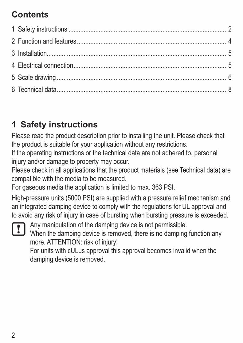
2
1 Safety instructionsPlease read the product description prior to installing the unit. Please check that the product is suitable for your application without any restrictions. If the operating instructions or the technical data are not adhered to, personal injury and/or damage to property may occur. Please check in all applications that the product materials (see Technical data) are compatible with the media to be measured.For gaseous media the application is limited to max. 363 PSI.High-pressure units (5000 PSI) are supplied with a pressure relief mechanism and an integrated damping device to comply with the regulations for UL approval and to avoid any risk of injury in case of bursting when bursting pressure is exceeded.
Any manipulation of the damping device is not permissible.When the damping device is removed, there is no damping function any more. ATTENTION: risk of injury!For units with cULus approval this approval becomes invalid when the damping device is removed.
Contents1 Safety instructions ...............................................................................................22 Function and features ..........................................................................................43 Installation............................................................................................................54 Electrical connection ............................................................................................55 Scale drawing ......................................................................................................66 Technical data ......................................................................................................8
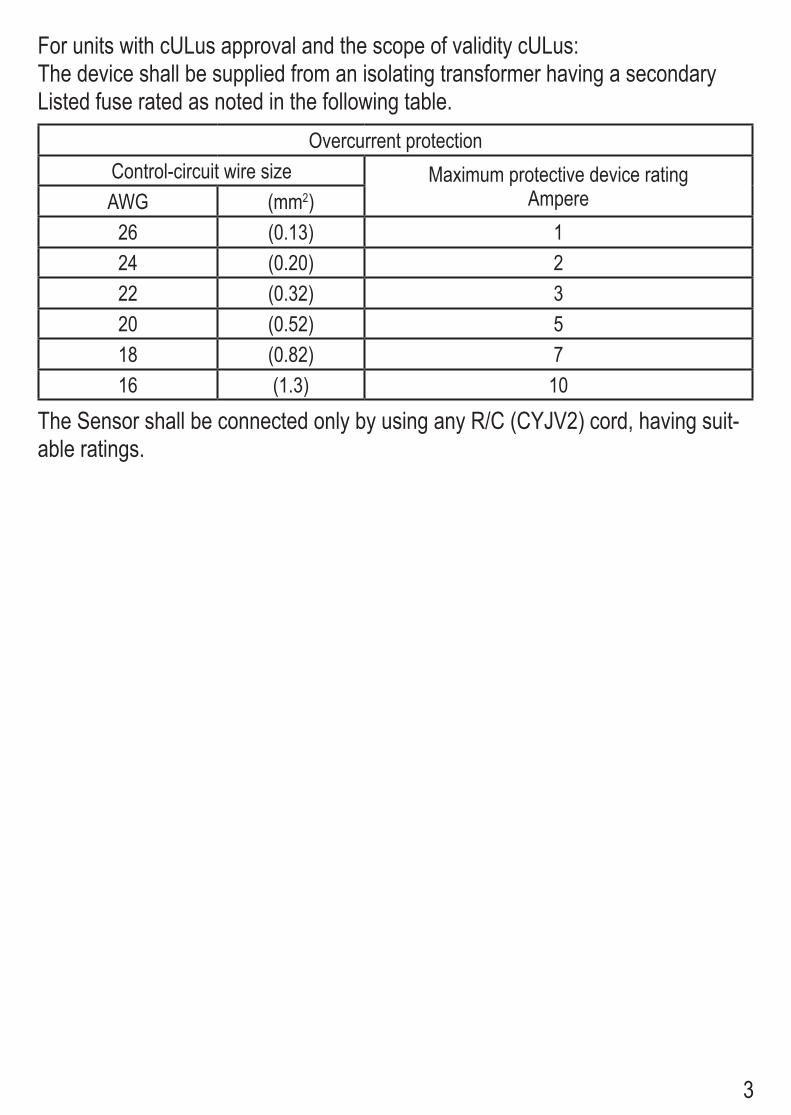
3
For units with cULus approval and the scope of validity cULus:The device shall be supplied from an isolating transformer having a secondary Listed fuse rated as noted in the following table.
Overcurrent protectionControl-circuit wire size Maximum protective device rating
AmpereAWG (mm2)26 (0.13) 124 (0.20) 222 (0.32) 320 (0.52) 518 (0.82) 716 (1.3) 10
The Sensor shall be connected only by using any R/C (CYJV2) cord, having suit-able ratings.
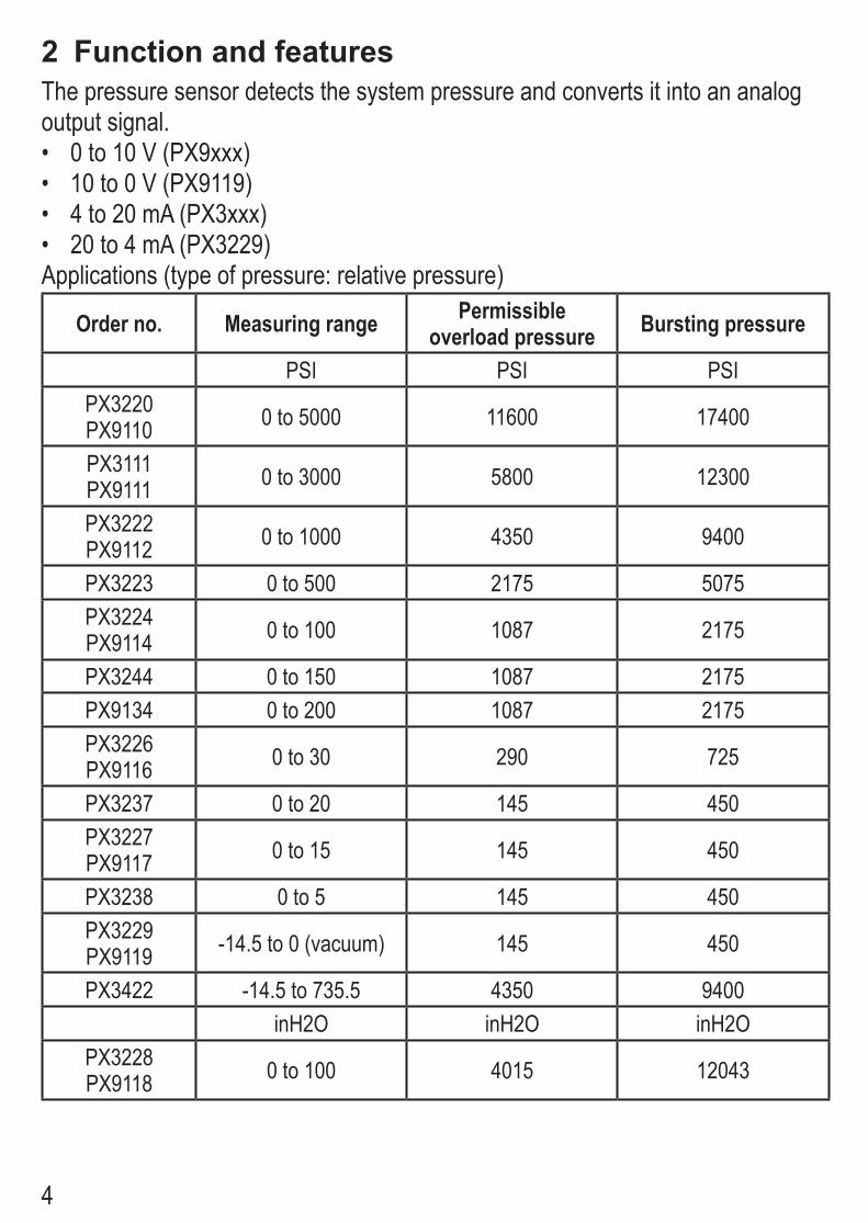
4
2 Function and featuresThe pressure sensor detects the system pressure and converts it into an analog output signal.• 0 to 10 V (PX9xxx)• 10 to 0 V (PX9119) • 4 to 20 mA (PX3xxx)• 20 to 4 mA (PX3229)Applications (type of pressure: relative pressure)
Order no. Measuring range Permissible overload pressure Bursting pressure
PSI PSI PSIPX3220PX9110 0 to 5000 11600 17400
PX3111PX9111 0 to 3000 5800 12300
PX3222PX9112 0 to 1000 4350 9400
PX3223 0 to 500 2175 5075PX3224PX9114 0 to 100 1087 2175
PX3244 0 to 150 1087 2175PX9134 0 to 200 1087 2175PX3226PX9116 0 to 30 290 725
PX3237 0 to 20 145 450PX3227PX9117 0 to 15 145 450
PX3238 0 to 5 145 450PX3229PX9119 -14.5 to 0 (vacuum) 145 450
PX3422 -14.5 to 735.5 4350 9400inH2O inH2O inH2O
PX3228PX9118 0 to 100 4015 12043

5
Avoid static and dynamic overpressure exceeding the given over-load pressure.Even if the bursting pressure is exceeded only for a short time the unit can be destroyed (danger of injuries)!
3 InstallationBefore mounting and removing the sensor, make sure that no pressure is applied to the system.
Mount the pressure sensor on a suitable process connection (see type label “Port Size”).
4 Electrical connectionThe unit must be connected by a qualified electrician.The national and international regulations for the installation of electrical equipment must be adhered to.Voltage supply to EN50178, SELV, PELV.
Disconnect power before connecting the unit as follows:Voltage output (PX9xxx)
!
"
#$
!"
#
$
%
&
!'
()*)
Current output (PX3xxx)
!
"
#$
!"
#
$
%
&
!'
()*)
()*)
For information about available sockets/connectors see: www.ifm.com → Products → Accessories

6
5 Scale drawingPX3220 PX9110 PX3111
PX3222PX3422
PX9111PX9112
79,5
M12 x130
30 14
M5-18 NPT1
4/
79,5
M12 x130
30 14
M5-18 NPT1
4/
1: Pressure relief mechanismNo mechanical force must be exerted on the pressure relief mechanism.
dimensions are in millimeters (25.4 mm = 1 inch)process connection 1/4 NPT, tigtening torque 25 Nm
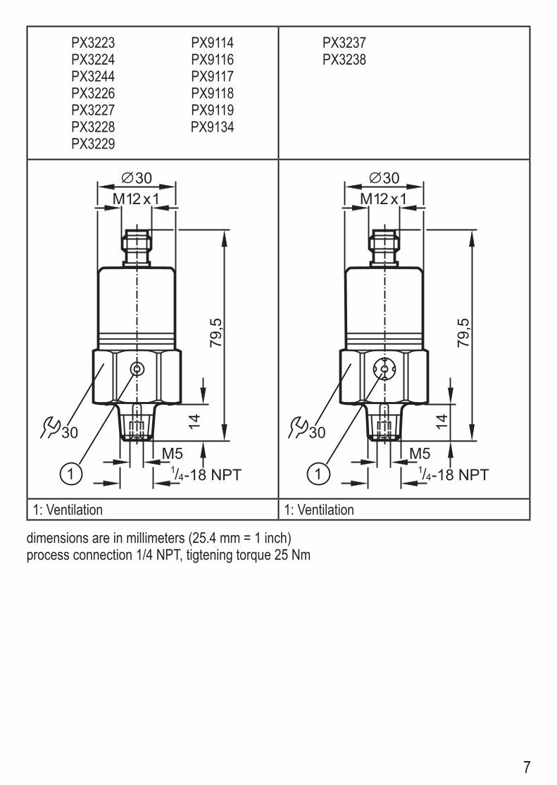
7
PX3223PX3224PX3244PX3226PX3227PX3228PX3229
PX9114PX9116PX9117PX9118PX9119PX9134
PX3237PX3238
79,5
M12 x130
30 14
M5-18 NPT1
4/79
,5
M12 x130
30 14M5
-18 NPT14/
1: Ventilation 1: Ventilation
dimensions are in millimeters (25.4 mm = 1 inch)process connection 1/4 NPT, tigtening torque 25 Nm
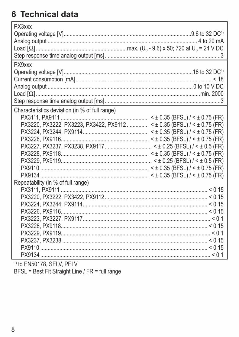
8
6 Technical dataPX3xxxOperating voltage [V] .......................................................................................9.6 to 32 DC1)
Analog output ...................................................................................................... 4 to 20 mALoad [Ω] ..............................................................max. (UB - 9,6) x 50; 720 at UB = 24 V DCStep response time analog output [ms] ...............................................................................3PX9xxxOperating voltage [V] ........................................................................................16 to 32 DC1)
Current consumption [mA] ..............................................................................................< 18Analog output ...................................................................................................0 to 10 V DCLoad [Ω] ................................................................................................................min. 2000Step response time analog output [ms] ...............................................................................3Characteristics deviation (in % of full range)
PX3111, PX9111 ............................................................ < ± 0.35 (BFSL) / < ± 0.75 (FR)PX3220, PX3222, PX3223, PX3422, PX9112 ............... < ± 0.35 (BFSL) / < ± 0.75 (FR)PX3224, PX3244, PX9114 ............................................. < ± 0.35 (BFSL) / < ± 0.75 (FR)PX3226, PX9116............................................................ < ± 0.35 (BFSL) / < ± 0.75 (FR)PX3227, PX3237, PX3238, PX9117 ................................ < ± 0.25 (BFSL) / < ± 0.5 (FR)PX3228, PX9118............................................................ < ± 0.35 (BFSL) / < ± 0.75 (FR)PX3229, PX9119.............................................................. < ± 0.25 (BFSL) / < ± 0.5 (FR)PX9110 .......................................................................... < ± 0.35 (BFSL) / < ± 0.75 (FR)PX9134 .......................................................................... < ± 0.35 (BFSL) / < ± 0.75 (FR)
Repeatability (in % of full range)PX3111, PX9111 .................................................................................................... < 0.15PX3220, PX3222, PX3422, PX9112 ...................................................................... < 0.15PX3224, PX3244, PX9114 ..................................................................................... < 0.15PX3226, PX9116.................................................................................................... < 0.15PX3223, PX3227, PX9117 ....................................................................................... < 0.1PX3228, PX9118.................................................................................................... < 0.15PX3229, PX9119...................................................................................................... < 0.1PX3237, PX3238 ................................................................................................... < 0.15PX9110 .................................................................................................................. < 0.15PX9134 .................................................................................................................... < 0.1
1) to EN50178, SELV, PELVBFSL = Best Fit Straight Line / FR = full range
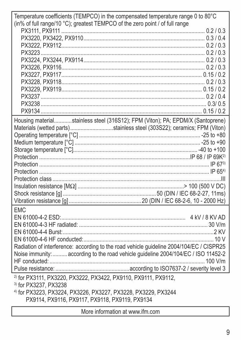
9
Temperature coefficients (TEMPCO) in the compensated temperature range 0 to 80°C (in% of full range/10 °C); greatest TEMPCO of the zero point / of full range
PX3111, PX9111 ................................................................................................. 0.2 / 0.3PX3220, PX3422, PX9110 .................................................................................. 0.3 / 0.4PX3222, PX9112................................................................................................. 0.2 / 0.3PX3223 ............................................................................................................... 0.2 / 0.3PX3224, PX3244, PX9114 .................................................................................. 0.2 / 0.3PX3226, PX9116................................................................................................. 0.2 / 0.3PX3227, PX9117............................................................................................... 0.15 / 0.2PX3228, PX9118................................................................................................. 0.2 / 0.3PX3229, PX9119............................................................................................... 0.15 / 0.2PX3237 ............................................................................................................... 0.2 / 0.4PX3238 ................................................................................................................ 0.3/ 0.5PX9134 ............................................................................................................. 0.15 / 0.2
Housing material............stainless steel (316S12); FPM (Viton); PA; EPDM/X (Santoprene)Materials (wetted parts) .............................stainless steel (303S22); ceramics; FPM (Viton) Operating temperature [°C] .................................................................................. -25 to +80Medium temperature [°C] ..................................................................................... -25 to +90Storage temperature [°C].................................................................................... -40 to +100Protection ......................................................................................................IP 68 / IP 69K2)
Protection ................................................................................................................... IP 673)
Protection ................................................................................................................... IP 654)
Protection class ..................................................................................................................IIIInsulation resistance [MΩ] ........................................................................> 100 (500 V DC)Shock resistance [g] ............................................................... 50 (DIN / IEC 68-2-27, 11ms)Vibration resistance [g] .................................................20 (DIN / IEC 68-2-6, 10 - 2000 Hz)EMCEN 61000-4-2 ESD: .................................................................................... 4 kV / 8 KV ADEN 61000-4-3 HF radiated: ....................................................................................... 30 V/mEN 61000-4-4 Burst: ......................................................................................................2 KVEN 61000-4-6 HF conducted: ........................................................................................ 10 VRadiation of interference: according to the road vehicle guideline 2004/104/EC / CISPR25Noise immunity: .......... according to the road vehicle guideline 2004/104/EC / ISO 11452-2HF conducted: ......................................................................................................... 100 V/mPulse resistance: ..................................................according to ISO7637-2 / severity level 32) for PX3111, PX3220, PX3222, PX3422, PX9110, PX9111, PX9112, 3) for PX3237, PX32384) for PX3223, PX3224, PX3226, PX3227, PX3228, PX3229, PX3244 PX9114, PX9116, PX9117, PX9118, PX9119, PX9134
More information at www.ifm.com

Installation InstructionsTemperature transmitter
TA3333TA3337
7045
59 /
01
12 /
2012
UK
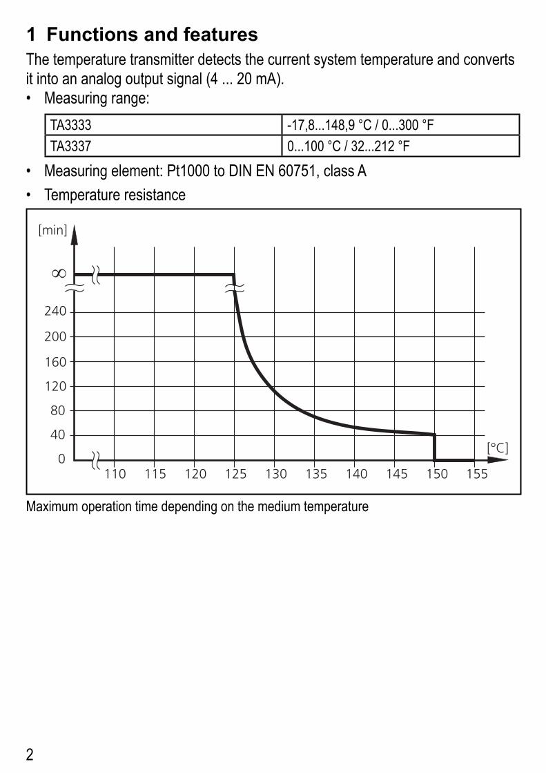
2
1 Functions and featuresThe temperature transmitter detects the current system temperature and converts it into an analog output signal (4 ... 20 mA).• Measuring range:
TA3333 -17,8...148,9 °C / 0...300 °FTA3337 0...100 °C / 32...212 °F
• Measuring element: Pt1000 to DIN EN 60751, class A• Temperature resistance
!!" !!# !$" !$# !%" !%# !&" !&# !#"
'()*&"
+"
!$"
!,"
$""
$&"
'-./*
"
!
!##
Maximum operation time depending on the medium temperature
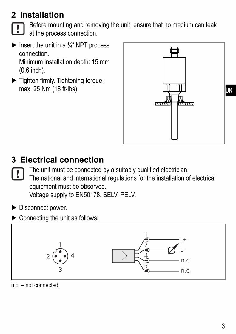
3
UK
2 InstallationBefore mounting and removing the unit: ensure that no medium can leak at the process connection.
Insert the unit in a ¼“ NPT process connection.Minimum installation depth: 15 mm (0.6 inch).
Tighten firmly. Tightening torque: max. 25 Nm (18 ft-lbs).
3 Electrical connectionThe unit must be connected by a suitably qualified electrician.The national and international regulations for the installation of electrical equipment must be observed.Voltage supply to EN50178, SELV, PELV.
Disconnect power. Connecting the unit as follows:
01
%
&
$
!
02
%
!
&$
/343
/343
n.c. = not connected
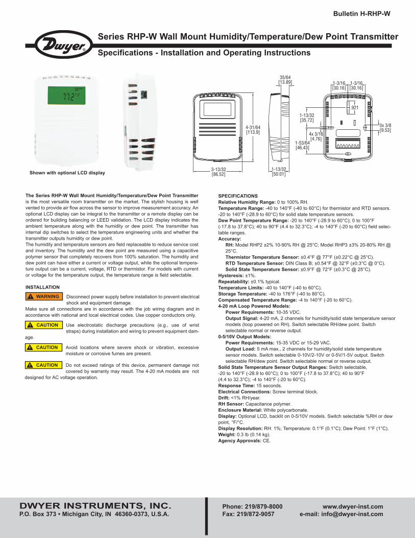
DWYER INSTRUMENTS, INC. Phone: 219/879-8000 www.dwyer-inst.comP.O. Box 373 • Michigan City, IN 46360-0373, U.S.A. Fax: 219/872-9057 e-mail: [email protected]
The Series RHP-W Wall Mount Humidity/Temperature/Dew Point Transmitteris the most versatile room transmitter on the market. The stylish housing is wellvented to provide air flow across the sensor to improve measurement accuracy. Anoptional LCD display can be integral to the transmitter or a remote display can beordered for building balancing or LEED validation. The LCD display indicates theambient temperature along with the humidity or dew point. The transmitter hasinternal dip switches to select the temperature engineering units and whether thetransmitter outputs humidity or dew point.The humidity and temperature sensors are field replaceable to reduce service costand inventory. The humidity and the dew point are measured using a capacitivepolymer sensor that completely recovers from 100% saturation. The humidity anddew point can have either a current or voltage output, while the optional tempera-ture output can be a current, voltage, RTD or thermistor. For models with currentor voltage for the temperature output, the temperature range is field selectable.
INSTALLATION
Series RHP-W Wall Mount Humidity/Temperature/Dew Point Transmitter
Specifications - Installation and Operating Instructions
Bulletin H-RHP-W
SPECIFICATIONSRelative Humidity Range: 0 to 100% RH.Temperature Range: -40 to 140°F (-40 to 60°C) for thermistor and RTD sensors. -20 to 140°F (-28.9 to 60°C) for solid state temperature sensors.Dew Point Temperature Range: -20 to 140°F (-28.9 to 60°C); 0 to 100°F (-17.8 to 37.8°C); 40 to 90°F (4.4 to 32.3°C); -4 to 140°F (-20 to 60°C) field selec-table ranges.Accuracy:
RH: Model RHP2 ±2% 10-90% RH @ 25°C; Model RHP3 ±3% 20-80% RH @ 25°C.Thermistor Temperature Sensor: ±0.4°F @ 77°F (±0.22°C @ 25°C).RTD Temperature Sensor: DIN Class B; ±0.54°F @ 32°F (±0.3°C @ 0°C).Solid State Temperature Sensor: ±0.9°F @ 72°F (±0.3°C @ 25°C).
Hysteresis: ±1%.Repeatability: ±0.1% typical.Temperature Limits: -40 to 140°F (-40 to 60°C).Storage Temperature: -40 to 176°F (-40 to 80°C).Compensated Temperature Range: -4 to 140°F (-20 to 60°C).4-20 mA Loop Powered Models:
Power Requirements: 10-35 VDC.Output Signal: 4-20 mA, 2 channels for humidity/solid state temperature sensor models (loop powered on RH). Switch selectable RH/dew point. Switch selectable normal or reverse output.
0-5/10V Output Models:Power Requirements: 15-35 VDC or 15-29 VAC.Output Load: 5 mA max., 2 channels for humidity/solid state temperature sensor models. Switch selectable 0-10V/2-10V or 0-5V/1-5V output. Switch selectable RH/dew point. Switch selectable normal or reverse output.
Solid State Temperature Sensor Output Ranges: Switch selectable, -20 to 140°F (-28.9 to 60°C); 0 to 100°F (-17.8 to 37.8°C); 40 to 90°F (4.4 to 32.3°C); -4 to 140°F (-20 to 60°C).Response Time: 15 seconds.Electrical Connections: Screw terminal block.Drift: <1% RH/year.RH Sensor: Capacitance polymer.Enclosure Material: White polycarbonate.Display: Optional LCD, backlit on 0-5/10V models. Switch selectable %RH or dewpoint, °F/°C.Display Resolution: RH: 1%; Temperature: 0.1°F (0.1°C); Dew Point: 1°F (1°C).Weight: 0.3 lb (0.14 kg).Agency Approvals: CE.
1-3/16[30.16]
1-3/16[30.16]
.921
3x 3/8[9.53]
35/64[13.89]
1-13/32[35.72]
1-53/64[46.43]
4x 3/16[4.76]
1-13/32[50.01]
4-31/64[113.9]
3-13/32[86.52]Shown with optional LCD display
Do not exceed ratings of this device, permanent damage notcovered by warranty may result. The 4-20 mA models are not
designed for AC voltage operation.
CAUTION
Avoid locations where severe shock or vibration, excessivemoisture or corrosive fumes are present.
CAUTION
Use electrostatic discharge precautions (e.g., use of wriststraps) during installation and wiring to prevent equipment dam-
age.
CAUTION
Disconnect power supply before installation to prevent electricalshock and equipment damage.
Make sure all connections are in accordance with the job wiring diagram and inaccordance with national and local electrical codes. Use copper conductors only.
WARNING
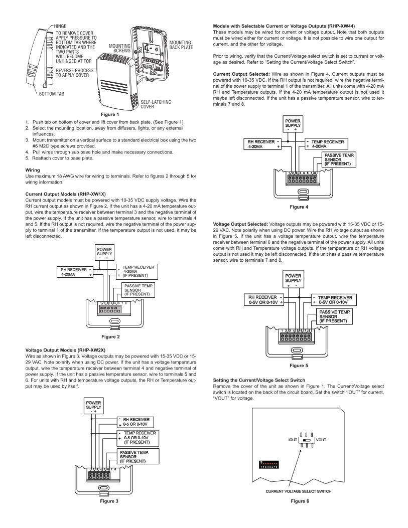
1. Push tab on bottom of cover and lift cover from back plate. (See Figure 1).2. Select the mounting location, away from diffusers, lights, or any external
influences.3. Mount transmitter on a vertical surface to a standard electrical box using the two
#6 M2C type screws provided.4. Pull wires through sub base hole and make necessary connections.5. Reattach cover to base plate.
WiringUse maximum 18 AWG wire for wiring to terminals. Refer to figures 2 through 5 forwiring information.
Current Output Models (RHP-XW1X)Current output models must be powered with 10-35 VDC supply voltage. Wire theRH current output as shown in Figure 2. If the unit has a 4-20 mA temperature out-put, wire the temperature receiver between terminal 3 and the negative terminal ofthe power supply. If the unit has a passive temperature sensor, wire to terminals 4and 5. If the RH output is not required, wire the negative terminal of the power sup-ply to terminal 1 of the transmitter. If the temperature output is not used, it may beleft disconnected.
Voltage Output Models (RHP-XW2X)Wire as shown in Figure 3. Voltage outputs may be powered with 15-35 VDC or 15-29 VAC. Note polarity when using DC power. If the unit has a voltage temperatureoutput, wire the temperature receiver between terminal 4 and negative terminal ofpower supply. If the unit has a passive temperature sensor, wire to terminals 5 and6. For units with RH and temperature voltage outputs, the RH or Temperature out-put may be used by itself.
Models with Selectable Current or Voltage Outputs (RHP-XW44)These models may be wired for current or voltage output. Note that both outputsmust be wired either for current or voltage. It is not possible to wire one output forcurrent, and the other for voltage.
Prior to wiring, verify that the Current/Voltage select switch is set to current or volt-age as desired. Refer to “Setting the Current/Voltage Select Switch”.
Current Output Selected: Wire as shown in Figure 4. Current outputs must bepowered with 10-35 VDC. If the RH output is not required, wire the negative termi-nal of the power supply to terminal 1 of the transmitter. All units come with 4-20 mARH and Temperature outputs. If the 4-20 mA temperature output is not used itmaybe left disconnected. If the unit has a passive temperature sensor, wire to ter-minals 7 and 8.
Voltage Output Selected: Voltage outputs may be powered with 15-35 VDC or 15-29 VAC. Note polarity when using DC power. Wire the RH voltage output as shownin Figure 5. If the unit has a voltage temperature output, wire the temperaturereceiver between terminal 6 and the negative terminal of the power supply. All unitscome with RH and Temperature voltage outputs. If the temperature or RH voltageoutput is not used it may be left disconnected. If the unit has a passive temperaturesensor, wire to terminals 7 and 8.
Setting the Current/Voltage Select SwitchRemove the cover of the unit as shown in Figure 1. The Current/Voltage selectswitch is located on the back of the circuit board. Set the switch “IOUT” for current,“VOUT” for voltage.
1 2 3 4 5 6 7 81 2 3 4 5 6 7 8
POWERSUPPLYPOWERSUPPLY
+ - +-
RH RECEIVERRH RECEIVER++-- TEMP RECEIVERTEMP RECEIVER
PASSIVE TEMP.SENSORPASSIVE TEMP.SENSOR
(IF PRESENT)(IF PRESENT)
(IF PRESENT)(IF PRESENT)
++--
4-20MA4-20MA4-20MA4-20MA
BOTTOM TAB
HINGETO REMOVE COVERAPPLY PRESSURE TOBOTTOM TAB WHERE INDICATED AND THE TWO PARTS WILL BECOME UNHINGED AT TOP
REVERSE PROCESS TO APPLY COVER
MOUNTINGBACK PLATE
SELF-LATCHINGCOVER
MOUNTINGSCREWS
Figure 1
Figure 2
Figure 3
Figure 4
Figure 5
Figure 6

DIP SWITCH SETTINGSTo access the DIP SWITCH, remove the cover of the unit as shown in Figure 1. TheDIP SWITCH is located on the back of the circuit board.
ALL DIP SWITCHES are factory set to “ON”
5V/10V Output Select (Applies only to Voltage Output units)DIP SWITCH#1 OFF: Output = 0-5VDIP SWITCH#1 ON: Output = 0-10V
Zero Suppression (Applies only to Voltage Output Units)DIP SWITCH#2 OFF : Output range = 1-5V or 2-10V, depending on output rangeDIP SWITCH#2 ON : Output range = 0-5V or 0-10V, depending on output range
Upper Display reads RH or DEW POINTDIP SWITCH#3 OFF: Upper Display reads Dew PointDIP SWITCH#3 ON: Upper Display reads RH
RH OUTPUT, Normal or InvertDIP SWITCH#4 OFF: Output is invertedDIP SWITCH#4 ON: Output is Normal
When set to normal output, the output increases as the RH increases. When set toinverted output, the output decreases as the RH increases.Example: Normal 4-20 mA output, 0%RH = 4 mA, 100% RH = 20 mA
Inverted 4-20 mA output, 0%RH = 20 mA, 100% RH = 4 mA
TEMP OUTPUT, Normal or InvertDIP SWITCH#5 OFF: Output is invertedDIP SWITCH#5 ON: Output is Normal
When set to normal output, the output increases as the temperature increases.When set to inverted output, the output decreases as the temperature increases.Example: Normal 4-20 mA output, -20°F = 4 mA, +140°F = 20 mA
Inverted 4-20 mA output, -20°F = 20 mA, +140°F = 4 mA
°F/°C SelectDIP SWITCH#6 OFF: °CDIP SWITCH#6 ON: °F
Temperature Output Range Select
The temperature range applies only to the current or voltage output. If the unit hasa display, it will display temperature from -40 to +140°F (-40 to +60°C). If the unit isset to read DEW POINT, the output range of the DEW POINT will be the same asthe Temperature Output Range.
Note: The display will indicate temperature even if the unit does not have a tem-perature output.
TROUBLESHOOTING1. Verify that the unit is mounted in the correct position.2. 4-20 mA Models: Verify appropriate supply voltage. The transmitter requires a minimum of 10 and amaximum of 35 VDC at its connection for proper operation. Choose a power sup-ply with a voltage and current rating which meets this requirement under all oper-ating conditions. If the power supply is unregulated, make sure voltage remainswithin these limits under all power line conditions. Ripple on the supply should notexceed 100 mV.
Loop Resistance – The maximum allowable loop resistance depends on thepower supply voltage. Maximum loop voltage drop must not reduce the transmittervoltage below the 10 VDC minimum. Maximum loop resistance can be calculatedwith the following equation. Vps is the power supply voltage.
Rmax =
Some receivers, particularly loop powered indicators, may maintain a fixed loopvoltage to power the device. This voltage drop must also be subtracted from thepower supply voltage when calculating the voltage margin for the transmitter. Thefollowing equation takes this into account. Vrec is the receiver fixed voltage.
Rmax =
0-10 V Output Models:Verify appropriate supply voltage. The 0-10V output models require a DC supply of15 to 35 V or an AC supply of 15-29 V for proper operation maximum. Maximumoutput load is 5 mA.
FIELD SENSOR REPLACEMENTReplacement sensors are available. Replacement sensors are factory calibratedand do not require any further calibration.1. Remove cover as shown in Figure 1.2. Remove existing sensor as shown in Figure 8.3. Replace the sensor with appropriate replacement sensor.4. Reattach cover to base plate.
Remote DisplayFor models that are ordered without an integral LCD display, remote display ModelA-449 can be used to display the temperature and humidity or dew point. The miniUSB plug of the remote display plugs into the receptor on the side of the housing.After a short warm up time, the display will begin to show the current temperatureand humidity or dew point measurements. Humidity or dew point can be selectedvia the internal dip switches as described earlier in this manual.
Sensor is sensitive to Electro-Static Discharge (ESD). Followindustry standard practice for control and protection against
ESD. Failure to exercise good ESD practices may cause damage to the sensor.
Range-4 to +140°F (-20 to +60°C)+40 to +90°F (+4.4 to +32.2°C)0 to +100°F (-17.8 to +37.8°C)-20 to +140°F (-28.9 to +60°C)
Dip Switch 7OFFOFFONON
Dip Switch 8OFFONOFFON
Figure 7
Vps-10.0
20 mA
Vps-10.0-Vrec20 mA
Figure 8
NOTICE
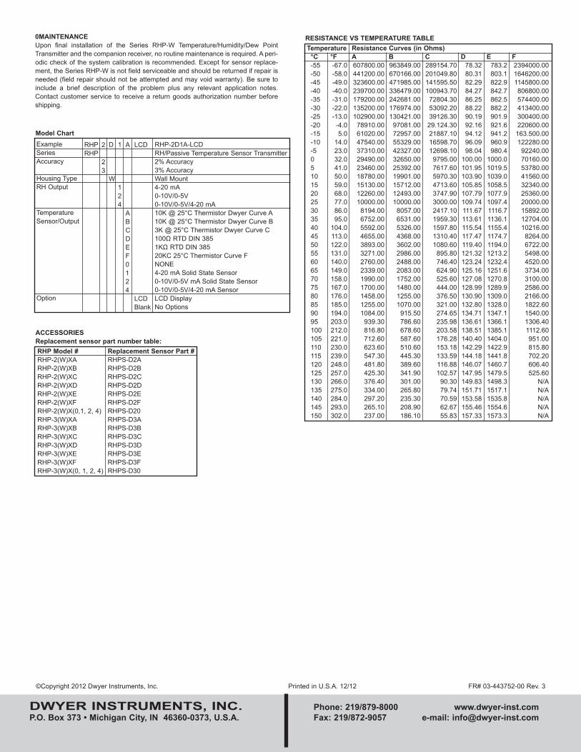
©Copyright 2012 Dwyer Instruments, Inc. Printed in U.S.A. 12/12 FR# 03-443752-00 Rev. 3
DWYER INSTRUMENTS, INC. Phone: 219/879-8000 www.dwyer-inst.comP.O. Box 373 • Michigan City, IN 46360-0373, U.S.A. Fax: 219/872-9057 e-mail: [email protected]
0MAINTENANCEUpon final installation of the Series RHP-W Temperature/Humidity/Dew PointTransmitter and the companion receiver, no routine maintenance is required. A peri-odic check of the system calibration is recommended. Except for sensor replace-ment, t he Series RHP-W is not field serviceable and should be returned if repair isneeded (field repair should not be attempted and may void warranty). Be sure toinclude a brief description of the problem plus any relevant application notes.Contact customer service to receive a return goods authorization number beforeshipping.
RHP Model #RHP-2(W)XARHP-2(W)XBRHP-2(W)XCRHP-2(W)XDRHP-2(W)XERHP-2(W)XFRHP-2(W)X(0,1, 2, 4)RHP-3(W)XARHP-3(W)XBRHP-3(W)XCRHP-3(W)XDRHP-3(W)XERHP-3(W)XFRHP-3(W)X(0, 1, 2, 4)
Replacement Sensor Part #RHPS-D2ARHPS-D2BRHPS-D2CRHPS-D2DRHPS-D2ERHPS-D2FRHPS-D20RHPS-D3ARHPS-D3BRHPS-D3CRHPS-D3DRHPS-D3ERHPS-D3FRHPS-D30
ExampleSeriesAccuracy
Housing TypeRH Output
TemperatureSensor/Output
Option
RHPRHP
2
23
D
W
1
124
A
ABCDEF0124
LCD
LCDBlank
RHP-2D1A-LCDRH/Passive Temperature Sensor Transmitter2% Accuracy3% AccuracyWall Mount4-20 mA0-10V/0-5V0-10V/0-5V/4-20 mA10K @ 25°C Thermistor Dwyer Curve A10K @ 25°C Thermistor Dwyer Curve B3K @ 25°C Thermistor Dwyer Curve C100Ω RTD DIN 3851KΩ RTD DIN 38520KC 25°C Thermistor Curve FNONE4-20 mA Solid State Sensor0-10V/0-5V mA Solid State Sensor0-10V/0-5V/4-20 mA SensorLCD DisplayNo Options
Model Chart
ACCESSORIESReplacement sensor part number table:
RESISTANCE VS TEMPERATURE TABLE
°C-55-50-45-40-35-30-25-20-15-10-505101520253035404550556065707580859095100105110115120125130135140145150
°F-67.0-58.0-49.0-40.0-31.0-22.0-13.0
-4.05.0
14.023.032.041.050.059.068.077.086.095.0
104.0113.0122.0131.0140.0149.0158.0167.0176.0185.0194.0203.0212.0221.0230.0239.0248.0257.0266.0275.0284.0293.0302.0
TemperatureA607800.00441200.00323600.00239700.00179200.00135200.00102900.00
78910.0061020.0047540.0037310.0029490.0023460.0018780.0015130.0012260.0010000.00
8194.006752.005592.004655.003893.003271.002760.002339.001990.001700.001458.001255.001084.00
939.30816.80712.60623.60547.30481.80425.30376.40334.00297.20265.10237.00
B963849.00670166.00471985.00336479.00242681.00176974.00130421.00
97081.0072957.0055329.0042327.0032650.0025392.0019901.0015712.0012493.0010000.00
8057.006531.005326.004368.003602.002986.002488.002083.001752.001480.001255.001070.00
915.50786.60678.60587.60510.60445.30389.60341.90301.00265.80235.30208.90186.10
C289154.70201049.80141595.50100943.70
72804.3053092.2039126.3029.124.3021887.1016598.7012698.10
9795.007617.605970.304713.603747.903000.002417.101959.301597.801310.401080.60
895.80746.40624.90525.60444.00376.50321.00274.65235.98203.58176.28153.18133.59116.88102.57
90.3079.7470.5962.6755.83
D78.3280.3182.2984.2786.2588.2290.1992.1694.1296.0998.04
100.00101.95103.90105.85107.79109.74111.67113.61115.54117.47119.40121.32123.24125.16127.08128.99130.90132.80134.71136.61138.51140.40142.29144.18146.07147.95149.83151.71153.58155.46157.33
E783.2803.1822.9842.7862.5882.2901.9921.6941.2960.9980.4
1000.01019.51039.01058.51077.91097.41116.71136.11155.41174.71194.01213.21232.41251.61270.81289.91309.01328.01347.11366.11385.11404.01422.91441.81460.71479.51498.31517.11535.81554.61573.3
F2394000.001646200.001145800.00806800.00574400.00413400.00300400.00220600.00163.500.00122280.00
92240.0070160.0053780.0041560.0032340.0025360.0020000.0015892.0012704.0010216.00
8264.006722.005498.004520.003734.003100.002586.002166.001822.601540.001306.401112.60951.00815.80702.20606.40525.60
N/AN/AN/AN/AN/A
Resistance Curves (in Ohms)
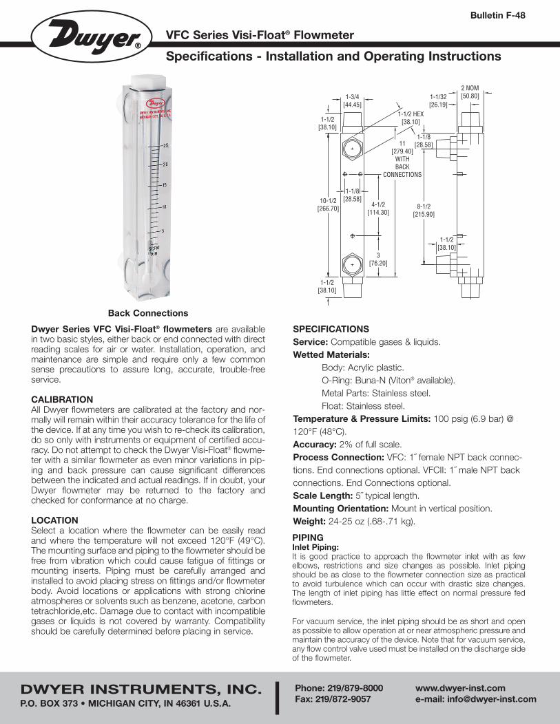
Dwyer Series VFC Visi-Float® flowmeters are availablein two basic styles, either back or end connected with directreading scales for air or water. Installation, operation, andmaintenance are simple and require only a few commonsense precautions to assure long, accurate, trouble-freeservice.
CALIBRATIONAll Dwyer flowmeters are calibrated at the factory and nor-mally will remain within their accuracy tolerance for the life ofthe device. If at any time you wish to re-check its calibration,do so only with instruments or equipment of certified accu-racy. Do not attempt to check the Dwyer Visi-Float® flowme-ter with a similar flowmeter as even minor variations in pip-ing and back pressure can cause significant differencesbetween the indicated and actual readings. If in doubt, yourDwyer flowmeter may be returned to the factory andchecked for conformance at no charge.
LOCATIONSelect a location where the flowmeter can be easily readand where the temperature will not exceed 120°F (49°C).The mounting surface and piping to the flowmeter should befree from vibration which could cause fatigue of fittings ormounting inserts. Piping must be carefully arranged andinstalled to avoid placing stress on fittings and/or flowmeterbody. Avoid locations or applications with strong chlorineatmospheres or solvents such as benzene, acetone, carbontetrachloride,etc. Damage due to contact with incompatiblegases or liquids is not covered by warranty. Compatibilityshould be carefully determined before placing in service.
PIPINGInlet Piping:It is good practice to approach the flowmeter inlet with as fewelbows, restrictions and size changes as possible. Inlet pipingshould be as close to the flowmeter connection size as practicalto avoid turbulence which can occur with drastic size changes.The length of inlet piping has little effect on normal pressure fedflowmeters.
For vacuum service, the inlet piping should be as short and openas possible to allow operation at or near atmospheric pressure andmaintain the accuracy of the device. Note that for vacuum service,any flow control valve used must be installed on the discharge sideof the flowmeter.
VFC Series Visi-Float® Flowmeter
Specifications - Installation and Operating Instructions
Bulletin F-48
SPECIFICATIONSService: Compatible gases & liquids.Wetted Materials:
Body: Acrylic plastic.O-Ring: Buna-N (Viton® available).Metal Parts: Stainless steel.Float: Stainless steel.
Temperature & Pressure Limits: 100 psig (6.9 bar) @120°F (48°C).Accuracy: 2% of full scale.Process Connection: VFC: 1˝ female NPT back connec-tions. End connections optional. VFCII: 1˝ male NPT backconnections. End Connections optional. Scale Length: 5˝ typical length.Mounting Orientation: Mount in vertical position.Weight: 24-25 oz (.68-.71 kg).
Back Connections
DWYER INSTRUMENTS, INC.P.O. BOX 373 • MICHIGAN CITY, IN 46361 U.S.A.
Phone: 219/879-8000 www.dwyer-inst.comFax: 219/872-9057 e-mail: [email protected]
1-1/2[38.10]
3[76.20]
4-1/2[114.30]
10-1/2[266.70]
1-1/2[38.10]
8-1/2[215.90]
2 NOM[50.80]1-1/32
[26.19]
1-1/8[28.58]
1-1/8[28.58]
1-1/2 HEX[38.10]
1-3/4[44.45]
1-1/2[38.10]
11[279.40]
WITHBACK
CONNECTIONS
F-48 10/02 3/3/04 8:39 AM Page 1
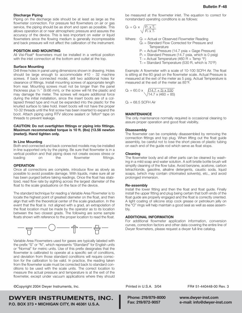
Discharge PipingPiping on the discharge side should be at least as large as theflowmeter connection. For pressure fed flowmeters on air or gasservice, the piping should be as short and open as possible. Thisallows operation at or near atmospheric pressure and assures theaccuracy of the device. This is less important on water or liquidflowmeters since the flowing medium is generally incompressibleand back pressure will not affect the calibration of the instrument.
POSITION AND MOUNTINGAll Visi-Float® flowmeters must be installed in a vertical positionwith the inlet connection at the bottom and outlet at the top.
Surface MountingDrill three holes in panel using dimensions shown in drawing. Holesshould be large enough to accommodate #10 - 32 machinescrews. If back connected model, drill two additional holes forclearance of fittings. Install mounting screws of appropriate lengthfrom rear. Mounting screws must not be longer than the panelthickness plus 3/8 ˝ (9.66 mm), or the screw will hit the plastic andmay damage the meter. The screws will require additional forceduring the initial installation, since the insert boots are of a col-lapsed thread type and must be expanded into the plastic for theknurled surface to take hold. Insert boots will not have the proper10-32 threads until the first screw has been inserted to expand theboot. Attach piping using RTV silicone sealant or Teflon® tape onthreads to prevent leakage.
CAUTION: Do not overtighten fittings or piping into fittings.Maximum recommended torque is 10 ft. (lbs) (13.56 newton(meter)). Hand tighten only.
In Line MountingBoth end connected and back connected models may be installedin-line supported only by the piping. Be sure that flowmeter is in avertical position and that piping does not create excess stress orloading on the flowmeter fittings.
OPERATIONOnce all connections are complete, introduce flow as slowly aspossible to avoid possible damage. With liquids, make sure all airhas been purged before taking readings. Once the float has stabi-lized, read flow rate by sighting across the largest diameter of thefloat to the scale graduations on the face of the device.
The standard technique for reading a Variable Area Flowmeter is tolocate the highest point of greatest diameter on the float, and thenalign that with the theoretical center of the scale graduation. In theevent that the float is not aligned with a grad, an extrapolation ofthe float location must be made by the operator as to its locationbetween the two closest grads. The following are some samplefloats shown with reference to the proper location to read the float.
Variable Area Flowmeters used for gases are typically labeled withthe prefix “S” or “N”, which represents “Standard” for English unitsor “Normal” for metric units. Use of this prefix designates that theflowmeter is calibrated to operate at a specific set of conditions,and deviation from those standard conditions will require correc-tion for the calibration to be valid. In practice, the reading takenfrom the flowmeter scale must be corrected back to standard con-ditions to be used with the scale units. The correct location tomeasure the actual pressure and temperature is at the exit of theflowmeter, except under vacuum applications where they should
be measured at the flowmeter inlet. The equation to correct fornonstandard operating conditions is as follows:
Q2 = Q1 x P1 x T2
P2 x T1
Where: Q1 = Actual or Observed Flowmeter ReadingQ2 = Standard Flow Corrected for Pressure and
TemperatureP1 = Actual Pressure (14.7 psia + Gage Pressure)P2 = Standard Pressure (14.7 psia, which is 0 psig)T1 = Actual Temperature (460 R + Temp °F)T2 = Standard Temperature (530 R, which is 70°F)
Example: A flowmeter with a scale of 10-100 SCFH Air. The floatis sitting at the 60 grad on the flowmeter scale. Actual Pressure ismeasured at the exit of the meter as 5 psig. Actual Temperature ismeasured at the exit of the meter as 85°F.
Q2 = 60.0 x (14.7 + 5) x 53014.7 x (460 + 85)
Q2 = 68.5 SCFH Air
MAINTENANCEThe only maintenance normally required is occasional cleaning toassure proper operation and good float visibility.
DisassemblyThe flowmeter can be completely disassembled by removing theconnection fittings and top plug. When lifting out the float guideassembly, be careful not to lose the short pieces of plastic tubingon each end of the guide rod which serve as float stops.
CleaningThe flowmeter body and all other parts can be cleaned by wash-ing in a mild soap and water solution. A soft bristle bottle brush willsimplify cleaning of the flow tube. Avoid benzene, acetone, carbontetrachloride, gasoline, alkaline detergents, caustic soda, liquidsoaps, (which may contain chlorinated solvents), etc., and avoidprolonged immersion.
Re-assemblyInstall the lower fitting and then the float and float guide. Finallyinstall the upper fitting and plug being certain that both ends of thefloat guide are properly engaged and the float is correctly oriented.A light coating of silicone stop cock grease or petroleum jelly onthe “O” rings will help maintain a good seal as well as ease assem-bly.
ADDITIONAL INFORMATIONFor additional flowmeter application information, conversioncurves, correction factors and other data covering the entire line ofDwyer flowmeters, please request a dwyer full-line catalog.
Bulletin F-48
©Copyright 2004 Dwyer Instruments, Inc. Printed in U.S.A. 3/04 FR# 51-440448-00 Rev. 3
DWYER INSTRUMENTS, INC.P.O. BOX 373 • MICHIGAN CITY, IN 46361 U.S.A.
Phone: 219/879-8000 www.dwyer-inst.comFax: 219/872-9057 e-mail: [email protected]
F-48 10/02 3/3/04 8:39 AM Page 2
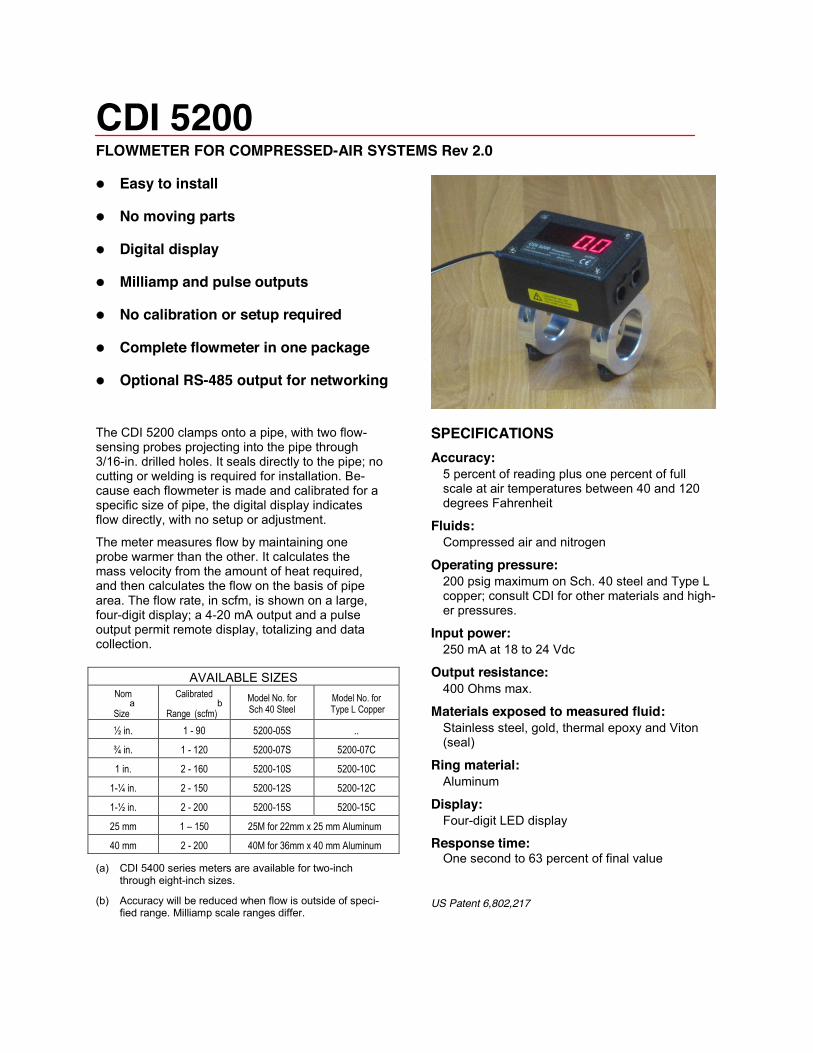
CDI 5200 FLOWMETER FOR COMPRESSED-AIR SYSTEMS Rev 2.0
z Easy to install
z No moving parts
z Digital display
z Milliamp and pulse outputs
z No calibration or setup required
z Complete flowmeter in one package
z Optional RS-485 output for networking
The CDI 5200 clamps onto a pipe, with two flow-sensing probes projecting into the pipe through 3/16-in. drilled holes. It seals directly to the pipe; no cutting or welding is required for installation. Be-cause each flowmeter is made and calibrated for a specific size of pipe, the digital display indicates flow directly, with no setup or adjustment.
The meter measures flow by maintaining one probe warmer than the other. It calculates the mass velocity from the amount of heat required, and then calculates the flow on the basis of pipe area. The flow rate, in scfm, is shown on a large, four-digit display; a 4-20 mA output and a pulse output permit remote display, totalizing and data collection.
AVAILABLE SIZES Nom
Sizea
Calibrated
Range (scfm)b Model No. for
Sch 40 Steel Model No. for
Type L Copper
½ in. 1 - 90 5200-05S ..
¾ in. 1 - 120 5200-07S 5200-07C
1 in. 2 - 160 5200-10S 5200-10C
1-¼ in. 2 - 150 5200-12S 5200-12C
1-½ in. 2 - 200 5200-15S 5200-15C
25 mm 1 – 150 25M for 22mm x 25 mm Aluminum
40 mm 2 - 200 40M for 36mm x 40 mm Aluminum
(a) CDI 5400 series meters are available for two-inch through eight-inch sizes.
(b) Accuracy will be reduced when flow is outside of speci-fied range. Milliamp scale ranges differ.
SPECIFICATIONS Accuracy:
5 percent of reading plus one percent of full scale at air temperatures between 40 and 120 degrees Fahrenheit
Fluids: Compressed air and nitrogen
Operating pressure: 200 psig maximum on Sch. 40 steel and Type L copper; consult CDI for other materials and high-er pressures.
Input power: 250 mA at 18 to 24 Vdc
Output resistance: 400 Ohms max.
Materials exposed to measured fluid: Stainless steel, gold, thermal epoxy and Viton (seal)
Ring material: Aluminum
Display: Four-digit LED display
Response time: One second to 63 percent of final value
US Patent 6,802,217
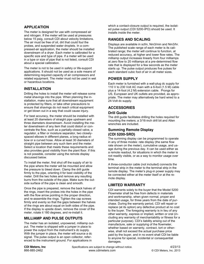
CDI Meters, Inc Specifications are subject to change without notice. 4/23/13 866-885-2462 www.cdimeters.com © CDI Meters, Inc. 2013
APPLICATION The meter is designed for use with compressed air and nitrogen. If the meter will be used at pressures below 15 psig, consult CDI about velocity limitations. The air must be free of oil, dirt that could foul the probes, and suspended water droplets. In a com-pressed-air application, the meter should be installed downstream of a dryer. Each meter is calibrated for a specific size and type of pipe. If a meter will be used in a type or size of pipe that is not listed, consult CDI about a special calibration.
The meter is not to be used in safety or life-support applications. It should not be used as a sole means of determining required capacity of air compressors and related equipment. The meter must not be used in wet or hazardous locations.
INSTALLATION Drilling the holes to install the meter will release some metal shavings into the pipe. When planning the in-stallation, make sure that all downstream equipment is protected by filters, or take other precautions to ensure that shavings do not reach critical equipment or get blown out in a way that could cause injury.
For best accuracy, the meter should be installed with at least 20 diameters of straight pipe upstream and three diameters downstream. Avoid installing the me-ter downstream of any item that could distort or con-centrate the flow, such as a partially-closed valve, a regulator, a filter or moisture separator, two closely-spaced elbows in different planes, a long-radius el-bow or a curved hose. Allow at least 30 diameters of straight pipe between any such item and the meter. Select a location that meets these requirements and also provides good visibility from the plant floor. If this is not possible, consider using the remote display discussed below.
To install the meter, first shut off the supply of air to the pipe where the meter will be mounted and allow the pressure to bleed down. Clamp the drill guide firmly to the pipe, orienting it for best visibility of the meter. Drill the two holes and remove any resulting burrs from the outside of the pipe. Make sure the out-side surface of the pipe is clean and smooth.
Once the pipe is prepared, remove the back halves of the rings, insert the probes into the holes in the pipe with the flow arrow pointing in the proper direction, and re-assemble the rings. Tighten the cap screws firmly and evenly so that the gaps between the halves of the rings are about equal on both sides of the pipe. If the display is upside down, remove the cover of the meter, rotate it 180 degrees, and re-install it.
MILLIAMP AND PULSE OUTPUTS The meter has an isolated, unpowered, milliamp out-put. The meter is shipped with a jumper in place to power the output from the instrument’s dc supply. With the jumper in place, the meter will source a dc signal. The pulse output is an open collector, refer-enced to the instrument ground. For applications in
which a contact-closure output is required, the isolat-ed pulse output (CDI 5200-IPO) should be used. It installs inside the meter.
RANGES AND SCALING Displays are available in scfm, Nm3/min and Nm3/hr. The published scale range of each meter is its cali-brated range; the meter will continue to function, at reduced accuracy, at higher and lower flow rates. The milliamp output increases linearly from four milliamps at zero flow to 20 milliamps at a pre-determined flow rate that is displayed for a few seconds as the meter starts up. The pulse output produces five pulses for each standard cubic foot of air in all meter sizes.
POWER SUPPLY Each meter is furnished with a wall-plug dc supply for 110 V to 230 Volt AC main with a 6-foot (1.5 M) cable plus a 14-foot (4.2 M) extension cable. Prongs for US, European and UK outlets are provided, as appro-priate. The meter may alternatively be hard wired to a 24-Volt dc supply.
ACCESSORIES Drill Guide The drill guide facilitates drilling the holes required for mounting the meters; a 3/16-inch drill bit and Allen wrenches are included.
Summing Remote Display (CDI 5200-SRD) The summing display can be programmed to operate in any of three modes: rate display (the same flow rate shown on the meter), cumulative usage, and us-age during the previous day. It can be used either as a remote readout, for situations in which the meter is not readily visible, or as a way to monitor usage over time.
A three-conductor cable (not included) connects the terminal strip in the meter to the terminal strip in the remote display. The meter’s plug-in power supply may be connected either at the meter itself or at the re-mote display.
LIMITED WARRANTY CDI warrants solely to the buyer that the Model 5200 Flowmeter shall be free from defects in materials and workmanship, when given normal, proper and intended usage, for three years from the date of pur-chase. During the warranty period, CDI will repair or replace (at its option) any defective product at no cost to the buyer. The foregoing warranty is in lieu of any other warranty, express or implied, written or oral (in-cluding any warranty of merchantability or fitness for a particular purpose). CDI’s liability arising out of the manufacture, sale or supplying of the flowmeter, whether based on warranty, contract, tort or other-wise, shall not exceed the actual purchase price paid by the buyer, and in no event shall CDI be liable to anyone for special, incidental or consequential damages.

OPERATIONS & MAINTENANCE MANUAL
TURNKEY ENVIRONMENTAL
“HOMER 229 SVE SYSTEM”
2018
Provided By:
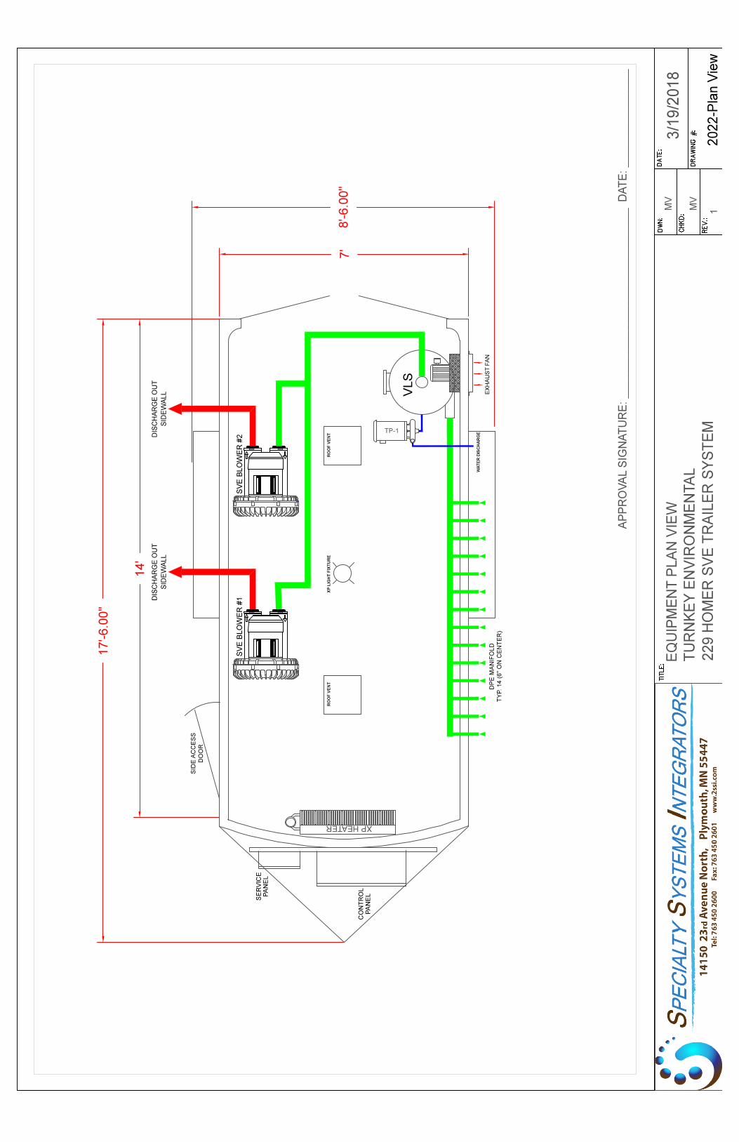
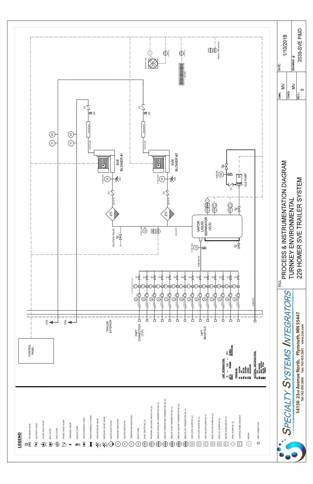
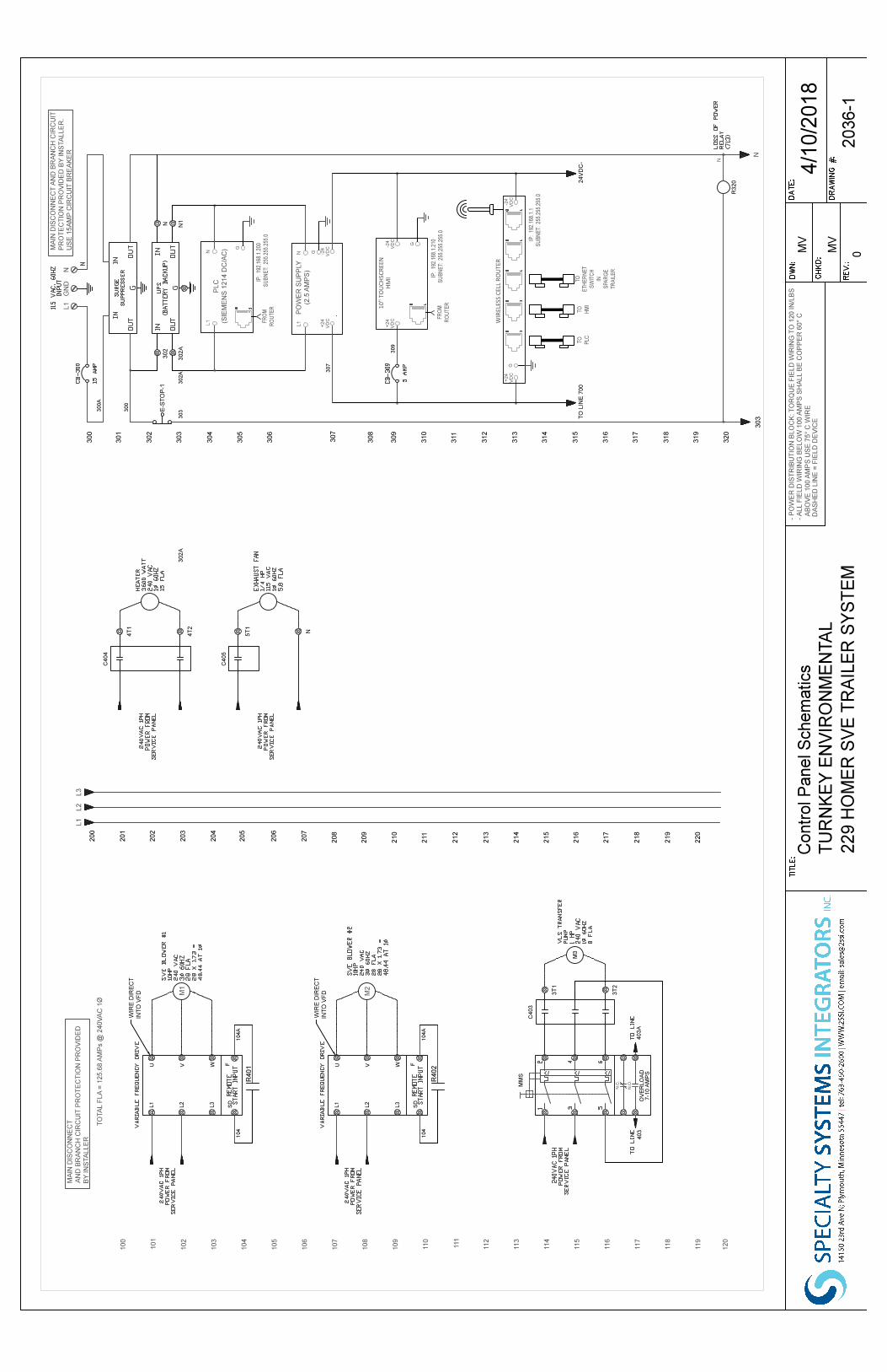
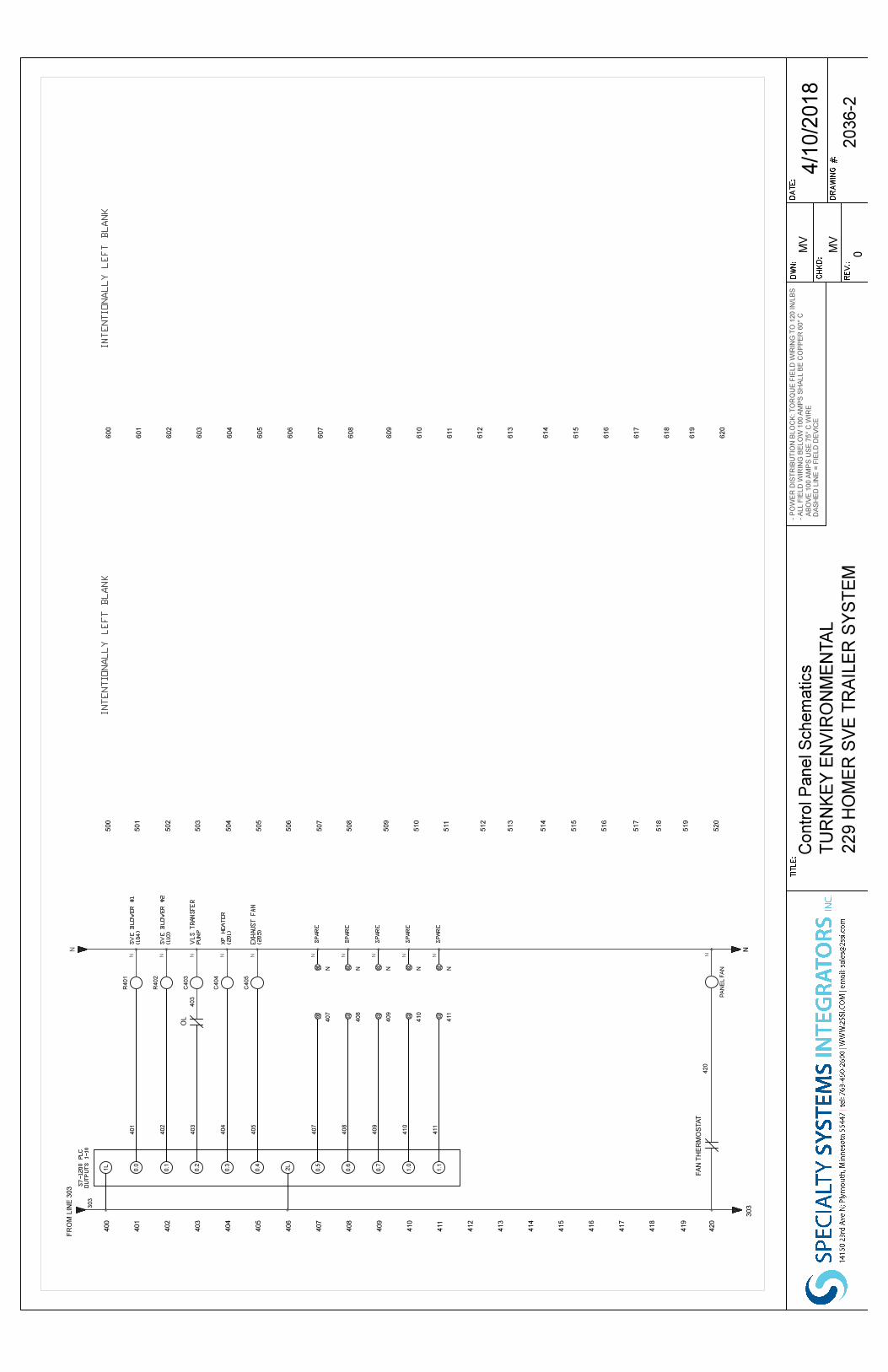
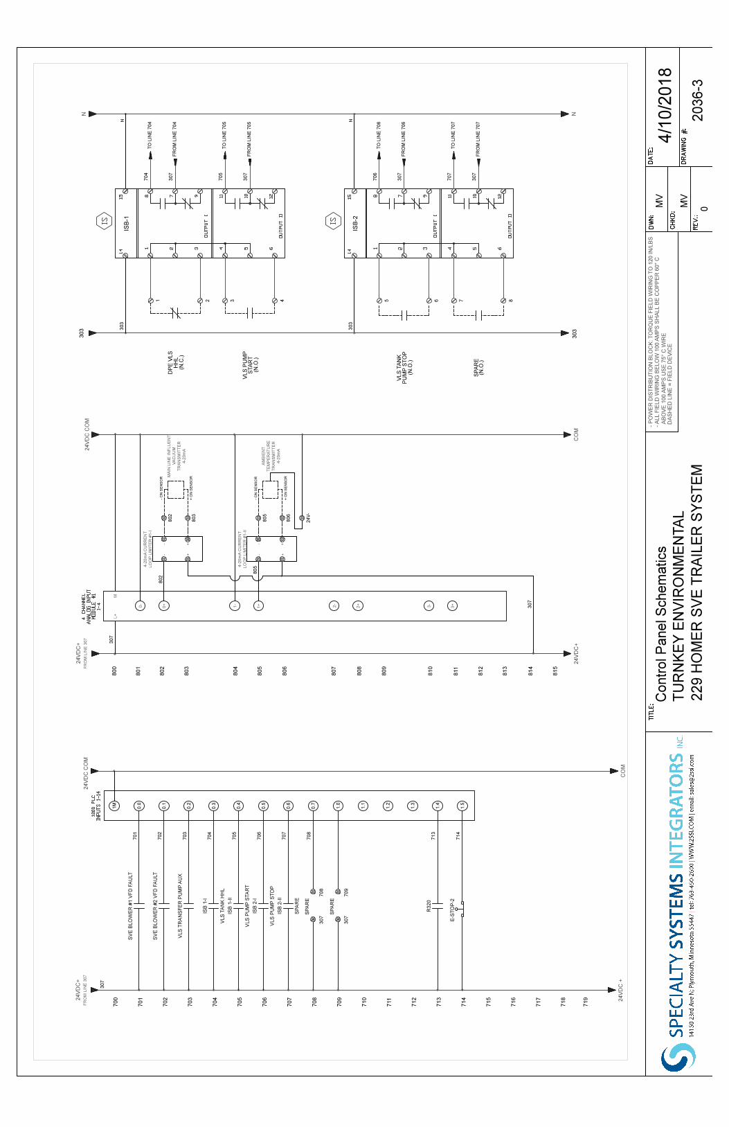
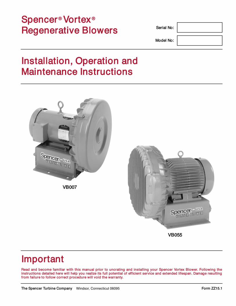
IInnssttaallllaattiioonn,, OOppeerraattiioonn aannddMMaaiinntteennaannccee IInnssttrruuccttiioonnss
IImmppoorrttaannttRReeaadd aanndd bbeeccoommee ffaammiilliiaarr wwiitthh tthhiiss mmaannuuaall pprriioorr ttoo uunnccrraattiinngg aanndd iinnssttaalllliinngg yyoouurr SSppeenncceerr VVoorrtteexx BBlloowweerr.. FFoolllloowwiinngg tthheeiinnssttrruuccttiioonnss ddeettaaiilleedd hheerree wwiillll hheellpp yyoouu rreeaalliizzee iittss ffuullll ppootteennttiiaall ooff eeffffiicciieenntt sseerrvviiccee aanndd eexxtteennddeedd lliiffeessppaann.. DDaammaaggee rreessuullttiinnggffrroomm ffaaiilluurree ttoo ffoollllooww ccoorrrreecctt pprroocceedduurree wwiillll vvooiidd tthhee wwaarrrraannttyy..
TThhee SSppeenncceerr TTuurrbbiinnee CCoommppaannyy Windsor, Connecticut 06095 FFoorrmm ZZZZ1155..11
SSeerriiaall NNoo::
MMooddeell NNoo::
VVBB000077
VVBB005555
SSppeenncceerr ®® VVoorrtteexx ®®
RReeggeenneerraattiivvee BBlloowweerrss

CCoonntteennttssI. General Page
Scope . . . . . . . . . . . . . . . . . . . . . . . . . . . . . . . . . 2Limited Warranty . . . . . . . . . . . . . . . . . . . . . . . . . 2Safety Precautions . . . . . . . . . . . . . . . . . . . . . . . 2
II. InstallationLocating, Mounting, Connecting . . . . . . . . . . . . . 2Wiring . . . . . . . . . . . . . . . . . . . . . . . . . . . . . . . . . 3
III. OperationLimits of Operation . . . . . . . . . . . . . . . . . . . . . 4-5Temperature Rise . . . . . . . . . . . . . . . . . . . . . . . . 5
IV. Disassembly and Reassembly General . . . . . . . . . . . . . . . . . . . . . . . . . . . . . . . . 5Disassembly Procedure . . . . . . . . . . . . . . . . . . . 5Reassembly Cautions . . . . . . . . . . . . . . . . . . . . . 5Locknut Torque . . . . . . . . . . . . . . . . . . . . . . . . . . 6
V. Vortex Blower DataAssembly Diagrams . . . . . . . . . . . . . . . . . . . . 6-17Parts Lists . . . . . . . . . . . . . . . . . . . . . . . . . . . 6-17Performance Curves . . . . . . . . . . . . . . . . . . . 6-17
VI. Troubleshooting Guide . . . . . . . . . . . . . . . . . . . . . 18
II.. GGeenneerraallSSccooppeeInformation contained in this manual relates to VortexBlowers standard and explosion-proof motor modelsVB001S, VB001, VB002S, VB002, VB003S, VB003,VB004S, VB004, VB007S, VB007, VB019S, VB019,VB030S, VB030, VB037S, VB037, VB055, VB075, andVB110.
LLiimmiitteedd WWaarrrraannttyy We warrant that this product will be free from defects inmaterial and workmanship for a period of 18 months fromdate of shipment or 12 months from date of startup,whichever comes first. Within the warranty period, weshall repair or replace F.O.B. our Factory such productsthat are determined by us to be defective.
TThhiiss wwaarrrraannttyy wwiillll nnoott aappppllyy ttoo aannyy pprroodduucctt wwhhiicchh hhaass bbeeeennssuubbjjeecctteedd ttoo mmiissuussee,, nneegglliiggeennccee,, oorr aacccciiddeenntt,, oorr mmiissaapp--pplliieedd oorr iimmpprrooppeerrllyy iinnssttaalllleedd.. TThhiiss wwaarrrraannttyy wwiillll nnoott aappppllyyttoo aannyy pprroodduucctt wwhhiicchh hhaass bbeeeenn ddiissaasssseemmbblleedd,, rreeppaaiirreedd,, oorrootthheerrwwiissee aalltteerreedd bbyy aannyy ppeerrssoonnss nnoott aauutthhoorriizzeedd bbyy tthheeSSppeenncceerr VVoorrtteexx SSeerrvviiccee DDeeppaarrttmmeenntt..
On units which include thermal protection, the thermalprotection must be connected as recommended.
The guarantee of the motor and control manufacturerswill govern the extent of our guarantee on such equip-ment. Warranty work on motors and controls must beauthorized by Spencer and must be performed in anauthorized shop as designated by the manufacturers.
The Spencer Turbine Company reserves the right toinvoice all expenses incurred when repairs are made inthe field at the specific request of the customer.
No assemblies or parts of assemblies will be accepted forrepair or replacement under this warranty without priorauthorization by The Spencer Turbine Company. Forcomplete warranty information, obtain Spencerʼs Form 706,“Terms and Conditions of Sales.”
SSaaffeettyy PPrreeccaauuttiioonnss PPoowweerr ssoouurrcceess,, pprrootteeccttiivvee ddeevviicceess,, aanndd ggrroouunnddiinngg pprroovvii--ssiioonnss mmuusstt bbee iinn aaccccoorrddaannccee wwiitthh wwiirriinngg iinnssttrruuccttiioonnsspprroovviiddeedd iinn tthhiiss mmaannuuaall..
BBlloowweerr bbeeccoommeess hhoott dduurriinngg ooppeerraattiioonn aanndd mmaayy ccaauusseebbuurrnnss iiff ttoouucchheedd..
DDoo nnoott ooppeerraattee tthhee bblloowweerr uunnddeerr llooaadd ccoonnddiittiioonnss wwhhiicchheexxcceeeedd tthhee rraatteedd ffuullll--llooaadd aammppss oonn tthhee nnaammeeppllaattee..
DDoo nnoott iinnssttaallll tthhee bblloowweerr iinn aannyy aarreeaa wwhhiicchh mmaayy hhaavvee aanneexxpplloossiivvee aattmmoosspphheerree oorr wwhhiicchh mmaayy ccoonnttaaiinn ffllaammmmaabblleeggaasseess oorr lliiqquuiiddss.. AAllwwaayyss pprroovviiddee pprrooppeerr vveennttiillaattiioonn.. DDoonnoott iinnssttaallll iinn aannyy aarreeaa wwhhiicchh mmaayy ssuubbjjeecctt tthhee bblloowweerr ttooccoorrrroossiivvee lliiqquuiiddss.. EExxcceessssiivvee mmooiissttuurree mmaayy ccaauussee eelleeccttrrii--ccaall ffaaiilluurree;; iinnssttaallll tthhee bblloowweerr iinn aarreeaass ffrreeee ffrroomm wwaatteerr oorrrraaiinn.. DDoo nnoott ooppeerraattee bblloowweerr wwiitthhoouutt mmoottoorr ccoooolliinngg ffaannccoovveerr,, oorr wwiitthhoouutt iimmppeelllleerr eenndd ccoovveerr..
BBeeffoorree iinnssttaalllliinngg bblloowweerrss wwiitthh eexxpplloossiioonn--pprrooooff mmoottoorrss,,tthhee bbuuyyeerr mmuusstt cchheecckk ffeeddeerraall,, ssttaattee aanndd llooccaall ccooddeess ttoosseeee iiff ssuucchh mmoottoorrss aarree aapppprroopprriiaattee ffoorr tthhee iinntteennddeedd aappppllii--ccaattiioonn eennvviirroonnmmeenntt.. IItt iiss tthhee bbuuyyeerr ʼss rreessppoonnssiibbiilliittyy ttooddeetteerrmmiinnee tthhee ssuuiittaabbiilliittyy ooff aannyy pprroodduucctt ffoorr aa ppaarrttiiccuullaarrppuurrppoossee..
SSttoorraaggee If machine is to be stored for an extended period of time,it must be carefully protected from dampness and dirt.
IIII.. IInnssttaallllaattiioonnLLooccaattiinngg,, MMoouunnttiinngg,, CCoonnnneeccttiinnggAmbient temperature at the installed location should notbe less than -5˚ F or greater than 104˚ F. Relative humidityshould not exceed 80%.
Mount the blower in a horizontal or vertical position asshown in Figure 1. For models VB055, VB075 andVB110, it is recommended to mount in the horizontalposition only. Check with factory prior to mountingthese models vertically.
FFiigg.. 11 MMoouunnttiinngg PPoossiittiioonnss
RReemmoovvee pprrootteeccttiivvee ccoovveerriinnggss,, ssuucchh aass vviinnyyll ttaappee oorrppllaassttiicc pplluuggss,, ffrroomm tthhee iinnlleett aanndd oouuttlleett ppoorrttss.. ModelsVB001, VB002 and VB003 are supplied with a patented(U.S. Patent 5,791,870) reversible flange with threadedpipe or tubing connections. Avoid excessive stress causedby pipe connector tightening or by misaligned pipe on the inlet and outlet ports. Support piping by brackets orother means.22
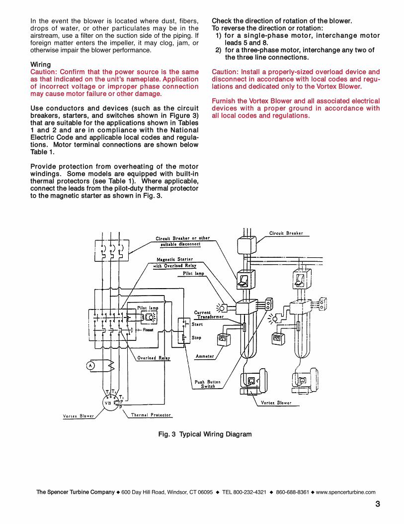
In the event the blower is located where dust, fibers,drops of water, or other particulates may be in theairstream, use a filter on the suction side of the piping. Ifforeign matter enters the impeller, it may clog, jam, orotherwise impair the blower performance.
WWiirriinnggCCaauuttiioonn:: CCoonnffiirrmm tthhaatt tthhee ppoowweerr ssoouurrccee iiss tthhee ssaammeeaass tthhaatt iinnddiiccaatteedd oonn tthhee uunniitt ʼss nnaammeeppllaattee.. AApppplliiccaattiioonnooff iinnccoorrrreecctt vvoollttaaggee oorr iimmpprrooppeerr pphhaassee ccoonnnneeccttiioonnmmaayy ccaauussee mmoottoorr ffaaiilluurree oorr ootthheerr ddaammaaggee..
UUssee ccoonndduuccttoorrss aanndd ddeevviicceess ((ssuucchh aass tthhee ccii rrccuuii ttbbrreeaakkeerrss,, ssttaarrtteerrss,, aanndd sswwiittcchheess sshhoowwnn iinn FFiigguurree 33))tthhaatt aarree ssuuiittaabbllee ffoorr tthhee aapppplliiccaattiioonnss sshhoowwnn iinn TTaabblleess11 aanndd 22 aanndd aarree iinn ccoommppll iiaannccee wwii tthh tthhee NNaatt iioonnaallEElleeccttrriicc CCooddee aanndd aapppplliiccaabbllee llooccaall ccooddeess aanndd rreegguullaa--ttiioonnss.. MMoottoorr tteerrmmiinnaall ccoonnnneeccttiioonnss aarree sshhoowwnn bbeelloowwTTaabbllee 11..
PPrroovviiddee pprrootteecctt iioonn ffrroomm oovveerrhheeaatt iinngg ooff tthhee mmoottoorrwwiinnddiinnggss.. SSoommee mmooddeellss aarree eeqquuiippppeedd wwiitthh bbuuiill tt--iinntthheerrmmaall pprrootteeccttoorrss ((sseeee TTaabbllee 11)).. WWhheerree aapppplliiccaabbllee,,ccoonnnneecctt tthhee lleeaaddss ffrroomm tthhee ppiilloott--dduuttyy tthheerrmmaall pprrootteeccttoorrttoo tthhee mmaaggnneettiicc ssttaarrtteerr aass sshhoowwnn iinn FFiigg.. 33..
CChheecckk tthhee ddiirreeccttiioonn ooff rroottaattiioonn ooff tthhee bblloowweerr..TToo rreevveerrssee tthhee ddiirreeccttiioonn oorr rroottaattiioonn::11)) ffoorr aa ssii nnggllee--pphhaassee mmoottoorr,, iinntteerrcchhaannggee mmoottoorr
lleeaaddss 55 aanndd 88..22)) ffoorr aa tthhrreeee--pphhaassee mmoottoorr,, iinntteerrcchhaannggee aannyy ttwwoo ooff
tthhee tthhrreeee lliinnee ccoonnnneeccttiioonnss..
CCaauuttiioonn:: IInnssttaallll aa pprrooppeerrllyy--ssiizzeedd oovveerrllooaadd ddeevviiccee aannddddiissccoonnnneecctt iinn aaccccoorrddaannccee wwiitthh llooccaall ccooddeess aanndd rreegguu--llaattiioonnss aanndd ddeeddiiccaatteedd oonnllyy ttoo tthhee VVoorrtteexx BBlloowweerr..
FFuurrnniisshh tthhee VVoorrtteexx BBlloowweerr aanndd aallll aassssoocciiaatteedd eelleeccttrriiccaallddeevviicceess wwii tthh aa pprrooppeerr ggrroouunndd iinn aaccccoorrddaannccee wwiitthhaallll llooccaall ccooddeess aanndd rreegguullaattiioonnss..
33
FFiigg.. 33 TTyyppiiccaall WWiirriinngg DDiiaaggrraamm
TThhee SSppeenncceerr TTuurrbbiinnee CCoommppaannyy 600 Day Hill Road, Windsor, CT 06095 TEL 800-232-4321 860-688-8361 www.spencerturbine.com
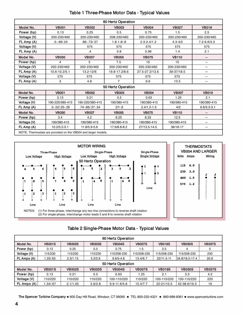
MMooddeell NNoo..PPoowweerr ((hhpp))VVooll ttaaggee ((VV))FFLL AAmmppss ((AA))
VVBB000011SS0.13
110/2201.34/.67
VVBB000022SS0.21
110/2202.1/1.05
VVBB000033SS0.5
110/2205.6/2.8
VVBB000044SS0.63
100-110/2209.9-11.6/5.8
VVBB000077SS1.25
110/22015.4/7.7
VVBB001199SS2.1
100-110/22022-21/10.5
VVBB003300SS3.3
100-110/22042-38.6/19.3
VVBB003377SS4.222019
MMooddeell NNoo..PPoowweerr ((hhpp))VVoollttaaggee ((VV))FFLL AAmmppss ((AA))
VVBB000011SS0.13
115/2301.25/.63
VVBB000022SS0.25
115/2302.3/1.15
VVBB000033SS0.5
115/2305.2/2.6
VVBB000044SS0.75
115/208-2309.6/5-4.8
VVBB000077SS1.5
115/208-23013.4/6.7
VVBB001199SS2.5
115/208-23022/11.5-11
VVBB003300SS4
115/208-23034.8/18.5-17.4
VVBB003377SS5
23020.8
44TThhee SSppeenncceerr TTuurrbbiinnee CCoommppaannyy 600 Day Hill Road, Windsor, CT 06095 TEL 800-232-4321 860-688-8361 www.spencerturbine.com
SSiinnggllee--PPhhaasseeSSiinnggllee VVoollttaaggee
5
1
4
8
LLiinnee
6600 HHeerrttzz OOppeerraattiioonn
5500 HHeerrttzz OOppeerraattiioonn
5500 HHeerrttzz OOppeerraattiioonn
TTaabbllee 22 SSiinnggllee--PPhhaassee MMoottoorr DDaattaa -- TTyyppiiccaall VVaalluueess
NOTES: (1) For three-phase, interchange any two line connections to reverse shaft rotation(2) For single-phase, interchange motor leads 5 and 8 to reverse shaft rotation
MMOOTTOORR WWIIRRIINNGGTThhrreeee--PPhhaassee
LLooww VVoollttaaggee HHiigghh VVoollttaaggeeSSiinnggllee--PPhhaassee
LLooww VVoollttaaggee HHiigghh VVoollttaaggee
TTHHEERRMMOOSSTTAATTSSVVBB000044 AANNDD LLAARRGGEERR
VVoollttss AAmmppss
LLiinnee LLiinnee LLiinnee LLiinnee
MMooddeell NNoo..PPoowweerr ((hhpp))VVoollttaaggee ((VV))FFLL AAmmpp ((AA))VVoollttaaggee ((VV))FFLL AAmmpp ((AA))
VVBB0000110.13
200-230/460.5-.48/.24
VVBB0000220.25
200-230/460.86-.73/.37
575.4
VVBB0000330.5
208-230/4601.8-1.6/.8
5750.8
VVBB0000440.75
200-230/4602.3-2.4/1.2
5750.96
VVBB0000771.5
200-230/4604.3-4/2
5751.4
VVBB0011992.5
200-230/4607.2-6.6/3.3
5752.1
TTaabbllee 11 TThhrreeee--PPhhaassee MMoottoorr DDaattaa -- TTyyppiiccaall VVaalluueess6600 HHeerrttzz OOppeerraattiioonn
MMooddeell NNoo..PPoowweerr ((hhpp))VVooll ttaaggee ((VV))FFLL AAmmpp ((AA))VVooll ttaaggee ((VV))FFLL AAmmpp ((AA))
VVBB0033004
200-230/46010.6-10.2/5.1
5753
VVBB0033775
200-230/46013.2-12/6
5754.8
VVBB0055557.5
200-230/46019.8-17.2/8.6
5757
VVBB00775510
200-230/46027.5-27.2/13.6
5759.6
VVBB11110015
200-230/46039-37/18.5
57513.5
———— ——
5500 HHeerrttzz OOppeerraattiioonn
MMooddeell NNoo..PPoowweerr ((hhpp))VVoollttaaggee ((VV))FFLL AAmmpp ((AA))
VVBB0033003.4
190/380-41510.2/5.2-5.1
VVBB0033774.2
190/380-41511.8/5.9-5.6
VVBB0055556.25
190/380-41517.6/8.8-8.2
VVBB0077558.33
190/380-41527/13.5-14.5
VVBB11110012.5
190/380-41536/18-17
————
WWiirriinngg
NOTE: Thermostats are provided on the VB004 and larger models.
MMooddeell NNoo..PPoowweerr ((hhpp))VVoollttaaggee ((VV))FFLL AAmmpp ((AA))
VVBB0000110.13
190-220/380-415.5-.52/.25-.26
VVBB0000220.21
190-220/380-415.74-.66/.37-.34
VVBB0000330.5
190/380-4152/1-.9
VVBB0000440.63
190/380-4152.4/1.2-1.3
VVBB0000771.25
190/380-4154/2
VVBB0011992.1
190/380-4156.6/3.3-3.1
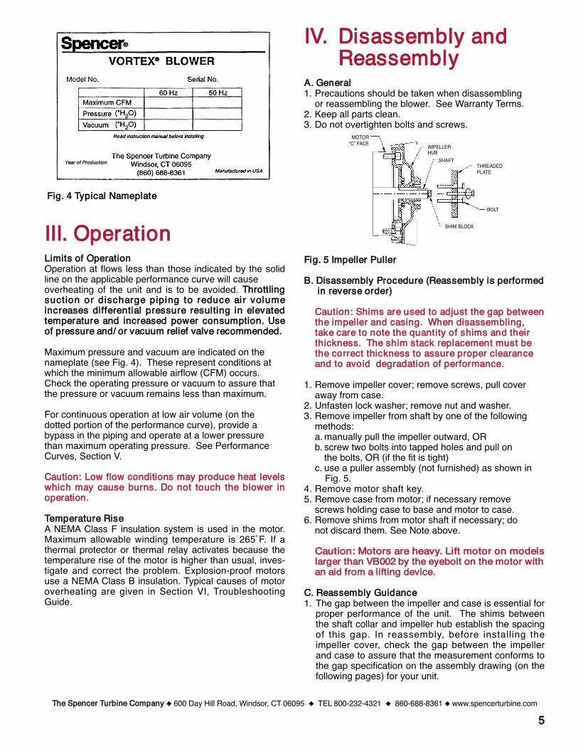
55
FFiigg.. 44 TTyyppiiccaall NNaammeeppllaattee
IIIIII.. OOppeerraattiioonnLLiimmiittss ooff OOppeerraattiioonnOperation at flows less than those indicated by the solidline on the applicable performance curve will causeoverheating of the unit and is to be avoided. TThhrroottttlliinnggssuucctt iioonn oorr ddiisscchhaarrggee ppiippiinngg ttoo rreedduuccee aaii rr vvoolluummeeiinnccrreeaasseess ddiiffffeerreennttiiaall pprreessssuurree rreessuullttiinngg iinn eelleevvaatteeddtteemmppeerraattuurree aanndd iinnccrreeaasseedd ppoowweerr ccoonnssuummppttiioonn.. UUssee ooff pprreessssuurree aanndd// oorr vvaaccuuuumm rreelliieeff vvaallvvee rreeccoommmmeennddeedd..
Maximum pressure and vacuum are indicated on thenameplate (see Fig. 4). These represent conditions atwhich the minimum allowable airflow (CFM) occurs. Check the operating pressure or vacuum to assure thatthe pressure or vacuum remains less than maximum.
For continuous operation at low air volume (on thedotted portion of the performance curve), provide abypass in the piping and operate at a lower pressurethan maximum operating pressure. See PerformanceCurves, Section V.
CCaauuttiioonn:: LLooww ffllooww ccoonnddiittiioonnss mmaayy pprroodduuccee hheeaatt lleevveellsswwhhiicchh mmaayy ccaauussee bbuurrnnss.. DDoo nnoott ttoouucchh tthhee bblloowweerr iinnooppeerraattiioonn..
TTeemmppeerraattuurree RRiisseeA NEMA Class F insulation system is used in the motor.Maximum allowable winding temperature is 265˚F. If athermal protector or thermal relay activates because thetemperature rise of the motor is higher than usual, inves-tigate and correct the problem. Explosion-proof motorsuse a NEMA Class B insulation. Typical causes of motoroverheating are given in Section VI, TroubleshootingGuide.
IIVV.. DDiissaasssseemmbbllyy aannddRReeaasssseemmbbllyy
AA.. GGeenneerraall1. Precautions should be taken when disassembling
or reassembling the blower. See Warranty Terms.2. Keep all parts clean.3. Do not overtighten bolts and screws.
FFiigg.. 55 IImmppeelllleerr PPuulllleerr
BB.. DDiissaasssseemmbbllyy PPrroocceedduurree ((RReeaasssseemmbbllyy iiss ppeerrffoorrmmeedd iinn rreevveerrssee oorrddeerr))
CCaauuttiioonn:: SShhiimmss aarree uusseedd ttoo aaddjjuusstt tthhee ggaapp bbeettwweeeenntthhee iimmppeelllleerr aanndd ccaassiinngg.. WWhheenn ddiissaasssseemmbblliinngg,,ttaakkee ccaarree ttoo nnoottee tthhee qquuaannttiittyy ooff sshhiimmss aanndd tthheeiirrtthhiicckknneessss.. TThhee sshhiimm ssttaacckk rreeppllaacceemmeenntt mmuusstt bbeetthhee ccoorrrreecctt tthhiicckknneessss ttoo aassssuurree pprrooppeerr cclleeaarraanncceeaanndd ttoo aavvooiidd ddeeggrraaddaattiioonn ooff ppeerrffoorrmmaannccee..
1. Remove impeller cover; remove screws, pull coveraway from case.
2. Unfasten lock washer; remove nut and washer.3. Remove impeller from shaft by one of the following
methods:a. manually pull the impeller outward, ORb. screw two bolts into tapped holes and pull on
the bolts, OR (if the fit is tight)c. use a puller assembly (not furnished) as shown in
Fig. 5.4. Remove motor shaft key.5. Remove case from motor; if necessary remove
screws holding case to base and motor to case.6. Remove shims from motor shaft if necessary; do
not discard them. See Note above.
CCaauuttiioonn:: MMoottoorrss aarree hheeaavvyy.. LLiifftt mmoottoorr oonn mmooddeellssllaarrggeerr tthhaann VVBB000022 bbyy tthhee eeyyeebboolltt oonn tthhee mmoottoorr wwiitthhaann aaiidd ffrroomm aa lliiffttiinngg ddeevviiccee..
CC.. RReeaasssseemmbbllyy GGuuiiddaannccee1. The gap between the impeller and case is essential for
proper performance of the unit. The shims betweenthe shaft collar and impeller hub establish the spacingof this gap. In reassembly, before installing theimpeller cover, check the gap between the impellerand case to assure that the measurement conforms tothe gap specification on the assembly drawing (on thefollowing pages) for your unit.
TThhee SSppeenncceerr TTuurrbbiinnee CCoommppaannyy 600 Day Hill Road, Windsor, CT 06095 TEL 800-232-4321 860-688-8361 www.spencerturbine.com
YYeeaarr ooff PPrroodduuccttiioonn THREADEDPLATE
SHIM BLOCK
MOTOR“C” FACE IMPELLER
HUBSHAFT
BOLT
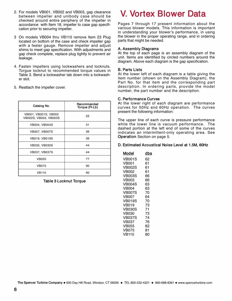
66
2. For models VB001, VB002 and VB003, gap clearancebetween impeller and unibody case should bechecked around entire periphery of the impeller inaccordance with Item 18, impeller to case gap specifi-cation prior to securing impeller.
3 On models VB004 thru VB110 remove Item 23 Pluglocated on bottom of the case and check impeller gapwith a feeler gauge. Remove impeller and adjustshims to meet gap specification. With adjustments andgap check complete, replace plug tightly to prevent airleakage.
4. Fasten impellers using lockwashers and locknuts.Torgue locknut to recommended torque values inTable 3. Bend a lockwasher tab down into a lockwash-er slot.
5. Reattach the impeller cover.
VV.. VVoorrtteexx BBlloowweerr DDaattaaPages 7 through 17 present information about thevarious blower models. This information is importantin understanding your blowerʼs performance, in usingthe blower in the proper operating range, and in orderingparts that might be needed.
AA.. AAsssseemmbbllyy DDiiaaggrraammss At the top of each page is an assembly diagram of theunit. Items are identified by circled numbers around thediagram. Above each diagram is the gap specification.
BB.. PPaarrttss LLiissttss At the lower left of each diagram is a table giving theitem number (shown on the Assembly Diagram), thePart No. for that item and the corresponding partdescription. In ordering parts, provide the modelnumber, the part number and the description.
CC.. PPeerrffoorrmmaannccee CCuurrvveessAt the lower right of each diagram are performancecurves for 50Hz and 60Hz operation. The curvespresent the following information:
The upper line of each curve is pressure performancewhile the lower line is vacuum performance. Thedashed portion at the left end of some of the curvesindicates an intermittent-only operating area. SeeOOppeerraattiioonn Section on page 5.
DD.. EEssttiimmaatteedd AAccoouussttiiccaall NNooiissee LLeevveell aatt 11..55MM,, 6600HHzz
MMooddeell ddbbaaVB001S 62VB001 61VB002S 61VB002 61VB003S 66VB003 66VB004S 63VB004 63VB007S 70VB007 64VB019S 70VB019 73VB030S 71VB030 73VB037S 74VB037 76VB055 82VB075 81VB110 80
TTaabbllee 33 LLoocckknnuutt TToorrqquuee
TThhee SSppeenncceerr TTuurrbbiinnee CCoommppaannyy 600 Day Hill Road, Windsor, CT 06095 TEL 800-232-4321 860-688-8361 www.spencerturbine.com
VB001, VB001S, VB002VB002S, VB003, VB003S
VB004, VB004S
VB007, VB007S
VB019, VB019S
VB030, VB030S
VB037, VB037S
VB055
VB075
VB110
22
31
36
36
44
44
77
90
90
CCaattaalloogg NNoo.. RReeccoommmmeennddeeddTToorrqquuee ((FFtt--LLbb))
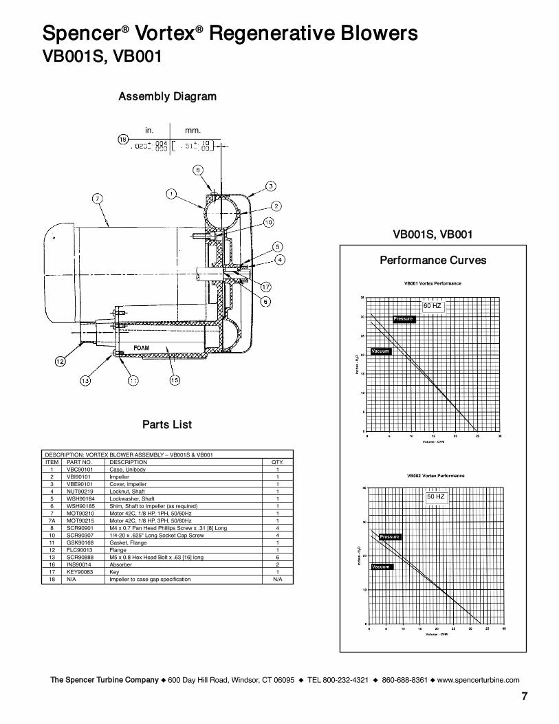
77
PPeerrffoorrmmaannccee CCuurrvveess
PPaarrttss LLiisstt
SSppeenncceerr®® VVoorrtteexx®® RReeggeenneerraattiivvee BBlloowweerrssVVBB000011SS,, VVBB000011
TThhee SSppeenncceerr TTuurrbbiinnee CCoommppaannyy 600 Day Hill Road, Windsor, CT 06095 TEL 800-232-4321 860-688-8361 www.spencerturbine.com
DESCRIPTION: VORTEX BLOWER ASSEMBLY – VB001S & VB001ITEM PART NO. DESCRIPTION QTY.
1 VBC90101 Case, Unibody 12 VBI90101 Impeller 13 VBE90101 Cover, Impeller 14 NUT90219 Locknut, Shaft 15 WSH90184 Lockwasher, Shaft 16 WSH90185 Shim, Shaft to Impeller (as required) 17 MOT90210 Motor 42C, 1/8 HP, 1PH, 50/60Hz 1
7A MOT90215 Motor 42C, 1/8 HP, 3PH, 50/60Hz 18 SCR90901 M4 x 0.7 Pan Head Phillips Screw x .31 [8] Long 4
10 SCR90307 1/4-20 x .625" Long Socket Cap Screw 411 GSK90168 Gasket, Flange 112 FLC90013 Flange 113 SCR90888 M5 x 0.8 Hex Head Bolt x .63 [16] long 616 INS90014 Absorber 217 KEY90083 Key 118 N/A Impeller to case gap specification N/A
AAsssseemmbbllyy DDiiaaggrraamm
in. mm.
VVBB000011SS,, VVBB000011
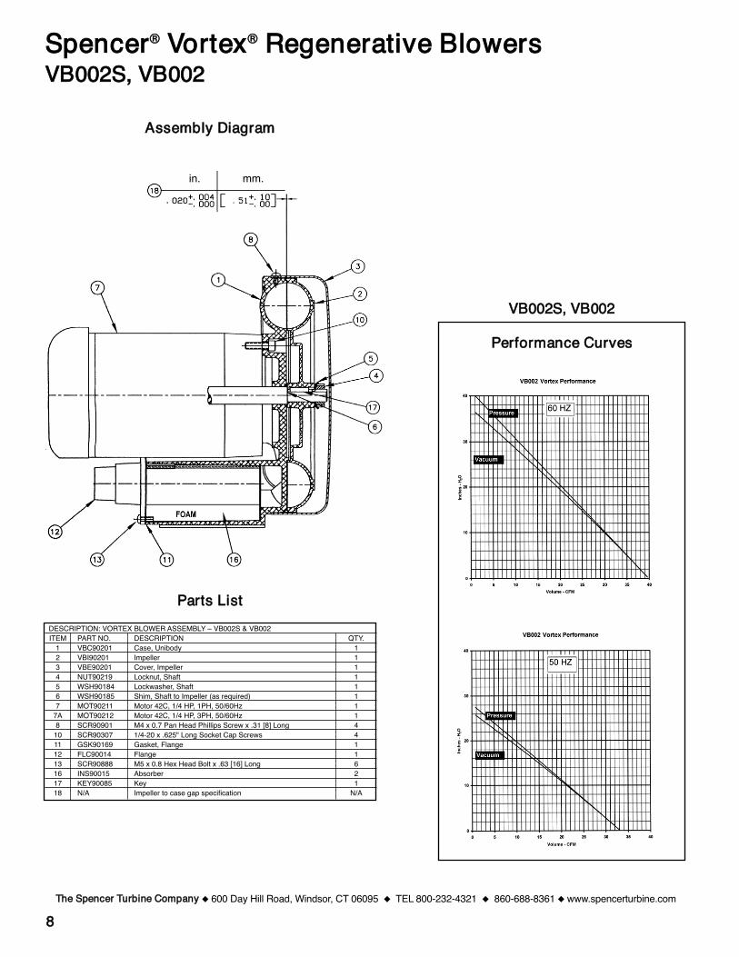
88
PPeerrffoorrmmaannccee CCuurrvveess
TThhee SSppeenncceerr TTuurrbbiinnee CCoommppaannyy 600 Day Hill Road, Windsor, CT 06095 TEL 800-232-4321 860-688-8361 www.spencerturbine.com
SSppeenncceerr®® VVoorrtteexx®® RReeggeenneerraattiivvee BBlloowweerrssVVBB000022SS,, VVBB000022
PPaarrttss LLiissttDESCRIPTION: VORTEX BLOWER ASSEMBLY – VB002S & VB002ITEM PART NO. DESCRIPTION QTY.
1 VBC90201 Case, Unibody 12 VBI90201 Impeller 13 VBE90201 Cover, Impeller 14 NUT90219 Locknut, Shaft 15 WSH90184 Lockwasher, Shaft 16 WSH90185 Shim, Shaft to Impeller (as required) 17 MOT90211 Motor 42C, 1/4 HP, 1PH, 50/60Hz 1
7A MOT90212 Motor 42C, 1/4 HP, 3PH, 50/60Hz 18 SCR90901 M4 x 0.7 Pan Head Phillips Screw x .31 [8] Long 4
10 SCR90307 1/4-20 x .625" Long Socket Cap Screws 411 GSK90169 Gasket, Flange 112 FLC90014 Flange 113 SCR90888 M5 x 0.8 Hex Head Bolt x .63 [16] Long 616 INS90015 Absorber 217 KEY90085 Key 118 N/A Impeller to case gap specification N/A
AAsssseemmbbllyy DDiiaaggrraamm
in. mm.
VVBB000022SS,, VVBB000022
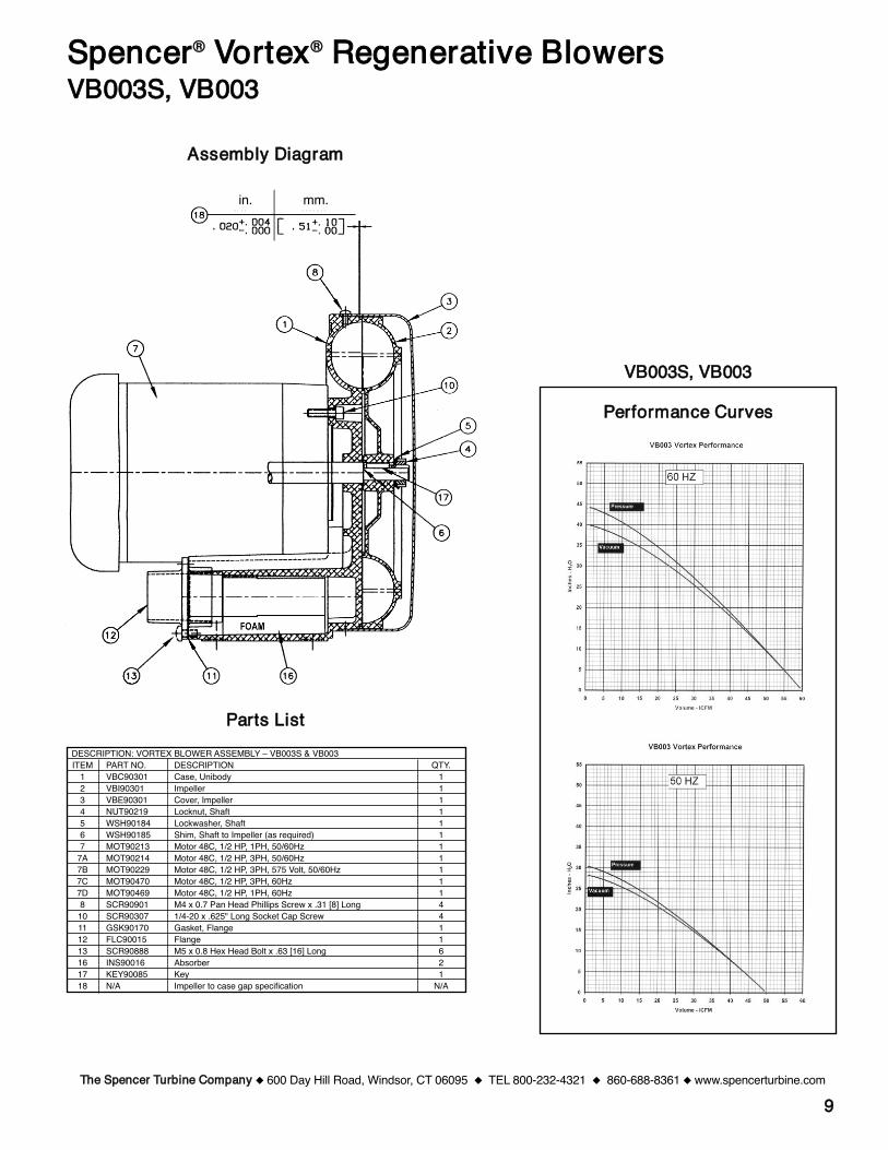
99
PPeerrffoorrmmaannccee CCuurrvveess
TThhee SSppeenncceerr TTuurrbbiinnee CCoommppaannyy 600 Day Hill Road, Windsor, CT 06095 TEL 800-232-4321 860-688-8361 www.spencerturbine.com
SSppeenncceerr®® VVoorrtteexx®® RReeggeenneerraattiivvee BBlloowweerrssVVBB000033SS,, VVBB000033
AAsssseemmbbllyy DDiiaaggrraamm
PPaarrttss LLiissttDESCRIPTION: VORTEX BLOWER ASSEMBLY – VB003S & VB003ITEM PART NO. DESCRIPTION QTY.
1 VBC90301 Case, Unibody 12 VBI90301 Impeller 13 VBE90301 Cover, Impeller 14 NUT90219 Locknut, Shaft 15 WSH90184 Lockwasher, Shaft 16 WSH90185 Shim, Shaft to Impeller (as required) 17 MOT90213 Motor 48C, 1/2 HP, 1PH, 50/60Hz 1
7A MOT90214 Motor 48C, 1/2 HP, 3PH, 50/60Hz 17B MOT90229 Motor 48C, 1/2 HP, 3PH, 575 Volt, 50/60Hz 17C MOT90470 Motor 48C, 1/2 HP, 3PH, 60Hz 17D MOT90469 Motor 48C, 1/2 HP, 1PH, 60Hz 18 SCR90901 M4 x 0.7 Pan Head Phillips Screw x .31 [8] Long 4
10 SCR90307 1/4-20 x .625" Long Socket Cap Screw 411 GSK90170 Gasket, Flange 112 FLC90015 Flange 113 SCR90888 M5 x 0.8 Hex Head Bolt x .63 [16] Long 616 INS90016 Absorber 217 KEY90085 Key 118 N/A Impeller to case gap specification N/A
in. mm.
VVBB000033SS,, VVBB000033
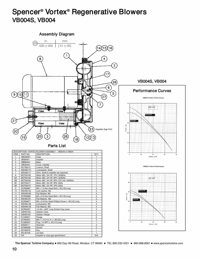
1100
PPeerrffoorrmmaannccee CCuurrvveess
TThhee SSppeenncceerr TTuurrbbiinnee CCoommppaannyy 600 Day Hill Road, Windsor, CT 06095 TEL 800-232-4321 860-688-8361 www.spencerturbine.com
SSppeenncceerr®® VVoorrtteexx®® RReeggeenneerraattiivvee BBlloowweerrssVVBB000044SS,, VVBB000044
AAsssseemmbbllyy DDiiaaggrraamm
PPaarrttss LLiissttDESCRIPTION: VORTEX BLOWER ASSEMBLY – VB004S & VB004ITEM PART NO. DESCRIPTION QTY.
1 VBC90401 Case 12 VBI90401 Impeller 13 VBB90401 Base 14 VBE90401 Cover, Impeller 15 NUT90212 Locknut, Shaft 16 WSH90170 Lockwasher, Shaft 17 WSH90177 Shim, Shaft to Impeller (as required) 18 MOT90193 Motor 48C, 3/4 HP, 1PH, 50/60Hz 1
8A MOT90192 Motor 48C, 3/4 HP, 3PH, 50/60Hz 18B MOT90230 Motor 48C, 3/4 HP, 3PH, 575 Volt, 50/60Hz 18C MOT90471 Motor 48C, 3/4 HP, 3PH, 60Hz 18D MOT90472 Motor 48C, 3/4 HP, 1PH, 60Hz 19 SCR90887 M6 x 1.0 Hex Head Bolt x .63 [16] Long 4
10 WSH90142 Lock washer, M5 411 WSH90166 Flat Washer, M5 412 SCR90888 M5 x 0.8 Hex Head Bolt x .63 [16] Long 213 WSH90181 Flat Washer, M5 214 SCR90877 M5 x 0.8 Pan Head Phillips Screw x .39 [10] Long 415 WSH90138 Lockwasher, M5 416 WSH90139 Flat Washer, M5 417 SCR90307 1/4-20 x .625" Long Socket Cap screw 418 GSK90165 Gasket, Case 119 GSK90163 Gasket, Flange 220 FLC90007 Flange 221 SCR90931 M6 x 1.0 S.H.C.S. x .98 [25] Long 423 PLG90037 Plug, 1/4 NPT x .43 [11] Long 125 INS90017 Absorber 426 SCN90065 Screen 227 KEY90076 Key 128 SEL90108 Lip Seal 129 N/A Impeller to case gap specification N/A
VVBB000044SS,, VVBB000044
Impeller Gap Port
29mm.
.020 +.002 [.51 +.05]
in.
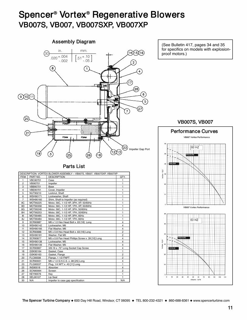
1111TThhee SSppeenncceerr TTuurrbbiinnee CCoommppaannyy 600 Day Hill Road, Windsor, CT 06095 TEL 800-232-4321 860-688-8361 www.spencerturbine.com
SSppeenncceerr®® VVoorrtteexx®® RReeggeenneerraattiivvee BBlloowweerrssVVBB000077SS,, VVBB000077,, VVBB000077SSXXPP,, VVBB000077XXPP
PPeerrffoorrmmaannccee CCuurrvveess
(See Bulletin 417, pages 34 and 35for specifics on models with explosion-proof motors.)
AAsssseemmbbllyy DDiiaaggrraamm
VVBB000077SS,, VVBB000077
Impeller Gap Port
PPaarrttss LLiissttDESCRIPTION: VORTEX BLOWER ASSEMBLY – VB007S, VB007, VB007SXP, VB007XPITEM PART NO. DESCRIPTION QTY.
1 VBC90701 Case 12 VBI90701 Impeller 13 VBB90701 Base 14 VBE90701 Cover, Impeller 15 NUT90210 Locknut, Shaft 16 WSH90171 Lockwasher, Shaft 17 WSH90160 Shim, Shaft to Impeller (as required) 1
8C MOT90225 Motor, 56C, 1-1/2 HP, 3PH, XP, 50/60Hz 18D MOT90358 Motor, 56C, 1-1/2 HP, 1PH, XP, 50/60Hz 18G MOT90248 Motor, 56C, 1-1/2 HP, 3PH, 50/60Hz 18H MOT90253 Motor, 56C, 1-1/2 HP, 1PH, 50/60Hz 18I MOT90485 Motor, 56C, 1-1/2 HP, 3PH, 60Hz 18J MOT90484 Motor, 56C, 1-1/2 HP, 1PH, 60Hz 19 SCR90887 M6 x 1.0 Hex Head Bolt x .63 [16] Long 4
10 WSH90142 Lockwasher, M6 411 WSH90166 Flat Washer, M6 412 SCR90888 M5 x 0.8 Hex Head Bolt x .63 [16] Long 213 WSH90181 Washer, Flat M5 214 SCR90877 M5 x 0.8 Pan Head Phillips Screw x .39 [10] Long 415 WSH90138 Lockwasher, M5 416 WSH90139 Flat Washer, M5 417 SCR90867 3/8-16 x .75" Long Socket Cap Screw 418 GSK90164 Gasket, Case 119 GSK90163 Gasket, Flange 220 FLC90008 Flange, 1 1/2 FNPT 221 SCR90931 M6 x 1.0 S.H.C.S. x .98 [25] Long 423 PLG90037 Plug, 1/4 NPT x .43 [11] Long 125 INS90018 Absorber 426 SCN90064 Screen 227 KEY90076 Key 128 SEL90107 Lip Seal 130 N/A Impeller to case gap specification N/A
[.51
in. mm.30
+.004-.002
.020 +.10-.05 ]
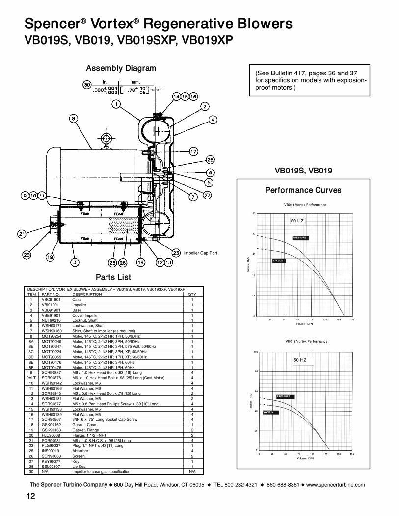
1122
PPeerrffoorrmmaannccee CCuurrvveess
TThhee SSppeenncceerr TTuurrbbiinnee CCoommppaannyy 600 Day Hill Road, Windsor, CT 06095 TEL 800-232-4321 860-688-8361 www.spencerturbine.com
SSppeenncceerr®® VVoorrtteexx®® RReeggeenneerraattiivvee BBlloowweerrssVVBB001199SS,, VVBB001199,, VVBB001199SSXXPP,, VVBB001199XXPP
(See Bulletin 417, pages 36 and 37for specifics on models with explosion-proof motors.)
AAsssseemmbbllyy DDiiaaggrraamm
PPaarrttss LLiissttDESCRIPTION: VORTEX BLOWER ASSEMBLY – VB019S, VB019, VB019SXP, VB019XPITEM PART NO. DESPCRIPTION QTY.
1 VBC91901 Case 12 VBI91901 Impeller 13 VBB91901 Base 14 VBE91901 Cover, Impeller 15 NUT90210 Locknut, Shaft 16 WSH90171 Lockwasher, Shaft 17 WSH90160 Shim, Shaft to Impeller (as required) 18 MOT90254 Motor, 145TC, 2-1/2 HP, 1PH, 50/60Hz 1
8A MOT90249 Motor, 145TC, 2-1/2 HP, 3PH, 50/60Hz 18B MOT90347 Motor, 145TC, 2-1/2 HP, 3PH, 575 Volt, 50/60Hz 18C MOT90224 Motor, 145TC, 2-1/2 HP, 3PH, XP, 50/60Hz 18D MOT90359 Motor, 145TC, 2-1/2 HP, 1PH, XP, 50/60Hz 18E MOT90476 Motor, 145TC, 2-1/2 HP, 3PH, 60Hz 18F MOT90475 Motor, 145TC, 2-1/2 HP, 1PH, 60Hz 19 SCR90887 M6 x 1.0 Hex Head Bolt x .63 [16] Long 4
9ALT SCR90876 M6. x 1.0 Hex Head Bolt x .98 [25] Long (Cast Motor) 410 WSH90142 Lockwasher, M6 411 WSH90166 Flat Washer, M6 412 SCR90943 M5 x 0.8 Hex Head Bolt x .79 [20] Long 213 WSH90181 Flat Washer, M5 214 SCR90877 M5 x 0.8 Pan Head Phillips Screw x .39 [10] Long 415 WSH90138 Lockwasher, M5 416 WSH90139 Flat Washer, M5 417 SCR90867 3/8-16 x .75" Long Socket Cap Screw 418 GSK90162 Gasket, Case 119 GSK90163 Gasket, Flange 220 FLC90008 Flange, 1 1/2 FNPT 221 SCR90931 M6 x 1.0 S.H.C.S. x .98 [25] Long 423 PLG90037 Plug, 1/4 NPT x .43 [11] Long 125 INS90019 Absorber 426 SCN90063 Screen 227 KEY90077 Key 128 SEL90107 Lip Seal 130 N/A Impeller to case gap specification N/A
VVBB001199SS,, VVBB001199
Impeller Gap Port
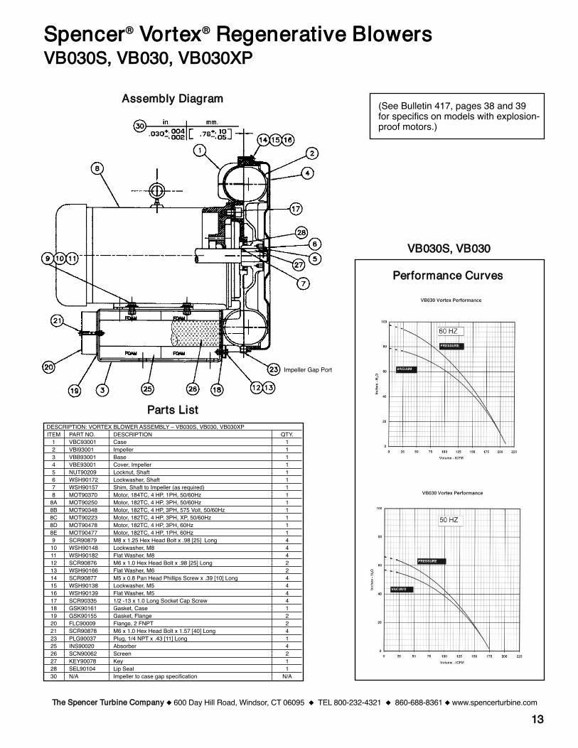
1133
PPeerrffoorrmmaannccee CCuurrvveess
TThhee SSppeenncceerr TTuurrbbiinnee CCoommppaannyy 600 Day Hill Road, Windsor, CT 06095 TEL 800-232-4321 860-688-8361 www.spencerturbine.com
SSppeenncceerr®® VVoorrtteexx®® RReeggeenneerraattiivvee BBlloowweerrssVVBB003300SS,, VVBB003300,, VVBB003300XXPP
(See Bulletin 417, pages 38 and 39for specifics on models with explosion-proof motors.)
AAsssseemmbbllyy DDiiaaggrraamm
PPaarrttss LLiissttDESCRIPTION: VORTEX BLOWER ASSEMBLY – VB030S, VB030, VB030XPITEM PART NO. DESCRIPTION QTY.
1 VBC93001 Case 12 VBI93001 Impeller 13 VBB93001 Base 14 VBE93001 Cover, Impeller 15 NUT90209 Locknut, Shaft 16 WSH90172 Lockwasher, Shaft 17 WSH90157 Shim, Shaft to Impeller (as required) 18 MOT90370 Motor, 184TC, 4 HP, 1PH, 50/60Hz 1
8A MOT90250 Motor, 182TC, 4 HP, 3PH, 50/60Hz 18B MOT90348 Motor, 182TC, 4 HP, 3PH, 575 Volt, 50/60Hz 18C MOT90223 Motor, 182TC, 4 HP, 3PH, XP, 50/60Hz 18D MOT90478 Motor, 182TC, 4 HP, 3PH, 60Hz 18E MOT90477 Motor, 182TC, 4 HP, 1PH, 60Hz 19 SCR90879 M8 x 1.25 Hex Head Bolt x .98 [25] Long 4
10 WSH90148 Lockwasher, M8 411 WSH90182 Flat Washer, M8 412 SCR90876 M6 x 1.0 Hex Head Bolt x .98 [25] Long 213 WSH90166 Flat Washer, M6 214 SCR90877 M5 x 0.8 Pan Head Phillips Screw x .39 [10] Long 415 WSH90138 Lockwasher, M5 416 WSH90139 Flat Washer, M5 417 SCR90335 1/2 -13 x 1.0 Long Socket Cap Screw 418 GSK90161 Gasket, Case 119 GSK90155 Gasket, Flange 220 FLC90009 Flange, 2 FNPT 221 SCR90878 M6 x 1.0 Hex Head Bolt x 1.57 [40] Long 423 PLG90037 Plug, 1/4 NPT x .43 [11] Long 125 INS90020 Absorber 426 SCN90062 Screen 227 KEY90078 Key 128 SEL90104 Lip Seal 130 N/A Impeller to case gap specification N/A
VVBB003300SS,, VVBB003300
Impeller Gap Port
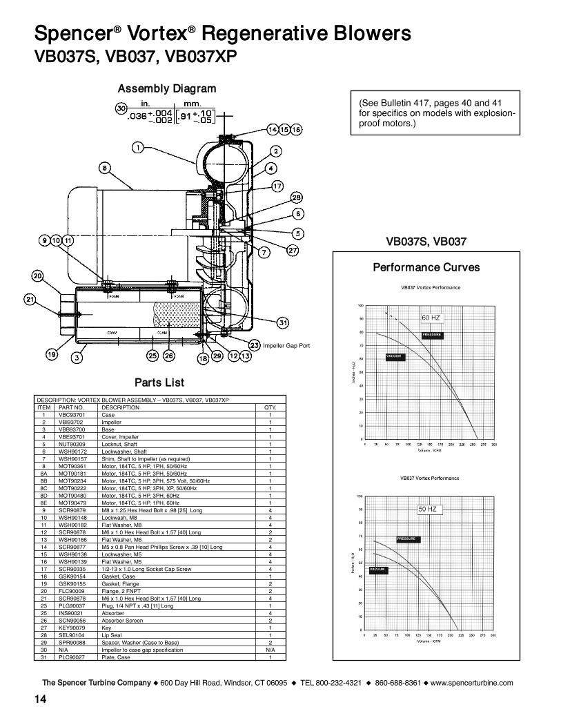
1144
PPeerrffoorrmmaannccee CCuurrvveess
TThhee SSppeenncceerr TTuurrbbiinnee CCoommppaannyy 600 Day Hill Road, Windsor, CT 06095 TEL 800-232-4321 860-688-8361 www.spencerturbine.com
SSppeenncceerr®® VVoorrtteexx®® RReeggeenneerraattiivvee BBlloowweerrssVVBB003377SS,, VVBB003377,, VVBB003377XXPP
(See Bulletin 417, pages 40 and 41for specifics on models with explosion-proof motors.)
AAsssseemmbbllyy DDiiaaggrraamm
PPaarrttss LLiissttDESCRIPTION: VORTEX BLOWER ASSEMBLY – VB037S, VB037, VB037XPITEM PART NO. DESCRIPTION QTY.
1 VBC93701 Case 12 VBI93702 Impeller 13 VBB93700 Base 14 VBE93701 Cover, Impeller 15 NUT90209 Locknut, Shaft 16 WSH90172 Lockwasher, Shaft 17 WSH90157 Shim, Shaft to Impeller (as required) 18 MOT90361 Motor, 184TC, 5 HP, 1PH, 50/60Hz 1
8A MOT90181 Motor, 184TC, 5 HP, 3PH, 50/60Hz 18B MOT90234 Motor, 184TC, 5 HP, 3PH, 575 Volt, 50/60Hz 18C MOT90222 Motor, 184TC, 5 HP, 3PH, XP, 50/60Hz 18D MOT90480 Motor, 184TC, 5 HP, 3PH, 60Hz 18E MOT90479 Motor, 184TC, 5 HP, 1PH, 60Hz 19 SCR90879 M8 x 1.25 Hex Head Bolt x .98 [25] Long 4
10 WSH90148 Lockwash, M8 411 WSH90182 Flat Washer, M8 412 SCR90878 M6 x 1.0 Hex Head Bolt x 1.57 [40] Long 213 WSH90166 Flat Washer, M6 214 SCR90877 M5 x 0.8 Pan Head Phillips Screw x .39 [10] Long 415 WSH90138 Lockwasher, M5 416 WSH90139 Flat Washer, M5 417 SCR90335 1/2-13 x 1.0 Long Socket Cap Screw 418 GSK90154 Gasket, Case 119 GSK90155 Gasket, Flange 220 FLC90009 Flange, 2 FNPT 221 SCR90878 M6 x 1.0 Hex Head Bolt x 1.57 [40] Long 423 PLG90037 Plug, 1/4 NPT x .43 [11] Long 125 INS90021 Absorber 426 SCN90056 Absorber Screen 227 KEY90079 Key 128 SEL90104 Lip Seal 129 SPR90088 Spacer, Washer (Case to Base) 230 N/A Impeller to case gap specification N/A31 PLC90027 Plate, Case 1
VVBB003377SS,, VVBB003377
Impeller Gap Port
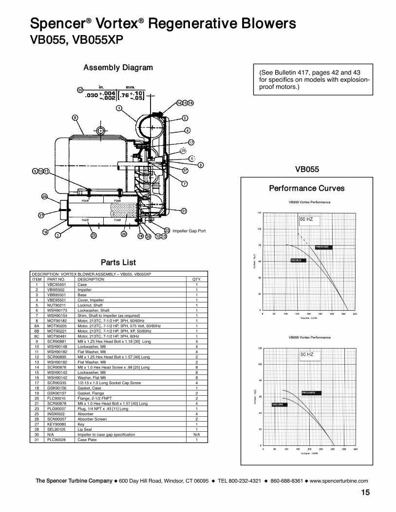
1155
PPeerrffoorrmmaannccee CCuurrvveess
TThhee SSppeenncceerr TTuurrbbiinnee CCoommppaannyy 600 Day Hill Road, Windsor, CT 06095 TEL 800-232-4321 860-688-8361 www.spencerturbine.com
SSppeenncceerr®® VVoorrtteexx®® RReeggeenneerraattiivvee BBlloowweerrssVVBB005555,, VVBB005555XXPP
(See Bulletin 417, pages 42 and 43for specifics on models with explosion-proof motors.)
AAsssseemmbbllyy DDiiaaggrraamm
PPaarrttss LLiissttDESCRIPTION: VORTEX BLOWER ASSEMBLY – VB055, VB055XPITEM PART NO. DESCRIPTION QTY.
1 VBC95501 Case 12 VBI95502 Impeller 13 VBB95501 Base 14 VBE95501 Cover, Impeller 15 NUT90211 Locknut, Shaft 16 WSH90173 Lockwasher, Shaft 17 WSH90154 Shim, Shaft to Impeller (as required) 18 MOT90182 Motor, 213TC, 7-1/2 HP, 3PH, 50/60Hz 1
8A MOT90205 Motor, 213TC, 7-1/2 HP, 3PH, 575 Volt, 50/60Hz 18B MOT90221 Motor, 213TC, 7-1/2 HP, 3PH, XP, 50/60Hz 18C MOT90481 Motor, 213TC, 7-1/2 HP, 3PH, 60Hz 19 SCR90881 M8 x 1.25 Hex Head Bolt x 1.18 [30] Long 4
10 WSH90148 Lockwasher, M8 411 WSH90182 Flat Washer, M8 412 SCR90895 M8 x 1.25 Hex Head Bolt x 1.57 [40] Long 213 WSH90182 Flat Washer, M8 214 SCR90876 M6 x 1.0 Hex Head Screw x .98 [25] Long 815 WSH90143 Lockwasher, M6 816 WSH90142 Washer, Flat M6 817 SCR90335 1/2-13 x 1.0 Long Socket Cap Screw 418 GSK90156 Gasket, Case 119 GSK90157 Gasket, Flange 220 FLC90010 Flange, 2-1/2 FNPT 221 SCR90878 M6 x 1.0 Hex Head Bolt x 1.57 [40] Long 423 PLG90037 Plug, 1/4 NPT x .43 [11] Long 125 INS90022 Absorber 426 SCN90057 Absorber Screen 227 KEY90080 Key 128 SEL90105 Lip Seal 130 N/A Impeller to case gap specification N/A31 PLC90028 Case Plate 1
VVBB005555
Impeller Gap Port
286
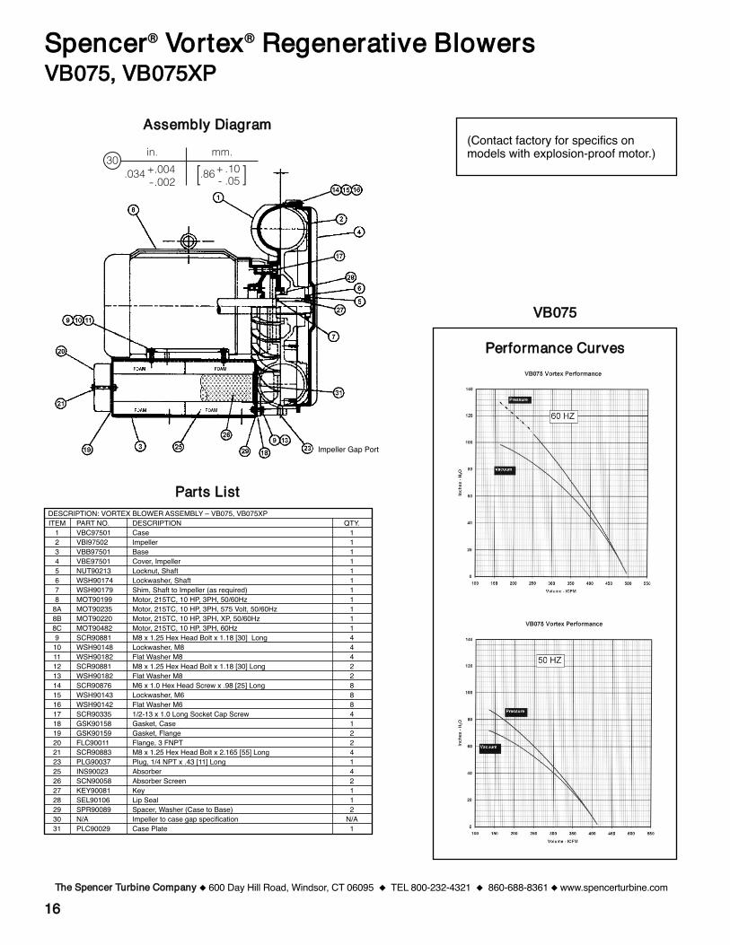
1166
PPeerrffoorrmmaannccee CCuurrvveess
TThhee SSppeenncceerr TTuurrbbiinnee CCoommppaannyy 600 Day Hill Road, Windsor, CT 06095 TEL 800-232-4321 860-688-8361 www.spencerturbine.com
SSppeenncceerr®® VVoorrtteexx®® RReeggeenneerraattiivvee BBlloowweerrssVVBB007755,, VVBB007755XXPP
AAsssseemmbbllyy DDiiaaggrraamm
PPaarrttss LLiissttDESCRIPTION: VORTEX BLOWER ASSEMBLY – VB075, VB075XPITEM PART NO. DESCRIPTION QTY.
1 VBC97501 Case 12 VBI97502 Impeller 13 VBB97501 Base 14 VBE97501 Cover, Impeller 15 NUT90213 Locknut, Shaft 16 WSH90174 Lockwasher, Shaft 17 WSH90179 Shim, Shaft to Impeller (as required) 18 MOT90199 Motor, 215TC, 10 HP, 3PH, 50/60Hz 1
8A MOT90235 Motor, 215TC, 10 HP, 3PH, 575 Volt, 50/60Hz 18B MOT90220 Motor, 215TC, 10 HP, 3PH, XP, 50/60Hz 18C MOT90482 Motor, 215TC, 10 HP, 3PH, 60Hz 19 SCR90881 M8 x 1.25 Hex Head Bolt x 1.18 [30] Long 4
10 WSH90148 Lockwasher, M8 411 WSH90182 Flat Washer M8 412 SCR90881 M8 x 1.25 Hex Head Bolt x 1.18 [30] Long 213 WSH90182 Flat Washer M8 214 SCR90876 M6 x 1.0 Hex Head Screw x .98 [25] Long 815 WSH90143 Lockwasher, M6 816 WSH90142 Flat Washer M6 817 SCR90335 1/2-13 x 1.0 Long Socket Cap Screw 418 GSK90158 Gasket, Case 119 GSK90159 Gasket, Flange 220 FLC90011 Flange, 3 FNPT 221 SCR90883 M8 x 1.25 Hex Head Bolt x 2.165 [55] Long 423 PLG90037 Plug, 1/4 NPT x .43 [11] Long 125 INS90023 Absorber 426 SCN90058 Absorber Screen 227 KEY90081 Key 128 SEL90106 Lip Seal 129 SPR90089 Spacer, Washer (Case to Base) 230 N/A Impeller to case gap specification N/A31 PLC90029 Case Plate 1
VVBB007755
(Contact factory for specifics onmodels with explosion-proof motor.)
Impeller Gap Port
30in. mm.+.004-.002
.86.034 + .10- .05[ ]
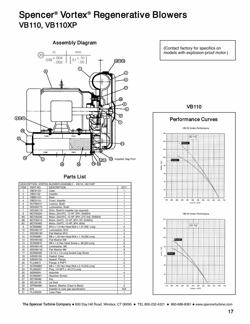
1177
PPeerrffoorrmmaannccee CCuurrvveess
TThhee SSppeenncceerr TTuurrbbiinnee CCoommppaannyy 600 Day Hill Road, Windsor, CT 06095 TEL 800-232-4321 860-688-8361 www.spencerturbine.com
SSppeenncceerr®® VVoorrtteexx®® RReeggeenneerraattiivvee BBlloowweerrssVVBB111100,, VVBB111100XXPP
AAsssseemmbbllyy DDiiaaggrraamm
PPaarrttss LLiissttDESCRIPTION: VORTEX BLOWER ASSEMBLY – VB110, VB110XPITEM PART NO. DESCRIPTION QTY.
1 VBC91101 Case 12 VBI91102 Impeller 13 VBB91101 Base 14 VBE91101 Cover, Impeller 15 NUT90213 Locknut, Shaft 16 WSH90174 Lockwasher, Shaft 17 WSH90179 Shim, Shaft to Impeller (as required) 18 MOT90200 Motor, 254-6TC, 15 HP, 3PH, 50/60Hz 1
8A MOT90236 Motor, 254-6TC, 15 HP, 3PH, 575 Volt, 50/60Hz 18B MOT90219 Motor, 254TC, 15 HP, 3PH, XP, 50/60Hz 18C MOT90483 Motor, 254TC, 15 HP, 3PH, 60Hz 19 SCR90882 M10 x 1.5 Hex Head Bolt x 1.57 [40] Long 4
10 WSH90137 Lockwasher, M10 411 WSH90183 Flat Washer M10 412 SCR90881 M8 x 1.25 Hex Head Bolt x 1.18 [30] Long 213 WSH90182 Flat Washer M8 214 SCR90876 M6 x 1.0 Hex Head Screw x .98 [25] Long 815 WSH90143 Lockwasher, M6 816 WSH90142 Flat Washer M6 817 SCR90335 1/2-13 x 1.0 Long Socket Cap Screw 418 GSK90160 Gasket, Case 119 GSK90159 Gasket, Flange 220 FLC90011 Flange, 3 FNPT 221 SCR90883 M8 x 1.25 Hex Head Bolt x 2.16 [55] Long 423 PLG90037 Plug, 1/4 NPT x .43 [11] Long 125 INS90024 Absorber 426 SCN90061 Absorber Screen 227 KEY90082 Key 128 SEL90106 Lip Seal 129 SPR90089 Spacer, Washer (Case to Base) 230 N/A Impeller to case gap specification N/A31 PLC90030 Case Plate 1
VVBB111100
(Contact factory for specifics onmodels with explosion-proof motor.)
Impeller Gap Port
30in. mm.+.004-.002 [.51 ]+.10
-.05.038
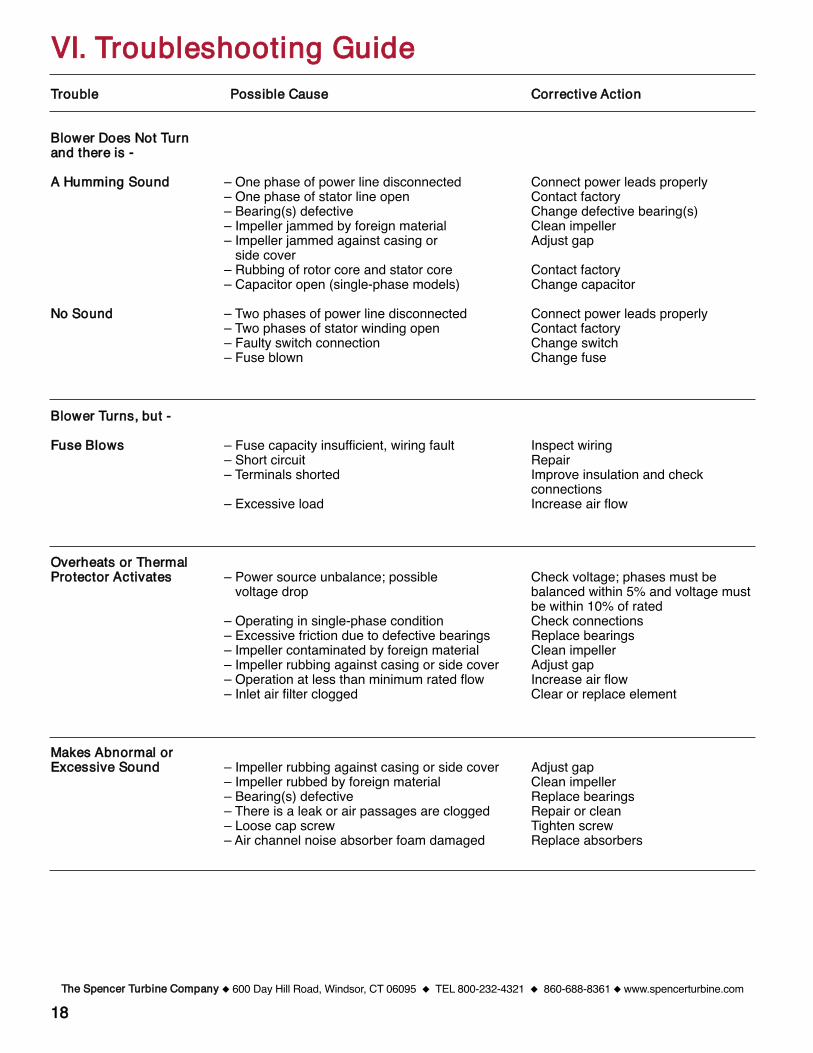
1188
TTrroouubbllee PPoossssiibbllee CCaauussee CCoorrrreeccttiivvee AAccttiioonn
BBlloowweerr DDooeess NNoott TTuurrnn aanndd tthheerree iiss --
AA HHuummmmiinngg SSoouunndd – One phase of power line disconnected Connect power leads properly– One phase of stator line open Contact factory– Bearing(s) defective Change defective bearing(s)– Impeller jammed by foreign material Clean impeller– Impeller jammed against casing or Adjust gap
side cover– Rubbing of rotor core and stator core Contact factory– Capacitor open (single-phase models) Change capacitor
NNoo SSoouunndd – Two phases of power line disconnected Connect power leads properly– Two phases of stator winding open Contact factory– Faulty switch connection Change switch– Fuse blown Change fuse
BBlloowweerr TTuurrnnss,, bbuutt --
FFuussee BBlloowwss – Fuse capacity insufficient, wiring fault Inspect wiring– Short circuit Repair– Terminals shorted Improve insulation and check
connections– Excessive load Increase air flow
OOvveerrhheeaattss oorr TThheerrmmaallPPrrootteeccttoorr AAccttiivvaatteess – Power source unbalance; possible Check voltage; phases must be
voltage drop balanced within 5% and voltage mustbe within 10% of rated
– Operating in single-phase condition Check connections– Excessive friction due to defective bearings Replace bearings– Impeller contaminated by foreign material Clean impeller– Impeller rubbing against casing or side cover Adjust gap– Operation at less than minimum rated flow Increase air flow– Inlet air filter clogged Clear or replace element
MMaakkeess AAbbnnoorrmmaall oorr EExxcceessssiivvee SSoouunndd – Impeller rubbing against casing or side cover Adjust gap
– Impeller rubbed by foreign material Clean impeller– Bearing(s) defective Replace bearings– There is a leak or air passages are clogged Repair or clean– Loose cap screw Tighten screw– Air channel noise absorber foam damaged Replace absorbers
VVII.. TTrroouubblleesshhoooottiinngg GGuuiiddee
TThhee SSppeenncceerr TTuurrbbiinnee CCoommppaannyy 600 Day Hill Road, Windsor, CT 06095 TEL 800-232-4321 860-688-8361 www.spencerturbine.com

CCuussttoommeerr MMaaiinntteennaannccee LLooggDATE PROCEDURE COMMENTS INITIALS
1199TThhee SSppeenncceerr TTuurrbbiinnee CCoommppaannyy 600 Day Hill Road, Windsor, CT 06095 TEL 800-232-4321 860-688-8361 www.spencerturbine.com

Spencer Corporate Headquarters and Manufacturing Plant, Windsor, CT USA
Form ZZ15.1 Copyright ©2012 The Spencer Turbine Company 042312KBA
Blowers & Vacuum Systems with an Engineering EdgeTThhee TTuurrbbiinnee CCoommppaannyy,, 660000 DDaayy HHiillll RRooaadd,, WWiinnddssoorr,, CCTT 0066009955 UUSSAA
TEL 800-232-4321 860-688-8361 FAX 860-688-0098 www.spencerturbine.com
PPrroodduuccttss && SSeerrvviicceess
FFoorr tthhee nnaammee aanndd tteelleepphhoonnee nnuummbbeerr ooff yyoouurr llooccaallSSppeenncceerr RReepprreesseennttaatt iivvee,, ccaall ll 880000--223322--44332211
oorr eemmaaii ll mmaarrkkeettiinngg@@ssppeenncceerr--aaiirr..ccoomm
IInndduussttrriiaallllyy rraatteedd pprroodduuccttss ooffffeerriinnggeeffffeeccttiivvee ssoolluuttiioonnss ffoorr aaiirr aanndd ggaasshhaannddlliinngg pprroobblleemmss::• Multistage centrifugal blowers• Single stage centrifugal blowers• Gas boosters and hermetic gas boosters• Regenerative blowers• Modular central vacuum systems• Mobile or stationary integrated vacuum units• Separators and dust collectors• Custom-engineered products with special
materials for extreme temperatures andpressures
CCoommpplleemmeennttaarryy aacccceessssoorriieess wwiitthh ssiinngglleessoouurrccee ccoonnvveenniieennccee aanndd ccoommppaattiibbiilliittyy::• Standard and custom electrical control panels –
UL, CUL Listed and C.E. Compliant available
• Valves, gauges, couplings, shrink sleeves,vibration isolators and other systemcomponents
• Comprehensive selection of tubing, fittings,vacuum hoses, valves and tools
CCoommpprreehheennssiivvee eennggiinneeeerriinngg aanndd ootthheerrccuussttoommeerr ssuuppppoorrtt sseerrvviicceess::• The industryʼs largest complement of
technical specialists in air and gas handlingtechnology
• Worldwide parts and service organization• Application research and testing facility
WWoorrllddwwiiddee oorrggaanniizzaattiioonn ooff ssaalleess rreepprree--sseennttaattiivveess aanndd ddiissttrriibbuuttoorrss ooffffeerriinngg::• Product selection, installation and operation
assistance• Comprehensive system design services• Follow-up services and troubleshooting
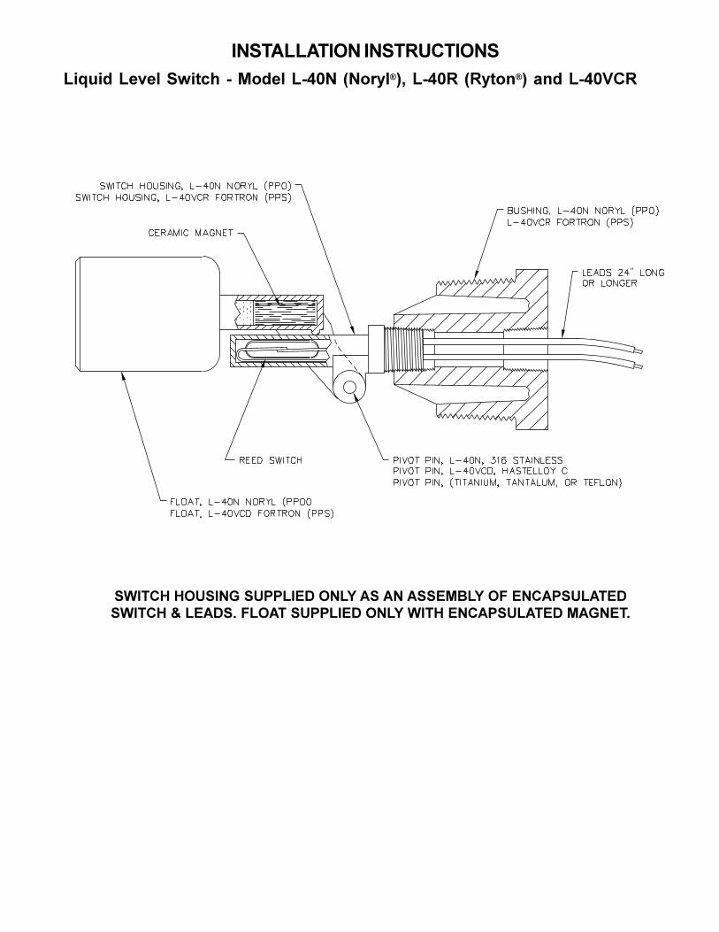
!"#$%&&%$!'"(!"#$)*+$!'"#!"#$"%&!'(')&*+",-.&/&01%')&!/234&54167)!89&!/23:&5:7,1;!8&<;%&!/23=>:
!"#$%&'&()!#*+'!),,-#./'(*-0'1!'1*'1!!.23-0'(4'.*%1,!)-1$./!"#$%&'5'-.1/!6'4-(1$'!),,-#./'(*-0'"#$&'.*%1,!)-1$./'21+*.$6
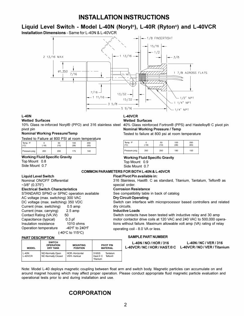
!"#$%&&%$!'"(!"#$)*+$!'"#!"#$"%&!'(')&*+",-.&/&01%')&!/234&54167)!89&!/23:&5:7,1;!8&<;%&!/23=>:
>?:@?:ABC?4
!
!"#$%&&%$'(")*'+,"#'("#!"!#$%&!'()!*"+,-!.!*"+,/01
!"#$%&'((')*+,-./0'1!"#$%&'(($)*+,-./)0*1$2/)3&4$56678$'-1$9!:$(;',-&*(($(;**&<,=/;$<,-%2345/6*&2-7458*9-'11,-':;'3<>*(;*1$;/$?',&@)*$';$A""$6BC$';$)//D$;*D<*)';@)*Temp. oF(oC)
0(-18)
50(10)
100(38)
200(93)
Pressure psig 200 200 175 140
!"#$=>?&'((')*+,-./0'1E"#$%&'(($)*,-./)0*1$?/);)/-4$566B8$'-1$F'(;*&&/34$G$<,=/;$<,-%2345/6*&2-7458*9-'11,-'*:*;'3<>*(;*1$;/$.',&@)*$';$A""$<(,$';$)//D$;*D<*)';@)*
Temp. oF(oC)
0(-18)
50(10)
100(38)
200(93)
Pressure psig 250 250 180 150
&2-7458*@6,4)*+<'04.40*A-/B4(C>/<$H/@-;$$$"IJB,1*$H/@-;$$"IK
&2-7458*@6,4)*+<'04.40*A-/B4(C>/<$H/@-;$$$"IAB,1*$H/@-;$$"IK
>DEED%*9F?FEG;G?+*@D?*HD;I*!"#$%*J*!"#$=>?!4K,4)*!'B'6*+L4(0M2/D,-'&$72L7??$M,..*)*-;,'&N9LAO$5"I9KPO8G6'0(-40/6*+L4(0M*>M/-/0('-41(401B>Q2MQRM$B627$/)$B62G$/<*)';,/-$'=',&'S&*QG$=/&;'T*$5D'UI$(V,;0W,-T8$9""$XQGMG$=/&;'T*$5D'UI$(V,;0W,-T8$9P"$XMGG@))*-;$5D'UI$(V,;0W,-T8$$$$$$"IP$'D<G@))*-;$5D'UI$0'))3,-T8$$$$$$$$YIP$'D<G/-;'0;$R';,-T$5XQZ[8$$$$$$$$P"G'<'0,;'-0*$5;3<,0'&8$$$$$$$$$$$"I9$<.C-(@&';,/-$)*(,(;'-0*$$$$$$$$$$$!"!"$/WD(7<*)';,/-$;*D<*)';@)*$$$$$$$$+E"!?$;/$YE"!?$$$$$$$$$$$$$$$$$$$$$$$$$$$$$$$$$$$$$$$$5+E"!G$;/$!!P!G8
@62/(*94B2(*945*/B/46/N6'*45O9!:$B;',-&*((Z$F'(;4I$G$'($(;'-1')1Z$>,;'-,@DZ$>'-;'&@DZ$>*.&/-4$'((<*0,'&$ /)1*)I>2--21425*?'141(/50'B**$0/D<';,S,&,;3$;'S&*$,-$S'0\$/.$0';'&/TP-C*>4-0,4(*D<'-/(458BV,;0W$0'-$ ,-;*).'0*$V,;W$D,0)/<)/0*((/)$S'(*1$0/-;)/&&*)($'-1$ )*&';*11)3$0,)0@,;(IQ5),0(4B'*!2/)1BV,;0W$0/-;'0;($W'=*$S**-$;*(;*1$V,;W$,-1@0;,=*$)*&'3$'-1$9"$'D<D/;/)$0/-;'0;/)$1),=*$0/,&($';$!Y"$XQG$'-1$YE"$XQG$;/$P""Z"""$/<*)'+;,/-($V,;W/@;$.',&@)*I$H'U,D@D$'&&/V'S&*$=/&;$'D<$5XQ8$)';,-T$/.$)*&'3
/<*)';,-T$0/,&$+$AI"$XQ$/)$&*((I
9F?;*PG+>?Q9;QD%
MODEL
SWITCHOPERATIONDRY TANK
MOUNTING POSITION
PIVOT PINMATERIAL
L-40NL-40VCR
NO-Normally OpenNC-Normally Closed
HOR.-HorizontalVER.-Vertical
316SS TantalumHast.® C Teflon®Titanium
+FE9!G*9F?;*%REHG?
2/;*]$H/1*&$^+E"$1*<&/3($D'T-*;,0$0/@<&,-T$S*;V**-$.&/';$')D$'-1$(V,;0W$S/13I$H'T-*;,0$<');,0&*($0'-$'00@D@&';*$/-$'-1')/@-1$D'T-*;$W/@(,-T$VW,0W$D'3$'..*0;$<)/<*)$/<*)';,/-I$6&*'(*$0/-1@0;$'<<)/<),';*$ .&@,1$D'T-*;,0$<');,0&*$*='&@';,/-$'-1/<*)';,/-'&$ ;*(;($<),/)$ ;/$'-1$1@),-T$ ,-(;'&&';,/-$'-1$@(*I
!"#$%*:*%D*:*ID?*:*STU!"#$=>?*:*%>*:*ID?*:*IF+;VW*>
!"#$%*:*%>*:*=G?*:*STU!"#$=>?*:*%D*:*=G?*:*;4(/54,3
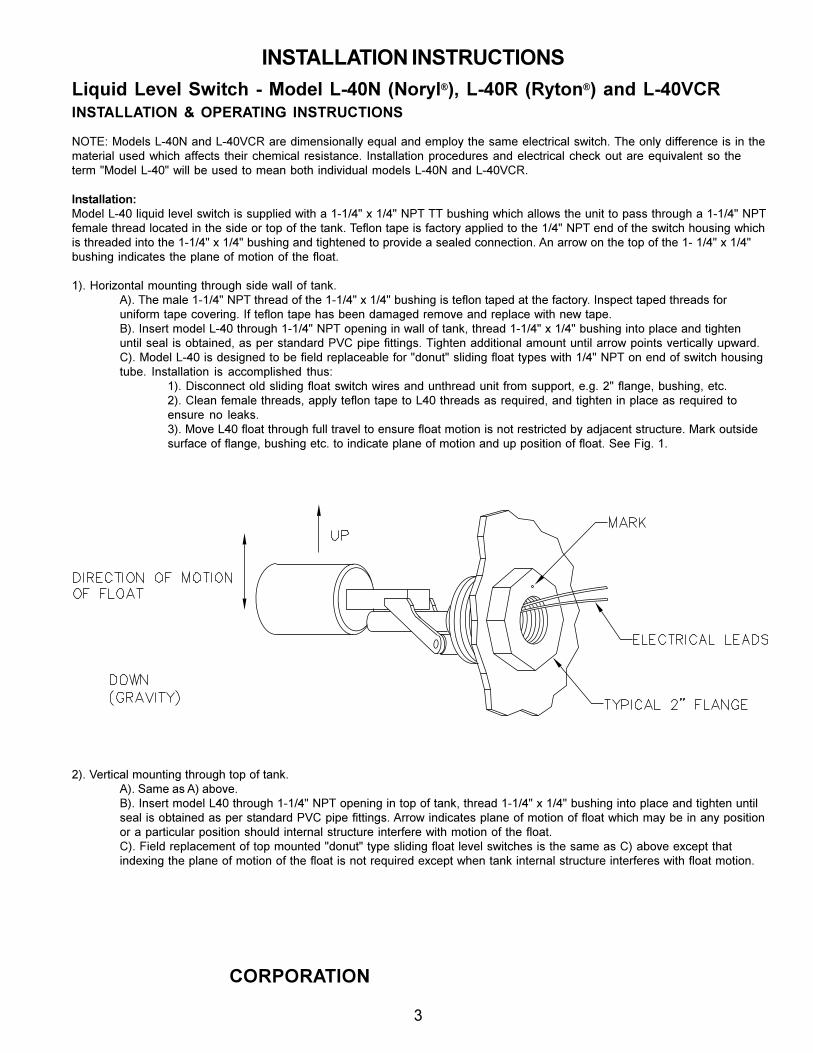
!"#$%&&%$!'"(!"#$)*+$!'"#!"#$"%&!'(')&*+",-.&/&01%')&!/234&54167)!89&!/23:&5:7,1;!8&<;%&!/23=>:
>?:@?:ABC?4
"
!"#$%&&%$!'"( )( '*+,%$!"-( !"#$,./$!'"#
27>_]$H/1*&($^+E"2$'-1$^+E"XGR$')*$1,D*-(,/-'&&3$*`@'&$'-1$*D<&/3$;W*$('D*$*&*0;),0'&$(V,;0WI$>W*$/-&3$1,..*)*-0*$,($,-$;W*D';*),'&$@(*1$VW,0W$'..*0;($ ;W*,)$0W*D,0'&$ )*(,(;'-0*I$ C-(;'&&';,/-$<)/0*1@)*($'-1$*&*0;),0'&$0W*0\$/@;$')*$*`@,='&*-;$(/$ ;W*;*)D$OH/1*&$^+E"O$V,&&$S*$@(*1$;/$D*'-$S/;W$,-1,=,1@'&$D/1*&($^+E"2$'-1$^+E"XGRIa
Q51(/66/(425OXH/1*&$^+E"$&,`@,1$&*=*&$(V,;0W$,($(@<<&,*1$V,;W$'$!+!LEO$U$!LEO$26>$>>$S@(W,-T$VW,0W$'&&/V($;W*$@-,;$;/$<'(($;W)/@TW$'$!+!LEO$26>.*D'&*$;W)*'1$&/0';*1$,-$;W*$(,1*$/)$;/<$/.$;W*$;'-\I$>*.&/-$;'<*$,($.'0;/)3$'<<&,*1$;/$;W*$!LEO$26>$*-1$/.$;W*$(V,;0W$W/@(,-T$VW,0W,($;W)*'1*1$,-;/$;W*$!+!LEO$U$!LEO$S@(W,-T$'-1$;,TW;*-*1$;/$<)/=,1*$'$(*'&*1$0/--*0;,/-I$Q-$'))/V$/-$;W*$;/<$/.$;W*$!+$!LEO$U$!LEOS@(W,-T$,-1,0';*($;W*$<&'-*$/.$D/;,/-$/.$;W*$.&/';Ia
!8I$F/),b/-;'&$D/@-;,-T$;W)/@TW$(,1*$V'&&$/.$;'-\IaQ8I$>W*$D'&*$!+!LEO$26>$;W)*'1$/.$;W*$!+!LEO$U$!LEO$S@(W,-T$,($;*.&/-$;'<*1$';$;W*$.'0;/)3I$C-(<*0;$;'<*1$;W)*'1($./)@-,./)D$;'<*$0/=*),-TI$C.$;*.&/-$;'<*$W'($S**-$1'D'T*1$)*D/=*$'-1$)*<&'0*$V,;W$-*V$;'<*Iac8I$C-(*);$D/1*&$^+E"$;W)/@TW$!+!LEO$26>$/<*-,-T$,-$V'&&$/.$;'-\Z$;W)*'1$!+!LEO$U$!LEO$S@(W,-T$,-;/$<&'0*$'-1$;,TW;*-@-;,&$(*'&$,($/S;',-*1Z$'($<*)$(;'-1')1$6XG$<,<*$.,;;,-T(I$>,TW;*-$'11,;,/-'&$'D/@-;$@-;,&$'))/V$</,-;($=*);,0'&&3$@<V')1IaG8I$H/1*&$^+E"$,($1*(,T-*1$;/$S*$.,*&1$)*<&'0*'S&*$./)$O1/-@;O$(&,1,-T$.&/';$;3<*($V,;W$!LEO$26>$/-$*-1$/.$(V,;0W$W/@(,-T;@S*I$ C-(;'&&';,/-$ ,($ '00/D<&,(W*1$ ;W@(]a
!8I$M,(0/--*0;$/&1$(&,1,-T$.&/';$(V,;0W$V,)*($'-1$@-;W)*'1$@-,;$.)/D$(@<</);Z$*ITI$YO$.&'-T*Z$S@(W,-TZ$*;0IY8I$G&*'-$.*D'&*$;W)*'1(Z$'<<&3$;*.&/-$;'<*$;/$^E"$;W)*'1($'($)*`@,)*1Z$'-1$;,TW;*-$,-$<&'0*$'($)*`@,)*1$;/*-(@)*$-/$ &*'\(Ia98I$H/=*$^E"$.&/';$;W)/@TW$.@&&$;)'=*&$;/$*-(@)*$.&/';$D/;,/-$,($-/;$)*(;),0;*1$S3$'1d'0*-;$(;)@0;@)*I$H')\$/@;(,1*(@).'0*$/.$.&'-T*Z$S@(W,-T$*;0I$;/$,-1,0';*$<&'-*$/.$D/;,/-$'-1$@<$</(,;,/-$/.$.&/';I$B**$?,TI$!Ia
Y8I$X*);,0'&$D/@-;,-T$;W)/@TW$;/<$/.$;'-\IaQ8I$B'D*$'($Q8$'S/=*Iac8I$C-(*);$D/1*&$^E"$;W)/@TW$!+!LEO$26>$/<*-,-T$,-$;/<$/.$;'-\Z$;W)*'1$!+!LEO$U$!LEO$S@(W,-T$,-;/$<&'0*$'-1$;,TW;*-$@-;,&(*'&$,($/S;',-*1$'($<*)$(;'-1')1$6XG$<,<*$.,;;,-T(I$Q))/V$,-1,0';*($<&'-*$/.$D/;,/-$/.$.&/';$VW,0W$D'3$S*$,-$'-3$</(,;,/-/)$'$<');,0@&')$</(,;,/-$(W/@&1$,-;*)-'&$(;)@0;@)*$,-;*).*)*$V,;W$D/;,/-$/.$;W*$.&/';IaG8I$?,*&1$)*<&'0*D*-;$/.$;/<$D/@-;*1$O1/-@;O$;3<*$(&,1,-T$.&/';$&*=*&$(V,;0W*($,($;W*$('D*$'($G8$'S/=*$*U0*<;$;W';,-1*U,-T$;W*$<&'-*$/.$D/;,/-$/.$;W*$.&/';$,($-/;$)*`@,)*1$*U0*<;$VW*-$;'-\$,-;*)-'&$(;)@0;@)*$,-;*).*)*($V,;W$.&/';$D/;,/-Ia
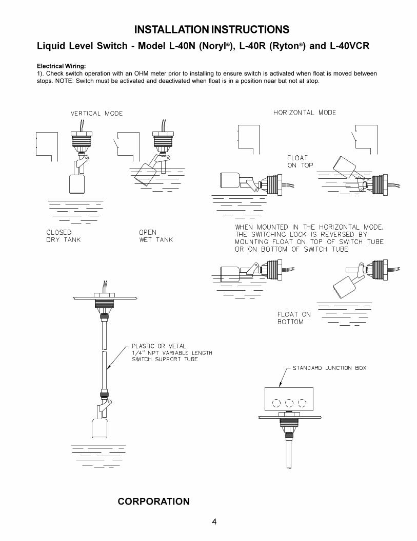
!"#$%&&%$!'"(!"#$)*+$!'"#!"#$"%&!'(')&*+",-.&/&01%')&!/234&54167)!89&!/23:&5:7,1;!8&<;%&!/23=>:
>?:@?:ABC?4
#
G6'0(-40/6*&4-458O!8I$GW*0\$(V,;0W$/<*)';,/-$V,;W$'-$7FH$D*;*)$<),/)$;/$,-(;'&&,-T$;/$*-(@)*$(V,;0W$,($'0;,=';*1$VW*-$.&/';$,($D/=*1$S*;V**-(;/<(I$27>_]$BV,;0W$D@(;$S*$'0;,=';*1$'-1$1*'0;,=';*1$VW*-$.&/';$,($,-$'$</(,;,/-$-*')$S@;$-/;$';$(;/<I
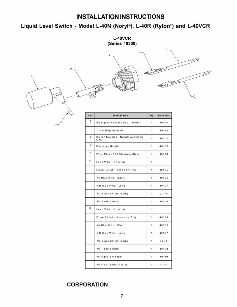
!"#$%&&%$!'"(!"#$)*+$!'"#!"#$"%&!'(')&*+",-.&/&01%')&!/234&54167)!89&!/23:&5:7,1;!8&<;%&!/23=>:
>?:@?:ABC?4
$
&0123/,4#56758(12922:
N o . P a rt N a m e Q ty. P a rt N o .
1 F lo a t (S o n ic a lly W e ld e d ) - N o ryl® 1 4 0 1 0 0
# A M a g ne t Ins id e 1 4 0 11 2
2 S w i tc h H o us ing - N o ryl® A s s e m b lyO n ly 1 4 0 1 0 2
3 B us h ing - N o ryl® 1 4 0 1 0 3
4 P ivo t P ins - 3 1 6 S ta in le s s S te e l 1 4 0 1 0 4
5 L e a d W i re - O p tio na l 1
O p e n S w itc h - A s s e m b ly O nly 1 4 0 1 0 5
# A B lue W ire - S ho rt 1 4 0 1 0 6
# B B lue W ire - L o ng 1 4 0 1 0 7
# C B la c k S hrink Tub ing 1 9 0 1 -F
# D R e e d S w i tc h 1 4 0 1 0 8
6 L e a d W i re - O p tio na l 1
O p e n S w itc h - A s s e m b ly O nly 1 4 0 1 0 9
# A B lue W ire - S ho rt 1 4 0 1 0 6
# B B lue W ire - L o ng 1 4 0 1 0 7
# C B la c k S hrink Tub ing 1 9 0 1 -F
# D R e e d S w i tc h 1 4 0 1 0 8
# E S q ua re M a g ne t 1 4 0 11 0
# F C le a r S hrink Tub ing 1 4 0 111
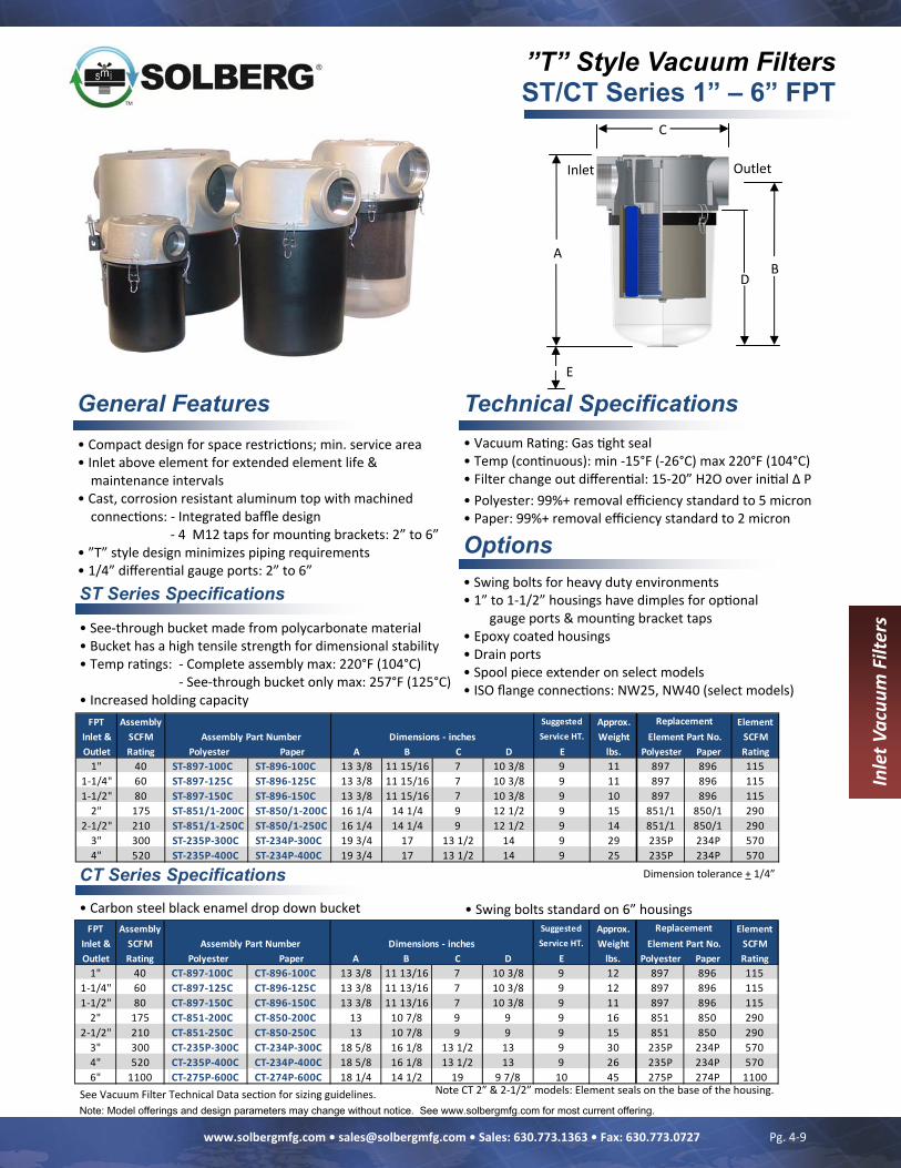
”T” Style Vacuum Filters ST/CT Series 1” – 6” FPT
Note: Model offerings and design parameters may change without notice. See www.solbergmfg.com for most current offering.
General Features
Options
• Vacuum Ra ng: Gas ght seal • Temp (con nuous): min ‐15°F (‐26°C) max 220°F (104°C) • Filter change out differen al: 15‐20” H2O over ini al Δ P • Polyester: 99%+ removal efficiency standard to 5 micron • Paper: 99%+ removal efficiency standard to 2 micron
Technical Specifications
• Swing bolts for heavy duty environments • 1” to 1‐1/2” housings have dimples for op onal
gauge ports & moun ng bracket taps • Epoxy coated housings • Drain ports • Spool piece extender on select models • ISO flange connec ons: NW25, NW40 (select models)
• Compact design for space restric ons; min. service area • Inlet above element for extended element life &
maintenance intervals • Cast, corrosion resistant aluminum top with machined
connec ons: ‐ Integrated baffle design ‐ 4 M12 taps for moun ng brackets: 2” to 6” • ”T” style design minimizes piping requirements • 1/4” differen al gauge ports: 2” to 6”
ST Series Specifications
CT Series Specifications Dimension tolerance + 1/4”
See Vacuum Filter Technical Data sec on for sizing guidelines.
A
C
Outlet Inlet
B
E
D
Inlet V
acuu
m Filters
• Carbon steel black enamel drop down bucket
• See‐through bucket made from polycarbonate material • Bucket has a high tensile strength for dimensional stability • Temp ra ngs: ‐ Complete assembly max: 220°F (104°C) ‐ See‐through bucket only max: 257°F (125°C) • Increased holding capacity
• Swing bolts standard on 6” housings
Pg. 4‐9 www.solbergmfg.com • [email protected] • Sales: 630.773.1363 • Fax: 630.773.0727
FPT Assembly Suggested Approx. ElementInlet & SCFM Service HT. Weight SCFMOutlet Rating Polyester Paper A B C D E lbs. Polyester Paper Rating
1" 40 CT‐897‐100C CT‐896‐100C 13 3/8 11 13/16 7 10 3/8 9 12 897 896 1151‐1/4" 60 CT‐897‐125C CT‐896‐125C 13 3/8 11 13/16 7 10 3/8 9 12 897 896 1151‐1/2" 80 CT‐897‐150C CT‐896‐150C 13 3/8 11 13/16 7 10 3/8 9 11 897 896 115
2" 175 CT‐851‐200C CT‐850‐200C 13 10 7/8 9 9 9 16 851 850 2902‐1/2" 210 CT‐851‐250C CT‐850‐250C 13 10 7/8 9 9 9 15 851 850 290
3" 300 CT‐235P‐300C CT‐234P‐300C 18 5/8 16 1/8 13 1/2 13 9 30 235P 234P 5704" 520 CT‐235P‐400C CT‐234P‐400C 18 5/8 16 1/8 13 1/2 13 9 26 235P 234P 5706" 1100 CT‐275P‐600C CT‐274P‐600C 18 1/4 14 1/2 19 9 7/8 10 45 275P 274P 1100
ReplacementElement Part No.Assembly Part Number Dimensions ‐ inches
Note CT 2” & 2‐1/2” models: Element seals on the base of the housing.
FPT Assembly Suggested Approx. ElementInlet & SCFM Service HT. Weight SCFMOutlet Rating Polyester Paper A B C D E lbs. Polyester Paper Rating
1" 40 ST‐897‐100C ST‐896‐100C 13 3/8 11 15/16 7 10 3/8 9 11 897 896 1151‐1/4" 60 ST‐897‐125C ST‐896‐125C 13 3/8 11 15/16 7 10 3/8 9 11 897 896 1151‐1/2" 80 ST‐897‐150C ST‐896‐150C 13 3/8 11 15/16 7 10 3/8 9 10 897 896 115
2" 175 ST‐851/1‐200C ST‐850/1‐200C 16 1/4 14 1/4 9 12 1/2 9 15 851/1 850/1 2902‐1/2" 210 ST‐851/1‐250C ST‐850/1‐250C 16 1/4 14 1/4 9 12 1/2 9 14 851/1 850/1 290
3" 300 ST‐235P‐300C ST‐234P‐300C 19 3/4 17 13 1/2 14 9 29 235P 234P 5704" 520 ST‐235P‐400C ST‐234P‐400C 19 3/4 17 13 1/2 14 9 25 235P 234P 570
ReplacementAssembly Part Number Element Part No.Dimensions ‐ inches

Installation Instructions Electronic pressure sensor
PX3111 PX322x PX323x PX3244 PX3422 PX911x PX913x
7045
71/0
6
02/2
011

2
1 Safety instructionsPlease read the product description prior to installing the unit. Please check that the product is suitable for your application without any restrictions. If the operating instructions or the technical data are not adhered to, personal injury and/or damage to property may occur. Please check in all applications that the product materials (see Technical data) are compatible with the media to be measured.For gaseous media the application is limited to max. 363 PSI.High-pressure units (5000 PSI) are supplied with a pressure relief mechanism and an integrated damping device to comply with the regulations for UL approval and to avoid any risk of injury in case of bursting when bursting pressure is exceeded.
Any manipulation of the damping device is not permissible.When the damping device is removed, there is no damping function any more. ATTENTION: risk of injury!For units with cULus approval this approval becomes invalid when the damping device is removed.
Contents1 Safety instructions ...............................................................................................22 Function and features ..........................................................................................43 Installation............................................................................................................54 Electrical connection ............................................................................................55 Scale drawing ......................................................................................................66 Technical data ......................................................................................................8

3
For units with cULus approval and the scope of validity cULus:The device shall be supplied from an isolating transformer having a secondary Listed fuse rated as noted in the following table.
Overcurrent protectionControl-circuit wire size Maximum protective device rating
AmpereAWG (mm2)26 (0.13) 124 (0.20) 222 (0.32) 320 (0.52) 518 (0.82) 716 (1.3) 10
The Sensor shall be connected only by using any R/C (CYJV2) cord, having suit-able ratings.

4
2 Function and featuresThe pressure sensor detects the system pressure and converts it into an analog output signal.• 0 to 10 V (PX9xxx)• 10 to 0 V (PX9119) • 4 to 20 mA (PX3xxx)• 20 to 4 mA (PX3229)Applications (type of pressure: relative pressure)
Order no. Measuring range Permissible overload pressure Bursting pressure
PSI PSI PSIPX3220PX9110 0 to 5000 11600 17400
PX3111PX9111 0 to 3000 5800 12300
PX3222PX9112 0 to 1000 4350 9400
PX3223 0 to 500 2175 5075PX3224PX9114 0 to 100 1087 2175
PX3244 0 to 150 1087 2175PX9134 0 to 200 1087 2175PX3226PX9116 0 to 30 290 725
PX3237 0 to 20 145 450PX3227PX9117 0 to 15 145 450
PX3238 0 to 5 145 450PX3229PX9119 -14.5 to 0 (vacuum) 145 450
PX3422 -14.5 to 735.5 4350 9400inH2O inH2O inH2O
PX3228PX9118 0 to 100 4015 12043
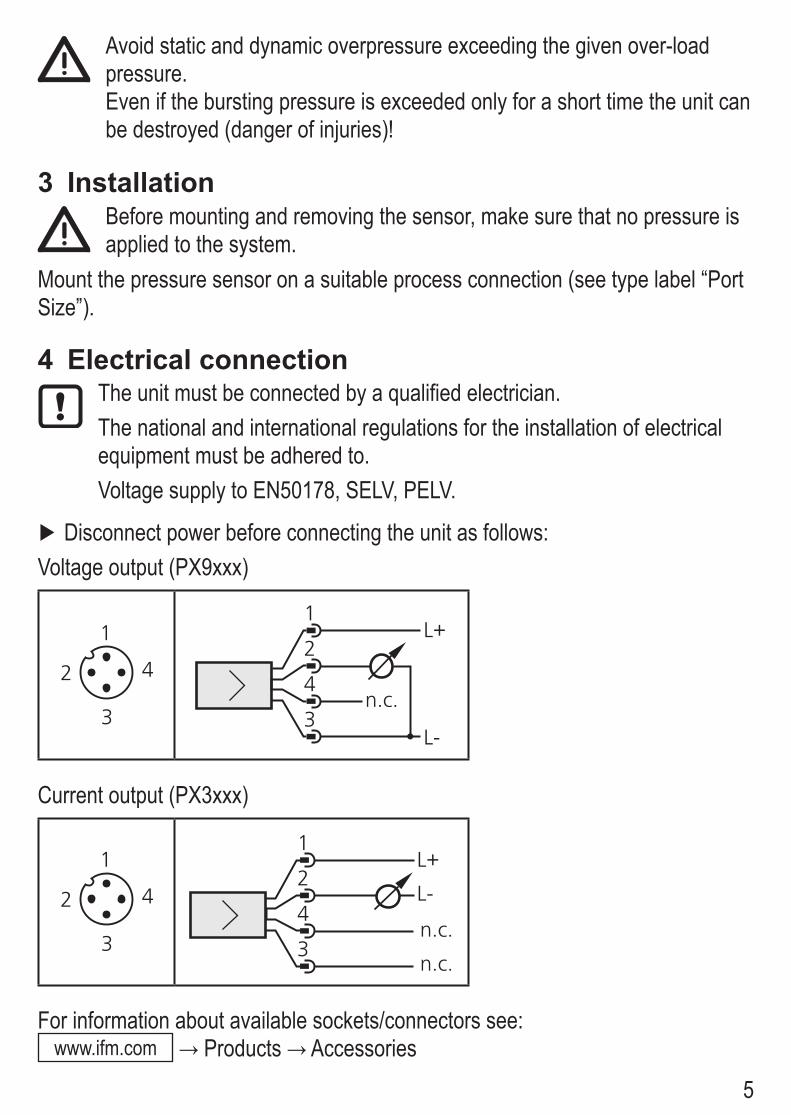
5
Avoid static and dynamic overpressure exceeding the given over-load pressure.Even if the bursting pressure is exceeded only for a short time the unit can be destroyed (danger of injuries)!
3 InstallationBefore mounting and removing the sensor, make sure that no pressure is applied to the system.
Mount the pressure sensor on a suitable process connection (see type label “Port Size”).
4 Electrical connectionThe unit must be connected by a qualified electrician.The national and international regulations for the installation of electrical equipment must be adhered to.Voltage supply to EN50178, SELV, PELV.
Disconnect power before connecting the unit as follows:Voltage output (PX9xxx)
!
"
#$
!"
#
$
%
&
!'
()*)
Current output (PX3xxx)
!
"
#$
!"
#
$
%
&
!'
()*)
()*)
For information about available sockets/connectors see: www.ifm.com → Products → Accessories
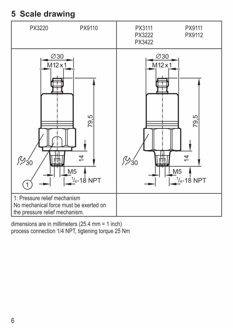
6
5 Scale drawingPX3220 PX9110 PX3111
PX3222PX3422
PX9111PX9112
79,5
M12 x130
30 14
M5-18 NPT1
4/
79,5
M12 x130
30 14
M5-18 NPT1
4/
1: Pressure relief mechanismNo mechanical force must be exerted on the pressure relief mechanism.
dimensions are in millimeters (25.4 mm = 1 inch)process connection 1/4 NPT, tigtening torque 25 Nm

7
PX3223PX3224PX3244PX3226PX3227PX3228PX3229
PX9114PX9116PX9117PX9118PX9119PX9134
PX3237PX3238
79,5
M12 x130
30 14
M5-18 NPT1
4/79
,5
M12 x130
30 14M5
-18 NPT14/
1: Ventilation 1: Ventilation
dimensions are in millimeters (25.4 mm = 1 inch)process connection 1/4 NPT, tigtening torque 25 Nm

8
6 Technical dataPX3xxxOperating voltage [V] .......................................................................................9.6 to 32 DC1)
Analog output ...................................................................................................... 4 to 20 mALoad [Ω] ..............................................................max. (UB - 9,6) x 50; 720 at UB = 24 V DCStep response time analog output [ms] ...............................................................................3PX9xxxOperating voltage [V] ........................................................................................16 to 32 DC1)
Current consumption [mA] ..............................................................................................< 18Analog output ...................................................................................................0 to 10 V DCLoad [Ω] ................................................................................................................min. 2000Step response time analog output [ms] ...............................................................................3Characteristics deviation (in % of full range)
PX3111, PX9111 ............................................................ < ± 0.35 (BFSL) / < ± 0.75 (FR)PX3220, PX3222, PX3223, PX3422, PX9112 ............... < ± 0.35 (BFSL) / < ± 0.75 (FR)PX3224, PX3244, PX9114 ............................................. < ± 0.35 (BFSL) / < ± 0.75 (FR)PX3226, PX9116............................................................ < ± 0.35 (BFSL) / < ± 0.75 (FR)PX3227, PX3237, PX3238, PX9117 ................................ < ± 0.25 (BFSL) / < ± 0.5 (FR)PX3228, PX9118............................................................ < ± 0.35 (BFSL) / < ± 0.75 (FR)PX3229, PX9119.............................................................. < ± 0.25 (BFSL) / < ± 0.5 (FR)PX9110 .......................................................................... < ± 0.35 (BFSL) / < ± 0.75 (FR)PX9134 .......................................................................... < ± 0.35 (BFSL) / < ± 0.75 (FR)
Repeatability (in % of full range)PX3111, PX9111 .................................................................................................... < 0.15PX3220, PX3222, PX3422, PX9112 ...................................................................... < 0.15PX3224, PX3244, PX9114 ..................................................................................... < 0.15PX3226, PX9116.................................................................................................... < 0.15PX3223, PX3227, PX9117 ....................................................................................... < 0.1PX3228, PX9118.................................................................................................... < 0.15PX3229, PX9119...................................................................................................... < 0.1PX3237, PX3238 ................................................................................................... < 0.15PX9110 .................................................................................................................. < 0.15PX9134 .................................................................................................................... < 0.1
1) to EN50178, SELV, PELVBFSL = Best Fit Straight Line / FR = full range

9
Temperature coefficients (TEMPCO) in the compensated temperature range 0 to 80°C (in% of full range/10 °C); greatest TEMPCO of the zero point / of full range
PX3111, PX9111 ................................................................................................. 0.2 / 0.3PX3220, PX3422, PX9110 .................................................................................. 0.3 / 0.4PX3222, PX9112................................................................................................. 0.2 / 0.3PX3223 ............................................................................................................... 0.2 / 0.3PX3224, PX3244, PX9114 .................................................................................. 0.2 / 0.3PX3226, PX9116................................................................................................. 0.2 / 0.3PX3227, PX9117............................................................................................... 0.15 / 0.2PX3228, PX9118................................................................................................. 0.2 / 0.3PX3229, PX9119............................................................................................... 0.15 / 0.2PX3237 ............................................................................................................... 0.2 / 0.4PX3238 ................................................................................................................ 0.3/ 0.5PX9134 ............................................................................................................. 0.15 / 0.2
Housing material............stainless steel (316S12); FPM (Viton); PA; EPDM/X (Santoprene)Materials (wetted parts) .............................stainless steel (303S22); ceramics; FPM (Viton) Operating temperature [°C] .................................................................................. -25 to +80Medium temperature [°C] ..................................................................................... -25 to +90Storage temperature [°C].................................................................................... -40 to +100Protection ......................................................................................................IP 68 / IP 69K2)
Protection ................................................................................................................... IP 673)
Protection ................................................................................................................... IP 654)
Protection class ..................................................................................................................IIIInsulation resistance [MΩ] ........................................................................> 100 (500 V DC)Shock resistance [g] ............................................................... 50 (DIN / IEC 68-2-27, 11ms)Vibration resistance [g] .................................................20 (DIN / IEC 68-2-6, 10 - 2000 Hz)EMCEN 61000-4-2 ESD: .................................................................................... 4 kV / 8 KV ADEN 61000-4-3 HF radiated: ....................................................................................... 30 V/mEN 61000-4-4 Burst: ......................................................................................................2 KVEN 61000-4-6 HF conducted: ........................................................................................ 10 VRadiation of interference: according to the road vehicle guideline 2004/104/EC / CISPR25Noise immunity: .......... according to the road vehicle guideline 2004/104/EC / ISO 11452-2HF conducted: ......................................................................................................... 100 V/mPulse resistance: ..................................................according to ISO7637-2 / severity level 32) for PX3111, PX3220, PX3222, PX3422, PX9110, PX9111, PX9112, 3) for PX3237, PX32384) for PX3223, PX3224, PX3226, PX3227, PX3228, PX3229, PX3244 PX9114, PX9116, PX9117, PX9118, PX9119, PX9134
More information at www.ifm.com
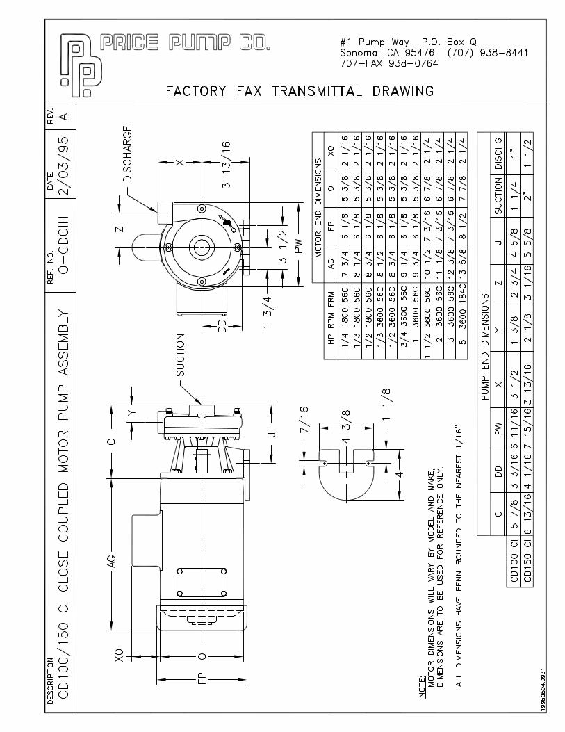
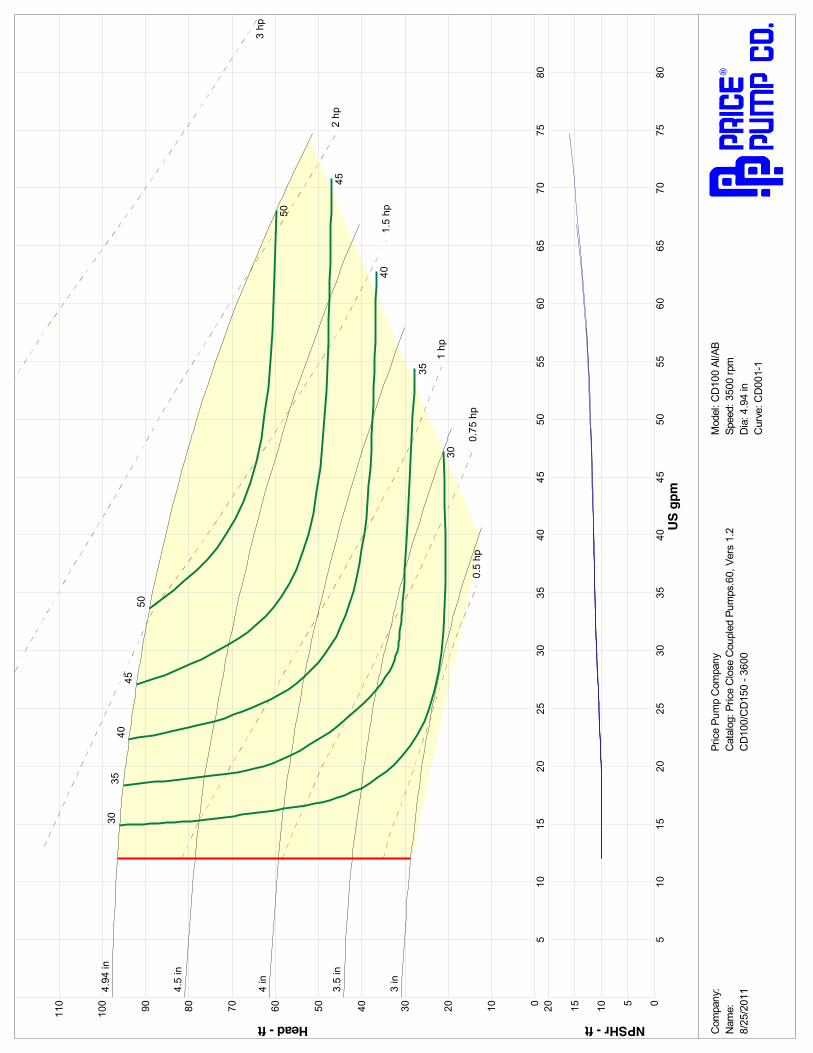
US g
pm
NPSHr - ft
8075
7065
6055
5045
4035
3025
2015
1005
5
101520
Head - ft
8075
7065
6055
5045
010
40
20
35
30
30
4050
25
60
20
70
15
8090
10
100
5
110
4.94
in
4.5
in
4 in
3.5
in
3 in
0.5
hp0.
75 h
p
1 hp
1.5
hp
2 hp
3 hp
30
30
35
35
40
40
45
45
50
50
Com
pany
:Pr
ice
Pum
p C
ompa
nyM
odel
: CD
100
Al/A
BN
ame:
Cat
alog
: Pric
e C
lose
Cou
pled
Pum
ps.6
0, V
ers
1.2
Spee
d: 3
500
rpm
8/25
/201
1C
D10
0/C
D15
0 - 3
600
Dia
: 4.9
4 in
Cur
ve: C
D00
1-1
IN167-CD rev. D
TYPE CD CENTRIFUGAL PUMPS
MODELS: CD 100/150
Price® Pump Company21775 8th. Street EastSonoma, CA 95476Tel: 707-938-8441Fax 707-938-0764Email: [email protected]
PLEASE FILL IN FROM PUMP NAMEPLATE
Pump Model______________________
Spec. No._________________________
Serial No._________________________
RETAIN MANUAL FOR REFERENCE
INSTALLATION, OPERATINGAND MAINTENANCE MANUAL
Price® Pump Co.

IN167-CD rev. DPage - 2
Co n g ratu latio n s Yo u are n o w th e o w n er o f a P rice® Pu m p Co . Cen trifu gal Pu m p . Th is p u m p w a s care fu lly in spe cted an d su b jected to fin a l p e rfo rm an ce te sts b e fo re b e in g rele ased fo r sh ip m e n t. In o rd e r to ach iev e m axim u m p erfo rm an ce a nd reliab ility, p le ase fo llo w th e s im p le in stru ct io n s in th is m a n u al.
R E CO M M E N D E D P R EC A U TIO N S
1 . F o r sa tis fa ct o r y o p e r at io n an d s afe ty , m a x im u m sys te m p r e ssu r e m u st n o t e x ce e d 3 5 0 p s i* (24 .6 k g/ sq cm ).
2 . F o r sa tis fa ct o r y o p e r at io n an d s afe ty , m a x im u m f lu id te m p e ra tu re m u s t n o t e x c ee d 3 0 0 °° F * (1 2 1°° C ) .
3 . N o m o d if ica tio n s, a d d itio n s o r d e let io n s sh o u ld b e m a d e t o th e p u m p w it h o u t p r io r ap p r o va l o f t h e fa ct o ry .
4 . D r a in p u m p c o m p le te ly an d flu sh w it h w a te r b e fo r e se r v icin g a p u m p h a n d lin g v o lat i le o r h ar m fu l l iq u id s .
R E A D C A R E FU L LY T H E C A U T IO N BE L O W
Th e p e rfo rm an c e o f yo u r P rice® Pu m p Co . Cen trif u ga l P u m p is b ase d on cle an , ro o m tem p eratu re , w ater w ith su ctio n co n d it ion s as sh o w n o n th e p e rfo rm an ce cu rv e s. If u sed to p u m p liq u id s oth e r th an w ater, p u m p p erfo rm an ce m ay d iff er fro m rated p erf o rm an ce b ase d o n th e d iffere n t sp ecific grav ity, tem p eratu re, v isco s ity, e tc. o f th e liq u id b ein g p u m p ed . A stan d ard p u m p , h o w e ve r, m ay n o t b e safe f o r p u m p in g all typ e s o f liq u id s , su ch as to xic, v o lat ile o r ch e m ical liq u id s, o r liq u id s u n d er ex tre m e te m p e ratu res o r pre ssu res .
P lease co n su lt P rice® Pu m p Co . te ch n ical sp e cificat io n s as w ell as lo ca l co d e s an d gen e ral re fe re n ces to d ete rm in e th e ap p ro p riate p u m p fo r y o u r p articu lar ap p licat ion . S in ce it is im po ss ib le fo r u s to an ticip ate ev e ry ap p licat io n o f a P rice® Cen trifu gal p um p , if yo u p lan to u se th e p u m p fo r a n o n -w ater ap p licat io n , co n tact Price ® P u m p Co . b e fo reh an d to d ete rm in e w h e th e r su ch ap p lic atio n m ay b e ap p ro p riate an d saf e u n d er th e o p eratin g co nd it io n s. Failu re to d o so co u ld re su lt in p ro p erty d am age o r p erso n al h arm .
* D e p e n d s o n se a l m ate ria ls a n d se a l ty p e
V is it ou r w eb site fo r p rod u ct in fo rm a tio n an d tech n ica l sup p o rt
w w w .p ricep u m p .co m
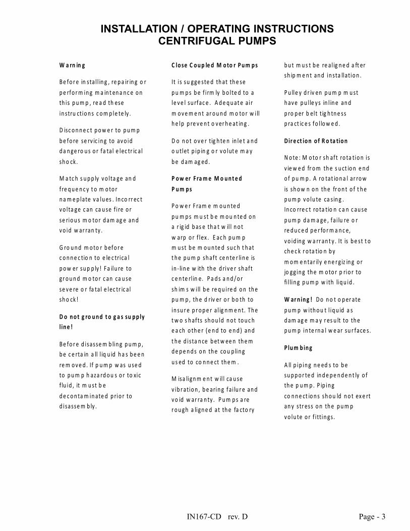
IN167-CD rev. D Page - 3
INSTALLATION / OPERATING INSTRUCTIONSCENTRIFUGAL PUMPS
W a rn in g
B e fo r e in sta l l in g , re p a ir in g o r p e rfo r m in g m a in t en a n c e o n th is p u m p , re a d th ese in stru ctio n s c o m p le te ly .
D isc o n n e c t p o w e r to p u m p b e fo re se rv ic in g to av o id d a n ge ro u s o r fa ta l e lec tr ic a l sh o ck .
M a tc h s u p p ly v o l ta ge an d f re q u e n c y t o m o to r n a m e p late v a lu es . In co rr ec t v o l ta ge c an ca u se f i re o r se rio u s m o to r d am ag e an d v o id w ar ran ty .
G ro u n d m o to r b efo r e c o n n e c tio n to e le c trica l p o w er su p p ly ! F a ilu re to g r o u n d m o to r c an ca u se se v e re o r fa ta l e lec tr ic a l sh o ck !
D o n o t g ro u n d t o g a s su p p ly l in e !
B e fo r e d isasse m b lin g p u m p , b e c e rta in a ll l iq u id h a s b e e n re m o v e d . If p u m p w as u se d to p u m p h aza rd o u s o r to xic f lu id , it m u st b e d e c o n ta m in ate d p rio r to d isasse m b ly .
C lo se C o u p le d M o to r P u m p s
It i s su gge ste d th at th e se p u m p s b e f i rm ly b o l te d to a le v e l su rfac e . A d e q u at e a i r m o v e m e n t ar o u n d m o to r w i ll h e lp p re v e n t o v er h e at in g .
D o n o t o v e r tig h te n in le t a n d o u tlet p ip in g o r v o lut e m a y b e d am ag ed .
P o w er F ra m e M o u n t e d
P u m p s
P o w e r F ram e m o u n te d p u m p s m u st b e m o u n te d o n a r ig id b as e th a t w il l n o t w arp o r f lex . E ac h p u m p m u st b e m o u n te d su c h t h at t h e p u m p sh af t ce n te r lin e is in - lin e w ith th e d riv e r sh af t c e n te rl in e. P a d s a n d / o r sh im s w i ll b e re q u ire d o n th e p u m p , th e d riv er o r b o th to in su r e p r o p e r a l ig n m e n t. Th e t w o s h af ts sh o u ld n o t to u c h e a ch o th e r ( e n d to e n d ) an d t h e d is ta n ce b et w ee n th e m d e p e n d s o n th e co u p lin g u s ed to co n n e ct th e m .
M isa lign m e n t w il l ca u se v ib r atio n , b e arin g fa i lu r e an d v o id w ar ra n ty . P u m p s a re r o u gh a lign e d at th e fa cto ry
b u t m u s t b e re a l ig n e d a ft er sh ip m e n t an d in sta llatio n .
P u lle y d r iv en p u m p m u st h av e p u l le y s in l in e an d p ro p er b el t t ig h tn e ss p ra ct ic e s fo l lo w e d .
D ir e ct io n o f R o ta tio n
N o te : M o to r sh af t ro ta tio n i s v ie w e d fr o m th e s u ct io n e n d o f p u m p . A ro tat io n a l ar ro w is sh o w n o n th e fr o n t o f t h e p u m p v o lu te ca s in g . In co rre c t ro ta tio n c a n c au se p u m p d a m a ge , fa i lu re o r re d u c e d p e r fo r m a n c e, v o id in g w a rr an t y . It is b e st t o ch e c k r o ta tio n b y m o m e n tar ily e n e r g iz in g o r jo gg in g th e m o to r p rio r to fi l lin g p u m p w ith liq u id .
W ar n in g ! D o n o t o p er ate p u m p w ith o u t l iq u id a s d am ag e m a y r es u lt to th e p u m p in te rn a l w e ar su r face s .
P lu m b in g
A ll p ip in g n e ed s to b e su p p o r te d in d e p e n d e n t ly o f th e p u m p . P ip in g co n n e ct io n s sh o u ld n o t ex e rt an y s tr ess o n th e p u m p v o lu te o r f i ttin gs .
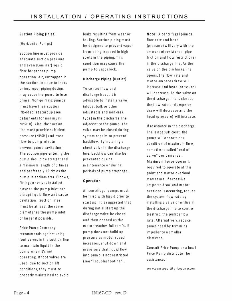
IN167-CD rev. DPage - 4
I N S T A L L A T I O N / O P E R A T I N G I N S T R U C T I O N S
Su ct io n P ip in g ( In le t )
(H o rizo n t a l P u m p s)
S u c tio n lin e m u st p ro v id e ad eq u ate su ct io n p r es su re an d e v e n (L am in a r) liq u id f lo w fo r p r o p e r p u m p o p e r atio n . A ir , e n tr ap p e d in th e su c tio n l in e d u e to le ak s o r im p r o p e r p ip in g d e s ign , m ay ca u se th e p u m p to lo se p r im e. N o n -p r im in g p u m p s m u st h av e t h e ir su c tio n ‘f lo o d e d ’ a t s t ar t u p ( see d a tash ee ts fo r m in im u m N P S H R ) . A lso , th e s u ct io n l in e m u st p r o v id e su f f ic ie n t p r ess u re ( N P S H ) a n d ev e n f lo w to p u m p in le t to p r ev e n t p u m p cav ita tio n . T h e su c tio n p ip e en te rin g t h e p u m p sh o u ld b e s tr a igh t an d a m in im u m le n gth o f 5 tim e s an d p r e fe r ab ly 1 0 tim e s th e p u m p in le t d iam e te r. E lb o w s, f it tin gs o r v a lv es in sta l led c lo s e to th e p u m p in le t ca n d is ru p t l iq u id f lo w a n d c a u se c av i tat io n . S u ct io n l in e s m u st b e at lea st th e sa m e d iam et er a s t h e p u m p in let o r lar ge r if p o ss ib le .
P r ic e P u m p C o m p a n y re c o m m e n d s aga in st u s in g fo o t v a lv e s in th e su c tio n lin e to m a in ta in liq u id in th e p u m p w h e n i t’s n o t o p e r atin g . If fo o t v a lv e s a re u se d , d u e to su c tio n li ft c o n d itio n s , t h ey m u st be p r o p e rly m ain ta in e d to av o id
le ak s re su l tin g fr o m w e ar o r fo u lin g . S u ct io n p ip in g m u st b e d e s ig n e d to p r ev en t v a p o r f ro m b e in g tr ap p ed in h igh sp o ts in th e p ip in g . T h is c o n d itio n m a y c au se th e p u m p to v ap o r lo c k .
D isc h a rg e P ip in g (O u t le t )
T o co n tro l flo w an d d isc h ar ge h ea d , i t is a d v isab le to in sta ll a v a lv e ( g lo b e , b a l l, o r o th e r a d ju sta b le an d n o n -lea k t y p e ) in th e d isc h a rge lin e a d jac e n t t o t h e p u m p . T h e v a lv e m a y b e clo se d d u rin g sy ste m r e p airs to p re v e n t b a c k flo w . B y in s ta l lin g a c h e ck v a lv e in th e d isc h ar ge l in e, b ac k f lo w c an a lso b e p r e v e n te d d u rin g m ain te n a n ce o r d u rin g p e r io d s o f p u m p sto p p ag e.
O p e r at io n
A l l c en tri fu ga l p u m p s m u st b e f il le d w it h l iq u id p rio r to s t ar t u p . It i s s u gge ste d th at d u rin g in i tia l s t art u p th e d isc h ar ge v a lv e b e c lo s ed a n d th e n o p e n e d a s th e m o to r r e ac h es fu l l rp m ’s . If p u m p d o e s n o t b u ild u p p r e ssu re as m o t o r sp e ed in c re ase s , sh u t d o w n an d m ak e su re t h at l iq u id f lo w in to p u m p is n o t re str ic te d ( se e “ Tr o u b le sh o o tin g” ) .
N o t e : A c e n tri fu ga l p u m p s flo w ra te a n d h ea d (p re ssu r e) w il l v ar y w ith th e am o u n t o f r e s is ta n c e (p ip e fr ic tio n an d f lo w r est rictio n s) in th e d isc h a rge lin e . A s th e v a lv e o n th e d isc h a rge lin e o p e n s , t h e f lo w r ate an d m o t o r am p er e s d r aw w i ll in c re a se a n d h e a d ( p r essu re ) w il l d e c re ase . A s th e v a lv e o n th e d isc h ar ge l in e is c lo se d , th e f lo w rat e an d a m p e re s d ra w w il l d e cr ea se a n d t h e h e ad (p re ssu r e) w il l in cr ea se .
If re s is ta n ce in th e d isc h ar ge lin e i s n o t su f ficie n t, th e p u m p w i ll o p e ra te at a co n d it io n o f m ax im u m f lo w , so m e tim e s ca lle d " en d o f cu r v e " p er fo rm an c e. M a xim u m h o rse -p o w e r is re q u ire d to o p e ra te at th is p o in t an d m o t o r o v e rlo ad m a y r esu lt. If e xc e ss iv e am p e re s d r aw an d m o to r o v e rlo ad i s o c c u rr in g , re d u c e th e s ys tem flo w rat e b y in st a l lin g a v a lv e o r o ri fi ce in th e d isc h ar ge l in e to co n tro l (r e strict ) th e p u m p s f lo w ra te . A l ter n at iv e ly , re d u ce p u m p h e a d b y tr im m in g im p e lle r t o a sm al le r d ia m e te r.
C o n s u lt P ric e P u m p o r a lo ca l P rice P u m p d is trib u to r fo r ass is ta n ce .
w w w .a p p sup po r t@ p ric ep um p.c o m
IN167-CD rev. D Page - 5
T R O U B L E S H O O T I N G
1 . P u m p fai ls to b u ild h e a d p r e ssu re :
C h e c k fo r :
a . P u m p n o t p r im e d .
b . In co rre c t p u m p ro tatio n .
c . D riv er s p ee d to o lo w .
d . S u ct io n l in e re str ic te d .
e . D riv e r fa ilu re .
f . P lu gg ed o r d a m a ge d im p e l le r.
g . P u m p o r im p e l le r u n d e r s ize d .
h . P u m p c av i tatio n .
i . Im p ro p e r im p e l le r c le ar an c e .
2 . P u m p fai ls to p r o v id e e n o u gh f lo w r a te .
C h e c k fo r :
a . S y st em r es is ta n ce to o h igh .
b . P u m p u n d er s ize d .
c . P u m p n o t p rim e d .
d . D r iv e r sp e e d to o lo w .
e . P o o r su c tio n c o n d itio n s .
f . Im p ro pe r im p e l le r c le ar an c e .
3 . E x ce ss iv e n o is e o r v ib r atio n d u r in g o p e r at io n .
C h e ck fo r:
a . M o to r b e a rin g fa il in g .
b . P u m p c av i ta tio n .
c . Im p ro p er im p el le r c le a ra n ce .
4 . L ea kin g m e c h a n ica l se a l.
C h e ck fo r:
a . Im p ro p er a sse m b ly .
b . W o r n o r c ra ck e d se a l fa ce s .
c . A b ras iv e m ate r ia l in f lu id .
d . L iq u id flash in g a t s ea l fa ce s (F lu id t em p e ra tu re to o h igh ) .
e . S e a l p r essu re r atin g to o lo w fo r th e se r v ic e.
f . C h e m ica l at tac k o f se a l c o m p o n e n ts .
g . S e a l o p e ra te d d r y o r w ith a l iq u id h a v in g p o o r lu b rica tin g p r o p e r tie s .
5 . P u m p g ra d u ally lo se s p r es su r e a n d h e a d .
C h e c k fo r:
a . In cr ea s in g tem p e ra tu re ca u s in g ca v it atio n o r liq u id v ap o rizatio n .
b . D riv e r fa ilu r e.
c. S u c tio n l i ft to o h ig h .
d . A i r e n te rin g su ct io n l in e .
6 . M o t o r o v e rh e a tin g .
C h e c k fo r:
a . Ex c ess iv e f lo w a n d am p d ra w (T h ro t tle d is ch a rge ) .
b . L o w v o l tage o r f re q u e n cy .
c. F lo w r ate to o lo w w ith re su l tin g h ea t ri se.
d . B e arin g fa i lu r e .
e. S y ste m te m p er atu re to o h ig h .
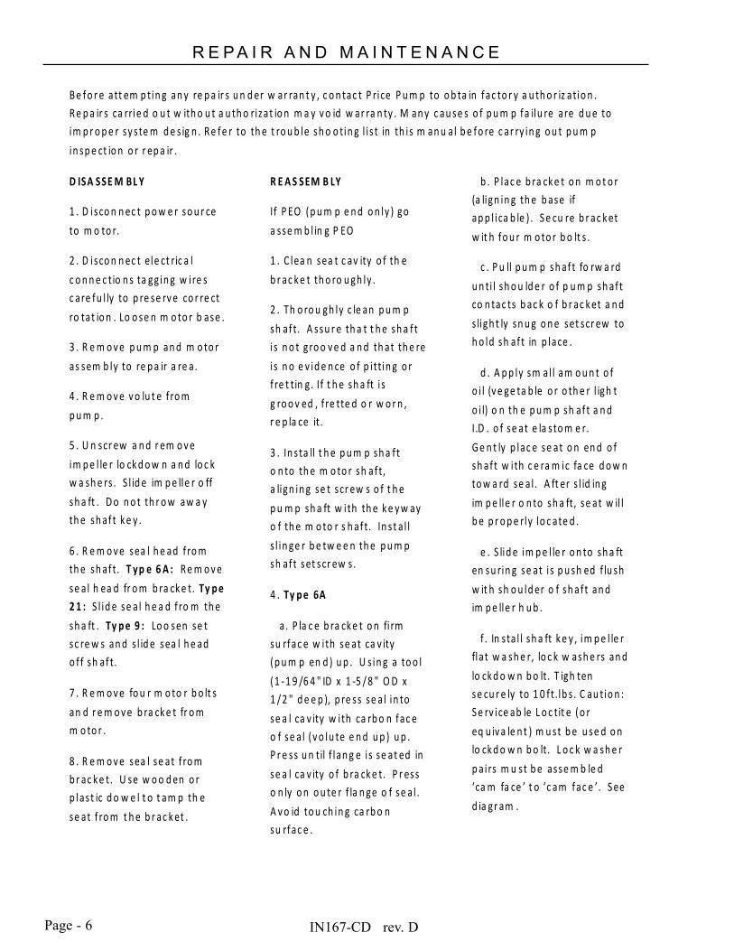
Page - 6
R E P A I R A N D M A I N T E N A N C E
B e fo r e att em p tin g an y re p a ir s u n d er w ar ran t y , c o n tac t P rice P u m p to o b ta in fac to r y a u th o r iz atio n . R e p a ir s ca rrie d o u t w ith o u t a u th o rizat io n m a y v o id w ar ra n ty . M an y c au se s o f p u m p fa ilu re are d u e to im p r o p e r sy ste m d e s ig n . R e fe r to th e t ro u b le sh o o tin g l i s t in th is m an u al b e fo re c ar ry in g o u t p u m p in sp e ct io n o r r ep a ir .
D ISA SSE M BL Y
1 . D isco n n ec t p o w e r so u r ce to m o to r.
2 . D isco n n ec t ele ct ric a l c o n n e c tio n s ta gg in g w ire s c are fu l ly to p re se rv e co r re ct ro tat io n . Lo o se n m o to r b ase .
3 . R e m o v e p u m p an d m o to r as sem b ly to re p a ir a re a.
4 . R e m o v e v o lu t e f ro m p u m p .
5 . U n scr ew a n d r em o v e im p e l le r lo ck d o w n a n d lo c k w a sh e rs . S l id e im p e lle r o ff sh a ft . D o n o t th r o w aw a y th e sh af t k e y .
6 . R e m o v e sea l h e ad f ro m th e sh af t. T yp e 6 A : R e m o v e se a l h ea d fr o m b ra ck e t. Ty p e 2 1 : S l id e se a l h e a d f ro m th e sh a ft . Ty p e 9 : Lo o sen se t sc re w s an d s l id e sea l h e ad o f f sh af t.
7 . R e m o v e fo u r m o to r b o lt s an d r e m o v e b ra ck e t fr o m m o to r .
8 . R e m o v e sea l se at f ro m b r ac k e t. U se w o o d en o r p last ic d o w e l t o t am p th e se at f ro m t h e b r ac k et .
R E A S SEM B LY
If P EO ( p u m p e n d o n ly ) go a sse m b l in g P EO
1 . C lea n sea t c av ity o f th e b r ac k e t th o ro u gh ly .
2 . Th o ro u gh ly c le an p u m p sh af t. A ssu r e th a t t h e sh a f t i s n o t g ro o v e d a n d th at th e re i s n o e v id e n ce o f p i ttin g o r f re t tin g . If t h e sh a ft i s g ro o v ed , f re tte d o r w o r n , r e p la ce it.
3 . In sta ll t h e p u m p sh a f t o n to th e m o to r sh af t, a lign in g se t scr ew s o f t h e p u m p sh a ft w ith th e k e y w ay o f th e m o to r s h af t. In s t a l l s l in ge r b e tw e e n th e p u m p sh af t set scr ew s.
4 . Ty p e 6A
a . P la c e b ra ck e t o n fi rm su rfac e w ith se at ca v ity ( p u m p en d ) u p . U s in g a to o l ( 1 -1 9 /6 4 " ID x 1 -5 / 8 " O D x 1 / 2 " d e e p ), p re ss se a l in to se a l ca v ity w ith ca rb o n fac e o f se a l ( v o lu te e n d u p ) u p . P r e ss u n til f lan g e i s se at ed in se a l ca v ity o f b ra ck e t. P r ess o n ly o n o u te r f la n ge o f se a l . A v o id to u ch in g ca rb o n su rfac e .
b . P lac e b ra ck e t o n m o t o r (a lign in g th e b ase if ap p l ica b le ) . S e cu re b r ac k et w it h fo u r m o to r b o lt s .
c . P u ll p u m p sh af t fo rw a rd u n ti l sh o u ld e r o f p u m p sh af t co n tac ts b ac k o f b r ac k et a n d s ligh t ly sn u g o n e set scr ew to h o ld sh af t in p lace .
d . A p p ly sm al l am o u n t o f o i l (v e ge ta b le o r o th e r l igh t o i l) o n th e p u m p sh af t a n d I.D . o f se at e la sto m e r. G e n t ly p lac e se at o n en d o f sh af t w ith c e ra m ic fa ce d o w n to w a rd se a l . A ft er s l id in g im p e lle r o n to sh a ft, se at w il l b e p r o p e rly lo c ate d .
e . S lid e im p e l le r o n to sh a ft en su rin g se at i s p u sh ed f lu sh w it h sh o u ld er o f sh af t an d im p e lle r h u b .
f . In s ta l l sh a ft k e y , im p e l le r fla t w a sh e r, lo c k w ash e rs an d lo ck d o w n b o lt. T igh ten se cu r e ly to 1 0 f t.lb s . C au tio n : S e rv ice ab le L o c tit e (o r eq u iv a le n t ) m u st b e u se d o n lo ck d o w n b o lt. L o c k w a sh e r p a irs m u st b e asse m b le d ‘ca m fa ce ’ t o ‘c am fac e ’. S ee d ia gr am .
IN167-CD rev. D
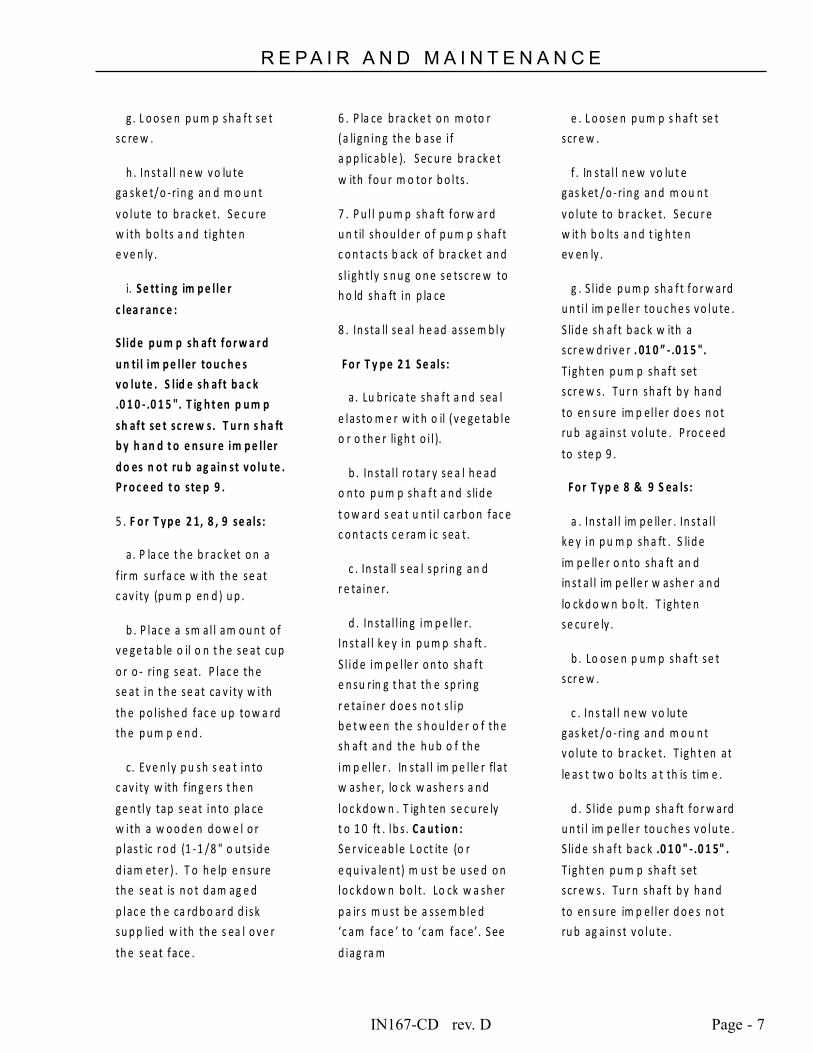
IN167-CD rev. D Page - 7
R E P A I R A N D M A I N T E N A N C E
g . L o o se n p u m p sh a f t se t sc re w .
h . In s t a l l n e w v o lu te ga sk e t/ o - rin g an d m o u n t v o lu te to b ra ck e t. S e c u re w ith b o l ts a n d tigh te n e v e n ly .
i. Se tt in g im p e lle r
c lea r an c e :
S lid e p u m p sh aft fo r w a r d
u n ti l im p e ller to u c h e s vo lu te . S l id e sh aft b a c k .0 1 0 - .0 1 5 ". T ig h t en p u m p
sh aft se t sc re w s. T u r n s h a ft b y h an d t o e n su r e im p e ller
d o es n o t ru b ag ain st vo lu te . P r o c e ed t o ste p 9 .
5 . F o r T yp e 2 1, 8 , 9 se als :
a . P la ce t h e b r ac k et o n a f ir m su rfa ce w ith th e se at c av i ty (p u m p en d ) u p .
b . P lac e a sm al l am o u n t o f v e ge ta b le o il o n t h e se at cu p o r o - rin g se at. P lac e th e se at in t h e se at ca v i ty w ith th e p o l ish e d fac e u p to w a rd th e p u m p e n d .
c. Ev e n ly p u sh s ea t in to c av i ty w ith f in g e rs t h e n ge n tly tap se at in to p la ce w ith a w o o d e n d o w e l o r p last ic r o d (1 -1 / 8 " o u ts id e d iam et er ) . T o h e lp e n su re th e se at is n o t d am ag e d p lac e th e ca rd b o ar d d isk su p p lied w ith th e s ea l o v e r th e se at face .
6 . P la ce b ra ck e t o n m o to r (a lign in g th e b ase i f a p p l ic ab le ). S ec u re b ra ck e t w ith fo u r m o to r b o l ts .
7 . P u l l p u m p sh a ft fo rw ar d u n til sh o u ld e r o f p u m p s h af t c o n t ac ts b ack o f b ra ck e t an d s l igh tly s n u g o n e se tsc re w to h o ld sh a ft in p la ce
8 . In sta ll se a l h e ad asse m b ly
F o r T y p e 2 1 Se als :
a . Lu b rica te sh a f t a n d sea l e lasto m e r w it h o il ( v e ge tab le o r o th e r ligh t o i l ).
b . In sta l l ro tar y se a l h e ad o n to p u m p sh a f t a n d s lid e t o w ar d s ea t u n ti l ca rb o n fac e c o n t ac ts c e ram ic sea t.
c . In s ta ll s ea l sp rin g an d r e ta in e r.
d . In s ta l l in g im p e l le r. In s t a l l k e y in p u m p sh a ft . S l id e im p e l le r o n to sh a f t e n su rin g t h at th e sp rin g r e ta in e r d o e s n o t s l ip b e t w ee n th e s h o u ld e r o f th e sh af t an d th e h u b o f th e im p el le r . In s ta l l im p e l le r flat w ash e r, lo ck w ash e r s a n d lo c k d o w n . T igh ten se c u re ly t o 1 0 ft . lb s . C a u t io n : S e r v ic e ab le L o ct ite (o r e q u iv a le n t) m u st b e u se d o n lo c k d o w n b o lt. Lo ck w a sh er p a ir s m u st b e a sse m b le d ‘c am fac e ’ to ‘c am fac e’. S ee d iag ra m
e . L o o se n p u m p s h af t se t scr e w .
f . In s ta l l n e w v o lu t e gas k et /o - rin g an d m o u n t v o lu te to b r ac k e t. S e cu r e w it h b o lts a n d t ig h te n ev en ly .
g . S l id e p u m p sh a f t fo r w ard u n ti l im p e lle r to u c h e s v o lu te . S lid e sh af t b ac k w ith a scr e w d riv e r . 01 0 ” - .0 1 5 ". T igh t en p u m p sh af t set scr e w s. Tu r n sh af t b y h an d to en su re im p el ler d o e s n o t ru b ag a in st v o lu te . P ro c e ed to s te p 9 .
F o r T yp e 8 & 9 S ea ls :
a . In st a l l im p e ller . In st a l l k e y in p u m p sh a ft . S lid e im p e lle r o n to sh a ft an d in st a l l im p e lle r w ash e r a n d lo ck d o w n b o lt. T igh te n se cu r e ly .
b . Lo o se n p u m p sh aft se t scr e w .
c . In s ta l l n e w v o lu te gas k et /o - rin g an d m o u n t v o lu te to b r ac k e t. T igh t en at le as t tw o b o lts a t th is t im e .
d . S l id e p u m p sh a ft fo r w ard u n ti l im p e lle r to u c h e s v o lu te . S lid e sh af t b ac k .0 1 0 " - .0 1 5" . T igh t en p u m p sh af t set scr e w s. Tu r n sh af t b y h an d to en su re im p el ler d o e s n o t ru b ag a in st v o lu te .
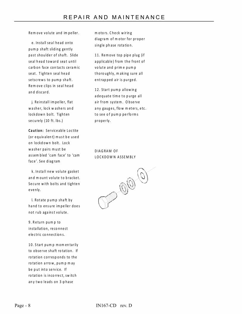
IN167-CD rev. DPage - 8
R E P A I R A N D M A I N T E N A N C E
R e m o v e v o lu te an d im p e ller .
e. In sta ll se a l h e ad o n to p u m p sh af t s lid in g ge n tly p a st sh o u ld e r o f sh a ft . S lid e se a l h ea d t o w ar d sea t u n ti l c arb o n fa ce co n tac ts ce ra m ic se at . T igh te n se a l h e a d se tsc re w s to p u m p sh a ft . R e m o v e c lip s in se a l h e a d an d d isc ar d .
j. R e in sta l l im p e l le r, flat w a sh e r, lo c k w ash e rs an d lo ck d o w n b o lt. T igh t en se c u re ly (10 f t. lb s .)
C a u t io n : S er v ic e ab le L o c tite ( o r e q u iv a len t) m u s t b e u se d o n lo ck d o w n b o lt . Lo c k w a sh e r p a i rs m u st b e as sem b led ‘c am fac e’ to ‘cam fac e ’. S e e d iag ram
k . In sta l l n e w v o lu te gask e t an d m o u n t v o lu te t o b rac k e t. S e c u re w ith b o l ts an d tigh te n e v e n ly .
l. R o t ate p u m p sh a ft b y h a n d t o en s u re im p e l le r d o e s n o t r u b aga in s t v o lu te .
9 . R e tu rn p u m p to in sta llatio n , re co n n e ct e le c tric co n n e ct io n s .
1 0 . S tart p u m p m o m en tar ily to o b se r v e sh a ft ro tatio n . If ro tat io n c o rr esp o n d s to th e ro tat io n a rro w , p u m p m ay b e p u t in t o se rv ic e. If ro tat io n i s in co rre c t, sw itc h an y t w o le ad s o n 3 -p h ase
m o to rs . C h e ck w ir in g d iag ra m o f m o to r fo r p r o p e r s in g le p h ase ro ta tio n .
1 1 . R e m o v e to p p ip e p lu g (i f a p p l ic ab le ) f ro m t h e f ro n t o f v o lu t e an d p r im e p u m p t h o ro u gh ly , m ak in g su re a l l e n t rap p ed a ir i s p u r ge d .
1 2 . S tar t p u m p a l lo w in g a d e q u at e tim e t o p u rge a l l a ir f r o m sy ste m . O b se rv e a n y gau g e s , f lo w m et er s , e tc . t o se e o f p u m p p e r fo rm s p r o p e r ly .
D IA G R A M O F L O C K D O W N A S S E M B L Y
IN167-CD rev. D Page - 9
R E P A I R A N D M A I N T E N A N C EINSTALLING A PEO (PUMP END ONLY) STUB SHAFT PUMP
a. Place the bracket on a firm surface, loosen stub shaft setscrews and carefully remove shipping plug.
b. Place motor in an upright position with motor shaft pointing upward. Make sure motor shaft and end bell flange are free of burrs and surfaces are clean.
c. Align PEO stub shaft setscrews (if applicable) with motor shaft keyway and carefully slid the PEO onto the motor shaft until it sits firmly onto the motor end bell flange.
d. Oriented the PEO’s discharge port or base to preferred motor configuration while referencing the motors electrical box position.
e. Install flange bolts and tighten. (Install pump base if applicable)
f. Reposition pump back onto motor base.
g. Refer to pump Reassembly Instructions and proceed to setting the impeller clearance (if applicable).
INSTALLING A PEO (PUMP END ONLY) NON-STUB SHAFT PUMP
a. Carefully un-pack all components received with your shipment and remove any shipping plugs.
b. Place the bracket on a firm surface with the seat cavity (pump end) up. Follow seal Installation / reassembly instructions contained within this manual.
c. Make sure motor shaft and motor end bell flange are free of burrs and surfaces are clean.
d. Carefully place the Bracket assembly over the motor shaft and align bracket with motor end bell flange.
e. Install impeller, gasket or o-ring, volute and volute mounting bolts.
f. Oriented the PEO’s discharge port or base to preferred motor configuration while referencing the motors electrical box position.
g. Install motor flange bolts and tighten all bolts to proper torque. (Install pump base if applicable)
IN167-CD rev. DPage - 10
R E P A I R A N D M A I N T E N A N C EType 21 C Face Style Double Seal Installation
(For Type CD, RC, LT & MS Series Pumps)
Double Seal pumps are generally used for one of these reasons:
1. To avoid seal damage when pumping abrasives.
2. To manage seal temperature when pumping hot liquids.
3. To prevent pump fluid from leaking to atmosphere when pumping toxic or other hazardous liquids.
A double seal must have pressure to the seal chamber at a minimum of 5 PSI preferable 10 PSI above pump pressure.
Flow rate through seal chamber will depend upon pump fluid temperature. Minimum flow rate should be 1 GPM for CD, RC, LT & MS Series Pumps. Flow rates may have to be increased with higher temperatures. Check the seal chamber discharge fluid temperature to be sure fluid is below boiling. We suggest a 140°F to 150°F temperature range. If seal cooling liquid flashes, seal may become damaged. Seal chamber fluid should enter at the bottom and discharge at the top to avoid entrapped air in the chamber. Be sure to prime the secondary pumping system properly as you would any other system.
CAUTION: Always Pressurize the Seal Chamber before starting the main pump!
In a pumping system that starts and stops automatically, insure that both pumps start at the same time.
REASSEMBLY:
1. Clean seat cavity of the bracket and seal plate thoroughly.
2. Thoroughly clean pump shaft. Assure that the shaft is not grooved and that there is no evidence of pitting or fretting. Polish the shaft with extra fine emery cloth and clean the keyway. If the shaft is grooved, fretted or worn, replace it.
3. Install the pump shaft onto the motor shaft, aligning set screws of the pump shaft with the keyway
of the motor shaft. Ensure all debris and burrs are removed from the motor shaft and that the slinger is in place.
4. Place bracket on motor (aligning the base if applicable). Secure bracket with four motor bolts.
5. Pull out pump shaft as far as it will go toward volute end and slightly tighten one set screw to hold shaft in place
6. Place a small amount of vegetable oil (or equivalent)
on the seat cup. Install seats into seat plate and bracket with polished faces up. Evenly push seat into seat cavity with fingers, then gently tap seat into place with a wooden dowel or plastic rod (1-1/8" outside diameter). To help ensure the seat is not damaged, place the cardboard disk supplied with the seal under the end of the dowel to prevent damaging the seat face.
7. Install seal head assembly:
IN167-CD rev. D Page - 11
R E P A I R A N D M A I N T E N A N C EFor Type 21:
a. Lubricate shaft and elastomer with vegetable oil or equivalent.
b. Install first rotary seal head onto pump shaft and slide toward seat using a twisting motion until carbon face touches seal seat.
c. Install second rotary seal head onto shaft sleeve with carbon facing towards pump end.
8. Install seal plate onto pump end of bracket with new gasket and tighten cap screws evenly (note: use pipe sealant on bolts).
9. Install impeller:
a. Install key in pump shaft.
b. Slide impeller onto shaft.
c. Install impeller washer and lockdown. Tighten to 10 ft-lbs.
10. Loosen pump shaft set screw.
11. Install new volute gasket or o-ring and mount volute. Secure with bolts and tighten evenly.
12. Move shaft back with a screwdriver .010”-.015”. Tighten pump shaft set screws. Turn shaft by hand to ensure impeller does not rub against volute.
13. Return pump to installation, reconnect electric connections.
14. Start pump momentarily to observe shaft rotation. If rotation corresponds to the
rotation arrow on the pump, it may be put into service. If rotation is incorrect, switch any two leads on 3-phase motors to change rotation. Check wiring diagram of motor for single phase rotation correction.
15. Remove top pipe plug (if applicable) from the front of volute and prime pump thoroughly, making sure all air is purged. Turn shaft one revolution and then refill. Replace the pipe plug.
16. Start pump allowing adequate time to purge all air from system. Observe any gauges, flow meters, etc., to see if pump performs properly.
Double Seal Flush Piping Installation
1. Piping of the double seal arrangement should be done in accordance with all governmental regulations and safety codes.
2. All double seals require a barrier flush between the seals for proper lubrication and cooling. The barrier liquid must be maintained at 10-15 PSIG above the discharge pressure of the pump and it must be chemically compatible with the pumped liquid, material construction of the pump,
and seals (5/8" double seals have 18-8 parts).
3. The barrier flush shall have a minimum flow rate in accordance with the graph below. If water is used as a fluid, the inlet temperature should not exceed 140°F.
4. A positive pressure must be maintained to the barrier flush between the seal faces even when the pump is not running. To conserve the barrier liquid a solenoid
valve (Item 1) may be installed and connected electrically in parallel with the motor so the barrier fluid flows only when the pump is running. Note: The maximum pressure of the barrier fluid at the inlet is 150 PSIG.
5. The inlet should be connected to the bottom and the outlet to the top of the seal cavity.
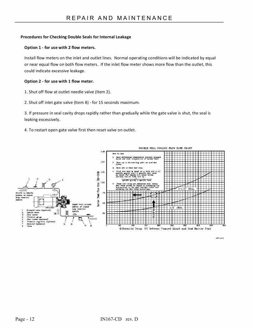
IN167-CD rev. DPage - 12
R E P A I R A N D M A I N T E N A N C E
Procedures for Checking Double Seals for Internal Leakage
Option 1 - for use with 2 flow meters.
Install flow meters on the inlet and outlet lines. Normal operating conditions will be indicated by equal or near equal flow on both flow meters. If the inlet flow meter shows more flow than the outlet, this could indicate excessive leakage.
Option 2 - for use with 1 flow meter.
1. Shut off flow at outlet needle valve (Item 2).
2. Shut off inlet gate valve (Item 8) - for 15 seconds maximum.
3. If pressure in seal cavity drops rapidly rather than gradually while the gate valve is shut, the seal is leaking excessively.
4. To restart open gate valve first then reset valve on outlet.

IN167-CD rev. D Page - 13
THIS PAGE INTENTIONALLY LEFT BLANK
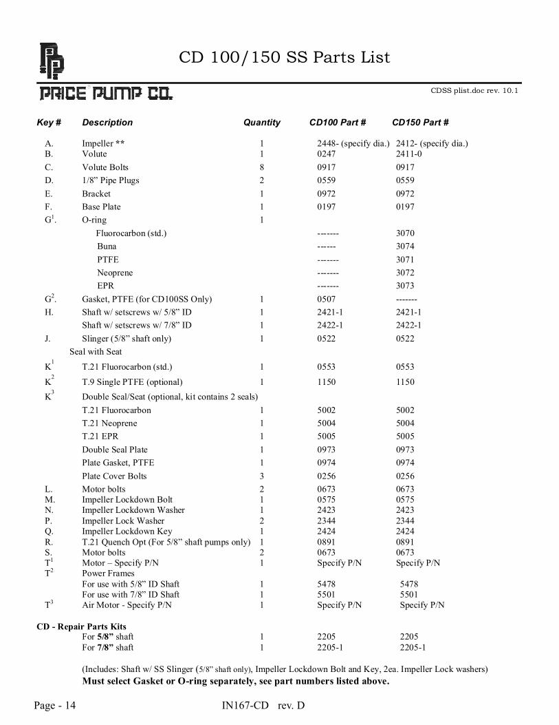
Page - 14 IN167-CD rev. D
CD 100/150 SS Parts List
CDSS plist.doc rev. 10.1
Key # Description Quantity CD100 Part # CD150 Part #
A. Impeller ** 1 2448- (specify dia.) 2412- (specify dia.) B. Volute 1 0247 2411-0 C. Volute Bolts 8 0917 0917 D. 1/8” Pipe Plugs 2 0559 0559 E. Bracket 1 0972 0972 F. Base Plate 1 0197 0197
G1. O-ring 1 Fluorocarbon (std.) ------- 3070
Buna ------ 3074 PTFE ------- 3071 Neoprene ------- 3072 EPR ------- 3073
G2. Gasket, PTFE (for CD100SS Only) 1 0507 ------- H. Shaft w/ setscrews w/ 5/8” ID 1 2421-1 2421-1 Shaft w/ setscrews w/ 7/8” ID 1 2422-1 2422-1 J. Slinger (5/8” shaft only) 1 0522 0522 Seal with Seat
K1 T.21 Fluorocarbon (std.) 1 0553 0553
K2 T.9 Single PTFE (optional) 1 1150 1150
K3 Double Seal/Seat (optional, kit contains 2 seals) T.21 Fluorocarbon 1 5002 5002 T.21 Neoprene 1 5004 5004 T.21 EPR 1 5005 5005 Double Seal Plate 1 0973 0973 Plate Gasket, PTFE 1 0974 0974 Plate Cover Bolts 3 0256 0256
L. Motor bolts 2 0673 0673 M. Impeller Lockdown Bolt 1 0575 0575 N. Impeller Lockdown Washer 1 2423 2423 P. Impeller Lock Washer 2 2344 2344 Q. Impeller Lockdown Key 1 2424 2424 R. T.21 Quench Opt (For 5/8” shaft pumps only) 1 0891 0891 S. Motor bolts 2 0673 0673 T1 Motor – Specify P/N 1 Specify P/N Specify P/N T2 Power Frames For use with 5/8” ID Shaft 1 5478 5478 For use with 7/8” ID Shaft 1 5501 5501 T3 Air Motor - Specify P/N 1 Specify P/N Specify P/N CD - Repair Parts Kits
For 5/8” shaft 1 2205 2205 For 7/8” shaft 1 2205-1 2205-1
(Includes: Shaft w/ SS Slinger (5/8” shaft only), Impeller Lockdown Bolt and Key, 2ea. Impeller Lock washers) Must select Gasket or O-ring separately, see part numbers listed above.
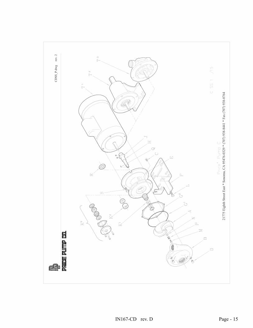
Page - 15IN167-CD rev. D
2177
5 Ei
ghth
Stre
et E
ast *
Son
oma,
CA
954
76-0
329
* (7
07) 9
38-8
441
* Fa
x (7
07) 9
38-0
764
CD
SS_P
.dw
g
rev.
2
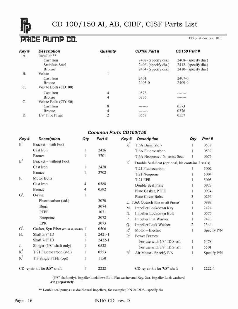
Page - 16 IN167-CD rev. D
CD 100/150 AI, AB, CIBF, CISF Parts List
CD plist.doc rev. 10.1 Key # Description Quantity CD100 Part # CD150 Part #
A. Impeller ** 1 Cast Iron 2402- (specify dia.) 2408- (specify dia.) Stainless Steel 2406- (specify dia.) 2412- (specify dia.) Bronze 2404- (specify dia.) 2410- (specify dia.) B. Volute 1 Cast Iron 2401 2407-0 Bronze 2403-0 2409-0
C. Volute Bolts (CD100) Cast Iron 4 0573 ------- Bronze 4 0376 ------- C. Volute Bolts (CD150) Cast Iron 8 ------- 0573 Bronze 4 ------- 0376
D. 1/8” Pipe Plugs 2 0557 0557 Common Parts CD100/150 Key # Description Qty Part # Key # Description Qty Part # E1 Bracket – with Foot Cast Iron 1 2426 Bronze 1 3701 E2 Bracket – without Foot Cast Iron 1 2428 Bronze 1 3702 F. Motor Bolts Cast Iron 4 0588 Bronze 4 0592 G1. O-ring 1 Fluorocarbon (std.) 3070
Buna 3074 PTFE 3071 Neoprene 3072 EPR 3073
G2. Gasket, Syn Fiber (CD100 AI, SF&BF) 1 0506 H. Shaft 5/8” ID 1 2421-1 Shaft 7/8” ID 1 2422-1 J. Slinger (5/8” shaft only) 1 0522
K1 T.21 Fluorocarbon (std.) 1 0553
K2 T.9 Single PTFE (opt) 1 1150
K3 T.6A Buna (std.) 1 0538 T.6A Fluorocarbon 1 0539 T.6A Neoprene / Ni-resist Seat 1 0675
K4 Double Seal/Seat (optional, kit contains 2 seals)
T.21 Fluorocarbon 1 5002 T.21 Neoprene 1 5004 T.21 EPR 1 5005 Double Seal Plate 1 0973 Plate Gasket, PTFE 1 0974 Plate Cover Bolts 3 0256 L. T.6A Quench (N/A on AB Pumps) 1 0899 M. Impeller Lockdown Key 1 2424 N. Impeller Lockdown Bolt 1 0575 P. Impeller Flat Washer 1 2423 Q. Impeller Lock Washer 2 2344 R1 Motor – Electric 1 Specify P/N R2 Power Frames For use with 5/8” ID Shaft 1 5478 For use with 7/8” ID Shaft 1 5501 R3 Air Motor - Specify P/N 1 Specify P/N
CD repair kit for 5/8” shaft 1 2222 CD repair kit for 7/8” shaft 1 2222-1
(5/8” shaft only), Impeller Lockdown Bolt, Flat washer and Key, 2ea. Impeller Lock washers) -ring separately.
** Double seal pumps use double seal impellers, for example; P/N 2402DS - specify dia.
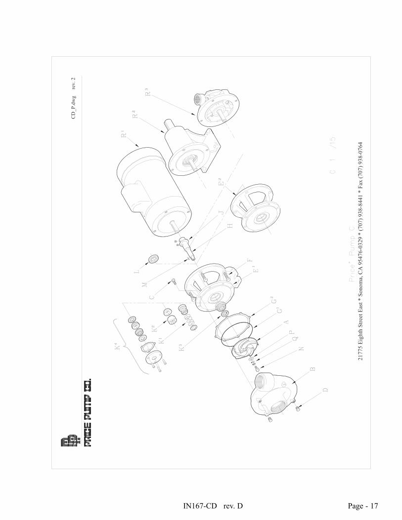
Page - 17IN167-CD rev. D
2177
5 Ei
ghth
Stre
et E
ast *
Son
oma,
CA
954
76-0
329
* (7
07) 9
38-8
441
* Fa
x (7
07) 9
38-0
764
CD
_P.d
wg
re
v. 2
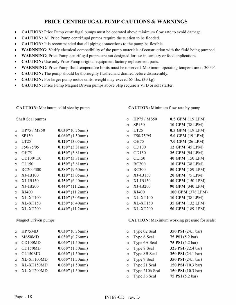
Page - 18 IN167-CD rev. D
PRICE CENTRIFUGAL PUMP CAUTIONS & WARNINGS
• CAUTION: Price Pump centrifugal pumps must be operated above minimum flow rate to avoid damage. • CAUTION: All Price Pump centrifugal pumps require the suction to be flooded. • CAUTION: It is recommended that all piping connections to the pump be flexible. • WARNNING: Verify chemical compatibility of the pump materials of construction with the fluid being pumped. • WARNNING: Price Pump centrifugal pumps are not designed for use in sanitary or food applications. • CAUTION: Use only Price Pump original equipment factory replacement parts. • WARNNING: Price Pump fluid temperature limits must be observed. Maximum operating temperature is 300°F. • CAUTION: The pump should be thoroughly flushed and drained before disassembly. • CAUTION: For larger pump motor units, weight may exceed 65 1bs. (30 kg). • CAUTION: Price Pump Magnet Driven pumps above 3Hp require a VFD or soft starter.
CAUTION: Maximum solid size by pump Shaft Seal pumps o HP75 / MS50 0.030” (0.76mm) o SP150 0.060” (1.50mm) o LT25 0.120” (3.05mm) o F50/75/95 0.150” (3.81mm) o OH75 0.150” (3.81mm) o CD100/150 0.150” (3.81mm) o CL150 0.150” (3.81mm) o RC200/300 0.380” (9.60mm) o XJ-JB100 0.120” (3.05mm) o XJ-JB150 0.250” (6.40mm) o XJ-JB200 0.440” (11.2mm) o XJ400 0.440” (11.2mm) o XL-XT100 0.120” (3.05mm) o XL-XT150 0.250” (6.40mm) o XL-XT200 0.440” (11.2mm)
Magnet Driven pumps
o HP75MD 0.030” (0.76mm) o MS50MD 0.030” (0.76mm) o CD100MD 0.060” (1.50mm) o CD150MD 0.060” (1.50mm) o CL150MD 0.060” (1.50mm) o XL-XT100MD 0.060” (1.50mm) o XL-XT150MD 0.060” (1.50mm) o XL-XT200MD 0.060” (1.50mm)
CAUTION: Minimum flow rate by pump
o HP75 / MS50 0.5 GPM (1.9 LPM) o SP150 10 GPM (38 LPM) o LT25 0.5 GPM (1.9 LPM) o F50/75/95 5.0 GPM (19 LPM) o OH75 7.0 GPM (26 LPM) o CD100 12 GPM (45 LPM) o CD150 25 GPM (94 LPM) o CL150 40 GPM (150 LPM) o RC200 10 GPM (38 LPM) o RC300 50 GPM (189 LPM) o XJ-JB150 20 GPM (75 LPM) o XJ-JB150 40 GPM (150 LPM) o XJ-JB200 90 GPM (340 LPM) o XJ400 100 GPM (378 LPM) o XL-XT100 10 GPM (38 LPM) o XL-XT150 35 GPM (132 LPM) o XL-XT200 50 GPM (189 LPM)
CAUTION: Maximum working pressure for seals: o Type 02 Seal 350 PSI (24.1 bar) o Type 6 Seal 75 PSI (5.2 bar) o Type 6A Seal 75 PSI (5.2 bar) o Type 8 Seal 325 PSI (22.4 bar) o Type 8B Seal 350 PSI (24.1 bar) o Type 9 Seal 350 PSI (24.1 bar) o Type 21 Seal 150 PSI (10.3 bar) o Type 2106 Seal 150 PSI (10.3 bar) o Type 36 Seal 75 PSI (5.2 bar)
IN167-CD rev. D
GENERAL TERMS OF SALE FOR PRODUCTS
Page - 19
1. GENERAL A. Seller's price is based on these sales terms and conditions. The agreement and inclusion of other or amended terms in this contract will result in a change (including increase) in Seller's price (as may be contained in any price books or quotations) to reflect such other or amended terms. This contract shall represent the final, complete and exclusive statement of the agreement between the parties and may not be modified, supplemented, explained or waived by parole evidence, any Terms and Conditions contained in Buyer's purchase order or request for quotation, any course of dealings between the parties, Seller's performance or delivery, or in any other way. The Terms and Conditions of this contract may only be modified or waived in a written document signed by an Officer of Seller. These terms are intended to cover all activity of Seller and Buyer hereunder, including sales and use of products, parts and work and all related matters (references to products include parts and references to work include construction, installation and start-up). Any reference by Seller to Buyer's specifications and similar requirements are only to describe the products and work covered hereby and no warranties or other terms therein shall have any force of effect. Any information provided by Seller including, but not limited to, suggestions as to specific equipment does not imply any guarantee of specific suitability and/or material compatibility in a particular application, since many factors outside the control of Seller may affect the suitability of products in a particular application. Catalogs, circulars, similar pamphlets and information contained on websites of the Seller are issued for general information purposes only and shall not be deemed to modify the provisions hereof. B. The agreement formed hereby and the language herein shall be construed and enforced under the Uniform Commercial Code as in effect in the State of California on the date hereof. 2. TAXES Any sales, use or other similar type taxes imposed on this sale or on this transaction and/or any import or export duties or fees as may be assessed or imposed on or as a result of deliveries under this transaction are not included in the price. Such taxes shall be billed separately to the Buyer. Seller will accept a valid exemption certificate from the Buyer if applicable; however, if an exemption certificate previously accepted is not recognized by the governmental taxing authority involved and the Seller is required to pay the tax covered by such exemption certificate. Buyer agrees to promptly reimburse Seller for the taxes paid. 3. PERFORMANCE, INSPECTION AND ACCEPTANCE A. Unless Seller specifically assumes installation, construction or start-up responsibility, all products shall be finally inspected and accepted within thirty (30) days after arrival at point of delivery. Where seller has responsibility for installation, construction or start-up all work shall be finally inspected and accepted with thirty (30) days after completion of the applicable work by Seller. All claims whatsoever by Buyer, (including claims for shortages) except only those provided for under the WARRANTY AND LIMITATION OF LIABILITY and PATENTS Clauses, hereof, must be asserted in writing by Buyer within said thirty (30) day period or they are waived. If this contract involves partial performance, all such claims must be asserted within said thirty- (30) day period for each partial performance. There shall be no revocation of acceptance. Rejection may be only for defects substantially impairing the value of products or work and Buyer's remedy for lesser defects shall be those provided for under the WARRANTY AND LIMITATION OF LIABILITY Clause. B. Seller shall not be responsible for non-performance or for delays in performance occasioned by any causes beyond Seller's reasonable control, including, by way of example and not limitation, to labor difficulties, delays of vendors or carriers, fires, governmental actions, or shortages of material, components, labor, or manufacturing facilities. Any delays so occasioned shall affect a corresponding extension of Seller's performance dates, which are, in any event, understood to be approximate. IN NO EVENT SHALL BUYER BE ENTITLED TO INCIDENTAL OR CONSEQUENTIAL DAMAGES FOR LATE PERFORMANCE OR FOR A FAILURE TO PERFORM. Seller reserves the right to make partial shipments and to ship products, parts or work which may be completed prior to the scheduled performance date. C. In the event that Seller has agreed to mount motors, turbines, gears, or other products which are not manufactured by Seller and which are not an integral part of Seller's manufactured product, and a delay in the delivery of such products to Seller occurs that will cause a delay in Seller's performance date, Seller reserves the right to ship its product upon completion of manufacture and to refund an equitable portion of the amount originally included in the purchase price for mounting without incurring liability for non-performance. D. Seller reserves to itself the right to change its specifications, drawings and standards if such changes will not impair the performance of its products, and parts, and further those products, and parts, will meet any of Buyer's specifications and other specific product requirements which are a part of this agreement. Seller is a global supplier of products and utilizes parts and products obtained worldwide, and Seller's products supplied under this contract shall be subject to Seller's sole determination as to all manufacturing, sourcing, assembly and supply unless otherwise specifically agreed in writing. E. The manufacture and inspection of products and parts shall be to Seller's Engineering and Quality Assurance standards, plus such other inspections or tests of documentation as are specifically agreed to by Seller. Requirements for any additional inspection, tests, documentation, or Buyer witness of manufacture, test, and/or inspection shall be subject to additional charges. 4. TITLE AND RISK OF LOSS Title and risk of loss shall pass to buyer upon delivery of products at the designated "Ex Works" as defined by Incoterms, unless other wise agreed by the parties. 5. EROSION AND CORROSION It is specifically understood that products and parts sold hereunder are not warranted for operation with erosive or corrosive fluids or for operation with any fluid or under any operating condition in variance with the specifications of this contract. No product or part shall be deemed to be defective by reason of failure to resist erosive or corrosive action of any fluid and Buyer shall have no claim whatsoever against Seller therefore. No product shall be deemed defective by reason of any effect on Seller's products of the action or results (such as vibration) of any goods or system (such as piping) not supplied by Seller.
6. BUYER’S RESPONSIBILITY The design specifications of the equipment require the operation of the equipment within certain parameters and may call for the use of speed controls, safety devices, set points or other control devices to insure that the operation remains within design parameters. Buyer agrees and understands that the equipment must be operated and maintained within design specifications and operated within the specifications of the contract, irrespective of whether controls or devices are otherwise required. 7. WARRANTY AND LIMITATION OF LIABILITY. A. Seller warrants only that its product and parts, when shipped, will be free from defects in materials and workmanship. All claims for defective products or parts under this warranty must be made in writing immediately upon discovery and, in any event, within two (2) years of shipment by seller and all claims for defective work must be made in writing immediately upon discovery. Defective items must be held for Seller's inspection and returned to the sellers’ point of original shipment upon request. ANY UNAUTHORIZED DISSASSEMBLY, ALTERATION OF OR TAMPERING WITH ANY PRODUCT ORCOMPONENT MAY "VOID" THE WARRANTY, IN THAT SUCH ACTION WILL RESULT IN SELLER BEING RELEASED AND RELIEVED FROM ITS OBLIGATIONS UNDER THIS WARRANTY AND FOR ANY FURTHER COSTS OR ACTIONS UNDER CLAUSE 7.C, FOLLOWING, AND THE BUYER ASSUMING SOLE RESPONSIBILITY FOR THE COSTS AND RESULTS OF SUCH ACTION. THE FOREGOING IS EXPRESSLY IN LIEU OF ALL OTHER WARRANTIES WHATSOEVER, EXPRESS, IMPLIED AND STATUTORY, INCLUDING WITHOUT LIMITATION, THE IMPLIED, WARRANTIES OF MERCHANTABILITY AND FITNESS. B. ANY PRODUCT (S) SOLD HEREUNDER WHICH ARE NOT MANUFACTURED BY SELLER ARE NOT WARRANTED BY SELLER and shall be covered only by the express warranty, if any, of the manufacturer thereof. With respect to products and parts not manufactured by Seller, Seller's only obligation shall be to assign to Buyer, to the extent possible, whatever warranty Seller obtains from the manufacturer. C. Upon Buyer's submission of a claim as provided above and its substantiation, Seller shall at its option either (i) repair or replace its product, part or work at the original place of shipment, or (ii) refund an equitable portion of the purchase price. D. THE FOREGOING IS SELLER'S ONLY OBLIGATION AND BUYER'S EXCLUSIVE REMEDY FOR BREACH OF WARRANTY AND, EXCEPT FOR THE REMEDIES PERMITTED UNDER THE PERFORMANCE, INSPECTION AND ACCEPTANCE AND THE PATENTS CLAUSES HEREOF, THE FOREGOING IS BUYER EXCLUSIVE REMEDY AGAINST SELLER FOR ALL CLAIMS ARISING HEREUNDER OR RELATING HERETO WHETHER SUCH CLAIMS ARE BASED ON BREACH OF CONTRACT, TORT (INCLUDING NEGLIGENCE OR STRICT LIABILITY), INDEMNITY OR OTHER THEORIES. BUYER'S FAILURE TO SUBMIT A CLAIM AS PROVIDED ABOVE SHALL SPECIFICALLY WAIVE ALL CLAIMS FOR DAMAGES OR OTHER RELIEF, INCLUDING BUT NOT LIMITED TO CLAIMSBASED ON LATENT DEFECTS. IN NO EVENT SHALL BUYER BE ENTITLED TO INDIRECT, SPECIAL, INCIDENTAL OR CONSEQUENTIAL DAMAGES, NOR FOR DAMAGES FOR LOSS OF USE, LOST PROFITS OR REVENUE, INTEREST, LOST GOODWILL, WORK OR PRODUCTION STOPPAGE,IMPAIRMENT OF OTHER GOODS, INCREASED EXPENSES OF OPERATION, OR THE COST OF PURCHASING REPLACEMENT POWER OR OTHER SERVICES BECAUSE OF SERVICE INTERRUPTIONS. FURTHERMORE, IN NO EVENT SHALL SELLER'S TOTAL LIABILITY FOR DAMAGES OF BUYER EXCEED THE PURCHASE PRICE OF THE PRODUCTS OR PARTS MANUFACTURED BY SELLER AND UPON WHICH SUCH LIABILITY IS BASED. ANY ACTION ARISING HEREUNDER RELATED HERETO, WHETHER BASED ON BREACH OF CONTRACT, TORT (INCLUDING NEGLIGENCE) OR OTHER THEORIES, MUST BE COMMENCED WITHIN ONE (1) YEAR AFTER THE CAUSE OF ACTION ACCRUES OR IT SHALL BE BARRED. 8. PURCHASER’S REPRESENTATIONS & WARRANTIES Purchaser represents and warranties that the products(s) covered by this contract shall not be used in or inconnection with a nuclear facility or application. The parties agree that this representation and warranty is material and is being relied on by seller. This provision may be modified in a separate writing signed by an officer of Price Pump Co. 9. PATENTS Seller agrees to assume the defense of any suit for infringement of any patents brought against Buyer to the extent of such suit charges infringement of an apparatus or product claim by Seller's product in and of itself, provided (i) said product is built entirely to Seller's design, (ii) Buyer notifies Seller in writing of the filing of such suit within ten (10) days after the service of process thereof, and (iii) Seller is given complete control of the defense of such suit, including the right to defend, settle and make changes in the product forthe purpose of avoiding infringement of any process or method claims. Provided however, Seller will not defend any suit for infringement of a claimed patent where such alleged infringement is the result of following specific instruction furnished by Seller. 10. EXTENT OF SUPPLY Only products as listed in Seller's proposal are included in this agreement. It must not be assumed that Seller has included anything beyond same. 11. MANUFACTURING SOURCES To maintain delivery schedules, Seller reserves the right to have all or any part of the Buyer's order manufactured at any of Sellers’, sellers’ licensees or sub contractors’ plants, globally. 12. TERMS OF PAYMENT Net 30 days from date of invoice. 13. ARBITRATION In the event a dispute arises between the parties relating to or arising out of this agreement, the parties agree to attempt to have their senior management amicably settle the matter. In the event that the matter cannot be settled, the parties shall submit all disputes relating to this Agreement (whether contract, tort, products liability or otherwise) to binding Arbitration before a panel of arbitrators under the Commercial Dispute Resolution Procedures of the American Arbitration Association. Each party shall appoint an arbitrator and the third shall be selected in accordance with the rules of the American Arbitration Association. Judgment upon the award may be entered in any court having jurisdiction. The parties shall cooperate in providing reasonable disclosure of relevant documents. Each party shall bear its own expenses, and the costs and fees of the arbitration shall be borne as allocated by the Arbitrator.

DWYER INSTRUMENTS, INC. Phone: 219/879-8000 www.dwyer-inst.comP.O. Box 373 • Michigan City, IN 46360-0373, U.S.A. Fax: 219/872-9057 e-mail: [email protected]
The Series RHP-W Wall Mount Humidity/Temperature/Dew Point Transmitteris the most versatile room transmitter on the market. The stylish housing is wellvented to provide air flow across the sensor to improve measurement accuracy. Anoptional LCD display can be integral to the transmitter or a remote display can beordered for building balancing or LEED validation. The LCD display indicates theambient temperature along with the humidity or dew point. The transmitter hasinternal dip switches to select the temperature engineering units and whether thetransmitter outputs humidity or dew point.The humidity and temperature sensors are field replaceable to reduce service costand inventory. The humidity and the dew point are measured using a capacitivepolymer sensor that completely recovers from 100% saturation. The humidity anddew point can have either a current or voltage output, while the optional tempera-ture output can be a current, voltage, RTD or thermistor. For models with currentor voltage for the temperature output, the temperature range is field selectable.
INSTALLATION
Series RHP-W Wall Mount Humidity/Temperature/Dew Point Transmitter
Specifications - Installation and Operating Instructions
Bulletin H-RHP-W
SPECIFICATIONSRelative Humidity Range: 0 to 100% RH.Temperature Range: -40 to 140°F (-40 to 60°C) for thermistor and RTD sensors. -20 to 140°F (-28.9 to 60°C) for solid state temperature sensors.Dew Point Temperature Range: -20 to 140°F (-28.9 to 60°C); 0 to 100°F (-17.8 to 37.8°C); 40 to 90°F (4.4 to 32.3°C); -4 to 140°F (-20 to 60°C) field selec-table ranges.Accuracy:
RH: Model RHP2 ±2% 10-90% RH @ 25°C; Model RHP3 ±3% 20-80% RH @ 25°C.Thermistor Temperature Sensor: ±0.4°F @ 77°F (±0.22°C @ 25°C).RTD Temperature Sensor: DIN Class B; ±0.54°F @ 32°F (±0.3°C @ 0°C).Solid State Temperature Sensor: ±0.9°F @ 72°F (±0.3°C @ 25°C).
Hysteresis: ±1%.Repeatability: ±0.1% typical.Temperature Limits: -40 to 140°F (-40 to 60°C).Storage Temperature: -40 to 176°F (-40 to 80°C).Compensated Temperature Range: -4 to 140°F (-20 to 60°C).4-20 mA Loop Powered Models:
Power Requirements: 10-35 VDC.Output Signal: 4-20 mA, 2 channels for humidity/solid state temperature sensor models (loop powered on RH). Switch selectable RH/dew point. Switch selectable normal or reverse output.
0-5/10V Output Models:Power Requirements: 15-35 VDC or 15-29 VAC.Output Load: 5 mA max., 2 channels for humidity/solid state temperature sensor models. Switch selectable 0-10V/2-10V or 0-5V/1-5V output. Switch selectable RH/dew point. Switch selectable normal or reverse output.
Solid State Temperature Sensor Output Ranges: Switch selectable, -20 to 140°F (-28.9 to 60°C); 0 to 100°F (-17.8 to 37.8°C); 40 to 90°F (4.4 to 32.3°C); -4 to 140°F (-20 to 60°C).Response Time: 15 seconds.Electrical Connections: Screw terminal block.Drift: <1% RH/year.RH Sensor: Capacitance polymer.Enclosure Material: White polycarbonate.Display: Optional LCD, backlit on 0-5/10V models. Switch selectable %RH or dewpoint, °F/°C.Display Resolution: RH: 1%; Temperature: 0.1°F (0.1°C); Dew Point: 1°F (1°C).Weight: 0.3 lb (0.14 kg).Agency Approvals: CE.
1-3/16[30.16]
1-3/16[30.16]
.921
3x 3/8[9.53]
35/64[13.89]
1-13/32[35.72]
1-53/64[46.43]
4x 3/16[4.76]
1-13/32[50.01]
4-31/64[113.9]
3-13/32[86.52]Shown with optional LCD display
Do not exceed ratings of this device, permanent damage notcovered by warranty may result. The 4-20 mA models are not
designed for AC voltage operation.
CAUTION
Avoid locations where severe shock or vibration, excessivemoisture or corrosive fumes are present.
CAUTION
Use electrostatic discharge precautions (e.g., use of wriststraps) during installation and wiring to prevent equipment dam-
age.
CAUTION
Disconnect power supply before installation to prevent electricalshock and equipment damage.
Make sure all connections are in accordance with the job wiring diagram and inaccordance with national and local electrical codes. Use copper conductors only.
WARNING

1. Push tab on bottom of cover and lift cover from back plate. (See Figure 1).2. Select the mounting location, away from diffusers, lights, or any external
influences.3. Mount transmitter on a vertical surface to a standard electrical box using the two
#6 M2C type screws provided.4. Pull wires through sub base hole and make necessary connections.5. Reattach cover to base plate.
WiringUse maximum 18 AWG wire for wiring to terminals. Refer to figures 2 through 5 forwiring information.
Current Output Models (RHP-XW1X)Current output models must be powered with 10-35 VDC supply voltage. Wire theRH current output as shown in Figure 2. If the unit has a 4-20 mA temperature out-put, wire the temperature receiver between terminal 3 and the negative terminal ofthe power supply. If the unit has a passive temperature sensor, wire to terminals 4and 5. If the RH output is not required, wire the negative terminal of the power sup-ply to terminal 1 of the transmitter. If the temperature output is not used, it may beleft disconnected.
Voltage Output Models (RHP-XW2X)Wire as shown in Figure 3. Voltage outputs may be powered with 15-35 VDC or 15-29 VAC. Note polarity when using DC power. If the unit has a voltage temperatureoutput, wire the temperature receiver between terminal 4 and negative terminal ofpower supply. If the unit has a passive temperature sensor, wire to terminals 5 and6. For units with RH and temperature voltage outputs, the RH or Temperature out-put may be used by itself.
Models with Selectable Current or Voltage Outputs (RHP-XW44)These models may be wired for current or voltage output. Note that both outputsmust be wired either for current or voltage. It is not possible to wire one output forcurrent, and the other for voltage.
Prior to wiring, verify that the Current/Voltage select switch is set to current or volt-age as desired. Refer to “Setting the Current/Voltage Select Switch”.
Current Output Selected: Wire as shown in Figure 4. Current outputs must bepowered with 10-35 VDC. If the RH output is not required, wire the negative termi-nal of the power supply to terminal 1 of the transmitter. All units come with 4-20 mARH and Temperature outputs. If the 4-20 mA temperature output is not used itmaybe left disconnected. If the unit has a passive temperature sensor, wire to ter-minals 7 and 8.
Voltage Output Selected: Voltage outputs may be powered with 15-35 VDC or 15-29 VAC. Note polarity when using DC power. Wire the RH voltage output as shownin Figure 5. If the unit has a voltage temperature output, wire the temperaturereceiver between terminal 6 and the negative terminal of the power supply. All unitscome with RH and Temperature voltage outputs. If the temperature or RH voltageoutput is not used it may be left disconnected. If the unit has a passive temperaturesensor, wire to terminals 7 and 8.
Setting the Current/Voltage Select SwitchRemove the cover of the unit as shown in Figure 1. The Current/Voltage selectswitch is located on the back of the circuit board. Set the switch “IOUT” for current,“VOUT” for voltage.
1 2 3 4 5 6 7 81 2 3 4 5 6 7 8
POWERSUPPLYPOWERSUPPLY
+ - +-
RH RECEIVERRH RECEIVER++-- TEMP RECEIVERTEMP RECEIVER
PASSIVE TEMP.SENSORPASSIVE TEMP.SENSOR
(IF PRESENT)(IF PRESENT)
(IF PRESENT)(IF PRESENT)
++--
4-20MA4-20MA4-20MA4-20MA
BOTTOM TAB
HINGETO REMOVE COVERAPPLY PRESSURE TOBOTTOM TAB WHERE INDICATED AND THE TWO PARTS WILL BECOME UNHINGED AT TOP
REVERSE PROCESS TO APPLY COVER
MOUNTINGBACK PLATE
SELF-LATCHINGCOVER
MOUNTINGSCREWS
Figure 1
Figure 2
Figure 3
Figure 4
Figure 5
Figure 6

DIP SWITCH SETTINGSTo access the DIP SWITCH, remove the cover of the unit as shown in Figure 1. TheDIP SWITCH is located on the back of the circuit board.
ALL DIP SWITCHES are factory set to “ON”
5V/10V Output Select (Applies only to Voltage Output units)DIP SWITCH#1 OFF: Output = 0-5VDIP SWITCH#1 ON: Output = 0-10V
Zero Suppression (Applies only to Voltage Output Units)DIP SWITCH#2 OFF : Output range = 1-5V or 2-10V, depending on output rangeDIP SWITCH#2 ON : Output range = 0-5V or 0-10V, depending on output range
Upper Display reads RH or DEW POINTDIP SWITCH#3 OFF: Upper Display reads Dew PointDIP SWITCH#3 ON: Upper Display reads RH
RH OUTPUT, Normal or InvertDIP SWITCH#4 OFF: Output is invertedDIP SWITCH#4 ON: Output is Normal
When set to normal output, the output increases as the RH increases. When set toinverted output, the output decreases as the RH increases.Example: Normal 4-20 mA output, 0%RH = 4 mA, 100% RH = 20 mA
Inverted 4-20 mA output, 0%RH = 20 mA, 100% RH = 4 mA
TEMP OUTPUT, Normal or InvertDIP SWITCH#5 OFF: Output is invertedDIP SWITCH#5 ON: Output is Normal
When set to normal output, the output increases as the temperature increases.When set to inverted output, the output decreases as the temperature increases.Example: Normal 4-20 mA output, -20°F = 4 mA, +140°F = 20 mA
Inverted 4-20 mA output, -20°F = 20 mA, +140°F = 4 mA
°F/°C SelectDIP SWITCH#6 OFF: °CDIP SWITCH#6 ON: °F
Temperature Output Range Select
The temperature range applies only to the current or voltage output. If the unit hasa display, it will display temperature from -40 to +140°F (-40 to +60°C). If the unit isset to read DEW POINT, the output range of the DEW POINT will be the same asthe Temperature Output Range.
Note: The display will indicate temperature even if the unit does not have a tem-perature output.
TROUBLESHOOTING1. Verify that the unit is mounted in the correct position.2. 4-20 mA Models: Verify appropriate supply voltage. The transmitter requires a minimum of 10 and amaximum of 35 VDC at its connection for proper operation. Choose a power sup-ply with a voltage and current rating which meets this requirement under all oper-ating conditions. If the power supply is unregulated, make sure voltage remainswithin these limits under all power line conditions. Ripple on the supply should notexceed 100 mV.
Loop Resistance – The maximum allowable loop resistance depends on thepower supply voltage. Maximum loop voltage drop must not reduce the transmittervoltage below the 10 VDC minimum. Maximum loop resistance can be calculatedwith the following equation. Vps is the power supply voltage.
Rmax =
Some receivers, particularly loop powered indicators, may maintain a fixed loopvoltage to power the device. This voltage drop must also be subtracted from thepower supply voltage when calculating the voltage margin for the transmitter. Thefollowing equation takes this into account. Vrec is the receiver fixed voltage.
Rmax =
0-10 V Output Models:Verify appropriate supply voltage. The 0-10V output models require a DC supply of15 to 35 V or an AC supply of 15-29 V for proper operation maximum. Maximumoutput load is 5 mA.
FIELD SENSOR REPLACEMENTReplacement sensors are available. Replacement sensors are factory calibratedand do not require any further calibration.1. Remove cover as shown in Figure 1.2. Remove existing sensor as shown in Figure 8.3. Replace the sensor with appropriate replacement sensor.4. Reattach cover to base plate.
Remote DisplayFor models that are ordered without an integral LCD display, remote display ModelA-449 can be used to display the temperature and humidity or dew point. The miniUSB plug of the remote display plugs into the receptor on the side of the housing.After a short warm up time, the display will begin to show the current temperatureand humidity or dew point measurements. Humidity or dew point can be selectedvia the internal dip switches as described earlier in this manual.
Sensor is sensitive to Electro-Static Discharge (ESD). Followindustry standard practice for control and protection against
ESD. Failure to exercise good ESD practices may cause damage to the sensor.
Range-4 to +140°F (-20 to +60°C)+40 to +90°F (+4.4 to +32.2°C)0 to +100°F (-17.8 to +37.8°C)-20 to +140°F (-28.9 to +60°C)
Dip Switch 7OFFOFFONON
Dip Switch 8OFFONOFFON
Figure 7
Vps-10.0
20 mA
Vps-10.0-Vrec20 mA
Figure 8
NOTICE

©Copyright 2012 Dwyer Instruments, Inc. Printed in U.S.A. 12/12 FR# 03-443752-00 Rev. 3
DWYER INSTRUMENTS, INC. Phone: 219/879-8000 www.dwyer-inst.comP.O. Box 373 • Michigan City, IN 46360-0373, U.S.A. Fax: 219/872-9057 e-mail: [email protected]
0MAINTENANCEUpon final installation of the Series RHP-W Temperature/Humidity/Dew PointTransmitter and the companion receiver, no routine maintenance is required. A peri-odic check of the system calibration is recommended. Except for sensor replace-ment, t he Series RHP-W is not field serviceable and should be returned if repair isneeded (field repair should not be attempted and may void warranty). Be sure toinclude a brief description of the problem plus any relevant application notes.Contact customer service to receive a return goods authorization number beforeshipping.
RHP Model #RHP-2(W)XARHP-2(W)XBRHP-2(W)XCRHP-2(W)XDRHP-2(W)XERHP-2(W)XFRHP-2(W)X(0,1, 2, 4)RHP-3(W)XARHP-3(W)XBRHP-3(W)XCRHP-3(W)XDRHP-3(W)XERHP-3(W)XFRHP-3(W)X(0, 1, 2, 4)
Replacement Sensor Part #RHPS-D2ARHPS-D2BRHPS-D2CRHPS-D2DRHPS-D2ERHPS-D2FRHPS-D20RHPS-D3ARHPS-D3BRHPS-D3CRHPS-D3DRHPS-D3ERHPS-D3FRHPS-D30
ExampleSeriesAccuracy
Housing TypeRH Output
TemperatureSensor/Output
Option
RHPRHP
2
23
D
W
1
124
A
ABCDEF0124
LCD
LCDBlank
RHP-2D1A-LCDRH/Passive Temperature Sensor Transmitter2% Accuracy3% AccuracyWall Mount4-20 mA0-10V/0-5V0-10V/0-5V/4-20 mA10K @ 25°C Thermistor Dwyer Curve A10K @ 25°C Thermistor Dwyer Curve B3K @ 25°C Thermistor Dwyer Curve C100Ω RTD DIN 3851KΩ RTD DIN 38520KC 25°C Thermistor Curve FNONE4-20 mA Solid State Sensor0-10V/0-5V mA Solid State Sensor0-10V/0-5V/4-20 mA SensorLCD DisplayNo Options
Model Chart
ACCESSORIESReplacement sensor part number table:
RESISTANCE VS TEMPERATURE TABLE
°C-55-50-45-40-35-30-25-20-15-10-505101520253035404550556065707580859095100105110115120125130135140145150
°F-67.0-58.0-49.0-40.0-31.0-22.0-13.0
-4.05.0
14.023.032.041.050.059.068.077.086.095.0
104.0113.0122.0131.0140.0149.0158.0167.0176.0185.0194.0203.0212.0221.0230.0239.0248.0257.0266.0275.0284.0293.0302.0
TemperatureA607800.00441200.00323600.00239700.00179200.00135200.00102900.00
78910.0061020.0047540.0037310.0029490.0023460.0018780.0015130.0012260.0010000.00
8194.006752.005592.004655.003893.003271.002760.002339.001990.001700.001458.001255.001084.00
939.30816.80712.60623.60547.30481.80425.30376.40334.00297.20265.10237.00
B963849.00670166.00471985.00336479.00242681.00176974.00130421.00
97081.0072957.0055329.0042327.0032650.0025392.0019901.0015712.0012493.0010000.00
8057.006531.005326.004368.003602.002986.002488.002083.001752.001480.001255.001070.00
915.50786.60678.60587.60510.60445.30389.60341.90301.00265.80235.30208.90186.10
C289154.70201049.80141595.50100943.70
72804.3053092.2039126.3029.124.3021887.1016598.7012698.10
9795.007617.605970.304713.603747.903000.002417.101959.301597.801310.401080.60
895.80746.40624.90525.60444.00376.50321.00274.65235.98203.58176.28153.18133.59116.88102.57
90.3079.7470.5962.6755.83
D78.3280.3182.2984.2786.2588.2290.1992.1694.1296.0998.04
100.00101.95103.90105.85107.79109.74111.67113.61115.54117.47119.40121.32123.24125.16127.08128.99130.90132.80134.71136.61138.51140.40142.29144.18146.07147.95149.83151.71153.58155.46157.33
E783.2803.1822.9842.7862.5882.2901.9921.6941.2960.9980.4
1000.01019.51039.01058.51077.91097.41116.71136.11155.41174.71194.01213.21232.41251.61270.81289.91309.01328.01347.11366.11385.11404.01422.91441.81460.71479.51498.31517.11535.81554.61573.3
F2394000.001646200.001145800.00806800.00574400.00413400.00300400.00220600.00163.500.00122280.00
92240.0070160.0053780.0041560.0032340.0025360.0020000.0015892.0012704.0010216.00
8264.006722.005498.004520.003734.003100.002586.002166.001822.601540.001306.401112.60951.00815.80702.20606.40525.60
N/AN/AN/AN/AN/A
Resistance Curves (in Ohms)
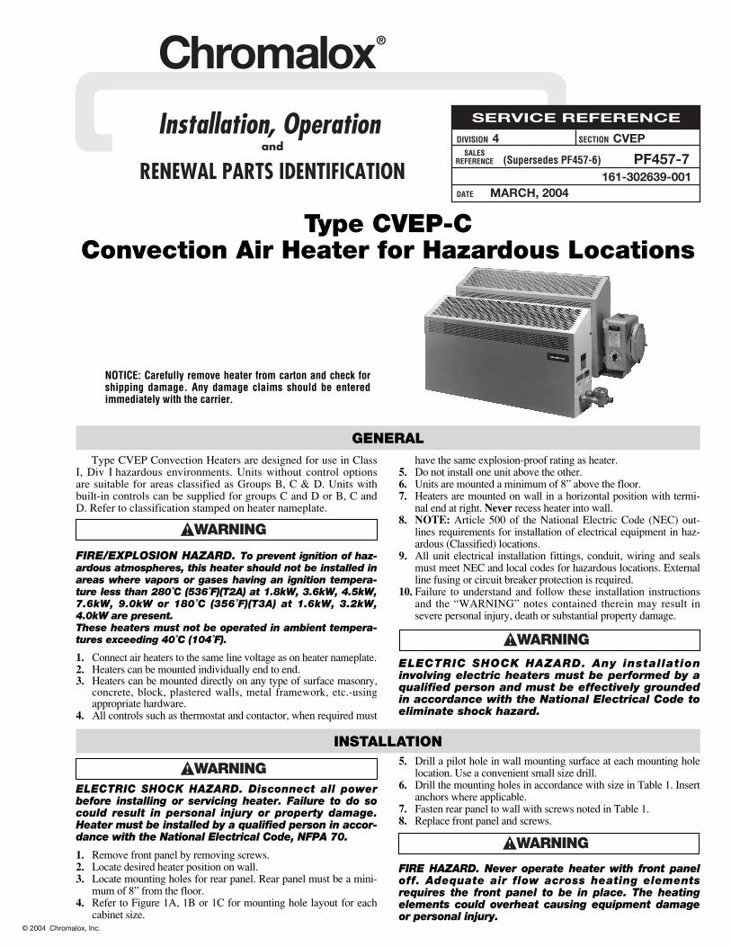
Chromalox®
DIVISION 4 SECTION CVEPSALES
REFERENCE
DATE
SERVICE REFERENCEInstallation, Operation and
RENEWAL PARTS IDENTIFICATIONPF457-7
MARCH, 2004
(Supersedes PF457-6)
161-302639-001
GENERAL
INSTALLATION
NOTICE: Carefully remove heater from carton and check forshipping damage. Any damage claims should be enteredimmediately with the carrier.
Type CVEP Convection Heaters are designed for use in ClassI, Div I hazardous environments. Units without control optionsare suitable for areas classified as Groups B, C & D. Units withbuilt-in controls can be supplied for groups C and D or B, C andD. Refer to classification stamped on heater nameplate.
FIRE/EXPLOSION HAZARD. To prevent ignition of haz-ardous atmospheres, this heater should not be installed inareas where vapors or gases having an ignition tempera-ture less than 280˚C (536˚F)(T2A) at 1.8kW, 3.6kW, 4.5kW,7.6kW, 9.0kW or 180˚C (356˚F)(T3A) at 1.6kW, 3.2kW,4.0kW are present.These heaters must not be operated in ambient tempera-tures exceeding 40˚C (104˚F).
1. Connect air heaters to the same line voltage as on heater nameplate.2. Heaters can be mounted individually end to end.3. Heaters can be mounted directly on any type of surface masonry,
concrete, block, plastered walls, metal framework, etc.-usingappropriate hardware.
4. All controls such as thermostat and contactor, when required must
have the same explosion-proof rating as heater.5. Do not install one unit above the other.6. Units are mounted a minimum of 8” above the floor.7. Heaters are mounted on wall in a horizontal position with termi-
nal end at right. Never recess heater into wall.8. NOTE: Article 500 of the National Electric Code (NEC) out-
lines requirements for installation of electrical equipment in haz-ardous (Classified) locations.
9. All unit electrical installation fittings, conduit, wiring and sealsmust meet NEC and local codes for hazardous locations. Externalline fusing or circuit breaker protection is required.
10. Failure to understand and follow these installation instructionsand the “WARNING” notes contained therein may result insevere personal injury, death or substantial property damage.
ELECTRIC SHOCK HAZARD. Any installationinvolving electric heaters must be performed by aqualified person and must be effectively groundedin accordance with the National Electrical Code toeliminate shock hazard.
ELECTRIC SHOCK HAZARD. Disconnect all powerbefore installing or servicing heater. Failure to do socould result in personal injury or property damage.Heater must be installed by a qualified person in accor-dance with the National Electrical Code, NFPA 70.
1. Remove front panel by removing screws.2. Locate desired heater position on wall.3. Locate mounting holes for rear panel. Rear panel must be a mini-
mum of 8” from the floor.4. Refer to Figure 1A, 1B or 1C for mounting hole layout for each
cabinet size.
5. Drill a pilot hole in wall mounting surface at each mounting holelocation. Use a convenient small size drill.
6. Drill the mounting holes in accordance with size in Table 1. Insertanchors where applicable.
7. Fasten rear panel to wall with screws noted in Table 1.8. Replace front panel and screws.
FIRE HAZARD. Never operate heater with front paneloff. Adequate air flow across heating elementsrequires the front panel to be in place. The heatingelements could overheat causing equipment damageor personal injury.
Type CVEP-CConvection Air Heater for Hazardous Locations
© 2004 Chromalox, Inc.
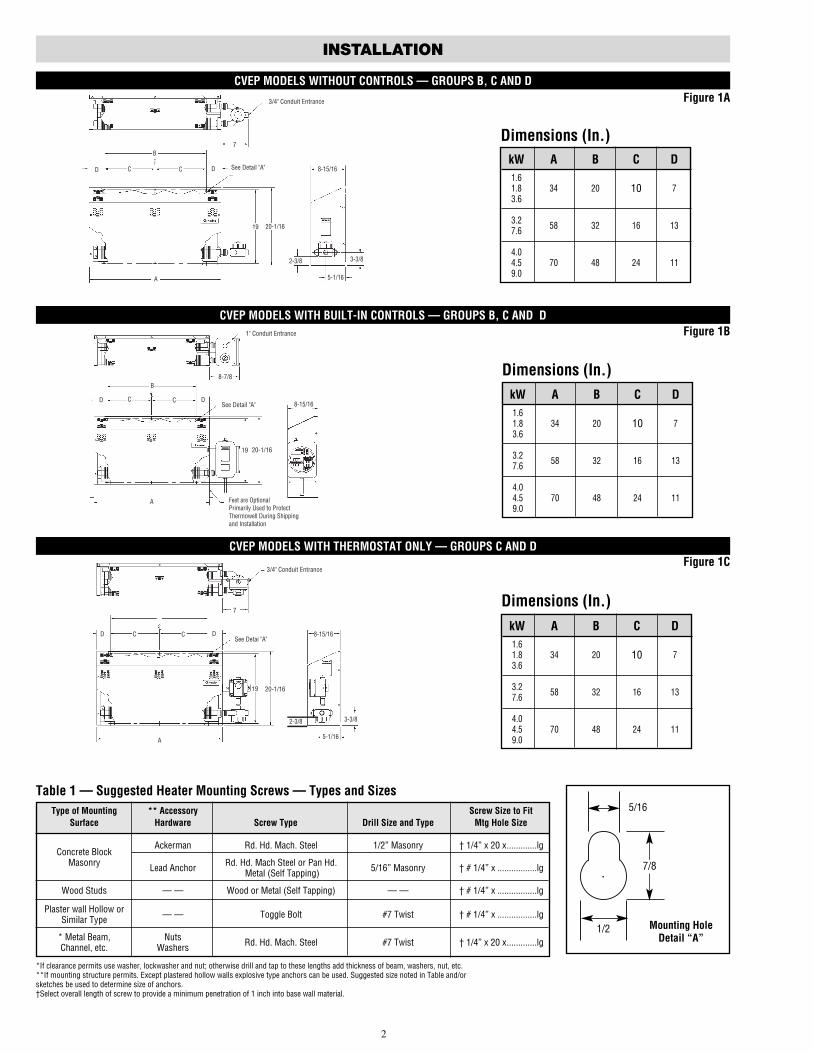
kW A B C D1.61.8 34 20 73.6
3.2 58 32 16 137.6
4.04.5 70 48 24 119.0
10
INSTALLATION
Dimensions (In.)
CVEP MODELS WITHOUT CONTROLS — GROUPS B, C AND D
Dimensions (In.)
CVEP MODELS WITH BUILT-IN CONTROLS — GROUPS B, C AND D
Dimensions (In.)
CVEP MODELS WITH THERMOSTAT ONLY — GROUPS C AND D
2
Type of Mounting ** Accessory Screw Size to FitSurface Hardware Screw Type Drill Size and Type Mtg Hole Size
Concrete BlockAckerman Rd. Hd. Mach. Steel 1/2” Masonry † 1/4” x 20 x.............lg
Masonry Lead Anchor Rd. Hd. Mach Steel or Pan Hd. 5/16” Masonry † # 1/4” x .................lg Metal (Self Tapping)
Wood Studs — — Wood or Metal (Self Tapping) — — † # 1/4” x .................lg
Plaster wall Hollow or — — Toggle Bolt #7 Twist † # 1/4” x .................lgSimilar Type
* Metal Beam, Nuts Rd. Hd. Mach. Steel #7 Twist † 1/4” x 20 x.............lgChannel, etc. Washers
Table 1 — Suggested Heater Mounting Screws — Types and Sizes
*If clearance permits use washer, lockwasher and nut; otherwise drill and tap to these lengths add thickness of beam, washers, nut, etc.**If mounting structure permits. Except plastered hollow walls explosive type anchors can be used. Suggested size noted in Table and/orsketches be used to determine size of anchors.†Select overall length of screw to provide a minimum penetration of 1 inch into base wall material.
1/2
7/8
5/16
Mounting HoleDetail “A”
Figure 1A
Figure 1B
Figure 1C
kW A B C D1.61.8 34 20 73.6
3.2 58 32 16 137.6
4.04.5 70 48 24 119.0
10
kW A B C D1.61.8 34 20 73.6
3.2 58 32 16 137.6
4.04.5 70 48 24 119.0
10
7/8
3/4" Conduit Entrance
7
D See Detail "A" 8-15/16D C C
B
19 20-1/16
A
2-3/8
5-1/16
3-3/8
1" Conduit Entrance
8-7/8
DSee Detail "A"
C CD
19 20-1/16
8-15/16
A
B
Feet are OptionalPrimarily Used to ProtectThermowell During Shippingand Installation
3/4" Conduit Entrance
7
DSee Detai "A"
C CD
19 20-1/16
8-15/16
5-1/16
3-3/8
A
2-3/8
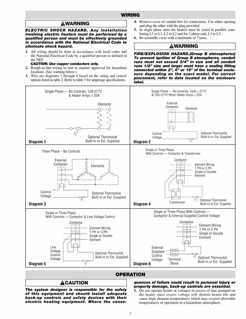
WIRING
ELECTRIC SHOCK HAZARD. Any installationinvolving electric heaters must be performed by aqualified person and must be effectively groundedin accordance with the National Electrical Code toeliminate shock hazard.1. All wiring should be done in accordance with local codes and
the National Electrical Code by a qualified person as defined inthe NEC.CAUTION: Use copper conductors only.
2. Rough-in-line-wiring to unit in manner approved for hazardouslocations. (See warning below.)
3. Wire per diagrams 1 through 6 based on the rating and controloptions listed in table 2. Refer to table 3 for amperage specifications.
4. Remove cover of conduit box for connections. Use either openingand plug the other with the plug provided.
5. In single phase units the heaters must be wired in parallel, com-bining L1 to L1, L2 to L2 and for 3 phase unit, L3 to L3.
6. Re-assemble cover with a minimum of 7 turns.
FIRE/EXPLOSION HAZARD.(Group B atmospheres)To prevent ignition of Group B atmospheres, conduitruns must not exceed 3/4” in size and all conduitruns 1/2” size and larger must have a sealing fittingconnected within 2”, 6” or 18” of the terminal enclo-sure depending on the exact model. For correctplacement, refer to data located on the enclosurelabel.
OPERATION
The system designer is responsible for the safetyof this equipment and should install adequateback-up controls and safety devices with theirelectric heating equipment. Where the conse-
quences of failure could result in personal injury orproperty damage, back-up controls are essential.1. Do not operate heater at voltages in excess of that stamped on
the heater since excess voltage will shorten heater life andcause high element temperatures which may exceed allowabletemperatures of operation in a hazardous atmosphere.
3
Elements
Optional ThermostatBuilt-In or Ext. Supplied
Single Phase — No Controls, 120-277V & Heater Amps < 22A
Diagram 1
Diagram 3
Diagram 5
Diagram 2
Diagram 4
Diagram 6
Elements
Optional ThermostatBuilt-In or Ext. Supplied
Single Phase — No Controls, Volts > 277V& 120–277V When Heater Amps > 22A
ExternalContactor
ControlVoltage
Elements
Optional ThermostatBuilt-In or Ext. Supplied
ExternalContactor
ControlVoltage
Three Phase – No Controls
Optional ThermostatBuilt-In or Ext. Supplied
Contactor
Transformer
Element Wiring1 PH or 3 PHSingle or DoubleElement
Single or Three PhaseWith Controls — Contactor & Transformer
Optional ThermostatBuilt-In or Ext. Supplied
Contactor
LineVoltageControlVoltage
Element Wiring1 PH or 3 PHSingle or DoubleElement
Single or Three PhaseWith Controls — Contactor & Line Voltage Control
Optional ThermostatBuilt-In or Ext. Supplied
ContactorElement Wiring1 PH or 3 PHSingle or DoubleElement
Single or Three Phase With Controls —Contactor & External Supplied Control Voltage
TerminalBlock
ExternalSuppliedControlVoltage
!
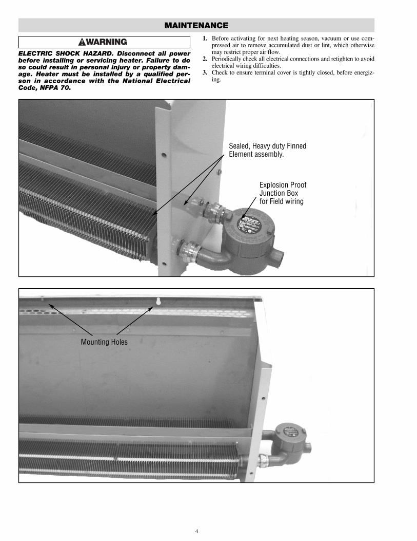
MAINTENANCE
ELECTRIC SHOCK HAZARD. Disconnect all powerbefore installing or servicing heater. Failure to doso could result in personal injury or property dam-age. Heater must be installed by a qualified per-son in accordance with the National ElectricalCode, NFPA 70.
1. Before activating for next heating season, vacuum or use com-pressed air to remove accumulated dust or lint, which otherwisemay restrict proper air flow.
2. Periodically check all electrical connections and retighten to avoidelectrical wiring difficulties.
3. Check to ensure terminal cover is tightly closed, before energiz-ing.
4
Sealed, Heavy duty FinnedElement assembly.
Explosion ProofJunction Boxfor Field wiring
Mounting Holes
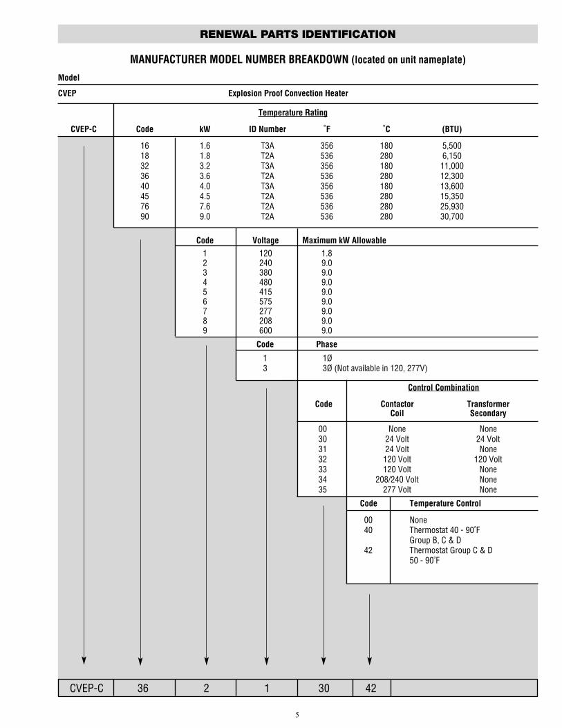
RENEWAL PARTS IDENTIFICATION
MANUFACTURER MODEL NUMBER BREAKDOWN (located on unit nameplate)
CVEP-C 36 2 1 30 42
5
Model
CVEP Explosion Proof Convection Heater
Temperature Rating
CVEP-C Code kW ID Number ˚F ˚C (BTU)
16 1.6 T3A 356 180 5,50018 1.8 T2A 536 280 6,15032 3.2 T3A 356 180 11,00036 3.6 T2A 536 280 12,30040 4.0 T3A 356 180 13,60045 4.5 T2A 536 280 15,35076 7.6 T2A 536 280 25,93090 9.0 T2A 536 280 30,700
Code Voltage Maximum kW Allowable1 120 1.82 240 9.03 380 9.04 480 9.05 415 9.06 575 9.07 277 9.08 208 9.09 600 9.0
Code Phase
1 1Ø3 3Ø (Not available in 120, 277V)
Control Combination
Code Contactor TransformerCoil Secondary
00 None None30 24 Volt 24 Volt31 24 Volt None32 120 Volt 120 Volt33 120 Volt None34 208/240 Volt None35 277 Volt None
Code Temperature Control
00 None40 Thermostat 40 - 90˚F
Group B, C & D42 Thermostat Group C & D
50 - 90˚F
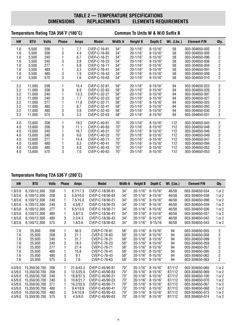
TABLE 2 — TEMPERATURE SPECIFICATIONSDIMENSIONS REPLACEMENTS ELEMENTS REQUIREMENTS
Temperature Rating T3A 356˚F (180˚C) Common To Units W & W/O Suffix B
kW BTU Volts Phase Amps Model Width A Height B Depth C Wt. (Lbs.) Element P/N Qty.
1.6 5,500 208 1 7.7 CVEP-C-16-81 34” 20-1/16” 8-15/16” 58 003-304650-002 21.6 5,500 208 3 4.4 CVEP-C-16-83 34” 20-1/16” 8-15/16” 58 003-304650-005 21.6 5,500 240 1 6.7 CVEP-C-16-21 34” 20-1/16” 8-15/16” 58 003-304650-096 21.6 5,500 240 3 3.8 CVEP-C-16-23 34” 20-1/16” 8-15/16” 58 003-304650-006 21.6 5,500 277 1 5.8 CVEP-C-16-71 34” 20-1/16” 8-15/16” 58 003-304650-004 21.6 5,500 480 1 3.3 CVEP-C-16-41 34” 20-1/16” 8-15/16” 58 003-304650-091 21.6 5,500 480 3 1.9 CVEP-C-16-43 34” 20-1/16” 8-15/16” 58 003-304650-009 21.6 5,500 575 3 1.6 CVEP-C-16-63 34” 20-1/16” 8-15/16” 58 003-304650-010 2
3.2 11,000 208 1 15.4 CVEP-C-32-81 58” 20-1/16” 8-15/16” 94 003-304650-023 23.2 11,000 208 3 8.9 CVEP-C-32-83 58” 20-1/16” 8-15/16” 94 003-304650-026 23.2 11,000 240 1 13.3 CVEP-C-32-21 58” 20-1/16” 8-15/16” 94 003-304650-097 23.2 11,000 240 3 7.7 CVEP-C-32-23 58” 20-1/16” 8-15/16” 94 003-304650-027 23.2 11,000 277 1 11.6 CVEP-C-32-71 58” 20-1/16” 8-15/16” 94 003-304650-025 23.2 11,000 480 1 6.7 CVEP-C-32-41 58” 20-1/16” 8-15/16” 94 003-304650-093 23.2 11,000 480 3 3.8 CVEP-C-32-43 58” 20-1/16” 8-15/16” 94 003-304650-030 23.2 11,000 575 3 3.2 CVEP-C-32-63 58” 20-1/16” 8-15/16” 94 003-304650-031 2
4.0 13,600 208 1 19.2 CVEP-C-40-81 70” 20-1/16” 8-15/16” 112 003-304650-045 24.0 13,600 208 3 11.1 CVEP-C-40-83 70” 20-1/16” 8-15/16” 112 003-304650-048 24.0 13,600 240 1 16.7 CVEP-C-40-21 70” 20-1/16” 8-15/16” 112 003-304650-046 24.0 13,600 240 3 9.6 CVEP-C-40-23 70” 20-1/16” 8-15/16” 112 003-304650-049 24.0 13,600 277 1 14.4 CVEP-C-40-71 70” 20-1/16” 8-15/16” 112 003-304650-047 24.0 13,600 480 1 8.3 CVEP-C-40-41 70” 20-1/16” 8-15/16” 112 003-304650-094 24.0 13,600 480 3 4.8 CVEP-C-40-43 70” 20-1/16” 8-15/16” 112 003-304650-052 24.0 13,600 575 3 7.0 CVEP-C-40-63 70” 20-1/16” 8-15/16” 112 003-304650-053 2
Temperature Rating T2A 536˚F (280˚C)
kW BTU Volts Phase Amps Model Width A Height B Depth C Wt. (Lbs.) Element P/N Qty.
1.8/3.6 6,150/12,300 208 1 8.7/17.3 CVEP-C-18/36-81 34” 20-1/16” 8-15/16” 46/58 003-304650-034 1 or 21.8/3.6 6,150/12,300 208 3 5.0/10.0 CVEP-C-18/36-83 34” 20-1/16” 8-15/16” 46/58 003-304650-038 1 or 21.8/3.6 6,150/12,300 240 1 7.5/15.0 CVEP-C-18/36-21 34” 20-1/16” 8-15/16” 46/58 003-304650-098 1 or 21.8/3.6 6,150/12,300 240 3 4.3/8.7 CVEP-C-18/36-23 34” 20-1/16” 8-15/16” 46/58 003-304650-039 1 or 21.8/3.6 6,150/12,300 277 1 6.5/13.0 CVEP-C-18/36-71 34” 20-1/16” 8-15/16” 46/58 003-304650-036 1 or 21.8/3.6 6,150/12,300 480 1 3.8/7.5 CVEP-C-18/36-41 34” 20-1/16” 8-15/16” 46/58 003-304650-037 1 or 21.8/3.6 6,150/12,300 480 3 2.2/4.3 CVEP-C-18/36-43 34” 20-1/16” 8-15/16” 46/58 003-304650-042 1 or 21.8/3.6 6,150/12,300 575 3 1.8/3.6 CVEP-C-18/36-63 34” 20-1/16” 8-15/16 46/58 003-304650-043 1 or 2
7.6 25,930 208 1 36.5 CVEP-C-76-81 58” 20-1/16” 8-15/16” 94 003-304650-055 27.6 25,930 208 3 21.1 CVEP-C-76-83 58” 20-1/16” 8-15/16” 94 003-304650-058 27.6 25,930 240 1 31.7 CVEP-C-76-21 58” 20-1/16” 8-15/16” 94 003-304650-099 27.6 25,930 240 3 18.3 CVEP-C-76-23 58” 20-1/16” 8-15/16” 94 003-304650-059 27.6 25,930 277 1 27.4 CVEP-C-76-71 58” 20-1/16” 8-15/16” 94 003-304650-057 27.6 25,930 480 1 15.8 CVEP-C-76-41 58” 20-1/16” 8-15/16” 94 003-304650-095 27.6 25,930 480 3 9.1 CVEP-C-76-43 58” 20-1/16” 8-15/16” 94 003-304650-062 27.6 25,930 575 3 7.6 CVEP-C-76-63 58” 20-1/16” 8-15/16” 94 003-304650-063 2
4.5/9.0 15,350/30,700 208 1 21.6/43.3 CVEP-C-45/90-81 70” 20-1/16” 8-15/16” 87/112 003-304650-065 1 or 24.5/9.0 15,350/30,700 208 3 12.5/25.0 CVEP-C-45/90-83 70” 20-1/16” 8-15/16” 87/112 003-304650-069 1 or 24.5/9.0 15,350/30,700 240 1 18.8/37.5 CVEP-C-45/90-21 70” 20-1/16” 8-15/16” 87/112 003-304650-100 1 or 24.5/9.0 15,350/30,700 240 3 10.8/21.7 CVEP-C-45/90-23 70” 20-1/16” 8-15/16” 87/112 003-304650-070 1 or 24.5/9.0 15,350/30,700 277 1 16.2/32.5 CVEP-C-45/90-71 70” 20-1/16” 8-15/16” 87/112 003-304650-067 1 or 24.5/9.0 15,350/30,700 480 1 9.4/18.8 CVEP-C-45/90-41 70” 20-1/16” 8-15/16” 87/112 003-304650-068 1 or 24.5/9.0 15,350/30,700 480 3 5.4/10.8 CVEP-C-45/90-43 70” 20-1/16” 8-15/16” 87/112 003-304650-073 1 or 24.5/9.0 15,350/30,700 575 3 4.5/9.0 CVEP-C-45/90-63 70” 20-1/16” 8-15/16” 87/112 003-304650-074 1 or 2
6
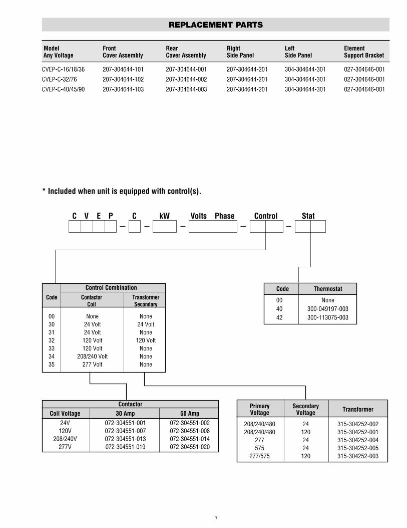
Model Front Rear Right Left ElementAny Voltage Cover Assembly Cover Assembly Side Panel Side Panel Support Bracket
CVEP-C-16/18/36 207-304644-101 207-304644-001 207-304644-201 304-304644-301 027-304646-001
CVEP-C-32/76 207-304644-102 207-304644-002 207-304644-201 304-304644-301 027-304646-001
CVEP-C-40/45/90 207-304644-103 207-304644-003 207-304644-201 304-304644-301 027-304646-001
Control CombinationCode Contactor Transformer
Coil Secondary
00 None None30 24 Volt 24 Volt31 24 Volt None32 120 Volt 120 Volt33 120 Volt None34 208/240 Volt None35 277 Volt None
Primary Secondary TransformerVoltage Voltage
208/240/480 24 315-304252-002208/240/480 120 315-304252-001
277 24 315-304252-004575 24 315-304252-005
277/575 120 315-304252-003
Code Thermostat
00 None40 300-049197-00342 300-113075-003
ContactorCoil Voltage 30 Amp 50 Amp
24V 072-304551-001 072-304551-002120V 072-304551-007 072-304551-008
208/240V 072-304551-013 072-304551-014277V 072-304551-019 072-304551-020
7
REPLACEMENT PARTS
C V E P C kW Volts Phase Control Stat
* Included when unit is equipped with control(s).

Chromalox warrants only that the Products and parts manufactured by Chromalox, whenshipped, and the work performed by Chromalox when performed, will meet all applicablespecification and other specific product and work requirements (including those of perfor-mance), if any, and will be free from defects in material and workmanship under normalconditions of use. All claims for defective or nonconforming (both hereinafter called defec-tive) Products, parts or work under this warranty must be made in writing immediately upondiscovery, and in any event, within one (1) year from delivery, provided, however all claimsfor defective Products and parts must be made in writing no later than eighteen (18) monthsafter shipment by Chromalox. Defective and nonconforming items must be held forChromalox's inspections and returned to the original f.o.b. point upon request. THE FORE-GOING IS EXPRESSLY IN LIEU OF ALL OTHER WARRANTIES WHATSOEVER, EXPRESS,IMPLIED AND STATUTORY, INCLUDING, WITHOUT LIMITATION, THE IMPLIED WAR-RANTIES OF MERCHANTABILITY AND FITNESS FOR A PARTICULAR PURPOSE.
Notwithstanding the provisions of this WARRANTY AND LIMITATION Clause, it is specifi-cally understood that Products and parts not manufactured and work not performed byChromalox are warranted only to the extent and in the manner that the same are warrantedto Chromalox by Chromalox's vendors, and then only to the extent that Chromalox is rea-sonably able to enforce such warranty, it being understood Chromalox shall have no obliga-tion to initiate litigation unless Buyer undertakes to pay all cost and expenses therefor,
including but not limited to attorney's fees, and indemnifies Chromalox against any liabilityto Chromalox's vendors arising out of such litigation.
Upon Buyer's submission of a claim as provided above and its substantiation, Chromaloxshall at its option either (i) repair or replace its Products, parts or work at the original f.o.b.point of delivery or (ii) refund an equitable portion of the purchase price.
THE FOREGOING IS CHROMALOX'S ONLY OBLIGATION AND BUYER'S EXCLUSIVE REM-EDY FOR BREACH OF WARRANTY, AND IS BUYER'S EXCLUSIVE REMEDY AGAINST CHRO-MALOX FOR ALL CLAIMS ARISING HEREUNDER OR RELATING HERETO WHETHER SUCHCLAIMS ARE BASED ON BREACH OF CONTRACT, TORT (INCLUDING NEGLIGENCE ANDSTRICT LIABILITY) OR OTHER THEORIES, BUYER'S FAILURE TO SUBMIT A CLAIM ASPROVIDED ABOVE SHALL SPECIFICALLY WAIVE ALL CLAIMS FOR DAMAGES OR OTHERRELIEF, INCLUDING BUT NOT LIMITED TO CLAIMS BASED ON LATENT DEFECTS. IN NOEVENT SHALL BUYER BE ENTITLED TO INCIDENTAL OR CONSEQUENTIAL DAMAGES ANDBUYER SHALL HOLD CHROMALOX HARMLESS THEREFROM. ANY ACTION BY BUYERARISING HEREUNDER OR RELATING HERETO, WHETHER BASED ON BREACH OF CON-TRACT, TORT (INCLUDING NEGLIGENCE AND STRICT LIABILITY) OR OTHER THEORIES,MUST BE COMMENCED WITHIN ONE (1) YEAR AFTER THE DATE OF SHIPMENT OR ITSHALL BE BARRED.
W2008M
WARRANTY AND LIMITATION OF REMEDY AND LIABILITY
2150 N. RULON WHITE BLVD., OGDEN, UT 84404Phone: 1-800-368-2493 www.chromalox.com
02 - 074TA - Q4 - EFLitho in U.S.A.

SMP – APPENDIX B: EXCAVATION WORK PLAN 229 HOMER STREET SITE
BCP SITE NO. C905044
0311-018-001 T KB
APPENDIX K
REMEDIAL SYSTEM OPTIMIZATION TABLE OF CONTENTS
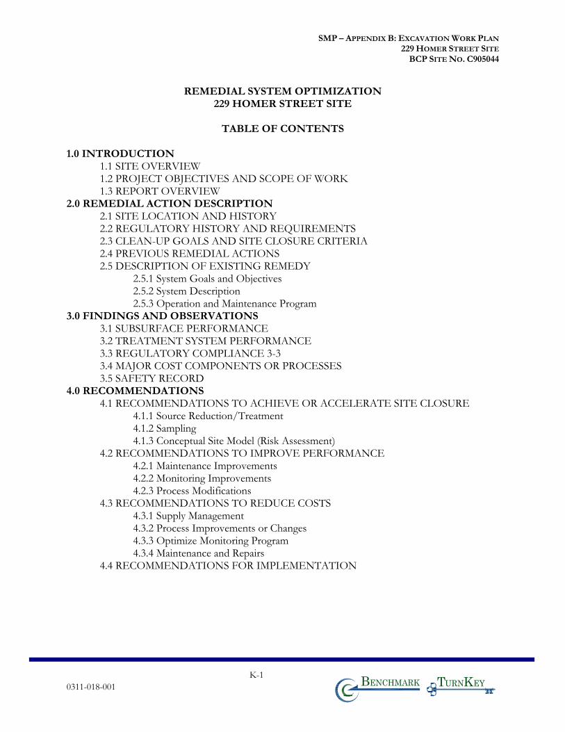
SMP – APPENDIX B: EXCAVATION WORK PLAN 229 HOMER STREET SITE
BCP SITE NO. C905044
K-1 0311-018-001 T KB
REMEDIAL SYSTEM OPTIMIZATION 229 HOMER STREET SITE
TABLE OF CONTENTS
1.0 INTRODUCTION
1.1 SITE OVERVIEW 1.2 PROJECT OBJECTIVES AND SCOPE OF WORK 1.3 REPORT OVERVIEW
2.0 REMEDIAL ACTION DESCRIPTION 2.1 SITE LOCATION AND HISTORY 2.2 REGULATORY HISTORY AND REQUIREMENTS 2.3 CLEAN-UP GOALS AND SITE CLOSURE CRITERIA 2.4 PREVIOUS REMEDIAL ACTIONS 2.5 DESCRIPTION OF EXISTING REMEDY
2.5.1 System Goals and Objectives 2.5.2 System Description 2.5.3 Operation and Maintenance Program
3.0 FINDINGS AND OBSERVATIONS 3.1 SUBSURFACE PERFORMANCE 3.2 TREATMENT SYSTEM PERFORMANCE 3.3 REGULATORY COMPLIANCE 3-3 3.4 MAJOR COST COMPONENTS OR PROCESSES 3.5 SAFETY RECORD
4.0 RECOMMENDATIONS 4.1 RECOMMENDATIONS TO ACHIEVE OR ACCELERATE SITE CLOSURE
4.1.1 Source Reduction/Treatment 4.1.2 Sampling 4.1.3 Conceptual Site Model (Risk Assessment)
4.2 RECOMMENDATIONS TO IMPROVE PERFORMANCE 4.2.1 Maintenance Improvements 4.2.2 Monitoring Improvements 4.2.3 Process Modifications
4.3 RECOMMENDATIONS TO REDUCE COSTS 4.3.1 Supply Management 4.3.2 Process Improvements or Changes 4.3.3 Optimize Monitoring Program 4.3.4 Maintenance and Repairs
4.4 RECOMMENDATIONS FOR IMPLEMENTATION
Related Documents


