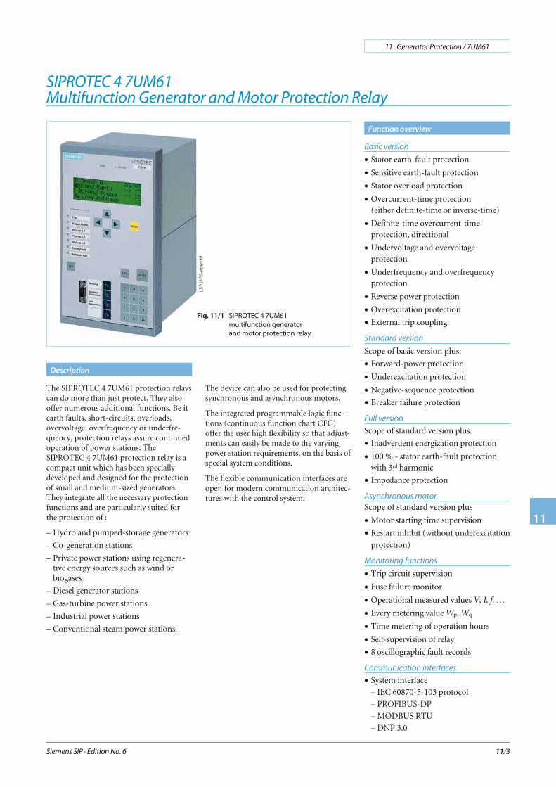
Function overview Description Siemens SIP · Edition No. 6 11 Generator Protection / 7UM61 11 11/3 Basic version • Stator earth-fault protection • Sensitive earth-fault protection • Stator overload protection • Overcurrent-time protection (either definite-time or inverse-time) • Definite-time overcurrent-time protection, directional • Undervoltage and overvoltage protection • Underfrequency and overfrequency protection • Reverse power protection • Overexcitation protection • External trip coupling Standard version Scope of basic version plus: • Forward-power protection • Underexcitation protection • Negative-sequence protection • Breaker failure protection Full version Scope of standard version plus: • Inadverdent energization protection • 100 % - stator earth-fault protection with 3 rd harmonic • Impedance protection Asynchronous motor Scope of standard version plus • Motor starting time supervision • Restart inhibit (without underexcitation protection) Monitoring functions • Trip circuit supervision • Fuse failure monitor • Operational measured values V, I, f, … • Every metering value Wp, Wq • Time metering of operation hours • Self-supervision of relay • 8 oscillographic fault records Communication interfaces • System interface – IEC 60870-5-103 protocol – PROFIBUS-DP – MODBUS RTU – DNP 3.0 SIPROTEC 4 7UM61 Multifunction Generator and Motor Protection Relay The SIPROTEC 4 7UM61 protection relays can do more than just protect. They also offer numerous additional functions. Be it earth faults, short-circuits, overloads, overvoltage, overfrequency or underfre- quency, protection relays assure continued operation of power stations. The SIPROTEC 4 7UM61 protection relay is a compact unit which has been specially developed and designed for the protection of small and medium-sized generators. They integrate all the necessary protection functions and are particularly suited for the protection of : – Hydro and pumped-storage generators – Co-generation stations – Private power stations using regenera- tive energy sources such as wind or biogases – Diesel generator stations – Gas-turbine power stations – Industrial power stations – Conventional steam power stations. The device can also be used for protecting synchronous and asynchronous motors. The integrated programmable logic func- tions (continuous function chart CFC) offer the user high flexibility so that adjust- ments can easily be made to the varying power station requirements, on the basis of special system conditions. The flexible communication interfaces are open for modern communication architec- tures with the control system. Fig. 11/1 SIPROTEC 4 7UM61 multifunction generator and motor protection relay LSP2176-afpen.tif

Welcome message from author
This document is posted to help you gain knowledge. Please leave a comment to let me know what you think about it! Share it to your friends and learn new things together.
Transcript
Function overview
Description
Siemens SIP · Edition No. 6
11 Generator Protection / 7UM61
11
11/3
Basic version
• Stator earth-fault protection
• Sensitive earth-fault protection
• Stator overload protection
• Overcurrent-time protection(either definite-time or inverse-time)
• Definite-time overcurrent-timeprotection, directional
• Undervoltage and overvoltageprotection
• Underfrequency and overfrequencyprotection
• Reverse power protection
• Overexcitation protection
• External trip coupling
Standard version
Scope of basic version plus:
• Forward-power protection
• Underexcitation protection
• Negative-sequence protection
• Breaker failure protection
Full version
Scope of standard version plus:
• Inadverdent energization protection
• 100 % - stator earth-fault protectionwith 3rd harmonic
• Impedance protection
Asynchronous motor
Scope of standard version plus
• Motor starting time supervision
• Restart inhibit (without underexcitation
protection)
Monitoring functions
• Trip circuit supervision
• Fuse failure monitor
• Operational measured values V, I, f, …
• Every metering value Wp, Wq
• Time metering of operation hours
• Self-supervision of relay
• 8 oscillographic fault records
Communication interfaces
• System interface
– IEC 60870-5-103 protocol
– PROFIBUS-DP
– MODBUS RTU
– DNP 3.0
SIPROTEC 4 7UM61
Multifunction Generator and Motor Protection Relay
The SIPROTEC 4 7UM61 protection relayscan do more than just protect. They alsooffer numerous additional functions. Be itearth faults, short-circuits, overloads,overvoltage, overfrequency or underfre-quency, protection relays assure continuedoperation of power stations. TheSIPROTEC 4 7UM61 protection relay is acompact unit which has been speciallydeveloped and designed for the protectionof small and medium-sized generators.They integrate all the necessary protectionfunctions and are particularly suited forthe protection of :
– Hydro and pumped-storage generators
– Co-generation stations
– Private power stations using regenera-tive energy sources such as wind orbiogases
– Diesel generator stations
– Gas-turbine power stations
– Industrial power stations
– Conventional steam power stations.
The device can also be used for protectingsynchronous and asynchronous motors.
The integrated programmable logic func-tions (continuous function chart CFC)offer the user high flexibility so that adjust-ments can easily be made to the varyingpower station requirements, on the basis ofspecial system conditions.
The flexible communication interfaces areopen for modern communication architec-tures with the control system.
Fig. 11/1 SIPROTEC 4 7UM61
multifunction generator
and motor protection relay
LSP
2176
-afp
en.ti
f
The 7UM6 protection relays of theSIPROTEC 4 family are compactmultifunction units which have been de-veloped for small to medium-sized powergeneration plants. They incorporate all thenecessary protective functions and areespecially suitable for the protection of:
– Hydro and pumped-storage generators
– Co-generation stations
– Private power stations using regenera-tive energy sources such as wind orbiogases
– Power generation with diesel generators
– Gas turbine power stations
– Industrial power stations
– Conventional steam power stations.
They can also be employed for protectionof motors and transformers.
The numerous other additional functionsassist the user in ensuring cost-effectivesystem management and reliable powersupply. Measured values display currentoperating conditions. Stored status indica-tions and fault recording provide assistancein fault diagnosis not only in the event of adisturbance in generator operation.
Combination of the units makes it possibleto implement effective redundancy con-cepts.
Protection functions
Numerous protection functions are neces-sary for reliable protection of electrical ma-chines. Their extent and combination aredetermined by a variety of factors, such asmachine size, mode of operation, plantconfiguration, availability requirements,experience and design philosophy.
This results in multifunctionality, which isimplemented in outstanding fashion bynumerical technology.
In order to satisfy differing requirements,the combination of functions is scalable(see Table 11/1). Selection is facilitated bydivision into groups.
Generator Basic
One application is concentrated on smallgenerators or as backup protection forlarger generators. The function mix is alsoan effective addition to transformer differ-ential protection with parallel-connectedtransformers. The functions are also suit-able for system disconnection.
Generator Standard
This function mix is recommended forgenerator outputs exceeding 1 MVA.It is also suitable for protection of synchro-nous motors.Another application is as backupprotection for the larger block units.
Generator Full
Here, all protection functions are availableand are recommended from generator out-puts exceeding 5 MVA. Backup protectionfor the larger block units is also a recom-mended application.
Asynchronous motor
This protection function mix is recom-mended for motors up to 1 - 2 MW.It offers a wide frequency operating rangefrom 11 Hz to 69 Hz. When an infeed isswitched, the protection adapts to thechanged voltage and frequency.
Siemens SIP · Edition No. 6
11 Generator Protection / 7UM61
11
11/4
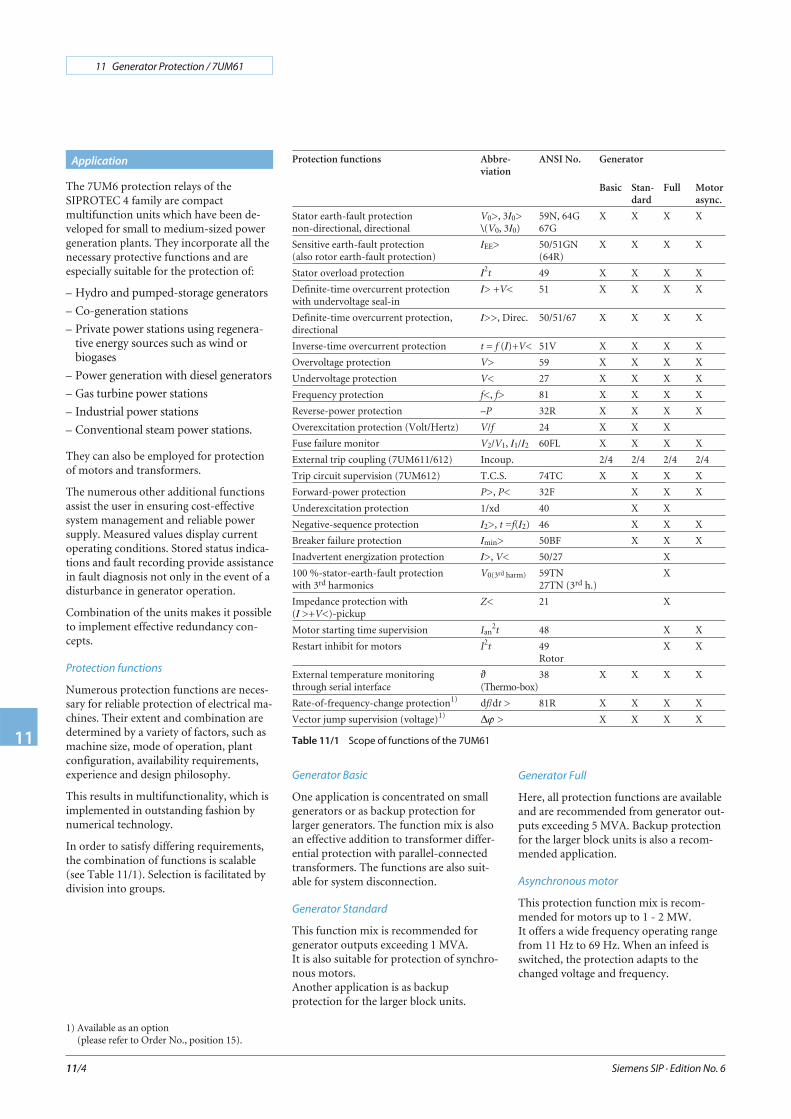
Application Protection functions Abbre-viation
ANSI No. Generator
Basic Stan-dard
Full Motorasync.
Stator earth-fault protectionnon-directional, directional
V0>, 3I0>\(V0, 3I0)
59N, 64G67G
X X X X
Sensitive earth-fault protection(also rotor earth-fault protection)
IEE> 50/51GN(64R)
X X X X
Stator overload protection I2t 49 X X X X
Definite-time overcurrent protectionwith undervoltage seal-in
I> +V< 51 X X X X
Definite-time overcurrent protection,directional
I>>, Direc. 50/51/67 X X X X
Inverse-time overcurrent protection t = f (I)+V< 51V X X X X
Overvoltage protection V> 59 X X X X
Undervoltage protection V< 27 X X X X
Frequency protection f<, f> 81 X X X X
Reverse-power protection –P 32R X X X X
Overexcitation protection (Volt/Hertz) V/f 24 X X X
Fuse failure monitor V2/V1, I1/I2 60FL X X X X
External trip coupling (7UM611/612) Incoup. 2/4 2/4 2/4 2/4
Trip circuit supervision (7UM612) T.C.S. 74TC X X X X
Forward-power protection P>, P< 32F X X X
Underexcitation protection 1/xd 40 X X
Negative-sequence protection I2>, t =f(I2) 46 X X X
Breaker failure protection Imin> 50BF X X X
Inadvertent energization protection I>, V< 50/27 X
100 %-stator-earth-fault protectionwith 3rd harmonics
V0(3rd harm) 59TN27TN (3rd h.)
X
Impedance protection with(I >+V<)-pickup
Z< 21 X
Motor starting time supervision Ian2t 48 X X
Restart inhibit for motors I2t 49Rotor
X X
External temperature monitoringthrough serial interface
ϑ(Thermo-box)
38 X X X X
Rate-of-frequency-change protection1) df/dt > 81R X X X X
Vector jump supervision (voltage)1) Δϕ > X X X X
Table 11/1 Scope of functions of the 7UM61
1) Available as an option(please refer to Order No., position 15).
Siemens SIP · Edition No. 6
11 Generator Protection / 7UM61
11
11/5
Application
Construction
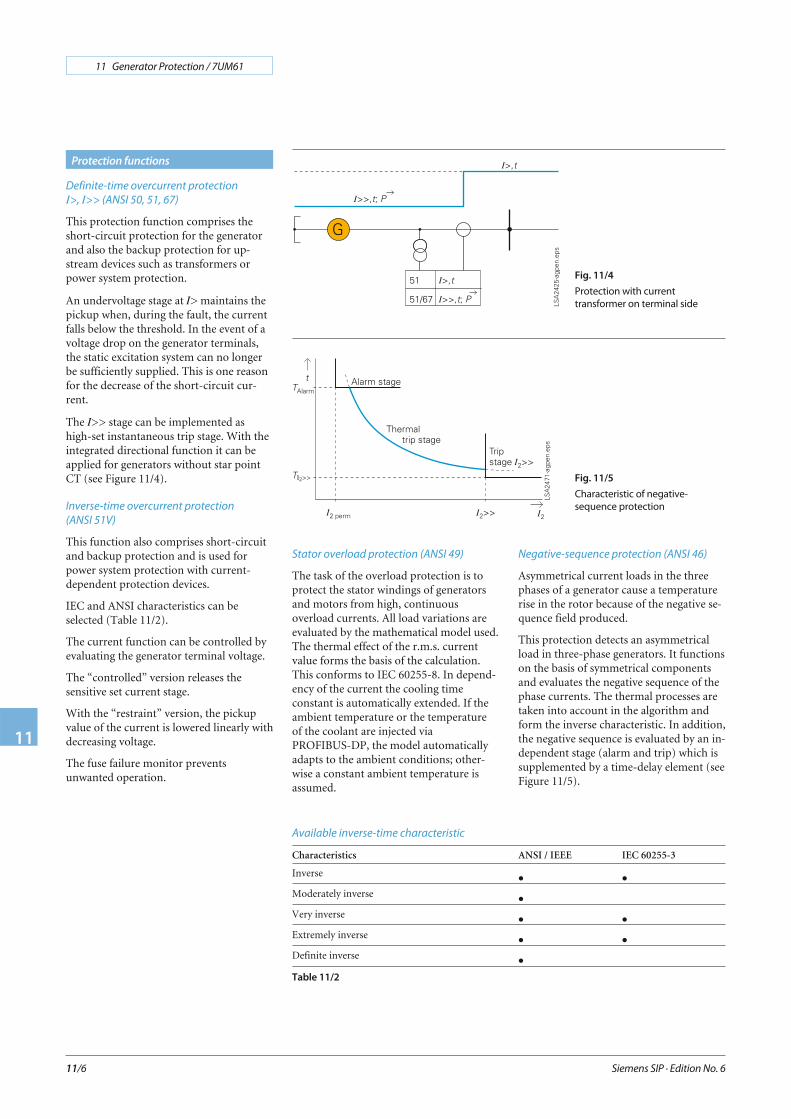
The SIPROTEC 4 units have a uniformdesign and a degree of functionality whichrepresents a whole new quality in protec-tion and control. Local operation has beendesigned according to ergonomic criteria.Large, easy-to-read displays were a majordesign aim. The DIGSI 4 operating pro-gram considerably simplifies planning andengineering and reduces commissioningtimes.
The 7UM611 is configured in 1/3 19 inch,and the 7UM612 in 1/2 19 inch width. Thismeans that the units of previous modelscan be replaced. The height throughout allhousing width increments is 243 mm.
All wires are connected directly or bymeans of ring-type cable lugs.
Alternatively, versions with plug-in termi-nals are also available. These permit the useof prefabricated cable harnesses.
In the case of panel surface mounting, theconnecting terminals are in the form ofscrew-type terminals at top and bottom.The communication interfaces are alsoarranged on the same sides.
Fig. 11/3
Rear view with wiring terminal
safety cover and serial interface
LSP
2166
-afp
en.e
ps
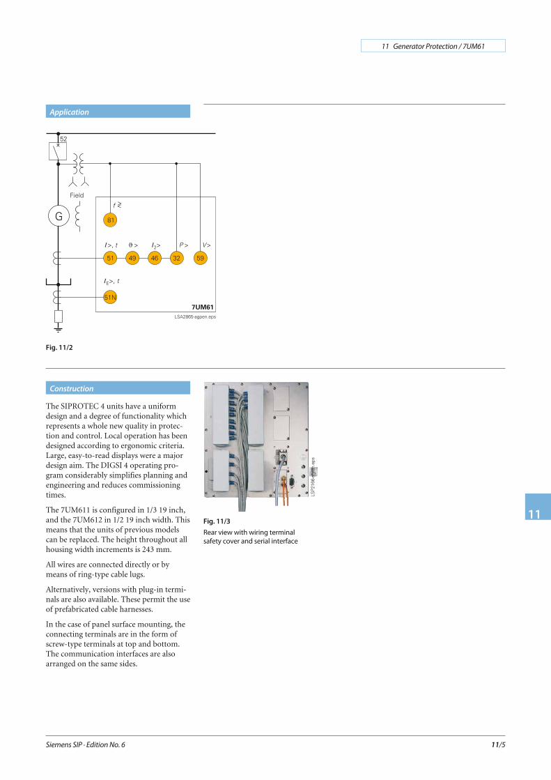
Fig. 11/2
Definite-time overcurrent protection
I>, I>> (ANSI 50, 51, 67)
This protection function comprises theshort-circuit protection for the generatorand also the backup protection for up-stream devices such as transformers orpower system protection.
An undervoltage stage at I> maintains thepickup when, during the fault, the currentfalls below the threshold. In the event of avoltage drop on the generator terminals,the static excitation system can no longerbe sufficiently supplied. This is one reasonfor the decrease of the short-circuit cur-rent.
The I>> stage can be implemented ashigh-set instantaneous trip stage. With theintegrated directional function it can beapplied for generators without star pointCT (see Figure 11/4).
Inverse-time overcurrent protection
(ANSI 51V)
This function also comprises short-circuitand backup protection and is used forpower system protection with current-dependent protection devices.
IEC and ANSI characteristics can beselected (Table 11/2).
The current function can be controlled byevaluating the generator terminal voltage.
The “controlled” version releases thesensitive set current stage.
With the “restraint” version, the pickupvalue of the current is lowered linearly withdecreasing voltage.
The fuse failure monitor preventsunwanted operation.
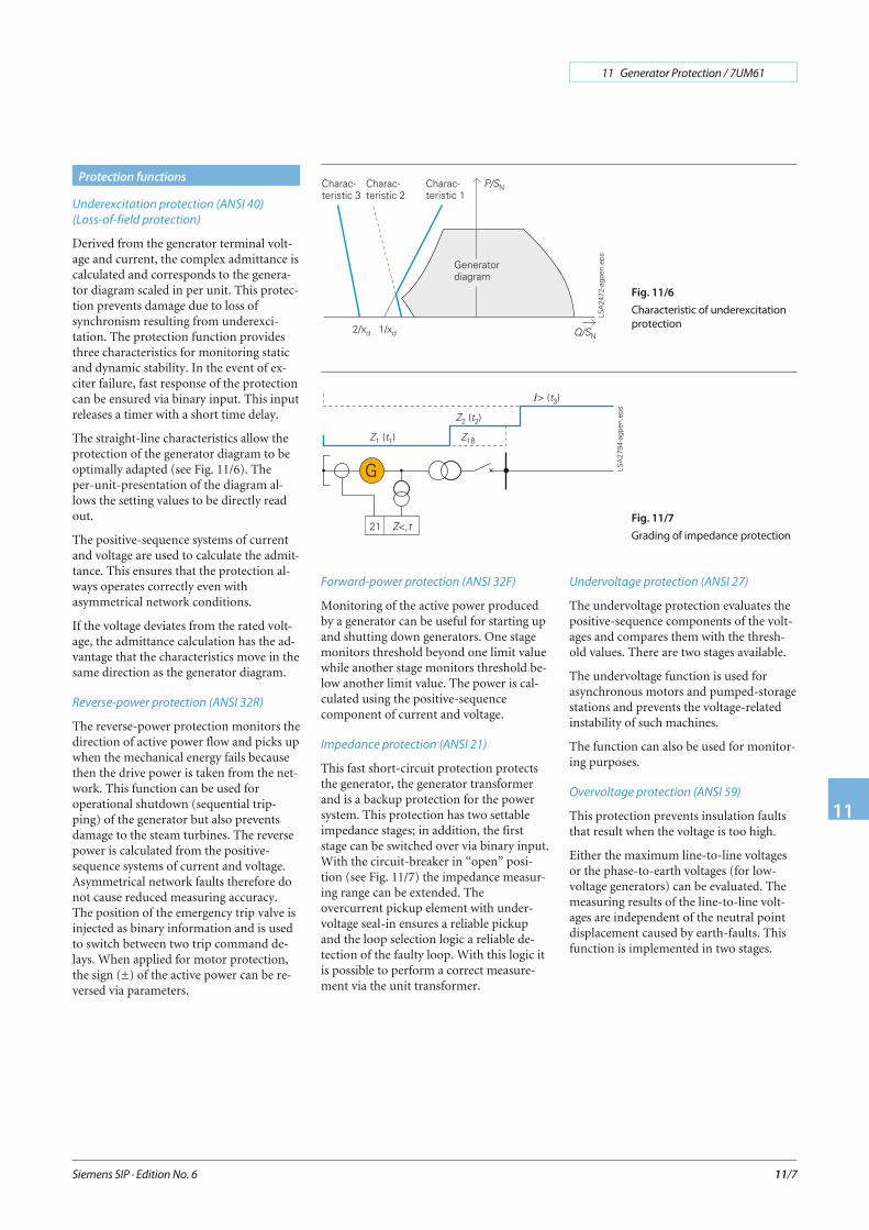
Stator overload protection (ANSI 49)
The task of the overload protection is toprotect the stator windings of generatorsand motors from high, continuousoverload currents. All load variations areevaluated by the mathematical model used.The thermal effect of the r.m.s. currentvalue forms the basis of the calculation.This conforms to IEC 60255-8. In depend-ency of the current the cooling timeconstant is automatically extended. If theambient temperature or the temperatureof the coolant are injected viaPROFIBUS-DP, the model automaticallyadapts to the ambient conditions; other-wise a constant ambient temperature isassumed.
Negative-sequence protection (ANSI 46)
Asymmetrical current loads in the threephases of a generator cause a temperaturerise in the rotor because of the negative se-quence field produced.
This protection detects an asymmetricalload in three-phase generators. It functionson the basis of symmetrical componentsand evaluates the negative sequence of thephase currents. The thermal processes aretaken into account in the algorithm andform the inverse characteristic. In addition,the negative sequence is evaluated by an in-dependent stage (alarm and trip) which issupplemented by a time-delay element (seeFigure 11/5).
Siemens SIP · Edition No. 6
11 Generator Protection / 7UM61
11
11/6
Protection functions
Fig. 11/4
Protection with current
transformer on terminal side
Fig. 11/5
Characteristic of negative-
sequence protection
Available inverse-time characteristic
Characteristics ANSI / IEEE IEC 60255-3
Inverse • •Moderately inverse •Very inverse • •Extremely inverse • •Definite inverse •Table 11/2
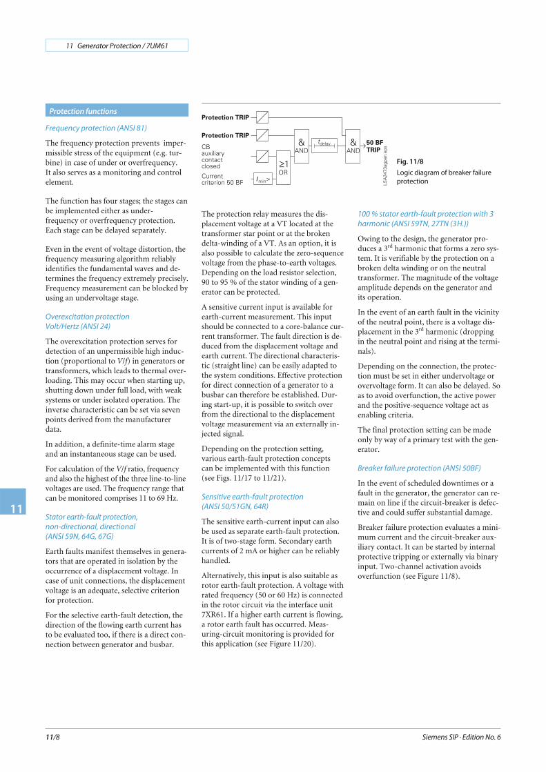
Underexcitation protection (ANSI 40)
(Loss-of-field protection)
Derived from the generator terminal volt-age and current, the complex admittance iscalculated and corresponds to the genera-tor diagram scaled in per unit. This protec-tion prevents damage due to loss ofsynchronism resulting from underexci-tation. The protection function providesthree characteristics for monitoring staticand dynamic stability. In the event of ex-citer failure, fast response of the protectioncan be ensured via binary input. This inputreleases a timer with a short time delay.
The straight-line characteristics allow theprotection of the generator diagram to beoptimally adapted (see Fig. 11/6). Theper-unit-presentation of the diagram al-lows the setting values to be directly readout.
The positive-sequence systems of currentand voltage are used to calculate the admit-tance. This ensures that the protection al-ways operates correctly even withasymmetrical network conditions.
If the voltage deviates from the rated volt-age, the admittance calculation has the ad-vantage that the characteristics move in thesame direction as the generator diagram.
Reverse-power protection (ANSI 32R)
The reverse-power protection monitors thedirection of active power flow and picks upwhen the mechanical energy fails becausethen the drive power is taken from the net-work. This function can be used foroperational shutdown (sequential trip-ping) of the generator but also preventsdamage to the steam turbines. The reversepower is calculated from the positive-sequence systems of current and voltage.Asymmetrical network faults therefore donot cause reduced measuring accuracy.The position of the emergency trip valve isinjected as binary information and is usedto switch between two trip command de-lays. When applied for motor protection,the sign (±) of the active power can be re-versed via parameters.
Forward-power protection (ANSI 32F)
Monitoring of the active power producedby a generator can be useful for starting upand shutting down generators. One stagemonitors threshold beyond one limit valuewhile another stage monitors threshold be-low another limit value. The power is cal-culated using the positive-sequencecomponent of current and voltage.
Impedance protection (ANSI 21)
This fast short-circuit protection protectsthe generator, the generator transformerand is a backup protection for the powersystem. This protection has two settableimpedance stages; in addition, the firststage can be switched over via binary input.With the circuit-breaker in “open” posi-tion (see Fig. 11/7) the impedance measur-ing range can be extended. Theovercurrent pickup element with under-voltage seal-in ensures a reliable pickupand the loop selection logic a reliable de-tection of the faulty loop. With this logic itis possible to perform a correct measure-ment via the unit transformer.
Undervoltage protection (ANSI 27)
The undervoltage protection evaluates thepositive-sequence components of the volt-ages and compares them with the thresh-old values. There are two stages available.
The undervoltage function is used forasynchronous motors and pumped-storagestations and prevents the voltage-relatedinstability of such machines.
The function can also be used for monitor-ing purposes.
Overvoltage protection (ANSI 59)
This protection prevents insulation faultsthat result when the voltage is too high.
Either the maximum line-to-line voltagesor the phase-to-earth voltages (for low-voltage generators) can be evaluated. Themeasuring results of the line-to-line volt-ages are independent of the neutral pointdisplacement caused by earth-faults. Thisfunction is implemented in two stages.
Siemens SIP · Edition No. 6
11 Generator Protection / 7UM61
11
11/7
Protection functions
Fig. 11/6
Characteristic of underexcitation
protection
Fig. 11/7
Grading of impedance protection
Frequency protection (ANSI 81)
The frequency protection prevents imper-missible stress of the equipment (e.g. tur-bine) in case of under or overfrequency.It also serves as a monitoring and controlelement.
The function has four stages; the stages canbe implemented either as under-frequency or overfrequency protection.Each stage can be delayed separately.
Even in the event of voltage distortion, thefrequency measuring algorithm reliablyidentifies the fundamental waves and de-termines the frequency extremely precisely.Frequency measurement can be blocked byusing an undervoltage stage.
Overexcitation protection
Volt/Hertz (ANSI 24)
The overexcitation protection serves fordetection of an unpermissible high induc-tion (proportional to V/f) in generators ortransformers, which leads to thermal over-loading. This may occur when starting up,shutting down under full load, with weaksystems or under isolated operation. Theinverse characteristic can be set via sevenpoints derived from the manufacturerdata.
In addition, a definite-time alarm stageand an instantaneous stage can be used.
For calculation of the V/f ratio, frequencyand also the highest of the three line-to-linevoltages are used. The frequency range thatcan be monitored comprises 11 to 69 Hz.
Stator earth-fault protection,
non-directional, directional
(ANSI 59N, 64G, 67G)
Earth faults manifest themselves in genera-tors that are operated in isolation by theoccurrence of a displacement voltage. Incase of unit connections, the displacementvoltage is an adequate, selective criterionfor protection.
For the selective earth-fault detection, thedirection of the flowing earth current hasto be evaluated too, if there is a direct con-nection between generator and busbar.
The protection relay measures the dis-placement voltage at a VT located at thetransformer star point or at the brokendelta-winding of a VT. As an option, it isalso possible to calculate the zero-sequencevoltage from the phase-to-earth voltages.Depending on the load resistor selection,90 to 95 % of the stator winding of a gen-erator can be protected.
A sensitive current input is available forearth-current measurement. This inputshould be connected to a core-balance cur-rent transformer. The fault direction is de-duced from the displacement voltage andearth current. The directional characteris-tic (straight line) can be easily adapted tothe system conditions. Effective protectionfor direct connection of a generator to abusbar can therefore be established. Dur-ing start-up, it is possible to switch overfrom the directional to the displacementvoltage measurement via an externally in-jected signal.
Depending on the protection setting,various earth-fault protection conceptscan be implemented with this function(see Figs. 11/17 to 11/21).
Sensitive earth-fault protection
(ANSI 50/51GN, 64R)
The sensitive earth-current input can alsobe used as separate earth-fault protection.It is of two-stage form. Secondary earthcurrents of 2 mA or higher can be reliablyhandled.
Alternatively, this input is also suitable asrotor earth-fault protection. A voltage withrated frequency (50 or 60 Hz) is connectedin the rotor circuit via the interface unit7XR61. If a higher earth current is flowing,a rotor earth fault has occurred. Meas-uring-circuit monitoring is provided forthis application (see Figure 11/20).
100 % stator earth-fault protection with 3rd
harmonic (ANSI 59TN, 27TN (3rdH.))
Owing to the design, the generator pro-duces a 3rd harmonic that forms a zero sys-tem. It is verifiable by the protection on abroken delta winding or on the neutraltransformer. The magnitude of the voltageamplitude depends on the generator andits operation.
In the event of an earth fault in the vicinityof the neutral point, there is a voltage dis-placement in the 3rd harmonic (droppingin the neutral point and rising at the termi-nals).
Depending on the connection, the protec-tion must be set in either undervoltage orovervoltage form. It can also be delayed. Soas to avoid overfunction, the active powerand the positive-sequence voltage act asenabling criteria.
The final protection setting can be madeonly by way of a primary test with the gen-erator.
Breaker failure protection (ANSI 50BF)
In the event of scheduled downtimes or afault in the generator, the generator can re-main on line if the circuit-breaker is defec-tive and could suffer substantial damage.
Breaker failure protection evaluates a mini-mum current and the circuit-breaker aux-iliary contact. It can be started by internalprotective tripping or externally via binaryinput. Two-channel activation avoidsoverfunction (see Figure 11/8).
Siemens SIP · Edition No. 6
11 Generator Protection / 7UM61
11
11/8
Protection functions
Fig. 11/8
Logic diagram of breaker failure
protection
Inadvertent energization protection
(ANSI 50, 27)
This protection has the function of limit-ing the damage of the generator in theevent of an unintentional switch-on of thecircuit-breaker, whether the generator isstanding still or rotating without being ex-cited or synchronized. If the power systemvoltage is connected, the generator starts asan asynchronous machine with a large slipand this leads to excessively high currentsin the rotor.
A logic circuit consisting of sensitive cur-rent measurement for each phase, mea-sured value detector, time control andblocking as of a minimum voltage, leads toan instantaneous trip command. If the fusefailure monitor responds, this function isineffective.
Starting time supervision (motor protection
only) (ANSI 48)
Starting time supervision protects the mo-tor against long unwanted start-ups, whichmight occur as a result of excessive loadtorque or excessive voltage drops withinthe motor, or if the rotor is locked.
The tripping time is dependent on thesquare of the start-up current and the setstart-up time (Inverse Characteristic). Itadapts itself to the start-up with reducedvoltage. The tripping time is determined inaccordance with the following formula:
t tTripstart
rms
start max=⎛⎝⎜
⎞⎠⎟ ⋅I
I
2
tTrip Tripping time
Istart Permissible start-up current
tstart max Permissible start-up time
Irms Measured r.m.s. current value
Calculation is not started until the currentIrms is higher than an adjustable responsevalue(e.g. 2 IN, MOTOR).
If the permissible locked-rotor time is lessthan the permissible start-up time (motorswith a thermally critical rotor), a binarysignal is set to detect a locked rotor bymeans of a tachometer generator. This bi-nary signal releases the set locked-rotortime, and tripping occurs after it haselapsed.
Restart inhibit for motors
(ANSI 66, 49Rotor)
When cold or at operating temperature,motors may only be connected a certainnumber of times in succession. Thestart-up current causes heat developmentin the rotor which is monitored by the re-start inhibit function.
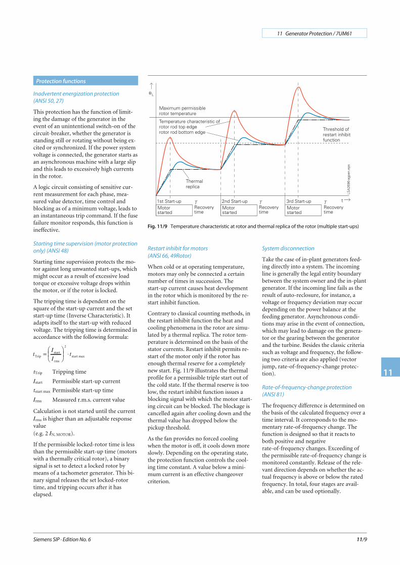
Contrary to classical counting methods, inthe restart inhibit function the heat andcooling phenomena in the rotor are simu-lated by a thermal replica. The rotor tem-perature is determined on the basis of thestator currents. Restart inhibit permits re-start of the motor only if the rotor hasenough thermal reserve for a completelynew start. Fig. 11/9 illustrates the thermalprofile for a permissible triple start out ofthe cold state. If the thermal reserve is toolow, the restart inhibit function issues ablocking signal with which the motor start-ing circuit can be blocked. The blockage iscancelled again after cooling down and thethermal value has dropped below thepickup threshold.
As the fan provides no forced coolingwhen the motor is off, it cools down moreslowly. Depending on the operating state,the protection function controls the cool-ing time constant. A value below a mini-mum current is an effective changeovercriterion.
System disconnection
Take the case of in-plant generators feed-ing directly into a system. The incomingline is generally the legal entity boundarybetween the system owner and the in-plantgenerator. If the incoming line fails as theresult of auto-reclosure, for instance, avoltage or frequency deviation may occurdepending on the power balance at thefeeding generator. Asynchronous condi-tions may arise in the event of connection,which may lead to damage on the genera-tor or the gearing between the generatorand the turbine. Besides the classic criteriasuch as voltage and frequency, the follow-ing two criteria are also applied (vectorjump, rate-of-frequency-change protec-tion).
Rate-of-frequency-change protection
(ANSI 81)
The frequency difference is determined onthe basis of the calculated frequency over atime interval. It corresponds to the mo-mentary rate-of-frequency change. Thefunction is designed so that it reacts toboth positive and negativerate-of-frequency changes. Exceeding ofthe permissible rate-of-frequency change ismonitored constantly. Release of the rele-vant direction depends on whether the ac-tual frequency is above or below the ratedfrequency. In total, four stages are avail-able, and can be used optionally.
Siemens SIP · Edition No. 6
11 Generator Protection / 7UM61
11
11/9
Protection functions
Fig. 11/9 Temperature characteristic at rotor and thermal replica of the rotor (multiple start-ups)
Vector jump
Monitoring the phase angle in the voltageis a criterion for identifying an interruptedinfeed. If the incoming line should fail, theabrupt current discontinuity leads to aphase angle jump in the voltage. This ismeasured by means of a delta process. Thecommand for opening the generator orcoupler circuit-breaker is issued if the setthreshold is exceeded.
External trip coupling
For recording and processing of externaltrip information, there are 2 (for 7UM611)or 4 (for 7UM612) binary inputs. They areprovided for information from theBuchholz relay or generator-specific com-mands and act like a protective function.Each input initiates a fault event and canbe individually delayed by a timer.
Trip circuit supervision (ANSI 74TC)
One or two binary inputs can be used formonitoring the circuit-breaker trip coil in-cluding its incoming cables. An alarm signaloccurs whenever the circuit is interrupted.
Phase rotation reversal
If the relay is used in a pumped-storagepower plant, matching to the prevailing ro-tary field is possible via a binary input(generator/motor operation via phase rota-tion reversal).
2 pre-definable parameter groups
In the protection, the setting values can bestored in two data sets. In addition to thestandard parameter group, the secondgroup is provided for certain operatingconditions (pumped-storage power sta-tions). It can be activated via binary input,local control or DIGSI 4.
Lockout (ANSI 86)
All binary outputs (alarm or trip relays)can be stored like LEDs and reset using theLED reset key. The lockout state is alsostored in the event of supply voltage fail-ure. Reclosure can only occur after thelockout state is reset.
Fuse failure and other monitoring
The relay comprises high-performancemonitoring for the hardware and software.
The measuring circuits, analog-digital con-version, power supply voltages, memoriesand software sequence (watch-dog) are allmonitored.
The fuse failure function detects failure ofthe measuring voltage due to short-circuitor open circuit of the wiring or VT andavoids overfunction of the undervoltage el-ements in the protection functions.
The positive and negative-sequence system(voltage and current) are evaluated.
Filter time
All binary inputs can be subjected to afilter time (indication suppression).
Siemens SIP · Edition No. 6
11 Generator Protection / 7UM61
11
11/10
Protection functions

With respect to communication, particularemphasis has been placed on high levels offlexibility, data integrity and utilization ofstandards common in energy automation.The design of the communication modulespermits interchangeability on the onehand, and on the other hand providesopenness for future standards (for exam-ple, Industrial Ethernet).
Local PC interface
The PC interface accessible from the frontof the unit permits quick access to all pa-rameters and fault event data. The use ofthe DIGSI 4 operating program duringcommissioning is particularly advanta-geous.
Rear-mounted interfaces
Two communication modules on the rearof the unit incorporate optional equipmentcomplements and permit retrofitting. Theyassure the ability to comply with the re-quirements of different communicationinterfaces (electrical or optical) and proto-cols (IEC 60870, PROFIBUS, DIGSI).
The interfaces make provision for the fol-lowing applications:
Service interface
In the RS485 version, several protectionunits can be centrally operated withDIGSI 4. By using a modem, remote con-trol is possible. This provides advantages infault clearance, in particular in unmannedsubstations.
System interface
This is used to communicate with a controlor protection and control system and sup-ports, depending on the module con-nected, a variety of communicationprotocols and interface designs.
IEC 60870-5-103
IEC 60870-5-103 is an internationally stan-dardized protocol for communication withprotection relays.
IEC 60870-5-103 is supported by a numberof protection unit manufacturers and isused worldwide.
The generator protection functions arestored in the manufacturer-specific, pub-lished part of the protocol.
PROFIBUS-DP
PROFIBUS is an internationally standard-ized communication protocol (EN 50170).PROFIBUS is supported internationally byseveral hundred manufacturers and has todate been used in more than 1,000,000applications all over the world.
With the PROFIBUS-DP, the protectioncan be directly connected to a SIMATICS5/S7. The transferred data are fault data,measured values and information from orto the logic (CFC).
MODBUS RTU
MODBUS is also a widely utilized commu-nication standard and is used in numerousautomation solutions.
DNP 3.0
DNP 3.0 (Distributed Network Protocolversion 3) is a messaging-based communi-cation protocol. The SIPROTEC 4 unitsare fully Level 1 and Level 2 compliantwith DNP 3.0. DNP 3.0 is supported by anumber of protection device manufactur-ers.
Safe bus architecture
• RS485 busWith this data transmission via copperconductors, electromagnetic interferenceinfluences are largely eliminated by theuse of twisted-pair conductor. Upon fail-ure of a unit, the remaining system con-tinues to operate without any faults.
• Fiber-optic double ring circuitThe fiber-optic double ring circuit is im-mune to electromagnetic interference.Upon failure of a section between twounits, the communication system contin-ues to operate without disturbance.
Siemens SIP · Edition No. 6
11 Generator Protection / 7UM61
11
11/11
Communication
Fig. 11/10
IEC 60870-5-103 star-type RS232 copper conductor
connection or fiber-optic connection
Fig. 11/11
PROFIBUS: RS485 copper conductors
Master control unit
System solution
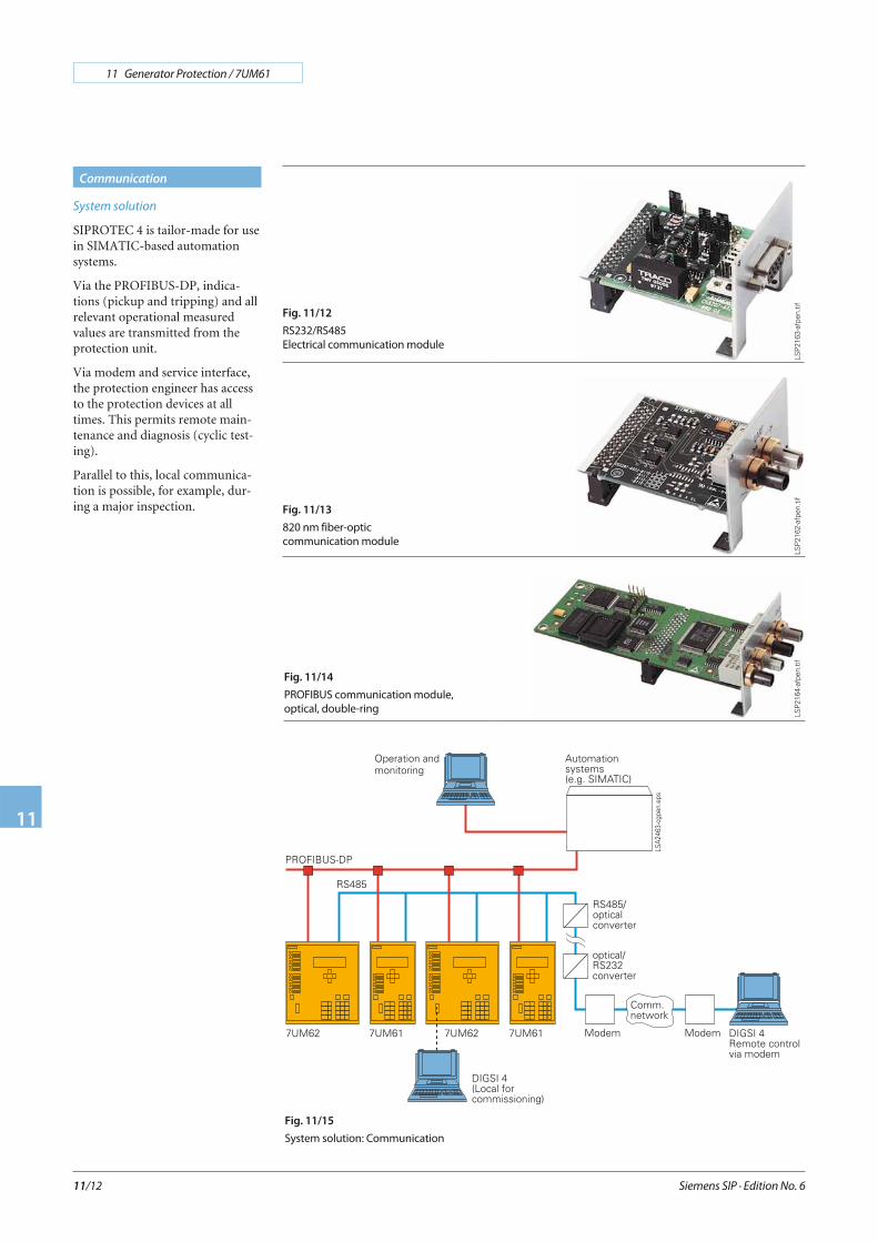
SIPROTEC 4 is tailor-made for usein SIMATIC-based automationsystems.
Via the PROFIBUS-DP, indica-tions (pickup and tripping) and allrelevant operational measuredvalues are transmitted from theprotection unit.
Via modem and service interface,the protection engineer has accessto the protection devices at alltimes. This permits remote main-tenance and diagnosis (cyclic test-ing).
Parallel to this, local communica-tion is possible, for example, dur-ing a major inspection.
Siemens SIP · Edition No. 6
11 Generator Protection / 7UM61
11
11/12
Communication
Fig. 11/13
820 nm fiber-optic
communication module
Fig. 11/12
RS232/RS485
Electrical communication module
Fig. 11/14
PROFIBUS communication module,
optical, double-ring
Fig. 11/15
System solution: Communication
LSP
2163
-afp
en.ti
fLS
P21
62-a
fpen
.tif
LSP
2164
-afp
en.ti
f
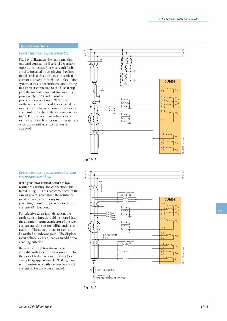
Direct generator - busbar connection
Fig. 11/16 illustrates the recommendedstandard connection if several generatorssupply one busbar. Phase-to-earth faultsare disconnected by employing the direc-tional earth-fault criterion. The earth-faultcurrent is driven through the cables of thesystem. If this is not sufficient, an earthingtransformer connected to the busbar sup-plies the necessary current (maximum ap-proximately 10 A) and permits aprotection range of up to 90 %. Theearth-fault current should be detected bymeans of core-balance current transform-ers in order to achieve the necessary sensi-tivity. The displacement voltage can beused as earth-fault criterion during startingoperations until synchronization isachieved.
Direct generator - busbar connection with
low-resistance earthing
If the generator neutral point has low-resistance earthing, the connection illus-trated in Fig. 11/17 is recommended. In thecase of several generators, the resistancemust be connected to only onegenerator, in order to prevent circulatingcurrents (3rd harmonic).
For selective earth-fault detection, theearth-current input should be looped intothe common return conductor of the twocurrent transformer sets (differential con-nection). The current transformers mustbe earthed at only one point. The displace-ment voltage VE is utilized as an additionalenabling criterion.
Balanced current transformers aredesirable with this form of connection. Inthe case of higher generator power (forexample, IN approximately 2000 A), cur-rent transformers with a secondary ratedcurrent of 5 A are recommended.
Siemens SIP · Edition No. 6
11 Generator Protection / 7UM61
11
11/13
Typical connections
Fig. 11/16
Fig. 11/17
Direct generator - busbar connection with
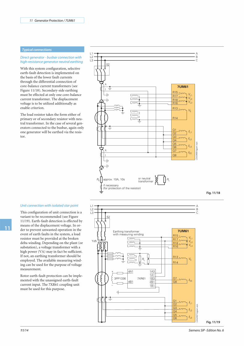
high-resistance generator neutral earthing
With this system configuration, selectiveearth-fault detection is implemented onthe basis of the lower fault currentsthrough the differential connection ofcore-balance current transformers (seeFigure 11/18). Secondary-side earthingmust be effected at only one core-balancecurrent transformer. The displacementvoltage is to be utilized additionally asenable criterion.
The load resistor takes the form either ofprimary or of secondary resistor with neu-tral transformer. In the case of several gen-erators connected to the busbar, again onlyone generator will be earthed via the resis-tor.
Unit connection with isolated star point
This configuration of unit connection is avariant to be recommended (see Figure11/19). Earth-fault detection is effected bymeans of the displacement voltage. In or-der to prevent unwanted operation in theevent of earth faults in the system, a loadresistor must be provided at the brokendelta winding. Depending on the plant (orsubstation), a voltage transformer with ahigh power (VA) may in fact be sufficient.If not, an earthing transformer should beemployed. The available measuring wind-ing can be used for the purpose of voltagemeasurement.
Rotor earth-fault protection can be imple-mented with the unassigned earth-faultcurrent input. The 7XR61 coupling unitmust be used for this purpose.
Siemens SIP · Edition No. 6
11 Generator Protection / 7UM61
11
11/14
Typical connections
Fig. 11/18
Fig. 11/19

Unit connection with neutral transformer
With this system configuration, distur-bance voltage reduction and damping inthe event of earth faults in the generatorarea are effected by a load resistor con-nected to generator neutral point. Themaximum earth-fault current is limited toapproximately 10 A. Configuration cantake the form of a primary or secondary re-sistor with neutral transformer. In order toavoid low secondary resistance, the trans-formation ratio of the neutral transformershould be low. The higher secondary volt-age can be reduced by means of a voltagedivider.
Electrically, the circuit is identical to theconfiguration in Figure 11/19.
Connection with low-voltage generators
As is generally known, the low-voltage sys-tem is solidly earthed, so that the generatorneutral point is connected to earth (seeFigure 11/21). With this configuration,there is the risk that, as a result of the 3rd
harmonics forming a zero phase-sequencesystem, circulating currents will flow viathe N-conductor. This must be limited bythe generator or system configuration (re-actor).
Otherwise, connection corresponds to thecustomary standard. In the case of residualcurrent transformer design, it has to be en-sured that the thermal current limit (1 s) ofthe IEE input is restricted to 300 A.
Siemens SIP · Edition No. 6
11 Generator Protection / 7UM61
11
11/15
Typical connections
Fig. 11/20
Fig. 11/21
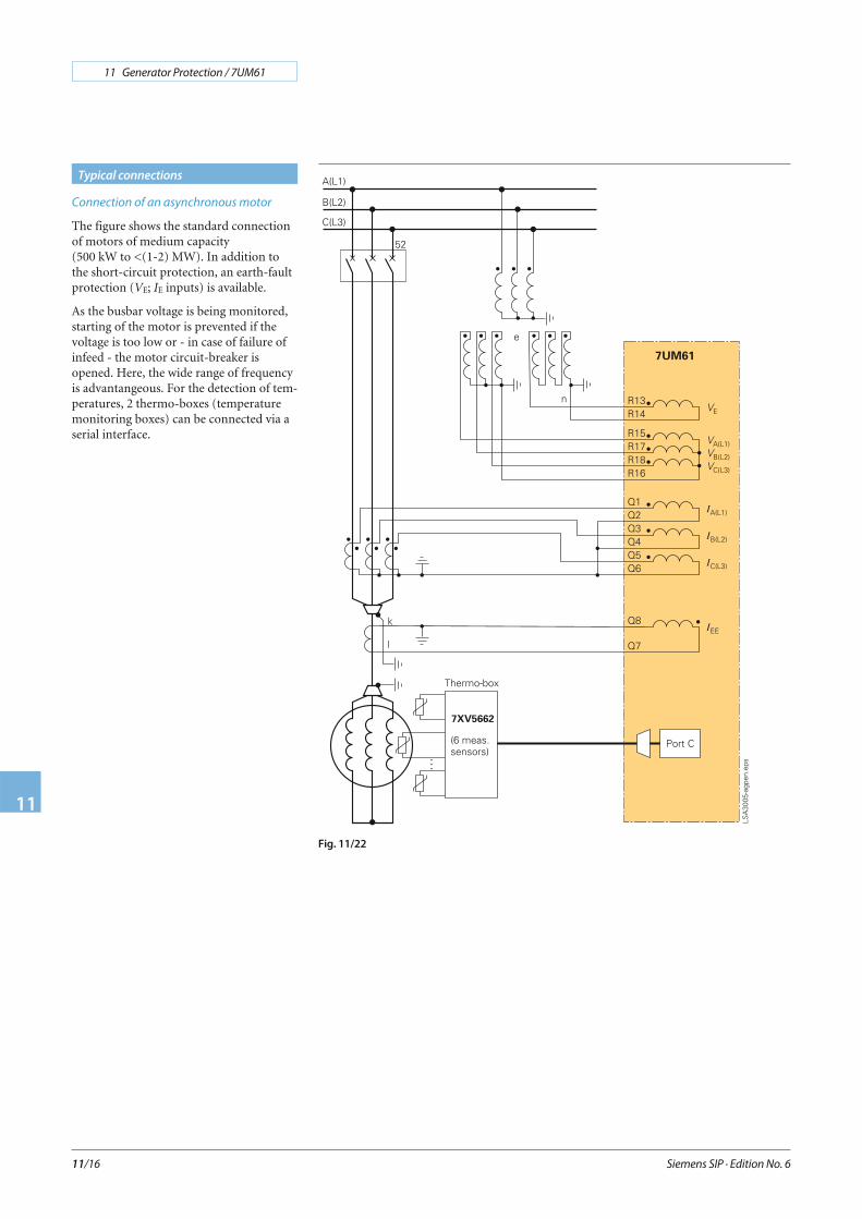
Connection of an asynchronous motor
The figure shows the standard connectionof motors of medium capacity(500 kW to <(1-2) MW). In addition tothe short-circuit protection, an earth-faultprotection (VE; IE inputs) is available.
As the busbar voltage is being monitored,starting of the motor is prevented if thevoltage is too low or - in case of failure ofinfeed - the motor circuit-breaker isopened. Here, the wide range of frequencyis advantangeous. For the detection of tem-peratures, 2 thermo-boxes (temperaturemonitoring boxes) can be connected via aserial interface.
Siemens SIP · Edition No. 6
11 Generator Protection / 7UM61
11
11/16
Typical connections
Fig. 11/22
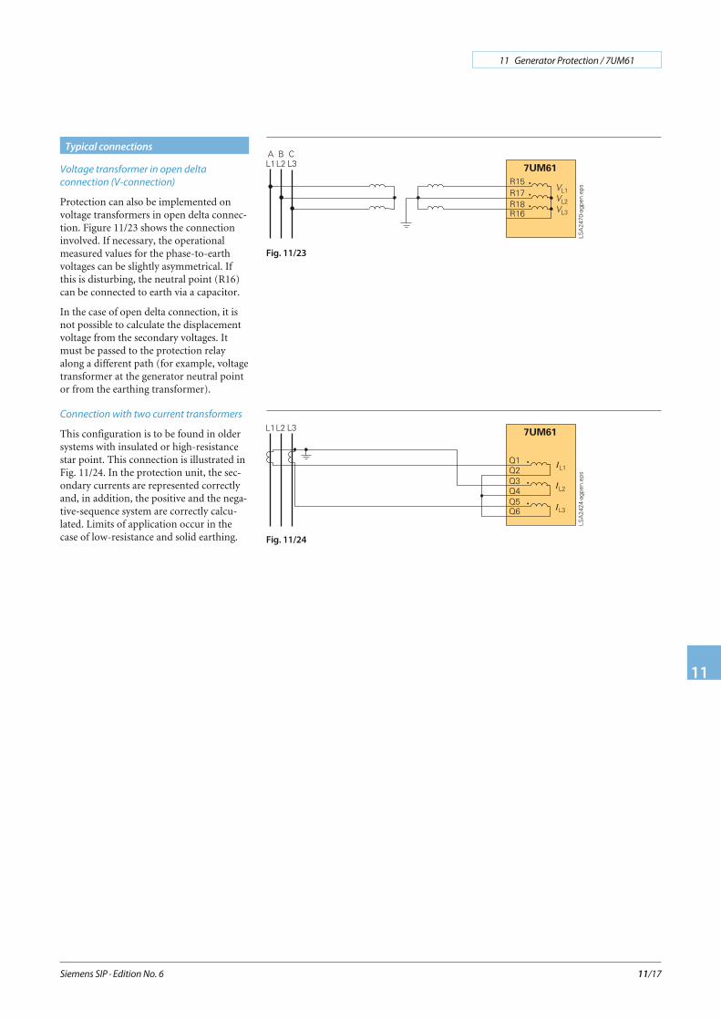
Voltage transformer in open delta
connection (V-connection)
Protection can also be implemented onvoltage transformers in open delta connec-tion. Figure 11/23 shows the connectioninvolved. If necessary, the operationalmeasured values for the phase-to-earthvoltages can be slightly asymmetrical. Ifthis is disturbing, the neutral point (R16)can be connected to earth via a capacitor.
In the case of open delta connection, it isnot possible to calculate the displacementvoltage from the secondary voltages. Itmust be passed to the protection relayalong a different path (for example, voltagetransformer at the generator neutral pointor from the earthing transformer).
Connection with two current transformers
This configuration is to be found in oldersystems with insulated or high-resistancestar point. This connection is illustrated inFig. 11/24. In the protection unit, the sec-ondary currents are represented correctlyand, in addition, the positive and the nega-tive-sequence system are correctly calcu-lated. Limits of application occur in thecase of low-resistance and solid earthing.
Siemens SIP · Edition No. 6
11 Generator Protection / 7UM61
11
11/17
Typical connections
Fig. 11/24
Fig. 11/23
Siemens SIP · Edition No. 6
11 Generator Protection / 7UM61
11
11/18
Technical data
Hardware
Analog inputs
Rated frequency 50 or 60 Hz
Rated current IN 1 or 5 A
Earth current, sensitive IEmax 1.6 A
Rated voltage VN 100 to 125 V
Power consumptionWith IN = 1 AWith IN = 5 AFor sensitive earth currentVoltage inputs (with 100 V)
Approx. 0.05 VAApprox. 0.3 VAApprox. 0.05 VAApprox. 0.3 VA
Capability in CT circuitsThermal (r.m.s. values)
Dynamic (peak)
100 IN for 1 s30 IN for 10 s4 IN continuous250 IN (one half cycle)
Earth current, sensitive
Dynamic (peak)
300 A for 1 s100 A for 10 s15 A continuous750 A (one half cycle)
Capability in voltage paths 230 V continuous
Auxiliary voltage
Rated auxiliary voltage 24 to 48 V DC60 to 125 V DC110 to 250 V DCand 115 V/230 V AC with 50/60 Hz
Permitted tolerance –20 to +20 %
Superimposed (peak-to-peak) ≤ 15 %
Power consumptionDuring normal operation
7UM6117UM612
During pickup with all inputsand outputs activated
7UM6117UM612
Approx. 4 WApprox. 4.5 W
Approx. 9.5 WApprox. 12.5 W
Bridging time during auxiliaryvoltage failure
at Vaux = 48 V and Vaux ≥ 110 Vat Vaux = 24 V and Vaux = 60 V
≥ 50 ms≥ 20 ms
Binary inputs
Number7UM6117UM612
715
3 pickup thresholdsRange is selectable with jumpers
10 to 19 V DC or 44 to 88 V DC88 to 176 V DC1)
Maximum permissible voltage 300 V DC
Current consumption, energized Approx. 1.8 mA
Output relays
Number7UM611
7UM612
12 (1 NO, 1 optional as NC,via jumper)20 (1 NO, 2 optional as NC,via jumper)
Switching capacityMakeBreakBreak (for resistive load)Break (for L/R ≤ 50 ms)
1000 W / VA30 VA40 W25 VA
Switching voltage 250 V
Permissible current 5 A continuous30 A for 0.5 seconds
LEDs
NumberRUN (green)ERROR (red)
11
Assignable LED (red)7UM6117UM612
714
Unit design
7XP20 housing For dimensions see dimensiondrawings, part 15
Degree of protection acc. toEN 60529
For surface-mounting housingFor flush-mounting housing
FrontRear
For the terminals
IP 51
IP 51IP 50IP 2x with terminal cover put on
WeightFlush mounting housing
7UM611 (1/3 x 19″)7UM612 (1/2 x 19″)
Surface mounting housing7UM611 (1/3 x 19″)7UM612 (1/2 x 19″)
Approx. 5.5 kgApprox. 7 kg
Approx. 7.5 kgApprox. 12 kg
1) Not valid for the CPU board.
Siemens SIP · Edition No. 6
11 Generator Protection / 7UM61
11
11/19
Technical data
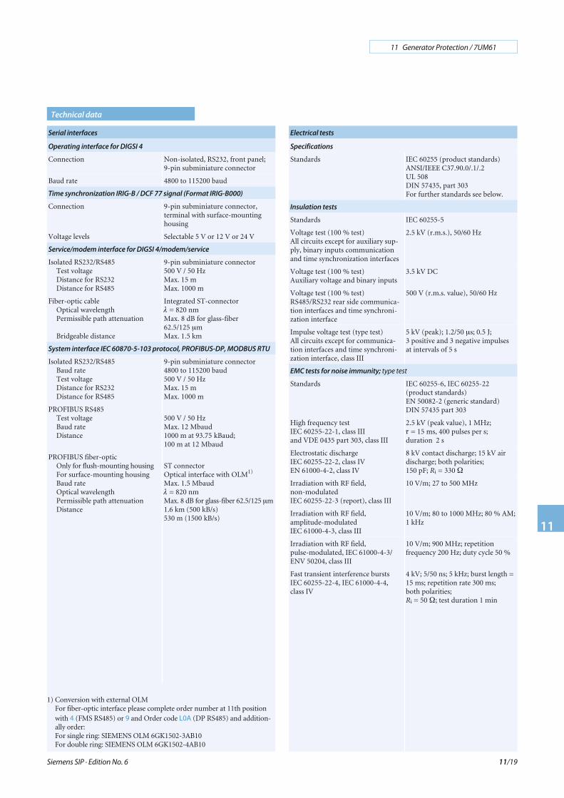
Serial interfaces
Operating interface for DIGSI 4
Connection Non-isolated, RS232, front panel;9-pin subminiature connector
Baud rate 4800 to 115200 baud
Time synchronization IRIG-B / DCF 77 signal (Format IRIG-B000)
Connection 9-pin subminiature connector,terminal with surface-mountinghousing
Voltage levels Selectable 5 V or 12 V or 24 V
Service/modem interface for DIGSI 4/modem/service
Isolated RS232/RS485Test voltageDistance for RS232Distance for RS485
9-pin subminiature connector500 V / 50 HzMax. 15 mMax. 1000 m
Fiber-optic cableOptical wavelengthPermissible path attenuation
Bridgeable distance
Integrated ST-connectorλ = 820 nmMax. 8 dB for glass-fiber62.5/125 μmMax. 1.5 km
System interface IEC 60870-5-103 protocol, PROFIBUS-DP, MODBUS RTU
Isolated RS232/RS485Baud rateTest voltageDistance for RS232Distance for RS485
9-pin subminiature connector4800 to 115200 baud500 V / 50 HzMax. 15 mMax. 1000 m
PROFIBUS RS485Test voltageBaud rateDistance
500 V / 50 HzMax. 12 Mbaud1000 m at 93.75 kBaud;100 m at 12 Mbaud
PROFIBUS fiber-opticOnly for flush-mounting housingFor surface-mounting housingBaud rateOptical wavelengthPermissible path attenuationDistance
ST connectorOptical interface with OLM1)
Max. 1.5 Mbaudλ = 820 nmMax. 8 dB for glass-fiber 62.5/125 μm1.6 km (500 kB/s)530 m (1500 kB/s)
Electrical tests
Specifications
Standards IEC 60255 (product standards)ANSI/IEEE C37.90.0/.1/.2UL 508DIN 57435, part 303For further standards see below.
Insulation tests
Standards IEC 60255-5
Voltage test (100 % test)All circuits except for auxiliary sup-ply, binary inputs communicationand time synchronization interfaces
2.5 kV (r.m.s.), 50/60 Hz
Voltage test (100 % test)Auxiliary voltage and binary inputs
3.5 kV DC
Voltage test (100 % test)RS485/RS232 rear side communica-tion interfaces and time synchroni-zation interface
500 V (r.m.s. value), 50/60 Hz
Impulse voltage test (type test)All circuits except for communica-tion interfaces and time synchroni-zation interface, class III
5 kV (peak); 1.2/50 μs; 0.5 J;3 positive and 3 negative impulsesat intervals of 5 s
EMC tests for noise immunity; type test
Standards IEC 60255-6, IEC 60255-22(product standards)EN 50082-2 (generic standard)DIN 57435 part 303
High frequency testIEC 60255-22-1, class IIIand VDE 0435 part 303, class III
2.5 kV (peak value), 1 MHz;τ = 15 ms, 400 pulses per s;duration 2 s
Electrostatic dischargeIEC 60255-22-2, class IVEN 61000-4-2, class IV
8 kV contact discharge; 15 kV airdischarge; both polarities;150 pF; Ri = 330 Ω
Irradiation with RF field,non-modulatedIEC 60255-22-3 (report), class III
10 V/m; 27 to 500 MHz
Irradiation with RF field,amplitude-modulatedIEC 61000-4-3, class III
10 V/m; 80 to 1000 MHz; 80 % AM;1 kHz
Irradiation with RF field,pulse-modulated, IEC 61000-4-3/ENV 50204, class III
10 V/m; 900 MHz; repetitionfrequency 200 Hz; duty cycle 50 %
Fast transient interference burstsIEC 60255-22-4, IEC 61000-4-4,class IV
4 kV; 5/50 ns; 5 kHz; burst length =15 ms; repetition rate 300 ms;both polarities;Ri = 50 Ω; test duration 1 min
1) Conversion with external OLMFor fiber-optic interface please complete order number at 11th positionwith 4 (FMS RS485) or 9 and Order code L0A (DP RS485) and addition-ally order:For single ring: SIEMENS OLM 6GK1502-3AB10For double ring: SIEMENS OLM 6GK1502-4AB10
Siemens SIP · Edition No. 6
11 Generator Protection / 7UM61
11
11/20
Technical data
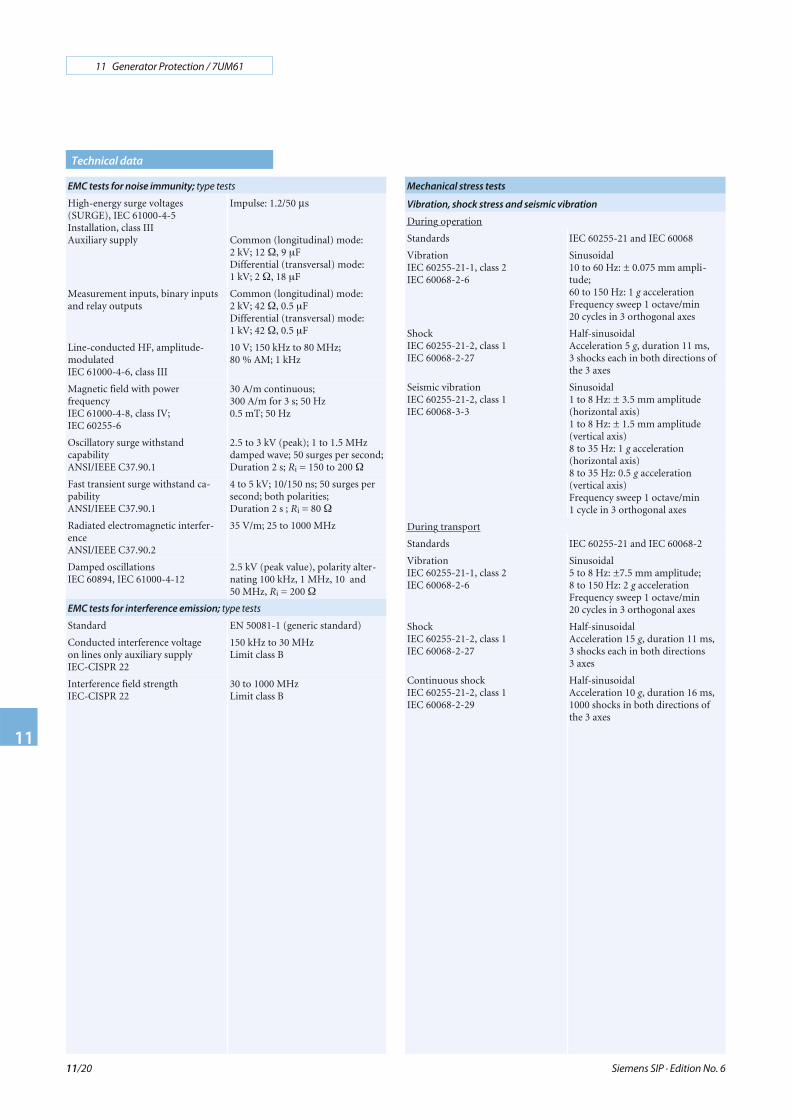
EMC tests for noise immunity; type tests
High-energy surge voltages(SURGE), IEC 61000-4-5Installation, class IIIAuxiliary supply
Impulse: 1.2/50 μs
Common (longitudinal) mode:2 kV; 12 Ω, 9 μFDifferential (transversal) mode:1 kV; 2 Ω, 18 μF
Measurement inputs, binary inputsand relay outputs
Common (longitudinal) mode:2 kV; 42 Ω, 0.5 μFDifferential (transversal) mode:1 kV; 42 Ω, 0.5 μF
Line-conducted HF, amplitude-modulatedIEC 61000-4-6, class III
10 V; 150 kHz to 80 MHz;80 % AM; 1 kHz
Magnetic field with powerfrequencyIEC 61000-4-8, class IV;IEC 60255-6
30 A/m continuous;300 A/m for 3 s; 50 Hz0.5 mT; 50 Hz
Oscillatory surge withstandcapabilityANSI/IEEE C37.90.1
2.5 to 3 kV (peak); 1 to 1.5 MHzdamped wave; 50 surges per second;Duration 2 s; Ri = 150 to 200 Ω
Fast transient surge withstand ca-pabilityANSI/IEEE C37.90.1
4 to 5 kV; 10/150 ns; 50 surges persecond; both polarities;Duration 2 s ; Ri = 80 Ω
Radiated electromagnetic interfer-enceANSI/IEEE C37.90.2
35 V/m; 25 to 1000 MHz
Damped oscillationsIEC 60894, IEC 61000-4-12
2.5 kV (peak value), polarity alter-nating 100 kHz, 1 MHz, 10 and50 MHz, Ri = 200 Ω
EMC tests for interference emission; type tests
Standard EN 50081-1 (generic standard)
Conducted interference voltageon lines only auxiliary supplyIEC-CISPR 22
150 kHz to 30 MHzLimit class B
Interference field strengthIEC-CISPR 22
30 to 1000 MHzLimit class B
Mechanical stress tests
Vibration, shock stress and seismic vibration
During operation
Standards IEC 60255-21 and IEC 60068
VibrationIEC 60255-21-1, class 2IEC 60068-2-6
Sinusoidal10 to 60 Hz: ± 0.075 mm ampli-tude;60 to 150 Hz: 1 g accelerationFrequency sweep 1 octave/min20 cycles in 3 orthogonal axes
ShockIEC 60255-21-2, class 1IEC 60068-2-27
Half-sinusoidalAcceleration 5 g, duration 11 ms,3 shocks each in both directions ofthe 3 axes
Seismic vibrationIEC 60255-21-2, class 1IEC 60068-3-3
Sinusoidal1 to 8 Hz: ± 3.5 mm amplitude(horizontal axis)1 to 8 Hz: ± 1.5 mm amplitude(vertical axis)8 to 35 Hz: 1 g acceleration(horizontal axis)8 to 35 Hz: 0.5 g acceleration(vertical axis)Frequency sweep 1 octave/min1 cycle in 3 orthogonal axes
During transport
Standards IEC 60255-21 and IEC 60068-2
VibrationIEC 60255-21-1, class 2IEC 60068-2-6
Sinusoidal5 to 8 Hz: ±7.5 mm amplitude;8 to 150 Hz: 2 g accelerationFrequency sweep 1 octave/min20 cycles in 3 orthogonal axes
ShockIEC 60255-21-2, class 1IEC 60068-2-27
Half-sinusoidalAcceleration 15 g, duration 11 ms,3 shocks each in both directions3 axes
Continuous shockIEC 60255-21-2, class 1IEC 60068-2-29
Half-sinusoidalAcceleration 10 g, duration 16 ms,1000 shocks in both directions ofthe 3 axes
Siemens SIP · Edition No. 6
11 Generator Protection / 7UM61
11
11/21
Technical data
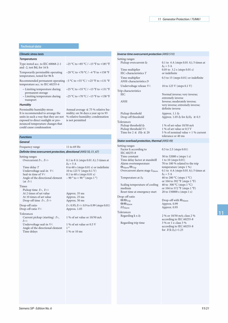
Climatic stress tests
Temperatures
Type-tested acc. to IEC 60068-2-1and -2, test Bd, for 16 h
–25 °C to +85 °C / –13 °F to +185 °F
Temporarily permissible operatingtemperature, tested for 96 h
–20 °C to +70 °C / –4 °F to +158 °F
Recommended permanent operatingtemperature acc. to IEC 60255-6
–5 °C to +55 °C / +25 °F to +131 °F
– Limiting temperature duringpermanent storage
– Limiting temperature duringtransport
–25 °C to +55 °C / –13 °F to +131 °F
–25 °C to +70 °C / –13 °F to +158 °F
Humidity
Permissible humidity stressIt is recommended to arrange theunits in such a way that they are notexposed to direct sunlight or pro-nounced temperature changes thatcould cause condensation
Annual average ≤ 75 % relative hu-midity; on 56 days a year up to 93% relative humidity; condensationis not permitted
Functions
General
Frequency range 11 to 69 Hz
Definite-time overcurrent protection, directional (ANSI 50, 51, 67)
Setting rangesOvercurrent I>, I>>
Time delay TUndervoltage seal-in V<Seal-in time of V<Angle of the directional element(at I>)
0.1 to 8 A (steps 0.01 A); 5 times atIN = 5 A0 to 60 s (steps 0.01 s) or indefinite10 to 125 V (steps 0.1 V)0.1 to 60 s (steps 0.01 s)– 90 ° to + 90 ° (steps 1 °)
TimesPickup time I>, I>>At 2 times of set valueAt 10 times of set valueDrop-off time I>, I>>
Approx. 35 msApprox. 25 msApprox. 50 ms
Drop-off ratioDrop-off ratio V<
I>: 0.95; I>>: 0.9 to 0.99 (steps 0.01)Approx. 1.05
TolerancesCurrent pickup (starting) I>,I>>Undervoltage seal-in V<Angle of the directional elementTime delays
1 % of set value or 10/50 mA
1 % of set value or 0.5 V1 °1 % or 10 ms
Inverse-time overcurrent protection (ANSI 51V)
Setting rangesPickup overcurrent IP
Time multiplierIEC-characteristics T
Time multiplierANSI-characteristics D
Undervoltage release V<
0.1 to 4 A (steps 0.01 A); 5 times atIN = 5 A0.05 to 3.2 s (steps 0.01 s)or indefinite
0.5 to 15 (steps 0.01) or indefinite
10 to 125 V (steps 0.1 V)
Trip characteristicsIEC
ANSI
Normal inverse; very inverse;extremely inverseInverse; moderately inverse;very inverse; extremely inverse;definite inverse
Pickup thresholdDrop-off threshold
Approx. 1.1 IP
Approx. 1.05 IP for IP/IN ≥ 0.3
TolerancesPickup threshold IP
Pickup threshold V<Time for 2 ≤ I/IP ≤ 20
1 % of set value 10/50 mA1 % of set value or 0.5 V5 % of nominal value + 1 % currenttolerance or 40 ms
Stator overload protection, thermal (ANSI 49)
Setting rangesFactor k according toIEC 60255-8Time constantTime delay factor at standstillAlarm overtemperatureΘAlarm/ΘTrip
Overcurrent alarm stage IAlarm
Temperature at IN
Scaling temperature of coolingmediumReset time at emergency start
0.5 to 2.5 (steps 0.01)
30 to 32000 s (steps 1 s)1 to 10 (steps 0.01)70 to 100 % related to the triptemperature (steps 1 %)0.1 to 4 A (steps 0.01 A); 5 times atIN = 5 A40 to 200 °C (steps 1 °C)or 104 to 392 °F (steps 1 °F)40 to 300 °C (steps 1 °C)or 104 to 572 °F (steps 1 °F)20 to 150000 s (steps 1 s)
Drop-off ratioΘ/ΘTrip
Θ/ΘAlarm
I/IAlarm
Drop-off with ΘAlarm
Approx. 0.99Approx. 0.95
TolerancesRegarding k x IP
Regarding trip time
2 % or 10/50 mA; class 2 %according to IEC 60255-83 % or 1 s: class 3 %according to IEC 60255-8for I/(k IN)>1.25

Siemens SIP · Edition No. 6
11 Generator Protection / 7UM61
11
11/22
Technical data
Negative-sequence protection (ANSI 46)
Setting rangesPermissible negative sequenceI2 perm. /IN
Definite time trip stage I2 >>/IN
Time delays TAlarm; TI2>>Negative-sequence factor kCooling down time TCooling
3 to 30 % (steps 1 %)
10 to 100 % (steps 1 %)0 to 60 s (steps 0.01 s) or indefinite2 to 40 s (steps 0.1 s)0 to 50000 s (steps 1 s)
TimesPickup time (definite stage)Drop-off time (definite stage)
Approx. 50 msApprox. 50 ms
Drop-off ratios I2 perm.; I2 >>Drop-off ratio thermal stage
Approx. 0.95Drop-off at fall below of I2 perm.
TolerancesPickup values I2 perm.; I2 >>
Time delaysThermal characteristicTime for 2 ≤ I2/I2 perm. ≤ 20
3 % of set value or 0.3 % negativesequence1 % or 10 ms5 % of nominal value +1 % currenttolerance or 600 ms
Underexcitation protection (ANSI 40)
Setting rangesConductance thresholds 1/xdcharacteristic (3 characteristics)Inclination angle α1, α2, α3
Time delay T
0.25 to 3.0 (steps 0.01)
50 to 120 ° (steps 1 °)0 to 50 s (steps 0.01 s) or indefinite
TimesStator criterion 1/xdcharacteristic; αUndervoltage blocking
Approx. 60 ms
Approx. 50 ms
Drop-off ratioStator criterion 1/xdcharacteristic; αUndervoltage blocking
Approx. 0.95
Approx. 1.1
TolerancesStator criterion 1/xdcharacteristicStator criterion αUndervoltage blockingTime delays T
3 % of set value
1 ° electrical1 % or 0.5 V1 % or 10 ms
Reverse-power protection (ANSI 32R)
Setting rangesReverse power PRev.>/SN
Time delays T–0.5 to –30 % (steps 0.01 %)0 to 60 s (steps 0.01 s) or indefinite
TimesPickup time
Drop-off time
Approx. 360 ms (50 Hz);Approx. 300 ms (60 Hz)Approx. 360 ms (50 Hz);Approx. 300 ms (60 Hz)
Drop-off ratio PRev.> Approx. 0.6
TolerancesReverse power PRev.>Time delays T
0.25 % SN ± 3 % set value1 % or 10 ms
Forward-power protection (ANSI 32F)
Setting rangesForward power PForw.</SN
Forward power PForw.>/SN
Time delays T
0.5 to 120 % (steps 0.1 %)1 to 120 % (steps 0.1 %)0 to 60 s (steps 0.01 s) or indefinite
TimesPickup time(accurate measuring)Pickup time(fast measuring)Drop-off time(accurate measuring)Drop-off time (fast measuring)
Approx. 360 ms (50 Hz);Approx. 300 ms (60 Hz)Approx. 60 ms (50 Hz);Approx. 50 ms (60 Hz)Approx. 360 ms (50 Hz);Approx. 300 ms (60 Hz)Approx. 60 ms (50 Hz);Approx. 50 ms (60 Hz)
Drop-off ratio PForw.<Drop-off ratio PForw.>
1.1 or 0.5 % of SN
Approx. 0.9 or –0.5 % of SN
TolerancesActive power PForw.<, PForw.>
Time delays T
0.25 % SN ± 3 % of set valueat Q < 0.5 SN at accurate measuring0.5 % SN ± 3 % of set valueat Q < 0.5 SN at fast measuring1 % or 10 ms
Impedance protection (ANSI 21)
Setting rangesOvercurrent pickup I>
Undervoltage seal-in V<Impedance Z1(related to IN =1 A)Impedance Z1B(related to IN =1 A)Impedance Z2(related to IN =1 A)Time delays T
0.1 to 4 A (steps 0.01 A); 5 times atIN = 5A10 to 125 V (steps 0.1V)0.05 to 130 Ω (steps 0.01 Ω)
0.05 to 65 Ω (steps 0.01 Ω)
0.05 to 65 Ω (steps 0.01 Ω)
0 to 60 s (steps 0.01 s) or indefinite
TimesShortest tripping timeDrop-off time
Approx. 40 msApprox. 50 ms
Drop-off ratioOvercurrent pickup I>Undervoltage seal-in V<
Approx. 0.95Approx. 1.05
TolerancesOvercurrent pickup I>Undervoltage seal-in V<Impedance measuring Z1, Z2Time delays T
1 % of set value. 10/50 mA1 % of set value. or 0.5 V|ΔZ/Z| ≤ 5 % for 30 ° ≤ ϕK ≤ 90 °1 % or 10 ms
Undervoltage protection (ANSI 27)
Setting rangeUndervoltage pickup V<, V<<(positive sequence as phase-to-phase values)Time delays T
10 to 125 V (steps 0.1 V)
0 to 60 s (steps 0.01 s) or indefinite
TimesPickup time V<, V<<Drop-off time V<, V<<
Approx. 50 msApprox. 50 ms
Drop-off ratio V<, V<< 1.01 to 1.1 (steps 0.01)
TolerancesVoltage limit valuesTime delays T
1 % of set value or 0.5 V1 % or 10 ms

Siemens SIP · Edition No. 6
11 Generator Protection / 7UM61
11
11/23
Technical data
Overvoltage protection (ANSI 59)
Setting rangesOvervoltage pickup V>, V>>(maximum phase-to-phasevoltage or phase-to-earth-voltage)Time delays T
30 to 170 V (steps 0.1 V)
0 to 60 s (steps 0.01 s) or indefinite
TimePickup times V>, V>>Drop-off times V>, V>>
Approx. 50 msApprox. 50 ms
Drop-off ratio V>, V>> 0.9 to 0.99 (steps 0.01)
TolerancesVoltage limit valueTime delays T
1 % of set value 0.5 V1 % or 10 ms
Frequency protection (ANSI 81)
Setting rangesSteps; selectable f>, f<Pickup values f>, f<Time delays TUndervoltage blocking V1<
440 to 65 Hz (steps 0.01 Hz)0 to 60 s (steps 0.01 s) or indefinite10 to 125 V (steps 0.1 V)
TimesPickup times f>, f<Drop-off times f>, f<
Approx. 100 msApprox. 100 ms
Drop-off difference ΔfDrop-off ratio V1<
Approx. 20 mHzApprox. 1.05
TolerancesFrequencyUndervoltage blockingTime delays T
10 mHz (at V> 0.5 VN)1 % of set value or 0.5 V1 % or 10 ms
Overexcitation protection (Volt/Hertz) (ANSI 24)
Setting rangesPickup threshold alarm stagePickup threshold V/f>>-stageTime delays TCharacteristic values of V/fand assigned times t(V/f )Cooling down time TCooling
1 to 1.2 (steps 0.01)1 to 1.4 (steps 0.01)0 to 60 s (steps 0.01 s) or indefinite1.1/1.15/1.2/1.25/1.3/1.35/1.40 to 20000 s (steps 1 s)0 to 20000 s (steps 1 s)
Times (Alarm and V/f>>-stage)Pickup times at 1.1 of set valueDrop-off times
Approx. 60 msApprox. 60 ms
Drop-off ratio (alarm, trip) 0.95
TolerancesV/f-pickupTime delays TThermal characteristic (time)
3 % of set value1 % or 10 ms5 % rated to V/f or 600 ms
90 % stator earth-fault protection, non-directional, directional
(ANSI 59N, 64G, 67G)
Setting rangesDisplacement voltage V0 >Earth current 3I0 >Angle of direction elementTime delays T
5 to 125 V (steps 0.1 V)2 to 1000 mA (steps 1 mA)0 to 360 ° (steps 1 °)0 to 60 s (steps 0,01 s) or indefinite
TimesPickup times V0>, 3I0>Drop-off times V0>/ 3I0>
Approx. 50 msApprox. 50 ms
Drop-off ratio V0>, 3I0>Drop-off difference angle
0.710 ° directed to power system
TolerancesDisplacement voltageEarth currentTime delays T
1 % of set value or 0.5 V1 % of set value or 0.5 mA1 % or 10 ms
Sensitive earth-fault protection (ANSI 50/51GN, 64R)
Setting rangesEarth current pickup IEE>,IEE>>Time delays TMeasuring circuit supervisionIEE<
2 to 1000 mA (steps 1 mA)
0 to 60 s (steps 0.01 s) or indefinite1.5 to 50 mA (steps 0.1 mA)
TimesPickup timesDrop-off timesMeasuring circuit supervision
Approx. 50 msApprox. 50 msApprox. 50 ms
Drop-off ratio IEE>, IEE>>Drop-off ratio measuring circuitsupervision IEE<
0.95 or 1 mAApprox. 1.1 or 1 mA
TolerancesEarth current pickupTime delays T
1 % of set value or 0.5 mA1 % or 10 ms
100 % stator earth-fault protection with 3rd harmonics
(ANSI 59TN, 27TN (3rd H.))
Setting rangesDisplacement voltageV0 (3rd harm.)>, V0 (3rd harm.)<Time delay TActive-power releasePositive-sequence voltage release
0.2 to 40 V (steps 0.1 V)
0 to 60 s (steps 0.01 s) or indefinite10 to 100 % (steps 1 %) or indefinite50 to 125 V (steps 0.1 V) or indefinite
TimesPickup timeDrop-off time
Approx. 80 msApprox. 80 ms
Drop-off ratioUndervoltage stage V0 (3rd harm.)<Overvoltage stage V0 (3rd harm.)>Active-power releasePositive-sequence voltage release
Approx. 1.4Approx. 0.6Approx. 0.9Approx. 0.95
TolerancesDisplacement voltageTime delay T
3 % of set value or 0.1 V1 % or 10 ms
Siemens SIP · Edition No. 6
11 Generator Protection / 7UM61
11
11/24
Technical data
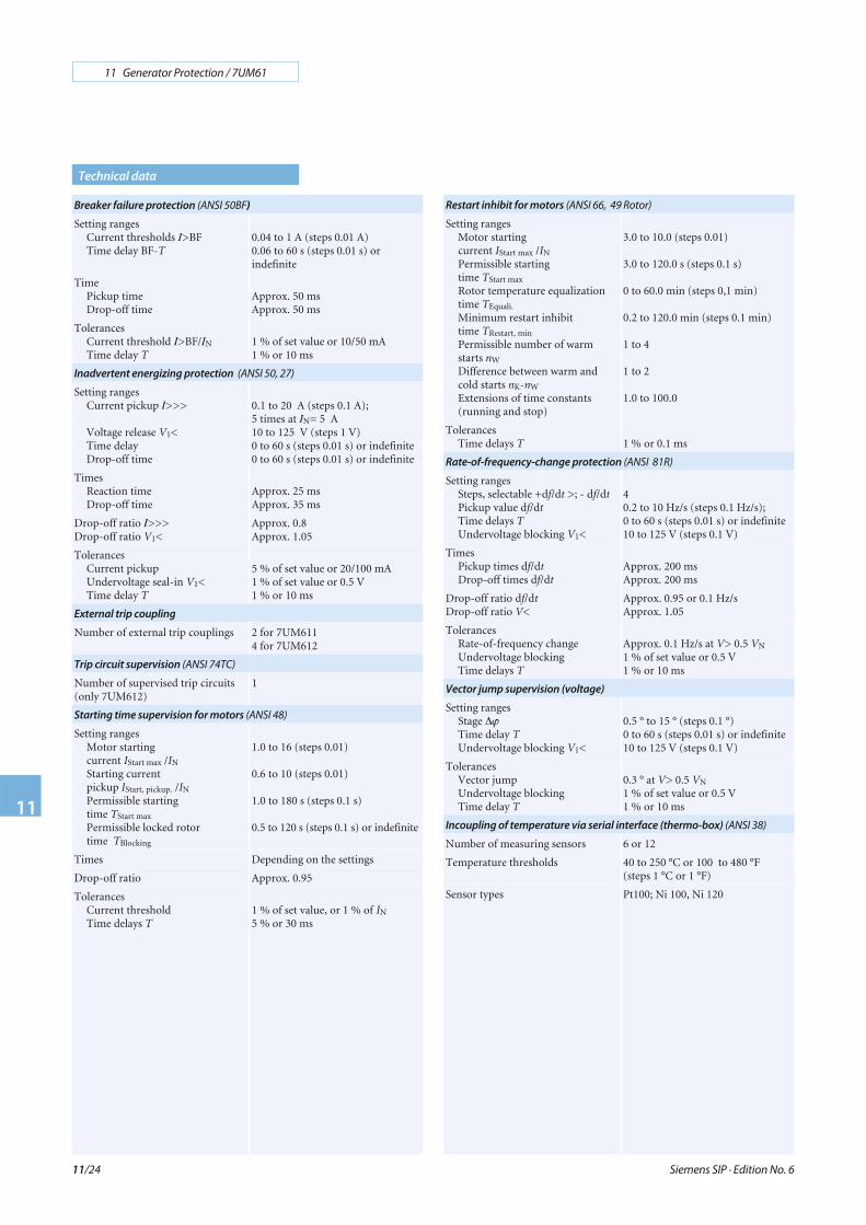
Breaker failure protection (ANSI 50BF)
Setting rangesCurrent thresholds I>BFTime delay BF-T
0.04 to 1 A (steps 0.01 A)0.06 to 60 s (steps 0.01 s) orindefinite
TimePickup timeDrop-off time
Approx. 50 msApprox. 50 ms
TolerancesCurrent threshold I>BF/IN
Time delay T1 % of set value or 10/50 mA1 % or 10 ms
Inadvertent energizing protection (ANSI 50, 27)
Setting rangesCurrent pickup I>>>
Voltage release V1<Time delayDrop-off time
0.1 to 20 A (steps 0.1 A);5 times at IN= 5 A10 to 125 V (steps 1 V)0 to 60 s (steps 0.01 s) or indefinite0 to 60 s (steps 0.01 s) or indefinite
TimesReaction timeDrop-off time
Approx. 25 msApprox. 35 ms
Drop-off ratio I>>>Drop-off ratio V1<
Approx. 0.8Approx. 1.05
TolerancesCurrent pickupUndervoltage seal-in V1<Time delay T
5 % of set value or 20/100 mA1 % of set value or 0.5 V1 % or 10 ms
External trip coupling
Number of external trip couplings 2 for 7UM6114 for 7UM612
Trip circuit supervision (ANSI 74TC)
Number of supervised trip circuits(only 7UM612)
1
Starting time supervision for motors (ANSI 48)
Setting rangesMotor startingcurrent IStart max /IN
Starting currentpickup IStart, pickup. /IN
Permissible startingtime TStart max
Permissible locked rotortime TBlocking
1.0 to 16 (steps 0.01)
0.6 to 10 (steps 0.01)
1.0 to 180 s (steps 0.1 s)
0.5 to 120 s (steps 0.1 s) or indefinite
Times Depending on the settings
Drop-off ratio Approx. 0.95
TolerancesCurrent thresholdTime delays T
1 % of set value, or 1 % of IN
5 % or 30 ms
Restart inhibit for motors (ANSI 66, 49 Rotor)
Setting rangesMotor startingcurrent IStart max /IN
Permissible startingtime TStart max
Rotor temperature equalizationtime TEquali.
Minimum restart inhibittime TRestart, min
Permissible number of warmstarts nW
Difference between warm andcold starts nK-nW
Extensions of time constants(running and stop)
3.0 to 10.0 (steps 0.01)
3.0 to 120.0 s (steps 0.1 s)
0 to 60.0 min (steps 0,1 min)
0.2 to 120.0 min (steps 0.1 min)
1 to 4
1 to 2
1.0 to 100.0
TolerancesTime delays T 1 % or 0.1 ms
Rate-of-frequency-change protection (ANSI 81R)
Setting rangesSteps, selectable +df/dt >; - df/dtPickup value df/dtTime delays TUndervoltage blocking V1<
40.2 to 10 Hz/s (steps 0.1 Hz/s);0 to 60 s (steps 0.01 s) or indefinite10 to 125 V (steps 0.1 V)
TimesPickup times df/dtDrop-off times df/dt
Approx. 200 msApprox. 200 ms
Drop-off ratio df/dtDrop-off ratio V<
Approx. 0.95 or 0.1 Hz/sApprox. 1.05
TolerancesRate-of-frequency changeUndervoltage blockingTime delays T
Approx. 0.1 Hz/s at V> 0.5 VN
1 % of set value or 0.5 V1 % or 10 ms
Vector jump supervision (voltage)
Setting rangesStage ΔϕTime delay TUndervoltage blocking V1<
0.5 ° to 15 ° (steps 0.1 °)0 to 60 s (steps 0.01 s) or indefinite10 to 125 V (steps 0.1 V)
TolerancesVector jumpUndervoltage blockingTime delay T
0.3 ° at V> 0.5 VN
1 % of set value or 0.5 V1 % or 10 ms
Incoupling of temperature via serial interface (thermo-box) (ANSI 38)
Number of measuring sensors 6 or 12
Temperature thresholds 40 to 250 °C or 100 to 480 °F(steps 1 °C or 1 °F)
Sensor types Pt100; Ni 100, Ni 120

Siemens SIP · Edition No. 6
11 Generator Protection / 7UM61
11
11/25
Operational measured values
Description Primary; secondary or per unit (%)
CurrentsTolerance
IL1; IL2; IL3; IEE; I1; I2
0.2 % of measured values or ±10 mA ± 1 digit
Voltages
Tolerance
VL1; VL2; VL3; VE; VL12; VL23; VL31;V1; V2
0.2 % of measured values or ± 0.2 V± 1 digit
ImpedanceTolerance
R, X1 %
PowerTolerance
S; P; Q1 % of measured values or ± 0.25 %SN
Phase angleTolerance
ϕ<0.1 °
Power factorTolerance
cos ϕ (p.f.)1 % ± 1 digit
FrequencyTolerance
f10 mHz at (V> 0.5 VN; 40 Hz < f< 65 Hz)
OverexcitationTolerance
V/f;1 %
Thermal measurementTolerance
ΘL1; ΘL2, ΘL3, Θ I2, ΘV/f,
5 %
Min./max. memory
Memory Measured values with date and time
Reset manual Via binary inputVia key padVia communication
ValuesPositive sequence voltagePositive sequence currentActive powerReactive powerFrequencyDisplacement voltage(3rd harmonics)
V1
I1
PQfVE(3
rdharm.)
Energy metering
Meter of 4 quadrantsTolerance
WP+; WP–; WQ+; WQ–
1 %
Fault records
Number of fault records Max. 8 fault records
Instantaneous valuesStorage timeSampling interval
Channels
Max. 5 sDepending on the actual frequency(e. g. 1.25 ms at 50 Hz;1.04 ms at 60 Hz))vL1, vL2, vL3, vE; iL1, iL2, iL3, iEE
R.m.s. valuesStorage periodSampling interval
Channels
Max. 80 sFixed (20 ms at 50 Hz; 16.67 ms at60 Hz)V1, VE, I1, I2, IEE, P, Q, ϕ, f-fn
Technical data
Additional functions
Fault event logging Storage of events of the last 8 faultsPuffer length max. 600 indicationsTime solution 1 ms
Operational indications Max. 200 indicationsTime solution 1 ms
Elapsed-hour meter Up to 6 decimal digits(criterion: current threshold)
Switching statistics Number of breaker operationPhase-summated tripping current
CE conformity
This product is in conformity with the Directives of the European Com-munities on the harmonization of the laws of the Member States relatingto electromagnetic compatibility (EMC Council Directive 89/336/EEC)and electrical equipment designed for use within certain voltage limits(Council Directive 73/23/EEC).
This unit conforms to the international standard IEC 60255, and theGerman standard DIN 57435/Part 303 (corresponding to VDE 0435/Part 303).
The unit has been developed and manufactured for application in anindustrial environment according to the EMC standards.
This conformity is the result of a test that was performed by Siemens AGin accordance with Article 10 of the Council Directive complying with thegeneric standards EN 50081-2 and EN 50082-2 for the EMC Directive andstandard EN 60255-6 for the “low-voltage Directive”.
Siemens SIP · Edition No. 6
11 Generator Protection / 7UM61
11
11/26
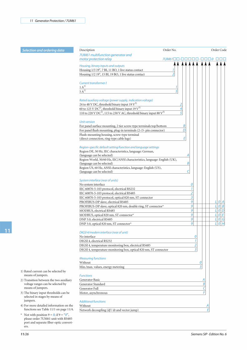
Selection and ordering data Description Order No. Order Code
7UM61 multifunction generator and
motor protection relay 7UM61��-�����-���0 ���
Housing, binary inputs and outputs
Housing 1/3 19", 7 BI, 11 BO, 1 live status contact 1
Housing 1/2 19", 15 BI, 19 BO, 1 live status contact 2
Current transformer IN
1 A1)1
5 A1)5
Rated auxiliary voltage (power supply, indication voltage)
24 to 48 V DC, threshold binary input 19 V3)2
60 to 125 V DC2), threshold binary input 19 V3)4
110 to 220 V DC2), 115 to 230 V AC, threshold binary input 88 V3)5
Unit version
For panel surface mounting, 2 tier screw-type terminals top/bottom B
For panel flush mounting, plug-in terminals (2-/3- pin connector) D
Flush-mounting housing, screw-type terminal(direct connection, ring-type cable lugs) E
Region-specific default setting/function and language settings
Region DE, 50 Hz, IEC characteristics, language: German,(language can be selected) A
Region World, 50/60 Hz, IEC/ANSI characteristics, language: English (UK),(language can be selected) B
Region US, 60 Hz, ANSI characteristics, language: English (US),(language can be selected) C
System interface (rear of units)
No system interface 0
IEC 60870-5-103 protocol, electrical RS232 1
IEC 60870-5-103 protocol, electrical RS485 2
IEC 60870-5-103 protocol, optical 820 nm, ST connector 3
PROFIBUS-DP slave, electrical RS485 9 L 0 A
PROFIBUS-DP slave, optical 820 nm, double ring, ST connector* 9 L 0 B
MODBUS, electrical RS485 9 L 0 D
MODBUS, optical 820 nm, ST connector* 9 L 0 E
DNP 3.0, electrical RS485 9 L 0 G
DNP 3.0, optical 820 nm, ST connector* 9 L 0 H
DIGSI 4/modem interface (rear of unit)
No interface 0
DIGSI 4, electrical RS232 1
DIGSI 4, temperature monitoring box, electrical RS485 2
DIGSI 4, temperature monitoring box, optical 820 nm, ST connector 3
Measuring functions
Without 0
Min./max. values, energy metering 3
Functions4)
Generator Basic A
Generator Standard B
Generator Full C
Motor, asynchronous F
Additional functions4)
Without A
Network decoupling (df / dt and vector jump) E
1) Rated current can be selected bymeans of jumpers.
2) Transition between the two auxiliaryvoltage ranges can be selected bymeans of jumpers.
3) The binary input thresholds can beselected in stages by means ofjumpers.
4) For more detailed information on thefunctions see Table 11/1 on page 11/4.
* Not with position 9 = B; if 9 = “B”,please order 7UM61 unit with RS485port and separate fiber-optic convert-ers.
Siemens SIP · Edition No. 6
11 Generator Protection / 7UM61
11
11/27
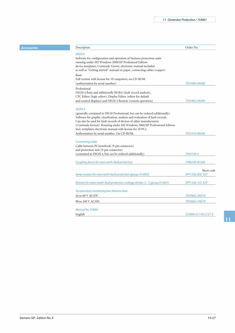
Accessories Description Order No.
DIGSI 4
Software for configuration and operation of Siemens protection unitsrunning under MS Windows 2000/XP Profesional Editiondevice templates, Comtrade Viewer, electronic manual includedas well as “Getting started” manual on paper, connecting cables (copper)
BasisFull version with license for 10 computers, on CD-ROM
(authorization by serial number) 7XS5400-0AA00
ProfessionalDIGSI 4 Basis and additionally SIGRA (fault record analysis),CFC Editor (logic editor), Display Editor (editor for default
and control displays) and DIGSI 4 Remote (remote operation) 7XS5402-0AA00
SIGRA 4
(generally contained in DIGSI Professional, but can be ordered additionally)Software for graphic visualization, analysis and evaluation of fault records.Can also be used for fault records of devices of other manufacturers(Comtrade format). Running under MS Windows 2000/XP Professional Edition.Incl. templates, electronic manual with license for 10 PCs.
Authorization by serial number. On CD-ROM. 7XS5410-0AA00
Connecting cable
Cable between PC/notebook (9-pin connector)and protection unit (9-pin connector)(contained in DIGSI 4, but can be ordered additionally) 7XV5100-4
Coupling device for rotor earth-fault protection 7XR6100-0CA00
Short codeSeries resistor for rotor earth-fault protection (group: 013002) 3PP1336-0DZ K2Y
Resistor for stator earth-fault protection (voltage divider, 5 : 1) (group 013001) 3PP1336-1CZ K2Y
Temperature monitoring box (thermo-box)
24 to 60 V AC/DC 7XV5662-2AD10
90 to 240 V AC/DC 7XV5662-5AD10
Manual for 7UM61
English C53000-G1176-C127-2
Siemens SIP · Edition No. 6
11 Generator Protection / 7UM61
11
11/28
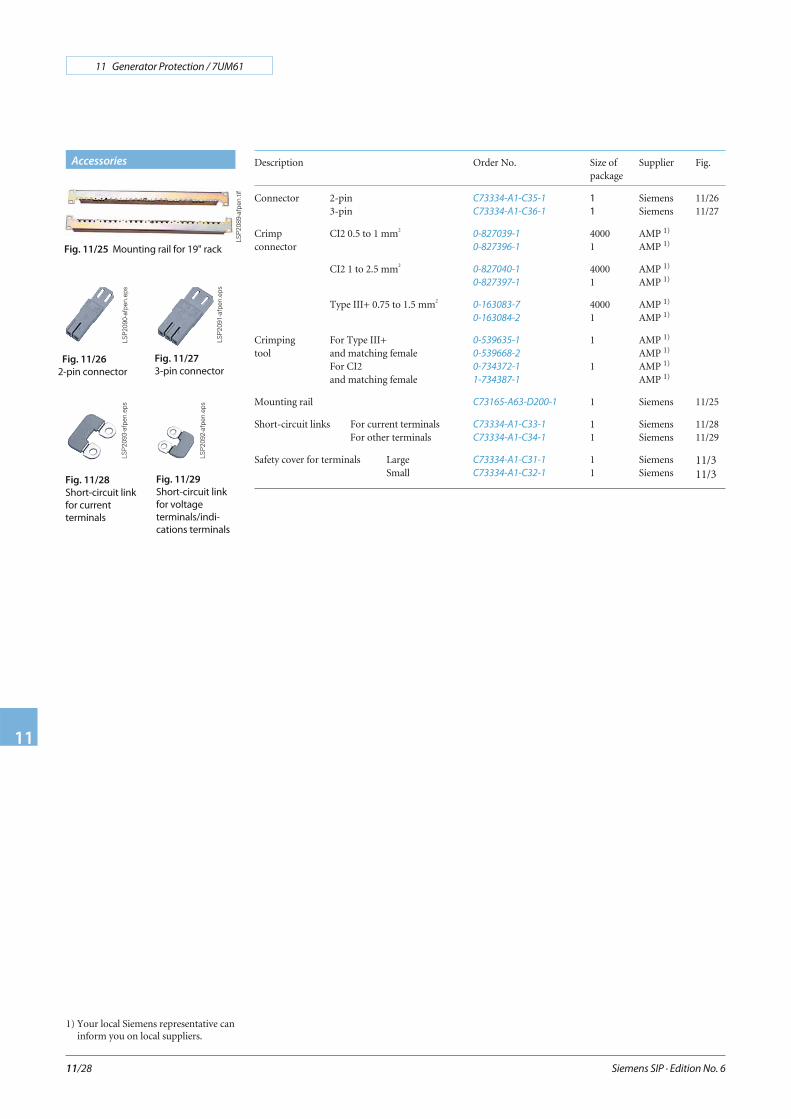
Description Order No. Size ofpackage
Supplier Fig.
Connector 2-pin3-pin
C73334-A1-C35-1
C73334-A1-C36-1
11
SiemensSiemens
11/2611/27
Crimp CI2 0.5 to 1 mm2
connector0-827039-1
0-827396-1
40001
AMP 1)
AMP 1)
CI2 1 to 2.5 mm20-827040-1
0-827397-1
40001
AMP 1)
AMP 1)
Type III+ 0.75 to 1.5 mm20-163083-7
0-163084-2
40001
AMP 1)
AMP 1)
Crimping For Type III+tool and matching female
For CI2and matching female
0-539635-1
0-539668-2
0-734372-1
1-734387-1
1
1
AMP 1)
AMP 1)
AMP 1)
AMP 1)
Mounting rail C73165-A63-D200-1 1 Siemens 11/25
Short-circuit links For current terminalsFor other terminals
C73334-A1-C33-1
C73334-A1-C34-1
11
SiemensSiemens
11/2811/29
Safety cover for terminals LargeSmall
C73334-A1-C31-1
C73334-A1-C32-1
11
SiemensSiemens
11/311/3
Fig. 11/25 Mounting rail for 19" rack
Fig. 11/28
Short-circuit link
for current
terminals
Fig. 11/29
Short-circuit link
for voltage
terminals/indi-
cations terminals
LSP
2089
-afp
en.ti
f
LSP
2093
-afp
en.e
ps
LSP
2092
-afp
en.e
ps
Accessories
Fig. 11/27
3-pin connector
LSP
2091
-afp
en.e
ps
Fig. 11/26
2-pin connector
LSP
2090
-afp
en.e
ps
1) Your local Siemens representative caninform you on local suppliers.
Siemens SIP · Edition No. 6
11 Generator Protection / 7UM61
11
11/29
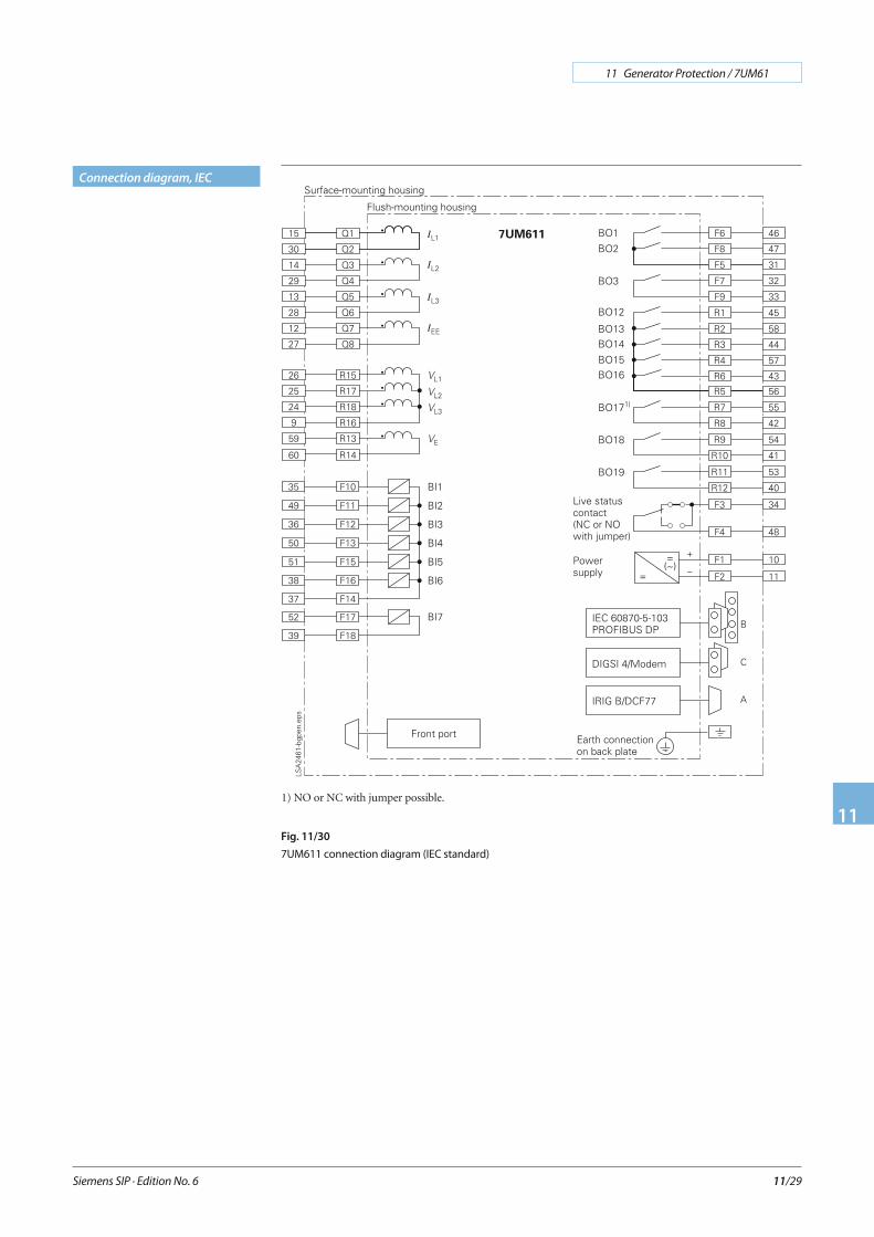
Connection diagram, IEC
Fig. 11/30
7UM611 connection diagram (IEC standard)
1) NO or NC with jumper possible.

Siemens SIP · Edition No. 6
11 Generator Protection / 7UM61
11
11/30
Connection diagram, IEC
Fig. 11/31
7UM612 connection diagram (IEC standard)
1) NO or NC with jumper possible.
Siemens SIP · Edition No. 6
11 Generator Protection / 7UM61
11
11/31
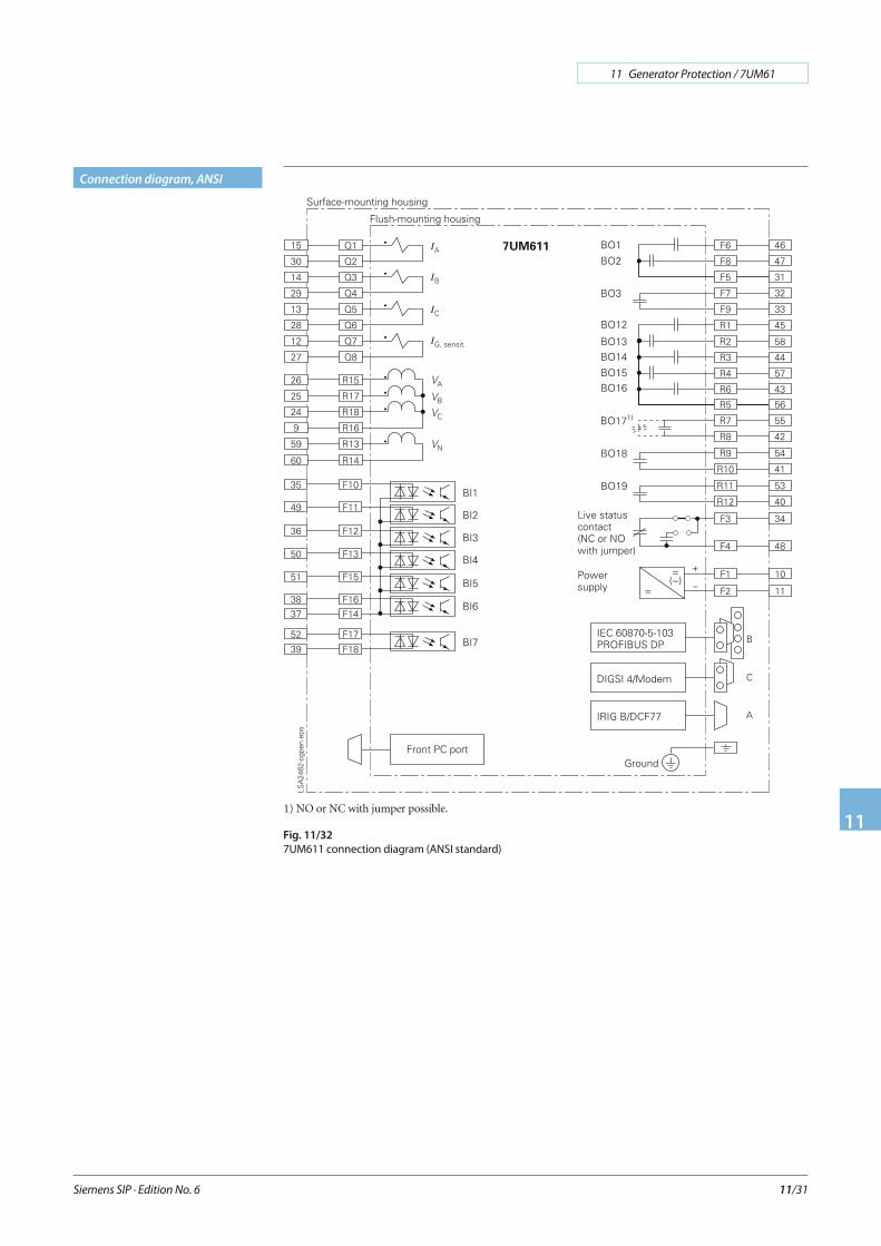
Connection diagram, ANSI
Fig. 11/32
7UM611 connection diagram (ANSI standard)
1) NO or NC with jumper possible.
Siemens SIP · Edition No. 6
11 Generator Protection / 7UM61
11
11/32
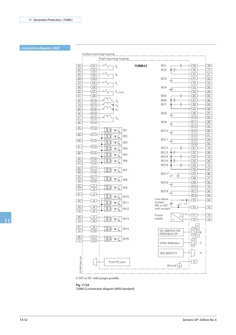
Connection diagram, ANSI
Fig. 11/33
7UM612 connection diagram (ANSI standard)
1) NO or NC with jumper possible.
Related Documents