A REPORT ON SUMMER TRAINING AT PRAGATI POWER CORPORATION LIMITED (A GOVERNMENT OF NCT DELHI UNDERTAKING) SUBMITTED TO TRAINING INCHARGE INDRAPRASTHA POWER GENERATION LIMITED & PRAGATI POWER CORPORATION LIMITED SUBMITTED BY AAKASH SINGH SENGAR (B.TECH PSE) ABHIJEET SHARMA (B.TECH PSE) AMAY JAIN (B.TECH PSE) GAURAV BALANI (B.TECH PSE) UJJWAL ANAND (B.TECH ENERGY TECHNOLOGY)

Welcome message from author
This document is posted to help you gain knowledge. Please leave a comment to let me know what you think about it! Share it to your friends and learn new things together.
Transcript

A REPORT ON
SUMMER TRAINING AT
PRAGATI POWER CORPORATION LIMITED
(A GOVERNMENT OF NCT DELHI UNDERTAKING)
SUBMITTED TO
TRAINING INCHARGE
INDRAPRASTHA POWER GENERATION LIMITED
&
PRAGATI POWER CORPORATION LIMITED
SUBMITTED BY
AAKASH SINGH SENGAR (B.TECH PSE)
ABHIJEET SHARMA (B.TECH PSE)
AMAY JAIN (B.TECH PSE)
GAURAV BALANI (B.TECH PSE)
UJJWAL ANAND (B.TECH ENERGY TECHNOLOGY)

A C K N O W L E D G E M E N T S
This project involved the collection and analysis of information from a wide variety of
sources and the efforts of many people beyond us. Thus it would not have been
possible to achieve the results reported in this document without their help, support
and encouragement. We would like to express our gratitude to the following people
for their help in the work leading to this report: Mr. K.S. Yadav (Deputy General Manager (Mechanical)) Mr. Sudhir Kumar (Manager – Technical (Electrical II)) Mr. Arvind Kumar Singh (Deputy Manager- Technical (Electrical
II)) Mr. Ashish (Deputy Manager- Technical (Electrical II) BOP
Unit) Mr. Vijay (Circuit Breaker Unit)

BRIEF PROFILE OF THE COMPANY: Pragati Power Corporation Limited is an undertaking of Government of NCT of Delhi. It was
incorporated on 9th January, 2001 to undertake power generation activities for supplying power to Delhi.
It is one of the leading Undertakings of GNCTD, generating profits since inception and paying dividends
regularly. It is presently having capital base of 2,019 crores and asset base of 3,319 crores. The
projected asset base and revenue income of Company in the near future are 6,000 crores and 5,000
crores respectively. The first project undertaken by the company was 330 MW gas based CCGT which
was fully commissioned in the year 2003-04. The station is presently operating at above 85% availability.
PPCL is presently setting up a 1500 MW Gas Based CCGT plant at Bawana in North-West Delhi to
augment the power generation at Load-Centre. Project is expected to fully commission by July 2011.
PPCL is also proposing to put up a 750 MW Gas Based CCGT at Bamnauli in South-West Delhi. The
project is expected to be commissioned in the year 2013-14. VISION:
To make Delhi-Power Surplus. MISSION:
To maximize generation from available capacity.
To plan & implement new generation capacity in Delhi.
Competitive pricing of our own generation.
To set ever-so high standards of environment Protection.
To develop competent human resources for managing the company, with good standards.
COMBINED CYCLE POWER PLANT:
Combined Cycle Power Plant (CCPP) or Combined Cycle Gas Turbine plant (CCGT)
A gas turbine generator generates electricity and heat in the exhaust is used to make steam, which
in turn drives a steam turbine to generate an additional electricity.
In CCPP, a successful common combination is the Brayton cycle (in the form of a turbine
burning natural gas) and the Rankine cycle (in the form of a steam power plant).
The gas turbine is comprised of three main components: a compressor, combustor and a turbine.
The air is, compressed in the compressor (adiabatic compression-no heat gain or loss), then mixed
with fuel and burnt by combustor under constant pressure conditions in the combustion chamber.
The resulting hot gas expands through the turbine to perform work (adiabatic expansion).
FUEL: The primary fuel for gas turbine is natural gas being supplied by M/s GAIL through HBJ pipe line. The gas is
received at GAIL Terminal installed in the vicinity of the power station. M/s GAIL is committed to supply
1.75 MCMD of gas on daily basis at a pressure of 20 kg per sq. cm. The caloric value of natural gas being
received for power generation is in the band of 8200-8500 kilocalories. The secondary fuel for gas
turbine is HSD/Naptha, which is used in case no gas supply is available. Demineralized water is injected
to control NOx. While machine is operated on Liquid fuel i.e. HSD/Naptha.
A. MECHANICAL EQUIPMENTS:
1. HEAT RECOVERY STEAM GENERATOR (HRSG):
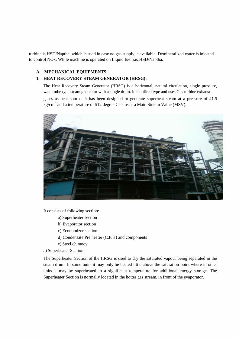
The Heat Recovery Steam Generator (HRSG) is a horizontal, natural circulation, single pressure,
water tube type steam generator with a single drum. It is unfired type and uses Gas turbine exhaust
gases as heat source. It has been designed to generate superheat steam at a pressure of 41.5
kg/cm2 and a temperature of 512 degree Celsius at a Main Stream Value (MSV).
It consists of following section:
a) Superheater section
b) Evaporator section
c) Economizer section
d) Condensate Pre heater (C.P.H) and components
e) Steel chimney
a) Superheater Section:
The Superheater Section of the HRSG is used to dry the saturated vapour being separated in the
steam drum. In some units it may only be heated little above the saturation point where in other
units it may be superheated to a significant temperature for additional energy storage. The
Superheater Section is normally located in the hotter gas stream, in front of the evaporator.

b) Evaporator Section: The most important component would, of course, be the Evaporator Section. So an evaporator
section may consist of one or more coils. In these coils, the effluent (water), passing through the
tubes is heated to the saturation point for the pressure it is flowing.
c) Economizer Section: The Economizer Section, sometimes called a preheater or preheat coil, is used to preheat the feedwater
being introduced to the system to replace the steam (vapour) being removed from the system via the
superheater or steam outlet and the water loss through blowdown. It is normally located in the colder
gas downstream of the evaporator. Since the evaporator inlet and outlet temperatures are both close to
the saturation temperature for the system pressure, the amount of heat that may be removed from the
flue gas is limited due to the approach to the evaporator, whereas the economizer inlet temperature is
low, allowing the flue gas temperature to be taken lower.

d) Condensate Pre- Heater (C.P.H) and Components: Low pressure feed water heaters also called condensate Pre heater sometimes used on combined
cycle units to heat the desecrator feed water thus the cycle required less desecration steam making
it more efficient. The purpose of condensate pre-heater is to increase the temperature of
demineralized water so that it requires lesser energy to be converted into steam which is pumped
into it by Condensate Extraction Pump after passing through the condenser. Now from CPH it is
pumped into de-aerator. The cycle for both LP and HP steam formation is same.CPH is
constructed of modules, consisting of spiral finned tubes welded to the top and bottom headers,
two rows (max.) per module. CPFI is designed for single pass flow on the gas side and multi-pass
flow on the tube side.
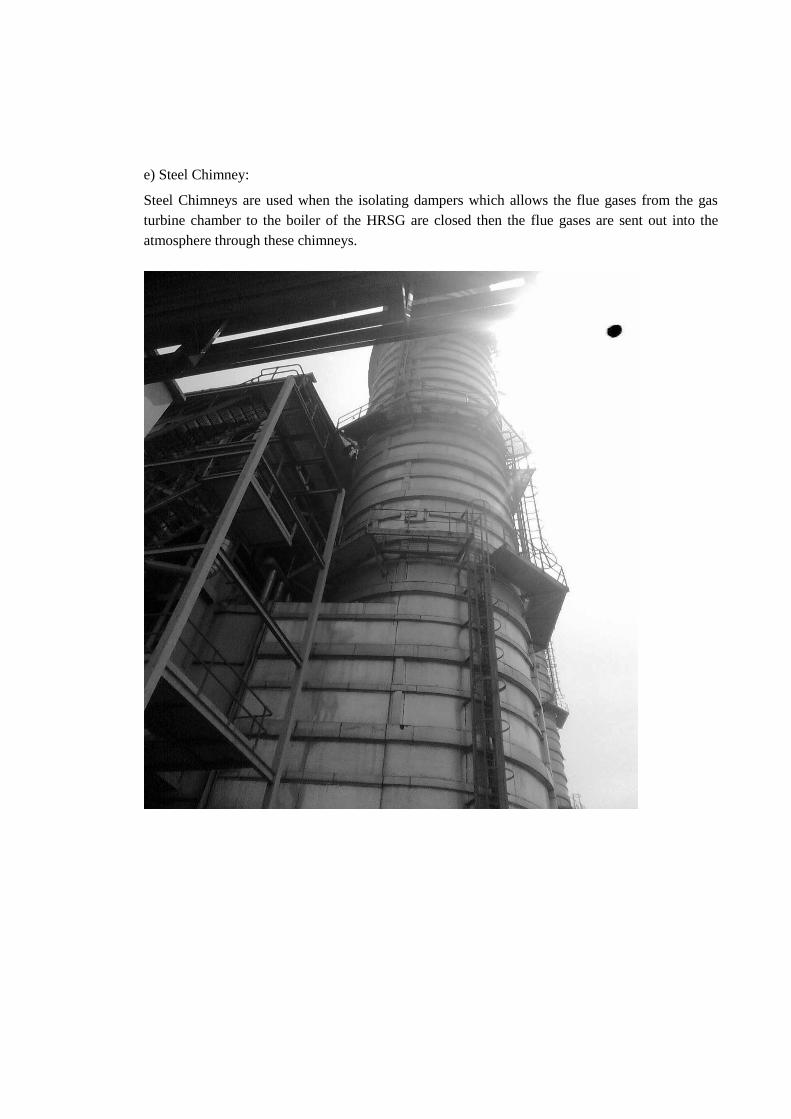
e) Steel Chimney: Steel Chimneys are used when the isolating dampers which allows the flue gases from the gas
turbine chamber to the boiler of the HRSG are closed then the flue gases are sent out into the
atmosphere through these chimneys.

2. CONDENSER:
The surface condenser is a shell and tube heat exchanger in which cooling water is circulated through
the tubes. The exhaust steam from the low pressure turbine enters the shell where it is cooled and
converted to condensate (water) by flowing over the tubes. Such condensers use steam ejectors or
rotary motor-driven exhausters for continuous removal of air and gases from the steam side to
maintain vacuum. For best efficiency, the temperature in the condenser must be kept as low as
practical in order to achieve the lowest possible pressure in the condensing steam. Since the
condenser temperature can almost always be kept significantly below 100oC where the vapour
pressure of water is much less than atmospheric pressure, the condenser generally works under
vacuum. Thus leaks of non-condensable air into the closed loop must be prevented. Plants
operating in hot climates may have to reduce output if their source of condenser cooling water
becomes warmer; unfortunately this usually coincides with periods of high electrical demand for
air conditioning. The condenser uses either circulating cooling water from a cooling tower to
reject waste heat to the atmosphere, or once-through water from a river.

3. DEAERATOR: A steam generating boiler requires that the boiler feed water should be devoid of air and other
dissolved gases, particularly corrosive ones, in order to avoid corrosion of the metal. Generally, power
stations use a deaerator to provide for the removal of air and other dissolved gases from the boiler
feedwater. A deaerator typically includes a vertical, domed deaeration section mounted on top of a
horizontal cylindrical vessel which serves as the deaerated boiler feedwater storage tank. Practical considerations demand that in a steam boiler/ steam turbine/generator unit the circulating steam, condensate, and feed water should be devoid of dissolved gases, particularly corrosive ones, and dissolved or suspended solids. The gases will give rise to corrosion of the metal in contact thereby thinning them and causing rupture. The solids will deposit on the heating surfaces giving rise to localized heating and tube ruptures due to overheating. Under some conditions it may give rise to stress corrosion cracking.

4. COOLING TOWERS: Cooling towers are heat removal devices used to transfer process waste heat to the atmosphere.
Cooling towers may either use the evaporation of water to remove process heat and cool the
working fluid to near the wet-bulb air temperature or rely solely on air to cool the working fluid
to near the dry-bulb air temperature. Common applications include cooling the circulating water
used in oil refineries, chemical plants, power stations and building cooling. The towers vary in
size from small roof-top units to very large hyperboloid structures (as in Image 1) that can be up
to 200 meters tall and 100 meters in diameter, or rectangular structures (as in Image 2) that can be
over 40 meters tall and 80 meters long. Smaller towers are normally factory-built, while larger
ones are constructed on site. At PPCL, ID Cooling Towers are used and arranged in the form of a
row of 8 cells separated by block partition walls from basin sills to the fan deck.
Fan Specifications: 8 bladed, axial flow and each blade have a diameter of 9144 mm.
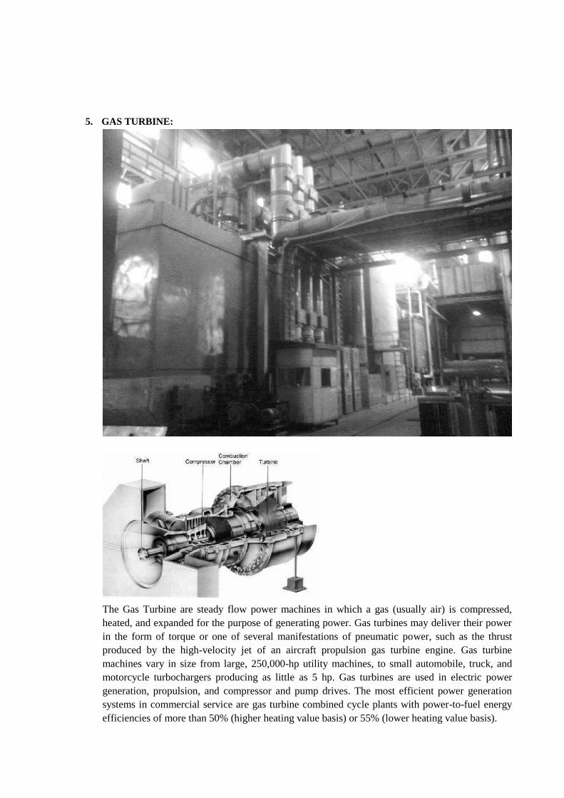
5. GAS TURBINE:
The Gas Turbine are steady flow power machines in which a gas (usually air) is compressed,
heated, and expanded for the purpose of generating power. Gas turbines may deliver their power
in the form of torque or one of several manifestations of pneumatic power, such as the thrust
produced by the high-velocity jet of an aircraft propulsion gas turbine engine. Gas turbine
machines vary in size from large, 250,000-hp utility machines, to small automobile, truck, and
motorcycle turbochargers producing as little as 5 hp. Gas turbines are used in electric power
generation, propulsion, and compressor and pump drives. The most efficient power generation
systems in commercial service are gas turbine combined cycle plants with power-to-fuel energy
efficiencies of more than 50% (higher heating value basis) or 55% (lower heating value basis).
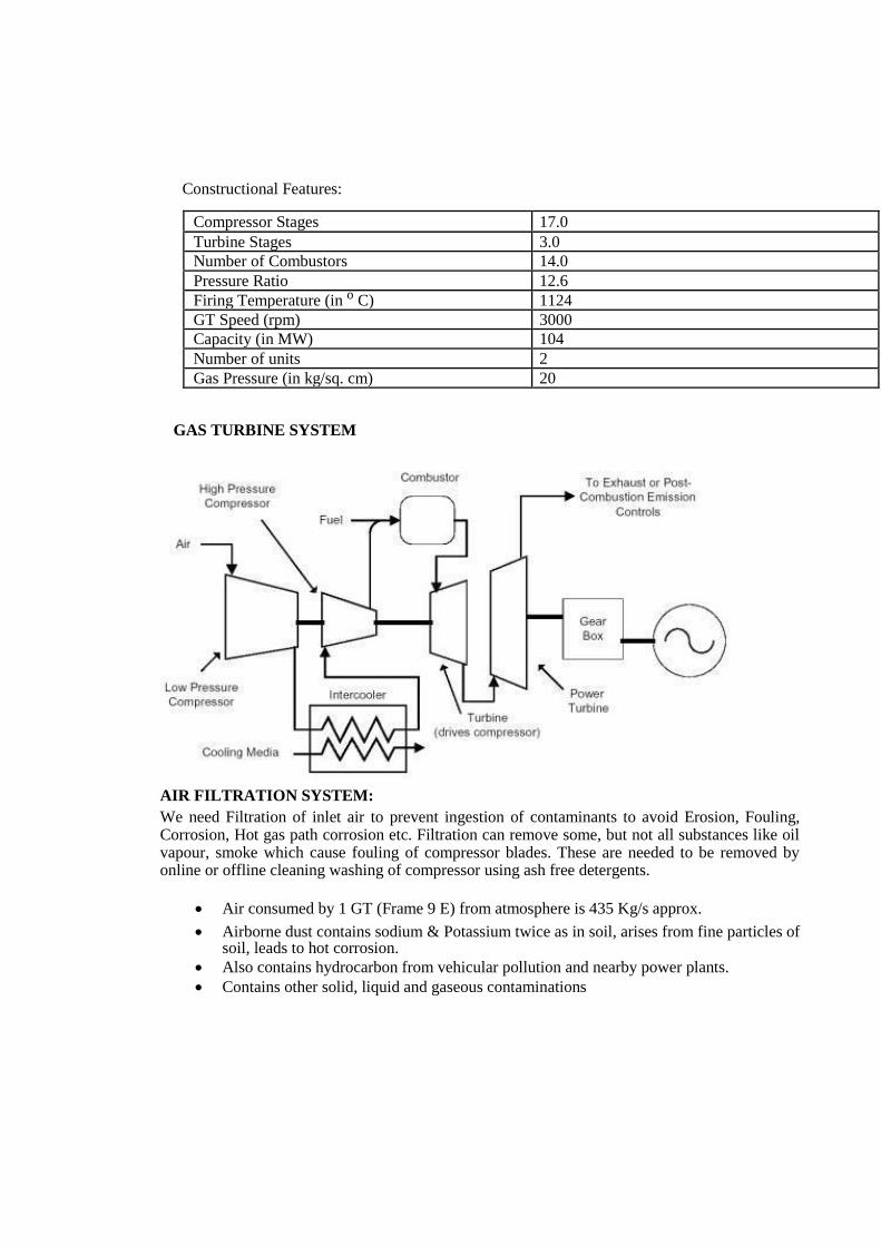
Constructional Features:
Compressor Stages 17.0 Turbine Stages 3.0 Number of Combustors 14.0 Pressure Ratio 12.6 Firing Temperature (in o C) 1124 GT Speed (rpm) 3000 Capacity (in MW) 104 Number of units 2 Gas Pressure (in kg/sq. cm) 20
GAS TURBINE SYSTEM AIR FILTRATION SYSTEM: We need Filtration of inlet air to prevent ingestion of contaminants to avoid Erosion, Fouling, Corrosion, Hot gas path corrosion etc. Filtration can remove some, but not all substances like oil vapour, smoke which cause fouling of compressor blades. These are needed to be removed by online or offline cleaning washing of compressor using ash free detergents.
Air consumed by 1 GT (Frame 9 E) from atmosphere is 435 Kg/s approx.
Airborne dust contains sodium & Potassium twice as in soil, arises from fine particles of soil, leads to hot corrosion.
Also contains hydrocarbon from vehicular pollution and nearby power plants.
Contains other solid, liquid and gaseous contaminations
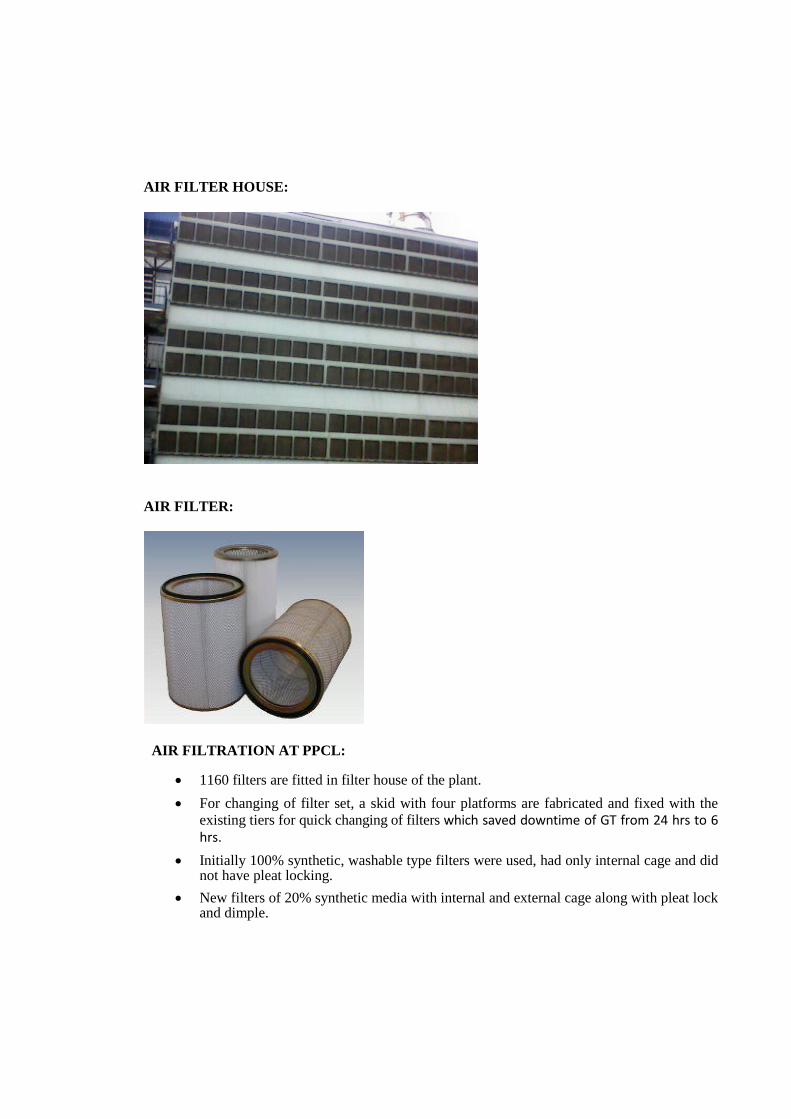
AIR FILTER HOUSE:
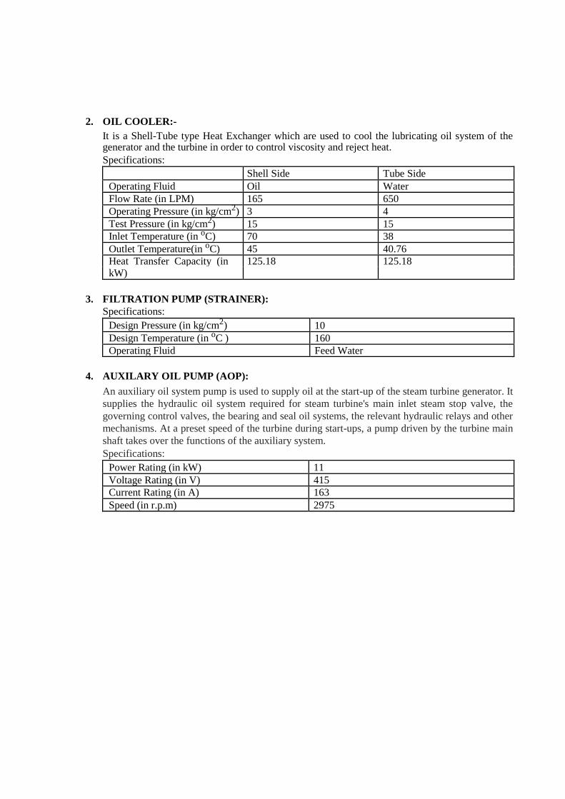
AIR FILTER:
AIR FILTRATION AT PPCL:
1160 filters are fitted in filter house of the plant.
For changing of filter set, a skid with four platforms are fabricated and fixed with the
existing tiers for quick changing of filters which saved downtime of GT from 24 hrs to 6
hrs.
Initially 100% synthetic, washable type filters were used, had only internal cage and did not have pleat locking.
New filters of 20% synthetic media with internal and external cage along with pleat lock
and dimple.

STEAM TURBINE: A steam turbine is a mechanical device that extracts thermal energy from pressurized steam, and converts it
into useful mechanical work. It has almost completely replaced the reciprocating piston steam engine
primarily because of its greater thermal efficiency and higher power-to-weight ratio. Also, because the
turbine generates rotary motion, rather than requiring a linkage mechanism to convert reciprocating to
rotary motion, it is particularly suited for use driving an electrical generator — about 86% of all electric
generation in the world is by use of steam turbines. The steam turbine is a form of heat engine that derives
much of its improvement in thermodynamic efficiency from the use of multiple stages in the expansion of the
steam, as opposed to the one stage in the Watt engine, which results in a closer approach to the ideal
reversible process. It converts the energy stored in steam into rotational mechanical energy.

SPECIFICATIONS OF STEAM TURBINE:
H.P Turbine Single flow with 28 reaction stages L.P. Turbine Double flow with 8 reaction stages H.P. Stop and Control Valves 2 L.P. Stop and Control Valves 2 Rated Speed 50/s Max. Speed (No Time Limitation) 51.5/s Min. Speed (No Time Limitation) 47.5/s Critical Speed (in r.p.m) 1292/2492 H.P. Steam Flow (in T/hr) 390 L.P. Steam Flow (in T/hr) 80
AUXILARIES AND AUXILARY SYSTEM:
1. BOILER FEED PUMP:-
Boiler feed pump is used to feed water to steam generator boiler drum at desired pressure and temperature. As the water is fed to the steam generator it has to be at the temperature & pressure that of the steam generator. Two types of BFP’s are used in the plant: a) HPBFP:
Motor Specifications: Power Rating (in kW) 1500 Stator Amps (in A) 157 Stator Volts (in V) 6600 Speed (in r.p.m) 1487 Insulation Class F
Pump Specifications:
Type of Pump Centrifugal Discharge (in m3 per hr) 240 Head (in m) 1407 Speed (in r.p.m) 4240 Temperature (in oC) 1516
b) LPBFP:
Specifications:
Power Rating (in kW) 45 Voltage Rating (in V) 415 Speed (in r.p.m) 2955 Current (in A) 72 Efficiency 92%
2. OIL COOLER:-
It is a Shell-Tube type Heat Exchanger which are used to cool the lubricating oil system of the generator and the turbine in order to control viscosity and reject heat. Specifications: Shell Side Tube Side
Operating Fluid Oil Water Flow Rate (in LPM) 165 650 Operating Pressure (in kg/cm2) 3 4 Test Pressure (in kg/cm2) 15 15 Inlet Temperature (in oC) 70 38 Outlet Temperature(in oC) 45 40.76 Heat Transfer Capacity (in 125.18 125.18 kW)
3. FILTRATION PUMP (STRAINER):
Specifications: Design Pressure (in kg/cm2) 10 Design Temperature (in oC ) 160 Operating Fluid Feed Water
4. AUXILARY OIL PUMP (AOP):
An auxiliary oil system pump is used to supply oil at the start-up of the steam turbine generator. It
supplies the hydraulic oil system required for steam turbine's main inlet steam stop valve, the
governing control valves, the bearing and seal oil systems, the relevant hydraulic relays and other
mechanisms. At a preset speed of the turbine during start-ups, a pump driven by the turbine main
shaft takes over the functions of the auxiliary system. Specifications:
Power Rating (in kW) 11 Voltage Rating (in V) 415 Current Rating (in A) 163 Speed (in r.p.m) 2975

5. JACKING OIL PUMP (JOP): JOP is used so as to ensure that there is no metal contact between a journal and the bearing. These are
positive displacement pumps that provide high pressure supply of oil under strategic journals of the
turbo generators and oil lifts the shaft slightly. Two types of JOP’s are used in the plant based on the supply of power namely:
a. JOP DC
This JOP runs on the DC supply from the Battery Bank and is used when the AC supply is not used i.e. in case of emergency situation so as to prevent friction between turbine blades and the
ground.
Specifications:
Power Rating (in kW) 11 Voltage Rating (in V) 125 Current Rating (in A) 112 Speed (in r.p.m) 1500
b. JOP AC
This JOP runs on three phase AC power supply.
Specifications:
Power Rating (in kW) 11 Voltage Rating (in V) 415 Current Rating (in A) 20.5
6. INSTRUMENT AIR COMPRESSOR (IAC):
An instrument air compressor controls the application of air for operating valves in pneumatic
instruments. Valves are process control equipment for industrial instruments and instrument air
compressors ensure that the air passing through to power these process control equipment is of
the correct pressure and temperature. Specifications:
Compressor Outlet Pressure (in bar) 5.9 Outlet AC Voltage (in kV) 235.1 Outlet AC Current (in A) 136.5
Efficiency of the plant: 47% to 51% Compressed Air: 10-12 kg/cm2
B. WATER TREATMENT PLANT
Boiler makeup water to the extent of 1.5-2% of the total flow is required to replenish the loss of
water through leakage from fittings and bearings, boiler blow-down escape with non condensable
gases in the Deaerator, turbine glands, and other causes. This makeup water needs to be treated
prior to feeding it to the boiler for-
Prevention of hard scale formation on the heating surfaces,
Elimination of corrosion,
Control of carry-over to eliminate the deposition on super heater tubes,
Prevention of silica deposition and corrosion damage to turbine blades. The cooling water makeup also demands significant amount of water at a prescribed parameters of PH turbidity, conductivity etc. Also, water is needed for various other plant activities at various

levels of cleanliness such as firefighting, service water etc. This entire water requirement is met
by the water treatment plant of the power plant. Thus, the water treatment plant treats the water
according to the requirements to which it needs to be put at various sections in the power plant.
This whole process largely comes under water treatment, which starts at the point, raw water
enters the plant boundaries and continues till the water id dispatched after treatment to its desired
destination.
a. RAW WATER:
The power plant receives its raw water from two sewage treatment plants namely, Delhi Gate Sewage Treatment Plant and Sen Nursing Home Sewage Treatment Plant. This water is not suitable for use in the power plant and has to be treated. Raw water contains a variety of impurities such as –
suspended solids and turbidity, Organics, Hardness(salts of calcium and magnesium), alkalinity(bicarbonates, carbonates, hydrates), Silica, and
Dissolved gases(O2 and CO2) Firstly the raw water is aerated i.e. oxygen is added to it by letting it to pass through stepped
platform into a storage tanks which is divided into two parts. After the water is aerated it is
pumped to Lime Softening Plant (also known as Stilling Chamber) where the turbidity and
hardness of the water are reduced. Here, lime, chlorine, poly electrolyte and ferric alum are dosed
in the stilling chamber. Ferric alum reduces the turbidity of the water and poly electrolyte
enhances sludge formation. Lime is added to the raw water to remove the hardness while chlorine
neutralizes the biological matter.

b. CLARIFICATION:
From the stilling chamber (located prior to the clarification tank) water is allowed to stand for
sometime in a big tank or reservoir, most of the suspended material settles down. The decanted
water is quiet clear and is taken out from outlet located at convenient points. This process of
clarification can be accelerated by adding coagulants such as ALUM (aluminum sulphate) or
ferrous sulphate or sodium aluminate. These result in the formation of a FLOC or precipitate of
aluminum hydroxide which tends to amalgamate colloidal, organic and suspended impurities that
settle down. The tank in which the whole process takes place is called clarification tank.
c. FILTRATION:
Water filtration is the process of separating suspended and colloidal impurities from the water by
passing it through a porous medium. A bed of granular filter material or media is used in most
power plant applications. A filter may be defined simply as a device consisting of a tank, a means
of supporting a working filter bed within the tank, suitable filter media, and necessary piping,
valving and controls. There are four types of filters that are used in the plant- Gravity Filter:
There are three Gravity Filters in the plant. These filters consists layers of sand, gravels and stones through water is filtered and sent to the Twin Bed Gravity Filters.
Twin Bed Gravity Filters (TBGF):
There are two such type of filters that are installed in the plant. These filters consist of a layer of Anthracite (best quality coal) in the bottom and above this layer is the layer of sand. Turbidity of water becomes 1-2 NTU
Activated Carbon Filter (ACF):
These filters consists of Activated Carbon which removes Cl2, odour, color, etc. from the water. These filters are two in number
Cartridge Filter:
These filters consists of cartridges which further filters the water coming
from the ACF and sends it to the RO Plant for further treatment. Impurities
of order of 5 microns are reduced and the turbidity is 0.11 NTU but the
conductivity is 1508 .7 S/cm
d. REVERSE OSMOSIS DEMINERALISATION (RODM):
It is a type of Membrane Desalination for desalination of brackish water to produce de-mineralized water fit for steam turbine cycle and auxiliary equipment’s cooling.
Reverse Osmosis:
This is a process in which osmosis takes place when pressure is applied. In this process the tank is divided into two chambers separated by a semi-permeable membrane made up of
Polyamide. When pressure is applied on water in one chamber then the water moves into the second chamber through the semi permeable membrane due to difference in pressure.
The water obtained from the RO system is called Permeate Water (Water from which most of the dissolved solids have been removed by the process of reverse osmosis) which is stored in the Permeate tank.
Mixed Bed:
From the Permeate tank the water is sent to the Mixed Bed which consists of cationic and anionic
resins which can be recharged using HCl and NaOH. In the Mixed Bed the conductivity of the
permeate water is reduced to less than 0.1% and the water from the mixed bed is called De-
Mineralized Water or DM Water which is used in the HRSG system for the generation of the
steam. From the Mixed Bed the DM water is pumped into the DM Water Tank.
C. ELECTRICAL EQUIPMENTS:
1. GENERATOR:
Generator is a device which converts mechanical energy into electrical energy. The plant have
total three generators out of which two generators are run by Gas Turbine (2*GTG) and the
remaining by Steam Turbine (1*ST). Rotating field type generators are employed which are
ventilated by the fans of rotor shaft or separately driven fans. The Generators used have 2 poles,
generates a frequency of 50 Hz and speed of the generators are 3000 r.p.m (Speed= 120*f/P)
The Power output of the two GTG’s is 2*104= 208 MW and the power output of the ST is 122 MW. Total power generated is 330 MW and the voltage is 10.5 kV.
Auxiliary Systems used for Generators are: a. Lubricating Oil System b. Hydrogen Cooling System c. Seal Oil System d. Stator Cooling Water System e. Excitation System
Tests are conducted on the generator for checking the insulation of the stator and rotor windings. The tests are-
Tan Delta Insulation Capacitance test:
Tan Delta is a diagnostic test conducted on the insulation of cables and
windings. It is used to measure the deterioration in the cable. It also gives an
idea of the aging process in the cable and enables us to predict the remaining
life of the cable. It is alternatively known as the loss angle test or the
dissipation factor test. The Tan Delta test works on the principle that any
insulation in its pure state acts as a capacitor. The test involves applying a
very low frequency AC voltage. The voltage is generally double the rated
voltage of the cable or winding. Insulation Resistance test:
The insulation resistance test (meggering) is of value for future comparison and also for determining if the transformer is to be subjected to the applied

voltage test. The winding insulation resistance test is a DC high voltage test
used to determine the dryness of winding insulation system. The test
measures the insulation resistance from individual windings to ground and/or
between individual windings.
Winding Resistance test:
Measurement is made to check transformer windings and terminal
connections and also both to use as reference for future measurements and to
calculate the load loss values at reference (e.g. 75ºC) temperature. Measuring
the winding resistance is done by using DC current and is very much
dependent on temperature. Generator cooling is done using CO2 which is cooled by water through fin fan system which uses ID Fans.
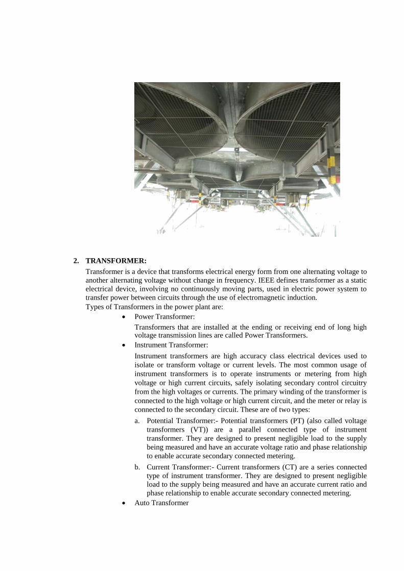
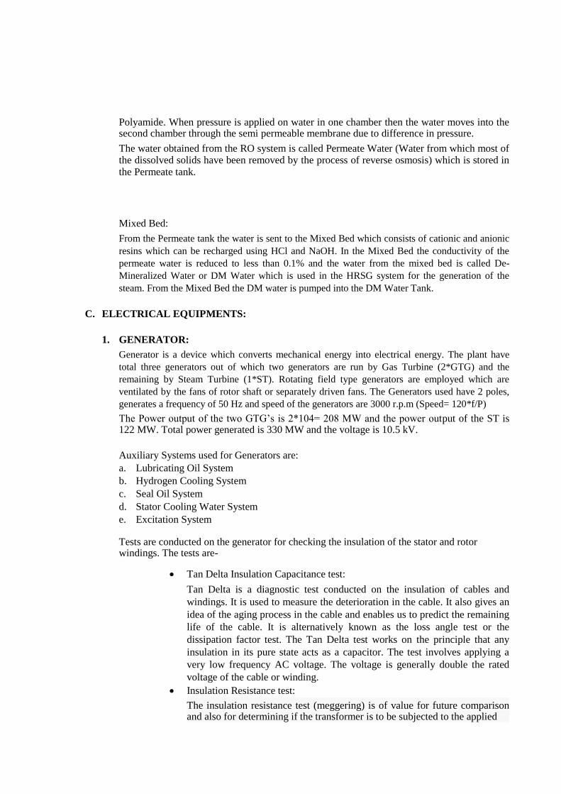
2. TRANSFORMER:
Transformer is a device that transforms electrical energy form from one alternating voltage to
another alternating voltage without change in frequency. IEEE defines transformer as a static
electrical device, involving no continuously moving parts, used in electric power system to
transfer power between circuits through the use of electromagnetic induction. Types of Transformers in the power plant are:
Power Transformer:
Transformers that are installed at the ending or receiving end of long high voltage transmission lines are called Power Transformers.
Instrument Transformer:
Instrument transformers are high accuracy class electrical devices used to
isolate or transform voltage or current levels. The most common usage of
instrument transformers is to operate instruments or metering from high
voltage or high current circuits, safely isolating secondary control circuitry
from the high voltages or currents. The primary winding of the transformer is
connected to the high voltage or high current circuit, and the meter or relay is
connected to the secondary circuit. These are of two types:
a. Potential Transformer:- Potential transformers (PT) (also called voltage
transformers (VT)) are a parallel connected type of instrument
transformer. They are designed to present negligible load to the supply
being measured and have an accurate voltage ratio and phase relationship
to enable accurate secondary connected metering.
b. Current Transformer:- Current transformers (CT) are a series connected
type of instrument transformer. They are designed to present negligible
load to the supply being measured and have an accurate current ratio and
phase relationship to enable accurate secondary connected metering. Auto Transformer

An autotransformer (sometimes called auto step down transformer) is an
electrical transformer with only one winding. The "auto" (Greek for "self")
prefix refers to the single coil acting on itself and not to any kind of
automatic mechanism. In an autotransformer, portions of the same winding
act as both the primary and secondary sides of the transformer. The winding
has at least three taps where electrical connections are made. Transformer on the basis of working i.e.
a. Step Up Transformer: - Transformer that steps up the voltage and have
primary winding as the LV side and secondary winding as HV side.
b. Step Down Transformer: - Transformer that steps down the voltage and have Primary winding as HV side and Secondary winding as LV side.
Specifications of Generating Transformer:
Type of Cooling OFAF ONAF ONAN Rating HV (MVA) 114 79.8 57 Rating LV (MVA) 114 79.8 57 No load Voltage (HV in 230 230 230 kV)
No load Voltage (LV in 10.5 10.5 10.5 kV)
Line Current HV 28.16 200.32 143.08 (Amps)
Line Current LV 6268.37 4387.86 3134.19 (Amps)
% Impedance at Normal 12.5(+ or -) 7.5% TOL
Tap (HV-LV)
Class of Insulation A
Temp. rise oil (in o C) 35
Temp. rise winding (in o 40 C)
HV 950 kVp, 395 kVrms
LV 75 kVp , 28 kVrms
HVN 95 kVp , 38 kVrms
Conservator Air Cell Type
Connection Symbol YNd11
Specifications of Unit Auxiliary Transformer:
Type of Cooling ONAN/ ONAF
Rating HV (MVA) 16/20
Rating LV (MVA) 16/20
No Load Voltage HV (kV) 10.5
No Load Voltage LV (kV) 6.9
Line Current HV (Amps) 879.77/1099.71
Line Current LV (Amps) 1338.78/1673.48
Temp rise Oil (in o C) 50
Temp rise Winding (in o C) 55
HV 75 kVp , 28 kVrms
LV 60 kVp , 20 kVrms
Connection Symbol Dyn1
3. SWITCHYARD:
For any power station, switchyard is an important part which bridges the generating station and
the distribution system i.e. via switchyard the generated electricity is fed to the sub-stations. It
connects the GTPS to the northern grid. The switchyard of Gas Turbine Power Plant is of 220
KV. The voltage generated is 10.5 KV, which is then step up to 220 KV by generator transformer.
This 220 KV is fed to the 220 KV switchyard. The switchyard has the double bus bar system i.e.
one is main bus and the other one is secondary bus. Some of the functions are:
Change voltage from one level to another Switch transmission and distribution circuits into and out of the grid system. Measure electric power quantities flowing in the circuits. Eliminate lightning and other surges from the system.
The Switchyard in the PPCL plant is maintained by Delhi Transco Limited (DTL).


Components used in the Switchyard are:
a. Isolators:
They are designed to open a ckt under no load. Its main purpose is to isolate portion of the circuit from the other & is not intended to be opened while current is flowing in the line.
b. Circuit Breakers:
It is a piece of equipment which can break the circuit automatically under faulty conditions and make the circuit either manually or by remote control under faulty conditions. They can be classified as:
Oil Circuit Breaker Air Blast Circuit Breaker Vacuum Circuit Breaker Gas (SF6) Circuit Breaker
In PPCL switchyard maintained by DTL, Gas (SF6) Circuit Breaker or Sulphur Hexafluoride Circuit Breaker is used.

Ratings of Gas Circuit Breaker in the Switchyard:
Also Vacuum Circuit Breaker is also used in plant and is maintained by PPCL and its ratings
are shown in the figure
c. Relays:
A relay is an electrically operated switch. Many relays use an electromagnet to
mechanically operate a switch, but other operating principles are also used, such as solid-
state relays. Relays are used where it is necessary to control a circuit by a low-power
signal (with complete electrical isolation between control and controlled circuits), or
where several circuits must be controlled by one signal.
In the switchyard maintained by DTL, there are a number of relays including electromagnet relays, numerical relays etc.
Also there is a master relay called 186,186 which detects even a small fault in the circuit and trips the circuit breaker.

d. Insulators:
Insulators are used in electrical equipment to support and separate electrical
conductors without allowing current through themselves. An insulating material used
in bulk to wrap electrical cables or other equipment is called insulation. The term
insulator is also used more specifically to refer to insulating supports used to attach
electric power distribution or transmission lines to utility poles and transmission
towers. They support the weight of the suspended wires without allowing the current
to flow through the tower to ground. e. Bus Couplers:
Bus coupler is a device which is used to couple one bus to the other without any interruption in power supply and without creating hazardous arcs. It is achieved with the help of circuit breaker and isolators.
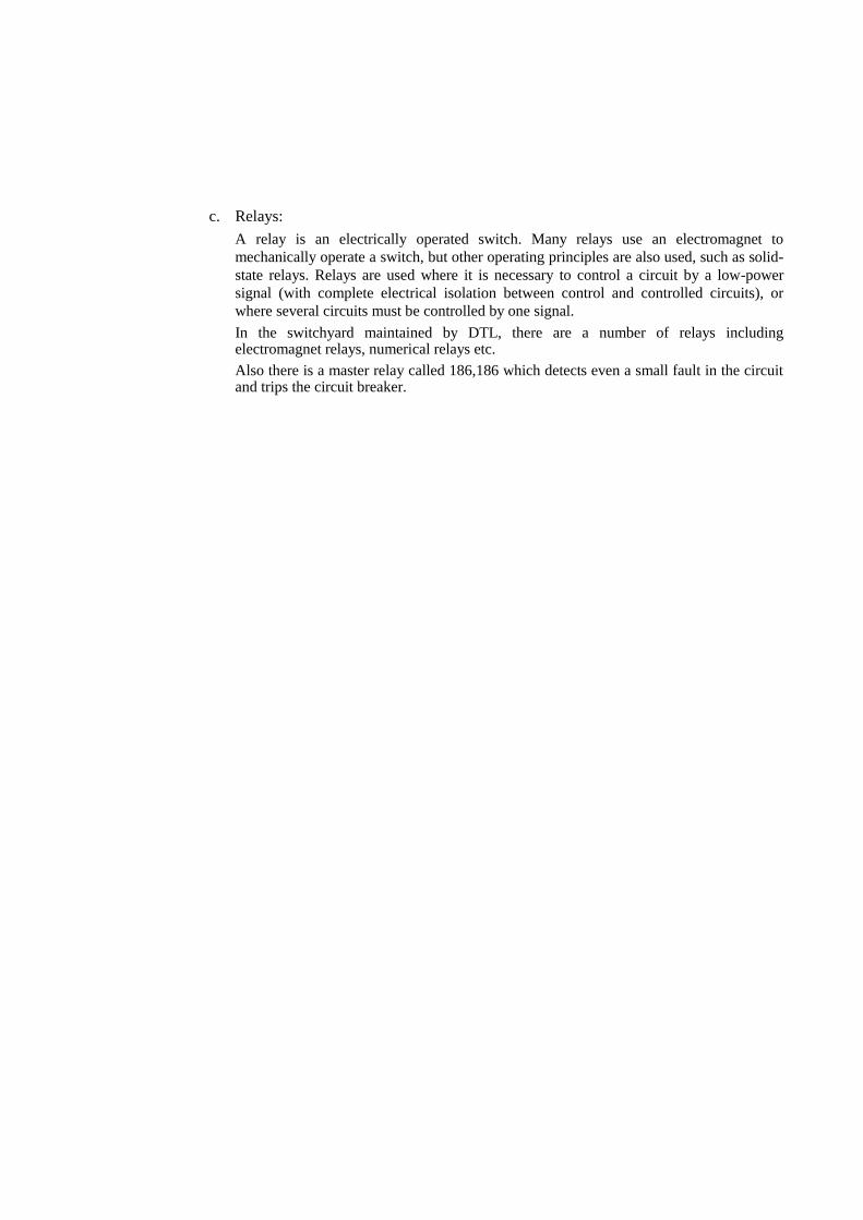
f. Current Transformer:
C.T is an instrument transformer used for protection & metering of high values of currents. C.T is used for reducing AC from higher to lower value of measurement/protection/control.
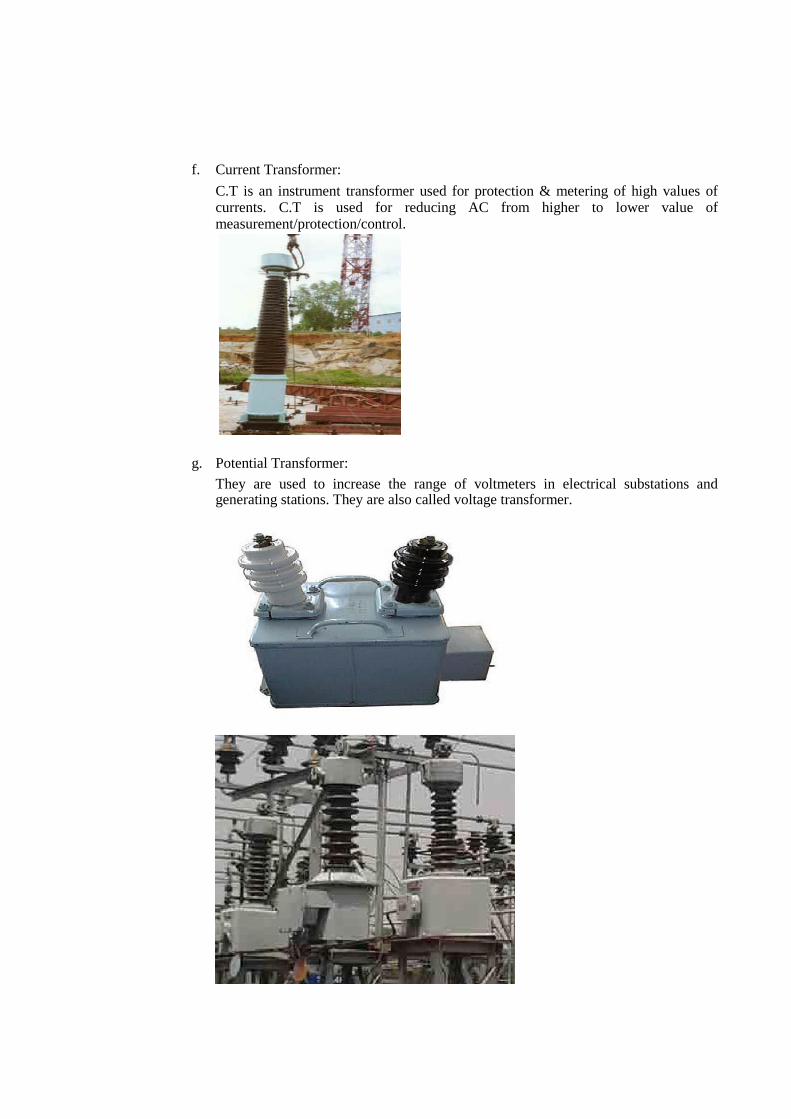
g. Potential Transformer:
They are used to increase the range of voltmeters in electrical substations and generating stations. They are also called voltage transformer.

h. Lightning Arrester:
A lightning arrester is a device used on electrical power systems and
telecommunications systems to protect the insulation and conductors of the system
from the damaging effects of lightning. The typical lightning arrester has a high-
voltage terminal and a ground terminal. When a lightning surge (or switching surge,
which is very similar) travels along the power line to the arrester, the current from the
surge is diverted through the arrestor, in most cases to earth. i. Earthing Links:
Switchyard Earthing is provided to protect personally from shocks and hazards from electrical equipments.

Single line diagram of DTL Substation in PPCL: