Data Sheet Data Sheet EPCOS AG 2008. Reproduction, publication and dissemination of this publication, enclosures hereto and the information contained therein without EPCOS’ prior express consent is prohibited. SIOV metal oxide varistors Leaded varistors, StandarD series Series/Type: S05, S07, S10, S14, S20 Date: December 2007

Welcome message from author
This document is posted to help you gain knowledge. Please leave a comment to let me know what you think about it! Share it to your friends and learn new things together.
Transcript
Data SheetData Sheet
EPCOS AG 2008. Reproduction, publication and dissemination of this publication, enclosureshereto and the information contained therein without EPCOS’ prior express consent is prohibited.
SIOV metal oxide varistors
Leaded varistors, StandarD series
Series/Type: S05, S07, S10, S14, S20
Date: December 2007
2 11/07Please read Cautions and warnings andImportant notes at the end of this document.
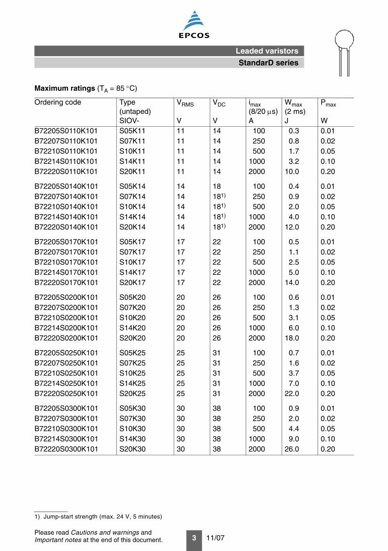
Construction
Round varistor element, leaded Coating: epoxy resin, flame-retardant to UL 94 V-0 Terminals: tinned copper wire
Features
Wide operating voltage range 11 … 1100 VRMS High surge current ratings up to 8 kA No derating up to 85 °C ambient temperature PSpice models
Approvals
UL CSA (all types ≥K115) SEV VDE CECC CQC S05/07 (K11 … K460), S10/S14 (K11 … K680), S20 (K11 … K1100) IEC
Delivery mode
Bulk (standard), taped versions on reel or in Ammo pack upon request. For further details refer to chapter “Taping, packaging and lead configuration” for leaded varistors.
Options
S10* types with lead spacing 5.0 mm and S20* types with lead spacing 7.5 mm are also availableon request.
General technical data
Climatic category to IEC 60068-1 40/85/56Operating temperature to CECC 42 000 – 40 … + 85 °CStorage temperature – 40 … +125 °CElectric strength to CECC 42 000 ≥2.5 kVRMS
Insulation resistance to CECC 42 000 ≥10 MΩResponse time <25 ns
Leaded varistors
StandarD series
3 11/07Please read Cautions and warnings andImportant notes at the end of this document.
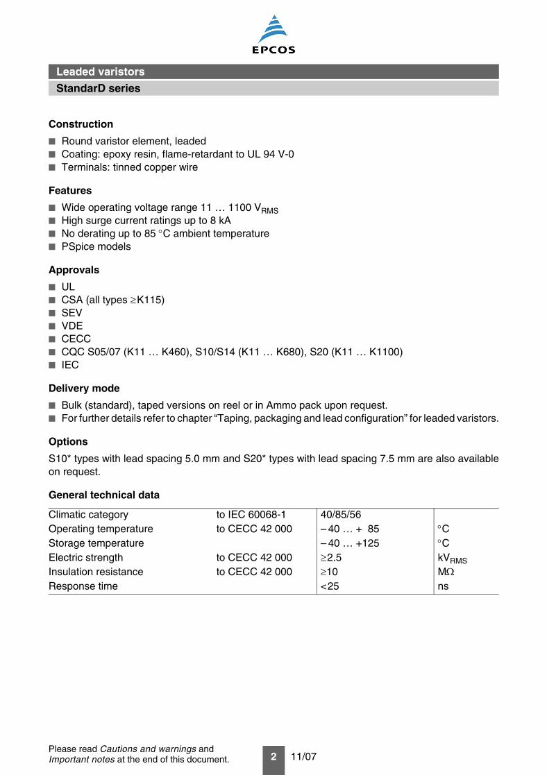
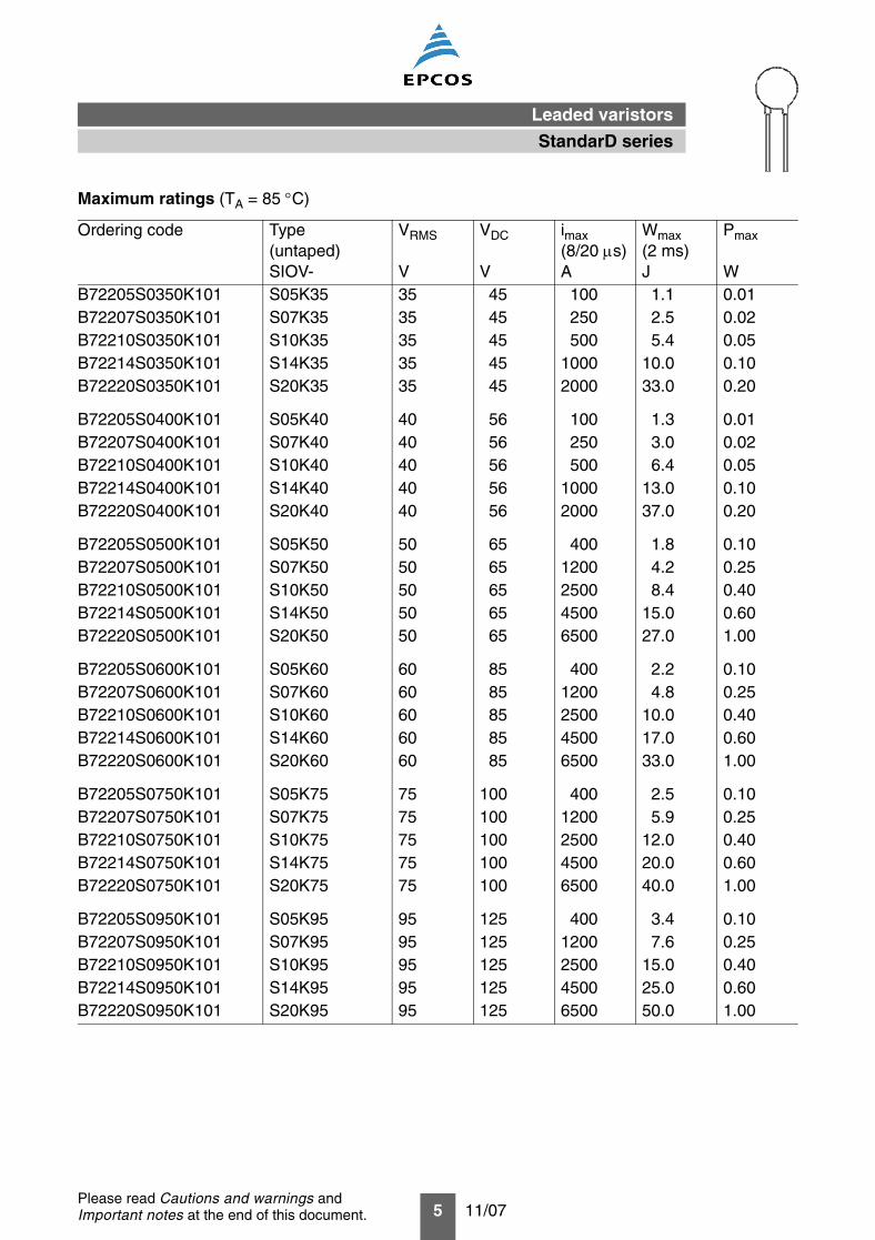
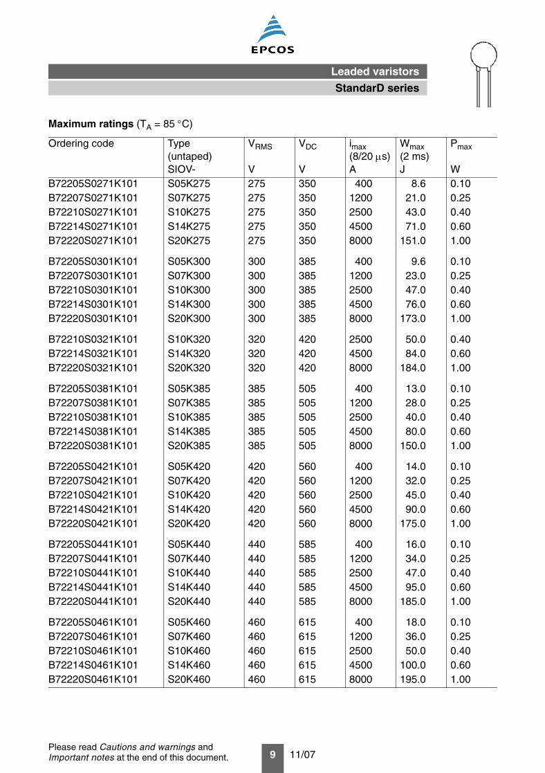
Maximum ratings (TA = 85 °C)
Ordering code Type(untaped)SIOV-
VRMS
V
VDC
V
imax(8/20 µs)A
Wmax(2 ms)J
Pmax
WB72205S0110K101 S05K11 11 14 100 0.3 0.01B72207S0110K101 S07K11 11 14 250 0.8 0.02B72210S0110K101 S10K11 11 14 500 1.7 0.05B72214S0110K101 S14K11 11 14 1000 3.2 0.10B72220S0110K101 S20K11 11 14 2000 10.0 0.20
B72205S0140K101 S05K14 14 18 100 0.4 0.01B72207S0140K101 S07K14 14 181) 250 0.9 0.02B72210S0140K101 S10K14 14 181) 500 2.0 0.05B72214S0140K101 S14K14 14 181) 1000 4.0 0.10B72220S0140K101 S20K14 14 181) 2000 12.0 0.20
B72205S0170K101 S05K17 17 22 100 0.5 0.01B72207S0170K101 S07K17 17 22 250 1.1 0.02B72210S0170K101 S10K17 17 22 500 2.5 0.05B72214S0170K101 S14K17 17 22 1000 5.0 0.10B72220S0170K101 S20K17 17 22 2000 14.0 0.20
B72205S0200K101 S05K20 20 26 100 0.6 0.01B72207S0200K101 S07K20 20 26 250 1.3 0.02B72210S0200K101 S10K20 20 26 500 3.1 0.05B72214S0200K101 S14K20 20 26 1000 6.0 0.10B72220S0200K101 S20K20 20 26 2000 18.0 0.20
B72205S0250K101 S05K25 25 31 100 0.7 0.01B72207S0250K101 S07K25 25 31 250 1.6 0.02B72210S0250K101 S10K25 25 31 500 3.7 0.05B72214S0250K101 S14K25 25 31 1000 7.0 0.10B72220S0250K101 S20K25 25 31 2000 22.0 0.20
B72205S0300K101 S05K30 30 38 100 0.9 0.01B72207S0300K101 S07K30 30 38 250 2.0 0.02B72210S0300K101 S10K30 30 38 500 4.4 0.05B72214S0300K101 S14K30 30 38 1000 9.0 0.10B72220S0300K101 S20K30 30 38 2000 26.0 0.20
1) Jump-start strength (max. 24 V, 5 minutes)
StandarD series
Leaded varistors
4 11/07Please read Cautions and warnings andImportant notes at the end of this document.
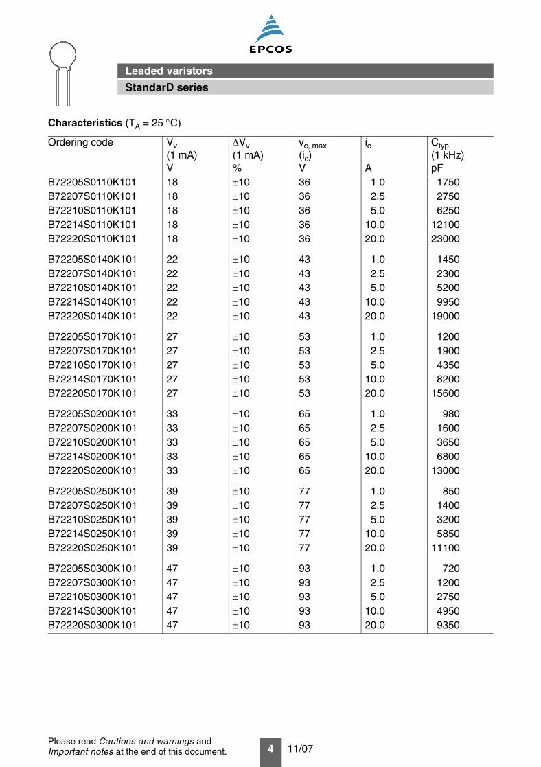
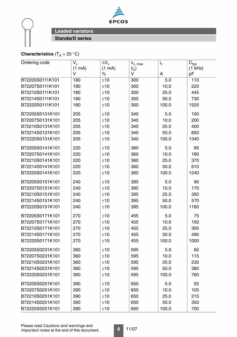
Characteristics (TA = 25 °C)
Ordering code Vv(1 mA)V
∆Vv(1 mA)%
vc, max(ic)V
ic
A
Ctyp(1 kHz)pF
B72205S0110K101 18 ±10 36 1.0 1750B72207S0110K101 18 ±10 36 2.5 2750B72210S0110K101 18 ±10 36 5.0 6250B72214S0110K101 18 ±10 36 10.0 12100B72220S0110K101 18 ±10 36 20.0 23000
B72205S0140K101 22 ±10 43 1.0 1450B72207S0140K101 22 ±10 43 2.5 2300B72210S0140K101 22 ±10 43 5.0 5200B72214S0140K101 22 ±10 43 10.0 9950B72220S0140K101 22 ±10 43 20.0 19000
B72205S0170K101 27 ±10 53 1.0 1200B72207S0170K101 27 ±10 53 2.5 1900B72210S0170K101 27 ±10 53 5.0 4350B72214S0170K101 27 ±10 53 10.0 8200B72220S0170K101 27 ±10 53 20.0 15600
B72205S0200K101 33 ±10 65 1.0 980B72207S0200K101 33 ±10 65 2.5 1600B72210S0200K101 33 ±10 65 5.0 3650B72214S0200K101 33 ±10 65 10.0 6800B72220S0200K101 33 ±10 65 20.0 13000
B72205S0250K101 39 ±10 77 1.0 850B72207S0250K101 39 ±10 77 2.5 1400B72210S0250K101 39 ±10 77 5.0 3200B72214S0250K101 39 ±10 77 10.0 5850B72220S0250K101 39 ±10 77 20.0 11100
B72205S0300K101 47 ±10 93 1.0 720B72207S0300K101 47 ±10 93 2.5 1200B72210S0300K101 47 ±10 93 5.0 2750B72214S0300K101 47 ±10 93 10.0 4950B72220S0300K101 47 ±10 93 20.0 9350
StandarD series
Leaded varistors
5 11/07Please read Cautions and warnings andImportant notes at the end of this document.
B72205S0350K101 S05K35 35 45 100 1.1 0.01B72207S0350K101 S07K35 35 45 250 2.5 0.02B72210S0350K101 S10K35 35 45 500 5.4 0.05B72214S0350K101 S14K35 35 45 1000 10.0 0.10B72220S0350K101 S20K35 35 45 2000 33.0 0.20
B72205S0400K101 S05K40 40 56 100 1.3 0.01B72207S0400K101 S07K40 40 56 250 3.0 0.02B72210S0400K101 S10K40 40 56 500 6.4 0.05B72214S0400K101 S14K40 40 56 1000 13.0 0.10B72220S0400K101 S20K40 40 56 2000 37.0 0.20
B72205S0500K101 S05K50 50 65 400 1.8 0.10B72207S0500K101 S07K50 50 65 1200 4.2 0.25B72210S0500K101 S10K50 50 65 2500 8.4 0.40B72214S0500K101 S14K50 50 65 4500 15.0 0.60B72220S0500K101 S20K50 50 65 6500 27.0 1.00
B72205S0600K101 S05K60 60 85 400 2.2 0.10B72207S0600K101 S07K60 60 85 1200 4.8 0.25B72210S0600K101 S10K60 60 85 2500 10.0 0.40B72214S0600K101 S14K60 60 85 4500 17.0 0.60B72220S0600K101 S20K60 60 85 6500 33.0 1.00
B72205S0750K101 S05K75 75 100 400 2.5 0.10B72207S0750K101 S07K75 75 100 1200 5.9 0.25B72210S0750K101 S10K75 75 100 2500 12.0 0.40B72214S0750K101 S14K75 75 100 4500 20.0 0.60B72220S0750K101 S20K75 75 100 6500 40.0 1.00
B72205S0950K101 S05K95 95 125 400 3.4 0.10B72207S0950K101 S07K95 95 125 1200 7.6 0.25B72210S0950K101 S10K95 95 125 2500 15.0 0.40B72214S0950K101 S14K95 95 125 4500 25.0 0.60B72220S0950K101 S20K95 95 125 6500 50.0 1.00
Maximum ratings (TA = 85 °C)
Ordering code Type(untaped)SIOV-
VRMS
V
VDC
V
imax(8/20 µs)A
Wmax(2 ms)J
Pmax
W
StandarD series
Leaded varistors
6 11/07Please read Cautions and warnings andImportant notes at the end of this document.
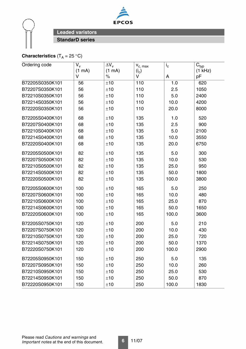
B72205S0350K101 56 ±10 110 1.0 620B72207S0350K101 56 ±10 110 2.5 1050B72210S0350K101 56 ±10 110 5.0 2400B72214S0350K101 56 ±10 110 10.0 4200B72220S0350K101 56 ±10 110 20.0 8000
B72205S0400K101 68 ±10 135 1.0 520B72207S0400K101 68 ±10 135 2.5 900B72210S0400K101 68 ±10 135 5.0 2100B72214S0400K101 68 ±10 135 10.0 3550B72220S0400K101 68 ±10 135 20.0 6750
B72205S0500K101 82 ±10 135 5.0 300B72207S0500K101 82 ±10 135 10.0 530B72210S0500K101 82 ±10 135 25.0 950B72214S0500K101 82 ±10 135 50.0 1800B72220S0500K101 82 ±10 135 100.0 3800
B72205S0600K101 100 ±10 165 5.0 250B72207S0600K101 100 ±10 165 10.0 480B72210S0600K101 100 ±10 165 25.0 870B72214S0600K101 100 ±10 165 50.0 1650B72220S0600K101 100 ±10 165 100.0 3600
B72205S0750K101 120 ±10 200 5.0 210B72207S0750K101 120 ±10 200 10.0 430B72210S0750K101 120 ±10 200 25.0 720B72214S0750K101 120 ±10 200 50.0 1370B72220S0750K101 120 ±10 200 100.0 2900
B72205S0950K101 150 ±10 250 5.0 135B72207S0950K101 150 ±10 250 10.0 260B72210S0950K101 150 ±10 250 25.0 530B72214S0950K101 150 ±10 250 50.0 870B72220S0950K101 150 ±10 250 100.0 1830
Characteristics (TA = 25 °C)
Ordering code Vv(1 mA)V
∆Vv(1 mA)%
vc, max(ic)V
ic
A
Ctyp(1 kHz)pF
StandarD series
Leaded varistors
7 11/07Please read Cautions and warnings andImportant notes at the end of this document.
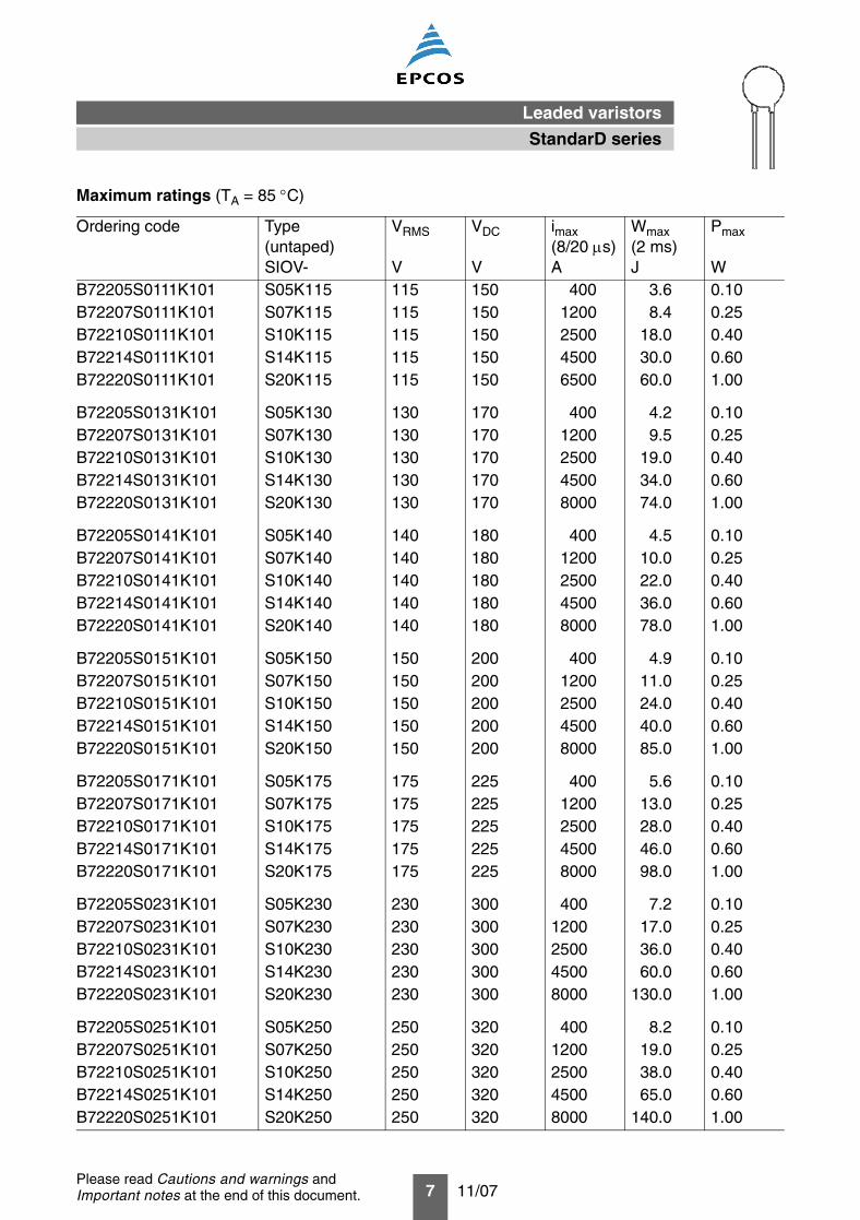
B72205S0111K101 S05K115 115 150 400 3.6 0.10B72207S0111K101 S07K115 115 150 1200 8.4 0.25B72210S0111K101 S10K115 115 150 2500 18.0 0.40B72214S0111K101 S14K115 115 150 4500 30.0 0.60B72220S0111K101 S20K115 115 150 6500 60.0 1.00
B72205S0131K101 S05K130 130 170 400 4.2 0.10B72207S0131K101 S07K130 130 170 1200 9.5 0.25B72210S0131K101 S10K130 130 170 2500 19.0 0.40B72214S0131K101 S14K130 130 170 4500 34.0 0.60B72220S0131K101 S20K130 130 170 8000 74.0 1.00
B72205S0141K101 S05K140 140 180 400 4.5 0.10B72207S0141K101 S07K140 140 180 1200 10.0 0.25B72210S0141K101 S10K140 140 180 2500 22.0 0.40B72214S0141K101 S14K140 140 180 4500 36.0 0.60B72220S0141K101 S20K140 140 180 8000 78.0 1.00
B72205S0151K101 S05K150 150 200 400 4.9 0.10B72207S0151K101 S07K150 150 200 1200 11.0 0.25B72210S0151K101 S10K150 150 200 2500 24.0 0.40B72214S0151K101 S14K150 150 200 4500 40.0 0.60B72220S0151K101 S20K150 150 200 8000 85.0 1.00
B72205S0171K101 S05K175 175 225 400 5.6 0.10B72207S0171K101 S07K175 175 225 1200 13.0 0.25B72210S0171K101 S10K175 175 225 2500 28.0 0.40B72214S0171K101 S14K175 175 225 4500 46.0 0.60B72220S0171K101 S20K175 175 225 8000 98.0 1.00
B72205S0231K101 S05K230 230 300 400 7.2 0.10B72207S0231K101 S07K230 230 300 1200 17.0 0.25B72210S0231K101 S10K230 230 300 2500 36.0 0.40B72214S0231K101 S14K230 230 300 4500 60.0 0.60B72220S0231K101 S20K230 230 300 8000 130.0 1.00
B72205S0251K101 S05K250 250 320 400 8.2 0.10B72207S0251K101 S07K250 250 320 1200 19.0 0.25B72210S0251K101 S10K250 250 320 2500 38.0 0.40B72214S0251K101 S14K250 250 320 4500 65.0 0.60B72220S0251K101 S20K250 250 320 8000 140.0 1.00
Maximum ratings (TA = 85 °C)
Ordering code Type(untaped)SIOV-
VRMS
V
VDC
V
imax(8/20 µs)A
Wmax(2 ms)J
Pmax
W
StandarD series
Leaded varistors
8 11/07Please read Cautions and warnings andImportant notes at the end of this document.
B72205S0111K101 180 ±10 300 5.0 110B72207S0111K101 180 ±10 300 10.0 220B72210S0111K101 180 ±10 300 25.0 445B72214S0111K101 180 ±10 300 50.0 730B72220S0111K101 180 ±10 300 100.0 1520
B72205S0131K101 205 ±10 340 5.0 100B72207S0131K101 205 ±10 340 10.0 200B72210S0131K101 205 ±10 340 25.0 400B72214S0131K101 205 ±10 340 50.0 650B72220S0131K101 205 ±10 340 100.0 1340
B72205S0141K101 220 ±10 360 5.0 95B72207S0141K101 220 ±10 360 10.0 180B72210S0141K101 220 ±10 360 25.0 370B72214S0141K101 220 ±10 360 50.0 610B72220S0141K101 220 ±10 360 100.0 1240
B72205S0151K101 240 ±10 395 5.0 90B72207S0151K101 240 ±10 395 10.0 170B72210S0151K101 240 ±10 395 25.0 350B72214S0151K101 240 ±10 395 50.0 570B72220S0151K101 240 ±10 395 100.0 1160
B72205S0171K101 270 ±10 455 5.0 75B72207S0171K101 270 ±10 455 10.0 150B72210S0171K101 270 ±10 455 25.0 300B72214S0171K101 270 ±10 455 50.0 490B72220S0171K101 270 ±10 455 100.0 1000
B72205S0231K101 360 ±10 595 5.0 60B72207S0231K101 360 ±10 595 10.0 115B72210S0231K101 360 ±10 595 25.0 230B72214S0231K101 360 ±10 595 50.0 380B72220S0231K101 360 ±10 595 100.0 760
B72205S0251K101 390 ±10 650 5.0 55B72207S0251K101 390 ±10 650 10.0 105B72210S0251K101 390 ±10 650 25.0 215B72214S0251K101 390 ±10 650 50.0 350B72220S0251K101 390 ±10 650 100.0 700
Characteristics (TA = 25 °C)
Ordering code Vv(1 mA)V
∆Vv(1 mA)%
vc, max(ic)V
ic
A
Ctyp(1 kHz)pF
StandarD series
Leaded varistors
9 11/07Please read Cautions and warnings andImportant notes at the end of this document.
B72205S0271K101 S05K275 275 350 400 8.6 0.10B72207S0271K101 S07K275 275 350 1200 21.0 0.25B72210S0271K101 S10K275 275 350 2500 43.0 0.40B72214S0271K101 S14K275 275 350 4500 71.0 0.60B72220S0271K101 S20K275 275 350 8000 151.0 1.00
B72205S0301K101 S05K300 300 385 400 9.6 0.10B72207S0301K101 S07K300 300 385 1200 23.0 0.25B72210S0301K101 S10K300 300 385 2500 47.0 0.40B72214S0301K101 S14K300 300 385 4500 76.0 0.60B72220S0301K101 S20K300 300 385 8000 173.0 1.00
B72210S0321K101 S10K320 320 420 2500 50.0 0.40B72214S0321K101 S14K320 320 420 4500 84.0 0.60B72220S0321K101 S20K320 320 420 8000 184.0 1.00
B72205S0381K101 S05K385 385 505 400 13.0 0.10B72207S0381K101 S07K385 385 505 1200 28.0 0.25B72210S0381K101 S10K385 385 505 2500 40.0 0.40B72214S0381K101 S14K385 385 505 4500 80.0 0.60B72220S0381K101 S20K385 385 505 8000 150.0 1.00
B72205S0421K101 S05K420 420 560 400 14.0 0.10B72207S0421K101 S07K420 420 560 1200 32.0 0.25B72210S0421K101 S10K420 420 560 2500 45.0 0.40B72214S0421K101 S14K420 420 560 4500 90.0 0.60B72220S0421K101 S20K420 420 560 8000 175.0 1.00
B72205S0441K101 S05K440 440 585 400 16.0 0.10B72207S0441K101 S07K440 440 585 1200 34.0 0.25B72210S0441K101 S10K440 440 585 2500 47.0 0.40B72214S0441K101 S14K440 440 585 4500 95.0 0.60B72220S0441K101 S20K440 440 585 8000 185.0 1.00
B72205S0461K101 S05K460 460 615 400 18.0 0.10B72207S0461K101 S07K460 460 615 1200 36.0 0.25B72210S0461K101 S10K460 460 615 2500 50.0 0.40B72214S0461K101 S14K460 460 615 4500 100.0 0.60B72220S0461K101 S20K460 460 615 8000 195.0 1.00
Maximum ratings (TA = 85 °C)
Ordering code Type(untaped)SIOV-
VRMS
V
VDC
V
imax(8/20 µs)A
Wmax(2 ms)J
Pmax
W
StandarD series
Leaded varistors
10 11/07Please read Cautions and warnings andImportant notes at the end of this document.
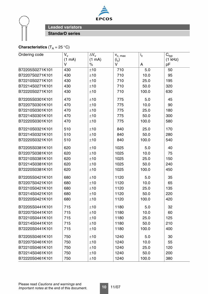
B72205S0271K101 430 ±10 710 5.0 50B72207S0271K101 430 ±10 710 10.0 95B72210S0271K101 430 ±10 710 25.0 195B72214S0271K101 430 ±10 710 50.0 320B72220S0271K101 430 ±10 710 100.0 630
B72205S0301K101 470 ±10 775 5.0 45B72207S0301K101 470 ±10 775 10.0 90B72210S0301K101 470 ±10 775 25.0 180B72214S0301K101 470 ±10 775 50.0 300B72220S0301K101 470 ±10 775 100.0 580
B72210S0321K101 510 ±10 840 25.0 170B72214S0321K101 510 ±10 840 50.0 280B72220S0321K101 510 ±10 840 100.0 540
B72205S0381K101 620 ±10 1025 5.0 40B72207S0381K101 620 ±10 1025 10.0 75B72210S0381K101 620 ±10 1025 25.0 150B72214S0381K101 620 ±10 1025 50.0 240B72220S0381K101 620 ±10 1025 100.0 450
B72205S0421K101 680 ±10 1120 5.0 35B72207S0421K101 680 ±10 1120 10.0 65B72210S0421K101 680 ±10 1120 25.0 135B72214S0421K101 680 ±10 1120 50.0 220B72220S0421K101 680 ±10 1120 100.0 420
B72205S0441K101 715 ±10 1180 5.0 32B72207S0441K101 715 ±10 1180 10.0 60B72210S0441K101 715 ±10 1180 25.0 125B72214S0441K101 715 ±10 1180 50.0 210B72220S0441K101 715 ±10 1180 100.0 400
B72205S0461K101 750 ±10 1240 5.0 30B72207S0461K101 750 ±10 1240 10.0 55B72210S0461K101 750 ±10 1240 25.0 120B72214S0461K101 750 ±10 1240 50.0 200B72220S0461K101 750 ±10 1240 100.0 380
Characteristics (TA = 25 °C)
Ordering code Vv(1 mA)V
∆Vv(1 mA)%
vc, max(ic)V
ic
A
Ctyp(1 kHz)pF
StandarD series
Leaded varistors
11 11/07Please read Cautions and warnings andImportant notes at the end of this document.
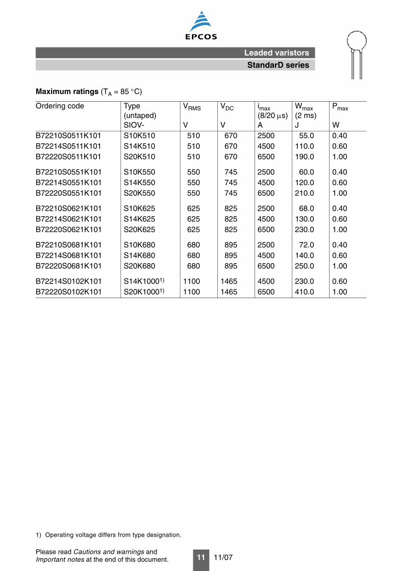
B72210S0511K101 S10K510 510 670 2500 55.0 0.40B72214S0511K101 S14K510 510 670 4500 110.0 0.60B72220S0511K101 S20K510 510 670 6500 190.0 1.00
B72210S0551K101 S10K550 550 745 2500 60.0 0.40B72214S0551K101 S14K550 550 745 4500 120.0 0.60B72220S0551K101 S20K550 550 745 6500 210.0 1.00
B72210S0621K101 S10K625 625 825 2500 68.0 0.40B72214S0621K101 S14K625 625 825 4500 130.0 0.60B72220S0621K101 S20K625 625 825 6500 230.0 1.00
B72210S0681K101 S10K680 680 895 2500 72.0 0.40B72214S0681K101 S14K680 680 895 4500 140.0 0.60B72220S0681K101 S20K680 680 895 6500 250.0 1.00
B72214S0102K101 S14K10001) 1100 1465 4500 230.0 0.60B72220S0102K101 S20K10001) 1100 1465 6500 410.0 1.00
Maximum ratings (TA = 85 °C)
Ordering code Type(untaped)SIOV-
VRMS
V
VDC
V
imax(8/20 µs)A
Wmax(2 ms)J
Pmax
W
1) Operating voltage differs from type designation.
StandarD series
Leaded varistors
12 11/07Please read Cautions and warnings andImportant notes at the end of this document.
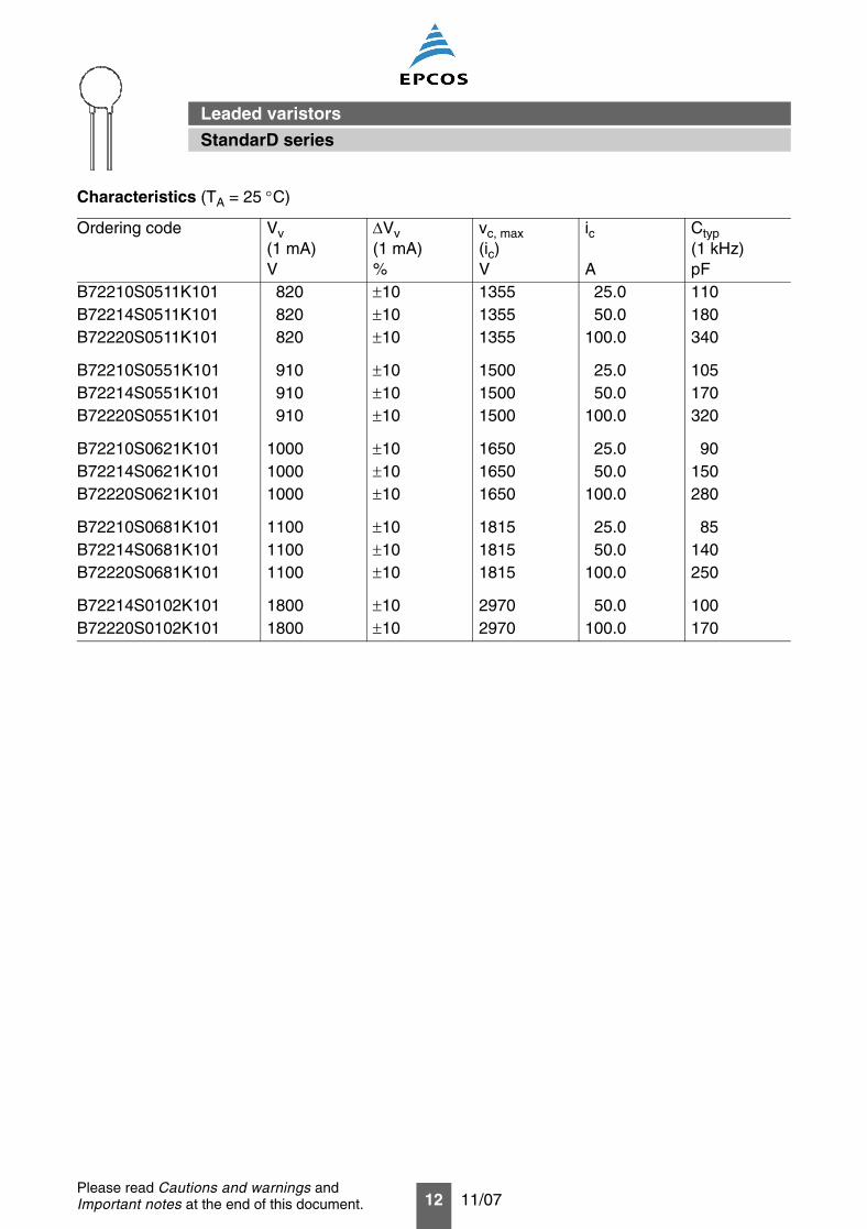
Characteristics (TA = 25 °C)
Ordering code Vv(1 mA)V
∆Vv(1 mA)%
vc, max(ic)V
ic
A
Ctyp(1 kHz)pF
B72210S0511K101 820 ±10 1355 25.0 110B72214S0511K101 820 ±10 1355 50.0 180B72220S0511K101 820 ±10 1355 100.0 340
B72210S0551K101 910 ±10 1500 25.0 105B72214S0551K101 910 ±10 1500 50.0 170B72220S0551K101 910 ±10 1500 100.0 320
B72210S0621K101 1000 ±10 1650 25.0 90B72214S0621K101 1000 ±10 1650 50.0 150B72220S0621K101 1000 ±10 1650 100.0 280
B72210S0681K101 1100 ±10 1815 25.0 85B72214S0681K101 1100 ±10 1815 50.0 140B72220S0681K101 1100 ±10 1815 100.0 250
B72214S0102K101 1800 ±10 2970 50.0 100B72220S0102K101 1800 ±10 2970 100.0 170
StandarD series
Leaded varistors
13 11/07Please read Cautions and warnings andImportant notes at the end of this document.
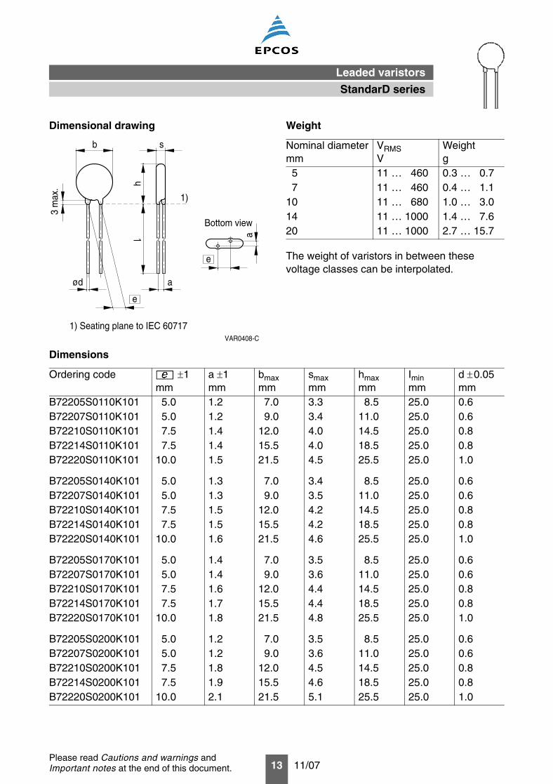
Dimensional drawing Weight
Dimensions
Ordering code ±1mm
a ±1mm
bmaxmm
smaxmm
hmaxmm
Iminmm
d ±0.05mm
B72205S0110K101 5.0 1.2 7.0 3.3 8.5 25.0 0.6B72207S0110K101 5.0 1.2 9.0 3.4 11.0 25.0 0.6B72210S0110K101 7.5 1.4 12.0 4.0 14.5 25.0 0.8B72214S0110K101 7.5 1.4 15.5 4.0 18.5 25.0 0.8B72220S0110K101 10.0 1.5 21.5 4.5 25.5 25.0 1.0
B72205S0140K101 5.0 1.3 7.0 3.4 8.5 25.0 0.6B72207S0140K101 5.0 1.3 9.0 3.5 11.0 25.0 0.6B72210S0140K101 7.5 1.5 12.0 4.2 14.5 25.0 0.8B72214S0140K101 7.5 1.5 15.5 4.2 18.5 25.0 0.8B72220S0140K101 10.0 1.6 21.5 4.6 25.5 25.0 1.0
B72205S0170K101 5.0 1.4 7.0 3.5 8.5 25.0 0.6B72207S0170K101 5.0 1.4 9.0 3.6 11.0 25.0 0.6B72210S0170K101 7.5 1.6 12.0 4.4 14.5 25.0 0.8B72214S0170K101 7.5 1.7 15.5 4.4 18.5 25.0 0.8B72220S0170K101 10.0 1.8 21.5 4.8 25.5 25.0 1.0
B72205S0200K101 5.0 1.2 7.0 3.5 8.5 25.0 0.6B72207S0200K101 5.0 1.2 9.0 3.6 11.0 25.0 0.6B72210S0200K101 7.5 1.8 12.0 4.5 14.5 25.0 0.8B72214S0200K101 7.5 1.9 15.5 4.6 18.5 25.0 0.8B72220S0200K101 10.0 2.1 21.5 5.1 25.5 25.0 1.0
VAR0408-C
ød
3 m
ax.
b s
a
h
a
Bottom view
1)
1) Seating plane to IEC 60717
e
e
The weight of varistors in between thesevoltage classes can be interpolated.
Nominal diametermm
VRMSV
Weightg
5 11 … 460 0.3 … 0.77 11 … 460 0.4 … 1.1
10 11 … 680 1.0 … 3.014 11 … 1000 1.4 … 7.620 11 … 1000 2.7 … 15.7
StandarD series
Leaded varistors
14 11/07Please read Cautions and warnings andImportant notes at the end of this document.
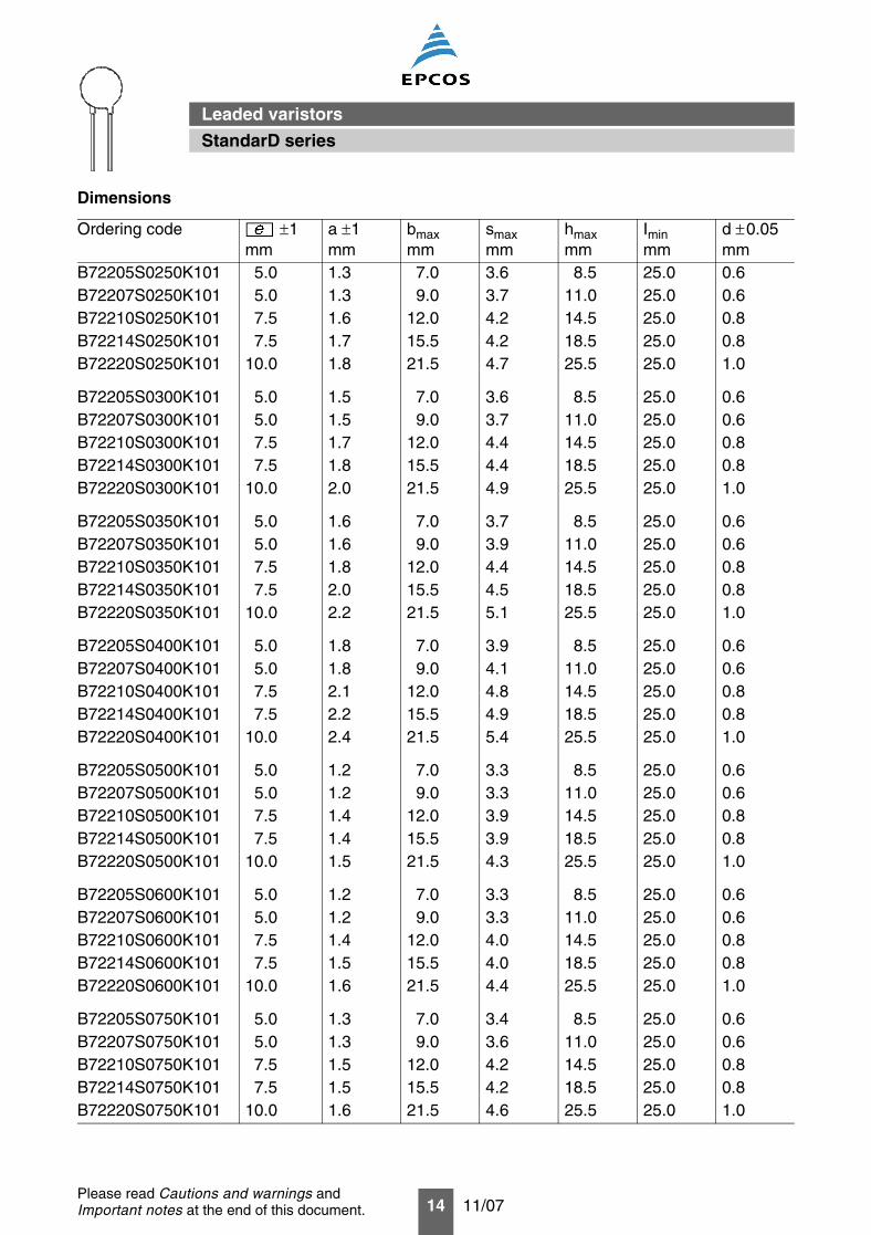
B72205S0250K101 5.0 1.3 7.0 3.6 8.5 25.0 0.6B72207S0250K101 5.0 1.3 9.0 3.7 11.0 25.0 0.6B72210S0250K101 7.5 1.6 12.0 4.2 14.5 25.0 0.8B72214S0250K101 7.5 1.7 15.5 4.2 18.5 25.0 0.8B72220S0250K101 10.0 1.8 21.5 4.7 25.5 25.0 1.0
B72205S0300K101 5.0 1.5 7.0 3.6 8.5 25.0 0.6B72207S0300K101 5.0 1.5 9.0 3.7 11.0 25.0 0.6B72210S0300K101 7.5 1.7 12.0 4.4 14.5 25.0 0.8B72214S0300K101 7.5 1.8 15.5 4.4 18.5 25.0 0.8B72220S0300K101 10.0 2.0 21.5 4.9 25.5 25.0 1.0
B72205S0350K101 5.0 1.6 7.0 3.7 8.5 25.0 0.6B72207S0350K101 5.0 1.6 9.0 3.9 11.0 25.0 0.6B72210S0350K101 7.5 1.8 12.0 4.4 14.5 25.0 0.8B72214S0350K101 7.5 2.0 15.5 4.5 18.5 25.0 0.8B72220S0350K101 10.0 2.2 21.5 5.1 25.5 25.0 1.0
B72205S0400K101 5.0 1.8 7.0 3.9 8.5 25.0 0.6B72207S0400K101 5.0 1.8 9.0 4.1 11.0 25.0 0.6B72210S0400K101 7.5 2.1 12.0 4.8 14.5 25.0 0.8B72214S0400K101 7.5 2.2 15.5 4.9 18.5 25.0 0.8B72220S0400K101 10.0 2.4 21.5 5.4 25.5 25.0 1.0
B72205S0500K101 5.0 1.2 7.0 3.3 8.5 25.0 0.6B72207S0500K101 5.0 1.2 9.0 3.3 11.0 25.0 0.6B72210S0500K101 7.5 1.4 12.0 3.9 14.5 25.0 0.8B72214S0500K101 7.5 1.4 15.5 3.9 18.5 25.0 0.8B72220S0500K101 10.0 1.5 21.5 4.3 25.5 25.0 1.0
B72205S0600K101 5.0 1.2 7.0 3.3 8.5 25.0 0.6B72207S0600K101 5.0 1.2 9.0 3.3 11.0 25.0 0.6B72210S0600K101 7.5 1.4 12.0 4.0 14.5 25.0 0.8B72214S0600K101 7.5 1.5 15.5 4.0 18.5 25.0 0.8B72220S0600K101 10.0 1.6 21.5 4.4 25.5 25.0 1.0
B72205S0750K101 5.0 1.3 7.0 3.4 8.5 25.0 0.6B72207S0750K101 5.0 1.3 9.0 3.6 11.0 25.0 0.6B72210S0750K101 7.5 1.5 12.0 4.2 14.5 25.0 0.8B72214S0750K101 7.5 1.5 15.5 4.2 18.5 25.0 0.8B72220S0750K101 10.0 1.6 21.5 4.6 25.5 25.0 1.0
Dimensions
Ordering code ±1mm
a ±1mm
bmaxmm
smaxmm
hmaxmm
Iminmm
d ±0.05mm
StandarD series
Leaded varistors
15 11/07Please read Cautions and warnings andImportant notes at the end of this document.
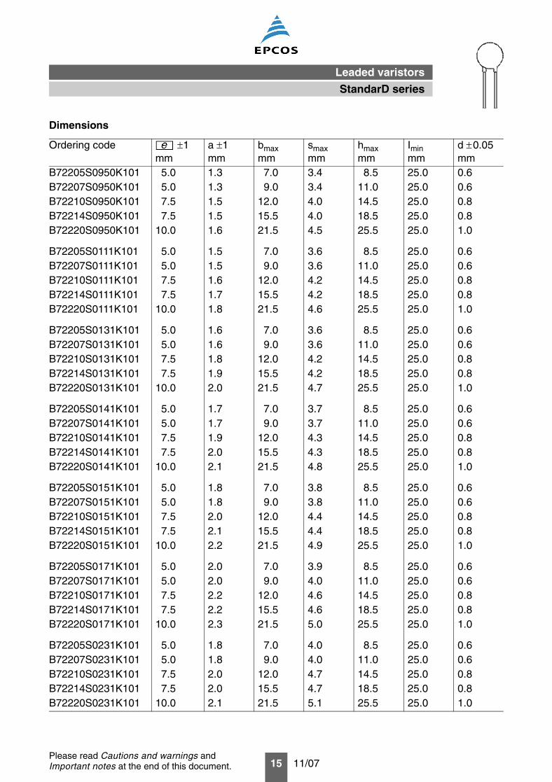
B72205S0950K101 5.0 1.3 7.0 3.4 8.5 25.0 0.6B72207S0950K101 5.0 1.3 9.0 3.4 11.0 25.0 0.6B72210S0950K101 7.5 1.5 12.0 4.0 14.5 25.0 0.8B72214S0950K101 7.5 1.5 15.5 4.0 18.5 25.0 0.8B72220S0950K101 10.0 1.6 21.5 4.5 25.5 25.0 1.0
B72205S0111K101 5.0 1.5 7.0 3.6 8.5 25.0 0.6B72207S0111K101 5.0 1.5 9.0 3.6 11.0 25.0 0.6B72210S0111K101 7.5 1.6 12.0 4.2 14.5 25.0 0.8B72214S0111K101 7.5 1.7 15.5 4.2 18.5 25.0 0.8B72220S0111K101 10.0 1.8 21.5 4.6 25.5 25.0 1.0
B72205S0131K101 5.0 1.6 7.0 3.6 8.5 25.0 0.6B72207S0131K101 5.0 1.6 9.0 3.6 11.0 25.0 0.6B72210S0131K101 7.5 1.8 12.0 4.2 14.5 25.0 0.8B72214S0131K101 7.5 1.9 15.5 4.2 18.5 25.0 0.8B72220S0131K101 10.0 2.0 21.5 4.7 25.5 25.0 1.0
B72205S0141K101 5.0 1.7 7.0 3.7 8.5 25.0 0.6B72207S0141K101 5.0 1.7 9.0 3.7 11.0 25.0 0.6B72210S0141K101 7.5 1.9 12.0 4.3 14.5 25.0 0.8B72214S0141K101 7.5 2.0 15.5 4.3 18.5 25.0 0.8B72220S0141K101 10.0 2.1 21.5 4.8 25.5 25.0 1.0
B72205S0151K101 5.0 1.8 7.0 3.8 8.5 25.0 0.6B72207S0151K101 5.0 1.8 9.0 3.8 11.0 25.0 0.6B72210S0151K101 7.5 2.0 12.0 4.4 14.5 25.0 0.8B72214S0151K101 7.5 2.1 15.5 4.4 18.5 25.0 0.8B72220S0151K101 10.0 2.2 21.5 4.9 25.5 25.0 1.0
B72205S0171K101 5.0 2.0 7.0 3.9 8.5 25.0 0.6B72207S0171K101 5.0 2.0 9.0 4.0 11.0 25.0 0.6B72210S0171K101 7.5 2.2 12.0 4.6 14.5 25.0 0.8B72214S0171K101 7.5 2.2 15.5 4.6 18.5 25.0 0.8B72220S0171K101 10.0 2.3 21.5 5.0 25.5 25.0 1.0
B72205S0231K101 5.0 1.8 7.0 4.0 8.5 25.0 0.6B72207S0231K101 5.0 1.8 9.0 4.0 11.0 25.0 0.6B72210S0231K101 7.5 2.0 12.0 4.7 14.5 25.0 0.8B72214S0231K101 7.5 2.0 15.5 4.7 18.5 25.0 0.8B72220S0231K101 10.0 2.1 21.5 5.1 25.5 25.0 1.0
Dimensions
Ordering code ±1mm
a ±1mm
bmaxmm
smaxmm
hmaxmm
Iminmm
d ±0.05mm
StandarD series
Leaded varistors

16 11/07Please read Cautions and warnings andImportant notes at the end of this document.
B72205S0251K101 5.0 1.8 7.0 4.2 8.5 25.0 0.6B72207S0251K101 5.0 1.8 9.0 4.2 11.0 25.0 0.6B72210S0251K101 7.5 2.0 12.0 4.8 14.5 25.0 0.8B72214S0251K101 7.5 2.0 15.5 4.8 18.5 25.0 0.8B72220S0251K101 10.0 2.2 21.5 5.3 25.5 25.0 1.0
B72205S0271K101 5.0 2.0 7.0 4.3 8.5 25.0 0.6B72207S0271K101 5.0 2.0 9.0 4.4 11.0 25.0 0.6B72210S0271K101 7.5 2.2 12.0 5.0 14.5 25.0 0.8B72214S0271K101 7.5 2.2 15.5 5.0 18.5 25.0 0.8B72220S0271K101 10.0 2.3 21.5 5.4 25.5 25.0 1.0
B72205S0301K101 5.0 2.1 7.0 4.5 8.5 25.0 0.6B72207S0301K101 5.0 2.1 9.0 4.5 11.0 25.0 0.6B72210S0301K101 7.5 2.3 12.0 5.1 14.5 25.0 0.8B72214S0301K101 7.5 2.3 15.5 5.2 18.5 25.0 0.8B72220S0301K101 10.0 2.4 21.5 5.6 25.5 25.0 1.0
B72210S0321K101 7.5 2.4 12.0 5.4 15.0 25.0 0.8B72214S0321K101 7.5 2.4 15.5 5.4 19.0 25.0 0.8B72220S0321K101 10.0 2.6 21.5 5.8 25.5 25.0 1.0
B72205S0381K101 5.0 2.5 7.0 5.1 9.0 25.0 0.6B72207S0381K101 5.0 2.5 9.0 5.2 11.5 25.0 0.6B72210S0381K101 7.5 2.7 12.0 5.8 15.0 25.0 0.8B72214S0381K101 7.5 2.7 15.5 5.9 19.0 25.0 0.8B72220S0381K101 10.0 2.8 21.5 6.3 26.0 25.0 1.0
B72205S0421K101 5.0 2.8 7.0 5.4 9.0 25.0 0.6B72207S0421K101 5.0 2.8 9.0 5.4 11.5 25.0 0.6B72210S0421K101 7.5 2.9 12.0 6.1 15.0 25.0 0.8B72214S0421K101 7.5 2.9 15.5 6.1 19.0 25.0 0.8B72220S0421K101 10.0 3.1 21.5 6.5 26.0 25.0 1.0
B72205S0441K101 5.0 2.8 7.0 5.5 9.0 25.0 0.6B72207S0441K101 5.0 2.8 9.0 5.5 11.5 25.0 0.6B72210S0441K101 7.5 3.0 12.0 6.2 15.0 25.0 0.8B72214S0441K101 7.5 3.0 15.5 6.3 19.0 25.0 0.8B72220S0441K101 10.0 3.1 21.5 6.7 26.0 25.0 1.0
Dimensions
Ordering code ±1mm
a ±1mm
bmaxmm
smaxmm
hmaxmm
Iminmm
d ±0.05mm
StandarD series
Leaded varistors
17 11/07Please read Cautions and warnings andImportant notes at the end of this document.
B72205S0461K101 5.0 3.0 7.0 5.7 9.0 25.0 0.6B72207S0461K101 5.0 3.0 9.0 5.7 11.5 25.0 0.6B72210S0461K101 7.5 3.1 12.0 6.3 15.0 25.0 0.8B72214S0461K101 7.5 3.1 15.5 6.4 19.0 25.0 0.8B72220S0461K101 10.0 3.3 21.5 6.8 26.0 25.0 1.0
B72210S0511K101 7.5 3.4 12.0 6.7 15.0 25.0 0.8B72214S0511K101 7.5 3.4 15.5 6.8 19.0 25.0 0.8B72220S0511K101 10.0 3.5 21.5 7.1 26.0 25.0 1.0
B72210S0551K101 7.5 3.7 12.0 7.1 15.0 25.0 0.8B72214S0551K101 7.5 3.7 15.5 7.2 19.0 25.0 0.8B72220S0551K101 10.0 3.9 21.5 7.5 26.0 25.0 1.0
B72210S0621K101 7.5 4.0 12.0 7.5 15.0 25.0 0.8B72214S0621K101 7.5 4.0 15.5 7.5 19.0 25.0 0.8B72220S0621K101 10.0 4.2 21.5 7.9 26.0 25.0 1.0
B72210S0681K101 7.5 4.4 12.0 7.9 15.0 25.0 0.8B72214S0681K101 7.5 4.4 15.5 8.0 19.0 25.0 0.8B72220S0681K101 10.0 4.5 21.5 8.4 26.0 25.0 1.0
B72214S0102K101 7.5 6.7 15.5 11.0 20.5 25.0 0.8B72220S0102K101 10.0 6.9 21.5 11.4 28.5 25.0 1.0
Dimensions
Ordering code ±1mm
a ±1mm
bmaxmm
smaxmm
hmaxmm
Iminmm
d ±0.05mm
StandarD series
Leaded varistors
18 11/07Please read Cautions and warnings andImportant notes at the end of this document.
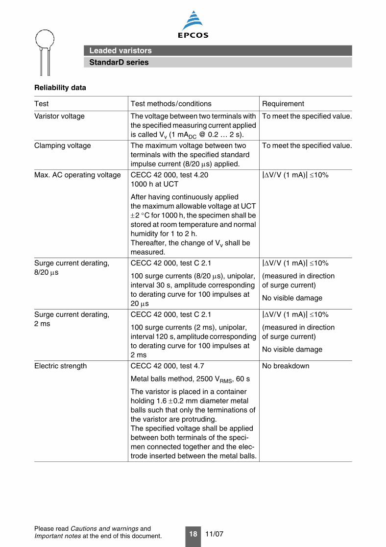
Reliability data
Test Test methods/conditions Requirement
Varistor voltage The voltage between two terminals with the specified measuring current applied is called Vv (1 mADC @ 0.2 … 2 s).
To meet the specified value.
Clamping voltage The maximum voltage between twoterminals with the specified standard impulse current (8/20 µs) applied.
To meet the specified value.
Max. AC operating voltage CECC 42 000, test 4.201000 h at UCT
After having continuously appliedthe maximum allowable voltage at UCT ±2 °C for 1000 h, the specimen shall be stored at room temperature and normal humidity for 1 to 2 h.Thereafter, the change of Vv shall be measured.
|∆V/V (1 mA)| ≤10%
Surge current derating,8/20 µs
CECC 42 000, test C 2.1
100 surge currents (8/20 µs), unipolar, interval 30 s, amplitude corresponding to derating curve for 100 impulses at 20 µs
|∆V/V (1 mA)| ≤10%
(measured in directionof surge current)
No visible damage
Surge current derating,2 ms
CECC 42 000, test C 2.1
100 surge currents (2 ms), unipolar,interval 120 s, amplitude corresponding to derating curve for 100 impulses at 2 ms
|∆V/V (1 mA)| ≤10%
(measured in directionof surge current)
No visible damage
Electric strength CECC 42 000, test 4.7
Metal balls method, 2500 VRMS, 60 s
The varistor is placed in a container holding 1.6 ±0.2 mm diameter metal balls such that only the terminations of the varistor are protruding.The specified voltage shall be applied between both terminals of the speci-men connected together and the elec-trode inserted between the metal balls.
No breakdown
StandarD series
Leaded varistors
19 11/07Please read Cautions and warnings andImportant notes at the end of this document.
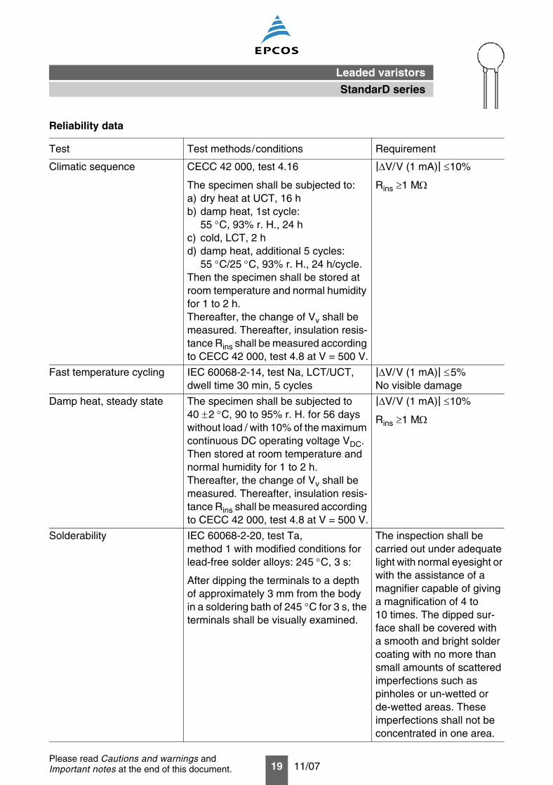
Climatic sequence CECC 42 000, test 4.16
The specimen shall be subjected to:a) dry heat at UCT, 16 hb) damp heat, 1st cycle:
55 °C, 93% r. H., 24 hc) cold, LCT, 2 hd) damp heat, additional 5 cycles:
55 °C/25 °C, 93% r. H., 24 h/cycle.Then the specimen shall be stored at room temperature and normal humidity for 1 to 2 h.Thereafter, the change of Vv shall be measured. Thereafter, insulation resis-tance Rins shall be measured according to CECC 42 000, test 4.8 at V = 500 V.
|∆V/V (1 mA)| ≤10%
Rins ≥1 MΩ
Fast temperature cycling IEC 60068-2-14, test Na, LCT/UCT, dwell time 30 min, 5 cycles
|∆V/V (1 mA)| ≤5%No visible damage
Damp heat, steady state The specimen shall be subjected to40 ±2 °C, 90 to 95% r. H. for 56 days without load / with 10% of the maximum continuous DC operating voltage VDC.Then stored at room temperature and normal humidity for 1 to 2 h.Thereafter, the change of Vv shall be measured. Thereafter, insulation resis-tance Rins shall be measured according to CECC 42 000, test 4.8 at V = 500 V.
|∆V/V (1 mA)| ≤10%
Rins ≥1 MΩ
Solderability IEC 60068-2-20, test Ta,method 1 with modified conditions for lead-free solder alloys: 245 °C, 3 s:
After dipping the terminals to a depthof approximately 3 mm from the bodyin a soldering bath of 245 °C for 3 s, the terminals shall be visually examined.
The inspection shall becarried out under adequate light with normal eyesight or with the assistance of a magnifier capable of giving a magnification of 4 to10 times. The dipped sur-face shall be covered witha smooth and bright solder coating with no more than small amounts of scattered imperfections such aspinholes or un-wetted orde-wetted areas. Theseimperfections shall not beconcentrated in one area.
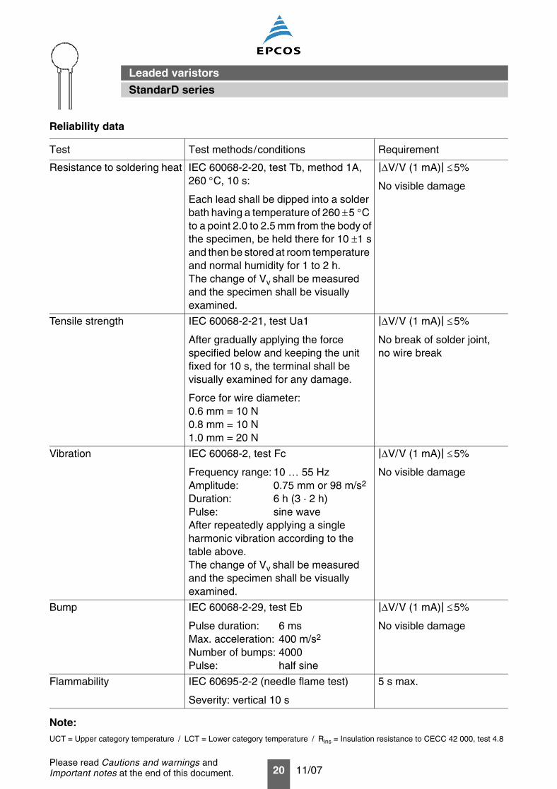
Reliability data
Test Test methods/conditions Requirement
StandarD series
Leaded varistors
20 11/07Please read Cautions and warnings andImportant notes at the end of this document.
Note:UCT = Upper category temperature / LCT = Lower category temperature / Rins = Insulation resistance to CECC 42 000, test 4.8
Resistance to soldering heat IEC 60068-2-20, test Tb, method 1A, 260 °C, 10 s:
Each lead shall be dipped into a solder bath having a temperature of 260 ±5 °C to a point 2.0 to 2.5 mm from the body ofthe specimen, be held there for 10 ±1 sand then be stored at room temperature and normal humidity for 1 to 2 h.The change of Vv shall be measured and the specimen shall be visuallyexamined.
|∆V/V (1 mA)| ≤5%
No visible damage
Tensile strength IEC 60068-2-21, test Ua1
After gradually applying the forcespecified below and keeping the unit fixed for 10 s, the terminal shall bevisually examined for any damage.
Force for wire diameter:0.6 mm = 10 N0.8 mm = 10 N1.0 mm = 20 N
|∆V/V (1 mA)| ≤5%
No break of solder joint,no wire break
Vibration IEC 60068-2, test Fc
Frequency range: 10 … 55 HzAmplitude: 0.75 mm or 98 m/s2
Duration: 6 h (3 · 2 h)Pulse: sine waveAfter repeatedly applying a singleharmonic vibration according to thetable above.The change of Vv shall be measured and the specimen shall be visuallyexamined.
|∆V/V (1 mA)| ≤5%
No visible damage
Bump IEC 60068-2-29, test Eb
Pulse duration: 6 msMax. acceleration: 400 m/s2
Number of bumps: 4000Pulse: half sine
|∆V/V (1 mA)| ≤5%
No visible damage
Flammability IEC 60695-2-2 (needle flame test)
Severity: vertical 10 s
5 s max.
Reliability data
Test Test methods/conditions Requirement
StandarD series
Leaded varistors
21 11/07Please read Cautions and warnings andImportant notes at the end of this document.
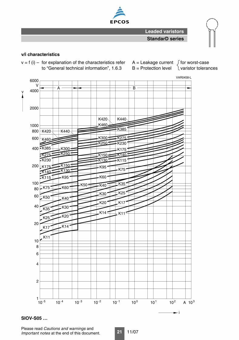
v/i characteristics
v = f (i) – for explanation of the characteristics refer A = Leakage current for worst-caseto “General technical information”, 1.6.3 B = Protection level varistor tolerances
SIOV-S05 …
VAR0458-L
1
A
2
B
4
6
810
20
60
80100
40
200
400
600
8001000
2000
4000
6000V
K300 K275K250 K230
K175K140K115
K75
K150K130
K95
K60
K40K50 K35
K25
K17
K11
K30
K20
K14
K14K17
K25 K20
K30K35
K50 K40
K60K75
K95K115
K130K150
K250K300
K140K175
K230K275
A10 5_10 4_ 310
_ 210_ _
10 1 100 101 102 103
K11
v
i
K385
K385
K460
K420 K440
K440K420K460
StandarD series
Leaded varistors
22 11/07Please read Cautions and warnings andImportant notes at the end of this document.
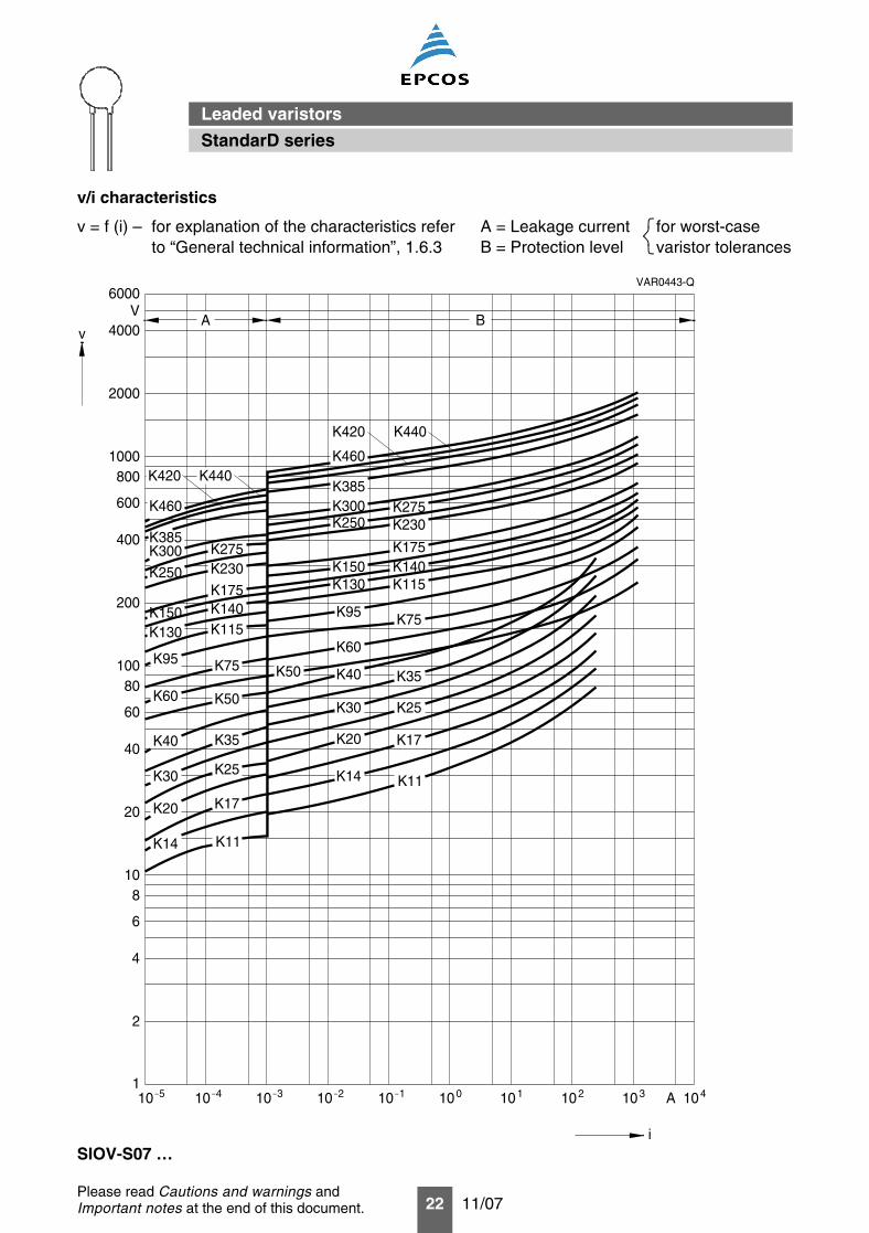
v/i characteristics
v = f (i) – for explanation of the characteristics refer A = Leakage current for worst-caseto “General technical information”, 1.6.3 B = Protection level varistor tolerances
SIOV-S07 …
VAR0443-Q
1
A
2
B
4
6
8
20
60
80100
40
200
400
600
8001000
2000
4000
6000V
100 101 102 103 10A 4
10
K14
K20
K30
K40
K60
K95
K130K150
K250
K300
K460
K275K230
K175K140K115
K75
K50
K35
K25
K17
K11
K460
K300K250
K150K130
K95
K60
K40
K30
K20
K14
K275K230
K175K140K115
K75
K50 K35
K25
K17
K11
510_ 410
_10
_3 _10 2 10 1_
v
i
K385
K385
K420 K440
K420 K440
StandarD series
Leaded varistors
23 11/07Please read Cautions and warnings andImportant notes at the end of this document.
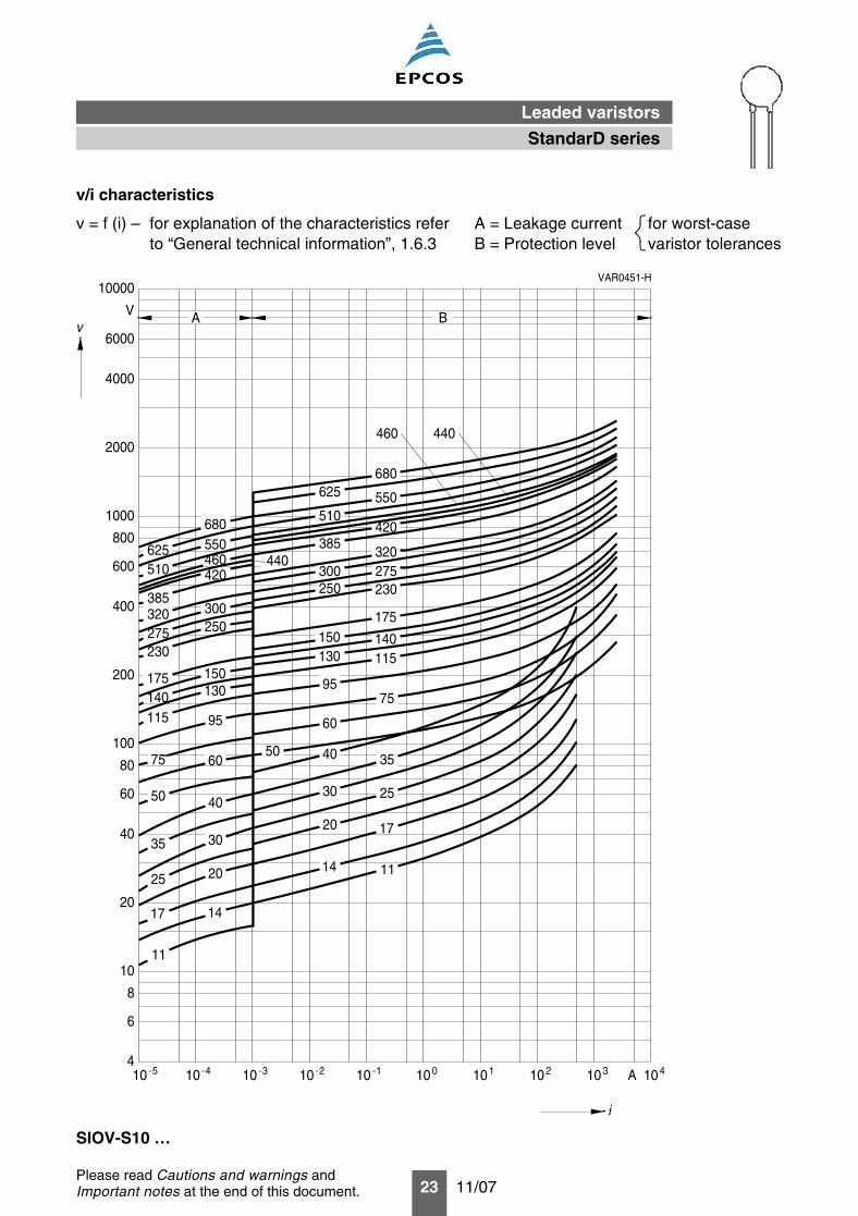
v/i characteristics
v = f (i) – for explanation of the characteristics refer A = Leakage current for worst-caseto “General technical information”, 1.6.3 B = Protection level varistor tolerances
SIOV-S10 …
VAR0451-H
4
i
Av
B
6
8
10
20
40
60
80
100
200
400
600
800
1000
2000
4000
6000
V
10000
11
17
25
35
50
14
20
30
40
75
115140175
230275
60
95
130150
250300
420
320385
440460510625 550
680
680625
510550
385420
460 440
320275230
175
140115
300250
150130
95
60
4050
30
20
14
75
35
25
17
11
101010 5_ 4_ _3_10 2 10
_1 100 101 102 103 10A 4
StandarD series
Leaded varistors
24 11/07Please read Cautions and warnings andImportant notes at the end of this document.
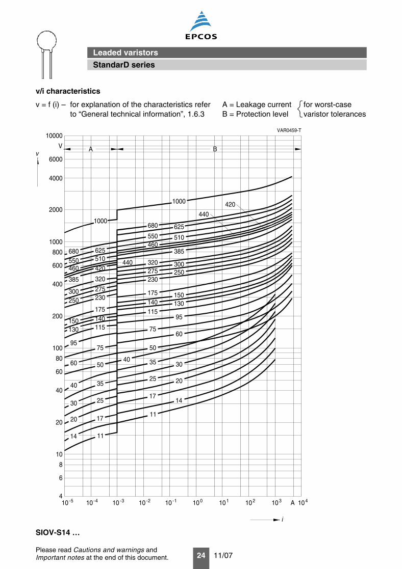
v/i characteristics
v = f (i) – for explanation of the characteristics refer A = Leakage current for worst-caseto “General technical information”, 1.6.3 B = Protection level varistor tolerances
SIOV-S14 …
VAR0459-T
4
i
Av
10
B
8
6
20
40
60
80
100
200
400
600
800
1000
2000
4000
6000
V
10000
680550460
625510420
385
440
275
320
230300250
150130
95
60
40
30
20
14
175140115
75
50
35
25
17
11
680 625550460
510
440
420
385
300250
150130
95
60
320275230
175140115
75
50
35
25
17
11
3040
20
14
101010 5_ 4_ _3_10 2 10
_1 100 101 102 103 10A 4
1000
1000
StandarD series
Leaded varistors
25 11/07Please read Cautions and warnings andImportant notes at the end of this document.
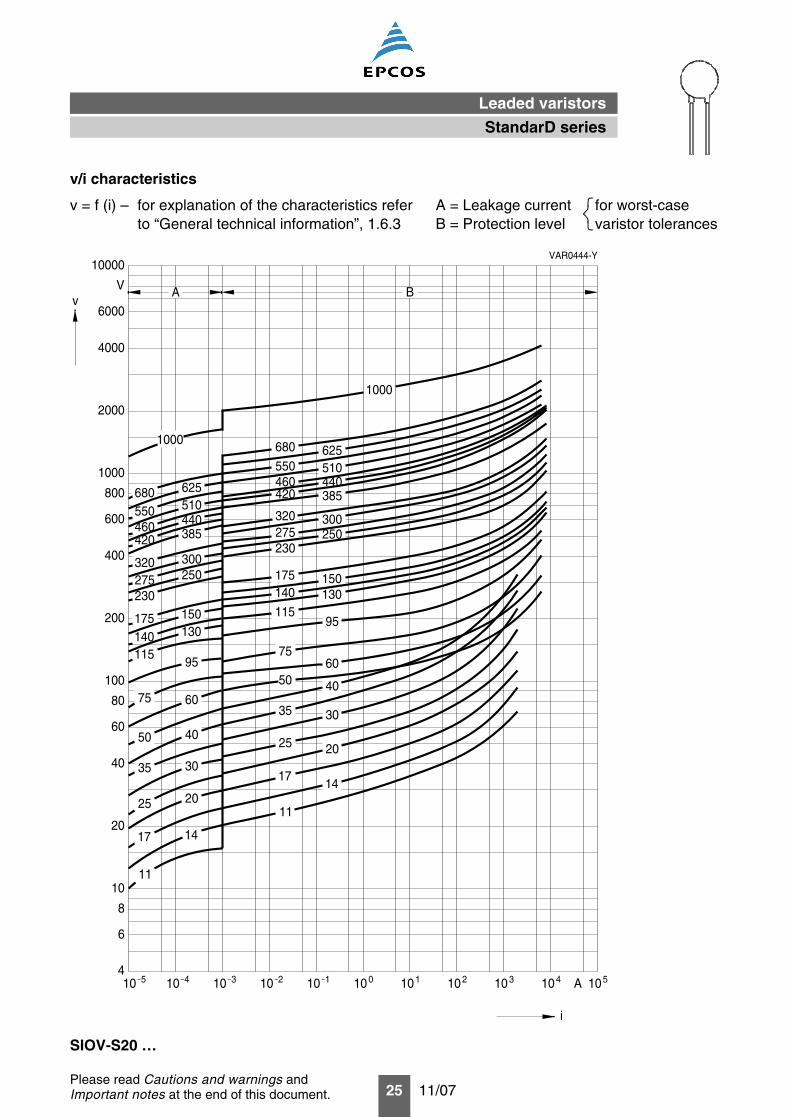
v/i characteristics
v = f (i) – for explanation of the characteristics refer A = Leakage current for worst-caseto “General technical information”, 1.6.3 B = Protection level varistor tolerances
SIOV-S20 …
VAR0444-Y
4
i
Av
B
6
8
10
20
40
60
80
100
200
400
600
800
1000
2000
4000
6000
V
10000
100 101 102 103 104 105A
11
17
25
35
50
14
20
30
40
75
115140175
230275320
420460550680
60
95
130150
250300
385440510625
1000
1000
680 625550460420
320275230
175140
115
75
50
35
25
17
11
510440385
300250
150130
95
60
40
30
20
14
_10 5 4_
10 10 3_10
_2 10 1_
StandarD series
Leaded varistors
26 11/07Please read Cautions and warnings andImportant notes at the end of this document.
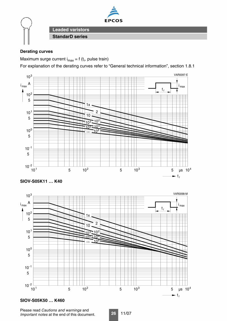
Derating curves
Maximum surge current imax = f (tr, pulse train)
For explanation of the derating curves refer to “General technical information”, section 1.8.1
SIOV-S05K11 … K40
SIOV-S05K50 … K460
VAR0097-E
5 5
A
rt
µs
i max
10 1 210 310 4105
310
102
10 1
100
5
5
5
5
10_2
1x
210
102310104510106
t rmaxi
10_1
VAR0098-M
5 5
A
rt
µs
i max
10 1 210 310 4105
310
102
10 1
100
5
5
5
5
10_2
1x
210
102310104510106
t rmaxi
10_1
StandarD series
Leaded varistors
27 11/07Please read Cautions and warnings andImportant notes at the end of this document.
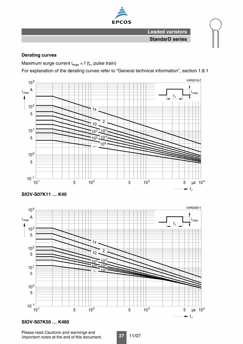
Derating curves
Maximum surge current imax = f (tr, pulse train)
For explanation of the derating curves refer to “General technical information”, section 1.8.1
SIOV-S07K11 … K40
SIOV-S07K50 … K460
VAR0018-Z
5 5
A
rt
µs
i max
10 1 210 310 4105
1x
210
102310104510106
t rmaxi
10_1
010
10 1
210
310
5
5
5
VAR0099-V
5 5
A
rt
µs
i max
10 1 210 310 4105
410
103
102
10 1
100
5
5
5
5
10_1
1x
210
102310104510106
t rmaxi
StandarD series
Leaded varistors
28 11/07Please read Cautions and warnings andImportant notes at the end of this document.
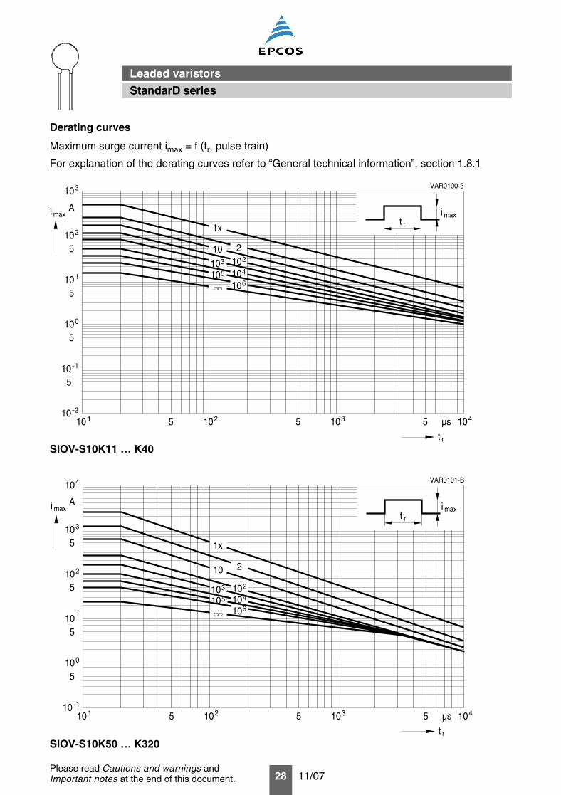
Derating curves
Maximum surge current imax = f (tr, pulse train)
For explanation of the derating curves refer to “General technical information”, section 1.8.1
SIOV-S10K11 … K40
SIOV-S10K50 … K320
VAR0100-3
5 5
A
rt
µs
i max
10 1 210 310 4105
310
102
10 1
100
5
5
5
5
10_2
1x
210102310104510106
t rmaxi
10_1
VAR0101-B
5 5
A
rt
µs
i max
10 1 210 310 4105
410
103
102
10 1
100
5
5
5
5
10_1
1x
210
102310104510106
t rmaxi
StandarD series
Leaded varistors
29 11/07Please read Cautions and warnings andImportant notes at the end of this document.
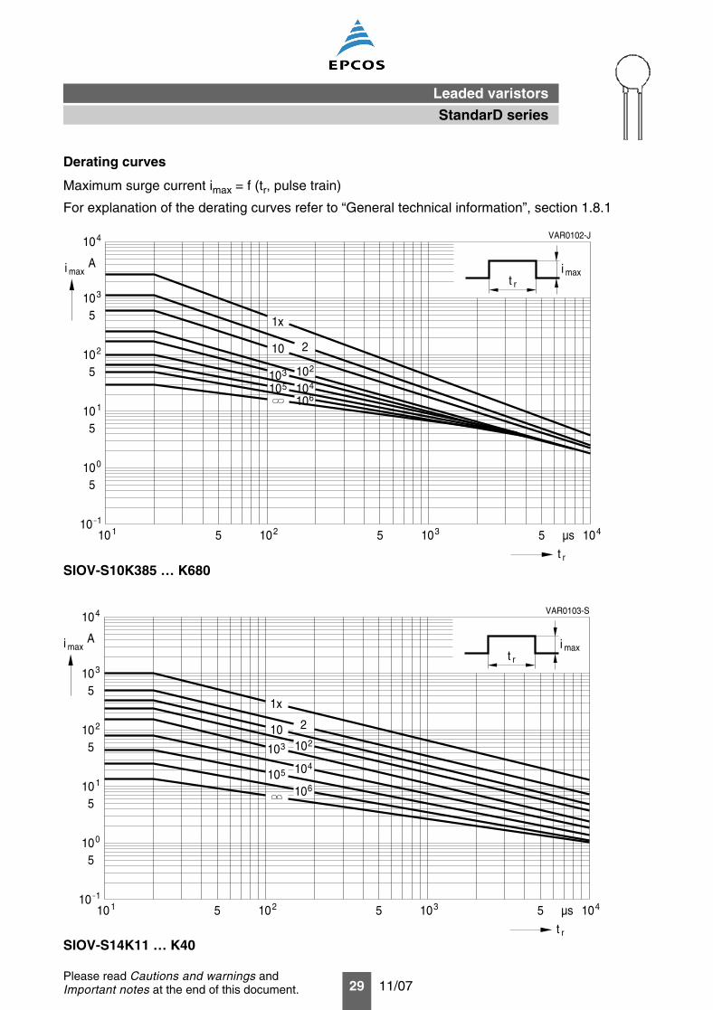
Derating curves
Maximum surge current imax = f (tr, pulse train)
For explanation of the derating curves refer to “General technical information”, section 1.8.1
SIOV-S10K385 … K680
SIOV-S14K11 … K40
VAR0102-J
5 5
A
rt
µs
i max
10 1 210 310 4105
410
103
102
10 1
100
5
5
5
5
10_1
t rmaxi
1x
10
103
105610
104102
2
VAR0103-S
5 5
A
rt
µs
i max
10 1 210 310 4105
410
103
102
10 1
100
5
5
5
5
10_1
1x
210102310
104510
106
t rmaxi
StandarD series
Leaded varistors
30 11/07Please read Cautions and warnings andImportant notes at the end of this document.
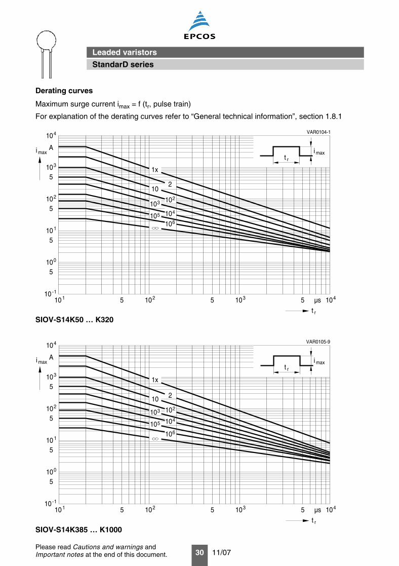
Derating curves
Maximum surge current imax = f (tr, pulse train)
For explanation of the derating curves refer to “General technical information”, section 1.8.1
SIOV-S14K50 … K320
SIOV-S14K385 … K1000
VAR0104-1
5 5
A
rt
µs
i max
10 1 210 310 4105
410
103
102
10 1
100
5
5
5
5
10_1
1x
210
102310
104510106
t rmaxi
VAR0105-9
5 5
A
rt
µs
i max
10 1 210 310 4105
410
103
102
10 1
100
5
5
5
5
10_1
1x
210
102310104
510106
t rmaxi
StandarD series
Leaded varistors
31 11/07Please read Cautions and warnings andImportant notes at the end of this document.
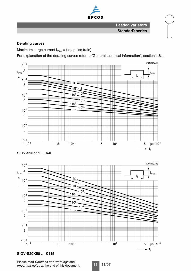
Derating curves
Maximum surge current imax = f (tr, pulse train)
For explanation of the derating curves refer to “General technical information”, section 1.8.1
SIOV-S20K11 … K40
SIOV-S20K50 … K115
VAR0106-H
5 5
A
rt
µs
i max
10 1 210 310 4105
410
103
102
10 1
100
5
5
5
5
10_1
1x
210102310
104
510106
t rmaxi
VAR0107-Q
5 5
A
rt
µs
i max
10 1 210 310 4105
410
103
102
10 1
100
5
5
5
5
10_1
1x
210
102310
104510
106
t rmaxi
StandarD series
Leaded varistors
32 11/07Please read Cautions and warnings andImportant notes at the end of this document.
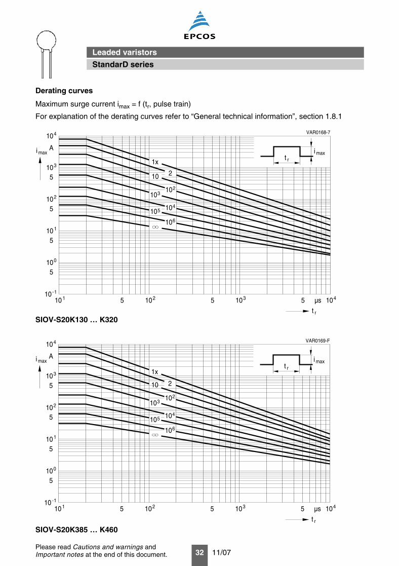
Derating curves
Maximum surge current imax = f (tr, pulse train)
For explanation of the derating curves refer to “General technical information”, section 1.8.1
SIOV-S20K130 … K320
SIOV-S20K385 … K460
VAR0168-7
5 5
A
rt
µs
i max
10 1 210 310 4105
410
103
102
10 1
100
5
5
5
5
10_1
1x
210
102310
104510
106
t rmaxi
VAR0169-F
5 5
A
rt
µs
i max
10 1 210 310 4105
410
103
102
10 1
100
5
5
5
5
10_1
1x
210
102310
104510
106
t rmaxi
StandarD series
Leaded varistors
33 11/07Please read Cautions and warnings andImportant notes at the end of this document.
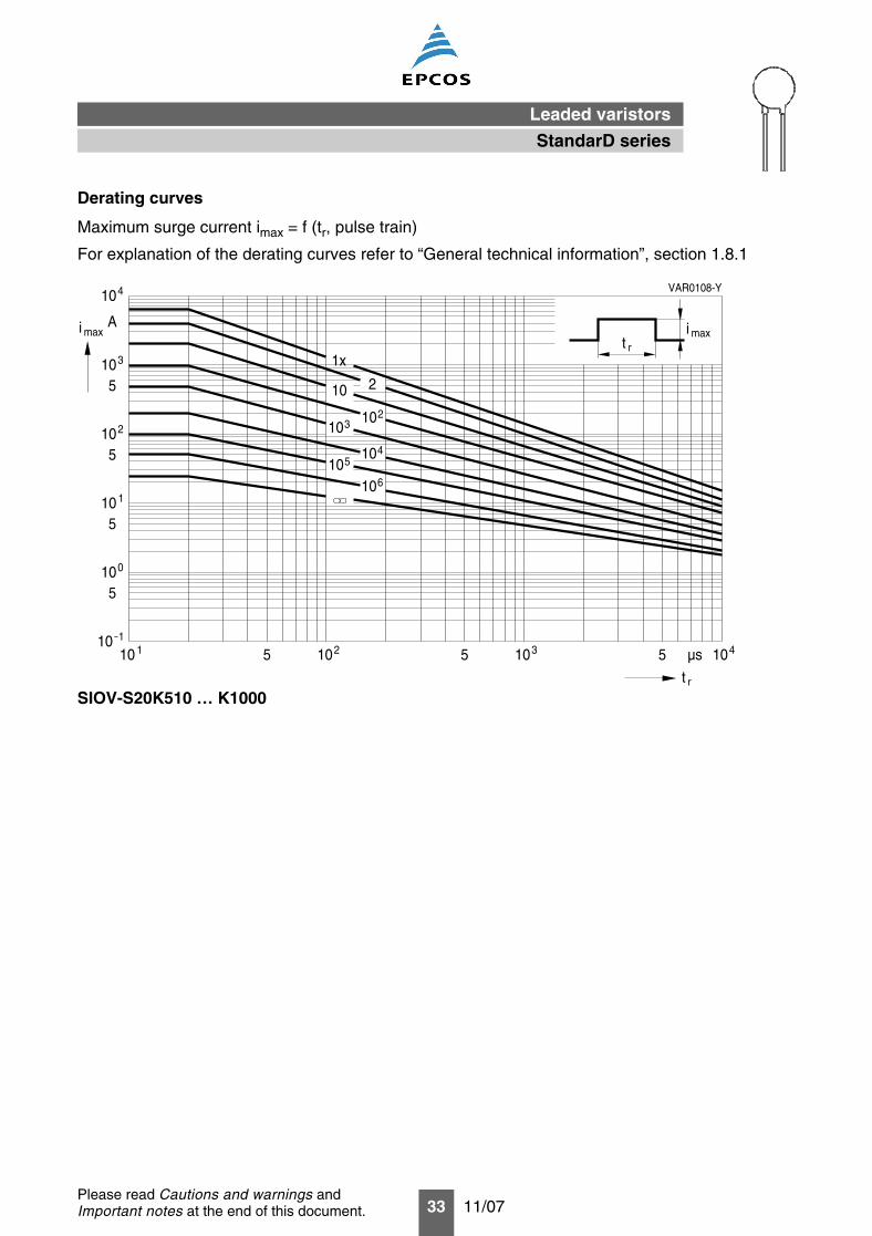
Derating curves
Maximum surge current imax = f (tr, pulse train)
For explanation of the derating curves refer to “General technical information”, section 1.8.1
SIOV-S20K510 … K1000
VAR0108-Y
5 5
A
rt
µs
i max
10 1 210 310 4105
410
103
102
10 1
100
5
5
5
5
10_1
1x
210
102310
10410
106
t rmaxi
5
StandarD series
Leaded varistors
34 11/07
Cautions and warnings
General
1. EPCOS metal oxide varistors (SIOVs) are designed for specific applications and should not beused for purposes not identified in our specifications, application notes and data books unlessotherwise agreed with EPCOS during the design-in-phase.
2. Ensure suitability of SIOVs through reliability testing during the design-in phase. SIOVs shouldbe evaluated taking into consideration worst-case conditions.
3. For applications of SIOVs in line-to-ground circuits based on various international and localstandards there are restrictions existing or additional safety measures required.
Storage
1. Store SIOVs only in original packaging. Do not open the package before storage.
2. Storage conditions in original packaging:
Storage temperature: –25 °C … +45 °CRelative humidity: <75% annual average,
<95% on maximum 30 days a year.Dew precipitation: Is to be avoided.
3. Avoid contamination of an SIOV’s surface during storage, handling and processing.
4. Avoid storage of SIOVs in harmful environments that can affect the function during long-termoperation (examples given under operation precautions).
5. The SIOV type series should be soldered within the time specified:
SIOV-S, -Q, -LS 24 monthsETFV and SFS types 12 months.
Handling
1. SIOVs must not be dropped.
2. Components must not be touched with bare hands. Gloves are recommended.
3. Avoid contamination of the surface of SIOV electrodes during handling, be careful of the sharpedge of SIOV electrodes.
Soldering (where applicable)
1. Use rosin-type flux or non-activated flux.
2. Insufficient preheating may cause ceramic cracks.
3. Rapid cooling by dipping in solvent is not recommended.
4. Complete removal of flux is recommended.
Please read Cautions and warnings andImportant notes at the end of this document.
Leaded varistors
StandarD series
35 11/07
Mounting
1. Potting, sealing or adhesive compounds can produce chemical reactions in the SIOV ceramicthat will degrade the component’s electrical characteristics.
2. Overloading SIOVs may result in ruptured packages and expulsion of hot materials. For this rea-son SIOVs should be physically shielded from adjacent components.
Operation
1. Use SIOVs only within the specified temperature operating range.
2. Use SIOVs only within the specified voltage and current ranges.
3. Environmental conditions must not harm SIOVs. Use SIOVs only in normal atmospheric condi-tions. Avoid use in the presence of deoxidizing gases (chlorine gas, hydrogen sulfide gas,ammonia gas, sulfuric acid gas, etc), corrosive agents, humid or salty conditions. Avoid contactwith any liquids and solvents.
Please read Cautions and warnings andImportant notes at the end of this document.
Leaded varistors
StandarD series
36 11/07
Important notes
The following applies to all products named in this publication:
1. Some parts of this publication contain statements about the suitability of our products forcertain areas of application. These statements are based on our knowledge of typicalrequirements that are often placed on our products in the areas of application concerned. Wenevertheless expressly point out that such statements cannot be regarded as bindingstatements about the suitability of our products for a particular customer application. Asa rule, EPCOS is either unfamiliar with individual customer applications or less familiar with themthan the customers themselves. For these reasons, it is always ultimately incumbent on thecustomer to check and decide whether an EPCOS product with the properties described in theproduct specification is suitable for use in a particular customer application.
2. We also point out that in individual cases, a malfunction of passive electronic componentsor failure before the end of their usual service life cannot be completely ruled out in thecurrent state of the art, even if they are operated as specified. In customer applicationsrequiring a very high level of operational safety and especially in customer applications in whichthe malfunction or failure of a passive electronic component could endanger human life or health(e.g. in accident prevention or life-saving systems), it must therefore be ensured by means ofsuitable design of the customer application or other action taken by the customer (e.g.installation of protective circuitry or redundancy) that no injury or damage is sustained by thirdparties in the event of malfunction or failure of a passive electronic component.
3. The warnings, cautions and product-specific notes must be observed.
4. In order to satisfy certain technical requirements, some of the products described in thispublication may contain substances subject to restrictions in certain jurisdictions (e.g.because they are classed as hazardous). Useful information on this will be found in ourMaterial Data Sheets on the Internet (www.epcos.com/material). Should you have any moredetailed questions, please contact our sales offices.
5. We constantly strive to improve our products. Consequently, the products described in thispublication may change from time to time. The same is true of the corresponding productspecifications. Please check therefore to what extent product descriptions and specificationscontained in this publication are still applicable before or when you place an order. We alsoreserve the right to discontinue production and delivery of products. Consequently, wecannot guarantee that all products named in this publication will always be available. Theaforementioned does not apply in the case of individual agreements deviating from the foregoingfor customer-specific products.
6. Unless otherwise agreed in individual contracts, all orders are subject to the current versionof the “General Terms of Delivery for Products and Services in the Electrical Industry”published by the German Electrical and Electronics Industry Association (ZVEI).
7. The trade names EPCOS, BAOKE, Alu-X, CeraDiode, CSSP, DSSP, MiniBlue, MKK, MLSC,MotorCap, PCC, PhaseCap, PhaseMod, SIFERRIT, SIFI, SIKOREL, SilverCap, SIMDAD,SIMID, SineFormer, SIOV, SIP5D, SIP5K, ThermoFuse, WindCap are trademarks registeredor pending in Europe and in other countries. Further information will be found on the Internet atwww.epcos.com/trademarks.
Mouser Electronics
Authorized Distributor
Click to View Pricing, Inventory, Delivery & Lifecycle Information: EPCOS:
B72205S0110K101 B72205S0111K101 B72205S0131K101 B72205S0140K101 B72205S0141K101
B72205S0151K101 B72205S0170K101 B72205S0171K101 B72205S0200K101 B72205S0231K101
B72205S0250K101 B72205S0251K101 B72205S0271K101 B72205S0300K101 B72205S0301K101
B72205S0350K101 B72205S0381K101 B72205S0400K101 B72205S0421K101 B72205S0441K101
B72205S0461K101 B72205S0500K101 B72205S0600K101 B72205S0750K101 B72205S0950K101
B72207S0110K101 B72207S0111K101 B72207S0131K101 B72207S0140K101 B72207S0141K101
B72207S0151K101 B72207S0170K101 B72207S0171K101 B72207S0200K101 B72207S0231K101
B72207S0250K101 B72207S0251K101 B72207S0271K101 B72207S0300K101 B72207S0301K101
B72207S0350K101 B72207S0381K101 B72207S0400K101 B72207S0421K101 B72207S0441K101
B72207S0461K101 B72207S0500K101 B72207S0600K101 B72207S0750K101 B72207S0950K101
B72210S0110K101 B72210S0111K101 B72210S0131K101 B72210S0140K101 B72210S0141K101
B72210S0151K101 B72210S0170K101 B72210S0171K101 B72210S0200K101 B72210S0231K101
B72210S0250K101 B72210S0251K101 B72210S0271K101 B72210S0300K101 B72210S0301K101
B72210S0321K101 B72210S0350K101 B72210S0381K101 B72210S0400K101 B72210S0421K101
B72210S0461K101 B72210S0500K101 B72210S0600K101 B72210S0750K101 B72210S0950K101
B72214S0110K101 B72214S0111K101 B72214S0131K101 B72214S0140K101 B72214S0141K101
B72214S0151K101 B72214S0170K101 B72214S0171K101 B72214S0200K101 B72214S0231K101
B72214S0250K101 B72214S0251K101 B72214S0271K101 B72214S0300K101 B72214S0301K101
B72214S0321K101 B72214S0350K101 B72214S0381K101 B72214S0400K101 B72214S0421K101
B72214S0461K101 B72214S0500K101 B72214S0511K101 B72214S0551K101 B72214S0600K101
Related Documents