Geophys. J. Int. (2012) 188, 763–778 doi: 10.1111/j.1365-246X.2011.05290.x GJI Geodynamics and tectonics Sinking of anhydrite blocks within a Newtonian salt diapir: modelling the influence of block aspect ratio and salt stratification Steffi Burchardt, 1 Hemin Koyi, 1 Harro Schmeling 2 and Lukas Fuchs 2 1 Department of Earth Sciences, Uppsala University, Villav¨ agen 16, 75236 Uppsala, Sweden. E-mail: steffi[email protected] 2 Faculty of Earth Sciences, J. W. Goethe University, Altenh¨ oferallee 1, 06438 Frankfurt am Main, Germany Accepted 2011 November 7. Received 2011 October 31; in original form 2011 July 22 SUMMARY 2-D Finite Differences models are used to analyse the strain produced by gravity-driven sink- ing of dense rectangular inclusions through homogeneous and vertically stratified Newtonian salt. We systematically modelled the descent of dense blocks of different sizes and initial orientations (aspect ratios) representing the Main Anhydrite fragments documented within, for example, the Gorleben salt diapir. Model results demonstrate that size of the blocks is a governing parameter which dictates the amount of strain produced within the block and in the surrounding host salt. Initial block orientation (aspect ratio), on the other hand, causes funda- mental differences in block deformation, while the resulting structures produced in the salt are principally the same in all models with homogeneous salt, covering shear zones and folding of passive markers. In models with vertically stratified salt with different viscosities, block descent takes place along complex paths. This results from greater strain accommodation by the ‘salt formation’ with the lowest viscosity and an asymmetrical distribution of initial vertical shear stresses around the block. Consequently, in these models, block strain is lower compared with the models with homogeneous salt (for the same viscosity as the high-viscosity salt), and sinking is accompanied by block rotation. The latter causes diapir-scale disturbance of the pre-sinking salt stratigraphy and complex sinking paths of the blocks. In particular, vertically oriented blocks sink into high-viscosity salt and drag with them some low-viscosity salt, while horizontal blocks sink in the low-viscosity salt. The resultant sinking velocities vary strongly depending on the sinking path of the block. Based on model results and observed structural configuration within the Gorleben salt diapir, we conclude that the internal complexity of a salt diapir governs its post-ascent deformation. Salt structure and its interaction with dense blocks should hence be considered in the assessment of the long-term stability of storage sites for hazardous waste. Key words: Fracture and flow; Diapir and diapirism; High strain deformation zones. 1 INTRODUCTION Salt diapirs of layered salt formations (e.g. Zechstein formation) are internally complex structures built up of mechanically and min- eralogically different salt types (or lithologies) and often contain inclusions of, for example, limestone, anhydrite and igneous rocks. The impact of such mechanically contrasting lithologies is not only visible during diapiric ascent, but also after ascent has ceased. Weinberg (1993) suggested that inclusions of sedimentary and ig- neous rocks with densities higher than the density of rock salt may start to sink through the salt when ascent rates are no longer suf- ficient to support the weight of the inclusion. This hypothesis is supported by analogue experimental and numerical results by Koyi (2000, 2001) and Chemia et al. (2008, 2009), triggering a vigorous debate about the question whether anhydrite blocks in natural salt structures are currently sinking or remain stable. The main argu- ment against the sinking of dense inclusions in salt is that many of them are found in the upper part, instead of at the bottom, of salt structures (e.g. Stroczyk et al. 2010; van Gent et al. 2011) and that there is supposedly no recent movement of anhydrite in salt mines. This debate is all the more heated as it concerns the long-term stability of planned disposal sites for hazardous wastes in internally heterogeneous salt diapirs, a strategy that is strongly politically influenced. Although we do not want to get involved in the political discussion, we believe that an open scientific dia- logue is essential, whether anhydrite blocks are actually sinking or will sink under certain conditions (triggered by temperature, fluids, glaciations, tectonic stresses, etc.) or not. In this respect, we present results of 2-D numerical models to understand the deformation associated with sinking of dense C 2011 The Authors 763 Geophysical Journal International C 2011 RAS Geophysical Journal International Downloaded from https://academic.oup.com/gji/article/188/3/763/689279 by guest on 31 July 2022

Welcome message from author
This document is posted to help you gain knowledge. Please leave a comment to let me know what you think about it! Share it to your friends and learn new things together.
Transcript

Geophys. J. Int. (2012) 188, 763–778 doi: 10.1111/j.1365-246X.2011.05290.x
GJI
Geo
dyna
mic
san
dte
cton
ics
Sinking of anhydrite blocks within a Newtonian salt diapir:modelling the influence of block aspect ratio and salt stratification
Steffi Burchardt,1 Hemin Koyi,1 Harro Schmeling2 and Lukas Fuchs2
1Department of Earth Sciences, Uppsala University, Villavagen 16, 75236 Uppsala, Sweden. E-mail: [email protected] of Earth Sciences, J. W. Goethe University, Altenhoferallee 1, 06438 Frankfurt am Main, Germany
Accepted 2011 November 7. Received 2011 October 31; in original form 2011 July 22
S U M M A R Y2-D Finite Differences models are used to analyse the strain produced by gravity-driven sink-ing of dense rectangular inclusions through homogeneous and vertically stratified Newtoniansalt. We systematically modelled the descent of dense blocks of different sizes and initialorientations (aspect ratios) representing the Main Anhydrite fragments documented within,for example, the Gorleben salt diapir. Model results demonstrate that size of the blocks is agoverning parameter which dictates the amount of strain produced within the block and in thesurrounding host salt. Initial block orientation (aspect ratio), on the other hand, causes funda-mental differences in block deformation, while the resulting structures produced in the salt areprincipally the same in all models with homogeneous salt, covering shear zones and foldingof passive markers. In models with vertically stratified salt with different viscosities, blockdescent takes place along complex paths. This results from greater strain accommodation bythe ‘salt formation’ with the lowest viscosity and an asymmetrical distribution of initial verticalshear stresses around the block. Consequently, in these models, block strain is lower comparedwith the models with homogeneous salt (for the same viscosity as the high-viscosity salt), andsinking is accompanied by block rotation. The latter causes diapir-scale disturbance of thepre-sinking salt stratigraphy and complex sinking paths of the blocks. In particular, verticallyoriented blocks sink into high-viscosity salt and drag with them some low-viscosity salt, whilehorizontal blocks sink in the low-viscosity salt. The resultant sinking velocities vary stronglydepending on the sinking path of the block. Based on model results and observed structuralconfiguration within the Gorleben salt diapir, we conclude that the internal complexity of asalt diapir governs its post-ascent deformation. Salt structure and its interaction with denseblocks should hence be considered in the assessment of the long-term stability of storage sitesfor hazardous waste.
Key words: Fracture and flow; Diapir and diapirism; High strain deformation zones.
1 I N T RO D U C T I O N
Salt diapirs of layered salt formations (e.g. Zechstein formation)are internally complex structures built up of mechanically and min-eralogically different salt types (or lithologies) and often containinclusions of, for example, limestone, anhydrite and igneous rocks.The impact of such mechanically contrasting lithologies is not onlyvisible during diapiric ascent, but also after ascent has ceased.Weinberg (1993) suggested that inclusions of sedimentary and ig-neous rocks with densities higher than the density of rock salt maystart to sink through the salt when ascent rates are no longer suf-ficient to support the weight of the inclusion. This hypothesis issupported by analogue experimental and numerical results by Koyi(2000, 2001) and Chemia et al. (2008, 2009), triggering a vigorousdebate about the question whether anhydrite blocks in natural salt
structures are currently sinking or remain stable. The main argu-ment against the sinking of dense inclusions in salt is that manyof them are found in the upper part, instead of at the bottom, ofsalt structures (e.g. Stroczyk et al. 2010; van Gent et al. 2011)and that there is supposedly no recent movement of anhydrite insalt mines. This debate is all the more heated as it concerns thelong-term stability of planned disposal sites for hazardous wastesin internally heterogeneous salt diapirs, a strategy that is stronglypolitically influenced. Although we do not want to get involvedin the political discussion, we believe that an open scientific dia-logue is essential, whether anhydrite blocks are actually sinking orwill sink under certain conditions (triggered by temperature, fluids,glaciations, tectonic stresses, etc.) or not.
In this respect, we present results of 2-D numerical modelsto understand the deformation associated with sinking of dense
C© 2011 The Authors 763Geophysical Journal International C© 2011 RAS
Geophysical Journal InternationalD
ownloaded from
https://academic.oup.com
/gji/article/188/3/763/689279 by guest on 31 July 2022

764 S. Burchardt et al.
Figure 1. NW–SE cross-section through the Gorleben diapir, including the intruded Upper Permian Zechstein formations (z1 to z4, in grey), the MainAnhydrite (in dark grey), the Mesozoic host formations (su to q), and the Lower Permian basement (ro). Modified from Bornemann et al. (2008).
inclusions through a Newtonian salt diapir characterized by verticalstratification, that is, vertically dipping stratigraphic contacts. Thissetup with vertically stratified salt is based on the basic structuralconfiguration found along the central axes and near the rims ofnatural salt structures as a consequence of diapiric emplacement(e.g. Hudec & Jackson 2007). In some of these diapirs, such asthe Gorleben diapir in Northern Germany, large blocks of anhy-drite have been entrained within the diapir at the interface betweendifferent salt formations. In this study, the focus is on the internaldeformation within a Newtonian salt diapir triggered by the gravity-driven sinking of such anhydrite inclusions. Three main parametersare systematically studied: block aspect ratio (AR), block orienta-tion prior to its sinking and salt heterogeneity. Our results are thuscomplementary to those of Chemia et al. (2009) and Burchardtet al. (2011a,b). Chemia et al. (2009) analysed the diapir-scale in-ternal deformation within the Gorleben diapir due to the sinkingof anhydrite blocks for different salt rheologies and the present-daystructural configuration of Gorleben. Burchardt et al. (2011a,b) fo-cussed on strain patterns in and around horizontal anhydrite blockssinking through homogeneous Newtonian salt. With this study, weare therefore expanding on the work of Burchardt et al. (2011a,b)by modelling vertically stratified salt and block orientations rangingfrom horizontal to vertical, while generalizing and systematizing theobject of research of Chemia et al. (2009).
2 G E O L O G I C A L B A C KG RO U N D O F ANAT U R A L E X A M P L E : T H E G O R L E B E ND I A P I R , N O RT H E R N G E R M A N Y
The Gorleben diapir is a NE–SW-trending, ∼14 km long, and3–4 km wide salt structure that intruded into the Mesozoic cover
rocks of the North German basin (Fig. 1). It comprises the upperthree out of four evaporite sequences of the Upper Permian Zech-stein with a total initial thickness of 1.15–1.4 km (Zirngast 1996).Due to detailed geoscientific studies including four exploratorywells, two shafts, and more than 40 wells exploring the overly-ing strata (Klinge et al. 2007; Bornemann et al. 2008; Brauer et al.2011), against the background of plans to establish a ‘permanent’storage site for medium- to high-grade radioactive waste in thisstructure, Gorleben diapir is among the best studied salt diapirsworldwide. It is hence used as a base for the setup of our models(see Section 3).
Ascent of salt is believed to have begun during Early to MiddleTriassic above a structural high in the Zechstein salt surface. DuringLate Triassic to Jurassic, a salt pillow had formed that evolved into adiapir during Late Jurassic to Early Cretaceous (Zirngast 1991). Di-apiric growth continued with maximum ascent rates of 0.08 mm a−1
relative to the sinking overburden during Late Cretaceous (Zirngast1996). During Miocene and recent times, salt-ascent rates of 0.02mm a−1 are estimated (Zirngast 1996).
The stratigraphic sequence included in the Gorleben diapir con-sists mainly of halite and potassium salt (mainly carnallite) of UpperPermian age, starting with the Staßfurt formation (z2), continuingwith the Leine (z3) and ending with the Aller formation (z4; Fig. 1),with original estimated thicknesses of 825 m, 320 m and 60 m,respectively (Bornemann et al. 1988). The Staßfurt formation (z2)comprises several sequences of rock salt, as well as one major potas-sium salt sequence. The Leine formation (z3) consists at its base ofthe so-called Main Anhydrite (z3HA), overlain by several salt se-quences and a top sequence of interlayered potassium salt, rock salt,anhydrite and clay. The Main Anhydrite (z3HA) has a maximumthickness of 70 m and consists of 93 per cent anhydrite, 4 per centmagnesite and 3 per cent carnallite, clay and other minerals (Schnier
C© 2011 The Authors, GJI, 188, 763–778
Geophysical Journal International C© 2011 RAS
Dow
nloaded from https://academ
ic.oup.com/gji/article/188/3/763/689279 by guest on 31 July 2022

Sinking of anhydrite blocks 765
1987). According to Kosmahl (1969), the Main Anhydrite consistsof 13 subunits, based on sedimentary stratification and carbonatecontent. In general, the carbonate content increases from bottom totop. The Aller formation (z4) comprises a basal unit of clay-rich salt,followed by coarse-grained anhydrite, several rock salt sequencesand clay-containing rock salt (Bornemann 1982; Bornemann et al.2008).
Three exploratory wells, two main shafts, the main and a numberof subsidiary drifts, and numerous exploration and geotechnicalboreholes reveal that the evaporite formations within the Gorlebendiapir are intensely folded at all scales with fold axes dipping ∼30◦
(Bornemann 1979). Folding of the z2 formation indicates its relativelower viscosity compared with the z3 and z4 evaporite sequences(Bornemann et al. 2008). The Main Anhydrite (z3HA) representsthe main mechanical heterogeneity within the Gorleben diapir. Itsdensity is considerably higher (the density of pure anhydrite is3000 kg m−3), and it is considerably more viscous than rock salt.At diapir scale, the Main Anhydrite is folded together with therising salt sequences but also fractured and sheared, resulting in theformation of separated segments ‘entrained’ as isolated rafts withinthe salt at the interface between the z2 and the z3 formations (Fig. 1;Bornemann et al. 2008). In addition, potash salt that is intercalatedwith several of the salt formations may act as strain concentrationzones due to its low viscosity.
The structural complexity of the Gorleben diapir is thus charac-terized by the following general features: The three involved Zech-stein formations are composed of evaporite sequences with differentrheological properties. The main mechanical heterogeneity withinthe diapir is the 70 m thick Main Anhydrite (z3HA). The internalstructure of the Gorleben diapir is characterized by intense fold-ing at all scales, where the Main Anhydrite has been entrained aselongate, isolated rafts or blocks between two different salt forma-tions belonging to the lower-viscosity z2 and the higher-viscosityz3 formations. In general, on diapir-scale, these blocks occur asvertical slabs within the stem of the diapir, horizontal boudins closeto the base of the diapir and in its uppermost part, as upward- anddownward-facing folds (Figs 1 and 2). The length of individual seg-ments of the Main Anhydrite sequence ranges from less than 100 mto more than 1500 m. These segments are surrounded by com-plex folds in the salt, in cases even resembling pocket- or drop-likeshapes (e.g. Fig. 2b). In the following, we will describe the setupand results of 2-D numerical models that analyse the formation andpotential future evolution of these structures.
3 M O D E L L I N G B A C KG RO U N D
Based on the principal structural configurations of the Main Anhy-drite segments within the Gorleben diapir, we set up three series ofmodels according to the following modelling strategy. Each modelanalyses the deformation associated with the gravity-driven sinkingof one anhydrite block. The block geometry was simplified to arectangular shape with a thickness of 100 m. To account for thedifferent lengths of anhydrite blocks in the Gorleben diapir, we ranmodels with a block length of 100–1000 m in five steps (100 m,300 m, 500 m, 700 m, 1000 m). To analyse the influence of the initialblock orientation prior to sinking, the blocks were placed verticallyor horizontally within the salt, resulting in thickness-to-width ARranging from 1:10 to 10:1 (Fig. 3).
In a first series of models (series A in Fig. 3), the block wasplaced within a rectangular reservoir of homogeneous salt with awidth of 2000 m and a depth of 4000 m (or 5000 m for verticalslabs). Salt rheology was assumed to be Newtonian with a linear
Figure 2. Close-up images of portions of cross-sections through the Gor-leben diapir displaying typical structures of anhydrite blocks at the interfacebetween the salt sequences of z2 and z3. Colour coding as in Fig. 1. Locationsof (a), (c) and (e) are indicated in Fig. 1. Images (b) and (d) show sectionsof a different cross-section. Modified from Bornemann et al. (2008).
viscosity of 1017 Pa s and a density of 2200 kg m−3. This salt rheol-ogy is in accordance with estimations of the diapir-scale rheologyof salt intrusions known from the literature (see Mukherjee et al.2010, and references therein). The anhydrite block was assigned alinear viscosity 1000 times that of the salt (1020 Pa s). This is inaccordance with the assumptions by Chemia et al. (2009), but basedon rough estimations since the rheological properties of anhydrite atconditions relevant to our models are unknown, even if some stud-ies exist on anhydrite rheology at high temperatures and strain rates(e.g. Muller & Siemes 1974; Muller et al. 1981; Zulauf et al. 2010).The anhydrite in the models was assigned a density of 2900 kg m−3,accounting for some impurity. The boundaries of the model weredefined as free-slip boundaries. Because they also represent mirrorplanes, only half of the lateral geometry was modelled based on thelateral symmetry of the model geometry.
In model series B, the model is 2500 m wide and 5000 m deep.The matrix salt is vertically layered similar to the central part of theGorleben diapir (Fig. 1) and comprises two different salt types witha viscosity of 1017 Pa s on one side and 5 × 10¹⁶ Pa s on the otherside (Fig. 3), accounting for a lower viscosity of the z2 formation incomparison to z3 in the Gorleben diapir. Similar to the natural case,the ‘anhydrite’ block is placed along the interface between both saltunits. In this series, only horizontal blocks with ARs of 1:3 and
C© 2011 The Authors, GJI, 188, 763–778
Geophysical Journal International C© 2011 RAS
Dow
nloaded from https://academ
ic.oup.com/gji/article/188/3/763/689279 by guest on 31 July 2022

766 S. Burchardt et al.
Figure 3. Scaled sketches of model set-ups.
1:5 were analysed, because structural configurations of horizontalanhydrite slabs in vertically layered salt do not occur in the Gorlebendiapir, apart from one horizontal anhydrite block located close tothe roof of the diapir (cf . Fig. 1), and are thus mostly of theoreticalinterest.
Model series C is equivalent to series B, but for the viscositycontrast between the two salt units, which is increased to one orderof magnitude with salt viscosities of 1016 and 1017 Pa s (Fig. 3).
Models were run with the Finite Differences code FDCON(Weinberg & Schmeling 1992) that uses a stream function formula-tion that applies Cholesky decomposition of the symmetric matrixto solve the equations of conservation of mass and momentum. Theequation of conservation of composition is solved by integrationof the velocity field along particle paths of a dense set of markerpoints using a fourth-order Runge-Kutta algorithm combined witha predictor-corrector step.
We chose a finite differences grid with a resolution of 401 invertical direction and 101 (series A) or 201 (series B and C), re-spectively, in horizontal direction with individual markers locatedevery 10 to 12.5 m in vertical and horizontal direction. Free slip wasenabled along all model boundaries, while compositional bound-aries within the model were defined as adhesive and described byeffective parameters that were derived from the arithmetic mean ofthe parameters (i.e. density, viscosity) of the adjoining materials.
Our models are based on a number of assumptions and sim-plifications, including the two-dimensionality but also limitationsregarding geometry and materials. All materials are homogeneous
and isotropic neglecting any stratigraphic heterogeneities within thesalt formations or the anhydrite. In particular, we do not considerthe influence of weaker layers composed of, for example, potashevaporites or the influence of impurities on the density of the an-hydrite layer. Furthermore, the materials used are incompressibleand entirely viscous, that is, no elastic behaviour of, for exam-ple, the anhydrite is enabled. The salt rheology in our models isNewtonian, based on diapir-scale rheology reported by Mukherjeeet al. (2010). However, salt rheology is a complex product of, forexample, composition, grain size, fluid content, temperature andstrain rate (e.g. Urai et al. 1986, 2008; Van Keeken et al. 1993;Jackson et al. 1994). Therefore, salt rheology may even vary locallyor be non-linear, which might result in deformation different fromour model results. Moreover, our models are isothermal, neglectingtemperature effects on the rheology. Limitations regarding geome-try include the simplified, rectangular shape of the anhydrite blockswith thicknesses of 100 m (instead of 70 m in case of the MainAnhydrite) and the perfectly straight interface between the two salttypes. Hence, pre-existing deformation caused by salt ascent andemplacement along with the entrainment of the Main Anhydritelayer is neglected.
To analyse the finite deformation of a fluid element in 2-D weapply a method developed by McKenzie (1979). The finite defor-mation transforms a vector y0, which joins two particles at time t =0, to a vector y(t) joining the same two particles at the time t > 0
y(t) = F(t)y0, (1)
C© 2011 The Authors, GJI, 188, 763–778
Geophysical Journal International C© 2011 RAS
Dow
nloaded from https://academ
ic.oup.com/gji/article/188/3/763/689279 by guest on 31 July 2022

Sinking of anhydrite blocks 767
where F(t) is called the strain or deformation matrix. During aninhomogeneous deformation y0 and y(t) have to be infinitesimallysmall. If F(t) is known, one can describe the deformation of aninitially circular fluid element into an ellipse, that is, the finite strainellipse. The matrix can be obtained by integration of the equation(McKenzie 1979)
Dt Fi j = Lik Fkj , (2)
where Dt is the Lagrangian derivative (i.e. the time derivative follow-ing a fluid particle) and Lij is the velocity gradient tensor (Malvern1969, p. 146). This equation can be integrated using the algorithmby McKenzie (1979)
Fn+1 = A−1BFn, (3)
where:
A = δi j − �t/2Li j
B = δi j + �t/2Li j
δij is the Kronecker delta and �t is the time increment. A and Bare calculated by the velocity gradient of the 2-D Eulerian gridand interpolated to the markers. Then the deformation matrix canbe integrated along the path of every single marker with eq. (3).Hence, the information of deformation is transported through timeand space by the advection of the markers. After integration, thematrix is interpolated back to the grid at certain times for illustration.Due to the incompressibility assumption, the volume of the ellipse,that is, the determinant of the matrix, has to be constant. Tests showthat the volume for every single marker changed by no more than 1per cent inside the model box. However, one still has to be careful atthe boundaries of the box and at rheological interfaces. Interpolatingthe finite strain back to the grid, we obtain larger errors for higherviscosity contrasts (less than 10 per cent error for a viscosity ratioof 100). Assuming that y0 describes a unit circle, one can calculatethe half axis of the strain ellipse by (Schmeling et al. 1988)
a =√
12
[C1 +
√(C2
1 − 4C22
)](4)
b =√
12
[C1 −
√(C2
1 − 4C22
)], (5)
where
C1 = F211 + F2
12 + F221 + F2
22
C2 = F11 F22 − F12 F21.
The finite deformation can then be calculated with (McKenzie1979)
f = log10(a/b). (6)
4 R E S U LT S
4.1 Anhydrite blocks sinking in homogeneoussalt (series A)
Dense blocks placed in homogeneous salt sink along straight paths.The block with an AR of 1:1 is characterized by slight horizontalstretching of its lower part (Fig. 4). Salt located above the block is
dragged down with the descending block into an entrainment chan-nel (Burchardt et al. 2011a,b) that is characterized by the higheststrain magnitudes and flanked by shear zones that show the samesense of shear on both sides. Directly below the block, a strainshadow in the salt occurs. The block and this low-strained (strainshadow) area in the salt are surrounded by a shear zone (‘envelop-ing shear zone’) during successive descent. Outside this shear zone,passive markers in the salt are folded (Fig. 4; Movie S1). As a whole,the highly strained area surrounding the block is approximately twotimes the block width.
In analogy to the block with an AR of 1:1, vertically orientedblocks show very little block strain and similar deformation patternsin the salt as observed in the model with the AR 1:1 block (Figs 4and 5; Movie S2). However, the enveloping shear zone along thethickness of the vertical blocks dips towards the lower block corner,thereby enclosing a less-strained portion of salt along the upper halfand above the block (Fig. 4). By increasing the block thickness,more salt is enclosed by the enveloping shear zone (Fig. 5). Incomparison, blocks initially oriented horizontally in the salt arefolded into synforms (Fig. 4; Movie S3) with increasing magnitudeof block strain at increasing block widths (Fig. 5; cf . Burchardt et al.2011a,b). The surrounding salt is strained in a wider area with widerblocks, but the produced structures resemble those in the modelswith the vertically oriented blocks.
4.2 Anhydrite blocks sinking in vertically layered salt(series B and C)
In contrast to the models of series A, blocks sinking in verticallylayered salt of series B show complex descent paths. The block withan AR of 1:1 rotates anticlockwise relative to the surrounding salttowards the lower-viscosity salt during the early stages of sinking(Fig. 6a; Movie S4). Salt above the block is dragged downwards inthe entrainment channel first along the interface between the twosalt formations, then within the higher-viscosity salt. Rotation of theblock causes a sliver of the lower-viscosity salt to wrap around thelower half of the block, while the block continuously sinks within thehigher-viscosity salt. Consequently, the block, enclosed by highlystrained lower-viscosity salt, sinks almost unstrained (Fig. 7) like adroplet, dragging lower-viscosity salt into the entrainment channel(Fig. 6a).
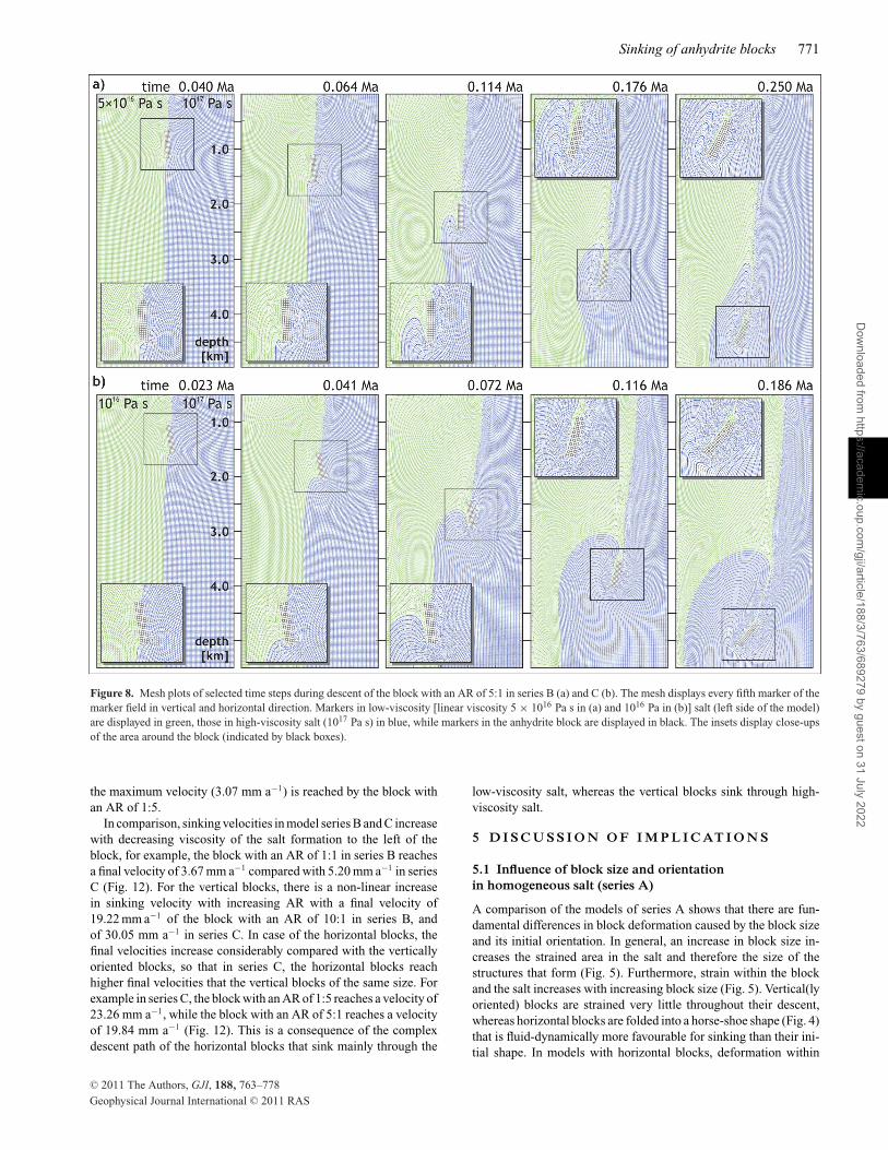
Vertically oriented blocks first rotate anticlockwise relative tothe surrounding stratified salt and sink with their lower marginfacing downwards into the higher-viscosity salt (Fig. 8a; MovieS5). Then the block rotates clockwise so that it rests on its rightside when reaching the bottom of the model. During descent, thelower-viscosity salt only envelops the left side of the block and itsupper left corner. In both salt formations, the early-formed strainpatterns are similar to those observed in model series A. However,despite the different viscosities on either side of the block, thefinite strain is surprisingly similar with slightly higher intensitiesin the lower-viscosity than in the higher-viscosity salt (Fig. 7a).With increasing thickness of the block, the initial rotation of theblock decreases in intensity and instead, the downward movementdominates. Furthermore, block strain increases so that the blockbecomes slightly bent when it approaches the bottom of the model.
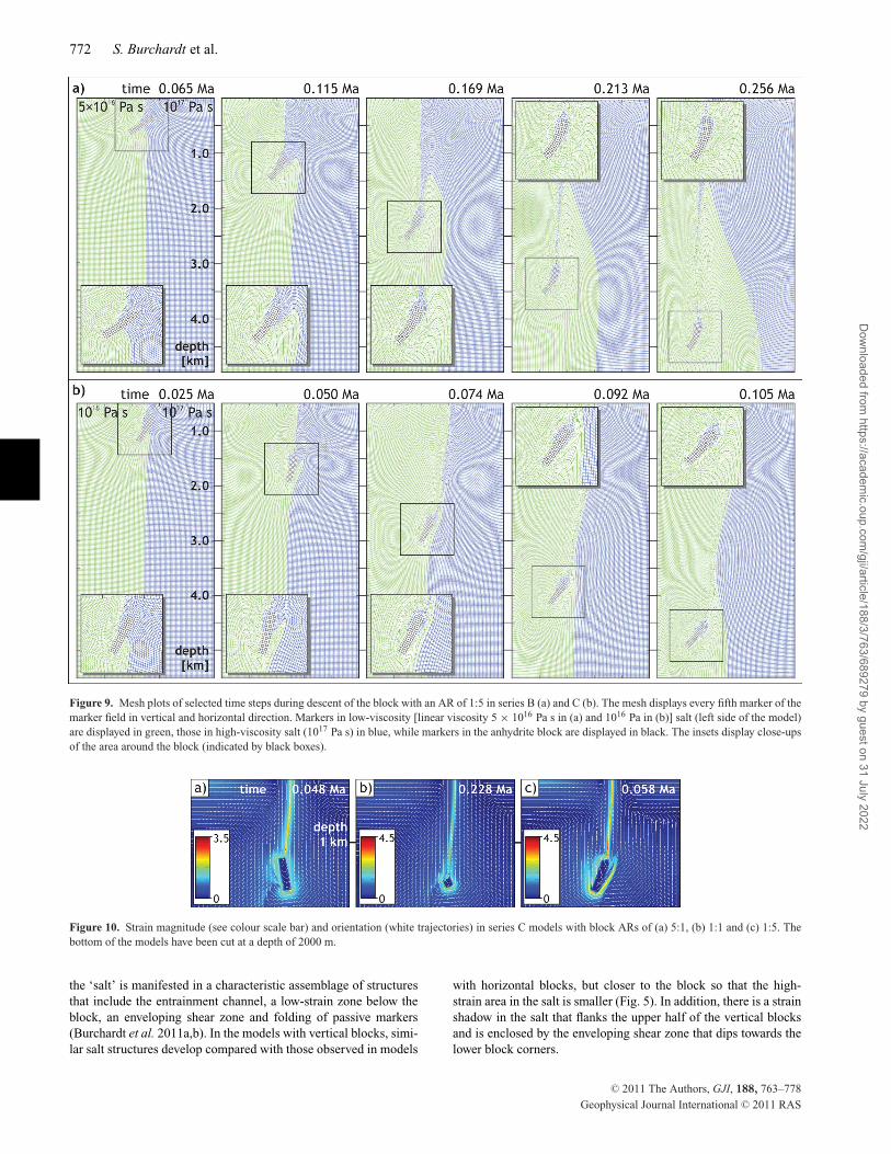
The horizontal blocks of series B show an anticlockwise ro-tation relative to the stratified salt into the lower-viscosity salt(Fig. 9a; Movie S6). There, the enveloping shear zone developsfirst. In contrast to the horizontal blocks in series A, block strain islow, so that the block sinks almost unstrained with its lower left
C© 2011 The Authors, GJI, 188, 763–778
Geophysical Journal International C© 2011 RAS
Dow
nloaded from https://academ
ic.oup.com/gji/article/188/3/763/689279 by guest on 31 July 2022

768 S. Burchardt et al.
Figure 4. Mesh plots of selected time steps during descent of blocks with ARs of 1:1, 5:1 and 1:5. The mesh displays every fifth marker of the marker fieldin vertical and horizontal direction. Markers in salt are displayed in black, while markers in the anhydrite block are displayed in green. Due to axial symmetry,only half the geometry of the models of series A was modelled (cf . Fig. 3). The bottom of the model has been cut. The insets display close-ups of the areaaround the block (indicated by black boxes).
C© 2011 The Authors, GJI, 188, 763–778
Geophysical Journal International C© 2011 RAS
Dow
nloaded from https://academ
ic.oup.com/gji/article/188/3/763/689279 by guest on 31 July 2022

Sinking of anhydrite blocks 769
Figure 5. Mesh plots of all models in series A after about 500 m of descent of the blocks. The mesh displays every fifth marker of the marker field in verticaland horizontal direction. Markers in salt are displayed in black, while markers in the anhydrite block are displayed in green. Due to axial symmetry, only halfthe geometry of the models of series A was modelled (cf . Fig. 3). The bottom of the model has been cut. Lower row displays close-ups of the area around theblock (indicated by black boxes).
corner facing downward into the lower-viscosity salt (Fig. 7c).This rotation causes the block to impinge the low-viscosity saltand drag the high-viscosity salt (with it) into the entrainment chan-nel. Consequently, the enveloping shear zones are located in thelow-viscosity salt only. During further sinking, the block is slightlyfolded, where folding becomes more intense with increasing blockwidth.
In model series C with a larger viscosity contrast between the twosalt layers, block rotation is stronger so that the block with an AR of1:1 rotates anticlockwise until its upper left corner faces downwardduring the early stages of sinking (Fig. 6b; Movie S7). In analogy tothe B-series model, the block sinks within the higher-viscosity saltenveloped by low-viscosity salt that is dragged downwards into theentrainment channel. During further sinking, block rotation reverses(to clockwise) so that the initial lower left corner faces downwards.Compared with the B-series model (Fig. 7b), the strain and overalldisturbance of the initial stratification of the salt layers are muchstronger (Fig. 10) with maximum finite strains of about 3.5 in seriesB and 4.5 in series C models.
The descend of initially vertically oriented blocks in theC-series models is characterized by an anticlockwise rotation ofthe blocks relative to the salt stratification that decreases in in-tensity at higher block thicknesses and is much more intensethan in the B-series models (Fig. 8b; Movie S8). For lower blockthicknesses, the anticlockwise rotation is more pronounced thanfor higher block thicknesses and is followed by block bending, theintensity of which increases with increasing block thickness. Forhigher block thicknesses, a phase of clockwise rotation follows theanticlockwise rotation. The former is more pronounced for highblock thicknesses.
The initially horizontally oriented block of series C with an ARof 1:3 rotates anticlockwise until its left side is facing downward,
before it sinks and causes high strain within the low-viscosity salt,close to the interface between the two salt formations (Movie S9).After sinking about half the distance to the model bottom in the low-viscosity salt, dragging with it some high-viscosity salt, the blockenters the high-viscosity salt and rotates clockwise as it approachesthe bottom, with the initial lower left corner facing downward.The block is slightly strained and enveloped by a thin layer oflow-viscosity salt that also encloses the high-viscosity salt that isdragged down with the upper, formerly right, part of the block.The highest strain is located in the entrainment channel and inthe salt below the block. In comparison, the block with an AR of1:5 rotates anticlockwise up to 80◦ (Fig. 9b; Movie S10). Then theblock sinks into the low-viscosity salt but stays close to the interfacebetween the two salt formations as it sinks. While approaching themodel bottom, slight clockwise back rotation and progressive blockbending of the downward-facing (left) side of the block occurs,while it sinks more and more into the low-viscosity salt away fromthe original location of the interface. The overall disturbance ofthe original salt stratigraphy is low with slight folding of the high-viscosity salt and strong shearing of the low-viscosity salt along theinterface with the high-viscosity salt. Strain in the salt surroundingthe block is higher than in the model with a block AR of 1:3 butlower than in the series-B model (Figs 7c and 10c).
4.3 Sinking velocities
Sinking velocities were determined in the centre of the square andhorizontally oriented blocks and in the lower central part (at the samevertical distance from the lower block boundary as in the horizontalblocks) of the vertically oriented blocks. For comparability reasons,we describe the velocity during the first 2000 m of sinking, that
C© 2011 The Authors, GJI, 188, 763–778
Geophysical Journal International C© 2011 RAS
Dow
nloaded from https://academ
ic.oup.com/gji/article/188/3/763/689279 by guest on 31 July 2022

770 S. Burchardt et al.
Figure 6. Mesh plots of selected time steps during descent of the block with an AR of 1:1 in series B (a) and C (b). The mesh displays every fifth marker of themarker field in vertical and horizontal direction. Markers in low-viscosity [linear viscosity 5 × 10¹⁶ Pa s in (a) and 1016 Pa in (b)] salt (left side of the model)are displayed in green, those in high-viscosity salt (1017 Pa s) in blue, while markers in the anhydrite block are displayed in black. The insets display close-upsof the area around the block (indicated by black boxes).
Figure 7. Strain magnitude (see colour scale bar) and strain orientation (white trajectories) in series B models with block ARs of (a) 5:1, (b) 1:1 and (c) 1:5.The bottom of the models have been cut at a depth of 2000 m.
is, before the block slows down as it approaches and ‘feels’ themodel bottom. In general, sinking velocities of all blocks are lowerin the initial stages before the blocks approach steady-state sinking(Fig. 11). This acceleration phase is particularly pronounced in themodels with horizontally oriented blocks (Fig. 11).
In model series A, the block with an AR of 1:1 reaches a velocityof 1.69 mm a−1 (Fig. 12). At greater block thicknesses, the velocity
increases to 13.12 mm a−1 for the block with and AR of 10:1. Toassess the effect of the shape of the vertical blocks, we ran a testmodel with a block with an AR of 1:1 (i.e. 100 m × 100 m) andthe same excess mass as the block with an AR of 10:1 (2200 kg +10 × 700 kg). The results give a final velocity of 64.41 mm a−1.The initially horizontal blocks of series A show a final velocity of2.80 mm a−1 for the block with an AR of 1:10 (Fig. 12). However,
C© 2011 The Authors, GJI, 188, 763–778
Geophysical Journal International C© 2011 RAS
Dow
nloaded from https://academ
ic.oup.com/gji/article/188/3/763/689279 by guest on 31 July 2022
Sinking of anhydrite blocks 771
Figure 8. Mesh plots of selected time steps during descent of the block with an AR of 5:1 in series B (a) and C (b). The mesh displays every fifth marker of themarker field in vertical and horizontal direction. Markers in low-viscosity [linear viscosity 5 × 10¹⁶ Pa s in (a) and 1016 Pa in (b)] salt (left side of the model)are displayed in green, those in high-viscosity salt (1017 Pa s) in blue, while markers in the anhydrite block are displayed in black. The insets display close-upsof the area around the block (indicated by black boxes).
the maximum velocity (3.07 mm a−1) is reached by the block withan AR of 1:5.
In comparison, sinking velocities in model series B and C increasewith decreasing viscosity of the salt formation to the left of theblock, for example, the block with an AR of 1:1 in series B reachesa final velocity of 3.67 mm a−1 compared with 5.20 mm a−1 in seriesC (Fig. 12). For the vertical blocks, there is a non-linear increasein sinking velocity with increasing AR with a final velocity of19.22 mm a−1 of the block with an AR of 10:1 in series B, andof 30.05 mm a−1 in series C. In case of the horizontal blocks, thefinal velocities increase considerably compared with the verticallyoriented blocks, so that in series C, the horizontal blocks reachhigher final velocities that the vertical blocks of the same size. Forexample in series C, the block with an AR of 1:5 reaches a velocity of23.26 mm a−1, while the block with an AR of 5:1 reaches a velocityof 19.84 mm a−1 (Fig. 12). This is a consequence of the complexdescent path of the horizontal blocks that sink mainly through the
low-viscosity salt, whereas the vertical blocks sink through high-viscosity salt.
5 D I S C U S S I O N O F I M P L I C AT I O N S
5.1 Influence of block size and orientationin homogeneous salt (series A)
A comparison of the models of series A shows that there are fun-damental differences in block deformation caused by the block sizeand its initial orientation. In general, an increase in block size in-creases the strained area in the salt and therefore the size of thestructures that form (Fig. 5). Furthermore, strain within the blockand the salt increases with increasing block size (Fig. 5). Vertical(lyoriented) blocks are strained very little throughout their descent,whereas horizontal blocks are folded into a horse-shoe shape (Fig. 4)that is fluid-dynamically more favourable for sinking than their ini-tial shape. In models with horizontal blocks, deformation within
C© 2011 The Authors, GJI, 188, 763–778
Geophysical Journal International C© 2011 RAS
Dow
nloaded from https://academ
ic.oup.com/gji/article/188/3/763/689279 by guest on 31 July 2022
772 S. Burchardt et al.
Figure 9. Mesh plots of selected time steps during descent of the block with an AR of 1:5 in series B (a) and C (b). The mesh displays every fifth marker of themarker field in vertical and horizontal direction. Markers in low-viscosity [linear viscosity 5 × 10¹⁶ Pa s in (a) and 1016 Pa in (b)] salt (left side of the model)are displayed in green, those in high-viscosity salt (1017 Pa s) in blue, while markers in the anhydrite block are displayed in black. The insets display close-upsof the area around the block (indicated by black boxes).
Figure 10. Strain magnitude (see colour scale bar) and orientation (white trajectories) in series C models with block ARs of (a) 5:1, (b) 1:1 and (c) 1:5. Thebottom of the models have been cut at a depth of 2000 m.
the ‘salt’ is manifested in a characteristic assemblage of structuresthat include the entrainment channel, a low-strain zone below theblock, an enveloping shear zone and folding of passive markers(Burchardt et al. 2011a,b). In the models with vertical blocks, simi-lar salt structures develop compared with those observed in models
with horizontal blocks, but closer to the block so that the high-strain area in the salt is smaller (Fig. 5). In addition, there is a strainshadow in the salt that flanks the upper half of the vertical blocksand is enclosed by the enveloping shear zone that dips towards thelower block corners.
C© 2011 The Authors, GJI, 188, 763–778
Geophysical Journal International C© 2011 RAS
Dow
nloaded from https://academ
ic.oup.com/gji/article/188/3/763/689279 by guest on 31 July 2022

Sinking of anhydrite blocks 773
Figure 11. Vertical position of the centre of the blocks as a function of timein (a) model series A, (b) model series B and (c) model series C.
5.2 Influence of salt stratification (series B and C)
In comparison with the results of model series A, vertical stratifica-tion of the salt in series B and C influences the mode of descent ofthe block and resulting deformation of both the block and the host-ing salt. In combination with the two parameters, block size andorientation, vertical salt stratification causes complex, diapir-scaledeformation patterns within the hosting diapir. Because the low-viscosity salt generally accommodates more strain (cf . Figs 7 and10), strain concentration in the low-viscosity salt causes an initialphase of anticlockwise rotation of the block that is expressed by the
Figure 12. Velocity of the blocks of all series after 2000 m sinking.
horizontal component of the velocity field of the block during theinitial stage of sinking (Fig. 13). As the blocks are connected to thehigh-viscosity salt at one half, vertical shear stresses are asymmet-rically distributed, which causes their anticlockwise rotation. Thisis seen as a linear increase of the horizontal velocity with depth inthe interval occupied by the block. Below the block, this causes saltflow towards the right half of the model. This is evident as positivehorizontal velocities (Fig. 13a). However, as the model is laterallyconfined and the distance to the bottom is still large, a horizontalreturn flow is triggered in the lower part of the model; this is evi-dent from negative horizontal velocities (Fig. 13a). Consequently,the interface between the two salt formations is deformed and dis-placed towards the left in all models with vertical blocks. Hence,the block encounters and impinges the high-viscosity salt as it de-scends further. Therefore, the initial velocity distribution (Fig. 13a)determines block rotation and controls whether the block moveswithin the low- or the high-viscosity salt (Fig. 13b and c), becauseit induces convection cells within the salt as a result of the spatialconfinement of the model box. As most salt structures possess afinite dimension, we assume that such convection is taking place innatural salt structures as well.
In case of the vertical blocks, the resulting deviation of the sinkingpath of the block from vertical descent (Figs 6, 8, 9, 13b and c)is highest at a block AR of 3:1. Thinner (AR 1:1) and thicker(AR >3:1) blocks sink along less deviated paths, because (1) themore compact-shaped blocks (e.g. AR 1:1) do not have enoughworking surface to be deflected and (2) thicker blocks need longervertical distances to rotate into the position of being exposed to alarge pitch angle.
Generally, block rotation and sinking along complex paths resultsin higher block strain of vertically oriented blocks and lower blockstrain of horizontal blocks compared with series A. Vertical blocks
C© 2011 The Authors, GJI, 188, 763–778
Geophysical Journal International C© 2011 RAS
Dow
nloaded from https://academ
ic.oup.com/gji/article/188/3/763/689279 by guest on 31 July 2022

774 S. Burchardt et al.
Figure 13. (a) Horizontal velocity profile through the central axis of the models at t0. (b) Horizontal component of the sinking path of the blocks (measured inthe block centre of the square and the horizontal blocks and the lower central part of the vertical blocks) of series B. (c) Horizontal component of the sinkingpath of the blocks (measured in the block centre of the square and the horizontal blocks and the lower central part of the vertical blocks) of series C.
sink into the high-viscosity salt dragging low-viscosity salt withthem into the entrainment channel (Fig. 8), while horizontal blockssink into the low-viscosity salt, because their initial anticlockwiserotation is much stronger (Fig. 9). In contrast to block folding in ho-mogeneous salt, block rotation in vertically stratified salt representsan alternative descent mechanism for initially horizontal blocks.Consequently, block strain in the models with horizontal blocks ofseries B and C is much less than in those of series A. Strain dis-tribution in the vertically stratified salt is controlled by the sinkingpath of the block, since it is mainly concentrated in the entrainmentchannel and the enveloping shear zone (Figs 7 and 10). In additionto the characteristic deformation structures in the vicinity of thesinking block, the overall stratification of the salt is disturbed onmodel scale.
Figure 14. (a) Close-up of part of the cross-section of the Gorleben diapirin Fig. 1 showing severely deformed blocks of the main anhydrite (darkgrey) located at the folded interface between z2 and z3 salt formations. SeeFig. 1 for key. (b) Close-up of a section of a block with an AR of 1:3 atthe interface between lower- and higher-viscosity salt in a model of series Cproducing a similar structure to that in (a).
A comparison between the results of model series B and C demon-strates that an increase in the viscosity contrast between the two saltformations causes an even stronger strain concentration in the low-viscosity salt (cf . Figs 7 and 10). Hence, the initial anticlockwiseblock rotation is more pronounced (e.g. Fig. 9), which in turn in-fluences the sinking path of the blocks. In case of the horizontalblock with an AR of 1:3, this leads to a complex sinking path, firstin the low-viscosity, then in the high-viscosity salt (see Movie S9).Furthermore, the increase in the viscosity contrast between the twosalt layers causes a stronger overall disturbance of the initial stratifi-cation and higher block strain in the models with vertically orientedblocks (Fig. 8).
Generally, and perhaps surprisingly, our model results show thatnot only all vertical blocks (e.g. Fig. 8) but also blocks with an AR of1:1 (Fig. 6) or 1:3 (in series C; Movie S9 in the Auxiliary Material)descend through the high-viscosity salt, rather than moving slightlysideways into the low-viscosity salt to take ‘the easy way’, whichone would intuitively expect on the grounds of extremum principles,such as that of minimum resistance. As discussed above, blockrotation and the associated large-scale velocity field influenced byspatial confinement (Fig. 13a) play an important role and cause this‘counterintuitive’ behaviour.
5.3 Sinking velocities
Two main parameters controlling sinking velocities are the blocksize and orientation. The vertically oriented blocks of modelseries A experience an increase in final velocity with increasingblock thickness (Fig. 12), as may be expected from an increase inmass. However, the test model demonstrates that the sinking ve-locity of the vertical blocks is not only a linear function of theirmass, but also influenced by their shape (i.e. thickness). This shape
C© 2011 The Authors, GJI, 188, 763–778
Geophysical Journal International C© 2011 RAS
Dow
nloaded from https://academ
ic.oup.com/gji/article/188/3/763/689279 by guest on 31 July 2022

Sinking of anhydrite blocks 775
effect of vertical blocks is also evident from increasing salt strainwith increasing block thickness (Fig. 5). In case of the horizontalblocks of series A, the shape effect is even stronger, causing a pro-nounced acceleration phase and much lower sinking velocities dueto block deformation, as has been discussed in detail by Burchardtet al. (2011a,b). More, specifically, block deformation during theacceleration phase results in a horse-shoe shape, a fluid-dynamicallymore favourable configuration than the initial block shape. This pro-cess is more effective at greater block width, explaining the higherblock strain in the model with an AR of 1:10 (Fig. 5).
Two further parameters controlling sinking velocities are the saltviscosity and stratification. From Stokes’ law (Stokes 1851), anincrease in sinking velocity of a spherical object with the inversedecrease in matrix viscosity is expected. From series A to C, saltviscosity in the left side of the model decreases by one order ofmagnitude, that is, an increase of sinking velocities in the range ofone order of magnitude would be expected if the salt in series Cwas not stratified. That the salt formation with the lowest viscosityis indeed one controlling parameter is supported by the observationthat the highest velocities occur in the models of the C series.However, the vertical stratification of the salt in model series B andC has severe influence not only on the sinking paths of the blocksand on block and salt deformation, but also on the sinking velocities.Vertical blocks in series B sink only about 1.5–2 times faster thanin series A, whereas those in series C sink about 2.3 times faster(Fig. 12), even though most blocks sink through the high-viscositysalt.
In the stratified models of series B, horizontal blocks still sinkslower than the vertical blocks of the same size, as in series A.However, the difference in velocity between horizontal and verticalblocks is not as strong (Fig. 12). This is due to the fact that thehorizontal blocks in series B have found a more efficient way to ap-proach a fluid-dynamically stable sinking configuration: they rotateso that they sink as vertical slabs. In case of series B, the blocksexperience more resistance by the low-viscosity salt compared withseries C, where the low-viscosity salt allows fast sinking of the ro-tated blocks, even faster than their originally vertical equivalents(Figs 11 and 12), because their initially different sense of rotationlets them sink within the low-viscosity salt (Movies S9 and S10).
These block-descent velocities predict sinking distances of about3–30 km Ma−1, which probably exceeds expected values. As statedabove, salt viscosities in the models (1017 Pa s) have been selected tofit an average value of reported viscosities (Mukherjee et al. 2010).However, according to Van Keeken et al. (1993), a linear viscosityof 1018 Pa s may also be likely for diapiric salt at depth. In this case,sinking velocities of our models can be scaled accordingly, loweringthem by about one order of magnitude, that is, 0.3–3 km Ma−1.
5.4 Implications for natural salt diapirs
The present-day configuration of natural salt diapirs reflects defor-mation processes during their emplacement and post-emplacementhistory that have produced complex structures. Even though oursimplified model setup cannot account for this complexity, the aimof our models was to simulate the strain pattern produced by post-emplacement sinking of entrained blocks and to unravel the influ-ence of basic parameters, such as block AR and salt stratificationon internal deformation of salt diapirs hosting denser blocks. Thequestion whether anhydrite blocks are currently sinking or not isvigorously discussed among researchers, since the complexity ofnatural salt structures makes it difficult to distinguish ascent- and
descent-related features. Apparently, sinking velocities predicted byour models would imply that all anhydrite blocks in, for example, theGorleben diapir would have sunken to the diapir bottom. However,why this is not the case has also not been explained satisfactorily.Yet, that they have not reached the diapir bottom, does not meanthat they are not sinking or will not sink under certain triggeringconditions, such as temperature effects (exerted by e.g. the heat ofnuclear waste), tectonic stresses, fluids and glaciations. Our modelresults should therefore be seen as a contribution to the answer ofthe question about the effects of a sinking block, rather than whetherblocks are currently sinking or not.
One of the main results of our models (regarding natural saltdiapirs, such as Gorleben) is that the internal stratification of thesalt with different viscosities, such as the lower-viscosity z2 forma-tion adjacent to the higher-viscosity z3 formation in Gorleben saltdiapir, has a strong influence on the gravitational sinking of denseinclusions, such as the Main Anhydrite. In contrast to models withblocks sinking in homogeneous salt (series A), complex sinkingpaths and diapir-scale disturbance of the pre-descent stratigraphyare produced in the vertically stratified models (series B and C).During the earliest stages of block descent, block rotation towardsthe lower-viscosity salt occurs, which might be one possible expla-nation for the vergence of fold hinges of the Main Anhydrite inthe lower structural levels of the northwestern part of the GorlebenDiapir (Fig. 1).
Block rotation and further sinking of the blocks in our modelsresults in successive detachment from the interface between thetwo salt formations. In some cases, this produces structural con-figurations that strikingly resemble those in the Gorleben Diapir(Fig. 14). Other structures observed in Gorleben may be explainedby the interaction of several blocks. This may cause deformationpatterns that differ from those produced by a single sinking block,as indicated by the results of a simple test model with several blockssinking simultaneously (Fig. 15).
Our observation that vertically oriented blocks generally needvery little time to accelerate to steady-state sinking and that hor-izontal blocks rotate to assume vertical orientations, indicate thata vertical slab is the fluid-dynamically most stable configurationfor sinking. This might explain the ‘absence’ of dense inclusions(stringers) in some seismic images, because in contrast to subhor-izontal, folded stringers, subvertically oriented structures are moredifficult to display on reflection seismic imaging (e.g. Stroczyk et al.2010; van Gent et al. 2011).
6 C O N C LU S I O N S
The results of 2-D finite differences models of rectangular, high-density inclusions (blocks) sinking in Newtonian salt demonstratethat initial block orientation and block size are two crucial param-eters in terms of (1) block deformation, (2) salt deformation and(3) velocity of block descent. In general, increasing block size re-sults in higher strain in the block and the surrounding salt and, toa certain degree, a higher sinking velocity. The influence of blockorientation is evident from the observation that sinking of verticalblocks is fastest and associated with smaller block strain and saltdeformation compared with horizontally oriented blocks sinkingin homogeneous salt. The latter are characterized by severe defor-mation, resulting in folding into horse-shoe shapes. However, saltdeformation during block descent generally results in basically thesame structural configuration, independent of the block size andorientation, with shear zones enveloping the block, folds flanking
C© 2011 The Authors, GJI, 188, 763–778
Geophysical Journal International C© 2011 RAS
Dow
nloaded from https://academ
ic.oup.com/gji/article/188/3/763/689279 by guest on 31 July 2022

776 S. Burchardt et al.
Figure 15. Mesh plots of selected time steps during descent of three blocks with an AR of 1:3 with salt-viscosity configuration of series B. The mesh displaysevery fifth marker of the marker field in vertical and horizontal direction. Markers in low-viscosity (linear viscosity 5 × 10¹⁶ Pa s) salt (left side of the model)are displayed in green, those in high-viscosity salt (1017 Pa s) in blue, while markers in the anhydrite block are displayed in black. Lower row displays close-upsof the area around the block (indicated by black boxes).
the shear zones and the entrainment channel above the block, wherethe highest strain occurs.
In the models with vertical salt stratification with different saltviscosities, as known from diapirs like Gorleben, we observed thatin general, strain is mainly accommodated by deformation of thelithology with the lower viscosity so that considerably lower blockstrain occurs compared with the models with homogeneous salt.Complex sinking paths of the blocks result from early-stage blockrotation towards the lower-viscosity salt caused by asymmetricallydistributed vertical shear stresses around the block and the effectof the spatial confinement of the system. Hence, pre-sinking blockorientation is less significant, as horizontal blocks rotate towardssubvertical orientations in vertically layered salt. As a somewhatsurprising result, our models show that the majority of the blocksinvestigated take a descent path through the high-viscosity salt,rather than taking ‘the easy way’ through the low-viscosity salt.In summary, our model results show that salt heterogeneity is
the main parameter controlling post-emplacement deformation ofsalt structures associated with the gravity-driven sinking of denseinclusions.
A C K N OW L E D G M E N T S
Research was financially supported by a postdoctoral grant to SBby the Swedish Research Council (VR). The authors are grateful forinspiring discussions with the participants of the salt deformationsession at GeoDarmstadt 2010 and comments by two anonymousreviewers.
R E F E R E N C E S
Bornemann, O., 1979. Das Gefugeinventar nordwestdeutscher Salzstruk-turen in Abhangigkeit von ihrer halokinetischen Stellung, PhD thesis.University of Braunschweig, Germany, pp. 119.
C© 2011 The Authors, GJI, 188, 763–778
Geophysical Journal International C© 2011 RAS
Dow
nloaded from https://academ
ic.oup.com/gji/article/188/3/763/689279 by guest on 31 July 2022

Sinking of anhydrite blocks 777
Bornemann, O., 1982. Stratigraphy and tectonics of the Zechstein in Gor-leben salt dome using drilling results, Z. Deut. Geol. Ges., 133, 119–134.
Bornemann, O., Jaritz, W. & Wittrock, J., 1988. Geotechnische Erkundungund Standsicherheitskriterien Bergwerk Gorleben. Teilprojekt I. Geolo-gisches und geotechnisches Untersuchungsprogramm, in Bericht Bunde-sanstalt fur Geowissenschaften und Rohstoffe, Forschungsvorhaben KWA85049, Arch.-Nr. 103 750, pp. 33.
Bornemann, O., Belau, J., Fischbeck, R., Hammer, J., Jaritz, W., Keller,S., Mingerzahn, G. & Schramm, M., 2008. Description of the Gorlebensite. Pt. 3: Results of the geological surface and underground explorationof the salt formation, BGR (Bundesanstalt fur Geowissenschaften undRohstoffe) Report 2413.
Brauer, V. et al., 2011. Description of the Gorleben site. Pt. 4: Geotech-nical exploration of the Gorleben salt dome, BGR (Bundesanstalt furGeowissenschaften und Rohstoffe) Report 2480.
Burchardt, S., Koyi, H. & Schmeling, H., 2011a. Strain pattern within andaround denser blocks sinking within Newtonian salt structures, J. Struct.Geol., 33, 145–153.
Burchardt, S., Koyi, H. & Schmeling, H., 2011b. The influence of viscositycontrast on the strain pattern and magnitude within and around denseblocks sinking through Newtonian rock salt, J. Struct. Geol., in press,doi:10.1016/j.jsg.2011.07.007.
Chemia, Z., Koyi, H. & Schmeling, H., 2008. Numerical modelling of riseand fall of dense layers in salt diapirs, Geophys. J. Int., 172, 798–816.
Chemia, Z., Schmeling, H. & Koyi, H., 2009. The effect of the salt viscosityon future evolution of the Gorleben salt diapir, Germany, Tectonophysics,473, 446–456.
Hudec, M.R. & Jackson, M.P.A., 2007. Terra infirma: understanding salttectonics, Earth Sci. Rev., 88, 1–28.
Jackson, M.P.A., Vendeville, B.C. & Schultz-Ela, D.D., 1994. Structuraldynamics of salt systems, Ann. Rev. Earth planet. Sci., 22, 93–117.
Klinge, H. et al., 2007. Description of the Gorleben site. Pt. 1: hydrogeologyof the overburden of the Gorleben salt dome, BGR (Bundesanstalt furGeowissenschaften und Rohstoffe) Report 629.
Kosmahl, W., 1969. Zur Stratigraphie, Petrographie, Palaogeographie,Genese und Sedimentation des gebanderten Anhydrits (Zechstein 2),Grauen Salztons und Hauptanhydrits (Zechstein 3) in Nordwestdeutsch-land, Beil. Geol. Jb., Hannover, 71, 129.
Koyi, H., 2000. Analogue modelling of entrainment of non-evaporitic rocksby salt diapirs, in Proceedings of the 8th World Salt Symposium, Vol. 1,pp. 149–153, ed. Geertman, R.M., Elsevier, The Hague, the Netherlands.
Koyi, H., 2001. Modeling the influence of sinking anhydrite blocks on saltdiapirs targeted for hazardous waste disposal, Geology, 29, 387–390.
Malvern, L.E., 1969. Introduction to the Mechanics of a ContinuousMedium, Prentice Hall Inc, Englewood Cliffs, NJ.
McKenzie, D., 1979. Finite deformation during fluid flow, Geophys. J. Int.,58, 689–715, doi:10.1111/j.1365-246X.1979.tb04803.x
Mukherjee, S., Talbot, C.J. & Koyi, H., 2010. Viscosity estimates of salt inthe Hormuz and Namakdan salt diapirs, Persian Gulf, Geol. Mag., 147,497–507.
Muller, P. & Siemes, H., 1974. Festigkeit, Verformabarkeit undGefugeregelung von Anhydrit – experimentelle Stauchverformung unterManteldrucken bis 5 kbar bei temperaturen bis 300◦C, Tectonophysics,23, 105–127.
Muller, W.H., Schmid, S.M. & Briegel, U., 1981. Deformation experimentson anhydrite rocks of different grain sizes: rheology and microfabric,Tectonophysics, 78, 527–543.
Schmeling, H., Cruden, A.R. & Marquart, G., 1988. Progressive deforma-tion in and around a fluid sphere moving through a viscous medium:implications for diapiric ascent, Tectonophysics, 149, 17–34.
Schnier, H., 1987. Ergebnisse festigkeitsmechanischer Laboruntersuchun-gen an Hauptanhydrit aus den Bohrungen Go 1002, Go 1003 und Go1005 des Salzstocks Gorleben, Laborbericht, Bundesanstalt fur Geowis-senschaften und Rohstoffe, Arch.-Nr. 101, 328.
Stokes, G.G., 1851. On the effect of the internal friction of fluids on themotions of pendulums, Trans. Cambr. Phil. Soc., 9, 8–106.
Stroczyk, F., van Gent, H., Urai, J.L. & Kukla, P.A., 2010. 3D seismic studyof complex intra-salt deformation: an example from the Upper Permian
Zechstein 3 stringer in the western Dutch offshore, J. geol. Soc. Lond., inpress.
Urai, J.L., Spiers, C.J., Zwart, H.J. & Lister, G.S., 1986. Weakening of rocksalt by water during long-term creep, Nature, 324, 554–557.
Urai, J.L., Schleder, Z., Spiers, C.J. & Kukla, P.A., 2008. Flow and transportproperties of salt rocks, in Dynamics of Complex Intracontinental Basins:The Central European Basin System, pp. 277—290, ed. Littke, R., Bayer,U., Gajewski, D. & Nelskamp, S., Springer-Verlag, Berlin, Germany.
Van Gent, H., Urai, J.L. & de Keijzer, M., 2011. The internal geometry ofsalt structures – A first look using 3D seismic data from the Zechstein ofthe Netherlands, J. Struct. Geol., 33, 292–311.
Van Keeken, P.E., Spiers, C.J., van den Berg, A.P. & Muyzert, E.J., 1993.The effective viscosity of rock salt: implementation of steady-state creeplaws in numerical models of salt diapirism, Tectonophysics, 225, 457–476.
Weinberg, R.F., 1993. The upward transport of inclusions in Newtonian andpower-law salt diapirs, Tectonophysics, 228, 141–150.
Weinberg, R.F. & Schmeling, H., 1992. Polydiapirs: multiwavelength gravitystructures, J. Struct. Geol., 14, 425–436.
Zirngast, M., 1991. Die Entwicklungsgeschichte des Salzstocks Gor-leben, Ergebnis einer strukturgewologischen Bearbeitung, GeologischesJahrbuch, Reihe A: Allgemeine und Regional Geologie BR Deutschlandund Nachbargebiete, Tektonik, Stratigraphie, Palaeohtologie, Heft 132,pp. 31, Bundesanstalt fur Bodenforschung und die Geologischen Lan-desamter der Bundesrepublik Deutschland, Hannover, Germany.
Zirngast, M., 1996. The development of the Gorleben salt dome (north-west Germany) based on quantitative analysis of peripheral sinks, in SaltTectonics, Geol. Soc. London, Spec. Pub., 100, 203–226.
Zulauf, G., Zulauf, J., Bornemann, O., Brenker, F., Hofer, H., Peinl, M. &Woodland, A., 2010. Experimental deformation of Gorleben anhydrite ina matrix of Asse rock salt under bulk constriction: Deformation mecha-nisms and the role of fluids, Paper presented at the 13th Symposium onTectonics Structural Geology and Crystalline Geology (TSK), April 2010,Frankfurt, Germany.
S U P P O RT I N G I N F O R M AT I O N
Additional Supporting Information may be found in the online ver-sion of this article:
Movie S1. Movie displaying the deformation of the marker meshof a model with a block with an AR of 1:1 sinking in homogeneoussalt (series A).Movie S2. Movie displaying the deformation of the marker meshof a model with a block with an AR of 5:1 sinking in homogeneoussalt (series A).Movie S3. Movie displaying the deformation of the marker meshof a model with a block with an AR of 1:5 sinking in homogeneoussalt (series A).Movie S4. Movie displaying the deformation of the marker meshof a model with a block with an AR of 1:1 sinking in vertically-stratified salt (series B).Movie S5. Movie displaying the deformation of the marker meshof a model with a block with an AR of 5:1 sinking in vertically-stratified salt (series B).Movie S6. Movie displaying the deformation of the marker meshof a model with a block with an AR of 1:5 sinking in vertically-stratified salt (series B).Movie S7. Movie displaying the deformation of the marker meshof a model with a block with an AR of 1:1 sinking in vertically-stratified salt (series C).Movie S8. Movie displaying the deformation of the marker meshof a model with a block with an AR of 5:1 sinking in vertically-stratified salt (series C).
C© 2011 The Authors, GJI, 188, 763–778
Geophysical Journal International C© 2011 RAS
Dow
nloaded from https://academ
ic.oup.com/gji/article/188/3/763/689279 by guest on 31 July 2022

778 S. Burchardt et al.
Movie S9. Movie displaying the deformation of the marker meshof a model with a block with an AR of 1:3 sinking in vertically-stratified salt (series C).Movie S10. Movie displaying the deformation of the marker meshof a model with a block with an AR of 1:5 sinking in vertically-stratified salt (series C).
Please note: Wiley-Blackwell are not responsible for the content orfunctionality of any supporting materials supplied by the authors.Any queries (other than missing material) should be directed to thecorresponding author for the article.
C© 2011 The Authors, GJI, 188, 763–778
Geophysical Journal International C© 2011 RAS
Dow
nloaded from https://academ
ic.oup.com/gji/article/188/3/763/689279 by guest on 31 July 2022
Related Documents


