Singularity Analysis of 3T2R Parallel Mechanisms using Grassmann-Cayley Algebra and Grassmann Line Geometry Semaan Amine, M Tale Masouleh, St´ ephane Caro, Philippe Wenger, Cl´ ement M. Gosselin To cite this version: Semaan Amine, M Tale Masouleh, St´ ephane Caro, Philippe Wenger, Cl´ ement M. Gosselin. Sin- gularity Analysis of 3T2R Parallel Mechanisms using Grassmann-Cayley Algebra and Grass- mann Line Geometry. Mechanism and Machine Theory, Elsevier, 2012, 52, pp.326-340. <10.1016/j.mechmachtheory.2011.11.015>. <hal-00833520> HAL Id: hal-00833520 https://hal.archives-ouvertes.fr/hal-00833520 Submitted on 12 Jun 2013 HAL is a multi-disciplinary open access archive for the deposit and dissemination of sci- entific research documents, whether they are pub- lished or not. The documents may come from teaching and research institutions in France or abroad, or from public or private research centers. L’archive ouverte pluridisciplinaire HAL, est destin´ ee au d´ epˆ ot et ` a la diffusion de documents scientifiques de niveau recherche, publi´ es ou non, ´ emanant des ´ etablissements d’enseignement et de recherche fran¸cais ou ´ etrangers, des laboratoires publics ou priv´ es.

Welcome message from author
This document is posted to help you gain knowledge. Please leave a comment to let me know what you think about it! Share it to your friends and learn new things together.
Transcript

Singularity Analysis of 3T2R Parallel Mechanisms using
Grassmann-Cayley Algebra and Grassmann Line
Geometry
Semaan Amine, M Tale Masouleh, Stephane Caro, Philippe Wenger, Clement
M. Gosselin
To cite this version:
Semaan Amine, M Tale Masouleh, Stephane Caro, Philippe Wenger, Clement M. Gosselin. Sin-gularity Analysis of 3T2R Parallel Mechanisms using Grassmann-Cayley Algebra and Grass-mann Line Geometry. Mechanism and Machine Theory, Elsevier, 2012, 52, pp.326-340.<10.1016/j.mechmachtheory.2011.11.015>. <hal-00833520>
HAL Id: hal-00833520
https://hal.archives-ouvertes.fr/hal-00833520
Submitted on 12 Jun 2013
HAL is a multi-disciplinary open accessarchive for the deposit and dissemination of sci-entific research documents, whether they are pub-lished or not. The documents may come fromteaching and research institutions in France orabroad, or from public or private research centers.
L’archive ouverte pluridisciplinaire HAL, estdestinee au depot et a la diffusion de documentsscientifiques de niveau recherche, publies ou non,emanant des etablissements d’enseignement et derecherche francais ou etrangers, des laboratoirespublics ou prives.


Singularity Analysis of 3T2R Parallel Mechanisms using
Grassmann-Cayley Algebra and Grassmann Geometry
S. Amine M. Tale Masouleh S. Caro P. Wenger§ C. Gosselin‘
IRCCyN Université Laval IRCCyN IRCCyN Université LavalNantes, France Québec, Canada Nantes, France Nantes, France Québec, Canada
June 12, 2013
Abstract
This paper deals with the singular configurations of symmetric 5-DOF parallel mechanisms performing
three translational and two independent rotational DOFs. The screw theory approach is adopted in order to
obtain the Jacobian matrices. The regularity of these matrices is examined using Grassmann-Cayley algebra
and Grassmann geometry. More emphasis is placed on the geometric investigation of singular configurations
by means of Grassmann-Cayley Algebra for a class of simplified designs whereas Grassmann geometry is
used for a matter of comparison. The results provide algebraic expressions for the singularity conditions,
in terms of some bracket monomials obtained from the superbracket decomposition. Accordingly, all the
singularity conditions can be enumerated.
Keywords: Parallel singularity, screw theory, 5-DOF parallel mechanisms, Grassmann geometry, Grassmann-
Cayley algebra, Jacobian matrix, superbracket decomposition
1 Introduction
The singular configurations of Parallel Mechanisms (PMs) are critical poses characterized by either the loss of
some degrees of freedom (DOF), the gain of some extra DOF or the loss of stiffness. The determination of
singular configurations is thus a central issue in robotics due to their major effect on the robot performance [1,
2]. Lower-mobility PMs are suitable for a wide range of applications that require fewer than six DOF. The
classification of the singularities of lower-mobility PMs has stimulated the interest of many researchers [3–6].
In this paper, the classification proposed in [4] is adopted. Accordingly, a lower-mobility PM can exhibit
three types of singularities: (i) limb singularities, (i i) platform singularities [4], also known as constraint
singularities [7] and (i i i) actuation singularities. In this paper, more emphasis is placed on the actuation
singularities that are more challenging than the other ones for the mechanisms under study.
Constraint and actuation singularities are referred to as parallel singularities and are related to the rank
deficiency of a Jacobian matrix derived from the first-order kinematic relation. The latter relation is referred
to as the input-output velocity equation and is linear with respect to the time-rate changes of the input-output
variables. The determination of the parallel singularities of a PM consists in finding either the poses, yielding
the singularity locus, or the conditions, yielding the configurations, in which the Jacobian matrix becomes rank-
deficient. A 6 6 Jacobian matrix J of a given lower-mobility PM can be derived following the methodology
proposed in [8] based on screw theory.
The next step is to explore the regularity of J, which can be performed with two general approaches: linear
algebra and Grassmann geometry [1, 2, 9–16]. Linear algebra consists in a direct analysis of J by expanding
its determinant and examining its vanishing conditions. Generally, the determinant of such a matrix is highly
[email protected]@[email protected]§[email protected]‘[email protected]
1

2
non linear and unwieldy to assess, even with a computer algebra system. Hence, linear algebra fails to provide
satisfactory results, and therefore, the use of Grassmann-Cayley Algebra (GCA) [2, 11, 12, 14] or Grassmann
Geometry (GG) [1,9,10,13,16] may be regarded as promising solutions to explore the degeneracy of J, namely,
to analyze the singularities of PMs.
The GCA is a systematic approach to obtain a bracket representation of the determinant of J, called su-
perbracket. By exploring this superbracket, it is possible to obtain a geometrical interpretation of the parallel
singularities. On the other hand, GG is a geometric approach that provides a classification for the conditions
under which a set of n Plücker lines spans a variety of dimension lower than n. This paper focuses on the ap-
plication of GCA to provide a compact vector expression for the singularity locus of 3T1R PMs with identical
limb structures.
Symmetric1 5-DOF PMs performing three translational and two independent rotational motions, referred
to as 3T2R, are considered as case studies to apply the GCA for two main reasons:
1. Recent studies on their kinematic properties, such as the Forward Kinematic Problem (FKP) [17–19], led
to interesting results and this might also be the case for their singularity analysis;
2. The actuation wrench and the constraint wrench—a line at infinity—of a given limb of such mechanisms
are not directly associated with the direction of a given mechanical joint (e.g., for the Gough-Stewart
platform with 6-UPS as kinematic arrangement the actuation wrench is along the prismatic actuator
direction).
In general, 5-DOF PMs fall into three classes according to their mobility: (i) three translational and two
rotational DOFs (3T2R), (ii) three rotational and two planar translational DOFs (3R2Tp) where the planar
motion could be either fixed or instantaneous and (iii) three rotational and two spherical translational DOFs
(3R2Ts) [20]. Geometrically, the 3T2R motion can be made equivalent to guiding a combination of a directed
line and a point on it. Accordingly, the 3T2R PMs can be used in a wide range of applications for a point-line
combination including, among others, 5-axis machine tools [21], welding and conical spray-gun. Moreover, 5-
DOF PMs are very useful for medical applications [22] that require at the same time mobility, compactness and
accuracy around a functional point. So far researchers have mainly worked on the type synthesis of such PMs [4,
20,23–26]. There were no symmetrical 5-DOF PMs until Huang and Li and Jin et al. independently solved the
problem and filled this gap [27, 28]. It is noteworthy that the most existing 5-DOF PMs are asymmetrical, i.e.,
have a 5-DOF passive limb that constrains some actuated 6-DOF limbs [29, 30].
Due to the short history of symmetric 5-DOF PMs, more precisely the ones performing a 3T2R motion
pattern, their kinematic properties are still not well understood. In some recent studies, the Inverse Kinematic
Problem (IKP), Forward Kinematic Problem (FKP), workspace and singularities were investigated [18, 19, 31–
34]. The singularities were investigated upon a different perspective based on GG [32]. The results obtained
in [32] are based on some inspections and intuitions. Thus, as a global objective, this paper aims at blending
these two approaches, namely, GCA and GG in order to obtain a more systematic approach to enumerate all
the singular configurations of the PMs under study. These PMs originate from the comprehensive study of
symmetric 5-DOF PMs (3T2R) whose FKP admits either a closed-form solution or a univariate expression [19,
34]. It should be noted that the GCA is applied based on the framework presented in [2, 11, 35–37].
The remainder of the paper is organized as follows. First, some concepts for the singularity analysis are
recalled. Then, the general architecture of the PMs under study is presented and a brief review of some existing
kinematic properties is given, which leads us to a class of simplified designs with certain practical interests.
In this paper, the singularity analysis method based on GCA is applied to two simplified designs. The results
obtained with GCA are then put in contrast with the ones obtained recently using GG in order to make these two
approaches complementary rather than opposite. Finally, the paper concludes with some remarks that provide
insight into ongoing works to extend this study to other types of lower-mobility PMs.
1In the context of this paper, the term symmetric refers to the limb type and not to the geometry, such as centro–symmetrical
simplifications.

3
2 Preliminary Concepts
2.1 Screw Theory
Screw theory [37–40] is suitable for the type synthesis [20] and the study of the instantaneous motion [41] of
PMs. A twist and a wrench are screws that represent the instantaneous motion of a rigid body and a system
of forces and moments applied on a rigid body, respectively. A zero-pitch wrench, namely, a pure force, cor-
responds to the Plücker coordinate vector of a finite line in the 3-dimensional projective space P3. In turn, an
infinite-pitch wrench, namely, a pure moment, corresponds to the Plücker coordinate vector of a line at infinity
in P3. It is noteworthy that finite lines and lines at infinity are projective lines, i.e., Plücker lines whose six
components satisfy the Grassmann Plücker relation [42]. A n-screw system is a screw subspace whose basis is
composed of n screws.
2.2 Projective Space
The 3-dimensional projective space P3 is characterized by the affine space R3 in addition to the plane at infin-
ity 1. It is noteworthy that the coordinates of a projective element are determined up to a scalar multiple. A
projective point has four homogeneous coordinates whereas a projective line has six Plücker coordinates rep-
resented by its Plücker coordinate vector. The following properties highlight the relations between projective
elements:
1. A finite point, A, is represented by its homogeneous coordinates vector a D .a1; a2; a3; 1/T , the first
three coordinates being its Cartesian coordinates in R3;
2. A finite line, L, is represented by its Plücker coordinates vector F D .sI r s/; where s is the line
direction, (r s) represents the moment of L with respect to the origin and r is the position vector of any
point on L;
3. Let underlined points denote points at infinity. Any finite line, F D .sI r s/, has a unique point at
infinity c D .sI 0/. This point is determined by the line direction up to a scalar multiple. Thus, all finite
lines of direction s intersect at one common point at infinity, namely, c;
4. All finite planes of normal vector m, have a common line at infinity. This line is given by: M D .0I m/
and passes through the point at infinity of any finite line orthogonal to m;
5. Two lines at infinity M1 D .0I m1/ and M2 D .0I m2/ intersect at a unique point at infinity g D
.m1 m2I 0/.
2.3 Grassmann-Cayley Algebra and Superbracket
The GCA was developed by H. Grassmann (1809–1877) as a calculus for linear varieties operating on extensors
with the join “_” and meet “^” operators. The latter are associated with the span and intersection of vector
spaces of extensors characterized with their step. GCA makes it possible to work at the symbolic level, and
therefore, to produce coordinate-free algebraic expressions for the singularity conditions of spatial PMs. For
further details on GCA, the reader is referred to [2, 11, 42] and references therein. The rows of J of a PM
are usually Plücker coordinate vectors of six projective lines [8, 43]. The superjoin of these six vectors in P5
corresponds to the determinant of J up to a scalar multiple, which is the superbracket in GCA ƒ.V .2// [42].
Thus, a singularity occurs when this superbracket vanishes. The superbracket is an expression involving 12
points selected on the six lines and can be developed into a linear combination of 24 bracket monomials [2,44],
each one being the product of three brackets of four projective points:
Œab; cd; ef; gh; ij; kl D
24X
iD1
yi (1)

4
where
y1 D ŒabcdŒefgiŒhjkl y2 D ŒabcdŒefhiŒgjkl y3 D ŒabcdŒefgjŒhikl
y4 D ŒabcdŒefhjŒgikl y5 D ŒabceŒdfghŒijkl y6 D ŒabdeŒcfghŒijkl
y7 D ŒabcfŒdeghŒijkl y8 D ŒabdfŒceghŒijkl y9 D ŒabceŒdghiŒfjkl
y10 D ŒabdeŒcghiŒfjkl y11 D ŒabcfŒdghiŒejkl y12 D ŒabceŒdghjŒfikl
y13 D ŒabdfŒcghiŒejkl y14 D ŒabdeŒcghjŒfikl y15 D ŒabcfŒdghjŒeikl
y16 D ŒabdfŒcghjŒeikl y17 D ŒabcgŒdefiŒhjkl y18 D ŒabdgŒcefiŒhjkl
y19 D ŒabchŒdefiŒgjkl y20 D ŒabcgŒdefjŒhikl y21 D ŒabdhŒcefiŒgjkl
y22 D ŒabdgŒcefjŒhikl y23 D ŒabchŒdefjŒgikl y24 D ŒabdhŒcefjŒgikl
A bracket Œabcd is null if and only if (iff) the projective points a; b; c and d are coplanar.
2.4 Grassmann Geometry
A general classification of linear varieties (sets of lines in the 3-dimensional projective space P3) can be found
in [1, 9, 45] and is summarized in Table 1. Since a projective line can be either a finite line or a line at infinity,
the foregoing classification does apply for a linear variety in which some lines at infinity may appear.
Table 1: Grassmann varieties [1, 9, 45].
Rank Class Linear variety
0 empty set ;
1 point a line in the 3-D space
2 lines (2a) a pair of skew lines
(2b) a flat pencil of lines
3 planes (3a) a regulus
(3b) the union of two flat pencils having a line in common
but lying in distinct planes and with distinct centers
(3c) all lines through a point
(3d) all lines in a plane
4 congruences (4a) elliptic congruence
(4b) hyperbolic congruence
(4c) parabolic congruence
(4d) degenerate congruence
5 complexes (5a) non singular complex; generated by five skew lines
(5b) singular complex; all the lines meeting one given line
3 Constraint Analysis of 5-RPUR PMs
3.1 General design and kinematic properties
Figures 1 and 2 provide respectively a schematic representation of a RPUR limb and a model of a 5-DOF PM
that can be used to produce all three translational DOFs, plus two independent rotational DOFs (3T2R) of the
end-effector. The mapping sequence between the desired orientation of the platform and angles and is the
first rotation, , about the x-axis followed by the second rotation, , about the yaxis.
The input of the mechanism is provided by the five linear prismatic actuators. From the type synthesis
presented in [25], the geometric characteristics associated with the components of each limb are as follows:
The actuated prismatic joint of the i-th limb is directed along2 i k AiBi and line (BiCi ) is directed along vi .
The first two revolute joints of the i-th limb have axes parallel to e1 and form a plane Pi while the axes of
the last two ones are parallel to e2 and form a plane Vi . It should be noted that the second and third revolute
2In what follows, operators “k”, “?”, “\” and “” denote the parallelism, the orthogonality, the intersection and the coincidence
of geometric entities, respectively.

5
Ai
Bi
Ci
e1
e2
vi
ρi
$i
V i
P i
Figure 1: Schematic representation of a RPUR limb.
B1
B2
B3
B4
B5
Ox
y
z
rB1
θ
φ
Figure 2: Schematic representation of a 5-RPUR PM.
joints in each limb are arranged with perpendicular axes intersecting at point Bi and are thus assimilated
to a U (Universal) joint. This mechanical simplification leads to a 5-RPUR type mechanism. Further results
regarding the kinematic properties such as the solution of the IKP, the FKP and the determination of the constant
orientation workspace can be found in [18, 19, 31–34]. It should be noted that the origin of this research work
is based on the results obtained for their FKP, with 1680 finite solutions [18], and the constant-orientation
workspace where Bohemian domes [46] come up for the vertex space [33].

6
3.1.1 Constraint wrench system
Each limb of the PM applies a constraint wrench, which is a pure moment (infinite-pitch wrench) O$c D .0I e1
e2/ being reciprocal to the five twists associated with the limb’s kinematic joints R, P, U and R. Consequently,
all the limbs of this 5-DOF PM apply the same constraint wrench implying that symmetric 5-DOF PMs are
highly overconstrained. Therefore, the constraint wrench system Wc of the PM is a 1-system given by:
Wc D span.O$c/ ; O$c D .0I e1 e2/ (2)
The moving platform cannot rotate about any axis not normal to e3 D e1 e2. It has three independent
translations and two independent rotations whose axes are orthogonal to e3.
Emerging here is the notion of platform singularity (constraint singularity [7]). From Eq. (2), it follows
that the order of the constraint wrench system for this class of 5-DOF PMs cannot be lower than one, since e1
and e2 are two fixed independent directions, which lets aside the platform singularity from the remainder of the
singularity analysis [25].
3.1.2 Actuation wrench system
By locking the actuator in the i-th limb, an additional constraint appears, which is called the actuation wrench
of the limb. It is a pure force reciprocal to the limb’s four revolute joints. Thus, the axis of this wrench is the
intersection line of planes Pi and Vi and passes necessarily through point Bi . Consequently, each limb li of the
mechanism applies one actuation force O$i , i D 1; : : : ; 5, of direction si and of axis Ai D Pi \ Vi as depicted
in Fig. 1. Plane Pi has (e1 i ) as normal vector while plane Vi has (e2 vi ) as normal one. The actuation
force of the i-th limb is expressed as:
O$i D .si I rBi si / ; si D .e1 i / .e2 vi / (3)
where rBiis the position vector of point Bi with respect to the reference frame .O; x; y; z/.
3.1.3 Jacobian matrix and overall wrench system
The rows of the Jacobian matrix J of the 5-RPUR PM can be expressed as the six unit screws O$1; O$2; O$3; O$4; O$5
and O$c that correspond to the Plücker coordinate vectors of six projective lines. The overall wrench system of
the PM is given by:
W D span.O$1; O$2; O$3; O$4; O$5; O$c/ (4)
In a non singular configuration, W is a 6-system and the six screws are linearly independent. Singular configura-
tions of the mechanism correspond to configurations in which these six screws become linearly dependent and
span a (n < 6)-system.
3.2 Simplified designs
The PMs under study in this paper are the results of a recent study [19] where the main purpose was to obtain
a family of simplified designs whose FKP admits either a closed-form solution or a univariate expression. This
issue, i.e., having a simple FKP, is a definite asset in the design of PMs, which makes the control of the PM
easier. Two among the nine simplified designs presented in [19], named AA and BB , are considered as case
studies to apply the GCA. Then, the results are compared with those obtained in [32] using GG.
3.2.1 The AA mechanism
The AA mechanism shown in Fig. 3 is obtained from the general architecture with3 B1 B2 B12, B3
B4 B34, C1 C2 C12 and C3 C4 C34. In turn, plane V1 V2 V12 is defined as the plane
containing B12, C12 and e2 whereas vector v1 v2 v12 lies in plane V12 and is orthogonal to e2. Similarly
for V34 and v34.
Let Ai denote the axis of screw O$i of direction si . We have A1 D P1 \V12 and A2 D P2 \V12. Moreover,
A1 and A2 intersect at point B12 which belongs to the three planes P1, P2 and V12. Screws O$1 and O$2 are
given by:
3For the i-th limb, point Bi is defined as the intersection point of the second and the third revolute joint axes.

7
B12
B34
B5
C12 C34
C5
v12
V12
V34
P 1
P 2
e2
e1
Figure 3: Schematic representation of the AA mechanism.
O$1 D .s1I rB12 s1/, where s1 D .e1 1/ .e2 v12/;
O$2 D .s2I rB12 s2/, where s2 D .e1 2/ .e2 v12/.
Now let us consider screws O$3, O$4 and O$5. We have A3 D P3 \ V34, A4 D P4 \ V34 and A5 D P5 \ V5.
Moreover, A3 and A4 intersect at point B34. Thus, screws O$3, O$4 and O$5 are given by:
O$3 D .s3I rB34 s3/, where s3 D .e1 3/ .e2 v34/;
O$4 D .s4I rB34 s4/, where s4 D .e1 4/ .e2 v34/;
O$5 D .s5I rB5 s5/, where s5 D .e1 5/ .e2 v5/.
Plane V12 contains axes A1 and A2 of the two screws O$1 and O$2. Likewise, plane V34 contains axes A3 and A4
of O$3 and O$4.
3.2.2 The BB mechanism
For the BB mechanism shown in Fig. 4, we have A1 A2 A12, A3 A4 A34 and C1C2 k C3C4 k e2.
The mechanism is assembled such that B1C1 k B2C2 k v12, B3C3 k B4C4 k v34. Thus, V1 V2 V12,
V3 V4 V34 and B1B2 k B3B4 k e2. In this paper, the singularity analysis is performed for this working
mode of the mechanism. It is noteworthy that the BB mechanism has other working modes for which plane
V12 (V34, respectively) may not exist. The working mode change appears when the robot goes through a limb
singularity. For example, if v4 k e1, the mechanism will be able to switch into another working mode in which
B3C3 is no longer parallel to B4C4. However, it is possible to prevent this mode change by imposing some
limits on the actuated prismatic joints.
The axis Ai of screw O$i , .i D 1; : : : ; 5/, passes through point Bi . Screws O$1, O$2, O$3, O$4, O$5 and O$c take the
following expressions:
O$1 D .s1I rB1 s1/, where s1 D .e1 1/ .e2 v12/;
O$2 D .s2I rB2 s2/, where s2 D .e1 2/ .e2 v12/;
O$3 D .s3I rB3 s3/, where s3 D .e1 3/ .e2 v34/;
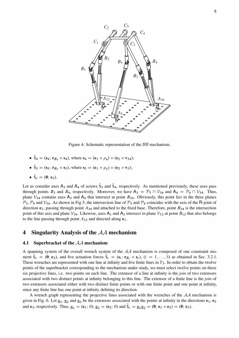
8
B1
B2
B3
B4B5
C1
C2
C3
C4
C5
A12 A34
A5
Figure 4: Schematic representation of the BB mechanism.
O$4 D .s4I rB4 s4/, where s4 D .e1 4/ .e2 v34/;
O$5 D .s5I rB5 s5/, where s5 D .e1 5/ .e2 v5/;
O$c D .0I e3/.
Let us consider axes A3 and A4 of screws O$3 and O$4, respectively. As mentioned previously, these axes pass
through points B3 and B4, respectively. Moreover, we have A3 D P3 \ V34 and A4 D P4 \ V34. Thus,
plane V34 contains axes A3 and A4 that intersect at point B34. Obviously, this point lies in the three planes
P3;P4 and V34. As shown in Fig 5, the intersection line of P3 and P4 coincides with the axis of the R-joint of
direction e1, passing through point A34 and attached to the fixed base. Therefore, point B34 is the intersection
point of this axis and plane V34. Likewise, axes A1 and A2 intersect in plane V12 at point B12 that also belongs
to the line passing through point A12 and directed along e1.
4 Singularity Analysis of the AA mechanism
4.1 Superbracket of the AA mechanism
A spanning system of the overall wrench system of the AA mechanism is composed of one constraint mo-
ment O$c D .0I e3/, and five actuation forces O$i D .si I rBi si /, .i D 1; : : : ; 5/ as obtained in Sec. 3.2.1.
These wrenches are represented with one line at infinity and five finite lines in P3. In order to obtain the twelve
points of the superbracket corresponding to the mechanism under study, we must select twelve points on these
six projective lines, i.e. two points on each line. The extensor of a line at infinity is the join of two extensors
associated with two distinct points at infinity belonging to this line. The extensor of a finite line is the join of
two extensors associated either with two distinct finite points or with one finite point and one point at infinity,
since any finite line has one point at infinity defining its direction.
A wrench graph representing the projective lines associated with the wrenches of the AA mechanism is
given in Fig. 6. Let e1, e2 and e3 be the extensors associated with the points at infinity in the directions e1, e2
and e3, respectively. Thus, e1 D .e1I 0/, e2 D .e2I 0/ and O$c D e1e2 D .0I e1 e2/ D .0I e3/.

9
B 1
B 2
B 3
B 4B 5
B 12
B 34A12 A34
A5
V12
V34
A3, A4
P1, P2
P3, P4
φ
θ
e1
e1
x
yz
Figure 5: Planes Pi and Vi for the BB mechanism.
Ω∞
R3
b12 b34 b5
e1
e2
e3
s1 s
2
s3
s4
s5
$1$2
$3$4
$5
$c
p1
p2
p3
p4
p5
v12
v34
v5
Figure 6: Wrench graph of the AA mechanism in P3.
Let pi, .i D 1; : : : ; 5/, be the extensor associated with the point at infinity in the direction i . Thus,
pi
D .i I 0/. The line at infinity e2e3 D .0I e2 e3/ D .0I e1/ passes through all points at infinity of
directions orthogonal to e1. Since i , .i D 1; : : : ; 5/, are orthogonal to e1, points pi
belong to e2e3.
Let v12, v34 and v5 be the extensors associated with the points at infinity in the directions v12, v34 and v5,

10
respectively. Thus, v12 D .v12I 0/, v34 D .v34I 0/ and v5 D .v5I 0/. Since v12, v34 and v5 are orthogonal
to e2, points v12, v34 and v5 belong to e1e3 D .0I e1 e3/ D .0I e2/.
The line at infinity LPiof plane Pi passes through p
iand e1, i.e., LPi
D e1piD .0I e1i /, .i D 1; : : : ; 5/.
Similarly, the lines at infinity of planes V12, V34 and V5 are LV12D e2v12 D .0I e2 v12/, LV34
D e2v34 D
.0I e2 v34/ and LV5D e2v5 D .0I e2 v5/.
Let b12, b34 and b5 be the extensors associated with points B12, B34 and B5, respectively, and let si ,
.i D 1; : : : ; 5/ represent the point at infinity of axis Ai . Since P1 \ V12 D A1, the lines at infinity of P1 and
V12 intersect at point s1. Accordingly,
s1 D LP1\ LV12
D e1p1^ e2v12 (5)
Likewise,
s2 D LP2\ LV12
D e1p2^ e2v12 (6)
s3 D LP3\ LV34
D e1p3^ e2v34 (7)
s4 D LP4\ LV34
D e1p4^ e2v34 (8)
s5 D LP5\ LV5
D e1p5^ e2v5 (9)
As a consequence, O$1 D b12s1, O$2 D b12s2, O$3 D b34s3, O$4 D b4s4, O$5 D b5s5 and O$c D e1e2. The
superbracket of the AA mechanism is expressed as follows:
SAA D Œb12s1; b12s2; b5s5; e1e2; b34s3; b34s4 (10)
4.2 Superbracket decomposition of the AA mechanism
From Eq. (1), the superbracket can be developed into a linear combination of 24 monomials. Since the bracket
of any four coplanar projective points is null, 20 among the 24 monomials of SAA are null. Therefore, SAA
takes the following simplified expression:
SAA D Œb12 b5 s5 b34Œb12 s1 s2 e1Œe2 s3 b34 s4 C Œb12 b5 s5 b34Œb12 s1 s2 e2Œe1 s3 b34 s4
C Œb12 e1 e2 b34Œb12 s1 s2 b5Œs5 s3 b34 s4 Œb12 e1 e2 b34Œb12 s1 s2 s5Œb5 s3 b34 s4
SAA D Œb12 b5 s5 b34
Œb12 s1 s2
e1Œ
e2s3b34 s4
C Œb12 e1 e2 b34
Œb12 s1 s2
b5Œ
s5s3b34 s4
(11)
where the dotted letters stand for permuted elements as explained in [11, 42]. The previous expression is
composed of two main terms X and Y , namely,
X D Œb12 b5 s5 b34
Œb12 s1 s2
e1Œ
e2s3b34 s4
(12)
Y D Œb12 e1 e2 b34
Œb12 s1 s2
b5Œ
s5s3b34 s4
(13)
The first term X is equal to zero when:
1. Œb12 b5 s5 b34 D 0 ) points b12, b5, b34 and s5
are coplanar;
2. .b12s1s2/^.s3b34s4/^.e
1e2/ D 0 ) the projective line (e
1e2) intersects the intersection line of planes
(b12s1s2) and .s3b34s4/. Plane (b12s1s2) is the plane containing the finite point B12 and the two points
at infinity s1
and s2
of directions s1 and s2, respectively. From Sec. 3.2.1, since plane V12 (respectively
V34) contains axes A1 and A2 (respectively A3 and A4) of the two screws O$1 and O$2 (respectively O$3 andO$4), we conclude that .b12s1s2/ V12 (respectively .s
3b34s4/ V34). Therefore,
.b12s1s2/ ^ .s3b34s4/ .V12 \ V34/ (14)
Moreover, the lines at infinity of planes V12 and V34 intersect at point e2. Thus, (b12s1s2/ ^ .s
3b34s4)
is a finite line of direction e2, which always intersects the line at infinity .e1e2/ at point e
2
4.
4More generally, the condition .b12s1s2/ ^ .s3b34s4/ ^ .e
1e2/ D 0 is verified when line (V12 \V34) lies in a plane having e3 as
normal vector.

11
Consequently, the first term X of Eq. (11) is always null and the superbracket of the AA mechanism is
reduced to:
SAA D Œb12 e1 e2 b34
Œb12 s1 s2
b5Œ
s5s3b34 s4
(15)
The singularity conditions of the AA mechanism correspond to the vanishing conditions of term Y that fall
into two main cases:
(a) Œb12 e1 e2 b34 D 0 ) points b12, b34, e1
and e2
are coplanar, which occurs if one of the following
conditions is verified:
(a.1) b12 b34, in this case points B12 and B34 coincide;
(a.2) b12 e1
(or b12 e2): impossible as a finite line cannot coincide with a point at infinity;
(a.3) b34 e1
(or b34 e2): impossible;
(a.4) e1
e2: impossible because e1 and e2 are two fixed independent directions;
(a.5) Points b12, e1
and e2
are aligned: impossible as a finite point cannot be aligned with two distinct
points at infinity;
(a.6) Points b34, e1
and e2
are aligned: impossible;
(a.7) Points b12, b34 and e1
are aligned: in this case (B12B34) is parallel to e1 as shown in Fig. 7(a);
(a.8) Points b12, b34 and e2
are aligned: in this case (B12B34) is parallel to e2;
(a.9) b12b34 ^ e1e2
D 0: in this case the point at infinity of line (B12B34) belongs to the line at infinity
e1e2. It means that line (B12B34) lies in a plane having e1 e2 as normal vector.
(b) .b12s1s2/ ^ .s3b34s4/ ^ .b5s5/ D 0, which occurs if one of the following conditions is verified:
(b.1) .b12s1s2/ D 0 ) plane .b12s1s2/ degenerates ) s1
s2, screws O$1 and O$2 are coaxial;
(b.2) .s3b34s4/ D 0 ) screws O$3 and O$4 are coaxial;
(b.3) .b5s5/ D 0 ) b5 s2: impossible;
(b.4) .b12s1s2/ .s3b34s4/ ) V12 and V34 are coplanar. Such a configuration is illustrated in Fig. 7(b);
(b.5) .b5s5/ 2 .b12s1s2/ ) the axis A5 of screw O$5 lies in plane V12;
(b.6) .b5s5/ 2 .s3b34s4/ ) A5 lies in V34;
(b.7) .b5s5/, namely, the actuation force O$5 intersects the intersection line of planes (b12s1s2) and .s3b34s4/,
namely, (V12 \ V34), as shown in Fig. 7(c). Thus, a singularity occurs if line .b5s5/ of direction
s5 and line (V12 \ V34) of direction e2 intersect. A particular case of this condition, illustrated
in Fig. 7(d), occurs if they intersect at infinity, i.e., if s5 k e2. This implies that 5 k e2, 5
being the direction of the actuated prismatic joint of the 5-th limb. Another particular case of this
condition happens when line (V12 \ V34) coincides with line .b5s5/, i.e., with axis A5.
From Eq. (15), a vector form for the singularity conditions can be expressed as follows:
n .e1 e2/
.s1 s2/ .s3 s4/
s5
D 0 (16)
where n is the unit vector of line .B12B34/.
4.3 Correspondence between GG and GCA
This paper, in contrast with most of the literature dealing with the singularity analysis of PMs, does not reject
one approach in favour of the other, i.e., GG and GCA, and it attempts to use both approaches as complementary
rather than regarding them as opposites. To do so, we resort to the results obtained in [32] for the singularity
analysis of the AA mechanism using the classification of linear varieties given in Table 2 that was presented
in [9]. By virtue of the results obtained with GCA, the whole singularity conditions for the AA mechanism are
made equivalent to the vanishing conditions of term Y . The latter can occur upon two different cases in which
the first case falls into nine sub-cases, with five excluded cases, and the second case results in seven different
cases where one was excluded.

12
(a) (b)
(c) (d)
e1
e2
e2
e2
$5
$5
B 12
B 34
V12
V12
V12
V34 V34
V34
V5
V5P5
P5
Figure 7: Singular configurations of the AA mechanism corresponding to cases (a.7), (b.4) and (b.7).
4.3.1 The first case: (a.1), (a.7), (a.8) and (a.9)
(a.1) If B12 B34, then the four actuation forces O$1, O$2, O$3 and O$4 will intersect at a common point. In that
case the foregoing forces span a variety of dimension three rather than four. From a theoretical stand
point, such a configuration corresponds to condition 3c of GG. However, for the proposed design of the
AA mechanism, this condition could be excluded.
(a.7) If B12B34 k e1, then the first axes (directed along e1) of the two U joints of the simplified arrangements
will coincide, as depicted in Fig. 7(a). By virtue of GG, in this case, two skew lines are transversal to
five lines. Reaching this step, based on Fig. 7(a), it is straightforward to conclude that the intersection
line of planes V12 and V34, namely, Tv k e2, is always concurrent with the axes of screws O$1; O$2; O$3; O$4
and O$c . On the other hand, when the first axes of both U joints are pointed to each other, there is a second
line, namely, .B12B34/ k e1, which crosses the foregoing five screws and which is skew with the first
transversal line, Tv, described above. Accordingly, this singularity is referred to as hyperbolic congru-
ence, condition 4b of GG, for which two skew lines are transversal to all lines. In such a configuration,
the five screws O$1; O$2; O$3; O$4 and O$c span a variety of dimension four rather than five.
(a.8) To explain this singularity, namely, B12B34 k e2, one should think beyond the classification given in [9].
From the classification proposed in [19] for some special cases in which a line at infinity is among a set
of Plücker lines, it reveals that this singularity corresponds to condition C21
4 . In this condition, two pairs

13
of lines, namely, fA1; A2g (the axes of O$1 and O$2) and fA3; A4g (the axes of O$3 and O$4), span two distinct
planes V12 and V34 whose projections into the plane perpendicular to the line at infinity, O$c , are parallel.
For the proposed design of the AA mechanism, this condition cannot occur.
(a.9) This case is a general condition that covers (a.7) and (a.8). From the above analysis for (a.7) and (a.8),
it can be inferred that all the configurations that condition (a.9) holds can be classified as hyperbolic
congruence, unless condition (a.8) is true. However, it can be noticed that C21
4 is the general condition
of (a.9).
Table 2: Singularity conditions of the AA mechanism: correspondence between GCA and GG.
Singularity Geometric Corresponding GLG
case (GCA) singularity condition singularity type
(a.1) B12 B34 3c, all lines through a point
(a.7) .B12B34/ k e1 4b, hyperbolic congruence
(a.8) .B12B34/ k e2 C21
4 , two pairs of concurrent lines
(a.9) .B12B34/ ? e1 e2 plus a line at infinity
(b.1) A1 A2 1, point
(b.2) A3 A4
(b.4) V12 V34 3d, all lines in a plane
5b, singular linear complex
(b.5) A5 2 V12
(b.6) A5 2 V34 5b, singular linear complex
.V12 \ V34/ A5
(b.7) s5 k e2
.V12 \ V34/ \ A5 ¤ ; 5b, singular linear complex
4c, parabolic congruence
4.3.2 The second case: (b.1), (b.2), (b.4), (b.5), (b.6) and (b.7)
(b.1) Only two conditions lead to coaxial O$1 and O$2: (a) P1 P2 and (b) v12 k e1 (this is also a limb
singularity5 where the actuation wrench becomes reciprocal to the input). In such a configuration, A1 D
.P1 \ V12/ coincides with A2 D .P2 \ V12/, namely, the three planes P1, P2 and V12 intersect at a
common line.
(b.2) Based on the above discussion, coaxial O$3 and O$4 happens upon two configurations: (a) P3 P4 and (b)
v34 k e1 (this is also a limb singularity).
(b.4) When V12 V34, axes A1; A2; A3 and A4 lie in a common plane and the screw system given by
span.O$1; O$2; O$3; O$4/ degenerates. Such a configuration is illustrated in Fig. 7(b) and corresponds to
condition 3d of GG, all lines in a plane. This case also corresponds to condition 5b of GG since in that
case the intersection line of V12 and V5, which is of direction e2, intersects the six screws of the overall
wrench system.
(b.5) We know that line .V12 \ V34/ is always concurrent with the axes of screws O$1; O$2; O$3 and O$4. As
mentioned previously, this line, being of direction e2, passes through the point at infinity e1. Therefore,
it crosses the line at infinity O$c D e1e2. If .b5s5/ 2 .b12s1s2/, then line .V12 \ V34/ also crosses screw
O$5 and, as a result, in such a configuration, this line crosses the six screws O$1; : : : ; O$5; and O$c . Based
on GG, this singularity is referred to as singular linear complex, condition 5b, which corresponds to a
variety of dimension five.
5Based on the results presented in [32], such a mechanism exhibits a limb singularity when v12 k e1 or i D 0.

14
(b.6) This case is similar to (b.5).
(b.7) In this case, O$5 passes through the intersection of two pairs of planes spanned by the set fA1; A2; A3; A4g
of the axes of screws O$1; O$2; O$3 and O$4. There are several possibilities for which this set can span different
pairs of planes. All these possibilities are studied in [32] and three cases turn out to be possible:
1. All planes Pi , i D 1; : : : ; 5, have a common intersection line. Clearly, this line called Tp is parallel
to e1. Thus, it is transversal to the line associated with the constraint wrench O$c . This singularity is
referred to as singular linear complex, condition 5b.
2. All planes Vi , i D 1; : : : ; 5, have a common intersection line. Obviously, this line called Tv is par-
allel to e2 and transversal to O$c . This singularity is referred to as singular linear complex, condition
5b. As mentioned previously, there is a particular configuration: s5 k e2, which implies that 5 k e2.
Such a configuration is illustrated in Fig. 7(d).
3. O$5 intersects the line passing through (B12B34). This is a parabolic congruence, condition 4c,
where the lines associated with O$1; O$2; O$3 and O$4 belong to the union of three planar pencils of
lines, in different planes, having a common line.
Table 2 illustrates the valid geometric singularity conditions of the AA mechanism obtained with GCA as well
as their corresponding GG singularity type.
4.4 Instantaneous motions associated with parallel singularities
Parallel singularities are critical configurations in which a PM loses its inherent stiffness and the motion of its
end-effector becomes uncontrollable. Since the AA mechanism is free of constraint singularities, its actuation
singularities correspond to the rank deficiency of J. In such configurations, the actuators of the PM cannot
control its end-effector’s motion, namely, the end-effector might generate some infinitesimal motion(s) even
when the actuators are locked. In each of these singularities, the wrenches O$1; O$2; O$3; O$4; O$5 and O$c form
a n < 6-system and the twist(s) reciprocal to this system for a given actuation singularity determine(s) the
uncontrolled motion of the end-effector [16].
(a.1) Theoretically, this corresponds to a configuration in which the four actuation forces $i (i D 1; : : : 4) pass
through a common point, namely, B12 B34. In that case, there exists a finite line .B12B5/, which
crosses the five actuation forces $i (i D 1; : : : 4). Let u and u D .uI 0/ be the unit vector and the point at
infinity of line B12B5, respectively. Two cases turn to be possible:
u 2 e1e2 , line .B12B5/ is orthogonal to e1 e2, i.e., it crosses O$c in addition to the five actuation
forces. In that case, the uncontrolled motion corresponds to a zero-pitch twist given by .uI rB12u/.
Thus, it is a pure rotation about an axis of direction u;
u … e1e2. In that case, one can find neither a zero-pitch twist nor an infinite-pitch twist reciprocal to
screws $1; : : : ; $5 and $c . Thus, the uncontrolled motion corresponds to a finite-pitch twist, namely,
a combination of a rotation and a translation.
(a.7),(a.8) and (a.9) A general condition for these cases is .B12B34/?e1 e2, which implies that a finite
line .B12B34/ crosses the five screws O$1; O$2; O$3; O$4 and O$c that form a 4-system. However, in these
cases, line .B12B34/ does not generally intersect O$5. It can be concluded that the uncontrolled motion
corresponds to a finite-pitch twist.
(b.1) In this condition, screws O$1 and O$2 are coaxial. It could be noticed that the condition P1 P2 appears
to be impossible for the proposed mechanism. On the other hand, if v12 k e1, the mechanisms exhibits
simultaneously an actuation singularity (O$1 and O$2 are coaxial) and two limb singularities (O$1 and O$2 are
reciprocal to the twists associated with the actuated prismatic joints of the first and the second limbs). As
s1 k s2 k e1 in such a configuration, the mechanism loses the translational DOF along e1.
(b.2) This condition can be analyzed similarly to (b.1).

15
(b.4) In that case a line in plane V12 V34 of direction e2 is reciprocal to the five screws O$1; O$2; O$3; O$4 and O$c
but not necessarily reciprocal to O$5. Thus, this case is similar to (a.9), namely, the uncontrolled motion
corresponds to a finite-pitch twist.
(b.5),(b.6) and (b.7) In these cases, line .V12 \ V34/ crosses axis A5 of screw O$5. As mentioned previously,
this implies that line .V12 \ V34/ of direction e2 crosses the six wrenches O$1; O$2; O$3; O$4; O$5 and O$c .
Accordingly, in all of these cases, the actuators cannot control the rotational DOF of the moving platform
about an axis of direction e2.
5 Singularity Analysis of the BB mechanism
5.1 Superbracket of the BB mechanism
Ω∞
R3
b12 b34 b5
b1
b2
b3
b4
e1
e2
e3
$1$2
$3$4
$5
$c
s1 s
2
s3
s4
s5
p1
p2
p3
p4
p5
v12
v34
v5
Figure 8: Wrench graph of the BB mechanism in P3.
For the BB mechanism, extensors si, i D 1; : : : ; 5, are obtained similarly to the AA mechanism. Let
b12, b34, b1, b2, b3, b4 and b5 be the 1-extensors associated with points B12, B34, B1, B2, B3, B4 and B5,
respectively. Since lines (B1B2) and (B3B4) are parallel to e2, b1b2 and b3b4 intersect 1 at e2. Figure 8
shows the wrench graph of the BB mechanism in P3.
The projective line associated with O$c D .0I e1 e2/ passes through the points at infinity e1
and e2.
Similarly to the AA mechanism, screw O$5 is represented by b5s5, where s5
D .s5I 0/ is the point at infinity
of direction s5. In what concerns screws O$i (i D 1; : : : ; 4), several representations turn to be possible. As an
example, let us consider screw O$1. Since the projective line associated with this screw passes through points b1,
b12 and s1, the 2-extensor associated with this screw can be expressed as the join of two among these three
points. The superbracket must be chosen in such a way that we obtain the simplest expression. Therefore,
all relations between the corresponding projective elements must be considered. Since b12 is a common point
of O$1 and O$2, it must be part of the two points representing O$1 in the superbracket. Thus, the second point is
either b1 or s1. Since b1 and b2 are aligned with e
2as well as b3 and b4, we choose to include points bi in the
superbracket of this PM rather than si, i D 1; : : : ; 4. However, for the superbracket of the BB mechanism, the
use of bi or si, i D 1; : : : ; 4, leads to the same number of monomials in the simplified expression. Accordingly,

16
the superbracket of the BB mechanism takes the form:
SBB D Œb12b1; b12b2; b5s5; e1e2; b34b3; b34b4 D Œb12s1; b12s2; b5s5; e1e2; b34s3; b34s4
D Œb12 e1 e2 b34
Œb12 b1 b2
b5Œ
s5b3 b34 b4
Œb12 b5 s5 b34
Œb12 b1 b2
e1Œ
e2b3 b34 b4
D Œb12 e1 e2 b34
Œb12 b1 b2
b5Œ
s5b3 b34 b4
(17)
The singularity conditions of the BB mechanism correspond to the vanishing conditions of SBB that fall into
two main cases:
(a) Œb12 e1 e2 b34 D 0 ) points b12, b34, e1
and e2
are coplanar, which can occur upon one of the following
subcases:
(a.1) Points B12 and B34 coincide;
(a.2) Line .B12B34/ is parallel to e1;
(a.3) Line .B12B34/ is parallel to e2;
(a.4) Line .B12B34/ is orthogonal to e1 e2.
(b) .b12b1b2/ ^ .b3b34b4/ ^ .b5s5/ D 0, which occurs if one of the following conditions is verified:
(b.1) Points B12, B1 and B2 are aligned (or two of them coincide), in this case, screws O$1 and O$2 are
coaxial;
(b.2) Screws O$3 and O$4 are coaxial;
(b.3) Planes V12 and V34 coincide;
(b.4) Axis A5 of screw O$5 lies in plane V12;
(b.5) A5 lies in V34;
(b.6) The intersection line of planes V12 and V34 coincides with A5;
(b.7) A5 is directed along e2, i.e., s5 is parallel to e2. This implies that 5 k e2;
(b.8) (V12 \ V34) and A5 are concurrent.
As mentioned in Sec. 3.2.2, for the BB mechanism, point B12 (respectively B34) belongs to the axis,
directed along e1, of the R-joint centered at A12 (respectively A34) and attached to the fixed base. Thus, the
second and third Cartesian coordinates of point B12 (respectively B34) are the same as those of point A12
(respectively A34). As pointed out in [33], a BB mechanism has a singular orientation for , called s , which
depends on the geometric parameters of the base and can be found by expanding condition (a.4):
.yA12 yA34
/ sin s C .zA12 zA34
/ cos s D 0 (18)
where ŒxA12; yA12
; zA12T and ŒxA34
; yA34; zA34
T are the Cartesian coordinate vectors of points A12 and A34,
respectively. For instance, for the design proposed in Fig. 4; s D 0.
6 Conclusions
This paper presented an exhaustive singularity analysis of two 3T2R 5-DOF Parallel Mechanisms (PMs) having
a simplified architecture. The proposed singularity analysis approach is applicable to lower-mobility PMs,
mainly those having infinite-pitch wrench(es) among the rows of their Jacobian matrix. For a given PM, this
approach consists of three main steps:
(i) The use of screw theory to represent the wrenches of the PM in the projective space. This representation is
very useful since it illustrates all the geometric relations between the wrenches of the PM and allows the
simplification of the superbracket decomposition.

17
(ii) The use of Grassmann-Cayley Algebra (GCA) to enumerate all the singularity conditions of the PMs under
study and to derive a vector expression for the singularity locus, which is difficult to obtain for such PMs
with other singularity analysis methods.
(iii) The use of Grassmann Geometry (GG) to examine the rank deficiency of the Jacobian matrix and charac-
terize the uncontrolled motion for a given singularity condition.
This paper showed that GCA and GG could be used together in order to better characterize and investigate the
singularities of spatial parallel mechanisms. The proposed approach is currently used by the authors to analyze
the singularities of other types of 5-DOF PMs like 3R2T PMs.
Acknowledgments
The authors would like to acknowledge the financial support of the Natural Sciences and Engineering Research
Council of Canada (NSERC), the Canada Research Chair program and the French “Agence Nationale de la
Recherche” (Project “SiRoPa”, SIngularités des RObots PArallèles).
References
[1] J. P. Merlet. Singular Configurations of Parallel Manipulators and Grassmann Geometry. The Interna-
tional Journal of Robotics Research, 8(5):45–56, 1989.
[2] P. Ben-Horin and M. Shoham. Singularity Analysis of a Class of Parallel Robots Based on Grassmann–
Cayley Algebra. Mechanism and Machine Theory, 41(8):958–970, 2006.
[3] C. Gosselin and J. Angeles. Singularity Analysis of Closed-Loop Kinematic Chains. IEEE Transactions
on Robotics and Automation, 6(3):281–290, 1990.
[4] Y. Fang and L. W. Tsai. Structure Synthesis of a Class of 4-DoF and 5-DoF Parallel Manipulators with
Identical Limb Structures. The International Journal of Robotics Research, 21(9):799–810, 2002.
[5] M. Conconi and M. Carricato. A New Assessment of Singularities of Parallel Kinematic Chains. In
Advances in Robot Kinematics: Analysis and Design, pages 3–12, 2008.
[6] D. Zlatanov, R. G. Fenton, and B. Benhabib. Singularity Analysis of Mechanisms and Robots Via a
Velocity-Equation Model of the Instantaneous Kinematics. In IEEE International Conference on Robotics
and Automation, pages 986–991, San Diego, CA, 1994.
[7] D. Zlatanov, I. Bonev, and C. M. Gosselin. Constraint Singularities of Parallel Mechanisms. In IEEE
International Conference on Robotics and Automation, pages 496–502, Washington, D.C., May 11U15
2002.
[8] S. A. Joshi and L. W. Tsai. Jacobian Analysis of Limited-DOF Parallel Manipulators. ASME Journal of
Mechanical Design, 124(2):254–258, June 2002.
[9] J. P. Merlet. Parallel Robots, volume 128 of Solid Mechanics and Its Applications. Springer, 2006.
[10] T. Mbarek, G. Lonij, and B. Corves. Singularity Analysis of a Fully Parallel Manipulator with Five-
Degrees-of-Freedom Based on Grassmann Line Geometry. In 12th IFToMM World Congress, BesanAgon,
France, June 18-21 2007.
[11] P. Ben-Horin and M. Shoham. Application of Grassmann–Cayley Algebra to Geometrical Interpretation
of Parallel Robot Singularities. The International Journal of Robotics Research, 28(1):127–141, 2009.
[12] N. L. White. Grassmann–Cayley Algebra and Robotics. Journal of Intelligent and Robotic Systems,
11(1):91–107, 1994.

18
[13] B. Monsarrat and C. Gosselin. Singularity Analysis of a Three-leg Six-Degree-Of-Freedom Parallel Plat-
form Mechanism Based on Grassmann Line Geometry. The International Journal of Robotics Research,
20(4):312–328, 2001.
[14] E. Staffetti and F. Thomas. Kinestatic Analysis of Serial and Parallel Robot Manipulators Using
Grassmann-Cayley Algebra. In J. Lenarcic and M. M. Stanisic, editors, Advances in Robot Kinematics,
pages 17–26, 2000.
[15] T. K. Tanev. Geometric Algebra Approach to Singularity of Parallel Manipulators with Limited Mobility.
In Advances in Robot Kinematics, pages 8–39. Springer, 2008.
[16] A. Wolf and M. Shoham. Investigation of Parallel Manipulators using Linear Complex Approximation.
ASME Journal of Mechanical Design, 125:564–572, 2003.
[17] M. Tale Masouleh, C. Gosselin, M. Husty, and D. R. Walter. Forward Kinematic Problem of 5-RPUR
Parallel Mechanisms (3T2R) with Identical Limb Structures. Mechanism and Machine Theory, 46(7):945
–959wolf2006screw, 2011.
[18] M. Tale Masouleh, M. Husty, and C. Gosselin. Forward Kinematic Problem of 5-PRUR Parallel Mecha-
nisms Using Study Parameters. In Advances in Robot Kinematics: Motion in Man and Machine, pages
211–221. Springer, 2010.
[19] M. Tale Masouleh. Kinematic Analysis of Five-DOF (3T2R) Parallel Mechanisms with Identical Limb
Structures. PhD thesis, Laval University, Quebec, QC, Canada, September 2010.
[20] X. Kong and C. Gosselin. Type Synthesis of Parallel Mechanisms, volume 33. Springer, Heidelberg, 2007.
[21] F. Gao, B. Peng, H. Zhao, and W. Li. A Novel 5-DOF Fully Parallel Kinematic Machine Tool. The
International Journal of Advanced Manufacturing Technology, 31(1):201–207, 2006.
[22] O. Piccin, B. Bayle, B. Maurin, and M. de Mathelin. Kinematic Modeling of a 5-DOF Parallel Mechanism
for Semi-Spherical Workspace. Mechanism and Machine Theory, 44(8):1485–1496, 2009.
[23] Z. Huang and Q. C. Li. General Methodology for Type Synthesis of Symmetrical Lower-Mobility Par-
allel Manipulators and Several Novel Manipulators. The International Journal of Robotics Research,
21(2):131–145, 2002.
[24] Z. Huang and Q. C. Li. Type Synthesis of Symmetrical Lower-Mobility Parallel Mechanisms using the
Constraint–Synthesis Method. The International Journal of Robotics Research, 22(1):59–79, 2003.
[25] X. Kong and C. Gosselin. Type Synthesis of 5-DOF Parallel Manipulators Based on Screw Theory.
Journal of Robotic Systems, 22(10):535–547, 2005.
[26] S. J. Zhu and Z. Huang. Eighteen Fully Symmetrical 5-DoF 3R2T Parallel Manipulators with Better
Actuating Modes. The International Journal of Advanced Manufacturing Technology, 34(3):406–412,
2007.
[27] Z. Huang and Q. C. Li. Two Novel Symmetrical 5-DOF Parallel Mechanisms. Journal of Yanshan
University, 25(4):283–286, 2001.
[28] Q. Jin, T. L. Yang, A. X. Liu, H. P. Shen, and F. H. Yao. Structure Synthesis of a Class of 5–DOF Parallel
Robot Mechanisms Based on Single Opened–Chain Units. In ASME 2001 Design Engineering Technical
Conferences, number DAC21153 in DETC2001, Pittsburgh, PA, 2001.
[29] T. Mbarek, I. Barmann, and B. Corves. Fully Parallel Structures with Five Degree of Freedom: Systematic
Classification and Determination of Workspace. In Proceedings of Mechatronics & Robotics, pages 990–
996, Aachen, 2004.
[30] J. Wang and C. Gosselin. Kinematic Analysis and Singularity Representation of Spatial Five-Degree-of-
Freedom Parallel Mechanisms. Journal of Robotic Systems, 14(12):851–869, 1997.
19
[31] C. Gosselin, M. Tale Masouleh, V. Duchaine, P. L. Richard, S. Foucault, and X. Kong. Parallel Mech-
anisms of the Multipteron Family: Kinematic Architectures and Benchmarking. In IEEE International
Conference on Robotics and Automation, pages 555–560, Roma, Italy, April 2007.
[32] M. Tale Masouleh and C. Gosselin. Singularity Analysis of 5-RPRRR Parallel Mechanisms via Grass-
mann Line Geometry. In Proceedings of the 2009 ASME Design Engineering Technical Conferences,
number 86261 in DETC2009, 2009.
[33] M. Tale Masouleh, M. H. Saadatzi, C. Gosselin, and H. D. Taghirad. A Geometric Constructive Approach
for the Workspace Analysis of Symmetrical 5-PRUR Parallel Mechanisms (3T2R). In ASME Design
Engineering Technical Conferences, number 28509 in DETC2010, Montreal, Quebec, Canada, August
15-18 2010.
[34] M. Tale Masouleh and C. Gosselin. Kinematic Analysis and Singularity Representation of 5-RPRRR
Parallel Mechanisms. In Fundamental Issues and Future Research Directions for Parallel Mechanisms
and Manipulators, pages 79–90, Montpellier, France, September 21-22 2008.
[35] D. Kanaan, P. Wenger, S. Caro, and D. Chablat. Singularity Analysis of Lower-Mobility Parallel Manipu-
lators using Grassmann–Cayley Algebra. IEEE Transactions on Robotics, 25:995–1004, 2009.
[36] S. Amine, D. Kanaan, S. Caro, and P. Wenger. Singularity Analysis of Lower-Mobility Parallel Robots
with an Articulated Nacelle. In Advances in Robot Kinematics: Motion in Man and Machine 2010, Part
5, pages 273–282. Springer, 2010.
[37] S. Amine, D. Kanaan, S. Caro, and P. Wenger. Constraint and Singularity Analysis of Lower-Mobility Par-
allel Manipulators with Parallelogram Joints. In ASME 2010 International Design Engineering Technical
Conferences, number 28483 in DETC2010, Montreal, Quebec, Canada, August 15-18 2010.
[38] R. S. Ball. A Treatise On the Theory of Screws. Cambridge University Press, Cambridge, CA, 1900.
[39] K. J. Waldron. The Mobility of Linkages. PhD Thesis, Stanford University, Cambridge, CA, 1969.
[40] K. H. Hunt. Kinematic Geometry of Mechanisms. Clarendon Press, Oxford, 1978.
[41] A. Wolf and M. Shoham. Screw theory tools for the synthesis of the geometry of a parallel robot for a
given instantaneous task. Mechanism and Machine Theory, 41(6):945 –959, 2006.
[42] N. L. White. Grassmann-Cayley Algebra and Robotics Applications, volume VIII. Handbook of Geomet-
ric Computing, 2005.
[43] T. Huang, H. T. Liu, and D. G. Chetwynd. Generalized Jacobian analysis of lower mobility manipulators.
Mechanism and Machine Theory, 46(6):831–844, 2011.
[44] T. McMillan. Invariants of Antisymmetric Tensors. PhD Thesis, University of Florida, 1990.
[45] J. P. Merlet. Parallel Manipulators. Part 2: Theory. Singular Configurations and Grassmann Geometry.
Technical Report 791, INRIA, Sophia Antipolis, France, 1988.
[46] I. A. Bonev and C. M. Gosselin. Geometric Algorithms for the Computation of the Constant-Orientation
Workspace and Singularity Surface of a Special 6-RUS Parallel Manipulator. In ASME 2002 Design
Engineering Technical Conferences, number MECH-34257 in DETC2002, Montreal, Quebec, Canada,
September 29–October 2 2002.
Related Documents


![Cayley Graphs of Free Groups - math.columbia.edualessandrini/Courses... · Cayley Graphs of Free Groups (3.3) Theorem 3.3.1 Cayley Graphs of Free Groups Cayley graph Cay(𝒁/2, [1])](https://static.cupdf.com/doc/110x72/5f0f0c067e708231d44239c6/cayley-graphs-of-free-groups-math-alessandrinicourses-cayley-graphs-of.jpg)