y ... I r . ,. SINGLE SEBAND RADIO COMMUNICATIONS EQUIPMENT TYPE - SSB-J ADDENDUM 'No. 2. June 1957 This Addendum applies to all sets wi Serial Numbers 5701 and above.. It covers the following modifications. 1. Add shorting sections to Switch Wafers S201, D, H, and I. 2. Add Auxiliary Channel Switch wafer S201 -J. 3. Add Auxiliary Channel Switch Terminal Board, TB202. 4. Add Receiver Antenna Lin, TB201. 5. Add R287 d R288. Schematic Diagram D1259266 is to be used for all sets with Serial numbers 5701 and above. FILTER TYPES: Only one type of Mechanical Filter is used in sets having Serial Numbers 5701 and above. This is the RCA type, MFU - 250 - 1, and will pass a sideband of approximately 3 kc wide while rejecting the 250 kc carrier. The accessory components required for this filter are listed in the Parts List cov- ering Addendum No. 2. The five additions constituting Addendum No. 2 provide better oper- ation and flexibility for the SSB-1 Transmitter-Receiver. Explanation for these add- itions is as follows: Item 1. The shorting sections of the switch wafers S201-D, H, and I, re- move the unused coils from the radio frequency circuits of the transmitter and re- ceiver, thus reducing losses and improving efficiency. Item 2. The Auxiliary Channel switch wer, S201-J is an extension of the channel Selector Switch. The five contacts of this wafer are brought out to a ter- minal board (TB202}. One contact is common to all the other contacts so that a AC or DC c urrent may be applied in series with a control device such as a relay indicator lamp, etc. Item 3. The Auxiliary Channel Switch Terminal Board (TB202} provides a terminal connection for the Auxiliary Channel switch and any outer contacts requir- ed for control operation of auxiliary equipment. Item 4. The Antenna Link on TB201 is removed when a pre-amplifier for the receiver or a linear power amplifier to follow the transmitter power amplifier is required. The input and output terminals of such amplifiers are connected to terminals B and A. Item 5. The resistors R287 and R288 connected across L220 and L221 re- spectively provide greater receiver stability for channels 1 and 2 thus improving reception on these channels. Refer to Transmitter Receiver Schematic (Figure 29-C}.

Welcome message from author
This document is posted to help you gain knowledge. Please leave a comment to let me know what you think about it! Share it to your friends and learn new things together.
Transcript
y ...
I r
. ,.
SINGLE SIDEBAND
RADIO COMMUNICATIONS EQUIPMENT
TYPE - SSB-J
ADDENDUM 'No. 2.
June 1957
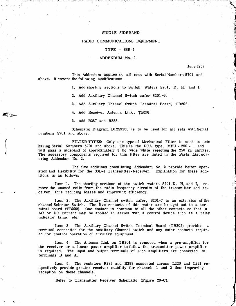
This Addendum applies to all sets with Serial Numbers 5701 and above.. It covers the following modifications.
1. Add shorting sections to Switch Wafers S201, D, H, and I.
2. Add Auxiliary Channel Switch wafer S201 -J.
3. Add Auxiliary Channel Switch Terminal Board, TB202.
4. Add Receiver Antenna Lint), TB201.
5. Add R287 and R288.
Schematic Diagram D1259266 is to be used for all sets with Serial numbers 5701 and above.
FILTER TYPES: Only one type of Mechanical Filter is used in sets having Serial Numbers 5701 and above. This is the RCA type, MFU - 250 - 1, and will pass a sideband of approximately 3 kc wide while rejecting the 250 kc carrier. The accessory components required for this filter are listed in the Parts List covering Addendum No. 2.
The five additions constituting Addendum No. 2 provide better operation and flexibility for the SSB-1 Transmitter-Receiver. Explanation for these additions is as follows:
Item 1. The shorting sections of the switch wafers S201-D, H, and I, remove the unused coils from the radio frequency circuits of the transmitter and receiver, thus reducing losses and improving efficiency.
Item 2. The Auxiliary Channel switch wafer, S201-J is an extension of the channel Selector Switch. The five contacts of this wafer are brought out to a terminal board (TB202}. One contact is common to all the other contacts so that a AC or DC current may be applied in series with a control device such as a relay indicator lamp, etc.
Item 3. The Auxiliary Channel Switch Terminal Board (TB202} provides a terminal connection for the Auxiliary Channel switch and any outer contacts required for control operation of auxiliary equipment.
Item 4. The Antenna Link on TB201 is removed when a pre-amplifier for the receiver or a linear power amplifier to follow the transmitter power amplifier is required. The input and output terminals of such amplifiers are connected to terminals B and A.
Item 5. The resistors R287 and R288 connected across L220 and L221 respectively provide greater receiver stability for channels 1 and 2 thus improving reception on these channels.
Refer to Transmitter Receiver Schematic (Figure 29-C} .
f:
PARTS LIST
-,
Reference
I c Locating
Function Name and Description Stock Number
Symbol g 0
SSB-1 FOr Serial Numbers
T R A N S M IT T E R - R E C E IV E R U N I T $701 and above
C238 4 I F120l Input Capacitor, Mica: 360 uuf'. ±2% 500 V de; GM.206316-G.
0242 I I FL201 Output I Same as C238.
029) FL202 Input I Same as 0238.
0294 FL202 Output I Same as 02)8.
0312
C313
0314
C315
4 I FL201 Input
FL201 Output
FL202 Input
FL202 Output
FL201 I 21 Trmsmitter Sideband
FL202'
R285
Receiver Sideband
21 FL201 attenuatictn
R286 I I n.201 attenuat:i..on
R287 2 1 L220 swamper
R288 L221 swamper
!jl SERIAL NO.
Capacitor, V.C.t 20-125 uut. Centralab 82.3-AN
Same as C312.
Same as 0238.
Same as 02,38
FILTER, Mechanical: Band-pass 250 kc; Upper side-band; 3 kc band-width at 6db.
Type RCA MFU-250-1.
Sae as F1201.
Resistor, Comp; 15,000 ohms l/2 w.
±10%
Sate as R285
Resistor, comp; 101000 ohms flO% Jan RC20BF103k.
Same as R287.
AUXILIARY CHANNEL SW
0 11t/l'' CHANNEL 1
CHANNEL 2
l CHANNEL 3
CHANNEL 4
- COMMON
006-274
087-175
136-o36
'I IIIII• RECEIVER A�T. LINK ����
A-B
1!.:� f)�l R E C ANT.
....
�,
•·
.....


l t
J
(
(
'
0967-108-2011
T - 1 TO NAVSHIPS 92917
TEMPORARY CORRECTION T-1TO THE TECHNICAL MANUAL FOR TYPE SSB-1 SINGLE- SIDEBAND RADIO COMMUNICATION EQU IP.MENT (NAVSHIPS 92917).
Temporary Correction T-1 does not apply to NAVSHIPS 92917 until Fjeld Change Number 1 has been accomplished. Therefore DO NOT correct the Technical Manual until the field change has been accomplished.
Field Change Number 1-SSB-1 applies to all Single-Sideband Radio Communica .. tion Equipment. Its purpose is to provide satisfactory operation of tht: SingleSideband Radio Communication Equipment, SSB-1, from standard naval remote system.
Correct the · Technical Manual with pen and ink in accordance with the following instructions. Make whatever deletions are necessary and where there is insufficient space on the given page to insert the corrective or added data, merely make the "f<?llowing notation along side of the affected text or diagram "See T -1 "
Arter the following co�ctiona have been IISde, staple these pages on the reverse side ot the front cover ot the manual as a permanent record.
Page Ref.
Title
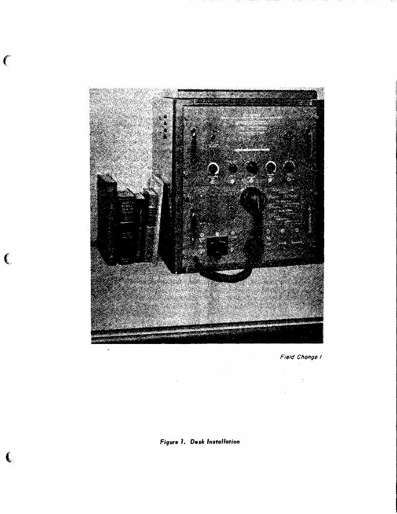
Figure 1.
1 Para. III.
2 Illustrations
4 TRANSMITTER
1 MAY 1958
Corrections To Be Made
Delete 11230" -- - · ---- -- - ----- --- ------------- -·-·- ---------- - --
Paste new Figure 1 over original Figure l -- -- - ------ ---- - -------
Delete 11 Telephone" in paragraph III. 5.
Delete reference to Figure 19.
· ·--· ------- -- --
AUDIO INPUT Change sub-paragraph a) to read as follows:
a) Single Button Carbon Microphone From Local Handset or From Standard Navy Remote System.
- - - - - · --- ·-
1 (of _16 pages)

T-1 TO NAVSHIPS 92917
Page Ref.
5 LINE VOLTAGE
5 LAMPS
7 Figure 3
8 Section I Para. 5
8 Section I Para. 6
12 Section II Para. 4.h.
13 Figure 6
14 Section II Para. 4. h.
14 Section II Para. 5
Corrections To Be Made -� �-=:i Delete '' 230"
Change "5" to "2" --.... - - -··
Paste new Figure 3 over original Figure 3
Delete the entire last sub-paragraph.
Change the second sub-paragraph to read as follows:
The equipment operates from 115 volt, 50 to 60 cycle single phase
-----
----- · ·- · · -
power source and requires approximately 310 watts for full power output. The equipment is connected to the standard navy remote system by a twelve wire cable for the control circuits, and a two wire audio cable for external speakers.
Line 3. Change "T-106" to "T-107"
Paste new Figure 6 over Qriginal Figure 6.
Line 10. Change to read as follows:
"operation or remote operation." - ---
Change sub-paragraph�· to read as follows:
a. Input voltage to the power supply -circuit is 115 volts, 50/60 cycle. Refer to figure 6.
'
!
�---- ------
1 MAY 1958 2 (of 16 pages)
+(l
)
.,. �.ifil
..

..
(
(
(
T-1 TO NAVSHIPS 92917
Page
14
Ref.
Section IIXX Para. 5
---··-···-
Corrections To Be Made -·------
Change sub-paragraph � · to read as follow�-
d. Turning TRANSMITTER switc b Sl03, on energizes realy K102 K-1'02 applies power to the pnmary of transformers TlOl, T102. and Tl08. TlOl supplies filament power for all the transmitter tubes. Tl 0 Zr supplies plate voltages for the HV rectifiers VlOl and V102 (type 5R 4GY), connected in a fullwave center tap circuit with plates in parallel to supply + 600 volts de through a single-section choke in·put filter to the plates of power amplifiers V201 and V202. Tl08 secondary supplies -20 volts de through a rectifier, ZIOl, and a double-'section choke input filter for the standard navy remote system.
t-----+----------+---------------------------- -- ---
14 Section IIXX Para. 5
Change sub-paragraph�· to read as follows�
�· LOCAL-REMOTE switch Sl06 selects the local handset or any one of the remote units which may be connected to the standard navy remote system. It switches the microphone circuit, the -20 volts de control voltage, the TransmHter Start-Stop control circuit and the power for the indicator lamp at the selected remote position. I
I ---- ·- -1
15 Line 1. Change "may be either ll5v or l30vx !
1---- --t-------- +-------a
_
c
_,
_
"
_
t
_o
_
r
_
e
_
a
_
d
_
'
_
'i
_
s 115v ac, ". �
Section III Para. 4
I I Section III
I j' Para. 4 Delete all reference to "230v, 50/60cps " 15
1 MAY 1958 3 {of 16 pages)

T-1 TO NAVSHIPS 92917
Page
15
22
Ref
Section III Para. 5.
Figure 10
Corrections To B e Made
Change paragraph 5. to read as fo1lows:
5. REMOTE CONNECTIONS.
Connections for remote stations are provided at terminal board T B 103 on the power supply chassis. Connections are made through the standard navy remote system. Control circuit connecti.ons are made using a MSCA-12 Cable. Audio connections are made using a TTHFWA-11/2 Cable connected to terminals 13 and
14 of TB103.
Paste new Figure 10 over original Figure 10.
I --- I
23
23
23
23
23
Section IV Par·a. 2.
Section IV Para. 2.
Figure 11.
Section IV Para. 2. c.
Section IV Para. 2. c.
1 MAY 1958
Line l. Change to read as follows:
Operation of a simplex radio telephone station using an SSB-1 with the standard navy remote system as shown in figure ll is as follows:
Change sub-paragraph�· (3) to read as follows:
(3) Turn TRANSMITTER switch@on.
Delete remote numbers 2 and 3.
Change sub-paragraph (2) to read as follows:
(2) On the power supply chassis, turn LOCAL-REMOTE switch @to Remote position.
Delete sub-paragraphs (3), (4), and (5). Add new sub-paragraph (3) as follows:
4 ( of16 Pages)
..
..
i��
''). '"
'�

(
(
l
T-1 TO NAVSHIPS 92917
Page Ref. Corrections To Be Made I ------
23
24
24
34
39
40
4 2
52
Section IV Para" 2. c. {continueQ)
Table 1 Power Supply Unit
Table 1 Power Supply Unit
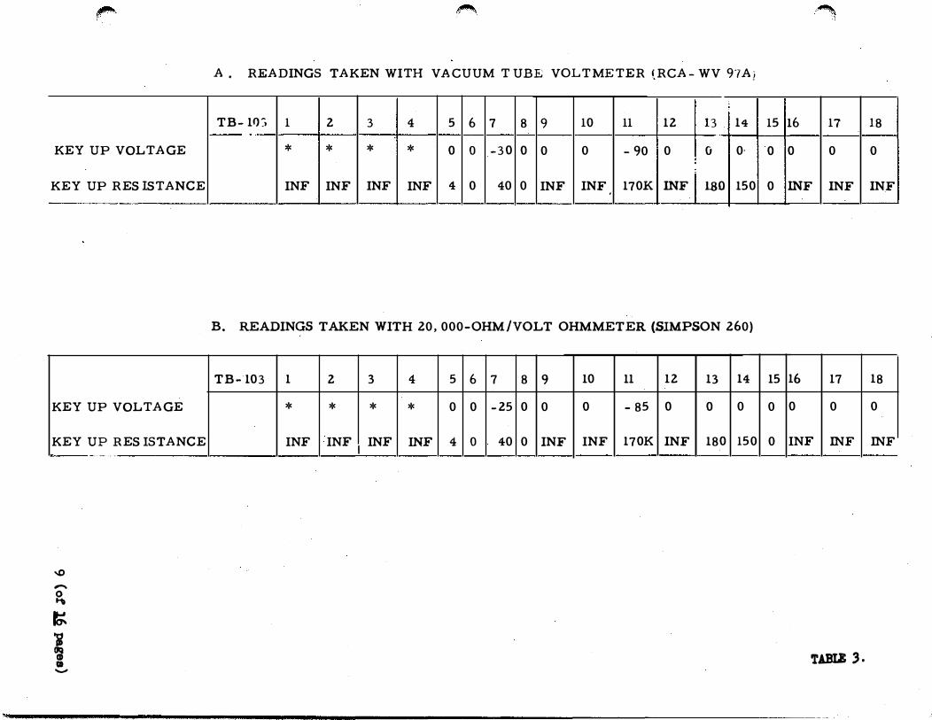
Table 3.
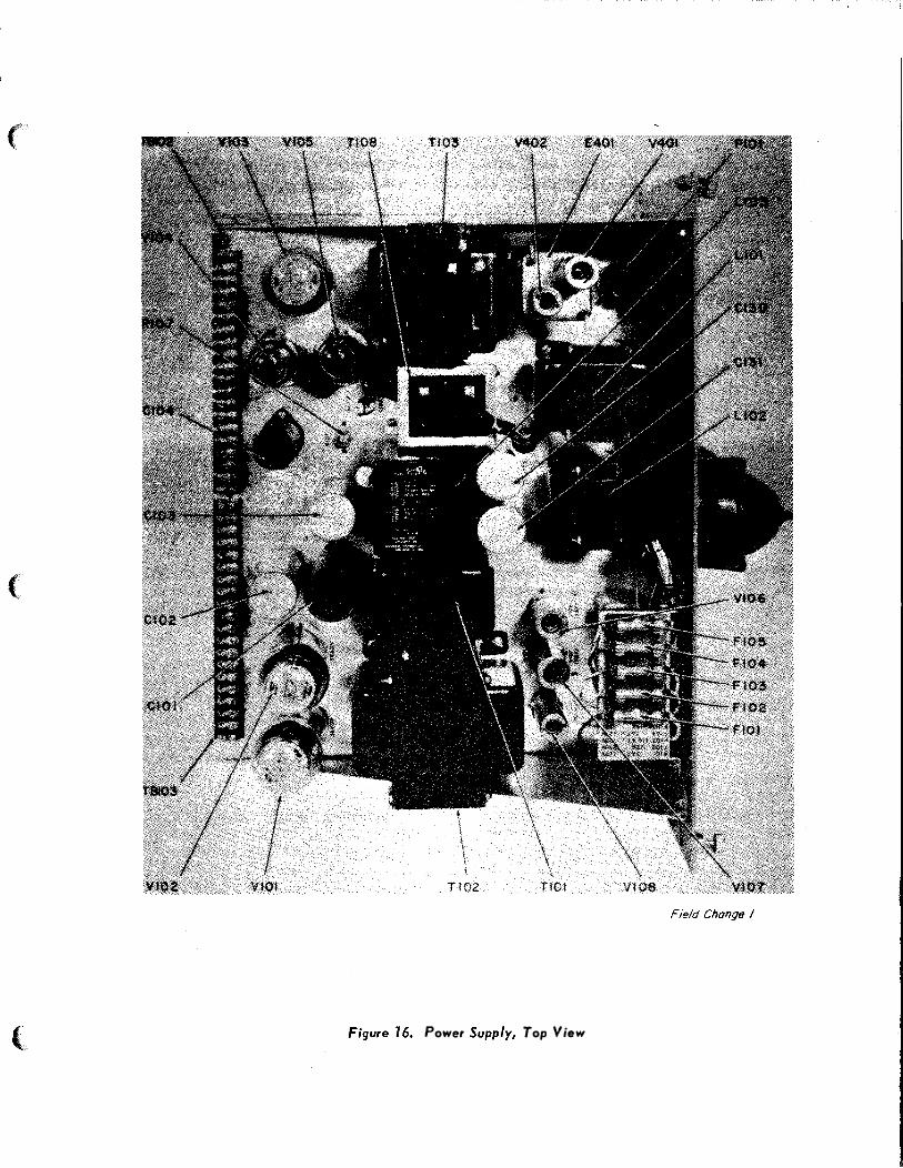
Figure 16.
Figure 17.
Figure 19.
PARTS LIST
-1-------- .... ·'· · · - - .. ----
1 MAY 1958
t
I
(3) The standard navy remote system is used for remote operation of the SSB-1 equipment. The system may be monitored by plugging a headset into the PHONES jack. This circuit monitors both transmitted and received signals. The received signal only may be monitored on the speaker by turning switch F to SPEAKER.
LOCAL-REMOTE, Column 2. Change "4" to II 211 •
Column 3. Change line 2 to read as follows:
"standard navy remote system. 11
Delete all references to "REMOTE INDICATORS -1-2-3"·
Change TB-10 3 to read terminals 1 through 18 '!"'es pectively. Make corrections as per Table 3 this bulletin.
H - -- I Paste new Figure 16 over original Figure 16.
---------
Paste new Figure 17 over original Figure 17. -----------
Delete Figure 19.
After Cl 29 add the following:
Cl30
Cl31
2 Filter capacitor in power supply
Filter
Capacitor, Electrolytic, 2000 mfd. � 15 v, Federal Stock Number N5910- 244-5513
Same as Cl30
5 (of 16 pages)
'

T-1 TO NAVSHIPS 92917
-------- ------�-------------------
Page Ref Corrections To Be Made I --------
57 PARTS LIST
59 PARTS LIST
59 PARTS LIST
62 PARTS LIST
' 63 PARTS LIST
63 PARTS LIST
l MAY 1958
Delete all reference to DS104, DS105, and DS106.
After KlOl add the following:
Kl02 1 Start-stop relay
After Ll02 add the following:
Ll03 1 filter choke
Relay, coil 115 vac., 50/60 cycles. contacts dpst StruthersDunn type 21BDXX101 Federal Stock Number N5945-645-1954,
Inductance, Dual Section,
0 8h., 7v rms, 120 cps., 600 rna .. Federal Stock Number N5950-637- 6433.
Delete all reference to Rl38, Rl39, Rl40 and Rl4l.
Delete all reference to Rl42.
After Rl43 add the following:
Rl44 Dropping resistor for Start-stop relay
Resistor, wirewound, 250 ohms, 10 watts, RW56G251 Federal Stock Number N5905-156-5965
6 (of 16 pages)
•
;�
,;): --
�
•
('
(
l
T-1 TO NAVSHIPS 92917
,..------- ------ ---------------------------------------Page Ref. Corrections To Be Made
1---------- -------- - ----------·--·-------· ----------------
64
64
67
67
67
PARTS LIST RZZ9
PARTS LIST R230
PARTS LIST Sl03
PARTS LIST Sl06
PARTS LIST Tl05
1 MAY 1958
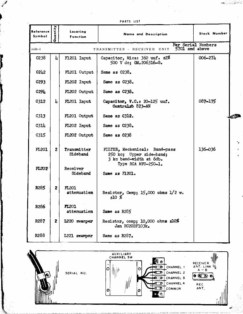
Change "Name and Description" column to read as follows:
Resistor, composition� 150,000 ohms, !. lOo/o, 1/Zw, JAN RCZOBF154K
Under "Stock: Number" column add "270-154"
Under "Quantity" column add "3".
Change "Name and Description" column to read as follows:
Same as R ZZ9.
Change ''Name and Description" column to read as follows:
Switch, Toggle, spdt, momentary contact, Federal Stock: Number N5930-050-2686
Delete "Stock: Number" column.
Change "Name and Description" column to read as follows:
Switch, Rotary, 1 section, 2 positions, 4 poles, Federal Stock: Number N5930-260-3144
Delete "Stock: Number" column.
Change "Locating Function" 'column to read as follows:
1 Speech input transformer.
Change "Name and Description" column to read as follows:
T ran.sformer, A udio, 600 ohms to ZS ohms, Federal Stock: Number N5950-645-1954
Delete "Stock: Number" column.
7 (of 16 p ages)
T- 1 TO NAVSHIPS 92917
Page
67
67
70
71
72
73, 74
Ref.
PARTS LIST Tl06
PARTS LIST
PARTS LIST
PARTS LIST R408
PARTS LIST
Figure 28
1 11AY 1958
I
Corrections To Be Made
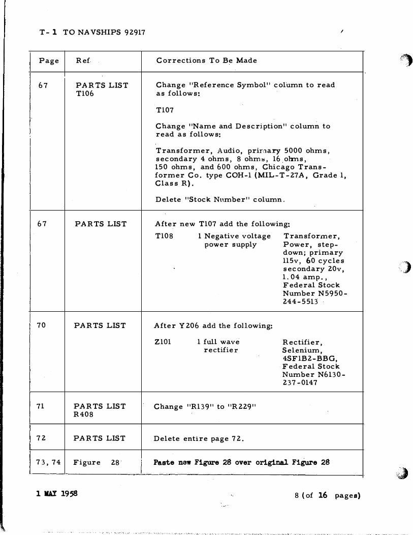
Change "Reference Symbol" column to read as follows:
Tl07
Change "Name and Description'' column to read as follows:
Transformer, Audio, prir.:1ary 5000 ohms, secondary 4 ohms, 8 ohm::;, 16 olrns, 150 ohms, and 600 ohms, Chicago Transformer Co. type COH-1 (MIL-T-27A, Grade 1, Class R).
Delete "Stock Number" column"
After new Tl07 add the following:
Tl08 1 Negative voltage Transformer, power supply Power, step
down; primary 115v, 60 cycles secondary 20v, 1. 04 amp., Federal Stock Number N5950-244-5513
After Y 206 add the following:
ZlOl 1 full wave rectifier
Change "Rl39" to "R 229"
Delete entire page 72.
Rectifier, Selenium, 4SF1B2-BBG, Federal Stock Number N6130-237 -0147
Paste new Figure 28 over original Figure 28
8 (of 16 pages)
\�
)
'�
f"
KEY UP VOLTAGE
KEY UP RES !STANCE
KEY UP VOLTAGE
KEY UP RES !STANCE
..0
-
�
�
i � fa -
. -· · -
�
A . READINGS TAKEN WITH VACUU M TUBE VOLTMETER (RC A- WV 97Aj
I
TB- 1Q:l 1 2 3 4 5 6 7 8 9 10 11 12 13 14 --
* * * * 0 0 -30 0 0 0 -90 0 () 0· !
INF INF INF INF 4 0 40 0 INF INF 170K INF I }.gO 150
B. READINGS TAKEN WITH 20, 000-0HM/VOLT OHMMETER (SIMPSON 260)
TB-103 1 2 3 4 5 6 7 8 9 10 11 12 13 14
* * * * 0 0 -25 0 0 0 - 85 0 0 0
INF INF I
INF INF 4 0 40 0 INF INF 170K INF 180 150
�
15 16 17 18
0 0 0 0
0 INF INF IN.F
15 16 17 18
0 0 0 0
0 INF INF INF
'l'ABIE 3.
c
0
·-..
..!:!
] Ill
c
-.a(
Ill
II
Q .
-

,
)
Fteto Change I
Figure 3. Cabinet Top Raised ancl Chassis Withdrawn
.;wJ

(
(
(
I I I I I I I I I I I I I I I I I I I I I I I I I I I
POWER SUPPLY T-101 - � - -----, I TRANSMITTER-RECEIVER I
TS I �I� FI LA�EN T T I METER l
,-------l" � V - 106 I ,SfN! FILAMEI
> +600 V
1 � V-201 I l V-20:
l I ,-v v-20'
T-102
- ; V-20: r-+-�-+---, ,tr---___j•....._-'-__, 1 PLATES �:�8l
• H V
V-201 V ·
F-I04; RE CT FILAMENTS 1 V-202
-20,
ZA , f V-101 T T I
V-102 • l
I,JRANSMITTERI V-107 I .----J DS·IOI
V-108 . FI LAME�
F·I 03 I� - I I 1 �=�8� �5!_ ll-- r +150V T PLATES V-2 1(
� ' L y REG V-209 V -2 1:
� > RECT V-105 I V-2 1 0 �=� I:
I I I I
s
I I I
'V � "\
� ti50V1 I V-208 V-2 1
��!:::=�) V-103 � V-2 I'
!RECEI VER! +210 V - I
RCVR INPUT V-2 I;
. ,, - -DS-102 � AN TENNA ..._ A XMTR OU
,.- T�.� t PU T I
Y-105 3 \.. I
7 T-103 ( F-105 PLATES I B- I -- ,
V-104 i3 ' 0.25A V-1078 I : � 1
7 I V-108 I : PLAl
tRECEIVERl j R•I03 �- l <C;R -104 1 ...(\ RELAY �=�
® BIAS S IL 5I: K-201 Y..l
_ REG ,. R -143 '' I -cr v-�
I Is I ! I � I S-102 \ V-104 <�R-107
C-129 PLA V-�
- � • I TES V-l
-=- � !PHONE( T� GRIDS �= 203
F-102 • � V-201 V- �g�
o.sA T-104 � 0 � TELE- I v-202 v- 2o6
IV .;: -=- 1 1 t
GRAPH v-203 v- 207
� ) , � OVEN 1 :1 - S-104 I ,
__ . -- -- -- -+ -
� >HEATERS ( V - 4-+ FILAMEN TS I I
_, - D KEY I V-401 1
1.-- P-OW- -ER-1 _ d - • V-402
- DS-103 - -=-
KEYI,;; 0 PLATES I ....
� RELAY - �: :g�A SPEECH PLATES
[ l K-101 I � ;
V-401
I 2 TB-101 � IPPER V-402
115 V -f-.+ LOC AL -----
F- 101 ( PUSH-TO-TALK Jo------ -----
3A . SWITCH j_
�__L�_s-101
= lJ�"fRl[-'RfiEl � � TB -102 I
S-103 S-106
1 15V i6
I
E bC lA K-102 35� 1 rr 50/60 CPS
-- _ -- ---- � H I
F .,o B - - - - fTTT' 2 4 I 5
..___ ___ �_j T � I 0 2 .... ----------------t-J�-------+-�2�50����10�W�--
�G 12\ : �A I �
v R-144 I 3
.� I I 2
I. I
� I
031
I I I I I 0 I ( -�Z-101 L-103 I "V
� � ���� + - I = 2
I 0 4
..._ _________________ L __ � fl) .... = 3 7 _, e
= T - I
� -
0 7 __. Mfd � Mfd .:J:. I
T-108 _j
Figure 6. Power ond Control Circuits FIELD CHANGE NO.I

. ,, . .. ·· .. .. f'lAt< · �-
.lfebiC.A!O;R
� .. trfA-.1 TftAttSF'SR . SWtTC.H
TELEGRAPH KEY JACK TRANSFER SWITCH
Figure JO. Front Pane! Controls
.,
')
LOCAL; TEt..��T .�' '·
Field Chanqe I
'�
�
.!!
>
Q.
0
....
..
Gl
:t
0
a..

,,,
)
Field Chonr;e I
Figure 77. Power Supply, Bottom View �

(
(
l
T-2 TO NAVSHIPS 92917 UNCLASSIFIED August 1958
TEMPORARY CORRECTION T-2 TO TECHNICAL MANUAL FOR TYPE SSB-1 SINGLE SIDE-BAND RADIO COMMUNICATION �UIPMENT, NAVSHIPS 92917
Temporary Correction T-2 does not apply to the Technical Manual until Field Change No. 2-SSB-1 has been accomplished. THEREFORE - DO NOT correct the Technical Manual until the field change has been accomplished.
Field Change No. 2-SSB-1 applies to all Single Sideband Radio Communication Equipment. Its purpose is to provide satisfactory operation of the Single Sideband Radio Communications with Antenna Tuning Group AN/SRA-20.
Correct the Technical Manual with pen and ink in accordance with the following instructions. Make whatever deletions are necessary and where there is insufficient space on the given page to insert the corrective or added data, merely make the following nota-tions along side of the affected text or diagram "See T- "
Insert this Temporary Correction immediately after the front cover of the Manual (just before Temporary Corr'ection T-1) as a permanent record.
�
7
22
.39
4.3
44
45
58
59
59
�·
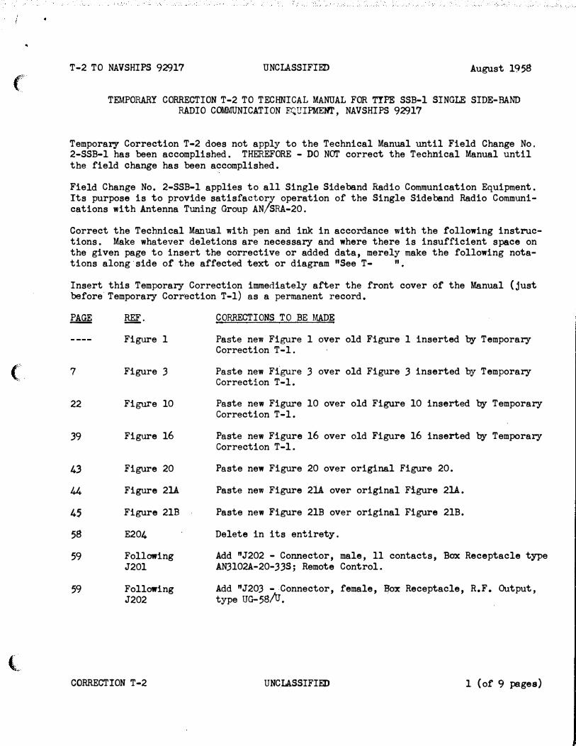
Figure 1
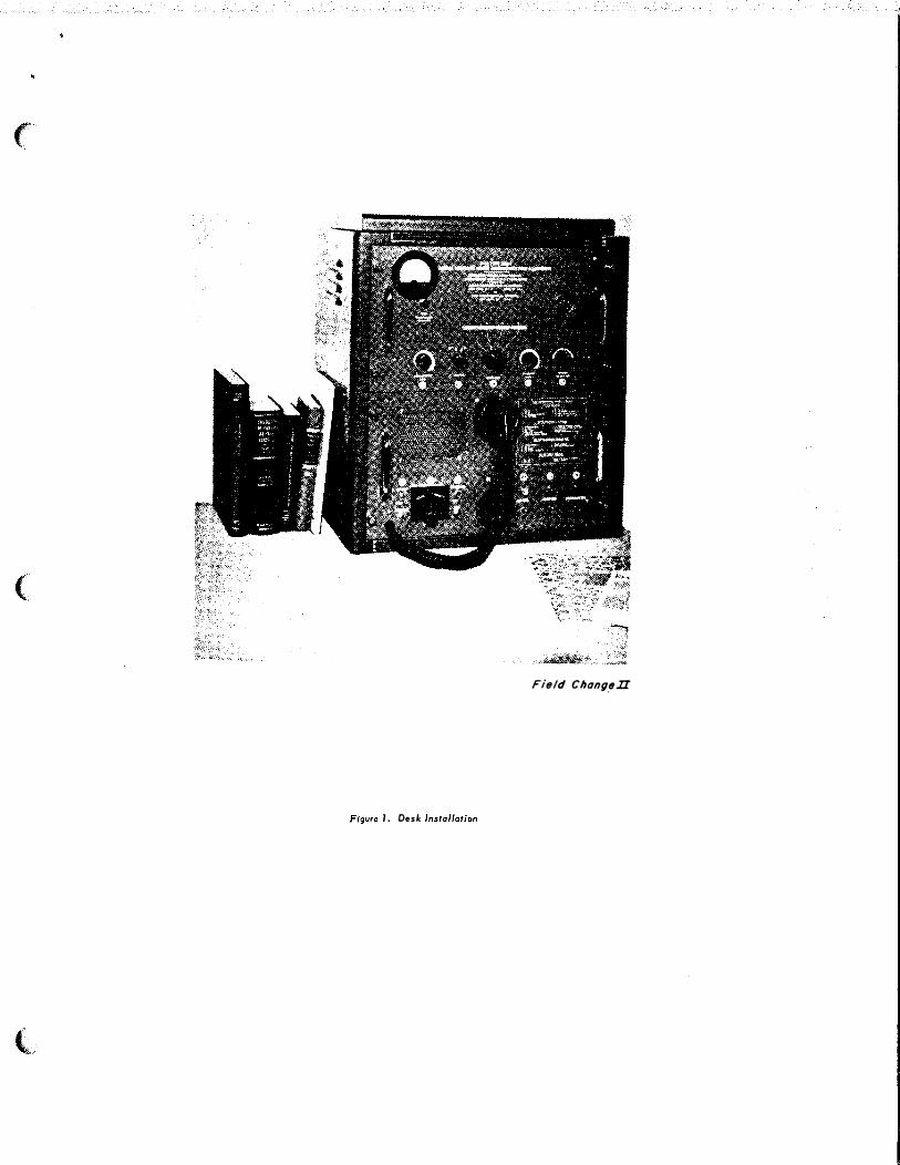
Figure .3
Figure 10
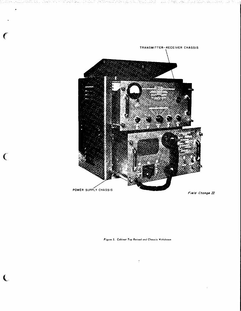
Figure 16
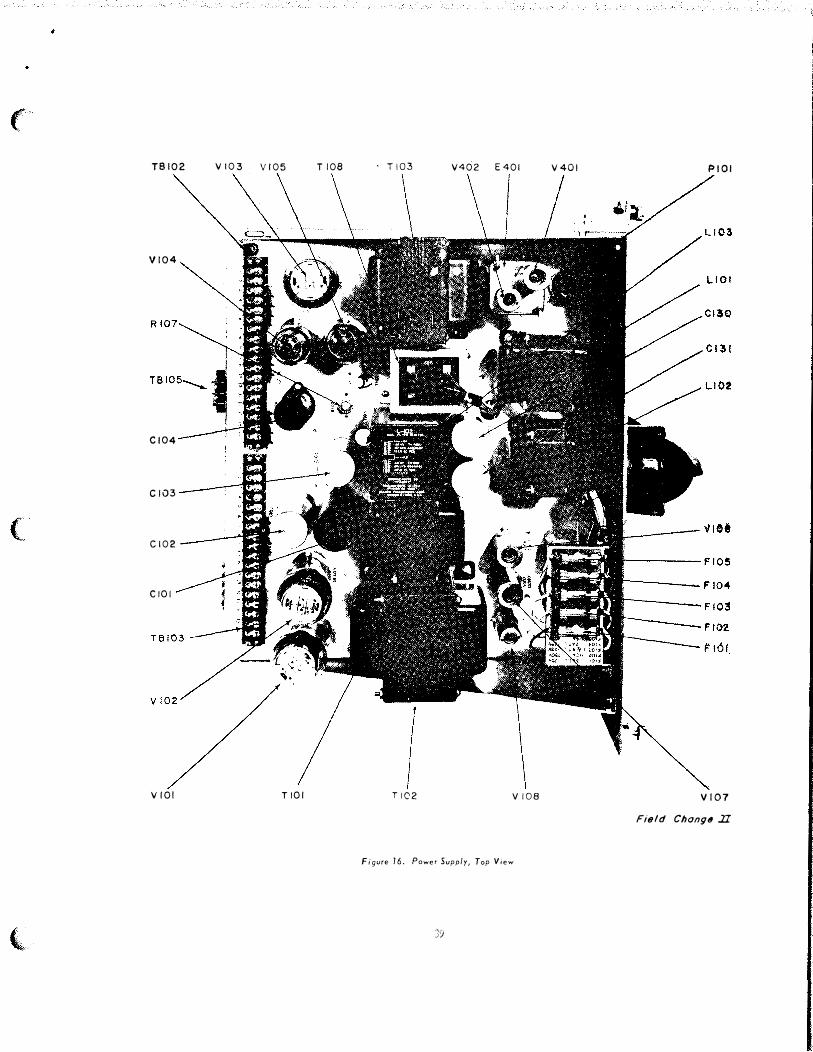
Figure 20
Figure 21A
Figure 21B
E204
Following J201
Following J202
CORRECTION T-2
CORRECTIONS TO BE MADE
Paste new Figure 1 over old Figure 1 inserted b,y Temporary Correction T-1.
Paste new Figure .3 over old Figure .3 inserted by Temporary Correction T-1.
Paste new Figure 10 over old Figure 10 inserted b,y Temporary Correction T-1.
Paste new Figure 16 over old Figure 16 inserted b,y Temporary Correction T-1.
Paste new Figure 20 over original Figure 20.
Paste new Figure 2iA over original Figure 21A.
Paste new Figure 21B over original Figure 21B.
Delete in its entirety.
Add "J202 - Connector, male, 11 contacts, Box Receptacle type AN.3102A-20-.3 .3S; Remote Control.
Add "J20.3 - Connector, female, �ox Receptacle, R.F. Output, type UG-58/U.
UNCLASSIFIED 1 (of 9 pages)

T-2 TO NAVSHIPS 92917
PAGE
60
67
68
73,74
75,76
77,78
Imf.
Following I.SlOl
Following S201 H & I
Following TB104
Figure 28. Power Supply Schematic
Figure 29A. Trans/Rec Schematic
Figure 29B Trana/Rec Schematic
CORRECTION T-2
UNCLASSIFIED August 1958
CORRECTIONS TO BE MADE
Add "M201 - Meter, milliammeter DC type, MF26W-300 DCMAR PA Plate current."
Add "S201 J Switch, rotary, 1 section, 12 positions."
Add "TB105, Terminal Board, 2 terminals, cinch type. No. 2-1.41-Y."
Correct in accordance with Figure 6 of Field Change Bulletin No. 2-SSB-1, NAVSHIPS 981008.
Correct in accordance with Figure 7 of Field Change Bulletin No. 2-SSB-1, NAVSHIPS 981008.
Correct in accordance with Figure 7 of Field Change Bulletin No. 2-SSB-1, NAVSHIPS 981008 .
UNCLASSIFIED 2.
..
·�
,)
,;,J
r
� 'b.
1:),
�
.c::
1.>
'1::1
....
"
....
�
...,
..
..
a
...:
(
TRANSMITTER-RECEIVER CHASSIS
(
POWER SUPPLY CHASSIS Field Chongtl II
Figute 3. Cabinet Top Raised anri Chassis Withritawn
(,

(�'
(
(
CARRIER SWITCH
..IJ
PEAK MODULATION •• )I
INDICATOR
TRANSMITTER
GA I N CONTROL S
LOUDSPEAKER
LOCAL- REMOTE TRANSFER SWITCH
CHANNEL SELECTOR
TELEGRAPH K�Y JACK
RECEIVER GAIN
CONTROL
SPEECH CLARIFIER
OPERATING INSTRU CTIONS
POWER CONTROL
S WITCHES
LOCAL TELEPHONE
HAND-SET
TELEGRAPH-PHONE TRANSFER SWITCH
Flt1ld Chang11 Il
Figure 10. Front Panel Controls
,,.-,
(
(
l.
TSI02
Vl04
Cl04
Ci03
Cl02
CIOI
VIOl
Vl03 VI05
TIOI
TI08 ' T 103
TIC2
V402 E401
V108
Figure 76. Power Supply, Top View
J�
V401 PtOI
VI07
Field Chong" .II
•
(
C243 V207 TP203 C272 V210 E203 V209 L213 C276 E201 V216 T20� V215
V214
L 221
L217
T203
L216
L220
L215
V211
L214
( - ·- ---- --
-w-e '-·--- -- - ------- L219
...,.._.,..., ../" � ��--��-- ----�-· ........ "'-.....
J201
C204 L202 C205 C203 C206 R201 K201 C207 C202 C208 C211 C201 C212 L203
Field Change Jl.
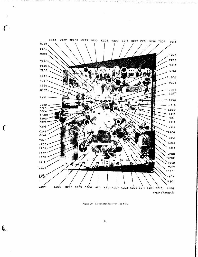
Figure 20. Transmitter-Receiver, Top View
43
(
(
C286
C284 C285 C2t3 C'209
C217
C218 C219
C216 C210 C28? C260
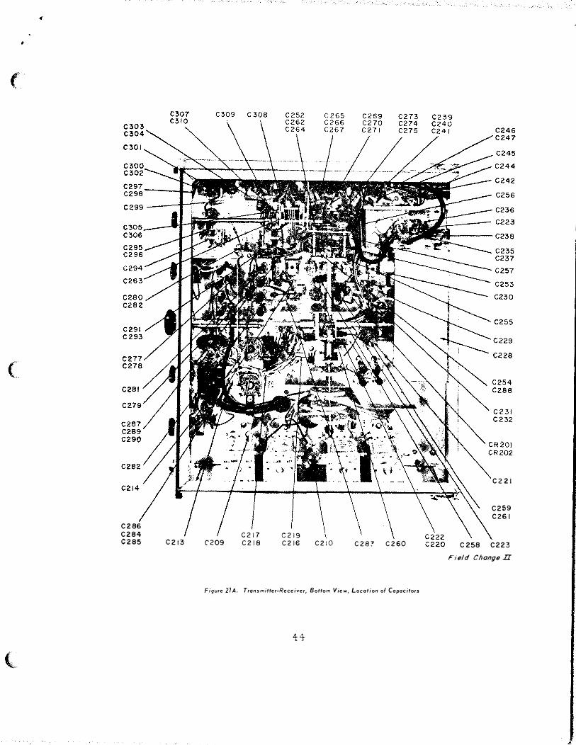
Figure 21A. Transmitter·Receiyer, Bottom View, Location of Capacitors
44
C221
C259
C26.1
C 258 C223
Field Change II

I
t
('
(
(,
R279
R27G R27 7 R27A
R274 R275
1=: R270 ----Ht-:1
R269
R268
R218
R219
R27 2
R273
R252
R251
R262
R257 R258 R259 L204
R242 R243 R244
R205 5201-8 5201-A S201-C S20i·O
Figure 218. Tronsmitter·Receiver, Bottom View, Location of
Components other than Capacitors "
45
L212
R229
22
R224 R226 R227
R216
R222 R217
R220 R221
R223
R236
R237
:>t-G
R235
R234
R212 R213 R214
5201-J
K210 R211
L210
R209
R238 R239 R240 R241
R208
Field Cllongei£

("
(
(
���\
0967-108-2013
T-.3 TO NAVSHIPS 92917 UNCLASSIFIID SEPI'EMBER 1958
TEMPORARY CORRECTION T-.3 TO TECHNICAL MANUAL FOR TYPE SSB-1 SINGLESIDEBAND RADIO COMMUNICATION EQUIPMENT (NAVSHIPS 92917)
Temporar.y Correction T-.3 does not apply to NAVSHIPS 92917 until Field Change Number .3-SSB�l has been accomplished. Therefore DO NOT correct the Technical Manual until the field change has been accomplished.
Field Change Number .3-SSB-1 applies to all Single-Sideband Radio Communication Equipment. Its purpose is to add an AGC circuit to the equipment thereby eliminating operational difficulties and unsatisfactory communications.
Correct the Technical Manual with pen and ink in accordance with the followin� instructions. Ma�e whatever deletions are necessary and where there is insufficient space on the given page to insert the corrective or added data, merely make the following notation along side of the affected text or diagram "See T-311•
Insert this Temporary Correction immediately after the front cover of NAVSHIPS 92917.
I' AGE REF'ERENCE
Figure 1
5 TUBES:
7 Figure 3
8 Paragraph 6
10 Figure 5
14 Paragraph 4 • .h.
CORRECTION T-3
CORRECTION TO BE MADE
Paste new Figure l over old Figure 1 inserted by Temporary Correction T-2.
Add the following to the list of TransmitterReceiver tubes:
V-217 . . . • . . . . • • 5726/ 6AL5 • • . . . . . . . • AGC Diode V-218 • . . . . . . . • 5814/12AU7 . . . . . . . . • DC Amplifier
Paste new Figure 3 over old Figure 3 inserted by Temporary Co rrection T-2.
Add the following to the end of the first subparagraph:
11and the AGC circuit. 11
Paste new Figure 5 over original Figure 5.
After Paragraph 4:.h. add "1· -See T-311• The following applies:
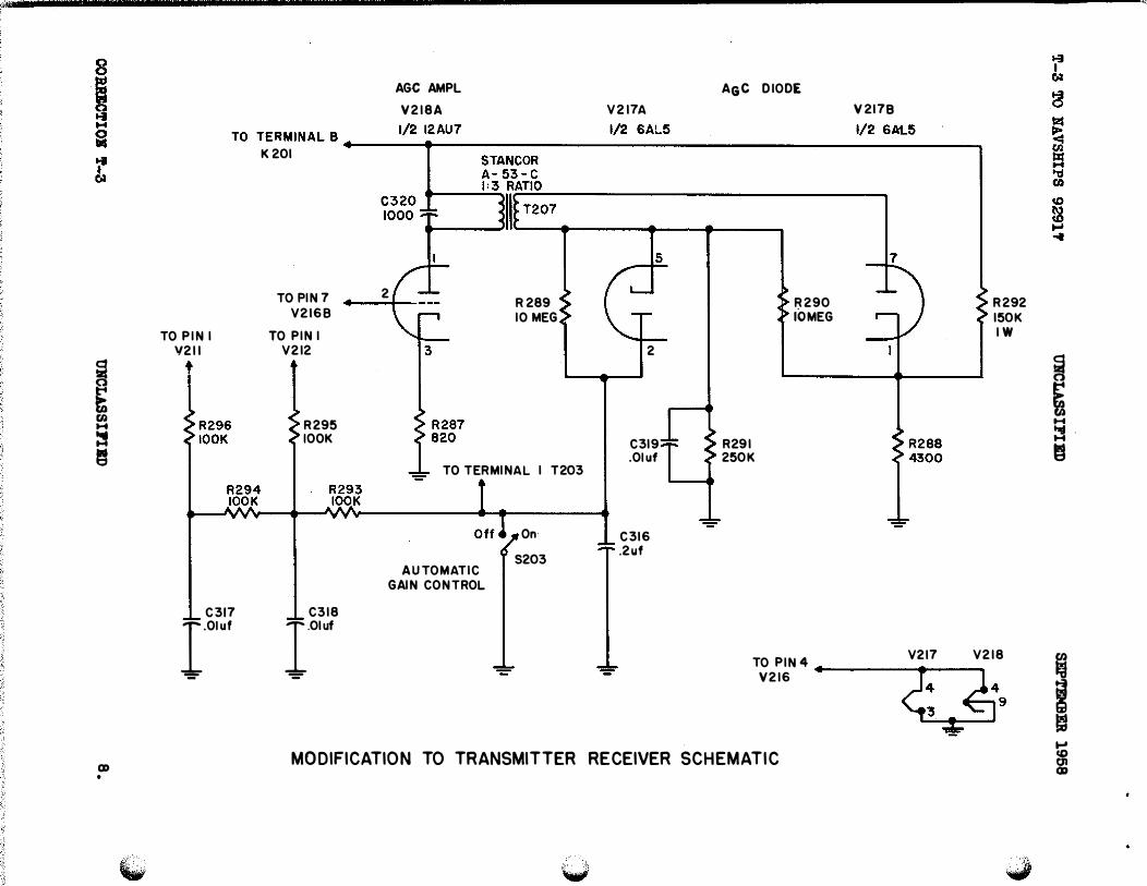
"i. The output of the mixer-demodulator V216A is also fed to the DC a mplifier V218 (one half of a 5814/12AU7 twintriode) of the AGC circuit, where it is amplified and fed through transformer T207 to the cathodes of V217A,B (a 5726/ 6AL5. twin diode). When a nagati ve signal appears at the secondary of T207 it causes the cathode of V217A to become negative with respect to its plate and
UNCLASSIFIED 1 (of 16 pages)
T-3 TO NAVSHIPS 92917
PAGE
19
21
22
23
24
29
30
33
43
44
4i
REFEREUCE
Paragraph B.j.
Paragraph 9.�.
Figure 10
Paragraph 2.�.
TABLE 1. TRANSMITTER-RECEIVER UNIT
Figure 15
Paragraph 4.�. ( 1)
TABLE 2
Figure 20
Figure 21A
Figure 21B
CORRECTION T-3
UNCLASSIFIED SEPTEMBER 1958
CORRECTION TO BE MADE
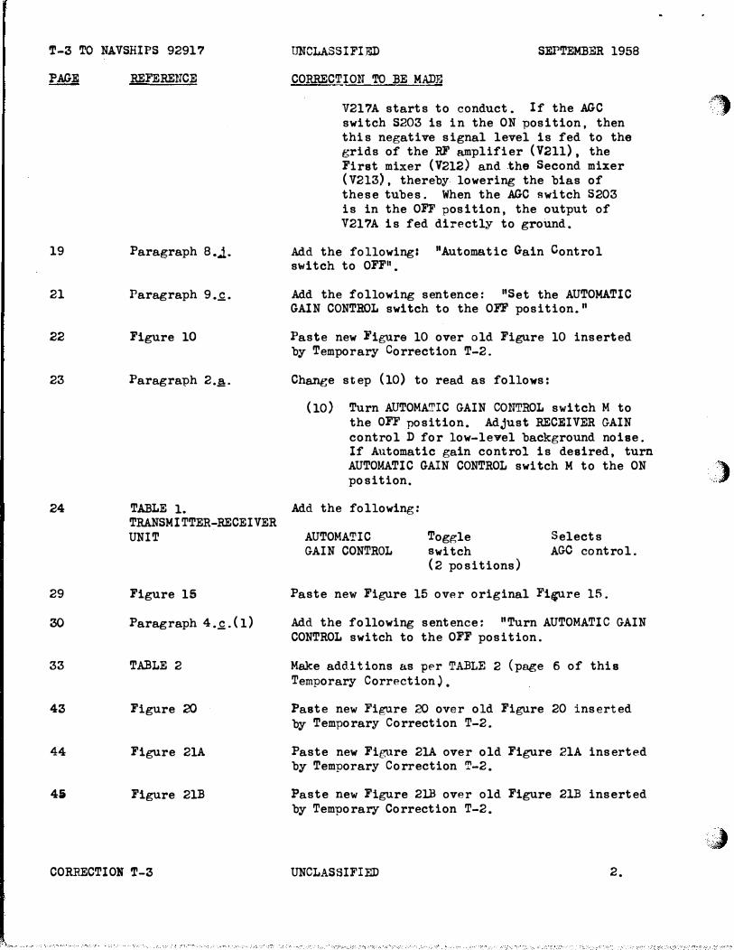
V217A starts to conduct. If the AGC switch S203 is in the ON position, then this negative signal level is fed to the grids of the RF amplifier (V2ll), the First mixer (V212) and the Second mixer (V213), thereby lowering the bias of these tubes. When the AGC switch S203 is in the OFF position, the output of V217A is fed directly to ground.
Add the following: "Automatic Gain Control switch to OFF11•
Add the following senten ce: "Set the AUTOMATIC GAIN CONTROL switch to the OFF position."
Paste new Figure 10 over old Figure 10 inserted by Temporary Correction T-2.
Change step (10) to read as follows:
(10) Turn AUTOMATIC GAIN CONTROL switch M to the OFF position. Adjust RECEIVER GAIN control D for low-level background noise. If Automatic gain control is desired, turn AUTOMATIC GAIN CONTROL switch M to the ON position.
Add the following:
AUTOMATIC GAIN CONTROL
Toggle switch (2 positions)
Selects AGO control.
Paste new Figure 15 over original Fi�re 15.
Add the following sentence: "Turn AUTOMATIC GAIN CONTROL switch to the OFF position.
Make add.itions a.s pf'r TABLE 2 (page 6 of this Temporary Correction).
Paste new Figure 20 over old Figure 20 inserted by Temporary Correction T-2.
Paste new Figure 21A ove r old Figure 21A inserted by Temporary Correction T-2.
Paste new Figure 2lB over old Figure 21B inserted by Temporary Correction T-2.
UNCLASSIFIED 2.
.��
.)
\;J

(
(
(
T-3 TO NAVSHIPS 92917
PAG:Z
52
56
57
57
58
54
65
66
67
RE:F'ERENC:m
PARTS LIST Cl26
PARTS LIST C277
PARTS LIST C3li
PARTS LIST ElOl
PARTS LIST E218
PARTS LIST R222
R234
PARTS LIST R258
R2.150
PARTS LIST
PARTS LIST Sl02
CORRECTION T-3
tmCLASSIFIED SEPTEMBER 1958
CORRECTIONS TO BE MADE
Change QP'AN!'TTY column to read "5".
Change Q)J.Al-."TITY column to read "4". Change LOC�ING FUNCTION column to read "V211 input capacitor." Change NAME A1TD DESCRIPTION column to read as follows: "Capacitor, Mica, 0.01 uf, fl�, 300 WVDC, plastic body, JAN CM35:Sl03K. 11
After C31S add the following:
0316 1 AGC filter Capacitor, fixed paper, 0.2 uf, flO% 400 WVDC metal case plastic insulated, 1-1/4" x 0.46211 diam.
C317 V211 AGO bypass
C318 V212 AGC bypass
0319 V217A cathode bypass
Same as C277
Same as C277
Same as C277
C320 T207 input tuning Same as Cl26
Change Q,UAN'riTY column from "att to "9" and 11711 to "a"·.
After E218 add the following:
E219 For V217
E220 For V218
Tube shield, JAN TS102U01.
Same as ElOl.
Change q,tl'ANTITY column to read 119".
Change Q,UANTITY column to read 11311•
Delete all reference to R258.
Change Q,UANTITY column to read "311•
Add new Pa�e 66A (page 7 of this Temporary Correction) between pages 66 and 67.
Change �ANTITY column to read 113".
UNCLASSIFIED 3.

T-3 TO NAfSHIPS 92917
PAGE
67
68
69
70
75,76
77,78
REFERENCE
PARTS LIST S202.
PARTS LIST !'206
PARTS LIST V216
XV106
XV108
PARTS LIST XV216
Figure 29A
Figure 29B
COR..'(ECTION T-3 "'
UNCLASSIFIED SEPTEMBER 1958
CORRECTIONS TO BE MADE
After S202 add the following:
S203 Automatic gain control on-off
Same as Sl02
After T206 add the following:
T207 1 AGC Interstage Transformer, audio, 1:3, max. , primary de current 10 ma., Stancor type A-53-C
After V216 add the following:
V217 1 AGC diode E lectron Tube, twin diode, 5726/6AL5
V218 1 AGC de amplifier
Electron Tube, mediummu duo diod.e, 5814/12AU7
Change QVANTITY column to read �3".
Change �ANTITY column to read "10".
After XV216 add the following:
XV217 Mounting for V217 Same as XV108
XV218 Mounting for V218 Same as XV106
Make the following deletions and additions to Figure 29A:
1. Remove C277, R258, and ground lead on terminal 2 of T203, and lead between S203, and lead between S201H and pin of V211.
2., Add capacitor C277 .OlUJ' between S201H and pin 1 of V211.
3. Add AGC circuit as shown in MODIFICATION TO TRA NSMITTER RECEIVER SCHEMATIC (page 8 of this Tempo�ary Correction).
Make the following deletions and additions to Figure 29B:
UNCLASSIFIED
1. Remove C277, R258, ground lead on terminal 2 of T203, and lead between S201H and pin 1 of V211.
4.
)�
')
·�

T-3 TO NAVSHIPS 92917
PAGE REFERENCE
( "· 78 Figure 29B
(
(
CORBECTION T-3
UNCLASSIFIED SEPTEMBER 1958
CORRBCTIONS TO BE MADE
2. Add capacitor 0277 .OlUF between S201H and pin 1 of V211.
3. Add AGC circuit as shown in MODIFI
CATION TO TRANSMITTER RECEIVER SCHEMATIC
(page 8 of this Temporar,r Correction).
UNCLASSIFIED 5.
SYMBOL
V-217
v -218
V-217
V-218
Ol •
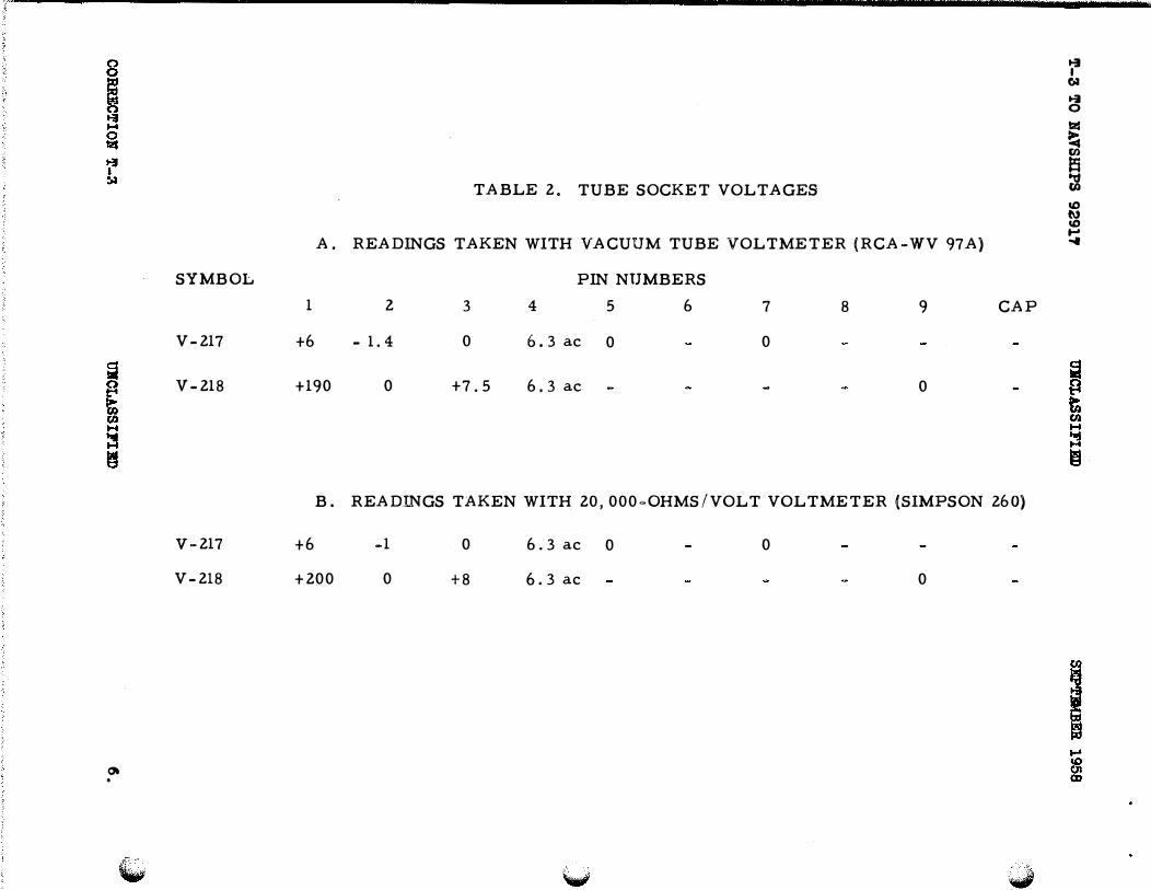
TABLE 2. TUBE SOCKET VOLTAGES
� I
6J
� 0
lzl
�
� dt co tl) co ....
A. READINGS TAKEN WITH VACUUM TUBE VOLTMETER (RCA-WV 97A) ...,
1 2 3
+6 - 1. 4 0
+190 0 +7.5
PIN NUMBERS
4 5 6
6. 3 ac 0
6. 3 ac
7 8 9 CAP
0
0
B. READINGS TAKEN WITH 20, 000=0HMS/VOLT VOLTMETER (SIMPSON 260)
+6 -1 0
+200 0 +8
6. 3 ac 0
6. 3 ac
0
0
(c
(
(
T-3 TO NAVSHIPS 92911
Reference Symbol
SSB-1
R287
R288
R289
R290
R291
R292
R293
R294
R295
R296
CORRECTION T-3
Qty.
1
1
2
1
UNCLASSIFIED SEPTEMBBR 1958
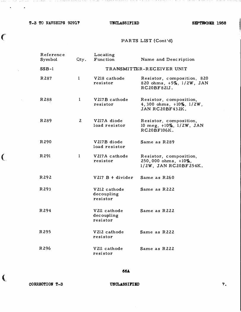
PARTS LIST (Cont'd)
Locating Function Name and Description
TRANSMIT1ER -RECEIVER UNIT
V218 cathode resistor
V217 B cathode resistor
V217A diode load resistor
V217B diode load resistor
V217A cathode resistor
Resistor, composition, 820 820 ohms, +5o/o, 1/2W, JAN RC20BF821J.
Resistor, composition, 4, 300 ohms, +10%, 1/2W, JAN RC20BF432K.
Resistor, composition, 10 meg, +lOo/a, l/2W, JAN RC20BF106K.
Same as R289
Resistor, composition, 250,000 ohms, +10%, l/2W, JAN RC20BF254K.
V217 B + divider Same as R260
V212 cathode Same as R222 de coupling resistor
V211 cathode Same as R222 decoupling resistor
V212 cathode resistor
V211 cathode resistor
66A
UHCL.ASSinlm
Same as R222
Same as R222
7.
� E en ....
:! (3
Q) •
AGC AMPL AGC DIODE V218 A V217A V217B
TO TERMIN AL B +---I/:_2..,.
12_ A_u _7 _______ _ 1 1_2_ 6 _AL_ 5 _________ _ 1_1 _2 _6_A1.. _5 __ ___,
K201
TO PIN I V211
C317
IOiuf
TO PIN7 V216B
TO PIN I V212
R295 lOOK
C318
101�
2 R 289 IO MEG
TO TERMINAL I T20 3 -
AUTOM ATIC GAIN CONTROL
On
S20 3
2
C319 .Oiuf
C316 .2uf
R290 R292 tO MEG 150K
IW
R291 250K
V217 V218
�: �· =!=
TO PIN4 ••---------V216
MODIFICATION TO TRANSMITTER RECEIVER SCHEMATIC
� i .... hid . ....
�
�
i = .... CD CJ1 QD

0
I""
., a· c �
p1 m 0 (') ';II:'
0 a·
10
�
., fii r 0 ("') :I: � z G) IT1 (JI
MIKE v-TONE T EST IOOO CPS
M I KE AMPL jv·I06(B),V·I07(A) V-401-6U8
IKC
L(fALANCED MOD
V - 207
1/2 12AT7ea. V-402-SAL!!
�
r TONE
osc V·I08(A)
1/2 12AT7
�._j .1:-tr t.__.. :- I
� TO
RECEIVET RANS M IT
RELAY
KEYING RELAY
K-101 SPEAKER
12AT7
250KC
CRYSTAL osc
V-210 6 BE8
250KC
MIXER DE MOD
V-218(A)
1/2 12AT7
251KC
� DC AMPL
V-218
1/2 12AU7
�
( 251KC ( 1401KC
' BALANCED l BALANCED MOD MOD
FL-201 V· 206 V-206 12AT7 12AT7
·�
ANTENNA w MODULATI ON
INO AMPL
V·203 6B A 6
14249KC NOMINAL
r 14Z49KC NOMINAL (14249KC NOMINAL
INTERMEO �I PWR PWR AMPL AMPLIFIERS 1--
V -204 V ·201,2 6 C L6 6146(2)
CF:RRIER OUT 1260KC
om-
,-I C RYSTAL t= 1150KC
CRYSTAL osc
� TO
KEYING tl RELAY
RECEIVE-TRANS,.T I
I I osc f---1 V-20 9
J
H
IF
AMPL
e BEe
....... J
6BA8 (2)
251 KC
AGC D I ODE
V-217
8AL6
1150KC
M ECH
CHANN EL
15650KC ----,
2nd Itt
F I LTER MIXER MIXER FL-20 2
J
V-213
J
V-212
J
6BE6 6BE8
251KC 1401 KC 14249KC
OFF� ON
�GC
NOMINAL
RELAY ..;...... K-201 �
RF
ELJTPL V-211
J
6BA8
14249 KC NOMINAL


(
(
{
POWER SUPPLY CHASSIS
TRANSMITTER- RECEIVER
CHASSIS
Field Change 3
Figure 3. Cabinet Top Raised and Chassis Withdrawn

PEAK MODULATION INDICATOR
TRANSMITTER GAIN
CONTROL
LOUDS PEAKER
LOUDSPEAKER-HANDSE T
TRANSFER SWITCH
CARRIER SWITCH
LOCAL REMOTE TELEGRAPH KEY JACK
TRANSFER SWITCH
CHANNEL SELECTOR AUTOMATiC GAIN
CONTROL SWITCH
RECEIVER
CONTROL
SPEECH CLARIFIER
OPERATING
INSTRUCTIONS
POWER CONTROL SWITCHES
TELEGRAPH-PHONE LOCAL TELEPHONE HANDSET
TRANSFER SWITCH
Field Change 3
Figure 10. Front Panel Controls
22
-�
)
• �
(
( I
(
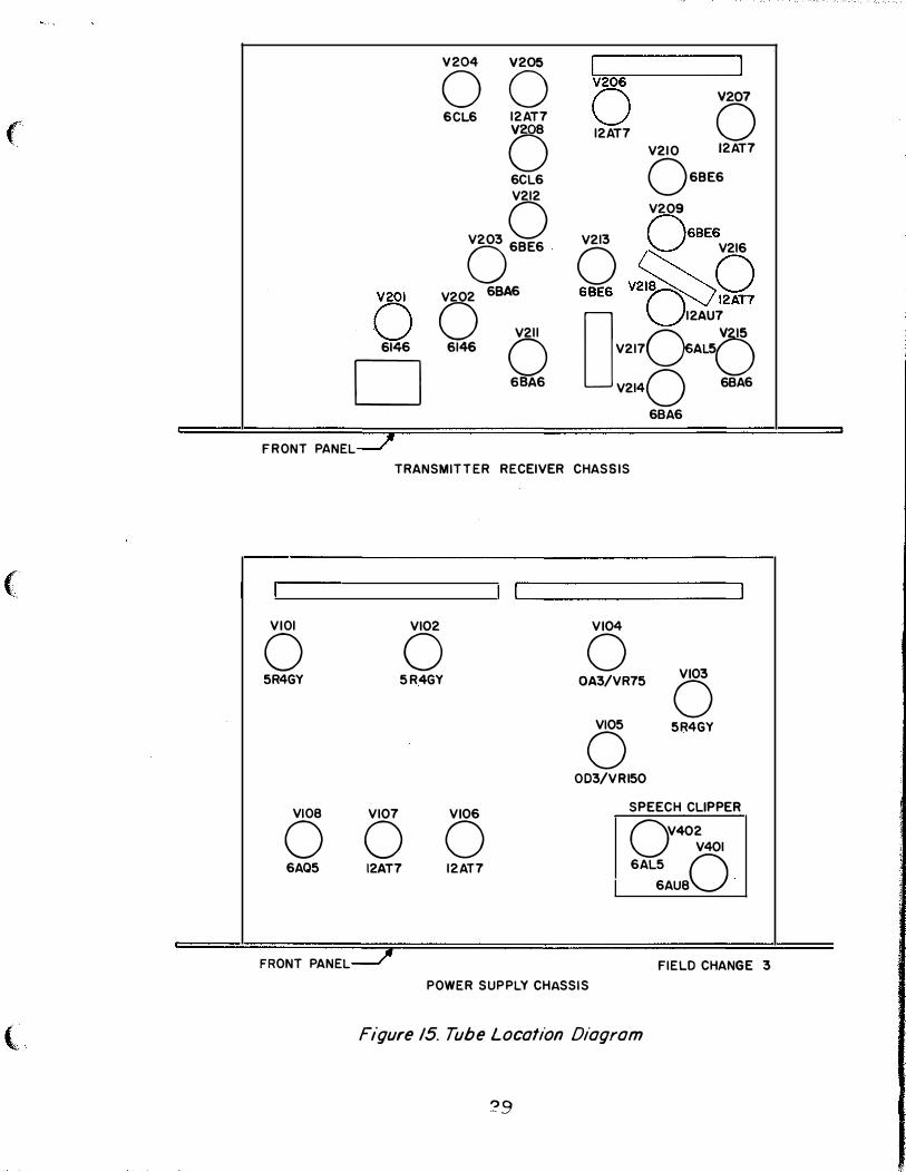
00 SCLS 12AT7
0 6CL6
V212
V203 0 0 68E6
0 12AT7 0
V210 12AT7
068E6
V209
V213 068E6
0 V216
•e•• v�oe 'Q 2� 12AT7 0 V202 6SA • . . ,.,. Q V211
D Q 0 12AU7
V2170A{) V2140 6BA6
6BA6
FRONT PANEL
TRANSMITTER RECEIVER CHASSIS
VIOl VI02 VI04
0 0 0 VI03 5R4GY 5R 4GY OA3/VR75 0
VI05 5R4GY 0 OD3/VRI50
VIOB VI07 VI06 SPEECH CLIPPER
0 0 0 OV402
V401
6AQ5 12AT7 12AT7 6AL5 0 6AU8
FRONT PANEL FIELD CHANGE 3
P OWER SUPP LY CHASS IS
Figure 15. Tube Location Diagram
?9

C243 V207 TP203 V210 C272 E203 V209 E201 L213 C276 V216 T206
R225
E202
FL201
TP202
R215
V206
C234-
C251
C226-
C227
T201--
C225
C250
J202 J203
V205
C249
C248
V204
L208
L206
L207
L205
C215
GNO. POST
L201
C204 C 205 L202 C203 C206 R201 K201 C211 C207 C202 C212 L203 C208 C201 V201 V203
Field Change 3
Figure 20. Transmitter-Receiver, Top View
43
"'' �-'-,-_,
T205
V215
T204
V218
V217
5203
V214
V213
FL202
TP205
L221
L217
T203
L216
L220
L215
V211
L214
L219
) TP204
J201
L218
V212
V208
M201
V202
T202
05201
•• '<(�

. .,.,..,._�.
(
C300 C302
C297 C298 C320
C299
C305 C306
C277
C295 C296
c 316
C280 C292
C291
( C293
C281
C279
C287 C289 C290
C282
C2 1 4
C286 C284 C285
(
C301
-
C303 C304
----��
C307 C310 C309
C265 C266
C308 C267
C252 C262 C264
C269 C270 C271
C273 C274 C275
C239 C240 C241
........ _,.,. ____________
C246 C247
C245
C244
C242
C256
C236
C223
C238
C257
"-... C253
C230
_, ------ ---�·* ___ ... ' ' ' �- ' C255
C213 C317 C209 C217 C318 C210 C216 C218 C219
C283 C260
C229
C228
C254 C288
C23 1 C232
CR201 CR202
C221
C259 C261
C220 C222
C258 C223
Field Chonqe 3
Figure 21A. Transmitter·Receiver, Bottom View, Location of Capacitors
��
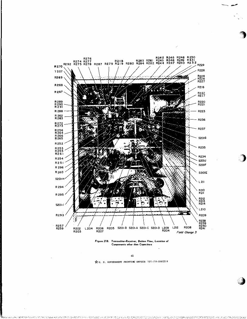
R276 R274 R277
R2 92 R275 R278 R287
��:��\ \ \ \ R26 9 , ·
R289 ___. ' ,4 :"" '!f�,---1- 5 .-.11f!;V� . R220 R 290 f '..;.c· . ·· \ .....J.-- R221 R 2 91
R 288
R 262 R263
R272 R273
R256 R264 R 266 � 265
R 252
R 253 R 255 R2 6 1
aa I �-efc-:;• ll ···--�
t!!J. N It\ 7 ;kd.�-- • .
--� R n•. � •�'-rall!iili'l�. ·
11-/'"fllllll!li -....-·& • , w LJ!!hW.lii
A #2!!9J.i!!!i!£1!:I411P/t --· ...,... "'1 � ..-:J> 4'
I. i# : R223
I R236
T-- R237
! ---.. 5201G
�� R235
/ll ' t • , '
R 254
I �,·' 1 "'-' .• .• :W�j!l ., •. R 2 5 1 ' • , II ·
/ ' 0'1 � �t � :: ! •• ,,- - i � � "'
�s�� R234
�-: ·� . ���:: R 296
R 260'
5201·H
R 294
R 295 / II .£.'7& J. :z rv llail:E ;_ . ._, 7\l\. R212 R213 t'\ R214 � L210
R209
R238
I I R239 R257 I I I I I R240 R259 R202 L 204 R206 R205 5201-B 5201-A 5201-C 5201-D L209 L212 R208 R241
R203 R207 R204 Field Change 3
Figure 218. Tronsmitter-Re�eiver, Bottolfi View, Location of
Components other than Capacitors
45
* U. S. GOVERNMENT PRINTING OFFICE: 1971-714-004/2514
--� �
-�
)
��
,.
(
(
(_
\_
l, '-
.-- ·-· 0967-LP-108-2014
./ � T-4 TO NAVSHIPS 92917 NOVEMBER 19 58
TEMPOR.{RY CORREC�ION T-4 TO TECHNICAL MANUAL FOR TYPE SSB-1 SINGLE-siDEBAND RADIO COMMUNICATION EQUIPMENT
Temporary Correction T-4 does not apply to NAVSHIPS 92917 until Field Change No. 4-3SB-1 has been accomplished. Therefore, DO NOT correct the Technical Manual until the field change has been accomplished.
Field Change Number 4-3SB-l applies to all Single-Side Band Communication Equipment type SSB-1 manufactured by the Radio Corporation of Areerica ( RCA ) . Its purpose is to provide safety features to the equipment which present hazards to operating personnel.
Correct the Technical Manual with pen and ink in accordance with the following instructions. Make whatever deletions or insertions that are necessary and where there is insufficient space on a given page to insert the corrective or added data, make the following notation along side of the affected text or diagram; "See T-4".
Insert this Temporary Correction immediately after the front cover of NAVSHIPS 92917 ( just before Temporary Correction T-3 ) as a permanent record.
� REFERENCE
Figure 1
13 Figure 6
14 Section II Para. 5 Q
14 Section II Para. 5 �
14 Section II Para. 5
CORRECTION T-4
CORRECTIONS TO BE ��E
Paste new Figure 1 ( supplied with this Temporary Correction ) over old Figure 1 inserted by Temporary Correction T-3.
Paste new Figure 6 ( supplied with this Temporary Correction ) over old Figure 6 inserted by Temporary Correction T-1.
Change Para. 5 £. to read: "Turning paver switch S-100 ££, energizes transformer T-104 by vay of the cabinet interlock switches and J-208. T-104 then applies power to the crystal oven heaters and keying relay K-101 etc • . . • • . • • • • . • • • • ".
Change first sentence to read: "The connections to the switches are such that when the pover switch or any of the interlock svitches are off, or if J-208 and P-208 are not properly mated, the entire equipment is de-energized, regardless of the positions of the other switches."
Add Sub. Para. H.: "The interlock circuit is vired in such a manner that the three interlock switches are wired into one half of the AC line through P-208, which is mounted on the back of the cabinet directly behind the paver supply chassis. J-208 en the pOYer supply chassis mount must mate with P-208 or the interlock circuit will not be complete. To operate the equipment with the power supply partly removed from the cabinet, place the power switch into battle short position, thus disabling the interlock system.
l (of 5 pages)

T-4 TO NAVSHIPS 92917
�
15
21
22
24
30
31
32
32
39
40
43
59
REFERENCE
Section III Para. 5
Section III Para. 10
Figure 10
TABLE 1 - POWER SUPPLY UNIT
Section V Para. 4 �
Section V Para. 4 g_( 11)
Section V Para. 4 £.(27)
Section V Para. 4 d(28)
Figure 16
Figure 17
Figure 20
PARTS LIST
CORRECTION T-4
NOVEMBER 19 58 '
CORRECTI ONS TO BE MADE
Change "Terminal board TB-103" to read "J-205", and change "Terminals 9 and 10" to read "Terminals A and B of J -207" •
Change "Terminal board TB-104" to read "J-206".
Paste new Figure 10 (supplied with this Temporary Correction) over old Figure 10 inserted by Temporary Correction T-3.
Power "J", column 2, change 11211 to " 3". Column 3, change first sentence to read; 11 In on position, line power is brought thru the interlocks into power supply". Add "In battle short position the interlocks are disabled".
Change "TB-102" to read "J-204"
Change "14 and 15 of TB-102" to read "2 and 3 of J-10111• (This is done by removal of the speech clipper plug-in-unit).
Change "14 and 15 of TB-102" to read "2 and 3 of J-101".
Change "14 and 15 of TB-102" to read "2 and 3 of J-101".
Paste new Figure 16 (supplied with this Temporary Correction) over old Figure 16 inserted by Temporary Correction T-2.
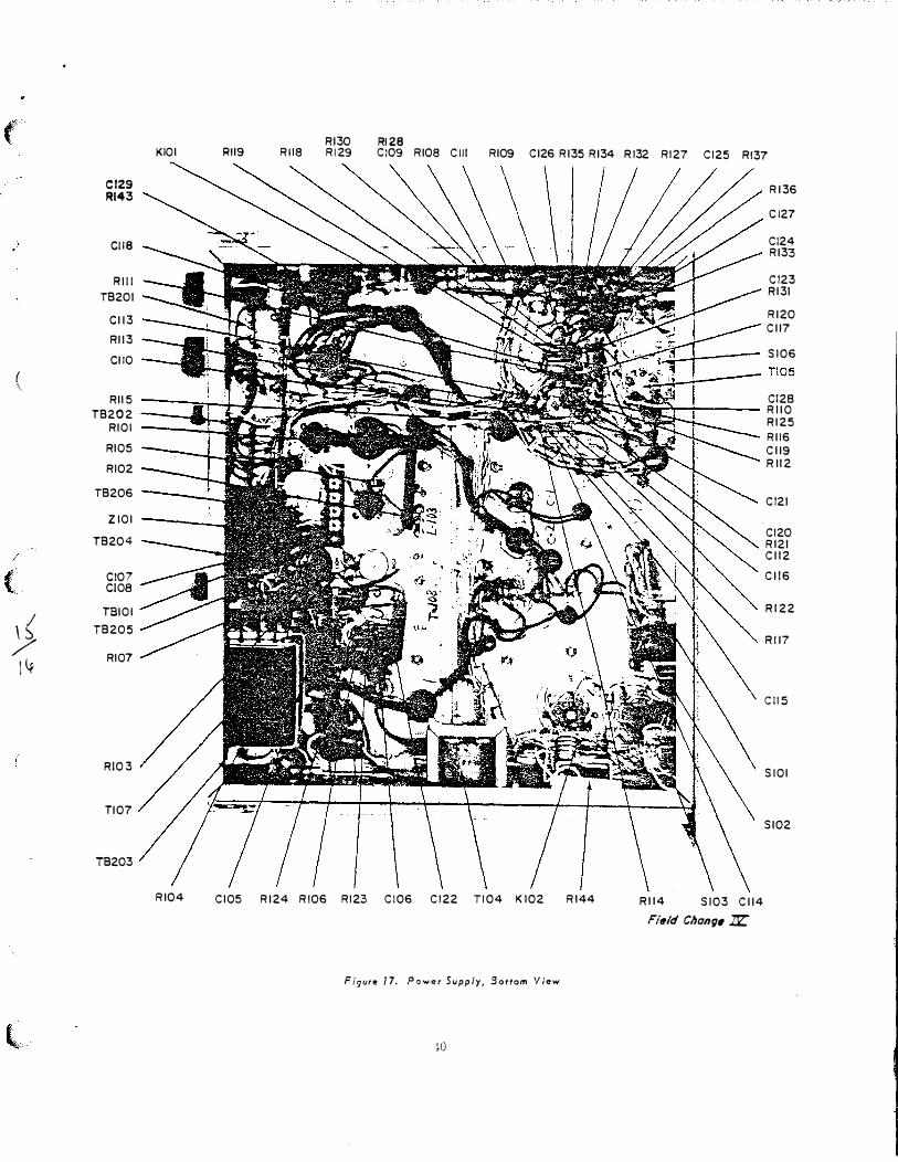
Paste new Figure 17 (supplied with this Temporary Correction) over old Figure 17 inserted by Temporary Correction T-1.
Paste new Figure 20 (supplied with this Temporary Correction) over old Figure 20 inserted by Temporary Correction T-3.
Af;,_er "J-203" add the following: J-204 1 socket: interchassis 24 pin barrier
polarization type with keyed shell . Amphenol type: No. 26-4401-24P.
2.
#
·�
1 /
')'

T-4 TO NAVSBIPS 92917 NOVEMBER 1958
• � REFERENCE CORRECTIONS TO BE ��DE
( 59 PARTS LIST After "J-204" add the .following: J-;:o5 1 socket: re�ote 14 contact box
receptacle; flJmphe-nol type: No. AN-
3102A-20-27P
59 PARTS LIST After "J-205" add the following: J-206 1 socket: TTY 4 contact box
receptacle; Amphe-nol type: No. AN-3102A-18-4P
59 PARTS LIST After 11J-206'' add th;;; following: J-207 1 socket: audio input 2 contact box
receptacle; Amphe-nol type: No. AN-3102A-10SL-4P
59 PARTS LIST After "J-207" add the following: J-208 1 socket: interlock 2 contact, 'With
angle brackets, Cinch-Jones No.
S-302-AB
59 PARTS LIST After "J-20811 add the follo'Wing: J-209 1 socket: AC input 3 contact, box
( receptacle; Amphe-nol type: No. AN'-
3102A-14S:..?p
60 PARTS LIST After "LS-101" add the follo'Wing: 0-201 2 ea plate caps Insulated plate
cap; 0-202 Same as 0-201
61 PARTS LIST After "P-202" add the following: P-203 1 plug; AC input 3 contact, straight
plug; solid shell Amphenol type No. AN-3106A-l4S-?S
61 PARTS LIST After "P-203" add the following: P-204 1 plug: interchassis 24 pin barrier pola-
rization type 'With latch-type keyed
shell. Amphenol type No. 26-4501-24S.
CORRECTION T-4 3.
T -4 TO NAVSHIPS 92917
PAGE
61
61
61
61
67
67
6?
67
67
67
REFERENCE
PARTS LIST
PARTS LIST
PARTS LIST
PARTS LIST
PARTS LIST S-101
PARTS LIST
PARTS LIST
PARTS LIST
PA!TS LIST
PARTS LIST
CORRECTION T-4
NOVEMBER 1958
CORRECTIONS TO BE MADE
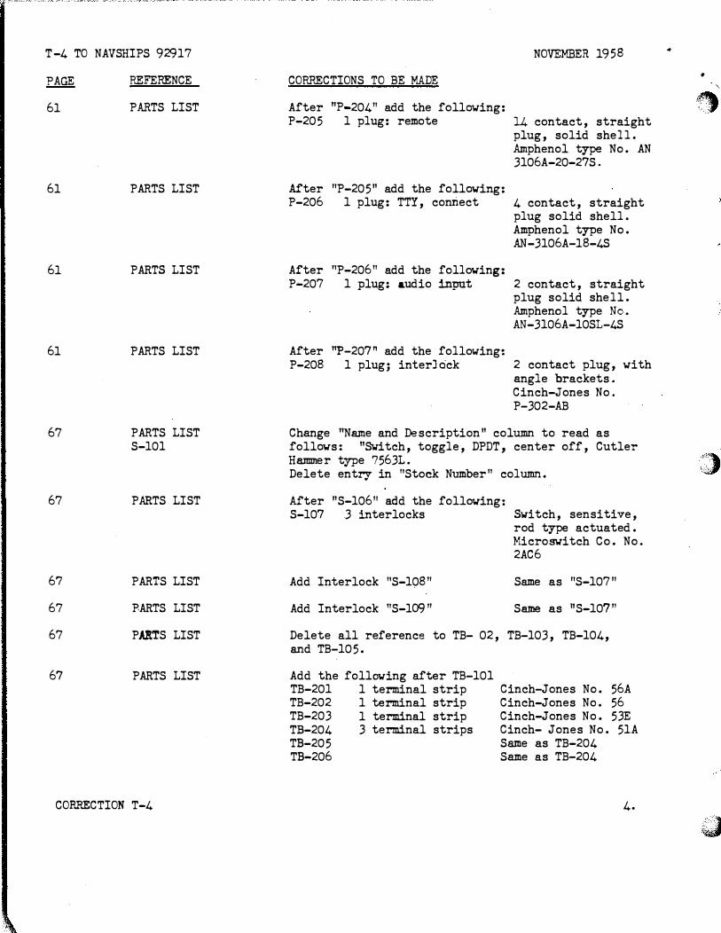
After "P-204" add the following: P-205 1 plug: remote 14 contact, straight
plug, solid shell. Amphenol type No. AN 3106A-20-27S.
After "P-205" add the following: P-206 1 plug: TTY, connect 4 contact, straight
plug solid shell. Amphenol type No. AN-3106A-18-4S
After "P-206" add the following: P-207 1 plug: audio input 2 contact, straight
plug solid shell. Amphenol type No. AN-3106A-10SL-4S
After "P-207" add the following: P-208 1 plug; interJock 2 contact plug, with
angle brackets. Cinch-Jones No. P-302-AB
Change ''Name and Description" column to read as follows: "Switch, toggle, DPDT, center off, Cutler Hammer type ?563L. Delete entry in "Stock Number" column.
After "S-10611 add the following: S-107 3 interlocks
Add Interlock "S-108"
Add Interlock "S-10911
Switch, sensitive, rod type actuated. Micro�itch Co. No. 2AC6
Same as "S-107"
Same as "S-107"
Delete all reference to TB- 02, TB-103, TB-104, and TB-105.
Add the folloving after TB-101 TB-201 1 terminal strip TB-202 1 terminal strip TB-203 1 terminal strip TB-204 3 terminal strips TB-205 TB-206
Cinch-Jones No. 56A Cinch-Jones No. 56 Cinch-Jones No. 53E Cinch- Jones No. 51A Same as TB-204 Same as TB-204
4.
..
•
'\
�
�')" '-c, i'
·�

("
(
(
� t
;' l
\
(
T-4 TO NAVSHIPS 92917
�
70
73-74
REFERENCE
PARTS LIST
Figure 28
CORRECTION T-4
CORRECTIONS TO BE MADE
Add the following after Z-101: 1 alligator clip, insulated
1 stand-off, insulated
·N O. 4-sSB-1
Precision �etal No. Serial 5000, lug 100
Paste new Figure 28 (supplied with this Temporary Correction) over old Figure 28 icserted by Temporary Correction T-2.
5.

...:

(
(
(;,
F-10.,. J 2A �
FIELD CHANGE NO.4
F-1'"'"
I. �
,- --� \ �
� I lL
!RECE I ,; OS·
LV RECT
V-103
+ISOV +1501/
�;:;:G V-105
-:r_ +2101/
Figure 6. Power and Control Circuits
13
� FILAMENTS
V-208 V-209 V-210 V-21 I V-2 I 2 V-2 13 V-214 v- 2 15 V-2 16

(
/-
/
;
(
\\ /
\J-
(
P EAK M ODULATION
INDICATOR
TRANSMITTER�
GAIN
C ONTROLS
LOUDSPEAKER
CARRIER SWITCH CHANNEL SELE CTOR
LOC AL-REMOTE TRANSFER SWITCH
TELEGRAPH
KEY JACK
Figure 10. Front Panel Controls
22
RECEIVER GAIN
CONTROL
SP EECH CLARIFIER
P OWER CONTROL
SWITCHES
LO CAL TELEPH ONE
HAND· SET
TELEGRAPH-PHONE
TRANSFER SWITCH
Field Change .IJl"

('
( \
( -
n
�
{ \
\.
t
FI04
FI05
FUSE
SHIELD
VI06
L102
Cl31
-- =
F103 FI02 FIOI Vl07 v 108 TI02
- ---T-.<--------·-------------c----�-------------- __ o, ____ ,. __
LIO I
�< .,. ob.
PIOI
V401
E401 �/ . �
.t',·,.� \\<o_>v,
TI03" /
TIOS
�
--.. --- L '
VI05 Vl03 VI04
,...
Figure 16. Power Supply, Top View
39
�
• -..::"'- ·" 6
TIOI
--»• - ---
;r , A�lf' Jliiiii!Jl
��1/ ¥ -��"-,.-·..,.If, {:._].j
VIOl
LI03
V102
CI02
J206
C I03
-J205
J207
J209
J204
Field Change �
(
{ \
/
( I
;? I�
l
KIOI �
Cl29 Rl43
Cll8
Rill
T8201
Cll3
Rl13
CliO
RII S T8202
RIO I
RIOS
RI02
T8206
ZIOI
T8204
C!07 CIOB
TBIOI
T8205
RIO?
RI0 3
Tl07
T8203
RI04
Rl28 Rll9 Rll8
Rl30 Rl29 CI09 RI08 Clll Rl09 Cl26 Rl35 Rl34 R l32 Rl27 Cl25 Rl37
CIOS Rl24 RI06 Rl23 CI06 Cl22 T104 KI02 R144
Figure 17. Power Supply, 3ottom View
w
Rl36
Cl27
C124 Rl33
Cl23 Rl31
Rl20 Cll7
SI06
-TIOS
Cl28 .-..-!----- RIIO
R114 SI03 Cll4
Field Chong' JJZ:
Rl25 Rl16 Cll9 R ll2
Cl21
Cl20 R121 Cll2
Cll6
Rl22
R!l7
C115
SIOI
Sl02

•
..
('?
!
(,
/
\
l
C243 V207 TP203 V210 C272 E203 V209 E201 L213 C276 V216 T206
T20!S '1215 T204 ' - - - -
R225
E202
U\, i.\-
� _ , .- :1 ;. , _�· !-"•:·-'::>-- Ti::·-�,;;--· // szo� FL201� � • ."1.· . • : ��'! �:t;�: /i: � '#f.���� ;:�,��;;=:�::{s:���
V 2 1 8
V217 R215-.. -..............I Clru��· � \�--;;--��- /::IJ.W II W ,: \1111 'lll!lll! W -------- V214
V213 --- �.......__�� ....... .. - :o-.0 ...__.,. , \ --�-o·����1lill!!illi1'Cv 'l'L·�.------
C234
C251
226 L22 1
C227 L217 T20l T203
L216 C225
L220 C224 L215
V211
L214 " .. nr=s
"·;z, �---��-------- L219
V212
V208
Y203
V2.02 0202
// �- ---"z� � " I-�
r\ ���" LZOS � _..... �_:::__�. - � �- �Li � 0 � � T202
C205 L202 C203 K 201 C211 C207 C202 C212 L203 C208 C201
0201
V201
F;eld Change I!Z
Figure 20. Transmitter-Receiver, Top View
43
0:S�GO\l!'iNMENT-P!HNT1NG OFF! CE ,-I 977�0�703-105/203


("
(
l
0967 105 2015 FORfliERLY
02MO 414 8005 T-5 to NAVSHIPS 92917 UNCLASSIFIEJ 15 J� 1959
TEMPORARY CORRECTION T-5 TO TECHNICAL �'IANUAL FOR SINGLE-SIDimA.ND RADIO COMMUNICATION �UIPI1ENT SSB-1 NAVSHIPS 92917
This te!'lporary correction 1a in effect a.fter Field Change 5-SSB-l bas been acco11plished. Therefore, do not correct the ma.nual until tlae .field chance hu been made.
Thia temporary eorrectioa changes the lllllual to renect the equipment changes I�ade b;r Field Change 5-SSB-1. The field change applies to all sets and ita purpose :ts to add a plate current meter :tn subma:rirle installations.
Make the .folloldng pen ar..d ink corrections. Insert this teraporary co:rrectio• ill the technical :manual i.Mmedi&tel3' after tlae tront cover and preceding T-4.
PAGE & REFERENCE SYMBOL
6o1 M 201
DESCRIPTION
Meter, 11ilHaMter DC type, eter reading 0-.300 ma, sealecl and ruggedized; type MR 26W-.300 DC MAR Federal Stook Number N6625-55.3-855.3.
Record this correction on RECORD OF CORRECTIONS ¥�E page.
This Technical Manual correction u terial was origi.Dall3' publishei as �art of Field CA.ance 5-SSB-lwhich appeared in EIB 4951 U.tei l9 September 1958.
Correctioa T-5 UNCLASSIDED (1 of 1 pap)

(
(
�"
T -6 to NAVSHIPS 92917 UNCLASSIFIED
0967-LP-108-2016
8 February 1961
0967-108-2016 Formerly 0280-414-8006
Temporary Correction T-6 to Technical Manual for Radio Set SSB-1
This temporary correction revises the manual to reflect the equipment changes made by Field Change 6.-SSB-1. The purpose of this field change is to increase sensitivity and maintain a more stable output. The field change applies to all SSB-1 that have completed Field Changes 1 through 4.
When this change is included in the manual. the manual shall cover the equip .. ment as though Field Change 6 ... .SSB-l had been accomplished on the equipment. This correction does not supersede any other corrections or changes.
· Maintenance support activities shall make this correction in the technical man• ual immediately.
Holders of equipment accompanied by technical manuals shall not make this correction in the manual until accomplishment of the field change.
Make the following pen-and•ink corrections. Insert these temporary correction in the technical manual in their appropriate columns.
1. Transmitter-Receiver Schematic, Pages 75, 76, 77 and 78J Figures 29 and Z9B.
Referring to temporary c..>rrection Figures 1 and 2, make the necessary pen•and .. ink correction to the Transmitter-Receiver Schematics to conform with Field Change 6..SSB-1.
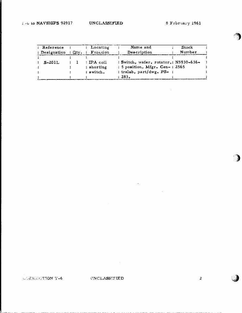
z. Parts List, Page 67, RCA Instruction Book, below S·201J', insert the follow• ing information:
; Reference : : Locating : Name and : Stock : Designation : Qty. ; Function : Description : Number
S·Z01K 1 :Receiver in-: Switch, wafer, rotator,: N5930-636-! put shorting : 5 position, Mfgr. Cen- : 2565 : switch. : tralab, part/dwg. PS- :
: 283.
3. Parts List, Page 67, RCA Instruction Book, below S-ZOlK, insert the following information:
CORRECTION T-6 UNCLASSIFIED Page 1 (of ·4)
.�. ·v to NAVSHIPS 92.917
: Reference : Designation : Qty:
S-2.01L 1
_,;;: �x,Ct'!ON T-6
UNCL.ASSI:nED 8 Februa:.:y 1961
r:oca.tiug Name and ; Stock Fun�tio�-· Description : Number
: IPA coil shorting
: switch.
: Switch, wafer, rotator,: N59 30-636• : 5 position, Mfgr. Cen- : 2.565 : tralab, part/dwg. PS.-: 283.
UNCLASSIFIED 2
·�
')
·.�

(
(
(
T-6 to N . .t.VSHIPS 92917
L-214
S-20IK REAR
CORRECTION T-6
4
I
DNCl.ASSinE' D I February 1961
TO R. F
AMPLIFIER VZII 681;6
BEFORE FIELD CHANGE -+-
AFTER FIELD CHANGE
� 0
1
4 2
Q... "
3 ( f �r.�··:J)�I r· --'-if' \�
··�' -FIGURE I
UNCLASSIJ"'rD
.�,_.i,._ ___ _
I •
TO R.F AMPLifiER V211 6BA6
3
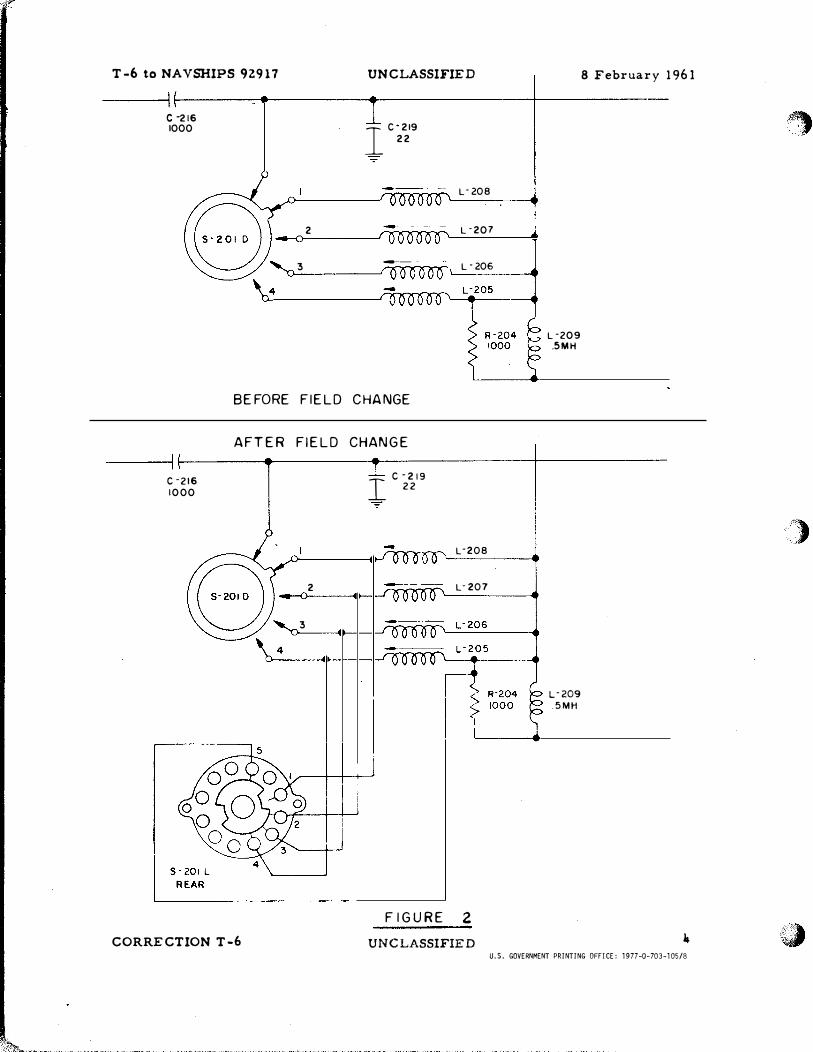
T -6 to NA VSHIPS 92917
c -216 1000
2
UNCLASSIFIED
I c·219
22
L-208
L-207
3 ---- .
1 L - 206 •
BEFORE FIELD CHANGE
AFTER FIELD CHANGE
c "216 1 000
CORRECTION T-6
2
3
I c "219
22
W L"208
L-207
F IGURE 2
UNCLASSIFIED
L ·209 .5MH
L-209 .5MH
8 February 1961
•
U.S. GOVERNMENT PRINTING OFFICE: 1977-0-703-105/8
·".· ,
··)�, '·>J<
; .,. �
Related Documents