Operating Manual DELTA SW4 Single Seat and Change-over Valve Read and understand this manual prior to operating or servicing this product. www.sks-online.com www.sks-webshop.com

Welcome message from author
This document is posted to help you gain knowledge. Please leave a comment to let me know what you think about it! Share it to your friends and learn new things together.
Transcript

Operating Manual
DELTA SW4Single Seat and Change-over Valve
Read and understand this manual prior to
operating or servicing this product.
www.sks-online.com www.sks-webshop.com

www.sks-online.com www.sks-webshop.com

Declaration of Conformity for Valves and Valve Manifolds
SPX Flow Technology Rosista GmbH, Zechenstr. 49, D-59425 Unna-Königsborn herewith declares that the
double seat valves of the series D2, SD4, SDT4, SDM4, SWcip4, DSV,
DA3, DE3, DEU3, DET3, DKR2, DKRT2, DKRH2 in the nominal diameters DN 25 - 150, 1“ – 6“ and 1 Sh5 - 6 Sh5
butterfly valves of the series SV1 and SVS 1 F
in the nominal diameters DN 25 - 100, DN 125 - 250 and 1“ – 4“
ball cocks of the series KH, KHV in the nominal diameters DN 15 - 100
single seat, diaphragm and spring loaded valves of the series
S2, SW4, SWmini4, SWT4, M3, MF3, M4, MF4, MP4, MS4, AP1, APT1, CPV, RG4, RGM4, RGE4, RGEM4, PR2, PR3, PR4, SI2, UF3, VRA,VRAH
in the nominal diameters DN 10 - 150, 1/2“ – 4“ and 1 Sh5 - 6 Sh5
and the valve manifolds installed thereof
meet the requirements of the Directives 2006/42/EC (superseding 89/392/EEC and 98/37/EC) and GPSG - 9.GPSGV.
For official inspections, SPX Flow Technology Rosista GmbH presents
a technical documentation according to Appendix VII of the Machinery Directive, this documentation consisting of documents of the development and construction,
description of measures taken to meet the conformity and to correspond with the basic requirements on safety and health, incl. an analysis of the risks,
as well as an operating manual with safety instructions.
The conformity of the valves and valve manifolds is guaranteed.
Authorised person for the documentation: SPX Flow Technology Rosista GmbH, Frank Baumbach, Zechenstr. 49, D-59425 Unna
November 30, 2010
Manager Research and Development
UK
www.sks-online.com www.sks-webshop.com

www.sks-online.com www.sks-webshop.com

DELTA SW4 - UK-3.qxp 23.04.2009
UK
Single Seat and Change-over Valve
DELTA SW4
Operating manual UK - rev. 3
1
1. General Terms 2
2. Safety Instructions 2
3. Mode of Operation 3
4. Auxiliary Equipment 4 - 54.1. Valve position indication
4.2. Control Unit
4.3. Stoke limitation SW4 / M4
4.4. Oil dampening cylinder
4.5. SW4 variants
5. Installation 6 - 75.1. Connections (threaded connections/clamp flange connections)
5.2. Welding instructions
6. Dimensions / Weights 8 - 96.1. Single seat valve
6.2. Change-over valve
7. Technical Data7.1. General data
7.2. Specification of compressed air quality
7.3. Closing times
7.4. Valve stroke
7.5. Pneumatic air consumption
7.6. Product pressures
7.7. kvs - values in m3/h 10 - 13
8. Maintenance 14
9. Service Instructions - Single seat valve 15 - 169.1 Dismantling from the line system
9.2 Disassembly of wear parts (product-wetted parts)
9.3 Installation of seals and assembly of valve
9.4 Installation of valve
10. Service Instructions - Actuator 1710.1 Maintenance of actuator
10.2 Installation of seals and assembly of actuator
10.3 Actuator with valve position feedback
11. Service Instructions - Change-over valve 18 - 1911.1 Dismantling from the line system
11.2 Disassembly of wear parts (product-wetted parts)
11.3 Installation of seals and assembly of valve
11.4 Installation of valve
12. Service Instructions 20Assembly tool for seat seal
13. Reconstruction of Actuator 2113.1. Reconstruction of actuator / dismantling
13.2. Assembly of actuator
14. Trouble Shooting 22
15. Spare Parts Lists15.1 Valve housing DN 25-100
15.2 Valve housing Inch 1”-4”
15.3 Actuator
15.4 Valve position indication
Table of Contents Page
www.sks-online.com www.sks-webshop.com

www.sks-online.com www.sks-webshop.com

1. General Terms
DELTA SW4 - UK-3.qxp 23.04.2009
UK
Single Seat and Change-over Valve
DELTA SW4
Operating manual UK - rev. 3
2
This operating manual should be read carefully by the competent
operating and maintenance personnel.
We point out that we will not accept any liability for damage or
malfunctions resulting from the non-compliance with this
operating manual.
Descriptions and data given herein are subject to technical
changes.
2. Safety Instructions
- DANGER!
- The technical safety symbol draws your attention to important
directions for operating safety. You will find it wherever the
activities described are bearing risks of personal injury.
- Separate electric and pneumatic connections.
- Depressurize the line system before any maintenance work.
Clean the valve if possible and drain residual liquids.
- Do not reach into the open valve.Risk of injury by suddenly operating valve. In dismantled state
there is the risk of bruising at movable parts of the valve.
- Observe Service Instructions to ensure safe maintenance
of the valve.
- Attention!With valve design NC (normally closed): Before releasing the housing clamp connection, the valve insert must be relieved by controlling the actuator.
- Attention!Welded actuators are preloaded by spring force.
Actuators which are no longer used and / or defective must be disposed in professional manner.
Defective actuators must be returned to your APV Solutions & Services company
for their professional disposal and free of charge for you.
Please address to your local APV representative.
Opening of the actuators is strictly forbidden.Danger to life!
!
!
!
www.sks-online.com www.sks-webshop.com

UK
Single Seat and Change-over Valve
DELTA SW4
Operating manual UK - rev. 3
3
Single seat and change-over valves DELTA SW4 have been
developed for use in the brewing and beverage, dairy
and food industries as well as for chemical and pharmaceutical
applications.
The valves are designed for universal applications and stand out
for their increased mechanical reliability and absolute ease of
service.
The field of application of the DELTA SW4 - valve is to shut off
and to change over line sections.
- Operation by pneumatic actuator with air connection,
reset by spring force.
- By different assembly of the actuator, the following designs
are possible:
NC: actuator normally closed / air-to-raise, spring-to-lower
NO: actuator normally open / air-to-lower, spring-to-raise
- The inner parts of the actuator need not be serviced.
- The cleaning of the inner valve is undertaken during CIP cleaning
of the line system.
- The standard SW4 valve is equipped with a control unit
DELTA CU 41 Direct Connect.
- The luminous diodes in the control unit indicate the position
of the valve shaft.
Single seat valve
Change-over valve
clamp
housing seal
housing - upper part
housing
seat seal
clamp
housing seal
shaft
actuator screw
hex. nut
centering washer
CU adapter
housing
shaft
seat seal
clamp
housing seal
yoke
guide bush
shaft seal
actuator
control unit
seat seal
3. Mode of Operation
DELTA SW4 - UK-3.qxp 23.04.2009
www.sks-online.com www.sks-webshop.com

UK
Single Seat and Change-over Valve
DELTA SW4
Operating manual UK - rev. 3
4
4.1. Valve position indication (fig. 4.1.)- Alternatively to the Control Unit, proximity switch holders (PSH)
for the valve position indication can be mounted on the actuator.
Proximity switches to signal the limit position of the valve seat
can be installed at the proximity switch holder if required.
We recommend to use our APV standard type:
Three-wire proximity switchOperating distance: 5mm / diameter: 11mm
Operating voltage: 10 - 30 V DC
pnp positive switching, closing function
Installation ,,non-flush"
Using a valve position indicator other than APV, we cannot accept
any liability for a faultless function.
4.2 Control Unit (fig. 4.2.)For the start-up as well as assembly and disassembly of the
different designs please use the respective manual.
The following different designs are available:
- An adapter is required to install the control unit on the SW4 valve.
valve position indication
fig. 4.1.
fig. 4.2.
CU3 Control Unit
CU4 Control Unit
Direct Connectreference number:
CU41-S-Direct Connect
08 - 45 - 100/93; H320460
Profibusreference number:
CU31-Profibus
08 - 45 - 001/93; H315495
Device Netreference number:
CU31 Device Net
16 - 31 - 240/93; H209422
AS-Interface 2.1reference number:
CU31 AS-interface 2.1
08 - 45 - 020/93; H315507
Benennung:reference number:
CU3 - adapter SW4 / M4
08-48-480/93; H315806
Benennung:reference number:
CU4-S-adapter for DN25/1”-100/4”
08-48-600/93; H320474
4. Auxiliary Equipment
DELTA SW4 - UK-3.qxp 23.04.2009
www.sks-online.com www.sks-webshop.com

UK
Single Seat and Change-over Valve
DELTA SW4
Operating manual UK - rev. 3
5
4.3. Stroke limitation SW4 / M4 (fig. 4.3.)The pneumatic stroke limitation provides for the
continuous adjustment of the total valve stroke of 0 - 100%
The pneumatic stroke limitation is installed on the actuator.
- The valve disc can be in three different positions:
open, throttled and closed.- The stroke limitation can only be applied with valve design
NC (FS) = normally closed.
To operate the pneumatic stroke limitation a separate control
is required.
The control unit CU43-S-2 Hall sensors - Direct Connect
can be used for this purpose.
4.4. Oil dampening cylinder (fig. 4.4.)
The oil dampening cylinder provides for a slow opening and
closing of the valve (to prevent pressure hammers in the line
system). The oil dampener is installed between the actuator
and the Control Unit.
- Function:
A throttling valve presses the oil from one chamber of the
dampening cylinder into the second chamber of the cylinder
during the switching process. By adjustment of the throttling
screw, the required delay can be variably adjusted.
4.5 SW4 variantsThe SW4 range contains the following designs:
- DELTA SW4 - DN125-150
- DELTA SW4 with manual actuation
- DELTA SWT4 - tank outlet valve
- DELTA SW4 - long stroke version
- DELTA SW4 -DPF (with steam chamber)
- DELTA SWR4 (with modulating cone).
Corresponding manuals are available for the different designs.
fig. 4.3.
fig. 4.4.
throttle screw
throttle valve
Control Unit + Adapter
Designation:reference number:
CU43-S-2 Hall sensors - Direct Connect
000 08-45-106/93; H320466
Designation:reference number:
CU4-S-adapter complete
000 08-48-600/93; H320474
4. Auxiliary Equipment
DELTA SW4 - UK-3.qxp 23.04.2009
www.sks-online.com www.sks-webshop.com

UK
Single Seat and Change-over Valve
DELTA SW4
Operating manual UK - rev. 3
6
- The installation of the valve must be undertaken in such a manner
that fluids can drain off the valve housing and should be provided
preferably in vertical position.
- Single seat valve : The valve housing can be welded direct
into the pipeline (completely dismantable
valve insert).
- Change-over valve : Through a flange or clamp connection,
the upper housing of change-over valves
is detachable from the pipeline.
(see fig. 5).
- Attention : Observe Welding Instructions.(see chapter 5.2)
5.1 Connections:Besides the housings with weld ends, the following connections
are alternatively available:
- male part to DIN 11851
- male part IDF / ISS to ISO 2853
- male part RJT to BS 4825-5
- male part SMS
- male part to DS 722
- flange connection FGN1 DIN
- flange connection FGN1 Zoll
- clamp connection to DIN 32676
- clamp connection to ISO 2852
change-over valve
separate connection
fig. 5.
5. Installation
DELTA SW4 - UK-3.qxp 23.04.2009
www.sks-online.com www.sks-webshop.com

UK
Single Seat and Change-over Valve
DELTA SW4
Operating manual UK - rev. 3
7
5. Installation
5.2. Welding Instructions
Shut-off valve:- Before welding of the valve, the valve insert must be dismantled
from the housing. Careful handling to avoid damage to the parts
is necessary.
Change-over valve:- Before welding of the valves, the valve insert must be dismantled
from the housing. The lower housing seal must be removed.
Careful handling to avoid damage to the parts is necessary.
- Welding should only be carried out by certified welders (EN 287-1).
(Seam quality EN 25817 "B").
- The welding of the valve housings must be undertaken in such a
way that the valve body is not deformed.
- The preparation of the weld seam up to 3 mm thickness must be
carried out as a square butt joint without air.
(Consider shrinkage!)
- TIG orbital welding is best!
- After welding of the valve housings or of the mating flanges and
after work at the pipelines, the corresponding parts of the
installation or pipelines must be cleaned from welding residues
and soiling. If these cleaning instructions are not observed,
welding residues and dirt particles can settle in the valve and
cause damage.
- Any damage resulting from the non-observance of these welding
instructions is not subject to our guarantee.
DELTA SW4 - UK-3.qxp 23.04.2009
www.sks-online.com www.sks-webshop.com

DELTA SW4 - UK-3.qxp 23.04.2009
UK
Single Seat and Change-over Valve
DELTA SW4
Operating manual UK - rev. 3
8
200
Ø D
FA
L
F
Ø K
Ø 134
SW41
SW42
SWE43
SWE44
A / L
1
SWE41/42
H
F F
G
D
H
F F
Ø D
SWE43/44
housing design
valve positionindication
A1 /
L1
6.1. Single seat valve
DN A L Ø D F G H Ø K A1 L1 weight in kg
25 410 460 26 50 18 54 86 338 442 5
40 414 481 38 67 24 66 86 342 475 5
50 451 523 50 72 32 78 126 379 529 7
65 459 544 66 85 40 94 126 387 566 7
80 512 610 81 98 47,5 109 189 440 647 13
100 522 633 100 111 57 128 189 450 689 15
Inch
1” 408 458 22,6 50 16,3 50,6 86 336 437 5
1,5” 412 479 34,9 67 22,5 62,9 86 340 470 5
2” 450 522 47,6 72 30,8 75,6 126 378 526 7
2,5” 456 541 60,3 85 37,2 88,3 126 384 557 7
3” 507 605 72,9 98 43,5 100,9 189 435 626 13
4” 520 631 97,6 111 55,8 125,6 189 448 685 15
single seat valve withCU4 control unit
SW
E41
SW
E42
6. Dimensions / Weights
dimensions in mm
www.sks-online.com www.sks-webshop.com

UK
Single Seat and Change-over Valve
DELTA SW4
Operating manual UK - rev. 3
9
Ø D
FH
A
L
FF
Ø 134
Ø K
change-over valve withCU4 control unit
200 valve position
indication
A1 /
L1
A / A
1
SWE45 / 46
HH
F F
G
SW
44
SW
43
SW
E46
SW
E45
SW
48
SW
47
dimensions in mm
housing design
6.2. Change-over valve
DN A L Ø D F G H Ø K A1 L1 weight in kg
25 410 460 26 50 18 54 86 338 442 6
40 414 481 38 67 24 66 86 342 475 6
50 451 523 50 72 32 78 126 379 529 8
65 459 544 66 85 40 94 126 387 566 8
80 512 610 81 98 47,5 109 189 440 647 15
100 522 633 100 111 57 128 189 450 689 17
Inch
1” 408 458 22,6 50 16,3 50,6 86 336 437 6
1,5” 412 479 34,9 67 22,5 62,9 86 340 470 6
2” 450 522 47,6 72 30,8 75,6 126 378 526 8
2,5” 456 541 60,3 85 37,2 88,3 126 384 557 8
3” 507 605 72,9 98 43,5 100,9 189 435 626 15
4” 520 631 97,6 111 55,8 125,6 189 448 685 17
Ø D
6. Dimensions / Weights
DELTA SW4 - UK-3.qxp 23.04.2009
www.sks-online.com www.sks-webshop.com

DELTA SW4 - UK-3.qxp 23.04.2009
UK
Single Seat and Change-over Valve
DELTA SW4
Operating manual UK - rev. 3
10
7. Technical Data
7.1. General data
product-wetted parts: 316 L, 1.4404
other parts: 1.4301
seals: standard: EPDM option: HNBR, VMQ, HNBR
max. product pressure: 10 bar
max. operating temperature: 135°C EPDM, HNBR*FPM, *VMQ
short-term load: 140°C EPDM, HNBR*FPM, *VMQ*(no steam)
air connection (for hose) : 6 x 1mmmax. pneumatic air pressure: 8 barmin. pneumatic air pressure: 6 bar
(Use dry and clean pneumatic air, only.)
7.2. Specification of compressed air quality
compressed air quality: quality class acc. to DIN/ISO 8573-1
content of solid particles: quality class 3 max. size of solid particles per m³
10000 of 0,5µm <d<1,0µm
500 of 1,0µm <d<5,0µm
content of water: quality class 4max. dew point temperature + 3°C
For installations at lower
temperatures or at higher altitudes,
additional measures must be
considered to reduce the pressure
dew point accordingly.
content of oil: quality class 1max. 0,01mg/m³
(The oil applied must be compatible with Polyurethaneelastomer materials.)
www.sks-online.com www.sks-webshop.com

UK
Single Seat and Change-over Valve
DELTA SW4
Operating manual UK - rev. 3
11
7.4. DELTA SW4 Valve stroke in mm
7.5. DELTA SW4 Pneumatic air consumption at 6 bar control pressure
7.3. Closing times for single seat and change-over valve DELTA SW4
The opening and closing times of the valves equipped with a control unit
can be determined by adjusting the throttle screw at the solenoid valve.
Closing times in sec.Pneumatic air 6 bar
hose length in meter
DN Inch 1m 10m
25 1” 1 2
40 1,5” 1 2
50 2” 3 4
65 2,5” 3 4
80 3” 5 6
100 4” 5 6
DN Inch
single-seat valve
SW41, SW42
SWE41, 42, 43, 44
change-over valve
SW43, SW44
SWE45, 46
25 1” 12 9
40 1,5” 25 22
50 2” 28 25
65 2,5” 28 25
80 3” 28 25
100 4” 28 25
actuatorper stroke
NL
Ø 74mm 1,0
Ø 110mm 2,1
Ø 165mm 4,5
7. Technical Data
DELTA SW4 - UK-3.qxp 23.04.2009
www.sks-online.com www.sks-webshop.com

DELTA SW4 - UK-3.qxp 23.04.2009
UK
Single Seat and Change-over Valve
DELTA SW4
Operating manual UK - rev. 3
12
7.6. DELTA SW4 calculatory product pressure in (bar)at 6 bar control air pressure
single seat valve
SW41 FS
single seat valve
SW41 NO with
6 bar air pressure
change-over valve
SW43 NC upper seat
with 6 bar air pressure
change-over valve
SW43 NO
upper seat
change-over valve
SW43 NO with
6 bar air pressure
change-over valve
SW43 NC
lower seat
Ø actuator in mm
DN Inch Ø 74 Ø 110 Ø 165
25 1” 11,7
40 1,5” 5,0 12,5
50 2” 2,8 7,6 19,6
2,5” 2,0 5,4 13,8
65 1,7 5,0 11,7
3” 3,8 9,9
80 3,1 7,9
100 4” 2,1 5,3
Ø actuator in mm
Ø 74 Ø 110 Ø 165
11,2
5,4 11,2
3,4 7,1 16,8
2,4 5,0 11,9
2,0 5,0 10,0
3,6 8,5
2,9 6,8
1,9 5,0
Ø actuator in mm
Ø 74 Ø 110 Ø 165
20,3
6,9 14,4
4,0 8,3 19,5
2,7 5,5 13,1
2,2 5,0 10,9
3,8 9,1
3,0 7,2
2,0 5,0
Ø actuator in mm
Ø 74 Ø 110 Ø 165
21,2
6,0 16,0
3,3 8,8 22,8
2,2 6,0 15,3
1,8 5,0 12,7
4,1 10,6
3,3 8,4
2,1 5,5
7. Technical Data
www.sks-online.com www.sks-webshop.com

UK
Single Seat and Change-over Valve
DELTA SW4
Operating manual UK - rev. 3
13
7.7. DELTA SW4 kvs - values in m³ / h
SW41, 42SWE41, 42SWE43, 44
SW41, 42SWE41, 42SWE43, 44
SW42SWE42SW44
SW43, 44SW47, 48
SW43, 44SW47, 48
DN
25 20 21 28 14 13
40 45 53 60 33 31
50 92 85 120 58 51
65 159 159 215 100 89
80 201 209 350 160 137
100 302 325 540 245 212
Inch
1” 16 18 26 10 10
1,5” 38 45 57 30 28
2” 83 77 118 54 49
2,5” 133 133 185 87 76
3” 176 176 300 137 114
4” 292 310 530 225 210
7. Technical Data
DELTA SW4 - UK-3.qxp 23.04.2009
www.sks-online.com www.sks-webshop.com

DELTA SW4 - UK-3.qxp 23.04.2009
UK
Single Seat and Change-over Valve
DELTA SW4
Operating manual UK - rev. 3
14
8. Maintenance
- The maintenance intervals depend on the corresponding
application and are to be determined by the operator himself
carrying out temporary checks.
- The valve must not be cleaned with products containing abrasive
or polishing material.
Especially the valve shaft must not, under any circumstances,
be cleaned with such agents.
Damage of the valve shaft can lead to leakages.
- Required tools :
- 1x wrench SW13
- 1x wrench SW17
- 1x wrench SW19
- 1x wrench SW30
- assembly tool for seat seal
(see chapter 12.)
- Exchange of seals is done according to service instructions.
A customer stock keeping of spare seals is recommended.
For the valve service we supply complete seal kits including
seal grease (see spare parts lists).
- Assembly of the valve and change of the valve design NC or NOaccording to service instructions.
- Slightly grease all seals before their installation !!!!!
Recommendation:APV food-grade-grease for EPDM, HNBR, FPM and NBR(0,75 kg/tin - ref.-No. 000 70-01-019/93)
(60 g/tube - ref.-No. 000 70-01-018/93)
or
APV food-grade-grease for VMQ(0,6 kg/tin - ref.-No. 000 70-01-017/93)
(60 g/tube - ref.-No. 000 70-01-016/93)
!!! Do not use grease containing mineral oil for EPDM seals.
!!! Do not use Silicone-based grease for VMQ seals.
www.sks-online.com www.sks-webshop.com

UK
Single Seat and Change-over Valve
DELTA SW4
Operating manual UK - rev. 3
15
Single seat valvesDELTA SW41, SW42, SWE41, SWE42, SWE43, SWE44
9.1. Disassembly from the line system
1. Shut off line pressure and drain lines if possible.
2. Valve design NC: Control actuator with air!
Do not touch movable valve parts!Risk of injury.
3. Detach clamp and lift valve insert off the housing.
4. Shut off compressed air and remove compressed air supply.
5. Take control unit off the actuator.
9.2. Dismantling of wear parts (product-wetted parts)
1. Remove housing seal.
2. Release actuator screw from the guide rod.
Remove the CU adapter.
3. Release the safety nut by holding the centering washer.
Remove the centering washer.
4. Pull the valve shaft out of the actuator.
Remove the seat seal.
5. Unscrew the yoke from the actuator.
6. Detach the seat seal, shaft seal and guide bush.
actuator screw
hex. nut
centering washer
CU adapter
single seat valve
housing
shaft
seat seal
clamp
housing seal
yoke
guide bush
shaft seal
actuator
control unit
seat seal
!
9. Service Instructions - Single Seat Valve
DELTA SW4 - UK-3.qxp 23.04.2009
www.sks-online.com www.sks-webshop.com

DELTA SW4 - UK-3.qxp 23.04.2009
UK
Single Seat and Change-over Valve
DELTA SW4
Operating manual UK - rev. 3
16
9.3. Installation of seals and assembly of valve
1. Insert the guide bush into the yoke.
Afterwards, insert the shaft seal and press in
the slightly greased seat seal (see fig. 9.3.1.).
See to the correct installing position.
2. Install the yoke at the actuator.
3. Insert the seat seal into the shaft. Use the assembly tool
to install the seat seal (see chapter 12). Grease the
seat seal only slightly before its installation.
In case of manual installation, vent the seal groove with
a thin object between the seal and groove wall.
4. Install the protective tube via the thread of the guide rod.
Slide the shaft through the yoke and actuator,
place centering washer and tighten it with the safety nut.
Hold up the centering washer during this process.
Tightening torque 40 Nm.
5. Slightly grease the housing seal and place it in the groove
of the yoke.
6. Install the adapter for the control unit on the actuator.
Apply a drop of a screw locker (e.g. type: Loctite semi-solid)
in the area of the threaded bore of the actuator screw.
Fasten actuator screw on the guide rod.
9.4. Assembly of valve
1. Fasten the control unit.
2. Connect compressed air supply.
3. Valve design NC: Control actuator with air.
Do not touch movable valve parts!Risk of injury by sudden valve operation.
4. Place the valve insert carefully into the housing and
fasten the clamp.
The housing seal must not be damaged during the installation.
5. Valve design NC: Shut off compressed air.
6. Check the basic adjustment of the valve position indication.
- The shift points can be adjusted by turning the positioning
screw in the control unit.
seat seal
guide bush
shaft seal
yoke
housing seal
shaft
guide rod
protective tube
seat seal
9. Service Instructions - Single Seat Valve
!
fig. 9.3.1.
www.sks-online.com www.sks-webshop.com

UK
Single Seat and Change-over Valve
DELTA SW4
Operating manual UK - rev. 3
17
10. Service Instructions - Actuator
10.1. Maintenance of actuator
1. Remove the air hoses from the actuator.
2. Remove inner hex. screws from the adapter of the control unit.
3. Unscrew the two seal screws with a spanner SW30
while holding up the actuator with a strap wrench.
10.2. Installation of seals and assembly of actuator
1. Install the greased o-rings and v-seals in the seal screws (fig. 10.2)
See to the correct installing direction of the v-seal.
2. Slide the seal screws over the piston rod at both sides of the
actuator and tighten them.
3. Fasten the adapter for the Control Unit and the yoke on the
actuator.
Attention: Observe position of adapter.
Attention: Consider the required valve design NC or NOduring the installation of the adapter and yoke. NC = normally closed / air-to-raise, spring-to-lower
NO = normally open / air-to-lower, spring-to-raise
4. Fasten the air hoses.
10.3. Actuator with valve position indicatorAssemlby of holders (fig. 10.3.)
1. Install the actuator screw on the actuator.
2. Provide the housing with the o-ring.
3. Fasten the housing by means of the 4 hex. screws M8
on the actuator.
4. Release the screws at the proximity switch holder and insert
the corresponding proximity switches. Then fasten the screws.
5. Place the actuator in one limit position.
6. Place the corresponding proximity switch in the corresponding
position. Release the positioning screw and move the holder until
the corresponding signal is indicated. Then continue the movement
by 2 to 3 mm to secure indication.
Fasten the positioning screw.
7. Place the actuator in the other limit position and carry out
positioning of the second proximity switch.
air connection
seal screw
v-seal
v-seal
o-ring
o-ring
actuator
piston rod
screw
positioning screw
proximity switch holder
housing
o-ring
actuator screw
centering washer
hex. screw M8
guide rod
piston rod - actuator
seal screw
fig. 10.2.
fig. 10.3.
DELTA SW4 - UK-3.qxp 23.04.2009
www.sks-online.com www.sks-webshop.com

DELTA SW4 - UK-3.qxp 23.04.2009
UK
Single Seat and Change-over Valve
DELTA SW4
Operating manual UK - rev. 3
18
11.1. Disassembly from the line system
1. Shut off line pressure and drain lines if possible.
2. Release connection between the upper housing globe and
the connected line.
3. Valve design NC: Control actuator with air.
Do not touch movable valve parts!Risk of injury.
4. Remove the lower clamp.
5. Lift the valve insert together with the upper housing
off the lower housing.
6. Attention: Valve design NC:Shutt off compressed air andremove compressed air supply.
7. Take control unit from the actuator.
11.2. Dismantling of product-wetted parts
1. Unscrew the actuator screw from the guide rod.
Dismantle adapter of control unit.
2. Attention: Valve design NC:Control valve with pneumatic air.
3. Unscrew the safety nut, while holding up the
centering washer. Remove the centering washer.
Attention: Valve design NC:Shut off valve with pneumatic air.
4. Take the shaft out of the actuator and remove the seat seals.
5. Detach the upper clamp and upper housing.
Remove the two housing seals.
6. Unscrew the yoke from the actuator.
7. Take off seat seals, shaft seal and guide bush.
Service of actuator, see section 10.1
actuator screw
safety nut
centering washer
control unit
CU adapter
actuator
seat seal
upper clamp
housing seal
upper housing
yoke
guide bush
shaft seal
llower clamp
housing seal
llower housing
shaft
seat seal
11. Service Instructions - Change-over Valve
!
Change-over valve
www.sks-online.com www.sks-webshop.com

UK
Single Seat and Change-over Valve
DELTA SW4
Operating manual UK - rev. 33
19
11.3. Installation of seals and assembly of valve
1. Insert the guide bush into the yoke. Then place the shaft seal,
press in the slightly greased seat seal.
See to the correct installing position.
2. Install the yoke at the actuator.
3. Insert the seat seal in the shaft. Use the APV assembly tool to
install the seat seal, see chapter 12. Grease the seat seal only
slightly before its installation. In case of manual installation, vent
the seal groove with a thin object between seal and groove wall.
4. Slightly grease the housing seals and install them in the grooves
of the yoke and of the upper housing.
Fasten the upper housing at the yoke by means of the clamp.
Attention: Valve design NC:Control the valve with air.
5. Slide the protective tube over the thread of the guide rod.
Slide the shaft through the upper housing, yoke and actuator.
Place the centering washer and tighten the safety nut.
Hold up the safety washer during this process.
Tightening torque 40 Nm.
6. Attention: Valve design NC:Shut off pneumatic air.
7. Install the control unit adapter on the actuator.
Apply a drop of a screw locker (e.g. type: Loctite semi-solid)
in the area of the threaded bore of the actuator screw.
Screw the actuator screw on the guide rod.
11.4. Installation of valve
1. Place the control unit on the adapter and fasten it.
2. Connect the compressed air supply.
3. Valve design NC: Control the actuator with air.
Do not touch movable valve parts!Risk of injury by sudden valve operation.
4. Place the valve insert carefully into the lower housing and
fasten the lower clamp.
The housing seals must not be damaged during the installation.
5. Valve design NC: Shut off compressed air.
6. Check the basic adjustment of the valve position indicator. - The shift points can be adjusted by turning the positioning screws.
seat seal
guide rod
shaft
protective tube
seat seal
guide bush
shaft seal
yoke
housing seal
fig. 11.3.1.
11. Service Instructions - Change-over Valve
!
DELTA SW4 - UK-3.qxp 23.04.2009
www.sks-online.com www.sks-webshop.com
DELTA SW4 - UK-3.qxp 23.04.2009
UK
Single Seat and Change-over Valve
DELTA SW4
Operating manual UK - rev. 3
20
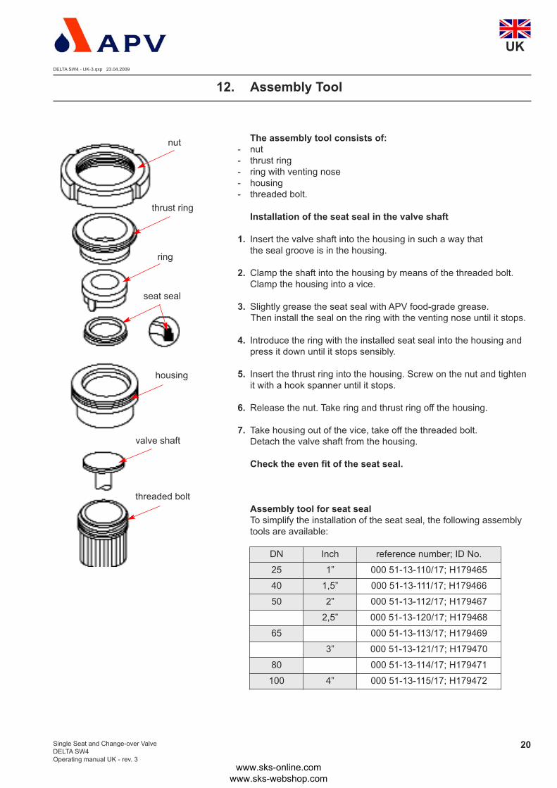
12. Assembly Tool
The assembly tool consists of:- nut
- thrust ring
- ring with venting nose
- housing
- threaded bolt.
Installation of the seat seal in the valve shaft
1. Insert the valve shaft into the housing in such a way that
the seal groove is in the housing.
2. Clamp the shaft into the housing by means of the threaded bolt.
Clamp the housing into a vice.
3. Slightly grease the seat seal with APV food-grade grease.
Then install the seal on the ring with the venting nose until it stops.
4. Introduce the ring with the installed seat seal into the housing and
press it down until it stops sensibly.
5. Insert the thrust ring into the housing. Screw on the nut and tighten
it with a hook spanner until it stops.
6. Release the nut. Take ring and thrust ring off the housing.
7. Take housing out of the vice, take off the threaded bolt.
Detach the valve shaft from the housing.
Check the even fit of the seat seal.
Assembly tool for seat sealTo simplify the installation of the seat seal, the following assembly
tools are available:
nut
thrust ring
ring
seat seal
valve shaft
housing
threaded bolt
DN Inch reference number; ID No.
25 1” 000 51-13-110/17; H179465
40 1,5” 000 51-13-111/17; H179466
50 2” 000 51-13-112/17; H179467
2,5” 000 51-13-120/17; H179468
65 000 51-13-113/17; H179469
3” 000 51-13-121/17; H179470
80 000 51-13-114/17; H179471
100 4” 000 51-13-115/17; H179472
www.sks-online.com www.sks-webshop.com

UK
Single Seat and Change-over Valve
DELTA SW4
Operating manual UK - rev. 3
21
At SW4 valves, the size of the actuator can be changed.
Observe the respective line pressure, see table page 12,
to increase or decrease the actuator sizes
(Ø 74 mm, Ø 110 mm, Ø 165 mm).
13.1 Reconstruction of actuatorDisassembly
1. Disassembly is carried out as described in chapter 9.
for single seat valves and in chapter 10. for change-over valves.
2. To change the actuator size, the respective guide rod (4)must be replaced.
Clamp the valve disc in a vice.
Attention: The valve disc must not be damaged (use protective cheeks or cleaning rags).Even inferior damage at the shaft rod
can lead to leakages.
3. Turn the guide rod (4) out of the shaft by means of the
centering washer (3) and a wrench SW17.
Assembly of actuator
1. Turn the respective guide rod into the shaft to the actuator.
Tightening torque 40 Nm
2. Further assembly is undertaken in reverse order.
13. Reconstruction of Actuator
DELTA SW4 - UK-3.qxp 23.04.2009
www.sks-online.com www.sks-webshop.com

DELTA SW4 - UK-3.qxp 23.04.2009
UK
Single Seat and Change-over Valve
DELTA SW4
Operating manual UK - rev. 3
22
14. Trouble Shooting
15. Spare Parts Lists
The reference numbers of the spare parts for the different
valve designs and sizes are included in the attached
spare parts drawings with corresponding lists.
Please indicate the following data
to place an order for spare parts:
- number of required parts
- reference number
- designation.
To order a complete new SW4 valve, please use the
the corresponding ordering sheet.
DELTA SW4 - VALVE PROGRAMME
ORDERING SHEET FOR SW4 VALVES WITH FITTINGS
Failure Remedy
Valve closed and pressure in upper housing
Valve is untight.
Replace seat seals.
Check line pressure:
permissible line pressure see 7.
Leakage in the area of the clamp. Replace housing seals.
Leakage at the upper valve shaft in the area
of the valve yoke.
Replace shaft seal, seat seal
and guide bush.
Actuator
Air escapes from the actuator rod. Replace complete seal screw for actuator.
Actuator does not work (air escapes permanently
from the venting plug.)Replace complete actuator.
Valve position indication
Feedback is missing. Carry out fine adjustment.
www.sks-online.com www.sks-webshop.com

SPX Flow Technology Rosista GmbHZechenstraße 49
D-59425 Unna
Phone: +49(0) 23 03/ 108-0 Fax: +49(0) 23 03 / 108-210
For more information about our worldwide locations, approvals, certifications and local representatives, please visit www.spxft.com.
Copyright © 2008 SPX Corporation
The information contained in this document, including any specifications and other product details, are subject to change without notice.
While we have taken care to ensure the information is accurate at the time of going to press, we assume no responsibility for errors or
omissions nor for any damages resulting from the use of the information contained herein.
Your local contact:
Translation of original operating manualUK
rev. 3
BA SW4 0000002
ID-No.: H170733
www.sks-online.com www.sks-webshop.com
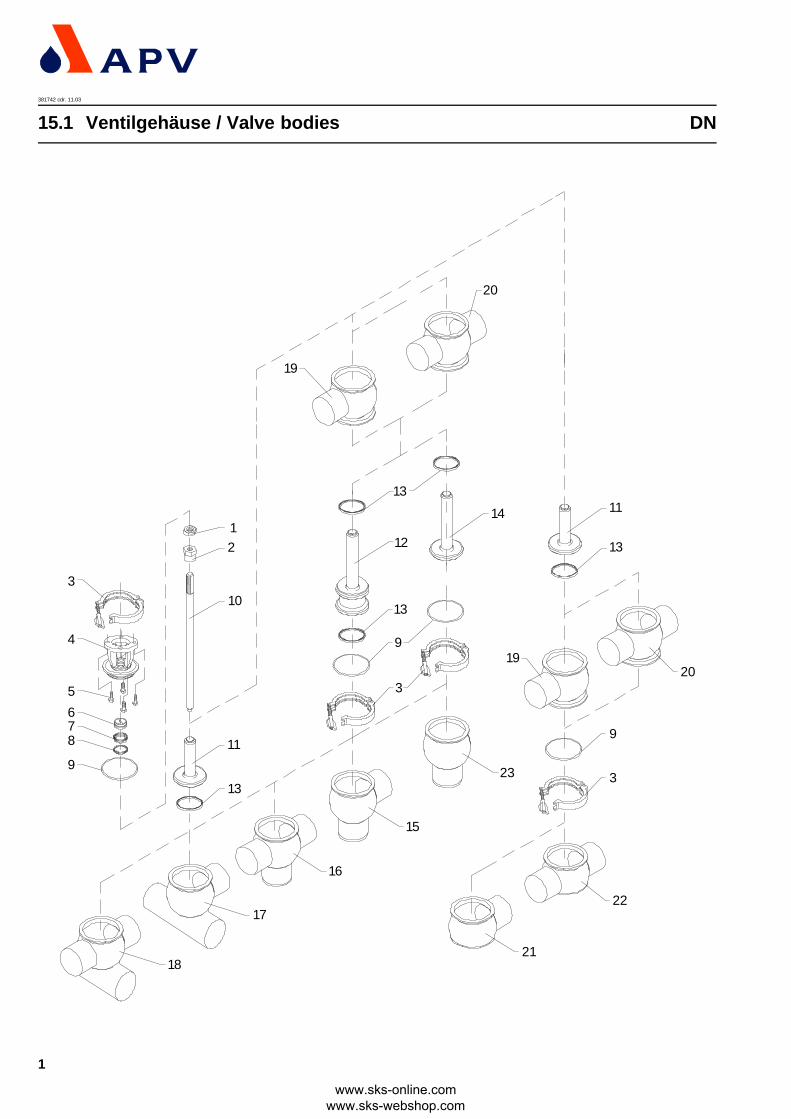
15.1 Ventilgehäuse / Valve bodies DN381742 cdr. 11.03
3
4
5
678
9
12
9
9
3
3
15
23
16
17
18
10
11
14
13
13
13
19
19
20
20
21
22
13
11
12
1
www.sks-online.com www.sks-webshop.com

www.sks-online.com www.sks-webshop.com

12345
678910
11121314
151617181920212223
DN15.1 Ventilgehäuse / Valve bodies
Pos. Stk./Qty. Benennung Description
DN25 DN40
65-50-101/1515-28-940/1242-40-387/1215-40-961/47
08-01-178/2358-33-150/2658-33-293/**58-33-292/**15-23-850/12
15-25-378/4215-25-379/4258-33-393/**15-25-380/42
15-60-390/4715-61-390/4715-66-380/4715-67-380/4715-62-002/4715-63-002/4715-60-101/4715-65-381/4715-60-091/47
DN50
65-50-101/1515-28-940/1242-40-437/1215-40-962/47
08-01-178/2358-33-150/2658-33-293/**58-33-124/**15-23-851/12
15-25-428/4215-25-429/4258-33-443/**15-25-430/42
15-60-440/4715-61-440/4715-66-430/4715-67-430/4715-62-003/4715-63-003/4715-60-102/4715-65-431/4715-60-092/47
DN65
65-50-101/1515-28-940/1242-40-487/1215-40-963/47
08-01-178/2358-33-150/2658-33-293/**58-33-442/**15-23-851/12
15-25-478/4215-25-479/4258-33-493/**15-25-480/42
15-60-490/4715-61-490/4715-66-480/4715-67-480/4715-62-004/4715-63-004/4715-60-103/4715-65-481/4715-60-093/47
DN80
65-50-101/1515-28-940/1242-40-537/1215-40-966/47
08-01-178/2358-33-150/2658-33-293/**58-33-492/**15-23-852/12
15-25-528/4215-25-529/4258-33-543/**15-25-530/42
15-60-540/4715-61-540/4715-66-530/4715-67-530/4715-62-005/4715-63-005/4715-60-104/4715-65-531/4715-60-094/47
DN100
65-50-101/1515-28-940/1242-40-637/1215-40-967/47
08-01-178/2358-33-150/2658-33-293/**58-33-127/**15-23-852/12
15-25-628/4215-25-629/4258-33-643/**15-25-630/42
15-60-640/4715-61-640/4715-66-630/4715-67-630/4715-62-006/4715-63-006/4715-60-105/4715-65-631/4715-60-095/47
Pos. Stk./Qty.
1111
Benennung
Dichtungssatz FPMDichtungssatz EPDMDichtungssatz VMQDichtungssatz HNBR
Description
Seal kit FPMSeal kit EPDMSeal kit VMQSeal kit HNBR
DN25
58-34-700/0058-34-700/0158-34-700/0258-34-700/06
DN40
58-34-701/0058-34-701/0158-34-701/0258-34-701/06
DN50
58-34-702/0058-34-702/0158-34-702/0258-34-702/06
DN65
58-34-703/0058-34-703/0158-34-703/0258-34-703/06
DN80
58-34-704/0058-34-704/0158-34-704/0258-34-704/06
DN100
58-34-705/0058-34-705/0158-34-705/0258-34-705/06
Ws.-Nr. / Part No.
Pos. Stk./Qty.
1111
Benennung
Dichtungssatz FPMDichtungssatz EPDMDichtungssatz VMQDichtungssatz HNBR
Description
Seal kit FPMSeal kit EPDMSeal kit VMQSeal kit HNBR
DN25
58-34-715/0058-34-715/0158-34-715/0258-34-715/06
DN40
58-34-716/0058-34-716/0158-34-716/0258-34-716/06
DN50
58-34-717/0058-34-717/0158-34-717/0258-34-717/06
DN65
58-34-718/0058-34-718/0158-34-718/0258-34-718/06
DN80
58-34-719/0058-34-719/0158-34-719/0258-34-719/06
DN100
58-34-720/0058-34-720/0158-34-720/0258-34-720/06
Ws.-Nr. / Part No.
Pos. Stk./Qty.
1111
Benennung
Dichtungssatz FPMDichtungssatz EPDMDichtungssatz VMQDichtungssatz HNBR
Description
Seal kit FPMSeal kit EPDMSeal kit VMQSeal kit HNBR
DN25
58-34-730/0058-34-730/0158-34-730/0258-34-730/06
DN40
58-34-731/0058-34-731/0158-34-731/0258-34-731/06
DN50
58-34-732/0058-34-732/0158-34-732/0258-34-732/06
DN65
58-34-733/0058-34-733/0158-34-733/0258-34-733/06
DN80
58-34-734/0058-34-734/0158-34-734/0258-34-734/06
DN100
58-34-735/0058-34-735/0158-34-735/0258-34-735/06
Ws.-Nr. / Part No.
381742 / 11.03
Skt. MutterZentrierscheibeGelenkklemmeLaterneSkt. Schraube
FührungsbuchseSchaftdichtungTellerdichtung*Gehäusedichtung*Zugstange
Schaft SW41Schaft SW43Tellerdichtung*Schaft SWT4
Gehäuse SW41Gehäuse SW42Gehäuse SWE43Gehäuse SWE44Geh.-Oberteil SW43Geh.-Oberteil SW44Geh.-Untert. SWE41Geh.-Untert. SWE48Kugelring SW41
Nut Center washerClampYokeScrew
Bushing Shaft seal Seat seal Housing sealGuide rod
Shaft SW41Shaft SW43Seat sealShaft SWT4
Housing SW41Housing SW42Housing SWE43Housing SWE44Hous.-upp. part SW43Hous.-upp. part SW44Hous.-low.part SWE41Hous.-low.part SWE48Ball ring SW41
65-50-101/1515-28-940/1242-40-287/1215-40-960/47
08-01-178/2358-33-150/2658-33-293/**58-33-267/**15-23-850/12
15-25-278/4215-25-279/4258-33-293/**15-25-280/42
15-60-290/4715-61-290/4715-66-280/4715-67-280/4715-62-001/4715-63-001/4715-60-100/4715-65-281/4715-60-090/47
DIN EN 24017-M8x20-A2-70DIN EN 24017-M8x16-A2-70
Ws.-Nr. / Part No.
* Dichtungssatz für SW41 + SW42 / SWE43+ SWE44Seal kit for SW41 + SW42 / SWE43+ SWE44
* Dichtungssatz für SWE41 + SWE42Seal kit for SWE41 + SWE42
* Dichtungssatz für SW43 + SW44Seal kit for SW43 + SW44
** /33: HNBR; /73: FPM (Viton); /93: EPDM; /13: VMQ****** Wenn die Tellerdichtung in VMQ ist, wird die Gehäusedichtung (Pos.9) in HNBR eingesetzt.
When seat seals are made of VMQ (silicone), the body seal (pos. 9) is to be made of HNBR
11
1-214
111
1-21
11
1-21
111111111
2
www.sks-online.com www.sks-webshop.com

www.sks-online.com www.sks-webshop.com

Zoll / inch15.2 Ventilgehäuse / Valve bodies381744 cdr. 11.03
3
4
5
678
9
12
9
9
3
3
15
23
16
17
18
10
11
14
13
13
13
19
19
20
20
21
22
13
11
12
3
www.sks-online.com www.sks-webshop.com

www.sks-online.com www.sks-webshop.com

58-34-701/0058-34-701/0158-34-701/0258-34-701/06
Zoll / inch15.2 Ventilgehäuse / Valve bodies381744 / 11.03
Pos. Stk./Qty.
12345
678910
11121314
151617181920212223
Benennung
1,5” 2”
65-50-101/1515-28-940/1242-40-437/1215-40-962/47
08-01-178/2358-33-150/2358-33-293/**58-33-124/**15-23-851/12
15-25-453/4215-25-454/4258-33-443/**15-25-455/42
15-60-465/4715-61-465/4715-66-455/4715-67-455/4715-62-012/4715-63-012/4715-60-112/4715-65-456/4715-60-085/47
2,5”
65-50-101/1515-28-940/1242-40-487/1215-40-964/47
08-01-178/2358-33-150/2358-33-293/**58-33-125/**15-23-851/12
15-25-503/4215-25-504/4258-33-109/**15-25-505/42
15-60-515/4715-61-515/4715-66-505/4715-67-505/4715-62-013/4715-63-013/4715-60-113/4715-65-506/4715-60-086/47
3” 4”
65-50-101/1515-28-940/1242-40-637/1715-40-967/47
08-01-178/2358-33-150/2358-33-293/** 58-33-127/**15-23-852/12
15-25-653/4215-25-654/4258-33-643/**15-25-655/42
15-60-665/4715-61-665/4715-66-655/4715-67-655/4715-62-015/4715-63-015/4715-60-115/4715-65-656/4715-60-088/47
** /33: HNBR; /73: FPM (Viton); /93: EPDM; /13: VMQ****** Wenn die Tellerdichtung in VMQ ist, wird die Gehäusedichtung (Pos.9) in HNBR eingesetzt.
When seat seals are made of VMQ (silicone), the body seal (pos. 9) is to be made of HNBR
Pos. Stk./Qty.
1111
Benennung
Dichtungssatz FPMDichtungssatz EPDMDichtungssatz VMQDichtungssatz HNBR
Description
Seal kit FPMSeal kit EPDMSeal kit VMQSeal kit HNBR
1”
58-34-700/0058-34-700/0158-34-700/0258-34-700/06
1,5” 2”
58-34-702/0058-34-702/0158-34-702/0258-34-702/06
2,5”
58-34-710/0058-34-710/0158-34-710/0258-34-710/06
3”
58-34-711/0058-34-711/0158-34-711/0258-34-711/06
4”
58-34-705/0058-34-705/0158-34-705/0258-34-705/06
Ws. - Nr. / Part No.
* Dichtungssatz für SW41 + SW42 / SWE43+ SWE44Seal kit for SW41 + SW42 / SWE43+ SWE44
Pos. Stk./Qty.
1111
Benennung
Dichtungssatz FPMDichtungssatz EPDMDichtungssatz VMQDichtungssatz HNBR
Description
Seal kit FPMSeal kit EPDMSeal kit VMQSeal kit HNBR
1”
58-34-715/0058-34-715/0158-34-715/0258-34-715/06
1,5”
58-34-716/0058-34-716/0158-34-716/0258-34-716/06
2”
58-34-717/0058-34-717/0158-34-717/0258-34-717/06
2,5”
58-34-725/0058-34-725/0158-34-725/0258-34-725/06
3”
58-34-726/0058-34-726/0158-34-726/0258-34-726/06
4”
58-34-720/0058-34-720/0158-34-720/0258-34-720/06
Ws. - Nr. / Part No.
* Dichtungssatz für SWE41 + SWE42Seal kit for SWE41 + SWE42
* Dichtungssatz für SW43 + SW44Seal kit for SW43 + SW44
Pos. Stk./Qty.
1111
Benennung
Dichtungssatz FPMDichtungssatz EPDMDichtungssatz VMQDichtungssatz HNBR
Description
Seal kit FPMSeal kit EPDMSeal kit VMQSeal kit HNBR
1”
58-34-730/0058-34-730/0158-34-730/0258-34-730/06
1,5”
58-34-731/0058-34-731/0158-34-731/0258-34-731/06
2”
58-34-732/0058-34-732/0158-34-732/0258-34-732/06
2,5”
58-34-740/0058-34-740/0158-34-740/0258-34-740/06
3”
58-34-741/0058-34-741/0158-34-741/0258-34-741/06
4”
58-34-735/0058-34-735/0158-34-735/0258-34-735/06
Ws. - Nr. / Part No.
11
1-214
111
1-21
11
1-21
111111111
Skt. Mutter M12Zentrierscheibe SW4GelenkklemmeLaterneSkt. Schraube
FührungsbuchseSchaftdichtungTellerdichtung*Gehäusedichtung*Zugstange
Schaft SW41Schaft SW43Tellerdichtung*Schaft SWT4
Gehäuse SW41Gehäuse SW42Gehäuse SWE43Gehäuse SWE44Geh.-Oberteil SW43Geh.-Oberteil SW44Geh.-Untert. SWE41Geh.-Untert. SWE48Kugelring SW41
Nut M12Center washer SW4ClampYokeScrew
Bushing Shaft seal Seat seal Housing sealGuide rod
Shaft SW41Shaft SW43Seat sealShaft SWT4
Housing SW41Housing SW42Housing SWE43Housing SWE44Hous.-upp. part SW43Hous.-upp. part SW44Hous.-low.part SWE41Hous.-low.part SWE48Ball ring SW41
65-50-101/1515-28-940/1242-40-387/1215-40-961/47
08-01-178/2358-33-150/2358-33-293/**58-33-292/**15-23-850/12
15-25-403/4215-25-404/4258-33-393/**15-25-405/42
15-60-415/4715-61-415/4715-66-405/4715-67-405/4715-62-011/4715-63-011/4715-60-111/4715-65-406/4715-60-084/47
65-50-101/1515-28-940/1242-40-537/1215-40-965/47
08-01-178/2358-33-150/2358-33-293/**58-33-126/**15-23-852/12
15-25-553/4215-25-554/4258-33-568/**15-25-555/42
15-60-565/4715-61-565/4715-66-555/4715-67-555/4715-62-014/4715-63-014/4715-60-114/4715-65-556/4715-60-087/47
Description Ws. - Nr. / Part No.
1”
65-50-101/1515-28-940/1242-40-287/1215-40-960/47
08-01-178/2358-33-150/2358-33-293/**58-33-267/**15-23-850/12
15-25-303/4215-25-304/4258-33-293/**15-25-305/42
15-60-315/4715-61-315/4715-66-305/4715-67-305/4715-62-010/4715-63-010/4715-60-110/4715-65-306/4715-60-083/47
DIN EN 24017-M8x20-A2-70DIN EN 24017-M8x16-A2-70
4
www.sks-online.com www.sks-webshop.com

www.sks-online.com www.sks-webshop.com

Ø74
--1
2*3
--2
1-21
Ø165
Actuator completeActuator complete Air/AirSeal bearing with O-ring and V-seal
Elbow Connector G1/8”Plug
15-32-052/1715-32-087/1715-28-845/93
08-60-750/9308-60-005/93
Ø110
15-32-051/1715-32-086/1715-28-845/93
08-60-750/9308-60-005/93
15-32-050/1715-32-085/1715-28-845/93
08-60-750/9308-60-005/93
Ws.-Nr. / Part No.Description
15.3 Steuerkopf / Actuator381743 ISS T 11.03
* Der Steuerkopf kpl. und Steuerkopf kpl. Luft / Luft ist standardmäßig mit 2 x Winkelverschraubungen ausgerüstet.* The actuator cpl. and actuator cpl. air/ air is designed with 2 x Elbow connector by standard.
1
1
1
1
3
1
2
Steuerkopf kpl.Steuerkopf kpl. - Luft/LuftDichtungsschraube mitO-ring und V-Dichtung
Winkelverschraubung G1/8”Stopfen
BenennungStk./Qty.Pos.
5
www.sks-online.com www.sks-webshop.com

www.sks-online.com www.sks-webshop.com
381727 ISS T 11.03
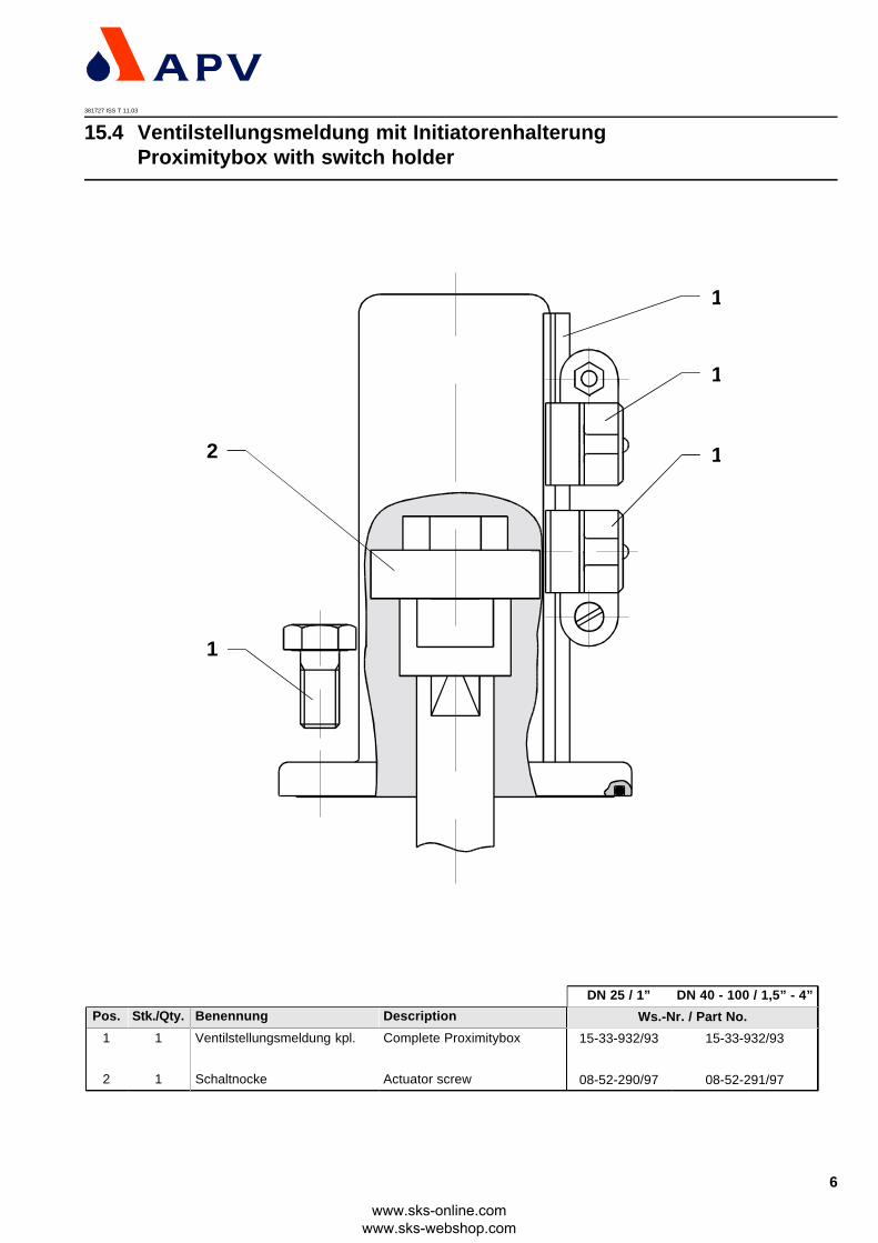
15.4 Ventilstellungsmeldung mit InitiatorenhalterungProximitybox with switch holder
2
1
1
1
1
Pos. Stk./Qty.
1
2
1
1
Benennung
Ventilstellungsmeldung kpl.
Schaltnocke
Description
Complete Proximitybox
Actuator screw
DN 25 / 1”
15-33-932/93
08-52-290/97
DN 40 - 100 / 1,5” - 4”
15-33-932/93
08-52-291/97
Ws.-Nr. / Part No.
6
www.sks-online.com www.sks-webshop.com

www.sks-online.com www.sks-webshop.com
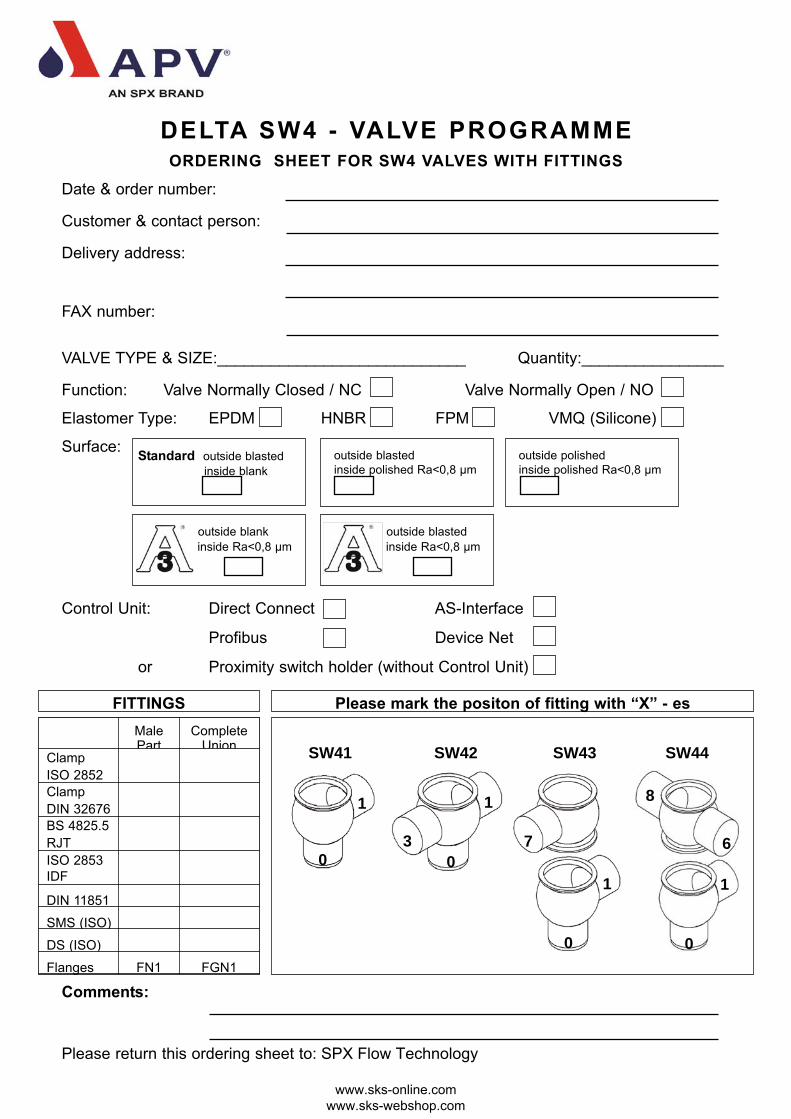
Date & order number:
Customer & contact person:
Delivery address:
FAX number:
VALVE TYPE & SIZE:____________________________ Quantity:________________
Function: Valve Normally Closed / NC Valve Normally Open / NO
Elastomer Type: EPDM HNBR FPM VMQ (Silicone)
Surface:
Control Unit: Direct Connect AS-Interface
Profibus Device Net
or Proximity switch holder (without Control Unit)
Comments:
Please return this ordering sheet to: SPX Flow Technology
DELTA SW4 - VALVE PROGRAMMEORDERING SHEET FOR SW4 VALVES WITH FITTINGS
Standard outside blasted
inside blank
outside blasted
inside polished Ra<0,8 µm
outside blank
inside Ra<0,8 µm
outside polished
inside polished Ra<0,8 µm
FITTINGS
outside blasted
inside Ra<0,8 µm
MalePart
CompleteUnion
Clamp
ISO 2852
Clamp
DIN 32676
BS 4825.5
RJT
ISO 2853
IDF
DIN 11851
SMS (ISO)
DS (ISO)
Flanges FN1 FGN1
SW41 SW42 SW43 SW44
Please mark the positon of fitting with “X” - es
7
0
10
1
3
1
0
0
1
8
6
www.sks-online.com www.sks-webshop.com
Related Documents