SINGLE-POINT INSERTION THERMAL MASS FLOW TRANSMITTERS . . ™ SERIES 454FTB

Welcome message from author
This document is posted to help you gain knowledge. Please leave a comment to let me know what you think about it! Share it to your friends and learn new things together.
Transcript
SSIINNGGLLEE--PPOOIINNTT IINNSSEERRTT IIOONNTTHHEERRMMAALL MMAASSSS FFLLOOWWTTRRAANNSSMMIITTTTEERRSS
. .
™
S E R I E S 454FTB
KEY FEATURES
■ Easy-to-use menu for display and set-up with HELPscreens.
■ Two-line 16 character, back-lit LCD with twenty button keypad (optional).
■ User selectable scrolling display.■ Adjustable LCD/Keypad orientation allowing ease
of reading the display for horizontal or vertical installations.
■ Process Temperature Rating of -40°C to +260°C(HT) or -40°C to +500°C (HHT).
■ PID Flow Controller.■ Two optically isolated loop-powered 4-20 mA
outputs, one for mass flow rate or mass velocity,one for process temperature or for PID application.
■ 4-20 mA outputs meet NAMUR NE43 recommendations.
■ Two optically isolated solid-state alarm/relays (optional).
■ Pulsed output for use as a remote flow totalizer(optional).
■ User selected English or Metric units (SFPM, SCFM,SCFH, PPM, PPH, °F; NMPS, NLPM, NCMH, KGM,KGH, °C).
■ Multi-Point calibration correction factors for Flow andTemperature.
■ User-entered METER ID.■ User-entered flow area.■ Programmable sensor out-of-tolerance indication and
alarm functions.■ User may change STP reference condition.■ User-selectable digital filtering for each METER.■ Built-in flow totalizers and elapsed time.■ User Access Code.■ USB port for terminal operation.■ Modbus ASCII or RTU communications.■ IP66/NEMA 4X/7 dual chamber epoxy painted
electronics enclosure.■ CE Compliance, including the current EMC,ATEX,
LVD and PED Directives.■ Configuration upload/download software using
a PC and USB connection.■ Velocity/Temperature/Mapping (VTM) for wide ranging
velocity and temperature.■ Input power options of 85 to 265 VAC 47/63 Hz
or 24 VDC.■ Remote Electronics Enclosure option.■ Velocity range of 0-24,000 SFPM (112 NMPS).■ Patented digital sensor control.■ Single PCB main electronics.
SERIES 454FTB SINGLE-POINT INSERTION THERMAL MASS FLOW TRANSMITTERS
■ Non-Incendive and Explosion-Proof/Flame-Proof Safety Approvals (CSA/ATEX).
■ Built-in purge timer and “hold value” feature during purge for use with Model 146 SensorCleaning System.
■ Optional Air Purge Sensor Cleaning System.■ Electronics operating temperature range of –25°C
to +65°C, non-condensing, and –40°C to +65°Cwithout the LCD/Keypad option.
■ Process Pressure Rating of 300PSIG.■ Alloy C-276 all-welded sensor construction.■ Fastest response to temperature and velocity
changes in the industry.■ Insensitive to orientation.■ Sensor lead length independent circuitry.■ All components pass an extensive burn-in test for
high reliability.■ Zero velocity cut-off.■ Automatic Sensor Blockage Correction Factor
(SBCF).■ Built-in zero–midspan–span CEM electronics drift
check circuits.■ Two digital inputs (optional).■ One 4-20mA input (optional).
APPLICATIONS
■ Industrial and process gas mass flows■ Combustion air flow measurements■ EPA Flow Monitors■ Flare stack metering■ Aeration air flow and digester off-gas flow■ Landfill vapor recovery■ Incinerator stack mass flow■ Solvent recovery system mass flow■ VOC mass flow■ Cement plants■ Coal-fired boiler combustion air■ Compressed air■ Natural gas, and most industrial gases■ Semi-conductor processing gas metering■ Nuclear power plants■ Air sampling in D.O.E. facilities■ O.E.M. applications
OUR MISSIONTo manufacture and market the best
thermal mass flow meters available and to support our customers in their efforts
to improve their business.
PAGE 2
Kurz Instruments, Inc. ■ 2411 Garden Road, Monterey, CA 93940 ■ Tel 800-424-7356Fax 831-646-8901 ■ www.kurzinstruments.com ■ e-mail: [email protected]
DESCRIPTION
The Series 454FTB repre-sents the newest addition tothe Kurz family of state-of-the-art microprocessorbased, industrial quality,Single-Point Insertion MassFlow Transmitters for indus-trial gases. It has manyimprovements and featuresthat greatly enhance the per-formance, including, the new FD2-HT Sensor rated at260°C, electronic self-checkfunctions, a flow control valvePID controller, a Patenteddigital thermal anemometerbridge, a more convenientremote electronic mountingconfiguration, a one-piecePCB for improved reliabilityand ease-of-use, built-in sensor cleaning purge timer,external inputs/outputs, andmany other Kurz engineeringand functional features. The454FTB includes the mostadvanced temperature com-pensation, microprocessortechnology and the highestrepeatability, accuracy, andreliability available. The454FTB has CE Complianceand a Canadian RegistrationNumber for most applica-tions.The 454FTB meets CSA(USA and Canada), IECExand ATEX Non-Incendive andExplosion-Proof/Flame-ProofSafety Standards and areIP66/NEMA 4X/7 Rated. Kurzis an ISO 9001:2000 QualityManufacturer.
DCN 367521 REV. I
PAGE 3
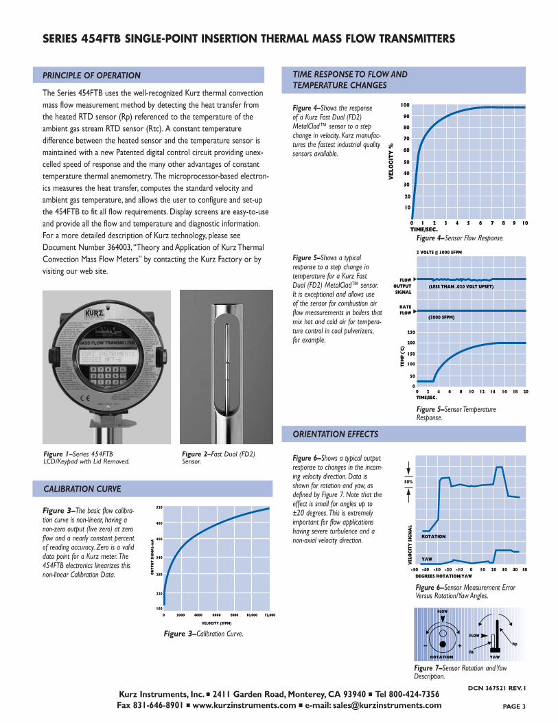
PRINCIPLE OF OPERATION
The Series 454FTB uses the well-recognized Kurz thermal convectionmass flow measurement method by detecting the heat transfer from the heated RTD sensor (Rp) referenced to the temperature of the ambient gas stream RTD sensor (Rtc). A constant temperature difference between the heated sensor and the temperature sensor ismaintained with a new Patented digital control circuit providing unex-celled speed of response and the many other advantages of constanttemperature thermal anemometry. The microprocessor-based electron-ics measures the heat transfer, computes the standard velocity and ambient gas temperature, and allows the user to configure and set-upthe 454FTB to fit all flow requirements. Display screens are easy-to-useand provide all the flow and temperature and diagnostic information.For a more detailed description of Kurz technology, please seeDocument Number 364003,“Theory and Application of Kurz ThermalConvection Mass Flow Meters” by contacting the Kurz Factory or byvisiting our web site.
FLOW
ROTATION YAW
+–FLOW
Rt
Rp
RATEFLOW
TIME/SEC.
2 VOLTS @ 3000 SFPM
TEM
P (˚
C)
250
200
150
100
50
00 2 4 6 8 10 12 14 16 18 20
(3000 SFPM)
FLOWOUTPUTSIGNAL
(LESS THAN .020 VOLT UPSET)
DEGREES ROTATION/YAW
VEL
OC
ITY
SIG
NA
L
-50 -40 -30 -20 -10 0 10 20 30 40 50
ROTATION
YAW
10%
SERIES 454FTB SINGLE-POINT INSERTION THERMAL MASS FLOW TRANSMITTERS
Kurz Instruments, Inc. ■ 2411 Garden Road, Monterey, CA 93940 ■ Tel 800-424-7356Fax 831-646-8901 ■ www.kurzinstruments.com ■ e-mail: [email protected]
VELOCITY (SFPM)
OU
TPU
T SI
GN
AL-
mA
0
160
220
280
340
400
460
520
2000 4000 6000 8000 10,000 12,000
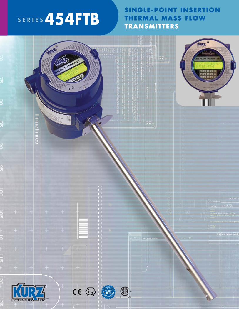
Figure 1–Series 454FTB LCD/Keypad with Lid Removed.
Figure 2–Fast Dual (FD2)Sensor.
CALIBRATION CURVE
Figure 3–The basic flow calibra-tion curve is non-linear, having anon-zero output (live zero) at zeroflow and a nearly constant percentof reading accuracy. Zero is a validdata point for a Kurz meter. The454FTB electronics linearizes thisnon-linear Calibration Data.
Figure 4–Shows the response of a Kurz Fast Dual (FD2)MetalClad™ sensor to a stepchange in velocity. Kurz manufac-tures the fastest industrial qualitysensors available.
Figure 5–Shows a typicalresponse to a step change in temperature for a Kurz Fast Dual (FD2) MetalClad™ sensor.It is exceptional and allows use of the sensor for combustion airflow measurements in boilers thatmix hot and cold air for tempera-ture control in coal pulverizers,for example.
Figure 6–Shows a typical outputresponse to changes in the incom-ing velocity direction. Data isshown for rotation and yaw, asdefined by Figure 7. Note that theeffect is small for angles up to±20 degrees. This is extremelyimportant for flow applicationshaving severe turbulence and anon-axial velocity direction.
Figure 3–Calibration Curve.
Figure 4–Sensor Flow Response.
Figure 5–Sensor Temperature Response.
Figure 6–Sensor Measurement Error Versus Rotation/Yaw Angles.
TIME RESPONSE TO FLOW AND TEMPERATURE CHANGES
ORIENTATION EFFECTS
Figure 7–Sensor Rotation and YawDescription.
70
80
90
100
60
50
40
30
20
10
0 1TIME/SEC.
VE
LOC
ITY
%
2 3 4 5 6 7 8 9 10
DCN 367521 REV. I

SENSOR PROTECTIONThe 454FTB circuitry includes circuitry to prevent anover-temperature condition caused by a sensor, wiringor component failure. Our sensors will not overheatat zero flow, unlike most competitive devices becauseof our constant temperature sensor control methodand the power limiting design.
AIR PURGE SENSOR CLEANING SYSTEMThe Model 454PFTB has a special nozzle in the sensorwindow for use with the Model 146 Air SensorCleaning System. The sensor cleaning is accomplishedby a short, high pressure blast of air (sonic velocity)directed at the velocity and temperature sensors. Kurzprovides solenoid valves and air blow-down tanks toallow periodic or on-demand cleaning. The 454PFTBhas a built-in timer and relay to initiate the purgecycle. The measurement value is “held” during thepurge cycle. The air blow-down tank uses customersupplied compressed air (instrument quality) at 60 to125 PSIG. The average cleaning air consumption is lessthan 0.125 SCFM. The Model 454PFTB is designed tomeasure air flow only at ambient pressure. CanadianRegistration (CRN) is not available for the Model454PFTB. The primary application is for extremelydirty stacks and ducts having dry particulate matterthat may build up on the sensor. Applications includefossil-fueled power boilers, municipal waste incinera-tors and combustion air flow situations in which flyash is entrained.
SENSOR ELECTRONICSThe Series 454FTB has several innovations whichimprove performance, reduce cost and provideextraordinary flexibility. The Patented digital sensorcontrol circuit uses an efficient switching power supply.The single-board PCB has an EEPROM loaded with thePCB serial number, calibration coefficients, and compo-nent values which insures the safety of the data. Thesensor electronics includes a sensor lead resistancecompensation circuit which is extremely important forlong sensor wires, rapid gas temperature changes andlarge temperature gradients between the sensor andthe ambient air.
SERIES 454FTB SINGLE-POINT INSERTION THERMAL MASS FLOW TRANSMITTERS
Kurz Instruments, Inc. ■ 2411 Garden Road, Monterey, CA 93940 ■ Tel 800-424-7356Fax 831-646-8901 ■ www.kurzinstruments.com ■ e-mail: [email protected] 4
SPECIFICATIONS
Process Temperature Rating:HT(-40°C to 260°C)HHT(-40°C to 500°C)
Process Pressure Rating:300 PSIG (20 BARg)
Sensor Material: Alloy C-276;optional abrasion-resistantChromium Nitride coating onAlloy C-276 sensor materials.PTFE coating for chemicalresistance on Alloy C-276 sensor and sensor support,HHT sensors, 260°C max.
Sensor Support Material:316L Stainless Steel, optionalAlloy C-276.
Repeatability: 0.25%Velocity Time Constant:
1 second for velocity changesat 6000 SFPM at a constanttemperature and 1 second fortemperature changes at a con-stant velocity of 6000 SFPM.
Process TemperatureTime Constant:8 seconds at a velocity of6000 SFPM.
Velocity Accuracy:See Feature 4 for overall accuracy including the effectsof process temperature.
Temperature Accuracy:±(1/2% of reading +1°C) forvelocities above 100 SPFM.
Power: +24 VDC ±10%, 85-265VAC, 47/63 Hz; 24 watts max.
Enclosure TemperatureRating: -25°C to +65°C
with LCD/Keypad option;-40°C to +65°C withoutLCD/Keypad option.
Enclosure: Epoxy-Painted aluminum, IP66/NEMA 4X/7 with glass window for displayoption.
Solid-State Relays:Optically isolated, 0.5 ampere,24 VAC/VDC maximum
Analog Outputs (4-20 mA):Optically isolated, user loop-powered, 12 bit resolution and accuracy, maximum loop-resistance is 300Ω at 18 VDC,550Ω at 24 VDC, 1400Ω at 36 VDC; meets NAMUR NE43recommendations.
Meter Filter Time Constant:Selectable 0 to 600 seconds.
Continued on next page
TECHNICAL DESCRIPTION
SENSOR DESIGNSeries 454FTB Insertion Mass Flow Transmitters usethe Kurz MetalClad™ FD2 all-welded Alloy C-276 sensor. In this design, the temperature sensor andvelocity sensor are mounted in separate tubes (or“stings”), providing exceptional thermal isolation fromthe sensor support structure and fast response toprocess temperature changes.
SENSOR MATERIALS AND CONSTRUCTIONThe standard sensor material for all Kurz metal sen-sors is Alloy C-276. This material is far superior to 316 Stainless Steel in high temperature and corrosive applications. Kurz offers Chromium Nitride coating for abrasive, dirty applications, such as in boiler coalpulverizers. Kurz exclusively uses Inconel sheathed mineral-insulated cable (MI cable) for temperaturesabove 260°C.
PROCESS TEMPERATURE RATINGKurz offers sensor process temperature ratings of260°C and 500°C. Field data verifies that the lifetime at 500°C is at least five years and the lifetime at 260°Cis at least 10 years.
TRANSMITTER CONFIGURATIONSTwo configurations are available; Directly AttachedElectronics Enclosure and Remote ElectronicEnclosure.
PROCESS TEMPERATURE COMPENSATIONThe influence of temperature on the thermal proper-ties of gases requires temperature compensation forrepeatable and accurate measurements. StandardTemperature Compensation (STC) is used for applica-tions in which the process temperature is below125°C over a moderate velocity range or below 260°Cover a more limited velocity range. If the process temperature and gas velocity vary widely,Velocity/Temperature/Mapping (VTM) is recommended.VTMincludes several process temperatures and uses themicroprocessor to calculate the velocity based on thebuilt-in process temperature measurement.
GAS CALIBRATIONThe customer has a choice of a laboratory calibrationor a gas correlation calibration. Air calibrations areperformed in the Kurz Model 400D NIST traceablewind tunnel.
DCN 367521 REV. I

SINGLE-POINT INSERTION THERMAL MASS FLOW TRANSMITTERS
SELECTABLE STP CONDITIONSThe mass flow calibration data is referenced to the Kurz laboratory standard of 77°F/14.69 PSIA (25° C/760 mmHg). The user may change the STP conditions to suit his requirement.
4-20 mA OUTPUTSThese loop-powered outputs are optically isolated,and include the NAMUR NE43 recommendationregarding fault detection. The fault conditions are generally set at the Kurz Factory, but may be set bythe user. The user may easily re-calibrate the 4-20 mAoutputs by entering “CALIB 4-20 mA OUTPUTS” measuring the output and adjusting it using the LCD/Keypad up/down buttons. The 4-20mA outputs maybe set-up for non-isolated, self-powered operation.
NAMUR NE43 COMPLIANCEKurz meets the NAMUR NE43 recommendation forthe 4-20 mA outputs, under a fault defined by the sensor Kick-Out menu, sensor or system fault.AnNE43 alarm may be selected as high or low, but notboth. This feature also frees up the alarm/relays sothat the user can set-up the flow and temperaturealarms for other needs.
TOTALIZER OUTPUTThe customer may order 0 or 2 solid-state opticallyisolated relays. If no relays are ordered, the alarmfunctions are displayed on the LCD. Both relays maybe used for alarms (LO, HI and HOL) or for theSensor Kick-Out Feature; or one relay may be usedfor an alarm function and one may be used as a pulsedoutput for use as a remote flow totalizer, or bothrelays may be used as pulsed outputs. Totalizers maybe automatically reset at a specific total quantity (i.e.,10,000 SCF). The 454PFTB uses one relay for thepurge initiation.
ROHUS AND WEEE DIRECTIVESThe new Series 454FTB meets the RoHS (Restrictionof use of certain Hazardous Substances) and theWEEE (Waste of Electrical and Electronic Equipment)EU Directives.
SERIES 454FTB
Kurz Instruments, Inc. ■ 2411 Garden Road, Monterey, CA 93940 ■ Tel 800-424-7356Fax 831-646-8901 ■ www.kurzinstruments.com ■ e-mail: [email protected] PAGE 5
SPECIFICATIONS Cont’d.
Safety Approvals:CSA Non-Incendive Approval:
IEC 79-15 and EN60079-0/15ATEX Non-Incendive Approval:
EN60079-0/15 and EN61241-1CSA Explosion-Proof Approval:
IEC 79-01 and EN60079-01ATEX Flame-Proof Safety Approval:
EN 60079-0/1 and EN61241-1(KEMA Pending)
Note: See Kurz website for the com-plete Safety Approvals Specifications.CE Directives:
EMC,ATEX, LVD and PED.Consult Kurz for details.
Serial Port Baud Rate:User selectable: 9600, 14,400,19,200, 38,400, 57,600.
Communication Ports:RS485 Modbus ASCII or RTUMode, and USB.
Digital Inputs:Two, contact closure,TTL.
Analog Input:One, 4-20mA, non-isolated.
LCD: Back-lit two-line alphanumericwith 16 characters per line.
LCD Update: Every two seconds.Keypad: 20-button membrane
mounted inside enclosure.LCD/Keypad Orientation:
Adjustable in 90° increments to accommodate viewing orientation.
Electronics EnclosureOrientation: 0° or 180° for viewing
(Feature 1).Memory:
EEPROM for all important data,with automatic sensor identification; Flash EEPROM forProgram Memory.
Net Weight/Shipping Weight: DCVersion: 4lbs/5lbs;AC Version: 6lbs/8lbs,add 4lbs/5lbs for remote option.
TECHNICAL DESCRIPTION Cont’d.
FIRMWARE The Display, Executive and Programming menus arevery easy-to-use and are largely self-explanatory. Theflow and temperature data may be scrolled so it can be seen through the window in the cover. The usermay press “D” and see the flow and temperature data,as well as the raw flow data. Pressing “H” holds thedisplay screen (but not the readings). A user accesscode is required for programming, seeing data andentering configuration and other user data.
HELP SCREENSBy pressing “HH” the user can obtain important infor-mation on the use of the Series 454FTB, including thefirmware version, Kurz telephone and fax numbers andthe web site address, etc.
SELF-DIAGNOSTICSThe 454FTB performs an extensive check-out uponpower-up and continuously monitors the sensorinputs/outputs and verifies the integrity of the sensorwiring and the measurements. The Sensor Kick-OutFeature is used to set the velocity and temperaturefault limits.
PROGRAMMABLE CORRECTION FACTORSA multi-point Variable Correction Factor (VCF) may be used to correct the flow calibration data to meetin-situ flow tests over the entire velocity range such as done for EPA Stack Flow Monitors. A SensorBlockage Correction Factor (SBCF) can be used tocorrect for the area reduction caused by the sensorsupport. The user enters the area of the flow passageand the sensor center line distance from the inside ofthe flow passage and the Series 454FTB automaticallycalculates the SBCF.
METER FILTER TIME CONSTANTA digital filter time constant may be set for eachMETER which affects the display readings and the 4-20mA outputs. The time constant can be set from 0 to600 seconds.
COMPATIBILITY WITH SERIES 155 MASS FLOW COMPUTERSA “Blind” Series 454FTB (ordered with the two 4-20mA Outputs and +24 VDC power input is fully com-patible with the inputs and features of the Series 155Mass Flow Computers. This Feature is used when twoor more Model 454FTBs are used in a multi-pointvelocity array. (Please see the Series 155 Brochure).
DCN 367521 REV. I

Kurz Instruments, Inc. ■ 2411 Garden Road, Monterey, CA 93940 ■ Tel 800-424-7356Fax 831-646-8901 ■ www.kurzinstruments.com ■ e-mail: [email protected] 6
SERIES 454FTB SINGLE-POINT INSERTION THERMAL MASS FLOW TRANSMITTERS
TECHNICAL DESCRIPTION Cont’d.
BUILT-IN “ZERO-MIDSPAN-SPAN” DRIFT CHECK/CALIBRATORA new feature is the addition of a Daily “Zero-Midspan-Span”Electronics Drift Check meeting the U.S. E.P.A. requirement for CEMStack Flow Monitors. A menu is entered to select the desired flowvalue (or 4-20 mA value) for “Zero-Midspan-Span” values and the timeinterval during each stepped flow value. The Drift Check is initiated bythe User with a contact closure or via Modbus. An acknowledgementrelay is normally activated. A solid-state relay and a digital input is needed (See Feature 11). The flow signal is compared against theexpected set-point for each level of selected velocity or flow rate values. In addition, this feature can be used to check the electronics foraccuracy and linearity.
PID FLOW CONTROLLERThe new 454FTB includes the capability of controlling the velocity orflow rate through the use of the user’s control valve, damper or posi-tion commanded 4-20 mA interface device. The Set-Point may be inter-nal or remote.
USB PORTA USB port for terminal operations includes a COM emulator driverwhich can be accessed using a PC terminal emulator program toremotely “echo” the LCD and keypad functions and upload/downloadthe system configuration and calibration data files using XMODEM protocol. The Series 454FTB may be operated in a manual or remoteterminal manner. Measurement summary data may be initiated manuallyand by pushing the “L” button on the keypad or from the PC. The infor-mation may also be obtained automatically by activating the LOG inter-val timer using the Series 454FTB keypad or a PC.
MODBUSThe Modbus local network protocol (ASCII or RTU) is included. Theuse of Modbus is extremely useful, as most features may be accessed,including configuration up-load, down-load, etc.
ORDERING INFORMATION
FLOW TRANSMITTER SELECTIONTable 1 lists the Series 454FTB Model number, Parent Number andMajor Features. Table 2 lists the Baseline (V *) Full Scale Velocity foreach Gas Type. Table 3 lists the Flow factor (F *) Equation for each Gas Type.
TABLE 1 SERIES 454FTB SELECTION TABLESensor Process
Model Parent Support Temp. Air SafetyNumber Number Dia. Rating Purge Approvals
454FTB-08-HT 756051 1⁄2" HT No NI, XP/FP
454FTB-08-HHT 756052 1⁄2" HHT No NI, XP/FP
454FTB-12-HT 756053 3⁄4" HT No NI, XP/FP
454FTB-12-HHT 756054 3⁄4" HHT No NI, XP/FP
454FTB-16-HT 756055 1" HT No NI, XP/FP
454FTB-16-HHT 756056 1" HHT No NI, XP/FP
454PFTB-16-HT 756057 1" HT Yes NI, XP/FP
454PFTB-16-HHT 756058 1" HHT Yes NI, XP/FP
Table 2: BASELINE V * VELOCITY RANGES (See Notes 1, 2, 3)VELOCITY SFPM (NMPS)
Gas Group Number and Gas Type
Model A C D E F GNumber Air, N2, Methane Dry Ethane Helium, Hydrogen
O2,Ar Digester Gas, Chlorine, PropaneCO2 Dry Ammonia Ethylene Butane
454FTB-08-HT 18,000 17,000 15,000 13,300 10,000 6,000454FTB-12-HT (84) (79) (70) (62) (47) (28)454FTB-16-HT
To 125°C
454FTB-08-HT 18,000 N/A N/A N/A N/A N/A454FTB-12-HT (84)454FTB-16-HT454PFTB-16-HT
To 260°C
454FTB-08-HHT 18,000 N/A N/A N/A N/A N/A454FTB-12-HHT (84)454FTB-16-HHT454PFTB-16-HHT
To 500°C
Note 1: See Nomenclature for the complete definition of Gas Group Number and Gas Type.
Note 2: SFPM: Standard Feet-Per-Minute (Ref.: 77°F, 14.69 PSIA).NMPS: Normal Meters-Per-Second (Ref.: 0°C, 760 mm Hg).NMPS = 0.00466 x SFPM (Approximate).
Note 3: The Baseline (V *) VELOCITY for each Mass Flow Transmitter Model Number andfor each type of Gas is the maximum velocity at standard conditions (See Note 2).
TABLE 3: FLOW FACTOR (F*) EQUATIONSGas Type DRP Equations
Group A:Air, N2,Ar, CO2, O2 Less than 1.333 F * = DRP
Greater than 1.333 F * = 1.333
Group C: Methane, Digester Gas, Less than 0.945 F * = 1.059DRP
Dry Ammonia Greater than 0.945 F * = 1.000
Group D: Dry Chlorine, Ethylene Less than 0.833 F * = 1.2DRP
Greater than 0.833 F * = 1.0
Group E: Ethane Less than 0.739 F * = 1.353DRP
Greater than 0.739 F * = 1.000
Group F: Helium, Propane, Less than 0.555 F * = 1.8DRP
Butane Greater than 0.555 F * = 1.00
Group G: Hydrogen Less than 0.333 F * = 3.0DRP
Greater than 0.333 F * = 1.000
DCN 367521 REV. I

Kurz Instruments, Inc. ■ 2411 Garden Road, Monterey, CA 93940 ■ Tel 800-424-7356Fax 831-646-8901 ■ www.kurzinstruments.com ■ e-mail: [email protected] PAGE 7
SERIES 454FTB SINGLE-POINT INSERTION THERMAL MASS FLOW TRANSMITTERSNOMENCLATURE:
SAFETY APPROVALSIdentifier Description
NI Non-Incendive, CSA and ATEX
XP/FP Explosion-Proof/Flame-Proof, CSA and ATEX
PROCESS TEMPERATURE RATINGIdentifier Description Range
HT High Temperature -40°F to 500°F (-40°C to 260°C)
HHT Very High Temperature -40°F to 932°F (-40°C to 500°C)
SENSOR TYPEIdentifier Description
FD2 Fast Dual Metal-Clad™ Velocity and Temperature Sensor, all-welded construction, 0.105" diameter sensor stings
GAS GROUP AND GAS TYPEGroup Gas Type
A Air, Nitrogen, Oxygen,Argon, Carbon Dioxide
C Methane, Digester Gas, Dry Ammonia
D Dry Chlorine, Ethylene
E Ethane
F Helium, Propane, Butane
G Hydrogen
DEFINITIONS FOR THE USE OF TABLES 1, 2, 3
Equation 1: DRP = PP x TS
PS TP
Equation 2: VMAX = F * x V *
V * = Baseline Velocity as listed in Table 2 (SFPM for English Units or NMPS for Metric Units at Standard conditions).
VP = Process Velocity (SFPM for English Units, NMPS for Metric Units).
VMAX = Maximum Velocity for a specific Gas Type under Process Conditions.
F * = Flow Factor.
TS = Standard Absolute Temperature: 537°R (77°F + 460) for English Units or 273°K (0°C) for Metric Units.
TP = Process Absolute Temperature: °R (T°F + 460) for English Units or °K (T°C + 273°C) for Metric Units.
PS = Standard Absolute Pressure (14.69 PSIA for English Units and 760mm Hgfor Metric Units).
PP = Process Absolute Pressure (PSIA for English Units and mm Hg for Metric Units).
DRP = Process Gas Density Ratio.
Example: Calculate the maximum allowable Gas Velocity ( VMAX ) for compressed air at 100˚F and 135 PSIA for the Model 454FTB-12-HT.a) From Table 2,V * = 18,000 SFPMb) Calculate DRP from Equation 1:
DRP = PP x TS = 135 x 537 = 8.81PS TP 14.69 560
c) Using Table 3 for Group A, Air: F * = 1.333 (DRP greater than 1.333)d) Using Equation 2: VMAX = F * x V * = 23,9444 SFPM (111.8 NMPS)
D 32 F F 077 M 01 A 015 B
SUMMARY OF FEATURESFeature Feature Description
1 Electronics Enclosure Configuration and Input Power, LCD/Keypad
2 Sensor Material/Sensor Support and Flange Material
3 Sensor Support Length
4 Process Temperature Compensation
5 Optional Flange Connection Size and Rating
6 Optional Flange U Dimension
7 Gas Velocity Calibration Data Range
8 Specialty Gas Velocity Calibration
9 Safety Approvals
10 Process Pressure
11 Analog & Digital Inputs/Outputs
12 Process Temperature
13924
FEATURE 1: ELECTRONICS ENCLOSURE CONFIGURATIONAND INPUT POWER (See Note 1)
Option Description
A Directly Attached Dual-Chamber Electronics Enclosure, AC-Power,LCD/Keypad.
B Directly Attached Dual-Chamber Electronics Enclosure, AC-Power, withoutLCD/Keypad.
C Directly Attached Dual-Chamber Electronics Enclosure rotated 180° for viewing,AC Power, LCD/Keypad.
D Remote Dual-Chamber Electronics Enclosure, AC-Power, LCD/Keypad.
E Remote Dual-Chamber Electronics Enclosure, AC-Power, withoutLCD/Keypad.
F Directly Attached Dual-Chamber Electronics Enclosure, 24VDC-Power,LCD Keypad.
G Directly Attached Dual-Chamber Electronics Enclosure rotated 180°for viewing, 24VDC-Power, LCD/Keypad.
H Directly Attached Single-Chamber Electronics Enclosure, 24VDC-Power,without LCD/Keypad.
I Remote Dual-Chamber Electronics Enclosure, 24 VDC-Power, LCD/Keypad.
J Remote Single-Chamber Electronics Enclosure, 24 VDC-Power, withoutLCD/Keypad.
Note 1: The temperature storage and operating rating of the Electronics Enclosure is -25°C to+65°C with the LCD/Keypad and -40°C to +65C without the LCD/Keypad. The conduit or cable sealmust be installed by an experienced and careful installer to prevent water intrusion into the enclo-sure and to maintain the enclosure rating. Failure to properly install the conduit seals may void theKurz warranty and may compromise the safety approval rating.Note 2: Stainless Steel Identification Tags are available. Customer must provide labeling information up to four lines of text with 32 characters each line.
Part Number Generation ProcedureWith the selected Parent Number, specify the entire Part Number by selecting an Option foreach Feature as shown in the example below. Feature Options in Bold type indicate the mostavailable Models, other options usually require a longer delivery time.
Example Part Number for a Model 454FTB-16-HHT:
756056
Parent F1 F2 F3 F4 F5 F6 F7 F8 F9 F10 F11 F12Number
DCN 367521 REV. I

Kurz Instruments, Inc. ■ 2411 Garden Road, Monterey, CA 93940 ■ Tel 800-424-7356Fax 831-646-8901 ■ www.kurzinstruments.com ■ e-mail: [email protected] 8
FEATURE 6: OPTIONAL FLANGE U DIMENSIONDirections
Divide the U Dimension (inches) by 100, round off the resulting number to the right ofthe decimal point to three significant digits, enter the resulting three digit number withoutthe decimal point. Enter 000 for no flange connection. UMIN = 4"Example: The U Dimension is 7.74"; Enter 077.
FEATURE 4: PROCESS TEMPERATURE COMPENSATION
The influence of temperature on the thermal properties of gases requires temperature compensation of the Thermal Mass Flow Sensor for repeatability and accurate measurements.Standard Temperature Compensation (STC) is used for applications in which the process temper-ature is below 125°C over a moderate velocity range (Option 1); or below 260°C over morelimited velocity range (Option 2).
If the process temperature and gas velocity vary widely,Velocity/Temperature/Mapping (VTM)is recommended. VTM (Options 3, 4) includes several calibrations. The multiple velocity calibra-tions are entered into the Microprocessor which performs a double interpolation between thevelocity calibration curves using the built-in process gas temperature measurement. The temper-ature compensation is based upon air, therefore, the accuracy at a high temperature when usinggases other than Air, Nitrogen or Oxygen may be reduced.
FIRST DIGIT 0F FEATURE 2: SENSOR MATERIALOption Description
3 Alloy C-276
7 Alloy C-276 with Abrasion-Resistant Chromium Nitride Coating (CrN)
FEATURE 3: SENSOR SUPPORT LENGTH LOption Support Length L Option Support Length L
B 6" (125°C Max) J 30"
C 9" (260°C Max) K 36"
D 12" M 48"
F 18" P 60"
H 24"
Option Description
1 Standard Temperature Compensation (STC) over process temperaturerange of -40°C to +125°C.Accuracy: ± [(1% + .025%/°C) reading + 20 SFPM + .25 SFPM/°C)] Above or below 25°C, all gases.
2 Standard Temperature Compensation (STC) over process temperaturerange of 0°C to 260°C.Accuracy: ± [(2% + .025%/°C) reading +20 SFPM + .25 SFPM/°C] Aboveor below 125°C; Air, 02 and N2 only.
3 Velocity/Temperature/Mapping (VTM) with data sets over process tempera-ture range of 0°C up to 260°C. Accuracy: ±(2% reading + 20 SFPM), Air,02 and N2 only.
4 Velocity/Temperature/Mapping (VTM) with data sets over the process temperature range of 0°C up to 500°C.Accuracy: ±(3% reading + 30SFPM), Specify Process Temperature Range, Air, 02 and N2 only. HHTModels.
How to Determine the U, L and L2 Dimensions for a Flange Connection
When ordering a flange, you must specify the U dimension, and verify that the sensorsupport length L and L2 are appropriate for the Process Temperature. Kurz recommendsthat the centerline of the sensor be located at the center of the pipe or duct, and thatexperimental flow profile tests be made to obtain the velocity profile correction factor(VCF) and enter it into the 454FTB. Refer to the outline drawings in the Series 454FTBBrochure. Note: Flange material must match Sensor Support Material (Feature 2).
U = The dimension between the centerline of the mass flow sensor and the flangemounting surface. The minimum U dimension is 4.0".
L = The length of the sensor support tube (Feature 3).L2 = The length of sensor support between the flange mounting surface and the sensor
support fitting. The minimum L2 is 5 inches for HT process temperatures and 8inches for HHT process temperatures.
L = U + L2 – 2.00"
FEATURE 5: OPTIONAL FLANGE CONNECTION SIZE AND RATING
Option Sensor Support Diameter Description
A 1⁄2",3⁄4", 1" No flange connection
B 1⁄2" 1⁄2", Class 150,ANSI B16.5
C 1⁄2" 1⁄2", Class 300,ANSI B16.5
D 1⁄2", 3⁄4" 3⁄4", Class 150,ANSI B16.5
E 1⁄2", 3⁄4" 3⁄4", Class 300,ANSI B16.5
F 1⁄2", 3⁄4", 1" 1", Class 150,ANSI B16.5
G 3⁄4", 1" 1", Class 300,ANSI B16.5
H 3⁄4", 1" 11⁄4", Class 150,ANSI B16.5
I 3⁄4", 1" 11⁄4", Class 300,ANSI B16.5
J 3⁄4", 1" 11⁄2", Class 150,ANSI B16.5
K 3⁄4", 1" 11⁄2", Class 300,ANSI B16.5
L 3⁄4", 1" 2", Class 150,ANSI B16.5
M 3⁄4", 1" 2", Class 300,ANSI B16.5
N 1" 21⁄2", Class 150,ANSI B16.5
P 1" 21⁄2", Class 300,ANSI B16.5
S 1" 3", Class 150,ANSI B16.5
T 1" 3", Class 300,ANSI B16.5
U 1" 4", Class 150,ANSI B16.5
V 1" 4", Class 300,ANSI B16.5
Note: Flange material must match the Sensor Support Material (Feature 2).
Option Support Length L Option Support Length L
FEATURE 7: GAS VELOCITY CALIBRATION DATA RANGE SFPM (NMPS) (Note 1)
Option Velocity Option Velocity
A VMAX M 6,000 (28.0)
B 300 (1.4) P 9,000 (41.9)
C 600 (2.8) R 12,000 (56)
E 1,000 (4.7) T 15,000 (70)
G 2,000 (9.3) V 18,000 (84)
I 3,000 (14) X 24,000 (112)
K 4,000 (18.6)
SERIES 454FTB SINGLE-POINT INSERTION THERMAL MASS FLOW TRANSMITTERS
Note 1: The Gas Velocity (VP) must be equal to or less than than VMAX for the Process AbsoluteTemperature and Pressure and for the specific Gas Group and Gas Type as determined using Tables 2& 3 and Equations 1, 2.
SECOND DIGIT OF FEATURE 2: SENSOR SUPPORT ANDFLANGE MATERIAL (Note 1)
Option Description
2 316L Stainless Steel
3 Alloy C-276
8 Alloy C-276 with PTFE Teflon Coating cured for chemical resistance.Includes support, sensor and flange; FD2-HHT sensors only, temperature rating of 260˚C Max.
Note 1: Sensor Support Material and Optional Flange Material must be the same, see Feature 5.
DCN 367521 REV. I
Kurz Instruments, Inc. ■ 2411 Garden Road, Monterey, CA 93940 ■ Tel 800-424-7356Fax 831-646-8901 ■ www.kurzinstruments.com ■ e-mail: [email protected] PAGE 9
SERIES 454FTB SINGLE-POINT INSERTION THERMAL MASS FLOW TRANSMITTERS
Laboratory CorrelationCalibration Gas Type Calibration
Option Pressure Option
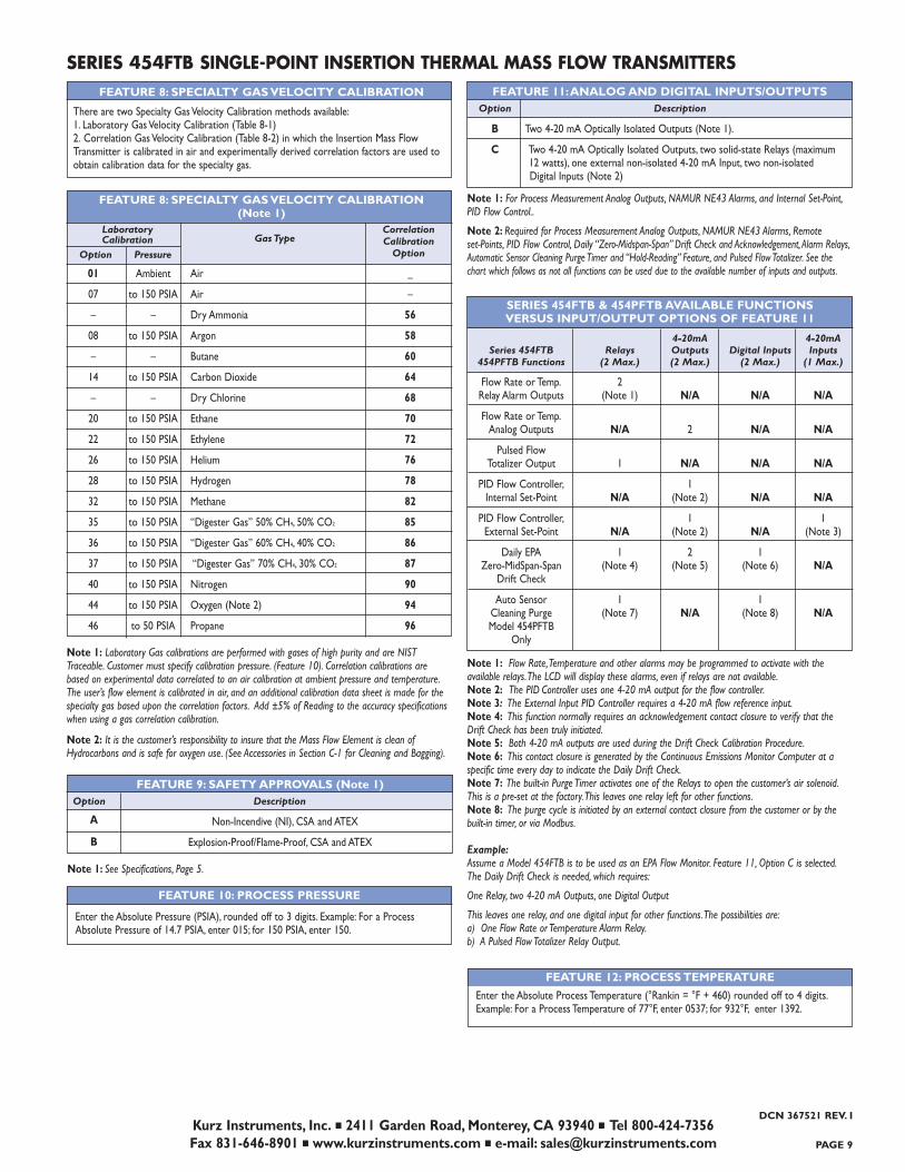
FEATURE 9: SAFETY APPROVALS (Note 1)Option Description
Non-Incendive (NI), CSA and ATEX
Explosion-Proof/Flame-Proof, CSA and ATEX
Note 1: See Specifications, Page 5.
FEATURE 10: PROCESS PRESSURE
Enter the Absolute Pressure (PSIA), rounded off to 3 digits. Example: For a ProcessAbsolute Pressure of 14.7 PSIA, enter 015; for 150 PSIA, enter 150.
FEATURE 11:ANALOG AND DIGITAL INPUTS/OUTPUTSOption Description
B Two 4-20 mA Optically Isolated Outputs (Note 1).
C Two 4-20 mA Optically Isolated Outputs, two solid-state Relays (maximum 12 watts), one external non-isolated 4-20 mA Input, two non-isolated Digital Inputs (Note 2)
Note 1: For Process Measurement Analog Outputs, NAMUR NE43 Alarms, and Internal Set-Point,PID Flow Control..
Note 2: Required for Process Measurement Analog Outputs, NAMUR NE43 Alarms, Remote set-Points, PID Flow Control, Daily “Zero-Midspan-Span” Drift Check and Acknowledgement, Alarm Relays,Automatic Sensor Cleaning Purge Timer and “Hold-Reading” Feature, and Pulsed Flow Totalizer. See thechart which follows as not all functions can be used due to the available number of inputs and outputs.
FEATURE 8: SPECIALTY GAS VELOCITY CALIBRATION
01 Ambient Air _
07 to 150 PSIA Air –
– – Dry Ammonia 56
08 to 150 PSIA Argon 58
– – Butane 60
14 to 150 PSIA Carbon Dioxide 64
– – Dry Chlorine 68
20 to 150 PSIA Ethane 70
22 to 150 PSIA Ethylene 72
26 to 150 PSIA Helium 76
28 to 150 PSIA Hydrogen 78
32 to 150 PSIA Methane 82
35 to 150 PSIA “Digester Gas” 50% CH4, 50% CO2 85
36 to 150 PSIA “Digester Gas” 60% CH4, 40% CO2 86
37 to 150 PSIA “Digester Gas” 70% CH4, 30% CO2 87
40 to 150 PSIA Nitrogen 90
44 to 150 PSIA Oxygen (Note 2) 94
46 to 50 PSIA Propane 96
Note 1: Laboratory Gas calibrations are performed with gases of high purity and are NISTTraceable. Customer must specify calibration pressure. (Feature 10). Correlation calibrations arebased on experimental data correlated to an air calibration at ambient pressure and temperature.The user’s flow element is calibrated in air, and an additional calibration data sheet is made for thespecialty gas based upon the correlation factors. Add ±5% of Reading to the accuracy specificationswhen using a gas correlation calibration.
Note 2: It is the customer’s responsibility to insure that the Mass Flow Element is clean ofHydrocarbons and is safe for oxygen use. (See Accessories in Section C-1 for Cleaning and Bagging).
SERIES 454FTB & 454PFTB AVAILABLE FUNCTIONSVERSUS INPUT/OUTPUT OPTIONS OF FEATURE 11
4-20mA 4-20mA Series 454FTB Relays Outputs Digital Inputs Inputs
454PFTB Functions (2 Max.) (2 Max.) (2 Max.) (1 Max.)
Flow Rate or Temp. 2Relay Alarm Outputs (Note 1) N/A N/A N/A
Flow Rate or Temp.Analog Outputs N/A 2 N/A N/A
Pulsed Flow Totalizer Output 1 N/A N/A N/A
PID Flow Controller, 1Internal Set-Point N/A (Note 2) N/A N/A
PID Flow Controller, 1 1External Set-Point N/A (Note 2) N/A (Note 3)
Daily EPA 1 2 1Zero-MidSpan-Span (Note 4) (Note 5) (Note 6) N/A
Drift Check
Auto Sensor 1 1Cleaning Purge (Note 7) N/A (Note 8) N/AModel 454PFTB
Only
Note 1: Flow Rate,Temperature and other alarms may be programmed to activate with the available relays.The LCD will display these alarms, even if relays are not available.Note 2: The PID Controller uses one 4-20 mA output for the flow controller.Note 3: The External Input PID Controller requires a 4-20 mA flow reference input.Note 4: This function normally requires an acknowledgement contact closure to verify that the Drift Check has been truly initiated.Note 5: Both 4-20 mA outputs are used during the Drift Check Calibration Procedure.Note 6: This contact closure is generated by the Continuous Emissions Monitor Computer at a specific time every day to indicate the Daily Drift Check.Note 7: The built-in Purge Timer activates one of the Relays to open the customer’s air solenoid.This is a pre-set at the factory.This leaves one relay left for other functions.Note 8: The purge cycle is initiated by an external contact closure from the customer or by thebuilt-in timer, or via Modbus.
Example:Assume a Model 454FTB is to be used as an EPA Flow Monitor. Feature 11, Option C is selected.The Daily Drift Check is needed, which requires:
One Relay, two 4-20 mA Outputs, one Digital Output
This leaves one relay, and one digital input for other functions.The possibilities are:a) One Flow Rate or Temperature Alarm Relay.b) A Pulsed Flow Totalizer Relay Output.
FEATURE 12: PROCESS TEMPERATURE
Enter the Absolute Process Temperature (°Rankin = °F + 460) rounded off to 4 digits.Example: For a Process Temperature of 77°F, enter 0537; for 932°F, enter 1392.
A
DCN 367521 REV. I
There are two Specialty Gas Velocity Calibration methods available:1. Laboratory Gas Velocity Calibration (Table 8-1)2. Correlation Gas Velocity Calibration (Table 8-2) in which the Insertion Mass FlowTransmitter is calibrated in air and experimentally derived correlation factors are used toobtain calibration data for the specialty gas.
B
FEATURE 8: SPECIALTY GAS VELOCITY CALIBRATION(Note 1)
Kurz Instruments, Inc. ■ 2411 Garden Road, Monterey, CA 93940 ■ Tel 800-424-7356Fax 831-646-8901 ■ www.kurzinstruments.com ■ e-mail: [email protected] 10
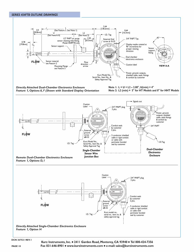
SERIES 454FTB OUTLINE DRAWINGS
Remote Dual-Chamber Electronics Enclosure Feature 1, Options D, I
Directly Attached Dual-Chamber Electronics EnclosureFeature 1, Options A, F (Shown with Standard Display Orientation
CL
Caution Label 3/4" MNPT plug
3 plcs.
Conduit sealsby customer2 plcs.External
groundscrew #8-32
Kurz model no.,serial no., item no. &safety approval tag
5 conductor shieldedcable in rigid conduitor cable withperimeter bondedseal by customer
FLOW
I.D. Tag
Directly Attached Single-Chamber Electronics EnclosureFeature 1, Option H
Note 1: L = U + L2 – 2.00", U(min) = 4"Note 2: L2 (min) = 5" for HT Models and 8" for HHT Models
Single-ChamberSensor Wire Junction Box
Sensorsupportfitting
VIEW A-A
45˚
FLOW
CL3/4" FNPT
Signals outCaution Label 3/4" MNPT plug
3 plcs.
Conduit sealsby customer2 plcs.External
groundscrew #8-32
Kurz Model No.,Serial No., Item No. &Safety Approval Tag
5 conductor shieldedcable in rigid conduitor cable withperimeter bondedseal by customer
INSTRUMENTSMONTEREY, CALIFORNIA
S FLOW TRANSIT
CLEAR GLOSS DISPLAY
P 7 8 9 HD 4 5 6 YES
™INC.INSTRUMENTS
FLOW
I.D. Tag
INSTRUMENTSMONTEREY, CALIFORNIA
S FLOW TRANSIT
CLEAR GLOSS DISPLAY
P 7 8 9 HD 4 5 6 YES
™IN
C.
INSTRU
MEN
TS
0.64[16.3mm]L2
(See Note 2)
L(See Feature 3. See Note 1)
U(See Feature 6)
5.44[138.2mm]
Display maybe rotated at 90˚ increments for proper viewing direction
Dual chamberelectronics enclosure
Caution label
Power, ground, outputs,shielded cable, seals, fittings& conduit by customer
3/4" FNPT Typ.
A
AFLOW
Sensor support
2.0[50.8mm]
0.78[19.8mm]
2.50[63.5mm]
D
Kurz Model No.,Serial No., Item No., &
Safety Approval Tag
CL
I.D. Tag
Flowdirection
arrow
External Gndscrew # 10-32
Sensor materialsee Feature 2
Mounting Flangesee Feature 5
Power, ground, outputs, shielded cable, seals fittings& conduit by customer
Dual-ChamberElectronics Enclosure
I.D.Tag
1/2" FNPT air purge sensor cleaning inlet fitting,
Model 454PFTB only.
DCN 367521 REV. I
PAGE 11
Kurz Instruments, Inc. ■ 2411 Garden Road, Monterey, CA 93940 ■ Tel 800-424-7356Fax 831-646-8901 ■ www.kurzinstruments.com ■ e-mail: [email protected]
DCN 367521 REV. I
Single-ChamberSensor Wire Junction Box
CL3/4" FNPT
Signals outCaution Label 3/4" MNPT plug
3 plcs.
Conduit sealsby customer2 plcs.External
groundscrew #8-32
Kurz model no.,serial no., item no. &safety approval tag
5 conductor shieldedcable in rigid conduitor cable withperimeter bondedseal by customer
FLOW
Optional I.D. Tag
Power, ground, outputs, shielded cable, seals fittings& conduit by customer
Single-ChamberElectronics Enclosure
I.D.Tag
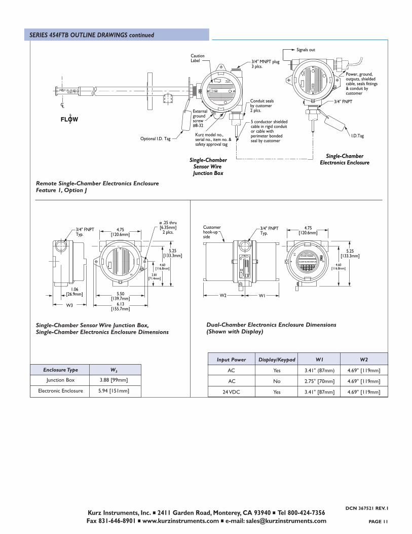
Input Power Display/Keypad W1 W2
AC Yes 3.41" (87mm) 4.69" [119mm]
AC No 2.75" [70mm] 4.69" [119mm]
24 VDC Yes 3.41" [87mm] 4.69" [119mm]
Single-Chamber Sensor Wire Junction Box,Single-Chamber Electronics Enclosure Dimensions
Dual-Chamber Electronics Enclosure Dimensions(Shown with Display)
Remote Single-Chamber Electronics EnclosureFeature 1, Option J
ø .25 thru[6.35mm]
2 plcs.
1.06[26.9mm]
W3 6.13[155.7mm]
5.50[139.7mm]
5.25[133.3mm]
4.75[120.6mm]
3/4" FNPTTyp.
2.81[71.4mm]
4.60[116.8mm]
INSTRUMENTSMONTEREY, CALIFORNIA
S FLOW TRANSIT
CLEAR GLOSS DISPLAY
P 7 8 9 HD 4 5 6 YES
™IN
C.
INSTRU
MEN
TS
3/4" FNPTTyp.
4.75[120.6mm]
Customerhook-upside
W2 W1
4.60[116.8mm]
5.25[133.3mm]
Enclosure Type W3
Junction Box 3.88 [99mm]
Electronic Enclosure 5.94 [151mm]
SERIES 454FTB OUTLINE DRAWINGS continued

The leader in Mass Flow
Technology for Process and
Environmental Measurements
Kurz Instruments, Inc.
2411 Garden Road, Monterey, CA 93940
800-424-7356 ■ 831-646-5911 ■ Fax 831-646-8901
www.kurzinstruments.com
e-mail: [email protected]
Kurz Instruments, Inc. ■ 2411 Garden Road, Monterey, CA 93940 ■ Tel 800-424-7356Fax 831-646-8901 ■ www.kurzinstruments.com ■ e-mail: [email protected] 12
IMPORTANT NOTICE: Specifications are subject to change without notice. © 2009 Kurz Instruments, Inc. DCN 367521 REV. I
™
Related Documents