Single integrated device for optical CDMA code processing in dual-code environment Yue-Kai Huang 1* , Ivan Glesk 1 , Christoph M. Greiner 2 , Dmitri Iazikov 2 , Thomas W. Mossberg 2 , Ting Wang 3 , and Paul R. Prucnal 1 1 Department of Electrical Engineering, Princeton University, Princeton, NJ 08544 USA 2 LightSmyth Technologies Inc., 1720 Willow Creek Circle, 520, Eugene, OR 97402 USA 3 NEC Laboratories America, Inc., 4 Independence Way, Princeton, NJ 08540 USA *Corresponding author: [email protected] Abstract: We report on the design, fabrication and performance of a matching integrated optical CDMA encoder-decoder pair based on holographic Bragg reflector technology. Simultaneous encoding/decoding operation of two multiple wavelength-hopping time-spreading codes was successfully demonstrated and shown to support two error-free OCDMA links at OC-24. A double-pass scheme was employed in the devices to enable the use of longer code length. ©2007 Optical Society of America OCIS codes: (060.2330) Fiber optics communications; (070.4560) Optical data processing; (130.3120) Integrated optics devices; (230.1480) Bragg reflectors. References and links 1. A. J. Mendez, R. M. Gagliardi, H. X. C. Feng, J. P. Heritage, and J. M. Morookian, “Strategies for realizing optical CDMA for dense, high-speed, long span, optical network applications,” J. Lightwave Technol. 18, 1685-1696 (2000). 2. I. Glesk, Y.-K. Huang, C.-S. Bres, and P. R. Prucnal, “Design and demonstration of a novel Optical CDMA platform for avionics applications,” Opt. Commun., 271, 65-70 (2007). 3. V. Baby, C.-S Bres, L. Xu, I. Glesk, and P. R. Prucnal, “Demonstration of differentiated service provisioning with 4-node 253 Gchip/s fast frequency-hopping time-spreading OCDMA,” Electron. Lett. 40, 755 (2004). 4. I. Glesk, Y.-K. Huang, C.-S. Bres, and P. R. Prucnal, “Design and demonstration of a novel Optical CDMA platform for avionics applications,” in MILCOM 2006, Technical Digest (CD), (Washington, DC, 2006), paper US-W-Y-4. 5. I. Glesk, Y.-K. Huang, C.-S. Bres, P. R. Prucnal, T. H. Curtis, and W. C. Kwong, “Optical Approach to Avionic Platforms Based on OCDMA,” in OFC 2007, Technical Digest (CD) (Optical Society of America, 2007), paper OMO8. 6. D. Iazikov, C. M. Greiner, and T. W. Mossberg, “Integrated holographic filters for flat-passband optical multiplexers,” Opt. Expr. 14, 3497 (2006). 7. Y.-K. Huang, V. Baby, P. R. Prucnal, C. M. Greiner, D. Iazikov, and T. W. Mossberg, "Integrated Holographic Encoder for Wavelength-Hopping/Time-spreading Optical CDMA,” IEEE Photon. Technol. Lett. 17, 825-827 (2005). 8. L. R. Chen, S.D. Benjamin, P.W.E Smith, and J. E. Sipe, “Applications of ultrashort pulse propagation in Bragg gratings for wavelength- division-multiplexing and code-division multiple access,” J. Quantum Electron. 34, 2117 (1998). 9. H. Fathallah, L. A. Rusch, and S. LaRochelle, “Passive Optical Fast Frequency-Hop CDMA Communications System,” J. Lightwave Technol. 17, 397 (1999). 10. J. M. Castro, I. Djordjevic, L. Minkov, C. M. Greiner, D. Iazikov, T. W. Mossberg, and D. F. Geraghty, “Compact OCDMA encoders based on the antisymmetric waveguide Bragg grating,” IEEE Photon. Technol. Lett. 18, 892-894 (2006). 11. K. Takiguchi, T. Shibata and M. Itoh, “Encoder/decoder on planar lightwave circuit for time-spreading/ wavelength-hopping optical CDMA,” Electron. Lett. 38, 469 (2002). 12. S. Yegnanarayanan, A. S. Bushan, and B. Jalali, “Fast wavelength- hopping time-spreading encoding/decoding for optical CDMA,” IEEE Photon. Technol. Lett. 12, 573-575 (2000). 13. G.-C. Yang, W.C. Kwong, Prime Codes with applications to CDMA Optical and Wireless Networks, (Artech House, Norwood, Massachusetts, 2002). 14. I. Glesk, V. Baby, C.-S. Bres, L. Xu, D. Rand, P.R. Prucnal, and W.C. Kwong, “A design of a wavelength- hopping time-spreading incoherent optical CDMA system,” Acta Physica Slovaka 55, 211-227 (2005). #80776 - $15.00 USD Received 7 Mar 2007; revised 23 May 2007; accepted 25 May 2007; published 31 May 2007 (C) 2007 OSA 11 June 2007 / Vol. 15, No. 12 / OPTICS EXPRESS 7327

Welcome message from author
This document is posted to help you gain knowledge. Please leave a comment to let me know what you think about it! Share it to your friends and learn new things together.
Transcript
Single integrated device for optical CDMA code processing in dual-code environment
Yue-Kai Huang1*, Ivan Glesk1, Christoph M. Greiner2, Dmitri Iazikov2, Thomas W. Mossberg2, Ting Wang3, and Paul R. Prucnal1
1Department of Electrical Engineering, Princeton University, Princeton, NJ 08544 USA 2LightSmyth Technologies Inc., 1720 Willow Creek Circle, 520, Eugene, OR 97402 USA
3 NEC Laboratories America, Inc., 4 Independence Way, Princeton, NJ 08540 USA *Corresponding author: [email protected]
Abstract: We report on the design, fabrication and performance of a matching integrated optical CDMA encoder-decoder pair based on holographic Bragg reflector technology. Simultaneous encoding/decoding operation of two multiple wavelength-hopping time-spreading codes was successfully demonstrated and shown to support two error-free OCDMA links at OC-24. A double-pass scheme was employed in the devices to enable the use of longer code length.
©2007 Optical Society of America
OCIS codes: (060.2330) Fiber optics communications; (070.4560) Optical data processing; (130.3120) Integrated optics devices; (230.1480) Bragg reflectors.
References and links
1. A. J. Mendez, R. M. Gagliardi, H. X. C. Feng, J. P. Heritage, and J. M. Morookian, “Strategies for realizing optical CDMA for dense, high-speed, long span, optical network applications,” J. Lightwave Technol. 18, 1685-1696 (2000).
2. I. Glesk, Y.-K. Huang, C.-S. Bres, and P. R. Prucnal, “Design and demonstration of a novel Optical CDMA platform for avionics applications,” Opt. Commun., 271, 65-70 (2007).
3. V. Baby, C.-S Bres, L. Xu, I. Glesk, and P. R. Prucnal, “Demonstration of differentiated service provisioning with 4-node 253 Gchip/s fast frequency-hopping time-spreading OCDMA,” Electron. Lett. 40, 755 (2004).
4. I. Glesk, Y.-K. Huang, C.-S. Bres, and P. R. Prucnal, “Design and demonstration of a novel Optical CDMA platform for avionics applications,” in MILCOM 2006, Technical Digest (CD), (Washington, DC, 2006), paper US-W-Y-4.
5. I. Glesk, Y.-K. Huang, C.-S. Bres, P. R. Prucnal, T. H. Curtis, and W. C. Kwong, “Optical Approach to Avionic Platforms Based on OCDMA,” in OFC 2007, Technical Digest (CD) (Optical Society of America, 2007), paper OMO8.
6. D. Iazikov, C. M. Greiner, and T. W. Mossberg, “Integrated holographic filters for flat-passband optical multiplexers,” Opt. Expr. 14, 3497 (2006).
7. Y.-K. Huang, V. Baby, P. R. Prucnal, C. M. Greiner, D. Iazikov, and T. W. Mossberg, "Integrated Holographic Encoder for Wavelength-Hopping/Time-spreading Optical CDMA,” IEEE Photon. Technol. Lett. 17, 825-827 (2005).
8. L. R. Chen, S.D. Benjamin, P.W.E Smith, and J. E. Sipe, “Applications of ultrashort pulse propagation in Bragg gratings for wavelength- division-multiplexing and code-division multiple access,” J. Quantum Electron. 34, 2117 (1998).
9. H. Fathallah, L. A. Rusch, and S. LaRochelle, “Passive Optical Fast Frequency-Hop CDMA Communications System,” J. Lightwave Technol. 17, 397 (1999).
10. J. M. Castro, I. Djordjevic, L. Minkov, C. M. Greiner, D. Iazikov, T. W. Mossberg, and D. F. Geraghty, “Compact OCDMA encoders based on the antisymmetric waveguide Bragg grating,” IEEE Photon. Technol. Lett. 18, 892-894 (2006).
11. K. Takiguchi, T. Shibata and M. Itoh, “Encoder/decoder on planar lightwave circuit for time-spreading/ wavelength-hopping optical CDMA,” Electron. Lett. 38, 469 (2002).
12. S. Yegnanarayanan, A. S. Bushan, and B. Jalali, “Fast wavelength- hopping time-spreading encoding/decoding for optical CDMA,” IEEE Photon. Technol. Lett. 12, 573-575 (2000).
13. G.-C. Yang, W.C. Kwong, Prime Codes with applications to CDMA Optical and Wireless Networks, (Artech House, Norwood, Massachusetts, 2002).
14. I. Glesk, V. Baby, C.-S. Bres, L. Xu, D. Rand, P.R. Prucnal, and W.C. Kwong, “A design of a wavelength-hopping time-spreading incoherent optical CDMA system,” Acta Physica Slovaka 55, 211-227 (2005).
#80776 - $15.00 USD Received 7 Mar 2007; revised 23 May 2007; accepted 25 May 2007; published 31 May 2007
(C) 2007 OSA 11 June 2007 / Vol. 15, No. 12 / OPTICS EXPRESS 7327

15. C.-C. Hsu, G.-C. Yang, and W. C. Kwong, “Performance Analysis of 2-D Optical Codes with Arbitrary Cross-Correlation Values under the Chip-Asynchronous Assumption,” IEEE Commun. Lett. 11, 170 - 172 (2007).
16. L. V. Natarajan, C. K. Shepherd, D. M. Brandelik, R. L. Sutherland, S. Chandra, V. P. Tondiglia, D. Tomlin, and T. J. Bunning, “Switchable holographic polymer-dispersed liquid crystal reflection gratings based on thiol-ene photopolymerization,” Chem. Mater., 15, 2477-2484 (2003).
17. C. M. Greiner, D. Iazikov, and T. W. Mossberg, “Low-loss silica-on-silicon two-dimensional Fabry–Perot cavity based on holographic Bragg reflectors,” Opt. Lett. 30, 38–40 (2005).
1. Introduction
Optical code division multiple access (OCDMA) offers many promising features for broad-band multiple access network environments. Compared to current dense wavelength division multiplexing systems OCDMA can provide superior spectrum utilization with higher channel counts per number of used wavelengths and more flexible data rates while at the same time offering similar data routing capabilities. Two-dimensional incoherent OCDMA has recently attracted wide attention due to its robust performance, phase insensitivity, ability to grant access asynchronously, and flexibility of bandwidth provisioning [1].
Recently we demonstrated a 4-user incoherent OCDMA testbed running at OC-24. To carry data, two-dimensional wavelength-hopping time-spreading (WHTS) OCDMA codes were employed [2]. WHTS OCDMA is a two-dimensional OCDMA approach that employs both wavelength and time dimensions [3] and provides more flexible codes and greater capacity than approaches solely based on the time or wavelength domain. In our previous work coders and decoders were based on thin film filters (TFFs) and fiber-based time delays [2, 3]. While TFF-based coder solutions provide excellent passband characteristics, they are of non-integrated nature and can consist of complex assemblies of multiple discrete optics components with the overall coder footprint constrained by the minimum allowable fiber bending diameter. For future commercial and military, e.g. avionic, OCDMA networks based on WHTS there is consequently a need for robust, lightweight, low-cost fully-integrated devices that can apply or strip temporal-spectral codes from data by providing appropriate color-dependent time-delays. Additionally, devices are needed for allowing simultaneously generation of multiple codes to support more powerful network functionalities such as dynamic dual-code swapping for increased data security/privacy [4,5].
Holographic Bragg reflectors (HBRs) [6] are computer-generated planar volume holograms fabricated in slab waveguides by deep ultraviolet photolithography. Like TFFs, HBR-based filtering relies on multipath interference. The HBR technology thus transfers the excellent passband control associated with TFFs to the fully-integrated environment of the planar lightwave circuit platform. Integrated circuit fabrication technology and embossing-based replication methods will ultimately provide very inexpensive devices in high volumes. Overlaying, stacking, and interleaving of individual HBRs [6] provide a pathway to build desired OCDMA encoders/decoders, e.g. for multi-code generation/detection. Previously we have demonstrated a stand-alone HBR-based OCDMA encoder prototype with two simultaneously generated codes [7]. Decoding operation and link performance was not investigated since a matched decoder had not been fabricated in the initial proof-of-principle work. Additionally, the chip wavelengths of the device of [7] were mostly under the C-band, raising difficulty for application in the current optical networks; and further, the two generated codes were not specifically designed by coding principles, thus the code cardinality, flexibility and its tolerance of multiple access interference (MAI) were still under question. In this paper, we successfully demonstrate WHTS based encoding and decoding with an integrated pair of OCDMA HBR-based encoder and decoder, each capable to simultaneously generate and decode two different WHTS codes at wavelengths around 1550nm. In the present implementation, we adopted carrier-hopping prime code design for the purpose of incorporating the devices in actual OCDMA test-beds [2], and measured the bit error rate of a two-user link situation to verify the performance of our design.
#80776 - $15.00 USD Received 7 Mar 2007; revised 23 May 2007; accepted 25 May 2007; published 31 May 2007
(C) 2007 OSA 11 June 2007 / Vol. 15, No. 12 / OPTICS EXPRESS 7328

A variety of encoder/decoder designs have been previously employed in 2D OCDMA besides thin-film-filter-based solutions [8-12]. These include devices based on fiber Bragg gratings [8,9], lithographically-defined asymmetric channel waveguide Bragg gratings [10], and arrayed waveguide gratings [11,12]. The present HBR-based encoder/decoder devices are fully integrated, generate/decode multiple codes at the same time, do not require additional components for separation of coded/decoded signals from the en/decoder input, and perform the operations of spectral slicing and temporal delay simultaneously, which leads to a very compact chip footprint. Additionally, since filtering is based on multi-path interference as in thin-film filters, HBRs allow one to flexibly tailor a coder’s reflection spectrum to a very high degree without incurring an insertion loss penalty as is the case of AWGs with tailored passbands [6].
HBR-enabled signal filtering, routing and coding in a slab waveguide environment constitute a new integrated photonic fabric much different from traditional channel waveguides. Signals are fully confined to the waveguide in one (the horizontal) direction, but free to propagate in the other two (transverse) directions, much like free space signals. One may call this routing concept “integrated free-space optics,” since in the unconfined dimensions signal propagation can be essentially understood based on free-space rather than waveguide optics.
The present HBR en/decoders employ a novel, never-before demonstrated layout, wherein signals undergo routing and filtering based on multiple, rather than a single [6,7], interactions with HBRs. This architecture heavily leverages the analogy of the HBR integrated photonic fabric to free-space optics in that the device design exploits free-space imaging principles. The design is a significant advance over previously demonstrated single-(retro) reflection layouts, such as that of [6,7], and constitutes the most advanced demonstration of the HBR “integrated free-space optics” approach to date.
2. Code design and selection
73.1 ps
Code (1, 2, 3)
Code (1, 3, 5)
146.2 ps
1553.33 nm1551.72 nm
1550.12 nm
800 ps
1 2 3
1 3 5
1553.33 nm1551.72 nm
1550.12 nm
73.1 ps
73.1 ps
Code (1, 2, 3)
Code (1, 3, 5)
146.2 ps
1553.33 nm1551.72 nm
1550.12 nm
800 ps
1 2 3
1 3 5
1553.33 nm1551.72 nm
1550.12 nm
73.1 ps
Fig. 1. The (1,2,3) and (1,3,5) codes in the (3,11) carrier-hopping prime code family and the respective matrix representation of the WHTS sequence. The horizontal and vertical numbers in the matrix represent the chip position and transmitting carrier.
Proper code selection is very important for good system performance and high network scalability with low raw bit-error rates (BERs). The HBR-based encoder and decoder were designed to fit the existing incoherent OCDMA testbed which runs at OC-24 [2]. For increased code cardinality and flexibility, carrier-hopping prime codes (CHPCs) were used [13]. In our design, we’ve chosen a subset of carrier-hopping prime code using only one prime number. With the prime number p and code weight w, every code matrix xi in the subset can be represented as a set of w ordered pairs and constructed by the following algorithm [14]:
[(1,1), (2, ), (3,2 ( 1) 1),....., ( , ( 1) ( 1) 1)]i p px i i w w i= ⊗ − + − ⊗ − + , for [1, ]i p∈ (1)
where “⊗p” denotes a modulo-p multiplication. In our testbed, every ordered pair (fν , th) in xi represents a binary one, where fν is the transmitting carrier index and th is the chip position of
#80776 - $15.00 USD Received 7 Mar 2007; revised 23 May 2007; accepted 25 May 2007; published 31 May 2007
(C) 2007 OSA 11 June 2007 / Vol. 15, No. 12 / OPTICS EXPRESS 7329
the binary one. This can be further simplified to the representation of (t1, t2, …, tw) where ti (i = 1~w) represents the chip position for the corresponding carrier fi or wavelength λi. For the example shown in Fig. 1, the two CHPCs with three wavelengths and eleven time chips, x2 and x3, can also use (1,2,3) and (1,3,5) for representation. The numbers within the parenthesis in order represents the chip position of λ1, λ2, and λ3 respectively.
The performance of a multi-wavelength OCDMA system with the (L, N) CHPC (L is the number of wavelengths and N is the number of time slots) can be determined [13]. Let K denotes the total number of simultaneous users in the system, the error probability of the CHPC wavelength-time OCDMA scheme can then be derived by Gaussian approximation [13,15]:
⎟⎟
⎠
⎞
⎜⎜
⎝
⎛
+−−Θ=
22)1(4 NNMAI
eK
wP
σσ (2)
where ∫ ∞−−=Θ
xdyyx )2/exp()2/1()( 2π is the standard normal cumulative distribution
function. 211,11,00,1
2 3/3/ qqqqMAI −++=σ is the average signal variance due to the influence of
MAI, where q1 is the probability of getting hit in a time slot and qi,j is the probability of the cross-correlation of the previous and the present time slot being i and j respectively, with
]1,0[, ∈ji . Both q1 and qi,j can be calculated by the properties and parameters of the CHPC with details given in [15]. In general, the error probability improves as the number of wavelengths L and/or the number of chips N increase. Because of the coding flexibility, the CHPC allows the adjustment of the number of wavelengths and time chips in order to achieve a predetermined BER performance at a given K. σNN
2 is the normalized noise power in the system. When dominated by thermal noise (σT) and ASE noise (σASE), the term can be approximated by 2222 /)( λσσσ ITASENN += , where Iλ is the received power of each wavelength in
the signal, assuming that they are equalized. To provide an approximate measure of the optimal system performance by ignoring the system noise term, simulations based on (2) suggest up to 10 simultaneous users with BER less than 10-9 can be supported in the OCDMA testbed using a (3,11) CHPCs [2]. The HBR based encoder was designed to simultaneously produce two of the (3,11) CHPCs: code (1, 2, 3) and code (1, 3, 5), which are shown in Fig. 1. When only these two codes were transmitted, σNN
2 is significantly larger than the first term thus the probability of error is dominated by noise in the system.
3. Design and fabrication of paired HBR encoder-decoder
We chose to design a 1×2 HBR OCDMA encoder/decoder pair that generates and decodes the (1,2,3) and (1,3,5) WHTS codes shown in Fig. 1, with chip size of 73.1 ps and the three wavelengths λ1= 1550.12 nm, λ2 = 1551.72 nm, λ3 = 1553.33 nm. Fig. 2(a) is a top-view schematic of the 1 × 2 HBR OCDMA encoder illustrating the encoding operation.
To generate the two codes, a pulse with broad spectrum spanning wavelengths λ1 through λ3 is injected into the encoder’s input channel waveguide. The latter launches the broadband pulse into a 7-mm long slab waveguide region where the pulse expands in the dimensions unconfined by the waveguide. Subsequent to this propagation, three 5-mm long HBR gratings select spectral slices from the expanded input pulse at the desired chip wavelengths (λ1, λ2, and λ3) and back-diffract them. Owing to their ~ 7.5 mm center-to-center spacing along the input direction, the gratings time delay the respective spectral slices by amounts required to create code (1,2,3). The back-diffracted signals comprising code sequence (1,2,3) are focused onto output channel 1 (see dashed line shown in Fig. 2) by the HBRs and leave the encoder. The generation of the (1,3,5) code sequence proceeds as follows: A fourth 500-μm long HBR with reflection pass-band spanning all three spectral chips, is located in front of output channel 1. It splits off a fraction of the impinging (1,2,3) code and redirects it back to the three HBRs (see dotted lines). As the split-off pulse sequence passes the HBR array for the
#80776 - $15.00 USD Received 7 Mar 2007; revised 23 May 2007; accepted 25 May 2007; published 31 May 2007
(C) 2007 OSA 11 June 2007 / Vol. 15, No. 12 / OPTICS EXPRESS 7330

second time the time delays between the three spectral slices are doubled, thus creating the (1,3,5) code which exits the encoder through output 2.
(b)
Code (1,3,5) output
Code (1,2,3) output
Broad band HBR splitter
HBRs
λ1λ2
λ3
Multi-λ Input
7.5 mm7.5 mm
(a)
7 mm
Output port (1,2,3): 130 μmWG angle : 0.92 °
Slab/Free Space Region
Input port: 0 μm
WG angle : 1.43 °
“Virtual” input port : 160 μm
WG angle : -1.72 °
Output port (1, 3, 5): -30 μmWG angle : -0.97 °
5.7 mm to die edge
Channel Region
Broadband HBR’scenter of curvature: 145 μm
Coding HBRs’center of curvature : 65 μm
Fig. 2. (a) Schematic top view of the 1×2 integrated holographic OCDMA encoder. The optical path for generation of code (1,2,3) is shown as dashed lines. A broad-band HBR splits off a fraction of the exiting (1,2,3) code sequence and converts it to code (1, 3, 5) (dotted lines) by double passing of the HBR array. Dimensions in the drawing are not to scale. The inset shows the photograph of packaged device chip. (b) Schematic detailing parameters of the encoder’s input-output channel waveguide manifold and locations of the HBR centers of curvature. The chip size, containing a matched encoder/decoder pair (only the encoder is shown here), is about 5×33 mm2.
The output signal waveforms of the encoder can be described by the following equations in the weakly reflection limit:
)22
(~)2
(~)2
(~
0
2
0
2
0
2
3211d
n
ctnd
n
ctn
n
ctnIcode +Δ++Δ+Δ∝ λλλ
(3)
)42
(ˆ)22
(ˆ)2
(ˆ0
2
0
2
0
2
3212d
n
ctnd
n
ctn
n
ctnIcode +Δ++Δ+Δ∝ λλλ
(4)
where c, t, and d represent the free-space speed of light, reference time for the output signal, and the distance between the adjacent HBR respectively. n0 is the refractive index in the waveguide core while )(~ rn iλΔ is the index variation envelope for the grating designed to
reflect λi. )(ˆ rniλΔ represents the self convolution of the index variation envelope,
)(~)(~ rnrn ii λλ Δ∗Δ , assuming that the reflection response of the broadband reflector is much
shorter compare to the index variation for all three wavelengths. This is justifiable since the broad band reflector’s length is only 0.5 mm compared to the 5 mm long HBRs. Double passing of the HBR array was necessitated by the fact that the (1,3,5) code has a total duration ~350 ps, which exceeds the time available through simply locating the λ1 and λ3 -gratings at opposite edges of the 33-mm long die. For OCDMA applications running at a higher data rate, e.g. OC-48 or OC-192, the complexity of the double-pass design can be avoided.
Fig. 2(b) is a schematic detailing parameters of the encoder’s input-output channel waveguide manifold and locations of the HBR centers of curvature. In the present coder configuration the coding HBRs (broadband HBR) consist(s) of simple circular contours whose common center is located 65 μm (145 μm) above the input channel waveguide. The location of the output waveguide for the code 1 (code 2) sequence is 130 μm above (30 μm below) the input channel.
#80776 - $15.00 USD Received 7 Mar 2007; revised 23 May 2007; accepted 25 May 2007; published 31 May 2007
(C) 2007 OSA 11 June 2007 / Vol. 15, No. 12 / OPTICS EXPRESS 7331

Elementary imaging principles guide in determining the location of the focused HBR output. For the present unity-conjugate-ratio layout, i.e. with the distance of input-channel opening to HBR equal to the HBR radius, the output will be located at the same longitudinal distance as the input but symmetrically displaced about the HBR optic axis. The output location of the code 2 sequence can be determined by this approach by considering that the back-reflection from the broadband HBR appears to originate from a virtual input port located 160 μm above the input (see Figure).
All waveguides have a design opening width of 15 μm, adiabatically increased from 5 μm at the die edge via a 0.3 mm-long taper. All output waveguide angles were coupling-optimized by matching the angle of the central output ray, obtained by ray tracing. Specific values are given in the Fig. 2(b). The distance from the input side of the slab waveguide region to the die edge is 5.7 mm. The layout of the matched 1×2 HBR based decoder (not shown) is identical to the encoder design of Fig. 2 with the exception that the spatial grating order is reversed (but with same relative distance) to correctly cancel the time delays created by the encoder.
The coders employ a dual-layer-core architecture [6] based on the silica-on-silicon planar lightwave circuit platform. In the grating region, the high-index grating layer is 300 nm thick with diffractive contours of equal thickness and the upper core layer is about 2.7 μm thick. Outside the grating regions, only a single core layer with index contrast of ~ 0.7% to the claddings and thickness of 2.9 μm remains. The two-dimensional HBR gratings were realized in the high-index subcore layer using a DUV optical scanner with 4× reduction ratio from a laser-written chromium-on-quartz reticle and subsequent reactive ion etching. The scanner provides the necessary resolution of order λ/4 in the material, i.e. 250 nm, to realize the gratings. Following the chemical vapor deposition of the upper core layer, the common and output channel waveguides were defined via i-line photolithography and etch followed by final cladding deposition. The fabricated chips were pigtailed and packaged. The overall die size containing the matched encoder/decoder pair was only 5×33 mm2.
The device layout of Fig. 2 constitutes only one of many possible designs that allow one to generate multiple codes with one device. In fact, especially for higher network data rates, it may be possible to store a full code set in one device to provide optical code generation for all users in an OCDMA network and/or enable advanced functionalities such as dynamic code swapping for network security. In that sense, it is non-vital for an HBR-based coder to possess tunability. From a more general perspective, coder tunability may be achieved via temperature changes, incorporation of electro-optic waveguide layers (e.g. polymers) or liquid crystals as recently demonstrated in [16].
4. Signal encoding and decoding experiments
4.1 Spectral and temporal transfer response
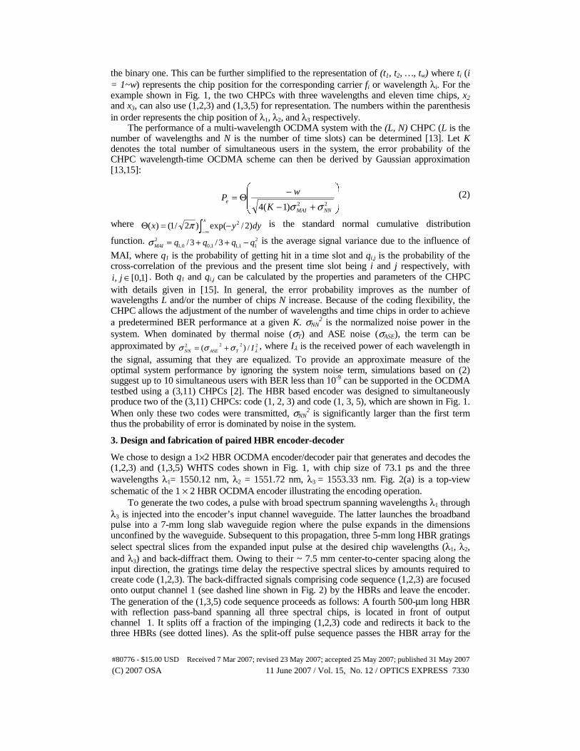
The experimental generation of the WHTS OCDMA codes is done by injecting a 10-nm wide 0.3-ps long supercontinuum optical pulse into the HBR encoder. The supercontinuum pulse was generated by passing the amplified output of a 1550 nm mode-locked erbium doped fiber laser through a piece of dispersion decreasing fiber. The measured optical spectra of the two codes are depicted in Fig. 3(a), clearly showing the three spectral bins centered at the design wavelengths. The difference between output spectral powers for code (1,2,3) and code (1,3,5) is due to the weakly reflecting nature of the broadband HBR and can be rectified in a future iteration. The shape of the spectral bins and their relative intensity is slightly distorted due to the non-uniformity of the supercontinuum spectral intensity (shown as upper solid black line for reference). Note the excellent fall-off characteristics and spectral isolation of the spectral bins, achieved by apodizing the HBR using a correlated-line approach and a Gaussian-weighted sinc function [6].
In Fig. 3(b) we show the temporal signature of output ports 1 and 2 as detected with a bandwidth-limited optical sampling oscilloscope with 30-GHz bandwidth. As is clearly shown, both generated WHTS codes are in perfect agreement with the code designs regarding
#80776 - $15.00 USD Received 7 Mar 2007; revised 23 May 2007; accepted 25 May 2007; published 31 May 2007
(C) 2007 OSA 11 June 2007 / Vol. 15, No. 12 / OPTICS EXPRESS 7332
the temporal separation of the spectral chips, i.e. the λ1, λ2, and λ3 pulses are ~73 ps apart for code (1,2,3) and ~146 ps apart for code (1,3,5). The intensity drop observable across the (1,3,5) pulse sequence is attributed to a grating-mediated out-coupling of waveguide signals to cladding and free-space modes. This loss mechanism scales with the aggregate grating length, both resonant and non-resonant, through which signals travel and thus gets worse for signals reflected from HBRs in the back of the encoder. The loss of concern is specific to the particular apodization approach used in obtaining the spectral bin transfer functions shown in Figure 3(a) and can be overcome by use of alternate approaches recently demonstrated [6].
Fig. 3. (a) Spectra and (b) time signatures of the generated WHTS codes.
The matched HBR based encoder and decoder have a slight polarization dependency. Specifically, for TE-polarized input the device response is slightly blue-shifted by about 100 pm. Pathways to reduce this shift have been discussed in [17]. Additionally, a polarization-dependent loss is observed for TE-input and is attributed to the apodization-induced out-coupling loss. In the experimental setup, the polarization of both codes at the decoder input can be adjusted by polarization controllers to produce sufficient contrast between the autocorrelation peak and the cross-correlation signal at the decoder outputs. In future design iterations this effect can be mitigated by employing an alternate apodization approach recently demonstrated to yield a polarization- dependent loss of only 0.2 dB [6].
4.2 Signal transmission with paired encoder and decoder
EAM
EAM
Dual-Code
EncoderSupercontinuumOptical Pulse Train : 1.25 GHz
(1,2,3)
(1,3,5)
Dual-Code
Decoder
Electronic Data 2 : 1.25 Gb/s
Electronic Data 1 : 1.25 Gb/s
Decoded signal for (1,3,5)
Decoded signalfor (1,2,3)
To Receiver and BERT
Multiplexed signal
OCDMA star network
Star couplerEAM
EAM
Dual-Code
EncoderSupercontinuumOptical Pulse Train : 1.25 GHz
(1,2,3)
(1,3,5)
Dual-Code
Decoder
Electronic Data 2 : 1.25 Gb/s
Electronic Data 1 : 1.25 Gb/s
Decoded signal for (1,3,5)
Decoded signalfor (1,2,3)
To Receiver and BERT
Multiplexed signal
OCDMA star network
Star coupler
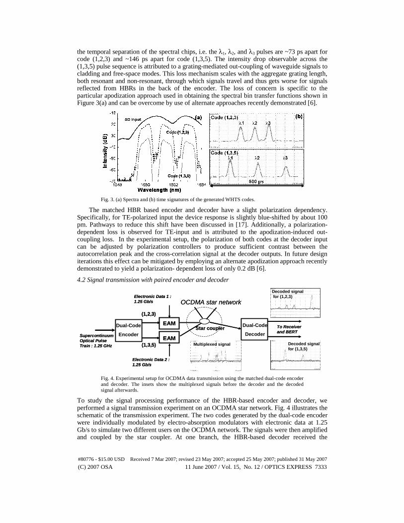
Fig. 4. Experimental setup for OCDMA data transmission using the matched dual-code encoder and decoder. The insets show the multiplexed signals before the decoder and the decoded signal afterwards.
To study the signal processing performance of the HBR-based encoder and decoder, we performed a signal transmission experiment on an OCDMA star network. Fig. 4 illustrates the schematic of the transmission experiment. The two codes generated by the dual-code encoder were individually modulated by electro-absorption modulators with electronic data at 1.25 Gb/s to simulate two different users on the OCDMA network. The signals were then amplified and coupled by the star coupler. At one branch, the HBR-based decoder received the
#80776 - $15.00 USD Received 7 Mar 2007; revised 23 May 2007; accepted 25 May 2007; published 31 May 2007
(C) 2007 OSA 11 June 2007 / Vol. 15, No. 12 / OPTICS EXPRESS 7333

multiplexed signals for code (1,2,3) and (1,3,5), as shown in the inset. Both decoded outputs, shown in the insets of Fig. 4, exhibit an auto-correlation signal (the highest peak) representing the decoded signal together with the cross-correlation signal from the other user. The decoded OCDMA signals were sent directly to a photo-detector followed by the BERT. No time demultiplexing or gating was applied, thus the MAI rejection was solely achieved by the robustness of CHPC design and the HBR device performance.
In Fig. 5 we plot the measured BER result in the transmission experiment. The squares show the case when each user is transmitting alone with the corresponding code, while the triangles show the effect when both of them are sending. The horizontal axis gives the average optical power received by the photo-detector. A simulated curve calculated from (2) is also plotted to fit the experimental data. In the case with MAI, since only half of the total received power should be considered as useful signal, the actual power penalty for allocating two users is only 0.5 dB. In both cases, transmission for each user easily achieved below 10-10 (no error observed for more than one minute at transmission rate of 1.25Gb/s) and showed no sign of error floor. Thus, the results from our experiment clearly demonstrate the capability of encoding and decoding multiple codes using HBR-based devices, with the aid of cautious code design using (3,11) CHPCs.
-27 -24 -21 -18 -15 -121E-12
1E-10
1E-8
1E-6
1E-4
0.01
BE
R
Received Optical Power (dBm)
(1,2,3) (1,3,5) (1,2,3) w/ MAI (1,3,5) w/ MAI
~ 3.5 dB
Fig. 5. The measured BER curves for data transmission using the dual-code encoder and decoder. A power penalty of only 0.5 dB is obtained for only two users.
5. Conclusion
In summary, we have successfully demonstrated the simultaneous generation and decoding of two WHTS codes using integrated HBR-based OCDMA encoders and decoders at OC-24 using (3,11) carrier-hopping prime codes. The performance of the integrated HBR-based OCDMA dual code encoder-decoder pair is in very good agreement with theory. The dual-code encoder and decoder were embedded into an OCDMA star network to support error-free signal transmission for two users. HBR technology enables inexpensive small footprint multi-port designs making possible multiple code generation - a very attractive approach in building cost-effective, robust and light-weight systems.
Acknowledgments
This work was supported in part by DARPA, PTAP, and a collaborative effort with Lockheed Martin Corporation.
#80776 - $15.00 USD Received 7 Mar 2007; revised 23 May 2007; accepted 25 May 2007; published 31 May 2007
(C) 2007 OSA 11 June 2007 / Vol. 15, No. 12 / OPTICS EXPRESS 7334
Related Documents