www.hiwin.tw www.hiwinmikro.tw Single-Axis Robot Technical Information Original Instructions

Welcome message from author
This document is posted to help you gain knowledge. Please leave a comment to let me know what you think about it! Share it to your friends and learn new things together.
Transcript
Sin
gle-A
xis Rob
ot Tech
nical In
formation
www.hiwin.tw www.hiwinmikro.twCopyright © HIWIN Technologies Corp.©2019 FORM K99TE16-1904 (PRINTED IN TAIWAN)The specifications in this catalog are subject to change without notification.
Single-Axis Robot
Technical Information
HIWIN TECHNOLOGIES CORP.No. 7, Jingke Road, Taichung Precision Machinery Park,Taichung 40852, TaiwanTel: +886-4-23594510Fax: [email protected]
HIWIN MIKROSYSTEM CORP.No. 6, Jingke Central Road, Taichung Precision Machinery Park,Taichung 40852, TaiwanTel: +886-4-23550110Fax: [email protected]
Original InstructionsSubsidiaries / Research Center
HIWIN Schweiz GmbHJONA, [email protected]
HIWIN s.r.o.BRNO, CZECH [email protected]
HIWIN [email protected]
HIWIN KOREASUWON‧MASAN, [email protected]
HIWIN CHINASUZHOU, [email protected]
Mega-Fabs Motion Systems, Ltd.HAIFA, [email protected]
HIWIN GmbHOFFENBURG, [email protected]
HIWIN JAPANKOBE‧TOKYO‧NAGOYA‧NAGANO‧TOHOKU‧SHIZUOKA.HOKURIKU‧HIROSHIMA‧FUKUOKA‧KUMAMOTO, [email protected]
HIWIN USACHICAGO, U.S.A. [email protected]
HIWIN SrlBRUGHERIO, [email protected]
1. HIWIN is a registered trademark of HIWIN Technologies Corp. For your protection, avoid buying counterfeit products from unknown sources.
2. Actual products may differ from specifications and photos provided in this catalog. These differences may be the result of various factors including product improvements.
3. HIWIN will not sell or export products or processes restricted under the “Foreign Trade Act” or related regulations. Export of restricted products should be approved by proper authorities in accordance with relevant laws and shall not be used to manufacture or develop nuclear, biochemical, missiles or other weapons.
4. HIWIN website for patented product directory: http://www.hiwin.tw/Products/Products_patents.aspx
Publication Date:October 2006, first edition
Print Date:April 2019, 16th edition
Single-Aixs Robot (Original Instructions) Technical Information
Copyright © HIWIN Technologies Corp.
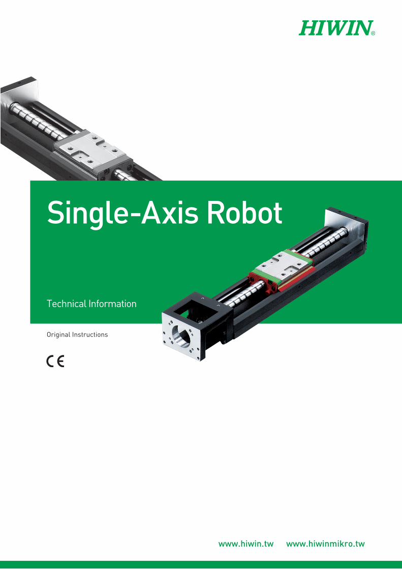
INDUSTRIE 4.0 Best Partner
Multi-Axis RobotPick-and-place / Assembly / Array and packaging / Semiconductor / Electro-Optical industry / Automotive industry / Food industry• Articulated Robot• Delta Robot• SCARA Robot• Wafer Robot• Electric Gripper • Integrated Electric Gripper• Rotary Joint
Single-Axis RobotPrecision / Semiconductor /Medical / FPD• KK, SK• KS, KA • KU, KE, KC
Torque Motor Rotary TableAerospace / Medical / Automotive industry / Machine tools / Machinery industry• RAB Series• RAS Series• RCV Series• RCH Series
BallscrewPrecision Ground / Rolled• Super S series• Super T series• Mini Roller• Ecological & Economical
lubrication Module E2• Rotating Nut (R1)• Energy-Saving & Thermal-
Controlling (Cool Type)• Heavy Load Series (RD) • Ball Spline
Linear GuidewayAutomation / Semiconductor / Medical• Ball Type--HG, EG, WE, MG, CG• Quiet Type--QH, QE, QW, QR• Other--RG, E2, PG, SE, RC
BearingMachine tools / Robot• Crossed Roller Bearings • Ballscrew Bearings • Linear Bearing• Support Unit
DATORKER® Robot ReducerRobots / Automation equipment / Semiconductor equipment / Machine tools• WUT Type-Combination Type (P) • WUI Type-Component Type (C) • WTI Type-Combination Type (P)• WTI Type-Sealed type (A)
AC Servo Motor & DriveSemiconductor / Packaging machine /SMT / Food industry / LCD• Drives-D1, D1-N, D2T • Motors-50W~2000W
Medical EquipmentHospital / Rehabilitation centers /Nursing homes• Robotic Gait Training System• Hygiene System• Robotic Endoscope HolderS
Linear MotorAutomated transport / AOI application / Precision / Semiconductor• Iron-core Linear Motor• Coreless Linear Motor • Linear Turbo Motor LMT • Planar Servo Motor • Air Bearing Platform• X-Y Stage • Gantry Systems
Torque Motor & Direct Drive MotorInspection / Testing equipment / Machine tools / Robot• Rotary Tables-TMS,TMY,TMN• TMRW Series• TMRI Series
(The specifications in this catalog are subject to change without notification.)
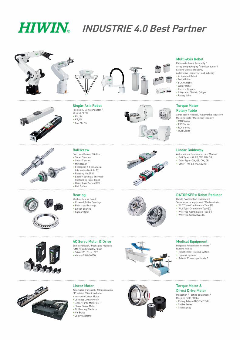
1. Precautions (Be sure to read before handling) .............................................. 1
2. KK Series ..................................................................................................................................... 12
3. SK Series ..................................................................................................................................... 49
4. KC Series ..................................................................................................................................... 68
5. KA Series ..................................................................................................................................... 82
6. KS Series ..................................................................................................................................... 127
7. KU Series ..................................................................................................................................... 148
8. KE Series ..................................................................................................................................... 155
9. HIWIN AC Servo Motor & Drive Specification Table .................................. 167
10. Motor & Drive ........................................................................................................................ 169
11. Lubricating Device ............................................................................................................ 250
Technical Information Index
Single-Axis Robot
K99TE16-1904 1
1. Precautions(Be sure to read before handling)
These safety instructions are intended to prevent hazardous situations and/or equipment damage. These
instructions indicate the level of potential hazard with the labels of “Danger,”“Warning”, or “Caution.” They
are all important notes for safety and must be followed in addition to International Standards (ISO/IEC)[Note 1],
Japanese Industrial Standards (JIS)[Note 2]and other safety regulations[Note 3].
[Note 1] ISO 10218: Robots and robotics devices - Safety requirement for industrial robots
IEC 60204-1: Safety of machinery – Electrical equipment of machine (Part1: General requirement)
[Note 2] JIS B 9960-1: Safety of machinery – Electrical equipment of machine (Part1: General requirement)
JIS B 8433 : Manipulating industrial robots - Safety
[Note 3] Labor Safety and Health Act ......etc.
This product is designed and manufactured as a component for using in general industrial machinery.
Please make sure to aquire the product specifications from the system designer or someone who has
sufficient knowledge and experience. In addition, please read the details of the“Technical Manual”
and “Software Operating Manual” carefully and take the educational training for related safety prior to
operating this product.
If the gripper is integrated in a system (machine, robot, etc.), the system needs to meet the regulations
and standards for safety measures. Check if the system satisfies the regulations and standards first. If so,
properly handle the product in accordance with the regulations and standards.
All situations are not covered by the “Danger”, “Warning”, and “Caution” safety signs. For more
details, be sure to read the instruction manuals thoroughly before operation.
Danger:Indicates an imminently hazardous situation which, if not avoided, will
result in death or serious injury.
Warning:Indicates a potentially hazardous situation which could result in death
or serious injury, if the equipment is operated incorrectly.
Caution:Indicates a potentially hazardous situation which may result in injury
and machine damage, if the equipment is operated incorrectly.
Danger
1.1 Safety Specifications
Do not use the product outside specifications. It
may cause the product to fail, stop functioning or
sustain damage. It may also significantly reduce
the service life of the product.
If the machine will stop in the event of system
problem such as emergency stop or power
failure, design a safety circuit or other device to
prevent equipment damage or injury.
Do not use this product in a place exposed to
ignitable, inflammable or explosive substances.
It may explode or ignite, resulting in product
damage or injury. Hot swapping is forbidden.
Please follow the instruction manual when wiring
the product. For plug in/plug out of the wire,
connect to the terminal quickly and reliably.
Please do not use the product with water and oil
to avoid electric shock or fire.
Before supplying power and operating the
product, always check the operation area of the
K99TE16-19042
equipment to ensure safety. When operating or
adjusting the gripper, be sure to observe safety
measures for the system.
Please do not disassemble, or modify the product
to avoid personal accident, electric shock, fire or
damage.
Do not expose the product to radiant heat
generated from a heat source, and use the
product within the ambient temperature range of
5 to 45.
Use the product in humidity range of 35% to 85%
(without dew condensation).
Please use the product below altitude of 1000
meters.
Please use when environmental illumination is
greater than 500 lux.
Do not use the product in an atmosphere of
corrosive gases (sulfuric acid or hydrochloric
acid). Rust may form and reduce the structural
strength of the product.
Do not use the product in a place exposed to dust,
or iron powder. If dust enters the product through
small openings and gaps, the product may suffer
damage.
Please do not use the product near severe
vibration.
Please do not use the product near strong
electromagnetic waves, locations that may
generate high current, welding operations which
may generate electric arc, locations that may
generate interference due to static electricity to
avoid the abnormal operation of product.
Please mount the product and jaws with adequate
screw tightening torque.
Please do not approach or touch the product
while the product is operating.
When a person is accidentally caught into
the machine, please turn off the power supply
immediately or push the emergency stop button
of external safety loop device, and then adjust the
jaws position or remove the jaws manually for
disengagement.
Do not touch the connectors or exposed terminals
of the controller. Doing so may result in electric
shock.
Turn off the power to the product in the event
of power failure. Failure to do so may cause the
product to suddenly start moving when the power
is restored, resulting in injury or product damage.
If the product is generating heat, smoke, a
strange smell or continual noise, turn off power
immediately. Continuing to use the product may
result in product damage or fire.
If the product does not activate while gripping a
workpiece, please cut off the power immediately.
Remove the workpiece by adjusting the jaws
position or removing the jaws manually. After the
abnormal state is corrected restart the power.
Please do not grip live or hazardous objects.
Prevent load from applying force to one jaw when
gripping a workpiece.
When the product is activated, please do not
apply any external force on the gripper.
Warning
Caution
Do not hold moving parts of the product or its
cables during installation. It may result in injury.
Do not insert a finger or object in the openings in
the product. It may cause fire, electric shock, or
injury.
The motor generates a large amount of heat
during operation, and the product surface
temperature is high. Ensure this will not affect a
workpiece near the gripper.
The actuator cables with the product are flexible,
but do not store the cables in a movable cable
duct that bends more than the specified bending
radius. (Rb ≥ 63mm)
K99TE16-1904 3
Do not scratch the actuator cables. Please
perform periodic inspections monthly.
Scratching, forcible bending, straining, winding,
and pinching may cause short circuit and
insulation failure, which results in electric shock
and malfunction.
When the product is unusable and scrapped,
please follow the local waste disposal
regulations for handling.
When using this product, please wear safety
shoes or the related protective equipment.
The mounting face has holes and slots for
positioning. Make use of them if necessary.
Design the jaws to be lightweight and minimum
length.
Mass of a workpiece that the jaws can grip
greatly differs depending on the material
quality, shape, and gripping surface condition of
the jaws.
Use speed and parameters appropriate with the
product to avoid making a great impact to the
jaws.
Please assure there is sufficient space for
maintenance and inspection, and perform
regular maintenance every six (6) months or
after activating the product 500,000 times.
Please perform maintenance of transmission
components in manual mode. After adjusting
the gripper to the maximum opening position,
please use the greasing device to replenish the
grease or apply the grease on the screw shaft
and both sides of groove.
The measured result of actual noise level
for product is 52.8 dB. (Conditions: distance
from the product is 1 meter, height from
the ground is 1.6 meters, maximum speed
is 80% operating). If the noise level is over
80dB(A) during operation, personal protective
equipment is required.
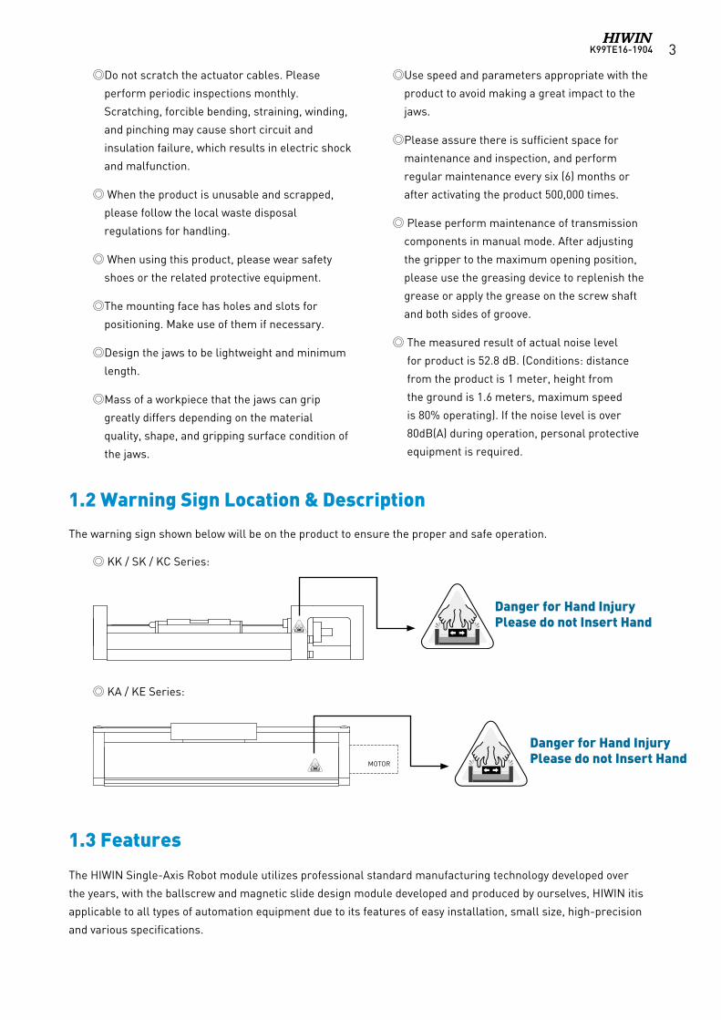
Danger for Hand InjuryPlease do not Insert Hand
Danger for Hand InjuryPlease do not Insert Hand
1.2 Warning Sign Location & Description
The warning sign shown below will be on the product to ensure the proper and safe operation.
1.3 Features
The HIWIN Single-Axis Robot module utilizes professional standard manufacturing technology developed over
the years, with the ballscrew and magnetic slide design module developed and produced by ourselves, HIWIN itis
applicable to all types of automation equipment due to its features of easy installation, small size, high-precision
and various specifications.
KK / SK / KC Series:
KA / KE Series:
MOTOR
K99TE16-19044
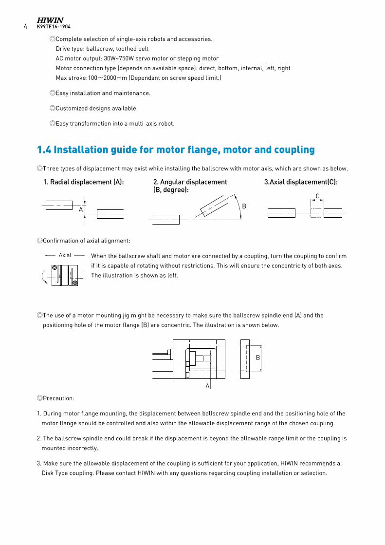
Three types of displacement may exist while installing the ballscrew with motor axis, which are shown as below.
Confirmation of axial alignment:
When the ballscrew shaft and motor are connected by a coupling, turn the coupling to confirm
if it is capable of rotating without restrictions. This will ensure the concentricity of both axes.
The illustration is shown as left.
The use of a motor mounting jig might be necessary to make sure the ballscrew spindle end (A) and the
positioning hole of the motor flange (B) are concentric. The illustration is shown below.
Precaution:
1. During motor flange mounting, the displacement between ballscrew spindle end and the positioning hole of the
motor flange should be controlled and also within the allowable displacement range of the chosen coupling.
2. The ballscrew spindle end could break if the displacement is beyond the allowable range limit or the coupling is
mounted incorrectly.
3. Make sure the allowable displacement of the coupling is sufficient for your application, HIWIN recommends a
Disk Type coupling. Please contact HIWIN with any questions regarding coupling installation or selection.
1. Radial displacement (A): 2. Angular displacement (B, degree):
3.Axial displacement(C):
軸向
B
A
C
B
A
Axial
軸向
B
A
C
B
A
Axial
軸向
B
A
C
B
A
Axial
軸向
B
A
C
B
A
Axial
軸向
B
A
C
B
A
Axial
1.4 Installation guide for motor flange, motor and coupling
Complete selection of single-axis robots and accessories.
Drive type: ballscrew, toothed belt
AC motor output: 30W~750W servo motor or stepping motor
Motor connection type (depends on available space): direct, bottom, internal, left, right
Max stroke:100~2000mm (Dependant on screw speed limit.)
Easy installation and maintenance.
Customized designs available.
Easy transformation into a multi-axis robot.
K99TE16-1904 5
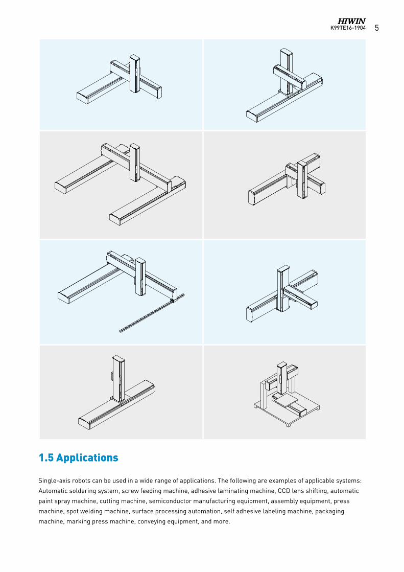
Single-axis robots can be used in a wide range of applications. The following are examples of applicable systems:
Automatic soldering system, screw feeding machine, adhesive laminating machine, CCD lens shifting, automatic
paint spray machine, cutting machine, semiconductor manufacturing equipment, assembly equipment, press
machine, spot welding machine, surface processing automation, self adhesive labeling machine, packaging
machine, marking press machine, conveying equipment, and more.
1.5 Applications
K99TE16-19046
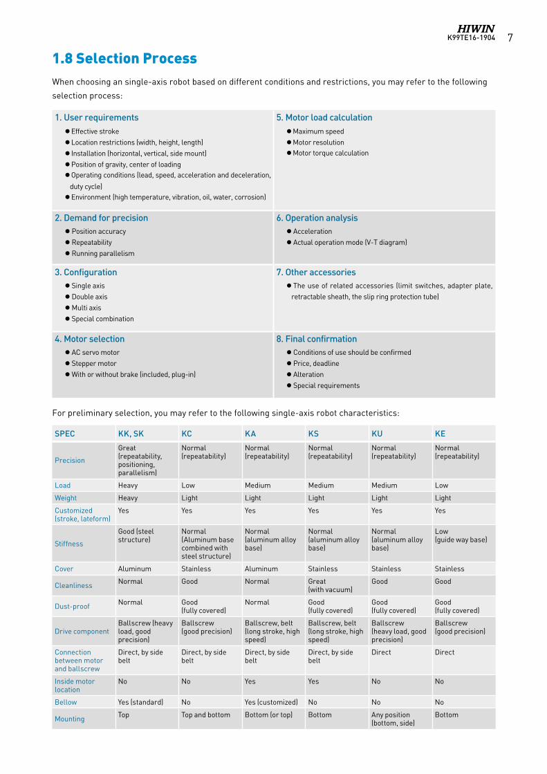
Single-axis robot components include a motor, drive, and upper controller as demonstrated below. Our customers
may choose from HIWIN's selection of excellent servo motors, stepping motors, and drives.
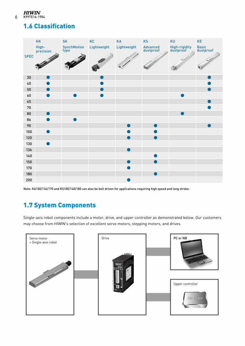
Note: KA100/136/170 and KS100/140/180 can also be belt driven for applications requiring high speed and long stroke.
SPEC
KK
High-precision
SK
SynchMotiontype
KC
Lightweight
KA
Lightweight
KS
Advanced dustproof
KU
High-rigidity dustproof
KE
Basic dustproof
30
40
50
60
65
70
80
86
90
100
120
130
136
140
150
170
180
200
1.6 Classification
1.7 System Components
Drive PC or NB
Upper controller
Controller
Servo motor + Single-axis robot
K99TE16-1904 7
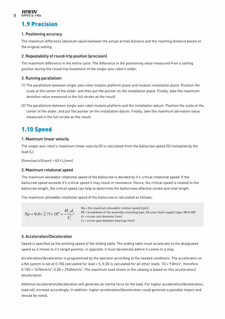
When choosing an single-axis robot based on different conditions and restrictions, you may refer to the following
selection process:
1. User requirements 5. Motor load calculation Effective stroke Location restrictions (width, height, length) Installation (horizontal, vertical, side mount) Position of gravity, center of loading Operating conditions (lead, speed, acceleration and deceleration,
duty cycle) Environment (high temperature, vibration, oil, water, corrosion)
Maximum speed Motor resolution Motor torque calculation
2. Demand for precision 6. Operation analysis Position accuracy Repeatability Running parallelism
Acceleration Actual operation mode (V-T diagram)
3. Configuration 7. Other accessories Single axis Double axis Multi axis Special combination
The use of related accessories (limit switches, adapter plate, retractable sheath, the slip ring protection tube)
4. Motor selection 8. Final confirmation AC servo motor Stepper motor With or without brake (included, plug-in)
Conditions of use should be confirmed Price, deadline Alteration Special requirements
SPEC KK, SK KC KA KS KU KE
Precision
Great (repeatability, positioning, parallelism)
Normal (repeatability)
Normal (repeatability)
Normal (repeatability)
Normal (repeatability)
Normal (repeatability)
Load Heavy Low Medium Medium Medium Low
Weight Heavy Light Light Light Light Light
Customized (stroke, lateform)
Yes Yes Yes Yes Yes Yes
Stiffness
Good (steel structure)
Normal (Aluminum base combined with steel structure)
Normal (aluminum alloy base)
Normal (aluminum alloy base)
Normal (aluminum alloy base)
Low (guide way base)
Cover Aluminum Stainless Aluminum Stainless Stainless Stainless
Cleanliness Normal Good Normal Great (with vacuum)
Good Good
Dust-proof Normal Good (fully covered)
Normal Good (fully covered)
Good (fully covered)
Good (fully covered)
Drive componentBallscrew (heavy load, good precision)
Ballscrew (good precision)
Ballscrew, belt (long stroke, high speed)
Ballscrew, belt (long stroke, high speed)
Ballscrew (heavy load, good precision)
Ballscrew (good precision)
Connection between motor and ballscrew
Direct, by side belt
Direct, by side belt
Direct, by side belt
Direct, by side belt
Direct Direct
Inside motor location
No No Yes Yes No No
Bellow Yes (standard) No Yes (customized) No No No
Mounting Top Top and bottom Bottom (or top) Bottom Any position (bottom, side)
Bottom
For preliminary selection, you may refer to the following single-axis robot characteristics:
1.8 Selection Process
K99TE16-19048
1. Positioning accuracy
The maximum difference (absolute value) between the actual arrival distance and the reaching distance based on
the original setting.
2. Repeatability of round-trip position (precision)
The maximum difference in the entire cycle. The difference in the positioning value measured from a setting
position during the round trip movement of the single-axis robot's slider.
3. Running parallelism
(1) The parallelism between single-axis robot module platform plane and module installation plane. Position the
scale at the center of the slider, and then put the pointer on the installation plane. Finally, take the maximum
deviation value measured in the full stroke as the result.
(2) The parallelism between single-axis robot module platform and the installation datum. Position the scale at the
center of the slider, and put the pointer on the installation datum. Finally, take the maximum derviation value
measured in the full stroke as the result.
1. Maximum linear velocity
The single-axis robot's maximum linear velocity (V) is calculated from the ballscrew speed (S) multiplied by the
lead (L).
V(mm/sec)=S(rpm)÷60×L(mm)
2. Maximum rotational speed
The maximum allowable rotational speed of the ballscrew is decided by it's critical rotational speed. If the
ballscrew speed exceeds it's critical speed it may result in resonance. Hence, the critical speed is related to the
ballscrew length, the critical speed can help to determine the ballscrews effective stroke and total length.
The maximum allowable rotational speed of the ballscrew is calculated as follows:
3. Acceleration/Deceleration
Speed is specified as the working speed of the sliding table. The sliding table must accelerate to the designated
speed as it moves to it's target position, in opposite, it must decelerate before it comes to a stop.
Acceleration/deceleration is programmed by the operator according to the needed conditions. The acceleraton on
a KA system is set at 0.15G calculated for lead = 5, 0.3G is calculated for all other leads. 1G = 9.8m/s2, therefore
0.15G = 1470mm/s2, 0.3G = 2940mm/s2. The maximum load shown in the catalog is based on this acceleration/
deceleration.
Attention Acceleration/deceleration will generate an inertia force on the load. For higher acceleration/deceleration,
load will increase accordingly. In addition, higher acceleration/deceleration could generate a possible impact and
should be noted.
2
81071.28.0t
rf
LdM
Np ×××=Np = the maximum allowable rotation speed (rpm)Mf = breakdown of the assembly mounting type; KA uses fixed-support type; Mf=0.689dr = screw root diameter (mm)Lt = screw span between bearings (mm)
1.9 Precision
1.10 Speed
K99TE16-1904 9
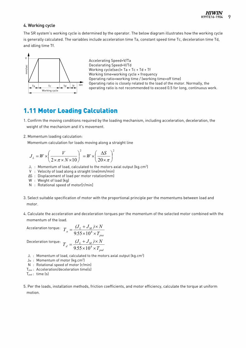
4. Working cycle
The SR system's working cycle is determined by the operator. The below diagram illustrates how the working cycle
is generally calculated. The variables include acceleration time Ta, constant speed time Tc, deceleration time Td,
and idling time Tf.
JL : Momentum of load, calculated to the motors axial output (kg.cm2) V : Velocity of load along a straight line(mm/min)ΔS : Displacementofloadpermotorrotation(mm) W : Weight of load (kg) N : Rotational speed of motor[r/min]
Acceleration torque:
Deceleration torque:
JL : Momentum of load, calculated to the motors axial output (kg.cm2) JM : Momentum of motor (kg.cm2) N : Rotational speed of motor (r/min) Tpsa : Acceleration/deceleration time(s) Tpsd : time (s)
Accelerating Speed=V/TaDecelerating Speed=V/TdWorking cycle(sec)= Ta + Tc + Td + TfWorking time=working cycle × frequency Operating ratio=working time / (working time+off time)Operating ratio is closely related to the load of the motor. Normally, the operating ratio is not recommended to exceed 0.5 for long, continuous work.
工作週期
Ta
mm
/sec
Tc Td Tf
V
sec
Working cycle
1.11 Motor Loading Calculation 1. Confirm the moving conditions required by the loading mechanism, including acceleration, deceleration, the
weight of the mechanism and it's movement.
2. Momentum loading calculation:
Momentum calculation for loads moving along a straight line
3. Select suitable specification of motor with the proportional principle per the momentums between load and
motor.
4. Calculate the acceleration and deceleration torques per the momentum of the selected motor combined with the
momentum of the load.
5. Per the loads, installation methods, friction coefficients, and motor efficiency, calculate the torque at uniform
motion.
K99TE16-190410
6. The maximum output torque of the selected motor should be larger than the sum of the acceleration torque
and load torque; if this condition is not met, the model number needs to be changed and calculated until the
requirement is satisfied.
7. Obtain the continuous effective torque per the load torque, acceleration torque, deceleration torque, and
continuous torque.
8. The rated output torque of the selected motor should be larger than the continuous effective torque; if this
condition is not met, the model number needs to be changed and calculated until the requirement is compliant.
If the ballscrew is used in the vertical direction (Z axis), the load should be within the maximum value indicated for
vertical loading. Vertical installation using timing belts is forbidden.
*Attention: To prevent the load from slipping off, a brake system is recommended on the motor when the KA
module is installed vertically.
Motor Side Mount and Belt Drive Module
To avoid ballscrew damage or belt slippage caused by incorrect belt tension, review table1&2 before installing
belt.
F : Axial force moving along a straight line F=FC + μx (Wxg + FO) TL : Load torque (N.m) FC : External force exerted in the axial direction (N) FO : External positive pressure exerted by the load onto the single-axis robot (N) W : Load (including sliding platform) (kg) μ : Friction coefficient η : Mechanical efficiency V : Velocity of load in a straight line (mm/min) N : Rotational speed of motor (r/min) g : Gravity (9.8m/s2)ΔS : Displacementofloadpermotorrotation(mm)
Tpsa : Acceleration time tc : Constant speed time Tpsd : Deceleration time th : Stop time Tf : Cycle time Ta : Acceleration torque TL : Load torque Td : Deceleration torque TLH : Continuous torque (horizontal movement, TLH=0)
1.12 Installation
1.13 Belt Tension of Motor Side Mount and Belt Drive Module
K99TE16-1904 11
For horizontal, side or slope (less than 30 degrees) orientation, the service life is dependent on the guideway, as
for vertical orientation, the service life is dependent on the ballscrew or fixed bearing which ever one is shorter.
The listed dynamic load (Fy, Fz, Mx, My, Mz) is based on a service life of 10,000km of travel. If the load is less than
the loading condition (Fy/Fyd + Fz/Fzd + Mx/Mxd + My/Myd + Mz/Mzd )≦1), the service life could be extended. If
the load is over, the service life will be less than 10,000km. To ensure long term use, it is recommended that the
loading be within the listed range.
All the related accessories, ballscrew and guideway need to be maintained. After every 3 months or 100km travel
distance, it is recommended to add grease to the ballscrew and guideway. Clean any dust or debris from the
system. Replace the grease if there is any color change. If you have any further questions, please contact HIWIN.
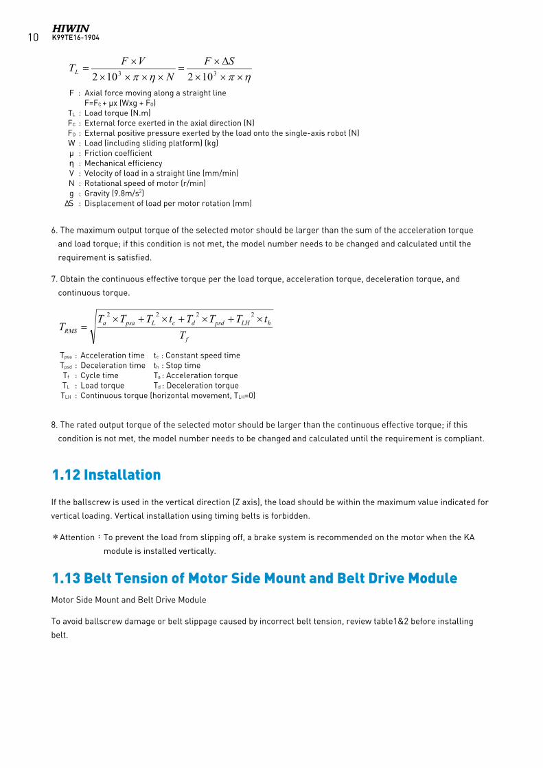
Table 1 Belt Tension of Motor Side Mount
Table 2 Belt Tension of Belt Drive Module
1.14 Service life
1.15 Maintenance
Model Blet Specification Max. Tension (N)
KA-100B HTD 3M-15W 74
KA-136B HTD 5M-25W 178
KA-170B HTD 5M-25W 178
KS-100B HTD 3M-15W 74
KS-140B HTD 5M-25W 178
KS-180B HTD 5M-25W 178
Model Blet Specification Max. Tension (N)
KA100-FL(R、D)FR-3GT-90W-309LFL-3GT-90W-216LFD-3GT-90W-237L
44
KA136-FL(R、D)FL(R)-5GT-90W-350LFD-5GT-90W-300L
55
KA170-FL(R、D)FL(R)-5GT-150W-420LFD-5GT-150W-320L
96
KA200-FL(R、D)FL(R)-5GT-150W-460LFD-5GT-150W-360L
96
KS100-FL(R) FL(R)-3GT-60W-234L 44
KS140-FL(R) FL(R)-5GT-90W-350L 55
KS180-FL(R) FL(R)-5GT-90W-400L 55
KC40-FL(R) 2GT-60W-160L 15
KC50-FL(R) 3GT-60W-180L 29
KC60-FL(R) 3GT-60W-186L 29
K99TE16-190412
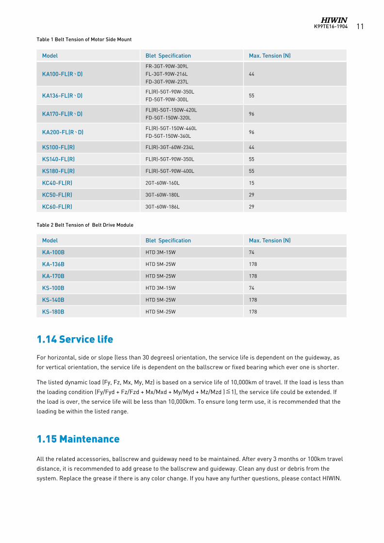
Single-Axis Robot2. KK Series
2.1 Features
Taiwan Patent No. 183022China Patent No. 481446USA Patent No. 6584868Germany Patent No. 20117489.8
An integrated system
Easy installation and maintenance
Compact and lightweight
High accuracy
High stiffness
Complete line of accessories
The structure of rail is analyzed by FEA to
get the best rigidity and weight. The analysis
results are shown as the right figures.
Motor housing
Ballscrew
End seal
BlockGrease nipple
Tail housing
Top seal
StoppperRail
The HIWIN KK single-axis robot is driven by a ballscrew while a guideway slides on an optimized U-rail to achieve
higher accuracy and greater stiffness.
K99TE16-1904 13
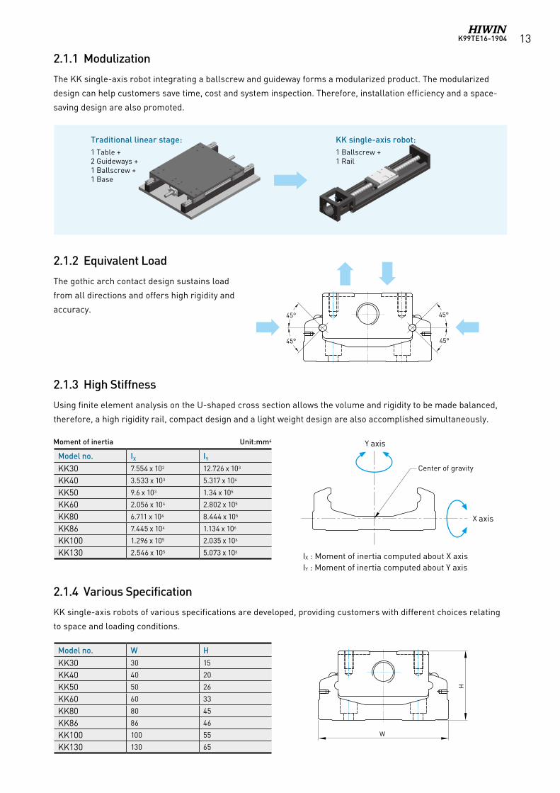
2.1.1 Modulization
The KK single-axis robot integrating a ballscrew and guideway forms a modularized product. The modularized
design can help customers save time, cost and system inspection. Therefore, installation efficiency and a space-
saving design are also promoted.
2.1.2 Equivalent Load
The gothic arch contact design sustains load
from all directions and offers high rigidity and
accuracy.
2.1.3 High Stiffness
Using finite element analysis on the U-shaped cross section allows the volume and rigidity to be made balanced,
therefore, a high rigidity rail, compact design and a light weight design are also accomplished simultaneously.
2.1.4 Various Specification
KK single-axis robots of various specifications are developed, providing customers with different choices relating
to space and loading conditions.
1 Table +2 Guideways +1 Ballscrew +1 Base
KK single-axis robot:1 Ballscrew +1 Rail
45°
45°
45°
45°
Model no. IX IY
KK30 7.554 x 10² 12.726 x 10³
KK40 3.533 x 10³ 5.317 x 10⁴
KK50 9.6 x 10³ 1.34 x 10⁵
KK60 2.056 x 10⁴ 2.802 x 10⁵
KK80 6.711 x 10⁴ 8.444 x 10⁵
KK86 7.445 x 10⁴ 1.134 x 10⁶
KK100 1.296 x 10⁵ 2.035 x 10⁶
KK130 2.546 x 10⁵ 5.073 x 10⁶
Model no. W HKK30 30 15
KK40 40 20
KK50 50 26
KK60 60 33
KK80 80 45
KK86 86 46
KK100 100 55
KK130 130 65
IX : Moment of inertia computed about X axisIY : Moment of inertia computed about Y axis
Moment of inertia Unit:mm4
Center of gravity
Y axis
X axis
Y axis
X axis
Center of gravity
W
H
Traditional linear stage:
K99TE16-190414
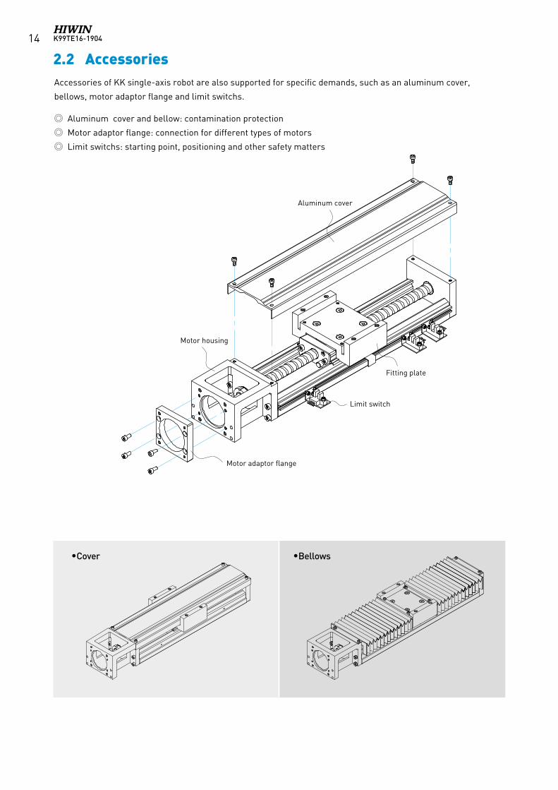
2.2 AccessoriesAccessories of KK single-axis robot are also supported for specific demands, such as an aluminum cover,
bellows, motor adaptor flange and limit switchs.
Aluminum cover and bellow: contamination protection
Motor adaptor flange: connection for different types of motors
Limit switchs: starting point, positioning and other safety matters
Aluminum cover
Fitting plate
Limit switch
Motor housing
Motor adaptor flange
Cover Bellows
K99TE16-1904 15
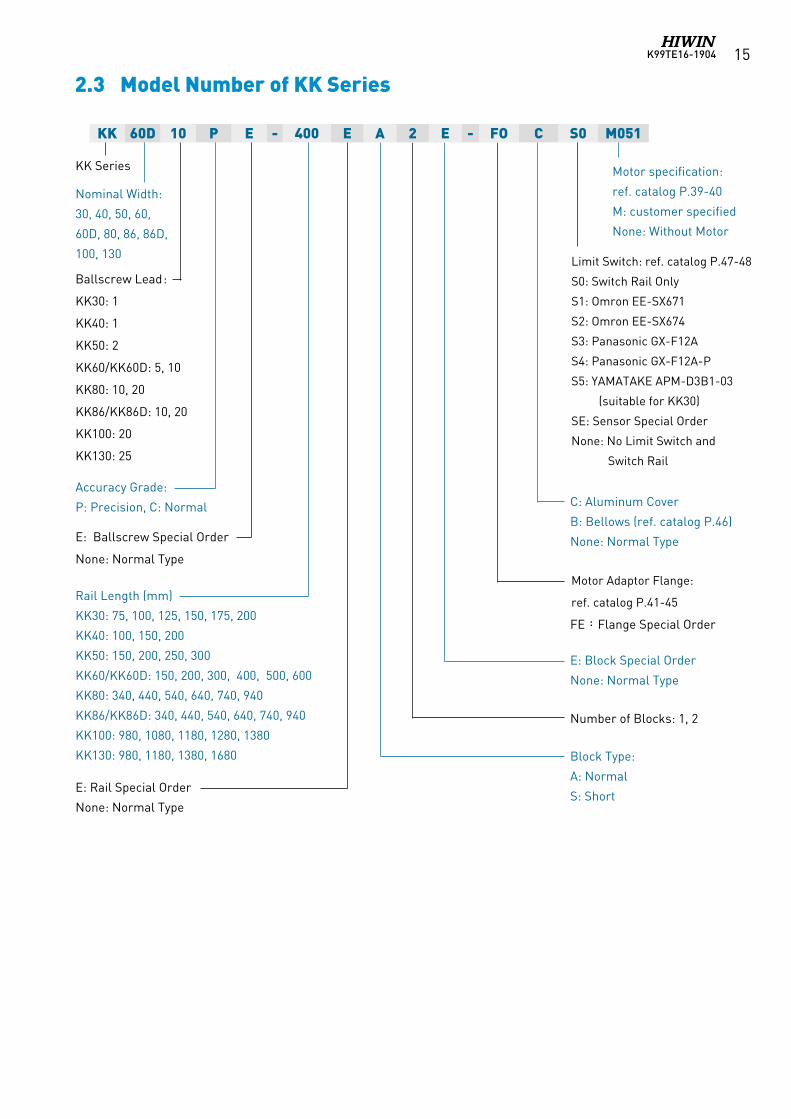
2.3 Model Number of KK Series
KK 60D 10 P E - 400 E A 2 E - FO C S0 M051
KK Series
Nominal Width:
30, 40, 50, 60,
60D, 80, 86, 86D,
100, 130
Accuracy Grade:
P: Precision, C: Normal
E: Ballscrew Special Order
None: Normal Type
Rail Length (mm)
KK30: 75, 100, 125, 150, 175, 200
KK40: 100, 150, 200
KK50: 150, 200, 250, 300
KK60/KK60D: 150, 200, 300, 400, 500, 600
KK80: 340, 440, 540, 640, 740, 940
KK86/KK86D: 340, 440, 540, 640, 740, 940
KK100: 980, 1080, 1180, 1280, 1380
KK130: 980, 1180, 1380, 1680
Ballscrew Lead:
KK30: 1
KK40: 1
KK50: 2
KK60/KK60D: 5, 10
KK80: 10, 20
KK86/KK86D: 10, 20
KK100: 20
KK130: 25
E: Rail Special Order
None: Normal Type
Limit Switch: ref. catalog P.47-48
S0: Switch Rail Only
S1: Omron EE-SX671
S2: Omron EE-SX674
S3: Panasonic GX-F12A
S4: Panasonic GX-F12A-P
S5: YAMATAKE APM-D3B1-03
(suitable for KK30)
SE: Sensor Special Order
None: No Limit Switch and
Switch Rail
Motor Adaptor Flange:
ref. catalog P.41-45
FE:Flange Special Order
E: Block Special Order
None: Normal Type
Number of Blocks: 1, 2
Block Type:
A: Normal
S: Short
C: Aluminum Cover
B: Bellows (ref. catalog P.46)
None: Normal Type
Motor specification:
ref. catalog P.39-40
M: customer specified
None: Without Motor
K99TE16-190416
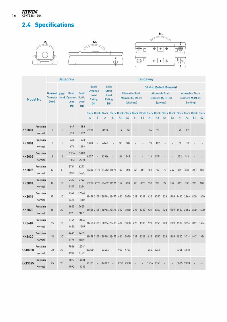
2.4 Specifications
MR MP
MY
Model No.
Ballscrew Guideway
Basic
Dynamic
Load
Rating
(N)
Basic
Static
Load
Rating
(N)
Static Rated Moment
Nominal
Diameter
(mm)
Lead (mm)
Basic
Dynamic
Load
(N)
Basic
Static
Load
(N)
Allowable Static
Moment MP (N-m)
(pitching)
Allowable Static
Moment MY (N-m)
(yawing)
Allowable Static
Moment MR(N-m)
(rolling)
Block
A
Block
S
Block
A
Block
S
Block
A1
Block
A2
Block
S1
Block
S2
Block
A1
Block
A2
Block
S1
Block
S2
Block
A1
Block
A2
Block
S1
Block
S2
KK3001Precision
6 1647 1088
2210 - 3510 - 14 73 - - 14 73 - - 41 82 - -Normal 618 1079
KK4001Precision
8 1735 1538
3920 - 6468 - 33 182 - - 33 182 - - 81 162 - -Normal 676 1284
KK5002Precision
8 22136 3489
8007 - 12916 - 116 545 - - 116 545 - - 222 444 - -Normal 1813 2910
KK6005Precision
12 53744 6243
13230 7173 21462 11574 152 760 72 367 152 760 72 367 419 838 241 482Normal 3377 5625
KK6010Precision
12 102410 3743
13230 7173 21462 11574 152 760 72 367 152 760 72 367 419 838 241 482Normal 2107 3234
KK8010Precision
15 107144 12642
31458 21051 50764 29475 622 3050 228 1309 622 3050 228 1309 1433 2866 800 1600Normal 6429 11387
KK8020Precision
15 204645 7655
31458 21051 50764 29475 622 3050 228 1309 622 3050 228 1309 1433 2866 800 1600Normal 4175 6889
KK8610Precision
15 107144 12642
31458 21051 50764 29475 622 3050 228 1309 622 3050 228 1309 1507 3014 847 1694Normal 6429 11387
KK8620Precision
15 204645 7655
31458 21051 50764 29475 622 3050 228 1309 622 3050 228 1309 1507 3014 847 1694Normal 4175 6889
KK10020Precision
20 207046 12544
39200 - 63406 - 960 4763 - - 960 4763 - - 2205 4410 - -Normal 4782 9163
KK13025Precision
25 257897 15931
48101 - 84829 - 1536 7350 - - 1536 7350 - - 3885 7770 - -Normal 7092 14352
K99TE16-1904 17
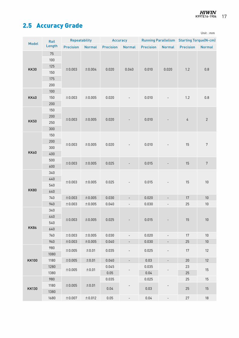
2.5 Accuracy GradeUnit : mm
ModelRail
Length
Repeatability Accuracy Running Parallelism Starting Torque(N-cm)
Precision Normal Precision Normal Precision Normal Precision Normal
KK30
75
±0.003 ±0.004 0.020 0.040 0.010 0.020 1.2 0.8
100
125
150
175
200
KK40
100
±0.003 ±0.005 0.020 - 0.010 - 1.2 0.8150
200
KK50
150
±0.003 ±0.005 0.020 - 0.010 - 4 2200
250
300
KK60
150
±0.003 ±0.005 0.020 - 0.010 - 15 7200
300
400
500±0.003 ±0.005 0.025 - 0.015 - 15 7
600
KK80
340
±0.003 ±0.005 0.025 - 0.015 - 15 10440
540
640
740 ±0.003 ±0.005 0.030 - 0.020 - 17 10
940 ±0.003 ±0.005 0.040 - 0.030 - 25 10
KK86
340
±0.003 ±0.005 0.025 - 0.015 - 15 10440
540
640
740 ±0.003 ±0.005 0.030 - 0.020 - 17 10
940 ±0.003 ±0.005 0.040 - 0.030 - 25 10
KK100
980±0.005 ±0.01 0.035 - 0.025 - 17 12
1080
1180 ±0.005 ±0.01 0.040 - 0.03 - 20 12
1280±0.005 ±0.01
0.045-
0.035-
2315
1380 0.05 0.04 25
KK130
980
±0.005 ±0.01
0.035
-
0.025
-
25 15
11800.04 0.03 25 15
1380
1680 ±0.007 ±0.012 0.05 - 0.04 - 27 18
K99TE16-190418
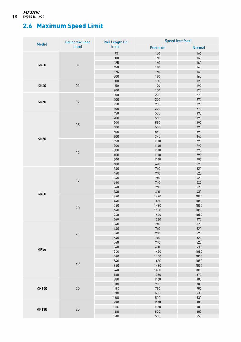
2.6 Maximum Speed Limit
ModelBallscrew Lead
(mm)Rail Length L2
(mm)
Speed (mm/sec)
Precision Normal
KK30 01
75 160 160100 160 160125 160 160150 160 160175 160 160200 160 160
KK40 01100 190 190150 190 190200 190 190
KK50 02
150 270 270200 270 270250 270 270300 270 270
KK60
05
150 550 390200 550 390300 550 390400 550 390500 550 390600 340 340
10
150 1100 790200 1100 790300 1100 790400 1100 790500 1100 790600 670 670
KK80
10
340 740 520440 740 520540 740 520640 740 520740 740 520940 610 430
20
340 1480 1050440 1480 1050540 1480 1050640 1480 1050740 1480 1050940 1220 870
KK86
10
340 740 520440 740 520540 740 520640 740 520740 740 520940 610 430
20
340 1480 1050440 1480 1050540 1480 1050640 1480 1050740 1480 1050940 1220 870
KK100 20
980 1120 8001080 980 8001180 750 7501280 630 6301380 530 530
KK130 25
980 1120 8001180 1120 8001380 830 8001680 550 550
K99TE16-1904 19
2.7 Life Calculations
2.7.1 Service Life
Under repeated stress between the raceway and the rolling elements, pitting and flaking will occur as it reaches
fatigue failure. The service life of the KK single-axis robot is defined as the distanced traveled before any failure of
the raceway or rolling elements appear.
2.7.2 Nominal Life (L)The service life varies greatly even when the KK units are manufactured in the same way or operated under the
same conditions. For this reason, nominal life is used as the criteria for predicting the service life of a KK unit.
2.7.3 Nominal Life Calculation
The calculating formulas are divided into two parts, guideway and ballscrew. The smaller value of the two would
be the recommended nominal life of the KK unit.
Nominal life formulas for both the guideway and ballscrew depend on several parameters and are shown below.
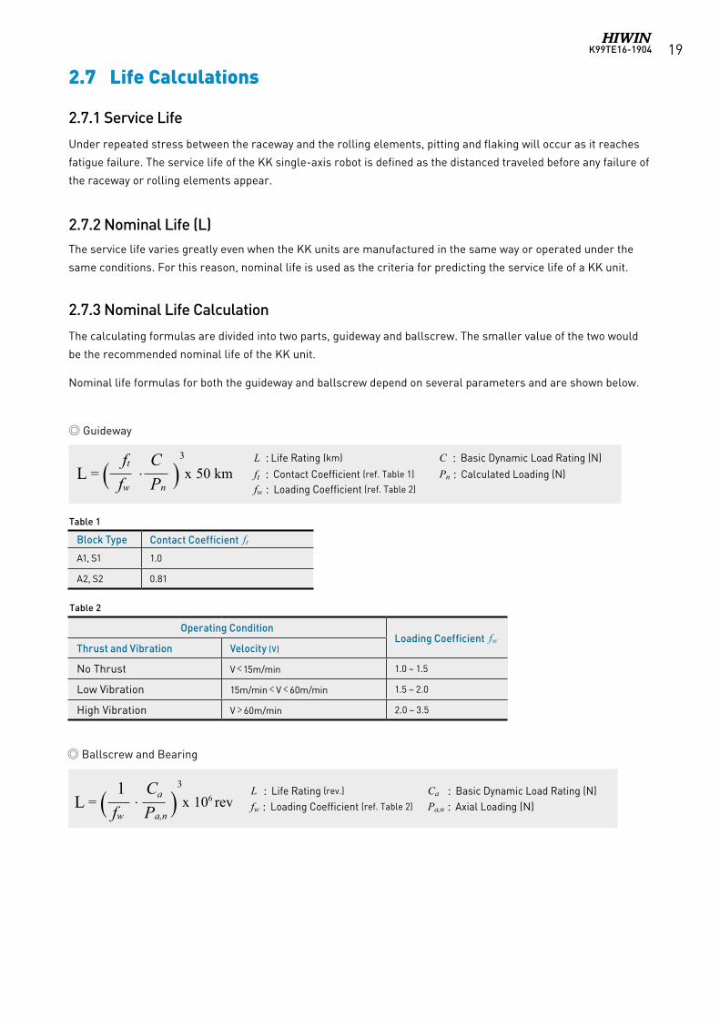
Guideway
L : Life Rating (km) C : Basic Dynamic Load Rating (N)ft : Contact Coefficient (ref. Table 1) Pn : Calculated Loading (N)fw : Loading Coefficient (ref. Table 2)
L = ( ft . C )3
x 50 km fw Pn
L : Life Rating (rev.) Ca : Basic Dynamic Load Rating (N)fw : Loading Coefficient (ref. Table 2) Pa,n : Axial Loading (N)
Operating ConditionLoading Coefficient fw
Thrust and Vibration Velocity (V)
No Thrust V﹤15m/min 1.0 ~ 1.5
Low Vibration 15m/min﹤V﹤60m/min 1.5 ~ 2.0
High Vibration V﹥60m/min 2.0 ~ 3.5
Ballscrew and Bearing
Table 2
L = ( 1 . Ca )3
x 106 rev fw Pa,n
Block Type Contact Coefficient ftA1, S1 1.0
A2, S2 0.81
Table 1
K99TE16-190420
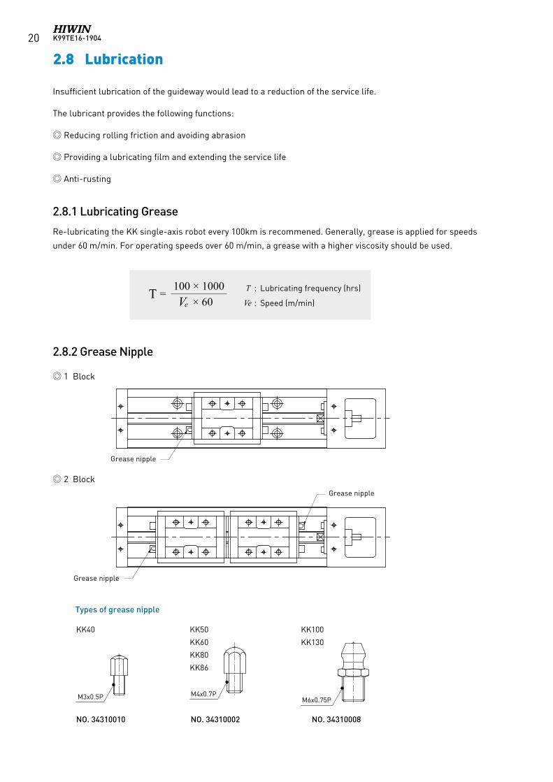
T = 100 × 1000 Ve × 60
Insufficient lubrication of the guideway would lead to a reduction of the service life.
The lubricant provides the following functions:
Reducing rolling friction and avoiding abrasion
Providing a lubricating film and extending the service life
Anti-rusting
2.8.1 Lubricating Grease
Re-lubricating the KK single-axis robot every 100km is recommened. Generally, grease is applied for speeds
under 60 m/min. For operating speeds over 60 m/min, a grease with a higher viscosity should be used.
2.8.2 Grease Nipple
2.8 Lubrication
T : Lubricating frequency (hrs)
Ve : Speed (m/min)
Grease nipple
Grease nipple
Grease nipple
1 Block
2 Block
Types of grease nipple
M6x0.75PM4x0.7PM3x0.5P
KK40 KK50
KK60
KK80
KK86
KK100
KK130
NO. 34310002 NO. 34310010 NO. 34310008
K99TE16-1904 21
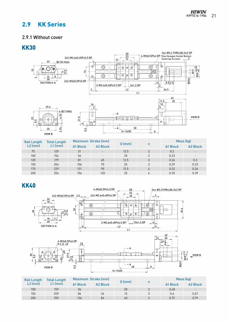
2.9 KK Series
2.9.1 Without cover
Rail Length L2 (mm)Total Length L1 (mm)
Maximum Stroke (mm)G (mm) n
Mass (kg)
A1 Block A2 Block A1 Block A2 Block75 129 31 - 12.5 2 0.2 -100 154 56 - 25 2 0.23 -125 179 81 45 12.5 3 0.26 0.3150 204 106 70 25 3 0.29 0.33175 229 131 95 12.5 4 0.32 0.36200 254 156 120 25 4 0.35 0.39
Rail Length L2 (mm)Total Length L1 (mm)
Maximum Stroke (mm)G (mm) n
Mass (kg)
A1 Block A2 Block A1 Block A2 Block100 159 36 - 20 2 0.48 -150 209 86 34 15 3 0.6 0.67200 259 136 84 40 3 0.72 0.79
KK30
KK40
Ø20
+0.0
3+0
Ø3h
6
Ø17
2
1011.5 25
44
142340
G50
(n-1)x50
4
L2L1
2xn-Ø3.4 THRU,Ø6.5x2 DP
2-M2.6x0.45Px3.5 DP
10
0.5
21.5
14 830
25
2.75
6.75
23
29.6
4-Ø3 THRU
15
19 9.5
SECTION A-A
A
A
Ø2 Oil Hole 12
5x1.2 DP6
2x2-M2.6x0.45Px3.5 DP
24.5
5.5 7.54
2
(Use Hexagon Socket Buttom Head Cap Screws)
0.5
4-M3x0.5Px4 DP
22
2
55
162x2-M3x0.5Px5 DP
VIEW B
VIEW B
KK30Without cover
A
A
SECTION A-A
1826
20
18 1140
13 13.5
2
2.5 5
0.530
30°
30°
10
10x1.2 DP
203358 2xn-Ø3.4THRU,Ø6.5x3 DP
39.6
0.5
27.5
6
L2 55
20
L1
814.5
251249
G60
4-M3x0.5Px6 DPP.C.D. 29
13.5
(n-1)x60
Ø4h
7
Ø20
+0.0
3+0 VIEW B
VIEW B
4-M3x0.5Px4.5 DP
2x2-M2.6x0.45Px4 DP2x2-M3x0.5Px6 DP
2-M2.6x0.45Px4.5 DP
K99TE16-190422
Rail Length L2 (mm)Total Length L1 (mm)
Maximum Stroke (mm)G (mm) K (mm) n m
Mass (kg)
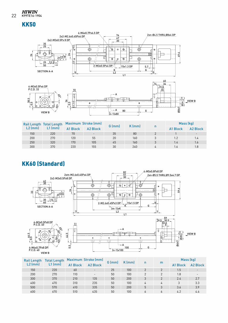
A1 Block A2 Block A1 Block A2 Block150 220 60 - 25 100 2 2 1.5 -200 270 110 - 50 100 2 2 1.8 -300 370 210 135 50 200 3 2 2.4 2.7400 470 310 235 50 100 4 4 3 3.3500 570 410 335 50 200 5 3 3.6 3.9600 670 510 435 50 100 6 6 4.2 4.6
KK50
Rail Length L2 (mm)Total Length L1 (mm)
Maximum Stroke (mm)G (mm) K (mm) n
Mass (kg)
A1 Block A2 Block A1 Block A2 Block150 220 70 - 35 80 2 1 -200 270 120 55 20 160 3 1.2 1.4250 320 170 105 45 160 3 1.4 1.6300 370 220 155 30 240 4 1.6 1.8
A
A
2535
26
12 16 1825 12.5
2.7
SECTION A-A
VIEW B
45°
45°0.
538.5
245.7GK
L2L1
15x1.3 DP
304774
4-M4x0.7Px6.5 DP2xn-Ø4.5 THRU,Ø8x4 DP2x2-M2.6x0.45Px4 DP
55
2x2-M3x0.5Px 8 DP
2-M3x0.5Px4 DP0.
5
4-M3x0.5Px6 DP
36
P.C.D. 33 10
G80(n-1)x80
1016.5
1460
Ø5h
7Ø
24+0
.03
+0
49.4
50
34
VIEW B
KK60 (Standard)
A
A
3042
33
3.1
15 23
3060
SECTION A-A
VIEW B
VIEW B
30°
30°
45°
45°0.
544.5
P.C.D. 40
4-M4x0.7Px8 DP
24
15x1.5 DP
305182
59.6
6GK
(m-1)xKL2
L17 7
2xn-Ø5.5 THRU,Ø9.5x4.7 DP4-M5x0.8Px8 DP
2-M2.6x0.45Px3 DP
2xm-M2.6x0.45Px4 DP
11
0.5
44.5
915.5
30.518.559
G100(n-1)x100
4-M3x0.5Px8 DP
Ø6h
7Ø
28+0
.03
+0
2x2-M3x0.5Px8 DP
15
22
P.C.D. 40
K99TE16-1904 23
Rail Length L2 (mm)Total Length L1 (mm)
Maximum Stroke (mm)G (mm) K (mm) n m
Mass (kg)
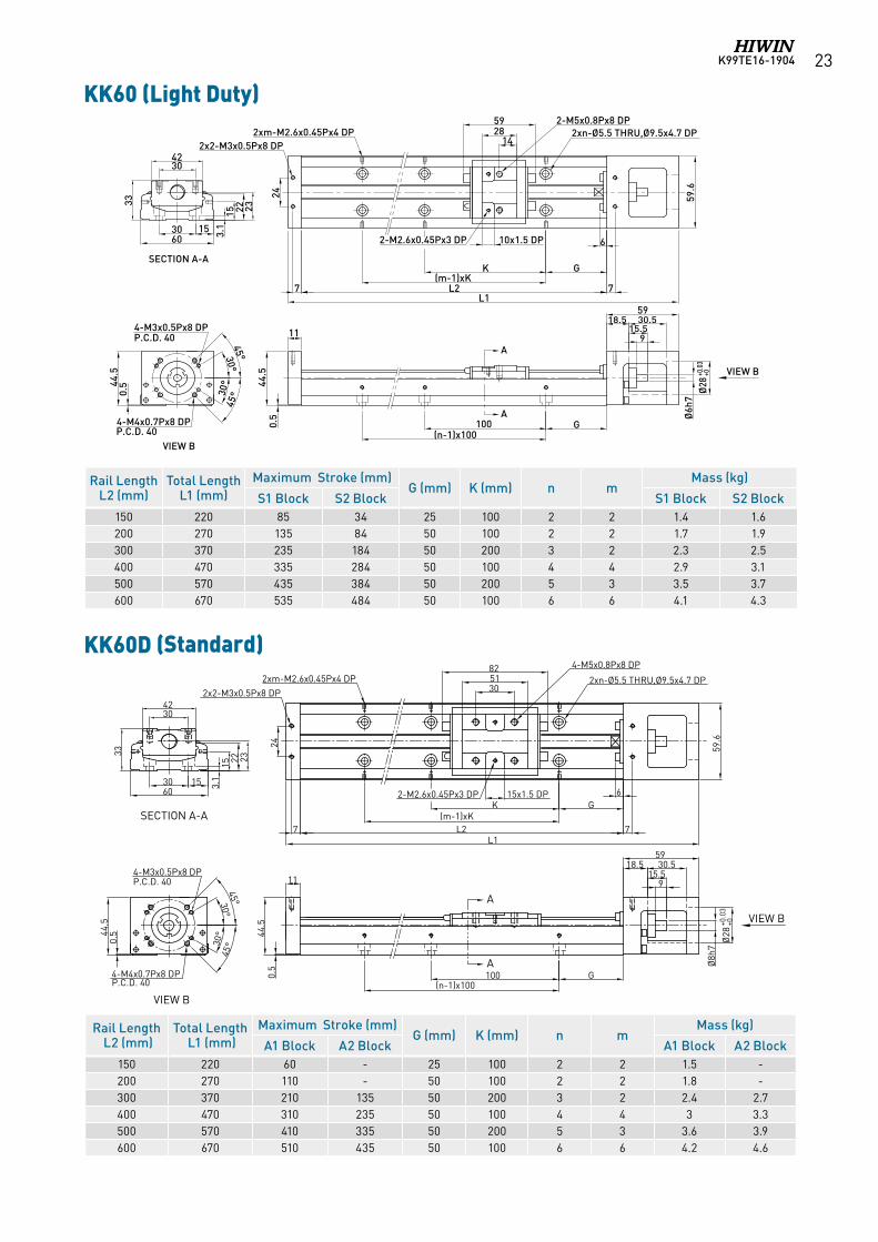
S1 Block S2 Block S1 Block S2 Block150 220 85 34 25 100 2 2 1.4 1.6200 270 135 84 50 100 2 2 1.7 1.9300 370 235 184 50 200 3 2 2.3 2.5400 470 335 284 50 100 4 4 2.9 3.1500 570 435 384 50 200 5 3 3.5 3.7600 670 535 484 50 100 6 6 4.1 4.3
KK60 (Light Duty)
3042
33
3.1
15 23
3060
SECTION A-A
VIEW B
30°
30°
45°
45°0.
544.5
P.C.D. 40
4-M4x0.7Px8 DP
4-M3x0.5Px8 DP
A
A
44.5
915.5
30.518.559
G100(n-1)x100
Ø6h
7Ø
28+0
.03
+0
0.5
59.6
2xn-Ø5.5 THRU,Ø9.5x4.7 DP2xm-M2.6x0.45Px4 DP
6
GK(m-1)xK
10x1.5 DP2-M2.6x0.45Px3 DP
142859 2-M5x0.8Px8 DP
L2L1
15
11
247 7
2x2-M3x0.5Px8 DP
VIEW B
22
P.C.D. 40
A
A
SECTION A-A
VIEW B
VIEW B
3042
33
3.1
15 23
KK60D (標準型)
3060
30°
30°
45°
45°0.
544.5
P.C.D. 40
4-M4x0.7Px8 DP
24
15x1.5 DP
305182
59.6
6GK
(m-1)xKL2
L17 7
2xn-Ø5.5 THRU,Ø9.5x4.7 DP
4-M5x0.8Px8 DP
2-M2.6x0.45Px3 DP
2xm-M2.6x0.45Px4 DP
11
0.5
44.5
30.518.559
G100(n-1)x100
4-M3x0.5Px8 DP
Ø28
+0.0
3+0
2x2-M3x0.5Px8 DP
15
22
P.C.D. 40
915.5
Ø8h
7
KK60D (Standard)
Rail Length L2 (mm)Total Length L1 (mm)
Maximum Stroke (mm)G (mm) K (mm) n m
Mass (kg)
A1 Block A2 Block A1 Block A2 Block150 220 60 - 25 100 2 2 1.5 -200 270 110 - 50 100 2 2 1.8 -300 370 210 135 50 200 3 2 2.4 2.7400 470 310 235 50 100 4 4 3 3.3500 570 410 335 50 200 5 3 3.6 3.9600 670 510 435 50 100 6 6 4.2 4.6
K99TE16-190424
Rail Length L2 (mm)Total Length L1 (mm)
Maximum Stroke (mm)G (mm) K (mm) n m
Mass (kg)
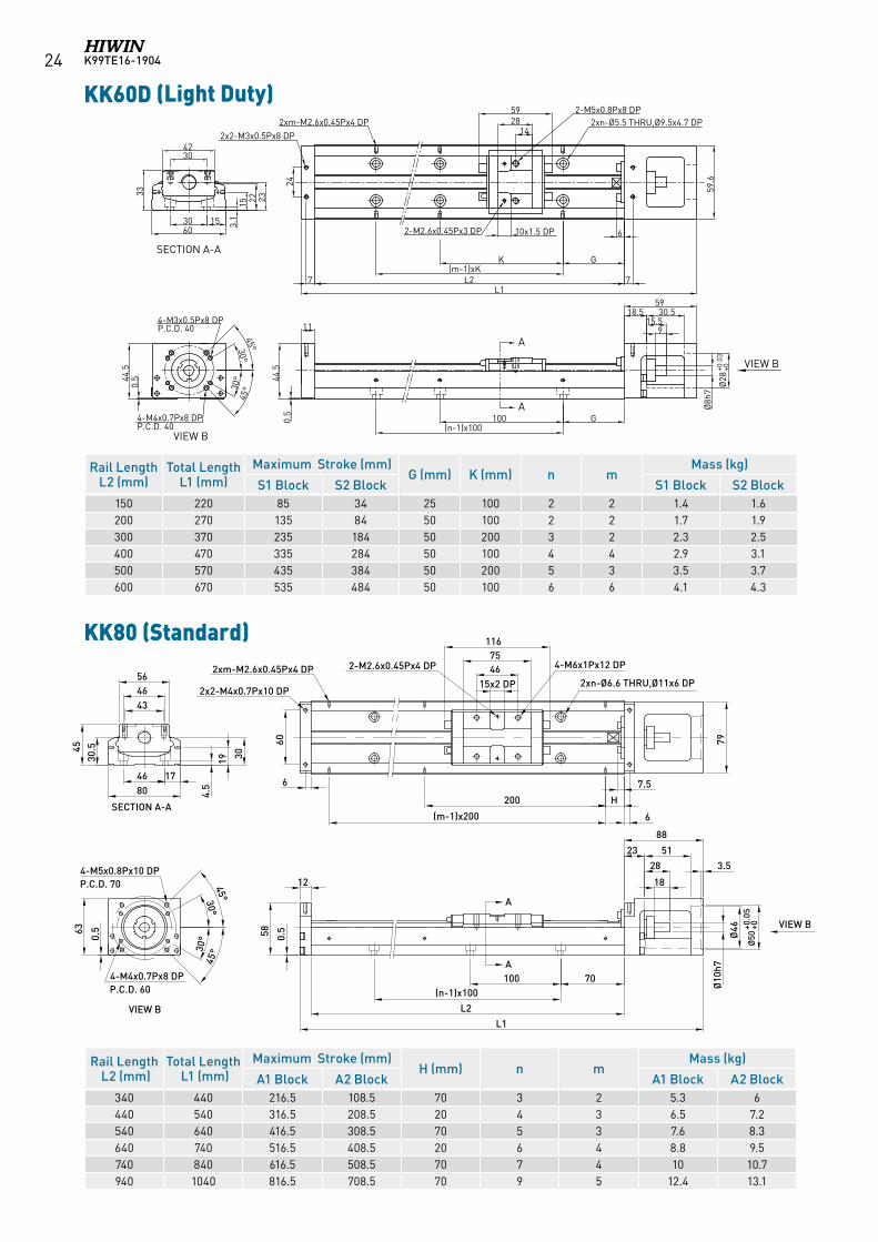
S1 Block S2 Block S1 Block S2 Block150 220 85 34 25 100 2 2 1.4 1.6200 270 135 84 50 100 2 2 1.7 1.9300 370 235 184 50 200 3 2 2.3 2.5400 470 335 284 50 100 4 4 2.9 3.1500 570 435 384 50 200 5 3 3.5 3.7600 670 535 484 50 100 6 6 4.1 4.3
Rail Length L2 (mm)Total Length L1 (mm)
Maximum Stroke (mm)H (mm) n m
Mass (kg)
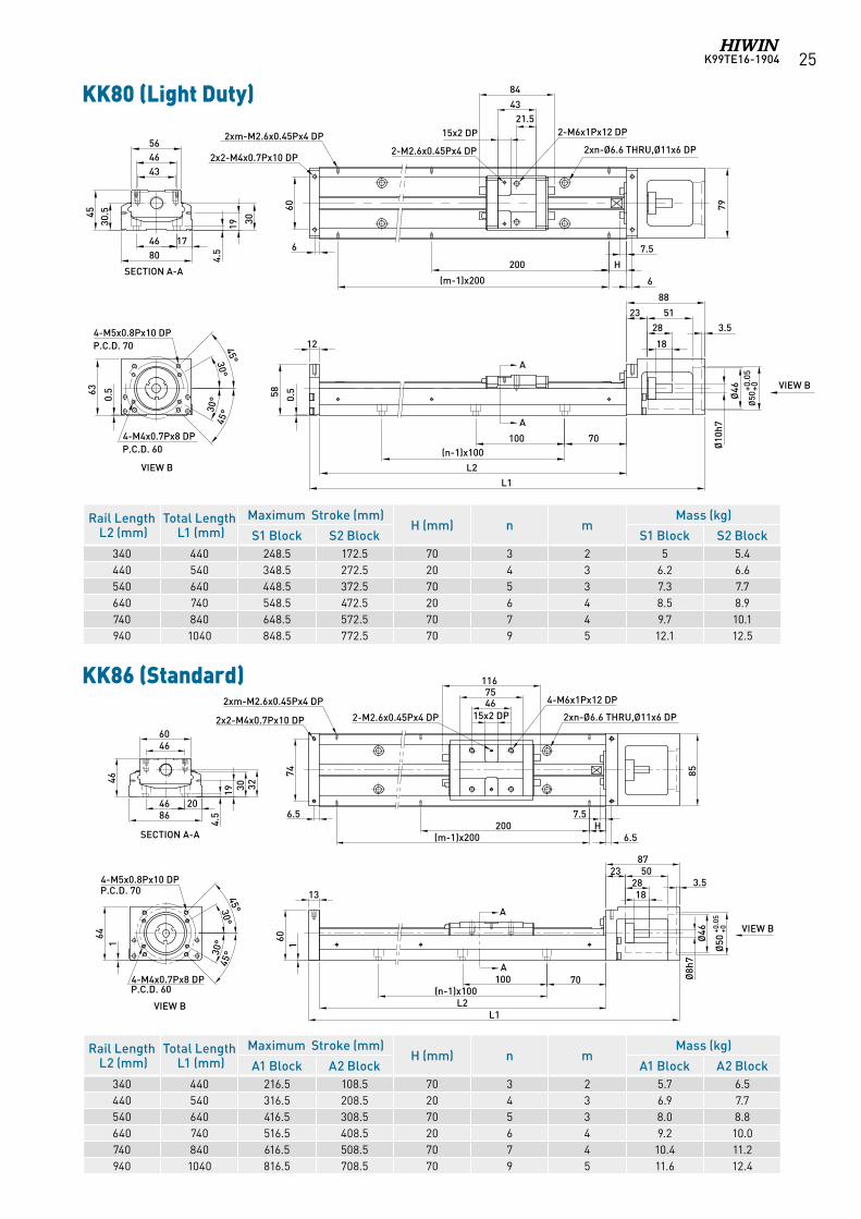
A1 Block A2 Block A1 Block A2 Block340 440 216.5 108.5 70 3 2 5.3 6440 540 316.5 208.5 20 4 3 6.5 7.2540 640 416.5 308.5 70 5 3 7.6 8.3640 740 516.5 408.5 20 6 4 8.8 9.5740 840 616.5 508.5 70 7 4 10 10.7940 1040 816.5 708.5 70 9 5 12.4 13.1
KK80 (Standard)
4-M5x0.8Px10 DPP.C.D. 70
63
0.5
12
0.558
70100
L2
(n-1)x100
L1
A
VIEW B
Ø10
h7
Ø50
+0.0
5+0
Ø46
18
28
5123
88
3.5
79
6
7.5
H200
(m-1)x200
6
60
15x2 DP4675
116
2xn-Ø6.6 THRU,Ø11x6 DP
4-M6x1Px12 DP2-M2.6x0.45Px4 DP2xm-M2.6x0.45Px4 DP
2x2-M4x0.7Px10 DP43
56
45
4680 4.
5
19 3030.5
VIEW B
KK80(Standard)
30°45°
30°
45°
4-M4x0.7Px8 DPP.C.D. 60
46
SECTION A-A
17
A
Without cover
4-M5x0.8Px10 DPP.C.D. 70
63
0.5
12
0.558
70100
L2
(n-1)x100
L1
VIEW B
Ø10
h7
Ø50
+0.0
5+0
Ø46
18
28
5123
88
3.5
79
6
7.5
H200
(m-1)x200
6
60
2xn-Ø6.6 THRU,Ø11x6 DP2xm-M2.6x0.45Px4 DP
2x2-M4x0.7Px10 DP43
56
45
4680 4.
5
19 3030.5
VIEW B
KK80(Light Duty)
30°45°
30°
45°
4-M4x0.7Px8 DPP.C.D. 60
46
SECTION A-A
17
15x2 DP
2-M2.6x0.45Px4 DP
21.543
84
2-M6x1Px12 DP
A
A
SECTION A-A
VIEW B
A
A
VIEW B
KK60D (輕載型)
3042
33
3.1
15 23
3060
30°
30°
45°
45°0.
544.5
P.C.D. 40
4-M4x0.7Px8 DP
4-M3x0.5Px8 DP
44.5
915.5
30.518.559
G100(n-1)x100
Ø8h
7
Ø28
+0.0
3+0
0.5
59.6
2xn-Ø5.5 THRU,Ø9.5x4.7 DP2xm-M2.6x0.45Px4 DP
6
GK(m-1)xK
10x1.5 DP2-M2.6x0.45Px3 DP
142859 2-M5x0.8Px8 DP
L2L1
15
11
247 7
2x2-M3x0.5Px8 DP
22
P.C.D. 40
KK60D (Light Duty)
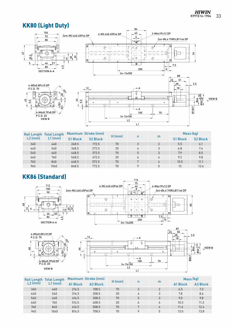
K99TE16-1904 25
Rail Length L2 (mm)Total Length L1 (mm)
Maximum Stroke (mm)H (mm) n m
Mass (kg)
S1 Block S2 Block S1 Block S2 Block340 440 248.5 172.5 70 3 2 5 5.4440 540 348.5 272.5 20 4 3 6.2 6.6540 640 448.5 372.5 70 5 3 7.3 7.7640 740 548.5 472.5 20 6 4 8.5 8.9740 840 648.5 572.5 70 7 4 9.7 10.1940 1040 848.5 772.5 70 9 5 12.1 12.5
4-M5x0.8Px10 DPP.C.D. 70
63
0.5
12
0.558
70100
L2
(n-1)x100
L1
A
VIEW B
Ø10
h7
Ø50
+0.0
5+0
Ø46
18
28
5123
88
3.5
79
6
7.5
H200
(m-1)x200
6
60
15x2 DP4675
116
2xn-Ø6.6 THRU,Ø11x6 DP
4-M6x1Px12 DP2-M2.6x0.45Px4 DP2xm-M2.6x0.45Px4 DP
2x2-M4x0.7Px10 DP43
56
45
4680 4.
5
19 3030.5
VIEW B
KK80(Standard)
30°45°
30°
45°
4-M4x0.7Px8 DPP.C.D. 60
46
SECTION A-A
17
A
Without cover
4-M5x0.8Px10 DPP.C.D. 70
63
0.5
12
0.558
70100
L2
(n-1)x100
L1
VIEW B
Ø10
h7
Ø50
+0.0
5+0
Ø46
18
28
5123
88
3.5
79
6
7.5
H200
(m-1)x200
6
60
2xn-Ø6.6 THRU,Ø11x6 DP2xm-M2.6x0.45Px4 DP
2x2-M4x0.7Px10 DP43
56
45
4680 4.
5
19 3030.5
VIEW B
KK80(Light Duty)
30°45°
30°
45°
4-M4x0.7Px8 DPP.C.D. 60
46
SECTION A-A
17
15x2 DP
2-M2.6x0.45Px4 DP
21.543
84
2-M6x1Px12 DP
A
A
KK80 (Light Duty)
Rail Length L2 (mm)Total Length L1 (mm)
Maximum Stroke (mm)H (mm) n m
Mass (kg)
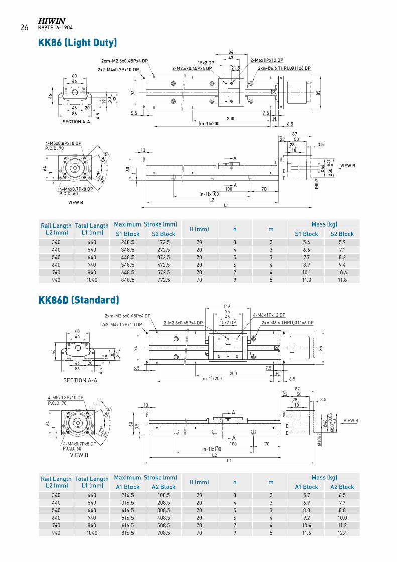
A1 Block A2 Block A1 Block A2 Block340 440 216.5 108.5 70 3 2 5.7 6.5440 540 316.5 208.5 20 4 3 6.9 7.7540 640 416.5 308.5 70 5 3 8.0 8.8640 740 516.5 408.5 20 6 4 9.2 10.0740 840 616.5 508.5 70 7 4 10.4 11.2940 1040 816.5 708.5 70 9 5 11.6 12.4
KK86 (Standard)
A
A
70100(n-1)x100
1828
238750
L2L1
13
85
2xn-Ø6.6 THRU,Ø11x6 DP
4-M6x1Px12 DP
15x2 DP46
116
2-M2.6x0.45Px4 DP
3.5
74
75
7.5H
(m-1)x200200
6.5
Ø50
+0.0
5+0
Ø46
Ø8h
7
VIEW B
160
2xm-M2.6x0.45Px4 DP
2x2-M4x0.7Px10 DP
164
VIEW B
4-M5x0.8Px10 DPP.C.D. 70
4-M4x0.7Px8 DPP.C.D. 60
30°
30°45°
45°
4660
46
204686
19 30 32
SECTION A-A
4.5 6.5
K99TE16-190426
Rail Length L2 (mm)Total Length L1 (mm)
Maximum Stroke (mm)H (mm) n m
Mass (kg)
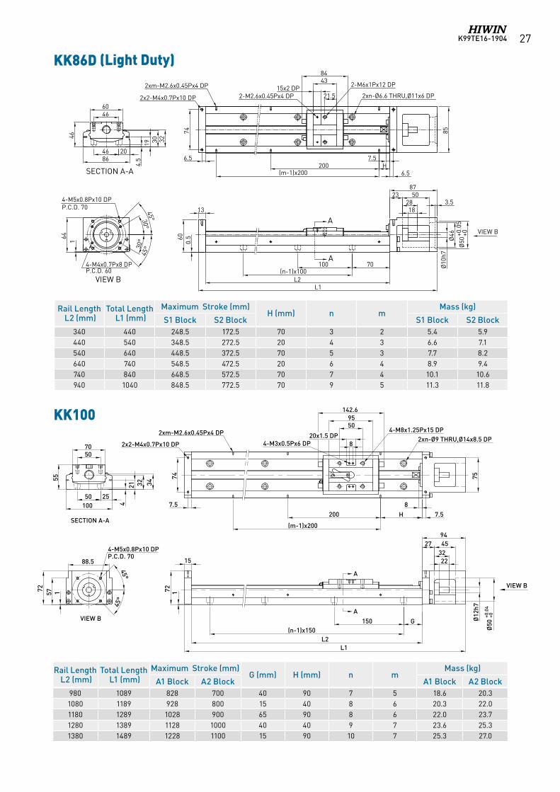
A1 Block A2 Block A1 Block A2 Block340 440 216.5 108.5 70 3 2 5.7 6.5440 540 316.5 208.5 20 4 3 6.9 7.7540 640 416.5 308.5 70 5 3 8.0 8.8640 740 516.5 408.5 20 6 4 9.2 10.0740 840 616.5 508.5 70 7 4 10.4 11.2940 1040 816.5 708.5 70 9 5 11.6 12.4
Rail Length L2 (mm)Total Length L1 (mm)
Maximum Stroke (mm)H (mm) n m
Mass (kg)
S1 Block S2 Block S1 Block S2 Block340 440 248.5 172.5 70 3 2 5.4 5.9440 540 348.5 272.5 20 4 3 6.6 7.1540 640 448.5 372.5 70 5 3 7.7 8.2640 740 548.5 472.5 20 6 4 8.9 9.4740 840 648.5 572.5 70 7 4 10.1 10.6940 1040 848.5 772.5 70 9 5 11.3 11.8
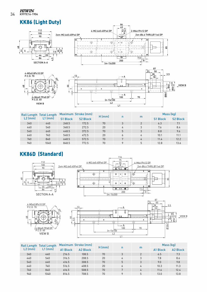
KK86 (Light Duty)
A
A
70100(n-1)x100
1828
238750
7.5H
(m-1)x200200
L2L1
4660
46
204686
19 30 32
13
164
4-M4x0.7Px8 DP
85
2xn-Ø6.6 THRU,Ø11x6 DP
2-M6x1Px12 DP15x2 DP21.5
4384
2xm-M2.6x0.45Px4 DP
2-M2.6x0.45Px4 DP
3.5
SECTION A-A
P.C.D. 60
74
2x2-M4x0.7Px10 DP
6.5
6.5
VIEW B
Ø50
+0.0
5+0
Ø46
Ø8h
7
4.5
VIEW B
160
4-M5x0.8Px10 DPP.C.D. 70
30°
30°45°
45°
KK86D (標準型)
A
AVIEW B
VIEW B
SECTION A-A
70100(n-1)x100
1828
238750
L2L1
13
852xn-Ø6.6 THRU,Ø11x6 DP
4-M6x1Px12 DP
15x2 DP46
116
2-M2.6x0.45Px4 DP
3.5
74
75
7.5H
(m-1)x200200
6.5
Ø50
+0.0
5+0
Ø46
Ø10
h7
0.560
2xm-M2.6x0.45Px4 DP
2x2-M4x0.7Px10 DP
164
4-M5x0.8Px10 DPP.C.D. 70
4-M4x0.7Px8 DPP.C.D. 60
30°
30°45°
45°
4660
46
204686
19 30 32
4.5 6.5
KK86D (Standard)
K99TE16-1904 27
Rail Length L2 (mm)Total Length L1 (mm)
Maximum Stroke (mm)G (mm) H (mm) n m
Mass (kg)
A1 Block A2 Block A1 Block A2 Block980 1089 828 700 40 90 7 5 18.6 20.31080 1189 928 800 15 40 8 6 20.3 22.01180 1289 1028 900 65 90 8 6 22.0 23.71280 1389 1128 1000 40 40 9 7 23.6 25.31380 1489 1228 1100 15 90 10 7 25.3 27.0
VIEW BA
15
72 1
H200
(m-1)x200
8
7.5
VIEW B
55
5070
20x1.5 DP
5095
142.6
75
88.5
45°
45°
74
2x2-M4x0.7Px10 DP
7.5
4-M3x0.5Px6 DP
4-M8x1.25Px15 DP
A
2xm-M2.6x0.45Px4 DP
82xn-Ø9 THRU,Ø14x8.5 DP
Ø12
h7
Ø50
+0.0
4+0
172 57
4-M5x0.8Px10 DPP.C.D. 70
SECTION A-A
2550100
2232
27 4594
G150(n-1)x150
L2L1
21 32 34
4
KK100
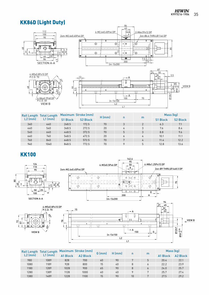
KK86D (Light Duty)
KK86D (輕載型)
A
A
SECTION A-A
VIEW B
VIEW B
70100(n-1)x100
1828
238750
7.5H
(m-1)x200200
L2L1
4660
46
204686
19 30 32
13
164
4-M4x0.7Px8 DP
85
2xn-Ø6.6 THRU,Ø11x6 DP
2-M6x1Px12 DP15x2 DP21.5
4384
2xm-M2.6x0.45Px4 DP
2-M2.6x0.45Px4 DP
3.5
P.C.D. 60
74
2x2-M4x0.7Px10 DP
6.5
6.5
Ø50
+0.0
5+0
Ø46
Ø10
h7
4.5
0.560
4-M5x0.8Px10 DPP.C.D. 70
30°
30°45°
45°
Rail Length L2 (mm)Total Length L1 (mm)
Maximum Stroke (mm)H (mm) n m
Mass (kg)
S1 Block S2 Block S1 Block S2 Block340 440 248.5 172.5 70 3 2 5.4 5.9440 540 348.5 272.5 20 4 3 6.6 7.1540 640 448.5 372.5 70 5 3 7.7 8.2640 740 548.5 472.5 20 6 4 8.9 9.4740 840 648.5 572.5 70 7 4 10.1 10.6940 1040 848.5 772.5 70 9 5 11.3 11.8
K99TE16-190428
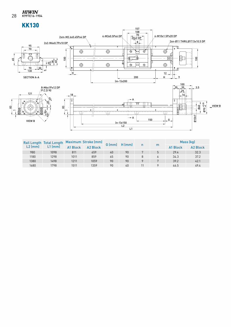
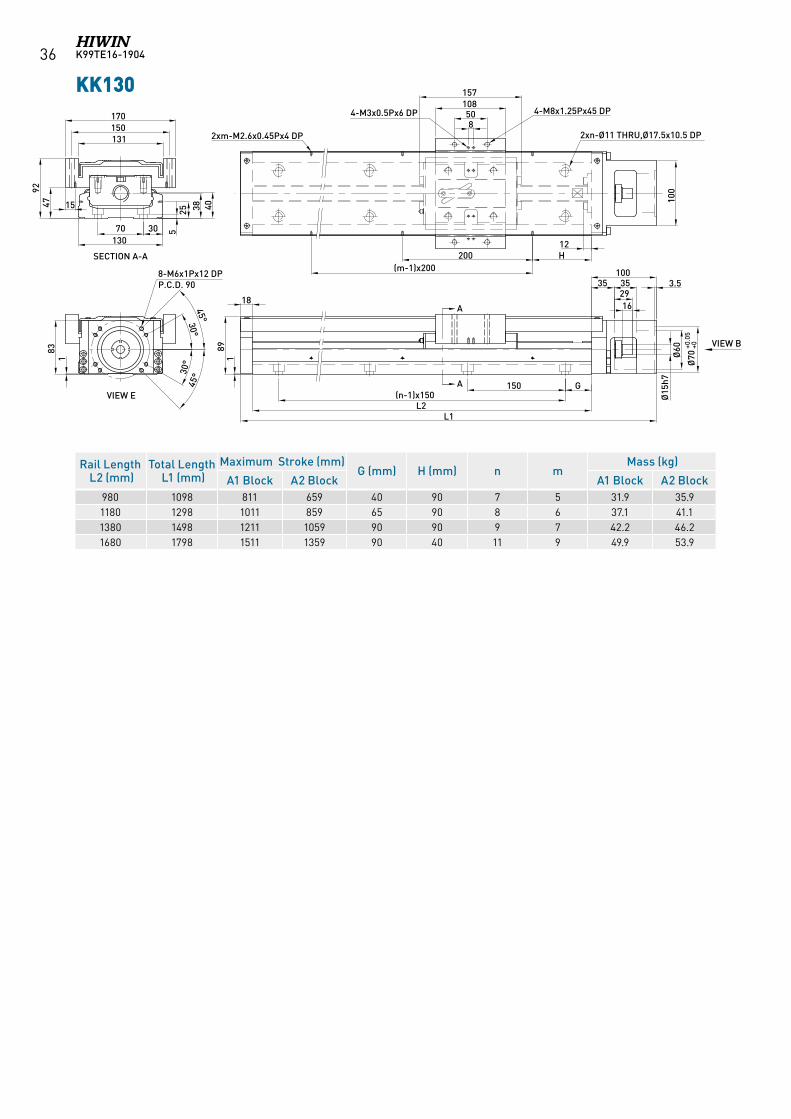
KK130
Rail Length L2 (mm)Total Length L1 (mm)
Maximum Stroke (mm)G (mm) H (mm) n m
Mass (kg)
A1 Block A2 Block A1 Block A2 Block980 1098 811 659 40 90 7 5 29.4 32.31180 1298 1011 859 65 90 8 6 34.3 37.21380 1498 1211 1059 90 90 9 7 39.2 42.11680 1798 1511 1359 90 40 11 9 46.5 49.4
100
3070
2570
38 40
95
130
2xn-Ø11 THRU,Ø17.5x10.5 DP
4-M10x1.5Px20 DP70108157
A
2xm-M2.6x0.45Px4 DP 4-M3x0.5Px6 DP
18
65
121
183
A
831
G150(n-1)x150
L2L1
SECTION A-A
VIEW B
5
100
9
2x2-M4x0.7Px10 DP
20x2 DP8
30°
45°
30°45°
1629
35 35100
3.5
VIEW B
Ø15
h7Ø
60
Ø70
+0.0
5+0
H200(m-1)x200
129
8-M6x1Px12 DPP.C.D 90
K99TE16-1904 29
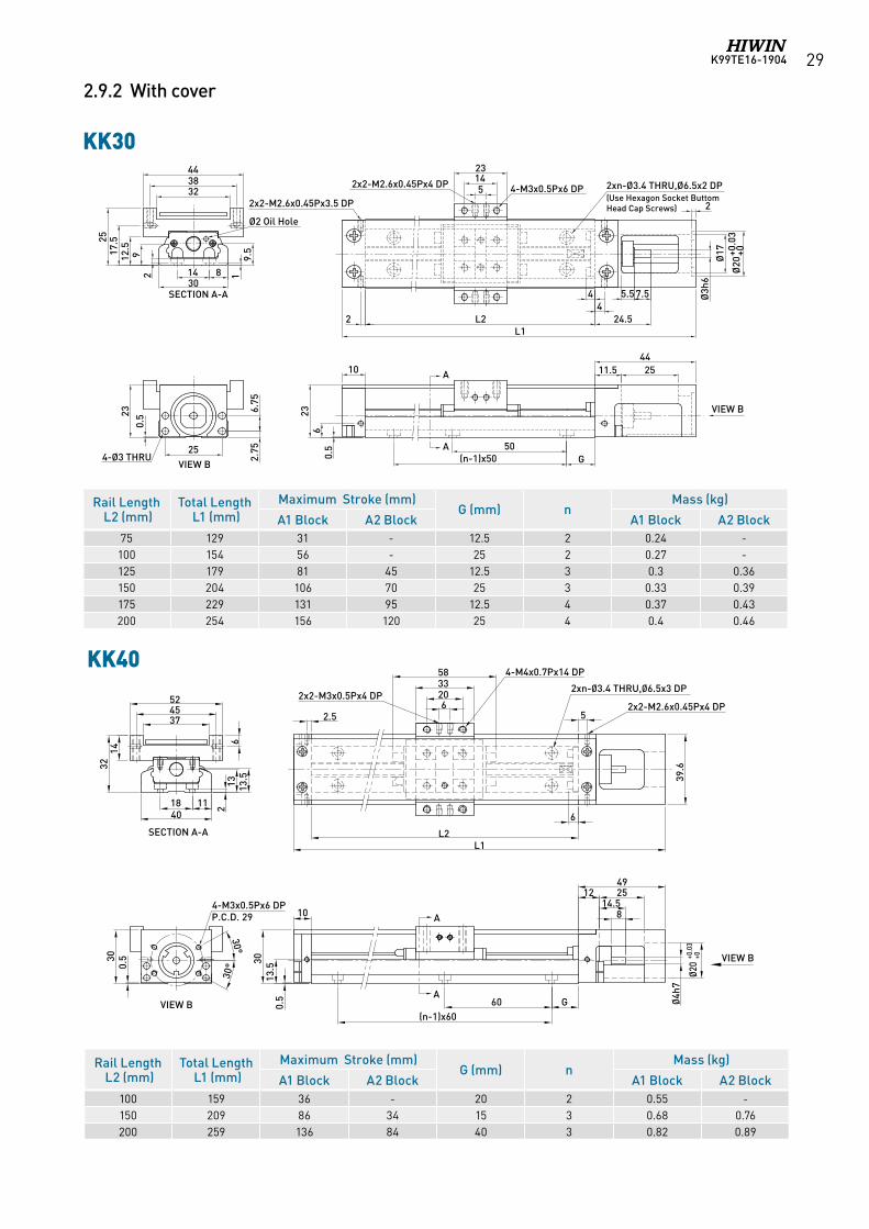
2.9.2 With cover
KK30
KK40
Ø20
+0.0
3+0
Ø3h
6
Ø17
2
11.5 2544
G50
(n-1)x50
4
L2L1
2xn-Ø3.4 THRU,Ø6.5x2 DP
10
0.5
23
14 830
25
2.75
6.75
2317
.5
19.
5
SECTION A-A
A
A
6
2x2-M2.6x0.45Px3.5 DP
24.5
5.5 7.54
2
0.5
2
VIEW B
VIEW B
12.5
9
323844
Ø2 Oil Hole
25
4-Ø3 THRU
144-M3x0.5Px6 DP 5
23
2x2-M2.6x0.45Px4 DP
KK30
With cover
(Use Hexagon Socket Buttom Head Cap Screws)
A
A
SECTION A-A
VIEW B
374552
6
1432
18 1140
13 13.5
2
4-M3x0.5Px6 DPP.C.D. 29
0.530
30°
30°
0.5
30
814.5
251249
G60
13.5
(n-1)x60
Ø4h7
Ø20
+0.0
3+0
5
39.6
6
L2L1
2xn-Ø3.4 THRU,Ø6.5x3 DP
6203358
2.52x2-M2.6x0.45Px4 DP
2x2-M3x0.5Px4 DP
4-M4x0.7Px14 DP
10
VIEW B
Rail Length L2 (mm)Total Length L1 (mm)
Maximum Stroke (mm)G (mm) n
Mass (kg)
A1 Block A2 Block A1 Block A2 Block75 129 31 - 12.5 2 0.24 -100 154 56 - 25 2 0.27 -125 179 81 45 12.5 3 0.3 0.36150 204 106 70 25 3 0.33 0.39175 229 131 95 12.5 4 0.37 0.43200 254 156 120 25 4 0.4 0.46
Rail Length L2 (mm)Total Length L1 (mm)
Maximum Stroke (mm)G (mm) n
Mass (kg)
A1 Block A2 Block A1 Block A2 Block100 159 36 - 20 2 0.55 -150 209 86 34 15 3 0.68 0.76200 259 136 84 40 3 0.82 0.89
K99TE16-190430
KK50
A
A
475562
2340
2.7
12 16 18
25 12.5
SECTION A-A
VIEW B
45°
45°
0.5
38.5
8
304774
5.7
GKL2
L1
49.4
2x2-M3x0.5Px4 DP
4-M4x0.7Px10 DP
2xn-Ø4.5 THRU,Ø8x4 DP2x2-M2.6x0.45Px4 DP
1016.5
1460
Ø5h
7Ø
24+0
.03
+0
G80(n-1)x80
4-M3x0.5Px6 DPP.C.D. 33
0.5
38.5
50
34
10
VIEW B
6.5
KK60 (Standard)
A
A
47
915.5
30.518.559
G100(n-1)x100
Ø6h
7Ø
28+0
.03
+0
8305482
2xn-Ø5.5 THRU,Ø9.5x4.7 DP2xm-M2.6x0.45Px4 DP
4-M5x0.8Px8 DP2x2-M2.6x0.45Px6 DP
6GK
(m-1)xK
0.5
59.6
3.130
60
SECTION A-A
6
4823 15 2322
647486
VIEW B
30°
30°
45°
45°0.
544.5
P.C.D. 40
4-M4x0.7Px8 DP
4-M3x0.5Px8 DP
L2L1
15
11
VIEW B
P.C.D. 40
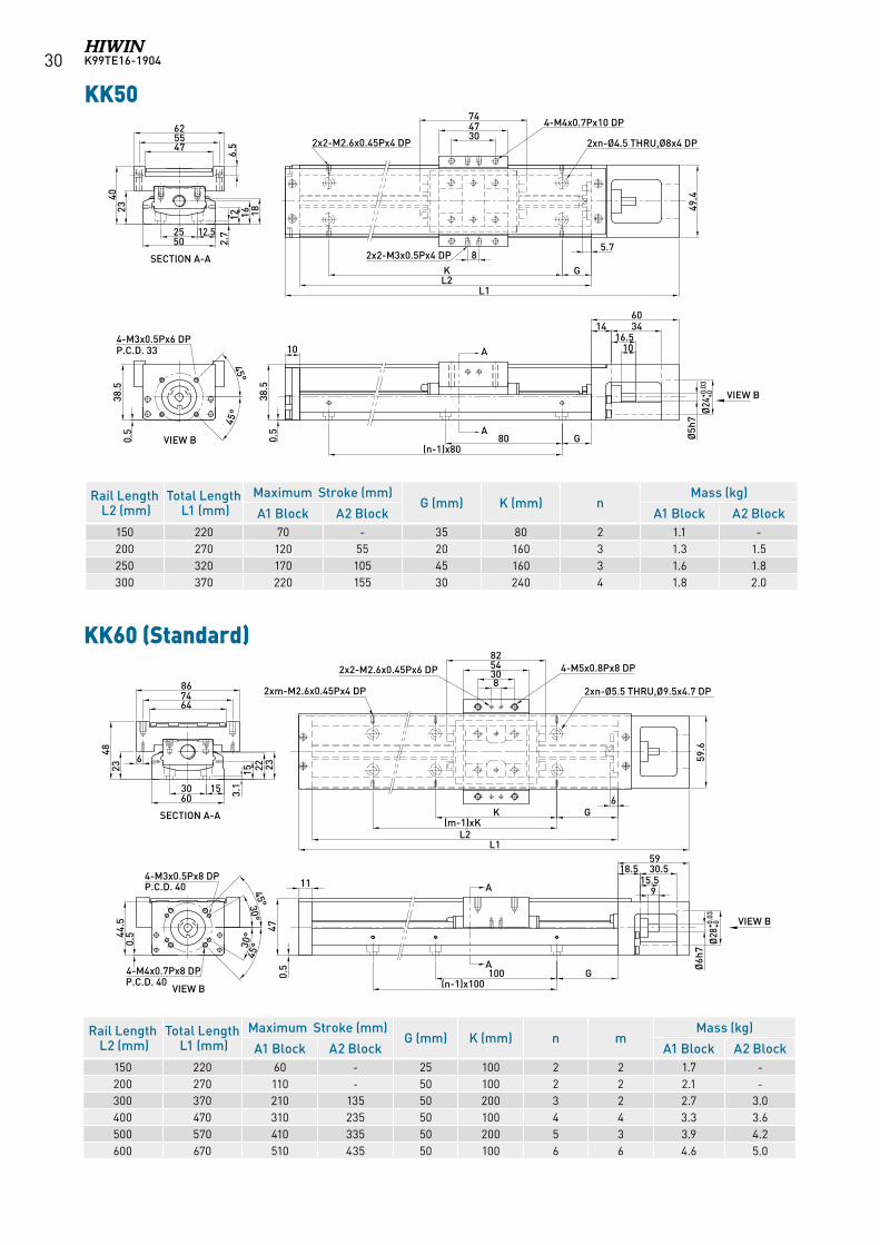
Rail Length L2 (mm)Total Length L1 (mm)
Maximum Stroke (mm)G (mm) K (mm) n m
Mass (kg)
A1 Block A2 Block A1 Block A2 Block150 220 60 - 25 100 2 2 1.7 -200 270 110 - 50 100 2 2 2.1 -300 370 210 135 50 200 3 2 2.7 3.0400 470 310 235 50 100 4 4 3.3 3.6500 570 410 335 50 200 5 3 3.9 4.2600 670 510 435 50 100 6 6 4.6 5.0
Rail Length L2 (mm)Total Length L1 (mm)
Maximum Stroke (mm)G (mm) K (mm) n
Mass (kg)
A1 Block A2 Block A1 Block A2 Block150 220 70 - 35 80 2 1.1 -200 270 120 55 20 160 3 1.3 1.5250 320 170 105 45 160 3 1.6 1.8300 370 220 155 30 240 4 1.8 2.0
K99TE16-1904 31
KK60 (Light Duty)
VIEW B
30°
30°
45°
45°0.
544.5
P.C.D. 40
4-M4x0.7Px8 DP
4-M3x0.5Px8 DP
3.130
60
SECTION A-A
6
4823 15 2322
647486
A
A
47
915.5
30.518.559
G100(n-1)x100
Ø6h
7
Ø28
+0.0
3+0
0.5
2xn-Ø5.5 THRU,Ø9.5x4.7 DP2xm-M2.6x0.45Px4 DP
6
GK(m-1)xK
82-M2.6x0.45Px6 DP
142859 2-M5x0.8Px8 DP
59.6
L2L1
15
11
VIEW B
P.C.D. 40
KK60D (Standard)
KK60D (標準型)
A
A
SECTION A-A
VIEW B
VIEW B
47
30.518.559
G100(n-1)x100
Ø28
+0.0
3+0
8305482
2xn-Ø5.5 THRU,Ø9.5x4.7 DP2xm-M2.6x0.45Px4 DP
4-M5x0.8Px8 DP2x2-M2.6x0.45Px6 DP
6GK
(m-1)xK
0.5
59.6
3.130
60
6
4823 15 2322
647486
30°
30°
45°
45°
0.544
.5
P.C.D. 40
4-M4x0.7Px8 DP
4-M3x0.5Px8 DP
L2L1
15
11
P.C.D. 40
915.5
Ø8h
7
Rail Length L2 (mm)Total Length L1 (mm)
Maximum Stroke (mm)G (mm) K (mm) n m
Mass (kg)
A1 Block A2 Block A1 Block A2 Block150 220 60 - 25 100 2 2 1.7 -200 270 110 - 50 100 2 2 2.1 -300 370 210 135 50 200 3 2 2.7 3.0400 470 310 235 50 100 4 4 3.3 3.6500 570 410 335 50 200 5 3 3.9 4.2600 670 510 435 50 100 6 6 4.6 5.0
Rail Length L2 (mm)Total Length L1 (mm)
Maximum Stroke (mm)G (mm) K (mm) n m
Mass (kg)
S1 Block S2 Block S1 Block S2 Block150 220 85 34 25 100 2 2 1.6 1.8200 270 135 84 50 100 2 2 1.9 2.1300 370 235 184 50 200 3 2 2.5 2.7400 470 335 284 50 100 4 4 3.1 3.3500 570 435 384 50 200 5 3 3.7 3.9600 670 535 484 50 100 6 6 4.4 4.6
K99TE16-190432
KK80 (Standard) KK80(Standard)
With cover
63
0.5
12
0.564
70100
L2(n-1)x100
L1
A
VIEW B
Ø10
h7
Ø50
+0.0
5+0
Ø46
18
285123
88
3.5
79
7.5
H200
(m-1)x200
2xm-M2.6x0.45Px4 DP
4680 4.
5
19 3030.5
VIEW B
30°
45°
4-M4x0.7Px8 DPP.C.D. 60
SECTION A-A
17
A
8092
104
67
30°45°
4-M5x0.8Px10 DPP.C.D. 70
5
4675
116
54-M6x1Px12 DP4-M2.6x0.45Px4 DP
2xn-Ø6.6 THRU,Ø11x6 DP
63
0.5
12
0.564
70100
L2(n-1)x100
L1
A
VIEW B
Ø10
h7
Ø50
+0.0
5+0
Ø46
18
285123
88
3.5
79
7.5
H200
(m-1)x200
2xm-M2.6x0.45Px4 DP
4680 4.
5
19 3030.5
VIEW B
30°
45°
4-M4x0.7Px8 DPP.C.D. 60
SECTION A-A
17
A
8092
104
67
30°45°
4-M5x0.8Px10 DPP.C.D. 70
5
4384
52-M6x1Px12 DP4-M2.6x0.45Px4 DP
2xn-Ø6.6 THRU,Ø11x6 DP
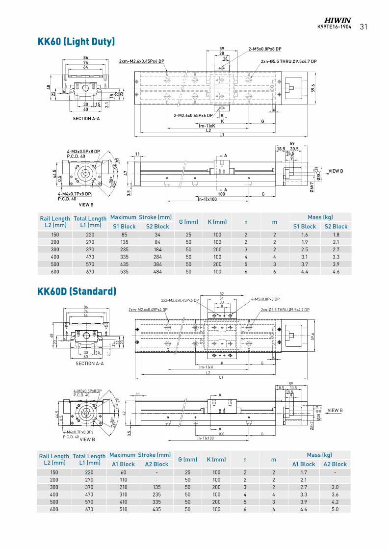
KK80(Light Duty)
3535
KK60D (Light Duty)
Rail Length L2 (mm)Total Length L1 (mm)
Maximum Stroke (mm)H (mm) n m
Mass (kg)
A1 Block A2 Block A1 Block A2 Block340 440 216.5 108.5 70 3 2 6 7.1440 540 316.5 208.5 20 4 3 7.2 8.3540 640 416.5 308.5 70 5 3 8.4 9.5640 740 516.5 408.5 20 6 4 9.7 10.8740 840 616.5 508.5 70 7 4 10.9 12940 1040 816.5 708.5 70 9 5 13.5 14.6
Rail Length L2 (mm)Total Length L1 (mm)
Maximum Stroke (mm)G (mm) K (mm) n m
Mass (kg)
S1 Block S2 Block S1 Block S2 Block150 220 85 34 25 100 2 2 1.6 1.8200 270 135 84 50 100 2 2 1.9 2.1300 370 235 184 50 200 3 2 2.5 2.7400 470 335 284 50 100 4 4 3.1 3.3500 570 435 384 50 200 5 3 3.7 3.9600 670 535 484 50 100 6 6 4.4 4.6
KK60D (輕載型)
VIEW B
SECTION A-A
A
A
VIEW B
30°
30°
45°
45°
0.544
.5
P.C.D. 40
4-M4x0.7Px8 DP
4-M3x0.5Px8 DP
3.130
60
6
4823 15 2322
647486
47
30.518.559
G100(n-1)x100
Ø28
+0.0
3+0
0.5
2xn-Ø5.5 THRU,Ø9.5x4.7 DP2xm-M2.6x0.45Px4 DP
6
GK(m-1)xK
82-M2.6x0.45Px6 DP
142859 2-M5x0.8Px8 DP
59.6
L2L1
15
11
P.C.D. 40
915.5
Ø8h
7
K99TE16-1904 33
KK80(Standard)
With cover
63
0.5
12
0.564
70100
L2(n-1)x100
L1
A
VIEW B
Ø10
h7
Ø50
+0.0
5+0
Ø46
18
285123
88
3.5
79
7.5
H200
(m-1)x200
2xm-M2.6x0.45Px4 DP
4680 4.
5
19 3030.5
VIEW B
30°
45°
4-M4x0.7Px8 DPP.C.D. 60
SECTION A-A
17
A
8092
104
67
30°45°
4-M5x0.8Px10 DPP.C.D. 70
5
4675
116
54-M6x1Px12 DP4-M2.6x0.45Px4 DP
2xn-Ø6.6 THRU,Ø11x6 DP
63
0.5
12
0.564
70100
L2(n-1)x100
L1
A
VIEW B
Ø10
h7
Ø50
+0.0
5+0
Ø46
18
285123
88
3.5
79
7.5
H200
(m-1)x200
2xm-M2.6x0.45Px4 DP
4680 4.
5
19 3030.5
VIEW B
30°
45°
4-M4x0.7Px8 DPP.C.D. 60
SECTION A-A
17
A
8092
104
67
30°45°
4-M5x0.8Px10 DPP.C.D. 70
5
4384
52-M6x1Px12 DP4-M2.6x0.45Px4 DP
2xn-Ø6.6 THRU,Ø11x6 DP
KK80(Light Duty)
3535
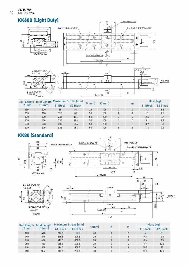
KK80 (Light Duty)
KK86 (Standard)
70100(n-1)x100
1828
238750
L2L1
7.5H
(m-1)x200200
85
3.5
Ø50
+0.0
5+0
Ø46
Ø8h
7
A
A
VIEW B
84675
116
166
13
100
68
90
112
6
168
4-M5x0.8Px10 DPP.C.D. 70
31
2xn-Ø6.6 THRU,Ø11x6 DP
4-M6x1Px12 DP4-M2.6x0.45Px6 DP
2xm-M2.6x0.45Px4 DP
VIEW B
4-M4x0.7Px8 DPP.C.D. 60
30°
30°45°
45°
204686
SECTION A-A
19 30 32
4.5
Rail Length L2 (mm)Total Length L1 (mm)
Maximum Stroke (mm)H (mm) n m
Mass (kg)
A1 Block A2 Block A1 Block A2 Block340 440 216.5 108.5 70 3 2 6.5 7.3440 540 316.5 208.5 20 4 3 7.8 8.6540 640 416.5 308.5 70 5 3 9.0 9.8640 740 516.5 408.5 20 6 4 10.3 11.3740 840 616.5 508.5 70 7 4 11.6 12.4940 1040 816.5 708.5 70 9 5 13.0 13.8
Rail Length L2 (mm)Total Length L1 (mm)
Maximum Stroke (mm)H (mm) n m
Mass (kg)
S1 Block S2 Block S1 Block S2 Block340 440 248.5 172.5 70 3 2 5.5 6.1440 540 348.5 272.5 20 4 3 6.8 7.4540 640 448.5 372.5 70 5 3 7.9 8.5640 740 548.5 472.5 20 6 4 9.2 9.8740 840 648.5 572.5 70 7 4 10.5 11.1940 1040 848.5 772.5 70 9 5 13 13.6
K99TE16-190434
KK86 (Light Duty)
70100(n-1)x100
1828
238750
L2L1
166
7.5H
(m-1)x200200
85
2xm-M2.6x0.45Px4 DP
4-M2.6x0.45Px6 DP 2-M6x1Px12 DP
2xn-Ø6.6 THRU,Ø11x6 DP
43
8
3.5
841
68
4-M5x0.8Px10 DPP.C.D. 70
Ø50
+0.0
5+0
Ø46
Ø8h
7
A
A
VIEW B
21.5
13
VIEW B
4-M4x0.7Px8 DPP.C.D. 60
30°
30°45°
45°
100
68
90
112
631
204686
SECTION A-A
19 30 32
4.5
KK86D (Standard)
Rail Length L2 (mm)Total Length L1 (mm)
Maximum Stroke (mm)H (mm) n m
Mass (kg)
A1 Block A2 Block A1 Block A2 Block340 440 216.5 108.5 70 3 2 6.5 7.3440 540 316.5 208.5 20 4 3 7.8 8.6540 640 416.5 308.5 70 5 3 9.0 9.8640 740 516.5 408.5 20 6 4 10.3 11.3740 840 616.5 508.5 70 7 4 11.6 12.4940 1040 816.5 708.5 70 9 5 13.0 13.8
KK86D (標準型)
A
A
VIEW B
VIEW B
SECTION A-A
70100(n-1)x100
1828
238750
L2L1
7.5H
(m-1)x200200
85
3.5
Ø50
+0.0
5+0
Ø46
Ø10
h78
4675
116
0.566
13
100
68
90
112
6
168
4-M5x0.8Px10 DPP.C.D. 70
31
2xn-Ø6.6 THRU,Ø11x6 DP
4-M6x1Px12 DP4-M2.6x0.45Px6 DP
2xm-M2.6x0.45Px4 DP
4-M4x0.7Px8 DPP.C.D. 60
30°
30°45°
45°
204686
19 30 32
4.5
Rail Length L2 (mm)Total Length L1 (mm)
Maximum Stroke (mm)H (mm) n m
Mass (kg)
S1 Block S2 Block S1 Block S2 Block340 440 248.5 172.5 70 3 2 6.3 7.1440 540 348.5 272.5 20 4 3 7.6 8.4540 640 448.5 372.5 70 5 3 8.8 9.6640 740 548.5 472.5 20 6 4 10.1 11.1740 840 648.5 572.5 70 7 4 11.4 12.2940 1040 848.5 772.5 70 9 5 12.8 13.6
K99TE16-1904 35
KK100
SECTION A-A
2550100
80
95110124
40
VIEW B
172 57
45°
45°
4-M5x0.8Px10 DPP.C.D. 70
G150(n-1)x150
L2L1
15
781
2232
27 4594
H200
(m-1)x200
8
75
2xm-M2.6x0.45Px4 DP
5095
142.6
4-M3x0.5Px6 DP 4-M8x1.25Px15 DP8 2xn-Ø9 THRU,Ø14x8.5 DP
7
A
A
VIEW B
Ø12
h7
Ø50
+0.0
4+0
21 32 34
4
KK86D (Light Duty)
Rail Length L2 (mm)Total Length L1 (mm)
Maximum Stroke (mm)G (mm) H (mm) n m
Mass (kg)
A1 Block A2 Block A1 Block A2 Block980 1089 828 700 40 90 7 5 20.4 22.11080 1189 928 800 15 40 8 6 22.2 23.91180 1289 1028 900 65 90 8 6 24.0 25.71280 1389 1128 1000 40 40 9 7 25.7 27.41380 1489 1228 1100 15 90 10 7 27.5 29.2
Rail Length L2 (mm)Total Length L1 (mm)
Maximum Stroke (mm)H (mm) n m
Mass (kg)
S1 Block S2 Block S1 Block S2 Block340 440 248.5 172.5 70 3 2 6.3 7.1440 540 348.5 272.5 20 4 3 7.6 8.4540 640 448.5 372.5 70 5 3 8.8 9.6640 740 548.5 472.5 20 6 4 10.1 11.1740 840 648.5 572.5 70 7 4 11.4 12.2940 1040 848.5 772.5 70 9 5 12.8 13.6
KK86D (輕載型)
A
A
VIEW B
VIEW B
SECTION A-A
70100(n-1)x100
1828
238750
L2L1
0.566
7.5H
(m-1)x200200
85
2xm-M2.6x0.45Px4 DP
4-M2.6x0.45Px6 DP 2-M6x1Px12 DP
2xn-Ø6.6 THRU,Ø11x6 DP
43
8
3.5
84
168
4-M5x0.8Px10 DPP.C.D. 70
Ø50
+0.0
5+0
Ø46
Ø10
h7
21.5
13
4-M4x0.7Px8 DPP.C.D. 60
30°
30°45°
45°
100
68
90
112
631
204686
19 30 32
4.5
K99TE16-190436
KK130
100
3070130
50108157
2xm-M2.6x0.45Px4 DP
4-M3x0.5Px6 DP
4792
15
131150170
1629
35 35100
3.5
18
H200(m-1)x200
12
4-M8x1.25Px45 DP8
183 89
1
G150(n-1)x150
8-M6x1Px12 DPP.C.D. 90
25 38 40
5
SECTION A-A
VIEW EL2
L1
2xn-Ø11 THRU,Ø17.5x10.5 DP
VIEW B
Ø15
h7Ø
60
Ø70
+0.0
5+0
A
A
30°
30°45°
45°
Rail Length L2 (mm)Total Length L1 (mm)
Maximum Stroke (mm)G (mm) H (mm) n m
Mass (kg)
A1 Block A2 Block A1 Block A2 Block980 1098 811 659 40 90 7 5 31.9 35.91180 1298 1011 859 65 90 8 6 37.1 41.11380 1498 1211 1059 90 90 9 7 42.2 46.21680 1798 1511 1359 90 40 11 9 49.9 53.9
K99TE16-1904 37
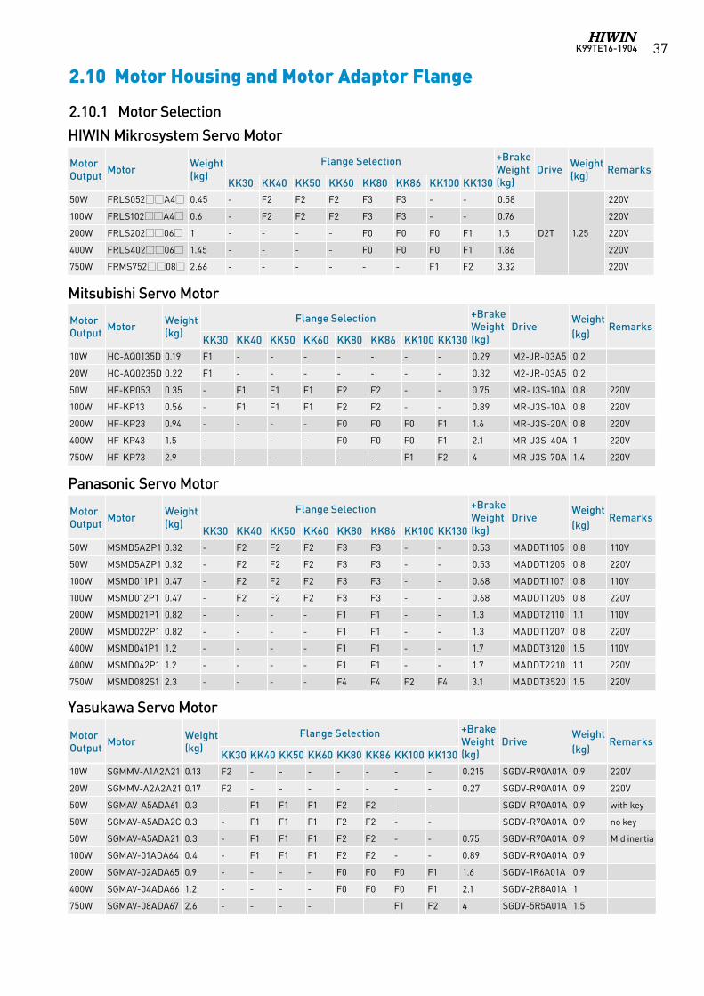
Panasonic Servo Motor
2.10 Motor Housing and Motor Adaptor Flange
Mitsubishi Servo Motor
Yasukawa Servo Motor
HIWIN Mikrosystem Servo Motor
2.10.1 Motor Selection
Motor Output Motor Weight
(kg)Flange Selection +Brake
Weight (kg)
DriveWeight (kg)
RemarksKK30 KK40 KK50 KK60 KK80 KK86 KK100 KK130
10W HC-AQ0135D 0.19 F1 - - - - - - - 0.29 M2-JR-03A5 0.2
20W HC-AQ0235D 0.22 F1 - - - - - - - 0.32 M2-JR-03A5 0.2
50W HF-KP053 0.35 - F1 F1 F1 F2 F2 - - 0.75 MR-J3S-10A 0.8 220V
100W HF-KP13 0.56 - F1 F1 F1 F2 F2 - - 0.89 MR-J3S-10A 0.8 220V
200W HF-KP23 0.94 - - - - F0 F0 F0 F1 1.6 MR-J3S-20A 0.8 220V
400W HF-KP43 1.5 - - - - F0 F0 F0 F1 2.1 MR-J3S-40A 1 220V
750W HF-KP73 2.9 - - - - - - F1 F2 4 MR-J3S-70A 1.4 220V
Motor Output Motor Weight
(kg)Flange Selection +Brake
Weight (kg)
DriveWeight (kg)
RemarksKK30 KK40 KK50 KK60 KK80 KK86 KK100 KK130
50W MSMD5AZP1 0.32 - F2 F2 F2 F3 F3 - - 0.53 MADDT1105 0.8 110V
50W MSMD5AZP1 0.32 - F2 F2 F2 F3 F3 - - 0.53 MADDT1205 0.8 220V
100W MSMD011P1 0.47 - F2 F2 F2 F3 F3 - - 0.68 MADDT1107 0.8 110V
100W MSMD012P1 0.47 - F2 F2 F2 F3 F3 - - 0.68 MADDT1205 0.8 220V
200W MSMD021P1 0.82 - - - - F1 F1 - - 1.3 MADDT2110 1.1 110V
200W MSMD022P1 0.82 - - - - F1 F1 - - 1.3 MADDT1207 0.8 220V
400W MSMD041P1 1.2 - - - - F1 F1 - - 1.7 MADDT3120 1.5 110V
400W MSMD042P1 1.2 - - - - F1 F1 - - 1.7 MADDT2210 1.1 220V
750W MSMD082S1 2.3 - - - - F4 F4 F2 F4 3.1 MADDT3520 1.5 220V
Motor Output Motor Weight
(kg)Flange Selection +Brake
Weight (kg)
DriveWeight (kg)
RemarksKK30 KK40 KK50 KK60 KK80 KK86 KK100 KK130
10W SGMMV-A1A2A21 0.13 F2 - - - - - - - 0.215 SGDV-R90A01A 0.9 220V
20W SGMMV-A2A2A21 0.17 F2 - - - - - - - 0.27 SGDV-R90A01A 0.9 220V
50W SGMAV-A5ADA61 0.3 - F1 F1 F1 F2 F2 - - SGDV-R70A01A 0.9 with key
50W SGMAV-A5ADA2C 0.3 - F1 F1 F1 F2 F2 - - SGDV-R70A01A 0.9 no key
50W SGMAV-A5ADA21 0.3 - F1 F1 F1 F2 F2 - - 0.75 SGDV-R70A01A 0.9 Mid inertia
100W SGMAV-01ADA64 0.4 - F1 F1 F1 F2 F2 - - 0.89 SGDV-R90A01A 0.9
200W SGMAV-02ADA65 0.9 - - - - F0 F0 F0 F1 1.6 SGDV-1R6A01A 0.9
400W SGMAV-04ADA66 1.2 - - - - F0 F0 F0 F1 2.1 SGDV-2R8A01A 1
750W SGMAV-08ADA67 2.6 - - - - F1 F2 4 SGDV-5R5A01A 1.5
Motor Output Motor Weight
(kg)Flange Selection +Brake
Weight (kg)
Drive Weight (kg) Remarks
KK30 KK40 KK50 KK60 KK80 KK86 KK100 KK13050W FRLS052A4 0.45 - F2 F2 F2 F3 F3 - - 0.58
D2T 1.25
220V
100W FRLS102A4 0.6 - F2 F2 F2 F3 F3 - - 0.76 220V
200W FRLS20206 1 - - - - F0 F0 F0 F1 1.5 220V
400W FRLS40206 1.45 - - - - F0 F0 F0 F1 1.86 220V
750W FRMS75208 2.66 - - - - - - F1 F2 3.32 220V
K99TE16-190438
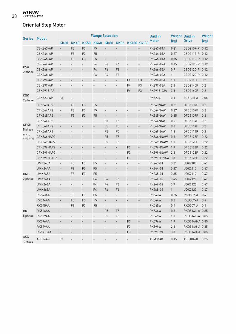
Oriental Step Motor
Series ModelFlange Selection Built in
MotorWeight (kg)
Built in Drive
Weight (kg)KK30 KK40 KK50 KK60 KK80 KK86 KK100 KK130
CSK 2 phase
CSK243-AP - F3 F3 F5 - - - - PK243-01A 0.21 CSD2109-P 0.12
CSK244-AP - F3 F3 F5 - - - - PK244-01A 0.27 CSD2112-P 0.12
CSK245-AP - F3 F3 F5 - - - - PK245-01A 0.35 CSD2112-P 0.12
CSK264-AP - - - F4 F6 F6 - - PK264-02A 0.45 CSD2120-P 0.12
CSK266-AP - - - F4 F6 F6 - - PK266-02A 0.7 CSD2120-P 0.12
CSK268-AP - - - F4 F6 F6 - - PK268-02A 1 CSD2120-P 0.12
CSK296-AP - - - - - - F4 F3 PK296-03A 1.7 CSD2145P 0.2
CSK299-AP - - - - - - F4 F3 PK299-03A 2.8 CSD2145P 0.2
CSK2913-AP - - - - - - F4 F3 PK2913-02A 3.8 CSD2140P 0.2CSK 2 phase
CSK523-AP F3 - - - - - - - PK523A 0.1 SD5103P3 0.04
CFKII 5 phase micro stepping
CFK543AP2 - F3 F3 F5 - - - - PK543NAW 0.21 DFC5107P 0.2
CFK544AP2 - F3 F3 F5 - - - - PK544NAW 0.27 DFC5107P 0.2
CFK545AP2 - F3 F3 F5 - - - - PK545NAW 0.35 DFC5107P 0.2
CFK564AP2 - - - - F5 F5 - - PK564NAW 0.6 DFC5114P 0.2
CFK566AP2 - - - - F5 F5 - - PK566NAW 0.8 DFC5114P 0.2
CFK569AP2 - - - - F5 F5 - - PK569NAW 1.3 DFC5114P 0.2
CFK566HAP2 - - - - F5 F5 - - PK566HNAW 0.8 DFC5128P 0.22
CKF569HAP2 - - - - F5 F5 - - PK569HNAW 1.3 DFC5128P 0.22
CFK596HAP2 - - - - - - F3 - PK596HNAW 1.7 DFC5128P 0.22
CFK599HAP2 - - - - - - F3 - PK599HNAW 2.8 DFC5128P 0.22
CFK5913HAP2 - - - - - - F3 - PK5913HNAW 3.8 DFC5128P 0.22
UMK 2 phase
UMK243A - F3 F3 F5 - - - - PK243-01 0.21 UDK2109 0.47
UMK244A - F3 F3 F5 - - - - PK244-01 0.27 UDK2112 0.47
UMK245A - F3 F3 F5 - - - - PK245-01 0.35 UDK2112 0.47
UMK264A - - - F4 F6 F6 - - PK264-02 0.45 UDK2120 0.47
UMK266A - - - F4 F6 F6 - - PK266-02 0.7 UDK2120 0.47
UMK268A - - - F4 F6 F6 - - PK268-02 1 UDK2120 0.47
RK 5 phase
RK543AA - F3 F3 F5 - - - - PK543W 0.25 RKD507-A 0.4
RK544AA - F3 F3 F5 - - - - PK544W 0.3 RKD507-A 0.4
RK545AA - F3 F3 F5 - - - - PK545W 0.4 RKD507-A 0.4
RK566AA - - - - F5 F5 - - PK566W 0.8 RKD514L-A 0.85
RK569AA - - - - F5 F5 - - PK569W 1.3 RKD514L-A 0.85
RK596AA - - - - - - F3 - PK596W 1.7 RKD514H-A 0.85
RK599AA - - - - - - F3 - PK599W 2.8 RKD514H-A 0.85
RK5913AA - - - - - - F3 - PK5913W 3.8 RKD514H-A 0.85ASC α-step
ASC34AK F3 - - - - - - - ASM34AK 0.15 ASD10A-K 0.25
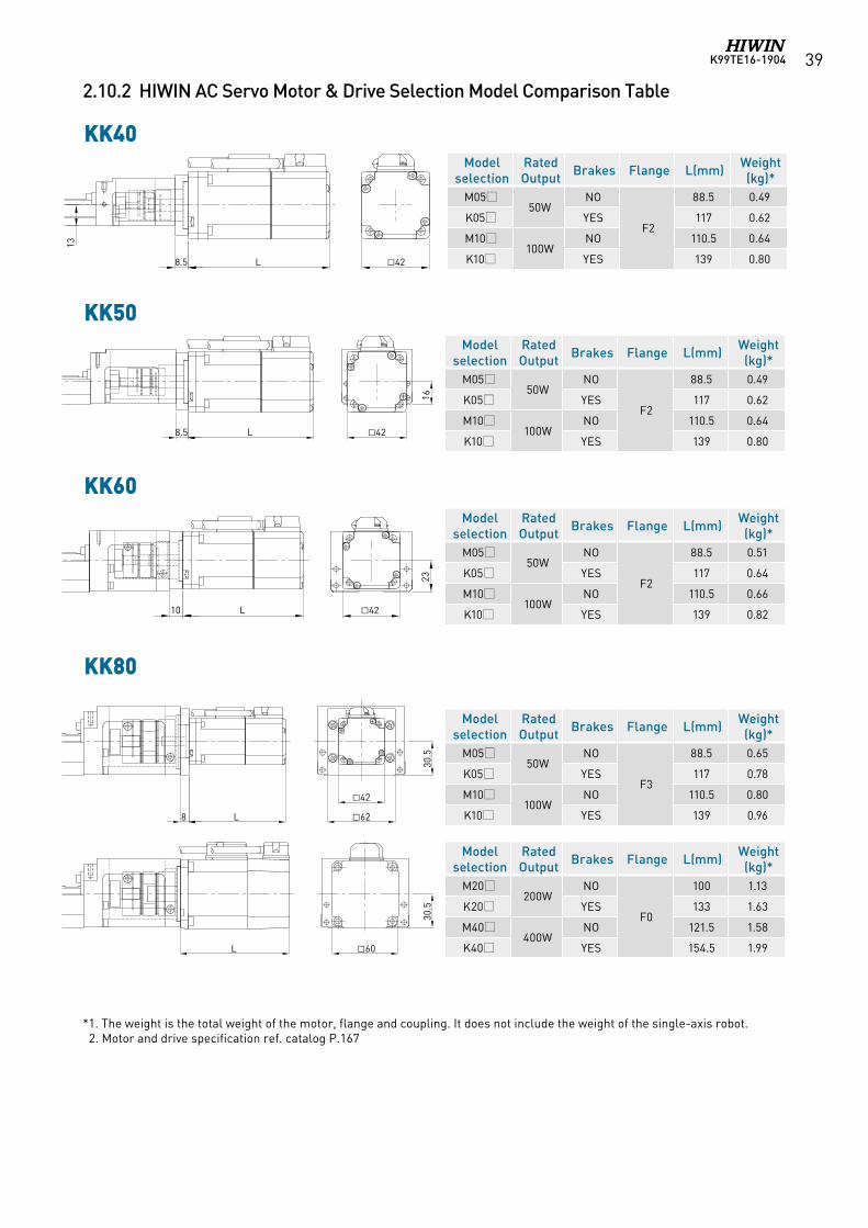
K99TE16-1904 39
2.10.2 HIWIN AC Servo Motor & Drive Selection Model Comparison Table
KK40
KK50
KK60
KK80
Model selection
RatedOutput Brakes Flange L(mm) Weight
(kg)*M05
50WNO
F2
88.5 0.49
K05 YES 117 0.62
M10100W
NO 110.5 0.64
K10 YES 139 0.80
Model selection
RatedOutput Brakes Flange L(mm) Weight
(kg)*M05
50WNO
F2
88.5 0.49
K05 YES 117 0.62
M10100W
NO 110.5 0.64
K10 YES 139 0.80
Model selection
RatedOutput Brakes Flange L(mm) Weight
(kg)*M05
50WNO
F2
88.5 0.51
K05 YES 117 0.64
M10100W
NO 110.5 0.66
K10 YES 139 0.82
Model selection
RatedOutput Brakes Flange L(mm) Weight
(kg)*M05
50WNO
F3
88.5 0.65
K05 YES 117 0.78
M10100W
NO 110.5 0.80
K10 YES 139 0.96
Model selection
RatedOutput Brakes Flange L(mm) Weight
(kg)*M20
200WNO
F0
100 1.13
K20 YES 133 1.63
M40400W
NO 121.5 1.58
K40 YES 154.5 1.99
8.5 L 42
13
8.5 L 4216
4210 L
23
8 L
42
62
30.5
30.5
L 60
*1. The weight is the total weight of the motor, flange and coupling. It does not include the weight of the single-axis robot. 2. Motor and drive specification ref. catalog P.167
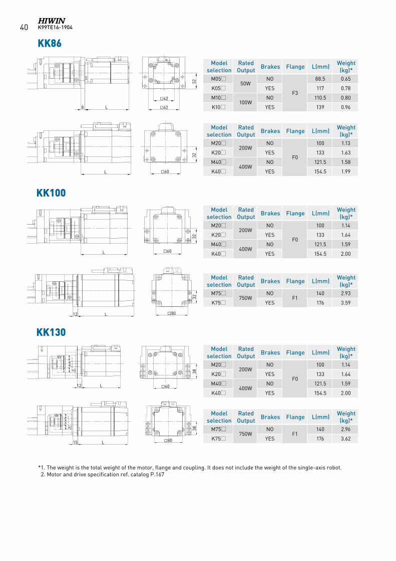
K99TE16-190440
*1. The weight is the total weight of the motor, flange and coupling. It does not include the weight of the single-axis robot. 2. Motor and drive specification ref. catalog P.167
KK86
KK100
KK130
Model selection
RatedOutput Brakes Flange L(mm) Weight
(kg)*M05
50WNO
F3
88.5 0.65
K05 YES 117 0.78
M10100W
NO 110.5 0.80
K10 YES 139 0.96
Model selection
RatedOutput Brakes Flange L(mm) Weight
(kg)*M20
200WNO
F0
100 1.13
K20 YES 133 1.63
M40400W
NO 121.5 1.58
K40 YES 154.5 1.99
Model selection
RatedOutput Brakes Flange L(mm) Weight
(kg)*M20
200WNO
F0
100 1.14
K20 YES 133 1.64
M40400W
NO 121.5 1.59
K40 YES 154.5 2.00
Model selection
RatedOutput Brakes Flange L(mm) Weight
(kg)*M20
200WNO
F0
100 1.14
K20 YES 133 1.64
M40400W
NO 121.5 1.59
K40 YES 154.5 2.00
Model selection
RatedOutput Brakes Flange L(mm) Weight
(kg)*M75
750WNO
F1140 2.93
K75 YES 176 3.59
Model selection
RatedOutput Brakes Flange L(mm) Weight
(kg)*M75
750WNO
F1140 2.96
K75 YES 176 3.62
42
62
32
8 L
L
32
60
32
L12 80
L12 60
38
L15 80
38
60
32
L
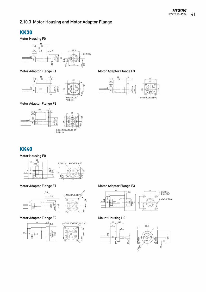
K99TE16-1904 41
2.10.3 Motor Housing and Motor Adaptor Flange
KK30
KK40
Motor Housing F0
Motor Adaptor Flange F2
Motor Adaptor Flange F1 Motor Adaptor Flange F3
2510
11.544
2330
2826
30
4-Ø3.5 THRU,Ø6x3.5 DPP.C.D. 28
28
30
4-M2.6x5 DPP.C.D. 33
45°
45°
23
5
Ø17
馬達連接法蘭 F1
45°
45°
3
2510
11.544 5
3
251011.5
44 62
Ø17
Ø17
馬達連接法蘭 F2
馬達連接法蘭 F3
2511.544
Ø3h
6 Ø20
+0.0
3+0
Ø20
+0.0
3+0
Ø22
+0.0
3+0
Ø20
+0.0
3+0
Ø17
馬達座 F0
25
2.75 6.
75
23
29.6
4-Ø3 THRU
0.5
4-Ø3 THRU,Ø5x3 DP
137.510 2
9.5
2510
11.544
2330
2826
30
4-Ø3.5 THRU,Ø6x3.5 DPP.C.D. 28
28
30
4-M2.6x5 DPP.C.D. 33
45°
45°
23
5
Ø17
馬達連接法蘭 F1
45°
45°
3
2510
11.544 5
3
251011.5
44 62
Ø17
Ø17
馬達連接法蘭 F2
馬達連接法蘭 F3
2511.544
Ø3h
6 Ø20
+0.0
3+0
Ø20
+0.0
3+0
Ø22
+0.0
3+0
Ø20
+0.0
3+0
Ø17
馬達座 F0
25
2.75 6.
75
23
29.6
4-Ø3 THRU
0.5
4-Ø3 THRU,Ø5x3 DP
137.510 2
9.5
Ø20
+0.03
0Ø
3.2
Ø20
Ø30
+0.0
5+0
45°
45°
40
P.C.D
. 46
4-M4x0.7Px8.5 DP8.5
39.6
0.5
13
27.5
23
h8
9
12 14.5
8
4h7
Motor Housing F0
Motor Adaptor Flange F2 Mount Housing H0
Motor Adaptor Flange F1 Motor Adaptor Flange F3
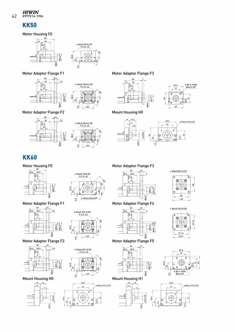
K99TE16-190442
KK50
KK60
馬達連接法蘭 F0
馬達連接法蘭 F1
馬達連接法蘭 F2
馬達連接法蘭 F3
馬達連接法蘭 F4
馬達連接法蘭 F5
KK60
KK50馬達連接法蘭 F0
馬達連接法蘭 F1
馬達連接法蘭 F2
馬達連接法蘭 F3760
Ø22
+0.0
5+0
3149.4
31
4-Ø3.5 THRU Ø6x3.5 DP
16.5
10
Ø5h
7
3414
8.560
16.5
10
Ø5h
7
3414
60
16.5
10
3414
60
16.5
10
Ø5h
7
3414
3.2
Ø30
+0.0
5+0
8.5
Ø5h
7
3.2
Ø30
+0.0
5+0
45°
45°
4-M3x0.5Px6 DPP.C.D. 33
45°
45°
4-M4x0.7Px8.5 DPP.C.D. 46
45°
45°
4-M3x0.5Px8.5 DPP.C.D. 45
0.5
1638
.5
Ø24
+0.0
3+0
0.5
1638
.5
0.5
1638
.5
49
40
15.5
9
15.518.5 30.5
59
Ø6h
7
Ø28
+0.0
3+0
0.5
2344
.5
30°45°
30°
45°
4-M4x0.7Px8 DPP.C.D. 40
4-M3x0.5Px8 DP
9
15.518.5 30.5
59 103.5
Ø6h
7
Ø30
+0.0
5+0
0.5
2344
.5
45°
45°
4-M4x0.7Px10 DPP.C.D. 46
40
40
42
9
15.518.5 30.5
59 103.5
Ø6h
7
Ø30
+0.0
5+0
0.5
2344
.5
45°
45°
4-M3x0.5Px10 DPP.C.D. 45
42
9
15.518.5 30.5
59 103
Ø6h
7
Ø36
+0.0
5+0
50
50
60
4-M5x0.8Px10 DP
9
15.518.5 30.5
59 103
9
15.518.5 30.5
59 8
Ø6h
7
Ø38
.1+0
.08
+0.0
3
Ø6h
7
Ø22
+0.0
5+0
47.1
4
47.14
57.7
4-M4x0.7Px10 DP
59.6
433115
.5
31
4-Ø3.4 THRU Ø6x4 DP0.
523
44.5
Ø26
.5Ø
26.5
Ø26
.5Ø
26.5
馬達連接法蘭 F0
馬達連接法蘭 F1
馬達連接法蘭 F2
馬達連接法蘭 F3
馬達連接法蘭 F4
馬達連接法蘭 F5
KK60
KK50馬達連接法蘭 F0
馬達連接法蘭 F1
馬達連接法蘭 F2
馬達連接法蘭 F3760
Ø22
+0.0
5+0
3149.4
31
4-Ø3.5 THRU Ø6x3.5 DP
16.5
10
Ø5h
7
3414
8.560
16.5
10
Ø5h
7
3414
60
16.5
10
3414
60
16.5
10
Ø5h
7
3414
3.2
Ø30
+0.0
5+0
8.5
Ø5h
7
3.2
Ø30
+0.0
5+0
45°
45°
4-M3x0.5Px6 DPP.C.D. 33
45°
45°
4-M4x0.7Px8.5 DPP.C.D. 46
45°
45°
4-M3x0.5Px8.5 DPP.C.D. 45
0.5
1638
.5
Ø24
+0.0
3+0
0.5
1638
.5
0.5
1638
.5
49
40
15.5
9
15.518.5 30.5
59
Ø6h
7
Ø28
+0.0
3+0
0.5
2344
.5
30°45°
30°
45°
4-M4x0.7Px8 DPP.C.D. 40
4-M3x0.5Px8 DP
9
15.518.5 30.5
59 103.5
Ø6h
7
Ø30
+0.0
5+0
0.5
2344
.5
45°
45°
4-M4x0.7Px10 DPP.C.D. 46
40
40
42
9
15.518.5 30.5
59 103.5
Ø6h
7
Ø30
+0.0
5+0
0.5
2344
.5
45°
45°
4-M3x0.5Px10 DPP.C.D. 45
42
9
15.518.5 30.5
59 103
Ø6h
7
Ø36
+0.0
5+0
50
50
60
4-M5x0.8Px10 DP
9
15.518.5 30.5
59 103
9
15.518.5 30.5
59 8
Ø6h
7
Ø38
.1+0
.08
+0.0
3
Ø6h
7
Ø22
+0.0
5+0
47.1
447.14
57.7
4-M4x0.7Px10 DP
59.6
433115
.5
31
4-Ø3.4 THRU Ø6x4 DP0.
523
44.5
Ø26
.5Ø
26.5
Ø26
.5Ø
26.5
馬達連接法蘭 F0
馬達連接法蘭 F1
馬達連接法蘭 F2
馬達連接法蘭 F3
馬達連接法蘭 F4
馬達連接法蘭 F5
KK60
KK50馬達連接法蘭 F0
馬達連接法蘭 F1
馬達連接法蘭 F2
馬達連接法蘭 F3760
Ø22
+0.0
5+0
3149.4
31
4-Ø3.5 THRU Ø6x3.5 DP
16.5
10
Ø5h
7
3414
8.560
16.5
10
Ø5h
7
3414
60
16.5
10
3414
60
16.5
10
Ø5h
7
3414
3.2
Ø30
+0.0
5+0
8.5
Ø5h
7
3.2
Ø30
+0.0
5+0
45°
45°
4-M3x0.5Px6 DPP.C.D. 33
45°
45°
4-M4x0.7Px8.5 DPP.C.D. 46
45°
45°
4-M3x0.5Px8.5 DPP.C.D. 45
0.5
1638
.5
Ø24
+0.0
3+0
0.5
1638
.5
0.5
1638
.5
49
40
15.5
9
15.518.5 30.5
59
Ø6h
7
Ø28
+0.0
3+0
0.5
2344
.5
30°45°
30°
45°
4-M4x0.7Px8 DPP.C.D. 40
4-M3x0.5Px8 DP
9
15.518.5 30.5
59 103.5
Ø6h
7
Ø30
+0.0
5+0
0.5
2344
.5
45°
45°
4-M4x0.7Px10 DPP.C.D. 46
40
40
42
9
15.518.5 30.5
59 103.5
Ø6h
7
Ø30
+0.0
5+0
0.5
2344
.5
45°
45°
4-M3x0.5Px10 DPP.C.D. 45
42
9
15.518.5 30.5
59 103
Ø6h
7
Ø36
+0.0
5+0
50
50
60
4-M5x0.8Px10 DP
9
15.518.5 30.5
59 103
9
15.518.5 30.5
59 8
Ø6h
7
Ø38
.1+0
.08
+0.0
3
Ø6h
7
Ø22
+0.0
5+0
47.1
4
47.14
57.7
4-M4x0.7Px10 DP
59.6
433115
.5
31
4-Ø3.4 THRU Ø6x4 DP0.
523
44.5
Ø26
.5Ø
26.5
Ø26
.5Ø
26.5
馬達連接法蘭 F0
馬達連接法蘭 F1
馬達連接法蘭 F2
馬達連接法蘭 F3
馬達連接法蘭 F4
馬達連接法蘭 F5
KK60
KK50馬達連接法蘭 F0
馬達連接法蘭 F1
馬達連接法蘭 F2
馬達連接法蘭 F3760
Ø22
+0.0
5+0
3149.4
31
4-Ø3.5 THRU Ø6x3.5 DP
16.5
10
Ø5h
7
3414
8.560
16.5
10
Ø5h
7
3414
60
16.5
10
3414
60
16.5
10
Ø5h
7
3414
3.2
Ø30
+0.0
5+0
8.5
Ø5h
7
3.2
Ø30
+0.0
5+0
45°
45°
4-M3x0.5Px6 DPP.C.D. 33
45°
45°
4-M4x0.7Px8.5 DPP.C.D. 46
45°
45°
4-M3x0.5Px8.5 DPP.C.D. 45
0.5
1638
.5
Ø24
+0.0
3+0
0.5
1638
.5
0.5
1638
.5
49
40
15.5
9
15.518.5 30.5
59
Ø6h
7
Ø28
+0.0
3+0
0.5
2344
.5
30°45°
30°
45°
4-M4x0.7Px8 DPP.C.D. 40
4-M3x0.5Px8 DP
9
15.518.5 30.5
59 103.5
Ø6h
7
Ø30
+0.0
5+0
0.5
2344
.5
45°
45°
4-M4x0.7Px10 DPP.C.D. 46
40
40
42
9
15.518.5 30.5
59 103.5
Ø6h
7
Ø30
+0.0
5+0
0.5
2344
.5
45°
45°
4-M3x0.5Px10 DPP.C.D. 45
42
9
15.518.5 30.5
59 103
Ø6h
7
Ø36
+0.0
5+0
50
50
60
4-M5x0.8Px10 DP
9
15.518.5 30.5
59 103
9
15.518.5 30.5
59 8
Ø6h
7
Ø38
.1+0
.08
+0.0
3
Ø6h
7
Ø22
+0.0
5+0
47.1
4
47.14
57.7
4-M4x0.7Px10 DP
59.6
433115
.5
31
4-Ø3.4 THRU Ø6x4 DP0.
523
44.5
Ø26
.5Ø
26.5
Ø26
.5Ø
26.5
10
16.5143
36 24
0.5
16 12
4-M3x0.5Px8 DP32
5h7
25h8
49.4
Motor Housing F0
Motor Adaptor Flange F2 Mount Housing H0
Motor Adaptor Flange F1 Motor Adaptor Flange F3
馬達連接法蘭 F0
馬達連接法蘭 F1
馬達連接法蘭 F2
馬達連接法蘭 F3
馬達連接法蘭 F4
馬達連接法蘭 F5
KK60
KK50馬達連接法蘭 F0
馬達連接法蘭 F1
馬達連接法蘭 F2
馬達連接法蘭 F3760
Ø22
+0.0
5+0
3149.4
31
4-Ø3.5 THRU Ø6x3.5 DP
16.5
10
Ø5h
7
3414
8.560
16.5
10
Ø5h
7
3414
60
16.5
10
3414
60
16.5
10
Ø5h
7
3414
3.2
Ø30
+0.0
5+0
8.5
Ø5h
7
3.2
Ø30
+0.0
5+0
45°
45°
4-M3x0.5Px6 DPP.C.D. 33
45°
45°
4-M4x0.7Px8.5 DPP.C.D. 46
45°
45°
4-M3x0.5Px8.5 DPP.C.D. 45
0.5
1638
.5
Ø24
+0.0
3+0
0.5
1638
.5
0.5
1638
.5
49
40
15.5
9
15.518.5 30.5
59
Ø6h
7
Ø28
+0.0
3+0
0.5
2344
.5
30°45°
30°
45°
4-M4x0.7Px8 DPP.C.D. 40
4-M3x0.5Px8 DP
9
15.518.5 30.5
59 103.5
Ø6h
7
Ø30
+0.0
5+0
0.5
2344
.5
45°
45°
4-M4x0.7Px10 DPP.C.D. 46
40
40
42
9
15.518.5 30.5
59 103.5
Ø6h
7
Ø30
+0.0
5+0
0.5
2344
.5
45°
45°
4-M3x0.5Px10 DPP.C.D. 45
42
9
15.518.5 30.5
59 103
Ø6h
7
Ø36
+0.0
5+0
50
50
60
4-M5x0.8Px10 DP
9
15.518.5 30.5
59 103
9
15.518.5 30.5
59 8
Ø6h
7
Ø38
.1+0
.08
+0.0
3
Ø6h
7
Ø22
+0.0
5+0
47.1
4
47.14
57.7
4-M4x0.7Px10 DP
59.6
433115
.5
31
4-Ø3.4 THRU Ø6x4 DP0.
523
44.5
Ø26
.5Ø
26.5
Ø26
.5Ø
26.5
馬達連接法蘭 F0
馬達連接法蘭 F1
馬達連接法蘭 F2
馬達連接法蘭 F3
馬達連接法蘭 F4
馬達連接法蘭 F5
KK60
KK50馬達連接法蘭 F0
馬達連接法蘭 F1
馬達連接法蘭 F2
馬達連接法蘭 F3760
Ø22
+0.0
5+0
3149.4
31
4-Ø3.5 THRU Ø6x3.5 DP
16.5
10
Ø5h
7
3414
8.560
16.5
10
Ø5h
7
3414
60
16.5
10
3414
60
16.5
10
Ø5h
7
3414
3.2
Ø30
+0.0
5+0
8.5
Ø5h
7
3.2
Ø30
+0.0
5+0
45°
45°
4-M3x0.5Px6 DPP.C.D. 33
45°
45°
4-M4x0.7Px8.5 DPP.C.D. 46
45°
45°
4-M3x0.5Px8.5 DPP.C.D. 45
0.5
1638
.5
Ø24
+0.0
3+0
0.5
1638
.5
0.5
1638
.5
49
40
15.5
9
15.518.5 30.5
59
Ø6h
7
Ø28
+0.0
3+0
0.5
2344
.5
30°45°
30°
45°
4-M4x0.7Px8 DPP.C.D. 40
4-M3x0.5Px8 DP
9
15.518.5 30.5
59 103.5
Ø6h
7
Ø30
+0.0
5+0
0.5
2344
.5
45°
45°
4-M4x0.7Px10 DPP.C.D. 46
40
40
42
9
15.518.5 30.5
59 103.5
Ø6h
7
Ø30
+0.0
5+0
0.5
2344
.5
45°
45°
4-M3x0.5Px10 DPP.C.D. 45
42
9
15.518.5 30.5
59 103
Ø6h
7
Ø36
+0.0
5+0
5050
60
4-M5x0.8Px10 DP
9
15.518.5 30.5
59 103
9
15.518.5 30.5
59 8
Ø6h
7
Ø38
.1+0
.08
+0.0
3
Ø6h
7
Ø22
+0.0
5+0
47.1
4
47.14
57.7
4-M4x0.7Px10 DP
59.6
433115
.5
31
4-Ø3.4 THRU Ø6x4 DP0.
523
44.5
Ø26
.5Ø
26.5
Ø26
.5Ø
26.5
馬達連接法蘭 F0
馬達連接法蘭 F1
馬達連接法蘭 F2
馬達連接法蘭 F3
馬達連接法蘭 F4
馬達連接法蘭 F5
KK60
KK50馬達連接法蘭 F0
馬達連接法蘭 F1
馬達連接法蘭 F2
馬達連接法蘭 F3760
Ø22
+0.0
5+0
3149.4
31
4-Ø3.5 THRU Ø6x3.5 DP
16.5
10
Ø5h
7
3414
8.560
16.5
10
Ø5h
7
3414
60
16.5
10
3414
60
16.5
10
Ø5h
7
3414
3.2
Ø30
+0.0
5+0
8.5
Ø5h
7
3.2
Ø30
+0.0
5+0
45°
45°
4-M3x0.5Px6 DPP.C.D. 33
45°
45°
4-M4x0.7Px8.5 DPP.C.D. 46
45°
45°
4-M3x0.5Px8.5 DPP.C.D. 45
0.5
1638
.5
Ø24
+0.0
3+0
0.5
1638
.5
0.5
1638
.5
49
40
15.5
9
15.518.5 30.5
59
Ø6h
7
Ø28
+0.0
3+0
0.5
2344
.5
30°45°
30°
45°
4-M4x0.7Px8 DPP.C.D. 40
4-M3x0.5Px8 DP
9
15.518.5 30.5
59 103.5
Ø6h
7
Ø30
+0.0
5+0
0.5
2344
.5
45°
45°
4-M4x0.7Px10 DPP.C.D. 46
40
40
42
9
15.518.5 30.5
59 103.5
Ø6h
7
Ø30
+0.0
5+0
0.5
2344
.5
45°
45°
4-M3x0.5Px10 DPP.C.D. 45
42
9
15.518.5 30.5
59 103
Ø6h
7
Ø36
+0.0
5+0
50
50
60
4-M5x0.8Px10 DP
9
15.518.5 30.5
59 103
9
15.518.5 30.5
59 8
Ø6h
7
Ø38
.1+0
.08
+0.0
3
Ø6h
7
Ø22
+0.0
5+0
47.1
4
47.14
57.7
4-M4x0.7Px10 DP
59.6
433115
.5
31
4-Ø3.4 THRU Ø6x4 DP0.
523
44.5
Ø26
.5Ø
26.5
Ø26
.5Ø
26.5
91518 16
33
59.6
0.523
44.5
16.5
33
6h7
30h8
4-M4x0.7Px15 DP9
1518 16
27
59.6
0.523
44.5
13.5
27
6h7
30.4
h8
4-M4x0.7Px15 DP
Motor Housing F0 Motor Adaptor Flange F3
Motor Adaptor Flange F2 Motor Adaptor Flange F5
Mount Housing H0 Mount Housing H1
Motor Adaptor Flange F1 Motor Adaptor Flange F4
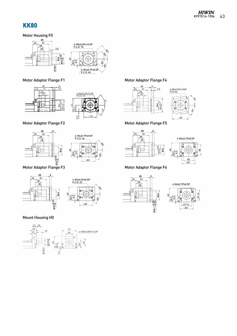
K99TE16-1904 43
KK80
2388
Ø10
h7Ø
46
Ø50
+0.0
5+0
1828
51
3.5
4-M5x0.8Px10 DPP.C.D. 70
63
0.5
30°45°
30°
45°
4-M4x0.7Px8 DPP.C.D. 60
Motor housing F0
Motor adaptor Flange F1
45°
45°
4-M4x0.7Px10 DPP.C.D. 70
Ø46
Ø50
+0.0
5+0
62
2388
1828
5110
Motor adaptor Flange F2
2388
1828
514-M4x0.7Px8 DPP.C.D. 46
45°
45°
8
Ø46
Ø30
+0.0
5+0
Motor adaptor Flange F3
2388
1828
518
Ø46
Ø30
+0.0
5+0
4-M3x0.5Px8 DPP.C.D. 45
45°
45°
2388
1828
51
Motor adaptor Flange F4
Motor adaptor Flange F5
2388
1828
51
12
Ø70
+0.0
5+0
3.5
Ø46
4-M5x0.8Px10 DPP.C.D. 90
45°
45°
8
Ø46
Ø36
+0.0
5+0
4-M4x0.7Px8 DP
50
50
Motor adaptor Flange F6
2388
1828
51
47.14
47.1
4
4-M4x0.7Px8 DP
Ø46
Ø38
.1+0
.08
+0.0
3
8
62
62
80
62
62
30.5
63
0.5
30.5
63
0.5
30.5
63
0.5
30.5
63
0.5
30.5
63
0.5
30.5
45°
45°
1828
502387 10
Ø50
+0.0
5+0
Ø46
3.5
62
P.C.D. 704-M4x0.7Px10 DP
85
311
63
45°
45°
P.C.D. 904-M5x0.8Px12 DP
85
311
63
1828
502387 12
Ø70
+0.0
5+0
Ø46
3.5
80
1828
512388 10
Ø50
+0.0
5+0
Ø46
3.5
45°
45°
4-M4x0.7Px10 DPP.C.D. 70
30.5
63
0.5
1828
512388 12
Ø70
+0.0
5+0
Ø46
3.5
62
45°
45°
4-M5x0.8Px12 DPP.C.D. 90
80
KK86-F1/SK86-F1
KK86-F4/SK86-F1
KK80-F1
KK80-F1
1828
512388 12
Ø70
+0.0
5+0
Ø46
3.5
45°
45°
4-M5x0.8Px12DPPCD 90
80
2388
Ø10
h7Ø
46
Ø50
+0.0
5+0
1828
51
3.5
4-M5x0.8Px10 DPP.C.D. 70
63
0.5
30°45°
30°
45°
4-M4x0.7Px8 DPP.C.D. 60
Motor housing F0
Motor adaptor Flange F1
45°
45°
4-M4x0.7Px10 DPP.C.D. 70
Ø46
Ø50
+0.0
5+0
62
2388
1828
5110
Motor adaptor Flange F2
2388
1828
514-M4x0.7Px8 DPP.C.D. 46
45°
45°
8
Ø46
Ø30
+0.0
5+0
Motor adaptor Flange F3
2388
1828
518
Ø46
Ø30
+0.0
5+0
4-M3x0.5Px8 DPP.C.D. 45
45°
45°
2388
1828
51
Motor adaptor Flange F4
Motor adaptor Flange F5
2388
1828
51
12
Ø70
+0.0
5+0
3.5
Ø46
4-M5x0.8Px10 DPP.C.D. 90
45°
45°
8
Ø46
Ø36
+0.0
5+0
4-M4x0.7Px8 DP
50
50
Motor adaptor Flange F6
2388
1828
51
47.14
47.1
4
4-M4x0.7Px8 DP
Ø46
Ø38
.1+0
.08
+0.0
3
8
62
62
80
62
62
30.5
63
0.5
30.5
63
0.5
30.5
63
0.5
30.5
63
0.5
30.5
63
0.5
30.5
2388
Ø10
h7Ø
46
Ø50
+0.0
5+0
1828
51
3.5
4-M5x0.8Px10 DPP.C.D. 70
63
0.5
30°45°
30°
45°
4-M4x0.7Px8 DPP.C.D. 60
Motor housing F0
Motor adaptor Flange F1
45°
45°
4-M4x0.7Px10 DPP.C.D. 70
Ø46
Ø50
+0.0
5+0
62
2388
1828
5110
Motor adaptor Flange F2
2388
1828
514-M4x0.7Px8 DPP.C.D. 46
45°
45°
8
Ø46
Ø30
+0.0
5+0
Motor adaptor Flange F3
2388
1828
518
Ø46
Ø30
+0.0
5+0
4-M3x0.5Px8 DPP.C.D. 45
45°
45°
2388
1828
51
Motor adaptor Flange F4
Motor adaptor Flange F5
2388
1828
51
12
Ø70
+0.0
5+0
3.5
Ø46
4-M5x0.8Px10 DPP.C.D. 90
45°
45°
8
Ø46
Ø36
+0.0
5+0
4-M4x0.7Px8 DP
50
50
Motor adaptor Flange F6
2388
1828
51
47.14
47.1
4
4-M4x0.7Px8 DP
Ø46
Ø38
.1+0
.08
+0.0
3
8
62
62
80
62
62
30.5
63
0.5
30.5
63
0.5
30.5
63
0.5
30.5
63
0.5
30.5
63
0.5
30.5
Motor Housing F0
Motor Adaptor Flange F1 Motor Adaptor Flange F4
Motor Adaptor Flange F2 Motor Adaptor Flange F5
Motor Adaptor Flange F3 Motor Adaptor Flange F6
Mount Housing H0
4-M5X0.8PX10 DP
63
0.5
Ø10
h7
Ø40
h8
18
28
12
2320
40
40
79
20
30.5
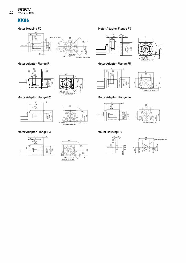
K99TE16-190444
KK86
40h8
132023
8h7
2818
40 4-M5x0.8Px12 DP85
64
132
2040
Motor Housing F0 Motor Adaptor Flange F4
Motor Adaptor Flange F1 Motor Adaptor Flange F5
Motor Adaptor Flange F2 Motor Adaptor Flange F6
Motor Adaptor Flange F3 Mount Housing H0
45°
45°
1828
502387 10
Ø50
+0.0
5+0
Ø46
3.5
62
P.C.D. 704-M4x0.7Px10 DP
85
311
63
45°
45°
P.C.D. 904-M5x0.8Px12 DP
85
311
63
1828
502387 12
Ø70
+0.0
5+0
Ø46
3.5
80
1828
512388 10
Ø50
+0.0
5+0
Ø46
3.5
45°
45°
4-M4x0.7Px10 DPP.C.D. 70
30.5
63
0.5
1828
512388 12
Ø70
+0.0
5+0
Ø46
3.5
62
45°
45°
4-M5x0.8Px12 DPP.C.D. 90
80
KK86-F1/SK86-F1
KK86-F4/SK86-F1
KK80-F1
KK80-F1
45°
45°
1828
502387 10
Ø50
+0.0
5+0
Ø46
3.5
62
P.C.D. 704-M4x0.7Px10 DP
85
311
63
45°
45°
P.C.D. 904-M5x0.8Px12 DP
85
311
63
1828
502387 12
Ø70
+0.0
5+0
Ø46
3.5
80
1828
512388 10
Ø50
+0.0
5+0
Ø46
3.5
45°
45°
4-M4x0.7Px10 DPP.C.D. 70
30.5
63
0.5
1828
512388 12
Ø70
+0.0
5+0
Ø46
3.5
62
45°
45°
4-M5x0.8Px12 DPP.C.D. 90
80
KK86-F1/SK86-F1
KK86-F4/SK86-F1
KK80-F1
KK80-F1
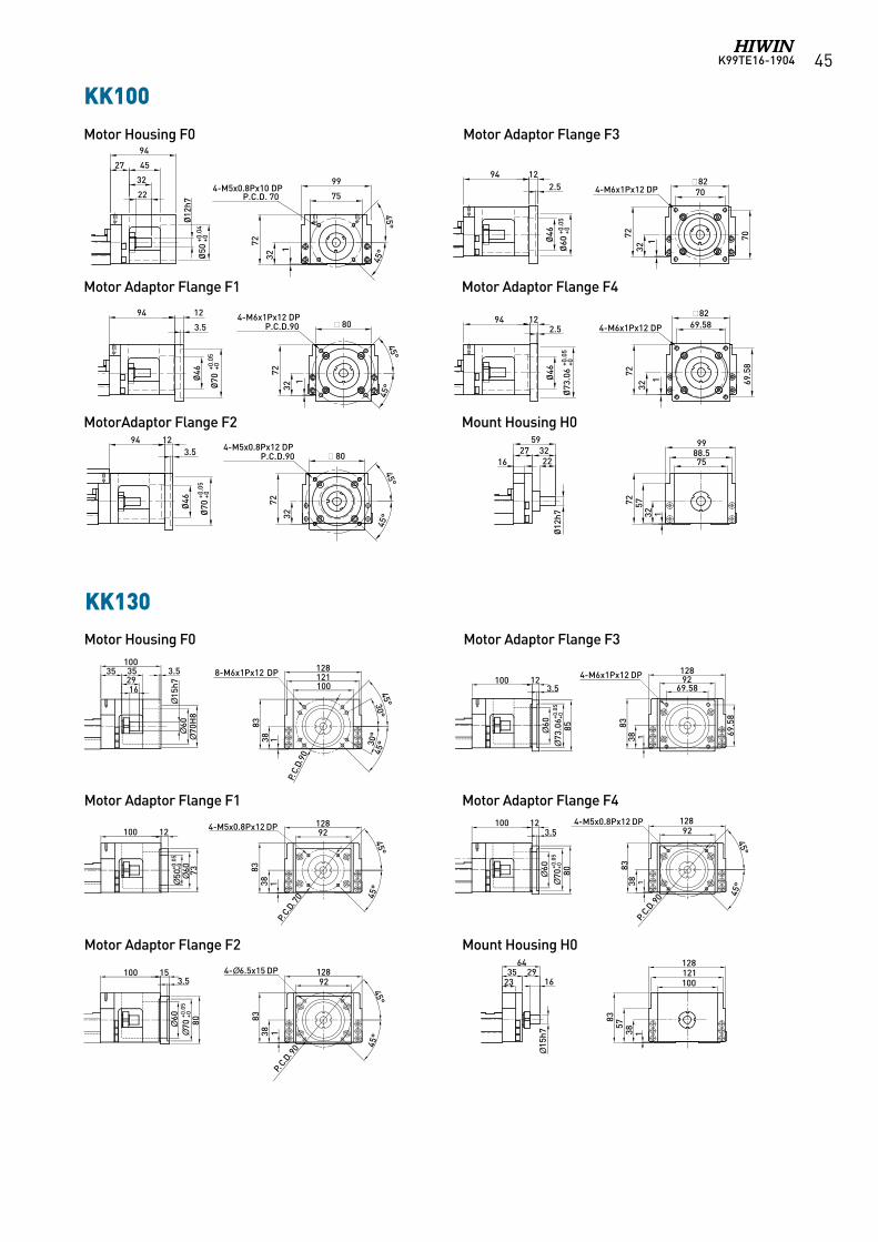
K99TE16-1904 45
KK100
KK130
1
72
22
32
4527
94
Ø50
+0.0
4+0
Ø12
h799
754-M5x0.8Px10 DP
P.C.D. 70
32
1
45°
45°
7232
45°45°
· 8094
3.5
Ø70
+0.0
5+0
Ø46
12 4-M6x1Px12 DPP.C.D.90
942.5
Ø46
Ø73
.06
+0.0
5+0
72
69.5
8
1
32
69.584-M6x1Px12 DP
45°
45°
72
32
· 80
943.5
12
Ø70
+0.0
5+0
4-M5x0.8Px12 DPP.C.D.90
12
Ø46
707232
1
·8270
942.5
12
Ø60
+0.0
5+0
Ø46
4-M6x1Px12 DP
·82
7588.599
1
57
2716
59
22
Ø12
h7
32
72
32
Motor Housing F0 Motor Adaptor Flange F3
Motor Adaptor Flange F1 Motor Adaptor Flange F4
MotorAdaptor Flange F2 Mount Housing H0
162935
15
h7 138
83
23
64
57
100121128
Motor Housing F0 Motor Adaptor Flange F3
Motor Adaptor Flange F1 Motor Adaptor Flange F4
Motor Adaptor Flange F2 Mount Housing H0
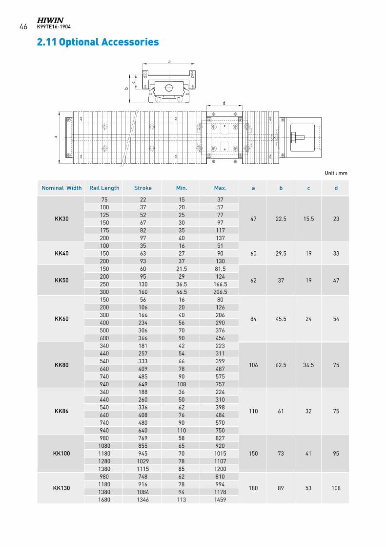
K99TE16-190446
aa
bc
d
2.11 Optional Accessories
Unit : mm
Nominal Width Rail Length Stroke Min. Max. a b c d
KK30
75 22 15 37
47 22.5 15.5 23
100 37 20 57125 52 25 77150 67 30 97175 82 35 117200 97 40 137
KK40100 35 16 51
60 29.5 19 33150 63 27 90200 93 37 130
KK50
150 60 21.5 81.5
62 37 19 47200 95 29 124250 130 36.5 166.5300 160 46.5 206.5
KK60
150 56 16 80
84 45.5 24 54
200 106 20 126300 166 40 206400 234 56 290500 306 70 376600 366 90 456
KK80
340 181 42 223
106 62.5 34.5 75
440 257 54 311540 333 66 399640 409 78 487740 485 90 575940 649 108 757
KK86
340 188 36 224
110 61 32 75
440 260 50 310540 336 62 398640 408 76 484740 480 90 570940 640 110 750
KK100
980 769 58 827
150 73 41 951080 855 65 9201180 945 70 10151280 1029 78 11071380 1115 85 1200
KK130
980 748 62 810
180 89 53 1081180 916 78 9941380 1084 94 11781680 1346 113 1459
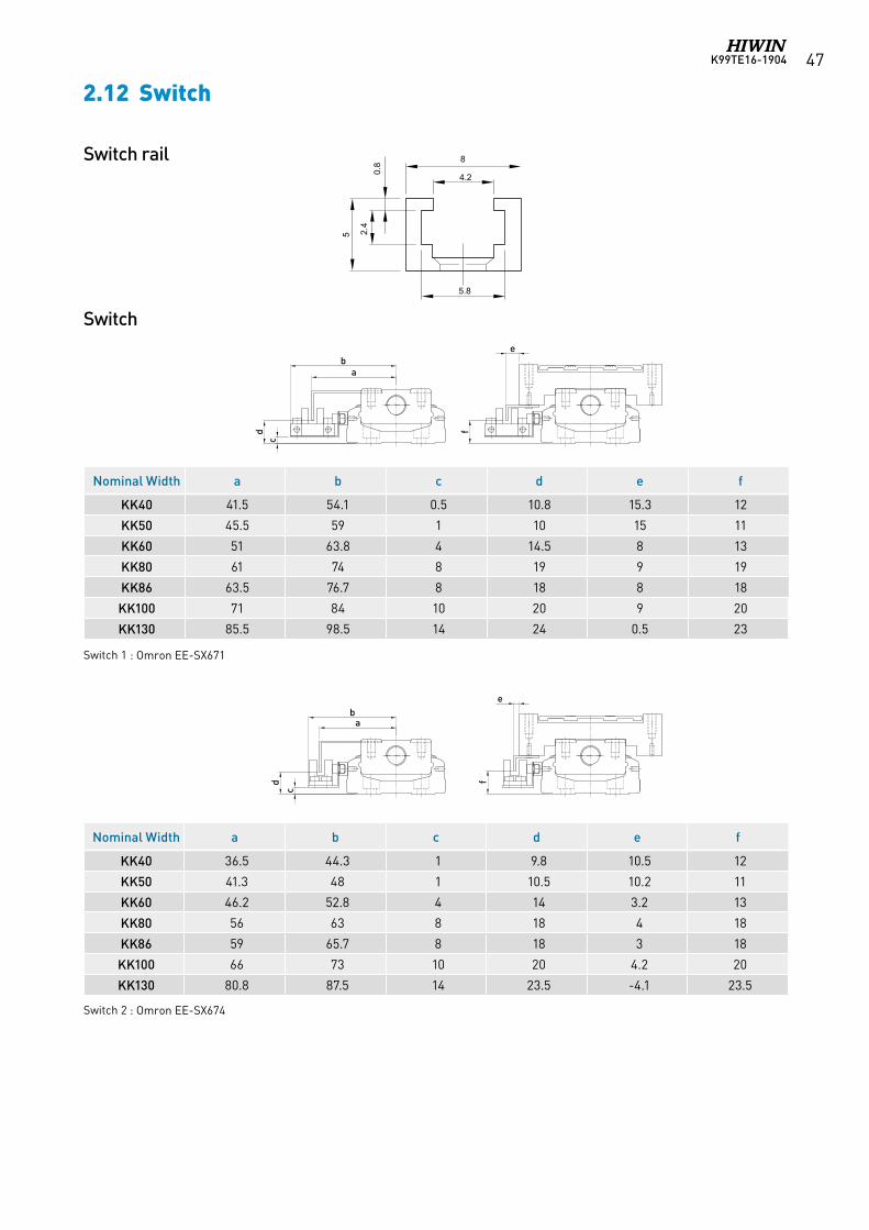
K99TE16-1904 47
2.12 Switch
Switch rail
Switch
g
h
i
j
g
h j
f
f
cd
cd
ab
ba
e
e
i
S1
S2
S3 & S4
S5
g
h
i
j
g
h j
f
f
cd
cd
ab
ba
e
e
i
S1
S2
S3 & S4
S5
Nominal Width a b c d e f
KK40 41.5 54.1 0.5 10.8 15.3 12
KK50 45.5 59 1 10 15 11
KK60 51 63.8 4 14.5 8 13
KK80 61 74 8 19 9 19
KK86 63.5 76.7 8 18 8 18
KK100 71 84 10 20 9 20
KK130 85.5 98.5 14 24 0.5 23
Nominal Width a b c d e f
KK40 36.5 44.3 1 9.8 10.5 12
KK50 41.3 48 1 10.5 10.2 11
KK60 46.2 52.8 4 14 3.2 13
KK80 56 63 8 18 4 18
KK86 59 65.7 8 18 3 18
KK100 66 73 10 20 4.2 20
KK130 80.8 87.5 14 23.5 -4.1 23.5
Switch 2 : Omron EE-SX674
Switch 1 : Omron EE-SX671
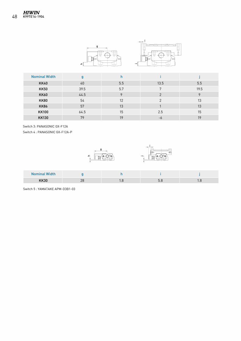
K99TE16-190448
g
h
i
j
g
h j
f
f
cd
cd
ab
ba
e
e
i
S1
S2
S3 & S4
S5
g
h
i
j
g
h j
f
f
cd
cd
ab
ba
e
e
i
S1
S2
S3 & S4
S5
Nominal Width g h i j
KK40 40 5.5 13.5 5.5
KK50 39.5 5.7 7 19.5
KK60 44.5 9 2 9
KK80 54 12 2 13
KK86 57 13 1 13
KK100 64.5 15 2.5 15
KK130 79 19 -6 19
Nominal Width g h i j
KK30 28 1.8 5.8 1.8
Switch 3: PANASONIC GX-F12A
Switch 4 : PANASONIC GX-F12A-P
Switch 5 : YAMATAKE APM-D3B1-03
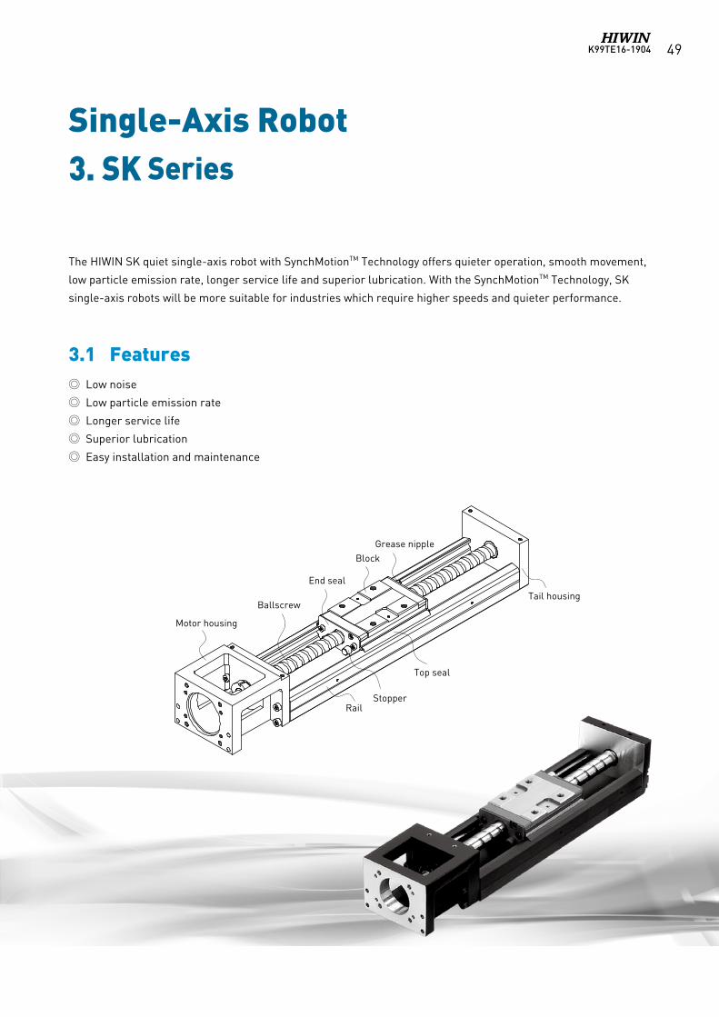
K99TE16-1904 49
Single-Axis Robot3. SK Series
3.1 Features
The HIWIN SK quiet single-axis robot with SynchMotionTM Technology offers quieter operation, smooth movement,
low particle emission rate, longer service life and superior lubrication. With the SynchMotionTM Technology, SK
single-axis robots will be more suitable for industries which require higher speeds and quieter performance.
Low noise
Low particle emission rate
Longer service life
Superior lubrication
Easy installation and maintenance
Motor housing
Ballscrew
End seal
BlockGrease nipple
Tail housing
Top seal
StopperRail
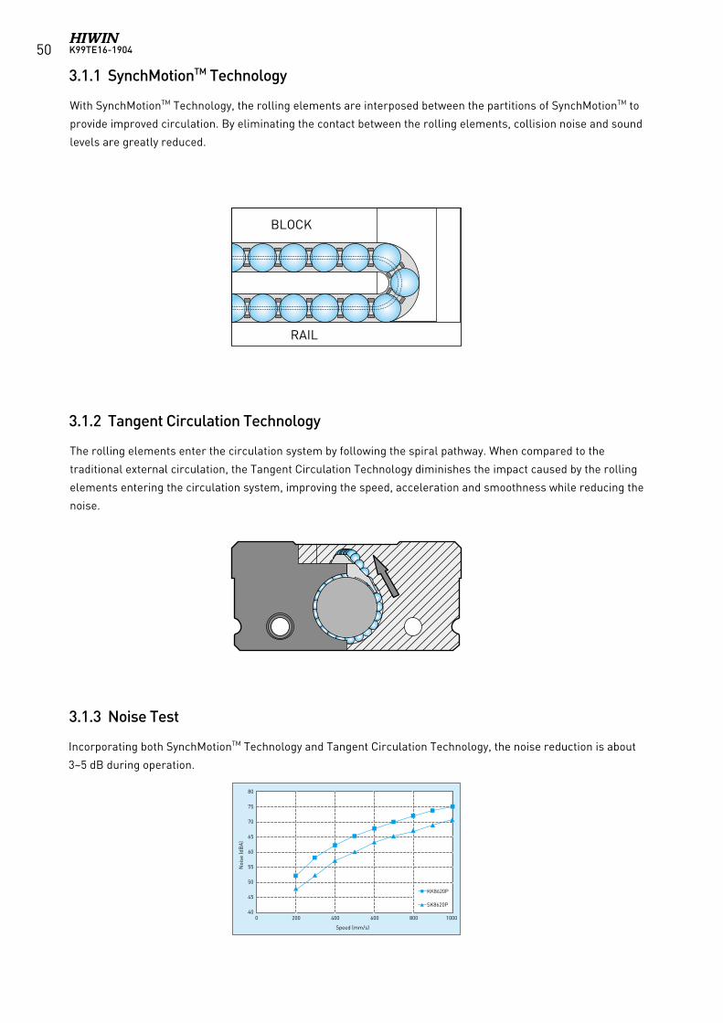
K99TE16-190450
3.1.1 SynchMotionTM Technology
3.1.2 Tangent Circulation Technology
3.1.3 Noise Test
With SynchMotionTM Technology, the rolling elements are interposed between the partitions of SynchMotionTM to
provide improved circulation. By eliminating the contact between the rolling elements, collision noise and sound
levels are greatly reduced.
The rolling elements enter the circulation system by following the spiral pathway. When compared to the
traditional external circulation, the Tangent Circulation Technology diminishes the impact caused by the rolling
elements entering the circulation system, improving the speed, acceleration and smoothness while reducing the
noise.
Incorporating both SynchMotionTM Technology and Tangent Circulation Technology, the noise reduction is about
3~5 dB during operation.
BLOCK
RAIL
80
75
70
65
60
55
50
45
400 200 400 600 800 1000
Noi
se (d
BA
)
Speed (mm/s)
KK8620P
SK8620P
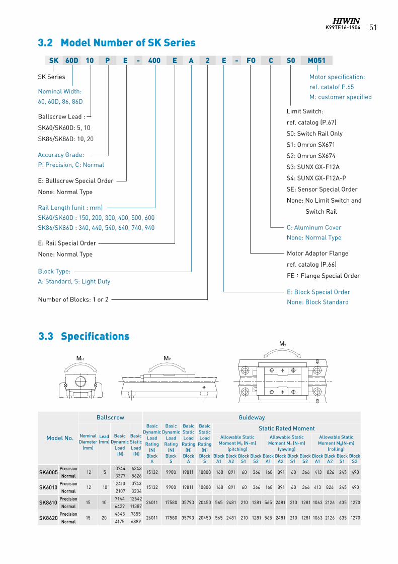
K99TE16-1904 51
3.2 Model Number of SK Series
C: Aluminum Cover
None: Normal Type
3.3 Specifications
Model No.
Ballscrew GuidewayBasic
Dynamic Load
Rating (N)
Basic Dynamic
Load Rating
(N)
Basic Static Load
Rating (N)
Basic Static Load
Rating (N)
Static Rated MomentNominal Diameter
(mm)
Lead (mm)
Basic Dynamic
Load (N)
Basic Static Load (N)
Allowable StaticMoment MP (N-m)
(pitching)
Allowable StaticMoment MY (N-m)
(yawing)
Allowable StaticMoment MR(N-m)
(rolling)Block
ABlock
SBlock
ABlock
SBlock
A1Block
A2Block
S1Block
S2Block
A1Block
A2Block
S1Block
S2Block
A1Block
A2Block
S1Block
S2
SK6005Precision
12 53744 6243
15132 9900 19811 10800 168 891 60 366 168 891 60 366 413 826 245 490Normal 3377 5626
SK6010Precision
12 102410 3743
15132 9900 19811 10800 168 891 60 366 168 891 60 366 413 826 245 490Normal 2107 3234
SK8610Precision
15 107144 12642
26011 17580 35793 20450 565 2481 210 1281 565 2481 210 1281 1063 2126 635 1270Normal 6429 11387
SK8620Precision
15 204645 7655
26011 17580 35793 20450 565 2481 210 1281 565 2481 210 1281 1063 2126 635 1270Normal 4175 6889
MR MP
My
SK 60D 10 P E - 400 E A 2 E - FO C S0 M051
SK Series
Nominal Width:
60, 60D, 86, 86D
Accuracy Grade:
P: Precision, C: Normal
E: Ballscrew Special Order
None: Normal Type
Rail Length (unit : mm)
SK60/SK60D : 150, 200, 300, 400, 500, 600
SK86/SK86D : 340, 440, 540, 640, 740, 940
Ballscrew Lead :
SK60/SK60D: 5, 10
SK86/SK86D: 10, 20
E: Rail Special Order
None: Normal Type
Limit Switch:
ref. catalog (P.67)
S0: Switch Rail Only
S1: Omron SX671
S2: Omron SX674
S3: SUNX GX-F12A
S4: SUNX GX-F12A-P
SE: Sensor Special Order
None: No Limit Switch and
Switch Rail
Motor Adaptor Flange
ref. catalog (P.66)
FE:Flange Special Order
E: Block Special Order
None: Block StandardNumber of Blocks: 1 or 2
Block Type:
A: Standard, S: Light Duty
Motor specification:
ref. catalof P.65
M: customer specified
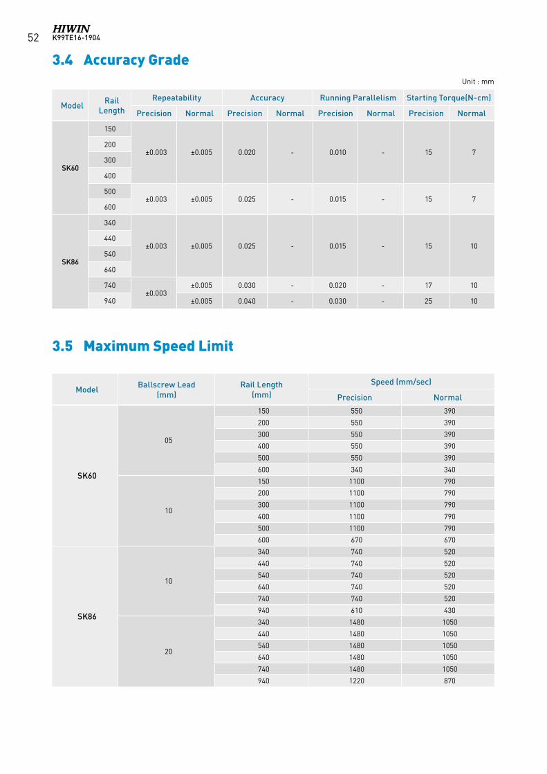
K99TE16-190452
3.4 Accuracy GradeUnit : mm
Model Rail Length
Repeatability Accuracy Running Parallelism Starting Torque(N-cm)
Precision Normal Precision Normal Precision Normal Precision Normal
SK60
150
±0.003 ±0.005 0.020 - 0.010 - 15 7200
300
400
500±0.003 ±0.005 0.025 - 0.015 - 15 7
600
SK86
340
±0.003 ±0.005 0.025 - 0.015 - 15 10440
540
640
740±0.003
±0.005 0.030 - 0.020 - 17 10
940 ±0.005 0.040 - 0.030 - 25 10
Model Ballscrew Lead(mm)
Rail Length(mm)
Speed (mm/sec)
Precision Normal
SK60
05
150 550 390
200 550 390
300 550 390
400 550 390
500 550 390
600 340 340
10
150 1100 790
200 1100 790
300 1100 790
400 1100 790
500 1100 790
600 670 670
SK86
10
340 740 520
440 740 520
540 740 520
640 740 520
740 740 520
940 610 430
20
340 1480 1050
440 1480 1050
540 1480 1050
640 1480 1050
740 1480 1050
940 1220 870
3.5 Maximum Speed Limit
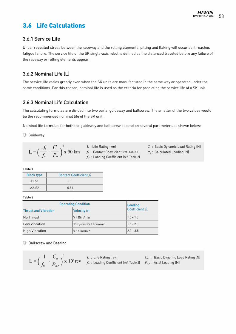
K99TE16-1904 53
3.6 Life Calculations
3.6.1 Service Life
Under repeated stress between the raceway and the rolling elements, pitting and flaking will occur as it reaches
fatigue failure. The service life of the SK single-axis robot is defined as the distanced traveled before any failure of
the raceway or rolling elements appear.
3.6.2 Nominal Life (L)The service life varies greatly even when the SK units are manufactured in the same way or operated under the
same conditions. For this reason, nominal life is used as the criteria for predicting the service life of a SK unit.
3.6.3 Nominal Life CalculationThe calculating formulas are divided into two parts, guideway and ballscrew. The smaller of the two values would
be the recommended nominal life of the SK unit.
Nominal life formulas for both the guideway and ballscrew depend on several parameters as shown below:
Guideway
L : Life Rating (km) C : Basic Dynamic Load Rating (N)ft : Contact Coefficient (ref. Table 1) Pn : Calculated Loading (N)fw : Loading Coefficient (ref. Table 2)
L = ( ft . C )3
x 50 km fw Pn
L : Life Rating (rev.) Ca : Basic Dynamic Load Rating (N)fw : Loading Coefficient (ref. Table 2) Pa,n : Axial Loading (N)
Operating Condition Loading Coefficient fwThrust and Vibration Velocity (V)
No Thrust V﹤15m/min 1.0 ~ 1.5
Low Vibration 15m/min﹤V﹤60m/min 1.5 ~ 2.0
High Vibration V﹥60m/min 2.0 ~ 3.5
Ballscrew and Bearing
Table 2
L = ( 1 . Ca )3
x 106 rev fw Pa,n
Block type Contact Coefficient ftA1, S1 1.0
A2, S2 0.81
Table 1
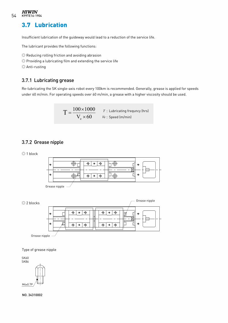
K99TE16-190454
3.7 Lubrication
Insufficient lubrication of the guideway would lead to a reduction of the service life.
The lubricant provides the following functions:
Reducing rolling friction and avoiding abrasion
Providing a lubricating film and extending the service life
Anti-rusting
3.7.1 Lubricating grease
Re-lubricating the SK single-axis robot every 100km is recommended. Generally, grease is applied for speeds
under 60 m/min. For operating speeds over 60 m/min, a grease with a higher viscosity should be used.
3.7.2 Grease nipple
1 block
2 blocks
T : Lubricating frequncy (hrs)
Ve : Speed (m/min)
Grease nipple
Grease nipple
Grease nipple
Type of grease nipple
M6x0.75PM4x0.7PM3x0.5P
KK40 KK50
KK60
KK80
KK86
KK100
KK130
NO. 34310002 NO. 34310010 NO. 34310008
SK60SK86
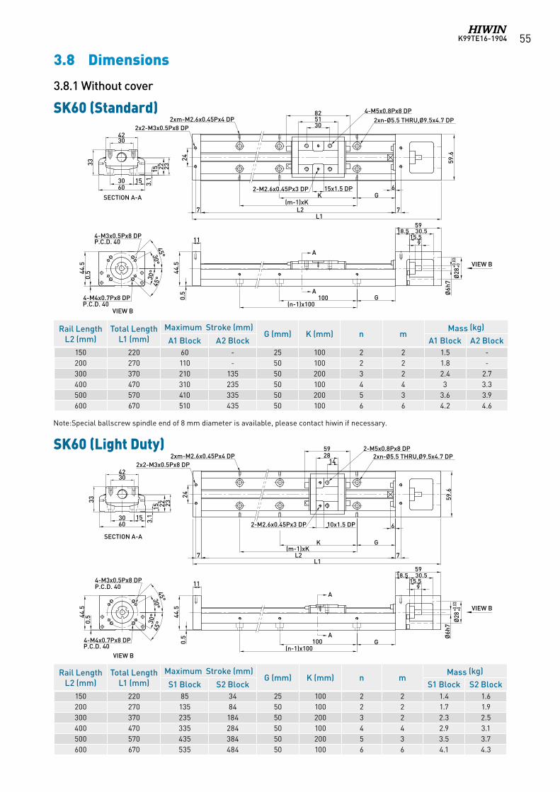
K99TE16-1904 55
Note:Special ballscrew spindle end of 8 mm diameter is available, please contact hiwin if necessary.
3.8 Dimensions
3.8.1 Without cover
SK60 (Standard)
SK60 (Light Duty)
A
A
3042
33
3.1
15 23
3060
SECTION A-A
VIEW B
VIEW B
30°
30°
45°
45°0.
544.5
P.C.D. 40
4-M4x0.7Px8 DP
2415x1.5 DP
305182
59.6
6GK
(m-1)xKL2
L17 7
2xn-Ø5.5 THRU,Ø9.5x4.7 DP4-M5x0.8Px8 DP
2-M2.6x0.45Px3 DP
2xm-M2.6x0.45Px4 DP
11
0.5
44.5
915.5
30.518.559
G100(n-1)x100
4-M3x0.5Px8 DP
Ø6h
7Ø
28+0
.03
+0
2x2-M3x0.5Px8 DP
15
22
P.C.D. 40
3042
33
3.1
15 23
3060
SECTION A-A
VIEW B
30°
30°
45°
45°0.
544.5
P.C.D. 40
4-M4x0.7Px8 DP
4-M3x0.5Px8 DP
A
A
44.5
915.5
30.518.559
G100(n-1)x100
Ø6h
7Ø
28+0
.03
+0
0.5
59.6
2xn-Ø5.5 THRU,Ø9.5x4.7 DP2xm-M2.6x0.45Px4 DP
6
GK(m-1)xK
10x1.5 DP2-M2.6x0.45Px3 DP
142859 2-M5x0.8Px8 DP
L2L1
15
11
24
7 7
2x2-M3x0.5Px8 DP
VIEW B
22
P.C.D. 40
Rail Length L2 (mm)
Total Length L1 (mm)
Maximum Stroke (mm)G (mm) K (mm) n m
Mass (kg)
S1 Block S2 Block S1 Block S2 Block150 220 85 34 25 100 2 2 1.4 1.6200 270 135 84 50 100 2 2 1.7 1.9300 370 235 184 50 200 3 2 2.3 2.5400 470 335 284 50 100 4 4 2.9 3.1500 570 435 384 50 200 5 3 3.5 3.7600 670 535 484 50 100 6 6 4.1 4.3
Rail Length L2 (mm)
Total Length L1 (mm)
Maximum Stroke (mm)G (mm) K (mm) n m
Mass (kg)
A1 Block A2 Block A1 Block A2 Block150 220 60 - 25 100 2 2 1.5 -200 270 110 - 50 100 2 2 1.8 -300 370 210 135 50 200 3 2 2.4 2.7400 470 310 235 50 100 4 4 3 3.3500 570 410 335 50 200 5 3 3.6 3.9600 670 510 435 50 100 6 6 4.2 4.6
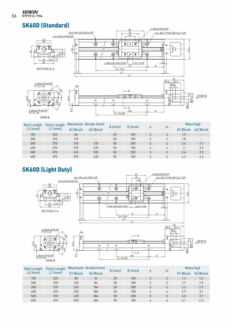
K99TE16-190456
SK60D (Standard)
SK60D (Light Duty)
Rail Length L2 (mm)Total Length L1 (mm)
Maximum Stroke (mm)G (mm) K (mm) n m
Mass (kg)
S1 Block S2 Block S1 Block S2 Block150 220 85 34 25 100 2 2 1.4 1.6200 270 135 84 50 100 2 2 1.7 1.9300 370 235 184 50 200 3 2 2.3 2.5400 470 335 284 50 100 4 4 2.9 3.1500 570 435 384 50 200 5 3 3.5 3.7600 670 535 484 50 100 6 6 4.1 4.3
A
A
SECTION A-A
VIEW B
VIEW B
3042
33
3.1
15 23
KK60D (標準型)
3060
30°
30°
45°
45°0.
544.5
P.C.D. 40
4-M4x0.7Px8 DP
24
15x1.5 DP
305182
59.6
6GK
(m-1)xKL2
L17 7
2xn-Ø5.5 THRU,Ø9.5x4.7 DP
4-M5x0.8Px8 DP
2-M2.6x0.45Px3 DP
2xm-M2.6x0.45Px4 DP
11
0.5
44.5
30.518.559
G100(n-1)x100
4-M3x0.5Px8 DP
Ø28
+0.0
3+0
2x2-M3x0.5Px8 DP
1522
P.C.D. 40
915.5
Ø8h
7
Rail Length L2 (mm)Total Length L1 (mm)
Maximum Stroke (mm)G (mm) K (mm) n m
Mass (kg)
A1 Block A2 Block A1 Block A2 Block150 220 60 - 25 100 2 2 1.5 -200 270 110 - 50 100 2 2 1.8 -300 370 210 135 50 200 3 2 2.4 2.7400 470 310 235 50 100 4 4 3 3.3500 570 410 335 50 200 5 3 3.6 3.9600 670 510 435 50 100 6 6 4.2 4.6
SECTION A-A
VIEW B
A
A
VIEW B
KK60D (輕載型)
3042
33
3.1
15 23
3060
30°
30°
45°
45°0.
544.5
P.C.D. 40
4-M4x0.7Px8 DP
4-M3x0.5Px8 DP
44.5
915.5
30.518.559
G100(n-1)x100
Ø8h
7
Ø28
+0.0
3+0
0.5
59.6
2xn-Ø5.5 THRU,Ø9.5x4.7 DP2xm-M2.6x0.45Px4 DP
6
GK(m-1)xK
10x1.5 DP2-M2.6x0.45Px3 DP
142859 2-M5x0.8Px8 DP
L2L1
15
11
24
7 7
2x2-M3x0.5Px8 DP
22
P.C.D. 40
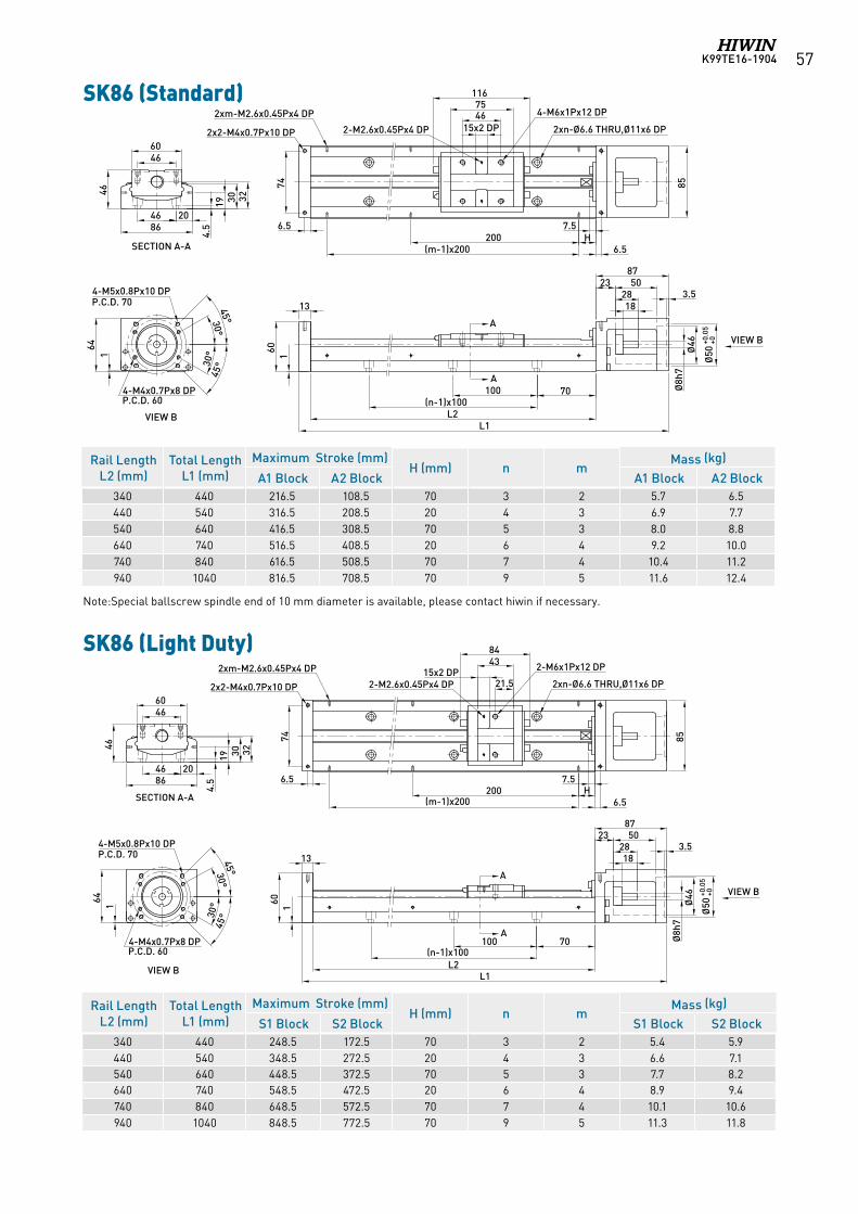
K99TE16-1904 57
Note:Special ballscrew spindle end of 10 mm diameter is available, please contact hiwin if necessary.
A
A
70100(n-1)x100
1828
238750
L2L1
13
85
2xn-Ø6.6 THRU,Ø11x6 DP
4-M6x1Px12 DP
15x2 DP46
116
2-M2.6x0.45Px4 DP
3.574
75
7.5H
(m-1)x200200
6.5
Ø50
+0.0
5+0
Ø46
Ø8h
7
VIEW B
160
2xm-M2.6x0.45Px4 DP
2x2-M4x0.7Px10 DP
164
VIEW B
4-M5x0.8Px10 DPP.C.D. 70
4-M4x0.7Px8 DPP.C.D. 60
30°
30°45°
45°
4660
46
204686
19 30 32SECTION A-A
4.5 6.5
A
A
70100(n-1)x100
1828
238750
7.5H
(m-1)x200200
L2L1
4660
46
204686
19 30 32
13
164
4-M4x0.7Px8 DP
852xn-Ø6.6 THRU,Ø11x6 DP
2-M6x1Px12 DP15x2 DP21.5
4384
2xm-M2.6x0.45Px4 DP
2-M2.6x0.45Px4 DP
3.5
SECTION A-A
P.C.D. 60
74
2x2-M4x0.7Px10 DP
6.5
6.5
VIEW B
Ø50
+0.0
5+0
Ø46
Ø8h
7
4.5
VIEW B
160
4-M5x0.8Px10 DPP.C.D. 70
30°
30°45°
45°
SK86 (Standard)
Rail Length L2 (mm)
Total Length L1 (mm)
Maximum Stroke (mm)H (mm) n m
Mass (kg)
A1 Block A2 Block A1 Block A2 Block340 440 216.5 108.5 70 3 2 5.7 6.5440 540 316.5 208.5 20 4 3 6.9 7.7540 640 416.5 308.5 70 5 3 8.0 8.8640 740 516.5 408.5 20 6 4 9.2 10.0740 840 616.5 508.5 70 7 4 10.4 11.2940 1040 816.5 708.5 70 9 5 11.6 12.4
SK86 (Light Duty)
Rail Length L2 (mm)
Total Length L1 (mm)
Maximum Stroke (mm)H (mm) n m
Mass (kg)
S1 Block S2 Block S1 Block S2 Block340 440 248.5 172.5 70 3 2 5.4 5.9440 540 348.5 272.5 20 4 3 6.6 7.1540 640 448.5 372.5 70 5 3 7.7 8.2640 740 548.5 472.5 20 6 4 8.9 9.4740 840 648.5 572.5 70 7 4 10.1 10.6940 1040 848.5 772.5 70 9 5 11.3 11.8
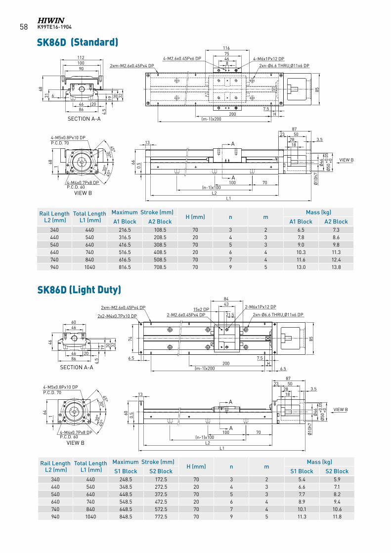
K99TE16-190458
Rail Length L2 (mm)Total Length L1 (mm)
Maximum Stroke (mm)H (mm) n m
Mass (kg)
A1 Block A2 Block A1 Block A2 Block340 440 216.5 108.5 70 3 2 6.5 7.3440 540 316.5 208.5 20 4 3 7.8 8.6540 640 416.5 308.5 70 5 3 9.0 9.8640 740 516.5 408.5 20 6 4 10.3 11.3740 840 616.5 508.5 70 7 4 11.6 12.4940 1040 816.5 708.5 70 9 5 13.0 13.8
KK86D (標準型)
A
A
VIEW B
VIEW B
SECTION A-A
70100(n-1)x100
1828
238750
L2L1
7.5H
(m-1)x200200
85
3.5
Ø50
+0.0
5+0
Ø46
Ø10
h7
84675
116
0.566
13
100
68
90
112
6
168
4-M5x0.8Px10 DPP.C.D. 70
31
2xn-Ø6.6 THRU,Ø11x6 DP
4-M6x1Px12 DP4-M2.6x0.45Px6 DP
2xm-M2.6x0.45Px4 DP
4-M4x0.7Px8 DPP.C.D. 60
30°
30°45°
45°
204686
19 30 32
4.5
SK86D (Standard)
SK86D (Light Duty)
KK86D (輕載型)
A
A
SECTION A-A
VIEW B
VIEW B
70100(n-1)x100
1828
238750
7.5H
(m-1)x200200
L2L1
4660
46
204686
19 30 32
13
164
4-M4x0.7Px8 DP
852xn-Ø6.6 THRU,Ø11x6 DP
2-M6x1Px12 DP15x2 DP21.5
4384
2xm-M2.6x0.45Px4 DP
2-M2.6x0.45Px4 DP
3.5
P.C.D. 60
74
2x2-M4x0.7Px10 DP
6.5
6.5
Ø50
+0.0
5+0
Ø46
Ø10
h7
4.5
0.560
4-M5x0.8Px10 DPP.C.D. 70
30°
30°45°
45°
Rail Length L2 (mm)Total Length L1 (mm)
Maximum Stroke (mm)H (mm) n m
Mass (kg)
S1 Block S2 Block S1 Block S2 Block340 440 248.5 172.5 70 3 2 5.4 5.9440 540 348.5 272.5 20 4 3 6.6 7.1540 640 448.5 372.5 70 5 3 7.7 8.2640 740 548.5 472.5 20 6 4 8.9 9.4740 840 648.5 572.5 70 7 4 10.1 10.6940 1040 848.5 772.5 70 9 5 11.3 11.8
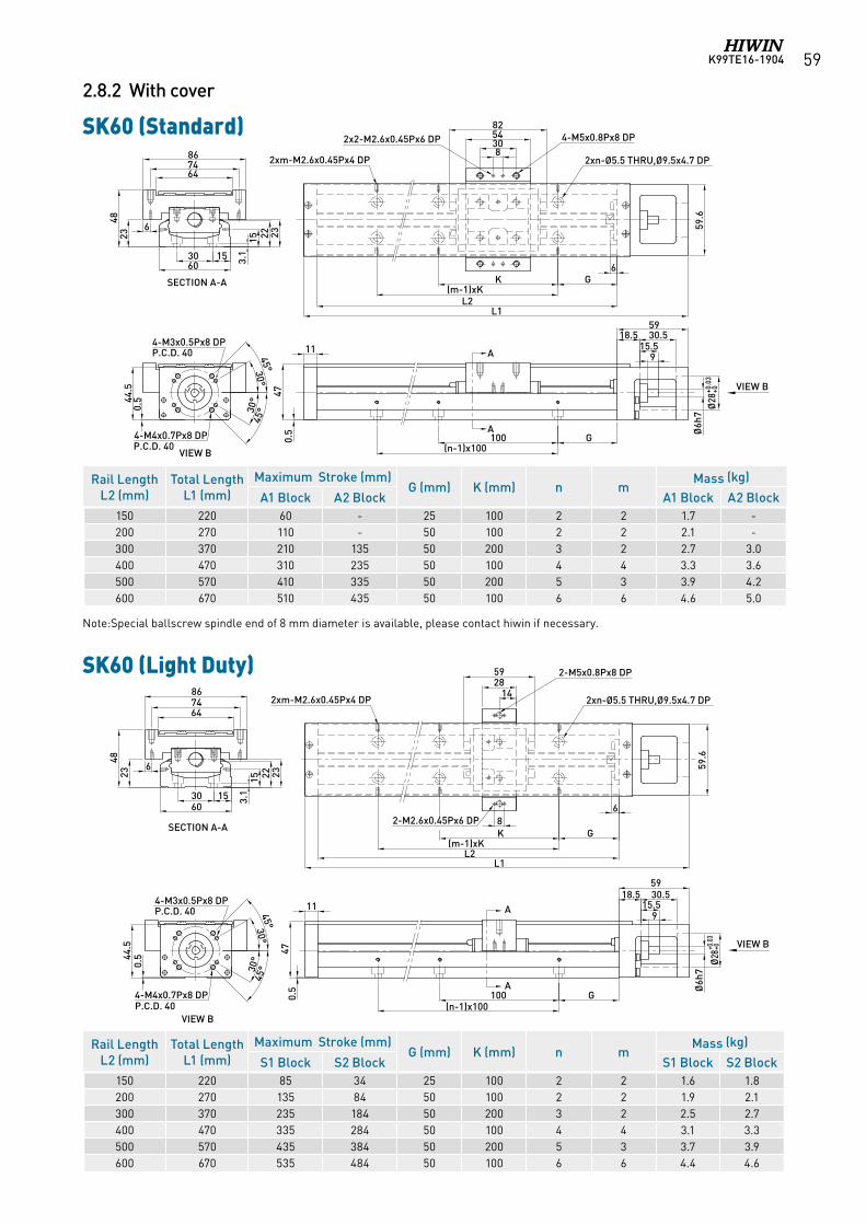
K99TE16-1904 59
SK60 (Standard)
SK60 (Light Duty)
2.8.2 With cover
A
A
47
915.5
30.518.559
G100(n-1)x100
Ø6h
7Ø
28+0
.03
+0
8305482
2xn-Ø5.5 THRU,Ø9.5x4.7 DP2xm-M2.6x0.45Px4 DP
4-M5x0.8Px8 DP2x2-M2.6x0.45Px6 DP
6GK
(m-1)xK0.
5
59.6
3.130
60
SECTION A-A
6
4823 15 2322
647486
VIEW B
30°
30°
45°
45°0.
544.5
P.C.D. 40
4-M4x0.7Px8 DP
4-M3x0.5Px8 DP
L2L1
15
11
VIEW B
P.C.D. 40
VIEW B
30°
30°
45°
45°0.
544.5
P.C.D. 40
4-M4x0.7Px8 DP
4-M3x0.5Px8 DP
3.130
60
SECTION A-A
6
4823 15 2322
647486
A
A
47
915.5
30.518.559
G100(n-1)x100
Ø6h
7
Ø28
+0.0
3+0
0.5
2xn-Ø5.5 THRU,Ø9.5x4.7 DP2xm-M2.6x0.45Px4 DP
6
GK(m-1)xK
82-M2.6x0.45Px6 DP
142859 2-M5x0.8Px8 DP
59.6
L2L1
15
11
VIEW B
P.C.D. 40
Note:Special ballscrew spindle end of 8 mm diameter is available, please contact hiwin if necessary.
Rail Length L2 (mm)
Total Length L1 (mm)
Maximum Stroke (mm)G (mm) K (mm) n m
Mass (kg)
A1 Block A2 Block A1 Block A2 Block150 220 60 - 25 100 2 2 1.7 -200 270 110 - 50 100 2 2 2.1 -300 370 210 135 50 200 3 2 2.7 3.0400 470 310 235 50 100 4 4 3.3 3.6500 570 410 335 50 200 5 3 3.9 4.2600 670 510 435 50 100 6 6 4.6 5.0
Rail Length L2 (mm)
Total Length L1 (mm)
Maximum Stroke (mm)G (mm) K (mm) n m
Mass (kg)
S1 Block S2 Block S1 Block S2 Block150 220 85 34 25 100 2 2 1.6 1.8200 270 135 84 50 100 2 2 1.9 2.1300 370 235 184 50 200 3 2 2.5 2.7400 470 335 284 50 100 4 4 3.1 3.3500 570 435 384 50 200 5 3 3.7 3.9600 670 535 484 50 100 6 6 4.4 4.6
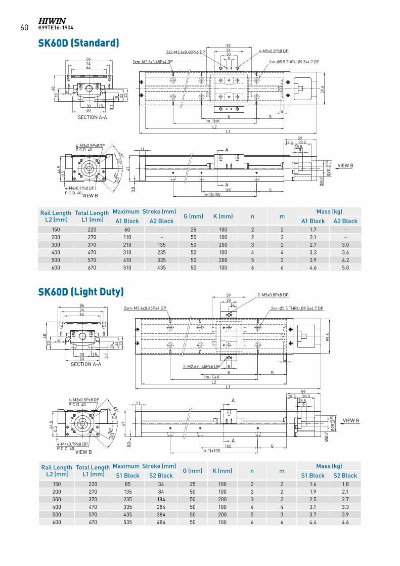
K99TE16-190460
KK60D (輕載型)
VIEW B
SECTION A-A
A
A
VIEW B
30°
30°
45°
45°
0.544
.5
P.C.D. 40
4-M4x0.7Px8 DP
4-M3x0.5Px8 DP
3.130
60
6
4823 15 2322
647486
47
30.518.559
G100(n-1)x100
Ø28
+0.0
3+0
0.5
2xn-Ø5.5 THRU,Ø9.5x4.7 DP2xm-M2.6x0.45Px4 DP
6
GK(m-1)xK
82-M2.6x0.45Px6 DP
142859 2-M5x0.8Px8 DP
59.6
L2L1
15
11
P.C.D. 40
915.5
Ø8h
7
KK60D (標準型)
A
A
SECTION A-A
VIEW B
VIEW B
47
30.518.559
G100(n-1)x100
Ø28
+0.0
3+0
8305482
2xn-Ø5.5 THRU,Ø9.5x4.7 DP2xm-M2.6x0.45Px4 DP
4-M5x0.8Px8 DP2x2-M2.6x0.45Px6 DP
6GK
(m-1)xK
0.5
59.6
3.130
60
6
4823 15 2322
647486
30°
30°
45°
45°
0.544
.5
P.C.D. 40
4-M4x0.7Px8 DP
4-M3x0.5Px8 DP
L2L1
15
11
P.C.D. 40
915.5
Ø8h
7
SK60D (Standard)
SK60D (Light Duty)
Rail Length L2 (mm)Total Length L1 (mm)
Maximum Stroke (mm)G (mm) K (mm) n m
Mass (kg)
S1 Block S2 Block S1 Block S2 Block150 220 85 34 25 100 2 2 1.6 1.8200 270 135 84 50 100 2 2 1.9 2.1300 370 235 184 50 200 3 2 2.5 2.7400 470 335 284 50 100 4 4 3.1 3.3500 570 435 384 50 200 5 3 3.7 3.9600 670 535 484 50 100 6 6 4.4 4.6
Rail Length L2 (mm)Total Length L1 (mm)
Maximum Stroke (mm)G (mm) K (mm) n m
Mass (kg)
A1 Block A2 Block A1 Block A2 Block150 220 60 - 25 100 2 2 1.7 -200 270 110 - 50 100 2 2 2.1 -300 370 210 135 50 200 3 2 2.7 3.0400 470 310 235 50 100 4 4 3.3 3.6500 570 410 335 50 200 5 3 3.9 4.2600 670 510 435 50 100 6 6 4.6 5.0
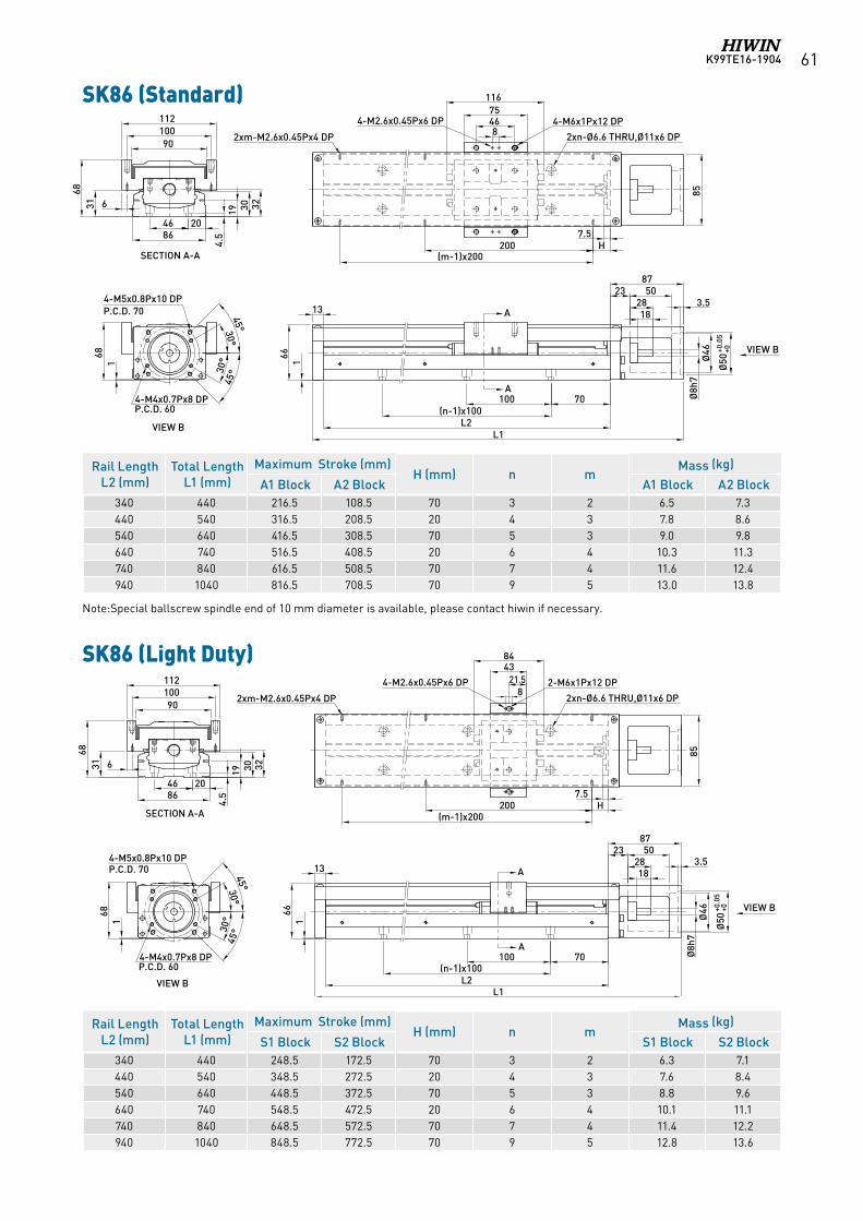
K99TE16-1904 61
Note:Special ballscrew spindle end of 10 mm diameter is available, please contact hiwin if necessary.
70100(n-1)x100
1828
238750
L2L1
7.5H
(m-1)x200200
85
3.5
Ø50
+0.0
5+0
Ø46
Ø8h
7
A
A
VIEW B
84675
116
166
13
100
68
90
112
6
168
4-M5x0.8Px10 DPP.C.D. 70
31
2xn-Ø6.6 THRU,Ø11x6 DP
4-M6x1Px12 DP4-M2.6x0.45Px6 DP
2xm-M2.6x0.45Px4 DP
VIEW B
4-M4x0.7Px8 DPP.C.D. 60
30°
30°45°
45°
204686
SECTION A-A
19 30 32
4.5
70100(n-1)x100
1828
238750
L2L1
166
7.5H
(m-1)x200200
852xm-M2.6x0.45Px4 DP
4-M2.6x0.45Px6 DP 2-M6x1Px12 DP
2xn-Ø6.6 THRU,Ø11x6 DP
43
8
3.5
84
168
4-M5x0.8Px10 DPP.C.D. 70
Ø50
+0.0
5+0
Ø46
Ø8h
7
A
A
VIEW B
21.5
13
VIEW B
4-M4x0.7Px8 DPP.C.D. 60
30°
30°45°
45°
100
68
90
112
631
204686
SECTION A-A
19 30 32
4.5
SK86 (Standard)
SK86 (Light Duty)
Rail Length L2 (mm)
Total Length L1 (mm)
Maximum Stroke (mm)H (mm) n m
Mass (kg)
A1 Block A2 Block A1 Block A2 Block340 440 216.5 108.5 70 3 2 6.5 7.3440 540 316.5 208.5 20 4 3 7.8 8.6540 640 416.5 308.5 70 5 3 9.0 9.8640 740 516.5 408.5 20 6 4 10.3 11.3740 840 616.5 508.5 70 7 4 11.6 12.4940 1040 816.5 708.5 70 9 5 13.0 13.8
Rail Length L2 (mm)
Total Length L1 (mm)
Maximum Stroke (mm)H (mm) n m
Mass (kg)
S1 Block S2 Block S1 Block S2 Block340 440 248.5 172.5 70 3 2 6.3 7.1440 540 348.5 272.5 20 4 3 7.6 8.4540 640 448.5 372.5 70 5 3 8.8 9.6640 740 548.5 472.5 20 6 4 10.1 11.1740 840 648.5 572.5 70 7 4 11.4 12.2940 1040 848.5 772.5 70 9 5 12.8 13.6
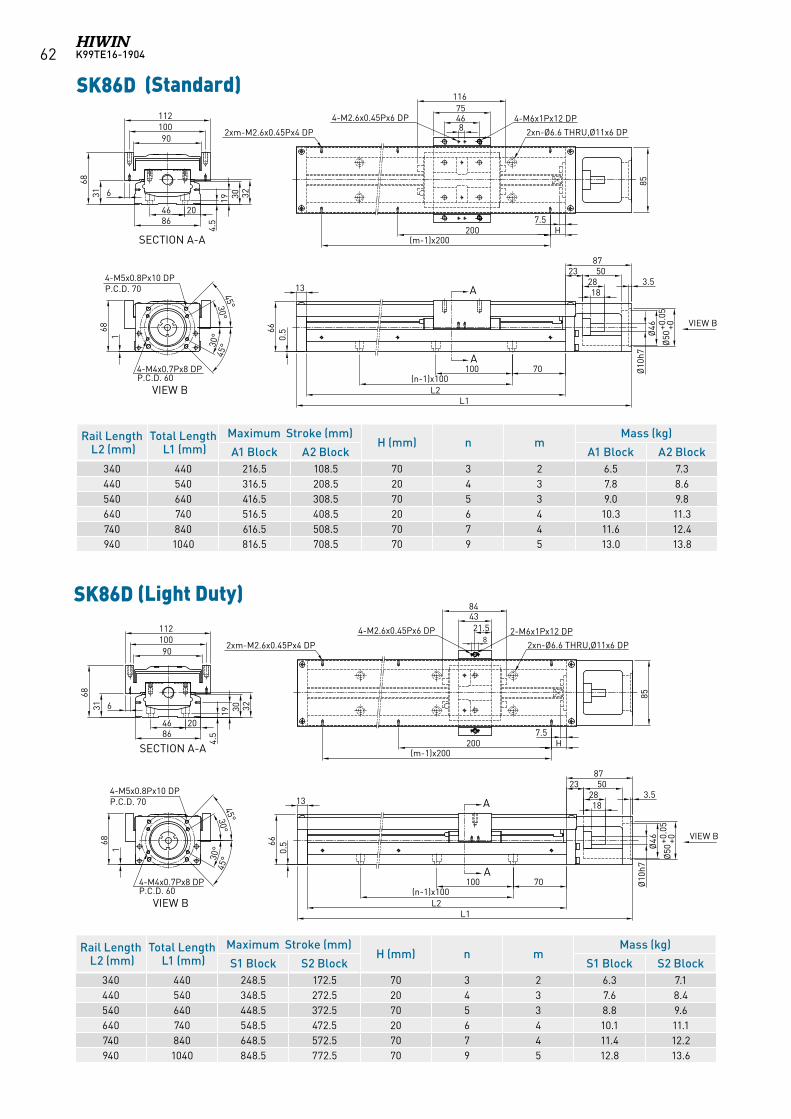
K99TE16-190462
SK86D (Standard)
Rail Length L2 (mm)Total Length L1 (mm)
Maximum Stroke (mm)H (mm) n m
Mass (kg)
A1 Block A2 Block A1 Block A2 Block340 440 216.5 108.5 70 3 2 6.5 7.3440 540 316.5 208.5 20 4 3 7.8 8.6540 640 416.5 308.5 70 5 3 9.0 9.8640 740 516.5 408.5 20 6 4 10.3 11.3740 840 616.5 508.5 70 7 4 11.6 12.4940 1040 816.5 708.5 70 9 5 13.0 13.8
KK86D (標準型)
A
A
VIEW B
VIEW B
SECTION A-A
70100(n-1)x100
1828
238750
L2L1
7.5H
(m-1)x200200
85
3.5
Ø50
+0.0
5+0
Ø46
Ø10
h7
84675
116
0.566
13
100
68
90
112
6
168
4-M5x0.8Px10 DPP.C.D. 70
31
2xn-Ø6.6 THRU,Ø11x6 DP
4-M6x1Px12 DP4-M2.6x0.45Px6 DP
2xm-M2.6x0.45Px4 DP
4-M4x0.7Px8 DPP.C.D. 60
30°
30°45°
45°
204686
19 30 32
4.5
SK86D (Light Duty)
Rail Length L2 (mm)Total Length L1 (mm)
Maximum Stroke (mm)H (mm) n m
Mass (kg)
S1 Block S2 Block S1 Block S2 Block340 440 248.5 172.5 70 3 2 6.3 7.1440 540 348.5 272.5 20 4 3 7.6 8.4540 640 448.5 372.5 70 5 3 8.8 9.6640 740 548.5 472.5 20 6 4 10.1 11.1740 840 648.5 572.5 70 7 4 11.4 12.2940 1040 848.5 772.5 70 9 5 12.8 13.6
KK86D (輕載型)
A
A
VIEW B
VIEW B
SECTION A-A
70100(n-1)x100
1828
238750
L2L1
0.566
7.5H
(m-1)x200200
852xm-M2.6x0.45Px4 DP
4-M2.6x0.45Px6 DP 2-M6x1Px12 DP
2xn-Ø6.6 THRU,Ø11x6 DP
43
8
3.5
84
168
4-M5x0.8Px10 DPP.C.D. 70
Ø50
+0.0
5+0
Ø46
Ø10
h721.5
13
4-M4x0.7Px8 DPP.C.D. 60
30°
30°45°
45°
100
68
90
112
631
204686
19 30 32
4.5
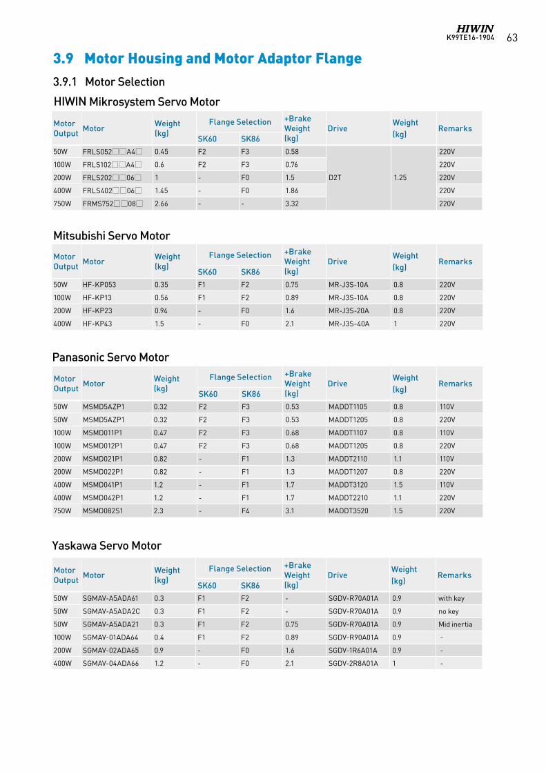
K99TE16-1904 63
3.9.1 Motor Selection
3.9 Motor Housing and Motor Adaptor Flange
Panasonic Servo Motor
Mitsubishi Servo Motor
Yaskawa Servo Motor
HIWIN Mikrosystem Servo Motor
Motor Output Motor Weight
(kg)Flange Selection +Brake
Weight (kg)
DriveWeight (kg)
RemarksSK60 SK86
50W FRLS052A4 0.45 F2 F3 0.58
D2T 1.25
220V
100W FRLS102A4 0.6 F2 F3 0.76 220V
200W FRLS20206 1 - F0 1.5 220V
400W FRLS40206 1.45 - F0 1.86 220V
750W FRMS75208 2.66 - - 3.32 220V
Motor Output Motor Weight
(kg)Flange Selection +Brake
Weight (kg)
DriveWeight (kg)
RemarksSK60 SK86
50W HF-KP053 0.35 F1 F2 0.75 MR-J3S-10A 0.8 220V
100W HF-KP13 0.56 F1 F2 0.89 MR-J3S-10A 0.8 220V
200W HF-KP23 0.94 - F0 1.6 MR-J3S-20A 0.8 220V
400W HF-KP43 1.5 - F0 2.1 MR-J3S-40A 1 220V
Motor Output Motor Weight
(kg)Flange Selection +Brake
Weight (kg)
DriveWeight (kg)
RemarksSK60 SK86
50W MSMD5AZP1 0.32 F2 F3 0.53 MADDT1105 0.8 110V
50W MSMD5AZP1 0.32 F2 F3 0.53 MADDT1205 0.8 220V
100W MSMD011P1 0.47 F2 F3 0.68 MADDT1107 0.8 110V
100W MSMD012P1 0.47 F2 F3 0.68 MADDT1205 0.8 220V
200W MSMD021P1 0.82 - F1 1.3 MADDT2110 1.1 110V
200W MSMD022P1 0.82 - F1 1.3 MADDT1207 0.8 220V
400W MSMD041P1 1.2 - F1 1.7 MADDT3120 1.5 110V
400W MSMD042P1 1.2 - F1 1.7 MADDT2210 1.1 220V
750W MSMD082S1 2.3 - F4 3.1 MADDT3520 1.5 220V
Motor Output Motor Weight
(kg)Flange Selection +Brake
Weight (kg)
DriveWeight (kg)
RemarksSK60 SK86
50W SGMAV-A5ADA61 0.3 F1 F2 - SGDV-R70A01A 0.9 with key
50W SGMAV-A5ADA2C 0.3 F1 F2 - SGDV-R70A01A 0.9 no key
50W SGMAV-A5ADA21 0.3 F1 F2 0.75 SGDV-R70A01A 0.9 Mid inertia
100W SGMAV-01ADA64 0.4 F1 F2 0.89 SGDV-R90A01A 0.9 -
200W SGMAV-02ADA65 0.9 - F0 1.6 SGDV-1R6A01A 0.9 -
400W SGMAV-04ADA66 1.2 - F0 2.1 SGDV-2R8A01A 1 -
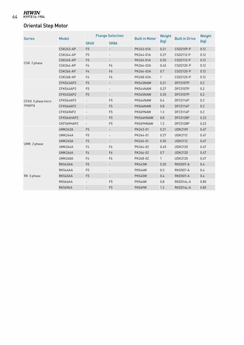
K99TE16-190464
Oriental Step Motor
Series ModelFlange Selection
Built in MotorWeight (kg)
Built in DriveWeight (kg)SK60 SK86
CSK 2 phase
CSK243-AP F5 - PK243-01A 0.21 CSD2109-P 0.12
CSK244-AP F5 - PK244-01A 0.27 CSD2112-P 0.12
CSK245-AP F5 - PK245-01A 0.35 CSD2112-P 0.12
CSK264-AP F4 F6 PK264-02A 0.45 CSD2120-P 0.12
CSK266-AP F4 F6 PK266-02A 0.7 CSD2120-P 0.12
CSK268-AP F4 F6 PK268-02A 1 CSD2120-P 0.12
CFKII 5 phase micro stepping
CFK543AP2 F5 - PK543NAW 0.21 DFC5107P 0.2
CFK544AP2 F5 - PK544NAW 0.27 DFC5107P 0.2
CFK545AP2 F5 - PK545NAW 0.35 DFC5107P 0.2
CFK564AP2 - F5 PK564NAW 0.6 DFC5114P 0.2
CFK566AP2 - F5 PK566NAW 0.8 DFC5114P 0.2
CFK569AP2 - F5 PK569NAW 1.3 DFC5114P 0.2
CFK566HAP2 - F5 PK566HNAW 0.8 DFC5128P 0.22
CKF569HAP2 - F5 PK569HNAW 1.3 DFC5128P 0.22
UMK 2 phase
UMK243A F5 - PK243-01 0.21 UDK2109 0.47
UMK244A F5 - PK244-01 0.27 UDK2112 0.47
UMK245A F5 - PK245-01 0.35 UDK2112 0.47
UMK264A F4 F6 PK264-02 0.45 UDK2120 0.47
UMK266A F4 F6 PK266-02 0.7 UDK2120 0.47
UMK268A F4 F6 PK268-02 1 UDK2120 0.47
RK 5 phase
RK543AA F5 - PK543W 0.25 RKD507-A 0.4
RK544AA F5 - PK544W 0.3 RKD507-A 0.4
RK545AA F5 - PK545W 0.4 RKD507-A 0.4
RK566AA - F5 PK566W 0.8 RKD514L-A 0.85
RK569AA - F5 PK569W 1.3 RKD514L-A 0.85
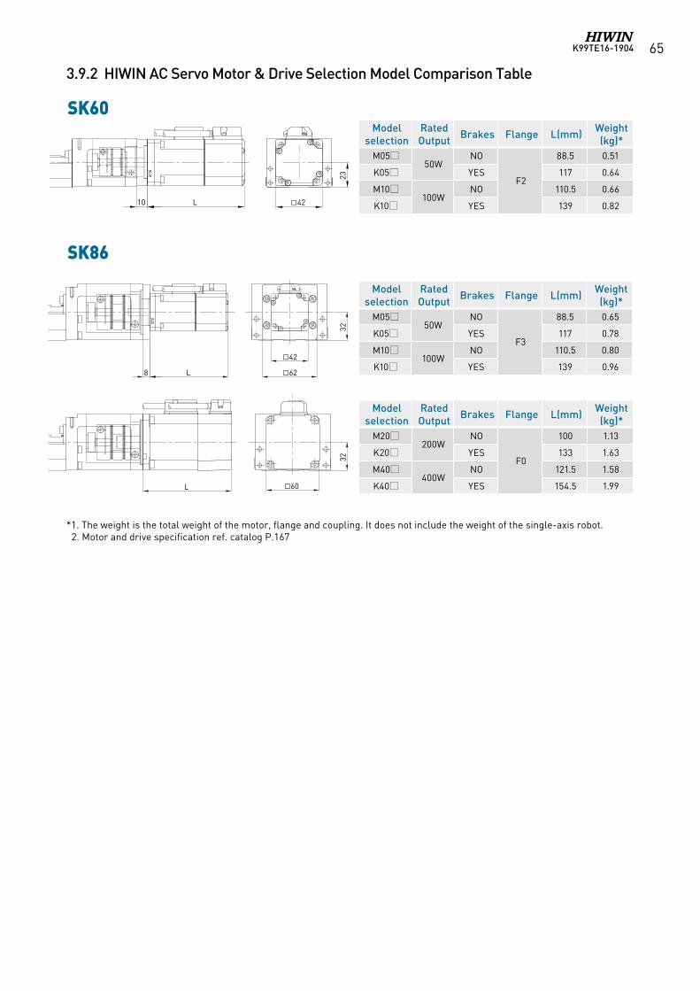
K99TE16-1904 65
3.9.2 HIWIN AC Servo Motor & Drive Selection Model Comparison Table
SK60
SK86
Model selection
RatedOutput Brakes Flange L(mm) Weight
(kg)*M05
50WNO
F2
88.5 0.51
K05 YES 117 0.64
M10100W
NO 110.5 0.66
K10 YES 139 0.824210 L
23
*1. The weight is the total weight of the motor, flange and coupling. It does not include the weight of the single-axis robot. 2. Motor and drive specification ref. catalog P.167
Model selection
RatedOutput Brakes Flange L(mm) Weight
(kg)*M05
50WNO
F3
88.5 0.65
K05 YES 117 0.78
M10100W
NO 110.5 0.80
K10 YES 139 0.96
Model selection
RatedOutput Brakes Flange L(mm) Weight
(kg)*M20
200WNO
F0
100 1.13
K20 YES 133 1.63
M40400W
NO 121.5 1.58
K40 YES 154.5 1.99
42
62
32
8 L
60
32
L
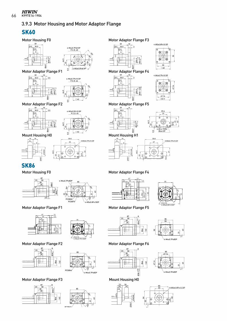
K99TE16-190466
3.9.3 Motor Housing and Motor Adaptor Flange
SK60
2387
3.5
502818
163
4-M5x0.8Px10DP
32
4-M4x0.7Px8DP
Ø46
85
Ø8h
7
PCDØ60PCDØ70
Ø50
+0.0
5+0
30° 45°
45°
3130°
4-M3x.5Px8DP
Ø6h
7Ø
28
23 0.544
.5
4-M4x.7Px8DP5930.5
915.5
18.5
PCD40
45°45°
30°30°
Ø26
.5
3
4-M4x.7Px10DPPCD46
59 10
42Ø
30+0
.05
+0
45°45°
59
Ø26
.5
3.510
4-M3x.5Px10DPPCD45
42Ø
30+0
.05
+0
45°45°
50
50
359
60
Ø26
.5
4-M5x0.8Px10DP10
Ø36
+0.0
5+0
45°45°
47.14103
Ø26
.5
47.1
4
4-M4x0.7Px10DP59
57.7
Ø38
.1+0
.08
+0.0
3
8723 50
1828
4-M4x0.7Px8DP
16362
8
Ø46
85
31
PCDØ46
Ø30
+0.0
5+0
45°45°
Ø46
8723
1828
50
631
4-M3x0.5Px8DP
62
8
85
31
PCDØ45
Ø30
+0.0
5+0
45°45°
50
8587
23
62
502818
8
4-M4x0.7Px8DP
50
311
63Ø46
Ø36
+0.0
5+0
8528
5087
238
62
18
47.1
4
47.14
4-M4x0.7Px8DP
631
31
Ø46
Ø38
.1+0
.08
+0.0
359 8
Ø22
+0.0
5+0
59.631
31
4-Ø3.4Thru,Ø6x4DP
43
4-M3x0.5PThru
45°
45°
PCD 904-M5x0.8Px12DP
85
311
63
1828
502387 12
Ø70
+0.0
5+0
Ø46
3.5
80
45°
45°
1828
502387 10
Ø50
+0.0
5+0
Ø46
3.5
62
PCD 704-M4x0.7Px10DP
85
311
63
SK86Motor Housing F0 Motor Adaptor Flange F4
Motor Adaptor Flange F1 Motor Adaptor Flange F5
Motor Adaptor Flange F2 Motor Adaptor Flange F6
Motor Adaptor Flange F3 Mount Housing H0
40h8
132023
8h7
2818
40 4-M5x0.8Px12 DP85
64
132
2040
91518 16
33
59.6
0.523
44.5
16.5
33
6h7
30h8
4-M4x0.7Px15 DP9
1518 16
27
59.6
0.523
44.5
13.5
27
6h7
30.4
h8
4-M4x0.7Px15 DP
Motor Housing F0 Motor Adaptor Flange F3
Motor Adaptor Flange F1 Motor Adaptor Flange F4
Motor Adaptor Flange F2 Motor Adaptor Flange F5
Mount Housing H0 Mount Housing H1
馬達連接法蘭 F0
馬達連接法蘭 F1
馬達連接法蘭 F2
馬達連接法蘭 F3
馬達連接法蘭 F4
馬達連接法蘭 F5
KK60
KK50馬達連接法蘭 F0
馬達連接法蘭 F1
馬達連接法蘭 F2
馬達連接法蘭 F3760
Ø22
+0.0
5+0
3149.4
31
4-Ø3.5 THRU Ø6x3.5 DP
16.5
10
Ø5h
7
3414
8.560
16.5
10
Ø5h
7
3414
60
16.5
10
3414
60
16.5
10
Ø5h
7
3414
3.2
Ø30
+0.0
5+0
8.5
Ø5h
7
3.2
Ø30
+0.0
5+0
45°
45°
4-M3x0.5Px6 DPP.C.D. 33
45°
45°
4-M4x0.7Px8.5 DPP.C.D. 46
45°
45°
4-M3x0.5Px8.5 DPP.C.D. 45
0.5
1638
.5
Ø24
+0.0
3+0
0.5
1638
.5
0.5
1638
.5
49
40
15.5
9
15.518.5 30.5
59Ø
6h7
Ø28
+0.0
3+0
0.5
2344
.5
30°45°
30°
45°
4-M4x0.7Px8 DPP.C.D. 40
4-M3x0.5Px8 DP
9
15.518.5 30.5
59 103.5
Ø6h
7
Ø30
+0.0
5+0
0.5
2344
.5
45°
45°
4-M4x0.7Px10 DPP.C.D. 46
40
40
42
9
15.518.5 30.5
59 103.5
Ø6h
7
Ø30
+0.0
5+0
0.5
2344
.5
45°
45°
4-M3x0.5Px10 DPP.C.D. 45
42
9
15.518.5 30.5
59 103
Ø6h
7
Ø36
+0.0
5+0
50
50
60
4-M5x0.8Px10 DP
9
15.518.5 30.5
59 103
9
15.518.5 30.5
59 8
Ø6h
7
Ø38
.1+0
.08
+0.0
3
Ø6h
7
Ø22
+0.0
5+0
47.1
4
47.14
57.7
4-M4x0.7Px10 DP
59.6
433115
.5
31
4-Ø3.4 THRU Ø6x4 DP0.
523
44.5
Ø26
.5Ø
26.5
Ø26
.5Ø
26.5
馬達連接法蘭 F0
馬達連接法蘭 F1
馬達連接法蘭 F2
馬達連接法蘭 F3
馬達連接法蘭 F4
馬達連接法蘭 F5
KK60
KK50馬達連接法蘭 F0
馬達連接法蘭 F1
馬達連接法蘭 F2
馬達連接法蘭 F3760
Ø22
+0.0
5+0
3149.4
314-Ø3.5 THRU Ø6x3.5 DP
16.5
10
Ø5h
7
3414
8.560
16.5
10
Ø5h
7
3414
60
16.5
10
3414
60
16.5
10
Ø5h
7
3414
3.2
Ø30
+0.0
5+0
8.5
Ø5h
7
3.2
Ø30
+0.0
5+0
45°
45°
4-M3x0.5Px6 DPP.C.D. 33
45°
45°
4-M4x0.7Px8.5 DPP.C.D. 46
45°
45°
4-M3x0.5Px8.5 DPP.C.D. 45
0.5
1638
.5
Ø24
+0.0
3+0
0.5
1638
.5
0.5
1638
.5
49
40
15.5
9
15.518.5 30.5
59
Ø6h
7
Ø28
+0.0
3+0
0.5
2344
.5
30°45°
30°
45°
4-M4x0.7Px8 DPP.C.D. 40
4-M3x0.5Px8 DP
9
15.518.5 30.5
59 103.5
Ø6h
7
Ø30
+0.0
5+0
0.5
2344
.5
45°
45°
4-M4x0.7Px10 DPP.C.D. 46
40
40
42
9
15.518.5 30.5
59 103.5
Ø6h
7
Ø30
+0.0
5+0
0.5
2344
.5
45°
45°
4-M3x0.5Px10 DPP.C.D. 45
42
9
15.518.5 30.5
59 103
Ø6h
7
Ø36
+0.0
5+0
50
50
60
4-M5x0.8Px10 DP
9
15.518.5 30.5
59 103
9
15.518.5 30.5
59 8
Ø6h
7
Ø38
.1+0
.08
+0.0
3
Ø6h
7
Ø22
+0.0
5+0
47.1
4
47.14
57.7
4-M4x0.7Px10 DP
59.6
433115
.5
31
4-Ø3.4 THRU Ø6x4 DP0.
523
44.5
Ø26
.5Ø
26.5
Ø26
.5Ø
26.5
馬達連接法蘭 F0
馬達連接法蘭 F1
馬達連接法蘭 F2
馬達連接法蘭 F3
馬達連接法蘭 F4
馬達連接法蘭 F5
KK60
KK50馬達連接法蘭 F0
馬達連接法蘭 F1
馬達連接法蘭 F2
馬達連接法蘭 F3760
Ø22
+0.0
5+0
3149.4
31
4-Ø3.5 THRU Ø6x3.5 DP
16.5
10
Ø5h
7
3414
8.560
16.5
10
Ø5h
7
3414
60
16.5
10
3414
60
16.5
10
Ø5h
7
3414
3.2
Ø30
+0.0
5+0
8.5
Ø5h
7
3.2
Ø30
+0.0
5+0
45°
45°
4-M3x0.5Px6 DPP.C.D. 33
45°
45°
4-M4x0.7Px8.5 DPP.C.D. 46
45°
45°
4-M3x0.5Px8.5 DPP.C.D. 45
0.5
1638
.5
Ø24
+0.0
3+0
0.5
1638
.5
0.5
1638
.5
49
40
15.5
9
15.518.5 30.5
59
Ø6h
7
Ø28
+0.0
3+0
0.5
2344
.5
30°45°
30°
45°
4-M4x0.7Px8 DPP.C.D. 40
4-M3x0.5Px8 DP
9
15.518.5 30.5
59 103.5
Ø6h
7
Ø30
+0.0
5+0
0.5
2344
.5
45°
45°
4-M4x0.7Px10 DPP.C.D. 46
40
40
42
9
15.518.5 30.5
59 103.5
Ø6h
7
Ø30
+0.0
5+0
0.5
2344
.5
45°
45°
4-M3x0.5Px10 DPP.C.D. 45
42
9
15.518.5 30.5
59 103
Ø6h
7
Ø36
+0.0
5+0
50
50
60
4-M5x0.8Px10 DP
9
15.518.5 30.5
59 103
9
15.518.5 30.5
59 8
Ø6h
7
Ø38
.1+0
.08
+0.0
3
Ø6h
7
Ø22
+0.0
5+0
47.1
4
47.14
57.7
4-M4x0.7Px10 DP
59.6
433115
.5
31
4-Ø3.4 THRU Ø6x4 DP0.
523
44.5
Ø26
.5Ø
26.5
Ø26
.5Ø
26.5
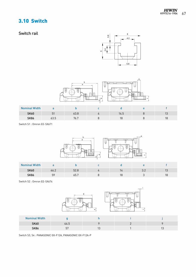
K99TE16-1904 67
3.10 Switch
Nominal Width a b c d e f
SK60 51 63.8 4 14.5 8 13
SK86 63.5 76.7 8 18 8 18
Nominal Width a b c d e f
SK60 46.2 52.8 4 14 3.2 13
SK86 59 65.7 8 18 3 18
Nominal Width g h i j
SK60 44.5 9 2 9
SK86 57 13 1 13
Switch rail
Switch S2 : Omron EE-SX674
Switch S1 : Omron EE-SX671
Switch S3, S4 : PANASONIC GX-F12A, PANASONIC GX-F12A-P
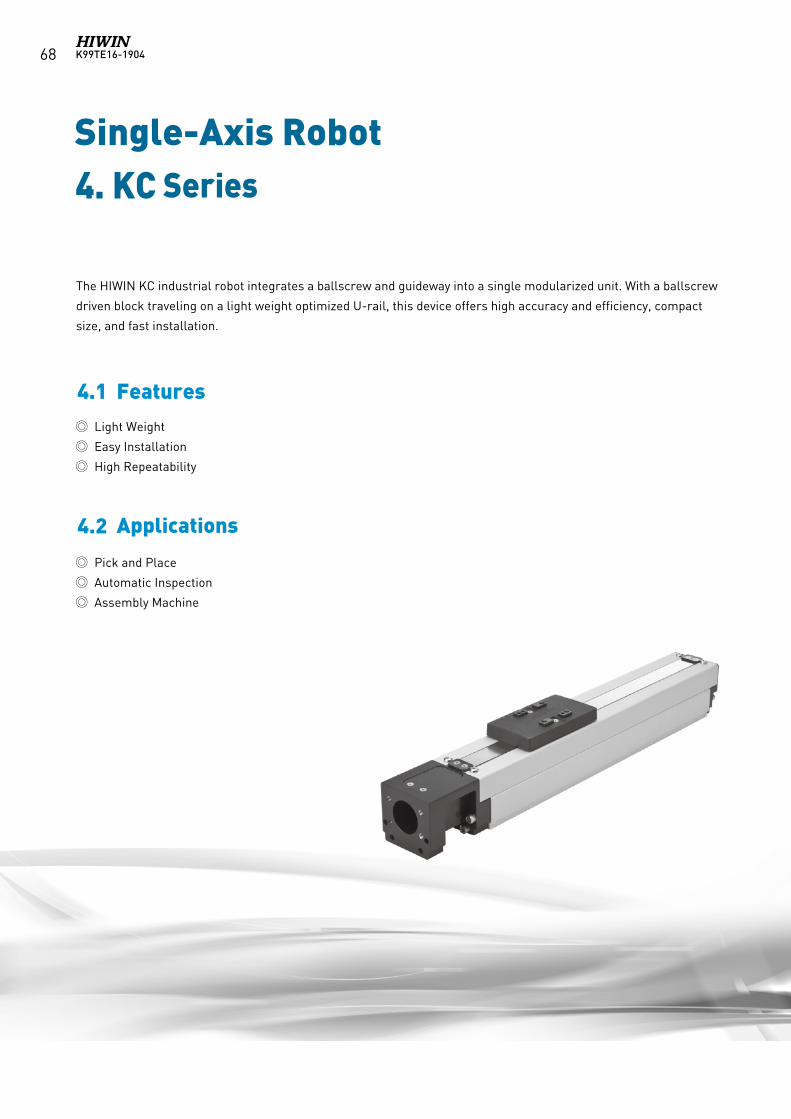
K99TE16-190468
Single-Axis Robot4. KC Series
Light Weight
Easy Installation
High Repeatability
4.1 Features
4.2 Applications
The HIWIN KC industrial robot integrates a ballscrew and guideway into a single modularized unit. With a ballscrew
driven block traveling on a light weight optimized U-rail, this device offers high accuracy and efficiency, compact
size, and fast installation.
Pick and Place
Automatic Inspection
Assembly Machine
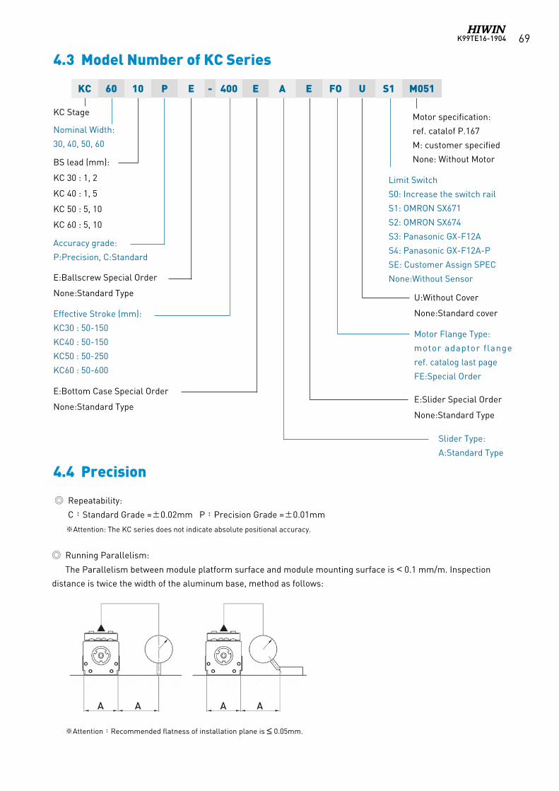
K99TE16-1904 69
KC Stage
Nominal Width:
30, 40, 50, 60
Accuracy grade:
P:Precision, C:Standard
E:Ballscrew Special Order
None:Standard Type
Effective Stroke (mm):
KC30 : 50-150
KC40 : 50-150
KC50 : 50-250
KC60 : 50-600
BS lead (mm):
KC 30 : 1, 2
KC 40 : 1, 5
KC 50 : 5, 10
KC 60 : 5, 10
E:Bottom Case Special Order
None:Standard Type
Limit Switch
S0: Increase the switch rail
S1: OMRON SX671
S2: OMRON SX674
S3: Panasonic GX-F12A
S4: Panasonic GX-F12A-P
SE: Customer Assign SPEC
None:Without Sensor
Motor Flange Type:
motor adaptor flange
ref. catalog last page
FE:Special Order
E:Slider Special Order
None:Standard Type
Slider Type:
A:Standard Type
U:Without Cover
None:Standard cover
Motor specification:
ref. catalof P.167
M: customer specified
None: Without Motor
4.3 Model Number of KC Series
4.4 Precision
KC 60 10 P E - 400 E A E FO U S1 M051
Repeatability:
C:Standard Grade =±0.02mm P:Precision Grade =±0.01mm
※Attention: The KC series does not indicate absolute positional accuracy.
※Attention:Recommended flatness of installation plane is ≤ 0.05mm.
Running Parallelism:
The Parallelism between module platform surface and module mounting surface is < 0.1 mm/m. Inspection
distance is twice the width of the aluminum base, method as follows:
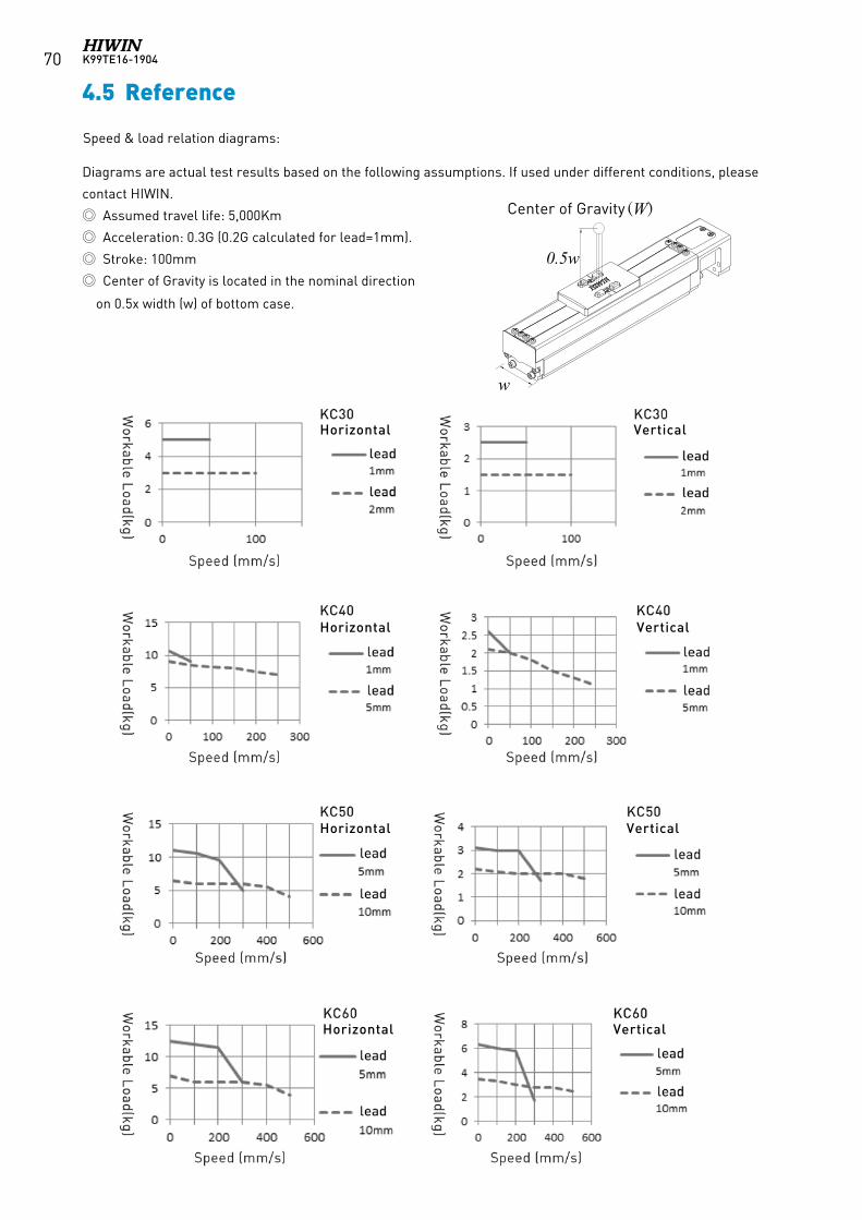
K99TE16-190470
Diagrams are actual test results based on the following assumptions. If used under different conditions, please
contact HIWIN.
Assumed travel life: 5,000Km
Acceleration: 0.3G (0.2G calculated for lead=1mm).
Stroke: 100mm
Center of Gravity is located in the nominal direction
on 0.5x width (w) of bottom case.
4.5 Reference
Center of Gravity (W)
w
0.5w
Speed & load relation diagrams:
Horizontal
Horizontal
Horizontal
Horizontal
Vertical
Vertical
Vertical
Vertical
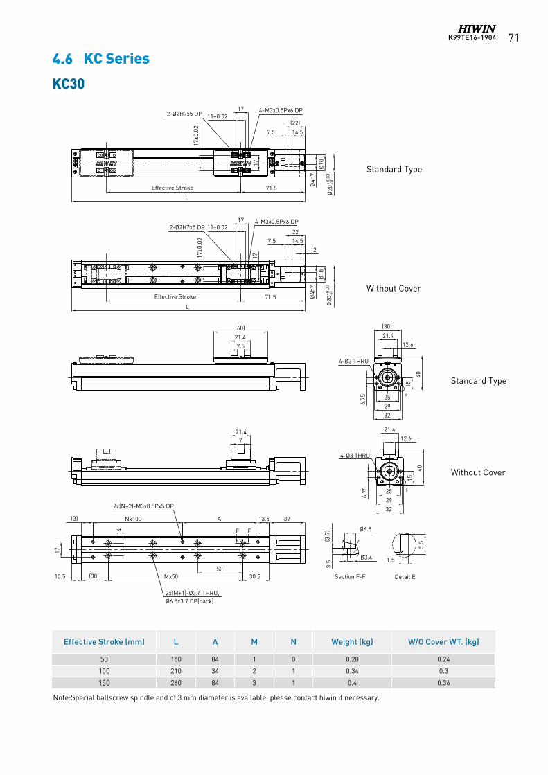
K99TE16-1904 71
KC30
Effective Stroke (mm) L A M N Weight (kg) W/O Cover WT. (kg)
50 160 84 1 0 0.28 0.24
100 210 34 2 1 0.34 0.3
150 260 84 3 1 0.4 0.36
Note:Special ballscrew spindle end of 3 mm diameter is available, please contact hiwin if necessary.
E
F F
E
Section F-F Detail E
322915
40
12.621.4
(30)
6.75
4-Ø3 THRU
25
71.5Effective Stroke
L
14.57.5
(22)
1711±0.02
11±0.02
17
17±0
.02
17±0
.02
4-M3x0.5Px6 DP2-Ø2H7x5 DP
7.521.4
(60)
3913.5A(13)
17
30.550
(30)10.5
14
2x(N+2)-M3x0.5Px5 DP
2x(M+1)-Ø3.4 THRU,Ø6.5x3.7 DP(back)
Nx100
Mx50
Ø4h
7
Ø20
+0.0
3-0
Ø20
+0.0
3-0
Ø18
3229
15
40
12.621.4
6.75
4-Ø3 THRU
25
721.4
71.5Effective Stroke
LØ
4h7
Ø18
214.57.522
17
17
4-M3x0.5Px6 DP2-Ø2H7x5 DP
Ø6.5
Ø3.4
3.5
(3.7
)
1.5
5.5
Standard Type
Standard Type
Without Cover
Without Cover
4.6 KC Series
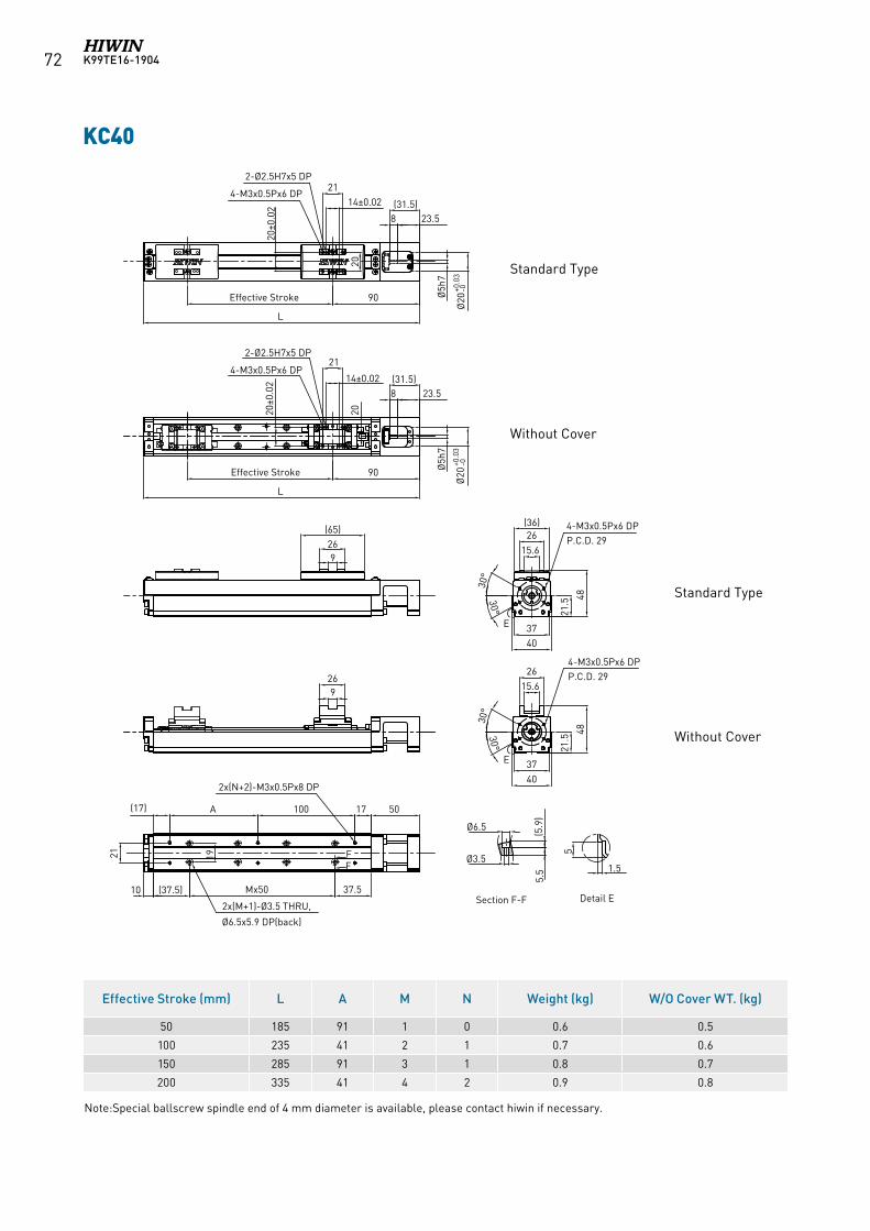
K99TE16-190472
Note:Special ballscrew spindle end of 4 mm diameter is available, please contact hiwin if necessary.
KC40
Effective Stroke (mm) L A M N Weight (kg) W/O Cover WT. (kg)
50 185 91 1 0 0.6 0.5
100 235 41 2 1 0.7 0.6
150 285 91 3 1 0.8 0.7
200 335 41 4 2 0.9 0.8
E
E
FF
17
37.5
(17)
(37.5)
90Effective Stroke
269
(65)
20
Section F-F
30°
30°
4-M3x0.5Px6 DPP.C.D. 29
3740
15.626
(36)
21.5 48
20±0
.02
14±0.0221
L
4-M3x0.5Px6 DP
2-Ø2.5H7x5 DP
Ø20
+0.0
3-0
Ø20
+0.0
3-0
Ø5h
7
23.58(31.5)
90Effective Stroke
269
20
30°
30°
4-M3x0.5Px6 DPP.C.D. 29
3740
21.5
48
20±0
.02 14±0.02
21
L
4-M3x0.5Px6 DP
2-Ø2.5H7x5 DP
Ø5h
7
23.58(31.5)
Ø3.5
Ø6.5
5.5
(5.9
)
21 19
5
Detail E
15.626
100A
Mx50
2x(M+1)-Ø3.5 THRU,
Ø6.5x5.9 DP(back)
2x(N+2)-M3x0.5Px8 DP
1.5
50
10
Standard Type
Standard Type
Without Cover
Without Cover
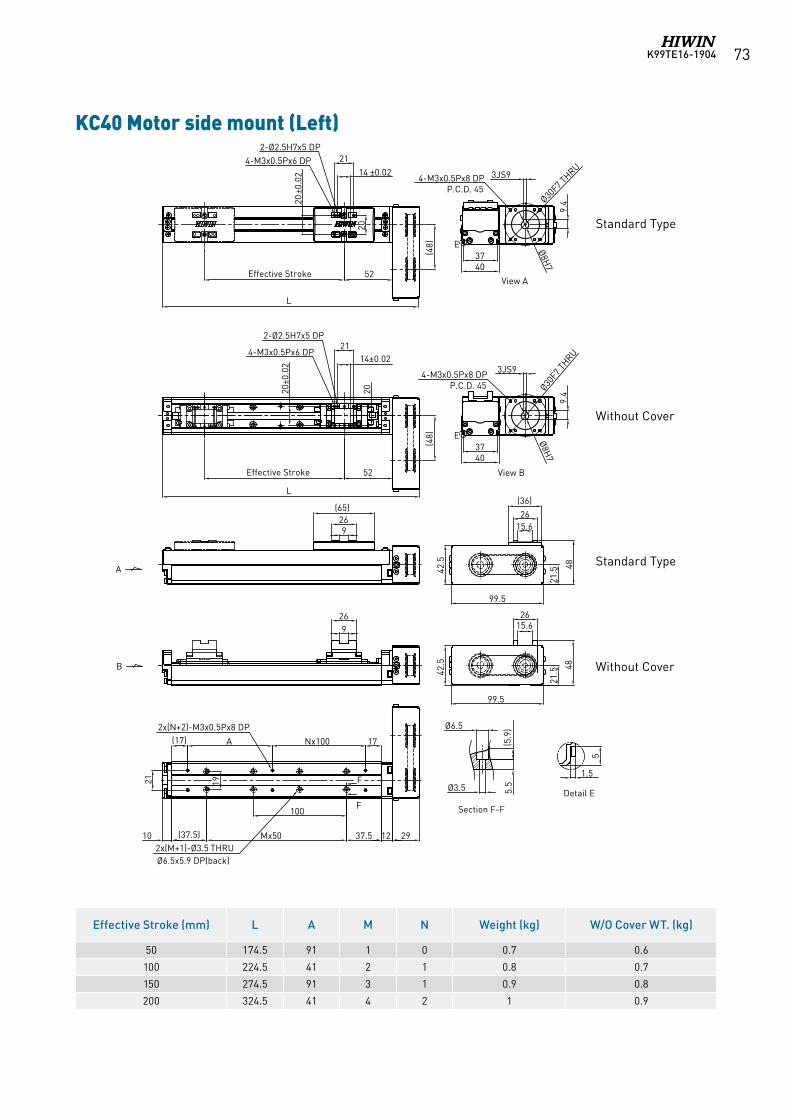
K99TE16-1904 73
KC40 Motor side mount (Left)
Standard Type
Standard Type
Without Cover
Without Cover
Section F-F
Detail E
E
View A
E
View B
52
(48)
4-M3x0.5Px6 DP2-Ø2.5H7x5 DP
20±0
.02
20
14 ±0.0221
926
(65)
A
(17)
(37.5) Mx50
A Nx100 17
F
F
21 19
10 37.5
100
12 29
52Effective Stroke
2020±0
.02
14±0.0221
L
4-M3x0.5Px6 DP
2-Ø2.5H7x5 DP
269
L
B
(48)
Effective Stroke
21.5
99.5
42.5
15.626
(36)
48
21.5
99.5
42.5
15.626
48
Ø3.5
Ø6.5
5.5
(5.9
)
5
1.5
4037
3JS9
9.4
Ø8H7
Ø30F7 T
HRU
4037
3JS9
9.4
Ø8H7
Ø30F7 T
HRU
4-M3x0.5Px8 DPP.C.D. 45
4-M3x0.5Px8 DPP.C.D. 45
2x(N+2)-M3x0.5Px8 DP
2x(M+1)-Ø3.5 THRUØ6.5x5.9 DP(back)
Effective Stroke (mm) L A M N Weight (kg) W/O Cover WT. (kg)
50 174.5 91 1 0 0.7 0.6
100 224.5 41 2 1 0.8 0.7
150 274.5 91 3 1 0.9 0.8
200 324.5 41 4 2 1 0.9
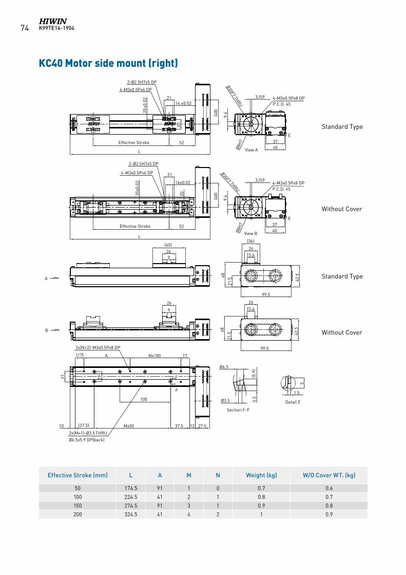
K99TE16-190474
KC40 Motor side mount (right)
E
View A
E
View B
Section F-F
Detail E
52
(48)
4-M3x0.5Px6 DP
2-Ø2.5H7x5 DP
20±0
.02
20
14 ±0.0221
926
(65)
A
(17)
(37.5) Mx50
A Nx100 17
F
F
21 19
10 37.5
100
12 27.5
52Effective Stroke
2020±0
.02 14±0.02
21
L
4-M3x0.5Px6 DP
2-Ø2.5H7x5 DP
(48)
26
9
L
B
Effective Stroke4037
3JS9
9.4
Ø8H
7
Ø30F7 THRU
4037
3JS9
9.4
Ø8H
7
Ø30F7 THRU
21.5
99.5
42.5
15.626
48
21.5
99.542
.5
15.626
(36)
48
4-M3x0.5Px8 DPP.C.D. 45
4-M3x0.5Px8 DPP.C.D. 45
Ø3.5
Ø6.5
5.5
(5.9
)
5
1.5
2x(N+2)-M3x0.5Px8 DP
2x(M+1)-Ø3.5 THRU
Ø6.5x5.9 DP(back)
Standard Type
Standard Type
Without Cover
Without Cover
Effective Stroke (mm) L A M N Weight (kg) W/O Cover WT. (kg)
50 174.5 91 1 0 0.7 0.6
100 224.5 41 2 1 0.8 0.7
150 274.5 91 3 1 0.9 0.8
200 324.5 41 4 2 1 0.9
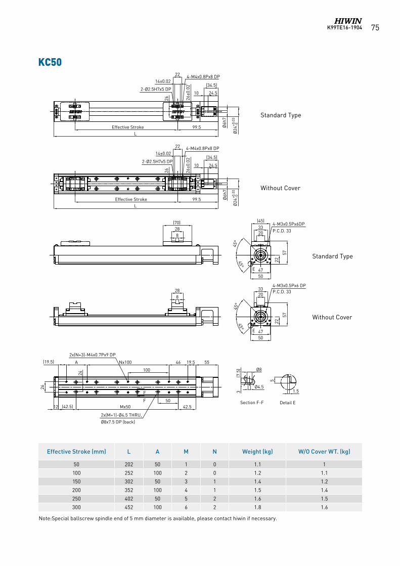
K99TE16-1904 75
KC50
Effective Stroke (mm) L A M N Weight (kg) W/O Cover WT. (kg)
50 202 50 1 0 1.1 1
100 252 100 2 0 1.2 1.1
150 302 50 3 1 1.4 1.2
200 352 100 4 1 1.5 1.4
250 402 50 5 2 1.6 1.5
300 452 100 6 2 1.8 1.6
E
E
99.5Effective StrokeL
2214±0.02
26±0
.02
26
4-M4x0.8Px8 DP
2-Ø2.5H7x5 DP
828
(70)
2033
(45)
2250
57
45°
45°
Ø6h
7
Ø24
+0.0
3-0
Ø24
+0.0
3-0
Section F-F
45°
45°
47
(34.5)
24.510
5
Detail E
26
24
F
F
5519.546
100
Nx100A(19.5)
12
2x(M+1)-Ø4.5 THRU,Ø8x7.5 DP (back)
2x(N+3)-M4x0.7Px9 DP
42.550
Mx50(42.5)
22
14±0.02
26±0
.02
26
4-M4x0.8Px8 DP
2-Ø2.5H7x5 DP
99.5Effective StrokeL
2033
22
50
57
47
4-M3x0.5Px6 DPP.C.D. 33
4-M3x0.5Px6DPP.C.D. 33
828
Ø6h
7
(34.5)
24.510
1.5Ø4.5
Ø8
3(7
.5)
Standard Type
Standard Type
Without Cover
Without Cover
Note:Special ballscrew spindle end of 5 mm diameter is available, please contact hiwin if necessary.
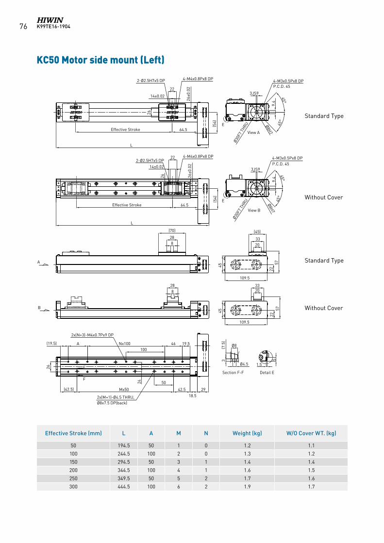
K99TE16-190476
KC50 Motor side mount (Left)
Effective Stroke (mm) L A M N Weight (kg) W/O Cover WT. (kg)
50 194.5 50 1 0 1.2 1.1
100 244.5 100 2 0 1.3 1.2
150 294.5 50 3 1 1.4 1.4
200 344.5 100 4 1 1.6 1.5
250 349.5 50 5 2 1.7 1.6
300 444.5 100 6 2 1.9 1.7
A
B
View A
View B
22
14±0.02
26
26±0
.02
4-M4x0.8Px8 DP2-Ø2.5H7x5 DP
64.5Effective Stroke
(54)
42.5
50
Mx50(42.5)
18.529
828
(70)
19.5A100
Nx100 46(19.5)
26
24
F
F
22
14±0.02
26±0
.02
264-M4x0.8Px8 DP
2-Ø2.5H7x5 DP
L
(54)
64.5Effective Stroke
828
L
3JS9
45°
45°
9.4
Ø8H7
Ø30F
7 TH
RU
4-M3x0.5Px8 DPP.C.D. 45
E
3JS9
45°
45°
9.4
Ø8H7
Ø30F
7 TH
RU
4-M3x0.5Px8 DPP.C.D. 45
E
2033
(45)
2257
109.5
45
2033
2257
109.5
45
Ø8(7.5
)3
Ø4.5
5
1.5
2x(N+3)-M4x0.7Px9 DP
2x(M+1)-Ø4.5 THRU,Ø8x7.5 DP(back)
Section F-F Detail E
Standard Type
Standard Type
Without Cover
Without Cover
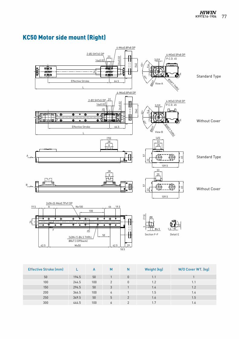
K99TE16-1904 77
KC50 Motor side mount (Right)
Effective Stroke (mm) L A M N Weight (kg) W/O Cover WT. (kg)
50 194.5 50 1 0 1.1 1
100 244.5 100 2 0 1.2 1.1
150 294.5 50 3 1 1.4 1.2
200 344.5 100 4 1 1.5 1.4
250 349.5 50 5 2 1.6 1.5
300 444.5 100 6 2 1.7 1.6
Standard Type
Standard Type
Without Cover
Without Cover
A
B
View A
View B
2214±0.02
26
26±0
.02
4-M4x0.8Px8 DP
2-Ø2.5H7x5 DP
(54)
42.5
50
Mx5042.518.5
29
828
(70)
19.5A
100
Nx100 4619.5
26
24
F
F
22
14±0.02
26±0
.02
26
4-M4x0.8Px8 DP
2-Ø2.5H7x5 DP
64.5Effective Stroke
(54)
828
L
64.5Effective Stroke
L
3JS9
45°
45°
9.4
Ø8H
7
Ø30F7 THRU
4-M3x0.5Px8 DP
P.C.D. 45
E
3JS9
45°
45°
9.4
Ø8H
7
Ø30F7 THRU
4-M3x0.5Px8 DPP.C.D. 45
E
2033
(45)
22
57
109.5
45
20
33
22
57
109.5
45
Detail E
5
1.5
2x(N+3)-M4x0.7Px9 DP
2x(M+1)-Ø4.5 THRU,Ø8x7.3 DP(back)
Ø8(7.5
)3
Ø4.5
Section F-F
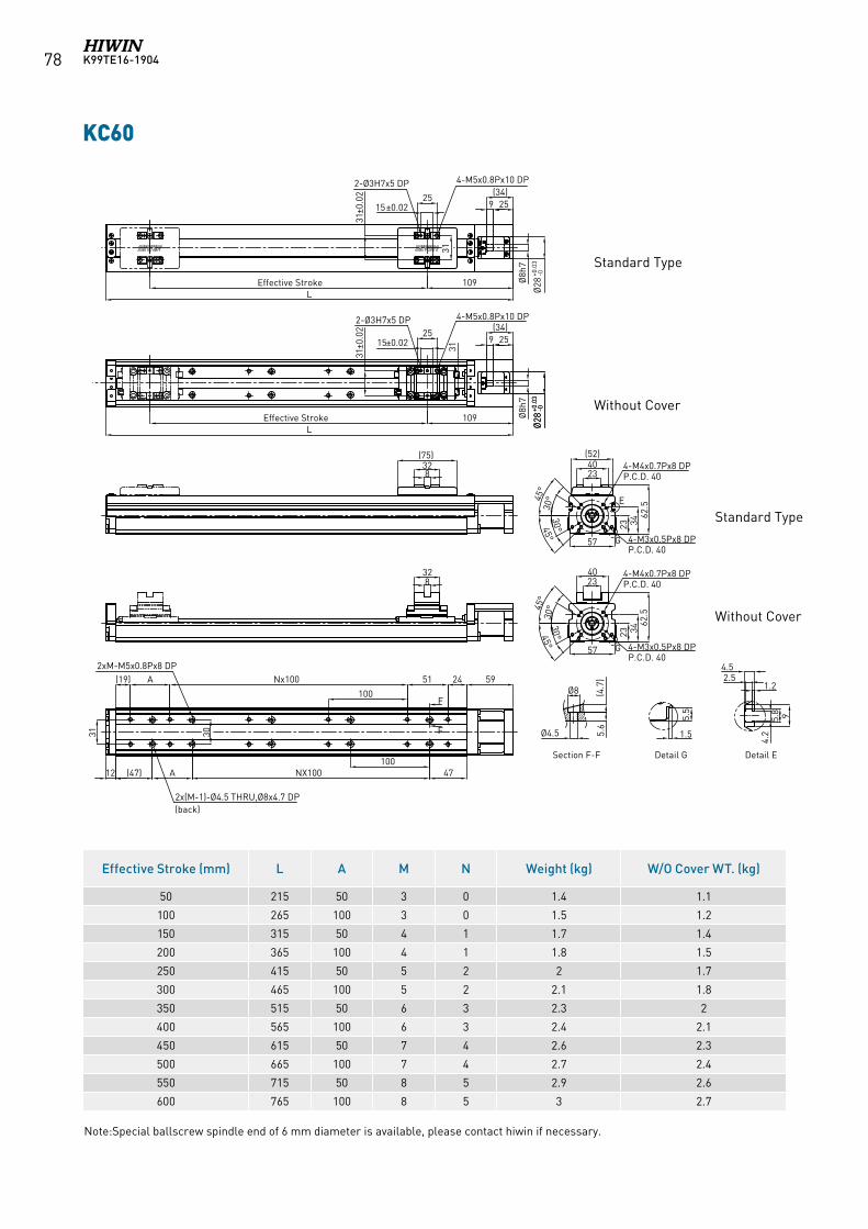
K99TE16-190478
KC60
Effective Stroke (mm) L A M N Weight (kg) W/O Cover WT. (kg)
50 215 50 3 0 1.4 1.1
100 265 100 3 0 1.5 1.2
150 315 50 4 1 1.7 1.4
200 365 100 4 1 1.8 1.5
250 415 50 5 2 2 1.7
300 465 100 5 2 2.1 1.8
350 515 50 6 3 2.3 2
400 565 100 6 3 2.4 2.1
450 615 50 7 4 2.6 2.3
500 665 100 7 4 2.7 2.4
550 715 50 8 5 2.9 2.6
600 765 100 8 5 3 2.7
4.2
9
4.52.5
1.2Ø8 (4.7
)
Ø4.5
(19)
(47)
31
51 24 59
47NX100
Nx100
2515±0.02
31±0
.02
31
328
12
Effective Stroke
Section F-F
F
F
9 25(34)
4-M5x0.8Px10 DP2-Ø3H7x5 DP
2xM-M5x0.8Px8 DP
2x(M-1)-Ø4.5 THRU,Ø8x4.7 DP(back)
5.5
1.5
109 Ø8h
7
Ø28
+0.0
3-0
(75)
5.8
L
30
A
A
100
5.6
Ø28
+0.0
3-0
2515±0.02
31±0
.02
31
Effective Stroke
9 25(34)
4-M5x0.8Px10 DP2-Ø3H7x5 DP
109 Ø8h
7
Ø28
+0.0
3-0
L
328
2340
57
23
62.5
45°
30° E
3445°30°
4-M4x0.7Px8 DPP.C.D. 40
4-M3x0.5Px8 DPP.C.D. 40
G
(52)
2340
57
23
62.5
45°
30°
3445°30°
4-M4x0.7Px8 DPP.C.D. 40
4-M3x0.5Px8 DPP.C.D. 40
G
100
Detail G Detail E
Standard Type
Standard Type
Without Cover
Without Cover
Note:Special ballscrew spindle end of 6 mm diameter is available, please contact hiwin if necessary.
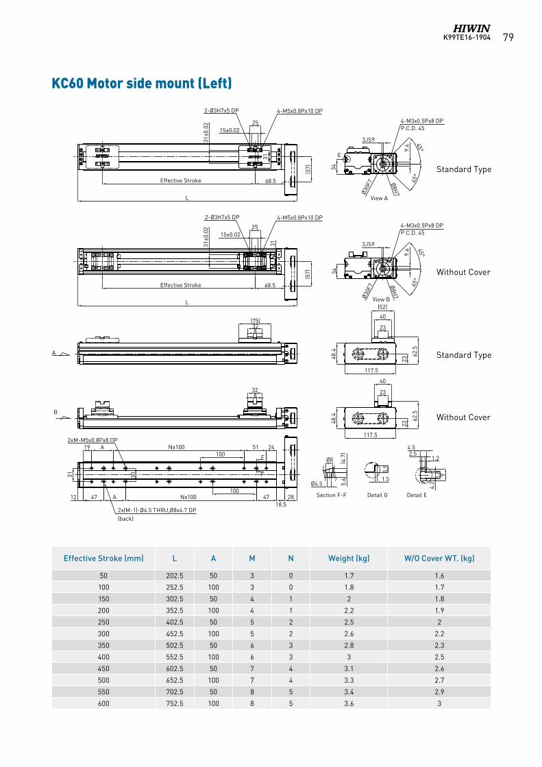
K99TE16-1904 79
KC60 Motor side mount (Left)
Effective Stroke (mm) L A M N Weight (kg) W/O Cover WT. (kg)
50 202.5 50 3 0 1.7 1.6
100 252.5 100 3 0 1.8 1.7
150 302.5 50 4 1 2 1.8
200 352.5 100 4 1 2.2 1.9
250 402.5 50 5 2 2.5 2
300 452.5 100 5 2 2.6 2.2
350 502.5 50 6 3 2.8 2.3
400 552.5 100 6 3 3 2.5
450 602.5 50 7 4 3.1 2.6
500 652.5 100 7 4 3.3 2.7
550 702.5 50 8 5 3.4 2.9
600 752.5 100 8 5 3.6 3
A
B
25
31
68.5Effective Stroke
L
15±0.02
31±0
.02
4-M5x0.8Px10 DP2-Ø3H7x5 DP
(57)
View A
E
3JS9 45°
45°
9.4
Ø8H
7Ø30F
7
34
4-M3x0.5Px8 DPP.C.D. 45
25
31
68.5Effective Stroke
L
15±0.02
31±0
.02
4-M5x0.8Px10 DP2-Ø3H7x5 DP
(57)
328
(75)
View B
45°
45°
9.4
Ø8H
7Ø30F
7
34
4-M3x0.5Px8 DPP.C.D. 45
3JS9
40
23
(52)
23
62.5
48.4
117.5
328
40
23
23
62.5
48.4
117.5
19
47
31
51 24
47Nx100
Nx100
12
F
F
2xM-M5x0.8Px8 DP
2x(M-1)-Ø4.5 THRU,Ø8x4.7 DP(back)
30
A
A
100
18.528
4.2
94.52.5
1.2Ø8 (4.7
)
Ø4.5
5.5
1.5 5.8
5.6
100
Section F-F Detail G Detail E
Standard Type
Standard Type
Without Cover
Without Cover
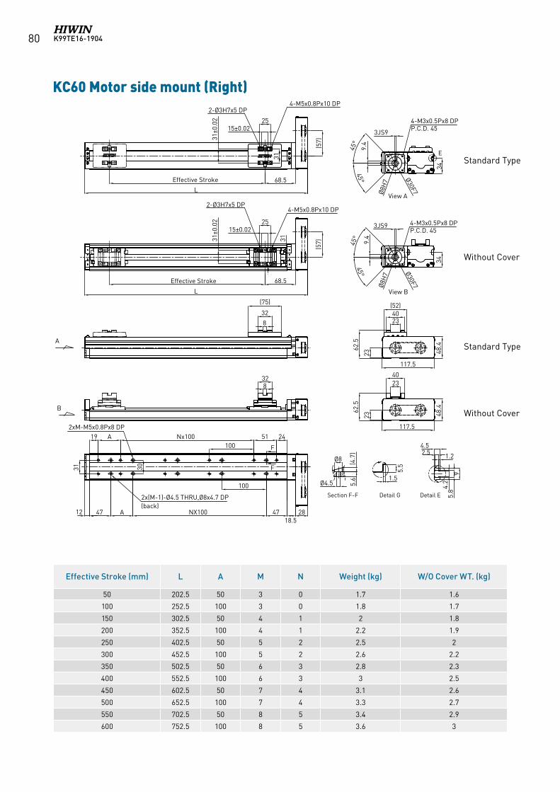
K99TE16-190480
KC60 Motor side mount (Right)
Effective Stroke (mm) L A M N Weight (kg) W/O Cover WT. (kg)
50 202.5 50 3 0 1.7 1.6
100 252.5 100 3 0 1.8 1.7
150 302.5 50 4 1 2 1.8
200 352.5 100 4 1 2.2 1.9
250 402.5 50 5 2 2.5 2
300 452.5 100 5 2 2.6 2.2
350 502.5 50 6 3 2.8 2.3
400 552.5 100 6 3 3 2.5
450 602.5 50 7 4 3.1 2.6
500 652.5 100 7 4 3.3 2.7
550 702.5 50 8 5 3.4 2.9
600 752.5 100 8 5 3.6 3
A
B
25
31
68.5Effective Stroke
L
15±0.02
31±0
.02
4-M5x0.8Px10 DP2-Ø3H7x5 DP
(57)
View A
E
3JS9
45°
45°
9.4
Ø8H
7
Ø30F7
34
25
3168.5Effective Stroke
L
15±0.02
31±0
.02
4-M5x0.8Px10 DP2-Ø3H7x5 DP
(57)
32
8
(75)
View B
328
19
47
31
51 24
47NX100
Nx100
12
F
F
2xM-M5x0.8Px8 DP
2x(M-1)-Ø4.5 THRU,Ø8x4.7 DP(back)
30
A
A
100
18.528
4-M3x0.5Px8 DPP.C.D. 45
45°
45°
9.4
Ø8H
7 Ø30F7
34
3JS9 4-M3x0.5Px8 DPP.C.D. 45
4023
(52)
23
62.5
48.4
117.5
4023
23
62.5
48.4
117.5
4.2
9
4.52.5 1.2Ø8 (4
.7)
Ø4.5
5.5
1.5
5.8
5.6
100
Section F-F Detail G Detail E
Standard Type
Standard Type
Without Cover
Without Cover
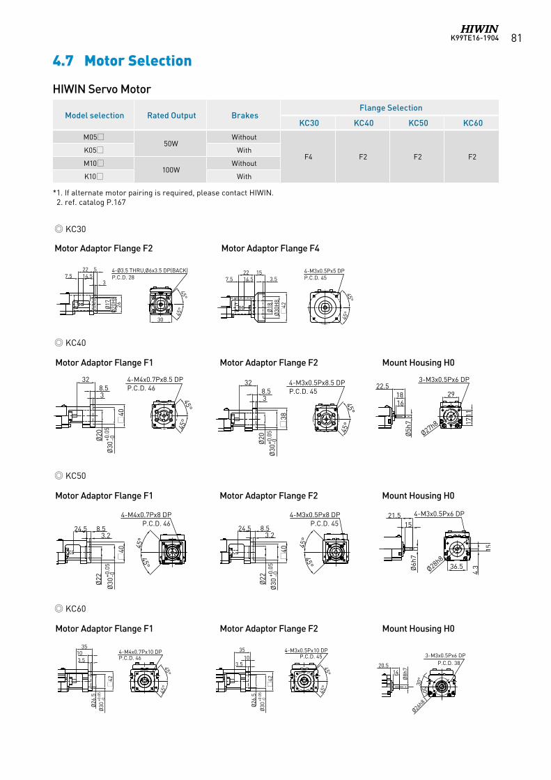
K99TE16-1904 81
4-Ø3.5 THRU,Ø6x3.5 DP(BACK)P.C.D. 28
45°
45°
5
3
26
30
14.522
7.5
Ø17
Ø20
H8
42
Ø30
H8
Ø18
45°
45°
4-M3x0.5Px5 DPP.C.D. 453.5
1514.522
7.5
HIWIN Servo Motor
Motor Adaptor Flange F2 Motor Adaptor Flange F4
Motor Adaptor Flange F1 Motor Adaptor Flange F2 Mount Housing H0
Motor Adaptor Flange F1 Motor Adaptor Flange F2 Mount Housing H0
Motor Adaptor Flange F1 Motor Adaptor Flange F2 Mount Housing H0
KC30
KC40
KC50
KC60
4.7 Motor Selection
Ø30
+0.0
5-0
Ø26
.5
42
3.510
35
45°
4-M4x0.7Px10 DPP.C.D. 46
45°
Ø30
+0.0
5-0
Ø26
.5
42
3.510
35
45°
4-M3x0.5Px10 DPP.C.D. 45
45°
3-M3x0.5Px6 DPP.C.D. 38
30°
30°
Ø8h
7
1420.5
Ø26h8
45°
45°
4-M4x0.7Px8.5 DPP.C.D. 46
Ø20
Ø30
+0.0
5-0
40
38.5
32
45°
45°
4-M3x0.5Px8.5 DPP.C.D. 45
Ø20
Ø30
+0.0
5-0
38
38.5
32
1711
29
3-M3x0.5Px6 DP
Ø27h8
Ø5h
7
1822.5
16
45°
45°
24.5
Ø30
+0.0
5-0
8.53.2
40
45°
45°
24.5
Ø30
+0.0
5-0
8.53.2
40
4-M4x0.7Px8 DPP.C.D. 46
4-M3x0.5Px8 DPP.C.D. 45
Ø22 Ø22
15
4.336.5Ø6h
7
Ø28h8
1521.5 4-M3x0.5Px6 DP
*1. If alternate motor pairing is required, please contact HIWIN. 2. ref. catalog P.167
Model selection Rated Output BrakesFlange Selection
KC30 KC40 KC50 KC60
M0550W
Without
F4 F2 F2 F2K05 With
M10100W
Without
K10 With
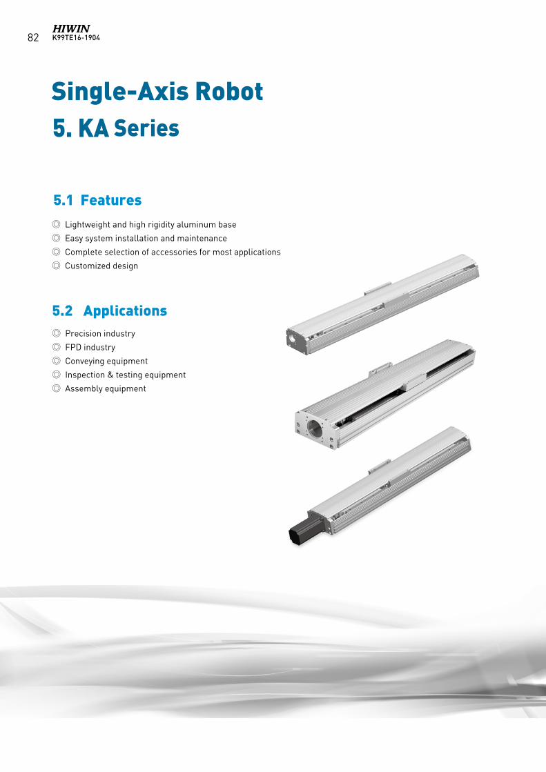
K99TE16-190482
Single-Axis Robot
5.2 Applications
Lightweight and high rigidity aluminum base
Easy system installation and maintenance
Complete selection of accessories for most applications
Customized design
Precision industry
FPD industry
Conveying equipment
Inspection & testing equipment
Assembly equipment
5. KA Series
5.1 Features
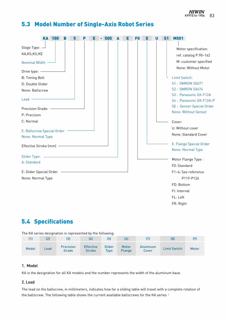
K99TE16-1904 83
5.3 Model Number of Single-Axis Robot Series
The KA series designation is represented by the following:(1) (2) (3) (4) (5) (6) (7) (8) (9)
Model Lead Precision Grade
Effective Stroke
Slider Type
Motor Flange
Aluminum Cover Limit Switch Motor
1. Model
KA is the designation for all KA models and the number represents the width of the aluminum base.
2. Lead
The lead on the ballscrew, in millimeters, indicates how far a sliding table will travel with a complete rotation of
the ballscrew. The following table shows the current available ballscrews for the KA series:
Stage Type:
KA,KS,KU,KE
Nominal Width
Lead
Precision Grade:
P: Precision
C: Normal
Effective Stroke (mm)
Drive type:
B: Timing Belt
D: Double Slider
None: Ballscrew
Motor specification:
ref. catalog P.90~162
M: customer specified
None: Without Motor
Limit Switch:
S1 : OMRON SX671
S2 : OMRON SX674
S3 : Panasonic GX-F12A
S4 : Panasonic GX-F12A-P
SE : Sensor Special Order
None: Without Sensor
Cover:
U: Without cover
None: Standard Cover
Motor Flange Type :
F0: Standard
F1~6: See reference
P119-P124
FD: Bottom
FI: Internal
FL: Left
FR: Right
Slider Type:
A: Standard
KA 100 B 5 P E - 500 A E F0 E U S1 M501
E: Ballscrew Special Order
None: Normal Type
E: Slider Special Order
None: Normal Type
E: Flange Special Order
None: Normal Type
5.4 Specifications
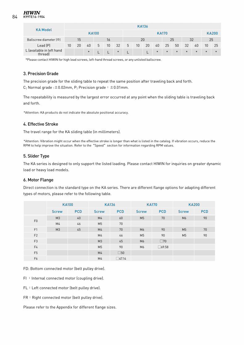
K99TE16-190484
KA ModelKA136
KA100 KA170 KA200
Ballscrew diameter (Φ) 15 16 20 25 32 25
Lead (P) 10 20 40 5 10 32 5 10 20 40 25 50 32 40 10 25L (available in left hand
thread) * L L * L L * * * * * * *
*Please contact HIWIN for high lead screws, left-hand thread screws, or any unlisted ballscrew.
3. Precision Grade
The precision grade for the sliding table to repeat the same position after traveling back and forth.
C; Normal grade :±0.02mm, P; Precision grade:±0.01mm.
The repeatability is measured by the largest error occurred at any point when the sliding table is traveling back
and forth.
*Attention: KA products do not indicate the absolute positional accuracy.
4. Effective Stroke
The travel range for the KA sliding table (in millimeters).
*Attention: Vibration might occur when the effective stroke is longer than what is listed in the catalog. If vibration occurs, reduce the RPM to help improve the situation. Refer to the“Speed”section for information regarding RPM values.
5. Slider Type
The KA series is designed to only support the listed loading. Please contact HIWIN for inquiries on greater dynamic
load or heavy load models.
6. Motor Flange
Direct connection is the standard type on the KA series. There are different flange options for adapting different
types of motors, please refer to the following table.
FD: Bottom connected motor (belt pulley drive).
FI :Internal connected motor (coupling drive).
FL:Left connected motor (belt pulley drive).
FR:Right connected motor (belt pulley drive).
Please refer to the Appendix for different flange sizes.
KA100 KA136 KA170 KA200
Screw PCD Screw PCD Screw PCD Screw PCD
F0M3 40 M4 60 M5 70 M6 90
M4 46 M5 70
F1 M3 45 M4 70 M6 90 M5 70
F2 M4 46 M5 90 M5 90
F3 M3 45 M6 70
F4 M5 90 M6 69.58
F5 M4 50
F6 M4 47.14
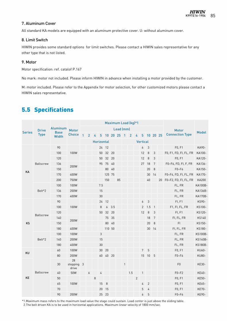
K99TE16-1904 85
5.5 Specifications
*1.Maximum mass refers to the maximum load value the stage could sustain. Load center is just above the sliding table. 2.The belt driven KA is to be used in horizontal applications. Maximum linear velocity of 1800 mm/sec.
Series Drive Type
Aluminum Base Width
Motor Choice
Maximum Load (kg)*1
Motor Connection Type Model
Lead (mm)
1 2 4 5 10 20 25 1 2 4 5 10 20 25
Horizontal Vertical
KA
Ballscrew
90
100W
24 12 6 3 F0, F1 KA90-
100 50 32 20 12 8 3 F0, F1, FD, FI, FL, FR KA100-
120 50 32 20 12 8 3 F0, F1 KA120-
136200W
95 75 40 27 18 7 F0~F6, FD, FI, F, FR KA136-
150 80 40 20 8 F0~F6 KA150-
170 400W 125 75 30 14 F0~F4, FD, FI, FL, FR KA170-
200 750W 150 85 40 20 F0~F2, FD, FI, FL, FR KA200
Belt*2
100 100W 7.5 FL, FR KA100B-
136 200W 15 FL, FR KA136B-
170 400W 30 FL, FR KA170B-
KS
Ballscrew
90
100W
24 12 6 3 FI, F1 KS90-
100 8 6 3.5 2 1.5 1 F1, FI, FL, FR KS100-
120 50 32 20 12 8 3 FI, F1 KS120-
140200W
75 35 18 7 FI, FL, FR KS140
150 80 40 20 8 FI KS150-
180 400W 110 50 30 14 FI, FL, FR KS180-
Belt*2
100 100W 3 FL, FR KS100B-
140 200W 15 FL, FR KS140B-
180 400W 30 FL, FR KS180B-
KU
Ballscrew
60 100W 30 20 7 5 F0, F1 KU60-
80 200W 60 40 20 15 10 5 F0~F6 KU80-
KE
3028
stepping drive
3 1 F0 KE30-
40 50W 6 4 1.5 1 F0~F2 KE40-
50
100W
8 2 F0, F1 KE50-
65 15 8 4 2 F0, F1 KE65-
70 20 15 5 4 F0, F1 KE70-
90 200W 25 23 6 5 F0~F6 KE90-
7. Aluminum Cover
All standard KA models are equipped with an aluminum protective cover. U: without aluminum cover.
8. Limit Switch
HIWIN provides some standard options for limit switches. Please contact a HIWIN sales representative for any
other type that is not listed.
9. Motor
Motor specification: ref. catalof P.167
No mark: motor not included. Please inform HIWIN in advance when installing a motor provided by the customer.
M: motor included. Please refer to the Appendix for motor selection, for other customized motors please contact a
HIWIN sales representative.
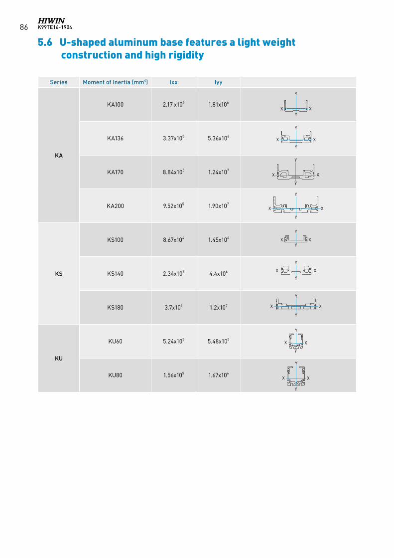
K99TE16-190486
Series Moment of Inertia (mm4) Ixx Iyy
KA
KA100 2.17 x10⁵ 1.81x10⁶
KA136 3.37x10⁵ 5.36x10⁶
KA170 8.84x10⁵ 1.24x10⁷
KA200 9.52x10⁵ 1.90x10⁷
KS
KS100 8.67x10⁴ 1.45x10⁶
KS140 2.34x10⁵ 4.4x10⁶
KS180 3.7x10⁵ 1.2x10⁷
KU
KU60 5.24x10⁵ 5.48x10⁵
KU80 1.56x10⁵ 1.67x10⁶
XX
Y
Y
Y
Y
X X
Y
Y
X X
Y
YX X
Y
Y
Y
X
X
X
X
X
X
Y
Y
Y
Y
Y
X
X
X
X
Y
Y
5.6 U-shaped aluminum base features a light weight construction and high rigidity
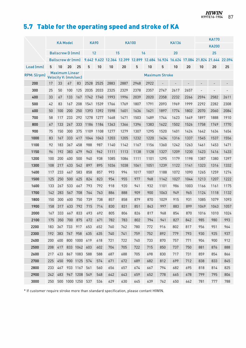
K99TE16-1904 87
5.7 Table for the operating speed and stroke of KA
KA Model KA90 KA100 KA136KA170
KA200
Ballscrew D (mm) 12 15 16 20 25
Ballscrew dr (mm) 9.642 9.622 12.364 12.399 12.899 12.684 16.924 16.624 17.084 21.824 21.644 22.094
Lead (mm) 5 10 20 25 5 10 10 20 5 10 5 10 20 10 20 25
RPM: S(rpm) Maximum Linear Velocity V: (mm/sec) Maximum Stroke
200 17 33 67 83 2528 2525 2883 2887 2948 2922 - - - - - -
300 25 50 100 125 2035 2033 2325 2329 2378 2357 2747 2617 2657 - - -
400 33 67 133 167 1742 1740 1993 1996 2039 2020 2358 2232 2266 2594 2582 2611
500 42 83 167 208 1541 1539 1766 1769 1807 1791 2093 1969 1999 2292 2282 2308
600 50 100 200 250 1393 1392 1598 1601 1636 1621 1897 1774 1802 2070 2060 2084
700 58 117 233 292 1278 1277 1468 1471 1503 1489 1744 1623 1649 1897 1888 1910
800 67 133 267 333 1186 1184 1363 1366 1396 1383 1622 1502 1526 1758 1749 1770
900 75 150 300 375 1109 1108 1277 1279 1307 1295 1520 1401 1424 1642 1634 1654
1000 83 167 333 417 1044 1043 1203 1205 1232 1220 1434 1316 1337 1545 1537 1556
1100 92 183 367 458 988 987 1140 1142 1167 1156 1360 1242 1263 1461 1453 1471
1150 96 192 383 479 963 962 1111 1113 1138 1128 1327 1209 1230 1423 1416 1433
1200 100 200 400 500 940 938 1085 1086 1111 1101 1295 1179 1198 1387 1380 1397
1300 108 217 433 542 897 895 1036 1038 1061 1051 1239 1122 1141 1323 1316 1332
1400 117 233 467 583 858 857 993 994 1017 1007 1188 1072 1090 1265 1259 1274
1500 125 250 500 625 824 823 954 955 977 968 1142 1027 1044 1213 1207 1222
1600 133 267 533 667 793 792 918 920 941 932 1101 986 1003 1166 1161 1175
1700 142 283 567 708 764 763 886 888 909 900 1063 949 965 1124 1118 1132
1800 150 300 600 750 739 738 857 858 879 870 1029 915 931 1085 1079 1093
1900 158 317 633 792 715 714 830 831 851 843 997 883 899 1049 1043 1057
2000 167 333 667 833 693 692 805 806 826 817 968 854 870 1016 1010 1024
2100 175 350 700 875 672 671 782 783 802 794 941 827 842 985 980 993
2200 183 367 733 917 653 652 760 762 780 772 916 802 817 956 951 964
2300 192 383 767 958 635 635 740 741 759 752 892 779 793 930 925 937
2400 200 400 800 1000 619 618 721 722 740 733 870 757 771 904 900 912
2500 208 417 833 1042 603 602 704 705 722 715 850 737 750 881 876 888
2600 217 433 867 1083 588 588 687 688 705 698 830 717 731 859 854 866
2700 225 450 900 1125 574 574 671 672 689 682 812 699 712 838 833 845
2800 233 467 933 1167 561 560 656 657 674 667 794 682 695 818 814 825
2900 242 483 967 1208 549 548 642 643 659 652 778 665 678 799 795 806
3000 250 500 1000 1250 537 536 629 630 645 639 762 650 662 781 777 788
* If customer require stroke more than standard specification, please contant HIWIN.
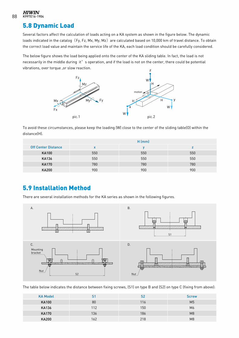
K99TE16-190488
5.8 Dynamic LoadSeveral factors affect the calculation of loads acting on a KA system as shown in the figure below. The dynamic
loads indicated in the catalog(Fy, Fz, Mx, My, Mz)are calculated based on 10,000 km of travel distance. To obtain
the correct load value and maintain the service life of the KA, each load condition should be carefully considered.
The below figure shows the load being applied onto the center of the KA sliding table. In fact, the load is not
necessarily in the middle during it’s operation, and if the load is not on the center, there could be potential
vibrations, over torque ,or slow reaction.
To avoid these circumstances, please keep the loading (W) close to the center of the sliding table(O) within the
distance(H).
5.9 Installation MethodThere are several installation methods for the KA series as shown in the following figures.
The table below indicates the distance between fixing screws, (S1) on type B and (S2) on type C (fixing from above):
Fz
FyMy Mx
Fx
Mz
z
x
y
motion
W
W
W
H
HH
O
S1
S2 NutNut
Mounting bracket
S1
S2 NutNut
Mounting bracket
S1
S2 NutNut
Mounting bracket
S1
S2 NutNut
Mounting bracket
A. B.
C. D.
KA Model S1 S2 Screw
KA100 80 116 M5
KA136 112 150 M6
KA170 136 186 M8
KA200 162 218 M8
pic.1 pic.2
H (mm)
Off Center Distance x y z
KA100 550 550 550
KA136 550 550 550
KA170 780 780 780
KA200 900 900 900
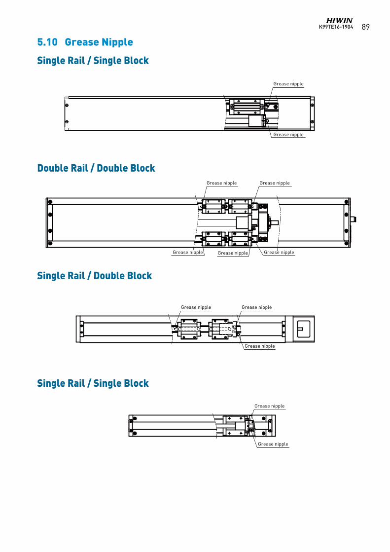
K99TE16-1904 89
Single Rail / Single Block
Double Rail / Double Block
Single Rail / Double Block
Single Rail / Single Block
5.10 Grease Nipple
單軌單滑塊
SR油嘴配置圖
雙軌雙滑塊
單軌單滑塊
單軌雙滑塊
Grease nipple
Grease nipple Grease nipple
Grease nippleGrease nippleGrease nipple
Grease nipple Grease nipple
Grease nipple
Grease nipple
Grease nipple
Grease nipple
單軌單滑塊
SR油嘴配置圖
雙軌雙滑塊
單軌單滑塊
單軌雙滑塊
Grease nipple
Grease nipple Grease nipple
Grease nippleGrease nippleGrease nipple
Grease nipple Grease nipple
Grease nipple
Grease nipple
Grease nipple
Grease nipple
單軌單滑塊
SR油嘴配置圖
雙軌雙滑塊
單軌單滑塊
單軌雙滑塊
Grease nipple
Grease nipple Grease nipple
Grease nippleGrease nippleGrease nipple
Grease nipple Grease nipple
Grease nipple
Grease nipple
Grease nipple
Grease nipple
單軌單滑塊
SR油嘴配置圖
雙軌雙滑塊
單軌單滑塊
單軌雙滑塊
Grease nipple
Grease nipple Grease nipple
Grease nippleGrease nippleGrease nipple
Grease nipple Grease nipple
Grease nipple
Grease nipple
Grease nipple
Grease nipple
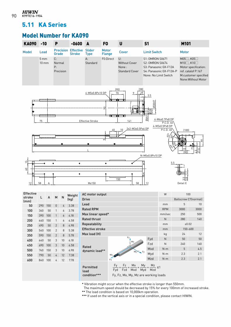
K99TE16-190490
135.5
3.5
5.8
Detail E
141Effective Stroke75
2970(90)
9(38)
3.5
1258150
Mx15058 A
(90)19
4.5
27.5
66
90
E
4-M5x0.8Px10 DP
N-M5x0.8Px10 DP
30°
30°
45°
45°
4-M4x0.7Px8 DPP.C.D. 46
4-M3x0.5Px8 DPP.C.D. 40
Ø6h
7Ø
28Ø
30H
7
(100)40 10 2x2-M3x0.5Px6 DP
L
12
1560
9
KA090 -10 P -0600 A FO U S1 M101
Model Lead Precision Grade
Effective Stroke
Slider Type
Motor Flange Cover Limit Switch Motor
5 mm 10 mm
C: NormalP: Precision
A: Standard
F0:Direct U: Without CoverNone : Standard Cover
S1: OMRON SX671 S2: OMRON SX674 S3: Panasonic GX-F12A S4: Panasonic GX-F12A-PNone: No Limit Switch
M05, K05M10, K10Motor specification:ref. catalof P.167M:customer specifiedNone:Without Motor
Model Number for KA090
5.11 KA Series
Effective stroke (mm)
L A M N Weight (kg)
50 290 150 0 4 3.38
100 340 50 1 6 3.78
150 390 100 1 6 4.18
200 440 150 1 6 4.58
250 490 50 2 8 4.98
300 540 100 2 8 5.38
350 590 150 2 8 5.78
400 640 50 3 10 6.18
450 690 100 3 10 6.58
500 740 150 3 10 6.98
550 790 50 4 12 7.38
600 840 100 4 12 7.78
AC motor output W 100
Drive Ballscrew C7(normal)
Lead mm 5 10
Rated RPM RPM 3000 3000
Max linear speed* mm/sec 250 500
Rated thrust N 280 140
Repeatability mm ±0.02
Effective stroke mm 150~600
Max load (H) kg 24 12
Rated dynamic load**
Fyd N 50 50
Fzd N 240 160
Mxd N-m 5 4.5
Myd N-m 2.3 2.1
Mzd N-m 2.3 2.1
Permitted load condition*** Fy, Fz, Mx, My, Mz are working loads
1++++MzdMz
MydMy
MxdMx
FzdFz
FydFy ≤
Fz
FyMy Mx
Fx
Mz
Fz
FyMy Mx
Fx
Mz
Fz
FyMy Mx
Fx
Mz
Fz
FyMy Mx
Fx
Mz
Fz
FyMy Mx
Fx
Mz
Fz
FyMy Mx
Fx
Mz
* Vibration might occur when the effective stroke is longer than 550mm. The maximum speed should be decreased by 15% for every 100mm of increased stroke.
** The load condition is based on 10,000km operation.*** If used on the vertical axis or in a special condition, please contact HIWIN.
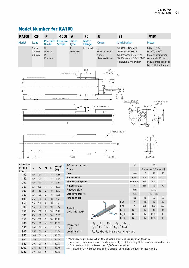
K99TE16-1904 91
AC motor output W 100
Drive Ballscrew C7(normal)
Lead mm 5 10 20
Rated RPM RPM 3000 3000 3000
Max linear speed* mm/sec 250 500 1000
Rated thrust N 280 140 70
Repeatability mm ±0.02
Effective stroke mm 100~1050
Max load (H) kg 50 32 20
Rated dynamic load**
Fyd N 50 50 50
Fzd N 500 320 200
Mxd N-m 16 16 16
Myd N-m 14 13.5 13
Mzd N-m 14 13.5 13
Permitted load condition*** Fy, Fz, Mx, My, Mz are working loads
Model Number for KA100 KA100 -20 P -1050 A F0 U S1 M101Model Lead Precision
GradeEffective Stroke
Slider Type
Motor Flange Cover Limit Switch Motor
5 mm 10 mm 20 mm
C: NormalP: Precision
A: Standard
F0:Direct U: Without CoverNone : Standard Cover
S1: OMRON SX671 S2: OMRON SX674 S3: Panasonic GX-F12A S4: Panasonic GX-F12A-PNone: No Limit Switch
M05, K05M10, K10Motor specification:ref. catalof P.167M:customer specifiedNone:Without Motor
Effective stroke (mm)
L A M N Weight (kg)
100 354 50 1 6 4.86
150 404 100 1 6 5.34
200 454 150 1 6 5.81
250 504 200 1 6 6.29
300 554 50 2 8 6.77
350 604 100 2 8 7.25
400 654 150 2 8 7.73
450 704 200 2 8 8.2
500 754 50 3 10 8.67
550 804 100 3 10 9.15
600 854 150 3 10 9.63
650 904 200 3 10 10.11
700 954 50 4 12 10.59
750 1004 100 4 12 11.06
800 1054 150 4 12 11.54
850 1104 200 4 12 12.02
900 1154 50 5 14 12.49
950 1204 100 5 14 12.97
1000 1254 150 5 14 13.45
1050 1304 200 5 14 13.93
1++++MzdMz
MydMy
MxdMx
FzdFz
FydFy ≤
Fz
FyMy Mx
Fx
Mz Fz
FyMy Mx
Fx
Mz
Fz
FyMy Mx
Fx
Mz
Fz
FyMy Mx
Fx
Mz
Fz
FyMy Mx
Fx
Mz
Fz
FyMy Mx
Fx
Mz
Fz
FyMy Mx
Fx
Mz
* Vibration might occur when the effective stroke is longer than 650mm. The maximum speed should be decreased by 15% for every 100mm of increased stroke.
** The load condition is based on 10,000km operation.*** If used on the vertical axis or in a special condition, please contact HIWIN.
15575 EFFECTIVE STROKE
35
200
A45 12
80
70(110)
4-M5x0.8Px12 DP
105014
12
100
Ø28
Ø30
H8
Ø10
h7
18(52)
(34)
(110)
(102)
4-M4x0.7Px8 DPP.C.D. 46
4-M3x0.5Px8 DPP.C.D. 40
938
71
22
3.5
5.8
13
4.5
DETAIL E
3.5
N-M5x0.8Px10 DP30
°
30°
45°
45°
E
2x2-M3x0.5Px6 DP
L
Mx200
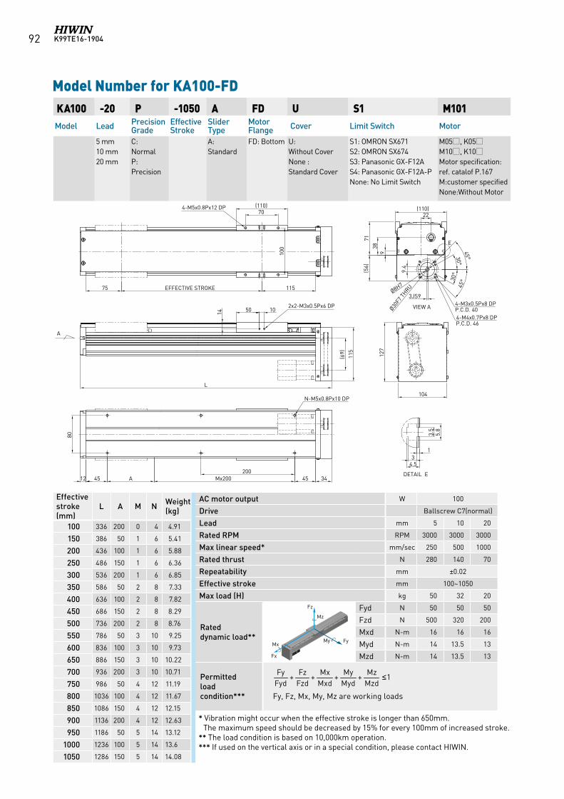
K99TE16-190492
AC motor output W 100
Drive Ballscrew C7(normal)
Lead mm 5 10 20
Rated RPM RPM 3000 3000 3000
Max linear speed* mm/sec 250 500 1000
Rated thrust N 280 140 70
Repeatability mm ±0.02
Effective stroke mm 100~1050
Max load (H) kg 50 32 20
Rated dynamic load**
Fyd N 50 50 50
Fzd N 500 320 200
Mxd N-m 16 16 16
Myd N-m 14 13.5 13
Mzd N-m 14 13.5 13
Permitted load condition*** Fy, Fz, Mx, My, Mz are working loads
KA100 -20 P -1050 A FD U S1 M101Model Lead Precision
GradeEffective Stroke
Slider Type
Motor Flange Cover Limit Switch Motor
5 mm 10 mm 20 mm
C: NormalP: Precision
A: Standard
FD: Bottom U: Without CoverNone : Standard Cover
S1: OMRON SX671 S2: OMRON SX674 S3: Panasonic GX-F12A S4: Panasonic GX-F12A-PNone: No Limit Switch
M05, K05M10, K10Motor specification:ref. catalof P.167M:customer specifiedNone:Without Motor
Model Number for KA100-FD
Effective stroke (mm)
L A M N Weight (kg)
100 336 200 0 4 4.91
150 386 50 1 6 5.41
200 436 100 1 6 5.88
250 486 150 1 6 6.36
300 536 200 1 6 6.85
350 586 50 2 8 7.33
400 636 100 2 8 7.82
450 686 150 2 8 8.29
500 736 200 2 8 8.76
550 786 50 3 10 9.25
600 836 100 3 10 9.73
650 886 150 3 10 10.22
700 936 200 3 10 10.71
750 986 50 4 12 11.19
800 1036 100 4 12 11.67
850 1086 150 4 12 12.15
900 1136 200 4 12 12.63
950 1186 50 5 14 13.12
1000 1236 100 5 14 13.6
1050 1286 150 5 14 14.08
1++++MzdMz
MydMy
MxdMx
FzdFz
FydFy ≤
* Vibration might occur when the effective stroke is longer than 650mm. The maximum speed should be decreased by 15% for every 100mm of increased stroke.
** The load condition is based on 10,000km operation.*** If used on the vertical axis or in a special condition, please contact HIWIN.
Fz
FyMy Mx
Fx
Mz Fz
FyMy Mx
Fx
Mz
Fz
FyMy Mx
Fx
Mz
Fz
FyMy Mx
Fx
Mz
Fz
FyMy Mx
Fx
Mz
Fz
FyMy Mx
Fx
Mz
Fz
FyMy Mx
Fx
Mz
VIEW A
E
DETAIL E
A
70(110)
100
11575
50 10
14
34454512
80
Ø30F7
THRU
13
4.5
3.5
5.8
4-M4x0.7Px8 DPP.C.D. 46
4-M5x0.8Px12 DP
2x2-M3x0.5Px6 DP
N-M5x0.8Px10 DP
115
127
104
938
(110)22
45°
45°
200
(69)
71(5
6)
Ø8H7
A Mx200
L
EFFECTIVE STROKE
30°
30°
4-M3x0.5Px8 DPP.C.D. 40
9.4
3JS9
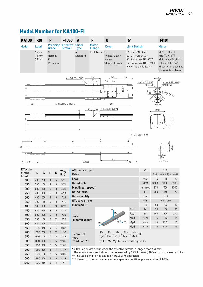
K99TE16-1904 93
AC motor output W 100
Drive Ballscrew C7(normal)
Lead mm 5 10 20
Rated RPM RPM 3000 3000 3000
Max linear speed* mm/sec 250 500 1000
Rated thrust N 280 140 70
Repeatability mm ±0.02
Effective stroke mm 100~1050
Max load (H) kg 50 32 20
Rated dynamic load**
Fyd N 50 50 50
Fzd N 500 320 200
Mxd N-m 16 16 16
Myd N-m 14 13.5 13
Mzd N-m 14 13.5 13
Permitted load condition*** Fy, Fz, Mx, My, Mz are working loads
KA100 -20 P -1050 A FI U S1 M101Model Lead Precision
GradeEffective Stroke
Slider Type
Motor Flange Cover Limit Switch Motor
5 mm 10 mm 20 mm
C: NormalP: Precision
A: Standard
FI : Internal U: Without CoverNone : Standard Cover
S1: OMRON SX671 S2: OMRON SX674 S3: Panasonic GX-F12A S4: Panasonic GX-F12A-PNone: No Limit Switch
M05, K05M10, K10Motor specification:ref. catalof P.167M:customer specifiedNone:Without Motor
Model Number for KA100-FI
Effective stroke (mm)
L A M N Weight (kg)
100 480 200 1 6 5.2
150 530 50 2 8 5.71
200 580 100 2 8 6.22
250 630 150 2 8 6.73
300 680 200 2 8 7.24
350 730 50 3 10 7.76
400 780 100 3 10 8.27
450 830 150 3 10 8.77
500 880 200 3 10 9.28
550 930 50 4 12 9.79
600 980 100 4 12 10.31
650 1030 150 4 12 10.82
700 1080 200 4 12 11.33
750 1130 50 5 14 11.83
800 1180 100 5 14 12.35
850 1230 150 5 14 12.86
900 1280 200 5 14 13.37
950 1330 50 6 16 13.88
1000 1380 100 6 16 14.39
1050 1430 150 6 16 14.91
1++++MzdMz
MydMy
MxdMx
FzdFz
FydFy ≤
* Vibration might occur when the effective stroke is longer than 650mm. The maximum speed should be decreased by 15% for every 100mm of increased stroke.
** The load condition is based on 10,000km operation.*** If used on the vertical axis or in a special condition, please contact HIWIN.
Fz
FyMy Mx
Fx
Mz Fz
FyMy Mx
Fx
Mz
Fz
FyMy Mx
Fx
Mz
Fz
FyMy Mx
Fx
Mz
Fz
FyMy Mx
Fx
Mz
Fz
FyMy Mx
Fx
Mz
Fz
FyMy Mx
Fx
Mz
L
2x2-M3x0.5Px6 DP1050
N-M5x0.8Px10 DP
(110)
719(102)
DETAIL E
13
4.5
3.5
5.8
View A
Mx200 30200
3012 A
14
8
2050
4-M3x0.5Px8 DP 4-M4x0.7Px8 DPP.C.D. 46P.C.D. 40
30°45°
2550
80
Ø30F7 THRU30°
45°
EFFECTIVE STROKE 285
(110)70
100
18 34
(52) 126
Ø10
h7
75
4-M5x0.8Px12 DP
E
A
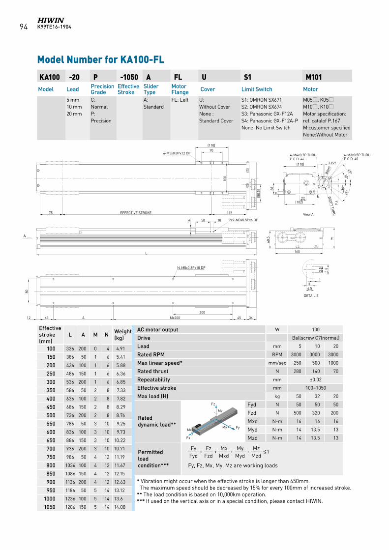
K99TE16-190494
AC motor output W 100
Drive Ballscrew C7(normal)
Lead mm 5 10 20
Rated RPM RPM 3000 3000 3000
Max linear speed* mm/sec 250 500 1000
Rated thrust N 280 140 70
Repeatability mm ±0.02
Effective stroke mm 100~1050
Max load (H) kg 50 32 20
Rated dynamic load**
Fyd N 50 50 50
Fzd N 500 320 200
Mxd N-m 16 16 16
Myd N-m 14 13.5 13
Mzd N-m 14 13.5 13
Permitted load condition*** Fy, Fz, Mx, My, Mz are working loads
KA100 -20 P -1050 A FL U S1 M101Model Lead Precision
GradeEffective Stroke
Slider Type
Motor Flange Cover Limit Switch Motor
5 mm 10 mm 20 mm
C: NormalP: Precision
A: Standard
FL: Left U: Without CoverNone : Standard Cover
S1: OMRON SX671 S2: OMRON SX674 S3: Panasonic GX-F12A S4: Panasonic GX-F12A-PNone: No Limit Switch
M05, K05M10, K10Motor specification:ref. catalof P.167M:customer specifiedNone:Without Motor
Model Number for KA100-FL
Effective stroke (mm)
L A M N Weight (kg)
100 336 200 0 4 4.91
150 386 50 1 6 5.41
200 436 100 1 6 5.88
250 486 150 1 6 6.36
300 536 200 1 6 6.85
350 586 50 2 8 7.33
400 636 100 2 8 7.82
450 686 150 2 8 8.29
500 736 200 2 8 8.76
550 786 50 3 10 9.25
600 836 100 3 10 9.73
650 886 150 3 10 10.22
700 936 200 3 10 10.71
750 986 50 4 12 11.19
800 1036 100 4 12 11.67
850 1086 150 4 12 12.15
900 1136 200 4 12 12.63
950 1186 50 5 14 13.12
1000 1236 100 5 14 13.6
1050 1286 150 5 14 14.08
1++++MzdMz
MydMy
MxdMx
FzdFz
FydFy ≤
* Vibration might occur when the effective stroke is longer than 650mm. The maximum speed should be decreased by 15% for every 100mm of increased stroke.
** The load condition is based on 10,000km operation.*** If used on the vertical axis or in a special condition, please contact HIWIN.
Fz
FyMy Mx
Fx
Mz Fz
FyMy Mx
Fx
Mz
Fz
FyMy Mx
Fx
Mz
Fz
FyMy Mx
Fx
Mz
Fz
FyMy Mx
Fx
Mz
Fz
FyMy Mx
Fx
Mz
Fz
FyMy Mx
Fx
Mz
13
4.5
3.5
5.8
(110)70
100
EFFECTIVE STROKE 11575
(58.
5)L
105014
12 45 A 45 34
200
80
160
(110)
Ø30F7 TH
RU
45°
45°
4-M4x0.7P THRU P.C.D. 46
22
2x2-M3x0.5Px6 DP
4-M5x0.8Px12 DP
Mx200
9
60.5 71
N-M5x0.8Px10 DP
Ø8H
7
38
(102) 9.4
3JS9
30°
30°
4-M3x0.5P THRUP.C.D. 40
A
View A
E
DETAIL E
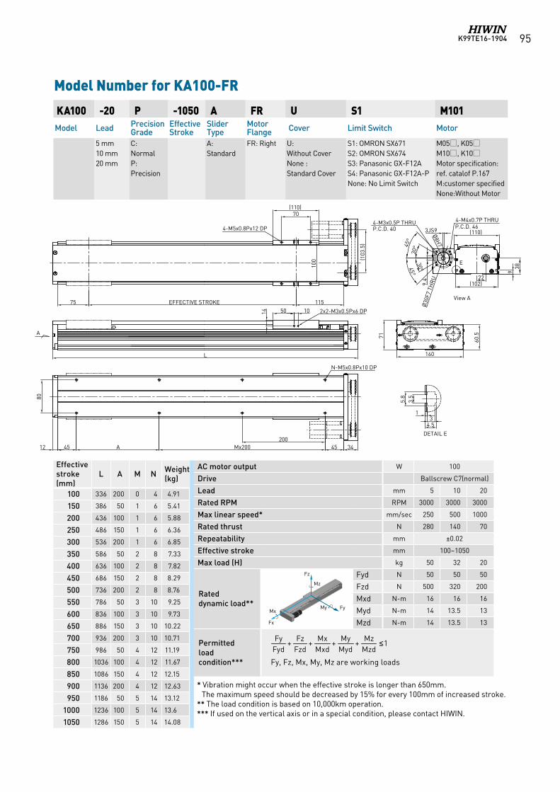
K99TE16-1904 95
AC motor output W 100
Drive Ballscrew C7(normal)
Lead mm 5 10 20
Rated RPM RPM 3000 3000 3000
Max linear speed* mm/sec 250 500 1000
Rated thrust N 280 140 70
Repeatability mm ±0.02
Effective stroke mm 100~1050
Max load (H) kg 50 32 20
Rated dynamic load**
Fyd N 50 50 50
Fzd N 500 320 200
Mxd N-m 16 16 16
Myd N-m 14 13.5 13
Mzd N-m 14 13.5 13
Permitted load condition*** Fy, Fz, Mx, My, Mz are working loads
KA100 -20 P -1050 A FR U S1 M101Model Lead Precision
GradeEffective Stroke
Slider Type
Motor Flange Cover Limit Switch Motor
5 mm 10 mm 20 mm
C: NormalP: Precision
A: Standard
FR: Right U: Without CoverNone : Standard Cover
S1: OMRON SX671 S2: OMRON SX674 S3: Panasonic GX-F12A S4: Panasonic GX-F12A-PNone: No Limit Switch
M05, K05M10, K10Motor specification:ref. catalof P.167M:customer specifiedNone:Without Motor
Model Number for KA100-FR
Effective stroke (mm)
L A M N Weight (kg)
100 336 200 0 4 4.91
150 386 50 1 6 5.41
200 436 100 1 6 5.88
250 486 150 1 6 6.36
300 536 200 1 6 6.85
350 586 50 2 8 7.33
400 636 100 2 8 7.82
450 686 150 2 8 8.29
500 736 200 2 8 8.76
550 786 50 3 10 9.25
600 836 100 3 10 9.73
650 886 150 3 10 10.22
700 936 200 3 10 10.71
750 986 50 4 12 11.19
800 1036 100 4 12 11.67
850 1086 150 4 12 12.15
900 1136 200 4 12 12.63
950 1186 50 5 14 13.12
1000 1236 100 5 14 13.6
1050 1286 150 5 14 14.08
1++++MzdMz
MydMy
MxdMx
FzdFz
FydFy ≤
* Vibration might occur when the effective stroke is longer than 650mm. The maximum speed should be decreased by 15% for every 100mm of increased stroke.
** The load condition is based on 10,000km operation.*** If used on the vertical axis or in a special condition, please contact HIWIN.
Fz
FyMy Mx
Fx
Mz Fz
FyMy Mx
Fx
Mz
Fz
FyMy Mx
Fx
Mz
Fz
FyMy Mx
Fx
Mz
Fz
FyMy Mx
Fx
Mz
Fz
FyMy Mx
Fx
Mz
Fz
FyMy Mx
Fx
Mz
13
4.5
3.5
5.8
(110)70
100
EFFECTIVE STROKE 11575
(103
.5)
L
105014
12 45 A 45 34200
80
(110)
Ø30
F7 T
HR
U
4-M4x0.7P THRU P.C.D. 46
22
2x2-M3x0.5Px6 DP
4-M5x0.8Px12 DP
Mx200
9
N-M5x0.8Px10 DP
Ø8H7
160
71
60.5
(102)
38
9.4
45°
45°
3JS9
30°
30°
4-M3x0.5P THRUP.C.D. 40
A
View A
DETAIL E
E
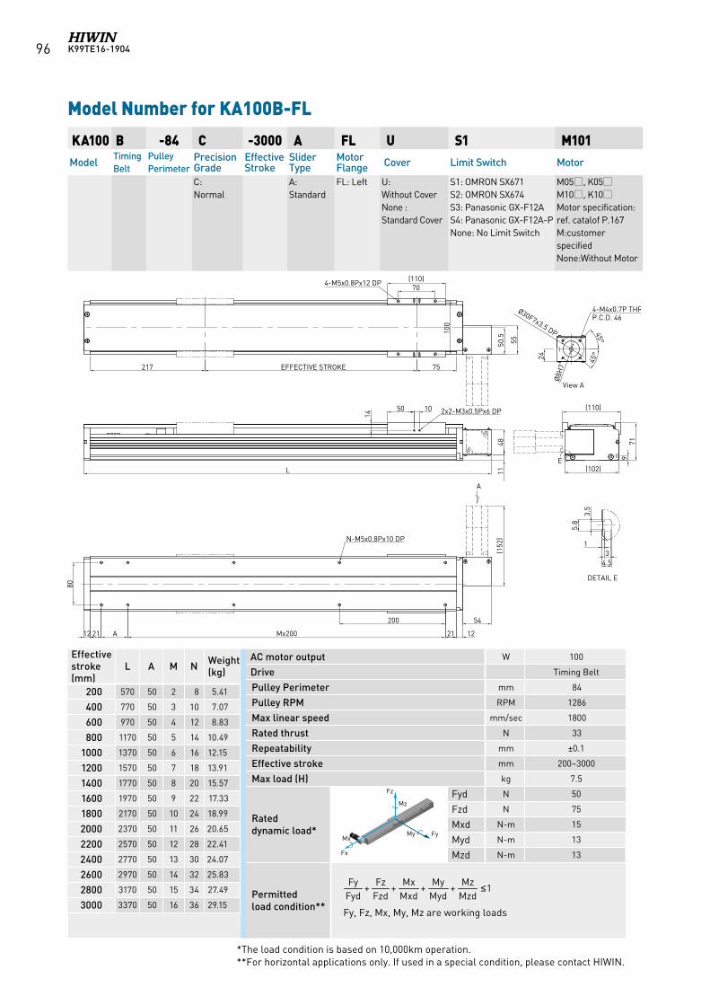
K99TE16-190496
AC motor output W 100
Drive Timing Belt
Pulley Perimeter mm 84
Pulley RPM RPM 1286
Max linear speed mm/sec 1800
Rated thrust N 33
Repeatability mm ±0.1
Effective stroke mm 200~3000
Max load (H) kg 7.5
Rated dynamic load*
Fyd N 50
Fzd N 75
Mxd N-m 15
Myd N-m 13
Mzd N-m 13
Permitted load condition** Fy, Fz, Mx, My, Mz are working loads
KA100 B -84 C -3000 A FL U S1 M101Model
Timing Belt
Pulley Perimeter
Precision Grade
Effective Stroke
Slider Type
Motor Flange Cover Limit Switch Motor
C: Normal
A: Standard
FL: Left U: Without CoverNone : Standard Cover
S1: OMRON SX671 S2: OMRON SX674 S3: Panasonic GX-F12A S4: Panasonic GX-F12A-PNone: No Limit Switch
M05, K05M10, K10Motor specification:ref. catalof P.167M:customer specifiedNone:Without Motor
Model Number for KA100B-FL
Effective stroke (mm)
L A M N Weight (kg)
200 570 50 2 8 5.41
400 770 50 3 10 7.07
600 970 50 4 12 8.83
800 1170 50 5 14 10.49
1000 1370 50 6 16 12.15
1200 1570 50 7 18 13.91
1400 1770 50 8 20 15.57
1600 1970 50 9 22 17.33
1800 2170 50 10 24 18.99
2000 2370 50 11 26 20.65
2200 2570 50 12 28 22.41
2400 2770 50 13 30 24.07
2600 2970 50 14 32 25.83
2800 3170 50 15 34 27.49
3000 3370 50 16 36 29.15
1++++MzdMz
MydMy
MxdMx
FzdFz
FydFy ≤
*The load condition is based on 10,000km operation. **For horizontal applications only. If used in a special condition, please contact HIWIN.
Fz
FyMy Mx
Fx
Mz Fz
FyMy Mx
Fx
Mz
Fz
FyMy Mx
Fx
Mz
Fz
FyMy Mx
Fx
Mz
Fz
FyMy Mx
Fx
Mz
Fz
FyMy Mx
Fx
Mz
Fz
FyMy Mx
Fx
Mz
70(110)
75EFFECTIVE STROKE217
1221Mx200A
200
2112
80
DETAIL E
100
4-M5x0.8Px12 DP
N-M5x0.8Px10 DP
3.5
5.8
34.5
1
View A
A
50 10
14 2x2-M3x0.5Px6 DP
L 1148
4-M4x0.7P THRU P.C.D. 46
24
Ø30F7x3.5 DP
Ø8H
7
45°
45°
50.5
55
(110)
(102)
971
E
54
(152
)
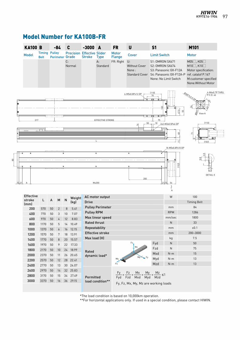
K99TE16-1904 97
AC motor output W 100
Drive Timing Belt
Pulley Perimeter mm 84
Pulley RPM RPM 1286
Max linear speed mm/sec 1800
Rated thrust N 33
Repeatability mm ±0.1
Effective stroke mm 200~3000
Max load (H) kg 7.5
Rated dynamic load*
Fyd N 50
Fzd N 75
Mxd N-m 15
Myd N-m 13
Mzd N-m 13
Permitted load condition** Fy, Fz, Mx, My, Mz are working loads
KA100 B -84 C -3000 A FR U S1 M101Model
Timing Belt
Pulley Perimeter
Precision Grade
Effective Stroke
Slider Type
Motor Flange Cover Limit Switch Motor
C: Normal
A: Standard
FR: Right U: Without CoverNone : Standard Cover
S1: OMRON SX671 S2: OMRON SX674 S3: Panasonic GX-F12A S4: Panasonic GX-F12A-PNone: No Limit Switch
M05, K05M10, K10Motor specification:ref. catalof P.167M:customer specifiedNone:Without Motor
Model Number for KA100B-FR
Effective stroke (mm)
L A M N Weight (kg)
200 570 50 2 8 5.41
400 770 50 3 10 7.07
600 970 50 4 12 8.83
800 1170 50 5 14 10.49
1000 1370 50 6 16 12.15
1200 1570 50 7 18 13.91
1400 1770 50 8 20 15.57
1600 1970 50 9 22 17.33
1800 2170 50 10 24 18.99
2000 2370 50 11 26 20.65
2200 2570 50 12 28 22.41
2400 2770 50 13 30 24.07
2600 2970 50 14 32 25.83
2800 3170 50 15 34 27.49
3000 3370 50 16 36 29.15
1++++MzdMz
MydMy
MxdMx
FzdFz
FydFy ≤
*The load condition is based on 10,000km operation. **For horizontal applications only. If used in a special condition, please contact HIWIN.
Fz
FyMy Mx
Fx
Mz Fz
FyMy Mx
Fx
Mz
Fz
FyMy Mx
Fx
Mz
Fz
FyMy Mx
Fx
Mz
Fz
FyMy Mx
Fx
Mz
Fz
FyMy Mx
Fx
Mz
Fz
FyMy Mx
Fx
Mz
70(110)
75EFFECTIVE STROKE217
1221Mx200A
200
2112
80
DETAIL E
100
4-M5x0.8Px12 DP
N-M5x0.8Px10 DP
3.5
5.8
34.5
1
View A
A
50 10
14 2x2-M3x0.5Px6 DP
L 1148
4-M4x0.7P THRU P.C.D. 46
24
Ø30F7x3.5 DP
Ø8H
7
45°
45°
47.5 55
(110)
(102)
971 E
54
(152
)
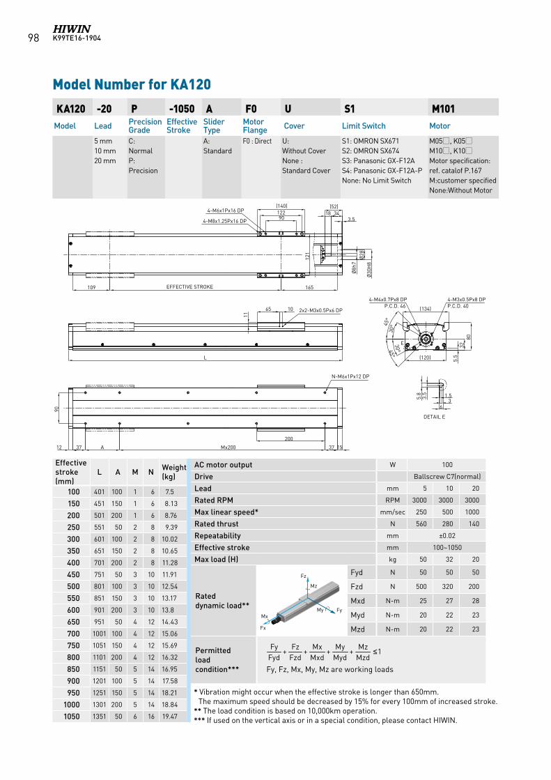
K99TE16-190498
AC motor output W 100
Drive Ballscrew C7(normal)
Lead mm 5 10 20
Rated RPM RPM 3000 3000 3000
Max linear speed* mm/sec 250 500 1000
Rated thrust N 560 280 140
Repeatability mm ±0.02
Effective stroke mm 100~1050
Max load (H) kg 50 32 20
Rated dynamic load**
Fyd N 50 50 50
Fzd N 500 320 200
Mxd N-m 25 27 28
Myd N-m 20 22 23
Mzd N-m 20 22 23
Permitted load condition*** Fy, Fz, Mx, My, Mz are working loads
KA120 -20 P -1050 A F0 U S1 M101Model Lead Precision
GradeEffective Stroke
Slider Type
Motor Flange Cover Limit Switch Motor
5 mm 10 mm 20 mm
C: NormalP: Precision
A: Standard
F0 : Direct U: Without CoverNone : Standard Cover
S1: OMRON SX671 S2: OMRON SX674 S3: Panasonic GX-F12A S4: Panasonic GX-F12A-PNone: No Limit Switch
M05, K05M10, K10Motor specification:ref. catalof P.167M:customer specifiedNone:Without Motor
Model Number for KA120
Effective stroke (mm)
L A M N Weight (kg)
100 401 100 1 6 7.5
150 451 150 1 6 8.13
200 501 200 1 6 8.76
250 551 50 2 8 9.39
300 601 100 2 8 10.02
350 651 150 2 8 10.65
400 701 200 2 8 11.28
450 751 50 3 10 11.91
500 801 100 3 10 12.54
550 851 150 3 10 13.17
600 901 200 3 10 13.8
650 951 50 4 12 14.43
700 1001 100 4 12 15.06
750 1051 150 4 12 15.69
800 1101 200 4 12 16.32
850 1151 50 5 14 16.95
900 1201 100 5 14 17.58
950 1251 150 5 14 18.21
1000 1301 200 5 14 18.84
1050 1351 50 6 16 19.47
1++++MzdMz
MydMy
MxdMx
FzdFz
FydFy ≤
* Vibration might occur when the effective stroke is longer than 650mm. The maximum speed should be decreased by 15% for every 100mm of increased stroke.
** The load condition is based on 10,000km operation.*** If used on the vertical axis or in a special condition, please contact HIWIN.
Fz
FyMy Mx
Fx
Mz
Fz
FyMy Mx
Fx
Mz
Fz
FyMy Mx
Fx
Mz
Fz
FyMy Mx
Fx
Mz
Fz
FyMy Mx
Fx
Mz
Fz
FyMy Mx
Fx
Mz
3418(52)
Ø8h
7Ø
28Ø
30H
8
3.590122(140)
EFFECTIVE STROKE 165109
65 10
11
L
1537
200
Mx2003712
90
(134)
(120) 5.5
3280
E
3.5
5.8 1.5
36
30°
30°
45°
45°
4-M3x0.5Px8 DPP.C.D. 40
4-M4x0.7Px8 DPP.C.D. 46
2x2-M3x0.5Px6 DP
N-M6x1Px12 DP
4-M8x1.25Px16 DP
4-M6x1Px16 DP
DETAIL E
121
A
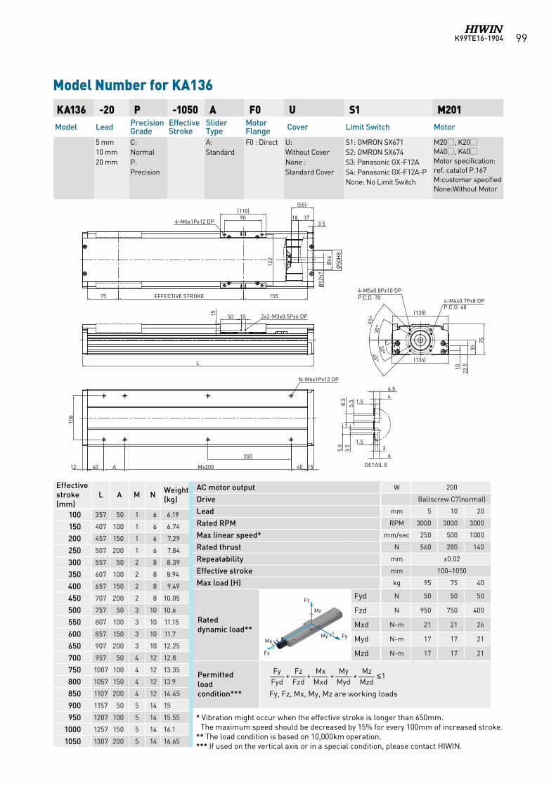
K99TE16-1904 99
AC motor output W 200
Drive Ballscrew C7(normal)
Lead mm 5 10 20
Rated RPM RPM 3000 3000 3000
Max linear speed* mm/sec 250 500 1000
Rated thrust N 560 280 140
Repeatability mm ±0.02
Effective stroke mm 100~1050
Max load (H) kg 95 75 40
Rated dynamic load**
Fyd N 50 50 50
Fzd N 950 750 400
Mxd N-m 21 21 26
Myd N-m 17 17 21
Mzd N-m 17 17 21
Permitted load condition*** Fy, Fz, Mx, My, Mz are working loads
KA136 -20 P -1050 A F0 U S1 M201Model Lead Precision
GradeEffective Stroke
Slider Type
Motor Flange Cover Limit Switch Motor
5 mm 10 mm 20 mm
C: NormalP: Precision
A: Standard
F0 : Direct U: Without CoverNone : Standard Cover
S1: OMRON SX671 S2: OMRON SX674 S3: Panasonic GX-F12A S4: Panasonic GX-F12A-PNone: No Limit Switch
M20, K20M40, K40Motor specification:ref. catalof P.167M:customer specifiedNone:Without Motor
Model Number for KA136
Effective stroke (mm)
L A M N Weight (kg)
100 357 50 1 6 6.19
150 407 100 1 6 6.74
200 457 150 1 6 7.29
250 507 200 1 6 7.84
300 557 50 2 8 8.39
350 607 100 2 8 8.94
400 657 150 2 8 9.49
450 707 200 2 8 10.05
500 757 50 3 10 10.6
550 807 100 3 10 11.15
600 857 150 3 10 11.7
650 907 200 3 10 12.25
700 957 50 4 12 12.8
750 1007 100 4 12 13.35
800 1057 150 4 12 13.9
850 1107 200 4 12 14.45
900 1157 50 5 14 15
950 1207 100 5 14 15.55
1000 1257 150 5 14 16.1
1050 1307 200 5 14 16.65
1++++MzdMz
MydMy
MxdMx
FzdFz
FydFy ≤
* Vibration might occur when the effective stroke is longer than 650mm. The maximum speed should be decreased by 15% for every 100mm of increased stroke.
** The load condition is based on 10,000km operation.*** If used on the vertical axis or in a special condition, please contact HIWIN.
Fz
FyMy Mx
Fx
Mz
Fz
FyMy Mx
Fx
Mz
Fz
FyMy Mx
Fx
Mz
Fz
FyMy Mx
Fx
Mz
Fz
FyMy Mx
Fx
Mz
Fz
FyMy Mx
Fx
Mz
Fz
FyMy Mx
Fx
Mz
4-M6x1Px12 DP
DETAIL E
E
2x2-M3x0.5Px6 DP
4-M5x0.8Px10 DPP.C.D. 70 4-M4x0.7Px8 DP
P.C.D. 60
N-M6x1Px12 DP
40
200
Mx20040
15 1050
(136)
(135)
15575
90(110)
122
15
L
1022
.535
75
EFFECTIVE STROKE
12
3.5
5.8
5.58.3 1.5
46.5
1.53
6
106
Ø46
Ø50
H8
(55)
373.5
45°
30°
30°45°
18
Ø12
h7
A
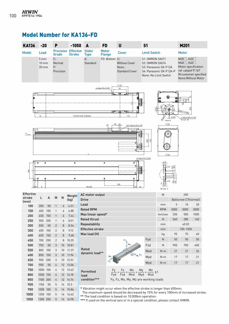
K99TE16-1904100
AC motor output W 200
Drive Ballscrew C7(normal)
Lead mm 5 10 20
Rated RPM RPM 3000 3000 3000
Max linear speed* mm/sec 250 500 1000
Rated thrust N 560 280 140
Repeatability mm ±0.02
Effective stroke mm 100~1050
Max load (H) kg 95 75 40
Rated dynamic load**
Fyd N 50 50 50
Fzd N 950 750 400
Mxd N-m 21 21 26
Myd N-m 17 17 21
Mzd N-m 17 17 21
Permitted load condition*** Fy, Fz, Mx, My, Mz are working loads
KA136 -20 P -1050 A FD U S1 M201Model Lead Precision
GradeEffective Stroke
Slider Type
Motor Flange Cover Limit Switch Motor
5 mm 10 mm 20 mm
C: NormalP: Precision
A: Standard
FD: Bottom U: Without CoverNone : Standard Cover
S1: OMRON SX671 S2: OMRON SX674 S3: Panasonic GX-F12A S4: Panasonic GX-F12A-PNone: No Limit Switch
M20, K20M40, K40Motor specification:ref. catalof P.167M:customer specifiedNone:Without Motor
Model Number for KA136-FD
Effective stroke (mm)
L A M N Weight (kg)
100 350 50 1 6 6.31
150 400 100 1 6 6.88
200 450 150 1 6 7.44
250 500 200 1 6 8.01
300 550 50 2 8 8.56
350 600 100 2 8 9.12
400 650 150 2 8 9.68
450 700 200 2 8 10.25
500 750 50 3 10 10.81
550 800 100 3 10 11.37
600 850 150 3 10 11.94
650 900 200 3 10 12.51
700 950 50 4 12 13.06
750 1000 100 4 12 13.62
800 1050 150 4 12 14.18
850 1100 200 4 12 14.74
900 1150 50 5 14 15.3
950 1200 100 5 14 15.86
1000 1250 150 5 14 16.42
1050 1300 200 5 14 16.98
1++++MzdMz
MydMy
MxdMx
FzdFz
FydFy ≤
* Vibration might occur when the effective stroke is longer than 650mm. The maximum speed should be decreased by 15% for every 100mm of increased stroke.
** The load condition is based on 10,000km operation.*** If used on the vertical axis or in a special condition, please contact HIWIN.
Fz
FyMy Mx
Fx
Mz
Fz
FyMy Mx
Fx
Mz
Fz
FyMy Mx
Fx
Mz
Fz
FyMy Mx
Fx
Mz
Fz
FyMy Mx
Fx
Mz
Fz
FyMy Mx
Fx
Mz
Fz
FyMy Mx
Fx
Mz
DETAIL E
3.5
5.8
5.5 8.31.5
46.5
1.53
6
(135)
(136)
90
(110)4-M6x1Px12 DP
122
75 EFFECTIVE STROKE 115
2X2-M3x0.5Px6 DP15
50 10
L
1220 20 48Mx200
N-M6x1Px12 DP
(85)
A200
E
1022
.5
75(8
3)
150
45°
45°
Ø14H
7
Ø50F7 THRU
View A
16.3
5JS9 4-M5x0.8Px10 DPP.C.D. 70
35
106
A
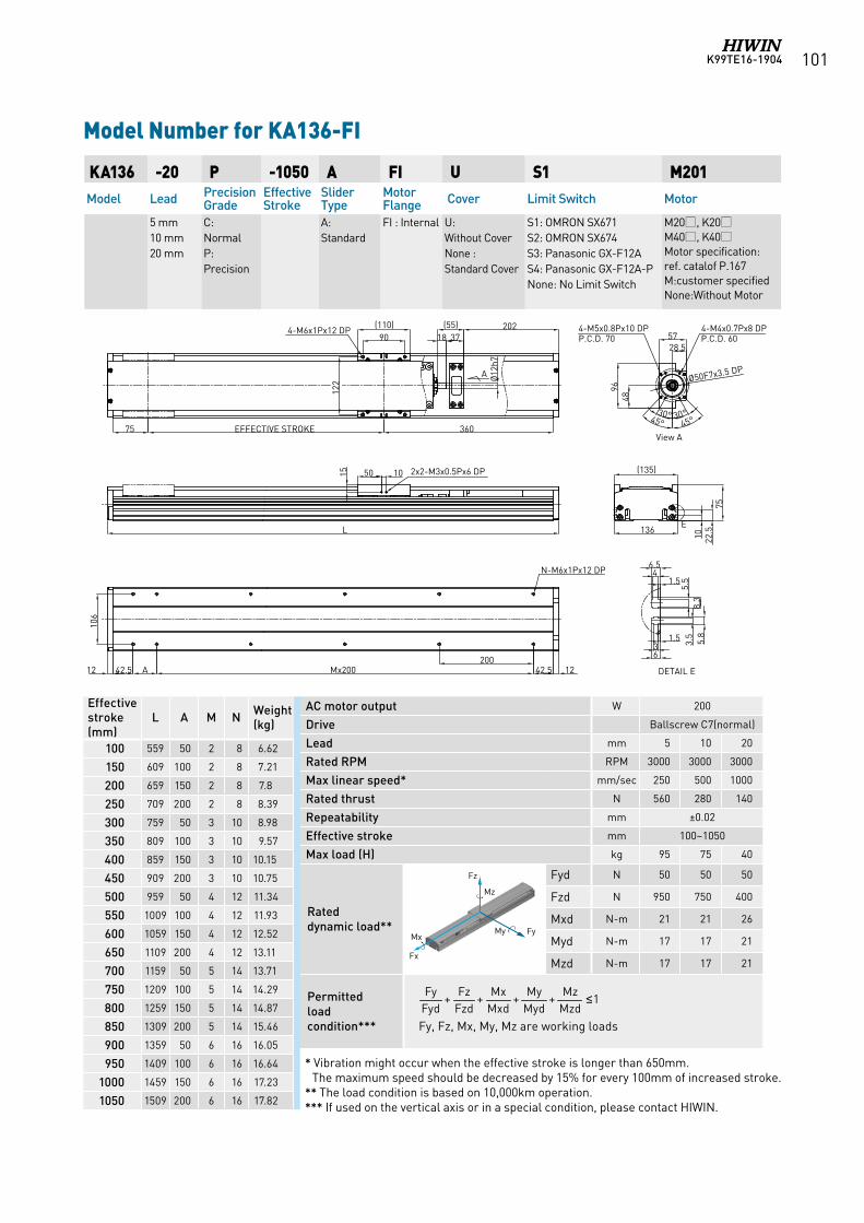
K99TE16-1904 101
AC motor output W 200
Drive Ballscrew C7(normal)
Lead mm 5 10 20
Rated RPM RPM 3000 3000 3000
Max linear speed* mm/sec 250 500 1000
Rated thrust N 560 280 140
Repeatability mm ±0.02
Effective stroke mm 100~1050
Max load (H) kg 95 75 40
Rated dynamic load**
Fyd N 50 50 50
Fzd N 950 750 400
Mxd N-m 21 21 26
Myd N-m 17 17 21
Mzd N-m 17 17 21
Permitted load condition*** Fy, Fz, Mx, My, Mz are working loads
KA136 -20 P -1050 A FI U S1 M201Model Lead Precision
GradeEffective Stroke
Slider Type
Motor Flange Cover Limit Switch Motor
5 mm 10 mm 20 mm
C: NormalP: Precision
A: Standard
FI : Internal
U: Without CoverNone : Standard Cover
S1: OMRON SX671 S2: OMRON SX674 S3: Panasonic GX-F12A S4: Panasonic GX-F12A-PNone: No Limit Switch
M20, K20M40, K40Motor specification:ref. catalof P.167M:customer specifiedNone:Without Motor
Model Number for KA136-FI
Effective stroke (mm)
L A M N Weight (kg)
100 559 50 2 8 6.62
150 609 100 2 8 7.21
200 659 150 2 8 7.8
250 709 200 2 8 8.39
300 759 50 3 10 8.98
350 809 100 3 10 9.57
400 859 150 3 10 10.15
450 909 200 3 10 10.75
500 959 50 4 12 11.34
550 1009 100 4 12 11.93
600 1059 150 4 12 12.52
650 1109 200 4 12 13.11
700 1159 50 5 14 13.71
750 1209 100 5 14 14.29
800 1259 150 5 14 14.87
850 1309 200 5 14 15.46
900 1359 50 6 16 16.05
950 1409 100 6 16 16.64
1000 1459 150 6 16 17.23
1050 1509 200 6 16 17.82
1++++MzdMz
MydMy
MxdMx
FzdFz
FydFy ≤
* Vibration might occur when the effective stroke is longer than 650mm. The maximum speed should be decreased by 15% for every 100mm of increased stroke.
** The load condition is based on 10,000km operation.*** If used on the vertical axis or in a special condition, please contact HIWIN.
Fz
FyMy Mx
Fx
Mz
Fz
FyMy Mx
Fx
Mz
Fz
FyMy Mx
Fx
Mz
Fz
FyMy Mx
Fx
Mz
Fz
FyMy Mx
Fx
Mz
Fz
FyMy Mx
Fx
Mz
Fz
FyMy Mx
Fx
Mz
4-M6x1Px12 DP 4-M5x0.8Px10 DP P.C.D. 70
4-M4x0.7Px8 DP P.C.D. 60
360EFFECTIVE STROKE75
90(110)
50 1015
L
200Mx200
(135)
136
1.536
3.5
5.8
5.5
8.3
46.5
10
N-M6x1Px12 DP
2x2-M3x0.5Px6 DP
E
DETAIL E
75
18
Ø12
h7
View A
122
37202(55)
1.5
A 42.5 1242.512
A Ø50F7x3.5 DP
4896
45° 45°
28.557
106
22.5
30° 30°
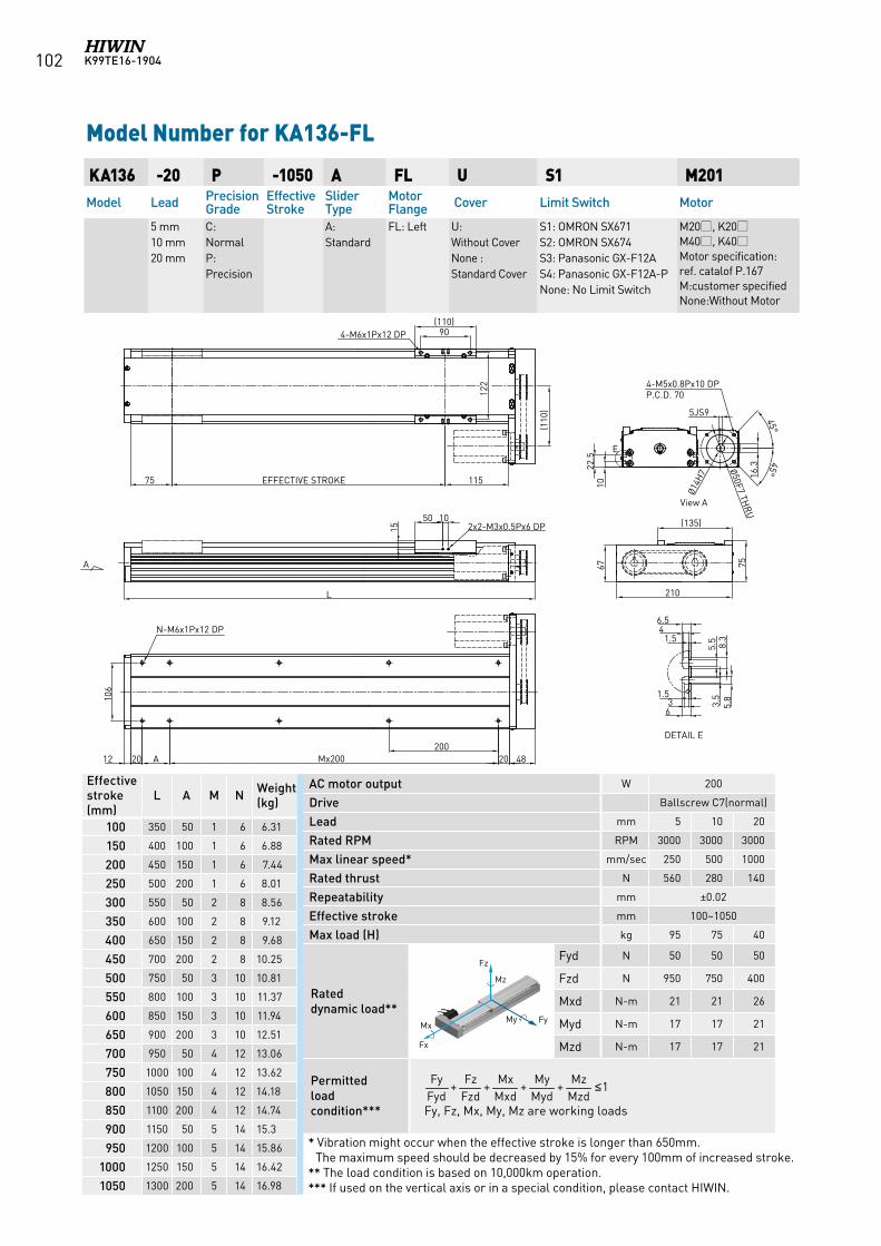
K99TE16-1904102
AC motor output W 200
Drive Ballscrew C7(normal)
Lead mm 5 10 20
Rated RPM RPM 3000 3000 3000
Max linear speed* mm/sec 250 500 1000
Rated thrust N 560 280 140
Repeatability mm ±0.02
Effective stroke mm 100~1050
Max load (H) kg 95 75 40
Rated dynamic load**
Fyd N 50 50 50
Fzd N 950 750 400
Mxd N-m 21 21 26
Myd N-m 17 17 21
Mzd N-m 17 17 21
Permitted load condition*** Fy, Fz, Mx, My, Mz are working loads
KA136 -20 P -1050 A FL U S1 M201Model Lead Precision
GradeEffective Stroke
Slider Type
Motor Flange Cover Limit Switch Motor
5 mm 10 mm 20 mm
C: NormalP: Precision
A: Standard
FL: Left U: Without CoverNone : Standard Cover
S1: OMRON SX671 S2: OMRON SX674 S3: Panasonic GX-F12A S4: Panasonic GX-F12A-PNone: No Limit Switch
M20, K20M40, K40Motor specification:ref. catalof P.167M:customer specifiedNone:Without Motor
Model Number for KA136-FL
Effective stroke (mm)
L A M N Weight (kg)
100 350 50 1 6 6.31
150 400 100 1 6 6.88
200 450 150 1 6 7.44
250 500 200 1 6 8.01
300 550 50 2 8 8.56
350 600 100 2 8 9.12
400 650 150 2 8 9.68
450 700 200 2 8 10.25
500 750 50 3 10 10.81
550 800 100 3 10 11.37
600 850 150 3 10 11.94
650 900 200 3 10 12.51
700 950 50 4 12 13.06
750 1000 100 4 12 13.62
800 1050 150 4 12 14.18
850 1100 200 4 12 14.74
900 1150 50 5 14 15.3
950 1200 100 5 14 15.86
1000 1250 150 5 14 16.42
1050 1300 200 5 14 16.98
1++++MzdMz
MydMy
MxdMx
FzdFz
FydFy ≤
* Vibration might occur when the effective stroke is longer than 650mm. The maximum speed should be decreased by 15% for every 100mm of increased stroke.
** The load condition is based on 10,000km operation.*** If used on the vertical axis or in a special condition, please contact HIWIN.
Fz
FyMy Mx
Fx
Mz
Fz
FyMy Mx
Fx
Mz
Fz
FyMy Mx
Fx
Mz
Fz
FyMy Mx
Fx
Mz
Fz
FyMy Mx
Fx
Mz
Fz
FyMy Mx
Fx
Mz
Fz
FyMy Mx
Fx
Mz
A
12 20 A Mx200 20
75 EFFECTIVE STROKE 115
90(110)
4-M6x1Px12 DP
N-M6x1Px12 DP
20048
122
View A
E
1022
.5
(110
)
Ø50F7 THR
U
106
Ø14H
7
5JS9
16.3
45°45°
210
(135)
67 75
4-M5x0.8Px10 DPP.C.D. 70
L
2x2-M3x0.5Px6 DP15
50 10
DETAIL E
3.5
5.8
5.5 8.31.5
46.5
1.53
6
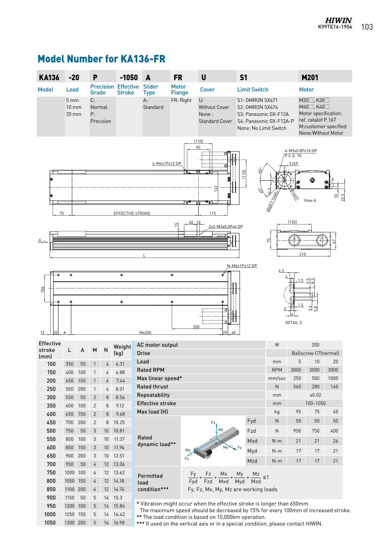
K99TE16-1904 103
AC motor output W 200
Drive Ballscrew C7(normal)
Lead mm 5 10 20
Rated RPM RPM 3000 3000 3000
Max linear speed* mm/sec 250 500 1000
Rated thrust N 560 280 140
Repeatability mm ±0.02
Effective stroke mm 100~1050
Max load (H) kg 95 75 40
Rated dynamic load**
Fyd N 50 50 50
Fzd N 950 750 400
Mxd N-m 21 21 26
Myd N-m 17 17 21
Mzd N-m 17 17 21
Permitted load condition*** Fy, Fz, Mx, My, Mz are working loads
KA136 -20 P -1050 A FR U S1 M201Model Lead Precision
GradeEffective Stroke
Slider Type
Motor Flange Cover Limit Switch Motor
5 mm 10 mm 20 mm
C: NormalP: Precision
A: Standard
FR: Right U: Without CoverNone : Standard Cover
S1: OMRON SX671 S2: OMRON SX674 S3: Panasonic GX-F12A S4: Panasonic GX-F12A-PNone: No Limit Switch
M20, K20M40, K40Motor specification:ref. catalof P.167M:customer specifiedNone:Without Motor
Model Number for KA136-FR
Effective stroke (mm)
L A M N Weight (kg)
100 350 50 1 6 6.31
150 400 100 1 6 6.88
200 450 150 1 6 7.44
250 500 200 1 6 8.01
300 550 50 2 8 8.56
350 600 100 2 8 9.12
400 650 150 2 8 9.68
450 700 200 2 8 10.25
500 750 50 3 10 10.81
550 800 100 3 10 11.37
600 850 150 3 10 11.94
650 900 200 3 10 12.51
700 950 50 4 12 13.06
750 1000 100 4 12 13.62
800 1050 150 4 12 14.18
850 1100 200 4 12 14.74
900 1150 50 5 14 15.3
950 1200 100 5 14 15.86
1000 1250 150 5 14 16.42
1050 1300 200 5 14 16.98
1++++MzdMz
MydMy
MxdMx
FzdFz
FydFy ≤
* Vibration might occur when the effective stroke is longer than 650mm. The maximum speed should be decreased by 15% for every 100mm of increased stroke.
** The load condition is based on 10,000km operation.*** If used on the vertical axis or in a special condition, please contact HIWIN.
Fz
FyMy Mx
Fx
Mz
Fz
FyMy Mx
Fx
Mz
Fz
FyMy Mx
Fx
Mz
Fz
FyMy Mx
Fx
Mz
Fz
FyMy Mx
Fx
Mz
Fz
FyMy Mx
Fx
Mz
Fz
FyMy Mx
Fx
Mz
12 20 A Mx200 20
L
75 EFFECTIVE STROKE 115
90(110)
4-M6x1Px12 DP
2x2-M3x0.5Px6 DP1050
15
N-M6x1Px12 DP
210
20048
122
(135)
View A
E
10
22.5
(110
)
4-M5x0.8Px10 DPP.C.D. 70
67
Ø50F
7 TH
RU
DETAIL E
3.5
5.8
5.5
8.31.5
46.5
1.53
6
106
Ø14H7
5JS9
16.3
75
45°
45°
A
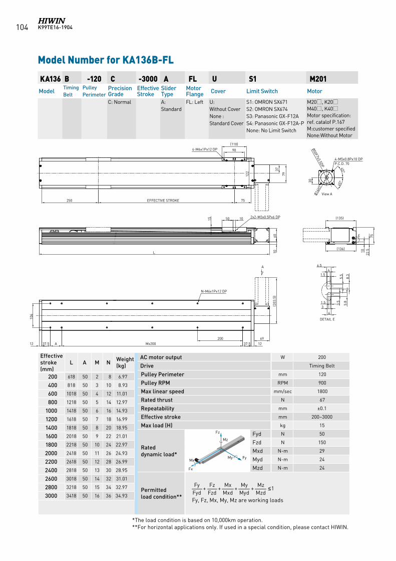
K99TE16-1904104
AC motor output W 200
Drive Timing Belt
Pulley Perimeter mm 120
Pulley RPM RPM 900
Max linear speed mm/sec 1800
Rated thrust N 67
Repeatability mm ±0.1
Effective stroke mm 200~3000
Max load (H) kg 15
Rated dynamic load*
Fyd N 50
Fzd N 150
Mxd N-m 29
Myd N-m 24
Mzd N-m 24
Permitted load condition** Fy, Fz, Mx, My, Mz are working loads
KA136 B -120 C -3000 A FL U S1 M201Model
Timing Belt
Pulley Perimeter
Precision Grade
Effective Stroke
Slider Type
Motor Flange Cover Limit Switch Motor
C: Normal A: Standard
FL: Left U: Without CoverNone : Standard Cover
S1: OMRON SX671 S2: OMRON SX674 S3: Panasonic GX-F12A S4: Panasonic GX-F12A-PNone: No Limit Switch
M20, K20M40, K40Motor specification:ref. catalof P.167M:customer specifiedNone:Without Motor
Model Number for KA136B-FL
Effective stroke (mm)
L A M N Weight (kg)
200 618 50 2 8 6.97
400 818 50 3 10 8.93
600 1018 50 4 12 11.01
800 1218 50 5 14 12.97
1000 1418 50 6 16 14.93
1200 1618 50 7 18 16.99
1400 1818 50 8 20 18.95
1600 2018 50 9 22 21.01
1800 2218 50 10 24 22.97
2000 2418 50 11 26 24.93
2200 2618 50 12 28 26.99
2400 2818 50 13 30 28.95
2600 3018 50 14 32 31.01
2800 3218 50 15 34 32.97
3000 3418 50 16 36 34.93
1++++MzdMz
MydMy
MxdMx
FzdFz
FydFy ≤
*The load condition is based on 10,000km operation. **For horizontal applications only. If used in a special condition, please contact HIWIN.
Fz
FyMy Mx
Fx
Mz
Fz
FyMy Mx
Fx
Mz
Fz
FyMy Mx
Fx
Mz
Fz
FyMy Mx
Fx
Mz
Fz
FyMy Mx
Fx
Mz
Fz
FyMy Mx
Fx
Mz
Fz
FyMy Mx
Fx
Mz
DETAIL E
250 EFFECTIVE STROKE 75
90
(110)
122
37.5Mx20037.5
106
4-M6x1Px12 DP
N-M6x1Px12 DP
A
A 1212200
105015
2x2-M3x0.5Px6 DP
L
E
1060
46.5
5.5
8.3
3.5
5.81.5
3
6
1.5
1022
.575
(135)
(136)
View A
37
79
69
(203
.5)
30
45°
45°
4-M5x0.8Px10 DPP.C.D. 70
Ø14H
7
Ø50F7x3.5DP
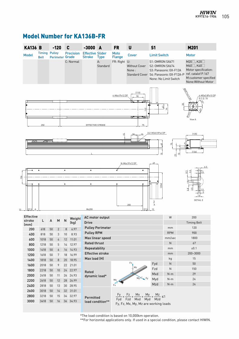
K99TE16-1904 105
AC motor output W 200
Drive Timing Belt
Pulley Perimeter mm 120
Pulley RPM RPM 900
Max linear speed mm/sec 1800
Rated thrust N 67
Repeatability mm ±0.1
Effective stroke mm 200~3000
Max load (H) kg 15
Rated dynamic load*
Fyd N 50
Fzd N 150
Mxd N-m 29
Myd N-m 24
Mzd N-m 24
Permitted load condition** Fy, Fz, Mx, My, Mz are working loads
KA136 B -120 C -3000 A FR U S1 M201Model
Timing Belt
Pulley Perimeter
Precision Grade
Effective Stroke
Slider Type
Moto Flange Cover Limit Switch Motor
C: Normal A: Standard
FR: Right U: Without CoverNone : Standard Cover
S1: OMRON SX671 S2: OMRON SX674 S3: Panasonic GX-F12A S4: Panasonic GX-F12A-PNone: No Limit Switch
M20, K20M40, K40Motor specification:ref. catalof P.167M:customer specifiedNone:Without Motor
Model Number for KA136B-FR
Effective stroke (mm)
L A M N Weight (kg)
200 618 50 2 8 6.97
400 818 50 3 10 8.93
600 1018 50 4 12 11.01
800 1218 50 5 14 12.97
1000 1418 50 6 16 14.93
1200 1618 50 7 18 16.99
1400 1818 50 8 20 18.95
1600 2018 50 9 22 21.01
1800 2218 50 10 24 22.97
2000 2418 50 11 26 24.93
2200 2618 50 12 28 26.99
2400 2818 50 13 30 28.95
2600 3018 50 14 32 31.01
2800 3218 50 15 34 32.97
3000 3418 50 16 36 34.93
1++++MzdMz
MydMy
MxdMx
FzdFz
FydFy ≤
*The load condition is based on 10,000km operation. **For horizontal applications only. If used in a special condition, please contact HIWIN.
Fz
FyMy Mx
Fx
Mz
Fz
FyMy Mx
Fx
Mz
Fz
FyMy Mx
Fx
Mz
Fz
FyMy Mx
Fx
Mz
Fz
FyMy Mx
Fx
Mz
Fz
FyMy Mx
Fx
Mz
Fz
FyMy Mx
Fx
Mz
250 EFFECTIVE STROKE 75
90
(110)
122
37.5Mx20037.5
106
4-M6x1Px12 DP
N-M6x1Px12 DP
DETAIL E
A
A 1212
200
105015
2x2-M3x0.5Px6 DP
L
E
1060
46.5
5.5
8.3
3.5
5.8 1.5
3
6
1.5
1023
75
(135)
(136)
View A
42
79
69(2
04)
30
45°
45°
4-M5x0.8Px10 DPP.C.D. 70
Ø50F7x3.5 DP
Ø14
H7
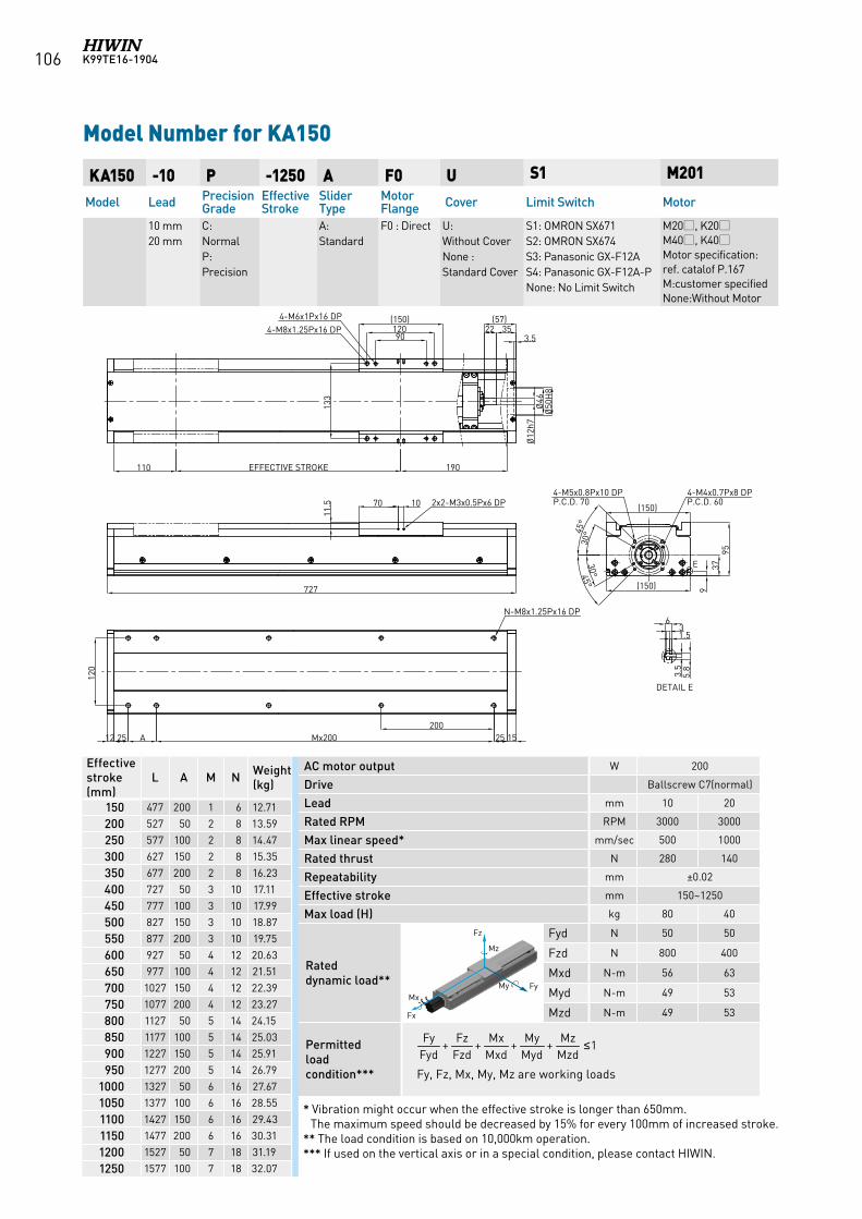
K99TE16-1904106
AC motor output W 200
Drive Ballscrew C7(normal)
Lead mm 10 20
Rated RPM RPM 3000 3000
Max linear speed* mm/sec 500 1000
Rated thrust N 280 140
Repeatability mm ±0.02
Effective stroke mm 150~1250
Max load (H) kg 80 40
Rated dynamic load**
Fyd N 50 50
Fzd N 800 400
Mxd N-m 56 63
Myd N-m 49 53
Mzd N-m 49 53
Permitted load condition*** Fy, Fz, Mx, My, Mz are working loads
KA150 -10 P -1250 A F0 U S1 M201
Model Lead Precision Grade
Effective Stroke
Slider Type
Motor Flange Cover Limit Switch Motor
10 mm 20 mm
C: NormalP: Precision
A: Standard
F0 : Direct U: Without CoverNone : Standard Cover
S1: OMRON SX671 S2: OMRON SX674 S3: Panasonic GX-F12A S4: Panasonic GX-F12A-PNone: No Limit Switch
M20, K20M40, K40Motor specification:ref. catalof P.167M:customer specifiedNone:Without Motor
Model Number for KA150
Effective stroke (mm)
L A M N Weight (kg)
150 477 200 1 6 12.71
200 527 50 2 8 13.59
250 577 100 2 8 14.47
300 627 150 2 8 15.35
350 677 200 2 8 16.23
400 727 50 3 10 17.11
450 777 100 3 10 17.99
500 827 150 3 10 18.87
550 877 200 3 10 19.75
600 927 50 4 12 20.63
650 977 100 4 12 21.51
700 1027 150 4 12 22.39
750 1077 200 4 12 23.27
800 1127 50 5 14 24.15
850 1177 100 5 14 25.03
900 1227 150 5 14 25.91
950 1277 200 5 14 26.79
1000 1327 50 6 16 27.67
1050 1377 100 6 16 28.55
1100 1427 150 6 16 29.43
1150 1477 200 6 16 30.31
1200 1527 50 7 18 31.19
1250 1577 100 7 18 32.07
1++++MzdMz
MydMy
MxdMx
FzdFz
FydFy ≤
* Vibration might occur when the effective stroke is longer than 650mm. The maximum speed should be decreased by 15% for every 100mm of increased stroke.
** The load condition is based on 10,000km operation.*** If used on the vertical axis or in a special condition, please contact HIWIN.
Fz
FyMy Mx
Fx
Mz
Fz
FyMy Mx
Fx
Mz
Fz
FyMy Mx
Fx
Mz
Fz
FyMy Mx
Fx
Mz
Fz
FyMy Mx
Fx
Mz
Fz
FyMy Mx
Fx
Mz
190
90120(150)
133
Ø12
h7Ø
46Ø
50H
8
3.5
3.5
5.8
6
1.53
937
95
1525
120
4-M8x1.25Px16 DP
E
DETAIL E
4-M4x0.7Px8 DPP.C.D. 60
4-M5x0.8Px10 DPP.C.D. 70
N-M8x1.25Px16 DP
(150)
35(57)
22
30°
30°45
°
45°
4-M6x1Px16 DP
70 10
11.5 2x2-M3x0.5Px6 DP
EFFECTIVE STROKE110
200Mx200A25
727
12
(150)
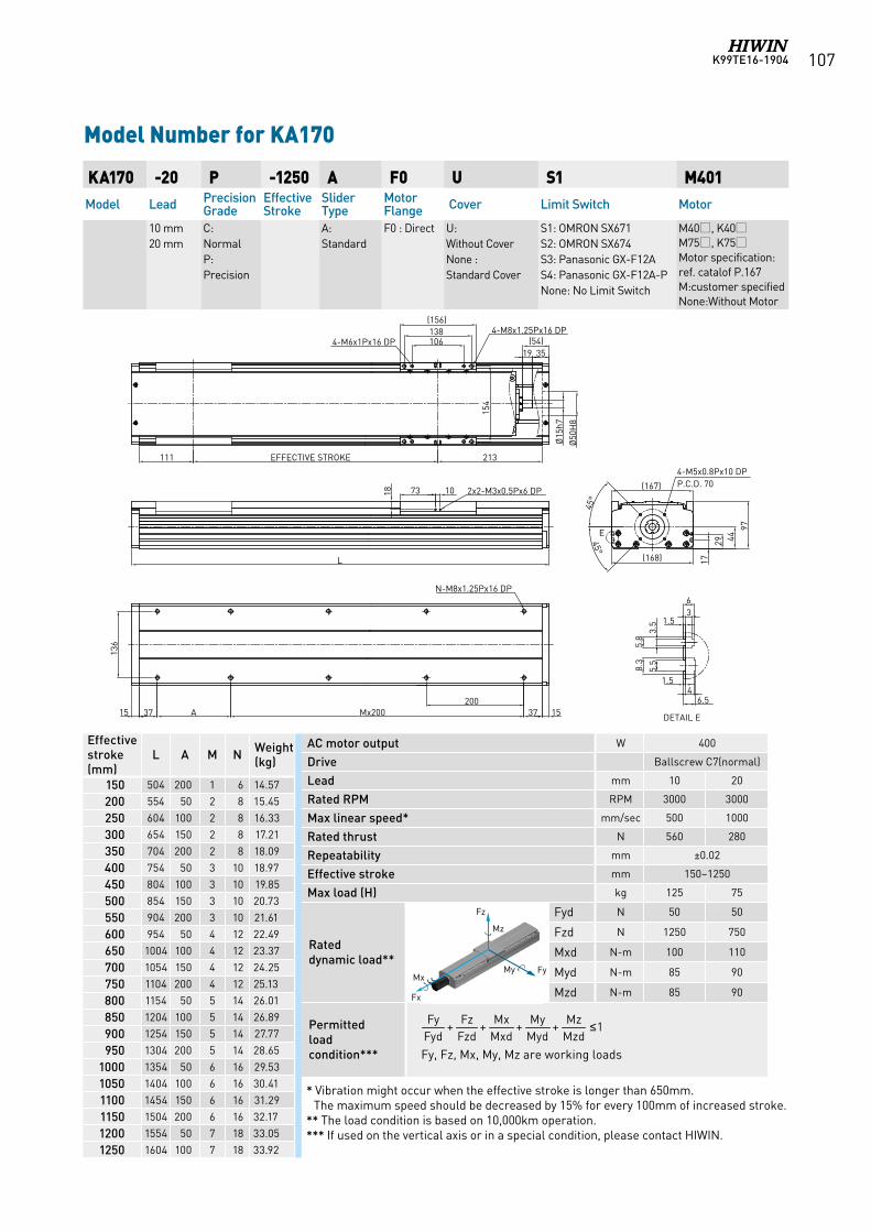
K99TE16-1904 107
AC motor output W 400
Drive Ballscrew C7(normal)
Lead mm 10 20
Rated RPM RPM 3000 3000
Max linear speed* mm/sec 500 1000
Rated thrust N 560 280
Repeatability mm ±0.02
Effective stroke mm 150~1250
Max load (H) kg 125 75
Rated dynamic load**
Fyd N 50 50
Fzd N 1250 750
Mxd N-m 100 110
Myd N-m 85 90
Mzd N-m 85 90
Permitted load condition*** Fy, Fz, Mx, My, Mz are working loads
KA170 -20 P -1250 A F0 U S1 M401Model Lead Precision
GradeEffective Stroke
Slider Type
Motor Flange Cover Limit Switch Motor
10 mm 20 mm
C: NormalP: Precision
A: Standard
F0 : Direct U: Without CoverNone : Standard Cover
S1: OMRON SX671 S2: OMRON SX674 S3: Panasonic GX-F12A S4: Panasonic GX-F12A-PNone: No Limit Switch
M40, K40M75, K75Motor specification:ref. catalof P.167M:customer specifiedNone:Without Motor
Model Number for KA170
Effective stroke (mm)
L A M N Weight (kg)
150 504 200 1 6 14.57
200 554 50 2 8 15.45
250 604 100 2 8 16.33
300 654 150 2 8 17.21
350 704 200 2 8 18.09
400 754 50 3 10 18.97
450 804 100 3 10 19.85
500 854 150 3 10 20.73
550 904 200 3 10 21.61
600 954 50 4 12 22.49
650 1004 100 4 12 23.37
700 1054 150 4 12 24.25
750 1104 200 4 12 25.13
800 1154 50 5 14 26.01
850 1204 100 5 14 26.89
900 1254 150 5 14 27.77
950 1304 200 5 14 28.65
1000 1354 50 6 16 29.53
1050 1404 100 6 16 30.41
1100 1454 150 6 16 31.29
1150 1504 200 6 16 32.17
1200 1554 50 7 18 33.05
1250 1604 100 7 18 33.92
1++++MzdMz
MydMy
MxdMx
FzdFz
FydFy ≤
* Vibration might occur when the effective stroke is longer than 650mm. The maximum speed should be decreased by 15% for every 100mm of increased stroke.
** The load condition is based on 10,000km operation.*** If used on the vertical axis or in a special condition, please contact HIWIN.
Fz
FyMy Mx
Fx
Mz
Fz
FyMy Mx
Fx
Mz
Fz
FyMy Mx
Fx
Mz
Fz
FyMy Mx
Fx
Mz
Fz
FyMy Mx
Fx
Mz
Fz
FyMy Mx
Fx
Mz
Fz
FyMy Mx
Fx
Mz
17
29
97
(167)
(168)
45°
Ø15
h7
Ø50
H8
3519106138
154
111 213
136
1537200
Mx200A3715
45°
107318
36
1.5
1.54
6.5
3.5
5.8
5.5
8.3
44
(156)
(54)
EFFECTIVE STROKE
L
4-M5x0.8Px10 DPP.C.D. 70
4-M6x1Px16 DP4-M8x1.25Px16 DP
N-M8x1.25Px16 DP
DETAIL E
E
2x2-M3x0.5Px6 DP
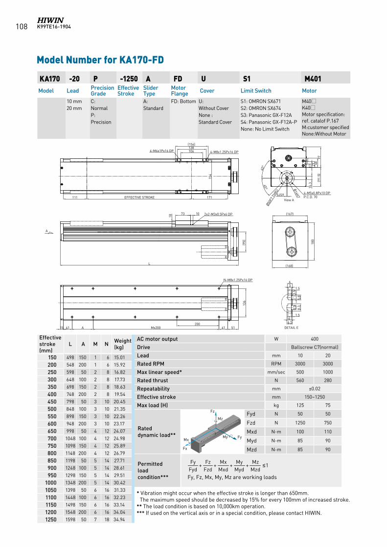
K99TE16-1904108
KA170 -20 P -1250 A FD U S1 M401Model Lead Precision
GradeEffective Stroke
Slider Type
Motor Flange Cover Limit Switch Motor
10 mm 20 mm
C: NormalP: Precision
A: Standard
FD: Bottom U: Without CoverNone : Standard Cover
S1: OMRON SX671 S2: OMRON SX674 S3: Panasonic GX-F12A S4: Panasonic GX-F12A-PNone: No Limit Switch
M40K40Motor specification:ref. catalof P.167M:customer specifiedNone:Without Motor
Model Number for KA170-FD
Effective stroke (mm)
L A M N Weight (kg)
150 498 150 1 6 15.01
200 548 200 1 6 15.92
250 598 50 2 8 16.82
300 648 100 2 8 17.73
350 698 150 2 8 18.63
400 748 200 2 8 19.54
450 798 50 3 10 20.45
500 848 100 3 10 21.35
550 898 150 3 10 22.26
600 948 200 3 10 23.17
650 998 50 4 12 24.07
700 1048 100 4 12 24.98
750 1098 150 4 12 25.89
800 1148 200 4 12 26.79
850 1198 50 5 14 27.71
900 1248 100 5 14 28.61
950 1298 150 5 14 29.51
1000 1348 200 5 14 30.42
1050 1398 50 6 16 31.33
1100 1448 100 6 16 32.23
1150 1498 150 6 16 33.14
1200 1548 200 6 16 34.04
1250 1598 50 7 18 34.94
AC motor output W 400
Drive Ballscrew C7(normal)
Lead mm 10 20
Rated RPM RPM 3000 3000
Max linear speed* mm/sec 500 1000
Rated thrust N 560 280
Repeatability mm ±0.02
Effective stroke mm 150~1250
Max load (H) kg 125 75
Rated dynamic load**
Fyd N 50 50
Fzd N 1250 750
Mxd N-m 100 110
Myd N-m 85 90
Mzd N-m 85 90
Permitted load condition*** Fy, Fz, Mx, My, Mz are working loads
1++++MzdMz
MydMy
MxdMx
FzdFz
FydFy ≤
* Vibration might occur when the effective stroke is longer than 650mm. The maximum speed should be decreased by 15% for every 100mm of increased stroke.
** The load condition is based on 10,000km operation.*** If used on the vertical axis or in a special condition, please contact HIWIN.
Fz
FyMy Mx
Fx
Mz
Fz
FyMy Mx
Fx
Mz
Fz
FyMy Mx
Fx
Mz
Fz
FyMy Mx
Fx
Mz
Fz
FyMy Mx
Fx
Mz
Fz
FyMy Mx
Fx
Mz
Fz
FyMy Mx
Fx
Mz
36
1.5
1.546.5
3.5
5.8
5.5
8.3
106138
154
4-M6x1Px16 DP 4-M8x1.25Px16 DP
111 EFFECTIVE STROKE
(156)
171
L
20015 41 A 41 51
N-M8x1.25Px16 DP
136
1073
18
2x2-M3x0.5Px6 DP
(95)
Mx200
(168)
(167)
17 29
9744
45°
45°
4-M5x0.8Px10 DPP.C.D. 70
180
Ø50F
7 TH
RU
(91.
5)
A
Ø14H7
16.3
5JS9
DETAIL E
E
View A
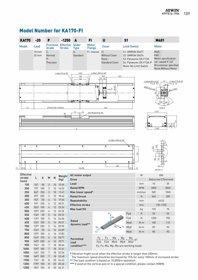
K99TE16-1904 109
KA170 -20 P -1250 A FI U S1 M401Model Lead Precision
GradeEffective Stroke
Slider Type
Motor Flange Cover Limit Switch Motor
10 mm 20 mm
C: NormalP: Precision
A: Standard
FI : Internal
U: Without CoverNone : Standard Cover
S1: OMRON SX671 S2: OMRON SX674 S3: Panasonic GX-F12A S4: Panasonic GX-F12A-PNone: No Limit Switch
M40K40Motor specification:ref. catalof P.167M:customer specifiedNone:Without Motor
Model Number for KA170-FI
Effective stroke (mm)
L A M N Weight (kg)
150 747 50 3 10 15.59
200 797 100 3 10 16.53
250 847 150 3 10 17.47
300 897 200 3 10 18.42
350 947 50 4 12 19.36
400 997 100 4 12 20.31
450 1047 150 4 12 23.24
500 1097 200 4 12 22.18
550 1147 50 5 14 23.12
600 1197 100 5 14 24.06
650 1247 150 5 14 25.01
700 1297 200 5 14 25.95
750 1347 50 6 16 26.89
800 1397 100 6 16 27.83
850 1447 150 6 16 28.77
900 1497 200 6 16 29.71
950 1547 50 7 18 30.66
1000 1597 100 7 18 31.61
1050 1647 150 7 18 32.54
1100 1697 200 7 18 33.48
1150 1747 50 8 20 34.42
1200 1797 100 8 20 35.36
1250 1847 150 8 20 36.31
AC motor output W 400
Drive Ballscrew C7(normal)
Lead mm 10 20
Rated RPM RPM 3000 3000
Max linear speed* mm/sec 500 1000
Rated thrust N 560 280
Repeatability mm ±0.02
Effective stroke mm 150~1250
Max load (H) kg 125 75
Rated dynamic load**
Fyd N 50 50
Fzd N 1250 750
Mxd N-m 100 110
Myd N-m 85 90
Mzd N-m 85 90
Permitted load condition*** Fy, Fz, Mx, My, Mz are working loads
1++++MzdMz
MydMy
MxdMx
FzdFz
FydFy ≤
* Vibration might occur when the effective stroke is longer than 650mm. The maximum speed should be decreased by 15% for every 100mm of increased stroke.
** The load condition is based on 10,000km operation.*** If used on the vertical axis or in a special condition, please contact HIWIN.
Fz
FyMy Mx
Fx
Mz
Fz
FyMy Mx
Fx
Mz
Fz
FyMy Mx
Fx
Mz
Fz
FyMy Mx
Fx
Mz
Fz
FyMy Mx
Fx
Mz
Fz
FyMy Mx
Fx
Mz
Fz
FyMy Mx
Fx
Mz
28.5
2433519
(54)
106138
(156)
456EFFECTIVE STROKE111
73 10
18
L
200Mx200
136
17 2997
(167)
(168)
VIEW A
Ø15
h7
E
4-M8x1.25Px16 DP4-M6x1Px16 DP
2X2-M3x0.5Px6 DP
N-M8x1.25Px16 DP
3.5
5.8
5.5
8.3
1.53
6
1.54
DETAIL EA 33.533.515 15
6.5
4-M5x0.8Px10 DP P.C.D. 70
4-M4x0.7Px8 DPP.C.D. 60
Ø50F7X3.5 DP
4896
45° 45°
Ø46 THRU
57
30° 30°
154
A
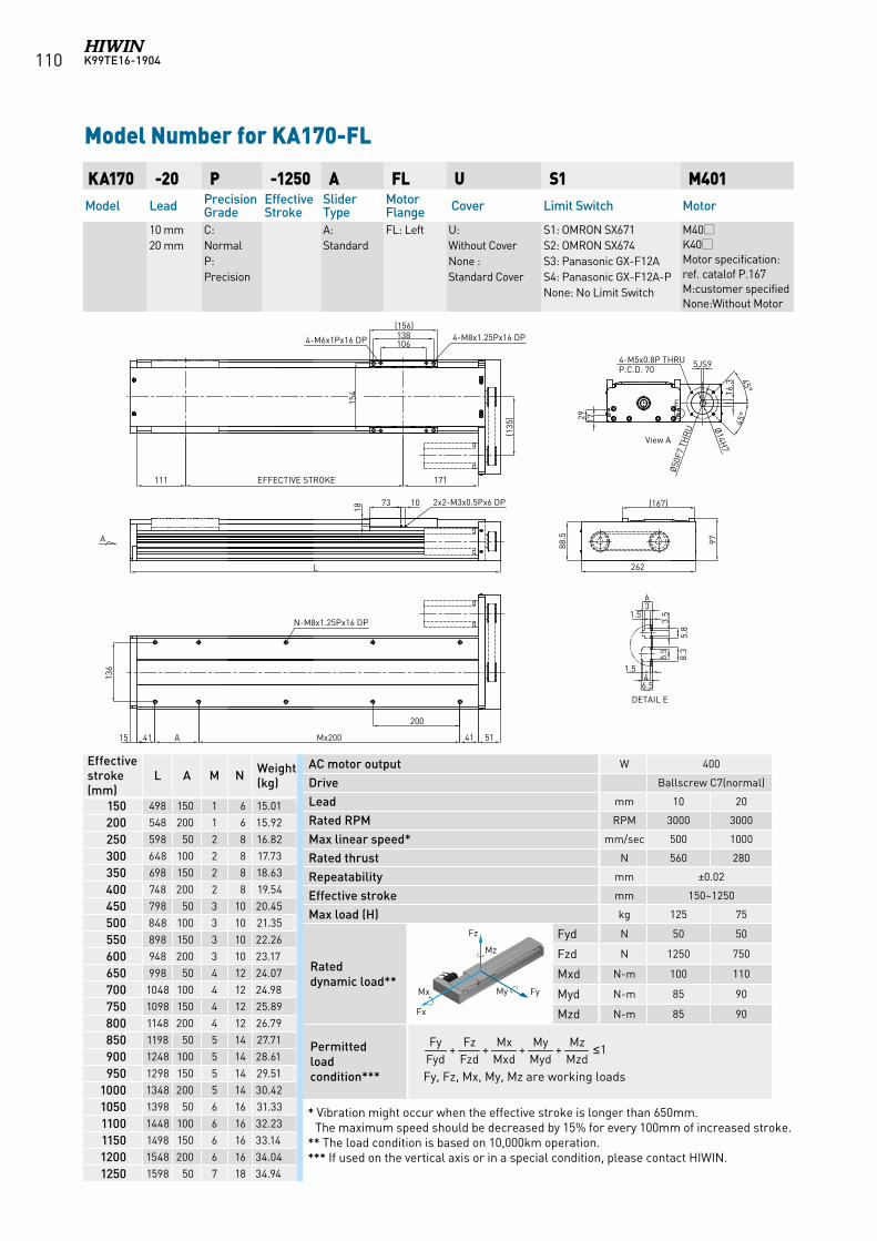
K99TE16-1904110
KA170 -20 P -1250 A FL U S1 M401Model Lead Precision
GradeEffective Stroke
Slider Type
Motor Flange Cover Limit Switch Motor
10 mm 20 mm
C: NormalP: Precision
A: Standard
FL: Left U: Without CoverNone : Standard Cover
S1: OMRON SX671 S2: OMRON SX674 S3: Panasonic GX-F12A S4: Panasonic GX-F12A-PNone: No Limit Switch
M40K40Motor specification:ref. catalof P.167M:customer specifiedNone:Without Motor
Model Number for KA170-FL
Effective stroke (mm)
L A M N Weight (kg)
150 498 150 1 6 15.01
200 548 200 1 6 15.92
250 598 50 2 8 16.82
300 648 100 2 8 17.73
350 698 150 2 8 18.63
400 748 200 2 8 19.54
450 798 50 3 10 20.45
500 848 100 3 10 21.35
550 898 150 3 10 22.26
600 948 200 3 10 23.17
650 998 50 4 12 24.07
700 1048 100 4 12 24.98
750 1098 150 4 12 25.89
800 1148 200 4 12 26.79
850 1198 50 5 14 27.71
900 1248 100 5 14 28.61
950 1298 150 5 14 29.51
1000 1348 200 5 14 30.42
1050 1398 50 6 16 31.33
1100 1448 100 6 16 32.23
1150 1498 150 6 16 33.14
1200 1548 200 6 16 34.04
1250 1598 50 7 18 34.94
AC motor output W 400
Drive Ballscrew C7(normal)
Lead mm 10 20
Rated RPM RPM 3000 3000
Max linear speed* mm/sec 500 1000
Rated thrust N 560 280
Repeatability mm ±0.02
Effective stroke mm 150~1250
Max load (H) kg 125 75
Rated dynamic load**
Fyd N 50 50
Fzd N 1250 750
Mxd N-m 100 110
Myd N-m 85 90
Mzd N-m 85 90
Permitted load condition*** Fy, Fz, Mx, My, Mz are working loads
1++++MzdMz
MydMy
MxdMx
FzdFz
FydFy ≤
* Vibration might occur when the effective stroke is longer than 650mm. The maximum speed should be decreased by 15% for every 100mm of increased stroke.
** The load condition is based on 10,000km operation.*** If used on the vertical axis or in a special condition, please contact HIWIN.
Fz
FyMy Mx
Fx
Mz
Fz
FyMy Mx
Fx
Mz
Fz
FyMy Mx
Fx
Mz
Fz
FyMy Mx
Fx
Mz
Fz
FyMy Mx
Fx
Mz
Fz
FyMy Mx
Fx
Mz
Fz
FyMy Mx
Fx
Mz
18
2x2-M3x0.5Px6 DP
(156)138106
154
4-M6x1Px16 DP 4-M8x1.25Px16 DP
L
15 41 A
EFFECTIVE STROKE111 171
N-M8x1.25Px16 DP
DETAIL E
36
1.5
1.54
6.5
3.5
5.8
5.5
8.3
4-M5x0.8P THRUP.C.D. 70
262
97
1729
(135
)
45°
45°
View A
88.5
Ø50
F7 T
HR
U
(167)73 10
Ø14H
7
136
16.3
5JS9
Mx200
200
41 51
E
A
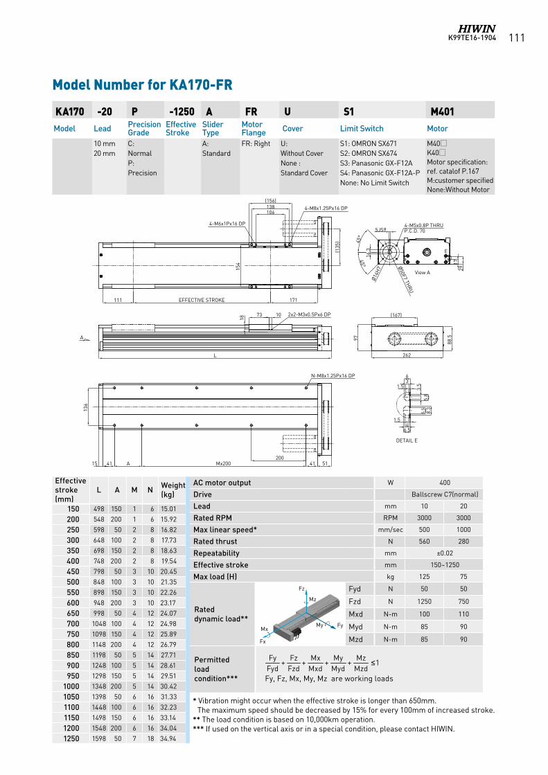
K99TE16-1904 111
KA170 -20 P -1250 A FR U S1 M401Model Lead Precision
GradeEffective Stroke
Slider Type
Motor Flange Cover Limit Switch Motor
10 mm 20 mm
C: NormalP: Precision
A: Standard
FR: Right U: Without CoverNone : Standard Cover
S1: OMRON SX671 S2: OMRON SX674 S3: Panasonic GX-F12A S4: Panasonic GX-F12A-PNone: No Limit Switch
M40K40Motor specification:ref. catalof P.167M:customer specifiedNone:Without Motor
Model Number for KA170-FR
Effective stroke (mm)
L A M N Weight (kg)
150 498 150 1 6 15.01
200 548 200 1 6 15.92
250 598 50 2 8 16.82
300 648 100 2 8 17.73
350 698 150 2 8 18.63
400 748 200 2 8 19.54
450 798 50 3 10 20.45
500 848 100 3 10 21.35
550 898 150 3 10 22.26
600 948 200 3 10 23.17
650 998 50 4 12 24.07
700 1048 100 4 12 24.98
750 1098 150 4 12 25.89
800 1148 200 4 12 26.79
850 1198 50 5 14 27.71
900 1248 100 5 14 28.61
950 1298 150 5 14 29.51
1000 1348 200 5 14 30.42
1050 1398 50 6 16 31.33
1100 1448 100 6 16 32.23
1150 1498 150 6 16 33.14
1200 1548 200 6 16 34.04
1250 1598 50 7 18 34.94
AC motor output W 400
Drive Ballscrew C7(normal)
Lead mm 10 20
Rated RPM RPM 3000 3000
Max linear speed* mm/sec 500 1000
Rated thrust N 560 280
Repeatability mm ±0.02
Effective stroke mm 150~1250
Max load (H) kg 125 75
Rated dynamic load**
Fyd N 50 50
Fzd N 1250 750
Mxd N-m 100 110
Myd N-m 85 90
Mzd N-m 85 90
Permitted load condition*** Fy, Fz, Mx, My, Mz are working loads
1++++MzdMz
MydMy
MxdMx
FzdFz
FydFy ≤
* Vibration might occur when the effective stroke is longer than 650mm. The maximum speed should be decreased by 15% for every 100mm of increased stroke.
** The load condition is based on 10,000km operation.*** If used on the vertical axis or in a special condition, please contact HIWIN.
Fz
FyMy Mx
Fx
Mz
Fz
FyMy Mx
Fx
Mz
Fz
FyMy Mx
Fx
Mz
Fz
FyMy Mx
Fx
Mz
Fz
FyMy Mx
Fx
Mz
Fz
FyMy Mx
Fx
Mz
Fz
FyMy Mx
Fx
Mz
18
2x2-M3x0.5Px6 DP
(156)138106
154
4-M6x1Px16 DP
4-M8x1.25Px16 DP
L
15 41 A Mx200
EFFECTIVE STROKE111 171
N-M8x1.25Px16 DP
20041
DETAIL E
36
1.5
1.54
6.5
3.5
5.8
5.5
8.3
4-M5x0.8P THRUP.C.D. 70
26297
1729
(135
) 45°
45°
View A
51
88.5
Ø50F7 THRU
(167)73 10
Ø14H
7
136
16.3
5JS9
E
A
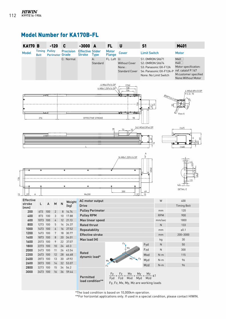
K99TE16-1904112
KA170 B -120 C -3000 A FL U S1 M401Model
Timing Belt
Pulley Perimeter
Precision Grade
Effective Stroke
Slider Type
Motor Flange Cover Limit Switch Motor
C: Normal A: Standard
FL: Left
U: Without CoverNone : Standard Cover
S1: OMRON SX671 S2: OMRON SX674 S3: Panasonic GX-F12A S4: Panasonic GX-F12A-PNone: No Limit Switch
M40K40Motor specification:ref. catalof P.167M:customer specifiedNone:Without Motor
Model Number for KA170B-FL
AC motor output W 400
Drive Timing Belt
Pulley Perimeter mm 120
Pulley RPM RPM 900
Max linear speed mm/sec 1800
Rated thrust N 133
Repeatability mm ±0.1
Effective stroke mm 200~3000
Max load (H) kg 30
Rated dynamic load*
Fyd N 50
Fzd N 300
Mxd N-m 115
Myd N-m 96
Mzd N-m 96
Permitted load condition** Fy, Fz, Mx, My, Mz are working loads
Effective stroke (mm)
L A M N Weight (kg)
200 673 100 2 8 14.74
400 873 100 3 10 17.88
600 1073 100 4 12 21.13
800 1273 100 5 14 24.37
1000 1473 100 6 16 27.52
1200 1673 100 7 18 30.77
1400 1873 100 8 20 34.01
1600 2073 100 9 22 37.07
1800 2273 100 10 24 40.3
2000 2473 100 11 26 43.54
2200 2673 100 12 28 46.68
2400 2873 100 13 30 49.92
2600 3073 100 14 32 53.07
2800 3273 100 15 34 56.2
3000 3473 100 16 36 59.44 1++++
MzdMz
MydMy
MxdMx
FzdFz
FydFy ≤
*The load condition is based on 10,000km operation. **For horizontal applications only. If used in a special condition, please contact HIWIN.
Fz
FyMy Mx
Fx
Mz
Fz
FyMy Mx
Fx
Mz
Fz
FyMy Mx
Fx
Mz
Fz
FyMy Mx
Fx
Mz
Fz
FyMy Mx
Fx
Mz
Fz
FyMy Mx
Fx
Mz
Fz
FyMy Mx
Fx
Mz
A
106138(156)
276 EFFECTIVE STROKE 98
1537Mx200A3715200
136
DETAIL E
N-M8x1.25Px16 DP36
1.5
1.54
6.5
3.5
5.8
5.5
8.3
154
4-M6x1Px16 DP
4-M8x1.25Px16 DP
17 29
(167)
(168)
E
73 1018
2x2-M3x0.5Px6 DP
L
1660
View A
42
79
69
(204
)
30
45°
45°
4-M5x0.8Px10 DPP.C.D. 70
Ø50F7x3.5 DP
Ø14H
7
97
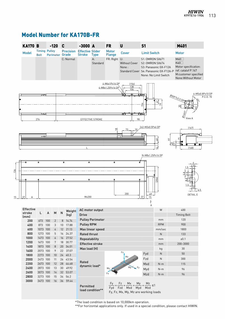
K99TE16-1904 113
KA170 B -120 C -3000 A FR U S1 M401Model
Timing Belt
Pulley Perimeter
Precision Grade
Effective Stroke
Slider Type
Motor Flange Cover Limit Switch Motor
C: Normal A: Standard
FR: Right U: Without CoverNone : Standard Cover
S1: OMRON SX671 S2: OMRON SX674 S3: Panasonic GX-F12A S4: Panasonic GX-F12A-PNone: No Limit Switch
M40K40Motor specification:ref. catalof P.167M:customer specifiedNone:Without Motor
Model Number for KA170B-FR
AC motor output W 400
Drive Timing Belt
Pulley Perimeter mm 120
Pulley RPM RPM 900
Max linear speed mm/sec 1800
Rated thrust N 133
Repeatability mm ±0.1
Effective stroke mm 200~3000
Max load (H) kg 30
Rated dynamic load*
Fyd N 50
Fzd N 300
Mxd N-m 115
Myd N-m 96
Mzd N-m 96
Permitted load condition** Fy, Fz, Mx, My, Mz are working loads
Effective stroke (mm)
L A M N Weight (kg)
200 673 100 2 8 14.74
400 873 100 3 10 17.88
600 1073 100 4 12 21.13
800 1273 100 5 14 24.37
1000 1473 100 6 16 27.52
1200 1673 100 7 18 30.77
1400 1873 100 8 20 34.01
1600 2073 100 9 22 37.07
1800 2273 100 10 24 40.3
2000 2473 100 11 26 43.54
2200 2673 100 12 28 46.68
2400 2873 100 13 30 49.92
2600 3073 100 14 32 53.07
2800 3273 100 15 34 56.2
3000 3473 100 16 36 59.44 1++++
MzdMz
MydMy
MxdMx
FzdFz
FydFy ≤
*The load condition is based on 10,000km operation. **For horizontal applications only. If used in a special condition, please contact HIWIN.
Fz
FyMy Mx
Fx
Mz
Fz
FyMy Mx
Fx
Mz
Fz
FyMy Mx
Fx
Mz
Fz
FyMy Mx
Fx
Mz
Fz
FyMy Mx
Fx
Mz
Fz
FyMy Mx
Fx
Mz
Fz
FyMy Mx
Fx
Mz
A
106138(156)
276 EFFECTIVE STROKE 98
1537Mx200A3715200
136
DETAIL E
N-M8x1.25Px16 DP
36
1.5
1.54
6.53.
55.
8
5.5
8.3
4-M6x1Px16 DP
4-M8x1.25Px16 DP
1729
(167)
(168)
E
73 1018
2x2-M3x0.5Px6 DP
L 1660
View A
4279
69
(204
)
30
45°
45°
4-M5x0.8Px10 DPP.C.D. 70
Ø50F7x3.5 DP
Ø14
H7
154
97
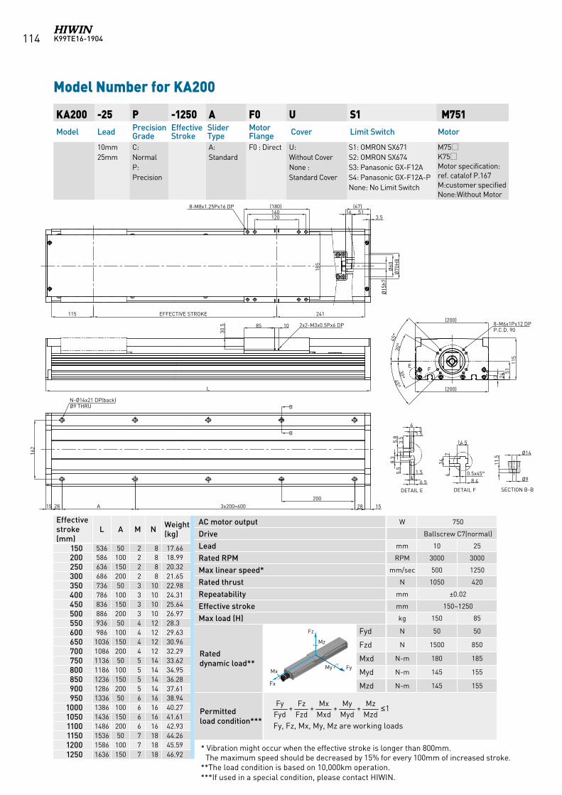
K99TE16-1904114
Model Number for KA200
KA200 -25 P -1250 A F0 U S1 M751Model Lead Precision
GradeEffective Stroke
Slider Type
Motor Flange Cover Limit Switch Motor
10mm25mm
C: NormalP: Precision
A: Standard
F0 : Direct U: Without CoverNone : Standard Cover
S1: OMRON SX671 S2: OMRON SX674 S3: Panasonic GX-F12A S4: Panasonic GX-F12A-PNone: No Limit Switch
M75K75Motor specification:ref. catalof P.167M:customer specifiedNone:Without Motor
AC motor output W 750
Drive Ballscrew C7(normal)
Lead mm 10 25
Rated RPM RPM 3000 3000
Max linear speed* mm/sec 500 1250
Rated thrust N 1050 420
Repeatability mm ±0.02
Effective stroke mm 150~1250
Max load (H) kg 150 85
Rated dynamic load**
Fyd N 50 50
Fzd N 1500 850
Mxd N-m 180 185
Myd N-m 145 155
Mzd N-m 145 155
Permitted load condition*** Fy, Fz, Mx, My, Mz are working loads
Effective stroke (mm)
L A M N Weight (kg)
150 536 50 2 8 17.66200 586 100 2 8 18.99250 636 150 2 8 20.32300 686 200 2 8 21.65350 736 50 3 10 22.98400 786 100 3 10 24.31450 836 150 3 10 25.64500 886 200 3 10 26.97550 936 50 4 12 28.3600 986 100 4 12 29.63650 1036 150 4 12 30.96700 1086 200 4 12 32.29750 1136 50 5 14 33.62800 1186 100 5 14 34.95850 1236 150 5 14 36.28900 1286 200 5 14 37.61950 1336 50 6 16 38.94
1000 1386 100 6 16 40.271050 1436 150 6 16 41.611100 1486 200 6 16 42.931150 1536 50 7 18 44.261200 1586 100 7 18 45.591250 1636 150 7 18 46.92
1++++MzdMz
MydMy
MxdMx
FzdFz
FydFy ≤
* Vibration might occur when the effective stroke is longer than 800mm. The maximum speed should be decreased by 15% for every 100mm of increased stroke.
**The load condition is based on 10,000km operation. ***If used in a special condition, please contact HIWIN.
Fz
FyMy Mx
Fx
Mz
Fz
FyMy Mx
Fx
Mz
Fz
FyMy Mx
Fx
Mz Fz
FyMy Mx
Fx
Mz
Fz
FyMy Mx
Fx
Mz
120160(180)
185
85 10
30.5
5116(67)
Ø15
h7
3.5
Ø60
Ø70
H8
241
2003x200=600A2815
(200)
12 2451
115
8-M8x1.25Px16 DP
2x2-M3x0.5Px6 DP
EFFECTIVE STROKE115
L
N-Ø14x21 DP(back)Ø9 THRU
31.5
6
1.54
6.5
E
DETAIL E
3.5
5.8
5.5
8.3
F
DETAIL F
8-M6x1Px12 DPP.C.D. 90
30°
30°
45°
45°
14.57
144 0.5x45°
8.4
B
B
Ø14
Ø9
11.5
SECTION B-B
28 15
162
(200)
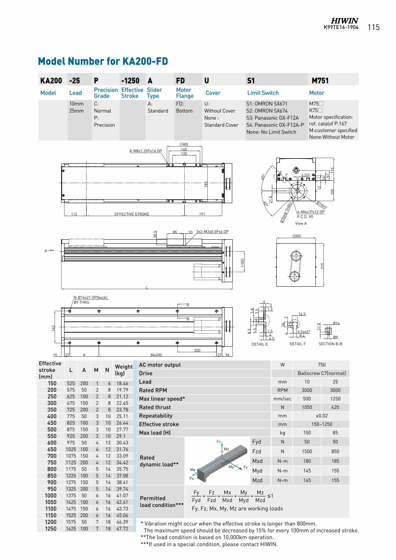
K99TE16-1904 115
KA200 -25 P -1250 A FD U S1 M751Model Lead Precision
GradeEffective Stroke
Slider Type
Motor Flange Cover Limit Switch Motor
10mm25mm
C: NormalP: Precision
A: Standard
FD: Bottom
U: Without CoverNone : Standard Cover
S1: OMRON SX671 S2: OMRON SX674 S3: Panasonic GX-F12A S4: Panasonic GX-F12A-PNone: No Limit Switch
M75K75Motor specification:ref. catalof P.167M:customer specifiedNone:Without Motor
Model Number for KA200-FD
AC motor output W 750
Drive Ballscrew C7(normal)
Lead mm 10 25
Rated RPM RPM 3000 3000
Max linear speed* mm/sec 500 1250
Rated thrust N 1050 420
Repeatability mm ±0.02
Effective stroke mm 150~1250
Max load (H) kg 150 85
Rated dynamic load**
Fyd N 50 50
Fzd N 1500 850
Mxd N-m 180 185
Myd N-m 145 155
Mzd N-m 145 155
Permitted load condition*** Fy, Fz, Mx, My, Mz are working loads
Effective stroke (mm)
L A M N Weight (kg)
150 525 200 1 6 18.46200 575 50 2 8 19.79250 625 100 2 8 21.12300 675 150 2 8 22.45350 725 200 2 8 23.78400 775 50 3 10 25.11450 825 100 3 10 26.44500 875 150 3 10 27.77550 925 200 3 10 29.1600 975 50 4 12 30.43650 1025 100 4 12 31.76700 1075 150 4 12 33.09750 1125 200 4 12 34.42800 1175 50 5 14 35.75850 1225 100 5 14 37.08900 1275 150 5 14 38.41950 1325 200 5 14 39.74
1000 1375 50 6 16 41.071050 1425 100 6 16 42.411100 1475 150 6 16 43.731150 1525 200 6 16 45.061200 1575 50 7 18 46.391250 1625 100 7 18 47.72
1++++MzdMz
MydMy
MxdMx
FzdFz
FydFy ≤
* Vibration might occur when the effective stroke is longer than 800mm. The maximum speed should be decreased by 15% for every 100mm of increased stroke.
**The load condition is based on 10,000km operation. ***If used in a special condition, please contact HIWIN.
Fz
FyMy Mx
Fx
Mz
Fz
FyMy Mx
Fx
Mz
Fz
FyMy Mx
Fx
Mz Fz
FyMy Mx
Fx
Mz
Fz
FyMy Mx
Fx
Mz
120160
(180)
185
8-M8x1.25Px16 DP
191EFFECTIVE STROKE113
31.5
6
1.546.5
DETAIL E
3.5
5.8
5.5
8.3
DETAIL F
14.5
714
4 0.5x45°8.4
Ø14
Ø9
11.5
SECTION B-B
View A
A
85 10
30.5 2x2-M3x0.5Px6 DP
162
200Mx200A2715
N-Ø14x21 DP(back)Ø9 THRU
B
B
27 56
(200)
219
Ø70H
8 TH
RU
4-M6x1Px12 DPP.C.D. 90
EF
1224
5111
510
5
(105
)
L
6JS9
21.8
45°
45°
Ø19H7
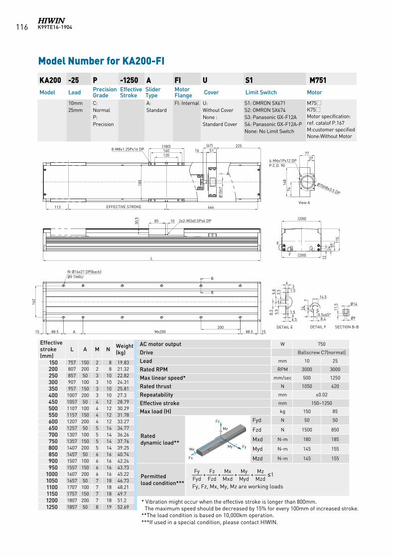
K99TE16-1904116
KA200 -25 P -1250 A FI U S1 M751Model Lead Precision
GradeEffective Stroke
Slider Type
Motor Flange Cover Limit Switch Motor
10mm25mm
C: NormalP: Precision
A: Standard
FI: Internal U: Without CoverNone : Standard Cover
S1: OMRON SX671 S2: OMRON SX674 S3: Panasonic GX-F12A S4: Panasonic GX-F12A-PNone: No Limit Switch
M75K75Motor specification:ref. catalof P.167M:customer specifiedNone:Without Motor
Model Number for KA200-FI
AC motor output W 750
Drive Ballscrew C7(normal)
Lead mm 10 25
Rated RPM RPM 3000 3000
Max linear speed* mm/sec 500 1250
Rated thrust N 1050 420
Repeatability mm ±0.02
Effective stroke mm 150~1250
Max load (H) kg 150 85
Rated dynamic load**
Fyd N 50 50
Fzd N 1500 850
Mxd N-m 180 185
Myd N-m 145 155
Mzd N-m 145 155
Permitted load condition*** Fy, Fz, Mx, My, Mz are working loads
Effective stroke (mm)
L A M N Weight (kg)
150 757 150 2 8 19.83200 807 200 2 8 21.32250 857 50 3 10 22.82300 907 100 3 10 24.31350 957 150 3 10 25.81400 1007 200 3 10 27.3450 1057 50 4 12 28.79500 1107 100 4 12 30.29550 1157 150 4 12 31.78600 1207 200 4 12 33.27650 1257 50 5 14 34.77700 1307 100 5 14 36.26750 1357 150 5 14 37.76800 1407 200 5 14 39.25850 1457 50 6 16 40.74900 1507 100 6 16 42.24950 1557 150 6 16 43.73
1000 1607 200 6 16 45.221050 1657 50 7 18 46.731100 1707 100 7 18 48.211150 1757 150 7 18 49.71200 1807 200 7 18 51.21250 1857 50 8 19 52.69
1++++MzdMz
MydMy
MxdMx
FzdFz
FydFy ≤
* Vibration might occur when the effective stroke is longer than 800mm. The maximum speed should be decreased by 15% for every 100mm of increased stroke.
**The load condition is based on 10,000km operation. ***If used in a special condition, please contact HIWIN.
Fz
FyMy Mx
Fx
Mz
Fz
FyMy Mx
Fx
Mz
Fz
FyMy Mx
Fx
Mz Fz
FyMy Mx
Fx
Mz
Fz
FyMy Mx
Fx
Mz
31.5
6
1.546.5
DETAIL E
3.5
5.8
5.5
8.3
DETAIL F
14.5
714
4 0.5x45°8.4
Ø14
Ø9
11.5
SECTION B-B
A
120160
(180)8-M8x1.25Px16 DP
185
2255116
(67)
464113
85 1030.5 2x2-M3x0.5Px6 DP
L
B
B
15 88.5 A Mx200 88.5 15200
N-Ø14x21 DP(back)Ø9 THRU
(200)
(200)
1224
5111
5
E
F
162
Ø15
h7
3777
7414
8
Ø70H8x3.5 DP
4-M6x1Px12 DPP.C.D. 90
EFFECTIVE STROKEView A
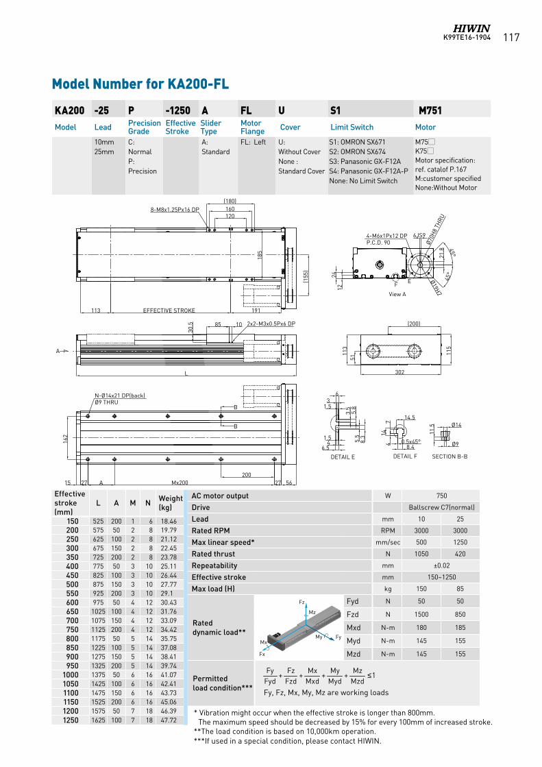
K99TE16-1904 117
Model Number for KA200-FL
KA200 -25 P -1250 A FL U S1 M751Model Lead Precision
GradeEffective Stroke
Slider Type
Motor Flange Cover Limit Switch Motor
10mm25mm
C: NormalP: Precision
A: Standard
FL: Left U: Without CoverNone : Standard Cover
S1: OMRON SX671 S2: OMRON SX674 S3: Panasonic GX-F12A S4: Panasonic GX-F12A-PNone: No Limit Switch
M75K75Motor specification:ref. catalof P.167M:customer specifiedNone:Without Motor
AC motor output W 750
Drive Ballscrew C7(normal)
Lead mm 10 25
Rated RPM RPM 3000 3000
Max linear speed* mm/sec 500 1250
Rated thrust N 1050 420
Repeatability mm ±0.02
Effective stroke mm 150~1250
Max load (H) kg 150 85
Rated dynamic load**
Fyd N 50 50
Fzd N 1500 850
Mxd N-m 180 185
Myd N-m 145 155
Mzd N-m 145 155
Permitted load condition*** Fy, Fz, Mx, My, Mz are working loads
Effective stroke (mm)
L A M N Weight (kg)
150 525 200 1 6 18.46200 575 50 2 8 19.79250 625 100 2 8 21.12300 675 150 2 8 22.45350 725 200 2 8 23.78400 775 50 3 10 25.11450 825 100 3 10 26.44500 875 150 3 10 27.77550 925 200 3 10 29.1600 975 50 4 12 30.43650 1025 100 4 12 31.76700 1075 150 4 12 33.09750 1125 200 4 12 34.42800 1175 50 5 14 35.75850 1225 100 5 14 37.08900 1275 150 5 14 38.41950 1325 200 5 14 39.74
1000 1375 50 6 16 41.071050 1425 100 6 16 42.411100 1475 150 6 16 43.731150 1525 200 6 16 45.061200 1575 50 7 18 46.391250 1625 100 7 18 47.72
1++++MzdMz
MydMy
MxdMx
FzdFz
FydFy ≤
* Vibration might occur when the effective stroke is longer than 800mm. The maximum speed should be decreased by 15% for every 100mm of increased stroke.
**The load condition is based on 10,000km operation. ***If used in a special condition, please contact HIWIN.
Fz
FyMy Mx
Fx
Mz
Fz
FyMy Mx
Fx
Mz
Fz
FyMy Mx
Fx
Mz Fz
FyMy Mx
Fx
Mz
Fz
FyMy Mx
Fx
Mz
45°
85 10
30.5 2x2-M3x0.5Px6 DP
L
A
1224
45°
Ø70H
8 TH
RU
Ø19H7
6JS9
21.8
4-M6x1Px12 DPP.C.D. 90
View A
EF
185
(155
)
120160
(180)
113 EFFECTIVE STROKE
8-M8x1.25Px16 DP
162
B
B
N-Ø14x21 DP(back)Ø9 THRU
15 27 A Mx200 27 56200
302
115
113
51
DETAIL F
14.5
714
4 0.5x45°8.4
Ø14
Ø9
11.5
SECTION B-B
31.5
6
1.54
6.5
3.5
5.8
5.5
8.3
DETAIL E
191
(200)
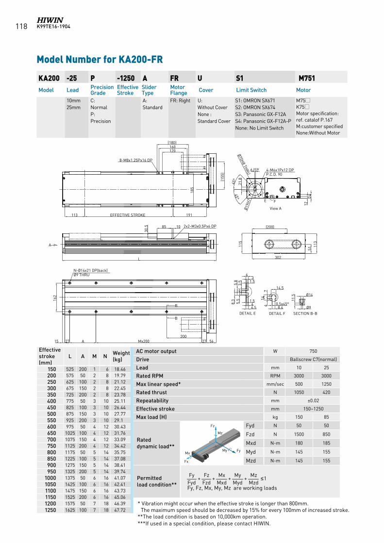
K99TE16-1904118
Model Number for KA200-FR
KA200 -25 P -1250 A FR U S1 M751Model Lead Precision
GradeEffective Stroke
Slider Type
Motor Flange Cover Limit Switch Motor
10mm25mm
C: NormalP: Precision
A: Standard
FR: Right U: Without CoverNone : Standard Cover
S1: OMRON SX671 S2: OMRON SX674 S3: Panasonic GX-F12A S4: Panasonic GX-F12A-PNone: No Limit Switch
M75K75Motor specification:ref. catalof P.167M:customer specifiedNone:Without Motor
AC motor output W 750
Drive Ballscrew C7(normal)
Lead mm 10 25
Rated RPM RPM 3000 3000
Max linear speed* mm/sec 500 1250
Rated thrust N 1050 420
Repeatability mm ±0.02
Effective stroke mm 150~1250
Max load (H) kg 150 85
Rated dynamic load**
Fyd N 50 50
Fzd N 1500 850
Mxd N-m 180 185
Myd N-m 145 155
Mzd N-m 145 155
Permitted load condition** Fy, Fz, Mx, My, Mz are working loads
Effective stroke (mm)
L A M N Weight (kg)
150 525 200 1 6 18.46200 575 50 2 8 19.79250 625 100 2 8 21.12300 675 150 2 8 22.45350 725 200 2 8 23.78400 775 50 3 10 25.11450 825 100 3 10 26.44500 875 150 3 10 27.77550 925 200 3 10 29.1600 975 50 4 12 30.43650 1025 100 4 12 31.76700 1075 150 4 12 33.09750 1125 200 4 12 34.42800 1175 50 5 14 35.75850 1225 100 5 14 37.08900 1275 150 5 14 38.41950 1325 200 5 14 39.74
1000 1375 50 6 16 41.071050 1425 100 6 16 42.411100 1475 150 6 16 43.731150 1525 200 6 16 45.061200 1575 50 7 18 46.391250 1625 100 7 18 47.72
1++++MzdMz
MydMy
MxdMx
FzdFz
FydFy ≤
* Vibration might occur when the effective stroke is longer than 800mm. The maximum speed should be decreased by 15% for every 100mm of increased stroke.
**The load condition is based on 10,000km operation. ***If used in a special condition, please contact HIWIN.
Fz
FyMy Mx
Fx
Mz
Fz
FyMy Mx
Fx
Mz
Fz
FyMy Mx
Fx
Mz Fz
FyMy Mx
Fx
Mz
Fz
FyMy Mx
Fx
Mz
45°
(200)
1224
45°
4-M6x1Px12 DPP.C.D. 90
Ø70H8 TH
RU
31.5
6
1.546.5
DETAIL E
3.5
5.8
5.5
8.3
DETAIL F
14.5
714
4 0.5x45°8.4
Ø14
Ø9
11.5
SECTION B-B
E F
View AØ19
H7
302
113
115
51
6JS9
21.8
120160
(180)
185
8-M8x1.25Px16 DP
85 10
30.5 2x2-M3x0.5Px6 DP
191EFFECTIVE STROKE113
162
5627200
Mx200A2715
N-Ø14x21 DP(back)Ø9 THRU
L
(155
)
A
B
B
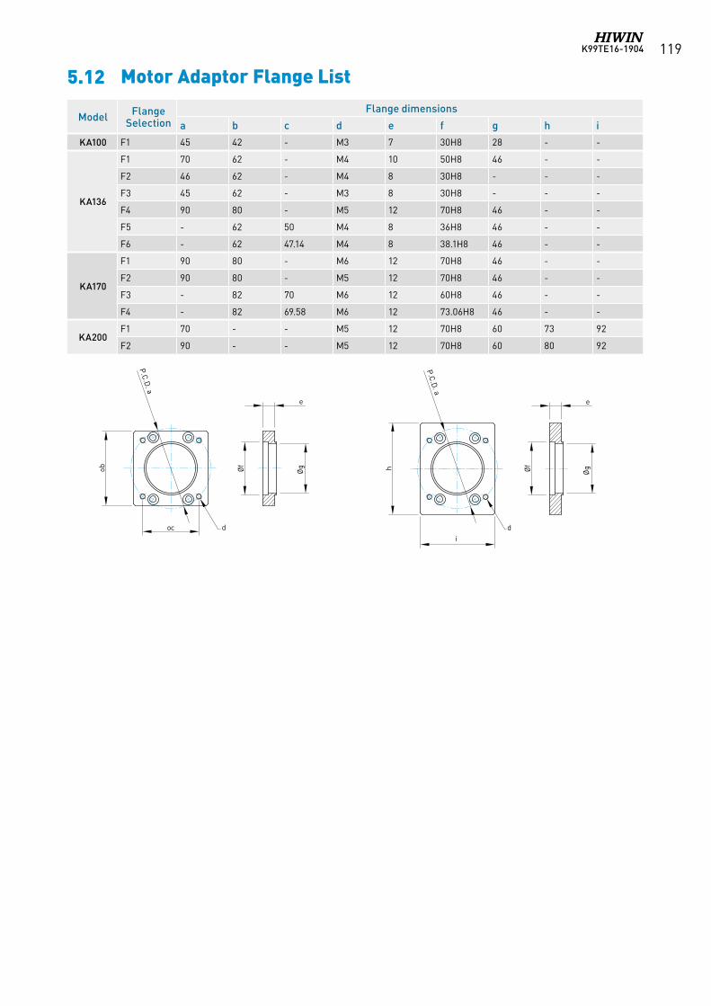
K99TE16-1904 119
Model Flange Selection
Flange dimensions
a b c d e f g h i
KA100 F1 45 42 - M3 7 30H8 28 - -
KA136
F1 70 62 - M4 10 50H8 46 - -
F2 46 62 - M4 8 30H8 - - -
F3 45 62 - M3 8 30H8 - - -
F4 90 80 - M5 12 70H8 46 - -
F5 - 62 50 M4 8 36H8 46 - -
F6 - 62 47.14 M4 8 38.1H8 46 - -
KA170
F1 90 80 - M6 12 70H8 46 - -
F2 90 80 - M5 12 70H8 46 - -
F3 - 82 70 M6 12 60H8 46 - -
F4 - 82 69.58 M6 12 73.06H8 46 - -
KA200F1 70 - - M5 12 70H8 60 73 92
F2 90 - - M5 12 70H8 60 80 92
ob
e
ØgØf
P.C.D. a
oc d
h
e
ØgØf
P.C.D. a
di
5.12 Motor Adaptor Flange List
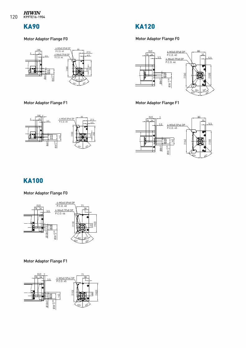
K99TE16-1904120
Motor Adaptor Flange F0 Motor Adaptor Flange F0
Motor Adaptor Flange F1 Motor Adaptor Flange F1
KA120
3418(52)
Ø8h
7
Ø28
Ø30
3.5
(134
)
(120
)
5.532
80
30° 30°45° 45°
4-M3x0.5Px8 DPP.C.D. 40
4-M4x0.7Px8 DPP.C.D. 46
3418(52)
Ø8h
7
Ø28
7
(134
)
(120
)
5.532
80
4-M3x0.5Px6 DPP.C.D. 45
3.5
45° 45°
+0.0
5 0
Ø30
+0.0
5 0
42
KA90
299
(38)
3.5
Ø6h
7
Ø28
Ø30
+0.0
30
4-M4x0.7Px8 DPP.C.D. 46
4-M3x0.5Px8 DPP.C.D. 40
(100
)
(90)
19
4.527.5
66
30° 30°
45° 45°
299
(38)
3.5
Ø6h
7
Ø28
Ø30
+0.0
50
(90)
19
4.527.5
664-M3x0.5Px6 DPP.C.D. 45
(100
)
45°45°
7
42
KA100
Ø28
Ø30
+0.0
50
Ø30
+0.0
50
Ø10
h7
18(52)
34
(110
)
(102
)
3871
22
3.5
30° 30°45° 45°
4-M4x0.7Px8 DP
4-M3x0.5Px6 DP
P.C.D. 46
P.C.D. 45
4-M3x0.5Px8 DPP.C.D. 40
1
Ø28
Ø10
h7
18(52)
347 71
38
(110
)
(102
)
45° 45°
22
3.5 1
42
KA90 KA120
KA100
Motor Adaptor Flange F0
Motor Adaptor Flange F1
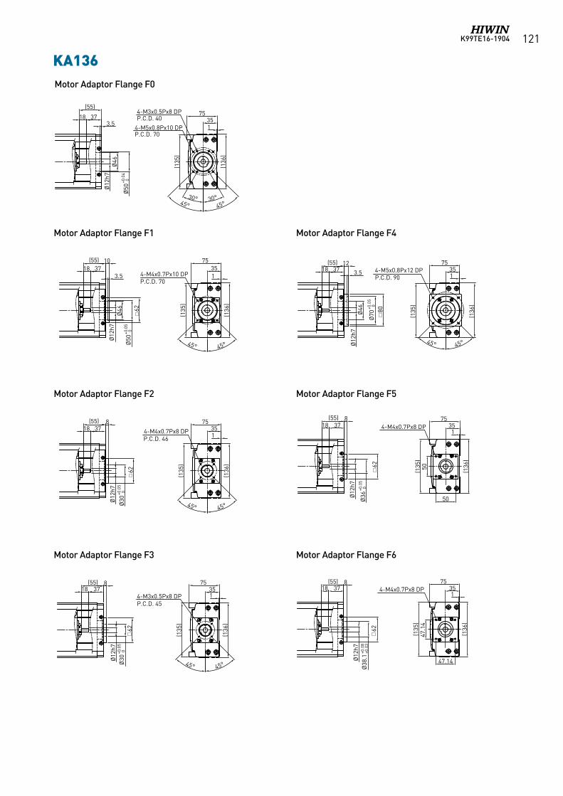
K99TE16-1904 121
Motor Adaptor Flange F0
KA136
(136
)
(135
)
3575
Ø46
Ø50
+0.0
40
(55)
373.5
45°30° 30°
45°
18
Ø12
h7
14-M5x0.8Px10 DPP.C.D. 70
4-M3x0.5Px8 DPP.C.D. 40
18(55)
374-M4x0.7Px10 DPP.C.D. 70
Ø50
+0.0
50
Ø30
+0.0
5 0
Ø30
+0.0
50
Ø36
+0.0
5 0
62
Ø46
7535
(135
)
45° 45°
(136
)
10
Ø12
h7
3.5 1
(136
)
(135
)
3575(55)
3718
Ø12
h7
45° 45°
62
8
14-M4x0.7Px8 DPP.C.D. 46
(136
)
(135
)
3575(55)
3718
Ø12
h7
8
45° 45°
14-M3x0.5Px8 DPP.C.D. 45
(136
)
(135
)
3575
Ø46
Ø70
+0.0
50
(55)3718
Ø12
h7
80
12
3.5
45° 45°
14-M5x0.8Px12 DPP.C.D. 90
(136
)
(135
)
3575
62
(55)3718
Ø12
h7
850
50
14-M4x0.7Px8 DP
(136
)
(135
)
3575
Ø38
.1+0
.08
+0.0
3
(55)3718
Ø12
h7
47.1
4
47.14
8
14-M4x0.7Px8 DP
62 62
KA136
Motor Adaptor Flange F1 Motor Adaptor Flange F4
Motor Adaptor Flange F2 Motor Adaptor Flange F5
Motor Adaptor Flange F3 Motor Adaptor Flange F6
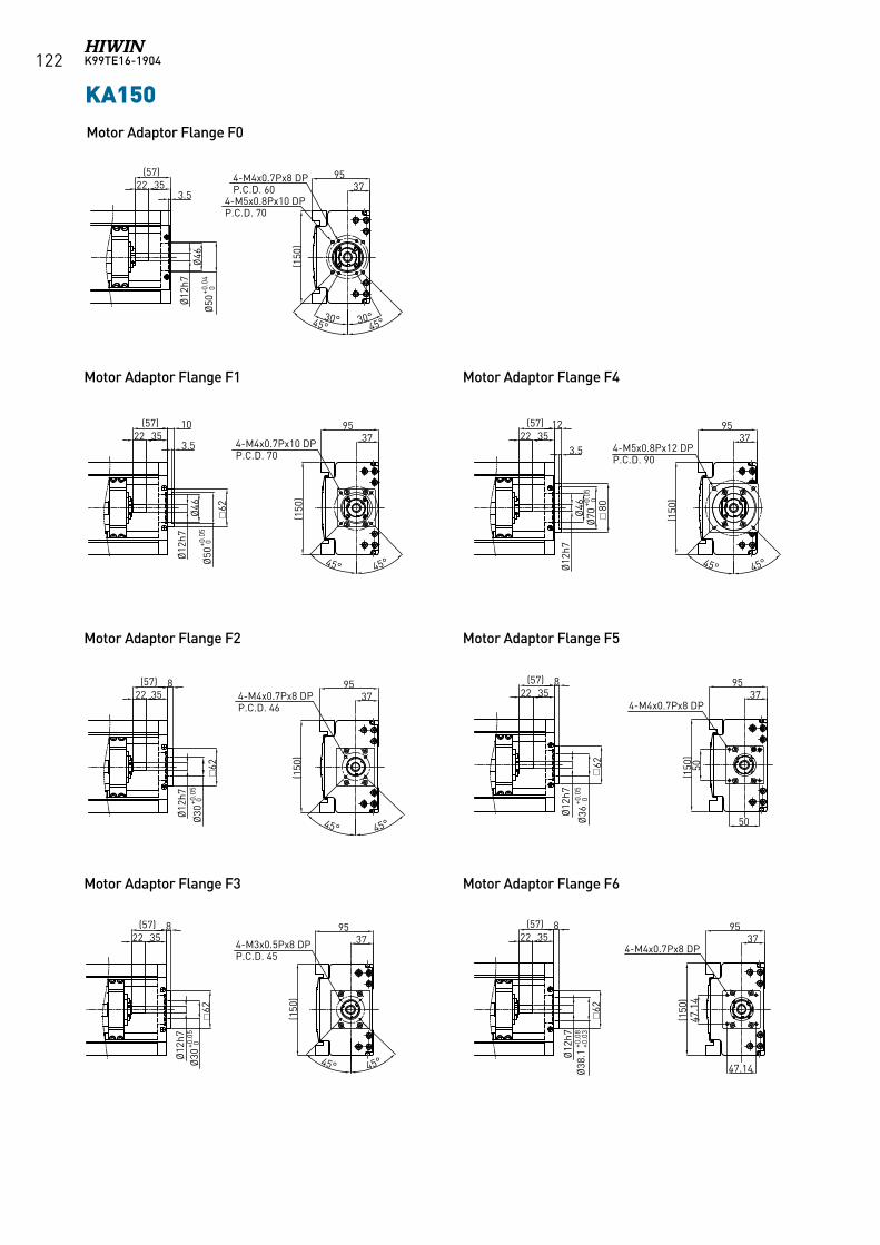
K99TE16-1904122
Motor Adaptor Flange F0
KA150
Motor Adaptor Flange F1 Motor Adaptor Flange F4
Motor Adaptor Flange F2 Motor Adaptor Flange F5
Motor Adaptor Flange F3 Motor Adaptor Flange F6
KA150
+0.0
4 0
Ø36
+0.0
5 0
Ø70
+0.0
5 0
Ø38
.1+0
.08
+0.0
3
Ø12
h7Ø
46Ø
503.5
37954-M4x0.7Px8 DP
P.C.D. 604-M5x0.8Px10 DPP.C.D. 70
(150
)
35(57)
22
30°30°45° 45°
Ø12
h7
3795
(150
)
35(57)
224-M4x0.7Px10 DPP.C.D. 70
45° 45°Ø50
+0.0
5 0
+0.0
5 0
62Ø46
3.5
10
Ø12
h7Ø
30+0
.05
0Ø
30
3795
(150
)
35(57)
22 4-M4x0.7Px8 DPP.C.D. 46
45° 45°
62
8
Ø12
h7
3795
(150
)
35(57)
224-M3x0.5Px8 DPP.C.D. 45
45°
8
62
45°
Ø12
h7
3795
(150
)
35(57)
22
Ø46 80
12
3.5
45° 45°
4-M5x0.8Px12 DPP.C.D. 90
Ø12
h7
3795
(150
)35
(57)22
4-M4x0.7Px8 DP50
50
62
8
Ø12
h7
3795
(150
)
35(57)
224-M4x0.7Px8 DP
47.1
4
47.14
62
8
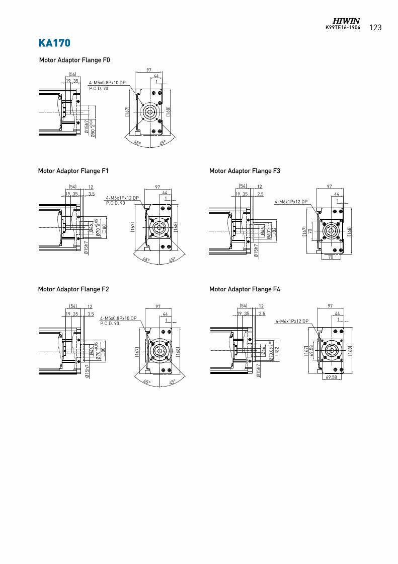
K99TE16-1904 123KA170
97
(167
)
(168
)
4435
Ø15
h7Ø
50+0
.04
0
45°45°
19(54)
14-M5x0.8Px10 DPP.C.D. 70
3519
(54)
Ø15
h7
97
(167
)
(168
)
44
45° 45°
80
123.5
Ø70
+0.0
50
Ø70
+0.0
5 0
Ø46
14-M6x1Px12 DPP.C.D. 90
97
(167
)
(168
)
443519
(54)
Ø15
h7Ø
46 80
12
3.5
45° 45°
14-M5x0.8Px10 DPP.C.D. 90
97
(167
)
(168
)
443519
(54)
Ø15
h7
70
70Ø
46 82
12
2.514-M6x1Px12 DP
97(1
67)
(168
)
443519
(54)
Ø15
h7
Ø73
.06+0
.05
0
69.5
8
69.58
Ø46 82
12
2.514-M6x1Px12 DP
Ø60
+0.0
50
KA170
Motor Adaptor Flange F1 Motor Adaptor Flange F3
Motor Adaptor Flange F2 Motor Adaptor Flange F4
Motor Adaptor Flange F0
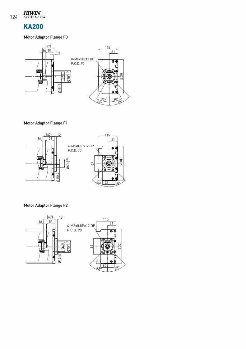
K99TE16-1904124 KA200
Ø70
+0.0
40
Ø70
+0.0
50
5116(67)
Ø15
h7
3.5
Ø60
(200
)
51115
8-M6x1Px12 DPP.C.D. 90
30° 30°45° 45°
5116(67)
Ø15
h7
92
Ø50
+0.0
50
(200
)
51115
4-M5x0.8Px12 DPP.C.D. 70
45° 45°73
12
5116(67)
Ø15
h7Ø
60
(200
)
51115
4-M5x0.8Px12 DPP.C.D. 90
45° 45°
92
12
80
KA200Motor Adaptor Flange F0
Motor Adaptor Flange F1
Motor Adaptor Flange F2
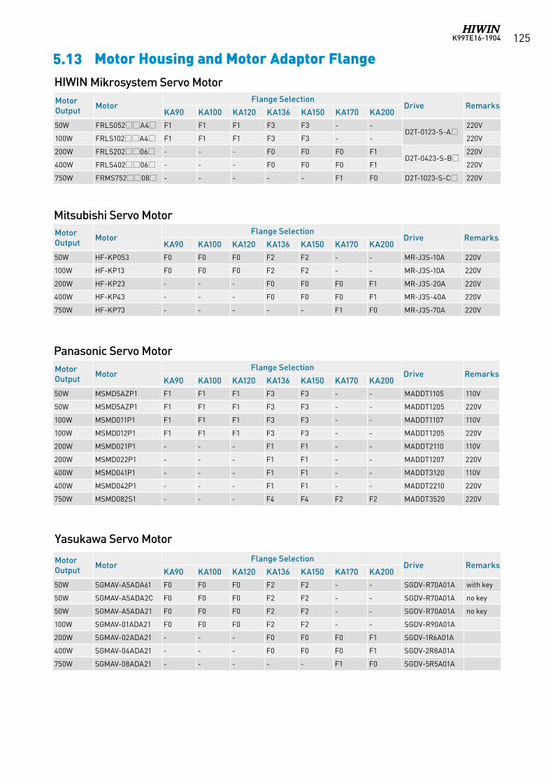
K99TE16-1904 125
5.13 Motor Housing and Motor Adaptor Flange
Panasonic Servo Motor
Mitsubishi Servo Motor
Yasukawa Servo Motor
HIWIN Mikrosystem Servo MotorMotor Output Motor
Flange SelectionDrive Remarks
KA90 KA100 KA120 KA136 KA150 KA170 KA200
50W FRLS052A4 F1 F1 F1 F3 F3 - -D2T-0123-S-A
220V
100W FRLS102A4 F1 F1 F1 F3 F3 - - 220V
200W FRLS20206 - - - F0 F0 F0 F1D2T-0423-S-B
220V
400W FRLS40206 - - - F0 F0 F0 F1 220V
750W FRMS75208 - - - - - F1 F0 D2T-1023-S-C 220V
Motor Output Motor
Flange SelectionDrive Remarks
KA90 KA100 KA120 KA136 KA150 KA170 KA200
50W HF-KP053 F0 F0 F0 F2 F2 - - MR-J3S-10A 220V
100W HF-KP13 F0 F0 F0 F2 F2 - - MR-J3S-10A 220V
200W HF-KP23 - - - F0 F0 F0 F1 MR-J3S-20A 220V
400W HF-KP43 - - - F0 F0 F0 F1 MR-J3S-40A 220V
750W HF-KP73 - - - - - F1 F0 MR-J3S-70A 220V
Motor Output Motor
Flange SelectionDrive Remarks
KA90 KA100 KA120 KA136 KA150 KA170 KA200
50W MSMD5AZP1 F1 F1 F1 F3 F3 - - MADDT1105 110V
50W MSMD5AZP1 F1 F1 F1 F3 F3 - - MADDT1205 220V
100W MSMD011P1 F1 F1 F1 F3 F3 - - MADDT1107 110V
100W MSMD012P1 F1 F1 F1 F3 F3 - - MADDT1205 220V
200W MSMD021P1 - - - F1 F1 - - MADDT2110 110V
200W MSMD022P1 - - - F1 F1 - - MADDT1207 220V
400W MSMD041P1 - - - F1 F1 - - MADDT3120 110V
400W MSMD042P1 - - - F1 F1 - - MADDT2210 220V
750W MSMD082S1 - - - F4 F4 F2 F2 MADDT3520 220V
Motor Output Motor
Flange SelectionDrive Remarks
KA90 KA100 KA120 KA136 KA150 KA170 KA200
50W SGMAV-A5ADA61 F0 F0 F0 F2 F2 - - SGDV-R70A01A with key
50W SGMAV-A5ADA2C F0 F0 F0 F2 F2 - - SGDV-R70A01A no key
50W SGMAV-A5ADA21 F0 F0 F0 F2 F2 - - SGDV-R70A01A no key
100W SGMAV-01ADA21 F0 F0 F0 F2 F2 - - SGDV-R90A01A
200W SGMAV-02ADA21 - - - F0 F0 F0 F1 SGDV-1R6A01A
400W SGMAV-04ADA21 - - - F0 F0 F0 F1 SGDV-2R8A01A
750W SGMAV-08ADA21 - - - - - F1 F0 SGDV-5R5A01A
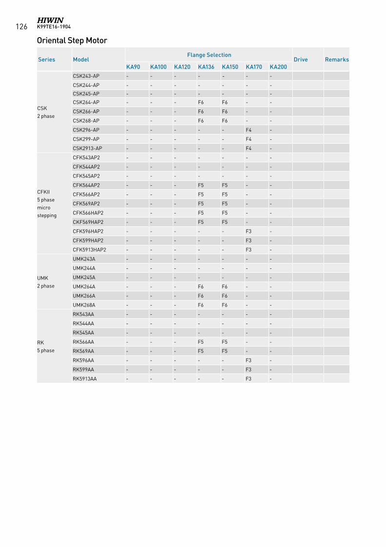
K99TE16-1904126
Oriental Step Motor
Series ModelFlange Selection
Drive RemarksKA90 KA100 KA120 KA136 KA150 KA170 KA200
CSK 2 phase
CSK243-AP - - - - - - -
CSK244-AP - - - - - - -
CSK245-AP - - - - - - -
CSK264-AP - - - F6 F6 - -
CSK266-AP - - - F6 F6 - -
CSK268-AP - - - F6 F6 - -
CSK296-AP - - - - - F4 -
CSK299-AP - - - - - F4 -
CSK2913-AP - - - - - F4 -
CFKII 5 phasemicrostepping
CFK543AP2 - - - - - - -
CFK544AP2 - - - - - - -
CFK545AP2 - - - - - - -
CFK564AP2 - - - F5 F5 - -
CFK566AP2 - - - F5 F5 - -
CFK569AP2 - - - F5 F5 - -
CFK566HAP2 - - - F5 F5 - -
CKF569HAP2 - - - F5 F5 - -
CFK596HAP2 - - - - - F3 -
CFK599HAP2 - - - - - F3 -
CFK5913HAP2 - - - - - F3 -
UMK 2 phase
UMK243A - - - - - - -
UMK244A - - - - - - -
UMK245A - - - - - - -
UMK264A - - - F6 F6 - -
UMK266A - - - F6 F6 - -
UMK268A - - - F6 F6 - -
RK 5 phase
RK543AA - - - - - - -
RK544AA - - - - - - -
RK545AA - - - - - - -
RK566AA - - - F5 F5 - -
RK569AA - - - F5 F5 - -
RK596AA - - - - - F3 -
RK599AA - - - - - F3 -
RK5913AA - - - - - F3 -
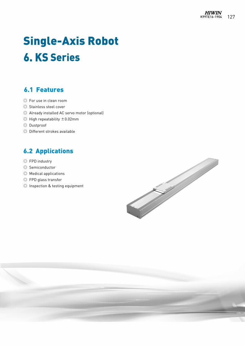
K99TE16-1904 127
Single-Axis Robot
6.2 Applications
For use in clean room
Stainless steel cover
Already installed AC servo motor (optional)
High repeatability ±0.02mm
Dustproof
Different strokes available
FPD industry
Semiconductor
Medical applications
FPD glass transfer
Inspection & testing equipment
6. KS Series
6.1 Features
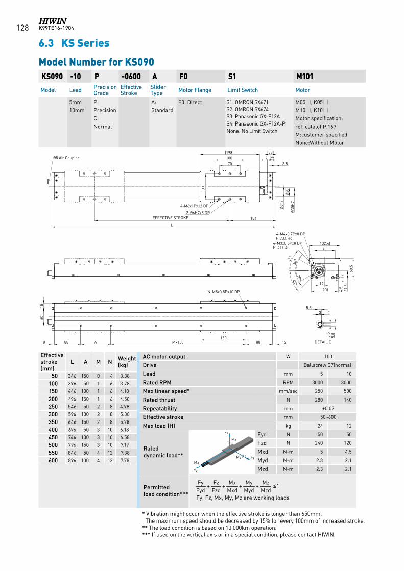
K99TE16-1904128
6.3 KS Series
KS090 -10 P -0600 A F0 S1 M101
Model Lead Precision Grade
Effective Stroke
Slider Type Motor Flange Limit Switch Motor
5mm10mm
P:Precision C:Normal
A:Standard
F0: Direct S1: OMRON SX671 S2: OMRON SX674 S3: Panasonic GX-F12A S4: Panasonic GX-F12A-PNone: No Limit Switch
M05, K05M10, K10Motor specification:ref. catalof P.167M:customer specifiedNone:Without Motor
Effective stroke (mm)
L A M N Weight (kg)
50 346 150 0 4 3.38
100 396 50 1 6 3.78
150 446 100 1 6 4.18
200 496 150 1 6 4.58
250 546 50 2 8 4.98
300 596 100 2 8 5.38
350 646 150 2 8 5.78
400 696 50 3 10 6.18
450 746 100 3 10 6.58
500 796 150 3 10 7.19
550 846 50 4 12 7.38
600 896 100 4 12 7.78
* Vibration might occur when the effective stroke is longer than 650mm. The maximum speed should be decreased by 15% for every 100mm of increased stroke.
** The load condition is based on 10,000km operation.*** If used on the vertical axis or in a special condition, please contact HIWIN.
AC motor output W 100
Drive Ballscrew C7(normal)
Lead mm 5 10
Rated RPM RPM 3000 3000
Max linear speed* mm/sec 250 500
Rated thrust N 280 140
Repeatability mm ±0.02
Effective stroke mm 50~600
Max load (H) kg 24 12
Rated dynamic load**
Fyd N 50 50
Fzd N 240 120
Mxd N-m 5 4.5
Myd N-m 2.3 2.1
Mzd N-m 2.3 2.1
Permitted load condition*** Fy, Fz, Mx, My, Mz are working loads
1++++MzdMz
MydMy
MxdMx
FzdFz
FydFy ≤
Model Number for KS090
Fz
FyMy Mx
Fx
Mz
Fz
FyMy Mx
Fx
Mz
Fz
FyMy Mx
Fx
Mz
Fz
FyMy Mx
Fx
Mz
Fz
FyMy Mx
Fx
Mz
Fz
FyMy Mx
Fx
Mz
154
9
EFFECTIVE STROKE
L
70100
(198)
4-M6x1Px12 DP
2-Ø6H7x8 DP
85
70(102.4)
19
(90) 4.5
27.5
68.5
1288150
Mx150A888
1560
30°45
°
45°
135.5
3.5
5.8
30°
Ø8 Air Coupler
4-M4x0.7Px8 DPP.C.D. 46
4-M3x0.5Px8 DPP.C.D. 40
N-M5x0.8Px10 DP
DETAIL E
E
29(38)
3.5
Ø6h
7Ø
28Ø
30H
7
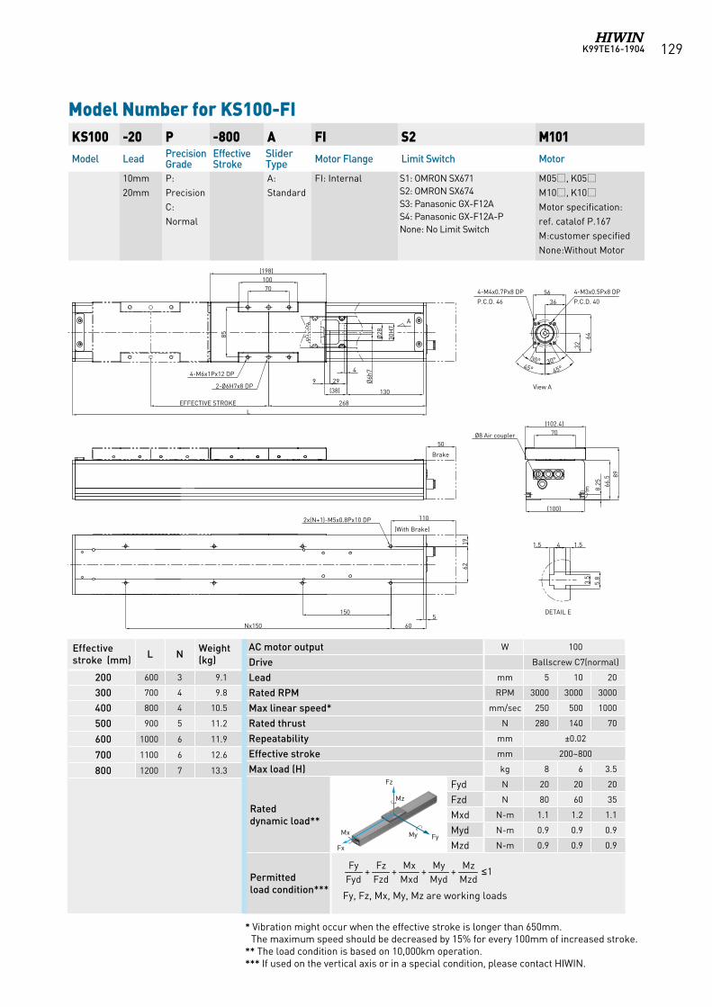
K99TE16-1904 129
Model Number for KS100-FI KS100 -20 P -800 A FI S2 M101Model Lead Precision
GradeEffective Stroke
Slider Type Motor Flange Limit Switch Motor
10mm20mm
P:Precision C:Normal
A:Standard
FI: Internal S1: OMRON SX671 S2: OMRON SX674 S3: Panasonic GX-F12A S4: Panasonic GX-F12A-PNone: No Limit Switch
M05, K05M10, K10Motor specification:ref. catalof P.167M:customer specifiedNone:Without Motor
AC motor output W 100
Drive Ballscrew C7(normal)
Lead mm 5 10 20
Rated RPM RPM 3000 3000 3000
Max linear speed* mm/sec 250 500 1000
Rated thrust N 280 140 70
Repeatability mm ±0.02
Effective stroke mm 200~800
Max load (H) kg 8 6 3.5
Rated dynamic load**
Fyd N 20 20 20
Fzd N 80 60 35
Mxd N-m 1.1 1.2 1.1
Myd N-m 0.9 0.9 0.9
Mzd N-m 0.9 0.9 0.9
Permitted load condition*** Fy, Fz, Mx, My, Mz are working loads
1++++MzdMz
MydMy
MxdMx
FzdFz
FydFy ≤
Effective stroke (mm) L N Weight
(kg)
200 600 3 9.1
300 700 4 9.8
400 800 4 10.5
500 900 5 11.2
600 1000 6 11.9
700 1100 6 12.6
800 1200 7 13.3
* Vibration might occur when the effective stroke is longer than 650mm. The maximum speed should be decreased by 15% for every 100mm of increased stroke.
** The load condition is based on 10,000km operation.*** If used on the vertical axis or in a special condition, please contact HIWIN.
Fz
FyMy Mx
Fx
Mz
Fz
FyMy Mx
Fx
Mz
Fz
FyMy Mx
Fx
Mz
Fz
FyMy Mx
Fx
Mz
Fz
FyMy Mx
Fx
Mz
8966
.5
(100)
70(102.4)
8.25
(198)10070
85
EFFECTIVE STROKE 268L
1962
560Nx150
1.541.5
3.5
5.8
2-Ø6H7x8 DP
Ø8 Air coupler
E
2x(N+1)-M5x0.8Px10 DP
DETAIL E
64
45°
36564-M4x0.7Px8 DP
P.C.D. 46
130
4-M6x1Px12 DP
(38)9 29 Ø
6h7
A
32
Ø28
30H
7
4
150
45°
30° 30°
4-M3x0.5Px8 DP
P.C.D. 40
110
(With Brake)
50
Brake
View A
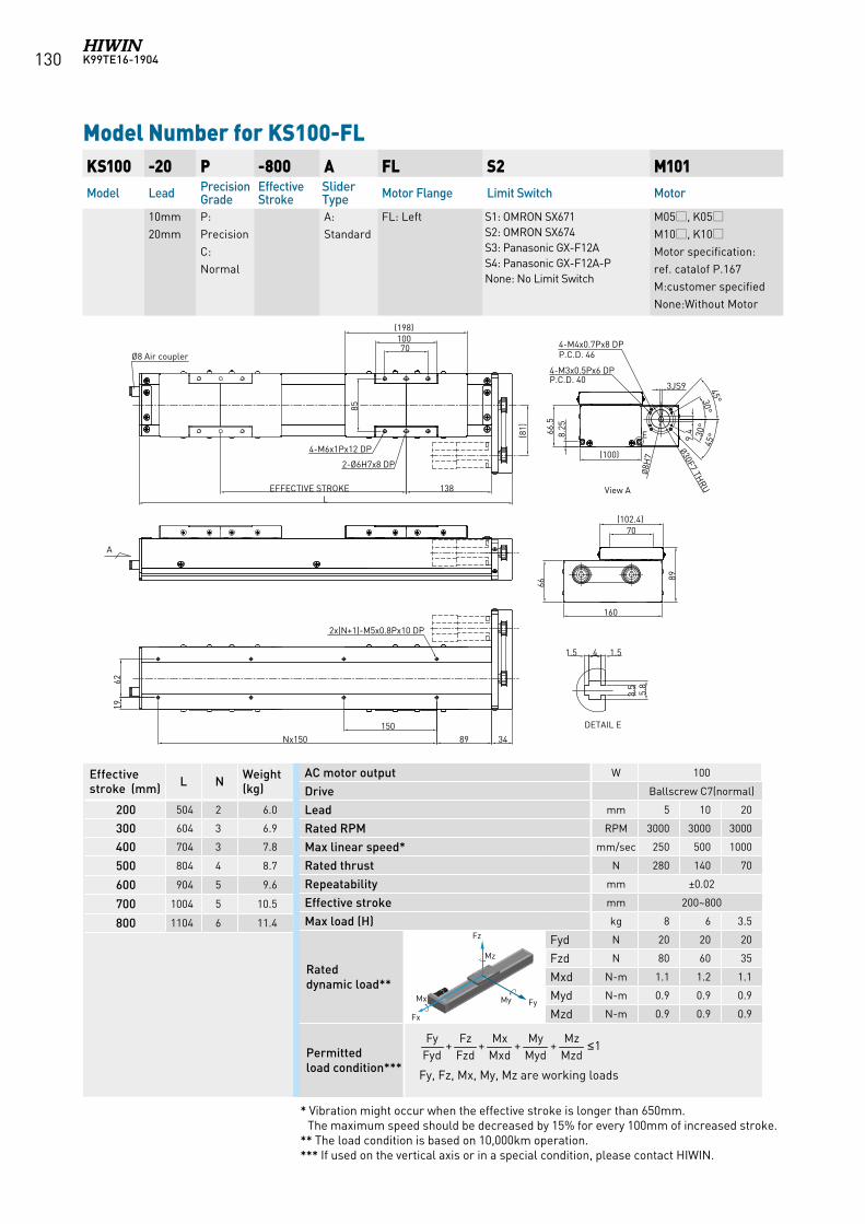
K99TE16-1904130
KS100 -20 P -800 A FL S2 M101Model Lead Precision
GradeEffective Stroke
Slider Type Motor Flange Limit Switch Motor
10mm20mm
P:Precision C:Normal
A:Standard
FL: Left S1: OMRON SX671 S2: OMRON SX674 S3: Panasonic GX-F12A S4: Panasonic GX-F12A-PNone: No Limit Switch
M05, K05M10, K10Motor specification:ref. catalof P.167M:customer specifiedNone:Without Motor
Model Number for KS100-FL
Effective stroke (mm) L N Weight
(kg)
200 504 2 6.0
300 604 3 6.9
400 704 3 7.8
500 804 4 8.7
600 904 5 9.6
700 1004 5 10.5
800 1104 6 11.4
AC motor output W 100
Drive Ballscrew C7(normal)
Lead mm 5 10 20
Rated RPM RPM 3000 3000 3000
Max linear speed* mm/sec 250 500 1000
Rated thrust N 280 140 70
Repeatability mm ±0.02
Effective stroke mm 200~800
Max load (H) kg 8 6 3.5
Rated dynamic load**
Fyd N 20 20 20
Fzd N 80 60 35
Mxd N-m 1.1 1.2 1.1
Myd N-m 0.9 0.9 0.9
Mzd N-m 0.9 0.9 0.9
Permitted load condition*** Fy, Fz, Mx, My, Mz are working loads
1++++MzdMz
MydMy
MxdMx
FzdFz
FydFy ≤
* Vibration might occur when the effective stroke is longer than 650mm. The maximum speed should be decreased by 15% for every 100mm of increased stroke.
** The load condition is based on 10,000km operation.*** If used on the vertical axis or in a special condition, please contact HIWIN.
Fz
FyMy Mx
Fx
Mz
Fz
FyMy Mx
Fx
Mz
Fz
FyMy Mx
Fx
Mz
Fz
FyMy Mx
Fx
Mz
Fz
FyMy Mx
Fx
Mz
85
34
1962
(81)
(198)10070
2-Ø6H7x8 DP
4-M6x1Px12 DP
138EFFECTIVE STROKEL
89150
Nx150
2x(N+1)-M5x0.8Px10 DP
70(102.4)
66
89
160
Ø30F7 THRU
8.2566
.5
4-M4x0.7Px8 DPP.C.D. 46
4-M3x0.5Px6 DPP.C.D. 40
E
1.541.5
3.5
5.8
DETAIL E
(100)
Ø8 Air coupler
3JS9
9.4
30°
30°
45°
45°
Ø8H
7
A
View A
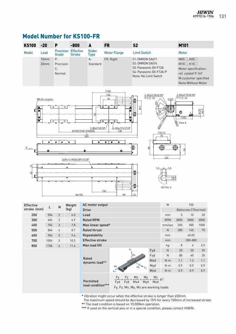
K99TE16-1904 131
Model Number for KS100-FR KS100 -20 P -800 A FR S2 M101Model Lead Precision
GradeEffective Stroke
Slider Type Motor Flange Limit Switch Motor
10mm20mm
P:Precision C:Normal
A:Standard
FR: Right S1: OMRON SX671 S2: OMRON SX674 S3: Panasonic GX-F12A S4: Panasonic GX-F12A-PNone: No Limit Switch
M05, K05M10, K10Motor specification:ref. catalof P.167M:customer specifiedNone:Without Motor
Effective stroke (mm) L N Weight
(kg)
200 504 2 6.0
300 604 3 6.9
400 704 3 7.8
500 804 4 8.7
600 904 5 9.6
700 1004 5 10.5
800 1104 6 11.4
AC motor output W 100
Drive Ballscrew C7(normal)
Lead mm 5 10 20
Rated RPM RPM 3000 3000 3000
Max linear speed* mm/sec 250 500 1000
Rated thrust N 280 140 70
Repeatability mm ±0.02
Effective stroke mm 200~800
Max load (H) kg 8 6 3.5
Rated dynamic load**
Fyd N 20 20 20
Fzd N 80 60 35
Mxd N-m 1.1 1.2 1.1
Myd N-m 0.9 0.9 0.9
Mzd N-m 0.9 0.9 0.9
Permitted load condition*** Fy, Fz, Mx, My, Mz are working loads
1++++MzdMz
MydMy
MxdMx
FzdFz
FydFy ≤
* Vibration might occur when the effective stroke is longer than 650mm. The maximum speed should be decreased by 15% for every 100mm of increased stroke.
** The load condition is based on 10,000km operation.*** If used on the vertical axis or in a special condition, please contact HIWIN.
Fz
FyMy Mx
Fx
Mz
Fz
FyMy Mx
Fx
Mz
Fz
FyMy Mx
Fx
Mz
Fz
FyMy Mx
Fx
Mz
Fz
FyMy Mx
Fx
Mz
(198)10070
85
2-Ø6H7x8 DP 4-M6x1Px12 DP138EFFECTIVE STROKE
3489150
Nx150
1962
2x(N+1)-M5x0.8Px10 DPØ3
0F7
THRU
70(102.4)
66
89
L
8.25
160
66.5
View A
4-M4x0.7Px8 DPP.C.D. 46
4-M3x0.5Px8 DPP.C.D. 40
(81)
1.541.5
3.5
5.8
DETAIL E
E
(100)
Ø8H
7
Ø8 Air coupler 3JS9
9.430
°
30°45°
45°
604
A
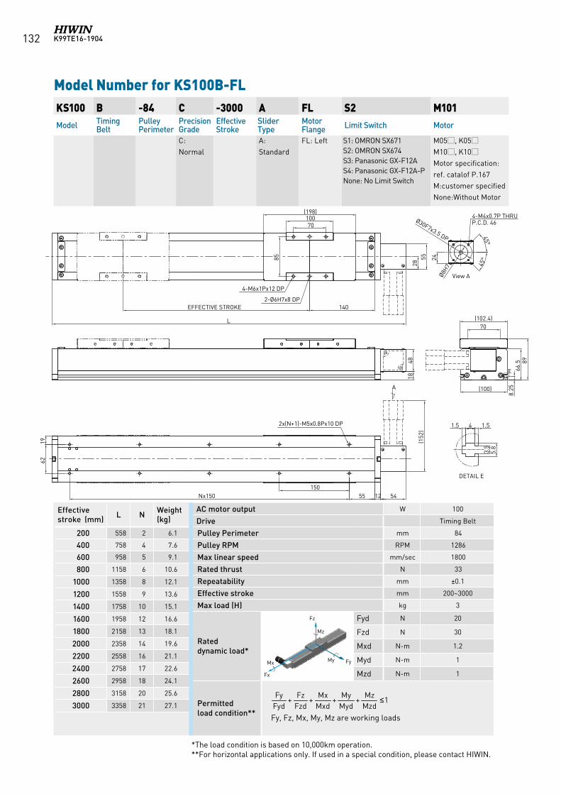
K99TE16-1904132
Model Number for KS100B-FL KS100 B -84 C -3000 A FL S2 M101Model Timing
BeltPulley Perimeter
Precision Grade
Effective Stroke
Slider Type
Motor Flange Limit Switch Motor
C:Normal
A:Standard
FL: Left S1: OMRON SX671 S2: OMRON SX674 S3: Panasonic GX-F12A S4: Panasonic GX-F12A-PNone: No Limit Switch
M05, K05M10, K10Motor specification:ref. catalof P.167M:customer specifiedNone:Without Motor
AC motor output W 100
Drive Timing Belt
Pulley Perimeter mm 84
Pulley RPM RPM 1286
Max linear speed mm/sec 1800
Rated thrust N 33
Repeatability mm ±0.1
Effective stroke mm 200~3000
Max load (H) kg 3
Rated dynamic load*
Fyd N 20
Fzd N 30
Mxd N-m 1.2
Myd N-m 1
Mzd N-m 1
Permitted load condition** Fy, Fz, Mx, My, Mz are working loads
1++++MzdMz
MydMy
MxdMx
FzdFz
FydFy ≤
Effective stroke (mm) L N Weight
(kg)
200 558 2 6.1
400 758 4 7.6
600 958 5 9.1
800 1158 6 10.6
1000 1358 8 12.1
1200 1558 9 13.6
1400 1758 10 15.1
1600 1958 12 16.6
1800 2158 13 18.1
2000 2358 14 19.6
2200 2558 16 21.1
2400 2758 17 22.6
2600 2958 18 24.1
2800 3158 20 25.6
3000 3358 21 27.1
*The load condition is based on 10,000km operation.**For horizontal applications only. If used in a special condition, please contact HIWIN.
Fz
FyMy Mx
Fx
Mz
Fz
FyMy Mx
Fx
Mz
Fz
FyMy Mx
Fx
Mz
Fz
FyMy Mx
Fx
Mz
Fz
FyMy Mx
Fx
Mz
55 12Nx150 54
62
EFFECTIVE STROKE 140
70100
(198)
4-M6x1Px12 DP
2-Ø6H7x8 DP
285585
2x(N+1)-M5x0.8Px10 DP(1
52)
8.25
66.5 89
70(102.4)
(100)
L
E
1.541.5
3.5
5.8
DETAIL E
4-M4x0.7P THRU P.C.D. 46
24
Ø30F7x3.5 DP
Ø8H7 45
°
45°
A
150
4818
19
View A
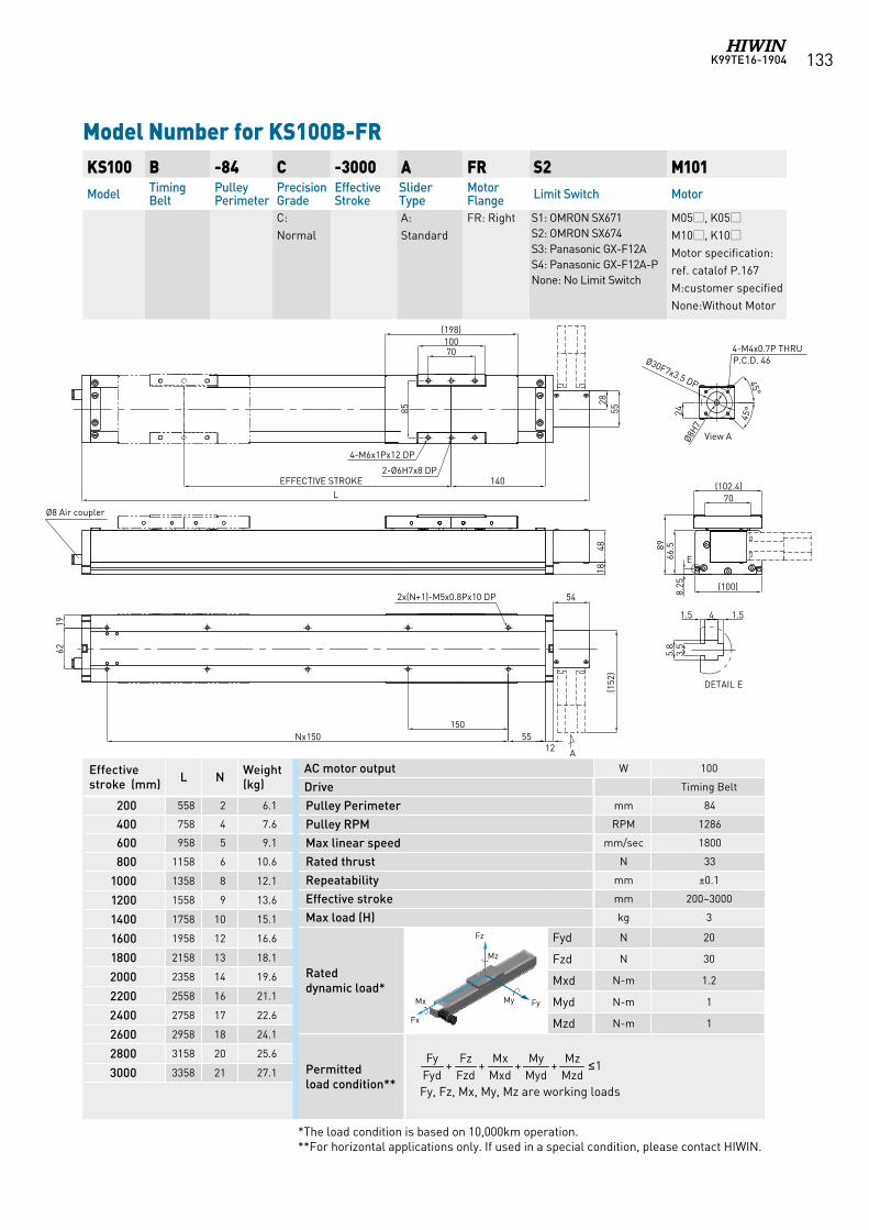
K99TE16-1904 133
Model Number for KS100B-FR KS100 B -84 C -3000 A FR S2 M101Model Timing
BeltPulley Perimeter
Precision Grade
Effective Stroke
Slider Type
Motor Flange Limit Switch Motor
C:Normal
A:Standard
FR: Right S1: OMRON SX671 S2: OMRON SX674 S3: Panasonic GX-F12A S4: Panasonic GX-F12A-PNone: No Limit Switch
M05, K05M10, K10Motor specification:ref. catalof P.167M:customer specifiedNone:Without Motor
AC motor output W 100
Drive Timing Belt
Pulley Perimeter mm 84
Pulley RPM RPM 1286
Max linear speed mm/sec 1800
Rated thrust N 33
Repeatability mm ±0.1
Effective stroke mm 200~3000
Max load (H) kg 3
Rated dynamic load*
Fyd N 20
Fzd N 30
Mxd N-m 1.2
Myd N-m 1
Mzd N-m 1
Permitted load condition** Fy, Fz, Mx, My, Mz are working loads
1++++MzdMz
MydMy
MxdMx
FzdFz
FydFy ≤
Effective stroke (mm) L N Weight
(kg)
200 558 2 6.1
400 758 4 7.6
600 958 5 9.1
800 1158 6 10.6
1000 1358 8 12.1
1200 1558 9 13.6
1400 1758 10 15.1
1600 1958 12 16.6
1800 2158 13 18.1
2000 2358 14 19.6
2200 2558 16 21.1
2400 2758 17 22.6
2600 2958 18 24.1
2800 3158 20 25.6
3000 3358 21 27.1
*The load condition is based on 10,000km operation.**For horizontal applications only. If used in a special condition, please contact HIWIN.
Fz
FyMy Mx
Fx
Mz
Fz
FyMy Mx
Fx
Mz
Fz
FyMy Mx
Fx
Mz
Fz
FyMy Mx
Fx
Mz
Fz
FyMy Mx
Fx
Mz
5512
Nx150
54
62
EFFECTIVE STROKE 140
70100
(198)
4-M6x1Px12 DP
2-Ø6H7x8 DP
285585
2x(N+1)-M5x0.8Px10 DP(1
52)
8.25
66.589
70(102.4)
(100)
L
E
1.5 4 1.5
3.5
5.8
DETAIL E
4-M4x0.7P THRU P.C.D. 46
24
Ø30F7x3.5 DP
Ø8H7
45°
45°
A
150
4818
19
View A
Ø8 Air coupler
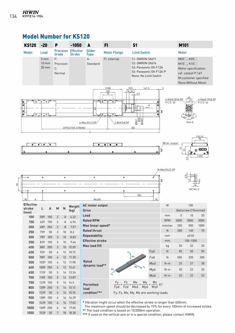
K99TE16-1904134
KS120 -20 P -1050 A FI S1 M101Model Lead Precision
GradeEffective Stroke
Slider Type Motor Flange Limit Switch Motor
5 mm 10 mm 20 mm
P:PrecisionC:Normal
A:Standard
FI: Internal S1: OMRON SX671 S2: OMRON SX674 S3: Panasonic GX-F12A S4: Panasonic GX-F12A-PNone: No Limit Switch
M05, K05M10, K10Motor specification:ref. catalof P.167M:customer specifiedNone:Without Motor
Model Number for KS120
Effective stroke (mm)
L A M N Weight (kg)
100 589 100 2 8 6.32
150 639 150 2 8 6.94
200 689 200 2 8 7.57
250 739 50 3 10 8.2
300 789 100 3 10 8.83
350 839 150 3 10 9.46
400 889 200 3 10 10.09
450 939 50 4 12 10.72
500 989 100 4 12 11.35
550 1039 150 4 12 11.98
600 1089 200 4 12 12.61
650 1139 50 5 14 13.24
700 1189 100 5 14 13.87
750 1239 150 5 14 14.5
800 1289 200 5 14 15.13
850 1339 50 6 16 15.76
900 1389 100 6 16 16.39
950 1439 150 6 16 17.02
1000 1489 200 6 16 17.65
1050 1539 50 7 18 18.28
AC motor output W 100
Drive Ballscrew C7(normal)
Lead mm 5 10 20
Rated RPM RPM 3000 3000 3000
Max linear speed* mm/sec 250 500 1000
Rated thrust N 280 140 70
Repeatability mm ±0.02
Effective stroke mm 100~1050
Max load (H) kg 50 32 20
Rated dynamic load**
Fyd N 50 50 50
Fzd N 500 320 200
Mxd N-m 25 27 28
Myd N-m 20 22 23
Mzd N-m 20 22 23
Permitted load condition*** Fy, Fz, Mx, My, Mz are working loads
1++++MzdMz
MydMy
MxdMx
FzdFz
FydFy ≤
* Vibration might occur when the effective stroke is longer than 600mm. The maximum speed should be decreased by 15% for every 100mm of increased stroke.
** The load condition is based on 10,000km operation.*** If used on the vertical axis or in a special condition, please contact HIWIN.
Fz
FyMy Mx
Fx
Mz
Fz
FyMy Mx
Fx
Mz
Fz
FyMy Mx
Fx
Mz
Fz
FyMy Mx
Fx
Mz
Fz
FyMy Mx
Fx
Mz
Fz
FyMy Mx
Fx
Mz
A
View A
E
3.5
5.8
1.53
6
DETAIL E
Ø8h
7 Ø28
Ø30
H7
3418167.5 5
3.5
352EFFECTIVE STROKEL
70100
(198)
38
200
Mx200A
90
70(102.4)
5.5
5577
2140
30° 30°45° 45°
(120)
4-M6x1Px12 DP 2-Ø6H7x8 DP
85
4-M3x0.5Px8 DPP.C.D. 40
4-M4x0.7Px8 DPP.C.D. 46
Ø8 Air coupler
N-M6x1Px12 DP
38
(52)
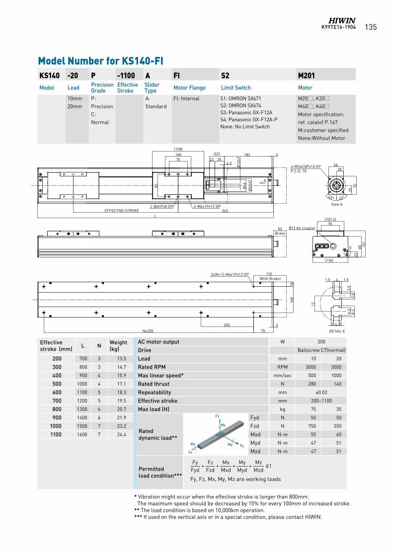
K99TE16-1904 135
Model Number for KS140-FIKS140 -20 P -1100 A FI S2 M201Model Lead Precision
GradeEffective Stroke
Slider Type Motor Flange Limit Switch Motor
10mm20mm
P:Precision C:Normal
A:Standard
FI: Internal S1: OMRON SX671 S2: OMRON SX674 S3: Panasonic GX-F12A S4: Panasonic GX-F12A-PNone: No Limit Switch
M20, K20M40, K40Motor specification:ref. catalof P.167M:customer specifiedNone:Without Motor
AC motor output W 200
Drive Ballscrew C7(normal)
Lead mm 10 20
Rated RPM RPM 3000 3000
Max linear speed* mm/sec 500 1000
Rated thrust N 280 140
Repeatability mm ±0.02
Effective stroke mm 200~1100
Max load (H) kg 75 35
Rated dynamic load**
Fyd N 50 50
Fzd N 750 350
Mxd N-m 55 60
Myd N-m 47 51
Mzd N-m 47 51
Permitted load condition*** Fy, Fz, Mx, My, Mz are working loads
1++++MzdMz
MydMy
MxdMx
FzdFz
FydFy ≤
Effective stroke (mm) L N Weight
(kg)
200 700 3 13.5
300 800 3 14.7
400 900 4 15.9
500 1000 4 17.1
600 1100 5 18.3
700 1200 5 19.5
800 1300 6 20.7
900 1400 6 21.9
1000 1500 7 23.2
1100 1600 7 24.4
* Vibration might occur when the effective stroke is longer than 800mm. The maximum speed should be decreased by 15% for every 100mm of increased stroke.
** The load condition is based on 10,000km operation.*** If used on the vertical axis or in a special condition, please contact HIWIN.
Fz
FyMy Mx
Fx
Mz
Fz
FyMy Mx
Fx
Mz
Fz
FyMy Mx
Fx
Mz
Fz
FyMy Mx
Fx
Mz
Fz
FyMy Mx
Fx
Mz
101
80
(136)
70(102.4)
22
(198)10070
85
363L
4-M6x1Px12 DP2-Ø6H7x8 DP
Ø12 Air coupler
E
1.541.5
12
3.5
5.8
5.5
8.3
242
1810
0
575Nx200
2x(N+1)-M6x1Px12 DP
70
58
35
28
45°45°
4-M5x0.8Px10 DPP.C.D. 70
182(57)22 35
Ø12
h7
5
A
Ø46
Ø50
H7
4.5
200
50
(With Brake)
Brake
125
EFFECTIVE STROKE
DETAIL E
View A
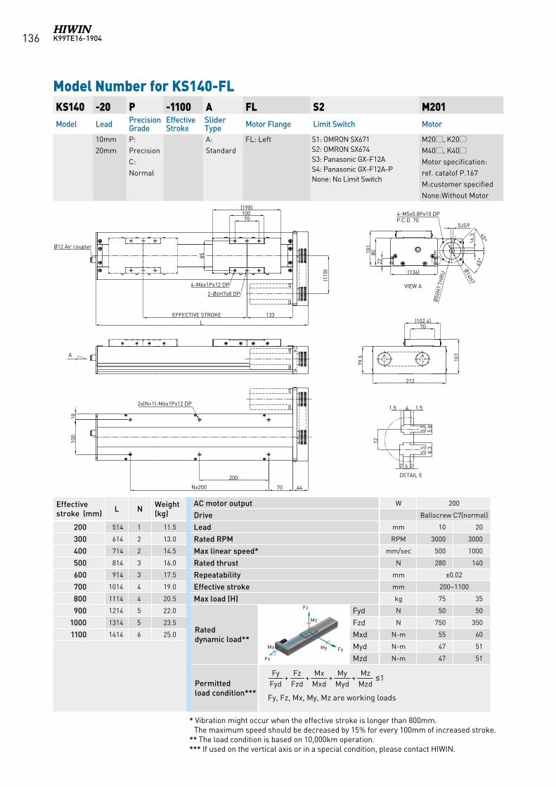
K99TE16-1904136
Model Number for KS140-FL KS140 -20 P -1100 A FL S2 M201Model Lead Precision
GradeEffective Stroke
Slider Type Motor Flange Limit Switch Motor
10mm20mm
P:Precision C:Normal
A:Standard
FL: Left S1: OMRON SX671 S2: OMRON SX674 S3: Panasonic GX-F12A S4: Panasonic GX-F12A-PNone: No Limit Switch
M20, K20M40, K40Motor specification:ref. catalof P.167M:customer specifiedNone:Without Motor
AC motor output W 200
Drive Ballscrew C7(normal)
Lead mm 10 20
Rated RPM RPM 3000 3000
Max linear speed* mm/sec 500 1000
Rated thrust N 280 140
Repeatability mm ±0.02
Effective stroke mm 200~1100
Max load (H) kg 75 35
Rated dynamic load**
Fyd N 50 50
Fzd N 750 350
Mxd N-m 55 60
Myd N-m 47 51
Mzd N-m 47 51
Permitted load condition*** Fy, Fz, Mx, My, Mz are working loads
1++++MzdMz
MydMy
MxdMx
FzdFz
FydFy ≤
Effective stroke (mm) L N Weight
(kg)
200 514 1 11.5
300 614 2 13.0
400 714 2 14.5
500 814 3 16.0
600 914 3 17.5
700 1014 4 19.0
800 1114 4 20.5
900 1214 5 22.0
1000 1314 5 23.5
1100 1414 6 25.0
* Vibration might occur when the effective stroke is longer than 800mm. The maximum speed should be decreased by 15% for every 100mm of increased stroke.
** The load condition is based on 10,000km operation.*** If used on the vertical axis or in a special condition, please contact HIWIN.
Fz
FyMy Mx
Fx
Mz
Fz
FyMy Mx
Fx
Mz
Fz
FyMy Mx
Fx
Mz
Fz
FyMy Mx
Fx
Mz
Fz
FyMy Mx
Fx
Mz
A
4-M5x0.8Px10 DPP.C.D. 70
1.541.5
12
3.5
5.8
5.5
8.3
242
DETAIL E
(110
)
4470
100
70100(198)
133EFFECTIVE STROKEL
4-M6x1Px12 DP
2-Ø6H7x8 DP
2x(N+1)-M6x1Px12 DP
70(102.4)
79.5 10
1
212
85
Ø12 Air coupler
18
200
Nx200
8022
101
(136)
E
VIEW A
5JS9
16.3
Ø50
H7
THR
U
Ø14H7
45°
45°
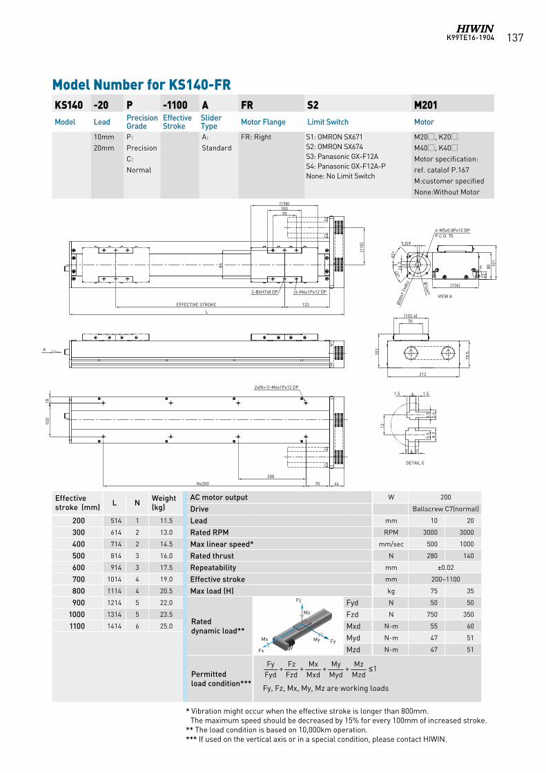
K99TE16-1904 137
Model Number for KS140-FR KS140 -20 P -1100 A FR S2 M201Model Lead Precision
GradeEffective Stroke
Slider Type Motor Flange Limit Switch Motor
10mm20mm
P:Precision C:Normal
A:Standard
FR: Right S1: OMRON SX671 S2: OMRON SX674 S3: Panasonic GX-F12A S4: Panasonic GX-F12A-PNone: No Limit Switch
M20, K20M40, K40Motor specification:ref. catalof P.167M:customer specifiedNone:Without Motor
AC motor output W 200
Drive Ballscrew C7(normal)
Lead mm 10 20
Rated RPM RPM 3000 3000
Max linear speed* mm/sec 500 1000
Rated thrust N 280 140
Repeatability mm ±0.02
Effective stroke mm 200~1100
Max load (H) kg 75 35
Rated dynamic load**
Fyd N 50 50
Fzd N 750 350
Mxd N-m 55 60
Myd N-m 47 51
Mzd N-m 47 51
Permitted load condition*** Fy, Fz, Mx, My, Mz are working loads
1++++MzdMz
MydMy
MxdMx
FzdFz
FydFy ≤
Effective stroke (mm) L N Weight
(kg)
200 514 1 11.5
300 614 2 13.0
400 714 2 14.5
500 814 3 16.0
600 914 3 17.5
700 1014 4 19.0
800 1114 4 20.5
900 1214 5 22.0
1000 1314 5 23.5
1100 1414 6 25.0
* Vibration might occur when the effective stroke is longer than 800mm. The maximum speed should be decreased by 15% for every 100mm of increased stroke.
** The load condition is based on 10,000km operation.*** If used on the vertical axis or in a special condition, please contact HIWIN.
Fz
FyMy Mx
Fx
Mz
Fz
FyMy Mx
Fx
Mz
Fz
FyMy Mx
Fx
Mz
Fz
FyMy Mx
Fx
Mz
Fz
FyMy Mx
Fx
Mz
(110
)
70(102.4)
79.510
1212
(198)10070
4-M6x1Px12 DP2-Ø6H7x8 DP
133EFFECTIVE STROKE
L
4470
200
Nx200
1810
0
2x(N+1)-M6x1Px12 DP
45°
8022
101
(136)
4-M5x0.8Px10 DPP.C.D. 70
1.541.5
12
3.5
5.4
5.5
8.3
242
DETAIL E
E
Ø50H
7 TH
RU
85
VIEW A
Ø14H
7
5JS9
16.3
45°
A
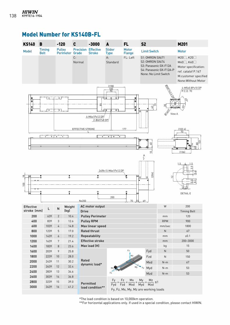
K99TE16-1904138
Model Number for KS140B-FL KS140 B -120 C -3000 A FL S2 M201Model Timing
BeltPulley Perimeter
Precision Grade
Effective Stroke
Slider Type
Motor Flange Limit Switch Motor
C:Normal
A:Standard
FL: Left S1: OMRON SX671 S2: OMRON SX674 S3: Panasonic GX-F12A S4: Panasonic GX-F12A-PNone: No Limit Switch
M20, K20M40, K40Motor specification:ref. catalof P.167M:customer specifiedNone:Without Motor
AC motor output W 200
Drive Timing Belt
Pulley Perimeter mm 120
Pulley RPM RPM 900
Max linear speed mm/sec 1800
Rated thrust N 67
Repeatability mm ±0.1
Effective stroke mm 200~3000
Max load (H) kg 15
Rated dynamic load*
Fyd N 50
Fzd N 150
Mxd N-m 67
Myd N-m 53
Mzd N-m 53
Permitted load condition** Fy, Fz, Mx, My, Mz are working loads
1++++MzdMz
MydMy
MxdMx
FzdFz
FydFy ≤
Effective stroke (mm) L N Weight
(kg)
200 639 2 10.4
400 839 3 12.6
600 1039 4 14.8
800 1239 5 17.0
1000 1439 6 19.2
1200 1639 7 21.4
1400 1839 8 23.6
1600 2039 9 25.8
1800 2239 10 28.0
2000 2439 11 30.2
2200 2639 12 32.4
2400 2839 13 34.6
2600 3039 14 36.8
2800 3239 15 39.0
3000 3439 16 41.2
*The load condition is based on 10,000km operation.**For horizontal applications only. If used in a special condition, please contact HIWIN.
Fz
FyMy Mx
Fx
Mz
Fz
FyMy Mx
Fx
Mz
Fz
FyMy Mx
Fx
Mz
Fz
FyMy Mx
Fx
Mz
Fz
FyMy Mx
Fx
Mz
70100
(198)
85
4279
EFFECTIVE STROKE 177L
4-M6x1Px12 DP2-Ø6H7x8 DP
2x(N+1)-M6x1Px12 DP
Nx200200
70 15 69
(204
)
70(102.4)
101
E
2280
(136)
View A
30
45°
45°
4-M5x0.8Px10 DPP.C.D. 70
Ø50F7x3.5 DP
A
100
1.541.5
12
3.5
5.4
5.5
8.3
242
DETAIL E
1060
Ø14H7
18
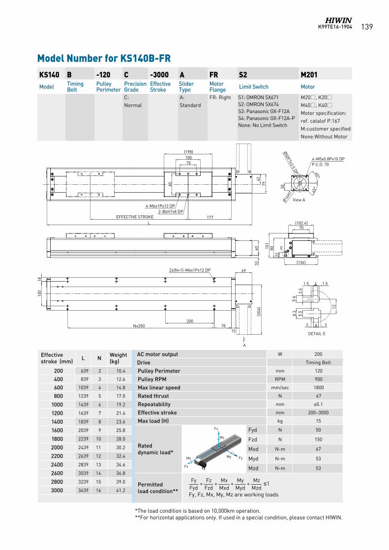
K99TE16-1904 139
Model Number for KS140B-FR KS140 B -120 C -3000 A FR S2 M201Model Timing
BeltPulley Perimeter
Precision Grade
Effective Stroke
Slider Type
Motor Flange Limit Switch Motor
C:Normal
A:Standard
FR: Right S1: OMRON SX671 S2: OMRON SX674 S3: Panasonic GX-F12A S4: Panasonic GX-F12A-PNone: No Limit Switch
M20, K20M40, K40Motor specification:ref. catalof P.167M:customer specifiedNone:Without Motor
AC motor output W 200
Drive Timing Belt
Pulley Perimeter mm 120
Pulley RPM RPM 900
Max linear speed mm/sec 1800
Rated thrust N 67
Repeatability mm ±0.1
Effective stroke mm 200~3000
Max load (H) kg 15
Rated dynamic load*
Fyd N 50
Fzd N 150
Mxd N-m 67
Myd N-m 53
Mzd N-m 53
Permitted load condition** Fy, Fz, Mx, My, Mz are working loads
1++++MzdMz
MydMy
MxdMx
FzdFz
FydFy ≤
Effective stroke (mm) L N Weight
(kg)
200 639 2 10.4
400 839 3 12.6
600 1039 4 14.8
800 1239 5 17.0
1000 1439 6 19.2
1200 1639 7 21.4
1400 1839 8 23.6
1600 2039 9 25.8
1800 2239 10 28.0
2000 2439 11 30.2
2200 2639 12 32.4
2400 2839 13 34.6
2600 3039 14 36.8
2800 3239 15 39.0
3000 3439 16 41.2
*The load condition is based on 10,000km operation.**For horizontal applications only. If used in a special condition, please contact HIWIN.
Fz
FyMy Mx
Fx
Mz
Fz
FyMy Mx
Fx
Mz
Fz
FyMy Mx
Fx
Mz
Fz
FyMy Mx
Fx
Mz
Fz
FyMy Mx
Fx
Mz
70100
(198)
85
4279
EFFECTIVE STROKE 177L
4-M6x1Px12 DP2-Ø6H7x8 DP
2x(N+1)-M6x1Px12 DP
20070
15
69
(204
)
70(102.4)
101
E
2280
(136)
View A
30
45°
45°
4-M5x0.8Px10 DPP.C.D. 70
Ø50F7x3.5 DP
A
100
1.5 4 1.5
12
3.5
5.4
5.5
8.3
2 4 2
DETAIL E
Ø14H7
1060
18
Nx200
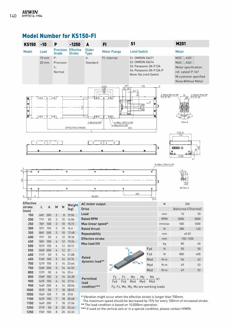
K99TE16-1904140
KS150 -10 P -1250 A FI S1 M201
Model Lead Precision Grade
Effective Stroke
Slider Type Motor Flange Limit Switch Motor
10 mm 20 mm
P:Precision C:Normal
A:Standard
FI: Internal S1: OMRON SX671 S2: OMRON SX674 S3: Panasonic GX-F12A S4: Panasonic GX-F12A-PNone: No Limit Switch
M20, K20M40, K40Motor specification:ref. catalof P.167M:customer specifiedNone:Without Motor
Model Number for KS150-FI
Effective stroke (mm)
L A M N Weight (kg)
150 669 200 2 8 13.96
200 719 50 3 10 14.84
250 769 100 3 10 15.72
300 819 150 3 10 16.6
350 869 200 3 10 17.48
400 919 50 4 12 18.36
450 969 100 4 12 19.24
500 1019 150 4 12 20.12
550 1069 200 4 12 21
600 1119 50 5 14 21.88
650 1169 100 5 14 22.76
700 1219 150 5 14 23.64
750 1269 200 5 14 24.52
800 1319 50 6 16 25.4
850 1369 100 6 16 26.28
900 1419 150 6 16 27.16
950 1469 200 6 16 28.04
1000 1519 50 7 18 28.92
1050 1569 100 7 18 29.8
1100 1619 150 7 18 30.68
1150 1669 200 7 18 31.56
1200 1719 50 8 20 32.44
1250 1769 100 8 20 33.32
AC motor output W 200
Drive Ballscrew C7(normal)
Lead mm 10 20
Rated RPM RPM 3000 3000
Max linear speed* mm/sec 500 1000
Rated thrust N 280 140
Repeatability mm ±0.02
Effective stroke mm 150~1250
Max load (H) kg 80 40
Rated dynamic load**
Fyd N 50 50
Fzd N 800 400
Mxd N-m 56 63
Myd N-m 49 53
Mzd N-m 49 53
Permitted load condition*** Fy, Fz, Mx, My, Mz are working loads
1++++MzdMz
MydMy
MxdMx
FzdFz
FydFy ≤
* Vibration might occur when the effective stroke is longer than 700mm. The maximum speed should be decreased by 15% for every 100mm of increased stroke.
** The load condition is based on 10,000km operation.*** If used on the vertical axis or in a special condition, please contact HIWIN.
Fz
FyMy Mx
Fx
Mz
Fz
FyMy Mx
Fx
Mz
Fz
FyMy Mx
Fx
Mz
Fz
FyMy Mx
Fx
Mz
Fz
FyMy Mx
Fx
Mz
Fz
FyMy Mx
Fx
Mz
A
3.5
5.8
6
1.53
DETAIL E
70100128(220)
132
EFFECTIVE STROKE 373L
29.5
200Mx200
114(152.4)
970 10
0
(150)
17822 35
(57)
Ø12
h7Ø
46Ø
50H
8
3.5
2859
E
5
1512
0
4-M8x1.25Px16 DP2-Ø6H7x8 DP4-M6x1Px12 DP
View A
4-M4x0.7Px8 DPP.C.D. 60
4-M5x0.8Px10 DPP.C.D. 70
30° 30°45° 45°
N-M8x1.25Px16 DP
A29.5
5
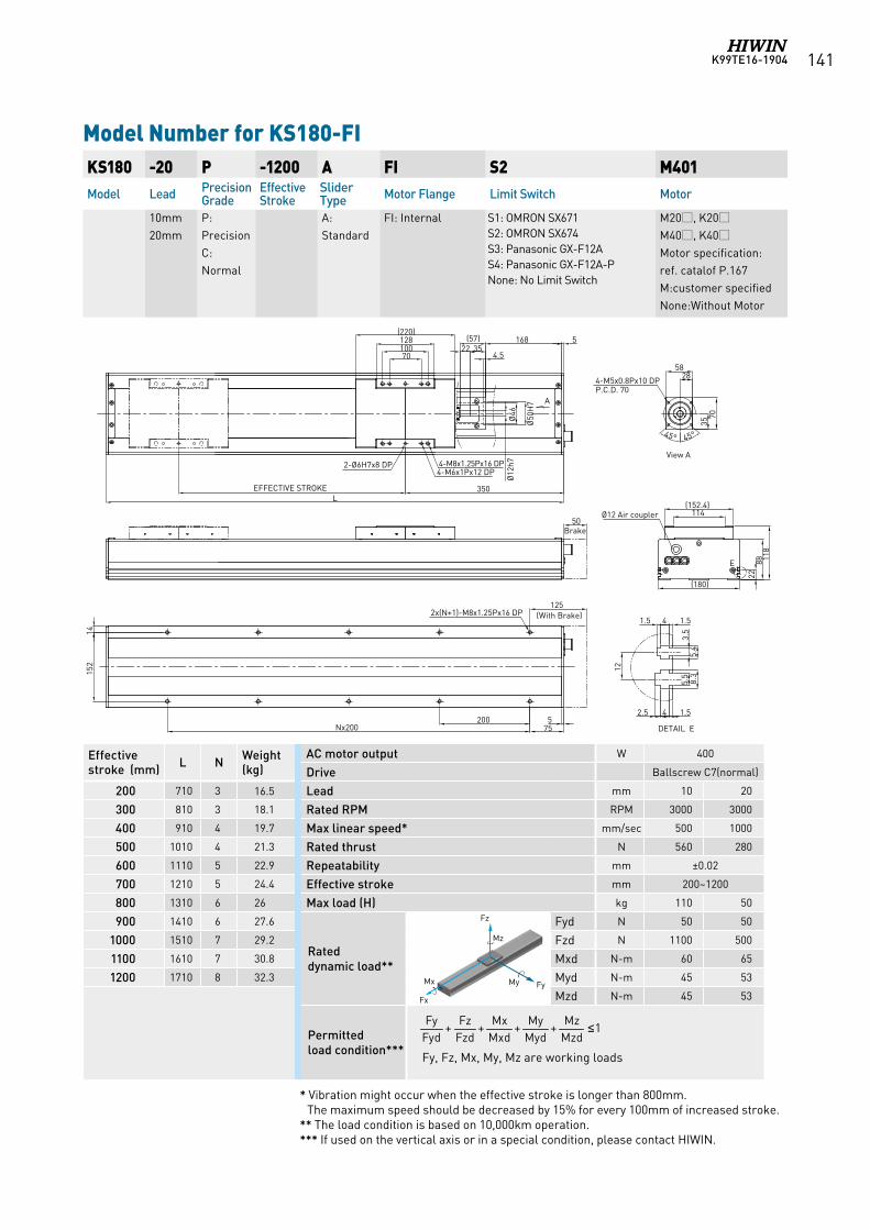
K99TE16-1904 141
Model Number for KS180-FIKS180 -20 P -1200 A FI S2 M401Model Lead Precision
GradeEffective Stroke
Slider Type Motor Flange Limit Switch Motor
10mm20mm
P:Precision C:Normal
A:Standard
FI: Internal S1: OMRON SX671 S2: OMRON SX674 S3: Panasonic GX-F12A S4: Panasonic GX-F12A-PNone: No Limit Switch
M20, K20M40, K40Motor specification:ref. catalof P.167M:customer specifiedNone:Without Motor
AC motor output W 400
Drive Ballscrew C7(normal)
Lead mm 10 20
Rated RPM RPM 3000 3000
Max linear speed* mm/sec 500 1000
Rated thrust N 560 280
Repeatability mm ±0.02
Effective stroke mm 200~1200
Max load (H) kg 110 50
Rated dynamic load**
Fyd N 50 50
Fzd N 1100 500
Mxd N-m 60 65
Myd N-m 45 53
Mzd N-m 45 53
Permitted load condition*** Fy, Fz, Mx, My, Mz are working loads
1++++MzdMz
MydMy
MxdMx
FzdFz
FydFy ≤
Effective stroke (mm) L N Weight
(kg)
200 710 3 16.5
300 810 3 18.1
400 910 4 19.7
500 1010 4 21.3
600 1110 5 22.9
700 1210 5 24.4
800 1310 6 26
900 1410 6 27.6
1000 1510 7 29.2
1100 1610 7 30.8
1200 1710 8 32.3
* Vibration might occur when the effective stroke is longer than 800mm. The maximum speed should be decreased by 15% for every 100mm of increased stroke.
** The load condition is based on 10,000km operation.*** If used on the vertical axis or in a special condition, please contact HIWIN.
Fz
FyMy Mx
Fx
Mz Fz
FyMy Mx
Fx
Mz
Fz
FyMy Mx
Fx
Mz
Fz
FyMy Mx
Fx
Mz
Fz
FyMy Mx
Fx
Mz
118
88
(180)
114(152.4)
22
E
575Nx200
2x(N+1)-M8x1.25Px16 DP
Ø12 Air coupler
1.541.512
3.5
5.4
5.5
8.3
1.542.5
5828
70
4-M5x0.8Px10 DPP.C.D. 70
45°45°
35
200
5168(57)3522
4.5
Ø12
h7Ø
46
Ø50
H7
70100128
(220)
350EFFECTIVE STROKEL
4-M8x1.25Px16 DP4-M6x1Px12 DP
2-Ø6H7x8 DP
1415
2
125
50
DETAIL E
View A
A
(With Brake)
Brake
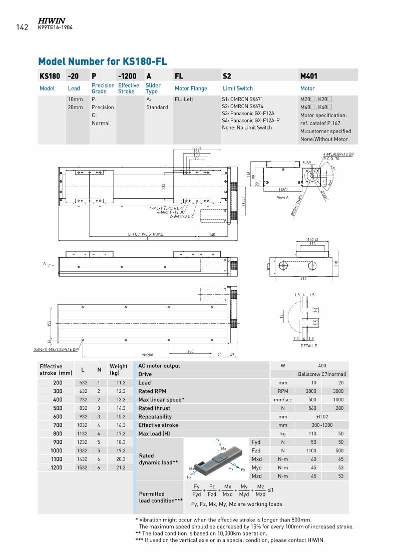
K99TE16-1904142
Model Number for KS180-FL KS180 -20 P -1200 A FL S2 M401Model Lead Precision
GradeEffective Stroke
Slider Type Motor Flange Limit Switch Motor
10mm20mm
P:Precision C:Normal
A:Standard
FL: Left S1: OMRON SX671 S2: OMRON SX674 S3: Panasonic GX-F12A S4: Panasonic GX-F12A-PNone: No Limit Switch
M20, K20M40, K40Motor specification:ref. catalof P.167M:customer specifiedNone:Without Motor
AC motor output W 400
Drive Ballscrew C7(normal)
Lead mm 10 20
Rated RPM RPM 3000 3000
Max linear speed* mm/sec 500 1000
Rated thrust N 560 280
Repeatability mm ±0.02
Effective stroke mm 200~1200
Max load (H) kg 110 50
Rated dynamic load**
Fyd N 50 50
Fzd N 1100 500
Mxd N-m 60 65
Myd N-m 45 53
Mzd N-m 45 53
Permitted load condition*** Fy, Fz, Mx, My, Mz are working loads
1++++MzdMz
MydMy
MxdMx
FzdFz
FydFy ≤
Effective stroke (mm) L N Weight
(kg)
200 532 1 11.3
300 632 2 12.3
400 732 2 13.3
500 832 3 14.3
600 932 3 15.3
700 1032 4 16.3
800 1132 4 17.3
900 1232 5 18.3
1000 1332 5 19.3
1100 1432 6 20.3
1200 1532 6 21.3
* Vibration might occur when the effective stroke is longer than 800mm. The maximum speed should be decreased by 15% for every 100mm of increased stroke.
** The load condition is based on 10,000km operation.*** If used on the vertical axis or in a special condition, please contact HIWIN.
Fz
FyMy Mx
Fx
Mz Fz
FyMy Mx
Fx
Mz
Fz
FyMy Mx
Fx
Mz
Fz
FyMy Mx
Fx
Mz
Fz
FyMy Mx
Fx
Mz
140EFFECTIVE STROKEL
4-M8x1.25Px16 DP
2-Ø6H7x8 DP4-M6x1Px12 DP
(135
)
132
70100128
(220)
4770
1415
2
2x(N+1)-M8x1.25Px16 DP 200Nx200
114(152.4)
87.5 11
8
4-M5x0.8Px10 DPP.C.D. 70
228811
8
Ø50H
7 TH
RUView A
1.541.5
12
3.5
5.4
5.5
8.3
1.542.5
DETAIL E
Ø14H7
264
5JS9
16.3
45°
45°
(180)
A
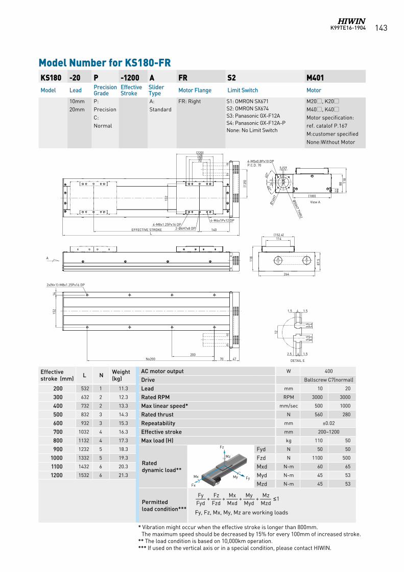
K99TE16-1904 143
Model Number for KS180-FR KS180 -20 P -1200 A FR S2 M401Model Lead Precision
GradeEffective Stroke
Slider Type Motor Flange Limit Switch Motor
10mm20mm
P:Precision C:Normal
A:Standard
FR: Right S1: OMRON SX671 S2: OMRON SX674 S3: Panasonic GX-F12A S4: Panasonic GX-F12A-PNone: No Limit Switch
M20, K20M40, K40Motor specification:ref. catalof P.167M:customer specifiedNone:Without Motor
AC motor output W 400
Drive Ballscrew C7(normal)
Lead mm 10 20
Rated RPM RPM 3000 3000
Max linear speed* mm/sec 500 1000
Rated thrust N 560 280
Repeatability mm ±0.02
Effective stroke mm 200~1200
Max load (H) kg 110 50
Rated dynamic load**
Fyd N 50 50
Fzd N 1100 500
Mxd N-m 60 65
Myd N-m 45 53
Mzd N-m 45 53
Permitted load condition*** Fy, Fz, Mx, My, Mz are working loads
1++++MzdMz
MydMy
MxdMx
FzdFz
FydFy ≤
Effective stroke (mm) L N Weight
(kg)
200 532 1 11.3
300 632 2 12.3
400 732 2 13.3
500 832 3 14.3
600 932 3 15.3
700 1032 4 16.3
800 1132 4 17.3
900 1232 5 18.3
1000 1332 5 19.3
1100 1432 6 20.3
1200 1532 6 21.3
* Vibration might occur when the effective stroke is longer than 800mm. The maximum speed should be decreased by 15% for every 100mm of increased stroke.
** The load condition is based on 10,000km operation.*** If used on the vertical axis or in a special condition, please contact HIWIN.
Fz
FyMy Mx
Fx
Mz Fz
FyMy Mx
Fx
Mz
Fz
FyMy Mx
Fx
Mz
Fz
FyMy Mx
Fx
Mz
Fz
FyMy Mx
Fx
Mz
(220)128
70100
140EFFECTIVE STROKEL
4-M8x1.25Px16 DP2-Ø6H7x8 DP
4-M6x1Px12 DP
(135
)
114(152.4)
87.511
8
45°
45°
4770200
Nx200
1415
2
4-M5x0.8Px10 DPP.C.D. 70
132
2x(N+1)-M8x1.25Px16 DP
A
2288 11
8
Ø50H7 TH
RU
1.541.5
12
3.5
5.4
5.5
8.3
1.542.5
DETAIL E
View AØ14H
7264
16.3
5JS9
(180)
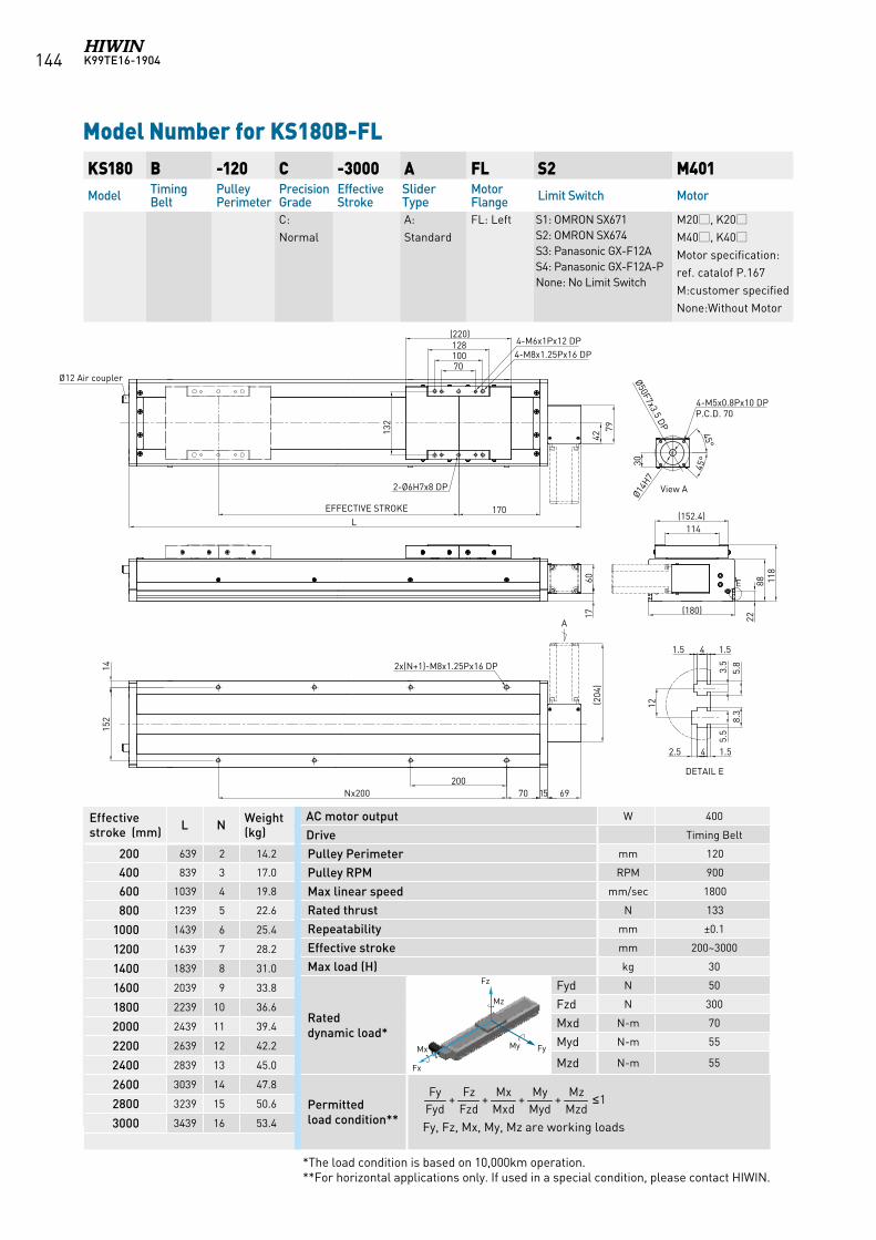
K99TE16-1904144
Model Number for KS180B-FL KS180 B -120 C -3000 A FL S2 M401Model Timing
BeltPulley Perimeter
Precision Grade
Effective Stroke
Slider Type
Motor Flange Limit Switch Motor
C:Normal
A:Standard
FL: Left S1: OMRON SX671 S2: OMRON SX674 S3: Panasonic GX-F12A S4: Panasonic GX-F12A-PNone: No Limit Switch
M20, K20M40, K40Motor specification:ref. catalof P.167M:customer specifiedNone:Without Motor
AC motor output W 400
Drive Timing Belt
Pulley Perimeter mm 120
Pulley RPM RPM 900
Max linear speed mm/sec 1800
Rated thrust N 133
Repeatability mm ±0.1
Effective stroke mm 200~3000
Max load (H) kg 30
Rated dynamic load*
Fyd N 50
Fzd N 300
Mxd N-m 70
Myd N-m 55
Mzd N-m 55
Permitted load condition** Fy, Fz, Mx, My, Mz are working loads
1++++MzdMz
MydMy
MxdMx
FzdFz
FydFy ≤
Effective stroke (mm) L N Weight
(kg)
200 639 2 14.2
400 839 3 17.0
600 1039 4 19.8
800 1239 5 22.6
1000 1439 6 25.4
1200 1639 7 28.2
1400 1839 8 31.0
1600 2039 9 33.8
1800 2239 10 36.6
2000 2439 11 39.4
2200 2639 12 42.2
2400 2839 13 45.0
2600 3039 14 47.8
2800 3239 15 50.6
3000 3439 16 53.4
*The load condition is based on 10,000km operation.**For horizontal applications only. If used in a special condition, please contact HIWIN.
Fz
FyMy Mx
Fx
Mz Fz
FyMy Mx
Fx
Mz
Fz
FyMy Mx
Fx
Mz
Fz
FyMy Mx
Fx
Mz
Fz
FyMy Mx
Fx
Mz
A
2x(N+1)-M8x1.25Px16 DP
4-M8x1.25Px16 DP4-M6x1Px12 DP
2-Ø6H7x8 DP
132
10070
128(220)
170EFFECTIVE STROKEL
70 15 69200
(152.4)114
118
8822
1.541.512
3.5
5.8
5.5
8.3
1.542.5
DETAIL E
E
View A
30
45°
45°
4-M5x0.8Px10 DPP.C.D. 70
Ø50F7x3.5 DP
4279
(204
)17
60
(180)
152
14
Ø14H7
Nx200
Ø12 Air coupler
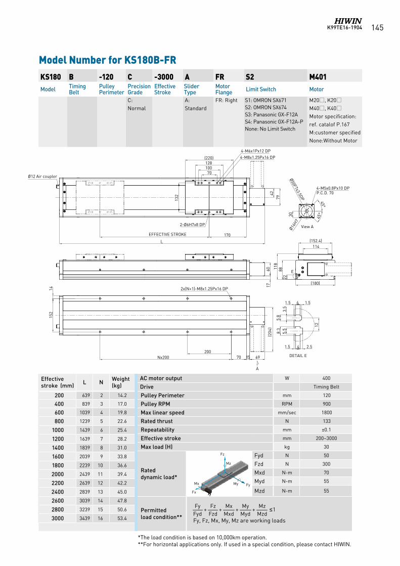
K99TE16-1904 145
Model Number for KS180B-FR KS180 B -120 C -3000 A FR S2 M401Model Timing
BeltPulley Perimeter
Precision Grade
Effective Stroke
Slider Type
Motor Flange Limit Switch Motor
C:Normal
A:Standard
FR: Right S1: OMRON SX671 S2: OMRON SX674 S3: Panasonic GX-F12A S4: Panasonic GX-F12A-PNone: No Limit Switch
M20, K20M40, K40Motor specification:ref. catalof P.167M:customer specifiedNone:Without Motor
AC motor output W 400
Drive Timing Belt
Pulley Perimeter mm 120
Pulley RPM RPM 900
Max linear speed mm/sec 1800
Rated thrust N 133
Repeatability mm ±0.1
Effective stroke mm 200~3000
Max load (H) kg 30
Rated dynamic load*
Fyd N 50
Fzd N 300
Mxd N-m 70
Myd N-m 55
Mzd N-m 55
Permitted load condition** Fy, Fz, Mx, My, Mz are working loads
1++++MzdMz
MydMy
MxdMx
FzdFz
FydFy ≤
Effective stroke (mm) L N Weight
(kg)
200 639 2 14.2
400 839 3 17.0
600 1039 4 19.8
800 1239 5 22.6
1000 1439 6 25.4
1200 1639 7 28.2
1400 1839 8 31.0
1600 2039 9 33.8
1800 2239 10 36.6
2000 2439 11 39.4
2200 2639 12 42.2
2400 2839 13 45.0
2600 3039 14 47.8
2800 3239 15 50.6
3000 3439 16 53.4
*The load condition is based on 10,000km operation.**For horizontal applications only. If used in a special condition, please contact HIWIN.
Fz
FyMy Mx
Fx
Mz Fz
FyMy Mx
Fx
Mz
Fz
FyMy Mx
Fx
Mz
Fz
FyMy Mx
Fx
Mz
Fz
FyMy Mx
Fx
Mz
A
2x(N+1)-M8x1.25Px16 DP
2-Ø6H7x8 DP
132
10070
128(220)
170EFFECTIVE STROKE
L
70 15 69Nx200200
(152.4)114
118
8822
1.5 4 1.5
12
3.5
5.8
5.5
8.3
1.5 4 2.5
DETAIL E
E
View A
30
45°
45°
4-M5x0.8Px10 DPP.C.D. 70
Ø50F7x3.5DP
4-M8x1.25Px16 DP4-M6x1Px12 DP
(204
)42
79
Ø14H7
(180)
6017
152
14
Ø12 Air coupler
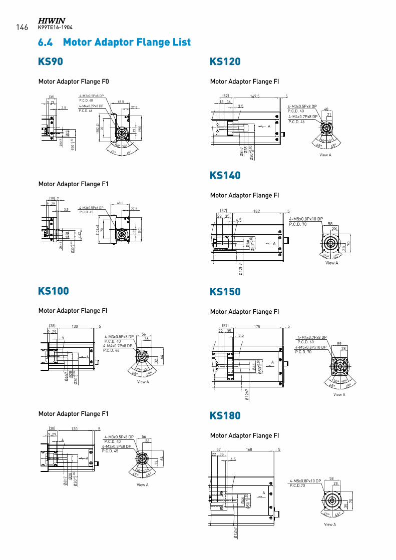
K99TE16-1904146
6.4 Motor Adaptor Flange List
Motor Adaptor Flange F0 Motor Adaptor Flange FI
Motor Adaptor Flange FI
Motor Adaptor Flange FI
Motor Adaptor Flange FI
Motor Adaptor Flange F1
Motor Adaptor Flange F1
KS90Ø
28
Ø30
+0.0
30
Ø6h
7
70(1
02.4
)
19 (90)
4-M4x0.7Px8 DPP.C.D. 46
27.5
68.5
4-M3x0.5Px8 DPP.C.D. 40
30° 30°
45°45°
3.5
299
(38)
Ø28
Ø30
+0.0
50
Ø6h
7
70(1
02.4
)
19 (90)
4-M3x0.5Px6 DPP.C.D. 45
27.5
68.5299
(38)
3.5
7
42
KS120
Ø8h
7Ø
28Ø
30+0
.05
0
3418167.5 5
3.5
2140
30° 30°45° 45°
4-M3x0.5Px8 DPP.C.D. 404-M4x0.7Px8 DPP.C.D. 46
(52)
A
View A
KS140
70
58
35
28
45°45°
4-M5x0.8Px10 DPP.C.D. 70
182(57)22 35
Ø12
h7
5
AØ46
Ø50
+0.0
20
4.5
View A
KS150
17822 35
(57)
Ø12
h7
Ø46
Ø50
+0.0
4 0
3.5
2859
5
4-M4x0.7Px8 DPP.C.D. 60
4-M5x0.8Px10 DPP.C.D. 70
30° 30°45° 45°
A
View A
KS180
1685722 35
5828
70
4-M5x0.8Px10 DPP.C.D.70
45°45°
35
5
Ø46
Ø50
+0.0
20
4.5
Ø12
h7
View A
A
KS100
3656
4-M3x0.5Px8 DPP.C.D. 40
A
Ø6h
7
9 29(38) 130
Ø28
Ø30
+0.0
20
3264
4
5
4-M4x0.7Px8 DPP.C.D. 46
30° 30°45° 45°
View A
3656
4-M3x0.5Px8 DPP.C.D. 45
A
Ø6h
7
9 29(38) 130
Ø28
Ø30
+0.0
20
3264
4
5
45° 45°30° 30°
4-M3x0.5Px8 DPP.C.D. 40
View A
KS90 KS120
KS140
KS150
KS180
KS100
Motor Adaptor Flange FI
K99TE16-1904 147
6.5 Motor Housing and Motor Adaptor Flange(KS Series)
Panasonic Servo Motor
Mitsubishi Servo Motor
Yasukawa Servo Motor
HIWIN Mikrosystem Servo MotorMotor Output Motor
Flange SelectionDrive Remarks
KS90 KS100 KS120 KS140 KS150 KS180
50W FRLS052A4 F1 F1 F1 - - -D2T-0123-S-A
220V
100W FRLS102A4 F1 F1 F1 - - - 220V
200W FRLS20206 - - - FI FI FID2T-0423-S-B
220V
400W FRLS40206 - - - FI FI FI 220V
750W FRMS75208 - - - - - - D2-T1023-S-C 220V
Motor Output Motor
Flange SelectionDrive Remarks
KS90 KS100 KS120 KS140 KS150 KS180
50W HF-KP053 F0 FI FI - - - MR-J3S-10A 220V
100W HF-KP13 F0 FI FI - - - MR-J3S-10A 220V
200W HF-KP23 - - - FI FI FI MR-J3S-20A 220V
400W HF-KP43 - - - FI FI FI MR-J3S-40A 220V
750W HF-KP73 - - - - - - MR-J3S-70A 220V
Motor Output Motor
Flange SelectionDrive Remarks
KS90 KS100 KS120 KS140 KS150 KS180
50W MSMD5AZP1 F1 F1 F1 - - - MADDT1105 110V
50W MSMD5AZP1 F1 F1 F1 - - - MADDT1205 220V
100W MSMD011P1 F1 F1 F1 - - - MADDT1107 110V
100W MSMD012P1 F1 F1 F1 - - - MADDT1205 220V
200W MSMD021P1 - - - - - - MADDT2110 110V
200W MSMD022P1 - - - - - - MADDT1207 220V
400W MSMD041P1 - - - - - - MADDT3120 110V
400W MSMD042P1 - - - - - - MADDT2210 220V
750W MSMD082S1 - - - - - - MADDT3520 220V
Motor Output Motor
Flange SelectionDrive Remarks
KS90 KS100 KS120 KS140 KS150 KS180
50W SGMAV-A5ADA61 F0 FI FI - - - SGDV-R70A01A with key
50W SGMAV-A5ADA2C F0 FI FI - - - SGDV-R70A01A no key
50W SGMAV-A5ADA21 F0 FI FI - - - SGDV-R70A01A no key
100W SGMAV-01ADA21 F0 FI F0 - - - SGDV-R90A01A
200W SGMAV-02ADA21 - - - FI FI FI SGDV-1R6A01A
400W SGMAV-04ADA21 - - - FI FI FI SGDV-2R8A01A
750W SGMAV-08ADA21 - - - - - - SGDV-5R5A01A
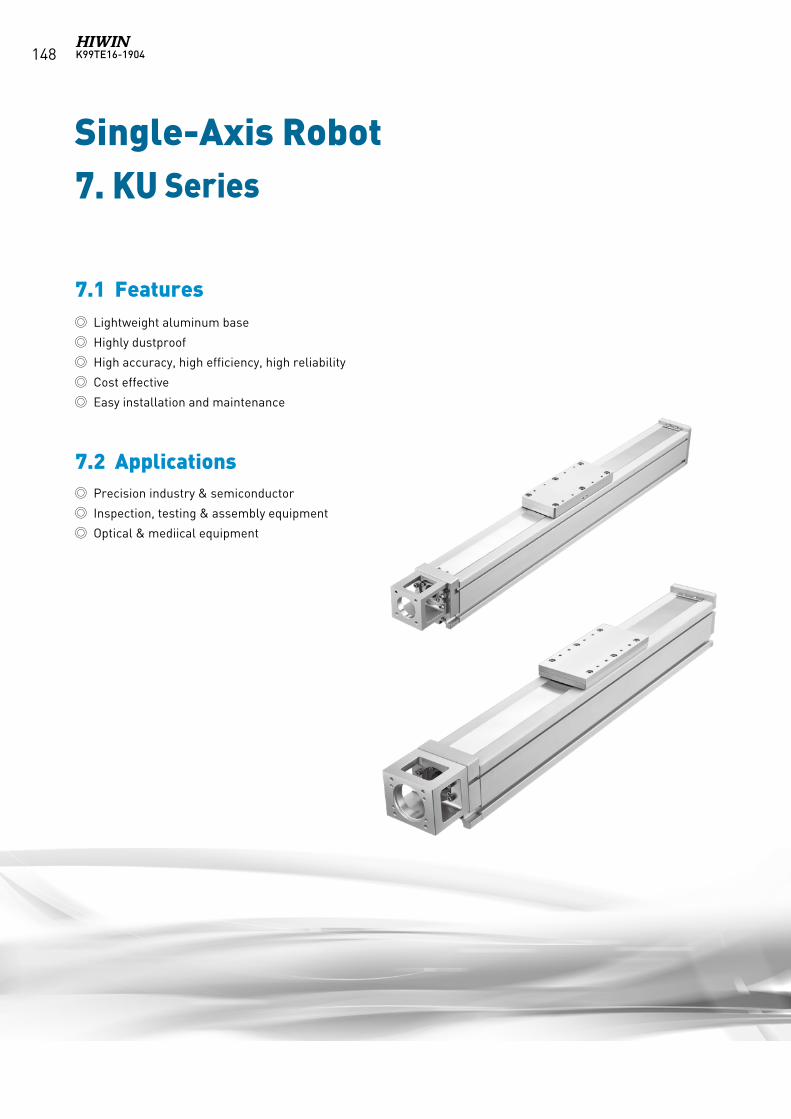
K99TE16-1904148
Single-Axis Robot
7.1 Features
7.2 Applications
7. KU Series
Lightweight aluminum base
Highly dustproof
High accuracy, high efficiency, high reliability
Cost effective
Easy installation and maintenance
Precision industry & semiconductor
Inspection, testing & assembly equipment
Optical & mediical equipment
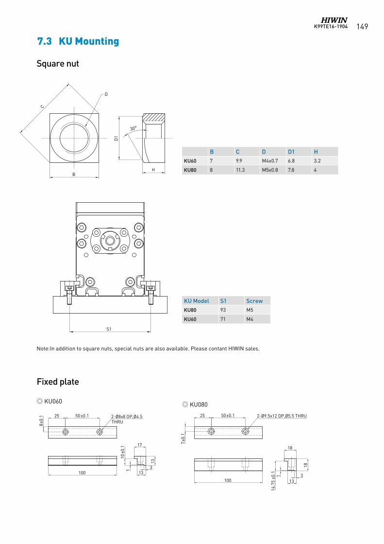
K99TE16-1904 149
25 50±0.1
7±0.
1
100
18
18
313
114
.75
±0.1
2-Ø9.5x12 DP,Ø5.5 THRU
13
17
3
13
110
±0.1
100
25 50±0.1
8±0.
1 2-Ø8x8 DP,Ø4.5 THRU
B C D D1 H
KU60 7 9.9 M4x0.7 6.8 3.2
KU80 8 11.3 M5x0.8 7.8 4
KU Model S1 Screw
KU80 93 M5
KU60 71 M4
C
B
D1
H
30°
D
S1
KU060 KU080
Square nut
Fixed plate
C
B
D1
H
30°
D
S1
7.3 KU Mounting
Note:In addition to square nuts, special nuts are also available. Please contant HIWIN sales.
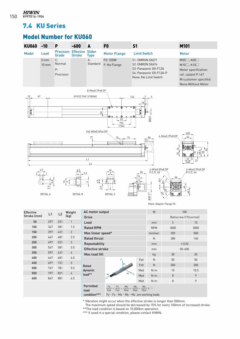
K99TE16-1904150
KU060 -10 P -600 A F0 S1 M101Model Lead Precision
GradeEffective Stroke
Slider Type Motor Flange Limit Switch Motor
5 mm10 mm
C: Normal
P: Precision
A: Standard
F0: 100WF: No Flange
S1: OMRON SX671 S2: OMRON SX674 S3: Panasonic GX-F12A S4: Panasonic GX-F12A-PNone: No Limit Switch
M05, K05M10, K10Motor specification:ref. catalof P.167M:customer specifiedNone:Without Motor
Model Number for KU060
7.4 KU Series
* Vibration might occur when the effective stroke is longer than 500mm. The maximum speed should be decreased by 15% for every 100mm of increased stroke.**The load condition is based on 10,000km operation.*** If used in a special condition, please contact HIWIN.
97124
52102
(154)
50
EFFECTIVE STROKE9710
Ø6h
7
42(60)
32(60) 13
48.5
5382
A
B
C
134.5
3.5
5.8
DETAIL A
2.56.5
6710
DETAIL B
710
62.5
6.5
DETAIL C
4-M4x0.7Px8 DP
3616
8-M4x0.7Px8 DP
18
9
1650
Ø30
+0.0
5 0
Motor Adaptor Flange F0
45°
45°
50
46
48.5
30°
30°
4-M3x0.5Px8 DPP.C.D. 40
4-M4x0.7Px8 DPP.C.D. 46
721013
L1
2x2-M3x0.5Px6 DP
L2
50With Motor Flange
Effective Stroke (mm) L1 L2 Weight
(kg)
50 297 331 1
100 347 381 1.5
150 397 431 2
200 447 481 2.5
250 497 531 3
300 547 581 3.5
350 597 631 4
400 647 681 4.5
450 697 731 5
500 747 781 5.5
550 797 831 6
600 847 881 6.5
AC motor output W 100
Drive Ballscrew C7(normal)
Lead mm 5 10
Rated RPM RPM 3000 3000
Max linear speed* mm/sec 250 500
Rated thrust N 280 140
Repeatability mm ±0.02
Effective stroke mm 50~600
Max load (H) kg 30 20
Rateddynamicload**
Fyd N 50 50
Fzd N 300 200
Mxd N-m 10 10.5
Myd N-m 8 9
Mzd N-m 8 9
Permitted load condition***
Fy+
Fz+
Mx+
My+
Mz≤ 1
Fyd Fzd Mxd Myd Mzd
Fy、Fz、Mx、My、Mz are working loads
Fz
FyMy Mx
Fx
Mz
Fz
FyMy Mx
Fx
Mz
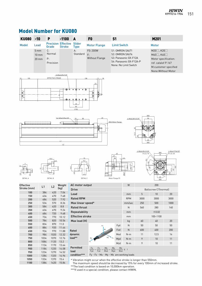
K99TE16-1904 151
KU080 -10 P -1100 A F0 S1 M201Model Lead Precision
GradeEffective Stroke
Slider Type Motor Flange Limit Switch Motor
5 mm
10 mm
20 mm
C: Normal
P: Precision
A: Standard
F0: 200W
F: Without Flange
S1: OMRON SX671 S2: OMRON SX674 S3: Panasonic GX-F12A S4: Panasonic GX-F12A-PNone: No Limit Switch
M20, K20M40, K40Motor specification:ref. catalof P.167M:customer specifiedNone:Without Motor
Model Number for KU080
* Vibration might occur when the effective stroke is longer than 550mm. The maximum speed should be decreased by 15% for every 100mm of increased stroke.**The load condition is based on 10,000km operation.***If used in a special condition, please contact HIWIN.
11
Ø46
.5
3.51829
65
64
65
138EFFECTIVE STROKE10512
40
85
64
(170)
10
13
80
L2
8-M5x0.8Px9 DP
2x2-M3x0.5Px6 DP
3.5
5.8
1.5 47
3.5
9.3
4.510.5
6.5
9.3
15
4.5
6.5
10.5
DETAIL A DETAIL B
15
23
18
DETAIL C
L1
Ø50
+0.0
5 0
Ø8h
7With Motor Flange
Motor Flange F0
(80)
61.5 67
103
40
(80)
A
B
C
4-M5x0.8Px10 DPP.C.D. 70
30°
18
30°
45°
45°
79
4-M4x0.7Px8 DPP.C.D. 60
50
(80)
18
51.5
20
40
(80)
A
B
C
4-M5x0.8Px10 DP
Effective Stroke (mm) L1 L2 Weight
(kg)
100 384 420 7.04150 434 470 7.48200 484 520 7.92250 534 570 8.36300 584 620 8.8350 634 670 9.24400 684 720 9.68450 734 770 10.12500 784 820 10.56550 834 870 11.0600 884 920 11.44650 934 970 11.88700 984 1020 12.32750 1034 1070 12.76800 1084 1120 13.2850 1134 1170 13.64900 1184 1220 14.08950 1234 1270 14.52
1000 1284 1320 14.961050 1334 1370 15.41100 1384 1420 15.84
AC motor output W 200
Drive Ballscrew C7(normal)
Lead mm 5 10 20
Rated RPM RPM 3000 3000 3000
Max linear speed* mm/sec 250 500 1000
Rated thrust N 560 280 140
Repeatability mm ±0.02
Effective stroke mm 100~1100
Max load (H) kg 60 40 20
Rateddynamicload**
Fyd N 50 50 50
Fzd N 600 400 200
Mxd N-m 11 12.5 14
Myd N-m 9 10 11
Mzd N-m 9 10 11
Permitted load condition***
Fy+
Fz+
Mx+
My+
Mz≤ 1
Fyd Fzd Mxd Myd Mzd
Fy、Fz、Mx、My、Mz are working loads
Fz
FyMy Mx
Fx
Mz
Fz
FyMy Mx
Fx
Mz
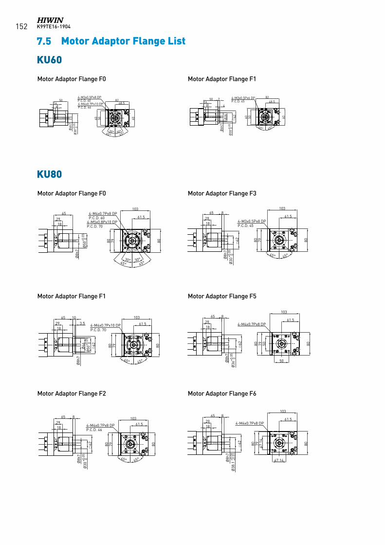
K99TE16-1904152
KU80
65
18
80
61.5
103
80
4-M5x0.8Px10 DPP.C.D. 70
30° 30°45° 45°
79
4-M4x0.7Px8 DPP.C.D. 6029
Ø50
+0.0
50
Ø8h
7
65
18
80
61.5
103
80
4-M4x0.7Px10 DP P.C.D. 70
79
29
Ø50
+0.0
50
Ø8h
7
45° 45°
62
Ø46
103.5
65
18
80
61.5103
80
4-M4x0.7Px8 DPP.C.D. 46
79
29
Ø30
+0.0
50
Ø8h
7
62
8
45° 45°
65
18
80
61.5
103
80
4-M3x0.5Px8 DPP.C.D. 45
79
29
Ø30
+0.0
50
Ø8h
7
62
8
45° 45°
65
18
80
61.5
1038079
29
Ø8h
7
4-M4x0.7Px8 DP
50
50
62
Ø36
+0.0
50
8
65
18
80
61.5
103
8079
29
Ø8h
7
4-M4x0.7Px8 DP
47.1
4
47.14
62
Ø38
.1+0
.08
+0.0
3
8
7.5 Motor Adaptor Flange List
Motor Adaptor Flange F0
Motor Adaptor Flange F0
Motor Adaptor Flange F1
Motor Adaptor Flange F2
Motor Adaptor Flange F1
Motor Adaptor Flange F3
Motor Adaptor Flange F5
Motor Adaptor Flange F6
KU60
60 60
48.582
4-M4x0.7Px10 DPP.C.D. 46
50
45° 45°
Ø6h
7
916
50
30° 30°
4-M3x0.5Px8 DPP.C.D. 40
Ø30
+0.0
50
60 60
48.5824-M3x0.5Px6 DP
P.C.D. 45
50
Ø6h
7
916
50
Ø30
+0.0
50
4
Ø28
7
42
45° 45°
KU60
KU80
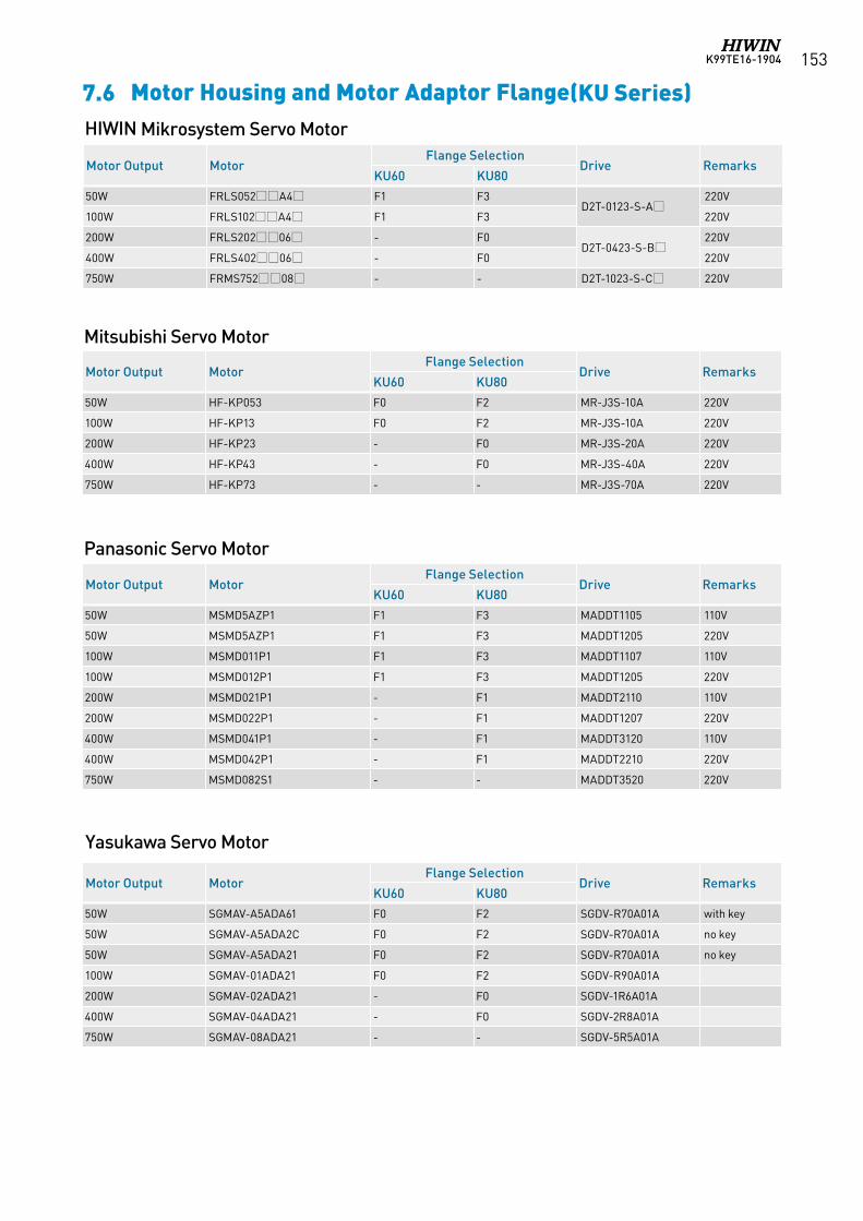
K99TE16-1904 153
7.6 Motor Housing and Motor Adaptor Flange(KU Series)
Panasonic Servo Motor
Mitsubishi Servo Motor
Yasukawa Servo Motor
HIWIN Mikrosystem Servo Motor
Motor Output MotorFlange Selection
Drive RemarksKU60 KU80
50W FRLS052A4 F1 F3D2T-0123-S-A
220V
100W FRLS102A4 F1 F3 220V
200W FRLS20206 - F0D2T-0423-S-B
220V
400W FRLS40206 - F0 220V
750W FRMS75208 - - D2T-1023-S-C 220V
Motor Output MotorFlange Selection
Drive RemarksKU60 KU80
50W HF-KP053 F0 F2 MR-J3S-10A 220V
100W HF-KP13 F0 F2 MR-J3S-10A 220V
200W HF-KP23 - F0 MR-J3S-20A 220V
400W HF-KP43 - F0 MR-J3S-40A 220V
750W HF-KP73 - - MR-J3S-70A 220V
Motor Output MotorFlange Selection
Drive RemarksKU60 KU80
50W MSMD5AZP1 F1 F3 MADDT1105 110V
50W MSMD5AZP1 F1 F3 MADDT1205 220V
100W MSMD011P1 F1 F3 MADDT1107 110V
100W MSMD012P1 F1 F3 MADDT1205 220V
200W MSMD021P1 - F1 MADDT2110 110V
200W MSMD022P1 - F1 MADDT1207 220V
400W MSMD041P1 - F1 MADDT3120 110V
400W MSMD042P1 - F1 MADDT2210 220V
750W MSMD082S1 - - MADDT3520 220V
Motor Output MotorFlange Selection
Drive RemarksKU60 KU80
50W SGMAV-A5ADA61 F0 F2 SGDV-R70A01A with key
50W SGMAV-A5ADA2C F0 F2 SGDV-R70A01A no key
50W SGMAV-A5ADA21 F0 F2 SGDV-R70A01A no key
100W SGMAV-01ADA21 F0 F2 SGDV-R90A01A
200W SGMAV-02ADA21 - F0 SGDV-1R6A01A
400W SGMAV-04ADA21 - F0 SGDV-2R8A01A
750W SGMAV-08ADA21 - - SGDV-5R5A01A
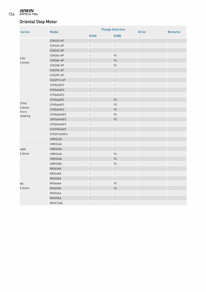
K99TE16-1904154
Oriental Step Motor
Series ModelFlange Selection
Drive RemarksKU60 KU80
CSK 2 phase
CSK243-AP - -
CSK244-AP - -
CSK245-AP - -
CSK264-AP - F6
CSK266-AP - F6
CSK268-AP - F6
CSK296-AP - -
CSK299-AP - -
CSK2913-AP - -
CFKII 5 phasemicrostepping
CFK543AP2 - -
CFK544AP2 - -
CFK545AP2 - -
CFK564AP2 - F5
CFK566AP2 - F5
CFK569AP2 - F5
CFK566HAP2 - F5
CKF569HAP2 - F5
CFK596HAP2 - -
CFK599HAP2 - -
CFK5913HAP2 - -
UMK 2 phase
UMK243A - -
UMK244A - -
UMK245A - -
UMK264A - F6
UMK266A - F6
UMK268A - F6
RK 5 phase
RK543AA - -
RK544AA - -
RK545AA - -
RK566AA - F5
RK569AA - F5
RK596AA - -
RK599AA - -
RK5913AA - -
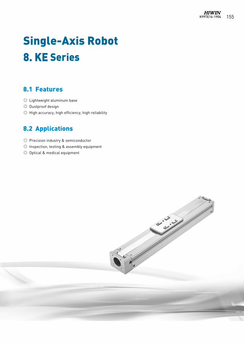
K99TE16-1904 155
Single-Axis Robot
8.1 Features
8.2 Applications
8. KE Series
Lightweight aluminum base
Dustproof design
High accuracy, high efficiency, high reliability
Precision industry & semiconductor
Inspection, testing & assembly equipment
Optical & medical equipment
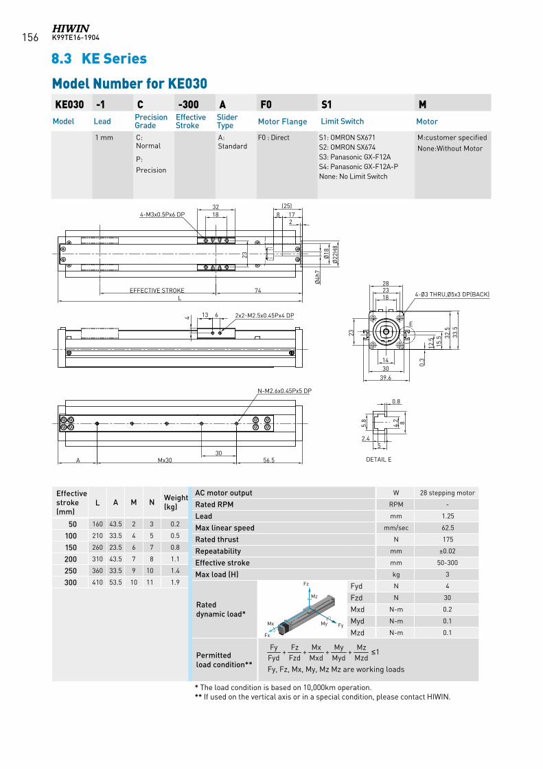
K99TE16-1904156
KE030 -1 C -300 A F0 S1 MModel Lead Precision
GradeEffective Stroke
Slider Type Motor Flange Limit Switch Motor
1 mm C: Normal
P: Precision
A: Standard
F0 : Direct S1: OMRON SX671 S2: OMRON SX674 S3: Panasonic GX-F12A S4: Panasonic GX-F12A-PNone: No Limit Switch
M:customer specifiedNone:Without Motor
Model Number for KE030
AC motor output W 28 stepping motor
Rated RPM RPM -
Lead mm 1.25
Max linear speed mm/sec 62.5
Rated thrust N 175
Repeatability mm ±0.02
Effective stroke mm 50-300
Max load (H) kg 3
Rated dynamic load*
Fyd N 4
Fzd N 30
Mxd N-m 0.2
Myd N-m 0.1
Mzd N-m 0.1
Permitted load condition** Fy, Fz, Mx, My, Mz Mz are working loads
* The load condition is based on 10,000km operation.** If used on the vertical axis or in a special condition, please contact HIWIN.
Effective stroke (mm)
L A M N Weight (kg)
50 160 43.5 2 3 0.2
100 210 33.5 4 5 0.5
150 260 23.5 6 7 0.8
200 310 43.5 7 8 1.1
250 360 33.5 9 10 1.4
300 410 53.5 10 11 1.9
1++++MzdMz
MydMy
MxdMx
FzdFz
FydFy ≤
Fz
FyMy Mx
Fx
Mz
Fz
FyMy Mx
Fx
Mz
Fz
FyMy Mx
Fx
Mz
Fz
FyMy Mx
Fx
Mz
Fz
FyMy Mx
Fx
Mz
Fz
FyMy
Mx
Fx
Mz
Fz
FyMy Mx
Fx
Mz
8.3 KE Series
74EFFECTIVE STROKEL
1832
23
56.530
Mx30A
18
28
1430
39.6
0.3
15.5 32
.533
.5
23
23
12.5
178(25)
2
Ø18
Ø22
H8
Ø4h
7
80.8
4.2
2.45
DETAIL E
5.8
E
4-M3x0.5Px6 DP
N-M2.6x0.45Px5 DP
4-Ø3 THRU,Ø5x3 DP(BACK)
13 64 2x2-M2.5x0.45Px4 DP
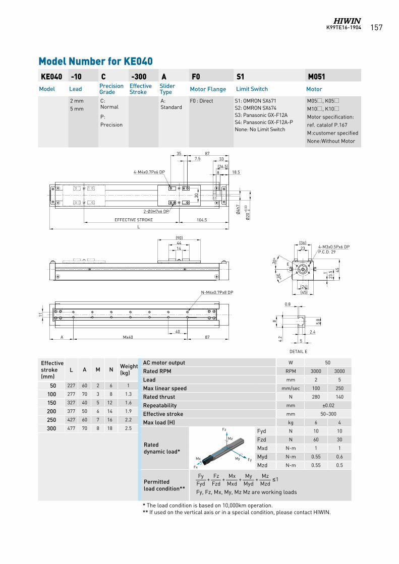
K99TE16-1904 157
KE040 -10 C -300 A F0 S1 M051Model Lead Precision
GradeEffective Stroke
Slider Type Motor Flange Limit Switch Motor
2 mm5 mm
C: Normal
P: Precision
A: Standard
F0 : Direct S1: OMRON SX671 S2: OMRON SX674 S3: Panasonic GX-F12A S4: Panasonic GX-F12A-PNone: No Limit Switch
M05, K05M10, K10Motor specification:ref. catalof P.167M:customer specifiedNone:Without Motor
Model Number for KE040
AC motor output W 50
Rated RPM RPM 3000 3000
Lead mm 2 5
Max linear speed mm/sec 100 250
Rated thrust N 280 140
Repeatability mm ±0.02
Effective stroke mm 50~300
Max load (H) kg 6 4
Rated dynamic load*
Fyd N 10 10
Fzd N 60 30
Mxd N-m 1 1
Myd N-m 0.55 0.6
Mzd N-m 0.55 0.5
Permitted load condition** Fy, Fz, Mx, My, Mz Mz are working loads
* The load condition is based on 10,000km operation.** If used on the vertical axis or in a special condition, please contact HIWIN.
Effective stroke (mm)
L A M N Weight (kg)
50 227 60 2 6 1
100 277 70 3 8 1.3
150 327 40 5 12 1.6
200 377 50 6 14 1.9
250 427 60 7 16 2.2
300 477 70 8 18 2.5
1++++MzdMz
MydMy
MxdMx
FzdFz
FydFy ≤
Fz
FyMy Mx
Fx
Mz
Fz
FyMy Mx
Fx
Mz
Fz
FyMy Mx
Fx
Mz
Fz
FyMy Mx
Fx
Mz
Fz
FyMy Mx
Fx
Mz
Fz
FyMy
Mx
Fx
Mz
Fz
FyMy Mx
Fx
Mz
35 877.5
18.5
Ø4h
7
Ø20
+0,0
3 0
(26.5)
33
30
104.5EFFECTIVE STROKE
1444
(90)
L
23(36)
(45)
123
.5 45A
4-M4x0.7Px6 DP
2-Ø3H7x6 DP
N-M4x0.7Px8 DP
4-M3x0.5Px6 DPP.C.D. 29
(24)
87Mx4040
11
8
8
0.8
4.2
2.4
5
5.8
DETAIL E
E30°
30°
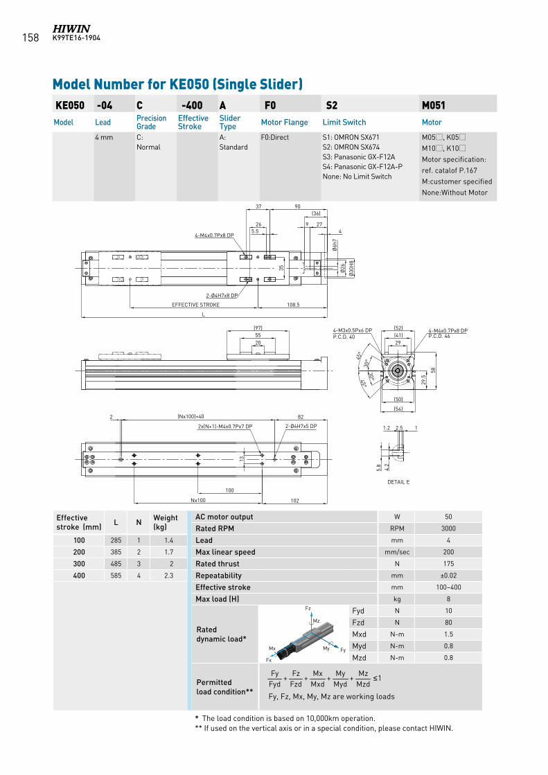
K99TE16-1904158
KE050 -04 C -400 A F0 S2 M051Model Lead Precision
GradeEffective Stroke
Slider Type Motor Flange Limit Switch Motor
4 mm C:Normal
A:Standard
F0:Direct S1: OMRON SX671 S2: OMRON SX674 S3: Panasonic GX-F12A S4: Panasonic GX-F12A-PNone: No Limit Switch
M05, K05M10, K10Motor specification:ref. catalof P.167M:customer specifiedNone:Without Motor
Model Number for KE050 (Single Slider)
AC motor output W 50
Rated RPM RPM 3000
Lead mm 4
Max linear speed mm/sec 200
Rated thrust N 175
Repeatability mm ±0.02
Effective stroke mm 100~400
Max load (H) kg 8
Rated dynamic load*
Fyd N 10
Fzd N 80
Mxd N-m 1.5
Myd N-m 0.8
Mzd N-m 0.8
Permitted load condition** Fy, Fz, Mx, My, Mz are working loads
1++++MzdMz
MydMy
MxdMx
FzdFz
FydFy ≤
Fz
FyMy Mx
Fx
Mz
Fz
FyMy Mx
Fx
Mz
Fz
FyMy Mx
Fx
Mz
Fz
FyMy Mx
Fx
Mz
Fz
FyMy Mx
Fx
Mz
Fz
FyMy
Mx
Fx
Mz
Fz
FyMy Mx
Fx
Mz* The load condition is based on 10,000km operation.** If used on the vertical axis or in a special condition, please contact HIWIN.
Effective stroke (mm) L N Weight
(kg)
100 285 1 1.4
200 385 2 1.7
300 485 3 2
400 585 4 2.3
L
9037
5.5
108.5EFFECTIVE STROKE
(97)5520
(52)(41)29
58
29.5
(54)
(50)
82(Nx100)+40
Nx100 102
13
35
4-M4x0.7Px8 DPP.C.D. 46
Ø6h
7
2-Ø4H7x5 DP
4-M4x0.7Px8 DP
2-Ø4H7x8 DP
2x(N+1)-M4x0.7Px7 DP
2
45°
45°
Ø30
H8
Ø26
4279
(36)
30°
30°
4-M3x0.5Px6 DPP.C.D. 40
100
26
DETAIL E
12.51.2
5.8
4.2
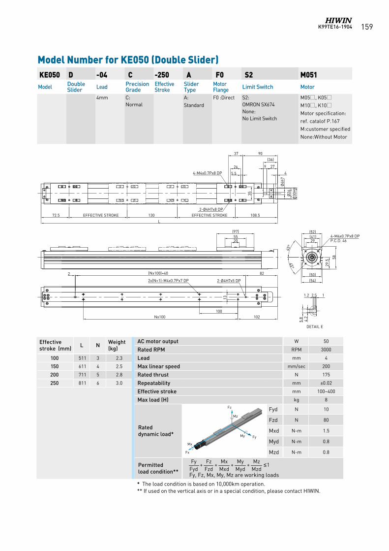
K99TE16-1904 159
KE050 D -04 C -250 A F0 S2 M051Model Double
Slider Lead Precision Grade
Effective Stroke
Slider Type
Motor Flange Limit Switch Motor
4mm C:Normal
A:Standard
F0 :Direct S2: OMRON SX674None: No Limit Switch
M05, K05M10, K10Motor specification:ref. catalof P.167M:customer specifiedNone:Without Motor
Model Number for KE050 (Double Slider)
AC motor output W 50
Rated RPM RPM 3000
Lead mm 4
Max linear speed mm/sec 200
Rated thrust N 175
Repeatability mm ±0.02
Effective stroke mm 100~400
Max load (H) kg 8
Rated dynamic load*
Fyd N 10
Fzd N 80
Mxd N-m 1.5
Myd N-m 0.8
Mzd N-m 0.8
Permitted load condition** Fy, Fz, Mx, My, Mz are working loads
1++++MzdMz
MydMy
MxdMx
FzdFz
FydFy ≤
* The load condition is based on 10,000km operation.** If used on the vertical axis or in a special condition, please contact HIWIN.
Effective stroke (mm) L N Weight
(kg)
100 511 3 2.3
150 611 4 2.5
200 711 5 2.8
250 811 6 3.0
Fz
FyMy Mx
Fx
Mz
Fz
FyMy Mx
Fx
Mz
Fz
FyMy Mx
Fx
Mz
Fz
FyMy Mx
Fx
Mz
Fz
FyMy Mx
Fx
Mz
Fz
FyMy
Mx
Fx
Mz
Fz
FyMy Mx
Fx
Mz
L
9037
5.5
108.5EFFECTIVE STROKE
(97)5520
(52)(41)29
58
29.5
(54)(50)82(Nx100)+40
Nx100 102
13
35
4-M4x0.7Px8 DPP.C.D. 46
Ø6h
72-Ø4H7x5 DP
4-M4x0.7Px8 DP
2-Ø4H7x8 DP
2x(N+1)-M4x0.7Px7 DP
2
45°
45°
Ø30
H8
Ø26
4
279
(36)
130EFFECTIVE STROKE72.5
100
26
DETAIL E
12.51.25.
84.
2
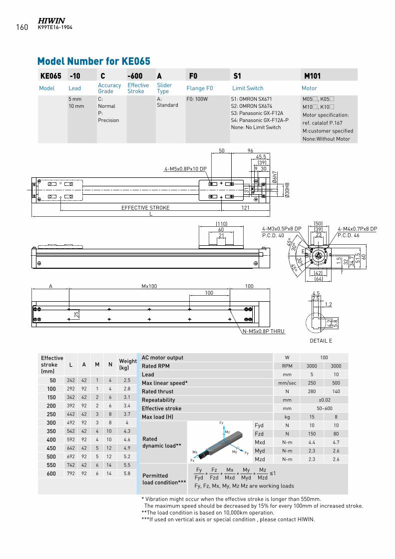
K99TE16-1904160
KE065 -10 C -600 A F0 S1 M101Model Lead Accuracy
GradeEffective Stroke
Slider Type Flange F0 Limit Switch Motor
5 mm10 mm
C: NormalP: Precision
A: Standard
F0: 100W S1: OMRON SX671 S2: OMRON SX674 S3: Panasonic GX-F12A S4: Panasonic GX-F12A-PNone: No Limit Switch
M05, K05M10, K10Motor specification:ref. catalof P.167M:customer specifiedNone:Without Motor
Model Number for KE065
Effective stroke (mm)
L A M N Weight (kg)
50 242 42 1 4 2.5
100 292 92 1 4 2.8
150 342 42 2 6 3.1
200 392 92 2 6 3.4
250 442 42 3 8 3.7
300 492 92 3 8 4
350 542 42 4 10 4.3
400 592 92 4 10 4.6
450 642 42 5 12 4.9
500 692 92 5 12 5.2
550 742 42 6 14 5.5
600 792 92 6 14 5.8
AC motor output W 100
Rated RPM RPM 3000 3000
Lead mm 5 10
Max linear speed* mm/sec 250 500
Rated thrust N 280 140
Repeatability mm ±0.02
Effective stroke mm 50~600
Max load (H) kg 15 8
Rated dynamic load**
Fyd N 10 10
Fzd N 150 80
Mxd N-m 4.4 4.7
Myd N-m 2.3 2.6
Mzd N-m 2.3 2.6
Permitted load condition*** Fy, Fz, Mx, My, Mz Mz are working loads
* Vibration might occur when the effective stroke is longer than 550mm. The maximum speed should be decreased by 15% for every 100mm of increased stroke.**The load condition is based on 10,000km operation. ***If used on vertical axis or special condition , please contact HIWIN.
1++++MzdMz
MydMy
MxdMx
FzdFz
FydFy ≤
Fz
FyMy Mx
Fx
Mz
Fz
FyMy Mx
Fx
Mz
Fz
FyMy Mx
Fx
Mz
Fz
FyMy Mx
Fx
Mz
Fz
FyMy Mx
Fx
Mz
Fz
FyMy
Mx
Fx
Mz
Fz
FyMy Mx
Fx
Mz
EFFECTIVE STROKE
DETAIL E
121
50
Ø30
H8
309
Ø6h
7
L
4-M5x0.8Px10 DP
31
45.596
(39)
2160
(110)
100100
Mx100A
25
N-M5x0.8P THRU
4.5
1.22.5
4.2
5.8
23(39)(50)
1.5
32 51.5 60
(42)(64)
34.7
45°
4-M4x0.7Px8 DPP.C.D. 46
E
45°
30°
30°
4-M3x0.5Px8 DPP.C.D. 40
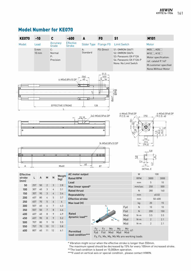
K99TE16-1904 161
* Vibration might occur when the effective stroke is longer than 550mm. The maximum speed should be decreased by 15% for every 100mm of increased stroke.**The load condition is based on 10,000km operation. ***If used on vertical axis or special condition , please contact HIWIN.
Effective stroke (mm)
L A M N Weight (kg)
50 257 50 2 3 2.8
100 307 40 3 4 3.1
150 357 90 3 4 3.4
200 407 80 4 5 3.7
250 457 70 5 6 4
300 507 60 6 7 4.3
350 557 50 7 8 4.6
400 607 40 8 9 4.9
450 657 90 8 9 5.2
500 707 80 9 10 5.5
550 757 70 10 11 5.8
600 807 60 11 12 6.1
KE070 -10 C -600 A F0 S1 M101Model Lead Accuracy
GradeEffective Stroke Slider Type Flange F0 Limit Switch Motor
5 mm10 mm
C: NormalP: Precision
A: Standard
F0: Direct S1: OMRON SX671 S2: OMRON SX674 S3: Panasonic GX-F12A S4: Panasonic GX-F12A-PNone: No Limit Switch
M05, K05M10, K10Motor specification:ref. catalof P.167M:customer specifiedNone:Without Motor
Model Number for KE070
AC motor output W 100
Rated RPM RPM 3000 3000
Lead mm 5 10
Max linear speed* mm/sec 250 500
Rated thrust N 280 140
Repeatability mm ±0.02
Effective stroke mm 50~600
Max load (H) kg 20 15
Rated dynamic load**
Fyd N 10 10
Fzd N 200 150
Mxd N-m 3.5 3.5
Myd N-m 2 2.1
Mzd N-m 2 2.1
Permitted load condition*** Fy, Fz, Mx, My, Mz Mz are working loads
1++++MzdMz
MydMy
MxdMx
FzdFz
FydFy ≤
Fz
FyMy Mx
Fx
Mz
Fz
FyMy Mx
Fx
Mz
Fz
FyMy Mx
Fx
Mz
Fz
FyMy Mx
Fx
Mz
Fz
FyMy Mx
Fx
Mz
Fz
FyMy
Mx
Fx
Mz
Fz
FyMy Mx
Fx
Mz
128EFFECTIVE STROKE
L
40(56)
4-M5x0.8Px10 DP
Ø6h
7Ø3
0H8
369(45)51,5
23 107
2x2-M3x0.5Px6 DP
8760
Mx60A
N-M5x0.8Px10 DP
4-M4x0.7Px8 DPP.C.D. 46 (75)
15(71)
1,5
42,2
44,5
8
0,84,
2
2,4
5
5,8
DETAIL E
4-M3x0.5Px8 DPP.C.D. 40
(79,4)
E
67
75
30°
30°
45°
45°
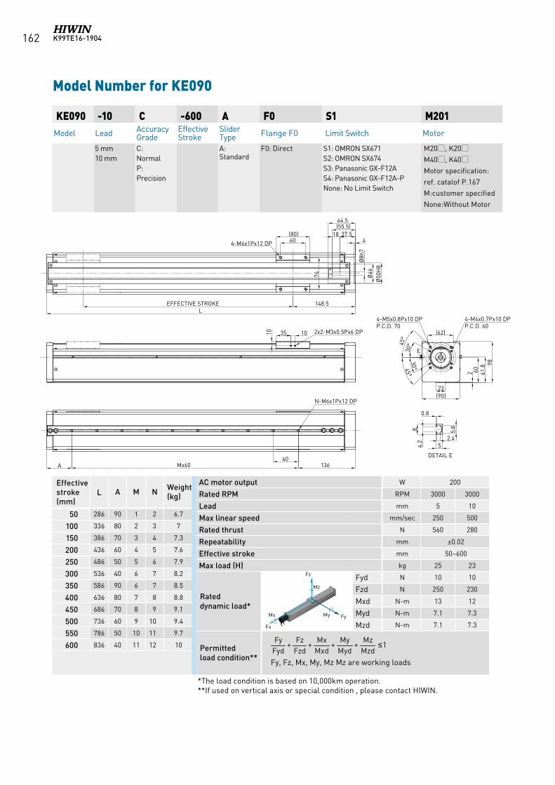
K99TE16-1904162
Effective stroke (mm)
L A M N Weight (kg)
50 286 90 1 2 6.7
100 336 80 2 3 7
150 386 70 3 4 7.3
200 436 60 4 5 7.6
250 486 50 5 6 7.9
300 536 40 6 7 8.2
350 586 90 6 7 8.5
400 636 80 7 8 8.8
450 686 70 8 9 9.1
500 736 60 9 10 9.4
550 786 50 10 11 9.7
600 836 40 11 12 10
KE090 -10 C -600 A F0 S1 M201Model Lead Accuracy
GradeEffective Stroke
Slider Type Flange F0 Limit Switch Motor
5 mm10 mm
C: NormalP: Precision
A: Standard
F0: Direct S1: OMRON SX671 S2: OMRON SX674 S3: Panasonic GX-F12A S4: Panasonic GX-F12A-PNone: No Limit Switch
M20, K20M40, K40Motor specification:ref. catalof P.167M:customer specifiedNone:Without Motor
Model Number for KE090
AC motor output W 200
Rated RPM RPM 3000 3000
Lead mm 5 10
Max linear speed mm/sec 250 500
Rated thrust N 560 280
Repeatability mm ±0.02
Effective stroke mm 50~600
Max load (H) kg 25 23
Rated dynamic load*
Fyd N 10 10
Fzd N 250 230
Mxd N-m 13 12
Myd N-m 7.1 7.3
Mzd N-m 7.1 7.3
Permitted load condition** Fy, Fz, Mx, My, Mz Mz are working loads
*The load condition is based on 10,000km operation. **If used on vertical axis or special condition , please contact HIWIN.
1++++MzdMz
MydMy
MxdMx
FzdFz
FydFy ≤
Fz
FyMy Mx
Fx
Mz
Fz
FyMy Mx
Fx
Mz
Fz
FyMy Mx
Fx
Mz
Fz
FyMy Mx
Fx
Mz
Fz
FyMy Mx
Fx
Mz
Fz
FyMy
Mx
Fx
Mz
Fz
FyMy Mx
Fx
Mz
2
(90)23
98
60
(62)
45°
45°
136A60
Mx60
N-M6x1Px12 DP
4-M4x0.7Px10 DPP.C.D. 60
4-M5x0.8Px10 DPP.C.D. 70
10 35 10
60(80)
76
4-M6x1Px12 DP
Ø50
H8
64.5
18(55.5)
37.5
148.5EFFECTIVE STROKEL
Ø46
Ø8h
7
2x2-M3x0.5Px6 DP
80.8
4.2 2.4
55.
8DETAIL E
E30°
30°
61.8
4
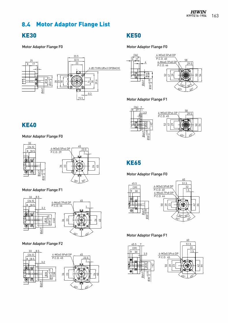
K99TE16-1904 163
KE65
Ø30
+0.0
30
309
Ø6h
7
45.5(39)
233950
1.532
51.560
42 64
4-M4x0.7Px8 DPP.C.D. 46
4-M3x0.5Px8 DPP.C.D. 40
30° 30°45° 45°
Ø30
+0.0
50
309
Ø6h
7
45.5(39)
233950
1.532
51.560
42 64
4-M3x0.5Px6 DPP.C.D. 45
42Ø28
7
3.5
45° 45°
KE40
18.5
(26.5)33
8
Ø20
+0.0
30
2336 45
30° 30°
1
454-M3x0.5Px6 DPP.C.D. 29
24
Ø4h
7
23.5
18.5
(26.5)33
8
Ø30
+0.0
5-0 2336 45
1
454-M3x0.5Px8 DPP.C.D. 45
24
Ø4h
7
23.5
38
8.5
3.2
45° 45°
18.5
(26.5)33
8
Ø30
+0.0
50
2336 45
1
454-M4x0.7Px8 DPP.C.D. 46
24
Ø4h
7
8.5
3.2
40
Ø20
Ø20
45° 45°
8.4 Motor Adaptor Flange List
Motor Adaptor Flange F0
Motor Adaptor Flange F0
Motor Adaptor Flange F0
Motor Adaptor Flange F1
Motor Adaptor Flange F1
Motor Adaptor Flange F2
KE30
1828 14 30 39.6
32.533.5
23
15.5
17825
2
Ø18
Ø22
+0.1 0
Ø4h
7
4-Ø3 THRU,Ø5x3 DP(BACK)
0.3
23
KE50
52 41 29
58
5450
4-M4x0.7Px8 DPP.C.D. 46
Ø6h
7
45° 45°Ø30
+0.0
50
Ø26
4279
(36)
30° 30°
4-M3x0.5Px8 DPP.C.D. 40
52 41 29
58
5450
Ø6h
7
Ø30
+0.0
50
Ø26
4
279(36)
4-M3x0.5Px6 DPP.C.D. 45
29.5
29.5
45° 45°
42
7
3.5
KE30
KE40
KE50
KE65
Motor Adaptor Flange F1
Motor Adaptor Flange F0

K99TE16-1904164
KE90
2
9023
98
60
62
45° 45°
4-M4x0.7Px10 DPP.C.D. 604-M5x0.8Px10 DPP.C.D. 70
Ø50
+0.0
30
64.5
18(55.5)
37.5
Ø46
Ø8h
7
4
30° 30°
2
9023
98
60
62
4-M4x0.7Px10 DPP.C.D. 70
Ø50
+0.0
50
64.5
18(55.5)
37.5
Ø46
Ø8h
7
4
45° 45°
62
10
3.5
2
9023
98
60
62
4-M4x0.7Px8 DPP.C.D. 46
Ø30
+0.0
50
64.5
18(55.5)
37.5
Ø8h
7
4
62
8
45° 45°
2
9023
98
60
62
4-M3x0.5Px8 DPP.C.D. 45
Ø30
+0.0
50
64.5
18(55.5)
37.5
Ø8h
7
4
62
8
45° 45°
2
9023
98
60
62
4-M4x0.7Px8 DP
Ø36
+0.0
50
64.5
18(55.5)
37.5
Ø8h
7
4
62
8
50
50
2
9023
98
60
62
4-M4x0.7Px8 DP
Ø38
.1+0
.08
+0.0
3
64.5
18(55.5)
37.5
Ø8h
7
4
62
8
47.1
4
47.14
Motor Adaptor Flange F0 Motor Adaptor Flange F1
Motor Adaptor Flange F0 Motor Adaptor Flange F3
Motor Adaptor Flange F1 Motor Adaptor Flange F5
Motor Adaptor Flange F2 Motor Adaptor Flange F6
KE70
Ø6h
7
Ø30
+0.0
50
369(45)
51.5
45°30°30°
4-M4x0.7Px8 DPP.C.D. 46
75 15 71
1.5
44.5
45°
4-M3x0.5Px8 DPP.C.D. 40
79.4
75Ø
6h7
Ø30
+0.0
50
369(45)
51.5
4-M3x0.5Px6 DP P.C.D. 45
75 15 71
1.5
44.5
79.4
75
45° 45°
42Ø28
7
3.5
KE70
Ø6h
7
Ø30
+0.0
50
369(45)
51.5
45°30°30°
4-M4x0.7Px8 DPP.C.D. 46
75 15 71
1.5
44.5
45°
4-M3x0.5Px8 DPP.C.D. 40
79.4
75
Ø6h
7
Ø30
+0.0
50
369(45)
51.5
4-M3x0.5Px6 DP P.C.D. 45
75 15 71
1.5
44.5
79.4
75
45° 45°
42Ø28
7
3.5
KE70
KE90
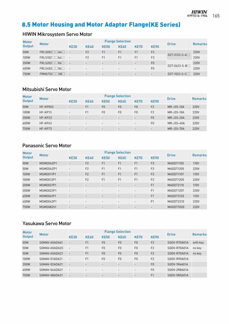
K99TE16-1904 165
8.5 Motor Housing and Motor Adaptor Flange(KE Series)
Panasonic Servo Motor
Mitsubishi Servo Motor
Yasukawa Servo Motor
HIWIN Mikrosystem Servo MotorMotor Output Motor
Flange SelectionDrive Remarks
KE30 KE40 KE50 KE65 KE70 KE90
50W FRLS052A4 - F2 F1 F1 F1 F3D2T-0123-S-A
220V
100W FRLS102A4 - F2 F1 F1 F1 F3 220V
200W FRLS20206 - - - - - F0D2T-0423-S-B
220V
400W FRLS40206 - - - - - F0 220V
750W FRMS75208 - - - - - - D2T-1023-S-C 220V
Motor Output Motor
Flange SelectionDrive Remarks
KE30 KE40 KE50 KE65 KE70 KE90
50W HF-KP053 - F1 F0 F0 F0 F2 MR-J3S-10A 220V
100W HF-KP13 - F1 F0 F0 F0 F2 MR-J3S-10A 220V
200W HF-KP23 - - - - - F0 MR-J3S-20A 220V
400W HF-KP43 - - - - - F0 MR-J3S-40A 220V
750W HF-KP73 - - - - - - MR-J3S-70A 220V
Motor Output Motor
Flange SelectionDrive Remarks
KE30 KE40 KE50 KE65 KE70 KE90
50W MSMD5AZP1 - F2 F1 F1 F1 F3 MADDT1105 110V
50W MSMD5AZP1 - F2 F1 F1 F1 F3 MADDT1205 220V
100W MSMD011P1 - F2 F1 F1 F1 F3 MADDT1107 110V
100W MSMD012P1 - F2 F1 F1 F1 F3 MADDT1205 220V
200W MSMD021P1 - - - - - F1 MADDT2110 110V
200W MSMD022P1 - - - - - F1 MADDT1207 220V
400W MSMD041P1 - - - - - F1 MADDT3120 110V
400W MSMD042P1 - - - - - F1 MADDT2210 220V
750W MSMD082S1 - - - - - - MADDT3520 220V
Motor Output Motor
Flange SelectionDrive Remarks
KE30 KE40 KE50 KE65 KE70 KE90
50W SGMAV-A5ADA61 - F1 F0 F0 F0 F2 SGDV-R70A01A with key
50W SGMAV-A5ADA2C - F1 F0 F0 F0 F2 SGDV-R70A01A no key
50W SGMAV-A5ADA21 - F1 F0 F0 F0 F2 SGDV-R70A01A no key
100W SGMAV-01ADA21 - F1 F0 F0 F0 F2 SGDV-R90A01A
200W SGMAV-02ADA21 - - - - - F0 SGDV-1R6A01A
400W SGMAV-04ADA21 - - - - - F0 SGDV-2R8A01A
750W SGMAV-08ADA21 - - - - - F1 SGDV-5R5A01A
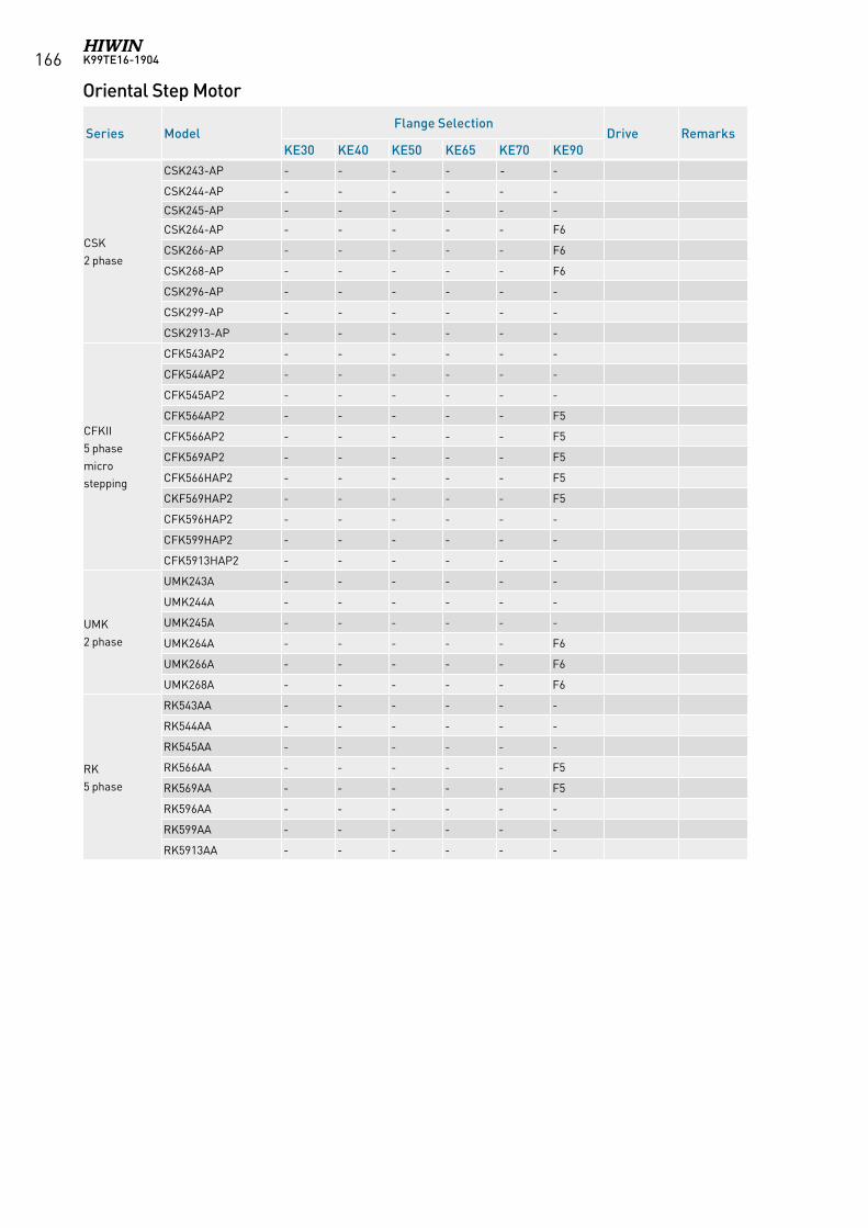
K99TE16-1904166
Oriental Step Motor
Series ModelFlange Selection
Drive RemarksKE30 KE40 KE50 KE65 KE70 KE90
CSK 2 phase
CSK243-AP - - - - - -
CSK244-AP - - - - - -
CSK245-AP - - - - - -
CSK264-AP - - - - - F6
CSK266-AP - - - - - F6
CSK268-AP - - - - - F6
CSK296-AP - - - - - -
CSK299-AP - - - - - -
CSK2913-AP - - - - - -
CFKII 5 phasemicrostepping
CFK543AP2 - - - - - -
CFK544AP2 - - - - - -
CFK545AP2 - - - - - -
CFK564AP2 - - - - - F5
CFK566AP2 - - - - - F5
CFK569AP2 - - - - - F5
CFK566HAP2 - - - - - F5
CKF569HAP2 - - - - - F5
CFK596HAP2 - - - - - -
CFK599HAP2 - - - - - -
CFK5913HAP2 - - - - - -
UMK 2 phase
UMK243A - - - - - -
UMK244A - - - - - -
UMK245A - - - - - -
UMK264A - - - - - F6
UMK266A - - - - - F6
UMK268A - - - - - F6
RK 5 phase
RK543AA - - - - - -
RK544AA - - - - - -
RK545AA - - - - - -
RK566AA - - - - - F5
RK569AA - - - - - F5
RK596AA - - - - - -
RK599AA - - - - - -
RK5913AA - - - - - -
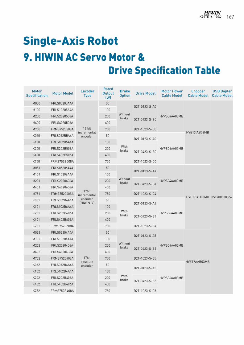
K99TE16-1904 167
Single-Axis Robot9. HIWIN AC Servo Motor & Drive Specification Table
MotorSpecification Motor Model Encoder
Type
Rated Output
(W)
Brake Option Drive Model Motor Power
Cable ModelEncoder
Cable ModelUSB DapterCable Model
M050 FRLS05205A4A
13 bitincremental
encoder
50
Without brake
D2T-0123-S-A0
HVPS04AA03MB
HVE13IAB03MB
051700800366
M100 FRLS10205A4A 100
M200 FRLS2020506A 200D2T-0423-S-B0
M400 FRLS4020506A 400
M750 FRMS7520508A 750 D2T-1023-S-C0
K050 FRLS052B5A4A 50
With brake
D2T-0123-S-A0
HVPS06AA03MB
K100 FRLS102B5A4A 100
K200 FRLS202B506A 200D2T-0423-S-B0
K400 FRLS402B506A 400
K750 FRMS752B508A 750 D2T-1023-S-C0
M051 FRLS05206A4A
17bitincremental
econder(HIWIN17)
50
Without brake
D2T-0123-S-A4
HVPS04AA03MB
HVE17IAB03MB
M101 FRLS10206A4A 100
M201 FRLS2020606A 200D2T-0423-S-B4
M401 FRLS4020606A 400
M751 FRMS7520608A 750 D2T-1023-S-C4
K051 FRLS052B6A4A 50
With brake
D2T-0123-S-A4
HVPS06AA03MB
K101 FRLS102B6A4A 100
K201 FRLS202B606A 200D2T-0423-S-B4
K401 FRLS402B606A 400
K751 FRMS752B608A 750 D2T-1023-S-C4
M052 FRLS05204A4A
17bitabsoluteencoder
50
Without brake
D2T-0123-S-A5
HVPS04AA03MB
HVE17AAB03MB
M102 FRLS10204A4A 100
M202 FRLS2020406A 200D2T-0423-S-B5
M402 FRLS4020406A 400
M752 FRMS7520408A 750 D2T-1023-S-C5
K052 FRLS052B4A4A 50
With brake
D2T-0123-S-A5
HVPS06AA03MB
K102 FRLS102B4A4A 100
K202 FRLS202B406A 200D2T-0423-S-B5
K402 FRLS402B406A 400
K752 FRMS752B408A 750 D2T-1023-S-C5

K99TE16-1904168
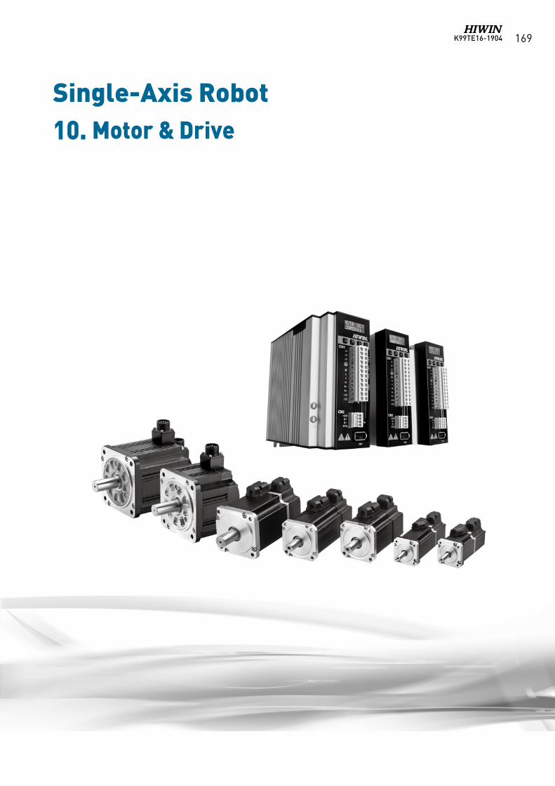
K99TE16-1904 169
Single-Axis Robot10. Motor & Drive
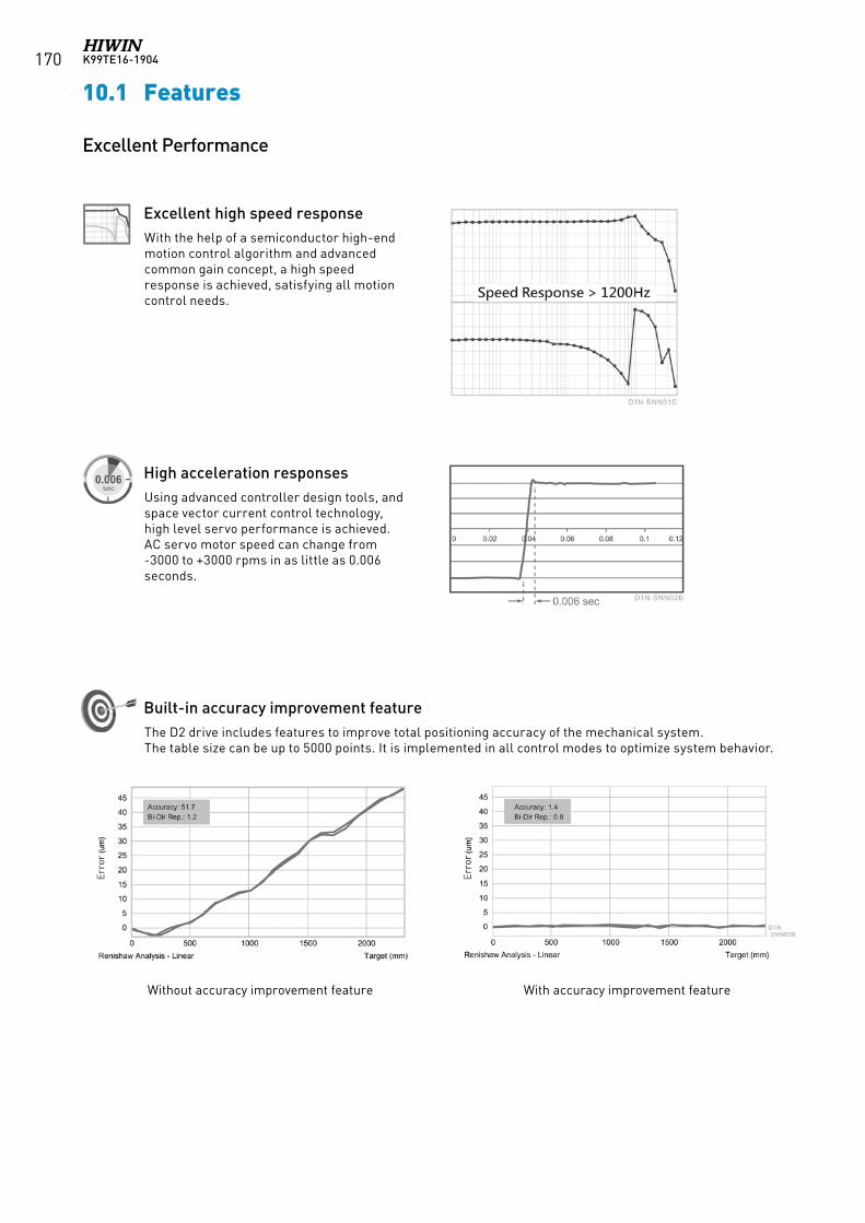
K99TE16-1904170
10.1 Features
With the help of a semiconductor high-end motion control algorithm and advanced common gain concept, a high speed response is achieved, satisfying all motion control needs.
Using advanced controller design tools, andspace vector current control technology, high level servo performance is achieved.AC servo motor speed can change from -3000 to +3000 rpms in as little as 0.006 seconds.
The D2 drive includes features to improve total positioning accuracy of the mechanical system.The table size can be up to 5000 points. It is implemented in all control modes to optimize system behavior.
Excellent high speed response
High acceleration responses
Built-in accuracy improvement feature
Without accuracy improvement feature With accuracy improvement feature
Excellent Performance
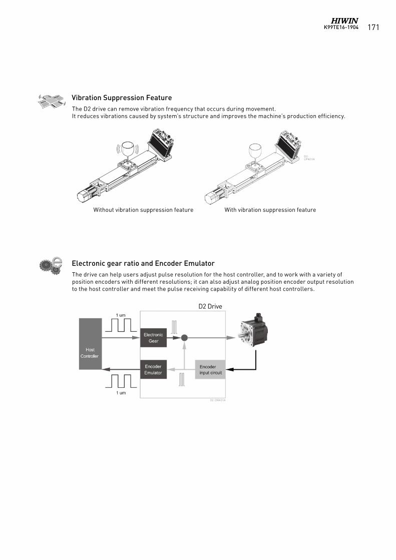
K99TE16-1904 171
The D2 drive can remove vibration frequency that occurs during movement.It reduces vibrations caused by system’s structure and improves the machine’s production efficiency.
The drive can help users adjust pulse resolution for the host controller, and to work with a variety of position encoders with different resolutions; it can also adjust analog position encoder output resolution to the host controller and meet the pulse receiving capability of different host controllers.
Vibration Suppression Feature
Electronic gear ratio and Encoder Emulator
Without vibration suppression feature With vibration suppression feature
D2 Drive
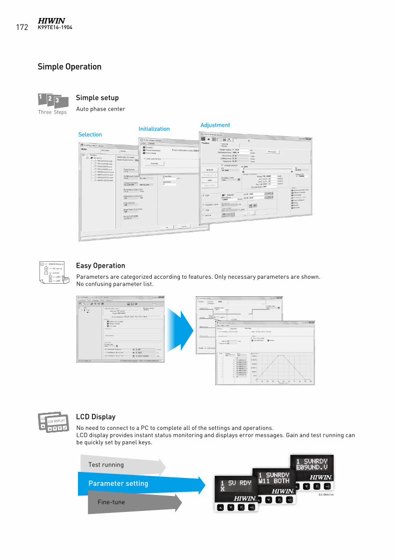
K99TE16-1904172
SelectionInitialization
Adjustment
HIWIN Motors
AC servo
Linear
LMC
LMF
1 2 3
HIWIN Motors
AC servo
Linear
LMC
LMF
1 2 3
Three Steps
Simple Operation
Auto phase center
Parameters are categorized according to features. Only necessary parameters are shown.No confusing parameter list.
No need to connect to a PC to complete all of the settings and operations.LCD display provides instant status monitoring and displays error messages. Gain and test running can be quickly set by panel keys.
Simple setup
Easy Operation
LCD Display
Test running
Parameter setting
Fine-tune
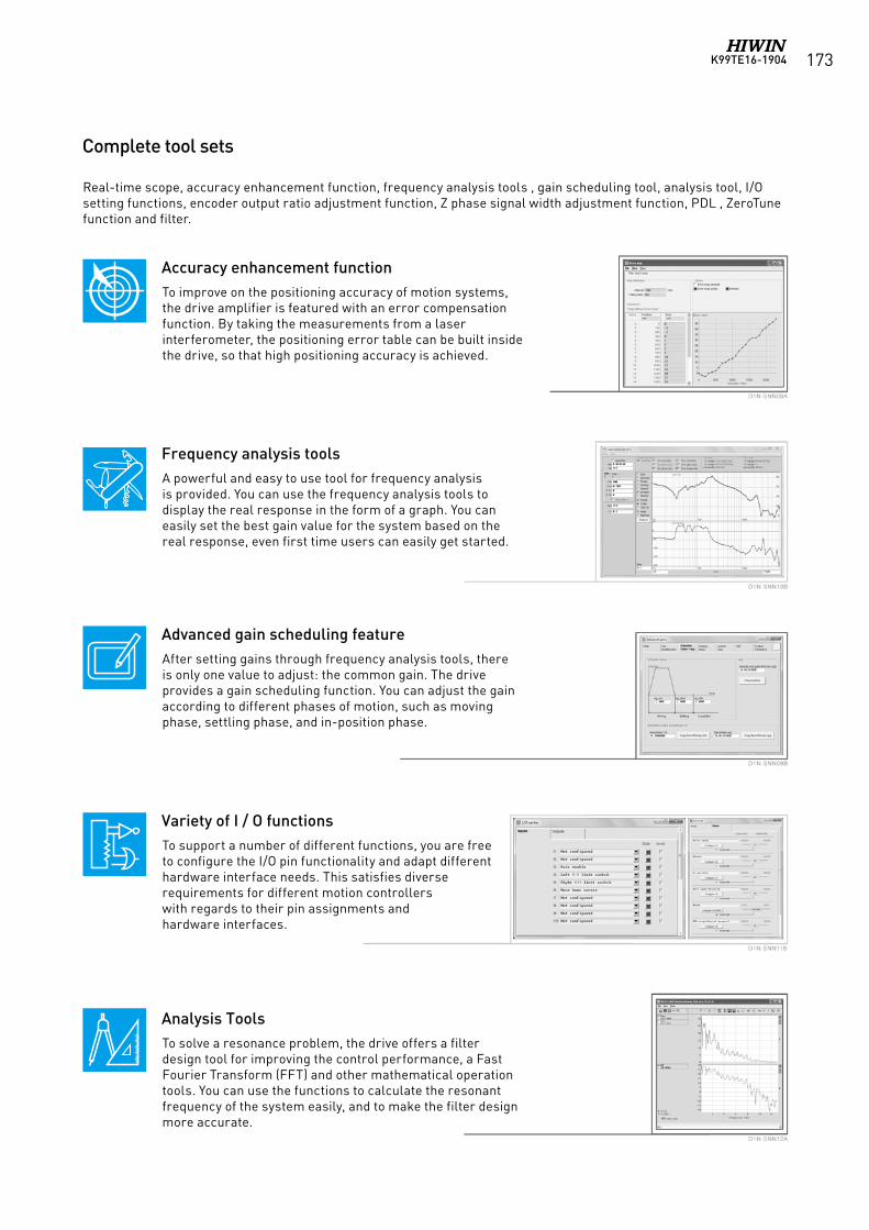
K99TE16-1904 173
Complete tool sets
To improve on the positioning accuracy of motion systems,the drive amplifier is featured with an error compensationfunction. By taking the measurements from a laserinterferometer, the positioning error table can be built insidethe drive, so that high positioning accuracy is achieved.
A powerful and easy to use tool for frequency analysisis provided. You can use the frequency analysis tools todisplay the real response in the form of a graph. You caneasily set the best gain value for the system based on thereal response, even first time users can easily get started.
After setting gains through frequency analysis tools, thereis only one value to adjust: the common gain. The driveprovides a gain scheduling function. You can adjust the gainaccording to different phases of motion, such as movingphase, settling phase, and in-position phase.
To support a number of different functions, you are free to configure the I/O pin functionality and adapt different hardware interface needs. This satisfies diverserequirements for different motion controllerswith regards to their pin assignments andhardware interfaces.
To solve a resonance problem, the drive offers a filterdesign tool for improving the control performance, a FastFourier Transform (FFT) and other mathematical operationtools. You can use the functions to calculate the resonantfrequency of the system easily, and to make the filter designmore accurate.
Accuracy enhancement function
Frequency analysis tools
Advanced gain scheduling feature
Variety of I / O functions
Analysis Tools
Real-time scope, accuracy enhancement function, frequency analysis tools , gain scheduling tool, analysis tool, I/O setting functions, encoder output ratio adjustment function, Z phase signal width adjustment function, PDL , ZeroTune function and filter.
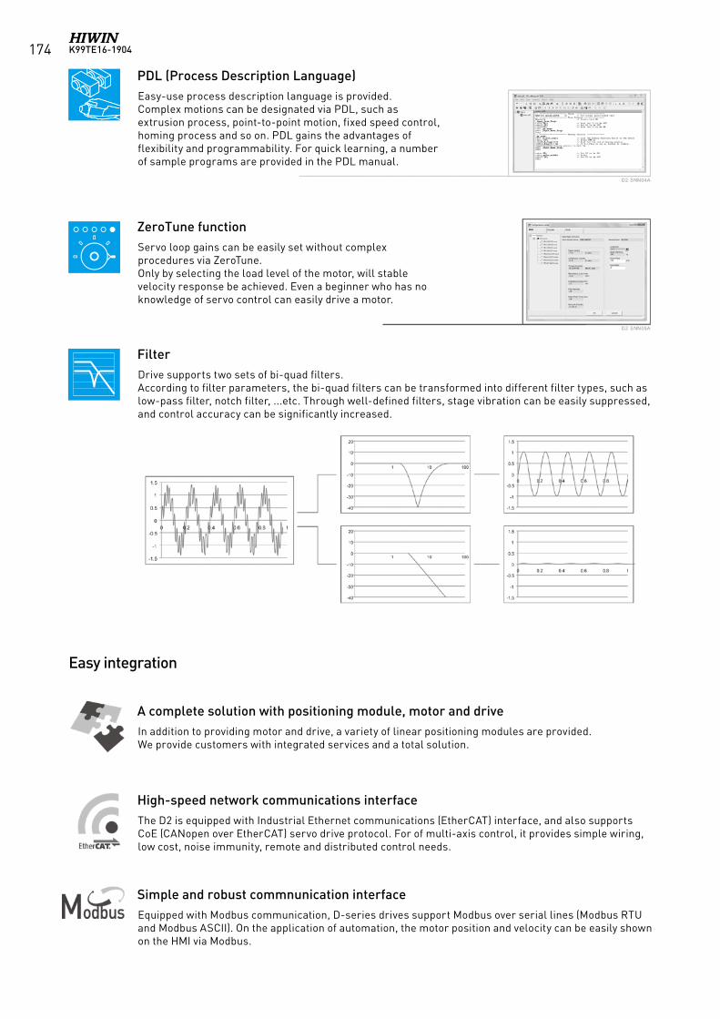
K99TE16-1904174
Easy-use process description language is provided.Complex motions can be designated via PDL, such asextrusion process, point-to-point motion, fixed speed control,homing process and so on. PDL gains the advantages offlexibility and programmability. For quick learning, a numberof sample programs are provided in the PDL manual.
In addition to providing motor and drive, a variety of linear positioning modules are provided.We provide customers with integrated services and a total solution.
The D2 is equipped with Industrial Ethernet communications (EtherCAT) interface, and also supports CoE (CANopen over EtherCAT) servo drive protocol. For of multi-axis control, it provides simple wiring, low cost, noise immunity, remote and distributed control needs.
Equipped with Modbus communication, D-series drives support Modbus over serial lines (Modbus RTU and Modbus ASCII). On the application of automation, the motor position and velocity can be easily shown on the HMI via Modbus.
Servo loop gains can be easily set without complex procedures via ZeroTune.Only by selecting the load level of the motor, will stable velocity response be achieved. Even a beginner who has no knowledge of servo control can easily drive a motor.
Drive supports two sets of bi-quad filters.According to filter parameters, the bi-quad filters can be transformed into different filter types, such as low-pass filter, notch filter, ...etc. Through well-defined filters, stage vibration can be easily suppressed, and control accuracy can be significantly increased.
PDL (Process Description Language)
A complete solution with positioning module, motor and drive
High-speed network communications interface
Simple and robust commnunication interface
ZeroTune function
Filter
Easy integration
K99TE16-1904 175
Drive Motor
CE Directives EMC Directives
EMC: EN61800-3 EN55011 EN61000-6-2 EN61000-6-4 EN61000-2-4 IEC60146-1-1 IEC61000-2-1
EN55011EN61000-6-2EN61000-6-4
Low-VoltageDirectives
LVDS:EN61800-5-1 EN60034-1EN60034-5
UL Directives UL:E348161(D2T 100W/400W/1000W)
UL1004-1UL1004-6
10.2 Safety Certification
10.2.1 RoHS compliant
10.2.2 Comply with CE & UL regulations
Components and finished product all meet RoHS(Restriction of Hazardous Substances Regulation) requirements which ensure the compliance to relevant laws of quality of goods.
RoHS regulations limit six hazardous substances are:Lead (Pb), mercury (Hg), hexavalent chromium (Cr6 +),Polybrominated Biphenyls (PBB), the maximum allowablecontent of Polybrominated diphenyl ethers (PBDE) is 0.1%(1000ppm), Cadmium (Cd) is 0.01% (100ppm).RoHS
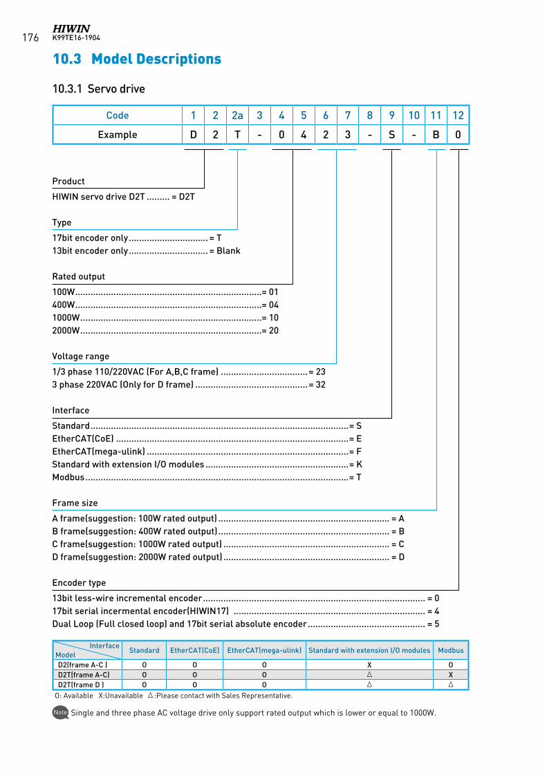
K99TE16-1904176
10.3 Model Descriptions
10.3.1 Servo drive
Code 1 2 2a 3 4 5 6 7 8 9 10 11 12
Example D 2 T - 0 4 2 3 - S - B 0
Product
HIWIN servo drive D2T ......... = D2T
Type
17bit encoder only ............................... = T13bit encoder only ............................... = Blank
Rated output
100W .........................................................................= 01400W .........................................................................= 041000W .......................................................................= 102000W .......................................................................= 20
Voltage range
1/3 phase 110/220VAC (For A,B,C frame) ..................................= 233 phase 220VAC (Only for D frame) ............................................= 32
Interface
Standard .....................................................................................................= SEtherCAT(CoE) ...........................................................................................= EEtherCAT(mega-ulink) ...............................................................................= FStandard with extension I/O modules ........................................................= KModbus .......................................................................................................= T
Frame size
A frame(suggestion: 100W rated output) ................................................................... = AB frame(suggestion: 400W rated output) ................................................................... = BC frame(suggestion: 1000W rated output) ................................................................. = CD frame(suggestion: 2000W rated output) ................................................................. = D
Encoder type
13bit less-wire incremental encoder ....................................................................................... = 017bit serial incermental encoder(HIWIN17) ........................................................................... = 4Dual Loop (Full closed loop) and 17bit serial absolute encoder .............................................. = 5
Single and three phase AC voltage drive only support rated output which is lower or equal to 1000W.Note
InterfaceModel
Standard EtherCAT(CoE) EtherCAT(mega-ulink) Standard with extension I/O modules Modbus
D2(frame A-C ) O O O X OD2T(frame A-C) O O O Δ XD2T(frame D ) O O O Δ Δ
O: Available X:Unavailable Δ:Please contact with Sales Representative.
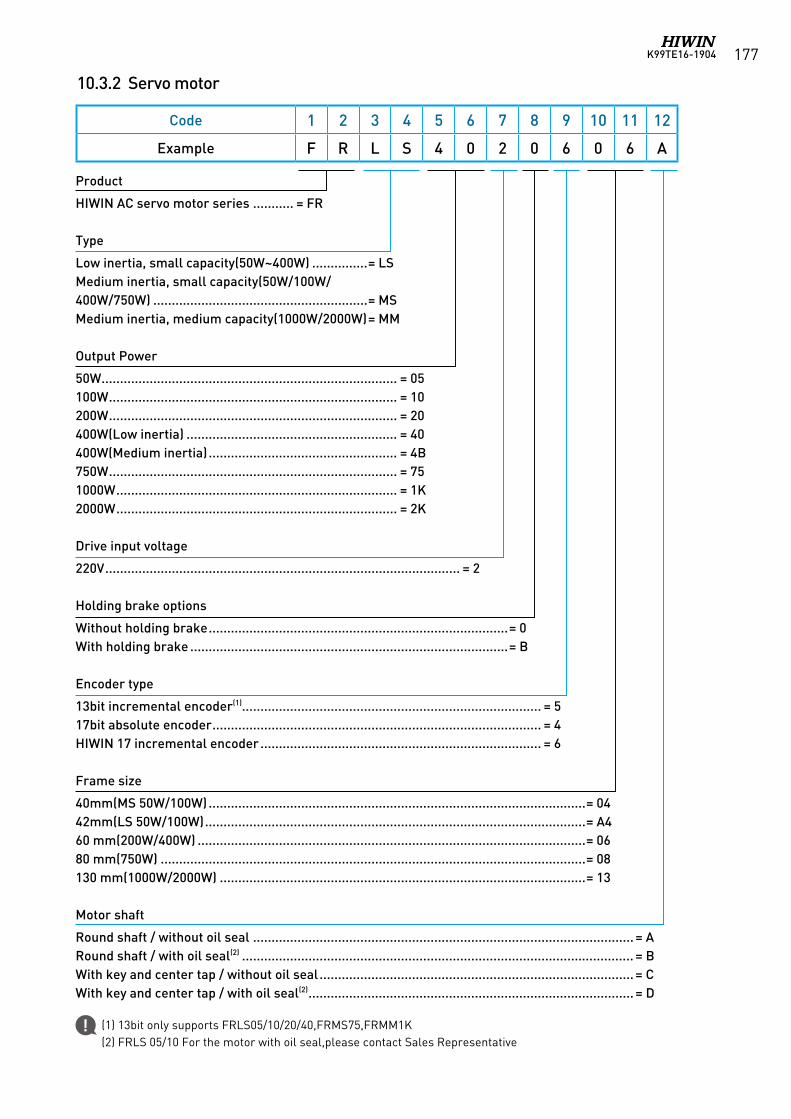
K99TE16-1904 177
(1) 13bit only supports FRLS05/10/20/40,FRMS75,FRMM1K(2) FRLS 05/10 For the motor with oil seal,please contact Sales Representative
10.3.2 Servo motor
Code 1 2 3 4 5 6 7 8 9 10 11 12
Example F R L S 4 0 2 0 6 0 6 A
Product
HIWIN AC servo motor series ........... = FR
Type
Low inertia, small capacity(50W~400W) ...............= LSMedium inertia, small capacity(50W/100W/400W/750W) ..........................................................= MSMedium inertia, medium capacity(1000W/2000W) = MM
Output Power
50W ................................................................................ = 05100W .............................................................................. = 10200W .............................................................................. = 20400W(Low inertia) ......................................................... = 40400W(Medium inertia) ................................................... = 4B750W .............................................................................. = 751000W ............................................................................ = 1K2000W ............................................................................ = 2K
Drive input voltage
220V ................................................................................................ = 2
Holding brake options
Without holding brake .................................................................................= 0With holding brake ......................................................................................= B
Encoder type
13bit incremental encoder(1)................................................................................. = 517bit absolute encoder ......................................................................................... = 4HIWIN 17 incremental encoder ............................................................................ = 6
Frame size
40mm(MS 50W/100W) ......................................................................................................= 0442mm(LS 50W/100W) .......................................................................................................= A460 mm(200W/400W) .........................................................................................................= 0680 mm(750W) ...................................................................................................................= 08130 mm(1000W/2000W) ...................................................................................................= 13
Motor shaft
Round shaft / without oil seal ....................................................................................................... = ARound shaft / with oil seal(2) .......................................................................................................... = BWith key and center tap / without oil seal ..................................................................................... = CWith key and center tap / with oil seal(2) ........................................................................................ = D
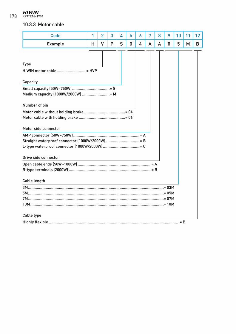
K99TE16-1904178
10.3.3 Motor cable
Code 1 2 3 4 5 6 7 8 9 10 11 12
Example H V P S 0 4 A A 0 5 M B
Type
HIWIN motor cable .......................... = HVP
Capacity
Small capacity (50W~750W) ..................................= SMedium capacity (1000W/2000W) .........................= M
Number of pin
Motor cable without holding brake .....................................= 04Motor cable with holding brake ..........................................= 06
Motor side connector
AMP connector (50W~750W) ............................................................ = AStraight waterproof connector (1000W/2000W) .............................. = BL-type waterproof connector (1000W/2000W) ................................. = C
Drive side connector
Open cable ends (50W~1000W) ...................................................................= AR-type terminals (2000W) ...........................................................................= B
Cable length
3M ...........................................................................................................................= 03M5M ...........................................................................................................................= 05M7M ...........................................................................................................................= 07M10M .........................................................................................................................= 10M
Cable type
Highly flexible ..................................................................................................................... = B
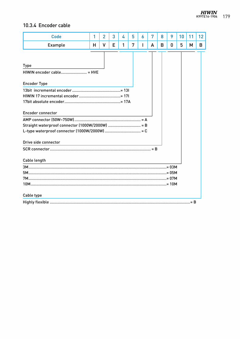
K99TE16-1904 179
10.3.4 Encoder cable
Code 1 2 3 4 5 6 7 8 9 10 11 12
Example H V E 1 7 I A B 0 5 M B
Type
HIWIN encoder cable ....................... = HVE
Encoder Type
13bit incremental encoder ...........................................= 13IHIWIN 17 incremental encoder .....................................= 17I17bit absolute encoder ..................................................= 17A
Encoder connector
AMP connector (50W~750W) ........................................................... = AStraight waterproof connector (1000W/2000W) ............................. = BL-type waterproof connector (1000W/2000W) ................................ = C
Drive side connector
SCR connector .......................................................................................... = B
Cable length
3M ...........................................................................................................................= 03M5M ...........................................................................................................................= 05M7M ...........................................................................................................................= 07M10M .........................................................................................................................= 10M
Cable type
Highly flexible .............................................................................................................................= B
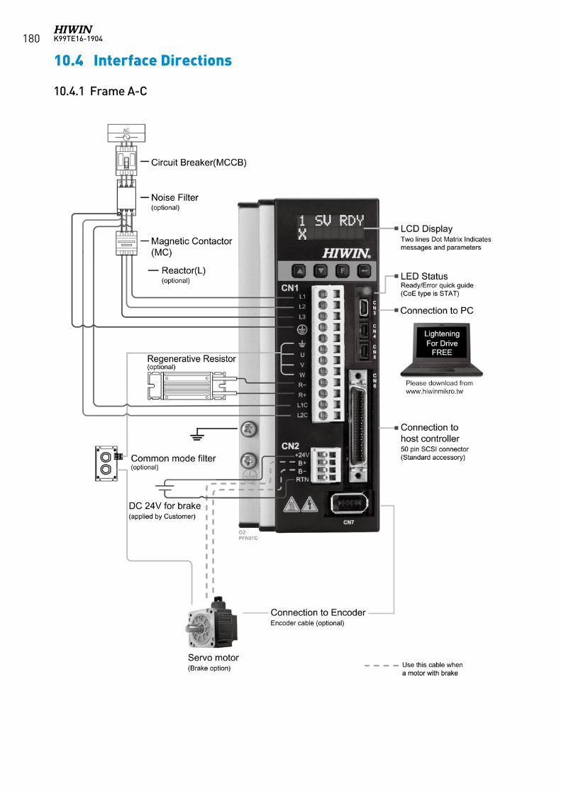
K99TE16-1904180
10.4 Interface Directions
10.4.1 Frame A-C
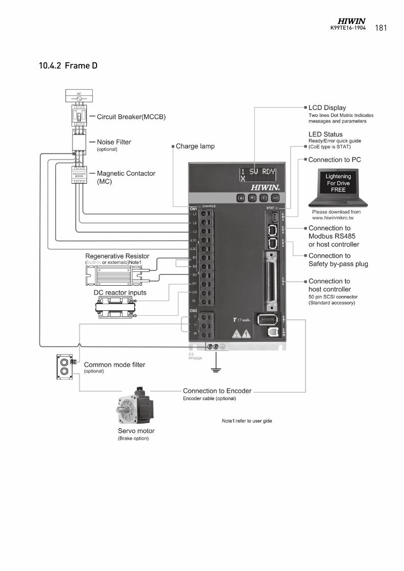
K99TE16-1904 181
10.4.2 Frame D
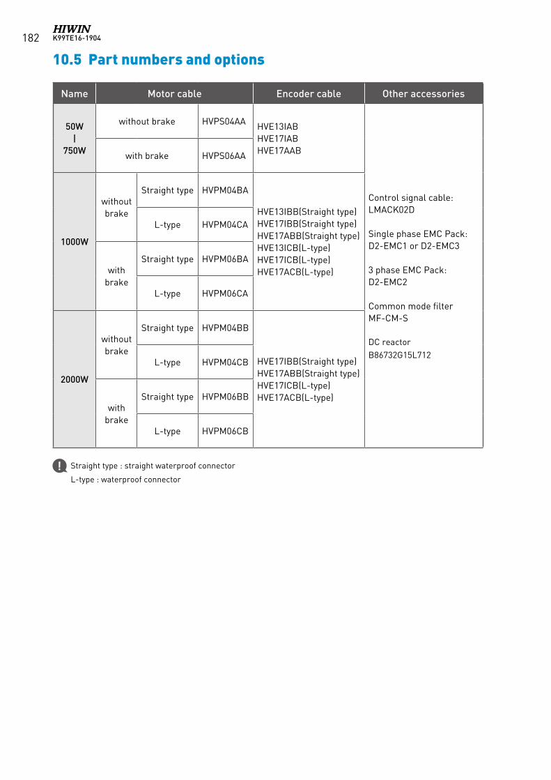
K99TE16-1904182
10.5 Part numbers and options
Name Motor cable Encoder cable Other accessories
50W |
750W
without brake HVPS04AA HVE13IABHVE17IABHVE17AAB
Control signal cable:LMACK02D
Single phase EMC Pack:D2-EMC1 or D2-EMC3
3 phase EMC Pack:D2-EMC2
Common mode filterMF-CM-S
DC reactorB86732G15L712
with brake HVPS06AA
1000W
without brake
Straight type HVPM04BA
HVE13IBB(Straight type)HVE17IBB(Straight type)HVE17ABB(Straight type)HVE13ICB(L-type)HVE17ICB(L-type)HVE17ACB(L-type)
L-type HVPM04CA
with brake
Straight type HVPM06BA
L-type HVPM06CA
2000W
without brake
Straight type HVPM04BB
HVE17IBB(Straight type)HVE17ABB(Straight type)HVE17ICB(L-type)HVE17ACB(L-type)
L-type HVPM04CB
with brake
Straight type HVPM06BB
L-type HVPM06CB
Straight type : straight waterproof connector
L-type : waterproof connector
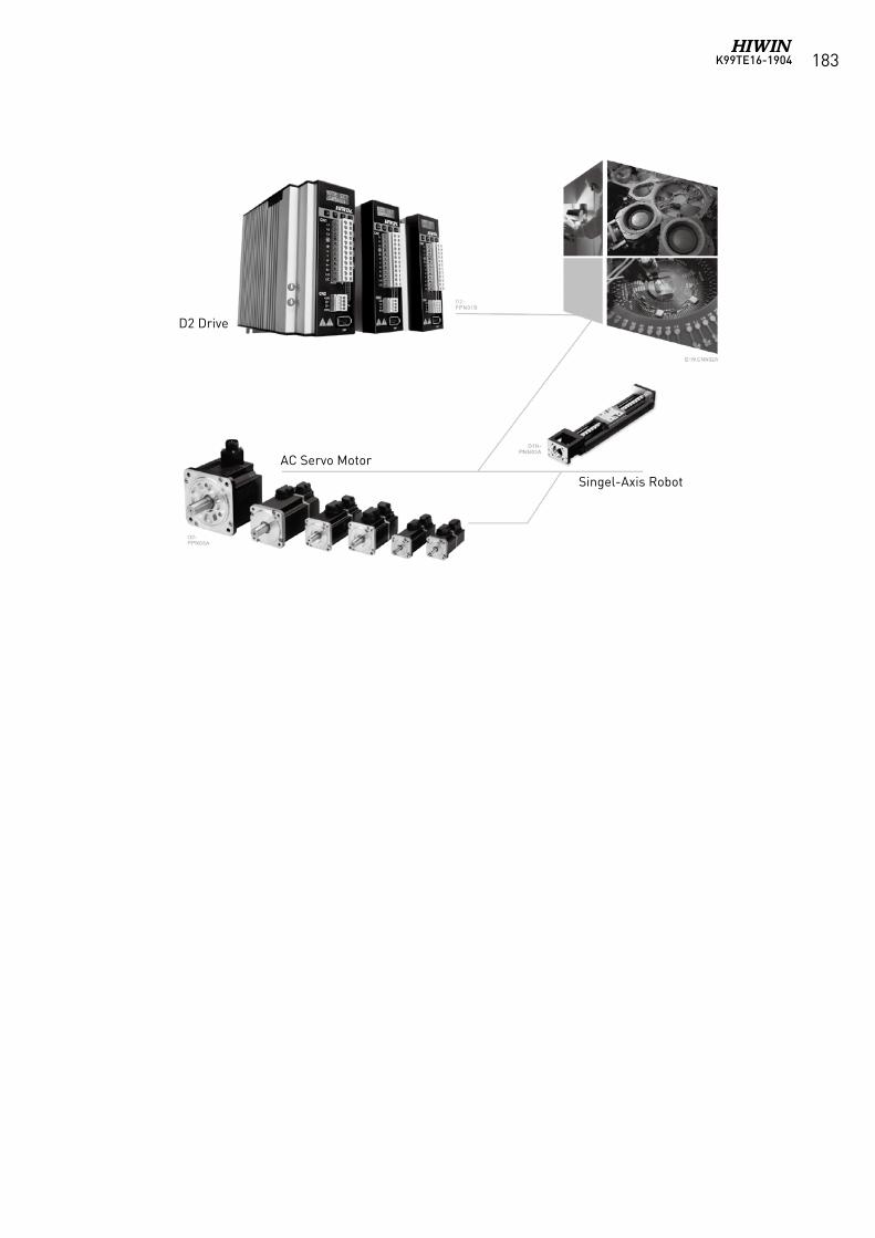
K99TE16-1904 183
D2 Drive
AC Servo Motor
Singel-Axis Robot
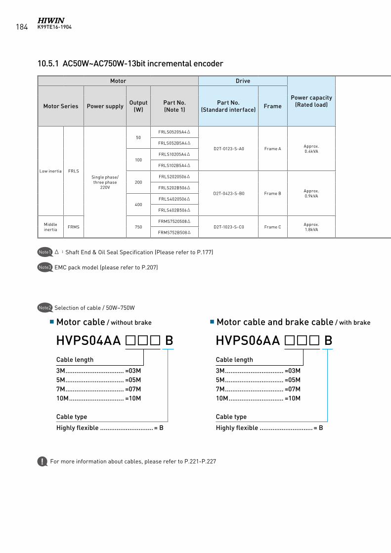
K99TE16-1904184
10.5.1 AC50W~AC750W-13bit incremental encoder
Motor Drive
Power capacity(Rated load)
Optional parts
Motor Series Power supply Output(W)
Part No.(Note 1)
Part No.(Standard interface) Frame
Motor cable(Note 2) Encoder cable D2 drive accessories
without brake with brake13bit
incremental(Note 2)
Control Signal Cable
Single phase
EMC Pack(Note 3)
Three phase
EMC Pack(Note 3)
External Regenerative
Resistor
Low inertia FRLSSingle phase/ three phase
220V
50FRLS05205A4Δ
D2T-0123-S-A0 Frame A Approx.0.4kVA
HVPS04AAB HVPS06AAB HVE13IABB LMACK02D
D2-EMC1
D2-EMC2
N/AFRLS052B5A4Δ
100FRLS10205A4Δ
FRLS102B5A4Δ
200FRLS2020506Δ
D2T-0423-S-B0 Frame B Approx.0.9kVA RG1
FRLS202B506Δ
400FRLS4020506Δ
FRLS402B506Δ
Middle inertia FRMS 750
FRMS7520508ΔD2T-1023-S-C0 Frame C Approx.
1.8kVA D2-EMC3 RG2FRMS752B508Δ
Δ:Shaft End & Oil Seal Specification (Please refer to P.177)Note1
Note3 EMC pack model (please refer to P.207)
Note2 Selection of cable / 50W~750W
Motor cable / without brake Motor cable and brake cable / with brake
For more information about cables, please refer to P.221-P.227
Cable length
3M ................................ =03M5M ................................ =05M7M ................................ =07M10M .............................. =10M
Cable type
Highly flexible ............................. = B
HVPS04AA BCable length
3M ................................ =03M5M ................................ =05M7M ................................ =07M10M .............................. =10M
Cable type
Highly flexible ............................. = B
HVPS06AA B
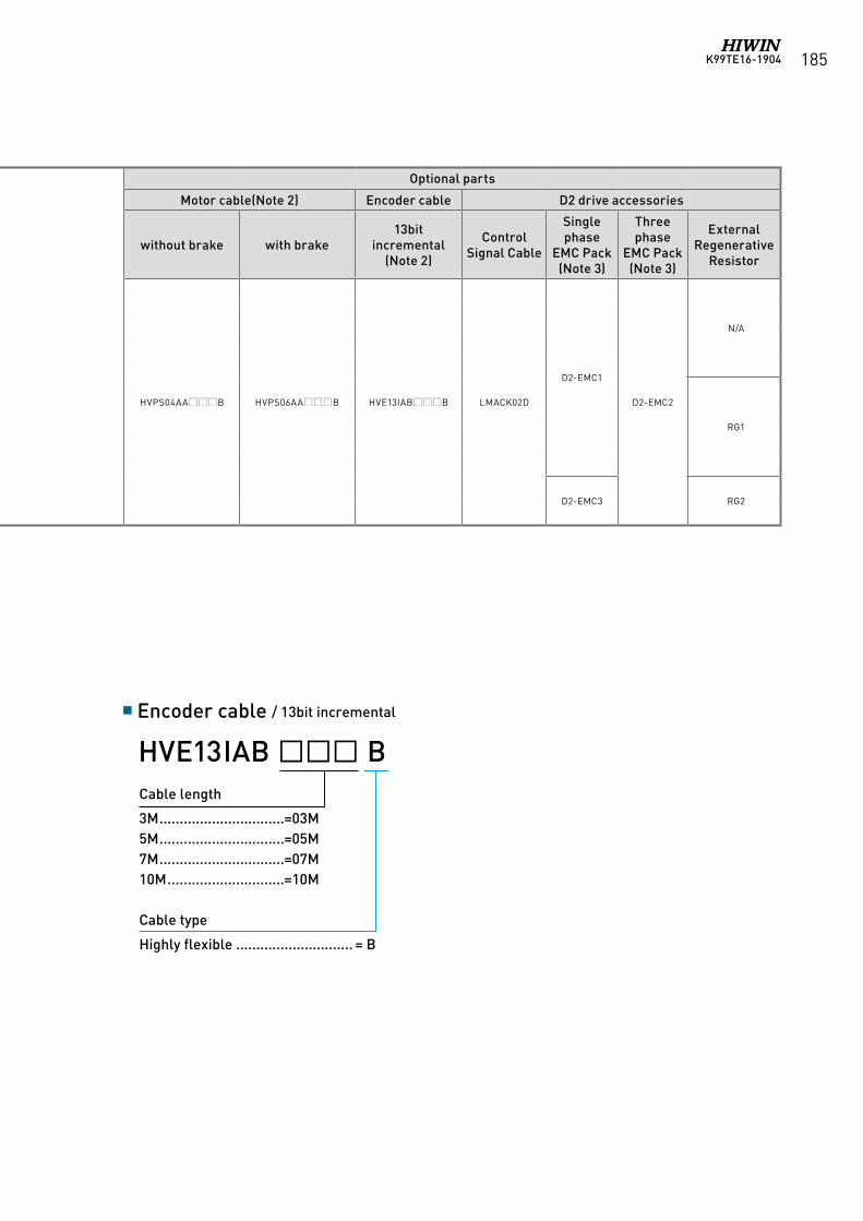
K99TE16-1904 185
Motor Drive
Power capacity(Rated load)
Optional parts
Motor Series Power supply Output(W)
Part No.(Note 1)
Part No.(Standard interface) Frame
Motor cable(Note 2) Encoder cable D2 drive accessories
without brake with brake13bit
incremental(Note 2)
Control Signal Cable
Single phase
EMC Pack(Note 3)
Three phase
EMC Pack(Note 3)
External Regenerative
Resistor
Low inertia FRLSSingle phase/ three phase
220V
50FRLS05205A4Δ
D2T-0123-S-A0 Frame A Approx.0.4kVA
HVPS04AAB HVPS06AAB HVE13IABB LMACK02D
D2-EMC1
D2-EMC2
N/AFRLS052B5A4Δ
100FRLS10205A4Δ
FRLS102B5A4Δ
200FRLS2020506Δ
D2T-0423-S-B0 Frame B Approx.0.9kVA RG1
FRLS202B506Δ
400FRLS4020506Δ
FRLS402B506Δ
Middle inertia FRMS 750
FRMS7520508ΔD2T-1023-S-C0 Frame C Approx.
1.8kVA D2-EMC3 RG2FRMS752B508Δ
Encoder cable / 13bit incremental
Cable length
3M ...............................=03M5M ...............................=05M7M ...............................=07M10M .............................=10M
Cable type
Highly flexible ............................. = B
HVE13IAB B
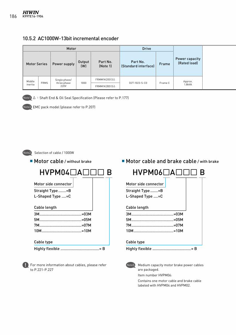
K99TE16-1904186
10.5.2 AC1000W-13bit incremental encoder
Motor Drive
Power capacity(Rated load)
Optional parts
Motor Series Power supply Output(W)
Part No.(Note 1)
Part No.(Standard interface) Frame
Motor cable(Note 2) Encoder cable D2 drive accessories
without brake with brake13bit
incremental(Note 2)
Control Signal Cable
Single phase
EMC Pack(Note 3)
Three phase
EMC Pack(Note 3)
External Regenerative
Resistor
Middle inertia FRMS
Single phase/ three phase
220V1000
FRMM1K20513ΔD2T-1023-S-C0 Frame C Approx.
1.8kVA HVPM04AB HVPM06AB HVE13IBB LMACK02D D2-EMC3 D2-EMC2 RG2FRMM1K2B513Δ
Note5 Medium capacity motor brake power cables are packaged.
Item number HVPM06:
Contains one motor cable and brake cable labeled with HVPM04 and HVPM02.
Motor cable / without brake Motor cable and brake cable / with brake
Motor side connector
Straight Type .......=BL-Shaped Type ....=C
Cable length
3M ......................................=03M5M ......................................=05M7M ......................................=07M10M ....................................=10M
Cable type
Highly flexible ...................................= B
HVPM04A BMotor side connector
Straight Type .......=BL-Shaped Type ....=C
Cable length
3M ......................................=03M5M ......................................=05M7M ......................................=07M10M ....................................=10M
Cable type
Highly flexible ...................................= B
HVPM06A B
Δ:Shaft End & Oil Seal Specification (Please refer to P.177)Note1
Note3 EMC pack model (please refer to P.207)
Note2 Selection of cable / 1000W
For more information about cables, please refer to P.221-P.227
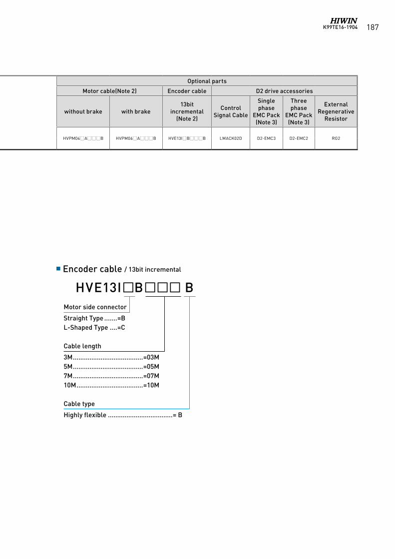
K99TE16-1904 187
Motor Drive
Power capacity(Rated load)
Optional parts
Motor Series Power supply Output(W)
Part No.(Note 1)
Part No.(Standard interface) Frame
Motor cable(Note 2) Encoder cable D2 drive accessories
without brake with brake13bit
incremental(Note 2)
Control Signal Cable
Single phase
EMC Pack(Note 3)
Three phase
EMC Pack(Note 3)
External Regenerative
Resistor
Middle inertia FRMS
Single phase/ three phase
220V1000
FRMM1K20513ΔD2T-1023-S-C0 Frame C Approx.
1.8kVA HVPM04AB HVPM06AB HVE13IBB LMACK02D D2-EMC3 D2-EMC2 RG2FRMM1K2B513Δ
Encoder cable / 13bit incremental
Motor side connector
Straight Type .......=BL-Shaped Type ....=C
Cable length
3M ......................................=03M5M ......................................=05M7M ......................................=07M10M ....................................=10M
Cable type
Highly flexible ...................................= B
HVE13IB B
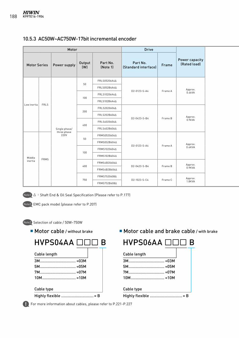
K99TE16-1904188
10.5.3 AC50W~AC750W-17bit incremental encoder
Motor Drive
Power capacity(Rated load)
Optional parts
Motor Series Power supply Output(W)
Part No.(Note 1)
Part No.(Standard interface) Frame
Motor cable(Note 2) Encoder cable D2 drive accessories
without brake with brake13bit
incremental(Note 2)
Control Signal Cable
Single phase
EMC Pack(Note 3)
Three phase
EMC Pack(Note 3)
External Regenerative
Resistor
Low inertia FRLS
Single phase/ three phase
220V
50FRLS05206A4∆
D2-0123-S-A4 Frame A Approx.0.4kVA
HVPS04AAB HVPS06AAB HVE17IABB LMACK02D
D2-EMC1
D2-EMC2
N/AFRLS052B6A4∆
100FRLS10206A4∆
FRLS102B6A4∆
200FRLS2020606∆
D2-0423-S-B4 Frame B Approx.0.9kVA RG1
FRLS202B606∆
400FRLS4020606∆
FRLS402B606∆
Middle inertia FRMS
50FRMS0520604∆
D2-0123-S-A4 Frame A Approx.0.4KVA
D2-EMC3 RG2
FRMS052B604∆
100FRMS1020604∆
FRMS102B604∆
400FRMS4B20606∆
D2-0423-S-B4 Frame B Approx.0.9KVA
FRMS4B2B606∆
750FRMS7520608∆
D2-1023-S-C4 Frame C Approx.1.8KVA
FRMS752B608∆
Motor cable / without brake Motor cable and brake cable / with brake
Cable length
3M ................................ =03M5M ................................ =05M7M ................................ =07M10M .............................. =10M
Cable type
Highly flexible ............................. = B
HVPS04AA BCable length
3M ................................ =03M5M ................................ =05M7M ................................ =07M10M .............................. =10M
Cable type
Highly flexible ............................. = B
HVPS06AA B
Δ:Shaft End & Oil Seal Specification (Please refer to P.177)Note1
Note3 EMC pack model (please refer to P.207)
Note2 Selection of cable / 50W~750W
For more information about cables, please refer to P.221-P.227
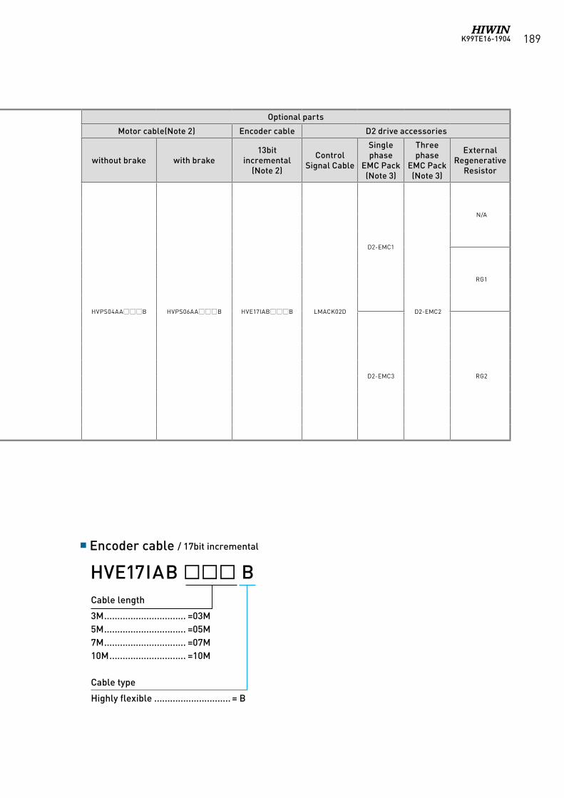
K99TE16-1904 189
Motor Drive
Power capacity(Rated load)
Optional parts
Motor Series Power supply Output(W)
Part No.(Note 1)
Part No.(Standard interface) Frame
Motor cable(Note 2) Encoder cable D2 drive accessories
without brake with brake13bit
incremental(Note 2)
Control Signal Cable
Single phase
EMC Pack(Note 3)
Three phase
EMC Pack(Note 3)
External Regenerative
Resistor
Low inertia FRLS
Single phase/ three phase
220V
50FRLS05206A4∆
D2-0123-S-A4 Frame A Approx.0.4kVA
HVPS04AAB HVPS06AAB HVE17IABB LMACK02D
D2-EMC1
D2-EMC2
N/AFRLS052B6A4∆
100FRLS10206A4∆
FRLS102B6A4∆
200FRLS2020606∆
D2-0423-S-B4 Frame B Approx.0.9kVA RG1
FRLS202B606∆
400FRLS4020606∆
FRLS402B606∆
Middle inertia FRMS
50FRMS0520604∆
D2-0123-S-A4 Frame A Approx.0.4KVA
D2-EMC3 RG2
FRMS052B604∆
100FRMS1020604∆
FRMS102B604∆
400FRMS4B20606∆
D2-0423-S-B4 Frame B Approx.0.9KVA
FRMS4B2B606∆
750FRMS7520608∆
D2-1023-S-C4 Frame C Approx.1.8KVA
FRMS752B608∆
Encoder cable / 17bit incremental
Cable length
3M ............................... =03M5M ............................... =05M7M ............................... =07M10M ............................. =10M
Cable type
Highly flexible ............................. = B
HVE17IAB B
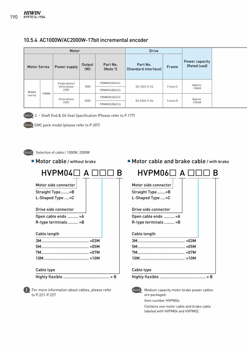
K99TE16-1904190
10.5.4 AC1000W/AC2000W-17bit incremental encoder
Motor Drive
Power capacity(Rated load)
Optional parts
Motor Series Power supply Output(W)
Part No.(Note 1)
Part No.(Standard interface) Frame
Motor cable(Note 2) Encoder cable D2 drive accessories
without brake with brake13bit
incremental(Note 2)
Control Signal Cable
Single phase
EMC Pack(Note 3)
Three phase
EMC Pack(Note 3)
External Regenerative
Resistor
Middle inertia FRMM
Single phase/ three phase
220V1000
FRMM1K20613ΔD2-1023-S-C4 Frame C Approx.
1.8kVA HVPM04AB HVPM06AB
HVE17IBB LMACK02D D2-EMC3 D2-EMC2 RG2FRMM1K2B613Δ
three phase220V 2000
FRMM2K20613ΔD2-2032-S-D4 Frame D Approx.
3.5kVA HVPM04BB HVPM06BBFRMM2K2B613Δ
Δ:Shaft End & Oil Seal Specification (Please refer to P.177)Note1
Note3 EMC pack model (please refer to P.207)
Note5 Medium capacity motor brake power cables are packaged.
Item number HVPM06:
Contains one motor cable and brake cable labeled with HVPM04 and HVPM02.
Motor cable / without brake Motor cable and brake cable / with brake
Motor side connector
Straight Type .......=BL-Shaped Type ....=C
Drive side connector
Open cable ends ......... =AR-type terminals ......... =B
Cable length
3M ......................................... =03M5M ......................................... =05M7M ......................................... =07M10M ....................................... =10M
Cable type
Highly flexible ........................................ = B
HVPM04 A BMotor side connector
Straight Type .......=BL-Shaped Type ....=C
Drive side connector
Open cable ends ......... =AR-type terminals ......... =B
Cable length
3M ......................................... =03M5M ......................................... =05M7M ......................................... =07M10M ....................................... =10M
Cable type
Highly flexible ........................................ = B
HVPM06 A B
Note2 Selection of cable / 1000W, 2000W
For more information about cables, please refer to P.221-P.227
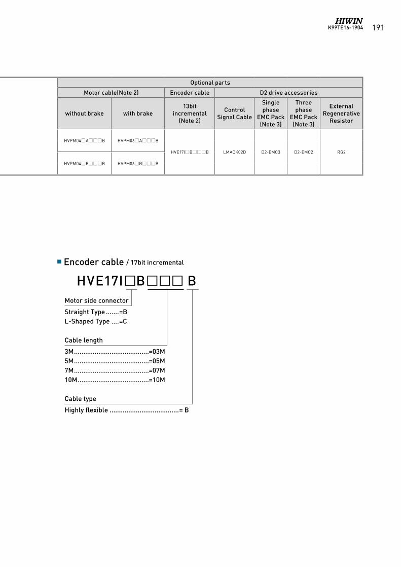
K99TE16-1904 191
Motor Drive
Power capacity(Rated load)
Optional parts
Motor Series Power supply Output(W)
Part No.(Note 1)
Part No.(Standard interface) Frame
Motor cable(Note 2) Encoder cable D2 drive accessories
without brake with brake13bit
incremental(Note 2)
Control Signal Cable
Single phase
EMC Pack(Note 3)
Three phase
EMC Pack(Note 3)
External Regenerative
Resistor
Middle inertia FRMM
Single phase/ three phase
220V1000
FRMM1K20613ΔD2-1023-S-C4 Frame C Approx.
1.8kVA HVPM04AB HVPM06AB
HVE17IBB LMACK02D D2-EMC3 D2-EMC2 RG2FRMM1K2B613Δ
three phase220V 2000
FRMM2K20613ΔD2-2032-S-D4 Frame D Approx.
3.5kVA HVPM04BB HVPM06BBFRMM2K2B613Δ
Encoder cable / 17bit incremental
Motor side connector
Straight Type .......=BL-Shaped Type ....=C
Cable length
3M ........................................=03M5M ........................................=05M7M ........................................=07M10M ......................................=10M
Cable type
Highly flexible .....................................= B
HVE17IB B
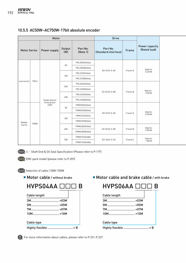
K99TE16-1904192
10.5.5 AC50W~AC750W-17bit absolute encoder
Motor Drive
Power capacity(Rated load)
Optional parts
Motor Series Power supply Output(W)
Part No.(Note 1)
Part No.(Standard interface) Frame
Motor cable(Note 2) Encoder cable D2 drive accessories
without brake with brake13bit
incremental(Note 2)
Control Signal Cable
Single phase
EMC Pack(Note 3)
Three phase
EMC Pack(Note 3)
External Regenerative
Resistor
Low inertia FRLS
Single phase/ three phase
220V
50FRLS05204A4∆
D2-0123-S-A5 Frame A Approx.0.4KVA
HVPS04AAB HVPS06AAB HVE17AABB LMACK02D
D2-EMC1
D2-EMC2
N/AFRLS052B4A4∆
100FRLS10204A4∆
FRLS102B4A4∆
200FRLS2020406∆
D2-0423-S-B5 Frame B Approx.0.9kVA RG1
FRLS202B406∆
400FRLS4020406∆
FRLS402B406∆
Middle inertia FRMS
50FRMS0520404∆
D2-0123-S-A5 Frame A Approx.0.4KVA
D2-EMC3 RG2
FRMS052B404∆
100FRMS1020404∆
FRMS102B404∆
400FRMS4B20406∆
D2-0423-S-B5 Frame B Approx.0.9KVA
FRMS4B2B406∆
750FRMS7520408∆
D2-1023-S-C5 Frame C Approx.1.8KVA
FRMS752B408∆
Cable length
3M ................................ =03M5M ................................ =05M7M ................................ =07M10M .............................. =10M
Cable type
Highly flexible ............................. = B
HVPS04AA BCable length
3M ................................ =03M5M ................................ =05M7M ................................ =07M10M .............................. =10M
Cable type
Highly flexible ............................. = B
HVPS06AA B
Δ:Shaft End & Oil Seal Specification (Please refer to P.177)Note1
Note3 EMC pack model (please refer to P.207)
Note2 Selection of cable / 50W~750W
Motor cable / without brake Motor cable and brake cable / with brake
For more information about cables, please refer to P.221-P.227
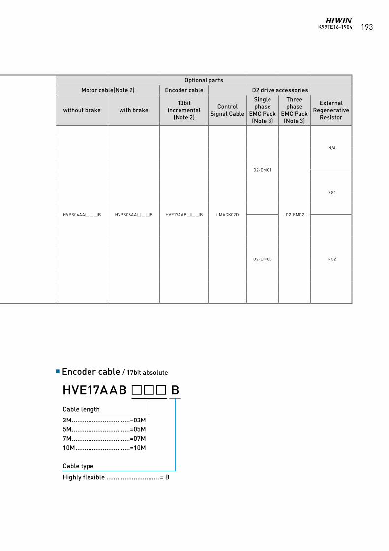
K99TE16-1904 193
Motor Drive
Power capacity(Rated load)
Optional parts
Motor Series Power supply Output(W)
Part No.(Note 1)
Part No.(Standard interface) Frame
Motor cable(Note 2) Encoder cable D2 drive accessories
without brake with brake13bit
incremental(Note 2)
Control Signal Cable
Single phase
EMC Pack(Note 3)
Three phase
EMC Pack(Note 3)
External Regenerative
Resistor
Low inertia FRLS
Single phase/ three phase
220V
50FRLS05204A4∆
D2-0123-S-A5 Frame A Approx.0.4KVA
HVPS04AAB HVPS06AAB HVE17AABB LMACK02D
D2-EMC1
D2-EMC2
N/AFRLS052B4A4∆
100FRLS10204A4∆
FRLS102B4A4∆
200FRLS2020406∆
D2-0423-S-B5 Frame B Approx.0.9kVA RG1
FRLS202B406∆
400FRLS4020406∆
FRLS402B406∆
Middle inertia FRMS
50FRMS0520404∆
D2-0123-S-A5 Frame A Approx.0.4KVA
D2-EMC3 RG2
FRMS052B404∆
100FRMS1020404∆
FRMS102B404∆
400FRMS4B20406∆
D2-0423-S-B5 Frame B Approx.0.9KVA
FRMS4B2B406∆
750FRMS7520408∆
D2-1023-S-C5 Frame C Approx.1.8KVA
FRMS752B408∆
Encoder cable / 17bit absolute
Cable length
3M ................................=03M5M ................................=05M7M ................................=07M10M ..............................=10M
Cable type
Highly flexible ............................. = B
HVE17AAB B
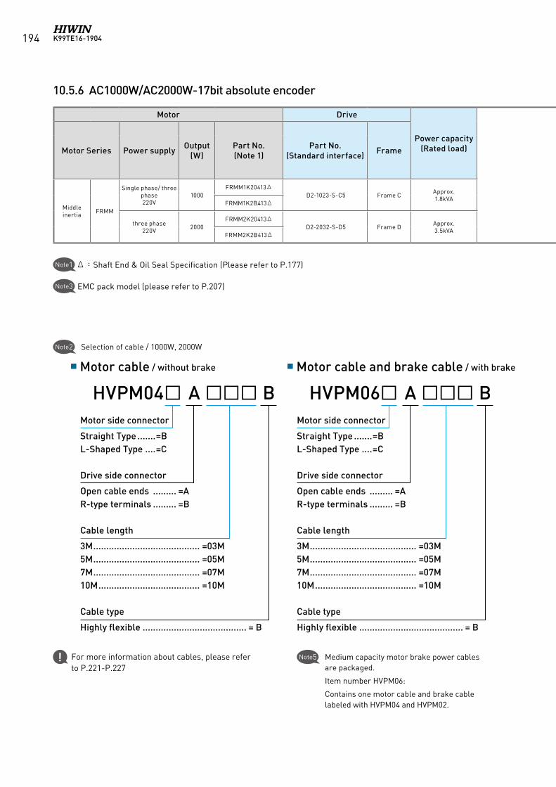
K99TE16-1904194
10.5.6 AC1000W/AC2000W-17bit absolute encoder
Motor Drive
Power capacity(Rated load)
Optional parts
Motor Series Power supply Output(W)
Part No.(Note 1)
Part No.(Standard interface) Frame
Motor cable(Note 2) Encoder cable D2 drive accessories
without brake with brake13bit
incremental(Note 2)
Control Signal Cable
Single phase
EMC Pack(Note 3)
Three phase
EMC Pack(Note 3)
External Regenerative
Resistor
Middle inertia FRMM
Single phase/ three phase220V
1000FRMM1K20413Δ
D2-1023-S-C5 Frame C Approx.1.8kVA HVPM04AB HVPM06AB
HVE17ABB LMACK02D D2-EMC3 D2-EMC2 RG2FRMM1K2B413Δ
three phase220V 2000
FRMM2K20413ΔD2-2032-S-D5 Frame D Approx.
3.5kVA HVPM04BB HVPM06BBFRMM2K2B413Δ
Δ:Shaft End & Oil Seal Specification (Please refer to P.177)Note1
Note3 EMC pack model (please refer to P.207)
Note2 Selection of cable / 1000W, 2000W
Motor cable / without brake Motor cable and brake cable / with brake
Note5 Medium capacity motor brake power cables are packaged.
Item number HVPM06:
Contains one motor cable and brake cable labeled with HVPM04 and HVPM02.
For more information about cables, please refer to P.221-P.227
Motor side connector
Straight Type .......=BL-Shaped Type ....=C
Drive side connector
Open cable ends ......... =AR-type terminals ......... =B
Cable length
3M ......................................... =03M5M ......................................... =05M7M ......................................... =07M10M ....................................... =10M
Cable type
Highly flexible ........................................ = B
HVPM04 A BMotor side connector
Straight Type .......=BL-Shaped Type ....=C
Drive side connector
Open cable ends ......... =AR-type terminals ......... =B
Cable length
3M ......................................... =03M5M ......................................... =05M7M ......................................... =07M10M ....................................... =10M
Cable type
Highly flexible ........................................ = B
HVPM06 A B
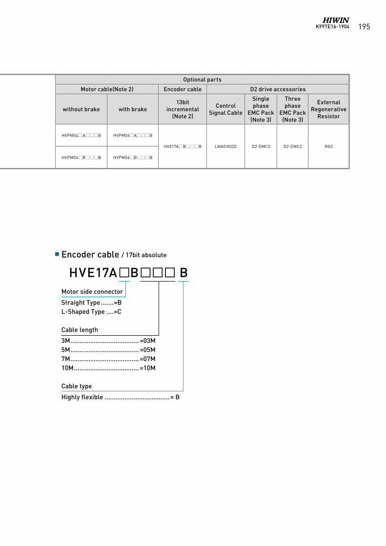
K99TE16-1904 195
Motor Drive
Power capacity(Rated load)
Optional parts
Motor Series Power supply Output(W)
Part No.(Note 1)
Part No.(Standard interface) Frame
Motor cable(Note 2) Encoder cable D2 drive accessories
without brake with brake13bit
incremental(Note 2)
Control Signal Cable
Single phase
EMC Pack(Note 3)
Three phase
EMC Pack(Note 3)
External Regenerative
Resistor
Middle inertia FRMM
Single phase/ three phase220V
1000FRMM1K20413Δ
D2-1023-S-C5 Frame C Approx.1.8kVA HVPM04AB HVPM06AB
HVE17ABB LMACK02D D2-EMC3 D2-EMC2 RG2FRMM1K2B413Δ
three phase220V 2000
FRMM2K20413ΔD2-2032-S-D5 Frame D Approx.
3.5kVA HVPM04BB HVPM06BBFRMM2K2B413Δ
Encoder cable / 17bit absolute
Motor side connector
Straight Type .......=BL-Shaped Type ....=C
Cable length
3M ...................................... =03M5M ...................................... =05M7M ...................................... =07M10M .................................... =10M
Cable type
Highly flexible .................................... = B
HVE17AB B
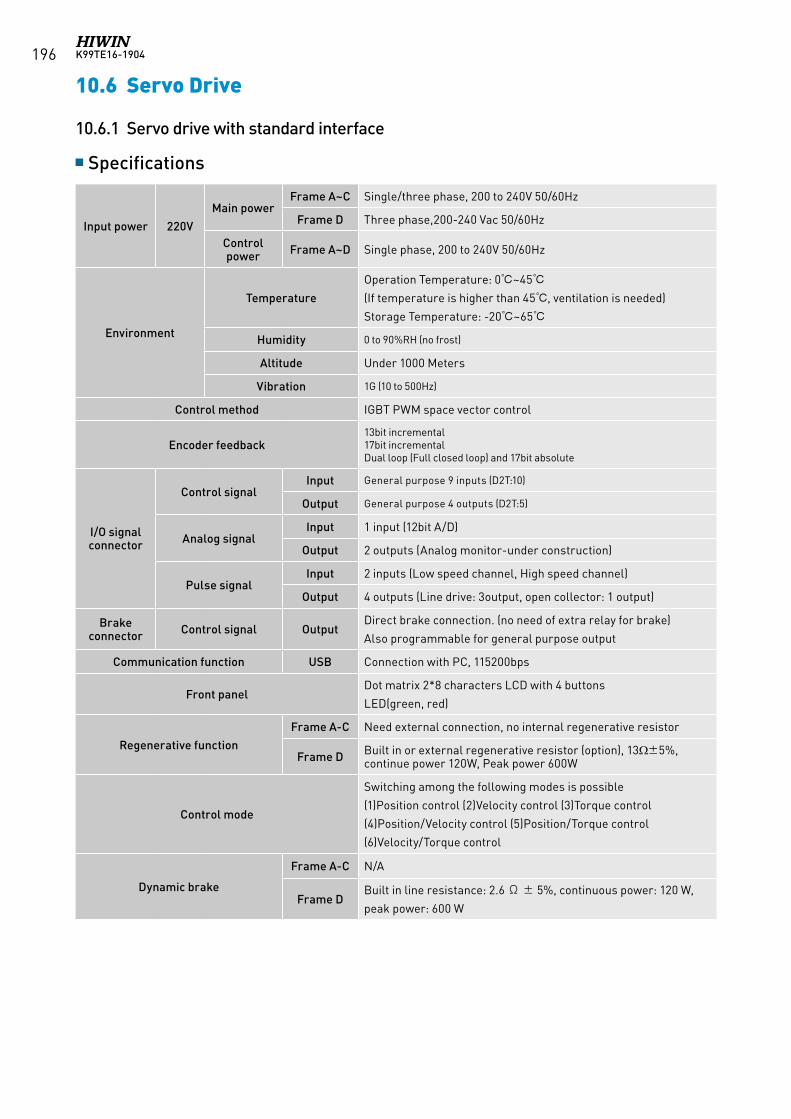
K99TE16-1904196
10.6 Servo Drive
Input power 220V
Main powerFrame A~C Single/three phase, 200 to 240V 50/60Hz
Frame D Three phase,200-240 Vac 50/60Hz
Control power Frame A~D Single phase, 200 to 240V 50/60Hz
Environment
Temperature
Operation Temperature: 0~45
(If temperature is higher than 45, ventilation is needed)
Storage Temperature: -20~65
Humidity 0 to 90%RH (no frost)
Altitude Under 1000 Meters
Vibration 1G (10 to 500Hz)
Control method IGBT PWM space vector control
Encoder feedback13bit incremental17bit incrementalDual loop (Full closed loop) and 17bit absolute
I/O signal connector
Control signalInput General purpose 9 inputs (D2T:10)
Output General purpose 4 outputs (D2T:5)
Analog signalInput 1 input (12bit A/D)
Output 2 outputs (Analog monitor-under construction)
Pulse signalInput 2 inputs (Low speed channel, High speed channel)
Output 4 outputs (Line drive: 3output, open collector: 1 output)
Brake connector Control signal Output
Direct brake connection. (no need of extra relay for brake)
Also programmable for general purpose output
Communication function USB Connection with PC, 115200bps
Front panelDot matrix 2*8 characters LCD with 4 buttons
LED(green, red)
Regenerative function
Frame A-C Need external connection, no internal regenerative resistor
Frame D Built in or external regenerative resistor (option), 13Ω±5%, continue power 120W, Peak power 600W
Control mode
Switching among the following modes is possible
(1)Position control (2)Velocity control (3)Torque control
(4)Position/Velocity control (5)Position/Torque control
(6)Velocity/Torque control
Dynamic brake
Frame A-C N/A
Frame DBuilt in line resistance: 2.6 Ω ± 5%, continuous power: 120 W,
peak power: 600 W
Specifications
10.6.1 Servo drive with standard interface
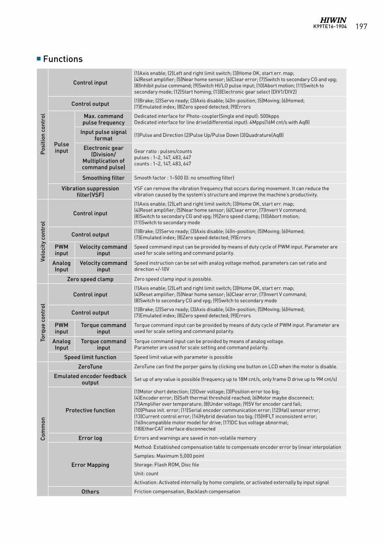
K99TE16-1904 197
Functions
Pos
itio
n co
ntro
l
Control input
(1)Axis enable; (2)Left and right limit switch; (3)Home OK, start err. map; (4)Reset amplifier; (5)Near home sensor; (6)Clear error; (7)Switch to secondary CG and vpg; (8)Inhibit pulse command; (9)Switch HI/LO pulse input; (10)Abort motion; (11)Switch to secondary mode; (12)Start homing; (13)Electronic gear select (DIV1/DIV2)
Control output (1)Brake; (2)Servo ready; (3)Axis disable; (4)In-position; (5)Moving; (6)Homed; (7)Emulated index; (8)Zero speed detected; (9)Errors
Pulse input
Max. command pulse frequency
Dedicated interface for Photo-coupler(Single end input): 500kppsDedicated interface for line drive(differential input): 4Mpps(16M cnt/s with AqB)
Input pulse signal format
(1)Pulse and Direction (2)Pulse Up/Pulse Down (3)Quadrature(AqB)
Electronic gear (Division/
Multiplication of command pulse)
Gear ratio : pulses/countspulses : 1~2, 147, 483, 647counts : 1~2, 147, 483, 647
Smoothing filter Smooth factor : 1~500 (0: no smoothing filter)
Vibration suppression filter(VSF)
VSF can remove the vibration frequency that occurs during movement. It can reduce the vibration caused by the system’s structure and improve the machine’s productivity.
Velo
city
con
trol
Control input
(1)Axis enable; (2)Left and right limit switch; (3)Home OK, start err. map;(4)Reset amplifier; (5)Near home sensor; (6)Clear error; (7)Invert V command; (8)Switch to secondary CG and vpg; (9)Zero speed clamp; (10)Abort motion;(11)Switch to secondary mode
Control output (1)Brake; (2)Servo ready; (3)Axis disable; (4)In-position; (5)Moving; (6)Homed;(7)Emulated index; (8)Zero speed detected; (9)Errors
PWM input
Velocity command input
Speed command input can be provided by means of duty cycle of PWM input. Parameter are used for scale setting and command polarity.
Analog Input
Velocity command input
Speed instruction can be set with analog voltage method, parameters can set ratio and direction +/-10V
Zero speed clamp Zero speed clamp input is possible.
Torq
ue c
ontr
ol
Control input(1)Axis enable; (2)Left and right limit switch; (3)Home OK, start err. map;(4)Reset amplifier; (5)Near home sensor; (6)Clear error; (7)Invert V command;(8)Switch to secondary CG and vpg; (9)Switch to secondary mode
Control output (1)Brake; (2)Servo ready; (3)Axis disable; (4)In-position; (5)Moving; (6)Homed;(7)Emulated index; (8)Zero speed detected; (9)Errors
PWM input
Torque command input
Torque command input can be provided by means of duty cycle of PWM input. Parameter are used for scale setting and command polarity.
Analog Input
Torque command input
Torque command input can be provided by means of analog voltage.Parameter are used for scale setting and command polarity.
Speed limit function Speed limit value with parameter is possible
Com
mon
ZeroTune ZeroTune can find the porper gains by clicking one button on LCD when the motor is disable.
Emulated encoder feedback output
Set up of any value is possible (frequency up to 18M cnt/s, only frame D drive up to 9M cnt/s)
Protective function
(1)Motor short detection; (2)Over voltage; (3)Position error too big; (4)Encoder error; (5)Soft thermal threshold reached; (6)Motor maybe disconnect;(7)Amplifier over temperature; (8)Under voltage; (9)5V for encoder card fail;(10)Phase init. error; (11)Serial encoder communication error; (12)Hall sensor error; (13)Current control error; (14)Hybrid deviation too big; (15)HFLT inconsistent error; (16)Incompatible motor model for drive; (17)DC bus voltage abnormal; (18)EtherCAT interface disconnected
Error log Errors and warnings are saved in non-volatile memory
Error Mapping
Method: Established compensation table to compensate encoder error by linear interpolation
Samples: Maximum 5,000 point
Storage: Flash ROM, Disc file
Unit: count
Activation: Activated internally by home complete, or activated externally by input signal
Others Friction compensation, Backlash compensation
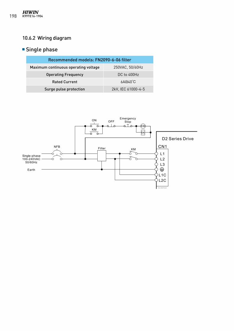
K99TE16-1904198
10.6.2 Wiring diagram
Single phase
Recommended models: FN2090-6-06 filter
Maximum continuous operating voltage 250VAC, 50/60Hz
Operating Frequency DC to 400Hz
Rated Current 6A@40
Surge pulse protection 2kV, IEC 61000-4-5
D2-WNT02A
ON OFF
KM
FilterNFBKM
SK
Single-phase100-240VAC
50/60Hz
Earth
L1L2L3
L1CL2C
CN1
D2 Series Drive
KM
EmergencyStop
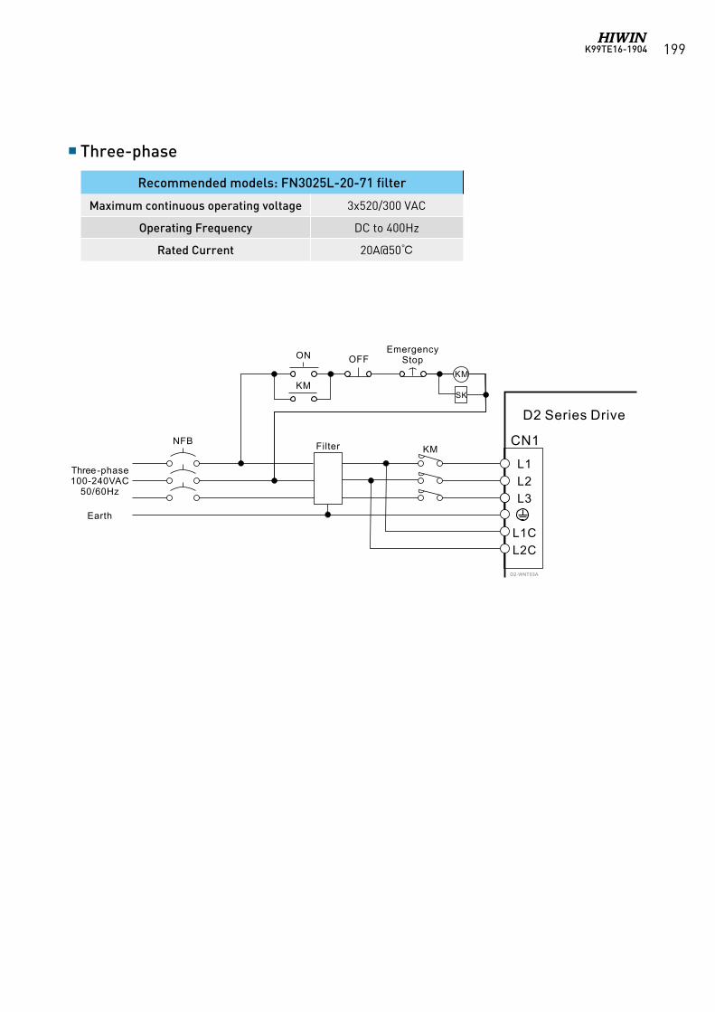
K99TE16-1904 199
Three-phase
Recommended models: FN3025L-20-71 filter
Maximum continuous operating voltage 3x520/300 VAC
Operating Frequency DC to 400Hz
Rated Current 20A@50
D2-WNT03A
ON OFF
KM
FilterNFBKM
SK
Three-phase100-240VAC
50/60Hz
Earth
L1L2L3
L1CL2C
CN1
D2 Series Drive
KM
EmergencyStop
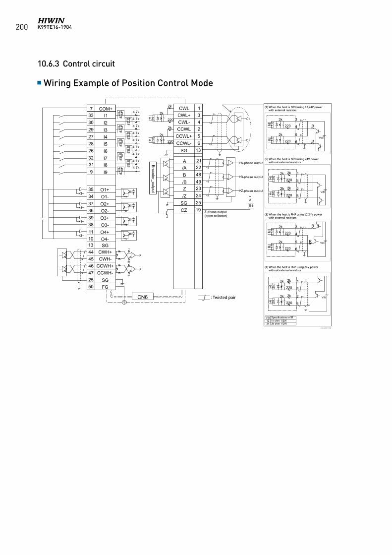
K99TE16-1904200
10.6.3 Control circuit
Wiring Example of Position Control Mode
733302927282632319
3534373639381110
444546472550
19252423
4849
2221
652431
13
COM+I1I2I3I4I5I6I7I8I9
O1+
O2+O1-
O2-O3+O3-O4+O4-SG
CWH+CWH-
CCWH+CCWH-
SGFG
CWLCWL+CWL-CCWL
CCWL+CCWL-
SG
A/AB/BZ/Z
SGCZ
4.7k
2k
CN6
4.7k
4.7k
4.7k
4.7k
4.7k
4.7k
4.7k
4.7k
2k
2k
2k
2k 2k
2k2k
220
220
220
220
13
Encoder_output
(1) When the host is NPN using 12,24V power with external resistors
(2) When the host is NPN using 24V power without external resistors
(3) When the host is PNP using 12,24V power with external resistors
(4) When the host is PNP using 24V power without external resistors
1
4
2
6
Vdc
2k
2k
R
R
220
220
3
4
5
6
Vdc
2k
2k
2k
2k
220
220
1
4
2
6Vdc
2k
2k
R
R
220
220
3
4
5
6Vdc
Vdc1224
Specifications of R1k ohm 1/2W2k ohm 1/2W
A-phase output
B-phase output
Z-phase output
Z-phase output(open collector)
: Twisted pair
D2-ENT17B
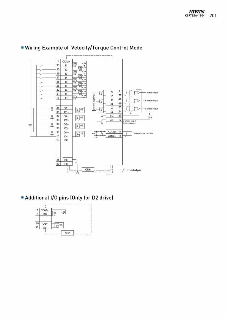
K99TE16-1904 201
Wiring Example of Velocity/Torque Control Mode
Additional I/O pins (Only for D2 drive)
+
-
733302927282632319
3534373639381110
2550
1514
19252423
4849
2221
13
COM+I1I2I3I4I5I6I7I8I9
O1+
O2+O1-
O2-O3+O3-O4+O4-SG
SGFG
A/AB/BZ/Z
SGCZ
ADC0+ADC0-
4.7k
CN6
4.7k
4.7k
4.7k
4.7k
4.7k
4.7k
4.7k
4.7k
Encoder_output
A-phase output
Voltage Iutput (+/-10V)
: Twisted pair
D2-ENT18B
B-phase output
Z-phase output
Z-phase output(open collector)
D2-ENT19A
78
4012
COM+I10
O5+O5-
4.7k
CN6
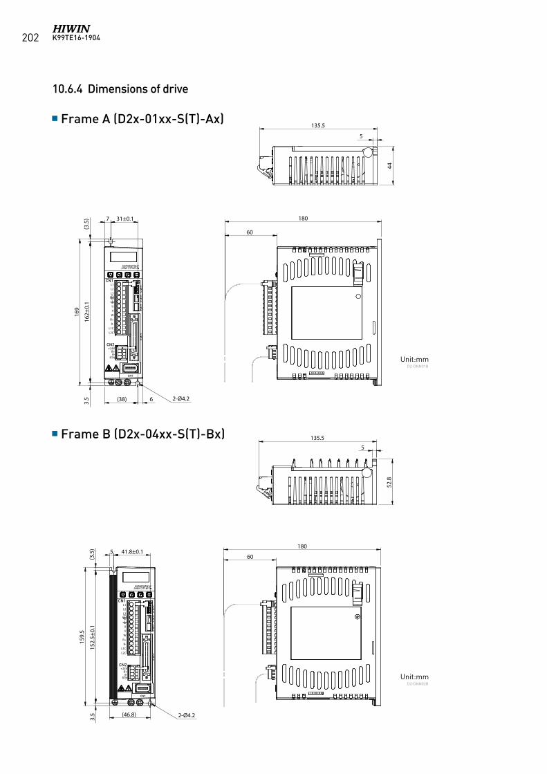
K99TE16-1904202
5
CN1
CN2
CN7
CN5
CN6
CN4
CN3
41.8±0.1180
135.5
5
52.8
60(3.5)
(46.8) 2-Ø4.2
159.5
3.5
152.5±
0.1
L1L2L3
UVWR+R-
L1CL2C
+24VB+B-
RTN
10.6.4 Dimensions of drive
Frame A (D2x-01xx-S(T)-Ax)
Frame B (D2x-04xx-S(T)-Bx)
Unit:mm
Unit:mm
D2-DNN01B
D2-DNN02B
7
CN1
CN2
CN7
CN5
CN6
CN4
CN3
31±0.1 180
135.5
5
44
60
(3.5)
(38) 6 2-Ø4.2
169
3.5
162±
0.1
L1L2L3
UVWR+R-
L1CL2C
+24VB+B-
RTN
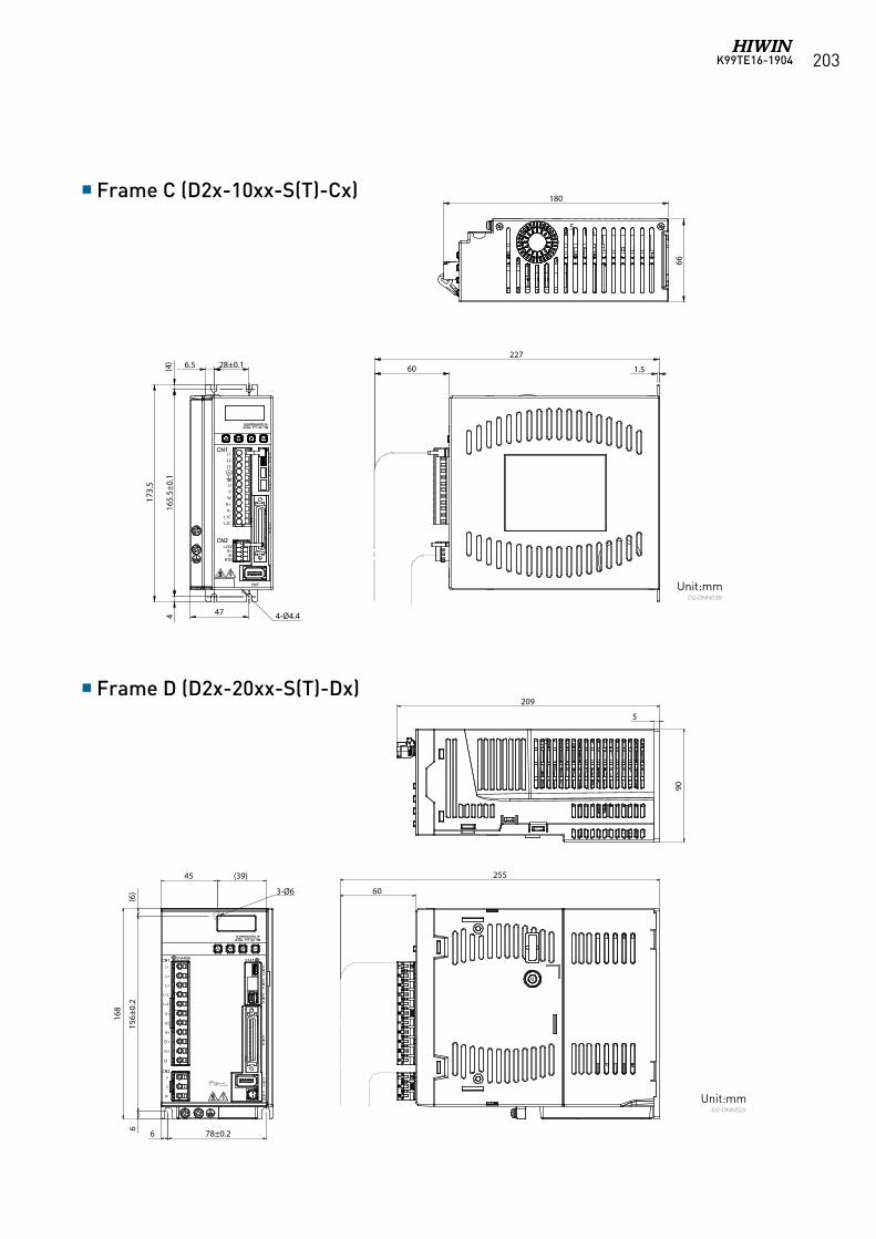
K99TE16-1904 203
Frame C (D2x-10xx-S(T)-Cx)
Frame D (D2x-20xx-S(T)-Dx)
Unit:mm
Unit:mm
D2-DNN03B
D2-DNN52A
6.5
CN1
CN2
CN7
CN5
CN6
CN4
CN3
28±0.1227
1.5
180
5
66
60(4)
47 4-Ø4.4
173.5
416
5.5±
0.1
L1L2L3
UVWR+R-
L1CL2C
+24VB+B-
RTN
45 (39)
CN1 CHARGE STAT
CN2
CN7
CN6
CN15
CN5
CN4
CN3
78±0.2
255
209
5
5
90
60
(6)
6
3-Ø6
168
615
6±0.2
L1
L2
L3
L1C
L2C
B1
B2
B3
1
2
U
V
W
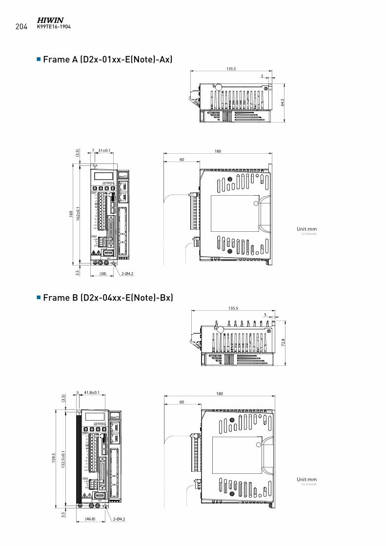
K99TE16-1904204
Frame A (D2x-01xx-E(Note)-Ax)
Frame B (D2x-04xx-E(Note)-Bx)
Unit:mm
Unit:mm
D2-DNN49B
D2-DNN50B
7
CN1
CN2
CN7
CN5
CN6
CN4
CN3
31±0.1 180
135.5
5
64.5
60
(3.5)
(38) 2-Ø4.2
169
3.5
162±
0.1
L1L2L3
UVWR+R-
L1CL2C
+24VB+B-
RTN
5
CN1
CN2
CN7
CN5
CN6
CN4
CN3
41.8±0.1 180
135.55
72.8
60(3.5)
(46.8) 2-Ø4.2
159.5
3.5
152.5±
0.1
L1L2L3
UVWR+R-
L1CL2C
+24VB+B-
RTN
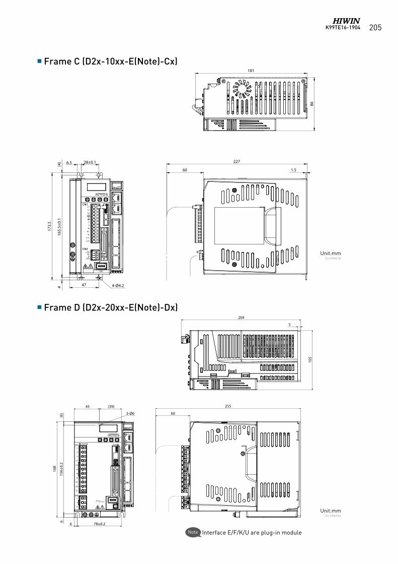
K99TE16-1904 205
45 (39)
CN1 CHARGE STAT
CN2
CN7
CN6
CN15
CN5
CN4
CN3
78±0.2
255
209
5
5
105
60
(6)
6
3-Ø6
168
615
6±0.2
L1
L2
L3
L1C
L2C
B1
B2
B3
1
2
U
V
W
6.5
CN1
CN2
CN7
CN5
CN6
CN4
CN3
28±0.1 227
181
5
86
60 1.5
(4)
47 4-Ø4.2
173.5
416
5.5±
0.1
L1L2L3
UVWR+R-
L1CL2C
+24VB+B-
RTN
Frame C (D2x-10xx-E(Note)-Cx)
Frame D (D2x-20xx-E(Note)-Dx)
Unit:mm
Unit:mm
D2-DNN51B
D2-DNN53A
Interface E/F/K/U are plug-in moduleNote
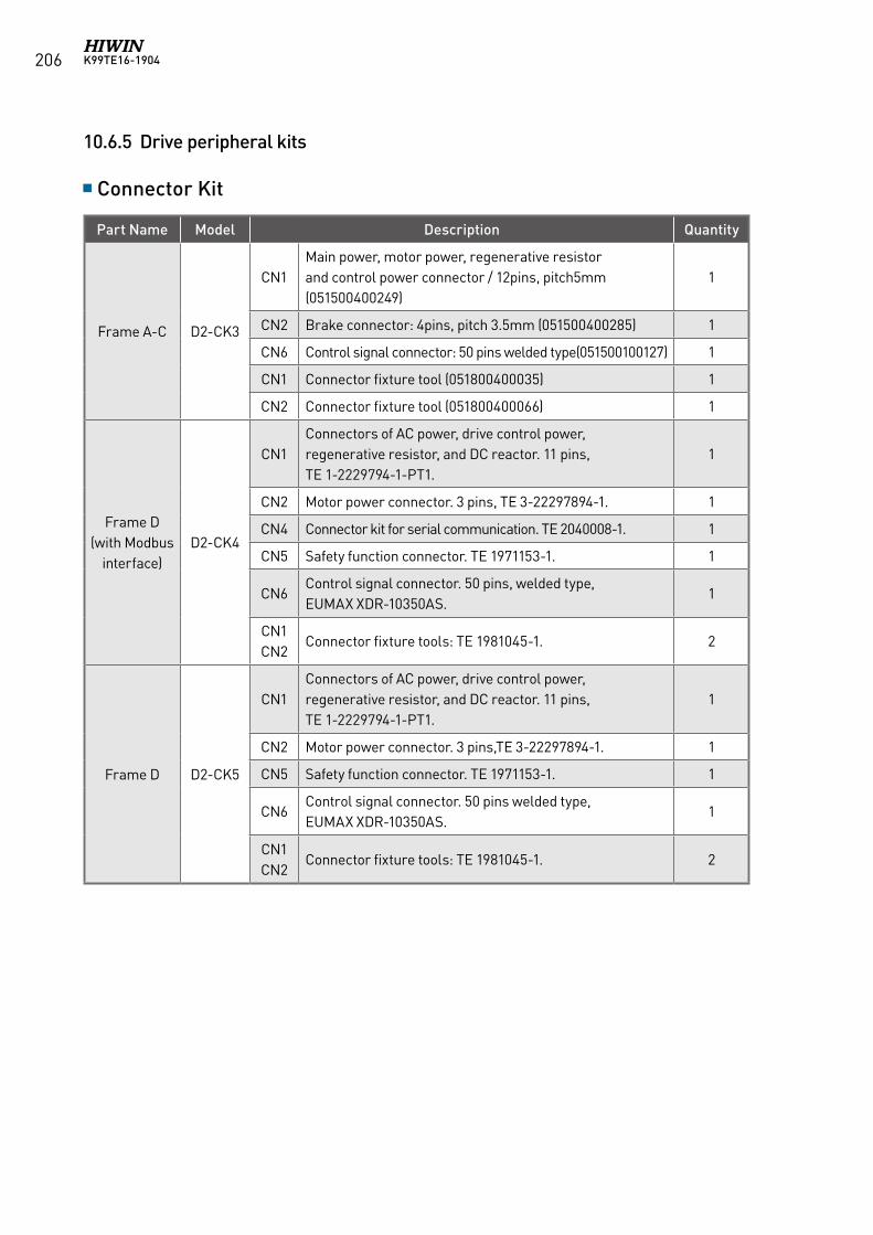
K99TE16-1904206
10.6.5 Drive peripheral kits
Connector Kit
Part Name Model Description Quantity
Frame A-C D2-CK3
CN1Main power, motor power, regenerative resistor and control power connector / 12pins, pitch5mm (051500400249)
1
CN2 Brake connector: 4pins, pitch 3.5mm (051500400285) 1
CN6 Control signal connector: 50 pins welded type(051500100127) 1
CN1 Connector fixture tool (051800400035) 1
CN2 Connector fixture tool (051800400066) 1
Frame D (with Modbus
interface)D2-CK4
CN1Connectors of AC power, drive control power, regenerative resistor, and DC reactor. 11 pins, TE 1-2229794-1-PT1.
1
CN2 Motor power connector. 3 pins, TE 3-22297894-1. 1
CN4 Connector kit for serial communication. TE 2040008-1. 1
CN5 Safety function connector. TE 1971153-1. 1
CN6Control signal connector. 50 pins, welded type, EUMAX XDR-10350AS.
1
CN1CN2
Connector fixture tools: TE 1981045-1. 2
Frame D D2-CK5
CN1Connectors of AC power, drive control power, regenerative resistor, and DC reactor. 11 pins, TE 1-2229794-1-PT1.
1
CN2 Motor power connector. 3 pins,TE 3-22297894-1. 1
CN5 Safety function connector. TE 1971153-1. 1
CN6Control signal connector. 50 pins welded type, EUMAX XDR-10350AS.
1
CN1CN2
Connector fixture tools: TE 1981045-1. 2
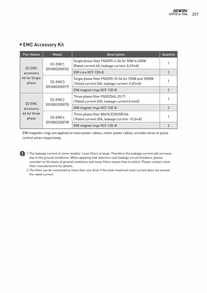
K99TE16-1904 207
EMC Accessory Kit
Part Name Model Description Quantity
D2 EMCaccessory
kit for Single phase
D2-EMC1(051800200074)
Single phase filter FN2090-6-06 for 50W to 400W(Rated current:6A, leakage current: 0.67mA)
1
EMI core KCF-130-B 2
D2-EMC3(051800200077)
Single phase filter FN2090-10-06 for 750W and 1000W( Rated current:10A, leakage current: 0.67mA)
1
EMI magnet rings KCF-130-B 2
D2 EMCaccessory
kit for three phase
D2-EMC2(051800200075)
Three phase filter FN3025HL-20-71( Rated current:20A, leakage current:0.4mA)
1
EMI magnet rings KCF-130-B 2
D2-EMC4(051800200078)
Three phase filter B84743C0035R166( Rated current:35A, leakage current: <0.5mA)
1
EMI magnet rings KCF-130-B 2
1. The leakage current of some models’ noise filters is large. Therefore the leakage current will increase due to the ground conditions. When applying leak detectors and leakage circuit breakers, please consider on the basis of ground conditions and noise filters issues how to select. Please contact noise filter manufacturers for details.
2. The filter can be connected to more than one drive if the total maximum load current does not exceed the rated current.
EMI magnetic rings are applied on main power cables, motor power cables, encoder wires or pulse control wires respectively.
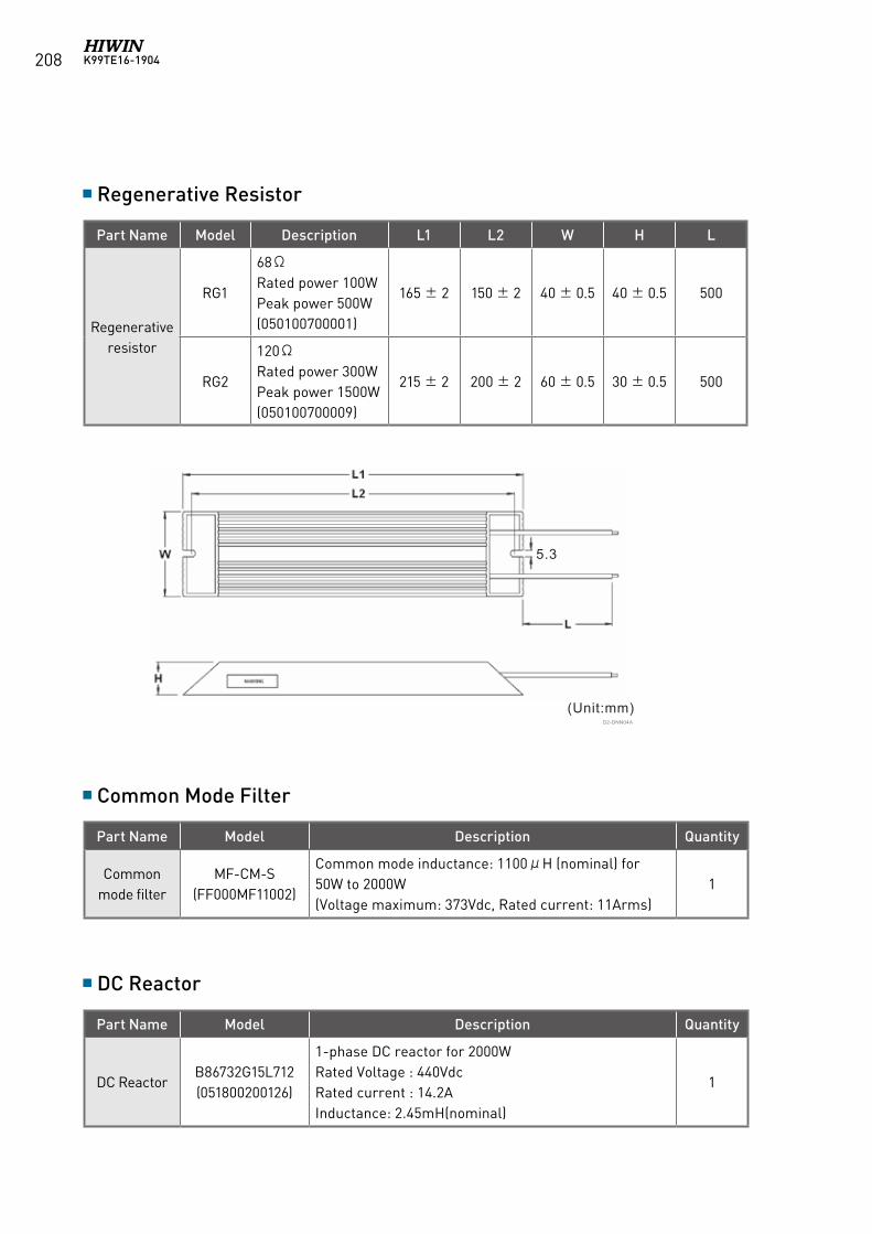
K99TE16-1904208
Regenerative Resistor
Common Mode Filter
DC Reactor
Part Name Model Description L1 L2 W H L
Regenerative resistor
RG1
68ΩRated power 100WPeak power 500W(050100700001)
165 ± 2 150 ± 2 40 ± 0.5 40 ± 0.5 500
RG2
120ΩRated power 300WPeak power 1500W(050100700009)
215 ± 2 200 ± 2 60 ± 0.5 30 ± 0.5 500
Part Name Model Description Quantity
Common mode filter
MF-CM-S(FF000MF11002)
Common mode inductance: 1100μH (nominal) for 50W to 2000W(Voltage maximum: 373Vdc, Rated current: 11Arms)
1
Part Name Model Description Quantity
DC ReactorB86732G15L712(051800200126)
1-phase DC reactor for 2000WRated Voltage : 440VdcRated current : 14.2AInductance: 2.45mH(nominal)
1
D2-DNN04A
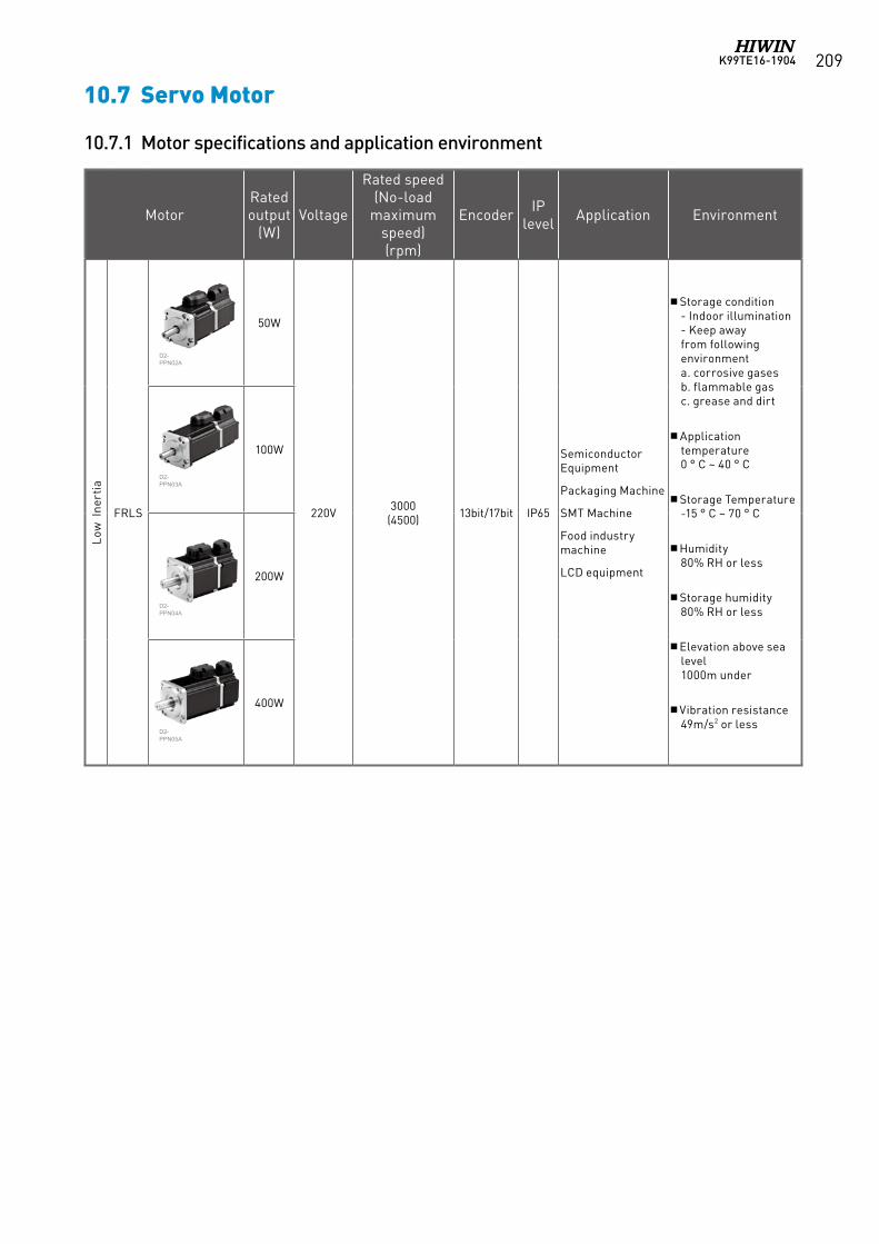
K99TE16-1904 209
10.7 Servo Motor
10.7.1 Motor specifications and application environment
MotorRated output
(W)Voltage
Rated speed (No-load
maximum speed) (rpm)
Encoder IP level Application Environment
Low
Ine
rtia
FRLS
50W
220V 3000(4500) 13bit/17bit IP65
Semiconductor Equipment
Packaging Machine
SMT Machine
Food industry machine
LCD equipment
Storage condition - Indoor illumination - Keep away from following environmenta. corrosive gases b. flammable gas c. grease and dirt
Application temperature0 ° C ~ 40 ° C
Storage Temperature -15 ° C ~ 70 ° C
Humidity 80% RH or less
Storage humidity 80% RH or less
Elevation above sea level 1000m under
Vibration resistance 49m/s2 or less
100W
200W
400W
D2-PPN02A
D2-PPN03A
D2-PPN04A
D2-PPN05A
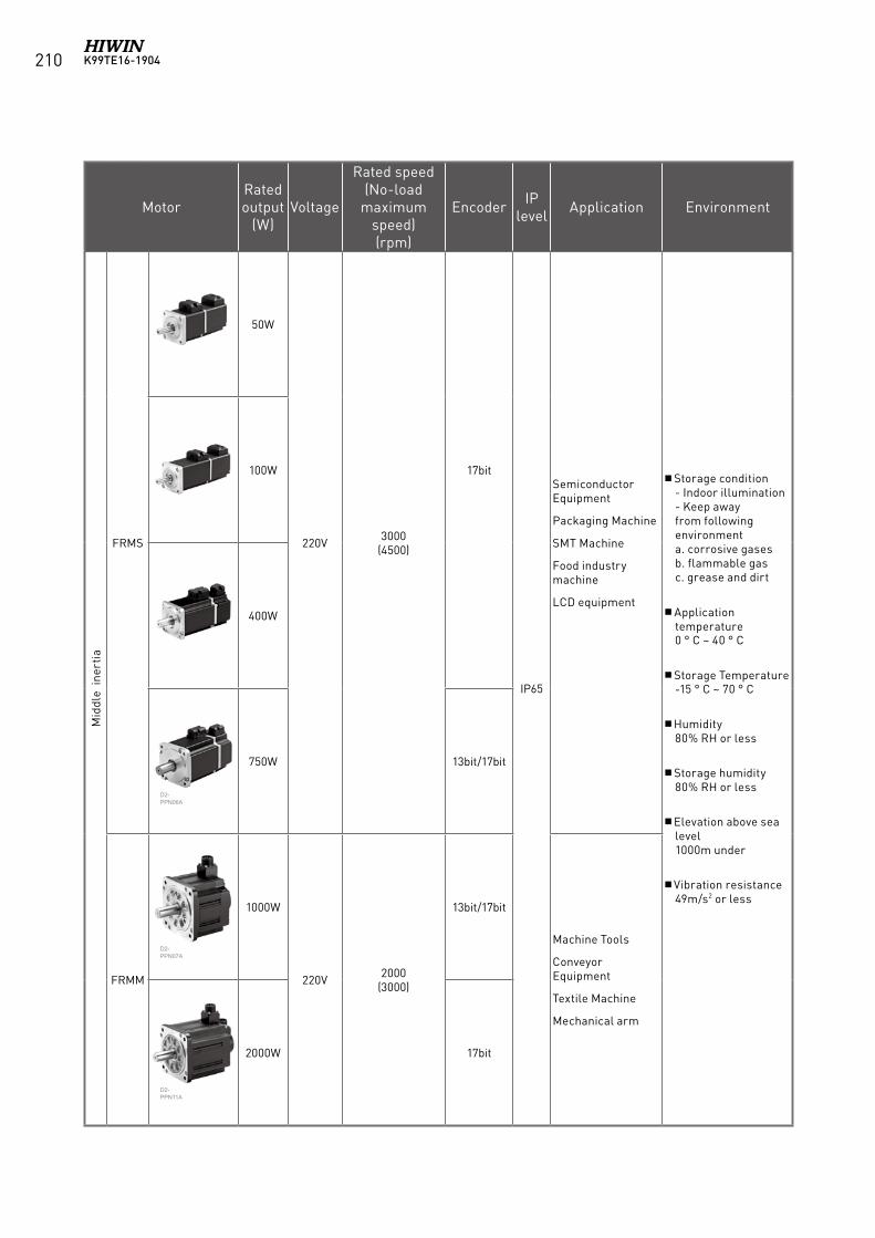
K99TE16-1904210
MotorRated output
(W)Voltage
Rated speed (No-load
maximum speed) (rpm)
Encoder IP level Application Environment
Mid
dle
iner
tia
FRMS
50W
220V 3000(4500)
17bit
IP65
Semiconductor Equipment
Packaging Machine
SMT Machine
Food industry machine
LCD equipment
Storage condition - Indoor illumination - Keep away from following environmenta. corrosive gases b. flammable gas c. grease and dirt
Application temperature0 ° C ~ 40 ° C
Storage Temperature -15 ° C ~ 70 ° C
Humidity 80% RH or less
Storage humidity 80% RH or less
Elevation above sea level 1000m under
Vibration resistance 49m/s2 or less
100W
400W
750W 13bit/17bit
FRMM
1000W
220V 2000(3000)
13bit/17bit
Machine Tools
Conveyor Equipment
Textile Machine
Mechanical arm
2000W 17bit
D2-PPN06A
D2-PPN07A
D2-PPN11A
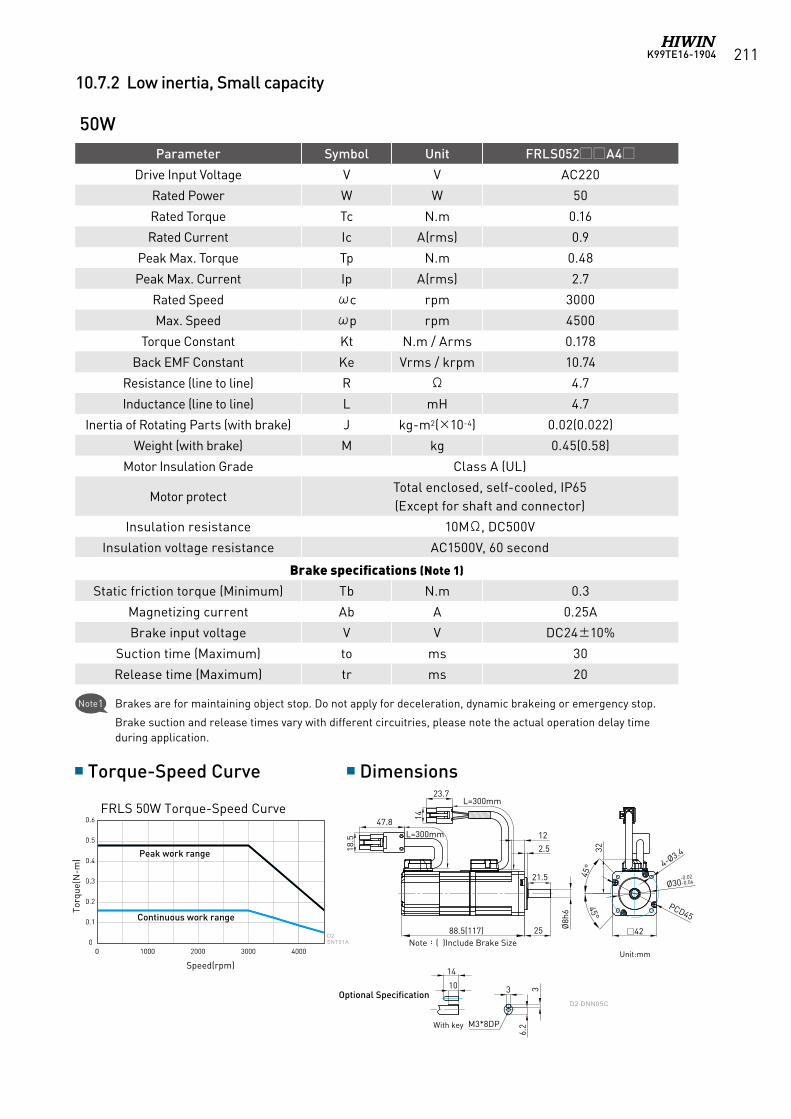
K99TE16-1904 211
10.7.2 Low inertia, Small capacity
Parameter Symbol Unit FRLS052A4
Drive Input Voltage V V AC220
Rated Power W W 50
Rated Torque Tc N.m 0.16
Rated Current Ic A(rms) 0.9
Peak Max. Torque Tp N.m 0.48
Peak Max. Current Ip A(rms) 2.7
Rated Speed ωc rpm 3000
Max. Speed ωp rpm 4500
Torque Constant Kt N.m / Arms 0.178
Back EMF Constant Ke Vrms / krpm 10.74
Resistance (line to line) R Ω 4.7
Inductance (line to line) L mH 4.7
Inertia of Rotating Parts (with brake) J kg-m2(×10-4) 0.02(0.022)
Weight (with brake) M kg 0.45(0.58)
Motor Insulation Grade Class A (UL)
Motor protectTotal enclosed, self-cooled, IP65(Except for shaft and connector)
Insulation resistance 10MΩ, DC500V
Insulation voltage resistance AC1500V, 60 second
Brake specifications (Note 1)
Static friction torque (Minimum) Tb N.m 0.3
Magnetizing current Ab A 0.25A
Brake input voltage V V DC24±10%
Suction time (Maximum) to ms 30
Release time (Maximum) tr ms 20
50W
Torque-Speed Curve Dimensions
D2-SNT01A
L=300mm
L=300mm23.7
14
25
2.5
Ø8h
6
PCD45
42
4-Ø3.4
Ø30-0.02-0.04
32
14
10 3 36.
2
88.5(117)註:( )內為含煞車器之尺寸
45°
45°
12
47.8
18.5
M3*8DP
21.5
(選配規格)
帶鍵
D2-DNN05C
FRLS 50W Torque-Speed Curve
Unit:mm
Note1 Brakes are for maintaining object stop. Do not apply for deceleration, dynamic brakeing or emergency stop.
Brake suction and release times vary with different circuitries, please note the actual operation delay time during application.
Optional Specification
With key
Torq
ue(N
-m)
Speed(rpm)
Note:( )Include Brake Size
Peak work range
Continuous work range
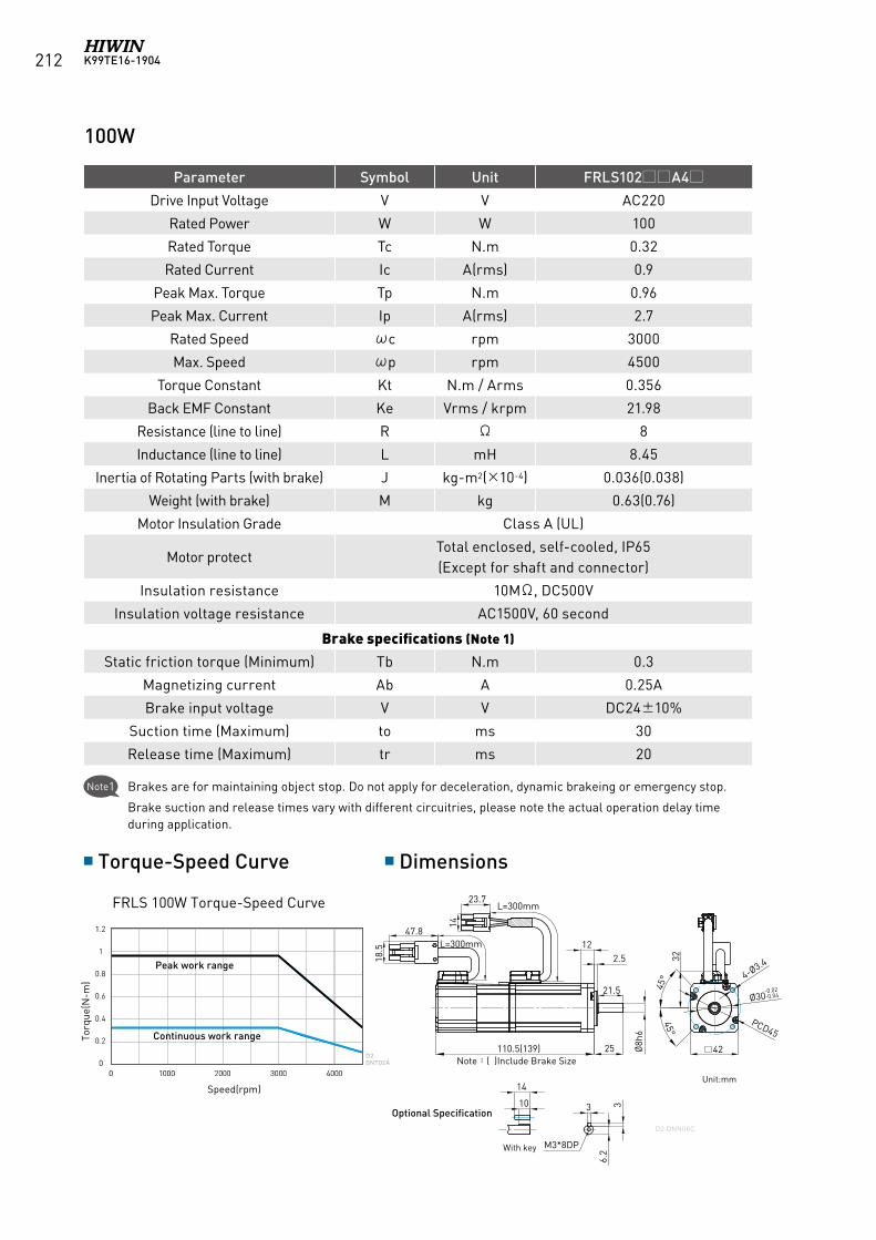
K99TE16-1904212
Parameter Symbol Unit FRLS102A4
Drive Input Voltage V V AC220
Rated Power W W 100
Rated Torque Tc N.m 0.32
Rated Current Ic A(rms) 0.9
Peak Max. Torque Tp N.m 0.96
Peak Max. Current Ip A(rms) 2.7
Rated Speed ωc rpm 3000
Max. Speed ωp rpm 4500
Torque Constant Kt N.m / Arms 0.356
Back EMF Constant Ke Vrms / krpm 21.98
Resistance (line to line) R Ω 8
Inductance (line to line) L mH 8.45
Inertia of Rotating Parts (with brake) J kg-m2(×10-4) 0.036(0.038)
Weight (with brake) M kg 0.63(0.76)
Motor Insulation Grade Class A (UL)
Motor protectTotal enclosed, self-cooled, IP65(Except for shaft and connector)
Insulation resistance 10MΩ, DC500V
Insulation voltage resistance AC1500V, 60 second
Brake specifications (Note 1)
Static friction torque (Minimum) Tb N.m 0.3
Magnetizing current Ab A 0.25A
Brake input voltage V V DC24±10%
Suction time (Maximum) to ms 30
Release time (Maximum) tr ms 20
100W
Torque-Speed Curve Dimensions
FRLS 100W Torque-Speed Curve
D2-SNT02A
L=300mm
L=300mm23.7
14
25
2.5
Ø8h
6
PCD45
42
4-Ø3.4
Ø30-0.02-0.04
32
14
10 3 36.
2
110.5(139)
45°
45°
1247.8
18.5
M3*8DP
註:( )內為含煞車器之尺寸
21.5
(選配規格)
帶鍵
D2-DNN06C
Unit:mm
With key
Optional Specification
Torq
ue(N
-m)
Speed(rpm)
Note:( )Include Brake Size
Peak work range
Continuous work range
Note1 Brakes are for maintaining object stop. Do not apply for deceleration, dynamic brakeing or emergency stop.
Brake suction and release times vary with different circuitries, please note the actual operation delay time during application.
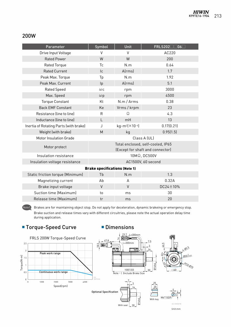
K99TE16-1904 213
Parameter Symbol Unit FRLS20206
Drive Input Voltage V V AC220
Rated Power W W 200
Rated Torque Tc N.m 0.64
Rated Current Ic A(rms) 1.7
Peak Max. Torque Tp N.m 1.92
Peak Max. Current Ip A(rms) 5.1
Rated Speed ωc rpm 3000
Max. Speed ωp rpm 4500
Torque Constant Kt N.m / Arms 0.38
Back EMF Constant Ke Vrms / krpm 23
Resistance (line to line) R Ω 4.3
Inductance (line to line) L mH 13
Inertia of Rotating Parts (with brake) J kg-m2(×10-4) 0.17(0.21)
Weight (with brake) M kg 0.95(1.5)
Motor Insulation Grade Class A (UL)
Motor protectTotal enclosed, self-cooled, IP65(Except for shaft and connector)
Insulation resistance 10MΩ, DC500V
Insulation voltage resistance AC1500V, 60 second
Brake specifications (Note 1)
Static friction torque (Minimum) Tb N.m 1.3
Magnetizing current Ab A 0.32A
Brake input voltage V V DC24±10%
Suction time (Maximum) to ms 30
Release time (Maximum) tr ms 20
Torque-Speed Curve Dimensions
FRLS 200W Torque-Speed Curve
D2-SNT03A
60
PCD Ø70
Ø50 0-0.025
4-Ø5.5
45°
45°
46.5
47.8 14
18.5 L=300mm
23.7 L=300mm
Ø14
h6
30
3
7.5
2520
5
115
M4*15DP
100(133)
Ø14
h6
30
37
26
註:( )內為含煞車器之尺寸
26
D2-DNN07B
(選配規格)
帶鍵
含油封Unit:mm
200W
Optional Specification
Note:( )Include Brake Size
Torq
ue(N
-m)
Speed(rpm)
Peak work range
Continuous work range
With key
With seal
Note1 Brakes are for maintaining object stop. Do not apply for deceleration, dynamic brakeing or emergency stop.
Brake suction and release times vary with different circuitries, please note the actual operation delay time during application.
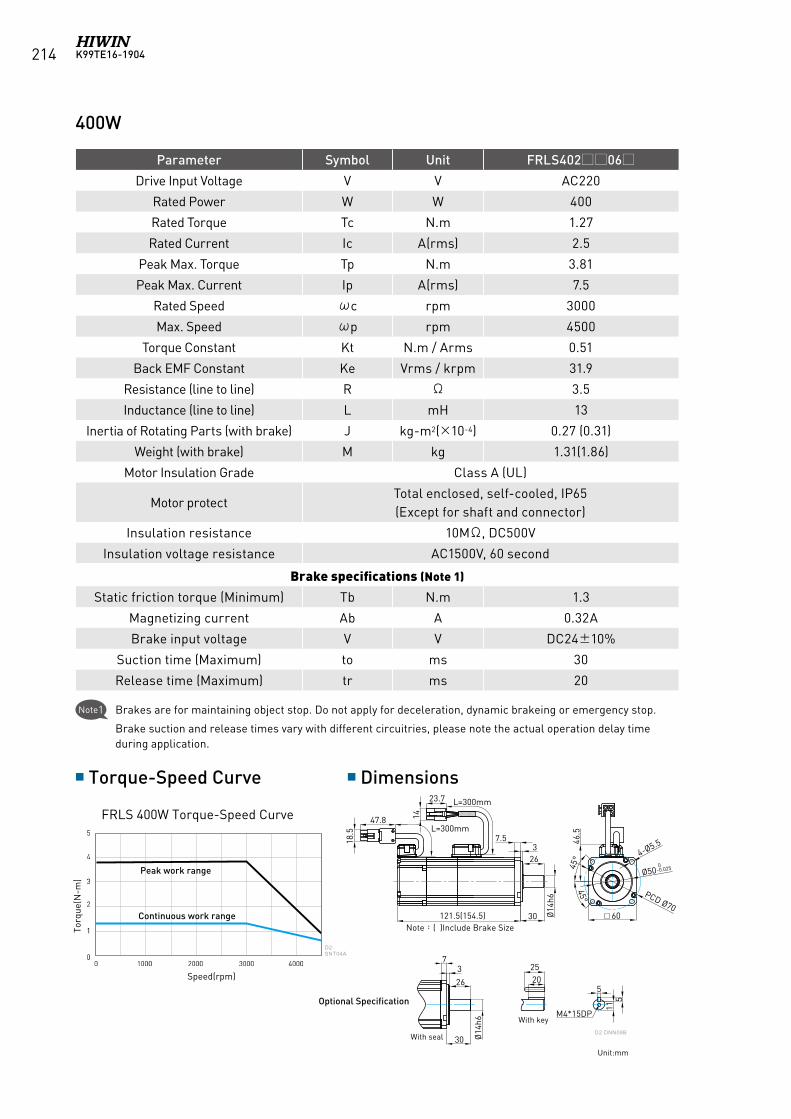
K99TE16-1904214
Parameter Symbol Unit FRLS40206
Drive Input Voltage V V AC220
Rated Power W W 400
Rated Torque Tc N.m 1.27
Rated Current Ic A(rms) 2.5
Peak Max. Torque Tp N.m 3.81
Peak Max. Current Ip A(rms) 7.5
Rated Speed ωc rpm 3000
Max. Speed ωp rpm 4500
Torque Constant Kt N.m / Arms 0.51
Back EMF Constant Ke Vrms / krpm 31.9
Resistance (line to line) R Ω 3.5
Inductance (line to line) L mH 13
Inertia of Rotating Parts (with brake) J kg-m2(×10-4) 0.27 (0.31)
Weight (with brake) M kg 1.31(1.86)
Motor Insulation Grade Class A (UL)
Motor protectTotal enclosed, self-cooled, IP65(Except for shaft and connector)
Insulation resistance 10MΩ, DC500V
Insulation voltage resistance AC1500V, 60 second
Brake specifications (Note 1)
Static friction torque (Minimum) Tb N.m 1.3
Magnetizing current Ab A 0.32A
Brake input voltage V V DC24±10%
Suction time (Maximum) to ms 30
Release time (Maximum) tr ms 20
Torque-Speed Curve Dimensions
FRLS 400W Torque-Speed Curve
D2-SNT04A
60
PCD Ø70
Ø50 0-0.025
4-Ø5.5
45°
45°
46.5
47.8 14
18.5 L=300mm
23.7 L=300mm
Ø14
h6
30
2520
5
115
M4*15DP
37.5
121.5(154.5)
Ø14
h6
30
37
26
註:( )內為含煞車器之尺寸
26
(選配規格)帶鍵
含油封D2-DNN08B
Unit:mm
400W
Optional Specification
Note:( )Include Brake Size Torq
ue(N
-m)
Speed(rpm)
Peak work range
Continuous work range
With key
With seal
Note1 Brakes are for maintaining object stop. Do not apply for deceleration, dynamic brakeing or emergency stop.
Brake suction and release times vary with different circuitries, please note the actual operation delay time during application.
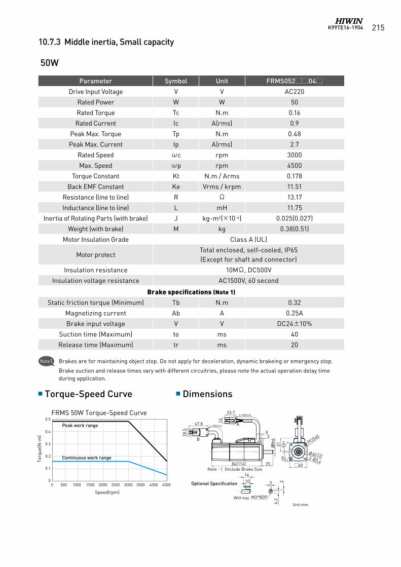
K99TE16-1904 215
10.7.3 Middle inertia, Small capacity
50W
1410 3 3
6.2M3*8DP
60
PCD Ø70
Ø50 0-0.025
4-Ø5.5
45°
45°
46.5
47.8 14
18.5 L=300mm
23.7L=300mm
Ø14
h6
30
37.5
121.5(154.5)
26
400W(Middle Inertia)
50W(Middle Inertia)
100W(Middle Inertia)
1410 3 3
6.2M3*8DP
2520
5
115
M4*15DP
Ø14h
6
30
37
26
40
31 45°
45°
Ø30 -0.02-0.04
PCD45
2-Ø3.4104(134) 25
Ø8h
6
63
L=300mm
L=300mm
14
23.7
A47.8
18.5
B
84(114) 25
Ø8h6
63
40
31 45°
45°
Ø30 -0.02-0.04
PCD45
2-Ø3.4
L=300mm
L=300mm
14
23.7
A47.8
18.5
B
Parameter Symbol Unit FRMS05204
Drive Input Voltage V V AC220
Rated Power W W 50
Rated Torque Tc N.m 0.16
Rated Current Ic A(rms) 0.9
Peak Max. Torque Tp N.m 0.48
Peak Max. Current Ip A(rms) 2.7
Rated Speed ωc rpm 3000
Max. Speed ωp rpm 4500
Torque Constant Kt N.m / Arms 0.178
Back EMF Constant Ke Vrms / krpm 11.51
Resistance (line to line) R Ω 13.17
Inductance (line to line) L mH 11.75
Inertia of Rotating Parts (with brake) J kg-m2(×10-4) 0.025(0.027)
Weight (with brake) M kg 0.38(0.51)
Motor Insulation Grade Class A (UL)
Motor protectTotal enclosed, self-cooled, IP65(Except for shaft and connector)
Insulation resistance 10MΩ, DC500V
Insulation voltage resistance AC1500V, 60 second
Brake specifications (Note 1)
Static friction torque (Minimum) Tb N.m 0.32
Magnetizing current Ab A 0.25A
Brake input voltage V V DC24±10%
Suction time (Maximum) to ms 40
Release time (Maximum) tr ms 20
Torque-Speed Curve Dimensions
FRMS 50W Torque-Speed Curve
0.1
00 500 1000
0.2
0.3
0.4
0.5
1500 2000 2500 3000 3500 4000 4500
0 500 1000 1500 2000 2500 3000 3500 4000 4500
0 500 1000 1500 2000 2500 3000 3500 4000 4500
0.2
0
0.4
0.6
0.8
1.0
400W(Middle Inertia)
50W(Middle Inertia)
100W(Middle Inertia)
0
4.0
3.0
2.0
1.0
Unit:mm
Optional Specification
Note:( )Include Brake Size
Torq
ue(N
-m)
Speed(rpm)
Peak work range
Continuous work range
With key
Note1 Brakes are for maintaining object stop. Do not apply for deceleration, dynamic brakeing or emergency stop.
Brake suction and release times vary with different circuitries, please note the actual operation delay time during application.
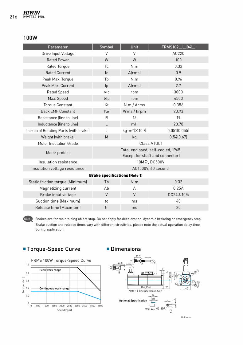
K99TE16-1904216
0.1
00 500 1000
0.2
0.3
0.4
0.5
1500 2000 2500 3000 3500 4000 4500
0 500 1000 1500 2000 2500 3000 3500 4000 4500
0 500 1000 1500 2000 2500 3000 3500 4000 4500
0.2
0
0.4
0.6
0.8
1.0
400W(Middle Inertia)
50W(Middle Inertia)
100W(Middle Inertia)
0
4.0
3.0
2.0
1.0
1410 3 3
6.2M3*8DP
60
PCD Ø70
Ø50 0-0.025
4-Ø5.5
45°
45°
46.5
47.8 14
18.5 L=300mm
23.7L=300mm
Ø14
h6
30
37.5
121.5(154.5)
26
400W(Middle Inertia)
50W(Middle Inertia)
100W(Middle Inertia)
1410 3 3
6.2M3*8DP
2520
5
115
M4*15DP
Ø14h
6
30
37
26
40
31 45°
45°
Ø30 -0.02-0.04
PCD45
2-Ø3.4104(134) 25
Ø8h
6
63
L=300mm
L=300mm
14
23.7
A47.8
18.5
B
84(114) 25
Ø8h6
63
40
31 45°
45°
Ø30 -0.02-0.04
PCD45
2-Ø3.4
L=300mm
L=300mm
14
23.7
A47.8
18.5
B
Parameter Symbol Unit FRMS10204
Drive Input Voltage V V AC220
Rated Power W W 100
Rated Torque Tc N.m 0.32
Rated Current Ic A(rms) 0.9
Peak Max. Torque Tp N.m 0.96
Peak Max. Current Ip A(rms) 2.7
Rated Speed ωc rpm 3000
Max. Speed ωp rpm 4500
Torque Constant Kt N.m / Arms 0.356
Back EMF Constant Ke Vrms / krpm 20.93
Resistance (line to line) R Ω 19
Inductance (line to line) L mH 23.78
Inertia of Rotating Parts (with brake) J kg-m2(×10-4) 0.051(0.055)
Weight (with brake) M kg 0.54(0.67)
Motor Insulation Grade Class A (UL)
Motor protectTotal enclosed, self-cooled, IP65(Except for shaft and connector)
Insulation resistance 10MΩ, DC500V
Insulation voltage resistance AC1500V, 60 second
Brake specifications (Note 1)
Static friction torque (Minimum) Tb N.m 0.32
Magnetizing current Ab A 0.25A
Brake input voltage V V DC24±10%
Suction time (Maximum) to ms 40
Release time (Maximum) tr ms 20
Torque-Speed Curve Dimensions
FRMS 100W Torque-Speed Curve
Unit:mm
100W
Optional Specification
Note:( )Include Brake Size Torq
ue(N
-m)
Speed(rpm)
Peak work range
Continuous work range
With key
Note1 Brakes are for maintaining object stop. Do not apply for deceleration, dynamic brakeing or emergency stop.
Brake suction and release times vary with different circuitries, please note the actual operation delay time during application.
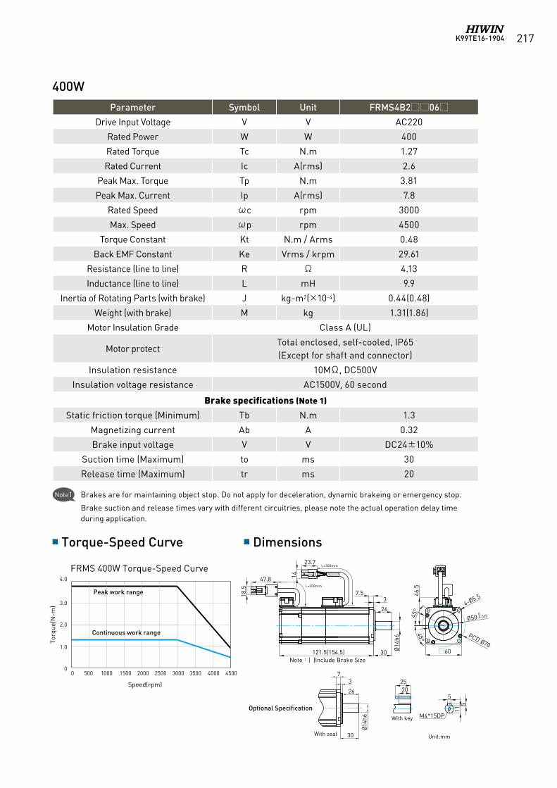
K99TE16-1904 217
400W
0.1
00 500 1000
0.2
0.3
0.4
0.5
1500 2000 2500 3000 3500 4000 4500
0 500 1000 1500 2000 2500 3000 3500 4000 4500
0 500 1000 1500 2000 2500 3000 3500 4000 4500
0.2
0
0.4
0.6
0.8
1.0
400W(Middle Inertia)
50W(Middle Inertia)
100W(Middle Inertia)
0
4.0
3.0
2.0
1.0
1410 3 3
6.2M3*8DP
60
PCD Ø70
Ø50 0-0.025
4-Ø5.5
45°
45°
46.5
47.8 14
18.5 L=300mm
23.7L=300mm
Ø14
h6
30
37.5
121.5(154.5)
26
400W(Middle Inertia)
50W(Middle Inertia)
100W(Middle Inertia)
1410 3 3
6.2M3*8DP
2520
5
115
M4*15DP
Ø14h
6
30
37
26
40
31 45°
45°
Ø30 -0.02-0.04
PCD45
2-Ø3.4104(134) 25
Ø8h
6
63
L=300mm
L=300mm
14
23.7
A47.8
18.5
B
84(114) 25
Ø8h6
63
40
31 45°
45°
Ø30 -0.02-0.04
PCD45
2-Ø3.4
L=300mm
L=300mm
14
23.7
A47.8
18.5
B
Parameter Symbol Unit FRMS4B206
Drive Input Voltage V V AC220
Rated Power W W 400
Rated Torque Tc N.m 1.27
Rated Current Ic A(rms) 2.6
Peak Max. Torque Tp N.m 3.81
Peak Max. Current Ip A(rms) 7.8
Rated Speed ωc rpm 3000
Max. Speed ωp rpm 4500
Torque Constant Kt N.m / Arms 0.48
Back EMF Constant Ke Vrms / krpm 29.61
Resistance (line to line) R Ω 4.13
Inductance (line to line) L mH 9.9
Inertia of Rotating Parts (with brake) J kg-m2(×10-4) 0.44(0.48)
Weight (with brake) M kg 1.31(1.86)
Motor Insulation Grade Class A (UL)
Motor protectTotal enclosed, self-cooled, IP65(Except for shaft and connector)
Insulation resistance 10MΩ, DC500V
Insulation voltage resistance AC1500V, 60 second
Brake specifications (Note 1)
Static friction torque (Minimum) Tb N.m 1.3
Magnetizing current Ab A 0.32
Brake input voltage V V DC24±10%
Suction time (Maximum) to ms 30
Release time (Maximum) tr ms 20
Torque-Speed Curve Dimensions
FRMS 400W Torque-Speed Curve
Unit:mm
Optional Specification
Note:( )Include Brake Size
Torq
ue(N
-m)
Speed(rpm)
Peak work range
Continuous work range
With key
With seal
Note1 Brakes are for maintaining object stop. Do not apply for deceleration, dynamic brakeing or emergency stop.
Brake suction and release times vary with different circuitries, please note the actual operation delay time during application.
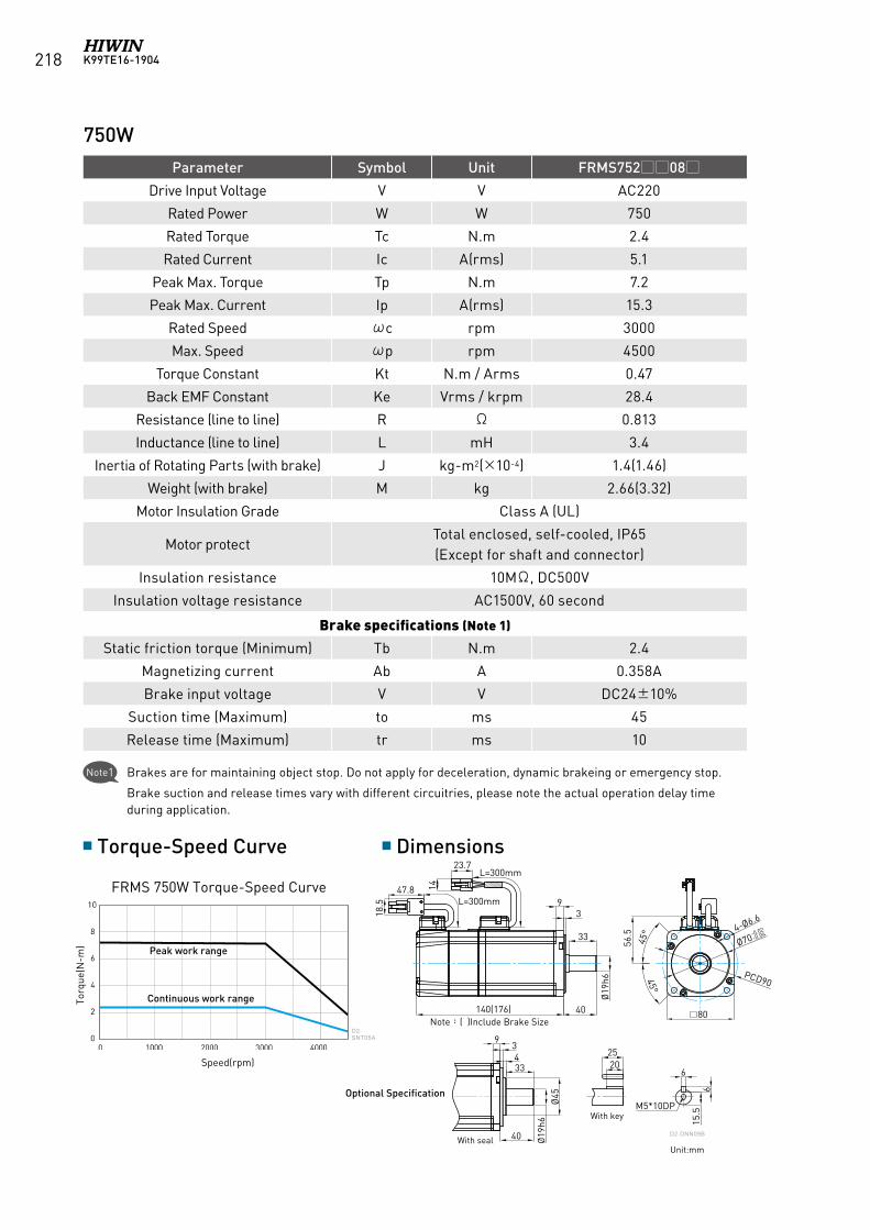
K99TE16-1904218
Parameter Symbol Unit FRMS75208
Drive Input Voltage V V AC220
Rated Power W W 750
Rated Torque Tc N.m 2.4
Rated Current Ic A(rms) 5.1
Peak Max. Torque Tp N.m 7.2
Peak Max. Current Ip A(rms) 15.3
Rated Speed ωc rpm 3000
Max. Speed ωp rpm 4500
Torque Constant Kt N.m / Arms 0.47
Back EMF Constant Ke Vrms / krpm 28.4
Resistance (line to line) R Ω 0.813
Inductance (line to line) L mH 3.4
Inertia of Rotating Parts (with brake) J kg-m2(×10-4) 1.4(1.46)
Weight (with brake) M kg 2.66(3.32)
Motor Insulation Grade Class A (UL)
Motor protectTotal enclosed, self-cooled, IP65(Except for shaft and connector)
Insulation resistance 10MΩ, DC500V
Insulation voltage resistance AC1500V, 60 second
Brake specifications (Note 1)
Static friction torque (Minimum) Tb N.m 2.4
Magnetizing current Ab A 0.358A
Brake input voltage V V DC24±10%
Suction time (Maximum) to ms 45
Release time (Maximum) tr ms 10
Torque-Speed Curve Dimensions
FRMS 750W Torque-Speed Curve
D2-SNT05A
40140(176)
93
Ø19
h6
4-Ø6.6
PCD90
80
56.5
25
6
615
.5
20
23.7
14
L=300mm
L=300mm
Ø70-0.02-0.04
45°
45°
47.8
18.5
M5*10DP
40
93
Ø19
h6
4
註:( )內為含煞車器之尺寸
33
33
Ø45(選配規格)
帶鍵
含油封D2-DNN09B
Unit:mm
750W
Optional Specification
Note:( )Include Brake Size
Torq
ue(N
-m)
Speed(rpm)
Peak work range
Continuous work range
With key
With seal
Note1 Brakes are for maintaining object stop. Do not apply for deceleration, dynamic brakeing or emergency stop.
Brake suction and release times vary with different circuitries, please note the actual operation delay time during application.
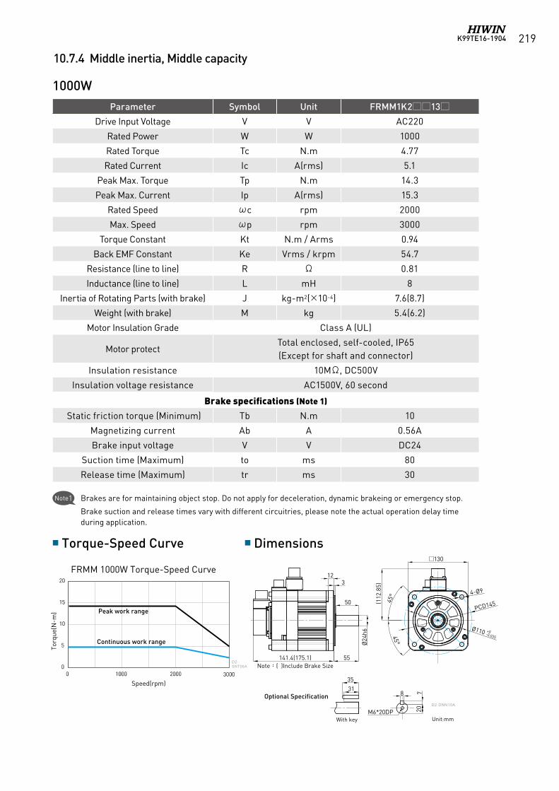
K99TE16-1904 219
Parameter Symbol Unit FRMM1K213
Drive Input Voltage V V AC220
Rated Power W W 1000
Rated Torque Tc N.m 4.77
Rated Current Ic A(rms) 5.1
Peak Max. Torque Tp N.m 14.3
Peak Max. Current Ip A(rms) 15.3
Rated Speed ωc rpm 2000
Max. Speed ωp rpm 3000
Torque Constant Kt N.m / Arms 0.94
Back EMF Constant Ke Vrms / krpm 54.7
Resistance (line to line) R Ω 0.81
Inductance (line to line) L mH 8
Inertia of Rotating Parts (with brake) J kg-m2(×10-4) 7.6(8.7)
Weight (with brake) M kg 5.4(6.2)
Motor Insulation Grade Class A (UL)
Motor protectTotal enclosed, self-cooled, IP65(Except for shaft and connector)
Insulation resistance 10MΩ, DC500V
Insulation voltage resistance AC1500V, 60 second
Brake specifications (Note 1)
Static friction torque (Minimum) Tb N.m 10
Magnetizing current Ab A 0.56A
Brake input voltage V V DC24
Suction time (Maximum) to ms 80
Release time (Maximum) tr ms 30
Torque-Speed Curve Dimensions
FRMM 1000W Torque-Speed Curve
D2-SNT06A
PCD145
4-Ø9
130
45°
45°
(112
.85)
31
35
20
8 7
M6*20DP
Ø110 +0-0.035
Ø24
h6
55141.4(175.1)
312
註:( )內為含煞車器之尺寸
50
(選配規格)
帶鍵
D2-DNN10A
Unit:mm
1000W
Optional Specification
Note:( )Include Brake Size
Torq
ue(N
-m)
Speed(rpm)
Peak work range
Continuous work range
With key
Note1 Brakes are for maintaining object stop. Do not apply for deceleration, dynamic brakeing or emergency stop.
Brake suction and release times vary with different circuitries, please note the actual operation delay time during application.
10.7.4 Middle inertia, Middle capacity
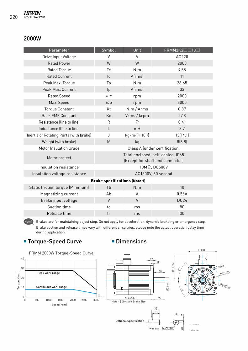
K99TE16-1904220
Parameter Symbol Unit FRMM2K213
Drive Input Voltage V V AC220
Rated Power W W 2000
Rated Torque Tc N.m 9.55
Rated Current Ic A(rms) 11
Peak Max. Torque Tp N.m 28.65
Peak Max. Current Ip A(rms) 33
Rated Speed ωc rpm 2000
Max. Speed ωp rpm 3000
Torque Constant Kt N.m / Arms 0.87
Back EMF Constant Ke Vrms / krpm 57.8
Resistance (line to line) R Ω 0.41
Inductance (line to line) L mH 3.7
Inertia of Rotating Parts (with brake) J kg-m2(×10-4) 13(14.1)
Weight (with brake) M kg 8(8.8)
Motor Insulation Grade Class A (under certification)
Motor protectTotal enclosed, self-cooled, IP65(Except for shaft and connector)
Insulation resistance 10MΩ, DC500V
Insulation voltage resistance AC1500V, 60 second
Brake specifications (Note 1)
Static friction torque (Minimum) Tb N.m 10
Magnetizing current Ab A 0.56A
Brake input voltage V V DC24
Suction time to ms 80
Release time tr ms 30
Torque-Speed Curve Dimensions
FRMM 2000W Torque-Speed Curve
D2-SNT07A
40
30
20
10
0500 1000 1500 2000 2500 3000
PCD145
4-Ø9
130
45°
45°
(112
.85)
Ø110 +0-0.035
Ø24
h6
55171.4(205.1)
312
3135
20
8 7
M6*20DP
註:( )內為含煞車器之尺寸
50
(選配規格)
帶鍵
D2-DNN42A
Unit:mm
2000W
Optional Specification
Note:( )Include Brake Size
Torq
ue(N
-m)
Speed(rpm)
Peak work range
Continuous work range
With key
Note1 Brakes are for maintaining object stop. Do not apply for deceleration, dynamic brakeing or emergency stop.
Brake suction and release times vary with different circuitries, please note the actual operation delay time during application.
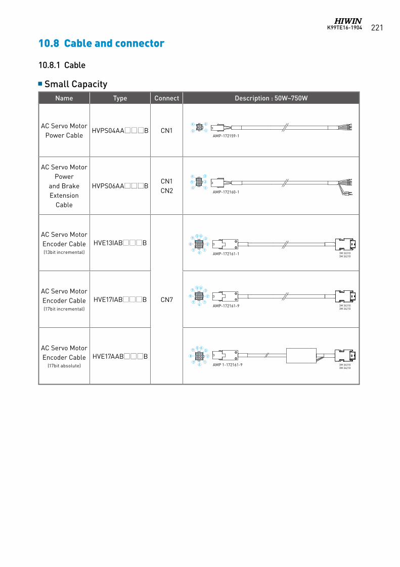
K99TE16-1904 221
10.8 Cable and connector
10.8.1 Cable
Small CapacityName Type Connect Description : 50W~750W
AC Servo MotorPower Cable
HVPS04AAB CN1
AC Servo Motor Power
and Brake Extension
Cable
HVPS06AABCN1CN2
AC Servo MotorEncoder Cable(13bit incremental)
HVE13IABB
CN7AC Servo MotorEncoder Cable(17bit incremental)
HVE17IABB
AC Servo MotorEncoder Cable
(17bit absolute)
HVE17AABB
AMP-172159-1
AMP-172160-1
AMP-172161-1
AMP-172161-9
6
8
3
2
14
59
7
6
5
3
2
14
3
2
1
4
6
8
3
2
14
59
7
6
8
3
2
14
59
7
B+B-
3M 36310 3M 36210
3M 36310 3M 36210
3M 363103M 36210
AMP 1-172161-9
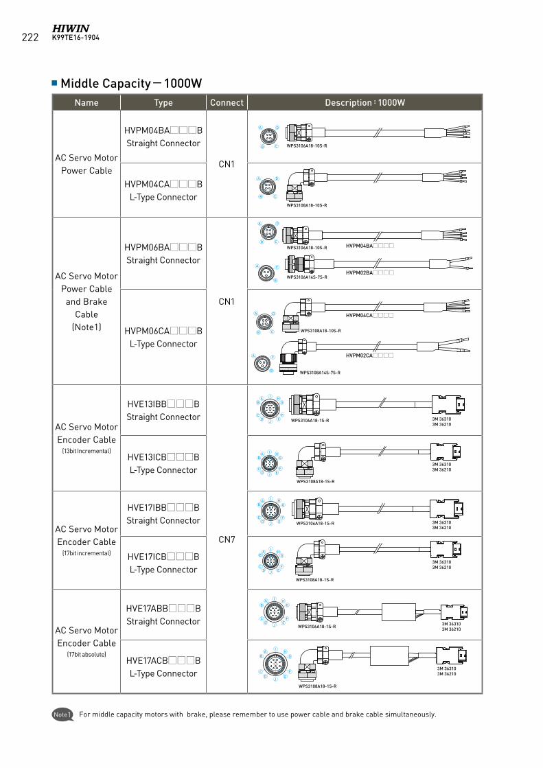
K99TE16-1904222
Middle Capacity-1000WName Type Connect Description:1000W
AC Servo MotorPower Cable
HVPM04BAB Straight Connector
CN1
HVPM04CAB L-Type Connector
AC Servo Motor Power Cable
and Brake Cable
(Note1)
HVPM06BAB Straight Connector
CN1
HVPM06CAB L-Type Connector
AC Servo MotorEncoder Cable
(13bit Incremental)
HVE13IBBB Straight Connector
CN7
HVE13ICBB L-Type Connector
AC Servo MotorEncoder Cable
(17bit incremental)
HVE17IBBB Straight Connector
HVE17ICBB L-Type Connector
AC Servo MotorEncoder Cable
(17bit absolute)
HVE17ABBB Straight Connector
HVE17ACBB L-Type Connector
WPS3108A18-10S-R
WPS3106A18-10S-R
HVPM04BA
HVPM02BA
HVPM04CA
HVPM02CA
WPS3106A18-1S-R
WPS3108A18-1S-R
WPS3106A18-1S-R
WPS3108A18-1S-R
WPS3106A18-10S-R
WPS3106A14S-7S-R
WPS3108A18-10S-R
WPS3108A14S-7S-R
WPS3108A18-1S-R
WPS3106A18-1S-R
18-1S
18-1S
18-1S
18-1S
18-1S
18-1S
A
B C
D
3M 363103M 36210
3M 363103M 36210
3M 363103M 36210
3M 363103M 36210
3M 363103M 36210
3M 363103M 36210
A
B C
D
A
A
A
A
A
AB
A
AB
CD
AB
CD
J EF
GH
I
JE
F
GH
I
AB
CD
JE
F
GH
I
B
CD
JE
F
GHI
CD J
I
EF
GH
B
CD
JE
F
GH
I
B
B
B
B
C
C
C
C
D
D
Note1 For middle capacity motors with brake, please remember to use power cable and brake cable simultaneously.
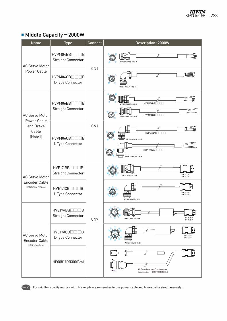
K99TE16-1904 223
WPS3106A18-1S-R
WPS3108A18-1S-R
WPS3108A18-1S-R
WPS3106A18-1S-R
18-1S
18-1S
18-1S
18-1S
A
B C
D
A
B C
D
A
A
A
A
A
AB
AB
CD
JE
F
GH
I
AB
CD
JE
F
GH
I
CD J
I
EF
GH
B
CD
JE
F
GH
I
B
B
B
B
C
C
C
C
D
D
WPS3108A18-10S-R
WPS3106A18-10S-R
HVPM04BB
HVPM02BA
HVPM04CB
HVPM02CA
WPS3106A18-10S-R
WPS3106A14S-7S-R
WPS3108A18-10S-R
WPS3108A14S-7S-R
3M 36310 3M 36210
3M 36310 3M 36210
3M 36310 3M 36210
3M 36310 3M 36210
Middle Capacity-2000WName Type Connect Description:2000W
AC Servo MotorPower Cable
HVPM04BBB Straight Connector
CN1
HVPM04CBB L-Type Connector
AC Servo Motor Power Cable
and Brake Cable
(Note1)
HVPM06BBB Straight Connector
CN1
HVPM06CBB L-Type Connector
AC Servo MotorEncoder Cable
(17bit incremental)
HVE17IBBB Straight Connector
CN7
HVE17ICBB L-Type Connector
AC Servo MotorEncoder Cable
(17bit absolute)
HVE17ABBB Straight Connector
HVE17ACBB L-Type Connector
HE00817DR300(3m)
Note1 For middle capacity motors with brake, please remember to use power cable and brake cable simultaneously.
AC Servo Dual loop Encoder CableSpecification:HE00817DR300(3m)
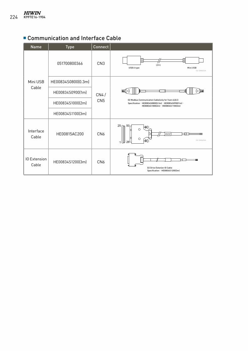
K99TE16-1904224
Communication and Interface CableName Type Connect
Mini USB Cable
051700800366 CN3
HE00834S0800(0.3m)
CN4 / CN5
HE00834S0900(1m)
HE00834S1000(2m)
HE00834S1100(3m)
Interface Cable
HE00815AC200 CN6
IO Extension Cable
HE00834S1200(3m) CN6
LMACK02D815AC2A3
50
26
25
1
Mini USBUSB A type(2m)
1015
0 3
M
D2-DNN25A
D2-DNN26A
LMACK02D815AC2A3
50
26
25
1
Mini USBUSB A type(2m)
1015
0 3
M
D2-DNN25A
D2-DNN26A
LMACK02D815AC2A3
50
26
25
1
Mini USBUSB A type(2m)
1015
0 3
M
D2-DNN25A
D2-DNN26A
LMACK02D815AC2A3
50
26
25
1
Mini USBUSB A type(2m)
1015
0 3
M
D2-DNN25A
D2-DNN26A
D2 Modbus Communication Cable(only for fram A,B,C)
Specification:HE00834S0800(0.3m)、HE00834S0900(1m)、 HE00834S1000(2m)、HE00834S1100(3m)
D2 Drive Extenion IO CableSpecification:HE00834S1200(3m)
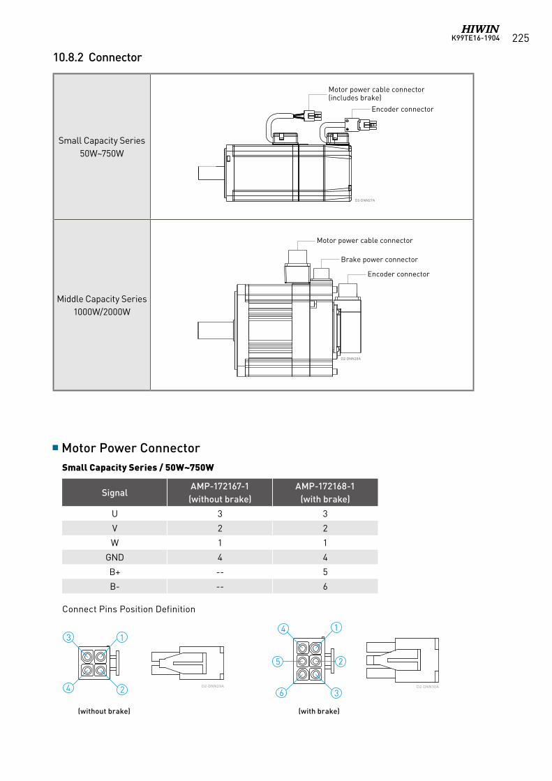
K99TE16-1904 225
10.8.2 Connector
D2-DNN29A D2-DNN30A
Motor Power Connector Small Capacity Series / 50W~750W
SignalAMP-172167-1(without brake)
AMP-172168-1(with brake)
U 3 3
V 2 2
W 1 1
GND 4 4
B+ -- 5
B- -- 6
Connect Pins Position Definition
(without brake) (with brake)
Small Capacity Series50W~750W
Middle Capacity Series1000W/2000W
DD22--DDNNNN2277AA
DD22--DDNNNN2288AA
馬達電源端接頭
煞車電源端接頭
編碼器端接頭
馬達電源端接頭(含煞車)
編碼器端接頭
Motor power cable connector
Brake power connector
Encoder connector
DD22--DDNNNN2277AA
DD22--DDNNNN2288AA
馬達電源端接頭
煞車電源端接頭
編碼器端接頭
馬達電源端接頭(含煞車)
編碼器端接頭
Motor power cable connector(includes brake)
Encoder connector
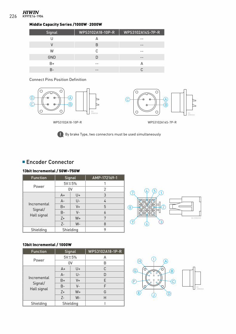
K99TE16-1904226
Middle Capacity Series /1000W‧2000W
Signal WPS3102A18-10P-R WPS3102A14S-7P-R
U A --
V B --
W C --
GND D --
B+ -- A
B- -- C
Connect Pins Position Definition
WPS3102A18-10P-R WPS3102A14S-7P-R
By brake Type, two connectors must be used simultaneously
D2-DNN32A
D2-DNN33A
Encoder Connector
13bit Incremental / 1000W
13bit Incremental / 50W~750W
Function Signal AMP-172169-1
Power5V±5% 1
0V 2
Incremental Signal/
Hall signal
A+ U+ 3A- U- 4B+ V+ 5B- V- 6Z+ W+ 7Z- W- 8
Shielding Shielding 9
Function Signal WPS3102A18-1P-R
Power5V±5% A
0V B
Incremental Signal/
Hall signal
A+ U+ CA- U- DB+ V+ EB- V- FZ+ W+ GZ- W- H
Shielding Shielding I
I AH
I AH
G
F
JE
GF
E J D
CB
D
C
B
D2-DNN33A
D2-DNN34A
D2-DNN35B
D2-DNN36B
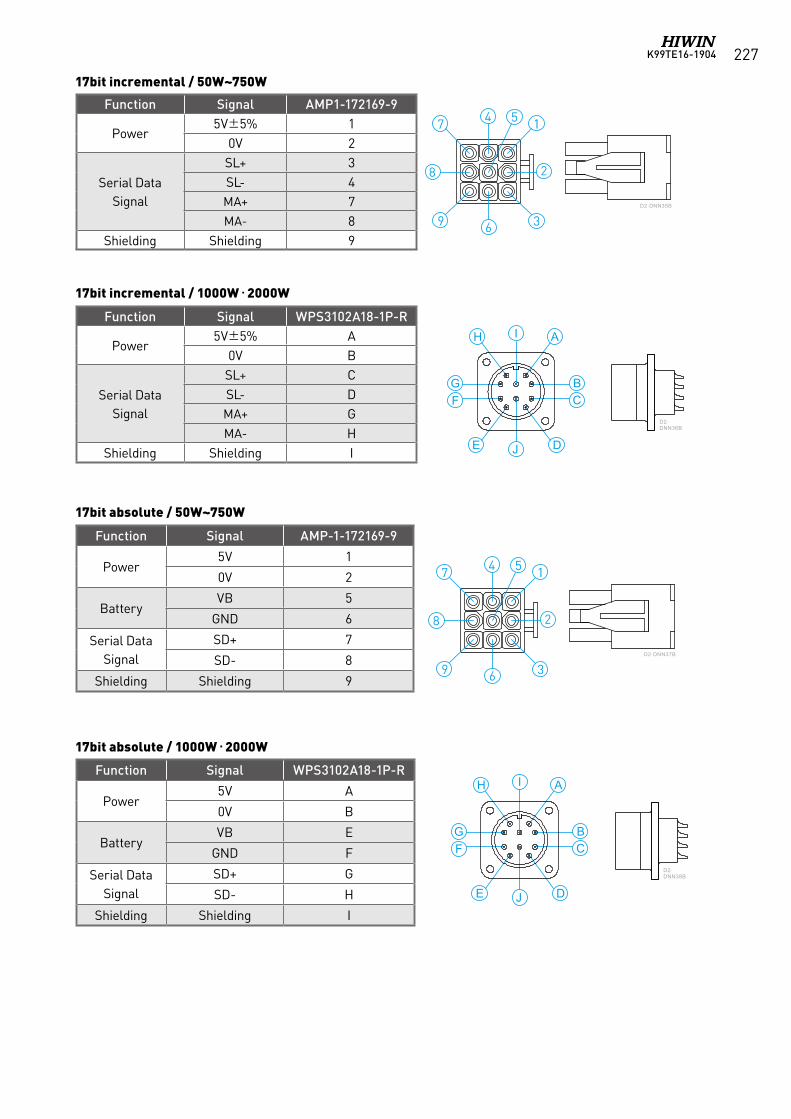
K99TE16-1904 227
Function Signal AMP-1-172169-9
Power5V 1
0V 2
BatteryVB 5
GND 6
Serial Data Signal
SD+ 7
SD- 8
Shielding Shielding 9
Function Signal WPS3102A18-1P-R
Power5V A
0V B
BatteryVB E
GND F
Serial Data Signal
SD+ G
SD- H
Shielding Shielding I
17bit absolute / 50W~750W
17bit absolute / 1000W‧2000W
D2-DNN37B
D2-DNN38B
I AH
GF
E J D
CB
Function Signal AMP1-172169-9
Power5V±5% 1
0V 2
Serial Data Signal
SL+ 3SL- 4MA+ 7MA- 8
Shielding Shielding 9
Function Signal WPS3102A18-1P-R
Power5V±5% A
0V B
Serial Data Signal
SL+ CSL- DMA+ GMA- H
Shielding Shielding I
17bit incremental / 50W~750W
I AH
I AH
G
F
JE
GF
E J D
CB
D
C
B
D2-DNN33A
D2-DNN34A
D2-DNN35B
D2-DNN36B
17bit incremental / 1000W‧2000W
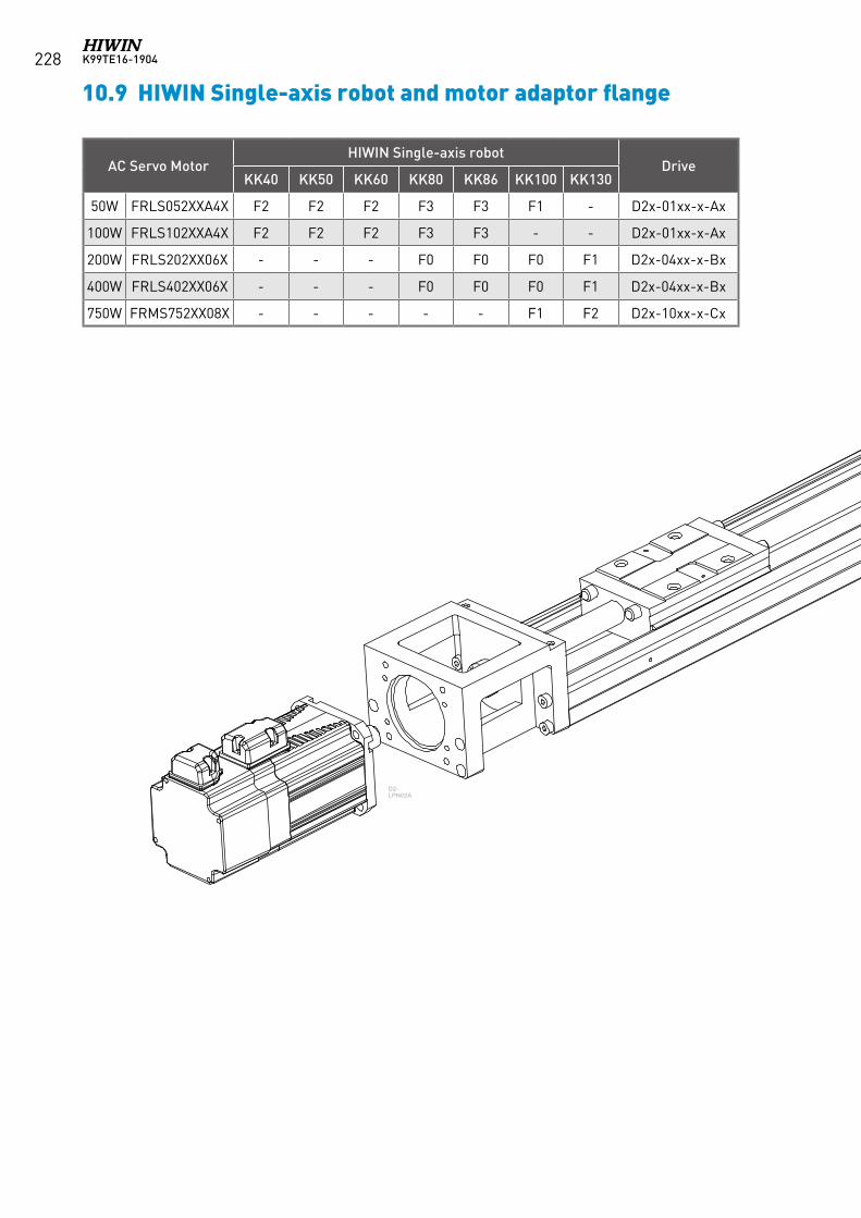
K99TE16-1904228
AC Servo MotorHIWIN Single-axis robot
DriveKK40 KK50 KK60 KK80 KK86 KK100 KK130
50W FRLS052XXA4X F2 F2 F2 F3 F3 F1 - D2x-01xx-x-Ax
100W FRLS102XXA4X F2 F2 F2 F3 F3 - - D2x-01xx-x-Ax
200W FRLS202XX06X - - - F0 F0 F0 F1 D2x-04xx-x-Bx
400W FRLS402XX06X - - - F0 F0 F0 F1 D2x-04xx-x-Bx
750W FRMS752XX08X - - - - - F1 F2 D2x-10xx-x-Cx
D2-LPN02A
10.9 HIWIN Single-axis robot and motor adaptor flange
K99TE16-1904 229
D2-LPN02A
10.10 Servo Motor Selection Guide
The motor selection guide in this chapter is located on-line at http://www.hiwinmikro.tw/hiwincal.aspx
1. Definition of mechanism to be driven by the motor.Define detailed dimentions of individual mechanical components (ex: ball screw length, lead and pulley diameter)Typical servo mechanisms are listed as follows:[Ball screw mechanism][Belt mechanism][Rack and pinion mechanism][Reduction gear mechanism]
2. Definition of operating pattern (motion velocity profile).The operating pattern can be defined by the following parameters: acceleration/deceleration time, constant-velocity time, stop time, cycle time, travel distance.
3. Calculation of load inertia and motor inertia ratio.Calculate load inertia for each mechanical component. (Refer to “General inertia calculation method” described later.)Then, divide the calculated load inertia by the inertia of the selected motor then check the inertia ratio. Note that the ratio should less than 10, if the selected motor is less than 750W. If the power of selected motor is higher than 1000W, the ratio should less than 10.
4. Calculation of motor velocity.Calculate the motor velocity from the moving distance, acceleration/deceleration time and constant-velocity time.
5. Calculation of torque.Calculate the required motor torque from the load inertia, acceleration/deceleration time and constant-velocity time.
6. Calculation of motorSelect a motor that meets the above 3 to 5 requirements.
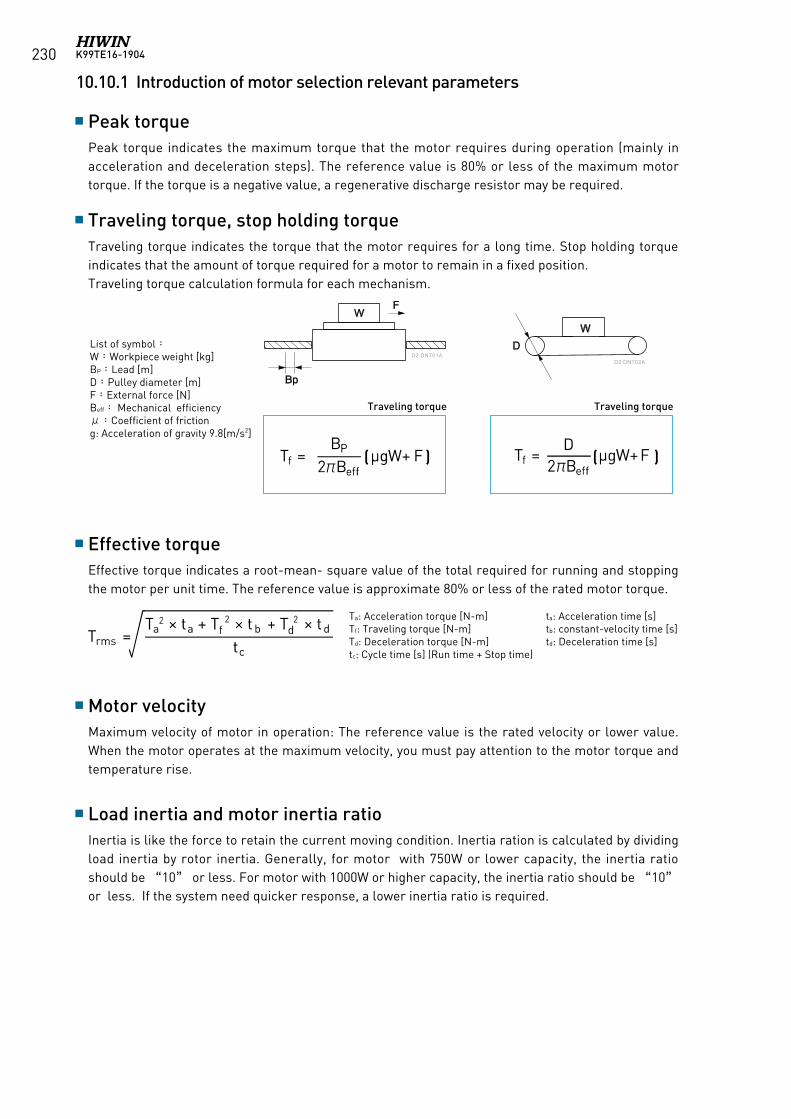
K99TE16-1904230
Peak torque
Traveling torque, stop holding torque
Effective torque
Motor velocity
Load inertia and motor inertia ratio
Peak torque indicates the maximum torque that the motor requires during operation (mainly in acceleration and deceleration steps). The reference value is 80% or less of the maximum motor torque. If the torque is a negative value, a regenerative discharge resistor may be required.
Traveling torque indicates the torque that the motor requires for a long time. Stop holding torque indicates that the amount of torque required for a motor to remain in a fixed position.Traveling torque calculation formula for each mechanism.
Effective torque indicates a root-mean- square value of the total required for running and stopping the motor per unit time. The reference value is approximate 80% or less of the rated motor torque.
Maximum velocity of motor in operation: The reference value is the rated velocity or lower value. When the motor operates at the maximum velocity, you must pay attention to the motor torque and temperature rise.
Inertia is like the force to retain the current moving condition. Inertia ration is calculated by dividing load inertia by rotor inertia. Generally, for motor with 750W or lower capacity, the inertia ratio should be “10” or less. For motor with 1000W or higher capacity, the inertia ratio should be “10” or less. If the system need quicker response, a lower inertia ratio is required.
WD
W
Bp
F
螺桿機構 皮帶機構
移動扭矩 移動扭矩
D2-DNT01AD2-DNT02A
List of symbol:W:Workpiece weight [kg] BP:Lead [m]D:Pulley diameter [m]F:External force [N]Beff: Mechanical efficiencyμ:Coefficient of frictiong: Acceleration of gravity 9.8[m/s2]
Ta: Acceleration torque [N-m] ta: Acceleration time [s]Tf: Traveling torque [N-m] tb: constant-velocity time [s]Td: Deceleration torque [N-m] td: Deceleration time [s]tc: Cycle time [s] (Run time + Stop time)
Traveling torqueTraveling torque
( ) ( )
10.10.1 Introduction of motor selection relevant parameters
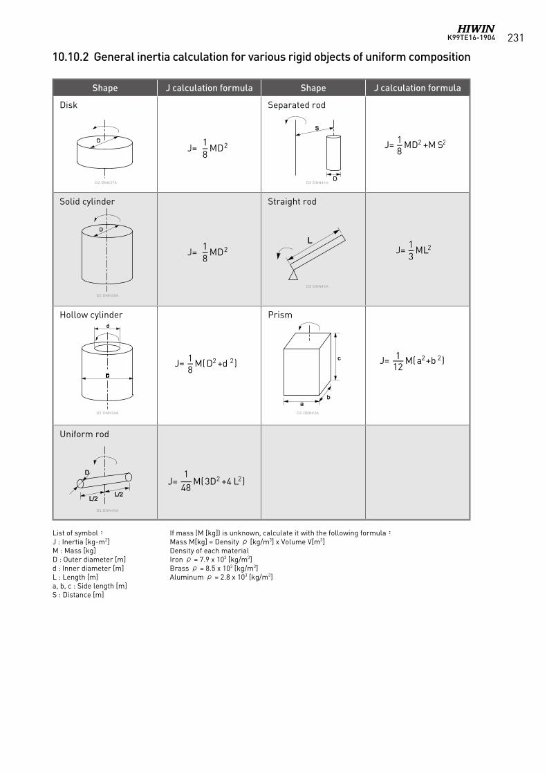
K99TE16-1904 231
Shape J calculation formula Shape J calculation formula
Disk Separated rod
Solid cylinder Straight rod
Hollow cylinder Prism
Uniform rod
D
D
DDDD
d
DDDDDDDDDD
D
L/2L/2
ab
c
L
S
DD2-DNN37A D2-DNN41A
D2-DNN42A
D2-DNN38A
D2-DNN39A D2-DNN43A
D2-DNN40A
List of symbol:J : Inertia [kg-m2]M : Mass [kg]D : Outer diameter [m]d : Inner diameter [m]L : Length [m]a, b, c : Side length [m]S : Distance [m]
If mass (M [kg]) is unknown, calculate it with the following formula:Mass M[kg] = Density ρ [kg/m3] x Volume V[m3]Density of each material Iron ρ = 7.9 x 10³ [kg/m3]Brass ρ = 8.5 x 10³ [kg/m3]Aluminum ρ = 2.8 x 10³ [kg/m3]
10.10.2 General inertia calculation for various rigid objects of uniform composition
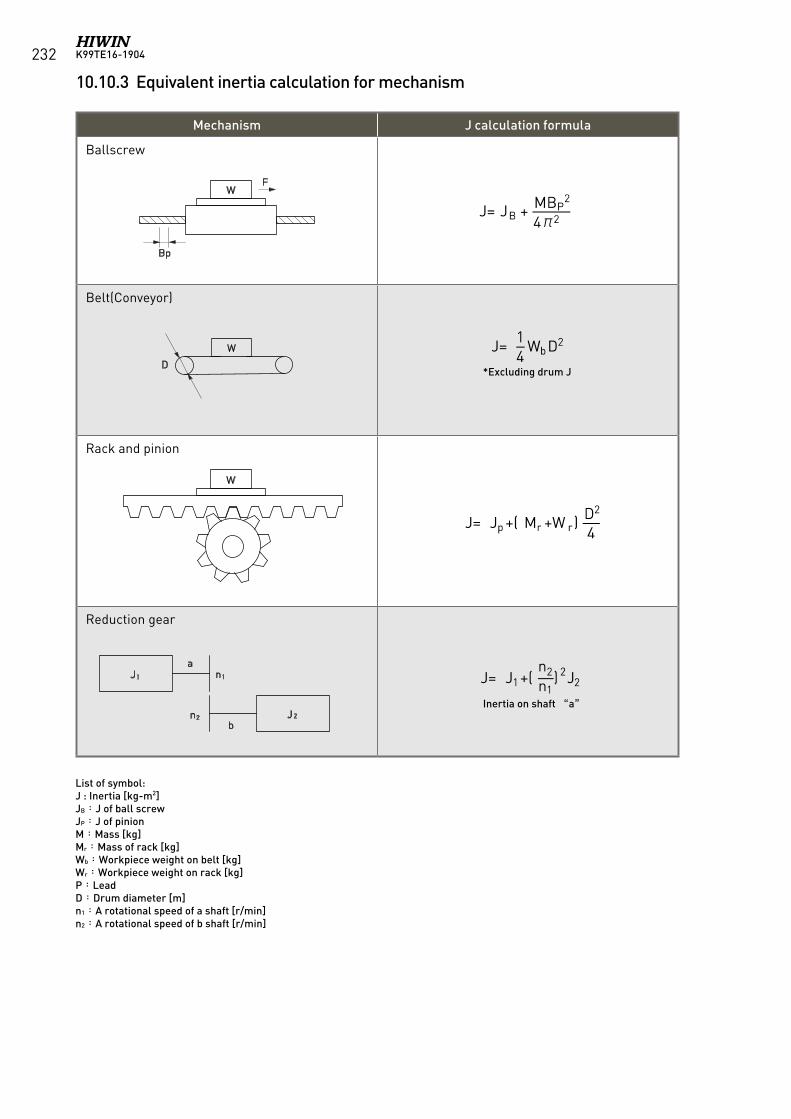
K99TE16-1904232
Mechanism J calculation formula
Ballscrew
Belt(Conveyor)
Rack and pinion
Reduction gear
List of symbol:J : Inertia [kg-m2]JB:J of ball screwJP:J of pinionM:Mass [kg]Mr:Mass of rack [kg]Wb:Workpiece weight on belt [kg]Wr:Workpiece weight on rack [kg]P:LeadD:Drum diameter [m]n1:A rotational speed of a shaft [r/min]n2:A rotational speed of b shaft [r/min]
*Excluding drum J
Inertia on shaft “a”
10.10.3 Equivalent inertia calculation for mechanism
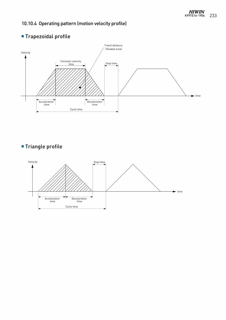
K99TE16-1904 233
Acceleration time
Deceleration time
Constant-velocity time
Cycle time
Stop time
Velocity
time
Travel distance (Shaded area)
Acceleration time
Deceleration time
Cycle time
Stop timeVelocity
time
Trapezoidal profile
Triangle profile
10.10.4 Operating pattern (motion velocity profile)
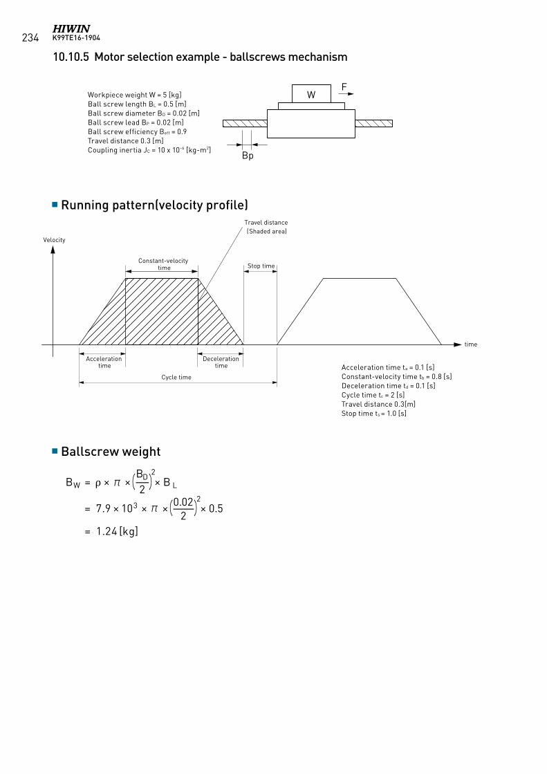
K99TE16-1904234
Workpiece weight W = 5 [kg]Ball screw length BL = 0.5 [m]Ball screw diameter BD = 0.02 [m]Ball screw lead BP = 0.02 [m]Ball screw efficiency Beff = 0.9Travel distance 0.3 [m]Coupling inertia JC = 10 x 10-6 [kg-m2]
Running pattern(velocity profile)
Ballscrew weight
Acceleration time ta = 0.1 [s]Constant-velocity time tb = 0.8 [s]Deceleration time td = 0.1 [s]Cycle time tc = 2 [s]Travel distance 0.3[m]Stop time ts = 1.0 [s]
W
Bp
F
W
D
BW = × π ×BD
2
2× B L
= 7.9 × 10³ × π × 0.022
2× 0.5
= 1.24 [kg]
( )
( )
Acceleration time
Deceleration time
Constant-velocity time
Cycle time
Stop time
Velocity
time
Travel distance (Shaded area)
10.10.5 Motor selection example - ballscrews mechanism
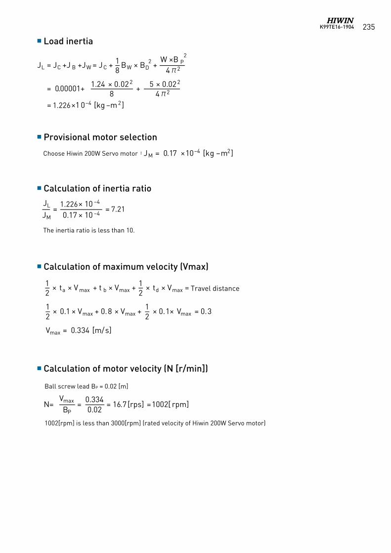
K99TE16-1904 235
Ball screw lead BP = 0.02 [m]
1002[rpm] is less than 3000[rpm] (rated velocity of Hiwin 200W Servo motor)
Load inertia
Provisional motor selection
Calculation of inertia ratio
Calculation of maximum velocity (Vmax)
Calculation of motor velocity (N [r/min])
Choose Hiwin 200W Servo motor:
The inertia ratio is less than 10.
12
× ta × V max + t b × Vmax + 12
× td × Vmax = Travel distance
12
× 0.1 × Vmax + 0.8 × Vmax + 12
× 0.1× Vmax = 0.3
Vmax = 0.334 [m/s]
N=Vmax
BP=
0.3340.02
= 16.7 =1002[ rpm[rps] ]
移動距離
JM = 0.17 ×10⁻⁴ [kg−m2]
Travel distance
JL = JC +J B +JW = JC + 18
BW × BD2 +
W ×B P2
4π2
= 0.00001+ 1.24 × 0.022
8+ × 0.022
4π2
= 1 3 ×1 0−4 [kg −m2]1.226
5
JL
JM=
1.73 × 10 −4
0.17 × 10 −4= 10.2
1.2267.21
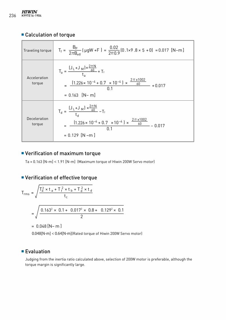
K99TE16-1904236
Traveling torque
Acceleration torque
Deceleration torque
Calculation of torque
Verification of maximum torque
Verification of effective torque
Evaluation
Ta = 0.163 [N-m] < 1.91 [N-m] (Maximum torque of Hiwin 200W Servo motor)
Judging from the inertia ratio calculated above, selection of 200W motor is preferable, although the torque margin is significantly large.
Tf = BP
2πBeff( μgW +F ) = 0.02
2π0.9(0 .1×9 .8 × + 0) = 0.035 [N−m ]5 0.017
Ta =(JL +J M)
ta+
=( × 10−4 + 0. ×
×
10−4 ) × 0.1
+
= 0 [N− m]
7
2πN60
2πx100260
Tf
1.2260.017
0.163
×Td =
(J L+J M)td
−
=(1.73 × 10⁻⁴ + 0.14 ×10⁻⁴ ) ×
0.1−0.035
= 0 [N −m ]
7
2πN60
2πx100260
Tf
1.2260.017
0.129
Trms =Ta
2 × t a + T f2 × t b + T d
2 × t d
tc
=0.2312 × 0.1 + 0.0352 × 0.8 + 0.1612 × 0.1
2
= 0.067[N− m ]
0.048[N-m] < 0.64[N-m](Rated torque of Hiwin 200W Servo motor)
0.1632
0.048
0.0172 0.1292

K99TE16-1904 237
Thank you for purchasing HIWIN’s AC servo motor. Installation and operation of the motor must be in accordance with the HIWIN manual. Before using the servo motor, please read these safety instructions and precautions carefully.
Unpacking instructions
Operation instructions
Safety instructions
Wiring instructions
1. Before using the servo motor, please read these safety instructions and precautions carefully. HIWIN is not responsible for any damage, accident, or injury caused by incorrect handling.
2. Examine the appearance of the motor for any unusual marks or damage from shipment. 3. Inspect the wires for damage.4. Do not disassemble the motor. Since the product design has been based on structure calculations,
computer simulations, and prototype testing, do not disassemble the product without the permission of HIWIN engineers.
5. Supervise children when handling this product.6. People with psychosomatic illness or insufficient experience should not handle this product,
unless under the direct supervision of managers or product narrators.* If any items are damaged or incorrect, please contact your distributor or HIWIN sales representative.
1. Higher than maximum specified current may cause demagnetization of magnetic components inside the motor.
2. The AC servo motor is designed to operate through a dedicated servo drive. Do not connect to a commercial power source (100/200V AC, 50/60 HZ). The motor will not operate correctly and may cause permanent damage.
3. The motor must be operated within its specified range.
1. The product can only be repaired by HIWIN engineers. Please send the product back to us if there is any unusual phenomenon.
2. Do not hold the motor by its wire harness or shaft. 3. Do not hit the motor or shaft. Shock can damage the encoder inside the motor.4. Do not apply loads to the motor shaft that are in excess of the specified value.5. Protect the motor and encoder from high electrical noise, vibration, and unusual temperatures. 6. Do not change the motor parts or disassemble the screws. HIWIN will not be responsible for any
damages, injuries, or accidents that may occur.
1. Ensure the specified power input value before using the product, and verify that the proper power supply is being used.
2. Before operation, please ensure that the motor, brake, and encoder are connected correctly. Incorrect wiring may cause abnormal motor operation or even cause permanent damage to the motor.
3. To avoid voltage coupling and electrical noise on the encoder, ensure adequate separation of the motor power wires and the encoder wires.
4. Ensure that the motor ground wire is connected to the ground terminal on the servo drive.5. Do not perform a dielectric voltage-withstand test on any encoder terminal. The test may cause
damage to the encoder.
10.11 Safety Precautions
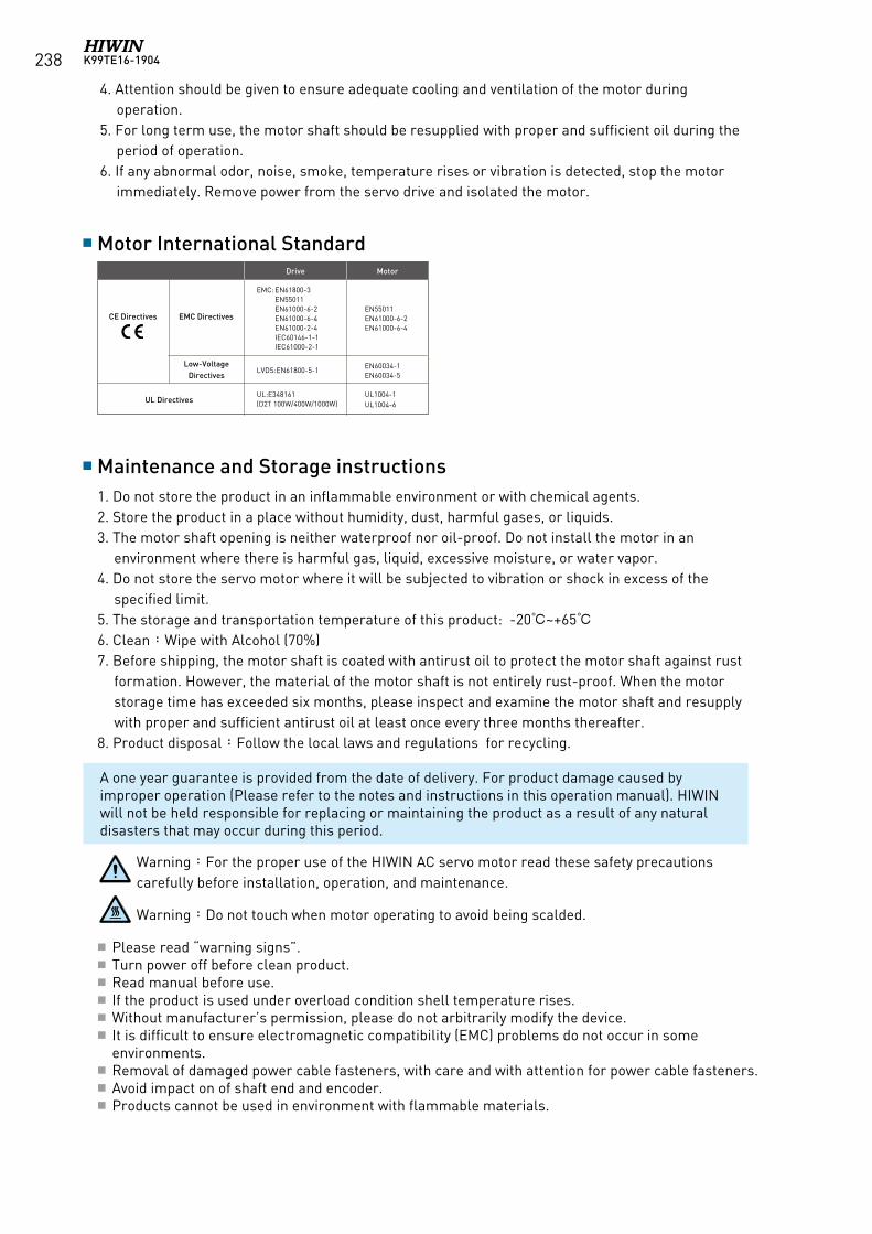
K99TE16-1904238
Maintenance and Storage instructions
Motor International Standard
1. Do not store the product in an inflammable environment or with chemical agents.2. Store the product in a place without humidity, dust, harmful gases, or liquids.3. The motor shaft opening is neither waterproof nor oil-proof. Do not install the motor in an
environment where there is harmful gas, liquid, excessive moisture, or water vapor. 4. Do not store the servo motor where it will be subjected to vibration or shock in excess of the
specified limit.5. The storage and transportation temperature of this product: -20~+656. Clean:Wipe with Alcohol (70%)7. Before shipping, the motor shaft is coated with antirust oil to protect the motor shaft against rust
formation. However, the material of the motor shaft is not entirely rust-proof. When the motor storage time has exceeded six months, please inspect and examine the motor shaft and resupply with proper and sufficient antirust oil at least once every three months thereafter.
8. Product disposal:Follow the local laws and regulations for recycling.
A one year guarantee is provided from the date of delivery. For product damage caused by improper operation (Please refer to the notes and instructions in this operation manual). HIWIN will not be held responsible for replacing or maintaining the product as a result of any natural disasters that may occur during this period.
Warning:For the proper use of the HIWIN AC servo motor read these safety precautions carefully before installation, operation, and maintenance.
Warning:Do not touch when motor operating to avoid being scalded.
4. Attention should be given to ensure adequate cooling and ventilation of the motor during operation.
5. For long term use, the motor shaft should be resupplied with proper and sufficient oil during the period of operation.
6. If any abnormal odor, noise, smoke, temperature rises or vibration is detected, stop the motor immediately. Remove power from the servo drive and isolated the motor.
Please read “warning signs”. Turn power off before clean product. Read manual before use. If the product is used under overload condition shell temperature rises. Without manufacturer’s permission, please do not arbitrarily modify the device. It is difficult to ensure electromagnetic compatibility (EMC) problems do not occur in some
environments. Removal of damaged power cable fasteners, with care and with attention for power cable fasteners. Avoid impact on of shaft end and encoder. Products cannot be used in environment with flammable materials.
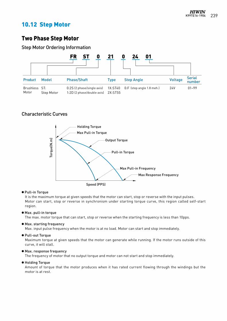
K99TE16-1904 239
Product Model Phase/Shaft Type Step Angle Voltage Serial number
Brushless Motor
ST: Step Motor
0:2S (2 phase/single axis)
1:2D (2 phase/double axis)1X:ST402X:ST55
0:F (step angle 1.8 meh.) 24V 01~99
FR ST 0 21 0 24 01
Two Phase Step MotorStep Motor Ordering Information
Characteristic Curves
Pull-in TorqueIt is the maximum torque at given speeds that the motor can start, stop or reverse with the input pulses.Motor can start, stop or reverse in synchronism under starting torque curve, this region called self-start region.
Max. pull-in torqueThe max. motor torque that can start, stop or reverse when the starting frequency is less than 10pps.
Max. starting frequencyMax. input pulse frequency when the motor is at no load. Motor can start and stop immediately.
Pull-out TorqueMaximum torque at given speeds that the motor can generate while running. If the motor runs outside of this curve, it will stall.
Max. response frequencyThe frequency of motor that no output torque and motor can not start and stop immediately.
Holding TorqueAmount of torque that the motor produces when it has rated current flowing through the windings but the motor is at rest.
轉矩
(N.m
)
速度(PPS)
最大啟動轉矩
握持轉矩
啟動轉矩
輸出轉矩
最大響應頻率
最大自啟動頻率
Pull-in Torque
Holding Torque
Output Torque
Max Pull-in Frequency
Max Pull-in Torque
Max Response Frequency
Speed (PPS)
Torq
ue(N
.m)
10.12 Step Motor
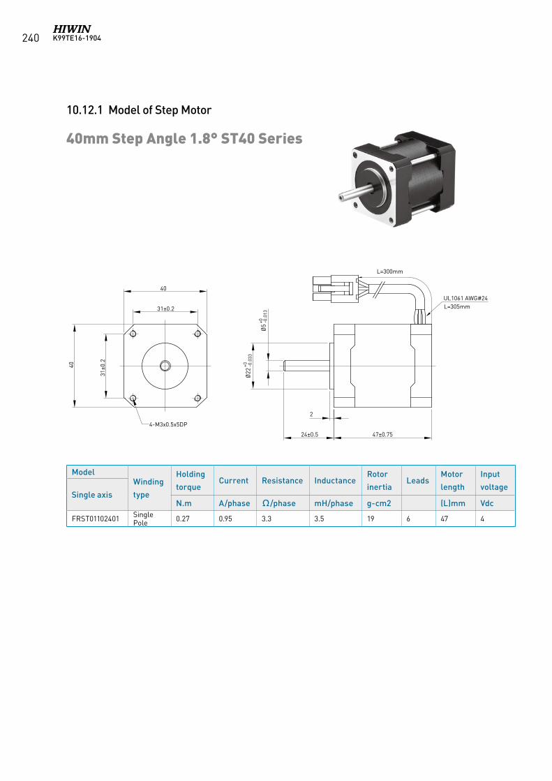
K99TE16-1904240
10.12.1 Model of Step Motor
40mm Step Angle 1.8° ST40 Series
ModelWinding
type
Holding
torqueCurrent Resistance Inductance
Rotor
inertiaLeads
Motor
length
Input
voltageSingle axis
N.m A/phase Ω/phase mH/phase g-cm2 (L)mm Vdc
FRST01102401 Single Pole 0.27 0.95 3.3 3.5 19 6 47 4
UL1061 AWG#24 L=305mm
47±0.75
40
40
31±0
.2
31±0.2
24±0.5
2
Ø22
+0 -0.0
33
Ø5
+0 -0.0
13
4-M3x0.5x5DP
L=300mm
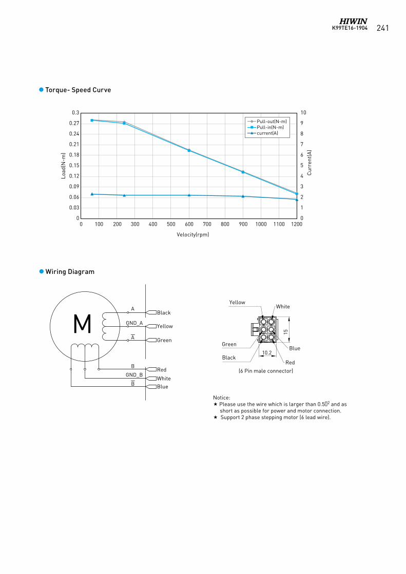
K99TE16-1904 241
Wiring Diagram
Notice: Pleaseusethewirewhichislargerthan0.52 and as
short as possible for power and motor connection. Support 2 phase stepping motor (6 lead wire).
15
10.2黑(BLACK)
綠(GREEN)
黃(YELLOW)
紅(RED)
藍(BLUE)
白(WHITE)
(公套母端 6Pin接頭 )
藍(BLUE)
黃(YELLOW)
紅(RED)
綠(GREEN)
黑(BLACK)
白(WHITE)
A
GND_A
A
B
GND_B
B
MBlack
Yellow
Green
Red
WhiteBlue
WhiteYellow
Green
Black
Blue
Red
(6 Pin male connector)
Torque- Speed Curve
0
1
2
3
4
5
6
7
8
9
10
0
0.03
0.06
0.09
0.12
0.15
0.18
0.21
0.24
0.27
0.3
0 100 200 300 400 500 600 700 800 900 1000 1100 1200
Cur
rent
(A)
Load
(N-m
)
Velocity(rpm)
Pull-out(N-m)Pull-in(N-m)current(A)
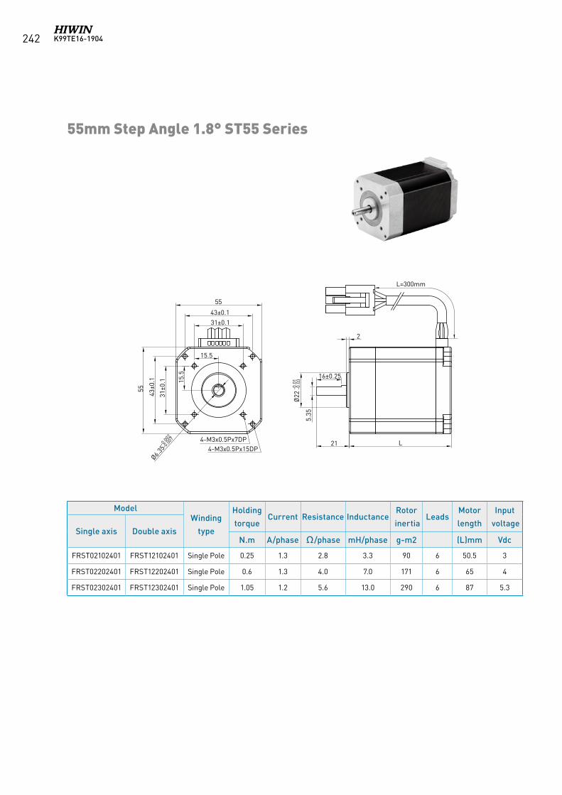
K99TE16-1904242
ModelWinding
type
Holding
torqueCurrent Resistance Inductance
Rotor
inertiaLeads
Motor
length
Input
voltageSingle axis Double axis
N.m A/phase Ω/phase mH/phase g-m2 (L)mm Vdc
FRST02102401 FRST12102401 Single Pole 0.25 1.3 2.8 3.3 90 6 50.5 3
FRST02202401 FRST12202401 Single Pole 0.6 1.3 4.0 7.0 171 6 65 4
FRST02302401 FRST12302401 Single Pole 1.05 1.2 5.6 13.0 290 6 87 5.3
55mm Step Angle 1.8° ST55 Series
21
2
L
55
31±0.1
15.5
55
31±0
.1 15.5 16±0.25
5.35
Ø6.35
-0.00
2-0
.007
Ø22
-0.0
1-0
.03
43±0.1
43±0
.1
4-M3x0.5Px15DP4-M3x0.5Px7DP
L=300mm
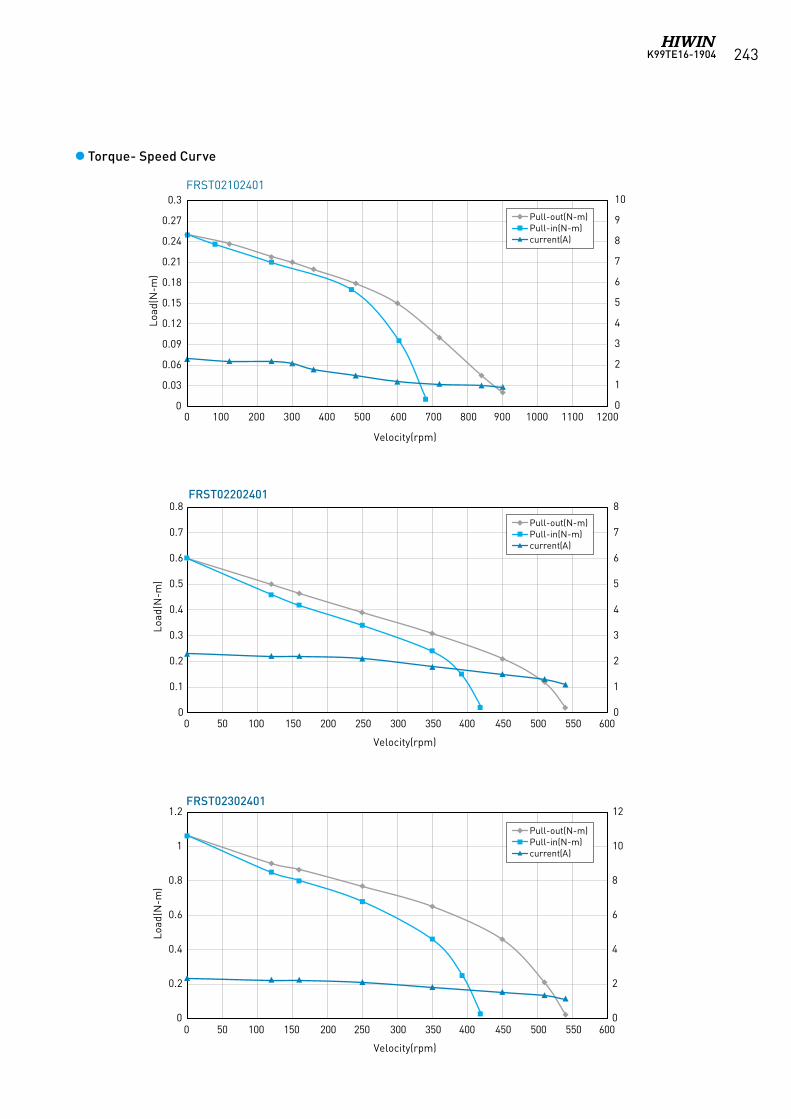
K99TE16-1904 243
0
2
4
6
8
10
12
0
0.2
0.4
0.6
0.8
1
1.2
0 50 100 150 200 250 300 350 400 450 500 550 600
Load
(N-m
)
Velocity(rpm)
Pull-out(N-m)Pull-in(N-m)current(A)
0
1
2
3
4
5
6
7
8
0
0.1
0.2
0.3
0.4
0.5
0.6
0.7
0.8
0 50 100 150 200 250 300 350 400 450 500 550 600
Load
(N-m
)
Velocity(rpm)
Pull-out(N-m)Pull-in(N-m)current(A)
0
0.03
0.06
0.09
0.12
0.15
0.18
0.21
0.24
0.27
0.3
Load
(N-m
)
0
1
2
3
4
5
6
7
8
9
10
0 100 200 300 400 500 600 700 800 900 1000 1100 1200
Velocity(rpm)
Pull-out(N-m)Pull-in(N-m)current(A)
Torque- Speed Curve
FRST02102401
FRST02202401
FRST02302401
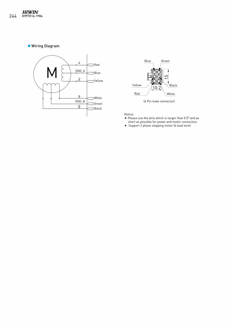
K99TE16-1904244
Wiring Diagram
15
10.2紅(RED)
黃(YELLOW)
藍(BLUE)
白(WHITE)
黑 (BLACK)
綠(GREEN)
( 公套母端 6Pin 接頭 )
藍 (BLUE)
黃 (YELLOW)
紅 (RED)
綠 (GREEN)
黑 (BLACK)
白 (WHITE)
A
GND_A
A
B
GND_B
B
M
Black
Black
Red
Blue
YellowYellow
RedWhite
White
Green
Notice: Please use the wire which is larger than 0.52 and as
short as possible for power and motor connection. Support 2 phase stepping motor (6 lead wire).
(6 Pin male connector)
Blue Green
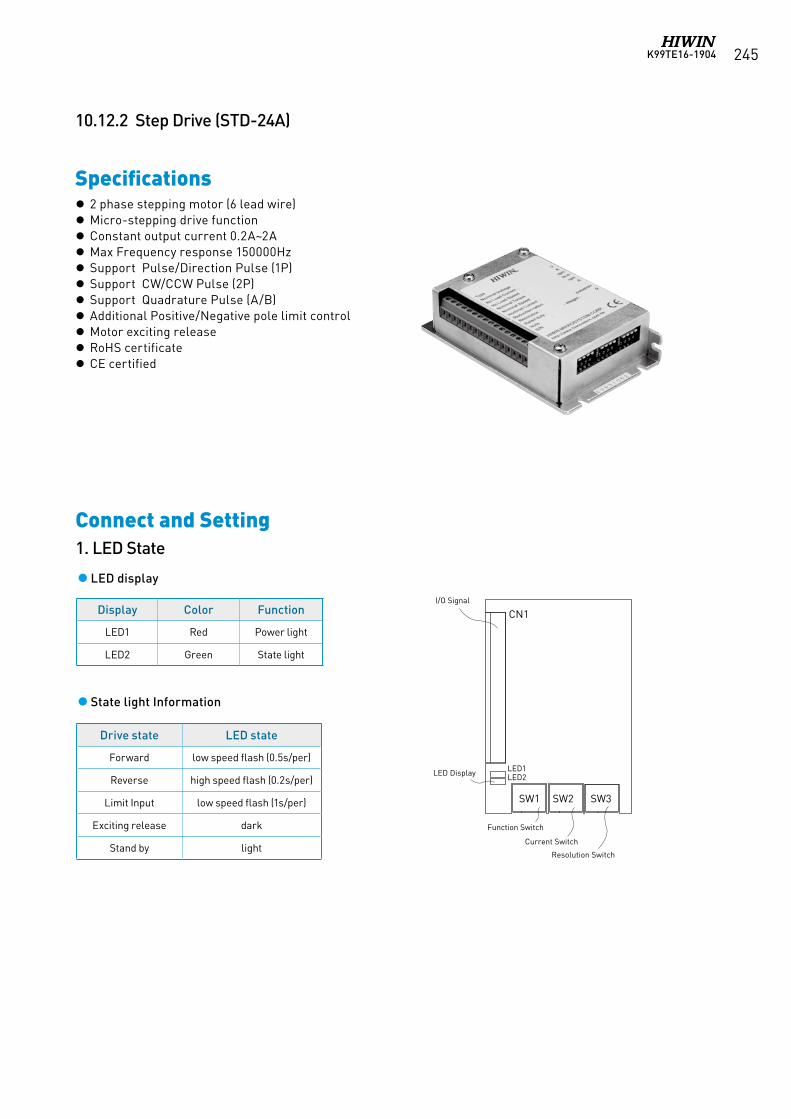
K99TE16-1904 245
Specifications
10.12.2 Step Drive (STD-24A)
2 phase stepping motor (6 lead wire) Micro-stepping drive function Constant output current 0.2A~2A Max Frequency response 150000Hz Support Pulse/Direction Pulse (1P) Support CW/CCW Pulse (2P) Support Quadrature Pulse (A/B) Additional Positive/Negative pole limit control Motor exciting release RoHS certificate CE certified
Connect and Setting1. LED State
LED display
State light Information
Display Color Function
LED1 Red Power light
LED2 Green State light
Drive state LED state
Forward low speed flash (0.5s/per)
Reverse high speed flash (0.2s/per)
Limit Input low speed flash (1s/per)
Exciting release dark
Stand by light
CN1
SW1 SW2 SW3
LED1LED2LED Display
Function Switch
Current Switch
Resolution Switch
I/O Signal
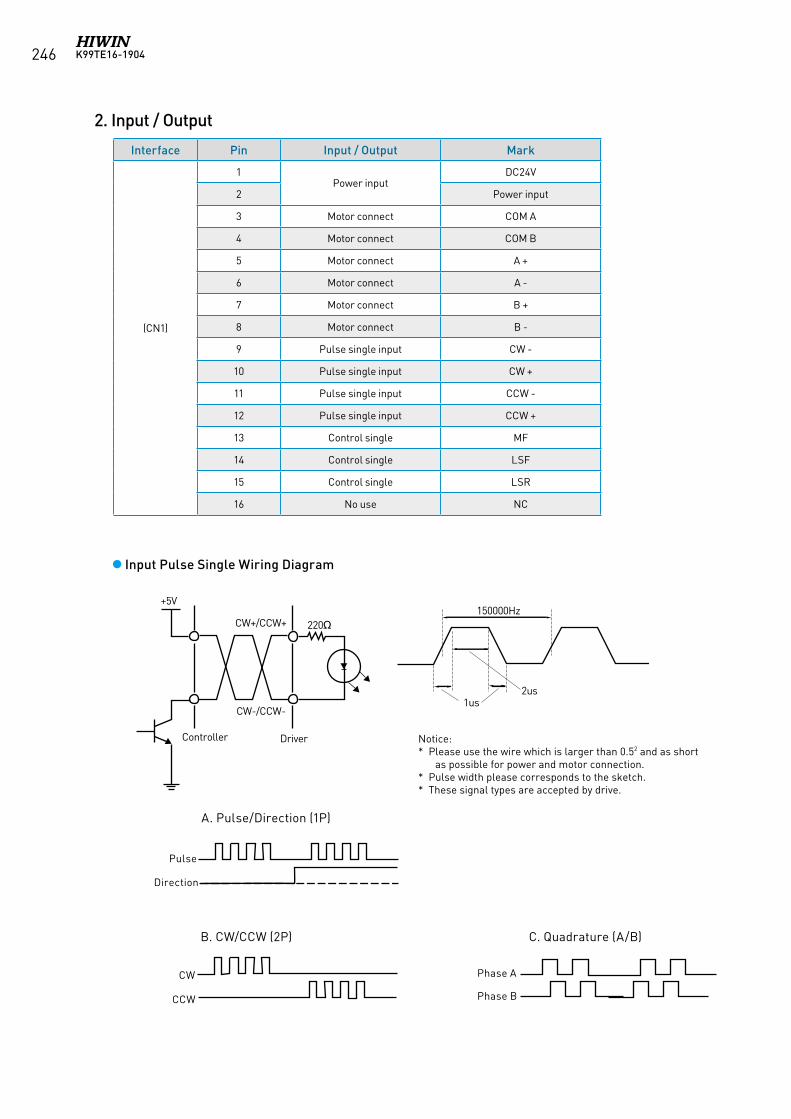
K99TE16-1904246
+5V
CW+/CCW+
Controller Driver
CW-/CCW-
220Ω150000Hz
1us2us
2. Input / Output
Interface Pin Input / Output Mark
(CN1)
1Power input
DC24V
2 Power input
3 Motor connect COM A
4 Motor connect COM B
5 Motor connect A +
6 Motor connect A -
7 Motor connect B +
8 Motor connect B -
9 Pulse single input CW -
10 Pulse single input CW +
11 Pulse single input CCW -
12 Pulse single input CCW +
13 Control single MF
14 Control single LSF
15 Control single LSR
16 No use NC
Input Pulse Single Wiring Diagram
Notice: * Please use the wire which is larger than 0.52 and as short
as possible for power and motor connection. * Pulse width please corresponds to the sketch. * These signal types are accepted by drive.
A. Pulse/Direction (1P)
B. CW/CCW (2P) C. Quadrature (A/B)
Pulse
Direction
CW
CCW
Phase A
Phase B
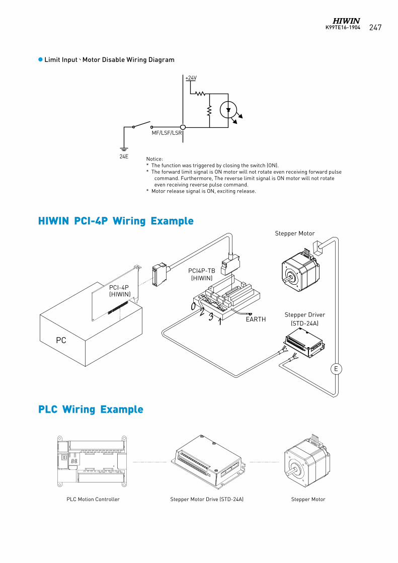
K99TE16-1904 247
Limit Input、Motor Disable Wiring Diagram
Notice:* The function was triggered by closing the switch (ON).* The forward limit signal is ON motor will not rotate even receiving forward pulse
command. Furthermore, The reverse limit signal is ON motor will not rotate even receiving reverse pulse command.
* Motor release signal is ON, exciting release.
24E
+24V
MF/LSF/LSR
PC
Stepper Motor
Stepper Driver(STD-24A)
PCI4P-TB(HIWIN)
EARTH
PCI-4P(HIWIN)
E
0 2 3 1
HIWIN PCI-4P Wiring Example
PLC Wiring Example
PLC Motion Controller Stepper Motor Drive (STD-24A) Stepper Motor
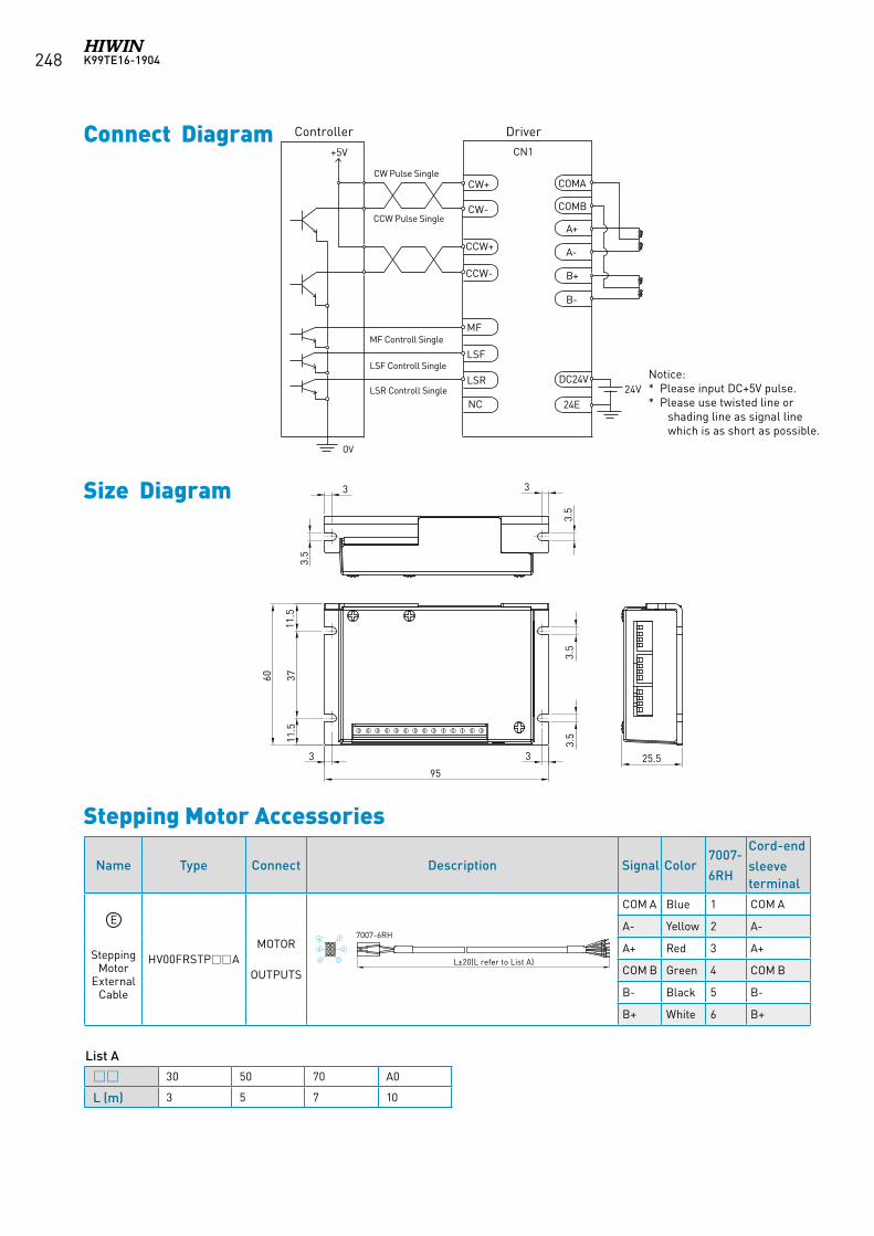
K99TE16-1904248
Name Type Connect Description Signal Color7007-
6RH
Cord-end
sleeveterminal
Stepping Motor
External Cable
HV00FRSTPAMOTOR
OUTPUTS
COM A Blue 1 COM A
A- Yellow 2 A-
A+ Red 3 A+
COM B Green 4 COM B
B- Black 5 B-
B+ White 6 B+
3.5
33
3.5
11.5
3711
.5
60
95
33
3.5
3.5
25.5
Size Diagram
Stepping Motor Accessories
Connect Diagram
Notice: * Please input DC+5V pulse.* Please use twisted line or
shading line as signal line which is as short as possible.
Controller
+5V
CW Pulse Single
CCW Pulse Single
MF Controll Single
LSR Controll Single
OV
LSF Controll Single
CN1
CW+
CCW+
MF
LSF
LSR
NC
CW-
CCW-
COMA
A+
24VDC24V
24E
COMB
A-
B+
B-
Driver
E
30 50 70 A0
L (m) 3 5 7 10
List A
3.5
33
3.5
11.5
3711
.5
60
95
33
3.5
3.5
25.5
L±20(L refer to List A)6
5
3
2
14 7007-6RH
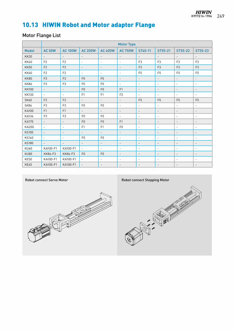
K99TE16-1904 249
Name Type Connect Description Signal Color7007-
6RH
Cord-end
sleeveterminal
Stepping Motor
External Cable
HV00FRSTPAMOTOR
OUTPUTS
COM A Blue 1 COM A
A- Yellow 2 A-
A+ Red 3 A+
COM B Green 4 COM B
B- Black 5 B-
B+ White 6 B+
Motor Flange List
10.13 HIWIN Robot and Motor adaptor Flange
Motor Type
Model AC 50W AC 100W AC 200W AC 400W AC 750W ST40-11 ST55-21 ST55-22 ST55-23
KK30 - - - - - - - - -
KK40 F2 F2 - - - F3 F3 F3 F3
KK50 F2 F2 - - - F3 F3 F3 F3
KK60 F2 F2 - - - F5 F5 F5 F5
KK80 F3 F3 F0 F0 - - - - -
KK86 F3 F3 F0 F0 - - - - -
KK100 - - F0 F0 F1 - - - -
KK130 - - F1 F1 F2 - - - -
SK60 F2 F2 - - - F5 F5 F5 F5
SK86 F3 F3 F0 F0 - - - - -
KA100 F1 F1 - - - - - - -
KA136 F3 F3 F0 F0 - - - - -
KA170 - - F0 F0 F1 - - - -
KA200 - - F1 F1 F0 - - - -
KS100 - - - - - - - - -
KS140 - - F0 F0 - - - - -
KS180 - - - - - - - - -
KU60 KA100-F1 KA100-F1 - - - - - - -
KU80 KK86-F3 KK86-F3 F0 F0 - - - - -
KE50 KA100-F1 KA100-F1 - - - - - - -
KE65 KA100-F1 KA100-F1 - - - - - - -
Robot connect Servo Motor Robot connect Stepping Motor
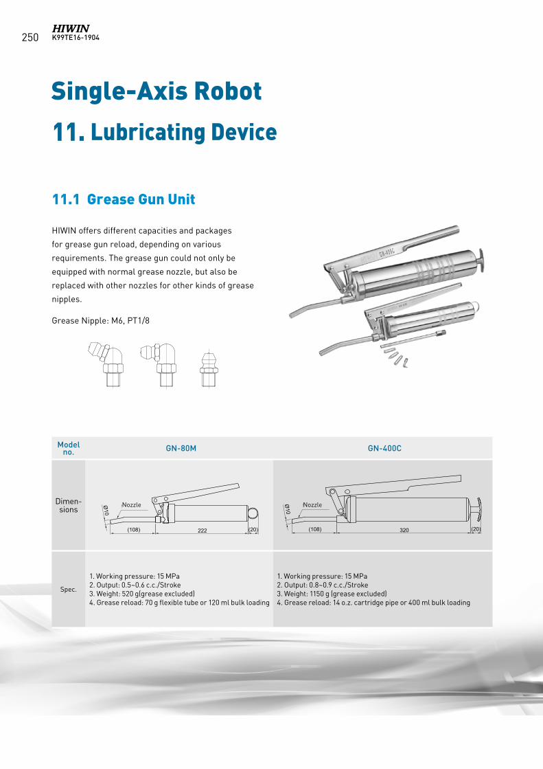
K99TE16-1904250
Single-Axis Robot
11. Lubricating Device
HIWIN offers different capacities and packages
for grease gun reload, depending on various
requirements. The grease gun could not only be
equipped with normal grease nozzle, but also be
replaced with other nozzles for other kinds of grease
nipples.
Grease Nipple: M6, PT1/8
11.1 Grease Gun Unit
Modelno. GN-80M GN-400C
Dimen-sions
Spec.
1. Working pressure: 15 MPa2. Output: 0.5~0.6 c.c./Stroke3. Weight: 520 g(grease excluded)4. Grease reload: 70 g flexible tube or 120 ml bulk loading
1. Working pressure: 15 MPa2. Output: 0.8~0.9 c.c./Stroke3. Weight: 1150 g (grease excluded)4. Grease reload: 14 o.z. cartridge pipe or 400 ml bulk loading
222(108) 320(108) (20)
Ø10彎管注油嘴Ø10
彎管注油嘴
(20)
Nozzle Nozzle
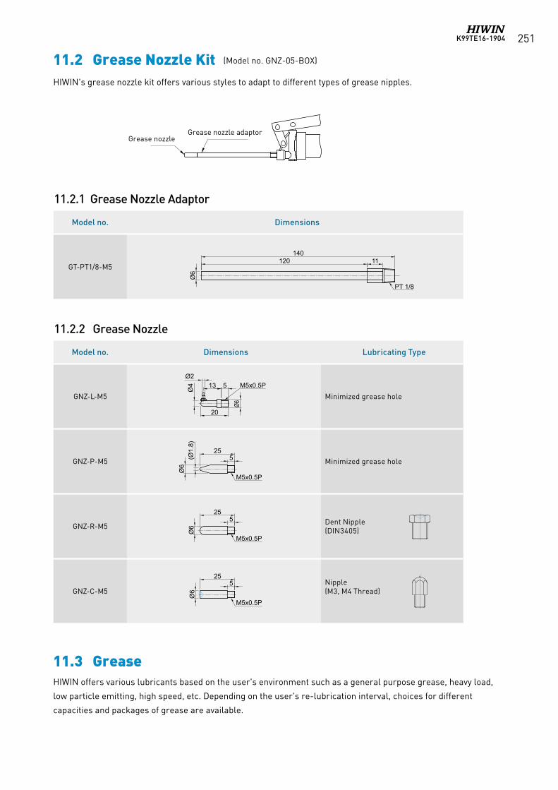
K99TE16-1904 251
11.2 Grease Nozzle KitHIWIN's grease nozzle kit offers various styles to adapt to different types of grease nipples.
Model no. Dimensions
GT-PT1/8-M5
Model no. Dimensions Lubricating Type
GNZ-L-M5 Minimized grease hole
GNZ-P-M5 Minimized grease hole
GNZ-R-M5 Dent Nipple(DIN3405)
GNZ-C-M5Nipple (M3, M4 Thread)
11.2.1 Grease Nozzle Adaptor
11.2.2 Grease Nozzle
Ø6
(Ø1.
8)
Ø6
20
Ø6
Ø6
120 11
PT 1/8
13
Ø6
5 M5x0.5P
Ø4
255
M5x0.5P
M5x0.5P
M5x0.5P
255
255
140
注油嘴轉接管注油嘴
Ø2
Ø6
(Ø1.
8)
Ø6
20
Ø6
Ø6
120 11
PT 1/8
13
Ø6
5 M5x0.5P
Ø4
255
M5x0.5P
M5x0.5P
M5x0.5P
255
255
140
注油嘴轉接管注油嘴
Ø2
Ø6
(Ø1.
8)
Ø6
20
Ø6
Ø6
120 11
PT 1/8
13
Ø6
5 M5x0.5P
Ø4
255
M5x0.5P
M5x0.5P
M5x0.5P
255
255
140
注油嘴轉接管注油嘴
Ø2
Ø6
(Ø1.
8)
Ø6
20
Ø6
Ø6
120 11
PT 1/8
13
Ø6
5 M5x0.5P
Ø4
255
M5x0.5P
M5x0.5P
M5x0.5P
255
255
140
注油嘴轉接管注油嘴
Ø2
Ø6
(Ø1.
8)
Ø6
20
Ø6
Ø6
120 11
PT 1/8
13
Ø6
5 M5x0.5P
Ø4
255
M5x0.5P
M5x0.5P
M5x0.5P
255
255
140
注油嘴轉接管注油嘴
Ø2
Ø6
(Ø1.
8)
Ø6
20
Ø6
Ø6
120 11
PT 1/8
13
Ø6
5 M5x0.5P
Ø4
255
M5x0.5P
M5x0.5P
M5x0.5P
255
255
140
注油嘴轉接管注油嘴
Ø2
Grease nozzleGrease nozzle adaptor
11.3 GreaseHIWIN offers various lubricants based on the user's environment such as a general purpose grease, heavy load,
low particle emitting, high speed, etc. Depending on the user's re-lubrication interval, choices for different
capacities and packages of grease are available.
(Model no. GNZ-05-BOX)
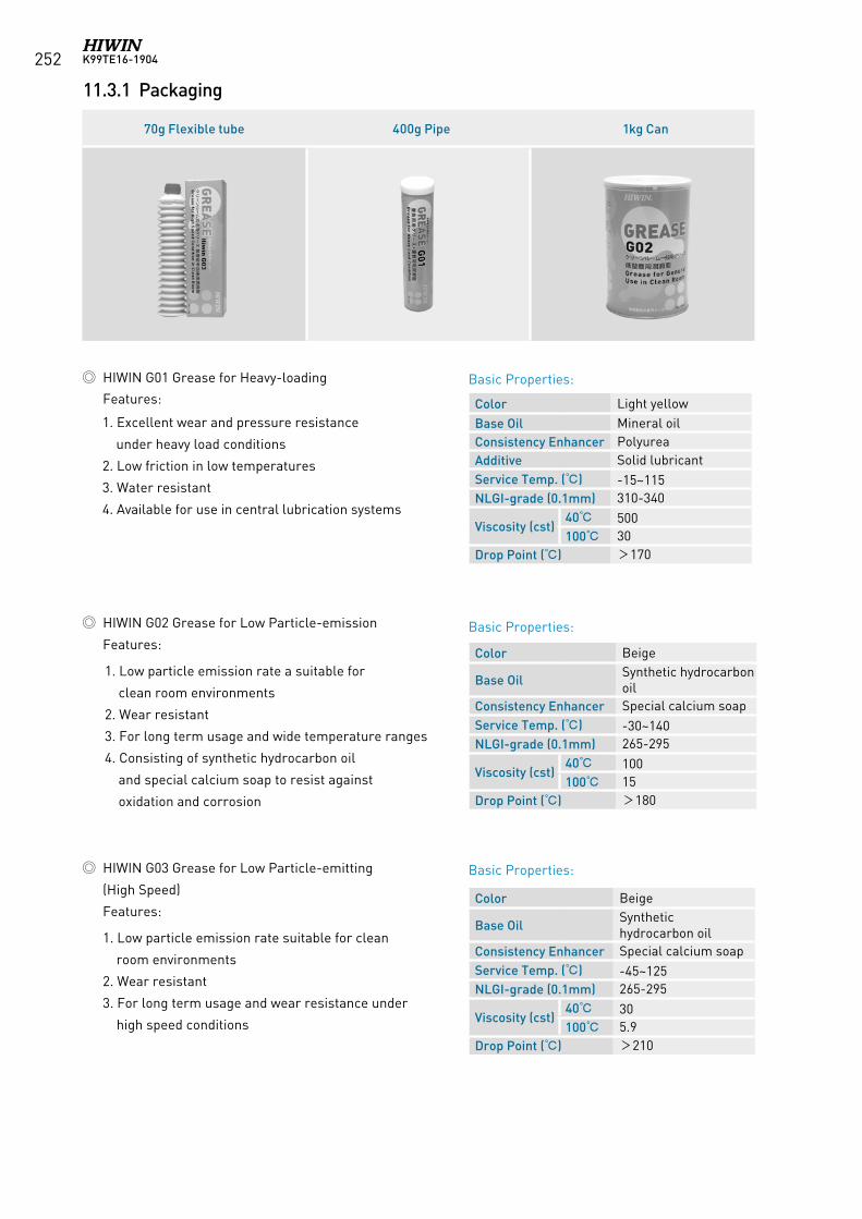
K99TE16-1904252
70g Flexible tube 400g Pipe 1kg Can
11.3.1 Packaging
Color Beige
Base OilSynthetic hydrocarbon oil
Consistency Enhancer Special calcium soapService Temp. () -30~140NLGI-grade (0.1mm) 265-295
Viscosity (cst)40 100100 15
Drop Point () >180
HIWIN G02 Grease for Low Particle-emission
Features:
Color Light yellowBase Oil Mineral oilConsistency Enhancer PolyureaAdditive Solid lubricantService Temp. () -15~115NLGI-grade (0.1mm) 310-340
Viscosity (cst)40 500100 30
Drop Point () >170
1. Excellent wear and pressure resistance
under heavy load conditions
2. Low friction in low temperatures
3. Water resistant
4. Available for use in central lubrication systems
1. Low particle emission rate a suitable for
clean room environments
2. Wear resistant
3. For long term usage and wide temperature ranges
4. Consisting of synthetic hydrocarbon oil
and special calcium soap to resist against
oxidation and corrosion
HIWIN G01 Grease for Heavy-loading Features:
Basic Properties:
Basic Properties:
Basic Properties:
Color Beige
Base OilSynthetic hydrocarbon oil
Consistency Enhancer Special calcium soapService Temp. () -45~125NLGI-grade (0.1mm) 265-295
Viscosity (cst)40 30100 5.9
Drop Point () >210
1. Low particle emission rate suitable for clean
room environments
2. Wear resistant
3. For long term usage and wear resistance under
high speed conditions
HIWIN G03 Grease for Low Particle-emitting
(High Speed)
Features:
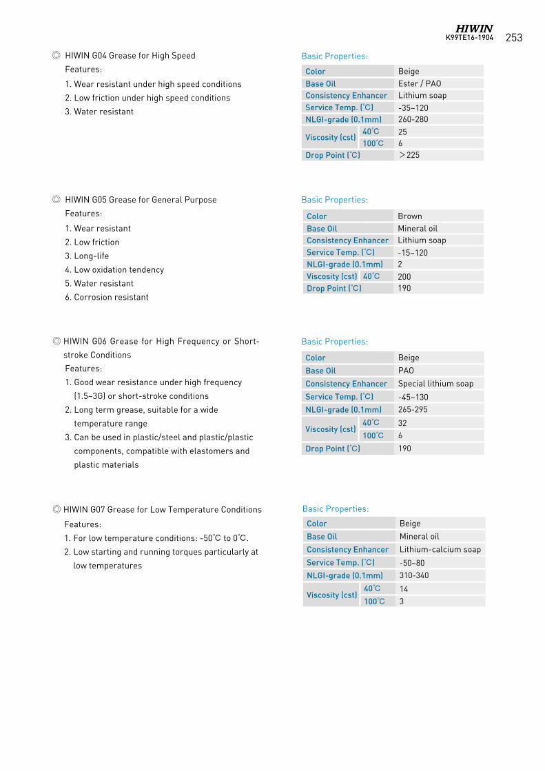
K99TE16-1904 253
Color BrownBase Oil Mineral oilConsistency Enhancer Lithium soapService Temp. () -15~120NLGI-grade (0.1mm) 2Viscosity (cst) 40 200Drop Point () 190
1. Wear resistant
2. Low friction
3. Long-life
4. Low oxidation tendency
5. Water resistant
6. Corrosion resistant
HIWIN G05 Grease for General Purpose
Features:
Color BeigeBase Oil Ester / PAOConsistency Enhancer Lithium soapService Temp. () -35~120NLGI-grade (0.1mm) 260-280
Viscosity (cst)40 25100 6
Drop Point () >225
1. Wear resistant under high speed conditions
2. Low friction under high speed conditions
3. Water resistant
Features:
1. For low temperature conditions: -50 to 0.
2. Low starting and running torques particularly at
low temperatures
HIWIN G06 Grease for High Frequency or Short-
stroke Conditions
HIWIN G07 Grease for Low Temperature Conditions
Color Beige
Base Oil PAO
Consistency Enhancer Special lithium soap
Service Temp. () -45~130NLGI-grade (0.1mm) 265-295
Viscosity (cst)40 32
100 6
Drop Point () 190
Color Beige
Base Oil Mineral oil
Consistency Enhancer Lithium-calcium soap
Service Temp. () -50~80
NLGI-grade (0.1mm) 310-340
Viscosity (cst)40 14
100 3
Basic Properties:
Basic Properties:
Basic Properties:
Basic Properties:
HIWIN G04 Grease for High Speed
Features:
Features:
1. Good wear resistance under high frequency
(1.5~3G) or short-stroke conditions
2. Long term grease, suitable for a wide
temperature range
3. Can be used in plastic/steel and plastic/plastic
components, compatible with elastomers and
plastic materials
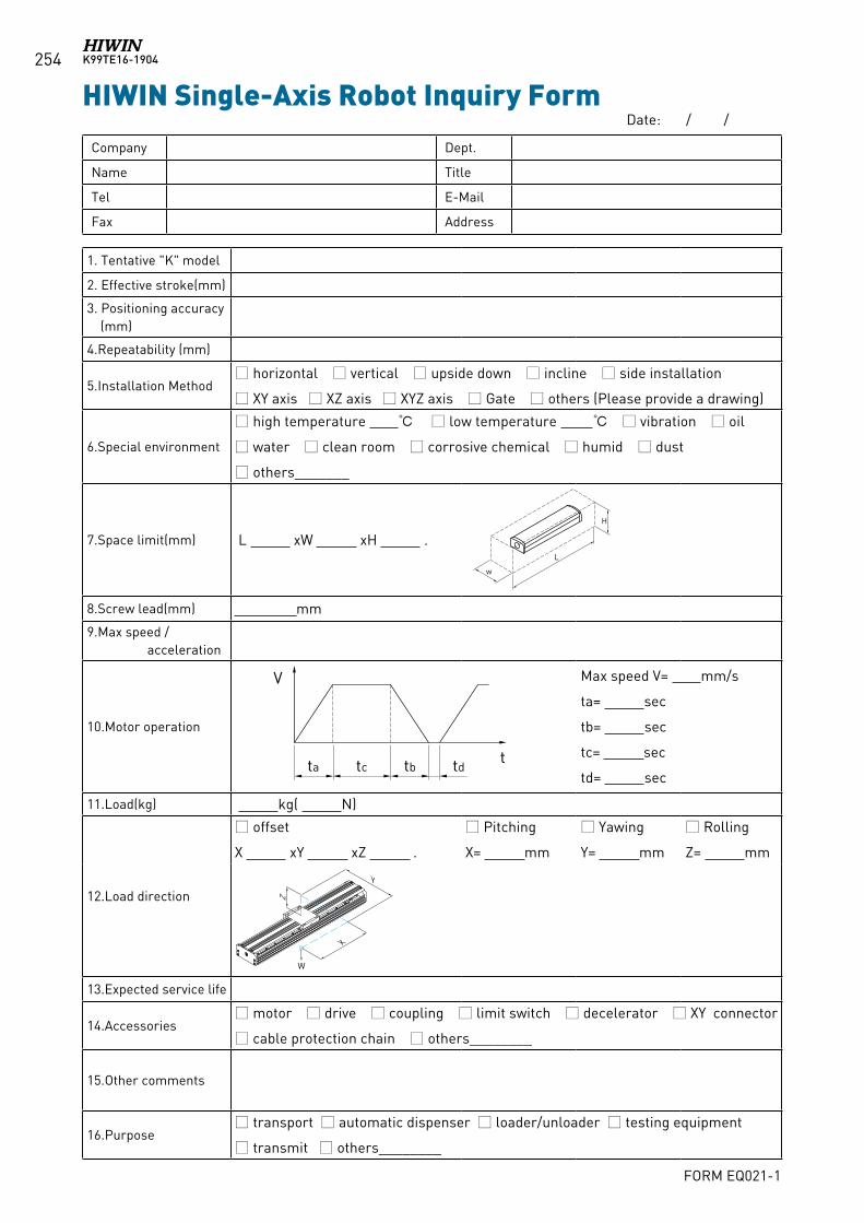
K99TE16-1904254
HIWIN Single-Axis Robot Inquiry Form
Company Dept.
Name Title
Tel E-Mail
Fax Address
1. Tentative "K" model
2. Effective stroke(mm)
3. Positioning accuracy (mm)
4.Repeatability (mm)
5.Installation Method horizontal vertical upside down incline side installation
XY axis XZ axis XYZ axis Gate others (Please provide a drawing)
6.Special environment
high temperature low temperature vibration oil
water clean room corrosive chemical humid dust
others_______
7. Space limit(mm) L xW xH .
w
L
H
8.Screw lead(mm) mm
9.Max speed / acceleration
10.Motor operation
V
tta tc tb td
Max speed V= mm/s
ta= sec
tb= sec
tc= sec
td= sec
11.Load(kg) kg( N)
12.Load direction
offset
X xY xZ .
Pitching
X= mm
Yawing
Y= mm
Rolling
Z= mm
Y
Z
X
W
13.Expected service life
14.Accessories motor drive coupling limit switch decelerator XY connector
cable protection chain others________
15. Other comments
16.Purpose transport automatic dispenser loader/unloader testing equipment
transmit others________
Date: / /
FORM EQ021-1

1. HIWIN is a registered trademark of HIWIN Technologies Corp. For your protection, avoid buying counterfeit products from unknown sources.
2. Actual products may differ from specifications and photos provided in this catalog. These differences may be the result of various factors including product improvements.
3. HIWIN will not sell or export products or processes restricted under the “Foreign Trade Act” or related regulations. Export of restricted products should be approved by proper authorities in accordance with relevant laws and shall not be used to manufacture or develop nuclear, biochemical, missiles or other weapons.
4. HIWIN website for patented product directory: http://www.hiwin.tw/Products/Products_patents.aspx
Publication Date:October 2006, first edition
Print Date:April 2019, 16th edition
Single-Aixs Robot (Original Instructions) Technical Information
Copyright © HIWIN Technologies Corp.
INDUSTRIE 4.0 Best Partner
Multi-Axis RobotPick-and-place / Assembly / Array and packaging / Semiconductor / Electro-Optical industry / Automotive industry / Food industry• Articulated Robot• Delta Robot• SCARA Robot• Wafer Robot• Electric Gripper • Integrated Electric Gripper• Rotary Joint
Single-Axis RobotPrecision / Semiconductor /Medical / FPD• KK, SK• KS, KA • KU, KE, KC
Torque Motor Rotary TableAerospace / Medical / Automotive industry / Machine tools / Machinery industry• RAB Series• RAS Series• RCV Series• RCH Series
BallscrewPrecision Ground / Rolled• Super S series• Super T series• Mini Roller• Ecological & Economical
lubrication Module E2• Rotating Nut (R1)• Energy-Saving & Thermal-
Controlling (Cool Type)• Heavy Load Series (RD) • Ball Spline
Linear GuidewayAutomation / Semiconductor / Medical• Ball Type--HG, EG, WE, MG, CG• Quiet Type--QH, QE, QW, QR• Other--RG, E2, PG, SE, RC
BearingMachine tools / Robot• Crossed Roller Bearings • Ballscrew Bearings • Linear Bearing• Support Unit
DATORKER® Robot ReducerRobots / Automation equipment / Semiconductor equipment / Machine tools• WUT Type-Combination Type (P) • WUI Type-Component Type (C) • WTI Type-Combination Type (P)• WTI Type-Sealed type (A)
AC Servo Motor & DriveSemiconductor / Packaging machine /SMT / Food industry / LCD• Drives-D1, D1-N, D2T • Motors-50W~2000W
Medical EquipmentHospital / Rehabilitation centers /Nursing homes• Robotic Gait Training System• Hygiene System• Robotic Endoscope HolderS
Linear MotorAutomated transport / AOI application / Precision / Semiconductor• Iron-core Linear Motor• Coreless Linear Motor • Linear Turbo Motor LMT • Planar Servo Motor • Air Bearing Platform• X-Y Stage • Gantry Systems
Torque Motor & Direct Drive MotorInspection / Testing equipment / Machine tools / Robot• Rotary Tables-TMS,TMY,TMN• TMRW Series• TMRI Series

Sin
gle-A
xis Rob
ot Tech
nical In
formation
www.hiwin.tw www.hiwinmikro.twCopyright © HIWIN Technologies Corp.©2019 FORM K99TE16-1904 (PRINTED IN TAIWAN)The specifications in this catalog are subject to change without notification.
Single-Axis Robot
Technical Information
HIWIN TECHNOLOGIES CORP.No. 7, Jingke Road, Taichung Precision Machinery Park,Taichung 40852, TaiwanTel: +886-4-23594510Fax: [email protected]
HIWIN MIKROSYSTEM CORP.No. 6, Jingke Central Road, Taichung Precision Machinery Park,Taichung 40852, TaiwanTel: +886-4-23550110Fax: [email protected]
Original InstructionsSubsidiaries / Research Center
HIWIN Schweiz GmbHJONA, [email protected]
HIWIN s.r.o.BRNO, CZECH [email protected]
HIWIN [email protected]
HIWIN KOREASUWON‧MASAN, [email protected]
HIWIN CHINASUZHOU, [email protected]
Mega-Fabs Motion Systems, Ltd.HAIFA, [email protected]
HIWIN GmbHOFFENBURG, [email protected]
HIWIN JAPANKOBE‧TOKYO‧NAGOYA‧NAGANO‧TOHOKU‧SHIZUOKA.HOKURIKU‧HIROSHIMA‧FUKUOKA‧KUMAMOTO, [email protected]
HIWIN USACHICAGO, U.S.A. [email protected]
HIWIN SrlBRUGHERIO, [email protected]
Related Documents