Single and Double Gates Operation & Maintenance Manual RELIABLE SAFE ACCESS

Welcome message from author
This document is posted to help you gain knowledge. Please leave a comment to let me know what you think about it! Share it to your friends and learn new things together.
Transcript
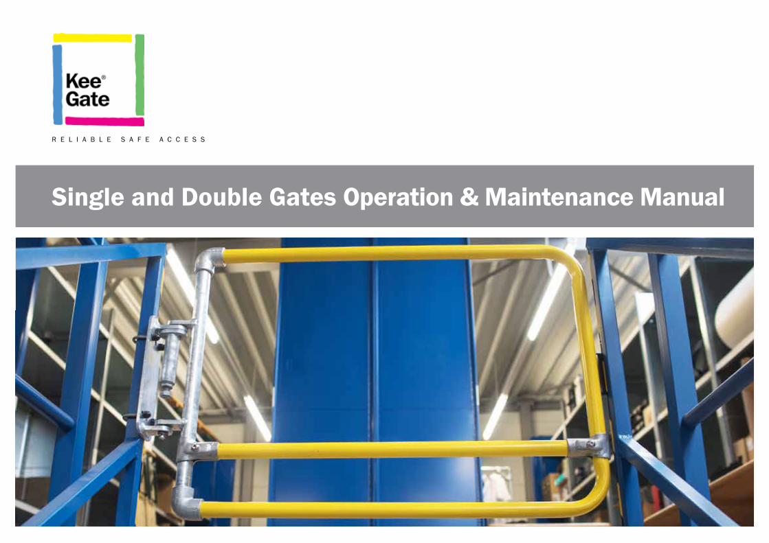
Single and Double Gates Operation & Maintenance Manual
R E L I A B L E S A F E A C C E S S
2
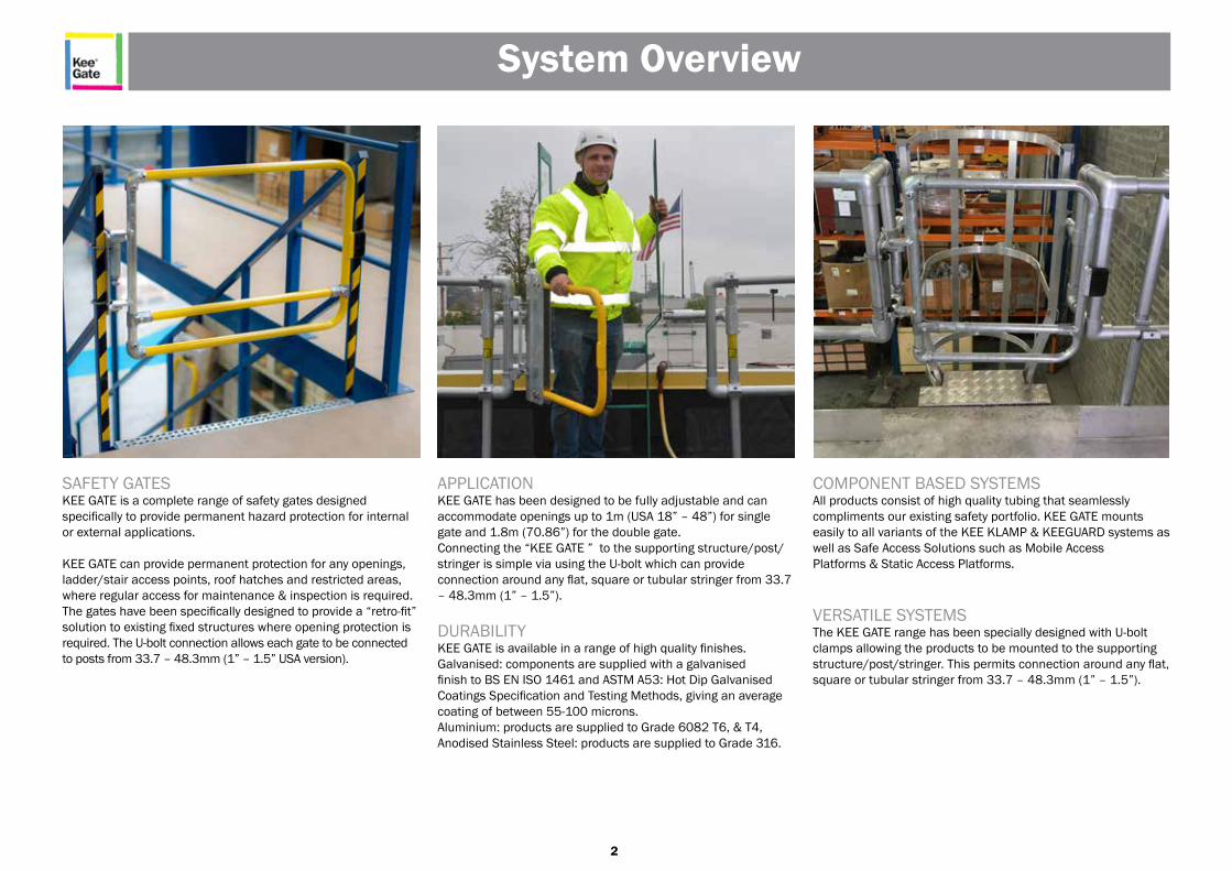
SAFETY GATESKEE GATE is a complete range of safety gates designedspecifically to provide permanent hazard protection for internal or external applications.
KEE GATE can provide permanent protection for any openings, ladder/stair access points, roof hatches and restricted areas, where regular access for maintenance & inspection is required. The gates have been specifically designed to provide a “retro-fit” solution to existing fixed structures where opening protection is required. The U-bolt connection allows each gate to be connected to posts from 33.7 – 48.3mm (1” – 1.5” USA version).
APPLICATIONKEE GATE has been designed to be fully adjustable and canaccommodate openings up to 1m (USA 18” – 48”) for single gate and 1.8m (70.86”) for the double gate.Connecting the “KEE GATE ” to the supporting structure/post/stringer is simple via using the U-bolt which can provideconnection around any flat, square or tubular stringer from 33.7 – 48.3mm (1” – 1.5”).
DURABILITYKEE GATE is available in a range of high quality finishes. Galvanised: components are supplied with a galvanisedfinish to BS EN ISO 1461 and ASTM A53: Hot Dip Galvanised Coatings Specification and Testing Methods, giving an average coating of between 55-100 microns.Aluminium: products are supplied to Grade 6082 T6, & T4, Anodised Stainless Steel: products are supplied to Grade 316.
COMPONENT BASED SYSTEMSAll products consist of high quality tubing that seamlesslycompliments our existing safety portfolio. KEE GATE mounts easily to all variants of the KEE KLAMP & KEEGUARD systems as well as Safe Access Solutions such as Mobile AccessPlatforms & Static Access Platforms.
VERSATILE SYSTEMSThe KEE GATE range has been specially designed with U-bolt clamps allowing the products to be mounted to the supporting structure/post/stringer. This permits connection around any flat, square or tubular stringer from 33.7 – 48.3mm (1” – 1.5”).
System Overview
3
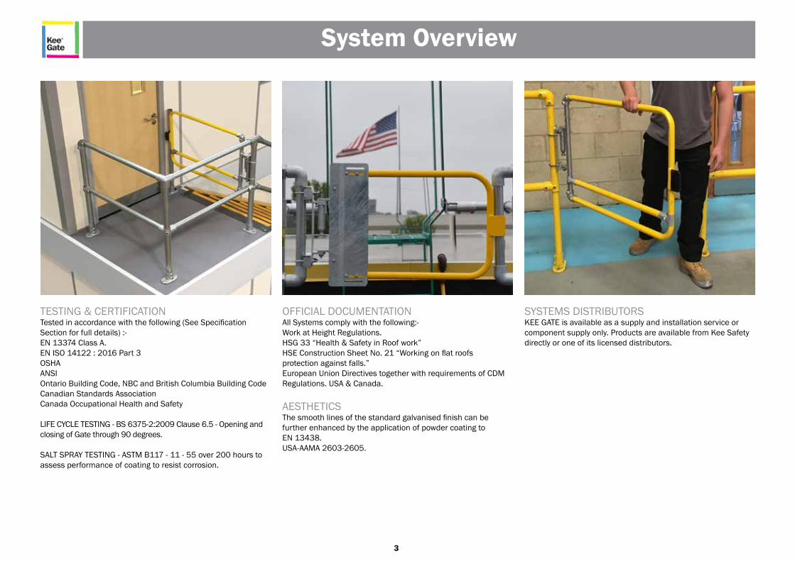
TESTING & CERTIFICATIONTested in accordance with the following (See SpecificationSection for full details) :-EN 13374 Class A.EN ISO 14122 : 2016 Part 3OSHA ANSI Ontario Building Code, NBC and British Columbia Building Code Canadian Standards Association Canada Occupational Health and Safety
LIFE CYCLE TESTING - BS 6375-2:2009 Clause 6.5 - Opening and closing of Gate through 90 degrees.
SALT SPRAY TESTING - ASTM B117 - 11 - 55 over 200 hours to assess performance of coating to resist corrosion.
OFFICIAL DOCUMENTATIONAll Systems comply with the following:-Work at Height Regulations.HSG 33 “Health & Safety in Roof work”HSE Construction Sheet No. 21 “Working on flat roofsprotection against falls.”European Union Directives together with requirements of CDM Regulations. USA & Canada.
AESTHETICSThe smooth lines of the standard galvanised finish can befurther enhanced by the application of powder coating toEN 13438.USA-AAMA 2603-2605.
SYSTEMS DISTRIBUTORSKEE GATE is available as a supply and installation service or component supply only. Products are available from Kee Safety directly or one of its licensed distributors.
System Overview
4
PRODUCT SPECIFICATION – EUROPEAN – USA - CANADIANFEATURES:- Spring Loaded, self-closing safety gate.GENERALKEE GATE systems require physical fixing to the buildings structure.The complete system’s design, manufacture, testing and installation have been externallyassessed and tested to European – USA – Canadian Standards.
MATERIALSEuropean Single & Double GateSteel tubing to EN 10255. 33.7mm diameter tube x 3.2mm wall thickness.All steel components galvanised to BS EN ISO 1461.All fixings are hot dipped galvanised to BS EN ISO 1461.All cast clamps have Threadkoat applied to all tapped holes. All grub screws are carbon steel and have Keekoat protection applied to ensure minimal maintenance. Where tubing is cut on site zinc rich paint is applied to the cut end of the tube.Powder Coating to EN 13438.
USA & Canada All steel components galvanised steel to ASTM A53.All fixings are hot dipped galvanised to ASTM A53.Powder Coating to USA-AAMA 2603-2605.
SINGLE GATE LAYOUT EUROPERecommended installed height of KEE GATE is 1.1m in Europe and Canada depending on the structure it is fixed to and National Regulations . Standard gate width 1m. Internal gapbetween top and bottom guardrail 634mm. Top rail to mid rail centre to centre 500mm.
SINGLE GATE LAYOUT USA & CANADARecommended installed height of KEE GATE is 42” in the USA depending on the structure it is fixed to and National Regulations.Standard gate widths 18”, 21”, 24”, 27”, 30”, 33”, 36”, 40”, 48” (each model can be adjusted on site). North America Lightweight Gate 38”. Internal gap between top and bottom guardrail 18.35”. Guardrail centre to centre 19.69”.
DOUBLE GATE LAYOUT EUROPERecommended installed height of KEE GATE is 1.1m in Europe and Canada depending on the structure it is fixed to and National Regulations. Double gate width 900mm. Internal gap between top and bottom guardrail 634mm. Top rail to mid rail centre to centre 500mm.
DOUBLE GATE LAYOUT USA & CANADARecommended installed height of KEE GATE is 42” in the USA depending on the structure it is fixed to and National Regulations. NA Guardrail centre to centre 19.68”. Double gate width 35.43”. Internal gap between top and bottom guardrail 18.35”. Guardrail centre to centre 19.69”.
TESTINGEN ISO 14122 : 2016 Part 3EN 13374 Class AOSHA – 200 lb applied to the top rail of the gate and 150 lb on the mid-rail of the gateANSI – The gate must comply with the same loading requirements as the structure to which it is attached.IBC – designed to resist linear load of 50 lb/ftOntario Building Code, NBC and British Columbia Building Code – “Handrails and anybuilding element that could be used as handrail shall be designed and attached in such amanner to resist, (a) a concentrated load at any point of not less than 0.9 kN (202 lb) and auniformly distributed load of 0.7 kN/m (48 lb/ft).OBC and NBC state – “all other guards” – 0.75 kN/m (52 lb/ft) or concentrated load of 1.0 kN (224 lb) applied at any point on top of the guardEvenly distributed vertical load on top of the guard – 1.5 kN/m (103 lb/ft)Canadian Standards Association – 0.9 kN (202 lb), 0.7 kN/m (48 lb/ft) – states “Guard - a protective barrier around an opening in a floor or at the open side of stairs, a landing, balcony, mezzanine, gallery, raised walkway or other location; used to prevent accidental falls from one level to another; such a barrier may or may not have openings through it.” Canada Occupational Health and Safety – 890N applied along top rail (200 lb)
LIFE CYCLE TESTING - BS 6375-2:2009 Clause 6.5 - Opening and closing of Gate through 90 degrees.
SALT SPRAY TESTING - ASTM B117 - 11 - 55 over 200 hours to assess performance ofcoating to resist corrosion.
Compliance
5
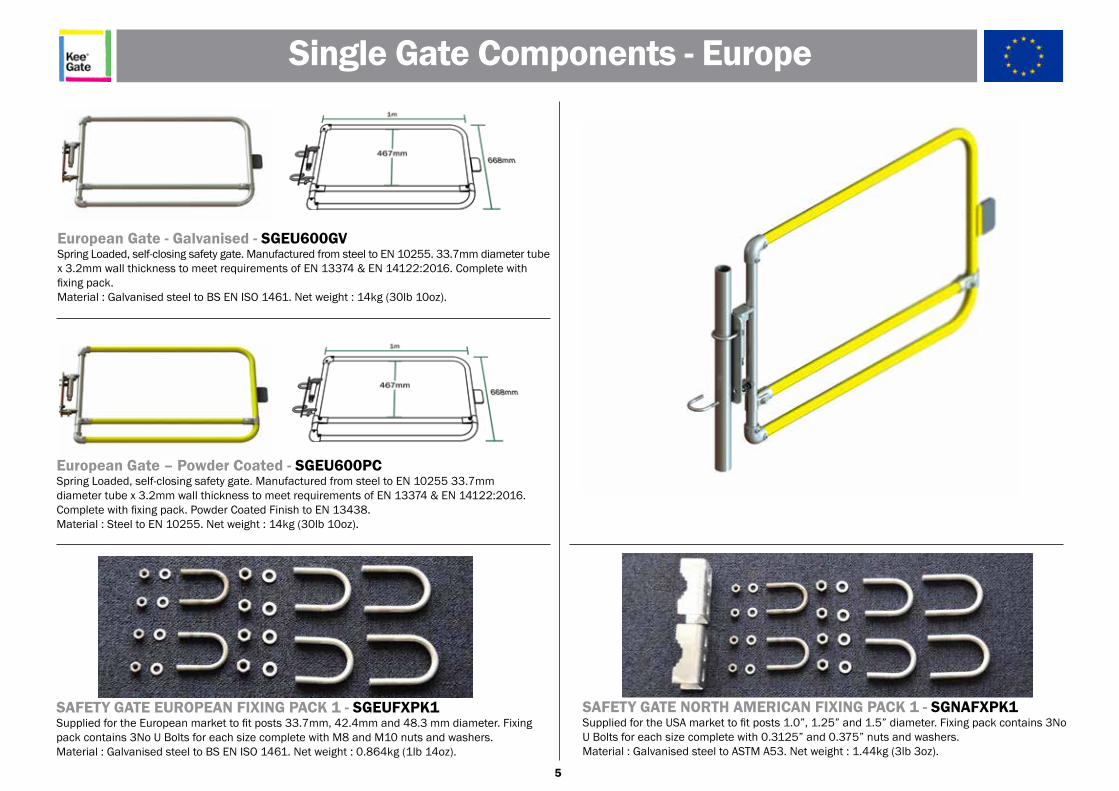
Single Gate Components - Europe
European Gate - Galvanised - SGEU600GVSpring Loaded, self-closing safety gate. Manufactured from steel to EN 10255. 33.7mm diameter tube x 3.2mm wall thickness to meet requirements of EN 13374 & EN 14122:2016. Complete with fixing pack.Material : Galvanised steel to BS EN ISO 1461. Net weight : 14kg (30lb 10oz).
European Gate – Powder Coated - SGEU600PCSpring Loaded, self-closing safety gate. Manufactured from steel to EN 10255 33.7mmdiameter tube x 3.2mm wall thickness to meet requirements of EN 13374 & EN 14122:2016.Complete with fixing pack. Powder Coated Finish to EN 13438. Material : Steel to EN 10255. Net weight : 14kg (30lb 10oz).
SAFETY GATE EUROPEAN FIXING PACK 1 - SGEUFXPK1Supplied for the European market to fit posts 33.7mm, 42.4mm and 48.3 mm diameter. Fixing pack contains 3No U Bolts for each size complete with M8 and M10 nuts and washers.Material : Galvanised steel to BS EN ISO 1461. Net weight : 0.864kg (1lb 14oz).
SAFETY GATE NORTH AMERICAN FIXING PACK 1 - SGNAFXPK1Supplied for the USA market to fit posts 1.0”, 1.25” and 1.5” diameter. Fixing pack contains 3No U Bolts for each size complete with 0.3125” and 0.375” nuts and washers.Material : Galvanised steel to ASTM A53. Net weight : 1.44kg (3lb 3oz).
6
Single Gate Components - North America
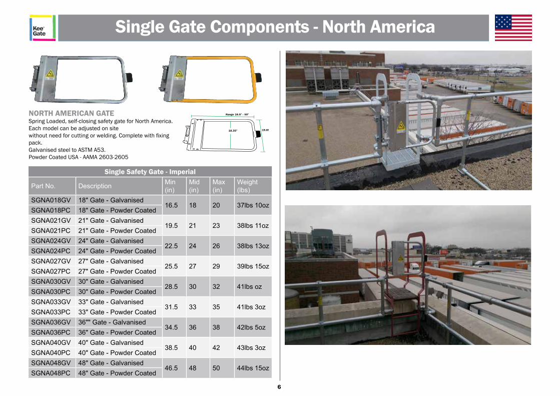
NORTH AMERICAN GATESpring Loaded, self-closing safety gate for North America. Each model can be adjusted on sitewithout need for cutting or welding. Complete with fixing pack.Galvanised steel to ASTM A53.Powder Coated USA - AAMA 2603-2605
18.35” 19.69”
Range 16.5" - 50"
Single Safety Gate - Imperial
Part No. Description Min(in)
Mid (in)
Max(in)
Weight(lbs)
SGNA018GV 18" Gate - Galvanised16.5 18 20 37lbs 10oz
SGNA018PC 18" Gate - Powder CoatedSGNA021GV 21" Gate - Galvanised
19.5 21 23 38lbs 11ozSGNA021PC 21" Gate - Powder CoatedSGNA024GV 24" Gate - Galvanised
22.5 24 26 38lbs 13ozSGNA024PC 24" Gate - Powder CoatedSGNA027GV 27" Gate - Galvanised
25.5 27 29 39lbs 15ozSGNA027PC 27" Gate - Powder CoatedSGNA030GV 30" Gate - Galvanised
28.5 30 32 41lbs ozSGNA030PC 30" Gate - Powder CoatedSGNA033GV 33" Gate - Galvanised
31.5 33 35 41lbs 3ozSGNA033PC 33" Gate - Powder CoatedSGNA036GV 36"" Gate - Galvanised
34.5 36 38 42lbs 5ozSGNA036PC 36" Gate - Powder CoatedSGNA040GV 40" Gate - Galvanised
38.5 40 42 43lbs 3ozSGNA040PC 40" Gate - Powder CoatedSGNA048GV 48" Gate - Galvanised
46.5 48 50 44lbs 15ozSGNA048PC 48" Gate - Powder Coated
7
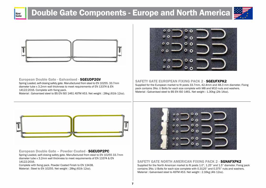
Double Gate Components - Europe and North America
European Double Gate - Galvanised - SGEUDP2GVSpring Loaded, self-closing safety gate. Manufactured from steel to EN 10255. 33.7mm diameter tube x 3.2mm wall thickness to meet requirements of EN 13374 & EN 14122:2016. Complete with fixing pack.Material : Galvanised steel to BS EN ISO 1461 ASTM A53. Net weight : 28kg (61lb 12oz).
European Double Gate – Powder Coated - SGEUDP2PCSpring Loaded, self-closing safety gate. Manufactured from steel to EN 10255 33.7mmdiameter tube x 3.2mm wall thickness to meet requirements of EN 13374 & EN 14122:2016.Complete with fixing pack. Powder Coated Finish to EN 13438. Material : Steel to EN 10255. Net weight : 28kg (61lb 12oz).
SAFETY GATE EUROPEAN FIXING PACK 2 - SGEUFXPK2Supplied for the European market to fit posts 33.7mm, 42.4mm and 48.3 mm diameter. Fixing pack contains 3No. U Bolts for each size complete with M8 and M10 nuts and washers. Material : Galvanised steel to BS EN ISO 1461. Net weight : 1.30kg (2lb 14oz).
SAFETY GATE NORTH AMERICAN FIXING PACK 2 - SGNAFXPK2Supplied for the North American market to fit posts 1.0”, 1.25” and 1.5” diameter. Fixing pack contains 3No. U Bolts for each size complete with 0.3125” and 0.375” nuts and washers. Material : Galvanised steel to ASTM A53. Net weight : 2.16kg (4lb 12oz).
8
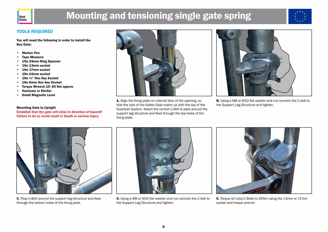
A. Align the fixing plate on internal face of the opening, so that the rails of the Safety Gate match up with the top of the Guardrail System. Select the correct U Bolt & pass around the support leg/structure and feed through the top holes of the fixing plate.
TOOLS REQUIRED
You will need the following in order to install theKee Gate:
• Marker Pen• Tape Measure• 1No 24mm Ring Spanner• 1No 13mm socket • 1No 17mm socket • 1No 24mm socket • 1No ¼” Hex Key Socket• 1No 6mm Hex Key Socket• Torque Wrench 10- 60 Nm approx• Hacksaw or Similar • Small Magnetic Level
Mounting Gate to UprightEstablish that the gate will close in direction of hazard!! Failure to do so could result in Death or serious injury.
D. Using a M8 or M10 flat washer and nut connect the U bolt to the Support Leg/Structure and tighten.
C. Pass U-Bolt around the support leg/structure and feed through the bottom holes of the fixing plate.
B. Using a M8 or M10 flat washer and nut connect the U bolt to the Support Leg/Structure and tighten.
E. Torque all nuts/U Bolts to 25Nm using the 13mm or 17mm socket and torque wrench.
Mounting and tensioning single gate spring
9
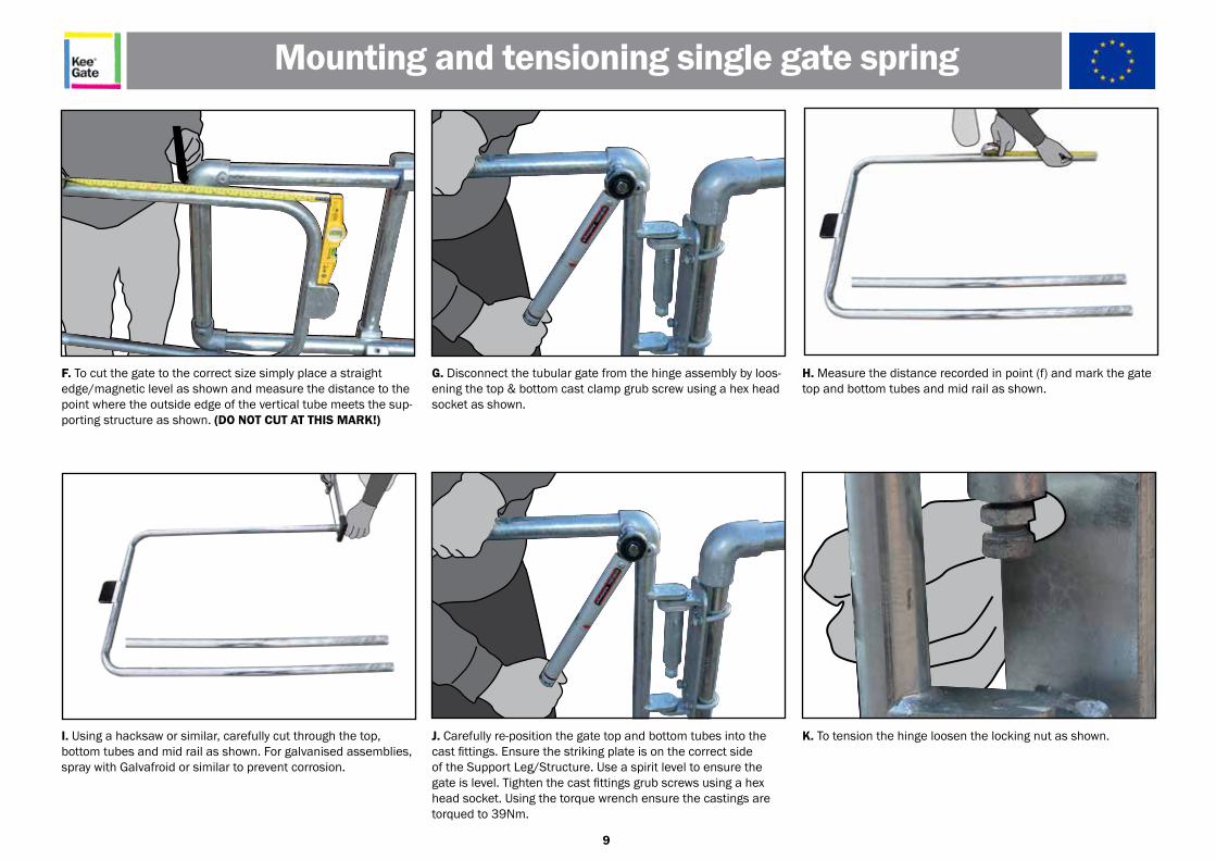
G. Disconnect the tubular gate from the hinge assembly by loos-ening the top & bottom cast clamp grub screw using a hex headsocket as shown.
J. Carefully re-position the gate top and bottom tubes into thecast fittings. Ensure the striking plate is on the correct sideof the Support Leg/Structure. Use a spirit level to ensure thegate is level. Tighten the cast fittings grub screws using a hexhead socket. Using the torque wrench ensure the castings aretorqued to 39Nm.
I. Using a hacksaw or similar, carefully cut through the top,bottom tubes and mid rail as shown. For galvanised assemblies,spray with Galvafroid or similar to prevent corrosion.
H. Measure the distance recorded in point (f) and mark the gatetop and bottom tubes and mid rail as shown.
F. To cut the gate to the correct size simply place a straightedge/magnetic level as shown and measure the distance to thepoint where the outside edge of the vertical tube meets the sup-porting structure as shown. (DO NOT CUT AT THIS MARK!)
K. To tension the hinge loosen the locking nut as shown.
Mounting and tensioning single gate spring
10
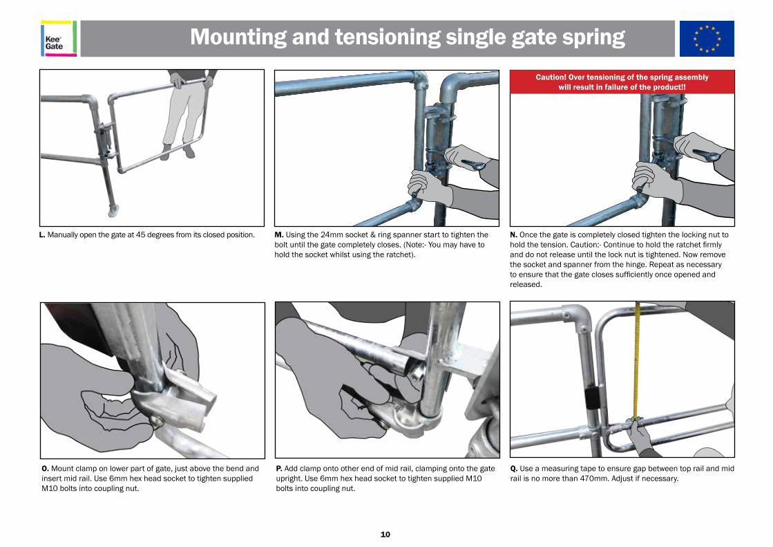
N. Once the gate is completely closed tighten the locking nut to hold the tension. Caution:- Continue to hold the ratchet firmly and do not release until the lock nut is tightened. Now remove the socket and spanner from the hinge. Repeat as necessary to ensure that the gate closes sufficiently once opened and released.
M. Using the 24mm socket & ring spanner start to tighten the bolt until the gate completely closes. (Note:- You may have to hold the socket whilst using the ratchet).
L. Manually open the gate at 45 degrees from its closed position.
Caution! Over tensioning of the spring assemblywill result in failure of the product!!
Mounting and tensioning single gate spring
O. Mount clamp on lower part of gate, just above the bend and insert mid rail. Use 6mm hex head socket to tighten supplied M10 bolts into coupling nut.
Q. Use a measuring tape to ensure gap between top rail and mid rail is no more than 470mm. Adjust if necessary.
P. Add clamp onto other end of mid rail, clamping onto the gate upright. Use 6mm hex head socket to tighten supplied M10 bolts into coupling nut.
11
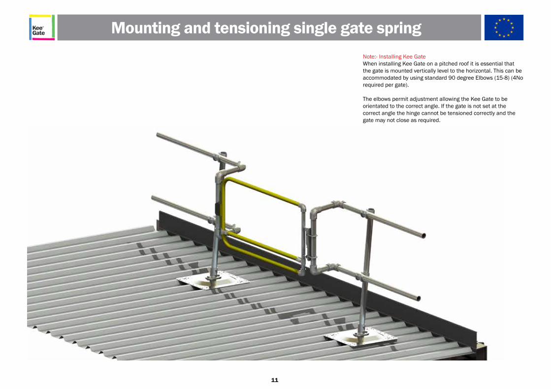
Note:- Installing Kee GateWhen installing Kee Gate on a pitched roof it is essential that the gate is mounted vertically level to the horizontal. This can be accommodated by using standard 90 degree Elbows (15-8) (4No required per gate).
The elbows permit adjustment allowing the Kee Gate to beorientated to the correct angle. If the gate is not set at thecorrect angle the hinge cannot be tensioned correctly and the gate may not close as required.
Mounting and tensioning single gate spring
12
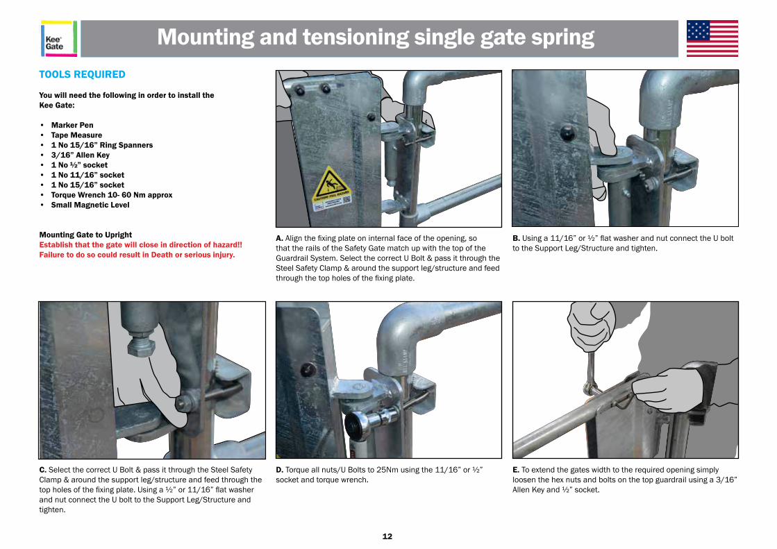
A. Align the fixing plate on internal face of the opening, so that the rails of the Safety Gate match up with the top of the Guardrail System. Select the correct U Bolt & pass it through the Steel Safety Clamp & around the support leg/structure and feed through the top holes of the fixing plate.
TOOLS REQUIRED
You will need the following in order to install theKee Gate: • Marker Pen• Tape Measure• 1 No 15/16” Ring Spanners• 3/16” Allen Key• 1 No ½” socket• 1 No 11/16” socket• 1 No 15/16” socket• Torque Wrench 10- 60 Nm approx• Small Magnetic Level
Mounting Gate to UprightEstablish that the gate will close in direction of hazard!! Failure to do so could result in Death or serious injury.
D. Torque all nuts/U Bolts to 25Nm using the 11/16” or ½” socket and torque wrench.
C. Select the correct U Bolt & pass it through the Steel Safety Clamp & around the support leg/structure and feed through the top holes of the fixing plate. Using a ½” or 11/16” flat washer and nut connect the U bolt to the Support Leg/Structure and tighten.
B. Using a 11/16” or ½” flat washer and nut connect the U bolt to the Support Leg/Structure and tighten.
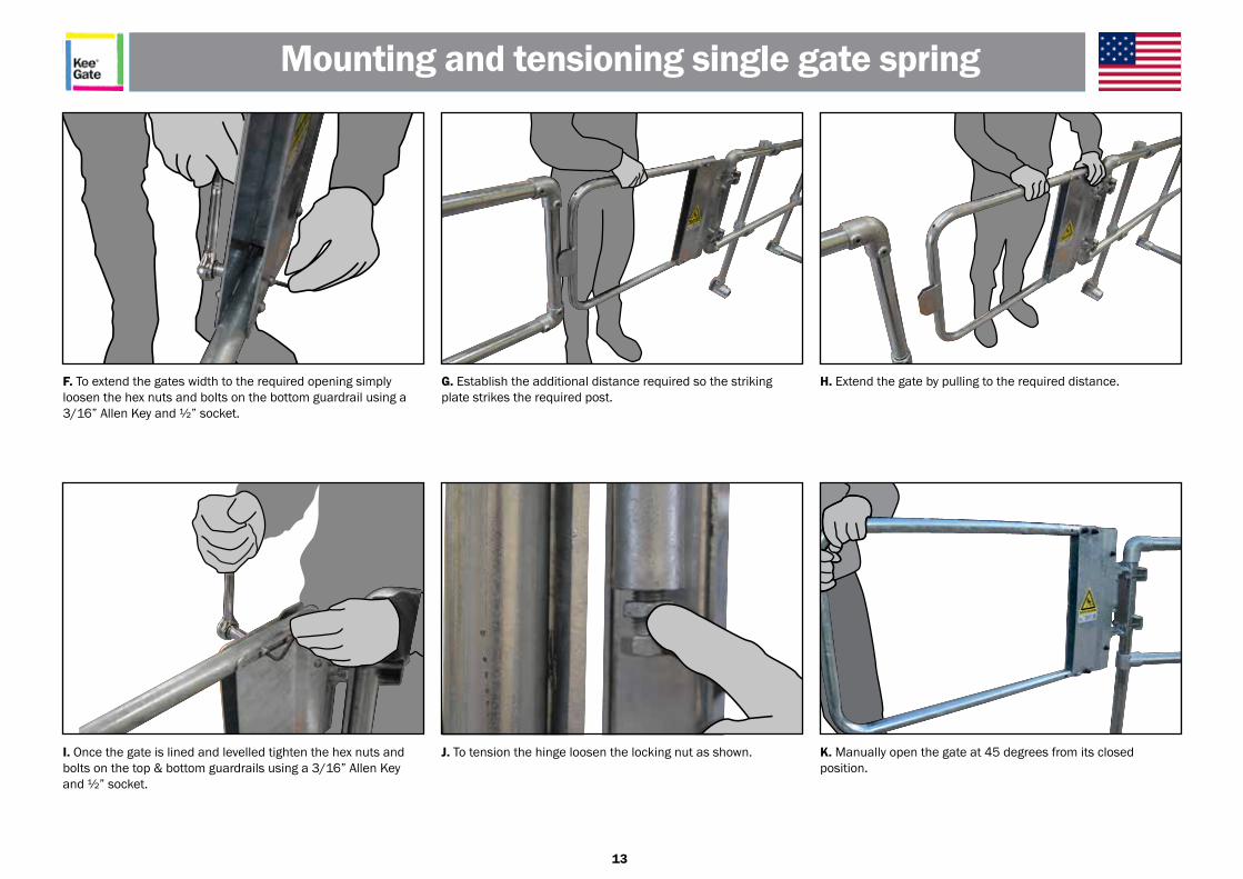
E. To extend the gates width to the required opening simply loosen the hex nuts and bolts on the top guardrail using a 3/16” Allen Key and ½” socket.
Mounting and tensioning single gate spring
13
G. Establish the additional distance required so the striking plate strikes the required post.
J. To tension the hinge loosen the locking nut as shown.I. Once the gate is lined and levelled tighten the hex nuts and bolts on the top & bottom guardrails using a 3/16” Allen Key and ½” socket.
H. Extend the gate by pulling to the required distance.F. To extend the gates width to the required opening simply loosen the hex nuts and bolts on the bottom guardrail using a 3/16” Allen Key and ½” socket.
K. Manually open the gate at 45 degrees from its closedposition.
Mounting and tensioning single gate spring
14
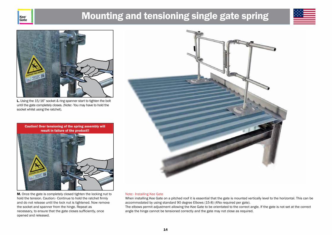
M. Once the gate is completely closed tighten the locking nut to hold the tension. Caution:- Continue to hold the ratchet firmly and do not release until the lock nut is tightened. Now remove the socket and spanner from the hinge. Repeat asnecessary, to ensure that the gate closes sufficiently, once opened and released.
Note:- Installing Kee GateWhen installing Kee Gate on a pitched roof it is essential that the gate is mounted vertically level to the horizontal. This can be accommodated by using standard 90 degree Elbows (15-8) (4No required per gate).The elbows permit adjustment allowing the Kee Gate to be orientated to the correct angle. If the gate is not set at the correct angle the hinge cannot be tensioned correctly and the gate may not close as required.
L. Using the 15/16” socket & ring spanner start to tighten the bolt until the gate completely closes. (Note:- You may have to hold the socket whilst using the ratchet).
Caution! Over tensioning of the spring assembly willresult in failure of the product!!
Mounting and tensioning single gate spring
15
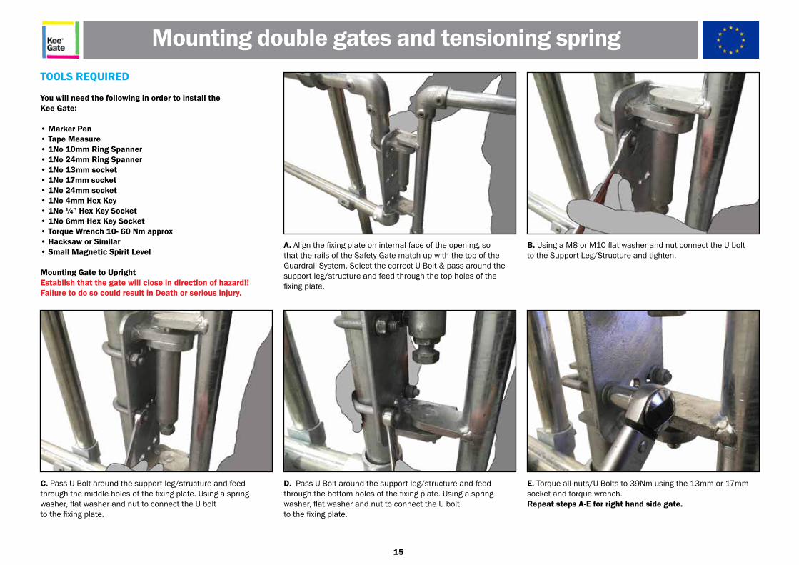
A. Align the fixing plate on internal face of the opening, sothat the rails of the Safety Gate match up with the top of theGuardrail System. Select the correct U Bolt & pass around thesupport leg/structure and feed through the top holes of thefixing plate.
TOOLS REQUIRED
You will need the following in order to install theKee Gate:
• Marker Pen• Tape Measure• 1No 10mm Ring Spanner• 1No 24mm Ring Spanner• 1No 13mm socket• 1No 17mm socket• 1No 24mm socket• 1No 4mm Hex Key• 1No ¼” Hex Key Socket• 1No 6mm Hex Key Socket• Torque Wrench 10- 60 Nm approx• Hacksaw or Similar• Small Magnetic Spirit Level
Mounting Gate to UprightEstablish that the gate will close in direction of hazard!!Failure to do so could result in Death or serious injury.
D. Pass U-Bolt around the support leg/structure and feedthrough the bottom holes of the fixing plate. Using a spring washer, flat washer and nut to connect the U boltto the fixing plate.
C. Pass U-Bolt around the support leg/structure and feedthrough the middle holes of the fixing plate. Using a spring washer, flat washer and nut to connect the U boltto the fixing plate.
B. Using a M8 or M10 flat washer and nut connect the U boltto the Support Leg/Structure and tighten.
E. Torque all nuts/U Bolts to 39Nm using the 13mm or 17mmsocket and torque wrench.Repeat steps A-E for right hand side gate.
Mounting double gates and tensioning spring
16
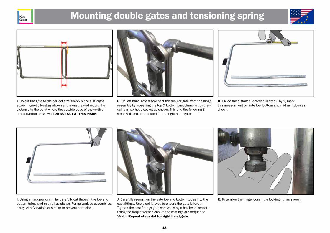
G. On left hand gate disconnect the tubular gate from the hinge assembly by loosening the top & bottom cast clamp grub screw using a hex head socket as shown. This and the following 3 steps will also be repeated for the right hand gate.
J. Carefully re-position the gate top and bottom tubes into thecast fittings. Use a spirit level, to ensure the gate is level. Tighten the cast fittings grub screws using a hex head socket. Using the torque wrench ensure the castings are torqued to 39Nm. Repeat steps G-J for right hand gate.
I. Using a hacksaw or similar carefully cut through the top andbottom tubes and mid rail as shown. For galvanised assemblies, spray with Galvafoid or similar to prevent corrosion.
H. Divide the distance recorded in step F by 2, markthis measurment on gate top, bottom and mid rail tubes as shown.
F. To cut the gate to the correct size simply place a straightedge/magnetic level as shown and measure and record thedistance to the point where the outside edge of the vertical tubes overlap as shown. (DO NOT CUT AT THIS MARK!)
K. To tension the hinge loosen the locking nut as shown.
Mounting double gates and tensioning spring
17
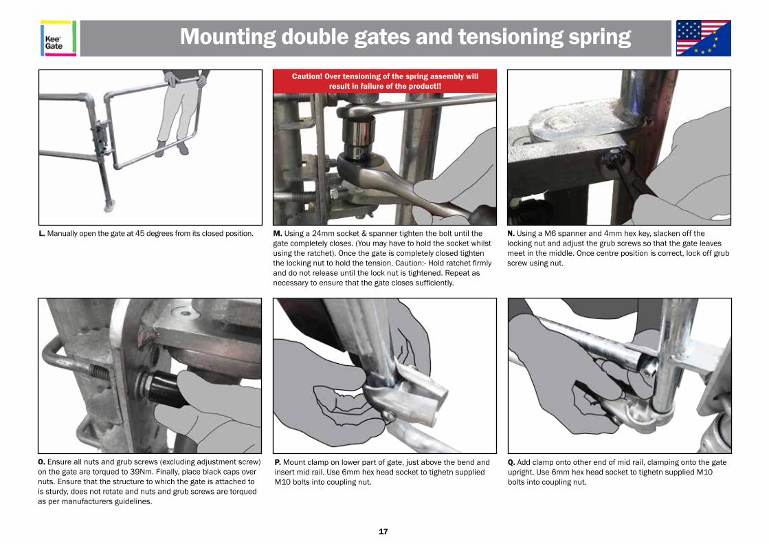
N. Using a M6 spanner and 4mm hex key, slacken off the locking nut and adjust the grub screws so that the gate leaves meet in the middle. Once centre position is correct, lock off grub screw using nut.
M. Using a 24mm socket & spanner tighten the bolt until the gate completely closes. (You may have to hold the socket whilst using the ratchet). Once the gate is completely closed tighten the locking nut to hold the tension. Caution:- Hold ratchet firmly and do not release until the lock nut is tightened. Repeat as necessary to ensure that the gate closes sufficiently.
L. Manually open the gate at 45 degrees from its closed position.
Mounting double gates and tensioning springCaution! Over tensioning of the spring assembly will
result in failure of the product!!
O. Ensure all nuts and grub screws (excluding adjustment screw) on the gate are torqued to 39Nm. Finally, place black caps over nuts. Ensure that the structure to which the gate is attached to is sturdy, does not rotate and nuts and grub screws are torqued as per manufacturers guidelines.
P. Mount clamp on lower part of gate, just above the bend and insert mid rail. Use 6mm hex head socket to tighetn supplied M10 bolts into coupling nut.
Q. Add clamp onto other end of mid rail, clamping onto the gate upright. Use 6mm hex head socket to tighetn supplied M10 bolts into coupling nut.
18
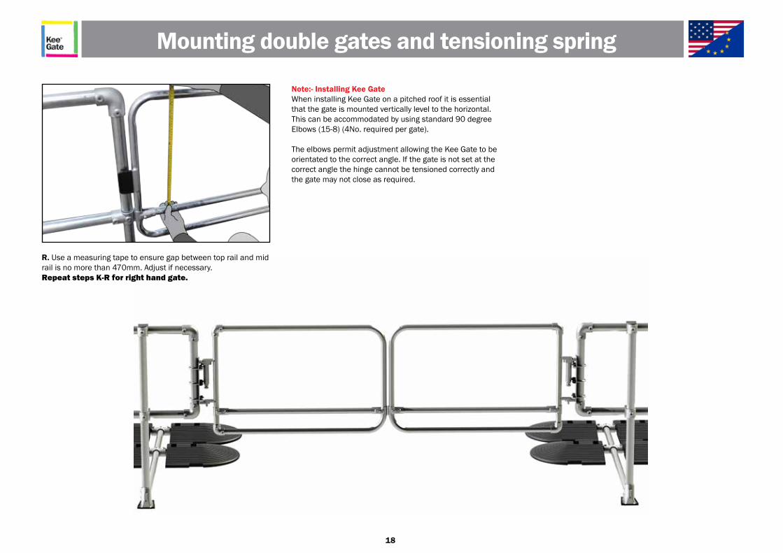
Note:- Installing Kee GateWhen installing Kee Gate on a pitched roof it is essential that the gate is mounted vertically level to the horizontal. This can be accommodated by using standard 90 degree Elbows (15-8) (4No. required per gate).
The elbows permit adjustment allowing the Kee Gate to be orientated to the correct angle. If the gate is not set at the correct angle the hinge cannot be tensioned correctly and the gate may not close as required.
R. Use a measuring tape to ensure gap between top rail and mid rail is no more than 470mm. Adjust if necessary.Repeat steps K-R for right hand gate.
Mounting double gates and tensioning spring
19
Periodic inspections by a competent person are recommended by the manufacturer. In UK/Europe these are required under Regulation 5 of the Workplace (Health, Safety & Welfare)Regulations, the Work at Height Regulations and Provision and Use of Work Equipment Regulations.The frequency will depend upon the environment, location and usage but should be at least every 12 months.
• Visually inspect the complete installed product in relation to the client’s needs. Establish if any modifications and/or additional products are required to reflect any refurbishment requirements or additional plant & equipment which have been installed and require access.
• Check installation configuration is complete as per the original installation drawing/plan.
• Ensure the product has not been modified or tampered with by unauthorised persons.
• Check the functionality of the product.
• Check the spring is correctly tensioned.
• Check all fixings are in place, greased and sufficiently torqued.
• Check the general height and level of the product.
• Any galvanised components showing signs of corrosion should be wire brushed thoroughly and galvanised spray/paint applied as appropriate. If rusted significantly, take digital photographs and include these in the inspection report.
• Inspect powder coated product surfaces and note any imperfections or general degradation.
• Check fixings to walls/structures including cat ladder clamps are in place, greased and sufficiently torqued.
• Check system plaque position & mark up to reflect date of the next required inspection. Establish if additional plaques are required due to any refurbishment works.
Kee Gate Recertification
Kee Safety LimitedCradley Business ParkOverend Road, Cradley HeathWest Midlands B64 7DW, UK
Phone: +44 (0) 1384 632 188Fax: +44 (0) 1384 632 [email protected]
Related Documents


