Single Acting Hydraulic Telescopic Cylinder Series SAT

Welcome message from author
This document is posted to help you gain knowledge. Please leave a comment to let me know what you think about it! Share it to your friends and learn new things together.
Transcript
Single Acting Hydraulic Telescopic CylinderSeries SAT

Parker Hannifin CorporationCylinder DivisionDes Plaines, Illinoiswww.parker.com/cylinder
Catalog HY18-0060-1/NA Single Acting Hydraulic Telescopic CylinderSeries SAT
In line with our policy of continuing product improvement, specifications and information contained in this catalog are subject to change.
Copyright ©2018 by Parker Hannifin Corporation. All rights reserved.
PRINTED IN THE U.S.A.
ASSEMBLED IN U.S.A.
WARNINGFAILURE OR IMPROPER SELECTION OR IMPROPER USE OF THE PRODUCTS AND/OR SYSTEMS DESCRIBED HEREIN OR RELATED ITEMS CAN CAUSE DEATH, PERSONAL INJURY AND PROPERTY DAMAGE.This document and other information from the Parker Hannifin Corporation, its subsidiaries and authorized distributors provide product and/or system options for further investigation by users having expertise. It is important that you analyze all aspects of your application, including consequences of any failure and review the information concerning the product or system in the current product catalog. Due to the variety of operating conditions and applications for these products or systems, the user, through its own analysis and testing, is solely responsible for making the final selection of the products and systems and assuring that all performance, safety and warning requirements of the application are met.The products described herein, including without limitation, product features, specifications, designs, availability and pricing, are subject to change by Parker Hannifin Corporation and its subsidiaries at any time without notice.
Offer of SaleThe items described in this document are hereby offered for sale by Parker Hannifin Corporation, its subsidiaries or its authorized distributors. This offer and its acceptance are governed by provisions stated on a separate page of the document entitled ‘Offer of Sale’.
WARNING!!
Before working on a telescopic cylinder mounted on a truck or trailer unit, use supports or holding devices that will absolutely prevent the body from accidentally lowering. Place control valve in the “Lower” position to assure that all pressure has been relieved from the cylinder.
Parker Hannifin CorporationCylinder DivisionDes Plaines, Illinoiswww.parker.com/cylinder
Catalog HY18-0060-1/NA Single Acting Hydraulic Telescopic CylinderSeries SAT
I
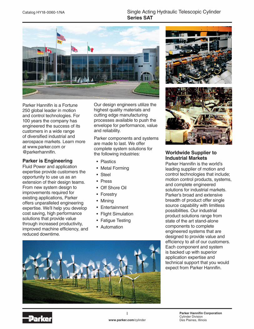
Parker Hannifin is a Fortune 250 global leader in motion and control technologies. For 100 years the company has engineered the success of its customers in a wide range of diversified industrial and aerospace markets. Learn more at www.parker.com or @parkerhannifin.
Parker is EngineeringFluid Power and application expertise provide customers the opportunity to use us as an extension of their design teams. From new system design to improvements required for existing applications, Parker offers unparalleled engineering expertise. We’ll help you develop cost saving, high performance solutions that provide value through increased productivity, improved machine efficiency, and reduced downtime.
Our design engineers utilize the highest quality materials and cutting edge manufacturing processes available to push the envelope for performance, value and reliability.
Parker components and systems are made to last. We offer complete system solutions for the following industries:
• Plastics• Metal Forming• Steel• Press• Off Shore Oil• Forestry• Mining• Entertainment• Flight Simulation• Fatigue Testing• Automation
Worldwide Supplier to Industrial MarketsParker Hannifin is the world’s leading supplier of motion and control technologies that include; motion control products, systems, and complete engineered solutions for industrial markets. Parker’s broad and extensive breadth of product offer single source capability with limitless possibilities. Our industrial product solutions range from state of the art stand-alone components to complete engineered systems that are designed to provide value and efficiency to all of our customers. Each component and system is backed up with superior application expertise and technical support that you would expect from Parker Hannifin.
Parker Hannifin CorporationCylinder DivisionDes Plaines, Illinois
II
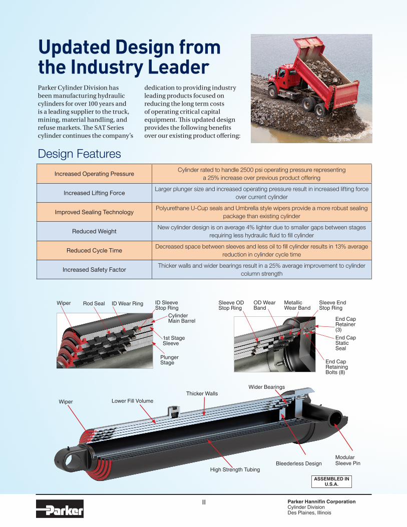
Updated Design from the Industry Leader
Increased Operating PressureCylinder rated to handle 2500 psi operating pressure representing
a 25% increase over previous product offering
Increased Lifting ForceLarger plunger size and increased operating pressure result in increased lifting force
over current cylinder
Improved Sealing TechnologyPolyurethane U-Cup seals and Umbrella style wipers provide a more robust sealing
package than existing cylinder
Reduced WeightNew cylinder design is on average 4% lighter due to smaller gaps between stages
requiring less hydraulic fluid to fill cylinder
Reduced Cycle TimeDecreased space between sleeves and less oil to fill cylinder results in 13% average
reduction in cylinder cycle time
Increased Safety FactorThicker walls and wider bearings result in a 25% average improvement to cylinder
column strength
Design Features
Parker Cylinder Division has been manufacturing hydraulic cylinders for over 100 years and is a leading supplier to the truck, mining, material handling, and refuse markets. The SAT Series cylinder continues the company’s
dedication to providing industry leading products focused on reducing the long term costs of operating critical capital equipment. This updated design provides the following benefits over our existing product offering:
Wiper Rod Seal ID Wear Ring ID Sleeve Stop Ring
Cylinder Main Barrel
Plunger Stage
1st Stage Sleeve
Sleeve OD Stop Ring
OD Wear Band
Metallic Wear Band
Sleeve End Stop Ring
End Cap Static Seal
End Cap Retainer (3)
End Cap Retaining Bolts (8)
Thicker WallsLower Fill VolumeWiper
Wider Bearings
Modular Sleeve PinBleederless Design
High Strength Tubing
ASSEMBLED IN U.S.A.
Single Acting Hydraulic Telescopic CylinderSeries SAT
Parker Hannifin CorporationCylinder DivisionDes Plaines, Illinoiswww.parker.com/cylinder
Catalog HY18-0060-1/NATable of Contents
1
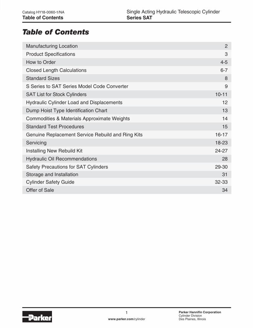
Manufacturing Location 2
Product Specifications 3
How to Order 4-5
Closed Length Calculations 6-7
Standard Sizes 8
S Series to SAT Series Model Code Converter 9
SAT List for Stock Cylinders 10-11
Hydraulic Cylinder Load and Displacements 12
Dump Hoist Type Identification Chart 13
Commodities & Materials Approximate Weights 14
Standard Test Procedures 15
Genuine Replacement Service Rebuild and Ring Kits 16-17
Servicing 18-23
Installing New Rebuild Kit 24-27
Hydraulic Oil Recommendations 28
Safety Precautions for SAT Cylinders 29-30Storage and Installation 31Cylinder Safety Guide 32-33
Offer of Sale 34
Table of Contents

Single Acting Telescopic CylinderSeries SAT
Parker Hannifin CorporationCylinder DivisionDes Plaines, Illinoiswww.parker.com/cylinder
Catalog HY18-0060-1/NA
2
Manufacturing Location
20138 I-30 • Benton, AR 72019 Tel.: (800) 848-5575 • Fax: (800) 694-3392
Benton, Arkansas
Introducing our new Telescopic Cylinder Crossover Tool
Now you can compare different brands of telescopic cylinders with the click of a mouse!
Our new conversion tool allows you to convert an S Series part number or
model code to SAT Series or the reverse.
www.parkercylinderdistributor.com/crossover-tool/
Single Acting Hydraulic Telescopic CylinderSeries SAT
Parker Hannifin CorporationCylinder DivisionDes Plaines, Illinoiswww.parker.com/cylinder
Catalog HY18-0060-1/NA
3
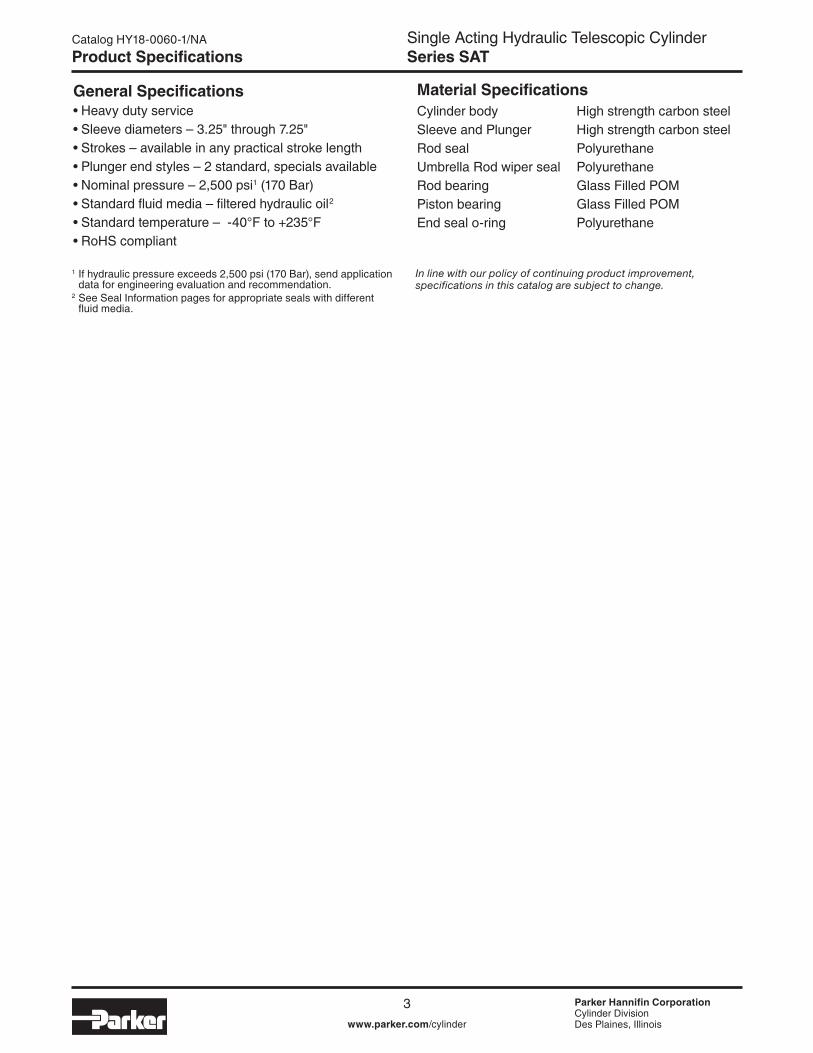
General Specifications• Heavy duty service• Sleeve diameters – 3.25" through 7.25"• Strokes – available in any practical stroke length• Plunger end styles – 2 standard, specials available• Nominal pressure – 2,500 psi1 (170 Bar)• Standard fluid media – filtered hydraulic oil2
• Standard temperature – -40°F to +235°F • RoHS compliant
In line with our policy of continuing product improvement, specifications in this catalog are subject to change.
Cylinder body High strength carbon steelSleeve and Plunger High strength carbon steelRod seal PolyurethaneUmbrella Rod wiper seal PolyurethaneRod bearing Glass Filled POMPiston bearing Glass Filled POMEnd seal o-ring Polyurethane
Material Specifications
Product Specifications
1 If hydraulic pressure exceeds 2,500 psi (170 Bar), send application data for engineering evaluation and recommendation.
2 See Seal Information pages for appropriate seals with different fluid media.
Single Acting Hydraulic Telescopic CylinderSeries SAT
Parker Hannifin CorporationCylinder DivisionDes Plaines, Illinoiswww.parker.com/cylinder
Catalog HY18-0060-1/NA
4www.parker.com/cylinder
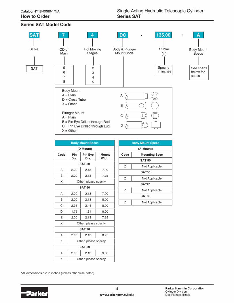
How to Order
Series SAT Model Code
Series OD of Main
# of Moving Stages
Body & Plunger Mount Code
Body Mount Specs
Stroke(in)
SAT 7 4 DC A135.00- -
5678
SAT 2345
Body MountA = PlainD = Cross TubeX = Other
Plunger MountA = PlainB = Pin Eye Drilled through RodC = Pin Eye Drilled through LugX = Other
A
B
C
D
Specify in inches
See charts below for specs
Body Mount Specs
(D-Mount)
Code Pin Dia.
Pin Eye Dia.
Mount Width
SAT 50
A 2.00 2.13 7.00
B 2.00 2.13 7.75
X Other, please specify
SAT 60
A 2.00 2.13 7.00
B 2.00 2.13 8.00
C 2.38 2.44 8.00
D 1.75 1.81 8.00
E 2.00 2.13 7.25
X Other, please specify
SAT 70
A 2.00 2.13 8.25
X Other, please specity
SAT 80
A 2.00 2.13 9.50
X Other, please specify
Body Mount Specs
(A-Mount)
Code Mounting Spec
SAT 50
Z Not Applicable
SAT60
Z Not Applicable
SAT70
Z Not Applicable
SAT80
Z Not Applicable
*All dimensions are in inches (unless otherwise noted).

Single Acting Hydraulic Telescopic CylinderSeries SAT
Parker Hannifin CorporationCylinder DivisionDes Plaines, Illinoiswww.parker.com/cylinder
Catalog HY18-0060-1/NA
5
How to Order
Series SAT Model Code
PlungerMount Specs
Port Type Port Size Closed Length (in)
A A A 52.00-
Specify in inches
See charts below for specs
Special
S
Use only if special modficiations are required
Code Type Shape A NPT Straight B SAE Straight C NPT 90 Elbow* D SAE 90 Elbow*
Code NPT SAE # of Ports A 3/4 #12 1.0 B 1 #16 1.0 C 1¼ #20 1.0 D 1½ #24 1.0 X Other Other 1.0 E 3/4 #12 2.0 F 1 #16 2.0 G 1¼ #20 2.0 H 1½ #24 2.0 X Other Other 2.0
Port Type
Plunger Mount Specs
(C-Mount)
2-Stage Cylinders
Code Pin Dia.
Pin Eye Dia.
Mount Width
SAT 52
A 2.00 2.06 2.00
B 1.63 1.69 1.50
C 2.13 2.19 1.50
X Other, please specify
SAT 62
A 2.00 2.06 2.00
X Other, please specify
SAT 72
X Other, please specify
SAT 82
X Other, please specify
Plunger Mount Specs
(C-Mount)
3-Stage Cylinders
Code Pin Dia.
Pin Eye Dia.
Mount Width
SAT 53
A 1.75 1.78 2.00
B 1.63 1.69 1.50
C 1.75 1.81 1.50
D 2.00 2.06 1.75
X Other, please specify
SAT 63
A 2.00 2.06 2.00
B 1.63 1.69 1.50
C 2.13 2.19 1.50
X Other, please specify
SAT 73
A 2.00 2.06 2.00
X Other, please specify
SAT 83
X Other, please specify
Plunger Mount Specs
(C-Mount)
4-Stage Cylinders
Code Pin Dia.
Pin Eye Dia.
Mount Width
SAT 64
A 2.00 2.06 1.75
B 1.75 1.81 2.00
C 1.63 1.69 1.50
D 1.75 1.81 1.50
X Other, please specify
SAT 74
A 2.00 2.06 2.00
B 1.63 1.69 1.50
C 2.13 2.19 1.50
X Other, please specify
SAT 84
A 2.00 2.06 2.00
X Other, please specify
Plunger Mount Specs
(C-Mount)
5-Stage Cylinders
Code Pin Dia.
Pin Eye Dia.
Mount Width
SAT 75
A 2.00 2.06 1.75
B 1.75 1.81 2.00
C 1.63 1.69 1.50
D 1.75 1.81 1.50
X Other, please specify
SAT 85
A 2.00 2.06 2.00
B 1.63 1.69 1.50
C 2.13 2.19 1.50
X Other, please specify
Plunger Mount Specs
(B-Mount)
Code Pin Dia.
Pin Eye Dia.
Mount Width
SAT 64
A 1.50 1.56 2.69
All Other Plunger B-Mounts
X Other, please specify
Plunger Mount Specs
(A-Mount)
For all Stages & Sizes
Code Mounting Spec
Z Not Applicable
Port Size and Quantity
*90° elbows only available in 1" NPT and #16 SAE Series
Single Acting Hydraulic Telescopic CylinderSeries SAT
Parker Hannifin CorporationCylinder DivisionDes Plaines, Illinoiswww.parker.com/cylinder
Catalog HY18-0060-1/NA
6www.parker.com/cylinder
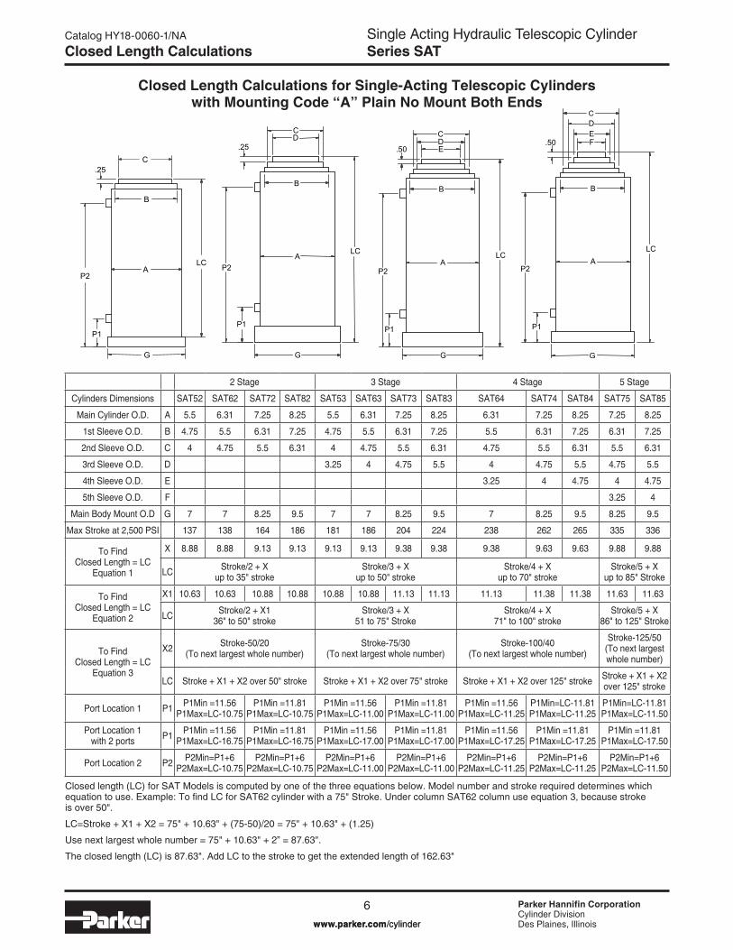
Closed Length Calculations
Closed length (LC) for SAT Models is computed by one of the three equations below. Model number and stroke required determines which equation to use. Example: To find LC for SAT62 cylinder with a 75" Stroke. Under column SAT62 column use equation 3, because stroke is over 50".
LC=Stroke + X1 + X2 = 75" + 10.63" + (75-50)/20 = 75" + 10.63" + (1.25)
Use next largest whole number = 75" + 10.63" + 2” = 87.63".
The closed length (LC) is 87.63". Add LC to the stroke to get the extended length of 162.63"
2 Stage 3 Stage 4 Stage 5 Stage
Cylinders Dimensions SAT52 SAT62 SAT72 SAT82 SAT53 SAT63 SAT73 SAT83 SAT64 SAT74 SAT84 SAT75 SAT85
Main Cylinder O.D. A 5.5 6.31 7.25 8.25 5.5 6.31 7.25 8.25 6.31 7.25 8.25 7.25 8.25
1st Sleeve O.D. B 4.75 5.5 6.31 7.25 4.75 5.5 6.31 7.25 5.5 6.31 7.25 6.31 7.25
2nd Sleeve O.D. C 4 4.75 5.5 6.31 4 4.75 5.5 6.31 4.75 5.5 6.31 5.5 6.31
3rd Sleeve O.D. D 3.25 4 4.75 5.5 4 4.75 5.5 4.75 5.5
4th Sleeve O.D. E 3.25 4 4.75 4 4.75
5th Sleeve O.D. F 3.25 4
Main Body Mount O.D G 7 7 8.25 9.5 7 7 8.25 9.5 7 8.25 9.5 8.25 9.5
Max Stroke at 2,500 PSI 137 138 164 186 181 186 204 224 238 262 265 335 336
To Find Closed Length = LC
Equation 1
X 8.88 8.88 9.13 9.13 9.13 9.13 9.38 9.38 9.38 9.63 9.63 9.88 9.88
LC Stroke/2 + X up to 35" stroke
Stroke/3 + X up to 50" stroke
Stroke/4 + X up to 70" stroke
Stroke/5 + X up to 85" Stroke
To Find Closed Length = LC
Equation 2
X1 10.63 10.63 10.88 10.88 10.88 10.88 11.13 11.13 11.13 11.38 11.38 11.63 11.63
LC Stroke/2 + X1 36" to 50" stroke
Stroke/3 + X 51 to 75" Stroke
Stroke/4 + X 71" to 100" stroke
Stroke/5 + X 86" to 125" Stroke
To Find Closed Length = LC
Equation 3
X2 Stroke-50/20 (To next largest whole number)
Stroke-75/30 (To next largest whole number)
Stroke-100/40 (To next largest whole number)
Stroke-125/50 (To next largest whole number)
LC Stroke + X1 + X2 over 50" stroke Stroke + X1 + X2 over 75" stroke Stroke + X1 + X2 over 125" stroke Stroke + X1 + X2 over 125" stroke
Port Location 1 P1 P1Min =11.56 P1Max=LC-10.75
P1Min =11.81 P1Max=LC-10.75
P1Min =11.56 P1Max=LC-11.00
P1Min =11.81 P1Max=LC-11.00
P1Min =11.56 P1Max=LC-11.25
P1Min=LC-11.81 P1Max=LC-11.25
P1Min=LC-11.81 P1Max=LC-11.50
Port Location 1 with 2 ports P1 P1Min =11.56
P1Max=LC-16.75P1Min =11.81
P1Max=LC-16.75P1Min =11.56
P1Max=LC-17.00P1Min =11.81
P1Max=LC-17.00P1Min =11.56
P1Max=LC-17.25P1Min =11.81
P1Max=LC-17.25P1Min =11.81
P1Max=LC-17.50
Port Location 2 P2 P2Min=P1+6 P2Max=LC-10.75
P2Min=P1+6 P2Max=LC-10.75
P2Min=P1+6 P2Max=LC-11.00
P2Min=P1+6 P2Max=LC-11.00
P2Min=P1+6 P2Max=LC-11.25
P2Min=P1+6 P2Max=LC-11.25
P2Min=P1+6 P2Max=LC-11.50
Closed Length Calculations for Single-Acting Telescopic Cylinders with Mounting Code “A” Plain No Mount Both Ends
CDE
B
P2
P1
A
G
LC
.50
CD
.25
P2
P1
G
LC
B
A
C
B
P2
.25
LCA
G
P1
DEF
B
A
G
LC
P2
P1
.50
C

Single Acting Hydraulic Telescopic CylinderSeries SAT
Parker Hannifin CorporationCylinder DivisionDes Plaines, Illinoiswww.parker.com/cylinder
Catalog HY18-0060-1/NA
7
Closed Length Calculations
Closed Length Calculations for Single-Acting Telescopic Cylinders with Mounting Code “DB” or “DC”
2 Stage 3 Stage 4 Stage 5 Stage
Cylinders Dimensions SAT52 SAT62 SAT72 SAT82 SAT53 SAT63 SAT73 SAT83 SAT64 SAT74 SAT84 SAT75 SAT85
Main Cylinder O.D. A 5.5 6.31 7.25 8.25 5.5 6.31 7.25 8.25 6.31 7.25 8.25 7.25 8.25
1st Sleeve O.D. B 4.75 5.5 6.31 7.25 4.75 5.5 6.31 7.25 5.5 6.31 7.25 6.31 7.25
2nd Sleeve O.D. C 4 4.75 5.5 6.31 4 4.75 5.5 6.31 4.75 5.5 6.31 5.5 6.31
3rd Sleeve O.D. D 3.25 4 4.75 5.5 4 4.75 5.5 4.75 5.5
4th Sleeve O.D. E 3.25 4 4.75 4 4.75
5th Sleeve O.D. F 3.25 4
Main Body Mount O.D G 7 7 8.25 9.5 7 7 8.25 9.5 7 8.25 9.5 8.25 9.5
Max Stroke at 2,500 PSI 137 138 164 186 181 186 204 224 238 262 265 335 336
To Find Closed Length = LC
Equation 1
X 12.75 12.75 13.19 13.19 13.00 13.00 13.44 13.44 13.25 13.69 13.69 13.94 13.94
LC Stroke/2 + X up to 35" stroke
Stroke/3 + X up to 50" stroke
Stroke/4 + X up to 70" stroke
Stroke/5 + X up to 85" Stroke
To Find Closed Length = LC
Equation 2
X1 14.50 14.50 14.94 14.94 14.75 14.75 15.19 15.19 15.00 15.44 15.44 15.69 15.69
LC Stroke/2 + X1 36" to 50" stroke
Stroke/3 + X 51 to 75" Stroke
Stroke/4 + X 71" to 100" stroke
Stroke/5 + X 86" to 125" Stroke
To Find Closed Length = LC
Equation 3
X2 Stroke-50/20 (To next largest whole number)
Stroke-75/30 (To next largest whole number)
Stroke-100/40 (To next largest whole number)
Stroke-125/50 (To next largest whole number)
LC Stroke + X1 + X2 over 50" stroke Stroke + X1 + X2 over 75" stroke Stroke + X1 + X2 over 125" stroke Stroke + X1 + X2 over 125" stroke
Port Location 1 P1 P1Min =12.88 P1Max=LC-10.75
P1Min =13.31 P1Max=LC-10.75
P1Min =12.88 P1Max=LC-11.00
P1Min =13.31 P1Max=LC-11.00
P1Min =12.88 P1Max=LC-11.25
P1Min=LC-13.31 P1Max=LC-11.25
P1Min=LC-13.31 P1Max=LC-11.50
Port Location 1 with 2 ports P1 P1Min =12.88
P1Max=LC-16.75P1Min =13.31
P1Max=LC-16.75P1Min =12.88
P1Max=LC-17.00P1Min =13.31
P1Max=LC-17.00P1Min =12.88
P1Max=LC-17.25P1Min =13.31
P1Max=LC-17.25P1Min =13.31
P1Max=LC-17.50
Port Location 2 P2 P2Min=P1+6 P2Max=LC-10.75
P2Min=P1+6 P2Max=LC-10.75
P2Min=P1+6 P2Max=LC-11.00
P2Min=P1+6 P2Max=LC-11.00
P2Min=P1+6 P2Max=LC-11.25
P2Min=P1+6 P2Max=LC-11.25
P2Min=P1+6 P2Max=LC-11.50
C
.25
B
A
G
LC
P2
P1
CDE
B
A
G
P2
P1
LC
.50
CD
B
A
G
P2
P1
LC
.25
CD
.50
B
A
G
P2
LC
P1
EF
Single Acting Hydraulic Telescopic CylinderSeries SAT
Parker Hannifin CorporationCylinder DivisionDes Plaines, Illinoiswww.parker.com/cylinder
Catalog HY18-0060-1/NA
8
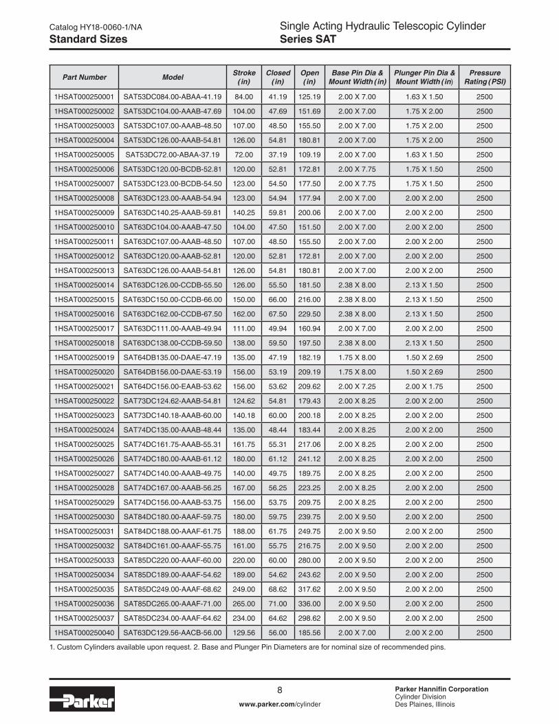
1. Custom Cylinders available upon request. 2. Base and Plunger Pin Diameters are for nominal size of recommended pins.
Part Number Model Stroke (in)
Closed (in)
Open (in)
Base Pin Dia & Mount Width (in)
Plunger Pin Dia & Mount Width (in)
Pressure Rating (PSI)
1HSAT000250001 SAT53DC084.00-ABAA-41.19 84.00 41.19 125.19 2.00 X 7.00 1.63 X 1.50 2500
1HSAT000250002 SAT53DC104.00-AAAB-47.69 104.00 47.69 151.69 2.00 X 7.00 1.75 X 2.00 2500
1HSAT000250003 SAT53DC107.00-AAAB-48.50 107.00 48.50 155.50 2.00 X 7.00 1.75 X 2.00 2500
1HSAT000250004 SAT53DC126.00-AAAB-54.81 126.00 54.81 180.81 2.00 X 7.00 1.75 X 2.00 2500
1HSAT000250005 SAT53DC72.00-ABAA-37.19 72.00 37.19 109.19 2.00 X 7.00 1.63 X 1.50 2500
1HSAT000250006 SAT53DC120.00-BCDB-52.81 120.00 52.81 172.81 2.00 X 7.75 1.75 X 1.50 2500
1HSAT000250007 SAT53DC123.00-BCDB-54.50 123.00 54.50 177.50 2.00 X 7.75 1.75 X 1.50 2500
1HSAT000250008 SAT63DC123.00-AAAB-54.94 123.00 54.94 177.94 2.00 X 7.00 2.00 X 2.00 2500
1HSAT000250009 SAT63DC140.25-AAAB-59.81 140.25 59.81 200.06 2.00 X 7.00 2.00 X 2.00 2500
1HSAT000250010 SAT63DC104.00-AAAB-47.50 104.00 47.50 151.50 2.00 X 7.00 2.00 X 2.00 2500
1HSAT000250011 SAT63DC107.00-AAAB-48.50 107.00 48.50 155.50 2.00 X 7.00 2.00 X 2.00 2500
1HSAT000250012 SAT63DC120.00-AAAB-52.81 120.00 52.81 172.81 2.00 X 7.00 2.00 X 2.00 2500
1HSAT000250013 SAT63DC126.00-AAAB-54.81 126.00 54.81 180.81 2.00 X 7.00 2.00 X 2.00 2500
1HSAT000250014 SAT63DC126.00-CCDB-55.50 126.00 55.50 181.50 2.38 X 8.00 2.13 X 1.50 2500
1HSAT000250015 SAT63DC150.00-CCDB-66.00 150.00 66.00 216.00 2.38 X 8.00 2.13 X 1.50 2500
1HSAT000250016 SAT63DC162.00-CCDB-67.50 162.00 67.50 229.50 2.38 X 8.00 2.13 X 1.50 2500
1HSAT000250017 SAT63DC111.00-AAAB-49.94 111.00 49.94 160.94 2.00 X 7.00 2.00 X 2.00 2500
1HSAT000250018 SAT63DC138.00-CCDB-59.50 138.00 59.50 197.50 2.38 X 8.00 2.13 X 1.50 2500
1HSAT000250019 SAT64DB135.00-DAAE-47.19 135.00 47.19 182.19 1.75 X 8.00 1.50 X 2.69 2500
1HSAT000250020 SAT64DB156.00-DAAE-53.19 156.00 53.19 209.19 1.75 X 8.00 1.50 X 2.69 2500
1HSAT000250021 SAT64DC156.00-EAAB-53.62 156.00 53.62 209.62 2.00 X 7.25 2.00 X 1.75 2500
1HSAT000250022 SAT73DC124.62-AAAB-54.81 124.62 54.81 179.43 2.00 X 8.25 2.00 X 2.00 2500
1HSAT000250023 SAT73DC140.18-AAAB-60.00 140.18 60.00 200.18 2.00 X 8.25 2.00 X 2.00 2500
1HSAT000250024 SAT74DC135.00-AAAB-48.44 135.00 48.44 183.44 2.00 X 8.25 2.00 X 2.00 2500
1HSAT000250025 SAT74DC161.75-AAAB-55.31 161.75 55.31 217.06 2.00 X 8.25 2.00 X 2.00 2500
1HSAT000250026 SAT74DC180.00-AAAB-61.12 180.00 61.12 241.12 2.00 X 8.25 2.00 X 2.00 2500
1HSAT000250027 SAT74DC140.00-AAAB-49.75 140.00 49.75 189.75 2.00 X 8.25 2.00 X 2.00 2500
1HSAT000250028 SAT74DC167.00-AAAB-56.25 167.00 56.25 223.25 2.00 X 8.25 2.00 X 2.00 2500
1HSAT000250029 SAT74DC156.00-AAAB-53.75 156.00 53.75 209.75 2.00 X 8.25 2.00 X 2.00 2500
1HSAT000250030 SAT84DC180.00-AAAF-59.75 180.00 59.75 239.75 2.00 X 9.50 2.00 X 2.00 2500
1HSAT000250031 SAT84DC188.00-AAAF-61.75 188.00 61.75 249.75 2.00 X 9.50 2.00 X 2.00 2500
1HSAT000250032 SAT84DC161.00-AAAF-55.75 161.00 55.75 216.75 2.00 X 9.50 2.00 X 2.00 2500
1HSAT000250033 SAT85DC220.00-AAAF-60.00 220.00 60.00 280.00 2.00 X 9.50 2.00 X 2.00 2500
1HSAT000250034 SAT85DC189.00-AAAF-54.62 189.00 54.62 243.62 2.00 X 9.50 2.00 X 2.00 2500
1HSAT000250035 SAT85DC249.00-AAAF-68.62 249.00 68.62 317.62 2.00 X 9.50 2.00 X 2.00 2500
1HSAT000250036 SAT85DC265.00-AAAF-71.00 265.00 71.00 336.00 2.00 X 9.50 2.00 X 2.00 2500
1HSAT000250037 SAT85DC234.00-AAAF-64.62 234.00 64.62 298.62 2.00 X 9.50 2.00 X 2.00 2500
1HSAT000250040 SAT63DC129.56-AACB-56.00 129.56 56.00 185.56 2.00 X 7.00 2.00 X 2.00 2500
Standard Sizes

Single Acting Hydraulic Telescopic CylinderSeries SAT
Parker Hannifin CorporationCylinder DivisionDes Plaines, Illinoiswww.parker.com/cylinder
Catalog HY18-0060-1/NA
9
S Series to SAT Series Conversion
S Series SAT SeriesPart Number Model Code Part Number Model Code
3771513168 S53DC-65-104.00 1HSAT000250002 SAT53DC104.00-AAAB-47.69
3771513169 S53DC-65-107.56 1HSAT000250003 SAT53DC107.00-AAAB-48.50
3771513170 S53DC-65-126.62 1HSAT000250004 SAT53DC126.00-AAAB-54.81
3771513171 S53DC-66-84.00 1HSAT000250001 SAT53DC84.00-ABAA-41.19
3771513172 S53DC-66-72.00 1HSAT000250005 SAT53DC72.00-ABAA-37.19
3771513177 S53DC-68-120.00 1HSAT000250006 SAT53DC120.00-BCDB-52.81
3771513178 S53DC-68-123.00 1HSAT000250007 SAT53DC123.00-BCDB-54.50
3771413308 S63DC-96-130.19 1HSAT000250040 SAT63DC129.56-AACB-56.00
3771413309 S63DC-97-111.00 1HSAT000250017 SAT63DC111.00-AAAB-49.94
3771413310 S63DC-97-123.00 1HSAT000250008 SAT63DC123.00-AAAB-54.94
3771413319 S63DC-101-104.00 1HSAT000250010 SAT63DC104.00-AAAB-47.50
3771413320 S63DC-101-107.56 1HSAT000250011 SAT63DC107.00-AAAB-48.50
3771413321 S63DC-101-120.00 1HSAT000250012 SAT63DC120.00-AAAB-52.81
3771413322 S63DC-101-126.62 1HSAT000250013 SAT63DC126.00-AAAB-54.81
3771413324 S63DC-101-140.25 1HSAT000250009 SAT63DC140.25-AAAB-59.81
3771413326 S63DC-102-126.00 1HSAT000250014 SAT63DC126.00-CCDB-55.50
3771413327 S63DC-102-138.00 1HSAT000250018 SAT63DC138.00-CCDB-59.50
3771413328 S63DC-102-150.00 1HSAT000250015 SAT63DC150.00-CCDB-66.00
3771413329 S63DC-102-162.00 1HSAT000250016 SAT63DC162.00-CCDB-67.50
3771414058 S64DB-12-135.00 1HSAT000250019 SAT64DB135.00-DAAE-47.19
3771414056 S64DB-12-156.00 1HSAT000250020 SAT64DB156.00-DAAE-53.19
3771414059 S64DC-14-156.00 1HSAT000250021 SAT64DC156.00-EAAB-53.62
3772513128 S73DC-66-124.88 1HSAT000250022 SAT73DC124.62-AAAB-54.81
3772513129 S73DC-66-140.44 1HSAT000250023 SAT73DC140.18-AAAB-60.00
3772514125 S74DC-74-135.00 1HSAT000250024 SAT74DC135.00-AAAB-48.44
3772514122 S74DC-74-140.00 1HSAT000250027 SAT74DC140.00-AAAB-49.75
3772514123 S74DC-74-156.00 1HSAT000250029 SAT74DC156.00-AAAB-53.75
3772514120 S74DC-74-161.75 1HSAT000250025 SAT74DC161.75-AAAB-55.31
3772514130 S74DC-74-167.00 1HSAT000250028 SAT74DC167.00-AAAB-56.25
3772514126 S74DC-74-180.00 1HSAT000250026 SAT74DC180.00-AAAB-61.12
3772914082 S84DC-66-161.00 1HSAT000250032 SAT84DC161.00-AAAF-55.75
3772914084 S84DC-66-180.00 1HSAT000250030 SAT84DC180.00-AAAF-59.75
3772914085 S84DC-66-188.00 1HSAT000250031 SAT84DC188.00-AAAF-61.75
3772915166 S85DC-66-190.00 1HSAT000250034 SAT85DC189.00-AAAF-54.62
3772915167 S85DC-66-220.00 1HSAT000250033 SAT85DC220.00-AAAF-60.00
3772915161 S85DC-66-235.00 1HSAT000250037 SAT85DC234.00-AAAF-64.62
3772915160 S85DC-66-250.00 1HSAT000250035 SAT85DC249.00-AAAF-68.62
3772915165 S85DC-66-265.00 1HSAT000250036 SAT85DC265.00-AAAF-71.00
S Series to SAT Series Model Code Conversion
Single Acting Hydraulic Telescopic CylinderSeries SAT
Parker Hannifin CorporationCylinder DivisionDes Plaines, Illinoiswww.parker.com/cylinder
Catalog HY18-0060-1/NA
10
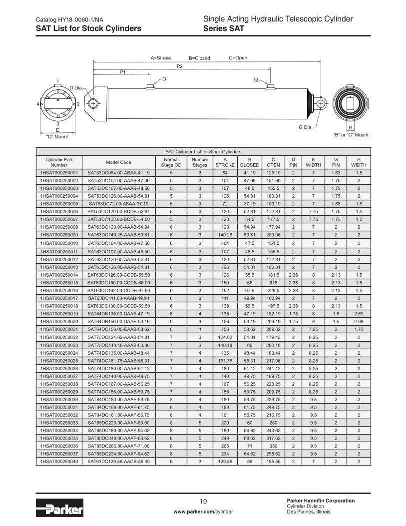
SAT Cylinder List for Stock CylindersCylinder Part
Number Model Code Nomial Stage OD
Number Stages
A STROKE
B CLOSED
C OPEN
D PIN
E WIDTH
G PIN
H WIDTH
1HSAT000250001 SAT53DC084.00-ABAA-41.19 5 3 84 41.19 125.19 2 7 1.63 1.51HSAT000250002 SAT53DC104.00-AAAB-47.69 5 3 104 47.69 151.69 2 7 1.75 21HSAT000250003 SAT53DC107.00-AAAB-48.50 5 3 107 48.5 155.5 2 7 1.75 21HSAT000250004 SAT53DC126.00-AAAB-54.81 5 3 126 54.81 180.81 2 7 1.75 21HSAT000250005 SAT53DC72.00-ABAA-37.19 5 3 72 37.19 109.19 2 7 1.63 1.51HSAT000250006 SAT53DC120.00-BCDB-52.81 5 3 120 52.81 172.81 2 7.75 1.75 1.51HSAT000250007 SAT53DC123.00-BCDB-54.50 5 3 123 54.5 177.5 2 7.75 1.75 1.51HSAT000250008 SAT63DC123.00-AAAB-54.94 6 3 123 54.94 177.94 2 7 2 21HSAT000250009 SAT63DC140.25-AAAB-59.81 6 3 140.25 59.81 200.06 2 7 2 2
1HSAT000250010 SAT63DC104.00-AAAB-47.50 6 3 104 47.5 151.5 2 7 2 2
1HSAT000250011 SAT63DC107.00-AAAB-48.50 6 3 107 48.5 155.5 2 7 2 21HSAT000250012 SAT63DC120.00-AAAB-52.81 6 3 120 52.81 172.81 2 7 2 21HSAT000250013 SAT63DC126.00-AAAB-54.81 6 3 126 54.81 180.81 2 7 2 21HSAT000250014 SAT63DC126.00-CCDB-55.50 6 3 126 55.5 181.5 2.38 8 2.13 1.51HSAT000250015 SAT63DC150.00-CCDB-66.00 6 3 150 66 216 2.38 8 2.13 1.51HSAT000250016 SAT63DC162.00-CCDB-67.50 6 3 162 67.5 229.5 2.38 8 2.13 1.51HSAT000250017 SAT63DC111.00-AAAB-49.94 6 3 111 49.94 160.94 2 7 2 21HSAT000250018 SAT63DC138.00-CCDB-59.50 6 3 138 59.5 197.5 2.38 8 2.13 1.51HSAT000250019 SAT64DB135.00-DAAE-47.19 6 4 135 47.19 182.19 1.75 8 1.5 2.691HSAT000250020 SAT64DB156.00-DAAE-53.19 6 4 156 53.19 209.19 1.75 8 1.5 2.691HSAT000250021 SAT64DC156.00-EAAB-53.62 6 4 156 53.62 209.62 2 7.25 2 1.75
1HSAT000250022 SAT73DC124.62-AAAB-54.81 7 3 124.62 54.81 179.43 2 8.25 2 2
1HSAT000250023 SAT73DC140.18-AAAB-60.00 7 3 140.18 60 200.18 2 8.25 2 21HSAT000250024 SAT74DC135.00-AAAB-48.44 7 4 135 48.44 183.44 2 8.25 2 21HSAT000250025 SAT74DC161.75-AAAB-55.31 7 4 161.75 55.31 217.06 2 8.25 2 21HSAT000250026 SAT74DC180.00-AAAB-61.12 7 4 180 61.12 241.12 2 8.25 2 21HSAT000250027 SAT74DC140.00-AAAB-49.75 7 4 140 49.75 189.75 2 8.25 2 21HSAT000250028 SAT74DC167.00-AAAB-56.25 7 4 167 56.25 223.25 2 8.25 2 21HSAT000250029 SAT74DC156.00-AAAB-53.75 7 4 156 53.75 209.75 2 8.25 2 21HSAT000250030 SAT84DC180.00-AAAF-59.75 8 4 180 59.75 239.75 2 9.5 2 21HSAT000250031 SAT84DC188.00-AAAF-61.75 8 4 188 61.75 249.75 2 9.5 2 21HSAT000250032 SAT84DC161.00-AAAF-55.75 8 4 161 55.75 216.75 2 9.5 2 21HSAT000250033 SAT85DC220.00-AAAF-60.00 8 5 220 60 280 2 9.5 2 21HSAT000250034 SAT85DC189.00-AAAF-54.62 8 5 189 54.62 243.62 2 9.5 2 21HSAT000250035 SAT85DC249.00-AAAF-68.62 8 5 249 68.62 317.62 2 9.5 2 21HSAT000250036 SAT85DC265.00-AAAF-71.00 8 5 265 71 336 2 9.5 2 21HSAT000250037 SAT85DC234.00-AAAF-64.62 8 5 234 64.62 298.62 2 9.5 2 21HSAT000250040 SAT63DC129.56-AACB-56.00 6 3 129.56 56 185.56 2 7 2 2
SAT List for Stock Cylinders
A=Stroke
P1O Q
B=Closed
D Dia.
G Dia.“B” or “C” Mount“D” Mount
E
1
2
3
4
H
C=Open
P2

Single Acting Hydraulic Telescopic CylinderSeries SAT
Parker Hannifin CorporationCylinder DivisionDes Plaines, Illinoiswww.parker.com/cylinder
Catalog HY18-0060-1/NA
11
SAT Cylinder List for Stock Cylinders
Cylinder Part Number Model Code O
PORT SIZE
P1 LOCA-TION
P1 Orien-tation 1,2,3, OR 4
Q PORT SIZE
P2 LOCA-TION
P2 Orien-tation 1,2,3, OR 4
GALS TO
FILL
GALS TO EX-
TEND
WEIGHT LBS
(DRY)
1HSAT000250001 SAT53DC084.00-ABAA-41.19 3/4ʺ NPT 13 1 0.44 4.66 1731HSAT000250002 SAT53DC104.00-AAAB-47.69 1ʺ NPT 15.06 1 0.56 5.79 2001HSAT000250003 SAT53DC107.00-AAAB-48.50 1ʺ NPT 37.06 1 0.58 5.95 2031HSAT000250004 SAT53DC126.00-AAAB-54.81 1ʺ NPT 39.38 1 0.66 7 2291HSAT000250005 SAT53DC72.00-ABAA-37.19 3/4ʺ NPT 23.06 1 0.38 4.38 1571HSAT000250006 SAT53DC120.00-BCDB-52.81 #16 SAE 90D 26.25 1 0.62 6.6 2221HSAT000250007 SAT53DC123.00-BCDB-54.50 #16 SAE 90D 26.25 1 0.65 6.85 2291HSAT000250008 SAT63DC123.00-AAAB-54.94 1ʺ NPT 28.25 1 0.76 9.59 2771HSAT000250009 SAT63DC140.25-AAAB-59.81 1ʺ NPT 29.75 1 0.87 10.96 3011HSAT000250010 SAT63DC104.00-AAAB-47.50 1ʺ NPT 15.06 1 0.7 8.1 2401HSAT000250011 SAT63DC107.00-AAAB-48.50 1ʺ NPT 15.06 1 0.72 8.34 2451HSAT000250012 SAT63DC120.00-AAAB-52.81 1ʺ NPT 15.06 1 0.75 9.34 2661HSAT000250013 SAT63DC126.00-AAAB-54.81 1ʺ NPT 15.06 1 0.79 9.81 2761HSAT000250014 SAT63DC126.00-CCDB-55.50 #16 SAE 90D 15.06 1 0.79 9.82 280
1HSAT000250015 SAT63DC150.00-CCDB-66.00 #16 SAE 90D 15.06 1 0.94 11.69 332
1HSAT000250016 SAT63DC162.00-CCDB-67.50 #16 SAE 90D 15.06 1 1.01 12.63 3391HSAT000250017 SAT63DC111.00-AAAB-49.94 1ʺ NPT 34.5 1 0.87 10.96 2521HSAT000250018 SAT63DC138.00-CCDB-59.50 #16 SAE 90D 24.81 1 0.86 10.76 300
1HSAT000250019 SAT64DB135.00-DAAE-47.19 3/4ʺ NPT 23.25 1 3/4ʺ NPT 23.25 2 0.77 9.1 286
1HSAT000250020 SAT64DB156.00-DAAE-53.19 3/4ʺ NPT 26.25 1 3/4ʺ NPT 26.25 2 0.86 10.62 3021HSAT000250021 SAT64DC156.00-EAAB-53.62 1ʺ NPT 15.06 1 0.89 10.52 3011HSAT000250022 SAT73DC124.62-AAAB-54.81 1ʺ NPT 39.38 1 0.89 13.07 3581HSAT000250023 SAT73DC140.18-AAAB-60.00 1ʺ NPT 15.56 1 1 14.71 3921HSAT000250024 SAT74DC135.00-AAAB-48.44 1ʺ NPT 24.13 1 0.9 12.49 3481HSAT000250025 SAT74DC161.75-AAAB-55.31 1ʺ NPT 39.63 1 1.08 14.93 3991HSAT000250026 SAT74DC180.00-AAAB-61.12 1ʺ NPT 45.44 1 1.2 16.6 4421HSAT000250027 SAT74DC140.00-AAAB-49.75 1ʺ NPT 15.06 1 0.95 12.93 3581HSAT000250028 SAT74DC167.00-AAAB-56.25 1ʺ NPT 15.06 1 1.13 15.42 4051HSAT000250029 SAT74DC156.00-AAAB-53.75 1ʺ NPT 15.06 1 1.05 14.4 3871HSAT000250030 SAT84DC180.00-AAAF-59.75 1ʺ NPT 15.5 1 1ʺ NPT 46.06 1 1.41 22.25 5501HSAT000250031 SAT84DC188.00-AAAF-61.75 1ʺ NPT 15.5 1 1ʺ NPT 48.06 1 1.42 22.3 5681HSAT000250032 SAT84DC161.00-AAAF-55.75 1ʺ NPT 15.5 1 1ʺ NPT 42.06 1 1.26 19.87 5141HSAT000250033 SAT85DC220.00-AAAF-60.00 1ʺ NPT 15.5 1 1ʺ NPT 46.06 1 1.5 24.12 5941HSAT000250034 SAT85DC189.00-AAAF-54.62 1ʺ NPT 15.5 1 1ʺ NPT 40.69 1 1.38 20.72 5401HSAT000250035 SAT85DC249.00-AAAF-68.62 1ʺ NPT 15.06 1 1ʺ NPT 54.69 1 1.82 27.29 6811HSAT000250036 SAT85DC265.00-AAAF-71.00 1ʺ NPT 15.5 1 1ʺ NPT 57.06 1 1.94 29.06 7051HSAT000250037 SAT85DC234.00-AAAF-64.62 1ʺ NPT 15.06 1 1ʺ NPT 50.69 1 1.71 25.65 6911HSAT000250040 SAT63DC129.56-AACB-56.00 1ʺ NPT 90 DEGREE 18.75 1 0.87 10.96 284
SAT List for Stock Cylinders
Single Acting Hydraulic Telescopic CylinderSeries SAT
Parker Hannifin CorporationCylinder DivisionDes Plaines, Illinoiswww.parker.com/cylinder
Catalog HY18-0060-1/NA
12
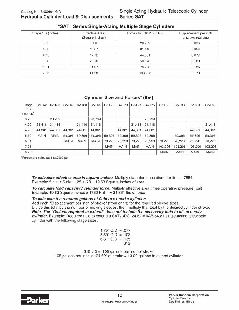
Hydraulic Cylinder Load & Displacements
Stage OD (inches) Effective Area (Square Inches)
Force (lbs.) @ 2,500 PSI Displacement per inch of stroke (gallons)
3.25 8.30 20,739 0.036
4.00 12.57 31,416 0.054
4.75 17.72 44,301 0.077
5.50 23.76 59,396 0.103
6.31 31.27 78,228 0.135
7.25 41.28 103,206 0.179
“SAT” Series Single-Acting Multiple Stage Cylinders
Cylinder Size and Forces* (lbs)
To calculate effective area in square inches: Multiply diameter times diameter times .7854 Example: 5 dia. x 5 dia. = 25 x .78 = 19.63 Square inches of area
To calculate load capacity / cylinder force: Multiply effective area times operating pressure (psi) Example: 19.63 Square inches x 1750 P.S.I. = 34,361 lbs of force
To calculate the required gallons of fluid to extend a cylinder: Add each "Displacement per inch of stroke" (from chart) for the required sleeve sizes. Divide this total by the number of moving sleeves, then multiply that total by the desired cylinder stroke. Note: The "Gallons required to extend" does not include the necessary fluid to fill an empty cylinder. Example: Required fluid to extend a SAT73DC124.62-AAAB-54.81 single-acting telescopic cylinder with the following stage sizes:
.315 ÷ 3 = .105 gallons per inch of stroke .105 gallons per inch x 124.62" of stroke = 13.09 gallons to extend cylinder
4.75" O.D. = .077 5.50" O.D. = .103 6.31" O.D. = .135
.315
*Forces are calculated at 2500 psi
Stage OD
(inches)
SAT52 SAT53 SAT62 SAT63 SAT64 SAT72 SAT73 SAT74 SAT75 SAT82 SAT83 SAT84 SAT85
3.25 20,739 20,739 20,739
4.00 31,416 31,416 31,416 31,416 31,416 31,416 31,416
4.75 44,301 44,301 44,301 44,301 44,301 44,301 44,301 44,301 44,301 44,301
5.50 MAIN MAIN 59,396 59,396 59,396 59,396 59,396 59,396 59,396 59,396 59,396 59,396
6.31 MAIN MAIN MAIN 78,228 78,228 78,228 78,228 78,228 78,228 78,228 78,228
7.25 MAIN MAIN MAIN MAIN 103,206 103,206 103,206 103,206
8.25 MAIN MAIN MAIN MAIN

Single Acting Hydraulic Telescopic CylinderSeries SAT
Parker Hannifin CorporationCylinder DivisionDes Plaines, Illinoiswww.parker.com/cylinder
Catalog HY18-0060-1/NA
1322 Parker Hannifi n Corporation
Mobile Cylinder DivisionYoungstown, OH
SINGLE STAGE SCISSORUNDERBODY TELESCOPICSLANT FORWARD OR SLANT REARWARD
UNDER BODY ARM HOIST
ROSSICSNOITOMTSOLROSSICS-MRAYDOBREDNU
UNDER BODY DIRECT LIFT
FRONT MOUNT TELESCOPICHEAD LIFT OR BOTTOM LIFT
TELESCOPIC SCISSORHINGE FORWARD OR REARWARD
Dump Hoist Type Identifi cation ChartDump Hoist Type Identification Chart

Single Acting Hydraulic Telescopic CylinderSeries SAT
Parker Hannifin CorporationCylinder DivisionDes Plaines, Illinoiswww.parker.com/cylinder
Catalog HY18-0060-1/NA
14
Commodities & Materials Approximate Weights
Material lbs. / cu. yd. tons / cu. yd. Material lbs. / cu. yd. tons / cu. yd.
Andesite stone 4887 2.44 Earth & sand, wet 3240 1.62
Ashes 1080 0.52 Fire Brick 3915 1.95
Asphalt 2700 1.35 Fire Clay 3510 1.75
Asphaltum 2349 1.17 Garbage 1150 0.57
Basalt rock 4887 2.44 Gravel, dry 2970 1.48
Brick, soft clay 2718 1.35 Gravel, out of water 1620 0.81
Brick, hard clay 3397 1.69 Granite 4536 2.26
Brick, pressed 3806 1.9 Lime, quick, loose 1431 0.71
Brick, paving 4246 2.12 Lime, quick, shaken 1485 0.70
Block, paving 3694 1.84 Limestone, solid 4536 2.26
Bluestone 2970 1.48 Limestone, loose 2592 1.29
Cement, natural 1512 0.75 Marble, solid 4455 2.22
Cement, Portland 2430 1.21 Marble, loose 2592 1.29
Cement, Portland, set 4941 2.47 Mortar, set 2781 1.39
Cement, Rosendale 1863 0.93 Mud, dry 2430 1.21
Cinders 1080 0.54 Mud, packed 3105 1.55
Clay, dry 1701 0.85 Mud, wet 2916 1.45
Clay, wet 2970 1.48 Pitch 1863 0.93
Clay & gravel, dry 2700 1.35 Plaster of Paris 2646 1.32
Coal, anthracite 1536 0.76 Powder, blasting 1682 0.84
Coal, bituminous 1275 0.64 Quartz 4374 2.18
Coke 837 0.42 Rubbish 199.8 0.09
Concrete, cinders 2970 1.48 Sand, dry, loose 2619 1.30
Concrete, gravel 4104 2.05 Sand, wet 3186 1.59
Concrete, limestone 4050 2.02 Sandstone 4023 2.01
Concrete, sandstone 3915 1.95 Slag, bank 1890 0.94
Concrete, trap rock 4185 2.09 Slag, screenings 2700 1.35
Crushed stone 2700 1.35 Slag, machine 2592 1.29
Earth, dry, loose 1890 0.94 Slag, sand 1485 0.74
Earth, damp, loose 2106 1.05 Shale 4374 2.18
Earth, damp packed 2592 1.29 Slate 4725 2.31
Earth & gravel, dry 2700 1.35 Tar 1674 0.83
Earth & gravel, wet 3240 1.62 Tile 2970 1.43
Earth & sand, dry 2709 1.35 Trap stone 5849 2.52
3/8” 0.375 15.320 lbs. per sq. ft.
1/4” (approx. 3 Ga.) 0 250 10.200 lbs. per sq. ft.
3/16” (approx. 7 Ga.) 0.188 7.650 lbs. per sq. ft.
8 Ga. 0.164 6.875 lbs. per sq. ft.
9 Ga. 0.149 6.250 lbs. per sq. ft.
10 Ga. 0.134 5.625 lbs. per sq. ft.
11 Ga. 0.120 5.000 lbs. per sq. ft.
12 Ga. 0.105 4.375 lbs. per sq. ft.
13 Ga. 0.090 3.750 lbs. per sq. ft.
14 Ga. 0.075 3.125 lbs. per sq. ft.
3/8” 0.375 5.18 lbs. per sq. ft.
1/4” 0.250 3.53 lbs. per sq. ft.
3/16” 0.188 2.65 lbs. per sq. ft.
5/32” 0.156 2.25 lbs. per sq. ft.
Approximate Weights of Materials
Steel Gauge, Thickness and Weight Aluminum Gauge, Thickness and Weight
Single Acting Hydraulic Telescopic CylinderSeries SAT
Parker Hannifin CorporationCylinder DivisionDes Plaines, Illinoiswww.parker.com/cylinder
Catalog HY18-0060-1/NA
15
Standard Test Procedures
1) Function Test Each Cylinder is placed on the test stand and hydraulic lines attached, the cylinder will be cycled its full stroke a minimum of one (1) full cycle. The cylinder will be rejected if it functions erratically. Erratic function is excessive chatter, slipstick, stalling and uncorrectable misstaging.
2) Proof Pressure Test After the function test is performed the cylinder will be extended fully and pressure held for a minimum of thirty (30) seconds. This pressure will be 3,000 psi or a pressure indicated on the assembly drawing or standard test procedure. The cylinder will be rejected for external leakage or structural deformation.
Please Consider the FollowingBefore Installing a New Cylinder in an Old Application
Has the problem been corrected that caused the original cylinder to fail?Is the hydraulic fluid clean of all contamination, water, and entrapped air?
Are the hydraulic system relief valve pressures set and operating properly?Is the mechanism or unit the cylinder is operating in good mechanical condition?
Single Acting Hydraulic Telescopic CylinderSeries SAT
Parker Hannifin CorporationCylinder DivisionDes Plaines, Illinoiswww.parker.com/cylinder
Catalog HY18-0060-1/NA
16
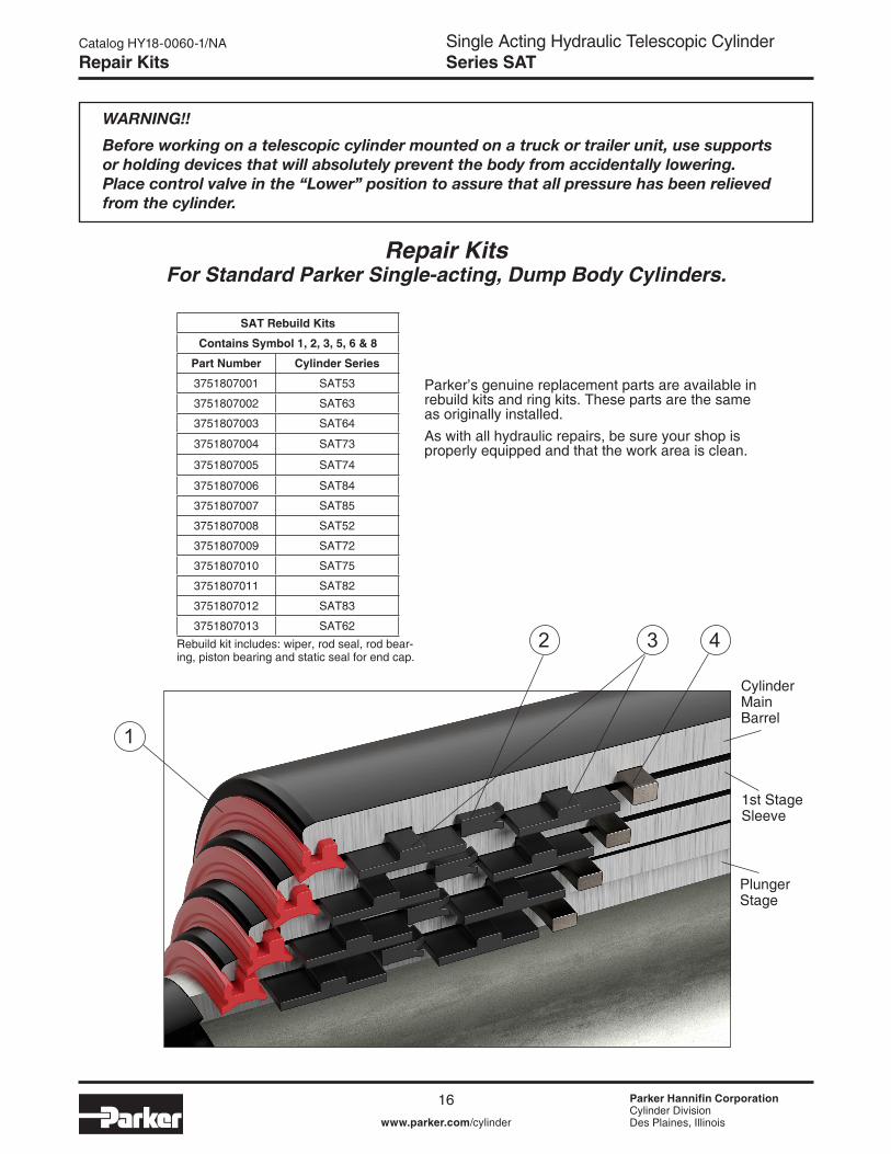
Repair Kits
SAT Rebuild Kits
Contains Symbol 1, 2, 3, 5, 6 & 8
Part Number Cylinder Series
3751807001 SAT53
3751807002 SAT63
3751807003 SAT64
3751807004 SAT73
3751807005 SAT74
3751807006 SAT84
3751807007 SAT85
3751807008 SAT52
3751807009 SAT72
3751807010 SAT75
3751807011 SAT82
3751807012 SAT83
3751807013 SAT62Rebuild kit includes: wiper, rod seal, rod bear-ing, piston bearing and static seal for end cap.
WARNING!!
Before working on a telescopic cylinder mounted on a truck or trailer unit, use supports or holding devices that will absolutely prevent the body from accidentally lowering. Place control valve in the “Lower” position to assure that all pressure has been relieved from the cylinder.
Repair KitsFor Standard Parker Single-acting, Dump Body Cylinders.
Parker’s genuine replacement parts are available in rebuild kits and ring kits. These parts are the same as originally installed.As with all hydraulic repairs, be sure your shop is properly equipped and that the work area is clean.
Plunger Stage
1st Stage Sleeve
Cylinder Main Barrel
1
2 43

Single Acting Hydraulic Telescopic CylinderSeries SAT
Parker Hannifin CorporationCylinder DivisionDes Plaines, Illinoiswww.parker.com/cylinder
Catalog HY18-0060-1/NA
17
Ring Kits
SAT Ring Kits
Contains Symbol 4, 7, 9 & 10
Ring Kit Number Cylinder Series
3751807014 SAT53
3751807015 SAT63
3751807016 SAT64
3751807017 SAT73
3751807018 SAT74
3751807019 SAT84
3751807020 SAT85
3751807021 SAT52
3751807022 SAT62
3751807023 SAT72
3751807024 SAT75
3751807025 SAT82
3751807026 SAT83Kit includes Sleeve OD and ID Stop Rings, and Roll Pins
WARNING!!
Before working on a telescopic cylinder mounted on a truck or trailer unit, use supports or holding devices that will absolutely prevent the body from accidentally lowering. Place control valve in the “Lower” position to assure that all pressure has been relieved from the cylinder.
Ring KitsFor Standard Parker Single-acting, Dump Body Cylinders.
End Cap Retainer (3)
End Cap Retaining Bolts (8)
5968
7
10
PIN EYE SLEEVE
ROLL PINGREASE FITTING
CYLINDER BODY MOUNT
Single Acting Hydraulic Telescopic CylinderSeries SAT
Parker Hannifin CorporationCylinder DivisionDes Plaines, Illinoiswww.parker.com/cylinder
Catalog HY18-0060-1/NA
18
Servicing
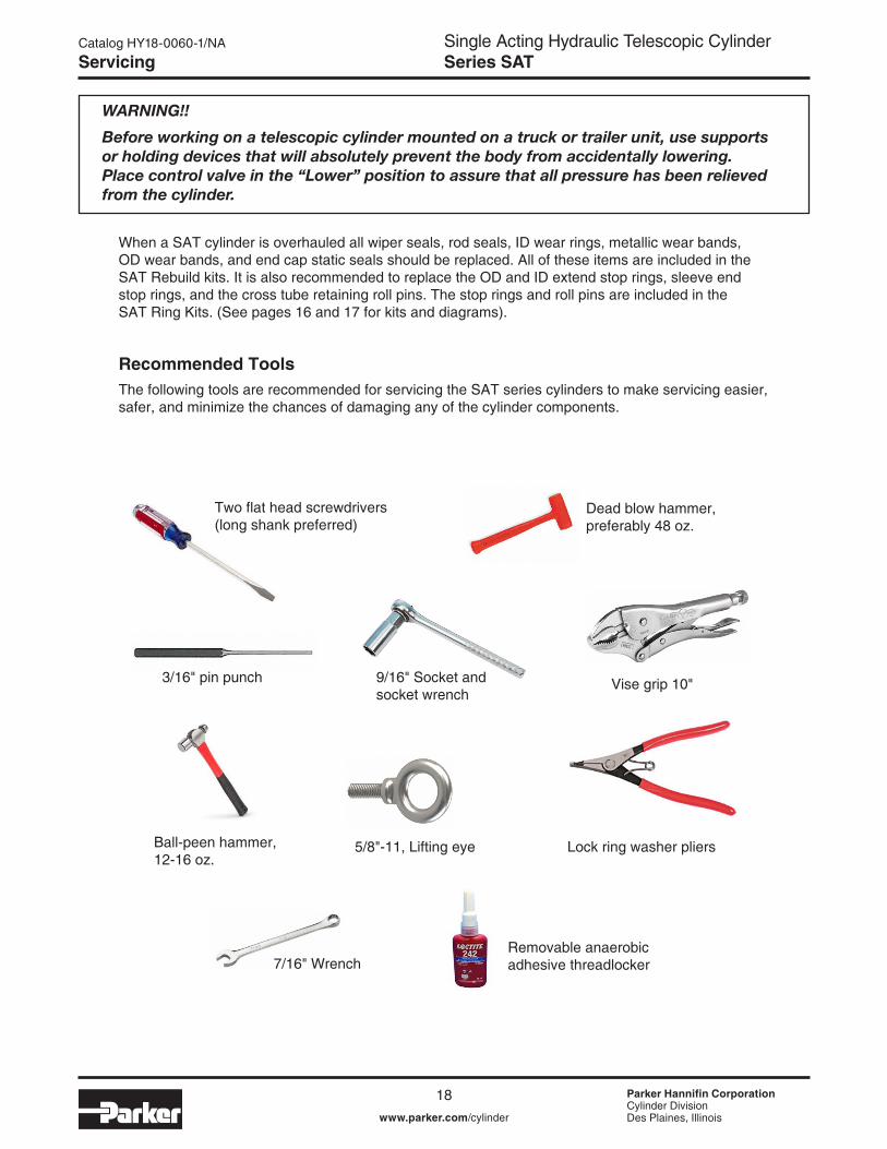
When a SAT cylinder is overhauled all wiper seals, rod seals, ID wear rings, metallic wear bands, OD wear bands, and end cap static seals should be replaced. All of these items are included in the SAT Rebuild kits. It is also recommended to replace the OD and ID extend stop rings, sleeve end stop rings, and the cross tube retaining roll pins. The stop rings and roll pins are included in the SAT Ring Kits. (See pages 16 and 17 for kits and diagrams).
Recommended ToolsThe following tools are recommended for servicing the SAT series cylinders to make servicing easier, safer, and minimize the chances of damaging any of the cylinder components.
Two flat head screwdrivers (long shank preferred)
Dead blow hammer, preferably 48 oz.
9/16" Socket and socket wrench
Ball-peen hammer, 12-16 oz.
5/8"-11, Lifting eye Lock ring washer pliers
Vise grip 10"
7/16" WrenchRemovable anaerobic adhesive threadlocker
3/16" pin punch
WARNING!!
Before working on a telescopic cylinder mounted on a truck or trailer unit, use supports or holding devices that will absolutely prevent the body from accidentally lowering. Place control valve in the “Lower” position to assure that all pressure has been relieved from the cylinder.

Single Acting Hydraulic Telescopic CylinderSeries SAT
Parker Hannifin CorporationCylinder DivisionDes Plaines, Illinoiswww.parker.com/cylinder
Catalog HY18-0060-1/NA
19
Servicing
Disassembling the CylinderBefore disassembling the cylinder, inspect each cylinder sleeve for any sign of gouges, scratches, dents, bulges, or corrosion. If any of these conditions exist, contact the factory for additional repair parts or repair instructions.
Note: Make sure to drain cylinder of hydraulic fluid before disassembly.
Caution: Make sure there is no trapped pressure in cylinder before removing the plug from port.
Remove the pin eye sleeve by removing the grease fitting and the 2 roll pins as shown in figure 1 below.
1) Remove the grease fitting (7/16" wrench)
2) Remove the roll pins by using the 3/16" pin punch and ball peen hammer to drive the roll pins through to the inside of the pin eye sleeve. Reach into the ID of Sleeve to remove roll pins.
3) Use dead blow hammer to knock the pin eye sleeve through the cylinder body end mount. Fig.2
Note: cleaning dirt and paint from outside of the pin eye sleeve can help in removal of the sleeve.
Figure 2
Figure 1
PIN EYE SLEEVE
PIN EYE SLEEVE
ROLL PINGREASE FITTING
CYLINDER BODY MOUNT
Single Acting Hydraulic Telescopic CylinderSeries SAT
Parker Hannifin CorporationCylinder DivisionDes Plaines, Illinoiswww.parker.com/cylinder
Catalog HY18-0060-1/NA
20
Servicing
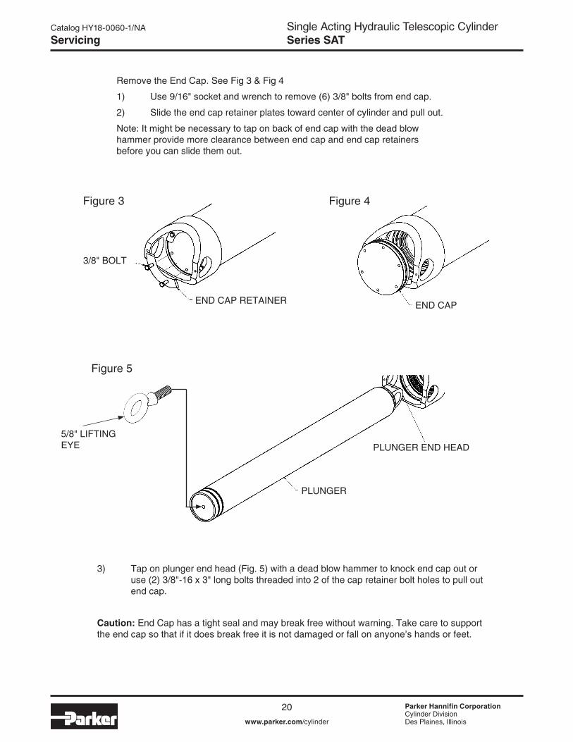
Remove the End Cap. See Fig 3 & Fig 4
1) Use 9/16" socket and wrench to remove (6) 3/8" bolts from end cap.
2) Slide the end cap retainer plates toward center of cylinder and pull out.
Note: It might be necessary to tap on back of end cap with the dead blow hammer provide more clearance between end cap and end cap retainers before you can slide them out.
3) Tap on plunger end head (Fig. 5) with a dead blow hammer to knock end cap out or use (2) 3/8"-16 x 3" long bolts threaded into 2 of the cap retainer bolt holes to pull out end cap.
Caution: End Cap has a tight seal and may break free without warning. Take care to support the end cap so that if it does break free it is not damaged or fall on anyone’s hands or feet.
3/8" BOLT
END CAP RETAINER END CAP
Figure 4
Figure 5
Figure 3
PLUNGER
PLUNGER END HEAD5/8" LIFTING EYE
Single Acting Hydraulic Telescopic CylinderSeries SAT
Parker Hannifin CorporationCylinder DivisionDes Plaines, Illinoiswww.parker.com/cylinder
Catalog HY18-0060-1/NA
21
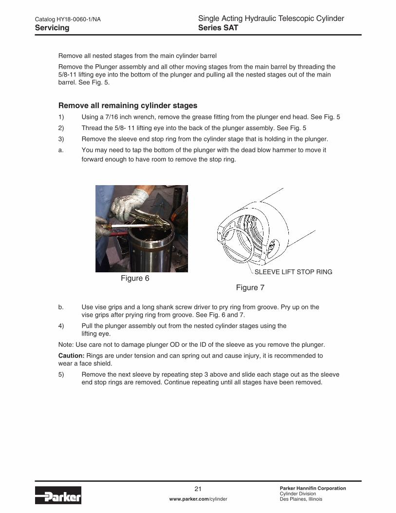
Remove all nested stages from the main cylinder barrel
Remove the Plunger assembly and all other moving stages from the main barrel by threading the 5/8-11 lifting eye into the bottom of the plunger and pulling all the nested stages out of the main barrel. See Fig. 5.
Remove all remaining cylinder stages1) Using a 7/16 inch wrench, remove the grease fitting from the plunger end head. See Fig. 5
2) Thread the 5/8- 11 lifting eye into the back of the plunger assembly. See Fig. 5
3) Remove the sleeve end stop ring from the cylinder stage that is holding in the plunger.
a. You may need to tap the bottom of the plunger with the dead blow hammer to move it forward enough to have room to remove the stop ring.
b. Use vise grips and a long shank screw driver to pry ring from groove. Pry up on the vise grips after prying ring from groove. See Fig. 6 and 7.
4) Pull the plunger assembly out from the nested cylinder stages using the lifting eye.
Note: Use care not to damage plunger OD or the ID of the sleeve as you remove the plunger.
Caution: Rings are under tension and can spring out and cause injury, it is recommended to wear a face shield.
5) Remove the next sleeve by repeating step 3 above and slide each stage out as the sleeve end stop rings are removed. Continue repeating until all stages have been removed.
Servicing
Figure 6SLEEVE LIFT STOP RING
Figure 7
Single Acting Hydraulic Telescopic CylinderSeries SAT
Parker Hannifin CorporationCylinder DivisionDes Plaines, Illinoiswww.parker.com/cylinder
Catalog HY18-0060-1/NA
22
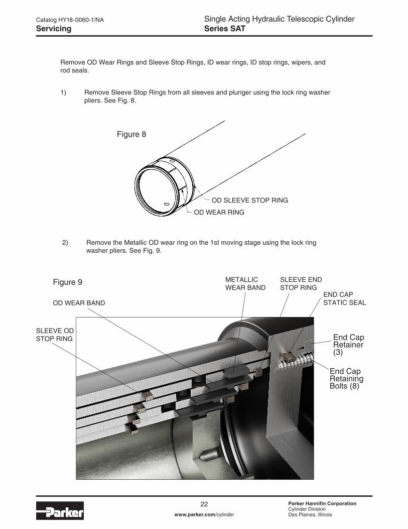
Remove OD Wear Rings and Sleeve Stop Rings, ID wear rings, ID stop rings, wipers, and rod seals.
1) Remove Sleeve Stop Rings from all sleeves and plunger using the lock ring washer pliers. See Fig. 8.
Servicing
Figure 8
OD WEAR RING
OD SLEEVE STOP RING
2) Remove the Metallic OD wear ring on the 1st moving stage using the lock ring washer pliers. See Fig. 9.
Figure 9
OD WEAR BAND
METALLIC WEAR BAND
SLEEVE END STOP RING
SLEEVE OD STOP RING
END CAP STATIC SEAL
End Cap Retainer (3)
End Cap Retaining Bolts (8)
Single Acting Hydraulic Telescopic CylinderSeries SAT
Parker Hannifin CorporationCylinder DivisionDes Plaines, Illinoiswww.parker.com/cylinder
Catalog HY18-0060-1/NA
23
Servicing
Figure 10
WIPER
ROD SEALID WEAR RING
ID SLEEVE STOP RING
Plunger Stage
1st Stage Sleeve
Cylinder Main Barrel
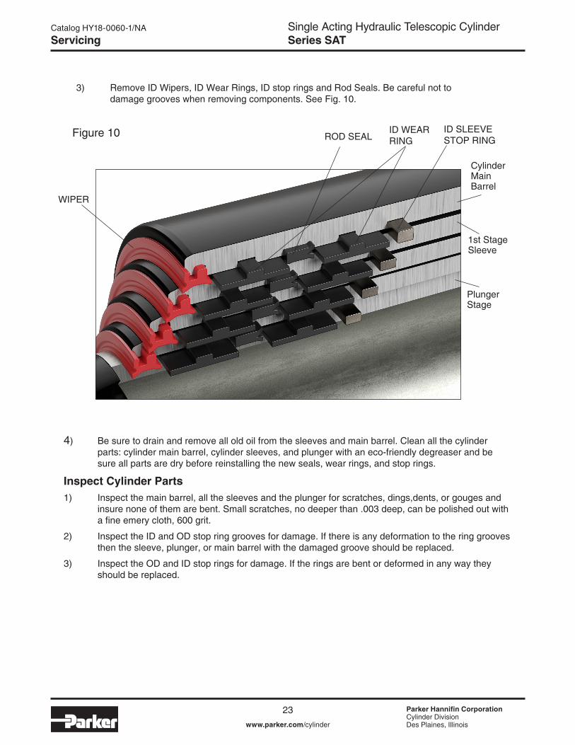
3) Remove ID Wipers, ID Wear Rings, ID stop rings and Rod Seals. Be careful not to damage grooves when removing components. See Fig. 10.
4) Be sure to drain and remove all old oil from the sleeves and main barrel. Clean all the cylinder parts: cylinder main barrel, cylinder sleeves, and plunger with an eco-friendly degreaser and be sure all parts are dry before reinstalling the new seals, wear rings, and stop rings.
Inspect Cylinder Parts1) Inspect the main barrel, all the sleeves and the plunger for scratches, dings,dents, or gouges and
insure none of them are bent. Small scratches, no deeper than .003 deep, can be polished out with a fine emery cloth, 600 grit.
2) Inspect the ID and OD stop ring grooves for damage. If there is any deformation to the ring grooves then the sleeve, plunger, or main barrel with the damaged groove should be replaced.
3) Inspect the OD and ID stop rings for damage. If the rings are bent or deformed in any way they should be replaced.

Single Acting Hydraulic Telescopic CylinderSeries SAT
Parker Hannifin CorporationCylinder DivisionDes Plaines, Illinoiswww.parker.com/cylinder
Catalog HY18-0060-1/NA
24
Installing new rebuild kit. 1) Apply Parker Lube-A-Cyl grease Part Number 0761630000 or equivalent, to the ID
of the rod seal, wiper seal and ID wear ring grooves. Also apply to the OD wear band grooves
2) Apply Parker Lube-A-Cyl grease or equivalent to the OD and ID wear bands, Metallic wear band, rods seals, and wiper seals.
3) Install the new components in the following order: ID wear rings, ID sleeve stop rings, rod seals, and then wiper seals into the main barrel and sleeves.
Note: Direction of seals, if installed improperly it will cause leakage and/or binding. For the wiper seal note the notch/groove on the front face of the seal is facing the outside of the cylinder sleeve. See Fig. 11.
Figure 11
WIPER
ROD SEALID WEAR RING
ID SLEEVE STOP RING
Plunger Stage
1st Stage Sleeve
Cylinder Main Barrel
Installing New Rebuild Kit
Single Acting Hydraulic Telescopic CylinderSeries SAT
Parker Hannifin CorporationCylinder DivisionDes Plaines, Illinoiswww.parker.com/cylinder
Catalog HY18-0060-1/NA
25
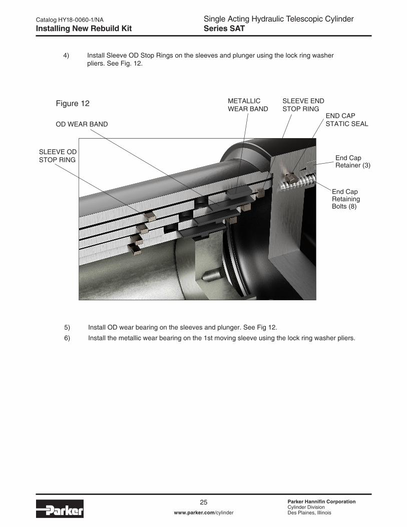
4) Install Sleeve OD Stop Rings on the sleeves and plunger using the lock ring washer pliers. See Fig. 12.
5) Install OD wear bearing on the sleeves and plunger. See Fig 12.
6) Install the metallic wear bearing on the 1st moving sleeve using the lock ring washer pliers.
Figure 12
OD WEAR BAND
METALLIC WEAR BAND
SLEEVE END STOP RING
SLEEVE OD STOP RING
END CAP STATIC SEAL
End Cap Retainer (3)
End Cap Retaining Bolts (8)
Installing New Rebuild Kit
Single Acting Hydraulic Telescopic CylinderSeries SAT
Parker Hannifin CorporationCylinder DivisionDes Plaines, Illinoiswww.parker.com/cylinder
Catalog HY18-0060-1/NA
26
Install sleeves and plunger into cylinder main barrel.
1) Lubricate the seals and sleeve/plunger with hydraulic oil before installing into main barrel.
2) Install the 1st sleeve (largest moving stage) into the cylinder main barrel. The sleeve will meet resistance when it gets to the seals. It will require some force to push the sleeve through the seals.
Caution: If assembling horizontal; guide the sleeves so it is not rubbing or scratching the ID of the cylinder main barrel and do not let the sleeves rub the ID stop ring as the this can cause damage to the OD of the sleeve.
3) Install the sleeve end stop ring.
4) Install the next moving sleeve (2nd Stage) into the 1st stage The second stage will need to pass the end of the 1st stage approximately 1 to 2 inches to install the sleeve end stop ring.
5) Install the sleeve end stop ring.
6) Repeat steps 4 and 5 above until all remaining sleeves and plunger have been installed.
Caution: Make sure all sleeve end stop rings are securely installed into the grooves.
Install Cylinder end cap.1) Install end cap static seal on to end cap.
2) Lubricate the end cap static seal with Lube-A-Cyl grease or equivalent.
3) Place end cap in place in cylinder body mount, push in place. Use the dead blow hammer to tap the end cap into place and be sure the cap is in past the end cap retainer groove.
4) Install the three end cap retainer pieces into place. If they are difficult to slide into the grooves, tap the end cap into the cylinder body a little farther.
5) Apply Loctite 242 or equivalent to the 3/8 inch bolts.
6) Install the 3/8 inch bolts and torque to 34 lbs-ft.
7) Install body mount pin eye sleeve into body mount. Be sure the roll pin holes on the sleeve line up with the roll pin holes on the body mount and the threads for the grease fitting are positioned in a location that will allow easy access to lubricate pin eye sleeve.
8) Drive in the 2 roll pins using the ball-peen hammer. Make sure the pins are in both the body mount and pin eye sleeve.
9) Install grease fitting into the plunger end head and the pin eye sleeve.
Installing New Rebuild Kit
Single Acting Hydraulic Telescopic CylinderSeries SAT
Parker Hannifin CorporationCylinder DivisionDes Plaines, Illinoiswww.parker.com/cylinder
Catalog HY18-0060-1/NA
27
Testing Rebuilt Cylinder in truck.1) Install cylinder on truck, making sure to follow all safety requirements specified by truck manufacturer.
2) Make sure all pins are fully secured
3) Grease the pins.
4) Connect hydraulic hose to cylinder
5) Check the hydraulic fluid in tank before operating cylinders. Make sure it is at the proper level.
6) Make sure all connections are tight. Loose connections may cause high pressure leaks and also allow air to get into the hydraulic system.
7) Be sure all personnel is clear before testing cylinder.
8) Test dumping cylinder.
9) This cylinder is a bleederless design. The cylinder should be fully cycled 5 to 7 times to bleed air from the cylinder.
10) Check all fitting connections and hoses for leaks.
11) Check each cylinder stage for any sign of leakage.
Installing New Rebuild Kit

Single Acting Hydraulic Telescopic CylinderSeries SAT
Parker Hannifin CorporationCylinder DivisionDes Plaines, Illinoiswww.parker.com/cylinder
Catalog HY18-0060-1/NA
28
Hydraulic Oil Recommendations
17 Parker Hannifi n CorporationMobile Cylinder DivisionYoungstown, OH
Hydraulic Oil Recommendations
All cylinder parts, with the exception of a few items, are lubricated by the hydraulic oil in the circuit. Particular attention must be paid to keep the oil in the circuit clean. Whenever there is a hydraulic component failure (cylinder, pump, valve), and there is a reason to feel that metal particles may be in the system, the oil must be drained, the entire system fl ushed clean, and any fi lter screens thoroughly cleaned or replaced. New oil should be supplied for the entire system. Oil suitable and recommended for use in circuits involving Commercial cylinders should meet the following specifi cations:
These suggestions are intended as a guide only.Obtain your fi nal oil recommendations from your oil supplier.
Viscosity Recommendations:Optimum operating viscosity is considered to be about 100 SSU.* 50 SSU minimum @ operating temperature 7500 SSU maximum @ starting temperature
* 150 to 225 SSU @ 100o F. (37.8o C.) (generally) 44 to 48 SSU @ 210o F. (98.9o C.) (generally)
Other Desirable Properties:Viscosity Index: 90 minimumAniline point: 175 minimum
Additives Usually Recommended:Rust and Oxidation (R & O) InhibitorsFoam Depressant
Other Desirable Characteristics:Stability of physical and chemical characteristics.High demulsibility (low emulsibility) for separation of water, air and contaminants.Resistant to the formation of gums, sludges, acids, tars and varnishes.High lubricity and fi lm strength.
General Recommendations:A good quality hydraulic oil conforming to the characteristics listed above is essential to the satisfactory performance and long life of any hydraulic system.
Oil should be changed on regular schedules in accordance with the manufactures recommendations and the system periodically fl ushed.
Oil operating temperature should not exceed 200o F. (93o C.) with a maximum of 180o F. (82o C.) generally recom-mended. 120o F. to 140o F. (50o C. to 60o C.) is generally considered optimum. High temperatures result in rapid oil deterioration and may point out a need for an oil cooler or a larger reservoir. The nearer to optimum temperature, the longer the service life of the oil and the hydraulic components.
Reservoir size should be large enough to hold and cool all the fl uid a system will need, yet it should not be waste-fully large. Minimum required capacity can vary anywhere between 1 and 3 times pump output. The reservoir must be able to hold all of the fl uid displaced by retracted cylinders when the system is not operating, yet provide space for expansion and foaming.
Oil poured into the reservoir should pass through a 100 mesh screen. Pour only clean oil from clean containers into the reservoir.
Approximate SSU at . . .
Normal Temperatures:0o F. (-18o C.) to 100o F. (37.8o C.) ambient100o F. (37.8o C.) to 180o F. (82.2o C.) system
Be sure the oil you use is recommended for the temperature you expect to encounter.
OilGrade
100OF.(37.8OC.)
210O F.(98.9OC.)
SAE 10 150 43
SAE 20 330 51
Never use Crank Case Drainings, Kerosene, Fuel Oil, or any Non-Lubricating Fluid, such as Water.
Single Acting Hydraulic Telescopic CylinderSeries SAT
Parker Hannifin CorporationCylinder DivisionDes Plaines, Illinoiswww.parker.com/cylinder
Catalog HY18-0060-1/NA
29
Safety Precautions for SAT Cylinders
12 Parker Hannifi n CorporationMobile Cylinder DivisionYoungstown, OH
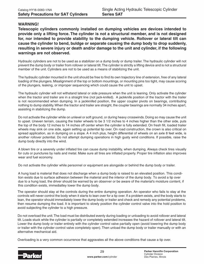
WARNING!Telescopic cylinders commonly installed on dumping vehicles are devices intended to provide only a lifting force. The cylinder is not a structural member, and is not designed for, nor intended to provide stability to the dumping vehicle. Rollover or lateral tilt can cause the cylinder to bend, buldge or separate causing the dump body to drop suddenly, resulting in severe injury or death and/or damage to the unit and cylinder, if the following warnings are not observed.
Hydraulic cylinders are not to be used as a stabilizer on a dump body or dump trailer. The hydraulic cylinder will not prevent the dump body or trailer from rollover or lateral tilt. The cylinder is strictly a lifting device and is not a structural member of the unit. Cylinders are not to be used as a means of stabilizing the unit.
The hydraulic cylinder mounted in the unit should be free to fi nd its own trajectory line of extension, free of any lateral loading of the plungers. Misalignment of the top or bottom mountings, or mounting pins too tight, may cause scoring of the plungers, leaking, or improper sequencing which could cause the unit to upset.
The hydraulic cylinder will not withstand lateral or side pressure when the unit is leaning. Only activate the cylinder when the tractor and trailer are in a straight line (not jack-knifed). A jackknife position of the tractor with the trailer is not recommended when dumping. In a jackknifed position, the upper coupler pivots on bearings, contributing nothing to dump stability. When the tractor and trailer are straight, the coupler bearings are normally 34 inches apart, assisting in stabilizing the dump.
Do not activate the cylinder while on unlevel or soft ground, or during heavy crosswinds. Doing so may cause the unit to upset. Uneven terrain, causing the trailer wheels to be 3 1/2 inches to 4 inches higher than the other side, puts the top of the body 12 inches to 14 inches off center when the cylinder is fully extended. On fresh fi ll, loaded trailer wheels may sink on one side, again setting up potential tip over. On road construction, the crown is also critical on spread application, as in dumping on a slope. A 4 inch plus, height differential of wheels on an axle 8 feet wide, is another rollover potential. Do not attempt dumping operations in high gusty wind conditions. If possible, raise the dump body directly into the wind.
A blown tire or a severely under infl ated tire can cause dump instability, when dumping. Always check tires visually for cuts or punctures by nails and metal. Make sure all tires are infl ated properly. Proper tire infl ation also improves wear and fuel economy.
Do not activate the cylinder while personnel or equipment are alongside or behind the dump body or trailer. A hung load is commodity that does not discharge when a dump body is raised to an elevated position. This condition exists due to surface adhesion between the commodity and the interior of the dump body. To avoid a tip over due to a hung load, the driver should be warned by an observer or be aware of the material’s moisture content, if this condition exists, immediately lower the dump body.
The operator should stay at the controls during the entire dumping operation. An operator who fails to stay at the controls will never control the body when it starts to lean over for a tip over. If a problem exists, and the body starts to lean, the operator should immediately lower the dump body or trailer and check and remedy any potential problems, then resume dumping the load. It is important to slowly position the cylinder control valve into the hold position to avoid subjecting the cylinder to a high pressure.
Do not overload the unit. The load must be distributed evenly during loading or unloading to avoid rollover and lateral tilt. Loads stuck while the cylinder is partially or completely extended increases the hazard of rollover and lateral tilt. Lower the dump body or trailer entirely with the cylinder control valve partially open (avoid lowering the dump body or trailer with the cylinder control valve completely open). Then unload the dump body or trailer manually or with an alternative mechanical aid.
Overloading is a very common occurrence that aggravates all the above conditions that cause a tip over.
Safety Precautions for Single-Acting Telescopic Cylinders
12 Parker Hannifi n CorporationMobile Cylinder DivisionYoungstown, OH
WARNING!Telescopic cylinders commonly installed on dumping vehicles are devices intended to provide only a lifting force. The cylinder is not a structural member, and is not designed for, nor intended to provide stability to the dumping vehicle. Rollover or lateral tilt can cause the cylinder to bend, buldge or separate causing the dump body to drop suddenly, resulting in severe injury or death and/or damage to the unit and cylinder, if the following warnings are not observed.
Hydraulic cylinders are not to be used as a stabilizer on a dump body or dump trailer. The hydraulic cylinder will not prevent the dump body or trailer from rollover or lateral tilt. The cylinder is strictly a lifting device and is not a structural member of the unit. Cylinders are not to be used as a means of stabilizing the unit.
The hydraulic cylinder mounted in the unit should be free to fi nd its own trajectory line of extension, free of any lateral loading of the plungers. Misalignment of the top or bottom mountings, or mounting pins too tight, may cause scoring of the plungers, leaking, or improper sequencing which could cause the unit to upset.
The hydraulic cylinder will not withstand lateral or side pressure when the unit is leaning. Only activate the cylinder when the tractor and trailer are in a straight line (not jack-knifed). A jackknife position of the tractor with the trailer is not recommended when dumping. In a jackknifed position, the upper coupler pivots on bearings, contributing nothing to dump stability. When the tractor and trailer are straight, the coupler bearings are normally 34 inches apart, assisting in stabilizing the dump.
Do not activate the cylinder while on unlevel or soft ground, or during heavy crosswinds. Doing so may cause the unit to upset. Uneven terrain, causing the trailer wheels to be 3 1/2 inches to 4 inches higher than the other side, puts the top of the body 12 inches to 14 inches off center when the cylinder is fully extended. On fresh fi ll, loaded trailer wheels may sink on one side, again setting up potential tip over. On road construction, the crown is also critical on spread application, as in dumping on a slope. A 4 inch plus, height differential of wheels on an axle 8 feet wide, is another rollover potential. Do not attempt dumping operations in high gusty wind conditions. If possible, raise the dump body directly into the wind.
A blown tire or a severely under infl ated tire can cause dump instability, when dumping. Always check tires visually for cuts or punctures by nails and metal. Make sure all tires are infl ated properly. Proper tire infl ation also improves wear and fuel economy.
Do not activate the cylinder while personnel or equipment are alongside or behind the dump body or trailer. A hung load is commodity that does not discharge when a dump body is raised to an elevated position. This condition exists due to surface adhesion between the commodity and the interior of the dump body. To avoid a tip over due to a hung load, the driver should be warned by an observer or be aware of the material’s moisture content, if this condition exists, immediately lower the dump body.
The operator should stay at the controls during the entire dumping operation. An operator who fails to stay at the controls will never control the body when it starts to lean over for a tip over. If a problem exists, and the body starts to lean, the operator should immediately lower the dump body or trailer and check and remedy any potential problems, then resume dumping the load. It is important to slowly position the cylinder control valve into the hold position to avoid subjecting the cylinder to a high pressure.
Do not overload the unit. The load must be distributed evenly during loading or unloading to avoid rollover and lateral tilt. Loads stuck while the cylinder is partially or completely extended increases the hazard of rollover and lateral tilt. Lower the dump body or trailer entirely with the cylinder control valve partially open (avoid lowering the dump body or trailer with the cylinder control valve completely open). Then unload the dump body or trailer manually or with an alternative mechanical aid.
Overloading is a very common occurrence that aggravates all the above conditions that cause a tip over.
Safety Precautions for Single-Acting Telescopic Cylinders
A hung load is material that does not discharge when a dump body is raised to an elevated position. This condi-tion exists due to surface adhesion between the material and the interior of the dump body. To avoid a tip over due to a hung load, the driver should be warned by an observer or be aware of the material's moisture content, if this condition exists, immediatley lower the dump body.
Single Acting Hydraulic Telescopic CylinderSeries SAT
Parker Hannifin CorporationCylinder DivisionDes Plaines, Illinoiswww.parker.com/cylinder
Catalog HY18-0060-1/NA
30
Safety Precautions for SAT Cylinders
13 Parker Hannifi n CorporationMobile Cylinder DivisionYoungstown, OH
Safety Precautions for Single-Acting Telescopic Cylinders
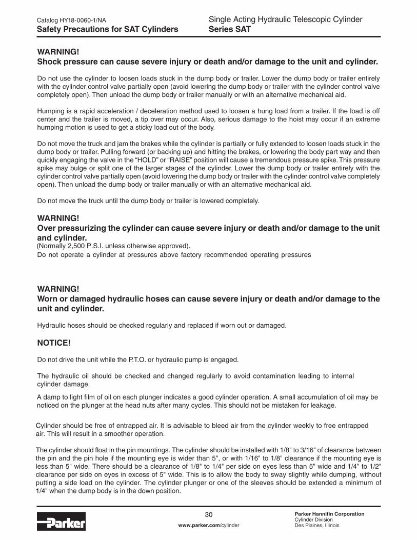
WARNING!Shock pressure can cause severe injury or death and/or damage to the unit and cylinder.
Do not use the cylinder to loosen loads stuck in the dump body or trailer. Lower the dump body or trailer entirely with the cylinder control valve partially open (avoid lowering the dump body or trailer with the cylinder control valve completely open). Then unload the dump body or trailer manually or with an alternative mechanical aid.
Humping is a rapid acceleration / deceleration method used to loosen a hung load from a trailer. If the load is off center and the trailer is moved, a tip over may occur. Also, serious damage to the hoist may occur if an extreme humping motion is used to get a sticky load out of the body.
Do not move the truck and jam the brakes while the cylinder is partially or fully extended to loosen loads stuck in the dump body or trailer. Pulling forward (or backing up) and hitting the brakes, or lowering the body part way and then quickly engaging the valve in the “HOLD” or “RAISE” position will cause a tremendous pressure spike. This pressure spike may bulge or split one of the larger stages of the cylinder. Lower the dump body or trailer entirely with the cylinder control valve partially open (avoid lowering the dump body or trailer with the cylinder control valve completely open). Then unload the dump body or trailer manually or with an alternative mechanical aid.
Do not move the truck until the dump body or trailer is lowered completely.
WARNING!Over pressurizing the cylinder can cause severe injury or death and/or damage to the unit and cylinder.
Do not operate a cylinder at pressures above factory recommended operating pressures
WARNING!Worn or damaged hydraulic hoses can cause severe injury or death and/or damage to the unit and cylinder.
Hydraulic hoses should be checked regularly and replaced if worn out or damaged.
NOTICE!
Do not drive the unit while the P.T.O. or hydraulic pump is engaged.
The hydraulic oil should be checked and changed regularly to avoid contamination leading to internal cylinder damage.
A damp to light fi lm of oil on each plunger indicates a good cylinder operation. A small accumulation of oil may be noticed on the plunger at the head nuts after many cycles. This should not be mistaken for packing leakage.
Cylinder should be free of entrapped air. It is advisable to bleed air from the cylinder weekly to free entrapped air. This will result in a smoother operation.
The cylinder should float in the pin mountings. The cylinder should be installed with 1/8" to 3/16" of clearance between the pin and the pin hole if the mounting eye is wider than 5", or with 1/16" to 1/8" clearance if the mounting eye is less than 5" wide. There should be a clearance of 1/8" to 1/4" per side on eyes less than 5" wide and 1/4" to 1/2" clearance per side on eyes in excess of 5" wide. This is to allow the body to sway slightly while dumping, without putting a side load on the cylinder. The cylinder plunger or one of the sleeves should be extended a minimum of 1/4" when the dump body is in the down position.
13 Parker Hannifi n CorporationMobile Cylinder DivisionYoungstown, OH
Safety Precautions for Single-Acting Telescopic Cylinders
WARNING!Shock pressure can cause severe injury or death and/or damage to the unit and cylinder.
Do not use the cylinder to loosen loads stuck in the dump body or trailer. Lower the dump body or trailer entirely with the cylinder control valve partially open (avoid lowering the dump body or trailer with the cylinder control valve completely open). Then unload the dump body or trailer manually or with an alternative mechanical aid.
Humping is a rapid acceleration / deceleration method used to loosen a hung load from a trailer. If the load is off center and the trailer is moved, a tip over may occur. Also, serious damage to the hoist may occur if an extreme humping motion is used to get a sticky load out of the body.
Do not move the truck and jam the brakes while the cylinder is partially or fully extended to loosen loads stuck in the dump body or trailer. Pulling forward (or backing up) and hitting the brakes, or lowering the body part way and then quickly engaging the valve in the “HOLD” or “RAISE” position will cause a tremendous pressure spike. This pressure spike may bulge or split one of the larger stages of the cylinder. Lower the dump body or trailer entirely with the cylinder control valve partially open (avoid lowering the dump body or trailer with the cylinder control valve completely open). Then unload the dump body or trailer manually or with an alternative mechanical aid.
Do not move the truck until the dump body or trailer is lowered completely.
WARNING!Over pressurizing the cylinder can cause severe injury or death and/or damage to the unit and cylinder.
Do not operate a cylinder at pressures above factory recommended operating pressures
WARNING!Worn or damaged hydraulic hoses can cause severe injury or death and/or damage to the unit and cylinder.
Hydraulic hoses should be checked regularly and replaced if worn out or damaged.
NOTICE!
Do not drive the unit while the P.T.O. or hydraulic pump is engaged.
The hydraulic oil should be checked and changed regularly to avoid contamination leading to internal cylinder damage.
A damp to light fi lm of oil on each plunger indicates a good cylinder operation. A small accumulation of oil may be noticed on the plunger at the head nuts after many cycles. This should not be mistaken for packing leakage.
Cylinder should be free of entrapped air. It is advisable to bleed air from the cylinder weekly to free entrapped air. This will result in a smoother operation.
The cylinder should float in the pin mountings. The cylinder should be installed with 1/8" to 3/16" of clearance between the pin and the pin hole if the mounting eye is wider than 5", or with 1/16" to 1/8" clearance if the mounting eye is less than 5" wide. There should be a clearance of 1/8" to 1/4" per side on eyes less than 5" wide and 1/4" to 1/2" clearance per side on eyes in excess of 5" wide. This is to allow the body to sway slightly while dumping, without putting a side load on the cylinder. The cylinder plunger or one of the sleeves should be extended a minimum of 1/4" when the dump body is in the down position.
A damp to light film of oil on each plunger indicates a good cylinder operation. A small accumulation of oil may be noticed on the plunger at the head nuts after many cycles. This should not be mistaken for leakage.
(Normally 2,500 P.S.I. unless otherwise approved).
Single Acting Hydraulic Telescopic CylinderSeries SAT
Parker Hannifin CorporationCylinder DivisionDes Plaines, Illinoiswww.parker.com/cylinder
Catalog HY18-0060-1/NA
3119 Parker Hannifi n CorporationMobile Cylinder DivisionYoungstown, OH
Storage and Installation
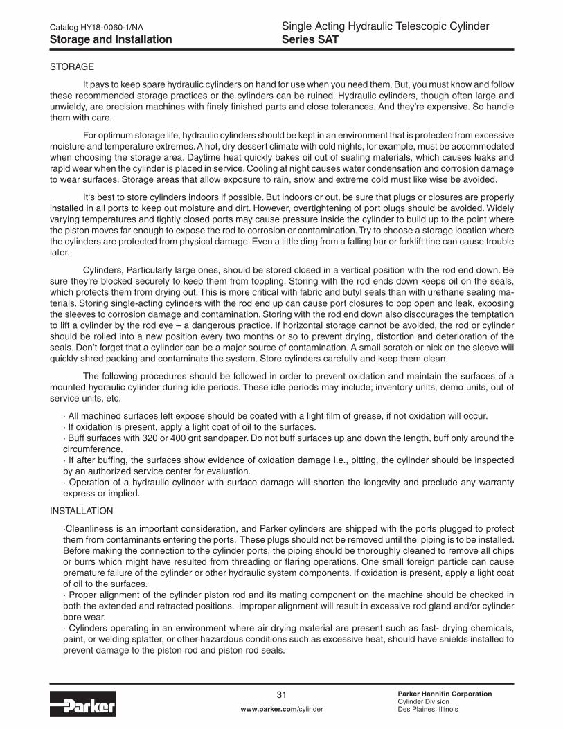
STORAGE
It pays to keep spare hydraulic cylinders on hand for use when you need them. But, you must know and follow these recommended storage practices or the cylinders can be ruined. Hydraulic cylinders, though often large and unwieldy, are precision machines with fi nely fi nished parts and close tolerances. And they’re expensive. So handle them with care.
For optimum storage life, hydraulic cylinders should be kept in an environment that is protected from excessive moisture and temperature extremes. A hot, dry dessert climate with cold nights, for example, must be accommodated when choosing the storage area. Daytime heat quickly bakes oil out of sealing materials, which causes leaks and rapid wear when the cylinder is placed in service. Cooling at night causes water condensation and corrosion damage to wear surfaces. Storage areas that allow exposure to rain, snow and extreme cold must like wise be avoided.
It‘s best to store cylinders indoors if possible. But indoors or out, be sure that plugs or closures are properly installed in all ports to keep out moisture and dirt. However, overtightening of port plugs should be avoided. Widely varying temperatures and tightly closed ports may cause pressure inside the cylinder to build up to the point where the piston moves far enough to expose the rod to corrosion or contamination. Try to choose a storage location where the cylinders are protected from physical damage. Even a little ding from a falling bar or forklift tine can cause trouble later.
Cylinders, Particularly large ones, should be stored closed in a vertical position with the rod end down. Be sure they’re blocked securely to keep them from toppling. Storing with the rod ends down keeps oil on the seals, which protects them from drying out. This is more critical with fabric and butyl seals than with urethane sealing ma-terials. Storing single-acting cylinders with the rod end up can cause port closures to pop open and leak, exposing the sleeves to corrosion damage and contamination. Storing with the rod end down also discourages the temptation to lift a cylinder by the rod eye – a dangerous practice. If horizontal storage cannot be avoided, the rod or cylinder should be rolled into a new position every two months or so to prevent drying, distortion and deterioration of the seals. Don’t forget that a cylinder can be a major source of contamination. A small scratch or nick on the sleeve will quickly shred packing and contaminate the system. Store cylinders carefully and keep them clean.
The following procedures should be followed in order to prevent oxidation and maintain the surfaces of a mounted hydraulic cylinder during idle periods. These idle periods may include; inventory units, demo units, out of service units, etc.
· All machined surfaces left expose should be coated with a light fi lm of grease, if not oxidation will occur.· If oxidation is present, apply a light coat of oil to the surfaces.· Buff surfaces with 320 or 400 grit sandpaper. Do not buff surfaces up and down the length, buff only around the circumference.· If after buffi ng, the surfaces show evidence of oxidation damage i.e., pitting, the cylinder should be inspected by an authorized service center for evaluation.· Operation of a hydraulic cylinder with surface damage will shorten the longevity and preclude any warranty express or implied.
INSTALLATION
·Cleanliness is an important consideration, and Parker cylinders are shipped with the ports plugged to protect them from contaminants entering the ports. These plugs should not be removed until the piping is to be installed. Before making the connection to the cylinder ports, the piping should be thoroughly cleaned to remove all chips or burrs which might have resulted from threading or fl aring operations. One small foreign particle can cause premature failure of the cylinder or other hydraulic system components. If oxidation is present, apply a light coat of oil to the surfaces.· Proper alignment of the cylinder piston rod and its mating component on the machine should be checked in both the extended and retracted positions. Improper alignment will result in excessive rod gland and/or cylinder bore wear.· Cylinders operating in an environment where air drying material are present such as fast- drying chemicals, paint, or welding splatter, or other hazardous conditions such as excessive heat, should have shields installed to prevent damage to the piston rod and piston rod seals.
Storage and Installation
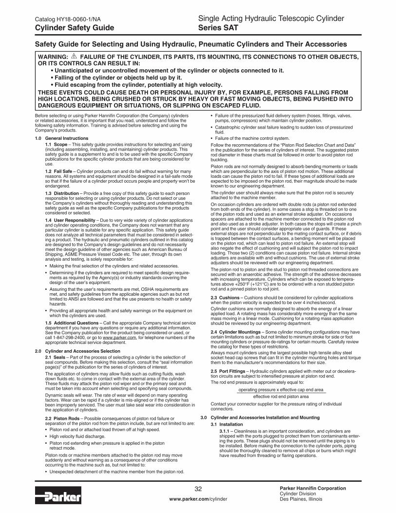
Single Acting Hydraulic Telescopic CylinderSeries SAT
Parker Hannifin CorporationCylinder DivisionDes Plaines, Illinoiswww.parker.com/cylinder
Catalog HY18-0060-1/NA
32
Cylinder Safety Guide
Before selecting or using Parker Hannifin Corporation (the Company) cylinders or related accessories, it is important that you read, understand and follow the following safety information. Training is advised before selecting and using the Company’s products.
1.0 General Instructions 1.1 Scope – This safety guide provides instructions for selecting and using
(including assembling, installing, and maintaining) cylinder products. This safety guide is a supplement to and is to be used with the specific Company publications for the specific cylinder products that are being considered for use.
1.2 Fail Safe – Cylinder products can and do fail without warning for many reasons. All systems and equipment should be designed in a fail-safe mode so that if the failure of a cylinder product occurs people and property won’t be endangered.
1.3 Distribution – Provide a free copy of this safety guide to each person responsible for selecting or using cylinder products. Do not select or use the Company’s cylinders without thoroughly reading and understanding this safety guide as well as the specific Company publications for the products considered or selected.
1.4 User Responsibility – Due to very wide variety of cylinder applications and cylinder operating conditions, the Company does not warrant that any particular cylinder is suitable for any specific application. This safety guide does not analyze all technical parameters that must be considered in select-ing a product. The hydraulic and pneumatic cylinders outlined in this catalog are designed to the Company’s design guidelines and do not necessarily meet the design guideline of other agencies such as American Bureau of Shipping, ASME Pressure Vessel Code etc. The user, through its own analysis and testing, is solely responsible for:
• Making the final selection of the cylinders and related accessories. • Determining if the cylinders are required to meet specific design require-
ments as required by the Agency(s) or industry standards covering the design of the user’s equipment.
• Assuring that the user’s requirements are met, OSHA requirements are met, and safety guidelines from the applicable agencies such as but not limited to ANSI are followed and that the use presents no health or safety hazards.
• Providing all appropriate health and safety warnings on the equipment on which the cylinders are used.
1.5 Additional Questions – Call the appropriate Company technical service department if you have any questions or require any additional information. See the Company publication for the product being considered or used, or call 1-847-298-2400, or go to www.parker.com, for telephone numbers of the appropriate technical service department.
2.0 Cylinder and Accessories Selection 2.1 Seals – Part of the process of selecting a cylinder is the selection of
seal compounds. Before making this selection, consult the “seal information page(s)” of the publication for the series of cylinders of interest.
The application of cylinders may allow fluids such as cutting fluids, wash down fluids etc. to come in contact with the external area of the cylinder. These fluids may attack the piston rod wiper and or the primary seal and must be taken into account when selecting and specifying seal compounds.
Dynamic seals will wear. The rate of wear will depend on many operating factors. Wear can be rapid if a cylinder is mis-aligned or if the cylinder has been improperly serviced. The user must take seal wear into consideration in the application of cylinders.
2.2 Piston Rods – Possible consequences of piston rod failure or separation of the piston rod from the piston include, but are not limited to are:
• Piston rod and or attached load thrown off at high speed. • High velocity fluid discharge. • Piston rod extending when pressure is applied in the piston
retract mode.
Piston rods or machine members attached to the piston rod may move suddenly and without warning as a consequence of other conditions occurring to the machine such as, but not limited to:
• Unexpected detachment of the machine member from the piston rod.
• Failure of the pressurized fluid delivery system (hoses, fittings, valves, pumps, compressors) which maintain cylinder position.
• Catastrophic cylinder seal failure leading to sudden loss of pressurized fluid.
• Failure of the machine control system. Follow the recommendations of the “Piston Rod Selection Chart and Data”
in the publication for the series of cylinders of interest. The suggested piston rod diameter in these charts must be followed in order to avoid piston rod buckling.
Piston rods are not normally designed to absorb bending moments or loads which are perpendicular to the axis of piston rod motion. These additional loads can cause the piston rod to fail. If these types of additional loads are expected to be imposed on the piston rod, their magnitude should be made known to our engineering department.
The cylinder user should always make sure that the piston rod is securely attached to the machine member.
On occasion cylinders are ordered with double rods (a piston rod extended from both ends of the cylinder). In some cases a stop is threaded on to one of the piston rods and used as an external stroke adjuster. On occasions spacers are attached to the machine member connected to the piston rod and also used as a stroke adjuster. In both cases the stops will create a pinch point and the user should consider appropriate use of guards. If these external stops are not perpendicular to the mating contact surface, or if debris is trapped between the contact surfaces, a bending moment will be placed on the piston rod, which can lead to piston rod failure. An external stop will also negate the effect of cushioning and will subject the piston rod to impact loading. Those two (2) conditions can cause piston rod failure. Internal stroke adjusters are available with and without cushions. The use of external stroke adjusters should be reviewed with our engineering department.
The piston rod to piston and the stud to piston rod threaded connections are secured with an anaerobic adhesive. The strength of the adhesive decreases with increasing temperature. Cylinders which can be exposed to tempera-tures above +250°F (+121°C) are to be ordered with a non studded piston rod and a pinned piston to rod joint.
2.3 Cushions – Cushions should be considered for cylinder applications when the piston velocity is expected to be over 4 inches/second.
Cylinder cushions are normally designed to absorb the energy of a linear applied load. A rotating mass has considerably more energy than the same mass moving in a linear mode. Cushioning for a rotating mass application should be reviewed by our engineering department.
2.4 Cylinder Mountings – Some cylinder mounting configurations may have certain limitations such as but not limited to minimum stroke for side or foot mounting cylinders or pressure de-ratings for certain mounts. Carefully review the catalog for these types of restrictions.
Always mount cylinders using the largest possible high tensile alloy steel socket head cap screws that can fit in the cylinder mounting holes and torque them to the manufacturer’s recommendations for their size.
2.5 Port Fittings – Hydraulic cylinders applied with meter out or decelera-tion circuits are subject to intensified pressure at piston rod end.
The rod end pressure is approximately equal to:
operating pressure x effective cap end area effective rod end piston area
Contact your connector supplier for the pressure rating of individual connectors.
3.0 Cylinder and Accessories Installation and Mounting 3.1 Installation 3.1.1 – Cleanliness is an important consideration, and cylinders are
shipped with the ports plugged to protect them from contaminants enter-ing the ports. These plugs should not be removed until the piping is to be installed. Before making the connection to the cylinder ports, piping should be thoroughly cleaned to remove all chips or burrs which might have resulted from threading or flaring operations.
Safety Guide for Selecting and Using Hydraulic, Pneumatic Cylinders and Their Accessories
WARNING: FAILURE OF THE CYLINDER, ITS PARTS, ITS MOUNTING, ITS CONNECTIONS TO OTHER OBJECTS, OR ITS CONTROLS CAN RESULT IN: • Unanticipated or uncontrolled movement of the cylinder or objects connected to it. • Falling of the cylinder or objects held up by it. • Fluid escaping from the cylinder, potentially at high velocity.THESE EVENTS COULD CAUSE DEATH OR PERSONAL INJURY BY, FOR EXAMPLE, PERSONS FALLING FROM HIGH LOCATIONS, BEING CRUSHED OR STRUCK BY HEAVY OR FAST MOVING OBJECTS, BEING PUSHED INTO DANGEROUS EQUIPMENT OR SITUATIONS, OR SLIPPING ON ESCAPED FLUID.
Single Acting Hydraulic Telescopic CylinderSeries SAT
Parker Hannifin CorporationCylinder DivisionDes Plaines, Illinoiswww.parker.com/cylinder
Catalog HY18-0060-1/NA
33
Cylinder Safety Guide
3.1.2 – Cylinders operating in an environment where air drying materials are present such as fast-drying chemicals, paint, or weld splatter, or other hazardous conditions such as excessive heat, should have shields installed to prevent damage to the piston rod and piston rod seals.
3.1.3 – Proper alignment of the cylinder piston rod and its mating component on the machine should be checked in both the extended and retracted positions. Improper alignment will result in excessive rod gland and/or cylinder bore wear. On fixed mounting cylinders attaching the pis-ton rod while the rod is retracted will help in achieving proper alignment.
3.1.4 – Sometimes it may be necessary to rotate the piston rod in order to thread the piston rod into the machine member. This operation must always be done with zero pressure being applied to either side of the piston. Failure to follow this procedure may result in loosening the piston to rod-threaded connection. In some rare cases the turning of the piston rod may rotate a threaded head and loosen it from the cylinder body. Confirm that this condition is not occurring. If it does, re-tighten the head firmly against the cylinder body.
For double rod cylinders it is also important that when attaching or detaching the piston rod from the machine member that the torque be applied to the piston rod end of the cylinder that is directly attaching to the machine member with the opposite end unrestrained. If the design of the machine is such that only the rod end of the cylinder opposite to where the rod attaches to the machine member can be rotated, consult the factory for further instructions.
3.2 Mounting Recommendations 3.2.1 – Always mount cylinders using the largest possible high tensile
alloy steel socket head screws that can fit in the cylinder mounting holes and torque them to the manufacturer’s recommendations for their size.
3.2.2 – Side-Mounted Cylinders – In addition to the mounting bolts, cylinders of this type should be equipped with thrust keys or dowel pins located so as to resist the major load.
3.2.3 – Tie Rod Mounting – Cylinders with tie rod mountings are recom-mended for applications where mounting space is limited. Nuts used for this mounting style should be torqued to the same value as the tie rods for that bore size.
3.2.4 – Flange Mount Cylinders – The controlled diameter of the rod gland extension on head end flange mount cylinders can be used as a pilot to locate the cylinders in relation to the machine. After align-ment has been obtained, the flanges may be drilled for pins or dowels to prevent shifting.
3.2.5 – Trunnion Mountings – Cylinders require lubricated bearing blocks with minimum bearing clearances. Bearing blocks should be carefully aligned and rigidly mounted so the trunnions will not be subjected to bending moments. The rod end should also be pivoted with the pivot pin in line and parallel to axis of the trunnion pins.
3.2.6 – Clevis Mountings – Cylinders should be pivoted at both ends with centerline of pins parallel to each other. After cylinder is mounted, be sure to check to assure that the cylinder is free to swing through its working arc without interference from other machine parts.
4.0 Cylinder and Accessories Maintenance, Troubleshooting and Replacement
4.1 Storage – At times cylinders are delivered before a customer is ready to install them and must be stored for a period of time. When storage is required the following procedures are recommended.
4.1.1 – Store the cylinders in an indoor area which has a dry, clean and noncorrosive atmosphere. Take care to protect the cylinder from both internal corrosion and external damage.
4.1.2 – Whenever possible cylinders should be stored in a vertical posi-tion (piston rod up). This will minimize corrosion due to possible conden-sation which could occur inside the cylinder. This will also minimize seal damage.
4.1.3 – Port protector plugs should be left in the cylinder until the time of installation.
4.1.4 – If a cylinder is stored full of hydraulic fluid, expansion of the fluid due to temperature changes must be considered. Installing a check valve with free flow out of the cylinder is one method.
4.1.5 – When cylinders are mounted on equipment that is stored outside for extended periods, exposed unpainted surfaces, e.g. piston rod, must be coated with a rust-inhibiting compound to prevent corrosion.
4.2 Cylinder Trouble Shooting
4.2.1 – External Leakage 4.2.1.1 – Rod seal leakage can generally be traced to worn or
damaged seals. Examine the piston rod for dents, gouges or score marks, and replace piston rod if surface is rough.
Rod seal leakage could also be traced to bearing wear. If clear-ance is excessive, replace rod bearing and seal. Rod seal leakage can also be traced to seal deterioration. If seals are soft or gummy or brittle, check compatibility of seal material with lubricant used if air cylinder, or operating fluid if hydraulic cylinder. Replace with seal material, which is compatible with these fluids. If the seals are hard or have lost elasticity, it is usually due to exposure to tem-peratures in excess of 165°F. (+74°C). Shield the cylinder from the heat source to limit temperature to 350°F. (+177°C.) and replace with fluorocarbon seals.
4.2.1.2 – Cylinder body seal leak can generally be traced to a loose head. Torque the head to manufacturer’s recommendation for that bore size.
Excessive pressure can also result in cylinder body seal leak. Determine maximum pressure to rated limits. Replace seals and retorque head as in paragraph above. Excessive pressure can also result in cylinder body seal leak. Determine if the pressure rating of the cylinder has been exceeded. If so, bring the operating pressure down to the rating of the cylinder and have the head replaced.
Pinched or extruded cylinder body seal will also result in a leak. Replace cylinder body seal and retorque as in paragraph above.
Cylinder body seal leakage due to loss of radial squeeze which shows up in the form of flat spots or due to wear on the O.D. or I.D. – Either of these are symptoms of normal wear due to high cycle rate or length of service. Replace seals as per paragraph above.
4.2.2 – Internal Leakage 4.2.2.1 – Piston seal leak (by-pass) 1 to 3 cubic inches per minute
leakage is considered normal for piston ring construction. Virtually no static leak with lipseal type seals on piston should be expected. Piston seal wear is a usual cause of piston seal leakage. Replace seals as required.
4.2.2.2 – With lipseal type piston seals excessive back pressure due to over-adjustment of speed control valves could be a direct cause of rapid seal wear. Contamination in a hydraulic system can result in a scored cylinder bore, resulting in rapid seal wear. In either case, replace piston seals as required.
4.2.2.3 – What appears to be piston seal leak, evidenced by the fact that the cylinder drifts, is not always traceable to the piston. To make sure, it is suggested that one side of the cylinder piston be pressurized and the fluid line at the opposite port be disconnected. Observe leakage. If none is evident, seek the cause of cylinder drift in other component parts in the circuit.
4.2.3 – Cylinder Fails to Move the Load 4.2.3.1 – Pneumatic or hydraulic pressure is too low. Check the
pressure at the cylinder to make sure it is to circuit requirements. 4.2.3.2 – Piston Seal Leak – Operate the valve to cycle the cylinder
and observe fluid flow at valve exhaust ports at end of cylinder stroke. Replace piston seals if flow is excessive.
4.2.3.3 – Cylinder is undersized for the load – Replace cylinder with one of a larger bore size.
4.3 Erratic or Chatter Operation 4.3.1 – Excessive friction at rod bearing or piston bearing due to load
misalignment – Correct cylinder-to-load alignment. 4.3.2 – Cylinder sized too close to load requirements – Reduce load or
install larger cylinder. 4.3.3 – Erratic operation could be traced to the difference between static
and kinetic friction. Install speed control valves to provide a back pres-sure to control the stroke.
4.4 Cylinder Modifications, Repairs, or Failed Component – Cylinders as shipped from the factory are not to be disassembled and or modified. If cylinders require modifications, these modifications must be done at company locations or by the Company’s certified facilities. The Industrial Cylinder Division Engineering Department must be notified in the event of a mechanical fracture or permanent deformation of any cylinder component (excluding seals). This includes a broken piston rod, head, mounting accessory or any other cylinder component. The notification should include all operation and application details. This information will be used to provide an engineered repair that will prevent recurrence of the failure.
It is allowed to disassemble cylinders for the purpose of replacing seals or seal assemblies. However, this work must be done by strictly following all the instructions provided with the seal kits.
Single Acting Hydraulic Telescopic CylinderSeries SAT
Parker Hannifin CorporationCylinder DivisionDes Plaines, Illinois
Catalog HY18-0060-1/NA
www.parker.com/cylinder
34
Offer of Sale
The items described in this document and other documents and descriptions provided by Parker Hannifin Corporation, its subsidiaries and its authorized distributors (“Seller”) are hereby offered for sale at prices to be established by Seller. This offer and its acceptance by any customer (“Buyer”) shall be governed by all of the following Terms and Conditions. Buyer’s order for any item described in its document, when communicated to Seller verbally, or in writing, shall constitute acceptance of this offer. All goods, services or work described will be referred to as “Products”.
1. Terms and Conditions. Seller’s willingness to offer Products, or accept an order for Products, to or from Buyer is subject to these Terms and Conditions or any newer version of the terms and conditions found on-line at www.parker.com/saleterms/. Seller objects to any contrary or additional terms or conditions of Buyer’s order or any other document issued by Buyer.2. Price Adjustments; Payments. Prices stated on Seller’s quote or other documen-tation offered by Seller are valid for 30 days, and do not include any sales, use, or other taxes unless specifically stated. Unless otherwise specified by Seller, all prices are F.C.A. Seller’s facility (INCOTERMS 2010). Payment is subject to credit approval and is due 30 days from the date of invoice or such other term as required by Seller’s Credit Department, after which Buyer shall pay interest on any unpaid invoices at the rate of 1.5% per month or the maximum allowable rate under applicable law.3. Delivery Dates; Title and Risk; Shipment. All delivery dates are approximate and Seller shall not be responsible for any damages resulting from any delay. Regardless of the manner of shipment, title to any products and risk of loss or damage shall pass to Buyer upon placement of the products with the shipment carrier at Seller’s facility. Unless otherwise stated, Seller may exercise its judgment in choosing the carrier and means of delivery. No deferment of shipment at Buyers’ request beyond the respec-tive dates indicated will be made except on terms that will indemnify, defend and hold Seller harmless against all loss and additional expense. Buyer shall be responsible for any additional shipping charges incurred by Seller due to Buyer’s acts or omissions.4. Warranty. Seller warrants that the Products sold hereunder shall be free from defects in material or workmanship for a period of eighteen months from the date of delivery to Buyer. The prices charged for Seller’s products are based upon the exclu-sive limited warranty stated above, and upon the following disclaimer: DISCLAIMER OF WARRANTY: THIS WARRANTY COMPRISES THE SOLE AND ENTIRE WARRANTY PERTAINING TO PRODUCTS PROVIDED HEREUNDER. SELLER DISCLAIMS ALL OTHER WARRANTIES, EXPRESS AND IMPLIED, INCLUDING DESIGN, MERCHANTABILITY AND FITNESS FOR A PARTICULAR PURPOSE.5. Claims; Commencement of Actions. Buyer shall promptly inspect all Products upon delivery. No claims for shortages will be allowed unless reported to the Seller within 10 days of delivery. No other claims against Seller will be allowed unless asserted in writing within 30 days after delivery. Buyer shall notify Seller of any alleged breach of warranty within 30 days after the date the defect is or should have been discovered by Buyer. Any action based upon breach of this agreement or upon any other claim arising out of this sale (other than an action by Seller for an amount due on any invoice) must be commenced within 12 months from the date of the breach without regard to the date breach is discovered.6. LIMITATION OF LIABILITY. UPON NOTIFICATION, SELLER WILL, AT ITS OPTION, REPAIR OR REPLACE A DEFECTIVE PRODUCT, OR REFUND THE PURCHASE PRICE. IN NO EVENT SHALL SELLER BE LIABLE TO BUYER FOR ANY SPECIAL, INDIRECT, INCIDENTAL OR CONSEQUENTIAL DAMAGES ARISING OUT OF, OR AS THE RESULT OF, THE SALE, DELIVERY, NON-DELIVERY, SERVICING, USE OR LOSS OF USE OF THE PRODUCTS OR ANY PART THEREOF, OR FOR ANY CHARGES OR EXPENSES OF ANY NATURE INCURRED WITHOUT SELLER’S WRITTEN CONSENT, EVEN IF SELLER HAS BEEN NEGLIGENT, WHETHER IN CONTRACT, TORT OR OTHER LEGAL THEORY. IN NO EVENT SHALL SELLER’S LIABILITY UNDER ANY CLAIM MADE BY BUYER EXCEED THE PURCHASE PRICE OF THE PRODUCTS.7. User Responsibility. The user, through its own analysis and testing, is solely responsible for making the final selection of the system and Product and assuring that all performance, endurance, maintenance, safety and warning requirements of the application are met. The user must analyze all aspects of the application and follow applicable industry standards and Product information. If Seller provides Product or system options, the user is responsible for determining that such data and specifica-tions are suitable and sufficient for all applications and reasonably foreseeable uses of the Products or systems.8. Loss to Buyer’s Property. Any designs, tools, patterns, materials, drawings, confi-dential information or equipment furnished by Buyer or any other items which become Buyer’s property, will be considered obsolete and may be destroyed by Seller after two consecutive years have elapsed without Buyer ordering the items manufactured using such property. Seller shall not be responsible for any loss or damage to such property while it is in Seller’s possession or control.9. Special Tooling. A tooling charge may be imposed for any special tooling, includ-ing without limitation, dies, fixtures, molds and patterns, acquired to manufacture Products. Such special tooling shall be and remain Seller’s property notwithstanding payment of any charges by Buyer. In no event will Buyer acquire any interest in appa-ratus belonging to Seller which is utilized in the manufacture of the Products, even if such apparatus has been specially converted or adapted for such manufacture and notwithstanding any charges paid by Buyer. Unless otherwise agreed, Seller shall have the right to alter, discard or otherwise dispose of any special tooling or other property in its sole discretion at any time.10. Buyer’s Obligation; Rights of Seller. To secure payment of all sums due or oth-erwise, Seller shall retain a security interest in the goods delivered and this agreement shall be deemed a Security Agreement under the Uniform Commercial Code. Buyer authorizes Seller as its attorney to execute and file on Buyer’s behalf all documents Seller deems necessary to perfect its security interest. 11. Improper use and Indemnity. Buyer shall indemnify, defend, and hold Seller harmless from any claim, liability, damages, lawsuits, and costs (including attorney fees), whether for personal injury, property damage, patent, trademark or copyright
infringement or any other claim, brought by or incurred by Buyer, Buyer’s employees, or any other person, arising out of: (a) improper selection, improper application or other misuse of Products purchased by Buyer from Seller; (b) any act or omission, negligent or otherwise, of Buyer; (c) Seller’s use of patterns, plans, drawings, or specifications furnished by Buyer to manufacture Product; or (d) Buyer’s failure to comply with these terms and conditions. Seller shall not indemnify Buyer under any circumstance except as otherwise provided.12. Cancellations and Changes. Orders shall not be subject to cancellation or change by Buyer for any reason, except with Seller’s written consent and upon terms that will indemnify, defend and hold Seller harmless against all direct, incidental and consequential loss or damage. Seller may change product features, specifications, designs and availability with notice to Buyer.13. Limitation on Assignment. Buyer may not assign its rights or obligations under this agreement without the prior written consent of Seller.14. Force Majeure. Seller does not assume the risk and shall not be liable for delay or failure to perform any of Seller’s obligations by reason of circumstances beyond the reasonable control of Seller (hereinafter “Events of Force Majeure”). Events of Force Majeure shall include without limitation: accidents, strikes or labor disputes, acts of any government or government agency, acts of nature, delays or failures in delivery from carriers or suppliers, shortages of materials, or any other cause beyond Seller’s reasonable control. 15. Waiver and Severability. Failure to enforce any provision of this agreement will not waive that provision nor will any such failure prejudice Seller’s right to enforce that provision in the future. Invalidation of any provision of this agreement by legislation or other rule of law shall not invalidate any other provision herein. The remaining provi-sions of this agreement will remain in full force and effect.16. Termination. Seller may terminate this agreement for any reason and at any time by giving Buyer thirty (30) days written notice of termination. Seller may immediately terminate this agreement, in writing, if Buyer: (a) commits a breach of any provision of this agreement (b) appointments a trustee, receiver or custodian for all or any part of Buyer’s property (c) files a petition for relief in bankruptcy on its own behalf, or by a third party (d) makes an assignment for the benefit of creditors, or (e) dissolves or liquidates all or a majority of its assets.17. Governing Law. This agreement and the sale and delivery of all Products here-under shall be deemed to have taken place in and shall be governed and construed in accordance with the laws of the State of Ohio, as applicable to contracts executed and wholly performed therein and without regard to conflicts of laws principles. Buyer irrevocably agrees and consents to the exclusive jurisdiction and venue of the courts of Cuyahoga County, Ohio with respect to any dispute, controversy or claim arising out of or relating to this agreement. 18. Indemnity for Infringement of Intellectual Property Rights. Seller shall have no liability for infringement of any patents, trademarks, copyrights, trade dress, trade secrets or similar rights except as provided in this Section. Seller will defend and indemnify Buyer against allegations of infringement of U.S. patents, U.S. trademarks, copyrights, trade dress and trade secrets (“Intellectual Property Rights”). Seller will defend at its expense and will pay the cost of any settlement or damages awarded in an action brought against Buyer based on an allegation that a Product sold pursuant to this Agreement infringes the Intellectual Property Rights of a third party. Seller’s obliga-tion to defend and indemnify Buyer is contingent on Buyer notifying Seller within ten (10) days after Buyer becomes aware of such allegations of infringement, and Seller having sole control over the defense of any allegations or actions including all negotia-tions for settlement or compromise. If a Product is subject to a claim that it infringes the Intellectual Property Rights of a third party, Seller may, at its sole expense and option, procure for Buyer the right to continue using the Product, replace or modify the Product so as to make it noninfringing, or offer to accept return of the Product and return the purchase price less a reasonable allowance for depreciation. Notwithstanding the fore-going, Seller shall have no liability for claims of infringement based on information provided by Buyer, or directed to Products delivered hereunder for which the designs are specified in whole or part by Buyer, or infringements resulting from the modification, combination or use in a system of any Product sold hereunder. The foregoing provi-sions of this Section shall constitute Seller’s sole and exclusive liability and Buyer’s sole and exclusive remedy for infringement of Intellectual Property Rights.19. Entire Agreement. This agreement contains the entire agreement between the Buyer and Seller and constitutes the final, complete and exclusive expression of the terms of sale. All prior or contemporaneous written or oral agreements or negotiations with respect to the subject matter are herein merged.20. Compliance with Law, U. K. Bribery Act and U.S. Foreign Corrupt Practices Act. Buyer agrees to comply with all applicable laws and regulations, including both those of the United Kingdom and the United States of America, and of the country or countries of the Territory in which Buyer may operate, including without limitation the U. K. Bribery Act, the U.S. Foreign Corrupt Practices Act (“FCPA”) and the U.S. Anti-Kickback Act (the “Anti-Kickback Act”), and agrees to indemnify and hold harmless Seller from the consequences of any violation of such provisions by Buyer, its employ-ees or agents. Buyer acknowledges that they are familiar with the provisions of the U. K. Bribery Act, the FCPA and the Anti-Kickback Act, and certifies that Buyer will adhere to the requirements thereof. In particular, Buyer represents and agrees that Buyer shall not make any payment or give anything of value, directly or indirectly to any governmental official, any foreign political party or official thereof, any candidate for foreign political office, or any commercial entity or person, for the purpose of influ-encing such person to purchase products or otherwise benefit the business of Seller.
Offer of Sale
AerospaceKey MarketsAftermarket services Commercial transportsEnginesGeneral & business aviationHelicoptersLaunch vehiclesMilitary aircraftMissilesPower generation Regional transportsUnmanned aerial vehicles
Key ProductsControl systems & actuation productsEngine systems & componentsFluid conveyance systems& componentsFluid metering, delivery & atomization devicesFuel systems & componentsFuel tank inerting systemsHydraulic systems & componentsThermal managementWheels & brakes
ElectromechanicalKey MarketsAerospaceFactory automationLife science & medicalMachine toolsPackaging machineryPaper machineryPlastics machinery & convertingPrimary metalsSemiconductor & electronicsTextileWire & cable
Key ProductsAC/DC drives & systemsElectric actuators, gantry robots & slidesElectrohydrostatic actuation systemsElectromechanical actuation systemsHuman machine interfaceLinear motorsStepper motors, servo motors, drives & controlsStructural extrusions
PneumaticsKey MarketsAerospaceConveyor & material handlingFactory automationLife science & medicalMachine toolsPackaging machineryTransportation & automotive
Key ProductsAir preparationBrass fittings & valvesManifoldsPneumatic accessoriesPneumatic actuators & grippersPneumatic valves & controlsQuick disconnectsRotary actuatorsRubber & thermoplastic hose & couplingsStructural extrusionsThermoplastic tubing & fittingsVacuum generators, cups & sensors
Fluid & Gas HandlingKey Markets Aerial liftAgricultureBulk chemical handlingConstruction machineryFood & beverageFuel & gas deliveryIndustrial machineryLife sciences MarineMiningMobileOil & gasRenewable energyTransportation
Key Products Check valves Connectors for low pressure fluid conveyanceDeep sea umbilicalsDiagnostic equipment Hose couplingsIndustrial hoseMooring systems & power cablesPTFE hose & tubing Quick couplingsRubber & thermoplastic hose Tube fittings & adaptersTubing & plastic fittings
HydraulicsKey Markets Aerial liftAgricultureAlternative energyConstruction machineryForestryIndustrial machineryMachine toolsMarineMaterial handlingMiningOil & gasPower generationRefuse vehiclesRenewable energyTruck hydraulicsTurf equipment
Key Products AccumulatorsCartridge valvesElectrohydraulic actuatorsHuman machine interfacesHybrid drivesHydraulic cylinders Hydraulic motors & pumpsHydraulic systemsHydraulic valves & controlsHydrostatic steeringIntegrated hydraulic circuitsPower take-offs Power unitsRotary actuatorsSensors
Process ControlKey Markets Alternative fuelsBiopharmaceuticalsChemical & refiningFood & beverageMarine & shipbuildingMedical & dentalMicroelectronicsNuclear PowerOffshore oil explorationOil & gasPharmaceuticalsPower generationPulp & paperSteelWater/wastewater
Key ProductsAnalytical Instruments Analytical sample conditioningproducts & systemsChemical injection fittings& valvesFluoropolymer chemicaldelivery fittings, valves & pumpsHigh purity gas delivery fittings, valves, regulators& digital flow controllersIndustrial mass flow meters/controllersPermanent no-weld tube fittingsPrecision industrial regulators& flow controllersProcess control double block & bleedsProcess control fittings, valves, regulators & manifold valves
Sealing & ShieldingKey Markets AerospaceChemical processingConsumerFluid powerGeneral industrialInformation technologyLife sciencesMicroelectronicsMilitaryOil & gasPower generationRenewable energyTelecommunicationsTransportation
Key Products Dynamic sealsElastomeric o-ringsElectro-medical instrumentdesign & assemblyEMI shieldingExtruded & precision-cut,fabricated elastomeric sealsHigh temperature metal sealsHomogeneous & insertedelastomeric shapesMedical device fabrication & assemblyMetal & plastic retainedcomposite sealsShielded optical windowsSilicone tubing & extrusionsThermal managementVibration dampening
Parker’s Motion & Control Technologies
At Parker, we’re guided by
a relentless drive to help
our customers become more
productive and achieve
higher levels of profitabil-
ity by engineering the best
systems for their require-
ments. It means looking at
customer applications from
many angles to find new
ways to create value. What-
ever the motion and control
technology need, Parker has
the experience, breadth of
product and global reach
to consistently deliver. No
company knows more about
motion and control technol-
ogy than Parker. For further
info call 1 800 C-Parker
(1 800 272 7537)
Climate ControlKey Markets AgricultureAir conditioningConstruction MachineryFood & beverageIndustrial machineryLife sciencesOil & gasPrecision coolingProcessRefrigerationTransportation
Key Products AccumulatorsAdvanced actuatorsCO
2 controls
Electronic controllersFilter driersHand shut-off valvesHeat exchangers Hose & fittingsPressure regulating valvesRefrigerant distributorsSafety relief valvesSmart pumpsSolenoid valvesThermostatic expansion valves
FiltrationKey MarketsAerospaceFood & beverageIndustrial plant & equipmentLife sciencesMarineMobile equipmentOil & gasPower generation & renewable energyProcessTransportation Water Purification
Key Products Analytical gas generatorsCompressed air filters & dryersEngine air, coolant, fuel & oil filtration systemsFluid condition monitoring systemsHydraulic & lubrication filtersHydrogen, nitrogen & zero air generatorsInstrumentation filtersMembrane & fiber filtersMicrofiltrationSterile air filtrationWater desalination & purification filters & systems

Parker Hannifin CorporationCylinder Division500 South Wolf RoadDes Plaines, IL 60016phone (847) 298-2400fax (800) 892-1008www.parker.com/cylinder
7/15/18 / Catalog HY18-0060-1/NA
Related Documents