Studer Innotec SA 2016 – V3.01 4O9I AJ SINE WAVE INVERTER SINUS-WECHSELRICHTER ONDULEUR SINUSOÏDAL INVERSOR SINUSOIDAL User’s and installer’s manual Betriebs- und Montageanleitung Manuel d’utilisation et de montage Manual de usuario y de montaje AJ 275-12 AJ 350-24 AJ 400-48 AJ 500-12 AJ 600-24 AJ 700-48 AJ 1000-12 AJ 1300-24 AJ 2100-12 AJ 2400-24

Welcome message from author
This document is posted to help you gain knowledge. Please leave a comment to let me know what you think about it! Share it to your friends and learn new things together.
Transcript

Studer Innotec SA 2016 – V3.01 4O9I
AJ
SINE WAVE INVERTER
SINUS-WECHSELRICHTER
ONDULEUR SINUSOÏDAL
INVERSOR SINUSOIDAL
User’s and installer’s manual
Betriebs- und Montageanleitung
Manuel d’utilisation et de montage
Manual de usuario y de montaje
AJ 275-12 AJ 350-24 AJ 400-48
AJ 500-12 AJ 600-24 AJ 700-48
AJ 1000-12 AJ 1300-24
AJ 2100-12 AJ 2400-24

STUDER Innotec SA AJ
V3.01 1
ENGLISH DESCRIPTION ........................................................................................................................... 4
INTRODUCTION ...................................................................................................................................................... 4 WARNING ............................................................................................................................................................. 4 INSTALLATION ........................................................................................................................................................ 4
Mounting the inverter................................................................................................................................ 4 CONNECTION ......................................................................................................................................................... 5 CONNECTING THE CONSUMER DEVICES ...................................................................................................................... 5
Note ........................................................................................................................................................... 5 EQUIVALENT DIAGRAM ............................................................................................................................................ 5 CONNECTING THE BATTERY ...................................................................................................................................... 5 USE ..................................................................................................................................................................... 6 CONTROL AND INDICATORS ...................................................................................................................................... 6 ACOUSTIC INDICATOR.............................................................................................................................................. 6 ALARM BY VOLTAGE FLICKERING ............................................................................................................................... 6 MODEL WITH STAND-BY SYSTEM ............................................................................................................................... 7 ACTIVATION / DEACTIVATION OF FUNCTIONS: ............................................................................................................. 8 SAFETY ................................................................................................................................................................. 8 BATTERY LIFETIME OPTIMIZER – BLO ........................................................................................................................ 9 WARRANTY LIMIT ................................................................................................................................................. 11 LIMITS OF MANUFACTURER LIABILITY ....................................................................................................................... 11 JT8 REMOTE CONTROL FOR AJ 1000-12 TO 2400-24 .............................................................................................. 11 MODELS WITH BUILT-IN SOLAR CHARGER (OPTION – S) .............................................................................................. 12 CONNECTION OF THE MODULES AJ 2100/2400-S .................................................................................................... 12 TECHNICAL DATA .................................................................................................................................................. 13
DEUTSCHE BESCHREIBUNG ................................................................................................................... 15
EINFÜHRUNG ....................................................................................................................................................... 15 VORSICHT ........................................................................................................................................................... 15 INSTALLATION ...................................................................................................................................................... 15
Montageort des AJ ................................................................................................................................... 15 Befestigung des AJ ................................................................................................................................... 15
ANSCHLUSS ......................................................................................................................................................... 16 ANSCHLUSS DER VERBRAUCHER .............................................................................................................................. 16
Bemerkung ............................................................................................................................................... 16 PRINZIPSCHEMA ................................................................................................................................................... 16 ANSCHLUSS DER BATTERIE ..................................................................................................................................... 16 ANWENDUNGEN .................................................................................................................................................. 17 BEDIENUNG UND ANZEIGEN ................................................................................................................................... 17 AKUSTISCHER SIGNALGEBER ................................................................................................................................... 17 ALARM DURCH SPANNUNGSSCHWANKUNG ................................................................................................................. 18 LASTERKENNUNGSSCHALTUNG „STAND-BY“ ................................................................................................................ 18 AKTIVIERUNG / DEAKTIVIERUNG VON FUNKTIONEN ................................................................................................... 19 SICHERHEITEN ...................................................................................................................................................... 19

STUDER Innotec SA AJ
V3.01 2
SCHUTZ DER BATTERIE DURCH ABSCHALTEN BEI UNTERSPANNUNG:.............................................................................. 19 BATTERIELEBENSDAUER-OPTIMIERER (BATTERY LIFETIME OPTIMIZER –BLO): ................................................................ 20 UNTERHALT ......................................................................................................................................................... 21 GARANTIEAUSSCHLUSS .......................................................................................................................................... 22 HAFTUNGSAUSSCHLUSS ......................................................................................................................................... 22 JT8 FERNSTEUERUNG FÜR AJ 1000-2400 ............................................................................................................... 22 MODELLE MIT SOLARLADEREGLER (OPTION – S) ....................................................................................................... 23 ANSCHLUSS DES SOLARMODULE AN AJ 2100/2400-S : ............................................................................................. 23 BEISPIEL.............................................................................................................................................................. 23 TECHNISCHE DATEN .............................................................................................................................................. 24
INSTRUCTIONS EN FRANÇAIS ............................................................................................................... 26
INTRODUCTION .................................................................................................................................................... 26 MISE EN GARDE ................................................................................................................................................... 26 INSTALLATION ...................................................................................................................................................... 26
Lieu de montage de l’onduleur ................................................................................................................ 26 Fixation de l’onduleur .............................................................................................................................. 26
RACCORDEMENT .................................................................................................................................................. 27 RACCORDEMENT DES CONSOMMATEURS .................................................................................................................. 27 SCHEMA EQUIVALENT ........................................................................................................................................... 27 RACCORDEMENT DE LA BATTERIE ............................................................................................................................ 27 UTILISATION ........................................................................................................................................................ 28 COMMANDE ET INDICATEURS ................................................................................................................................. 28 INDICATEUR SONORE ............................................................................................................................................ 28 ALARME PAR FLUCTUATION DE TENSION ................................................................................................................... 28 MODELES AVEC STAND-BY ..................................................................................................................................... 29 ACTIVATION / DESACTIVATION DE FONCTIONS: .......................................................................................................... 30 SECURITES ........................................................................................................................................................... 30 PROTECTION DE LA BATTERIE PAR DECONNEXION EN TENSION BASSE : ........................................................................... 30 OPTIMISEUR DE DUREE DE VIE DE BATTERIE (BATTERY LIFETIME OPTIMIZER – B.L.O.) : ................................................... 31 MAINTENANCE .................................................................................................................................................... 32 EXCLUSION DE LA GARANTIE ................................................................................................................................... 33 EXCLUSION DE LA RESPONSABILITE .......................................................................................................................... 33 JT8 - COMMANDE A DISTANCE POUR AJ 1000 A 2400 .............................................................................................. 33 MODELES AVEC CHARGEUR SOLAIRE (OPTION – S) ..................................................................................................... 34 RACCORDEMENT DES MODULES SUR AJ 2100/2400-S : ............................................................................................ 34 EXEMPLES DE MONTAGE ........................................................................................................................................ 34
DONNEES TECHNIQUES ............................................................................................................................. 35

STUDER Innotec SA AJ
V3.01 3
INSTRUCCIONES EN ESPAÑOL .................................................................................................. 37
INTRODUCCIÓN ....................................................................................................................................... 37 ATENCIÓN ............................................................................................................................................. 37 INSTALACIÓN .......................................................................................................................................... 37
Lugar de montaje del inversor .................................................................................................... 37 Fijación del inversor .................................................................................................................... 37
CONEXIÓN ............................................................................................................................................. 38 CONEXIÓN DE LOS CONSUMIDORES ............................................................................................................. 38 ESQUEMA DE PRINCIPIO............................................................................................................................ 38 CONEXIÓN DE LA BATERÍA ......................................................................................................................... 38 UTILIZACIÓN .......................................................................................................................................... 39 FUNCIONES E INDICADORES ....................................................................................................................... 39 INDICADOR ACÚSTICO .............................................................................................................................. 39 ALARMA POR FLUCTUACIÓN DE TENSIÓN ...................................................................................................... 40 MODELOS CON STANDBY .......................................................................................................................... 40 ACTIVACIÓN / DESACTIVACIÓN DE FUNCIONES ............................................................................................... 41 SEGURIDAD ............................................................................................................................................ 41 OPTIMIZADOR DE VIDA ÚTIL DE BATERÍA (BATTERY LIFETIME OPTIMIZER – B.L.O.): ............................................. 42 MANTENIMIENTO ................................................................................................................................... 43 LÍMITES DE GARANTÍA .............................................................................................................................. 44 EXCLUSIÓN DE RESPONSABILIDAD ............................................................................................................... 44 JT8 – CONTROL REMOTO PARA AJ 1000 A 2400 ......................................................................................... 44 MODELOS CON CARGADOR SOLAR (OPCIÓN – S) ........................................................................................... 45 CONEXIÓN DE LOS MÓDULOS SOBRE AJ 2100/2400-S: ................................................................................. 45 EJEMPLOS DE MONTAJE ............................................................................................................................ 45 DATOS TECNICOS .................................................................................................................................... 46
DECLARATION OF EC CONFORMITY, ................................................................................................... 48
STUDER Innotec SA AJ
V3.01 4
ENGLISH DESCRIPTION
INTRODUCTION
The AJ series sine wave inverters have been
designed to meet industrial and domestic
needs. They meet the highest requirements in
terms of comfort, safety and reliability.
Any device designed for the public electrical
grid of 230 V 50 Hz can be connected to them
(up to the nominal power of the inverter).
The AJ series is the perfect source of voltage in
any place where the public grid is not
available.
This document is an essential part of the inverter
and must always be carried with it and be
available for anyone working on the
installation.
Should you have any doubt or question, do not
hesitate to contact your specialist salesperson
who will give you the best advice.
WARNING
A deficient assembly could result in damage to
the device, cause function failures or potential
damage to the users.
The working device generates a high voltage
which might be lethal in case of contact. So,
any manipulation of the inverter must be
carried out with utmost care and meet the
local rules.
THE OWNER MUST NOT MANIPULATE ANY PIECE
INSIDE THE INVERTER.
Opening the inverter or using it incorrectly will
result in the immediate loss of the warranty.
The inverter AJ is to be used only with a lead
battery. As for the use of batteries, follow the
manufacturer’s instructions.
No current or voltage generating device
(public grid, generator, ...) may be connected
to the output of the inverter because this could
result into its destruction.
INSTALLATION
The AJ sine wave inverter is an electronic
device, for which some caution must be taken
when installing it:
Place where the inverter is to be installed:
Out of reach for unauthorized persons,
especially children.
In a dry place (max. 95% humidity), and in any
case with no condensation.
Not directly on top of the batteries.
No easily inflammable material should be
placed directly underneath or close to the AJ.
Ventilation must be free, and a space of 10 cm.
on each side is needed for good evacuation of
the internal heat.
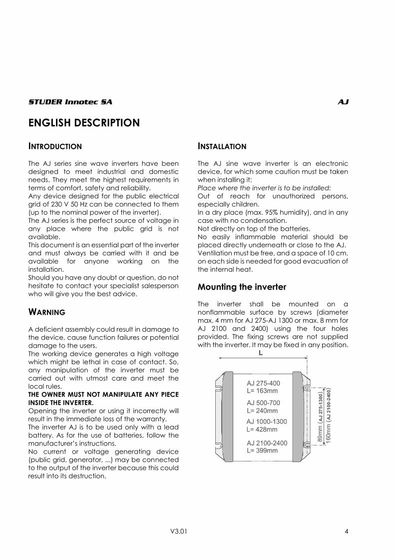
Mounting the inverter
The inverter shall be mounted on a
nonflammable surface by screws (diameter
max. 4 mm for AJ 275-AJ 1300 or max. 8 mm for
AJ 2100 and 2400) using the four holes
provided. The fixing screws are not supplied
with the inverter. It may be fixed in any position.
STUDER Innotec SA AJ
V3.01 5
CONNECTION
The connection of the inverter should be done
with utmost care for a good operation of the
system. The technical data and connection’s
description are either under one side of the
inverter or onto the cable connection side. First
connect the consumer devices and install a
plug so as to prevent any further contact once
the 230 V voltage is present.
Installation is to be made only by authorized
persons.
CONNECTING THE CONSUMER DEVICES
The AJ is supplied with a 230 V cable to be
connected to the consumer devices. This
connection must be done observing the
following colours:
Yellow-green: earth
Brown: phase
Blue: neutral
Once the consumer devices are connected,
make sure that they are turned off before
connecting the battery.
Note
An Inverter constitutes a voltage source
independent from the grid and could be
considered in the same way as a generator set.
The voltage in between the phase and the
neutral is 230V. An appropriate divisor
establishes a 115V voltage in between neutral
and earth, and between the phase and earth.
According to the local prescriptions or
particular requirement, (example: use of a
ground fault detector) a true neutral may be
established by connecting the neutral and the
earth wire together (yellow - green and blue).
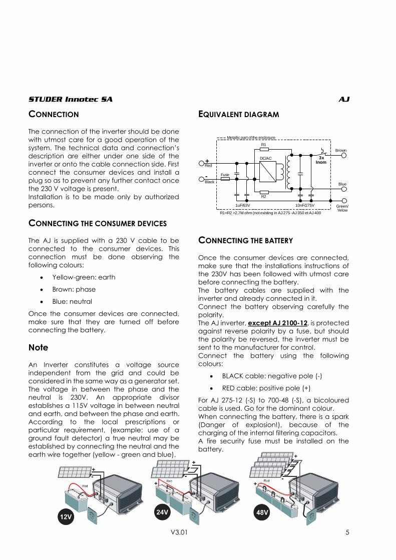
EQUIVALENT DIAGRAM
CONNECTING THE BATTERY
Once the consumer devices are connected,
make sure that the installations instructions of
the 230V has been followed with utmost care
before connecting the battery.
The battery cables are supplied with the
inverter and already connected in it.
Connect the battery observing carefully the
polarity.
The AJ inverter, except AJ 2100-12, is protected
against reverse polarity by a fuse, but should
the polarity be reversed, the inverter must be
sent to the manufacturer for control.
Connect the battery using the following
colours:
BLACK cable: negative pole (-)
RED cable: positive pole (+)
For AJ 275-12 (-S) to 700-48 (-S), a bicoloured
cable is used. Go for the dominant colour.
When connecting the battery, there is a spark
(Danger of explosion!), because of the
charging of the internal filtering capacitors.
A fire security fuse must be installed on the
battery.
DC/AC
R1
R2
1uF/63V 10nF/275V
3x Inom+
-
R1=R2 >2,7M ohm (not existing in AJ 275 -AJ 350 et AJ 400
Metallic part of the enclosure
Blue
Green/Yelow
Brown
Fuse
Red
Black
STUDER Innotec SA AJ
V3.01 6
Check that the cables are well adjusted and
well tightened.
As long as it is possible, do not extend the
cables supplied with the batteries. Extending
them may increase the losses and lead to a
malfunction of the inverter.
Once the inverter is connected to the batteries,
a 230 V voltage is present at the output of the
inverter.
USE
CONTROL AND INDICATORS
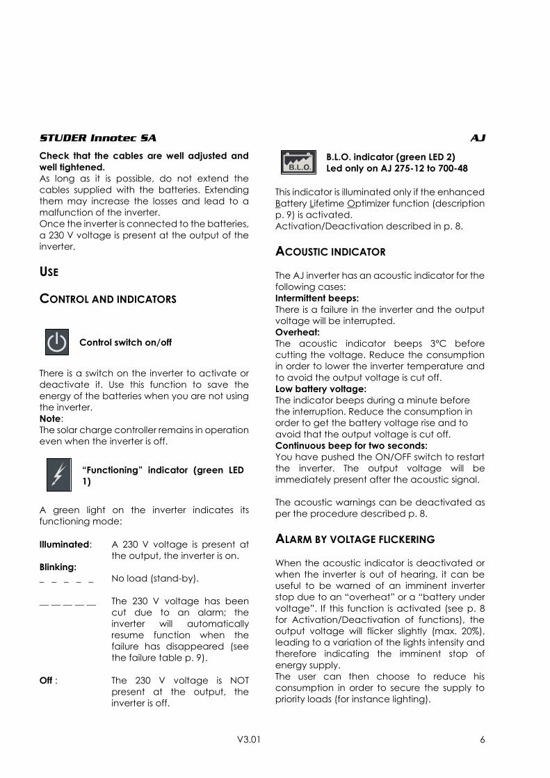
Control switch on/off
There is a switch on the inverter to activate or
deactivate it. Use this function to save the
energy of the batteries when you are not using
the inverter.
Note:
The solar charge controller remains in operation
even when the inverter is off.
“Functioning” indicator (green LED
1)
A green light on the inverter indicates its
functioning mode:
Illuminated: A 230 V voltage is present at
the output, the inverter is on.
Blinking:
_ _ _ _ _ No load (stand-by).
__ __ __ __ __ The 230 V voltage has been
cut due to an alarm; the
inverter will automatically
resume function when the
failure has disappeared (see
the failure table p. 9).
Off : The 230 V voltage is NOT
present at the output, the
inverter is off.
B.L.O. indicator (green LED 2)
Led only on AJ 275-12 to 700-48
This indicator is illuminated only if the enhanced
Battery Lifetime Optimizer function (description
p. 9) is activated.
Activation/Deactivation described in p. 8.
ACOUSTIC INDICATOR
The AJ inverter has an acoustic indicator for the
following cases:
Intermittent beeps:
There is a failure in the inverter and the output
voltage will be interrupted.
Overheat:
The acoustic indicator beeps 3ºC before
cutting the voltage. Reduce the consumption
in order to lower the inverter temperature and
to avoid the output voltage is cut off.
Low battery voltage:
The indicator beeps during a minute before
the interruption. Reduce the consumption in
order to get the battery voltage rise and to
avoid that the output voltage is cut off.
Continuous beep for two seconds:
You have pushed the ON/OFF switch to restart
the inverter. The output voltage will be
immediately present after the acoustic signal.
The acoustic warnings can be deactivated as
per the procedure described p. 8.
ALARM BY VOLTAGE FLICKERING
When the acoustic indicator is deactivated or
when the inverter is out of hearing, it can be
useful to be warned of an imminent inverter
stop due to an “overheat” or a “battery under
voltage”. If this function is activated (see p. 8
for Activation/Deactivation of functions), the
output voltage will flicker slightly (max. 20%),
leading to a variation of the lights intensity and
therefore indicating the imminent stop of
energy supply.
The user can then choose to reduce his
consumption in order to secure the supply to
priority loads (for instance lighting).
STUDER Innotec SA AJ
V3.01 7
MODEL WITH STAND-BY SYSTEM
The inverters from the AJ 500-12 are equipped
with a stand-by system (also available in the
models AJ 275-12/350-24/400-48 with the
option -S).
The stand-by is an energy saving system which
turns off the inverter intermittently when no
consumer is detected. In this mode the
functioning indicator (green LED 1) blinks,
showing the intermittent presence of the
voltage.
The detection threshold is set by default at 2 W.
On models from AJ 500-12 onwards it is possible
to deactivate this function or to modify the
threshold by adjusting the yellow Turning Knob
marked Stand-by.
Adjusting the switching-on level is as follows:
Switch off all consuming devices; turn the
Turning Knob to the right (clockwise) until the
LED is blinking, switch ON the smallest
consuming device (i.e. mobile phone charger);
turn the Turning Knob slowly to the left until LED
is lit continuously. Check that the inverter goes
back in stand-by mode when you remove the
load. If not, this means that the load is too small
to be detected.
If the stand-by is not required, turn the Knob fully
to the right.
The minimal load detected can be adjusted
between 1 and 20 W. In most cases this
adjustment is not necessary. This adjustment is
made with a small screw driver in the hole
marked stand-by. In the full counter clockwise
position, the sensibility is minimal (20 W). Do not
push on the screw driver.
NOTE: In this mode the output voltage is
intermittently present at the output!
STUDER Innotec SA AJ
V3.01 8
ACTIVATION / DEACTIVATION OF FUNCTIONS:
The following functions of the AJ range can be freely enabled or disabled by the user:
1. Acoustic warning of imminent stop of the inverter according to p. 6.
2. Battery lifetime optimizer function as described p. 9.
3. Imminent stop alarm by voltage flickering as described p. 6.
The state « activated » or « deactivated » of the functions is indicated by the buzzer with a continuous
push on the on/off key after a duration given for each function as per the table below:
Single « beep » short = function activated
Double « beep » short = function deactivated
Function
Duration of impulse
(onto on/off) Default setting
1. Acoustic alarm 5 seconds Activated
2. Battery Lifetime Optimization
(B.L.O.) 10 seconds Deactivated
3. Alarm by voltage flickering 15 seconds Deactivated The state is reversed if the on/off key is released within 2 seconds following the buzzer sound.
To consult the state of functions without having any effect on them or changing their programming
it is possible to maintain the on/off key pushed on. Beyond 20 seconds the buzzer will sound
continuously to indicate the end of the sequence and will stop by the release of the key.
SAFETY
The inverter is electronically protected. It is protected against reverse polarity by an internal fuse,
except for AJ 2100-12 inverter, which must be protected by an external fuse. The next table displays
the various possible default cases and their consequences.
Caution: the inverter is not protected against the connection of an AC source (generator or grid) at
its output. Such connection will cause a major failure and should be avoided.
Battery protection by LVD - Low voltage disconnection battery protection:
The battery is protected from deep discharge by stopping the inverter if the battery reaches a
voltage lower than 0.87*Unom (10.5, 21 or 42 V) during more than 1 minute. An acoustic signal or a
voltage flickering (if authorized) is activated during 1 minute before the inverters stops. The inverter
must then be restarted manually. It will restart automatically if the battery voltage is back to a value
higher than 1.04*Unom (12.5, 25 or 50 V).The inverter will stop immediately (with no delay) if the
battery voltage is lower than 0.75*Unom (9, 18 or 36 V).

STUDER Innotec SA AJ
V3.01 9
The table below will show you the different causes of inverter stopping.
BATTERY LIFETIME OPTIMIZER – BLO
Cycling a battery in permanent charging
mode from 0 to 30% is often a cause of early
aging of batteries, particularly in solar home
systems.
In order to enhance the battery lifetime, the AJ
inverters are equipped with a unique function
that will readjust the low voltage disconnection
(LVD) threshold according to the behavior of
the user consumption. This allows a full
recharge of the battery.
This function can be activated at any time as
per the procedure described p. 8.
An indicator (green LED 2) only available on
from AJ 275-12 to 700-48 is lit or blinks when this
function is activated. The number of blinks
indicates the LVD currently applied.
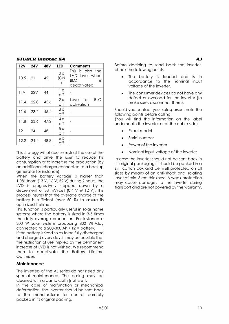
If this indicator is lit continuously, this means that
the use of the battery is correct and that it was
well charged. The LVD is then set at 0.87*unom
(10.5, 21or 42V) as per the model. This also
means that you have the widest availability of
the energy stored and that your battery is likely
to last longer.
If the indicator is blinking one or several times,
this means that the use of the battery is
restricted and that the disconnection voltage
was set according to the table below (+/- 2%).
CAUSE CONSEQUENCE SOLUTION
Low battery
voltage, Voltage <
0.87*Unom
Inverter temporary
stopped, the green
indicator blinks.
Automatic restart when the battery
voltage rises at 1.04*Unom.
Deep discharged
battery 0.75*Unom Inverter stopped
Inverter should be manually restarted
when the battery has reached
=0.87*Unom
Overheating
Inverter temporary
stopped, the green
indicator blinks.
Automatic restart when the temperature
reaches the normal range.
Battery
overvoltage
1.33*Unom
Inverter stopped.
Wait until the battery voltage reaches the
correct level.
Push the ON/OFF button to reactivate the
inverter. 1.25*Unom
Short circuit at the
output Inverter stopped.
Eliminate the short circuit.
Push the ON/OFF button to reactivate the
inverter.
Overload Inverter stopped.
Use the inverter only in the range of its
nominal power. Regular use in overload
power diminishes the lifetime of the
inverter.
Push the ON/OFF button to reactivate the
inverter.
Battery reverse
polarity
Internal fuse broken
down. Back to manufacturer for testing.
STUDER Innotec SA AJ
V3.01 10
This strategy will of course restrict the use of the
battery and drive the user to reduce his
consumption or to increase the production (by
an additional charger connected to a backup
generator for instance).
When the battery voltage is higher than
1.08*Unom (13 V, 16 V, 52 V) during 2 hours, the
LVD is progressively stepped down by a
decrement of 33 mV/cell (0.4 V @ 12 V). This
process insures that the average charge of the
battery is sufficient (over 50 %) to assure its
optimized lifetime.
This function is particularly useful in solar home
systems where the battery is sized in 3-5 times
the daily average production. For instance a
200 W solar system producing 800 Wh/day
connected to a 200-300 Ah / 12 V battery.
If the battery is sized so as to be fully discharged
and charged every day, it may be possible that
the restriction of use implied by the permanent
increase of LVD is not wished. We recommend
then to deactivate the Battery Lifetime
Optimizer.
Maintenance
The inverters of the AJ series do not need any
special maintenance. The casing may be
cleaned with a damp cloth (not wet).
In the case of malfunction or mechanical
deformation, the inverter should be sent back
to the manufacturer for control carefully
packed in its original packing.
Before deciding to send back the inverter,
check the following points:
The battery is loaded and is in
accordance to the nominal input
voltage of the inverter.
The consumer devices do not have any
defect or overload for the inverter (to
make sure, disconnect them).
Should you contact your salesperson, note the
following points before calling:
(You will find this information on the label
underneath the inverter or at the cable side)
Exact model
Serial number
Power of the inverter
Nominal input voltage of the inverter
In case the inverter should not be sent back in
its original packaging, it should be packed in a
stiff carton box and be well protected on all
sides by means of an anti-shock and isolating
layer of min. 5 cm thickness. A weak protection
may cause damages to the inverter during
transport and are not covered by the warranty.
12V 24V 48V LED Comments
10.5 21 42
0 x
(ON
)
This is also the
LVD level when
BLO is
deactivated
11V 22V 44 1 x
off -
11.4 22.8 45.6 2 x
off
Level at BLO
activation
11.6 23.2 46.4 3 x
off -
11.8 23.6 47.2 4 x
off -
12 24 48 5 x
off -
12.2 24.4 48.8 6 x
off -
STUDER Innotec SA AJ
V3.01 11
WARRANTY LIMIT
The warranty period is 5 years.
It does not cover damages arising from a use
not conforming to the user manual, not
described in it or resulting from any other
inappropriate use like:
Battery reverse polarity
Inadequate input voltage
(overvoltage)
Back-feeding at the inverter output by
public grid, generator or any other
source.
Mechanical shock or deformation
especially by transport due to an
inadequate package.
Contact with liquid or oxidation by
condensation.
Use in inappropriate environment (dust,
corrosive vapour, humidity, high temperature
...).
LIMITS OF MANUFACTURER LIABILITY
Studer Innotec SA cannot control the
installation, use and maintenance of the
inverter. Thus, we are not responsible for
damages, costs or losses resulting from an
installation which is not in accordance with the
regulations or from inappropriate use or
maintenance.
The customer is always responsible for the use
of the Studer inverters.
This device has not been designed and is not
warranted for use in life support equipment or
any other critical device with potential risks of
important harm to people or to the
environment. We do not accept any
responsibility for any violation of patent rights or
other third person rights resulting from the use of
the inverter.
Studer Innotec SA keeps the right to modify its
products without previous notice.
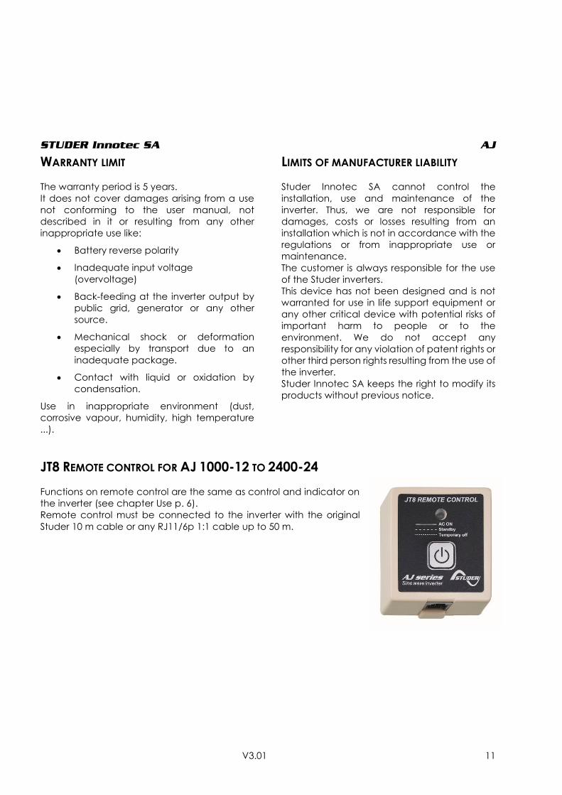
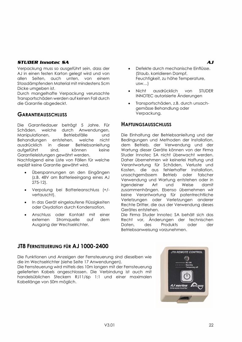
JT8 REMOTE CONTROL FOR AJ 1000-12 TO 2400-24
Functions on remote control are the same as control and indicator on
the inverter (see chapter Use p. 6).
Remote control must be connected to the inverter with the original
Studer 10 m cable or any RJ11/6p 1:1 cable up to 50 m.
STUDER Innotec SA AJ
V3.01 12
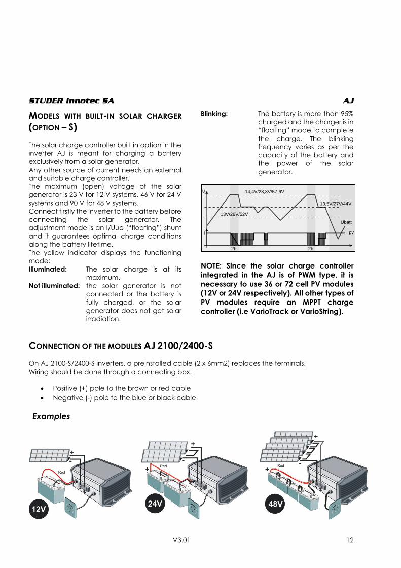
MODELS WITH BUILT-IN SOLAR CHARGER
(OPTION – S)
The solar charge controller built in option in the
inverter AJ is meant for charging a battery
exclusively from a solar generator.
Any other source of current needs an external
and suitable charge controller.
The maximum (open) voltage of the solar
generator is 23 V for 12 V systems, 46 V for 24 V
systems and 90 V for 48 V systems.
Connect firstly the inverter to the battery before
connecting the solar generator. The
adjustment mode is an I/Uuo (“floating”) shunt
and it guarantees optimal charge conditions
along the battery lifetime.
The yellow indicator displays the functioning
mode:
Illuminated: The solar charge is at its
maximum.
Not illuminated: the solar generator is not
connected or the battery is
fully charged, or the solar
generator does not get solar
irradiation.
Blinking: The battery is more than 95%
charged and the charger is in
“floating” mode to complete
the charge. The blinking
frequency varies as per the
capacity of the battery and
the power of the solar
generator.
NOTE: Since the solar charge controller
integrated in the AJ is of PWM type, it is
necessary to use 36 or 72 cell PV modules
(12V or 24V respectively). All other types of
PV modules require an MPPT charge
controller (i.e VarioTrack or VarioString).
CONNECTION OF THE MODULES AJ 2100/2400-S
On AJ 2100-S/2400-S inverters, a preinstalled cable (2 x 6mm2) replaces the terminals.
Wiring should be done through a connecting box.
Positive (+) pole to the brown or red cable
Negative (-) pole to the blue or black cable
Examples
14,4V/28,8V/57,6V
13V/26V/52V
13,5V/27V/44V
Ubatt
I pvI
U
2h 2h

STUDER Innotec SA AJ
V3.01 13
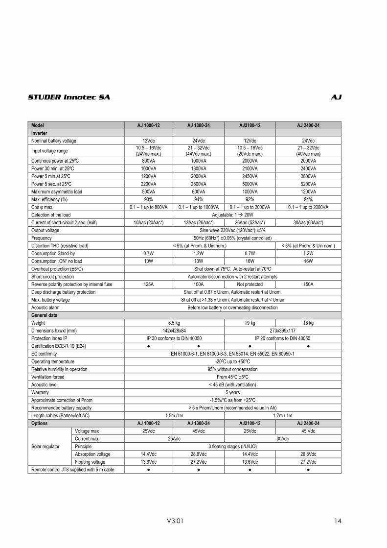
TECHNICAL DATA
Model AJ 275-12 AJ 350-24 AJ400-48 AJ 500-12 AJ 600-24 AJ 700-48
Inverter
Nominal battery voltage 12Vdc 24Vdc 48Vdc 12Vdc 24Vdc 48Vdc
Input voltage range 10.5 – 16Vdc (24Vdc max.)
21 – 32Vdc (44Vdc max.)
42 – 64Vdc (24Vdc max.)
10.5 – 16Vdc (20Vdc max.)
21 – 32Vdc (40Vdc max)
42 – 64Vdc (24Vdc max.)
Continous power at 25ºC 200VA 300VA 300VA 400VA 500VA 500VA
Power 30 min. at 25ºC 275VA 350VA 400VA 500VA 600VA 700VA
Power 5 min. at 25ºC 350VA 500VA 600VA 575VA 675VA 900VA
Power 5 sec.at 25ºC 450VA 650VA 1000VA 1000VA 1200VA 1400VA
Maximum asymmetric load 150VA 150VA 200VA 250VA 300VA 300VA
Max. efficiency (%) 93% 94% 94% 93% 94% 94%
Cos φ max. 0.1 – 1 up to
200VA 0.1 – 1 up to
300VA 0.1 – 1 up to
300VA 0.1 – 1 up to
400VA 0.1 – 1 up to
500VA 0.1 – 1 up to
500VA
Detection of the load 2W (only with the solar option –S) Adjustable: 1 20W
Current of chort-circuit 2 sec. (exit) 2.3Aac (4.6Aac*) 3.2Aac
(6.4Aac*) 4.6Aac (9.2Aac*) 5.2Aac (10Aac*)
5.7Aac (11.4Aac*)
7Aac (14Aac*)
Output voltage Sine wave 230Vac (120Vac*) ±5%
Frequency 50Hz (60Hz*) ±0.05% (crystal controlled)
Distortion THD (resistive load) < 5% (at Pnom. & Uin nom.)
Consumption Stand-by 0.3W** 0.5W** 1.1W** 0.4W 0.6W 1.5W
Consumption „ON“ no load 2.4W 3.5W 5.2W 4.6W 7.2W 12W
Overheat protection (±5ºC) Shut down at 75ºC, Auto-restart at 70ºC
Overload and short circuit protection
Automatic disconnection with 2 restart attempts
Reverse polarity protection by internal fuse
60A 40A 25A 120A 90A 60A
Deep discharge battery protection Shut off at 0.87 x Unom, Automatic restart at Unom.
Max. battery voltage Shut off at >1.33 x Unom, Automatic restart at < Umax
Acoustic alarm Before low battery or overheating disconnection
General data
Weight 2.4 kg 2.6 kg 4.5 kg
Dimensions hxwxl (mm) 142x163x84 142x240x84
Protection index IP IP 30 conforms to DIN 40050
Certification ECE-R 10 (E24) ● ● Not available ● ● Not available
EC confirmity EN 61000-6-1, EN 61000-6-3, EN 55014, EN 55022, EN 60950-1
Operating temperature -20ºC up to +50ºC
Relative humidity in operation 95% without condensation
Ventilation forced From 45ºC ±5ºC
Acoustic level < 45 dB (with ventilation)
Warranty 5 years
Approximate correction of Pnom -1.5%/ºC as from +25ºC
Recommended battery capacity > 5 x Pnom/Unom (recommended value in Ah)
Length cables (Battery/left AC) 1.2m /1m 1.5m / 1m
Options AJ 275-12 AJ 350-24 AJ400-48 AJ 500-12 AJ 600-24 AJ 700-48
Solar regulator
Voltage max 25Vdc 45Vdc 90Vdc 25 Vdc 45Vdc 90Vdc
Current max. 10Adc 15Adc
Principle 3 floating stages (I/U/UO)
Absorption voltage
14.4Vdc 28.8Vdc 57.6Vdc 14.4Vdc 28.8Vdc 57.6Vdc
Floating voltage 13.6Vdc 27.2Vdc 54.4Vdc 13.6Vdc 27.2Vdc 54.4Vdc
Plug for remote control (RCM) ● ● ● ● ● ●
STUDER Innotec SA AJ
V3.01 14
Model AJ 1000-12 AJ 1300-24 AJ2100-12 AJ 2400-24
Inverter
Nominal battery voltage 12Vdc 24Vdc 12Vdc 24Vdc
Input voltage range 10.5 – 16Vdc (24Vdc max.)
21 – 32Vdc (44Vdc max.)
10.5 – 16Vdc (20Vdc max.)
21 – 32Vdc (40Vdc max)
Continous power at 25ºC 800VA 1000VA 2000VA 2000VA
Power 30 min. at 25ºC 1000VA 1300VA 2100VA 2400VA
Power 5 min.at 25ºC 1200VA 2000VA 2450VA 2800VA
Power 5 sec. at 25ºC 2200VA 2800VA 5000VA 5200VA
Maximum asymmetric load 500VA 600VA 1000VA 1200VA
Max. efficiency (%) 93% 94% 92% 94%
Cos φ max. 0.1 – 1 up to 800VA 0.1 – 1 up to 1000VA 0.1 – 1 up to 2000VA 0.1 – 1 up to 2000VA
Detection of the load Adjustable: 1 20W
Current of chort-circuit 2 sec. (exit) 10Aac (20Aac*) 13Aac (26Aac*) 26Aac (52Aac*) 30Aac (60Aac*)
Output voltage Sine wave 230Vac (120Vac*) ±5%
Frequency 50Hz (60Hz*) ±0.05% (crystal controlled)
Distortion THD (resistive load) < 5% (at Pnom. & Uin nom.) < 3% (at Pnom. & Uin nom.)
Consumption Stand-by 0.7W 1.2W 0.7W 1.2W
Consumption „ON“ no load 10W 13W 16W 16W
Overheat protection (±5ºC) Shut down at 75ºC, Auto-restart at 70ºC
Short circuit protection Automatic disconnection with 2 restart attempts
Reverse polarity protection by internal fuse 125A 100A Not protected 150A
Deep discharge battery protection Shut off at 0.87 x Unom, Automatic restart at Unom.
Max. battery voltage Shut off at >1.33 x Unom, Automatic restart at < Umax
Acoustic alarm Before low battery or overheating disconnection
General data
Weight 8.5 kg 19 kg 18 kg
Dimensions hxwxl (mm) 142x428x84 273x399x117
Protection index IP IP 30 conforms to DIN 40050 IP 20 conforms to DIN 40050
Certification ECE-R 10 (E24) ● ● ● ●
EC confirmity EN 61000-6-1, EN 61000-6-3, EN 55014, EN 55022, EN 60950-1
Operating temperature -20ºC up to +50ºC
Relative humidity in operation 95% without condensation
Ventilation forced From 45ºC ±5ºC
Acoustic level < 45 dB (with ventilation)
Warranty 5 years
Approximate correction of Pnom -1.5%/ºC as from +25ºC
Recommended battery capacity > 5 x Pnom/Unom (recommended value in Ah)
Length cables (Battery/left AC) 1.5m /1m 1.7m / 1m
Options AJ 1000-12 AJ 1300-24 AJ2100-12 AJ 2400-24
Solar regulator
Voltage max 25Vdc 45Vdc 25Vdc 45 Vdc
Current max. 25Adc 30Adc
Principle 3 floating stages (I/U/UO)
Absorption voltage 14.4Vdc 28.8Vdc 14.4Vdc 28.8Vdc
Floating voltage 13.6Vdc 27.2Vdc 13.6Vdc 27.2Vdc
Remote control JT8 supplied with 5 m cable ● ● ● ●
STUDER Innotec SA AJ
V3.01 15
DEUTSCHE BESCHREIBUNG
EINFÜHRUNG
Die Wechselrichter der Serie AJ sind für den
Betrieb von allen handelsüblichen 230V
Geräten konzipiert worden. Die AJ genügen
den höchsten Anforderungen an
Zuverlässigkeit, Sicherheit und Komfort.
Jedes für das 230V-Wechselstromnetz
geeignete Gerät kann auch mit einem AJ
betrieben werden.
Ein AJ ist die ideale Spannungsquelle überall da
wo das öffentliche Netz nicht hinführt.
Diese Beschreibung ist in jedem Fall Teil der
Lieferung eines AJ. Sie muss allen Personen
welche mit einem AJ arbeiten zur Verfügung
stehen!
Bei eventuellen Fragen oder Unklarheiten kann
Ihnen der Händler Auskunft geben.
VORSICHT
Eine falsche Behandlung oder Montage des
Wechselrichters kann schwerwiegende Folgen
haben wie; Beschädigung des Gerätes,
hervorrufen einer Fehlfunktion oder den
Benutzer gefährden!
Der AJ erzeugt eine 230V-Sinusspannung wie im
öffentlichen Stromnetz. Jegliche Berührung
kann fatale Folgen haben! Die
Installationsarbeiten mit dem Wechselrichter AJ
verlangen besondere Aufmerksamkeit und
dürfen nur von geschultem Personal ausgeführt
werden und müssen in jedem Fall den jeweils
gültigen Installationsvorschriften entsprechen.
Der AJ darf in keinem Fall geöffnet werden.
Das Öffnen oder die nicht konforme An-
wendung des AJ bedeuten den Verlust
jeglicher Garantieansprüche.
Der AJ darf mit keiner anderen Spannungs-
oder Stromquelle als mit Bleibatterien betrieben
werden.
Am Ausgang des AJ dürfen keine Spannungs-
oder Stromquellen wie Notstromgeneratoren,
das öffentliche Netz usw. angeschlossen
werden, da der Wechselrichter zerstört werden
könnte.
Der Einsatz von Batterien verlangt besondere
Vorsicht. Befolgen Sie darum unbedingt die
Richtlinien des Batterieherstellers.
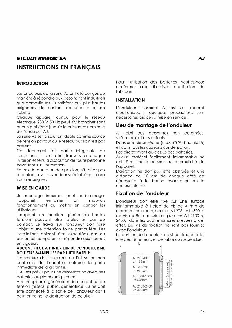
INSTALLATION
Der Sinuswechselrichter AJ ist ein elektronisches
Gerät. Für dessen Installation sind darum einige
Vorsichtsmassnahmen zu beachten.
Montageort des AJ
Der Montageort sollte gegen unbefugten
Zugriff gesichert sein (vor allem auch vor Zugriff
von kleinen Kindern).
In einem trockenen Raum mit einer
Luftfeuchtigkeit von max. 95% ohne
Kondensation.
Nicht direkt über der Batterie.
Bei den Lüftungsein- bzw. Auslässen muss für
eine unbehinderte Lüftung 10cm Freiraum
belassen werden.
In der Umgebung des Wechselrichters darf sich
kein leicht brennbares Material befinden oder
darunter gelagert werden.
Befestigung des AJ
Der Wechselrichter kann, auf einer nicht
brennbaren Unterlage, mit Hilfe von 4
Schrauben (Durchm. max. 4mm für AJ 275-AJ
1300 oder Durchm. max. 8mm für AJ 2100 und
2400) in jeder beliebigen Lage montiert
werden. Für die Befestigung dürfen nur die 4
von aussen zugänglichen Löcher verwendet
werden. Die Befestigungs-Schrauben sind nicht
beigelegt.

STUDER Innotec SA AJ
V3.01 16
ANSCHLUSS
Der Anschluss des AJ muss mit besonderer
Vorsicht ausgeführt werden. Eine sichere und
einwandfreie Funktion der Anlage wird
dadurch gewährleistet. Die Gerätedaten und
die Anschlussbezeichnung befinden sich auf
der Gehäuseunterseite oder auf der
Kabelanschlussseite. Vor dem Anschluss des AJ
an die Batterie muss das Kabel OUT 230V mit
einer Steckerkupplung (weiblich) versehen
werden oder bei einer festen Installation muss
der Anschluss entsprechend den
Installationsvorschriften von geschultem
Personal ausgeführt werden.
ANSCHLUSS DER VERBRAUCHER
Der Wechselrichter AJ wird mit bereits
angeschlossen Kabeln geliefert. Das schwarze
3-adrige Kabel für den 230V-Ausgang muss
entsprechend den folgenden Farben
angeschlossen werden:
Gelb-/Grün : Erdleiter
Braun : Phase
Blau : Neutral
Vor dem Anschluss der Batterie muss darauf
geachtet werden, dass die angeschlossenen
Verbraucher ausgeschaltet sind.
Bemerkung
Ein Wechselrichter ist eine vom Netz unabhängige
Spannungsquelle vergleichbar mit einem
Notstromgenerator. Phase und Neutralleiter
können darum vertauscht werden. Zwischen
Phase und Neutralleiter liegt eine Spannung von
230V. Zwischen Phase und Erde sowie zwischen
Neutral und Erde liegen jeweils 115V an. Je nach
Installationsvorschrift oder Anwendung (beim
benutzen eines FI Schutzschalters) können
Neutral-Leiter und Erde (gelb-grün und blau)
verbunden werden.
PRINZIPSCHEMA
ANSCHLUSS DER BATTERIE
Vor dem Anschluss der Batterie muss
sichergestellt sein, dass die 230V Installation
vorschriftsgemäss ausgeführt wurde.
Der AJ wird mit angeschlossen Batteriekabeln
geliefert. Beim Anschliessen der Batterie muss
unbedingt auf die richtige Polarität geachtet
werden. Die AJ, mit Ausnahme des AJ 2100-12,
sind durch eine Sicherung gegen Verpolung
geschützt. Für einen eventuellen
Sicherungswechsel muss der AJ zur Kontrolle an
den zuständigen Händler gebracht werden.
Kabel Schwarz: -Minus-Pol
Kabel Rot: + Plus-Pol
Für die Kabel der AJ 275-12 bis AJ 700-48 gelten
die jeweils dominierenden Farben!
Beim Anschliessen der Batterie entsteht ein
Funken (EXPLOSIONSGEFAHR!) durch das
Aufladen der internen Kondensatoren. Die
Batterie muss mit einer Sicherung auf der
Batterieklemme versehen sein!
DC/AC
R1
R2
1uF/63V 10nF/275V
3x Inom+
-
DC/AC
R1
R2
1uF/63V 10nF/275V
3x Inom+
-
R1=R2 >2,7M Ohm (nicht vorhanden in AJ 275 -AJ 350 und AJ 400
Metallteile des Gehäuses
Blau
Gelb/Grün
Braun
Sich.
Rot
Schwarz

STUDER Innotec SA AJ
V3.01 17
Kontrollieren Sie, dass die Anschlüsse gut
festgeschraubt sind.
Die Batteriekabel sollten nicht verlängert
werden. Eine Verlängerung der Batteriekabel
bedeutet grössere Verluste und/oder
Funktionsstörungen des AJ und somit auch der
angeschlossenen Geräte.
Sobald der AJ an der Batterie angeschlossen
wird, ist er eingeschaltet und es liegen 230V am
Ausgang.
ANWENDUNGEN
BEDIENUNG UND ANZEIGEN
Mit der Drucktaste kann der AJ ein- und
ausgeschaltet werden. Schalten Sie den
Wechselrichter mit dieser Taste aus, wenn Sie
keine Energie brauchen.
Anmerkung : Der Solarladeregler funktioniert
weiterhin auch wenn das Gerät ausgeschalten
ist.
Funktionsanzeige (Grüne LED 1)
Eine grüne Leuchtdiode (LED) zeigt den
Funktionszustand des Wechselrichters an :
LED leuchtet: Der Wechselrichter ist in
Funktion; am Ausgang liegen
230V.
LED blinkt:
_ _ _ _ _ Der Wechselrichter ist im
Stand-by-Betrieb p15.
__ __ __ __ __ Der Wechselrichter ist wegen
eines Alarms vorübergehend
ausgeschaltet. Nach
verschwinden des Alarms
schaltet sich der Wechselrich-
ter automatisch wieder ein.
(Die möglichen Alarmgründe
sind auf der folgenden Tabelle
aufgeführt.)
LED gelöscht: Der Wechselrichter ist
ausgeschaltet, am Ausgang
liegt keine 230V-Spannung.
„BLO“ Anzeige (Grüne LED 2)
(LED ausschliesslich auf den AJ
275-12 bis 700-48)
Diese Anzeige leuchtet nur wenn die BLO
„Battery Lifetime Optimizer“-Funktion
(Beschrieb S. 20) aktiviert ist (zur
Aktivierung/Deaktivierung siehe S. 19).
AKUSTISCHER SIGNALGEBER
Der Wechselrichter AJ ist mit einem akustischen
Signalgeber ausgerüstet welcher in folgenden
Fällen piept:
Intermittierender Ton:
Signal, dass der Wechselrichter sich im
Alarmzustand befindet und demnächst die
Ausgangsspannung abschalten wird.
Mögliche Fehler :
Überhitzung:
Alarm 3°C bevor der Wechselrichter
abschaltet. Einen Teil der Last abschalten,
damit der Wechselrichter nicht mehr überlastet
ist und sich abkühlen kann.
Unterspannung der Batterie:
Wenn die Batteriespannung zu tief fällt, pfeift
der Signalgeber eine Minute lang bevor der
Wechselrichter abschaltet.
Dauerton während 2 Sek.:
Warnsignal, dass 2 Sekunden nach dem
Einschalten mit der Taste ON/OFF der Wechsel-
richter einschaltet, und dass an dessen
Ausgang 230V anliegen !
Der akustische Signalgeber kann wie auf Seite
17 beschrieben, ausgeschalten werden.
Steuertaste on/off
STUDER Innotec SA AJ
V3.01 18
ALARM DURCH SPANNUNGSSCHWANKUNG
Wenn der akustische Signalgeber deaktiviert ist
oder sich das Gerät ausser Hörweite befindet,
kann es nützlich sein wenn man von einer
bevorstehenden Unterspannung oder
Überhitzung des Wechselrichters gewarnt wird.
Wenn diese Funktion aktiviert ist (Aktivierung /
Deaktivierung der Funktion siehe Seite 19), wird
die Ausgangsspannung leicht schwanken (max
-20%) damit die angeschlossenen und
benutzten Lampen anfangen zu flackern und
somit vor einem bevorstehenden Unterbruch
der Energiequelle warnen. Beim Eintreten
dieses Falles kann der Benutzer somit den
Verbrauch reduzieren und damit die Funktion
der prioritären Verbraucher verlängern.
LASTERKENNUNGSSCHALTUNG „STAND-BY“
Alle Wechselrichter ab AJ 500-12 sind mit einem
Stand-by-System ausgerüstet (Auch erhältlich
für die Serie 275/350/400 mit der Option –S). Um
die Batterie nicht unnötig zu entladen, schaltet
sich der Wechselrichter automatisch aus wenn
kein Verbraucher angeschlossen ist, und
automatisch wieder ein wenn ein Verbraucher
eingeschaltet wird. Die LED blinkt, wenn der
Wechselrichter im Stand-by Modus ist.
Werksseitig wird der Einschaltpegel auf etwa
2W eingestellt. Der Einschaltpegel kann mit
dem gelben Drehknopf „STAND-BY“ mit einem
kleinen Schraubenzieher eingestellt werden.
Das Einstellen des Einschaltpegels geschieht
folgendermassen: Sämtliche Verbraucher
ausschalten; Den Drehknopf nach rechts
(Uhrzeigersinn) drehen bis die LED blinkt; den
kleinsten Verbraucher einschalten (z.B.
Ladegerät für das Mobiltelefon); Drehknopf
langsam nach links drehen bis die LED leuchtet.
Danach zur Kontrolle diesen kleinen
Verbraucher ausschalten der Wechselrichter
muss nach einigen Sekunden wieder im Stand-
by-Modus arbeiten. Geschieht dies nicht, ist die
Last des Verbrauchers zu klein um erkannt zu
werden.
Ist der Stand-by Modus nicht erwünscht, muss
der Drehknopf ganz nach links gedreht
werden.
Die minimal zu erkennende Last kann zwischen
1 und 20W eingestellt werden. In den meisten
Fällen ist diese Einstellung nicht erforderlich. Die
Einstellung wird mit Hilfe eines Schraubenziehers
N°1 vorgenommen, indem der gelbe
Drehknopf „Stand-by“ angepasst wird. In der
maximalen Position ist die Sensibilität am
kleinsten (20W). Nicht auf den Schraubenzieher
drücken.
VORSICHT: Auch im Standby Modus liegen am
Ausgang zeitweise 230V an!
STUDER Innotec SA AJ
V3.01 19
AKTIVIERUNG / DEAKTIVIERUNG VON FUNKTIONEN
Folgende Funktionalitäten der AJ Serie können vom Anwender frei aktiviert oder deaktiviert werden:
1. Alarm für bevorstehenden Stopp durch akustisches Signal „Buzzer“ (Beschrieb Seite 17).
2. Algorithmus zur Optimierung der Batterielebensdauer „B.L.O.“ (Beschrieb Seite 20).
3. Alarm für bevorstehenden Stopp durch Spannungsschwankung (Beschrieb Seite 18).
Der aktivierte oder deaktivierte Zustand der Funktionen wird durch den akustischen Signalgeber
angedeutet. Dabei muss die Ein/Aus Taste gedrückt gehalten werden, damit die Zustände der
Funktionen nach einer bestimmten Zeit, wie in der folgenden Tabelle ersichtlich, angezeigt werden:
Einfacher kurzer „Bip“ = Funktion aktiviert
Doppelter kurzer „Bip“ = Funktion deaktiviert
Funktion Impulsdauer (auf Ein/Aus) Grundeinstellung
1. Akustischer Alarm 5 Sekunden aktiviert
2. Optimierung der
Batterielebensdauer (B.L.O) 10 Sekunden deaktiviert
3. Alarm durch
Spannungsschwankung 15 Sekunden deaktiviert
Der Zustand der Funktion wird gewechselt wenn in den zwei Sekunden nach dem ertönen des
akustischen Signalgebers die Taste losgelassen wird.
Um den Zustand der Funktionen zu überprüfen ohne diese zu ändern, muss die Taste Ein/Aus
durchgehend gedrückt werden. Nach 20 Sekunden wird der akustische Signalgeber mit einem
Dauerton das Ende der Lese-Sequenz anzeigen und wird beim loslassen der Taste beendet.
SICHERHEITEN
Die Wechselrichter AJ sind mit diversen elektronischen Systemen geschützt. Als Schutz gegen
Verpolung dient eine Schmelzsicherung. Der AJ 2100-12 enthält keine Schmelzsicherung und ist somit
nicht gegen Verpolung geschützt und muss extern abgesichert werden!
Vorsicht, der Wechselrichter ist nicht geschützt gegen einen versehentlichen Anschluss einer anderen
Quelle (Netz oder Generator) an den AC Ausgang. Ein solcher Anschluss kann zu einem vollständigen
Ausfall des Gerätes führen und sollte auf jeden Fall vermieden werden.
SCHUTZ DER BATTERIE DURCH ABSCHALTEN BEI UNTERSPANNUNG:
Die Batterie wird vor einer Tiefenentladung durch den Halt des Wechselrichters geschützt, wenn die
Spannung ein Level unter 0.87*Unom während 1 Minute erreicht (10.5, 21oder 42V). Ein akustischer
oder Spannungsschwankungsalarm (falls erlaubt) wird während einer Minute aktiviert bevor der
Wechselrichter ausschaltet. Der Wechselrichter kann manuell neu gestartet werden.
Er startet automatisch wenn die Batteriespannung wieder über 1.04*Unom liegt (12.5, 25 oder 50V).
Der Wechselrichter wird umgehend ausgeschalten wenn die Batteriespannung unter 0.75*Unom ist
(9, 18 oder 36V).

STUDER Innotec SA AJ
V3.01 20
Die nachfolgende Tabelle gibt verschiedene Fehlermöglichkeiten mit deren Folgen und
Handhabung wieder:
BATTERIELEBENSDAUER-OPTIMIERER (BATTERY LIFETIME OPTIMIZER –BLO):
Ein Batteriezyklus der sich immer zwischen 0-30%
bewegt ist häufig der vorzeitige Ausfallsgrund
einer Batterie. Dieser Fall liegt vielfach bei
kleinen Solarinstallationen vor.
Um die Lebensdauer der Batterie in solchen
Fällen zu verbessern, sind die Wechselrichter
der Serie AJ mit einer automatischen
Anpassung der Abschaltschwelle ausgerüstet.
Diese Anpassung zwingt den Anwender seinen
Verbrauch so anzupassen dass die Batterie
wieder voll aufgeladen wird.
Diese Funktion kann zu jeder Zeit aktiviert oder
deaktiviert werden, wie beschrieben auf Seite
19.
Die Funktionsanzeige (grüne LED2 erhältlich nur
auf AJ 275-12 bis AJ700-48) leuchtet oder blinkt
wenn diese Funktion aktiviert ist. Die Anzahl der
blinkenden Impulse gibt an auf welchem
aktuellen Niveau sich die Abschaltschwelle
befindet.
Wenn die Funktionsanzeige durchgehend
leuchtet, bedeutet das dass die Anwendung
der Batterie im grünen Bereich liegt und diese
auch genügend aufgeladen wird. In diesem
Fall liegt die Abschaltschwelle bei 0.87*Unom,
d.h. 10.5, 21.oder 42V je nach Modell. In diesem
Fall haben Sie die grösste Verfügbarkeit der
gespeicherten Energie und die Batterie ist
weniger anfällig auf einen vorzeitigen
Kapazitätsverlust.
FEHLER WIRKUNG LÖSUNG
Batteriespannung zu
tief 0.87*Unom
Wechselrichter ist vorü-
bergehend gestoppt.
Die grüne LED blinkt.
Nach Wiederanstieg der Batteriespannung
schaltet sich der Wechselrichter automatisch
wieder ein 1.04*Unom
Batteriespannung
tiefer als 0.75*Unom
Wechselrichter
gestoppt. Die grüne
Leuchte ist aus.
Das Wiedereinschalten ist erst wieder
möglich, wenn die Batterie 0.87*Unom
erreicht hat. Kein automatischer Start.
Überhitzung
Der Wechselrichter
wurde überlastet. Die
grüne LED blinkt.
Automatischer Start des Wechselrichters
nachdem dessen Temperatur gesunken ist.
Überspannung der
Batterie 1.33*Unom
Wechselrichter
gestoppt.
Warten Sie bis die Batteriespannung wieder
stimmt. Eine zu hohe Spannung kann den
Wechselrichter zerstören. Automatischer Start
wenn die Batteriespannung wieder bei
1.25*Unom ist.
Kurzschluss am
Ausgang des
Wechselrichters
Wechselrichter
gestoppt.
Kurzschluss entfernen (Installation kon-
trollieren).
Wechselrichter mit der Taste ON/OFF
einschalten.
Überlastung des
Wechselrichters
Wechselrichter
gestoppt.
Den Wechselrichter in den Grenzen seiner
Nominalleistung verwenden. Regelmässiger
Betrieb mit Überlast verkürzt die Lebensdauer!
Wechselrichter mit der Taste ON/OFF
einschalten.
Anschluss der Batterie
mit falscher Polarität
Interne Sicherung
zerstört.
Wechselrichter zurück zum Händler zur
Kontrolle !
STUDER Innotec SA AJ
V3.01 21
Wenn die Funktionsanzeige ein- oder mehrmals
blinkt, bedeutet dies eine Einschränkung der
Batterieanwendung und dass die
Abschaltschwelle auf einem der Niveaus aus
der folgenden Tabelle fixiert wurde (+/- 2%).
Mit dieser Strategie der eingeschränkten
Batterieanwendung wird der Anwender dazu
aufgefordert den Verbrauch zu minimieren
oder die Produktion zu erhöhen, eventuell
durch die kurzfristige Anwendung einer
zusätzlichen Energiequelle (zusätzlicher
Batterielader oder mit einem Generator).
Wenn die Batteriespannung während 2h höher
als 2.16V/Element (13V, 26V oder 52V) ist, wird
die Abschaltschwelle progressiv und
schrittweise um 33mV/Element (0.4 bei12V)
gesenkt. Dieser Prozess garantiert dass eine
durchschnittliche Ladung der Batterie ausreicht
(höher als 50%) um dieser eine optimale
Lebensdauer zu gewährleisten.
Diese Funktion ist besonders empfehlenswert
bei individuellen Solarsystemen in welchen die
Batterie so ausgelegt wird das diese die 3-5
fache Tagesproduktion speichern kann.
z.B. ein 200W Solarsystem welches täglich etwa
800Wh produziert mit einer Batterie von 200 bis
300Ah.
Wenn die Batterie so unterdimensioniert ist dass
sie bei jedem Zyklus vollständig entladen und
wieder aufgeladen wird, ist diese Anpassung
der Batterieschwelle möglicherweise nicht
wünschenswert und daher die BLO Funktion zu
deaktivieren.
UNTERHALT
Die Wechselrichter AJ benötigen keinen
Unterhalt. Bei Bedarf kann das Gehäuse mit
einem feuchten, nicht nassen Lappen gereinigt
werden.
Bei Funktionsstörungen des Wechselrichters
sollte dieser sehr gut verpackt zur Kontrolle an
den Händler zurückgesandt werden. Dasselbe
gilt auch bei jeglicher äusseren Verformung des
Gehäuses oder Verletzung der Anschlusskabel.
Bei Fehlfunktionen sollten folgende Punkte
abgeklärt werden bevor der AJ zum Händler
zurückgesandt wird:
Ist die Batterie geladen und entspricht
die Batteriespannung der Eingangs-
spannung des AJ?
Sind die angeschlossenen Verbraucher
im Leistungsbereich des Wechselrich-
ters?
Ist der Verbraucher defekt oder ist dessen
Anlaufstrom zu hoch? (z.B. Kompressor
Kühlschränke können mit einem AJ 275-12
nicht betrieben werden).
Wenn trotzdem der Händler kontaktiert werden
muss, notieren Sie bitte die folgenden Punkte:
(Die Angaben finden Sie auf der Unterseite
oder der Kabelanschlussseite des AJ)
Wechselrichtertyp
Seriennummer des Wechselrichters
Leistung des Wechselrichters
Die Nominalspannung des
Wechselrichters
Für das Versenden des AJ muss unbedingt auf
eine gute Verpackung geachtet werden. Die
12 V 24 V 48 V LED Anmerkunge
n
10.5 21 42 0 x off
(ON)
Die Schwelle
ist dieselbe
wenn der BLO
ausgeschalte
n ist.
11V 22V 44 1 x off -
11.4 22.8 45.6 2 x off
Ausgangssch
w-elle BLO,
wird
umgehend
angewandt
wenn die
Funktion
aktiviert wird.
11.6 23.2 46.4 3 x off -
11.8 23.6 47.2 4 x off -
12 24 48 5 x off -
12.2 24.4 48.8 6 x off -
STUDER Innotec SA AJ
V3.01 22
Verpackung muss so ausgeführt sein, dass der
AJ in einen festen Karton gelegt wird und von
allen Seiten, auch unten, von einem
Stossdämpfenden Material mit mindestens 5cm
Dicke umgeben ist.
Durch mangelhafte Verpackung verursachte
Transportschäden werden auf keinen Fall durch
die Garantie abgedeckt.
GARANTIEAUSSCHLUSS
Die Garantiedauer beträgt 5 Jahre. Für
Schäden, welche durch Anwendungen,
Manipulationen, Betriebsfälle und
Behandlungen entstehen, welche nicht
ausdrücklich in dieser Betriebsanleitung
aufgeführt sind, können keine
Garantieleistungen gewährt werden.
Nachfolgend eine Liste von Fällen für welche
explizit keine Garantie gewährt wird.
Überspannungen an den Eingängen
(z.B. 48V am Batterieeingang eines AJ
275-12).
Verpolung bei Batterieanschluss (+/-
vertauscht).
In das Gerät eingelaufene Flüssigkeiten
oder Oxydation durch Kondensation.
Anschluss oder Kontakt mit einer
externen Stromquelle auf dem
Ausgang der Wechselrichter.
Defekte durch mechanische Einflüsse.
(Staub, korridieren Dampf,
Feuchtigkeit, zu höhe Temperature,
usw…)
Nicht ausdrücklich von STUDER
INNOTEC autorisierte Änderungen
Transportschäden, z.B. durch unsach-
gemässe Behandlung oder
Verpackung.
HAFTUNGSAUSSCHLUSS
Die Einhaltung der Betriebsanleitung und der
Bedingungen und Methoden der Installation,
dem Betrieb, der Verwendung und der
Wartung dieser Geräte können von der Firma
Studer Innotec SA nicht überwacht werden.
Daher übernehmen wir keinerlei Haftung und
Verantwortung für Schäden, Verluste und
Kosten, die aus fehlerhafter Installation,
unsachgemässem Betrieb oder falscher
Verwendung und Wartung entstehen oder in
irgendeiner Art und Weise damit
zusammenhängen. Ebenso übernehmen wir
keine Verantwortung für patentrechtliche
Verletzungen oder Verletzungen anderer
Rechte Dritter, die aus der Verwendung dieses
Gerätes entstehen.
Die Firma Studer Innotec SA behält sich das
Recht vor, Änderungen der technischen
Daten, des Produkts oder der
Betriebsanweisung vorzunehmen.
JT8 FERNSTEUERUNG FÜR AJ 1000-2400
Die Funktionen und Anzeigen der Fernsteuerung sind dieselben wie
die im Wechselrichter (siehe Seite 17 Anwendungen).
Die Fernsteuerung wird mittels des 10m langen mit der Fernsteuerung
gelieferten Kabels angeschlossen. Die Verbindung ist auch mit
handelsüblichen Steckern RJ11/6p 1:1 und einer maximalen
Kabellänge von 50m möglich.

STUDER Innotec SA AJ
V3.01 23
MODELLE MIT SOLARLADEREGLER
(OPTION – S)
Der in den Wechselrichtern AJ mit der Option
„S“ eingebaute Solarladeregler ist
ausschliesslich nur für den Anschluss von
fotovoltaischen Solarmodulen geeignet um
damit die Batterien zu laden! Sämtliche
anderen Strom- oder Spannungsquellen zum
Laden der Batterien benötigen eine separate
Ladeeinrichtung und dürfen auf keinen Fall an
den AJ angeschlossen werden. Die Leerlaufs-
Spannung der Solarmodule darf im Maximum
23V für die 12V-Modelle, max. 46V für die 24V-
Modelle und max. 90V für die 48V-Modelle des
AJ betragen. Der Shunt-Laderegler arbeitet
nach dem Prinzip I/U/Uo mit Schwebe-
ladeeinrichtung und garantiert somit immer die
beste Ladung und Lebensdauer der Batterie.
Die Funktion des Ladereglers wird mittels der
orangefarbenen Leuchtdiode angezeigt:
LED leuchtet: Ladung mit maximalem Strom.
LED gelöscht: Das Solarmodul ist nicht oder
falsch angeschlossen; es ist
nicht verschattet oder die
Batterie ist vollgeladen.
LED blinkt: Die Batterie ist mit mehr als 95%
geladen und der Laderegler
arbeitet im
Schwebelademodus. (Die
Blinkfrequenz der LED variiert
entsprechend der
Ladeleistung, dem Verbrauch
und dem Zustand der Batterie).
HINWEIS: Da der im AJ integrierte
Solarladeregler eine PWM-Regelung hat,
dürfen nur Solarmodule mit 36 oder 72 Zellen
angeschlossen werden (12V oder 24V Off-Grid
Module). Für alle anderen Arten von
Solarmodulen wird ein MPPT-Solarladeregler
benötigt (z.B. VarioTrack oder VarioString).
ANSCHLUSS DES SOLARMODULE AN AJ 2100/2400-S :
An den Wechselrichtern AJ 2100/2400-S werden die Solarmodule über eine Abzweigdose an das
bereits im Gerät verdrahtete Kabel (2 x 6mm2) angeschlossen. Das Kabel am Eingang „SOLAR“ muss
entsprechend folgenden Farben angeschlossen werden.
Braun oder rot = Pluspol (+)
Blau oder Schwarz = Minuspol (-)
BEISPIEL
14,4V/28,8V/57,6V
13V/26V/52V
13,5V/27V/44V
Ubatt
I pvI
U
2h 2h

STUDER Innotec SA AJ
V3.01 24
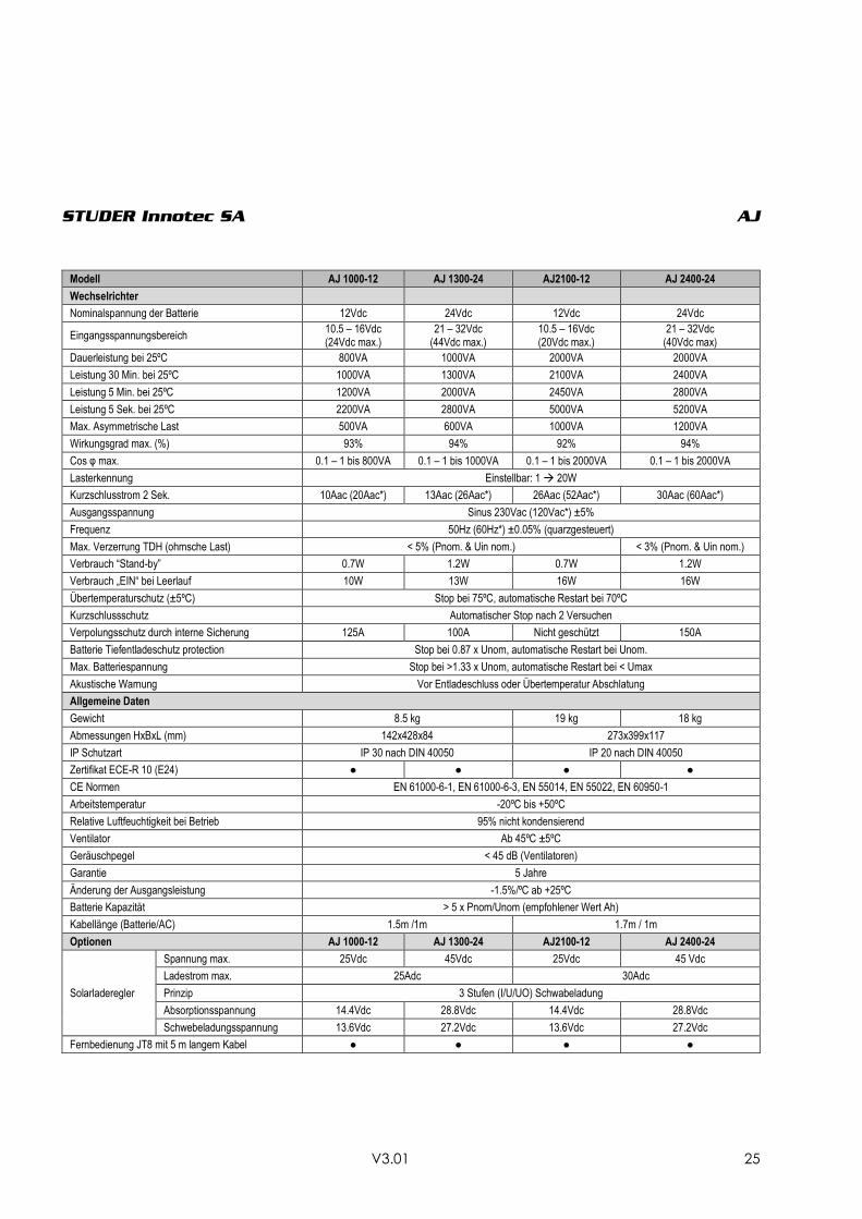
TECHNISCHE DATEN
Modell AJ 275-12 AJ 350-24 AJ400-48 AJ 500-12 AJ 600-24 AJ 700-48
Wechselrichter
Nominalspannung der Batterie 12Vdc 24Vdc 48Vdc 12Vdc 24Vdc 48Vdc
Eingangsspannungsbereich 10.5 – 16Vdc (24Vdc max.)
21 – 32Vdc (44Vdc max.)
42 – 64Vdc (24Vdc max.)
10.5 – 16Vdc (20Vdc max.)
21 – 32Vdc (40Vdc max)
42 – 64Vdc (24Vdc max.)
Dauerleistung bei 25ºC 200VA 300VA 300VA 400VA 500VA 500VA
Leistung 30 Min. bei 25ºC 275VA 350VA 400VA 500VA 600VA 700VA
Leistung 5 Min. bei 25ºC 350VA 500VA 600VA 575VA 675VA 900VA
Leistung 5 Sek. bei 25ºC 450VA 650VA 1000VA 1000VA 1200VA 1400VA
Max. Asymmetrische Last 150VA 150VA 200VA 250VA 300VA 300VA
Wirkungsgrad max. (%) 93% 94% 94% 93% 94% 94%
Cos φ max. 0.1 – 1 bis
200VA 0.1 – 1 bis
300VA 0.1 – 1 bis
300VA 0.1 – 1 bis
400VA 0.1 – 1 bis
500VA 0.1 – 1 bis
500VA
Lasterkennung 2W (nur mit option –S) Einstellbar: 1 20W
Kurzschlusstrom 2 Sek. 2.3Aac
(4.6Aac*) 3.2Aac
(6.4Aac*) 4.6Aac
(9.2Aac*) 5.2Aac (10Aac*)
5.7Aac (11.4Aac*)
7Aac (14Aac*)
Ausgangsspannung Sinus 230Vac (120Vac*) ±5%
Frequenz 50Hz (60Hz*) ±0.05% (quarzgesteuert)
Max. Verzerrung TDH (ohmsche Last) < 5% (Pnom. & Uin nom.)
Verbrauch “Stand-by” 0.3W** 0.5W** 1.1W** 0.4W 0.6W 1.5W
Verbrauch „EIN“ bei Leerlauf 2.4W 3.5W 5.2W 4.6W 7.2W 12W
Übertemperaturschutz (±5ºC) Stop bei 75ºC, automatische Restart bei 70ºC
Kurzschlussschutz Automatischer Stop nach 2 Versuchen
Verpolungsschutz durch interne Sicherung 60A 40A 25A 120A 90A 60A
Batterie Tiefentladeschutz protection Stop bei 0.87 x Unom, automatische Restart bei Unom.
Max. Batteriespannung Stop bei >1.33 x Unom, automatische Restart bei < Umax
Akustische Warnung Vor Entladeschluss oder Übertemperatur Abschlatung
Allgemeine Daten
Gewicht 2.4 kg 2.6 kg 4.5 kg
Abmessungen HxBxL (mm) 142x163x84 142x240x84
IP Schutzart IP 30 nach DIN 40050
Zertifikat ECE-R 10 (E24) ● ● Nicht
verfügbar ● ● Nicht verfügbar
CE Normen EN 61000-6-1, EN 61000-6-3, EN 55014, EN 55022, EN 60950-1
Arbeitstemperatur -20ºC bis +50ºC
Relative Luftfeuchtigkeit bei Betrieb 95% nicht kondensierend
Ventilator Ab 45ºC ±5ºC
Geräuschpegel < 45 dB (Ventilatoren)
Garantie 5 Jahre
Änderung der Ausgangsleistung -1.5%/ºC ab +25ºC
Batterie Kapazität > 5 x Pnom/Unom (empfohlener Wert Ah)
Kabellänge (Batterie/AC) 1.2m /1m 1.5m / 1m
Optionen AJ 275-12 AJ 350-24 AJ400-48 AJ 500-12 AJ 600-24 AJ 700-48
Solarladeregler
Spannung max. 25Vdc 45Vdc 90Vdc 25 Vdc 45Vdc 90Vdc
Ladestrom max. 10Adc 15Adc
Prinzip 3 Stufen (I/U/UO) Schwabeladung
Absorptionsspannung 14.4Vdc 28.8Vdc 57.6Vdc 14.4Vdc 28.8Vdc 57.6Vdc
Schwebeladungsspannung 13.6Vdc 27.2Vdc 54.4Vdc 13.6Vdc 27.2Vdc 54.4Vdc
Eingang für Fernsteuerung (RCM) ● ● ● ● ● ●
STUDER Innotec SA AJ
V3.01 25
Modell AJ 1000-12 AJ 1300-24 AJ2100-12 AJ 2400-24
Wechselrichter
Nominalspannung der Batterie 12Vdc 24Vdc 12Vdc 24Vdc
Eingangsspannungsbereich 10.5 – 16Vdc (24Vdc max.)
21 – 32Vdc (44Vdc max.)
10.5 – 16Vdc (20Vdc max.)
21 – 32Vdc (40Vdc max)
Dauerleistung bei 25ºC 800VA 1000VA 2000VA 2000VA
Leistung 30 Min. bei 25ºC 1000VA 1300VA 2100VA 2400VA
Leistung 5 Min. bei 25ºC 1200VA 2000VA 2450VA 2800VA
Leistung 5 Sek. bei 25ºC 2200VA 2800VA 5000VA 5200VA
Max. Asymmetrische Last 500VA 600VA 1000VA 1200VA
Wirkungsgrad max. (%) 93% 94% 92% 94%
Cos φ max. 0.1 – 1 bis 800VA 0.1 – 1 bis 1000VA 0.1 – 1 bis 2000VA 0.1 – 1 bis 2000VA
Lasterkennung Einstellbar: 1 20W
Kurzschlusstrom 2 Sek. 10Aac (20Aac*) 13Aac (26Aac*) 26Aac (52Aac*) 30Aac (60Aac*)
Ausgangsspannung Sinus 230Vac (120Vac*) ±5%
Frequenz 50Hz (60Hz*) ±0.05% (quarzgesteuert)
Max. Verzerrung TDH (ohmsche Last) < 5% (Pnom. & Uin nom.) < 3% (Pnom. & Uin nom.)
Verbrauch “Stand-by” 0.7W 1.2W 0.7W 1.2W
Verbrauch „EIN“ bei Leerlauf 10W 13W 16W 16W
Übertemperaturschutz (±5ºC) Stop bei 75ºC, automatische Restart bei 70ºC
Kurzschlussschutz Automatischer Stop nach 2 Versuchen
Verpolungsschutz durch interne Sicherung 125A 100A Nicht geschützt 150A
Batterie Tiefentladeschutz protection Stop bei 0.87 x Unom, automatische Restart bei Unom.
Max. Batteriespannung Stop bei >1.33 x Unom, automatische Restart bei < Umax
Akustische Warnung Vor Entladeschluss oder Übertemperatur Abschlatung
Allgemeine Daten
Gewicht 8.5 kg 19 kg 18 kg
Abmessungen HxBxL (mm) 142x428x84 273x399x117
IP Schutzart IP 30 nach DIN 40050 IP 20 nach DIN 40050
Zertifikat ECE-R 10 (E24) ● ● ● ●
CE Normen EN 61000-6-1, EN 61000-6-3, EN 55014, EN 55022, EN 60950-1
Arbeitstemperatur -20ºC bis +50ºC
Relative Luftfeuchtigkeit bei Betrieb 95% nicht kondensierend
Ventilator Ab 45ºC ±5ºC
Geräuschpegel < 45 dB (Ventilatoren)
Garantie 5 Jahre
Änderung der Ausgangsleistung -1.5%/ºC ab +25ºC
Batterie Kapazität > 5 x Pnom/Unom (empfohlener Wert Ah)
Kabellänge (Batterie/AC) 1.5m /1m 1.7m / 1m
Optionen AJ 1000-12 AJ 1300-24 AJ2100-12 AJ 2400-24
Solarladeregler
Spannung max. 25Vdc 45Vdc 25Vdc 45 Vdc
Ladestrom max. 25Adc 30Adc
Prinzip 3 Stufen (I/U/UO) Schwabeladung
Absorptionsspannung 14.4Vdc 28.8Vdc 14.4Vdc 28.8Vdc
Schwebeladungsspannung 13.6Vdc 27.2Vdc 13.6Vdc 27.2Vdc
Fernbedienung JT8 mit 5 m langem Kabel ● ● ● ●
STUDER Innotec SA AJ
V3.01 26
INSTRUCTIONS EN FRANÇAIS
INTRODUCTION
Les onduleurs de la série AJ ont été conçus de
manière à répondre aux besoins tant industriels
que domestiques. Ils satisfont aux plus hautes
exigences de confort, de sécurité et de
fiabilité.
Chaque appareil conçu pour le réseau
électrique 230 V 50 Hz peut s’y brancher sans
aucun problème jusqu'à la puissance nominale
de l’onduleur AJ.
La série AJ est la solution idéale comme source
de tension partout où le réseau public n’est pas
présent.
Ce document fait partie intégrante de
l’onduleur, il doit être transmis à chaque
livraison et tenu à disposition de toute personne
travaillant sur l’installation.
En cas de doute ou de question, n’hésitez pas
à contacter votre vendeur spécialisé qui saura
vous renseigner.
MISE EN GARDE
Un montage incorrect peut endommager
l’appareil, entraîner un mauvais
fonctionnement ou mettre en danger les
utilisateurs.
L’appareil en fonction génère de hautes
tensions pouvant être fatales en cas de
contact. Le travail sur l’onduleur doit faire
l’objet d’une attention toute particulière. Les
installations doivent être exécutées par du
personnel compétent et répondre aux normes
en vigueur.
AUCUNE PIECE A L’INTERIEUR DE L’ONDULEUR NE
DOIT ETRE MANIPULEE PAR L’UTILISATEUR.
L’ouverture de l’onduleur ou l’utilisation non
conforme de l’onduleur entraîne la perte
immédiate de la garantie.
L’AJ est prévu pour une alimentation avec des
batteries au plomb uniquement.
Aucun appareil générateur de courant ou de
tension (réseau public, génératrice, ...) ne doit
être connecté à la sortie de l’onduleur car il
peut entraîner la destruction de celui-ci.
Pour l’utilisation des batteries, veuillez-vous
conformer aux directives d’utilisation du
fabricant.
INSTALLATION
L’onduleur sinusoïdal AJ est un appareil
électronique ; quelques précautions sont
nécessaires lors de sa mise en service :
Lieu de montage de l’onduleur
A l’abri des personnes non autorisées,
spécialement des enfants.
Dans une pièce sèche (max. 95 % d’humidité)
et dans tous les cas sans condensation.
Pas directement au-dessus des batteries.
Aucun matériel facilement inflammable ne
doit être stocké dessous ou à proximité de
l’appareil.
L’aération ne doit pas être obstruée et une
distance de 10 cm de chaque côté est
nécessaire à la bonne évacuation de la
chaleur interne.
Fixation de l’onduleur
L’onduleur doit être fixé sur une surface
ininflammable à l’aide de vis de 4 mm de
diamètre maximum, pour les AJ 275 - AJ 1300 et
de vis de 8mm maximum pour les AJ 2100 et
2400, dans les quatre rainures prévues à cet
effet. Les vis de fixation ne sont pas fournies
avec l’onduleur.
La position de l’onduleur n’est pas importante:
elle peut être murale, de table ou suspendue.
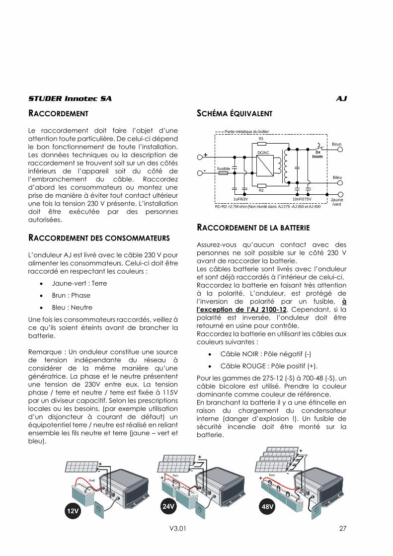
STUDER Innotec SA AJ
V3.01 27
RACCORDEMENT
Le raccordement doit faire l’objet d’une
attention toute particulière. De celui-ci dépend
le bon fonctionnement de toute l’installation.
Les données techniques ou la description de
raccordement se trouvent soit sur un des côtés
inférieurs de l’appareil soit du côté de
l’embranchement du câble. Raccordez
d’abord les consommateurs ou montez une
prise de manière à éviter tout contact ultérieur
une fois la tension 230 V présente. L’installation
doit être exécutée par des personnes
autorisées.
RACCORDEMENT DES CONSOMMATEURS
L’onduleur AJ est livré avec le câble 230 V pour
alimenter les consommateurs. Celui-ci doit être
raccordé en respectant les couleurs :
Jaune-vert : Terre
Brun : Phase
Bleu : Neutre
Une fois les consommateurs raccordés, veillez à
ce qu’ils soient éteints avant de brancher la
batterie.
Remarque : Un onduleur constitue une source
de tension indépendante du réseau à
considérer de la même manière qu’une
génératrice. La phase et le neutre présentent
une tension de 230V entre eux. La tension
phase / terre et neutre / terre est fixée à 115V
par un diviseur capacitif. Selon les prescriptions
locales ou les besoins, (par exemple utilisation
d’un disjoncteur à courant de défaut) un
équipotentiel terre / neutre est réalisé en reliant
ensemble les fils neutre et terre (jaune – vert et
bleu).
SCHÉMA ÉQUIVALENT
RACCORDEMENT DE LA BATTERIE
Assurez-vous qu’aucun contact avec des
personnes ne soit possible sur le côté 230 V
avant de raccorder la batterie.
Les câbles batterie sont livrés avec l’onduleur
et sont déjà raccordés à l’intérieur de celui-ci.
Raccordez la batterie en faisant très attention
à la polarité. L’onduleur, est protégé de
l’inversion de polarité par un fusible, à
l’exception de l’AJ 2100-12. Cependant, si la
polarité est inversée, l’onduleur doit être
retourné en usine pour contrôle.
Raccordez la batterie en utilisant les câbles aux
couleurs suivantes :
Câble NOIR : Pôle négatif (-)
Câble ROUGE : Pôle positif (+).
Pour les gammes de 275-12 (-S) à 700-48 (-S), un
câble bicolore est utilisé. Prendre la couleur
dominante comme couleur de référence.
En branchant la batterie il y a une étincelle en
raison du chargement du condensateur
interne (danger d’explosion !). Un fusible de
sécurité incendie doit être monté sur la
batterie.
DC/AC
R1
R2
1uF/63V 10nF/275V
3x Inom+
- fusible
Brun
Bleu
Jaune/vert
Partie métalique du boîtier
R1=R2 >2,7M ohm (Non monté dans AJ 275 -AJ 350 et AJ 400

STUDER Innotec SA AJ
V3.01 28
Vérifiez le serrage des câbles.
Dans la mesure du possible ne rallongez pas les
câbles de batteries fournis. Le fait de rallonger
les câbles de batterie peut augmenter les
pertes et provoquer un dysfonctionnement de
l’onduleur.
Une fois l’onduleur branché sur la batterie, la
tension 230 V est présente à la sortie de
l’onduleur.
UTILISATION
COMMANDE ET INDICATEURS
Bouton de commande marche /
arrêt (on/off)
Un bouton de commande est accessible sur
l’onduleur. Il permet de l’enclencher ou de le
déclencher. Utilisez cette fonction pour
économiser l’énergie des batteries en mettant
l’appareil hors fonction lorsque vous ne l’utilisez
pas.
Note : Le régulateur solaire reste en fonction
même lorsque l’appareil est arrêté.
Indicateur "Fonctionnement" (LED
verte 1)
Un indicateur lumineux vert placé sur l’onduleur
indique le mode de fonctionnement:
Allumé : La tension 230 V est présente à
la sortie ; l’onduleur est en
fonction.
Clignotant :
_ _ _ _ _ L’onduleur est en mode stand-
by voir p 29.
__ __ __ __ __ La tension 230 V est coupée
momentanément suite à une
alarme; l’onduleur se remettra
automatiquement en fonction
dès que la cause de l’alarme
aura disparue (voir tableau des
fautes p. 31)
Eteint : La tension 230 V n’est pas
présente à la sortie ; l’onduleur
est éteint.
Indicateur "BLO" (LED verte 2) (LED présente uniquement sur les AJ
275-12 à 700-48)
Cet indicateur lumineux est allumé seulement
lorsque la fonction " Battery Lifetime Optimizer –
B.L.O " (description en p. 31) est activée (voir p.
30 pour activation/désactivation des
fonctions).
INDICATEUR SONORE
L’onduleur AJ dispose d’un indicateur sonore
qui signale les cas suivants :
Son intermittent :
L’onduleur est en présence d’une faute et va
couper la tension de sortie.
Fautes possibles :
Surchauffe :
L’indicateur sonne 3°C avant l’arrêt de
l’onduleur. Diminuez la consommation afin
d’abaisser la température de l’onduleur et ainsi
éviter l’arrêt.
Sous tension de batterie :
L’indicateur sonne une minute avant la
coupure. Si la tension de batterie remonte
(grâce à une diminution de la consommation),
la tension de sortie ne sera pas coupée.
Son continu de deux secondes :
Vous avez appuyé sur le bouton ON/OFF pour
redémarrer l’onduleur. La tension de sortie est
immédiatement présente à la sortie après le
signal sonore.
L’indicateur sonore peut être désactivé selon la
procédure en p. 30.
ALARME PAR FLUCTUATION DE TENSION
Lorsque l’indicateur sonore est désactivé ou
lorsque l’appareil est hors de portée
acoustique, il peut être utile d’être averti de
l’arrêt imminent de l’onduleur en cas de "sous
tension de batterie" ou de "surchauffe". Si cette
fonction est activée (voir p. 30 pour
activation/désactivation des fonctions), la
tension de sortie fluctuera légèrement (max. -
STUDER Innotec SA AJ
V3.01 29
20%) faisant ainsi varier l’intensité lumineuse des
lampes éventuellement allumées, indiquant
ainsi l’imminence de l’arrêt de la fourniture
d’énergie. L’utilisateur pourra, le cas échéant,
choisir de diminuer sa consommation afin de
prolonger l’usage de fonctions prioritaires
(éclairage par exemple).
MODÈLES AVEC STAND-BY
Les onduleurs dès l’AJ 500-12 sont équipés d’un
système stand-by (aussi disponible pour les
gammes 275 / 350 / 400 avec l’option –S).
Le stand-by est un système d’économie
d’énergie qui déclenche l’onduleur par
intermittence lorsqu’aucun consommateur
n’est détecté. Dans ce mode, l’indicateur de
fonctionnement (LED verte 1) clignote,
indiquant la présence par intermittence de la
tension.
Le seuil de détection est ajusté d’usine à une
valeur de 2W environ. Sur les modèles de
puissance supérieure à 400W, il est possible de
désactiver cette fonction ou d’en modifier le
seuil en ajustant le bouton de réglage jaune
marqué stand-by. L’ajustement du niveau de
détection s’effectue comme suit : éteindre tous
les consommateurs, tourner le bouton rotatif
vers la droite (sens des aiguilles d’une montre)
jusqu’à que la LED 1 clignote, allumer le plus
petit consommateur (par ex. un chargeur pour
tél. portable), tourner doucement le bouton
rotatif vers la gauche jusqu’à ce que la LED 1
s’allume en continu. Contrôler que l’onduleur
se mette en mode stand-by quand vous
enlevez la charge. Si dans ce cas le mode
standby-by ne s’active pas, cela signifie que la
charge est trop petite pour être détectée.
Si le stand-by n’est pas souhaité, tourner le
bouton complètement à droite.
La puissance minimale détectée peut être
ajustée entre 1 et 20 W. Dans la plupart des
installations, ce réglage n’est pas utile. Le
réglage se fait à l’aide d’un tournevis plat n°1
en ajustant le bouton de réglage jaune
marqué « stand-by » sur l’onduleur. Dans la
position maximale à droite, la sensibilité est
minimale (20 W). Ne pas appuyer sur le
tournevis.
ATTENTION
En fonctionnement stand-by le 230V est
présent par intermittence à la sortie.
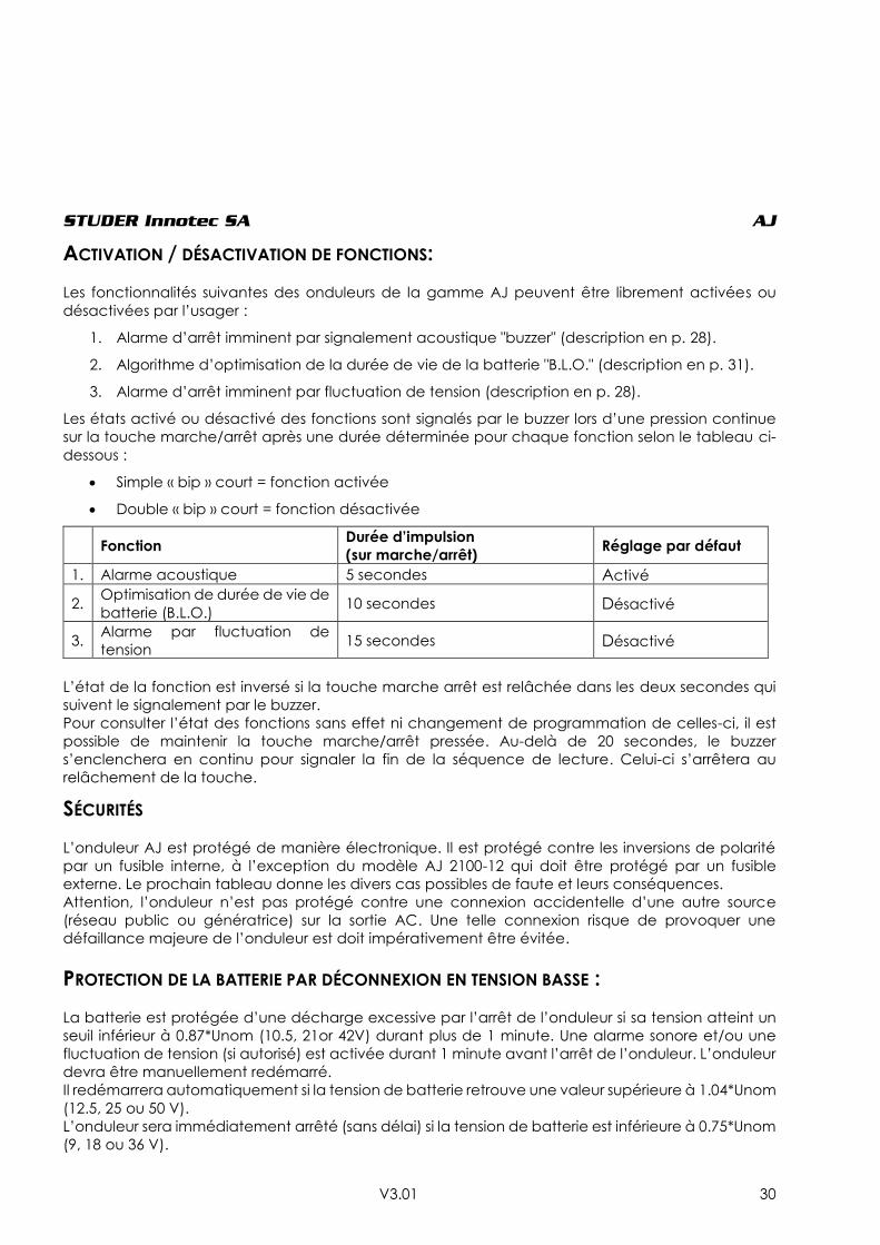
STUDER Innotec SA AJ
V3.01 30
ACTIVATION / DÉSACTIVATION DE FONCTIONS:
Les fonctionnalités suivantes des onduleurs de la gamme AJ peuvent être librement activées ou
désactivées par l’usager :
1. Alarme d’arrêt imminent par signalement acoustique "buzzer" (description en p. 28).
2. Algorithme d’optimisation de la durée de vie de la batterie "B.L.O." (description en p. 31).
3. Alarme d’arrêt imminent par fluctuation de tension (description en p. 28).
Les états activé ou désactivé des fonctions sont signalés par le buzzer lors d’une pression continue
sur la touche marche/arrêt après une durée déterminée pour chaque fonction selon le tableau ci-
dessous :
Simple « bip » court = fonction activée
Double « bip » court = fonction désactivée
Fonction
Durée d’impulsion
(sur marche/arrêt) Réglage par défaut
1. Alarme acoustique 5 secondes Activé
2. Optimisation de durée de vie de
batterie (B.L.O.) 10 secondes Désactivé
3. Alarme par fluctuation de
tension 15 secondes Désactivé
L’état de la fonction est inversé si la touche marche arrêt est relâchée dans les deux secondes qui
suivent le signalement par le buzzer.
Pour consulter l’état des fonctions sans effet ni changement de programmation de celles-ci, il est
possible de maintenir la touche marche/arrêt pressée. Au-delà de 20 secondes, le buzzer
s’enclenchera en continu pour signaler la fin de la séquence de lecture. Celui-ci s’arrêtera au
relâchement de la touche.
SÉCURITÉS
L’onduleur AJ est protégé de manière électronique. Il est protégé contre les inversions de polarité
par un fusible interne, à l’exception du modèle AJ 2100-12 qui doit être protégé par un fusible
externe. Le prochain tableau donne les divers cas possibles de faute et leurs conséquences.
Attention, l’onduleur n’est pas protégé contre une connexion accidentelle d’une autre source
(réseau public ou génératrice) sur la sortie AC. Une telle connexion risque de provoquer une
défaillance majeure de l’onduleur est doit impérativement être évitée.
PROTECTION DE LA BATTERIE PAR DÉCONNEXION EN TENSION BASSE :
La batterie est protégée d’une décharge excessive par l’arrêt de l’onduleur si sa tension atteint un
seuil inférieur à 0.87*Unom (10.5, 21or 42V) durant plus de 1 minute. Une alarme sonore et/ou une
fluctuation de tension (si autorisé) est activée durant 1 minute avant l’arrêt de l’onduleur. L’onduleur
devra être manuellement redémarré.
Il redémarrera automatiquement si la tension de batterie retrouve une valeur supérieure à 1.04*Unom
(12.5, 25 ou 50 V).
L’onduleur sera immédiatement arrêté (sans délai) si la tension de batterie est inférieure à 0.75*Unom
(9, 18 ou 36 V).
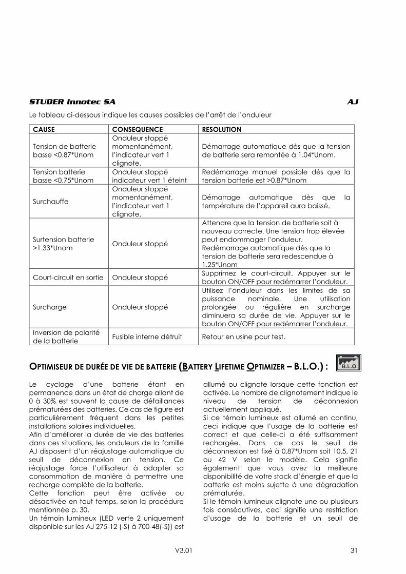
STUDER Innotec SA AJ
V3.01 31
Le tableau ci-dessous indique les causes possibles de l’arrêt de l’onduleur
OPTIMISEUR DE DURÉE DE VIE DE BATTERIE (BATTERY LIFETIME OPTIMIZER – B.L.O.) :
Le cyclage d’une batterie étant en
permanence dans un état de charge allant de
0 à 30% est souvent la cause de défaillances
prématurées des batteries. Ce cas de figure est
particulièrement fréquent dans les petites
installations solaires individuelles.
Afin d’améliorer la durée de vie des batteries
dans ces situations, les onduleurs de la famille
AJ disposent d’un réajustage automatique du
seuil de déconnexion en tension. Ce
réajustage force l’utilisateur à adapter sa
consommation de manière à permettre une
recharge complète de la batterie.
Cette fonction peut être activée ou
désactivée en tout temps, selon la procédure
mentionnée p. 30.
Un témoin lumineux (LED verte 2 uniquement
disponible sur les AJ 275-12 (-S) à 700-48(-S)) est
allumé ou clignote lorsque cette fonction est
activée. Le nombre de clignotement indique le
niveau de tension de déconnexion
actuellement appliqué.
Si ce témoin lumineux est allumé en continu,
ceci indique que l’usage de la batterie est
correct et que celle-ci a été suffisamment
rechargée. Dans ce cas le seuil de
déconnexion est fixé à 0.87*Unom soit 10.5, 21
ou 42 V selon le modèle. Cela signifie
également que vous avez la meilleure
disponibilité de votre stock d’énergie et que la
batterie est moins sujette à une dégradation
prématurée.
Si le témoin lumineux clignote une ou plusieurs
fois consécutives, ceci signifie une restriction
d’usage de la batterie et un seuil de
CAUSE CONSEQUENCE RESOLUTION
Tension de batterie
basse <0.87*Unom
Onduleur stoppé
momentanément,
l’indicateur vert 1
clignote.
Démarrage automatique dès que la tension
de batterie sera remontée à 1.04*Unom.
Tension batterie
basse <0.75*Unom
Onduleur stoppé
indicateur vert 1 éteint
Redémarrage manuel possible dès que la
tension batterie est >0.87*Unom
Surchauffe
Onduleur stoppé
momentanément,
l’indicateur vert 1
clignote.
Démarrage automatique dès que la
température de l’appareil aura baissé.
Surtension batterie
>1.33*Unom Onduleur stoppé
Attendre que la tension de batterie soit à
nouveau correcte. Une tension trop élevée
peut endommager l’onduleur.
Redémarrage automatique dès que la
tension de batterie sera redescendue à
1.25*Unom
Court-circuit en sortie Onduleur stoppé Supprimez le court-circuit. Appuyer sur le
bouton ON/OFF pour redémarrer l’onduleur.
Surcharge Onduleur stoppé
Utilisez l’onduleur dans les limites de sa
puissance nominale. Une utilisation
prolongée ou régulière en surcharge
diminuera sa durée de vie. Appuyer sur le
bouton ON/OFF pour redémarrer l’onduleur.
Inversion de polarité
de la batterie Fusible interne détruit Retour en usine pour test.
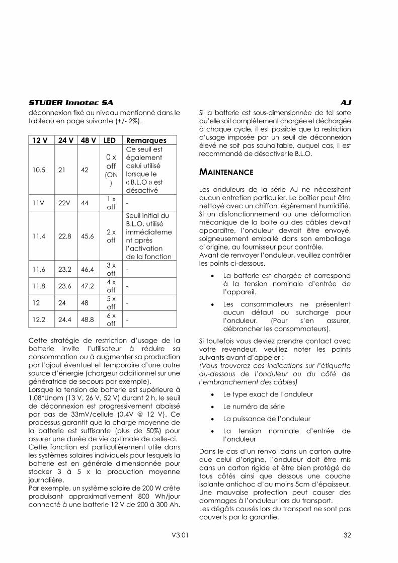
STUDER Innotec SA AJ
V3.01 32
déconnexion fixé au niveau mentionné dans le
tableau en page suivante (+/- 2%).
Cette stratégie de restriction d’usage de la
batterie invite l’utilisateur à réduire sa
consommation ou à augmenter sa production
par l’ajout éventuel et temporaire d’une autre
source d’énergie (chargeur additionnel sur une
génératrice de secours par exemple).
Lorsque la tension de batterie est supérieure à
1.08*Unom (13 V, 26 V, 52 V) durant 2 h, le seuil
de déconnexion est progressivement abaissé
par pas de 33mV/cellule (0,4V @ 12 V). Ce
processus garantit que la charge moyenne de
la batterie est suffisante (plus de 50%) pour
assurer une durée de vie optimale de celle-ci.
Cette fonction est particulièrement utile dans
les systèmes solaires individuels pour lesquels la
batterie est en générale dimensionnée pour
stocker 3 à 5 x la production moyenne
journalière.
Par exemple, un système solaire de 200 W crête
produisant approximativement 800 Wh/jour
connecté à une batterie 12 V de 200 à 300 Ah.
Si la batterie est sous-dimensionnée de tel sorte
qu’elle soit complètement chargée et déchargée
à chaque cycle, il est possible que la restriction
d’usage imposée par un seuil de déconnexion
élevé ne soit pas souhaitable, auquel cas, il est
recommandé de désactiver le B.L.O.
MAINTENANCE
Les onduleurs de la série AJ ne nécessitent
aucun entretien particulier. Le boîtier peut être
nettoyé avec un chiffon légèrement humidifié.
Si un disfonctionnement ou une déformation
mécanique de la boite ou des câbles devait
apparaître, l’onduleur devrait être envoyé,
soigneusement emballé dans son emballage
d’origine, au fournisseur pour contrôle.
Avant de renvoyer l’onduleur, veuillez contrôler
les points ci-dessous.
La batterie est chargée et correspond
à la tension nominale d’entrée de
l’appareil.
Les consommateurs ne présentent
aucun défaut ou surcharge pour
l’onduleur. (Pour s’en assurer,
débrancher les consommateurs).
Si toutefois vous deviez prendre contact avec
votre revendeur, veuillez noter les points
suivants avant d’appeler :
(Vous trouverez ces indications sur l’étiquette
au-dessous de l’onduleur ou du côté de
l’embranchement des câbles)
Le type exact de l’onduleur
Le numéro de série
La puissance de l’onduleur
La tension nominale d’entrée de
l’onduleur
Dans le cas d’un renvoi dans un carton autre
que celui d’origine, l’onduleur doit être mis
dans un carton rigide et être bien protégé de
tous côtés ainsi que dessous une couche
isolante antichoc d’au moins 5cm d’épaisseur.
Une mauvaise protection peut causer des
dommages à l’onduleur lors du transport.
Les dégâts causés lors du transport ne sont pas
couverts par la garantie.
12 V 24 V 48 V LED Remarques
10.5 21 42
0 x
off (ON
)
Ce seuil est
également
celui utilisé
lorsque le
« B.L.O » est
désactivé
11V 22V 44 1 x
off -
11.4 22.8 45.6 2 x
off
Seuil initial du
B.L.O. utilisé
immédiateme
nt après
l’activation
de la fonction
11.6 23.2 46.4 3 x
off -
11.8 23.6 47.2 4 x
off -
12 24 48 5 x
off -
12.2 24.4 48.8 6 x
off -
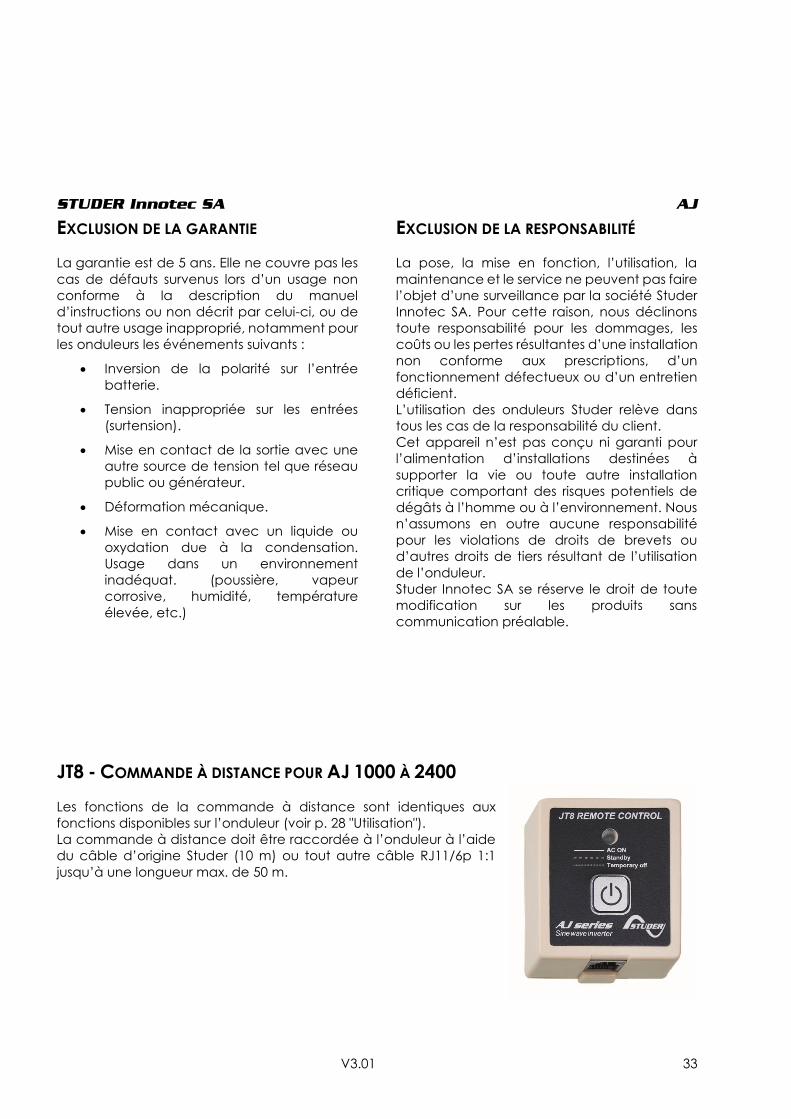
STUDER Innotec SA AJ
V3.01 33
EXCLUSION DE LA GARANTIE
La garantie est de 5 ans. Elle ne couvre pas les
cas de défauts survenus lors d’un usage non
conforme à la description du manuel
d’instructions ou non décrit par celui-ci, ou de
tout autre usage inapproprié, notamment pour
les onduleurs les événements suivants :
Inversion de la polarité sur l’entrée
batterie.
Tension inappropriée sur les entrées
(surtension).
Mise en contact de la sortie avec une
autre source de tension tel que réseau
public ou générateur.
Déformation mécanique.
Mise en contact avec un liquide ou
oxydation due à la condensation.
Usage dans un environnement
inadéquat. (poussière, vapeur
corrosive, humidité, température
élevée, etc.)
EXCLUSION DE LA RESPONSABILITÉ
La pose, la mise en fonction, l’utilisation, la
maintenance et le service ne peuvent pas faire
l’objet d’une surveillance par la société Studer
Innotec SA. Pour cette raison, nous déclinons
toute responsabilité pour les dommages, les
coûts ou les pertes résultantes d’une installation
non conforme aux prescriptions, d’un
fonctionnement défectueux ou d’un entretien
déficient.
L’utilisation des onduleurs Studer relève dans
tous les cas de la responsabilité du client.
Cet appareil n’est pas conçu ni garanti pour
l’alimentation d’installations destinées à
supporter la vie ou toute autre installation
critique comportant des risques potentiels de
dégâts à l’homme ou à l’environnement. Nous
n’assumons en outre aucune responsabilité
pour les violations de droits de brevets ou
d’autres droits de tiers résultant de l’utilisation
de l’onduleur.
Studer Innotec SA se réserve le droit de toute
modification sur les produits sans
communication préalable.
JT8 - COMMANDE À DISTANCE POUR AJ 1000 À 2400
Les fonctions de la commande à distance sont identiques aux
fonctions disponibles sur l’onduleur (voir p. 28 "Utilisation").
La commande à distance doit être raccordée à l’onduleur à l’aide
du câble d’origine Studer (10 m) ou tout autre câble RJ11/6p 1:1
jusqu’à une longueur max. de 50 m.
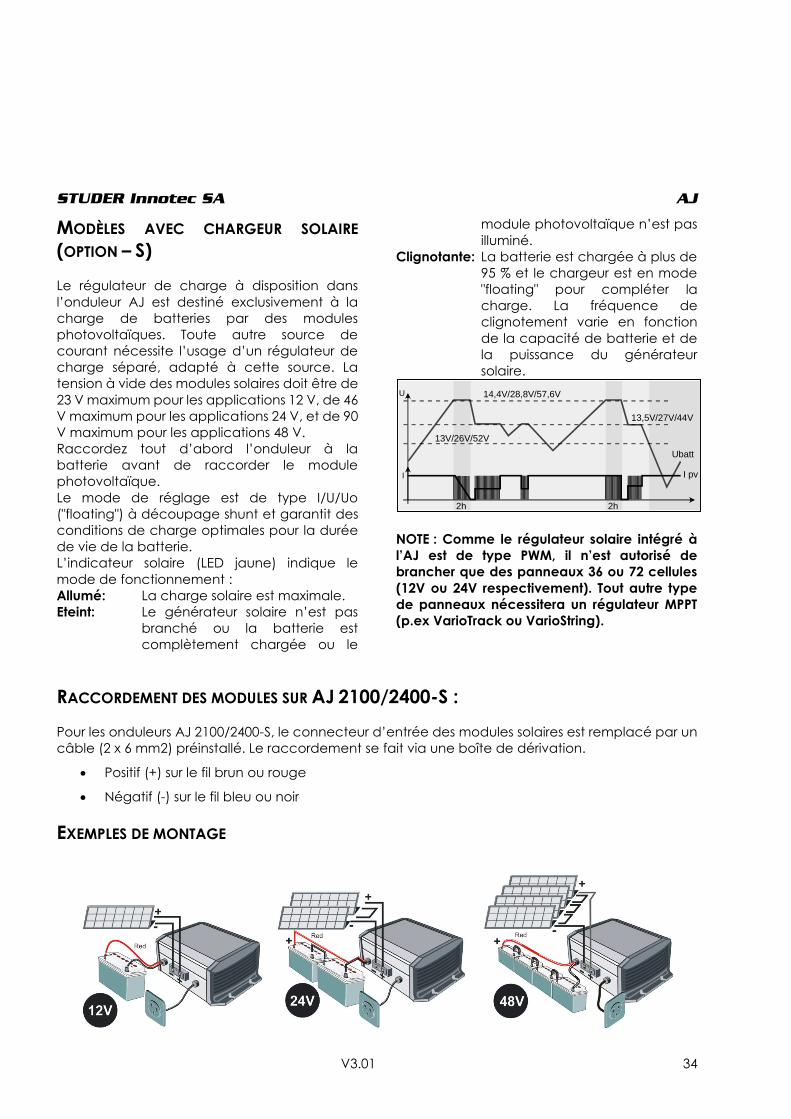
STUDER Innotec SA AJ
V3.01 34
MODÈLES AVEC CHARGEUR SOLAIRE
(OPTION – S)
Le régulateur de charge à disposition dans
l’onduleur AJ est destiné exclusivement à la
charge de batteries par des modules
photovoltaïques. Toute autre source de
courant nécessite l’usage d’un régulateur de
charge séparé, adapté à cette source. La
tension à vide des modules solaires doit être de
23 V maximum pour les applications 12 V, de 46
V maximum pour les applications 24 V, et de 90
V maximum pour les applications 48 V.
Raccordez tout d’abord l’onduleur à la
batterie avant de raccorder le module
photovoltaïque.
Le mode de réglage est de type I/U/Uo
("floating") à découpage shunt et garantit des
conditions de charge optimales pour la durée
de vie de la batterie.
L’indicateur solaire (LED jaune) indique le
mode de fonctionnement :
Allumé: La charge solaire est maximale.
Eteint: Le générateur solaire n’est pas
branché ou la batterie est
complètement chargée ou le
module photovoltaïque n’est pas
illuminé.
Clignotante: La batterie est chargée à plus de
95 % et le chargeur est en mode
"floating" pour compléter la
charge. La fréquence de
clignotement varie en fonction
de la capacité de batterie et de
la puissance du générateur
solaire.
NOTE : Comme le régulateur solaire intégré à
l’AJ est de type PWM, il n’est autorisé de
brancher que des panneaux 36 ou 72 cellules
(12V ou 24V respectivement). Tout autre type
de panneaux nécessitera un régulateur MPPT
(p.ex VarioTrack ou VarioString).
RACCORDEMENT DES MODULES SUR AJ 2100/2400-S :
Pour les onduleurs AJ 2100/2400-S, le connecteur d’entrée des modules solaires est remplacé par un
câble (2 x 6 mm2) préinstallé. Le raccordement se fait via une boîte de dérivation.
Positif (+) sur le fil brun ou rouge
Négatif (-) sur le fil bleu ou noir
EXEMPLES DE MONTAGE
14,4V/28,8V/57,6V
13V/26V/52V
13,5V/27V/44V
Ubatt
I pvI
U
2h 2h
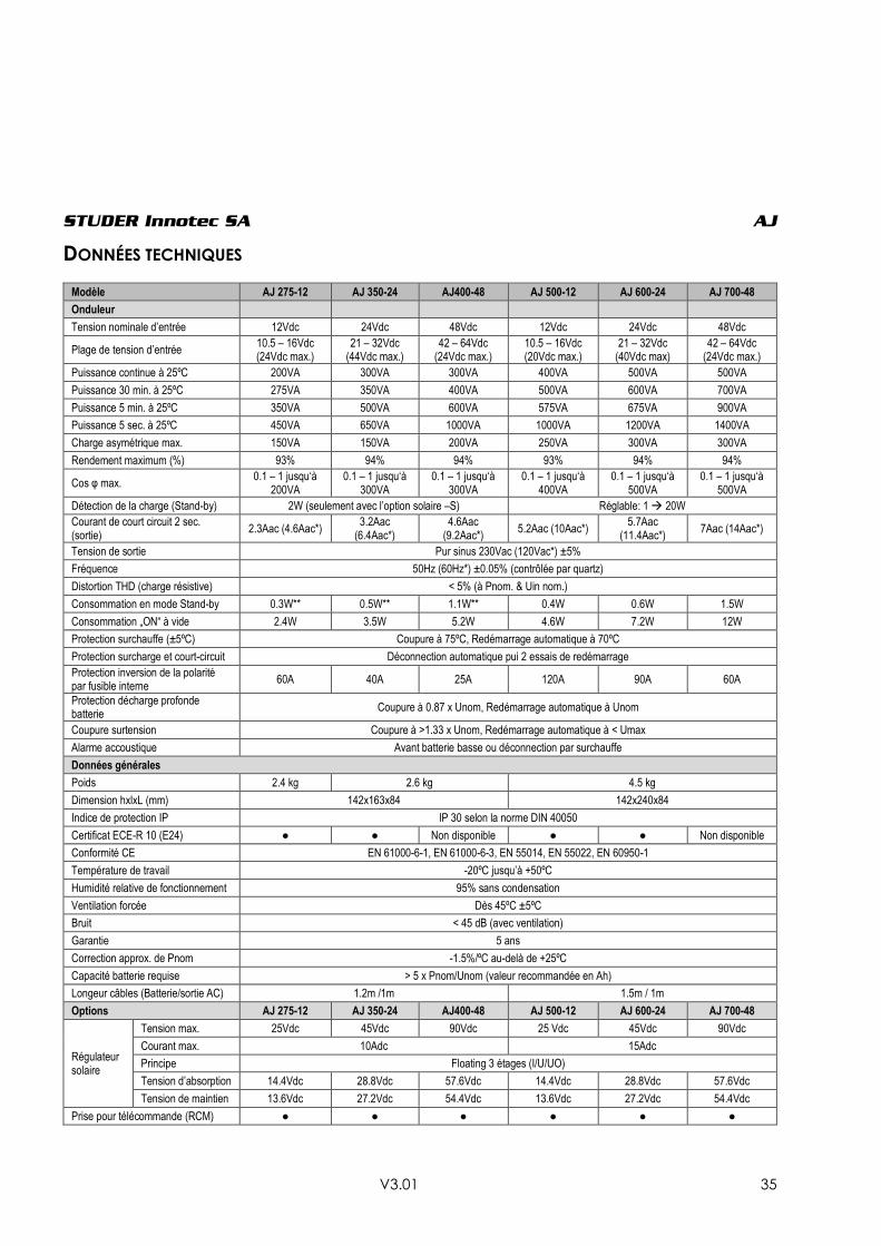
STUDER Innotec SA AJ
V3.01 35
DONNÉES TECHNIQUES
Modèle AJ 275-12 AJ 350-24 AJ400-48 AJ 500-12 AJ 600-24 AJ 700-48
Onduleur
Tension nominale d’entrée 12Vdc 24Vdc 48Vdc 12Vdc 24Vdc 48Vdc
Plage de tension d’entrée 10.5 – 16Vdc (24Vdc max.)
21 – 32Vdc (44Vdc max.)
42 – 64Vdc (24Vdc max.)
10.5 – 16Vdc (20Vdc max.)
21 – 32Vdc (40Vdc max)
42 – 64Vdc (24Vdc max.)
Puissance continue à 25ºC 200VA 300VA 300VA 400VA 500VA 500VA
Puissance 30 min. à 25ºC 275VA 350VA 400VA 500VA 600VA 700VA
Puissance 5 min. à 25ºC 350VA 500VA 600VA 575VA 675VA 900VA
Puissance 5 sec. à 25ºC 450VA 650VA 1000VA 1000VA 1200VA 1400VA
Charge asymétrique max. 150VA 150VA 200VA 250VA 300VA 300VA
Rendement maximum (%) 93% 94% 94% 93% 94% 94%
Cos φ max. 0.1 – 1 jusqu‘à
200VA 0.1 – 1 jusqu‘à
300VA 0.1 – 1 jusqu‘à
300VA 0.1 – 1 jusqu‘à
400VA 0.1 – 1 jusqu‘à
500VA 0.1 – 1 jusqu‘à
500VA
Détection de la charge (Stand-by) 2W (seulement avec l’option solaire –S) Réglable: 1 20W
Courant de court circuit 2 sec. (sortie)
2.3Aac (4.6Aac*) 3.2Aac
(6.4Aac*) 4.6Aac
(9.2Aac*) 5.2Aac (10Aac*)
5.7Aac (11.4Aac*)
7Aac (14Aac*)
Tension de sortie Pur sinus 230Vac (120Vac*) ±5%
Fréquence 50Hz (60Hz*) ±0.05% (contrôlée par quartz)
Distortion THD (charge résistive) < 5% (à Pnom. & Uin nom.)
Consommation en mode Stand-by 0.3W** 0.5W** 1.1W** 0.4W 0.6W 1.5W
Consommation „ON“ à vide 2.4W 3.5W 5.2W 4.6W 7.2W 12W
Protection surchauffe (±5ºC) Coupure à 75ºC, Redémarrage automatique à 70ºC
Protection surcharge et court-circuit Déconnection automatique pui 2 essais de redémarrage
Protection inversion de la polarité par fusible interne
60A 40A 25A 120A 90A 60A
Protection décharge profonde batterie
Coupure à 0.87 x Unom, Redémarrage automatique à Unom
Coupure surtension Coupure à >1.33 x Unom, Redémarrage automatique à < Umax
Alarme accoustique Avant batterie basse ou déconnection par surchauffe
Données générales
Poids 2.4 kg 2.6 kg 4.5 kg
Dimension hxlxL (mm) 142x163x84 142x240x84
Indice de protection IP IP 30 selon la norme DIN 40050
Certificat ECE-R 10 (E24) ● ● Non disponible ● ● Non disponible
Conformité CE EN 61000-6-1, EN 61000-6-3, EN 55014, EN 55022, EN 60950-1
Température de travail -20ºC jusqu’à +50ºC
Humidité relative de fonctionnement 95% sans condensation
Ventilation forcée Dès 45ºC ±5ºC
Bruit < 45 dB (avec ventilation)
Garantie 5 ans
Correction approx. de Pnom -1.5%/ºC au-delà de +25ºC
Capacité batterie requise > 5 x Pnom/Unom (valeur recommandée en Ah)
Longeur câbles (Batterie/sortie AC) 1.2m /1m 1.5m / 1m
Options AJ 275-12 AJ 350-24 AJ400-48 AJ 500-12 AJ 600-24 AJ 700-48
Régulateur solaire
Tension max. 25Vdc 45Vdc 90Vdc 25 Vdc 45Vdc 90Vdc
Courant max. 10Adc 15Adc
Principe Floating 3 étages (I/U/UO)
Tension d’absorption 14.4Vdc 28.8Vdc 57.6Vdc 14.4Vdc 28.8Vdc 57.6Vdc
Tension de maintien 13.6Vdc 27.2Vdc 54.4Vdc 13.6Vdc 27.2Vdc 54.4Vdc
Prise pour télécommande (RCM) ● ● ● ● ● ●
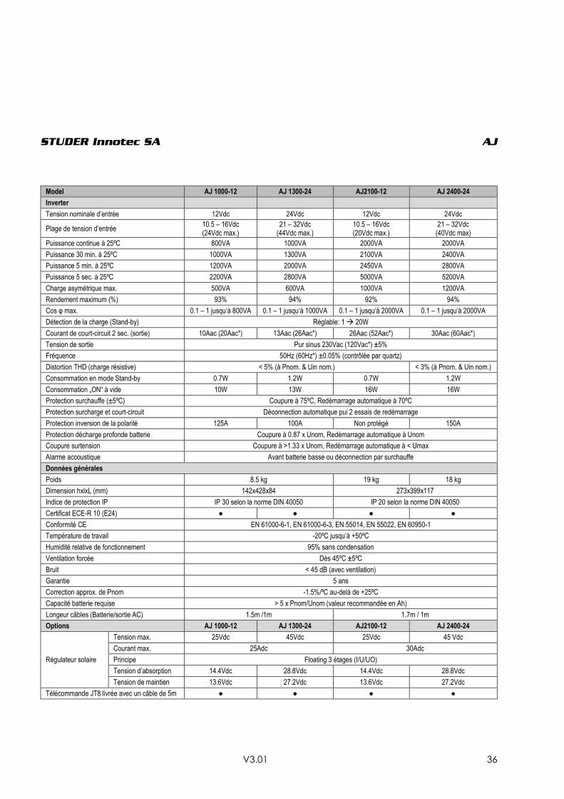
STUDER Innotec SA AJ
V3.01 36
Model AJ 1000-12 AJ 1300-24 AJ2100-12 AJ 2400-24
Inverter
Tension nominale d’entrée 12Vdc 24Vdc 12Vdc 24Vdc
Plage de tension d’entrée 10.5 – 16Vdc (24Vdc max.)
21 – 32Vdc (44Vdc max.)
10.5 – 16Vdc (20Vdc max.)
21 – 32Vdc (40Vdc max)
Puissance continue à 25ºC 800VA 1000VA 2000VA 2000VA
Puissance 30 min. à 25ºC 1000VA 1300VA 2100VA 2400VA
Puissance 5 min. à 25ºC 1200VA 2000VA 2450VA 2800VA
Puissance 5 sec. à 25ºC 2200VA 2800VA 5000VA 5200VA
Charge asymétrique max. 500VA 600VA 1000VA 1200VA
Rendement maximum (%) 93% 94% 92% 94%
Cos φ max. 0.1 – 1 jusqu‘à 800VA 0.1 – 1 jusqu‘à 1000VA 0.1 – 1 jusqu‘à 2000VA 0.1 – 1 jusqu‘à 2000VA
Détection de la charge (Stand-by) Réglable: 1 20W
Courant de court-circuit 2 sec. (sortie) 10Aac (20Aac*) 13Aac (26Aac*) 26Aac (52Aac*) 30Aac (60Aac*)
Tension de sortie Pur sinus 230Vac (120Vac*) ±5%
Fréquence 50Hz (60Hz*) ±0.05% (contrôlée par quartz)
Distortion THD (charge résistive) < 5% (à Pnom. & Uin nom.) < 3% (à Pnom. & Uin nom.)
Consommation en mode Stand-by 0.7W 1.2W 0.7W 1.2W
Consommation „ON“ à vide 10W 13W 16W 16W
Protection surchauffe (±5ºC) Coupure à 75ºC, Redémarrage automatique à 70ºC
Protection surcharge et court-circuit Déconnection automatique pui 2 essais de redémarrage
Protection inversion de la polarité 125A 100A Non protégé 150A
Protection décharge profonde batterie Coupure à 0.87 x Unom, Redémarrage automatique à Unom
Coupure surtension Coupure à >1.33 x Unom, Redémarrage automatique à < Umax
Alarme accoustique Avant batterie basse ou déconnection par surchauffe
Données générales
Poids 8.5 kg 19 kg 18 kg
Dimension hxlxL (mm) 142x428x84 273x399x117
Indice de protection IP IP 30 selon la norme DIN 40050 IP 20 selon la norme DIN 40050
Certificat ECE-R 10 (E24) ● ● ● ●
Conformité CE EN 61000-6-1, EN 61000-6-3, EN 55014, EN 55022, EN 60950-1
Température de travail -20ºC jusqu’à +50ºC
Humidité relative de fonctionnement 95% sans condensation
Ventilation forcée Dès 45ºC ±5ºC
Bruit < 45 dB (avec ventilation)
Garantie 5 ans
Correction approx. de Pnom -1.5%/ºC au-delà de +25ºC
Capacité batterie requise > 5 x Pnom/Unom (valeur recommandée en Ah)
Longeur câbles (Batterie/sortie AC) 1.5m /1m 1.7m / 1m
Options AJ 1000-12 AJ 1300-24 AJ2100-12 AJ 2400-24
Régulateur solaire
Tension max. 25Vdc 45Vdc 25Vdc 45 Vdc
Courant max. 25Adc 30Adc
Principe Floating 3 étages (I/U/UO)
Tension d’absorption 14.4Vdc 28.8Vdc 14.4Vdc 28.8Vdc
Tension de maintien 13.6Vdc 27.2Vdc 13.6Vdc 27.2Vdc
Télécommande JT8 livrée avec un câble de 5m ● ● ● ●

STUDER Innotec SA AJ
V3.01 37
INSTRUCCIONES EN ESPAÑOL
INTRODUCCIÓN
Los inversores de la gama AJ se concibieron de
manera a responder a las necesidades tanto
industriales como domésticas. Satisfarán a las
más altas exigencias de comodidad,
seguridad y fiabilidad.
Se le puede conectar sin problema cualquier
aparato destinado a alimentarse con la red
eléctrica 230V 50Hz hasta la potencia nominal
del inversor AJ.
La gama AJ es la solución ideal como fuente
de tensión en cualquier parte dónde la red
pública no está presente.
Este documento es parte integrante del
inversor, debe entregarse con cada equipo y
ponerse a disposición de toda persona
trabajando sobre la instalación.
En caso de duda o de pregunta, no dude en
contactar su proveedor especialista que
podrá informarle.
ATENCIÓN
Un montaje incorrecto puede dañar el equipo,
provocar un funcionamiento defectuoso o
poner en peligro los usuarios.
El equipo encendido genera altas tensiones
que pueden ser mortales en caso de contacto.
El trabajo sobre el inversor debe hacerse con
gran cuidado. Las instalaciones deben
hacerse por personal competente y responder
a las normas de ámbito local.
EL USUARIO NO PUEDE MANIPULAR NINGUNA
PIEZA EN EL INTERIOR DEL INVERSOR.
La apertura del inversor o el uso no conforme
del inversor conllevará la pérdida inmediata
de la garantía.
Únicamente se puede alimentar el AJ con
baterías al plomo.
Ningún aparato generador de corriente o de
tensión (red pública, generador,…) debe
conectarse a la salida del inversor porque
podría provocar la destrucción de este.
Para el uso de baterías, confórmese a las
directivas de utilización del fabricante.
INSTALACIÓN
El inversor sinusoidal AJ es un equipo
electrónico; hay que tomar ciertas
precauciones cuando se pone en servicio:
Lugar de montaje del inversor
Dónde no puedan llegar personas no
autorizadas, especialmente niños.
En un lugar seco (máx. 95% de humedad) y en
todos los casos sin condensación.
No directamente por encima de las baterías.
No se tiene que almacenar ningún material
que se puede inflamar por debajo o cerca del
equipo.
No se debe tapar la ventilación y se necesita
una distancia mínima de 10 cm de cada lado
del equipo para una buena evacuación del
calor interno.
Fijación del inversor
El inversor debe fijarse en una superficie no
inflamable con la ayuda de tornillos de 4mm
de diámetro máximo, para los AJ 275 – AJ 1300
y de tornillos de 8mm para los AJ 2100 y 2400,
en las cuatro ranuras previstas a ese efecto. Los
tornillos de fijación no se entregan con el
inversor.
La posición del inversor no es importante:
puede ser contra un muro, encima de una
mesa o suspendido.
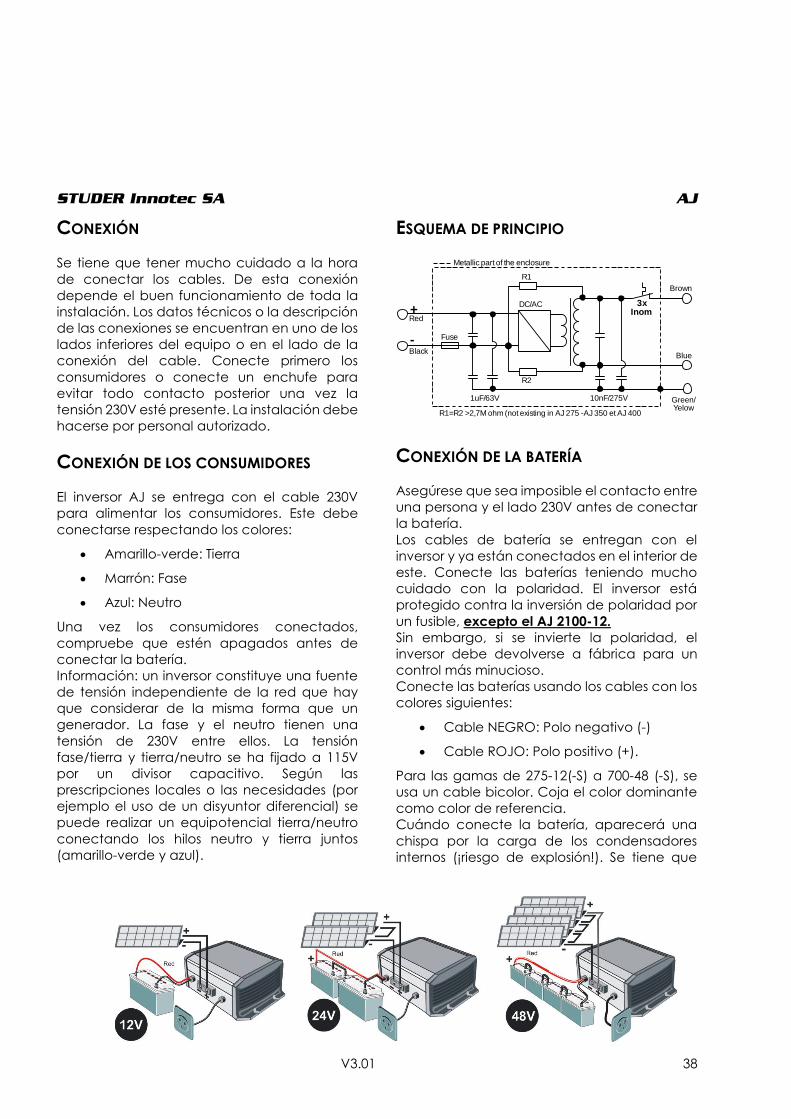
STUDER Innotec SA AJ
V3.01 38
CONEXIÓN
Se tiene que tener mucho cuidado a la hora
de conectar los cables. De esta conexión
depende el buen funcionamiento de toda la
instalación. Los datos técnicos o la descripción
de las conexiones se encuentran en uno de los
lados inferiores del equipo o en el lado de la
conexión del cable. Conecte primero los
consumidores o conecte un enchufe para
evitar todo contacto posterior una vez la
tensión 230V esté presente. La instalación debe
hacerse por personal autorizado.
CONEXIÓN DE LOS CONSUMIDORES
El inversor AJ se entrega con el cable 230V
para alimentar los consumidores. Este debe
conectarse respectando los colores:
Amarillo-verde: Tierra
Marrón: Fase
Azul: Neutro
Una vez los consumidores conectados,
compruebe que estén apagados antes de
conectar la batería.
Información: un inversor constituye una fuente
de tensión independiente de la red que hay
que considerar de la misma forma que un
generador. La fase y el neutro tienen una
tensión de 230V entre ellos. La tensión
fase/tierra y tierra/neutro se ha fijado a 115V
por un divisor capacitivo. Según las
prescripciones locales o las necesidades (por
ejemplo el uso de un disyuntor diferencial) se
puede realizar un equipotencial tierra/neutro
conectando los hilos neutro y tierra juntos
(amarillo-verde y azul).
ESQUEMA DE PRINCIPIO
CONEXIÓN DE LA BATERÍA
Asegúrese que sea imposible el contacto entre
una persona y el lado 230V antes de conectar
la batería.
Los cables de batería se entregan con el
inversor y ya están conectados en el interior de
este. Conecte las baterías teniendo mucho
cuidado con la polaridad. El inversor está
protegido contra la inversión de polaridad por
un fusible, excepto el AJ 2100-12.
Sin embargo, si se invierte la polaridad, el
inversor debe devolverse a fábrica para un
control más minucioso.
Conecte las baterías usando los cables con los
colores siguientes:
Cable NEGRO: Polo negativo (-)
Cable ROJO: Polo positivo (+).
Para las gamas de 275-12(-S) a 700-48 (-S), se
usa un cable bicolor. Coja el color dominante
como color de referencia.
Cuándo conecte la batería, aparecerá una
chispa por la carga de los condensadores
internos (¡riesgo de explosión!). Se tiene que
DC/AC
R1
R2
1uF/63V 10nF/275V
3x Inom+
-
R1=R2 >2,7M ohm (not existing in AJ 275 -AJ 350 et AJ 400
Metallic part of the enclosure
Blue
Green/Yelow
Brown
Fuse
Red
Black
STUDER Innotec SA AJ
V3.01 39
montar un fusible de seguridad contra
incendios en la batería.
Verifique el apretado de los cables.
Siempre que sea posible, no prolongue los
cables entregados. El hecho de prolongar los
cables de batería puede aumentar las
pérdidas y provocar un disfuncionamiento del
equipo.
Una vez el inversor conectado sobre la batería,
la tensión 230V está presente en salida del
inversor.
UTILIZACIÓN
FUNCIONES E INDICADORES
Se puede acceder al pulsador de mando
sobre el inversor. Permite el encendido y
apagado del equipo. Utilice esta función para
economizar la energía de las baterías
poniendo el equipo fuera de tensión cuándo
no lo utilice.
Nota: El regulador solar sigue funcionando
aunque apague el equipo.
Indicador "Funcionamiento" (LED
verde 1)
Un indicador luminoso verde encima del
inversor indica el modo de funcionamiento:
Encendido: La tensión 230 V está presente
en la salida; el inversor está
funcionando
Parpadea:
_ _ _ _ _ El inversor está en modo
standby.
__ __ __ __ __ La tensión 230 V se ha parado
momentáneamente tras una
alarma; el inversor arrancará
automáticamente en cuánto
la causa de la alarma haya
desaparecido (ver tabla de
fallos p. 42).
Apagado: No hay tensión 230 V en salida;
el inversor está apagado.
Indicador "BLO" (LED verde 2)
(LED presente únicamente en los AJ
275-12 à 700-48)
Este indicador luminoso se enciendo
solamente cuando la función “Battery Liftime
Optimizer – B.L.O” (descripción en p. 42) se
activa (ver p. 41 para activación /
desactivación de las funciones).
INDICADOR ACÚSTICO
El inversor AJ dispone de un indicador sonoro
que señala los casos siguientes:
Sonido intermitente:
El inversor detecta un problema y cortará la
tensión de salida.
Posibles problemas:
Sobrecalentamiento:
El indicador pita 3°C antes de la parada del
inversor. Disminuya el consumo para bajar la
temperatura del inversor y así evitar la parada.
Baja tensión de batería:
El indicador pita un minuto antes del corte. Si la
tensión de batería vuelve a subir (gracias a una
disminución del consumo), la tensión de salida
no se cortará.
Sonido continúo de dos segundos:
Ha pulsado sobre le pulsador ON/OFF para
reiniciar el inversor. La tensión de salida está
inmediatamente presente a la salida tras la
señal sonora.
El indicador sonoro puede desactivarse según
el procedimiento p 30.
Botón de mando
encendido/apagado (on/off)
STUDER Innotec SA AJ
V3.01 40
ALARMA POR FLUCTUACIÓN DE TENSIÓN
Cuando el indicador sonoro se desactiva o
cuando el equipo está demasiado lejos para
poder oír el pitido, puede ser útil tener el aviso
de que el inversor se va a parar en caso de
“baja tensión de batería” o por
“sobrecalentamiento”. Si se activa esta
función (ver p. 41 para activación/
desactivación de las funciones), la tensión de
salida fluctuará ligeramente (máx. 20%)
provocando una variación de intensidad
luminosa de las lámparas que estén
eventualmente conectadas e indicando así la
inminencia de la parada de entrega de
energía. El usuario podrá elegir, si lo desea,
reducir su consumo para prolongar el uso de
funciones prioritarias (iluminación por ejemplo).
MODELOS CON STANDBY
Los inversores desde el AJ 500-12 llevan
integrado un sistema de Standby (también
disponible para la gama 275 / 350 / 400 con la
opción –S). El standby es un sistema de
economía de energía que desconecta el
inversor de forma intermitente cuando no se
detecta ningún consumidor. En este modo, el
indicador de funcionamiento (LED verde 1)
parpadea, indicando la presencia de tensión
de forma intermitente.
El umbral de detección se ajusta de fábrica a
un valor aproximado de 2W. En los modelos de
potencia superior a 400W, es posible
desactivar esta función o modificar el umbral
ajustando el potenciómetro de ajuste amarillo
marcado Standby. El ajuste del nivel de
detección se efectúa como sigue: apague
todos los consumidores, gire el potenciómetro
hacia la derecha (sentido de las agujas del
reloj) hasta que el LED parpadee, conecte su
más pequeño consumidor (por ejemplo un
cargador de móvil), gire lentamente el
potenciómetro hacia la izquierda hasta que el
LED se encienda continuamente. Controle que
el inversor se ponga en modo standby cuando
quite la carga. Si en este caso el modo standby
no se activa, esto significa que la carga es
demasiado pequeña para ser detectada.
Si no se desea el standby, gire el
potenciómetro completamente hacia la
derecha.
La potencia mínima detectada puede
ajustarse entre 1 y 20W. En la mayoría de las
instalaciones, este ajuste no es necesario. El
reglaje se hace con la ayuda de un
destornillador plano n°1 ajustando el
potenciómetro amarillo marcado “Standby”
sobre el inversor. En la posición máxima a la
derecha, la sensibilidad es mínima (20W). No
presione el destornillador contra el
potenciómetro.
CUIDADO
Funcionando en modo Standby, la tensión
230V está presente en la salida de forma
intermitente.
STUDER Innotec SA AJ
V3.01 41
ACTIVACIÓN / DESACTIVACIÓN DE FUNCIONES
Las funcionalidades siguientes de los inversores de la gama AJ pueden activarse o desactivarse
libremente por el usuario:
1. Alarma de parada inminente por señal acústica “buzzer” (descripción en p. 39).
2. Algoritmo de optimización de vida útil de la batería "B.L.O." (descripción en p. 42).
3. Alarma de parada inminente por fluctuación de tensión (descripción en p. 40).
Los estados activado o desactivado de las funciones se señalan con el buzzer cuando se presiona
continuamente sobre la tecla encendido/apagado tras un tiempo determinado para cada función
según la tabla siguiente:
Simple “bip” corto = función activada
Doble “bip” corto = función desactivada
Función
Tiempo de impulsión
(sobre on/off) Ajuste por defecto
1. Alarma acústica 5 segundos Activado
2. Optimización de vida útil de batería
(B.L.O.) 10 segundos Desactivado
3. Alarma por fluctuación de tensión 15 segundos Desactivado
El estado de la función se cambia si se suelta la tecla encendido/apagado en los dos segundos tras
el aviso del buzzer.
Para consultar el estado de las funciones sin efectuar ningún cambio de programación de éstas,
debe mantener pulsada la tecla encendido/apagado. Después de 20 segundos el buzzer pitará de
forma continua para indicar el fin de la secuencia de lectura y se parará cuándo suelte la tecla.
SEGURIDAD
El inversor AJ está protegido de manera electrónica. Está protegido contra inversiones de polaridad
por un fusible interno, excepto el modelo AJ 2100-12 que debe protegerse con un fusible externo.
La tabla siguiente muestra los diversos casos posibles de fallos y sus consecuencias.
Cuidado, el inversor no está protegido contra conexiones accidentales de otras fuentes (red pública
o generador) en la salida AC. Este tipo de conexión puede provocar daños de mayor importancia
en el inversor y debe absolutamente evitarse.
Protección de la batería por desconexión en baja tensión:
La batería está protegida contra descargas excesivas por el apagado del inversor si su tensión llega
a un nivel inferior a 0.87*Unom (10.5, 21 o 42V) durante más de 1 minuto. Una alarma sonora o por
fluctuación de tensión (si autorizada) se activa 1 minuto antes de que el inversor se apague. El
inversor se podrá arrancar manualmente.
Arrancará automáticamente si la tensión de batería vuelve a un valor superior a 1.04*Unom (12.5,
25 o 50V).
El inversor se apagará inmediatamente (sin plazo) si la tensión de batería es inferior a 0.75*Unom (9,
18 o 36V).

STUDER Innotec SA AJ
V3.01 42
La tabla siguiente indica las posibles causas de fallo del inversor
OPTIMIZADOR DE VIDA ÚTIL DE BATERÍA (BATTERY LIFETIME OPTIMIZER – B.L.O.):
Ciclar una batería que está permanentemente
entre 0 y 30% de su capacidad es a menudo la
causa de fallos prematuros en las baterías. Esta
situación se presenta muy a menudo en
pequeñas instalaciones solares individuales.
Para mejorar la vida útil de las baterías en esta
situación, los inversores de la gama AJ (de 275-
12 (-S) a 700-48 (-S)) disponen de un ajuste
automático del umbral de desconexión por
tensión. Este reajuste obliga al usuario a
adaptar su consumo de manera a permitir una
recarga completa de la batería. Esta función
puede activarse o desactivarse en cualquier
momento, según el procedimiento
mencionado en p. 41.
Un indicador luminoso (LED verde 2
únicamente disponible en los AJ 275-12 à 700-
48) está encendido o parpadea cuando se
activa esta función. El número de parpadeos
indica el nivel de tensión de desconexión
actualmente aplicado.
Si este indicador luminoso está encendido
continuamente, quiere decir que la batería se
usa de forma correcta y que está
suficientemente recargada. En este caso, el
umbral de desconexión se fija a 0.87*Unom
(10.5, 21o 42V según el modelo). Esto significa
también que tiene la mayor disponibilidad de
su stock de energía y que la batería está
menos sujeta a una degradación prematura.
Si el LED parpadea una o varias veces
consecutivas, significa una restricción de uso
de la batería y un umbral de desconexión
fijado al nivel mencionado en la tabla
siguiente (+/- 2%).
CAUSA CONSECUENCIA RESOLUCIÓN
Tensión de batería
baja <0.87*Unom
Inversor parado
momentáneamente, el
indicador verde 1
parpadea
Arranque automático en cuanto la tensión
de batería alcance 1.04*Unom.
Tensión de batería
baja <0.75*Unom
Inversor parado
indicador verde 1
apagado
Arranque manual posible en cuanto la
tensión de batería alcance >0.87*Unom.
Sobrecalentamiento
Inversor parado
momentáneamente,
indicador verde 1
parpadea.
Arranque automático en cuanto la
temperatura del equipo haya bajado.
Sobretensión de
batería >1.33*Unom Inversor parado
Esperar que la tensión de batería vuelva a ser
correcta. Una tensión demasiado elevada
puede dañar el inversor. Arranque
automático en cuanto la tensión de la
batería haya bajado a 1.25*Unom.
Cortocircuito en
salida Inversor parado
Suprimir el cortocircuito. Pulse la tecla
ON/OFF para arrancar el inversor.
Sobrecarga Inversor parado
Utilice el inversor en los límites de su potencia
nominal. Un uso prolongado o regular en
sobrecarga disminuirá su vida útil. Pulse sobre
la tecla ON/OFF para arrancar el inversor.
Inversión de
polaridad de la
batería
Fusible interno destruido Retorno a fábrica para pruebas.
STUDER Innotec SA AJ
V3.01 43
Esta estrategia de restricción de uso de la
batería invita al usuario a reducir su consumo o
aumentar su producción añadiendo eventual
y temporalmente otra fuente de energía
(cargador adicional sobre un generador de
emergencia por ejemplo).
Cuando la tensión de la batería es superior a
1.08*Unom (13V, 26V, 52V) durante 2h, el
umbral de desconexión se reduce con etapas
de 33mV/célula (0.4V @ 12V). Este proceso
garantiza que la carga media de la batería
sea suficiente (más del 50%) para asegurar una
vida útil óptima de la batería.
Esta función es particularmente útil en sistemas
solares individuales para los cuales se
dimensiona en general la batería para
almacenar 3 a 5 veces la producción media
diaria.
Por ejemplo, un sistema solar de 200W pico que
produce aproximadamente 800Wh/día
conectado a una batería 12V de 200 a 300Ah.
Si la batería se dimensiona por lo bajo de tal
forma que esté completamente cargada y
descargada en cada ciclo, es posible que no
se desee la restricción de uso impuesta por un
umbral de desconexión elevado, en cual caso,
se recomienda que se desactive el B.L.O.
MANTENIMIENTO
Los inversores de la gama AJ no necesitan
ningún mantenimiento particular. La caja
puede limpiarse con un paño húmedo. Si
apareciera una deformación mecánica de la
caja o de los cables o un disfuncionamiento,
tendría que enviar el inversor, cuidadosamente
empaquetado en su embalaje de origen, a su
proveedor para control.
Antes de reenviar el inversor, controle los
puntos siguientes.
La batería está cargada y corresponde
a la tensión nominal del equipo.
Los consumidores no tienen ningún
defecto o provocan sobrecarga para
el inversor (Para asegurarse,
desconecte los aparatos).
Si tiene que contactar su distribuidor de todas
formas, note los puntos siguientes antes de
llamar:
(Encontrará estas indicaciones en la etiqueta
debajo del inversor o del lado de las
conexiones de los cables)
El tipo exacto de inversores
El número de serie
La potencia del inversor
La tensión nominal de entrada del
inversor
En el caso de reenvío en un embalaje diferente
que el original, el inversor debe ponerse en un
cartón rígido y estar bien protegido por todos
los lados y por debajo una capa aislante anti
golpe de al menos 5cm de ancho. Una mala
protección puede causar daños al inversor
durante el transporte. Los daños debidos al
transporte no se cubren con la garantía.
12V 24V 48V LED Observaciones
10.5 21 42 0 x
(ON)
Este umbral
también se usa
cuando se
desactiva el
”B.L.O”
11V 22V 44 1 x
off -
11.4 22.8 45.6 2 x
off
Primer umbral
del B.L.O usado
inmediatament
e después de la
activación de la
función
11.6 23.2 46.4 3 x
off -
11.8 23.6 47.2 4 x
off -
12 24 48 5 x
off -
12.2 24.4 48.8 6 x
off -
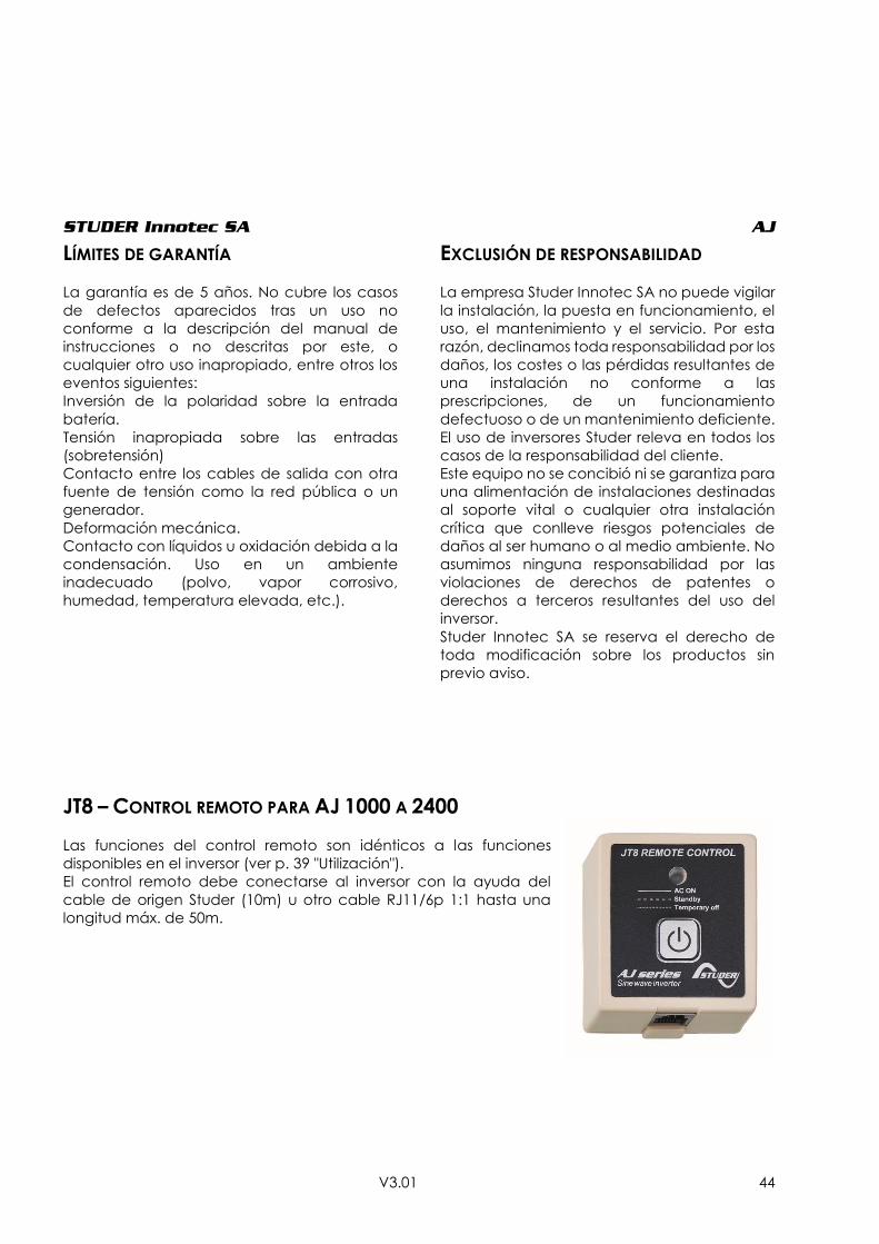
STUDER Innotec SA AJ
V3.01 44
LÍMITES DE GARANTÍA
La garantía es de 5 años. No cubre los casos
de defectos aparecidos tras un uso no
conforme a la descripción del manual de
instrucciones o no descritas por este, o
cualquier otro uso inapropiado, entre otros los
eventos siguientes:
Inversión de la polaridad sobre la entrada
batería.
Tensión inapropiada sobre las entradas
(sobretensión)
Contacto entre los cables de salida con otra
fuente de tensión como la red pública o un
generador.
Deformación mecánica.
Contacto con líquidos u oxidación debida a la
condensación. Uso en un ambiente
inadecuado (polvo, vapor corrosivo,
humedad, temperatura elevada, etc.).
EXCLUSIÓN DE RESPONSABILIDAD
La empresa Studer Innotec SA no puede vigilar
la instalación, la puesta en funcionamiento, el
uso, el mantenimiento y el servicio. Por esta
razón, declinamos toda responsabilidad por los
daños, los costes o las pérdidas resultantes de
una instalación no conforme a las
prescripciones, de un funcionamiento
defectuoso o de un mantenimiento deficiente.
El uso de inversores Studer releva en todos los
casos de la responsabilidad del cliente.
Este equipo no se concibió ni se garantiza para
una alimentación de instalaciones destinadas
al soporte vital o cualquier otra instalación
crítica que conlleve riesgos potenciales de
daños al ser humano o al medio ambiente. No
asumimos ninguna responsabilidad por las
violaciones de derechos de patentes o
derechos a terceros resultantes del uso del
inversor.
Studer Innotec SA se reserva el derecho de
toda modificación sobre los productos sin
previo aviso.
JT8 – CONTROL REMOTO PARA AJ 1000 A 2400
Las funciones del control remoto son idénticos a las funciones
disponibles en el inversor (ver p. 39 "Utilización").
El control remoto debe conectarse al inversor con la ayuda del
cable de origen Studer (10m) u otro cable RJ11/6p 1:1 hasta una
longitud máx. de 50m.

STUDER Innotec SA AJ
V3.01 45
MODELOS CON CARGADOR SOLAR
(OPCIÓN – S)
El regulador de carga a disposición en el
inversor AJ se destina exclusivamente a la
carga de la batería para módulos
fotovoltaicos. Cualquier otra fuente de
corriente necesita el uso de un regulador de
carga separado, adaptado a esa fuente. La
tensión en vacío de los módulos solares debe
ser de 23V máximo para las aplicaciones 12V,
de 46V máximo para las aplicaciones 24V y de
90V máximo para las aplicaciones 48V.
Conecte primero el inversor a la batería antes
de conectar el módulo fotovoltaico. El modo
de ajuste es de tipo I/U/Uo ("floating")
conmutada shunt y garantiza condiciones de
carga óptimas para la vida útil de la batería.
El indicador amarillo indica el modo de
funcionamiento:
Encendido: La carga solar es máxima.
Apagado: El generador solar no se ha
conectado o la batería está
completamente cargada o el
módulo fotovoltaico no está
iluminado.
Parpadeante: La batería está cargada a más
del 95% y el cargador está en
modo "floating" para completar
la carga. La frecuencia del
parpadeo varía en función de
la capacidad de batería y de la
potencia del generador solar.
NOTA: como el regulador solar integrado en el
AJ es de tipo PWM, solo se pueden conectar
módulos fotovoltaicos de 36 o 72 células (12V
o 24V respectivamente). Si se usa cualquier
otro tipo de módulo, necesitaría un regulador
de tipo MPPT (p.ej VarioTrack o VarioString).
CONEXIÓN DE LOS MÓDULOS SOBRE AJ 2100/2400-S:
Para los inversores AJ 2100/2400-S, el conector de entrada de los módulos solares se reemplaza por
un cable (2 x 6mm2) preinstalado. La conexión se hace a través de una caja de derivación.
Positivo (+) sobre el hilo marrón o rojo
Negativo (-) sobre el hilo azul o negro
EJEMPLOS DE MONTAJE
14,4V/28,8V/57,6V
13V/26V/52V
13,5V/27V/44V
Ubatt
I pvI
U
2h 2h

STUDER Innotec SA AJ
V3.01 46
DATOS TÉCNICOS
Modelo AJ 275-12 AJ 350-24 AJ400-48 AJ 500-12 AJ 600-24 AJ 700-48
Inversor
Tensíon nominal de batería 12Vdc 24Vdc 48Vdc 12Vdc 24Vdc 48Vdc
Campo de tensíon de entrada 10.5 – 16Vdc (24Vdc max.)
21 – 32Vdc (44Vdc max.)
42 – 64Vdc (24Vdc max.)
10.5 – 16Vdc (20Vdc max.)
21 – 32Vdc (40Vdc max)
42 – 64Vdc (24Vdc max.)
Potencia contínua a 25ºC 200VA 300VA 300VA 400VA 500VA 500VA
Potencia 30 min. a 25ºC 275VA 350VA 400VA 500VA 600VA 700VA
Potencia 5 min. a 25ºC 350VA 500VA 600VA 575VA 675VA 900VA
Potencia 5 sec. a 25ºC 450VA 650VA 1000VA 1000VA 1200VA 1400VA
Carga asimétrica máxima 150VA 150VA 200VA 250VA 300VA 300VA
Rendimiento máximo (%) 93% 94% 94% 93% 94% 94%
Cos φ max. 0.1 – 1 hasta
200VA 0.1 – 1 hasta
300VA 0.1 – 1 hasta
300VA 0.1 – 1 hasta
400VA 0.1 – 1 hasta
500VA 0.1 – 1 hasta
500VA
Deteccíon de carga 2W (únicamente con la opcíon solar –S) Adjustable: 1 20W
Corriente de corto cicuito 2 seg. (exit) 2.3Aac (4.6Aac*) 3.2Aac
(6.4Aac*) 4.6Aac (9.2Aac*) 5.2Aac (10Aac*)
5.7Aac (11.4Aac*)
7Aac (14Aac*)
Tensíon de salida Onda sinusoidal 230Vac (120Vac*) ±5%
Frecuencia 50Hz (60Hz*) ±0.05% (controlado por cuarzo)
Distorsíon THD (carga resistiva) < 5% (a Pnom. & Uin nom.)
Consumo Stand-by 0.3W** 0.5W** 1.1W** 0.4W 0.6W 1.5W
Consumption „ON“ sin carga 2.4W 3.5W 5.2W 4.6W 7.2W 12W
Proteccíon de sobre temperatura (±5ºC) Apagado a 75ºC, reinicio automático a 70ºC
Proteccíon de sobre temperatura y corto ciruito
Desconexíon automática con 2 intentos de reinicio
Proteccíon polarizacíon inversa con fusible interno
60A 40A 25A 120A 90A 60A
Proteccíon contra descargas excesivas protection
Apagado a 0.87 x Unom, reinicio automático a Unom.
Corte sobretensíon Apagado a >1.33 x Unom, reinicio automático < Umax
Alarma acústica Desconexíon antes de batería baja o sobre temperatura
Datos generales
Peso 2.4 kg 2.6 kg 4.5 kg
Dimensiones AxaxL (mm) 142x163x84 142x240x84
Índice de proteccíon IP IP 30 conforme con DIN 40050
Certificacíon ECE-R 10 (E24) ● ● No disponible ● ● No disponible
Conformidad EC EN 61000-6-1, EN 61000-6-3, EN 55014, EN 55022, EN 60950-1
Temperatura de trabajo -20ºC a +50ºC
Humedad relativa de funcionamiento 95% sin condensacíon
Ventilacíon forzada A partir de 45ºC ±5ºC
Nivel acústico < 45 dB (con ventilacíon)
Garantía 5 anõs
Correccíon aproximada de Pnom -1.5%/ºC a partir +25ºC
Capacidad de batería recomendada > 5 x Pnom/Unom (valor recomendado en Ah)
Longitud de cables (Batería/salida AC) 1.2m /1m 1.5m / 1m
Opciones AJ 275-12 AJ 350-24 AJ400-48 AJ 500-12 AJ 600-24 AJ 700-48
Regulador Solar
Tensíon max 25Vdc 45Vdc 90Vdc 25 Vdc 45Vdc 90Vdc
Corriente max. 10Adc 15Adc
Principio Mantenimiento 3 niveles (I/U/UO)
Tensíon de absorcíon
14.4Vdc 28.8Vdc 57.6Vdc 14.4Vdc 28.8Vdc 57.6Vdc
Tensíon flotacíon 13.6Vdc 27.2Vdc 54.4Vdc 13.6Vdc 27.2Vdc 54.4Vdc
Enchufe para control remoto (RCM) ● ● ● ● ● ●
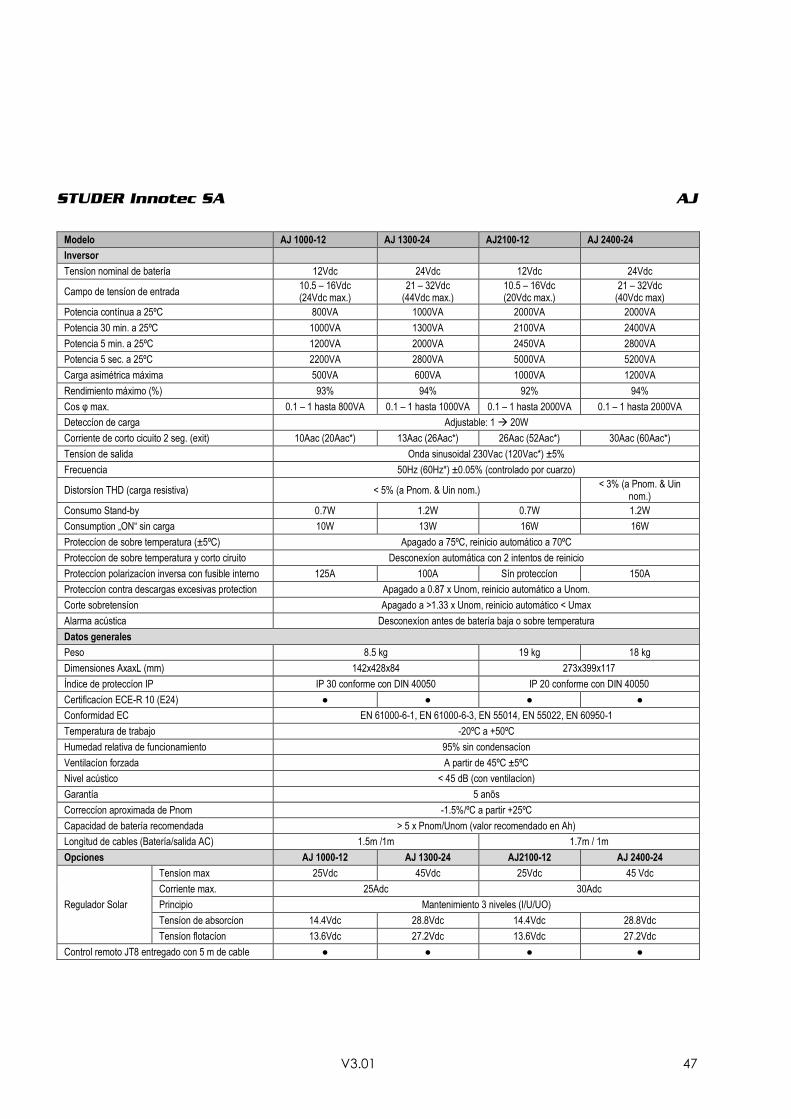
STUDER Innotec SA AJ
V3.01 47
Modelo AJ 1000-12 AJ 1300-24 AJ2100-12 AJ 2400-24
Inversor
Tensíon nominal de batería 12Vdc 24Vdc 12Vdc 24Vdc
Campo de tensíon de entrada 10.5 – 16Vdc (24Vdc max.)
21 – 32Vdc (44Vdc max.)
10.5 – 16Vdc (20Vdc max.)
21 – 32Vdc (40Vdc max)
Potencia contínua a 25ºC 800VA 1000VA 2000VA 2000VA
Potencia 30 min. a 25ºC 1000VA 1300VA 2100VA 2400VA
Potencia 5 min. a 25ºC 1200VA 2000VA 2450VA 2800VA
Potencia 5 sec. a 25ºC 2200VA 2800VA 5000VA 5200VA
Carga asimétrica máxima 500VA 600VA 1000VA 1200VA
Rendimiento máximo (%) 93% 94% 92% 94%
Cos φ max. 0.1 – 1 hasta 800VA 0.1 – 1 hasta 1000VA 0.1 – 1 hasta 2000VA 0.1 – 1 hasta 2000VA
Deteccíon de carga Adjustable: 1 20W
Corriente de corto cicuito 2 seg. (exit) 10Aac (20Aac*) 13Aac (26Aac*) 26Aac (52Aac*) 30Aac (60Aac*)
Tensíon de salida Onda sinusoidal 230Vac (120Vac*) ±5%
Frecuencia 50Hz (60Hz*) ±0.05% (controlado por cuarzo)
Distorsíon THD (carga resistiva) < 5% (a Pnom. & Uin nom.) < 3% (a Pnom. & Uin
nom.)
Consumo Stand-by 0.7W 1.2W 0.7W 1.2W
Consumption „ON“ sin carga 10W 13W 16W 16W
Proteccíon de sobre temperatura (±5ºC) Apagado a 75ºC, reinicio automático a 70ºC
Proteccíon de sobre temperatura y corto ciruito Desconexíon automática con 2 intentos de reinicio
Proteccíon polarizacíon inversa con fusible interno 125A 100A Sín proteccíon 150A
Proteccíon contra descargas excesivas protection Apagado a 0.87 x Unom, reinicio automático a Unom.
Corte sobretensíon Apagado a >1.33 x Unom, reinicio automático < Umax
Alarma acústica Desconexíon antes de batería baja o sobre temperatura
Datos generales
Peso 8.5 kg 19 kg 18 kg
Dimensiones AxaxL (mm) 142x428x84 273x399x117
Índice de proteccíon IP IP 30 conforme con DIN 40050 IP 20 conforme con DIN 40050
Certificacíon ECE-R 10 (E24) ● ● ● ●
Conformidad EC EN 61000-6-1, EN 61000-6-3, EN 55014, EN 55022, EN 60950-1
Temperatura de trabajo -20ºC a +50ºC
Humedad relativa de funcionamiento 95% sin condensacíon
Ventilacíon forzada A partir de 45ºC ±5ºC
Nivel acústico < 45 dB (con ventilacíon)
Garantía 5 anõs
Correccíon aproximada de Pnom -1.5%/ºC a partir +25ºC
Capacidad de batería recomendada > 5 x Pnom/Unom (valor recomendado en Ah)
Longitud de cables (Batería/salida AC) 1.5m /1m 1.7m / 1m
Opciones AJ 1000-12 AJ 1300-24 AJ2100-12 AJ 2400-24
Regulador Solar
Tensíon max 25Vdc 45Vdc 25Vdc 45 Vdc
Corriente max. 25Adc 30Adc
Principio Mantenimiento 3 niveles (I/U/UO)
Tensíon de absorcíon 14.4Vdc 28.8Vdc 14.4Vdc 28.8Vdc
Tensíon flotacíon 13.6Vdc 27.2Vdc 13.6Vdc 27.2Vdc
Control remoto JT8 entregado con 5 m de cable ● ● ● ●

STUDER Innotec SA AJ
V3.01 48
DECLARATION OF EC CONFORMITY,

Studer Innotec SA
Rue des Casernes 57
1950 Sion – Switzerland
Tél : +41(0) 27 205 60 80
Fax : +41(0) 27 205 60 88
www.studer-innotec.com
Related Documents