© Siemens AG 2013 - 2015. All rights reserved A5E32100920-004, 07/2015 1 SINAMICS/SIMOTICS SINAMICS V90, SIMOTICS S-1FL6 Getting Started Table of contents 1 Safety instructions .................................................................................................................................................. 3 1.1 Fundamental safety instructions .............................................................................................................. 3 1.1.1 General safety instructions ...................................................................................................................... 3 1.1.2 Safety instructions for electromagnetic fields (EMF)................................................................................ 5 1.1.3 Handling electrostatic sensitive devices (ESD) ....................................................................................... 5 1.1.4 Industrial security .................................................................................................................................... 6 1.1.5 Residual risks of power drive systems..................................................................................................... 6 1.2 Additional safety instructions ................................................................................................................... 7 1.2.1 Residual risks during the operation of electric motors ........................................................................... 13 2 General information .............................................................................................................................................. 14 2.1 Deliverables........................................................................................................................................... 14 2.1.1 Drive components.................................................................................................................................. 14 2.1.2 Motor components ................................................................................................................................. 16 2.2 Function list ........................................................................................................................................... 18 2.3 Device combination ............................................................................................................................... 19 2.4 Accessories ........................................................................................................................................... 20 2.5 Technical data ....................................................................................................................................... 20 2.5.1 Technical data - servo drives................................................................................................................. 20 2.5.2 Technical data - servo motors ............................................................................................................... 22 3 Mounting .............................................................................................................................................................. 24 3.1 Mounting the drive ................................................................................................................................. 24 3.2 Mounting the motor................................................................................................................................ 26 4 Connecting ........................................................................................................................................................... 30 4.1 System connection ................................................................................................................................ 30 4.2 Main circuit wirings ................................................................................................................................ 32 4.2.1 Line supply - L1, L2, L3 ......................................................................................................................... 32 4.2.2 Motor power - U, V, W ........................................................................................................................... 32 4.3 Control/Status interface - X8 ................................................................................................................. 33 4.4 24 V power supply/STO - X6 ................................................................................................................. 39 4.5 Encoder interface - X9 ........................................................................................................................... 40 4.6 External braking resistor - DCP, R1 ...................................................................................................... 42 4.7 Motor holding brake - X7 ....................................................................................................................... 42 4.8 RS485 interface - X12 ........................................................................................................................... 42 5 Commissioning ..................................................................................................................................................... 43 5.1 Introduction to the BOP ......................................................................................................................... 44 5.2 Initial commissioning in JOG mode ....................................................................................................... 48 5.3 Commissioning in pulse train position control mode (PTI) ..................................................................... 50

Welcome message from author
This document is posted to help you gain knowledge. Please leave a comment to let me know what you think about it! Share it to your friends and learn new things together.
Transcript
© Siemens AG 2013 - 2015. All rights reserved A5E32100920-004, 07/2015 1
SINAMICS/SIMOTICS SINAMICS V90, SIMOTICS S-1FL6 Getting Started
Table of contents 1 Safety instructions .................................................................................................................................................. 3
1.1 Fundamental safety instructions .............................................................................................................. 3 1.1.1 General safety instructions ...................................................................................................................... 3 1.1.2 Safety instructions for electromagnetic fields (EMF)................................................................................ 5 1.1.3 Handling electrostatic sensitive devices (ESD) ....................................................................................... 5 1.1.4 Industrial security .................................................................................................................................... 6 1.1.5 Residual risks of power drive systems..................................................................................................... 6
1.2 Additional safety instructions ................................................................................................................... 7 1.2.1 Residual risks during the operation of electric motors ........................................................................... 13
2 General information .............................................................................................................................................. 14
2.1 Deliverables ........................................................................................................................................... 14 2.1.1 Drive components.................................................................................................................................. 14 2.1.2 Motor components ................................................................................................................................. 16
2.2 Function list ........................................................................................................................................... 18
2.3 Device combination ............................................................................................................................... 19
2.4 Accessories ........................................................................................................................................... 20
2.5 Technical data ....................................................................................................................................... 20 2.5.1 Technical data - servo drives ................................................................................................................. 20 2.5.2 Technical data - servo motors ............................................................................................................... 22
3 Mounting .............................................................................................................................................................. 24
3.1 Mounting the drive ................................................................................................................................. 24
3.2 Mounting the motor................................................................................................................................ 26
4 Connecting ........................................................................................................................................................... 30
4.1 System connection ................................................................................................................................ 30
4.2 Main circuit wirings ................................................................................................................................ 32 4.2.1 Line supply - L1, L2, L3 ......................................................................................................................... 32 4.2.2 Motor power - U, V, W ........................................................................................................................... 32
4.3 Control/Status interface - X8 ................................................................................................................. 33
4.4 24 V power supply/STO - X6 ................................................................................................................. 39
4.5 Encoder interface - X9 ........................................................................................................................... 40
4.6 External braking resistor - DCP, R1 ...................................................................................................... 42
4.7 Motor holding brake - X7 ....................................................................................................................... 42
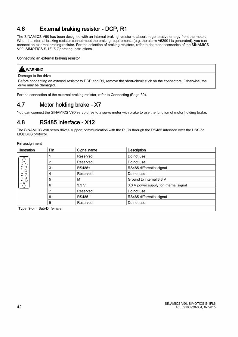
4.8 RS485 interface - X12 ........................................................................................................................... 42
5 Commissioning ..................................................................................................................................................... 43
5.1 Introduction to the BOP ......................................................................................................................... 44
5.2 Initial commissioning in JOG mode ....................................................................................................... 48
5.3 Commissioning in pulse train position control mode (PTI) ..................................................................... 50

SINAMICS V90, SIMOTICS S-1FL6 2 A5E32100920-004, 07/2015
5.4 Commissioning control functions........................................................................................................... 51 5.4.1 Selecting a control mode ....................................................................................................................... 51 5.4.2 Selecting a setpoint pulse train input channel ....................................................................................... 52 5.4.3 Selecting a setpoint pulse train input form ............................................................................................ 52 5.4.4 In position (INP) .................................................................................................................................... 53 5.4.5 Calculating electronic gear ratio ............................................................................................................ 53 5.4.6 Absolute position system ...................................................................................................................... 55
6 Parameters ...........................................................................................................................................................56
6.1 Overview ............................................................................................................................................... 56
6.2 Parameter list ........................................................................................................................................ 57
7 Diagnostics ...........................................................................................................................................................87
7.1 Overview ............................................................................................................................................... 87
7.2 List of faults and alarms ........................................................................................................................ 91

SINAMICS V90, SIMOTICS S-1FL6 A5E32100920-004, 07/2015 3
1 Safety instructions 1.1 Fundamental safety instructions
1.1.1 General safety instructions
DANGER Danger to life due to live parts and other energy sources Death or serious injury can result when live parts are touched. • Only work on electrical devices when you are qualified for this job. • Always observe the country-specific safety rules. Generally, six steps apply when establishing safety: 1. Prepare for shutdown and notify all those who will be affected by the procedure. 2. Disconnect the machine from the supply.
– Switch off the machine. – Wait until the discharge time specified on the warning labels has elapsed. – Check that it really is in a no-voltage condition, from phase conductor to phase conductor and phase
conductor to protective conductor. – Check whether the existing auxiliary supply circuits are de-energized. – Ensure that the motors cannot move.
3. Identify all other dangerous energy sources, e.g. compressed air, hydraulic systems, or water. 4. Isolate or neutralize all hazardous energy sources by closing switches, grounding or short-circuiting or
closing valves, for example. 5. Secure the energy sources against switching on again. 6. Ensure that the correct machine is completely interlocked. After you have completed the work, restore the operational readiness in the inverse sequence.
WARNING Danger to life through a hazardous voltage when connecting an unsuitable power supply Touching live components can result in death or severe injury. • Only use power supplies that provide SELV (Safety Extra Low Voltage) or PELV- (Protective Extra Low
Voltage) output voltages for all connections and terminals of the electronics modules.
WARNING Danger to life when live parts are touched on damaged devices Improper handling of devices can cause damage. For damaged devices, hazardous voltages can be present at the enclosure or at exposed components; if touched, this can result in death or severe injury. • Ensure compliance with the limit values specified in the technical data during transport, storage and
operation. • Do not use any damaged devices.
WARNING Danger to life through electric shock due to unconnected cable shields Hazardous touch voltages can occur through capacitive cross-coupling due to unconnected cable shields. • As a minimum, connect cable shields and the conductors of power cables that are not used (e.g. brake
cores) at one end at the grounded housing potential.
SINAMICS V90, SIMOTICS S-1FL6 4 A5E32100920-004, 07/2015
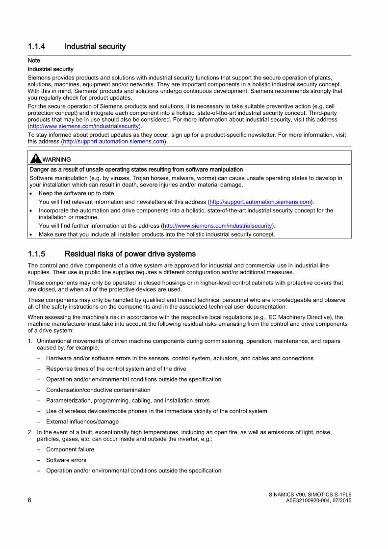
WARNING Danger to life due to electric shock when not grounded For missing or incorrectly implemented protective conductor connection for devices with protection class I, high voltages can be present at open, exposed parts, which when touched, can result in death or severe injury. • Ground the device in compliance with the applicable regulations.
WARNING Danger to life due to electric shock when opening plug connections in operation When opening plug connections in operation, arcs can result in severe injury or death. • Only open plug connections when the equipment is in a no-voltage state, unless it has been explicitly stated
that they can be opened in operation.
WARNING Danger to life due to fire spreading if housing is inadequate Fire and smoke development can cause severe personal injury or material damage. • Install devices without a protective housing in a metal control cabinet (or protect the device by another equivalent
measure) in such a way that contact with fire is prevented. • Ensure that smoke can only escape via controlled and monitored paths.
WARNING Danger to life through unexpected movement of machines when using mobile wireless devices or mobile phones Using mobile wireless devices or mobile phones with a transmit power > 1 W closer than approx. 2 m to the components may cause the devices to malfunction, influence the functional safety of machines therefore putting people at risk or causing material damage. • Switch the wireless devices or mobile phones off in the immediate vicinity of the components.
WARNING Danger to life due to the motor catching fire in the event of insulation overload There is higher stress on the motor insulation through a ground fault in an IT system. If the insulation fails, it is possible that death or severe injury can occur as a result of smoke and fire. • Use a monitoring device that signals an insulation fault. • Correct the fault as quickly as possible so the motor insulation is not overloaded.
WARNING Danger to life due to fire if overheating occurs because of insufficient ventilation clearances Inadequate ventilation clearances can cause overheating of components with subsequent fire and smoke. This can cause severe injury or even death. This can also result in increased downtime and reduced service lives for devices/systems. • Ensure compliance with the specified minimum clearance as ventilation clearance for the respective component.
WARNING Danger of an accident occurring due to missing or illegible warning labels Missing or illegible warning labels can result in accidents involving death or serious injury. • Check that the warning labels are complete based on the documentation. • Attach any missing warning labels to the components, in the national language if necessary. • Replace illegible warning labels.

SINAMICS V90, SIMOTICS S-1FL6 A5E32100920-004, 07/2015 5
NOTICE Device damage caused by incorrect voltage/insulation tests Incorrect voltage/insulation tests can damage the device. • Before carrying out a voltage/insulation check of the system/machine, disconnect the devices as all converters and
motors have been subject to a high voltage test by the manufacturer, and therefore it is not necessary to perform an additional test within the system/machine.
WARNING Danger to life when safety functions are inactive Safety functions that are inactive or that have not been adjusted accordingly can cause operational faults on machines that could lead to serious injury or death. • Observe the information in the appropriate product documentation before commissioning. • Carry out a safety inspection for functions relevant to safety on the entire system, including all safety-related
components. • Ensure that the safety functions used in your drives and automation tasks are adjusted and activated through
appropriate parameterizing. • Perform a function test. • Only put your plant into live operation once you have guaranteed that the functions relevant to safety are running
correctly.
Note Important safety notices for Safety Integrated functions If you want to use Safety Integrated functions, you must observe the safety notices in the Safety Integrated manuals.
WARNING Danger to life or malfunctions of the machine as a result of incorrect or changed parameterization As a result of incorrect or changed parameterization, machines can malfunction, which in turn can lead to injuries or death. • Protect the parameterization (parameter assignments) against unauthorized access. • Respond to possible malfunctions by applying suitable measures (e.g. EMERGENCY STOP or EMERGENCY OFF).
1.1.2 Safety instructions for electromagnetic fields (EMF)
WARNING Danger to life from electromagnetic fields Electromagnetic fields (EMF) are generated by the operation of electrical power equipment such as transformers, converters or motors. People with pacemakers or implants are at a special risk in the immediate vicinity of these devices/systems. • Ensure that the persons involved are the necessary distance away (minimum 2 m).
1.1.3 Handling electrostatic sensitive devices (ESD) Electrostatic sensitive devices (ESD) are individual components, integrated circuits, modules or devices that may be damaged by either electric fields or electrostatic discharge.
NOTICE Damage through electric fields or electrostatic discharge Electric fields or electrostatic discharge can cause malfunctions through damaged individual components, integrated circuits, modules or devices. • Only pack, store, transport and send electronic components, modules or devices in their original packaging
or in other suitable materials, e.g conductive foam rubber of aluminum foil. • Only touch components, modules and devices when you are grounded by one of the following methods:
– Wearing an ESD wrist strap – Wearing ESD shoes or ESD grounding straps in ESD areas with conductive flooring
• Only place electronic components, modules or devices on conductive surfaces (table with ESD surface, conductive ESD foam, ESD packaging, ESD transport container).
SINAMICS V90, SIMOTICS S-1FL6 6 A5E32100920-004, 07/2015
1.1.4 Industrial security
Note Industrial security Siemens provides products and solutions with industrial security functions that support the secure operation of plants, solutions, machines, equipment and/or networks. They are important components in a holistic industrial security concept. With this in mind, Siemens’ products and solutions undergo continuous development. Siemens recommends strongly that you regularly check for product updates. For the secure operation of Siemens products and solutions, it is necessary to take suitable preventive action (e.g. cell protection concept) and integrate each component into a holistic, state-of-the-art industrial security concept. Third-party products that may be in use should also be considered. For more information about industrial security, visit this address (http://www.siemens.com/industrialsecurity). To stay informed about product updates as they occur, sign up for a product-specific newsletter. For more information, visit this address (http://support.automation.siemens.com).
WARNING Danger as a result of unsafe operating states resulting from software manipulation Software manipulation (e.g. by viruses, Trojan horses, malware, worms) can cause unsafe operating states to develop in your installation which can result in death, severe injuries and/or material damage. • Keep the software up to date.
You will find relevant information and newsletters at this address (http://support.automation.siemens.com). • Incorporate the automation and drive components into a holistic, state-of-the-art industrial security concept for the
installation or machine. You will find further information at this address (http://www.siemens.com/industrialsecurity).
• Make sure that you include all installed products into the holistic industrial security concept.
1.1.5 Residual risks of power drive systems The control and drive components of a drive system are approved for industrial and commercial use in industrial line supplies. Their use in public line supplies requires a different configuration and/or additional measures.
These components may only be operated in closed housings or in higher-level control cabinets with protective covers that are closed, and when all of the protective devices are used.
These components may only be handled by qualified and trained technical personnel who are knowledgeable and observe all of the safety instructions on the components and in the associated technical user documentation.
When assessing the machine's risk in accordance with the respective local regulations (e.g., EC Machinery Directive), the machine manufacturer must take into account the following residual risks emanating from the control and drive components of a drive system:
1. Unintentional movements of driven machine components during commissioning, operation, maintenance, and repairs caused by, for example,
– Hardware and/or software errors in the sensors, control system, actuators, and cables and connections
– Response times of the control system and of the drive
– Operation and/or environmental conditions outside the specification
– Condensation/conductive contamination
– Parameterization, programming, cabling, and installation errors
– Use of wireless devices/mobile phones in the immediate vicinity of the control system
– External influences/damage
2. In the event of a fault, exceptionally high temperatures, including an open fire, as well as emissions of light, noise, particles, gases, etc. can occur inside and outside the inverter, e.g.:
– Component failure
– Software errors
– Operation and/or environmental conditions outside the specification
SINAMICS V90, SIMOTICS S-1FL6 A5E32100920-004, 07/2015 7
– External influences/damage Inverters of the Open Type/IP20 degree of protection must be installed in a metal control cabinet (or protected by another equivalent measure) such that contact with fire inside and outside the inverter is not possible.
3. Hazardous shock voltages caused by, for example,
– Component failure
– Influence during electrostatic charging
– Induction of voltages in moving motors
– Operation and/or environmental conditions outside the specification
– Condensation/conductive contamination
– External influences/damage
4. Electrical, magnetic and electromagnetic fields generated in operation that can pose a risk to people with a pacemaker, implants or metal replacement joints, etc., if they are too close
5. Release of environmental pollutants or emissions as a result of improper operation of the system and/or failure to dispose of components safely and correctly
Note The components must be protected against conductive contamination (e.g. by installing them in a control cabinet with degree of protection IP54 according to IEC 60529 or NEMA 12). Assuming that conductive contamination at the installation site can definitely be excluded, a lower degree of cabinet protection may be permitted.
For more information about residual risks of the components in a drive system, see the relevant sections in the technical user documentation.
1.2 Additional safety instructions
WARNING Danger to life from permanent magnet fields Even when switched off, electric motors with permanent magnets represent a potential risk for persons with heart pacemakers or implants if they are close to converters/motors. • If you are such a person (with heart pacemaker or implant) then keep a minimum distance of 2 m. • When transporting or storing permanent magnet motors always use the original packing materials with the warning
labels attached. • Clearly mark the storage locations with the appropriate warning labels. • IATA regulations must be observed when transported by air.
WARNING Injury caused by moving parts or those that are flung out Touching moving motor parts or drive output elements and loose motor parts that are flung out (e.g. feather keys) in operation can result in severe injury or death. • Remove any loose parts or secure them so that they cannot be flung out. • Do not touch any moving parts. • Safeguard all moving parts using the appropriate safety guards.
WARNING Danger to life due to fire if overheating occurs because of insufficient cooling Inadequate cooling can cause overheating resulting in death or severe injury as a result of smoke and fire. This can also result in increased failures and reduced service lives of motors. • Comply with the specified coolant requirements for the motor.
SINAMICS V90, SIMOTICS S-1FL6 8 A5E32100920-004, 07/2015
WARNING Danger to life due to fire as a result of overheating caused by incorrect operation When incorrectly operated and in the case of a fault, the motor can overheat resulting in fire and smoke. This can result in severe injury or death. Further, excessively high temperatures destroy motor components and result in increased failures as well as shorter service lives of motors. • Operate the motor according to the relevant specifications. • Only operate the motors in conjunction with effective temperature monitoring. • Immediately switch off the motor if excessively high temperatures occur.
CAUTION Risk of injury due to touching hot surfaces In operation, the motor can reach high temperatures, which can cause burns if touched. • Mount the motor so that it is not accessible in operation. When maintenance is required • allow the motor to cool down before starting any work. • Use the appropriate personnel protection equipment, e.g. gloves.
Delivery check
Note Intact deliverables Deliverables received must be intact. It's not permissible to put a damaged unit into use.
Transport and storage
NOTICE Property loss Notify Siemens service personnel immediately of any damage discovered after delivery. If the equipment is put into storage, keep it in a dry, dust-free, and low-vibration environment. The storage temperature ranges from -40 °C to +70 °C. Otherwise you will suffer property loss.
Mechanical installation
WARNING Death or severe personal injury from harsh installation environment A harsh installation environment will jeopardize personal safety and equipment. Therefore, • Do not install the drive and the motor in an area subject to inflammables or combustibles, water or corrosion hazards. • Do not install the drive and the motor in an area where it is likely to be exposed to constant vibrations or physical
shocks. • Do not keep the drive exposed to strong electro-magnetic interference. • Make sure that no foreign body (e.g., chips of wood or metal, dust, paper, etc.) can be seen inside the drive or on the
heat sink of the drive. • Make sure that the drive is installed in an electrical cabinet with an adequate degree of protection.
Note Mounting clearance To guarantee good heat dissipation and ease of cabling, keep sufficient clearance between drives, one drive and another device/inner wall of the cabinet.
SINAMICS V90, SIMOTICS S-1FL6 A5E32100920-004, 07/2015 9
Note Screw tightening Make sure you fix the screw to the terminal door of the drive after you have completed the installation work.
Electrical installation
DANGER Death or severe personal injury from electrical shock The earth leakage current for the drive can be greater than AC 3.5 mA, which may cause death or severe personal injury due to electrical shock. A fixed earth connection is required to eliminate the dangerous leakage current. In addition, the minimum size of the protective earth conductor shall comply with the local safety regulations for high leakage current equipment.
DANGER Danger to life when PE connectors are touched When the equipment is working, hazardous touch current can be present at the PE connectors; if touched, this can result in death or severe personal injury. • Do not touch the PE connector during operation or within a certain period since power disconnection.
WARNING Personal injury and damage to property from improper connections Improper connections have high risks of electrical shock and short circuit, which will jeopardize personal safety and equipment. • The drive must be directly connected with the motor. It is not permissible to connect a capacitor, inductor or
filter between them. • Make sure that all connections are correct and reliable, the drive and the motor are well grounded. • The line supply voltage must be within the allowable range (refer to the drive rating plate). Never connect
the line supply cable to the motor terminals U, V, W or connect the motor power cable to the line input terminals L1, L2, L3.
• Never wire up the U, V, W terminals in an interchanged phase sequence. • If the CE marking for cables is mandatory in some cases, the motor power cable, line supply cable and
brake cable used must all be shielded cables. • For terminal box connection, make sure that the clearances in air between non-insulated live parts are at
least 5.5 mm. • Route signal cables and power cables separately in different cable conduits. The signal cables shall be at
least 10 cm away from the power cables. • Cables connected may not come into contact with rotating mechanical parts.
CAUTION Personal injury and damage to property from inadequate protection Inadequate protection may cause minor personal injury or damage to property. • The drive must have been disconnected from the power supply for at least five minutes before you perform any wiring
to it. • Check that the equipment is dead! • Make sure that the drive and the motor are properly grounded. • Route a second PE conductor with the cross section of the supply system lead in parallel to the protective earth via
separate terminals or use a copper protective earth conductor with a cross section of 10 mm2. • Terminals for equipotential bondings that exist in addition to terminals for PE conductors must not be used for looping-
through the PE conductors. • To ensure protective separation, an isolating transformer must be used for the 380 VAC line supply system.
SINAMICS V90, SIMOTICS S-1FL6 10 A5E32100920-004, 07/2015
NOTICE Damage to property from incorrect input voltage Incorrect input voltage will cause severe damage to the drive. It is recommended that the actual input voltage should not be greater than 110% of the rated voltage or smaller than 75%.
Note STO wiring The safe torque off (STO) function can stop a motor using safety relays without involving any upper level control. It is disabled in the factory configuration by short-circuiting the STO terminals. The safety function of the servo drive is SIL 2 (EN61800-5-2). Connect the STO terminals as the actual requirements.
Commissioning/Operation
CAUTION Burns from hot surface The operating temperature of drive base-plate and heat sink is higher than 65 °C, and the surface temperature of the motor may reach up to 80 °C. The hot surface may burn your hands. Do not touch the motor or the heat sink of the drive during operation or within a certain period since power disconnection.
NOTICE Shortening the service life of motor brake The motor brake is used for holding purpose only. Frequent emergency stops with the motor brake will shorten its service life. Unless absolutely necessary, do not apply the motor brake as an emergency stop or deceleration mechanism.
NOTICE Damage to the equipment from frequent power-on/off Frequent power-on/off will cause damage to the drive. Do not switch on/off the power frequently.
Note Voltage requirement Before switching the power on, make sure that the drive system has been reliably installed and connected, and the line supply voltage is within the allowable range.
Note Drive functioning interfered by use of radio devices Some environmental factors may result in power derating, e.g. altitude and surrounding temperature. In this case, the drive cannot work normally. Environmental factors must be taken into account during commissioning or operation.
Troubleshooting
WARNING Drive remaining charged The drive may remain charged in a short period after it is powered off. Touching terminals or disassembling cables may cause minor injury due to electrical shock. Do not touch terminals or disassemble cables until the drive system has been disconnected for at least five minutes.
SINAMICS V90, SIMOTICS S-1FL6 A5E32100920-004, 07/2015 11
WARNING Personal injury due to unexpected restart The machine might unexpectedly restart after the power supply that was suddenly switched off is switched on again. Touching the machine at this time may cause personal injury. Do not approach the machine after the power supply is switched on again.
Disposal
Note Equipment disposal Disposal of the equipment must be made in accordance with the regulations of the competent environmental protection administration on the disposal of electronic wastes.
Certification
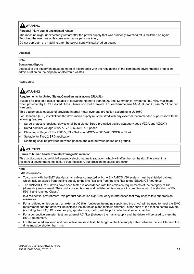
WARNING Requirements for United States/Canadian installations (UL/cUL) Suitable for use on a circuit capable of delivering not more than 65000 rms Symmetrical Amperes, 480 VAC maximum, when protected by UL/cUL-listed Class J fuses or circuit breakers. For each frame size AA, A, B, and C, use 75 °C copper wire only. This equipment is capable of providing internal motor overload protection according to UL508C. For Canadian (cUL) installations the drive mains supply must be fitted with any external recommended suppressor with the following features: • Surge-protective devices; device shall be a Listed Surge-protective device (Category code VZCA and VZCA7) • Rated nominal voltage 480/277 VAC, 50/60 Hz, 3-phase • Clamping voltage VPR = 2000 V, IN = 3kA min, MCOV = 508 VAC, SCCR = 65 kA • Suitable for Type 2 SPD application • Clamping shall be provided between phases and also between phase and ground.
WARNING Harms to human health from electromagnetic radiation This product may cause high-frequency electromagnetic radiation, which will affect human health. Therefore, in a residential environment, make sure that necessary suppression measures are taken.
Note EMC instructions • To comply with the EMC standards, all cables connected with the SINAMICS V90 system must be shielded cables,
which include cables from the line supply to the line filter and from the line filter to the SINAMICS V90 drive. • The SINAMICS V90 drives have been tested in accordance with the emission requirements of the category of C2
(domestic) environment. The conductive emissions and radiated emissions are in compliance with the standard of EN 55011 and reached Class A.
• In a residential environment, this product can cause high-frequency interferences that may necessitate suppression measures.
• For a radiated emission test, an external AC filter (between the mains supply and the drive) will be used to meet the EMC requirement and the drive will be installed inside the shielded metallic chamber, other parts of the motion control system (including the PLC, DC power supply, spindle drive, motor) will be put inside the shielded chamber.
• For a conductive emission test, an external AC filter (between the mains supply and the drive) will be used to meet the EMC requirement.
• For the radiated emission and conductive emission test, the length of the line supply cable between the line filter and the drive must be shorter than 1 m.
SINAMICS V90, SIMOTICS S-1FL6 12 A5E32100920-004, 07/2015
Information regarding non-Siemens products
Note Non-Siemens products This document contains recommendations relating to non-Siemens products. Non-Siemens products whose fundamental suitability is familiar to us. It goes without saying that equivalent products from other manufacturers may be used. Our recommendations are to be seen as helpful information, not as requirements or dictates. We cannot accept any liability for the quality and properties/features of non-Siemens products.
Warning labels
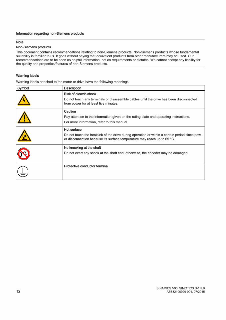
Warning labels attached to the motor or drive have the following meanings:
Symbol Description
Risk of electric shock Do not touch any terminals or disassemble cables until the drive has been disconnected from power for at least five minutes.
Caution Pay attention to the information given on the rating plate and operating instructions. For more information, refer to this manual.
Hot surface Do not touch the heatsink of the drive during operation or within a certain period since pow-er disconnection because its surface temperature may reach up to 65 °C.
No knocking at the shaft Do not exert any shock at the shaft end; otherwise, the encoder may be damaged.
Protective conductor terminal

SINAMICS V90, SIMOTICS S-1FL6 A5E32100920-004, 07/2015 13
1.2.1 Residual risks during the operation of electric motors The motors may be operated only when all protective equipment is used.
Motors may be handled only by qualified and instructed qualified personnel that knows and observes all safety instructions for the motors that are explained in the associated technical user documentation.
When assessing the machine's risk in accordance with the respective local regulations (e.g., EC Machinery Directive), the machine manufacturer must take into account the following residual risks emanating from the control and drive components of a drive system:
1. Unintentional movements of driven machine components during commissioning, operation, maintenance, and repairs caused by, for example,
– Hardware and/or software errors in the sensors, control system, actuators, and cables and connections
– Response times of the control system and of the drive
– Operation and/or environmental conditions outside the specification
– Condensation/conductive contamination
– Errors during the assembly, installation, programming and parameterization
– Use of wireless devices/mobile phones in the immediate vicinity of the control system
– External influences/damage
2. In case of failure, unusually high temperatures inside and outside the motor, including open fire as well as the emission of light, noise, particles, gases, etc. can result, for example in
– Component failure
– Software errors in converter operation
– Operation and/or environmental conditions outside the specification
– External influences/damage
3. Hazardous shock voltages caused by, for example,
– Component failure
– Influence during electrostatic charging
– Induction of voltages in moving motors
– Operation and/or environmental conditions outside the specification
– Condensation/conductive contamination
– External influences/damage
4. Electrical, magnetic and electromagnetic fields generated in operation that can pose a risk to people with a pacemaker, implants or metal replacement joints, etc., if they are too close
5. Release of noxious substances and emissions in the case of improper operation and/or improper disposal of components
SINAMICS V90, SIMOTICS S-1FL6 14 A5E32100920-004, 07/2015
2 General information 2.1 Deliverables
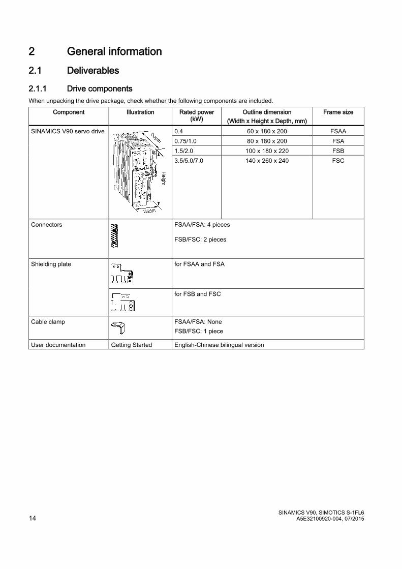
2.1.1 Drive components When unpacking the drive package, check whether the following components are included.
Component Illustration Rated power (kW)
Outline dimension (Width x Height x Depth, mm)
Frame size
SINAMICS V90 servo drive
0.4 60 x 180 x 200 FSAA 0.75/1.0 80 x 180 x 200 FSA 1.5/2.0 100 x 180 x 220 FSB 3.5/5.0/7.0 140 x 260 x 240 FSC
Connectors
FSAA/FSA: 4 pieces FSB/FSC: 2 pieces
Shielding plate
for FSAA and FSA
for FSB and FSC
Cable clamp
FSAA/FSA: None FSB/FSC: 1 piece
User documentation Getting Started English-Chinese bilingual version
SINAMICS V90, SIMOTICS S-1FL6 A5E32100920-004, 07/2015 15
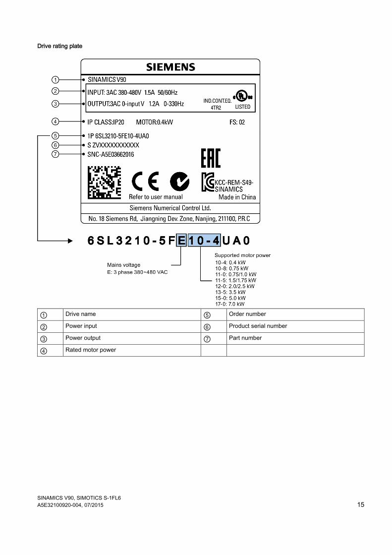
Drive rating plate
① Drive name ⑤ Order number
② Power input ⑥ Product serial number
③ Power output ⑦ Part number
④ Rated motor power
SINAMICS V90, SIMOTICS S-1FL6 16 A5E32100920-004, 07/2015
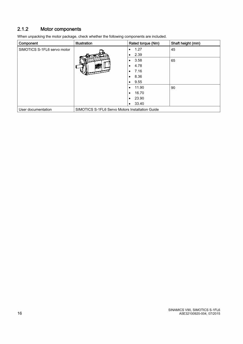
2.1.2 Motor components When unpacking the motor package, check whether the following components are included.
Component Illustration Rated torque (Nm) Shaft height (mm) SIMOTICS S-1FL6 servo motor
• 1.27 • 2.39
45
• 3.58 • 4.78 • 7.16 • 8.36 • 9.55
65
• 11.90 • 16.70 • 23.90 • 33.40
90
User documentation SIMOTICS S-1FL6 Servo Motors Installation Guide
SINAMICS V90, SIMOTICS S-1FL6 A5E32100920-004, 07/2015 17
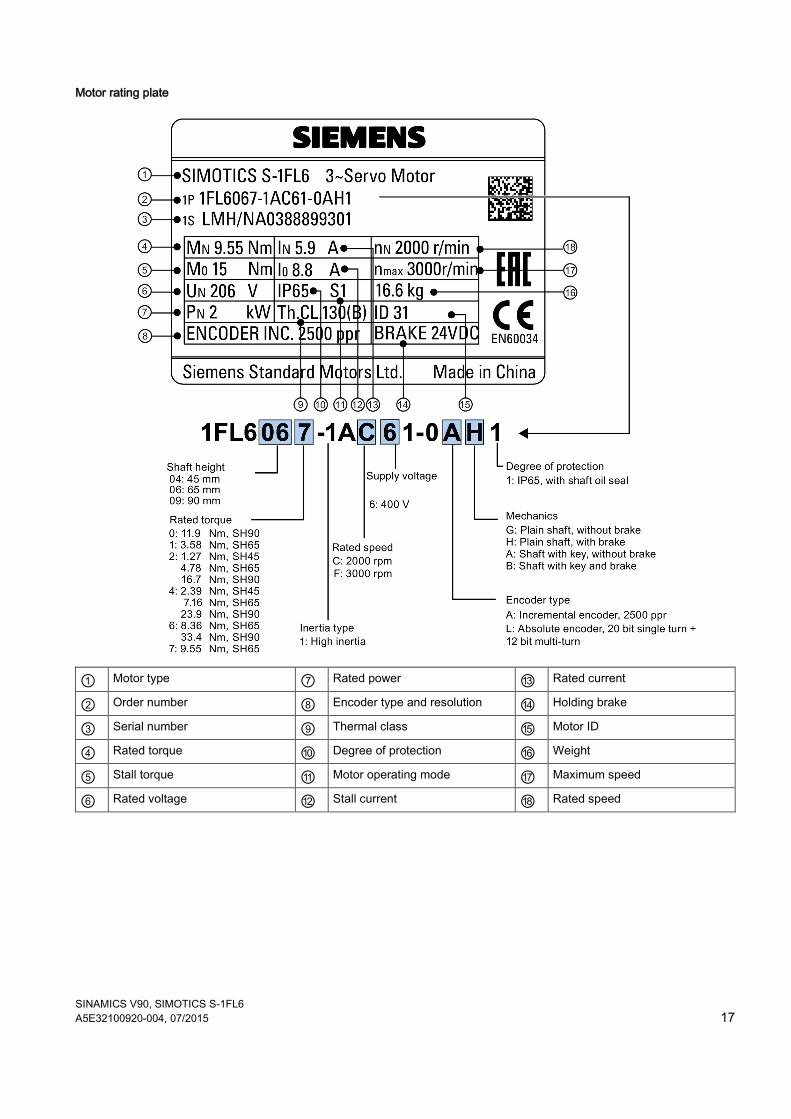
Motor rating plate
① Motor type ⑦ Rated power ⑬ Rated current
② Order number ⑧ Encoder type and resolution ⑭ Holding brake
③ Serial number ⑨ Thermal class ⑮ Motor ID
④ Rated torque ⑩ Degree of protection ⑯ Weight
⑤ Stall torque ⑪ Motor operating mode ⑰ Maximum speed
⑥ Rated voltage ⑫ Stall current ⑱ Rated speed
SINAMICS V90, SIMOTICS S-1FL6 18 A5E32100920-004, 07/2015
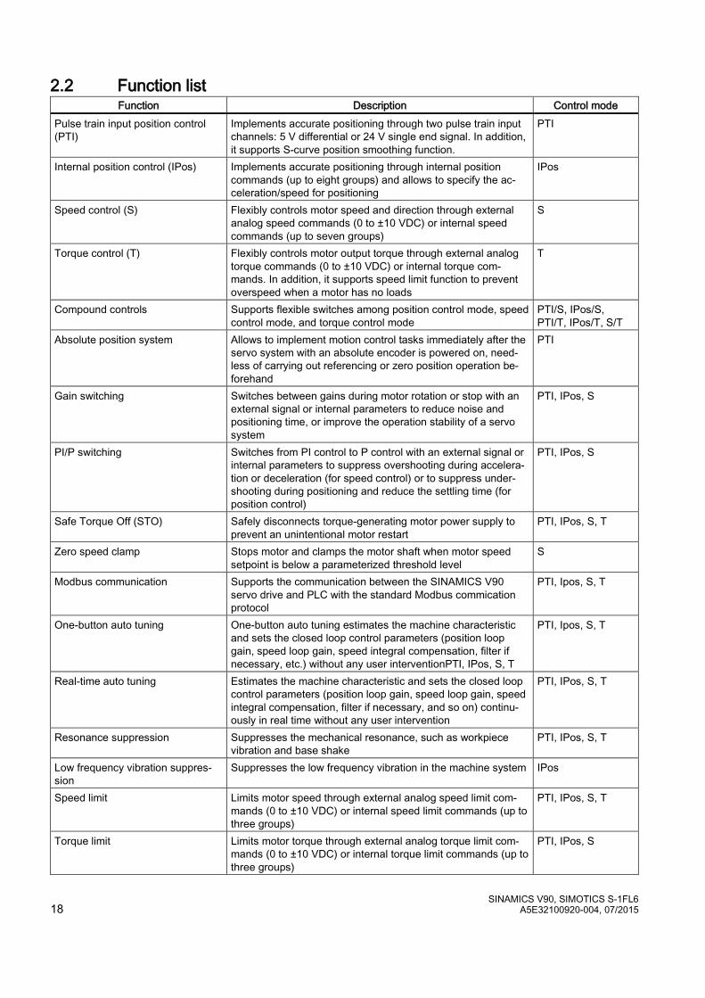
2.2 Function list Function Description Control mode
Pulse train input position control (PTI)
Implements accurate positioning through two pulse train input channels: 5 V differential or 24 V single end signal. In addition, it supports S-curve position smoothing function.
PTI
Internal position control (IPos) Implements accurate positioning through internal position commands (up to eight groups) and allows to specify the ac-celeration/speed for positioning
IPos
Speed control (S) Flexibly controls motor speed and direction through external analog speed commands (0 to ±10 VDC) or internal speed commands (up to seven groups)
S
Torque control (T) Flexibly controls motor output torque through external analog torque commands (0 to ±10 VDC) or internal torque com-mands. In addition, it supports speed limit function to prevent overspeed when a motor has no loads
T
Compound controls Supports flexible switches among position control mode, speed control mode, and torque control mode
PTI/S, IPos/S, PTI/T, IPos/T, S/T
Absolute position system Allows to implement motion control tasks immediately after the servo system with an absolute encoder is powered on, need-less of carrying out referencing or zero position operation be-forehand
PTI
Gain switching Switches between gains during motor rotation or stop with an external signal or internal parameters to reduce noise and positioning time, or improve the operation stability of a servo system
PTI, IPos, S
PI/P switching Switches from PI control to P control with an external signal or internal parameters to suppress overshooting during accelera-tion or deceleration (for speed control) or to suppress under-shooting during positioning and reduce the settling time (for position control)
PTI, IPos, S
Safe Torque Off (STO) Safely disconnects torque-generating motor power supply to prevent an unintentional motor restart
PTI, IPos, S, T
Zero speed clamp Stops motor and clamps the motor shaft when motor speed setpoint is below a parameterized threshold level
S
Modbus communication Supports the communication between the SINAMICS V90 servo drive and PLC with the standard Modbus commication protocol
PTI, Ipos, S, T
One-button auto tuning One-button auto tuning estimates the machine characteristic and sets the closed loop control parameters (position loop gain, speed loop gain, speed integral compensation, filter if necessary, etc.) without any user interventionPTI, IPos, S, T
PTI, Ipos, S, T
Real-time auto tuning Estimates the machine characteristic and sets the closed loop control parameters (position loop gain, speed loop gain, speed integral compensation, filter if necessary, and so on) continu-ously in real time without any user intervention
PTI, IPos, S, T
Resonance suppression Suppresses the mechanical resonance, such as workpiece vibration and base shake
PTI, IPos, S, T
Low frequency vibration suppres-sion
Suppresses the low frequency vibration in the machine system IPos
Speed limit Limits motor speed through external analog speed limit com-mands (0 to ±10 VDC) or internal speed limit commands (up to three groups)
PTI, IPos, S, T
Torque limit Limits motor torque through external analog torque limit com-mands (0 to ±10 VDC) or internal torque limit commands (up to three groups)
PTI, IPos, S
SINAMICS V90, SIMOTICS S-1FL6 A5E32100920-004, 07/2015 19
Function Description Control mode Electronic gear ratio Defines a multiplier factor for input pulses PTI, IPos Basic operator panel (BOP) Displays servo status on a 6-digit 7-segment LED display PTI, IPos, S, T External braking resistor An external braking resistor can be used when the internal
braking resistor is insufficient for regenerative energy. PTI, IPos, S, T
Digital inputs/outputs (DIs/DOs) Control signals and status signals can be assigned to eight programmable digital inputs and six digital outputs.
PTI, IPos, S, T
Smoothing function Transforms position characteristics from the pulse train input setpoint into an S-curve profile with a parameterized time con-stant
PTI
SINAMICS V-ASSISTANT You can perform parameter settings, test operation, adjust-ment and other operations with a PC.
PTI, IPos, S, T
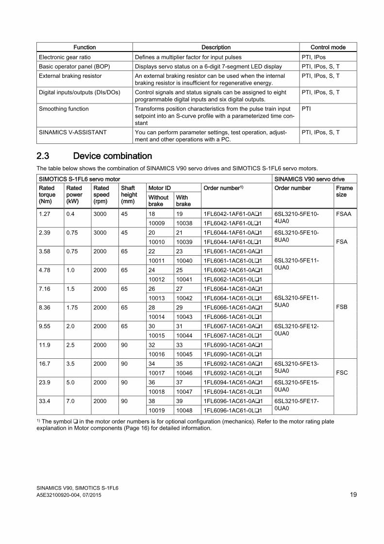
2.3 Device combination The table below shows the combination of SINAMICS V90 servo drives and SIMOTICS S-1FL6 servo motors.
SIMOTICS S-1FL6 servo motor SINAMICS V90 servo drive Rated torque (Nm)
Rated power (kW)
Rated speed (rpm)
Shaft height (mm)
Motor ID Order number1) Order number Frame size Without
brake With brake
1.27 0.4 3000 45 18 19 1FL6042-1AF61-0A❑1 6SL3210-5FE10-4UA0
FSAA 10009 10038 1FL6042-1AF61-0L❑1
2.39 0.75 3000 45 20 21 1FL6044-1AF61-0A❑1 6SL3210-5FE10-8UA0
FSA 10010 10039 1FL6044-1AF61-0L❑1
3.58 0.75 2000 65 22 23 1FL6061-1AC61-0A❑1 6SL3210-5FE11-0UA0
10011 10040 1FL6061-1AC61-0L❑1 4.78 1.0 2000 65 24 25 1FL6062-1AC61-0A❑1
10012 10041 1FL6062-1AC61-0L❑1 7.16 1.5 2000 65 26 27 1FL6064-1AC61-0A❑1
6SL3210-5FE11-5UA0
FSB
10013 10042 1FL6064-1AC61-0L❑1 8.36 1.75 2000 65 28 29 1FL6066-1AC61-0A❑1
10014 10043 1FL6066-1AC61-0L❑1 9.55 2.0 2000 65 30 31 1FL6067-1AC61-0A❑1 6SL3210-5FE12-
0UA0 10015 10044 1FL6067-1AC61-0L❑1 11.9 2.5 2000 90 32 33 1FL6090-1AC61-0A❑1
10016 10045 1FL6090-1AC61-0L❑1 16.7 3.5 2000 90 34 35 1FL6092-1AC61-0A❑1 6SL3210-5FE13-
5UA0 FSC 10017 10046 1FL6092-1AC61-0L❑1
23.9 5.0 2000 90 36 37 1FL6094-1AC61-0A❑1 6SL3210-5FE15-0UA0 10018 10047 1FL6094-1AC61-0L❑1
33.4 7.0 2000 90 38 39 1FL6096-1AC61-0A❑1 6SL3210-5FE17-0UA0 10019 10048 1FL6096-1AC61-0L❑1
1) The symbol ❑ in the motor order numbers is for optional configuration (mechanics). Refer to the motor rating plate explanation in Motor components (Page 16) for detailed information.
SINAMICS V90, SIMOTICS S-1FL6 20 A5E32100920-004, 07/2015
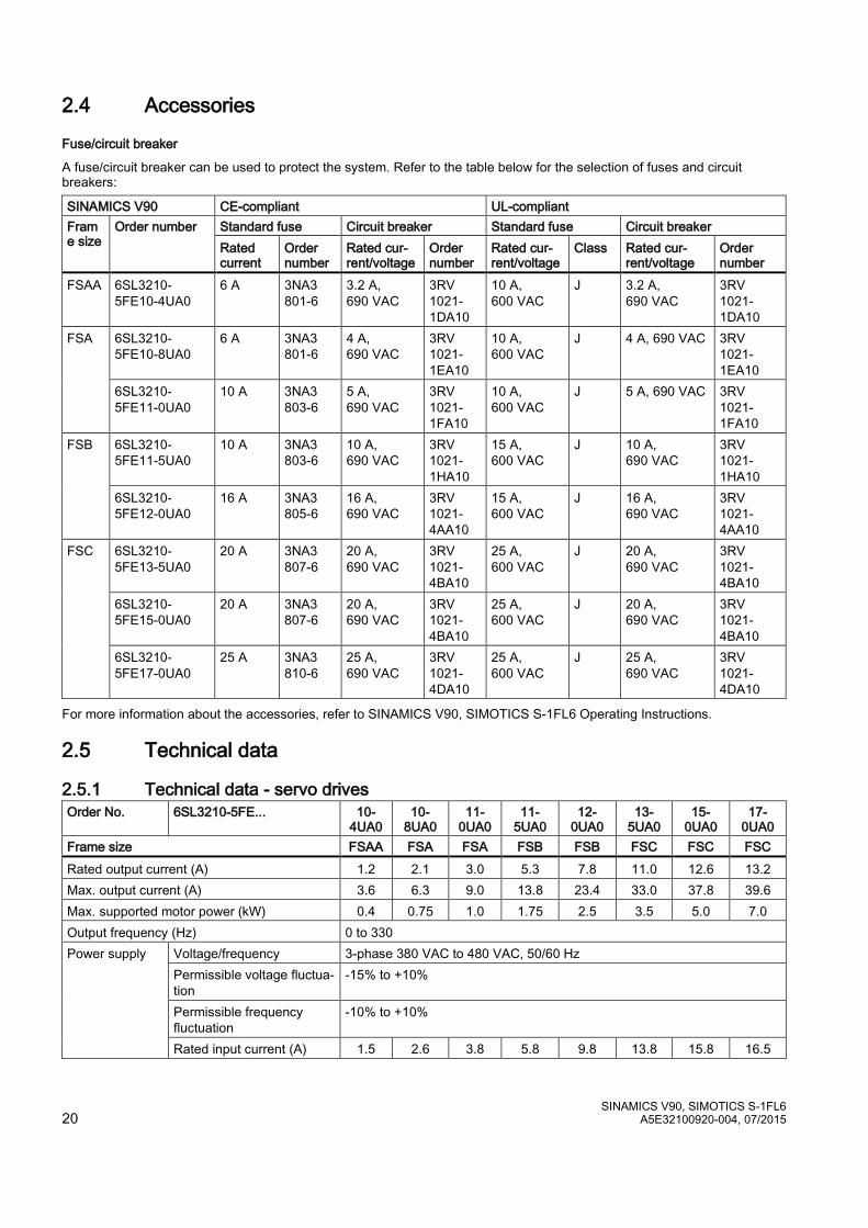
2.4 Accessories
Fuse/circuit breaker
A fuse/circuit breaker can be used to protect the system. Refer to the table below for the selection of fuses and circuit breakers:
SINAMICS V90 CE-compliant UL-compliant Frame size
Order number Standard fuse Circuit breaker Standard fuse Circuit breaker Rated current
Order number
Rated cur-rent/voltage
Order number
Rated cur-rent/voltage
Class Rated cur-rent/voltage
Order number
FSAA 6SL3210-5FE10-4UA0
6 A 3NA3 801-6
3.2 A, 690 VAC
3RV 1021-1DA10
10 A, 600 VAC
J 3.2 A, 690 VAC
3RV 1021-1DA10
FSA 6SL3210-5FE10-8UA0
6 A 3NA3 801-6
4 A, 690 VAC
3RV 1021-1EA10
10 A, 600 VAC
J 4 A, 690 VAC 3RV 1021-1EA10
6SL3210-5FE11-0UA0
10 A 3NA3 803-6
5 A, 690 VAC
3RV 1021-1FA10
10 A, 600 VAC
J 5 A, 690 VAC 3RV 1021-1FA10
FSB
6SL3210-5FE11-5UA0
10 A 3NA3 803-6
10 A, 690 VAC
3RV 1021-1HA10
15 A, 600 VAC
J 10 A, 690 VAC
3RV 1021-1HA10
6SL3210-5FE12-0UA0
16 A 3NA3 805-6
16 A, 690 VAC
3RV 1021-4AA10
15 A, 600 VAC
J 16 A, 690 VAC
3RV 1021-4AA10
FSC 6SL3210-5FE13-5UA0
20 A 3NA3 807-6
20 A, 690 VAC
3RV 1021-4BA10
25 A, 600 VAC
J 20 A, 690 VAC
3RV 1021-4BA10
6SL3210-5FE15-0UA0
20 A 3NA3 807-6
20 A, 690 VAC
3RV 1021-4BA10
25 A, 600 VAC
J 20 A, 690 VAC
3RV 1021-4BA10
6SL3210-5FE17-0UA0
25 A 3NA3 810-6
25 A, 690 VAC
3RV 1021-4DA10
25 A, 600 VAC
J 25 A, 690 VAC
3RV 1021-4DA10
For more information about the accessories, refer to SINAMICS V90, SIMOTICS S-1FL6 Operating Instructions.
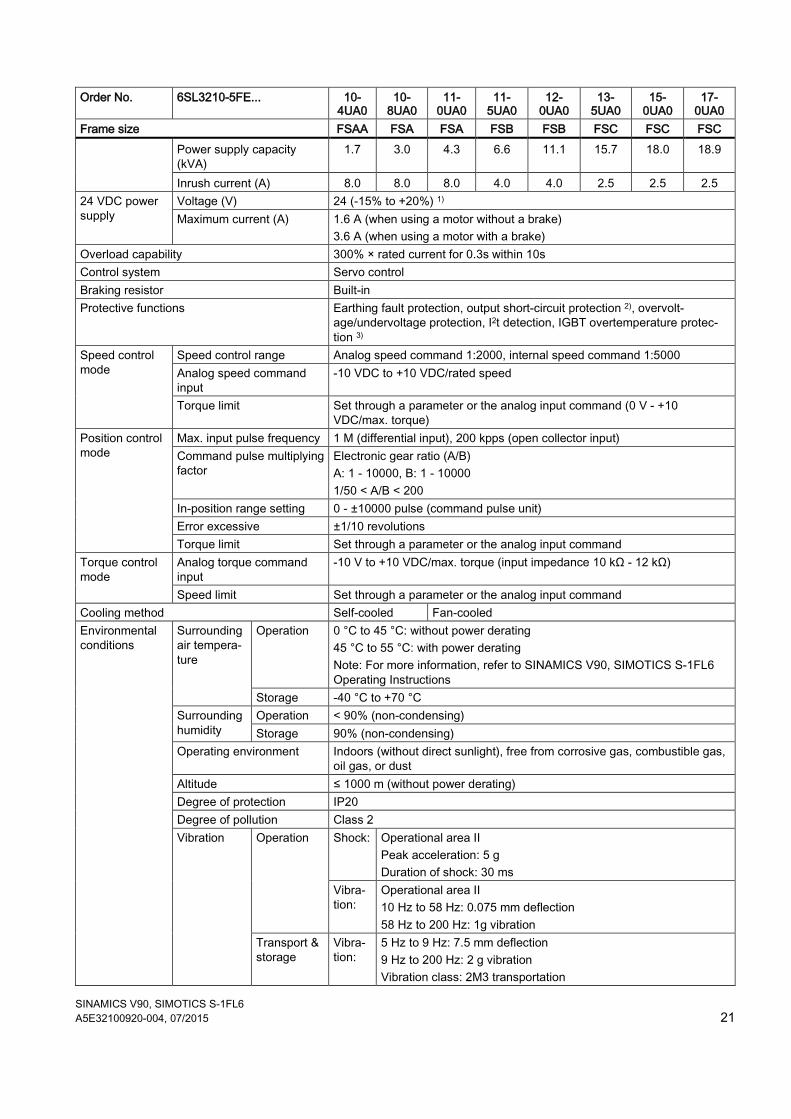
2.5 Technical data
2.5.1 Technical data - servo drives Order No. 6SL3210-5FE... 10-
4UA0 10-
8UA0 11-
0UA0 11-
5UA0 12-
0UA0 13-
5UA0 15-
0UA0 17-
0UA0 Frame size FSAA FSA FSA FSB FSB FSC FSC FSC Rated output current (A) 1.2 2.1 3.0 5.3 7.8 11.0 12.6 13.2 Max. output current (A) 3.6 6.3 9.0 13.8 23.4 33.0 37.8 39.6 Max. supported motor power (kW) 0.4 0.75 1.0 1.75 2.5 3.5 5.0 7.0 Output frequency (Hz) 0 to 330 Power supply Voltage/frequency 3-phase 380 VAC to 480 VAC, 50/60 Hz
Permissible voltage fluctua-tion
-15% to +10%
Permissible frequency fluctuation
-10% to +10%
Rated input current (A) 1.5 2.6 3.8 5.8 9.8 13.8 15.8 16.5
SINAMICS V90, SIMOTICS S-1FL6 A5E32100920-004, 07/2015 21
Order No. 6SL3210-5FE... 10-4UA0
10- 8UA0
11-0UA0
11-5UA0
12- 0UA0
13-5UA0
15-0UA0
17-0UA0
Frame size FSAA FSA FSA FSB FSB FSC FSC FSC Power supply capacity (kVA)
1.7 3.0 4.3 6.6 11.1 15.7 18.0 18.9
Inrush current (A) 8.0 8.0 8.0 4.0 4.0 2.5 2.5 2.5 24 VDC power supply
Voltage (V) 24 (-15% to +20%) 1) Maximum current (A) 1.6 A (when using a motor without a brake)
3.6 A (when using a motor with a brake) Overload capability 300% × rated current for 0.3s within 10s Control system Servo control Braking resistor Built-in Protective functions Earthing fault protection, output short-circuit protection 2), overvolt-
age/undervoltage protection, I2t detection, IGBT overtemperature protec-tion 3)
Speed control mode
Speed control range Analog speed command 1:2000, internal speed command 1:5000 Analog speed command input
-10 VDC to +10 VDC/rated speed
Torque limit Set through a parameter or the analog input command (0 V - +10 VDC/max. torque)
Position control mode
Max. input pulse frequency 1 M (differential input), 200 kpps (open collector input) Command pulse multiplying factor
Electronic gear ratio (A/B) A: 1 - 10000, B: 1 - 10000 1/50 < A/B < 200
In-position range setting 0 - ±10000 pulse (command pulse unit) Error excessive ±1/10 revolutions Torque limit Set through a parameter or the analog input command
Torque control mode
Analog torque command input
-10 V to +10 VDC/max. torque (input impedance 10 kΩ - 12 kΩ)
Speed limit Set through a parameter or the analog input command Cooling method Self-cooled Fan-cooled Environmental conditions
Surrounding air tempera-ture
Operation 0 °C to 45 °C: without power derating 45 °C to 55 °C: with power derating Note: For more information, refer to SINAMICS V90, SIMOTICS S-1FL6 Operating Instructions
Storage -40 °C to +70 °C Surrounding humidity
Operation < 90% (non-condensing) Storage 90% (non-condensing)
Operating environment Indoors (without direct sunlight), free from corrosive gas, combustible gas, oil gas, or dust
Altitude ≤ 1000 m (without power derating) Degree of protection IP20 Degree of pollution Class 2 Vibration Operation Shock: Operational area II
Peak acceleration: 5 g Duration of shock: 30 ms
Vibra-tion:
Operational area II 10 Hz to 58 Hz: 0.075 mm deflection 58 Hz to 200 Hz: 1g vibration
Transport & storage
Vibra-tion:
5 Hz to 9 Hz: 7.5 mm deflection 9 Hz to 200 Hz: 2 g vibration Vibration class: 2M3 transportation
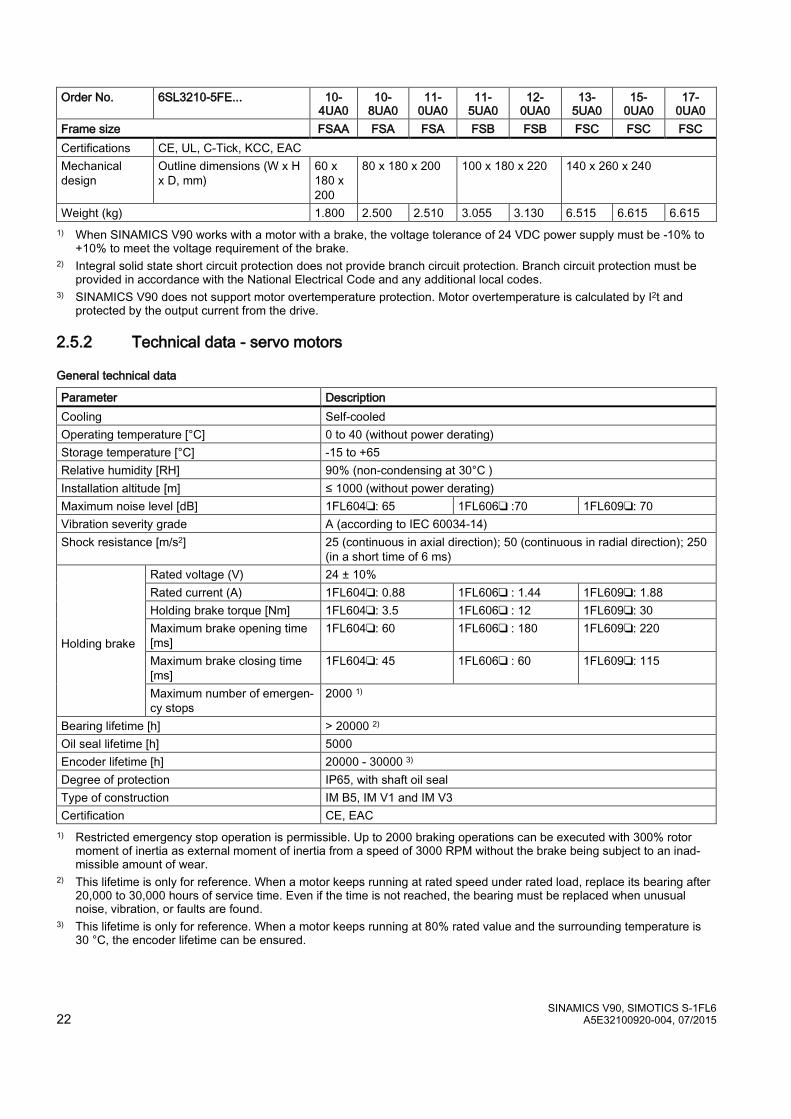
SINAMICS V90, SIMOTICS S-1FL6 22 A5E32100920-004, 07/2015
Order No. 6SL3210-5FE... 10-4UA0
10- 8UA0
11-0UA0
11-5UA0
12- 0UA0
13-5UA0
15-0UA0
17-0UA0
Frame size FSAA FSA FSA FSB FSB FSC FSC FSC Certifications CE, UL, C-Tick, KCC, EAC Mechanical design
Outline dimensions (W x H x D, mm)
60 x 180 x 200
80 x 180 x 200 100 x 180 x 220 140 x 260 x 240
Weight (kg) 1.800 2.500 2.510 3.055 3.130 6.515 6.615 6.615 1) When SINAMICS V90 works with a motor with a brake, the voltage tolerance of 24 VDC power supply must be -10% to
+10% to meet the voltage requirement of the brake. 2) Integral solid state short circuit protection does not provide branch circuit protection. Branch circuit protection must be
provided in accordance with the National Electrical Code and any additional local codes. 3) SINAMICS V90 does not support motor overtemperature protection. Motor overtemperature is calculated by I2t and
protected by the output current from the drive.
2.5.2 Technical data - servo motors
General technical data
Parameter Description Cooling Self-cooled Operating temperature [°C] 0 to 40 (without power derating) Storage temperature [°C] -15 to +65 Relative humidity [RH] 90% (non-condensing at 30°C ) Installation altitude [m] ≤ 1000 (without power derating) Maximum noise level [dB] 1FL604❑: 65 1FL606❑ :70 1FL609❑: 70 Vibration severity grade A (according to IEC 60034-14) Shock resistance [m/s2] 25 (continuous in axial direction); 50 (continuous in radial direction); 250
(in a short time of 6 ms) Holding brake
Rated voltage (V) 24 ± 10% Rated current (A) 1FL604❑: 0.88 1FL606❑ : 1.44 1FL609❑: 1.88 Holding brake torque [Nm] 1FL604❑: 3.5 1FL606❑ : 12 1FL609❑: 30 Maximum brake opening time [ms]
1FL604❑: 60 1FL606❑ : 180 1FL609❑: 220
Maximum brake closing time [ms]
1FL604❑: 45 1FL606❑ : 60 1FL609❑: 115
Maximum number of emergen-cy stops
2000 1)
Bearing lifetime [h] > 20000 2) Oil seal lifetime [h] 5000 Encoder lifetime [h] 20000 - 30000 3) Degree of protection IP65, with shaft oil seal Type of construction IM B5, IM V1 and IM V3 Certification CE, EAC 1) Restricted emergency stop operation is permissible. Up to 2000 braking operations can be executed with 300% rotor
moment of inertia as external moment of inertia from a speed of 3000 RPM without the brake being subject to an inad-missible amount of wear.
2) This lifetime is only for reference. When a motor keeps running at rated speed under rated load, replace its bearing after 20,000 to 30,000 hours of service time. Even if the time is not reached, the bearing must be replaced when unusual noise, vibration, or faults are found.
3) This lifetime is only for reference. When a motor keeps running at 80% rated value and the surrounding temperature is 30 °C, the encoder lifetime can be ensured.

SINAMICS V90, SIMOTICS S-1FL6 A5E32100920-004, 07/2015 23
Specific technical data
Order No. 1FL60... 42 44 61 62 64 66 67 90 92 94 96 Rated power [kW] 0.40 0.75 0.75 1.00 1.50 1.75 2.00 2.5 3.5 5.0 7.0 1) Rated torque [Nm] 1.27 2.39 3.58 4.78 7.16 8.36 9.55 11.9 16.7 23.9 33.4 Maximum torque [Nm]
3.8 7.2 10.7 14.3 21.5 25.1 28.7 35.7 50.0 70.0 90.0
Rated speed [rpm] 3000 2000 2000 Maximum speed [rpm]
4000 3000 3000 2500 2000
Rated frequency [Hz] 200 133 133 Rated current [A] 1.2 2.1 2.5 3.0 4.6 5.3 5.9 7.8 11.0 12.6 13.2 Maximum current [A] 3.6 6.3 7.5 9.0 13.8 15.9 17.7 23.4 33.0 36.9 35.6 Moment of inertia [10-
4 kgm2] 2.7 5.2 8.0 15.3 15.3 22.6 29.9 47.4 69.1 90.8 134.3
Moment of inertia (with brake) [10-4 kgm2]
3.2 5.7 9.1 16.4 16.4 23.7 31.0 56.3 77.9 99.7 143.2
Recommended load to motor inertia ratio
< 1000% < 500% < 500%
Weight of incremen-tal en-coder motor [kg]
With brake
4.6 6.4 8.6 11.3 11.3 14.0 16.6 21.3 25.7 30.3 39.1
Without brake
3.3 5.1 5.6 8.3 8.3 11.0 13.6 15.3 19.7 24.3 33.2
Weight of absolute encoder motor [kg]
With brake
4.4 6.2 8.3 11.0 11.0 13.6 16.3 20.9 25.3 29.9 38.7
Without brake
3.1 4.9 5.3 8.0 8.0 10.7 13.3 14.8 19.3 23.9 32.7
1) When the surrounding temperature is higher than 30 °C, the 1FL6096 motors with brake will have a power derating of 10%.
Note The data of rated torque, rated power, and maximum torque in the above table allow a tolerance of 10%.
Power derating
For deviating conditions (surrounding temperature > 40 °C or installation altitude > 1000 m above sea level) the permissible torque/power must be determined from the following table. Surrounding temperatures and installation altitudes are rounded off to 5 °C and 500 m respectively.
Power derating as a function of the installation altitude and ambient temperature
Installation altitude above sea level (m)
Surrounding temperature in °C < 30 30 to 40 45 50 55
1000 1.07 1.00 0.96 0.92 0.87 1500 1.04 0.97 0.93 0.89 0.84 2000 1.00 0.94 0.90 0.86 0.82 2500 0.96 0.90 0.86 0.83 0.78 3000 0.92 0.86 0.82 0.79 0.75 3500 0.88 0.82 0.79 0.75 0.71 4000 0.82 0.77 0.74 0.71 0.67
SINAMICS V90, SIMOTICS S-1FL6 24 A5E32100920-004, 07/2015
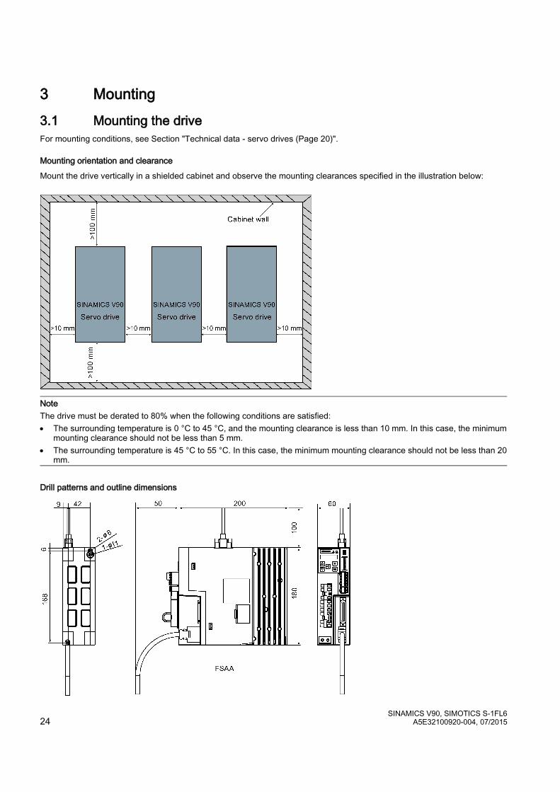
3 Mounting 3.1 Mounting the drive For mounting conditions, see Section "Technical data - servo drives (Page 20)".
Mounting orientation and clearance
Mount the drive vertically in a shielded cabinet and observe the mounting clearances specified in the illustration below:
Note The drive must be derated to 80% when the following conditions are satisfied: • The surrounding temperature is 0 °C to 45 °C, and the mounting clearance is less than 10 mm. In this case, the minimum
mounting clearance should not be less than 5 mm. • The surrounding temperature is 45 °C to 55 °C. In this case, the minimum mounting clearance should not be less than 20
mm.
Drill patterns and outline dimensions
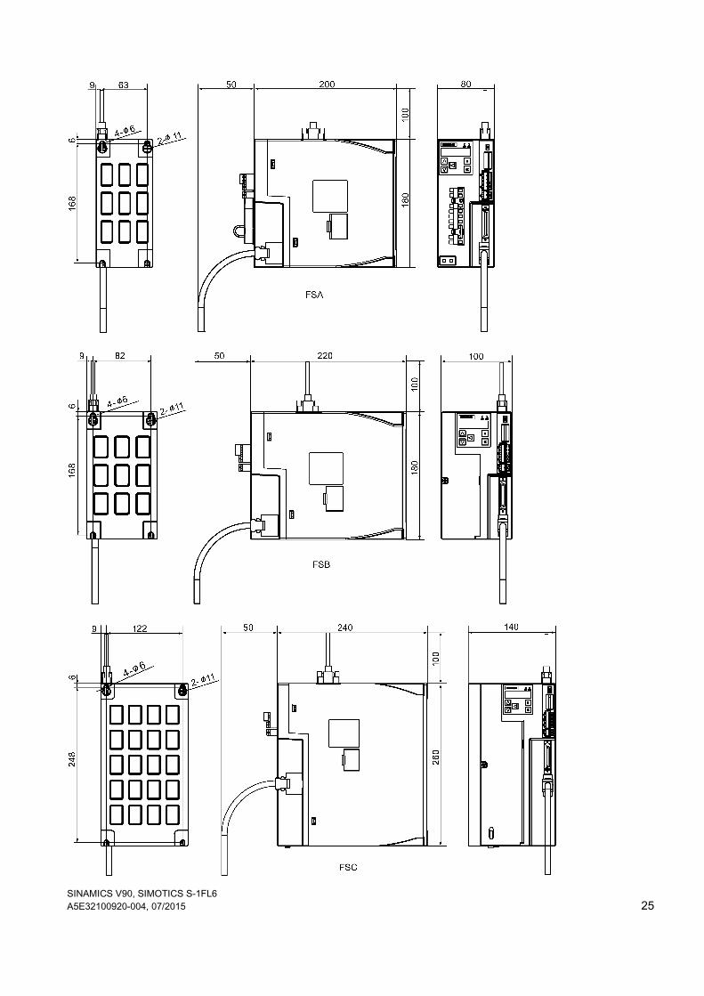
SINAMICS V90, SIMOTICS S-1FL6 A5E32100920-004, 07/2015 25
SINAMICS V90, SIMOTICS S-1FL6 26 A5E32100920-004, 07/2015
Mounting the drive
Use two M5 screws to mount the FSAA drive and four M5 screws to mount the FSA, FSB, and FSC drives. The recommended tightening torque is 2.0 Nm.
Note Taking EMC factors into account, you are recommended to mount the drive in a shielded cabinet.
3.2 Mounting the motor For mounting conditions, see Technical data - servo motors (Page 22).
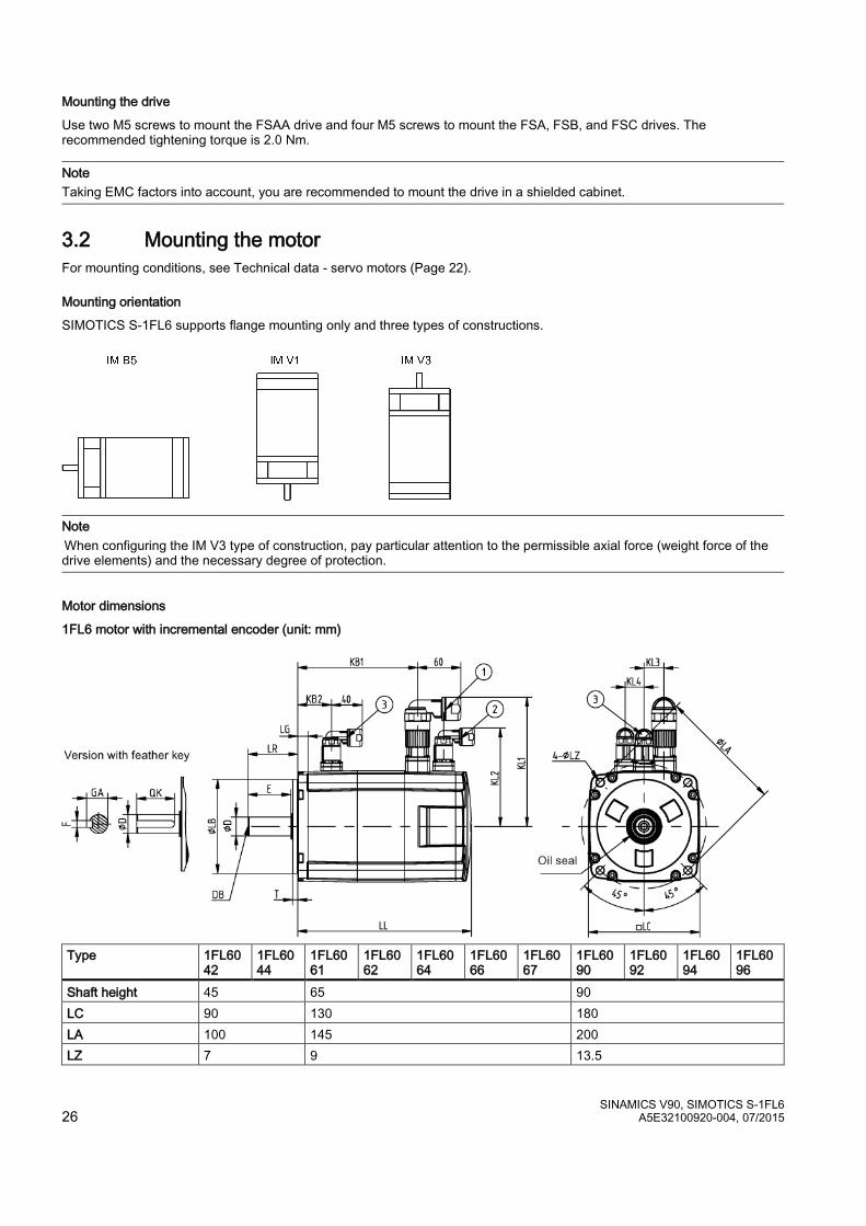
Mounting orientation
SIMOTICS S-1FL6 supports flange mounting only and three types of constructions.
Note When configuring the IM V3 type of construction, pay particular attention to the permissible axial force (weight force of the drive elements) and the necessary degree of protection.
Motor dimensions
1FL6 motor with incremental encoder (unit: mm)
Type 1FL60
42 1FL6044
1FL6061
1FL6062
1FL6064
1FL6066
1FL6067
1FL6090
1FL6092
1FL6094
1FL6096
Shaft height 45 65 90 LC 90 130 180 LA 100 145 200 LZ 7 9 13.5
SINAMICS V90, SIMOTICS S-1FL6 A5E32100920-004, 07/2015 27
Type 1FL6042
1FL6044
1FL6061
1FL6062
1FL6064
1FL6066
1FL6067
1FL6090
1FL6092
1FL6094
1FL6096
LB 80 110 114.3 LR 35 58 80 T 4 6 3 LG 10 12 18 D 19 22 35 DB M6x16 M8x16 M12x25 E 30 50 75 QK 25 44 60 GA 21.5 25 38 F 6-0.03 8-0.036 10-0.036 Without brake
LL 154.5 201.5 148 181 181 214 247 189.5 211.5 237.5 289.5 KB1 93.5 140.5 85.5 118.5 118.5 151.5 184.5 140 162 188 240 KB2 - - -
With brake
LL 201 248 202.5 235.5 235.5 268.5 301.5 255 281 307 359 KB1 140 187 140 173 173 206 239 206 232 258 310 KB2 31.5 39.5 44.5
KL1 129 151 177 KL2 92 115 149 KL3 - 23 34 KL4 - 22 34
• ①−Power cable connector, ②−Incremental encoder cable connector, ③−Brake cable connector. These connectors should be ordered separately. For the ordering information refer to Operating Instructions.
• The boundary dimension of encoder connector−② and brake connector−③ are the same. • Shaft height 90 mm motor has two M8 screws hole for eyebolts
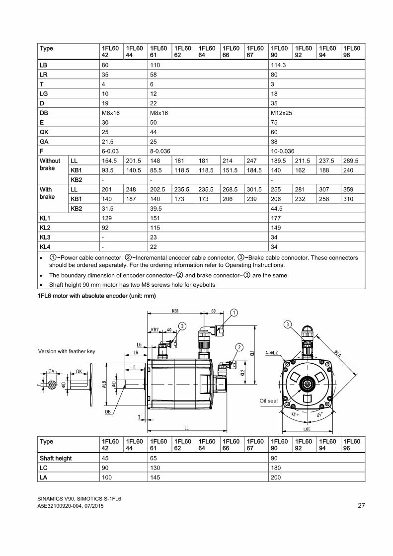
1FL6 motor with absolute encoder (unit: mm)
Type 1FL60
42 1FL6044
1FL6061
1FL6062
1FL6064
1FL6066
1FL6067
1FL6090
1FL6092
1FL6094
1FL6096
Shaft height 45 65 90 LC 90 130 180 LA 100 145 200

SINAMICS V90, SIMOTICS S-1FL6 28 A5E32100920-004, 07/2015
Type 1FL6042
1FL6044
1FL6061
1FL6062
1FL6064
1FL6066
1FL6067
1FL6090
1FL6092
1FL6094
1FL6096
LZ 7 9 13.5 LB 80 110 114.3 LR 35 58 80 T 4 6 3 LG 10 12 18 D 19 22 35 DB M6x16 M8x16 M12x25 E 30 50 75 QK 25 44 60 GA 21.5 25 38 F 6-0.03 8-0.036 10-0.036 Without brake
LL 157 204 151 184 184 217 250 197 223 249 301 KB1 100 147 92 125 125 158 191 135 161 187 239 KB2 - - -
With brake
LL 203.5 250.5 205.5 238.5 238.5 271.5 304.5 263 289 315 367 KB1 147 194 147 180 180 213 246 201 227 253 305 KB2 31.5 39.5 44.5
KL1 129 151 177 KL2 60 60 60 KL3 - - - KL4 - - -
• ①-Power cable connector, ②−Absolute encoder cable connector, ③−Brake cable connector. These connectors should be ordered separately. For the ordering information refer to Operating Instructions.
• The boundary dimension of encoder connector−② and brake connector−③ are the same. • Shaft height 90 mm motor has two M8 screws hole for eyebolts
Mounting the motor
WARNING Personal injury and material damage Some motors, especially the 1FL609❑ are heavy. The excessive weight of the motor should be considered and any necessary assistance required for mounting should be sought. Otherwise, the motor can fall down during mounting. This can result in serious personal injury or material damage.
NOTICE Damage to the motor If the liquid enters the motor, the motor may be damaged During motor installation or operation, make sure that no liquid (water, oil, etc.) can penetrate into the motor. Besides, when installing the motor horizontally, make sure that the cable outlet faces downward to protect the motor from ingress of oil or water.
Note Using the eyebolts The 1FL609❑ motor (90 mm shaft height) has two M8 screw holes for screwing in two eyebolts. Lift the 1FL609❑ motor only at the eyebolts. Eyebolts that have been screwed in must be either tightened or removed after mounting.
SINAMICS V90, SIMOTICS S-1FL6 A5E32100920-004, 07/2015 29
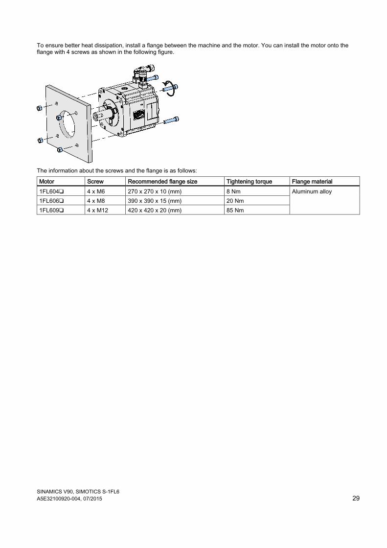
To ensure better heat dissipation, install a flange between the machine and the motor. You can install the motor onto the flange with 4 screws as shown in the following figure.
The information about the screws and the flange is as follows:
Motor Screw Recommended flange size Tightening torque Flange material 1FL604❑ 4 x M6 270 x 270 x 10 (mm) 8 Nm Aluminum alloy 1FL606❑ 4 x M8 390 x 390 x 15 (mm) 20 Nm 1FL609❑ 4 x M12 420 x 420 x 20 (mm) 85 Nm
SINAMICS V90, SIMOTICS S-1FL6 30 A5E32100920-004, 07/2015
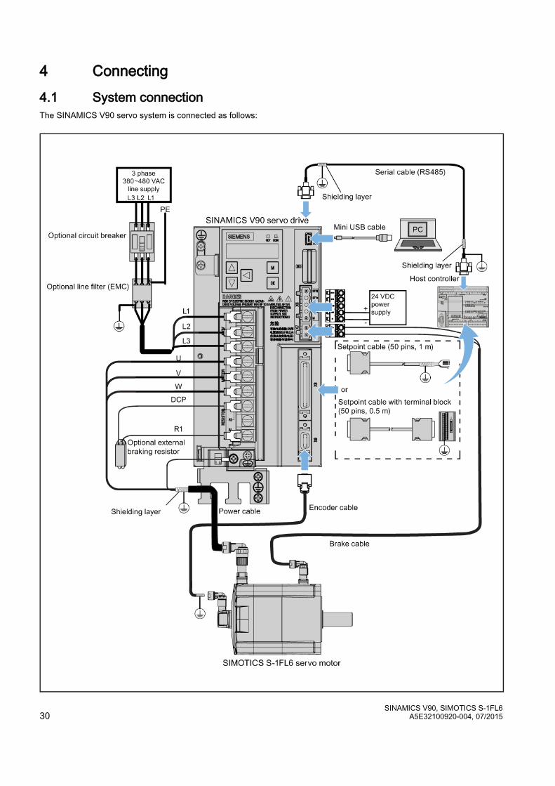
4 Connecting 4.1 System connection The SINAMICS V90 servo system is connected as follows:

SINAMICS V90, SIMOTICS S-1FL6 A5E32100920-004, 07/2015 31
NOTICE Important wiring information In order to meet EMC requirements, all cables must be shielded cables. The cable shields of shielded twisted-pair cables should be connected to the shielding plate or the cable clamp of the servo drive.
NOTICE Drive damage caused by short-circuiting between the shielding wire and the pins on the connectors The shielding wire may inadvertently be short-circuited to the pins on the to-be-assembled encoder connector and setpoint cable connector. This can cause damage to the drive. Exercise caution when connecting the shielding cable to the connectors. You can see the assembly methods in chapter "Assembly of cable terminals on the drive side" in SINAMICS V90, SIMOTICS S-1FL6 Operating Instructions for reference.
Note The mini-USB interface of the SINAMICS V90 is used for fast commissioning and diagnostics with SINAMICS V-ASSISTANT installed in the PC. Do not use it for long monitoring.
Connecting the cable shields with the shielding plate
To achieve EMC-compliant installation of the drive, use the shielding plate that is shipped with the drive to connect the cable shields. See the following example for steps to connect cable shields with the shielding plate:
SINAMICS V90, SIMOTICS S-1FL6 32 A5E32100920-004, 07/2015
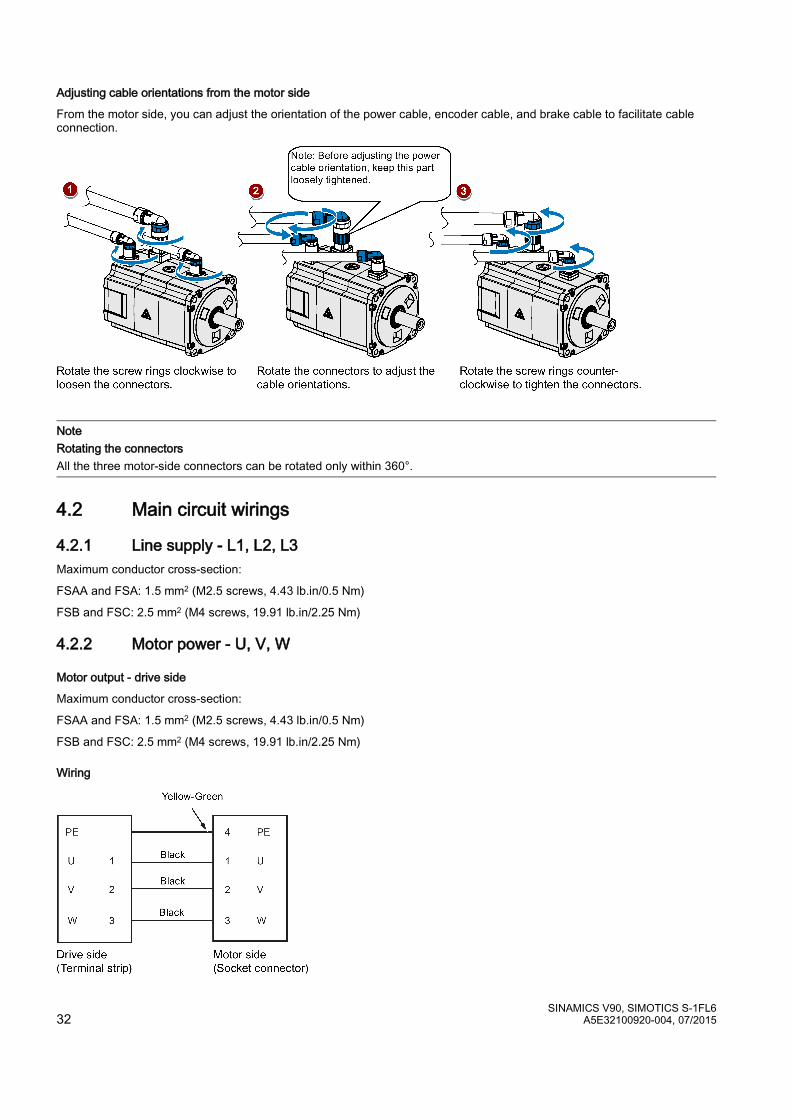
Adjusting cable orientations from the motor side
From the motor side, you can adjust the orientation of the power cable, encoder cable, and brake cable to facilitate cable connection.
Note Rotating the connectors All the three motor-side connectors can be rotated only within 360°.
4.2 Main circuit wirings
4.2.1 Line supply - L1, L2, L3 Maximum conductor cross-section:
FSAA and FSA: 1.5 mm2 (M2.5 screws, 4.43 lb.in/0.5 Nm)
FSB and FSC: 2.5 mm2 (M4 screws, 19.91 lb.in/2.25 Nm)
4.2.2 Motor power - U, V, W
Motor output - drive side
Maximum conductor cross-section:
FSAA and FSA: 1.5 mm2 (M2.5 screws, 4.43 lb.in/0.5 Nm)
FSB and FSC: 2.5 mm2 (M4 screws, 19.91 lb.in/2.25 Nm)
Wiring

SINAMICS V90, SIMOTICS S-1FL6 A5E32100920-004, 07/2015 33
Plugging the motor power cable (FSAA and FSA)
Note The FSB and FSC servo drives are equipped with barrier terminals for motor power connection. You can fix the motor power cable using the M4 screws on the servo drives.
4.3 Control/Status interface - X8
Interface definition
Signal type Pin No.
Signal Description Pin No.
Signal Description
Type: 50-pin MDR socket Pulse train inputs (PTI)/Pulse train encoder outputs (PTO)
1, 2, 26, 27
Position setpoint with pulse train input. Exclusive for high-speed 5 V differential pulse train input (RS485) Maximum frequency: 1 MHz Signal transmission of this channel has better noise immunity.
36, 37, 38, 39
Position setpoint with pulse train input. 24 V single end pulse train input Maximum frequency: 200 kHz
15, 16, 40, 41
Encoder emulation pulse output with high-speed 5 V differential signals (A+/A-, B+/B-)
42, 43
Encoder Zero phase pulse output with high-speed 5 V differential signals
17 Encoder Zero phase pulse output with open collector
1 PTIA_D+ High-speed 5 V differential pulse train input A (+)
15 PTOA+ High-speed 5 V differential pulse train encoder output A (+)
2 PTIA_D- High-speed 5 V differential pulse train input A (-)
16 PTOA- High-speed 5 V differential pulse train encoder output A (-)
26 PTIB_D+ High-speed 5 V differential pulse train input B (+)
40 PTOB+ High-speed 5 V differential pulse train encoder output B (+)
27 PTIB_D- High-speed 5 V differential pulse train input B (-)
41 PTOB- High-speed 5 V differential pulse train encoder output B (-)
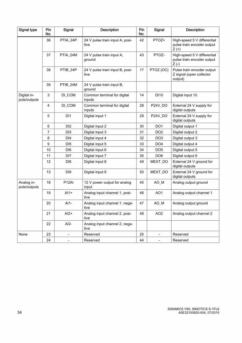
SINAMICS V90, SIMOTICS S-1FL6 34 A5E32100920-004, 07/2015
Signal type Pin No.
Signal Description Pin No.
Signal Description
36 PTIA_24P 24 V pulse train input A, posi-tive
42 PTOZ+ High-speed 5 V differential pulse train encoder output Z (+)
37 PTIA_24M 24 V pulse train input A, ground
43 PTOZ- High-speed 5 V differential pulse train encoder output Z (-)
38 PTIB_24P 24 V pulse train input B, posi-tive
17 PTOZ (OC) Pulse train encoder output Z signal (open collector output)
39 PTIB_24M 24 V pulse train input B, ground
Digital in-puts/outputs
3 DI_COM Common terminal for digital inputs
14 DI10 Digital input 10
4 DI_COM Common terminal for digital inputs
28 P24V_DO External 24 V supply for digital outputs
5 DI1 Digital input 1 29 P24V_DO External 24 V supply for digital outputs
6 DI2 Digital input 2 30 DO1 Digital output 1 7 DI3 Digital input 3 31 DO2 Digital output 2 8 DI4 Digital input 4 32 DO3 Digital output 3 9 DI5 Digital input 5 33 DO4 Digital output 4 10 DI6 Digital input 6 34 DO5 Digital output 5 11 DI7 Digital input 7 35 DO6 Digital output 6 12 DI8 Digital input 8 49 MEXT_DO External 24 V ground for
digital outputs 13 DI9 Digital input 9 50 MEXT_DO External 24 V ground for
digital outputs Analog in-puts/outputs
18 P12AI 12 V power output for analog input
45 AO_M Analog output ground
19 AI1+ Analog input channel 1, posi-tive
46 AO1 Analog output channel 1
20 AI1- Analog input channel 1, nega-tive
47 AO_M Analog output ground
21 AI2+ Analog input channel 2, posi-tive
48 AO2 Analog output channel 2
22 AI2- Analog input channel 2, nega-tive
None 23 - Reserved 25 - Reserved 24 - Reserved 44 - Reserved
SINAMICS V90, SIMOTICS S-1FL6 A5E32100920-004, 07/2015 35
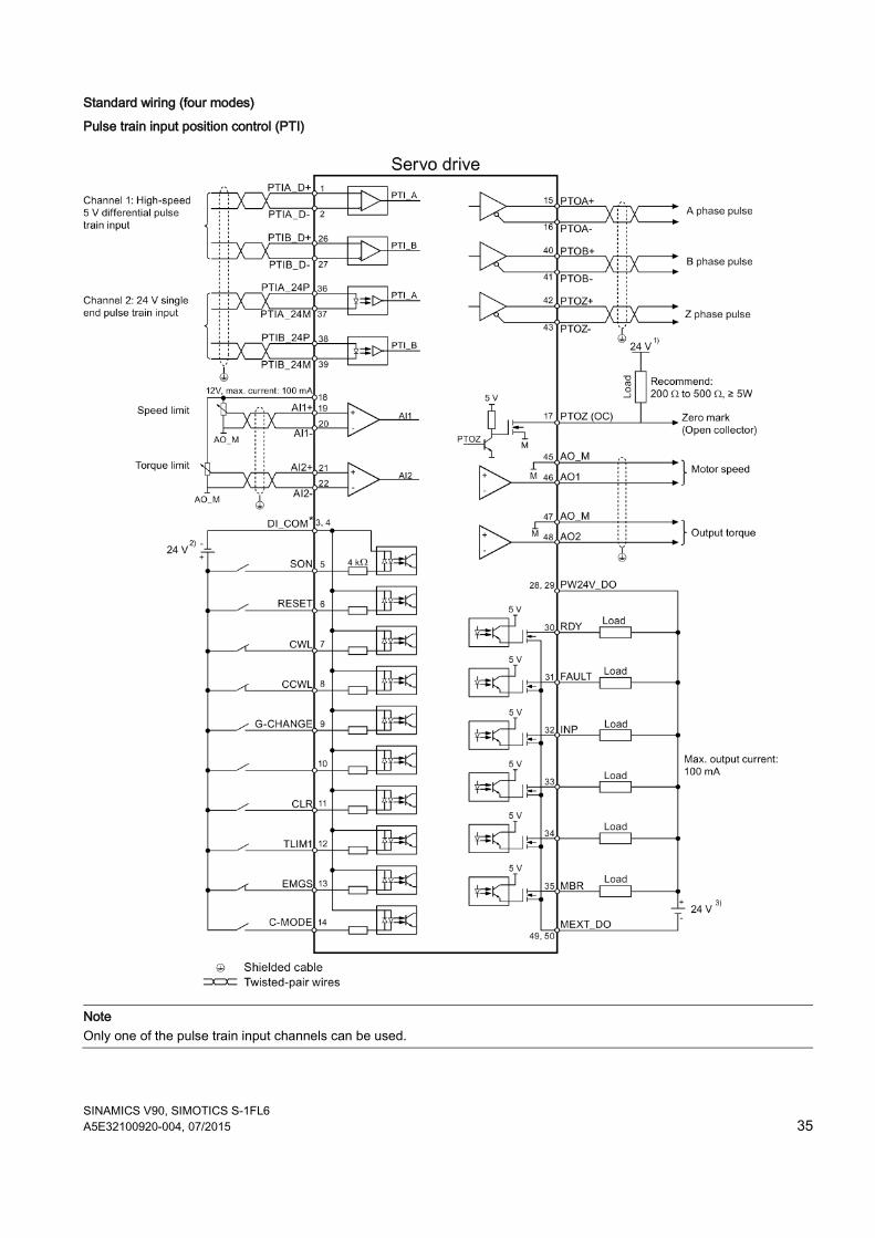
Standard wiring (four modes)
Pulse train input position control (PTI)
Note Only one of the pulse train input channels can be used.

SINAMICS V90, SIMOTICS S-1FL6 36 A5E32100920-004, 07/2015
Internal position control (IPos)
SINAMICS V90, SIMOTICS S-1FL6 A5E32100920-004, 07/2015 37
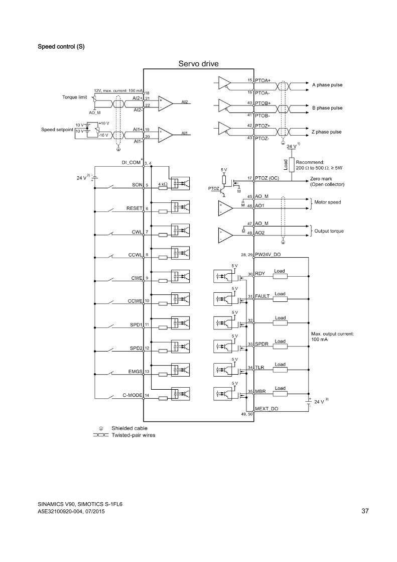
Speed control (S)
SINAMICS V90, SIMOTICS S-1FL6 38 A5E32100920-004, 07/2015
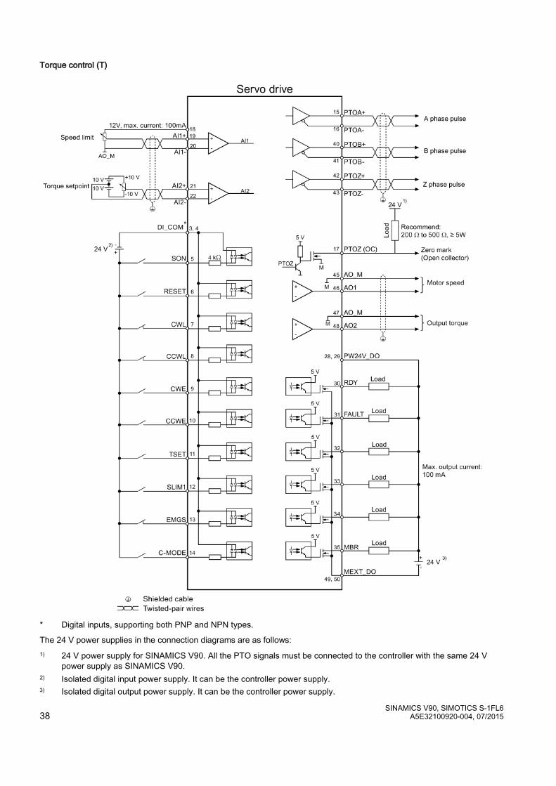
Torque control (T)
* Digital inputs, supporting both PNP and NPN types.
The 24 V power supplies in the connection diagrams are as follows: 1) 24 V power supply for SINAMICS V90. All the PTO signals must be connected to the controller with the same 24 V
power supply as SINAMICS V90. 2) Isolated digital input power supply. It can be the controller power supply. 3) Isolated digital output power supply. It can be the controller power supply.

SINAMICS V90, SIMOTICS S-1FL6 A5E32100920-004, 07/2015 39
4.4 24 V power supply/STO - X6 The pin assignment for the X6 interface is shown as follows:
Interface Signal name Description
STO 1 Safe torque off channel 1 STO + Specific power supply for safe torque off STO 2 Safe torque off channel 2 +24 V Power supply, 24 VDC
M Power supply, 0 VDC Maximum conductor cross-section: 1.5 mm2
Wiring
WARNING Material damages and personal injuries by the drop of a hanging axis When the servo system is used as a hanging axis, the axis will drop if the positive and negative poles of the 24 V power supply are connected inversely. Unexpected drop of the hanging axis may cause material damages and personal injuries. Make sure that the 24 V power supply is correctly connected.
WARNING Material damages and personal injuries by the drop of a hanging axis It is not allowed to use the STO with a hanging axis because the axis may drop. Unexpected drop of the hanging axis may cause material damages and personal injuries.
Note Using the STO function The STO1, STO+ and STO2 are short connected at the factory setting. When the STO function is to be used, you must remove the short-circuit stick before connecting the STO interfaces. If you do not need to use it any more, you must reinsert the short-circuit stick; otherwise, the motor will not run. For detailed information about the STO function, refer to chapter "Safety Integrated basic functions" of SINAMICS V90, SIMOTICS S-1FL6 Operating Instructions.
SINAMICS V90, SIMOTICS S-1FL6 40 A5E32100920-004, 07/2015
Plugging the 24 V power supply and STO cables
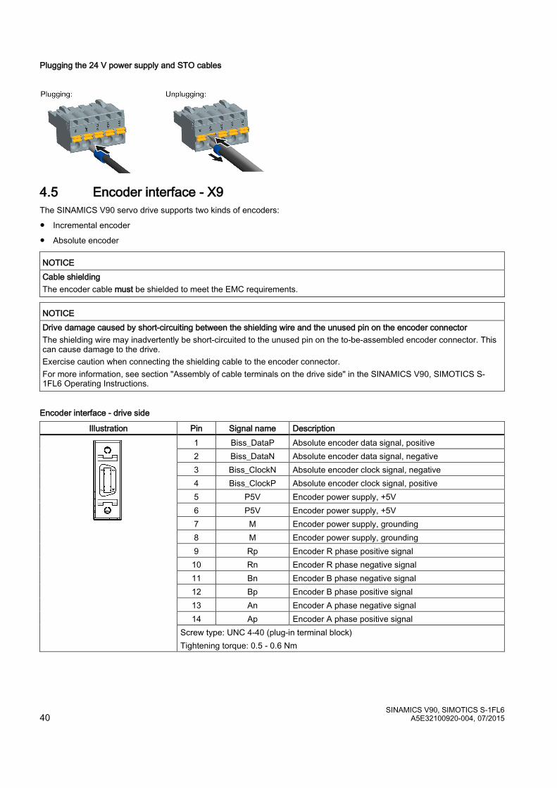
4.5 Encoder interface - X9 The SINAMICS V90 servo drive supports two kinds of encoders:
● Incremental encoder
● Absolute encoder
NOTICE Cable shielding The encoder cable must be shielded to meet the EMC requirements.
NOTICE Drive damage caused by short-circuiting between the shielding wire and the unused pin on the encoder connector The shielding wire may inadvertently be short-circuited to the unused pin on the to-be-assembled encoder connector. This can cause damage to the drive. Exercise caution when connecting the shielding cable to the encoder connector. For more information, see section "Assembly of cable terminals on the drive side" in the SINAMICS V90, SIMOTICS S-1FL6 Operating Instructions.
Encoder interface - drive side
Illustration Pin Signal name Description
1 Biss_DataP Absolute encoder data signal, positive 2 Biss_DataN Absolute encoder data signal, negative 3 Biss_ClockN Absolute encoder clock signal, negative 4 Biss_ClockP Absolute encoder clock signal, positive 5 P5V Encoder power supply, +5V 6 P5V Encoder power supply, +5V 7 M Encoder power supply, grounding 8 M Encoder power supply, grounding 9 Rp Encoder R phase positive signal 10 Rn Encoder R phase negative signal 11 Bn Encoder B phase negative signal 12 Bp Encoder B phase positive signal 13 An Encoder A phase negative signal 14 Ap Encoder A phase positive signal
Screw type: UNC 4-40 (plug-in terminal block) Tightening torque: 0.5 - 0.6 Nm
SINAMICS V90, SIMOTICS S-1FL6 A5E32100920-004, 07/2015 41
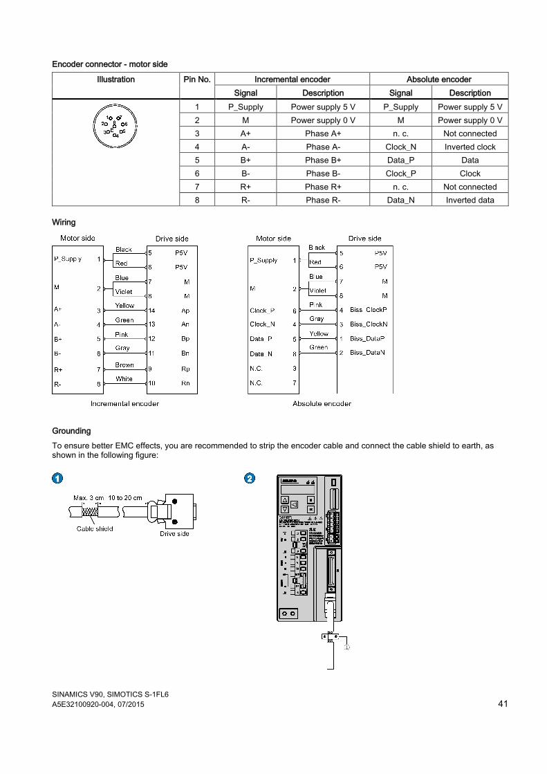
Encoder connector - motor side
Illustration Pin No. Incremental encoder Absolute encoder Signal Description Signal Description
1 P_Supply Power supply 5 V P_Supply Power supply 5 V 2 M Power supply 0 V M Power supply 0 V 3 A+ Phase A+ n. c. Not connected 4 A- Phase A- Clock_N Inverted clock 5 B+ Phase B+ Data_P Data 6 B- Phase B- Clock_P Clock 7 R+ Phase R+ n. c. Not connected 8 R- Phase R- Data_N Inverted data
Wiring
Grounding
To ensure better EMC effects, you are recommended to strip the encoder cable and connect the cable shield to earth, as shown in the following figure:
SINAMICS V90, SIMOTICS S-1FL6 42 A5E32100920-004, 07/2015
4.6 External braking resistor - DCP, R1 The SINAMICS V90 has been designed with an internal braking resistor to absorb regenerative energy from the motor. When the internal braking resistor cannot meet the braking requirements (e.g. the alarm A52901 is generated), you can connect an external braking resistor. For the selection of braking resistors, refer to chapter accessories of the SINAMICS V90, SIMOTICS S-1FL6 Operating Instructions.
Connecting an external braking resistor
WARNING Damage to the drive Before connecting an external resistor to DCP and R1, remove the short-circuit stick on the connectors. Otherwise, the drive may be damaged.
For the connection of the external braking resistor, refer to Connecting (Page 30).
4.7 Motor holding brake - X7 You can connect the SINAMICS V90 servo drive to a servo motor with brake to use the function of motor holding brake.
4.8 RS485 interface - X12 The SINAMICS V90 servo drives support communication with the PLCs through the RS485 interface over the USS or MODBUS protocol.
Pin assignment
Illustration Pin Signal name Description
1 Reserved Do not use 2 Reserved Do not use 3 RS485+ RS485 differential signal 4 Reserved Do not use 5 M Ground to internal 3.3 V 6 3.3 V 3.3 V power supply for internal signal 7 Reserved Do not use 8 RS485- RS485 differential signal 9 Reserved Do not use
Type: 9-pin, Sub-D, female
SINAMICS V90, SIMOTICS S-1FL6 A5E32100920-004, 07/2015 43
5 Commissioning Prior to commissioning, read "Introduction to the BOP (Page 44)" for more information about the BOP operations. In case of any faults or alarms during commissioning, refer to Chapter "Diagnostics (Page 87)" for detailed description.
CAUTION Carefully read the safety instructions Before your commissioning or operation, read Section "General safety instructions (Page 3)" and the safety instructions on "Commissioning/Operation" in Section "Auto hotspot" carefully. Failure to observe the instructions may cause serious effects.
WARNING Material damages and personal injuries by the drop of a hanging axis When the servo system is used as a hanging axis, the axis will drop if the positive and negative poles of the 24 V power supply are connected inversely. Unexpected drop of the hanging axis may cause material damages and personal injuries. Before commissioning, a crosstie must be used to hold the hanging axis in prevention of an unexpected drop. In addition, make sure that the 24 V power supply is correctly connected.
NOTICE Plugging or unplugging the SD card will cause startup failure. Do not plug or unplug the SD card during startup; otherwise, the drive will fail to start up.
NOTICE Firmware damage due to drive power-off during data transfer Switching off the 24 VDC power supply for the drive during data transfer from the SD card to the drive can cause damage to the drive firmware. • Do not switch off the drive power supply when the data transfer from the SD card to the drive is in process.
NOTICE Existing setting data may be overwritten by the setting data on the SD card during startup. • When a drive is switched on with an SD card containing user setting data, the existing setting data on the drive will be
overwritten. • When a drive is switched on with an SD card containing no user setting data, the drive will automatically save the
existing user setting data onto the SD card. Before starting up the drive with an SD card, check whether the SD card contains user setting data. Otherwise, the existing data on the drive may be overwritten.
Engineering tool - SINAMICS V-ASSISTANT
You can use the engineering tool SINAMICS V-ASSISTANT to perform the trial operation.
SINAMICS V-ASSISTANT is a software tool that can be installed on a PC and runs on the Windows operating system. It communicates with the SINAMICS V90 servo drive with a USB cable. With SINAMICS V-ASSISTANT, you can change drive parameters and monitor drive working states in online mode.
For more information, refer to SINAMICS V-ASSISTANT Online Help. You can search and download SINAMICS V-ASSISTANT from Technical support website (http://support.automation.siemens.com).
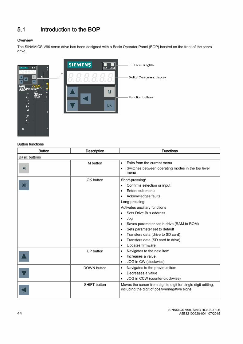
SINAMICS V90, SIMOTICS S-1FL6 44 A5E32100920-004, 07/2015
5.1 Introduction to the BOP
Overview
The SINAMICS V90 servo drive has been designed with a Basic Operator Panel (BOP) located on the front of the servo drive.
Button functions
Button Description Functions Basic buttons
M button • Exits from the current menu • Switches between operating modes in the top level
menu
OK button Short-pressing: • Confirms selection or input • Enters sub menu • Acknowledges faults Long-pressing: Activates auxiliary functions • Sets Drive Bus address • Jog • Saves parameter set in drive (RAM to ROM) • Sets parameter set to default • Transfers data (drive to SD card) • Transfers data (SD card to drive) • Updates firmware
UP button • Navigates to the next item • Increases a value • JOG in CW (clockwise)
DOWN button • Navigates to the previous item • Decreases a value • JOG in CCW (counter-clockwise)
SHIFT button Moves the cursor from digit to digit for single digit editing, including the digit of positive/negative signs
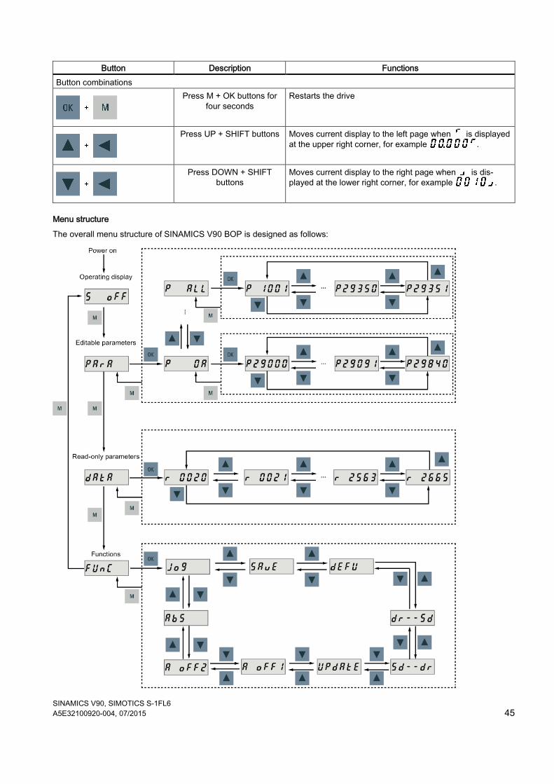
SINAMICS V90, SIMOTICS S-1FL6 A5E32100920-004, 07/2015 45
Button Description Functions Button combinations
Press M + OK buttons for four seconds
Restarts the drive
Press UP + SHIFT buttons Moves current display to the left page when is displayed at the upper right corner, for example .
Press DOWN + SHIFT buttons
Moves current display to the right page when is dis-played at the lower right corner, for example .
Menu structure
The overall menu structure of SINAMICS V90 BOP is designed as follows:
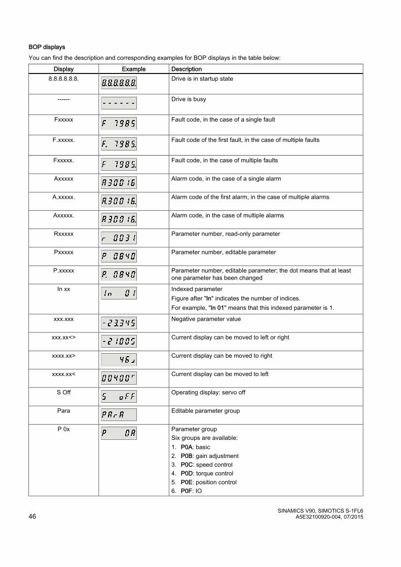
SINAMICS V90, SIMOTICS S-1FL6 46 A5E32100920-004, 07/2015
BOP displays
You can find the description and corresponding examples for BOP displays in the table below:
Display Example Description 8.8.8.8.8.8.
Drive is in startup state
------
Drive is busy
Fxxxxx
Fault code, in the case of a single fault
F.xxxxx.
Fault code of the first fault, in the case of multiple faults
Fxxxxx.
Fault code, in the case of multiple faults
Axxxxx
Alarm code, in the case of a single alarm
A.xxxxx.
Alarm code of the first alarm, in the case of multiple alarms
Axxxxx.
Alarm code, in the case of multiple alarms
Rxxxxx
Parameter number, read-only parameter
Pxxxxx
Parameter number, editable parameter
P.xxxxx
Parameter number, editable parameter; the dot means that at least one parameter has been changed
In xx
Indexed parameter Figure after "In" indicates the number of indices. For example, "In 01" means that this indexed parameter is 1.
xxx.xxx
Negative parameter value
xxx.xx<>
Current display can be moved to left or right
xxxx.xx>
Current display can be moved to right
xxxx.xx<
Current display can be moved to left
S Off
Operating display: servo off
Para
Editable parameter group
P 0x
Parameter group Six groups are available: 1. P0A: basic 2. P0B: gain adjustment 3. P0C: speed control 4. P0D: torque control 5. P0E: position control 6. P0F: IO
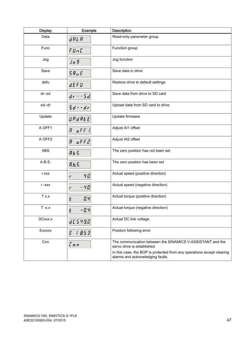
SINAMICS V90, SIMOTICS S-1FL6 A5E32100920-004, 07/2015 47
Display Example Description Data
Read-only parameter group
Func
Function group
Jog
Jog function
Save
Save data in drive
defu
Restore drive to default settings
dr--sd
Save data from drive to SD card
sd--dr
Upload data from SD card to drive
Update
Update firmware
A OFF1
Adjust AI1 offset
A OFF2
Adjust AI2 offset
ABS
The zero position has not been set
A.B.S.
The zero position has been set
r xxx
Actual speed (positive direction)
r -xxx
Actual speed (negative direction)
T x.x
Actual torque (positive direction)
T -x.x
Actual torque (negative direction)
DCxxx.x
Actual DC link voltage
Exxxxx
Position following error
Con
The communication between the SINAMICS V-ASSISTANT and the servo drive is established. In this case, the BOP is protected from any operations except clearing alarms and acknowledging faults.
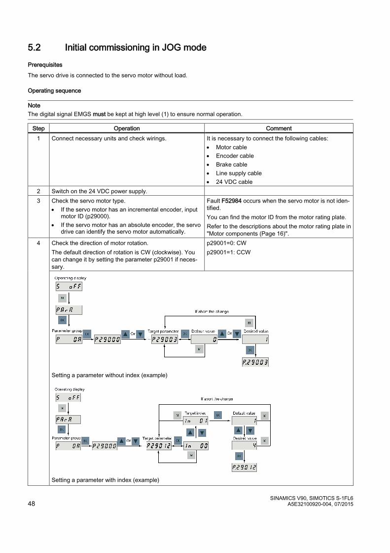
SINAMICS V90, SIMOTICS S-1FL6 48 A5E32100920-004, 07/2015
5.2 Initial commissioning in JOG mode
Prerequisites
The servo drive is connected to the servo motor without load.
Operating sequence
Note The digital signal EMGS must be kept at high level (1) to ensure normal operation.
Step Operation Comment 1 Connect necessary units and check wirings. It is necessary to connect the following cables:
• Motor cable • Encoder cable • Brake cable • Line supply cable • 24 VDC cable
2 Switch on the 24 VDC power supply. 3 Check the servo motor type.
• If the servo motor has an incremental encoder, input motor ID (p29000).
• If the servo motor has an absolute encoder, the servo drive can identify the servo motor automatically.
Fault F52984 occurs when the servo motor is not iden-tified. You can find the motor ID from the motor rating plate. Refer to the descriptions about the motor rating plate in "Motor components (Page 16)".
4 Check the direction of motor rotation. The default direction of rotation is CW (clockwise). You can change it by setting the parameter p29001 if neces-sary.
p29001=0: CW p29001=1: CCW
Setting a parameter without index (example)
Setting a parameter with index (example)

SINAMICS V90, SIMOTICS S-1FL6 A5E32100920-004, 07/2015 49
5 Check the Jog speed. The default Jog speed is 100 rpm. You can change it by setting the parameter p1058.
6 If the servo motor has a brake, configure the motor holding brake by setting parameter p1215.
• p1215=0: no motor holding brake available • p1215=1: motor holding brake according to se-
quence control (SON) • p1215=2: motor holding brake always open • p1215=3: SIEMENS internal use The factory setting is p1215=0 (no motor holding brake available).
7 Save parameters with the BOP menu function "Save".
8 Switch on the 3-phase 380 VAC power supply. 9 Clear faults and alarms. Refer to Chapter "Diagnostics (Page 87)". 10 For the BOP, enter the Jog menu function and press the
UP or DOWN button to run the servo motor.
Jog in speed (example)
Jog in torque (example)
For the engineering tool, use the Jog function to run the servo motor.
For more information about JOG with SINAMICS V-ASSISTANT, see the SINAMICS V-ASSISTANT Online Help.
SINAMICS V90, SIMOTICS S-1FL6 50 A5E32100920-004, 07/2015
5.3 Commissioning in pulse train position control mode (PTI) Step Operation Comment
1 Switch off the mains supply. 2 Power off the servo drive and connect it to host control-
ler (for example, SIMATIC PLCs) with the signal cable. The digital signals CWL, CCWL and EMGS must be kept at high level (1) to ensure normal operation.
3 Switch on the 24 VDC power supply. 4 Check the servo motor type.
• If the servo motor has an incremental encoder, input motor ID (p29000).
• If the servo motor has an absolute encoder, the servo drive can identify the servo motor automati-cally.
Fault F52984 occurs when the servo motor is not identi-fied. You can find the motor ID from the motor rating plate. Refer to the descriptions about the motor rating plate in "Motor components (Page 16)".
5 Check current control mode by viewing value of the parameter p29003. Pulse train input position control mode (p29003=0) is the factory setting of SINAMICS V90 servo drives.
Refer to "Selecting a control mode (Page 51)".
6 Save the parameter and restart the servo drive to apply the seting of the pulse train input position control mode.
7 Select a setpoint pulse train input form by setting pa-rameter p29010.
• p29010=0: pulse + direction, positive logic • p29010=1: AB track, positive logic • p29010=2: pulse + direction, negative logic • p29010=3: AB track, negative logic The factory setting is p29010=0 (pulse + direction, posi-tive logic). Refer to "Selecting a setpoint pulse train input form (Page 52)".
8 Select a pulse input channel by setting parameter p29014.
• p29014=0: high-speed 5 V differential pulse train input (RS485)
• p29014=1: 24 V single end pulse train input 24V single end pulse train input is the factory setting. Refer to "Selecting a setpoint pulse train input channel (Page 52)".
9 Set the electronic gear ratio. You can use one of the following three methods to set the electronic gear ratio: • Set the electronic gear ratio with parameters p29012
and p29013. – p29012: numerator of the electronic gear. Four
numerators in total (p29012[0] to p29012[3]) are available.
– p29013: denominator of the electronic gear. • Set the setpoint pluses per revolution.
– p29011: number of setpoint pulses per revolution. • Calculate the electronic gear ratio by selecting me-
chanical structure. – For more information, see SINAMICS V90 V-
ASSISTANT Online Help. Refer to "Calculating electronic gear ratio (Page 53)".
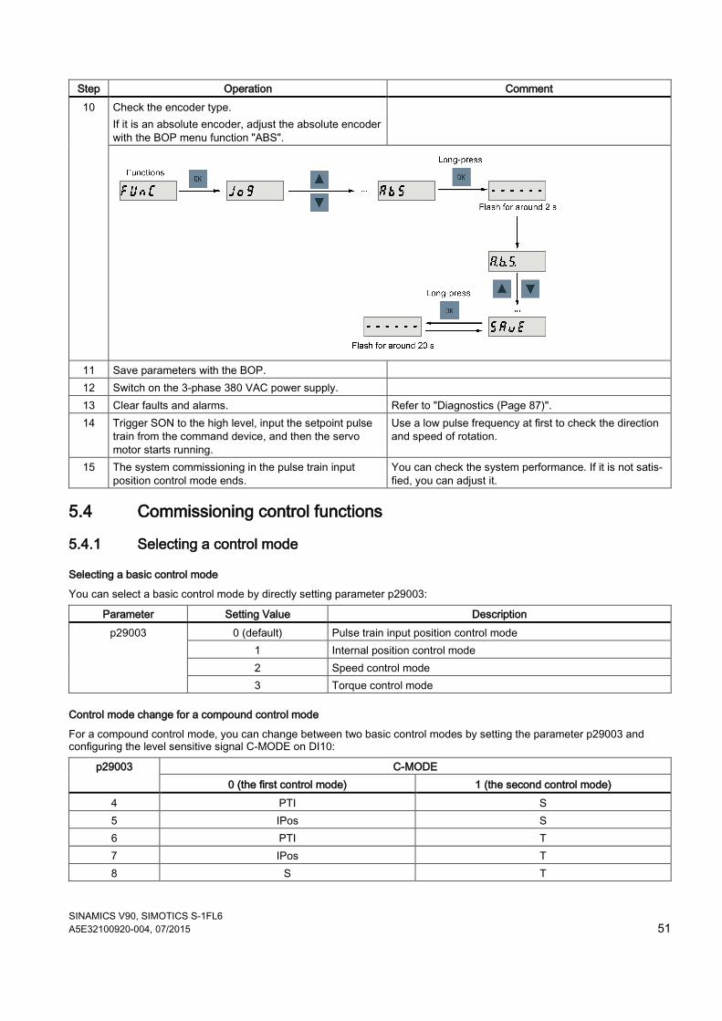
SINAMICS V90, SIMOTICS S-1FL6 A5E32100920-004, 07/2015 51
Step Operation Comment 10 Check the encoder type.
If it is an absolute encoder, adjust the absolute encoder with the BOP menu function "ABS".
11 Save parameters with the BOP. 12 Switch on the 3-phase 380 VAC power supply. 13 Clear faults and alarms. Refer to "Diagnostics (Page 87)". 14 Trigger SON to the high level, input the setpoint pulse
train from the command device, and then the servo motor starts running.
Use a low pulse frequency at first to check the direction and speed of rotation.
15 The system commissioning in the pulse train input position control mode ends.
You can check the system performance. If it is not satis-fied, you can adjust it.
5.4 Commissioning control functions
5.4.1 Selecting a control mode
Selecting a basic control mode
You can select a basic control mode by directly setting parameter p29003:
Parameter Setting Value Description p29003 0 (default) Pulse train input position control mode
1 Internal position control mode 2 Speed control mode 3 Torque control mode
Control mode change for a compound control mode
For a compound control mode, you can change between two basic control modes by setting the parameter p29003 and configuring the level sensitive signal C-MODE on DI10:
p29003 C-MODE 0 (the first control mode) 1 (the second control mode)
4 PTI S 5 IPos S 6 PTI T 7 IPos T 8 S T
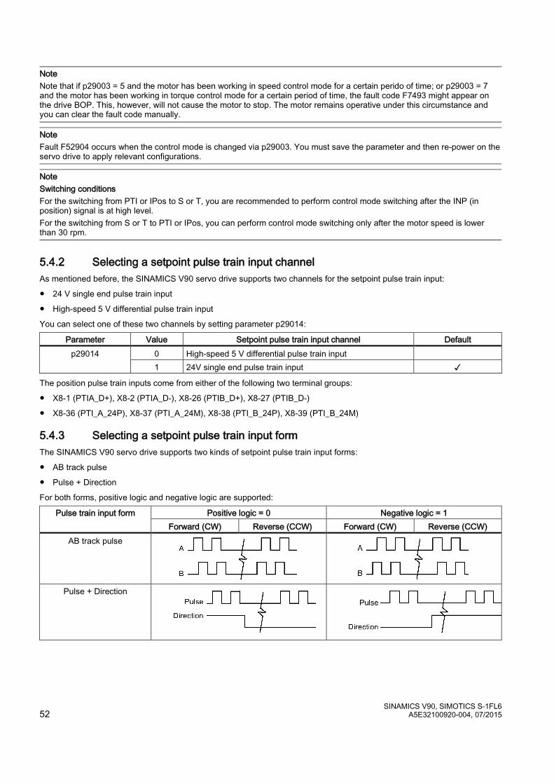
SINAMICS V90, SIMOTICS S-1FL6 52 A5E32100920-004, 07/2015
Note Note that if p29003 = 5 and the motor has been working in speed control mode for a certain perido of time; or p29003 = 7 and the motor has been working in torque control mode for a certain period of time, the fault code F7493 might appear on the drive BOP. This, however, will not cause the motor to stop. The motor remains operative under this circumstance and you can clear the fault code manually.
Note Fault F52904 occurs when the control mode is changed via p29003. You must save the parameter and then re-power on the servo drive to apply relevant configurations.
Note Switching conditions For the switching from PTI or IPos to S or T, you are recommended to perform control mode switching after the INP (in position) signal is at high level. For the switching from S or T to PTI or IPos, you can perform control mode switching only after the motor speed is lower than 30 rpm.
5.4.2 Selecting a setpoint pulse train input channel As mentioned before, the SINAMICS V90 servo drive supports two channels for the setpoint pulse train input:
● 24 V single end pulse train input
● High-speed 5 V differential pulse train input
You can select one of these two channels by setting parameter p29014:
Parameter Value Setpoint pulse train input channel Default p29014 0 High-speed 5 V differential pulse train input
1 24V single end pulse train input ✓
The position pulse train inputs come from either of the following two terminal groups:
● X8-1 (PTIA_D+), X8-2 (PTIA_D-), X8-26 (PTIB_D+), X8-27 (PTIB_D-)
● X8-36 (PTI_A_24P), X8-37 (PTI_A_24M), X8-38 (PTI_B_24P), X8-39 (PTI_B_24M)
5.4.3 Selecting a setpoint pulse train input form The SINAMICS V90 servo drive supports two kinds of setpoint pulse train input forms:
● AB track pulse
● Pulse + Direction
For both forms, positive logic and negative logic are supported:
Pulse train input form Positive logic = 0 Negative logic = 1 Forward (CW) Reverse (CCW) Forward (CW) Reverse (CCW)
AB track pulse
Pulse + Direction
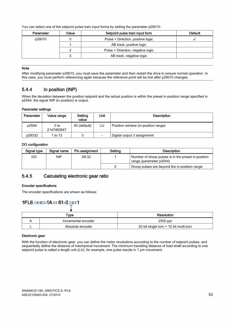
SINAMICS V90, SIMOTICS S-1FL6 A5E32100920-004, 07/2015 53
You can select one of the setpoint pulse train input forms by setting the parameter p29010:
Parameter Value Setpoint pulse train input form Default p29010 0 Pulse + Direction, positive logic ✓
1 AB track, positive logic 2 Pulse + Direction, negative logic 3 AB track, negative logic
Note After modifying parameter p29010, you must save the parameter and then restart the drive to ensure normal operation. In this case, you must perform referencing again because the reference point will be lost after p29010 changes.
5.4.4 In position (INP) When the deviation between the position setpoint and the actual position is within the preset in-position range specified in p2544, the signal INP (in position) is output.
Parameter settings
Parameter Value range Setting value
Unit Description
p2544 0 to 2147483647
40 (default) LU Position window (in-position range)
p29332 1 to 13 3 - Digital output 3 assignment
DO configuration
Signal type Signal name Pin assignment Setting Description DO INP X8-32 1 Number of droop pulses is in the preset in-position
range (parameter p2544) 0 Droop pulses are beyond the in-position range
5.4.5 Calculating electronic gear ratio
Encoder specifications
The encoder specifications are shown as follows:
Type Resolution
A Incremental encoder 2500 ppr L Absolute encoder 20 bit single turn + 12 bit multi-turn
Electronic gear
With the function of electronic gear, you can define the motor revolutions according to the number of setpoint pulses, and sequentially define the distance of mechanical movement. The minimum travelling distance of load shaft according to one setpoint pulse is called a length unit (LU); for example, one pulse results in 1 µm movement.
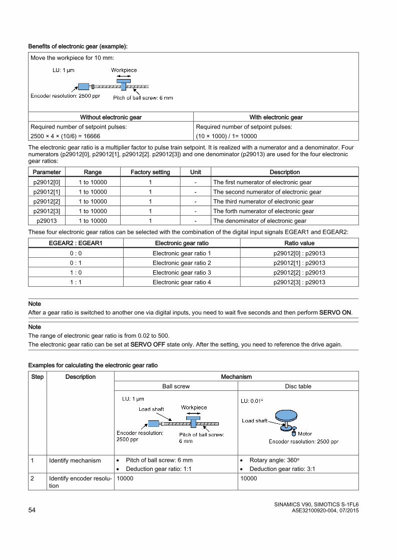
SINAMICS V90, SIMOTICS S-1FL6 54 A5E32100920-004, 07/2015
Benefits of electronic gear (example):
Move the workpiece for 10 mm:
Without electronic gear With electronic gear Required number of setpoint pulses: 2500 × 4 × (10/6) = 16666
Required number of setpoint pulses: (10 × 1000) / 1= 10000
The electronic gear ratio is a multiplier factor to pulse train setpoint. It is realized with a numerator and a denominator. Four numerators (p29012[0], p29012[1], p29012[2]. p29012[3]) and one denominator (p29013) are used for the four electronic gear ratios:
Parameter Range Factory setting Unit Description p29012[0] 1 to 10000 1 - The first numerator of electronic gear p29012[1] 1 to 10000 1 - The second numerator of electronic gear p29012[2] 1 to 10000 1 - The third numerator of electronic gear p29012[3] 1 to 10000 1 - The forth numerator of electronic gear
p29013 1 to 10000 1 - The denominator of electronic gear
These four electronic gear ratios can be selected with the combination of the digital input signals EGEAR1 and EGEAR2:
EGEAR2 : EGEAR1 Electronic gear ratio Ratio value 0 : 0 Electronic gear ratio 1 p29012[0] : p29013 0 : 1 Electronic gear ratio 2 p29012[1] : p29013 1 : 0 Electronic gear ratio 3 p29012[2] : p29013 1 : 1 Electronic gear ratio 4 p29012[3] : p29013
Note After a gear ratio is switched to another one via digital inputs, you need to wait five seconds and then perform SERVO ON.
Note The range of electronic gear ratio is from 0.02 to 500. The electronic gear ratio can be set at SERVO OFF state only. After the setting, you need to reference the drive again.
Examples for calculating the electronic gear ratio
Step Description Mechanism Ball screw Disc table
1 Identify mechanism • Pitch of ball screw: 6 mm • Deduction gear ratio: 1:1
• Rotary angle: 360o • Deduction gear ratio: 3:1
2 Identify encoder resolu-tion
10000 10000
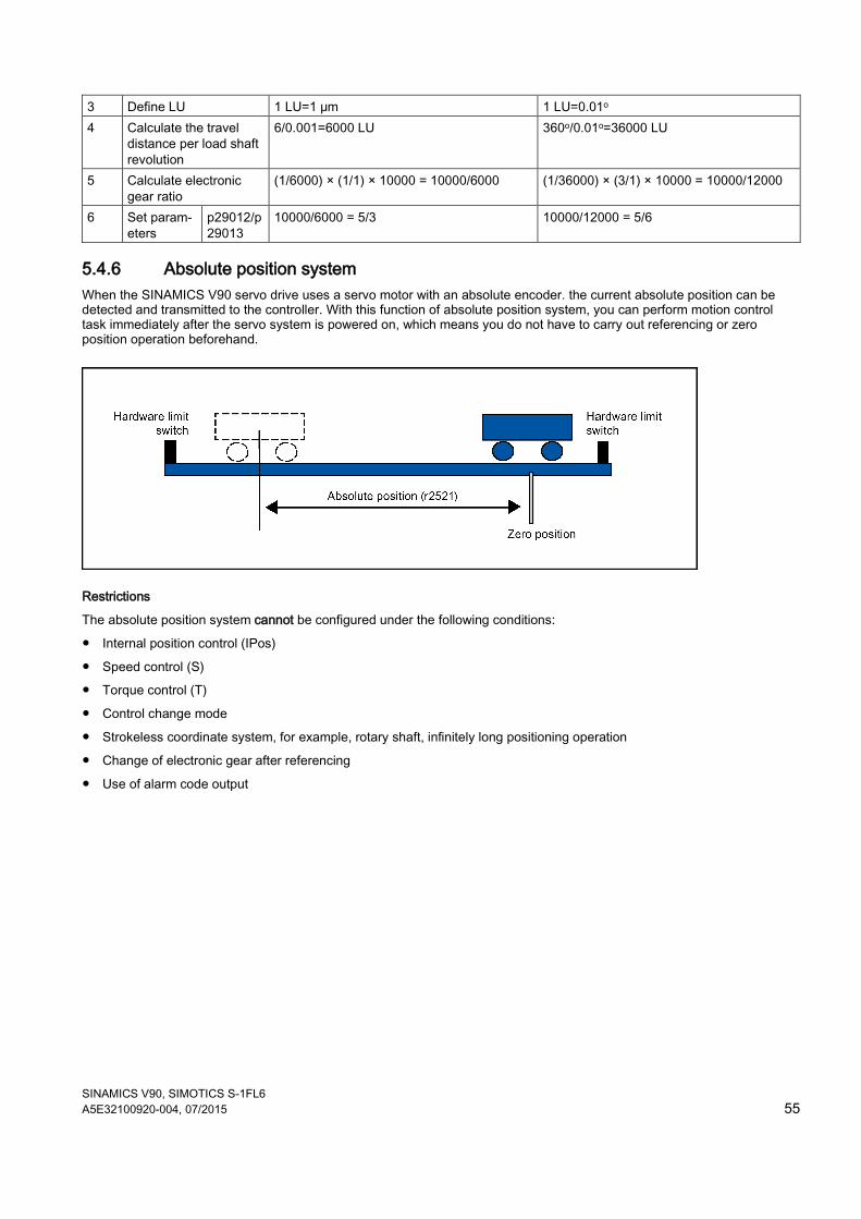
SINAMICS V90, SIMOTICS S-1FL6 A5E32100920-004, 07/2015 55
3 Define LU 1 LU=1 μm 1 LU=0.01o 4 Calculate the travel
distance per load shaft revolution
6/0.001=6000 LU 360o/0.01o=36000 LU
5 Calculate electronic gear ratio
(1/6000) × (1/1) × 10000 = 10000/6000 (1/36000) × (3/1) × 10000 = 10000/12000
6 Set param-eters
p29012/p29013
10000/6000 = 5/3 10000/12000 = 5/6
5.4.6 Absolute position system When the SINAMICS V90 servo drive uses a servo motor with an absolute encoder. the current absolute position can be detected and transmitted to the controller. With this function of absolute position system, you can perform motion control task immediately after the servo system is powered on, which means you do not have to carry out referencing or zero position operation beforehand.
Restrictions
The absolute position system cannot be configured under the following conditions:
● Internal position control (IPos)
● Speed control (S)
● Torque control (T)
● Control change mode
● Strokeless coordinate system, for example, rotary shaft, infinitely long positioning operation
● Change of electronic gear after referencing
● Use of alarm code output
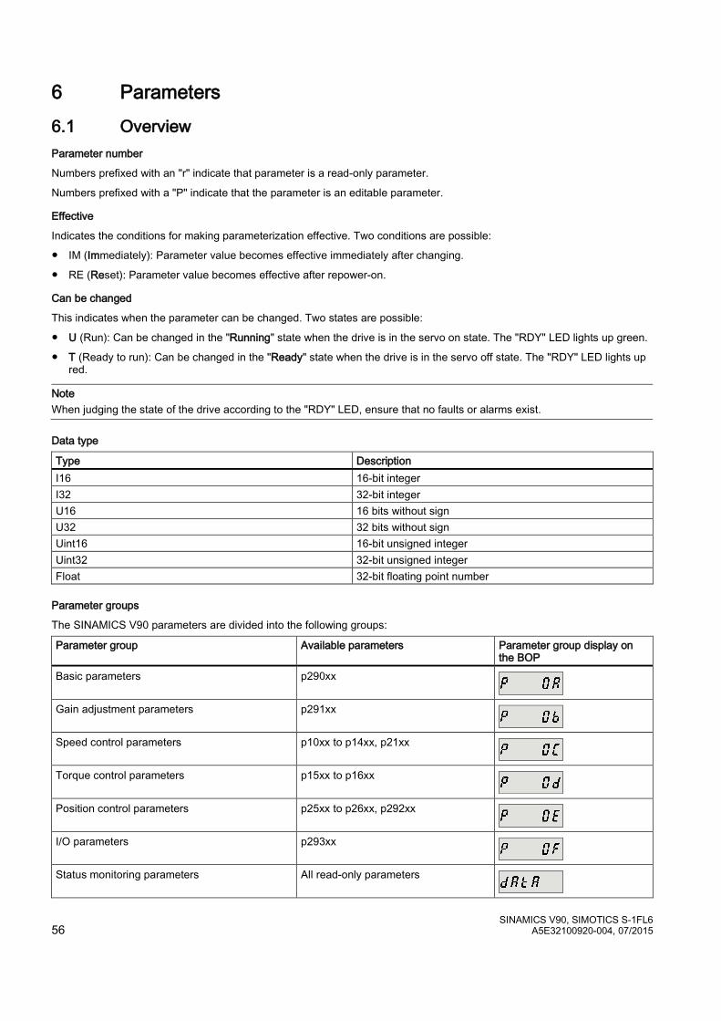
SINAMICS V90, SIMOTICS S-1FL6 56 A5E32100920-004, 07/2015
6 Parameters 6.1 Overview Parameter number
Numbers prefixed with an "r" indicate that parameter is a read-only parameter.
Numbers prefixed with a "P" indicate that the parameter is an editable parameter.
Effective
Indicates the conditions for making parameterization effective. Two conditions are possible:
● IM (Immediately): Parameter value becomes effective immediately after changing.
● RE (Reset): Parameter value becomes effective after repower-on.
Can be changed
This indicates when the parameter can be changed. Two states are possible:
● U (Run): Can be changed in the "Running" state when the drive is in the servo on state. The "RDY" LED lights up green.
● T (Ready to run): Can be changed in the "Ready" state when the drive is in the servo off state. The "RDY" LED lights up red.
Note When judging the state of the drive according to the "RDY" LED, ensure that no faults or alarms exist.
Data type
Type Description I16 16-bit integer I32 32-bit integer U16 16 bits without sign U32 32 bits without sign Uint16 16-bit unsigned integer Uint32 32-bit unsigned integer Float 32-bit floating point number
Parameter groups
The SINAMICS V90 parameters are divided into the following groups:
Parameter group Available parameters Parameter group display on the BOP
Basic parameters p290xx
Gain adjustment parameters p291xx
Speed control parameters p10xx to p14xx, p21xx
Torque control parameters p15xx to p16xx
Position control parameters p25xx to p26xx, p292xx
I/O parameters p293xx
Status monitoring parameters All read-only parameters
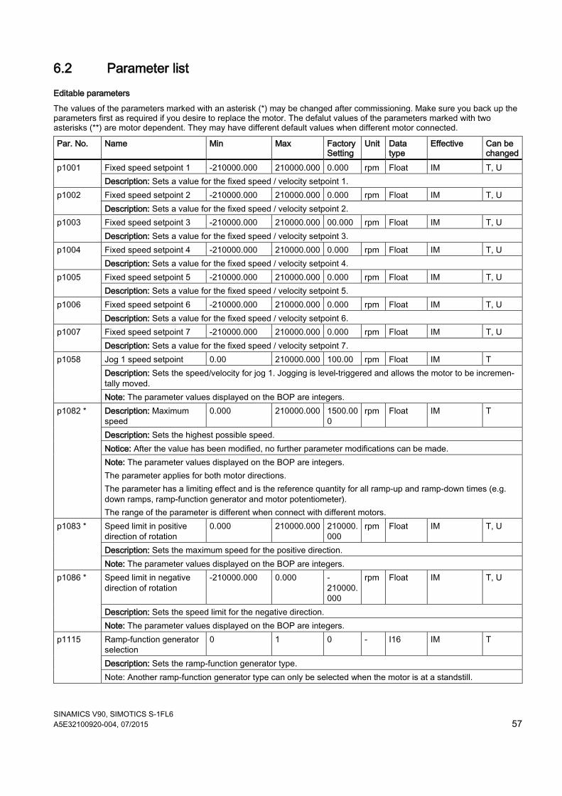
SINAMICS V90, SIMOTICS S-1FL6 A5E32100920-004, 07/2015 57
6.2 Parameter list
Editable parameters
The values of the parameters marked with an asterisk (*) may be changed after commissioning. Make sure you back up the parameters first as required if you desire to replace the motor. The defalut values of the parameters marked with two asterisks (**) are motor dependent. They may have different default values when different motor connected.
Par. No. Name Min Max Factory Setting
Unit Data type
Effective Can be changed
p1001
Fixed speed setpoint 1 -210000.000 210000.000 0.000 rpm Float IM T, U Description: Sets a value for the fixed speed / velocity setpoint 1.
p1002 Fixed speed setpoint 2 -210000.000 210000.000 0.000 rpm Float IM T, U Description: Sets a value for the fixed speed / velocity setpoint 2.
p1003
Fixed speed setpoint 3 -210000.000 210000.000 00.000 rpm Float IM T, U Description: Sets a value for the fixed speed / velocity setpoint 3.
p1004
Fixed speed setpoint 4 -210000.000 210000.000 0.000 rpm Float IM T, U Description: Sets a value for the fixed speed / velocity setpoint 4.
p1005
Fixed speed setpoint 5 -210000.000 210000.000 0.000 rpm Float IM T, U Description: Sets a value for the fixed speed / velocity setpoint 5.
p1006
Fixed speed setpoint 6 -210000.000 210000.000 0.000 rpm Float IM T, U Description: Sets a value for the fixed speed / velocity setpoint 6.
p1007
Fixed speed setpoint 7 -210000.000 210000.000 0.000 rpm Float IM T, U Description: Sets a value for the fixed speed / velocity setpoint 7.
p1058
Jog 1 speed setpoint 0.00 210000.000 100.00 rpm Float IM T Description: Sets the speed/velocity for jog 1. Jogging is level-triggered and allows the motor to be incremen-tally moved. Note: The parameter values displayed on the BOP are integers.
p1082 * Description: Maximum speed
0.000 210000.000 1500.000
rpm Float IM T
Description: Sets the highest possible speed. Notice: After the value has been modified, no further parameter modifications can be made. Note: The parameter values displayed on the BOP are integers. The parameter applies for both motor directions. The parameter has a limiting effect and is the reference quantity for all ramp-up and ramp-down times (e.g. down ramps, ramp-function generator and motor potentiometer). The range of the parameter is different when connect with different motors.
p1083 * Speed limit in positive direction of rotation
0.000 210000.000 210000.000
rpm Float IM T, U
Description: Sets the maximum speed for the positive direction. Note: The parameter values displayed on the BOP are integers.
p1086 * Speed limit in negative direction of rotation
-210000.000 0.000 -210000.000
rpm Float IM T, U
Description: Sets the speed limit for the negative direction. Note: The parameter values displayed on the BOP are integers.
p1115 Ramp-function generator selection
0 1 0 - I16 IM T
Description: Sets the ramp-function generator type. Note: Another ramp-function generator type can only be selected when the motor is at a standstill.
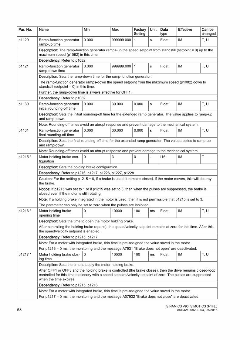
SINAMICS V90, SIMOTICS S-1FL6 58 A5E32100920-004, 07/2015
Par. No. Name Min Max Factory Setting
Unit Data type
Effective Can be changed
p1120 Ramp-function generator ramp-up time
0.000 999999.000 1 s Float IM T, U
Description: The ramp-function generator ramps-up the speed setpoint from standstill (setpoint = 0) up to the maximum speed (p1082) in this time. Dependency: Refer to p1082
p1121 Ramp-function generator ramp-down time
0.000 999999.000 1 s Float IM T, U
Description: Sets the ramp-down time for the ramp-function generator. The ramp-function generator ramps-down the speed setpoint from the maximum speed (p1082) down to standstill (setpoint = 0) in this time. Further, the ramp-down time is always effective for OFF1. Dependency: Refer to p1082
p1130 Ramp-function generator initial rounding-off time
0.000 30.000 0.000 s Float IM T, U
Description: Sets the initial rounding-off time for the extended ramp generator. The value applies to ramp-up and ramp-down. Note: Rounding-off times avoid an abrupt response and prevent damage to the mechanical system.
p1131 Ramp-function generator final rounding-off time
0.000 30.000 0.000 s Float IM T, U
Description: Sets the final rounding-off time for the extended ramp generator. The value applies to ramp-up and ramp-down. Note: Rounding-off times avoid an abrupt response and prevent damage to the mechanical system.
p1215 * Motor holding brake con-figuration
0 3 0 - I16 IM T
Description: Sets the holding brake configuration. Dependency: Refer to p1216, p1217, p1226, p1227, p1228 Caution: For the setting p1215 = 0, if a brake is used, it remains closed. If the motor moves, this will destroy the brake. Notice: If p1215 was set to 1 or if p1215 was set to 3, then when the pulses are suppressed, the brake is closed even if the motor is still rotating. Note: If a holding brake integrated in the motor is used, then it is not permissible that p1215 is set to 3. The parameter can only be set to zero when the pulses are inhibited.
p1216 * Motor holding brake opening time
0 10000 100 ms Float IM T, U
Description: Sets the time to open the motor holding brake. After controlling the holding brake (opens), the speed/velocity setpoint remains at zero for this time. After this, the speed/velocity setpoint is enabled. Dependency: Refer to p1215, p1217 Note: For a motor with integrated brake, this time is pre-assigned the value saved in the motor. For p1216 = 0 ms, the monitoring and the message A7931 "Brake does not open" are deactivated.
p1217 * Motor holding brake clos-ing time
0 10000 100 ms Float IM T, U
Description: Sets the time to apply the motor holding brake. After OFF1 or OFF3 and the holding brake is controlled (the brake closes), then the drive remains closed-loop controlled for this time stationary with a speed setpoint/velocity setpoint of zero. The pulses are suppressed when the time expires. Dependency: Refer to p1215, p1216 Note: For a motor with integrated brake, this time is pre-assigned the value saved in the motor. For p1217 = 0 ms, the monitoring and the message A07932 "Brake does not close" are deactivated.

SINAMICS V90, SIMOTICS S-1FL6 A5E32100920-004, 07/2015 59
Par. No. Name Min Max Factory Setting
Unit Data type
Effective Can be changed
p1226 Threshold for zero speed detection
0.00 210000.00 20.00 rpm Float IM T, U
Description: Sets the speed threshold for the standstill identification. Acts on the actual value and setpoint monitoring. When braking with OFF1 or OFF3, when the threshold is undershot, standstill is identified. The following applies when the brake control is activated: When the threshold is undershot, the brake control is started and the system waits for the brake closing time in p1217. The pulses are then suppressed. If the brake control is not activated, the following applies: When the threshold is undershot, the pulses are suppressed and the drive coasts down. Dependency: Refer to p1215, p1216, p1217, p1227 Notice: For reasons relating to the compatibility to earlier firmware versions, a parameter value of zero in indices 1 to 31 is overwritten with the parameter value in index 0 when the drive boots. Note: Standstill is identified in the following cases: - The speed actual value falls below the speed threshold in p1226 and the time started after this in p1228 has expired. - The speed setpoint falls below the speed threshold in p1226 and the time started after this in p1227 has expired. The actual value sensing is subject to measuring noise. For this reason, standstill cannot be detected if the speed threshold is too low.
p1227 Zero speed detection monitoring time
0.000 300.000 300.000 s Float IM T, U
Description: Sets the monitoring time for the standstill identification. When braking with OFF1 or OFF3, standstill is identified after this time has expired, after the setpoint speed has fallen below p1226. After this, the brake control is started, the system waits for the closing time in p1217 and then the pulses are suppressed. Dependency: Refer to p1215, p1216, p1217, p1226 Notice: The setpoint is not equal to zero dependent on the selected value. This can therefore cause the moni-toring time in p1227 to be exceeded. In this case, for a driven motor, the pulses are not suppressed.. Note: Standstill is identified in the following cases: - The speed actual value falls below the speed threshold in p1226 and the time started after this in p1228 has expired. - The speed setpoint falls below the speed threshold in p1226 and the time started after this in p1227 has expired. For p1227 = 300.000 s, the following applies: Monitoring is de-activated. For p1227 = 0.000 s, the following applies: With OFF1 or OFF3 and a ramp-down time = 0, the pulses are immediately suppressed and the motor "coasts" down.
p1228 Pulse suppression delay time
0.000 299.000 0.000 s Float IM T, U
Description: Sets the delay time for pulse suppression. After OFF1 or OFF3, the pulses are canceled, if at least one of the following conditions is fulfilled: - The speed actual value falls below the threshold in p1226 and the time started after this in p1228 has ex-pired. - The speed setpoint falls below the threshold in p1226 and the time started after this in p1227 has expired. Dependency: Refer to p1226, p1227 Notice: When the motor holding brake is activated, pulse cancellation is additionally delayed by the brake closing time (p1217).
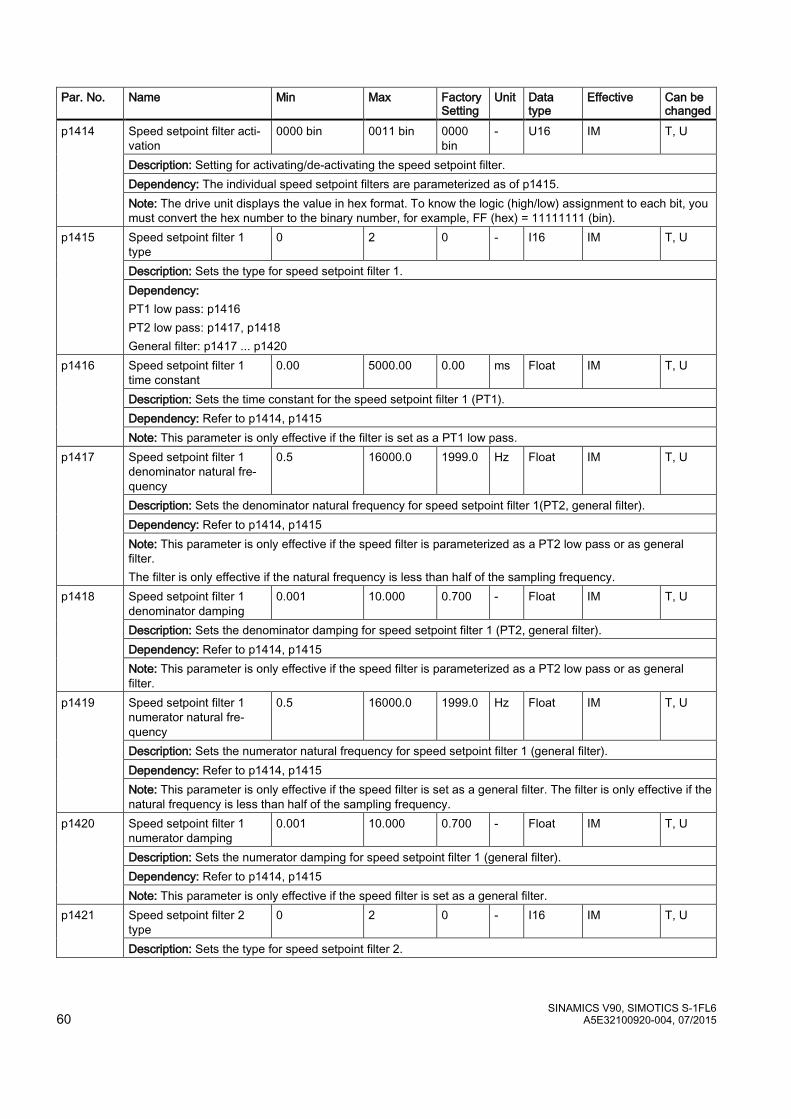
SINAMICS V90, SIMOTICS S-1FL6 60 A5E32100920-004, 07/2015
Par. No. Name Min Max Factory Setting
Unit Data type
Effective Can be changed
p1414 Speed setpoint filter acti-vation
0000 bin 0011 bin 0000 bin
- U16 IM T, U
Description: Setting for activating/de-activating the speed setpoint filter. Dependency: The individual speed setpoint filters are parameterized as of p1415. Note: The drive unit displays the value in hex format. To know the logic (high/low) assignment to each bit, you must convert the hex number to the binary number, for example, FF (hex) = 11111111 (bin).
p1415 Speed setpoint filter 1 type
0 2 0 - I16 IM T, U
Description: Sets the type for speed setpoint filter 1. Dependency: PT1 low pass: p1416 PT2 low pass: p1417, p1418 General filter: p1417 ... p1420
p1416 Speed setpoint filter 1 time constant
0.00 5000.00 0.00 ms Float IM T, U
Description: Sets the time constant for the speed setpoint filter 1 (PT1). Dependency: Refer to p1414, p1415 Note: This parameter is only effective if the filter is set as a PT1 low pass.
p1417 Speed setpoint filter 1 denominator natural fre-quency
0.5 16000.0 1999.0 Hz Float IM T, U
Description: Sets the denominator natural frequency for speed setpoint filter 1(PT2, general filter). Dependency: Refer to p1414, p1415 Note: This parameter is only effective if the speed filter is parameterized as a PT2 low pass or as general filter. The filter is only effective if the natural frequency is less than half of the sampling frequency.
p1418 Speed setpoint filter 1 denominator damping
0.001 10.000 0.700 - Float IM T, U
Description: Sets the denominator damping for speed setpoint filter 1 (PT2, general filter). Dependency: Refer to p1414, p1415 Note: This parameter is only effective if the speed filter is parameterized as a PT2 low pass or as general filter.
p1419 Speed setpoint filter 1 numerator natural fre-quency
0.5 16000.0 1999.0 Hz Float IM T, U
Description: Sets the numerator natural frequency for speed setpoint filter 1 (general filter). Dependency: Refer to p1414, p1415 Note: This parameter is only effective if the speed filter is set as a general filter. The filter is only effective if the natural frequency is less than half of the sampling frequency.
p1420 Speed setpoint filter 1 numerator damping
0.001 10.000 0.700 - Float IM T, U
Description: Sets the numerator damping for speed setpoint filter 1 (general filter). Dependency: Refer to p1414, p1415 Note: This parameter is only effective if the speed filter is set as a general filter.
p1421 Speed setpoint filter 2 type
0 2 0 - I16 IM T, U
Description: Sets the type for speed setpoint filter 2.
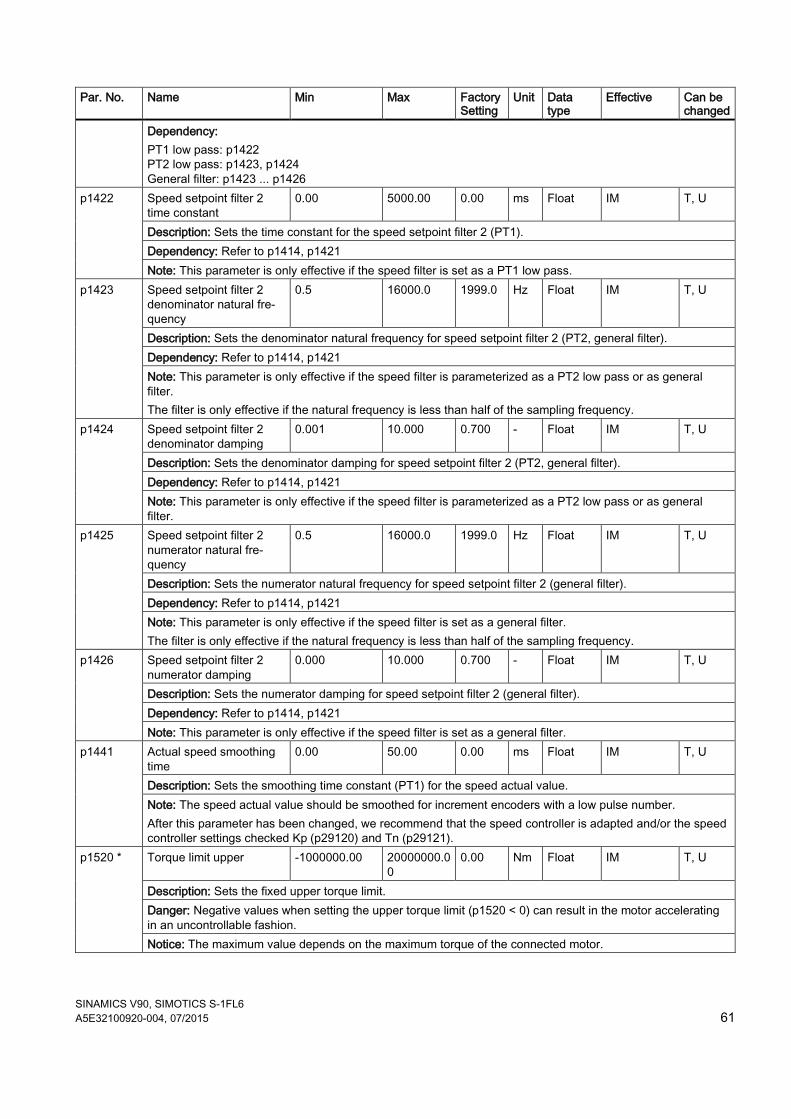
SINAMICS V90, SIMOTICS S-1FL6 A5E32100920-004, 07/2015 61
Par. No. Name Min Max Factory Setting
Unit Data type
Effective Can be changed
Dependency: PT1 low pass: p1422 PT2 low pass: p1423, p1424 General filter: p1423 ... p1426
p1422 Speed setpoint filter 2 time constant
0.00 5000.00 0.00 ms Float IM T, U
Description: Sets the time constant for the speed setpoint filter 2 (PT1). Dependency: Refer to p1414, p1421 Note: This parameter is only effective if the speed filter is set as a PT1 low pass.
p1423 Speed setpoint filter 2 denominator natural fre-quency
0.5 16000.0 1999.0 Hz Float IM T, U
Description: Sets the denominator natural frequency for speed setpoint filter 2 (PT2, general filter). Dependency: Refer to p1414, p1421 Note: This parameter is only effective if the speed filter is parameterized as a PT2 low pass or as general filter. The filter is only effective if the natural frequency is less than half of the sampling frequency.
p1424 Speed setpoint filter 2 denominator damping
0.001 10.000 0.700 - Float IM T, U
Description: Sets the denominator damping for speed setpoint filter 2 (PT2, general filter). Dependency: Refer to p1414, p1421 Note: This parameter is only effective if the speed filter is parameterized as a PT2 low pass or as general filter.
p1425 Speed setpoint filter 2 numerator natural fre-quency
0.5 16000.0 1999.0 Hz Float IM T, U
Description: Sets the numerator natural frequency for speed setpoint filter 2 (general filter). Dependency: Refer to p1414, p1421 Note: This parameter is only effective if the speed filter is set as a general filter. The filter is only effective if the natural frequency is less than half of the sampling frequency.
p1426 Speed setpoint filter 2 numerator damping
0.000 10.000 0.700 - Float IM T, U
Description: Sets the numerator damping for speed setpoint filter 2 (general filter). Dependency: Refer to p1414, p1421 Note: This parameter is only effective if the speed filter is set as a general filter.
p1441 Actual speed smoothing time
0.00 50.00 0.00 ms Float IM T, U
Description: Sets the smoothing time constant (PT1) for the speed actual value. Note: The speed actual value should be smoothed for increment encoders with a low pulse number. After this parameter has been changed, we recommend that the speed controller is adapted and/or the speed controller settings checked Kp (p29120) and Tn (p29121).
p1520 * Torque limit upper -1000000.00 20000000.00
0.00 Nm Float IM T, U
Description: Sets the fixed upper torque limit. Danger: Negative values when setting the upper torque limit (p1520 < 0) can result in the motor accelerating in an uncontrollable fashion. Notice: The maximum value depends on the maximum torque of the connected motor.
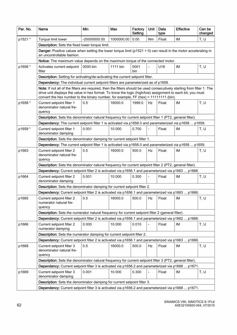
SINAMICS V90, SIMOTICS S-1FL6 62 A5E32100920-004, 07/2015
Par. No. Name Min Max Factory Setting
Unit Data type
Effective Can be changed
p1521 * Torque limit lower -20000000.00 1000000.00 0.00 Nm Float IM T, U Description: Sets the fixed lower torque limit. Danger: Positive values when setting the lower torque limit (p1521 > 0) can result in the motor accelerating in an uncontrollable fashion. Notice: The maximum value depends on the maximum torque of the connected motor.
p1656 * Activates current setpoint filter
0000 bin 1111 bin 0001 bin
- U16 IM T, U
Description: Setting for activating/de-activating the current setpoint filter. Dependency: The individual current setpoint filters are parameterized as of p1658. Note: If not all of the filters are required, then the filters should be used consecutively starting from filter 1. The drive unit displays the value in hex format. To know the logic (high/low) assignment to each bit, you must convert the hex number to the binary number, for example, FF (hex) = 11111111 (bin).
p1658 * Current setpoint filter 1 denominator natural fre-quency
0.5 16000.0 1999.0 Hz Float IM T, U
Description: Sets the denominator natural frequency for current setpoint filter 1 (PT2, general filter). Dependency: The current setpoint filter 1 is activated via p1656.0 and parameterized via p1658 ... p1659.
p1659 * Current setpoint filter 1 denominator damping
0.001 10.000 0.700 - Float IM T, U
Description: Sets the denominator damping for current setpoint filter 1. Dependency: The current setpoint filter 1 is activated via p1656.0 and parameterized via p1658 ... p1659.
p1663 Current setpoint filter 2 denominator natural fre-quency
0.5 16000.0 500.0 Hz Float IM T, U
Description: Sets the denominator natural frequency for current setpoint filter 2 (PT2, general filter). Dependency: Current setpoint filter 2 is activated via p1656.1 and parameterized via p1663 ... p1666.
p1664 Current setpoint filter 2 denominator damping
0.001 10.000 0.300 - Float IM T, U
Description: Sets the denominator damping for current setpoint filter 2. Dependency: Current setpoint filter 2 is activated via p1656.1 and parameterized via p1663 ... p1666.
p1665 Current setpoint filter 2 numerator natural fre-quency
0.5 16000.0 500.0 Hz Float IM T, U
Description: Sets the numerator natural frequency for current setpoint filter 2 (general filter). Dependency: Current setpoint filter 2 is activated via p1656.1 and parameterized via p1662 ... p1666.
p1666
Current setpoint filter 2 numerator damping
0.000 10.000 0.010 - Float IM T, U
Description: Sets the numerator damping for current setpoint filter 2. Dependency: Current setpoint filter 2 is activated via p1656.1 and parameterized via p1663 ... p1666.
p1668 Current setpoint filter 3 denominator natural fre-quency
0.5 16000.0 500.0 Hz Float IM T, U
Description: Sets the denominator natural frequency for current setpoint filter 3 (PT2, general filter). Dependency: Current setpoint filter 3 is activated via p1656.2 and parameterized via p1668 ... p1671.
p1669 Current setpoint filter 3 denominator damping
0.001 10.000 0.300 - Float IM T, U
Description: Sets the denominator damping for current setpoint filter 3. Dependency: Current setpoint filter 3 is activated via p1656.2 and parameterized via p1668 ... p1671.

SINAMICS V90, SIMOTICS S-1FL6 A5E32100920-004, 07/2015 63
Par. No. Name Min Max Factory Setting
Unit Data type
Effective Can be changed
p1670 Current setpoint filter 3 numerator natural fre-quency
0.5 16000.0 500.0 Hz Float IM T, U
Description: Sets the numerator natural frequency for current setpoint filter 3 (general filter). Dependency: Current setpoint filter 3 is activated via p1656.2 and parameterized via p1668 ... p1671.
p1671 Current setpoint filter 3 numerator damping
0.000 10.000 0.010 - Float IM T, U
Description: Sets the numerator damping for current setpoint filter 3. Dependency: Current setpoint filter 3 is activated via p1656.2 and parameterized via p1668 ... p1671.
p1673 Current setpoint filter 4 denominator natural fre-quency
0.5 16000.0 500.0 Hz Float IM T, U
Description: Sets the denominator natural frequency for current setpoint filter 4 (PT2, general filter). Dependency: Current setpoint filter 4 is activated via p1656.3 and parameterized via p1673 ... p1675.
p1674 Current setpoint filter 4 denominator damping
0.001 10.000 0.300 - Float IM T, U
Description: Sets the denominator damping for current setpoint filter 4. Dependency: Current setpoint filter 4 is activated via p1656.3 and parameterized via p1673 ... p1675.
p1675 Current setpoint filter 4 numerator natural fre-quency
0.5 16000.0 500.0 Hz Float IM T, U
Description: Sets the numerator natural frequency for current setpoint filter 4 (general filter). Dependency: Current setpoint filter 4 is activated via p1656.3 and parameterized via p1673 ... p1675.
p1676 Current setpoint filter 4 numerator damping
0.000 10.000 0.010 - Float IM T, U
Description: Sets the numerator damping for current setpoint filter 4. Dependency: Current setpoint filter 4 is activated via p1656.3 and parameterized via p1673 ... p1675.
p2153 Speed actual value filter time constant
0 1000000 0 ms Float IM T, U
Description: Sets the time constant of the PT1 element to smooth the speed / velocity actual value. The smoothed actual speed/velocity is compared with the threshold values and is only used for messages and signals.
p2161 * Speed threshold 3 0.00 210000.00 10.00 rpm Float IM T, U Description: Sets the speed threshold value for the signal that indicates the axis is stationary.
p2162 * Hysteresis speed n_act > n_max
0.00 60000.00 0.00 rpm Float IM T, U
Description: Sets the hysteresis speed (bandwidth) for the signal "n_act > n_max". Note: For a negative speed limit, the hysteresis is effective below the limit value and for a positive speed limit above the limit value. If significant overshoot occurs in the maximum speed range (for example, due to load shedding), you are advised to increase the dynamic response of the speed controller (if possible). If this is insufficient, the hyste-resis p2162 can only be increased by more than 10% of the rated speed when the maximum speed of the motor is sufficiently greater than the speed limit p1082. The range of the parameter is different when connect with different motors.
p2525
LR encoder adjustment offset
0 4294967295
0 LU U32 IM T
Description: For the absolute encoder adjustment, a drive determines the position offset. Note: The position offset is only relevant for absolute encoders. The drive determines it when making the adjustment and the user should not change it.
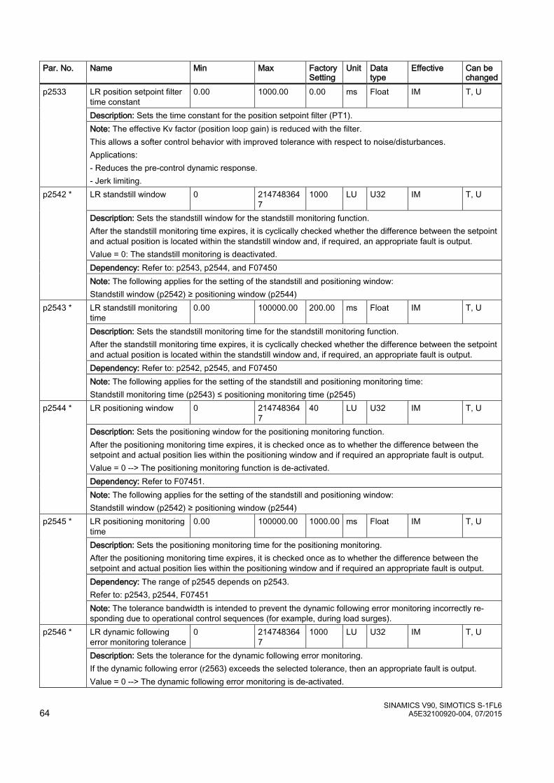
SINAMICS V90, SIMOTICS S-1FL6 64 A5E32100920-004, 07/2015
Par. No. Name Min Max Factory Setting
Unit Data type
Effective Can be changed
p2533 LR position setpoint filter time constant
0.00 1000.00 0.00 ms Float IM T, U
Description: Sets the time constant for the position setpoint filter (PT1). Note: The effective Kv factor (position loop gain) is reduced with the filter. This allows a softer control behavior with improved tolerance with respect to noise/disturbances. Applications: - Reduces the pre-control dynamic response. - Jerk limiting.
p2542 *
LR standstill window 0 2147483647
1000 LU U32 IM T, U
Description: Sets the standstill window for the standstill monitoring function. After the standstill monitoring time expires, it is cyclically checked whether the difference between the setpoint and actual position is located within the standstill window and, if required, an appropriate fault is output. Value = 0: The standstill monitoring is deactivated. Dependency: Refer to: p2543, p2544, and F07450 Note: The following applies for the setting of the standstill and positioning window: Standstill window (p2542) ≥ positioning window (p2544)
p2543 * LR standstill monitoring time
0.00 100000.00 200.00 ms Float IM T, U
Description: Sets the standstill monitoring time for the standstill monitoring function. After the standstill monitoring time expires, it is cyclically checked whether the difference between the setpoint and actual position is located within the standstill window and, if required, an appropriate fault is output. Dependency: Refer to: p2542, p2545, and F07450 Note: The following applies for the setting of the standstill and positioning monitoring time: Standstill monitoring time (p2543) ≤ positioning monitoring time (p2545)
p2544 * LR positioning window 0 2147483647
40 LU U32 IM T, U
Description: Sets the positioning window for the positioning monitoring function. After the positioning monitoring time expires, it is checked once as to whether the difference between the setpoint and actual position lies within the positioning window and if required an appropriate fault is output. Value = 0 --> The positioning monitoring function is de-activated. Dependency: Refer to F07451. Note: The following applies for the setting of the standstill and positioning window: Standstill window (p2542) ≥ positioning window (p2544)
p2545 * LR positioning monitoring time
0.00 100000.00 1000.00 ms Float IM T, U
Description: Sets the positioning monitoring time for the positioning monitoring. After the positioning monitoring time expires, it is checked once as to whether the difference between the setpoint and actual position lies within the positioning window and if required an appropriate fault is output. Dependency: The range of p2545 depends on p2543. Refer to: p2543, p2544, F07451 Note: The tolerance bandwidth is intended to prevent the dynamic following error monitoring incorrectly re-sponding due to operational control sequences (for example, during load surges).
p2546 * LR dynamic following error monitoring tolerance
0 2147483647
1000 LU U32 IM T, U
Description: Sets the tolerance for the dynamic following error monitoring. If the dynamic following error (r2563) exceeds the selected tolerance, then an appropriate fault is output. Value = 0 --> The dynamic following error monitoring is de-activated.
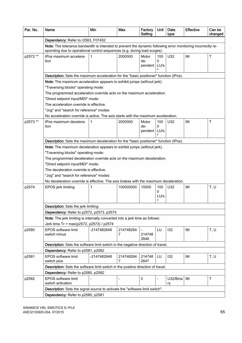
SINAMICS V90, SIMOTICS S-1FL6 A5E32100920-004, 07/2015 65
Par. No. Name Min Max Factory Setting
Unit Data type
Effective Can be changed
Dependency: Refer to r2563, F07452 Note: The tolerance bandwidth is intended to prevent the dynamic following error monitoring incorrectly re-sponding due to operational control sequences (e.g. during load surges).
p2572 ** IPos maximum accelera-tion
1 2000000 Motor de-pendent
1000 LU/s²
U32 IM T
Description: Sets the maximum acceleration for the "basic positioner" function (IPos). Note: The maximum acceleration appears to exhibit jumps (without jerk). "Traversing blocks" operating mode: The programmed acceleration override acts on the maximum acceleration. "Direct setpoint input/MDI" mode: The acceleration override is effective. "Jog" and "search for reference" modes: No acceleration override is active. The axis starts with the maximum acceleration.
p2573 ** IPos maximum decelera-tion
1 2000000 Motor de-pendent
1000 LU/s²
U32 IM T
Description: Sets the maximum deceleration for the "basic positioner" function (IPos). Note: The maximum deceleration appears to exhibit jumps (without jerk). "Traversing blocks" operating mode: The programmed deceleration override acts on the maximum deceleration. "Direct setpoint input/MDI" mode: The deceleration override is effective. "Jog" and "search for reference" modes: No deceleration override is effective. The axis brakes with the maximum deceleration.
p2574 EPOS jerk limiting 1 100000000 10000 1000 LU/s3
U32 IM T, U
Description: Sets the jerk limiting. Dependency: Refer to p2572, p2573, p2575 Note: The jerk limiting is internally converted into a jerk time as follows: Jerk time Tr = max(p2572, p2573) / p2574
p2580 EPOS software limit switch minus
-2147482648 2147482647
-2147482648
LU I32 IM T, U
Description: Sets the software limit switch in the negative direction of travel. Dependency: Refer to p2581, p2582
p2581 EPOS software limit switch plus
-2147482648 2147482647
2147482647
LU I32 IM T, U
Description: Sets the software limit switch in the positive direction of travel. Dependency: Refer to p2580, p2582
p2582 EPOS software limit switch activation
- - 0 - U32/Binary
IM T
Description: Sets the signal source to activate the "software limit switch". Dependency: Refer to p2580, p2581
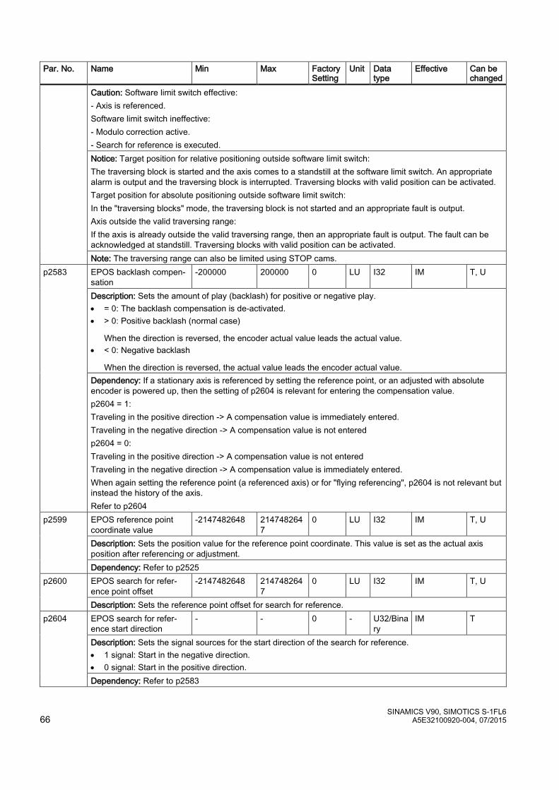
SINAMICS V90, SIMOTICS S-1FL6 66 A5E32100920-004, 07/2015
Par. No. Name Min Max Factory Setting
Unit Data type
Effective Can be changed
Caution: Software limit switch effective: - Axis is referenced. Software limit switch ineffective: - Modulo correction active. - Search for reference is executed. Notice: Target position for relative positioning outside software limit switch: The traversing block is started and the axis comes to a standstill at the software limit switch. An appropriate alarm is output and the traversing block is interrupted. Traversing blocks with valid position can be activated. Target position for absolute positioning outside software limit switch: In the "traversing blocks" mode, the traversing block is not started and an appropriate fault is output. Axis outside the valid traversing range: If the axis is already outside the valid traversing range, then an appropriate fault is output. The fault can be acknowledged at standstill. Traversing blocks with valid position can be activated. Note: The traversing range can also be limited using STOP cams.
p2583 EPOS backlash compen-sation
-200000 200000 0 LU I32 IM T, U
Description: Sets the amount of play (backlash) for positive or negative play. • = 0: The backlash compensation is de-activated. • > 0: Positive backlash (normal case)
When the direction is reversed, the encoder actual value leads the actual value. • < 0: Negative backlash
When the direction is reversed, the actual value leads the encoder actual value. Dependency: If a stationary axis is referenced by setting the reference point, or an adjusted with absolute encoder is powered up, then the setting of p2604 is relevant for entering the compensation value. p2604 = 1: Traveling in the positive direction -> A compensation value is immediately entered. Traveling in the negative direction -> A compensation value is not entered p2604 = 0: Traveling in the positive direction -> A compensation value is not entered Traveling in the negative direction -> A compensation value is immediately entered. When again setting the reference point (a referenced axis) or for "flying referencing", p2604 is not relevant but instead the history of the axis. Refer to p2604
p2599 EPOS reference point coordinate value
-2147482648 2147482647
0 LU I32 IM T, U
Description: Sets the position value for the reference point coordinate. This value is set as the actual axis position after referencing or adjustment. Dependency: Refer to p2525
p2600 EPOS search for refer-ence point offset
-2147482648 2147482647
0 LU I32 IM T, U
Description: Sets the reference point offset for search for reference. p2604 EPOS search for refer-
ence start direction - - 0 - U32/Bina
ry IM T
Description: Sets the signal sources for the start direction of the search for reference. • 1 signal: Start in the negative direction. • 0 signal: Start in the positive direction. Dependency: Refer to p2583
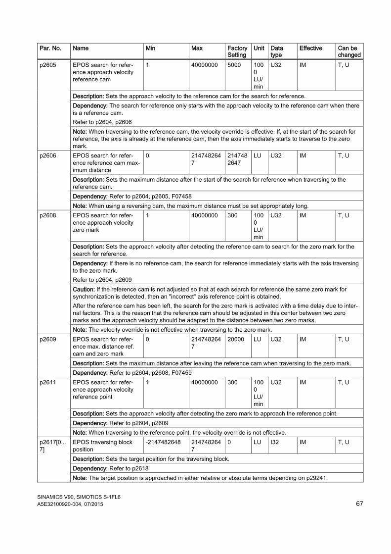
SINAMICS V90, SIMOTICS S-1FL6 A5E32100920-004, 07/2015 67
Par. No. Name Min Max Factory Setting
Unit Data type
Effective Can be changed
p2605 EPOS search for refer-ence approach velocity reference cam
1 40000000 5000 1000 LU/min
U32 IM T, U
Description: Sets the approach velocity to the reference cam for the search for reference. Dependency: The search for reference only starts with the approach velocity to the reference cam when there is a reference cam. Refer to p2604, p2606 Note: When traversing to the reference cam, the velocity override is effective. If, at the start of the search for reference, the axis is already at the reference cam, then the axis immediately starts to traverse to the zero mark.
p2606 EPOS search for refer-ence reference cam max-imum distance
0 2147482647
2147482647
LU U32 IM T, U
Description: Sets the maximum distance after the start of the search for reference when traversing to the reference cam. Dependency: Refer to p2604, p2605, F07458 Note: When using a reversing cam, the maximum distance must be set appropriately long.
p2608 EPOS search for refer-ence approach velocity zero mark
1 40000000 300 1000 LU/min
U32 IM T, U
Description: Sets the approach velocity after detecting the reference cam to search for the zero mark for the search for reference. Dependency: If there is no reference cam, the search for reference immediately starts with the axis traversing to the zero mark. Refer to p2604, p2609 Caution: If the reference cam is not adjusted so that at each search for reference the same zero mark for synchronization is detected, then an "incorrect" axis reference point is obtained. After the reference cam has been left, the search for the zero mark is activated with a time delay due to inter-nal factors. This is the reason that the reference cam should be adjusted in this center between two zero marks and the approach velocity should be adapted to the distance between two zero marks. Note: The velocity override is not effective when traversing to the zero mark.
p2609 EPOS search for refer-ence max. distance ref. cam and zero mark
0 2147482647
20000 LU U32 IM T, U
Description: Sets the maximum distance after leaving the reference cam when traversing to the zero mark. Dependency: Refer to p2604, p2608, F07459
p2611 EPOS search for refer-ence approach velocity reference point
1 40000000 300 1000 LU/min
U32 IM T, U
Description: Sets the approach velocity after detecting the zero mark to approach the reference point. Dependency: Refer to p2604, p2609 Note: When traversing to the reference point, the velocity override is not effective.
p2617[0...7]
EPOS traversing block position
-2147482648 2147482647
0 LU I32 IM T, U
Description: Sets the target position for the traversing block. Dependency: Refer to p2618 Note: The target position is approached in either relative or absolute terms depending on p29241.
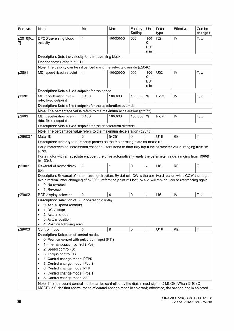
SINAMICS V90, SIMOTICS S-1FL6 68 A5E32100920-004, 07/2015
Par. No. Name Min Max Factory Setting
Unit Data type
Effective Can be changed
p2618[0...7]
EPOS traversing block velocity
1 40000000 600 1000 LU/min
I32 IM T, U
Description: Sets the velocity for the traversing block. Dependency: Refer to p2617 Note: The velocity can be influenced using the velocity override (p2646).
p2691 MDI speed fixed setpoint 1 40000000 600 1000 LU/min
U32 IM T, U
Description: Sets a fixed setpoint for the speed. p2692 MDI acceleration over-
ride, fixed setpoint 0.100 100.000 100.000 % Float IM T, U
Description: Sets a fixed setpoint for the acceleration override. Note: The percentage value refers to the maximum acceleration (p2572).
p2693 MDI deceleration over-ride, fixed setpoint
0.100 100.000 100.000 % Float IM T, U
Description: Sets a fixed setpoint for the deceleration override. Note: The percentage value refers to the maximum deceleration (p2573).
p29000 * Motor ID 0 54251 0 - U16 RE T Description: Motor type number is printed on the motor rating plate as motor ID. For a motor with an incremental encoder, users need to manually input the parameter value, ranging from 18 to 39. For a motor with an absolute encoder, the drive automatically reads the parameter value, ranging from 10009 to 10048.
p29001 Reversal of motor direc-tion
0 1 0 - I16 RE T
Description: Reversal of motor running direction. By default, CW is the positive direction while CCW the nega-tive direction. After changing of p29001, reference point will lost, A7461 will remind user to referencing again. • 0: No reversal • 1: Reverse
p29002 BOP display selection 0 4 0 - I16 IM T, U Description: Selection of BOP operating display. • 0: Actual speed (default) • 1: DC voltage • 2: Actual torque • 3: Actual position • 4: Position following error
p29003 Control mode 0 8 0 - U16 RE T Description: Selection of control mode. • 0: Position control with pulse train input (PTI) • 1: Internal position control (IPos) • 2: Speed control (S) • 3: Torque control (T) • 4: Control change mode: PTI/S • 5: Control change mode: IPos/S • 6: Control change mode: PTI/T • 7: Control change mode: IPos/T • 8: Control change mode: S/T Note: The compound control mode can be controlled by the digital input signal C-MODE. When DI10 (C-MODE) is 0, the first control mode of control change mode is selected; otherwise, the second one is selected.
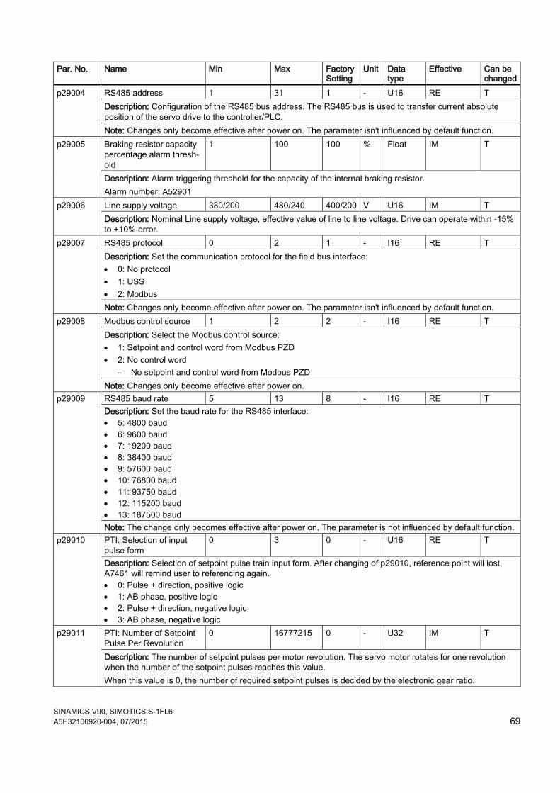
SINAMICS V90, SIMOTICS S-1FL6 A5E32100920-004, 07/2015 69
Par. No. Name Min Max Factory Setting
Unit Data type
Effective Can be changed
p29004
RS485 address 1 31 1 - U16 RE T Description: Configuration of the RS485 bus address. The RS485 bus is used to transfer current absolute position of the servo drive to the controller/PLC. Note: Changes only become effective after power on. The parameter isn't influenced by default function.
p29005
Braking resistor capacity percentage alarm thresh-old
1 100 100 % Float IM T
Description: Alarm triggering threshold for the capacity of the internal braking resistor. Alarm number: A52901
p29006 Line supply voltage 380/200 480/240 400/200 V U16 IM T Description: Nominal Line supply voltage, effective value of line to line voltage. Drive can operate within -15% to +10% error.
p29007 RS485 protocol 0 2 1 - I16 RE T Description: Set the communication protocol for the field bus interface: • 0: No protocol • 1: USS • 2: Modbus Note: Changes only become effective after power on. The parameter isn't influenced by default function.
p29008 Modbus control source 1 2 2 - I16 RE T Description: Select the Modbus control source: • 1: Setpoint and control word from Modbus PZD • 2: No control word
– No setpoint and control word from Modbus PZD Note: Changes only become effective after power on.
p29009 RS485 baud rate 5 13 8 - I16 RE T Description: Set the baud rate for the RS485 interface: • 5: 4800 baud • 6: 9600 baud • 7: 19200 baud • 8: 38400 baud • 9: 57600 baud • 10: 76800 baud • 11: 93750 baud • 12: 115200 baud • 13: 187500 baud Note: The change only becomes effective after power on. The parameter is not influenced by default function.
p29010
PTI: Selection of input pulse form
0 3 0 - U16 RE T
Description: Selection of setpoint pulse train input form. After changing of p29010, reference point will lost, A7461 will remind user to referencing again. • 0: Pulse + direction, positive logic • 1: AB phase, positive logic • 2: Pulse + direction, negative logic • 3: AB phase, negative logic
p29011
PTI: Number of Setpoint Pulse Per Revolution
0 16777215 0 - U32 IM T
Description: The number of setpoint pulses per motor revolution. The servo motor rotates for one revolution when the number of the setpoint pulses reaches this value. When this value is 0, the number of required setpoint pulses is decided by the electronic gear ratio.
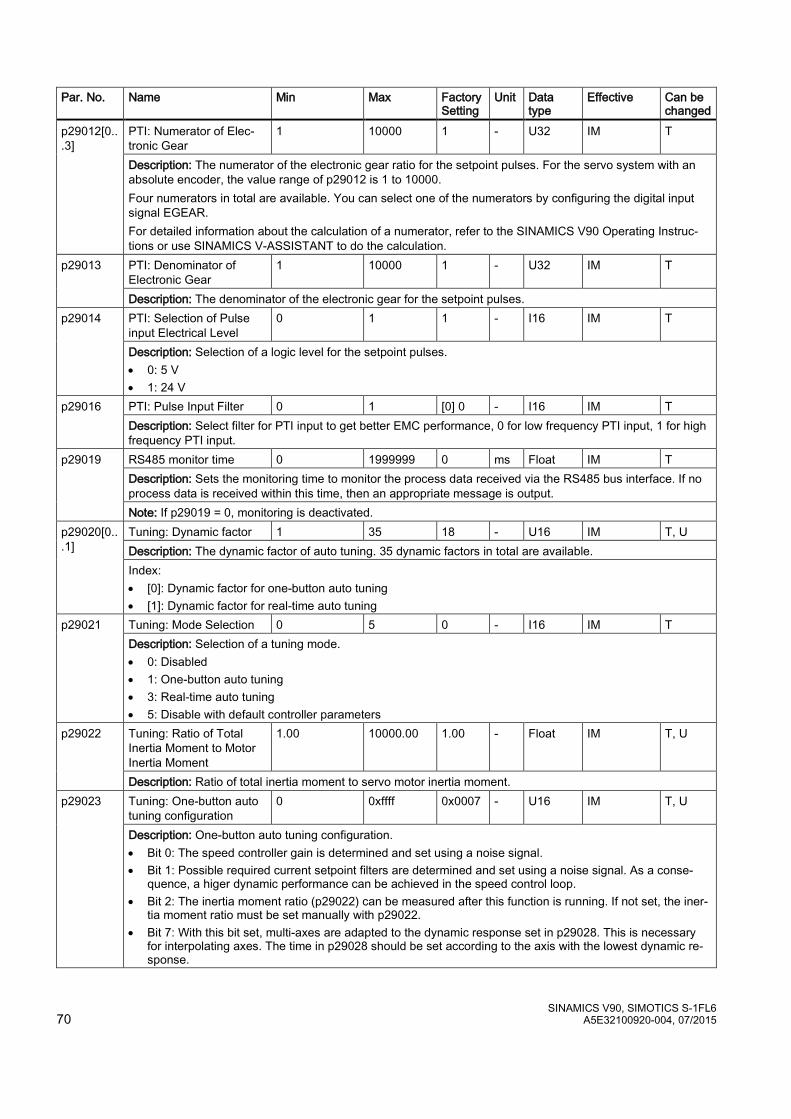
SINAMICS V90, SIMOTICS S-1FL6 70 A5E32100920-004, 07/2015
Par. No. Name Min Max Factory Setting
Unit Data type
Effective Can be changed
p29012[0...3]
PTI: Numerator of Elec-tronic Gear
1 10000 1 - U32 IM T
Description: The numerator of the electronic gear ratio for the setpoint pulses. For the servo system with an absolute encoder, the value range of p29012 is 1 to 10000. Four numerators in total are available. You can select one of the numerators by configuring the digital input signal EGEAR. For detailed information about the calculation of a numerator, refer to the SINAMICS V90 Operating Instruc-tions or use SINAMICS V-ASSISTANT to do the calculation.
p29013
PTI: Denominator of Electronic Gear
1 10000 1 - U32 IM T
Description: The denominator of the electronic gear for the setpoint pulses. p29014
PTI: Selection of Pulse input Electrical Level
0 1 1 - I16 IM T
Description: Selection of a logic level for the setpoint pulses. • 0: 5 V • 1: 24 V
p29016 PTI: Pulse Input Filter 0 1 [0] 0 - I16 IM T Description: Select filter for PTI input to get better EMC performance, 0 for low frequency PTI input, 1 for high frequency PTI input.
p29019 RS485 monitor time 0 1999999 0 ms Float IM T Description: Sets the monitoring time to monitor the process data received via the RS485 bus interface. If no process data is received within this time, then an appropriate message is output. Note: If p29019 = 0, monitoring is deactivated.
p29020[0...1]
Tuning: Dynamic factor 1 35 18 - U16 IM T, U Description: The dynamic factor of auto tuning. 35 dynamic factors in total are available. Index: • [0]: Dynamic factor for one-button auto tuning • [1]: Dynamic factor for real-time auto tuning
p29021 Tuning: Mode Selection 0 5 0 - I16 IM T Description: Selection of a tuning mode. • 0: Disabled • 1: One-button auto tuning • 3: Real-time auto tuning • 5: Disable with default controller parameters
p29022 Tuning: Ratio of Total Inertia Moment to Motor Inertia Moment
1.00 10000.00 1.00 - Float IM T, U
Description: Ratio of total inertia moment to servo motor inertia moment. p29023
Tuning: One-button auto tuning configuration
0 0xffff 0x0007 - U16 IM T, U
Description: One-button auto tuning configuration. • Bit 0: The speed controller gain is determined and set using a noise signal. • Bit 1: Possible required current setpoint filters are determined and set using a noise signal. As a conse-
quence, a higer dynamic performance can be achieved in the speed control loop. • Bit 2: The inertia moment ratio (p29022) can be measured after this function is running. If not set, the iner-
tia moment ratio must be set manually with p29022. • Bit 7: With this bit set, multi-axes are adapted to the dynamic response set in p29028. This is necessary
for interpolating axes. The time in p29028 should be set according to the axis with the lowest dynamic re-sponse.
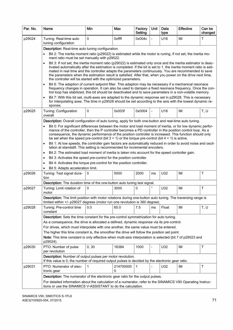
SINAMICS V90, SIMOTICS S-1FL6 A5E32100920-004, 07/2015 71
Par. No. Name Min Max Factory Setting
Unit Data type
Effective Can be changed
p29024 Tuning: Real-time auto tuning configuration
0 0xffff 0x004c - U16 IM T
Description: Real-time auto tuning configuration. • Bit 2: The inertia moment ratio (p29022) is estimated while the motor is runing, if not set, the inertia mo-
ment ratio must be set manually with p29022. • Bit 3: If not set, the inertia moment ratio (p29022) is estimated only once and the inertia estimator is deac-
tivated automatically after the estimation is completed. If the bit is set to 1, the inertia moment ratio is esti-mated in real time and the controller adapts the parameters continuously. You are recommended to save the parameters when the estimation result is satisfied. After that, when you power on the drive next time, the controller will be started with the optimized parameters.
• Bit 6: The adaption of current setpoint filter. This adaption may be necessary if a mechanical resonace frequency changes in operation. It can also be used to dampen a fixed resonace frequency. Once the con-trol loop has stabilized, this bit should be deactivated and to save parameters in a non-volatile memory.
• Bit 7: With this bit set, multi-axes are adapted to the dynamic response set in p29028. This is necessary for interpolating axes. The time in p29028 should be set according to the axis with the lowest dynamic re-sponse.
p29025 Tuning: Configuration overall
0 0x003f 0x0004 - U16 IM T, U
Description: Overall configuration of auto tuning, apply for both one-button and real-time auto tuning. • Bit 0: For significant differences between the motor and load moment of inertia, or for low dynamic perfor-
mance of the controller, then the P controller becomes a PD controller in the position control loop. As a consequence, the dynamic performance of the position controller is increased. This function should only be set when the speed pre-control (bit 3 = 1) or the torque pre-control (bit 4 = 1) is active.
• Bit 1: At low speeds, the controller gain factors are automatically reduced in order to avoid noise and oscil-lation at standstill. This setting is recommended for incremental encoders.
• Bit 2: The estimated load moment of inertia is taken into account for the speed controller gain. • Bit 3: Activates the speed pre-control for the position controller. • Bit 4: Activates the torque pre-control for the position controller. • Bit 5: Adapts acceleration limit.
p29026 Tuning: Test signal dura-tion
0 5000 2000 ms U32 IM T
Description: The duration time of the one-button auto tuning test signal. p29027 Tuning: Limit rotation of
motor 0 3000 0 ° U32 IM T
Description: The limit position with motor rotations during one-button auto tuning. The traversing range is limited within +/- p29027 degrees (motor run one revolution is 360 degree).
p29028 Tuning: Pre-control time constant
0.0 60.0 7.5 ms Float IM T, U
Description: Sets the time constant for the pre-control symmetrization for auto tuning. As a consequence, the drive is allocated a defined, dynamic response via its pre-control. For drives, which must interpolate with one another, the same value must be entered. The higher this time constant is, the smoother the drive will follow the position set point. Note: This time constant is only effective when multi-axis interpolation is selected (bit 7 of p29023 and p29024).
p29030 PTO: Number of pulse per revolution
0, 30 16384 1000 - U32 IM T
Description: Number of output pulses per motor revolution. If this value is 0, the number of required output pulses is decided by the electronic gear ratio.
p29031 PTO: Numerator of elec-tronic gear
1 2147000000
1 - U32 IM T
Description: The numerator of the electronic gear ratio for the output pulses. For detailed information about the calculation of a numerator, refer to the SINAMICS V90 Operating Instruc-tions or use the SINAMICS V-ASSISTANT to do the calculation.
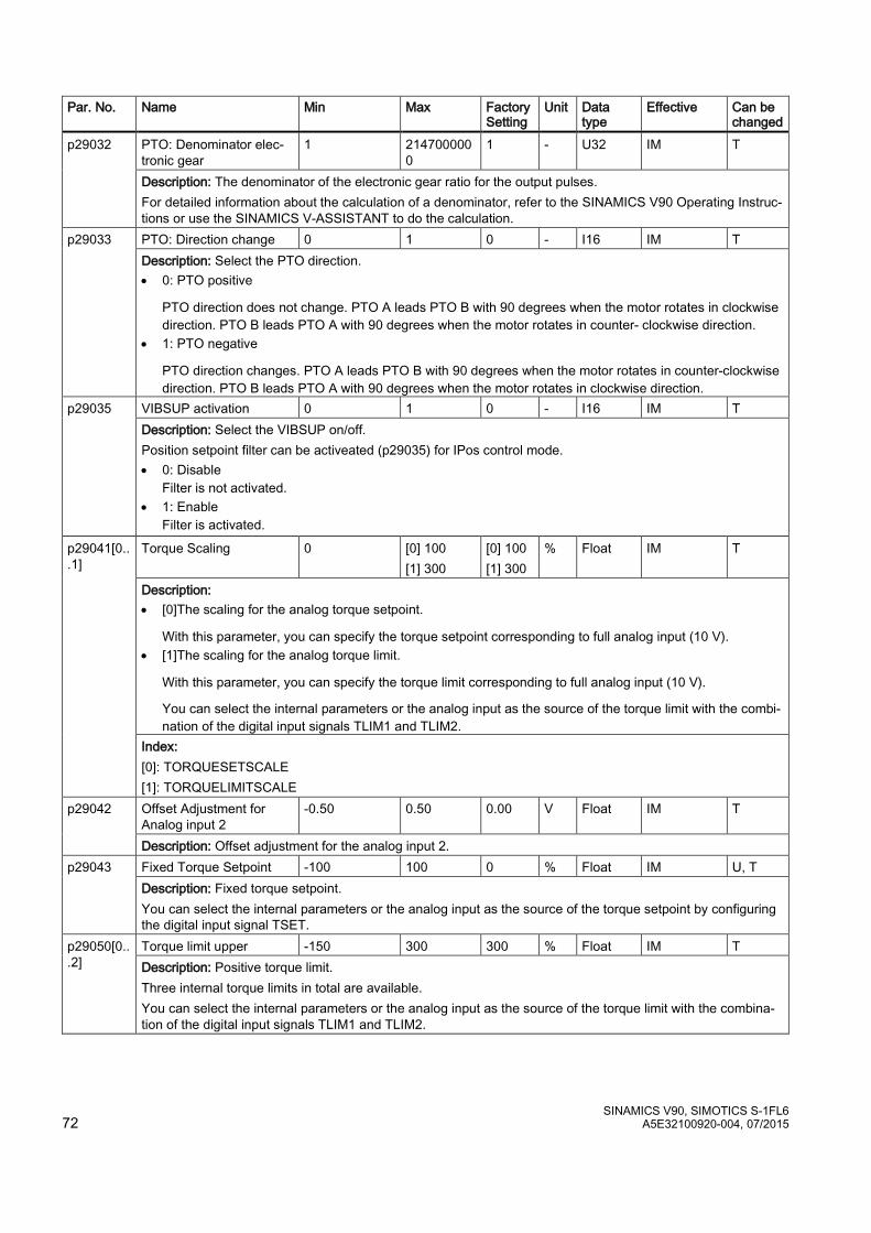
SINAMICS V90, SIMOTICS S-1FL6 72 A5E32100920-004, 07/2015
Par. No. Name Min Max Factory Setting
Unit Data type
Effective Can be changed
p29032 PTO: Denominator elec-tronic gear
1 2147000000
1 - U32 IM T
Description: The denominator of the electronic gear ratio for the output pulses. For detailed information about the calculation of a denominator, refer to the SINAMICS V90 Operating Instruc-tions or use the SINAMICS V-ASSISTANT to do the calculation.
p29033 PTO: Direction change 0 1 0 - I16 IM T Description: Select the PTO direction. • 0: PTO positive
PTO direction does not change. PTO A leads PTO B with 90 degrees when the motor rotates in clockwise direction. PTO B leads PTO A with 90 degrees when the motor rotates in counter- clockwise direction.
• 1: PTO negative
PTO direction changes. PTO A leads PTO B with 90 degrees when the motor rotates in counter-clockwise direction. PTO B leads PTO A with 90 degrees when the motor rotates in clockwise direction.
p29035 VIBSUP activation 0 1 0 - I16 IM T Description: Select the VIBSUP on/off. Position setpoint filter can be activeated (p29035) for IPos control mode. • 0: Disable
Filter is not activated. • 1: Enable
Filter is activated.
p29041[0...1]
Torque Scaling 0 [0] 100 [1] 300
[0] 100 [1] 300
% Float IM T
Description: • [0]The scaling for the analog torque setpoint.
With this parameter, you can specify the torque setpoint corresponding to full analog input (10 V). • [1]The scaling for the analog torque limit.
With this parameter, you can specify the torque limit corresponding to full analog input (10 V).
You can select the internal parameters or the analog input as the source of the torque limit with the combi-nation of the digital input signals TLIM1 and TLIM2.
Index: [0]: TORQUESETSCALE [1]: TORQUELIMITSCALE
p29042 Offset Adjustment for Analog input 2
-0.50 0.50 0.00 V Float IM T
Description: Offset adjustment for the analog input 2. p29043 Fixed Torque Setpoint -100 100 0 % Float IM U, T
Description: Fixed torque setpoint. You can select the internal parameters or the analog input as the source of the torque setpoint by configuring the digital input signal TSET.
p29050[0...2]
Torque limit upper -150 300 300 % Float IM T Description: Positive torque limit. Three internal torque limits in total are available. You can select the internal parameters or the analog input as the source of the torque limit with the combina-tion of the digital input signals TLIM1 and TLIM2.

SINAMICS V90, SIMOTICS S-1FL6 A5E32100920-004, 07/2015 73
Par. No. Name Min Max Factory Setting
Unit Data type
Effective Can be changed
p29051[0...2]
Torque limit lower -300 150 -300 % Float IM T Description: Negative torque limit. Three internal torque limits in total are available. You can select the internal parameters or the analog input as the source of the torque limit with the combina-tion of the digital input signals TLIM1 and TLIM2.
p29060 * Speed Scaling 6 210000 3000 rpm Float IM T Description: The scaling for the analog speed setpoint. With this parameter, you can specify the speed setpoint corresponding to full analog input (10 V).
p29061 Offset Adjustment for Analog input 1
-0.50 0.50 0.00 V Float IM T
Description: Offset adjustment for the analog input 1. p29070[0...2] *
Speed limit positive 0 210000 210000 rpm Float IM T Description: Positive speed limit. Three internal speed limits in total are available. You can select the internal parameters or the analog input as the source of the speed limit with the combina-tion of the digital input signals SLIM1 and SLIM2.
p29071[0...2] *
Speed limit negative -210000 0 -210000
rpm Float IM T
Description: Negative speed limit. Three internal speed limits in total are available. You can select the internal parameters or the analog input as the source of the speed limit with the combina-tion of the digital input signals SLIM1 and SLIM2.
p29075 Speed Clamp Threshold 0 200 200 rpm Float IM T Description: The threshold for the zero speed clamp. If the function of zero speed clamp has been enabled under the speed control mode, the motor speed is clamped to 0 when both the setpoint speed and the actual speed are below this threshold.
p29078 Speed Reach Threshold 0.0 100.0 10 rpm Float IM T Description: Speed reached range (deviation between setpoint and motor speed)
p29080 Overload Threshold for Output Signal Triggering
10 300 100 % Float IM T
Description: Overload threshold for the output power. p29090 Offset Adjustment for
Analog output 1 -0.50 0.50 0.00 V Float IM T
Description: Offset adjustment for analog output 1. p29091 Offset Adjustment for
Analog output 2 -0.50 0.50 0.00 V Float IM T
Description: Offset adjustment for analog output 2. p29110[0...1] **
Position Loop Gain 0.000 300.000 [0] Motor de-pendent [1] 1.000
1000/min
Float IM T, U
Description: Position loop gain. Two position loop gains in total are available. You can switch between these two gains by configuring the digital input signal G-CHANGE or setting relevant condition parameters. The first position loop gain is the default setting. Dependency: The parameter value will be set to default after configuring a new motor ID (p29000).

SINAMICS V90, SIMOTICS S-1FL6 74 A5E32100920-004, 07/2015
Par. No. Name Min Max Factory Setting
Unit Data type
Effective Can be changed
p29111 Speed Pre-control Factor (Feed Forward)
0.00 200.00 0.00 % Float IM T, U
Description: Setting to activate and weight the speed pre-control value. Value = 0 % --> The pre-control is de-activated.
p29120[0...1] **
Speed Loop Gain 0.00 999999.00 [0] Motor de-pendent [1] 0.30
Nms/rad
Float IM T, U
Description: Speed loop gain. Two speed loop gains in total are available. You can switch between these two gains by configuring the digital input signal G-CHANGE or setting relevant condition parameters. The first speed loop gain is the default setting. Dependency: The parameter value will be set to default after configuring a new motor ID (p29000).
p29121[0...1] *
Speed Loop Integral time 0.00 100000.00 [0] 15 [1] 20
ms Float IM T, U
Description: Speed loop integral time. Two speed loop integral time values in total are available. You can switch between these two time values by configuring the digital input signal G-CHANGE or setting relevant condition parameters. The first speed loop integral time is the default setting. Dependency: The parameter value will be set to default after configuring a new motor ID (p29000).
p29130
Gain Switching: Mode Selection
0 4 0 - I16 IM T
Description: Selects gain switching mode. • 0: Disabled • 1: Switch through DI-G-CHANG • 2: Position deviation as switch condition • 3: Pulse input frequency as switch condition • 4: Actual speed as switch condition Note: Only when the auto tuning function (p20021=0) is disabled can the gain switching function be used.
p29131 Gain Switching Condition: Pulse Deviation
0 2147483647
100 LU I32 IM T
Description: Triggers position deviation threshold for gain switching. If the gain switching function is enabled and this condition is selected: • Switch from the first group of control parameters to the second group when the position deviation is larger
than the threshold. • Switch from the second group of control parameters to the first group when the position deviation is small-
er than the threshold. p29132 Gain Switching Condition:
Position Setpoint Fre-quency
0 2147000064
100 1000 LU/min
Float IM T
Description: Triggers pulse input frequency (PTI) threshold or internal position speed (IPos) threshold for gain switching. If the gain switching function is enabled and this condition is selected: 1. PTI
– Switch from the first group of control parameters to the second group when the pulse train input pulse is higher than the threshold.
– Switch from the second group of control parameters to the first group when the pulse train input is low-er than the threshold.
2. IPos – Switch from the first group of control parameters to the second group when the speed of fixed position
setpoint is larger than the threshold. – Switch from the second group of control parameters to the first group when the IPos is smaller than the
threshold.
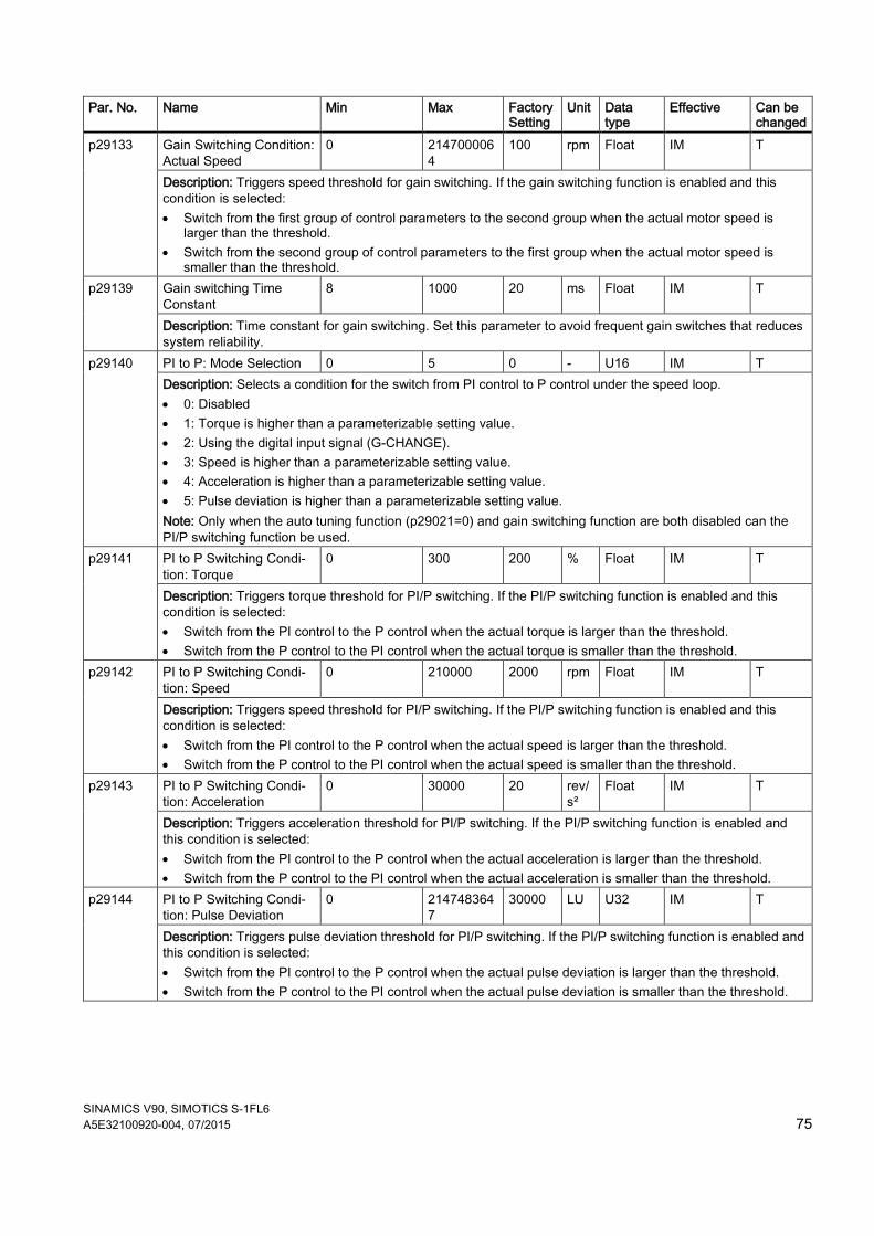
SINAMICS V90, SIMOTICS S-1FL6 A5E32100920-004, 07/2015 75
Par. No. Name Min Max Factory Setting
Unit Data type
Effective Can be changed
p29133 Gain Switching Condition: Actual Speed
0 2147000064
100 rpm Float IM T
Description: Triggers speed threshold for gain switching. If the gain switching function is enabled and this condition is selected: • Switch from the first group of control parameters to the second group when the actual motor speed is
larger than the threshold. • Switch from the second group of control parameters to the first group when the actual motor speed is
smaller than the threshold. p29139 Gain switching Time
Constant 8 1000 20 ms Float IM T
Description: Time constant for gain switching. Set this parameter to avoid frequent gain switches that reduces system reliability.
p29140 PI to P: Mode Selection 0 5 0 - U16 IM T Description: Selects a condition for the switch from PI control to P control under the speed loop. • 0: Disabled • 1: Torque is higher than a parameterizable setting value. • 2: Using the digital input signal (G-CHANGE). • 3: Speed is higher than a parameterizable setting value. • 4: Acceleration is higher than a parameterizable setting value. • 5: Pulse deviation is higher than a parameterizable setting value. Note: Only when the auto tuning function (p29021=0) and gain switching function are both disabled can the PI/P switching function be used.
p29141
PI to P Switching Condi-tion: Torque
0 300 200 % Float IM T
Description: Triggers torque threshold for PI/P switching. If the PI/P switching function is enabled and this condition is selected: • Switch from the PI control to the P control when the actual torque is larger than the threshold. • Switch from the P control to the PI control when the actual torque is smaller than the threshold.
p29142 PI to P Switching Condi-tion: Speed
0 210000 2000 rpm Float IM T
Description: Triggers speed threshold for PI/P switching. If the PI/P switching function is enabled and this condition is selected: • Switch from the PI control to the P control when the actual speed is larger than the threshold. • Switch from the P control to the PI control when the actual speed is smaller than the threshold.
p29143 PI to P Switching Condi-tion: Acceleration
0 30000 20 rev/s²
Float IM T
Description: Triggers acceleration threshold for PI/P switching. If the PI/P switching function is enabled and this condition is selected: • Switch from the PI control to the P control when the actual acceleration is larger than the threshold. • Switch from the P control to the PI control when the actual acceleration is smaller than the threshold.
p29144 PI to P Switching Condi-tion: Pulse Deviation
0 2147483647
30000 LU U32 IM T
Description: Triggers pulse deviation threshold for PI/P switching. If the PI/P switching function is enabled and this condition is selected: • Switch from the PI control to the P control when the actual pulse deviation is larger than the threshold. • Switch from the P control to the PI control when the actual pulse deviation is smaller than the threshold.
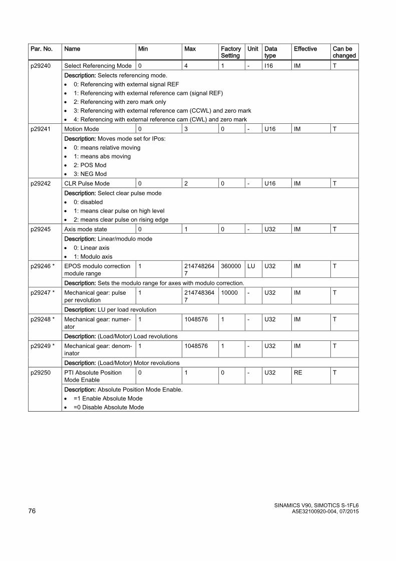
SINAMICS V90, SIMOTICS S-1FL6 76 A5E32100920-004, 07/2015
Par. No. Name Min Max Factory Setting
Unit Data type
Effective Can be changed
p29240 Select Referencing Mode 0 4 1 - I16 IM T Description: Selects referencing mode. • 0: Referencing with external signal REF • 1: Referencing with external reference cam (signal REF) • 2: Referencing with zero mark only • 3: Referencing with external reference cam (CCWL) and zero mark • 4: Referencing with external reference cam (CWL) and zero mark
p29241 Motion Mode 0 3 0 - U16 IM T Description: Moves mode set for IPos: • 0: means relative moving • 1: means abs moving • 2: POS Mod • 3: NEG Mod
p29242 CLR Pulse Mode 0 2 0 - U16 IM T Description: Select clear pulse mode • 0: disabled • 1: means clear pulse on high level • 2: means clear pulse on rising edge
p29245
Axis mode state 0 1 0 - U32 IM T Description: Linear/modulo mode • 0: Linear axis • 1: Modulo axis
p29246 * EPOS modulo correction module range
1 2147482647
360000 LU U32 IM T
Description: Sets the modulo range for axes with modulo correction. p29247 * Mechanical gear: pulse
per revolution 1 214748364
7 10000 - U32 IM T
Description: LU per load revolution p29248 * Mechanical gear: numer-
ator 1 1048576 1 - U32 IM T
Description: (Load/Motor) Load revolutions p29249 * Mechanical gear: denom-
inator 1 1048576 1 - U32 IM T
Description: (Load/Motor) Motor revolutions p29250 PTI Absolute Position
Mode Enable 0 1 0 - U32 RE T
Description: Absolute Position Mode Enable. • =1 Enable Absolute Mode • =0 Disable Absolute Mode

SINAMICS V90, SIMOTICS S-1FL6 A5E32100920-004, 07/2015 77
Par. No. Name Min Max Factory Setting
Unit Data type
Effective Can be changed
p29300
Digital Input Forced Sig-nals
0 127 0 - U32 IM T, U
Description: Input signals are forced to be high. 7 bits in total. • Bit 0: SON • Bit 1: CWL • Bit 2: CCWL • Bit 3: TLIM1 • Bit 4: SPD1 • Bit 5: TSET • Bit 6: EMGS If one or more bits are set to be high, the corresponding input signals are forced to be logical high signals. Note: The drive unit displays the value in hex format. To know the logic (high/low) assignment to each bit, you must convert the hex number to the binary number, for example, FF (hex) = 11111111 (bin).
p29301[0...3]
Digital Input 1 Assign-ment
0 28 1 - I16 IM T
Description: Defines the function of digital input signal DI1 (PTI mode) • SON 1 • RESET 2 • CWL 3 • CCWL 4 • G-CHANGE 5 • P-TRG 6 • CLR 7 • EGEAR1 8 • EGEAR2 9 • TLIMT1 10 • TLIMT2 11 • CWE 12 • CCWE 13 • ZSCLAMP 14 • SPD1 15 • SPD2 16 • SPD3 17 • TSET 18 • SLIMT1 19 • SLIMT2 20 • POS1 21 • POS2 22 • POS3 23 • REF 24 • SREF 25 • STEPF 26 • STEPB 27 • STEPH 28 Index: • [0]: DI1 for Control mode 0 • [1]: DI1 for Control mode 1 • [2]: DI1 for Control mode 2 • [3]: DI1 for Control mode 3
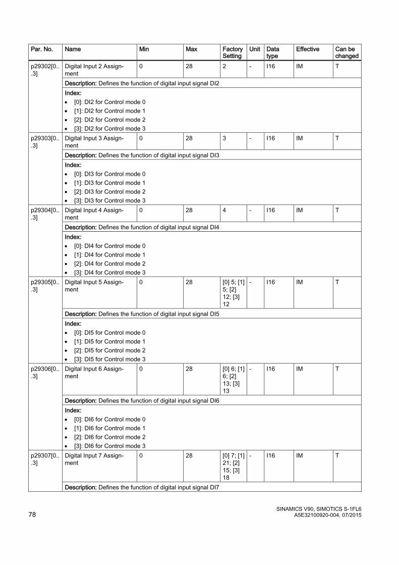
SINAMICS V90, SIMOTICS S-1FL6 78 A5E32100920-004, 07/2015
Par. No. Name Min Max Factory Setting
Unit Data type
Effective Can be changed
p29302[0...3]
Digital Input 2 Assign-ment
0 28 2 - I16 IM T
Description: Defines the function of digital input signal DI2 Index: • [0]: DI2 for Control mode 0 • [1]: DI2 for Control mode 1 • [2]: DI2 for Control mode 2 • [3]: DI2 for Control mode 3
p29303[0...3]
Digital Input 3 Assign-ment
0 28 3 - I16 IM T
Description: Defines the function of digital input signal DI3 Index: • [0]: DI3 for Control mode 0 • [1]: DI3 for Control mode 1 • [2]: DI3 for Control mode 2 • [3]: DI3 for Control mode 3
p29304[0...3]
Digital Input 4 Assign-ment
0 28 4 - I16 IM T
Description: Defines the function of digital input signal DI4 Index: • [0]: DI4 for Control mode 0 • [1]: DI4 for Control mode 1 • [2]: DI4 for Control mode 2 • [3]: DI4 for Control mode 3
p29305[0...3]
Digital Input 5 Assign-ment
0 28 [0] 5; [1] 5; [2] 12; [3] 12
- I16 IM T
Description: Defines the function of digital input signal DI5 Index: • [0]: DI5 for Control mode 0 • [1]: DI5 for Control mode 1 • [2]: DI5 for Control mode 2 • [3]: DI5 for Control mode 3
p29306[0...3]
Digital Input 6 Assign-ment
0 28 [0] 6; [1] 6; [2] 13; [3] 13
- I16 IM T
Description: Defines the function of digital input signal DI6 Index: • [0]: DI6 for Control mode 0 • [1]: DI6 for Control mode 1 • [2]: DI6 for Control mode 2 • [3]: DI6 for Control mode 3
p29307[0...3]
Digital Input 7 Assign-ment
0 28 [0] 7; [1] 21; [2] 15; [3] 18
- I16 IM T
Description: Defines the function of digital input signal DI7
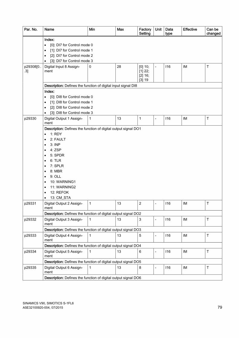
SINAMICS V90, SIMOTICS S-1FL6 A5E32100920-004, 07/2015 79
Par. No. Name Min Max Factory Setting
Unit Data type
Effective Can be changed
Index: • [0]: DI7 for Control mode 0 • [1]: DI7 for Control mode 1 • [2]: DI7 for Control mode 2 • [3]: DI7 for Control mode 3
p29308[0...3]
Digital Input 8 Assign-ment
0 28 [0] 10; [1] 22; [2] 16; [3] 19
- I16 IM T
Description: Defines the function of digital input signal DI8 Index: • [0]: DI8 for Control mode 0 • [1]: DI8 for Control mode 1 • [2]: DI8 for Control mode 2 • [3]: DI8 for Control mode 3
p29330 Digital Output 1 Assign-ment
1 13 1 - I16 IM T
Description: Defines the function of digital output signal DO1 • 1: RDY • 2: FAULT • 3: INP • 4: ZSP • 5: SPDR • 6: TLR • 7: SPLR • 8: MBR • 9: OLL • 10: WARNING1 • 11: WARNING2 • 12: REFOK • 13: CM_STA
p29331 Digital Output 2 Assign-ment
1 13 2 - I16 IM T
Description: Defines the function of digital output signal DO2 p29332 Digital Output 3 Assign-
ment 1 13 3 - I16 IM T
Description: Defines the function of digital output signal DO3 p29333 Digital Output 4 Assign-
ment 1 13 5 - I16 IM T
Description: Defines the function of digital output signal DO4 p29334 Digital Output 5 Assign-
ment 1 13 6 - I16 IM T
Description: Defines the function of digital output signal DO5 p29335 Digital Output 6 Assign-
ment 1 13 8 - I16 IM T
Description: Defines the function of digital output signal DO6
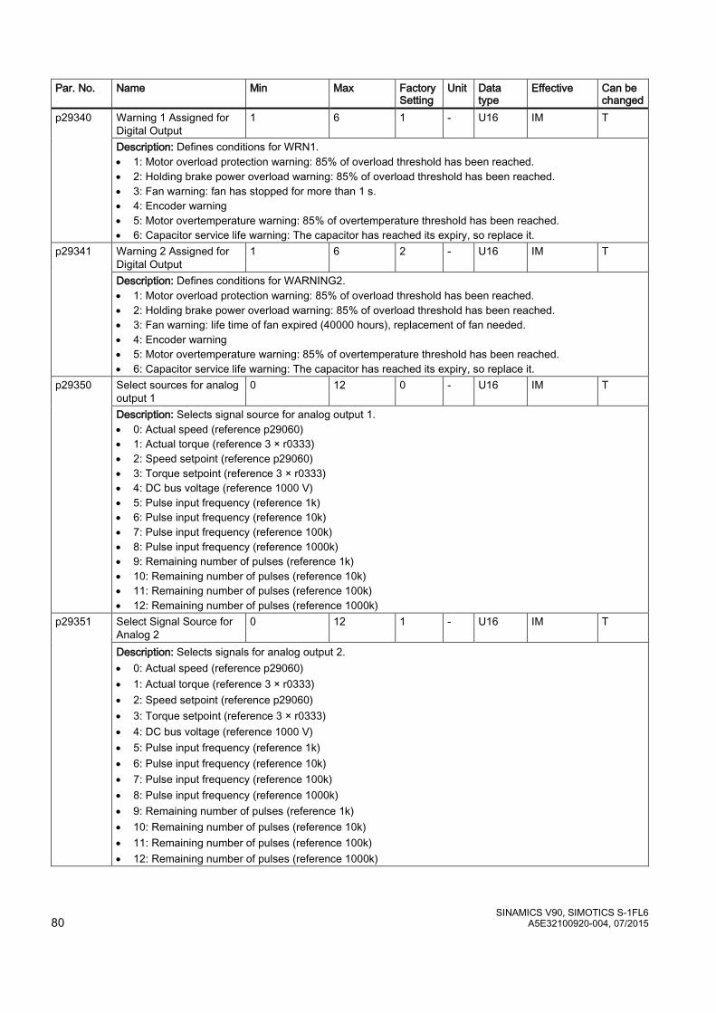
SINAMICS V90, SIMOTICS S-1FL6 80 A5E32100920-004, 07/2015
Par. No. Name Min Max Factory Setting
Unit Data type
Effective Can be changed
p29340 Warning 1 Assigned for Digital Output
1 6 1 - U16 IM T
Description: Defines conditions for WRN1. • 1: Motor overload protection warning: 85% of overload threshold has been reached. • 2: Holding brake power overload warning: 85% of overload threshold has been reached. • 3: Fan warning: fan has stopped for more than 1 s. • 4: Encoder warning • 5: Motor overtemperature warning: 85% of overtemperature threshold has been reached. • 6: Capacitor service life warning: The capacitor has reached its expiry, so replace it.
p29341
Warning 2 Assigned for Digital Output
1 6 2 - U16 IM T
Description: Defines conditions for WARNING2. • 1: Motor overload protection warning: 85% of overload threshold has been reached. • 2: Holding brake power overload warning: 85% of overload threshold has been reached. • 3: Fan warning: life time of fan expired (40000 hours), replacement of fan needed. • 4: Encoder warning • 5: Motor overtemperature warning: 85% of overtemperature threshold has been reached. • 6: Capacitor service life warning: The capacitor has reached its expiry, so replace it.
p29350 Select sources for analog output 1
0 12 0 - U16 IM T
Description: Selects signal source for analog output 1. • 0: Actual speed (reference p29060) • 1: Actual torque (reference 3 × r0333) • 2: Speed setpoint (reference p29060) • 3: Torque setpoint (reference 3 × r0333) • 4: DC bus voltage (reference 1000 V) • 5: Pulse input frequency (reference 1k) • 6: Pulse input frequency (reference 10k) • 7: Pulse input frequency (reference 100k) • 8: Pulse input frequency (reference 1000k) • 9: Remaining number of pulses (reference 1k) • 10: Remaining number of pulses (reference 10k) • 11: Remaining number of pulses (reference 100k) • 12: Remaining number of pulses (reference 1000k)
p29351 Select Signal Source for Analog 2
0 12 1 - U16 IM T
Description: Selects signals for analog output 2. • 0: Actual speed (reference p29060) • 1: Actual torque (reference 3 × r0333) • 2: Speed setpoint (reference p29060) • 3: Torque setpoint (reference 3 × r0333) • 4: DC bus voltage (reference 1000 V) • 5: Pulse input frequency (reference 1k) • 6: Pulse input frequency (reference 10k) • 7: Pulse input frequency (reference 100k) • 8: Pulse input frequency (reference 1000k) • 9: Remaining number of pulses (reference 1k) • 10: Remaining number of pulses (reference 10k) • 11: Remaining number of pulses (reference 100k) • 12: Remaining number of pulses (reference 1000k)

SINAMICS V90, SIMOTICS S-1FL6 A5E32100920-004, 07/2015 81
Par. No. Name Min Max Factory Setting
Unit Data type
Effective Can be changed
p31581 VIBSUP: Filter type 0 1 0 - I16 IM T Description: Sets the filter type for VIBSUP. Depending on the selected filter type, the VIBSUP filter results in motion sequences that take somewhat longer. • 0: The rugged VIBSUP filter has a lower sensitivity to frequency offsets compared with the sensitive filter
type, but results in a higher delay of the motion sequence. The total motion sequence is extended by the time period Td (Td = 1/fd).
• 1: The sensitive VIBSUP filter has a higher sensitivity to frequency offsets compared with the rugged filter type, but results in a lower delay of the motion sequence. The total motion sequence is extended by half the time period Td/2 (Td = 1/fd).
p31585 VIBSUP: Filter frequency fd
0.5 62.5 1 Hz Float 32 IM T
Description: Sets the frequency of the damped natural vibration of the mechanical system. This frequency can be determined by making the appropriate measurements. Note: The maximum frequency that can be set depends on the filter sampling time.
p31586 VIBSUP: Filter damping 0.00 0.99 0.03 - Float 32 IM T Description: Sets the value for the damping of the natural mechanical vibration to be filtered. Typically, the damping value is about 0.03, and can be optimized by performing the appropriate positioning tests.
Read-only parameters
Par. No. Name Unit Data type r0020 Speed setpoint smoothed rpm Float
Description: Displays the currently smoothed speed setpoint at the input of the speed controller or U/f characteristic (after the interpolator). Note: Smoothing time constant = 100 ms The signal is not suitable as a process quantity and may only be used as a display quantity. The speed setpoint is available smoothed (r0020) and unsmoothed.
r0021 Actual speed smoothed rpm Float Description: Displays the smoothed actual value of the motor speed. Note: Smoothing time constant = 100 ms The signal is not suitable as a process quantity and may only be used as a display quantity. The speed actual value is available smoothed (r0021) and unsmoothed.
r0026 DC link voltage smoothed V Float Description: Displays the smoothed actual value of the DC link voltage. Notice: When measuring a DC link voltage < 200 V, for the Power Module (e.g. PM340) a valid meas-ured value is not supplied. In this case, when an external 24 V power supply is connected, a value of approx. 24 V is displayed in the display parameter. Note: Smoothing time constant = 100 ms The signal is not suitable as a process quantity and may only be used as a display quantity. The DC link voltage is available smoothed (r0026) and unsmoothed.
r0027 Absolute actual current smoothed Arms Float Description: Displays the smoothed absolute actual current value. Notice: This smoothed signal is not suitable for diagnostics or evaluation of dynamic operations. In this case, the unsmoothed value should be used. Note: Smoothing time constant = 100 ms The signal is not suitable as a process quantity and may only be used as a display quantity. The absolute current actual value is available smoothed (r0027) and unsmoothed.
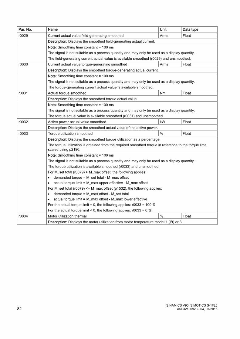
SINAMICS V90, SIMOTICS S-1FL6 82 A5E32100920-004, 07/2015
Par. No. Name Unit Data type r0029 Current actual value field-generating smoothed Arms Float
Description: Displays the smoothed field-generating actual current. Note: Smoothing time constant = 100 ms The signal is not suitable as a process quantity and may only be used as a display quantity. The field-generating current actual value is available smoothed (r0029) and unsmoothed.
r0030 Current actual value torque-generating smoothed Arms Float Description: Displays the smoothed torque-generating actual current. Note: Smoothing time constant = 100 ms The signal is not suitable as a process quantity and may only be used as a display quantity. The torque-generating current actual value is available smoothed.
r0031 Actual torque smoothed Nm Float Description: Displays the smoothed torque actual value. Note: Smoothing time constant = 100 ms The signal is not suitable as a process quantity and may only be used as a display quantity. The torque actual value is available smoothed (r0031) and unsmoothed.
r0032 Active power actual value smoothed kW Float Description: Displays the smoothed actual value of the active power.
r0033 Torque utilization smoothed % Float Description: Displays the smoothed torque utilization as a percentage. The torque utilization is obtained from the required smoothed torque in reference to the torque limit, scaled using p2196. Note: Smoothing time constant = 100 ms The signal is not suitable as a process quantity and may only be used as a display quantity. The torque utilization is available smoothed (r0033) and unsmoothed. For M_set total (r0079) > M_max offset, the following applies: • demanded torque = M_set total - M_max offset • actual torque limit = M_max upper effective - M_max offset For M_set total (r0079) <= M_max offset (p1532), the following applies: • demanded torque = M_max offset - M_set total • actual torque limit = M_max offset - M_max lower effective For the actual torque limit = 0, the following applies: r0033 = 100 % For the actual torque limit < 0, the following applies: r0033 = 0 %
r0034 Motor utilization thermal % Float Description: Displays the motor utilization from motor temperature model 1 (I2t) or 3.
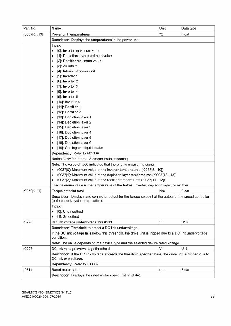
SINAMICS V90, SIMOTICS S-1FL6 A5E32100920-004, 07/2015 83
Par. No. Name Unit Data type r0037[0...19] Power unit temperatures °C Float
Description: Displays the temperatures in the power unit. Index: • [0]: Inverter maximum value • [1]: Depletion layer maximum value • [2]: Rectifier maximum value • [3]: Air intake • [4]: Interior of power unit • [5]: Inverter 1 • [6]: Inverter 2 • [7]: Inverter 3 • [8]: Inverter 4 • [9]: Inverter 5 • [10]: Inverter 6 • [11]: Rectifier 1 • [12]: Rectifier 2 • [13]: Depletion layer 1 • [14]: Depletion layer 2 • [15]: Depletion layer 3 • [16]: Depletion layer 4 • [17]: Depletion layer 5 • [18]: Depletion layer 6 • [19]: Cooling unit liquid intake Dependency: Refer to A01009 Notice: Only for internal Siemens troubleshooting. Note: The value of -200 indicates that there is no measuring signal. • r0037[0]: Maximum value of the inverter temperatures (r0037[5...10]). • r0037[1]: Maximum value of the depletion layer temperatures (r0037[13...18]). • r0037[2]: Maximum value of the rectifier temperatures (r0037[11...12]). The maximum value is the temperature of the hottest inverter, depletion layer, or rectifier.
r0079[0...1] Torque setpoint total Nm Float Description: Displays and connector output for the torque setpoint at the output of the speed controller (before clock cycle interpolation). Index: • [0]: Unsmoothed • [1]: Smoothed
r0296 DC link voltage undervoltage threshold V U16 Description: Threshold to detect a DC link undervoltage. If the DC link voltage falls below this threshold, the drive unit is tripped due to a DC link undervoltage condition. Note: The value depends on the device type and the selected device rated voltage.
r0297 DC link voltage overvoltage threshold V U16 Description: If the DC link voltage exceeds the threshold specified here, the drive unit is tripped due to DC link overvoltage. Dependency: Refer to F30002.
r0311 Rated motor speed rpm Float Description: Displays the rated motor speed (rating plate).
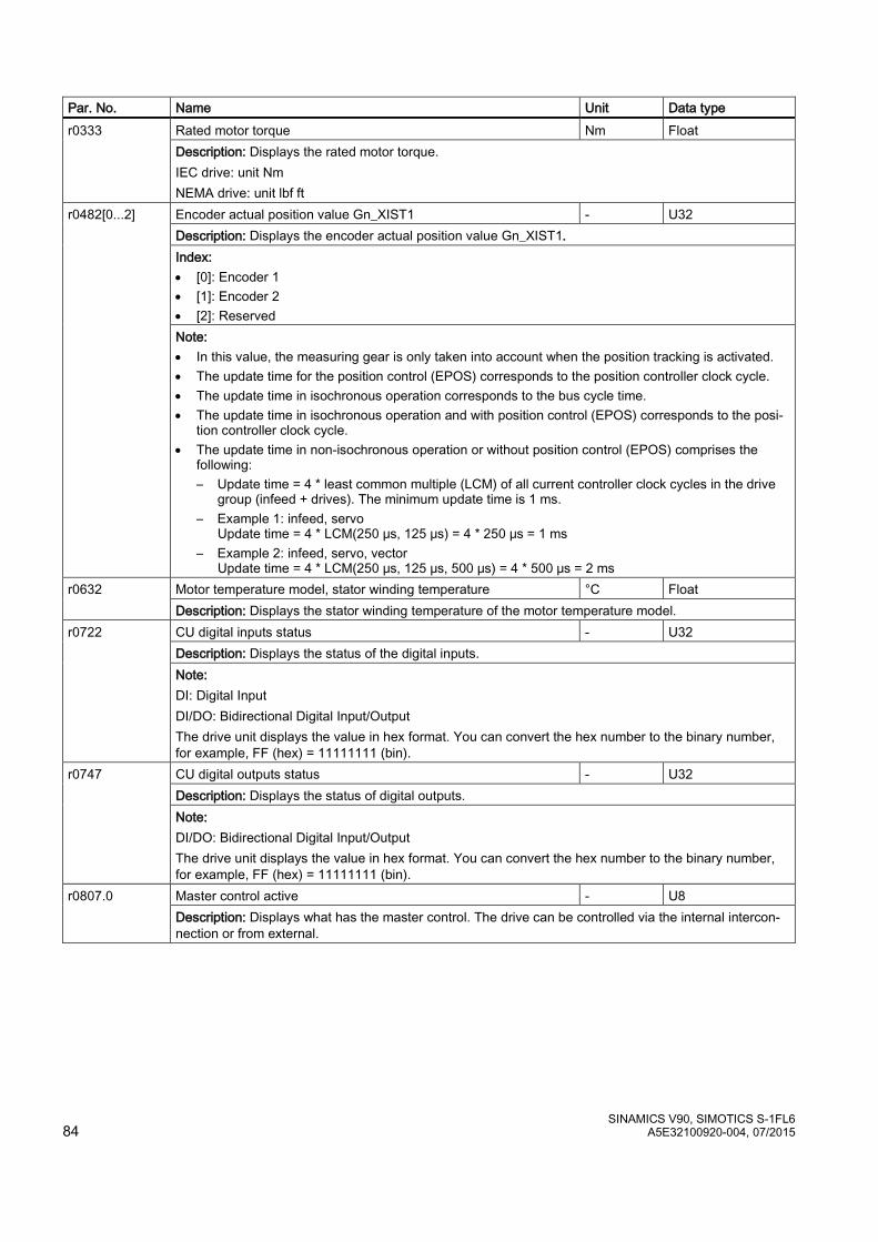
SINAMICS V90, SIMOTICS S-1FL6 84 A5E32100920-004, 07/2015
Par. No. Name Unit Data type r0333
Rated motor torque Nm Float Description: Displays the rated motor torque. IEC drive: unit Nm NEMA drive: unit lbf ft
r0482[0...2] Encoder actual position value Gn_XIST1 - U32 Description: Displays the encoder actual position value Gn_XIST1. Index: • [0]: Encoder 1 • [1]: Encoder 2 • [2]: Reserved Note: • In this value, the measuring gear is only taken into account when the position tracking is activated. • The update time for the position control (EPOS) corresponds to the position controller clock cycle. • The update time in isochronous operation corresponds to the bus cycle time. • The update time in isochronous operation and with position control (EPOS) corresponds to the posi-
tion controller clock cycle. • The update time in non-isochronous operation or without position control (EPOS) comprises the
following: – Update time = 4 * least common multiple (LCM) of all current controller clock cycles in the drive
group (infeed + drives). The minimum update time is 1 ms. – Example 1: infeed, servo
Update time = 4 * LCM(250 μs, 125 μs) = 4 * 250 μs = 1 ms – Example 2: infeed, servo, vector
Update time = 4 * LCM(250 μs, 125 μs, 500 μs) = 4 * 500 μs = 2 ms r0632
Motor temperature model, stator winding temperature °C Float Description: Displays the stator winding temperature of the motor temperature model.
r0722 CU digital inputs status - U32 Description: Displays the status of the digital inputs. Note: DI: Digital Input DI/DO: Bidirectional Digital Input/Output The drive unit displays the value in hex format. You can convert the hex number to the binary number, for example, FF (hex) = 11111111 (bin).
r0747 CU digital outputs status - U32 Description: Displays the status of digital outputs. Note: DI/DO: Bidirectional Digital Input/Output The drive unit displays the value in hex format. You can convert the hex number to the binary number, for example, FF (hex) = 11111111 (bin).
r0807.0 Master control active - U8 Description: Displays what has the master control. The drive can be controlled via the internal intercon-nection or from external.
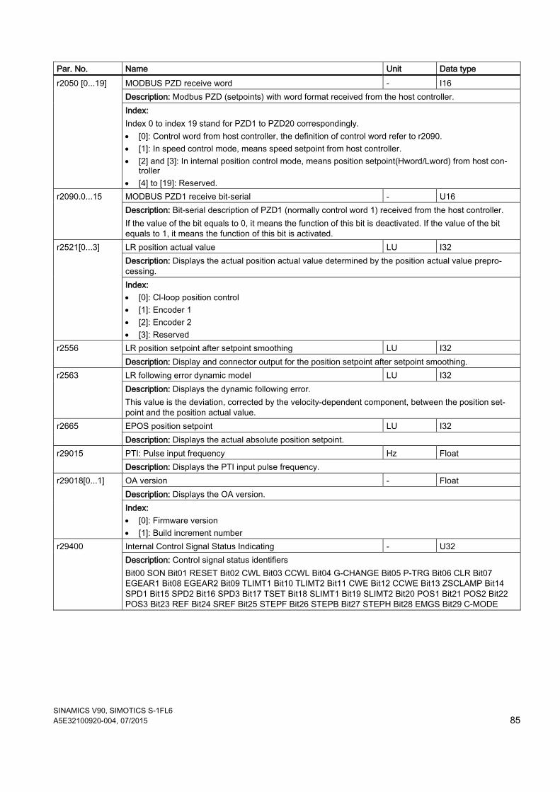
SINAMICS V90, SIMOTICS S-1FL6 A5E32100920-004, 07/2015 85
Par. No. Name Unit Data type r2050 [0...19] MODBUS PZD receive word - I16
Description: Modbus PZD (setpoints) with word format received from the host controller. Index: Index 0 to index 19 stand for PZD1 to PZD20 correspondingly. • [0]: Control word from host controller, the definition of control word refer to r2090. • [1]: In speed control mode, means speed setpoint from host controller. • [2] and [3]: In internal position control mode, means position setpoint(Hword/Lword) from host con-
troller • [4] to [19]: Reserved.
r2090.0...15 MODBUS PZD1 receive bit-serial - U16 Description: Bit-serial description of PZD1 (normally control word 1) received from the host controller. If the value of the bit equals to 0, it means the function of this bit is deactivated. If the value of the bit equals to 1, it means the function of this bit is activated.
r2521[0...3] LR position actual value LU I32 Description: Displays the actual position actual value determined by the position actual value prepro-cessing. Index: • [0]: Cl-loop position control • [1]: Encoder 1 • [2]: Encoder 2 • [3]: Reserved
r2556 LR position setpoint after setpoint smoothing LU I32 Description: Display and connector output for the position setpoint after setpoint smoothing.
r2563
LR following error dynamic model LU I32 Description: Displays the dynamic following error. This value is the deviation, corrected by the velocity-dependent component, between the position set-point and the position actual value.
r2665 EPOS position setpoint LU I32 Description: Displays the actual absolute position setpoint.
r29015
PTI: Pulse input frequency Hz Float Description: Displays the PTI input pulse frequency.
r29018[0...1] OA version - Float Description: Displays the OA version. Index: • [0]: Firmware version • [1]: Build increment number
r29400
Internal Control Signal Status Indicating - U32 Description: Control signal status identifiers Bit00 SON Bit01 RESET Bit02 CWL Bit03 CCWL Bit04 G-CHANGE Bit05 P-TRG Bit06 CLR Bit07 EGEAR1 Bit08 EGEAR2 Bit09 TLIMT1 Bit10 TLIMT2 Bit11 CWE Bit12 CCWE Bit13 ZSCLAMP Bit14 SPD1 Bit15 SPD2 Bit16 SPD3 Bit17 TSET Bit18 SLIMT1 Bit19 SLIMT2 Bit20 POS1 Bit21 POS2 Bit22 POS3 Bit23 REF Bit24 SREF Bit25 STEPF Bit26 STEPB Bit27 STEPH Bit28 EMGS Bit29 C-MODE
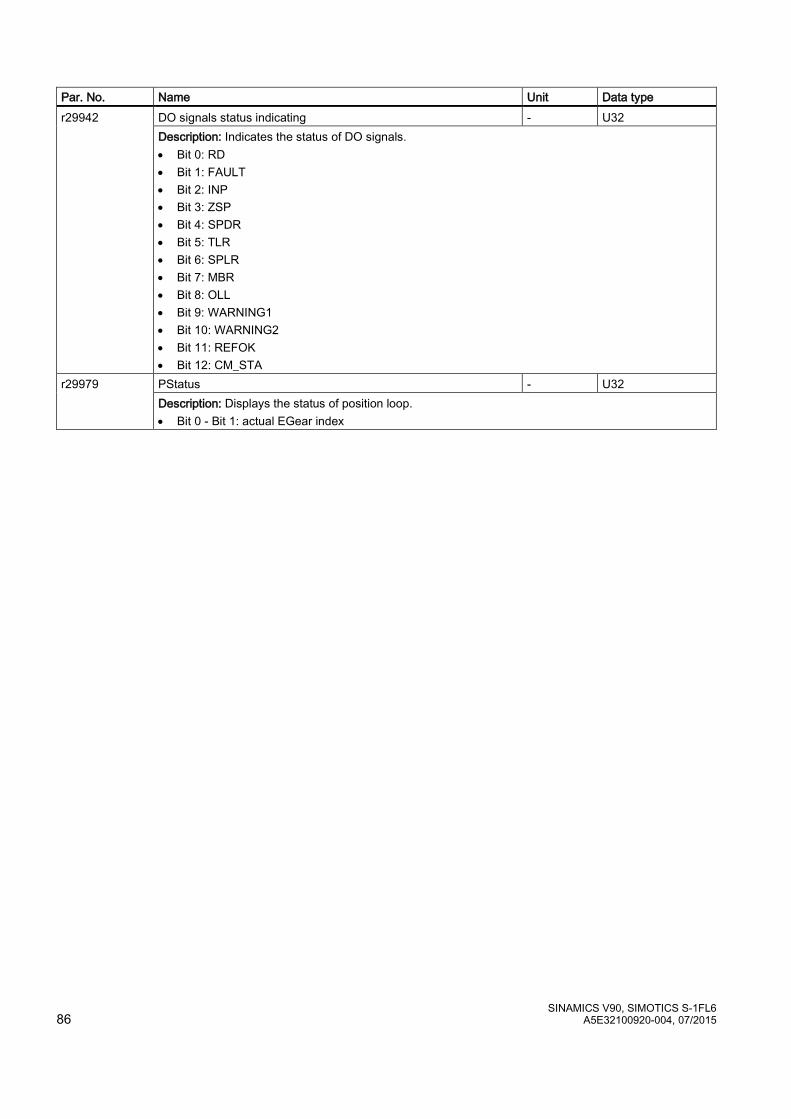
SINAMICS V90, SIMOTICS S-1FL6 86 A5E32100920-004, 07/2015
Par. No. Name Unit Data type r29942
DO signals status indicating - U32 Description: Indicates the status of DO signals. • Bit 0: RD • Bit 1: FAULT • Bit 2: INP • Bit 3: ZSP • Bit 4: SPDR • Bit 5: TLR • Bit 6: SPLR • Bit 7: MBR • Bit 8: OLL • Bit 9: WARNING1 • Bit 10: WARNING2 • Bit 11: REFOK • Bit 12: CM_STA
r29979 PStatus - U32 Description: Displays the status of position loop. • Bit 0 - Bit 1: actual EGear index
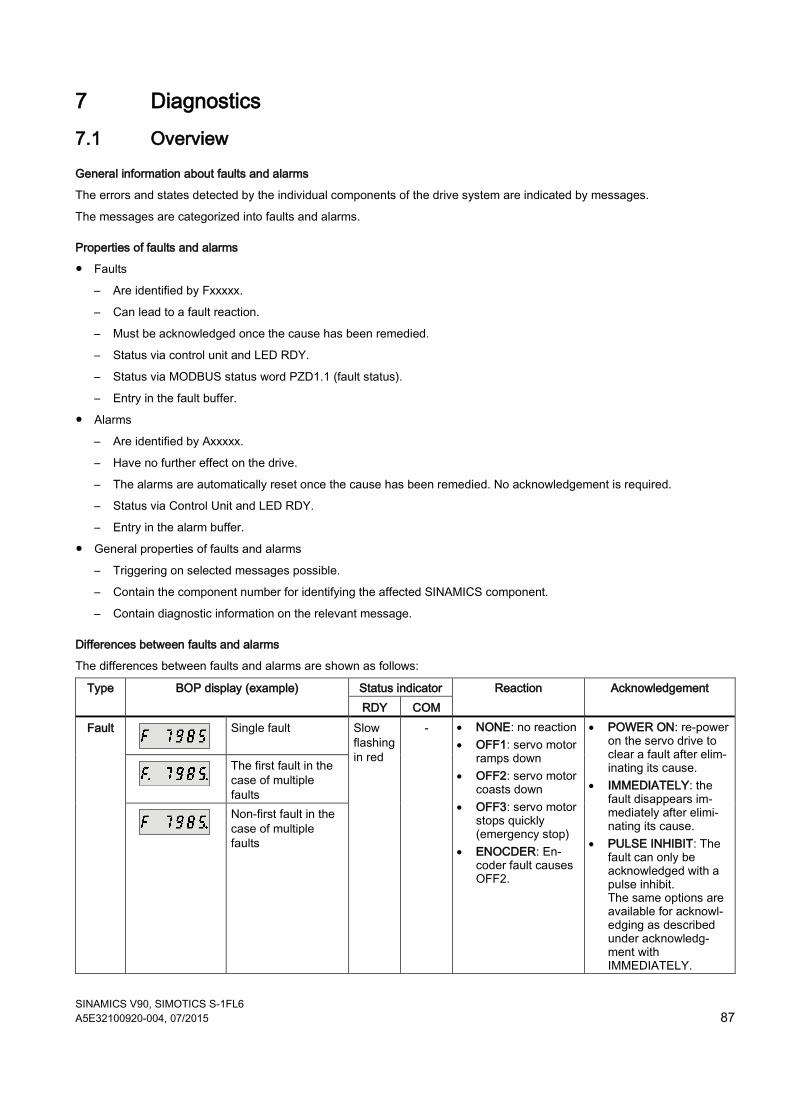
SINAMICS V90, SIMOTICS S-1FL6 A5E32100920-004, 07/2015 87
7 Diagnostics 7.1 Overview
General information about faults and alarms
The errors and states detected by the individual components of the drive system are indicated by messages.
The messages are categorized into faults and alarms.
Properties of faults and alarms
● Faults
– Are identified by Fxxxxx.
– Can lead to a fault reaction.
– Must be acknowledged once the cause has been remedied.
– Status via control unit and LED RDY.
– Status via MODBUS status word PZD1.1 (fault status).
– Entry in the fault buffer.
● Alarms
– Are identified by Axxxxx.
– Have no further effect on the drive.
– The alarms are automatically reset once the cause has been remedied. No acknowledgement is required.
– Status via Control Unit and LED RDY.
– Entry in the alarm buffer.
● General properties of faults and alarms
– Triggering on selected messages possible.
– Contain the component number for identifying the affected SINAMICS component.
– Contain diagnostic information on the relevant message.
Differences between faults and alarms
The differences between faults and alarms are shown as follows:
Type BOP display (example) Status indicator Reaction Acknowledgement RDY COM
Fault
Single fault Slow flashing in red
- • NONE: no reaction • OFF1: servo motor
ramps down • OFF2: servo motor
coasts down • OFF3: servo motor
stops quickly (emergency stop)
• ENOCDER: En-coder fault causes OFF2.
• POWER ON: re-power on the servo drive to clear a fault after elim-inating its cause.
• IMMEDIATELY: the fault disappears im-mediately after elimi-nating its cause.
• PULSE INHIBIT: The fault can only be acknowledged with a pulse inhibit. The same options are available for acknowl-edging as described under acknowledg-ment with IMMEDIATELY.
The first fault in the case of multiple faults
Non-first fault in the case of multiple faults
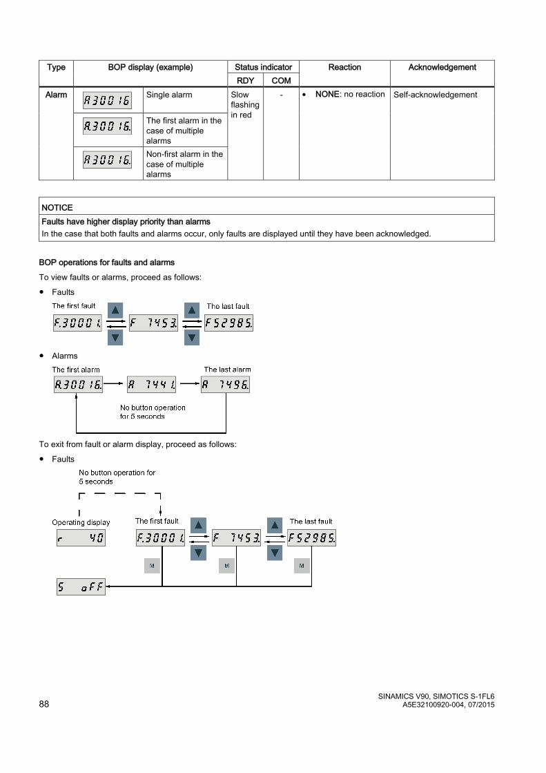
SINAMICS V90, SIMOTICS S-1FL6 88 A5E32100920-004, 07/2015
Type BOP display (example) Status indicator Reaction Acknowledgement RDY COM
Alarm
Single alarm Slow flashing in red
- • NONE: no reaction Self-acknowledgement
The first alarm in the case of multiple alarms
Non-first alarm in the case of multiple alarms
NOTICE Faults have higher display priority than alarms In the case that both faults and alarms occur, only faults are displayed until they have been acknowledged.
BOP operations for faults and alarms
To view faults or alarms, proceed as follows:
● Faults
● Alarms
To exit from fault or alarm display, proceed as follows:
● Faults
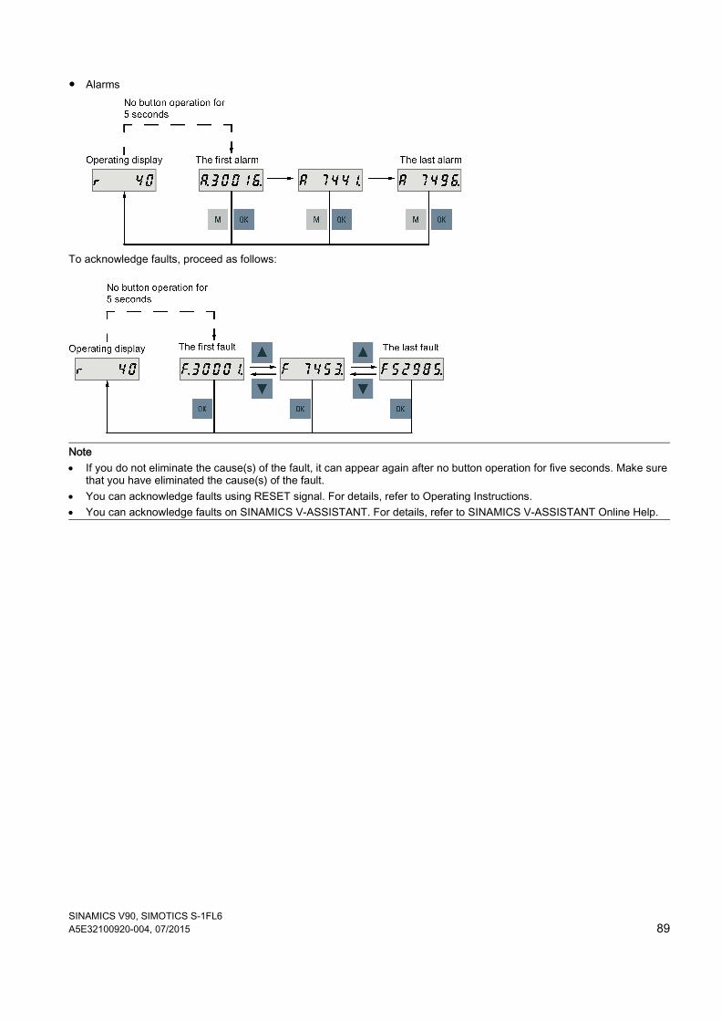
SINAMICS V90, SIMOTICS S-1FL6 A5E32100920-004, 07/2015 89
● Alarms
To acknowledge faults, proceed as follows:
Note • If you do not eliminate the cause(s) of the fault, it can appear again after no button operation for five seconds. Make sure
that you have eliminated the cause(s) of the fault. • You can acknowledge faults using RESET signal. For details, refer to Operating Instructions. • You can acknowledge faults on SINAMICS V-ASSISTANT. For details, refer to SINAMICS V-ASSISTANT Online Help.
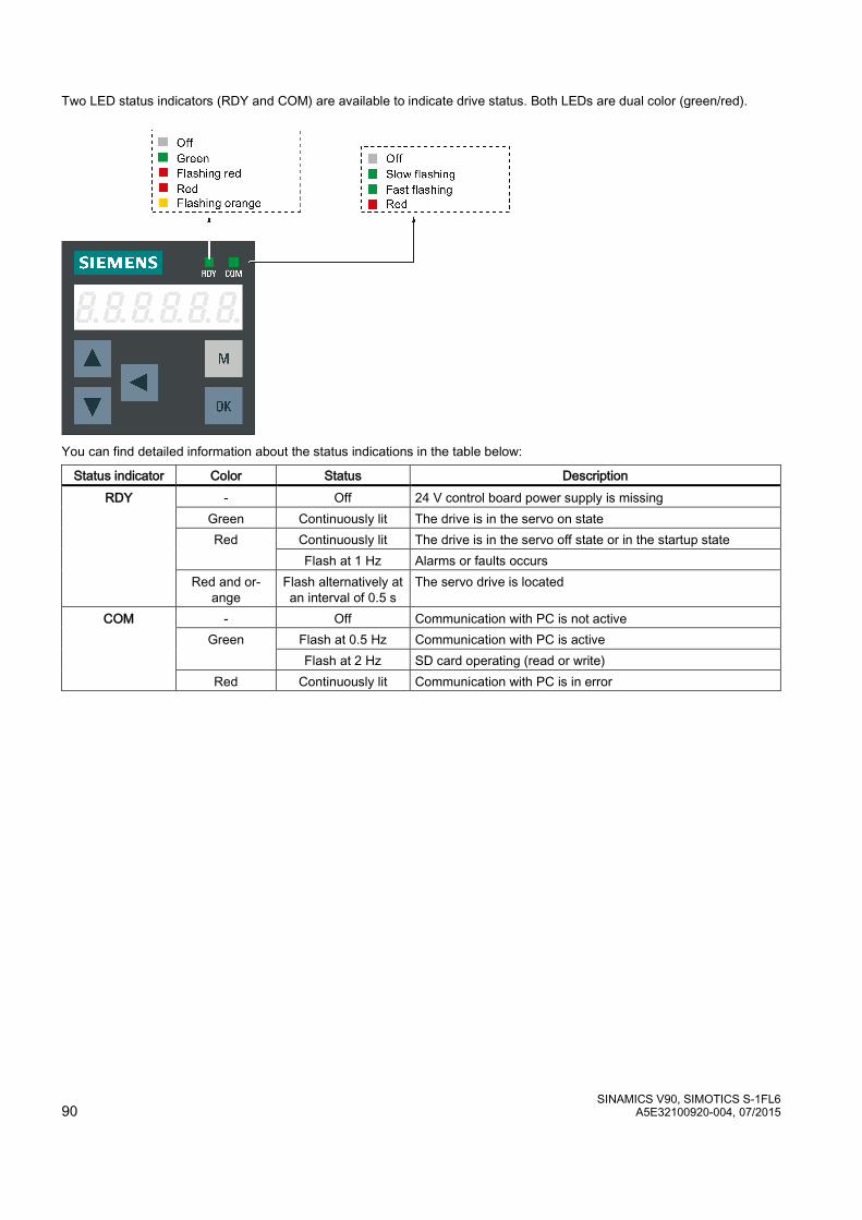
SINAMICS V90, SIMOTICS S-1FL6 90 A5E32100920-004, 07/2015
Two LED status indicators (RDY and COM) are available to indicate drive status. Both LEDs are dual color (green/red).
You can find detailed information about the status indications in the table below:
Status indicator Color Status Description RDY - Off 24 V control board power supply is missing
Green Continuously lit The drive is in the servo on state Red Continuously lit The drive is in the servo off state or in the startup state
Flash at 1 Hz Alarms or faults occurs Red and or-
ange Flash alternatively at an interval of 0.5 s
The servo drive is located
COM - Off Communication with PC is not active Green Flash at 0.5 Hz Communication with PC is active
Flash at 2 Hz SD card operating (read or write) Red Continuously lit Communication with PC is in error
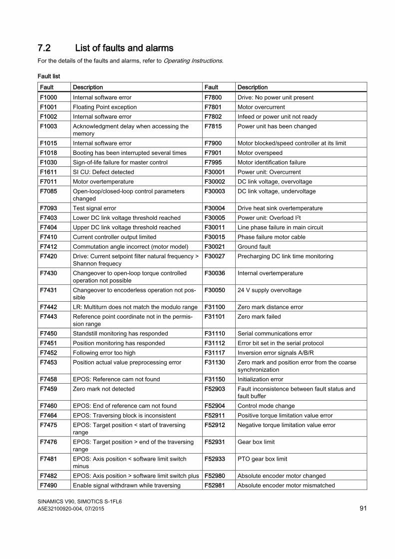
SINAMICS V90, SIMOTICS S-1FL6 A5E32100920-004, 07/2015 91
7.2 List of faults and alarms For the details of the faults and alarms, refer to Operating Instructions.
Fault list
Fault Description Fault Description F1000 Internal software error F7800 Drive: No power unit present F1001 Floating Point exception F7801 Motor overcurrent F1002 Internal software error F7802 Infeed or power unit not ready F1003 Acknowledgment delay when accessing the
memory F7815 Power unit has been changed
F1015 Internal software error F7900 Motor blocked/speed controller at its limit F1018 Booting has been interrupted several times F7901 Motor overspeed F1030 Sign-of-life failure for master control F7995 Motor identification failure F1611 SI CU: Defect detected F30001 Power unit: Overcurrent F7011 Motor overtemperature F30002 DC link voltage, overvoltage F7085 Open-loop/closed-loop control parameters
changed F30003 DC link voltage, undervoltage
F7093 Test signal error F30004 Drive heat sink overtemperature F7403 Lower DC link voltage threshold reached F30005 Power unit: Overload I2t F7404 Upper DC link voltage threshold reached F30011 Line phase failure in main circuit F7410 Current controller output limited F30015 Phase failure motor cable F7412 Commutation angle incorrect (motor model) F30021 Ground fault F7420 Drive: Current setpoint filter natural frequency >
Shannon frequecy F30027 Precharging DC link time monitoring
F7430 Changeover to open-loop torque controlled operation not possible
F30036 Internal overtemperature
F7431 Changeover to encoderless operation not pos-sible
F30050 24 V supply overvoltage
F7442 LR: Multiturn does not match the modulo range F31100 Zero mark distance error F7443 Reference point coordinate not in the permis-
sion range F31101 Zero mark failed
F7450 Standstill monitoring has responded F31110 Serial communications error F7451 Position monitoring has responded F31112 Error bit set in the serial protocol F7452 Following error too high F31117 Inversion error signals A/B/R F7453 Position actual value preprocessing error F31130 Zero mark and position error from the coarse
synchronization F7458 EPOS: Reference cam not found F31150 Initialization error F7459 Zero mark not detected F52903 Fault inconsistence between fault status and
fault buffer F7460 EPOS: End of reference cam not found F52904 Control mode change F7464 EPOS: Traversing block is inconsistent F52911 Positive torque limitation value error F7475 EPOS: Target position < start of traversing
range F52912 Negative torque limitation value error
F7476 EPOS: Target position > end of the traversing range
F52931 Gear box limit
F7481 EPOS: Axis position < software limit switch minus
F52933 PTO gear box limit
F7482 EPOS: Axis position > software limit switch plus F52980 Absolute encoder motor changed F7490 Enable signal withdrawn while traversing F52981 Absolute encoder motor mismatched

SINAMICS V90, SIMOTICS S-1FL6 92 A5E32100920-004, 07/2015
Fault Description Fault Description F7491 STOP cam minus reached F52983 No encoder detected F7492 STOP cam plus reached F52984 Incremental encoder motor not configured F7493 LR: Overflow of the value range for position
actual value F52985 Absolute encoder motor wrong
F7599 Encoder 1: Adjustment not possible F52987 Absolute encoder replaced
Alarm list
Alarm Description Alarm Description A1009 Control module overtemperature A7479 EPOS: Software limit switch minus reached A1019 Writing to the removable data medium unsuc-
cessful A7480 EPOS: Software limit switch plus reached
A1032 All parameters must be saved A7496 SON enable missing A1045 Configuring data invalid A7576 Encoderless operation due to a fault active A1920 Drive Bus: Receive setpoints after To A7582 Position actual value preprocessing error A1932 Drive Bus clock cycle synchronization missing
for DSC A7585 P-TRG or CLR active
A5000 Drive heat sink overtemperature A7588 Encoder 2: Position value preprocessing does not have a valid encoder
A7012 Motor temperature model 1/3 overtemperature A7805 Power unit overload I2t A7441 LR: Save the position offset of the absolute
encoder adjustment A7965 Save required
A7454 LR: Position value preprocessing does not have a valid encoder
A7971 Angular commutation offset determination acti-vated
A7456 EPOS: Setpoint velocity limited A7991 Motor data identification activated A7461 EPOS: Reference point not set A30016 Load supply switched off A7469 EPOS: Traversing block < target position <
software limit switch minus A30031 Hardware current limiting in phase U
A7470 EPOS: Traversing block> target position > software limit switch plus
A31411 Absolute encoder signals internal alarms
A7471 EPOS: Traversing block target position outside the modulo range
A31412 Error bit set in the serial protocol
A7472 EPOS: Traversing block ABS_POS/ABS_NEG not possible
A52900 Failure during data copying
A7473 EPOS: Beginning of traversing range reached A52901 Braking resistor reaches alarm threshold A7474 EPOS: End of traversing range reached A52902 Emergency missing A7477 EPOS: Target position < software limit switch
minus A52932 PTO max limit
A7478 EPOS: Target position > software limit switch plus
For more information about the faults and alarms, refer to SINAMICS V90, SIMOTICS S-1FL6 Operating Instructions.
SINAMICS V90, SIMOTICS S-1FL6 A5E32100920-004, 07/2015
Siemens AG Division Digital Factory Postfach 48 48 90026 NÜRNBERG
Related Documents