Operating Manual (Edition 04/2004) sinamics Braking Module / Braking Resistor SINAMICS G130

Welcome message from author
This document is posted to help you gain knowledge. Please leave a comment to let me know what you think about it! Share it to your friends and learn new things together.
Transcript
Operating Manual (Edition 04/2004)
sinamics
Braking Module / Braking Resistor SINAMICS G130

04/04 Contents
SINAMICS G130 - Braking Module / Braking Resistor Operating Manual i
Contents
1 Safety Information 1-1
2 General 2-1
3 Mechanical Installation 3-1
4 Connection 4-1
5 Maintenance and Servicing 5-1
6 Technical Specifications 6-1

Contents 04/04
SINAMICS G130 - Braking Module / Braking Resistor 1-2 Operating Manual
04/04 Safety Information
SINAMICS G130 - Braking Module / Braking Resistor Operating Manual 1-1
1 Safety Information
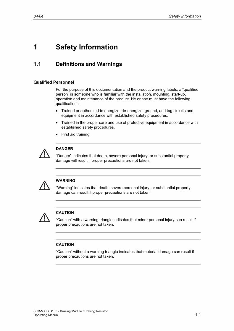
1.1 Definitions and Warnings
Qualified Personnel For the purpose of this documentation and the product warning labels, a “qualified person” is someone who is familiar with the installation, mounting, start-up, operation and maintenance of the product. He or she must have the following qualifications:
• Trained or authorized to energize, de-energize, ground, and tag circuits and equipment in accordance with established safety procedures.
• Trained in the proper care and use of protective equipment in accordance with established safety procedures.
• First aid training.
DANGER
“Danger” indicates that death, severe personal injury, or substantial property damage will result if proper precautions are not taken.
WARNING
“Warning” indicates that death, severe personal injury, or substantial property damage can result if proper precautions are not taken.
CAUTION
“Caution” with a warning triangle indicates that minor personal injury can result if proper precautions are not taken.
CAUTION
“Caution” without a warning triangle indicates that material damage can result if proper precautions are not taken.
Safety Information 04/04
SINAMICS G130 - Braking Module / Braking Resistor 1-2 Operating Manual
IMPORTANT
“Important” indicates that an unwanted result or situation can result if the appropriate advice is not taken into account.
NOTE
“Note” indicates important information about the product or respective part of the documentation that is essential to highlight.
WARNING
Hazardous voltages are present in this electrical equipment during operation. Non-observance of the warnings can result in severe personal injury or property damage. Only qualified personnel should work on or around the equipment. This personnel must be thoroughly familiar with all warning and maintenance procedures described in this documentation. The successful and safe operation of this device is dependent on correct transport, proper storage and installation, as well as careful operation and maintenance. National safety guidelines must be observed.
04/04 Safety Information
SINAMICS G130 - Braking Module / Braking Resistor Operating Manual 1-3
1.2 Safety and Operating Instructions
DANGER
This equipment is used in industrial high-voltage installations. During operation, this equipment contains rotating and live, bare parts. For this reason, they could cause severe injury or significant material damage if the required covers are removed, if they are used or operated incorrectly, or have not been properly maintained. When the machines are used in non-industrial areas, the installation location must be protected against unauthorized access (protective fencing, appropriate signs).
Prerequisites Those responsible for protecting the plant must ensure the following:
• The basic planning work for the plant and the transport, assembly, installation, commissioning, maintenance, and repair work is carried out by qualified personnel and/or checked by experts responsible.
• The operating manual and machine documentation are always available.
• The technical data and specifications regarding the applicable installation, connection, environmental, and operating conditions are always observed.
• The plant-specific assembly and safety guidelines are observed and personal protection equipment is used.
• Unqualified personnel are forbidden from using these machines and working near them.
This operating manual is intended for qualified personnel and only contain information and notes relating to the intended purpose of the machines.
The operating manual and machine documentation are written in different languages as specified in the delivery contracts.
NOTE
The services and support provided by the SIEMENS service centers are recommended for planning, installation, commissioning, and servicing work.
Safety Information 04/04
SINAMICS G130 - Braking Module / Braking Resistor 1-4 Operating Manual
Components that can be Destroyed by Electrostatic Discharge (ESD)
CAUTION The board contains components that can be destroyed by electrostatic discharge. These components can be easily destroyed if not handled properly. If you do have to use electronic boards, however, please observe the following:
• You should only touch electronic boards if absolutely necessary.
• When you touch boards, however, your body must be electrically discharged beforehand.
• Boards must not come into contact with highly insulating materials (such as plastic parts, insulated desktops, articles of clothing manufactured from man-made fibers).
• Boards must only be placed on conductive surfaces.
• Boards and components should only be stored and transported in conductive packaging (such as metalized plastic boxes or metal containers).
• If the packaging material is not conductive, the boards must be wrapped with a conductive packaging material (such as conductive foam rubber or household aluminum foil).
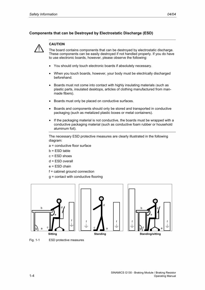
The necessary ESD protective measures are clearly illustrated in the following diagram: a = conductive floor surface b = ESD table c = ESD shoes d = ESD overall e = ESD chain f = cabinet ground connection g = contact with conductive flooring
g g
StandingSitting Standing/sitting
a
b
e
d
c
d
ac
db
c a
e
ff f f f
Fig. 1-1 ESD protective measures
04/04 General
SINAMICS G130 - Braking Module / Braking Resistor Operating Manual 2-1
2 General
2.1 Braking Module
Description A braking module (and an external braking resistor) is required in certain cases when the drive is to be braked or brought to a standstill (e.g. EMERGENCY OFF category 1). The braking module contains the power electronics and the associated control. The supply voltage for the electronics is drawn from the DC link.
During operation, the DC link energy is converted to heat loss in an external braking resistor.
The braking module functions independently of the converter closed-loop control. To boost performance, several braking modules can be operated in parallel. In this case, each braking module must have its own braking resistor.
Structure The braking module is inserted in a mounting location inside the power module, the fan of which ensures forced cooling. The braking module is connected to the DC link by means of the busbar sets and flexible cables, which are supplied as standard.
Assigning the Braking Module and Power Module
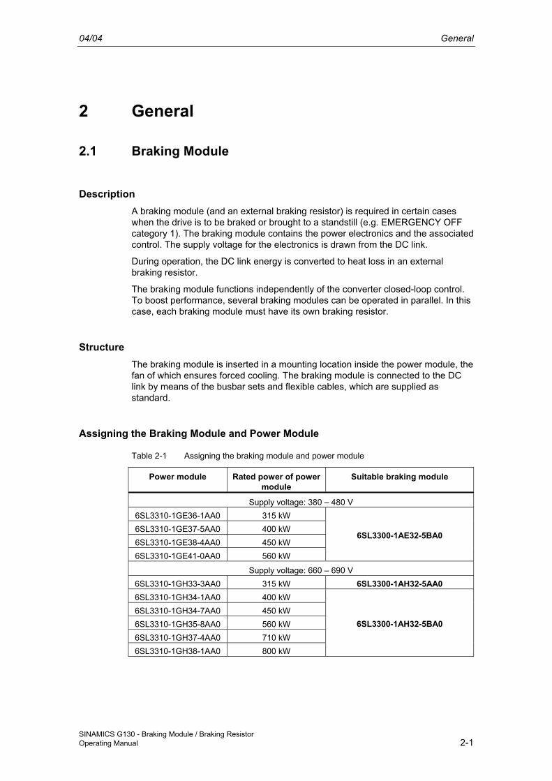
Table 2-1 Assigning the braking module and power module
Power module Rated power of power module
Suitable braking module
Supply voltage: 380 – 480 V 6SL3310-1GE36-1AA0 315 kW 6SL3310-1GE37-5AA0 400 kW 6SL3310-1GE38-4AA0 450 kW 6SL3310-1GE41-0AA0 560 kW
6SL3300-1AE32-5BA0
Supply voltage: 660 – 690 V 6SL3310-1GH33-3AA0 315 kW 6SL3300-1AH32-5AA0 6SL3310-1GH34-1AA0 400 kW 6SL3310-1GH34-7AA0 450 kW 6SL3310-1GH35-8AA0 560 kW 6SL3310-1GH37-4AA0 710 kW 6SL3310-1GH38-1AA0 800 kW
6SL3300-1AH32-5BA0
General 04/04
SINAMICS G130 - Braking Module / Braking Resistor 2-2 Operating Manual
2.2 Braking Resistor
Description In converters with no regenerative feedback capability, the energy that occurs in the drive train under regenerative conditions is fed back to the DC link where it is reduced via braking resistors.
The braking resistor is connected to the braking module. The distance between the braking module and braking resistor must not exceed 50 m. The resulting heat loss can be dissipated outside the switchgear room.
The standard available resistor has a rating of 200 kW.
To boost performance, braking modules and braking resistors can be connected in parallel. In this case, the braking modules are installed in the outlet air ducts of the power module. Depending on the size of the power module, up to 3 mounting locations are available:
• Type GX: 1
• Type HX: 2
• Type JX: 3
Since the braking resistors can be used in converters with a wide voltage range, the voltage can be adjusted (e.g. to reduce the voltage stress on the motor and converter) by setting the response thresholds on the braking module.
A thermostat monitors the braking resistor for overtemperature and issues a signal on a floating contact if the limit value is exceeded.
04/04 Mechanical Installation
SINAMICS G130 - Braking Module / Braking Resistor Operating Manual 3-1
3 Mechanical Installation
3.1 General
WARNING To ensure that the devices operate safely and reliably, they must be properly installed and put into operation by qualified personnel, taking into account the warning messages provided in these operating instructions. In particular, both the general and national installation and safety guidelines for high-voltage installations (e.g. VDE – the Union of German Technical Engineers) and the guidelines relating to the professional use of tools and the use of personal protective equipment must be observed. Death, serious injury, or substantial material damage can result if these factors are not taken into account.
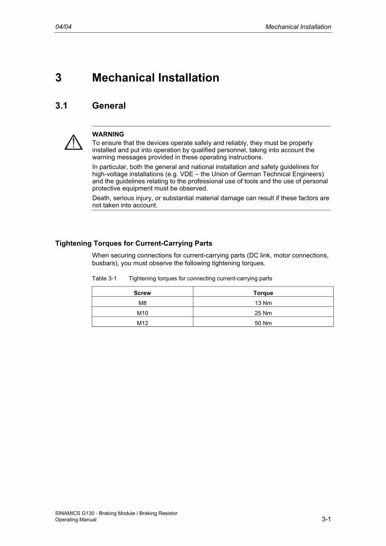
Tightening Torques for Current-Carrying Parts When securing connections for current-carrying parts (DC link, motor connections, busbars), you must observe the following tightening torques.
Table 3-1 Tightening torques for connecting current-carrying parts
Screw Torque M8 13 Nm
M10 25 Nm
M12 50 Nm
Mechanical Installation 04/04
SINAMICS G130 - Braking Module / Braking Resistor 3-2 Operating Manual
3.2 Braking Modules: Overview
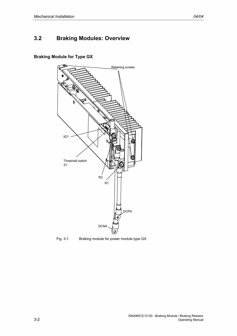
Braking Module for Type GX
R2
R1
X21
Threshold switchS1
DCPA
DCNA
Retaining screws
Fig. 3-1 Braking module for power module type GX
04/04 Mechanical Installation
SINAMICS G130 - Braking Module / Braking Resistor Operating Manual 3-3
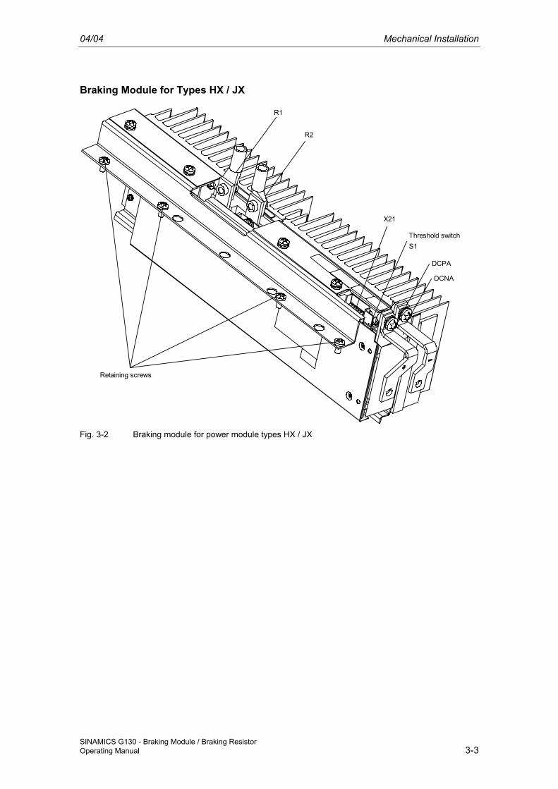
Braking Module for Types HX / JX
R2
R1
X21
Threshold switchS1
DCPA
DCNA
Retaining screws
Fig. 3-2 Braking module for power module types HX / JX
Mechanical Installation 04/04
SINAMICS G130 - Braking Module / Braking Resistor 3-4 Operating Manual
3.3 Installing the Braking Module
3.3.1 Installing the Braking Module in Power Module Type GX
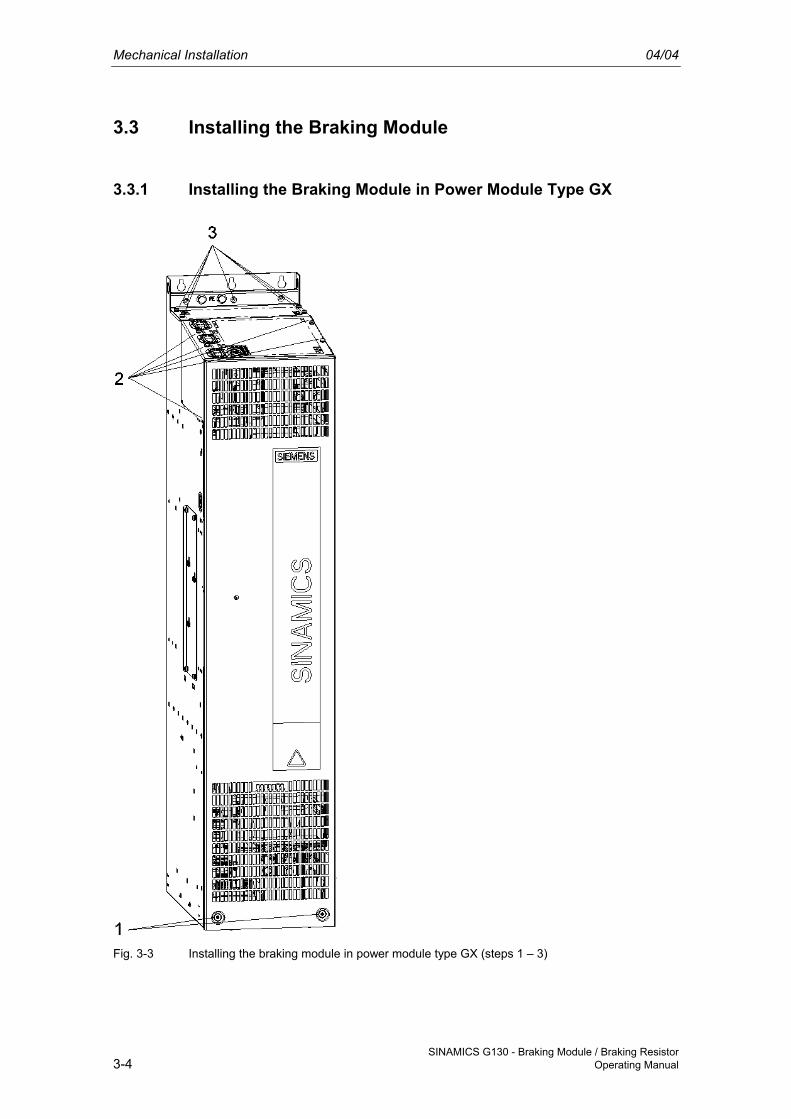
Fig. 3-3 Installing the braking module in power module type GX (steps 1 – 3)
04/04 Mechanical Installation
SINAMICS G130 - Braking Module / Braking Resistor Operating Manual 3-5
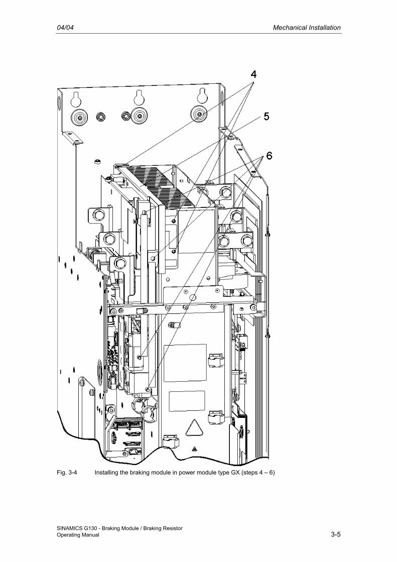
Fig. 3-4 Installing the braking module in power module type GX (steps 4 – 6)
Mechanical Installation 04/04
SINAMICS G130 - Braking Module / Braking Resistor 3-6 Operating Manual
Installing the Braking Module The installation steps are numbered in accordance with Fig. 3-3 and Fig. 3-4.
1. Unscrew the 2 M6 screws from the front cover and lift off the cover.
2. Unscrew the 4 screws from the upper cover plate. Unscrew the 1 M6 nut on the left-hand side. Remove the front cover.
3. Unscrew the 4 screws from the upper cover plate. Unscrew the 3 screws from the rear cut-out sections. Remove the rear cover.
4. Unscrew the 3 screws for the blanking plate. Remove the plate.
5. Insert the braking module where the cover used to be and secure it using the 3 screws (step 4).
6. Secure the connection cable to the DC link with 2 screws (braking module connection) and 2 nuts (DC link connection).
Carry out the subsequent steps in reverse order from steps 1 – 3.
An opening above the connections for the braking resistor (R1, R2) is provided in the cover for connecting the cable to the braking resistor.
CAUTION The tightening torques specified in Table 3-1 must be observed.
04/04 Mechanical Installation
SINAMICS G130 - Braking Module / Braking Resistor Operating Manual 3-7
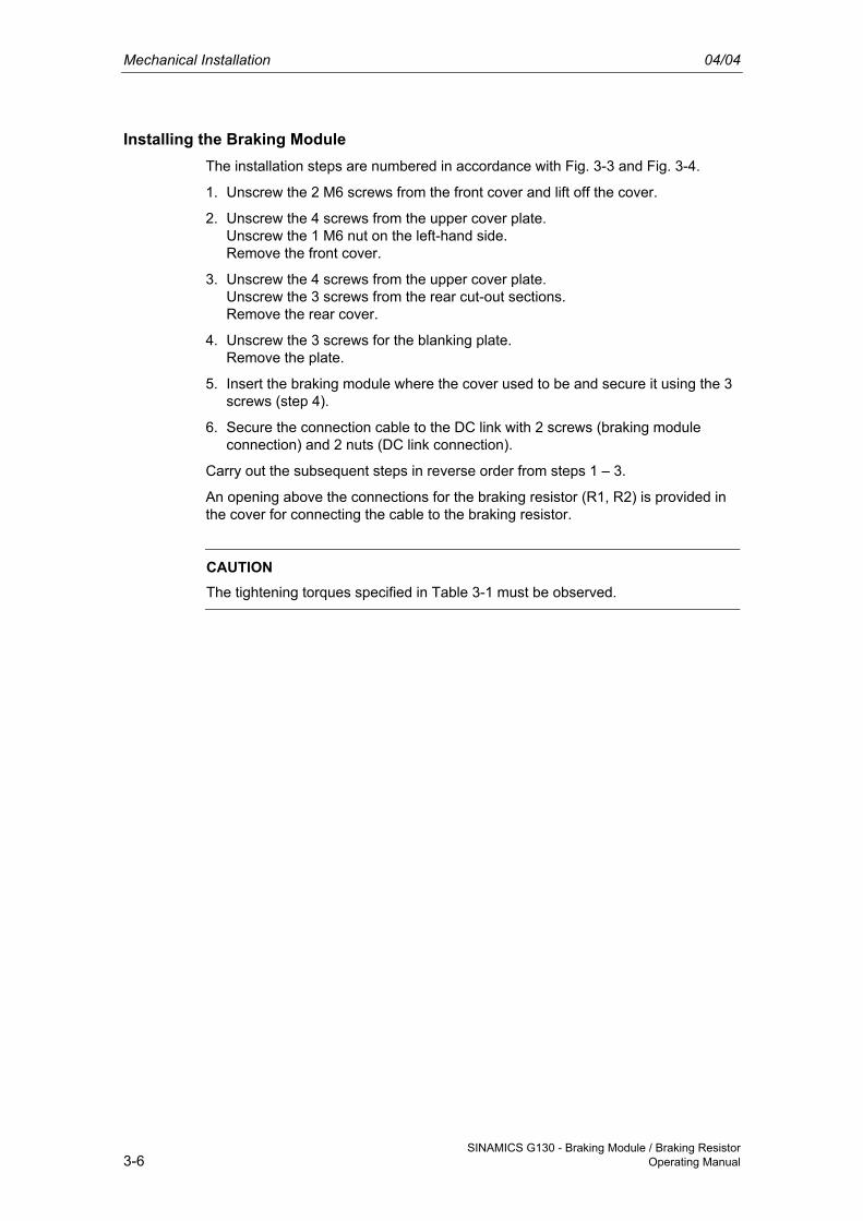
3.3.2 Installing the Braking Module in Power Module Type HX
Fig. 3-5 Installing the braking module in power module type HX
Mechanical Installation 04/04
SINAMICS G130 - Braking Module / Braking Resistor 3-8 Operating Manual
Installing the Braking Module The installation steps are numbered in accordance with Fig. 3-5.
1. Insert the braking module.
2. Screw in the 4 retaining screws for securing the braking module.
3. Install the connection bracket for the DC link (DCPA/DCNA).
CAUTION The tightening torques specified in Table 3-1 must be observed.
04/04 Mechanical Installation
SINAMICS G130 - Braking Module / Braking Resistor Operating Manual 3-9
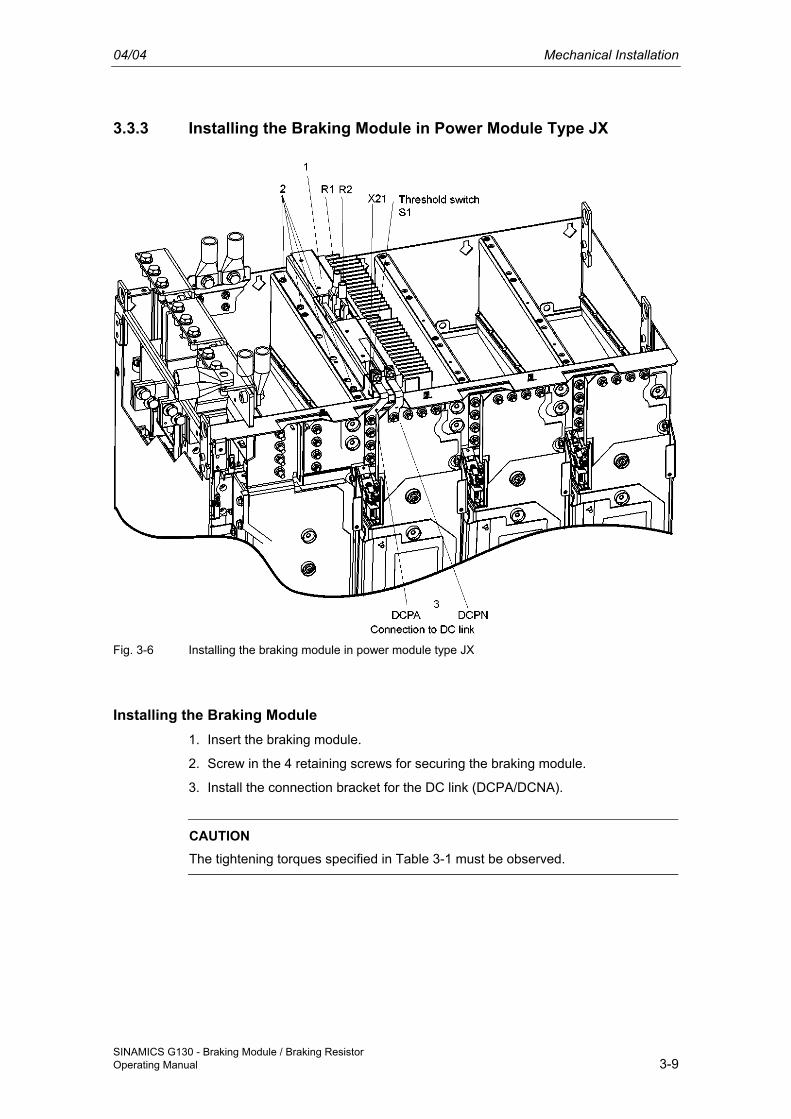
3.3.3 Installing the Braking Module in Power Module Type JX
Fig. 3-6 Installing the braking module in power module type JX
Installing the Braking Module 1. Insert the braking module.
2. Screw in the 4 retaining screws for securing the braking module.
3. Install the connection bracket for the DC link (DCPA/DCNA).
CAUTION The tightening torques specified in Table 3-1 must be observed.
Mechanical Installation 04/04
SINAMICS G130 - Braking Module / Braking Resistor 3-10 Operating Manual
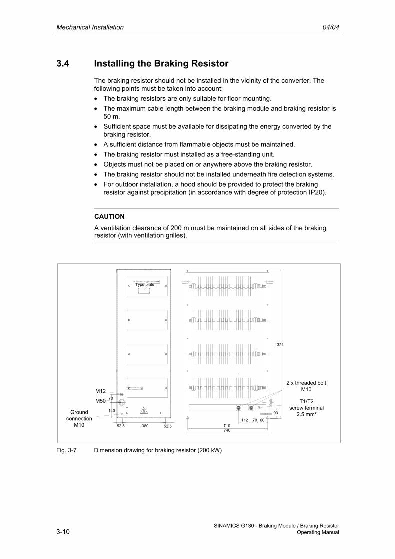
3.4 Installing the Braking Resistor
The braking resistor should not be installed in the vicinity of the converter. The following points must be taken into account: • The braking resistors are only suitable for floor mounting. • The maximum cable length between the braking module and braking resistor is
50 m. • Sufficient space must be available for dissipating the energy converted by the
braking resistor. • A sufficient distance from flammable objects must be maintained. • The braking resistor must installed as a free-standing unit. • Objects must not be placed on or anywhere above the braking resistor. • The braking resistor should not be installed underneath fire detection systems. • For outdoor installation, a hood should be provided to protect the braking
resistor against precipitation (in accordance with degree of protection IP20).
CAUTION A ventilation clearance of 200 m must be maintained on all sides of the braking resistor (with ventilation grilles).
52.538052.5
140
70
M12
M50
Type plate
Groundconnection
M106070112
710740
93
1321
T1/T2screw terminal
2.5 mm²
2 x threaded boltM10
Fig. 3-7 Dimension drawing for braking resistor (200 kW)
04/04 Connection
SINAMICS G130 - Braking Module / Braking Resistor Operating Manual 4-1
4 Connection
WARNING The chassis units are operated with high voltages. All connection procedures must be carried out with the cabinet de-energized. All work on the units must be carried out by trained personnel only. Death, serious injury, or substantial material damage can result if these warnings are not taken into account.
Work on an open device must be carried out with extreme caution because external supply voltages may be present. The power and control terminals may be live even when the motor is not running. Dangerously high voltage levels are still present in the cabinet up to five minutes after it has been disconnected due to the DC link capacitors. For this reason, the cabinet should not be opened until after a reasonable period of time has elapsed.
The operator is responsible for ensuring that the motor, converter, and other devices are installed and connected in accordance with the recognized technical rules in the country of installation and applicable regional guidelines. Special attention should be paid to cable dimensioning, fuses, grounding, shutdown, disconnection, and overcurrent protection.
If an item of protective gear trips in a branch circuit, a leakage current may have been disconnected. To reduce the risk of fire or an electric shock, the current-carrying parts and other components in the cabinet unit should be inspected and damaged parts replaced. When an item of protective gear trips, the cause of the trip must be identified and rectified.
Connection 04/04
SINAMICS G130 - Braking Module / Braking Resistor 4-2 Operating Manual
4.1 Connecting the Braking Module
4.1.1 Interface Overview
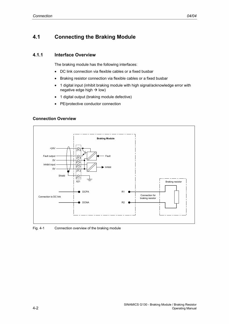
The braking module has the following interfaces:
• DC link connection via flexible cables or a fixed busbar
• Braking resistor connection via flexible cables or a fixed busbar
• 1 digital input (inhibit braking module with high signal/acknowledge error with negative edge high low)
• 1 digital output (braking module defective)
• PE/protective conductor connection
Connection Overview
Inhibit
Fault output
Inhibit input
Fault
0V
Shield
+24V
X21
0V
21.1
21.2
21.3
21.4
21.5
21.6
DCPA
DCNA
R1
R2
Connection to DC link Connection forbraking resistor
Braking resistor
Braking Module
Fig. 4-1 Connection overview of the braking module
04/04 Connection
SINAMICS G130 - Braking Module / Braking Resistor Operating Manual 4-3
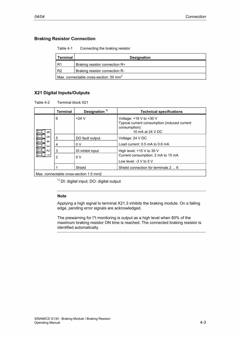
Braking Resistor Connection
Table 4-1 Connecting the braking resistor
Terminal Designation
R1 Braking resistor connection R+
R2 Braking resistor connection R-
Max. connectable cross-section: 50 mm2
X21 Digital Inputs/Outputs
Table 4-2 Terminal block X21
Terminal Designation 1) Technical specifications
6 +24 V Voltage: +18 V to +30 V Typical current consumption (induced current consumption): 10 mA at 24 V DC
5 DO fault output
4 0 V
Voltage: 24 V DC
Load current: 0.5 mA to 0.6 mA
3 DI inhibit input
2 0 V
High level: +15 V to 30 V Current consumption: 2 mA to 15 mA
Low level: -3 V to 5 V
65
43
21
1 Shield Shield connection for terminals 2 ... 6
Max. connectable cross-section 1.5 mm2 1) DI: digital input; DO: digital output
Note
Applying a high signal to terminal X21.3 inhibits the braking module. On a falling edge, pending error signals are acknowledged.
The prewarning for I*t monitoring is output as a high level when 80% of the maximum braking resistor ON time is reached. The connected braking resistor is identified automatically.
Connection 04/04
SINAMICS G130 - Braking Module / Braking Resistor 4-4 Operating Manual
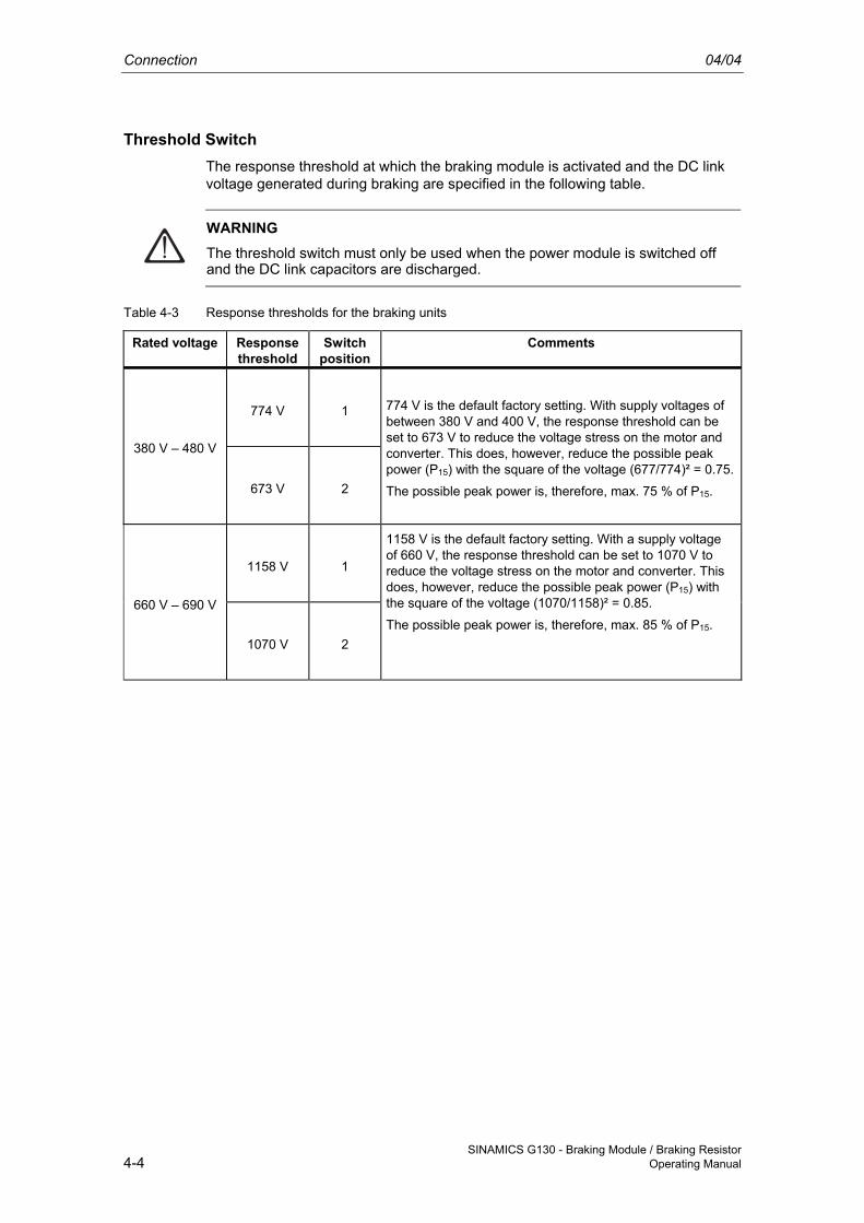
Threshold Switch The response threshold at which the braking module is activated and the DC link voltage generated during braking are specified in the following table.
WARNING The threshold switch must only be used when the power module is switched off and the DC link capacitors are discharged.
Table 4-3 Response thresholds for the braking units
Rated voltage Response threshold
Switch position
Comments
774 V 1
380 V – 480 V
673 V 2
774 V is the default factory setting. With supply voltages of between 380 V and 400 V, the response threshold can be set to 673 V to reduce the voltage stress on the motor and converter. This does, however, reduce the possible peak power (P15) with the square of the voltage (677/774)² = 0.75.
The possible peak power is, therefore, max. 75 % of P15.
1158 V 1
660 V – 690 V
1070 V 2
1158 V is the default factory setting. With a supply voltage of 660 V, the response threshold can be set to 1070 V to reduce the voltage stress on the motor and converter. This does, however, reduce the possible peak power (P15) with the square of the voltage (1070/1158)² = 0.85.
The possible peak power is, therefore, max. 85 % of P15.
04/04 Connection
SINAMICS G130 - Braking Module / Braking Resistor Operating Manual 4-5
4.2 Connecting the Braking Resistor
WARNING The braking module must only be connected when the power module has been disconnected from the power supply and the DC link capacitors have been discharged.
CAUTION The braking resistor cables must be laid in such a way that they are short-circuit and ground-fault proof!
The length of the connection cables between the braking module and external braking resistor must not exceed 50 m.
Recommended connection cross-section: 50 mm² (AWG 00)
Thermostat A thermostat is installed to protect the braking resistor against overload. Its floating contacts must be integrated in the fault chain on the system side.
Table 4-4 Connecting the thermostat
Terminal Function description
T1 Thermostat connection
T2 Thermostat connection
Max. connectable cross-section: 2.5 mm² (AWG 12)

04/04 Maintenance and Servicing
SINAMICS G130 - Braking Module / Braking Resistor Operating Manual 5-1
5 Maintenance and Servicing Maintenance and servicing are not carried out for the braking module and braking resistor. If a fault occurs, the braking module and braking resistor must be replaced.
Maintenance and Servicing 04/04
SINAMICS G130 - Braking Module / Braking Resistor 5-2 Operating Manual
04/04 Technical Specifications
SINAMICS G130 - Braking Module / Braking Resistor Operating Manual 6-1
6 Technical Specifications
General Technical Specifications
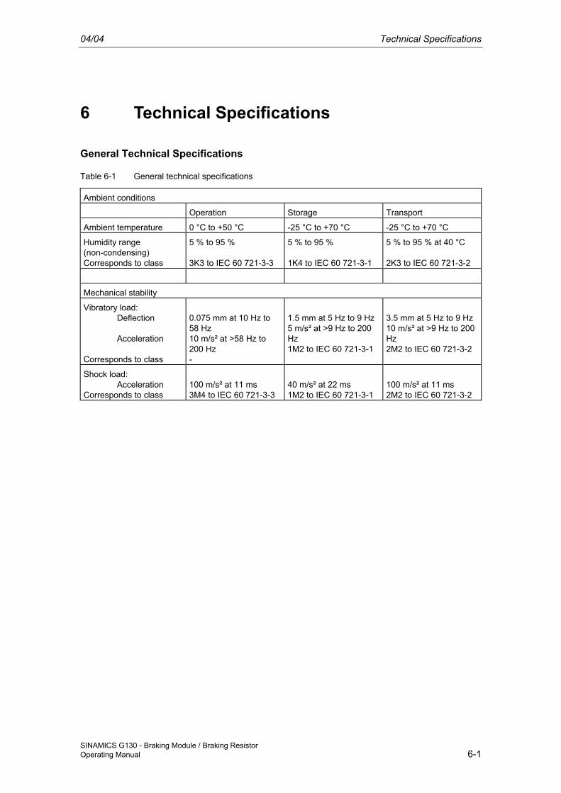
Table 6-1 General technical specifications
Ambient conditions Operation Storage Transport
Ambient temperature 0 °C to +50 °C -25 °C to +70 °C -25 °C to +70 °C
Humidity range (non-condensing) Corresponds to class
5 % to 95 % 3K3 to IEC 60 721-3-3
5 % to 95 % 1K4 to IEC 60 721-3-1
5 % to 95 % at 40 °C 2K3 to IEC 60 721-3-2
Mechanical stability
Vibratory load: Deflection Acceleration Corresponds to class
0.075 mm at 10 Hz to 58 Hz 10 m/s² at >58 Hz to 200 Hz -
1.5 mm at 5 Hz to 9 Hz5 m/s² at >9 Hz to 200 Hz 1M2 to IEC 60 721-3-1
3.5 mm at 5 Hz to 9 Hz10 m/s² at >9 Hz to 200 Hz 2M2 to IEC 60 721-3-2
Shock load: Acceleration Corresponds to class
100 m/s² at 11 ms 3M4 to IEC 60 721-3-3
40 m/s² at 22 ms 1M2 to IEC 60 721-3-1
100 m/s² at 11 ms 2M2 to IEC 60 721-3-2
Technical Specifications 04/04
SINAMICS G130 - Braking Module / Braking Resistor 6-2 Operating Manual
Specific Technical Specifications for the Braking Module
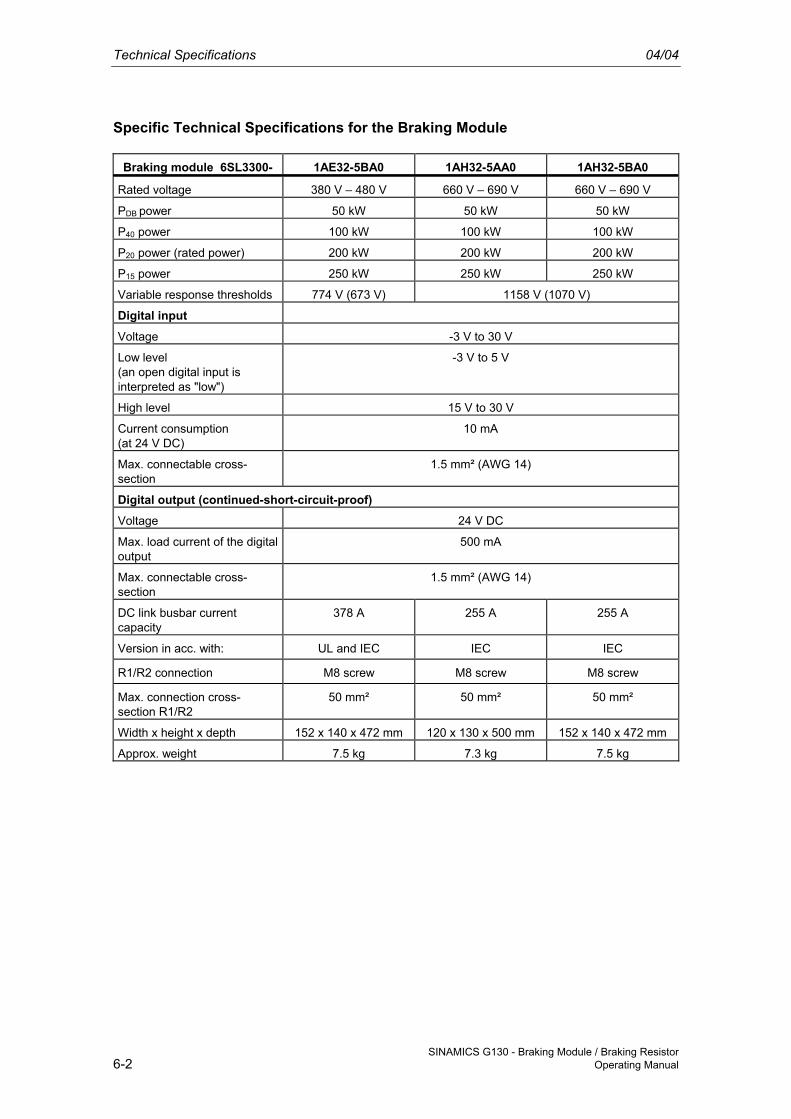
Braking module 6SL3300- 1AE32-5BA0 1AH32-5AA0 1AH32-5BA0
Rated voltage 380 V – 480 V 660 V – 690 V 660 V – 690 V
PDB power 50 kW 50 kW 50 kW
P40 power 100 kW 100 kW 100 kW
P20 power (rated power) 200 kW 200 kW 200 kW
P15 power 250 kW 250 kW 250 kW
Variable response thresholds 774 V (673 V) 1158 V (1070 V)
Digital input Voltage -3 V to 30 V
Low level (an open digital input is interpreted as "low")
-3 V to 5 V
High level 15 V to 30 V
Current consumption (at 24 V DC)
10 mA
Max. connectable cross-section
1.5 mm² (AWG 14)
Digital output (continued-short-circuit-proof)
Voltage 24 V DC
Max. load current of the digital output
500 mA
Max. connectable cross-section
1.5 mm² (AWG 14)
DC link busbar current capacity
378 A 255 A 255 A
Version in acc. with: UL and IEC IEC IEC
R1/R2 connection M8 screw M8 screw M8 screw
Max. connection cross-section R1/R2
50 mm² 50 mm² 50 mm²
Width x height x depth 152 x 140 x 472 mm 120 x 130 x 500 mm 152 x 140 x 472 mm
Approx. weight 7.5 kg 7.3 kg 7.5 kg
04/04 Technical Specifications
SINAMICS G130 - Braking Module / Braking Resistor Operating Manual 6-3
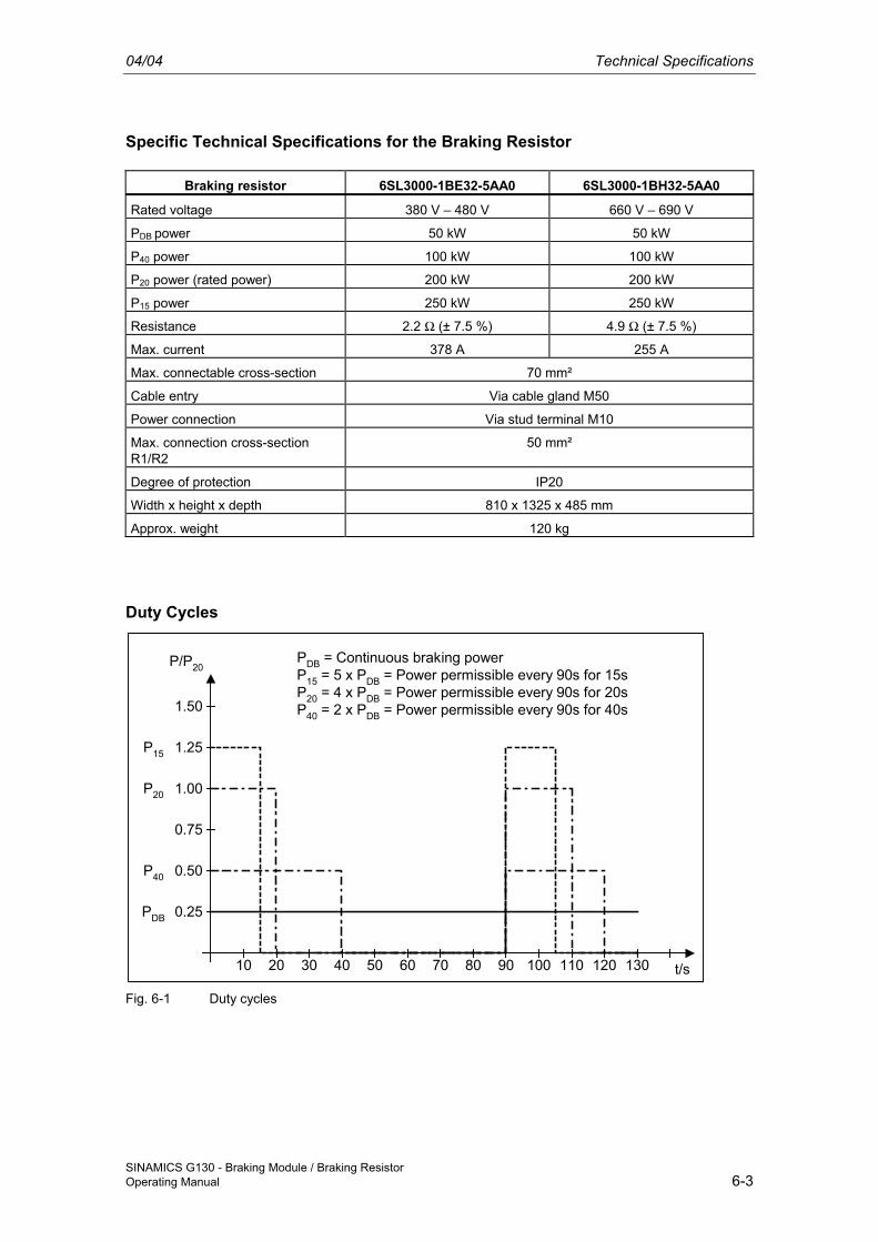
Specific Technical Specifications for the Braking Resistor
Braking resistor 6SL3000-1BE32-5AA0 6SL3000-1BH32-5AA0
Rated voltage 380 V – 480 V 660 V – 690 V
PDB power 50 kW 50 kW
P40 power 100 kW 100 kW
P20 power (rated power) 200 kW 200 kW
P15 power 250 kW 250 kW
Resistance 2.2 Ω (± 7.5 %) 4.9 Ω (± 7.5 %)
Max. current 378 A 255 A
Max. connectable cross-section 70 mm²
Cable entry Via cable gland M50
Power connection Via stud terminal M10
Max. connection cross-section R1/R2
50 mm²
Degree of protection IP20
Width x height x depth 810 x 1325 x 485 mm
Approx. weight 120 kg
Duty Cycles
10 20 30 40 50 60 70 80 90 100 110 120 130
0.25
0.50
0.75
1.00
1.25
1.50
P/P20
t/s
P15
P20
P40
PDB
PDB = Continuous braking powerP15 = 5 x PDB = Power permissible every 90s for 15sP20 = 4 x PDB = Power permissible every 90s for 20sP40 = 2 x PDB = Power permissible every 90s for 40s
Fig. 6-1 Duty cycles

Technical Specifications 04/04
SINAMICS G130 - Braking Module / Braking Resistor 6-4 Operating Manual


Siemens AG Automation and Drives Large Drives P.O. Box 4743, D – 90025 Nuremberg Germany www.ad.siemens.de
© Siemens AG 2004Subject to change without prior notice
Doc. no.: A5E00331454A
Printed in Germany
Related Documents