SINAMICS Function Manual · 01/2012 SINAMICS S120 s

Welcome message from author
This document is posted to help you gain knowledge. Please leave a comment to let me know what you think about it! Share it to your friends and learn new things together.
Transcript
SINAMICS
Function Manual · 01/2012
SINAMICS S120
s

Drive functions
___________________
___________________
___________________
___________________
___________________
___________________
___________________
___________________
___________________
___________________
___________________
___________________
___________________
___________________
SINAMICS
S120 Drive functions
Function Manual
Valid from: Firmware version 4.5
(FH1), 01/2012 6SL3097-4AB00-0BP2
Foreword
Infeed 1
Extended setpoint channel 2
Servo control 3
Vector control 4
U/f control (vector control) 5
Basic functions 6
Function modules 7
Monitoring and protective functions
8
Safety Integrated basic functions
9
Communication 10
Applications 11
Basic information about the drive system
12
Appendix A
Legal information
Legal information Warning notice system
This manual contains notices you have to observe in order to ensure your personal safety, as well as to prevent damage to property. The notices referring to your personal safety are highlighted in the manual by a safety alert symbol, notices referring only to property damage have no safety alert symbol. These notices shown below are graded according to the degree of danger.
DANGER indicates that death or severe personal injury will result if proper precautions are not taken.
WARNING indicates that death or severe personal injury may result if proper precautions are not taken.
CAUTION with a safety alert symbol, indicates that minor personal injury can result if proper precautions are not taken.
CAUTION without a safety alert symbol, indicates that property damage can result if proper precautions are not taken.
NOTICE indicates that an unintended result or situation can occur if the relevant information is not taken into account.
If more than one degree of danger is present, the warning notice representing the highest degree of danger will be used. A notice warning of injury to persons with a safety alert symbol may also include a warning relating to property damage.
Qualified Personnel The product/system described in this documentation may be operated only by personnel qualified for the specific task in accordance with the relevant documentation, in particular its warning notices and safety instructions. Qualified personnel are those who, based on their training and experience, are capable of identifying risks and avoiding potential hazards when working with these products/systems.
Proper use of Siemens products Note the following:
WARNING Siemens products may only be used for the applications described in the catalog and in the relevant technical documentation. If products and components from other manufacturers are used, these must be recommended or approved by Siemens. Proper transport, storage, installation, assembly, commissioning, operation and maintenance are required to ensure that the products operate safely and without any problems. The permissible ambient conditions must be complied with. The information in the relevant documentation must be observed.
Trademarks All names identified by ® are registered trademarks of Siemens AG. The remaining trademarks in this publication may be trademarks whose use by third parties for their own purposes could violate the rights of the owner.
Disclaimer of Liability We have reviewed the contents of this publication to ensure consistency with the hardware and software described. Since variance cannot be precluded entirely, we cannot guarantee full consistency. However, the information in this publication is reviewed regularly and any necessary corrections are included in subsequent editions.
Siemens AG Industry Sector Postfach 48 48 90026 NÜRNBERG GERMANY
Order number: 6SL3097-4AB00-0BP2 03/2012 Technical data subject to change
Copyright © Siemens AG 2012. All rights reserved

Drive functions Function Manual, (FH1), 01/2012, 6SL3097-4AB00-0BP2 3
Foreword
SINAMICS documentation The SINAMICS documentation is organized in the following categories:
General documentation/catalogs
User documentation
Manufacturer/service documentation
More information The following link provides information on the topics:
Ordering documentation/overview of documentation
Additional links to download documents
Using documentation online (find and browse through manuals/information) http://www.siemens.com/motioncontrol/docu
Please send any questions about the technical documentation (e.g. suggestions for improvement, corrections) to the following e-mail address: [email protected]
My Documentation Manager Under the following link there is information on how to create your own individual documentation based on Siemens' content, and adapt it for your own machine documentation: http://www.siemens.com/mdm
Training Under the following link there is information on SITRAIN - training from Siemens for products, systems and automation engineering solutions: http://www.siemens.com/sitrain
FAQs You can find Frequently Asked Questions in the Service&Support pages under Product Support: http://support.automation.siemens.com
SINAMICS You can find information on SINAMICS under: http://www.siemens.com/sinamics
Foreword
Drive functions 4 Function Manual, (FH1), 01/2012, 6SL3097-4AB00-0BP2
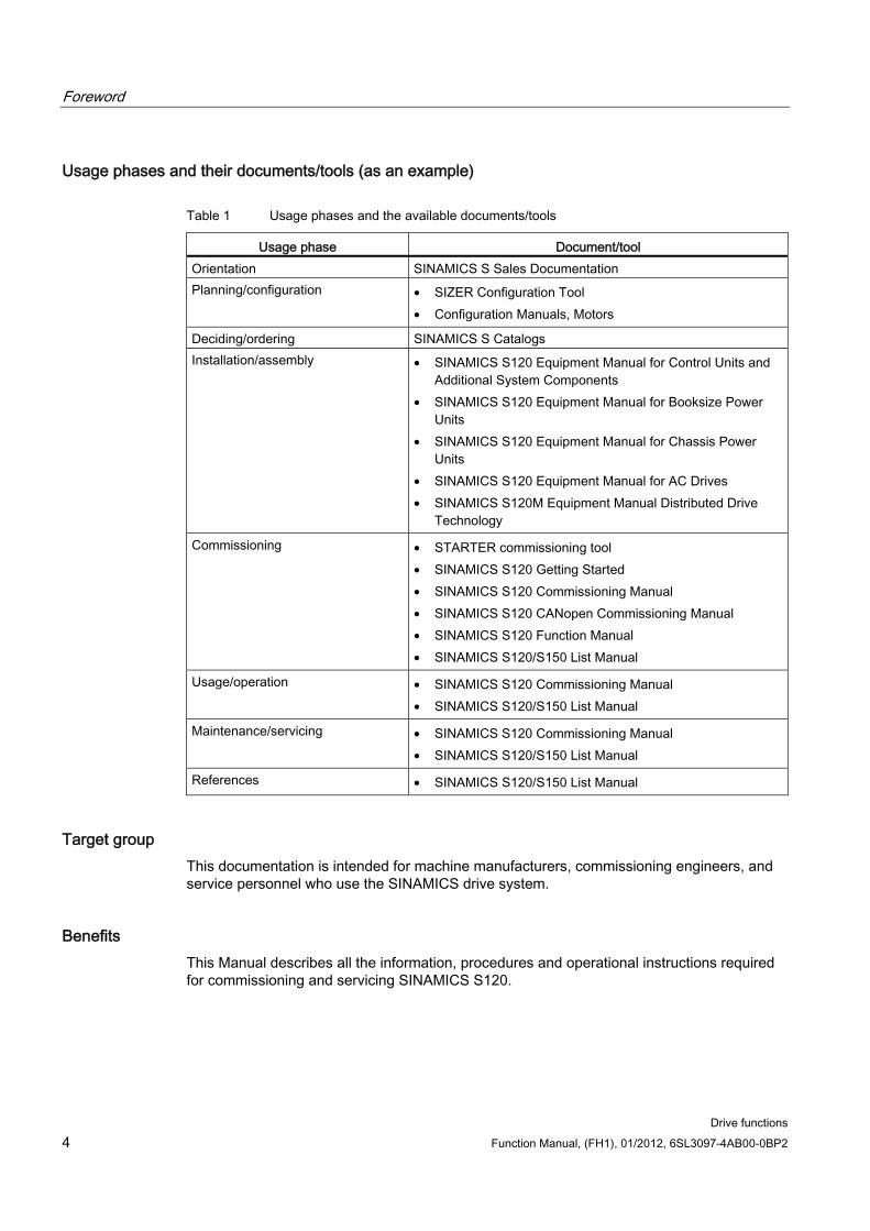
Usage phases and their documents/tools (as an example)
Table 1 Usage phases and the available documents/tools
Usage phase Document/tool Orientation SINAMICS S Sales Documentation Planning/configuration • SIZER Configuration Tool
• Configuration Manuals, Motors
Deciding/ordering SINAMICS S Catalogs Installation/assembly • SINAMICS S120 Equipment Manual for Control Units and
Additional System Components • SINAMICS S120 Equipment Manual for Booksize Power
Units • SINAMICS S120 Equipment Manual for Chassis Power
Units • SINAMICS S120 Equipment Manual for AC Drives • SINAMICS S120M Equipment Manual Distributed Drive
Technology
Commissioning • STARTER commissioning tool • SINAMICS S120 Getting Started • SINAMICS S120 Commissioning Manual • SINAMICS S120 CANopen Commissioning Manual • SINAMICS S120 Function Manual • SINAMICS S120/S150 List Manual
Usage/operation • SINAMICS S120 Commissioning Manual • SINAMICS S120/S150 List Manual
Maintenance/servicing • SINAMICS S120 Commissioning Manual • SINAMICS S120/S150 List Manual
References • SINAMICS S120/S150 List Manual
Target group This documentation is intended for machine manufacturers, commissioning engineers, and service personnel who use the SINAMICS drive system.
Benefits This Manual describes all the information, procedures and operational instructions required for commissioning and servicing SINAMICS S120.
Foreword
Drive functions Function Manual, (FH1), 01/2012, 6SL3097-4AB00-0BP2 5
Standard scope The scope of the functionality described in this document may differ from the scope of the functionality of the drive system that is actually supplied.
It may be possible for other functions not described in this documentation to be executed in the drive system. However, no claim can be made regarding the availability of these functions when the equipment is first supplied or in the event of servicing.
Functions that are not available in a particular product version of the drive system may be described in the documentation. The functionality of the supplied drive system should only be taken from the ordering documentation.
Extensions or changes made by the machine manufacturer must be documented by the machine manufacturer.
For reasons of clarity, this documentation does not contain all of the detailed information on all of the product types. This documentation cannot take into consideration every conceivable type of installation, operation and service/maintenance.
Technical Support Country-specific telephone numbers for technical support are provided in the Internet under Contact:
http://www.siemens.com/automation/service&support
EC Declaration of Conformity The EC Declaration of Conformity for the EMC Directive can be found on the Internet at:
http://support.automation.siemens.com
There – as a search term – enter the number 15257461 or contact your local Siemens office.
Structure The Function Manual is structured as follows:
Chapter 1 Infeed (Page 21) Chapter 2 Extended setpoint channel (Page 49) Chapter 3 Servo control (Page 69) Chapter 4 Vector control (Page 139) Chapter 5 U/f control (vector control) (Page 215) Chapter 6 Basic functions (Page 231) Chapter 7 Function modules (Page 317) Chapter 8 Monitoring and protective functions (Page 427) Chapter 9 Safety Integrated basic functions (Page 453) Chapter 10 Communication (Page 501) Chapter 11 Applications (Page 683) Chapter 12 Basic information about the drive system (Page 701)
Foreword
Drive functions 6 Function Manual, (FH1), 01/2012, 6SL3097-4AB00-0BP2
Advice for beginners:
First read Chapter Basic information about the drive system (Page 701), followed by the appropriate chapter depending on the particular requirement.
Search guides The following help is available for better orientation:
Contents
List of abbreviations
Index
Notation The following notation and abbreviations are used in this documentation:
Notation for parameters (examples):
p0918 Adjustable parameter 918
r1024 Display parameter 1024
p1070[1] Adjustable parameter 1070, index 1
p2098[1].3 Adjustable parameter 2098, index 1, bit 3
p0099[0...3] Adjustable parameter 99 indices 0 to 3
r0945[2](3) Display parameter 945 index 2 of drive object 3
p0795.4 Adjustable parameter 795 bit 4
Notation for faults and alarms (examples):
F12345 Fault 12345
A67890 Alarm 67890
Foreword
Drive functions Function Manual, (FH1), 01/2012, 6SL3097-4AB00-0BP2 7
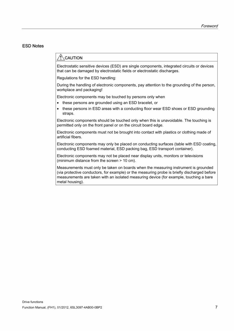
ESD Notes
CAUTION Electrostatic sensitive devices (ESD) are single components, integrated circuits or devices that can be damaged by electrostatic fields or electrostatic discharges.
Regulations for the ESD handling:
During the handling of electronic components, pay attention to the grounding of the person, workplace and packaging!
Electronic components may be touched by persons only when • these persons are grounded using an ESD bracelet, or • these persons in ESD areas with a conducting floor wear ESD shoes or ESD grounding
straps.
Electronic components should be touched only when this is unavoidable. The touching is permitted only on the front panel or on the circuit board edge.
Electronic components must not be brought into contact with plastics or clothing made of artificial fibers.
Electronic components may only be placed on conducting surfaces (table with ESD coating, conducting ESD foamed material, ESD packing bag, ESD transport container).
Electronic components may not be placed near display units, monitors or televisions (minimum distance from the screen > 10 cm).
Measurements must only be taken on boards when the measuring instrument is grounded (via protective conductors, for example) or the measuring probe is briefly discharged before measurements are taken with an isolated measuring device (for example, touching a bare metal housing).
Foreword
Drive functions 8 Function Manual, (FH1), 01/2012, 6SL3097-4AB00-0BP2
Safety instructions
DANGER • Commissioning is absolutely prohibited until it has been completely ensured that the
machine, in which the components described here are to be installed, is in full compliance with the provisions of the EC Machinery Directive.
• SINAMICS devices and AC motors must only be commissioned by suitably qualified personnel.
• The personnel must take into account the information provided in the technical customer documentation for the product, and be familiar with and follow the specified danger and warning notices.
• When electrical equipment and motors are operated, the electrical circuits automatically conduct a dangerous voltage.
• When the machine or system is operated, hazardous axis movements can occur. • All of the work carried out on the electrical machine or system must be carried out with it
in a no-voltage condition. • SINAMICS devices with three-phase motors must only be connected to the power
supply via an AC-DC residual-current-operated device with selective switching once verification has been provided that the SINAMICS device is compatible with the residual-current-operated device in accordance with IEC 61800-5-1.
WARNING • The successful and safe operation of this equipment and motors is dependent on
correct transport, proper storage, installation and mounting as well as careful operator control, service and maintenance.
• For special versions of the drive units and motors, information and data in the Catalogs and quotations additionally apply.
• In addition to the danger and warning information provided in the technical customer documentation, the applicable national, local, and plant-specific regulations and requirements must be taken into account.
• Only protective extra-low voltages (PELVs) that comply with EN 60204-1 may be connected to any connections and terminals between 0 and 48 V.
CAUTION • The motors can have surface temperatures of over +80 °C. • This is the reason that temperature-sensitive components, e.g. cables or electronic
components may neither be in contact nor be attached to the motor. • When attaching the connecting cables, you must ensure that:
– they are not damaged – they are not under tension – they cannot come into contact with any rotating parts
Foreword
Drive functions Function Manual, (FH1), 01/2012, 6SL3097-4AB00-0BP2 9
CAUTION • As part of routine tests, SINAMICS devices with three-phase motors are subject to a
voltage test in accordance with EN 61800-5-1. Before the voltage test is performed on the electrical equipment of industrial machines to EN 60204-1, Section 18.4, all connectors of SINAMICS equipment must be disconnected/unplugged to prevent the equipment from being damaged.
• Motors should be connected-up according to the circuit diagram provided. otherwise they can be destroyed.
Note
When operated in dry areas, SINAMICS equipment with three-phase motors conforms to Low-Voltage Directive 2006/95/EC.

Foreword
Drive functions 10 Function Manual, (FH1), 01/2012, 6SL3097-4AB00-0BP2
Drive functions Function Manual, (FH1), 01/2012, 6SL3097-4AB00-0BP2 11
Contents
Foreword ................................................................................................................................................... 3
1 Infeed ...................................................................................................................................................... 21
1.1 Active Infeed ................................................................................................................................21 1.1.1 Active Infeed closed-loop control booksize..................................................................................22 1.1.2 Active Infeed closed-loop control chassis....................................................................................24 1.1.3 Function diagrams and parameters .............................................................................................25 1.1.4 Line and DC link identification......................................................................................................26 1.1.5 Active Infeed open-loop control ...................................................................................................27 1.1.6 Reactive current control ...............................................................................................................30 1.1.7 Harmonics controller ....................................................................................................................31
1.2 Smart Infeed.................................................................................................................................31 1.2.1 Line supply and DC link identification routine for Smart Infeed Booksize ...................................34 1.2.2 Smart Infeed open-loop control....................................................................................................35
1.3 Basic Infeed .................................................................................................................................38 1.3.1 Function diagrams and parameters .............................................................................................40 1.3.2 Basic Infeed open-loop control ....................................................................................................41
1.4 Line contactor control...................................................................................................................44
1.5 Pre-charging and bypass contactor chassis ................................................................................46
2 Extended setpoint channel ...................................................................................................................... 49
2.1 Activating the "extended setpoint channel" function module in the servo control mode .............49
2.2 Description ...................................................................................................................................50
2.3 Fixed speed setpoints ..................................................................................................................51
2.4 Motorized potentiometer ..............................................................................................................52
2.5 Jog ...............................................................................................................................................54
2.6 Main/supplementary setpoint and setpoint modification..............................................................58
2.7 Direction of rotation limiting and direction of rotation changeover...............................................59
2.8 Suppression bandwidths and setpoint limits................................................................................61
2.9 Ramp-function generator .............................................................................................................63
3 Servo control ........................................................................................................................................... 69
3.1 Speed controller ...........................................................................................................................72
3.2 Speed setpoint filter .....................................................................................................................73
3.3 Speed controller adaptation .........................................................................................................74
3.4 Torque-controlled operation.........................................................................................................76
3.5 Torque setpoint limitation.............................................................................................................78
3.6 Current controller .........................................................................................................................82
Contents
Drive functions 12 Function Manual, (FH1), 01/2012, 6SL3097-4AB00-0BP2
3.7 Current setpoint filters ................................................................................................................. 85
3.8 Note about the electronic motor model ....................................................................................... 91
3.9 V/f control .................................................................................................................................... 91
3.10 Optimizing the current and speed controller ............................................................................... 95
3.11 Sensorless operation (without an encoder) ................................................................................ 97
3.12 Motor data identification............................................................................................................ 101 3.12.1 Motor data identification induction motor .................................................................................. 104 3.12.2 Motor data identification synchronous motor ............................................................................ 106
3.13 Pole position identification......................................................................................................... 108
3.14 Vdc control ................................................................................................................................ 114
3.15 Dynamic Servo Control (DSC) .................................................................................................. 118
3.16 Travel to fixed stop.................................................................................................................... 122
3.17 Vertical axes.............................................................................................................................. 126
3.18 Variable signaling function ........................................................................................................ 127
3.19 Central probe evaluation........................................................................................................... 129 3.19.1 Central probe evaluation examples .......................................................................................... 134
4 Vector control ........................................................................................................................................ 139
4.1 Sensorless vector control (SLVC)............................................................................................. 142
4.2 Vector control with encoder....................................................................................................... 150
4.3 Speed controller ........................................................................................................................ 150
4.4 Speed controller adaptation ...................................................................................................... 153
4.5 Speed controller pre-control and reference model ................................................................... 156
4.6 Droop......................................................................................................................................... 160
4.7 Open actual speed value .......................................................................................................... 161
4.8 Torque control ........................................................................................................................... 163
4.9 Torque limiting........................................................................................................................... 165
4.10 Vdc control ................................................................................................................................ 167
4.11 Current setpoint filter................................................................................................................. 171
4.12 Speed actual value filter............................................................................................................ 172
4.13 Current controller adaptation..................................................................................................... 173
4.14 Motor data identification and rotating measurement................................................................. 174
4.15 Efficiency optimization............................................................................................................... 181
4.16 Quick magnetization for induction motors................................................................................. 182
4.17 Instructions for commissioning induction motors (ASM)........................................................... 185
4.18 Instructions for commissioning permanent-magnet synchronous motors ................................ 188 4.18.1 Encoder adjustment in operation .............................................................................................. 191 4.18.2 Automatic encoder adjustment ................................................................................................. 193
Contents
Drive functions Function Manual, (FH1), 01/2012, 6SL3097-4AB00-0BP2 13
4.18.3 Pole position identification .........................................................................................................194 4.18.4 Function diagrams and parameters ...........................................................................................196
4.19 Instructions for commissioning separately-excited synchronous motors ..................................196
4.20 Flying restart ..............................................................................................................................197
4.21 Synchronization..........................................................................................................................199
4.22 Voltage Sensing Module ............................................................................................................200
4.23 Simulation mode ........................................................................................................................202 4.23.1 Description .................................................................................................................................202 4.23.2 Features .....................................................................................................................................203 4.23.3 Commissioning...........................................................................................................................203
4.24 Redundance operation power units ...........................................................................................203
4.25 Bypass .......................................................................................................................................204 4.25.1 Bypass with synchronization with overlap .................................................................................205 4.25.2 Bypass with synchronization without overlap ............................................................................208 4.25.3 Bypass without synchronization.................................................................................................209
4.26 Asynchronous pulse frequency..................................................................................................212 4.26.1 Asynchronous pulse frequency..................................................................................................212 4.26.2 Boundary conditions for asynchronous pulse frequency ...........................................................213
5 U/f control (vector control) ..................................................................................................................... 215
5.1 Voltage boost .............................................................................................................................218
5.2 Slip compensation......................................................................................................................222
5.3 Resonance damping ..................................................................................................................223
5.4 Vdc control .................................................................................................................................224
6 Basic functions ...................................................................................................................................... 231
6.1 Changing over units ...................................................................................................................231
6.2 Reference parameters/normalizations.......................................................................................232
6.3 Modular machine concept..........................................................................................................236
6.4 Sinusoidal filter...........................................................................................................................238
6.5 dv/dt filter plus VPL ....................................................................................................................240
6.6 dv/dt filter compact plus Voltage Peak Limiter...........................................................................241
6.7 Pulse frequency wobbling ..........................................................................................................243
6.8 Direction reversal without changing the setpoint .......................................................................244
6.9 Automatic restart (vector, servo, infeed)....................................................................................245
6.10 Armature short-circuit braking, DC braking................................................................................248 6.10.1 Armature short-circuit braking for permanent-magnet synchronous motors .............................249 6.10.1.1 Internal armature short-circuit braking .......................................................................................249 6.10.1.2 External armature short-circuit braking......................................................................................250 6.10.2 DC braking .................................................................................................................................253 6.10.2.1 Activation via parameters...........................................................................................................253 6.10.2.2 Activation via fault response ......................................................................................................254
Contents
Drive functions 14 Function Manual, (FH1), 01/2012, 6SL3097-4AB00-0BP2
6.10.2.3 Activation via OFF command.................................................................................................... 254 6.10.2.4 Activation via a speed threshold ............................................................................................... 255 6.10.3 Configuring the fault response .................................................................................................. 255 6.10.4 Function diagrams and parameters .......................................................................................... 256
6.11 Motor Module as braking module.............................................................................................. 257 6.11.1 Features .................................................................................................................................... 257 6.11.2 Configuring the resistors ........................................................................................................... 258 6.11.3 Activating the function ............................................................................................................... 262 6.11.4 Protective equipment ................................................................................................................ 263 6.11.5 Function diagrams and parameters .......................................................................................... 264
6.12 OFF3 torque limits..................................................................................................................... 265
6.13 Technology function: friction characteristic ............................................................................... 265
6.14 Simple brake control ................................................................................................................. 267
6.15 Runtime (operating hours counter) ........................................................................................... 269
6.16 Energy-saving display ............................................................................................................... 270
6.17 Encoder diagnostics.................................................................................................................. 274 6.17.1 Datalogger................................................................................................................................. 274 6.17.2 Encoder dirty signal................................................................................................................... 275
6.18 Tolerant encoder monitoring ..................................................................................................... 275 6.18.1 Encoder track monitoring .......................................................................................................... 276 6.18.2 Zero mark tolerance .................................................................................................................. 277 6.18.3 Freezing the speed raw value................................................................................................... 278 6.18.4 Adjustable hardware filter.......................................................................................................... 278 6.18.5 Edge evaluation of the zero mark ............................................................................................. 279 6.18.6 Pole position adaptation............................................................................................................ 280 6.18.7 Pulse number correction for faults ............................................................................................ 281 6.18.8 "Tolerance band pulse number" monitoring.............................................................................. 282 6.18.9 Signal edge evaluation (1x, 4x)................................................................................................. 283 6.18.10 Setting the measuring time to evaluate speed "0" .................................................................... 284 6.18.11 Sliding averaging of the speed actual value ............................................................................. 284 6.18.12 Troubleshooting ........................................................................................................................ 285 6.18.13 Tolerance window and correction ............................................................................................. 287 6.18.14 Dependencies ........................................................................................................................... 287 6.18.15 Overview of important parameters............................................................................................ 289
6.19 Parking axis and parking encoder............................................................................................. 290
6.20 Position tracking........................................................................................................................ 293 6.20.1 General Information .................................................................................................................. 293 6.20.2 Measuring gear ......................................................................................................................... 294
6.21 ENCODER as drive object ........................................................................................................ 298 6.21.1 Preconditions for creating an ENCODER drive object using STARTER .................................. 298 6.21.2 Creating an ENCODER drive object with STARTER, offline .................................................... 299
6.22 Terminal Module 41 .................................................................................................................. 300 6.22.1 SIMOTION mode ...................................................................................................................... 300 6.22.2 SINAMICS mode....................................................................................................................... 301 6.22.3 Zero mark emulation ................................................................................................................. 302 6.22.4 Zero mark synchronization........................................................................................................ 305
Contents
Drive functions Function Manual, (FH1), 01/2012, 6SL3097-4AB00-0BP2 15
6.22.5 Limit frequencies for TM41 ........................................................................................................306 6.22.6 Example in the SINAMICS mode...............................................................................................307 6.22.7 Function diagrams and parameters ...........................................................................................308
6.23 Upgrade the firmware and project..............................................................................................309 6.23.1 Firmware/project upgrade using the STARTER ........................................................................310 6.23.2 Downgrade lock .........................................................................................................................312
6.24 Pulse/direction interface.............................................................................................................312
6.25 Derating function for chassis units .............................................................................................314
7 Function modules .................................................................................................................................. 317
7.1 Technology controller.................................................................................................................317
7.2 Extended monitoring functions...................................................................................................321
7.3 Extended Brake Control.............................................................................................................323
7.4 Braking Module ..........................................................................................................................328
7.5 Cooling unit ................................................................................................................................329
7.6 Extended torque control (kT estimator, servo)...........................................................................331
7.7 Closed-loop position control.......................................................................................................333 7.7.1 General features ........................................................................................................................333 7.7.2 Position actual value conditioning..............................................................................................333 7.7.2.1 Features .....................................................................................................................................333 7.7.2.2 Description .................................................................................................................................333 7.7.2.3 Indexed actual value acquisition................................................................................................336 7.7.2.4 Load gear position tracking........................................................................................................337 7.7.2.5 Commissioning position tracking load gear using STARTER....................................................345 7.7.2.6 Function diagrams and parameters ...........................................................................................346 7.7.3 Position controller ......................................................................................................................346 7.7.4 Monitoring functions...................................................................................................................348 7.7.5 Measuring probe evaluation and reference mark search ..........................................................350 7.7.6 Commissioning...........................................................................................................................351
7.8 Basic positioner..........................................................................................................................352 7.8.1 Mechanical system ....................................................................................................................355 7.8.2 Limits..........................................................................................................................................357 7.8.3 EPOS and safe setpoint velocity limitation ................................................................................361 7.8.4 Referencing................................................................................................................................362 7.8.5 Referencing with several zero marks per revolution..................................................................371 7.8.6 Safely referencing under EPOS.................................................................................................374 7.8.7 Traversing blocks.......................................................................................................................376 7.8.8 Travel to fixed stop.....................................................................................................................381 7.8.9 Direct setpoint input (MDI) .........................................................................................................384 7.8.10 Jog .............................................................................................................................................387 7.8.11 Status signals.............................................................................................................................388
7.9 Master/slave for Active Infeed....................................................................................................390 7.9.1 Operating principle.....................................................................................................................390 7.9.2 Basic structure ...........................................................................................................................391 7.9.3 Types of communication ............................................................................................................393 7.9.4 Description of functions..............................................................................................................394 7.9.5 Commissioning...........................................................................................................................397
Contents
Drive functions 16 Function Manual, (FH1), 01/2012, 6SL3097-4AB00-0BP2
7.9.6 Function diagrams and parameters .......................................................................................... 398
7.10 Connecting the motors in parallel ............................................................................................. 399
7.11 Parallel connection of power units ............................................................................................ 401 7.11.1 Applications of parallel connections.......................................................................................... 403 7.11.1.1 Parallel connection of Basic Line Modules ............................................................................... 405 7.11.1.2 Parallel connection of Smart Line Modules............................................................................... 407 7.11.1.3 Parallel connection of Active Line Modules .............................................................................. 408 7.11.1.4 Parallel connection of Motor Modules....................................................................................... 410 7.11.2 Commissioning.......................................................................................................................... 412 7.11.3 Additional drive in addition to the parallel connection............................................................... 412
7.12 Extended stop and retract ......................................................................................................... 415 7.12.1 Preconditions for extended stop and retract ............................................................................. 416 7.12.2 Activating and enabling the ESR function................................................................................. 416 7.12.3 Valid sources for triggering the ESR functions ......................................................................... 417 7.12.4 Invalid sources .......................................................................................................................... 418 7.12.5 ESR responses ......................................................................................................................... 418 7.12.5.1 Extended stopping .................................................................................................................... 418 7.12.5.2 Extended retract........................................................................................................................ 419 7.12.5.3 Regenerative operation............................................................................................................. 420 7.12.6 Restrictions for ESR.................................................................................................................. 420 7.12.7 PROFIdrive telegram for ESR................................................................................................... 421 7.12.8 Function diagrams and parameters .......................................................................................... 421
7.13 Moment of inertia estimator....................................................................................................... 422
8 Monitoring and protective functions ....................................................................................................... 427
8.1 Power unit protection, general .................................................................................................. 427
8.2 Thermal monitoring and overload responses............................................................................ 427
8.3 Block protection......................................................................................................................... 430
8.4 Stall protection (only for vector control) .................................................................................... 431
8.5 Thermal motor protection .......................................................................................................... 432 8.5.1 Thermal motor models .............................................................................................................. 432 8.5.1.1 Thermal motor model 1 ............................................................................................................. 433 8.5.1.2 Thermal motor model 2 ............................................................................................................. 433 8.5.1.3 Thermal motor model 3 ............................................................................................................. 434 8.5.2 Motor temperature sensing ....................................................................................................... 436 8.5.3 Sensor Modules ........................................................................................................................ 437 8.5.4 Sensor Module Cabinet-Mounted ............................................................................................. 437 8.5.5 Sensor Module External............................................................................................................ 438 8.5.6 Sensor Module SME 20/25 ....................................................................................................... 438 8.5.7 Sensor Module External 120/125.............................................................................................. 438 8.5.8 Terminal Modules...................................................................................................................... 440 8.5.9 Terminal Module 31 .................................................................................................................. 440 8.5.10 Terminal Module 120 ................................................................................................................ 441 8.5.11 Terminal Module 150 ................................................................................................................ 443 8.5.11.1 Measurement with up to 6 channels: ........................................................................................ 444 8.5.11.2 Measurement with up to 12 channels: ...................................................................................... 445 8.5.11.3 Forming groups of temperature sensors................................................................................... 445 8.5.11.4 Evaluating temperature channels ............................................................................................. 446
Contents
Drive functions Function Manual, (FH1), 01/2012, 6SL3097-4AB00-0BP2 17
8.5.12 Motor Module/Power Module chassis format.............................................................................447 8.5.13 CU310-2/CUA31/CUA32 ...........................................................................................................448 8.5.14 Motor with DRIVE-CLiQ .............................................................................................................449 8.5.15 Temperature sensor evaluation .................................................................................................449 8.5.16 Function diagrams and parameters ...........................................................................................450
9 Safety Integrated basic functions........................................................................................................... 453
9.1 Latest information ......................................................................................................................453
9.2 General information ...................................................................................................................454 9.2.1 Explanations, standards, and terminology.................................................................................454 9.2.2 Supported functions ...................................................................................................................457 9.2.3 Controlling the Safety Integrated functions................................................................................458 9.2.4 Parameter, Checksum, Version, Password ...............................................................................459 9.2.5 Forced dormant error detection .................................................................................................461
9.3 Safety instructions......................................................................................................................462
9.4 Safe Torque Off (STO)...............................................................................................................463
9.5 Safe Stop 1 (SS1, time controlled) ............................................................................................466 9.5.1 SS1 (time controlled) with OFF3................................................................................................466 9.5.2 SS1 (time controlled) without OFF3...........................................................................................467 9.5.3 Function diagrams and parameters ...........................................................................................468
9.6 Safe Brake Control (SBC)..........................................................................................................470
9.7 Response times .........................................................................................................................472
9.8 Control via terminals on the Control Unit and Motor/Power Module..........................................473 9.8.1 Simultaneity and tolerance time of the two monitoring channels...............................................476 9.8.2 Bit pattern test ............................................................................................................................477
9.9 Commissioning the "STO", "SBC" and "SS1" functions ............................................................478 9.9.1 General information about commissioning safety functions ......................................................478 9.9.2 Procedure for commissioning "STO", "SBC" and "SS1"............................................................480 9.9.3 Safety faults ...............................................................................................................................484
9.10 Acceptance test and certificate..................................................................................................486 9.10.1 Acceptance test structure ..........................................................................................................487 9.10.1.1 Content of the complete acceptance test ..................................................................................488 9.10.1.2 Content of the partial acceptance test .......................................................................................488 9.10.1.3 Test scope for specific measures ..............................................................................................490 9.10.2 Safety logbook ...........................................................................................................................491 9.10.3 Documentation...........................................................................................................................491 9.10.4 Acceptance tests........................................................................................................................494 9.10.4.1 General information about acceptance tests .............................................................................494 9.10.4.2 Acceptance test for Safe Torque Off (STO)...............................................................................494 9.10.4.3 Acceptance test for Safe Stop 1, time controlled (SS1) ............................................................495 9.10.4.4 Acceptance test for "Safe Brake Control" (SBC) .......................................................................497 9.10.5 Completion of certificate ............................................................................................................498
9.11 Overview of parameters and function diagrams ........................................................................500
10 Communication...................................................................................................................................... 501
10.1 Communication according to PROFIdrive .................................................................................501 10.1.1 Application classes ....................................................................................................................504
Contents
Drive functions 18 Function Manual, (FH1), 01/2012, 6SL3097-4AB00-0BP2
10.1.2 Cyclic communication ............................................................................................................... 509 10.1.2.1 Telegrams and process data .................................................................................................... 509 10.1.2.2 Description of control words and setpoints ............................................................................... 515 10.1.2.3 MOMRED.................................................................................................................................. 525 10.1.2.4 Description of status words and actual values.......................................................................... 532 10.1.2.5 Control and status words for encoder ....................................................................................... 553 10.1.2.6 Extended encoder evaluation.................................................................................................... 562 10.1.2.7 Central control and status words .............................................................................................. 563 10.1.2.8 Motion Control with PROFIdrive ............................................................................................... 572 10.1.2.9 Diagnostics channel for cyclic communication.......................................................................... 575 10.1.3 Parallel operation of communication interfaces ........................................................................ 577 10.1.4 Acyclic communication.............................................................................................................. 581 10.1.4.1 General information about acyclic communication ................................................................... 581 10.1.4.2 Structure of orders and responses............................................................................................ 583 10.1.4.3 Determining the drive object numbers ...................................................................................... 588 10.1.4.4 Example 1: read parameters..................................................................................................... 589 10.1.4.5 Example 2: write parameters (multi-parameter request) .......................................................... 591
10.2 Communication via PROFIBUS DP .......................................................................................... 594 10.2.1 General information about PROFIBUS..................................................................................... 594 10.2.1.1 General information about PROFIBUS for SINAMICS ............................................................. 594 10.2.1.2 Example: telegram structure for cyclic data transmission......................................................... 597 10.2.2 Commissioning PROFIBUS ...................................................................................................... 600 10.2.2.1 Setting the PROFIBUS interface............................................................................................... 600 10.2.2.2 PROFIBUS interface in operation ............................................................................................. 602 10.2.2.3 Commissioning PROFIBUS ...................................................................................................... 604 10.2.2.4 Diagnostics options ................................................................................................................... 605 10.2.2.5 SIMATIC HMI addressing ......................................................................................................... 605 10.2.2.6 Monitoring: telegram failure....................................................................................................... 607 10.2.3 Motion Control with PROFIBUS................................................................................................ 609 10.2.4 Slave-to-slave communication .................................................................................................. 612 10.2.4.1 Setpoint assignment in the subscriber ...................................................................................... 615 10.2.4.2 Activating/parameterizing slave-to-slave communication ......................................................... 615 10.2.4.3 Commissioning of the PROFIBUS slave-to-slave communication ........................................... 616 10.2.4.4 GSD in operation....................................................................................................................... 625 10.2.4.5 Diagnosing the PROFIBUS slave-to-slave communication in STARTER ................................ 627
10.3 Communication via PROFINET IO ........................................................................................... 628 10.3.1 General information about PROFINET IO ................................................................................ 628 10.3.1.1 Real-time (RT) and isochronous real-time (IRT) communication ............................................. 629 10.3.1.2 Addresses ................................................................................................................................. 630 10.3.1.3 Data transfer ............................................................................................................................. 632 10.3.1.4 Communication channels for PROFINET ................................................................................. 633 10.3.2 Drive control with PROFINET ................................................................................................... 635 10.3.2.1 Media redundancy..................................................................................................................... 638 10.3.3 RT classes for PROFINET IO ................................................................................................... 638 10.3.4 PROFINET GSDML .................................................................................................................. 643 10.3.5 Motion Control with PROFINET ................................................................................................ 645 10.3.6 Communication with CBE20 ..................................................................................................... 648 10.3.6.1 EtherNet/IP................................................................................................................................ 649 10.3.7 PN gate ..................................................................................................................................... 649 10.3.7.1 Functions transferred from PN Gate ......................................................................................... 650 10.3.7.2 Preconditions for PN Gate ........................................................................................................ 651
Contents
Drive functions Function Manual, (FH1), 01/2012, 6SL3097-4AB00-0BP2 19
10.3.8 PROFINET with 2 controllers.....................................................................................................652 10.3.8.1 Control Unit settings...................................................................................................................652 10.3.8.2 Configuring Shared Device ........................................................................................................655 10.3.8.3 Overview of important parameters.............................................................................................664 10.3.9 PROFIenergy .............................................................................................................................664 10.3.9.1 Function diagrams and parameters ...........................................................................................666
10.4 Communication via SINAMICS Link ..........................................................................................667 10.4.1 Basic principles of SINAMICS Link............................................................................................667 10.4.2 Topology ....................................................................................................................................669 10.4.3 Configuring and commissioning.................................................................................................670 10.4.4 Example .....................................................................................................................................673 10.4.5 Communication failure when booting or in cyclic operation.......................................................680
11 Applications ........................................................................................................................................... 683
11.1 Switching on a drive object X_INF using a VECTOR drive object.............................................683
11.2 Description .................................................................................................................................684
11.3 Application examples with DMC20 ............................................................................................689
11.4 DCC axial winder .......................................................................................................................693
11.5 Control Units without infeed control ...........................................................................................697
11.6 Application: emergency stop with power failure and/or emergency stop (Servo)......................698
12 Basic information about the drive system .............................................................................................. 701
12.1 Parameter ..................................................................................................................................701
12.2 Data sets ....................................................................................................................................704 12.2.1 CDS: Command Data Set..........................................................................................................704 12.2.2 DDS: Drive Data Set ..................................................................................................................705 12.2.3 EDS: Encoder Data Set .............................................................................................................706 12.2.4 MDS: Motor Data Set.................................................................................................................707 12.2.5 Function diagrams and parameters ...........................................................................................709
12.3 Drive objects ..............................................................................................................................710
12.4 BICO technology: interconnecting signals .................................................................................712 12.4.1 Binectors, connectors ................................................................................................................712 12.4.2 Interconnecting signals using BICO technology ........................................................................713 12.4.3 Internal encoding of the binector/connector output parameters ................................................714 12.4.4 Sample interconnections............................................................................................................715 12.4.5 BICO technology:.......................................................................................................................716 12.4.6 Scaling .......................................................................................................................................717 12.4.7 Propagation of faults ..................................................................................................................718
12.5 Inputs/outputs.............................................................................................................................719 12.5.1 Digital inputs/outputs..................................................................................................................719 12.5.2 Use of bidirectional inputs/outputs on the CU............................................................................722 12.5.3 Analog inputs .............................................................................................................................724 12.5.4 Analog outputs ...........................................................................................................................725
12.6 Backing up the non-volatile memory..........................................................................................726
12.7 Parameterizing using the BOP20 (Basic Operator Panel 20)....................................................728 12.7.1 General information about the BOP20.......................................................................................728
Contents
Drive functions 20 Function Manual, (FH1), 01/2012, 6SL3097-4AB00-0BP2
12.7.2 Displays and using the BOP20 ................................................................................................. 733 12.7.3 Fault and alarm displays ........................................................................................................... 738 12.7.4 Controlling the drive using the BOP20...................................................................................... 739
12.8 Examples of replacing components .......................................................................................... 739
12.9 DRIVE-CLiQ topology ............................................................................................................... 742
12.10 Rules for wiring with DRIVE-CLiQ ............................................................................................ 744 12.10.1 Changing the offline topology in STARTER.............................................................................. 745 12.10.2 Binding DRIVE-CLiQ rules ........................................................................................................ 745 12.10.3 Recommended DRIVE-CLiQ rules ........................................................................................... 751 12.10.4 Wiring example for drives in vector control mode..................................................................... 754 12.10.5 Wiring example for parallel connection of Motor Modules in vector control mode ................... 756 12.10.6 Sample wiring: Power Modules................................................................................................. 758 12.10.7 Sample wiring for servo drives.................................................................................................. 760 12.10.8 Sample wiring for vector V/f drives ........................................................................................... 760
12.11 Emergency operating mode for DRIVE-CLiQ components ...................................................... 761
12.12 System sampling times and number of controllable drives....................................................... 763 12.12.1 Notes on the number of controllable drives .............................................................................. 764 12.12.2 Setting the sampling times........................................................................................................ 768 12.12.3 Rules for setting the sampling time........................................................................................... 769 12.12.4 Default settings for the sampling times ..................................................................................... 771 12.12.5 Examples when changing sampling times / pulse frequencies................................................. 772 12.12.6 Overview of important parameters (see SINAMICS S120/S150 List Manual).......................... 773
12.13 Licensing ................................................................................................................................... 774
12.14 Write and know-how protection................................................................................................. 778 12.14.1 Write protection ......................................................................................................................... 778 12.14.2 Know-how protection................................................................................................................. 780 12.14.2.1 Copy protection.................................................................................................................... 782 12.14.2.2 Using know-how protection.................................................................................................. 783 12.14.2.3 Replacing devices for know-how protection with copy protection ....................................... 785 12.14.3 Overview of important parameters............................................................................................ 788
A Appendix................................................................................................................................................ 791
A.1 Availability of hardware components ........................................................................................ 791
A.2 Availability of SW functions....................................................................................................... 793
A.3 Functions of SINAMICS S120 Combi ....................................................................................... 801
A.4 SINAMICS S120 Functions....................................................................................................... 803
A.5 List of abbreviations .................................................................................................................. 806
Index...................................................................................................................................................... 817
Drive functions Function Manual, (FH1), 01/2012, 6SL3097-4AB00-0BP2 21
Infeed 11.1 Active Infeed
Features Controlled DC link voltage whose level can be adjusted (independent of line voltage
fluctuations)
Regenerative feedback capability
Specific reactive current setting
Low line harmonics, sinusoidal line current (cos φ = 1)
Several Active Line Modules connected in parallel
Master/Slave operation for several Active Line Modules
Description The Active Infeed closed-loop control works in conjunction with the line reactor or an Active Interface Module and the Active Line Module as step-up controller. The level of the DC link voltage can be defined through parameters, and, by means of the control, it is independent of line voltage fluctuations.
The open and closed-loop control firmware of the Active Line Module runs on the Control Unit assigned to it. The Active Line Module and Control Unit communicate via DRIVE-CLiQ.
The operating modes "parallel connection" and "master/slave connection" of the power units are described in this manual in Chapter Function modules (Page 317).
The use of a "Voltage Sensing Module" (VSM) is described in Chapter Vector control.
Infeed 1.1 Active Infeed
Drive functions 22 Function Manual, (FH1), 01/2012, 6SL3097-4AB00-0BP2
1.1.1 Active Infeed closed-loop control booksize
Schematic structure
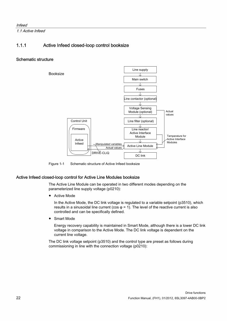
Figure 1-1 Schematic structure of Active Infeed booksize
Active Infeed closed-loop control for Active Line Modules booksize The Active Line Module can be operated in two different modes depending on the parameterized line supply voltage (p0210):
Active Mode
In the Active Mode, the DC link voltage is regulated to a variable setpoint (p3510), which results in a sinusoidal line current (cos φ = 1). The level of the reactive current is also controlled and can be specifically defined.
Smart Mode
Energy recovery capability is maintained in Smart Mode, although there is a lower DC link voltage in comparison to the Active Mode. The DC link voltage is dependent on the current line voltage.
The DC link voltage setpoint (p3510) and the control type are preset as follows during commissioning in line with the connection voltage (p0210):
Infeed 1.1 Active Infeed
Drive functions Function Manual, (FH1), 01/2012, 6SL3097-4AB00-0BP2 23
Table 1- 1 Presetting the control type and DC link voltage booksize
Supply voltage p0210 [V] 380-400 401-415 416-440 460 480 Control type p3400.0 "0" = Active Mode "1" = Smart Mode Vdc_setp p3510 [V] 600 625 562-5941) 6211) 6481) 1) Voltages specified for the smart mode are derived from the rectified line supply voltage. The DC link voltage setpoint (p3510) has no effect in this control mode.
Voltage Sensing Module (VSM10) used with S120 Active Line Module Using a Voltage Sensing Module (VSM10) to sense the line voltage, drives can also be operated in systems with significant frequency fluctuations beyond the range defined in IEC 61000-2-4 if certain supplementary conditions are met. Significant frequency fluctuations may occur e.g. in (isolated) diesel-electric systems but not in large interconnected systems such as the European interconnected supply network. In non-European countries, e.g. in countries with power distribution over a wide geographical region (countries with a large surface such as Australia, USA, China), line voltage dips occur more frequently, the dips are somewhat lower and, above all, they can occur for longer periods of time up to several seconds. In such line systems, the use of the Voltage Sensing Module is urgently recommended.
Commissioning During commissioning, the device supply voltage (p0210) and the selection of an optional line filter (p0220) must be parameterized.
Following automatic commissioning, the appropriate filter for the matching Active Interface Module is preset as the line filter. If the drive line-up is set up differently, then the line filter type must be adjusted using p0220.
When it is first switched on with a new/modified network, an automatic controller setting should be implemented using the line/DC link identification routine (p3410).
Note
In a supply system without regenerative feedback capability (e.g. generators), regenerative operation must be inhibited via the binector input p3533.
CAUTION When a Wideband Line Filter is connected, it must be parameterized with p0220 = 1...5. The temperature sensor must be connected to terminal X21 of the Active Line Module.
The DC link voltage (p3510) can be set within the following limits:
Upper limit:
– Maximum DC link voltage (p0280)
– Product of line voltage (p0210) and max. step-up factor (r3508)
Lower limit: Supply voltage (p0210) multiplied by 1.42
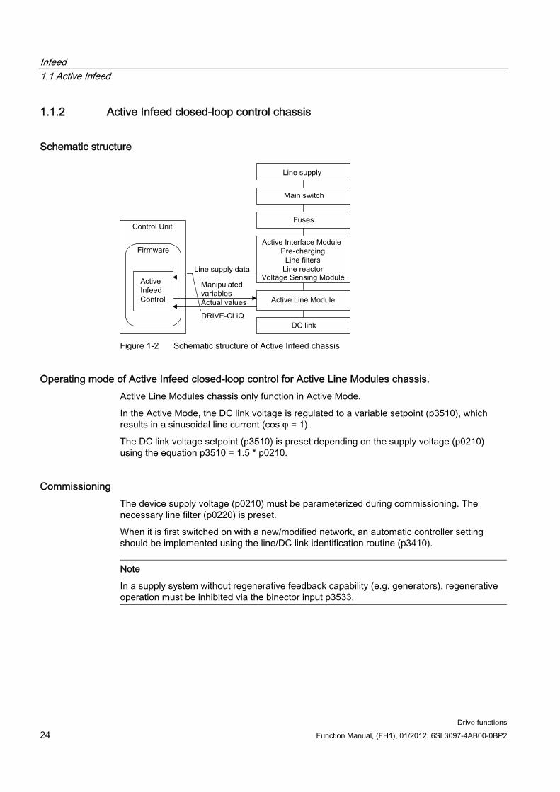
Infeed 1.1 Active Infeed
Drive functions 24 Function Manual, (FH1), 01/2012, 6SL3097-4AB00-0BP2
1.1.2 Active Infeed closed-loop control chassis
Schematic structure
Figure 1-2 Schematic structure of Active Infeed chassis
Operating mode of Active Infeed closed-loop control for Active Line Modules chassis. Active Line Modules chassis only function in Active Mode.
In the Active Mode, the DC link voltage is regulated to a variable setpoint (p3510), which results in a sinusoidal line current (cos φ = 1).
The DC link voltage setpoint (p3510) is preset depending on the supply voltage (p0210) using the equation p3510 = 1.5 * p0210.
Commissioning The device supply voltage (p0210) must be parameterized during commissioning. The necessary line filter (p0220) is preset.
When it is first switched on with a new/modified network, an automatic controller setting should be implemented using the line/DC link identification routine (p3410).
Note
In a supply system without regenerative feedback capability (e.g. generators), regenerative operation must be inhibited via the binector input p3533.
Infeed 1.1 Active Infeed
Drive functions Function Manual, (FH1), 01/2012, 6SL3097-4AB00-0BP2 25
The DC link voltage (p3510) can be set within the following limits:
Upper limit:
– Maximum DC link voltage (p0280)
– Product of the supply voltage (p0210) and step-up factor (max. p3508 = 2.00)
Lower limit: Supply voltage (p0210) multiplied by 1.42
CAUTION Step-up factor for Active Line Modules, chassis format
For thermal reasons, the step-up factor may be set to a maximum of 2.00.
1.1.3 Function diagrams and parameters
Function diagrams (see SINAMICS S120/S150 List Manual) 1774 Overviews - Active Infeed
8920 Control word sequence control infeed
...
8964 Messages and monitoring, supply frequency and Vdc monitoring
Overview of important parameters (see SINAMICS S120/S150 List Manual) r0002 Infeed operating display
r0046 CO/BO: Missing enable signals
p0210 Device supply voltage
p0220 Infeed line filter type
p0280 DC link voltage maximum steady-state
p0840 BI: ON/OFF1
p0844 BI: 1. OFF2
p0852 BI: Enable operation
r0898 CO/BO: Control word sequence control infeed
r0899 CO/BO: Status word sequence control infeed
r2138 CO/BO: Control word, faults/alarms
r2139 CO/BO: Status word, faults/alarms 1
p3400 Infeed configuration word
r3405 CO/BO: Status word infeed
Infeed 1.1 Active Infeed
Drive functions 26 Function Manual, (FH1), 01/2012, 6SL3097-4AB00-0BP2
p3410 Infeed identification method
p3508 Infeed step-up factor maximum
p3510 Infeed DC link voltage setpoint
p3533 BI: Infeed, inhibit regenerative operation
p3610 Infeed reactive current fixed setpoint
p3611 CI: Infeed reactive current supplementary setpoint
1.1.4 Line and DC link identification The characteristic line supply and DC link quantities are determined using the automatic parameter identification routine. They provide the basis to optimally set the controllers in the Line Module.
An optimal setting of the current and voltage control is achieved with the help of the line supply and DC link identification routine. The dynamic response of the current control can be adjusted with p3560.
Note
If the line supply environment changes or the components connected to the DC link (e.g. after installation of the equipment at the customer's site or after expanding the drive line-up), the line supply/DC link identification routine should be repeated with p3410 = 5. Only then can it be guaranteed that the infeed operates with the optimum controller settings.
When the identification function is activated, alarm A06400 is output.
Identification methods For additional identification methods, see the SINAMICS S120/S150 List Manual.
p3410 = 4: An identification run for the total inductance and DC link capacitance is initiated when the pulses are next enabled (two measuring routines with different current magnitudes). Data determined during identification (r3411 and r3412) is entered into p3421 and p3422 and the controller is recalculated. At the same time, the parameters for current controller adaptation are determined (p3620, p3622). All infeed parameters are then automatically stored in non-volatile memory. The infeed continues to operate without interruption on the new controller parameters.
p3410 = 5: The same measurements and write operations are always carried out for p3410 = 4. Before the first identification run, however, the parameter values for line inductance and DC link capacitance are reset (p3421 = p0223 and p3422 = p0227).
Infeed 1.1 Active Infeed
Drive functions Function Manual, (FH1), 01/2012, 6SL3097-4AB00-0BP2 27
p3410 is automatically set to 0 when one of the two identification routines (p3410 = 4 or p3410 = 5) completes successfully.
Note
Identification using p3410 = 5 should preferably be used.
It may be necessary to reset the closed-loop controller to the factory settings if an identification run was unsuccessful, for example.
Overview of important parameters (see SINAMICS S120/S150 List Manual) p3410 Infeed identification method
r3411 Infeed inductance identified
r3412 Infeed DC-link capacitance identified
p3560 Infeed Vdc controller proportional gain
1.1.5 Active Infeed open-loop control
Description The Active Line Module can be controlled via the BICO interconnection using terminals or the fieldbus. The operating status is indicated on the operating display r0002. The missing enable signals for operation (r0002 = 00) are mapped in parameter r0046. The EP terminals (enable pulses) must be connected in accordance with the Manual of the corresponding power units. The drive unit must have been commissioned for the first time.
Acknowledging faults Faults that are still present but the causes of which have been rectified can be acknowledged using a 0/1 edge at the "1. Acknowledge faults" signal (p2103).
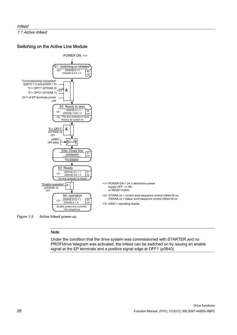
Infeed 1.1 Active Infeed
Drive functions 28 Function Manual, (FH1), 01/2012, 6SL3097-4AB00-0BP2
Switching on the Active Line Module
Figure 1-3 Active Infeed power-up
Note
Under the condition that the drive system was commissioned with STARTER and no PROFIdrive telegram was activated, the infeed can be switched on by issuing an enable signal at the EP terminals and a positive signal edge at OFF1 (p0840).
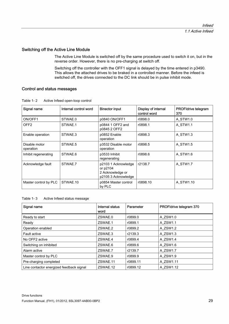
Infeed 1.1 Active Infeed
Drive functions Function Manual, (FH1), 01/2012, 6SL3097-4AB00-0BP2 29
Switching off the Active Line Module The Active Line Module is switched off by the same procedure used to switch it on, but in the reverse order. However, there is no pre-charging at switch off.
Switching off the controller with the OFF1 signal is delayed by the time entered in p3490. This allows the attached drives to be braked in a controlled manner. Before the infeed is switched off, the drives connected to the DC link should be in pulse inhibit mode.
Control and status messages
Table 1- 2 Active Infeed open-loop control
Signal name Internal control word Binector input Display of internal control word
PROFIdrive telegram 370
ON/OFF1 STWAE.0 p0840 ON/OFF1 r0898.0 A_STW1.0 OFF2 STWAE.1 p0844 1 OFF2 and
p0845 2 OFF2 r0898.1 A_STW1.1
Enable operation STWAE.3 p0852 Enable operation
r0898.3 A_STW1.3
Disable motor operation
STWAE.5 p3532 Disable motor operation
r0898.5 A_STW1.5
Inhibit regenerating STWAE.6 p3533 Inhibit regenerating
r0898.6 A_STW1.6
Acknowledge fault STWAE.7 p2103 1 Acknowledge or p2104 2 Acknowledge or p2105 3 Acknowledge
r2138.7 A_STW1.7
Master control by PLC STWAE.10 p0854 Master control by PLC
r0898.10 A_STW1.10
Table 1- 3 Active Infeed status message
Signal name Internal status word
Parameter PROFIdrive telegram 370
Ready to start ZSWAE.0 r0899.0 A_ZSW1.0 Ready ZSWAE.1 r0899.1 A_ZSW1.1 Operation enabled ZSWAE.2 r0899.2 A_ZSW1.2 Fault active ZSWAE.3 r2139.3 A_ZSW1.3 No OFF2 active ZSWAE.4 r0899.4 A_ZSW1.4 Switching on inhibited ZSWAE.6 r0899.6 A_ZSW1.6 Alarm active ZSWAE.7 r2139.7 A_ZSW1.7 Master control by PLC ZSWAE.9 r0899.9 A_ZSW1.9 Pre-charging completed ZSWAE.11 r0899.11 A_ZSW1.11 Line contactor energized feedback signal ZSWAE.12 r0899.12 A_ZSW1.12
Infeed 1.1 Active Infeed
Drive functions 30 Function Manual, (FH1), 01/2012, 6SL3097-4AB00-0BP2
1.1.6 Reactive current control A reactive current setpoint can be set to compensate the reactive current or to stabilize the line voltage in infeed mode. The total setpoint is the sum of the fixed setpoint p3610 and the dynamic setpoint via the connector input p3611.
The direction of rotation of the line supply is compensated automatically with reactive current control.
– A negative reactive current setpoint causes an inductive reactive current
– A positive reactive current setpoint generates a capacitive reactive current
The closed-loop control limits the reactive current setpoint dynamically in such a way that the sum of the active current setpoint and the reactive current setpoint does not exceed the maximum device current.
The reactive current demand of a line filter selected in the configuration wizard is automatically supplied by the Active Infeed Module. This means that the display value of the actual reactive current setpoint in r0075 no longer corresponds with the parameterized total reactive current setpoint.
The reactive power setpoint of the Active Infeed Module with respect to the line supply can be obtained by multiplying the parameterized total reactive current setpoint by 1.73 * rated line voltage.
Function diagrams (see SINAMICS S120/S150 List Manual) 1774 Overviews - Active Infeed
8946 Current pre-control / current controller / gating unit (p3400.0 = 0)
Overview of important parameters (see SINAMICS S120/S150 List Manual) p3610 Infeed reactive current fixed setpoint
p3611 CI: Infeed reactive current supplementary setpoint
Infeed 1.2 Smart Infeed
Drive functions Function Manual, (FH1), 01/2012, 6SL3097-4AB00-0BP2 31
1.1.7 Harmonics controller
Description Harmonics in the line voltage cause harmonics in the line currents. Current harmonics can be reduced by activating the harmonics controller.
Example: setting the harmonics controller The 5th and 7th harmonics are to be compensated:
Table 1- 4 Example parameters for the harmonics controller
Index p3624 p3625 [0] 5 100 % [1] 7 100 % The phase currents in parameter p0069[0..2] (U, V, W) can be checked using the STARTER trace function.
Overview of important parameters (see the SINAMICS S120/150 List Manual) p3624[0...1] Infeed harmonics controller order
p3625[0...1] Infeed harmonics controller scaling
r3626[0...1] Infeed harmonics controller output
r0069[0..6] Phase current, actual value
1.2 Smart Infeed
Features For Smart Line Modules with a power of ≥ 16 kW
Unregulated DC link voltage
Regenerative feedback capability
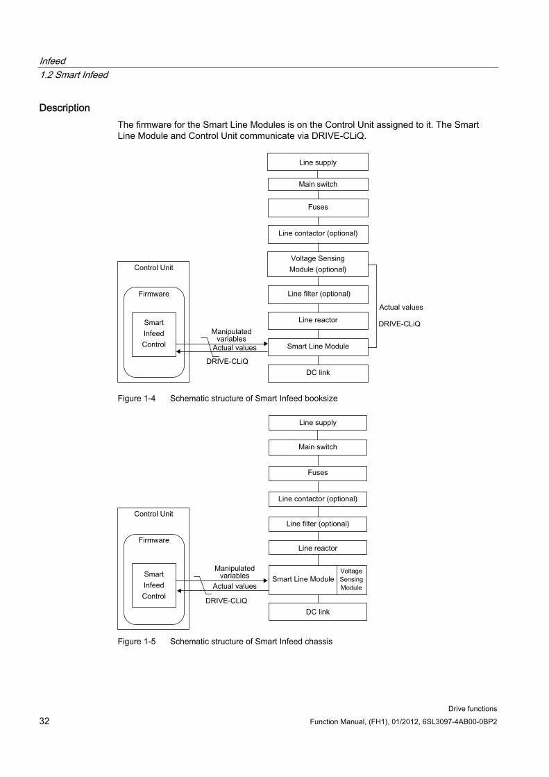
Infeed 1.2 Smart Infeed
Drive functions 32 Function Manual, (FH1), 01/2012, 6SL3097-4AB00-0BP2
Description The firmware for the Smart Line Modules is on the Control Unit assigned to it. The Smart Line Module and Control Unit communicate via DRIVE-CLiQ.
Figure 1-4 Schematic structure of Smart Infeed booksize
Figure 1-5 Schematic structure of Smart Infeed chassis
Infeed 1.2 Smart Infeed
Drive functions Function Manual, (FH1), 01/2012, 6SL3097-4AB00-0BP2 33
Commissioning The device connection voltage (p0210) must be parameterized during commissioning.
Note
In a supply system without regenerative feedback capability (e.g. generators), regenerative operation must be inhibited via the binector input p3533.
Smart Line Modules do not support kinetic buffering in generator mode.
Function diagrams (see SINAMICS S120/S150 List Manual) 1775 Overviews - Smart Infeed
8820 Control word sequence control infeed
8826 Status word sequence control infeed
8828 Status word infeed
8832 Processor
8834 Missing enables, line contactor control
8850 Interface to the Smart Infeed (control signals, actual values)
8860 Supply voltage monitoring
8864 Power frequency and Vdc monitoring
Overview of important parameters (see SINAMICS S120/S150 List Manual) r0002 Infeed operating display
r0046 CO/BO: Missing enable signals
p0210 Device supply voltage
p0840 BI: ON/OFF1
p0844 BI: 1. OFF2
p0852 BI: Enable operation
r0898 CO/BO: Control word sequence control infeed
r0899 CO/BO: Status word sequence control infeed
r2138 CO/BO: Control word, faults/alarms
r2139 CO/BO: Status word, faults/alarms 1
r3405 CO/BO: Status word infeed
p3533 BI: Infeed, inhibit regenerative operation
Infeed 1.2 Smart Infeed
Drive functions 34 Function Manual, (FH1), 01/2012, 6SL3097-4AB00-0BP2
1.2.1 Line supply and DC link identification routine for Smart Infeed Booksize The characteristic line supply and DC link quantities are determined using the automatic parameter identification routine. They provide the basis to optimally set the controllers in the Line Module.
Note
If the line supply environment changes or the components connected to the DC link (e.g. after installation of the equipment at the customer's site or after expanding the drive line-up), the line supply/DC link identification routine should be repeated with p3410 = 5. Only then can it be guaranteed that the infeed operates with an optimum controller setting.
When the identification function is activated, alarm A06400 is output.
CAUTION The line supply and DC link identification routine is not permissible for Smart Line Modules of the Chassis type.
Identification methods For additional identification methods, see the SINAMICS S120/S150 List Manual.
p3410 = 4: An identification run for the total inductance and DC link capacitance is initiated when the pulses are next enabled (two measuring routines with different current magnitudes). Data determined during identification (r3411 and r3412) is entered into p3421 and p3422 and the controller is recalculated. At the same time, the parameters for current controller adaptation are determined (p6320, p6322). All infeed parameters are then automatically stored in non-volatile memory. The infeed continues to operate without interruption on the new controller parameters.
p3410 = 5: The same measurements and write operations are always carried out for p3410 = 4. However, before the first identification run, the parameter values for line inductance and DC link capacitance are reset (p3421 = p0223 and p3422 = p0227) and the coarse settings are made for the controller.
p3410 is automatically set to 0 when one of the two identification routines (p3410 = 4 or p3410 = 5) completes successfully.
Note
Identification using p3410 = 5 should preferably be used.
It may be necessary to reset the closed-loop controller to the factory settings if an identification run was unsuccessful, for example.
Infeed 1.2 Smart Infeed
Drive functions Function Manual, (FH1), 01/2012, 6SL3097-4AB00-0BP2 35
Overview of important parameters (see SINAMICS S120/S150 List Manual) p3410 Infeed identification method
p3421 Infeed inductance
p3422 Infeed DC link capacitance
1.2.2 Smart Infeed open-loop control The Smart Line Module can be controlled via the BICO interconnection, e.g. using terminals or the fieldbus. The operating status is indicated on the operating display r0002. The missing enable signals for operation (r0002 = 00) are mapped in parameter r0046. The EP terminals (enable pulses) must be connected in accordance with the Manual of the corresponding power units. The drive unit must have been commissioned for the first time.
Acknowledging faults Faults that are still present but the causes of which have been rectified can be acknowledged using a 0/1 edge at the "1. Acknowledge faults" signal (p2103).
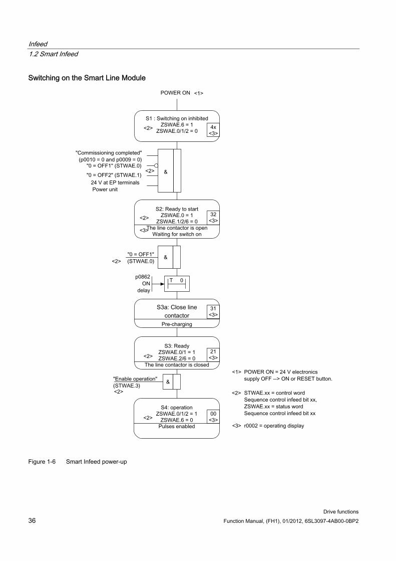
Infeed 1.2 Smart Infeed
Drive functions 36 Function Manual, (FH1), 01/2012, 6SL3097-4AB00-0BP2
Switching on the Smart Line Module
Figure 1-6 Smart Infeed power-up
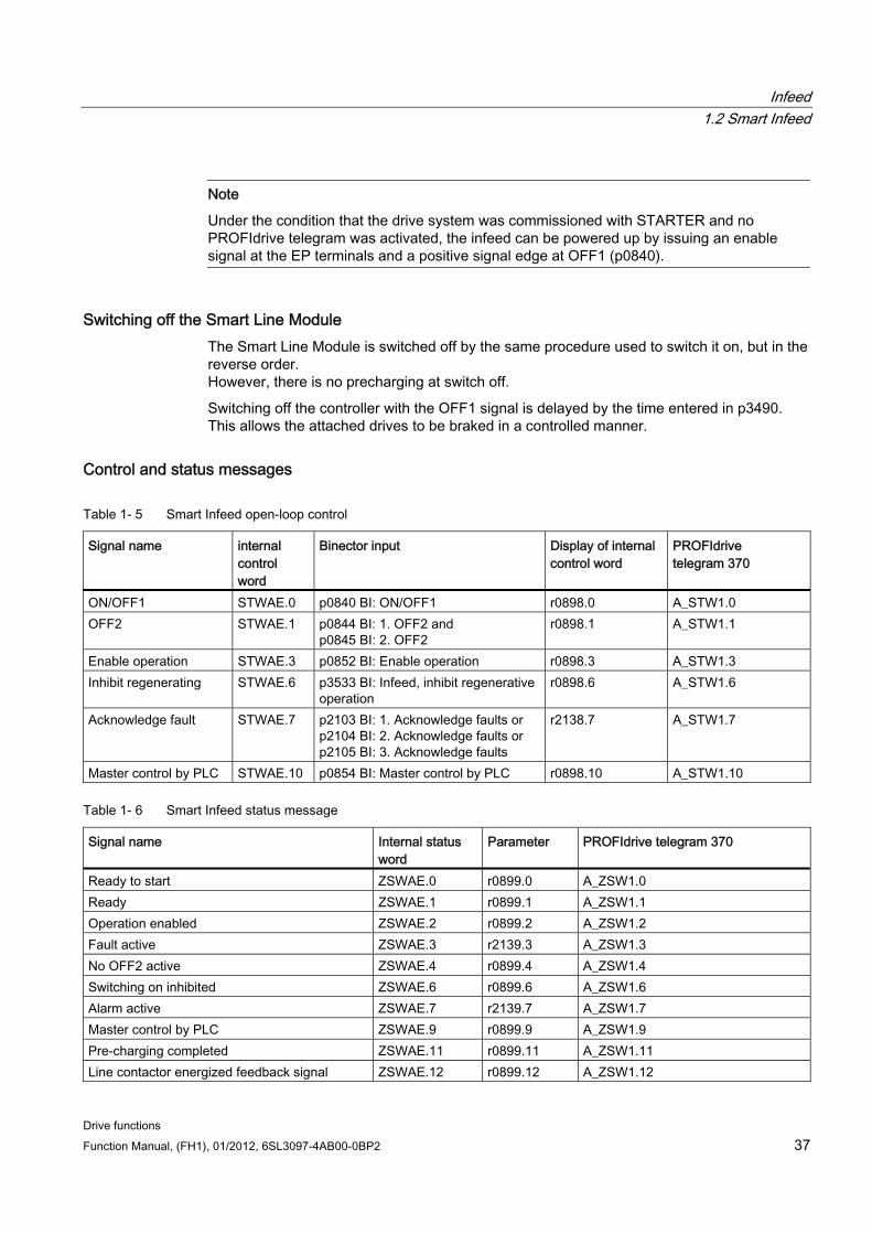
Infeed 1.2 Smart Infeed
Drive functions Function Manual, (FH1), 01/2012, 6SL3097-4AB00-0BP2 37
Note
Under the condition that the drive system was commissioned with STARTER and no PROFIdrive telegram was activated, the infeed can be powered up by issuing an enable signal at the EP terminals and a positive signal edge at OFF1 (p0840).
Switching off the Smart Line Module The Smart Line Module is switched off by the same procedure used to switch it on, but in the reverse order. However, there is no precharging at switch off.
Switching off the controller with the OFF1 signal is delayed by the time entered in p3490. This allows the attached drives to be braked in a controlled manner.
Control and status messages
Table 1- 5 Smart Infeed open-loop control
Signal name internal control word
Binector input Display of internal control word
PROFIdrive telegram 370
ON/OFF1 STWAE.0 p0840 BI: ON/OFF1 r0898.0 A_STW1.0 OFF2 STWAE.1 p0844 BI: 1. OFF2 and
p0845 BI: 2. OFF2 r0898.1 A_STW1.1
Enable operation STWAE.3 p0852 BI: Enable operation r0898.3 A_STW1.3 Inhibit regenerating STWAE.6 p3533 BI: Infeed, inhibit regenerative
operation r0898.6 A_STW1.6
Acknowledge fault STWAE.7 p2103 BI: 1. Acknowledge faults or p2104 BI: 2. Acknowledge faults or p2105 BI: 3. Acknowledge faults
r2138.7 A_STW1.7
Master control by PLC STWAE.10 p0854 BI: Master control by PLC r0898.10 A_STW1.10
Table 1- 6 Smart Infeed status message
Signal name Internal status word
Parameter PROFIdrive telegram 370
Ready to start ZSWAE.0 r0899.0 A_ZSW1.0 Ready ZSWAE.1 r0899.1 A_ZSW1.1 Operation enabled ZSWAE.2 r0899.2 A_ZSW1.2 Fault active ZSWAE.3 r2139.3 A_ZSW1.3 No OFF2 active ZSWAE.4 r0899.4 A_ZSW1.4 Switching on inhibited ZSWAE.6 r0899.6 A_ZSW1.6 Alarm active ZSWAE.7 r2139.7 A_ZSW1.7 Master control by PLC ZSWAE.9 r0899.9 A_ZSW1.9 Pre-charging completed ZSWAE.11 r0899.11 A_ZSW1.11 Line contactor energized feedback signal ZSWAE.12 r0899.12 A_ZSW1.12
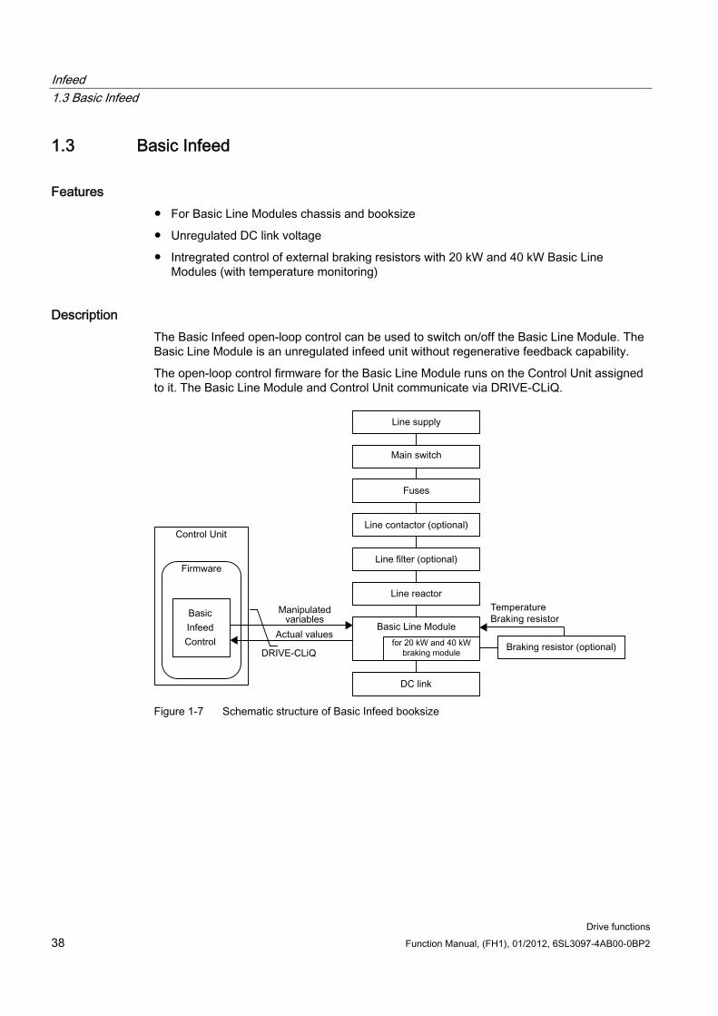
Infeed 1.3 Basic Infeed
Drive functions 38 Function Manual, (FH1), 01/2012, 6SL3097-4AB00-0BP2
1.3 Basic Infeed
Features For Basic Line Modules chassis and booksize
Unregulated DC link voltage
Intregrated control of external braking resistors with 20 kW and 40 kW Basic Line Modules (with temperature monitoring)
Description The Basic Infeed open-loop control can be used to switch on/off the Basic Line Module. The Basic Line Module is an unregulated infeed unit without regenerative feedback capability.
The open-loop control firmware for the Basic Line Module runs on the Control Unit assigned to it. The Basic Line Module and Control Unit communicate via DRIVE-CLiQ.
Figure 1-7 Schematic structure of Basic Infeed booksize
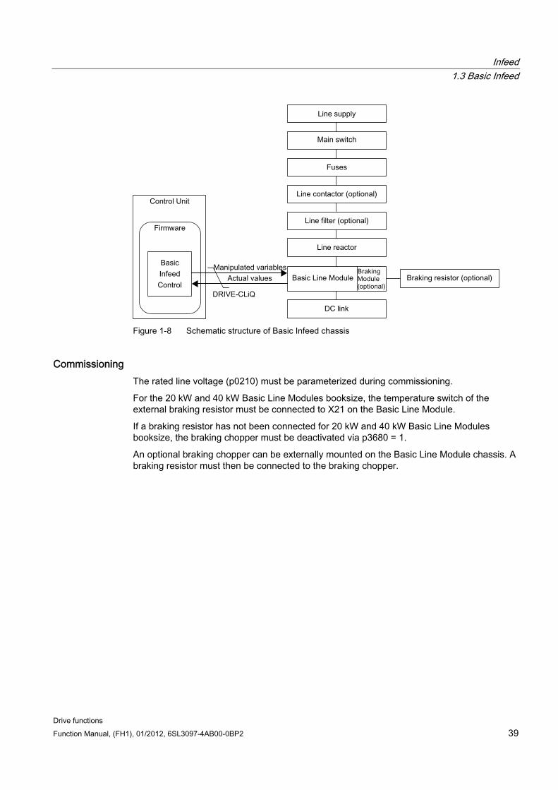
Infeed 1.3 Basic Infeed
Drive functions Function Manual, (FH1), 01/2012, 6SL3097-4AB00-0BP2 39
Figure 1-8 Schematic structure of Basic Infeed chassis
Commissioning The rated line voltage (p0210) must be parameterized during commissioning.
For the 20 kW and 40 kW Basic Line Modules booksize, the temperature switch of the external braking resistor must be connected to X21 on the Basic Line Module.
If a braking resistor has not been connected for 20 kW and 40 kW Basic Line Modules booksize, the braking chopper must be deactivated via p3680 = 1.
An optional braking chopper can be externally mounted on the Basic Line Module chassis. A braking resistor must then be connected to the braking chopper.
Infeed 1.3 Basic Infeed
Drive functions 40 Function Manual, (FH1), 01/2012, 6SL3097-4AB00-0BP2
DANGER Vdc control with Basic Line Modules
If several Motor Modules are supplied from a non-regenerative infeed unit (e.g. a Basic Line Module), the Vdc_max control may only be activated for that Motor Module whose drive has the nominal highest moment of inertia of all connected drives. For the other Motor Modules this function must be disabled or monitoring must be set. If the Vdc_max control is active for several Motor Modules, then for an unfavorable parameterization, the controllers can mutually influence one another negatively. The drives can become unstable, individual drives can unintentionally accelerate. • Activating the Vdc_max control:
– Vector control: p1240 = 1 (factory setting) – Servo control: p1240 = 1 – U/f control: p1280 = 1 (factory setting)
• Inhibiting the Vdc_max control: – Vector control: p1240 = 0 – Servo control: p1240 = 0 (factory setting) – U/f control: p1280 = 0
• Activating the Vdc_max monitoring function – Vector control: p1240 = 4 or 6 – Servo control: p1240 = 4 or 6 – U/f control: p1280 = 4 or 6
1.3.1 Function diagrams and parameters
Function diagrams (see SINAMICS S120/S150 List Manual) 8720 Control word sequence control infeed
8726 Status word sequence control infeed
8732 Sequencer
8734 Missing enable signals, line contactor control
8750 Interface to the Basic Infeed power unit (control signals, actual values)
8760 Signals and monitoring functions (p3400.0 = 0)
Overview of important parameters (see SINAMICS S120/S150 List Manual) r0002 Infeed operating display
r0046 CO/BO: Missing enable signals
p0210 Device supply voltage
p0840 BI: ON/OFF1
Infeed 1.3 Basic Infeed
Drive functions Function Manual, (FH1), 01/2012, 6SL3097-4AB00-0BP2 41
p0844 BI: 1. OFF2
r0898 CO/BO: Control word sequence control infeed
r0899 CO/BO: Status word sequence control infeed
p1240[0...n] Vdc controller or Vdc monitoring configuration
p1280[0...n] Vdc controller or Vdc monitoring configuration (U/f)
r2138 CO/BO: Control word, faults/alarms
r2139 CO/BO: Status word, faults/alarms 1
p3680 BI: Inhibit Braking Module internally
1.3.2 Basic Infeed open-loop control
Description The Basic Line Module can be controlled via a BICO interconnection, e.g. using terminals or fieldbus. The operating status is indicated on the operating display r0002. The missing enable signals for operation (r0002 = 00) are mapped in parameter r0046. The EP terminals (enable pulses) must be connected in accordance with the Manual of the corresponding power units.
Acknowledging faults Faults that are still present but the causes of which have been rectified can be acknowledged using a 0/1 edge at the "1. Acknowledge faults" signal (p2103).
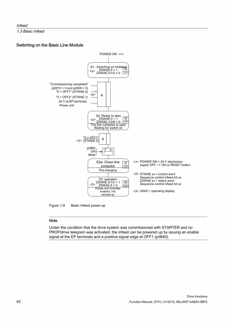
Infeed 1.3 Basic Infeed
Drive functions 42 Function Manual, (FH1), 01/2012, 6SL3097-4AB00-0BP2
Switching on the Basic Line Module
Figure 1-9 Basic Infeed power-up
Note
Under the condition that the drive system was commissioned with STARTER and no PROFIdrive telegram was activated, the infeed can be powered up by issuing an enable signal at the EP terminals and a positive signal edge at OFF1 (p0840).
Infeed 1.3 Basic Infeed
Drive functions Function Manual, (FH1), 01/2012, 6SL3097-4AB00-0BP2 43
Switching off the Basic Line Module For switching off, carry out the steps for switching on in the reverse order. However, there is no pre-charging at switch off.
Control and status messages
Table 1- 7 Basic Infeed open-loop control
Signal name Internal control word
Binector input Display of internal control word
PROFIdrive telegram 370
ON/OFF1 STWAE.0 p0840 BI: ON/OFF1 r0898.0 A_STW1.0 OFF2 STWAE.1 p0844 BI: 1. OFF2 and
p0845 BI: 2. OFF2 r0898.1 A_STW1.1
Acknowledge fault STWAE.7 p2103 BI: 1. Acknowledge faults or p2104 BI: 2. Acknowledge faults or p2105 BI: 3. Acknowledge faults
r2138.7 A_STW1.7
Master control by PLC STWAE.10 p0854 BI: Master control by PLC r0898.10 A_STW1.10
Table 1- 8 Basic Infeed status message
Signal name Internal status word Parameter PROFIdrive telegram 370 Ready to start ZSWAE.0 r0899.0 A_ZSW1.0 Ready ZSWAE.1 r0899.1 A_ZSW1.1 Operation enabled ZSWAE.2 r0899.2 A_ZSW1.2 Fault active ZSWAE.3 r2139.3 A_ZSW1.3 No OFF2 active ZSWAE.4 r0899.4 A_ZSW1.4 Switching on inhibited ZSWAE.6 r0899.6 A_ZSW1.6 Alarm active ZSWAE.7 r2139.7 A_ZSW1.7 Master control by PLC ZSWAE.9 r0899.9 A_ZSW1.9 Pre-charging completed ZSWAE.11 r0899.11 A_ZSW1.11 Line contactor energized feedback signal
ZSWAE.12 r0899.12 A_ZSW1.12
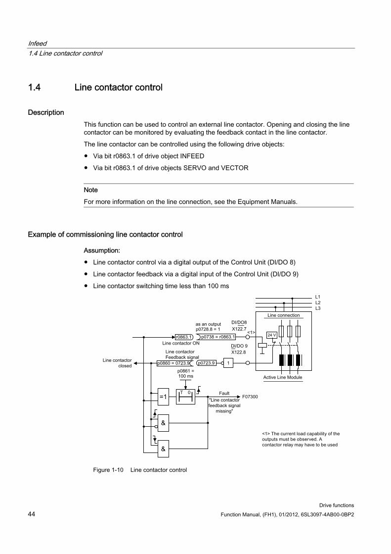
Infeed 1.4 Line contactor control
Drive functions 44 Function Manual, (FH1), 01/2012, 6SL3097-4AB00-0BP2
1.4 Line contactor control
Description This function can be used to control an external line contactor. Opening and closing the line contactor can be monitored by evaluating the feedback contact in the line contactor.
The line contactor can be controlled using the following drive objects:
Via bit r0863.1 of drive object INFEED
Via bit r0863.1 of drive objects SERVO and VECTOR
Note
For more information on the line connection, see the Equipment Manuals.
Example of commissioning line contactor control
Assumption:
Line contactor control via a digital output of the Control Unit (DI/DO 8)
Line contactor feedback via a digital input of the Control Unit (DI/DO 9)
Line contactor switching time less than 100 ms
Figure 1-10 Line contactor control
Infeed 1.4 Line contactor control
Drive functions Function Manual, (FH1), 01/2012, 6SL3097-4AB00-0BP2 45
Commissioning steps:
Connect the line contactor control contact to DI/DO 8.
Note
Note the current carrying capacity of the digital output (see the Manual of the Control Units and supplementary system components). A line contactor may have to be used.
Parameterize DI/DO 8 as output (p0728.8 = 1).
Assign parameter p0738 the control signal for the line contactor r0863.1.
Connect the line contactor feedback contact to DI/DO 9.
Assign parameter p0860 an inverted input signal r0723.9.
Enter the monitoring time for the line contactor (100 ms) in p0861.
Function diagrams (see SINAMICS S120/S150 List Manual) 8934 Missing enables, line contactor control
Overview of important parameters (see SINAMICS S120/S150 List Manual) p0860 BI: Line contactor, feedback signal
r0863.1 CO/BO: Drive coupling status word/control word
Infeed 1.5 Pre-charging and bypass contactor chassis
Drive functions 46 Function Manual, (FH1), 01/2012, 6SL3097-4AB00-0BP2
1.5 Pre-charging and bypass contactor chassis
Description Pre-charging is the procedure for charging the DC link capacitors via resistors. Pre-charging is normally carried out from the feeding supply network, although it can also be carried out from a pre-charged DC link. The pre-charging input circuit limits the charging current of the DC link capacitors.
The pre-charging input circuit for Active and Smart Infeed in the chassis design comprises a pre-charging contactor with pre-charging resistors and a bypass contactor. The Active Line Module controls the pre-charging input circuit in the Active Interface Module via terminals.
The pre-charging circuit in the Active Interface Module of module types FX and GX contains the bypass contactor. The bypass contactor must be provided separately for frame sizes HX and JX.
With the Smart Line Module, pre-charging is integrated in the Smart Line Module itself, although the bypass contactor must be provided externally.
For further information: See the Manual for chassis power units
Procedure during power ON/OFF
Power ON:
The pre-charging contactor is closed and the DC link is charged via the pre-charging resistors.
Once pre-charging is complete, the bypass contactor is closed and the pre-charging contactor opened. The DC link is pre-charged and ready for operation. If pre-charging could not be completed, fault F06000 is output.
Power OFF:
The pulses are inhibited and the bypass contactor is then opened.

Infeed 1.5 Pre-charging and bypass contactor chassis
Drive functions Function Manual, (FH1), 01/2012, 6SL3097-4AB00-0BP2 47

Infeed 1.5 Pre-charging and bypass contactor chassis
Drive functions 48 Function Manual, (FH1), 01/2012, 6SL3097-4AB00-0BP2
Drive functions Function Manual, (FH1), 01/2012, 6SL3097-4AB00-0BP2 49
Extended setpoint channel 2
Description In the servo control mode, the extended setpoint channel is deactivated by default. If an extended setpoint channel is required, it has to be activated. The extended setpoint channel is always activated in the vector control mode.
Properties of servo control mode without the "extended setpoint channel" function module The setpoint is directly interconnected to p1155[D] (e.g. from a higher-level control or
technology controller)
Dynamic Servo Control (DSC) only
When using DSC, the "extended setpoint channel" is not used. This unnecessarily uses the computation time of the Control Unit and, for servo, can be deactivated.
Deceleration ramp OFF1 via p1121[D]
The deceleration ramp in p1121 is also effective when the "Extended setpoint channel" is deactivated.
Deceleration ramp OFF3 via p1135[D]
For PROFIdrive telegrams 2 to 103 and 999 only (free assignment)
STW 1 bit 5 (freeze ramp-function generator), no function
2.1 Activating the "extended setpoint channel" function module in the servo control mode
In the servo control mode, the "extended setpoint channel" function module can be activated via the commissioning wizard or the drive configuration (configuring DDS).
You can check the current configuration in parameter r0108.8. Once you have set the configuration, you have to download it to the Control Unit where it is stored in a non-volatile memory (see the SINAMICS S120 Commissioning Manual).
Note
When the "extended setpoint channel" function module for servo is activated, under certain circumstances, the number of drives in the multi-axis group that can be controlled from a Control Unit is reduced.
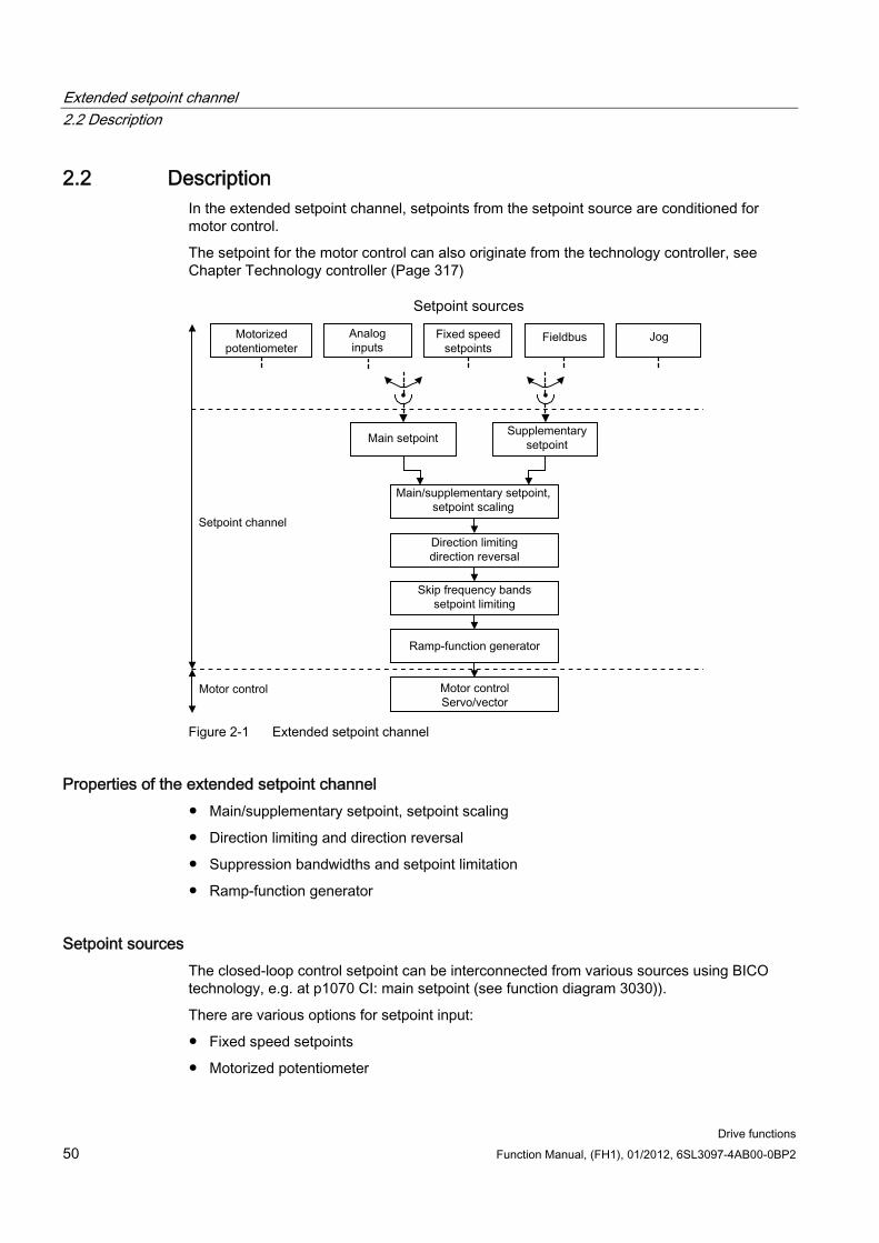
Extended setpoint channel 2.2 Description
Drive functions 50 Function Manual, (FH1), 01/2012, 6SL3097-4AB00-0BP2
2.2 Description In the extended setpoint channel, setpoints from the setpoint source are conditioned for motor control.
The setpoint for the motor control can also originate from the technology controller, see Chapter Technology controller (Page 317)
Figure 2-1 Extended setpoint channel
Properties of the extended setpoint channel Main/supplementary setpoint, setpoint scaling
Direction limiting and direction reversal
Suppression bandwidths and setpoint limitation
Ramp-function generator
Setpoint sources The closed-loop control setpoint can be interconnected from various sources using BICO technology, e.g. at p1070 CI: main setpoint (see function diagram 3030)).
There are various options for setpoint input:
Fixed speed setpoints
Motorized potentiometer
Extended setpoint channel 2.3 Fixed speed setpoints
Drive functions Function Manual, (FH1), 01/2012, 6SL3097-4AB00-0BP2 51
Jog
Field bus
– Setpoint via PROFIBUS, for example
Analog inputs of the following exemplary components:
– e.g. Terminal Board 30 (TB30)
– e.g. Terminal Module 31 (TM31)
– e.g. Terminal Module 41 (TM41)
2.3 Fixed speed setpoints
Description This function can be used to specify preset speed setpoints. The fixed setpoints are defined in parameters and selected via binector inputs. Both the individual fixed setpoints and the effective fixed setpoint are available for further interconnection via a connector output (e.g. to connector input p1070 - CI: main setpoint).
Properties Number of fixed setpoints: Fixed setpoint 1 to 15
Selection of fixed setpoints: Binector input bits 0 to 3
– Binector input bits 0, 1, 2 and 3 = 0 → setpoint = 0 active
– Unused binector inputs have the same effect as a "0" signal
Function diagrams (see SINAMICS S120/S150 List Manual) 1550 Overviews - setpoint channel
3010 Fixed speed setpoints
Overview of important parameters (see SINAMICS S120/S150 List Manual) p1001[0...n] CO: Fixed speed setpoint 1
...
p1015[0...n] CO: Fixed speed setpoint 15
p1020[0...n] BI: Fixed speed setpoint selection Bit 0
p1021[0...n] BI: Fixed speed setpoint selection Bit 1
p1022[0...n] BI: Fixed speed setpoint selection Bit 2
p1023[0...n] BI: Fixed speed setpoint selection Bit 3
Extended setpoint channel 2.4 Motorized potentiometer
Drive functions 52 Function Manual, (FH1), 01/2012, 6SL3097-4AB00-0BP2
r1024 CO: Fixed speed setpoint effective
r1197 Fixed speed setpoint current number
Parameterization with STARTER In the STARTER commissioning tool, the "Fixed setpoints" parameter screen in the project navigator under the relevant drive is called by double-clicking on Setpoint channel → Fixed setpoints.
2.4 Motorized potentiometer
Description This function is used to simulate an electromechanical potentiometer for setpoint input.
You can switch between manual and automatic mode for setpoint input. The specified setpoint is routed to an internal ramp-function generator. Setting values, start values and braking with OFF1 do not require the ramp-function generator of the motorized potentiometer.
The output of the ramp-function generator for the motorized potentiometer is available for further interconnection via a connector output (e.g. interconnection to connector input p1070 - CI: main setpoint, an additional ramp-function generator is then active).
Properties for manual mode (p1041 = "0") Separate binector inputs for Raise and Lower are used to adjust the input setpoint:
– p1035 BI: Motorized potentiometer, setpoint, raise
– p1036 BI: Motorized potentiometer, setpoint, lower
Invert setpoint (p1039)
Configurable ramp-function generator, e.g.:
– Ramp-up/ramp-down time (p1047/p1048) referred to p1082
– Setting value (p1043/p1044)
– Activate/deactivate initial rounding (p1030.2 = 1/0)
Non-volatile storage of the setpoints via p1030.3 = 1
Configurable setpoint for Power ON (p1030.0)
– Starting value is the value in p1040 (p1030.0 = 0)
– Starting value is the stored value (p1030.0 = 1)
Extended setpoint channel 2.4 Motorized potentiometer
Drive functions Function Manual, (FH1), 01/2012, 6SL3097-4AB00-0BP2 53
Properties for automatic mode (p1041 = "1") The input setpoint is specified via a connector input (p1042).
The motorized potentiometer acts like a "normal" ramp-function generator.
Configurable ramp-function generator, e.g.:
– Activate/deactivate (p1030.1 = 1/0)
– Ramp-up/ramp-down time (p1047/p1048)
– Setting value (p1043/p1044)
– Activate/deactivate initial rounding (p1030.2 = 1/0)
Non-volatile storage of the setpoints via p1030.3 = 1
Configurable setpoint for Power ON (p1030.0)
– Starting value is the value in p1040 (p1030.0 = 0)
– Starting value is the stored value (p1030.0 = 1)
Function diagrams (see SINAMICS S120/S150 List Manual) 1550 Setpoint channel
2501 Control word sequence control
3020 Motorized potentiometer
Overview of important parameters (see SINAMICS S120/S150 List Manual) p1030[0...n] Motorized potentiometer configuration
p1035[0...n] BI: Motorized potentiometer, setpoint, raise
p1036[0...n] BI: Motorized potentiometer, setpoint, lower
p1037[0...n] Motorized potentiometer maximum speed
p1038[0...n] Motorized potentiometer minimum speed
p1039[0...n] BI: Motorized potentiometer, inversion
p1040[0...n] Motorized potentiometer initial value
p1041[0...n] BI: Motorized potentiometer, manual/automatic
p1042[0...n] CI: Motorized potentiometer, automatic setpoint
p1043[0...n] BI: Motorized potentiometer, accept setpoint
p1044[0...n] CI: Motorized potentiometer, setting value
r1045 CO: Motorized potentiometer, speed setpoint in front of the ramp-function generator
p1047[0...n] Motorized potentiometer ramp-up time
p1048[0...n] Motorized potentiometer ramp-down time
r1050 CO: Motorized potentiometer, setpoint after the ramp-function generator
p1082[0...n] Maximum speed
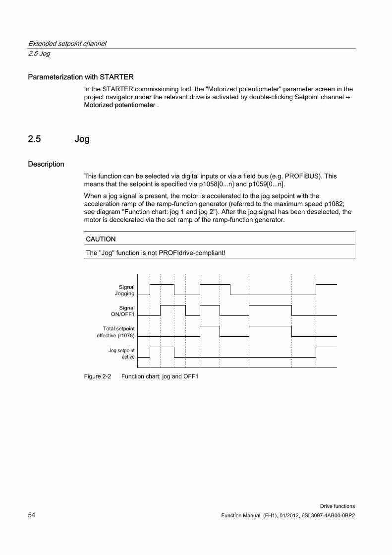
Extended setpoint channel 2.5 Jog
Drive functions 54 Function Manual, (FH1), 01/2012, 6SL3097-4AB00-0BP2
Parameterization with STARTER In the STARTER commissioning tool, the "Motorized potentiometer" parameter screen in the project navigator under the relevant drive is activated by double-clicking Setpoint channel → Motorized potentiometer .
2.5 Jog
Description This function can be selected via digital inputs or via a field bus (e.g. PROFIBUS). This means that the setpoint is specified via p1058[0...n] and p1059[0...n].
When a jog signal is present, the motor is accelerated to the jog setpoint with the acceleration ramp of the ramp-function generator (referred to the maximum speed p1082; see diagram "Function chart: jog 1 and jog 2"). After the jog signal has been deselected, the motor is decelerated via the set ramp of the ramp-function generator.
CAUTION The "Jog" function is not PROFIdrive-compliant!
Figure 2-2 Function chart: jog and OFF1
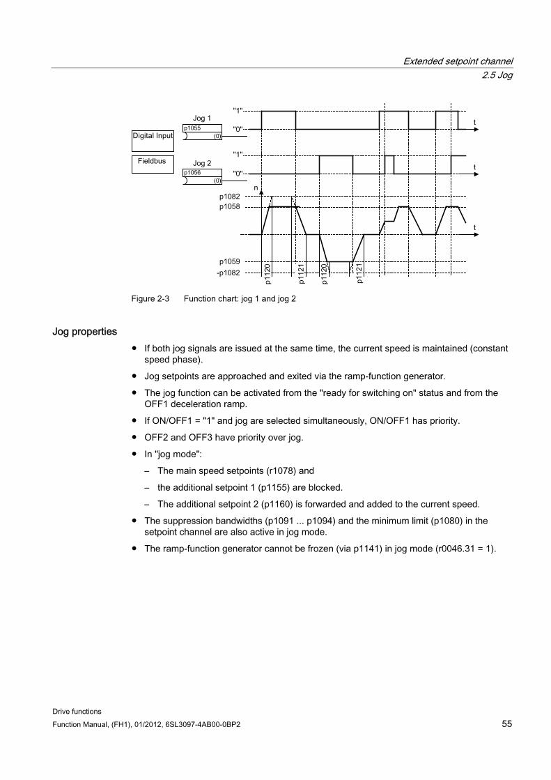
Extended setpoint channel 2.5 Jog
Drive functions Function Manual, (FH1), 01/2012, 6SL3097-4AB00-0BP2 55
Figure 2-3 Function chart: jog 1 and jog 2
Jog properties If both jog signals are issued at the same time, the current speed is maintained (constant
speed phase).
Jog setpoints are approached and exited via the ramp-function generator.
The jog function can be activated from the "ready for switching on" status and from the OFF1 deceleration ramp.
If ON/OFF1 = "1" and jog are selected simultaneously, ON/OFF1 has priority.
OFF2 and OFF3 have priority over jog.
In "jog mode":
– The main speed setpoints (r1078) and
– the additional setpoint 1 (p1155) are blocked.
– The additional setpoint 2 (p1160) is forwarded and added to the current speed.
The suppression bandwidths (p1091 ... p1094) and the minimum limit (p1080) in the setpoint channel are also active in jog mode.
The ramp-function generator cannot be frozen (via p1141) in jog mode (r0046.31 = 1).
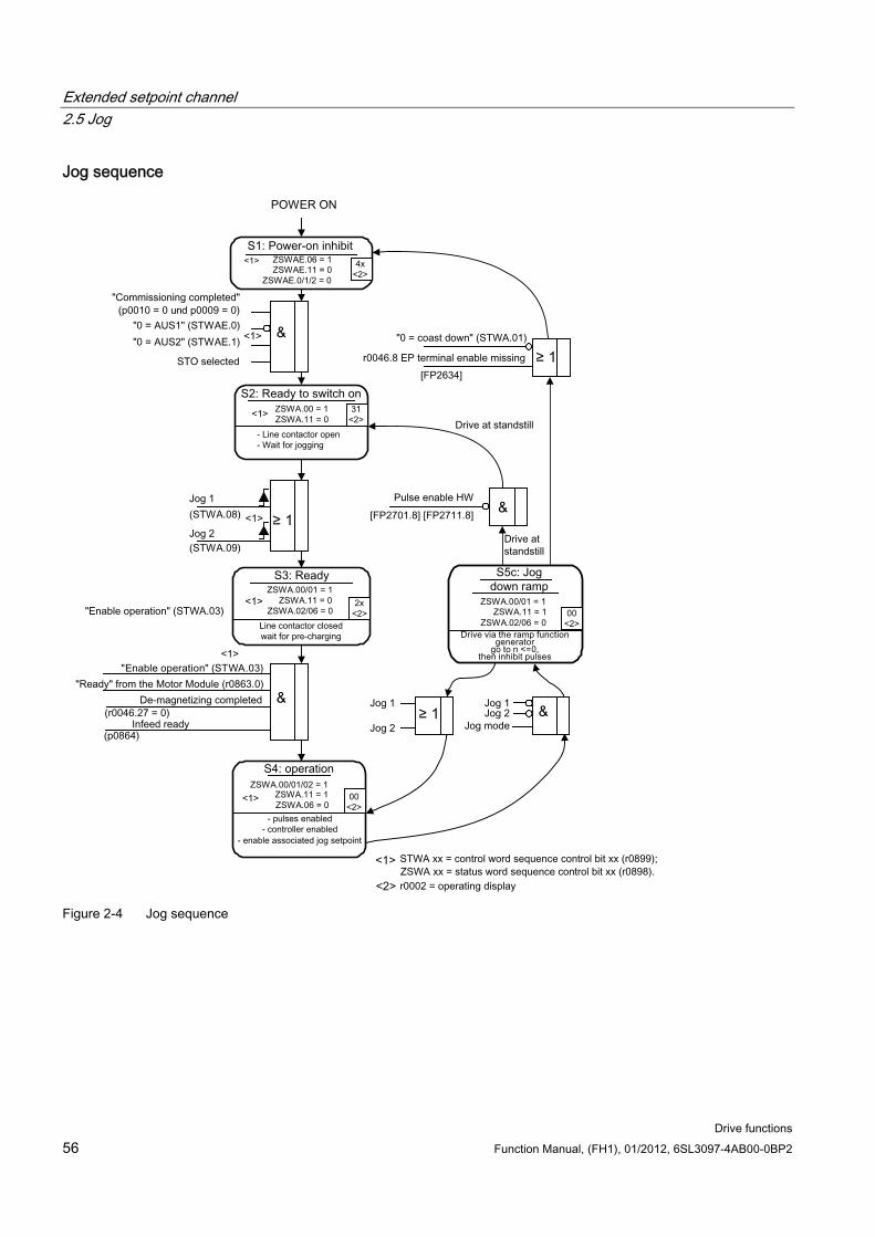
Extended setpoint channel 2.5 Jog
Drive functions 56 Function Manual, (FH1), 01/2012, 6SL3097-4AB00-0BP2
Jog sequence
Figure 2-4 Jog sequence
Extended setpoint channel 2.5 Jog
Drive functions Function Manual, (FH1), 01/2012, 6SL3097-4AB00-0BP2 57
Control and status messages
Table 2- 1 Jog control
Signal name Internal control word
Binector input PROFIdrive/Siemens telegram 1 ... 352
0 = OFF1 STWA.0 p0840 BI: ON/OFF1 STW1.0 0 = OFF2 STWA.1 p0844 BI: 1. OFF2
p0845 BI: 2. OFF2 STW1.1
0 = OFF3 STWA.2 p0848 BI: 1. OFF3 p0849 BI: 2. OFF3
STW1.2
Enable operation STWA.3 p0852 BI: Enable operation STW1.3 Jog 1 STWA.8 p1055 BI: Jog bit 0 STW1.8 1) Jog 2 STWA.9 p1056 BI: Jog bit 1 STW1.9 1)
1) Interconnected automatically in telegrams 7, 9, 110, and 111 only.
Table 2- 2 Jog status message
Signal name Internal status word Parameter PROFIdrive/Siemens telegram 1 ... 352
Ready to start ZSWA.0 r0899.0 ZSW1.0 Ready ZSWA.1 r0899.1 ZSW1.1 Operation enabled ZSWA.2 r0899.2 ZSW1.2 Switching on inhibited ZSWA.6 r0899.6 ZSW1.6 Pulses enabled ZSWA.11 r0899.11 ZSW2.10 2)
2) Only available in Interface Mode p2038 = 0.
Function diagrams (see SINAMICS S120/S150 List Manual) 2610 Execution control - processor
3030 Setpoint channel - Main/additional setpoint, setpoint scaling, jogging
Overview of important parameters (see SINAMICS S120/S150 List Manual) p1055[0...n] BI: Jog bit 0
p1056[0...n] BI: Jog bit 1
p1058[0...n] jog 1 speed setpoint
p1059[0...n] jog 2 speed setpoint
p1082[0...n] Maximum speed
p1120[0...n] Ramp-function generator ramp-up time
p1121[0...n] Ramp-function generator ramp-down time
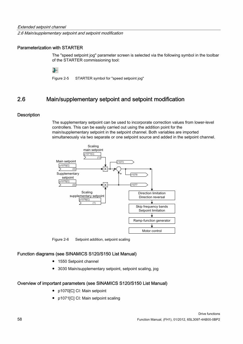
Extended setpoint channel 2.6 Main/supplementary setpoint and setpoint modification
Drive functions 58 Function Manual, (FH1), 01/2012, 6SL3097-4AB00-0BP2
Parameterization with STARTER The "speed setpoint jog" parameter screen is selected via the following symbol in the toolbar of the STARTER commissioning tool:
Figure 2-5 STARTER symbol for "speed setpoint jog"
2.6 Main/supplementary setpoint and setpoint modification
Description The supplementary setpoint can be used to incorporate correction values from lower-level controllers. This can be easily carried out using the addition point for the main/supplementary setpoint in the setpoint channel. Both variables are imported simultaneously via two separate or one setpoint source and added in the setpoint channel.
Figure 2-6 Setpoint addition, setpoint scaling
Function diagrams (see SINAMICS S120/S150 List Manual) 1550 Setpoint channel
3030 Main/supplementary setpoint, setpoint scaling, jog
Overview of important parameters (see SINAMICS S120/S150 List Manual) p1070[C] CI: Main setpoint
p1071[C] CI: Main setpoint scaling
Extended setpoint channel 2.7 Direction of rotation limiting and direction of rotation changeover
Drive functions Function Manual, (FH1), 01/2012, 6SL3097-4AB00-0BP2 59
r1073[C] CO: Main setpoint effective
p1075[C] CI: Supplementary setpoint
p1076[C] CI: Supplementary setpoint scaling
r1077[C] CO: Supplementary setpoint effective
r1078[C] CO: Total setpoint effective
Parameterization with STARTER The "speed setpoint" parameter screen is selected via the following symbol in the toolbar of the STARTER commissioning tool:
Figure 2-7 STARTER symbol for "speed setpoint"
2.7 Direction of rotation limiting and direction of rotation changeover
Description A reversing operation involves a direction of rotation reversal. Selecting setpoint inversion p1113[C] can reverse the direction of rotation in the setpoint channel.
Parameter p1110[C] or p1111[C] can be set respectively to prevent input of a negative or positive setpoint via the setpoint channel. However, the following settings for minimum speed (p1080) in the setpoint channel are still operative. With the minimum speed, the motor can turn in a negative direction, although p1110 = 1 is set.
Figure 2-8 Direction of rotation limiting and direction of rotation reversal
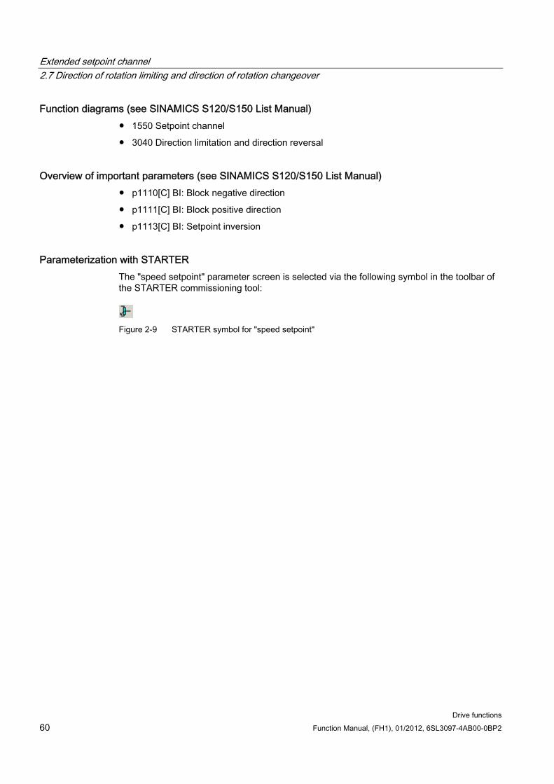
Extended setpoint channel 2.7 Direction of rotation limiting and direction of rotation changeover
Drive functions 60 Function Manual, (FH1), 01/2012, 6SL3097-4AB00-0BP2
Function diagrams (see SINAMICS S120/S150 List Manual) 1550 Setpoint channel
3040 Direction limitation and direction reversal
Overview of important parameters (see SINAMICS S120/S150 List Manual) p1110[C] BI: Block negative direction
p1111[C] BI: Block positive direction
p1113[C] BI: Setpoint inversion
Parameterization with STARTER The "speed setpoint" parameter screen is selected via the following symbol in the toolbar of the STARTER commissioning tool:
Figure 2-9 STARTER symbol for "speed setpoint"
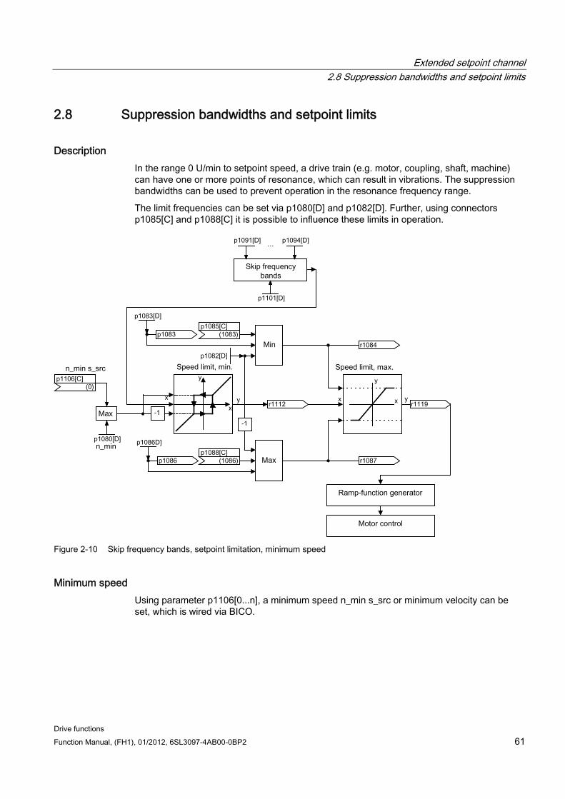
Extended setpoint channel 2.8 Suppression bandwidths and setpoint limits
Drive functions Function Manual, (FH1), 01/2012, 6SL3097-4AB00-0BP2 61
2.8 Suppression bandwidths and setpoint limits
Description In the range 0 U/min to setpoint speed, a drive train (e.g. motor, coupling, shaft, machine) can have one or more points of resonance, which can result in vibrations. The suppression bandwidths can be used to prevent operation in the resonance frequency range.
The limit frequencies can be set via p1080[D] and p1082[D]. Further, using connectors p1085[C] and p1088[C] it is possible to influence these limits in operation.
Figure 2-10 Skip frequency bands, setpoint limitation, minimum speed
Minimum speed Using parameter p1106[0...n], a minimum speed n_min s_src or minimum velocity can be set, which is wired via BICO.
Extended setpoint channel 2.8 Suppression bandwidths and setpoint limits
Drive functions 62 Function Manual, (FH1), 01/2012, 6SL3097-4AB00-0BP2
Function diagrams (see SINAMICS S120/S150 List Manual) 1550 Setpoint channel
3050 Suppression bandwidth and speed limiting
Overview of important parameters (see SINAMICS S120/S150 List Manual)
Setpoint limitation
p1080[D] Minimum speed
p1082[D] Maximum speed
p1083[D] CO: Speed limit in positive direction of rotation
r1084 CO: Speed limit positive effective
p1085[C] CI: Speed limit in positive direction of rotation
p1086[D] CO: Speed limit negative direction of rotation
r1087 CO: Speed limit negative effective
p1088[C] CI: Speed limit negative direction of rotation
p1106[0...n] CI: Minimum speed
r1119 CO: Ramp-function generator setpoint at the input
Skip frequency bands
p1091[D] Suppression speed 1
...
p1094[D] Suppression speed 4
p1101[D] Suppression speed bandwidth
Parameterization with STARTER The "speed limitation" parameter screen is selected by activating the following icon in toolbar of the STARTER commissioning tool:
Figure 2-11 STARTER icon for "speed limitation"
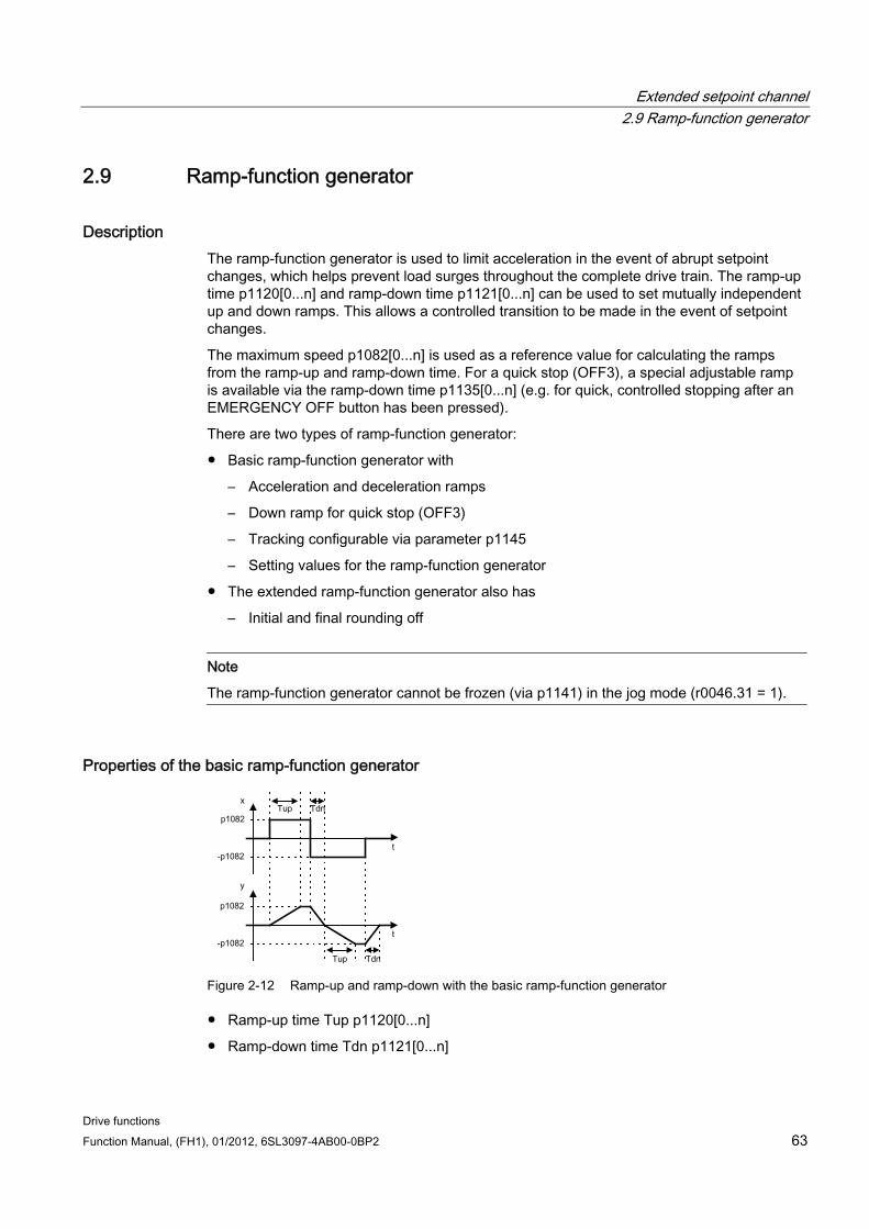
Extended setpoint channel 2.9 Ramp-function generator
Drive functions Function Manual, (FH1), 01/2012, 6SL3097-4AB00-0BP2 63
2.9 Ramp-function generator
Description The ramp-function generator is used to limit acceleration in the event of abrupt setpoint changes, which helps prevent load surges throughout the complete drive train. The ramp-up time p1120[0...n] and ramp-down time p1121[0...n] can be used to set mutually independent up and down ramps. This allows a controlled transition to be made in the event of setpoint changes.
The maximum speed p1082[0...n] is used as a reference value for calculating the ramps from the ramp-up and ramp-down time. For a quick stop (OFF3), a special adjustable ramp is available via the ramp-down time p1135[0...n] (e.g. for quick, controlled stopping after an EMERGENCY OFF button has been pressed).
There are two types of ramp-function generator:
Basic ramp-function generator with
– Acceleration and deceleration ramps
– Down ramp for quick stop (OFF3)
– Tracking configurable via parameter p1145
– Setting values for the ramp-function generator
The extended ramp-function generator also has
– Initial and final rounding off
Note
The ramp-function generator cannot be frozen (via p1141) in the jog mode (r0046.31 = 1).
Properties of the basic ramp-function generator
Figure 2-12 Ramp-up and ramp-down with the basic ramp-function generator
Ramp-up time Tup p1120[0...n]
Ramp-down time Tdn p1121[0...n]
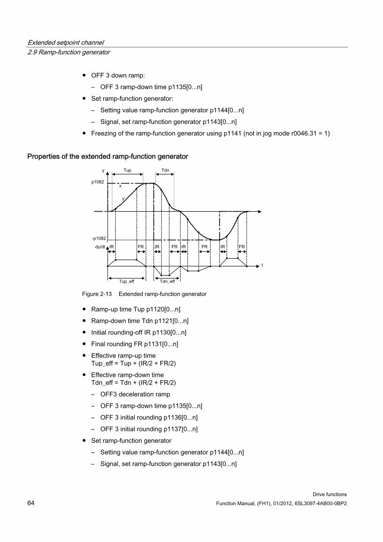
Extended setpoint channel 2.9 Ramp-function generator
Drive functions 64 Function Manual, (FH1), 01/2012, 6SL3097-4AB00-0BP2
OFF 3 down ramp:
– OFF 3 ramp-down time p1135[0...n]
Set ramp-function generator:
– Setting value ramp-function generator p1144[0...n]
– Signal, set ramp-function generator p1143[0...n]
Freezing of the ramp-function generator using p1141 (not in jog mode r0046.31 = 1)
Properties of the extended ramp-function generator
Figure 2-13 Extended ramp-function generator
Ramp-up time Tup p1120[0...n]
Ramp-down time Tdn p1121[0...n]
Initial rounding-off IR p1130[0...n]
Final rounding FR p1131[0...n]
Effective ramp-up time Tup_eff = Tup + (IR/2 + FR/2)
Effective ramp-down time Tdn_eff = Tdn + (IR/2 + FR/2)
– OFF3 deceleration ramp
– OFF 3 ramp-down time p1135[0...n]
– OFF 3 initial rounding p1136[0...n]
– OFF 3 initial rounding p1137[0...n]
Set ramp-function generator
– Setting value ramp-function generator p1144[0...n]
– Signal, set ramp-function generator p1143[0...n]
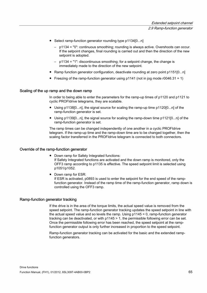
Extended setpoint channel 2.9 Ramp-function generator
Drive functions Function Manual, (FH1), 01/2012, 6SL3097-4AB00-0BP2 65
Select ramp-function generator rounding type p1134[0...n]
– p1134 = "0": continuous smoothing; rounding is always active. Overshoots can occur. If the setpoint changes, final rounding is carried out and then the direction of the new setpoint is adopted.
– p1134 = "1": discontinuous smoothing; for a setpoint change, the change is immediately made to the direction of the new setpoint.
Ramp function generator configuration, deactivate rounding at zero point p1151[0...n]
Freezing of the ramp-function generator using p1141 (not in jog mode r0046.31 = 1)
Scaling of the up ramp and the down ramp In order to being able to enter the parameters for the ramp-up times of p1120 and p1121 to cyclic PROFIdrive telegrams, they are scalable.
Using p1138[0...n], the signal source for scaling the ramp-up time p1120[0...n] of the ramp-function generator is set.
Using p1139[0...n], the signal source for scaling the ramp-down time p1121[0...n] of the ramp-function generator is set.
The ramp times can be changed independently of one another in a cyclic PROFIdrive telegram. If the ramp-up time and the ramp-down time are to be changed together, then the scaling factor transferred in the PROFIdrive telegram is connected to both connectors.
Override of the ramp-function generator Down ramp for Safety Integrated functions:
If Safety Integrated functions are activated and the down ramp is monitored, only the OFF3 ramp according to p1135 is effective. The speed setpoint limit is selected using p1051/p1052.
Down ramp for ESR: If ESR is activated, p0893 is used to enter the setpoint for the end speed of the ramp-function generator. Instead of the ramp time of the ramp-function generator, ramp down is controlled using the OFF3 ramp.
Ramp-function generator tracking If the drive is in the area of the torque limits, the actual speed value is removed from the speed setpoint. The ramp-function generator tracking updates the speed setpoint in line with the actual speed value and so levels the ramp. Using p1145 = 0, ramp-function generator tracking can be deactivated, or with p1145 > 1, the permissible following error can be set. Once the permissible following error has been reached, the speed setpoint at the ramp-function generator output is only further increased in proportion to the speed setpoint.
Ramp-function generator tracking can be activated for the basic and the extended ramp-function generators.
Extended setpoint channel 2.9 Ramp-function generator
Drive functions 66 Function Manual, (FH1), 01/2012, 6SL3097-4AB00-0BP2
Figure 2-14 Ramp-function generator tracking
Without ramp-function generator tracking
p1145 = 0
Drive accelerates until t2 although setpoint < actual value
With ramp-function generator tracking
At p1145 > 1 (values between 0 and 1 are not applicable), ramp-function generator tracking is activated when the torque limit is approached. The ramp-function generator output thereby only exceeds the actual speed value by a deviation value that can be defined in p1145.
t1 and t2 almost identical
Function diagrams (see SINAMICS S120/S150 List Manual) 1550 Setpoint channel
3060 Basic ramp-function generator
3070 Extended ramp-function generator
3080 Ramp-function generator selection, status word, tracking
Signal overview (see SINAMICS S120/S150 List Manual) Control signal STW1.2 OFF3
Control signal STW1.4 Enable ramp-function generator
Control signal STW1.5 Start/stop ramp-function generator
Control signal STW1.6 Enable setpoint
Control signal STW2.1 Bypass ramp-function generator
Overview of important parameters (see SINAMICS S120/S150 List Manual) p0893 ESR speed
p1051 [0...n] CI: Speed limit in RFG, positive direction of rotation
Extended setpoint channel 2.9 Ramp-function generator
Drive functions Function Manual, (FH1), 01/2012, 6SL3097-4AB00-0BP2 67
p1052 [0...n] CI: Speed limit RFG, negative direction of rotation
p1083[0...n] CO: Speed limit in positive direction of rotation
p1115 Ramp-function generator selection
r1119 CO: Ramp-function generator setpoint at the input
p1120[0...n] Ramp-function generator ramp-up time
p1121[0...n] Ramp-function generator ramp-down time
p1122[0...n] BI: Bypass ramp-function generator
p1130[0...n] Ramp-function generator initial rounding time
p1131[0...n] Ramp-function generator final rounding time
p1134[0...n] Ramp-function generator rounding type
p1135[0...n] OFF3 ramp-down time
p1136[0...n] OFF3 initial rounding time
p1137[0...n] OFF3 final rounding time
p1138[0...n] CI: Up ramp scaling
p1139[0...n] CI: Down ramp scaling
p1140[0...n] BI: Enable ramp-function generator
p1141[0...n] BI: Continue ramp-function generator
p1143[0...n] BI: Ramp-function generator, accept setting value
p1144[0...n C] CI: Ramp-function generator setting value
p1145[0...n] Ramp-function generator tracking, intensity
p1148 [0...n] Ramp-function generator tolerance for ramp-up and ramp-down active
r1149 CO: Ramp-function generator acceleration
r1150 CO: Ramp-function generator speed setpoint at the output
p1151 [0...n] Ramp-function generator configuration
Parameterization with STARTER The "ramp-function generator" parameter screen is selected via the following icon in the toolbar of the STARTER commissioning tool:
Figure 2-15 STARTER icon for "ramp-function generator"

Extended setpoint channel 2.9 Ramp-function generator
Drive functions 68 Function Manual, (FH1), 01/2012, 6SL3097-4AB00-0BP2
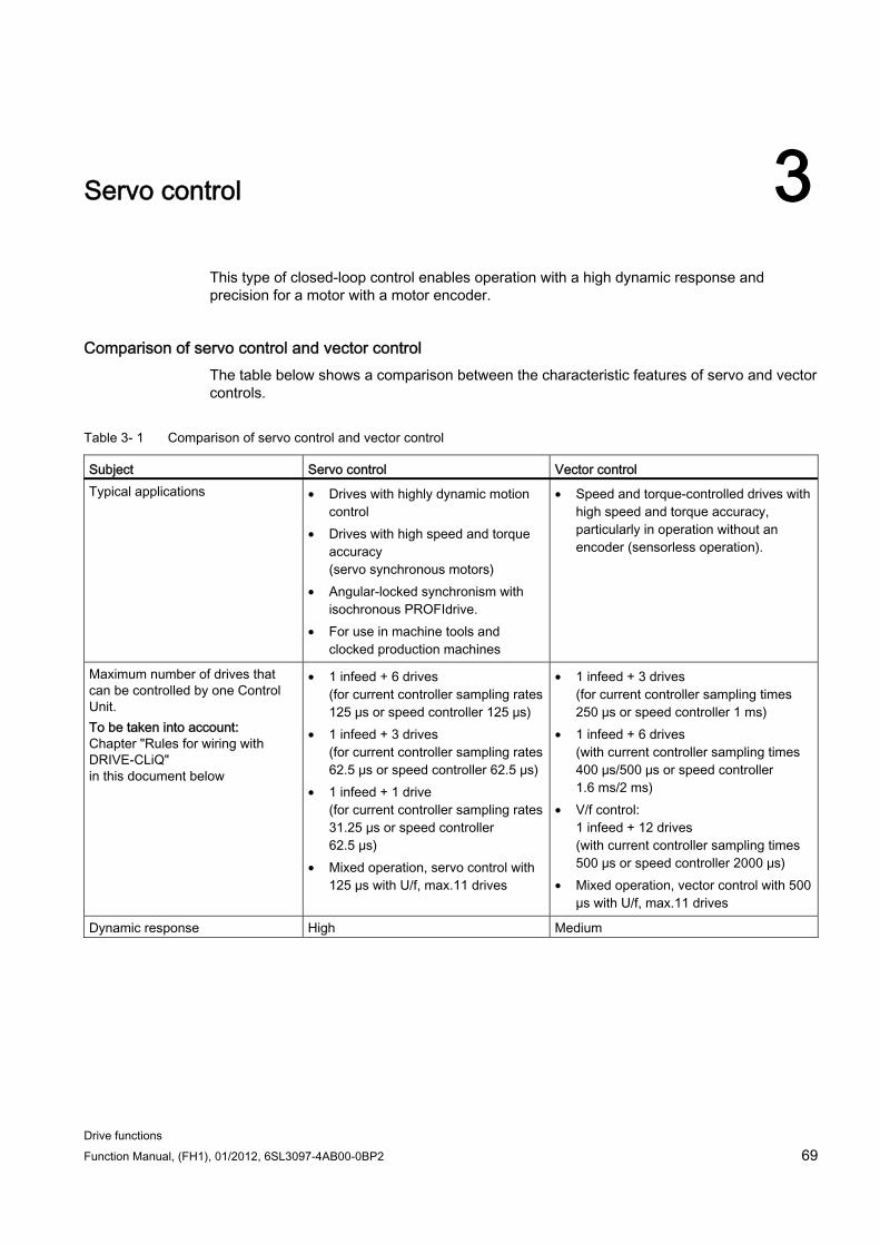
Drive functions Function Manual, (FH1), 01/2012, 6SL3097-4AB00-0BP2 69
Servo control 3
This type of closed-loop control enables operation with a high dynamic response and precision for a motor with a motor encoder.
Comparison of servo control and vector control The table below shows a comparison between the characteristic features of servo and vector controls.
Table 3- 1 Comparison of servo control and vector control
Subject Servo control Vector control Typical applications • Drives with highly dynamic motion
control • Drives with high speed and torque
accuracy (servo synchronous motors)
• Angular-locked synchronism with isochronous PROFIdrive.
• For use in machine tools and clocked production machines
• Speed and torque-controlled drives with high speed and torque accuracy, particularly in operation without an encoder (sensorless operation).
Maximum number of drives that can be controlled by one Control Unit. To be taken into account: Chapter "Rules for wiring with DRIVE-CLiQ" in this document below
• 1 infeed + 6 drives (for current controller sampling rates 125 μs or speed controller 125 μs)
• 1 infeed + 3 drives (for current controller sampling rates 62.5 μs or speed controller 62.5 μs)
• 1 infeed + 1 drive (for current controller sampling rates 31.25 μs or speed controller 62.5 μs)
• Mixed operation, servo control with 125 µs with U/f, max.11 drives
• 1 infeed + 3 drives (for current controller sampling times 250 μs or speed controller 1 ms)
• 1 infeed + 6 drives (with current controller sampling times 400 μs/500 μs or speed controller 1.6 ms/2 ms)
• V/f control: 1 infeed + 12 drives (with current controller sampling times 500 μs or speed controller 2000 μs)
• Mixed operation, vector control with 500 µs with U/f, max.11 drives
Dynamic response High Medium
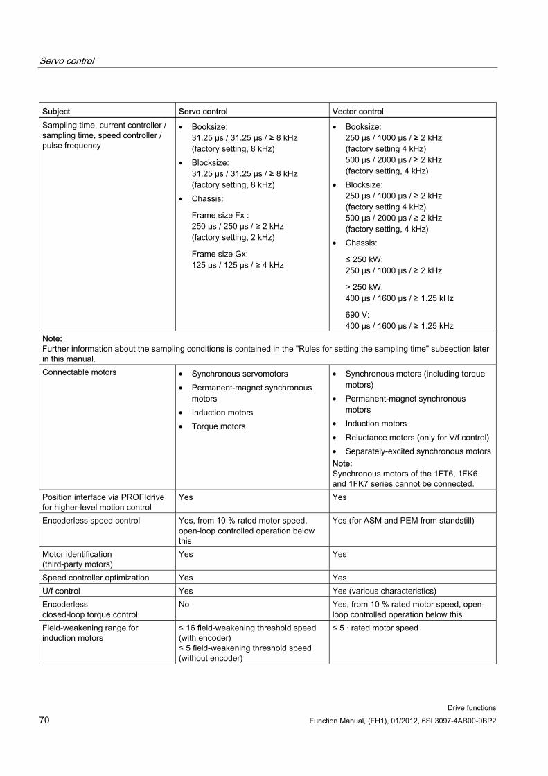
Servo control
Drive functions 70 Function Manual, (FH1), 01/2012, 6SL3097-4AB00-0BP2
Subject Servo control Vector control Sampling time, current controller / sampling time, speed controller / pulse frequency
• Booksize: 31.25 μs / 31.25 μs / ≥ 8 kHz (factory setting, 8 kHz)
• Blocksize: 31.25 μs / 31.25 μs / ≥ 8 kHz (factory setting, 8 kHz)
• Chassis:
Frame size Fx : 250 μs / 250 μs / ≥ 2 kHz (factory setting, 2 kHz)
Frame size Gx: 125 μs / 125 μs / ≥ 4 kHz
• Booksize: 250 μs / 1000 μs / ≥ 2 kHz (factory setting 4 kHz) 500 μs / 2000 μs / ≥ 2 kHz (factory setting, 4 kHz)
• Blocksize: 250 μs / 1000 μs / ≥ 2 kHz (factory setting 4 kHz) 500 μs / 2000 μs / ≥ 2 kHz (factory setting, 4 kHz)
• Chassis:
≤ 250 kW: 250 μs / 1000 μs / ≥ 2 kHz
> 250 kW: 400 μs / 1600 μs / ≥ 1.25 kHz
690 V: 400 μs / 1600 μs / ≥ 1.25 kHz
Note: Further information about the sampling conditions is contained in the "Rules for setting the sampling time" subsection later in this manual. Connectable motors • Synchronous servomotors
• Permanent-magnet synchronous motors
• Induction motors • Torque motors
• Synchronous motors (including torque motors)
• Permanent-magnet synchronous motors
• Induction motors • Reluctance motors (only for V/f control) • Separately-excited synchronous motors Note: Synchronous motors of the 1FT6, 1FK6 and 1FK7 series cannot be connected.
Position interface via PROFIdrive for higher-level motion control
Yes Yes
Encoderless speed control Yes, from 10 % rated motor speed, open-loop controlled operation below this
Yes (for ASM and PEM from standstill)
Motor identification (third-party motors)
Yes Yes
Speed controller optimization Yes Yes U/f control Yes Yes (various characteristics) Encoderless closed-loop torque control
No Yes, from 10 % rated motor speed, open-loop controlled operation below this
Field-weakening range for induction motors
≤ 16 field-weakening threshold speed (with encoder) ≤ 5 field-weakening threshold speed (without encoder)
≤ 5 · rated motor speed
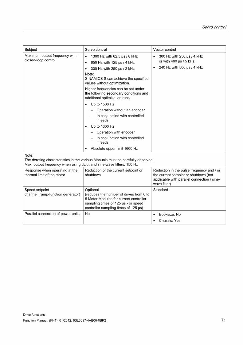
Servo control
Drive functions Function Manual, (FH1), 01/2012, 6SL3097-4AB00-0BP2 71
Subject Servo control Vector control Maximum output frequency with closed-loop control
• 1300 Hz with 62.5 μs / 8 kHz • 650 Hz with 125 μs / 4 kHz • 300 Hz with 250 μs / 2 kHz Note: SINAMICS S can achieve the specified values without optimization. Higher frequencies can be set under the following secondary conditions and additional optimization runs: • Up to 1500 Hz
– Operation without an encoder – In conjunction with controlled
infeeds • Up to 1600 Hz
– Operation with encoder – In conjunction with controlled
infeeds • Absolute upper limit 1600 Hz
• 300 Hz with 250 μs / 4 kHz or with 400 μs / 5 kHz
• 240 Hz with 500 μs / 4 kHz
Note: The derating characteristics in the various Manuals must be carefully observed! Max. output frequency when using dv/dt and sine-wave filters: 150 Hz Response when operating at the thermal limit of the motor
Reduction of the current setpoint or shutdown
Reduction in the pulse frequency and / or the current setpoint or shutdown (not applicable with parallel connection / sine-wave filter)
Speed setpoint channel (ramp-function generator)
Optional (reduces the number of drives from 6 to 5 Motor Modules for current controller sampling times of 125 μs - or speed controller sampling times of 125 μs)
Standard
Parallel connection of power units No • Booksize: No • Chassis: Yes
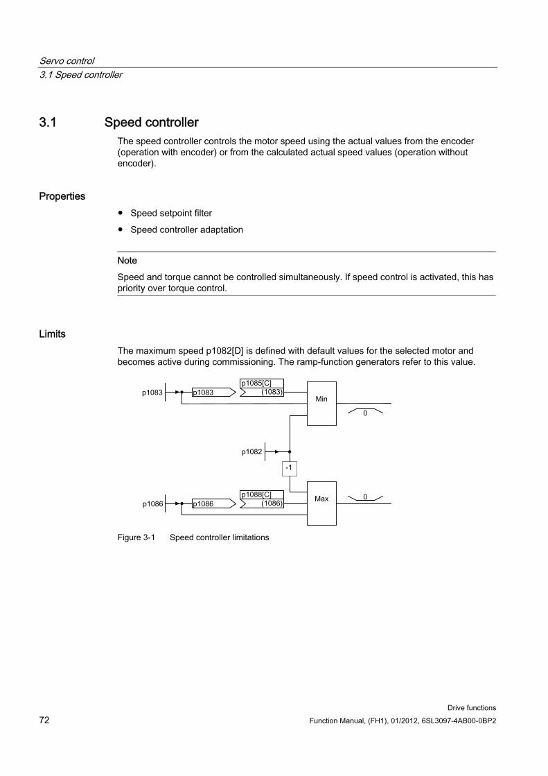
Servo control 3.1 Speed controller
Drive functions 72 Function Manual, (FH1), 01/2012, 6SL3097-4AB00-0BP2
3.1 Speed controller The speed controller controls the motor speed using the actual values from the encoder (operation with encoder) or from the calculated actual speed values (operation without encoder).
Properties Speed setpoint filter
Speed controller adaptation
Note
Speed and torque cannot be controlled simultaneously. If speed control is activated, this has priority over torque control.
Limits The maximum speed p1082[D] is defined with default values for the selected motor and becomes active during commissioning. The ramp-function generators refer to this value.
Figure 3-1 Speed controller limitations
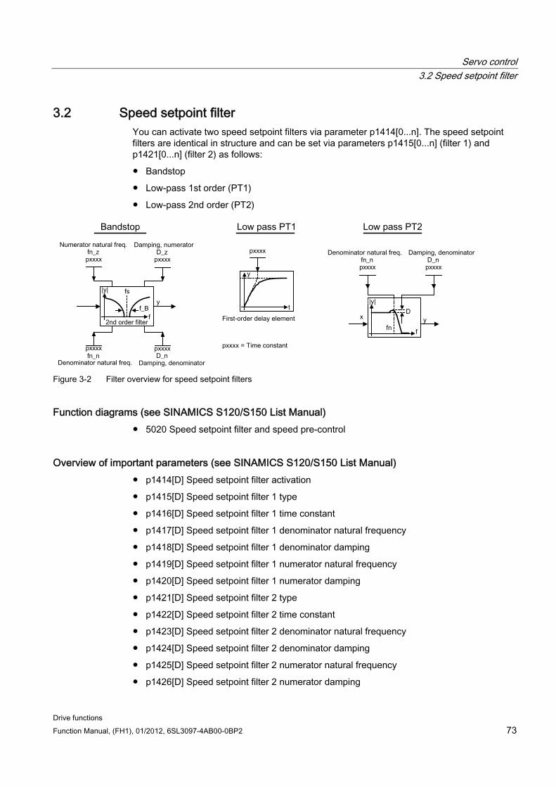
Servo control 3.2 Speed setpoint filter
Drive functions Function Manual, (FH1), 01/2012, 6SL3097-4AB00-0BP2 73
3.2 Speed setpoint filter You can activate two speed setpoint filters via parameter p1414[0...n]. The speed setpoint filters are identical in structure and can be set via parameters p1415[0...n] (filter 1) and p1421[0...n] (filter 2) as follows:
Bandstop
Low-pass 1st order (PT1)
Low-pass 2nd order (PT2)
Figure 3-2 Filter overview for speed setpoint filters
Function diagrams (see SINAMICS S120/S150 List Manual) 5020 Speed setpoint filter and speed pre-control
Overview of important parameters (see SINAMICS S120/S150 List Manual) p1414[D] Speed setpoint filter activation
p1415[D] Speed setpoint filter 1 type
p1416[D] Speed setpoint filter 1 time constant
p1417[D] Speed setpoint filter 1 denominator natural frequency
p1418[D] Speed setpoint filter 1 denominator damping
p1419[D] Speed setpoint filter 1 numerator natural frequency
p1420[D] Speed setpoint filter 1 numerator damping
p1421[D] Speed setpoint filter 2 type
p1422[D] Speed setpoint filter 2 time constant
p1423[D] Speed setpoint filter 2 denominator natural frequency
p1424[D] Speed setpoint filter 2 denominator damping
p1425[D] Speed setpoint filter 2 numerator natural frequency
p1426[D] Speed setpoint filter 2 numerator damping
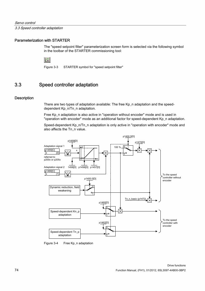
Servo control 3.3 Speed controller adaptation
Drive functions 74 Function Manual, (FH1), 01/2012, 6SL3097-4AB00-0BP2
Parameterization with STARTER The "speed setpoint filter" parameterization screen form is selected via the following symbol in the toolbar of the STARTER commissioning tool:
Figure 3-3 STARTER symbol for "speed setpoint filter"
3.3 Speed controller adaptation
Description There are two types of adaptation available: The free Kp_n adaptation and the speed-dependent Kp_n/Tn_n adaptation.
Free Kp_n adaptation is also active in "operation without encoder" mode and is used in "operation with encoder" mode as an additional factor for speed-dependent Kp_n adaptation.
Speed-dependent Kp_n/Tn_n adaptation is only active in "operation with encoder" mode and also affects the Tn_n value.
Figure 3-4 Free Kp_n adaptation
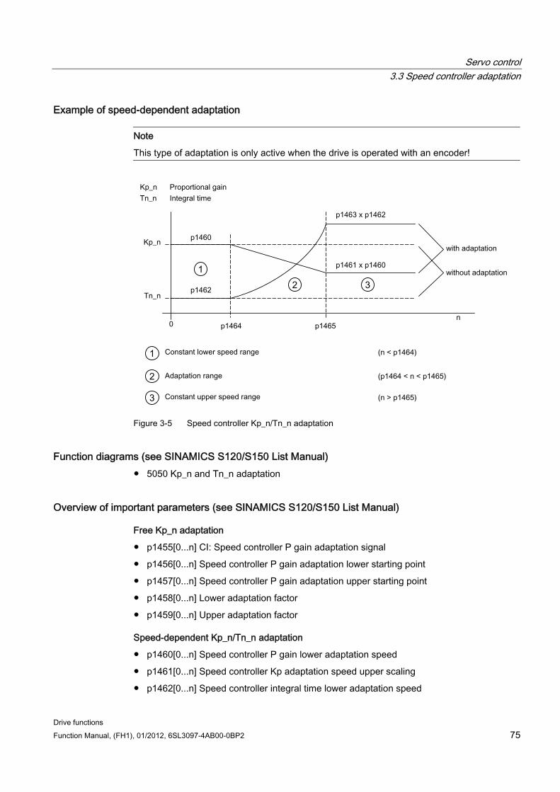
Servo control 3.3 Speed controller adaptation
Drive functions Function Manual, (FH1), 01/2012, 6SL3097-4AB00-0BP2 75
Example of speed-dependent adaptation
Note
This type of adaptation is only active when the drive is operated with an encoder!
Figure 3-5 Speed controller Kp_n/Tn_n adaptation
Function diagrams (see SINAMICS S120/S150 List Manual) 5050 Kp_n and Tn_n adaptation
Overview of important parameters (see SINAMICS S120/S150 List Manual)
Free Kp_n adaptation
p1455[0...n] CI: Speed controller P gain adaptation signal
p1456[0...n] Speed controller P gain adaptation lower starting point
p1457[0...n] Speed controller P gain adaptation upper starting point
p1458[0...n] Lower adaptation factor
p1459[0...n] Upper adaptation factor
Speed-dependent Kp_n/Tn_n adaptation
p1460[0...n] Speed controller P gain lower adaptation speed
p1461[0...n] Speed controller Kp adaptation speed upper scaling
p1462[0...n] Speed controller integral time lower adaptation speed
Servo control 3.4 Torque-controlled operation
Drive functions 76 Function Manual, (FH1), 01/2012, 6SL3097-4AB00-0BP2
p1463[0...n] Speed controller Tn adaptation speed upper scaling
p1464[0...n] Speed controller lower adaptation speed
p1465[0...n] Speed controller upper adaptation speed
p1466[0...n] CI: Speed controller P gain scaling
Parameterization with STARTER The "speed controller" parameter screen is selected via the following icon in the toolbar of the STARTER commissioning tool:
Figure 3-6 STARTER icon for "speed controller"
3.4 Torque-controlled operation
Description An operating mode switchover (p1300) can be carried out or a binector input (p1501) used to switch from speed control to torque control mode. All torque setpoints from the speed control system are rendered inactive. The setpoints for torque control mode are selected by parameterization.
Properties Switchover to torque control mode via:
– Operating mode selection
– Binector input
Torque setpoint can be specified:
– The torque setpoint source can be selected
– The torque setpoint can be scaled
– An additional torque setpoint can be entered
Display of the overall torque
Commissioning of torque control mode 1. Set torque control mode (p1300 = 23; p1501 = "1" signal)
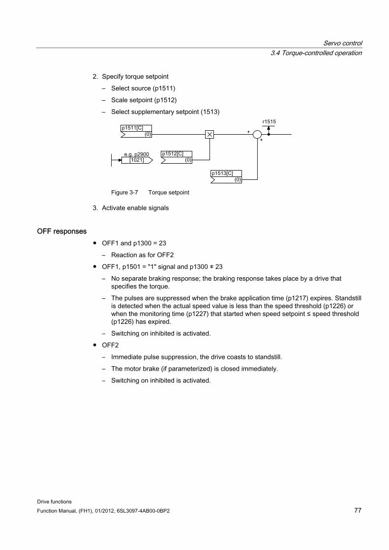
Servo control 3.4 Torque-controlled operation
Drive functions Function Manual, (FH1), 01/2012, 6SL3097-4AB00-0BP2 77
2. Specify torque setpoint
– Select source (p1511)
– Scale setpoint (p1512)
– Select supplementary setpoint (1513)
Figure 3-7 Torque setpoint
3. Activate enable signals
OFF responses OFF1 and p1300 = 23
– Reaction as for OFF2
OFF1, p1501 = "1" signal and p1300 ≠ 23
– No separate braking response; the braking response takes place by a drive that specifies the torque.
– The pulses are suppressed when the brake application time (p1217) expires. Standstill is detected when the actual speed value is less than the speed threshold (p1226) or when the monitoring time (p1227) that started when speed setpoint ≤ speed threshold (p1226) has expired.
– Switching on inhibited is activated.
OFF2
– Immediate pulse suppression, the drive coasts to standstill.
– The motor brake (if parameterized) is closed immediately.
– Switching on inhibited is activated.
Servo control 3.5 Torque setpoint limitation
Drive functions 78 Function Manual, (FH1), 01/2012, 6SL3097-4AB00-0BP2
OFF3
– Switch to speed-controlled operation
– n_set = 0 is input immediately to brake the drive along the OFF3 deceleration ramp (p1135).
– When zero speed is detected, the motor brake (if parameterized) is closed.
– The pulses are suppressed when the motor brake application time (p1217) has elapsed. Standstill is detected when the actual speed value is less than the speed threshold (p1226) or when the monitoring time (p1227) that started when speed setpoint ≤ speed threshold (p1226) has expired.
– Switching on inhibited is activated.
Function diagrams (see SINAMICS S120/S150 List Manual) 5060 Torque setpoint, control type switchover
5610 Torque limiting/reduction/interpolator
Overview of important parameters (see SINAMICS S120/S150 List Manual) p1300 Open-loop/closed-loop control operating mode
r1406.12 Torque control active
p1501[C] BI: Change over between closed-loop speed/torque control
p1511[C] CI: Supplementary torque 1
p1512[C] CI: Supplementary torque 1 scaling
p1513[C] CI: Supplementary torque 2
r1515 Supplementary torque total
Parameterization with STARTER The "torque setpoint" parameterization screen form is selected via the following icon in the toolbar of the STARTER commissioning tool:
Figure 3-8 STARTER icon for "torque setpoint"
3.5 Torque setpoint limitation
Description The steps required for limiting the torque setpoint are as follows:
1. Define the torque setpoint and an additional torque setpoint
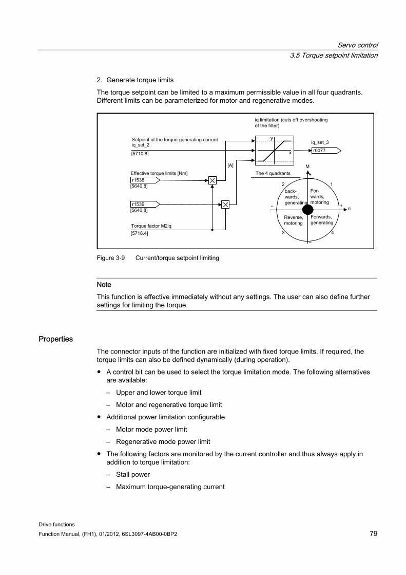
Servo control 3.5 Torque setpoint limitation
Drive functions Function Manual, (FH1), 01/2012, 6SL3097-4AB00-0BP2 79
2. Generate torque limits
The torque setpoint can be limited to a maximum permissible value in all four quadrants. Different limits can be parameterized for motor and regenerative modes.
Figure 3-9 Current/torque setpoint limiting
Note
This function is effective immediately without any settings. The user can also define further settings for limiting the torque.
Properties The connector inputs of the function are initialized with fixed torque limits. If required, the torque limits can also be defined dynamically (during operation).
A control bit can be used to select the torque limitation mode. The following alternatives are available:
– Upper and lower torque limit
– Motor and regenerative torque limit
Additional power limitation configurable
– Motor mode power limit
– Regenerative mode power limit
The following factors are monitored by the current controller and thus always apply in addition to torque limitation:
– Stall power
– Maximum torque-generating current
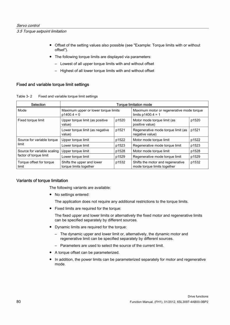
Servo control 3.5 Torque setpoint limitation
Drive functions 80 Function Manual, (FH1), 01/2012, 6SL3097-4AB00-0BP2
Offset of the setting values also possible (see "Example: Torque limits with or without offset").
The following torque limits are displayed via parameters:
– Lowest of all upper torque limits with and without offset
– Highest of all lower torque limits with and without offset
Fixed and variable torque limit settings
Table 3- 2 Fixed and variable torque limit settings
Selection Torque limitation mode Mode Maximum upper or lower torque limits
p1400.4 = 0 Maximum motor or regenerative mode torque limits p1400.4 = 1
Upper torque limit (as positive value)
p1520 Motor mode torque limit (as positive value)
p1520 Fixed torque limit
Lower torque limit (as negative value)
p1521 Regenerative mode torque limit (as negative value)
p1521
Upper torque limit p1522 Motor mode torque limit p1522 Source for variable torque limit Lower torque limit p1523 Regenerative mode torque limit p1523
Upper torque limit p1528 Motor mode torque limit p1528 Source for variable scaling factor of torque limit Lower torque limit p1529 Regenerative mode torque limit p1529 Torque offset for torque limit
Shifts the upper and lower torque limits together
p1532 Shifts the motor and regenerative mode torque limits together
p1532
Variants of torque limitation The following variants are available:
No settings entered:
The application does not require any additional restrictions to the torque limits.
Fixed limits are required for the torque:
The fixed upper and lower limits or alternatively the fixed motor and regenerative limits can be specified separately by different sources.
Dynamic limits are required for the torque:
– The dynamic upper and lower limit or, alternatively, the dynamic motor and regenerative limit can be specified separately by different sources.
– Parameters are used to select the source of the current limit.
A torque offset can be parameterized.
In addition, the power limits can be parameterized separately for motor and regenerative mode.
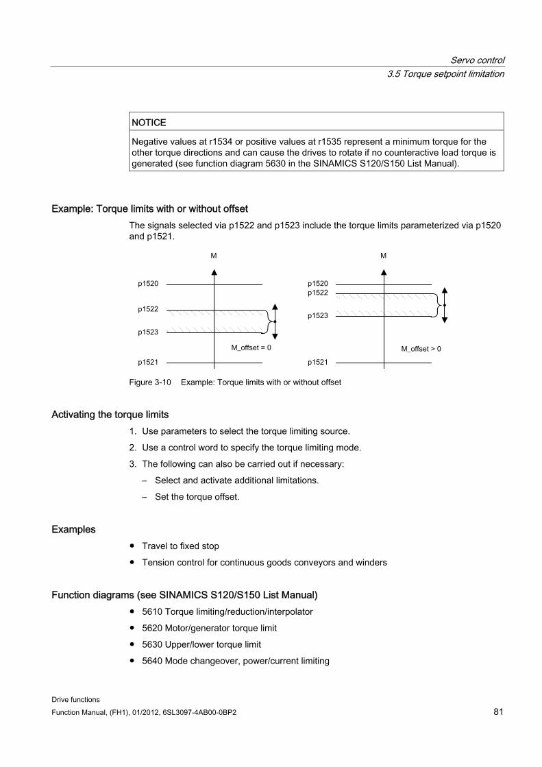
Servo control 3.5 Torque setpoint limitation
Drive functions Function Manual, (FH1), 01/2012, 6SL3097-4AB00-0BP2 81
NOTICE Negative values at r1534 or positive values at r1535 represent a minimum torque for the other torque directions and can cause the drives to rotate if no counteractive load torque is generated (see function diagram 5630 in the SINAMICS S120/S150 List Manual).
Example: Torque limits with or without offset The signals selected via p1522 and p1523 include the torque limits parameterized via p1520 and p1521.
Figure 3-10 Example: Torque limits with or without offset
Activating the torque limits 1. Use parameters to select the torque limiting source.
2. Use a control word to specify the torque limiting mode.
3. The following can also be carried out if necessary:
– Select and activate additional limitations.
– Set the torque offset.
Examples Travel to fixed stop
Tension control for continuous goods conveyors and winders
Function diagrams (see SINAMICS S120/S150 List Manual) 5610 Torque limiting/reduction/interpolator
5620 Motor/generator torque limit
5630 Upper/lower torque limit
5640 Mode changeover, power/current limiting
Servo control 3.6 Current controller
Drive functions 82 Function Manual, (FH1), 01/2012, 6SL3097-4AB00-0BP2
Overview of important parameters (see SINAMICS S120/S150 List Manual) p0640[0...n] Current limit
p1400[0...n] Speed control configuration
r1508 CO: Torque setpoint before supplementary torque
r1509 CO: Torque setpoint before torque limiting
r1515 Supplementary torque total
p1520[0...n] CO: Torque limit, upper/motoring
p1521[0...n] CO: Torque limit, lower/regenerative
p1522[C] CI: Torque limit, upper/motoring
p1523[C] CI: Torque limit, lower/regenerative
r1526 Torque limit, upper/motoring without offset
r1527 Torque limit, lower/regenerative without offset
p1528[0...n] CI: Torque limit, upper/motoring, scaling
p1529[0...n] CI: Torque limit, lower/regenerative scaling
p1530[0...n] Motor mode power limit
p1531[0...n] Regenerative mode power limit
p1532[0...n] CO: Torque limit, offset
r1533 Current limit torque-generating, total
r1534 CO: Torque limit, upper total
r1535 CO: Torque limit, lower total
r1538 CO: Upper effective torque limit
r1539 CO: Lower effective torque limit
Parameterization with STARTER The "torque limit" parameterization screen form is selected via the following icon in the toolbar of the STARTER commissioning tool:
Figure 3-11 STARTER icon for "torque limit"
3.6 Current controller
Properties PI controller for current control
Four identical current setpoint filters
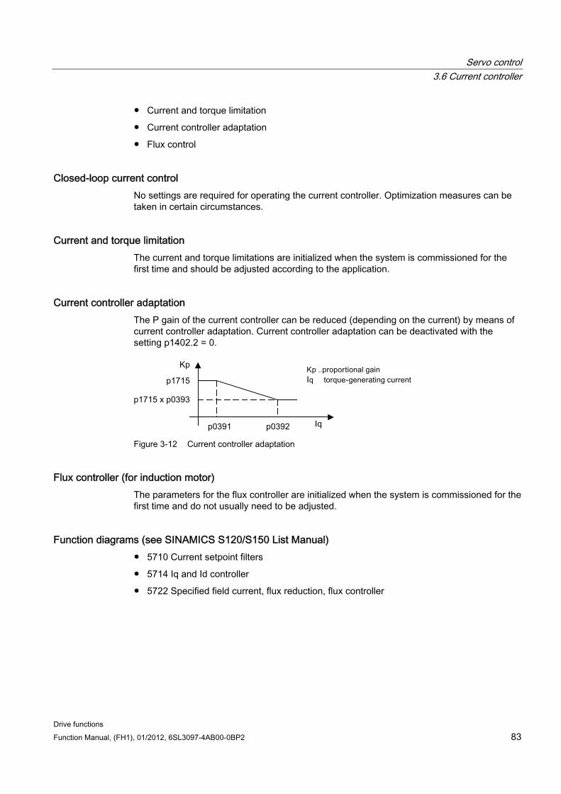
Servo control 3.6 Current controller
Drive functions Function Manual, (FH1), 01/2012, 6SL3097-4AB00-0BP2 83
Current and torque limitation
Current controller adaptation
Flux control
Closed-loop current control No settings are required for operating the current controller. Optimization measures can be taken in certain circumstances.
Current and torque limitation The current and torque limitations are initialized when the system is commissioned for the first time and should be adjusted according to the application.
Current controller adaptation The P gain of the current controller can be reduced (depending on the current) by means of current controller adaptation. Current controller adaptation can be deactivated with the setting p1402.2 = 0.
Figure 3-12 Current controller adaptation
Flux controller (for induction motor) The parameters for the flux controller are initialized when the system is commissioned for the first time and do not usually need to be adjusted.
Function diagrams (see SINAMICS S120/S150 List Manual) 5710 Current setpoint filters
5714 Iq and Id controller
5722 Specified field current, flux reduction, flux controller
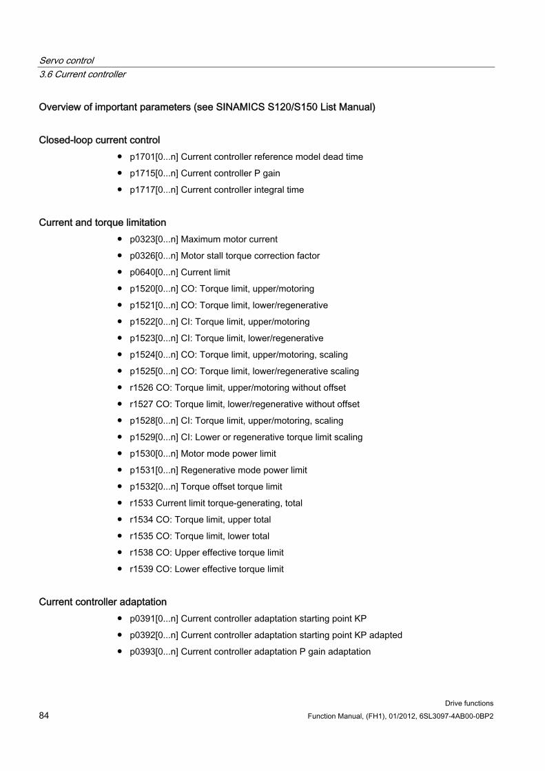
Servo control 3.6 Current controller
Drive functions 84 Function Manual, (FH1), 01/2012, 6SL3097-4AB00-0BP2
Overview of important parameters (see SINAMICS S120/S150 List Manual)
Closed-loop current control p1701[0...n] Current controller reference model dead time
p1715[0...n] Current controller P gain
p1717[0...n] Current controller integral time
Current and torque limitation p0323[0...n] Maximum motor current
p0326[0...n] Motor stall torque correction factor
p0640[0...n] Current limit
p1520[0...n] CO: Torque limit, upper/motoring
p1521[0...n] CO: Torque limit, lower/regenerative
p1522[0...n] CI: Torque limit, upper/motoring
p1523[0...n] CI: Torque limit, lower/regenerative
p1524[0...n] CO: Torque limit, upper/motoring, scaling
p1525[0...n] CO: Torque limit, lower/regenerative scaling
r1526 CO: Torque limit, upper/motoring without offset
r1527 CO: Torque limit, lower/regenerative without offset
p1528[0...n] CI: Torque limit, upper/motoring, scaling
p1529[0...n] CI: Lower or regenerative torque limit scaling
p1530[0...n] Motor mode power limit
p1531[0...n] Regenerative mode power limit
p1532[0...n] Torque offset torque limit
r1533 Current limit torque-generating, total
r1534 CO: Torque limit, upper total
r1535 CO: Torque limit, lower total
r1538 CO: Upper effective torque limit
r1539 CO: Lower effective torque limit
Current controller adaptation p0391[0...n] Current controller adaptation starting point KP
p0392[0...n] Current controller adaptation starting point KP adapted
p0393[0...n] Current controller adaptation P gain adaptation
Servo control 3.7 Current setpoint filters
Drive functions Function Manual, (FH1), 01/2012, 6SL3097-4AB00-0BP2 85
p1590[0...n] Flux controller P gain
p1592[0...n] Flux controller integral time
Commissioning with STARTER The "current controller" parameterizing screen is selected via the following icon in the toolbar of the STARTER commissioning tool:
Figure 3-13 STARTER icon for "current controller"
3.7 Current setpoint filters
Description The four current setpoint filters connected in series can be parameterized as follows:
Low-pass 2nd order (PT2: -40 dB/decade) (type 1)
General filter 2nd order (type 2) Bandstop and lowpass with reduction are converted to the parameters of the general filter 2nd order using the STARTER commissioning tool.
– Bandstop
– Low-pass with reduction by a constant value
The phase frequency curve is shown alongside the amplitude log frequency curve. A phase shift results in a control system delay and should be kept to a minimum.
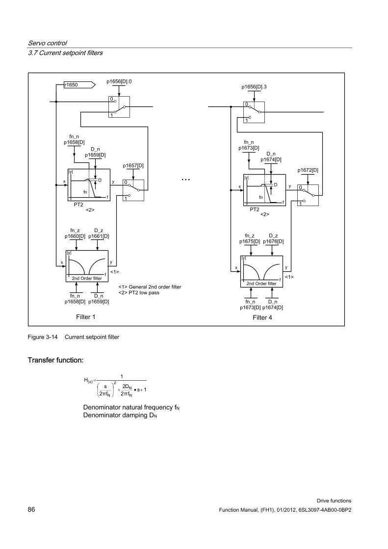
Servo control 3.7 Current setpoint filters
Drive functions 86 Function Manual, (FH1), 01/2012, 6SL3097-4AB00-0BP2
Figure 3-14 Current setpoint filter
Transfer function:
Denominator natural frequency fN
Denominator damping DN
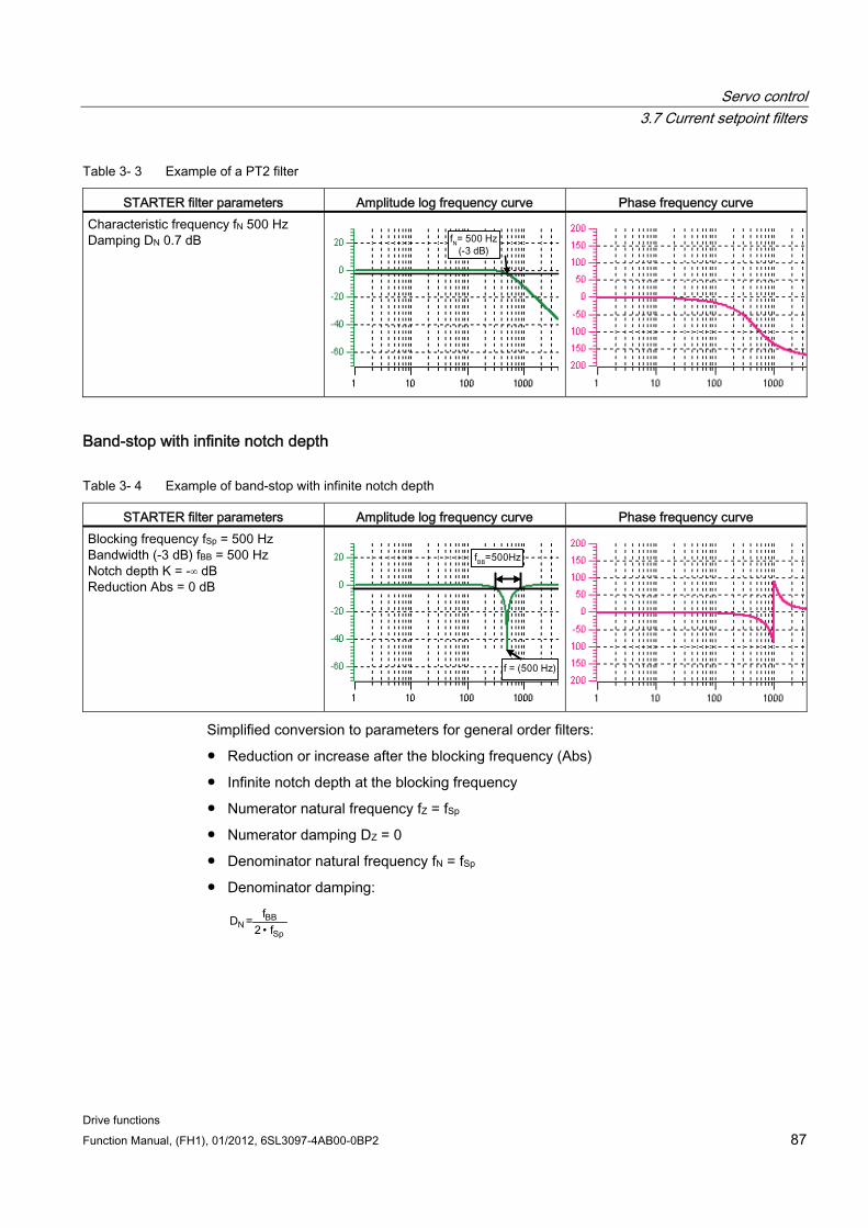
Servo control 3.7 Current setpoint filters
Drive functions Function Manual, (FH1), 01/2012, 6SL3097-4AB00-0BP2 87
Table 3- 3 Example of a PT2 filter
STARTER filter parameters Amplitude log frequency curve Phase frequency curve Characteristic frequency fN 500 Hz Damping DN 0.7 dB
Band-stop with infinite notch depth
Table 3- 4 Example of band-stop with infinite notch depth
STARTER filter parameters Amplitude log frequency curve Phase frequency curve Blocking frequency fSp = 500 Hz Bandwidth (-3 dB) fBB = 500 Hz Notch depth K = -∞ dB Reduction Abs = 0 dB
Simplified conversion to parameters for general order filters:
Reduction or increase after the blocking frequency (Abs)
Infinite notch depth at the blocking frequency
Numerator natural frequency fZ = fSp
Numerator damping DZ = 0
Denominator natural frequency fN = fSp
Denominator damping:
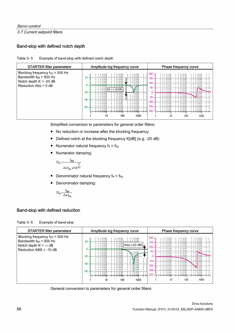
Servo control 3.7 Current setpoint filters
Drive functions 88 Function Manual, (FH1), 01/2012, 6SL3097-4AB00-0BP2
Band-stop with defined notch depth
Table 3- 5 Example of band-stop with defined notch depth
STARTER filter parameters Amplitude log frequency curve Phase frequency curve Blocking frequency fSp = 500 Hz Bandwidth fBB = 500 Hz Notch depth K = -20 dB Reduction Abs = 0 dB
Simplified conversion to parameters for general order filters:
No reduction or increase after the blocking frequency
Defined notch at the blocking frequency K[dB] (e.g. -20 dB)
Numerator natural frequency fZ = fSp
Numerator damping:
Denominator natural frequency fN = fSp
Denominator damping:
Band-stop with defined reduction
Table 3- 6 Example of band-stop
STARTER filter parameters Amplitude log frequency curve Phase frequency curve Blocking frequency fSP = 500 Hz Bandwidth fBB = 500 Hz Notch depth K = -∞ dB Reduction ABS = -10 dB
General conversion to parameters for general order filters:
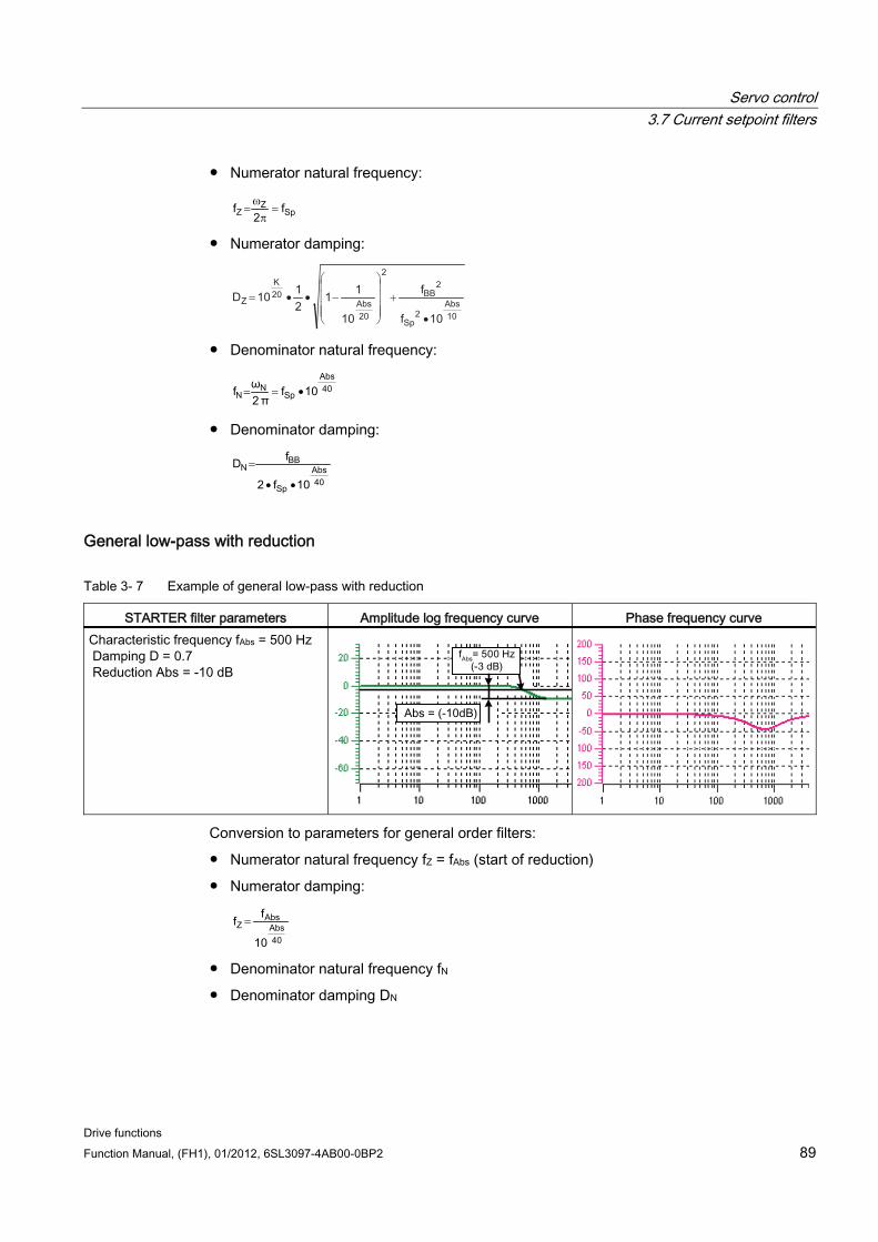
Servo control 3.7 Current setpoint filters
Drive functions Function Manual, (FH1), 01/2012, 6SL3097-4AB00-0BP2 89
Numerator natural frequency:
2
= π
ω =
Numerator damping:
102
2
2
20
20
1010
11
2
110
•
+⎟⎟⎟⎟
⎠
⎞
⎜⎜⎜⎜
⎝
⎛
−••=
Denominator natural frequency:
=
Denominator damping:
General low-pass with reduction
Table 3- 7 Example of general low-pass with reduction
STARTER filter parameters Amplitude log frequency curve Phase frequency curve Characteristic frequency fAbs = 500 Hz Damping D = 0.7 Reduction Abs = -10 dB
Conversion to parameters for general order filters:
Numerator natural frequency fZ = fAbs (start of reduction)
Numerator damping:
Denominator natural frequency fN
Denominator damping DN
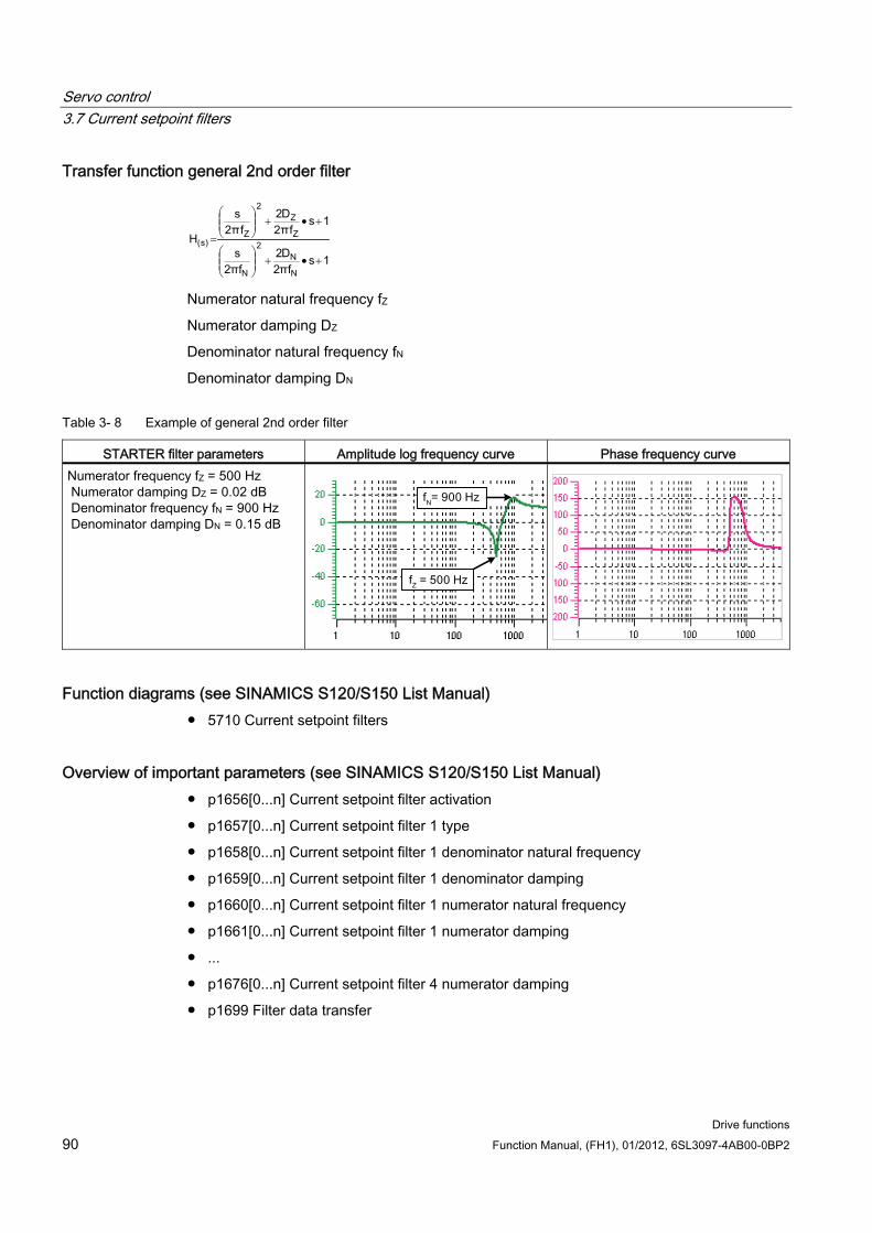
Servo control 3.7 Current setpoint filters
Drive functions 90 Function Manual, (FH1), 01/2012, 6SL3097-4AB00-0BP2
Transfer function general 2nd order filter
Numerator natural frequency fZ
Numerator damping DZ
Denominator natural frequency fN
Denominator damping DN
Table 3- 8 Example of general 2nd order filter
STARTER filter parameters Amplitude log frequency curve Phase frequency curve Numerator frequency fZ = 500 Hz Numerator damping DZ = 0.02 dB Denominator frequency fN = 900 Hz Denominator damping DN = 0.15 dB
Function diagrams (see SINAMICS S120/S150 List Manual) 5710 Current setpoint filters
Overview of important parameters (see SINAMICS S120/S150 List Manual) p1656[0...n] Current setpoint filter activation
p1657[0...n] Current setpoint filter 1 type
p1658[0...n] Current setpoint filter 1 denominator natural frequency
p1659[0...n] Current setpoint filter 1 denominator damping
p1660[0...n] Current setpoint filter 1 numerator natural frequency
p1661[0...n] Current setpoint filter 1 numerator damping
...
p1676[0...n] Current setpoint filter 4 numerator damping
p1699 Filter data transfer
Servo control 3.8 Note about the electronic motor model
Drive functions Function Manual, (FH1), 01/2012, 6SL3097-4AB00-0BP2 91
Parameterization with STARTER The "current setpoint filter" parameter screen is selected via the following icon in the toolbar of the STARTER commissioning tool:
Figure 3-15 STARTER icon for "current setpoint filter"
3.8 Note about the electronic motor model A model change takes place within the speed range p1752*(100%-p1756) and p1752. With induction motors with encoder, the torque image is more accurate in higher speed ranges; the effect of the rotor resistance and the saturation of the main field inductance are corrected. With synchronous motors with encoder, the commutation angle is monitored. If the kT estimator has been activated, the torque image for synchronous motors is more accurate too.
3.9 V/f control
Description For U/f control, the drive is operated with an open control loop. In this open-loop control system, the drive does not require speed feedback and no actual current sensing. Operation is possible with a small amount of motor data.
With U/f control, the following components and data can be checked:
Motor Module
Power cable between the Motor Module and motor
Motor
DRIVE-CLiQ cable between the Motor Module and motor
Encoder and actual encoder value
The following motors can be operated with V/f control:
Induction motors
Synchronous motors
Note
In V/f mode, the calculated actual speed value is always displayed in r0063. The speed of the encoder (if installed) is displayed in r0061. If an encoder is not installed, r0061 displays "0".
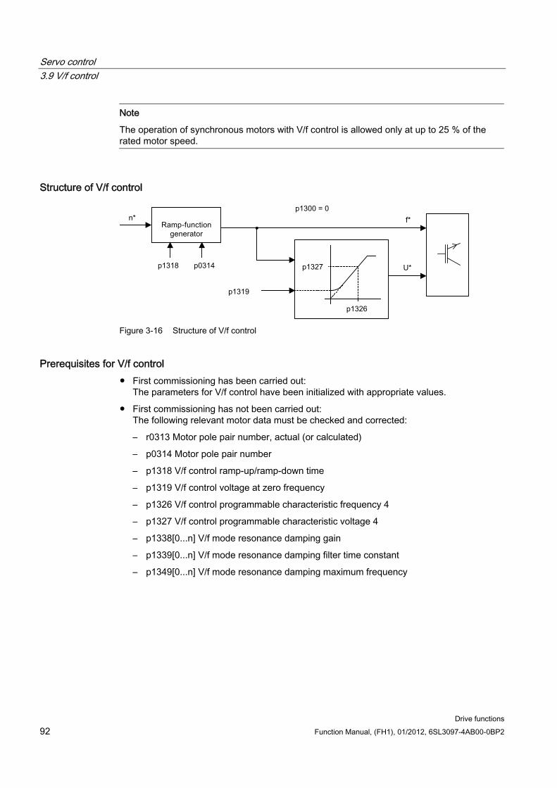
Servo control 3.9 V/f control
Drive functions 92 Function Manual, (FH1), 01/2012, 6SL3097-4AB00-0BP2
Note
The operation of synchronous motors with V/f control is allowed only at up to 25 % of the rated motor speed.
Structure of V/f control
Figure 3-16 Structure of V/f control
Prerequisites for V/f control First commissioning has been carried out:
The parameters for V/f control have been initialized with appropriate values.
First commissioning has not been carried out: The following relevant motor data must be checked and corrected:
– r0313 Motor pole pair number, actual (or calculated)
– p0314 Motor pole pair number
– p1318 V/f control ramp-up/ramp-down time
– p1319 V/f control voltage at zero frequency
– p1326 V/f control programmable characteristic frequency 4
– p1327 V/f control programmable characteristic voltage 4
– p1338[0...n] V/f mode resonance damping gain
– p1339[0...n] V/f mode resonance damping filter time constant
– p1349[0...n] V/f mode resonance damping maximum frequency
Servo control 3.9 V/f control
Drive functions Function Manual, (FH1), 01/2012, 6SL3097-4AB00-0BP2 93
Note
With synchronous motors, V/f mode is normally only stable at low speeds. Higher speeds can induce vibrations.
Oscillation damping is activated on the basis of suitable default parameter values and does not require further parameterization in most applications. If you become aware of interference caused by a transient response, you have the option of gradually increasing the value of p1338 and evaluating how this affects your system.
Note
The drive can be ramped up to the current limit (p0640) relatively quickly without the need for extensive parameterization (when operating the drive with a variable moment of inertia, for example).
Note the following: Only the ramp-function generator stops when the current limit (p0640) is reached. This does not prevent the current from increasing even further. In view of this, the parameters you set must include a safety margin relative to the current limits for the monitoring functions to prevent the drive from switching off with an overcurrent fault.
Commissioning V/f control 1. Verify the preconditions for V/f control mode.
2. Set p0311 –> rated motor speed.
3. Set p1317 = 1 –> activates the function.
4. Activate the enable signals for operation.
5. Specify the speed setpoint.
Note Automatic activation of additional functions
With p1317 = 1, the following functions are also activated automatically: • Resonance damping (p1338)
In order to obtain a pure diagnostic mode without any influence on actual values, the resonance damping must be deactivated (p1338 = 0).
• Vdc controller (p1240, p1244, p1248, p1250) • Limitation of the up ramp as a result of M, P and I limits • As soon as the current limit p0640 is exceeded, then the ramp-function generator is
stopped
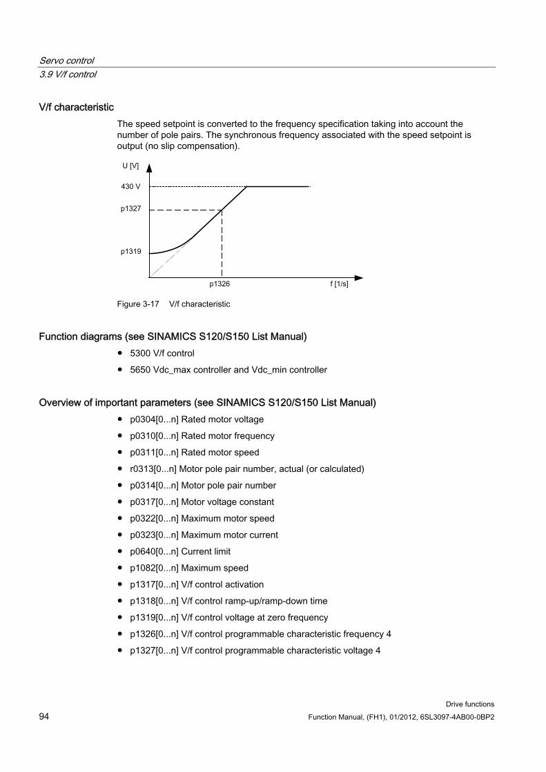
Servo control 3.9 V/f control
Drive functions 94 Function Manual, (FH1), 01/2012, 6SL3097-4AB00-0BP2
V/f characteristic The speed setpoint is converted to the frequency specification taking into account the number of pole pairs. The synchronous frequency associated with the speed setpoint is output (no slip compensation).
Figure 3-17 V/f characteristic
Function diagrams (see SINAMICS S120/S150 List Manual) 5300 V/f control
5650 Vdc_max controller and Vdc_min controller
Overview of important parameters (see SINAMICS S120/S150 List Manual) p0304[0...n] Rated motor voltage
p0310[0...n] Rated motor frequency
p0311[0...n] Rated motor speed
r0313[0...n] Motor pole pair number, actual (or calculated)
p0314[0...n] Motor pole pair number
p0317[0...n] Motor voltage constant
p0322[0...n] Maximum motor speed
p0323[0...n] Maximum motor current
p0640[0...n] Current limit
p1082[0...n] Maximum speed
p1317[0...n] V/f control activation
p1318[0...n] V/f control ramp-up/ramp-down time
p1319[0...n] V/f control voltage at zero frequency
p1326[0...n] V/f control programmable characteristic frequency 4
p1327[0...n] V/f control programmable characteristic voltage 4
Servo control 3.10 Optimizing the current and speed controller
Drive functions Function Manual, (FH1), 01/2012, 6SL3097-4AB00-0BP2 95
3.10 Optimizing the current and speed controller
General information
CAUTION Controller optimization may only be performed by skilled personnel with a knowledge of control engineering.
The following tools are available for optimizing the controllers:
"Function generator" in STARTER
"Trace" in STARTER
"Measuring function" in STARTER
Measuring sockets on the Control Unit
Optimizing the current controller The current controller is initialized when the system is commissioned for the first time and is adequately optimized for most applications.
Optimizing the speed controller The speed controller is set in accordance with the motor moment of inertia when the motor is configured for the first time. The calculated proportional gain is set to approximately 30% of the maximum possible gain in order to minimize vibrations when the controller is mounted on the mechanical system of the machine for the first time.
The integral time of the speed controller is always preset to 10 ms.
The following optimization measures are necessary in order to achieve the full dynamic response:
Increase the proportional gain Kp_n (p1460)
Change the integral action time Tn_n (p1462)
Automatic controller setting of the speed controller (frequency response analysis) in STARTER The automatic speed controller setting has the following features:
– Section identification using FFT analysis
– Automatic setting of filters in the current setpoint arm, e.g. for damping resonances
– Automatic setting of the controller (gain factor Kp, integral time Tn)
The automatic controller settings can be verified with the measuring functions.
The "automatic controller setting" parameterization screen form is selected using the following symbol in the toolbar of the STARTER commissioning tool:
Servo control 3.10 Optimizing the current and speed controller
Drive functions 96 Function Manual, (FH1), 01/2012, 6SL3097-4AB00-0BP2
Figure 3-18 STARTER symbol for "automatic controller setting"
Example of measuring the speed controller frequency response By measuring the speed controller frequency response and the control system, critical resonance frequencies can, if necessary, be determined at the stability limit of the speed control loop and dampened using one or more current setpoint filters. This normally enables the proportional gain to be increased (e.g. Kp_n = 3* default value).
After the Kp_n value has been set, the ideal integral action time Tn_n (e.g. reduced from 10 ms to 5 ms) can be determined.
Example of speed setpoint step change A rectangular step change can be applied to the speed setpoint via the speed setpoint step change measuring function. The measuring function has preselected the measurement for the speed setpoint and the torque-generating current.
Figure 3-19 Setting the proportional gain Kp
Parameter overview See "Speed controller".
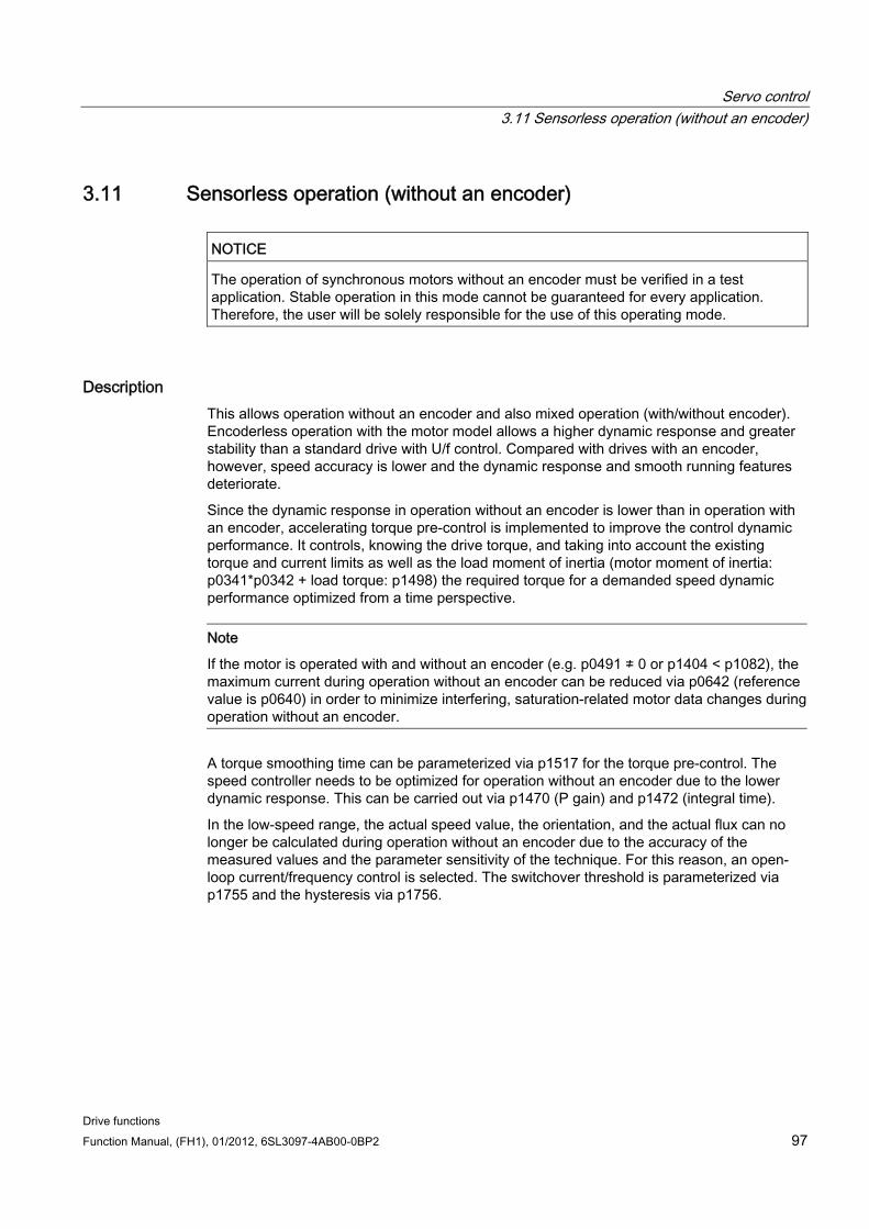
Servo control 3.11 Sensorless operation (without an encoder)
Drive functions Function Manual, (FH1), 01/2012, 6SL3097-4AB00-0BP2 97
3.11 Sensorless operation (without an encoder)
NOTICE The operation of synchronous motors without an encoder must be verified in a test application. Stable operation in this mode cannot be guaranteed for every application. Therefore, the user will be solely responsible for the use of this operating mode.
Description This allows operation without an encoder and also mixed operation (with/without encoder). Encoderless operation with the motor model allows a higher dynamic response and greater stability than a standard drive with U/f control. Compared with drives with an encoder, however, speed accuracy is lower and the dynamic response and smooth running features deteriorate.
Since the dynamic response in operation without an encoder is lower than in operation with an encoder, accelerating torque pre-control is implemented to improve the control dynamic performance. It controls, knowing the drive torque, and taking into account the existing torque and current limits as well as the load moment of inertia (motor moment of inertia: p0341*p0342 + load torque: p1498) the required torque for a demanded speed dynamic performance optimized from a time perspective.
Note
If the motor is operated with and without an encoder (e.g. p0491 ≠ 0 or p1404 < p1082), the maximum current during operation without an encoder can be reduced via p0642 (reference value is p0640) in order to minimize interfering, saturation-related motor data changes during operation without an encoder.
A torque smoothing time can be parameterized via p1517 for the torque pre-control. The speed controller needs to be optimized for operation without an encoder due to the lower dynamic response. This can be carried out via p1470 (P gain) and p1472 (integral time).
In the low-speed range, the actual speed value, the orientation, and the actual flux can no longer be calculated during operation without an encoder due to the accuracy of the measured values and the parameter sensitivity of the technique. For this reason, an open-loop current/frequency control is selected. The switchover threshold is parameterized via p1755 and the hysteresis via p1756.
Servo control 3.11 Sensorless operation (without an encoder)
Drive functions 98 Function Manual, (FH1), 01/2012, 6SL3097-4AB00-0BP2
To accept a high load torque even in the open-loop controlled range, the motor current can be increased via p1612. To do so, the drive torque (e.g. friction torque) must be known or estimated. An additional reserve of approx. 20% should also be added. In synchronous motors, the torque is converted to the current via the motor torque constant (p0316). In the lower speed range, the required current cannot be measured directly on the Motor Module. The default setting is 50% (synchronous motor) or 80% (induction motor) of the motor rated current (p0305). When parameterizing the motor current (p1612), you must take into account the thermal motor load.
Note
Encoderless operation is not permitted for vertical axes or similar. Encoderless operation is not suitable for a higher-level closed-loop position control either.
The start behavior of synchronous motors from standstill can be improved further by parameterizing the pole position identification (p1982 = 1).
Behavior once pulses have been canceled Once the pulses have been canceled in operation without an encoder, the current actual speed value of the motor can no longer be calculated. Once the pulses are enabled again, the system must search for the actual speed value.
p1400.11 can be used to parameterize whether the search is to begin with the speed setpoint (p1400.11 = 1) or with speed = 0.0 (p1400.11 = 0). Under normal circumstances, p1400.11 = 0 because the motor is usually started from standstill. If the motor is rotating faster than the changeover speed p1755 when the pulses are enabled, p1400.11 = 1 must be set.
If the motor is rotating and the start value for the search is as of the setpoint (p1400.11 = 1), the speed setpoint must be in the same direction as the actual speed before the pulses can be enabled. A large discrepancy between the actual and setpoint speed can cause a malfunction.
WARNING Once the pulses have been canceled, no information about the motor speed is available. The computed actual speed value is then set to zero, which means that all actual speed value messages and output signals no longer provide any useful information.
Switchover between closed-loop/open-loop operation and operation with/without encoder Operation without an encoder is activated via parameter setting p1300 = 20. If p1300 = 20 or p1404 = 0, operation without an encoder is active across the entire speed range. If the speed value is less than the changeover speed p1755, the motor is operated in accordance with the current/frequency.
During operation with an encoder, a switchover can be made to operation without an encoder when the speed threshold p1404 is exceeded. If p1404 > 0 and p1404 < p1755, a switchover is not made to operation without an encoder until the speed exceeds p1755.
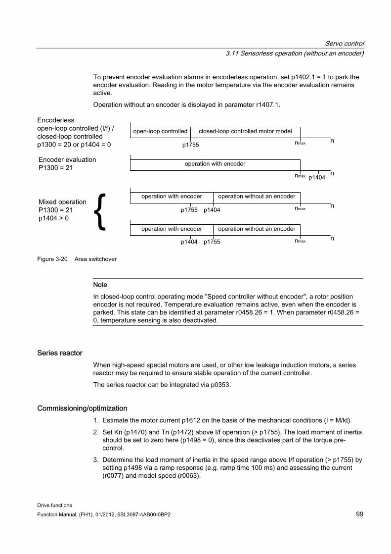
Servo control 3.11 Sensorless operation (without an encoder)
Drive functions Function Manual, (FH1), 01/2012, 6SL3097-4AB00-0BP2 99
To prevent encoder evaluation alarms in encoderless operation, set p1402.1 = 1 to park the encoder evaluation. Reading in the motor temperature via the encoder evaluation remains active.
Operation without an encoder is displayed in parameter r1407.1.
Figure 3-20 Area switchover
Note
In closed-loop control operating mode "Speed controller without encoder", a rotor position encoder is not required. Temperature evaluation remains active, even when the encoder is parked. This state can be identified at parameter r0458.26 = 1. When parameter r0458.26 = 0, temperature sensing is also deactivated.
Series reactor When high-speed special motors are used, or other low leakage induction motors, a series reactor may be required to ensure stable operation of the current controller.
The series reactor can be integrated via p0353.
Commissioning/optimization 1. Estimate the motor current p1612 on the basis of the mechanical conditions (I = M/kt).
2. Set Kn (p1470) and Tn (p1472) above I/f operation (> p1755). The load moment of inertia should be set to zero here (p1498 = 0), since this deactivates part of the torque pre-control.
3. Determine the load moment of inertia in the speed range above I/f operation (> p1755) by setting p1498 via a ramp response (e.g. ramp time 100 ms) and assessing the current (r0077) and model speed (r0063).
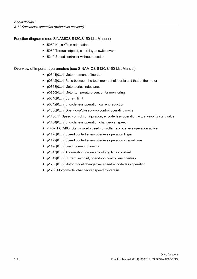
Servo control 3.11 Sensorless operation (without an encoder)
Drive functions 100 Function Manual, (FH1), 01/2012, 6SL3097-4AB00-0BP2
Function diagrams (see SINAMICS S120/S150 List Manual) 5050 Kp_n-/Tn_n adaptation
5060 Torque setpoint, control type switchover
5210 Speed controller without encoder
Overview of important parameters (see SINAMICS S120/S150 List Manual) p0341[0...n] Motor moment of inertia
p0342[0...n] Ratio between the total moment of inertia and that of the motor
p0353[0...n] Motor series inductance
p0600[0...n] Motor temperature sensor for monitoring
p0640[0...n] Current limit
p0642[0...n] Encoderless operation current reduction
p1300[0...n] Open-loop/closed-loop control operating mode
p1400.11 Speed control configuration; encoderless operation actual velocity start value
p1404[0...n] Encoderless operation changeover speed
r1407.1 CO/BO: Status word speed controller; encoderless operation active
p1470[0...n] Speed controller encoderless operation P gain
p1472[0...n] Speed controller encoderless operation integral time
p1498[0...n] Load moment of inertia
p1517[0...n] Accelerating torque smoothing time constant
p1612[0...n] Current setpoint, open-loop control, encoderless
p1755[0...n] Motor model changeover speed encoderless operation
p1756 Motor model changeover speed hysteresis
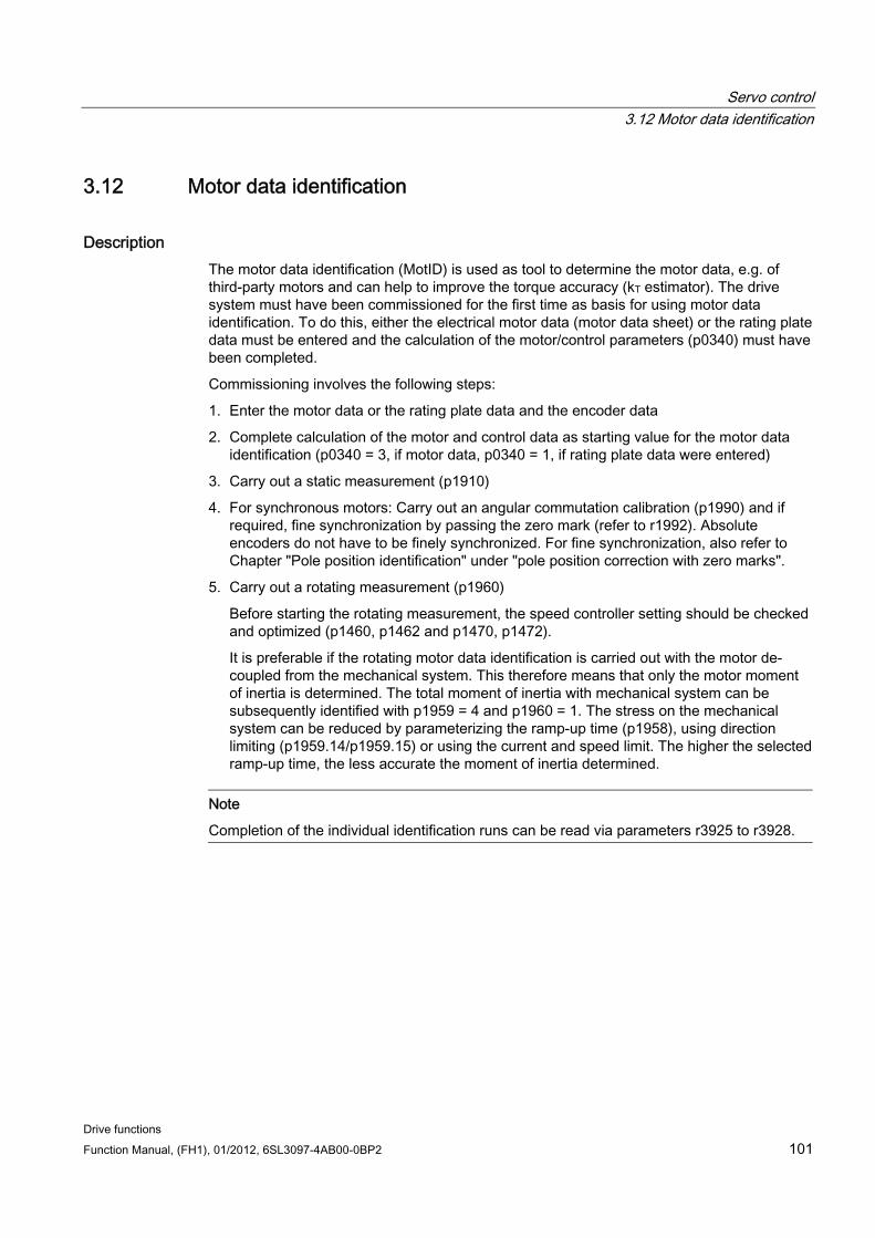
Servo control 3.12 Motor data identification
Drive functions Function Manual, (FH1), 01/2012, 6SL3097-4AB00-0BP2 101
3.12 Motor data identification
Description The motor data identification (MotID) is used as tool to determine the motor data, e.g. of third-party motors and can help to improve the torque accuracy (kT estimator). The drive system must have been commissioned for the first time as basis for using motor data identification. To do this, either the electrical motor data (motor data sheet) or the rating plate data must be entered and the calculation of the motor/control parameters (p0340) must have been completed.
Commissioning involves the following steps:
1. Enter the motor data or the rating plate data and the encoder data
2. Complete calculation of the motor and control data as starting value for the motor data identification (p0340 = 3, if motor data, p0340 = 1, if rating plate data were entered)
3. Carry out a static measurement (p1910)
4. For synchronous motors: Carry out an angular commutation calibration (p1990) and if required, fine synchronization by passing the zero mark (refer to r1992). Absolute encoders do not have to be finely synchronized. For fine synchronization, also refer to Chapter "Pole position identification" under "pole position correction with zero marks".
5. Carry out a rotating measurement (p1960)
Before starting the rotating measurement, the speed controller setting should be checked and optimized (p1460, p1462 and p1470, p1472).
It is preferable if the rotating motor data identification is carried out with the motor de-coupled from the mechanical system. This therefore means that only the motor moment of inertia is determined. The total moment of inertia with mechanical system can be subsequently identified with p1959 = 4 and p1960 = 1. The stress on the mechanical system can be reduced by parameterizing the ramp-up time (p1958), using direction limiting (p1959.14/p1959.15) or using the current and speed limit. The higher the selected ramp-up time, the less accurate the moment of inertia determined.
Note
Completion of the individual identification runs can be read via parameters r3925 to r3928.
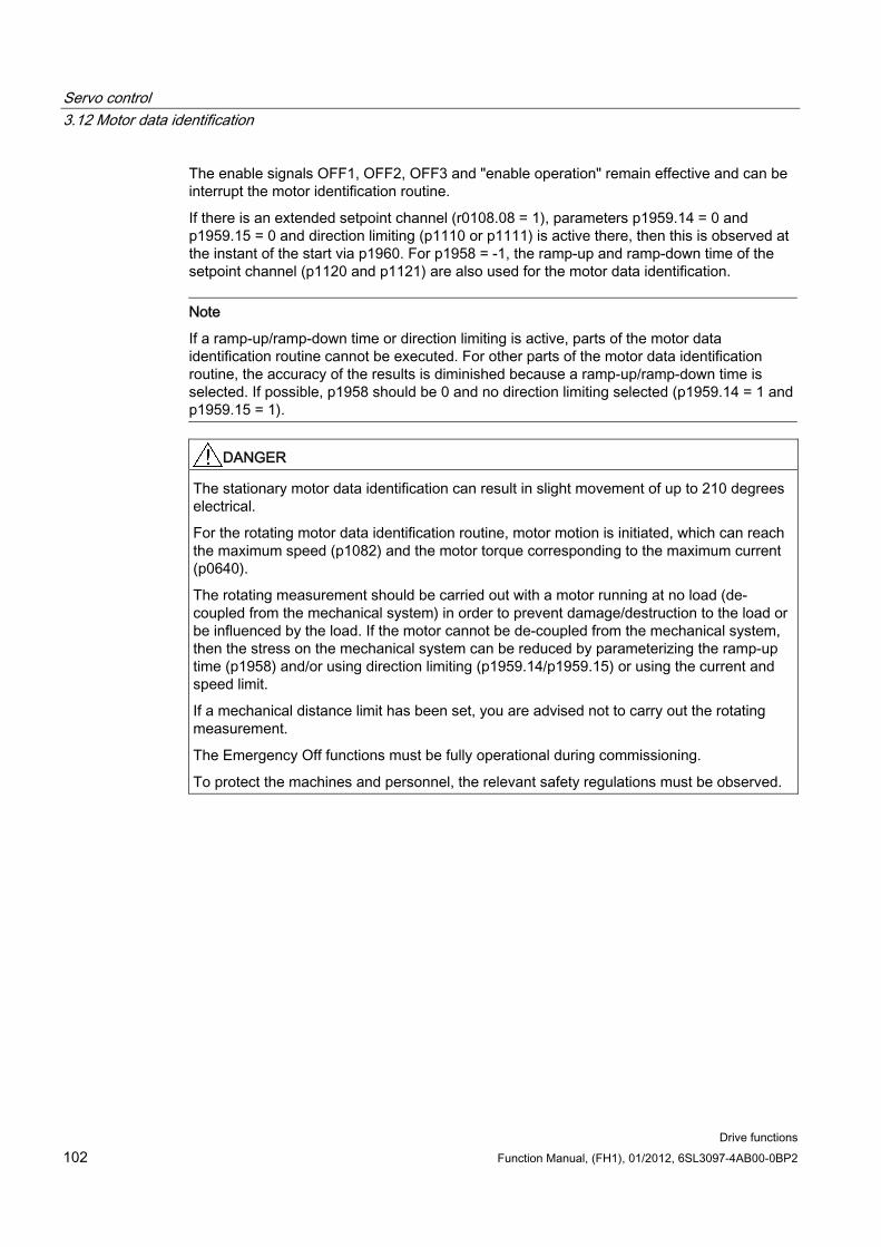
Servo control 3.12 Motor data identification
Drive functions 102 Function Manual, (FH1), 01/2012, 6SL3097-4AB00-0BP2
The enable signals OFF1, OFF2, OFF3 and "enable operation" remain effective and can be interrupt the motor identification routine.
If there is an extended setpoint channel (r0108.08 = 1), parameters p1959.14 = 0 and p1959.15 = 0 and direction limiting (p1110 or p1111) is active there, then this is observed at the instant of the start via p1960. For p1958 = -1, the ramp-up and ramp-down time of the setpoint channel (p1120 and p1121) are also used for the motor data identification.
Note
If a ramp-up/ramp-down time or direction limiting is active, parts of the motor data identification routine cannot be executed. For other parts of the motor data identification routine, the accuracy of the results is diminished because a ramp-up/ramp-down time is selected. If possible, p1958 should be 0 and no direction limiting selected (p1959.14 = 1 and p1959.15 = 1).
DANGER The stationary motor data identification can result in slight movement of up to 210 degrees electrical.
For the rotating motor data identification routine, motor motion is initiated, which can reach the maximum speed (p1082) and the motor torque corresponding to the maximum current (p0640).
The rotating measurement should be carried out with a motor running at no load (de-coupled from the mechanical system) in order to prevent damage/destruction to the load or be influenced by the load. If the motor cannot be de-coupled from the mechanical system, then the stress on the mechanical system can be reduced by parameterizing the ramp-up time (p1958) and/or using direction limiting (p1959.14/p1959.15) or using the current and speed limit.
If a mechanical distance limit has been set, you are advised not to carry out the rotating measurement.
The Emergency Off functions must be fully operational during commissioning.
To protect the machines and personnel, the relevant safety regulations must be observed.
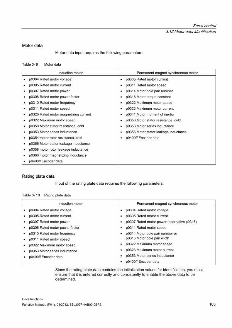
Servo control 3.12 Motor data identification
Drive functions Function Manual, (FH1), 01/2012, 6SL3097-4AB00-0BP2 103
Motor data Motor data input requires the following parameters:
Table 3- 9 Motor data
Induction motor Permanent-magnet synchronous motor
• p0304 Rated motor voltage • p0305 Rated motor current • p0307 Rated motor power • p0308 Rated motor power factor • p0310 Rated motor frequency • p0311 Rated motor speed • p0320 Rated motor magnetizing current • p0322 Maximum motor speed • p0350 Motor stator resistance, cold • p0353 Motor series inductance • p0354 motor rotor resistance, cold • p0356 Motor stator leakage inductance • p0358 motor rotor leakage inductance • p0360 motor magnetizing inductance • p0400ff Encoder data
• p0305 Rated motor current • p0311 Rated motor speed • p0314 Motor pole pair number • p0316 Motor torque constant • p0322 Maximum motor speed • p0323 Maximum motor current • p0341 Motor moment of inertia • p0350 Motor stator resistance, cold • p0353 Motor series inductance • p0356 Motor stator leakage inductance • p0400ff Encoder data
Rating plate data Input of the rating plate data requires the following parameters:
Table 3- 10 Rating plate data
Induction motor Permanent-magnet synchronous motor
• p0304 Rated motor voltage • p0305 Rated motor current • p0307 Rated motor power • p0308 Rated motor power factor • p0310 Rated motor frequency • p0311 Rated motor speed • p0322 Maximum motor speed • p0353 Motor series inductance • p0400ff Encoder data
• p0304 Rated motor voltage • p0305 Rated motor current • p0307 Rated motor power (alternative p0316) • p0311 Rated motor speed • p0314 Motor pole pair number or
p0315 Motor pole pair width • p0322 Maximum motor speed • p0323 Maximum motor current • p0353 Motor series inductance • p0400ff Encoder data
Since the rating plate data contains the initialization values for identification, you must ensure that it is entered correctly and consistently to enable the above data to be determined.

Servo control 3.12 Motor data identification
Drive functions 104 Function Manual, (FH1), 01/2012, 6SL3097-4AB00-0BP2
Parameters to control the motor data identification The following parameters influence the motor data identification:
Table 3- 11 Parameters for control
Static measurement (motor data identification) Rotating measurement
• p0640 current limit • p1215 Motor holding brake configuration • p1909 Motor data identification control word • p1910 Motor data identification, stationary • p1959.14/.15 Positive/negative direction permitted*
• p0640 current limit • p1082 Maximum speed • p1958 motor data identification ramp-up/ramp-down time• p1959 Rotating measurement configuration • p1960 Rotating measurement selection
Note: If a brake is being used and is operational (p1215 = 1, 3), then the stationary measurement with closed brake is carried out. If possible (e.g. no hanging/suspended axis), we recommend that the brake is opened before the motor data identification (p1215 = 2). This also means that the encoder size can be adjusted and the angular commutation calibrated.
* The p1959 setting has the following effects on the rotational direction parameter p1821: Positive direction permitted, with setting p1821= 0 means: Clockwise direction of rotation Negative direction permitted, with setting p1821=1 means: Counter-clockwise direction of rotation
3.12.1 Motor data identification induction motor The data are identified in the gamma equivalent circuit diagram and displayed in r19xx. The motor parameters p0350, p0354, p0356, p0358 and p0360 taken from the motor data identification refer to the T equivalent circuit diagram of the induction machine and cannot be directly compared. This is the reason that an r parameter is listed in the table, which displays the parameterized motor parameters in the gamma equivalent circuit diagram.
Table 3- 12 Data determined using p1910 for induction motors (stationary measurement)
Determined data (gamma) Data that are accepted (p1910 = 1) r1912 identified stator resistance p0350 motor stator resistance, cold
+ p0352 cable resistance r1913 rotor time constant identified r0384
motor rotor time constant/damping time constant, d axis r1915 stator inductance identified - r1925 threshold voltage identified - r1927 rotor resistance identified r0374 motor resistance cold (gamma)
p0354 r1932 d inductance r0377 motor leakage inductance, total (gamma)
p0353 motor series inductance p0356 motor leakage inductance p0358 motor leakage inductance p1715 current controller P gain p1717 current controller integral action time
r1934 q inductance identified -
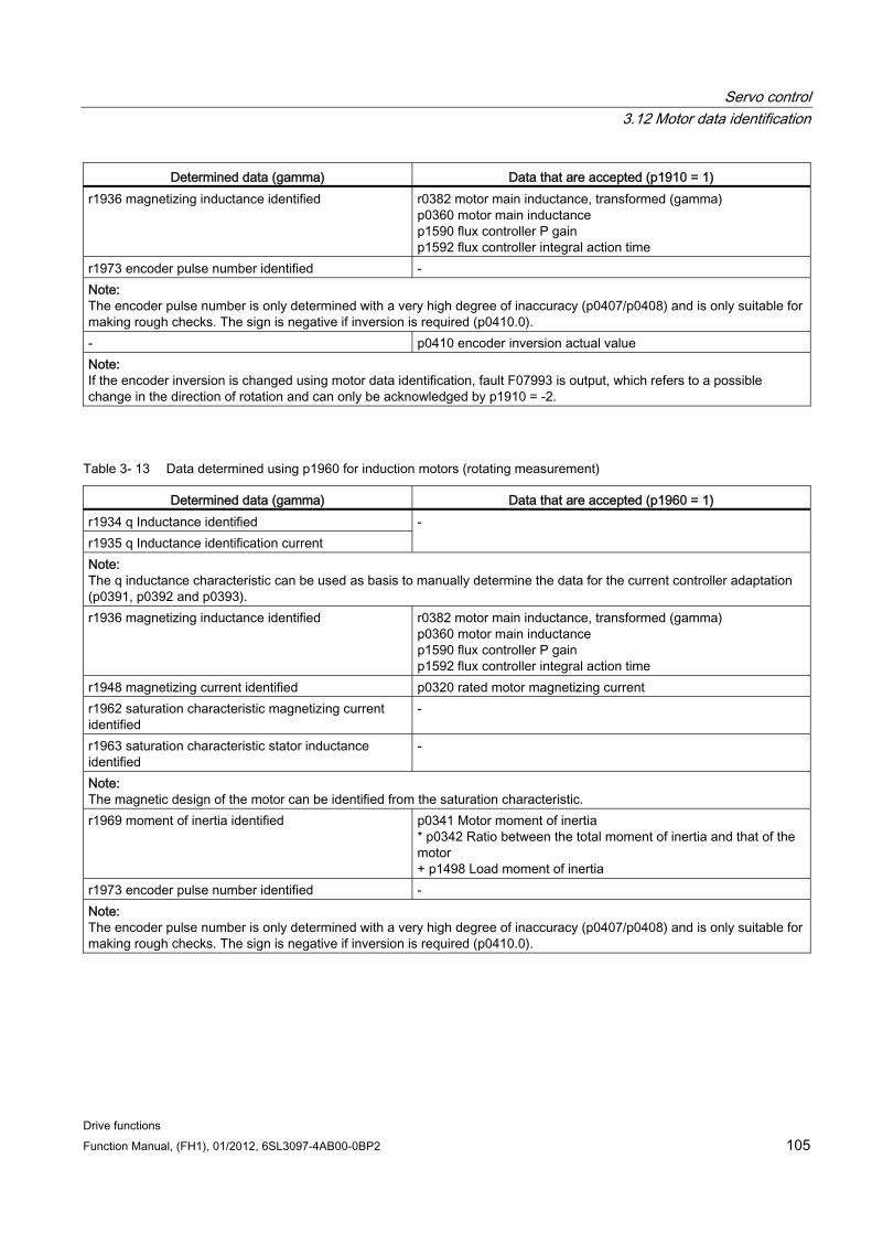
Servo control 3.12 Motor data identification
Drive functions Function Manual, (FH1), 01/2012, 6SL3097-4AB00-0BP2 105
Determined data (gamma) Data that are accepted (p1910 = 1) r1936 magnetizing inductance identified r0382 motor main inductance, transformed (gamma)
p0360 motor main inductance p1590 flux controller P gain p1592 flux controller integral action time
r1973 encoder pulse number identified - Note: The encoder pulse number is only determined with a very high degree of inaccuracy (p0407/p0408) and is only suitable for making rough checks. The sign is negative if inversion is required (p0410.0). - p0410 encoder inversion actual value Note: If the encoder inversion is changed using motor data identification, fault F07993 is output, which refers to a possible change in the direction of rotation and can only be acknowledged by p1910 = -2.
Table 3- 13 Data determined using p1960 for induction motors (rotating measurement)
Determined data (gamma) Data that are accepted (p1960 = 1) r1934 q Inductance identified r1935 q Inductance identification current
-
Note: The q inductance characteristic can be used as basis to manually determine the data for the current controller adaptation (p0391, p0392 and p0393). r1936 magnetizing inductance identified r0382 motor main inductance, transformed (gamma)
p0360 motor main inductance p1590 flux controller P gain p1592 flux controller integral action time
r1948 magnetizing current identified p0320 rated motor magnetizing current r1962 saturation characteristic magnetizing current identified
-
r1963 saturation characteristic stator inductance identified
-
Note: The magnetic design of the motor can be identified from the saturation characteristic. r1969 moment of inertia identified p0341 Motor moment of inertia
* p0342 Ratio between the total moment of inertia and that of the motor + p1498 Load moment of inertia
r1973 encoder pulse number identified - Note: The encoder pulse number is only determined with a very high degree of inaccuracy (p0407/p0408) and is only suitable for making rough checks. The sign is negative if inversion is required (p0410.0).
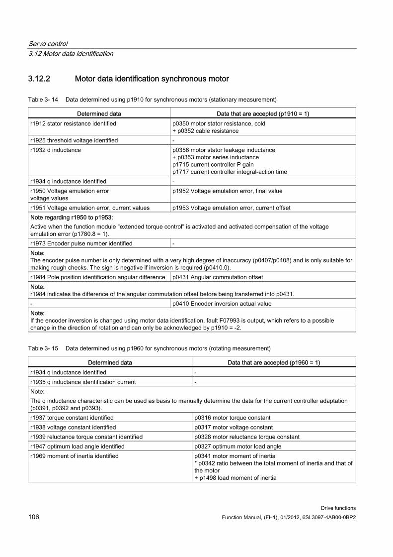
Servo control 3.12 Motor data identification
Drive functions 106 Function Manual, (FH1), 01/2012, 6SL3097-4AB00-0BP2
3.12.2 Motor data identification synchronous motor
Table 3- 14 Data determined using p1910 for synchronous motors (stationary measurement)
Determined data Data that are accepted (p1910 = 1) r1912 stator resistance identified p0350 motor stator resistance, cold
+ p0352 cable resistance r1925 threshold voltage identified - r1932 d inductance p0356 motor stator leakage inductance
+ p0353 motor series inductance p1715 current controller P gain p1717 current controller integral-action time
r1934 q inductance identified - r1950 Voltage emulation error voltage values
p1952 Voltage emulation error, final value
r1951 Voltage emulation error, current values p1953 Voltage emulation error, current offset Note regarding r1950 to p1953: Active when the function module "extended torque control" is activated and activated compensation of the voltage emulation error (p1780.8 = 1). r1973 Encoder pulse number identified - Note: The encoder pulse number is only determined with a very high degree of inaccuracy (p0407/p0408) and is only suitable for making rough checks. The sign is negative if inversion is required (p0410.0). r1984 Pole position identification angular difference p0431 Angular commutation offset Note: r1984 indicates the difference of the angular commutation offset before being transferred into p0431. - p0410 Encoder inversion actual value Note: If the encoder inversion is changed using motor data identification, fault F07993 is output, which refers to a possible change in the direction of rotation and can only be acknowledged by p1910 = -2.
Table 3- 15 Data determined using p1960 for synchronous motors (rotating measurement)
Determined data Data that are accepted (p1960 = 1) r1934 q inductance identified - r1935 q inductance identification current - Note: The q inductance characteristic can be used as basis to manually determine the data for the current controller adaptation (p0391, p0392 and p0393). r1937 torque constant identified p0316 motor torque constant r1938 voltage constant identified p0317 motor voltage constant r1939 reluctance torque constant identified p0328 motor reluctance torque constant r1947 optimum load angle identified p0327 optimum motor load angle r1969 moment of inertia identified p0341 motor moment of inertia
* p0342 ratio between the total moment of inertia and that of the motor + p1498 load moment of inertia
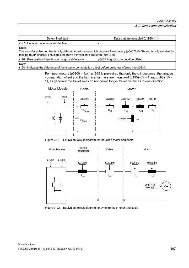
Servo control 3.12 Motor data identification
Drive functions Function Manual, (FH1), 01/2012, 6SL3097-4AB00-0BP2 107
Determined data Data that are accepted (p1960 = 1) r1973 Encoder pulse number identified - Note: The encoder pulse number is only determined with a very high degree of inaccuracy (p0407/p0408) and is only suitable for making rough checks. The sign is negative if inversion is required (p0410.0). r1984 Pole position identification angular difference p0431 Angular commutation offset Note: r1984 indicates the difference of the angular commutation offset before being transferred into p0431.
For linear motors (p0300 = 4xx), p1959 is pre-set so that only the q inductance, the angular commutation offset and the high inertia mass are measured (p1959.05 = 1 and p1959.10 = 1), as generally the travel limits do not permit longer travel distances in one direction.
Figure 3-21 Equivalent circuit diagram for induction motor and cable
Figure 3-22 Equivalent circuit diagram for synchronous motor and cable
Servo control 3.13 Pole position identification
Drive functions 108 Function Manual, (FH1), 01/2012, 6SL3097-4AB00-0BP2
Overview of important parameters (see SINAMICS S120/S150 List Manual) r0047 Status identification
Standstill measurement
p1909[0...n] Motor data identification control word
p1910 Motor data identification, stationary
Rotating measurement
p1958[0...n] Rotating measurement ramp-up/ramp-down time
p1959[0...n] Rotating measurement configuration
p1960 Rotating measurement selection
3.13 Pole position identification For synchronous motors, the pole position identification determines its electrical pole position, that is required for the field-oriented control. Generally, the electrical pole position is provided from a mechanically adjusted encoder with absolute information.
A one-off pole position identification run is required for motors with encoders that are either not calibrated or have not been adjusted.
Select a technique using p1980
Start the one-off pole position identification by setting p1990 = 1, the value in p1982 is not taken into consideration.
For Siemens 1FN1, 1FN3 and 1FN6 linear motors, p1990 is automatically set to 1 after commissioning or after an encoder has been replaced.
For the following encoder properties, pole position identification is not required:
Absolute encoder (e.g. EnDat, DRIVE-CLiQ encoder)
Encoder with C/D track and pole pair number ≤ 8
Hall sensor
Resolver with a multiple integer ratio between the motor pole pair number and the encoder pole pair number
Incremental encoder with a multiple integer ratio between the motor pole pair number and the encoder pulse number
The pole position identification is used for:
Determining the pole position (p1982 = 1)
Determining the angular commutation offset during commissioning (p1990 = 1)
Plausibility check for encoders with absolute information (p1982 = 2)
Servo control 3.13 Pole position identification
Drive functions Function Manual, (FH1), 01/2012, 6SL3097-4AB00-0BP2 109
WARNING When the motors are not braked, the motor rotates or moves as a result of the current impressed during the measurement. The magnitude of the motion depends on the magnitude of the current and the moment of inertia of the motor and load.
Note Siemens standard motors
When using standard Siemens motors, the automatically pre-selected setting should be kept.
Notes regarding pole position identification The relevant technique can be selected using parameter P1980. The following techniques are available for pole position identification:
Saturation-based 1st + 2nd harmonics (p1980 = 0)
Saturation-based 1st harmonic (p1980 = 1)
Saturation-based, two-stage (p1980 = 4)
Motion-based (p1980 = 10)
Elasticity-based (p1980 = 20)
The following supplementary conditions apply to the saturation-based motion technique:
This technique can be used for both braked and non-braked motors.
It can only be used for a speed setpoint = 0 or from standstill.
The specified current magnitudes (p0325, p0329) must be sufficient to provide a significant measuring result.
For motors without iron, the pole position cannot be identified using the saturation-based technique.
For 1FN3 motors, it is not permissible to traverse with the 2nd harmonic (p1980 = 0, 4).
With 1FK7 motors, a two-stage procedure must not be used (p1980 = 4). The value in p0329, which is set automatically, must not be reduced.
For the motion-based technique, the following supplementary conditions apply:
The motor must be free to move and it may not be subject to external forces (no hanging/suspended axes).
It can only be used for a speed setpoint = 0 or from standstill.
If there is a motor brake, then this must be open (p1215 = 2).
The specified current magnitude (p1993) must move the motor by a sufficient amount.
For the elasticity-based technique, the following supplementary conditions apply:
Servo control 3.13 Pole position identification
Drive functions 110 Function Manual, (FH1), 01/2012, 6SL3097-4AB00-0BP2
A brake must be available and must also be closed during the pole position identification. Either the drive controls the brake (p1215 = 1 or 3) or the brake is externally closed well in advance of the start of the pole position identification and is re-opened after the operation has been completed.
Parameters p3090 to p3096 must be correctly set for a successful pole position identification.
The specified current magnitude (p3096) must deflect the motor by a sufficient amount.
The ratio between the sign of the deflection and the force/torque must be taken into account in p3090.0.
WARNING Before using the pole position identification routine, the control sense of the speed control loop must be corrected (p0410.0).
For linear motors, see SINAMICS S120 Commissioning Manual (IH1).
For rotating motors, in encoderless operation with a small positive speed setpoint (e.g. 10 rpm), the speed actual value (r0061) and the speed setpoint (r1438) must have the same sign.
CAUTION If more than one 1FN3 linear motor is using saturation-based pole position identification for commutation (p1980 ≤ 4 and p1982 = 1), this can reduce accuracy when the commutation angle is determined. If a high level of accuracy is essential, (e.g. when p0404.15 = 0 or to determine the offset of the commutation angle using p1990 = 1), the pole position identification runs should be carried out consecutively. This can be achieved by staggering the time at which the individual drives are enabled.
Pole position correction with zero marks The pole position identification routine provides coarse synchronization. If zero marks exist, the pole position can be automatically compared with the zero mark position once the zero mark(s) have been passed (fine synchronization). The zero mark position must be either mechanically or electrically (p0431) calibrated. If the encoder system permits this, then we recommend fine synchronization (p0404.15 = 1). This is because it avoids measurement spread and allows the determined pole position to be additionally checked.
Suitable zero marks One zero mark in the complete traversing range
Equidistant zero marks
Distance-coded zero marks
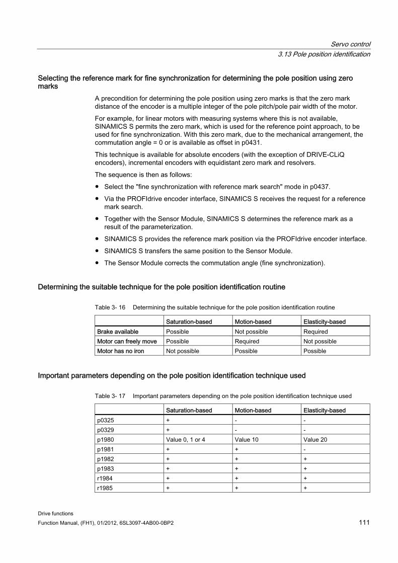
Servo control 3.13 Pole position identification
Drive functions Function Manual, (FH1), 01/2012, 6SL3097-4AB00-0BP2 111
Selecting the reference mark for fine synchronization for determining the pole position using zero marks
A precondition for determining the pole position using zero marks is that the zero mark distance of the encoder is a multiple integer of the pole pitch/pole pair width of the motor.
For example, for linear motors with measuring systems where this is not available, SINAMICS S permits the zero mark, which is used for the reference point approach, to be used for fine synchronization. With this zero mark, due to the mechanical arrangement, the commutation angle = 0 or is available as offset in p0431.
This technique is available for absolute encoders (with the exception of DRIVE-CLiQ encoders), incremental encoders with equidistant zero mark and resolvers.
The sequence is then as follows:
Select the "fine synchronization with reference mark search" mode in p0437.
Via the PROFIdrive encoder interface, SINAMICS S receives the request for a reference mark search.
Together with the Sensor Module, SINAMICS S determines the reference mark as a result of the parameterization.
SINAMICS S provides the reference mark position via the PROFIdrive encoder interface.
SINAMICS S transfers the same position to the Sensor Module.
The Sensor Module corrects the commutation angle (fine synchronization).
Determining the suitable technique for the pole position identification routine
Table 3- 16 Determining the suitable technique for the pole position identification routine
Saturation-based Motion-based Elasticity-based Brake available Possible Not possible Required Motor can freely move Possible Required Not possible Motor has no iron Not possible Possible Possible
Important parameters depending on the pole position identification technique used
Table 3- 17 Important parameters depending on the pole position identification technique used
Saturation-based Motion-based Elasticity-based p0325 + - - p0329 + - - p1980 Value 0, 1 or 4 Value 10 Value 20 p1981 + + - p1982 + + + p1983 + + + r1984 + + + r1985 + + +
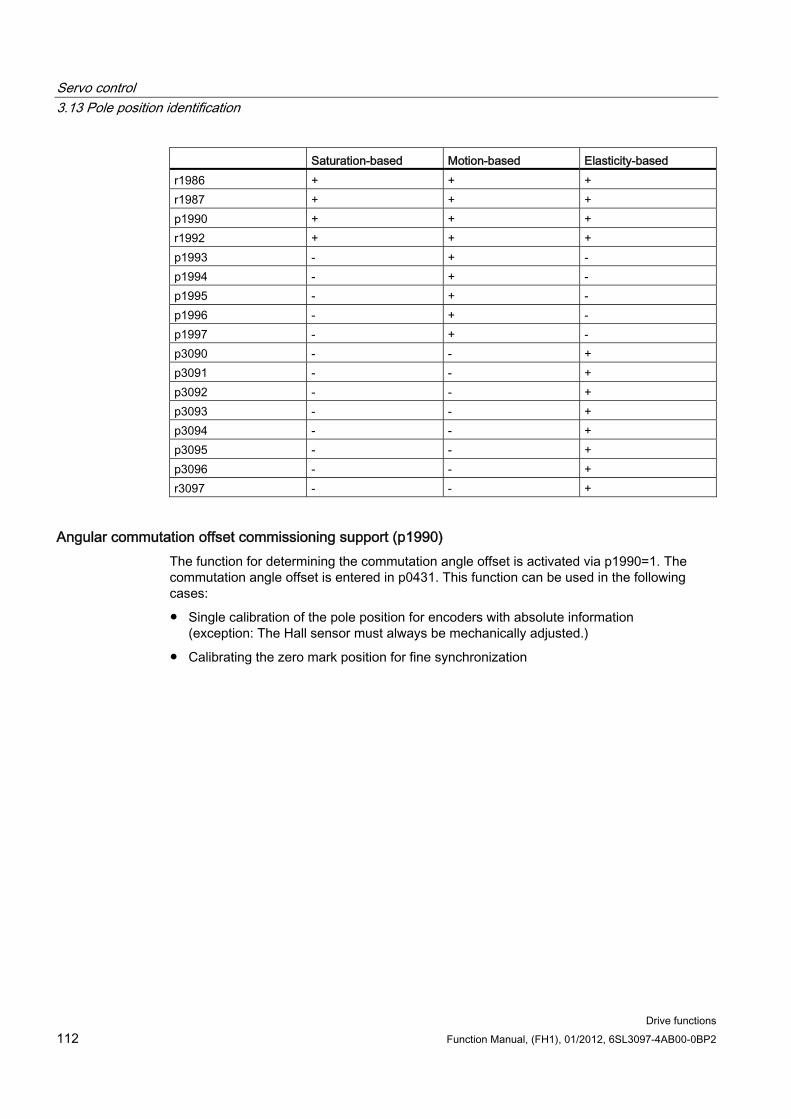
Servo control 3.13 Pole position identification
Drive functions 112 Function Manual, (FH1), 01/2012, 6SL3097-4AB00-0BP2
Saturation-based Motion-based Elasticity-based r1986 + + + r1987 + + + p1990 + + + r1992 + + + p1993 - + - p1994 - + - p1995 - + - p1996 - + - p1997 - + - p3090 - - + p3091 - - + p3092 - - + p3093 - - + p3094 - - + p3095 - - + p3096 - - + r3097 - - +
Angular commutation offset commissioning support (p1990) The function for determining the commutation angle offset is activated via p1990=1. The commutation angle offset is entered in p0431. This function can be used in the following cases:
Single calibration of the pole position for encoders with absolute information (exception: The Hall sensor must always be mechanically adjusted.)
Calibrating the zero mark position for fine synchronization
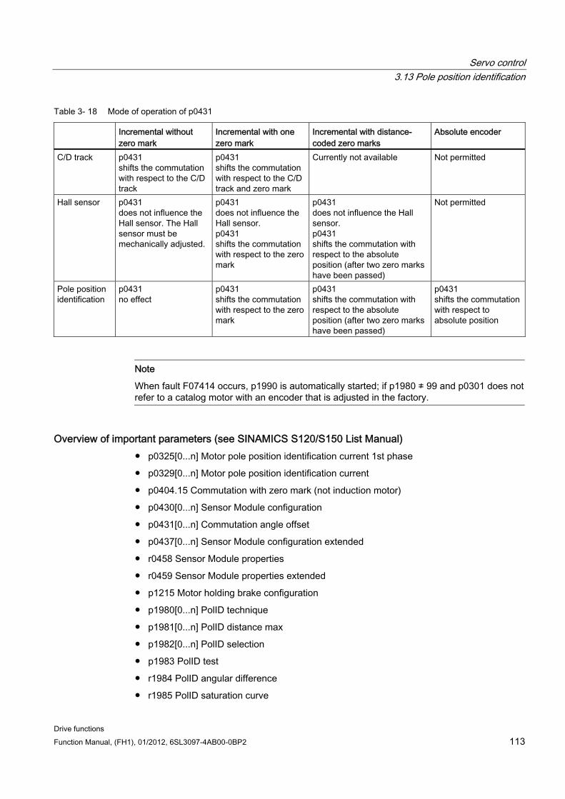
Servo control 3.13 Pole position identification
Drive functions Function Manual, (FH1), 01/2012, 6SL3097-4AB00-0BP2 113
Table 3- 18 Mode of operation of p0431
Incremental without zero mark
Incremental with one zero mark
Incremental with distance-coded zero marks
Absolute encoder
C/D track p0431 shifts the commutation with respect to the C/D track
p0431 shifts the commutation with respect to the C/D track and zero mark
Currently not available Not permitted
Hall sensor p0431 does not influence the Hall sensor. The Hall sensor must be mechanically adjusted.
p0431 does not influence the Hall sensor. p0431 shifts the commutation with respect to the zero mark
p0431 does not influence the Hall sensor. p0431 shifts the commutation with respect to the absolute position (after two zero marks have been passed)
Not permitted
Pole position identification
p0431 no effect
p0431 shifts the commutation with respect to the zero mark
p0431 shifts the commutation with respect to the absolute position (after two zero marks have been passed)
p0431 shifts the commutation with respect to absolute position
Note
When fault F07414 occurs, p1990 is automatically started; if p1980 ≠ 99 and p0301 does not refer to a catalog motor with an encoder that is adjusted in the factory.
Overview of important parameters (see SINAMICS S120/S150 List Manual) p0325[0...n] Motor pole position identification current 1st phase
p0329[0...n] Motor pole position identification current
p0404.15 Commutation with zero mark (not induction motor)
p0430[0...n] Sensor Module configuration
p0431[0...n] Commutation angle offset
p0437[0...n] Sensor Module configuration extended
r0458 Sensor Module properties
r0459 Sensor Module properties extended
p1215 Motor holding brake configuration
p1980[0...n] PolID technique
p1981[0...n] PolID distance max
p1982[0...n] PolID selection
p1983 PolID test
r1984 PolID angular difference
r1985 PolID saturation curve
Servo control 3.14 Vdc control
Drive functions 114 Function Manual, (FH1), 01/2012, 6SL3097-4AB00-0BP2
r1986 PolID saturation curve 2
r1987 PolID trigger curve
p1990 Determine encoder adjustment commutation angle offset
p1991[0...n] Motor changeover commutation angle correction
r1992 Pole ID diagnostics
p1993[0...n] Pole ID current, motion based
p1994[0...n] Pole ID rise time, motion based
p1995[0...n] Pole ID gain, motion based
p1996[0...n] Pole ID integral time, motion based
p1997[0...n] Pole ID smoothing time, motion based
p3090[0...n] Pole ID elasticity-based configuration
p3091[0...n] Pole ID elasticity-based ramp time
p3092[0...n] Pole ID elasticity-based wait time
p3093[0...n] Pole ID elasticity-based measuring operation number
p3094[0...n] Pole ID elasticity-based deflection expected
p3095[0...n] Pole ID elasticity-based deflection permissible
p3096[0...n] Pole ID elasticity-based current
r3097.0...31 BO: Pole ID elasticity-based status
3.14 Vdc control
Description The Vdc control monitors the DC voltage in the DC link for overvoltage and undervoltage. If an overvoltage or undervoltage is identified in the DC link line-up, a subsequent response can be set with the Vdc control via p1240.
The torque limits of the motors for which the Vdc controller is active can be affected if discrepancies in the DC link voltage are significant enough. The motors may no longer be able to maintain their setpoint speed or the acceleration/braking phases are prolonged.
In a drive line-up, one or more drives can be used to relieve or support the DC link. This allows a fault due to an unfavorable DC link voltage to be avoided. The drives remain ready for operation.
Generally, a maximum motoring power pmot of the Motor Module from the DC link is given by
Pmot = VDC, actual value x (VDC, actual value - p1248) x p1250
Correspondingly, a maximum regenerative feedback power Pgen of the Motor Module into the DC link of
Pgen = VDC, actual value x (p1244 - VDC, actual value) x p1250 is obtained
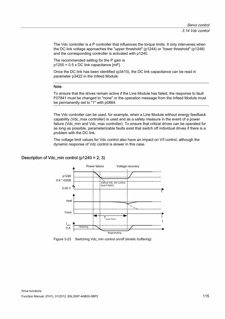
Servo control 3.14 Vdc control
Drive functions Function Manual, (FH1), 01/2012, 6SL3097-4AB00-0BP2 115
The Vdc controller is a P controller that influences the torque limits. It only intervenes when the DC link voltage approaches the "upper threshold" (p1244) or "lower threshold" (p1248) and the corresponding controller is activated with p1240.
The recommended setting for the P gain is p1250 = 0.5 x DC link capacitance [mF].
Once the DC link has been identified (p3410), the DC link capacitance can be read in parameter p3422 in the Infeed Module.
Note
To ensure that the drives remain active if the Line Module has failed, the response to fault F07841 must be changed to "none" or the operation message from the Infeed Module must be permanently set to "1" with p0864.
The Vdc controller can be used, for example, when a Line Module without energy feedback capability (Vdc_max controller) is used and as a safety measure in the event of a power failure (Vdc_min and Vdc_max controller). To ensure that critical drives can be operated for as long as possible, parameterizable faults exist that switch off individual drives if there is a problem with the DC link.
The voltage limit values for Vdc control also have an impact on V/f control, although the dynamic response of Vdc control is slower in this case.
Description of Vdc_min control (p1240 = 2, 3)
Figure 3-23 Switching Vdc_min control on/off (kinetic buffering)
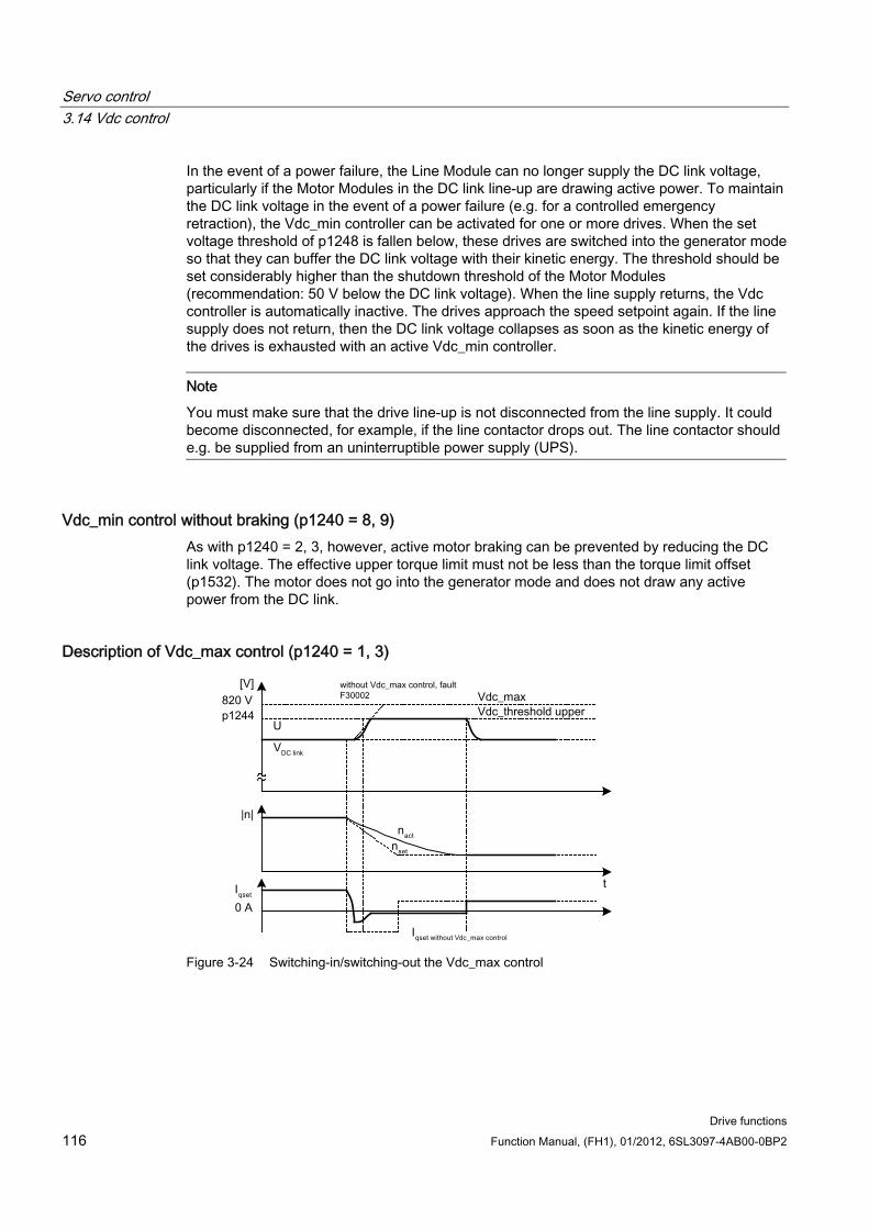
Servo control 3.14 Vdc control
Drive functions 116 Function Manual, (FH1), 01/2012, 6SL3097-4AB00-0BP2
In the event of a power failure, the Line Module can no longer supply the DC link voltage, particularly if the Motor Modules in the DC link line-up are drawing active power. To maintain the DC link voltage in the event of a power failure (e.g. for a controlled emergency retraction), the Vdc_min controller can be activated for one or more drives. When the set voltage threshold of p1248 is fallen below, these drives are switched into the generator mode so that they can buffer the DC link voltage with their kinetic energy. The threshold should be set considerably higher than the shutdown threshold of the Motor Modules (recommendation: 50 V below the DC link voltage). When the line supply returns, the Vdc controller is automatically inactive. The drives approach the speed setpoint again. If the line supply does not return, then the DC link voltage collapses as soon as the kinetic energy of the drives is exhausted with an active Vdc_min controller.
Note
You must make sure that the drive line-up is not disconnected from the line supply. It could become disconnected, for example, if the line contactor drops out. The line contactor should e.g. be supplied from an uninterruptible power supply (UPS).
Vdc_min control without braking (p1240 = 8, 9) As with p1240 = 2, 3, however, active motor braking can be prevented by reducing the DC link voltage. The effective upper torque limit must not be less than the torque limit offset (p1532). The motor does not go into the generator mode and does not draw any active power from the DC link.
Description of Vdc_max control (p1240 = 1, 3)
Figure 3-24 Switching-in/switching-out the Vdc_max control
Servo control 3.14 Vdc control
Drive functions Function Manual, (FH1), 01/2012, 6SL3097-4AB00-0BP2 117
With Infeed Modules without feedback or in the event of a power failure, the DC link voltage can increase until it reaches the shutdown threshold when drives in the DC link line-up are decelerated. To prevent the system from shutting down due to a DC link overvoltage, the Vdc_max controller can be activated for one or more drives. The Vdc_max controller is normally activated for drives that have to decelerate/accelerate high levels of kinetic energy themselves. When the overvoltage threshold in p1244 is reached (recommended setting: 50 V higher than the DC link voltage), the braking torque of the drives with an active Vdc_max controller is reduced by shifting the torque limit. These drives feed back exactly the same amount of energy, that is drawn as a result of losses or loads in the DC link. This function minimizes the braking time.
Note
If other drives in the drive line-up, where the Vdc_max controller is not active, feed energy back, the drives with an active Vdc_max controller can even be accelerated to absorb the braking energy and, in turn, relieve the DC link.
Description of Vdc_max control without acceleration (p1240 = 7, 9) As with p1240 = 1, 3, if the drive must not be accelerated by means of feedback from other drives in the DC link, acceleration can be prevented by the setting p1240 = 7, 9. The effective lower torque limit must not be greater than the torque limit offset (p1532).
Description of Vdc controller monitoring functions (p1240 = 4, 5, 6) In the event of a power failure, the Line Module can no longer supply the DC link voltage, particularly if the Motor Modules in the DC link line-up are drawing active power. To ensure that the DC link voltage is not burdened with uncritical drives in the event of a power failure, these drives can be switched off by a fault (F30003) with a parameterizable voltage threshold (p1248). This is carried out by activating the Vdc_min monitoring function (p1240 = 5, 6).
In the event of a power failure, the DC link voltage can increase until it reaches the shutdown threshold when drives are decelerated. To ensure that the DC link voltage is not loaded with uncritical drives in the event of a power failure, these drives can be switched off with fault F30002 with a parameterizable voltage threshold in p1244. This is carried out by activating the Vdc_max monitoring function (p1240 = 4, 6).
Function diagrams (see SINAMICS S120/S150 List Manual) 5650 Vdc_max controller and Vdc_min controller
5300 V/f control
Overview of important parameters (see SINAMICS S120/S150 List Manual) r0056.14 CO/BO: Status word, closed loop control: Vdc_max controller active
r0056.15 CO/BO: Status word, closed loop control: Vdc_min controller active
p1240[0...n] Vdc controller or Vdc monitoring configuration
Servo control 3.15 Dynamic Servo Control (DSC)
Drive functions 118 Function Manual, (FH1), 01/2012, 6SL3097-4AB00-0BP2
p1244[0...n] DC link voltage threshold, upper
p1248[0...n] DC link voltage threshold, lower
p1250[0...n] Vdc controller proportional gain
3.15 Dynamic Servo Control (DSC) The function Dynamic Servo Control" (DSC) is a closed-loop control structure which is computed in a fast speed controller clock cycle and is supplied with setpoints by the control in the position controller clock cycle.
This allows higher position controller gain factors to be achieved.
If the drive reaches its torque limits when in the DSC mode, e.g. because of excessively fast setpoint inputs, then positioning motion can be overshot. With this so-called wind-up effect, the drive overshoots the specified target, the control enters a specific correction, the drive reverses, again overshoots the target, etc. In order to avoid this behavior, the drive limits the position controller to values, which the drive can always reliably maintain depending on the acceleration capability. Set p1400.17 = 1 in order to activate dynamic setpoint limiting in the DSC mode. In this case, the total weight (mtot) must be precisely parameterizing (determine the weight p0341, p0342 and p1498 possibly using the mot ID). If the limiting responds then this is indicated in r1407.19. On this topic, also observe the description of parameter p1400.17 and function diagram 3090.
Preconditions The following prerequisites are necessary to use the "Dynamic Servo Control" function:
n-set mode
Isochronous PROFIBUS DP or PROFINET IO with IRT
The position controller gain factor (KPC) and the position deviation (XERR) must be included in the setpoint telegram of PROFIBUS DP or PROFINET IO with IRT (refer to P0915).
The position actual value must be transferred to the master in the actual value telegram of PROFIBUS DP or PROFINET IO with IRT via the encoder interface Gx_XIST1.
When DSC is activated, the speed setpoint N_SOLL_B from the PROFIdrive telegram from PROFIBUS DP or PROFINET IO with IRT is used as a speed pre-control value.
The internal quasi position controller, DSC position controller (FP5030), use the position actual value G1_XIST1 from the motor measuring system or the position actual value from an additional encoder system (telegrams 6, 106, 116, 118, 136 and 138 or free telegrams).
The following PROFIdrive telegrams support DSC:
Standard telegrams 5 and 6
SIEMENS telegrams 105, 106, 116, 118, 125, 126, 136, 138, 139
Servo control 3.15 Dynamic Servo Control (DSC)
Drive functions Function Manual, (FH1), 01/2012, 6SL3097-4AB00-0BP2 119
Further PZD data telegram types can be used with the telegram extension. It must then be ensured that SERVO supports a maximum of 20 PZD setpoints and 28 PZD actual values.
Note
Synchronization is required on the control side and on the drive side for the operation of DSC.
A detailed description of the DSC mode of operation is provided in function diagram 3090 (see SINAMICS S120/S150 List Manual).
Reducing the number of drives Dynamic Servo Control results in an additional utilization for the Control Unit. This reduces the maximum possible number of drives to
Five drives with a current controller cycle of 125 µs
Two drives with a current controller cycle of 62.5 µs.
Operating states The following operating states are possible for DSC (for details, see SINAMICS S120/S150 List Manual, function diagram 3090):
Operating state for DSC Meaning Speed/torque precontrol with linear interpolation
As a result of the step-like torque precontrol in the position controller clock cycle, a pulsed torque characteristic is obtained with the excitation clock cycle.
Speed precontrol with splines1) • The position setpoint is made symmetrical. • The speed precontrol value is not made symmetrical.
Speed/torque precontrol with splines1)
• The position setpoint is made symmetrical. • The speed precontrol value is made symmetrical. 2) • The torque precontrol value is not made symmetrical.
1) The following improvements are achieved as a result of spline interpolation: • A finer interpolation of the torque in the speed controller clock cycle and therefore softer motion;
torque surges are also avoided. • For torque-speed precontrol:
Extremely high path accuracy (i.e. lower following error in the control behavior). • High-frequency path motion is possible 2) For active symmetrization (T_SYMM > 0), using p1427 you can set an additive symmetrizing time constant T_SYMM_ADD to symmetrizing the speed precontrol value when torque precontrol is active. In this case, the speed precontrol value is symmetrized with the sum of the following time constants: T_SYMM (see p1195) + T_SYMM_ADD (p1427) + 0.5 × T_speed controller cycle (p0115[1]) In this case, speed generation is automatically taken into account using position differences with half a speed controller cycle.
Servo control 3.15 Dynamic Servo Control (DSC)
Drive functions 120 Function Manual, (FH1), 01/2012, 6SL3097-4AB00-0BP2
Activation If the preconditions for dynamic servo control are fulfilled, then the DSC structure is activated using a logical interconnection of the following parameters via a selected PROFIdrive telegram:
p1190 "DSC position deviation XERR"
p1191 "DSC position controller gain KPC"
p1194 "CI: DSC control word DSC_STW"
p1195 "CI: DSC Symmetrizing time constant T_SYMM"
p1430 "CI: Speed precontrol"
If KPC = 0 is transferred, only speed control with the speed precontrol values can be used (p1430, PROFIdrive N_SOLL_B and p1160 n_set_2). Position controlled operation requires a transfer of KPC > 0.
When dynamic servo control is activated, you check the position controller gain KPC in the master. It may be necessary to correct the setting.
Note KPC when DSC is activated
After activating dynamic servo control, check the position controller gain KPC in the master. It may be necessary to correct the setting.
Channel p1155 for speed setpoint 1, as well as channel r1119 for the extended setpoint, are disconnected when DSC is active.
When DSC is activated, p1160 for speed setpoint 2 and p1430 for the speed precontrol are added to the speed setpoint from the DSC, see function diagram 5030.
Deactivation If the interconnection is removed at the connector input for KPC or XERR (p1191 = 0 or p1190 = 0), the DSC structure is dissolved and the "DSC" function" deactivated. The sum from r1119 and p1155 is then added to the values from p1160 and p1430 from the speed pre-control.
Since it is possible to set higher gain factors using DSC, the control loop can become unstable when DSC is disabled. For this reason, before deselecting DSC, the value for KPC in the master must be reduced.
Speed setpoint filter A speed setpoint filter for smoothing the speed setpoint steps is not required when DSC is active.
When using the "DSC" function, it only makes sense to use speed setpoint filter 1 to support the position controller, e.g. to suppress resonance effects.
Servo control 3.15 Dynamic Servo Control (DSC)
Drive functions Function Manual, (FH1), 01/2012, 6SL3097-4AB00-0BP2 121
External encoder systems (except motor encoder) If, with DSC active, an external encoder is to be used, this requires the selection of a telegram with additional encoder actual values: Telegram 6,106,116,118,138 or free telegrams.
For optimum control in the DSC mode, the same encoder(s) (encoder 2 and/or encoder 3) must be selected for the control (master) and the drive via parameter p1192 "DSC encoder selection".
Since the motor encoder (encoder 1) is no longer used in this case, the adaptation factor for the conversion of the selected encoder system into the motor encoder system is determined using parameter p1193 "DCS encoder adaptation factor". The factor represents the ratio of the pulse difference between the motor encoder and the used encoder for the same reference distance.
The effect of the parameters p1192 and p1193 is illustrated in function diagram 3090.
Diagnostics Parameter r1407 indicates which DSC closed-loop control structure is active, e.g. r1407.20 = 1 means "DSC with Spline on".
Preconditions for the indication:
p1190 and p1191 must be connected to a signal source with a value of > 0 (DSC structure activated).
OFF1, OFF3 and STOP2 must not be active.
The motor data identification must not be active.
Master control must not be active.
The following conditions can mean that although the bit is set, the DSC function is not active:
Isochronous mode has not been selected (r2054 ≠ 4).
PROFIBUS is not isochronous (r2064[0] ≠ 1).
On the control side, DSC is not active, which causes the value of KPC = 0 to be transmitted to p1191.
Function diagrams (see SINAMICS S120/S150 List Manual) 2420 PROFIdrive - standard telegrams and process data
2422 PROFIdrive - Manufacturer-specific telegrams and process data 1
2423 PROFIdrive - Manufacturer-specific telegrams and process data 2
2424 PROFIdrive - Manufacturer-specific/free telegrams and process data
3090 Dynamic Servo Control (DSC)
5020 Speed setpoint filter and speed pre-control
5030 Reference model
Servo control 3.16 Travel to fixed stop
Drive functions 122 Function Manual, (FH1), 01/2012, 6SL3097-4AB00-0BP2
Overview of important parameters (see SINAMICS S120/S150 List Manual) p1160 CI: Speed controller, speed setpoint 2
p1190 CI: DSC position deviation XERR
p1191 CI: DSC position controller gain KPC
p1192[D]: DSC encoder selection
p1193[D]: DSC encoder adaptation factor
p1194 CI: DSC control word DSC_STW
p1195 CI: DSC Symmetrizing time constant T_SYMM
p1400.17 speed control configuration; DSC position controller limiting active
r1407.4 CO/BO: Status word speed controller; speed setpoint of DSC
r1407.19 CO/BO: Status word speed controller; DSC position controller limited
r1407.20 CO/BO: Status word speed controller; DSC with spline on
r1407.21 CO/BO: Status word speed controller; speed precontrol for DSC with spline on
r1407.22 CO/BO: Status word speed controller; torque precontrol for DSC with spline on
p1430 CI: Speed pre-control
3.16 Travel to fixed stop
Description This function can be used to move a motor to a fixed stop at a specified torque without a fault being signaled. When the stop is reached, the specified torque is established and is then continuously available.
The desired torque derating is brought about by scaling the upper/motor-mode torque limit and the lower/regenerative-mode torque limit.
Application examples Screwing parts together with a defined torque.
Moving to a mechanical reference point.
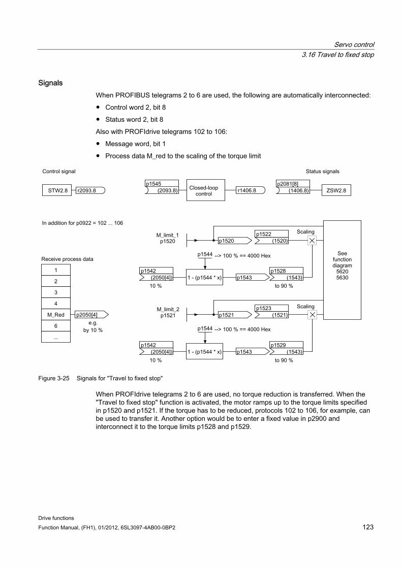
Servo control 3.16 Travel to fixed stop
Drive functions Function Manual, (FH1), 01/2012, 6SL3097-4AB00-0BP2 123
Signals When PROFIBUS telegrams 2 to 6 are used, the following are automatically interconnected:
Control word 2, bit 8
Status word 2, bit 8
Also with PROFIdrive telegrams 102 to 106:
Message word, bit 1
Process data M_red to the scaling of the torque limit
Figure 3-25 Signals for "Travel to fixed stop"
When PROFIdrive telegrams 2 to 6 are used, no torque reduction is transferred. When the "Travel to fixed stop" function is activated, the motor ramps up to the torque limits specified in p1520 and p1521. If the torque has to be reduced, protocols 102 to 106, for example, can be used to transfer it. Another option would be to enter a fixed value in p2900 and interconnect it to the torque limits p1528 and p1529.
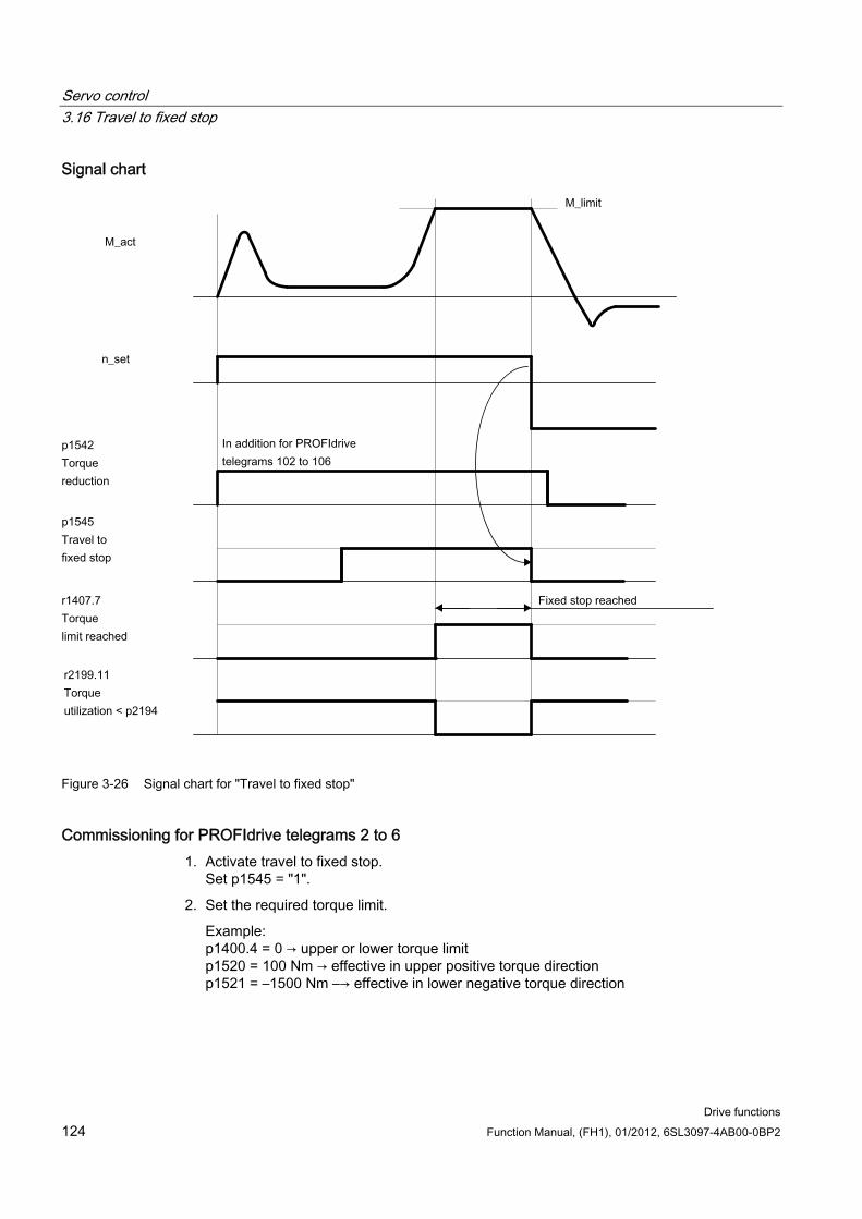
Servo control 3.16 Travel to fixed stop
Drive functions 124 Function Manual, (FH1), 01/2012, 6SL3097-4AB00-0BP2
Signal chart
Figure 3-26 Signal chart for "Travel to fixed stop"
Commissioning for PROFIdrive telegrams 2 to 6 1. Activate travel to fixed stop.
Set p1545 = "1".
2. Set the required torque limit.
Example: p1400.4 = 0 → upper or lower torque limit p1520 = 100 Nm → effective in upper positive torque direction p1521 = –1500 Nm –→ effective in lower negative torque direction
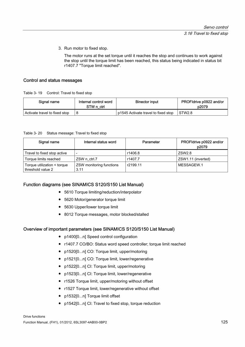
Servo control 3.16 Travel to fixed stop
Drive functions Function Manual, (FH1), 01/2012, 6SL3097-4AB00-0BP2 125
3. Run motor to fixed stop.
The motor runs at the set torque until it reaches the stop and continues to work against the stop until the torque limit has been reached, this status being indicated in status bit r1407.7 "Torque limit reached".
Control and status messages
Table 3- 19 Control: Travel to fixed stop
Signal name Internal control word STW n_ctrl
Binector input PROFIdrive p0922 and/or p2079
Activate travel to fixed stop 8 p1545 Activate travel to fixed stop STW2.8
Table 3- 20 Status message: Travel to fixed stop
Signal name Internal status word Parameter PROFIdrive p0922 and/or p2079
Travel to fixed stop active - r1406.8 ZSW2.8 Torque limits reached ZSW n_ctrl.7 r1407.7 ZSW1.11 (inverted) Torque utilization < torque threshold value 2
ZSW monitoring functions 3.11
r2199.11 MESSAGEW.1
Function diagrams (see SINAMICS S120/S150 List Manual) 5610 Torque limiting/reduction/interpolator
5620 Motor/generator torque limit
5630 Upper/lower torque limit
8012 Torque messages, motor blocked/stalled
Overview of important parameters (see SINAMICS S120/S150 List Manual) p1400[0...n] Speed control configuration
r1407.7 CO/BO: Status word speed controller; torque limit reached
p1520[0...n] CO: Torque limit, upper/motoring
p1521[0...n] CO: Torque limit, lower/regenerative
p1522[0...n] CI: Torque limit, upper/motoring
p1523[0...n] CI: Torque limit, lower/regenerative
r1526 Torque limit, upper/motoring without offset
r1527 Torque limit, lower/regenerative without offset
p1532[0...n] Torque limit offset
p1542[0...n] CI: Travel to fixed stop, torque reduction
Servo control 3.17 Vertical axes
Drive functions 126 Function Manual, (FH1), 01/2012, 6SL3097-4AB00-0BP2
r1543 CO: Travel to fixed stop, torque scaling
p1544 Travel to fixed stop, evaluation torque reduction
p1545[0...n] BI: Activate travel to fixed stop
p2194[0...n] Torque threshold 2
p2199.11 BO: Torque utilization < torque threshold value 2
3.17 Vertical axes
Description With a vertical axis without mechanical weight compensation, electronic weight compensation can be set by offsetting the torque limits (p1532). The torque limits specified in p1520 and p1521 are shifted by this offset value.
The offset value can be read in r0031 and transferred in p1532.
To reduce compensation once the brake has been released, the torque offset can be interconnected as a supplementary torque setpoint (p1513). In this way, the holding torque is set as soon as the brake has been released.
Function diagrams (see SINAMICS S120/S150 List Manual) 5060 Torque setpoint, control type switchover
5620 Motor/generator torque limit
5630 Upper/lower torque limit
Overview of important parameters (see SINAMICS S120/S150 List Manual) r0031 Actual torque smoothed
p1513[0...n] CI: Supplementary torque 2
p1520[0...n] CO: Torque limit, upper/motoring
p1521[0...n] CO: Torque limit, lower/regenerative
p1532[0...n] CO: Torque limit, offset
Servo control 3.18 Variable signaling function
Drive functions Function Manual, (FH1), 01/2012, 6SL3097-4AB00-0BP2 127
3.18 Variable signaling function Using the "Variable signaling" function, BICO interconnections and parameters, which have the attribute traceable, can be monitored.
Note Attribute "traceable"
A parameter, whose value can be acquired using the trace function of STARTER or SCOUT, is allocated the "traceable" attribute. These parameters can be called in STARTER or SCOUT under the device trace function. The attribute itself is not visible.
Enter the desired data source into parameter p3291 of the expert list of drive object. In parameter p3295 define a threshold value for the data source. The hysteresis of the threshold value can be set with p3296. If the threshold value is violated, then an output signal is generated from r3294.
A pickup delay can be set with p3297 and a dropout delay with p3298 for the output signal r3294.
The setting of a hysteresis results in a tolerance band around the threshold value. If the upper band limit is exceeded, the output signal r3294 is set to "1", if it drops below the lower band limit the output signal is set to "0"
You set the sampling time of the variable signaling function in p3299.
After completing the configuration, activate the variable signaling function with p3290.0 = 1.
Note
The variable signaling function works with an accuracy of 8 ms (also to be taken into account for pickup and dropout delay).
Example 1: Heating should be switched on depending on the temperature. For this the analog signal of an external sensor is connected with the variable signaling function. A temperature threshold and a hysteresis is defined to prevent the heating from switching on and off constantly.
Example 2: The pressure as process variable is to be monitored, whereby a temporary overpressure is tolerated. For this the output signal of an external sensor is connected with the variable signaling function. The pressure thresholds and a pull-in delay are set as tolerance time.
When the output signal of the variable signaling function is set, bit 5 in message word MELDW is set during cyclic communication. The message word MELDW is a component of the telegrams 102, 103, 105, 106, 110, 111, 116, 118, 126.
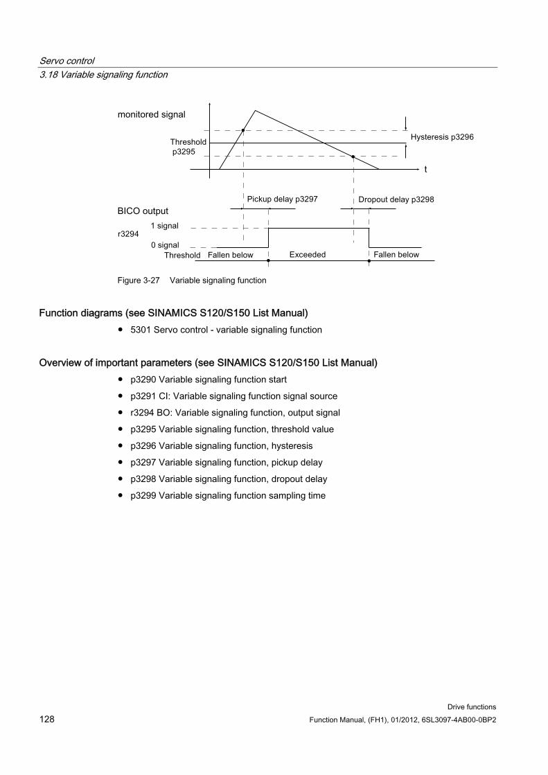
Servo control 3.18 Variable signaling function
Drive functions 128 Function Manual, (FH1), 01/2012, 6SL3097-4AB00-0BP2
Figure 3-27 Variable signaling function
Function diagrams (see SINAMICS S120/S150 List Manual) 5301 Servo control - variable signaling function
Overview of important parameters (see SINAMICS S120/S150 List Manual) p3290 Variable signaling function start
p3291 CI: Variable signaling function signal source
r3294 BO: Variable signaling function, output signal
p3295 Variable signaling function, threshold value
p3296 Variable signaling function, hysteresis
p3297 Variable signaling function, pickup delay
p3298 Variable signaling function, dropout delay
p3299 Variable signaling function sampling time
Servo control 3.19 Central probe evaluation
Drive functions Function Manual, (FH1), 01/2012, 6SL3097-4AB00-0BP2 129
3.19 Central probe evaluation Frequently, motion control systems have to detect and save the positions of drive axes at an instant in time defined by an external event. For example, this external event may be the signal edge of a probe. The following can be necessary:
Several probes have to be evaluated
The position actual values of several axes must be saved with a probe event.
For the central probe evaluation, the instant in time of the probe signal is detected and saved by a central function. From the sampling values of the position signals of the various axes, the control interpolates the times of the position actual values at the probe instant. Three evaluation techniques are implemented in SINAMICS S120 for this purpose:
With handshake
Withouthandshake, two edges
Withouthandshake, more than two edges
The evaluation techniques can be set using parameter p0684:
1. p0684 = 0: Measuring with handshake (factory setting)
2. p0684 = 1: Measuring without handshake
– A change to p0684 = 0 or 1 is possible in the RUN state
3. p0684 = 16: Measuring several signal edges per probe, without handshake
– A change to p0684 = 16 only becomes active after "Save parameters" and "Power On"
– A change of p0684 = 16 to p0684 = 0 or 1 only becomes active "After save parameters" and "Power On"
The fail safety of the standard PROFIdrive connection without handshake cannot be guaranteed. The "without handshake" function has been released for "integrated" platforms (e.g. SINAMICS integrated in SIMOTION D425). You must use the with handshake version to ensure absolute reliability when detecting the probe.
PROFIdrive telegrams for the central measuring function 1. Telegram 390: No probe
2. Telegram 391: 2 probes (when p0684=0/1)
3. Telegram 392: 6 probes (when p0684=0/1)
4. Telegram 393: 8 probes (when p0684=0/1)
5. Telegram 394: No probe
6. Telegram 395: 16 probes, time stamp (p0684 = 16)
Common features for central measuring with and without handshake Both measuring techniques have the following points in common:
1. Setting the input terminal in p0680.
Servo control 3.19 Central probe evaluation
Drive functions 130 Function Manual, (FH1), 01/2012, 6SL3097-4AB00-0BP2
2. Signal source, synchronization signal in p0681.
3. Signal source, control word probe p0682.
4. Transfer with the communication interface PROFIdrive.
5. Synchronizing and monitoring isochronous PROFIdrive
6. Prerequisite for measurements is the synchronization between the control and drive.
7. Setpoint transfer at start time To and actual value transfer at instant in time Ti in the PROFIBUS clock cycle (max. 8 ms).
8. Time stamp: Format (drive increments, NC decrements)
9. Each valid time stamp in the drive is incremented by 1 in order to make a differentiation between a valid measuring time zero and an invalid time format. This increment is removed again by the higher-level control.
10. The value "0" in the interface is an invalid time format and indicates that a measured value is not available.
11. Sequencer for the control/status word processing
12. Monitoring functions (sign of life)
13. Faults
Note Time-critical data transfer
The status information E_DIGITAL and A_DIGITAL in telegrams 39x are not subject to any precise time restraints according to the specifications. The transfer of E_DIGITAL and the output of A_DIGITAL is realized independently of the PROFIBUS cycle clock with the PROFIdrive PZD sampling rate according to p2048. Depending on the module, this can be set to between 1 ms and 16 ms. As a consequence, deadtimes must be expected for the transfer of output values and the feedback signal of input values.
Although the probe status word MT ZSW is identical with the content of E_DIGITAL, it is however directly transferred in PZDs. As a consequence, for time-critical applications measuring probes or cams should be used.
Central measuring with handshake With p0684 = 0, you activate the evaluation technique with handshake for the central probe evaluation. You can evaluate a maximum of one positive and/or negative edge per probe within four DP cycles.
TDP = PROFIBUS cycle (also DP cycle) TMAPC = master application cycle time (time grid, in which the master application generates new setpoints).
1. Transfer, control word probe (BICO p0682 to PZD3) at the start instant To in the MAPC cycle.
2. The measurement is activated with a 0/1 transition of the control bit for a falling or rising edge in the probe control word.
Servo control 3.19 Central probe evaluation
Drive functions Function Manual, (FH1), 01/2012, 6SL3097-4AB00-0BP2 131
3. If the measurement is activated, in data bus cycle (e.g. PROFIBUS cycle: DP cycle) a check is made as to whether a measured value is available.
4. If a measured value is available, then the time stamp is entered into either p0686 or p0687.
5. The time stamp is transferred until the control bit for falling or rising edge is set to zero in the control word. Then, the associated time stamp is set to zero.
6. The measurement is deactivated by a 1/0 transition of the control bit in the probe control word.
7. Transfer with PROFIdrive telegrams 391, 392 or 393.
Central measurement without handshake, two edges With p0684 = 1, you activate the evaluation technique without handshake for the central probe evaluation. You can evaluate a maximum of two edges per probe simultaneously within two DP cycles. Precondition: TDP = TMAPC (cycle ratio = 1:1, cycle reduction not possible).
If the measurement is activated, a check is made in the DP cycle as to whether a measured value was acquired:
1. If a measured value is available, then the time stamp is entered in either p0686 or p0687 and a new measurement is automatically activated.
2. If a measured value is not available, then the time stamp zero is entered into either p0686 or p0687.
3. This means that a time stamp is only transferred once before it is overwritten with zero or a new time stamp.
4. The measurement is immediately reactivated after the measured values have been read out.
5. Parallel to acquiring new probe events, the measuring results are transferred to the higher-level control for one DP cycle clock without evaluating the success.
6. For each probe, a maximum of one rising and one falling edge can be detected for each 2 DP cycles.
7. Transfer with PROFIdrive telegrams 391, 392 or 393.
Central measurement without handshake, more than two edges With p0684 = 16, you activate the evaluation technique without handshake for the central probe evaluation. You can evaluate up to 16 signal edges from a maximum of 2 probes simultaneously within a DP cycle.
DP cycle = PROFIBUS cycle = TDP TMAPC = master application cycle time (time grid, in which the master application generates new setpoints).
1. For each probe, up to 8 rising and/or 8 falling edges can be detected in each DP cycle and saved in a measurement buffer.
2. For each probe it can be selected whether the rising or falling signal edges are to be taken into account.
Servo control 3.19 Central probe evaluation
Drive functions 132 Function Manual, (FH1), 01/2012, 6SL3097-4AB00-0BP2
3. The cyclic measurement is activated with a 0/1 transition of the control bit for the signal edges in the probe control word.
4. After activating the measurement, the measured value buffer is emptied once for initialization.
5. When the buffer is full, the oldest measured value is overwritten first (first in/first out). The bit "measured value buffer full" in the probe-diagnostic word signals the risk of losing measured values.
6. The measured value buffer is then cyclically emptied and the measured values are converted in the sense of a measuring task into a time stamp. The time stamps are saved according to their chronological order, starting with the oldest, in the indexes of parameter r0565[0...15] for the transfer.
7. If several probes of being used, then the time stamps of the measurements are entered into the telegram block, corresponding to their chronological sequence, from the lowest up to the highest probe.
8. Up to 16 time stamps (MT_ZS), can be entered into telegram 395.
9. As soon as there is no longer any space for the time stamps of a probe in telegram 395, then the "Telegram full" is set in MT_DIAG. Example:
– From the 1st probe, 4 values are transferred
– From the 2nd probe, 6 values are transferred
– From the 3rd probe only the first 6 measured values are transferred, the rest is cut off and "Full telegram" is signaled in MT_DIAG.
10. From a selected probe, all signal edges are always taken into account. Individual signal edges cannot be selected or deselected.
11. The time stamps are transferred in parallel (to acquire new probe events associated with a time stamp without handshake). A time stamp is only transferred for one DP cycle. Then the time stamp overwritten with zero or a new time stamp.
12. The cyclic measurement is deactivated with a 1/0 transition of the control bit for a falling or rising signal edge in the probe control word.
13. Transfer with PROFIdrive telegram 395.
The PZDs of the probe time stamp are BiCo parameters, which are automatically connected with the indices of the new parameter r0565[16] when the telegram block is selected.
After the measuring function has been activated, for several measured values per DP cycle, the acquired time stamps are saved in the indices of r0565[0...15] for transfer, corresponding to their sequence in time starting with the oldest measured value.
Probe time stamp references For telegram 395, the probe time stamps MT_ZS_1...16 are assigned to the telegram locations using the probe time stamp references MT_ZSB1...4.
Four probe time stamps each (MT_ZS) are assigned a probe time stamp reference (MT_ZSB):
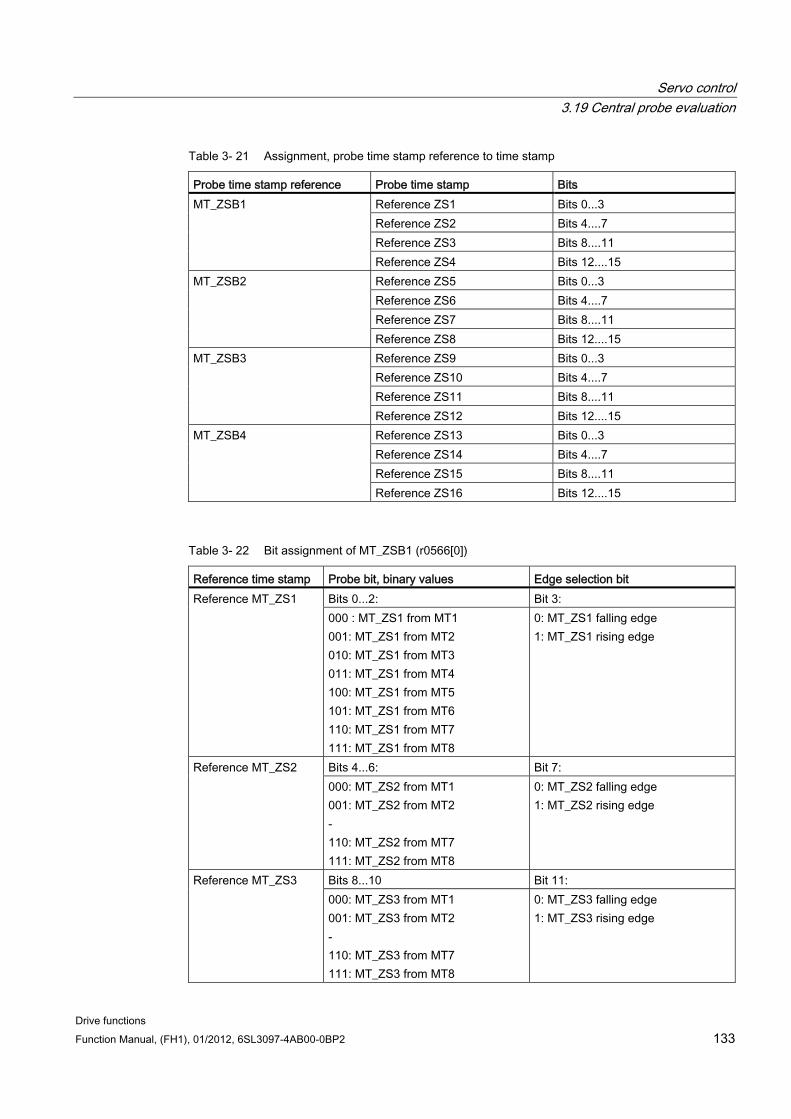
Servo control 3.19 Central probe evaluation
Drive functions Function Manual, (FH1), 01/2012, 6SL3097-4AB00-0BP2 133
Table 3- 21 Assignment, probe time stamp reference to time stamp
Probe time stamp reference Probe time stamp Bits Reference ZS1 Bits 0...3 Reference ZS2 Bits 4....7 Reference ZS3 Bits 8....11
MT_ZSB1
Reference ZS4 Bits 12....15 Reference ZS5 Bits 0...3 Reference ZS6 Bits 4....7 Reference ZS7 Bits 8....11
MT_ZSB2
Reference ZS8 Bits 12....15 Reference ZS9 Bits 0...3 Reference ZS10 Bits 4....7 Reference ZS11 Bits 8....11
MT_ZSB3
Reference ZS12 Bits 12....15 Reference ZS13 Bits 0...3 Reference ZS14 Bits 4....7 Reference ZS15 Bits 8....11
MT_ZSB4
Reference ZS16 Bits 12....15
Table 3- 22 Bit assignment of MT_ZSB1 (r0566[0])
Reference time stamp Probe bit, binary values Edge selection bit Bits 0...2: Bit 3: Reference MT_ZS1 000 : MT_ZS1 from MT1 001: MT_ZS1 from MT2 010: MT_ZS1 from MT3 011: MT_ZS1 from MT4 100: MT_ZS1 from MT5 101: MT_ZS1 from MT6 110: MT_ZS1 from MT7 111: MT_ZS1 from MT8
0: MT_ZS1 falling edge 1: MT_ZS1 rising edge
Bits 4...6: Bit 7: Reference MT_ZS2 000: MT_ZS2 from MT1 001: MT_ZS2 from MT2 - 110: MT_ZS2 from MT7 111: MT_ZS2 from MT8
0: MT_ZS2 falling edge 1: MT_ZS2 rising edge
Bits 8...10 Bit 11: Reference MT_ZS3 000: MT_ZS3 from MT1 001: MT_ZS3 from MT2 - 110: MT_ZS3 from MT7 111: MT_ZS3 from MT8
0: MT_ZS3 falling edge 1: MT_ZS3 rising edge
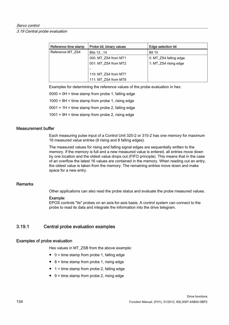
Servo control 3.19 Central probe evaluation
Drive functions 134 Function Manual, (FH1), 01/2012, 6SL3097-4AB00-0BP2
Reference time stamp Probe bit, binary values Edge selection bit Bits 12...14 Bit 15 Reference MT_ZS4 000: MT_ZS4 from MT1 001: MT_ZS4 from MT2 - 110: MT_ZS4 from MT7 111: MT_ZS4 from MT8
0: MT_ZS4 falling edge 1: MT_ZS4 rising edge
Examples for determining the reference values of the probe evaluation in hex:
0000 = 0H = time stamp from probe 1, falling edge
1000 = 8H = time stamp from probe 1, rising edge
0001 = 1H = time stamp from probe 2, falling edge
1001 = 9H = time stamp from probe 2, rising edge
Measurement buffer Each measuring pulse input of a Control Unit 320-2 or 310-2 has one memory for maximum 16 measured value entries (8 rising and 8 falling edges).
The measured values for rising and falling signal edges are sequentially written to the memory. If the memory is full and a new measured value is entered, all entries move down by one location and the oldest value drops out (FIFO principle). This means that in the case of an overflow the latest 16 values are contained in the memory. When reading out an entry, the oldest value is taken from the memory. The remaining entries move down and make space for a new entry.
Remarks Other applications can also read the probe status and evaluate the probe measured values.
Example: EPOS controls "its" probes on an axis-for-axis basis. A control system can connect to the probe to read its data and integrate the information into the drive telegram.
3.19.1 Central probe evaluation examples
Examples of probe evaluation Hex values in MT_ZSB from the above example:
0 = time stamp from probe 1, falling edge
8 = time stamp from probe 1, rising edge
1 = time stamp from probe 2, falling edge
9 = time stamp from probe 2, rising edge
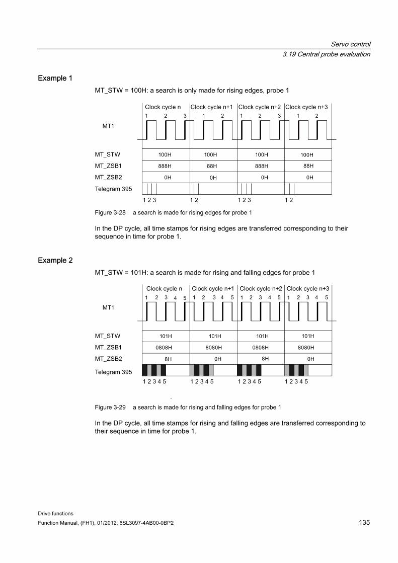
Servo control 3.19 Central probe evaluation
Drive functions Function Manual, (FH1), 01/2012, 6SL3097-4AB00-0BP2 135
Example 1 MT_STW = 100H: a search is only made for rising edges, probe 1
Figure 3-28 a search is made for rising edges for probe 1
In the DP cycle, all time stamps for rising edges are transferred corresponding to their sequence in time for probe 1.
Example 2 MT_STW = 101H: a search is made for rising and falling edges for probe 1
Figure 3-29 a search is made for rising and falling edges for probe 1
In the DP cycle, all time stamps for rising and falling edges are transferred corresponding to their sequence in time for probe 1.
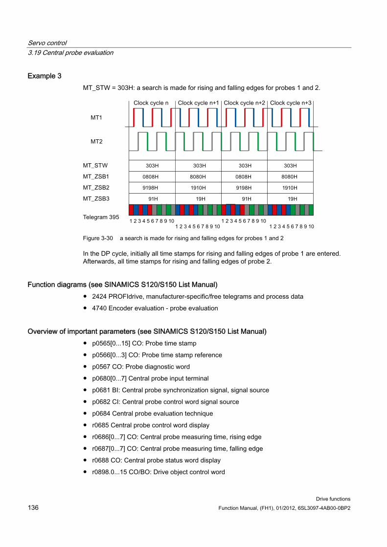
Servo control 3.19 Central probe evaluation
Drive functions 136 Function Manual, (FH1), 01/2012, 6SL3097-4AB00-0BP2
Example 3 MT_STW = 303H: a search is made for rising and falling edges for probes 1 and 2.
Figure 3-30 a search is made for rising and falling edges for probes 1 and 2
In the DP cycle, initially all time stamps for rising and falling edges of probe 1 are entered. Afterwards, all time stamps for rising and falling edges of probe 2.
Function diagrams (see SINAMICS S120/S150 List Manual) 2424 PROFIdrive, manufacturer-specific/free telegrams and process data
4740 Encoder evaluation - probe evaluation
Overview of important parameters (see SINAMICS S120/S150 List Manual) p0565[0...15] CO: Probe time stamp
p0566[0...3] CO: Probe time stamp reference
p0567 CO: Probe diagnostic word
p0680[0...7] Central probe input terminal
p0681 BI: Central probe synchronization signal, signal source
p0682 CI: Central probe control word signal source
p0684 Central probe evaluation technique
r0685 Central probe control word display
r0686[0...7] CO: Central probe measuring time, rising edge
r0687[0...7] CO: Central probe measuring time, falling edge
r0688 CO: Central probe status word display
r0898.0...15 CO/BO: Drive object control word

Servo control 3.19 Central probe evaluation
Drive functions Function Manual, (FH1), 01/2012, 6SL3097-4AB00-0BP2 137
r0899.0...15 CO/BO: Drive object status word
p0922 IF1 PROFIdrive telegram selection
p0925 PROFIdrive isochronous sign of life tolerance

Servo control 3.19 Central probe evaluation
Drive functions 138 Function Manual, (FH1), 01/2012, 6SL3097-4AB00-0BP2
Drive functions Function Manual, (FH1), 01/2012, 6SL3097-4AB00-0BP2 139
Vector control 4
Compared with vector V/f control, vector control offers the following benefits:
Stability vis-à-vis load and setpoint changes
Short rise times for setpoint changes (→ better control behavior)
Short settling times for load changes (→ better response to disturbances)
Acceleration and braking are possible with maximum available torque
Motor protection due to variable torque limitation in motor and regenerative mode
Drive and braking torque controlled independently of the speed
Maximum breakaway torque possible at speed 0
Vector control can be used with or without an encoder.
The following criteria indicate when an encoder is required:
High speed accuracy is required
High dynamic response requirements
– Better command behavior
– Better disturbance characteristic
Torque control is required in a control range greater than 1:10
Allows a defined and/or variable torque for speeds below approx. 10% of the rated motor frequency (p0310) to be maintained.
With regard to setpoint input, vector control is divided into:
Speed control
Torque/current control (in short: torque control)
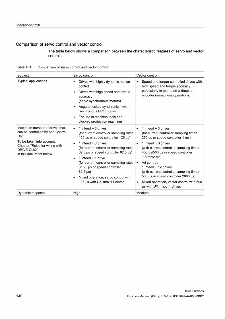
Vector control
Drive functions 140 Function Manual, (FH1), 01/2012, 6SL3097-4AB00-0BP2
Comparison of servo control and vector control The table below shows a comparison between the characteristic features of servo and vector controls.
Table 4- 1 Comparison of servo control and vector control
Subject Servo control Vector control Typical applications • Drives with highly dynamic motion
control • Drives with high speed and torque
accuracy (servo synchronous motors)
• Angular-locked synchronism with isochronous PROFIdrive.
• For use in machine tools and clocked production machines
• Speed and torque-controlled drives with high speed and torque accuracy, particularly in operation without an encoder (sensorless operation).
Maximum number of drives that can be controlled by one Control Unit. To be taken into account: Chapter "Rules for wiring with DRIVE-CLiQ" in this document below
• 1 infeed + 6 drives (for current controller sampling rates 125 μs or speed controller 125 μs)
• 1 infeed + 3 drives (for current controller sampling rates 62.5 μs or speed controller 62.5 μs)
• 1 infeed + 1 drive (for current controller sampling rates 31.25 μs or speed controller 62.5 μs)
• Mixed operation, servo control with 125 µs with U/f, max.11 drives
• 1 infeed + 3 drives (for current controller sampling times 250 μs or speed controller 1 ms)
• 1 infeed + 6 drives (with current controller sampling times 400 μs/500 μs or speed controller 1.6 ms/2 ms)
• V/f control: 1 infeed + 12 drives (with current controller sampling times 500 μs or speed controller 2000 μs)
• Mixed operation, vector control with 500 µs with U/f, max.11 drives
Dynamic response High Medium
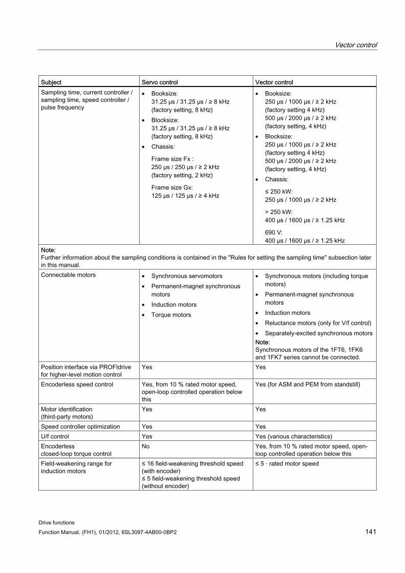
Vector control
Drive functions Function Manual, (FH1), 01/2012, 6SL3097-4AB00-0BP2 141
Subject Servo control Vector control Sampling time, current controller / sampling time, speed controller / pulse frequency
• Booksize: 31.25 μs / 31.25 μs / ≥ 8 kHz (factory setting, 8 kHz)
• Blocksize: 31.25 μs / 31.25 μs / ≥ 8 kHz (factory setting, 8 kHz)
• Chassis:
Frame size Fx : 250 μs / 250 μs / ≥ 2 kHz (factory setting, 2 kHz)
Frame size Gx: 125 μs / 125 μs / ≥ 4 kHz
• Booksize: 250 μs / 1000 μs / ≥ 2 kHz (factory setting 4 kHz) 500 μs / 2000 μs / ≥ 2 kHz (factory setting, 4 kHz)
• Blocksize: 250 μs / 1000 μs / ≥ 2 kHz (factory setting 4 kHz) 500 μs / 2000 μs / ≥ 2 kHz (factory setting, 4 kHz)
• Chassis:
≤ 250 kW: 250 μs / 1000 μs / ≥ 2 kHz
> 250 kW: 400 μs / 1600 μs / ≥ 1.25 kHz
690 V: 400 μs / 1600 μs / ≥ 1.25 kHz
Note: Further information about the sampling conditions is contained in the "Rules for setting the sampling time" subsection later in this manual. Connectable motors • Synchronous servomotors
• Permanent-magnet synchronous motors
• Induction motors • Torque motors
• Synchronous motors (including torque motors)
• Permanent-magnet synchronous motors
• Induction motors • Reluctance motors (only for V/f control) • Separately-excited synchronous motors Note: Synchronous motors of the 1FT6, 1FK6 and 1FK7 series cannot be connected.
Position interface via PROFIdrive for higher-level motion control
Yes Yes
Encoderless speed control Yes, from 10 % rated motor speed, open-loop controlled operation below this
Yes (for ASM and PEM from standstill)
Motor identification (third-party motors)
Yes Yes
Speed controller optimization Yes Yes U/f control Yes Yes (various characteristics) Encoderless closed-loop torque control
No Yes, from 10 % rated motor speed, open-loop controlled operation below this
Field-weakening range for induction motors
≤ 16 field-weakening threshold speed (with encoder) ≤ 5 field-weakening threshold speed (without encoder)
≤ 5 · rated motor speed
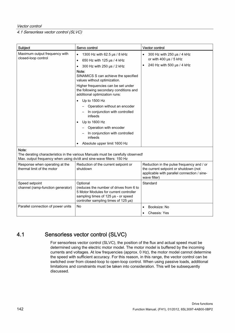
Vector control 4.1 Sensorless vector control (SLVC)
Drive functions 142 Function Manual, (FH1), 01/2012, 6SL3097-4AB00-0BP2
Subject Servo control Vector control Maximum output frequency with closed-loop control
• 1300 Hz with 62.5 μs / 8 kHz • 650 Hz with 125 μs / 4 kHz • 300 Hz with 250 μs / 2 kHz Note: SINAMICS S can achieve the specified values without optimization. Higher frequencies can be set under the following secondary conditions and additional optimization runs: • Up to 1500 Hz
– Operation without an encoder – In conjunction with controlled
infeeds • Up to 1600 Hz
– Operation with encoder – In conjunction with controlled
infeeds • Absolute upper limit 1600 Hz
• 300 Hz with 250 μs / 4 kHz or with 400 μs / 5 kHz
• 240 Hz with 500 μs / 4 kHz
Note: The derating characteristics in the various Manuals must be carefully observed! Max. output frequency when using dv/dt and sine-wave filters: 150 Hz Response when operating at the thermal limit of the motor
Reduction of the current setpoint or shutdown
Reduction in the pulse frequency and / or the current setpoint or shutdown (not applicable with parallel connection / sine-wave filter)
Speed setpoint channel (ramp-function generator)
Optional (reduces the number of drives from 6 to 5 Motor Modules for current controller sampling times of 125 μs - or speed controller sampling times of 125 μs)
Standard
Parallel connection of power units No • Booksize: No • Chassis: Yes
4.1 Sensorless vector control (SLVC) For sensorless vector control (SLVC), the position of the flux and actual speed must be determined using the electric motor model. The motor model is buffered by the incoming currents and voltages. At low frequencies (approx. 0 Hz), the motor model cannot determine the speed with sufficient accuracy. For this reason, in this range, the vector control can be switched over from closed-loop to open-loop control. When using passive loads, additional limitations and constraints must be taken into consideration. This will be subsequently discussed.
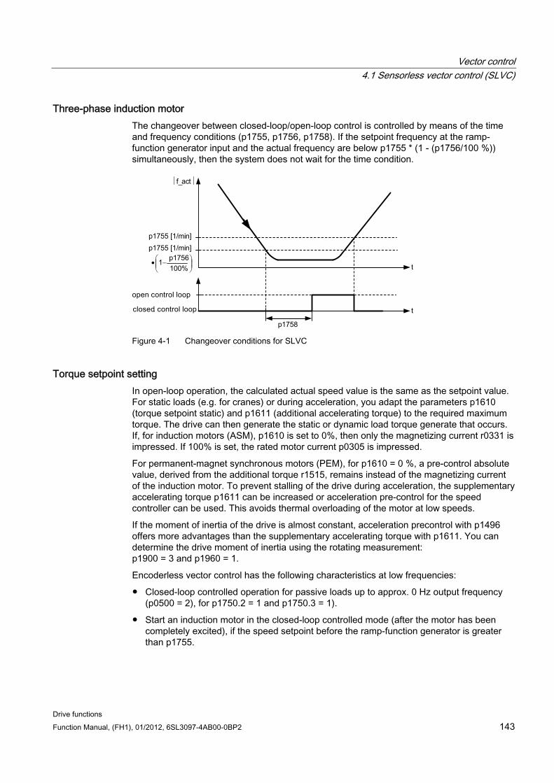
Vector control 4.1 Sensorless vector control (SLVC)
Drive functions Function Manual, (FH1), 01/2012, 6SL3097-4AB00-0BP2 143
Three-phase induction motor The changeover between closed-loop/open-loop control is controlled by means of the time and frequency conditions (p1755, p1756, p1758). If the setpoint frequency at the ramp-function generator input and the actual frequency are below p1755 * (1 - (p1756/100 %)) simultaneously, then the system does not wait for the time condition.
f_act
t
p1755 [1/min]
p1755 [1/min]
1758
t
⎟⎟⎠
⎞⎜⎜⎝
⎛ −•%100
1756p1
p Figure 4-1 Changeover conditions for SLVC
Torque setpoint setting In open-loop operation, the calculated actual speed value is the same as the setpoint value. For static loads (e.g. for cranes) or during acceleration, you adapt the parameters p1610 (torque setpoint static) and p1611 (additional accelerating torque) to the required maximum torque. The drive can then generate the static or dynamic load torque generate that occurs. If, for induction motors (ASM), p1610 is set to 0%, then only the magnetizing current r0331 is impressed. If 100% is set, the rated motor current p0305 is impressed.
For permanent-magnet synchronous motors (PEM), for p1610 = 0 %, a pre-control absolute value, derived from the additional torque r1515, remains instead of the magnetizing current of the induction motor. To prevent stalling of the drive during acceleration, the supplementary accelerating torque p1611 can be increased or acceleration pre-control for the speed controller can be used. This avoids thermal overloading of the motor at low speeds.
If the moment of inertia of the drive is almost constant, acceleration precontrol with p1496 offers more advantages than the supplementary accelerating torque with p1611. You can determine the drive moment of inertia using the rotating measurement: p1900 = 3 and p1960 = 1.
Encoderless vector control has the following characteristics at low frequencies:
Closed-loop controlled operation for passive loads up to approx. 0 Hz output frequency (p0500 = 2), for p1750.2 = 1 and p1750.3 = 1).
Start an induction motor in the closed-loop controlled mode (after the motor has been completely excited), if the speed setpoint before the ramp-function generator is greater than p1755.
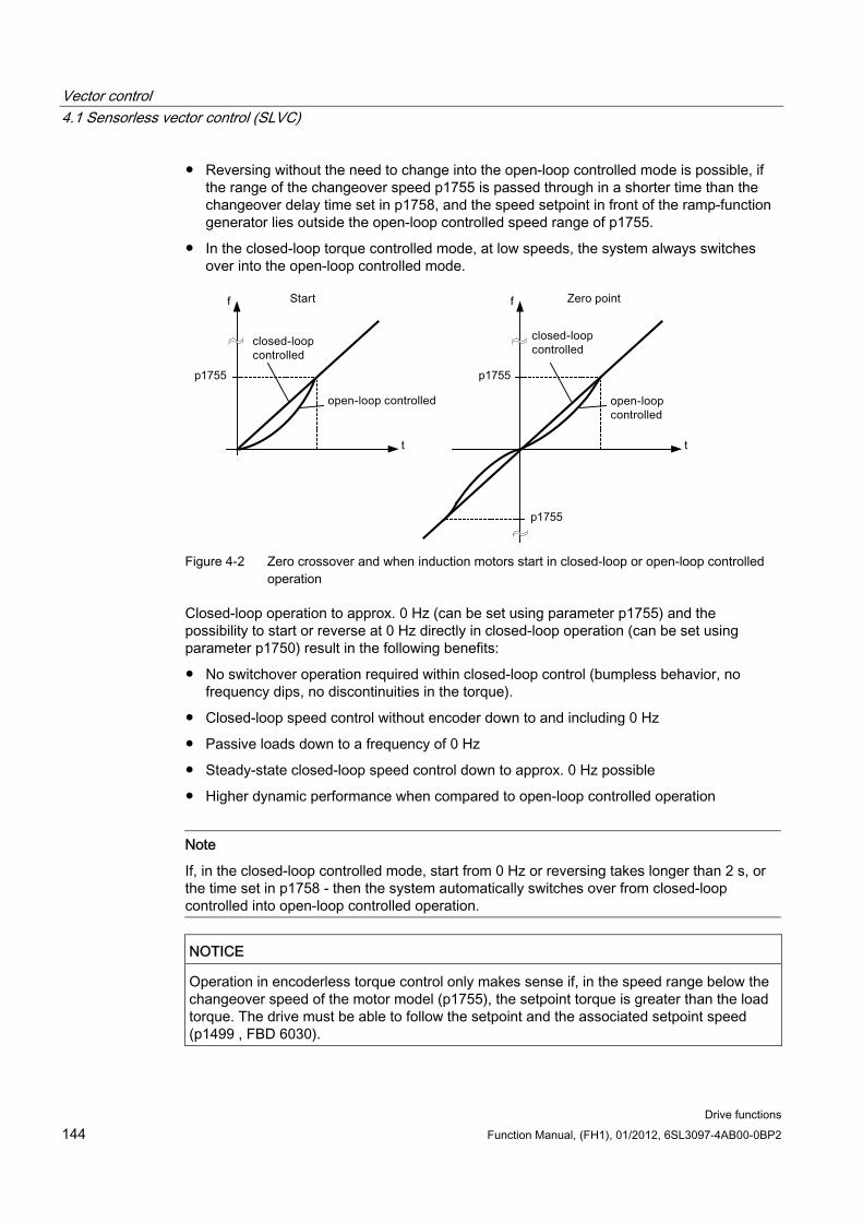
Vector control 4.1 Sensorless vector control (SLVC)
Drive functions 144 Function Manual, (FH1), 01/2012, 6SL3097-4AB00-0BP2
Reversing without the need to change into the open-loop controlled mode is possible, if the range of the changeover speed p1755 is passed through in a shorter time than the changeover delay time set in p1758, and the speed setpoint in front of the ramp-function generator lies outside the open-loop controlled speed range of p1755.
In the closed-loop torque controlled mode, at low speeds, the system always switches over into the open-loop controlled mode.
Figure 4-2 Zero crossover and when induction motors start in closed-loop or open-loop controlled
operation
Closed-loop operation to approx. 0 Hz (can be set using parameter p1755) and the possibility to start or reverse at 0 Hz directly in closed-loop operation (can be set using parameter p1750) result in the following benefits:
No switchover operation required within closed-loop control (bumpless behavior, no frequency dips, no discontinuities in the torque).
Closed-loop speed control without encoder down to and including 0 Hz
Passive loads down to a frequency of 0 Hz
Steady-state closed-loop speed control down to approx. 0 Hz possible
Higher dynamic performance when compared to open-loop controlled operation
Note
If, in the closed-loop controlled mode, start from 0 Hz or reversing takes longer than 2 s, or the time set in p1758 - then the system automatically switches over from closed-loop controlled into open-loop controlled operation.
NOTICE Operation in encoderless torque control only makes sense if, in the speed range below the changeover speed of the motor model (p1755), the setpoint torque is greater than the load torque. The drive must be able to follow the setpoint and the associated setpoint speed (p1499 , FBD 6030).
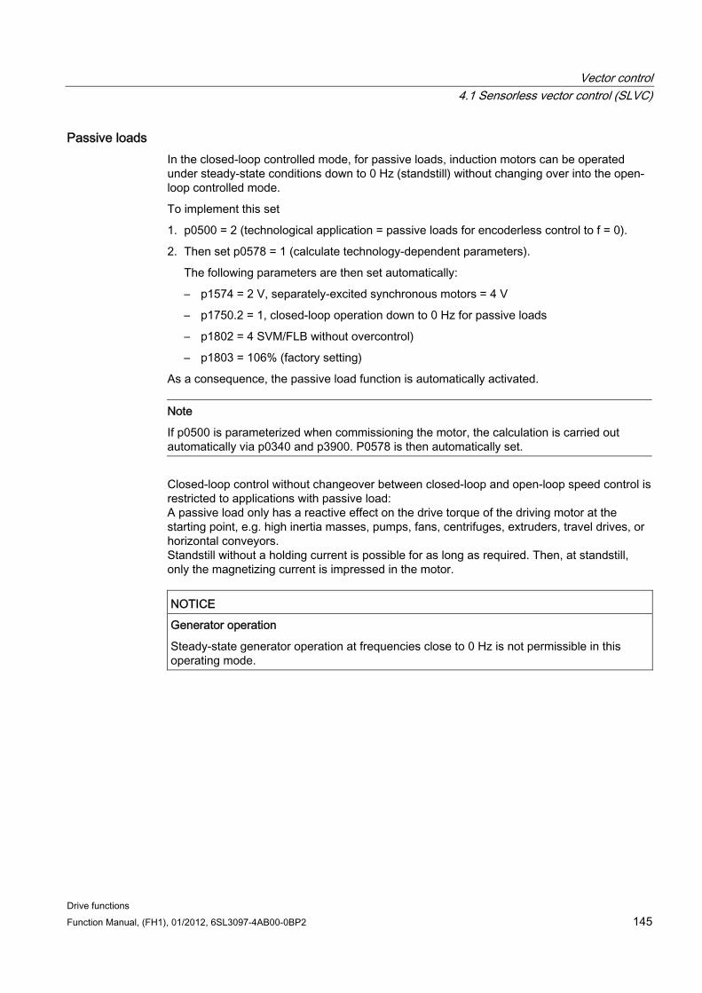
Vector control 4.1 Sensorless vector control (SLVC)
Drive functions Function Manual, (FH1), 01/2012, 6SL3097-4AB00-0BP2 145
Passive loads In the closed-loop controlled mode, for passive loads, induction motors can be operated under steady-state conditions down to 0 Hz (standstill) without changing over into the open-loop controlled mode.
To implement this set
1. p0500 = 2 (technological application = passive loads for encoderless control to f = 0).
2. Then set p0578 = 1 (calculate technology-dependent parameters).
The following parameters are then set automatically:
– p1574 = 2 V, separately-excited synchronous motors = 4 V
– p1750.2 = 1, closed-loop operation down to 0 Hz for passive loads
– p1802 = 4 SVM/FLB without overcontrol)
– p1803 = 106% (factory setting)
As a consequence, the passive load function is automatically activated.
Note
If p0500 is parameterized when commissioning the motor, the calculation is carried out automatically via p0340 and p3900. P0578 is then automatically set.
Closed-loop control without changeover between closed-loop and open-loop speed control is restricted to applications with passive load: A passive load only has a reactive effect on the drive torque of the driving motor at the starting point, e.g. high inertia masses, pumps, fans, centrifuges, extruders, travel drives, or horizontal conveyors. Standstill without a holding current is possible for as long as required. Then, at standstill, only the magnetizing current is impressed in the motor.
NOTICE Generator operation
Steady-state generator operation at frequencies close to 0 Hz is not permissible in this operating mode.
Vector control 4.1 Sensorless vector control (SLVC)
Drive functions 146 Function Manual, (FH1), 01/2012, 6SL3097-4AB00-0BP2
Figure 4-3 Vector control without an encoder
Blocking drives If the load torque is higher than the torque limiting of the sensorless vector control, the drive is braked to zero speed (standstill). In order that the open-loop controlled mode is not selected after the time p1758, p1750.6 can be set to 1. Under certain circumstances the "Motor blocked delay time" (p2177) must be increased.
NOTICE Exception for reversing drives
It is not permissible to use this setting if the load can force the drive to reverse.
Active loads Active loads, which can reverse the drive, e.g. hoisting gear, must be started in the open-loop speed control mode. In this case, bit p1750.6 must be set to 0 (open-loop controlled operation when the motor is blocked). The static (steady state) torque setpoint p1610 must be greater than the maximum occurring load torque.
Note Loads that can drive the motor
For applications with high regenerative load torques at low speeds, p1750.7 can also be set to 1 As a result, the speed changeover limits of the motor model are increased and a faster changeover can be made into open-loop controlled operation.
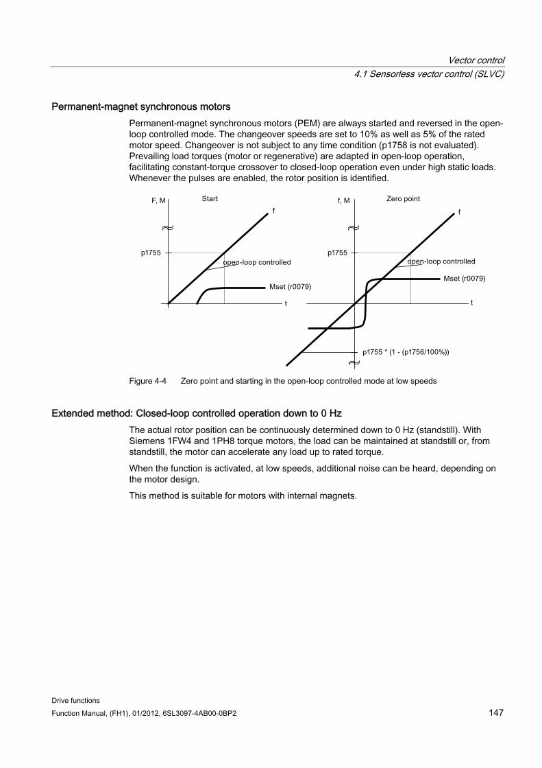
Vector control 4.1 Sensorless vector control (SLVC)
Drive functions Function Manual, (FH1), 01/2012, 6SL3097-4AB00-0BP2 147
Permanent-magnet synchronous motors Permanent-magnet synchronous motors (PEM) are always started and reversed in the open-loop controlled mode. The changeover speeds are set to 10% as well as 5% of the rated motor speed. Changeover is not subject to any time condition (p1758 is not evaluated). Prevailing load torques (motor or regenerative) are adapted in open-loop operation, facilitating constant-torque crossover to closed-loop operation even under high static loads. Whenever the pulses are enabled, the rotor position is identified.
Figure 4-4 Zero point and starting in the open-loop controlled mode at low speeds
Extended method: Closed-loop controlled operation down to 0 Hz The actual rotor position can be continuously determined down to 0 Hz (standstill). With Siemens 1FW4 and 1PH8 torque motors, the load can be maintained at standstill or, from standstill, the motor can accelerate any load up to rated torque.
When the function is activated, at low speeds, additional noise can be heard, depending on the motor design.
This method is suitable for motors with internal magnets.
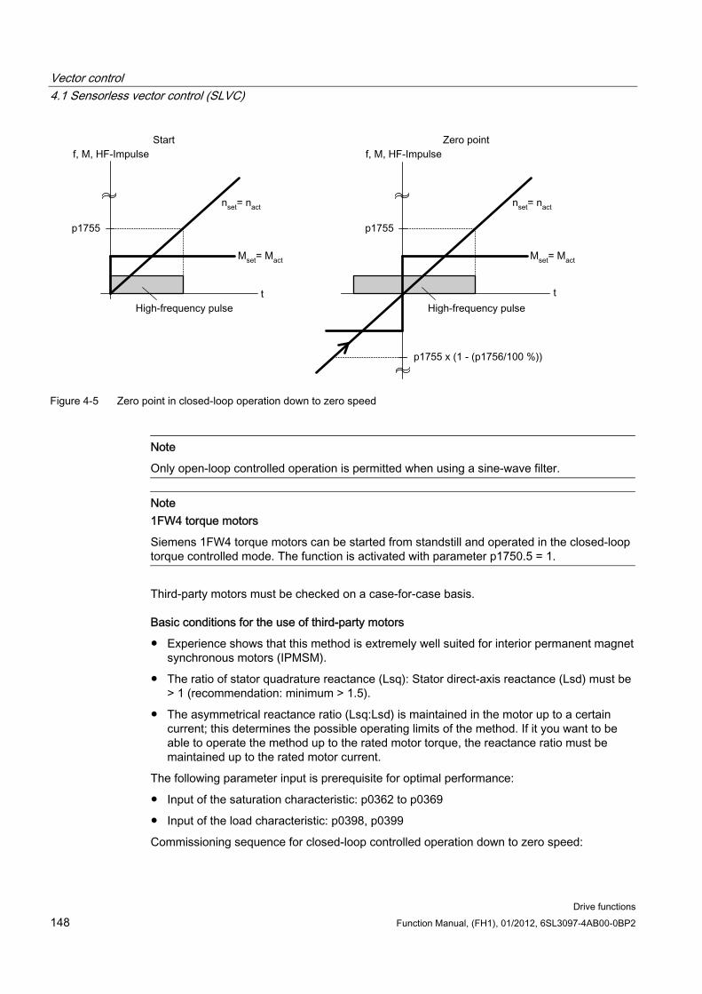
Vector control 4.1 Sensorless vector control (SLVC)
Drive functions 148 Function Manual, (FH1), 01/2012, 6SL3097-4AB00-0BP2
Figure 4-5 Zero point in closed-loop operation down to zero speed
Note
Only open-loop controlled operation is permitted when using a sine-wave filter.
Note 1FW4 torque motors
Siemens 1FW4 torque motors can be started from standstill and operated in the closed-loop torque controlled mode. The function is activated with parameter p1750.5 = 1.
Third-party motors must be checked on a case-for-case basis.
Basic conditions for the use of third-party motors
Experience shows that this method is extremely well suited for interior permanent magnet synchronous motors (IPMSM).
The ratio of stator quadrature reactance (Lsq): Stator direct-axis reactance (Lsd) must be > 1 (recommendation: minimum > 1.5).
The asymmetrical reactance ratio (Lsq:Lsd) is maintained in the motor up to a certain current; this determines the possible operating limits of the method. If it you want to be able to operate the method up to the rated motor torque, the reactance ratio must be maintained up to the rated motor current.
The following parameter input is prerequisite for optimal performance:
Input of the saturation characteristic: p0362 to p0369
Input of the load characteristic: p0398, p0399
Commissioning sequence for closed-loop controlled operation down to zero speed:
Vector control 4.1 Sensorless vector control (SLVC)
Drive functions Function Manual, (FH1), 01/2012, 6SL3097-4AB00-0BP2 149
Perform commissioning with motor identification at standstill.
Enter the parameters for saturation characteristic and load characteristic.
Activate closed-loop controlled operation down to zero speed via parameter p1750.5 = 1.
The following advantages are obtained by maintaining closed-loop controlled operation:
No torque irregularities as a result of changeover operations in the closed-loop control structure
Closed-loop speed and torque control without encoder (sensorless) up to and including 0 Hz.
Higher dynamic performance when compared to open-loop controlled operation
Encoderless operation of drive line-ups (e.g., in the paper industry, master-slave operation) is possible.
Active (including hanging/suspended) loads down to a frequency equal to zero.
NOTICE
Output filter
The technique cannot be used with the existing output filter.
Function diagrams (see SINAMICS S120/S150 List Manual) 6030 Vector control - speed setpoint, droop
6730 Interface to Motor Module (ASM, p0300 = 1)
6731 Interface to the Motor Module (PEM, p0300 = 2)
Overview of important parameters (see SINAMICS S120/S150 List Manual) p0305[0...n] Rated motor current
r0331[0...n] Actual motor magnetizing current/short-circuit current
p0500 technology application
p1610[0...n] Torque setpoint static (SLVC)
p1611[0...n] Supplementary accelerating torque (SLVC)
p1750[0...n] Motor model configuration
p1755[0...n] Motor model changeover speed encoderless operation
p1756 Motor model changeover speed hysteresis encoderless operation
p1758[0...n] Motor model changeover delay time, closed/open-loop control
p1802[0...n] modulator mode
p1803[0...n] modulation depth maximum
Vector control 4.2 Vector control with encoder
Drive functions 150 Function Manual, (FH1), 01/2012, 6SL3097-4AB00-0BP2
4.2 Vector control with encoder
Benefits of vector control with an encoder: The speed can be controlled right down to 0 Hz (standstill)
Constant torque in the rated speed range
Compared with speed control without an encoder, the dynamic response of drives with an encoder is significantly better because the speed is measured directly and integrated in the model created for the current components.
Higher speed accuracy
Motor model change A model change takes place between the current model and the observer model within the speed range p1752*(100 %-p1753) and p1752. In the current model range (i.e at lower speeds), torque accuracy depends on whether thermal tracking of the rotor resistance is carried out correctly. In the observer-model range and at speeds of less than approx. 20% of the rated speed, torque accuracy depends primarily on whether thermal tracking of the stator resistance is carried out correctly. If the resistance of the supply cable is greater than 20 ... 30 % of the total resistance, this should be entered in p0352 before motor data identification is carried out (p1900/p1910).
To deactivate thermal adaptation, set p0620 = 0. This may be necessary if adaptation cannot function accurately enough due to the following general conditions. For example, if a KTY sensor is not used for temperature detection and the ambient temperatures fluctuate significantly or the overtemperatures of the motor (p0626 ... p0628) deviate significantly from the default settings due to the design of the motor.
4.3 Speed controller Both closed-loop control procedures with and without an encoder (VC, SLVC) have the same speed controller structure, which contains the following components:
PI controller
Speed controller pre-control
Droop
The total of the output variables result in the torque setpoint, which is reduced to the permissible magnitude by means of the torque setpoint limitation.
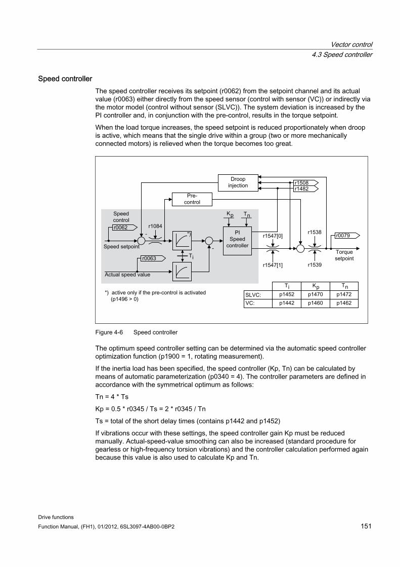
Vector control 4.3 Speed controller
Drive functions Function Manual, (FH1), 01/2012, 6SL3097-4AB00-0BP2 151
Speed controller The speed controller receives its setpoint (r0062) from the setpoint channel and its actual value (r0063) either directly from the speed sensor (control with sensor (VC)) or indirectly via the motor model (control without sensor (SLVC)). The system deviation is increased by the PI controller and, in conjunction with the pre-control, results in the torque setpoint.
When the load torque increases, the speed setpoint is reduced proportionately when droop is active, which means that the single drive within a group (two or more mechanically connected motors) is relieved when the torque becomes too great.
Figure 4-6 Speed controller
The optimum speed controller setting can be determined via the automatic speed controller optimization function (p1900 = 1, rotating measurement).
If the inertia load has been specified, the speed controller (Kp, Tn) can be calculated by means of automatic parameterization (p0340 = 4). The controller parameters are defined in accordance with the symmetrical optimum as follows:
Tn = 4 * Ts
Kp = 0.5 * r0345 / Ts = 2 * r0345 / Tn
Ts = total of the short delay times (contains p1442 and p1452)
If vibrations occur with these settings, the speed controller gain Kp must be reduced manually. Actual-speed-value smoothing can also be increased (standard procedure for gearless or high-frequency torsion vibrations) and the controller calculation performed again because this value is also used to calculate Kp and Tn.
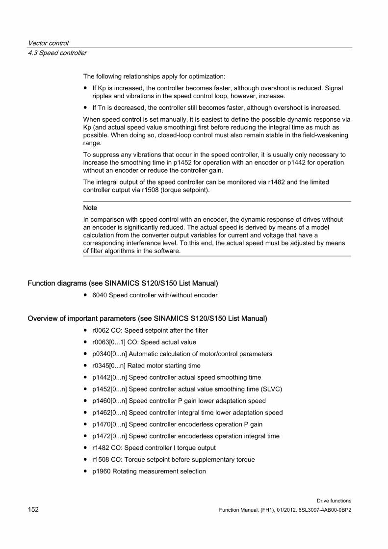
Vector control 4.3 Speed controller
Drive functions 152 Function Manual, (FH1), 01/2012, 6SL3097-4AB00-0BP2
The following relationships apply for optimization:
If Kp is increased, the controller becomes faster, although overshoot is reduced. Signal ripples and vibrations in the speed control loop, however, increase.
If Tn is decreased, the controller still becomes faster, although overshoot is increased.
When speed control is set manually, it is easiest to define the possible dynamic response via Kp (and actual speed value smoothing) first before reducing the integral time as much as possible. When doing so, closed-loop control must also remain stable in the field-weakening range.
To suppress any vibrations that occur in the speed controller, it is usually only necessary to increase the smoothing time in p1452 for operation with an encoder or p1442 for operation without an encoder or reduce the controller gain.
The integral output of the speed controller can be monitored via r1482 and the limited controller output via r1508 (torque setpoint).
Note
In comparison with speed control with an encoder, the dynamic response of drives without an encoder is significantly reduced. The actual speed is derived by means of a model calculation from the converter output variables for current and voltage that have a corresponding interference level. To this end, the actual speed must be adjusted by means of filter algorithms in the software.
Function diagrams (see SINAMICS S120/S150 List Manual) 6040 Speed controller with/without encoder
Overview of important parameters (see SINAMICS S120/S150 List Manual) r0062 CO: Speed setpoint after the filter
r0063[0...1] CO: Speed actual value
p0340[0...n] Automatic calculation of motor/control parameters
r0345[0...n] Rated motor starting time
p1442[0...n] Speed controller actual speed smoothing time
p1452[0...n] Speed controller actual value smoothing time (SLVC)
p1460[0...n] Speed controller P gain lower adaptation speed
p1462[0...n] Speed controller integral time lower adaptation speed
p1470[0...n] Speed controller encoderless operation P gain
p1472[0...n] Speed controller encoderless operation integral time
r1482 CO: Speed controller I torque output
r1508 CO: Torque setpoint before supplementary torque
p1960 Rotating measurement selection
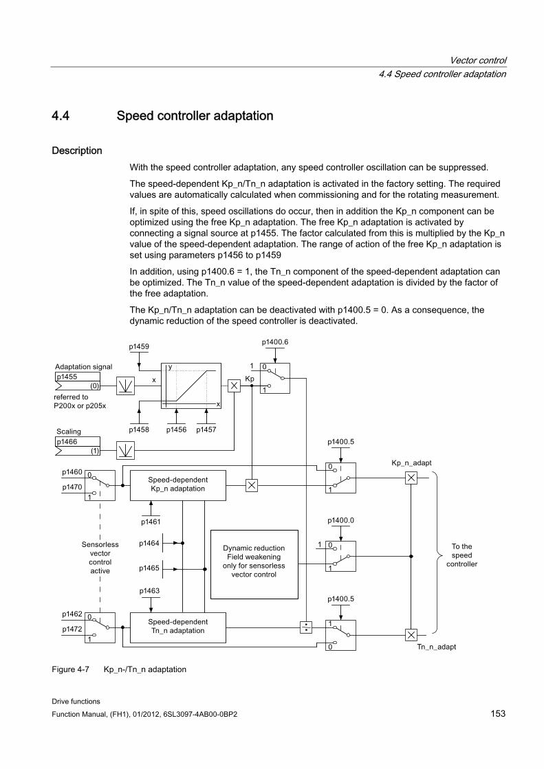
Vector control 4.4 Speed controller adaptation
Drive functions Function Manual, (FH1), 01/2012, 6SL3097-4AB00-0BP2 153
4.4 Speed controller adaptation
Description With the speed controller adaptation, any speed controller oscillation can be suppressed.
The speed-dependent Kp_n/Tn_n adaptation is activated in the factory setting. The required values are automatically calculated when commissioning and for the rotating measurement.
If, in spite of this, speed oscillations do occur, then in addition the Kp_n component can be optimized using the free Kp_n adaptation. The free Kp_n adaptation is activated by connecting a signal source at p1455. The factor calculated from this is multiplied by the Kp_n value of the speed-dependent adaptation. The range of action of the free Kp_n adaptation is set using parameters p1456 to p1459
In addition, using p1400.6 = 1, the Tn_n component of the speed-dependent adaptation can be optimized. The Tn_n value of the speed-dependent adaptation is divided by the factor of the free adaptation.
The Kp_n/Tn_n adaptation can be deactivated with p1400.5 = 0. As a consequence, the dynamic reduction of the speed controller is deactivated.
Figure 4-7 Kp_n-/Tn_n adaptation
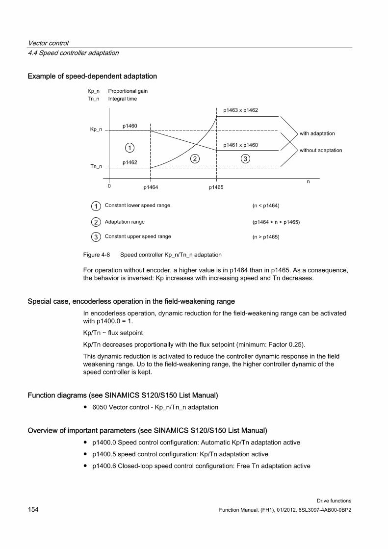
Vector control 4.4 Speed controller adaptation
Drive functions 154 Function Manual, (FH1), 01/2012, 6SL3097-4AB00-0BP2
Example of speed-dependent adaptation
Figure 4-8 Speed controller Kp_n/Tn_n adaptation
For operation without encoder, a higher value is in p1464 than in p1465. As a consequence, the behavior is inversed: Kp increases with increasing speed and Tn decreases.
Special case, encoderless operation in the field-weakening range In encoderless operation, dynamic reduction for the field-weakening range can be activated with p1400.0 = 1.
Kp/Tn ∼ flux setpoint
Kp/Tn decreases proportionally with the flux setpoint (minimum: Factor 0.25).
This dynamic reduction is activated to reduce the controller dynamic response in the field weakening range. Up to the field-weakening range, the higher controller dynamic of the speed controller is kept.
Function diagrams (see SINAMICS S120/S150 List Manual) 6050 Vector control - Kp_n/Tn_n adaptation
Overview of important parameters (see SINAMICS S120/S150 List Manual) p1400.0 Speed control configuration: Automatic Kp/Tn adaptation active
p1400.5 speed control configuration: Kp/Tn adaptation active
p1400.6 Closed-loop speed control configuration: Free Tn adaptation active
Vector control 4.4 Speed controller adaptation
Drive functions Function Manual, (FH1), 01/2012, 6SL3097-4AB00-0BP2 155
p1470 Speed controller encoderless operation P-gain
p1472 Speed controller encoderless operation integral-action time
Free Tn adaptation
p1455[0...n] CI: Speed controller P gain adaptation signal
p1456[0...n] Speed controller P gain adaptation lower starting point
p1457[0...n] Speed controller P gain adaptation upper starting point
p1458[0...n] Lower adaptation factor
p1459[0...n] Upper adaptation factor
p1466[0...n] CI: Speed controller P gain scaling
Speed-dependent Kp_n/Tn_n adaptation
p1460[0...n] Speed controller P gain lower adaptation speed
p1461[0...n] Speed controller Kp adaptation speed upper scaling
p1462 Speed controller integral action time adaptation speed, lower
p1463 Speed controller Tn adaptation speed upper scaling
p1464 Speed controller adaptation speed, lower
p1465 Speed controller adaptation speed, upper
Dynamic response reduction field weakening (SLVC only)
p1400.0 Speed control configuration: Automatic Kp/Tn adaptation active
Parameterization with STARTER The "speed controller" parameter screen is selected via the following icon in the toolbar of the STARTER commissioning tool:
Figure 4-9 STARTER icon for "speed controller"
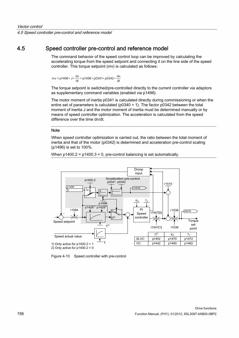
Vector control 4.5 Speed controller pre-control and reference model
Drive functions 156 Function Manual, (FH1), 01/2012, 6SL3097-4AB00-0BP2
4.5 Speed controller pre-control and reference model The command behavior of the speed control loop can be improved by calculating the accelerating torque from the speed setpoint and connecting it on the line side of the speed controller. This torque setpoint (mv) is calculated as follows:
The torque setpoint is switched/pre-controlled directly to the current controller via adaptors as supplementary command variables (enabled via p1496).
The motor moment of inertia p0341 is calculated directly during commissioning or when the entire set of parameters is calculated (p0340 = 1). The factor p0342 between the total moment of inertia J and the motor moment of inertia must be determined manually or by means of speed controller optimization. The acceleration is calculated from the speed difference over the time dn/dt.
Note
When speed controller optimization is carried out, the ratio between the total moment of inertia and that of the motor (p0342) is determined and acceleration pre-control scaling (p1496) is set to 100%.
When p1400.2 = p1400.3 = 0, pre-control balancing is set automatically.
-
- r1547[0]r1538
r1547[1] r1539
r1518
=0
>0
p0341 p0342
p1496
SLVC:
VC:
p1452
p1442
p1470
p1460
p1472
p1462
Kp Tn
Kp Tn
r1084 r0079
Ti
T)2
i
T)2
i
0
1p1495
p1400.2
p14281) p14291)
r1515
Figure 4-10 Speed controller with pre-control
Vector control 4.5 Speed controller pre-control and reference model
Drive functions Function Manual, (FH1), 01/2012, 6SL3097-4AB00-0BP2 157
If the speed controller has been correctly adjusted, it only has to compensate for disturbance variables in its own control loop, which can be achieved by means of a relatively small change to the correcting variables. Speed setpoint changes, on the other hand, are carried out without involving the speed controller and are, therefore, performed more quickly.
The effect of the pre-control variable can be adapted according to the application via the evaluation factor p1496. If p1496 = 100 %, pre-control is calculated in accordance with the motor and load moment of inertia (p0341, p0342). A balancing filter is used automatically to prevent the speed controller from acting against the injected torque setpoint. The time constant of the balancing filter corresponds to the equivalent delay time of the speed control loop. Speed controller pre-control is correctly set (p1496 = 100%, calibration via p0342) when the I component of the speed controller (r1482) does not change during a ramp-up or ramp-down in the range n > 20% x p0310. Thus, the pre-control allows a new speed setpoint to be approached without overshoot (prerequisite: the torque limiting does not act and the moment of inertia remains constant).
If the speed controller is pre-controlled through injection, the speed setpoint (r0062) is delayed with the same smoothing time (p1442 or p1452) as the actual value (r1445). This ensures that no target/actual difference (r0064) occurs at the controller input during acceleration, which would be attributable solely to the signal propagation time.
When speed pre-control is activated, the speed setpoint must be specified continuously or without a higher interference level (avoids sudden torque changes). An appropriate signal can be generated by smoothing the speed setpoint or activating the ramp-function generator rounding p1130 – p1131.
The starting time r0345 (Tstart) is a measure for the total moment of inertia J of the machine and describes the time during which the unloaded drive can be accelerated with the rated motor torque r0333 (Mmot,rated) from standstill to the rated motor speed p0311 (nmot,rated).
If these supplementary conditions are in line with the application, the starting time can be used as the lowest value for the ramp-up or ramp-down time.
Note
The ramp-up and ramp-down times (p1120; p1121) of the ramp-function generator in the setpoint channel should be set accordingly so that the motor speed can track the setpoint during acceleration and braking. This ensures that speed controller pre-control is functioning optimally.
The acceleration pre-control using a connector input (p1495) is activated by the parameter settings p1400.2 = 1 and p1400.3 = 0. p1428 (dead time) and p1429 (time constant) can be set for balancing purposes.
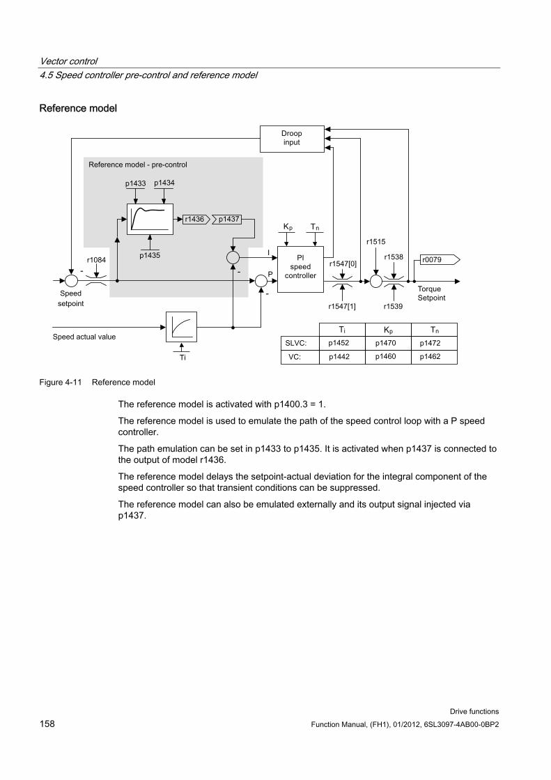
Vector control 4.5 Speed controller pre-control and reference model
Drive functions 158 Function Manual, (FH1), 01/2012, 6SL3097-4AB00-0BP2
Reference model
Figure 4-11 Reference model
The reference model is activated with p1400.3 = 1.
The reference model is used to emulate the path of the speed control loop with a P speed controller.
The path emulation can be set in p1433 to p1435. It is activated when p1437 is connected to the output of model r1436.
The reference model delays the setpoint-actual deviation for the integral component of the speed controller so that transient conditions can be suppressed.
The reference model can also be emulated externally and its output signal injected via p1437.
Vector control 4.5 Speed controller pre-control and reference model
Drive functions Function Manual, (FH1), 01/2012, 6SL3097-4AB00-0BP2 159
Function diagrams (see SINAMICS S120/S150 List Manual) 6031 Pre-control balancing for reference/acceleration model
6040 Speed controller
Overview of important parameters (see SINAMICS S120/S150 List Manual) p0311[0...n] Rated motor speed
r0333[0...n] Rated motor torque
p0341[0...n] Motor moment of inertia
p0342[0...n] Ratio between the total moment of inertia and that of the motor
r0345[0...n] Rated motor starting time
p1400.2[0...n] Speed control configuration: Acceleration pre-control source
p1428[0...n] Speed pre-control deadtime for balancing pre-control speed
p1429[0...n] Speed pre-control time constant for balancing
p1496[0...n] Acceleration pre-control scaling
r1518 CO: Accelerating torque
Overview of important parameters (see SINAMICS S120/S150 List Manual) for the reference model
p1400.3[0...n] Speed control configuration: Reference model speed setpoint I component
p1433[0...n] Speed controller reference model natural frequency
p1434[0...n] Speed controller reference model damping
p1435[0...n] Speed controller reference model deadtime
r1436 CO: Speed controller reference model speed setpoint output
p1437[0...n] CI: Speed controller reference model I component input
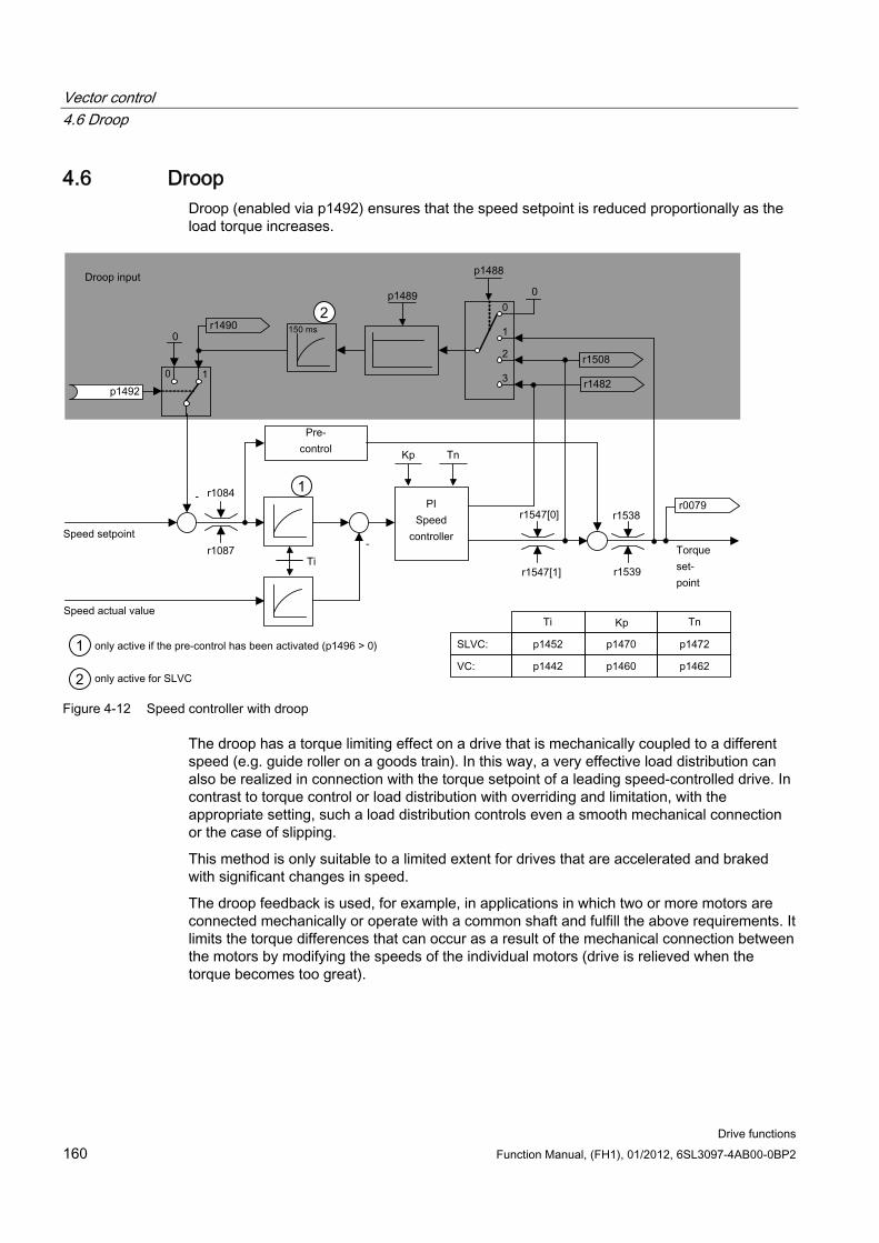
Vector control 4.6 Droop
Drive functions 160 Function Manual, (FH1), 01/2012, 6SL3097-4AB00-0BP2
4.6 Droop Droop (enabled via p1492) ensures that the speed setpoint is reduced proportionally as the load torque increases.
Figure 4-12 Speed controller with droop
The droop has a torque limiting effect on a drive that is mechanically coupled to a different speed (e.g. guide roller on a goods train). In this way, a very effective load distribution can also be realized in connection with the torque setpoint of a leading speed-controlled drive. In contrast to torque control or load distribution with overriding and limitation, with the appropriate setting, such a load distribution controls even a smooth mechanical connection or the case of slipping.
This method is only suitable to a limited extent for drives that are accelerated and braked with significant changes in speed.
The droop feedback is used, for example, in applications in which two or more motors are connected mechanically or operate with a common shaft and fulfill the above requirements. It limits the torque differences that can occur as a result of the mechanical connection between the motors by modifying the speeds of the individual motors (drive is relieved when the torque becomes too great).
Vector control 4.7 Open actual speed value
Drive functions Function Manual, (FH1), 01/2012, 6SL3097-4AB00-0BP2 161
Preconditions
All coupled drives must be operated in vector control and closed-loop speed control, with or without an encoder.
Only one (1) common ramp-function generator may be used for mechanically coupled drives.
Function diagrams (see SINAMICS S120/S150 List Manual) 6030 Speed setpoint, droop
Overview of important parameters (see SINAMICS S120/S150 List Manual) r0079 CO: Torque setpoint
p1488[0...n] Droop input source
p1489[0...n] Droop feedback scaling
p1492[0...n] BI: Droop feedback enable
r1482 CO: Speed controller I torque output
r1490 CO: Droop feedback speed reduction
r1508 CO: Torque setpoint before supplementary torque
4.7 Open actual speed value
Description The signal source for the actual speed value of the speed controller is specified via parameter p1440 (CI: speed controller actual speed value). The unsmoothed actual speed value r0063[0] has been preset as the signal source in the factory.
Depending on the machine, parameter p1440 can be used, for example, to switch on a filter in the actual value channel or feed in an external actual speed value.
Parameter r1443 is used to display the actual speed value present at p1440.
Note
When infeeding an external actual speed value, care should be taken that the monitoring functions continue to be derived from the motor model.
Behavior for speed control with an encoder (p1300 = 21) A motor encoder must always be available for the speed or position signal of the motor model (e.g. evaluation via SMC, see p0400). The actual speed of the motor (r0061) and the position information for synchronous motors still come from this motor encoder and are not influenced by the setting in p1440.
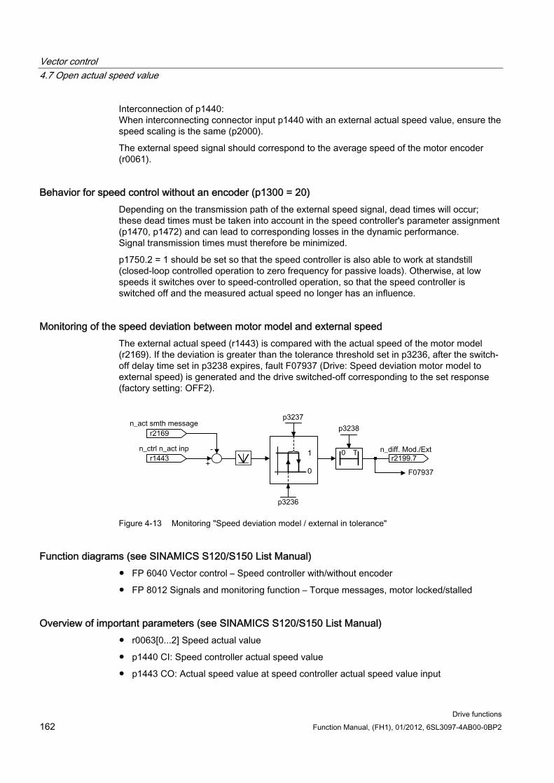
Vector control 4.7 Open actual speed value
Drive functions 162 Function Manual, (FH1), 01/2012, 6SL3097-4AB00-0BP2
Interconnection of p1440: When interconnecting connector input p1440 with an external actual speed value, ensure the speed scaling is the same (p2000).
The external speed signal should correspond to the average speed of the motor encoder (r0061).
Behavior for speed control without an encoder (p1300 = 20) Depending on the transmission path of the external speed signal, dead times will occur; these dead times must be taken into account in the speed controller's parameter assignment (p1470, p1472) and can lead to corresponding losses in the dynamic performance. Signal transmission times must therefore be minimized.
p1750.2 = 1 should be set so that the speed controller is also able to work at standstill (closed-loop controlled operation to zero frequency for passive loads). Otherwise, at low speeds it switches over to speed-controlled operation, so that the speed controller is switched off and the measured actual speed no longer has an influence.
Monitoring of the speed deviation between motor model and external speed The external actual speed (r1443) is compared with the actual speed of the motor model (r2169). If the deviation is greater than the tolerance threshold set in p3236, after the switch-off delay time set in p3238 expires, fault F07937 (Drive: Speed deviation motor model to external speed) is generated and the drive switched-off corresponding to the set response (factory setting: OFF2).
Figure 4-13 Monitoring "Speed deviation model / external in tolerance"
Function diagrams (see SINAMICS S120/S150 List Manual) FP 6040 Vector control – Speed controller with/without encoder
FP 8012 Signals and monitoring function – Torque messages, motor locked/stalled
Overview of important parameters (see SINAMICS S120/S150 List Manual) r0063[0...2] Speed actual value
p1440 CI: Speed controller actual speed value
p1443 CO: Actual speed value at speed controller actual speed value input
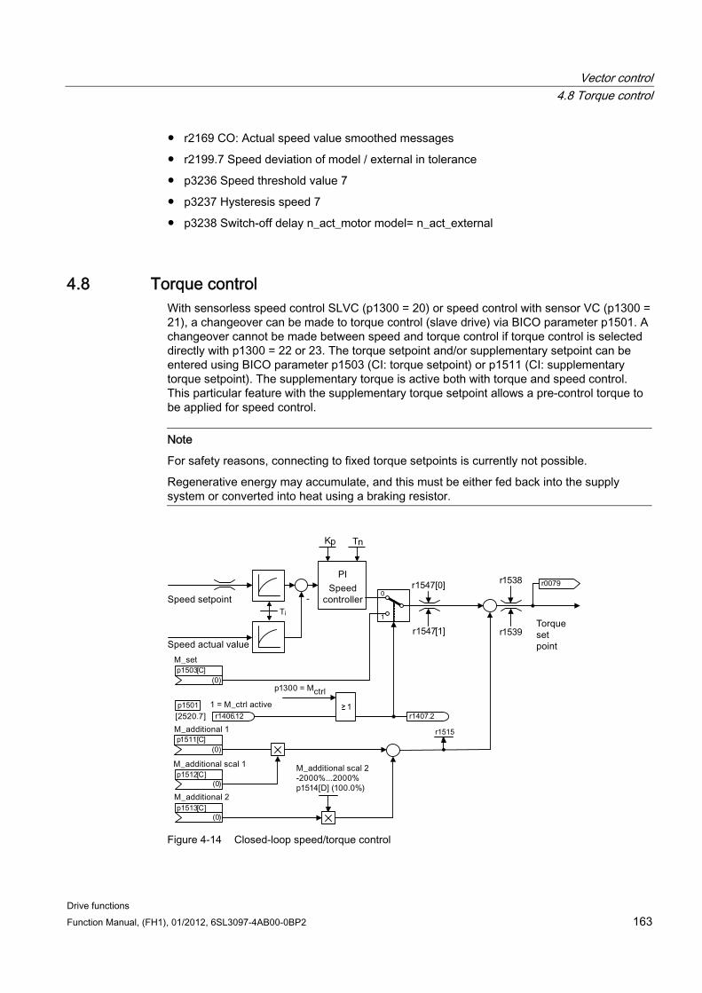
Vector control 4.8 Torque control
Drive functions Function Manual, (FH1), 01/2012, 6SL3097-4AB00-0BP2 163
r2169 CO: Actual speed value smoothed messages
r2199.7 Speed deviation of model / external in tolerance
p3236 Speed threshold value 7
p3237 Hysteresis speed 7
p3238 Switch-off delay n_act_motor model= n_act_external
4.8 Torque control With sensorless speed control SLVC (p1300 = 20) or speed control with sensor VC (p1300 = 21), a changeover can be made to torque control (slave drive) via BICO parameter p1501. A changeover cannot be made between speed and torque control if torque control is selected directly with p1300 = 22 or 23. The torque setpoint and/or supplementary setpoint can be entered using BICO parameter p1503 (CI: torque setpoint) or p1511 (CI: supplementary torque setpoint). The supplementary torque is active both with torque and speed control. This particular feature with the supplementary torque setpoint allows a pre-control torque to be applied for speed control.
Note
For safety reasons, connecting to fixed torque setpoints is currently not possible.
Regenerative energy may accumulate, and this must be either fed back into the supply system or converted into heat using a braking resistor.
-
r1547[0]r1538
r1547[1] r1539
Ti
r0079
(0)
p1512[C]
(0)
p1513[C]
(0)
p1511[C]
(0)
p1503[C]
r1406.12
p1501
r1515
r1407.2
0
1
Figure 4-14 Closed-loop speed/torque control
Vector control 4.8 Torque control
Drive functions 164 Function Manual, (FH1), 01/2012, 6SL3097-4AB00-0BP2
The total of the two torque setpoints is limited in the same way as the speed control torque setpoint. Above the maximum speed (p1082), a speed limiting controller reduces the torque limits in order to prevent the drive from accelerating any further.
A "real" torque control (with self-adjusting speed) is only possible in closed-loop but not open-loop control for sensorless vector control (SLVC). In open-loop control, the torque setpoint adjusts the setpoint speed via a ramp-function generator (integration time ~ p1499 x p0341 x p0342). For this reason, encoderless torque control at standstill is only suitable for applications that require an accelerating torque but no load torque (e.g. traction drives). This restriction does not apply to torque control with sensor.
OFF responses OFF1 and p1300 = 22, 23
– Reaction as for OFF2
OFF1, p1501 = "1" signal and p1300 ≠ 22, 23
– No separate braking response; the braking response takes place by a drive that specifies the torque.
– The pulses are suppressed when the brake application time (p1217) expires. Standstill is detected when the actual speed value is less than the speed threshold (p1226) or when the monitoring time (p1227) that started when speed setpoint ≤ speed threshold (p1226) has expired.
– Switching on inhibited is activated.
OFF2
– Immediate pulse suppression, the drive coasts to standstill.
– The motor brake (if parameterized) is closed immediately.
– Switching on inhibited is activated.
OFF3
– Switch to speed-controlled operation
– n_set = 0 is input immediately to brake the drive along the OFF3 deceleration ramp (p1135).
– When zero speed is detected, the motor brake (if parameterized) is closed.
– The pulses are suppressed when the motor brake application time (p1217) has elapsed. Standstill is detected when the actual speed value is less than the speed threshold (p1226) or when the monitoring time (p1227) that started when speed setpoint ≤ speed threshold (p1226) has expired.
– Switching on inhibited is activated.
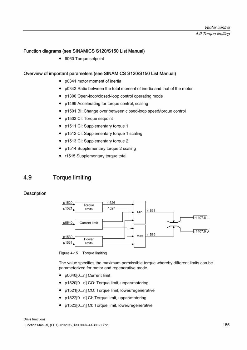
Vector control 4.9 Torque limiting
Drive functions Function Manual, (FH1), 01/2012, 6SL3097-4AB00-0BP2 165
Function diagrams (see SINAMICS S120/S150 List Manual) 6060 Torque setpoint
Overview of important parameters (see SINAMICS S120/S150 List Manual) p0341 motor moment of inertia
p0342 Ratio between the total moment of inertia and that of the motor
p1300 Open-loop/closed-loop control operating mode
p1499 Accelerating for torque control, scaling
p1501 BI: Change over between closed-loop speed/torque control
p1503 CI: Torque setpoint
p1511 CI: Supplementary torque 1
p1512 CI: Supplementary torque 1 scaling
p1513 CI: Supplementary torque 2
p1514 Supplementary torque 2 scaling
r1515 Supplementary torque total
4.9 Torque limiting
Description
Figure 4-15 Torque limiting
The value specifies the maximum permissible torque whereby different limits can be parameterized for motor and regenerative mode.
p0640[0...n] Current limit
p1520[0...n] CO: Torque limit, upper/motoring
p1521[0...n] CO: Torque limit, lower/regenerative
p1522[0...n] CI: Torque limit, upper/motoring
p1523[0...n] CI: Torque limit, lower/regenerative
Vector control 4.9 Torque limiting
Drive functions 166 Function Manual, (FH1), 01/2012, 6SL3097-4AB00-0BP2
p1524[0...n] CO: Torque limit, upper/motoring, scaling
p1525[0...n] CO: Torque limit, lower/regenerative scaling
p1530[0...n] Motor mode power limit
p1531[0...n] Regenerative mode power limit
The current active torque limit values are displayed in the following parameters:
r0067 Maximum drive output current
r1526 Torque limit, upper/motoring without offset
r1527 Torque limit, lower/regenerative without offset
All of the following limits apply to the torque setpoint, which is present either at the speed controller output in the case of speed control, or at the torque input in the case of torque control. The minimum/maximum value of the different limits is used in each case. The minimum value is calculated cyclically and displayed in parameters r1538 and r1539.
r1538 CO: Upper effective torque limit
r1539 CO: Lower effective torque limit
These cyclic values therefore limit the torque setpoint at the speed controller output/torque input or indicate the instantaneous maximum possible torque. If the torque setpoint is limited in the Motor Module, this is indicated via the following diagnostic parameters:
r1407.8 Upper torque limit active
r1407.9 Lower torque limit active
indicated.
Function diagrams (see SINAMICS S120/S150 List Manual) 6060 Torque setpoint
6630 Upper/lower torque limit
6640 Current/power/torque limits
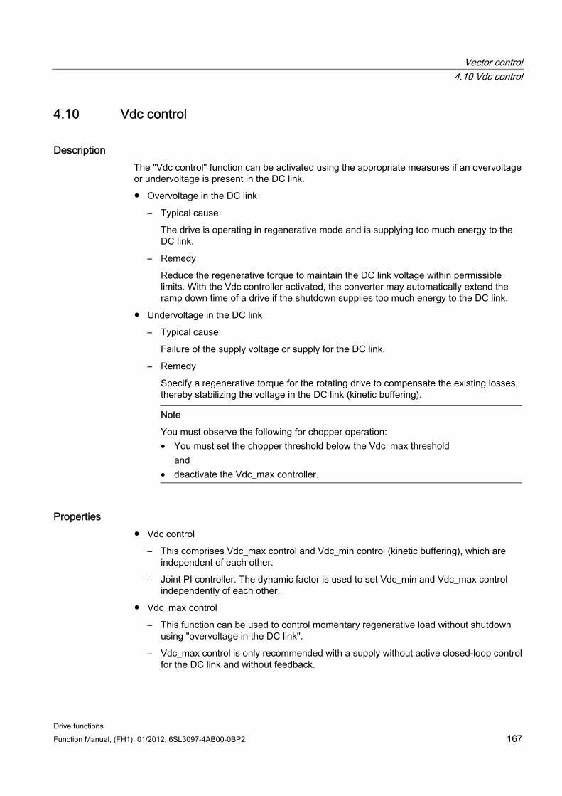
Vector control 4.10 Vdc control
Drive functions Function Manual, (FH1), 01/2012, 6SL3097-4AB00-0BP2 167
4.10 Vdc control
Description The "Vdc control" function can be activated using the appropriate measures if an overvoltage or undervoltage is present in the DC link.
Overvoltage in the DC link
– Typical cause
The drive is operating in regenerative mode and is supplying too much energy to the DC link.
– Remedy
Reduce the regenerative torque to maintain the DC link voltage within permissible limits. With the Vdc controller activated, the converter may automatically extend the ramp down time of a drive if the shutdown supplies too much energy to the DC link.
Undervoltage in the DC link
– Typical cause
Failure of the supply voltage or supply for the DC link.
– Remedy
Specify a regenerative torque for the rotating drive to compensate the existing losses, thereby stabilizing the voltage in the DC link (kinetic buffering).
Note
You must observe the following for chopper operation: • You must set the chopper threshold below the Vdc_max threshold
and • deactivate the Vdc_max controller.
Properties Vdc control
– This comprises Vdc_max control and Vdc_min control (kinetic buffering), which are independent of each other.
– Joint PI controller. The dynamic factor is used to set Vdc_min and Vdc_max control independently of each other.
Vdc_max control
– This function can be used to control momentary regenerative load without shutdown using "overvoltage in the DC link".
– Vdc_max control is only recommended with a supply without active closed-loop control for the DC link and without feedback.
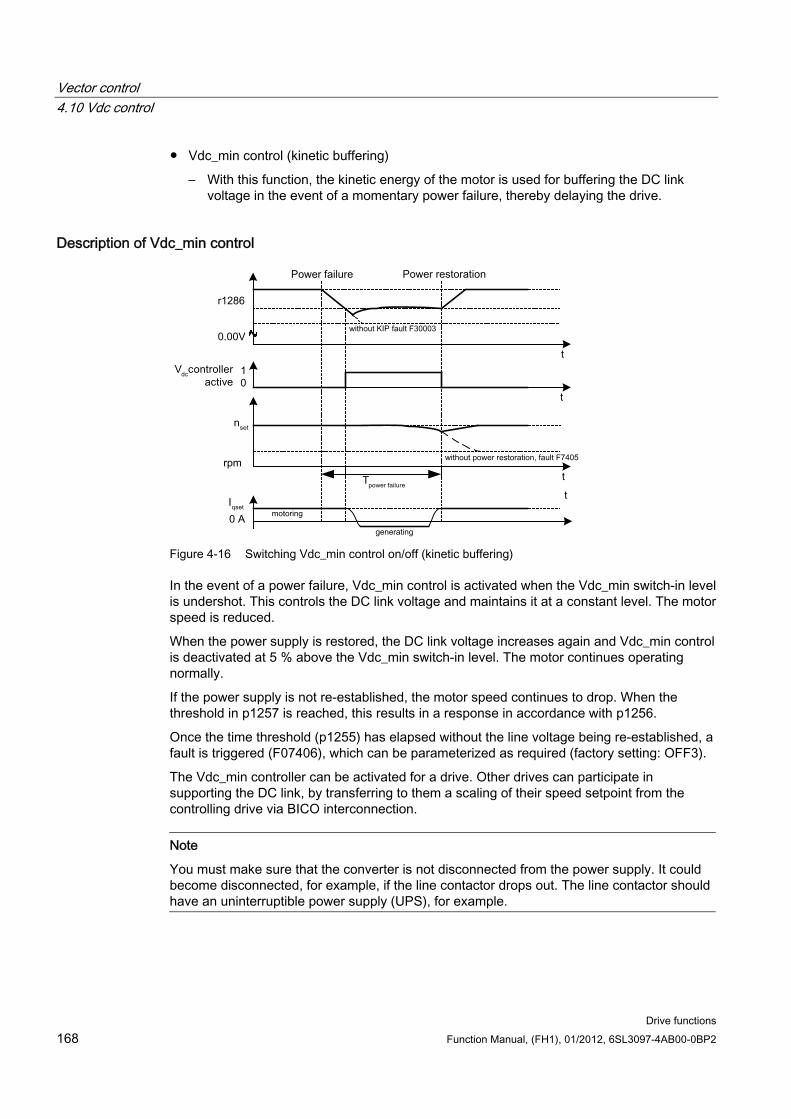
Vector control 4.10 Vdc control
Drive functions 168 Function Manual, (FH1), 01/2012, 6SL3097-4AB00-0BP2
Vdc_min control (kinetic buffering)
– With this function, the kinetic energy of the motor is used for buffering the DC link voltage in the event of a momentary power failure, thereby delaying the drive.
Description of Vdc_min control
Figure 4-16 Switching Vdc_min control on/off (kinetic buffering)
In the event of a power failure, Vdc_min control is activated when the Vdc_min switch-in level is undershot. This controls the DC link voltage and maintains it at a constant level. The motor speed is reduced.
When the power supply is restored, the DC link voltage increases again and Vdc_min control is deactivated at 5 % above the Vdc_min switch-in level. The motor continues operating normally.
If the power supply is not re-established, the motor speed continues to drop. When the threshold in p1257 is reached, this results in a response in accordance with p1256.
Once the time threshold (p1255) has elapsed without the line voltage being re-established, a fault is triggered (F07406), which can be parameterized as required (factory setting: OFF3).
The Vdc_min controller can be activated for a drive. Other drives can participate in supporting the DC link, by transferring to them a scaling of their speed setpoint from the controlling drive via BICO interconnection.
Note
You must make sure that the converter is not disconnected from the power supply. It could become disconnected, for example, if the line contactor drops out. The line contactor should have an uninterruptible power supply (UPS), for example.
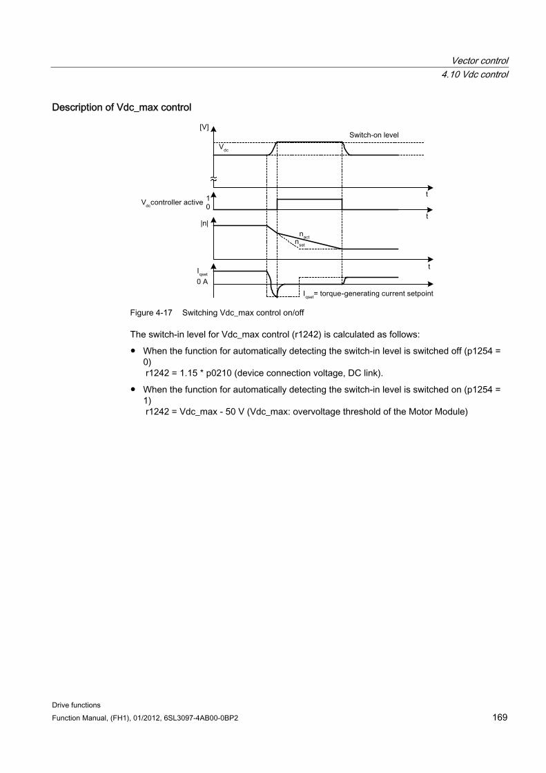
Vector control 4.10 Vdc control
Drive functions Function Manual, (FH1), 01/2012, 6SL3097-4AB00-0BP2 169
Description of Vdc_max control
Figure 4-17 Switching Vdc_max control on/off
The switch-in level for Vdc_max control (r1242) is calculated as follows:
When the function for automatically detecting the switch-in level is switched off (p1254 = 0) r1242 = 1.15 * p0210 (device connection voltage, DC link).
When the function for automatically detecting the switch-in level is switched on (p1254 = 1) r1242 = Vdc_max - 50 V (Vdc_max: overvoltage threshold of the Motor Module)
Vector control 4.10 Vdc control
Drive functions 170 Function Manual, (FH1), 01/2012, 6SL3097-4AB00-0BP2
DANGER Vdc control with Basic Line Modules
If several Motor Modules are supplied from a non-regenerative infeed unit (e.g. a Basic Line Module), the Vdc_max control may only be activated for that Motor Module whose drive has the nominal highest moment of inertia of all connected drives. For the other Motor Modules this function must be disabled or monitoring must be set. If the Vdc_max control is active for several Motor Modules, then for an unfavorable parameterization, the controllers can mutually influence one another negatively. The drives can become unstable, individual drives can unintentionally accelerate. • Activating the Vdc_max control:
– Vector control: p1240 = 1 (factory setting) – Servo control: p1240 = 1 – U/f control: p1280 = 1 (factory setting)
• Inhibiting the Vdc_max control: – Vector control: p1240 = 0 – Servo control: p1240 = 0 (factory setting) – U/f control: p1280 = 0
• Activating the Vdc_max monitoring function – Vector control: p1240 = 4 or 6 – Servo control: p1240 = 4 or 6 – U/f control: p1280 = 4 or 6
Function diagrams (see SINAMICS S120/S150 List Manual) 6220 Vdc_max controller and Vdc_min controller
Overview of important parameters (see SINAMICS S120/S150 List Manual) p1240[0...n] Vdc controller or Vdc monitoring configuration
r1242 Vdc_max controller switch-in level
p1243[0...n] Vdc_max controller dynamic factor (control)
p1245[0...n] Vdc_min controller switch-in level (kinetic buffering) (control)
r1246 Vdc_min controller switch-in level (kinetic buffering) (control)
p1247[0...n] Vdc_min controller dynamic factor (kinetic buffering) (control)
p1250[0...n] Vdc controller proportional gain (control)
p1251[0...n] Vdc controller integral time (control)
p1252[0...n] Vdc controller derivative-action time (control)
p1254 Vdc_max controller automatic detection ON level (control)
p1256[0...n] Vdc_min controller response (kinetic buffering) (control)
p1257[0...n] Vdc_min controller speed threshold (controller)
r1258 CO: Vdc controller output (ctrl)
Vector control 4.11 Current setpoint filter
Drive functions Function Manual, (FH1), 01/2012, 6SL3097-4AB00-0BP2 171
4.11 Current setpoint filter
Description You can parameterize the two current setpoint filters 1 and 2 connected in series as follows:
Low-pass 2nd order (PT2): -40 dB/decade)
Bandstop
Low-pass with reduction
General 2nd order filter
The STARTER commissioning tool converts band-stop and low-pass filters with reduction into the parameters of the general 2nd order filter. The phase frequency curve is shown alongside the amplitude log frequency curve. A phase shift results in a control system delay and should be kept to a minimum.
You activate the current setpoint filters with p1656[0...n].0 = 1 and p1656[0...n].1 = 1. You set the current setpoint filter parameters with p1657 to p1666.
Function diagrams (see SINAMICS S120/S150 List Manual) 6710 Current setpoint filters
Overview of important parameters (see SINAMICS S120/S150 List Manual) p1655[0...n] CI: Current setpoint filter natural frequency tuning
p1656[0...n] Current setpoint filter activation
p1657[0...n] current setpoint filter 1st type
p1658[0...n] current setpoint filter 1 denominator natural frequency
p1659[0...n] current setpoint filter 1 denominator damping
p1660[0...n] current setpoint filter 1 numerator natural frequency
p1661[0...n] current setpoint filter 1 numerator damping
p1662[0...n] current setpoint filter 2nd type
p1663[0...n] current setpoint filter 2 denominator natural frequency
p1664[0...n] current setpoint filter 2 denominator damping
p1665[0...n] current setpoint filter 2 numerator natural frequency
p1666[0...n] current setpoint filter 2 numerator damping
Vector control 4.12 Speed actual value filter
Drive functions 172 Function Manual, (FH1), 01/2012, 6SL3097-4AB00-0BP2
4.12 Speed actual value filter
Description For vector control a speed actual value filter can be set. You can parameterize the speed actual value filter as follows:
Low-pass 2nd order (PT2): -40 dB/decade)
Bandstop
Low-pass with reduction
General 2nd order filter
The STARTER commissioning tool converts band-stop and low-pass filters with reduction into the parameters of the general 2nd order filter.
You activate speed actual value filter with p1656.4 = 1. You set the speed actual value filter parameters with p1677 to p1681.
Note
For the vector control, there are 2 current setpoint filters and one speed actual value filter. The speed actual value filter has been allocated the number "5".
Function diagrams (see SINAMICS S120/S150 List Manual) 1680 Overviews - Vector control, encoder evaluations (position, speed, temperature)
4715 Encoder evaluation - Actual speed value and pole position sensing, motor encoder ASM/SM (encoder1)
Overview of important parameters (see SINAMICS S120/S150 List Manual) p1655[0...4] CI: Speed actual value filter 5 natural frequency tuning
p1656[0...n].4 speed actual value filter 5 activation
p1677[0...n] speed actual value filter 5th type
p1678[0...n] speed actual value filter 5 denominator natural frequency
p1679[0...n] speed actual value filter 5 denominator damping
p1680[0...n] speed actual value filter 5 numerator natural frequency
p1681[0...n] speed actual value filter 5 numerator damping
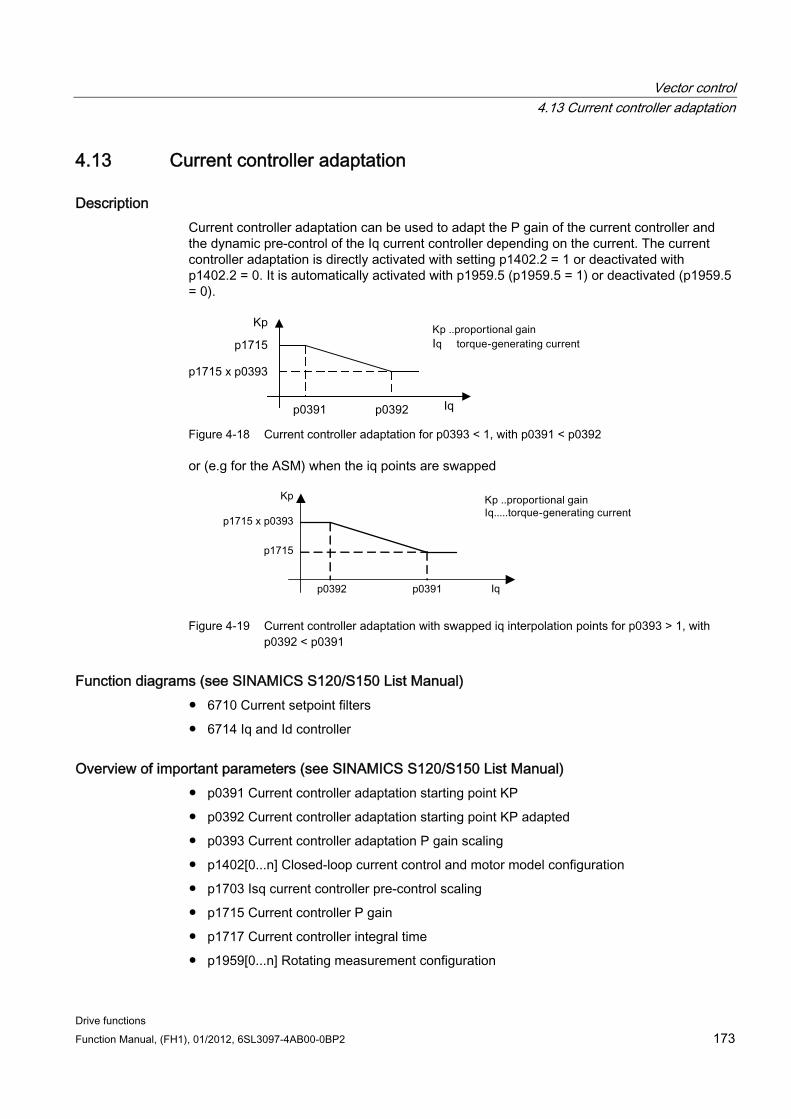
Vector control 4.13 Current controller adaptation
Drive functions Function Manual, (FH1), 01/2012, 6SL3097-4AB00-0BP2 173
4.13 Current controller adaptation
Description Current controller adaptation can be used to adapt the P gain of the current controller and the dynamic pre-control of the Iq current controller depending on the current. The current controller adaptation is directly activated with setting p1402.2 = 1 or deactivated with p1402.2 = 0. It is automatically activated with p1959.5 (p1959.5 = 1) or deactivated (p1959.5 = 0).
Figure 4-18 Current controller adaptation for p0393 < 1, with p0391 < p0392
or (e.g for the ASM) when the iq points are swapped
p1715 x p0393
p1715
Kp
p0391p0392 Iq
Figure 4-19 Current controller adaptation with swapped iq interpolation points for p0393 > 1, with
p0392 < p0391
Function diagrams (see SINAMICS S120/S150 List Manual) 6710 Current setpoint filters
6714 Iq and Id controller
Overview of important parameters (see SINAMICS S120/S150 List Manual) p0391 Current controller adaptation starting point KP
p0392 Current controller adaptation starting point KP adapted
p0393 Current controller adaptation P gain scaling
p1402[0...n] Closed-loop current control and motor model configuration
p1703 Isq current controller pre-control scaling
p1715 Current controller P gain
p1717 Current controller integral time
p1959[0...n] Rotating measurement configuration
Vector control 4.14 Motor data identification and rotating measurement
Drive functions 174 Function Manual, (FH1), 01/2012, 6SL3097-4AB00-0BP2
4.14 Motor data identification and rotating measurement
Description There are two motor data identification options, which are based on each other:
Motor data identification with p1910 (standstill measurement)
Rotating measurement with p1960
Note
For both types of motor data identification the following applies: If there is a motor brake, then this must be open (p1215 = 2).
These can be selected more easily via p1900. p1900 = 2 selects the standstill measurement (motor not rotating). The setting p1900 = 1 also activates the rotating measurement, i.e. with the setting of p1900 = 1 and p1960 depending on the current control mode (p1300).
If a permanent-magnet synchronous motor is being used (p0300 = 2), then with p1900 > 1, the encoder adjustment (p1990 = 1) is automatically activated. The technique used can be set in p1980.
Parameter p1960 is set depending on p1300:
p1960 = 1, when p1300 = 20 or 22 (without encoder)
p1960 = 2, when p1300 = 21 or 23 (with encoder)
The measurements, parameterized using p1900 are started in the following sequence after the drive has been enabled:
Standstill (static) measurement - after the measurement has been completed, the pulses are inhibited and parameter p1910 is reset to 0.
Encoder adjustment - after the measurement has been completed, the pulses are inhibited and parameter p1990 is reset to 0.
Rotating measurement - after the measurement has been completed, the pulses are inhibited and parameter p1960 is reset to 0.
After all of the measurements, activated using p1900 have been successfully completed, then this is set to 0.
Note
To set the new controller setting permanently, the data must be saved in a non-volatile memory (see also "Parameters").
Completion of the individual motor data identification runs can be read via parameters r3925 to r3928.
The motor data identification runs influence only the currently valid motor data set (MDS).
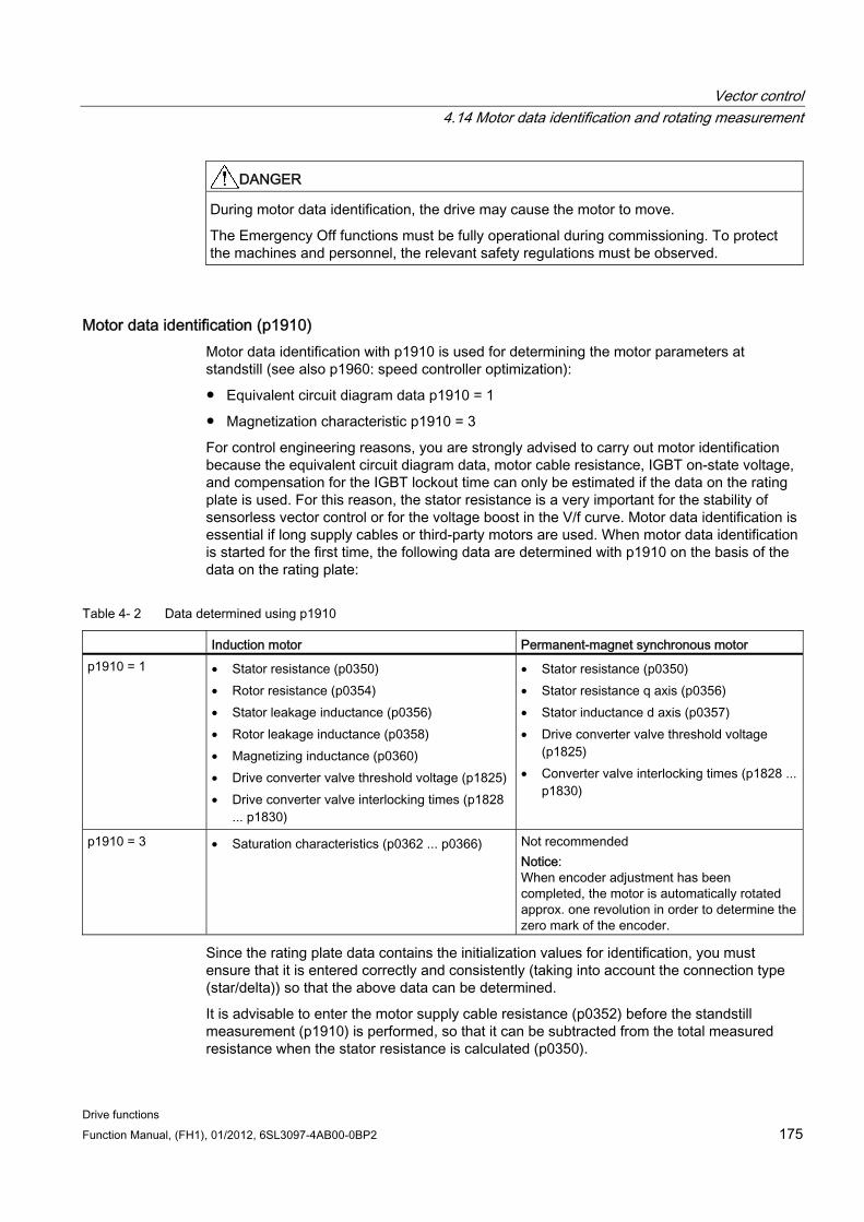
Vector control 4.14 Motor data identification and rotating measurement
Drive functions Function Manual, (FH1), 01/2012, 6SL3097-4AB00-0BP2 175
DANGER During motor data identification, the drive may cause the motor to move.
The Emergency Off functions must be fully operational during commissioning. To protect the machines and personnel, the relevant safety regulations must be observed.
Motor data identification (p1910) Motor data identification with p1910 is used for determining the motor parameters at standstill (see also p1960: speed controller optimization):
Equivalent circuit diagram data p1910 = 1
Magnetization characteristic p1910 = 3
For control engineering reasons, you are strongly advised to carry out motor identification because the equivalent circuit diagram data, motor cable resistance, IGBT on-state voltage, and compensation for the IGBT lockout time can only be estimated if the data on the rating plate is used. For this reason, the stator resistance is a very important for the stability of sensorless vector control or for the voltage boost in the V/f curve. Motor data identification is essential if long supply cables or third-party motors are used. When motor data identification is started for the first time, the following data are determined with p1910 on the basis of the data on the rating plate:
Table 4- 2 Data determined using p1910
Induction motor Permanent-magnet synchronous motor p1910 = 1 • Stator resistance (p0350)
• Rotor resistance (p0354) • Stator leakage inductance (p0356) • Rotor leakage inductance (p0358) • Magnetizing inductance (p0360) • Drive converter valve threshold voltage (p1825) • Drive converter valve interlocking times (p1828
... p1830)
• Stator resistance (p0350) • Stator resistance q axis (p0356) • Stator inductance d axis (p0357) • Drive converter valve threshold voltage
(p1825) • Converter valve interlocking times (p1828 ...
p1830)
p1910 = 3 • Saturation characteristics (p0362 ... p0366) Not recommended Notice: When encoder adjustment has been completed, the motor is automatically rotated approx. one revolution in order to determine the zero mark of the encoder.
Since the rating plate data contains the initialization values for identification, you must ensure that it is entered correctly and consistently (taking into account the connection type (star/delta)) so that the above data can be determined.
It is advisable to enter the motor supply cable resistance (p0352) before the standstill measurement (p1910) is performed, so that it can be subtracted from the total measured resistance when the stator resistance is calculated (p0350).
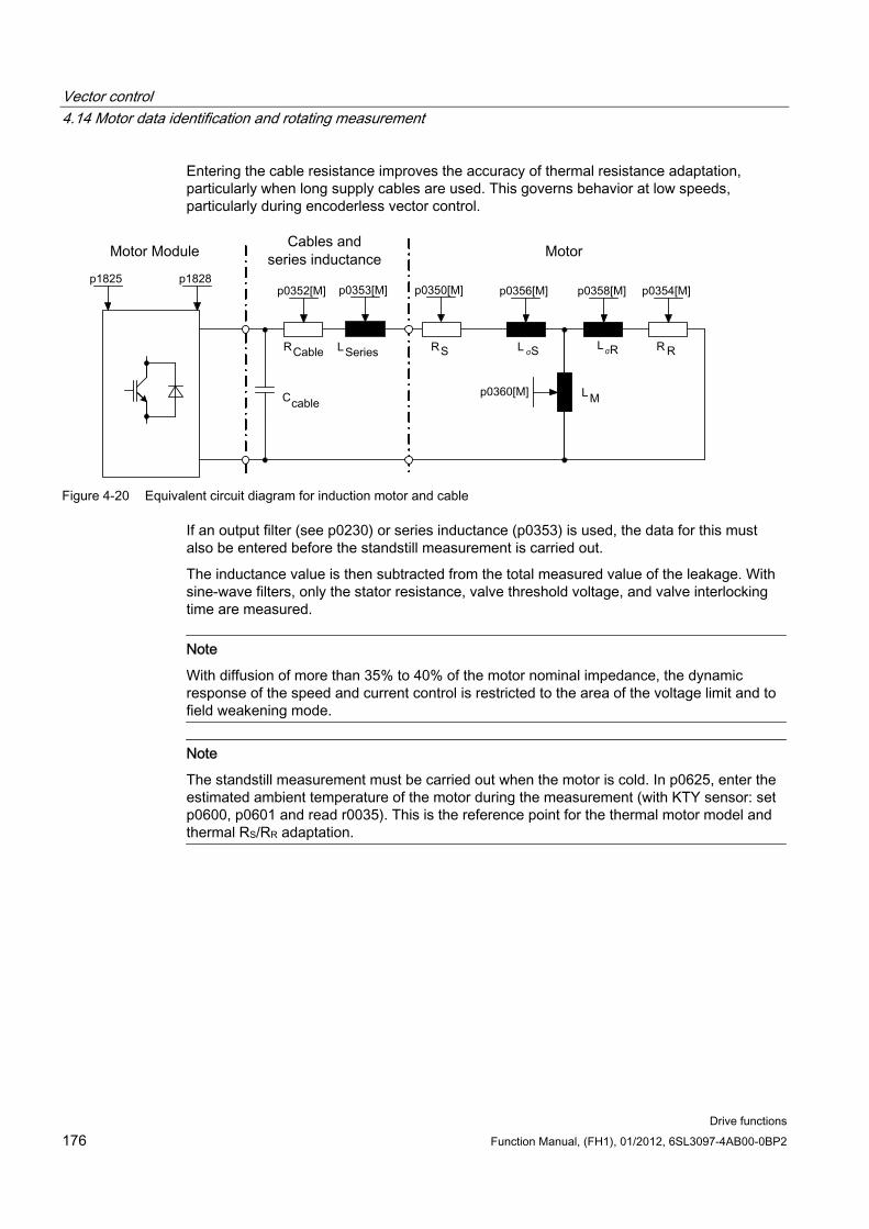
Vector control 4.14 Motor data identification and rotating measurement
Drive functions 176 Function Manual, (FH1), 01/2012, 6SL3097-4AB00-0BP2
Entering the cable resistance improves the accuracy of thermal resistance adaptation, particularly when long supply cables are used. This governs behavior at low speeds, particularly during encoderless vector control.
Figure 4-20 Equivalent circuit diagram for induction motor and cable
If an output filter (see p0230) or series inductance (p0353) is used, the data for this must also be entered before the standstill measurement is carried out.
The inductance value is then subtracted from the total measured value of the leakage. With sine-wave filters, only the stator resistance, valve threshold voltage, and valve interlocking time are measured.
Note
With diffusion of more than 35% to 40% of the motor nominal impedance, the dynamic response of the speed and current control is restricted to the area of the voltage limit and to field weakening mode.
Note
The standstill measurement must be carried out when the motor is cold. In p0625, enter the estimated ambient temperature of the motor during the measurement (with KTY sensor: set p0600, p0601 and read r0035). This is the reference point for the thermal motor model and thermal RS/RR adaptation.
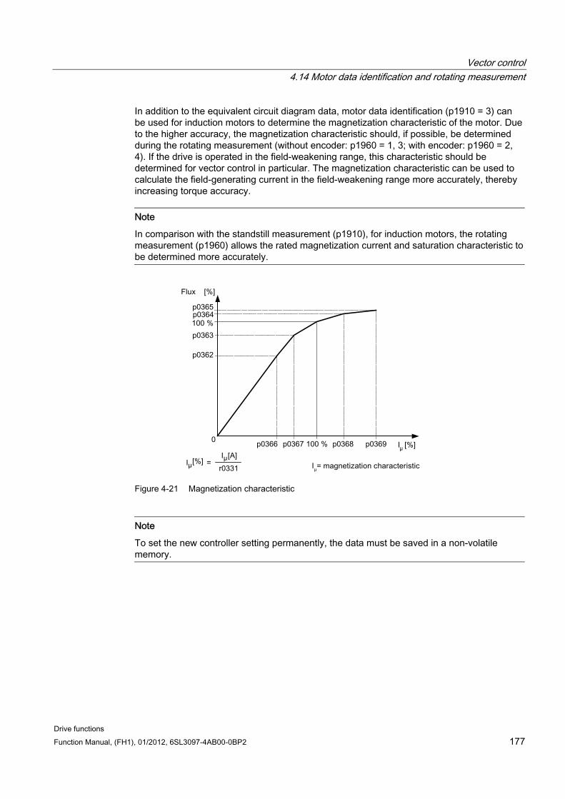
Vector control 4.14 Motor data identification and rotating measurement
Drive functions Function Manual, (FH1), 01/2012, 6SL3097-4AB00-0BP2 177
In addition to the equivalent circuit diagram data, motor data identification (p1910 = 3) can be used for induction motors to determine the magnetization characteristic of the motor. Due to the higher accuracy, the magnetization characteristic should, if possible, be determined during the rotating measurement (without encoder: p1960 = 1, 3; with encoder: p1960 = 2, 4). If the drive is operated in the field-weakening range, this characteristic should be determined for vector control in particular. The magnetization characteristic can be used to calculate the field-generating current in the field-weakening range more accurately, thereby increasing torque accuracy.
Note
In comparison with the standstill measurement (p1910), for induction motors, the rotating measurement (p1960) allows the rated magnetization current and saturation characteristic to be determined more accurately.
Figure 4-21 Magnetization characteristic
Note
To set the new controller setting permanently, the data must be saved in a non-volatile memory.
Vector control 4.14 Motor data identification and rotating measurement
Drive functions 178 Function Manual, (FH1), 01/2012, 6SL3097-4AB00-0BP2
Motor data identification sequence Enter p1910 > 0. Alarm A07991 is displayed.
Motor data identification starts the next time that the motor is switched on.
p1910 resets itself to "0" (successful identification) or fault F07990 is output.
r0047 displays the current status of the measurement.
Rotating measurement (p1960) Rotating measurement can be activated via p1960 or p1900 = 1.
The main difference of rotating measurement is speed control optimization, with which the drive's moment of inertia is ascertained and speed controller is set. In addition, the saturation characteristic and rated magnetization current of induction motors are measured.
If the rotating measurement is not to be carried out using the speed set in p1965, this parameter can be changed before the measurement is started. Higher speeds are recommended.
The same applies to the speed in p1961 for which the saturation characteristic is determined and the encoder test is carried out.
The speed controller is set to the symmetrical optimum in accordance with dynamic factor p1967. p1967 must be set before the optimization run and only affects the calculation of the controller parameters.
If, during the measurement, it becomes clear that, with the specified dynamic factor, the drive cannot operate in a stable manner or the torque ripples are too large, the dynamic response is reduced automatically and the result displayed in r1968. The drive must then be checked to ensure that it is stable across the entire control range. If necessary, the dynamic response may have to be reduced or Kp/Tn adaptation for the speed controller parameterized accordingly.
When commissioning induction machines, you are advised to proceed as follows:
Before connecting the load, a complete "rotating measurement" (without encoder: p1960 = 1; with encoder: p1960 = 2) should be carried out. Since the induction machine is idling, you can expect highly accurate results regarding the saturation characteristic and the rated magnetization current.
When the load is connected, speed controller optimization should be repeated because the total inertia load has changed. This is realized by selecting parameter p1960 (without encoder: p1960 = 3; with encoder: p1960 = 4). The saturation characteristic recording is automatically deactivated in parameter p1959 during the speed optimization run.
When permanent-magnet synchronous motors are commissioned, with the load connected, the speed controller should be optimized (p1960 = 2/4).
Vector control 4.14 Motor data identification and rotating measurement
Drive functions Function Manual, (FH1), 01/2012, 6SL3097-4AB00-0BP2 179
Rotating measurement (p1960 > 0): Sequence The following measurements are carried out when the enable signals are set and a switch-on command is issued in accordance with the settings in p1959 and p1960.
Encoder test
If a speed encoder is used, the direction of rotation and the pulse number are checked.
Only for induction motors:
– Measurement of the saturation characteristic (p0362 to p0369)
– Measurement of the magnetization current (p0320) and determination of the offset voltage of the converter for offset compensation
– Measurement of the saturation of the leakage inductance, for induction motors, and setting of the current controller adaptation (p0391…p0393)
This is automatically activated with 1LA1 and 1LA8 motors (p0300 = 11, 18) (see p1959.5).
Speed controller optimization
– p1470 and p1472, when p1960 = 1 (operation without encoder)
– p1460 and p1462, when p1960 = 2 (operation with encoder)
– Kp adaptation switch-off
Acceleration pre-control setting (p1496)
Setting for ratio between the total moment of inertia and that of the motor (p0342)
Note
To set the new controller setting permanently, the data must be saved in a non-volatile memory.
DANGER During speed controller optimization, the drive triggers movements in the motor that can reach the maximum motor speed. The Emergency Off functions must be fully operational during commissioning. To protect the machines and personnel, the relevant safety regulations must be observed.
Note
If speed controller optimization is used for operation with encoder, then the closed-loop control operating mode is automatically changed over to closed-loop speed control without encoder, so that the encoder test can be carried out.
Vector control 4.14 Motor data identification and rotating measurement
Drive functions 180 Function Manual, (FH1), 01/2012, 6SL3097-4AB00-0BP2
Overview of important parameters (see SINAMICS S120/S150 List Manual) r0047 motor data identification routine and speed controller optimization
p1300[0...n] Open-loop/closed-loop control operating mode
p1900 Motor data identification and rotating measurement
r3925[0...n] identification final display
r3927[0...n] motor data identification, induction motor data determined
r3928[0...n] Rotating measurement configuration
Rotating measurement
p0391[0...n] Current controller adaptation starting point Kp
p0392[0...n] Current controller adaptation starting point Kp adapted
p0393[0...n] Current controller adaptation P gain scaling
p1959[0...n] Rotating measurement configuration
p1960 Rotating measurement selection
p1961 Saturation characteristic speed for calculation
p1965 Speed_ctrl_opt speed
p1967 Seed_ctrl_opt dynamic factor
r1968 Speed_ctrl_opt dynamic factor actual
r1969 Speed_ctrl_opt moment of inertia determined
r1973 Rotating measurement encoder test pulse number determined
p1980[0...n] PolID technique
p1990 Determine encoder adjustment commutation angle offset
Motor data identification at standstill
p1909[0...n] Motor data identification control word
p1910 Motor data identification selection
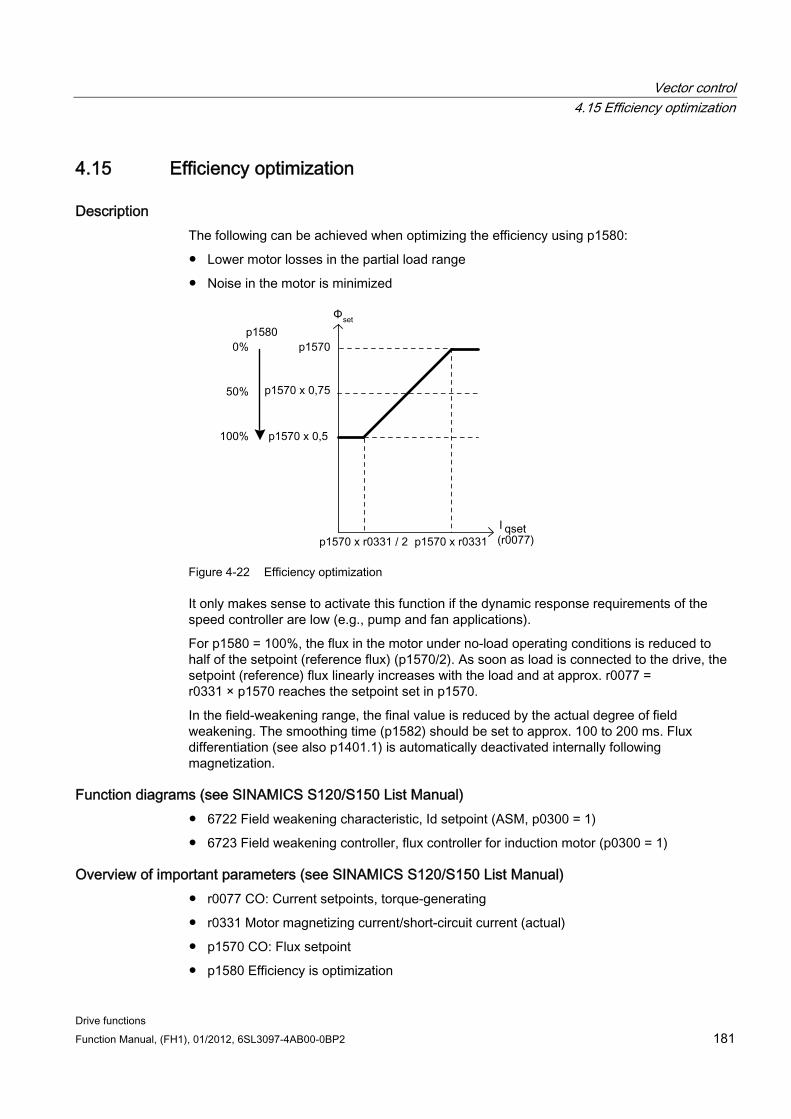
Vector control 4.15 Efficiency optimization
Drive functions Function Manual, (FH1), 01/2012, 6SL3097-4AB00-0BP2 181
4.15 Efficiency optimization
Description The following can be achieved when optimizing the efficiency using p1580:
Lower motor losses in the partial load range
Noise in the motor is minimized
Figure 4-22 Efficiency optimization
It only makes sense to activate this function if the dynamic response requirements of the speed controller are low (e.g., pump and fan applications).
For p1580 = 100%, the flux in the motor under no-load operating conditions is reduced to half of the setpoint (reference flux) (p1570/2). As soon as load is connected to the drive, the setpoint (reference) flux linearly increases with the load and at approx. r0077 = r0331 × p1570 reaches the setpoint set in p1570.
In the field-weakening range, the final value is reduced by the actual degree of field weakening. The smoothing time (p1582) should be set to approx. 100 to 200 ms. Flux differentiation (see also p1401.1) is automatically deactivated internally following magnetization.
Function diagrams (see SINAMICS S120/S150 List Manual) 6722 Field weakening characteristic, Id setpoint (ASM, p0300 = 1)
6723 Field weakening controller, flux controller for induction motor (p0300 = 1)
Overview of important parameters (see SINAMICS S120/S150 List Manual) r0077 CO: Current setpoints, torque-generating
r0331 Motor magnetizing current/short-circuit current (actual)
p1570 CO: Flux setpoint
p1580 Efficiency is optimization
Vector control 4.16 Quick magnetization for induction motors
Drive functions 182 Function Manual, (FH1), 01/2012, 6SL3097-4AB00-0BP2
4.16 Quick magnetization for induction motors
Description Application example for the "quick magnetization for induction motors" function:
For crane applications, frequently a frequency converter is switched alternately to different motors. After being switched to a different motor, a new data set must be loaded in the frequency converter and the motor magnetized. This can result in excessive waiting times, which can be significantly reduced by means of quick magnetization.
Features Application for induction motors in closed-loop vector control.
Fast flux build-up through injection of a field-generating current at the current limit, resulting in a significant reduction in magnetizing time.
The "flying restart" function continues working with parameter p0346 (magnetization time).
Magnetization is not dependent on a brake configuration (p1215) as it is with servo drives.
Commissioning Parameter p1401.6 = 1 (flux control configuration) is set in order to activate quick magnetization.
This setting initiates the following sequence during motor starting:
The field-producing current setpoint jumps to its limit value: 0.9 * r0067 (Imax).
The flux increases as fast as physically possible with the specified current.
The flux setpoint r0083 is made to follow accordingly.
As soon as the flux threshold value programmed in p1573 is reached (min.: 10% and max. 200%, factory setting 100%), excitation is ended and the speed setpoint is enabled. The flux threshold value must not be set too low for a large load because the torque-producing current is limited during magnetization.
Note
The flux threshold value set in parameter p1573 is effective only if the actual flux during magnetization reaches the value programmed in p1573 before the time set in p0346.
The flux is increased further until the flux setpoint in p1570 has been reached.
The field-producing current setpoint is reduced by means of a flux controller with P gain (p1590) and the parameterized smoothing factor (p1616).
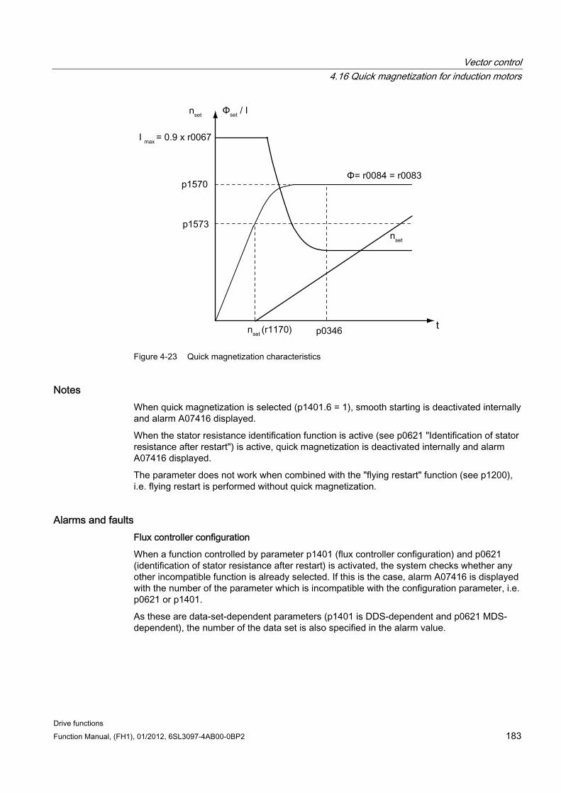
Vector control 4.16 Quick magnetization for induction motors
Drive functions Function Manual, (FH1), 01/2012, 6SL3097-4AB00-0BP2 183
Figure 4-23 Quick magnetization characteristics
Notes When quick magnetization is selected (p1401.6 = 1), smooth starting is deactivated internally and alarm A07416 displayed.
When the stator resistance identification function is active (see p0621 "Identification of stator resistance after restart") is active, quick magnetization is deactivated internally and alarm A07416 displayed.
The parameter does not work when combined with the "flying restart" function (see p1200), i.e. flying restart is performed without quick magnetization.
Alarms and faults Flux controller configuration
When a function controlled by parameter p1401 (flux controller configuration) and p0621 (identification of stator resistance after restart) is activated, the system checks whether any other incompatible function is already selected. If this is the case, alarm A07416 is displayed with the number of the parameter which is incompatible with the configuration parameter, i.e. p0621 or p1401.
As these are data-set-dependent parameters (p1401 is DDS-dependent and p0621 MDS-dependent), the number of the data set is also specified in the alarm value.
Vector control 4.16 Quick magnetization for induction motors
Drive functions 184 Function Manual, (FH1), 01/2012, 6SL3097-4AB00-0BP2
The flux control configuration (p1401) settings are inconsistent. Fault codes: 1 = quick magnetization (p1401.6) and smooth starting (p1401.0) 2 = quick magnetization (p1401.6) and flux build-up control (p1401.2) 3 = quick magnetization (p1401.6) and Rs identification (stator resistance identification) after restart (p0621 = 2)
Remedy:
For fault cause 1:
– Deactivate smooth starting: p1401.0 = 0
– Deactivate quick magnetization: p1401.6 = 0
For fault cause 2:
– Deactivate flux build-up control: p1401.2 = 0
– Deactivate quick magnetization: p1401.6 = 0
For fault cause 3:
– Change Rs identification parameter settings: p0621 = 0, 1
– Deactivate quick magnetization: p1401.6 = 0
Flux controller output limited
If the current limit p0640[D] is set very low (below the rated magnetization current value in p0320[M]), the parameterized flux setpoint p1570 [D] might not be reached at all.
As soon as the time in p0346 (magnetization time) is exceeded, fault F07411 is output. Generally, the magnetization time is significantly longer than the flux build-up time associated with quick magnetization. Reaction: OFF2 Acknowledgement: Immediately
Cause:
With quick magnetization configured (p1401.6 = 1), the specified flux setpoint is not reached even though the current setpoint = 90 % of maximum current.
Motor data are incorrect.
Motor data and motor connection type (star/delta) do not match.
Current limit in p0640 is set too low for the motor concerned.
Induction motor (encoderless, open-loop control) at I2t limit.
Motor Module rating is too low.
Remedy:
Correct the motor data.
Check the motor connection type.
Correct the current limits (p0640, p0323).
Reduce the load on the induction motor.
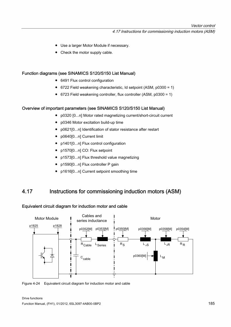
Vector control 4.17 Instructions for commissioning induction motors (ASM)
Drive functions Function Manual, (FH1), 01/2012, 6SL3097-4AB00-0BP2 185
Use a larger Motor Module if necessary.
Check the motor supply cable.
Function diagrams (see SINAMICS S120/S150 List Manual) 6491 Flux control configuration
6722 Field weakening characteristic, Id setpoint (ASM, p0300 = 1)
6723 Field weakening controller, flux controller (ASM, p0300 = 1)
Overview of important parameters (see SINAMICS S120/S150 List Manual) p0320 [0...n] Motor rated magnetizing current/short-circuit current
p0346 Motor excitation build-up time
p0621[0...n] Identification of stator resistance after restart
p0640[0...n] Current limit
p1401[0...n] Flux control configuration
p1570[0...n] CO: Flux setpoint
p1573[0...n] Flux threshold value magnetizing
p1590[0...n] Flux controller P gain
p1616[0...n] Current setpoint smoothing time
4.17 Instructions for commissioning induction motors (ASM)
Equivalent circuit diagram for induction motor and cable
Figure 4-24 Equivalent circuit diagram for induction motor and cable
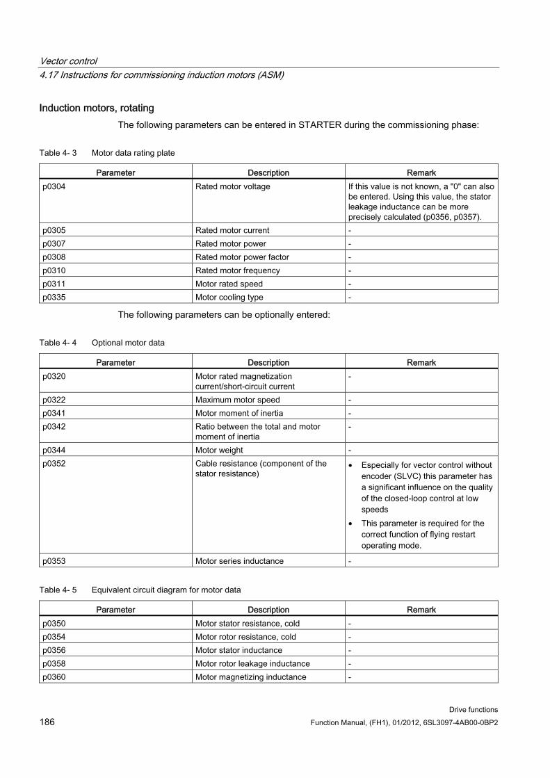
Vector control 4.17 Instructions for commissioning induction motors (ASM)
Drive functions 186 Function Manual, (FH1), 01/2012, 6SL3097-4AB00-0BP2
Induction motors, rotating The following parameters can be entered in STARTER during the commissioning phase:
Table 4- 3 Motor data rating plate
Parameter Description Remark p0304 Rated motor voltage If this value is not known, a "0" can also
be entered. Using this value, the stator leakage inductance can be more precisely calculated (p0356, p0357).
p0305 Rated motor current - p0307 Rated motor power - p0308 Rated motor power factor - p0310 Rated motor frequency - p0311 Motor rated speed - p0335 Motor cooling type -
The following parameters can be optionally entered:
Table 4- 4 Optional motor data
Parameter Description Remark p0320 Motor rated magnetization
current/short-circuit current -
p0322 Maximum motor speed - p0341 Motor moment of inertia - p0342 Ratio between the total and motor
moment of inertia -
p0344 Motor weight - p0352 Cable resistance (component of the
stator resistance) • Especially for vector control without
encoder (SLVC) this parameter has a significant influence on the quality of the closed-loop control at low speeds
• This parameter is required for the correct function of flying restart operating mode.
p0353 Motor series inductance -
Table 4- 5 Equivalent circuit diagram for motor data
Parameter Description Remark p0350 Motor stator resistance, cold - p0354 Motor rotor resistance, cold - p0356 Motor stator inductance - p0358 Motor rotor leakage inductance - p0360 Motor magnetizing inductance -
Vector control 4.17 Instructions for commissioning induction motors (ASM)
Drive functions Function Manual, (FH1), 01/2012, 6SL3097-4AB00-0BP2 187
Features Field weakening up to approx. 1.2 * rated speed (this depends on the drive converter
supply voltage and the motor data, also refer to supplementary conditions).
Flying restart
Vector closed-loop speed and torque control
Vector V/f control
Motor identification
Speed controller optimization (rotating measurement)
Thermal protection via temperature sensor (PTC/KTY)
All encoders that can be connected to an SMC10, SMC20 or SMC30 are supported.
Operation with or without encoder is possible.
Supplementary conditions Depending on the terminal voltage and load cycle, the maximum torque can be taken from the motor data sheets / project design instructions.
Commissioning We recommend the following points when commissioning:
Commissioning wizard in STARTER
The motor identification routine and the "rotating measurement" (p1900) can be activated from the commissioning wizard in STARTER.
Motor identification (standstill (static) measurement (p1910)
Rotating measurement (p1960)
The optional motor data can be entered if it is known. Otherwise, they are estimated using the rating plate data or are determined using a motor identification routine or speed controller optimization.
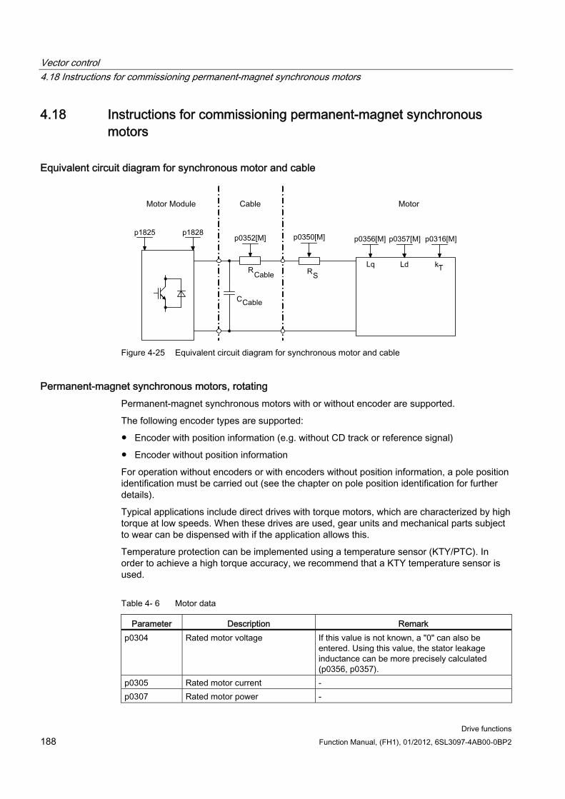
Vector control 4.18 Instructions for commissioning permanent-magnet synchronous motors
Drive functions 188 Function Manual, (FH1), 01/2012, 6SL3097-4AB00-0BP2
4.18 Instructions for commissioning permanent-magnet synchronous motors
Equivalent circuit diagram for synchronous motor and cable
Figure 4-25 Equivalent circuit diagram for synchronous motor and cable
Permanent-magnet synchronous motors, rotating Permanent-magnet synchronous motors with or without encoder are supported.
The following encoder types are supported:
Encoder with position information (e.g. without CD track or reference signal)
Encoder without position information
For operation without encoders or with encoders without position information, a pole position identification must be carried out (see the chapter on pole position identification for further details).
Typical applications include direct drives with torque motors, which are characterized by high torque at low speeds. When these drives are used, gear units and mechanical parts subject to wear can be dispensed with if the application allows this.
Temperature protection can be implemented using a temperature sensor (KTY/PTC). In order to achieve a high torque accuracy, we recommend that a KTY temperature sensor is used.
Table 4- 6 Motor data
Parameter Description Remark p0304 Rated motor voltage If this value is not known, a "0" can also be
entered. Using this value, the stator leakage inductance can be more precisely calculated (p0356, p0357).
p0305 Rated motor current - p0307 Rated motor power -
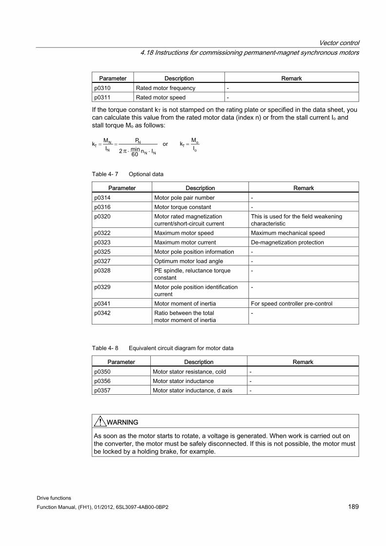
Vector control 4.18 Instructions for commissioning permanent-magnet synchronous motors
Drive functions Function Manual, (FH1), 01/2012, 6SL3097-4AB00-0BP2 189
Parameter Description Remark p0310 Rated motor frequency - p0311 Rated motor speed -
If the torque constant kT is not stamped on the rating plate or specified in the data sheet, you can calculate this value from the rated motor data (index n) or from the stall current Io and stall torque Mo as follows:
= ==π ..
Table 4- 7 Optional data
Parameter Description Remark p0314 Motor pole pair number - p0316 Motor torque constant - p0320 Motor rated magnetization
current/short-circuit current This is used for the field weakening characteristic
p0322 Maximum motor speed Maximum mechanical speed p0323 Maximum motor current De-magnetization protection p0325 Motor pole position information - p0327 Optimum motor load angle - p0328 PE spindle, reluctance torque
constant -
p0329 Motor pole position identification current
-
p0341 Motor moment of inertia For speed controller pre-control p0342 Ratio between the total
motor moment of inertia -
Table 4- 8 Equivalent circuit diagram for motor data
Parameter Description Remark p0350 Motor stator resistance, cold - p0356 Motor stator inductance - p0357 Motor stator inductance, d axis -
WARNING As soon as the motor starts to rotate, a voltage is generated. When work is carried out on the converter, the motor must be safely disconnected. If this is not possible, the motor must be locked by a holding brake, for example.
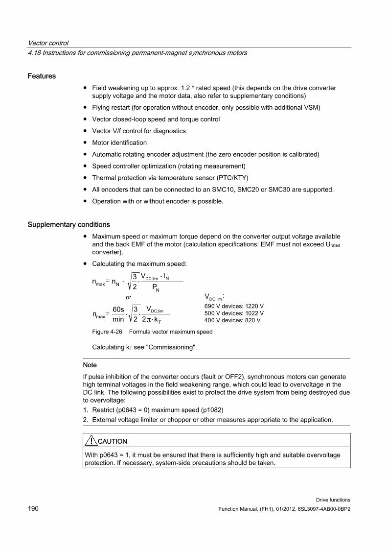
Vector control 4.18 Instructions for commissioning permanent-magnet synchronous motors
Drive functions 190 Function Manual, (FH1), 01/2012, 6SL3097-4AB00-0BP2
Features Field weakening up to approx. 1.2 * rated speed (this depends on the drive converter
supply voltage and the motor data, also refer to supplementary conditions)
Flying restart (for operation without encoder, only possible with additional VSM)
Vector closed-loop speed and torque control
Vector V/f control for diagnostics
Motor identification
Automatic rotating encoder adjustment (the zero encoder position is calibrated)
Speed controller optimization (rotating measurement)
Thermal protection via temperature sensor (PTC/KTY)
All encoders that can be connected to an SMC10, SMC20 or SMC30 are supported.
Operation with or without encoder is possible.
Supplementary conditions Maximum speed or maximum torque depend on the converter output voltage available
and the back EMF of the motor (calculation specifications: EMF must not exceed Urated converter).
Calculating the maximum speed:
=
=π
Figure 4-26 Formula vector maximum speed
Calculating kT see "Commissioning".
Note
If pulse inhibition of the converter occurs (fault or OFF2), synchronous motors can generate high terminal voltages in the field weakening range, which could lead to overvoltage in the DC link. The following possibilities exist to protect the drive system from being destroyed due to overvoltage: 1. Restrict (p0643 = 0) maximum speed (p1082) 2. External voltage limiter or chopper or other measures appropriate to the application.
CAUTION With p0643 = 1, it must be ensured that there is sufficiently high and suitable overvoltage protection. If necessary, system-side precautions should be taken.
Vector control 4.18 Instructions for commissioning permanent-magnet synchronous motors
Drive functions Function Manual, (FH1), 01/2012, 6SL3097-4AB00-0BP2 191
Depending on the terminal voltage and load cycle, the maximum torque can be taken from the motor data sheets / project design instructions.
Commissioning We recommend the following points when commissioning:
Commissioning wizard in STARTER
When commissioning the drive, using the Wizards in STARTER, the motor identification and the "rotating measurement" (p1900) can be activated. The encoder adjustment (p1990) is automatically activated together with the motor identification routine.
Motor identification (standstill (static) measurement (p1910)
Encoder adjustment (p1990)
WARNING During first commissioning and when the encoder is replaced, the encoder must be adjusted (p1990).
Rotating measurement (p1960)
The following parameters can be entered in STARTER during the commissioning phase:
The optional motor data can be entered if it is known. Otherwise, they are estimated using the rating plate data or are determined using a motor identification routine or speed controller optimization.
4.18.1 Encoder adjustment in operation This function is only released for permanent-magnet synchronous motors operating in the vector control mode. You can use this function to readjust encoders that have been replaced in operation. The encoders can be adjusted within a motor line-up. The adjustment is also possible when coupled to the load.
Adjusting a new encoder After you have mounted the encoder, set parameter p1990 to 3 (encoder adjustment). The encoder adjustment automatically starts the next time the system is switched-on; the sequence starts with a pole position identification. After the adjustment has been completed, p1990 = 0 and pulse inhibit is set. The determined commutation angle offset is entered into parameter p0431. This completes the measurement and the result is saved in the RAM.
The encoder module checks the consistency of the encoder pulses and zero mark. With this procedure, you can achieve an accuracy of approx. ±15° electrical. This accuracy is sufficient for starting with maximum 95 % rated torque. A fine calibration/adjustment is required for higher starting torques. If, after two motor revolutions, a zero mark has not been detected, the drive switches off with fault F07970.
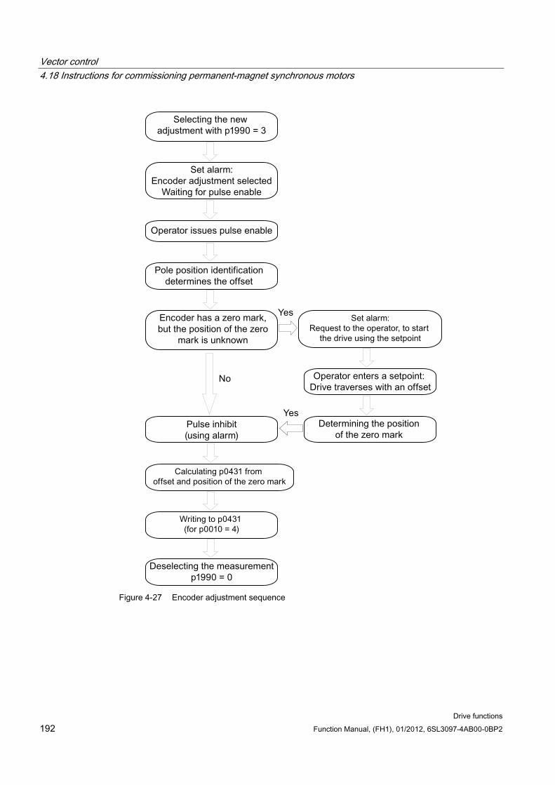
Vector control 4.18 Instructions for commissioning permanent-magnet synchronous motors
Drive functions 192 Function Manual, (FH1), 01/2012, 6SL3097-4AB00-0BP2
Figure 4-27 Encoder adjustment sequence
Vector control 4.18 Instructions for commissioning permanent-magnet synchronous motors
Drive functions Function Manual, (FH1), 01/2012, 6SL3097-4AB00-0BP2 193
Fine adjustment Start the fine adjustment with the motor rotating with p1905 = 90. The measurement
takes approximately 1 minute. The actual steps of the fine encoder adjustment are displayed using alarm A07976. During the measurement, the difference between the encoder and the EMF model is determined. The fine adjustment can also be carried out in no-load operation (idle operation).
CAUTION Rotating measurement
During the rotating measurement, the motor speed must exceed 40% of the rated speed. The torque must remain below half of the rated torque.
At the end of the measurement, p1905 is set to 0. An additional alarm notifies the operator that the result from p0431 will be written to the RAM at the next pulse inhibit.
Note RAM to ROM
To backup the new values, carry out a "RAM to ROM" after the adjustment.
The adjustment result is also valid, if, when the system/machine starts, the motor is driven by other motors in the group of motors through the material web coupling. By correctly evaluating the encoder, the Control Unit identifies the pole position and speed of the motor.
Note 1FW4 permanent-magnet synchronous motors
1FW4 motors have been optimized for operation with this function. When commissioning with the STARTER commissioning tool, all of the required data are automatically transferred to the Control Unit. (see also SINAMICS S120 Commissioning Manual)
4.18.2 Automatic encoder adjustment
Description The pole wheel-oriented closed-loop control of the synchronous motor requires information about the pole wheel position angle. Automatic encoder adjustment must be used under the following conditions:
The pole wheel position encoders are not mechanically adjusted
After a motor encoder has been replaced
Vector control 4.18 Instructions for commissioning permanent-magnet synchronous motors
Drive functions 194 Function Manual, (FH1), 01/2012, 6SL3097-4AB00-0BP2
Automatic encoder adjustment only makes sense for encoders with absolute position information and/or zero mark. The following encoders are supported:
Sin/Cos encoder with A/B-, R-track as well as with A/B-, C/D-, R-track
Resolver
Absolute encoder (e.g. EnDat, DRIVE-CLiQ encoder, SSI)
Incremental encoder with zero mark
Encoder adjustment using a zero mark If an incremental encoder with zero mark is being used, after the zero mark has been passed, the position of the zero mark can be calibrated. Commutation with the zero mark is activated via p0404.15.
Commissioning the encoder Automatic encoder adjustment is activated with p1990 = 1. When the pulses are enabled the next time, the measurement is carried out and the angular difference determined (p1984) is entered into p0431. For p1990 = 2 the determined angular difference (p1984) is not entered into p0431 and has not effect on the closed-loop motor control. Using this function, the angular difference - entered into p0431 - can be checked. For extremely high moments of inertia, the run time can be scaled higher using p1999.
WARNING The measurement causes the motor to rotate. The motor turns through a minimum of one complete revolution.
Overview of important parameters (see SINAMICS S120/S150 List Manual) p0404.15 Encoder configuration active, commutation with zero mark
p0431[0...n] commutation angle offset
p1990 Encoder adjustment selection
p1999[0...n] Commutation angle offset-calibration and PolID scaling
4.18.3 Pole position identification The pole position identification routine is used to determine rotor position at start up. This is required when no pole position information is available. If, for example, incremental encoders are used or operation without encoder is employed, then pole position identification is started automatically. For operation with encoder, pole position identification can be started via p1982 = "1", or via p1780.6 = "1", for operation without encoder .
Vector control 4.18 Instructions for commissioning permanent-magnet synchronous motors
Drive functions Function Manual, (FH1), 01/2012, 6SL3097-4AB00-0BP2 195
If possible, pole position identification should be carried out in decoupled state. If there is no large moment of inertia and there is only negligible friction, then the identification can also be carried out in coupled state.
If there is negligible friction and high moment of inertia, then the dynamic response for the speed encoder can be adjusted to the moment of inertia by increasing p1999.
If there is high friction torque or an active load, then an adjustment is only possible in decoupled state.
4 pole position identification techniques can be selected:
p1980 = 1, voltage pulsing, first harmonic
This technique also functions for magnetically isotropic motors if adequate iron saturation can be achieved.
p1980 = 4, voltage pulsing, two-stage
This technique functions with motors that are magnetically anisotropic. During the measurement, the motor must be at a standstill. The measurement is carried out the next time that the pulses are enabled.
Note
Using this type of identification, the motor can emit a significant amount of noise.
p1980 = 6, voltage pulsing, two-stage inverse
p1980 = 10, DC current impression
This technique functions for all motors; however, it takes more time than the measurement selected using p1980 = 4. During the measurement, the motor must be able to rotate. The measurement is carried out the next time that the pulses are enabled. For extremely high moments of inertia, the run time can be scaled higher using p1999.
WARNING
The measurement can electrically trigger a rotation or movement of the motor, by up to a half rotation.
Overview of important parameters (see SINAMICS S120/S150 List Manual) p0325 Motor pole position identification current 1st phase
p0329 Motor pole position identification current
p1780.6 Selects pole position identification PEM without an encoder
p1980 Pole position identification technique
p1982 Pole position identification technique
r1984 Pole position identification angular difference
r1985 Pole position identification saturation curve
r1987 Pole position identification trigger curve
p1999 Angular commutation offset calibration, scaling
Vector control 4.19 Instructions for commissioning separately-excited synchronous motors
Drive functions 196 Function Manual, (FH1), 01/2012, 6SL3097-4AB00-0BP2
4.18.4 Function diagrams and parameters
Overview of important parameters (see SINAMICS S120/S150 List Manual) p0300[0...n] motor type selection
p0301[0...n] motor code number selection
p0304[0...n] rated motor voltage
p0305[0...n] rated motor current
p0307[0...n] rated motor power
p0311[0...n] rated motor speed
p0312[0...n] rated motor torque
p0314[0...n] motor pole pair number
p0322 maximum motor speed
p0323 maximum motor current
p0324 maximum winding speed
p0431[0...n] commutation angle offset
p1905 parameter tuning selection
p1990 determine encoder adjustment commutation angle offset
4.19 Instructions for commissioning separately-excited synchronous motors
Note Separately excited synchronous motor
Please consult Siemens technical support if you wish to commission a separately-excited synchronous motor.
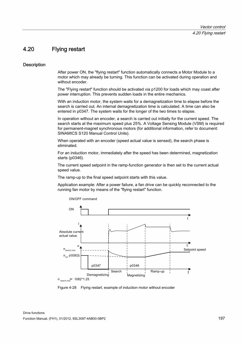
Vector control 4.20 Flying restart
Drive functions Function Manual, (FH1), 01/2012, 6SL3097-4AB00-0BP2 197
4.20 Flying restart
Description After power ON, the "flying restart" function automatically connects a Motor Module to a motor which may already be turning. This function can be activated during operation and without encoder.
The "Flying restart" function should be activated via p1200 for loads which may coast after power interruption. This prevents sudden loads in the entire mechanics.
With an induction motor, the system waits for a demagnetization time to elapse before the search is carried out. An internal demagnetization time is calculated. A time can also be entered in p0347. The system waits for the longer of the two times to elapse.
In operation without an encoder, a search is carried out initially for the current speed. The search starts at the maximum speed plus 25%. A Voltage Sensing Module (VSM) is required for permanent-magnet synchronous motors (for additional information, refer to document: SINAMICS S120 Manual Control Units).
When operated with an encoder (speed actual value is sensed), the search phase is eliminated.
For an induction motor, immediately after the speed has been determined, magnetization starts (p0346).
The current speed setpoint in the ramp-function generator is then set to the current actual speed value.
The ramp-up to the final speed setpoint starts with this value.
Application example: After a power failure, a fan drive can be quickly reconnected to the running fan motor by means of the "flying restart" function.
t
t
Figure 4-28 Flying restart, example of induction motor without encoder
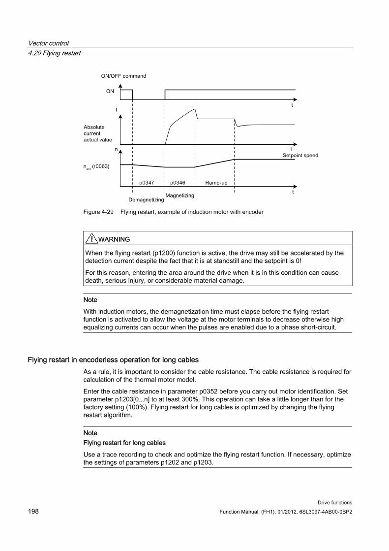
Vector control 4.20 Flying restart
Drive functions 198 Function Manual, (FH1), 01/2012, 6SL3097-4AB00-0BP2
ON
Figure 4-29 Flying restart, example of induction motor with encoder
WARNING When the flying restart (p1200) function is active, the drive may still be accelerated by the detection current despite the fact that it is at standstill and the setpoint is 0!
For this reason, entering the area around the drive when it is in this condition can cause death, serious injury, or considerable material damage.
Note
With induction motors, the demagnetization time must elapse before the flying restart function is activated to allow the voltage at the motor terminals to decrease otherwise high equalizing currents can occur when the pulses are enabled due to a phase short-circuit.
Flying restart in encoderless operation for long cables As a rule, it is important to consider the cable resistance. The cable resistance is required for calculation of the thermal motor model.
Enter the cable resistance in parameter p0352 before you carry out motor identification. Set parameter p1203[0...n] to at least 300%. This operation can take a little longer than for the factory setting (100%). Flying restart for long cables is optimized by changing the flying restart algorithm.
Note Flying restart for long cables
Use a trace recording to check and optimize the flying restart function. If necessary, optimize the settings of parameters p1202 and p1203.
Vector control 4.21 Synchronization
Drive functions Function Manual, (FH1), 01/2012, 6SL3097-4AB00-0BP2 199
Overview of important parameters (see SINAMICS S120/S150 List Manual) p0352[0...n] Cable resistance
p1082[0...n] Maximum speed
p1200[0...n] Flying restart operating mode
p1202[0...n] Flying restart search current
p1203[0...n] Flying restart search rate factor
r1204.0...13 CO/BO: Flying restart, U/f control status
r1205.0...15 CO/BO: Flying restart, vector control status
4.21 Synchronization
Precondition Drive in the vector control mode with Voltage Sensing Module (VSM10)
Induction motor without encoder
Vector control
Features Connector inputs for the actual voltage sensing of the motor via VSM10 (p3661, r3662)
Setting a phase difference (p3809)
Can be activated by parameter (p3802)
Description With the "synchronization" function, a Motor Module can be synchronized to a line supply, for example to regenerate into the line supply. Another application after synchronization, is to switchover to temporarily operate the motor directly on the line supply (bypass), to carry out maintenance work on the drive converter without a plant shutdown.
Synchronizing is activated using parameter p3800 and either internal or external actual voltage sensing is selected. With internal actual voltage sensing (p3800 = 1), the voltage setpoints of the electrical motor model are used for the synchronization. For external actual voltage sensing (p3800 = 0), the voltage is sensed using a VSM, which is connected to the line phases. The voltage values must be transferred to the synchronization via connectors r3661 and r3662.
Function diagrams (see SINAMICS S120/S150 List Manual) 7020 Technology functions - synchronizing
Vector control 4.22 Voltage Sensing Module
Drive functions 200 Function Manual, (FH1), 01/2012, 6SL3097-4AB00-0BP2
Overview of important parameters (see SINAMICS S120/S150 List Manual) p3800[0...n] Sync-line-drive activation
p3801[0...n] Sync-line-drive, drive object number
p3802[0...n] BI: Sync-line-drive enable
r3803 CO/BO: Sync-line-drive control word
r3804 CO: Sync-line-drive target frequency
r3805 CO: Sync-line-drive frequency difference
p3806[0...n] sync-line-drive frequency difference threshold value
r3808 CO: Sync-line-drive phase difference
p3809[0...n] sync-line-drive phase setpoint
p3811[0...n] sync-line-drive, frequency limiting
r3812 CO: Sync line drive correction frequency
p3813[0...n] sync-line-drive phase synchronism threshold value
r3814 CO: Sync line drive voltage difference
p3815[0...n] sync-line-drive voltage difference threshold value
r3819.0...7 CO/BO: Status word, synchronizing
4.22 Voltage Sensing Module
Description The Voltage Sensing Module (VSM) is required in the Vector Control and in V/f control for following functions:
Synchronizing Using the "synchronizing" function, the system is synchronized to an existing line supply. For example, after synchronization the motor is directly switched over to the line supply (bypass). A further application is to temporarily operate the motor from the line supply in order to be able to carry out maintenance work on the drive converter without switching off the plant. For external actual voltage sensing (p3800 = 1), the voltage is sensed using a VSM which is connected to the line phases. The voltage values must be transferred to the synchronization via connectors r3661 and r3662.
Flying restart After switch on, the "flying restart" function automatically connects a Motor Module to a motor which may already be turning. In operation without an encoder, a search is carried out initially for the motor speed. For this function, a Voltage Sensing Module (VSM) is required for permanent-magnet synchronous motors (for additional information, refer to reference: SINAMICS S Manual Control Units).
Vector control 4.22 Voltage Sensing Module
Drive functions Function Manual, (FH1), 01/2012, 6SL3097-4AB00-0BP2 201
Topology view The VSM is used on the encoder side for SINAMICS S120 drives. The VSM is only used at the VECTOR drive object in sensorless operating modes. The VSM is integrated into the topology at the position of the motor encoder.
VSM commissioning using STARTER The VSM for the VECTOR drive object is selected in STARTER using the drive wizard. As the VSM is not assigned to the encoder data sets (EDS), it cannot be selected on the encoder side. The component number of the VSM from the current topology must be entered in parameter p0151[0,1]. This parameter assigns the VSM data set to a VSM evaluation routine. With parameter p0155[0...n] "Activate/deactivate Voltage Sensing Module", it is possible to activate or deactivate the VSM explicitly as a topology component.
VSM parameters are independent of the SINAMICS data set model. A maximum of two VSMs may be used for each VECTOR drive object, i.e. two VSM data sets are available.
Note Using two VSM
If two VSMs are connected to one Motor Module, the first VSM (p0151[0]) is used to measure the line voltage (p3801). The motor voltage is measured (p1200) with the second VSM.
Identification via LED and firmware version VSM identification via LED is activated in parameter p0154 on the VECTOR drive object.
When p0154 = 1, the LED READY on the relevant VSM flashes green/orange or red/orange at a frequency of 2 Hz.
The firmware version of the VSM can be displayed using parameter p0158[0,1] on the VECTOR drive object.
Function diagrams (see SINAMICS S120/S150 List Manual) 7020 Synchronization
9880 VSM analog inputs
9886 VSM temperature evaluation
9887 VSM sensor monitoring KTY/PTC
Overview of important parameters (see SINAMICS S120/S150 List Manual) p3800[0...n] Sync-line-drive activation
p3801[0...n] Sync-line-drive, drive object number
Vector control 4.23 Simulation mode
Drive functions 202 Function Manual, (FH1), 01/2012, 6SL3097-4AB00-0BP2
Drive object A_INF p0140 VSM number of data sets
p0141[0...n] VSM component number
p0144[0...n] Voltage Sensing Module identification via LED
p0145[0...n] Activate/deactivate Voltage Sensing Module
r0146[0...n] Voltage Sensing Module active/inactive
r0147[0...n] Voltage Sensing Module EPROM data version
r0148[0...n] Voltage Sensing Module firmware version
VECTOR drive object p0151[0...n] Voltage Sensing Module component number
p0154[0...n] Voltage Sensing Module identification via LED
p0155[0...n] Activate/deactivate Voltage Sensing Module
p0158[0...n] Voltage Sensing Module firmware version
4.23 Simulation mode
4.23.1 Description Simulation mode allows you to simulate the drive without a connected motor and without the DC link voltage. In this case, it should be noted that the simulation mode can only be activated under an actual DC link voltage of 40 V. If the voltage is higher, simulation mode is reset and fault message F07826 is output.
With the simulation mode, you can test the communication with a higher-level automation system. If the drive is also to return actual values, note that it must be switched over to encoderless operation during simulation mode. This means that large parts of the SINAMICS software (e.g., software channel, sequence control, communications, technology function, etc.) can be tested in advance without requiring a motor.
For units with outputs of > 75 W it is recommended to test the activation of the power semiconductors after repairs. To do so, a DC voltage < 40 V is applied to the DC link, and the possible pulse patterns must be tested by the control software.
The software must allow enabling of the pulses and the output of various frequencies. IThis is implemented using V/f control or encoderless closed-loop speed control.
Note
Simulation mode cannot be activated without a power unit. A power unit must be connected via DRIVE-CLiQ.
Vector control 4.24 Redundance operation power units
Drive functions Function Manual, (FH1), 01/2012, 6SL3097-4AB00-0BP2 203
4.23.2 Features Automatic deactivation with a DC link voltage greater than 40 V (measurement tolerance
± 4 V) with fault F07826 and immediate pulse inhibit (OFF2)
Can be activated via parameter p1272
Deactivation of line contactor activation during simulation mode
Activation of power semi-conductor with low DC link voltage and with motor (for test purposes).
Power unit and closed-loop control can be simulated without a connected motor.
4.23.3 Commissioning The simulation mode can be activated via p1272 =1. The following preconditions must be satisfied to do this:
Initial commissioning must be complete (default: Standard induction motors).
The DC link voltage must be below 40 V (observe the tolerance of the DC link voltage sensing).
4.24 Redundance operation power units
Features Redundancy for up to 4 chassis power units
Power unit can be deactivated via parameter (p0125)
Power unit can be deactivated via binector input (p0895)
Description Redundancy mode can be used so that operation can be continued in spite of the failure of one power unit connected in parallel.
Note
Despite this redundancy circuit, the entire plant may shut down when defects develop in one power unit (feedback effects due to absence of electrical isolation).
In order that the failed power unit can be replaced, DRIVE-CLiQ cables must be connected in a star-type configuration - it may be necessary to use a DRIVE-CLiQ HUB Module (DMC20 or DME20). The failed power unit must be deactivated via p0125 or via the binector input p0895, before it is removed. When a replacement power unit has been installed it must be activated accordingly.
Vector control 4.25 Bypass
Drive functions 204 Function Manual, (FH1), 01/2012, 6SL3097-4AB00-0BP2
Preconditions Only possible for identical chassis power units connected in parallel
Maximum number of parallel power units is 4
Parallel connection of power units with suitable power reserves
DRIVE-CLiQ star topology (possibly a DMC20 or a DME20, refer to the GH1 manual)
Motor with one single-winding system (p7003 = 0)
No Safe Torque Off (STO)
Overview of important parameters (see SINAMICS S120/S150 List Manual) p0125 Activate/deactivate power unit component
r0126 Power unit component active/inactive
p0895 BI: Activate/deactivate power unit component
p7003 Par_circuit winding system
4.25 Bypass
Features Available for the vector control mode
Available for induction motors without encoder
Description The bypass function controls two contactors via digital outputs of the drive converter and evaluates the feedback signals of the contactors via digital inputs (e.g. via TM31). This circuit allows the motor to either be fed from the drive converter or connected directly to the supply line. The drive converter controls the contactors; the feedback signals for the contactor states must be fed back to the drive converter.
This bypass circuit can be implemented in two ways:
Without synchronizing the motor to the line supply and
Synchronizing the motor to the line supply.
For all bypass versions, the following applies:
The bypass is always switched-out when one of the control word signals "OFF2" or "OFF3" is withdrawn.
Exception: When required, the bypass switch can be interlocked by a higher-level control so that the drive converter can be completely powered-down (i.e. including the control electronics) while the motor is operated from the line supply. The contactor interlocking should be implemented on the plant/system side.
Vector control 4.25 Bypass
Drive functions Function Manual, (FH1), 01/2012, 6SL3097-4AB00-0BP2 205
When the drive is started up again after POWER ON, the status of the bypass contactors is evaluated. After powering up, the converter can thereby change straight into "Ready to start and bypass" status. This is only possible if the bypass is activated via a control signal, the control signal (p1266) is still present once the system has been ramped up, and the automatic restart function (p1200 = 4) is active.
Changing the converter into "Ready to start and bypass" status after powering up, is of a higher priority than switching back on automatically.
Monitoring of the motor temperatures using temperature sensors is active while the converter is in one of two statuses "Ready to start and bypass" or "Ready for operation and bypass".
The two motor contactors must be designed for switching under load.
Note
The examples contained in the following descriptions are only basic circuits designed to explain the basic function. The dimensions of specific circuit configurations (contactors, protective equipment) must be calculated for specific systems.
Prerequisite The bypass function is only possible for encoderless closed-loop speed control (p1300 = 20) or V/f control (p1300 = 0...19) and when an induction motor is used.
Commissioning the bypass function The bypass function is part of the function module "technology controller" that can be activated when using the commissioning Wizard. Parameter r0108.16 indicates whether it has been activated.
4.25.1 Bypass with synchronization with overlap
Description When "bypass with synchronization with overlap (p1260 = 1)" is activated, then motor is transferred, synchronized to the line supply and is also retrieved again. During the changeover, the two contactors K1 and K2 are simultaneously closed for a time (phase lock synchronization).
A reactor is used to de-couple the drive converter from the line supply - the uk value for the reactor is 10% +/- 2%.
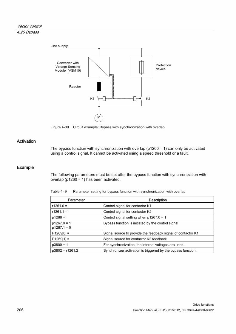
Vector control 4.25 Bypass
Drive functions 206 Function Manual, (FH1), 01/2012, 6SL3097-4AB00-0BP2
Figure 4-30 Circuit example: Bypass with synchronization with overlap
Activation The bypass function with synchronization with overlap (p1260 = 1) can only be activated using a control signal. It cannot be activated using a speed threshold or a fault.
Example The following parameters must be set after the bypass function with synchronization with overlap (p1260 = 1) has been activated.
Table 4- 9 Parameter setting for bypass function with synchronization with overlap
Parameter Description r1261.0 = Control signal for contactor K1 r1261.1 = Control signal for contactor K2 p1266 = Control signal setting when p1267.0 = 1 p1267.0 = 1 p1267.1 = 0
Bypass function is initiated by the control signal
P1269[0] = Signal source to provide the feedback signal of contactor K1 P1269[1] = Signal source for contactor K2 feedback p3800 = 1 For synchronization, the internal voltages are used. p3802 = r1261.2 Synchronizer activation is triggered by the bypass function.
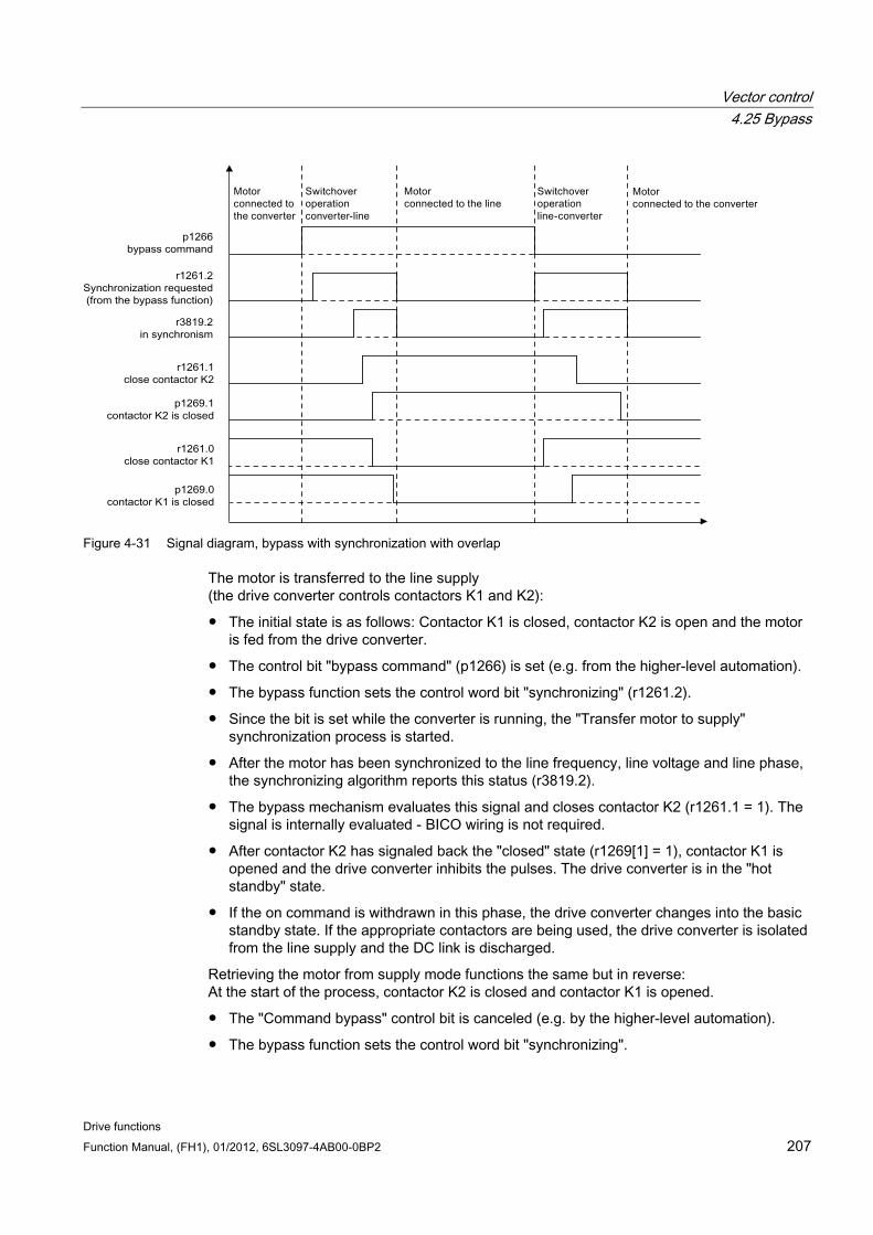
Vector control 4.25 Bypass
Drive functions Function Manual, (FH1), 01/2012, 6SL3097-4AB00-0BP2 207
Figure 4-31 Signal diagram, bypass with synchronization with overlap
The motor is transferred to the line supply (the drive converter controls contactors K1 and K2):
The initial state is as follows: Contactor K1 is closed, contactor K2 is open and the motor is fed from the drive converter.
The control bit "bypass command" (p1266) is set (e.g. from the higher-level automation).
The bypass function sets the control word bit "synchronizing" (r1261.2).
Since the bit is set while the converter is running, the "Transfer motor to supply" synchronization process is started.
After the motor has been synchronized to the line frequency, line voltage and line phase, the synchronizing algorithm reports this status (r3819.2).
The bypass mechanism evaluates this signal and closes contactor K2 (r1261.1 = 1). The signal is internally evaluated - BICO wiring is not required.
After contactor K2 has signaled back the "closed" state (r1269[1] = 1), contactor K1 is opened and the drive converter inhibits the pulses. The drive converter is in the "hot standby" state.
If the on command is withdrawn in this phase, the drive converter changes into the basic standby state. If the appropriate contactors are being used, the drive converter is isolated from the line supply and the DC link is discharged.
Retrieving the motor from supply mode functions the same but in reverse: At the start of the process, contactor K2 is closed and contactor K1 is opened.
The "Command bypass" control bit is canceled (e.g. by the higher-level automation).
The bypass function sets the control word bit "synchronizing".
Vector control 4.25 Bypass
Drive functions 208 Function Manual, (FH1), 01/2012, 6SL3097-4AB00-0BP2
Pulses are enabled. Since "Synchronize" is set before "Pulse enable", the converter interprets this as a command to retrieve a motor from the supply and to take it over.
After the motor has been synchronized to the line frequency, line voltage and line phase, the synchronizing algorithm reports this status.
The bypass mechanism evaluates this signal and closes contactor K1. The signal is internally evaluated - BICO wiring is not required.
Once contactor K1 has reported "closed" status, contactor K2 is opened and the motor is operated again on the converter.
4.25.2 Bypass with synchronization without overlap
Description When "bypass with synchronization without overlap (p1260 = 2)" is activated, contactor K2 to be closed is only closed when contactor K1 has opened (anticipatory type synchronization). During this time, the motor is not connected to the line supply so that its speed is determined by the load and the friction. Phasing of the motor voltage before synchronization must be set such that there is an "initial jump" upstream of the supply to which synchronization should be carried out. This is done by setting the synchronization setpoint (p3809). As a result of the motor braking in the short time during which, both contactors are open, when closing contactor K2, a phase and frequency difference of approximately zero is obtained.
For the function to run correctly, the moment of inertia of the drive and the load must be sufficient.
Note A sufficiently high moment of inertia
is characterized by a change in the motor speed when opening contactors K1 and K2 that is approximately equal to the rated slip and no more. The electrical angle difference of the motor relative to the phase difference of the line supply may only change to the extent that it can be compensated using p3809.
It is no longer necessary to use the de-coupling reactor after having determined the synchronizing setpoint (p3809).
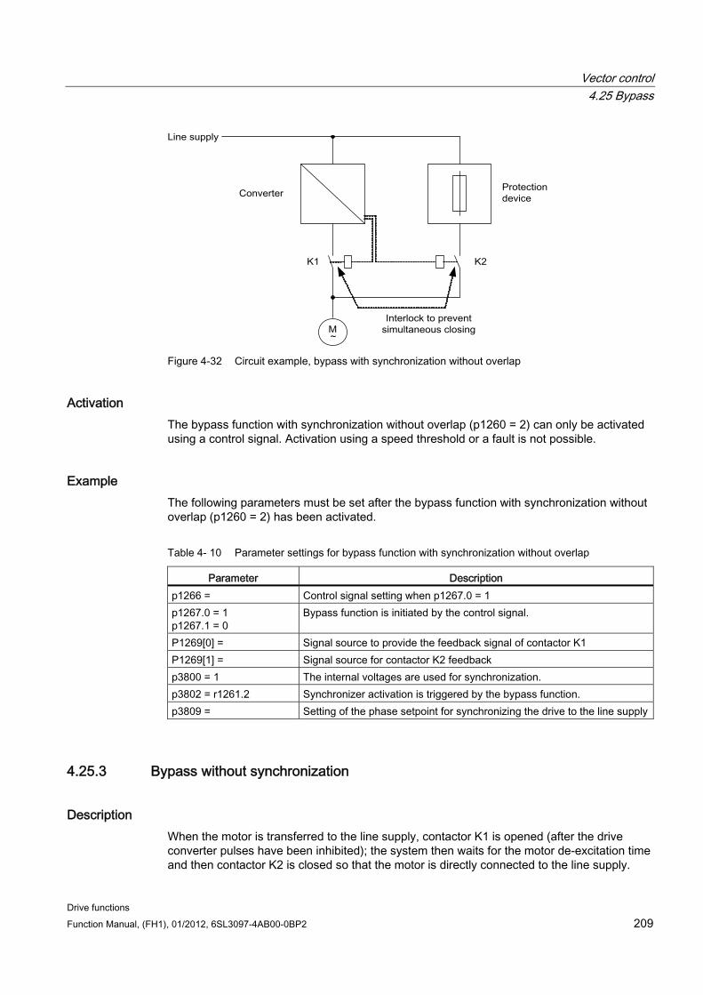
Vector control 4.25 Bypass
Drive functions Function Manual, (FH1), 01/2012, 6SL3097-4AB00-0BP2 209
Figure 4-32 Circuit example, bypass with synchronization without overlap
Activation The bypass function with synchronization without overlap (p1260 = 2) can only be activated using a control signal. Activation using a speed threshold or a fault is not possible.
Example The following parameters must be set after the bypass function with synchronization without overlap (p1260 = 2) has been activated.
Table 4- 10 Parameter settings for bypass function with synchronization without overlap
Parameter Description p1266 = Control signal setting when p1267.0 = 1 p1267.0 = 1 p1267.1 = 0
Bypass function is initiated by the control signal.
P1269[0] = Signal source to provide the feedback signal of contactor K1 P1269[1] = Signal source for contactor K2 feedback p3800 = 1 The internal voltages are used for synchronization. p3802 = r1261.2 Synchronizer activation is triggered by the bypass function. p3809 = Setting of the phase setpoint for synchronizing the drive to the line supply
4.25.3 Bypass without synchronization
Description When the motor is transferred to the line supply, contactor K1 is opened (after the drive converter pulses have been inhibited); the system then waits for the motor de-excitation time and then contactor K2 is closed so that the motor is directly connected to the line supply.
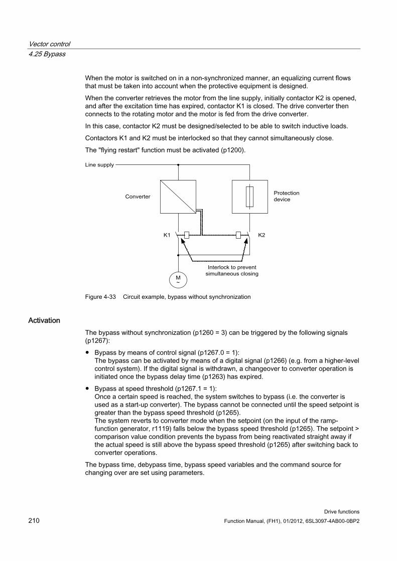
Vector control 4.25 Bypass
Drive functions 210 Function Manual, (FH1), 01/2012, 6SL3097-4AB00-0BP2
When the motor is switched on in a non-synchronized manner, an equalizing current flows that must be taken into account when the protective equipment is designed.
When the converter retrieves the motor from the line supply, initially contactor K2 is opened, and after the excitation time has expired, contactor K1 is closed. The drive converter then connects to the rotating motor and the motor is fed from the drive converter.
In this case, contactor K2 must be designed/selected to be able to switch inductive loads.
Contactors K1 and K2 must be interlocked so that they cannot simultaneously close.
The "flying restart" function must be activated (p1200).
Figure 4-33 Circuit example, bypass without synchronization
Activation The bypass without synchronization (p1260 = 3) can be triggered by the following signals (p1267):
Bypass by means of control signal (p1267.0 = 1): The bypass can be activated by means of a digital signal (p1266) (e.g. from a higher-level control system). If the digital signal is withdrawn, a changeover to converter operation is initiated once the bypass delay time (p1263) has expired.
Bypass at speed threshold (p1267.1 = 1): Once a certain speed is reached, the system switches to bypass (i.e. the converter is used as a start-up converter). The bypass cannot be connected until the speed setpoint is greater than the bypass speed threshold (p1265). The system reverts to converter mode when the setpoint (on the input of the ramp-function generator, r1119) falls below the bypass speed threshold (p1265). The setpoint > comparison value condition prevents the bypass from being reactivated straight away if the actual speed is still above the bypass speed threshold (p1265) after switching back to converter operations.
The bypass time, debypass time, bypass speed variables and the command source for changing over are set using parameters.
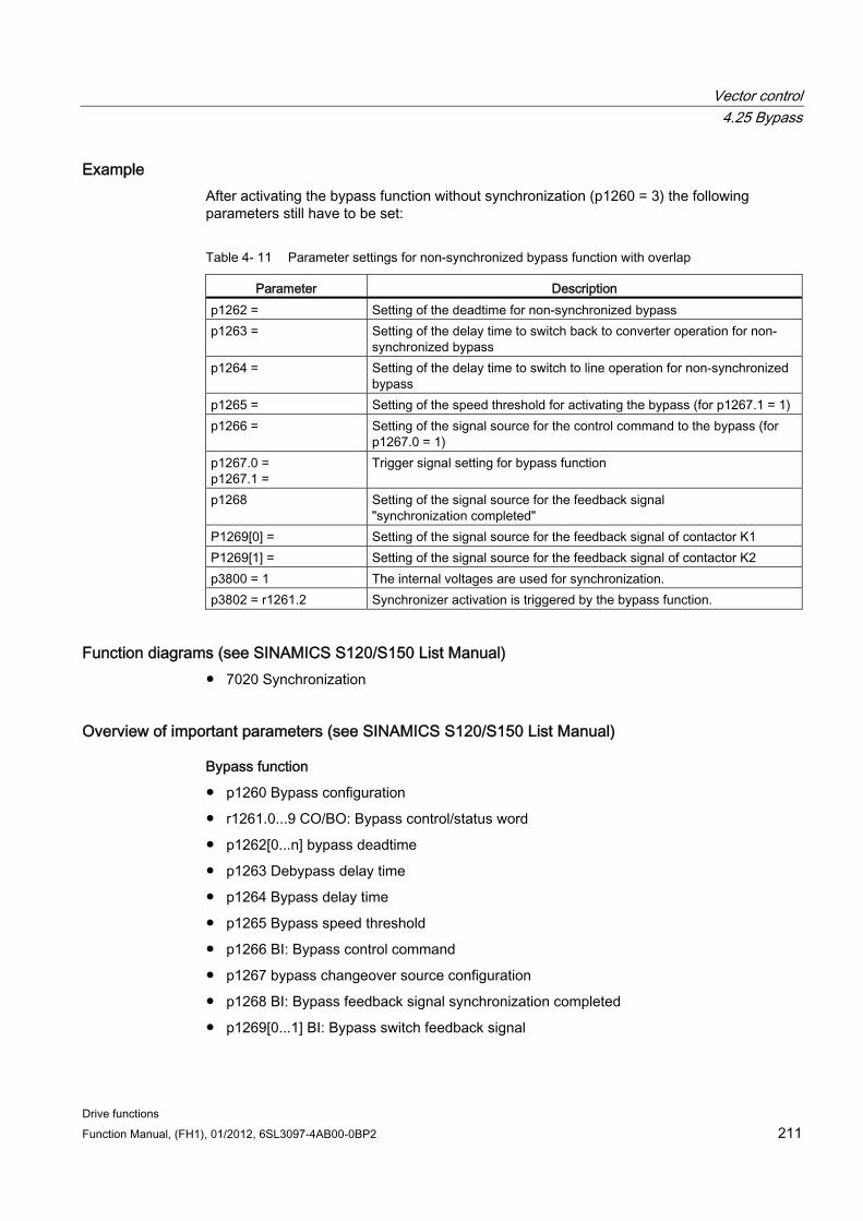
Vector control 4.25 Bypass
Drive functions Function Manual, (FH1), 01/2012, 6SL3097-4AB00-0BP2 211
Example After activating the bypass function without synchronization (p1260 = 3) the following parameters still have to be set:
Table 4- 11 Parameter settings for non-synchronized bypass function with overlap
Parameter Description p1262 = Setting of the deadtime for non-synchronized bypass p1263 = Setting of the delay time to switch back to converter operation for non-
synchronized bypass p1264 = Setting of the delay time to switch to line operation for non-synchronized
bypass p1265 = Setting of the speed threshold for activating the bypass (for p1267.1 = 1) p1266 = Setting of the signal source for the control command to the bypass (for
p1267.0 = 1) p1267.0 = p1267.1 =
Trigger signal setting for bypass function
p1268 Setting of the signal source for the feedback signal "synchronization completed"
P1269[0] = Setting of the signal source for the feedback signal of contactor K1 P1269[1] = Setting of the signal source for the feedback signal of contactor K2 p3800 = 1 The internal voltages are used for synchronization. p3802 = r1261.2 Synchronizer activation is triggered by the bypass function.
Function diagrams (see SINAMICS S120/S150 List Manual) 7020 Synchronization
Overview of important parameters (see SINAMICS S120/S150 List Manual)
Bypass function
p1260 Bypass configuration
r1261.0...9 CO/BO: Bypass control/status word
p1262[0...n] bypass deadtime
p1263 Debypass delay time
p1264 Bypass delay time
p1265 Bypass speed threshold
p1266 BI: Bypass control command
p1267 bypass changeover source configuration
p1268 BI: Bypass feedback signal synchronization completed
p1269[0...1] BI: Bypass switch feedback signal
Vector control 4.26 Asynchronous pulse frequency
Drive functions 212 Function Manual, (FH1), 01/2012, 6SL3097-4AB00-0BP2
Synchronization
p3800[0...n] activate sync-line-drive
p3801[0...n] sync-line-drive, drive object number
p3802[0...n] BI: Sync-line-drive enable
r3803.0 CO/BO: Sync-line-drive control word
r3804 CO: Sync-line-drive target frequency
r3805 CO: Sync-line-drive frequency difference
p3806[0...n] sync-line-drive frequency difference threshold value
r3808 CO: Sync-line-drive phase difference
p3809[0...n] sync-line-drive phase setpoint
p3811[0...n] sync-line-drive, frequency limiting
r3812 CO: Sync line drive correction frequency
p3813[0...n] sync-line-drive phase synchronism threshold value
r3814 CO: Sync line drive voltage difference
p3815[0...n] sync-line-drive voltage difference threshold value
p3816 CI: Sync line-drive voltage actual value U12 = U1 – U2
p3817 CI: Sync line-drive voltage actual value U23 = U2 – U3
r3819.0...7 CO/BO: Sync-line-drive status word
4.26 Asynchronous pulse frequency
4.26.1 Asynchronous pulse frequency The pulse frequency is coupled to the current controller clock cycle, and can only be adjusted in multiple integer steps. For most standard applications, this setting makes sense and should not be modified.
For certain applications, it may be advantageous if the pulse frequency is decoupled from the current controller clock cycle. The consequences are:
More optimal dimensioning of the Motor Module or Power Modules
Certain motor types are operated with a more favorable pulse frequency
Motor Modules of different sizes can be operated with different pulse frequencies
Faster sampling times can be set for DCC and free function blocks
Faster setpoint transfers from a higher-level control system are possible
Automatic commissioning routines with different current controller cycles are simplified
This function is enabled for Motor Modules and Power Modules in the chassis format in vector control.
Vector control 4.26 Asynchronous pulse frequency
Drive functions Function Manual, (FH1), 01/2012, 6SL3097-4AB00-0BP2 213
Activating the function You can activate the function with p1810.12 = 1
Set the pulse frequency with p1800 in 50 Hz increments to the desired pulse frequency. The maximum pulse frequency that can be set is twice the current controller clock cycle.
Activate the current actual value correction with p1840 = 0.
Application example Situation:
A large (>250kW) Motor Module in the chassis format and a small (< 250kW) Motor Module, e.g. in the booksize format, are to be connected to one DRIVE-CLiQ line.
The factory setting of the current controller cycle of the small Motor Module is 250 µs, corresponding to a pulse frequency of 2 kHz. The factory setting of the current controller cycle of the large Motor Module is 400 µs, corresponding to a pulse frequency of 1.25 kHz.
Problem:
For standard applications, the current controller clock cycle of the large Motor Modules is increased up to 500 µs, an integer multiple of the current controller cycle of 250 µs. As a consequence, the pulse frequency of the large Motor Module is 1 kHz. As a consequence, the Motor Module in the chassis format is no longer optimally utilized.
Solution:
Activate separation of pulse frequency and current controller cycle for the large Motor Module.
The Motor Module Booksize is still operated in synchronism with the current control cycle of 250 µs at a pulse frequency of 2 kHz.
For the Motor Module in the chassis format, set the pulse frequency to asynchronous operation with p1800.12 = 1. Then increase the pulse frequency of the Motor Module Chassis to 1.25 KHz using p1800, while the current controller clock cycle remains at 500 µs. The Motor Module Chassis is better utilized as a result of the increased pulse frequency.
4.26.2 Boundary conditions for asynchronous pulse frequency 1. A higher system utilization as a result of the activated gating unit for the asynchronous
pulse frequency (p1810.12 = 1) and the required current actual value correction (p1840 = 1) causes
– Halving the maximum number of axes that can be used
– A reduction in the current controller dynamic performance
2. The maximum pulse frequency that can be set is limited to double the frequency of the current controller cycle.
3. The pulse technique, where the pulse frequency can be freely adjusted, is not suitable for a permanent-magnet synchronous motor without an encoder.
Vector control 4.26 Asynchronous pulse frequency
Drive functions 214 Function Manual, (FH1), 01/2012, 6SL3097-4AB00-0BP2
4. If output reactors or filters are connected to a Motor Module in the chassis format, when dimensioning the reactors, the maximum pulse frequency must be taken into account and for sine-wave filters, the minimum pulse frequency.
5. The motor data identification must be performed with current controller cycles of 250 µs or 500 µs with 2 kHz.
Overview of important parameters (see SINAMICS S120/S150 List Manual) p0115[0...6] Sampling times for internal control loops
p1810 modulator configuration
p1840[0...n] Actual value correction configuration
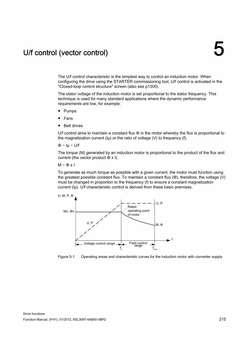
Drive functions Function Manual, (FH1), 01/2012, 6SL3097-4AB00-0BP2 215
U/f control (vector control) 5
The U/f control characteristic is the simplest way to control an induction motor. When configuring the drive using the STARTER commissioning tool, U/f control is activated in the "Closed-loop control structure" screen (also see p1300).
The stator voltage of the induction motor is set proportional to the stator frequency. This technique is used for many standard applications where the dynamic performance requirements are low, for example:
Pumps
Fans
Belt drives
U/f control aims to maintain a constant flux Φ in the motor whereby the flux is proportional to the magnetization current (Iµ) or the ratio of voltage (V) to frequency (f).
Φ ∼ Iµ ∼ U/f
The torque (M) generated by an induction motor is proportional to the product of the flux and current (the vector product Φ x I).
M ∼ Φ x I
To generate as much torque as possible with a given current, the motor must function using the greatest possible constant flux. To maintain a constant flux (Φ), therefore, the voltage (V) must be changed in proportion to the frequency (f) to ensure a constant magnetization current (Iµ). U/f characteristic control is derived from these basic premises.
Figure 5-1 Operating areas and characteristic curves for the induction motor with converter supply
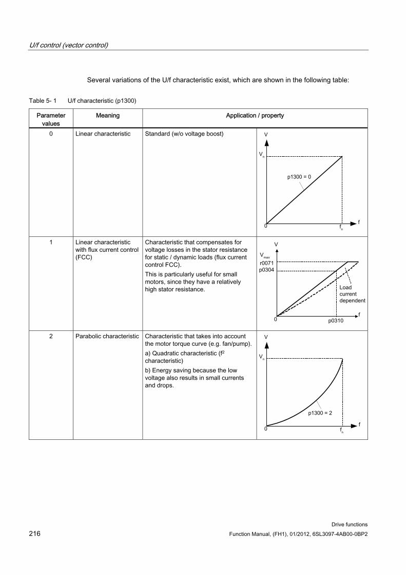
U/f control (vector control)
Drive functions 216 Function Manual, (FH1), 01/2012, 6SL3097-4AB00-0BP2
Several variations of the U/f characteristic exist, which are shown in the following table:
Table 5- 1 U/f characteristic (p1300)
Parameter values
Meaning Application / property
0 Linear characteristic Standard (w/o voltage boost)
1 Linear characteristic with flux current control (FCC)
Characteristic that compensates for voltage losses in the stator resistance for static / dynamic loads (flux current control FCC). This is particularly useful for small motors, since they have a relatively high stator resistance.
2 Parabolic characteristic Characteristic that takes into account the motor torque curve (e.g. fan/pump). a) Quadratic characteristic (f2 characteristic) b) Energy saving because the low voltage also results in small currents and drops.
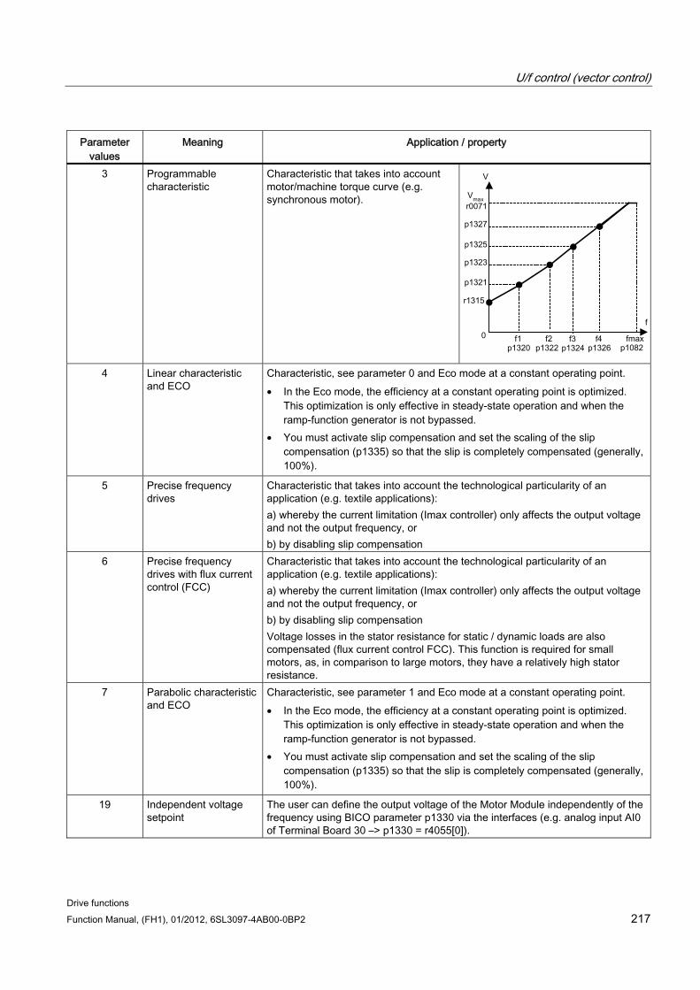
U/f control (vector control)
Drive functions Function Manual, (FH1), 01/2012, 6SL3097-4AB00-0BP2 217
Parameter values
Meaning Application / property
3 Programmable characteristic
Characteristic that takes into account motor/machine torque curve (e.g. synchronous motor).
4 Linear characteristic and ECO
Characteristic, see parameter 0 and Eco mode at a constant operating point. • In the Eco mode, the efficiency at a constant operating point is optimized.
This optimization is only effective in steady-state operation and when the ramp-function generator is not bypassed.
• You must activate slip compensation and set the scaling of the slip compensation (p1335) so that the slip is completely compensated (generally, 100%).
5 Precise frequency drives
Characteristic that takes into account the technological particularity of an application (e.g. textile applications): a) whereby the current limitation (Imax controller) only affects the output voltage and not the output frequency, or b) by disabling slip compensation
6 Precise frequency drives with flux current control (FCC)
Characteristic that takes into account the technological particularity of an application (e.g. textile applications): a) whereby the current limitation (Imax controller) only affects the output voltage and not the output frequency, or b) by disabling slip compensation Voltage losses in the stator resistance for static / dynamic loads are also compensated (flux current control FCC). This function is required for small motors, as, in comparison to large motors, they have a relatively high stator resistance.
7 Parabolic characteristic and ECO
Characteristic, see parameter 1 and Eco mode at a constant operating point. • In the Eco mode, the efficiency at a constant operating point is optimized.
This optimization is only effective in steady-state operation and when the ramp-function generator is not bypassed.
• You must activate slip compensation and set the scaling of the slip compensation (p1335) so that the slip is completely compensated (generally, 100%).
19 Independent voltage setpoint
The user can define the output voltage of the Motor Module independently of the frequency using BICO parameter p1330 via the interfaces (e.g. analog input AI0 of Terminal Board 30 –> p1330 = r4055[0]).

U/f control (vector control) 5.1 Voltage boost
Drive functions 218 Function Manual, (FH1), 01/2012, 6SL3097-4AB00-0BP2
Function diagram FP 6300 U/f characteristic and voltage boost
Parameter p1300[0...n] Open-loop/closed-loop control operating mode
5.1 Voltage boost According to the U/f characteristic, at an output frequency of 0 Hz, the control supplies an output voltage of 0 V. This means that at 0 V, the motor cannot generate any torque. The voltage booster function is used to
magnetize an induction motors at n = 0 rpm,
establish a torque at n = 0 rpm, e.g. in order to hold a load,
generate a breakaway, acceleration or braking torque,
to compensate for resistive losses in the windings and feeder cables.
Three types of voltage boost can be selected:
1. Permanent voltage boost with p1310
2. Voltage boost only while accelerating with p1311
3. Voltage boost only while starting for the first time with p1312
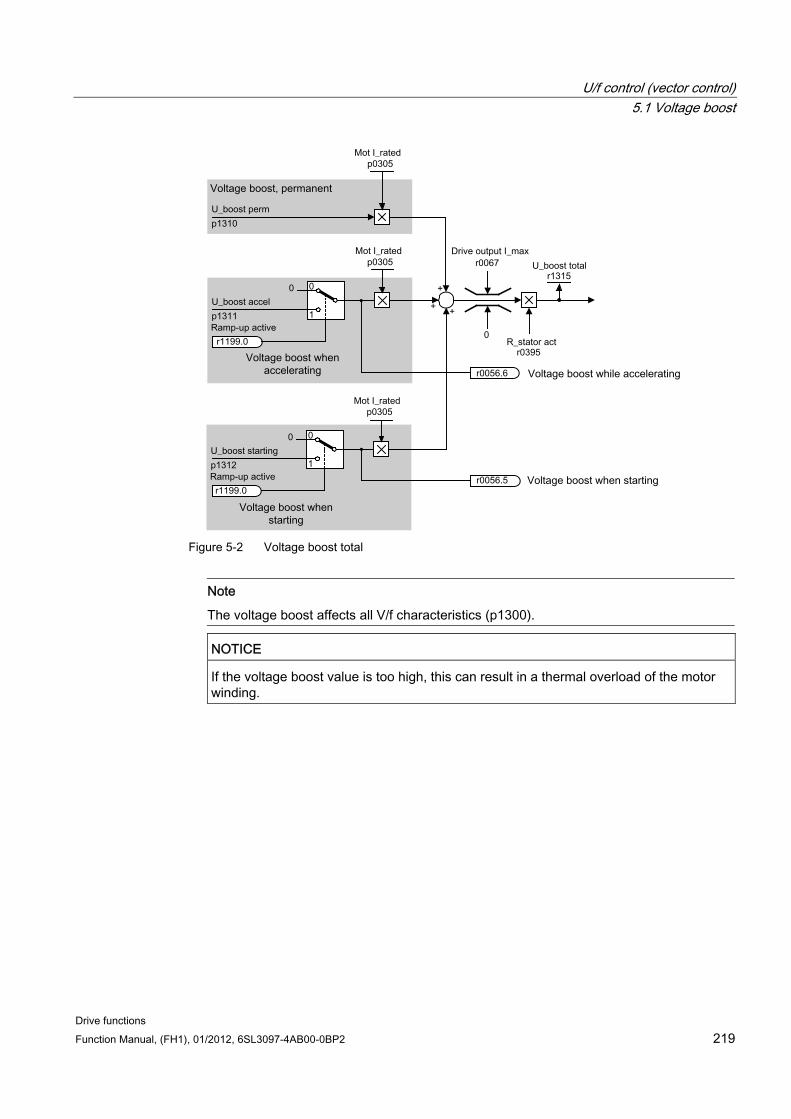
U/f control (vector control) 5.1 Voltage boost
Drive functions Function Manual, (FH1), 01/2012, 6SL3097-4AB00-0BP2 219
Figure 5-2 Voltage boost total
Note
The voltage boost affects all V/f characteristics (p1300).
NOTICE
If the voltage boost value is too high, this can result in a thermal overload of the motor winding.
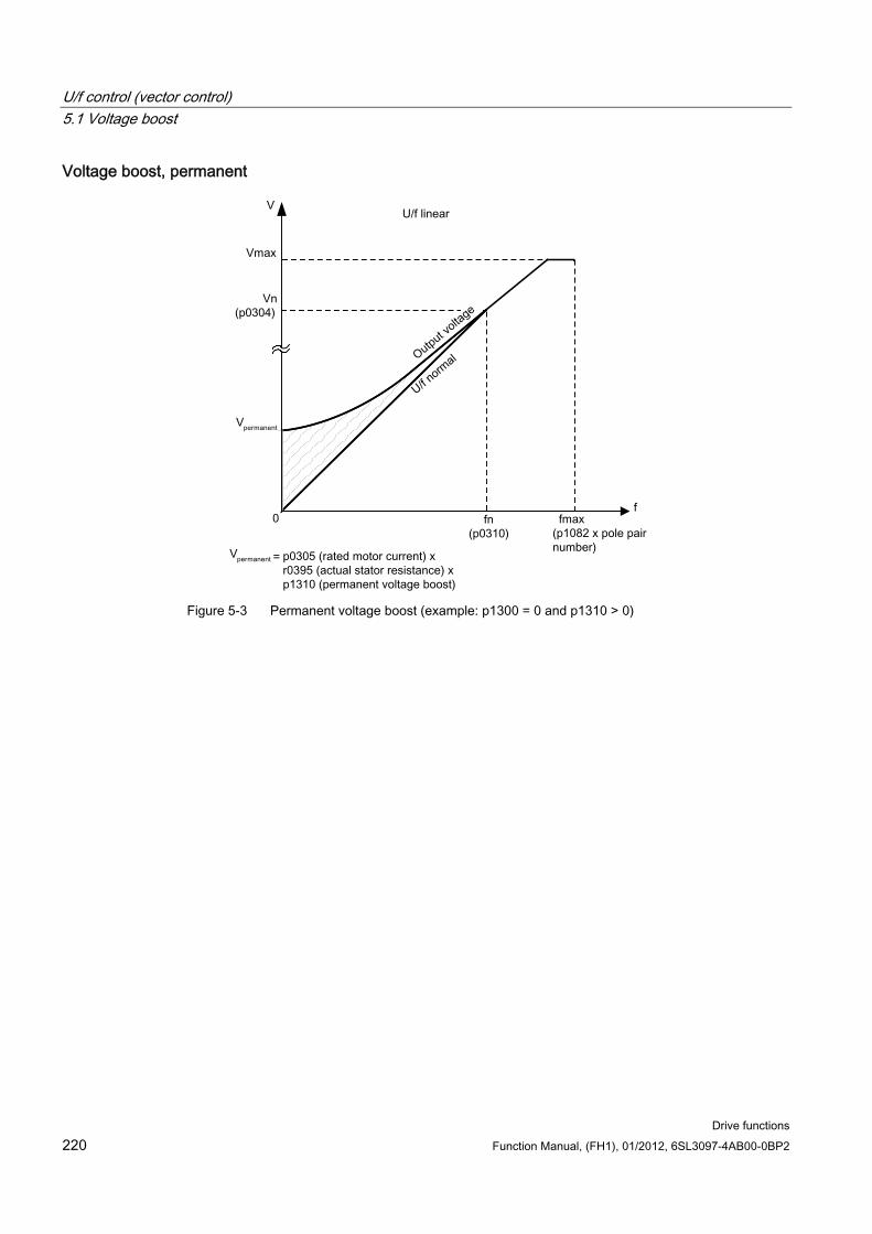
U/f control (vector control) 5.1 Voltage boost
Drive functions 220 Function Manual, (FH1), 01/2012, 6SL3097-4AB00-0BP2
Voltage boost, permanent
Figure 5-3 Permanent voltage boost (example: p1300 = 0 and p1310 > 0)
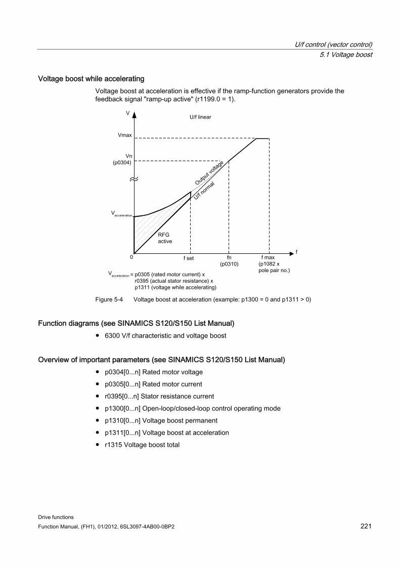
U/f control (vector control) 5.1 Voltage boost
Drive functions Function Manual, (FH1), 01/2012, 6SL3097-4AB00-0BP2 221
Voltage boost while accelerating Voltage boost at acceleration is effective if the ramp-function generators provide the feedback signal "ramp-up active" (r1199.0 = 1).
Figure 5-4 Voltage boost at acceleration (example: p1300 = 0 and p1311 > 0)
Function diagrams (see SINAMICS S120/S150 List Manual) 6300 V/f characteristic and voltage boost
Overview of important parameters (see SINAMICS S120/S150 List Manual) p0304[0...n] Rated motor voltage
p0305[0...n] Rated motor current
r0395[0...n] Stator resistance current
p1300[0...n] Open-loop/closed-loop control operating mode
p1310[0...n] Voltage boost permanent
p1311[0...n] Voltage boost at acceleration
r1315 Voltage boost total
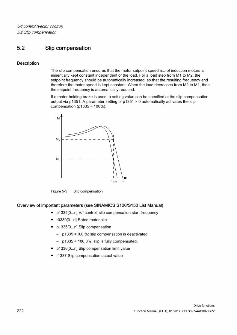
U/f control (vector control) 5.2 Slip compensation
Drive functions 222 Function Manual, (FH1), 01/2012, 6SL3097-4AB00-0BP2
5.2 Slip compensation
Description The slip compensation ensures that the motor setpoint speed nset of induction motors is essentially kept constant independent of the load. For a load step from M1 to M2, the setpoint frequency should be automatically increased, so that the resulting frequency and therefore the motor speed is kept constant. When the load decreases from M2 to M1, then the setpoint frequency is automatically reduced.
If a motor holding brake is used, a setting value can be specified at the slip compensation output via p1351. A parameter setting of p1351 > 0 automatically activates the slip compensation (p1335 = 100%).
Figure 5-5 Slip compensation
Overview of important parameters (see SINAMICS S120/S150 List Manual) p1334[0...n] V/f control, slip compensation start frequency
r0330[0...n] Rated motor slip
p1335[0...n] Slip compensation
– p1335 = 0.0 %: slip compensation is deactivated.
– p1335 = 100.0%: slip is fully compensated.
p1336[0...n] Slip compensation limit value
r1337 Slip compensation actual value
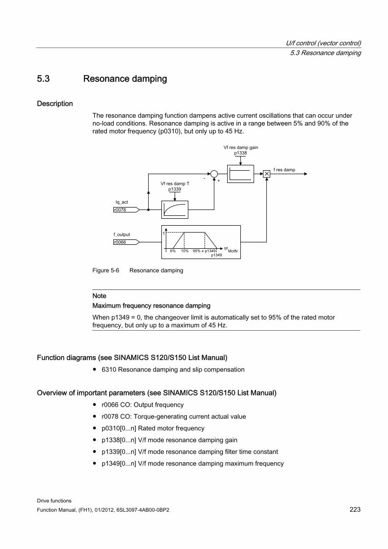
U/f control (vector control) 5.3 Resonance damping
Drive functions Function Manual, (FH1), 01/2012, 6SL3097-4AB00-0BP2 223
5.3 Resonance damping
Description The resonance damping function dampens active current oscillations that can occur under no-load conditions. Resonance damping is active in a range between 5% and 90% of the rated motor frequency (p0310), but only up to 45 Hz.
Figure 5-6 Resonance damping
Note Maximum frequency resonance damping
When p1349 = 0, the changeover limit is automatically set to 95% of the rated motor frequency, but only up to a maximum of 45 Hz.
Function diagrams (see SINAMICS S120/S150 List Manual) 6310 Resonance damping and slip compensation
Overview of important parameters (see SINAMICS S120/S150 List Manual) r0066 CO: Output frequency
r0078 CO: Torque-generating current actual value
p0310[0...n] Rated motor frequency
p1338[0...n] V/f mode resonance damping gain
p1339[0...n] V/f mode resonance damping filter time constant
p1349[0...n] V/f mode resonance damping maximum frequency
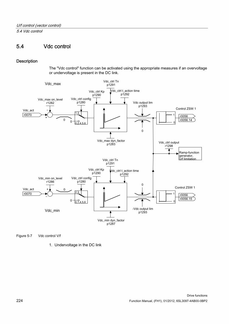
U/f control (vector control) 5.4 Vdc control
Drive functions 224 Function Manual, (FH1), 01/2012, 6SL3097-4AB00-0BP2
5.4 Vdc control
Description The "Vdc control" function can be activated using the appropriate measures if an overvoltage or undervoltage is present in the DC link.
Figure 5-7 Vdc control V/f
1. Undervoltage in the DC link
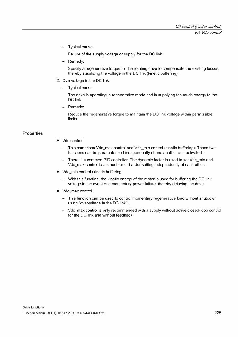
U/f control (vector control) 5.4 Vdc control
Drive functions Function Manual, (FH1), 01/2012, 6SL3097-4AB00-0BP2 225
– Typical cause:
Failure of the supply voltage or supply for the DC link.
– Remedy:
Specify a regenerative torque for the rotating drive to compensate the existing losses, thereby stabilizing the voltage in the DC link (kinetic buffering).
2. Overvoltage in the DC link
– Typical cause:
The drive is operating in regenerative mode and is supplying too much energy to the DC link.
– Remedy:
Reduce the regenerative torque to maintain the DC link voltage within permissible limits.
Properties Vdc control
– This comprises Vdc_max control and Vdc_min control (kinetic buffering). These two functions can be parameterized independently of one another and activated.
– There is a common PID controller. The dynamic factor is used to set Vdc_min and Vdc_max control to a smoother or harder setting independently of each other.
Vdc_min control (kinetic buffering)
– With this function, the kinetic energy of the motor is used for buffering the DC link voltage in the event of a momentary power failure, thereby delaying the drive.
Vdc_max control
– This function can be used to control momentary regenerative load without shutdown using "overvoltage in the DC link".
– Vdc_max control is only recommended with a supply without active closed-loop control for the DC link and without feedback.
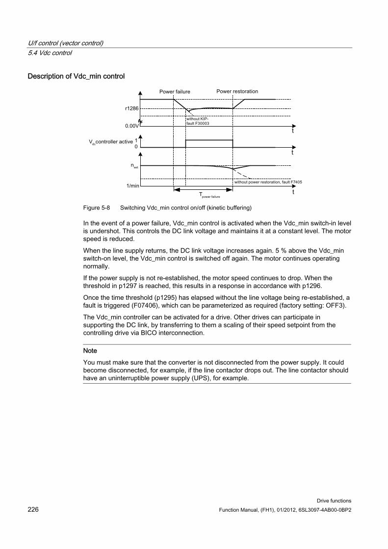
U/f control (vector control) 5.4 Vdc control
Drive functions 226 Function Manual, (FH1), 01/2012, 6SL3097-4AB00-0BP2
Description of Vdc_min control
Figure 5-8 Switching Vdc_min control on/off (kinetic buffering)
In the event of a power failure, Vdc_min control is activated when the Vdc_min switch-in level is undershot. This controls the DC link voltage and maintains it at a constant level. The motor speed is reduced.
When the line supply returns, the DC link voltage increases again. 5 % above the Vdc_min switch-on level, the Vdc_min control is switched off again. The motor continues operating normally.
If the power supply is not re-established, the motor speed continues to drop. When the threshold in p1297 is reached, this results in a response in accordance with p1296.
Once the time threshold (p1295) has elapsed without the line voltage being re-established, a fault is triggered (F07406), which can be parameterized as required (factory setting: OFF3).
The Vdc_min controller can be activated for a drive. Other drives can participate in supporting the DC link, by transferring to them a scaling of their speed setpoint from the controlling drive via BICO interconnection.
Note
You must make sure that the converter is not disconnected from the power supply. It could become disconnected, for example, if the line contactor drops out. The line contactor should have an uninterruptible power supply (UPS), for example.
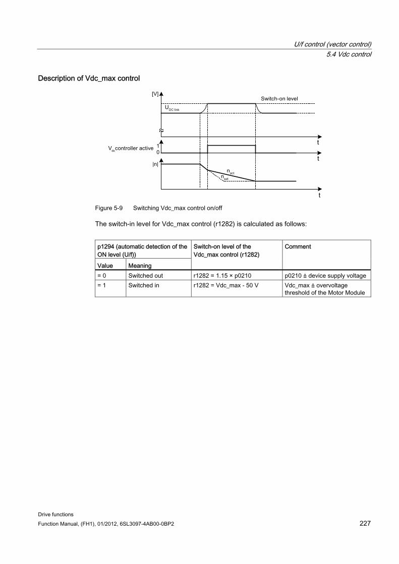
U/f control (vector control) 5.4 Vdc control
Drive functions Function Manual, (FH1), 01/2012, 6SL3097-4AB00-0BP2 227
Description of Vdc_max control
Figure 5-9 Switching Vdc_max control on/off
The switch-in level for Vdc_max control (r1282) is calculated as follows:
p1294 (automatic detection of the ON level (U/f))
Value Meaning
Switch-on level of the Vdc_max control (r1282)
Comment
= 0 Switched out r1282 = 1.15 × p0210 p0210 ≙ device supply voltage = 1 Switched in r1282 = Vdc_max - 50 V Vdc_max ≙ overvoltage
threshold of the Motor Module
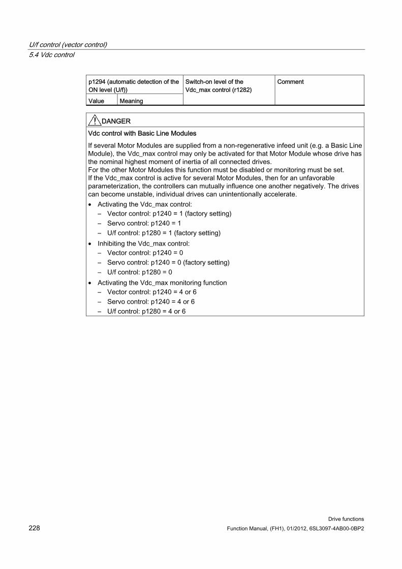
U/f control (vector control) 5.4 Vdc control
Drive functions 228 Function Manual, (FH1), 01/2012, 6SL3097-4AB00-0BP2
p1294 (automatic detection of the ON level (U/f))
Value Meaning
Switch-on level of the Vdc_max control (r1282)
Comment
DANGER Vdc control with Basic Line Modules
If several Motor Modules are supplied from a non-regenerative infeed unit (e.g. a Basic Line Module), the Vdc_max control may only be activated for that Motor Module whose drive has the nominal highest moment of inertia of all connected drives. For the other Motor Modules this function must be disabled or monitoring must be set. If the Vdc_max control is active for several Motor Modules, then for an unfavorable parameterization, the controllers can mutually influence one another negatively. The drives can become unstable, individual drives can unintentionally accelerate. • Activating the Vdc_max control:
– Vector control: p1240 = 1 (factory setting) – Servo control: p1240 = 1 – U/f control: p1280 = 1 (factory setting)
• Inhibiting the Vdc_max control: – Vector control: p1240 = 0 – Servo control: p1240 = 0 (factory setting) – U/f control: p1280 = 0
• Activating the Vdc_max monitoring function – Vector control: p1240 = 4 or 6 – Servo control: p1240 = 4 or 6 – U/f control: p1280 = 4 or 6
U/f control (vector control) 5.4 Vdc control
Drive functions Function Manual, (FH1), 01/2012, 6SL3097-4AB00-0BP2 229
Function diagrams (see SINAMICS S120/S150 List Manual) 6320 Vdc_max controller and Vdc_min controller U/f open-loop control
Overview of important parameters (see SINAMICS S120/S150 List Manual) p1280[0...n] Vdc controller configuration (V/f)
r1282 Vdc_max controller switch-in level (V/f)
p1283[0...n] Vdc_max controller dynamic factor (V/f)
p1285[0...n] Vdc_min controller switch-in level (kinetic buffering) (V/f)
r1286 Vdc_min controller switch-in level (kinetic buffering) (V/f)
p1287[0...n] Vdc_min controller dynamic factor (kinetic buffering) (V/f)
p1290[0...n] Vdc controller proportional gain (V/f)
p1291[0...n] Vdc controller integral action time (V/f)
p1292[0...n] Vdc controller derivative action time (V/f)
p1293[0...n] Vdc controller output limiting (U/f)
p1294 Vdc_max controller automatic detection ON signal level (V/f)
p1295[0...n] Vdc_min controller time threshold (U/f)
p1296[0...n] Vdc_min controller response (kinetic buffering) (V/f)
p1297[0...n] Vdc_min controller speed threshold (V/f)
r1298 CO: Vdc controller output (V/f)

U/f control (vector control) 5.4 Vdc control
Drive functions 230 Function Manual, (FH1), 01/2012, 6SL3097-4AB00-0BP2
Drive functions Function Manual, (FH1), 01/2012, 6SL3097-4AB00-0BP2 231
Basic functions 66.1 Changing over units
Description By changing over the units, parameters and process quantities for input and output can be changed over to an appropriate system of units (US units or as per unit quantities (%)).
The following supplementary conditions apply when changing over units:
Parameters of the rating plate of the drive converter or the motor rating plate can be changed over between SI/US units; however, a per unit representation is not possible.
After changing over the units parameter, all parameters that are assigned to one of the units group dependent on it, are all changed over to the new system of units.
A parameter is available to select technological units (p0595) to represent technological quantities in the technology controller.
If the units are converted to per unit quantities and the reference quantity changed, the percentage value entered in a parameter is not changed. Example:
– A fixed speed of 80% corresponds, for a reference speed of 1500 RPM, to a value of 1200 RPM.
– If the reference speed is changed to 3000 RPM, then the value of 80% is kept and now means 2400 RPM.
Restrictions When a unit changeover occurs, rounding to the decimal places is carried out. This can
mean that the original value might change by up to one decimal place.
If a referenced form is selected and the reference parameters (e.g. p2000) are changed retrospectively, the referenced values of some of the control parameters are also adjusted to ensure that the control behavior is unaffected.
If the reference variables (p2000 to p2007) are changed offline in STARTER, there is a risk that the parameter value ranges will be violated. In this case, appropriate fault messages will be displayed when the parameters are loaded to the drive unit.
Groups of units Every parameter that can be changed over is assigned to a units group, that, depending on the group, can be changed over within certain limits.
This assignment and the unit groups can be read for each parameter in the parameter list in the SINAMICS S120/S150 List Manual.
Basic functions 6.2 Reference parameters/normalizations
Drive functions 232 Function Manual, (FH1), 01/2012, 6SL3097-4AB00-0BP2
The unit groups can be individually switched using 4 parameters (p0100, p0349, p0505 and p0595).
Overview of important parameters (see SINAMICS S120/S150 List Manual) p0010 Commissioning parameter filter
p0100 Motor Standard IEC/NEMA
p0349 Selecting the system of units, motor equivalent circuit diagram data
p0505 Selecting the system of units
p0595 Selecting technological units
p0596 Reference quantity, technological units
p2000 CO: Reference frequency/speed
p2001 CO: Reference voltage
p2002 CO: Reference current
p2003 CO: Reference torque
r2004 CO: Reference power
p2005 CO: Reference angle
p2007 CO: Reference acceleration
Function in STARTER The function for converting units in STARTER, can be found under Drive object → Configuration → Units. The reference parameters can be found under Drive object → Configuration → Reference parameters.
6.2 Reference parameters/normalizations
Description Reference values, corresponding to 100%, are required for the statement of units as percentages. These reference values are entered in parameters p2000 to p2007. They are computed during the calculation through p0340 = 1 or in STARTER during drive configuration. After calculation in the drive, these parameters are automatically protected via p0573 = 1 from boundary violation through a new calculation (p0340). This eliminates the need to adjust the references values in a PROFIdrive controller whenever a new calculation of the reference parameters via p0340 takes place.
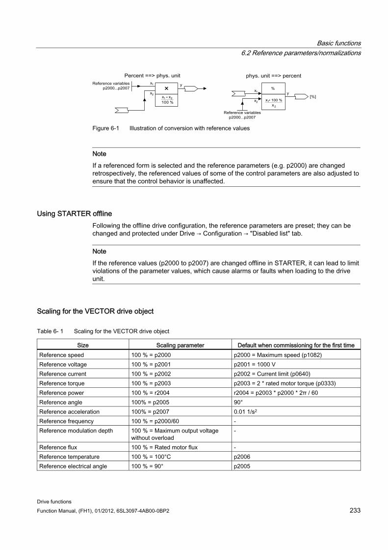
Basic functions 6.2 Reference parameters/normalizations
Drive functions Function Manual, (FH1), 01/2012, 6SL3097-4AB00-0BP2 233
Figure 6-1 Illustration of conversion with reference values
Note
If a referenced form is selected and the reference parameters (e.g. p2000) are changed retrospectively, the referenced values of some of the control parameters are also adjusted to ensure that the control behavior is unaffected.
Using STARTER offline Following the offline drive configuration, the reference parameters are preset; they can be changed and protected under Drive → Configuration → "Disabled list" tab.
Note
If the reference values (p2000 to p2007) are changed offline in STARTER, it can lead to limit violations of the parameter values, which cause alarms or faults when loading to the drive unit.
Scaling for the VECTOR drive object
Table 6- 1 Scaling for the VECTOR drive object
Size Scaling parameter Default when commissioning for the first time Reference speed 100 % = p2000 p2000 = Maximum speed (p1082) Reference voltage 100 % = p2001 p2001 = 1000 V Reference current 100 % = p2002 p2002 = Current limit (p0640) Reference torque 100 % = p2003 p2003 = 2 * rated motor torque (p0333) Reference power 100 % = r2004 r2004 = p2003 * p2000 * 2π / 60 Reference angle 100% = p2005 90° Reference acceleration 100% = p2007 0.01 1/s2 Reference frequency 100 % = p2000/60 - Reference modulation depth 100 % = Maximum output voltage
without overload -
Reference flux 100 % = Rated motor flux - Reference temperature 100 % = 100°C p2006 Reference electrical angle 100 % = 90° p2005
Basic functions 6.2 Reference parameters/normalizations
Drive functions 234 Function Manual, (FH1), 01/2012, 6SL3097-4AB00-0BP2
Note Operation of motors in the field-weakening range
If the motors are to be operated in the field-weakening range > 2:1, the value of parameter p2000 must be set ≤ 1/2 x maximum speed of the drive object.
Scaling for the SERVO drive object
Table 6- 2 Scaling for the SERVO drive object
Size Scaling parameter Default when commissioning for the first time Reference speed 100 % = p2000 Induction motor p2000 = Maximum motor speed (p0322)
Synchronous motor p2000 = Rated motor speed (p0311) Reference voltage 100 % = p2001 p2001 = 1000 V Reference current 100 % = p2002 p2002 = Motor limit current (p0338); when p0338 = "0", 2
* rated motor current (p0305) Reference torque 100 % = p2003 p2003 = p0338 * p0334; when "0", 2 * rated motor torque
(p0333) Reference power 100 % = r2004 r2004 = p2003 * p2000 * π / 30 Reference angle 100% = p2005 90° Reference acceleration 100% = p2007 0.01 1/s2 Reference frequency 100 % = p2000/60 - Reference modulation depth 100 % = Maximum output
voltage without overload -
Reference flux 100 % = Rated motor flux - Reference temperature 100 % = 100°C p2006 Reference electrical angle 100 % = 90° P2005
Note Operation of motors in the field-weakening range
If the motors are to be operated in the field-weakening range > 2:1, the value of parameter p2000 must be set ≤ 1/2 x maximum speed of the drive object.

Basic functions 6.2 Reference parameters/normalizations
Drive functions Function Manual, (FH1), 01/2012, 6SL3097-4AB00-0BP2 235
Scaling for the A_INF drive object
Table 6- 3 Scaling for the A_INF drive object
Size Scaling parameter Default when commissioning for the first time Reference frequency 100 % = p2000 p2000 = p0211 Reference voltage 100 % = p2001 p2001 = p0210 Reference current 100 % = p2002 p2002 = r0206/p0210/√3 Reference power 100 % = r2004 r2004 = r0206 Reference modulation depth 100 % = Maximum output
voltage without overload -
Reference temperature 100 % = 100°C p2006 Reference electrical angle 100 % = 90° -
Scaling for the S_INF drive object
Table 6- 4 Scaling for the S_INF drive object
Size Scaling parameter Default when commissioning for the first time Reference frequency 100 % = p2000 p2000 = 50 Hz Reference voltage 100 % = p2001 p2001 = p0210 Reference current 100 % = p2002 p2002 = r0206/p0210/√3 Reference power 100 % = r2004 r2004 = r0206 Reference modulation depth 100 % = Maximum output
voltage without overload -
Reference temperature 100 % = 100°C p2006 Reference electrical angle 100 % = 90° -
Scaling for the B_INF drive object
Table 6- 5 Scaling for the B_INF drive object
Size Scaling parameter Default when commissioning for the first time Reference frequency 100 % = p2000 p2000 = 50 Hz Reference voltage 100 % = p2001 p2001 = p0210 Reference current 100 % = p2002 p2002 = r0206/p0210/√3 Reference power 100 % = r2004 r2004 = r0206 Reference temperature 100 % = 100°C p2006 Reference electrical angle 100 % = 90° -
Basic functions 6.3 Modular machine concept
Drive functions 236 Function Manual, (FH1), 01/2012, 6SL3097-4AB00-0BP2
Overview of important parameters (see SINAMICS S120/S150 List Manual) r0206[0...4] Rated power unit power
p0210 Device supply voltage
p0340 Automatic calculation of motor/control parameters
p0573 Disable automatic calculation of reference values
p2000 Reference speed reference frequency
p2001 Reference voltage
p2002 Reference current
p2003 Reference torque
r2004 Reference power
p2005 Reference angle
p2006 reference temperature
p2007 Reference acceleration
6.3 Modular machine concept
Description The modular machine concept is based on a maximum topology created "offline" in STARTER. The maximum design of a particular machine type is referred to as the maximum configuration in which all the machine components that may be used are pre-configured in the target topology. Sections of the maximum configuration can be removed by deactivating/removing drive objects (p0105 = 2).
If a component fails, the sub-topology can also be used to allow a machine to continue running until the spare part is available. In this case, however, no BICO source must be interconnected from this drive object to other drive objects.
Example of a sub-topology The starting point is a machine created offline in STARTER for which "Drive 1" has not yet been implemented.
Object "Drive 1" must be removed from the target topology via p0105 = 2 in the "offline" mode.
The DRIVE-CLiQ cable is reconnected from the Control Unit directly to "Drive 2".
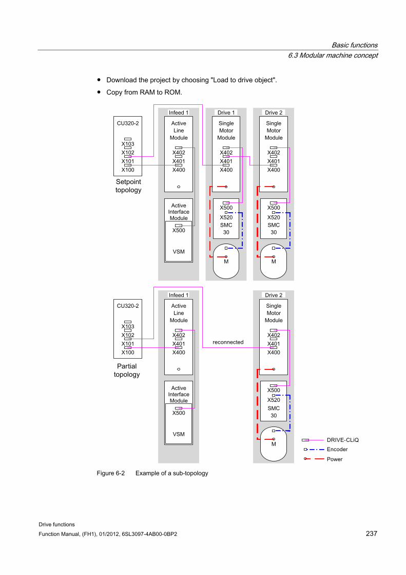
Basic functions 6.3 Modular machine concept
Drive functions Function Manual, (FH1), 01/2012, 6SL3097-4AB00-0BP2 237
Download the project by choosing "Load to drive object".
Copy from RAM to ROM.
Figure 6-2 Example of a sub-topology
Basic functions 6.4 Sinusoidal filter
Drive functions 238 Function Manual, (FH1), 01/2012, 6SL3097-4AB00-0BP2
CAUTION
If a drive in a Safety Integrated line-up is deactivated via p0105, r9774 is not read correctly because the signals from the deactivated drive are no longer updated.
Remedy: Remove this drive from the group before you deactivate it. See also: /FH1/ SINAMICS S120 Function Manual, Chapter Safety Integrated Basic Functions.
Overview of important parameters (see SINAMICS S120/S150 List Manual) p0105 Activate/deactivate drive object
r0106 Drive object active/inactive
p0125 Activate/deactivate power unit component
r0126 Power unit component active/inactive
p0145 Activate/deactivate encoder interface
r0146 Encoder interface active/inactive
p9495 BICO response to deactivated drive objects
p9496 Re-establish BICO to the now activated drive objects
r9498[0 ... 29] BICO BI/CI parameter to deactivated drive objects
r9499[0 ... 29] BICO BO/CO parameter to deactivated drive objects
6.4 Sinusoidal filter
Description The sine-wave filter limits the rate of rise of voltage and the capacitive charge/discharge currents that usually occur with inverter operation. They also prevent additional noise caused by the pulse frequency. The service life of the motor is the same as that with direct line operation.
CAUTION If a sine-wave filter is connected to the Power Module or Motor Module, the converter must be activated during commissioning (p0230 = 3) to prevent the filter from being destroyed.
If a sine-wave filter is connected to the Power Module or Motor Module, the Power Module or Motor Module must not be operated without a connected motor because otherwise the filter can be destroyed.
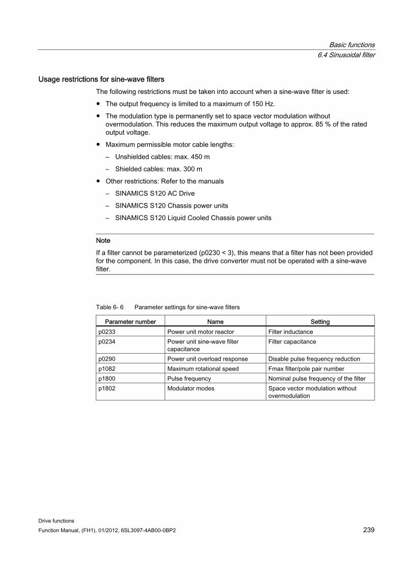
Basic functions 6.4 Sinusoidal filter
Drive functions Function Manual, (FH1), 01/2012, 6SL3097-4AB00-0BP2 239
Usage restrictions for sine-wave filters The following restrictions must be taken into account when a sine-wave filter is used:
The output frequency is limited to a maximum of 150 Hz.
The modulation type is permanently set to space vector modulation without overmodulation. This reduces the maximum output voltage to approx. 85 % of the rated output voltage.
Maximum permissible motor cable lengths:
– Unshielded cables: max. 450 m
– Shielded cables: max. 300 m
Other restrictions: Refer to the manuals
– SINAMICS S120 AC Drive
– SINAMICS S120 Chassis power units
– SINAMICS S120 Liquid Cooled Chassis power units
Note
If a filter cannot be parameterized (p0230 < 3), this means that a filter has not been provided for the component. In this case, the drive converter must not be operated with a sine-wave filter.
Table 6- 6 Parameter settings for sine-wave filters
Parameter number Name Setting p0233 Power unit motor reactor Filter inductance p0234 Power unit sine-wave filter
capacitance Filter capacitance
p0290 Power unit overload response Disable pulse frequency reduction p1082 Maximum rotational speed Fmax filter/pole pair number p1800 Pulse frequency Nominal pulse frequency of the filter p1802 Modulator modes Space vector modulation without
overmodulation
Basic functions 6.5 dv/dt filter plus VPL
Drive functions 240 Function Manual, (FH1), 01/2012, 6SL3097-4AB00-0BP2
6.5 dv/dt filter plus VPL
Description The du/dt filter plus Voltage Peak Limiter comprises two components: the du/dt reactor and the voltage limiting network (Voltage Peak Limiter VPL), which cuts off the voltage peaks and returns the energy to the DC link.
The dv/dt filter plus Voltage Peak Limiter is designed for use with motors for which the voltage strength of the insulation system is unknown or insufficient. Standard motors of the 1LA5, 1LA6 and 1LA8 series only require them at supply voltages > 500 V +10 %.
The dv/dt filter plus Voltage Peak Limiter limits the rate of voltage rise to values < 500 V/µs and the typical voltage peaks to the values below (with motor cable lengths of < 150 m):
Voltage peaks ÛLL (typically) < 1000 V for Vline < 575 V
Voltage peaks ÛLL (typically) < 1250 V for 660 V < Vline < 690 V
Restrictions The following restrictions must be taken into account when a dv/dt filter is used:
The output frequency is limited to a maximum of 150 Hz.
Maximum permissible motor cable lengths:
– Shielded cables: max. 300 m
– Unshielded cables: max. 450 m
Other restrictions: Refer to the manuals
– SINAMICS S120 AC Drive
– SINAMICS S120 Chassis power units
– SINAMICS S120 Liquid Cooled Chassis power units
WARNING
When a dv/dt filter with Voltage Peak Limiter is used, the maximum permissible pulse frequency of the Power Module or Motor Module is 4 kHz (chassis power units up to 250 kW at 400 V) or 2.5 kHz (chassis power units from 315 kW to 800 kW at 400 V or 75 kW up to 1200 kW at 690 V). If a higher pulse frequency is set, then this could destroy the dv/dt filter.
Commissioning The dv/dt filter must be activated when commissioning the system (p0230 = 2).

Basic functions 6.6 dv/dt filter compact plus Voltage Peak Limiter
Drive functions Function Manual, (FH1), 01/2012, 6SL3097-4AB00-0BP2 241
6.6 dv/dt filter compact plus Voltage Peak Limiter
Description The dv/dt filter compact plus Voltage Peak Limiter comprises two components, the dv/dt reactor and the voltage limiting network (Voltage Peak Limiter, VPL). A VPL cuts off the voltage peaks and feeds the energy back into the DC link.
The dv/dt filter compact plus Voltage Peak Limiter is designed for use with motors for which the voltage strength is unknown or is insufficient.
The dv/dt filter compact plus Voltage Peak Limiter limits the voltage load on the motor cables to values in accordance with the limit value curve A in compliance with IEC/TS 60034-25:2007.
The voltage rate-of-rise is limited to < 1600 V/µs. The voltage peaks are limited to < 1400 V.
WARNING When a dv/dt filter compact plus Voltage Peak Limiter is used, the drive must not be continuously operated with an output frequency lower than 10 Hz.
A maximum operating time of 5 minutes at an output frequency less than 10 Hz is permitted if this is then followed by an operating time of 5 minutes with an output frequency of greater than 10 Hz.
Continuous operation with output frequencies of less than 10 Hz can thermally destroy the dv/dt filter.
WARNING When using a dv/dt filter compact with Voltage Peak Limiter, the pulse frequency of a Power Module or a Motor Module must not exceed 4 kHz.
For the following chassis format power units, the pulse frequency must not exceed 2.5 kHz:• 400 V: Up to 250 kW • 400 V: 315 kW - 800 kW • 690 V: 75 kW - 1200 kW
If a higher pulse frequency is set, then this could destroy the dv/dt filter.

Basic functions 6.6 dv/dt filter compact plus Voltage Peak Limiter
Drive functions 242 Function Manual, (FH1), 01/2012, 6SL3097-4AB00-0BP2
Restrictions The following additional restrictions must be taken into account when a dv/dt filter is used:
The output frequency is limited to a maximum of 150 Hz.
Maximum permissible motor cable lengths:
– Shielded cables: Max. 100 m
– Unshielded cables: Max. 150 m
Other restrictions: Refer to the manuals
– SINAMICS S120 AC Drive
– SINAMICS S120 Chassis power units
– SINAMICS S120 Liquid Cooled Chassis power units
Commissioning During commissioning, you must activate the dv/dt filter with p0230 = 2.
Basic functions 6.7 Pulse frequency wobbling
Drive functions Function Manual, (FH1), 01/2012, 6SL3097-4AB00-0BP2 243
6.7 Pulse frequency wobbling
Description The function is available for Motor Modules in chassis format with DRIVE-CLiQ (order numbers: 6SL3xxx-xxxxx-xxx3) available in the vector control mode.
Pulse frequency wobbling damps the spectral components, which can generate unwanted noise in the motor. Wobbling can be activated only for pulse frequencies that are lower than or equal to the current controller frequency (see also p0115[0]).
Wobbling causes the pulse frequency in a modulation interval to deviate from the setpoint frequency. This means that the actual pulse frequency might be higher than the average pulse frequency required.
A noise generator can be used to vary the pulse frequency around an average value. In this case, the average pulse frequency is equal to the setpoint pulse frequency. The pulse frequency can be varied in every current controller cycle if the cycle is constant. Current measurement errors resulting from asynchronous pulse and control intervals are compensated by a correction in the actual current value.
Pulse frequency wobbling can be parameterized with parameter p1810 "Modulator configuration".
Parameter p1811[0...n] "Pulse frequency wobbling amplitude" can be set to adjust the magnitude of variation in the pulse frequency wobble to between 0 and 20 %. The factory setting is 0 %. For a wobble amplitude of p1811 = 0 %, the maximum possible pulse frequency is p1800 = 2 * 1/current controller cycle (1000/p0115[0]). With a wobble amplitude setting of p1811 > 0, the maximum possible pulse frequency is p1800 = 1/current controller cycle (1000/p0115[0]). These conditions apply to all indices.
Note
If pulse frequency wobbling is deactivated, parameter p1811 is set to "0" in all of the indices.
Overview of important parameters (see SINAMICS S120/S150 List Manual) p1810 modulator configuration
p1811[0...n] pulse frequency wobbling amplitude
Basic functions 6.8 Direction reversal without changing the setpoint
Drive functions 244 Function Manual, (FH1), 01/2012, 6SL3097-4AB00-0BP2
6.8 Direction reversal without changing the setpoint
Features Not change to the speed setpoint and actual value, the torque setpoint and actual value
and the relative position change.
Only possible when the pulses are inhibited
CAUTION If direction reversal is configured in the data set configurations (e.g. p1821[0] = 0 and p1821[1] = 1), then when the function module basic positioner or position control is activated, the absolute adjustment is reset each time the system boots or when the direction changes (p2507), as the position reference is lost when the direction reverses.
Description The direction of rotation of the motor can be reversed using the direction reversal via p1821 without having to change the motor rotating field by interchanging two phases at the motor and having to invert the encoder signals using p0410.
The direction reversal via p1821 can be detected as a result of the motor direction of rotation. The speed setpoint and actual value, torque setpoint and actual value and also the relative position change remain unchanged.
The direction change can be identified as a result of the phase voltage (r0089). When the direction reverses, then the absolute position reference is also lost.
In the vector control mode, in addition, the output direction of rotation of the drive converter can be reversed using p1820. This means that the rotating field can be changed without having to interchange the power connections. If an encoder is being used, the direction of rotation must, when required, be adapted using p0410.
Note Rotating/moving measurement for motor identification for servos drives
Use parameter p1959[0...n].14/15 = 0 to activate a direction inhibit for the rotating measurement for motor identification where necessary. The direction inhibit should be deactivated with p1959[0...n].14/15 = 1 for complete and accurate identification of the motor.
Basic functions 6.9 Automatic restart (vector, servo, infeed)
Drive functions Function Manual, (FH1), 01/2012, 6SL3097-4AB00-0BP2 245
Overview of important parameters (see SINAMICS S120/S150 List Manual) r0069 Phase current, actual value
r0089 Actual phase voltage
p1820 Direction of rotation reversal of the output phases (vector)
p1821 Rotational direction
p1959[0...n] Rotating measurement configuration
p2507 LR absolute encoder adjustment status
6.9 Automatic restart (vector, servo, infeed)
Description The automatic restart function is used to automatically restart the drive/drive line-up - e.g. when the power is restored after a power failure. In this case, all of the faults present are automatically acknowledged and the drive is powered-up again. This function is not only restricted to line supply faults; it can also be used to automatically acknowledge faults and to restart the motor after any fault trips. In order to allow the drive to be powered-up while the motor shaft is still rotating, the "flying restart" function should be activated using p1200. Before the automatic restart starts, it should be ensured that the supply voltage is available and is present at the infeed.
On this subject, also note the information in Chapter Switching on a drive object X_INF using a VECTOR drive object (Page 683)1).
CAUTION Automatic restart functions in the vector and servo modes - and for infeeds with closed-loop infeed control. After the line supply voltage is connected, Smart Line Modules 5kW/10kW automatically power themselves up.
WARNING If p1210 is set to the value > 1, the Line Modules / motors can start automatically once the line supply has been re-established. This is especially critical, if, after longer line supply failures, motors come to a standstill (zero speed) and it is incorrectly assumed that they have been powered-down. For this reason, entering the area around the drive when it is in this condition can cause death, serious injury, or considerable material damage.
Basic functions 6.9 Automatic restart (vector, servo, infeed)
Drive functions 246 Function Manual, (FH1), 01/2012, 6SL3097-4AB00-0BP2
Automatic restart mode
Table 6- 7 Automatic restart mode
p1210 Mode Meaning 0 Disables automatic restart Automatic restart inactive 1 Acknowledges all faults without
restarting Any faults that are present, are acknowledged automatically once the cause has been rectified. If further faults occur after faults have been acknowledged, then these are also again automatically acknowledged. A minimum time of p1212 + 1s must expire between successful fault acknowledgement and a fault re-occurring if the signal ON/OFF1 (control word 1, bit 0) is at a HIGH signal level. If the ON/OFF1 signal is at a LOW signal level, the time between a successful fault acknowledgement and a new fault must be at least 1s. For p1210 = 1, fault F07320 is not generated if the acknowledge attempt failed (e.g. because the faults occurred too frequently).
4 Restart after line supply failure, without additional start attempts
An automatic restart is only carried out, if in addition, fault F30003 has occurred at the Motor Module, there is a high signal at binector input p1208[1], or in the case of an infeed drive object (X_INF1)), fault F06200 has occurred. If additional faults are present, then these faults are also acknowledged and when successfully acknowledged, the starting attempt is continued. The failure of the CU's 24 V supply will be interpreted as a line supply failure.
6 Restart after a fault with additional start attempts
An automatic restart is carried out after any fault or for p1208[0] = 1. If the faults occur one after the other, then the number of start attempts is defined in p1211. Monitoring over time can be set using p1213.
14 Restart after line supply failure following manual acknowledgement
As for 4: However, existing faults must be acknowledged manually.
16 Restart after a fault following manual acknowledgement
As for 6: However, existing faults must be acknowledged manually.
Starting attempts (p1211) and waiting time (p1212) p1211 is used to specify the number of starting attempts. The number is internally decremented after each successful fault acknowledgement (line supply voltage must be re-applied or the infeed signals that it is ready. Fault F07320 is signaled if the number of parameterized startup attempts is exceeded.
When p1211 = x, x + 1 starting attempts are made.
Basic functions 6.9 Automatic restart (vector, servo, infeed)
Drive functions Function Manual, (FH1), 01/2012, 6SL3097-4AB00-0BP2 247
Note
A start attempt immediately starts when the fault occurs.
The faults are automatically acknowledged in intervals of half the waiting time p1212.
After successfully acknowledgment and the voltage returns, then the system is automatically powered-up again.
The starting attempt has been successfully completed if the flying restart and the motor magnetization (induction motor) have been completed (r0056.4 = 1) and one additional second has expired. The starting counter is only reset back to the initial value p1211 after this time.
If additional faults occur between successful acknowledgement and the end of the startup attempt, then the startup counter, when it is acknowledged, is also decremented.
Monitoring time line supply return (p1213) The monitoring time starts when the faults are detected. If the automatic acknowledgements are not successful, the monitoring time runs again. If the drive has not successfully started again after the monitoring time has expired (flying restart and motor magnetization must have been completed: r0056.4 = 1), fault F07320 is output. The monitoring is deactivated with p1213 = 0.
If p1213 is set lower than the sum of p1212, the magnetization time r0346 and the additional delay time due to flying restart, then fault F07320 is generated at each restart. p1210 = 1 prevents a restart The monitoring time must be extended if the faults that occur cannot be immediately and successfully acknowledged (e.g. when faults are permanently present).
Commissioning 1. Activating the function for drive object VECTOR and X_INF1)
– Automatic restart: Set mode (p1210).
– Flying restart: Activate function (p1200).
2. Set starting attempts (p1211).
3. Set waiting times (p1212, p1213).
4. Check function.
Exceptions There are faults, where after they have occurred, an automatic restart would be dangerous or is undesirable. Enter the numbers of these faults into p1206[0...9]. The automatic restart is suppressed if one of these faults occurs. After the cause of the fault has been removed, the drives must be switched-on in another way.
Basic functions 6.10 Armature short-circuit braking, DC braking
Drive functions 248 Function Manual, (FH1), 01/2012, 6SL3097-4AB00-0BP2
Overview of important parameters (see SINAMICS S120/S150 List Manual) r0863 CO/BO: Drive coupling status word/control word
p1206[0...9] faults without automatic restart
p1207 BI: Automatic restart (AR) - connection to the following drive object
p1208 BI: Automatic restart - infeed fault
p1210 Automatic restart, mode
p1211 Automatic restart, attempts to start
p1212 Automatic restart, delay time start attempts
p1213 Automatic restart, waiting time increment 1) X_INF stands for all drive objects "Infeed"; i.e.: A_INF, B_INF, S_INF
6.10 Armature short-circuit braking, DC braking Armature short-circuit braking or DC braking can be set using parameters p1231[0..n]. The current status of the armature short-circuit braking or the DC braking can be seen in r1239.
Armature short-circuit braking Using this function, you can brake permanent-magnet synchronous motors. The stator windings of synchronous motors are then short-circuited. For a rotating synchronous motor, a current flows that brakes the motor.
Armature short-circuit braking is preferably used when
braking should be realized without energy recovery
the drive should be braked when the power fails
an infeed unit is used that is not capable of energy recovery
for orientation loss, e.g. in the event of an encoder fault, the motor should still be braked.
You can switch the armature short-circuit braking internally via the Motor Module or externally using a contactor circuit with braking resistors.
The advantage of armature short-circuit braking over a mechanical brake is the response time of the internal armature short-circuit braking with just a few milliseconds. The response time of a mechanical brake is about 40 ms. For external armature short-circuit braking, the slowness of the switching contactor results in a response time of over 60 ms.
DC braking Using this function, you can brake induction motors down to standstill. With DC braking, a DC current is impressed in the stator windings of the induction motor.
DC braking is preferred in the event of danger, when
Basic functions 6.10 Armature short-circuit braking, DC braking
Drive functions Function Manual, (FH1), 01/2012, 6SL3097-4AB00-0BP2 249
it is not possible to ramp-down the drive in a controlled fashion
an infeed unit is used that is not capable of energy recovery
no braking resistor is used
6.10.1 Armature short-circuit braking for permanent-magnet synchronous motors
Preconditions This function has been released for Motor Modules in the booksize and chassis formats.
Short-circuit-proof motors (p0320 < p0323)
One of the following motor types is used:
– rotating permanent-magnet synchronous motor (p0300 = 2xx)
– linear permanent-magnet synchronous motor (p0300 = 4xx)
The maximum current of the Motor Module (r0209.0) must be at least 1.8x the motor short-circuit current (r0331).
Note Internal short-circuit braking despite power failure
If armature short-circuit braking should still be maintained despite a power failure, you must buffer the 24 V power supply for the Motor Module. For this purpose, you can use for example a dedicated SITOP unit for the Motor Module or a Control Supply Module (CSM).
6.10.1.1 Internal armature short-circuit braking With the internal armature short-circuit braking, the motor windings are short-circuited using the Motor Module.
Setting The internal armature short-circuit braking is set with p1231 = 4.
Activation The function is activated and initiated if the signal source of p1230 is set to a "1".
Deactivation The function is deactivated if the signal source of p1230 is set to a "0". When triggered by a fault, the fault must have been removed and acknowledged.
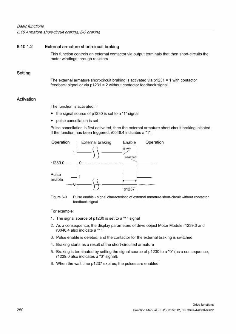
Basic functions 6.10 Armature short-circuit braking, DC braking
Drive functions 250 Function Manual, (FH1), 01/2012, 6SL3097-4AB00-0BP2
6.10.1.2 External armature short-circuit braking This function controls an external contactor via output terminals that then short-circuits the motor windings through resistors.
Setting The external armature short-circuit braking is activated via p1231 = 1 with contactor feedback signal or via p1231 = 2 without contactor feedback signal.
Activation The function is activated, if
the signal source of p1230 is set to a "1" signal
pulse cancellation is set
Pulse cancellation is first activated, then the external armature short-circuit braking initiated. If the function has been triggered, r0046.4 indicates a "1".
Figure 6-3 Pulse enable - signal characteristic of external armature short-circuit without contactor
feedback signal
For example:
1. The signal source of p1230 is set to a "1" signal
2. As a consequence, the display parameters of drive object Motor Module r1239.0 and r0046.4 also indicate a "1".
3. Pulse enable is deleted, and the contactor for the external braking is switched.
4. Braking starts as a result of the short-circuited armature
5. Braking is terminated by setting the signal source of p1230 to a "0" (as a consequence, r1239.0 also indicates a "0" signal).
6. When the wait time p1237 expires, the pulses are enabled.
Basic functions 6.10 Armature short-circuit braking, DC braking
Drive functions Function Manual, (FH1), 01/2012, 6SL3097-4AB00-0BP2 251
Calculating the external braking resistors To achieve the highest braking effect, calculate the values of the resistors using the following formula:
Rext = 5.2882 × 10⁻⁵ × p0314 × p0356 × nmax - p0350
nmax = maximum speed used
Parameter assignment You can parameterize the Motor Module and the Control Unit using the STARTER commissioning tool. The expert lists of the drive objects and an input screen form to enter the digital inputs/outputs are available.
The input screen form of the Control Unit for the digital inputs/outputs DI/DO 8 to 15 is located under the "Control Unit/bidirectional digital inputs/outputs" window tab.
Terminals 11 and 14 are connected to ground.
The digital inputs/outputs DI/DO 8 to 15 are connected with terminals 9, 10, 12 and 13 at terminal blocks X122 and X132. Parameters p0728[8...15] are used to define the terminals as an input or output.
As digital inputs, DI 8 to 15 are interconnected with the parameters p0722[8...15] or with p0723[8...15] inverted.
The outputs are interconnected with parameters p0738 to p0745.
The outputs can be inverted with p0748[8...15] = 1.
Parameters p0722 to p0748 are Control Unit parameters.
Parameters p123x, r1239 and r0046 are drive parameters.
Example of external armature short-circuit braking Before parameterizing external armature short-circuit braking, you have created a new project with a Motor Module and a motor. The following conditions should be fulfilled:
A short-circuit contactor with an additional feedback signal contact is used. (p1231 = 1).
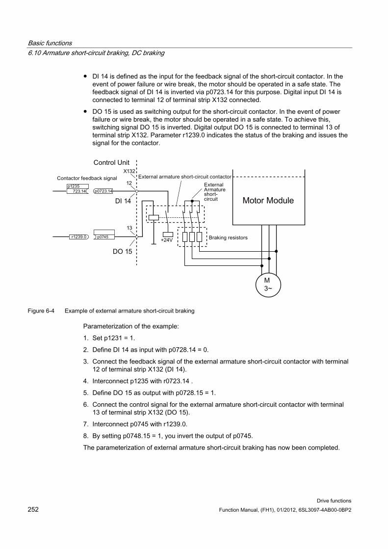
Basic functions 6.10 Armature short-circuit braking, DC braking
Drive functions 252 Function Manual, (FH1), 01/2012, 6SL3097-4AB00-0BP2
DI 14 is defined as the input for the feedback signal of the short-circuit contactor. In the event of power failure or wire break, the motor should be operated in a safe state. The feedback signal of DI 14 is inverted via p0723.14 for this purpose. Digital input DI 14 is connected to terminal 12 of terminal strip X132 connected.
DO 15 is used as switching output for the short-circuit contactor. In the event of power failure or wire break, the motor should be operated in a safe state. To achieve this, switching signal DO 15 is inverted. Digital output DO 15 is connected to terminal 13 of terminal strip X132. Parameter r1239.0 indicates the status of the braking and issues the signal for the contactor.
Figure 6-4 Example of external armature short-circuit braking
Parameterization of the example:
1. Set p1231 = 1.
2. Define DI 14 as input with p0728.14 = 0.
3. Connect the feedback signal of the external armature short-circuit contactor with terminal 12 of terminal strip X132 (DI 14).
4. Interconnect p1235 with r0723.14 .
5. Define DO 15 as output with p0728.15 = 1.
6. Connect the control signal for the external armature short-circuit contactor with terminal 13 of terminal strip X132 (DO 15).
7. Interconnect p0745 with r1239.0.
8. By setting p0748.15 = 1, you invert the output of p0745.
The parameterization of external armature short-circuit braking has now been completed.
Basic functions 6.10 Armature short-circuit braking, DC braking
Drive functions Function Manual, (FH1), 01/2012, 6SL3097-4AB00-0BP2 253
6.10.2 DC braking
Preconditions This function has been released for Motor Modules in the booksize, blocksize and
chassis formats.
An induction motor must be used.
With the function "DC braking", after a demagnetization time, a DC current is injected in the stator windings of the induction motor. The DC current brakes the motor.
6.10.2.1 Activation via parameters
Setting DC braking is set with parameter p1231 = 4.
Setting the braking current for DC braking with p1232[0..n]
Setting the braking current duration for DC braking with p1233[0..n]
Setting the start speed for DC braking with p1234[0..n]
Activation The function is activated if the signal source of p1230 is set to "1". Initially, for the motor demagnetization time p0347[0 ... n], the pulses are inhibited until the motor is demagnetized. The DC braking start speed parameter p1234 is not taken into account with this activation.
The DC braking current p1232[0 ... n] is injected into the motor as long as a "1" signal is available at the input of p1230. The motor can be braked down to standstill.
If the drive is switched off – and DC braking is activated – the drive switches itself on. DC current is then injected into the stator windings.
Basic functions 6.10 Armature short-circuit braking, DC braking
Drive functions 254 Function Manual, (FH1), 01/2012, 6SL3097-4AB00-0BP2
Deactivation If DC braking is deactivated by setting the signal source of p1230 to "0" and the ON command is still active, then the drive returns to its selected operating mode.
The following is applicable:
for servo control (with encoder): The drive returns to close-loop control after the demagnetization time has elapsed (p0347 can also be set to 0).
for vector control (with and without encoder): When the "flying restart" function is activated, the Motor Module is synchronized with the motor frequency. The drive is then switched back into closed-loop controlled operation. If the "flying restart" function is not activated, the drive can only be restarted from standstill. In this case, for a new start you must wait until the drive has come to a standstill.
for U/f operation: When the "flying restart" function is activated, the Motor Module is synchronized with the motor frequency. The drive is then switched back to U/f operation. If the "flying restart" function is not available, the drive can only be restarted from standstill. In this case, for a new start you must wait until the drive has come to a standstill.
6.10.2.2 Activation via fault response If DC braking is activated as fault response, then the following responses are executed:
1. The motor is braked along the braking ramp up to the threshold in p1234. The gradient of the braking ramp corresponds to the gradient of the down ramp (can be set using p1121).
2. The pulses are inhibited for the duration of the motor de-magnetization time (p0347) until the magnetic field in the motor has decayed.
3. After p0347 has expired, DC braking starts for the period of time according to p1233. If an encoder is being used, the braking operation lasts until the speed falls below the zero speed threshold set in p1226. If an encoder is not being used, braking lasts until the time set in p1233 has expired.
NOTICE
For encoderless servo control, it is possible that operation cannot be continued after DC braking has been completed. An OFF2 fault message is then output.
6.10.2.3 Activation via OFF command
Setting as a response to OFF fault signals With p1231 = 5, DC braking is set as a response to OFF1 or OFF3. Parameter p1230 has no influence on the response for OFF1/OFF3. The speed threshold is set with p1234, under which DC braking is activated.
Basic functions 6.10 Armature short-circuit braking, DC braking
Drive functions Function Manual, (FH1), 01/2012, 6SL3097-4AB00-0BP2 255
Activation using OFF1/OFF3 DC braking is activated with OFF1 or OFF3.
If the motor speed ≥ p1234, the motor is braked down to p1234. As soon as the motor speed is < p1234, the pulses are disabled and the motor is demagnetized.
If the motor speed at OFF1/OFF3 is already < p1234, the pulses are immediately inhibited and the motor is demagnetized.
DC braking is then activated for the duration p1233 and is then switched off.
When OFF1/OFF3 is prematurely canceled, then normal operation is resumed.
DC braking as emergency braking of a fault response remains active.
6.10.2.4 Activation via a speed threshold
Setting If p1231 is set to 14, DC braking as a response is activated as soon as the actual speed falls below p1234.
Activation Before activation, the actual speed must be > p1234. DC braking can then be activated when both of the following conditions are met:
1. the actual speed has fallen below p1234
2. the signal source of p1230 is set to "1"
The pulses are first disabled. As a consequence, the motor is demagnetized. DC braking is then initiated for the duration p1233. The motor is braked with the braking current p1232.
If the signal source of p1230 is set to "0", the braking command is canceled and the drive goes back into the previous operating mode.
DC braking for OFF1 or OFF3 is only executed if the signal source of p1230 is set to "1".
DC braking as emergency braking of a fault response remains active.
6.10.3 Configuring the fault response
Changing the fault response The responses can be set to selected faults using parameters p2100 and p2101. Only responses can be set that are intended for the corresponding faults.
Basic functions 6.10 Armature short-circuit braking, DC braking
Drive functions 256 Function Manual, (FH1), 01/2012, 6SL3097-4AB00-0BP2
Using parameter p0491, responses to encoder faults of a motor encoder can be set (F07412 and many F3yxxx, y = 1, 2, 3).
Note Motor type change
If the preconditions for armature short-circuit braking or DC braking are no longer satisfied after a motor type has been changed (see p0300), then those modified parameters that have armature short-circuit braking or DC braking as a response (e.g. p2100, p2101 or p0491) are set to the factory setting.
Note Deselecting armature short-circuit or DC braking
Armature short-circuit or DC braking cannot be deactivated using parameter p1231, as long as a response parameterized with p2100, p2101 or p0491 has a fault condition.
6.10.4 Function diagrams and parameters
Function diagrams (see SINAMICS S120/S150 List Manual) 7014 External Armature Short-Circuit (EASC, p0300 = 2xx or 4xx)
7016 Internal Armature Short-Circuit (IASC, p0300 = 2xx or 4xx)
7017 DC brake (p0300 = 1xx)
Overview of important parameters (see SINAMICS S120/S150 List Manual) r0046.0...31 CO/BO: Missing enable signals
p0300[0...n] motor type selection
p0347[0...n] motor demagnetization time
p0491 motor encoder fault response ENCODER
r0722.0...21 CO/BO: CU digital inputs, status
r0723.0...21 CO/BO: CU digital inputs, status inverted
p0728 CU set input or output
p0738 BI: CU signal source for terminal DI/DO 8
to
p0745 BI: CU signal source for terminal DI/DO 15
p0748 CU invert digital outputs
p1226[0...n] standstill identification (zero speed) speed threshold
p1230[0...n] BI: Armature short-circuit/DC braking activation
Basic functions 6.11 Motor Module as braking module
Drive functions Function Manual, (FH1), 01/2012, 6SL3097-4AB00-0BP2 257
p1231[0...n] Armature short-circuit/DC braking configuration
p1232[0...n] DC braking, braking current
p1233[0...n] DC braking time
p1234[0...n] speed at the start of DC braking
p1235[0...n] BI: External armature short-circuit, contactor feedback signal
p1237[0...n] external armature short-circuit, waiting time when opening
r1239.0...13 CO/BO: Armature short-circuit/DC braking status word
6.11 Motor Module as braking module Using this function, a Motor Module is operated as a braking module. To do this, three resistors are connected to the Motor Module instead of a motor.
Preconditions for operation as a braking module:
Three identical braking resistors in a star (see table below) or delta connection
At least 10 m cable length to the resistors
Configuration in STARTER
– VECTOR drive object
– U/f control
Note
This function is released for: • SINAMICS S120 Motor Modules Cabinet • SINAMICS S120 Motor Modules Chassis (500 V - 690 V) • SINAMICS S120 Motor Modules Chassis (380 V - 480 V) > 250 kW • SINAMICS S120 Motor Modules Chassis Liquid Cooled (380 V - 480 V) > 250 kW • SINAMICS S120 Motor Modules Chassis Liquid Cooled (500 V - 690 V)
6.11.1 Features Only permitted for Motor Modules in the chassis format (refer to the list above)
Three identical resistors required
Parallel connection of Motor Modules possible
Integrated protective devices are available for monitoring the resistors
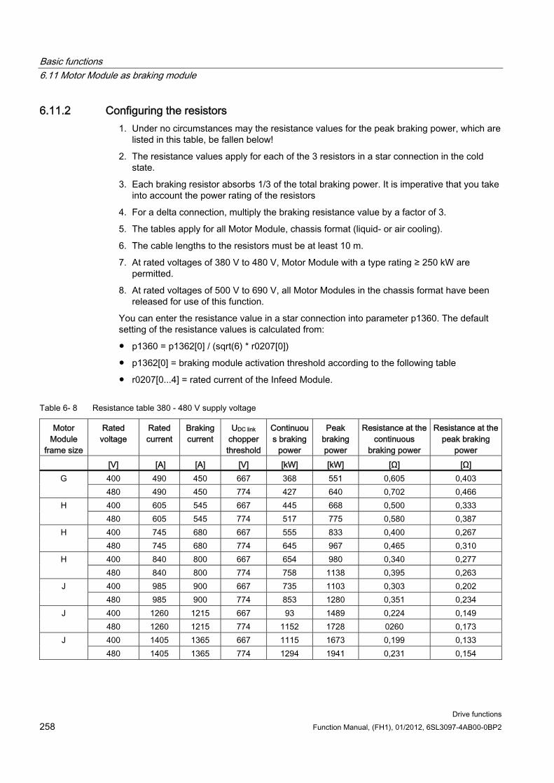
Basic functions 6.11 Motor Module as braking module
Drive functions 258 Function Manual, (FH1), 01/2012, 6SL3097-4AB00-0BP2
6.11.2 Configuring the resistors 1. Under no circumstances may the resistance values for the peak braking power, which are
listed in this table, be fallen below!
2. The resistance values apply for each of the 3 resistors in a star connection in the cold state.
3. Each braking resistor absorbs 1/3 of the total braking power. It is imperative that you take into account the power rating of the resistors
4. For a delta connection, multiply the braking resistance value by a factor of 3.
5. The tables apply for all Motor Module, chassis format (liquid- or air cooling).
6. The cable lengths to the resistors must be at least 10 m.
7. At rated voltages of 380 V to 480 V, Motor Module with a type rating ≥ 250 kW are permitted.
8. At rated voltages of 500 V to 690 V, all Motor Modules in the chassis format have been released for use of this function.
You can enter the resistance value in a star connection into parameter p1360. The default setting of the resistance values is calculated from:
p1360 = p1362[0] / (sqrt(6) * r0207[0])
p1362[0] = braking module activation threshold according to the following table
r0207[0...4] = rated current of the Infeed Module.
Table 6- 8 Resistance table 380 - 480 V supply voltage
Motor Module
frame size
Rated voltage
Rated current
Braking current
UDC link chopper threshold
Continuous braking
power
Peak braking power
Resistance at the continuous
braking power
Resistance at the peak braking
power [V] [A] [A] [V] [kW] [kW] [Ω] [Ω]
400 490 450 667 368 551 0,605 0,403 G 480 490 450 774 427 640 0,702 0,466 400 605 545 667 445 668 0,500 0,333 H 480 605 545 774 517 775 0,580 0,387 400 745 680 667 555 833 0,400 0,267 H 480 745 680 774 645 967 0,465 0,310 400 840 800 667 654 980 0,340 0,277 H 480 840 800 774 758 1138 0,395 0,263 400 985 900 667 735 1103 0,303 0,202 J 480 985 900 774 853 1280 0,351 0,234 400 1260 1215 667 93 1489 0,224 0,149 J 480 1260 1215 774 1152 1728 0260 0,173 400 1405 1365 667 1115 1673 0,199 0,133 J 480 1405 1365 774 1294 1941 0,231 0,154
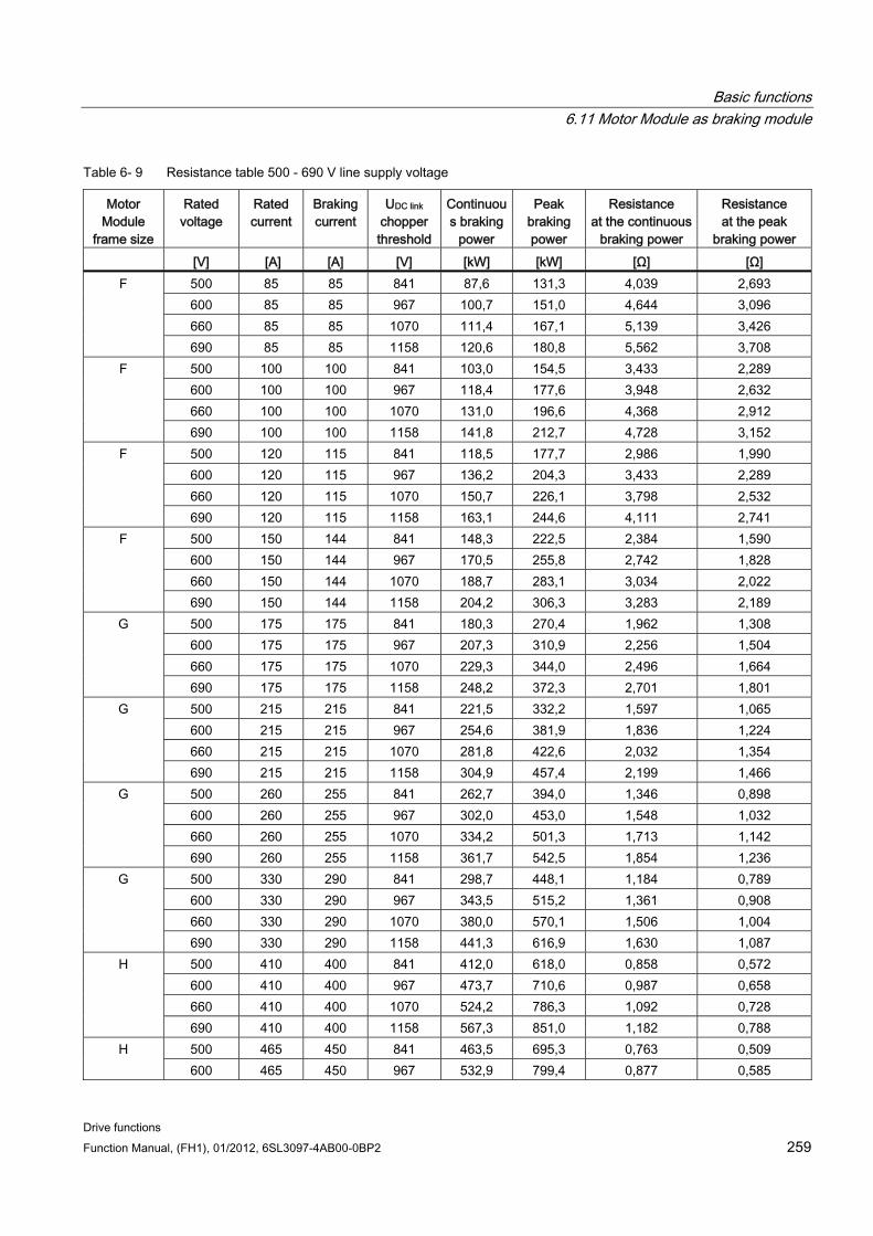
Basic functions 6.11 Motor Module as braking module
Drive functions Function Manual, (FH1), 01/2012, 6SL3097-4AB00-0BP2 259
Table 6- 9 Resistance table 500 - 690 V line supply voltage
Motor Module
frame size
Rated voltage
Rated current
Braking current
UDC link chopper threshold
Continuous braking
power
Peak braking power
Resistance at the continuous
braking power
Resistance at the peak
braking power [V] [A] [A] [V] [kW] [kW] [Ω] [Ω]
500 85 85 841 87,6 131,3 4,039 2,693 600 85 85 967 100,7 151,0 4,644 3,096 660 85 85 1070 111,4 167,1 5,139 3,426
F
690 85 85 1158 120,6 180,8 5,562 3,708 500 100 100 841 103,0 154,5 3,433 2,289 600 100 100 967 118,4 177,6 3,948 2,632 660 100 100 1070 131,0 196,6 4,368 2,912
F
690 100 100 1158 141,8 212,7 4,728 3,152 500 120 115 841 118,5 177,7 2,986 1,990 600 120 115 967 136,2 204,3 3,433 2,289 660 120 115 1070 150,7 226,1 3,798 2,532
F
690 120 115 1158 163,1 244,6 4,111 2,741 500 150 144 841 148,3 222,5 2,384 1,590 600 150 144 967 170,5 255,8 2,742 1,828 660 150 144 1070 188,7 283,1 3,034 2,022
F
690 150 144 1158 204,2 306,3 3,283 2,189 500 175 175 841 180,3 270,4 1,962 1,308 600 175 175 967 207,3 310,9 2,256 1,504 660 175 175 1070 229,3 344,0 2,496 1,664
G
690 175 175 1158 248,2 372,3 2,701 1,801 500 215 215 841 221,5 332,2 1,597 1,065 600 215 215 967 254,6 381,9 1,836 1,224 660 215 215 1070 281,8 422,6 2,032 1,354
G
690 215 215 1158 304,9 457,4 2,199 1,466 500 260 255 841 262,7 394,0 1,346 0,898 600 260 255 967 302,0 453,0 1,548 1,032 660 260 255 1070 334,2 501,3 1,713 1,142
G
690 260 255 1158 361,7 542,5 1,854 1,236 500 330 290 841 298,7 448,1 1,184 0,789 600 330 290 967 343,5 515,2 1,361 0,908 660 330 290 1070 380,0 570,1 1,506 1,004
G
690 330 290 1158 441,3 616,9 1,630 1,087 500 410 400 841 412,0 618,0 0,858 0,572 600 410 400 967 473,7 710,6 0,987 0,658 660 410 400 1070 524,2 786,3 1,092 0,728
H
690 410 400 1158 567,3 851,0 1,182 0,788 500 465 450 841 463,5 695,3 0,763 0,509 H 600 465 450 967 532,9 799,4 0,877 0,585
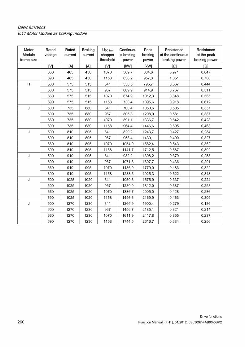
Basic functions 6.11 Motor Module as braking module
Drive functions 260 Function Manual, (FH1), 01/2012, 6SL3097-4AB00-0BP2
Motor Module
frame size
Rated voltage
Rated current
Braking current
UDC link chopper threshold
Continuous braking
power
Peak braking power
Resistance at the continuous
braking power
Resistance at the peak
braking power [V] [A] [A] [V] [kW] [kW] [Ω] [Ω]
660 465 450 1070 589,7 884,6 0,971 0,647 690 465 450 1158 638,2 957,3 1,051 0,700 500 575 515 841 530,5 795,7 0,667 0,444 600 575 515 967 609,9 914,9 0,767 0,511 660 575 515 1070 674,9 1012,3 0,848 0,565
H
690 575 515 1158 730,4 1095,6 0,918 0,612 500 735 680 841 700,4 1050,6 0,505 0,337 600 735 680 967 805,3 1208,0 0,581 0,387 660 735 680 1070 891,1 1336,7 0,642 0,428
J
690 735 680 1158 964,4 1446,6 0,695 0,463 500 810 805 841 829,2 1243,7 0,427 0,284 600 810 805 967 953,4 1430,1 0,490 0,327 660 810 805 1070 1054,9 1582,4 0,543 0,362
J
690 810 805 1158 1141,7 1712,5 0,587 0,392 500 910 905 841 932,2 1398,2 0,379 0,253 600 910 905 967 1071,8 1607,7 0,436 0,291 660 910 905 1070 1186,0 1779,0 0,483 0,322
J
690 910 905 1158 1283,5 1925,3 0,522 0,348 500 1025 1020 841 1050,6 1575,9 0,337 0,224 600 1025 1020 967 1280,0 1812,0 0,387 0,258 660 1025 1020 1070 1336,7 2005,0 0,428 0,286
J
690 1025 1020 1158 1446,6 2169,9 0,463 0,309 500 1270 1230 841 1266,9 1900,4 0,279 0,186 600 1270 1230 967 1456,7 2185,1 0,321 0,214 660 1270 1230 1070 1611,9 2417,8 0,355 0,237
J
690 1270 1230 1158 1744,5 2616,7 0,384 0,256
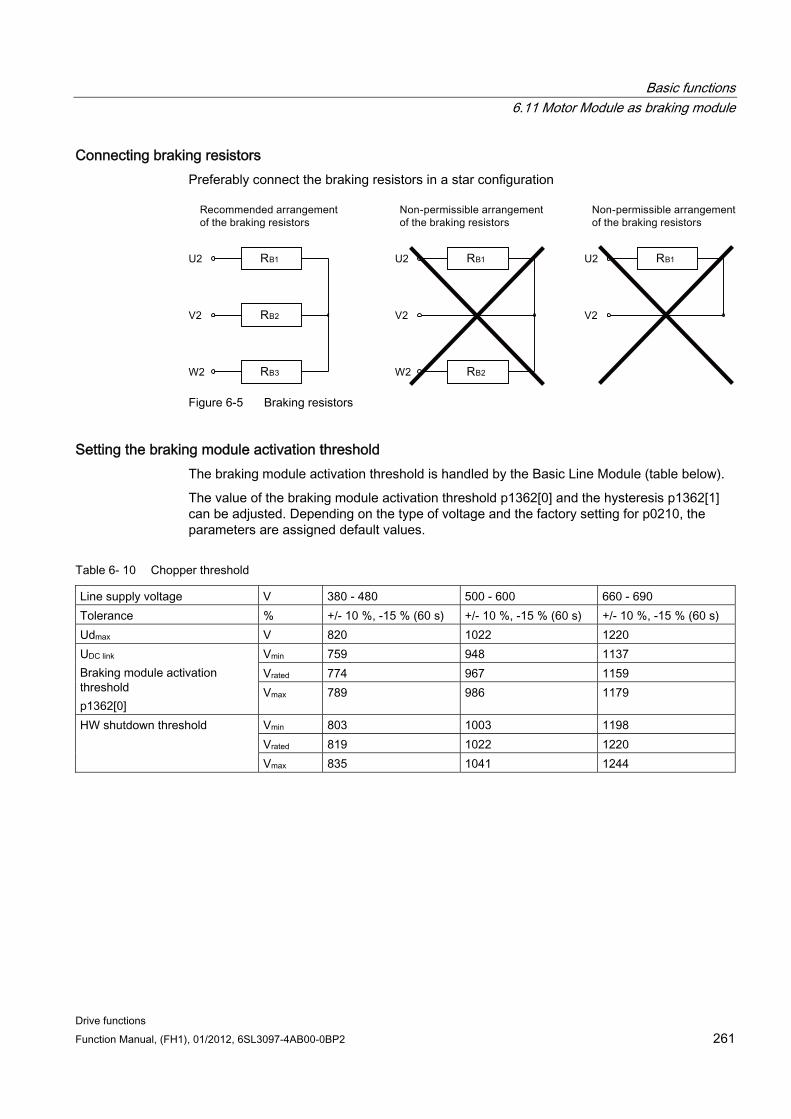
Basic functions 6.11 Motor Module as braking module
Drive functions Function Manual, (FH1), 01/2012, 6SL3097-4AB00-0BP2 261
Connecting braking resistors Preferably connect the braking resistors in a star configuration
Figure 6-5 Braking resistors
Setting the braking module activation threshold The braking module activation threshold is handled by the Basic Line Module (table below).
The value of the braking module activation threshold p1362[0] and the hysteresis p1362[1] can be adjusted. Depending on the type of voltage and the factory setting for p0210, the parameters are assigned default values.
Table 6- 10 Chopper threshold
Line supply voltage V 380 - 480 500 - 600 660 - 690 Tolerance % +/- 10 %, -15 % (60 s) +/- 10 %, -15 % (60 s) +/- 10 %, -15 % (60 s) Udmax V 820 1022 1220
Vmin 759 948 1137 Vrated 774 967 1159
UDC link Braking module activation threshold p1362[0]
Vmax 789 986 1179
Vmin 803 1003 1198 Vrated 819 1022 1220
HW shutdown threshold
Vmax 835 1041 1244
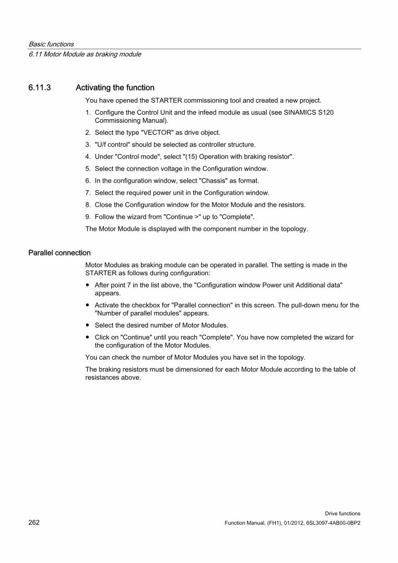
Basic functions 6.11 Motor Module as braking module
Drive functions 262 Function Manual, (FH1), 01/2012, 6SL3097-4AB00-0BP2
6.11.3 Activating the function You have opened the STARTER commissioning tool and created a new project.
1. Configure the Control Unit and the infeed module as usual (see SINAMICS S120 Commissioning Manual).
2. Select the type "VECTOR" as drive object.
3. "U/f control" should be selected as controller structure.
4. Under "Control mode", select "(15) Operation with braking resistor".
5. Select the connection voltage in the Configuration window.
6. In the configuration window, select "Chassis" as format.
7. Select the required power unit in the Configuration window.
8. Close the Configuration window for the Motor Module and the resistors.
9. Follow the wizard from "Continue >" up to "Complete".
The Motor Module is displayed with the component number in the topology.
Parallel connection Motor Modules as braking module can be operated in parallel. The setting is made in the STARTER as follows during configuration:
After point 7 in the list above, the "Configuration window Power unit Additional data" appears.
Activate the checkbox for "Parallel connection" in this screen. The pull-down menu for the "Number of parallel modules" appears.
Select the desired number of Motor Modules.
Click on "Continue" until you reach "Complete". You have now completed the wizard for the configuration of the Motor Modules.
You can check the number of Motor Modules you have set in the topology.
The braking resistors must be dimensioned for each Motor Module according to the table of resistances above.
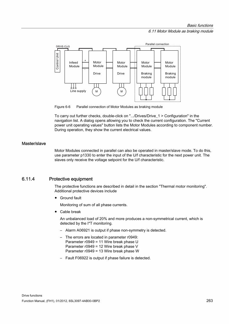
Basic functions 6.11 Motor Module as braking module
Drive functions Function Manual, (FH1), 01/2012, 6SL3097-4AB00-0BP2 263
Figure 6-6 Parallel connection of Motor Modules as braking module
To carry out further checks, double-click on ".../Drives/Drive_1 > Configuration" in the navigation list. A dialog opens allowing you to check the current configuration. The "Current power unit operating values" button lists the Motor Modules according to component number. During operation, they show the current electrical values.
Master/slave Motor Modules connected in parallel can also be operated in master/slave mode. To do this, use parameter p1330 to enter the input of the U/f characteristic for the next power unit. The slaves only receive the voltage setpoint for the U/f characteristic.
6.11.4 Protective equipment The protective functions are described in detail in the section "Thermal motor monitoring". Additional protective devices include
Ground fault
Monitoring of sum of all phase currents.
Cable break
An unbalanced load of 20% and more produces a non-symmetrical current, which is detected by the I*T monitoring.
– Alarm A06921 is output if phase non-symmetry is detected.
– The errors are located in parameter r0949: Parameter r0949 = 11 Wire break phase U Parameter r0949 = 12 Wire break phase V Parameter r0949 = 13 Wire break phase W
– Fault F06922 is output if phase failure is detected.
Basic functions 6.11 Motor Module as braking module
Drive functions 264 Function Manual, (FH1), 01/2012, 6SL3097-4AB00-0BP2
Overcurrent
The Imax controller is active. The setpoint is stored in parameter p0067.
Overtemperature of the resistors
The temperature is monitored using bimetal temperature switches mounted on the resistors.
Configuring the temperature evaluation contacts
Switch the temperature evaluation contacts of all 3 resistors in series.
Connect the temperature evaluation contacts to the temperature sensor evaluation of the Motor Module (terminals X41.3 and X41.4).
Set parameter p0600 = 11 and p0601 = 4.
Parameterize the temperature sensor evaluation of the Motor Module as "external fault".
6.11.5 Function diagrams and parameters
Function diagrams (see SINAMICS S120/S150 List Manual) None
Overview of important parameters (see SINAMICS S120/S150 List Manual) r0207[0…4] Power unit rated current
r0949[0...63] Fault value
p1300[0...n] Open-loop/closed-loop control operating mode
p1330[0...n] CI: U/f control independent of voltage setpoint
p1360 Braking Module braking resistance, cold
p1362[0…1] Braking Module switch-on threshold
p1363 CO: Braking Module output voltage
p1364 Braking Module non-symmetrical resistance
Basic functions 6.12 OFF3 torque limits
Drive functions Function Manual, (FH1), 01/2012, 6SL3097-4AB00-0BP2 265
6.12 OFF3 torque limits
Description If the torque limits are externally specified (e.g. tension controller), then the drive can only be stopped with a reduced torque. If stopping in the selected time p3490 of the infeed has not been completed, the infeed shuts down and the drive coasts down.
In order to avoid this, there is a binector input (p1551), that for a LOW signal, activates the torque limits p1520 and p1521. This means that the drive can brake with the maximum torque by interconnecting the signal OFF 3 (r0899.5) to this binector.
Function diagrams (see SINAMICS S120/S150 List Manual) 5620 Motor/generator torque limits
5630 Upper/lower torque limit
6630 Upper/lower torque limit
Overview of important parameters (see SINAMICS S120/S150 List Manual) p1520 Torque limit, upper/motoring
p1521 Torque limit, lower/regenerative
6.13 Technology function: friction characteristic
Description The friction characteristic curve is used to compensate the friction torque for the motor and the driven machine. A friction characteristic enables the speed controller to be pre-controlled and improves the response.
10 interpolation points are used for each friction characteristic curve. The coordinates of every interpolation point are defined by a speed parameter (p382x) and a torque parameter (p383x) (point 1 = p3820 and p3830).
Features 10 interpolation points are available for mapping the friction characteristic curve.
An automatic function allows you to record the friction characteristic curve (record friction characteristic curve).
A connector output (r3841) can be applied as friction torque (p1569).
The friction characteristic can be activated and deactivated (p3842).
Basic functions 6.13 Technology function: friction characteristic
Drive functions 266 Function Manual, (FH1), 01/2012, 6SL3097-4AB00-0BP2
Function diagrams (see SINAMICS S120/S150 List Manual) 5610 Torque limiting/reduction/interpolator
6710 Current setpoint filters
7010 Friction characteristic curve
Overview of important parameters (see SINAMICS S120/S150 List Manual) p3820 Friction characteristic curve value n0
...
p3839 Friction characteristic curve value M9
r3840 CO/BO: Friction characteristic curve status
r3841 CO: Friction characteristic curve output
p3842 Friction characteristic curve activation
p3845 Friction characteristic curve record activation
Commissioning via parameters In p382x, speeds for the measurement are predefined as a function of the maximum speed p1082 during first commissioning. They can be changed appropriately.
The automatic friction characteristic plot can be activated using p3845. The characteristic is then plotted the next time that it is enabled.
The following settings are possible:
p3845 = 0 Friction characteristic curve recording deactivated
p3845 = 1 Friction characteristic curve recording activated, all directions of rotation
The friction characteristic curve is recorded in both directions of rotation. The results of the positive and negative measurement are averaged and entered in p383x.
p3845 = 2 Friction characteristic curve recording activated, positive direction of rotation
p3845 = 3 Friction characteristic curve recording activated, negative direction of rotation
DANGER
When the friction characteristic is plotted, the drive can cause the motor to move. As a result, the motor may reach maximum speed.
The Emergency Off functions must be fully operational during commissioning. To protect the machines and personnel, the relevant safety regulations must be observed.
Commissioning via STARTER In STARTER, the friction characteristic curve can be started up via the dialog under "Functions".
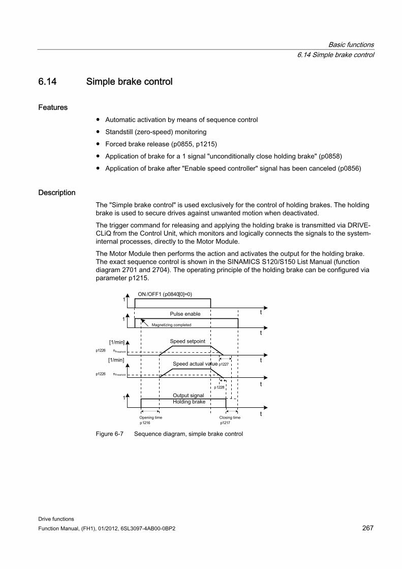
Basic functions 6.14 Simple brake control
Drive functions Function Manual, (FH1), 01/2012, 6SL3097-4AB00-0BP2 267
6.14 Simple brake control
Features Automatic activation by means of sequence control
Standstill (zero-speed) monitoring
Forced brake release (p0855, p1215)
Application of brake for a 1 signal "unconditionally close holding brake" (p0858)
Application of brake after "Enable speed controller" signal has been canceled (p0856)
Description The "Simple brake control" is used exclusively for the control of holding brakes. The holding brake is used to secure drives against unwanted motion when deactivated.
The trigger command for releasing and applying the holding brake is transmitted via DRIVE-CLiQ from the Control Unit, which monitors and logically connects the signals to the system-internal processes, directly to the Motor Module.
The Motor Module then performs the action and activates the output for the holding brake. The exact sequence control is shown in the SINAMICS S120/S150 List Manual (function diagram 2701 and 2704). The operating principle of the holding brake can be configured via parameter p1215.
OFF
Output signal
Holding brake
Speed setpoint
ON
Speed actual value
Pulse enable
Magnetizing completed
Closing timeOpening time
Threshold
[1/min]
[1/min]
nThreshold
p1227
p1228
p1226
p1226
p1216 p1217
/ 1 (p0840[0]=0)
n
t
t
1
1
t
t
1
t
Figure 6-7 Sequence diagram, simple brake control
Basic functions 6.14 Simple brake control
Drive functions 268 Function Manual, (FH1), 01/2012, 6SL3097-4AB00-0BP2
The start of the closing time for the brake depends on the expiration of the shorter of the two times p1227 (standstill detection monitoring time) and p1228 (pulse cancellation delay time).
WARNING The holding brake must not be used as a service brake.
When holding brakes are used, the special technological and machine-specific conditions and standards for ensuring personnel and machine safety must be observed.
The risks involved with vertical axes, for example, must also be taken into account.
Commissioning Simple brake control is activated automatically (p1215 = 1) when the Motor Module has an internal brake control and a connected brake has been found.
If no internal brake control is available, the control can be activated using a parameter (p1215 = 3).
CAUTION If p1215 = 0 (no brake available) is set when a brake is present, the drive runs with applied brake. This can destroy the brake.
CAUTION It is only permissible to activate brake control monitoring for booksize power units and blocksize power units with Safe Brake Relay (p1278 = 0).
Function diagrams (see SINAMICS S120/S150 List Manual) 2701 Simple brake control (r0108.14 = 0)
2704 Extended brake control (r0108.14 = 1)
Overview of important parameters (see SINAMICS S120/S150 List Manual) r0056.4 Magnetizing complete
r0060 CO: Speed setpoint before the setpoint filter
r0063 CO: Actual speed value after actual-value smoothing (servo)
r0063[0...2] CO: Speed actual value
r0108.14 Extended brake control
p0855[C] BI: Unconditionally release holding brake
p0856 BI: Speed controller enabled
p0858 BI: Unconditionally close holding brake
Basic functions 6.15 Runtime (operating hours counter)
Drive functions Function Manual, (FH1), 01/2012, 6SL3097-4AB00-0BP2 269
r0899.12 BO: Holding brake open
r0899.13 BO: Command, close holding brake
p1215 Motor holding brake configuration
p1216 Holding brake release time
p1217 Holding brake application time
p1226 Threshold for zero speed detection
p1227 Zero speed detection monitoring time
p1228 Zero speed detection, delay time
p1278 Brake control diagnostics evaluation
6.15 Runtime (operating hours counter)
Total system runtime The total system runtime is displayed in p2114 (Control Unit). Index 0 indicates the system runtime in milliseconds after reaching 86.400.000 ms (24 hours), the value is reset. Index 1 indicates the system runtime in days.
At power-off the counter value is saved.
After the drive unit is powered-up, the counter continues to run with the value that was saved the last time that the drive unit was powered-down.
Relative system runtime The relative system runtime after the last POWER ON is displayed in p0969 (Control Unit). The value is in milliseconds and the counter overflows after 49 days.
Actual motor operating hours The motor operating hours counter p0650 (drive) is started when the pulses are enabled. When the pulse enable is withdrawn, the counter is stopped and the value saved.
If p0651 is at 0, the counter is deactivated.
If the maintenance interval set in p0651 is reached, alarm A01590 is triggered. Once the motor has been maintained, the maintenance interval must be reset.
CAUTION If the motor data set is switched during the star/delta changeover without the motor being changed, the two values in p0650 must be added to determine the correct number of motor operating hours.
Basic functions 6.16 Energy-saving display
Drive functions 270 Function Manual, (FH1), 01/2012, 6SL3097-4AB00-0BP2
Operating hours counter for the fan The operating hours of the fan in the power unit are displayed in p0251 (drive).
The number of hours operated can only be reset to 0 in this parameter (e.g. after a fan has been replaced). The service life of the fan is entered in p0252 (drive). Alarm A30042 is output 500 hours before this figure is reached. Monitoring is deactivated when p0252 = 0.
6.16 Energy-saving display
Introduction Through the tailored, speed-controlled operation, a drive can consume significantly less energy than with a conventional closed-loop process control. This is especially true for continuous-flow machines with parabolic load characteristics, such as centrifugal pumps and fans. Using the SINAMICS S120 system enables control of the flow rate or the pressure by changing the speed of the continuous-flow machine. As a consequence, the plant or system is controlled close to its maximum efficiency over the complete operating range.
Energy savings display The energy saved is displayed in r0041.
Machines with a lower energy-saving potential When compared to continuous-flow machines with parabolic load characteristic, machines with a linear or constant load characteristic, such as conveyor drives or reciprocating pumps, have a lower energy-saving potential.
This function is optimized for fluid-flow machines.
Situation In a conventionally controlled plant or system, the flow rate of the medium is controlled using valves or throttles. In this case, the drive motor operates at a constant rated speed defined by the particular operation. The system efficiency decreases significantly if the flow rate is reduced by means of valves or throttles. The pressure in the system increases. The motor also consumes energy when the valves/throttles are completely closed, i.e. with a flow rate of Q = 0. In addition, undesirable process-related situations can occur; for example, cavitation in the continuous-flow machine or increased heating of the continuous-flow machine and the medium.
Basic functions 6.16 Energy-saving display
Drive functions Function Manual, (FH1), 01/2012, 6SL3097-4AB00-0BP2 271
Solution to optimize the system When using a speed controller, the process-specific flow rate of the continuous-flow machine is controlled by varying the speed. The flow rate changes proportionally with the speed of the continuous-flow machine. Any throttles or valves remain completely open. The entire plant/system characteristic is shifted by the speed controller to achieve the required flow rate. As a consequence, the complete system operates close to the optimum efficiency – and especially in the partial load range, uses significantly less energy than when using a throttle or valve to control the flow rate.
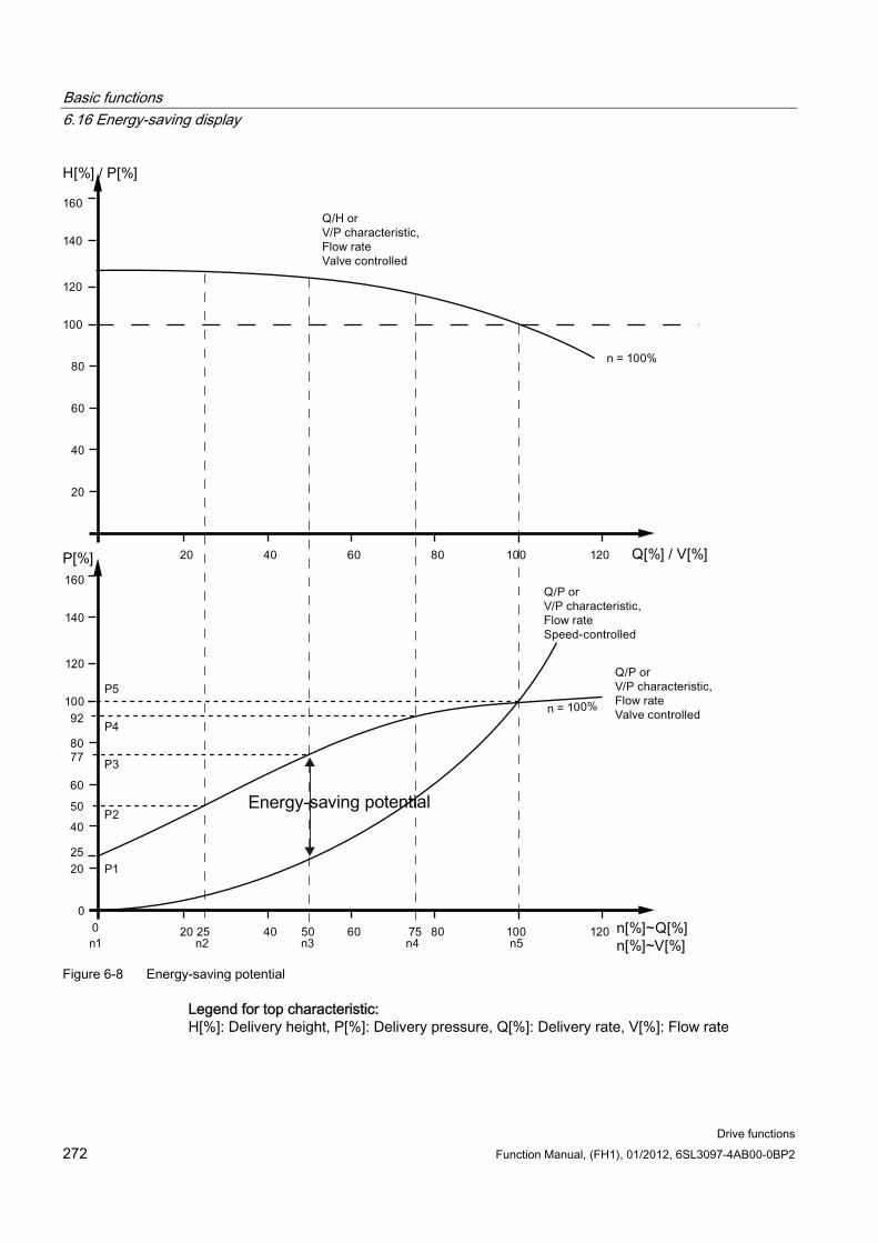
Basic functions 6.16 Energy-saving display
Drive functions 272 Function Manual, (FH1), 01/2012, 6SL3097-4AB00-0BP2
Figure 6-8 Energy-saving potential
Legend for top characteristic: H[%]: Delivery height, P[%]: Delivery pressure, Q[%]: Delivery rate, V[%]: Flow rate
Basic functions 6.16 Energy-saving display
Drive functions Function Manual, (FH1), 01/2012, 6SL3097-4AB00-0BP2 273
Legend for bottom characteristic: P[%]: Power drawn by the conveyor machine, n[%]: Speed of the conveyor machine Interpolation points p3320 ... p3329 for the system characteristic with n = 100%:
P1 ... P5: Power drawn, n1 ... n5: Speed corresponding to a closed-loop speed control machine
Energy-saving function This function determines the amount of energy used and compares it with the interpolated energy required for a plant or system equipped with a conventional throttle control. The amount of energy saved is calculated over the last 100 operating hours and is displayed in kW. For an operating time of less than 100 hours, the potential energy-saving is interpolated up to 100 operating hours. To do this, you must manually enter the plant/system characteristic with the conventional throttle control.
Note Plant/system characteristic
The factory setting is used as basis for the calculation if you do not enter the interpolation points for your plant/system characteristic. The values of the factory setting can deviate from your plant/system characteristic and result in an inaccurate calculation.
This calculation is configurable individually for each individual axis.
Activation of the function This function is enabled only for vector mode.
The function is automatically activated after the pulses have been enabled
Enter 5 interpolation points for the load characteristic in parameters p3320 to p3329:
Table 6- 11 Plant/system interpolation points
Interpolation point Parameter Factory setting: P - power in % n - speed in %
p3320 P1 = 25.00 1 p3321 n1 = 0.00 p3322 P2 = 50.00 2 p3323 n2 = 25.00 p3324 P3 = 77.00 3 p3325 n3 = 50.00 p3326 P4 = 92.00 4 p3327 n4 = 75.00 p3328 P5 = 100.00 5 p3329 n5 = 100.00
Basic functions 6.17 Encoder diagnostics
Drive functions 274 Function Manual, (FH1), 01/2012, 6SL3097-4AB00-0BP2
Reset the energy display Set p0040 = 1, to reset the value of parameter r0041 to 0. Parameter p0040 is then automatically set back to 0.
6.17 Encoder diagnostics
6.17.1 Datalogger A datalogger is available to support troubleshooting; this datalogger can localize errors in the encoder evaluation.
Commissioning Set parameter p0437.0 = 1 to activate this function.
The datalogger is automatically active as soon as the current controller time is slower than 125 μs.
Principle of operation The datalogger reads out several internal signals of the encoder evaluation, which serve as basis for the actual value generation. A change in the fault state serves as trigger for the recording. Data is recorded a short time before the fault state as well as afterwards.
The diagnostics data is saved on the memory card in the following directories:
/USER/SINAMICS/DATA/SMTRC00.BIN
…
/USER/SINAMICS/DATA/SMTRC07.BIN
/USER/SINAMICS/DATA/SMTRCIDX.TXT
The following information is contained in the index file (SMTRCIDX.TXT):
Displaying the last written BIN file
Number of still possible write operations (from 10000 downwards).
Note
BIN files can only be evaluated by Siemens.
Alarm A3x9301) is output while diagnostics data is being actively recorded. Do not switch off the system during this time. 1) x = encoder number (x = 1, 2 or 3)
Basic functions 6.18 Tolerant encoder monitoring
Drive functions Function Manual, (FH1), 01/2012, 6SL3097-4AB00-0BP2 275
6.17.2 Encoder dirty signal Some encoders have an additional output, which switches from "high" to "low", if the evaluation electronics in the encoder can no longer determine a reliable position.
In order to inform you about this, the drive only outputs alarm A3x4701) when an SMC30 is used. 1) x = encoder number (x = 1, 2 or 3)
Commissioning Connect the corresponding encoder signal with the CTRL input (monitoring signal) of the device. Parameterization is not required.
Note
The input is automatically set to a high level if a wire is broken: As a consequence, for a broken wire, the encoder is considered to be "good".
Overview of important parameters (see SINAMICS S120/S150 List Manual) p0437[0...n] Sensor Module configuration extended
6.18 Tolerant encoder monitoring The tolerant encoder monitoring offers the following expanded functionality regarding the evaluation of encoder signals:
Encoder track monitoring (Page 276)
Zero mark tolerance (Page 277) (also for other sensor modules)
Freeze speed raw value (Page 278)
Adjustable hardware filter (Page 278)
Edge evaluation of the zero mark (Page 279)
Pole position adaptation (Page 280)
Pulse number correction for faults (Page 281)
Monitoring, tolerance band, pulse number (Page 282)
Expansion of the encoder evaluation (1x, 4x) (Page 283)
Setting the measuring time to evaluate speed "0" (Page 284)
The number of current controller cycles can be set to generate the average value of the speed actual value (Page 284)
These supplementary functions allow you to improve the evaluation of your encoder signals. This may be necessary in special cases where the Control Unit receives incorrect encoder signals or specific properties of the signals must be compensated for.
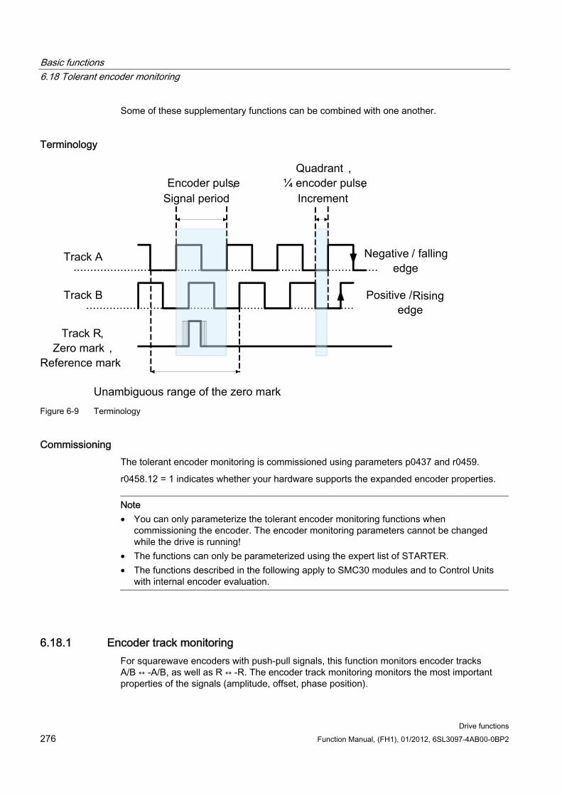
Basic functions 6.18 Tolerant encoder monitoring
Drive functions 276 Function Manual, (FH1), 01/2012, 6SL3097-4AB00-0BP2
Some of these supplementary functions can be combined with one another.
Terminology
Encoder pulse,
Signal period
Quadrant ,
¼ encoder pulse,
Increment
Track A
Track B
Track R,
Zero mark ,
Reference mark
Unambiguous range of the zero mark
Positive /
edge
Negative / falling
edge
Rising
Figure 6-9 Terminology
Commissioning The tolerant encoder monitoring is commissioned using parameters p0437 and r0459.
r0458.12 = 1 indicates whether your hardware supports the expanded encoder properties.
Note • You can only parameterize the tolerant encoder monitoring functions when
commissioning the encoder. The encoder monitoring parameters cannot be changed while the drive is running!
• The functions can only be parameterized using the expert list of STARTER. • The functions described in the following apply to SMC30 modules and to Control Units
with internal encoder evaluation.
6.18.1 Encoder track monitoring For squarewave encoders with push-pull signals, this function monitors encoder tracks A/B ↔ -A/B, as well as R ↔ -R. The encoder track monitoring monitors the most important properties of the signals (amplitude, offset, phase position).
Basic functions 6.18 Tolerant encoder monitoring
Drive functions Function Manual, (FH1), 01/2012, 6SL3097-4AB00-0BP2 277
Commissioning The following parameters must be set as precondition for track monitoring:
p0404.3 = 1 switches to the squarewave encoder
p0405.0 = 1 sets the signal to bipolar
Set p0405.2 = 1 to activate track monitoring.
If you selected your encoder from the list of parameter p0400, then the values above are pre-selected and cannot be changed (also refer to the information on p0400 in the SINAMICS S120/S150 List Manual).
Deactivating track monitoring If encoder track monitoring is activated, you can deactivate the function by setting p0437.26 = 1.
Evaluating messages All of the track monitoring functions can be individually evaluated. You can use both HTL as well as TTL encoders.
If a fault is detected, then fault F3x1171) is output. The faulted tracks are included in the fault value bit-coded.
Note
For modules CU310-2, CUA32, D410-2 and SMC30 (only order numbers 6SL3055-0AA00-5CA0 and 6SL3055-0AA00-5CA1) there is only a general signal. If you connect a squarewave encoder without R track to one of these modules, then if track monitoring is activated, fault F3x1171) is output.
To avoid this fault, at the encoder connection, you must connect the "ground encoder supply" (pin 7) with the "reference signal R" (pin 10), as well as the "encoder supply" (pin 4) with the "inverse reference signal R" (pin 11).
1) x = encoder number (x = 1, 2 or 3)
6.18.2 Zero mark tolerance This function allows individual faults to be tolerated regarding the number of encoder pulses between two zero marks.
Commissioning Set parameter p0430.21 = 1 to activate the "zero mark tolerance" function.
Basic functions 6.18 Tolerant encoder monitoring
Drive functions 278 Function Manual, (FH1), 01/2012, 6SL3097-4AB00-0BP2
Principle of operation The function runs as follows:
The "zero mark tolerance" function starts to become effective after the 2nd zero mark has been detected.
After this, if the number of track pulses between two zero marks does not match the configured number of pulses once, then alarms A3x4001) (alarm threshold, zero mark distance error) or A3x4011) (alarm threshold, zero mark failed) is output.
The alarms are cleared if the next zero mark is received at the correct position.
However, if a new zero mark position error is identified, fault F3x1001) (zero mark distance error) or Fx31011) (zero mark failed) is output.
1) x = encoder number (x = 1, 2 or 3)
6.18.3 Freezing the speed raw value If, for high speed changes, the dn/dt monitoring function responds, then the "freeze speed raw value" function gives you the opportunity of briefly specifying the speed actual value therefore equalizing the speed change.
Commissioning Set parameter p0437.6 = 1 to activate the "freeze speed raw value" function.
Sequence If the dn/dt monitor responds, the alarm A3x418 " Encoder x: Speed difference per
sampling rate exceeded"1) is output.
A frozen speed actual value limited to just 2 current controller clock cycles is supplied.
The rotor position continues to integrate
The actual value is released again after2 current controller cycles 1) x = encoder number (x = 1, 2 or 3)
6.18.4 Adjustable hardware filter The adjustable hardware filter function allows an encoder signal to be filtered, therefore suppressing short interference pulses.
Commissioning Set parameter p0438 ≠ 0 to activate the "adjustable hardware filter" function.
Basic functions 6.18 Tolerant encoder monitoring
Drive functions Function Manual, (FH1), 01/2012, 6SL3097-4AB00-0BP2 279
Parameterization In parameter p0438 (squarewave encoder filter time) enter the filter time in the range
from 0 to 100 μs. The hardware filter only supports values 0 (no filtering), 0.04 μs, 0.64 μs, 2.56 μs, 10.24 μs and 20.48 μs
If a value is set that does not match one of the discrete values specified above, the firmware automatically sets the next closest discrete value. The drive does not output an alarm or fault message.
You can see the active, effective filter time in parameter r0452.
Note
The zero mark alarms F3x100, F3x101 and F3x1311), that are already output for a zero mark with a width of ¼ encoder pulse at half n_max speed, are suppressed when the hardware filter is activated.
Effect You can calculate the influence of the filter time on the maximum possible speed as follows:
n_max [rpm] = 60 / (p0408 · 2 · r0452)
Here, p0408 is the pulse number of the rotary encoder.
Example Specifications:
p0408 = 2048
r0452 = 10.24 [μs]
n_max is then calculated as follows:
n_max = 60 / (2048 · 2 · 10.24 · 10-6) = 1430 [rpm]
As a consequence, with this filter time you can operate the motor up to a maximum of 1430 rpm. 1) x = encoder number (x = 1, 2 or 3)
6.18.5 Edge evaluation of the zero mark This functionality is suitable for encoders, where the zero mark ≥ 1 pulse wide. In this particular case, errors would otherwise occur as a result of the edge detection of the zero mark.
For a positive direction of rotation, the positive edge of the zero mark is evaluated and for a negative direction of rotation, the negative edge. As a consequence, for encoders where the zero mark is wider than one pulse, it is possible to parameterize them with equidistant zero marks (p0404.12 = 1), i.e. the zero mark checks (F3x100, F3x1011)) are activated.

Basic functions 6.18 Tolerant encoder monitoring
Drive functions 280 Function Manual, (FH1), 01/2012, 6SL3097-4AB00-0BP2
Commissioning Set parameter p0437.1 = 1 to activate the "edge evaluation of the zero mark" function.
The factory setting p0437.1 = 0 keeps the operation at the known zero mark detection.
Parameterization Under unfavorable conditions, if the drive oscillates around the zero mark for one
revolution, a zero mark error can occur with the rough order of magnitude of the zero mark width.
This behavior can be avoided using the appropriate value of parameter "p4686 zero mark minimum length". You can assign ¾ of the zero mark width to parameter p4686 in order to achieve the most rugged behavior possible.
In order that the drive, for small inaccuracies, does not output fault F3x100 (N, A) "Encoder x: Zero mark distance error"1) a small, adjustable deviation of the zero mark distances is permitted: "p4680 zero mark monitoring tolerance permissible" This parameter makes the system less sensitive to issuing F3x1001), if p0430.22 = 0 (no pole position adaptation) and p0437.2 = 0 (no pulse number correction for faults) are set.
1) x = encoder number (x = 1, 2 or 3)
6.18.6 Pole position adaptation For example, for a dirty encoder disk, the drive adds the missing pulses to the pole position using the zero mark that is cyclically received in order to correct the pole position error. If, for example EMC interference causes too many pulses to be added, then these will be subtracted again every time the zero mark is crossed.
Commissioning Set parameter p0430.22 = 1 to activate the "pole position adaptation" function.
Principle of operation When the pole position adaptation is activated, the incorrect pulses on the A/B track are corrected in the pole position for commutation. The tolerance bandwidth for the zero mark is ±30° electrical. The rate of correction is ¼ of an encoder pulse between two zero marks; this means that sporadically missing or superfluous pulses are corrected.
Note
When the function "Commutation with zero mark" (p0404.15 = 1) is activated, then the system waits until fine synchronization has been completed before making a correction (r1992.8 = 1).
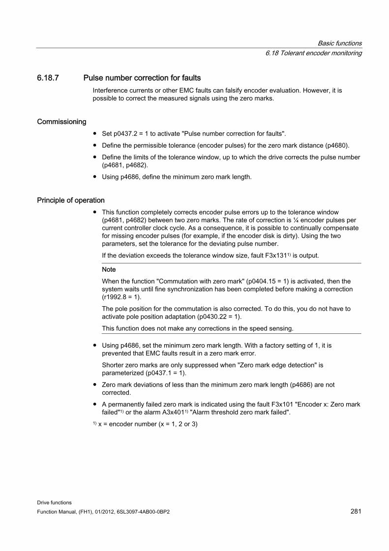
Basic functions 6.18 Tolerant encoder monitoring
Drive functions Function Manual, (FH1), 01/2012, 6SL3097-4AB00-0BP2 281
6.18.7 Pulse number correction for faults Interference currents or other EMC faults can falsify encoder evaluation. However, it is possible to correct the measured signals using the zero marks.
Commissioning Set p0437.2 = 1 to activate "Pulse number correction for faults".
Define the permissible tolerance (encoder pulses) for the zero mark distance (p4680).
Define the limits of the tolerance window, up to which the drive corrects the pulse number (p4681, p4682).
Using p4686, define the minimum zero mark length.
Principle of operation This function completely corrects encoder pulse errors up to the tolerance window
(p4681, p4682) between two zero marks. The rate of correction is ¼ encoder pulses per current controller clock cycle. As a consequence, it is possible to continually compensate for missing encoder pulses (for example, if the encoder disk is dirty). Using the two parameters, set the tolerance for the deviating pulse number.
If the deviation exceeds the tolerance window size, fault F3x1311) is output.
Note
When the function "Commutation with zero mark" (p0404.15 = 1) is activated, then the system waits until fine synchronization has been completed before making a correction (r1992.8 = 1).
The pole position for the commutation is also corrected. To do this, you do not have to activate pole position adaptation (p0430.22 = 1).
This function does not make any corrections in the speed sensing.
Using p4686, set the minimum zero mark length. With a factory setting of 1, it is prevented that EMC faults result in a zero mark error.
Shorter zero marks are only suppressed when "Zero mark edge detection" is parameterized (p0437.1 = 1).
Zero mark deviations of less than the minimum zero mark length (p4686) are not corrected.
A permanently failed zero mark is indicated using the fault F3x101 "Encoder x: Zero mark failed"1) or the alarm A3x4011) "Alarm threshold zero mark failed".
1) x = encoder number (x = 1, 2 or 3)
Basic functions 6.18 Tolerant encoder monitoring
Drive functions 282 Function Manual, (FH1), 01/2012, 6SL3097-4AB00-0BP2
6.18.8 "Tolerance band pulse number" monitoring This function monitors the number of encoder pulses between two zero marks. An alarm is output if the number lies outside a tolerance band that can be selected.
Commissioning Set parameter p0430.2 = 1 to activate the "tolerance band pulse number monitoring"
function.
Using parameters p4683 and p4684, set the upper and the lower limits of the tolerance band. Within this tolerance band, the detected number of pulses is considered to be correct.
Principle of operation After each zero mark, it is again checked as to whether up to the next zero mark the
number of pulses lies within the tolerance band. If this is not the case and "pulse number correction for faults" (p0437.2 = 1) is parameterized, then alarm A3x4221) is output for 5 seconds.
If one of the limits has a value of 0, then alarm A3x4221) is deactivated.
Display of uncorrected encoder pulses For p0437.7 = 1, the number of corrected pulse errors is displayed in r4688 with the correct sign. Set p0437.7 = 0 in order to indicate the corrected pulse errors per zero mark distance in r4688.
For a drift after one revolution, if the tolerance band limit is not reached, an alarm is not output. A new measurement is performed if the zero mark is exceeded.
Number of pulses outside the tolerance band
If the tolerance band is violated, then in addition to alarm A3x4221) r4689.1 = 1 is set. This value remains for a minimum of 100 ms, so that a control can detect several violations in quick succession one after the other even for high-speed drives.
You can send the message bits of parameter r4689 to a higher-level control via PROFIBUS / PROFINET as process data.
You can send the accumulated correction value to a higher-level control via PROFIBUS (e.g.: p2051[x] = r4688). The control can then set the contents of the counter to a specific value.
Note
The "tolerance band pulse number monitoring" also functions for external encoders, which operate in a drive line-up as leading value encoder (monitoring the position value XIST1 from a direct measuring system).
1) x = encoder number (x = 1, 2 or 3)

Basic functions 6.18 Tolerant encoder monitoring
Drive functions Function Manual, (FH1), 01/2012, 6SL3097-4AB00-0BP2 283
6.18.9 Signal edge evaluation (1x, 4x) The "signal edge evaluation" function allows squarewave encoders with higher production tolerances or older encoders to be used. Using this function, a "steadier" speed actual value is calculated for encoders with an uneven pulse duty factor of the encoder signals. As a consequence, you can keep the old motors together with the encoders - for example when modernizing plants.
Commissioning Sets parameters p0437 bit 4 and bit 5 as follows to activate "signal edge evaluation":
p0437.4 p0437.5 Evaluation 0 0 4 x (factory setting) 0 1 Reserved 1 0 1 x 1 1 Reserved
Principle of operation For the 4x evaluation, both the rising and falling edges of a contiguous pulse pair on the A and B tracks are evaluated.
For the 1x evaluation, only the first or the last edge of a contiguous pulse pair on the A and B tracks are evaluated.
A 4x evaluation of the pulse encoder signals allows a minimum speed to be detected which is a factor of 4 lower than for the 1x evaluation. For incremental encoders with uneven pulse duty factor of the encoder signals or where the encoder signals are not precisely offset by 90°, a 4x evaluation can result in a speed actual value that is somewhat less steady.
The following formula defines the lowest speed where a distinction can be made to 0:
n_min = 60 / (x*p0408) [rpm]
with x = 1 or 4 (x times evaluation)
Note
You can only use the reduction to 1x evaluation in conjunction with the edge zero mark or without zero mark. Detection with an accuracy of one pulse is no longer possible for zero marks with "unambiguous range" or distance-coded zero marks.
Basic functions 6.18 Tolerant encoder monitoring
Drive functions 284 Function Manual, (FH1), 01/2012, 6SL3097-4AB00-0BP2
6.18.10 Setting the measuring time to evaluate speed "0" This function is only necessary for slow-speed drives (up to 40 rpm rated speed) in order to be able to output actual speeds correctly close to 0. For a stationary drive, this prevents that the I component of the speed controller slowly increases and the drive unnecessarily establishes a torque.
Commissioning Enter the required measuring time in parameter p0453: A speed actual value of 0 is
output, if, within this time, no pulses are detected from the A/B track.
6.18.11 Sliding averaging of the speed actual value For slow-speed drives (< 40 rpm), when using standard encoders with a pulse number of 1024, a problem is encountered due to the fact that the same number of encoder pulses is not available for every current controller clock cycle (for p0430.20 = 1: Speed calculation without extrapolation, "Incremental difference"). The different number of encoder pulses means that the speed actual value display jumps, although the encoder itself is rotating at a constant speed.
Commissioning For sliding averaging, set parameter p0430.20 = 0 (edge time measurement).
In parameter p4685, enter the number of current controller clock cycles over which the average value should be formed to calculate the speed. The averaging means that individual incorrect pulses, depending on the number of specified clock cycles, are smoothed.
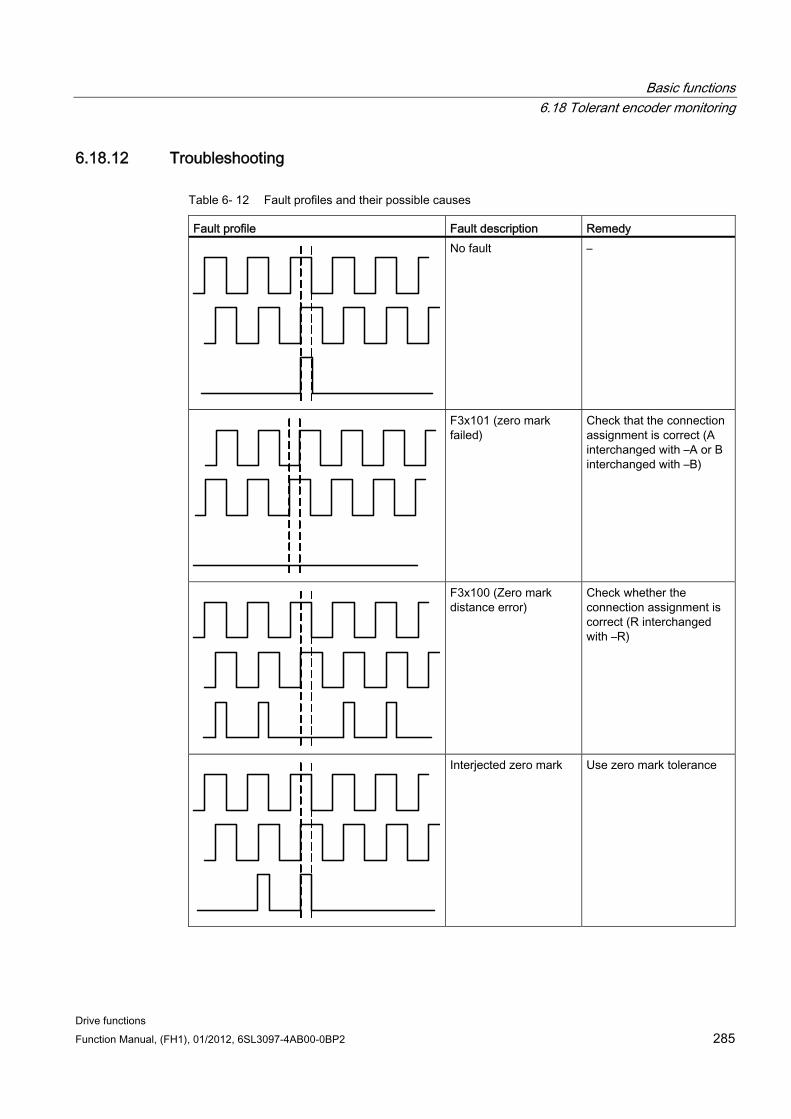
Basic functions 6.18 Tolerant encoder monitoring
Drive functions Function Manual, (FH1), 01/2012, 6SL3097-4AB00-0BP2 285
6.18.12 Troubleshooting
Table 6- 12 Fault profiles and their possible causes
Fault profile Fault description Remedy No fault –
F3x101 (zero mark failed)
Check that the connection assignment is correct (A interchanged with –A or B interchanged with –B)
F3x100 (Zero mark distance error)
Check whether the connection assignment is correct (R interchanged with –R)
Interjected zero mark Use zero mark tolerance
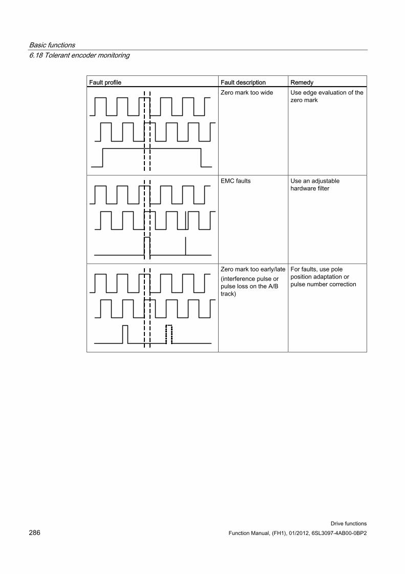
Basic functions 6.18 Tolerant encoder monitoring
Drive functions 286 Function Manual, (FH1), 01/2012, 6SL3097-4AB00-0BP2
Fault profile Fault description Remedy Zero mark too wide Use edge evaluation of the
zero mark
EMC faults Use an adjustable hardware filter
Zero mark too early/late (interference pulse or pulse loss on the A/B track)
For faults, use pole position adaptation or pulse number correction
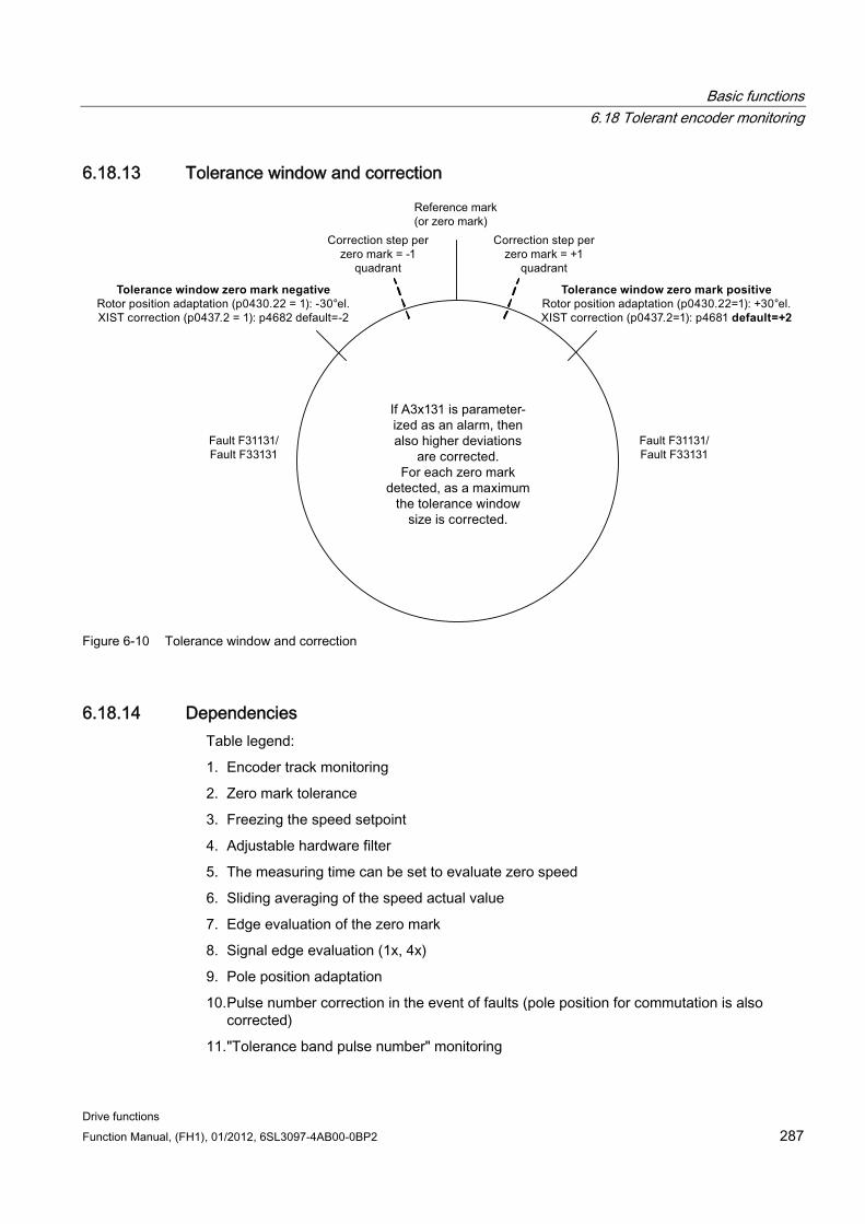
Basic functions 6.18 Tolerant encoder monitoring
Drive functions Function Manual, (FH1), 01/2012, 6SL3097-4AB00-0BP2 287
6.18.13 Tolerance window and correction
Reference mark
(or zero mark)
If A3x131 is parameter-
ized as an alarm, then
also higher deviations
are corrected.
For each zero mark
detected, as a maximum
the tolerance window
size is corrected.
Correction step per
zero mark = -1
quadrant
Correction step per
zero mark = +1
quadrant
Tolerance window zero mark negativeRotor position adaptation (p0430.22 = 1): -30°el.
XIST correction (p0437.2 = 1): p4682 default=-2
Tolerance window zero mark positiveRotor position adaptation (p0430.22=1): +30°el.
XIST correction (p0437.2=1): p4681 default=+2
Fault F31131/
Fault F33131
Fault F31131/
Fault F33131
Figure 6-10 Tolerance window and correction
6.18.14 Dependencies Table legend:
1. Encoder track monitoring
2. Zero mark tolerance
3. Freezing the speed setpoint
4. Adjustable hardware filter
5. The measuring time can be set to evaluate zero speed
6. Sliding averaging of the speed actual value
7. Edge evaluation of the zero mark
8. Signal edge evaluation (1x, 4x)
9. Pole position adaptation
10. Pulse number correction in the event of faults (pole position for commutation is also corrected)
11. "Tolerance band pulse number" monitoring
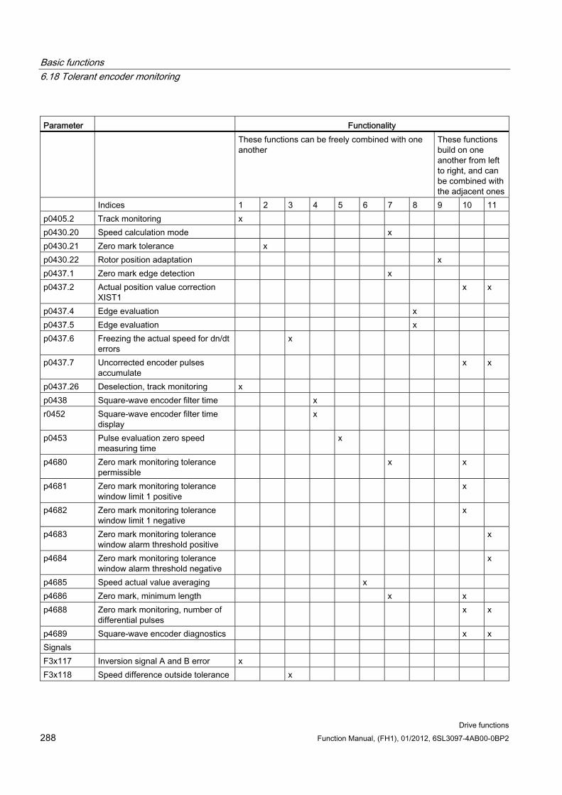
Basic functions 6.18 Tolerant encoder monitoring
Drive functions 288 Function Manual, (FH1), 01/2012, 6SL3097-4AB00-0BP2
Parameter Functionality These functions can be freely combined with one
another These functions build on one another from left to right, and can be combined with the adjacent ones
Indices 1 2 3 4 5 6 7 8 9 10 11 p0405.2 Track monitoring x p0430.20 Speed calculation mode x p0430.21 Zero mark tolerance x p0430.22 Rotor position adaptation x p0437.1 Zero mark edge detection x p0437.2 Actual position value correction
XIST1 x x
p0437.4 Edge evaluation x p0437.5 Edge evaluation x p0437.6 Freezing the actual speed for dn/dt
errors x
p0437.7 Uncorrected encoder pulses accumulate
x x
p0437.26 Deselection, track monitoring x p0438 Square-wave encoder filter time x r0452 Square-wave encoder filter time
display x
p0453 Pulse evaluation zero speed measuring time
x
p4680 Zero mark monitoring tolerance permissible
x x
p4681 Zero mark monitoring tolerance window limit 1 positive
x
p4682 Zero mark monitoring tolerance window limit 1 negative
x
p4683 Zero mark monitoring tolerance window alarm threshold positive
x
p4684 Zero mark monitoring tolerance window alarm threshold negative
x
p4685 Speed actual value averaging x p4686 Zero mark, minimum length x x p4688 Zero mark monitoring, number of
differential pulses x x
p4689 Square-wave encoder diagnostics x x Signals F3x117 Inversion signal A and B error x F3x118 Speed difference outside tolerance x
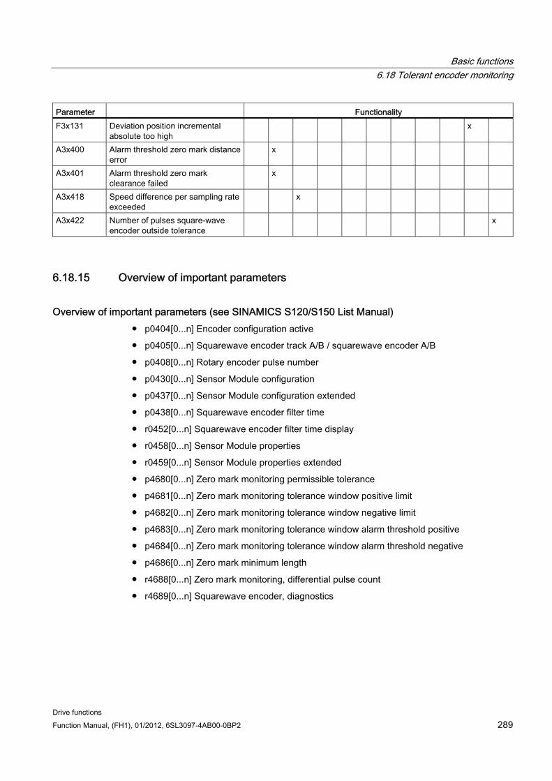
Basic functions 6.18 Tolerant encoder monitoring
Drive functions Function Manual, (FH1), 01/2012, 6SL3097-4AB00-0BP2 289
Parameter Functionality F3x131 Deviation position incremental
absolute too high x
A3x400 Alarm threshold zero mark distance error
x
A3x401 Alarm threshold zero mark clearance failed
x
A3x418 Speed difference per sampling rate exceeded
x
A3x422 Number of pulses square-wave encoder outside tolerance
x
6.18.15 Overview of important parameters
Overview of important parameters (see SINAMICS S120/S150 List Manual) p0404[0...n] Encoder configuration active
p0405[0...n] Squarewave encoder track A/B / squarewave encoder A/B
p0408[0...n] Rotary encoder pulse number
p0430[0...n] Sensor Module configuration
p0437[0...n] Sensor Module configuration extended
p0438[0...n] Squarewave encoder filter time
r0452[0...n] Squarewave encoder filter time display
r0458[0...n] Sensor Module properties
r0459[0...n] Sensor Module properties extended
p4680[0...n] Zero mark monitoring permissible tolerance
p4681[0...n] Zero mark monitoring tolerance window positive limit
p4682[0...n] Zero mark monitoring tolerance window negative limit
p4683[0...n] Zero mark monitoring tolerance window alarm threshold positive
p4684[0...n] Zero mark monitoring tolerance window alarm threshold negative
p4686[0...n] Zero mark minimum length
r4688[0...n] Zero mark monitoring, differential pulse count
r4689[0...n] Squarewave encoder, diagnostics
Basic functions 6.19 Parking axis and parking encoder
Drive functions 290 Function Manual, (FH1), 01/2012, 6SL3097-4AB00-0BP2
6.19 Parking axis and parking encoder The parking function is used in two ways:
"Parking axis"
– Monitoring of all encoders and Motor Modules assigned to the "Motor control" application of a drive are suppressed.
– All encoders assigned to the "Motor control" application of a drive are prepared for the "removed" state.
– The Motor Module that is assigned the application "Motor control" of drive is prepared for the state "removed Motor Module".
"Parking encoder"
– Monitoring of a certain encoder is suppressed.
– The encoder is prepared for the "removed" state.
Parking an axis When an axis is parked, the power unit and all the encoders assigned to the "motor control" are switched to inactive (r0146[n] = 0).
Control is carried out via the control/status words of the cyclic telegram (STW2.7 and ZSW2.7) or using parameters p0897 and r0896.0.
The drive must be brought to a standstill by the higher-level controller (disable pulses e.g. via STW1.0/OFF1).
DRIVE-CLiQ communication to downstream components via the deactivated power unit (r0126 = 0) remains active.
A measuring system that is not assigned to the "motor control" (e.g. direct measuring system) remains active (r0146[n] = 1).
The drive object remains active (r0106 = 1).
Note
Once the "Parking axis" / "Parking encoder" status has been canceled, you may have to carry out the following actions: • If the motor encoder has been replaced: determine the commutation angle offset
(p1990). • A new encoder must be referenced again (e.g. to determine the machine zero point).
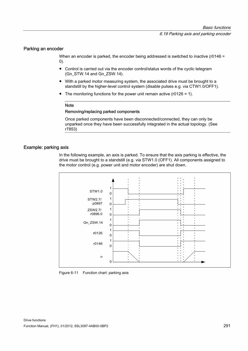
Basic functions 6.19 Parking axis and parking encoder
Drive functions Function Manual, (FH1), 01/2012, 6SL3097-4AB00-0BP2 291
Parking an encoder When an encoder is parked, the encoder being addressed is switched to inactive (r0146 = 0).
Control is carried out via the encoder control/status words of the cyclic telegram (Gn_STW.14 and Gn_ZSW.14).
With a parked motor measuring system, the associated drive must be brought to a standstill by the higher-level control system (disable pulses e.g. via CTW1.0/OFF1).
The monitoring functions for the power unit remain active (r0126 = 1).
Note Removing/replacing parked components
Once parked components have been disconnected/connected, they can only be unparked once they have been successfully integrated in the actual topology. (See r7853)
Example: parking axis In the following example, an axis is parked. To ensure that the axis parking is effective, the drive must be brought to a standstill (e.g. via STW1.0 (OFF1). All components assigned to the motor control (e.g. power unit and motor encoder) are shut down.
Figure 6-11 Function chart: parking axis
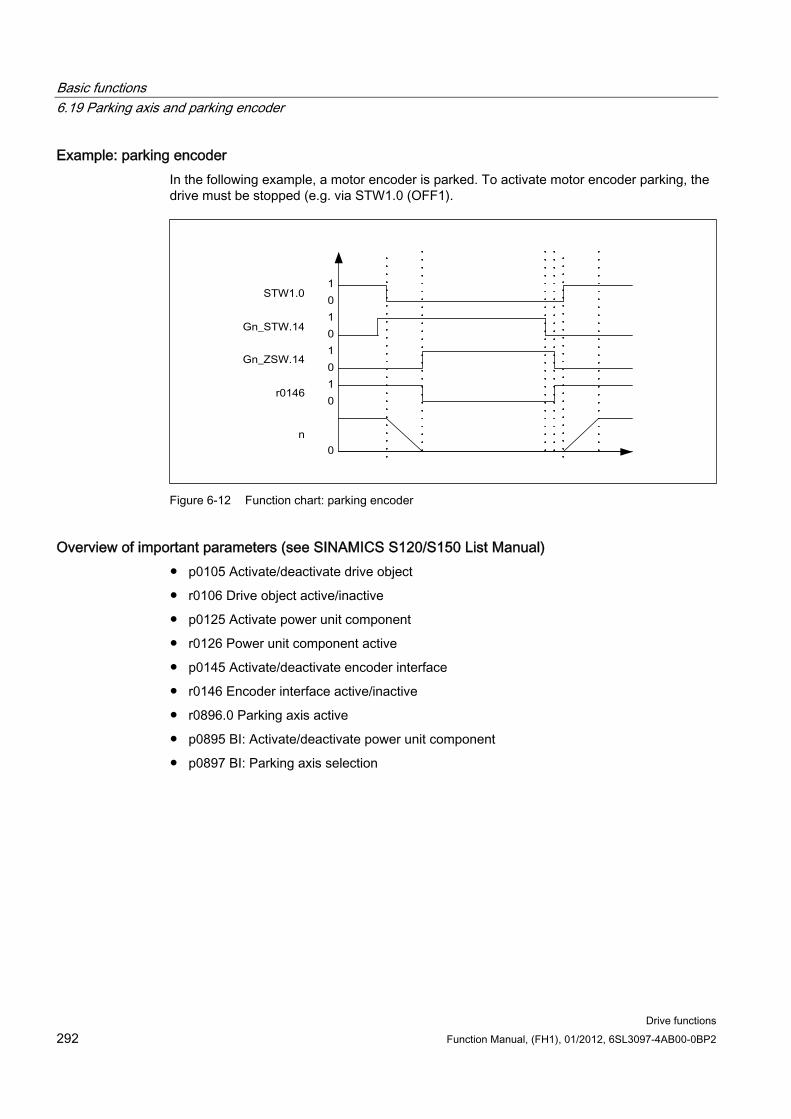
Basic functions 6.19 Parking axis and parking encoder
Drive functions 292 Function Manual, (FH1), 01/2012, 6SL3097-4AB00-0BP2
Example: parking encoder In the following example, a motor encoder is parked. To activate motor encoder parking, the drive must be stopped (e.g. via STW1.0 (OFF1).
Figure 6-12 Function chart: parking encoder
Overview of important parameters (see SINAMICS S120/S150 List Manual) p0105 Activate/deactivate drive object
r0106 Drive object active/inactive
p0125 Activate power unit component
r0126 Power unit component active
p0145 Activate/deactivate encoder interface
r0146 Encoder interface active/inactive
r0896.0 Parking axis active
p0895 BI: Activate/deactivate power unit component
p0897 BI: Parking axis selection
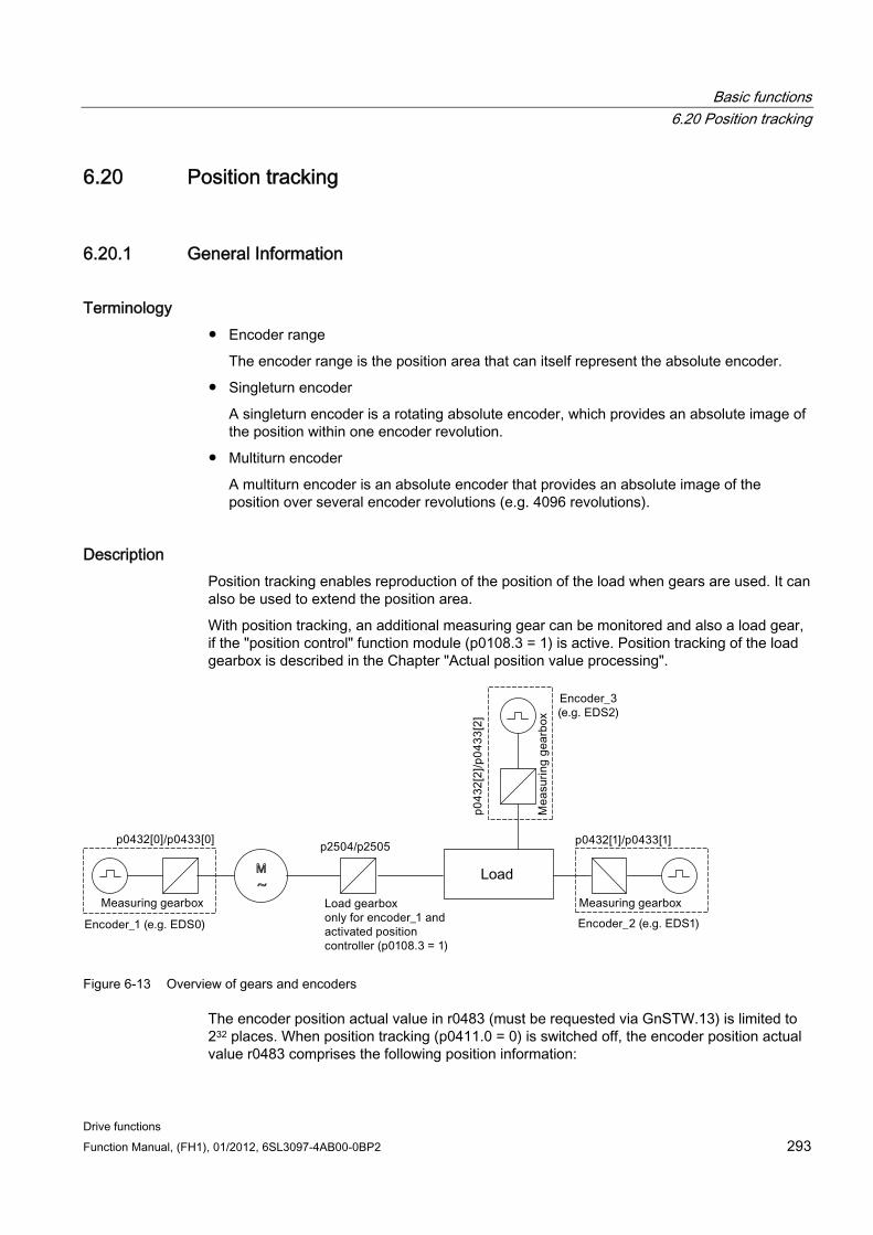
Basic functions 6.20 Position tracking
Drive functions Function Manual, (FH1), 01/2012, 6SL3097-4AB00-0BP2 293
6.20 Position tracking
6.20.1 General Information
Terminology Encoder range
The encoder range is the position area that can itself represent the absolute encoder.
Singleturn encoder
A singleturn encoder is a rotating absolute encoder, which provides an absolute image of the position within one encoder revolution.
Multiturn encoder
A multiturn encoder is an absolute encoder that provides an absolute image of the position over several encoder revolutions (e.g. 4096 revolutions).
Description Position tracking enables reproduction of the position of the load when gears are used. It can also be used to extend the position area.
With position tracking, an additional measuring gear can be monitored and also a load gear, if the "position control" function module (p0108.3 = 1) is active. Position tracking of the load gearbox is described in the Chapter "Actual position value processing".
~M
Figure 6-13 Overview of gears and encoders
The encoder position actual value in r0483 (must be requested via GnSTW.13) is limited to 232 places. When position tracking (p0411.0 = 0) is switched off, the encoder position actual value r0483 comprises the following position information:
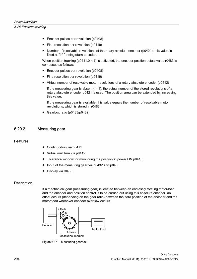
Basic functions 6.20 Position tracking
Drive functions 294 Function Manual, (FH1), 01/2012, 6SL3097-4AB00-0BP2
Encoder pulses per revolution (p0408)
Fine resolution per revolution (p0419)
Number of resolvable revolutions of the rotary absolute encoder (p0421), this value is fixed at "1" for singleturn encoders.
When position tracking (p0411.0 = 1) is activated, the encoder position actual value r0483 is composed as follows:
Encoder pulses per revolution (p0408)
Fine resolution per revolution (p0419)
Virtual number of resolvable motor revolutions of a rotary absolute encoder (p0412)
If the measuring gear is absent (n=1), the actual number of the stored revolutions of a rotary absolute encoder p0421 is used. The position area can be extended by increasing this value.
If the measuring gear is available, this value equals the number of resolvable motor revolutions, which is stored in r0483.
Gearbox ratio (p0433/p0432)
6.20.2 Measuring gear
Features Configuration via p0411
Virtual multiturn via p0412
Tolerance window for monitoring the position at power ON p0413
Input of the measuring gear via p0432 and p0433
Display via r0483
Description If a mechanical gear (measuring gear) is located between an endlessly rotating motor/load and the encoder and position control is to be carried out using this absolute encoder, an offset occurs (depending on the gear ratio) between the zero position of the encoder and the motor/load whenever encoder overflow occurs.
Figure 6-14 Measuring gearbox
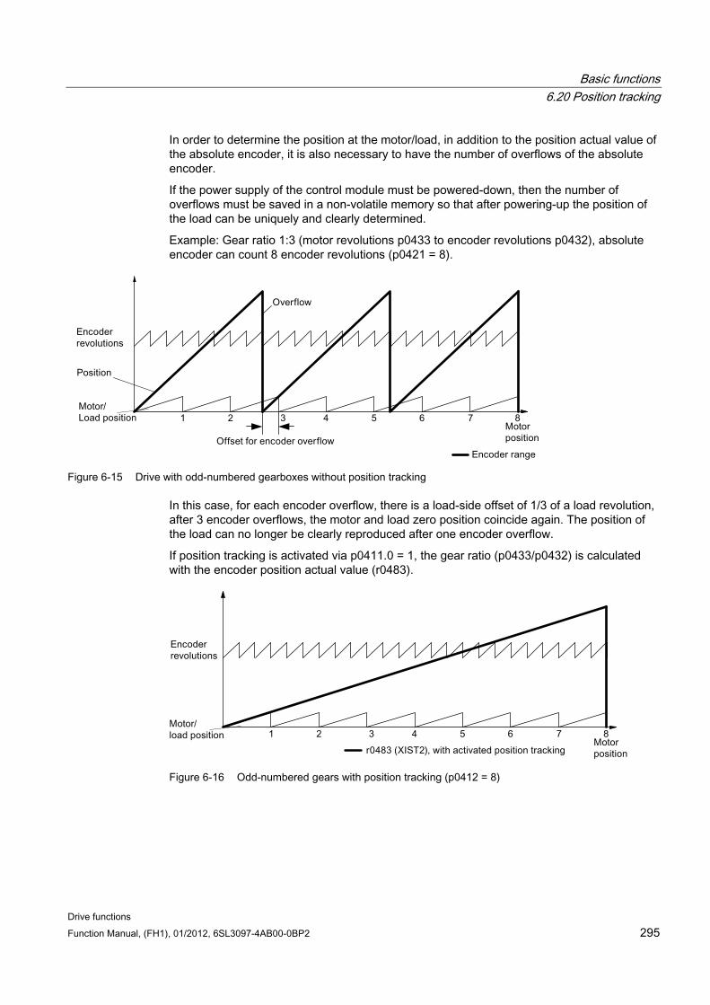
Basic functions 6.20 Position tracking
Drive functions Function Manual, (FH1), 01/2012, 6SL3097-4AB00-0BP2 295
In order to determine the position at the motor/load, in addition to the position actual value of the absolute encoder, it is also necessary to have the number of overflows of the absolute encoder.
If the power supply of the control module must be powered-down, then the number of overflows must be saved in a non-volatile memory so that after powering-up the position of the load can be uniquely and clearly determined.
Example: Gear ratio 1:3 (motor revolutions p0433 to encoder revolutions p0432), absolute encoder can count 8 encoder revolutions (p0421 = 8).
Figure 6-15 Drive with odd-numbered gearboxes without position tracking
In this case, for each encoder overflow, there is a load-side offset of 1/3 of a load revolution, after 3 encoder overflows, the motor and load zero position coincide again. The position of the load can no longer be clearly reproduced after one encoder overflow.
If position tracking is activated via p0411.0 = 1, the gear ratio (p0433/p0432) is calculated with the encoder position actual value (r0483).
Figure 6-16 Odd-numbered gears with position tracking (p0412 = 8)
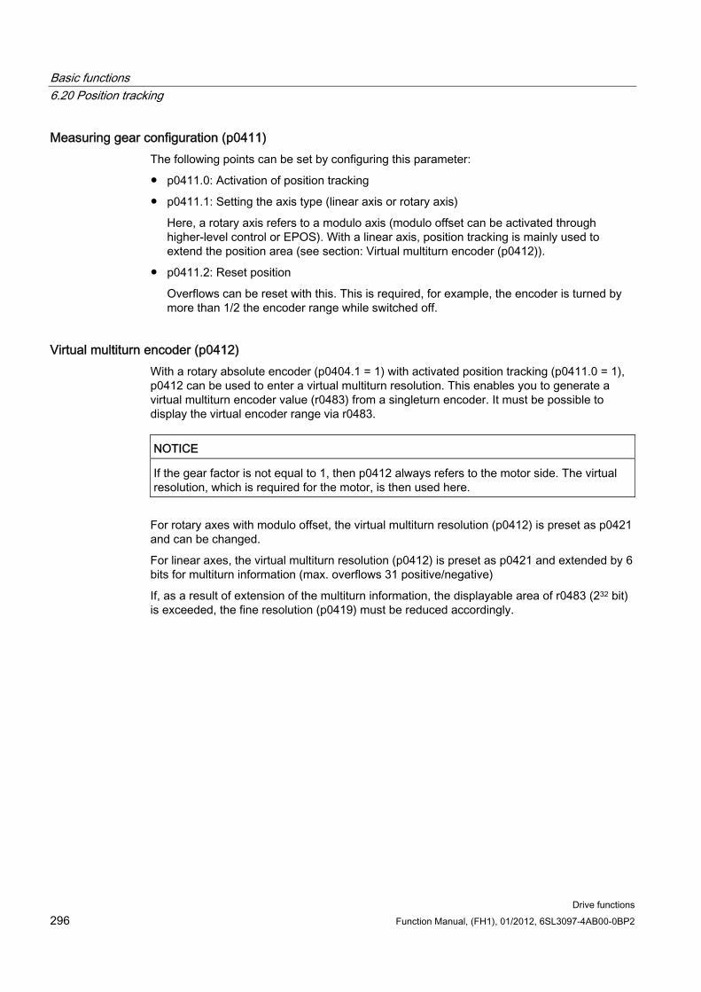
Basic functions 6.20 Position tracking
Drive functions 296 Function Manual, (FH1), 01/2012, 6SL3097-4AB00-0BP2
Measuring gear configuration (p0411) The following points can be set by configuring this parameter:
p0411.0: Activation of position tracking
p0411.1: Setting the axis type (linear axis or rotary axis)
Here, a rotary axis refers to a modulo axis (modulo offset can be activated through higher-level control or EPOS). With a linear axis, position tracking is mainly used to extend the position area (see section: Virtual multiturn encoder (p0412)).
p0411.2: Reset position
Overflows can be reset with this. This is required, for example, the encoder is turned by more than 1/2 the encoder range while switched off.
Virtual multiturn encoder (p0412) With a rotary absolute encoder (p0404.1 = 1) with activated position tracking (p0411.0 = 1), p0412 can be used to enter a virtual multiturn resolution. This enables you to generate a virtual multiturn encoder value (r0483) from a singleturn encoder. It must be possible to display the virtual encoder range via r0483.
NOTICE If the gear factor is not equal to 1, then p0412 always refers to the motor side. The virtual resolution, which is required for the motor, is then used here.
For rotary axes with modulo offset, the virtual multiturn resolution (p0412) is preset as p0421 and can be changed.
For linear axes, the virtual multiturn resolution (p0412) is preset as p0421 and extended by 6 bits for multiturn information (max. overflows 31 positive/negative)
If, as a result of extension of the multiturn information, the displayable area of r0483 (232 bit) is exceeded, the fine resolution (p0419) must be reduced accordingly.
Basic functions 6.20 Position tracking
Drive functions Function Manual, (FH1), 01/2012, 6SL3097-4AB00-0BP2 297
Tolerance window (p0413) After switching on, the difference between the stored position and the actual position is ascertained and, depending on the result, the following is initiated:
Difference within the tolerance window → the position is reproduced based on the actual encoder value.
Difference outside the tolerance window → message F07449 is output.
The tolerance window is preset to quarter of the encoder range and can be changed.
NOTICE
The position can only be reproduced if, in the powered-down state, the encoder was moved through less than half of the range that it can represent. For the standard EQN1325 encoder, this is 2048 revolutions or half a revolution for singleturn encoders.
Note
The ratio stamped on the gear rating plate is often just a rounded-off value (e.g.1:7.34). If, for a rotary axis, it is not permissible to have any long-term drift, then the actual ratio of the gear teeth must be requested from the gear manufacturer.
Note regarding using synchronous motors with a measuring gear Field-oriented control of synchronous motors requires a clear reference between the pole position and encoder position. This reference must also be carefully maintained when using measuring geares: This is the reason that the ratio between the pole pair number and the encoder revolutions must be an integer multiple ≥ 1 (e.g. pole pair number 17, measuring gear 4.25, ratio = 4).
Commissioning The position tracking of the measuring gear can be activated in the drive wizard (STARTER) during the configuration of the drive. During the configuration there is an item for encoder parameterization. In the encoder dialog, click on the "Details" button and activate the checkbox for position tracking in the displayed dialog.
The parameters p0412 (Measuring gear, rotary absolute encoder, revolutions, virtual) and p0413 (Measuring gear, position tracking tolerance window) can only be set via the expert list.
Prerequisite Absolute encoder
Basic functions 6.21 ENCODER as drive object
Drive functions 298 Function Manual, (FH1), 01/2012, 6SL3097-4AB00-0BP2
Function diagrams (see SINAMICS S120/S150 List Manual) 4704 Position and temperature sensing, encoders 1 ... 3
Overview of important parameters (see SINAMICS S120/S150 List Manual) p0402 Gear type selection
p0411 Measuring gear configuration
p0412 Measuring gear absolute encoder rotary revolutions virtual
p0413 Measuring gear position tracking, tolerance window
p0421 Absolute encoder rotary multiturn resolution
p0432 Gear factor encoder revolutions
p0433 Gear factor motor/load revolutions
r0477 CO: Measuring gear, position difference
r0485 CO: Measuring gear, raw encoder value, incremental
r0486 CO: Measuring gear, raw encoder value, absolute
6.21 ENCODER as drive object Encoders can be linked in as autonomous drive objects (Drive Object =DO) and evaluated. An ENCODER drive object can be addressed as encoder via PROFIBUS/PROFINET as an independent unit.
Using an ENCODER drive object allows an encoder of an upstream machine to be directly connected via a Sensor Module without having to take an indirect route via the 2nd encoder of a drive. The encoder is connected via an encoder interface of a Sensor Modules. If the Sensor Modules, to which the encoder is connected, has its own DRIVE-CLiQ interface (e.g. an SME20), then the encoder can be connected to any free DRIVE-CLiQ socket via the Sensor Module.
6.21.1 Preconditions for creating an ENCODER drive object using STARTER STARTER V4.1.5 or higher
Project with one CU320-2
The project can also be created OFFLINE. A description of this can be found in the SINAMICS S120 Commissioning Manual in Chapter "Commissioning".
Connection conditions for ENCODER drive objects All encoders that can be assigned to a drive can be used.
ENCODER drive objects may be connected to all DRIVE-CLiQ ports.
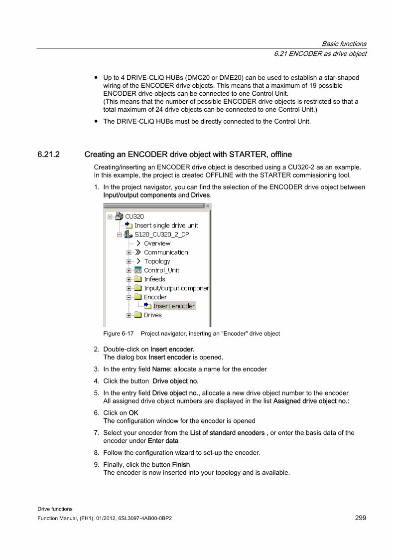
Basic functions 6.21 ENCODER as drive object
Drive functions Function Manual, (FH1), 01/2012, 6SL3097-4AB00-0BP2 299
Up to 4 DRIVE-CLiQ HUBs (DMC20 or DME20) can be used to establish a star-shaped wiring of the ENCODER drive objects. This means that a maximum of 19 possible ENCODER drive objects can be connected to one Control Unit. (This means that the number of possible ENCODER drive objects is restricted so that a total maximum of 24 drive objects can be connected to one Control Unit.)
The DRIVE-CLiQ HUBs must be directly connected to the Control Unit.
6.21.2 Creating an ENCODER drive object with STARTER, offline Creating/inserting an ENCODER drive object is described using a CU320-2 as an example. In this example, the project is created OFFLINE with the STARTER commissioning tool.
1. In the project navigator, you can find the selection of the ENCODER drive object between Input/output components and Drives.
Figure 6-17 Project navigator, inserting an "Encoder" drive object
2. Double-click on Insert encoder. The dialog box Insert encoder is opened.
3. In the entry field Name: allocate a name for the encoder
4. Click the button Drive object no.
5. In the entry field Drive object no., allocate a new drive object number to the encoder All assigned drive object numbers are displayed in the list Assigned drive object no.:
6. Click on OK The configuration window for the encoder is opened
7. Select your encoder from the List of standard encoders , or enter the basis data of the encoder under Enter data
8. Follow the configuration wizard to set-up the encoder.
9. Finally, click the button Finish The encoder is now inserted into your topology and is available.
Basic functions 6.22 Terminal Module 41
Drive functions 300 Function Manual, (FH1), 01/2012, 6SL3097-4AB00-0BP2
6.22 Terminal Module 41
General features Pulse encoder emulation, TTL signals according to the RS422 standard (X520)
1 analog input
4 digital inputs
4 bidirectional digital inputs/outputs
Terminal Module 41 (TM41) emulates incremental encoder signals (TTL) – and outputs them via interface X520. The signals are based on speed setpoints, which are transferred via process data words (p4400 = 0), or using the position actual value of a leading encoder (p4400 = 1). The emulated incremental encoder signal can, for example, be evaluated by a control or other drives. The TM41 may be connected to all of the permissible encoder types.
For all referencing modes of the drive object, zero marks with an adjustable offset can be emulated.
The number of pulses output (virtual pulses) per revolution is independent of the leading encoder and can be set in a wide range. The number pulses that are output can be scaled (up or down) with respect to the leading encoder.
With the additional inputs and outputs, these can be used for example to input an analog speed setpoint or control and status signals, for example OFF1 / ON, "ready for operation" or fault.
6.22.1 SIMOTION mode The SIMOTION mode is set using parameter p4400 = 0. The incremental encoder emulation is based on the speed setpoint.
A speed setpoint r2060 is received via PROFIdrive telegram 3, which is interconnected to p1155. The speed setpoint can be filtered using a (p1414.0) PT2 - element that can be activated (p1417 and p1418). The speed setpoint can be delayed with the deadtime p1412. The number of encoder pulses per revolution can be set using parameter p0408. The distance between the zero marks and the position when enabling the A/B tracks (r4402.1) is entered into parameter p4426 and enabled with p4401.0 = 1.
Note Signaling faults
To be able to signal encoder emulation faults of the TM41 to a higher-level control, parameter r2139.0...12 CO/BO: Status word faults/alarms 1 must be interconnected via BICO with a digital output (TM41 or CU). The output can then be read from the external control system.
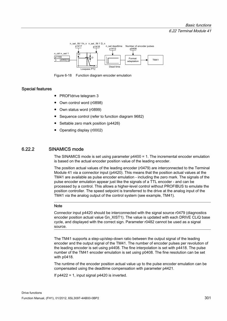
Basic functions 6.22 Terminal Module 41
Drive functions Function Manual, (FH1), 01/2012, 6SL3097-4AB00-0BP2 301
Figure 6-18 Function diagram encoder emulation
Special features PROFIdrive telegram 3
Own control word (r0898)
Own status word (r0899)
Sequence control (refer to function diagram 9682)
Settable zero mark position (p4426)
Operating display (r0002)
6.22.2 SINAMICS mode The SINAMICS mode is set using parameter p4400 = 1. The incremental encoder emulation is based on the actual encoder position value of the leading encoder.
The position actual values of the leading encoder (r0479) are interconnected to the Terminal Module 41 via a connector input (p4420). This means that the position actual values at the TM41 are available as pulse encoder emulation - including the zero mark. The signals of the pulse encoder emulation appear just like the signals of a TTL encoder - and can be processed by a control. This allows a higher-level control without PROFIBUS to emulate the position controller. The speed setpoint is transferred to the drive at the analog input of the TM41 via the analog output of the control system (see example, TM41).
Note
Connector input p4420 should be interconnected with the signal source r0479 (diagnostics encoder position actual value Gn_XIST1). The value is updated with each DRIVE CLiQ base cycle, and displayed with the correct sign. Parameter r0482 cannot be used as a signal source.
The TM41 supports a step-up/step-down ratio between the output signal of the leading encoder and the output signal of the TM41. The number of encoder pulses per revolution of the leading encoder is set using p4408. The fine interpolation is set with p4418. The pulse number of the TM41 encoder emulation is set using p0408. The fine resolution can be set with p0418.
The runtime of the encoder position actual value up to the pulse encoder emulation can be compensated using the deadtime compensation with parameter p4421.
If p4422 = 1, input signal p4420 is inverted.
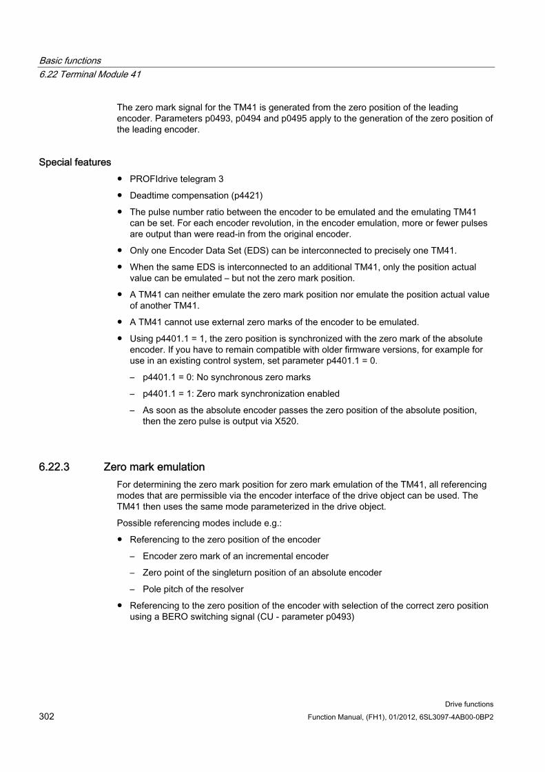
Basic functions 6.22 Terminal Module 41
Drive functions 302 Function Manual, (FH1), 01/2012, 6SL3097-4AB00-0BP2
The zero mark signal for the TM41 is generated from the zero position of the leading encoder. Parameters p0493, p0494 and p0495 apply to the generation of the zero position of the leading encoder.
Special features PROFIdrive telegram 3
Deadtime compensation (p4421)
The pulse number ratio between the encoder to be emulated and the emulating TM41 can be set. For each encoder revolution, in the encoder emulation, more or fewer pulses are output than were read-in from the original encoder.
Only one Encoder Data Set (EDS) can be interconnected to precisely one TM41.
When the same EDS is interconnected to an additional TM41, only the position actual value can be emulated – but not the zero mark position.
A TM41 can neither emulate the zero mark position nor emulate the position actual value of another TM41.
A TM41 cannot use external zero marks of the encoder to be emulated.
Using p4401.1 = 1, the zero position is synchronized with the zero mark of the absolute encoder. If you have to remain compatible with older firmware versions, for example for use in an existing control system, set parameter p4401.1 = 0.
– p4401.1 = 0: No synchronous zero marks
– p4401.1 = 1: Zero mark synchronization enabled
– As soon as the absolute encoder passes the zero position of the absolute position, then the zero pulse is output via X520.
6.22.3 Zero mark emulation For determining the zero mark position for zero mark emulation of the TM41, all referencing modes that are permissible via the encoder interface of the drive object can be used. The TM41 then uses the same mode parameterized in the drive object.
Possible referencing modes include e.g.:
Referencing to the zero position of the encoder
– Encoder zero mark of an incremental encoder
– Zero point of the singleturn position of an absolute encoder
– Pole pitch of the resolver
Referencing to the zero position of the encoder with selection of the correct zero position using a BERO switching signal (CU - parameter p0493)
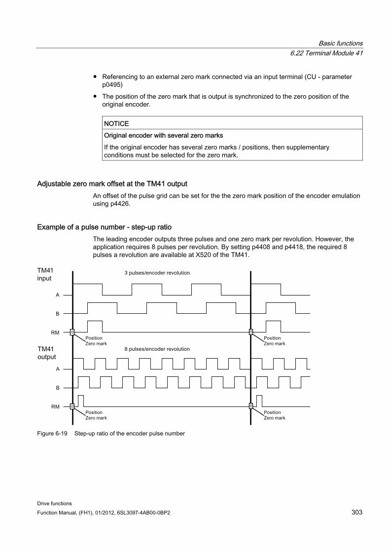
Basic functions 6.22 Terminal Module 41
Drive functions Function Manual, (FH1), 01/2012, 6SL3097-4AB00-0BP2 303
Referencing to an external zero mark connected via an input terminal (CU - parameter p0495)
The position of the zero mark that is output is synchronized to the zero position of the original encoder.
NOTICE
Original encoder with several zero marks
If the original encoder has several zero marks / positions, then supplementary conditions must be selected for the zero mark.
Adjustable zero mark offset at the TM41 output An offset of the pulse grid can be set for the the zero mark position of the encoder emulation using p4426.
Example of a pulse number - step-up ratio The leading encoder outputs three pulses and one zero mark per revolution. However, the application requires 8 pulses per revolution. By setting p4408 and p4418, the required 8 pulses a revolution are available at X520 of the TM41.
Figure 6-19 Step-up ratio of the encoder pulse number
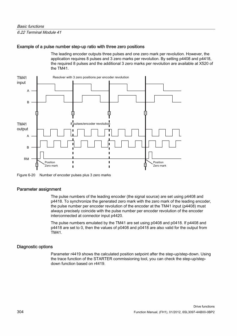
Basic functions 6.22 Terminal Module 41
Drive functions 304 Function Manual, (FH1), 01/2012, 6SL3097-4AB00-0BP2
Example of a pulse number step-up ratio with three zero positions The leading encoder outputs three pulses and one zero mark per revolution. However, the application requires 8 pulses and 3 zero marks per revolution. By setting p4408 and p4418, the required 8 pulses and the additional 3 zero marks per revolution are available at X520 of the TM41.
Figure 6-20 Number of encoder pulses plus 3 zero marks
Parameter assignment The pulse numbers of the leading encoder (the signal source) are set using p4408 and p4418. To synchronize the generated zero mark with the zero mark of the leading encoder, the pulse number per encoder revolution of the encoder at the TM41 input (p4408) must always precisely coincide with the pulse number per encoder revolution of the encoder interconnected at connector input p4420.
The pulse numbers emulated by the TM41 are set using p0408 and p0418. If p4408 and p4418 are set to 0, then the values of p0408 and p0418 are also valid for the output from TM41.
Diagnostic options Parameter r4419 shows the calculated position setpoint after the step-up/step-down. Using the trace function of the STARTER commissioning tool, you can check the step-up/step-down function based on r4419.
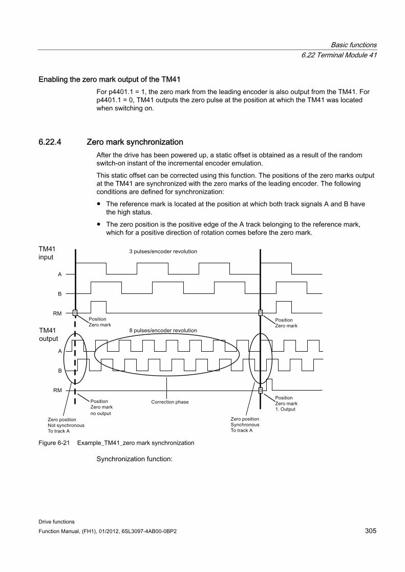
Basic functions 6.22 Terminal Module 41
Drive functions Function Manual, (FH1), 01/2012, 6SL3097-4AB00-0BP2 305
Enabling the zero mark output of the TM41 For p4401.1 = 1, the zero mark from the leading encoder is also output from the TM41. For p4401.1 = 0, TM41 outputs the zero pulse at the position at which the TM41 was located when switching on.
6.22.4 Zero mark synchronization After the drive has been powered up, a static offset is obtained as a result of the random switch-on instant of the incremental encoder emulation.
This static offset can be corrected using this function. The positions of the zero marks output at the TM41 are synchronized with the zero marks of the leading encoder. The following conditions are defined for synchronization:
The reference mark is located at the position at which both track signals A and B have the high status.
The zero position is the positive edge of the A track belonging to the reference mark, which for a positive direction of rotation comes before the zero mark.
Figure 6-21 Example_TM41_zero mark synchronization
Synchronization function:
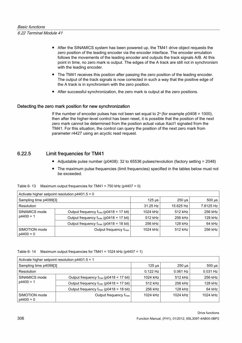
Basic functions 6.22 Terminal Module 41
Drive functions 306 Function Manual, (FH1), 01/2012, 6SL3097-4AB00-0BP2
After the SINAMICS system has been powered up, the TM41 drive object requests the zero position of the leading encoder via the encoder interface. The encoder emulation follows the movements of the leading encoder and outputs the track signals A/B. At this point in time, no zero mark is output. The edges of the A track are still not in synchronism with the leading encoder.
The TM41 receives this position after passing the zero position of the leading encoder. The output of the track signals is now corrected in such a way that the positive edge of the A track is in synchronism with the zero position.
After successful synchronization, the zero mark is output at the zero positions.
Detecting the zero mark position for new synchronization If the number of encoder pulses has not been set equal to 2n (for example p0408 = 1000), then after the higher-level control has been reset, it is possible that the position of the next zero mark cannot be determined from the position actual value Xact1 signaled from the TM41. For this situation, the control can query the position of the next zero mark from parameter r4427 using an acyclic read request.
6.22.5 Limit frequencies for TM41 Adjustable pulse number (p0408): 32 to 65536 pulses/revolution (factory setting = 2048)
The maximum pulse frequencies (limit frequencies) specified in the tables below must not be exceeded.
Table 6- 13 Maximum output frequencies for TM41 = 750 kHz (p4407 = 0)
Activate higher setpoint resolution p4401.5 = 0 Sampling time p4099[3] 125 µs 250 µs 500 µsResolution 31.25 Hz 15.625 Hz 7.8125 Hz
Output frequency fmax (p0418 < 17 bit) 1024 kHz 512 kHz 256 kHzOutput frequency fmax (p0418 = 17 bit) 512 kHz 256 kHz 128 kHz
SINAMICS mode p4400 = 1
Output frequency fmax (p0418 = 18 bit) 256 kHz 128 kHz 64 kHzSIMOTION mode p4400 = 0
Output frequency fmax 1024 kHz 512 kHz 256 kHz
Table 6- 14 Maximum output frequencies for TM41 = 1024 kHz (p4407 = 1)
Activate higher setpoint resolution p4401.5 = 1 Sampling time p4099[3] 125 µs 250 µs 500 µsResolution 0.122 Hz 0.061 Hz 0.031 Hz
Output frequency fmax (p0418 < 17 bit) 1024 kHz 512 kHz 256 kHzOutput frequency fmax (p0418 = 17 bit) 512 kHz 256 kHz 128 kHz
SINAMICS mode p4400 = 1
Output frequency fmax (p0418 = 18 bit) 256 kHz 128 kHz 64 kHzSIMOTION mode p4400 = 0
Output frequency fmax 1024 kHz 1024 kHz 1024 kHz
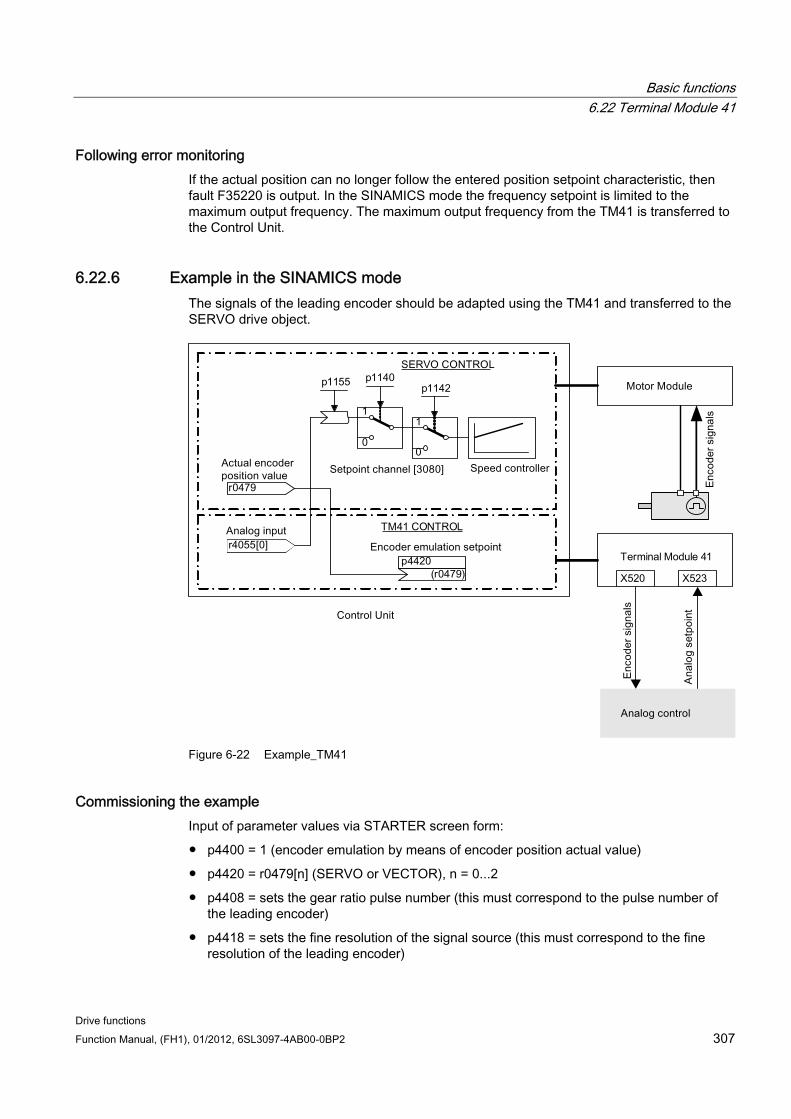
Basic functions 6.22 Terminal Module 41
Drive functions Function Manual, (FH1), 01/2012, 6SL3097-4AB00-0BP2 307
Following error monitoring If the actual position can no longer follow the entered position setpoint characteristic, then fault F35220 is output. In the SINAMICS mode the frequency setpoint is limited to the maximum output frequency. The maximum output frequency from the TM41 is transferred to the Control Unit.
6.22.6 Example in the SINAMICS mode The signals of the leading encoder should be adapted using the TM41 and transferred to the SERVO drive object.
Figure 6-22 Example_TM41
Commissioning the example Input of parameter values via STARTER screen form:
p4400 = 1 (encoder emulation by means of encoder position actual value)
p4420 = r0479[n] (SERVO or VECTOR), n = 0...2
p4408 = sets the gear ratio pulse number (this must correspond to the pulse number of the leading encoder)
p4418 = sets the fine resolution of the signal source (this must correspond to the fine resolution of the leading encoder)
Basic functions 6.22 Terminal Module 41
Drive functions 308 Function Manual, (FH1), 01/2012, 6SL3097-4AB00-0BP2
p0408 = sets the pulse number of the encoder emulation
p0418 = sets the fine resolution of the encoder emulation
Note
To be able to signal encoder emulation faults of the TM41 to a higher-level control, parameter r2139.0...8 CO/BO: Status word faults/alarms 1 must be interconnected via a BICO with a digital output (TM41 or CU) which can be read by the external control system.
6.22.7 Function diagrams and parameters
Function diagrams (see SINAMICS S120/S150 List Manual) 9660 Digital inputs, electrically isolated (DI 0 ... DI 3)
9661 Digital inputs/outputs, bi-directional (DI/DO 0 and DI/DO 1)
9662 Digital inputs/outputs, bi-directional (DI/DO 2 and DI/DO 3)
9663 Analog input (AI 0)
9674 Incremental encoder emulation (p4400 = 0)
9676 Incremental encoder emulation (p4400 = 1)
9678 Control word sequence control
9680 Execution control status word
9682 Processor
Overview of important parameters (see SINAMICS S120/S150 List Manual)
General
r0002 TM41 operating display
p0408 TM41 encoder emulation pulse number
p0418 fine resolution Gx_XIST1 (in bits)
p4099 TM41 inputs/outputs, sampling time
p4400 TM41 incremental encoder emulation operating mode
p4401 TM41 incremental encoder emulation mode
p4402 CO/BO: TM41 incremental encoder emulation status
r4419 TM41 encoder emulation diagnostics position setpoint
Incremental encoder emulation using a speed setpoint (p4400 = 0)
Basic functions 6.23 Upgrade the firmware and project
Drive functions Function Manual, (FH1), 01/2012, 6SL3097-4AB00-0BP2 309
p0840 BI: ON/OFF1
r0898 CO/BO: Control word, sequence control
r0899 CO/BO: Status word, sequence control
p1155 CI: Incremental encoder emulation speed setpoint 1
p4426 Incremental encoder emulation, pulses for zero mark
Incremental encoder emulation using the encoder actual position (p4400 = 1)
p4408 TM41 encoder emulation pulse number signal source
p4418 TM41 encoder emulation fine resolution signal source
p4420 CI: TM41 incremental encoder emulation encoder actual position
p4421 TM41 incremental encoder emulation deadtime compensation
p4422 TM41 position actual value inversion
p4426 TM41 encoder emulation pulses for the zero mark
6.23 Upgrade the firmware and project The firmware must be upgraded, if, in a more recent firmware version, an extended functional scope is available that you would like to use.
In principle, upgrading the firmware functions the same for both the CU310-2 and the 320-2. Projects cannot be transferred between a CU310 or CU310-2 and a CU320 or a CU320-2.
The firmware for the SINAMICS drive system is distributed in the system. It is installed on the Control Unit and in every individual DRIVE-CLiQ component.
When it powers up, the Control Unit automatically takes its firmware from the memory card. As a consequence, it does not have to be specifically upgraded. The Control Unit firmware is automatically upgraded when replacing the memory card by one with a more recent firmware version.
The firmware of the DRIVE-CLiQ components is also provided on the memory card of the Control Unit. With the factory setting p7826 = 1, it is automatically transferred from the memory card to the DRIVE-CLiQ components when commissioned for the first time. When upgraded, the firmware is saved (non-volatile) in the DRIVE-CLiQ components.
Once the project has been downloaded or automatic configuration has been carried out, the firmware is automatically upgraded on all the connected DRIVE-CLiQ components. This upgrades all DRIVE-CLiQ components to the firmware releases that match the memory card.
This operation can take several minutes. This is indicated by the RDY-LED on the corresponding components flashing green/red and the Control Unit RDY-LED flashing orange at 0.5 Hz.
Parameter p7827 indicates the progress.
Basic functions 6.23 Upgrade the firmware and project
Drive functions 310 Function Manual, (FH1), 01/2012, 6SL3097-4AB00-0BP2
The update has been completed if the RDY-LED on the Control Unit stops to flash in a 0.5Hz rhythm. Once the update process has been completed, the RDY-LED of the respective component goes into a steady light condition, for which the upgrade has been completed and the new firmware has been activated. For the components for which the RDY LED flashes green/red at 2 Hz you must perform a POWER ON to activate the new firmware.
Note Possible communication interruptions
When activating the new firmware, it is possible that a component interrupts cyclic communication. Communication problems will then occur that you must acknowledge.
For individual components, STARTER screens (<Drive Unit> → Overview → Version overview) can be used to read the firmware version or start a firmware upgrade manually for specific components.
Note
The versions of the DRIVE-CLiQ components and that of the Control Unit can differ. A version overview is available in the STARTER under <Drive Unit> → Overview → Version Overview.
Note
DRIVE-CLiQ components with higher firmware releases are downwards compatible and also operate with DRIVE-CLiQ components that have lower firmware releases.
6.23.1 Firmware/project upgrade using the STARTER
Preconditions A functioning drive project
A memory card with the latest firmware
The STARTER commissioning tool with new firmware on the programming device (PG/PC)
PG/PC is connected with the Control Unit (target device).
Converting an existing project to new firmware 1. Does the project exist in the STARTER commissioning tool?
Basic functions 6.23 Upgrade the firmware and project
Drive functions Function Manual, (FH1), 01/2012, 6SL3097-4AB00-0BP2 311
– If yes, then connect with the target system (go online)
– Continue with 3
2. Open the project using STARTER:
– Connect with the target system (online mode)
– Load the project from the target system into the PG/PC
– Disconnect the connection to the target device (offline mode)
3. Converting the project to the current firmware version:
– In the project navigator, right-click on <Drive unit > -> Target device -> Device version / Upgrade device type
– Select the required firmware version, e.g. version "SINAMICS S120 firmware version 4.x" -> Change version
4. Transfer the project into the new hardware
– Connect the new hardware with the PG/PC
– Connect with the target system (online mode)
– Load to the target device
5. Carry out a POWER ON for the drive unit (Control Unit and all DRIVE-CLiQ components). After the complete power up, the project is active in the new firmware version in the DRIVE-CLiQ components.
Upgrading the firmware to latest version. 1. Replacing the memory card.
– Disconnect the Control Unit from the power supply
– Remove the memory card containing the old firmware version
– Insert the memory card containing the new firmware version
– Power-up the Control Unit again
2. Go online and download the project to the target device, then execute the "Copy RAM to ROM..." command.
3. The firmware for the DRIVE-CLiQ components is automatically upgraded.
4. Wait until the Control Unit has completed the transfer of the new firmware. This is signaled at the diagnostic RDY LED.
5. Carry out a POWER ON for the drive unit (Control Unit and all DRIVE-CLiQ components). After the complete power up, the new firmware version is active in the DRIVE-CLiQ components and subsequently displayed in the version overview.
Basic functions 6.24 Pulse/direction interface
Drive functions 312 Function Manual, (FH1), 01/2012, 6SL3097-4AB00-0BP2
6.23.2 Downgrade lock The downgrade lock prevents the firmware from being downgraded from firmware upgrades which were intended to debug firmware programs.
Note Upgrade higher firmware versions
Components with higher firmware versions are fully downwards compatible with components with lower firmware versions. Following a firmware upgrade, a component will also operate without restrictions with components that have a lower firmware version.
NOTICE Firmware retrofit of a Control Unit
A higher firmware version is also characterized by having a larger range of functions than a lower firmware version. If you downgrade a Control Unit from a higher to a lower firmware version, it is possible that certain functions will no longer be available.
6.24 Pulse/direction interface Thanks to the pulse/direction interface, in the SERVO and VECTOR control modes, SINAMICS S120 can be used for simple positioning tasks on a controller.
The encoder interface of the SMC30 (connector X521) is used to connect the controller to the CU320-2.
The internal encoder interface at connector X23 is used to connect the controller to the CU310-2.
The controller enters the setpoints for the pulse/direction signals to the drive via the encoder interface.
The speed actual value r0061 thus entered can then be connected as speed setpoint to the fixed setpoint p1155 via BICO
Note • More information on the Control Unit CU320-2 and the SMC30 is provided in
Reference: SINAMICS S120 Control Units Manual • More information on the Control Unit CU310-2 is provided in
Reference: SINAMICS S120 AC Drive Manual
Application: Speed-controlled drive The drive is subject to speed control when operating on the controller. The clock frequency stipulates the speed setpoint. The pulse number is entered in p0408. This is calculated from the clock frequency of the controller and the preferred maximum motor speed. The following formula applies:
Basic functions 6.24 Pulse/direction interface
Drive functions Function Manual, (FH1), 01/2012, 6SL3097-4AB00-0BP2 313
Pulse number = (max. clock frequency • 60)/max. speed
Example: If the controller has a maximum clock frequency of 100 kHz and the motor being used is to run at its maximum rated speed of 3000 rpm, the resulting pulse number will be 2000.
Wiring the SMC30 input signals The input signals for the pulse/direction interface are wired via connector X521 of the SMC30:
Table 6- 15 Wiring the SMC30
Pin Signal name Technical specifications 1 Pulse – 2 M Ground 3 Direction of rotation – 4 M Ground 5 ... 8 Not relevant –
Wiring the CU310-2 input signals The input signals for the pulse/direction interface are wired via connector X23 of the CU310-2:
Table 6- 16 Wiring the CU310-2
Pin Signal name Technical specifications 1 ... 11 Not relevant – 12 M Ground 13 Direction of rotation – 14 M Ground 15 Pulse –
Settings in the configuration wizard Make the settings for the pulse/direction interface (rotary, 24 V, terminal, no track monitoring, no zero mark, ...) in the configuration wizard of STARTER in the dialog Encoder data.
Note
The pulse/direction interface is activated using p0405.5 = 1 (e.g. via the Expert list of STARTER).
Basic functions 6.25 Derating function for chassis units
Drive functions 314 Function Manual, (FH1), 01/2012, 6SL3097-4AB00-0BP2
Overview of important parameters (see SINAMICS S120/S150 List Manual) p0010 Drive commissioning parameter filter
r0061 CO: Actual speed value unsmoothed
p0400[0...n] Encoder type selection
p0404[0...n] Encoder configuration active
p0405[0...n] Rectangular signal encoder track A/B
p0408[0...n] Rotary encoder pulse number
r0722 CO/BO: CU digital inputs, status
p0738 BI: CU signal source for terminal DI/DO 8
p0739 BI: CU signal source for terminal DI/DO 9
p2530 CI: LR position setpoint
p2550 BI: LR enable 2
6.25 Derating function for chassis units An adapted derating function greatly reduces the noise produced by chassis format power units (Motor Modules and Power Modules) and enables operation at a multiple of the rated pulse frequency at nearly rated current. This is achieved by monitoring the temperature difference between heat sink and chip using temperature sensors. When the operating temperature threshold is exceeded, the pulse frequency or permitted current limit, respectively, is automatically reduced.
This enables the maximum output current of the power unit to be achieved even at high pulse frequencies. The derating curve becomes effective at a later point.
The derating function is effective for Motor Modules and Power Modules in the chassis format. Units that are connected in parallel operate in the same manner as single units. The dependency of the output current on the pulse frequency for the chassis power units is described in the S120 Manual, Chassis Power Units.
Operating principle In order to optimize the use of the power unit also at temperatures below the maximum permitted ambient temperature, the maximum output current is controlled as a function of the operating temperature. This function also accounts for the dynamic response of the thermal performance (rise and decay curves of the operating temperature).
An alarm threshold is calculated that is weighted with the current ambient temperature.
By weighting the alarm threshold with the current ambient temperature, the power unit can output higher currents close to nominal current even at lower ambient temperatures.
Depending on the setting of parameter p0290 "Power unit overload response", the pulse frequency or the current will be reduced, or no response will occur if the alarm threshold is exceeded. An alarm (e.g. A07805 "Infeed: Power unit overload") is generated even if no response is desired.
Basic functions 6.25 Derating function for chassis units
Drive functions Function Manual, (FH1), 01/2012, 6SL3097-4AB00-0BP2 315
The following quantities can result in a response to thermal overload:
Heat sink temperature via r0037.[0]
Chip temperature via r0037.[1]
Power unit overload after I2t calculation via r0036
Possible measures to avoid thermal overload:
For servo control, reduce the output current (closed-loop speed/velocity or torque/force)
Reduction of the output frequency for U/f control.
Reduction of the pulse frequency for vector control.
Parameter r0293 "Power unit alarm threshold model temperature" indicates the temperature alarm threshold for the difference between the chip and heat-sink temperatures.

Basic functions 6.25 Derating function for chassis units
Drive functions 316 Function Manual, (FH1), 01/2012, 6SL3097-4AB00-0BP2
Drive functions Function Manual, (FH1), 01/2012, 6SL3097-4AB00-0BP2 317
Function modules 7
A function module is a functional expansion of a drive project that can be activated during commissioning.
Examples of function modules:
Technology controller
Setpoint channel
Extended brake control
Function modules have their own parameters and, in some cases, also their own alarm and fault messages. These parameters and messages are only displayed when the function module is active. Please note when configuring, that an activated function module frequently requires additional computing time.
Commissioning with STARTER In the commissioning screens of STARTER, you can either directly or indirectly activate the function modules (e.g. technology controller). When the basic positioner (EPOS) is activated, for example, the position control is also automatically activated.
Commissioning via parameter (only with BOP20) Function modules can be activated/deactivated using parameter p0108 of the Control Unit (CU). The READY LED on the main component of the drive object can be made to flash using parameter p0124.
Overview of important parameters (see the SINAMICS S120/150 List Manual) p0108[0..23] drive objects function module
p0124[0...23] main component detection via LED
7.1 Technology controller Simple closed-loop control functions can be implemented with the technology controller, e.g.:
Fill level control
Temperature control
Dancer roll position control
Pressure control
Flow control
Function modules 7.1 Technology controller
Drive functions 318 Function Manual, (FH1), 01/2012, 6SL3097-4AB00-0BP2
Simple closed-loop controls without higher-level controller
Tension control
The technology controller features:
Two scalable setpoints
Scalable output signal
Separate fixed values
Integrated motorized potentiometer
The output limits can be activated and deactivated via the ramp-function generator.
The D component can be switched into the control deviation or actual value channel.
The motorized potentiometer of the technology controller is only active when the drive pulses are enabled.
Description The technology controller is designed as a PID controller, whereby the differentiator can be switched to the control deviation channel or the actual value channel (factory setting). The P, I, and D components can be set separately. A value of 0 deactivates the corresponding component. Setpoints can be specified via two connector inputs. The setpoints can be scaled via parameters (p2255 and p2256). A ramp-function generator in the setpoint channel can be used to set the setpoint ramp-up/ramp-down time via parameters p2257 and p2258. The setpoint and actual value channel each have a smoothing element. The smoothing time can be set via parameters p2261 and p2265.
The setpoints can be specified via separate fixed setpoints (p2201 to p2215), the motorized potentiometer, or via the field bus (e.g., PROFIBUS).
Pre-control can be integrated via a connector input.
The output can be scaled via parameter p2295 and the control direction reversed. It can be limited via parameters p2291 and p2292 and interconnected as required via a connector output (r2294).
The actual value can be integrated, for example, via an analog input on the TB30.
If a PID controller has to be used for control reasons, the D component is switched to the setpoint/actual value difference (p2263 = 1) unlike in the factory setting. This is always necessary when the D component is to be effective, even if the reference variable changes. The D component can only be activated when p2274 > 0.
Commissioning with STARTER The "technology controller" function module can be activated via the commissioning Wizard or the drive configuration (DDS configuring).
You can check the actual configuration in parameter r0108.16.
Application example: Fill level control The objective here is to maintain a constant level in the container.
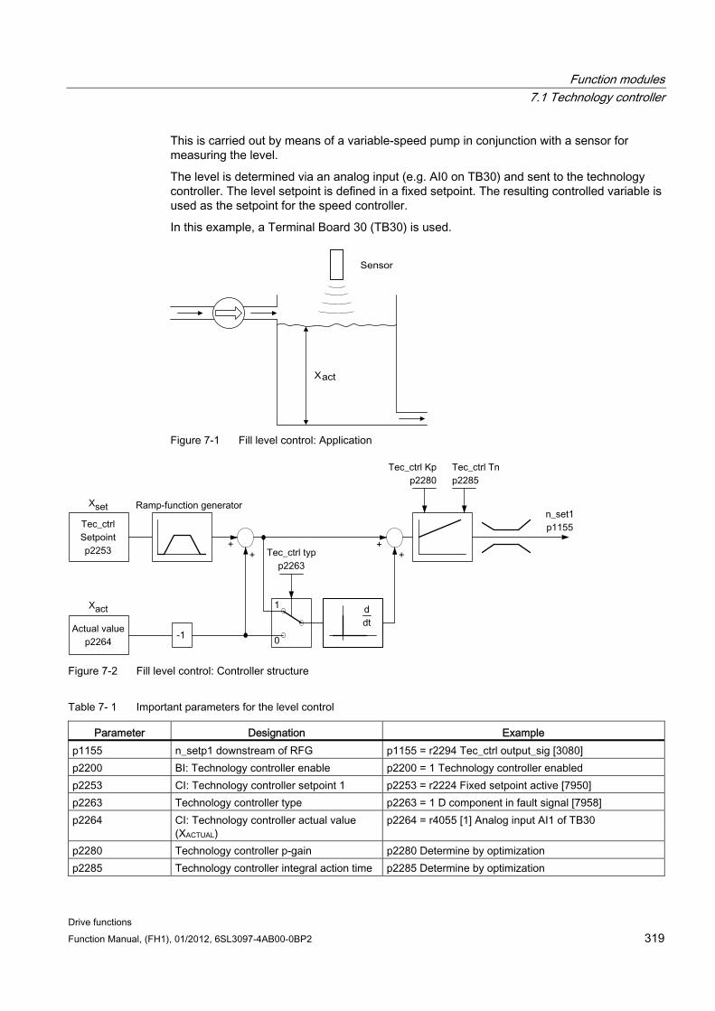
Function modules 7.1 Technology controller
Drive functions Function Manual, (FH1), 01/2012, 6SL3097-4AB00-0BP2 319
This is carried out by means of a variable-speed pump in conjunction with a sensor for measuring the level.
The level is determined via an analog input (e.g. AI0 on TB30) and sent to the technology controller. The level setpoint is defined in a fixed setpoint. The resulting controlled variable is used as the setpoint for the speed controller.
In this example, a Terminal Board 30 (TB30) is used.
Figure 7-1 Fill level control: Application
Figure 7-2 Fill level control: Controller structure
Table 7- 1 Important parameters for the level control
Parameter Designation Example p1155 n_setp1 downstream of RFG p1155 = r2294 Tec_ctrl output_sig [3080] p2200 BI: Technology controller enable p2200 = 1 Technology controller enabled p2253 CI: Technology controller setpoint 1 p2253 = r2224 Fixed setpoint active [7950] p2263 Technology controller type p2263 = 1 D component in fault signal [7958] p2264 CI: Technology controller actual value
(XACTUAL) p2264 = r4055 [1] Analog input AI1 of TB30
p2280 Technology controller p-gain p2280 Determine by optimization p2285 Technology controller integral action time p2285 Determine by optimization
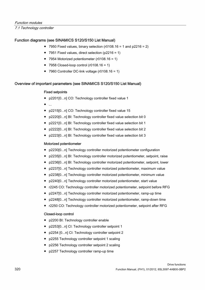
Function modules 7.1 Technology controller
Drive functions 320 Function Manual, (FH1), 01/2012, 6SL3097-4AB00-0BP2
Function diagrams (see SINAMICS S120/S150 List Manual) 7950 Fixed values, binary selection (r0108.16 = 1 and p2216 = 2)
7951 Fixed values, direct selection (p2216 = 1)
7954 Motorized potentiometer (r0108.16 = 1)
7958 Closed-loop control (r0108.16 = 1)
7960 Controller DC-link voltage (r0108.16 = 1)
Overview of important parameters (see SINAMICS S120/S150 List Manual)
Fixed setpoints
p2201[0...n] CO: Technology controller fixed value 1
...
p2215[0...n] CO: Technology controller fixed value 15
p2220[0...n] BI: Technology controller fixed value selection bit 0
p2221[0...n] BI: Technology controller fixed value selection bit 1
p2222[0...n] BI: Technology controller fixed value selection bit 2
p2223[0...n] BI: Technology controller fixed value selection bit 3
Motorized potentiometer
p2230[0...n] Technology controller motorized potentiometer configuration
p2235[0...n] BI: Technology controller motorized potentiometer, setpoint, raise
p2236[0...n] BI: Technology controller motorized potentiometer, setpoint, lower
p2237[0...n] Technology controller motorized potentiometer, maximum value
p2238[0...n] Technology controller motorized potentiometer, minimum value
p2240[0...n] Technology controller motorized potentiometer, start value
r2245 CO: Technology controller motorized potentiometer, setpoint before RFG
p2247[0...n] Technology controller motorized potentiometer, ramp-up time
p2248[0...n] Technology controller motorized potentiometer, ramp-down time
r2250 CO: Technology controller motorized potentiometer, setpoint after RFG
Closed-loop control
p2200 BI: Technology controller enable
p2253[0...n] CI: Technology controller setpoint 1
p2254 [0...n] CI: Technology controller setpoint 2
p2255 Technology controller setpoint 1 scaling
p2256 Technology controller setpoint 2 scaling
p2257 Technology controller ramp-up time
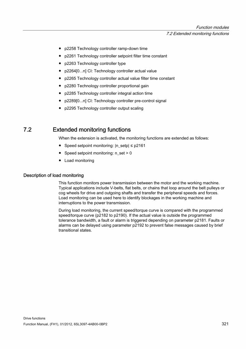
Function modules 7.2 Extended monitoring functions
Drive functions Function Manual, (FH1), 01/2012, 6SL3097-4AB00-0BP2 321
p2258 Technology controller ramp-down time
p2261 Technology controller setpoint filter time constant
p2263 Technology controller type
p2264[0...n] CI: Technology controller actual value
p2265 Technology controller actual value filter time constant
p2280 Technology controller proportional gain
p2285 Technology controller integral action time
p2289[0...n] CI: Technology controller pre-control signal
p2295 Technology controller output scaling
7.2 Extended monitoring functions When the extension is activated, the monitoring functions are extended as follows:
Speed setpoint monitoring: |n_setp| ≤ p2161
Speed setpoint monitoring: n_set > 0
Load monitoring
Description of load monitoring This function monitors power transmission between the motor and the working machine. Typical applications include V-belts, flat belts, or chains that loop around the belt pulleys or cog wheels for drive and outgoing shafts and transfer the peripheral speeds and forces. Load monitoring can be used here to identify blockages in the working machine and interruptions to the power transmission.
During load monitoring, the current speed/torque curve is compared with the programmed speed/torque curve (p2182 to p2190). If the actual value is outside the programmed tolerance bandwidth, a fault or alarm is triggered depending on parameter p2181. Faults or alarms can be delayed using parameter p2192 to prevent false messages caused by brief transitional states.
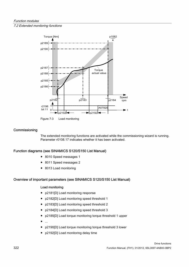
Function modules 7.2 Extended monitoring functions
Drive functions 322 Function Manual, (FH1), 01/2012, 6SL3097-4AB00-0BP2
Figure 7-3 Load monitoring
Commissioning The extended monitoring functions are activated while the commissioning wizard is running. Parameter r0108.17 indicates whether it has been activated.
Function diagrams (see SINAMICS S120/S150 List Manual) 8010 Speed messages 1
8011 Speed messages 2
8013 Load monitoring
Overview of important parameters (see SINAMICS S120/S150 List Manual)
Load monitoring
p2181[D] Load monitoring response
p2182[D] Load monitoring speed threshold 1
p2183[D] Load monitoring speed threshold 2
p2184[D] Load monitoring speed threshold 3
p2185[D] Load torque monitoring torque threshold 1 upper
...
p2190[D] Load torque monitoring torque threshold 3 lower
p2192[D] Load monitoring delay time
Function modules 7.3 Extended Brake Control
Drive functions Function Manual, (FH1), 01/2012, 6SL3097-4AB00-0BP2 323
Speed setpoint monitoring
p2150[D] Hysteresis speed 3
p2151[C] CI: Speed setpoint
p2161[D] Speed threshold value 3
r2198.4 BO: ZSW monitoring 2, |n_setp| ≤ p2161
r2198.5 BO: ZSW monitoring 2, n_setp < 0
7.3 Extended Brake Control
Features Forced brake release (p0855, p1215)
Application of brake for a 1 signal "unconditionally close holding brake" (p0858)
Binector inputs for releasing/applying the brake (p1218, p1219)
Connector input for threshold value for releasing/applying the brake (p1220)
OR/AND block, each with two inputs (p1279, r1229.10, r1229.11)
Holding and operational brakes can be activated.
Function for monitoring brake feedback signals (r1229.4, r1229.5)
Configurable responses (A07931, A07932)
Application of brake after "Enable speed controller" signal has been canceled (p0856)
Brake control options The "Extended brake control" function allows complex braking control for e.g. motor holding brakes and operational brakes.
The brake is controlled as follows (the sequence reflects the priority):
Using parameter p1215
Via binectors p1219[0...3] and p0855
Using zero speed detection
Via the connector interconnection, threshold value
For an AC drive with "Safe Brake Relay," the "Safe Brake Control" safety function requires that the type of the brake control be set in parameter p1278, to "Brake control with diagnostic evaluation" (p1278 = 0). This parameter is automatically set for booksize components.
Function modules 7.3 Extended Brake Control
Drive functions 324 Function Manual, (FH1), 01/2012, 6SL3097-4AB00-0BP2
Commissioning The extended brake control function can be activated while the commissioning wizard is running. Activation can be checked in parameter r0108.14.
Unless you change the default settings, the extended brake control function behaves in exactly the same way as the simple brake control function.
Brake control will be activated automatically (p1215 = 1) when the Motor Module has an internal brake control and a connected brake has been found.
If no internal brake control is available, the control can be activated using a parameter (p1215 = 3).
In the case of brakes with a feedback signal (p1222), the inverted signal must be connected to the BICO input for the second (p1223) feedback signal. The brake closing and opening times can be set in p1216 and p1217.
Note
If p1215 = 0 (no brake available) is set when a brake is present, the drive runs with applied brake. This can destroy the brake.
CAUTION It is only permissible to activate brake control monitoring for booksize power units and blocksize power units with Safe Brake Relay (p1278 = 0).
Examples Start-up with brake applied When the motor is switched on, the setpoint is enabled immediately (providing the required enabling signals have been issued) even if the brake has not yet been released (p1152 = 1). The factory setting p1152 = r0899.15 must be disconnected. The drive starts to generate torque against the applied brake. The brake is not released until the motor torque or current (p1220) has exceeded braking threshold 1 (p1221). Depending on the type and version of the brake, it may take some time for it to be fully released. Note that once the braking threshold torque has been exceeded, the operation enabling signal (p0899.2) is interrupted while the brake is being released (p1216) to ensure that the motor current does not exceed the permissible limit values during this period and/or the motor torque generated does not damage the brake. Interval p1216 must be set on the basis of the time the brake actually requires to release.
Emergency brake If emergency braking is required, the brake must be applied both electrically and mechanically. This can be achieved by using OFF3 as a tripping signal for emergency braking: p1219[0] = r0898.2 and p1275.00 = 1 (OFF3 to "Apply Brake Immediately" and invert signal).
To ensure that frequency converter does not operate against the brake, the OFF3 ramp (p1135) should be set to 0 seconds. Regenerative energy can be generated, which must be either fed back to the line supply or dissipated by means of a braking resistor.
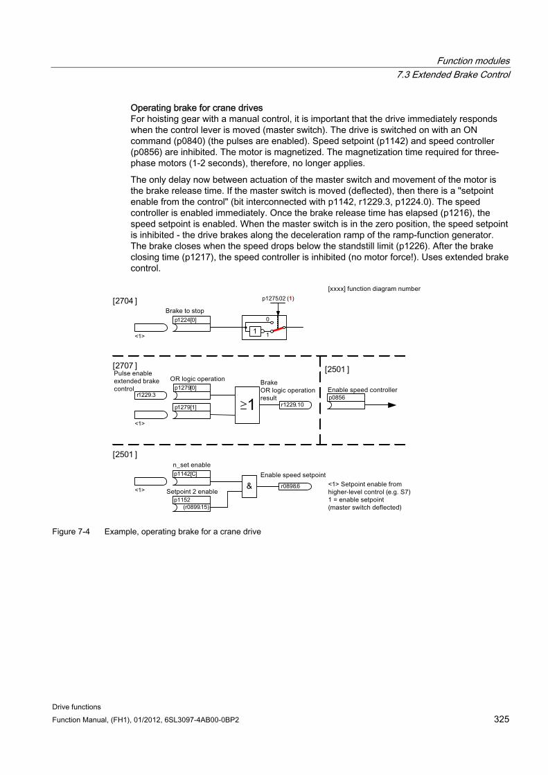
Function modules 7.3 Extended Brake Control
Drive functions Function Manual, (FH1), 01/2012, 6SL3097-4AB00-0BP2 325
Operating brake for crane drives For hoisting gear with a manual control, it is important that the drive immediately responds when the control lever is moved (master switch). The drive is switched on with an ON command (p0840) (the pulses are enabled). Speed setpoint (p1142) and speed controller (p0856) are inhibited. The motor is magnetized. The magnetization time required for three-phase motors (1-2 seconds), therefore, no longer applies.
The only delay now between actuation of the master switch and movement of the motor is the brake release time. If the master switch is moved (deflected), then there is a "setpoint enable from the control" (bit interconnected with p1142, r1229.3, p1224.0). The speed controller is enabled immediately. Once the brake release time has elapsed (p1216), the speed setpoint is enabled. When the master switch is in the zero position, the speed setpoint is inhibited - the drive brakes along the deceleration ramp of the ramp-function generator. The brake closes when the speed drops below the standstill limit (p1226). After the brake closing time (p1217), the speed controller is inhibited (no motor force!). Uses extended brake control.
[ ]
1 r1229.10
p1279[0]
p1279[1]
r1229.3
<1>
p1275.02 (1)
1
0
1
p1224[0]
<1>
r0898.6&
p1142[C]
(r0899.15)
p1152
<1>
[2501 ]
p0856
Figure 7-4 Example, operating brake for a crane drive
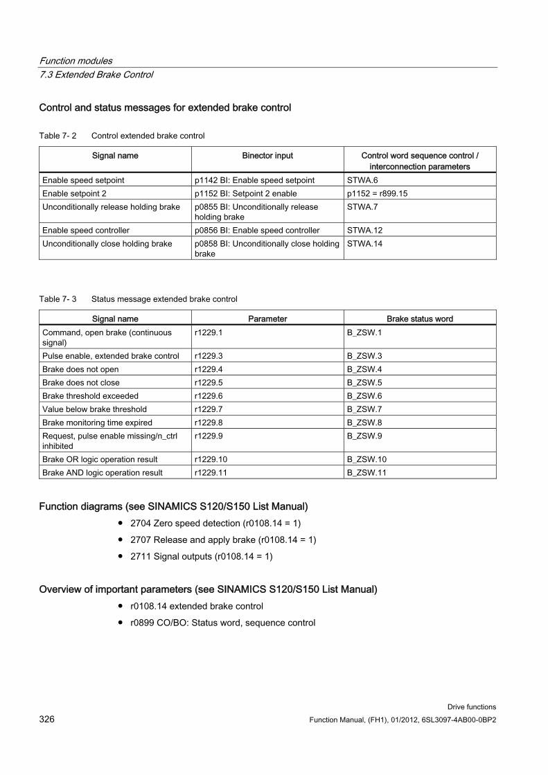
Function modules 7.3 Extended Brake Control
Drive functions 326 Function Manual, (FH1), 01/2012, 6SL3097-4AB00-0BP2
Control and status messages for extended brake control
Table 7- 2 Control extended brake control
Signal name Binector input Control word sequence control / interconnection parameters
Enable speed setpoint p1142 BI: Enable speed setpoint STWA.6 Enable setpoint 2 p1152 BI: Setpoint 2 enable p1152 = r899.15 Unconditionally release holding brake p0855 BI: Unconditionally release
holding brake STWA.7
Enable speed controller p0856 BI: Enable speed controller STWA.12 Unconditionally close holding brake p0858 BI: Unconditionally close holding
brake STWA.14
Table 7- 3 Status message extended brake control
Signal name Parameter Brake status word Command, open brake (continuous signal)
r1229.1 B_ZSW.1
Pulse enable, extended brake control r1229.3 B_ZSW.3 Brake does not open r1229.4 B_ZSW.4 Brake does not close r1229.5 B_ZSW.5 Brake threshold exceeded r1229.6 B_ZSW.6 Value below brake threshold r1229.7 B_ZSW.7 Brake monitoring time expired r1229.8 B_ZSW.8 Request, pulse enable missing/n_ctrl inhibited
r1229.9 B_ZSW.9
Brake OR logic operation result r1229.10 B_ZSW.10 Brake AND logic operation result r1229.11 B_ZSW.11
Function diagrams (see SINAMICS S120/S150 List Manual) 2704 Zero speed detection (r0108.14 = 1)
2707 Release and apply brake (r0108.14 = 1)
2711 Signal outputs (r0108.14 = 1)
Overview of important parameters (see SINAMICS S120/S150 List Manual) r0108.14 extended brake control
r0899 CO/BO: Status word, sequence control
Function modules 7.3 Extended Brake Control
Drive functions Function Manual, (FH1), 01/2012, 6SL3097-4AB00-0BP2 327
Standstill (zero-speed) monitoring
r0060 CO: Speed setpoint before the setpoint filter
r0063 CO: Actual speed smoothed (servo)
r0063[0...2] CO: Actual speed value (vector)
p1224[0...3] BI: Close motor holding brake at standstill
p1225 CI: Standstill detection, threshold value
p1226[0...n] standstill monitoring (zero speed) speed threshold
p1227 Zero speed detection monitoring time
p1228 Zero speed detection, delay time
p1276 Motor holding brake standstill detection bypass
Release and apply the brake
p0855 BI: Unconditionally release holding brake
p0858 BI: Unconditionally close holding brake
p1216 Holding brake release time
p1217 Holding brake application time
p1218[0...1] BI: Open motor holding brake
p1219[0...3 ] BI: Immediately close motor holding brake
p1220 CI: Open motor holding brake, signal source, threshold
p1221 Open motor holding brake threshold
p1277 Motor holding brake delay braking threshold exceeded
Free blocks
p1279[0...3] BI: Motor holding brake, OR/AND logic operation
Brake monitoring functions
p1222 BI: Motor holding brake, feedback signal, brake closed
p1223 BI: Motor holding brake, feedback signal, brake open
Configuration, control/status words
p1215 Motor holding brake configuration
r1229.1...11 CO/BO: Motor holding brake status word
p1275 Motor holding brake control word
p1278 Brake control diagnostics evaluation
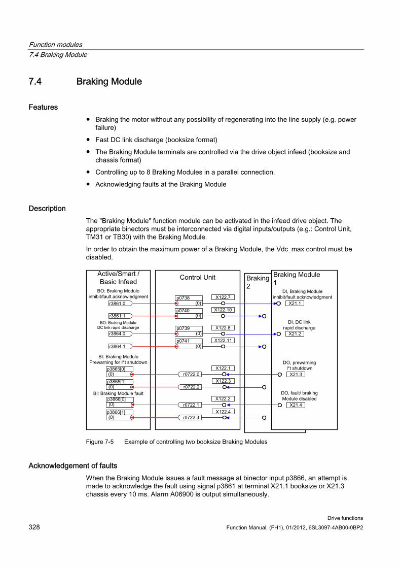
Function modules 7.4 Braking Module
Drive functions 328 Function Manual, (FH1), 01/2012, 6SL3097-4AB00-0BP2
7.4 Braking Module
Features Braking the motor without any possibility of regenerating into the line supply (e.g. power
failure)
Fast DC link discharge (booksize format)
The Braking Module terminals are controlled via the drive object infeed (booksize and chassis format)
Controlling up to 8 Braking Modules in a parallel connection.
Acknowledging faults at the Braking Module
Description The "Braking Module" function module can be activated in the infeed drive object. The appropriate binectors must be interconnected via digital inputs/outputs (e.g.: Control Unit, TM31 or TB30) with the Braking Module.
In order to obtain the maximum power of a Braking Module, the Vdc_max control must be disabled.
Figure 7-5 Example of controlling two booksize Braking Modules
Acknowledgement of faults When the Braking Module issues a fault message at binector input p3866, an attempt is made to acknowledge the fault using signal p3861 at terminal X21.1 booksize or X21.3 chassis every 10 ms. Alarm A06900 is output simultaneously.
Function modules 7.5 Cooling unit
Drive functions Function Manual, (FH1), 01/2012, 6SL3097-4AB00-0BP2 329
Fast DC link discharge (booksize) It is only possible to quickly discharge the DC link via the Braking Module for the booksize format. It is activated via binector input p3863 and started after the line contactor opens and the adjustable delay time (p3862) has expired. The fast discharge is completed when the line contactor contact closes.
NOTICE A fast DC link discharge requires the use of a line contactor with feedback signal (p0860) that is controlled via r0863.1.
Overview of important parameters (see SINAMICS S120/S150 List Manual) r0108.26 Drive object function module - Braking Module external
p3860 Braking Module number of modules connected in parallel
r3861.0...7 BO: Braking Module inhibit/acknowledgement
p3862 Braking Module DC link fast discharge delay time
p3863 BI: Braking Module activate DC link fast discharge
p3864.0...7 BO: Braking Module DC link fast discharge
p3865[0...7] BI: Braking Module pre-alarm I*t shutdown
p3866[0...7] BI: Braking Module fault
7.5 Cooling unit
Features Automatically activated when using liquid-cooled power units
Evaluation of an external sensor for leakage water
Evaluation of an external sensor for liquid flow
Evaluation of an external sensor for conductivity
Monitoring the liquid intake temperature using external temperature sensors
Monitoring the flow rating using internal temperature sensors
Evaluation of signals transmitted from the PLC of the cooling unit
Acknowledging cooling unit faults
Function modules 7.5 Cooling unit
Drive functions 330 Function Manual, (FH1), 01/2012, 6SL3097-4AB00-0BP2
Description A cooling unit (RKA) is responsible for the cooling and the (non) conductivity in the de-ionized water cooling circuit of a liquid-cooled power unit. The cooling unit is controlled and monitored from a PLC that is part of the cooling unit.
The cooling unit function module described here is used as an interface between the Control Unit and the external PLC as well as external sensors of the cooling unit. Signals for control and messages between the PLC and the Control Unit can be exchanged via this interface. The PLC communicates with the Control Unit via terminals and/or via a fieldbus (e.g. PROFIBUS or PROFINET).
Commissioning You activate the "cooling unit" function module while configuring the associated power unit (a power unit is a Motor Module or an Infeed Module):
1. When selecting the power unit, set the cooling type to "Liquid cooling"
2. Complete the configuration
3. After configuration has been completed, in the navigation window under "Power Unit>>Functions", the heat exchanger unit can be seen (also in the shortcut menu of the power unit under "Functions").
4. Double-click on "Cooling unit" opens the window for setting the monitoring functions. In this window, BICO interconnections can be set for communication with the control of the cooling unit and the cooling water circuit monitoring.
Function diagrams (see SINAMICS S120/S150 List Manual) 9794 Cooling unit, control and feedback signals
9795 Cooling unit sequence control
Overview of important parameters (see SINAMICS S120/S150 List Manual) r0046.29 Missing enable signals - cooling unit ready missing
r0108.28 drive object function module cooling unit
p0192.06 Power unit firmware properties - water cooling
r0204.06 Power unit hardware properties - water cooling
p0260 Cooling unit, starting time 1
p0261 Cooling unit, starting time 2
p0262 Cooling unit fault conductivity delay time
p0263 Cooling unit fault water flow delay time
p0264 Cooling unit, run-on time
r0265 BO: Cooling unit control word
p0266[0...7] BI: Cooling unit signal source feedback signals
r0267 BO: Cooling unit status word display

Function modules 7.6 Extended torque control (kT estimator, servo)
Drive functions Function Manual, (FH1), 01/2012, 6SL3097-4AB00-0BP2 331
7.6 Extended torque control (kT estimator, servo)
Features kT estimator (only for synchronous motors)
Compensation of the voltage emulation error of the drive converter (p1952, p1953)
Configuration via p1780
Description The "extended torque control" function module comprises two modules - the kT estimator and the compensation of the voltage emulation error of the drive converter. As a consequence, the torque accuracy is increased.
Note
When this function module is activated, the maximum number of drives that can be controlled from a Control Unit is reduced by at least one drive.
Commissioning The extended torque control is activated offline:
1. Right-click on the drive > "Properties ... The window " >"Object properties" is opened.
2. Click on the "Function modules" tab A list of possible function modules is opened
3. Select "Extended torque control" by clicking in the option check box
4. Activate the function module by clicking "OK"
5. Then select "connect with selected target devices"
6. "Load project to target system".
Activation can be checked in parameter r0108.1.
Description of the kT estimator The adaptation of the torque constants for synchronous motors is used to improve the absolute torque accuracy for the control (closed-loop) of synchronous motors. The magnetization of the permanent magnets varies as a result of production tolerances and temperature fluctuations and saturation effects. The function "kT estimator" adapts the torque constant kT [Nm/A] in the control to the prevailing magnetization. It only makes sense to use the kT estimator in conjunction with the friction characteristic as the kT estimator corrects the inner motor torque. The frictional losses must be compensated from the friction characteristic using a supplementary torque.
Function modules 7.6 Extended torque control (kT estimator, servo)
Drive functions 332 Function Manual, (FH1), 01/2012, 6SL3097-4AB00-0BP2
The kT estimator requires the most accurate values for the motor parameters as possible in order to achieve a high torque accuracy. Before using the kT estimator, a motor identification (p1909, p1910) must be performed with activated kTestimator. In this procedure, the values for stator resistance (p0350), leakage inductance (p0356) and voltage emulation errors (p1952, p1953) are determined. The cable resistance must be entered in p0352 before motor identification.
The motor should be at room temperature when the identification routine is carried out. Compensation of the voltage emulation error must be activated (p1780.8 = 1). The motor temperature (p0600) should be recorded via a KTY sensor (p0601 = 2 or 3).
The kT estimator requires the motor temperature in order to track/correct the temperature-dependent quantities. The estimate is less accurate if a motor temperature sensor is not connected.
The kT estimator is only activated above a specific speed (p1752). The terminal voltage of the converter always has small inaccuracies. The lower the output voltage and speed, the more inaccurate the estimate. This is the reason that the estimation is de-activated below a specific speed. The estimated value is smoothed using time constant p1795. The correction value for the torque constant is displayed in r1797.
By identifying the torque constant kT using the rotating motor identification routine, the torque accuracy can be improved also below the speed threshold (p1752).
The kT estimator is activated using p1780.3 and the voltage compensation using p1780.8.
Function diagrams (see SINAMICS S120/S150 List Manual) 7008 kT estimator
Overview of important parameters (see SINAMICS S120/S150 List Manual) r0108.1 drive objects function module - extended torque control
p1780.3 selects motor model PEM kT adaptation
p1780.8 Compensation of the voltage emulation error in the drive converter
Motor/drive converter identification
p0352[0...n] Cable resistance
p1909 Motor data identification control word
p1910 Motor data identification, stationary
kT estimator
p1752[0...n] Motor model changeover speed operation with encoder
p1795[0...n] motor model PEM kT adaptation smoothing time
r1797[0...n] motor model PEM kT adaptation correction value
Compensation of the voltage emulation error of the drive converter
p1952[0...n] Voltage emulation error final value
p1953[0...n] Voltage emulation error current offset
Function modules 7.7 Closed-loop position control
Drive functions Function Manual, (FH1), 01/2012, 6SL3097-4AB00-0BP2 333
7.7 Closed-loop position control
7.7.1 General features The position controller essentially comprises the following parts:
Position actual value conditioning (including the lower-level measuring probe evaluation and reference mark search)
Position controller (including limits, adaptation and the pre-control calculation)
Monitoring functions (including standstill, positioning, dynamic following error monitoring and cam signals)
Position tracking of the load gear (motor encoder), using absolute encoders for rotary axes (modulo) as for linear axes.
7.7.2 Position actual value conditioning
7.7.2.1 Features Correction value (p2512, p2513)
Setting value (p2514, p2515)
Position offset (p2516)
Position actual value (r2521)
Velocity actual value (r2522)
Motor revolutions (p2504)
Load revolutions (p2505)
Spindle pitch (p2506)
Position tracking (p2720ff)
7.7.2.2 Description The position actual value conditioning converts the actual position value into a neutral distance unit LU (Length Unit). To do this, the function block uses the encoder evaluation/motor control with the available encoder interfaces Gn_XIST1, Gn_XIST2, Gn_STW and Gn_ZSW. These just provide position information in encoder pulses and fine resolution (increments).
The position actual value is conditioned, regardless of whether the position controller is enabled immediately after the system has booted, as soon as valid values are received via the encoder interface.
Parameter p2502 (encoder assignment) is used to define from which encoder (1, 2 or 3), the position actual value is sensed.
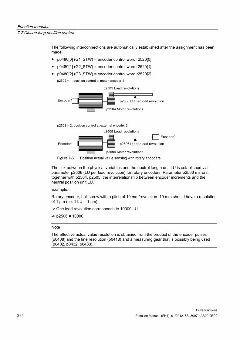
Function modules 7.7 Closed-loop position control
Drive functions 334 Function Manual, (FH1), 01/2012, 6SL3097-4AB00-0BP2
The following interconnections are automatically established after the assignment has been made.
p0480[0] (G1_STW) = encoder control word r2520[0]
p0480[1] (G2_STW) = encoder control word r2520[1]
p0480[2] (G3_STW) = encoder control word r2520[2]
Figure 7-6 Position actual value sensing with rotary encoders
The link between the physical variables and the neutral length unit LU is established via parameter p2506 (LU per load revolution) for rotary encoders. Parameter p2506 mirrors, together with p2504, p2505, the interrelationship between encoder increments and the neutral position unit LU.
Example:
Rotary encoder, ball screw with a pitch of 10 mm/revolution. 10 mm should have a resolution of 1 µm (i.e. 1 LU = 1 µm).
-> One load revolution corresponds to 10000 LU
-> p2506 = 10000
Note
The effective actual value resolution is obtained from the product of the encoder pulses (p0408) and the fine resolution (p0418) and a measuring gear that is possibly being used (p0402, p0432, p0433).
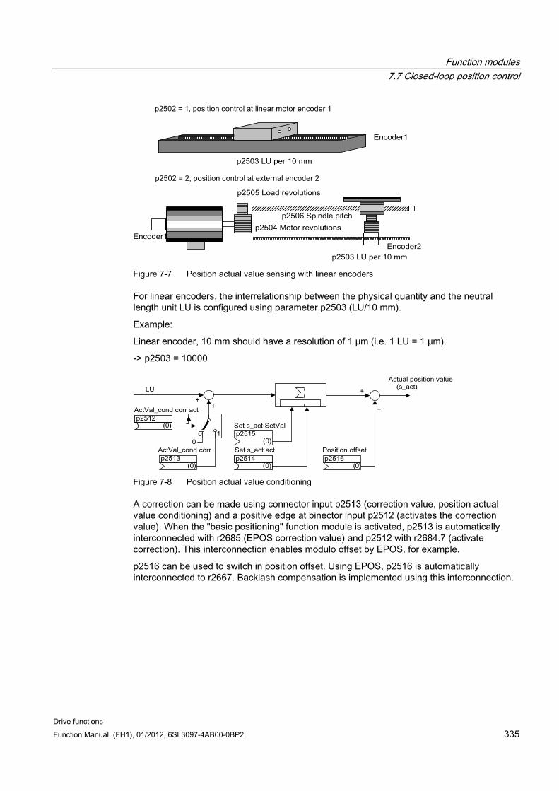
Function modules 7.7 Closed-loop position control
Drive functions Function Manual, (FH1), 01/2012, 6SL3097-4AB00-0BP2 335
Figure 7-7 Position actual value sensing with linear encoders
For linear encoders, the interrelationship between the physical quantity and the neutral length unit LU is configured using parameter p2503 (LU/10 mm).
Example:
Linear encoder, 10 mm should have a resolution of 1 µm (i.e. 1 LU = 1 µm).
-> p2503 = 10000
Figure 7-8 Position actual value conditioning
A correction can be made using connector input p2513 (correction value, position actual value conditioning) and a positive edge at binector input p2512 (activates the correction value). When the "basic positioning" function module is activated, p2513 is automatically interconnected with r2685 (EPOS correction value) and p2512 with r2684.7 (activate correction). This interconnection enables modulo offset by EPOS, for example.
p2516 can be used to switch in position offset. Using EPOS, p2516 is automatically interconnected to r2667. Backlash compensation is implemented using this interconnection.
Function modules 7.7 Closed-loop position control
Drive functions 336 Function Manual, (FH1), 01/2012, 6SL3097-4AB00-0BP2
Using the connector input p2515 (position setting value) and a "1" signal at binector input p2514 (set position actual value), a position setting value can be entered.
WARNING When the actual position value is set (p2514 = "1" signal), the actual position value of the position controller is kept at the value of connector p2515 as standard.
Incoming encoder increments are not evaluated. A difference in position cannot be compensated for in this situation.
An inversion of the actual position value resulting from the encoder is undertaken using parameter p0410. An inversion of the axis motion can be entered using a negative value in p2505.
7.7.2.3 Indexed actual value acquisition
Features Encoder assignment (p2502[D])
Absolute encoder adjustment (p2507[E])
Activate measuring probe evaluation (p2509[0...3])
Measuring probe evaluation selection (p2510[0..3])
Measuring probe edge (p2511[0..3])
Activate position actual value conditioning, correction value (p2512[0...3])
Position actual value conditioning, correction value (p2513[0...3])
Position offset (p2516[0...3])
Position actual value (r2521[0...3])
Velocity actual value (r2522[0...3])
Measuring probe evaluation/Reference mark search (p2523[0..3])
Encoder adjustment, offset (p2525[E])
Status word position controller (r2526)
Status word encoder1 (r2527)
Status word encoder2 (r2528)
Status word encoder3 (r2529)
EPOS reference point coordinate, signal source (p2598[0...3])
Function diagram 4010 Position control - Position actual value conditioning
Function modules 7.7 Closed-loop position control
Drive functions Function Manual, (FH1), 01/2012, 6SL3097-4AB00-0BP2 337
Description The indexed position actual value acquisition permits e.g. length measurements on parts as well as the detection of axis positions by a higher-level controller (e.g. SIMATIC S7) in addition to the position control e.g. of a belt conveyor.
Two more encoders can be operated in parallel with the encoders for actual value preprocessing and position control in order to collect actual values and measured data.
The indexed acquisition of actual values can preprocess a position actual value at each of the three encoder outputs. The parameter p2502[0...3] is used to select the encoder evaluation for position control.
The parameters of the indexed actual value acquisition are indexed four times. The indexes 1..3 are assigned to the encoder evaluations 1..3. The index 0 is assigned to position control.
The parameter r2521[0...3] can be used to retrieve the current actual values of all connected encoders. For example, the position actual value for position control in r2521[0] is identical with the value r2521[1] if the position control uses encoder evaluation 1. The signal source for a position offset can be set in parameter p2516[0...3].
The absolute encoder adjustment is initiated via p2507[0...3].2, and its successful completion is reported via p2507[0...3].3. The signal source "Reference point coordinate for the position controller" p2598[0] is interconnected with p2599 during basic positioning. The other signal sources are not interconnected in the standard configuration.
The measuring probe evaluation can be enabled for the encoder evaluation x, which is not assigned to position control, via p2509[x]. The signal sources are assigned via p2510[0...3], the edge evaluation is set via p2511[0...3]. The measured value is available in r2523[x] if, in the status word for encoder x (encoder 0: r2526.0..9, encoder1: 2627.0..2, encoder2: r2628.0..2, encoder3: r2529.0..2) the "Measurement value valid" bit is set.
The actual position values of the different encoders can be read out using parameter r2521[0...3]. These position actual values can be corrected with a signed value from p2513[0...3] after a 0/1 signal from the signal source in p2512[0...3].
In addition, the velocity actual value (r2522[0...3]) and the position offset for absolute encoders p2525[0...3] can be processed for each encoder by the higher-level controller.
7.7.2.4 Load gear position tracking
Features Configuration via p2720
Virtual multiturn via p2721
Tolerance window for monitoring the position at switching on p2722
Input of the load gear via p2504 and p2505
Display via r2723
Preconditions Absolute encoder
Function modules 7.7 Closed-loop position control
Drive functions 338 Function Manual, (FH1), 01/2012, 6SL3097-4AB00-0BP2
Description Position tracking enables reproduction of the position of the load when gears are used. It can also be used to extend the position area.
Position tracking for load gear functions in the same way as position tracking for the measuring gear (see "Position tracking/Measuring gear"). Position tracking is activated via parameter p2720.0 = 1. The position tracking of the load gear, however, is only relevant for the motor encoder (encoder 1). The load gear ratio is entered via parameters p2504 and p2505. Position tracking can be activated with rotary axes (modulo) and linear axes.
Position tracking for the load gear can only be activated once for each motor data set MDS.
The load position actual value in r2723 (must be requested via Gn_STW.13, see chapter "Control and status words for encoders") comprises the following information:
Encoder pulses per revolution (p0408)
Fine resolution per revolution (p0419)
Virtual number of stored revolutions of a rotary absolute encoder (p2721)
Load gear ratio (p2504/p2505)
Measuring gear ratio (p0433/p0432), if p0411.0 = 1
Note
The sum of p0408, p0419 and p2721 is limited to 32 bits.
Note
Load gear problems and solutions, see example in chapter Position tracking -> Measuring gear.
Example of position area extension With absolute encoders without position tracking, it must be ensured that the traversing range is 0 smaller than half the encoder range, because beyond this range, no unique reference remains after switching on and off (see description on parameter p2507). This traversing range can be extended using the virtual multiturn (p2721).
The following diagram illustrates an absolute encoder that can represent 8 encoder revolutions (p0421 = 8).
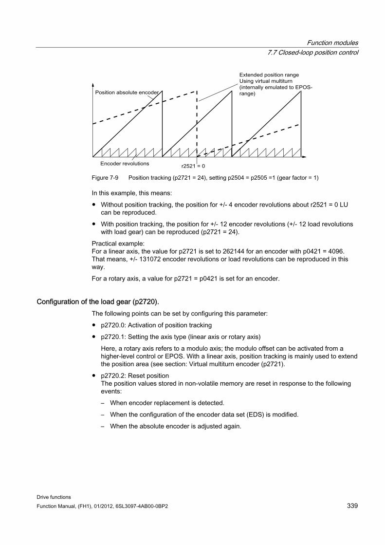
Function modules 7.7 Closed-loop position control
Drive functions Function Manual, (FH1), 01/2012, 6SL3097-4AB00-0BP2 339
Figure 7-9 Position tracking (p2721 = 24), setting p2504 = p2505 =1 (gear factor = 1)
In this example, this means:
Without position tracking, the position for +/- 4 encoder revolutions about r2521 = 0 LU can be reproduced.
With position tracking, the position for +/- 12 encoder revolutions (+/- 12 load revolutions with load gear) can be reproduced (p2721 = 24).
Practical example: For a linear axis, the value for p2721 is set to 262144 for an encoder with p0421 = 4096. That means, +/- 131072 encoder revolutions or load revolutions can be reproduced in this way.
For a rotary axis, a value for p2721 = p0421 is set for an encoder.
Configuration of the load gear (p2720). The following points can be set by configuring this parameter:
p2720.0: Activation of position tracking
p2720.1: Setting the axis type (linear axis or rotary axis)
Here, a rotary axis refers to a modulo axis; the modulo offset can be activated from a higher-level control or EPOS. With a linear axis, position tracking is mainly used to extend the position area (see section: Virtual multiturn encoder (p2721).
p2720.2: Reset position The position values stored in non-volatile memory are reset in response to the following events:
– When encoder replacement is detected.
– When the configuration of the encoder data set (EDS) is modified.
– When the absolute encoder is adjusted again.
Function modules 7.7 Closed-loop position control
Drive functions 340 Function Manual, (FH1), 01/2012, 6SL3097-4AB00-0BP2
Note
If position tracking of the load gear is activated with parameter p2720[0] = 1 (position gear load tracking) after the encoder is adjusted (p2507 = 3), the adjustment will be reset.
If the encoder is adjusted again when load position tracking is active, the load gear position will be reset (overflows).
The permissible position tracking range is mapped onto the reproducible encoder range of EPOS.
It is possible to activate position tracking for several DDS.
Virtual multiturn encoder (p2721) The number of resolvable load rotations for a rotary absolute encoder with active position tracking can be set by means of the virtual multiturn resolution. It is only editable for rotary axes.
With a rotary absolute encoder (p0404.1 = 1) with activated position tracking (p2720.0 = 1), p2721 can be used to enter a virtual multiturn resolution.
NOTICE If the gearbox factor is not equal to 1, then p2721 always refers to the load side. The virtual resolution, which is required for the load, is then set here.
In the case of rotary axes, the virtual multiturn resolution (p2721) is preset to the multiturn resolution value of the encoder (p0421) and can be altered. Example: Singleturn encoder Parameter p0421 is preset to p0421 = 1. However, parameter p2721 can be altered subsequently, e.g. the user can program p2721 = 5. As a result, the encoder evaluation initiates 5 load rotations before the same absolute value is achieved again.
In the case of linear axes, the virtual multiturn resolution (p2721) is preset to the multiturn resolution value of the encoder (p0421), which is extended by 6 bits, (max. 32 positive/negative overflows). The setting for p2721 cannot be edited again afterwards. Example: Multiturn encoder: For a linear axis, the value for p2721 is set to 262144 for an encoder with p0421 = 4096. That means, +/- 131072 encoder revolutions or load revolutions can be reproduced in this way.
If, as a result of extension of the multiturn information, the displayable area of r2723 (32 bits) is exceeded, the fine resolution (p0419) must be reduced accordingly.
Function modules 7.7 Closed-loop position control
Drive functions Function Manual, (FH1), 01/2012, 6SL3097-4AB00-0BP2 341
Tolerance window (p2722) After switching on, the difference between the stored position and the actual position is ascertained and, depending on the result, the following is initiated:
Difference within the tolerance window -> the position is reproduced based on the current actual encoder value.
Difference outside the tolerance window -> an appropriate fault (F07449) is output.
The tolerance window is preset to quarter of the encoder range and can be changed.
CAUTION The position can only be reproduced if, in the powered-down state, the encoder was moved through less than half of the range that it can represent. For the standard EQN1325 encoder, this is 2048 revolutions or half a revolution for singleturn encoders.
Note
The ratio stamped on the gear rating plate is often just a rounded-off value (e.g.1:7.34). If, for a rotary axis, it is not permissible to have any long-term drift, then the actual ratio of the gearbox teeth must be requested from the gearbox manufacturer.
Multiple drive data sets Position tracking of the load gear can be activated in multiple drive data sets.
The load gear is DDS-dependent.
Load gear position tracking is computed only for the active drive data set and is EDS-dependent.
The position tracking memory is only available once for each EDS.
For position tracking to be continued in different drive data sets under the same mechanical conditions and with the same encoder data sets, it must be activated explicitly in all the relevant drive data sets. Possible applications of drive data set changeover with continuation of position tracking:
– Star/delta changeover
– Different ramp-up times / controller settings
When the changeover between drive data sets involves a change in gear unit, the position tracking function starts from the beginning again, i.e. it behaves on changeover as if a POWER ON had occurred.
With identical mechanical conditions and encoder data set, a DDS changeover does not affect the status of the encoder adjustment or reference point.
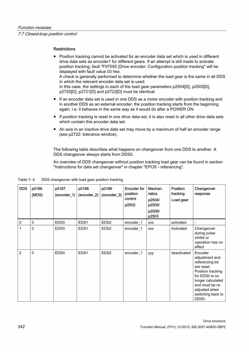
Function modules 7.7 Closed-loop position control
Drive functions 342 Function Manual, (FH1), 01/2012, 6SL3097-4AB00-0BP2
Restrictions
Position tracking cannot be activated for an encoder data set which is used in different drive data sets as encoder1 for different gears. If an attempt is still made to activate position tracking, fault "F07555 (Drive encoder: Configuration position tracking" will be displayed with fault value 03 hex. A check is generally performed to determine whether the load gear is the same in all DDS in which the relevant encoder data set is used. In this case, the settings in each of the load gear parameters p2504[D], p2505[D], p2720[D], p2721[D] and p2722[D] must be identical.
If an encoder data set is used in one DDS as a motor encoder with position tracking and in another DDS as an external encoder, the position tracking starts from the beginning again, i.e. it behaves in the same way as it would do after a POWER ON.
If position tracking is reset in one drive data set, it is also reset in all other drive data sets which contain this encoder data set.
An axis in an inactive drive data set may move by a maximum of half an encoder range (see p2722: tolerance window).
The following table describes what happens on changeover from one DDS to another. A DDS changeover always starts from DDS0.
An overview of DDS changeover without position tracking load gear can be found in section "Instructions for data set changeover" in chapter "EPOS - referencing".
Table 7- 4 DDS changeover with load gear position tracking
DDS p0186 (MDS)
p0187 (encoder_1)
p0188 (encoder_2)
p0189 (encoder_3)
Encoder for position control p2502
Mechan. ratios p2504/ p2505/ p2506/ p2503
Position tracking Load gear
Changeover response
0 0 EDS0 EDS1 EDS2 encoder_1 xxx activated - 1 0 EDS0 EDS1 EDS2 encoder_1 xxx Activated Changeover
during pulse inhibit or operation has no effect
2 0 EDS0 EDS1 EDS2 encoder_1 yyy deactivated Encoder adjustment and referencing bit are reset. Position tracking for EDS0 is no longer calculated and must be re-adjusted when switching back to DDS0.
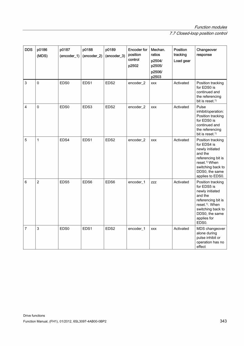
Function modules 7.7 Closed-loop position control
Drive functions Function Manual, (FH1), 01/2012, 6SL3097-4AB00-0BP2 343
DDS p0186 (MDS)
p0187 (encoder_1)
p0188 (encoder_2)
p0189 (encoder_3)
Encoder for position control p2502
Mechan. ratios p2504/ p2505/ p2506/ p2503
Position tracking Load gear
Changeover response
3 0 EDS0 EDS1 EDS2 encoder_2 xxx Activated Position tracking for EDS0 is continued and the referencing bit is reset.1)
4 0 EDS0 EDS3 EDS2 encoder_2 xxx Activated Pulse inhibit/operation: Position tracking for EDS0 is continued and the referencing bit is reset.1)
5 1 EDS4 EDS1 EDS2 encoder_2 xxx Activated Position tracking for EDS4 is newly initiated and the referencing bit is reset.1) When switching back to DDS0, the same applies to EDS0.
6 2 EDS5 EDS6 EDS6 encoder_1 zzz Activated Position tracking for EDS5 is newly initiated and the referencing bit is reset.1). When switching back to DDS0, the same applies for EDS0.
7 3 EDS0 EDS1 EDS2 encoder_1 xxx Activated MDS changeover alone during pulse inhibit or operation has no effect
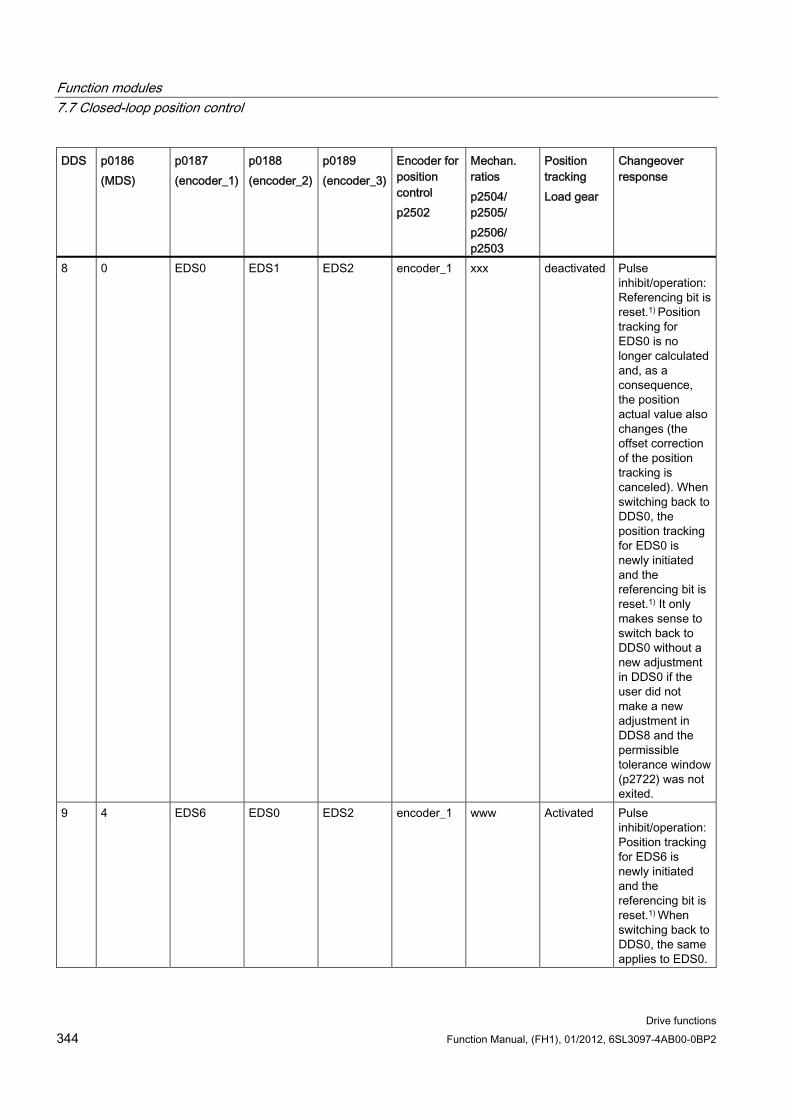
Function modules 7.7 Closed-loop position control
Drive functions 344 Function Manual, (FH1), 01/2012, 6SL3097-4AB00-0BP2
DDS p0186 (MDS)
p0187 (encoder_1)
p0188 (encoder_2)
p0189 (encoder_3)
Encoder for position control p2502
Mechan. ratios p2504/ p2505/ p2506/ p2503
Position tracking Load gear
Changeover response
8 0 EDS0 EDS1 EDS2 encoder_1 xxx deactivated Pulse inhibit/operation: Referencing bit is reset.1) Position tracking for EDS0 is no longer calculated and, as a consequence, the position actual value also changes (the offset correction of the position tracking is canceled). When switching back to DDS0, the position tracking for EDS0 is newly initiated and the referencing bit is reset.1) It only makes sense to switch back to DDS0 without a new adjustment in DDS0 if the user did not make a new adjustment in DDS8 and the permissible tolerance window (p2722) was not exited.
9 4 EDS6 EDS0 EDS2 encoder_1 www Activated Pulse inhibit/operation: Position tracking for EDS6 is newly initiated and the referencing bit is reset.1) When switching back to DDS0, the same applies to EDS0.
Function modules 7.7 Closed-loop position control
Drive functions Function Manual, (FH1), 01/2012, 6SL3097-4AB00-0BP2 345
1) The referencing bit (r2684.11) is reset for a DDS changeover. If, in the new DDS, the EDS already has an adjusted encoder, then the referencing bit is set again.
Definitions:
Position tracking is continued
The behavior of the position tracking during the changeover is the same as it would be if the data set had not even been changed.
Position tracking is newly initiated (The position actual value can change when the changeover is made!)
The behavior during changeover is the same as the behavior after a POWER ON. The position value read by the absolute encoder is compared to the stored value. If the position difference is within the tolerance window (p2722), the position is corrected correspondingly; if it is outside the range, a corresponding fault F07449 is output
Position tracking is reset (The position actual value can change when the changeover is made!)
The stored absolute value is rejected and the overflow counter is reset to zero.
Position tracking is not calculated (The position actual value changes when the changeover is made!)
The saved absolute value of the position tracking - including the offset correction from the dissolved DDS - is not used.
www, xxx, yyy, zzz: Different mechanical conditions.
Additional information: The position tracking memory is only available once for each EDS.
7.7.2.5 Commissioning position tracking load gear using STARTER The position tracking function can be configured in the "Mechanical system" screen for "Position control" in STARTER. The "Mechanical system" screen for "Position control" is not made accessible unless the function module "Basic positioner" is activated (r0108.4 = 1) which means that the function module "Position control" (r0108.3 = 1) is automatically activated as well.
The "Basic positioner" function module can be activated via the commissioning wizard or the drive configuration (configure DDS) (configuration "Closed-loop control structure" - checkbox "Basic positioner").
Configuring the position tracking load gear function The "Position tracking load gear" function can be configured in the following STARTER screens:
1. In the "Mechanical system configuration" screen in the commissioning wizard.
2. In the project navigator under Drive → "Technology" → "Position control" in the "Mechanical system" screen.
Function modules 7.7 Closed-loop position control
Drive functions 346 Function Manual, (FH1), 01/2012, 6SL3097-4AB00-0BP2
7.7.2.6 Function diagrams and parameters
Function diagrams (see SINAMICS S120/S150 List Manual) 4010 Position actual value conditioning
4704 position and temperature sensing, encoders 1...3
4710 Actual speed value and rotor pos. meas., motor enc. (encoder 1)
Overview of important parameters (see SINAMICS S120/S150 List Manual) p2502[0...n] LR encoder assignment
p2503[0...n] LR length unit LU per 10 mm
p2504[0...n] LR motor/load motor revolutions
p2505[0...n] LR motor/load load revolutions
p2506[0...n] LR length unit LU per load revolution
r2520[0...n] CO: LR position actual value conditioning encoder control word
r2521[0...n] CO: LR actual position value
r2522[0...n] CO: LR actual velocity value
r2523[0...n] CO: LR measured value
r2524[0...n] CO: LR LU/revolutions
r2525[0...n] CO: LR encoder adjustment offset
r2526[0...n] CO/BO: LR status word
p2720[0...n] Load gear configuration
p2721[0...n] Load gear absolute encoder rotary revolutions virtual
p2722[0...n] Load gear position tracking tolerance window
r2723[0...n] CO: Load gea absolute value
r2724[0...n] CO: Load gear position difference
7.7.3 Position controller
Features Symmetrization (p2535, p2536)
Limiting (p2540, p2541)
Pre-control (p2534)
Adaptation (p2537, p2538)
Function modules 7.7 Closed-loop position control
Drive functions Function Manual, (FH1), 01/2012, 6SL3097-4AB00-0BP2 347
Note
We only recommend that experts use the position controller functions without using the basic positioner.
Description The position controller is a PI controller. The P gain can be adapted using the product of connector input p2537 (position controller adaptation) and parameter p2538 (Kp).
Using connector input p2541 (limit), the speed setpoint of the position controller can be limited without pre-control. This connector input is pre-interconnected with connector output p2540.
The position controller is enabled by an AND link of the binector inputs p2549 (position controller 1 enable) and p2550 (position controller 2 enable).
The position setpoint filter (p2533 time constant position setpoint filter) is a PT1 element, the symmetrizing filter as deadtime element (p2535 symmetrizing filter speed pre-control (deadtime) and PT1 element (p2536 symmetrizing filter speed pre-control (PT1)). The speed pre-control p2534 (factor, speed pre-control) can be disabled via the value 0.
Function diagrams (see SINAMICS S120/S150 List Manual) 4015 Position controller
Overview of important parameters (see SINAMICS S120/S150 List Manual) p2533[0...n] LR position setpoint filter time constant
p2534[0...n] LR speed precontrol factor
p2535[0...n] LR speed precontrol symmetrizing filter dead time
p2536[0...n] LR speed precontrol symmetrizing filter PT1
p2537 CI: LR position controller adaptation
p2538[0...n] LR proportional gain
p2539[0...n] LR integral time
p2540 CO: LR position controller output speed limit
p2541 CI: LR position controller output speed limit signal source
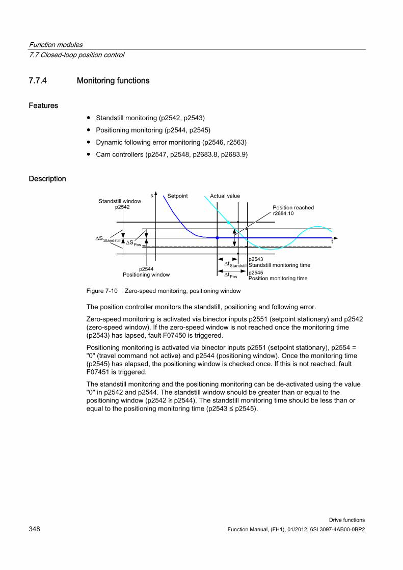
Function modules 7.7 Closed-loop position control
Drive functions 348 Function Manual, (FH1), 01/2012, 6SL3097-4AB00-0BP2
7.7.4 Monitoring functions
Features Standstill monitoring (p2542, p2543)
Positioning monitoring (p2544, p2545)
Dynamic following error monitoring (p2546, r2563)
Cam controllers (p2547, p2548, p2683.8, p2683.9)
Description
Figure 7-10 Zero-speed monitoring, positioning window
The position controller monitors the standstill, positioning and following error.
Zero-speed monitoring is activated via binector inputs p2551 (setpoint stationary) and p2542 (zero-speed window). If the zero-speed window is not reached once the monitoring time (p2543) has lapsed, fault F07450 is triggered.
Positioning monitoring is activated via binector inputs p2551 (setpoint stationary), p2554 = "0" (travel command not active) and p2544 (positioning window). Once the monitoring time (p2545) has elapsed, the positioning window is checked once. If this is not reached, fault F07451 is triggered.
The standstill monitoring and the positioning monitoring can be de-activated using the value "0" in p2542 and p2544. The standstill window should be greater than or equal to the positioning window (p2542 ≥ p2544). The standstill monitoring time should be less than or equal to the positioning monitoring time (p2543 ≤ p2545).
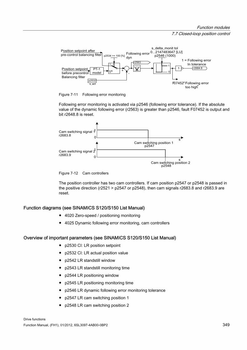
Function modules 7.7 Closed-loop position control
Drive functions Function Manual, (FH1), 01/2012, 6SL3097-4AB00-0BP2 349
Figure 7-11 Following error monitoring
Following error monitoring is activated via p2546 (following error tolerance). If the absolute value of the dynamic following error (r2563) is greater than p2546, fault F07452 is output and bit r2648.8 is reset.
Figure 7-12 Cam controllers
The position controller has two cam controllers. If cam position p2547 or p2548 is passed in the positive direction (r2521 > p2547 or p2548), then cam signals r2683.8 and r2683.9 are reset.
Function diagrams (see SINAMICS S120/S150 List Manual) 4020 Zero-speed / positioning monitoring
4025 Dynamic following error monitoring, cam controllers
Overview of important parameters (see SINAMICS S120/S150 List Manual) p2530 CI: LR position setpoint
p2532 CI: LR actual position value
p2542 LR standstill window
p2543 LR standstill monitoring time
p2544 LR positioning window
p2545 LR positioning monitoring time
p2546 LR dynamic following error monitoring tolerance
p2547 LR cam switching position 1
p2548 LR cam switching position 2
Function modules 7.7 Closed-loop position control
Drive functions 350 Function Manual, (FH1), 01/2012, 6SL3097-4AB00-0BP2
p2551 BI: LR setpoint message present
p2554 BI: LR travel command message active
r2563 CO: LR latest following error
r2683.8 Actual position value <= cam switching position 1
r2683.9 Actual position value <= cam switching position 2
r2684 CO/BO: EPOS status word 2
7.7.5 Measuring probe evaluation and reference mark search
Description The "Reference mark search" and "Measuring probe evaluation" functions can be initiated and carried out via binector input p2508 (activate reference mark search) and p2509 (activate measuring probe evaluation). Binector inputs p2510 (measurement probe selection) and p2511 (measurement probe edge evaluation) define the mode for measurement probe evaluation.
The probe signals are recorded via the encoder encoder status and control word. To speed up signal processing, direct measuring probe evaluation can be activated by selecting the input terminals for probes 1/2 via p2517 and p2518. Measuring probe evaluation is carried out in the position controller cycle, whereby the set send clock cycle of the controller (r2064[1]) must be an integer multiple of the position controller cycle (p0115[4]).
The system outputs a message if the same probe input is already being used (see also p0488, p0489, p0580, and p0680).
The appropriate function is started using a 0/1 edge at the appropriate input p2508 (activate reference mark search) or p2509 (activate measuring probe evaluation) via the encoder control word. Status bit r2526.1 (reference function) signals that the function is active (feedback from the encoder status word). Status bit r2526.2 (measurement value valid) shows the presence of the measurement required r2523 (position for reference mark or measurement probe).
Once the function is complete (position determined for reference mark or measurement probe), r2526.1 (reference function active) and r2526.2 (measurement valid) continue to remain active and the measurement is provided by r2523 (reference measurement) until the corresponding input p2508 (activate reference mark searches) or p2509 (activate measurement probe evaluation) is reset (0 signal).
If the function (reference mark search or measuring probe evaluation) has still not been completed and the corresponding input p2508 or p2509 is reset, then the function is interrupted via the encoder control word and status bit r2526.1 (reference function active) is reset via the encoder status word.
If both binector inputs p2508 and p2509 are simultaneously set, this causes the active function to be interrupted and no function is started. This is indicated using alarm A07495 "reference function interrupted" and remains until the signals at the binector inputs are reset. The alarm is also generated if, during an activated function (reference mark search or measuring probe evaluation) a fault is signaled using the encoder status word.
Function modules 7.7 Closed-loop position control
Drive functions Function Manual, (FH1), 01/2012, 6SL3097-4AB00-0BP2 351
If the "position control" function module is selected, these parameters (p2508 to p2511) are preassigned with "0". If the "basic positioner" function module is selected, the functions "reference mark search" (for the function reference point search) and "measuring probe evaluation" (for the function flying referencing) are initiated by the function module basic positioner and the feedback signal (r2526, r2523) is fed back to this (also see Chapter Control and status words for encoder (Page 553)).
Function diagrams (see SINAMICS S120/S150 List Manual) 4010 Position actual value conditioning
4720 Encoder interface, receive signals, encoder 1 ... 3
4730 Encoder interface, send signals, encoder 1 ... 3
Overview of important parameters (see SINAMICS S120/S150 List Manual) p2508 BI: LR activate reference mark search
p2509 BI: LR activate measuring probe evaluation
p2510 BI: LR measuring probe evaluation, selection
p2511 BI: LR measuring probe evaluation edge
p2517 LR direct probe 1 input terminal
p2518 LR direct probe 2 input terminal
r2523 CO: LR measured value
r2526 CO/BO: LR status word
7.7.6 Commissioning The "positon control" function module is integrated in the system as follows:
Commissioning The configuration screen for "Position control" in STARTER is not made accessible unless the function module "Basic positioner" is activated (r0108.4 = 1) which means that the function module "Position control" (r0108.3 = 1) is automatically activated as well.
The "basic positioner" function module can be activated via the commissioning wizard or the drive configuration (configure DDS) (configuration "Closed-loop control structure" - checkbox "Basic positioner").
To ensure correct, error-free operation of the basic positioner, it is absolutely essential that the "Position control" function module is activated and the position control correctly configured.
Function modules 7.8 Basic positioner
Drive functions 352 Function Manual, (FH1), 01/2012, 6SL3097-4AB00-0BP2
If the "position control" function module is active, and to optimize the speed controller, a function generator signal is interconnected to the speed controller input p1160, then the position controller monitoring functions respond. To prevent this from happening, the position controller must be disabled (p2550 = 0) and switched to the tracking mode (p2655 = 1, for control using PROFIdrive telegram 110 PosSTW.0 = 1). In this way, the monitoring functions are switched off and the position setpoint is tracked.
Function diagrams (see SINAMICS S120/S150 List Manual) 4010 Position actual value conditioning
4015 Position controller
4020 Zero-speed / positioning monitoring
4025 Dynamic following error monitoring, cam controllers
Overview of important parameters (see SINAMICS S120/S150 List Manual) r0108 drive objects, function module
p1160[0...n] CI: Speed controller, speed setpoint 2
p2550 BI: LR enable 2
7.8 Basic positioner
General description The basic positioner (EPOS) is used to position linear and rotary axes (modulo) in absolute/relative terms with motor encoder (indirect measuring system) or machine encoder (direct measuring system). EPOS is available in the servo and vector modes.
For the basic positioner functionality, STARTER provides graphic guides through the configuration, commissioning and diagnostic functions. A control panel in STARTER supports you when operating the basic positioner and when operating in the closed-loop speed controlled mode.
The position control is automatically activated when activating the basic positioner using the commissioning wizards of STARTER. The required BICO interconnections are automatically made.
When the basic positioner is activated (r0108.4 = 1), then the position control (r0108.3 = 1) should also be activated. This is realized automatically when activating the basic positioner via the STARTER commissioning wizard.
CAUTION The basic positioner requires the position controller functions. The BICO interconnections, which are automatically made by the basic positioner when activated, must be changed by experienced users (experts) only.
Function modules 7.8 Basic positioner
Drive functions Function Manual, (FH1), 01/2012, 6SL3097-4AB00-0BP2 353
This means that the following functions are available for the position control:
Standstill (zero-speed) monitoring
Position monitoring
Dynamic following error monitoring
Cam controllers
Modulo function
Probe evaluation
For further details, see the section "Position control".
In addition, the following functions can be carried out using the basic positioner:
Mechanical system
– Backlash compensation
– Modulo offset
– Position tracking of the load gear (motor encoder) with absolute encoders
Limits
– Traversing profile limits
– Traversing range limits
– Jerk limitation
Referencing or adjusting
– Set reference point (for an axis at standstill that has reached its target position)
– Reference point approach (autonomous mode including reversing cam functionality, automatic direction of rotation reversal, referencing to "cams and encoder zero mark" or only "encoder zero mark" or "external equivalent zero mark (BERO)")
– Flying referencing (during the "normal" traversing motion, it is possible to reference, superimposed, using the measuring probe evaluation; generally, evaluating e.g. a BERO. Higher-level (superimposed) function for the modes "jog", direct setpoint input/MDI and "traversing blocks")
– Referencing with incremental measuring systems
– Absolute encoder adjustment
Function modules 7.8 Basic positioner
Drive functions 354 Function Manual, (FH1), 01/2012, 6SL3097-4AB00-0BP2
Traversing blocks operating mode
– Positioning using traversing blocks that can be saved in the drive unit including block change enable conditions and specific tasks for an axis that was previously referenced
– Traversing block editor using STARTER
– A traversing block contains the following information: traversing block number job (e.g. positioning, wait, GOTO block step, setting of binary outputs) motion parameters (target position, velocity override for acceleration and deceleration) mode (e.g: Skip block, block change enable conditions such as "Continue_with_stop" and "Continue_flying") Task parameters (e.g. delay time, block step conditions)
Direct setpoint input (MDI) mode
– Positioning (absolute, relative) and setting-up (endless closed-loop position control) using direct setpoint inputs (e.g. via the PLC or process data)
– It is always possible to influence the motion parameters during traversing (on-the-fly setpoint acceptance) as well as on-the-fly change between the Setup and Positioning modes.
Jog mode
– Closed-loop position controlled traversing of the axis with the "endless position controlled" or "jog incremental" modes that can be toggled between (traverse through a "step width")
Standard PROFIdrive positioning telegrams are available (telegrams 7, 9 and 110), the selection of which automatically establishes the internal "connection" to the basic positioner.
Control via PROFIdrive telegrams 7 and 110 (for additional information, see Chapter Cyclic communication (Page 509) and SINAMICS S120/S150 List Manual)
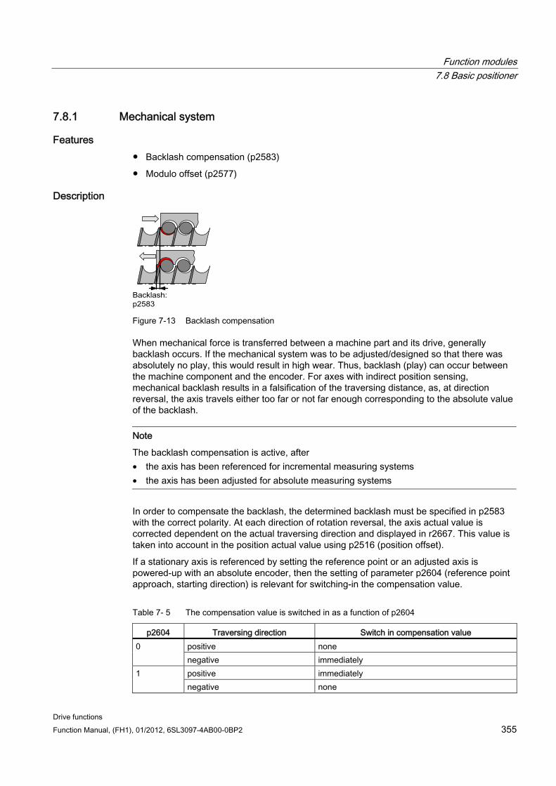
Function modules 7.8 Basic positioner
Drive functions Function Manual, (FH1), 01/2012, 6SL3097-4AB00-0BP2 355
7.8.1 Mechanical system
Features Backlash compensation (p2583)
Modulo offset (p2577)
Description
Figure 7-13 Backlash compensation
When mechanical force is transferred between a machine part and its drive, generally backlash occurs. If the mechanical system was to be adjusted/designed so that there was absolutely no play, this would result in high wear. Thus, backlash (play) can occur between the machine component and the encoder. For axes with indirect position sensing, mechanical backlash results in a falsification of the traversing distance, as, at direction reversal, the axis travels either too far or not far enough corresponding to the absolute value of the backlash.
Note
The backlash compensation is active, after • the axis has been referenced for incremental measuring systems • the axis has been adjusted for absolute measuring systems
In order to compensate the backlash, the determined backlash must be specified in p2583 with the correct polarity. At each direction of rotation reversal, the axis actual value is corrected dependent on the actual traversing direction and displayed in r2667. This value is taken into account in the position actual value using p2516 (position offset).
If a stationary axis is referenced by setting the reference point or an adjusted axis is powered-up with an absolute encoder, then the setting of parameter p2604 (reference point approach, starting direction) is relevant for switching-in the compensation value.
Table 7- 5 The compensation value is switched in as a function of p2604
p2604 Traversing direction Switch in compensation value positive none 0 negative immediately positive immediately 1 negative none
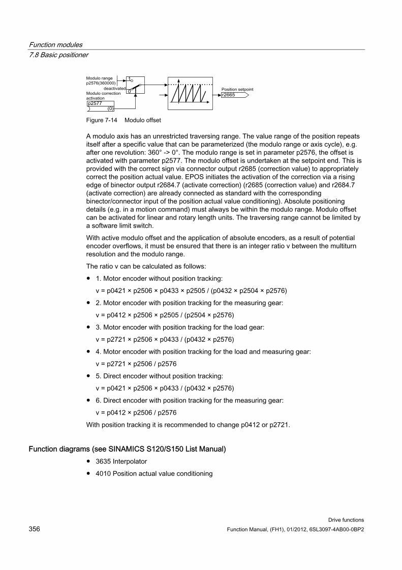
Function modules 7.8 Basic positioner
Drive functions 356 Function Manual, (FH1), 01/2012, 6SL3097-4AB00-0BP2
Figure 7-14 Modulo offset
A modulo axis has an unrestricted traversing range. The value range of the position repeats itself after a specific value that can be parameterized (the modulo range or axis cycle), e.g. after one revolution: 360° -> 0°. The modulo range is set in parameter p2576, the offset is activated with parameter p2577. The modulo offset is undertaken at the setpoint end. This is provided with the correct sign via connector output r2685 (correction value) to appropriately correct the position actual value. EPOS initiates the activation of the correction via a rising edge of binector output r2684.7 (activate correction) (r2685 (correction value) and r2684.7 (activate correction) are already connected as standard with the corresponding binector/connector input of the position actual value conditioning). Absolute positioning details (e.g. in a motion command) must always be within the modulo range. Modulo offset can be activated for linear and rotary length units. The traversing range cannot be limited by a software limit switch.
With active modulo offset and the application of absolute encoders, as a result of potential encoder overflows, it must be ensured that there is an integer ratio v between the multiturn resolution and the modulo range.
The ratio v can be calculated as follows:
1. Motor encoder without position tracking:
v = p0421 × p2506 × p0433 × p2505 / (p0432 × p2504 × p2576)
2. Motor encoder with position tracking for the measuring gear:
v = p0412 × p2506 × p2505 / (p2504 × p2576)
3. Motor encoder with position tracking for the load gear:
v = p2721 × p2506 × p0433 / (p0432 × p2576)
4. Motor encoder with position tracking for the load and measuring gear:
v = p2721 × p2506 / p2576
5. Direct encoder without position tracking:
v = p0421 × p2506 × p0433 / (p0432 × p2576)
6. Direct encoder with position tracking for the measuring gear:
v = p0412 × p2506 / p2576
With position tracking it is recommended to change p0412 or p2721.
Function diagrams (see SINAMICS S120/S150 List Manual) 3635 Interpolator
4010 Position actual value conditioning
Function modules 7.8 Basic positioner
Drive functions Function Manual, (FH1), 01/2012, 6SL3097-4AB00-0BP2 357
Overview of important parameters (see SINAMICS S120/S150 List Manual) p2576 EPOS modulo offset, modulo range
p2577 BI: EPOS modulo offset activation
p2583 EPOS backlash compensation
r2684 CO/BO: EPOS status word 2
r2685 CO: EPOS correction value
Commissioning with STARTER In STARTER, the mechanical system screen form can be found under position control.
7.8.2 Limits
Description The velocity, acceleration and deceleration can be limited and the software limit switches and STOP cams set.
Features Traversing profile limits
– Maximum velocity (p2571)
– Maximum acceleration (p2572) / maximum deceleration (p2573)
Traversing range limits
– Software limit switch (p2578, p2579, p2580, p2581, p2582)
– STOP cams (p2568, p2569, p2570)
Jerk limitation
– Jerk limitation (p2574)
– Activation of jerk limitation (p2575)
Maximum velocity The maximum velocity of an axis is defined using parameter p2571. The velocity should not be set to be greater than the maximum speeds in r1084 and r1087.
The drive is limited to this velocity if a higher velocity is specified or programmed via the override (p2646) for the reference point approach or is programmed in the traversing block.
Parameter p2571 (maximum velocity) defines the maximum traversing velocity in units 1000 LU/min. If the maximum velocity is changed, then this limits the velocity of a traversing task that is presently being executed.
Function modules 7.8 Basic positioner
Drive functions 358 Function Manual, (FH1), 01/2012, 6SL3097-4AB00-0BP2
This limit is only effective in the positioning mode for:
Jog mode
Processing traversing blocks
Direct setpoint input/MDI for positioning/setting-up
Reference point approach
Maximum acceleration/deceleration Parameter p2572 (maximum acceleration) and p2573 (maximum deceleration) define the maximum acceleration and the maximum deceleration. In both cases, the units are 1000 LU/s2.
Both values are relevant for:
Jog mode
Processing traversing blocks
Direct setpoint input/MDI for positioning and setting up
Reference point approach
The parameters do not have any effect when faults occur with the fault responses OFF1 / OFF2 / OFF3.
In the traversing blocks mode, the acceleration and deceleration can be set in multiple integer steps (1 %, 2 % ... 100 %) of the maximum acceleration and deceleration. In “direct setpoint input/MDI for positioning and setting up” operating mode, the acceleration/delay override (assignment of 4000 hex = 100%) is specified
Note
A maximum acceleration or deceleration dependent on the actual velocity (transitioned acceleration) is not supported.
Note
When using the PROFIdrive telegram 110, the velocity override is already connected and has to be supplied by the telegram.
Software limit switches The connector inputs p2578 (software limit switch minus) and p2579 (software limit switch plus) limit the position setpoint if the following prerequisites are fulfilled:
The software limit switches are activated (p2582 = "1")
The reference point is set (r2684.11 = 1)
The modulo correction is not active (p2577 = "0")
The connector inputs are, in the factory setting, linked to the connector output p2580 (software limit switch minus) and p2581 (software limit switch plus).
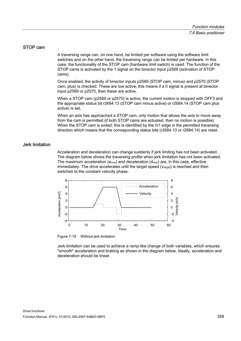
Function modules 7.8 Basic positioner
Drive functions Function Manual, (FH1), 01/2012, 6SL3097-4AB00-0BP2 359
STOP cam A traversing range can, on one hand, be limited per software using the software limit switches and on the other hand, the traversing range can be limited per hardware. In this case, the functionality of the STOP cam (hardware limit switch) is used. The function of the STOP cams is activated by the 1 signal on the binector input p2568 (activation of STOP cams).
Once enabled, the activity of binector inputs p2569 (STOP cam, minus) and p2570 (STOP cam, plus) is checked. These are low active; this means if a 0 signal is present at binector input p2569 or p2570, then these are active.
When a STOP cam (p2569 or p2570) is active, the current motion is stopped with OFF3 and the appropriate status bit r2684.13 (STOP cam minus active) or r2684.14 (STOP cam plus active) is set.
When an axis has approached a STOP cam, only motion that allows the axis to move away from the cam is permitted (if both STOP cams are actuated, then no motion is possible). When the STOP cam is exited, this is identified by the 0/1 edge in the permitted traversing direction which means that the corresponding status bits (r2684.13 or r2684.14) are reset.
Jerk limitation Acceleration and deceleration can change suddenly if jerk limiting has not been activated. The diagram below shows the traversing profile when jerk limitation has not been activated. The maximum acceleration (amax) and deceleration (dmax) are, in this case, effective immediately. The drive accelerates until the target speed (vtarget) is reached and then switches to the constant velocity phase.
Figure 7-15 Without jerk limitation
Jerk limitation can be used to achieve a ramp-like change of both variables, which ensures "smooth" acceleration and braking as shown in the diagram below. Ideally, acceleration and deceleration should be linear.
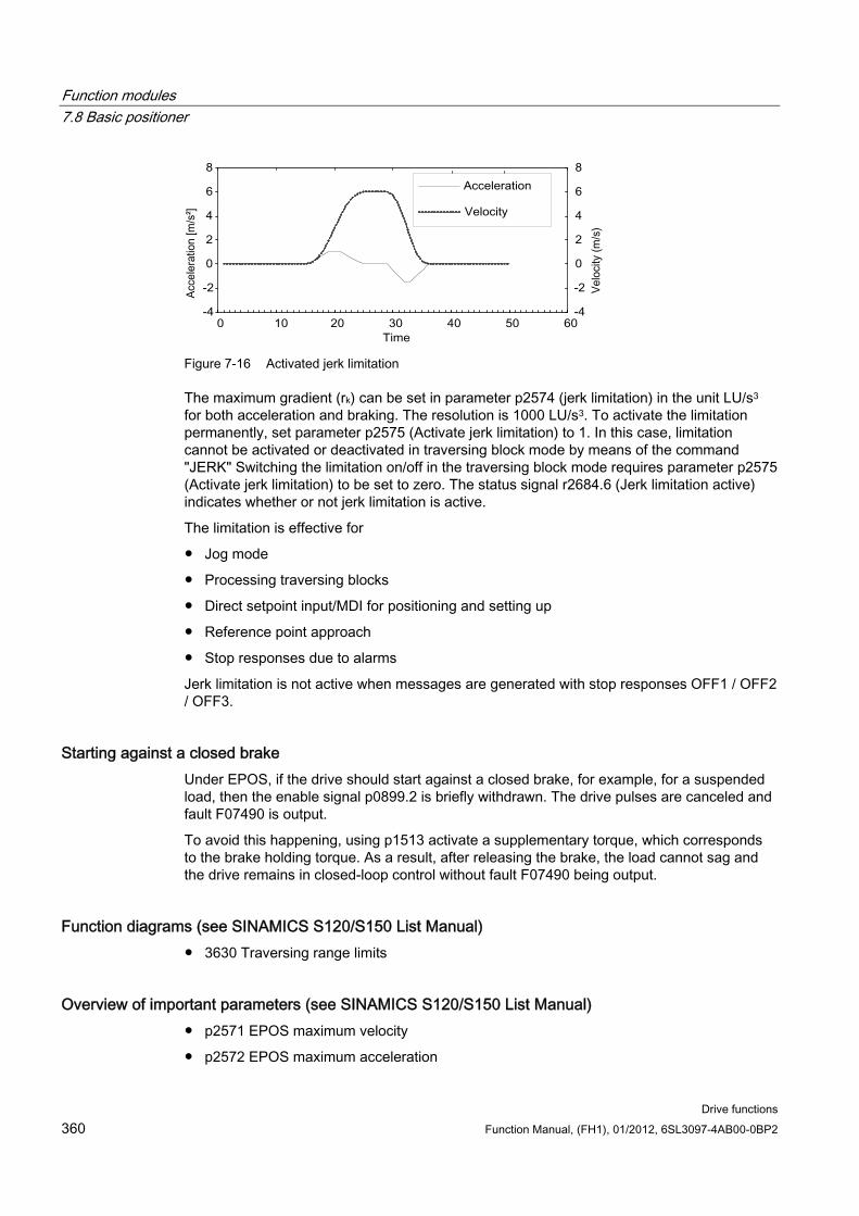
Function modules 7.8 Basic positioner
Drive functions 360 Function Manual, (FH1), 01/2012, 6SL3097-4AB00-0BP2
Figure 7-16 Activated jerk limitation
The maximum gradient (rk) can be set in parameter p2574 (jerk limitation) in the unit LU/s3 for both acceleration and braking. The resolution is 1000 LU/s3. To activate the limitation permanently, set parameter p2575 (Activate jerk limitation) to 1. In this case, limitation cannot be activated or deactivated in traversing block mode by means of the command "JERK" Switching the limitation on/off in the traversing block mode requires parameter p2575 (Activate jerk limitation) to be set to zero. The status signal r2684.6 (Jerk limitation active) indicates whether or not jerk limitation is active.
The limitation is effective for
Jog mode
Processing traversing blocks
Direct setpoint input/MDI for positioning and setting up
Reference point approach
Stop responses due to alarms
Jerk limitation is not active when messages are generated with stop responses OFF1 / OFF2 / OFF3.
Starting against a closed brake Under EPOS, if the drive should start against a closed brake, for example, for a suspended load, then the enable signal p0899.2 is briefly withdrawn. The drive pulses are canceled and fault F07490 is output.
To avoid this happening, using p1513 activate a supplementary torque, which corresponds to the brake holding torque. As a result, after releasing the brake, the load cannot sag and the drive remains in closed-loop control without fault F07490 being output.
Function diagrams (see SINAMICS S120/S150 List Manual) 3630 Traversing range limits
Overview of important parameters (see SINAMICS S120/S150 List Manual) p2571 EPOS maximum velocity
p2572 EPOS maximum acceleration
Function modules 7.8 Basic positioner
Drive functions Function Manual, (FH1), 01/2012, 6SL3097-4AB00-0BP2 361
p2573 EPOS maximum deceleration
p2646 CI: EPOS velocity override
Software limit switches
p2578 CI: EPOS software limit switch, minus signal source
p2579 CI: EPOS software limit switch, plus signal source
p2580 CO: EPOS software limit switch, minus
p2581 CO: EPOS software limit switch, plus
p2582 BI: EPOS software limit switch activation
r2683 CO/BO: EPOS status word 1
STOP cam
p2568 BI: EPOS STOP cam activation
p2569 BI: EPOS STOP cam, minus
p2570 BI: EPOS STOP cam, plus
r2684 CO/BO: EPOS status word 2
Jerk limitation
p2574 EPOS jerk limitation
p2575 BI: EPOS jerk limitation activation
7.8.3 EPOS and safe setpoint velocity limitation If safe speed monitoring (SLS) or the safe direction motion monitoring (SDI) is also to be used at the same time as the EPOS positioning function , EPOS must be informed about the activated monitoring limits. Otherwise these speed monitoring limits can be violated by the EPOS setpoint input. By monitoring the limit value, if violated, the drive is stopped therefore exiting the intended motion sequence. In this case, the relevant safety faults are output first, and then the sequential faults created by EPOS.
With parameters r9733.0 = p2594.1 and p9733.1 = p2594.2, the safety functions offer EPOS a setpoint limit value, which when taken into account, avoids the safety limit value from being violated.
This means that the setpoint limit value in r9733 must therefore be transferred to the input for the maximum setpoint speed/velocity of EPOS (p2594), to prevent a safety limit value violation as a result of the EPOS setpoint input. In this regard you must set the delay time for SLS/SOS/SDI (p9551/p9351), so that the relevant safety monitoring functions only become active after the maximum required time for the speed to be reduced below the limit. This required braking time is determined by the actual speed, the jerk limiting in p2574 and the maximum deceleration in p2573.
Further information can be found in the SINAMICS S120 Safety Integrated Function Manual.
Function modules 7.8 Basic positioner
Drive functions 362 Function Manual, (FH1), 01/2012, 6SL3097-4AB00-0BP2
7.8.4 Referencing
Features Reference point offset (p2600)
Reversing cams (p2613, p2614)
Reference cam (p2612)
Binector input start (p2595)
Binector input setting (p2596)
Velocity override (p2646)
Reference point coordinate (p2598, p2599)
Selecting the referencing type (p2597)
Absolute encoder adjustment (p2507)
NOTICE Referencing distance-coded zero marks is not supported.
Description After a machine has been powered up, for positioning, the absolute dimension reference must be established to the machine zero. This operation is known as referencing.
The following referencing types are possible:
Setting the reference point (all encoder types)
Incremental encoder Active referencing (reference point approach (p2597 = 0)):
– Reference cams and encoder zero mark (p2607 = 1)
– Encoder zero mark (p0495 = 0 or p0494 = 0)*)
– External zero mark (p0495 ≠ 0 or p0494 ≠ 0) *)
Flying referencing (passive (p2597 = 1))
Absolute encoder
– Absolute encoder adjustment
– Flying referencing (passive (p2597 = 1))
A connector input is provided for all referencing types to input the reference point coordinate; this allows, e.g. the change/input via the higher-level control. However, to permanently enter the reference point coordinate, an adjustable parameter for this quantity is also required. As standard, this adjustable parameter p2599 is interconnected to connector input p2598.
Function modules 7.8 Basic positioner
Drive functions Function Manual, (FH1), 01/2012, 6SL3097-4AB00-0BP2 363
Set reference point The reference point can be set using a 0/1 edge at binector input p2596 (set reference point) if no traversing commands are active and the actual position value is valid (p2658 = 1 signal). A reference point can also be set for an intermediate stop.
The current actual position of the drive is set here as the reference point using the coordinates specified by connector input p2598 (reference point coordinates). The setpoint (r2665) is adjusted accordingly.
This function also uses actual position value correction for the position controller (p2512 and p2513). Connector input p2598 is connected to adjustable parameter p2599 as standard. The binector input is not effective for the traversing task being presently executed.
Absolute encoder adjustment Absolute encoders must be adjusted while commissioning. After the machine has been powered-down the position information of the encoder is kept.
When p2507 = 2 is entered, using the reference point coordinate in p2599, an offset value (p2525) is determined. This is used to calculate the position actual value (r2521). Parameter p2507 signals the adjustment with a "3" - in addition bit r2684.11 (reference point set) is set to "1".
The offset of the encoder adjustment (p2525) should be saved in a non-volatile fashion (RAM to ROM) to permanently save it.
Note
If an adjustment is lost for an already adjusted axis, the axis will remain unadjusted even after a POWER ON of the drive unit. The axis needs to be adjusted again in such cases.
CAUTION During adjustment with the rotary absolute encoder, a range is aligned symmetrically around the zero point with half the encoder range within which the position is restored after switch off/on. If position tracking is deactivated (2720.0 = 0), only one encoder overflow is permitted to occur in this range (further details are given in chapter Position controller → Position actual value conditioning). Once adjustment has been carried out, the range must not be exited because a unique reference between the actual encoder value and the mechanical components cannot be established outside the range.
If the reference point p2599 is in the encoder range, the actual position value is set in line with the reference point during adjustment. Otherwise, it is set to a corrected value in the encoder range.
No overflow occurs with linear absolute encoders, which means that the position can be restored within the entire traversing range after switch on/off once adjustment has been carried out. During adjustment, the actual position value is set in line with the reference point.
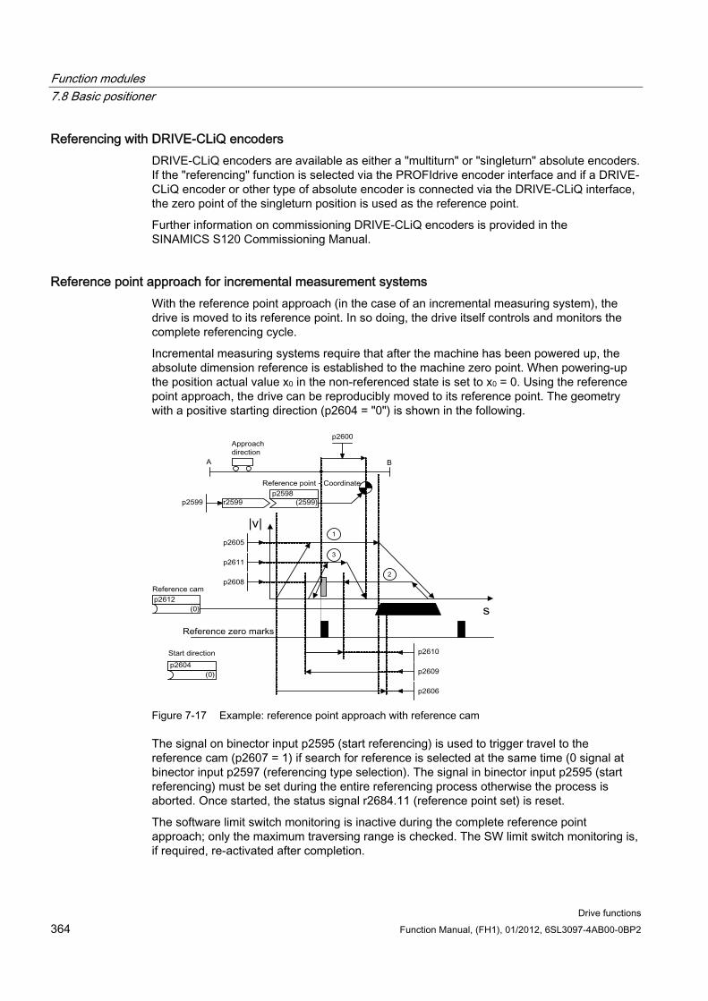
Function modules 7.8 Basic positioner
Drive functions 364 Function Manual, (FH1), 01/2012, 6SL3097-4AB00-0BP2
Referencing with DRIVE-CLiQ encoders DRIVE-CLiQ encoders are available as either a "multiturn" or "singleturn" absolute encoders. If the "referencing" function is selected via the PROFIdrive encoder interface and if a DRIVE-CLiQ encoder or other type of absolute encoder is connected via the DRIVE-CLiQ interface, the zero point of the singleturn position is used as the reference point.
Further information on commissioning DRIVE-CLiQ encoders is provided in the SINAMICS S120 Commissioning Manual.
Reference point approach for incremental measurement systems With the reference point approach (in the case of an incremental measuring system), the drive is moved to its reference point. In so doing, the drive itself controls and monitors the complete referencing cycle.
Incremental measuring systems require that after the machine has been powered up, the absolute dimension reference is established to the machine zero point. When powering-up the position actual value x0 in the non-referenced state is set to x0 = 0. Using the reference point approach, the drive can be reproducibly moved to its reference point. The geometry with a positive starting direction (p2604 = "0") is shown in the following.
Figure 7-17 Example: reference point approach with reference cam
The signal on binector input p2595 (start referencing) is used to trigger travel to the reference cam (p2607 = 1) if search for reference is selected at the same time (0 signal at binector input p2597 (referencing type selection). The signal in binector input p2595 (start referencing) must be set during the entire referencing process otherwise the process is aborted. Once started, the status signal r2684.11 (reference point set) is reset.
The software limit switch monitoring is inactive during the complete reference point approach; only the maximum traversing range is checked. The SW limit switch monitoring is, if required, re-activated after completion.
Function modules 7.8 Basic positioner
Drive functions Function Manual, (FH1), 01/2012, 6SL3097-4AB00-0BP2 365
The velocity override set is only effective during the search for the reference cam (step 1). This ensures that the "cam end" and "zero mark" positions are always overrun at the same speed. If signal propagation delays arise during switching processes, this ensures that the offset caused during establishment of position is the same in each referencing process.
Axes that only have one zero mark over their complete traversing or modulo range are designated with parameter p2607 = 0 (no reference cam present). After starting the referencing process, synchronization to the reference zero marks is started straight away (see step 2) for these axes.
Step 1: travel to reference cam
If there is no reference cam present (p2607 = 0), go to step 2.
When the referencing process is started, the drive accelerates at maximum acceleration (p2572) to the reference cam approach velocity (p2605). The direction of the approach is determined by the signal of binector input p2604 (search for reference start direction).
When the reference cam is reached, this is communicated to the drive using the signal at binector input p2612 (reference cam); the drive then brakes down to standstill with the maximum deceleration (p2573).
If a signal at binector input p2613 (reversing cam, MINUS) or at binector input p2614 (reversing cam, PLUS) is detected during reference point approach, the search direction is reversed.
If the minus reversing cam is approached in the positive direction of travel or the plus reversing cam in the negative direction of travel, fault F07499 (EPOS: reversing cam approached with the incorrect traversing direction) is output. In this case, the wiring of the reversing cams (BI: p2613, BI: p2614) or the direction of approach to the reversing cam must be checked.
The reversing cams are low active. If both reversing cams are active (p2613 = "0" and p2614 = "0"), the drive remains stationary. As soon as the reference cam is found, then synchronization to the reference zero mark is immediately started (refer to step 2).
If the axis leaves its start position and travels the distance defined in parameter p2606 (max. distance to reference cam) heading towards the reference cam without actually reaching the reference cam, the drive remains stationary and fault F07458 (reference cam not found) is issued.
Function modules 7.8 Basic positioner
Drive functions 366 Function Manual, (FH1), 01/2012, 6SL3097-4AB00-0BP2
If the axis is already located at the cam, when referencing is started, then traversing to the reference cam is not executed, but synchronization to the reference zero mark is immediately started (refer to step 2).
Note
The velocity override is effective during the search for the cam. By changing the encoder data set, status signal r2684.11 (reference point set) is reset.
The cam switch must be able to delivery both a rising and a falling edge. For a reference point approach with evaluation of the encoder zero mark, for increasing position actual values the 0/1 edge is evaluated and for decreasing position actual values, the 1/0 edge. Inversion of the edge evaluation is not possible at the sensor zero mark.
If the length measuring system has several zero marks which repeat at cyclic intervals (e.g. incremental, rotary measuring system), you must ensure that the cam is adjusted so that the same zero mark is always evaluated.
The following factors may impact the behavior of the "reference cam" control signal: • Switching accuracy and time delay of reference cam switch • Position controller cycle of drive • Interpolation cycle of drive • Temperature sensitivity of machine’s mechanical system
Step 2: Synchronizing to the reference zero mark (encoder zero mark or external zero mark)
Reference cam available (p2607 = 1):
In step 2, the drive accelerates to the velocity specified in p2608 (zero mark approach velocity) in the direction opposite to that specified using binector input p2604 (reference point approach start direction). The zero mark is expected at distance p2609 (max. distance to zero mark). The search for the zero mark is active (status bit r2684.0 = "1" (search for reference active)) as soon as the drive leaves the cam (p2612 = "0") and is within the tolerance band for evaluation (p2609 - p2610). If the position of the zero mark is known (encoder evaluation), the actual position of the drive can be synchronized using the zero mark. The drive starts the search for reference (see step 3). The distance moved between the end of the cam and the zero mark is displayed in diagnostics parameter r2680 (difference between the cam - zero mark).
Function modules 7.8 Basic positioner
Drive functions Function Manual, (FH1), 01/2012, 6SL3097-4AB00-0BP2 367
Encoder zero mark available (p0494 = 0 or p0495 = 0) *), no reference cams (p2607 = 0):
Synchronization to the reference zero mark begins as soon as the signal at binector input p2595 (start referencing) is detected. The drive accelerates to the velocity, specified in parameter p2608 (zero mark approach velocity) in the direction specified by the signal of binector input p2604 (reference point approach start direction).
The drive synchronizes to the first zero mark and then starts to travel towards the reference point (see step 3).
Note
In this case the direction of approach to the reference zero mark is the opposite to the axes with reference cams!
External zero mark available (p0494 ≠ 0 or p0495 ≠ 0) *), no reference cams (p2607 = 0):
Synchronization to an external zero mark begins as soon as the signal at binector input p2595 (start referencing) is detected. The drive accelerates to the velocity, specified in parameter p2608 (zero mark approach velocity) in the direction specified by the signal of binector input p2604 (reference point approach start direction). The drive synchronizes to the first external zero mark (p0494 or p0495) *). The drive continues to travel with the same velocity and travel is started to the reference point (refer to step 3).
Note
The velocity override is inoperative during this process.
An equivalent zero mark can be set and the corresponding digital input selected using parameters p0494 or p0495 *) (equivalent zero mark input terminal). As standard, for increasing actual position values, the 0/1 edge is evaluated and for decreasing position actual values, the 1/0 edge. For the equivalent zero mark, this can be inverted using parameter p0490 (invert measuring probe or equivalent zero mark).
Step 3: Travel to reference point
Travel to the reference point is started when the drive has successfully synchronized to the reference zero mark (see step 2). Once the reference zero mark has been detected, the drive accelerates on-the-fly to the reference point approach velocity set in parameter p2611. The drive moves through the reference point offset (p2600), i.e. the distance between the zero mark and reference point.
If the axis has reached the reference point, then the position actual value and setpoint are set to the value specified using connector input p2598 (reference point coordinate) (as standard, connector input p2598 is connected with adjustable parameter p2599). The axis is then homed and the status signal r2684.11 (reference point set) set.
Note
The velocity override is inoperative during this process.
If the braking distance is longer than the reference point offset or a direction reversal is required as a result of the selected reference point offset, then after detecting the reference zero mark, the drive initially brakes to standstill and then travels back.
Function modules 7.8 Basic positioner
Drive functions 368 Function Manual, (FH1), 01/2012, 6SL3097-4AB00-0BP2
Flying referencing Inaccuracies in the actual value acquisition are compensated with flying referencing. This increases the load-side positioning accuracy.
The mode "flying referencing" (also known as post-referencing, positioning monitoring), which is selected using a "1" signal at binector input p2597 (select referencing type), can be used in every mode (jog, traversing block and direct setpoint input for positioning/setting-up) and is superimposed on the currently active mode. Flying referencing can be selected both with incremental and absolute measuring systems.
With "flying referencing" during incremental positioning (relative) you can select whether the offset value is to be taken into account for the travel path or not (p2603).
The "flying referencing" is activated by a 0/1 edge at binector input p2595 (start referencing). The signal in binector input p2595 (start referencing) must be set during the entire referencing process otherwise the process is aborted.
Status bit r2684.1 (passive/flying referencing active) is linked with binector input p2509 (activate measurement probe evaluation). It activates measurement probe evaluation. Binector inputs p2510 (measurement probe selection) and p2511 (measurement probe edge evaluation) can be used to set which measurement probe (1 or 2) and which measurement edge (0/1 or 1/0) is to be used.
The measurement probe pulse is used to supply connector input p2660 (home measurement value) with the measurement via parameter r2523. The validity of the measurement is reported to binector input p2661 (measurement valid feedback) via r2526.2.
Note
The following must always apply to the "Flying referencing mode" windows:
p2602 (outer window) > p2601 (inner window).
See function diagram 3614 for more information on the "Flying referencing mode" function.
The following then happens:
If the drive has not yet been homed, status bit r2684.11 (reference point set) is set to "1".
If the drive has already been homed, status bit r2684.11 (reference point set) is not reset when starting flying referencing.
If the drive has already been homed and the position difference is less than the inner window (p2601), the old actual position value is retained.
Function modules 7.8 Basic positioner
Drive functions Function Manual, (FH1), 01/2012, 6SL3097-4AB00-0BP2 369
If the drive has already been homed and the position difference is more than the outer window (p2602), alarm A07489 (reference point offset outside window 2) is output and the status bit r2684.3 (pressure mark outside window 2) set. No offset to the actual position value is undertaken.
If the drive has already been referenced and the position difference is more than the inner window (p2601) and less that the outer window (p2602), the actual position value is offset.
Note
On-the-fly referencing is superimposed on an active operating mode, it is therefore not an active mode.
In contrast to searches for reference, flying referencing can be carried out superimposed by the machine process.
As standard, for flying referencing, measuring probe evaluation is used; when enabled, the measuring probe is selected (p2510) and the edge evaluation (p2511) (in the factory setting, measuring probe 1 is always the measuring probe, flank evaluation in the factory setting is always the 0/1 edge).
Instructions for data set changeover Using drive data set changeover (DDS), motor data sets (MDS, p0186) and encoder data sets (EDS, p0187 to p0189) can be changed over. The following table shows when the reference bit (r2684.11) or the status of the adjustment with absolute encoders (p2507) is reset.
In the following cases, when a DDS switch takes place, the current actual position value becomes invalid (p2521 = 0) and the reference point (r2684.11 = 0) is reset.
The EDS that is effective for the position control changes.
The encoder assignment changes (p2502).
The mechanical relationships change (p2503...p2506)
With absolute encoders, the status of the adjustment (p2507) is also reset, if the same absolute encoder is selected for the position control although the mechanical relationships have changed (p2503 ... p2506).
In operating mode, a fault (F07494) is also output.
The following table contains a few examples for data set changeover. The initial data set is always DDS0.
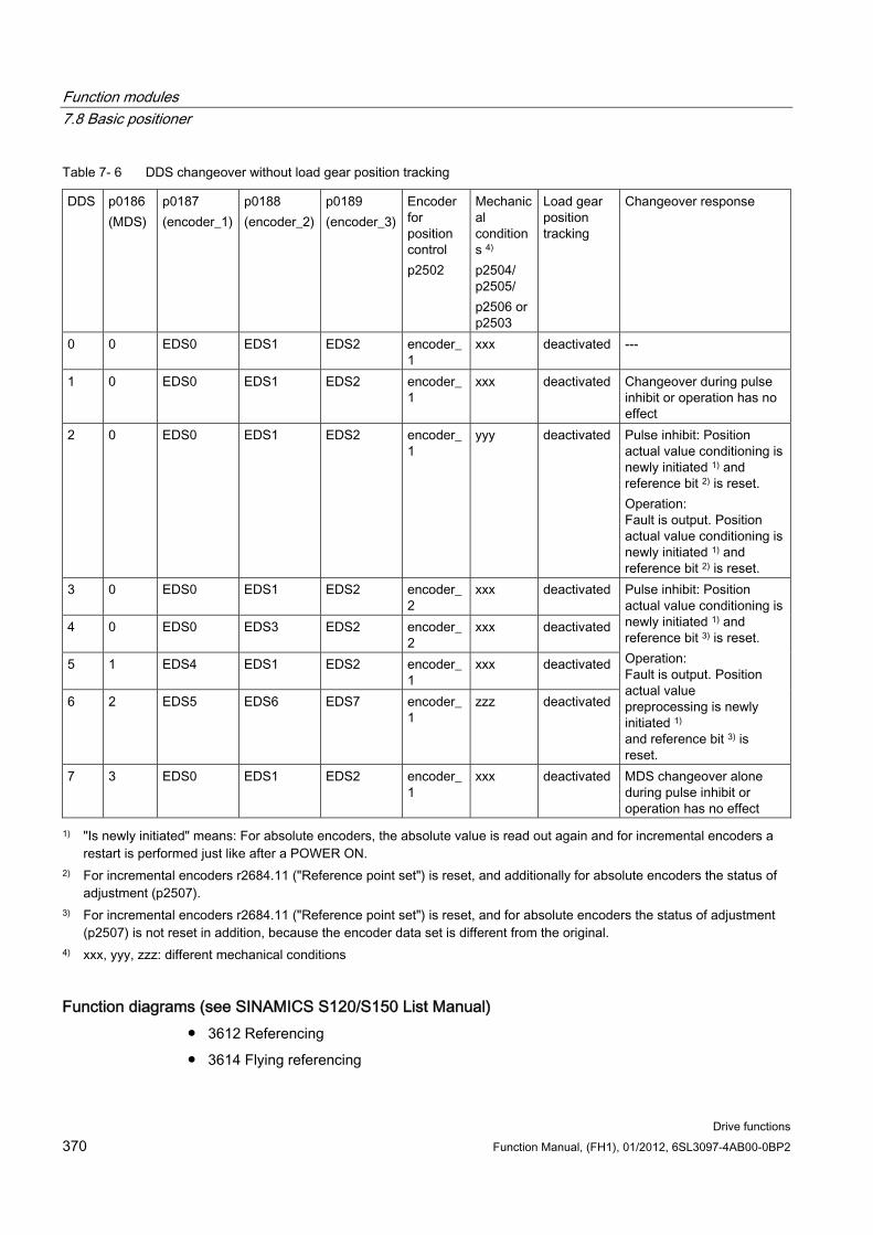
Function modules 7.8 Basic positioner
Drive functions 370 Function Manual, (FH1), 01/2012, 6SL3097-4AB00-0BP2
Table 7- 6 DDS changeover without load gear position tracking
DDS p0186 (MDS)
p0187 (encoder_1)
p0188 (encoder_2)
p0189 (encoder_3)
Encoder for position control p2502
Mechanical conditions 4) p2504/ p2505/ p2506 or p2503
Load gear position tracking
Changeover response
0 0 EDS0 EDS1 EDS2 encoder_1
xxx deactivated ---
1 0 EDS0 EDS1 EDS2 encoder_1
xxx deactivated Changeover during pulse inhibit or operation has no effect
2 0 EDS0 EDS1 EDS2 encoder_1
yyy deactivated Pulse inhibit: Position actual value conditioning is newly initiated 1) and reference bit 2) is reset. Operation: Fault is output. Position actual value conditioning is newly initiated 1) and reference bit 2) is reset.
3 0 EDS0 EDS1 EDS2 encoder_2
xxx deactivated
4 0 EDS0 EDS3 EDS2 encoder_2
xxx deactivated
5 1 EDS4 EDS1 EDS2 encoder_1
xxx deactivated
6 2 EDS5 EDS6 EDS7 encoder_1
zzz deactivated
Pulse inhibit: Position actual value conditioning is newly initiated 1) and reference bit 3) is reset. Operation: Fault is output. Position actual value preprocessing is newly initiated 1) and reference bit 3) is reset.
7 3 EDS0 EDS1 EDS2 encoder_1
xxx deactivated MDS changeover alone during pulse inhibit or operation has no effect
1) "Is newly initiated" means: For absolute encoders, the absolute value is read out again and for incremental encoders a restart is performed just like after a POWER ON.
2) For incremental encoders r2684.11 ("Reference point set") is reset, and additionally for absolute encoders the status of adjustment (p2507).
3) For incremental encoders r2684.11 ("Reference point set") is reset, and for absolute encoders the status of adjustment (p2507) is not reset in addition, because the encoder data set is different from the original.
4) xxx, yyy, zzz: different mechanical conditions
Function diagrams (see SINAMICS S120/S150 List Manual) 3612 Referencing
3614 Flying referencing
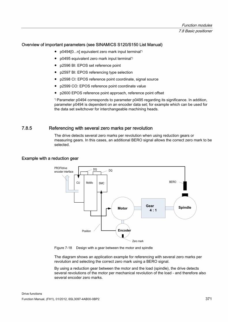
Function modules 7.8 Basic positioner
Drive functions Function Manual, (FH1), 01/2012, 6SL3097-4AB00-0BP2 371
Overview of important parameters (see SINAMICS S120/S150 List Manual) p0494[0...n] equivalent zero mark input terminal*)
p0495 equivalent zero mark input terminal*)
p2596 BI: EPOS set reference point
p2597 BI: EPOS referencing type selection
p2598 CI: EPOS reference point coordinate, signal source
p2599 CO: EPOS reference point coordinate value
p2600 EPOS reference point approach, reference point offset *) Parameter p0494 corresponds to parameter p0495 regarding its significance. In addition, parameter p0494 is dependent on an encoder data set; for example which can be used for the data set switchover for interchangeable machining heads.
7.8.5 Referencing with several zero marks per revolution The drive detects several zero marks per revolution when using reduction gears or measuring gears. In this cases, an additional BERO signal allows the correct zero mark to be selected.
Example with a reduction gear
Gear4 : 1
Spindle
CU MoMo SMC
Encoder
Motor
Position
BERO
Zero mark
DQ DQPROFIdriveencoder interface
Figure 7-18 Design with a gear between the motor and spindle
The diagram shows an application example for referencing with several zero marks per revolution and selecting the correct zero mark using a BERO signal.
By using a reduction gear between the motor and the load (spindle), the drive detects several revolutions of the motor per mechanical revolution of the load - and therefore also several encoder zero marks.
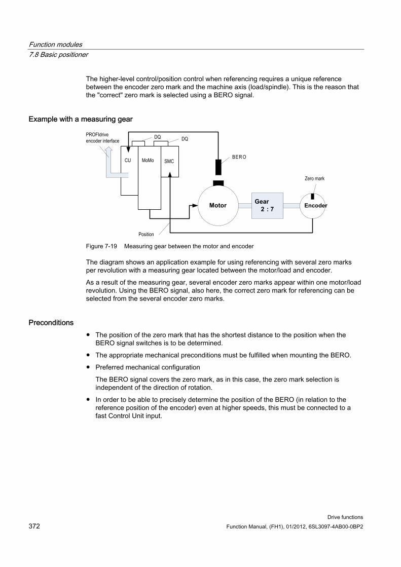
Function modules 7.8 Basic positioner
Drive functions 372 Function Manual, (FH1), 01/2012, 6SL3097-4AB00-0BP2
The higher-level control/position control when referencing requires a unique reference between the encoder zero mark and the machine axis (load/spindle). This is the reason that the "correct" zero mark is selected using a BERO signal.
Example with a measuring gear
Gear2 : 7Motor
CU MoMo SMC
Position
DQ DQPROFIdriveencoder interface
Encoder
Zero mark
BER O
Figure 7-19 Measuring gear between the motor and encoder
The diagram shows an application example for using referencing with several zero marks per revolution with a measuring gear located between the motor/load and encoder.
As a result of the measuring gear, several encoder zero marks appear within one motor/load revolution. Using the BERO signal, also here, the correct zero mark for referencing can be selected from the several encoder zero marks.
Preconditions The position of the zero mark that has the shortest distance to the position when the
BERO signal switches is to be determined.
The appropriate mechanical preconditions must be fulfilled when mounting the BERO.
Preferred mechanical configuration
The BERO signal covers the zero mark, as in this case, the zero mark selection is independent of the direction of rotation.
In order to be able to precisely determine the position of the BERO (in relation to the reference position of the encoder) even at higher speeds, this must be connected to a fast Control Unit input.
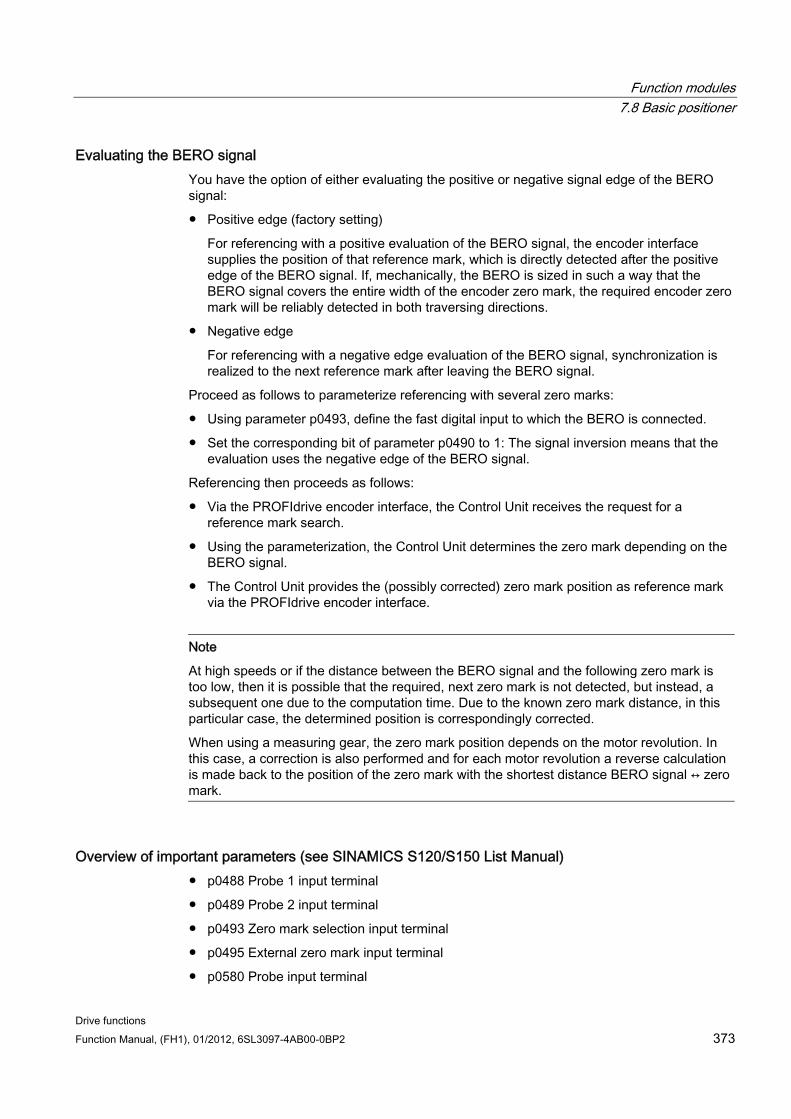
Function modules 7.8 Basic positioner
Drive functions Function Manual, (FH1), 01/2012, 6SL3097-4AB00-0BP2 373
Evaluating the BERO signal You have the option of either evaluating the positive or negative signal edge of the BERO signal:
Positive edge (factory setting)
For referencing with a positive evaluation of the BERO signal, the encoder interface supplies the position of that reference mark, which is directly detected after the positive edge of the BERO signal. If, mechanically, the BERO is sized in such a way that the BERO signal covers the entire width of the encoder zero mark, the required encoder zero mark will be reliably detected in both traversing directions.
Negative edge
For referencing with a negative edge evaluation of the BERO signal, synchronization is realized to the next reference mark after leaving the BERO signal.
Proceed as follows to parameterize referencing with several zero marks:
Using parameter p0493, define the fast digital input to which the BERO is connected.
Set the corresponding bit of parameter p0490 to 1: The signal inversion means that the evaluation uses the negative edge of the BERO signal.
Referencing then proceeds as follows:
Via the PROFIdrive encoder interface, the Control Unit receives the request for a reference mark search.
Using the parameterization, the Control Unit determines the zero mark depending on the BERO signal.
The Control Unit provides the (possibly corrected) zero mark position as reference mark via the PROFIdrive encoder interface.
Note
At high speeds or if the distance between the BERO signal and the following zero mark is too low, then it is possible that the required, next zero mark is not detected, but instead, a subsequent one due to the computation time. Due to the known zero mark distance, in this particular case, the determined position is correspondingly corrected.
When using a measuring gear, the zero mark position depends on the motor revolution. In this case, a correction is also performed and for each motor revolution a reverse calculation is made back to the position of the zero mark with the shortest distance BERO signal ↔ zero mark.
Overview of important parameters (see SINAMICS S120/S150 List Manual) p0488 Probe 1 input terminal
p0489 Probe 2 input terminal
p0493 Zero mark selection input terminal
p0495 External zero mark input terminal
p0580 Probe input terminal
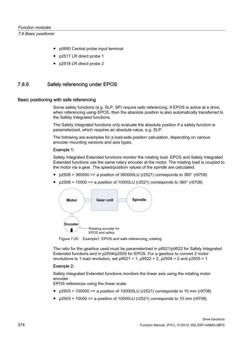
Function modules 7.8 Basic positioner
Drive functions 374 Function Manual, (FH1), 01/2012, 6SL3097-4AB00-0BP2
p0680 Central probe input terminal
p2517 LR direct probe 1
p2518 LR direct probe 2
7.8.6 Safely referencing under EPOS
Basic positioning with safe referencing Some safety functions (e.g. SLP, SP) require safe referencing. If EPOS is active at a drive, when referencing using EPOS, then the absolute position is also automatically transferred to the Safety Integrated functions.
The Safety Integrated functions only evaluate the absolute position if a safety function is parameterized, which requires an absolute value, e.g. SLP.
The following are examples for a load-side position calculation, depending on various encoder mounting versions and axis types.
Example 1:
Safety Integrated Extended functions monitor the rotating load. EPOS and Safety Integrated Extended functions use the same rotary encoder at the motor. The rotating load is coupled to the motor via a gear. The speed/position values of the spindle are calculated.
p2506 = 360000 => a position of 360000LU (r2521) corresponds to 360° (r9708)
p2506 = 10000 => a position of 10000LU (r2521) corresponds to 360° (r9708)
SpindleGear unitMotor
Encoder
Figure 7-20 Example1: EPOS and safe referencing_rotating
The ratio for the gearbox used must be parameterized in p9521/p9522 for Safety Integrated Extended functions and in p2504/p2505 for EPOS. For a gearbox to convert 2 motor revolutions to 1 load revolution, set p9521 = 1, p9522 = 2, p2504 = 2 and p2505 = 1.
Example 2:
Safety Integrated Extended functions monitors the linear axis using the rotating motor encoder. EPOS references using the linear scale.
p2503 = 100000 => a position of 100000LU (r2521) corresponds to 10 mm (r9708)
p2503 = 10000 => a position of 10000LU (r2521) corresponds to 10 mm (r9708)
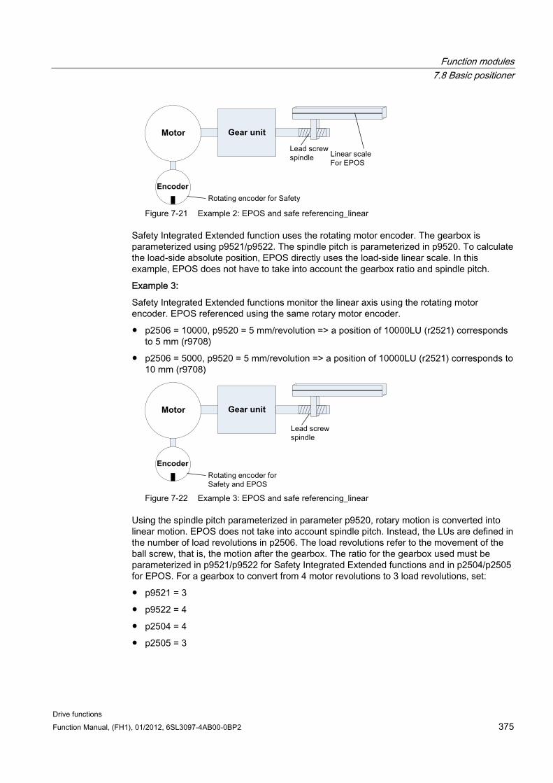
Function modules 7.8 Basic positioner
Drive functions Function Manual, (FH1), 01/2012, 6SL3097-4AB00-0BP2 375
Gear unitMotor
Encoder
Figure 7-21 Example 2: EPOS and safe referencing_linear
Safety Integrated Extended function uses the rotating motor encoder. The gearbox is parameterized using p9521/p9522. The spindle pitch is parameterized in p9520. To calculate the load-side absolute position, EPOS directly uses the load-side linear scale. In this example, EPOS does not have to take into account the gearbox ratio and spindle pitch.
Example 3:
Safety Integrated Extended functions monitor the linear axis using the rotating motor encoder. EPOS referenced using the same rotary motor encoder.
p2506 = 10000, p9520 = 5 mm/revolution => a position of 10000LU (r2521) corresponds to 5 mm (r9708)
p2506 = 5000, p9520 = 5 mm/revolution => a position of 10000LU (r2521) corresponds to 10 mm (r9708)
Gear unitMotor
Encoder
Figure 7-22 Example 3: EPOS and safe referencing_linear
Using the spindle pitch parameterized in parameter p9520, rotary motion is converted into linear motion. EPOS does not take into account spindle pitch. Instead, the LUs are defined in the number of load revolutions in p2506. The load revolutions refer to the movement of the ball screw, that is, the motion after the gearbox. The ratio for the gearbox used must be parameterized in p9521/p9522 for Safety Integrated Extended functions and in p2504/p2505 for EPOS. For a gearbox to convert from 4 motor revolutions to 3 load revolutions, set:
p9521 = 3
p9522 = 4
p2504 = 4
p2505 = 3
Function modules 7.8 Basic positioner
Drive functions 376 Function Manual, (FH1), 01/2012, 6SL3097-4AB00-0BP2
Flying referencing using Safety Integrated Extended functions Flying referencing is frequently used to compensate for any inaccuracies in the actual value sensing, and therefore to optimize positioning accuracy on the load side. The Safety Integrated Extended functions have lower accuracy requirements than the control. For Safety Integrated Extended functions, cyclic adjustment is not necessary.
The initial activation signal initiates referencing. If, at the next switching signal, it is detected that the "referenced" state already exists, then no new reference position is transferred to Safety Integrated functions.
7.8.7 Traversing blocks
Description Up to 64 different traversing tasks can be saved. The maximum number is set using parameter p2615 (maximum number of traversing tasks). All parameters which describe a traversing order are effective during a block change, i.e. if:
The appropriate traversing block number is selected using binector inputs p2625 to p2630 (block selection, bits 0...5) and started using the signal at binector input p2531 (activate traversing task).
A block change is made in a sequence of traversing tasks.
An external block change p2632 "External block change" is triggered.
Traversing blocks are parameterized using parameter sets that have a fixed structure:
Traversing block number (p2616[0...63]) Every traversing block must be assigned a traversing block number (in STARTER "No."). The traversing blocks are executed in the sequence of the traversing block numbers. Numbers containing the value "-1" are ignored so that the space can be reserved for subsequent traversing blocks, for example.
Task (p2621[0...63]) 1: POSITIONING 2: FIXED ENDSTOP 3: ENDLESS_POS 4: ENDLESS_NEG 5: WAIT 6: GOTO 7: SET_O 8: RESET_O 9: JERK
Motion parameters
– Target position or traversing distance (p2617[0...63])
– Velocity (p2618[0...63])
– Acceleration override (p2619[0...63])
– Deceleration override (p2620[0...63])
Function modules 7.8 Basic positioner
Drive functions Function Manual, (FH1), 01/2012, 6SL3097-4AB00-0BP2 377
Task mode (p2623[0...63]) The execution of a traversing task can be influenced by parameter p2623 (task mode). This is automatically written by programming the traversing blocks in STARTER. Value = 0000 cccc bbbb aaaa
– aaaa: Identifiers 000x → hide/show block (x = 0: show, x = 1: hide) A hidden block cannot be selected binary-coded via binector inputs p2625 to p2630. An alarm is output if you attempt to do so.
– bbbb: Continuation condition 0000, END: 0/1 edge at p2631 0001, CONTINUE_WITH_STOP: The exact position parameterized in the block is approached (brake to standstill and positioning window monitoring) before block processing can continue. 0010, CONTINUE_ON-THE-FLY: The system switches to the next traversing block "on the fly" when the braking point for the current block is reached (if the direction needs to be changed, this does not occur until the drive stops within the positioning window). 0011, CONTINUE_EXTERNAL: Same as "CONTINUE_ON-THE-FLY", except that an instant block change can be triggered up to the braking point by a 0/1 edge. The 0/1 edge can be triggered via the binector input p2633 when p2632 = 1 or via the measuring probe input p2661, which is connected to parameter r2526.2 of the "position control" function module, when p2632 = 0. Position detection via the measuring input can be used as an accurate starting position for relative positioning. If an external block change is not triggered, a block change is triggered at the braking point. 0100, CONTINUE_EXTERNAL_WAIT Control signal "External block change" can be used to trigger a flying changeover to the next task at any time during the traveling phase. If "External block change" is not triggered, the axis remains in the parameterized target position until the signal is issued. The difference here is that with CONTINUE_EXTERNAL, a flying changeover is carried out at the braking point if "External block change" has not been triggered, while here the drive waits for the signal in the target position. 0101, CONTINUE_EXTERNAL_ALARM This is the same as CONTINUE_EXTERNAL_WAIT, except that alarm A07463 "External traversing block change in traversing block x not requested" is output when "External block change" is not triggered by the time the drive comes to a standstill. The alarm can be converted to a fault with a stop response so that block processing can be canceled if the control signal is not issued.
– cccc: positioning mode With the POSITON task (p2621 = 1), defines how the position specified in the traversing task is to be approached. 0000, ABSOLUTE: The position specified in p2617 is approached. 0001, RELATIVE: The axis is traveled along the value specified in p2617. 0010, ABS_POS: For rotary axes with modulo offset only. The position specified in p2617 is approached in a positive direction. 0011, ABS_NEG: For rotary axes with modulo offset only. The position specified in p2617 is approached in a negative direction.
Function modules 7.8 Basic positioner
Drive functions 378 Function Manual, (FH1), 01/2012, 6SL3097-4AB00-0BP2
Task parameter (command-dependent significance) (p2622[0...63])
Intermediate stop and reject traversing task The intermediate stop is activated by a 0 signal at p2640. After activation, the system brakes with the parameterized deceleration value (p2620 or p2645).
The current traversing task can be canceled by a 0 signal at p2641. After activation, the system brakes with the maximum deceleration (p2573).
The "intermediate stop" and "cancel traversing task" functions are only effective in the modes "traversing blocks" and "direct setpoint input/MDI".
POSITIONING The POSITIONING task initiates motion. The following parameters are evaluated:
p2616[x] Block number
p2617[x] Position
p2618[x] Velocity
p2619[x] Acceleration override
p2620[x] Acceleration override
p2623[x] Task mode
The task is executed until the target position is reached. If, when the task is activated, the drive is already located at the target position, then for the block change enable (CONTINUE_ON-THE-FLY or CONTINUE_EXTERNAL, the text task is selected in the same interpolation clock cycle. For CONTINUE_WITH_STOP, the next block is activated in the next interpolation clock cycle. CONTINUE_EXTERNAL_ALARM causes a message to be output immediately.
FIXED STOP The FIXED STOP task triggers a traversing movement with reduced torque to fixed stop.
The following parameters are relevant:
p2616[x] Block number
p2617[x] Position
p2618[x] Velocity
p2619[x] Acceleration override
p2620[x] Acceleration override
p2623[x] Task mode
p2622[x] Task parameter clamping torque [0.01 Nm] with rotary motors or clamping force in [0.01 N] with linear motors.
Possible continuation conditions include END, CONTINUE_WITH_STOP, CONTINUE_EXTERNAL, CONTINUE_EXTERNAL_WAIT.
Function modules 7.8 Basic positioner
Drive functions Function Manual, (FH1), 01/2012, 6SL3097-4AB00-0BP2 379
ENDLESS POS, ENDLESS NEG Using these tasks, the axis is accelerated to the specified velocity and is moved, until:
A software limit switch is reached.
A STOP cam signal has been issued.
The traversing range limit is reached.
Motion is interrupted by the control signal "no intermediate stop/intermediate stop (p2640).
Motion is interrupted by the control signal "do not reject traversing task/reject traversing task" (p2641).
An external block change is triggered (with the appropriate continuation condition).
The following parameters are relevant:
p2616[x] Block number
p2618[x] Velocity
p2619[x] Acceleration override
p2623[x] Task mode
All continuation conditions are possible.
JERK Jerk limitation can be activated (command parameter = 1) or deactivated (task parameter = 0) by means of the JERK task. The signal at the binector input p2575 "Active jerk limitation" must be set to zero. The value parameterized in "jerk limit" p2574 is the jerk limit.
A precise stop is always carried out here regardless of the parameterized continuation condition of the task preceding the JERK task.
The following parameters are relevant:
p2616[x] Block number
p2622[x] Task parameter = 0 or 1
All continuation conditions are possible.
WAITING The WAIT order can be used to set a waiting period, which should expire before the following order is processed.
The following parameters are relevant:
p2616[x] Block number
p2622[x]Task parameter = delay time in milliseconds ≥ 0 ms
p2623[x] Task mode
Function modules 7.8 Basic positioner
Drive functions 380 Function Manual, (FH1), 01/2012, 6SL3097-4AB00-0BP2
The delay time is entered in milliseconds - but is rounded-off to a multiple of the interpolator clock cycles p0115[5]. The minimum delay time is one interpolation clock cycle; this means that if a delay time is parameterized, which is less than an interpolation clock cycle, then the system waits for one interpolation clock cycle.
Example:
Wait time: 9 ms Interpolation clock cycle: 4 ms Active waiting time: 12 ms
Regardless of the parameterized continuation condition, which is parameterized for the job, which precedes the WAIT-job, an exact stop is always executed before the wait time expires. The WAIT task can be executed by an external block change.
Possible continuation conditions include END, CONTINUE_WITH_STOP, CONTINUE_EXTERNAL, CONTINUE_EXTERNAL_WAIT, and CONTINUE_EXTERNAL_ALARM. The fault message is triggered when "External block change" has still not been issued after the waiting time has elapsed.
GOTO Using the GOTO task, jumps can be executed within a sequence of traversing tasks. The block number which is to be jumped to must be specified as task parameter. A continuation condition is not permissible. If there is a block with this number, then alarm A07468 (jump destination does not exist in traversing block x) is output and the block is designated as being inconsistent.
The following parameters are relevant:
p2616[x] Block number
p2622[x] Task parameter = Next traversing block number
Any two of the SET_O, RESET_O and GOTO orders can be processed in an interpolation cycle and a subsequent POSITION and WAIT order can be started.
SET_O, RESET_O The tasks SET_O and RESET_O allow up to two binary signals (output 1 or 2) to be simultaneously set or reset. The number of the output (1 or 2) is specified bit-coded in the task parameter.
The following parameters are relevant:
p2616[x] Block number
p2622[x] Task parameter = bit-coded output: 0x1: Output 1 0x2: Output 2 0x3: Output 1 + 2
Possible continuation conditions are END, CONTINUE_ON-THE-FLY and CONTINUE_WITH_STOP, and CONTINUE_EXTERNAL_WAIT.
The binary signals (r2683.10 (output 1) (or r2683.11 (output 2)) can be assigned to digital outputs. The assignment in STARTER is made using the button "configuration digital output".
Function modules 7.8 Basic positioner
Drive functions Function Manual, (FH1), 01/2012, 6SL3097-4AB00-0BP2 381
Any two of the SET_O, RESET_O and GOTO orders can be processed in an interpolation cycle and a subsequent POSITION and WAIT order can be started.
Function diagrams (see SINAMICS S120/S150 List Manual) 3616 Traversing blocks operating mode
Overview of important parameters (see SINAMICS S120/S150 List Manual) p2616 EPOS traversing block, block number
p2617 EPOS traversing block, position
p2618 EPOS traversing block, velocity
p2619 EPOS traversing block, acceleration override
p2620 EPOS traversing block, deceleration override
p2621 EPOS traversing block, task
p2622 EPOS traversing block, task parameter
p2623 EPOS traversing block, task mode
p2625...p2630 BI: EPOS block selection bits 0 ... 5
7.8.8 Travel to fixed stop
Description The "Travel to fixed stop" function can be used, for example, to traverse sleeves to a fixed stop against the workpiece with a predefined torque. In this way, the workpiece can be securely clamped. The clamping torque can be parameterized in the traversing task (p2622). An adjustable monitoring window for travek to fixed stop prevents the drive from traveling beyond the window if the fixed stop should break away.
In positioning mode, travel to fixed stop is started when a traversing block is processed with the FIXED STOP command. In this traversing block, in addition to the specification of the dynamic parameterized position, speed, acceleration override and delay override, the required clamping torque can be specified as task parameter p2622. From the start position onwards, the target position is approached with the parameterized speed. The fixed stop (the workpiece) must be between the start position and the braking point of the axis; that is, the target position is placed inside the workpiece. The preset torque limit is effective from the start, i.e. travel to fixed stop also occurs with a reduced torque. The preset acceleration and delay overrides and the current speed override are also effective. Dynamic following error monitoring (p2546) in the position controller is not effective when traveling to the fixed stop. As long as the drive travels to the fixed stop or is in fixed stop, the "Travel to fixed stop active" status bit r2683.14 is set.
Function modules 7.8 Basic positioner
Drive functions 382 Function Manual, (FH1), 01/2012, 6SL3097-4AB00-0BP2
Fixed stop is reached As soon as the axis comes into contact with the mechanical fixed stop, the closedloop control in the drive raises the torque so that the axis can move on. The torque increases up to the value specified in the task and then remains constant. Depending on the binector input p2637 (fixed stop reached), the "fixed stop reached" status bit r2683.12 is set if
the following error exceeds the value set in parameter p2634 (fixed stop: maximum following error) (p2637 = r2526.4) or
external, the status is set via the signal at binector input p2637 (fixed stop reached) (for p2637 ≠ r2526.4).
In travel to fixed stop, the clamping torque or clamping force in the traversing block is configured via the task parameter. It is specified in the units 0.01 Nm or 1 N (rotary / linear motor). The function module is coupled to the torque limit of the basic system via the connector output r2686[0] (torque limit upper) or r2686[1] (torque limit lower), which are connected to the connector input p1528 (torque limit upper scaling) or p1529 (torque limit lower scaling). The connector outputs r2686[0] (torque limit upper) and r2686[1] (torque limit lower) are set to 100% when fixed stop is not active. During active fixed stop, r2686[0] (torque limit upper) or r2686[1] (torque limit lower) are evaluated as a percentage of p1522/p1523 in such a way that the specified clamping torque or clamping force is limited.
When the fixed stop is acknowledged (p2637), the "Speed setpoint total" (p2562) is frozen, as long as the binector input p2553 (fixed stop reached message) is set. The speed control holds the setpoint torque due to the applied speed setpoint. The setpoint torque is output for diagnosis via the connector output r2687 (torque setpoint).
If the parameterized clamping torque is reached at the fixed stop, the status bit r2683.13 "Fixed stop clamping torque reached" is set.
Once the "Fixed stop reached" status has been detected, the traversing task "Travel to fixed stop" is ended. The program advances to the next block depending on the task parameterization. The drive remains in fixed stop until the next positioning task is processed or the system is switched to jog mode. The clamping torque is therefore also applied during subsequent waiting tasks. The continuation condition CONTINUE_EXTERNAL_WAIT can be used to specify that the drive must remain at the fixed stop until a step enabling signal is applied externally.
As long as the drive remains in fixed stop, the position setpoint is adjusted to the actual position value (position setpoint = actual position value). Fixed stop monitoring and controller enable are active.
Note
If the drive is in fixed stop, it can be referenced using the control signal "Set reference point."
If the axis leaves the position that it had at detection of the fixed stop by more than the selected monitoring window for the fixed stop p2635, then the status bit r2683.12 is reset. At the same time, the speed setpoint is set to 0, and fault F07484 "Fixed stop outside of the monitoring window" is triggered with the reaction OFF3 (quick stop). The monitoring window can be set using the parameter p2635 ("Fixed stop monitoring window"). It applies to both positive and negative traversing directions and must be selected such that it will only be triggered if the axis breaks away from the fixed stop.
Function modules 7.8 Basic positioner
Drive functions Function Manual, (FH1), 01/2012, 6SL3097-4AB00-0BP2 383
Fixed stop is not reached If the brake application point is reached without the "fixed stop reached" status being detected, then the fault F07485 "Fixed stop is not reached" is output with fault reaction OFF1, the torque limit is canceled and the drive cancels the traversing block.
Note • The fault can be changed into an alarm (see chapter: "Message configuration" in the
Commissioning Manual IH1), which means that the drive program will advance to the next specified block.
• The target point must be sufficiently far inside the workpiece.
Interruption to "Travel to fixed stop" The "travel to fixed stop" traversing task can be interrupted and continued using the "intermediate stop" signal at the binector input p2640. The block is canceled using the binector input signal p2641 "Reject traversing task" or by removing the controller enable. In all of these cases, the drive is correspondingly braked. Measures are taken to prevent any risk of damage if the block is canceled when an axis has almost reached the fixed stop (setpoint already beyond the fixed stop, but still within the threshold for fixed stop detection). For this purpose, the position setpoint is made to follow the actual position value after standstill. As soon as the fixed stop is reached, the drive remains in fixed stop even after cancelation. It can be moved away from the fixed stop using jog or by selecting a new traversing task.
Note
The fixed stop monitoring window (p2635) is only activated when the drive is at the fixed stop and remains active until the fixed stop is exited.
Vertical axis
Note
In servo mode, a torque limit offset (p1532) can be entered for vertical axes (see also chapter: Servo control -> Vertical axis).
With asymmetrical torque limits p1522 and p1523, the net weight is taken into account for travel to fixed stop in parameters r2686 and r2687.
If, for example, with a suspended load, p1522 is set to +1000 Nm and p1523 to -200 Nm, then a net weight of 400 Nm (p1522 - p1523) is assumed. If the clamping torque is now configured as 400 Nm, then r2686[0] is preset to 80%, r2686[1] to 0 % and r2687 to 800 Nm when travel to fixed stop is activated.
Function modules 7.8 Basic positioner
Drive functions 384 Function Manual, (FH1), 01/2012, 6SL3097-4AB00-0BP2
Function diagrams (see SINAMICS S120/S150 List Manual) 3616 Traversing blocks mode (r0108.4 = 1)
3617 Travel to fixed stop (r0108.4 = 1)
4025 Dynamic following error monitoring, cam controllers (r0108.3 = 1)
Overview of important parameters (see SINAMICS S120/S150 List Manual) p1528 CI: Torque limit, upper/motoring, scaling
p1529 CI: Torque limit, lower/regenerative scaling
p1545 BI: Activate travel to fixed stop
r2526 CO/BO: LR status word
p2622 EPOS traversing block, task parameter
p2634 EPOS Fixed stop maximum permissible following error
p2635 EPOS Fixed stop monitoring window
p2637 BI: EPOS Fixed stop reached
p2638 BI: EPOS Fixed stop outside monitoring window
r2683 CO/BO: EPOS status word 1
r2686 CO: EPOS Torque limit effective
r2686 CO: EPOS force limiting active (for linear motors)
7.8.9 Direct setpoint input (MDI)
Features Select direct setpoint input (p2647)
Select positioning type (p2648)
Direction selection (p2651, p2652)
Setting-up (p2653)
Fixed setpoints
– CO: Position setpoint (p2690)
– CO: Velocity setpoint (p2691)
– CO: Acceleration override (p2692)
– CO: Deceleration override (p2693)
Function modules 7.8 Basic positioner
Drive functions Function Manual, (FH1), 01/2012, 6SL3097-4AB00-0BP2 385
Connector inputs
– CI: MDI position setpoint (p2642)
– CI: MDI velocity setpoint (p2643)
– CI: MDI acceleration override (p2644)
– CI: MDI deceleration override (p2645)
– CI: Velocity override (p2646)
Accept (p2649, p2650)
Description The direct setpoint input function allows for positioning (absolute, relative) and setup (endless position-controlled) by means of direct setpoint input (e.g. via the PLC using process data).
During traversing, the motion parameters can also be influenced (on-the-fly setpoint acceptance) and an on-the-fly change can be undertaken between the Setup and Positioning modes. The "direct setpoint input" mode (MDI) can also be used if the axis is not referenced in the "setup" or "relative positioning" modes, which means that "flying referencing" (see the separate section), flying synchronization, and post-referencing are possible.
The direct setpoint input function is activated by p2647 = 1. A distinction is made between two modes: positioning mode (p2653 = 0) and setup mode (p2653 = 1).
In "positioning" mode, the parameters (position, velocity, acceleration and deceleration) can be used to carry out absolute (p2648 = 1) or relative (p2648 = 0) positioning with the parameter p2690 (fixed setpoint position).
In the setting-up mode, using parameters (velocity, acceleration and deceleration) "endless" closed-loop position control behavior can be carried out.
It is possible to make a flying changeover between the two modes.
If continuous acceptance (p2649 = 1) is activated, changes to the MDI parameters are accepted immediately. Otherwise the values are only accepted when there is a positive edge at binector input p2650 (setpoint acceptance edge).
Note
Continuous acceptance p2649 = 1 can only be set with free telegram configuration p0922 = 999. No relative positioning is allowed with continuous acceptance.
The direction of positioning can be specified using p2651 (positive direction specification) and p2652 (negative direction specification). If both inputs have the same status, the shortest distance is traveled during absolute positioning (p2648 = "1") of modulo axes (p2577 = "1").
To use the positioning function, the drive must be in operating mode (r0002 = 0). The following options are available for starting positioning:
Function modules 7.8 Basic positioner
Drive functions 386 Function Manual, (FH1), 01/2012, 6SL3097-4AB00-0BP2
p2649 is "1" and positive edge on p2647
p2649 is "0" and p2647 is "1"
– positive edge on p2650 or
– positive edge on p2649
An overview of the setpoint transfer/direct setpoint input can be found in the function block diagram 3620 (see SINAMICS S120/S150 List Manual).
MDI mode with the use of PROFIdrive telegram 110. If the connector input p2654 is preset with a connector input <> 0 (e.g. with PROFIdrive telegram 110 with r2059[11]), then it will internally manage the control signals "Select positioning type", "Positive direction selection" and "Negative direction selection". The following characteristics are evaluated from the value of the connector input:
xx0x = absolute -> p2648
xx1x = relative -> p2648
xx2x = ABS_POS -> p2648, p2651
xx3x = ABS_NEG -> p2648, p2652
Intermediate stop and reject traversing task The intermediate stop is activated by a 0 signal at p2640. After activation, the system brakes with the parameterized deceleration value (p2620 or p2645).
The current traversing task can be canceled by a 0 signal at p2641. After activation, the system brakes with the maximum deceleration (p2573).
The "intermediate stop" and "cancel traversing task" functions are only effective in the modes "traversing blocks" and "direct setpoint input/MDI".
Function diagrams (see SINAMICS S120/S150 List Manual) 3618 EPOS - direct setpoint input mode/MDI, dynamic values
3620 EPOS - direct setpoint input mode/MDI
Overview of important parameters (see SINAMICS S120/S150 List Manual) p2577 BI: EPOS modulo offset activation
p2642 CI: EPOS direct setpoint input/MDI, position setpoint
p2643 CI: EPOS direct setpoint input/MDI, velocity setpoint
p2644 CI: EPOS direct setpoint input/MDI, acceleration override
p2645 CI: EPOS direct setpoint input/MDI, delay override
p2648 BI: EPOS direct setpoint input/MDI, positioning type
p2649 BI: EPOS direct setpoint input/MDI, acceptance type
Function modules 7.8 Basic positioner
Drive functions Function Manual, (FH1), 01/2012, 6SL3097-4AB00-0BP2 387
p2650 BI: EPOS direct setpoint input/MDI, setpoint acceptance edge
p2651 BI: EPOS direct setpoint input/MDI, positive direction selection
p2652 BI: EPOS direct setpoint input/MDI, negative direction selection
p2653 BI: EPOS direct setpoint input/MDI, setup selection
p2654 CI: EPOS direct setpoint input/MDI, mode adaptation
p2690 CO: EPOS position, fixed setpoint
p2691 CO: EPOS velocity, fixed setpoint
p2692 CO: EPOS acceleration override, fixed setpoint
p2693 CO: EPOS delay override, fixed setpoint
7.8.10 Jog
Features Jog signals (p2589, p2590)
Velocity (p2585, p2586)
Incremental (p2587, p2588, p2591)
Description Using parameter p2591 it is possible to change over between jog incremental and jog velocity.
The traversing distances p2587 and p2588 and velocities p2585 and p2586 are entered using the jog signals p2589 and p2590. The traversing distances are only effective for a "1" signal at p2591 (jog, incremental). For p2591 = "0" then the axis moves to the start of the traversing range or the end of the traversing range with the specified velocity.
An overview of the "Jog" function can be found in the function block diagram 3610 (see SINAMICS S120/S150 List Manual).
Function diagrams (see SINAMICS S120/S150 List Manual) 3610 EPOS - jog mode
Overview of important parameters (see SINAMICS S120/S150 List Manual) p2585 EPOS jog 1 setpoint velocity
p2586 EPOS jog 2 setpoint velocity
p2587 EPOS jog 1 traversing distance
p2588 EPOS jog 2 traversing distance
p2589 BI: EPOS jog 1 signal source
p2590 BI: EPOS jog 2 signal source
p2591 BI: EPOS jog incremental
Function modules 7.8 Basic positioner
Drive functions 388 Function Manual, (FH1), 01/2012, 6SL3097-4AB00-0BP2
7.8.11 Status signals The status signals relevant to positioning mode are described below.
Tracking mode active (r2683.0) The "Follow-up active mode" status signal shows that follow-up mode has been activated which can be done by binector input p2655 (follow-up mode) or by a fault. In this status, the position setpoint follows the actual position value, i.e. position setpoint = actual position value.
Setpoint static (r2683.2) The status signal "setpoint static" indicates that the setpoint velocity has a value of 0. The actual velocity can deviate from zero due to a following error. While the status word has a value of 0, a traversing task is being processed.
Traversing command active (r2684.15) The status signal "traversing command active" indicates that a traversing command is active. A motion command should be understood to comprise all motions (including jog, setup etc.). Contrary to the status signal "setpoint static", the status signal remains active - e.g. if a traversing command was stopped by a velocity override or intermediate stop.
SW limit switch plus reached (r2683.7) SW limit switch minus reached (r2683.6)
These status signals indicate that the parameterized negative p2578/p2580 or positive p2579/p2581 traversing range limit was reached or passed. If both status signals are 0, the drive is located within the traversing limits.
Stop cam minus active (r2684.13) Stop cam plus active (r2684.14)
These status signals indicate that the STOP cam minus p2569 or STOP cam plus p2570 has been reached or passed. The signals are reset when the cams are left in the direction other than that in which they were approached.
Axis moves forwards (r2683.4) Axis moves backwards (r2683.5) Axis accelerates (r2684.4) Drive decelerates (r2684.5) Drive stationary (zero speed) (r2199.0)
These signals display the current motion status. If the actual absolute speed is less or equal to p2161, then the status signal "drive stationary" is set - otherwise it is deleted. The signals are appropriately set if jog mode, reference point approach or a traversing task is active.
Function modules 7.8 Basic positioner
Drive functions Function Manual, (FH1), 01/2012, 6SL3097-4AB00-0BP2 389
Cam switching signal 1 (r2683.8) Cam switching signal 2 (r2683.9)
The electronic cam function can be implemented using these signals. Cam switching signal 1 is 0 if the actual position is greater than p2547 - otherwise 1. Cam switching signal 2 is 0 if the actual position is greater than p2548 - otherwise 1. This means that the signal is deleted if the drive is located behind (after) the cam switching position. The position controller initiates these signals.
Direct output 1 (r2683.10) Direct output 2 (r2683.11)
If a digital output is parameterized, the function "direct output 1" or "direct output 2", then it can be set by a corresponding command in the traversing task (SET_O) or reset (RESET_O).
Following error in tolerance (r2684.8) When the axis is traversed, closed-loop position controlled, using a model, the permissible following error is determined from the instantaneous velocity and the selected Kv factor. Parameter p2546 defines a dynamic following error window that defines the permissible deviation from the calculated value. The status signal indicates as to whether the following error is within the window (status 1).
Target position reached (r2684.10) The status signal "target position reached" indicates that the drive has reached its target position at the end of a traversing command. This signal is set as soon as the actual drive position is within the positioning window p2544 and is reset, if it leaves this window.
The status signal is not set, if
Signal level 1 at binector input p2554 "signal traversing command active".
Signal level 0 at binector input p2551 "signal setpoint static".
The status signal remains set, until
Signal level 1 at binector input p2551 "signal setpoint static".
Reference point set (r2684.11) The signal is set as soon as referencing has been successfully completed. It is deleted as soon as no reference is there or at the start of the reference point approach.
Acknowledgement, traversing block activated (r2684.12) A positive edge is used to acknowledge that in the mode "traversing blocks" a new traversing task or setpoint was transferred (the same signal level as binector input p2631 activate traversing task). In the mode "direct setpoint input / MDI for setting-up/positioning" a positive edge is used to acknowledge that a new traversing task or setpoint was transferred (the same signal level as binector input p2650 "edge setpoint transfer", if the transfer type was selected using a signal edge (binector input p2649 "0" signal)).
Function modules 7.9 Master/slave for Active Infeed
Drive functions 390 Function Manual, (FH1), 01/2012, 6SL3097-4AB00-0BP2
Velocity limiting active (r2683.1) If the actual setpoint velocity exceeds the maximum velocity p2571 - taking into account the velocity override - it is limited and the control signal is set.
7.9 Master/slave for Active Infeed
7.9.1 Operating principle This function allows drives to be operated with a redundant infeed. Redundancy can only be implemented in the components specified below, such as Line Module, Motor Module and Control Units. The function can be applied for the following applications:
Hoisting gear that is to continue functioning in emergency mode (e.g. so that the load can still be placed down).
Paper and steel works that require a line drive to continue operation at a reduced line velocity.
Oil production platforms that must continue normal production even if one infeed fails (full redundancy).
Expansion of output range for plants with infeeds of different dimensions
Infeed from line supplies/transformers with phase displacement and/or voltage difference to a common DC link.
This function requires each infeed to be served by a separate Control Unit. It also requires either a higher-level control system (e.g. SIMATIC S7) to transfer current setpoints using the PROFIBUS slave-to-slave communication capability or TM31 modules which transmit current setpoints in the form of analog signals. If the infeeds are appropriately configured, operation can continue even if an infeed has failed. The master is selected by the controller and operated under Vdc voltage control (parameter p3513 = 0) with current control. The slaves receive their setpoint directly from the master and are only operated under current control (parameter p3513 = 1).
Electrical isolation from the line with isolating transformers is necessary to prevent equalizing currents from flowing.
The infeed can be decoupled from the DC link by means of a DC breaker.
Function modules 7.9 Master/slave for Active Infeed
Drive functions Function Manual, (FH1), 01/2012, 6SL3097-4AB00-0BP2 391
7.9.2 Basic structure
Description DRIVE-CLiQ can be used to connect an Active Line Module (ALM) to a Control Unit (CU) and Voltage Sensing Module (VSM) to create an infeed train. A Motor Module together with a Sensor Module Cabinet (SMC) or Sensor Module External (SME) forms a drive train. A Control Unit controls the complete drive system. If one of the modules develops a fault, only the affected train will fail. This failure can be signaled, e.g. via read parameter r0863.0, as a fault message to the higher-level controller. The fault is evaluated in the user program of the higher-level controller, which sends corresponding signals to the other infeeds. If a higher-level controller is not used, the fault can be evaluated by means of DCC charts in the Active Line Modules.
All the other trains remain fully functional, which means that they can continue operating normally.
Features The "master/slave" function only works in conjunction with Active Line Modules.
One Active Line Module is the master and up to three others are slaves.
If the master fails, a slave ALM takes on the role of the master.
The redundant infeeds can continue functioning normally even if one infeed train has failed.
Electrical isolation between the infeed trains is needed on the line side to prevent circulating currents caused by non-synchronous pulsing patterns.
The entire infeed system supplies a joint DC busbar (DC link).
Since the Active Line Module cannot detect whether the DC link is disconnected or a DC link fuse has blown, an additional circuit to monitor these states must be installed (DC breaker checkback function and fuse signaling contacts).
The higher-level controller communicates with the CUs and Active Line Modules via PROFIBUS/PROFINET or analog data. If a higher-level controller is not to be used, the control signals must be hard-wired (e.g. via TM31).
Infeed trains with different outputs can be combined.
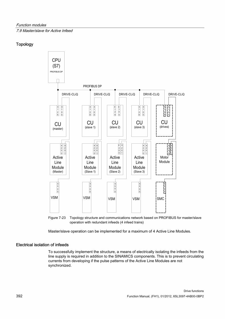
Function modules 7.9 Master/slave for Active Infeed
Drive functions 392 Function Manual, (FH1), 01/2012, 6SL3097-4AB00-0BP2
Topology
Figure 7-23 Topology structure and communications network based on PROFIBUS for master/slave
operation with redundant infeeds (4 infeed trains)
Master/slave operation can be implemented for a maximum of 4 Active Line Modules.
Electrical isolation of infeeds To successfully implement the structure, a means of electrically isolating the infeeds from the line supply is required in addition to the SINAMICS components. This is to prevent circulating currents from developing if the pulse patterns of the Active Line Modules are not synchronized.
Function modules 7.9 Master/slave for Active Infeed
Drive functions Function Manual, (FH1), 01/2012, 6SL3097-4AB00-0BP2 393
Two solutions are possible for the electrical isolation:
Using an isolating transformer for each slave infeed train. The primary side of the transformer is to be connected to the grounded or ungrounded line transformer. The secondary side must never be grounded.
Using a three-winding transformer for the master and slave infeeds. In this case, only the neutral point of one winding may be grounded to prevent further electrical coupling via ground.
Whichever solution is chosen, it must be noted that a separate transformer must be used for each Active Line Module (slaves 1 to 3).
DC breaker
Note
When an infeed develops a fault it is disconnected on the line side by the line contactor, on the DC link side, using a DC breaker. Infeeds must not be switched in to a charged DC link. The DC link must be discharged before another infeed train can be switched in.
An infeed may only be connected to a charged DC link if a DC breaker with pre-charging branch is installed.
7.9.3 Types of communication To implement master/slave operation, the CUs must be able to communicate with one another. The master passes the active current setpoint to the slaves. To optimize Vdc control (DC link voltage), the dead times during communication must be kept to a minimum.
PROFIBUS slave-to-slave communication The data is exchanged directly between the CUs without passing via the DP master. A PROFIBUS master (higher-level controller) is required to act as a "clock generator" (e.g. an S7-CPU). The minimum PROFIBUS cycle time that can be set depends on the Profibus master specifications.
Isochronous mode must be set for PROFIBUS. The PROFIBUS cycle time must not exceed 2 ms otherwise the closed-loop control may start to oscillate.
In order to ensure that other infeeds do not switch to fault status when one CU fails, the fault message F01946 "Link to Publisher disconnected" must be deactivated.
The number "1946" can be set in one of the parameters p2101[0..19] and p2101[x] set to "0" in order to block fault message F01946. This means that the drive will not shut down when one slave-to-slave communication node fails.
In a master/slave infeed, a common current controller cycle is essential, particularly when infeeds with different outputs are used. If the number of PROFIBUS nodes or drives increases, this can affect the bus cycle or current controller sampling time.
Function modules 7.9 Master/slave for Active Infeed
Drive functions 394 Function Manual, (FH1), 01/2012, 6SL3097-4AB00-0BP2
Communication using an analog setpoint The analog setpoint between the CUs with Terminal Module 31 (TM31) can also be used as an alternative to bus communication. The factory setting for the sampling time of analog inputs and/or outputs is 4 ms (TM31 inputs/outputs sampling time p4099[1/2]). The sampling times must be an integer multiple of the basic sampling times (r0110). The lowest common denominator of the current controller clock cycle for the integrated infeeds must be selected to implement the "master/slave" function. The sampling time of the analog inputs/outputs should be the set to the same value as the current controller cycle (e.g. 250 µs). The slave can then use the analog setpoint every second current controller cycle. with the dead time corresponding to one clock cycle.
The advantages of this variant is that the communication system can be configured to be independent of bus and master.
Disadvantages are the additional hardware wiring and the necessity to use one TM31 per CU. This communication method is also more susceptible to EMC-related problems. It is not absolutely essential to use a higher-level control (e.g. SIMATIC S7) for this system. Control functions can also be implemented using DCC charts in individual CUs.
7.9.4 Description of functions The "Mmaster/slave" function module is not implemented in the higher-level control, but directly in the firmware of the CUs and infeeds. It is signaled by r0108.19 = 1 (option "Master/slave" for infeeds selected in STARTER). The Vdc closed-loop control band and current setpoint via multiplexers of the Active Line Module control are implemented in the function module.
All infeeds must be parameterized in such a way that they are fully functional as both a master and slave. The infeeds can be switched between master and slave role during operation. Switchover is handled by a higher-level control according to the setting in parameter p3513. A master is configured to operate with Vdc control (p3513 = 0) and current control, while the slaves operate only with current control (p3513 = 1). The setpoint input of the active current Iactive(set) is transferred from the master to the slaves via the communication links between the Control Units.
If the Active Line Module is used for reactive power compensation with external reactive current setpoint, then the reactive current setpoint must also be wired for the slave. The master-to-slave setpoint specifies only the active current.
When Active Line Modules have been deactivated, make sure that the maximum DC link capacitance CZK for the remaining Active Line Modules is not exceeded during the switch-on procedure (danger of overloading the pre-charging resistors).
Parameter p3422 (CDC linkcapacitance) can be changed in operation. This means that the closed-loop control can be directly adjusted via this parameter when the master/slave configuration changes, instead of changing the proportional gain of the VDC link controller (p3560). When parameter p3422 changes, parameter p3560 is recomputed automatically by the firmware.
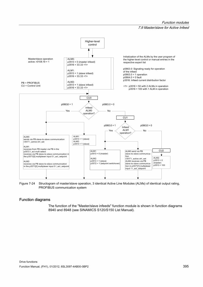
Function modules 7.9 Master/slave for Active Infeed
Drive functions Function Manual, (FH1), 01/2012, 6SL3097-4AB00-0BP2 395
p0863.0 = 0
p0863.0 = 0p0863.0 = 1
p0863.0 = 1
ALM1:
p3513 = 1 (Slave)
ALM2:
p3513 = 1 (Slave)
Figure 7-24 Structogram of master/slave operation, 3 identical Active Line Modules (ALMs) of identical output rating,
PROFIBUS communication system
Function diagrams The function of the "Master/slave infeeds" function module is shown in function diagrams 8940 and 8948 (see SINAMICS S120/S150 List Manual).
Function modules 7.9 Master/slave for Active Infeed
Drive functions 396 Function Manual, (FH1), 01/2012, 6SL3097-4AB00-0BP2
Explanations for the function diagrams
Current setpoint interconnection Parameter p3570 is used to connect the setpoint for the closed-loop current control (active current setpoint from the master). Using parameter p3513, which can be changed in the "ready for operation" state, it is possible to switch between master (Vdc control, parameter p3513 = 0) and slave (current control, parameter p3513 = 1) from the higher-level control system.
Selection of the current setpoint The current setpoint can be selected by means of a control word (XCS) (p3572) using a multiplexer with 4 inputs (X0 … X3) (p3571.0 … p3571.3). This means that the current setpoint of the new master can be selected when the old master has failed.
Selection of the current distribution factor
To prevent a reduction in control dynamics of the DC link voltage controller for non-symmetrical loads, this current distribution factor must be updated immediately when an infeed fails or is activated.
The current distribution factor is calculated from the number of active infeeds and their rated data. The sum of the current distribution factors of all active infeeds must always equal 100 %.
The current distribution factor can be selected by means of a control word (XCS) (p3577) using a multiplexer with 6 inputs (X0 ... X5) (p3576.0...5).
Alternatively, a new current distribution factor can be calculated in the higher-level control, sent via cyclic PROFIBUS PZD telegrams and interconnected directly to the connector input "Infeed: additional current distribution factor" (p3579).
A further alternative is to update the current distribution factor via an acyclic PROFIBUS parameter write order of p3516. This produces deadtimes however.
For alternatives without multiplexer, this can be used for a different function.
Vdc control band The Vdc limits can be violated in master/slave operation if the DC link load changes abruptly (e.g. load surges or emergency stop). For this reason, the DC link voltage is monitored on the basis of a Vdc control band. The Vdc control band defines a specific voltage range with hysteresis - set in parameter p3574.0/1 (upper/lower limit Vdc voltage band) and p3574.2/3 (hysteresis upper/lower voltage limit). A signal is generated if the DC link voltage leaves this voltage range. By evaluating this signal, the slave is changed over from closed-loop current to closed-loop voltage control. When the DC link voltage returns to within the control band, the slave is switched back to closed-loop current control. The Vdc control operates permanently in "standby mode" so that it can be re-activated when necessary.
Function modules 7.9 Master/slave for Active Infeed
Drive functions Function Manual, (FH1), 01/2012, 6SL3097-4AB00-0BP2 397
7.9.5 Commissioning
Line supply and DC link identification routine Before the option "Master/slave" operation is enabled in STARTER, the line supply and DC link identification runs (see corresponding section in this function manual) must be executed during commissioning for each infeed train.
Please follow the instructions given in the commissioning manual for the commissioning of infeeds.
Once each individual infeed has been identified, the correct inductance for current control and the DC link capacitance for voltage control are set.
If a DC breaker for isolating the infeed from the DC link is installed, DC link identification must be performed again for all active infeeds after one has been disconnected, as it is necessary to acquire the DC link capacitance again. If the DC link capacitance is not adapted in this way, then the change in capacitance will affect the dynamic response of the Vdc control.
Note Aligning the setpoints of the DC link voltage
The setpoints of the DC link voltage Vdc from p3510 of the master and the slaves must be set to the same values to ensure that the Vdc tolerance bandwidth monitoring functions correctly.
Activation of the master/slave function The "Master/slave" function is activated with the checkbox/option "Master/Slave" in the STARTER wizard for the relevant infeed. Parameter r0108.19 can be used to scan for an active function module in the CU or the Active Line Modules (r0108.19 = 1).
All other required parameters are set via the corresponding expert lists for the relevant infeed.
Note
The bus cycle time for Active Line Modules operating in master-slave operation must not exceed 2 ms, If the bus cycle time is higher, then the dynamic response (p3560) must be significantly reduced. This means that load surges can no longer be corrected properly.
Increasing the bus cycle time can cause the DC link voltage to oscillate, an effect which can sometimes be managed by reducing the dynamic response (p3560). The system cannot be guaranteed to function reliably with bus cycle times of > 2 ms.
The Vdc setpoint in p3510 must be set high enough to prevent the standby controller from responding to line overvoltage (the response threshold of 97% can be increased if necessary, but current and voltage harmonics will develop if the setting causes overcontrol).
Function modules 7.9 Master/slave for Active Infeed
Drive functions 398 Function Manual, (FH1), 01/2012, 6SL3097-4AB00-0BP2
In any case, the tolerance band must be set wide enough that it will not be violated should the control factor reserve controller still respond because the measures described above have not been implemented.
Master/slave switchover If a power unit fails during operation, the higher-level controller can switch each infeed line from current control (slave operation) to DC link voltage control (master operation) and vice versa (parameter setting for master: p3513= 0, for slave: p3513 = 1).
Switching in an ALM in operation In an operational master-slave group, an ALM must first be switched in as a slave.
Shutting down an ALM from an operating group Shutting down an ALM from the group should be realized in the slave state and with OFF2 (pulse inhibit). If a master fails with a fault (OFF2 response, pulse inhibit), one of the slaves must be immediately switched as master.
Two masters must not be operated simultaneously in the infeed group.
7.9.6 Function diagrams and parameters
Function diagrams (see SINAMICS S120/S150 List Manual) 8940 Controller control factor reserve/controller DC link voltage
8948 Master/slave (r0108.19 = 1)
Overview of important parameters (see SINAMICS S120/S150 List Manual) p3513 BI: Disable voltage-controlled operation
p3516 infeed current distribution factor
p3570 CI: Master/slave active current setpoint
p3571[0...3] CI: Master/slave active current setpoint multiplexer input
p3572 CI: Master/slave active current setpoint multiplexer selection
r3573 CO: Master/slave active current setpoint multiplexer output
p3574[0...3] master/slave DC link voltage monitoring
r3575.0...2 BO: Master/slave DC link voltage monitoring status
Function modules 7.10 Connecting the motors in parallel
Drive functions Function Manual, (FH1), 01/2012, 6SL3097-4AB00-0BP2 399
7.10 Connecting the motors in parallel For simple commissioning of group drives (a number of identical motors operating on one power unit) in control modes servo and vector, the number of parallel-connected motors can be entered in STARTER or in the parameter list (p0306)
An equivalent motor is computed internally depending on the number of motors specified. The motor data identification determines the data for an equivalent motor. Motors connected in parallel can also operate on an encoder (on the 1st motor).
Note
For information about parallel connection of Motor Modules, please refer to section "Parallel connection of power units".
Features Up to 50 motors connected in parallel can be operated on one frequency converter.
It is not permissible to connect synchronous or reluctance motors in parallel.
The original motor data set (p0300 ff.) is not modified. It is merely the data set transfer to the closed-loop control which is organized according to the number of parallel-connected motors.
The stationary motor data identification also works for parallel connections.
The rotating measurement function also works if the motors can rotate without distance limit. Uneven loading of the motors or a high degree of gear backlash will negatively affect the accuracy of the rotating measurement result.
The cable lengths for motors connected in parallel must be as symmetrical as possible to afford the most even possible distribution of current among individual motors.
Commissioning via STARTER Parameter p0306 is assigned in a STARTER commissioning screen. When the subsequent parameters are set, p0306 is included in the calculation of the current limit (p0640) and in the reference current (p2002). Parameter p0306 has a value range of 1 to 50, and is it dependent on the motor data set (MDS).
To connect motors in parallel, select the corresponding motor in the selection screen and select the "Parallel motor connection" option. Enter the number of motors in the parallel connection in the entry field "Number". This display and input function is available for vector control only. For servo control, the parallel connection of motors can only be configured using the expert list (parameter p0306).
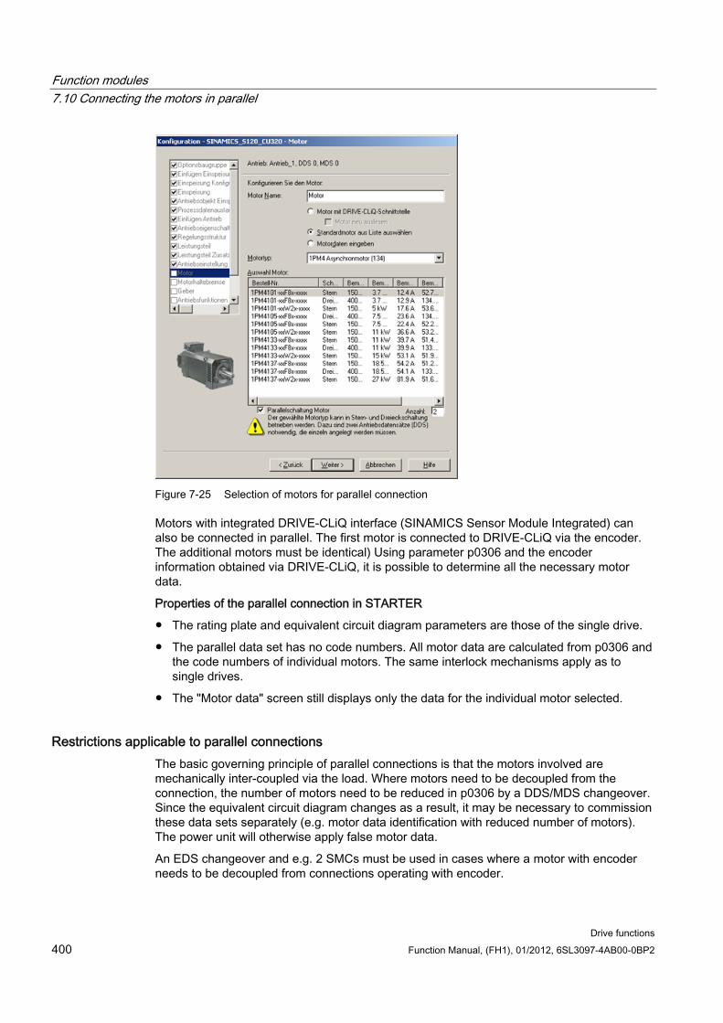
Function modules 7.10 Connecting the motors in parallel
Drive functions 400 Function Manual, (FH1), 01/2012, 6SL3097-4AB00-0BP2
Figure 7-25 Selection of motors for parallel connection
Motors with integrated DRIVE-CLiQ interface (SINAMICS Sensor Module Integrated) can also be connected in parallel. The first motor is connected to DRIVE-CLiQ via the encoder. The additional motors must be identical) Using parameter p0306 and the encoder information obtained via DRIVE-CLiQ, it is possible to determine all the necessary motor data.
Properties of the parallel connection in STARTER
The rating plate and equivalent circuit diagram parameters are those of the single drive.
The parallel data set has no code numbers. All motor data are calculated from p0306 and the code numbers of individual motors. The same interlock mechanisms apply as to single drives.
The "Motor data" screen still displays only the data for the individual motor selected.
Restrictions applicable to parallel connections The basic governing principle of parallel connections is that the motors involved are mechanically inter-coupled via the load. Where motors need to be decoupled from the connection, the number of motors need to be reduced in p0306 by a DDS/MDS changeover. Since the equivalent circuit diagram changes as a result, it may be necessary to commission these data sets separately (e.g. motor data identification with reduced number of motors). The power unit will otherwise apply false motor data.
An EDS changeover and e.g. 2 SMCs must be used in cases where a motor with encoder needs to be decoupled from connections operating with encoder.
Function modules 7.11 Parallel connection of power units
Drive functions Function Manual, (FH1), 01/2012, 6SL3097-4AB00-0BP2 401
Vector control with encoder for parallel-connected drives functions in the same way as for a single drive if the drives are coupled via the load and the speeds do not differ by more than the working-point-dependent pull-out slip.
Counter-example: The gear ratios used to couple the motors with the load are large and the backlash and elasticity in the drive train are therefore high. If the load then causes one of the motors to rotate, but the other is still stationary, the drive without an encoder will stall.
If a motor is defective, the individual motor will be shut down on overcurrent by the motor circuit breaker. The power unit will be shut down by the control (if available) or, in the case of a turn-to-turn fault in the motor, the power unit will go into the fault condition. The motor must then be decoupled from the parallel grouping. Parameter p0306 is changed by the DDS/MDS changeover.
Overview of important parameters (see SINAMICS S120/S150 List Manual) p0300[0...n] Motor type
p0306[0...n] Number of motors connected in parallel
p0307[0...n] Rated motor power
p0640[0...n] Current limit
p2002 Reference current
7.11 Parallel connection of power units In order to extend the power range, SINAMICS S120 supports the parallel connection of identical power units such as Line Modules and/or Motor Modules. The prerequisites for connecting power units in parallel are as follows:
Same type
Same type rating
Same rated voltage
Same firmware version
Chassis or cabinet format
The Motor Modules must be operated in vector control
It makes sense to connect Line Modules and Motor Modules in parallel for the following reasons:
To boost the converter output if it is not technically or economically feasible to achieve the required power by any other means.
To increase the availability, for example, to maintain emergency operation (possibly also at a lower rating), if a power unit fails.
Function modules 7.11 Parallel connection of power units
Drive functions 402 Function Manual, (FH1), 01/2012, 6SL3097-4AB00-0BP2
Parallel operation is not released under the following conditions:
Combining different types of Infeed Module within the same parallel connection (e.g. Basic Line Modules with Smart Line Modules or Basic Line Modules with Active Line Modules).
Motor Modules in servo control
Infeed Modules and Motor Modules in the booksize and blocksize formats
Features The main features of parallel connection are:
Parallel connection of up to four Motor Modules on one motor
– Parallel connection of multiple Motor Modules on one motor with separate winding systems (p7003 = 1).
Note
Motors with separate winding systems are recommended.
– Parallel connection of multiple Motor Modules on one motor with a single winding system (p7003 = 0) is possible.
CAUTION Additional information and instructions in the Manual SINAMICS S120 Chassis Power Units must be carefully taken into consideration.
Parallel connection of up to four power units on the infeed side (closed/open loop).
A Control Unit, which controls and monitors power units on the line and motor sides connected in parallel, can control an additional drive, e.g. an auxiliary drive (see Chapter Additional drive in addition to the parallel connection (Page 412)).
Redundant operation: Two Control Units, which control and monitor the line-side and motor-side power units connected in parallel cannot control additional drives.
Parallel-connected power units must be connected to the same Control Unit.
A Control Unit CU320-2 can simultaneously actuate a maximum of one parallel connection on the line side and one parallel connection on the motor side.
Components at the line and motor ends for decoupling the parallel-connected power units and for ensuring symmetrical current distribution are recommended.
Simple commissioning, because no special parameterization is necessary.
Individual power units can be parameterized and diagnosed (troubleshooting) with p7000 ff.
The following Modules can be connected in parallel:
Function modules 7.11 Parallel connection of power units
Drive functions Function Manual, (FH1), 01/2012, 6SL3097-4AB00-0BP2 403
Basic Line Modules (BLM), 6-pulse and 12-pulse (each with the associated line reactors)
Smart Line Modules (SLM), 6-pulse and 12-pulse (each with the associated line reactors)
Active Line Modules (ALM), 6-pulse and 12-pulse (each with the associated Active Interface Modules)
Motor Modules (in vector control mode)
Note Exceptions for combined operation of Line Modules
Smart Line Modules may be operated together with Basic Line Modules whose last digit of the order number is a "3" (Chassis) or a "2" (Cabinet) with one or several CUs if precisely defined preconditions and the information in the Configuration Manual are maintained. You can find this information in the "SINAMICS - Low Voltage Configuration Manual".
A slight reduction of the rated current must be considered for parallel connection of power units. The reduction of the rated current (derating) of a power unit for parallel connection is:
7.5% for parallel connections of SINAMICS S120 Basic Line Modules and SINAMICS S120 Smart Line Modules when neither module is equipped with a current compensation control.
5.0% for parallel connections of SINAMICS S120 Active Line Modules and SINAMICS S120 Motor Modules when each module is operates with a current compensation control.
7.11.1 Applications of parallel connections Power units can be connected in parallel (infeeds) in the following cases:
Variant Condition 6-pulse circuit The modules connected in parallel are supplied from a two-winding
transformer. 12-pulse circuit The modules connected in parallel are supplied via a three-winding
transformer, whose secondary windings supply voltages with a phase shift of 30°.
The following diagram is an overview of the module variants discussed in this section for inclusion in power unit parallel connections.
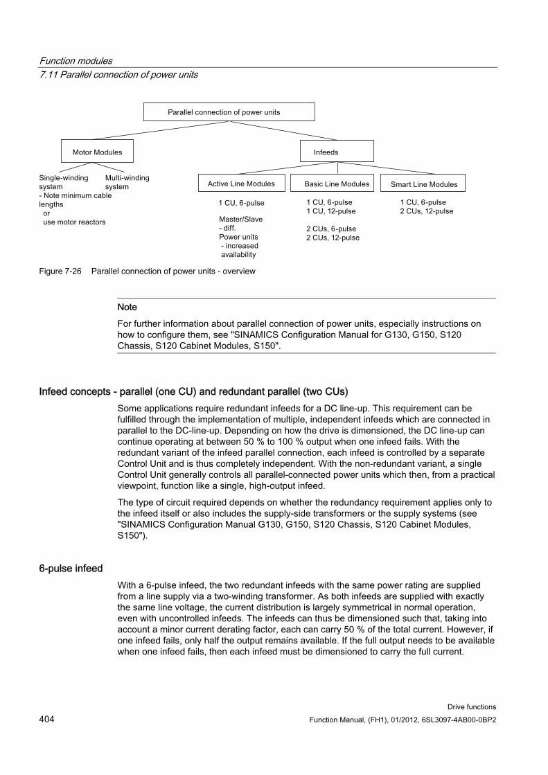
Function modules 7.11 Parallel connection of power units
Drive functions 404 Function Manual, (FH1), 01/2012, 6SL3097-4AB00-0BP2
Figure 7-26 Parallel connection of power units - overview
Note
For further information about parallel connection of power units, especially instructions on how to configure them, see "SINAMICS Configuration Manual for G130, G150, S120 Chassis, S120 Cabinet Modules, S150".
Infeed concepts - parallel (one CU) and redundant parallel (two CUs) Some applications require redundant infeeds for a DC line-up. This requirement can be fulfilled through the implementation of multiple, independent infeeds which are connected in parallel to the DC-line-up. Depending on how the drive is dimensioned, the DC line-up can continue operating at between 50 % to 100 % output when one infeed fails. With the redundant variant of the infeed parallel connection, each infeed is controlled by a separate Control Unit and is thus completely independent. With the non-redundant variant, a single Control Unit generally controls all parallel-connected power units which then, from a practical viewpoint, function like a single, high-output infeed.
The type of circuit required depends on whether the redundancy requirement applies only to the infeed itself or also includes the supply-side transformers or the supply systems (see "SINAMICS Configuration Manual G130, G150, S120 Chassis, S120 Cabinet Modules, S150").
6-pulse infeed With a 6-pulse infeed, the two redundant infeeds with the same power rating are supplied from a line supply via a two-winding transformer. As both infeeds are supplied with exactly the same line voltage, the current distribution is largely symmetrical in normal operation, even with uncontrolled infeeds. The infeeds can thus be dimensioned such that, taking into account a minor current derating factor, each can carry 50 % of the total current. However, if one infeed fails, only half the output remains available. If the full output needs to be available when one infeed fails, then each infeed must be dimensioned to carry the full current.

Function modules 7.11 Parallel connection of power units
Drive functions Function Manual, (FH1), 01/2012, 6SL3097-4AB00-0BP2 405
12-pulse infeed For a 12-pulse infeed, the two redundant infeeds with the same power rating are supplied from a line supply via a three-winding transformer. Depending on the transformer design, the line-side voltages of the two infeeds will include minor tolerances of between about 0.5 % to 1 %. These can cause slightly asymmetrical current distribution in normal operation when uncontrolled infeeds are used and current derating factors must be applied accordingly. If the full output needs to be available when one infeed fails, then each infeed must be dimensioned to carry the full current.
6-pulse, 12-pulse infeed When separate Control Units are used, pre-charging may not be synchronized accurately enough, i.e. a converter system must be able to pre-charge the total capacity of the drive line-up. Pre-charging power for the DC link in parallel operation must be dimensioned so that the capacitance of the DC link can be fully charged by a single converter system. Otherwise a separate pre-charging device must be provided.
Configuring a parallel connection Additional information on configuring parallel power units connections can be found in the "SINAMICS Low Voltage Configuration Manual".
7.11.1.1 Parallel connection of Basic Line Modules Features of Basic Line Modules:
The DC link voltage is greater than the rms value of the line rated voltage by a factor of 1.35.
They are used in cases where regenerative feedback capability is not required.
If regenerative operating states occur in the drive line-up, Braking Modules that convert the excess energy to heat in braking resistors must be used.
Basic Line Modules are available for the following voltages and power ratings:
Table 7- 7 Basic Line Modules
Line supply voltage Rated power 380 to 480 V AC, 3-phase 200 ... 710 kW 500 to 690 V AC, 3-phase 250 ... 1100 kW
The following rules must be observed when connecting Basic Line Modules in parallel:
Up to 4 identical Basic Line Modules can be connected in parallel.
A common Control Unit must always be used to implement the parallel connection.
Special Line Connection Modules are available for the parallel connection.
Function modules 7.11 Parallel connection of power units
Drive functions 406 Function Manual, (FH1), 01/2012, 6SL3097-4AB00-0BP2
With multiple infeeds, power must be supplied to the systems from a common infeed point (i.e. the modules cannot be operated on different line supplies).
A current reduction (derating) of 7.5 % must be taken into consideration, regardless of the number of modules connected in parallel.
As Basic Line Modules have no current compensation control, the three-winding transformer, power cabling and line reactors must meet the following requirements in order to provide a balanced current:
Three-winding transformer must be symmetrical, recommended vector groups Dy5d0 or Dy11d0.
Relative short-circuit voltage of three-winding transformer uk ≥ 4%.
Difference between relative short-circuit voltages of secondary windings Δuk ≤ 5%.
Difference between no-load voltages of secondary windings ΔU ≤ 0.5 %.
Use of symmetrical power cabling between the transformer and the Basic Line Modules (cables of identical type with the same cross-section and length)
Using line reactors that match the Basic Line Modules
Line reactors can be omitted if a double-tier transformer is used and only one Basic Line Module is connected to each secondary winding of the transformer.
A double-tier transformer is generally the only means of meeting the requirements of a three-winding transformer for this application. Line reactors must always be installed if other types of three-winding transformer are used. Alternative solutions for obtaining a phase displacement of 30 °, such as two separate transformers with different vector groups, cannot be used due to the inadmissibly high tolerances involved.
6-pulse parallel connection of Basic Line Modules With the 6-pulse parallel connection, up to four Basic line modules are supplied by a common two-winding transformer on the line side and controlled by a common control unit.
12-pulse parallel connection of Basic Line Modules For 12-pulse parallel connections, up to four Basic Line Modules are supplied by a three-winding transformer on the line side. In this case, an even number of modules, i.e. two or four, must be divided between the two secondary windings. The Basic Line Modules of both subsystems are controlled by a common Control Unit - even though the input voltages are 30° out of phase. There is also the redundant version with which two BLMs in each case are controlled by one Control Unit.
Function modules 7.11 Parallel connection of power units
Drive functions Function Manual, (FH1), 01/2012, 6SL3097-4AB00-0BP2 407
DANGER Vdc control with Basic Line Modules
If several Motor Modules are supplied from a non-regenerative infeed unit (e.g. a Basic Line Module), the Vdc_max control may only be activated for that Motor Module whose drive has the nominal highest moment of inertia of all connected drives. For the other Motor Modules this function must be disabled or monitoring must be set. If the Vdc_max control is active for several Motor Modules, then for an unfavorable parameterization, the controllers can mutually influence one another negatively. The drives can become unstable, individual drives can unintentionally accelerate. • Activating the Vdc_max control:
– Vector control: p1240 = 1 (factory setting) – Servo control: p1240 = 1 – U/f control: p1280 = 1 (factory setting)
• Inhibiting the Vdc_max control: – Vector control: p1240 = 0 – Servo control: p1240 = 0 (factory setting) – U/f control: p1280 = 0
• Activating the Vdc_max monitoring function – Vector control: p1240 = 4 or 6 – Servo control: p1240 = 4 or 6 – U/f control: p1280 = 4 or 6
7.11.1.2 Parallel connection of Smart Line Modules Smart Line Modules are infeed/regenerative feedback units. Like the Basic Line Modules, they supply energy to the connected Motor Modules, but unlike the Basic Line Module, they are capable of feeding back regenerative energy to the line supply. The DC link voltage is greater than the rms value of the line rated voltage by a factor of 1.3.
Smart Line Modules are suitable for connection to grounded (TN, TT) and non-grounded (IT) supply systems. The following voltages and power ratings are available:
Table 7- 8 Smart Line Modules
Line supply voltage Rated power 380 to 480 V AC, 3-phase 250 ... 800 kW 500 to 690 V AC, 3-phase 450 ... 1400 kW
The following rules must be observed when connecting Smart Line Modules in parallel:
Up to 4 identical Smart Line Modules can be connected in parallel.
A common Control Unit must always be used to implement the parallel connection.
A 4% reactor is always required upstream of each Smart Line Module for the purpose of current balancing.
Special Line Connection Modules are available for the parallel connection.
Function modules 7.11 Parallel connection of power units
Drive functions 408 Function Manual, (FH1), 01/2012, 6SL3097-4AB00-0BP2
With multiple infeeds, power must be supplied to the systems from a common infeed point (i.e. the modules cannot be operated on different line supplies).
A derating factor of 7.5 % must be taken into consideration, regardless of the number of modules connected in parallel.
6-pulse parallel connection of Smart Line Modules With the 6-pulse parallel connection, up to four Smart line modules are supplied by a common two-winding transformer on the line side and synchronously controlled by a common Control Unit.
As Smart Line Modules have no current compensation control, the current must be balanced by the following measures:
Use of suitable line reactors for the Smart Line Modules.
Use of symmetrical power cabling between the transformer and the parallel-connected Smart Line Modules (cables of identical type with the same cross-section and length).
The current reduction (derating) from the rated value for individual Smart Line Modules in a parallel connection is 7.5 %.
12-pulse parallel connection of Smart Line Modules With 12-pulse parallel connections, up to four Smart Line Modules are supplied by a three-winding transformer on the line side. In this case, an even number of Smart Line Modules, i.e. two or four, must be divided between the two secondary windings. In contrast to Basic Line Modules, the Smart Line Modules of both subsystems have to be controlled by two Control Units due to the 30° phase displacement in the input voltages.
7.11.1.3 Parallel connection of Active Line Modules Active Line Modules can supply motoring energy and return regenerative energy to the line supply.
The parallel connection of up to four Active Line Modules is supplied by a shared two-winding transformer and controlled synchronously by a shared Control Unit. The modules must not be connected to the supply via a three-winding transformer with phase-displaced secondary voltages. Active Line Modules produce a stabilized DC voltage that remains constant regardless of fluctuations in the line voltage (the line voltage must range within the permissible tolerances).
The DC link voltage is greater than the rms value of the line rated voltage by a factor of 1.5.
Active Line Modules draw a virtually sinusoidal current from the supply system and cause virtually no line harmonic distortions.
Function modules 7.11 Parallel connection of power units
Drive functions Function Manual, (FH1), 01/2012, 6SL3097-4AB00-0BP2 409
Active Line Modules are available for the following voltages and power ratings:
Table 7- 9 Active Line Modules
Line supply voltage Rated power 380 to 480 V AC, 3-phase 132 ... 900 kW 500 to 690 V AC, 3-phase 560 ... 1400 kW
The following rules must be observed when connecting Active Line Modules in parallel:
Up to 4 identical Active Line Modules can be connected in parallel.
Active Line Modules can only be connected and operated in parallel in the vector control mode.
A common Control Unit must always be used to implement the parallel connection.
Special Line Connection Modules are available for connecting the modules in parallel.
With multiple infeeds, power must be supplied to the systems from a common infeed point (i.e. the modules cannot be operated on different line supplies).
A derating factor of 5% must be taken into consideration, regardless of the number of modules connected in parallel.
The following measures help to ensure balanced currents in parallel connections of Active Line Modules:
Reactors in the Clean Power Filters of the Active Interface Modules.
Use of symmetrical power cabling between the transformer and the parallel-connected Active Interface Modules / Active Line Modules (cables of identical type with the same cross-section and length).
The current reduction from the rated value for individual Active Interface Modules / Active Line Modules in a parallel connection is 5 %.
6-pulse, redundant parallel connection of Active Line Modules with multiple Control Units For a description of parallel connections of multiple Active Line Modules under the control of separate Control Units, please refer to section " Master/slave function for infeeds".
12-pulse parallel connection of Active Line Modules The 12-pulse parallel connection can operate in master-slave mode (section "Master/slave function for infeeds").
Modules with different ratings can be included in the connection (as in the case of 6-pulse master-slave operation).
Function modules 7.11 Parallel connection of power units
Drive functions 410 Function Manual, (FH1), 01/2012, 6SL3097-4AB00-0BP2
7.11.1.4 Parallel connection of Motor Modules Up to four Motor Modules operating in parallel can supply a single motor in vector control. The motor can have electrically isolated winding systems or a common winding system. The type of winding system defines the following requirements:
The required decoupling measures at the outputs of the Motor Modules connected in parallel
The possible modulation systems to generate pulse patterns
In conjunction with the type of infeed, the modulation systems define the maximum attainable output voltage or the maximum attainable motor voltage.
Winding systems for motors in SINAMICS parallel connections The following are admissible:
1. Motors with electrically isolated winding systems (multi-winding system) in which the individual systems are not electrically coupled.
2. Motors with a common winding system (single winding system) in which all parallel windings in the motor are interconnected in such a way that from the outside they look like a single winding system.
The following are inadmissible:
1. Motors with separate winding systems on the line side which have a common, internal neutral.
Below are two examples illustrating the possible configuration of parallel connections of motors with a two-winding system or single winding system.
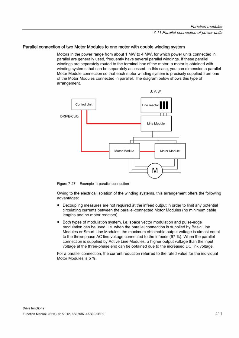
Function modules 7.11 Parallel connection of power units
Drive functions Function Manual, (FH1), 01/2012, 6SL3097-4AB00-0BP2 411
Parallel connection of two Motor Modules to one motor with double winding system Motors in the power range from about 1 MW to 4 MW, for which power units connected in parallel are generally used, frequently have several parallel windings. If these parallel windings are separately routed to the terminal box of the motor, a motor is obtained with winding systems that can be separately accessed. In this case, you can dimension a parallel Motor Module connection so that each motor winding system is precisely supplied from one of the Motor Modules connected in parallel. The diagram below shows this type of arrangement.
Figure 7-27 Example 1: parallel connection
Owing to the electrical isolation of the winding systems, this arrangement offers the following advantages:
Decoupling measures are not required at the infeed output in order to limit any potential circulating currents between the parallel-connected Motor Modules (no minimum cable lengths and no motor reactors).
Both types of modulation system, i.e. space vector modulation and pulse-edge modulation can be used, i.e. when the parallel connection is supplied by Basic Line Modules or Smart Line Modules, the maximum obtainable output voltage is almost equal to the three-phase AC line voltage connected to the infeeds (97 %). When the parallel connection is supplied by Active Line Modules, a higher output voltage than the input voltage at the three-phase end can be obtained due to the increased DC link voltage.
For a parallel connection, the current reduction referred to the rated value for the individual Motor Modules is 5 %.
Function modules 7.11 Parallel connection of power units
Drive functions 412 Function Manual, (FH1), 01/2012, 6SL3097-4AB00-0BP2
Parallel connection of two Active Line Modules and two Motor Modules on a motor with a single winding system
In many cases, it is not possible to use motors with separate winding systems, for example, in the following cases:
The required number of separate winding systems cannot be realized due to the pole number
The motor is a third-party motor
A motor with a common winding system is already present.
In such cases, the outputs of the Motor Modules connected in parallel are interconnected via the motor cables in the motor terminal box.
Active Interface Modules isolate switching-frequency harmonics from the supply connection and thus effect basic interference suppression of the supply system. These modules are essential to the operation of Active Line Modules. The VSM10 Voltage Sensing Module also helps Active Line Modules to operate properly when mains power conditions are less than ideal (e.g. severe voltage fluctuations, brief interruptions in the line voltage). VSMs are integrated as standard in the Active Interface Modules for Active Line Modules in chassis format.
7.11.2 Commissioning During commissioning, power units connected in parallel are treated like a power unit on the line or motor side.
NOTICE Parallel connection of Motor Modules in vector control
You have an offline project in vector control with parallel-connected Motor Modules and then transfer it online to the Control Unit. To save the project in the Control Unit, you must perform a POWER ON. The next time you switch on you receive an error message that the online topology is inconsistent. Load the project now to the programming device. This resolves the inconsistency.
For further detailed information about commissioning, restrictions regarding operation and parameterization options, please refer to the following references
SINAMICS S120 Commissioning Manual
SINAMICS S120/S150 List Manual Parameters r7002 ff.
7.11.3 Additional drive in addition to the parallel connection Frequently, a controlled auxiliary drive is required in addition to the main drives, e.g. as excitation controller for shaft-mounted generators in shipbuilding or as lubricating pump drive, fan drive etc.
Function modules 7.11 Parallel connection of power units
Drive functions Function Manual, (FH1), 01/2012, 6SL3097-4AB00-0BP2 413
For drive units with power units connected in parallel (Line Modules, Motor Modules) an additional drive can be supplied as an auxiliary drive. This drive object is supplied via a separate Motor Module from the common DC link and controlled from the CU320-2 via a dedicated DRIVE-CLiQ socket.
Conditions for switching in an auxiliary drive The secondary conditions for connecting an additional drive object as auxiliary drive to a parallel connection are:
Only power units of the same type and the same power rating may be connected together in parallel.
Up to 4 Line Modules and up to 4 Motor Modules can be connected together in parallel.
All the Power Modules operate on a common DC link.
Due to the different cycle times, Line Modules and Motor Modules must be connected to separate DRIVE-CLiQ sockets. Mixed operation at one DRIVE-CLiQ socket results in a malfunction.
Parameter p9620 (signal source for STO/SBC/SS1) of the DOs of all Motor Modules must be interconnected in the same way.
Automatic commissioning of the additional drive object is not possible.
The additional drive object must be created offline and then transferred online to the drive.
The additional drive object must be connected to a separate DRIVE-CLiQ socket.
The maximum power of the auxiliary drive must be selected so that the maximum power of all the Motor Modules incl. the additional drive - does not exceed the total power rating of the parallel Line Modules.
Existing supplementary conditions and the resulting logic operations and monitoring functions must be adapted to the new requirements.
Creating a project with the appropriate topology
The required topology can be created using either the STARTER or SCOUT tool:
The project is always created offline.
The Control Unit combines parallel-connected power units to form a large Line Module or Motor Module.
The auxiliary drive is assigned a separate DRIVE-CLiQ line.
The DRIVE-CLiQ connections must be implemented corresponding to the topology that has been created
Example of the required topology
You can see an example created with STARTER below. 3 Basic Line Modules, 2 Motor Modules and an auxiliary drive are configured. The parallel connections can be clearly seen in the topology tree as one infeed and one drive. You can also see the additional auxiliary drive. The DRIVE-CLiQ connections are shown as a thin line. The three parallel Line Modules are connected to one DRIVE-CLiQ line, the two Motor Modules to the next DRIVE-CLiQ line, and the auxiliary drive to a third line.
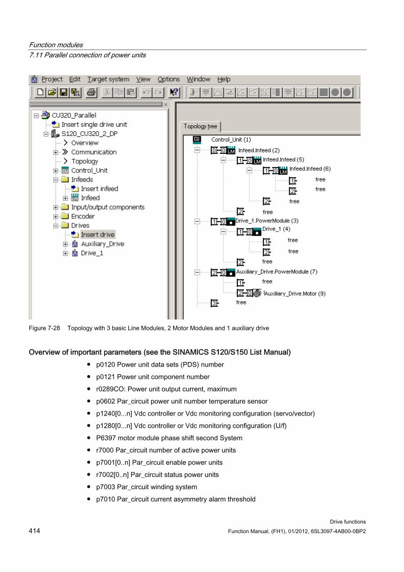
Function modules 7.11 Parallel connection of power units
Drive functions 414 Function Manual, (FH1), 01/2012, 6SL3097-4AB00-0BP2
Figure 7-28 Topology with 3 basic Line Modules, 2 Motor Modules and 1 auxiliary drive
Overview of important parameters (see the SINAMICS S120/S150 List Manual) p0120 Power unit data sets (PDS) number
p0121 Power unit component number
r0289CO: Power unit output current, maximum
p0602 Par_circuit power unit number temperature sensor
p1240[0...n] Vdc controller or Vdc monitoring configuration (servo/vector)
p1280[0...n] Vdc controller or Vdc monitoring configuration (U/f)
P6397 motor module phase shift second System
r7000 Par_circuit number of active power units
p7001[0..n] Par_circuit enable power units
r7002[0..n] Par_circuit status power units
p7003 Par_circuit winding system
p7010 Par_circuit current asymmetry alarm threshold
Function modules 7.12 Extended stop and retract
Drive functions Function Manual, (FH1), 01/2012, 6SL3097-4AB00-0BP2 415
p7011 Par_circuit DC link voltage asymmetry alarm threshold
...
r7250[0...4] Par_circuit power unit rated output
r7251[0...4] Par_circuit power unit rated current
r7252[0...4] Par_circuit power unit maximum current
..
r7320[0...n] Par_circuit VSM line filter capacity phase U
r7321[0...n] Par_circuit VSM line filter capacity phase V
r7322[0...n] Par_circuit VSM line filter capacity phase W
7.12 Extended stop and retract
Overview The "extended stop and retract" function module (ESR) allows a workpiece and tool to be separated without causing any damage when a fault situation occurs. The drive axes involved are defined and are retracted and/or stopped in a controlled fashion. For this function, the drives must be operated in the SERVO control mode.
The drive-integrated ESR functions are described in this manual:
1. Extended stopping of the drive
2. Extended retraction of the drive
3. Generator operation with monitoring to buffer the DC link voltage
ESR functions can be initiated from the higher-level control using a trigger signal, or independently in the drives themselves in the event of a fault (the function is integrated in the drive). The ESR functions integrated in the drive act on an axis-for-axis basis.
Using an axis-specific trigger, ESR functions are directly initiated for an individual axis.
Using a local trigger on the device itself, the ESR functions are simultaneously initiated for those axes under the drive line that are activated for ESR.
NOTICE
ESR functionality under Safety Integrated Functions
If extended stop and retract are to activated simultaneously with Safety Integrated Functions, the following conditions must also be satisfied. Further information can be found in the SINAMICS S120 Safety Integrated Function Manual.
Function modules 7.12 Extended stop and retract
Drive functions 416 Function Manual, (FH1), 01/2012, 6SL3097-4AB00-0BP2
Example
For a machine tool, several drives are simultaneously operational, e.g. a workpiece drive and various feed drives for a tool. In the case of a fault, it is not permissible that the tool remains inserted in the workpiece. This could make both unusable. The tool and workpiece must be separated from one another in a controlled fashion before the drives are allowed to come to a standstill.
The "extended stop and retract" function module allows drive-integrated retraction using the feed drives with subsequent stopping. This means, for example when the line supply fails, a drive can be switched into the generator mode. This then supplies energy for the DC link so that the feed drives can retract the tool from the workpiece and then be subsequently stopped.
7.12.1 Preconditions for extended stop and retract The following is required in order to be able to use these functions:
Hardware:
CU320-2, order number: 6SL3040-1MA00-0AA1 (DP) or 6SL3040-1MA01-0AA0 (PN)
The 24 V power supply for the electronics must be secured
A PG/PC to program the parameters
Software:
SINAMICS firmware V4.4 or higher
7.12.2 Activating and enabling the ESR function PG/PC and drive are connected with one another via PROFIBUS or PROFINET.
1. Use parameter p0888 to select the ESR function:
– p0888 = 0: No function
– p0888 = 1: Extended stopping (function integrated in the drive)
– p0888 = 2: Extended retraction (function integrated in the drive)
– p0888 = 3: Generator operation (Vdc controller)
2. Use p0889 = 1 to enable the ESR response.
3. Transfer the settings into the Control Unit using "RAM to ROM".
The parameterization of p0888 can be changed from a higher-level control depending on the particular situation - as long as the ESR response is not yet enabled.
ESR status
The actual ESR status can be monitored using parameter r0887.0...13.
Function modules 7.12 Extended stop and retract
Drive functions Function Manual, (FH1), 01/2012, 6SL3097-4AB00-0BP2 417
7.12.3 Valid sources for triggering the ESR functions
Axis-related trigger sources Conditions for triggering the function:
ESR function has been configured in the drive with p0888, e.g. stopping or retraction.
ESR function has been enabled in the drive with p0889 = 1.
The pulse enable has been set.
A distinction is made between the following initiating fault sources:
1. Internal drive fault
– Faults with reactions OFF1 or OFF3
– p0840 (On/OFF1) and p0849 (OFF3) wired to terminal
2. Internal trigger signal
– The source for the ESR trigger signal is set via BICO using p0890.
Triggering for all drives of a Control Unit Conditions for triggering the function:
ESR function has been configured in the drive, e.g. stopping or retraction.
ESR function has been enabled in the drive.
The pulse enable has been set.
A distinction is made between the following initiating fault sources:
1. Communication failure:
– The Control Unit detects the communication failure and triggers autonomous reactions in all the enabled drives.
– A status checkback signal is no longer possible.
– The higher-level control removes the "Master control by PLC" signal (F07220).
– Interruption of data transmission via the field bus (F01910 or F08501).
2. External trigger signal
– An external trigger signal from the control triggers the ESR function via the telegrams 390, 391 or 392.
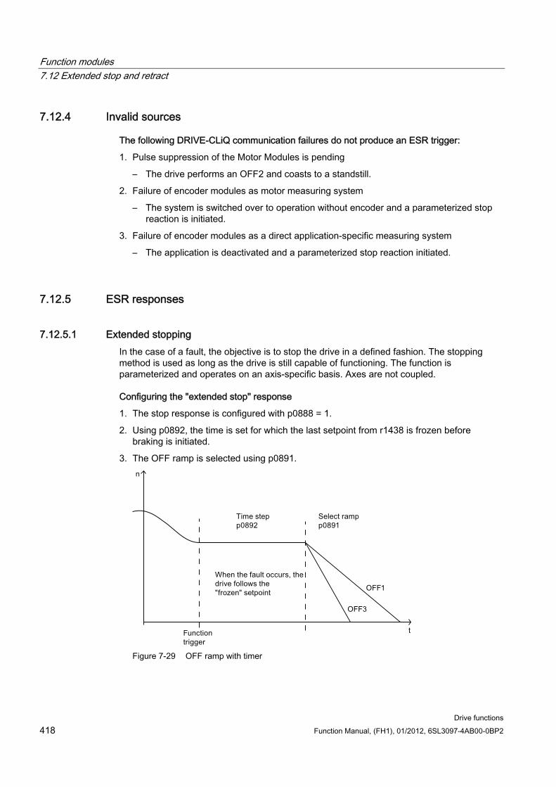
Function modules 7.12 Extended stop and retract
Drive functions 418 Function Manual, (FH1), 01/2012, 6SL3097-4AB00-0BP2
7.12.4 Invalid sources
The following DRIVE-CLiQ communication failures do not produce an ESR trigger:
1. Pulse suppression of the Motor Modules is pending
– The drive performs an OFF2 and coasts to a standstill.
2. Failure of encoder modules as motor measuring system
– The system is switched over to operation without encoder and a parameterized stop reaction is initiated.
3. Failure of encoder modules as a direct application-specific measuring system
– The application is deactivated and a parameterized stop reaction initiated.
7.12.5 ESR responses
7.12.5.1 Extended stopping In the case of a fault, the objective is to stop the drive in a defined fashion. The stopping method is used as long as the drive is still capable of functioning. The function is parameterized and operates on an axis-specific basis. Axes are not coupled.
Configuring the "extended stop" response
1. The stop response is configured with p0888 = 1.
2. Using p0892, the time is set for which the last setpoint from r1438 is frozen before braking is initiated.
3. The OFF ramp is selected using p0891.
Figure 7-29 OFF ramp with timer
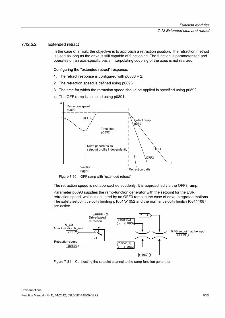
Function modules 7.12 Extended stop and retract
Drive functions Function Manual, (FH1), 01/2012, 6SL3097-4AB00-0BP2 419
7.12.5.2 Extended retract In the case of a fault, the objective is to approach a retraction position. The retraction method is used as long as the drive is still capable of functioning. The function is parameterized and operates on an axis-specific basis. Interpolating coupling of the axes is not realized.
Configuring the "extended retract" response:
1. The retract response is configured with p0888 = 2.
2. The retraction speed is defined using p0893.
3. The time for which the retraction speed should be applied is specified using p0892.
4. The OFF ramp is selected using p0891.
Figure 7-30 OFF ramp with "extended retract"
The retraction speed is not approached suddenly. It is approached via the OFF3 ramp.
Parameter p0893 supplies the ramp-function generator with the setpoint for the ESR retraction speed, which is actuated by an OFF3 ramp in the case of drive-integrated motions. The safety setpoint velocity limiting p1051/p1052 and the normal velocity limits r1084/r1087 are active.
Figure 7-31 Connecting the setpoint channel to the ramp-function generator
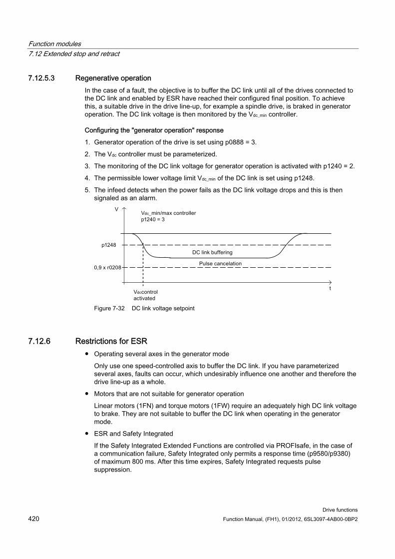
Function modules 7.12 Extended stop and retract
Drive functions 420 Function Manual, (FH1), 01/2012, 6SL3097-4AB00-0BP2
7.12.5.3 Regenerative operation In the case of a fault, the objective is to buffer the DC link until all of the drives connected to the DC link and enabled by ESR have reached their configured final position. To achieve this, a suitable drive in the drive line-up, for example a spindle drive, is braked in generator operation. The DC link voltage is then monitored by the Vdc_min controller.
Configuring the "generator operation" response
1. Generator operation of the drive is set using p0888 = 3.
2. The Vdc controller must be parameterized.
3. The monitoring of the DC link voltage for generator operation is activated with p1240 = 2.
4. The permissible lower voltage limit Vdc_min of the DC link is set using p1248.
5. The infeed detects when the power fails as the DC link voltage drops and this is then signaled as an alarm.
Figure 7-32 DC link voltage setpoint
7.12.6 Restrictions for ESR Operating several axes in the generator mode
Only use one speed-controlled axis to buffer the DC link. If you have parameterized several axes, faults can occur, which undesirably influence one another and therefore the drive line-up as a whole.
Motors that are not suitable for generator operation
Linear motors (1FN) and torque motors (1FW) require an adequately high DC link voltage to brake. They are not suitable to buffer the DC link when operating in the generator mode.
ESR and Safety Integrated
If the Safety Integrated Extended Functions are controlled via PROFIsafe, in the case of a communication failure, Safety Integrated only permits a response time (p9580/p9380) of maximum 800 ms. After this time expires, Safety Integrated requests pulse suppression.
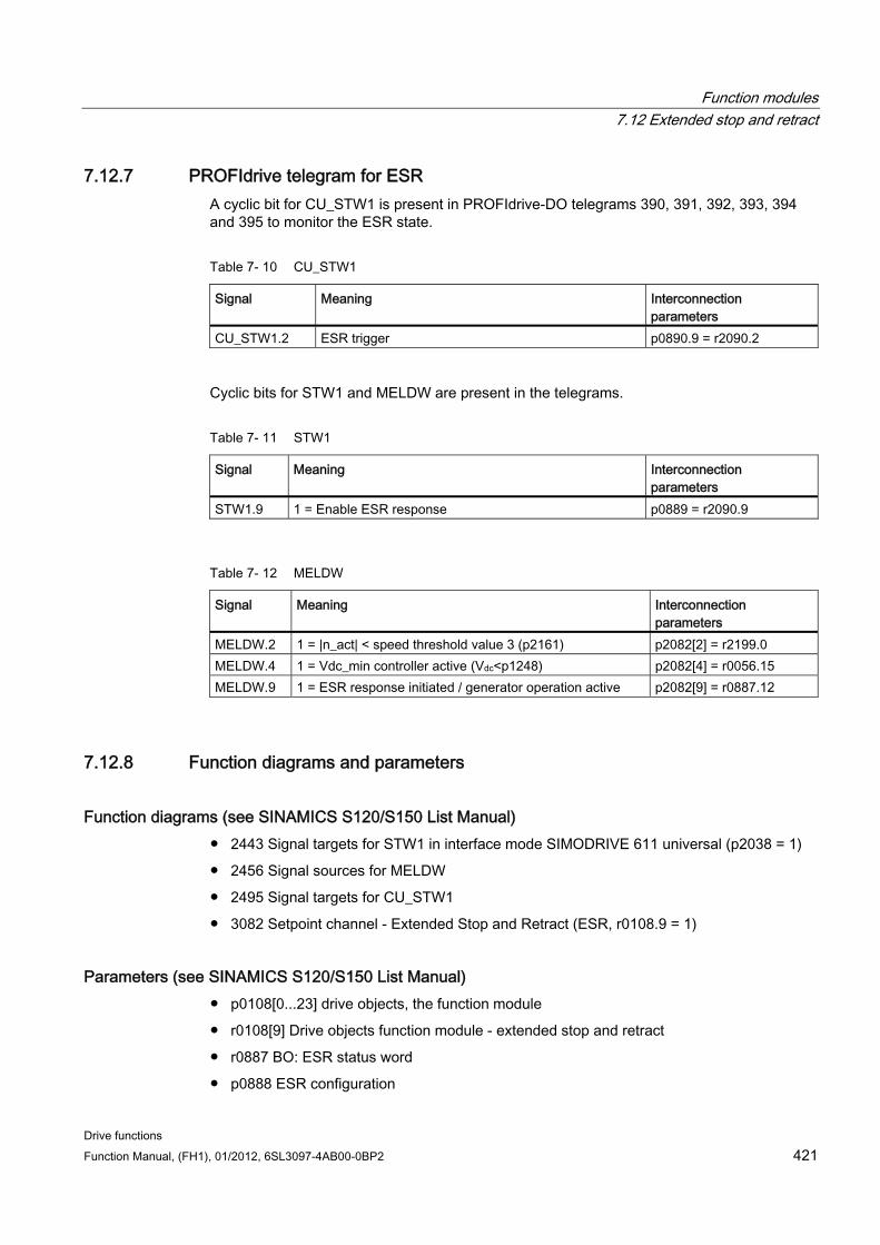
Function modules 7.12 Extended stop and retract
Drive functions Function Manual, (FH1), 01/2012, 6SL3097-4AB00-0BP2 421
7.12.7 PROFIdrive telegram for ESR A cyclic bit for CU_STW1 is present in PROFIdrive-DO telegrams 390, 391, 392, 393, 394 and 395 to monitor the ESR state.
Table 7- 10 CU_STW1
Signal Meaning Interconnection parameters
CU_STW1.2 ESR trigger p0890.9 = r2090.2
Cyclic bits for STW1 and MELDW are present in the telegrams.
Table 7- 11 STW1
Signal Meaning Interconnection parameters
STW1.9 1 = Enable ESR response p0889 = r2090.9
Table 7- 12 MELDW
Signal Meaning Interconnection parameters
MELDW.2 1 = |n_act| < speed threshold value 3 (p2161) p2082[2] = r2199.0 MELDW.4 1 = Vdc_min controller active (Vdc<p1248) p2082[4] = r0056.15 MELDW.9 1 = ESR response initiated / generator operation active p2082[9] = r0887.12
7.12.8 Function diagrams and parameters
Function diagrams (see SINAMICS S120/S150 List Manual) 2443 Signal targets for STW1 in interface mode SIMODRIVE 611 universal (p2038 = 1)
2456 Signal sources for MELDW
2495 Signal targets for CU_STW1
3082 Setpoint channel - Extended Stop and Retract (ESR, r0108.9 = 1)
Parameters (see SINAMICS S120/S150 List Manual) p0108[0...23] drive objects, the function module
r0108[9] Drive objects function module - extended stop and retract
r0887 BO: ESR status word
p0888 ESR configuration
Function modules 7.13 Moment of inertia estimator
Drive functions 422 Function Manual, (FH1), 01/2012, 6SL3097-4AB00-0BP2
p0889 BI: Enable ESR response
p0890 BI: ESR trigger
p0891 ESR OFF ramp
p0892 ESR timer
p0893 ESR velocity / ESR speed
p1051 [0...n] CI: Speed limit in RFG, positive direction of rotation
p1052 [0...n] CI: Velocity limit RFG, negative direction
p1084 CO: Speed limit positive effective
p1087 CO: Speed limit negative effective
p1240[0...n] Vdc controller or Vdc monitoring configuration
p1248[0...n] DC link voltage threshold, lower
p1438 CO: Speed controller, speed setpoint
p9380 SI Motion, pulse cancellation delay bus failure (Motor Module)
p9580 SI Motion, pulse cancellation delay bus failure (Control Unit)
7.13 Moment of inertia estimator
Features
Note
This function has only been released for for drives with servo control. The moment of inertia is measured for drives with vector control.
The moment of inertia estimator function is required, if tools with different mass moments of inertia are connected alternating to one drive. For this situation, continuously repeating the motor data identification is too complex.
For encoderless operation, the total moment of inertia of the motor and driven machine must be known. In controlled operation (for speeds less than p1755) in the acceleration phase, it is not permissible that the motor stalls. In closed-loop operation (speeds above p1755), the speed/torque precontrol requires the precise moment of inertia in order to optimize the dynamics of the speed controller. An incorrect moment of inertia at the end of the acceleration phase, results in an undesirable overshoot or undershoot.
You can also activate the moment of inertia estimator in operation with an encoder. To do this, the speed/torque pre-control must be activated (p1402.4 = 1), so that the moment of inertia is included in the motor closed-loop control.
Function modules 7.13 Moment of inertia estimator
Drive functions Function Manual, (FH1), 01/2012, 6SL3097-4AB00-0BP2 423
Description If an unknown load is present during the speed change, then the moment of inertia cannot be determined. The complete actual motor torque is known. It is not known what percentage is used to accelerate the motor and what is used to accelerate the load. This is the reason that acceleration or deceleration (using the speed setpoint) must be without load.
In phases where machining takes place during the speed setpoint change, e.g. thread cutting, the moment of inertia estimator can be frozen via a BICO switch (source of p1502 = 1). This means that a previously moment of inertia that was correctly determined is not modified as a result of an incorrect estimation.
Phases are required in which the speed is adjusted without load. The moment of inertia is determined from the motor torque and the speed change and is subsequently processed. For initial adaptation, the system waits for specific deadtime (100 ms) so that mechanical transients do not falsify determination of the overall moment of inertia. For operation without encoder, the total moment of inertia can only be determined in the controlled range. The required speed actual value can only be determined in the controlled range.
In operation with encoder, the moment of inertia estimation operates over the complete speed range. However, in all cases, only during a sufficient speed change in the control behavior (|r1518[1]| > 0.05*|p1538 – p1539|) – and if the value of the moment of inertia estimation is not frozen with p1502[0...n] = 1. The start value of the moment of inertia estimator is the parameterized moment of inertia (p0341 * p0341 + p1498). The moment of inertia estimation must be set to the highest expected moment of inertia, so that when accelerating for the first time in the open-controlled range, the motor does not stall. As long as the pulses are not deleted, the actual estimated value of the moment of inertia is always used in the motor model. This value is stored in r1493. The estimated moment of inertia is reset to the parameterized value with each pulse inhibit. The speed controller is not adapted to the estimated moment of inertia.
Commissioning To activate the moment of inertia estimator, set
p1400.18 = 1
r0108[axis number - 1].10 = 1.
A data set changeover can be used to activate or deactivate the moment of inertia estimator. For operation with encoder, p1402.4 = 1 must also be set. If the function for adapting the moment of inertia via BICO technology (p1497 connected) is activated, the moment of inertia estimator is not active.
The speed setpoint change to determine the moment of inertia estimator should be realized without load. To do this, a measuring time of at least 100 ms is necessary. After this, the load can be connected. The estimated moment of inertia can be monitored in r1493.
If the speed setpoint changes must be realized under load, then freeze the currently estimated moment of inertia for this time by setting the source of p1502 = 1.
Function modules 7.13 Moment of inertia estimator
Drive functions 424 Function Manual, (FH1), 01/2012, 6SL3097-4AB00-0BP2
Overview of important parameters (see SINAMICS S120/S150 List Manual) p0108[0...23] drive objects, the function module
p0341[0...n] Motor moment of inertia
p1400[0...n] Speed control configuration
p1402[0...n] Closed-loop current control and motor model configuration
r1493 CO: Moment of inertia, total
p1497[0...n] CI: Moment of inertia scaling
p1498[0...n] Load moment of inertia
p1502[0...n] BI: Freezing the moment of inertia estimator
r1518[0...1] CO: Accelerating torque
r1538 CO: Upper effective torque limit
r1539 CO: Lower effective torque limit
p1755[0...n] Motor model changeover speed encoderless operation

Function modules 7.13 Moment of inertia estimator
Drive functions Function Manual, (FH1), 01/2012, 6SL3097-4AB00-0BP2 425

Function modules 7.13 Moment of inertia estimator
Drive functions 426 Function Manual, (FH1), 01/2012, 6SL3097-4AB00-0BP2
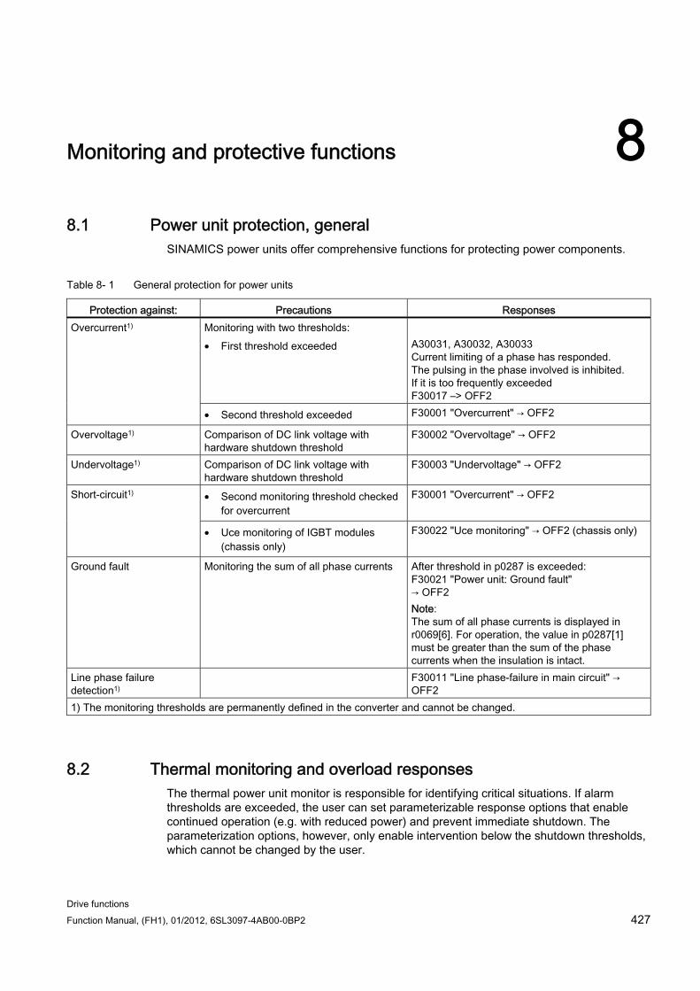
Drive functions Function Manual, (FH1), 01/2012, 6SL3097-4AB00-0BP2 427
Monitoring and protective functions 88.1 Power unit protection, general
SINAMICS power units offer comprehensive functions for protecting power components.
Table 8- 1 General protection for power units
Protection against: Precautions Responses Monitoring with two thresholds: • First threshold exceeded
A30031, A30032, A30033 Current limiting of a phase has responded. The pulsing in the phase involved is inhibited. If it is too frequently exceeded F30017 –> OFF2
Overcurrent1)
• Second threshold exceeded F30001 "Overcurrent" → OFF2
Overvoltage1) Comparison of DC link voltage with hardware shutdown threshold
F30002 "Overvoltage" → OFF2
Undervoltage1) Comparison of DC link voltage with hardware shutdown threshold
F30003 "Undervoltage" → OFF2
• Second monitoring threshold checked for overcurrent
F30001 "Overcurrent" → OFF2 Short-circuit1)
• Uce monitoring of IGBT modules (chassis only)
F30022 "Uce monitoring" → OFF2 (chassis only)
Ground fault Monitoring the sum of all phase currents After threshold in p0287 is exceeded: F30021 "Power unit: Ground fault" → OFF2 Note: The sum of all phase currents is displayed in r0069[6]. For operation, the value in p0287[1] must be greater than the sum of the phase currents when the insulation is intact.
Line phase failure detection1)
F30011 "Line phase-failure in main circuit" → OFF2
1) The monitoring thresholds are permanently defined in the converter and cannot be changed.
8.2 Thermal monitoring and overload responses The thermal power unit monitor is responsible for identifying critical situations. If alarm thresholds are exceeded, the user can set parameterizable response options that enable continued operation (e.g. with reduced power) and prevent immediate shutdown. The parameterization options, however, only enable intervention below the shutdown thresholds, which cannot be changed by the user.
Monitoring and protective functions 8.2 Thermal monitoring and overload responses
Drive functions 428 Function Manual, (FH1), 01/2012, 6SL3097-4AB00-0BP2
The following thermal monitoring options are available:
I2t monitoring - A07805 - F30005
I2t monitoring is used to protect components that have a high thermal time constant compared with semi-conductors. An overload with regard to I2t is present when the converter load r0036 is greater than 100% (load in % in relation to rated operation).
Heat-sink temperature - A05000 – F30004
Is used to monitor the temperature r0037.0 of the heatsink on the power semiconductors (IGBT).
Chip temperature - A05001 - F30025
Significant temperature differences can occur between the IGBT barrier junction and the heat sink. The calculated barrier junction temperature is displayed in r0037[13...18]; the monitoring ensures that the specified maximum barrier junction temperature is not exceeded.
If an overload occurs with respect to any of these three monitoring functions, an alarm is first output. The alarm threshold p0294 (I2t monitoring) can be parameterized relative to the shutdown (trip) values.
Example The temperature difference between two sensors must not exceed more than 15 Kelvin (K); a temperature difference of 5 K is set for the temperature monitoring of the heat sink and the air intake. This means that 15 K or 5 K below the shutdown threshold an alarm is issued regarding the pending overtemperature. Using p0294, it is only possible to change the alarm threshold so that an alarm is received earlier. This means that an intervention can then be made in the drive process (e.g. reduce the load, reduce the ambient temperature).
Overload responses The power unit responds with alarm A07805. The Control Unit initiates the parameterized responses via p0290 at the same time that the alarm is issued. Possible responses include:
Reducing the pulse frequency (p0290 = 2, 3)
This is a highly effective method of reducing losses in the power unit, since switching losses account for a high proportion of the overall losses. In many applications, a temporary reduction in pulse frequency is tolerable in order to maintain the process.
Disadvantage:
Reducing the pulse frequency increases the current ripple which, in turn, can increase the torque ripple on the motor shaft (with low inertia load), thereby increasing the noise level. Reducing the pulse frequency does not affect the dynamic response of the current control circuit, since the sampling time for the current control circuit remains constant.
Reducing the output frequency (p0290 = 0, 2)
This variant is recommended when you do not need to reduce the pulse frequency or the pulse frequency has already been set to the lowest level. Further, the load should also have a characteristic similar to the fan, that is, a quadratic torque characteristic with falling speed. Reducing the output frequency significantly reduces the converter output current which, in turn, reduces the losses in the power unit.
Monitoring and protective functions 8.2 Thermal monitoring and overload responses
Drive functions Function Manual, (FH1), 01/2012, 6SL3097-4AB00-0BP2 429
No reduction (p0290 = 1)
You should choose this option if it is neither possible to reduce the pulse frequency nor reduce the output current. The converter does not change its operating point once an alarm threshold has been overshot, which means that the drive can be operated until it reaches its shutdown values. Once it reaches its shutdown threshold, the converter switches itself off with alarm A05000 (power unit: Overtemperature inverter heat sink), A05001 (power unit: Overtemperature chip) or A07850 (drive: Power unit overload I2t). The time until shutdown, however, is not defined and depends on the degree of overload.
Control Unit CU310-2 has an electronically controlled fan. If the integrated sensor detects an overtemperature, the integrated fan is started to cool the Control Unit.
Function diagrams (see SINAMICS S120/S150 List Manual) 8014 Thermal monitoring, power unit
Overview of important parameters (see SINAMICS S120/S150 List Manual) r0036 CO: Power unit overload I2t
r0037 CO: Power unit temperatures
p0290 Power unit overload response
p0294 Power unit alarm for I2t overload
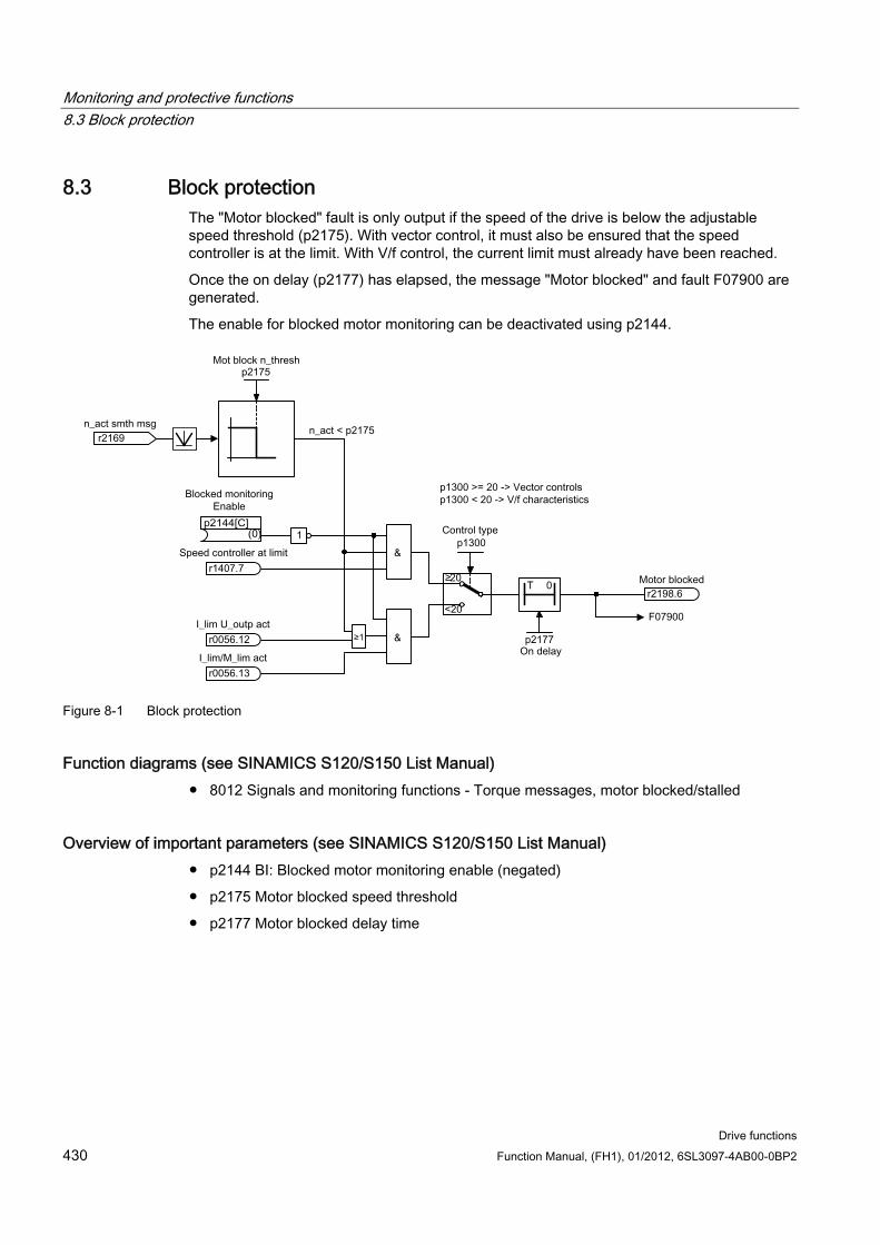
Monitoring and protective functions 8.3 Block protection
Drive functions 430 Function Manual, (FH1), 01/2012, 6SL3097-4AB00-0BP2
8.3 Block protection The "Motor blocked" fault is only output if the speed of the drive is below the adjustable speed threshold (p2175). With vector control, it must also be ensured that the speed controller is at the limit. With V/f control, the current limit must already have been reached.
Once the on delay (p2177) has elapsed, the message "Motor blocked" and fault F07900 are generated.
The enable for blocked motor monitoring can be deactivated using p2144.
Figure 8-1 Block protection
Function diagrams (see SINAMICS S120/S150 List Manual) 8012 Signals and monitoring functions - Torque messages, motor blocked/stalled
Overview of important parameters (see SINAMICS S120/S150 List Manual) p2144 BI: Blocked motor monitoring enable (negated)
p2175 Motor blocked speed threshold
p2177 Motor blocked delay time
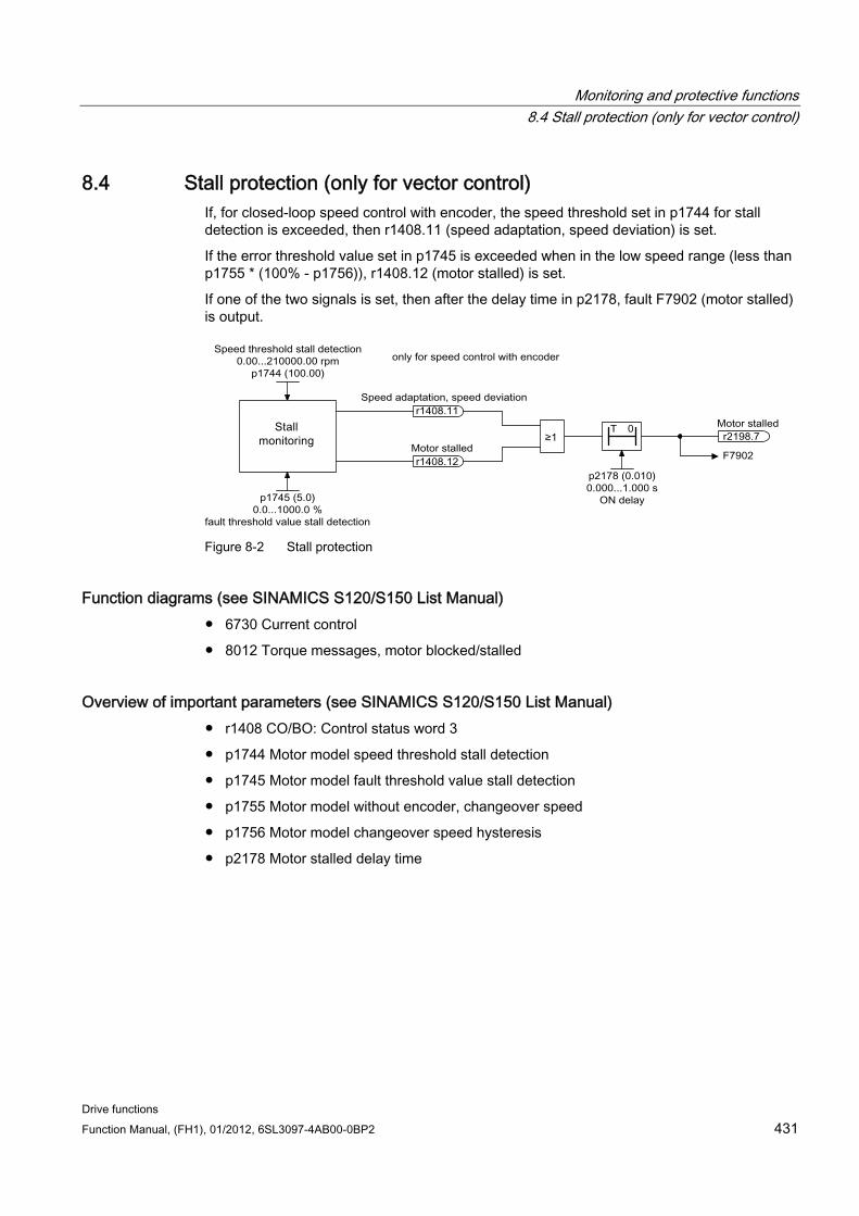
Monitoring and protective functions 8.4 Stall protection (only for vector control)
Drive functions Function Manual, (FH1), 01/2012, 6SL3097-4AB00-0BP2 431
8.4 Stall protection (only for vector control) If, for closed-loop speed control with encoder, the speed threshold set in p1744 for stall detection is exceeded, then r1408.11 (speed adaptation, speed deviation) is set.
If the error threshold value set in p1745 is exceeded when in the low speed range (less than p1755 * (100% - p1756)), r1408.12 (motor stalled) is set.
If one of the two signals is set, then after the delay time in p2178, fault F7902 (motor stalled) is output.
Figure 8-2 Stall protection
Function diagrams (see SINAMICS S120/S150 List Manual) 6730 Current control
8012 Torque messages, motor blocked/stalled
Overview of important parameters (see SINAMICS S120/S150 List Manual) r1408 CO/BO: Control status word 3
p1744 Motor model speed threshold stall detection
p1745 Motor model fault threshold value stall detection
p1755 Motor model without encoder, changeover speed
p1756 Motor model changeover speed hysteresis
p2178 Motor stalled delay time
Monitoring and protective functions 8.5 Thermal motor protection
Drive functions 432 Function Manual, (FH1), 01/2012, 6SL3097-4AB00-0BP2
8.5 Thermal motor protection The thermal motor protection monitors the motor temperature and responds to overtemperature conditions with alarms or faults. The motor temperature is either measured with sensors in the motor, or is calculated without sensors, using a temperature model from the operating data of the motor. Combinations of temperature measurement and taking into consideration a motor temperature model are possible. As soon as critical motor temperatures are determined, measures to protect the motor are initiated.
For thermal motor protection with temperature sensors, the motor temperature is directly measured in the motor windings. The temperature sensors are either connected to the Control Unit, the Motor Module or supplementary modules. The determined temperature values are sent to the Control Unit, which then responds according to the parameter settings. When switching on again after a power failure, the actual motor temperatures are immediately available.
With thermal motor protection without temperature sensors, different thermal motor models are used for calculation. The temperatures according to the motor temperature model are calculated from the motor operating data. For a 3-mass model, the masses of the motor parts and the type of ventilation, for the I2t model (for synchronous motors), the motor current in relation to the operating time is taken into consideration in the calculation. For motor temperature protection without temperature sensor, p0600[0...n] is set to 0, p0612.00 to 1 and p0612.01 to 1. (For more information, see Chapter, Temperature model.)
If you are using motors from the motor lists, or with integrated DRIVE-CLiQ connection, the relevant motor data is automatically transferred to the Control Unit.
In the control type "Vector Control", using p0610 the reaction of the drive to a detected motor overtemperature can be parameterized. The motor may either be switched off immediately – or continue to operate at reduced power, reduced load, under adapted conditions.
8.5.1 Thermal motor models Thermal motor models are used so that thermal motor protection without a temperature sensor or with temperature sensor deactivated (p0600 = 0) is guaranteed. The simultaneous use of temperature sensors and a thermal motor model also make sense. For example, a very fast temperature increase, which is not detected by the sensors in sufficient time, can potentially damage motor. This situation can occur for motors with a low thermal capacity.
Monitoring and protective functions 8.5 Thermal motor protection
Drive functions Function Manual, (FH1), 01/2012, 6SL3097-4AB00-0BP2 433
Depending on the particular model, the temperature rise is either assigned different motor parts (stator, rotor), or is calculated from the motor current and the thermal time constant. A combination of motor temperature model with additional temperature sensors can also be used.
WARNING Ambient temperatures
A thermal motor model cannot fully replace a sensor. The thermal model cannot protect the motor if incorrectly installed, for increased ambient temperatures or if errors were made in the parameter settings. Without temperature sensors, thermal motor models are not in a position to identify or take into account the ambient temperatures or the initial motor temperature.
8.5.1.1 Thermal motor model 1 Thermal motor model 1 is only used for synchronous motors. It is based on a continuous current measurement. The dynamic load of the motor is determined from the motor current and the motor model time constant. The actual value of the motor winding temperature can be measured using a temperature sensor and subsequently taken into account.
The thermal I2t motor model is activated with p0612.00 = 1.
The motor utilization is displayed in parameter r0034. Parameter r0034 is calculated from the following values:
Absolute current actual value r0068
I2t motor model thermal time constant p0611
Motor stall current p0318
Measured motor temperature r0035
When the alarm threshold p0605 is exceeded, alarm A07012 "Motor temperature model overtemperature" is output.
If the fault threshold p0615 is exceeded, fault F07011 "Motor overtemperature" is output.
8.5.1.2 Thermal motor model 2 The thermal motor model 2 is used for induction motors. It is a thermal 3-mass model.
The thermal 3-mass model is activated with p0612.01 = 1. Enter the total motor mass in p0344. The 3-mass model splits up the total motor mass as follows:
p0617 = thermally active iron mass (stator): laminated cores and frame) as a percentage of p0344
p0618 = thermally active copper mass (stator: windings) as a percentage of p0344
p0619 = thermally active rotor mass (rotor) as a percentage of p0344
p0625 = ambient temperature
p0626 = overtemperature, stator iron
Monitoring and protective functions 8.5 Thermal motor protection
Drive functions 434 Function Manual, (FH1), 01/2012, 6SL3097-4AB00-0BP2
p0627 = overtemperature, stator winding
p0628 = rotor winding temperature rise
Motor temperature rises are calculated on the basis of motor measured values. The calculated temperature rises are indicated in the parameters:
r0630 Motor temperature model ambient temperature
r0631 Motor temperature model stator iron temperature
r0632 Motor temperature model stator winding temperature
r0633 Motor temperature model rotor temperature
When operated with an additional KTY84 temperature sensor, the calculated temperature value from thermal motor model 2 is continuously corrected to track the measured temperature value. After deactivating the temperature sensor with p0600 = 0, the calculation continues with the last measured temperature value.
8.5.1.3 Thermal motor model 3 Thermal motor model 3 is intended exclusively for use with motors with the 1FK7Basis design. This motor design has no integrated temperature sensors. The thermal motor model 3 is a thermal 3-mass model. It is activated with p0612.02 = 1. The necessary parameters are automatically transferred when commissioning via DRIVE-CLiQ.
Motor temperature rises are calculated on the basis of motor measured values. The calculated temperature rises are indicated in the parameters:
r0034 motor utilization
r0630 Motor temperature model ambient temperature
r0631 Motor temperature model stator iron temperature
r0632 Motor temperature model stator winding temperature
r0633 Motor temperature model rotor temperature
Table 8- 2 List of motors
Motor type 1 1FK7041 - 8GF71 2 1FK7042 - 8GF71 3 1FK7060 - 8GF71 4 1FK7063 - 8GF71 5 1FK7100 - 8FC71 6 1FK7101 - 8FC71 7 1FK7103 - 8FB71 8 1FK7105 - 8FB71
Monitoring and protective functions 8.5 Thermal motor protection
Drive functions Function Manual, (FH1), 01/2012, 6SL3097-4AB00-0BP2 435
Function diagrams (see SINAMICS S120/S150 List Manual) 8016 Thermal motor monitoring
8017 Thermal motor models (only for synchronous motor, p0300 = xxx)
Overview of important parameters (see SINAMICS S120/S150 List Manual)
Thermal motor model 1
r0034 CO: Motor utilization
p0318[0...n] motor stall current
p0605[0...n] mot_temp_mod threshold
p0612[0...n] Motor temperature model activation
p0615[0...n] mot_temp_mod fault threshold
Thermal motor model 2
p0344[0...n] Motor mass
p0612[0...n] Motor temperature model activation
p0617[0...n] Stator thermally relevant iron component
p0618[0...n] Stator thermally relevant copper component
p0619[0...n] rotor thermally relevant mass
p0625[0...n] Motor ambient temperature
p0626[0...n] Motor ambient temperature stator iron
p0627[0...n] Motor ambient temperature stator winding
p0628[0...n] Motor ambient temperature rotor winding
r0630[0...n] mot_temp_mod ambient temperature
r0631[0...n] mot_temp_mod stator iron temperature
r0632[0...n] mot_temp_mod stator winding temperature
r0633[0...n] mot_temp_mod rotor temperature
Thermal motor model 3
p0612[0...n] Motor temperature model activation
r0630[0...n] mot_temp_mod ambient temperature
r0631[0...n] mot_temp_mod stator iron temperature
r0632[0...n] mot_temp_mod stator winding temperature
r0633[0...n] mot_temp_mod rotor temperature
Monitoring and protective functions 8.5 Thermal motor protection
Drive functions 436 Function Manual, (FH1), 01/2012, 6SL3097-4AB00-0BP2
8.5.2 Motor temperature sensing
Temperature sensors The motor temperature is sensed using temperature sensors integrated in the motor windings. The sensors used are selected as standard from the following four different sensor types:
1. PTC
2. KTY84
3. PT100/PT1000
4. Bimetallic sensor with NC contact (abbreviated, "bimetal NC contact")
Function of the PTC The temperature sensor is connected to the Sensor Module at the appropriate terminals (-Temp) and (+Temp) (see the relevant section in the Manual SINAMICS S120 Control Units and Supplementary System Components). The threshold value for switching over to an alarm or fault is 1650 Ω.
A PTC usually has a strongly non-linear characteristic, and as a consequence is used just like a switch. When the typical rated response temperature is exceeded, then the resistance changes abruptly (step function). The tripping resistance is ≥1650 Ohm.
p0600 = 1 activates the motor temperature sensing using sensor 1
p0601 = 1 sets the PTC temperature sensor type
Function of the KTY The temperature sensor is connected to the Sensor Module at the appropriate terminals (-Temp) and (+Temp) (see the relevant section in the Manual SINAMICS S120 Control Units and Supplementary System Components).
A KTY84/1C130 temperature sensor has an almost linear characteristic and is therefore also suitable for continuously measuring and displaying the motor temperature. KTY sensors are used for measuring the motor temperature in the range from -140 °C up to +188.6 °C. Temperature actual values outside this range are not taken into account.
p0600 = 1 activates the motor temperature sensing using sensor 1
p0601 = 2 sets the KTY temperature sensor type
Function of the PT100/PT1000 A PT100 or PT1000 is in principle a PTC with a very linear characteristic, and is suitable for continuous and exact temperature measurements. Not every sensor input is PT100/PT1000-capable.
p0600 = 1 activates the motor temperature sensing using sensor 1
p0601 = 5 sets the PT100 temperature sensor type
Monitoring and protective functions 8.5 Thermal motor protection
Drive functions Function Manual, (FH1), 01/2012, 6SL3097-4AB00-0BP2 437
Function of the bimetallic NC contact A bimetallic switch at a certain nominal response temperature actuates a switch. The tripping resistance is <100 Ohm. Not every sensor input is bimetal NC contact-capable.
p0600 = 1 activates the motor temperature sensing using sensor 1
p0601 = 4 sets the bimetallic NC contact temperature sensor type
Temperature sensor type for multiple temperature channels If you use several temperature channels, set p0601 = 10. Then the sensors are interconnected via BICO
8.5.3 Sensor Modules Sensor Modules are needed when additional temperature sensors are to be connected via DRIVE-CLiQ. Various Sensor Modules are available to do this:
Sensor Module Cabinet-Mounted (SMC) for rail mounting in control cabinets
Sensor Module External (SME) in degree of protection IP67, installed close to the motor
PTC and KTY84 temperature sensors – and in some cases – bimetallic NC contacts, can be connected to the Sensor Modules.
Table 8- 3 Temperature sensor connection
Device Interface +Temp -Temp Temperature sensor type SMC10 X520 13 25 KTY84 / PTC SMC20 X520 13 25 KTY84 / PTC
X520 1 8 KTY84 / PTC SMC30 X531 4 3 KTY84 / PTC
SME20 X100 9 7 KTY84 / PTC SME25 - - A temperature sensor cannot be connected SME120 X200 See below KTY84/PTC/bimetallic NC contact SME125 X200 See below KTY84/PTC/bimetallic NC contact
8.5.4 Sensor Module Cabinet-Mounted A Sensor Module Cabinet-Mounted (SMCx0) evaluates the sensor signals. The results are transferred to the drive for further processing via DRIVE-CLiQ. The SMCx0 is intended for operation in a control cabinet. SMC10, SMC20 and SMC30 differ regarding the sensor interfaces. They have the same function for detecting the motor temperature. An SMC30 offers to alternative encoder connections. The encoder can either be connected at interface X520, a 15 pin Sub-D connector – or at interface X521/X531, via terminal strip.
Monitoring and protective functions 8.5 Thermal motor protection
Drive functions 438 Function Manual, (FH1), 01/2012, 6SL3097-4AB00-0BP2
8.5.5 Sensor Module External A Sensor Module External (SME) is required if the sensor interface is to be installed close to the motor sensor outside a control cabinet. The SME has an IP67 degree of protection.
8.5.6 Sensor Module SME 20/25
Sensor Module External 20/25 The SME20 and SME25 evaluate encoder and sensor data. The calculated values are transferred to the Control Unit via DRIVE-CLiQ. SME20 and SME25 differ regarding the encoder interface.
A temperature sensor cannot be connected to the SME25 to sense the motor temperature. Instead, use an SME125.
8.5.7 Sensor Module External 120/125 A Sensor Module External 120 (SME120) or Sensor Module External 125 (SME125) is required for the following application conditions:
The sensor interface is installed close to the motor outside a control cabinet
Several motor temperature channels are required
The motor temperature sensors do not have safe protective separation
Safe protective separation is not possible.
SME12x has an IP67 degree of protection. SME12x are particularly suitable for linear and torque motor applications.
If r0458[0...2].8 = 1, up to three temperature sensors can be connected at terminal block X200. Each sensor is assigned to a temperature channel.
The SME12x evaluates the data of the temperature sensors and makes the calculated values available via DRIVE-CLiQ for further processing.
Table 8- 4 Assignment of terminal strip X200 for the temperature sensors
Terminal Function Channel
Parameter Temperature sensor type
1 -Temp 2 +Temp
2 p4601[0] KTY84/PTC/bimetallic NC contact Linear and torque motors: KTY84
3 +Temp 4 -Temp
3 p4602[0] KTY84/PTC/bimetallic NC contact Linear and torque motors: PTC – triplet 1 or bimetal NC contact
5 +Temp 6 -Temp
4 p4603[0] KTY84/PTC/bimetallic NC contact Linear and torque motors: PTC – triplet 1 or bimetal NC contact
Monitoring and protective functions 8.5 Thermal motor protection
Drive functions Function Manual, (FH1), 01/2012, 6SL3097-4AB00-0BP2 439
Temperature measurement p0600 = 1/2/3 selects the additional motor temperature measurement via channels 2 to 4.
p0601 = 10 activates the evaluation via several temperature channels SME12x.
KTY84 p4601[0...n] to p4603[0...n] = 20 sets temperature sensor type KTY.
If the value in parameter r4620[0...3] is not equal -200 °C, then the temperature display is valid. The actual value of the temperature sensors is displayed:
– r4620[1] temperature sensors from channel 2
– r4620[2] temperature sensors from channel 3
– r4620[3] temperature sensors from channel 4
PTC p4601[0...n] to p4603[0...n] = 10/11/12 sets the temperature sensor type PTC, the
evaluation type and activates the evaluation.
– p4601[0...n] = 10 PTC fault
– p4601[0...n] = 11 PTC alarm
– p4601[0...n] = 12 PTC alarm and timer
r4620[0...3] = -200 °C.
Bimetallic NC contact p4601[0...n] to p4603[0...n] = 30/31/32 sets the temperature sensor type bimetal NC
contact, the evaluation type and activates the evaluation.
– p4601[0...n] = 30 bimetal NC contact fault
– p4601[0...n] = 31 bimetal NC contact alarm
– p4601[0...n] = 32 bimetal NC contact alarm and timer
r4620[0...3] = -200 °C.
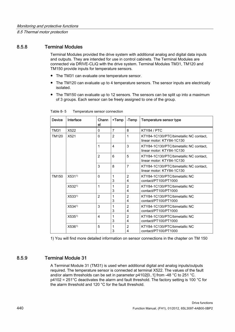
Monitoring and protective functions 8.5 Thermal motor protection
Drive functions 440 Function Manual, (FH1), 01/2012, 6SL3097-4AB00-0BP2
8.5.8 Terminal Modules Terminal Modules provided the drive system with additional analog and digital data inputs and outputs. They are intended for use in control cabinets. The Terminal Modules are connected via DRIVE-CLiQ with the drive system. Terminal Modules TM31, TM120 and TM150 provide inputs for temperature sensors.
The TM31 can evaluate one temperature sensor.
The TM120 can evaluate up to 4 temperature sensors. The sensor inputs are electrically isolated.
The TM150 can evaluate up to 12 sensors. The sensors can be split up into a maximum of 3 groups. Each sensor can be freely assigned to one of the group.
Table 8- 5 Temperature sensor connection
Device Interface Channel
+Temp -Temp Temperature sensor type
TM31 X522 0 7 8 KTY84 / PTC 0 2 1 KTY84-1C130/PTC/bimetallic NC contact,
linear motor: KTY84-1C130 1 4 3 KTY84-1C130/PTC/bimetallic NC contact,
linear motor: KTY84-1C130 2 6 5 KTY84-1C130/PTC/bimetallic NC contact,
linear motor: KTY84-1C130
TM120 X521
3 8 7 KTY84-1C130/PTC/bimetallic NC contact, linear motor: KTY84-1C130
X5311) 0 1 3
2 4
KTY84-1C130/PTC/bimetallic NC contact/PT100/PT1000
X5321) 1 1 3
2 4
KTY84-1C130/PTC/bimetallic NC contact/PT100/PT1000
X5331) 2 1 3
2 4
KTY84-1C130/PTC/bimetallic NC contact/PT100/PT1000
X5341) 3 1 3
2 4
KTY84-1C130/PTC/bimetallic NC contact/PT100/PT1000
X5351) 4 1 3
2 4
KTY84-1C130/PTC/bimetallic NC contact/PT100/PT1000
TM150
X5361) 5 1 3
2 4
KTY84-1C130/PTC/bimetallic NC contact/PT100/PT1000
1) You will find more detailed information on sensor connections in the chapter on TM 150
8.5.9 Terminal Module 31 A Terminal Module 31 (TM31) is used when additional digital and analog inputs/outputs required. The temperature sensor is connected at terminal X522. The values of the fault and/or alarm thresholds can be set in parameter p4102[0..1] from -48 °C to 251 °C. p4102 = 251°C deactivates the alarm and fault threshold. The factory setting is 100 °C for the alarm threshold and 120 °C for the fault threshold.
Monitoring and protective functions 8.5 Thermal motor protection
Drive functions Function Manual, (FH1), 01/2012, 6SL3097-4AB00-0BP2 441
Temperature measurement p0600 = 10 activates the motor temperature measurement via the external sensor.
p0603 sets the signal source for the evaluation of the motor temperature
p4100 = 0 disables the evaluation. Then parameter r4105 = -300°C.
PTC p4100 = 1 sets the PTC temperature sensor type and activates the evaluation.
r4105 indicates the following values:
– If the temperature actual value is less than the nominal response temperature, then -50°C is displayed.
– If the temperature actual value is higher than the nominal response temperature, then 250 °C is displayed.
– If the actual temperature value is invalid (F35920 initiated), then -300°C is displayed.
– If p4100 = 0, -300°C is displayed.
KTY84 p4100 = 2 sets the KTY84 temperature sensor type and activates the evaluation.
r4105 indicates the following values:
– The actual temperature value of the temperature evaluation
– -300 °C if no sensor has been selected or the temperature actual value is invalid
8.5.10 Terminal Module 120 If the temperature sensors in the installed motors do not have protective separation, then you require a Terminal Module 120 (TM120). Up to 4 different temperature sensors can be connected to the TM120. The TM120 senses the temperature actual values and evaluates them. The fault and alarm thresholds (p4102) of the temperature actual values can be set from -48 °C up to 251°C. Temperature sensors are connected at the TM120 at terminal strip X521 according to the table above.
You will find additional information on this topic in the SINAMICS S120 Control Units and Additional Components Manual.
Temperature measurement p0600[0...n] = 20 or 21 activates the motor temperature sensing via an external sensor.
p0601[0...n] = 11 sets the evaluation for several temperature channels.
p0608[0...3] allocates the temperature channels for the motor temperatures to signal source 2.
Monitoring and protective functions 8.5 Thermal motor protection
Drive functions 442 Function Manual, (FH1), 01/2012, 6SL3097-4AB00-0BP2
p0609[0...3] allocates the temperature channels for the motor temperatures to signal source 3.
p4100[0...n] = 0 deactivates temperature evaluation.
r4101[0...3] indicates the actual resistance value of the respective temperature sensor. The maximum measurable resistance is 2170 Ω.
p4102[0/2/4/6] sets the alarm thresholds of the temperature sensors to between -48 °C and 250 °C.
p4102[1/3/5/7] sets the fault thresholds of the temperature sensors to between -48 °C and 250 °C.
p4102[0...7] = 251 °C deactivates the alarm and/or fault message that has been set.
p4610[0...n] to p4613[0...n], assigns up to four temperature sensors to the motor and defines the responses.
r4620[0...3] ≠ -200 °C means:
– a KTY84 is connected
– the temperature display is valid.
r4620[0...3] = -200 °C means:
– a PTC or a bimetal NC contact is connected
– there is a temperature sensor fault
– the sensor channel is deactivated
– the temperature evaluation is deactivated
KTY84 p4100[0...3] = 2 assigns the temperature sensor type KTY84 to a corresponding channel
1 to 4, and activates the evaluation.
r4105[0...3] displays the temperature actual value of the measuring channel involved of the temperature evaluation. If no sensor has been selected or if the temperature actual value is invalid, the value -300 °C is in the parameter.
PTC p4100[0...3] = 1, sets temperature sensor type PTC to the corresponding channel 1 to 4,
and activates the evaluation.
r4105[0...3] displays the temperature actual value of the temperature evaluation.
– If the temperature actual value is lower than the rated response temperature, then r4105[0...3] is set to -50 °C.
– If the temperature actual value is higher than the rated response temperature, then r4105[0...3] is set to 250 °C.
– If no sensor has been selected or if the temperature actual value is invalid, then r4105[0...3] is set to -300 °C.

Monitoring and protective functions 8.5 Thermal motor protection
Drive functions Function Manual, (FH1), 01/2012, 6SL3097-4AB00-0BP2 443
Bimetallic NC contact p4100[0...3] = 4 sets the temperature sensor type bimetal NC contact, and activates the
evaluation.
r4105[0...3] displays the temperature actual value of the temperature evaluation.
– If the temperature actual value is lower than the rated response temperature, then r4105[0...3] is set to -50 °C.
– If the temperature actual value is higher than the rated response temperature, then r4105[0...3] is set to 250 °C.
– If no sensor has been selected or if the temperature actual value is invalid, then r4105[0...3] is set to -300 °C.
8.5.11 Terminal Module 150 The Terminal Module 150 (TM150) has 6x 4-pole terminals for temperature sensors. Temperature sensors can be connected in a 1x2, 1x3 or 1x4-wire system. In a 2x2-wire system, up to 12 input channels can be evaluated. 12 input channels can be evaluated in the factory setting. The temperature channels of a TM150 can be subdivided into 3 groups and evaluated together.
The TM150 can acquire the signals from KTY84, PTC, bimetallic NC contact, PT100 and PT1000 temperature sensors and evaluate them. The fault and/or alarm thresholds of the temperature values can be set from -99 °C up to 251°C. The temperature sensors are connected at terminal strip X531 to X536 according to the following table.
The TM150 temperature inputs are not electrically isolated.
You can find additional information in the function diagrams 9625, 9626 and 9627 in the SINAMICS S120/S150 List Manual.
Selecting the sensor types p4100[0...11] sets the sensor type for the respective temperature channel.
r4105[0...11] indicates the actual value of the temperature channel.
– For switching temperature sensors, such as e.g. PTC and bimetallic NC contact, symbolically two limit values are displayed:
– r4105[0...11] = -50°C: The temperature actual value is below the rated response temperature.
– r4105[0...11] = +250°C: The temperature actual value is above the rated response temperature.
NOTICE
For PTC and bimetallic NC contact the following applies:
What is shown in r4105[0...11] does not correspond to the actual temperature value.
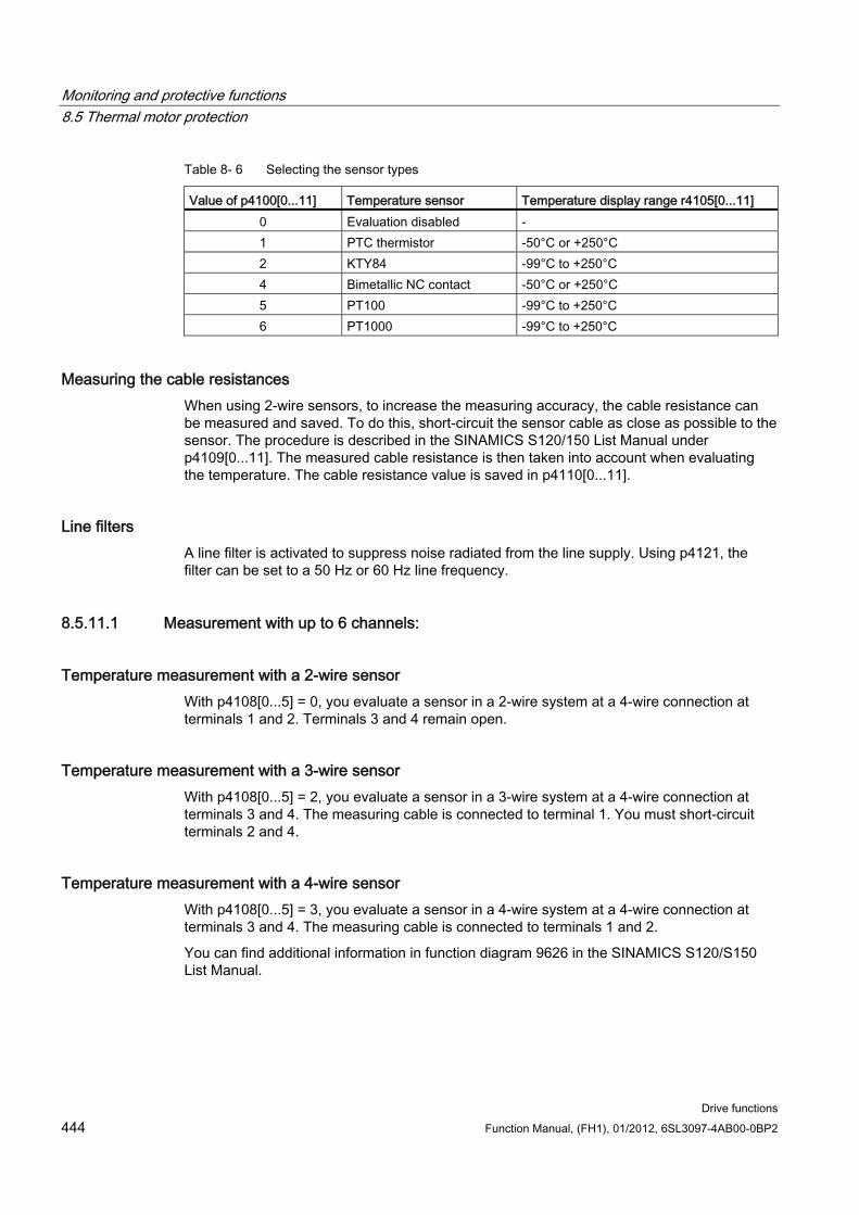
Monitoring and protective functions 8.5 Thermal motor protection
Drive functions 444 Function Manual, (FH1), 01/2012, 6SL3097-4AB00-0BP2
Table 8- 6 Selecting the sensor types
Value of p4100[0...11] Temperature sensor Temperature display range r4105[0...11] 0 Evaluation disabled - 1 PTC thermistor -50°C or +250°C 2 KTY84 -99°C to +250°C 4 Bimetallic NC contact -50°C or +250°C 5 PT100 -99°C to +250°C 6 PT1000 -99°C to +250°C
Measuring the cable resistances When using 2-wire sensors, to increase the measuring accuracy, the cable resistance can be measured and saved. To do this, short-circuit the sensor cable as close as possible to the sensor. The procedure is described in the SINAMICS S120/150 List Manual under p4109[0...11]. The measured cable resistance is then taken into account when evaluating the temperature. The cable resistance value is saved in p4110[0...11].
Line filters A line filter is activated to suppress noise radiated from the line supply. Using p4121, the filter can be set to a 50 Hz or 60 Hz line frequency.
8.5.11.1 Measurement with up to 6 channels:
Temperature measurement with a 2-wire sensor With p4108[0...5] = 0, you evaluate a sensor in a 2-wire system at a 4-wire connection at terminals 1 and 2. Terminals 3 and 4 remain open.
Temperature measurement with a 3-wire sensor With p4108[0...5] = 2, you evaluate a sensor in a 3-wire system at a 4-wire connection at terminals 3 and 4. The measuring cable is connected to terminal 1. You must short-circuit terminals 2 and 4.
Temperature measurement with a 4-wire sensor With p4108[0...5] = 3, you evaluate a sensor in a 4-wire system at a 4-wire connection at terminals 3 and 4. The measuring cable is connected to terminals 1 and 2.
You can find additional information in function diagram 9626 in the SINAMICS S120/S150 List Manual.
Monitoring and protective functions 8.5 Thermal motor protection
Drive functions Function Manual, (FH1), 01/2012, 6SL3097-4AB00-0BP2 445
8.5.11.2 Measurement with up to 12 channels:
Temperature measurement with two 2-wire sensors With p4108[0...5] = 1 you can acquire the signals from two sensors in 2-wire technology. The first sensor is connected to terminals 1 and 2. The second sensor (number = first sensor + 6) is connected at terminals 3 and 4. You can find additional information in function diagram 9627 in the SINAMICS S120/S150 List Manual.
When connecting two 2-wire sensors to terminal X531, the first sensor is assigned to temperature channel 1 and the second sensor is assigned to channel 7 (1+6).
Up to 12 temperature sensors can be connected to a TM150.
NOTICE Connection diagram for 12 temperature channels
The temperature sensors connected to a TM150 are not numbered consecutively. The first 6 temperature channels retain their numbering of 0 to 5. The other 6 temperature channels are consecutively numbered from 6 to 11, starting at terminal X531. (see function diagram 9627 in the SINAMICS S120/150 List Manual)
Example of 8 temperature channels:
2x2 conductors at terminal X531: p4108[0] = 1 ≙ sensor 1 is at channel 0 and sensor 2 is at channel 6 2x2 conductor at terminal X532: p4108[1] = 1 ≙ sensor 1 is at channel 1 and sensor 2 is at channel 7 1x3 conductor at terminal X533: p4108[2] = 2 ≙ sensor 1 is at channel 2 1x3 conductor is at terminal X534: p4108[3] = 2 ≙ sensor 1 is at channel 3 1x4 conductor is at terminal X535: p4108[4] = 3 ≙ sensor 1 is at channel 4 1x2 conductor is at terminal X536: p4108[5] = 0 ≙ sensor 1 is at channel 5
8.5.11.3 Forming groups of temperature sensors You can combine the temperature channels to form groups using parameter p4111[0...2]. For each group, the following calculated values are provided from the temperature actual values (r4105[0...11]):
Maximum: r4112[0...2], (index 0,1,2 = group 0,1,2)
Minimum: r4113[0...2]
Average value: r4114[0...2]
Example:
The temperature actual value from channels 0, 3, 7, and 9 should be combined in group 1:
p4111[1].0 = 1
p4111[1].3 = 1
p4111[1].7 = 1
p4111[1].9 = 1
Monitoring and protective functions 8.5 Thermal motor protection
Drive functions 446 Function Manual, (FH1), 01/2012, 6SL3097-4AB00-0BP2
The calculated values from group 1 are available in the following parameters for interconnection:
r4112[1] = maximum
r4113[1] = minimum
r4114[1] = average value
NOTICE Forming groups of temperature channels
Only form groups of continuously measuring temperature sensors. The switching temperature sensors PTC and bimetallic NC contacts are only assigned two temperatures - 50°C and +250°C, depending on the state. Within a group with continuous temperature actual values, the calculation of the maximum/minimum/average value temperature is significantly falsified by taking into account switching temperature sensors.
8.5.11.4 Evaluating temperature channels For each of the individual 12 temperature channels, an alarm threshold and a fault threshold can be set in p4102[0...23]. The even parameter indices contain the alarm threshold and the uneven parameter indices, the fault threshold. The temperature thresholds can be set between -99°C and +251°C for each channel.
If the evaluation of the temperature actual value from p4105[0...11] exceeds the alarm threshold set in p4102[0...23], then an alarm is output at r4104.0...23. Timer p4103[0...11] is started at the same time.
If, after the timer has expired, the temperature actual value is still above the alarm threshold, then an appropriate fault is output. This fault can be acknowledged as soon as the temperature actual value is again below the alarm threshold.
If the evaluation of the temperature actual value from p4105[0...11] has exceeded the fault threshold set in p4102[0...23], then the corresponding fault is immediately activated.
Using p4118[0...11], a hysteresis for p4102[0...23] can be set for each channel.
Using p4119[0...11], a filter can be activated to smooth the temperature signal for each channel.
The time constant of the filter depends on the number of active temperature channels and can be read in r4120.
Failure of a sensor Using parameter p4117[0...2], the response to the failure of a temperature sensor can be set within a group:
p4117 = 0 is set. The failed sensor is not taken into account.
p4117 = 1 is set. The group outputs the value -300 °C to the outputs for the maximum value, minimum value and the mean value.
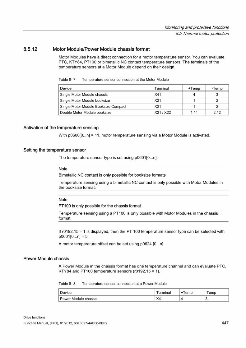
Monitoring and protective functions 8.5 Thermal motor protection
Drive functions Function Manual, (FH1), 01/2012, 6SL3097-4AB00-0BP2 447
8.5.12 Motor Module/Power Module chassis format Motor Modules have a direct connection for a motor temperature sensor. You can evaluate PTC, KTY84, PT100 or bimetallic NC contact temperature sensors. The terminals of the temperature sensors at a Motor Module depend on their design.
Table 8- 7 Temperature sensor connection at the Motor Module
Device Terminal +Temp -Temp Single Motor Module chassis X41 4 3 Single Motor Module booksize X21 1 2 Single Motor Module Booksize Compact X21 1 2 Double Motor Module booksize X21 / X22 1 / 1 2 / 2
Activation of the temperature sensing With p0600[0...n] = 11, motor temperature sensing via a Motor Module is activated.
Setting the temperature sensor The temperature sensor type is set using p0601[0...n].
Note Bimetallic NC contact is only possible for booksize formats
Temperature sensing using a bimetallic NC contact is only possible with Motor Modules in the booksize format.
Note PT100 is only possible for the chassis format
Temperature sensing using a PT100 is only possible with Motor Modules in the chassis format.
If r0192.15 = 1 is displayed, then the PT 100 temperature sensor type can be selected with p0601[0...n] = 5.
A motor temperature offset can be set using p0624 [0...n].
Power Module chassis A Power Module in the chassis format has one temperature channel and can evaluate PTC, KTY84 and PT100 temperature sensors (r0192.15 = 1).
Table 8- 8 Temperature sensor connection at a Power Module
Device Terminal +Temp -Temp Power Module chassis X41 4 3
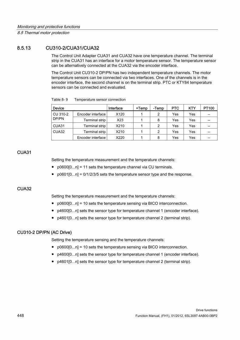
Monitoring and protective functions 8.5 Thermal motor protection
Drive functions 448 Function Manual, (FH1), 01/2012, 6SL3097-4AB00-0BP2
8.5.13 CU310-2/CUA31/CUA32 The Control Unit Adapter CUA31 and CUA32 have one temperature channel. The terminal strip in the CUA31 has an interface for a motor temperature sensor. The temperature sensor can be alternatively connected at the CUA32 via the encoder interface.
The Control Unit CU310-2 DP/PN has two independent temperature channels. The motor temperature sensors can be connected via two interfaces. One of the channels is in the encoder interface, the second channel is on the terminal strip. PTC or KTY84 temperature sensors can be connected and evaluated.
Table 8- 9 Temperature sensor connection
Device Interface +Temp -Temp PTC KTY PT100 Encoder interface X120 1 2 Yes Yes -- CU 310-2
DP/PN Terminal strip X23 1 8 Yes Yes -- CUA31 Terminal strip X210 1 2 Yes Yes --
Terminal strip X210 1 2 Yes Yes -- CUA32 Encoder interface X220 1 8 Yes Yes --
CUA31 Setting the temperature measurement and the temperature channels:
p0600[0...n] = 11 sets the temperature channel via CU terminals.
p0601[0...n] = 0/1/2/3/5 sets the temperature sensor type and the response.
CUA32 Setting the temperature measurement and the temperature channels:
p0600[0...n] = 10 sets the temperature sensing via BICO interconnection.
p4600[0...n] sets the sensor type for temperature channel 1 (encoder interface).
p4601[0...n] sets the sensor type for temperature channel 2 (terminal strip).
CU310-2 DP/PN (AC Drive) Setting the temperature sensing and the temperature channels:
p0600[0...n] = 10 sets the temperature sensing via BICO interconnection.
p4600[0...n] sets the sensor type for temperature channel 1 (encoder interface).
p4601[0...n] sets the sensor type for temperature channel 2 (terminal strip).
Monitoring and protective functions 8.5 Thermal motor protection
Drive functions Function Manual, (FH1), 01/2012, 6SL3097-4AB00-0BP2 449
8.5.14 Motor with DRIVE-CLiQ The motor and encoder data are saved as an electronic type plate in a motor equipped with a DRIVE-CLiQ connection. This data is transferred to the Control Unit when commissioning. As a consequence, when commissioning this motor type, all of the necessary parameters are pre-assigned and set automatically. The same is true for the parameters required to monitor the motor temperature. Other changes are not required.
The default settings for monitoring the motor temperature are:
p0600 = 1, motor temperature sensor for monitoring via encoder 1
p0601 = 2, the motor temperature sensor type is a KTY84.
p0604[0...n] motor temperature alarm threshold
p0605[0...n] motor temperature fault threshold
p0606[0...n] motor temperature timer (timer to changeover from an alarm to a fault value).
8.5.15 Temperature sensor evaluation
Temperature measurement via KTY or PT100 When the alarm threshold p0604 is exceeded, alarm A07910 is output.
For vector control, using parameter p0610, you can set the drive response when the alarm is initiated:
– 0: No response, alarm only A07910, no reduction of I_max
– 1: Alarm A07910 and fault F07011, reduction of I_max
– 2: Alarm A07910 and fault F07011, no reduction of I_max
When the fault threshold is reached (set via p0605, factory setting = 145 °C), fault F07011 is triggered in conjunction with the setting in p0610.
Temperature measurement via PTC Alarm A07910 is triggered once the PTC responds
Fault F07011 is triggered once the waiting time defined in p0606 has elapsed
Monitoring and protective functions 8.5 Thermal motor protection
Drive functions 450 Function Manual, (FH1), 01/2012, 6SL3097-4AB00-0BP2
Sensor monitoring for wire breakage/short-circuit A sensor monitoring function for a short-circuit in the sensor cable is possible for a PTC
and a KTY84 . Wire break monitoring is possible for a KTY84 sensor: If the temperature value lies outside the specified range of -140 °C ... +250 °C, then it is probable that the sensor cable either has a broken wire or short-circuit. The alarm A07015 "Drive: Motor temperature sensor alarm" is initiated. After the wait time in p0607 has expired, fault F07016 "Drive: Motor temperature sensor fault" is output.
If an induction motor is connected, you can suppress fault F07016 by setting p0607 = 0. The drive then continues to operate with the data calculated in the thermal 3-mass model.
If the motor temperature sensor set in p0600 is not connected, alarm A07820 "Temperature sensor not connected" is triggered.
8.5.16 Function diagrams and parameters
Function diagrams (see SINAMICS S120/S150 List Manual) 8016 thermal motor monitoring
8017 Thermal I2t motor model
9576 Terminal Module 31 - temperature evaluation (KTY/PTC)
9605 Terminal Module 120 - temperature evaluation, channels 1 and 2 (KTY/PTC/bimetallic switch)
9606 Terminal Module 120 - temperature evaluation, channels 3 and 4 (KTY/PTC/bimetallic switch)
9625 Terminal Module 150 - temperature evaluation structure (channel 0...11)
9626 Terminal Module 150 - temperature evaluation 1x2, 3, 4-wire (channel 0...5)
9627 Terminal Module 150 - temperature evaluation 2x2 conductor (channel 6...11)
Overview of important parameters (see SINAMICS S120/S150 List Manual) r0034 CO: Motor utilization
r0035 CO: Motor temperature
r0068 CO: Absolute current actual value
p0318[0...n] motor stall current
p0600[0...n] motor temperature sensor for monitoring
p0601[0...n] motor temperature sensor type
p0603 CI: Motor temperature signal source
p0604[0...n] motor temperature alarm threshold
p0605[0...n] motor temperature fault threshold
p0606[0...n] motor temperature timer stage
Monitoring and protective functions 8.5 Thermal motor protection
Drive functions Function Manual, (FH1), 01/2012, 6SL3097-4AB00-0BP2 451
p0607[0...n] temperature sensor fault timer stage
p0608[0...3] CI: Motor temperature, signal source 2
p0609[0...3] CI: Motor temperature, signal source 3
p0610[0...n] motor overtemperature reaction
p0624[0...n] motor temperature offset PT100
p0625[0...n] motor ambient temperature
p4600[0...n] motor temperature sensor 1 sensor type
p4601[0...n] motor temperature sensor 2 sensor type
p4602[0...n] motor temperature sensor 3 sensor type
p4603[0...n] motor temperature sensor 4 sensor type
r4620[0...3] measured motor temperature
Additional parameters for TM31 p4100 TM31 temperature evaluation sensor type
p4102[0...1] TM31 temperature evaluation, fault/alarm threshold
p4103 TM31 temperature evaluation timer
r4104.0...1 BO: TM31 temperature evaluation status
r4105 CO: TM31 temperature evaluation actual value
Additional parameters for TM120 p4100[0...3] TM120 temperature evaluation sensor type
r4101[0...3] TM120 temperature evaluation, sensor resistance
p4102[0...7] TM120 temperature evaluation, fault/alarm threshold
p4103[0...3] TM120 temperature evaluation, timer
r4104.0...7 BO: TM120 temperature evaluation status
r4105 [0...3] CO: TM120 temperature evaluation actual value
Additional parameters for TM150 p4100[0...11] TM150 temperature evaluation sensor type
r4101[0...11] TM150 temperature evaluation sensor resistance
p4102[0...23] TM150 temperature evaluation, fault/alarm threshold
p4103[0...11] TM150 temperature evaluation, timer
r4104.0...23 BO: TM150 temperature evaluation status
r4105[0...11] CO: TM150 temperature evaluation actual value
p4108[0...5] TM150 measurement method
Monitoring and protective functions 8.5 Thermal motor protection
Drive functions 452 Function Manual, (FH1), 01/2012, 6SL3097-4AB00-0BP2
p4109[0...11] TM150 cable resistance measurement
p4110[0...11] TM150 cable resistance value
p4111[0...2] TM150 group, channel assignment
r4112[0...2] CO: TM150 group temperature actual value ,maximum
r4113[0...2] CO: TM150 group temperature actual value, minimum
r4114[0...2] CO: TM150 group temperature actual value, average
p4117[0...2] TM150 group sensor fault effect
p4118[0...11] TM150 fault/alarm threshold, hysteresis
p4119[0...11] TM150 activating/deactivating smoothing
r4120 TM150 temperature filter, time constant
p4121 TM150 filter rated line frequency
Thermal motor models p0318[0...n] motor stall current
p0335[0...n] Motor cooling type/motor cooling type
p0344[0...n] Motor ground (for thermal motor model)
p0611[0...n] I2t motor model, thermal time constant
p0612[0...n] thermal motor model configuration
p0615[0...n] I2t motor model, fault threshold
p0617[0...n] thermally relevant iron in the stator
p0618[0...n] thermally relevant copper in the stator
p0619[0...n] thermally relevant mass of the rotor
p0620[0...n] Thermal adaptation stator and rotor resistance
p0625[0...n] Motor ambient temperature
Drive functions Function Manual, (FH1), 01/2012, 6SL3097-4AB00-0BP2 453
Safety Integrated basic functions 99.1 Latest information
Important note for maintaining the operational safety of your system:
WARNING Systems with safety-related characteristics are subject to special operational safety requirements on the part of the operating company. The supplier is also obliged to comply with special product monitoring measures. For this reason, we publish a special newsletter containing information on product developments and features that are (or could be) relevant when operating safety-related systems. You should subscribe to the corresponding newsletter in order to obtain the latest information and to allow you to modify your equipment accordingly.
Go into the Internet under:
http://automation.siemens.com
To subscribe to the newsletter, please proceed as follows:
1. Select the desired language for the webpage.
2. Click on the menu item "Support".
3. Click on the menu item "Newsletter".
Note
You have to register and log in if you want to subscribe to any newsletters. You will be led automatically through the registration process.
4. Click on "Login" and log in with your access data. If you do not yet have a login and password, select "Yes, I would like to register now".
You can subscribe to the individual newsletters in the following window.
5. Select the document type you wish to be informed about under "Select document type for topic and product newsletters".
6. Under the "Product Support" heading on this page, you can see which newsletter is currently available.
Safety Integrated basic functions 9.2 General information
Drive functions 454 Function Manual, (FH1), 01/2012, 6SL3097-4AB00-0BP2
7. Open the subject area "Safety Engineering - Safety Integrated".
You will now be shown which newsletter is available for this particular subject area or topic. You can subscribe to the appropriate newsletter by clicking on the box. If you require more detailed information on the newsletters then please click on these. A small supplementary window is opened from where you can take the appropriate information.
8. At the very least, register for the newsletters for the following product areas:
– Safety Integrated for SIMOTION
– Drive Technology
9.2 General information
Note
This manual describes the Safety Integrated Basic Functions.
The Safety Integrated Extended Functions are described in the following documentation:
References: /FHS/ SINAMICS S120 Function Manual Safety Integrated.
9.2.1 Explanations, standards, and terminology
Safety Integrated The "Safety Integrated" functions enable the implementation of highly effective application-oriented functions for man and machine protection. This innovate safety technology offers the following benefits:
Increased safety
More economic operation
Greater flexibility
Higher level of plant availability
Standards and Directives Various standards and guidelines for safety technology must be observed. Guidelines are binding for both the manufacturer and operator of machines.
Standards generally reflect the state of the art and act as a basis for implementing safety concepts. Unlike directives, however, they are not binding.
Below is a list of standards and guidelines for safety technology.
Safety Integrated basic functions 9.2 General information
Drive functions Function Manual, (FH1), 01/2012, 6SL3097-4AB00-0BP2 455
EC Machinery Directive 2006/42/EC
This guideline defines basic protection measures for safety technology.
EN 292-1
Basic terminology and general design principles.
EN 954-1/ ISO 13849-1
Safety-related parts of control systems
EN 1050
Risk assessment
EN 60204-1:2006
Safety of machinery - Electrical equipment of machines - Part 1: Electrical equipment of machinery - General requirements
IEC 61508
Functional reliability of electrical and electronic systems
This standard defines "safety integrity levels" (SIL), which not only describe a certain degree of integrity with regard to safety-oriented software but also defined, quantitative error probability ranges with regard to the hardware.
IEC 61800-5-2
Adjustable-speed electrical power drive systems Part 5-2: Safety requirements - Functional
Note
In conjunction with certified components, the safety functions of the SINAMICS S120 drive system fulfill the following requirements: • Category 3 to EN 954-1/ ISO 13849-1. • Safety integrity level 2 (SIL 2) to IEC 61508.
In addition, the SINAMICS S120 safety functions are normally certified by independent institutions. A list of currently certified components is available on request from your local Siemens office.
Note
When operated in dry areas, SINAMICS equipment with three-phase motors conforms to Low-Voltage Directive 2006/95/EC.
Safety Integrated basic functions 9.2 General information
Drive functions 456 Function Manual, (FH1), 01/2012, 6SL3097-4AB00-0BP2
Two-channel monitoring structure All the main hardware and software functions for Safety Integrated are implemented in two independent monitoring channels (e.g. switch-off signal paths, data management, data comparison).
The two drive monitoring channels are implemented using the following components:
Control Unit
The Motor Module/Power Module belonging to a drive.
The monitoring functions in each monitoring channel work on the principle that a defined status must prevail before each action is carried out and a specific acknowledgement must be made after each action.
If these expectations of a monitoring channel are not fulfilled, the drive coasts to a standstill (two-channel) and an appropriate message is output.
Switch-off signal paths Two independent switch-off signal paths are available. All switch-off signal paths are low-active, thereby ensuring that the system is always switched to a safe state if a component fails or in the event of an open circuit.
If a fault is discovered in the switch-off signal paths, the "Safe Torque Off" function is activated and a system restart inhibited.
Monitoring cycle The safety-relevant drive functions are executed cyclically in the monitoring clock cycle.
The safety monitoring clock cycle lasts a minimum of 4 ms. Increasing the current controller cycle (p0115) also increases the safety monitoring clock cycle.
Data cross-check A cyclic cross-check of the safety-related data in the two monitoring channels is carried out.
If any data are inconsistent, a stop response is triggered with any Safety function.
Overview of parameters (see SINAMICS S120/S150 List Manual) r9780 SI Monitoring clock cycle (Control Unit)
r9880 SI Monitoring clock cycle (Motor Module)
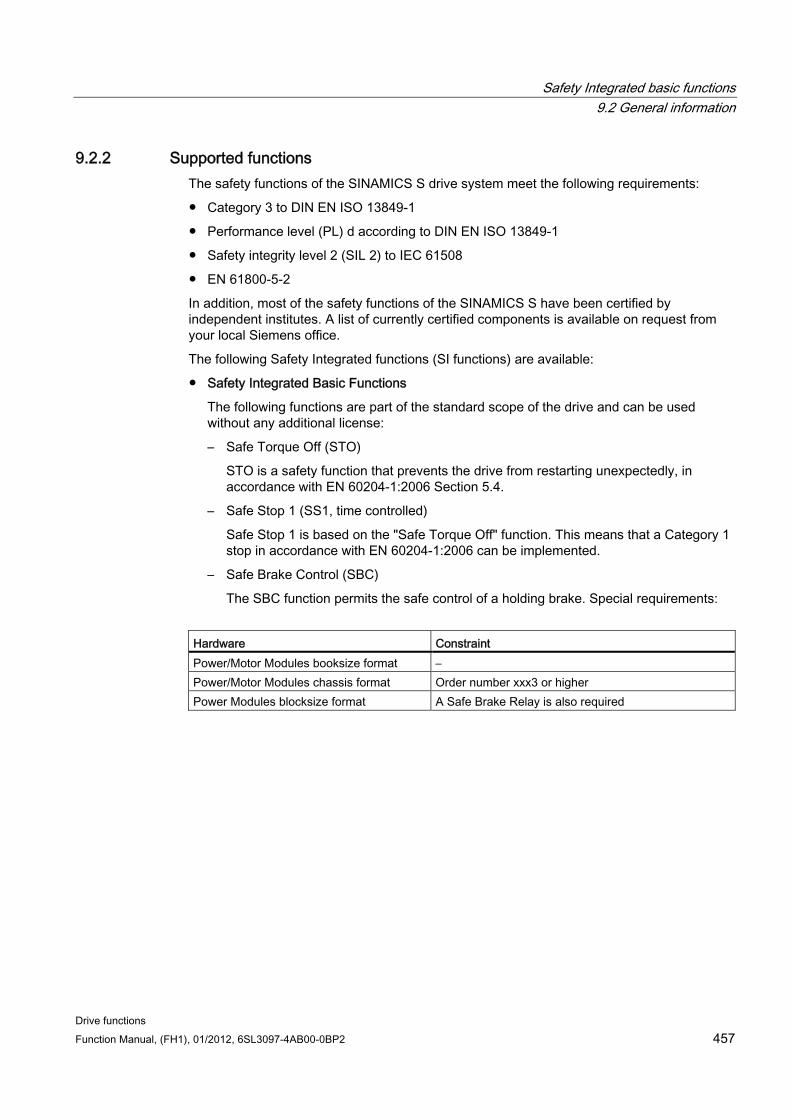
Safety Integrated basic functions 9.2 General information
Drive functions Function Manual, (FH1), 01/2012, 6SL3097-4AB00-0BP2 457
9.2.2 Supported functions The safety functions of the SINAMICS S drive system meet the following requirements:
Category 3 to DIN EN ISO 13849-1
Performance level (PL) d according to DIN EN ISO 13849-1
Safety integrity level 2 (SIL 2) to IEC 61508
EN 61800-5-2
In addition, most of the safety functions of the SINAMICS S have been certified by independent institutes. A list of currently certified components is available on request from your local Siemens office.
The following Safety Integrated functions (SI functions) are available:
Safety Integrated Basic Functions
The following functions are part of the standard scope of the drive and can be used without any additional license:
– Safe Torque Off (STO)
STO is a safety function that prevents the drive from restarting unexpectedly, in accordance with EN 60204-1:2006 Section 5.4.
– Safe Stop 1 (SS1, time controlled)
Safe Stop 1 is based on the "Safe Torque Off" function. This means that a Category 1 stop in accordance with EN 60204-1:2006 can be implemented.
– Safe Brake Control (SBC)
The SBC function permits the safe control of a holding brake. Special requirements:
Hardware Constraint Power/Motor Modules booksize format – Power/Motor Modules chassis format Order number xxx3 or higher Power Modules blocksize format A Safe Brake Relay is also required
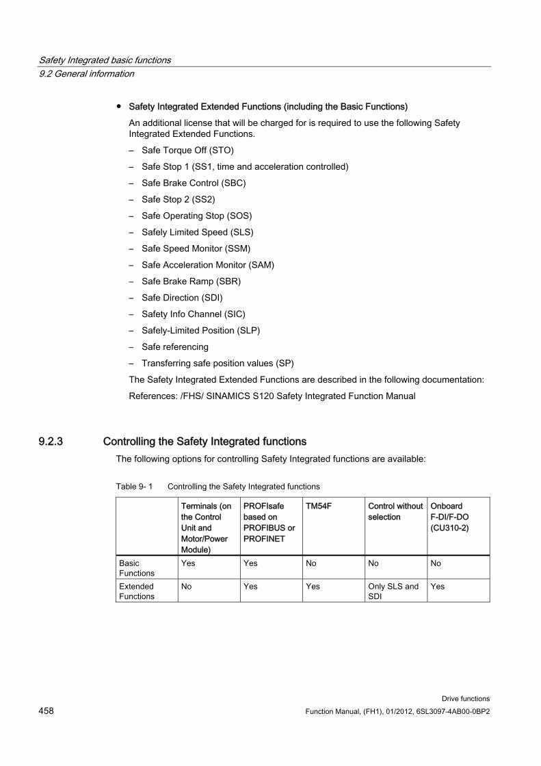
Safety Integrated basic functions 9.2 General information
Drive functions 458 Function Manual, (FH1), 01/2012, 6SL3097-4AB00-0BP2
Safety Integrated Extended Functions (including the Basic Functions)
An additional license that will be charged for is required to use the following Safety Integrated Extended Functions.
– Safe Torque Off (STO)
– Safe Stop 1 (SS1, time and acceleration controlled)
– Safe Brake Control (SBC)
– Safe Stop 2 (SS2)
– Safe Operating Stop (SOS)
– Safely Limited Speed (SLS)
– Safe Speed Monitor (SSM)
– Safe Acceleration Monitor (SAM)
– Safe Brake Ramp (SBR)
– Safe Direction (SDI)
– Safety Info Channel (SIC)
– Safely-Limited Position (SLP)
– Safe referencing
– Transferring safe position values (SP)
The Safety Integrated Extended Functions are described in the following documentation:
References: /FHS/ SINAMICS S120 Safety Integrated Function Manual
9.2.3 Controlling the Safety Integrated functions The following options for controlling Safety Integrated functions are available:
Table 9- 1 Controlling the Safety Integrated functions
Terminals (on the Control Unit and Motor/Power Module)
PROFIsafe based on PROFIBUS or PROFINET
TM54F Control without selection
Onboard F-DI/F-DO (CU310-2)
Basic Functions
Yes Yes No No No
Extended Functions
No Yes Yes Only SLS and SDI
Yes
Safety Integrated basic functions 9.2 General information
Drive functions Function Manual, (FH1), 01/2012, 6SL3097-4AB00-0BP2 459
NOTICE PROFIsafe or TM54F
Using a Control Unit, control is possible either via PROFIsafe or TM54F. Mixed operation is not permissible.
9.2.4 Parameter, Checksum, Version, Password
Properties of Safety Integrated parameters The following applies to Safety Integrated parameters:
They are kept separate for each monitoring channel.
During startup, checksum calculations (Cyclic Redundancy Check, CRC) are performed on the Safety parameter data and checked. The display parameters are not contained in the CRC.
Data storage: The parameters are stored on the non-volatile memory card.
Factory settings for Safety parameters
– A reset of the safety parameters to the factory setting on a drive-specific basis using p3900 and p0010 = 30 is only possible when the safety functions are not enabled (p9301 = p9501 = p9601 = p9801 = p10010 = 0).
– The Safety parameters can be reset to the factory setting with p0970 = 5. To do so, the Safety Integrated password must be set. When Safety Integrated is enabled, this can result in faults, which in turn require an acceptance test to be performed. Then save the parameters and carry out a POWER ON.
– A complete reset of all parameters to the factory settings (p0976 = 1 and p0009 = 30 on the Control Unit) is possible even when the safety functions are enabled (p9301 = p9501 = p9601 = p9801 = p10010 ≠ 0).
They are password-protected against accidental or unauthorized changes.
Checking the checksum For each monitoring channel, the Safety parameters include one parameter for the actual checksum for the Safety parameters that have undergone a checksum check.
During commissioning, the actual checksum must be transferred to the corresponding parameter for the reference checksum. This can be done for all checksums of a drive object at the same time with parameter p9701.
Basic Functions
r9798 SI actual checksum SI parameters (Control Unit)
p9799 SI reference checksum SI parameters (Control Unit)
Safety Integrated basic functions 9.2 General information
Drive functions 460 Function Manual, (FH1), 01/2012, 6SL3097-4AB00-0BP2
r9898 SI actual checksum SI parameters (Motor Module)
p9899 SI reference checksum SI parameters (Motor Module)
During each ramp-up procedure, the actual checksum is calculated via the Safety parameters and then compared with the reference checksum.
If the actual and reference checksums differ, fault F01650/F30650 or F01680/F30680 is output and an acceptance test requested.
Safety Integrated versions The Safety firmware has a separate version ID for the Control Unit and Motor Module.
For the Basic Functions:
r9770 SI version, drive-autonomous safety functions (Control Unit)
r9870 SI version (Motor Module)
Password The Safety password protects the Safety parameters against unintentional or unauthorized access.
In the commissioning mode for Safety Integrated (p0010 = 95), you cannot change Safety parameters until you have entered the valid Safety password in p9761 for the drives.
When Safety Integrated is commissioned for the first time, the following applies:
– Safety passwords = 0
– Default setting for p9761 = 0
In other words: The Safety password does not need to be set during first commissioning.
In the case of a series commissioning of Safety or in the case of spare part installation, the following applies:
– The Safety password is retained on the memory card and in the STARTER project.
– No Safety password is required in the case of spare part installation.
Change password for the drives
– p0010 = 95 Commissioning mode
– p9761 = Enter "old Safety password".
– p9762 = Enter "new password".
– p9763 = Confirm "new password".
– The new and confirmed Safety password is valid immediately.
If you need to change Safety parameters but you do not know the Safety password, proceed as follows:
1. Set the entire drive unit (Control Unit with all connected drives/components) to the factory setting.
Safety Integrated basic functions 9.2 General information
Drive functions Function Manual, (FH1), 01/2012, 6SL3097-4AB00-0BP2 461
2. Recommission the drive unit and drives.
3. Recommission Safety Integrated.
Or contact your regional Siemens office and ask for the password to be deleted (complete drive project must be made available).
Overview of important parameters for "Password" (see SINAMICS S120/S150 List Manual)
p9761 SI password input
p9762 SI password new
p9763 SI password acknowledgement
9.2.5 Forced dormant error detection
Forced dormant error detection or test of the switch-off signal paths for Safety Integrated Basic Functions
The forced dormant error detection function at the switch-off signal paths is used to detect software/hardware faults at both monitoring channels in time and is automated by means of activation/deactivation of the "Safe Torque Off" function.
To fulfill the requirements of ISO 13849-1 regarding timely error detection, the two switch-off signal paths must be tested at least once within a defined time to ensure that they are functioning properly. This functionality must be implemented by means of forced dormant error detection function, triggered either in manual mode or by the automated process.
A timer ensures that forced dormant error detection is carried out as quickly as possible.
p9659 SI timer for the forced dormant error detection.
Forced dormant error detection must be carried out at least once during the time set in this parameter.
Once this time has elapsed, an alarm is output and remains present until forced dormant error detection is carried out.
The timer returns to the set value each time the STO function is deactivated.
When the appropriate safety devices are implemented (e.g. protective doors), it can be assumed that running machinery will not pose any risk to personnel. For this reason, an alarm is only output to inform the user that a forced dormant error detection run is due and to request that this be carried out at the next available opportunity. This alarm does not affect machine operation.
The user must set the time interval for carrying out forced dormant error detection to between 0.00 and 9000.00 hours depending on the application (factory setting: 8.00 hours).
Examples of when to carry out forced dormant error detection:
When the drives are at a standstill after the system has been switched on (POWER ON).
When the protective door is opened.
At defined intervals (e.g. every 8 hours).
In automatic mode (time and event dependent)
Safety Integrated basic functions 9.3 Safety instructions
Drive functions 462 Function Manual, (FH1), 01/2012, 6SL3097-4AB00-0BP2
9.3 Safety instructions
Safety instructions
WARNING After hardware and/or software components have been modified or replaced, it is only permissible for the system to run up and the drives to be activated with the protective devices closed. Personnel may not be in the hazardous area.
It may be necessary to carry out a partial or complete acceptance test or a simplified functional test (see the "Acceptance test" chapter) after making certain changes or replacements.
Before persons may re-enter the hazardous area, the drives should be tested to ensure that they exhibit stable control behavior by briefly moving them in both the plus and minus directions (+/–).
Please note the following during switch-on:
The safety-related functions are only available and can be activated after the system has completely started up.
WARNING The Category 0 stop function according to EN 60204-1 (defined as STO in Safety Integrated) means that the drives are not braked to zero speed, but coast to a stop (this may take some time depending on the level of kinetic energy involved). This has to be incorporated in the protective door interlocking logic.
WARNING Safety Integrated is not capable of detecting parameterization errors made by the machine manufacturer. The required level of safety can only be assured by careful acceptance testing.
WARNING The automatic firmware update via p7826 = 1 (upgrade and downgrade) must not be deactivated under any circumstances when using Safety Integrated.
CAUTION If two power transistors in the power unit (one in the upper and one offset in the lower inverter bridge) fail at the same time, this can cause a momentary movement. The maximum movement can be: Synchronous rotary motors: Max. movement = 180 ° / pole pair count Synchronous linear motors: Max. movement = pole width
Safety Integrated basic functions 9.4 Safe Torque Off (STO)
Drive functions Function Manual, (FH1), 01/2012, 6SL3097-4AB00-0BP2 463
CAUTION The "automatic restart" function may not be used together with the safety functions STO/SBC and SS1. The reason for this is that EN 60204 Part 1 (1998) in chapter 9.2.5.4.2 does not permit this (merely de-selecting a safety shutdown function must not cause the machine to restart).
NOTICE Components cannot be deactivated via p0105, for example, with activated Safety functions.
9.4 Safe Torque Off (STO) In conjunction with a machine function or in the event of a fault, the "Safe Torque Off" (STO) function is used to safely disconnect the torque-generating energy feed to the motor.
When the function is selected, the drive unit is in a "safe status". The switching on inhibited function prevents the drive unit from being restarted.
The two-channel pulse suppression function integrated in the Motor Modules / Power Modules is a basis for this function.
Functional features of "Safe Torque Off" This function is integrated in the drive; this means that a higher-level controller is not
required.
The function is drive-specific, i.e. it is available for each drive and must be individually commissioned.
The function must be enabled using parameters.
When the "Safe Torque Off" function is selected, the following applies:
– The motor cannot be started accidentally.
– The pulse suppression safely disconnects the torque-generating energy feed to the motor.
– The power unit and motor are not electrically isolated.
Extended acknowledgment:
If STO is selected/deselected (and p9307.0/p9507.0 = 1 are set), then the safety messages are withdrawn automatically.
If, in addition to the "Extended Functions", the "Basic Functions via terminals" are also enabled, then in addition to selecting/deselecting STO via PROFIsafe or TM54F, acknowledgment is also possible by selecting/deselecting STO via terminals; whereby only messages of the stop responses STOP C, STOP D, STOP E and STOP F can be acknowledged, as long as STOP A or STOP B has not been initiated.
Safety Integrated basic functions 9.4 Safe Torque Off (STO)
Drive functions 464 Function Manual, (FH1), 01/2012, 6SL3097-4AB00-0BP2
WARNING Appropriate measures must be taken to ensure that the motor does not undesirably move once the energy feed has been disconnected, e.g. against coasting down or for a hanging/suspended axis, the "Safe Brake Control" (SBC) function should be enabled, also refer to Chapter "Safe Brake Control".
CAUTION If two power transistors simultaneously fail in the power unit (one in the upper and one in the lower bridge), then this can cause brief momentary movement.
The maximum movement can be: • Synchronous rotary motors: Max. movement = 180 ° / No. of pole pairs • Synchronous linear motors: Max. movement = pole width
The status of the "Safe Torque Off" function is displayed using parameters (r9772, r9872, r9773 and r9774).
Enabling the "Safe Torque Off" function The "Safe Torque Off" function is enabled via the following parameters:
STO via terminals: p9601.0 = 1, p9801.0 = 1
STO via PROFIsafe:
– p9601.0 = 0, p9801.0 = 0
– p9601.2 = 0, p9801.2 = 0
– p9601.3 = 1, p9801.3 = 1
STO via PROFIsafe and terminals:
– p9601.0 = 1, p9801.0 = 1
– p9601.2 = 0, p9801.2 = 0
– p9601.3 = 1, p9801.3 = 1
Selecting/deselecting "Safe Torque Off" The following is executed when "Safe Torque Off" is selected:
Each monitoring channel triggers safe pulse suppression via its switch-off signal path.
A motor holding brake is closed (if connected and configured).
Deselecting "Safe Torque Off" represents an internal safety acknowledgement. The following is executed if the cause of the fault has been removed:
Each monitoring channel cancels safe pulse suppression via its switch-off signal path.
The Safety requirement "Close motor holding brake" is canceled.
Safety Integrated basic functions 9.4 Safe Torque Off (STO)
Drive functions Function Manual, (FH1), 01/2012, 6SL3097-4AB00-0BP2 465
Any pending STOP F or STOP A commands are canceled (see r9772 / r9872).
The messages in the fault memory must be additionally reset using the general acknowledgement mechanism.
Note
If "Safe Torque Off" is selected and deselected through one channel within the time in p9650/p9850, the pulses are suppressed without a message being output.
However, if you want a message to be displayed, then you must reconfigure N01620/N30620 as an alarm or fault using p2118 and p2119.
Restart after the "Safe Torque Off" function has been selected 1. Deselect the function.
2. Issue drive enable signals.
3. Cancel the "switching on inhibited" and switch the drive back on.
– 1/0 edge at input signal "ON/OFF1" (cancel "switching on inhibited")
– 0/1 edge at input signal "ON/OFF1" (switch on drive)
Status for "Safe Torque Off" The status of the "Safe Torque Off" (STO) function is displayed using the parameters r9772, r9872, r9773 and r9774.
As an alternative, the status of the functions can be displayed using the configurable messages N01620 and N30620 (configured using p2118 and p2119).
Response time for the "Safe Torque Off" function For the response times when the function is selected/deselected via input terminals, see the table in "Response times".
Internal armature short-circuit with the "Safe Torque Off" function The function "internal armature short-circuit" can be configured together with the "STO" function. However, only one of the two functions can be selected, as an OFF2 is also always triggered when STO is selected. This OFF2 disables the function "Internal armature short-circuit".
The "STO" safety function has the higher priority when simultaneously selected. If the "STO" function is initiated, then an activated "internal armature short-circuit" is disabled.
Safety Integrated basic functions 9.5 Safe Stop 1 (SS1, time controlled)
Drive functions 466 Function Manual, (FH1), 01/2012, 6SL3097-4AB00-0BP2
Overview of important parameters (see SINAMICS S120/S150 List Manual) p9601 SI enable, functions integrated in the drive (Control Unit)
r9772 CO/BO: SI Status (Control Unit)
r9872 CO/BO: SI Status (Motor Module)
r9773 CO/BO: SI Status (Control Unit + Motor Module)
r9774 CO/BO: SI Status (group STO)
p0799 CU inputs/outputs sampling time
r9780 SI Monitoring clock cycle (Control Unit)
p9801 SI enable, functions integrated in the drive (Motor Module)
r9880 SI Monitoring clock cycle (Motor Module)
9.5 Safe Stop 1 (SS1, time controlled)
9.5.1 SS1 (time controlled) with OFF3
General description The "Safe Stop 1" (SS1) function allows the drive to be stopped in accordance with EN 60204-1, Stop Category 1. The drive decelerates with the OFF3 ramp (p1135) once "Safe Stop 1" is selected and switches to "Safe Torque Off" once the delay time set in p9652/p9852 has elapsed.
CAUTION If the "Safe Stop 1" function (time-controlled) function has been selected by parameterizing a delay in p9652/p9852, STO can no longer be selected directly via terminals.
Functional features of Safe Stop 1 SS1 is enabled when p9652 and p9852 (delay time) are not equal to "0".
Setting parameter p9652/p9852 has the following effect:
Setting Effect Control mode for Basic Functions p9652/p9852 = 0 STO enabled Via terminals STO enabled and SS1 not enabled (cannot
therefore be selected) Via PROFIsafe
p9652/p9852 > 0 SS1 enabled Via PROFIsafe or terminals
Safety Integrated basic functions 9.5 Safe Stop 1 (SS1, time controlled)
Drive functions Function Manual, (FH1), 01/2012, 6SL3097-4AB00-0BP2 467
When SS1 is selected, the drive is braked along the OFF3 ramp (p1135) and STO/SBC is automatically initiated after the delay time has expired (p9652/p9852).
After the function has been selected, the delay timer runs down – even if the function is deselected during this time. In this case, after the delay time has expired, the STO/SBC function is selected and then again deselected immediately.
Note
So that the drive is able to travel down the OFF3 ramp completely and any motor holding brake present can be applied, the delay time should be set as follows: • Motor holding brake parameterized: Delay time ≥ p1135 + p1228 + p1217 • Motor holding brake not parameterized: Delay time ≥ p1135 + p1228
The selection is realized through two channels - however braking along the OFF3 ramp, only through one channel.
Precondition The Basic Functions or STO are enabled via terminals and/or PROFIsafe.
– p9601.0/p9801.0 = 1 (enable via terminals)
– p9601.3/p9801.3 = 1 (enable via PROFIsafe)
In order that the drive can brake down to a standstill even when selected through one channel, the time in p9652/p9852 must be shorter than the sum of the parameters for the data cross-check (p9650/p9850 and p9658/p9858). Otherwise the drive will coast down after p9650 + p9658 have elapsed.
Status for Safe Stop 1 The status of the "Safe Stop 1" (SS1) function is displayed using the parameters r9772, r9872, r9773 and r9774.
Alternatively, the status of the functions can be displayed using the configurable messages N01621 and N30621 (configured using p2118 and p2119).
9.5.2 SS1 (time controlled) without OFF3
General description
CAUTION The "Safe Stop 1 (time-controlled) without OFF3" function does not correspond to stopping according to EN 60204-1, Stop Category 1.
Safety Integrated basic functions 9.5 Safe Stop 1 (SS1, time controlled)
Drive functions 468 Function Manual, (FH1), 01/2012, 6SL3097-4AB00-0BP2
CAUTION During the delay time (p9652/p9852), for "Safe Stop 1 (time controlled) without OFF3" any axis movement is possible as a result of the position controller.
Differences between "Safe Stop 1 (time-controlled) with and without OFF3" Without OFF3, "Safe Stop 1 (time controlled)" functions in principle exactly the same way as described in the previous Chapter "Safe Stop 1 (time controlled) with OFF3. Note, however, the following differences:
In order to activate "Safe Stop 1 (time controlled) without OFF3", additionally set p9653 to 1.
When SS1 is selected, the drive is not braked along the OFF3 ramp, but after the delay time has expired (p9652/p9852), only STO/SBC is automatically initiated. After the function has been selected, the delay timer runs down – even if the function is deselected during this time. In this case, after the delay time has expired, the STO/SBC function is selected and then again deselected immediately.
9.5.3 Function diagrams and parameters
Function diagrams (see SINAMICS S120/S150 List Manual) 2810 STO (Safe Torque Off), SS1 (Safe Stop 1)
2811 STO (Safe Torque Off), safe pulse cancellation
Overview of important parameters (see SINAMICS S120/S150 List Manual) p1135[0...n] OFF3 ramp-down time
p1217 Holding brake closing time
p1228 Pulse suppression delay time
p9601 SI enable, functions integrated in the drive (Control Unit)
p9650 SI SGE changeover tolerance time (Control Unit)
p9651 SI STO/SBC/SS1 debounce time (Control Unit)
p9652 SI Safe Stop 1 delay time (Control Unit)
p9658 SI transition time STOP F to STOP A (Control Unit)
r9772 CO/BO: SI Status (Control Unit)
r9773 CO/BO: SI Status (Control Unit + Motor Module)
r9774 CO/BO: SI Status (group STO)
r9780 SI Monitoring clock cycle (Control Unit)
Safety Integrated basic functions 9.5 Safe Stop 1 (SS1, time controlled)
Drive functions Function Manual, (FH1), 01/2012, 6SL3097-4AB00-0BP2 469
p9801 SI enable, functions integrated in the drive (Motor Module)
p9850 SI SGE changeover tolerance time (Motor Module)
p9851 SI STO/SBC/SS1 debounce time (Control Unit)
p9852 SI Safe Stop 1 delay time (Motor Module)
p9858 SI transition time STOP F to STOP A (Motor Module)
r9872 CO/BO: SI Status (Motor Module)
r9880 SI Monitoring clock cycle (Motor Module)
Only for "Safe Stop 1 (time controlled) without OFF3"
p9653 SI Safe Stop 1 drive-integrated braking response
Safety Integrated basic functions 9.6 Safe Brake Control (SBC)
Drive functions 470 Function Manual, (FH1), 01/2012, 6SL3097-4AB00-0BP2
9.6 Safe Brake Control (SBC) The "Safe Brake Control" function (SBC) is used to control holding brakes that function according to the closed-circuit principle (e.g. motor holding brake).
The command for releasing or applying the brake is transmitted to the Motor Module/Power Module via DRIVE-CLiQ. he Motor Module/Safe Brake Relay then carries out the action and activates the outputs for the brake.
Brake activation via the brake connection on the Motor Module/Safe Brake Relay involves a safe, two-channel method.
Note • Chassis components support this function from an order number with the ending ...xxx3.
A Safe Brake Adapter is needed in addition for this design. • To ensure that this function can be used for Blocksize Power Modules, a Safe Brake
Relay must be used (for more information, see the Equipment Manual). When the Power Module is configured automatically, the Safe Brake Relay is detected and the motor holding brake type is defaulted (p1278 = 0).
WARNING "Safe Brake Control" does not detect mechanical defects. The system does not detect whether a brake is e.g. worn or has a mechanical defect, whether it opens or closes. A cable break or a short-circuit in the brake winding is only detected when the state changes, i.e. when the brake either opens or closes.
Functional features of "Safe Brake Control" SBC is executed when "Safe Torque Off" (STO) is selected.
Unlike conventional brake control, SBC is executed via p1215 through two channels.
SBC is executed regardless of the brake control or mode set in p1215. SBC is not recommended, however, when 1215 = 0 or 3.
The function must be enabled using parameters.
When the state changes, electrical faults, such as e.g. a short-circuit in the brake winding or wire breakage can be detected.
Enabling the "Safe Brake Control" function The "Safe Brake Control" function is enabled via the following parameters:
p9602 SI enable safe brake control (Control Unit)
p9802 SI enable safe brake control (Motor Module)
The "Safe Brake Control" function cannot be used until at least one safety monitoring function has been enabled (i.e. p9601 = p9801 ≠ 0).
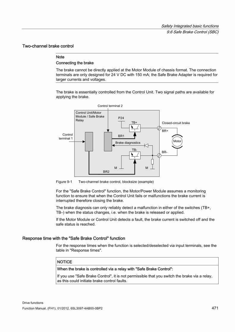
Safety Integrated basic functions 9.6 Safe Brake Control (SBC)
Drive functions Function Manual, (FH1), 01/2012, 6SL3097-4AB00-0BP2 471
Two-channel brake control
Note Connecting the brake
The brake cannot be directly applied at the Motor Module of chassis format. The connection terminals are only designed for 24 V DC with 150 mA; the Safe Brake Adapter is required for larger currents and voltages.
The brake is essentially controlled from the Control Unit. Two signal paths are available for applying the brake.
Figure 9-1 Two-channel brake control, blocksize (example)
For the "Safe Brake Control" function, the Motor/Power Module assumes a monitoring function to ensure that when the Control Unit fails or malfunctions the brake current is interrupted therefore closing the brake.
The brake diagnosis can only reliably detect a malfunction in either of the switches (TB+, TB–) when the status changes, i.e. when the brake is released or applied.
If the Motor Module or Control Unit detects a fault, the brake current is switched off and the safe status is reached.
Response time with the "Safe Brake Control" function For the response times when the function is selected/deselected via input terminals, see the table in "Response times".
NOTICE When the brake is controlled via a relay with "Safe Brake Control":
If you use "Safe Brake Control", it is not permissible that you switch the brake via a relay, as this could initiate brake control faults.
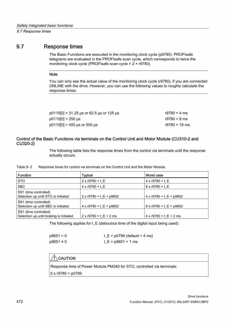
Safety Integrated basic functions 9.7 Response times
Drive functions 472 Function Manual, (FH1), 01/2012, 6SL3097-4AB00-0BP2
9.7 Response times The Basic Functions are executed in the monitoring clock cycle (p9780). PROFIsafe telegrams are evaluated in the PROFIsafe scan cycle, which corresponds to twice the monitoring clock cycle (PROFIsafe scan cycle = 2 × r9780).
Note
You can only see the actual value of the monitoring clock cycle (r9780), if you are connected ONLINE with the drive. However, you can use the following values to roughly calculate the response times:
p0115[0] = 31.25 µs or 62.5 µs or 125 µs r9780 = 4 ms p0115[0] = 250 µs r9780 = 8 ms p0115[0] = 400 µs or 500 µs r9780 = 16 ms
Control of the Basic Functions via terminals on the Control Unit and Motor Module (CU310-2 and CU320-2)
The following table lists the response times from the control via terminals until the response actually occurs.
Table 9- 2 Response times for control via terminals on the Control Unit and the Motor Module.
Function Typical Worst case STO 2 x r9780 + t_E 4 x r9780 + t_E SBC 4 x r9780 + t_E 8 x r9780 + t_E SS1 (time controlled) Selection up until STO is initiated
2 x r9780 + t_E + p9652
4 x r9780 + t_E + p9652
SS1 (time controlled) Selection up until SBC is initiated
4 x r9780 + t_E + p9652
8 x r9780 + t_E + p9652
SS1 (time controlled) Selection up until braking is initiated
2 x r9780 + t_E + 2 ms
4 x r9780 + t_E + 2 ms
The following applies for t_E (debounce time of the digital input being used):
p9651 = 0 t_E = p0799 (default = 4 ms) p9651 ≠ 0 t_E = p9651 + 1 ms
CAUTION Response time of Power Module PM340 for STO, controlled via terminals:
5 x r9780 + p0799
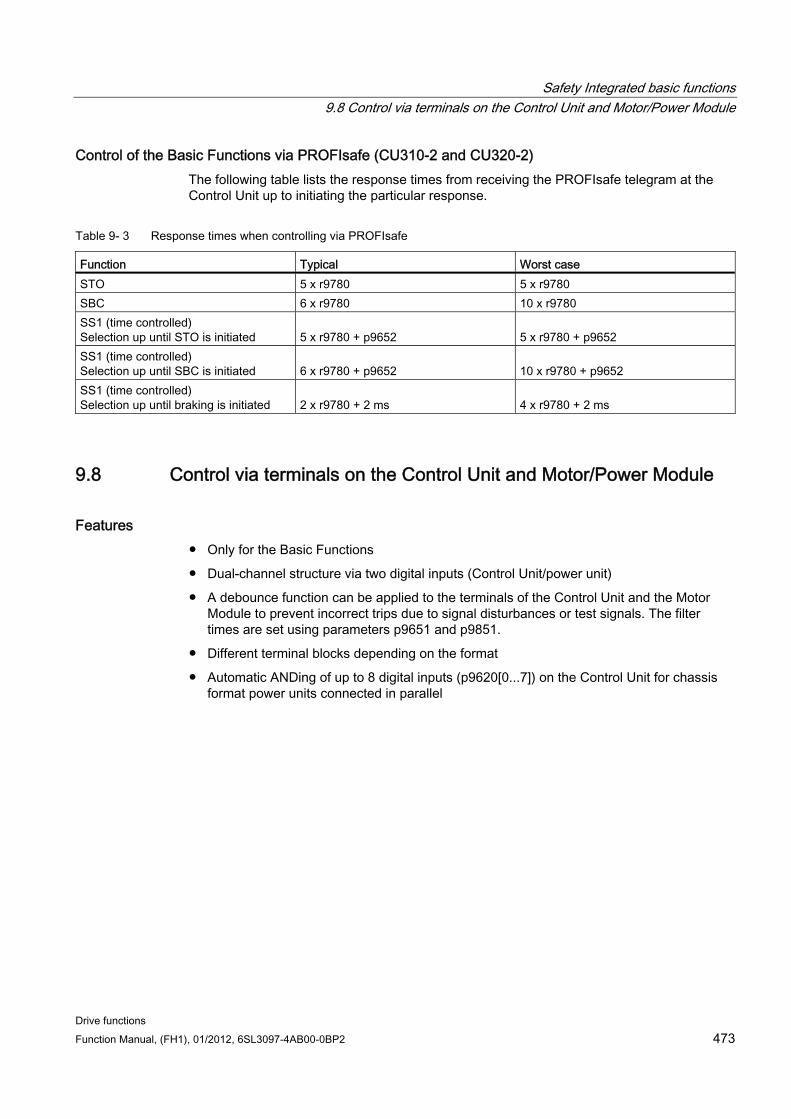
Safety Integrated basic functions 9.8 Control via terminals on the Control Unit and Motor/Power Module
Drive functions Function Manual, (FH1), 01/2012, 6SL3097-4AB00-0BP2 473
Control of the Basic Functions via PROFIsafe (CU310-2 and CU320-2) The following table lists the response times from receiving the PROFIsafe telegram at the Control Unit up to initiating the particular response.
Table 9- 3 Response times when controlling via PROFIsafe
Function Typical Worst case STO 5 x r9780 5 x r9780 SBC 6 x r9780 10 x r9780 SS1 (time controlled) Selection up until STO is initiated
5 x r9780 + p9652
5 x r9780 + p9652
SS1 (time controlled) Selection up until SBC is initiated
6 x r9780 + p9652
10 x r9780 + p9652
SS1 (time controlled) Selection up until braking is initiated
2 x r9780 + 2 ms
4 x r9780 + 2 ms
9.8 Control via terminals on the Control Unit and Motor/Power Module
Features Only for the Basic Functions
Dual-channel structure via two digital inputs (Control Unit/power unit)
A debounce function can be applied to the terminals of the Control Unit and the Motor Module to prevent incorrect trips due to signal disturbances or test signals. The filter times are set using parameters p9651 and p9851.
Different terminal blocks depending on the format
Automatic ANDing of up to 8 digital inputs (p9620[0...7]) on the Control Unit for chassis format power units connected in parallel
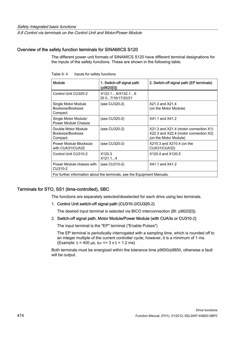
Safety Integrated basic functions 9.8 Control via terminals on the Control Unit and Motor/Power Module
Drive functions 474 Function Manual, (FH1), 01/2012, 6SL3097-4AB00-0BP2
Overview of the safety function terminals for SINAMICS S120 The different power unit formats of SINAMICS S120 have different terminal designations for the inputs of the safety functions. These are shown in the following table.
Table 9- 4 Inputs for safety functions
Module 1. Switch-off signal path (p9620[0])
2. Switch-off signal path (EP terminals)
Control Unit CU320-2 X122.1....6/X132.1…6 DI 0...7/16/17/20/21
Single Motor Module Booksize/Booksize Compact
(see CU320-2) X21.3 and X21.4 (on the Motor Module)
Single Motor Module/ Power Module Chassis
(see CU320-2) X41.1 and X41.2
Double Motor Module Booksize/Booksize Compact
(see CU320-2) X21.3 and X21.4 (motor connection X1) X22.3 and X22.4 (motor connection X2) (on the Motor Module)
Power Module Blocksize with CUA31/CUA32
(see CU320-2) X210.3 and X210.4 (on the CUA31/CUA32)
Control Unit CU310-2 X120.3 X121.1...4
X120.4 and X120.5
Power Module chassis with CU310-2
(see CU310-2) X41.1 and X41.2
For further information about the terminals, see the Equipment Manuals.
Terminals for STO, SS1 (time-controlled), SBC The functions are separately selected/deselected for each drive using two terminals.
1. Control Unit switch-off signal path (CU310-2/CU320-2)
The desired input terminal is selected via BICO interconnection (BI: p9620[0]).
2. Switch-off signal path, Motor Module/Power Module (with CUA3x or CU310-2)
The input terminal is the "EP" terminal ("Enable Pulses")
The EP terminal is periodically interrogated with a sampling time, which is rounded off to an integer multiple of the current controller cycle; however, it is a minimum of 1 ms. (Example: ti = 400 µs, tEP => 3 x ti = 1.2 ms)
Both terminals must be energized within the tolerance time p9650/p9850, otherwise a fault will be output.
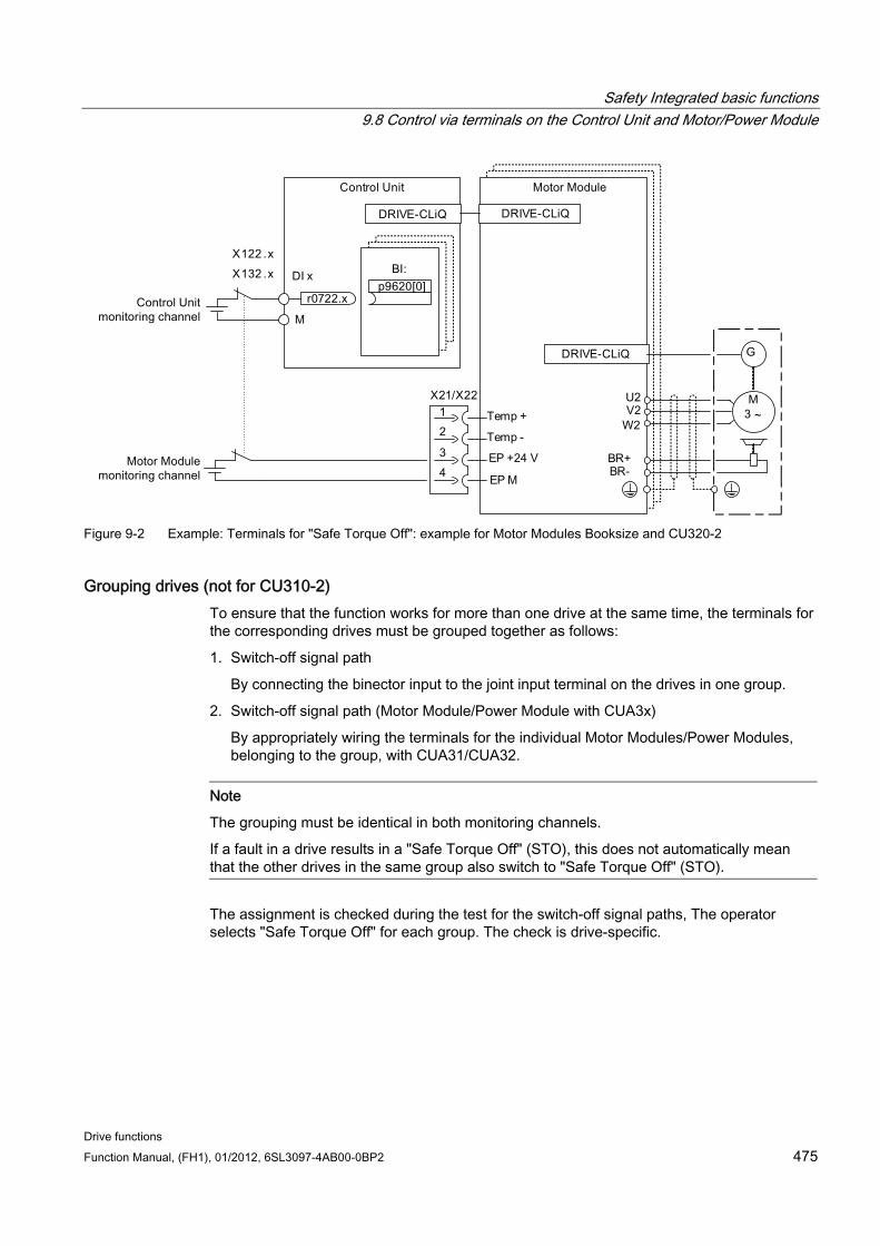
Safety Integrated basic functions 9.8 Control via terminals on the Control Unit and Motor/Power Module
Drive functions Function Manual, (FH1), 01/2012, 6SL3097-4AB00-0BP2 475
Figure 9-2 Example: Terminals for "Safe Torque Off": example for Motor Modules Booksize and CU320-2
Grouping drives (not for CU310-2) To ensure that the function works for more than one drive at the same time, the terminals for the corresponding drives must be grouped together as follows:
1. Switch-off signal path
By connecting the binector input to the joint input terminal on the drives in one group.
2. Switch-off signal path (Motor Module/Power Module with CUA3x)
By appropriately wiring the terminals for the individual Motor Modules/Power Modules, belonging to the group, with CUA31/CUA32.
Note
The grouping must be identical in both monitoring channels.
If a fault in a drive results in a "Safe Torque Off" (STO), this does not automatically mean that the other drives in the same group also switch to "Safe Torque Off" (STO).
The assignment is checked during the test for the switch-off signal paths, The operator selects "Safe Torque Off" for each group. The check is drive-specific.
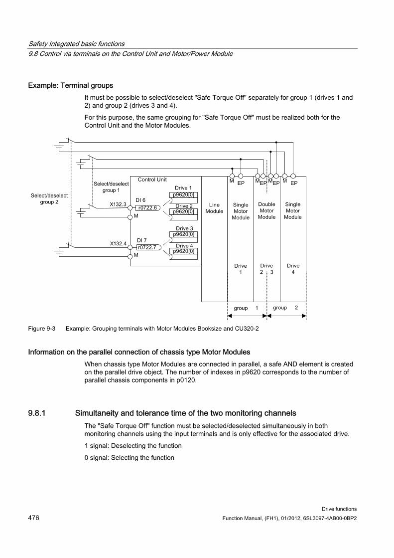
Safety Integrated basic functions 9.8 Control via terminals on the Control Unit and Motor/Power Module
Drive functions 476 Function Manual, (FH1), 01/2012, 6SL3097-4AB00-0BP2
Example: Terminal groups It must be possible to select/deselect "Safe Torque Off" separately for group 1 (drives 1 and 2) and group 2 (drives 3 and 4).
For this purpose, the same grouping for "Safe Torque Off" must be realized both for the Control Unit and the Motor Modules.
Figure 9-3 Example: Grouping terminals with Motor Modules Booksize and CU320-2
Information on the parallel connection of chassis type Motor Modules When chassis type Motor Modules are connected in parallel, a safe AND element is created on the parallel drive object. The number of indexes in p9620 corresponds to the number of parallel chassis components in p0120.
9.8.1 Simultaneity and tolerance time of the two monitoring channels The "Safe Torque Off" function must be selected/deselected simultaneously in both monitoring channels using the input terminals and is only effective for the associated drive.
1 signal: Deselecting the function
0 signal: Selecting the function
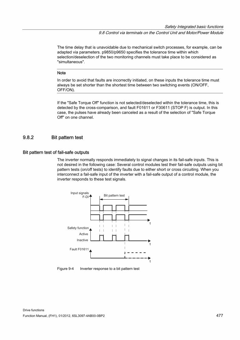
Safety Integrated basic functions 9.8 Control via terminals on the Control Unit and Motor/Power Module
Drive functions Function Manual, (FH1), 01/2012, 6SL3097-4AB00-0BP2 477
The time delay that is unavoidable due to mechanical switch processes, for example, can be adapted via parameters. p9850/p9650 specifies the tolerance time within which selection/deselection of the two monitoring channels must take place to be considered as "simultaneous".
Note
In order to avoid that faults are incorrectly initiated, on these inputs the tolerance time must always be set shorter than the shortest time between two switching events (ON/OFF, OFF/ON).
If the "Safe Torque Off" function is not selected/deselected within the tolerance time, this is detected by the cross-comparison, and fault F01611 or F30611 (STOP F) is output. In this case, the pulses have already been canceled as a result of the selection of "Safe Torque Off" on one channel.
9.8.2 Bit pattern test
Bit pattern test of fail-safe outputs The inverter normally responds immediately to signal changes in its fail-safe inputs. This is not desired in the following case: Several control modules test their fail-safe outputs using bit pattern tests (on/off tests) to identify faults due to either short or cross circuiting. When you interconnect a fail-safe input of the inverter with a fail-safe output of a control module, the inverter responds to these test signals.
Figure 9-4 Inverter response to a bit pattern test
Safety Integrated basic functions 9.9 Commissioning the "STO", "SBC" and "SS1" functions
Drive functions 478 Function Manual, (FH1), 01/2012, 6SL3097-4AB00-0BP2
Note
If the test pulses lead to unintended triggering of the Safety Integrated functions, a filtering (p9651/p9851 SI STO/SBC/SS1 debounce time) of the terminal inputs must be parameterized.
Overview of important parameters (see the SINAMICS S120/S150 List Manual) p9651 SI STO/SBC/SS1 debounce time (Control Unit)
p9851 SI STO/SBC/SS1 debounce time (Control Unit)
9.9 Commissioning the "STO", "SBC" and "SS1" functions
9.9.1 General information about commissioning safety functions
Commissioning notes
NOTICE For safety-relevant reasons, using the STARTER commissioning tool (or SCOUT) you can only set the safety-relevant parameters of the Control Unit offline. In order to set the safety-relevant parameters of the Motor Module, establish an online connection to SINAMICS S120 and copy the parameters using the "Copy parameter" button on the start screen of the safety configuration into the Motor Module.
Note • The "STO", "SBC" and "SS1" functions are drive specific. This means that the functions
must be commissioned individually for each drive. • If the version in the Motor Module is incompatible, the Control Unit responds as follows
during the switchover to safety commissioning mode (p0010 = 95): – Fault F01655 (SI CU: Align the monitoring functions) is output. The fault initiates stop
response OFF2. The fault cannot be acknowledged until safety commissioning mode (p0010 ≠ 95) is exited.
– The Control Unit triggers a safe pulse suppression via its own safety switch-off signal path.
– If parameterized (p1215), the motor holding brake is applied. – The Safety functions cannot be enabled (p9601/p9801 and p9602/p9802).
Safety Integrated basic functions 9.9 Commissioning the "STO", "SBC" and "SS1" functions
Drive functions Function Manual, (FH1), 01/2012, 6SL3097-4AB00-0BP2 479
Prerequisites for commissioning the safety functions 1. Commissioning of the drives must be complete.
2. Non-safe pulse suppression must be present (e.g. via OFF1 = "0" or OFF2 = "0")
If the motor holding brake is connected and parameterized, the holding brake is applied.
3. The terminals for "Safe Torque Off" must be wired.
4. For operation with SBC, the following applies:
A motor with motor holding brake must be connected to the appropriate terminal of the Motor Module.
Standard commissioning of the safety functions 1. A project that has been commissioned and uploaded to STARTER can be transferred to
another drive unit without losing the Safety parameterization.
2. If the source and target devices have different firmware versions, it may be necessary to adapt the reference checksums (p9799, p9899). This is indicated by the faults F01650 (fault value: 1000) and F30650 (fault value: 1000).
3. Once the project has been downloaded to the target device, an acceptance test must be carried out (see chapter "Acceptance test and acceptance protocol"). This is indicated by fault F01650 (fault value: 2004).
NOTICE
Once a project has been downloaded, it must be stored on the non-volatile memory card (copy from RAM to ROM).
Replacing Motor Modules with a more recent firmware version 1. After a Motor Module fails, a more recent firmware version can be installed on the new
Motor Module.
2. If the old and new devices have different firmware versions, it may be necessary to adjust the reference checksums (p9899) (see the following table). This is indicated by fault F30650 (fault value: 1000).
Table 9- 5 Adapting the reference checksum (p9899)
no. Parameter Description/comments 1 p0010 = 95 Safety Integrated: set commissioning mode. 2 p9761 = "Value" Enter the Safety password. 3 p9899 = "r9898" Adapt the reference checksum on the Motor Module 4 p0010 ≠ 95 Safety Integrated: exit commissioning mode 5 POWER ON Carry out a POWER ON.
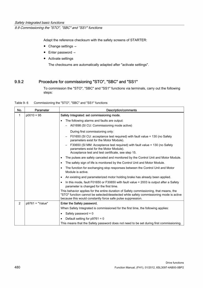
Safety Integrated basic functions 9.9 Commissioning the "STO", "SBC" and "SS1" functions
Drive functions 480 Function Manual, (FH1), 01/2012, 6SL3097-4AB00-0BP2
Adapt the reference checksum with the safety screens of STARTER:
Change settings →
Enter password →
Activate settings
The checksums are automatically adapted after "activate settings".
9.9.2 Procedure for commissioning "STO", "SBC" and "SS1" To commission the "STO", "SBC" and "SS1" functions via terminals, carry out the following steps:
Table 9- 6 Commissioning the "STO", "SBC" and "SS1" functions
No. Parameter Description/comments 1 p0010 = 95 Safety Integrated: set commissioning mode.
• The following alarms and faults are output: – A01698 (SI CU: Commissioning mode active)
During first commissioning only: – F01650 (SI CU: acceptance test required) with fault value = 130 (no Safety
parameters exist for the Motor Module). – F30650 (SI MM: Acceptance test required) with fault value = 130 (no Safety
parameters exist for the Motor Module). Acceptance test and test certificate, see step 15.
• The pulses are safely canceled and monitored by the Control Unit and Motor Module. • The safety sign of life is monitored by the Control Unit and Motor Module. • The function for exchanging stop responses between the Control Unit and Motor
Module is active. • An existing and parameterized motor holding brake has already been applied. • In this mode, fault F01650 or F30650 with fault value = 2003 is output after a Safety
parameter is changed for the first time. This behavior applies for the entire duration of Safety commissioning, that means, the "STO" function cannot be selected/deselected while safety commissioning mode is active because this would constantly force safe pulse suppression.
2 p9761 = "Value" Enter the Safety password. When Safety Integrated is commissioned for the first time, the following applies: • Safety password = 0 • Default setting for p9761 = 0 This means that the Safety password does not need to be set during first commissioning.
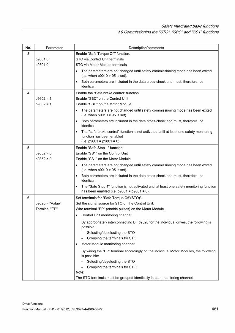
Safety Integrated basic functions 9.9 Commissioning the "STO", "SBC" and "SS1" functions
Drive functions Function Manual, (FH1), 01/2012, 6SL3097-4AB00-0BP2 481
No. Parameter Description/comments 3
p9601.0 p9801.0
Enable "Safe Torque Off" function. STO via Control Unit terminals STO via Motor Module terminals • The parameters are not changed until safety commissioning mode has been exited
(i.e. when p0010 ≠ 95 is set). • Both parameters are included in the data cross-check and must, therefore, be
identical.
4 p9602 = 1 p9802 = 1
Enable the "Safe brake control" function. Enable "SBC" on the Control Unit Enable "SBC" on the Motor Module • The parameters are not changed until safety commissioning mode has been exited
(i.e. when p0010 ≠ 95 is set). • Both parameters are included in the data cross-check and must, therefore, be
identical. • The "safe brake control" function is not activated until at least one safety monitoring
function has been enabled (i.e. p9601 = p9801 ≠ 0).
5 p9652 > 0 p9852 > 0
Enable "Safe Stop 1" function. Enable "SS1" on the Control Unit Enable "SS1" on the Motor Module • The parameters are not changed until safety commissioning mode has been exited
(i.e. when p0010 ≠ 95 is set). • Both parameters are included in the data cross-check and must, therefore, be
identical. • The "Safe Stop 1" function is not activated until at least one safety monitoring function
has been enabled (i.e. p9601 = p9801 ≠ 0).
6 p9620 = "Value" Terminal "EP"
Set terminals for "Safe Torque Off (STO)". Set the signal source for STO on the Control Unit. Wire terminal "EP" (enable pulses) on the Motor Module. • Control Unit monitoring channel:
By appropriately interconnecting BI: p9620 for the individual drives, the following is possible: – Selecting/deselecting the STO – Grouping the terminals for STO
• Motor Module monitoring channel:
By wiring the "EP" terminal accordingly on the individual Motor Modules, the following is possible: – Selecting/deselecting the STO – Grouping the terminals for STO
Note: The STO terminals must be grouped identically in both monitoring channels.
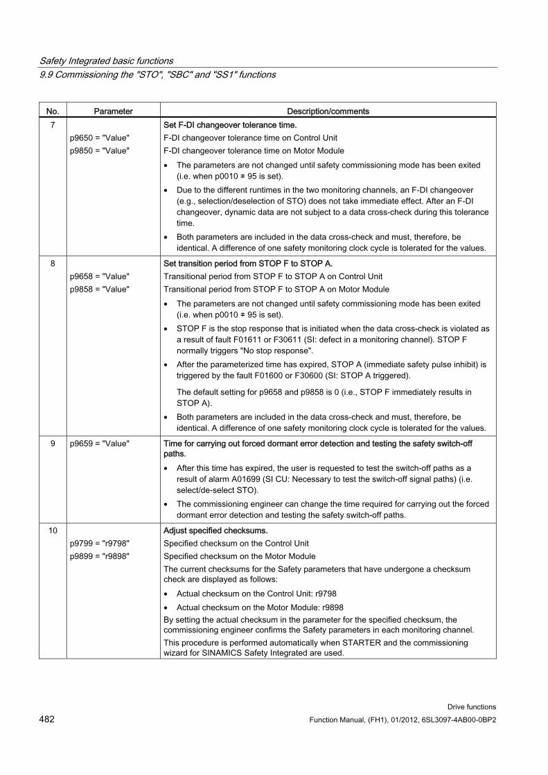
Safety Integrated basic functions 9.9 Commissioning the "STO", "SBC" and "SS1" functions
Drive functions 482 Function Manual, (FH1), 01/2012, 6SL3097-4AB00-0BP2
No. Parameter Description/comments 7
p9650 = "Value" p9850 = "Value"
Set F-DI changeover tolerance time. F-DI changeover tolerance time on Control Unit F-DI changeover tolerance time on Motor Module • The parameters are not changed until safety commissioning mode has been exited
(i.e. when p0010 ≠ 95 is set). • Due to the different runtimes in the two monitoring channels, an F-DI changeover
(e.g., selection/deselection of STO) does not take immediate effect. After an F-DI changeover, dynamic data are not subject to a data cross-check during this tolerance time.
• Both parameters are included in the data cross-check and must, therefore, be identical. A difference of one safety monitoring clock cycle is tolerated for the values.
8 p9658 = "Value" p9858 = "Value"
Set transition period from STOP F to STOP A. Transitional period from STOP F to STOP A on Control Unit Transitional period from STOP F to STOP A on Motor Module • The parameters are not changed until safety commissioning mode has been exited
(i.e. when p0010 ≠ 95 is set). • STOP F is the stop response that is initiated when the data cross-check is violated as
a result of fault F01611 or F30611 (SI: defect in a monitoring channel). STOP F normally triggers "No stop response".
• After the parameterized time has expired, STOP A (immediate safety pulse inhibit) is triggered by the fault F01600 or F30600 (SI: STOP A triggered).
The default setting for p9658 and p9858 is 0 (i.e., STOP F immediately results in STOP A).
• Both parameters are included in the data cross-check and must, therefore, be identical. A difference of one safety monitoring clock cycle is tolerated for the values.
9 p9659 = "Value" Time for carrying out forced dormant error detection and testing the safety switch-off paths. • After this time has expired, the user is requested to test the switch-off paths as a
result of alarm A01699 (SI CU: Necessary to test the switch-off signal paths) (i.e. select/de-select STO).
• The commissioning engineer can change the time required for carrying out the forced dormant error detection and testing the safety switch-off paths.
10 p9799 = "r9798" p9899 = "r9898"
Adjust specified checksums. Specified checksum on the Control Unit Specified checksum on the Motor Module The current checksums for the Safety parameters that have undergone a checksum check are displayed as follows: • Actual checksum on the Control Unit: r9798 • Actual checksum on the Motor Module: r9898 By setting the actual checksum in the parameter for the specified checksum, the commissioning engineer confirms the Safety parameters in each monitoring channel. This procedure is performed automatically when STARTER and the commissioning wizard for SINAMICS Safety Integrated are used.
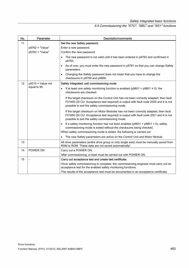
Safety Integrated basic functions 9.9 Commissioning the "STO", "SBC" and "SS1" functions
Drive functions Function Manual, (FH1), 01/2012, 6SL3097-4AB00-0BP2 483
No. Parameter Description/comments 11
p9762 = "Value" p9763 = "Value"
Set the new Safety password. Enter a new password. Confirm the new password. • The new password is not valid until it has been entered in p9762 and confirmed in
p9763. • As of now, you must enter the new password in p9761 so that you can change Safety
parameters. • Changing the Safety password does not mean that you have to change the
checksums in p9799 and p9899.
12 p0010 = Value not equal to 95
Safety Integrated: exit commissioning mode • If at least one safety monitoring function is enabled (p9601 = p9801 ≠ 0), the
checksums are checked:
If the target checksum on the Control Unit has not been correctly adapted, then fault F01650 (SI CU: Acceptance test required) is output with fault code 2000 and it is not possible to exit the safety commissioning mode.
If the target checksum on Motor Modules has not been correctly adapted, then fault F01650 (SI CU: Acceptance test required) is output with fault code 2001 and it is not possible to exit the safety commissioning mode.
• If a safety monitoring function has not been enabled (p9601 = p9801 = 0), safety commissioning mode is exited without the checksums being checked.
When safety commissioning mode is exited, the following is carried out: • The new Safety parameters are active on the Control Unit and Motor Module.
13 All drive parameters (entire drive group or only single axis) must be manually saved from RAM to ROM. These data are not saved automatically!
14 POWER ON Carry out a POWER ON. After commissioning, a reset must be carried out with POWER ON.
15 - Carry out acceptance test and create test certificate. Once safety commissioning is complete, the commissioning engineer must carry out an acceptance test for the enabled safety monitoring functions. The results of the acceptance test must be documented in an acceptance certificate.
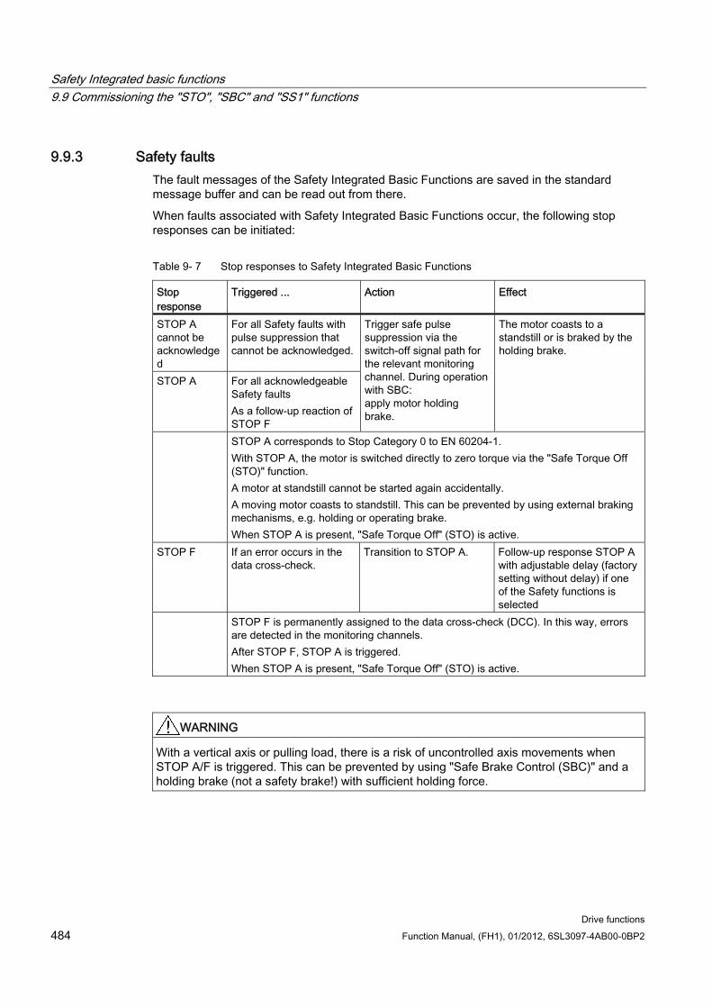
Safety Integrated basic functions 9.9 Commissioning the "STO", "SBC" and "SS1" functions
Drive functions 484 Function Manual, (FH1), 01/2012, 6SL3097-4AB00-0BP2
9.9.3 Safety faults The fault messages of the Safety Integrated Basic Functions are saved in the standard message buffer and can be read out from there.
When faults associated with Safety Integrated Basic Functions occur, the following stop responses can be initiated:
Table 9- 7 Stop responses to Safety Integrated Basic Functions
Stop response
Triggered ... Action Effect
STOP A cannot be acknowledged
For all Safety faults with pulse suppression that cannot be acknowledged.
STOP A For all acknowledgeable Safety faults As a follow-up reaction of STOP F
Trigger safe pulse suppression via the switch-off signal path for the relevant monitoring channel. During operation with SBC: apply motor holding brake.
The motor coasts to a standstill or is braked by the holding brake.
STOP A corresponds to Stop Category 0 to EN 60204-1. With STOP A, the motor is switched directly to zero torque via the "Safe Torque Off (STO)" function. A motor at standstill cannot be started again accidentally. A moving motor coasts to standstill. This can be prevented by using external braking mechanisms, e.g. holding or operating brake. When STOP A is present, "Safe Torque Off" (STO) is active.
STOP F If an error occurs in the data cross-check.
Transition to STOP A. Follow-up response STOP A with adjustable delay (factory setting without delay) if one of the Safety functions is selected
STOP F is permanently assigned to the data cross-check (DCC). In this way, errors are detected in the monitoring channels. After STOP F, STOP A is triggered. When STOP A is present, "Safe Torque Off" (STO) is active.
WARNING With a vertical axis or pulling load, there is a risk of uncontrolled axis movements when STOP A/F is triggered. This can be prevented by using "Safe Brake Control (SBC)" and a holding brake (not a safety brake!) with sufficient holding force.
Safety Integrated basic functions 9.9 Commissioning the "STO", "SBC" and "SS1" functions
Drive functions Function Manual, (FH1), 01/2012, 6SL3097-4AB00-0BP2 485
Acknowledging the Safety faults There are several options for acknowledging Safety faults (for more details see S120 Commissioning Manual):
1. Faults associated with Safety Integrated Basic Functions must be acknowledged as
follows: - Remove the cause of the fault. - Deselect "Safe Torque Off" (STO). - Acknowledge the fault. If the Safety commissioning mode is exited when the Safety functions are switched off (p0010 = value not equal to 95 when p9601 = p9801 = 0), then all the Safety faults can be acknowledged. Once Safety commissioning mode has been selected again (p0010 = 95), all the faults that were previously present reappear. 2. The higher-level controller sets the signal "Internal Event ACK" via the PROFIsafe
telegram (STW bit 7). A falling edge in this signal resets the status "Internal Event" and so acknowledges the fault.
NOTICE Safety faults can also be acknowledged (as with all other faults) by switching the drive unit off and then on again (POWER ON).
If this action has not eliminated the fault cause, the fault is displayed again immediately after power up.
Description of faults and alarms
Note
The faults and alarms for SINAMICS Safety Integrated functions are described in the following document:
References: SINAMICS S120/S150 List Manual
Safety Integrated basic functions 9.10 Acceptance test and certificate
Drive functions 486 Function Manual, (FH1), 01/2012, 6SL3097-4AB00-0BP2
9.10 Acceptance test and certificate
Note
After commissioning the Safety Integrated functions, you can use STARTER to create an acceptance report template containing the parameters to be documented (see STARTER → Drive unit → Documentation).
The acceptance test requirements (configuration check) for electrical drive safety functions emanate from DIN EN 61800-5-2, Chapter 7.1 Point f). The acceptance test "configuration check" is named in this standard.
Description of the application including a picture
Description of the safety relevant components (including software versions) which are used in the application
List of the PDS(SR) [Power Drive System(Safety Related)] safety functions used
Results of all tests of these safety functions, using the specified testing procedure
List of all safety relevant parameters and their values in the PDS(SR)
Checksum, test date and confirmation by testing personnel
The acceptance test for systems with Safety Integrated functions (SI functions) is focused on validating the functionality of Safety Integrated monitoring and stop functions implemented in the drive system. The test objective is to verify proper implementation of the defined safety functions and of test mechanisms (forced dormant error detection measures) and to examine the response of specific monitoring functions to the explicit input of values outside tolerance limits. The test must cover all drive-specific Safety Integrated motion monitoring functions and global Safety Integrated functionality of Terminal Module TM54F (if used).
WARNING A new acceptance test must be carried out if any changes were made to SI function parameters and must be logged in the acceptance report.
Note
The acceptance test is designed to ensure that the safety functions are correctly parameterized. The measured values (e.g. distance, time) and the system behavior identified (e.g. initiation of a specific stop) can be used for checking the plausibility of the configured safety functions. The objective of an acceptance test is to identify potential configuration errors and/or to document the correct function of the configuration. The measured values are typical values (not worst case values). They represent the behavior of the machine at the time of measurement. These measurements cannot be used to derive real values (e.g. maximum values for over-travel distances).
Safety Integrated basic functions 9.10 Acceptance test and certificate
Drive functions Function Manual, (FH1), 01/2012, 6SL3097-4AB00-0BP2 487
9.10.1 Acceptance test structure
Authorized person, acceptance report The test of each SI function must be carried out by an authorized person and logged in the acceptance report. The report must be signed by the person who carried out the acceptance test. The acceptance report must be kept in the logbook of the relevant machine. Access rights to SI parameters must be protected by a password. This procedure must be documented in the acceptance report – the password itself must not appear there. Authorized in this sense refers to a person who has the necessary technical training and knowledge of the safety functions and is authorized by the machine manufacturer to carry out the acceptance test.
Note • Observe the information in the chapter "Procedures for initial commissioning". • The acceptance report presented below is both an example and recommendation. • An acceptance report template in electronic format is available at your local Siemens
sales office.
Necessity of an acceptance test A complete acceptance test (as described in this chapter) is required after initial commissioning of Safety Integrated functionality on a machine. Safety-related function expansions, transfer of the commissioning settings to other series machines, hardware changes, software upgrades or similar, permit the acceptance test to be performed with a reduced scope if necessary. A summary of conditions which determine the necessary test scope or proposals in this context is provided below.
In order to define a partial acceptance test, it is necessary in the first instance to specify the acceptance test objects, and in the second instance to define logical groups which represent the elements of the acceptance test. The acceptance test must be carried out separately for each individual drive (as far as the machine allows).
Prerequisites for the acceptance test The machine is properly wired.
All safety equipment such as protective door monitoring devices, light barriers or emergency limit switches are connected and ready for operation.
Commissioning of the open-loop and closed-loop control must be completed, as e.g. the over-travel distance may otherwise change as a result of a changed dynamic response of the drive control. These include, for example:
– Configuration of the setpoint channel
– Position control in the higher-level controller
– Drive control
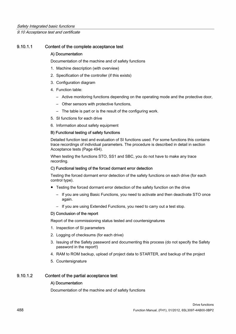
Safety Integrated basic functions 9.10 Acceptance test and certificate
Drive functions 488 Function Manual, (FH1), 01/2012, 6SL3097-4AB00-0BP2
9.10.1.1 Content of the complete acceptance test A) Documentation
Documentation of the machine and of safety functions
1. Machine description (with overview)
2. Specification of the controller (if this exists)
3. Configuration diagram
4. Function table:
– Active monitoring functions depending on the operating mode and the protective door,
– Other sensors with protective functions,
– The table is part or is the result of the configuring work.
5. SI functions for each drive
6. Information about safety equipment
B) Functional testing of safety functions
Detailed function test and evaluation of SI functions used. For some functions this contains trace recordings of individual parameters. The procedure is described in detail in section Acceptance tests (Page 494).
When testing the functions STO, SS1 and SBC, you do not have to make any trace recording.
C) Functional testing of the forced dormant error detection
Testing the forced dormant error detection of the safety functions on each drive (for each control type).
Testing the forced dormant error detection of the safety function on the drive
– If you are using Basic Functions, you need to activate and then deactivate STO once again.
– If you are using Extended Functions, you need to carry out a test stop.
D) Conclusion of the report
Report of the commissioning status tested and countersignatures
1. Inspection of SI parameters
2. Logging of checksums (for each drive)
3. Issuing of the Safety password and documenting this process (do not specify the Safety password in the report!)
4. RAM to ROM backup, upload of project data to STARTER, and backup of the project
5. Countersignature
9.10.1.2 Content of the partial acceptance test A) Documentation
Documentation of the machine and of safety functions
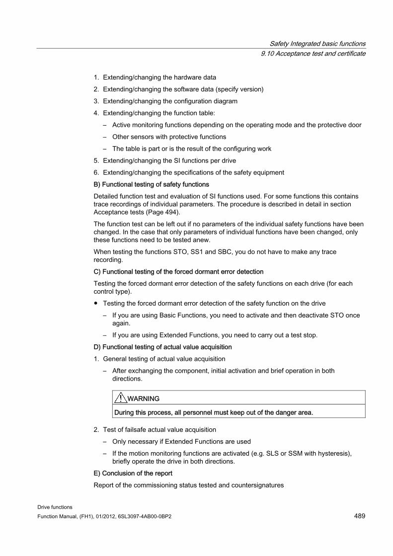
Safety Integrated basic functions 9.10 Acceptance test and certificate
Drive functions Function Manual, (FH1), 01/2012, 6SL3097-4AB00-0BP2 489
1. Extending/changing the hardware data
2. Extending/changing the software data (specify version)
3. Extending/changing the configuration diagram
4. Extending/changing the function table:
– Active monitoring functions depending on the operating mode and the protective door
– Other sensors with protective functions
– The table is part or is the result of the configuring work
5. Extending/changing the SI functions per drive
6. Extending/changing the specifications of the safety equipment
B) Functional testing of safety functions
Detailed function test and evaluation of SI functions used. For some functions this contains trace recordings of individual parameters. The procedure is described in detail in section Acceptance tests (Page 494).
The function test can be left out if no parameters of the individual safety functions have been changed. In the case that only parameters of individual functions have been changed, only these functions need to be tested anew.
When testing the functions STO, SS1 and SBC, you do not have to make any trace recording.
C) Functional testing of the forced dormant error detection
Testing the forced dormant error detection of the safety functions on each drive (for each control type).
Testing the forced dormant error detection of the safety function on the drive
– If you are using Basic Functions, you need to activate and then deactivate STO once again.
– If you are using Extended Functions, you need to carry out a test stop.
D) Functional testing of actual value acquisition
1. General testing of actual value acquisition
– After exchanging the component, initial activation and brief operation in both directions.
WARNING
During this process, all personnel must keep out of the danger area.
2. Test of failsafe actual value acquisition
– Only necessary if Extended Functions are used
– If the motion monitoring functions are activated (e.g. SLS or SSM with hysteresis), briefly operate the drive in both directions.
E) Conclusion of the report
Report of the commissioning status tested and countersignatures
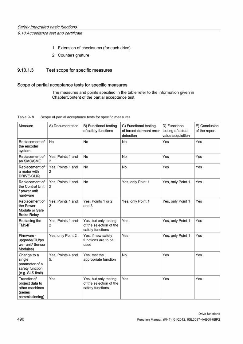
Safety Integrated basic functions 9.10 Acceptance test and certificate
Drive functions 490 Function Manual, (FH1), 01/2012, 6SL3097-4AB00-0BP2
1. Extension of checksums (for each drive)
2. Countersignature
9.10.1.3 Test scope for specific measures
Scope of partial acceptance tests for specific measures The measures and points specified in the table refer to the information given in ChapterContent of the partial acceptance test.
Table 9- 8 Scope of partial acceptance tests for specific measures
Measure A) Documentation B) Functional testing of safety functions
C) Functional testing of forced dormant error detection
D) Functional testing of actual value acquisition
E) Conclusion of the report
Replacement of the encoder system
No No No Yes Yes
Replacement of an SMC/SME
Yes, Points 1 and 2
No No Yes Yes
Replacement of a motor with DRIVE-CLiQ
Yes, Points 1 and 2
No No Yes Yes
Replacement of the Control Unit / power unit hardware
Yes, Points 1 and 2
No Yes, only Point 1 Yes, only Point 1 Yes
Replacement of the Power Module or Safe Brake Relay
Yes, Points 1 and 2
Yes, Points 1 or 2 and 3
Yes, only Point 1 Yes, only Point 1 Yes
Replacing the TM54F
Yes, Points 1 and 2
Yes, but only testing of the selection of the safety functions
Yes Yes, only Point 1 Yes
Firmware - upgrade(CU/power unit/ Sensor Modules)
Yes, only Point 2 Yes, if new safety functions are to be used
Yes Yes, only Point 1 Yes
Change to a single parameter of a safety function (e.g. SLS limit)
Yes, Points 4 and 5.
Yes, test the appropriate function
No Yes Yes
Transfer of project data to other machines (series commissioning)
Yes Yes, but only testing of the selection of the safety functions
Yes Yes Yes
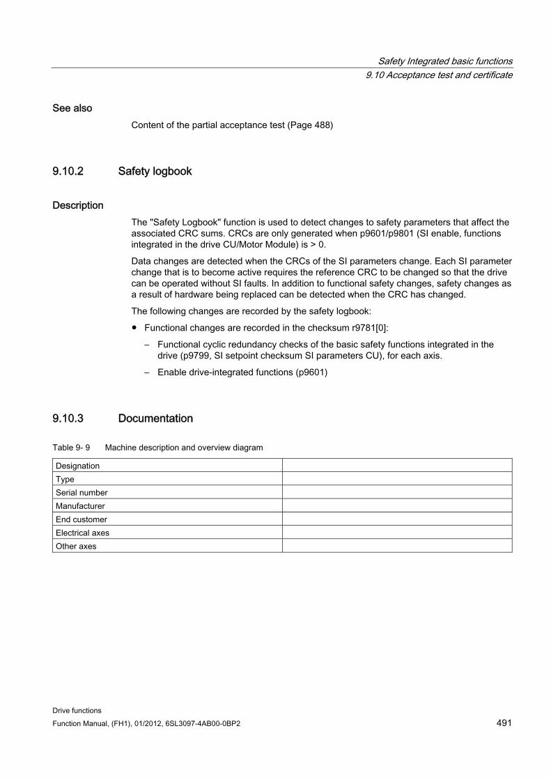
Safety Integrated basic functions 9.10 Acceptance test and certificate
Drive functions Function Manual, (FH1), 01/2012, 6SL3097-4AB00-0BP2 491
See also Content of the partial acceptance test (Page 488)
9.10.2 Safety logbook
Description The "Safety Logbook" function is used to detect changes to safety parameters that affect the associated CRC sums. CRCs are only generated when p9601/p9801 (SI enable, functions integrated in the drive CU/Motor Module) is > 0.
Data changes are detected when the CRCs of the SI parameters change. Each SI parameter change that is to become active requires the reference CRC to be changed so that the drive can be operated without SI faults. In addition to functional safety changes, safety changes as a result of hardware being replaced can be detected when the CRC has changed.
The following changes are recorded by the safety logbook:
Functional changes are recorded in the checksum r9781[0]:
– Functional cyclic redundancy checks of the basic safety functions integrated in the drive (p9799, SI setpoint checksum SI parameters CU), for each axis.
– Enable drive-integrated functions (p9601)
9.10.3 Documentation
Table 9- 9 Machine description and overview diagram
Designation Type Serial number Manufacturer End customer Electrical axes Other axes
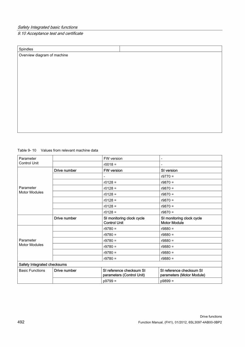
Safety Integrated basic functions 9.10 Acceptance test and certificate
Drive functions 492 Function Manual, (FH1), 01/2012, 6SL3097-4AB00-0BP2
Spindles Overview diagram of machine
Table 9- 10 Values from relevant machine data
FW version - Parameter Control Unit r0018 = -
Drive number FW version SI version - r9770 = r0128 = r9870 = r0128 = r9870 = r0128 = r9870 = r0128 = r9870 = r0128 = r9870 =
Parameter Motor Modules
r0128 = r9870 = Drive number SI monitoring clock cycle
Control Unit SI monitoring clock cycle Motor Module
r9780 = r9880 = r9780 = r9880 = r9780 = r9880 = r9780 = r9880 = r9780 = r9880 =
Parameter Motor Modules
r9780 = r9880 = Safety Integrated checksums
Drive number SI reference checksum SI parameters (Control Unit)
SI reference checksum SI parameters (Motor Module)
Basic Functions
p9799 = p9899 =
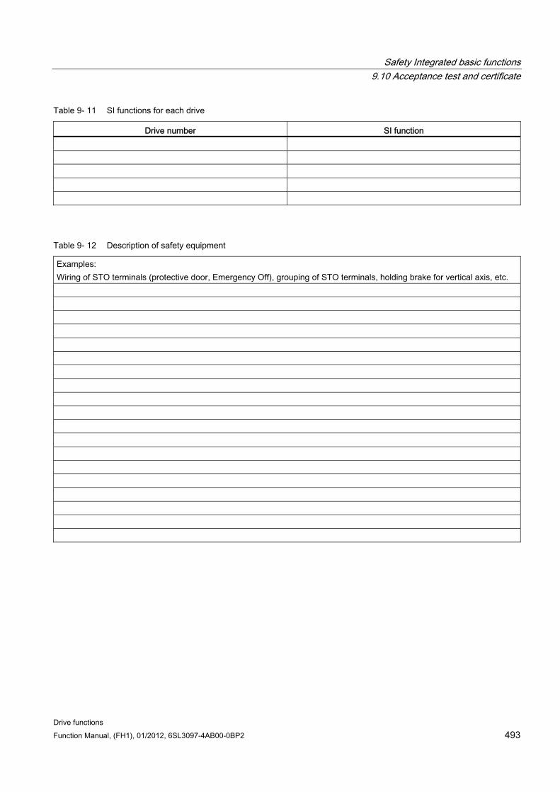
Safety Integrated basic functions 9.10 Acceptance test and certificate
Drive functions Function Manual, (FH1), 01/2012, 6SL3097-4AB00-0BP2 493
Table 9- 11 SI functions for each drive
Drive number SI function
Table 9- 12 Description of safety equipment
Examples: Wiring of STO terminals (protective door, Emergency Off), grouping of STO terminals, holding brake for vertical axis, etc.
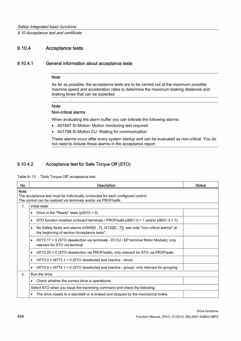
Safety Integrated basic functions 9.10 Acceptance test and certificate
Drive functions 494 Function Manual, (FH1), 01/2012, 6SL3097-4AB00-0BP2
9.10.4 Acceptance tests
9.10.4.1 General information about acceptance tests
Note
As far as possible, the acceptance tests are to be carried out at the maximum possible machine speed and acceleration rates to determine the maximum braking distances and braking times that can be expected.
Note Non-critical alarms
When evaluating the alarm buffer you can tolerate the following alarms: • A01697 SI Motion: Motion monitoring test required • A01796 SI Motion CU: Waiting for communication
These alarms occur after every system startup and can be evaluated as non-critical. You do not need to include these alarms in the acceptance report.
9.10.4.2 Acceptance test for Safe Torque Off (STO)
Table 9- 13 "Safe Torque Off" acceptance test
No. Description Status Note: The acceptance test must be individually conducted for each configured control. The control can be realized via terminals and/or via PROFIsafe.
Initial state
• Drive in the "Ready" state (p0010 = 0)
• STO function enabled (onboard terminals / PROFIsafe p9601.0 = 1 and/or p9601.3 = 1)
• No Safety faults and alarms (r0945[0...7], r2122[0...7]); see note "non-critical alarms" at the beginning of section Acceptance tests".
• r9772.17 = 0 (STO deselection via terminals - DI CU / EP terminal Motor Module); only relevant for STO via terminal
• r9772.20 = 0 (STO deselection via PROFIsafe); only relevant for STO via PROFIsafe
• r9773.0 = r9773.1 = 0 (STO deselected and inactive - drive)
1.
• r9774.0 = r9774.1 = 0 (STO deselected and inactive - group); only relevant for grouping
Run the drive
• Check whether the correct drive is operational
Select STO when you issue the traversing command and check the following:
2.
• The drive coasts to a standstill or is braked and stopped by the mechanical brake.
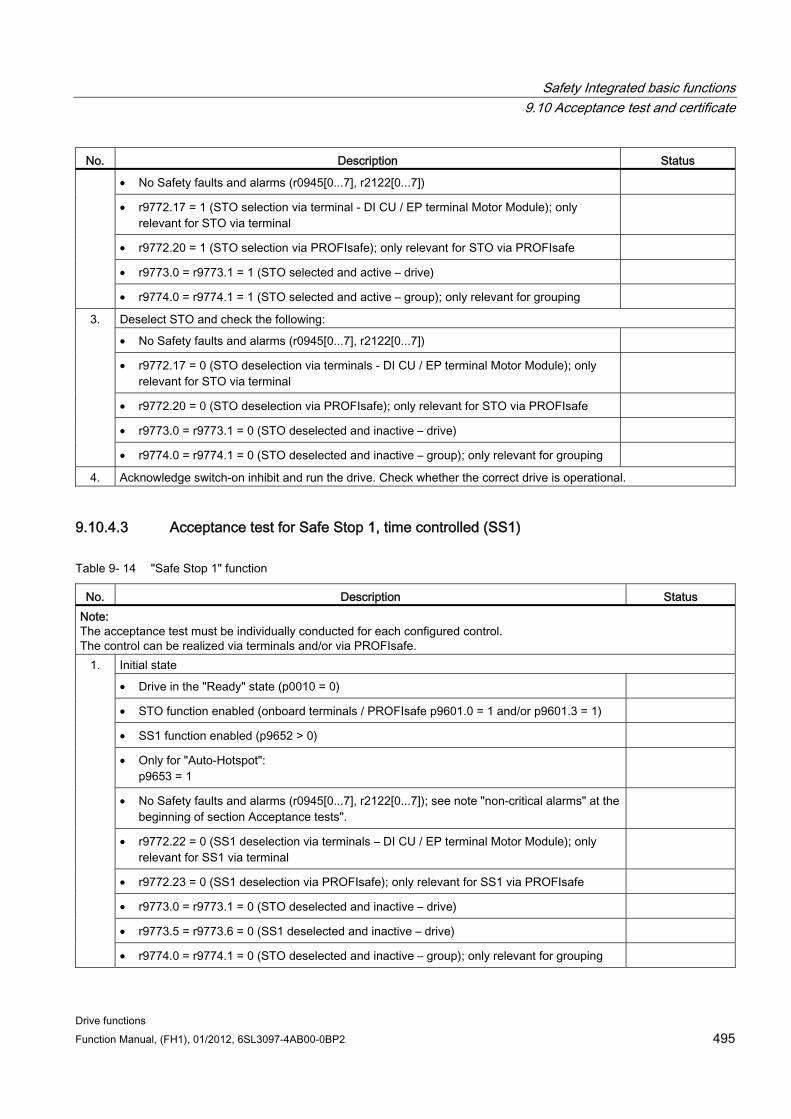
Safety Integrated basic functions 9.10 Acceptance test and certificate
Drive functions Function Manual, (FH1), 01/2012, 6SL3097-4AB00-0BP2 495
No. Description Status
• No Safety faults and alarms (r0945[0...7], r2122[0...7])
• r9772.17 = 1 (STO selection via terminal - DI CU / EP terminal Motor Module); only relevant for STO via terminal
• r9772.20 = 1 (STO selection via PROFIsafe); only relevant for STO via PROFIsafe
• r9773.0 = r9773.1 = 1 (STO selected and active – drive)
• r9774.0 = r9774.1 = 1 (STO selected and active – group); only relevant for grouping
Deselect STO and check the following:
• No Safety faults and alarms (r0945[0...7], r2122[0...7])
• r9772.17 = 0 (STO deselection via terminals - DI CU / EP terminal Motor Module); only relevant for STO via terminal
• r9772.20 = 0 (STO deselection via PROFIsafe); only relevant for STO via PROFIsafe
• r9773.0 = r9773.1 = 0 (STO deselected and inactive – drive)
3.
• r9774.0 = r9774.1 = 0 (STO deselected and inactive – group); only relevant for grouping
4. Acknowledge switch-on inhibit and run the drive. Check whether the correct drive is operational.
9.10.4.3 Acceptance test for Safe Stop 1, time controlled (SS1)
Table 9- 14 "Safe Stop 1" function
No. Description Status Note: The acceptance test must be individually conducted for each configured control. The control can be realized via terminals and/or via PROFIsafe.
Initial state
• Drive in the "Ready" state (p0010 = 0)
• STO function enabled (onboard terminals / PROFIsafe p9601.0 = 1 and/or p9601.3 = 1)
• SS1 function enabled (p9652 > 0)
• Only for "Auto-Hotspot": p9653 = 1
• No Safety faults and alarms (r0945[0...7], r2122[0...7]); see note "non-critical alarms" at the beginning of section Acceptance tests".
• r9772.22 = 0 (SS1 deselection via terminals – DI CU / EP terminal Motor Module); only relevant for SS1 via terminal
• r9772.23 = 0 (SS1 deselection via PROFIsafe); only relevant for SS1 via PROFIsafe
• r9773.0 = r9773.1 = 0 (STO deselected and inactive – drive)
• r9773.5 = r9773.6 = 0 (SS1 deselected and inactive – drive)
1.
• r9774.0 = r9774.1 = 0 (STO deselected and inactive – group); only relevant for grouping
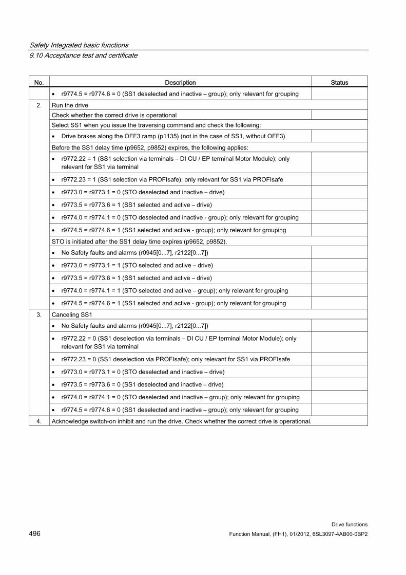
Safety Integrated basic functions 9.10 Acceptance test and certificate
Drive functions 496 Function Manual, (FH1), 01/2012, 6SL3097-4AB00-0BP2
No. Description Status
• r9774.5 = r9774.6 = 0 (SS1 deselected and inactive – group); only relevant for grouping
Run the drive Check whether the correct drive is operational Select SS1 when you issue the traversing command and check the following:
• Drive brakes along the OFF3 ramp (p1135) (not in the case of SS1, without OFF3)
Before the SS1 delay time (p9652, p9852) expires, the following applies:
• r9772.22 = 1 (SS1 selection via terminals – DI CU / EP terminal Motor Module); only relevant for SS1 via terminal
• r9772.23 = 1 (SS1 selection via PROFIsafe); only relevant for SS1 via PROFIsafe
• r9773.0 = r9773.1 = 0 (STO deselected and inactive – drive)
• r9773.5 = r9773.6 = 1 (SS1 selected and active – drive)
• r9774.0 = r9774.1 = 0 (STO deselected and inactive - group); only relevant for grouping
• r9774.5 = r9774.6 = 1 (SS1 selected and active - group); only relevant for grouping
STO is initiated after the SS1 delay time expires (p9652, p9852).
• No Safety faults and alarms (r0945[0...7], r2122[0...7])
• r9773.0 = r9773.1 = 1 (STO selected and active – drive)
• r9773.5 = r9773.6 = 1 (SS1 selected and active – drive)
• r9774.0 = r9774.1 = 1 (STO selected and active – group); only relevant for grouping
2.
• r9774.5 = r9774.6 = 1 (SS1 selected and active - group); only relevant for grouping
Canceling SS1
• No Safety faults and alarms (r0945[0...7], r2122[0...7])
• r9772.22 = 0 (SS1 deselection via terminals – DI CU / EP terminal Motor Module); only relevant for SS1 via terminal
• r9772.23 = 0 (SS1 deselection via PROFIsafe); only relevant for SS1 via PROFIsafe
• r9773.0 = r9773.1 = 0 (STO deselected and inactive – drive)
• r9773.5 = r9773.6 = 0 (SS1 deselected and inactive – drive)
• r9774.0 = r9774.1 = 0 (STO deselected and inactive – group); only relevant for grouping
3.
• r9774.5 = r9774.6 = 0 (SS1 deselected and inactive – group); only relevant for grouping
4. Acknowledge switch-on inhibit and run the drive. Check whether the correct drive is operational.
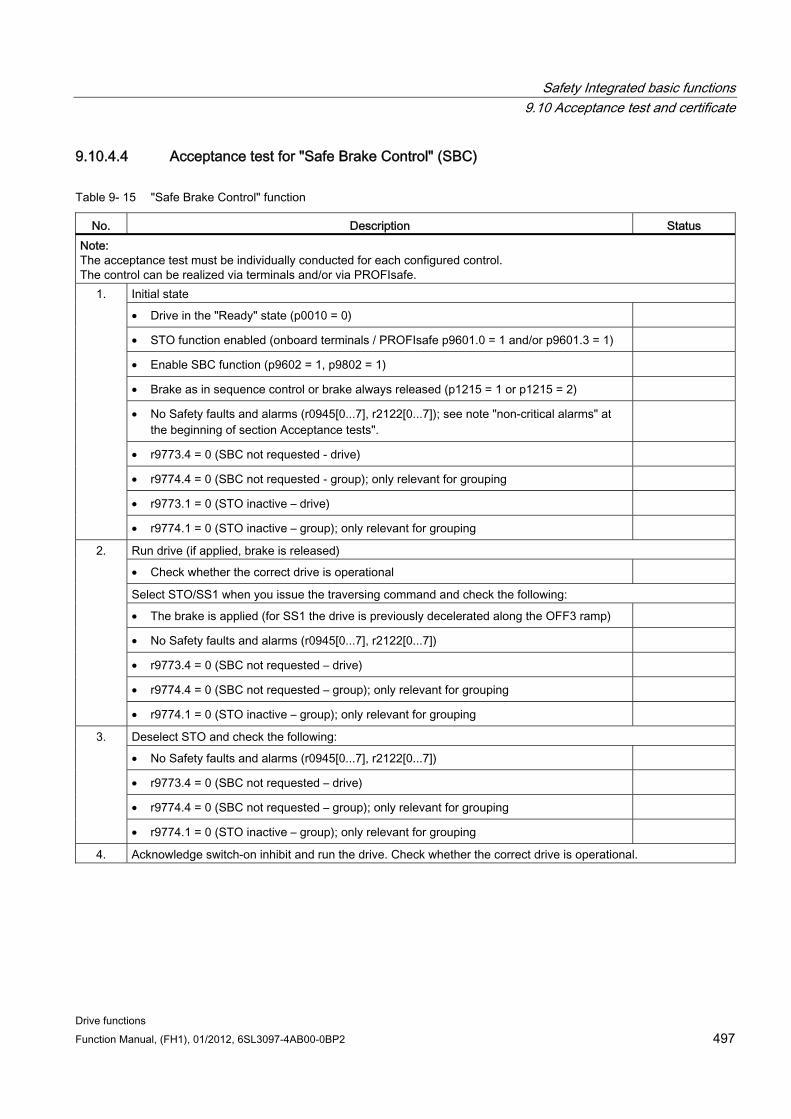
Safety Integrated basic functions 9.10 Acceptance test and certificate
Drive functions Function Manual, (FH1), 01/2012, 6SL3097-4AB00-0BP2 497
9.10.4.4 Acceptance test for "Safe Brake Control" (SBC)
Table 9- 15 "Safe Brake Control" function
No. Description Status Note: The acceptance test must be individually conducted for each configured control. The control can be realized via terminals and/or via PROFIsafe.
Initial state
• Drive in the "Ready" state (p0010 = 0)
• STO function enabled (onboard terminals / PROFIsafe p9601.0 = 1 and/or p9601.3 = 1)
• Enable SBC function (p9602 = 1, p9802 = 1)
• Brake as in sequence control or brake always released (p1215 = 1 or p1215 = 2)
• No Safety faults and alarms (r0945[0...7], r2122[0...7]); see note "non-critical alarms" at the beginning of section Acceptance tests".
• r9773.4 = 0 (SBC not requested - drive)
• r9774.4 = 0 (SBC not requested - group); only relevant for grouping
• r9773.1 = 0 (STO inactive – drive)
1.
• r9774.1 = 0 (STO inactive – group); only relevant for grouping
Run drive (if applied, brake is released)
• Check whether the correct drive is operational
Select STO/SS1 when you issue the traversing command and check the following:
• The brake is applied (for SS1 the drive is previously decelerated along the OFF3 ramp)
• No Safety faults and alarms (r0945[0...7], r2122[0...7])
• r9773.4 = 0 (SBC not requested – drive)
• r9774.4 = 0 (SBC not requested – group); only relevant for grouping
2.
• r9774.1 = 0 (STO inactive – group); only relevant for grouping
Deselect STO and check the following:
• No Safety faults and alarms (r0945[0...7], r2122[0...7])
• r9773.4 = 0 (SBC not requested – drive)
• r9774.4 = 0 (SBC not requested – group); only relevant for grouping
3.
• r9774.1 = 0 (STO inactive – group); only relevant for grouping
4. Acknowledge switch-on inhibit and run the drive. Check whether the correct drive is operational.
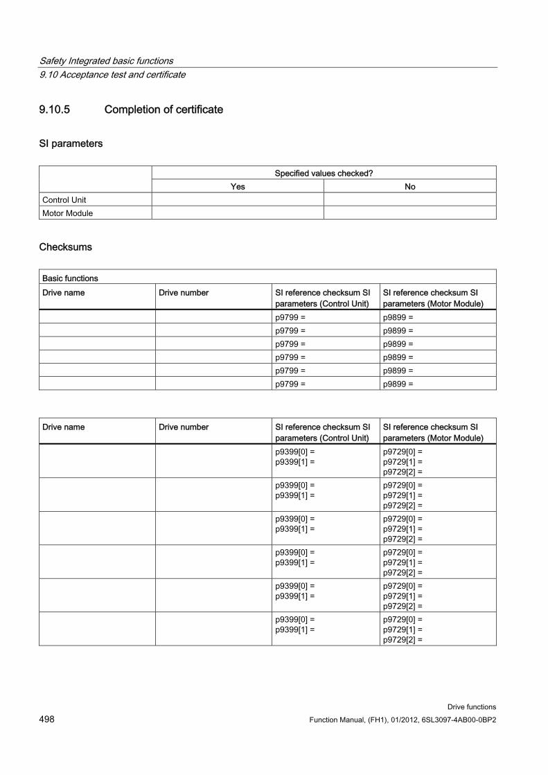
Safety Integrated basic functions 9.10 Acceptance test and certificate
Drive functions 498 Function Manual, (FH1), 01/2012, 6SL3097-4AB00-0BP2
9.10.5 Completion of certificate
SI parameters
Specified values checked? Yes No
Control Unit Motor Module
Checksums Basic functions Drive name Drive number SI reference checksum SI
parameters (Control Unit) SI reference checksum SI parameters (Motor Module)
p9799 = p9899 = p9799 = p9899 = p9799 = p9899 = p9799 = p9899 = p9799 = p9899 = p9799 = p9899 =
Drive name Drive number SI reference checksum SI
parameters (Control Unit) SI reference checksum SI parameters (Motor Module)
p9399[0] = p9399[1] =
p9729[0] = p9729[1] = p9729[2] =
p9399[0] = p9399[1] =
p9729[0] = p9729[1] = p9729[2] =
p9399[0] = p9399[1] =
p9729[0] = p9729[1] = p9729[2] =
p9399[0] = p9399[1] =
p9729[0] = p9729[1] = p9729[2] =
p9399[0] = p9399[1] =
p9729[0] = p9729[1] = p9729[2] =
p9399[0] = p9399[1] =
p9729[0] = p9729[1] = p9729[2] =
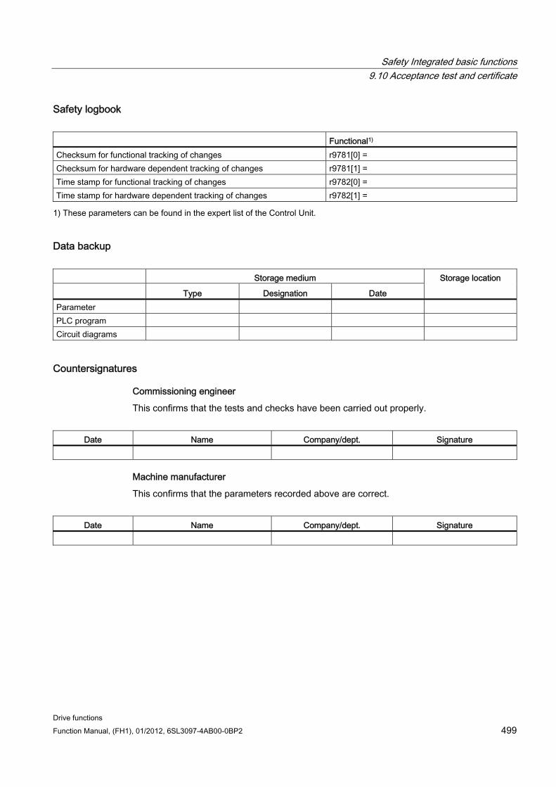
Safety Integrated basic functions 9.10 Acceptance test and certificate
Drive functions Function Manual, (FH1), 01/2012, 6SL3097-4AB00-0BP2 499
Safety logbook Functional1) Checksum for functional tracking of changes r9781[0] = Checksum for hardware dependent tracking of changes r9781[1] = Time stamp for functional tracking of changes r9782[0] = Time stamp for hardware dependent tracking of changes r9782[1] =
1) These parameters can be found in the expert list of the Control Unit.
Data backup Storage medium
Type Designation Date
Storage location
Parameter PLC program Circuit diagrams
Countersignatures
Commissioning engineer
This confirms that the tests and checks have been carried out properly.
Date Name Company/dept. Signature
Machine manufacturer
This confirms that the parameters recorded above are correct.
Date Name Company/dept. Signature
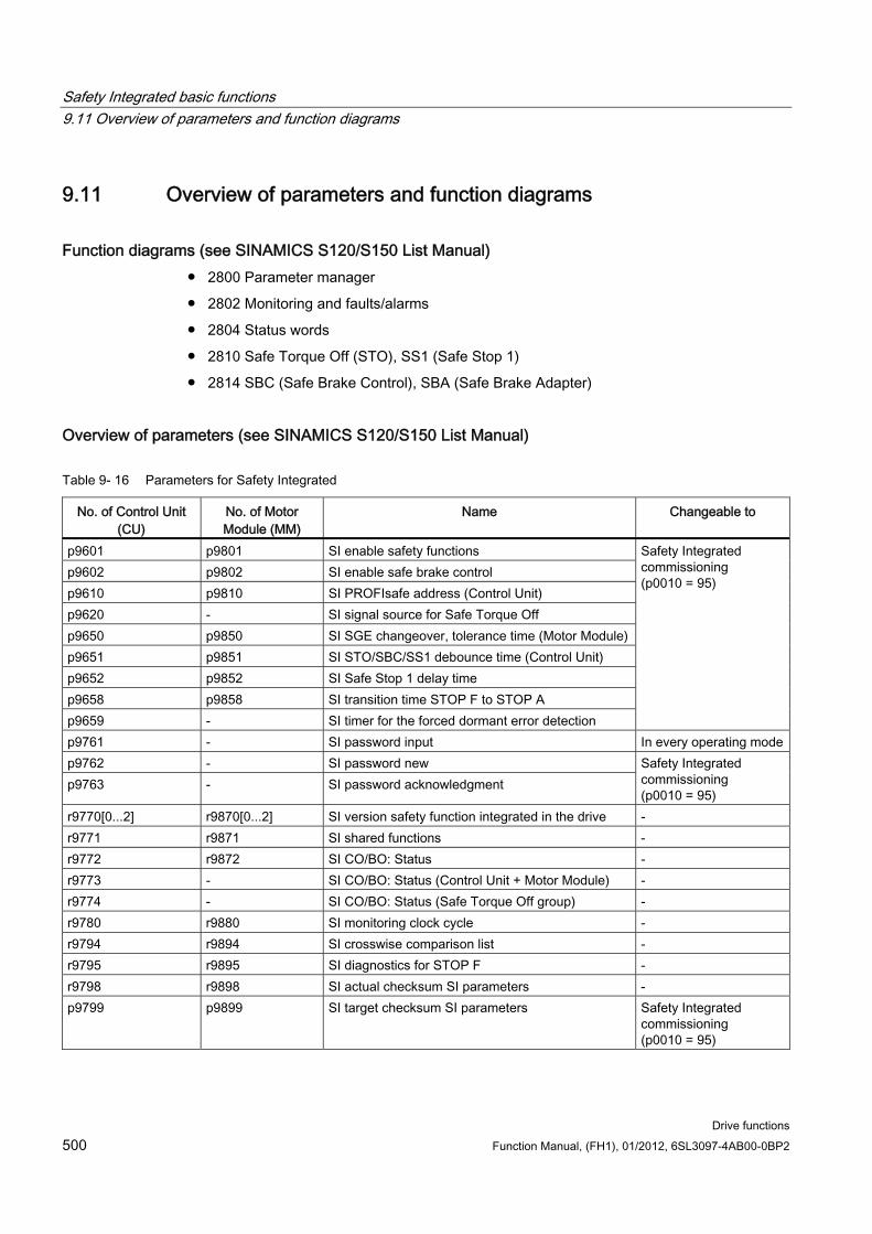
Safety Integrated basic functions 9.11 Overview of parameters and function diagrams
Drive functions 500 Function Manual, (FH1), 01/2012, 6SL3097-4AB00-0BP2
9.11 Overview of parameters and function diagrams
Function diagrams (see SINAMICS S120/S150 List Manual) 2800 Parameter manager
2802 Monitoring and faults/alarms
2804 Status words
2810 Safe Torque Off (STO), SS1 (Safe Stop 1)
2814 SBC (Safe Brake Control), SBA (Safe Brake Adapter)
Overview of parameters (see SINAMICS S120/S150 List Manual)
Table 9- 16 Parameters for Safety Integrated
No. of Control Unit (CU)
No. of Motor Module (MM)
Name Changeable to
p9601 p9801 SI enable safety functions p9602 p9802 SI enable safe brake control p9610 p9810 SI PROFIsafe address (Control Unit) p9620 - SI signal source for Safe Torque Off p9650 p9850 SI SGE changeover, tolerance time (Motor Module) p9651 p9851 SI STO/SBC/SS1 debounce time (Control Unit) p9652 p9852 SI Safe Stop 1 delay time p9658 p9858 SI transition time STOP F to STOP A p9659 - SI timer for the forced dormant error detection
Safety Integrated commissioning (p0010 = 95)
p9761 - SI password input In every operating modep9762 - SI password new p9763 - SI password acknowledgment
Safety Integrated commissioning (p0010 = 95)
r9770[0...2] r9870[0...2] SI version safety function integrated in the drive - r9771 r9871 SI shared functions - r9772 r9872 SI CO/BO: Status - r9773 - SI CO/BO: Status (Control Unit + Motor Module) - r9774 - SI CO/BO: Status (Safe Torque Off group) - r9780 r9880 SI monitoring clock cycle - r9794 r9894 SI crosswise comparison list - r9795 r9895 SI diagnostics for STOP F - r9798 r9898 SI actual checksum SI parameters - p9799 p9899 SI target checksum SI parameters Safety Integrated
commissioning (p0010 = 95)
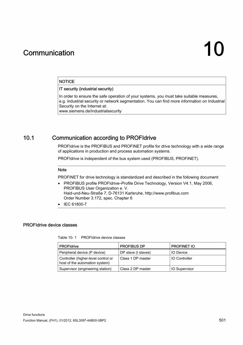
Drive functions Function Manual, (FH1), 01/2012, 6SL3097-4AB00-0BP2 501
Communication 10
NOTICE IT security (industrial security)
In order to ensure the safe operation of your systems, you must take suitable measures, e.g. industrial security or network segmentation. You can find more information on Industrial Security on the Internet at: www.siemens.de/industrialsecurity
10.1 Communication according to PROFIdrive PROFIdrive is the PROFIBUS and PROFINET profile for drive technology with a wide range of applications in production and process automation systems.
PROFIdrive is independent of the bus system used (PROFIBUS, PROFINET).
Note
PROFINET for drive technology is standardized and described in the following document: • PROFIBUS profile PROFIdrive–Profile Drive Technology, Version V4.1, May 2006,
PROFIBUS User Organization e. V. Haid-und-Neu-Straße 7, D-76131 Karlsruhe, http://www.profibus.com Order Number 3.172, spec. Chapter 6
• IEC 61800-7
PROFIdrive device classes
Table 10- 1 PROFIdrive device classes
PROFIdrive PROFIBUS DP PROFINET IO Peripheral device (P device) DP slave (I slaves) IO Device Controller (higher-level control or host of the automation system)
Class 1 DP master IO Controller
Supervisor (engineering station) Class 2 DP master IO Supervisor
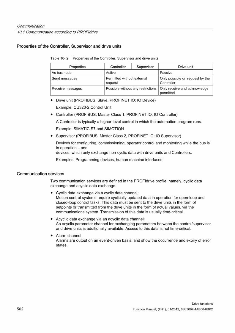
Communication 10.1 Communication according to PROFIdrive
Drive functions 502 Function Manual, (FH1), 01/2012, 6SL3097-4AB00-0BP2
Properties of the Controller, Supervisor and drive units
Table 10- 2 Properties of the Controller, Supervisor and drive units
Properties Controller Supervisor Drive unit As bus node Active Passive Send messages Permitted without external
request Only possible on request by the Controller
Receive messages Possible without any restrictions Only receive and acknowledge permitted
Drive unit (PROFIBUS: Slave, PROFINET IO: IO Device)
Example: CU320-2 Control Unit
Controller (PROFIBUS: Master Class 1, PROFINET IO: IO Controller)
A Controller is typically a higher-level control in which the automation program runs.
Example: SIMATIC S7 and SIMOTION
Supervisor (PROFIBUS: Master Class 2, PROFINET IO: IO Supervisor)
Devices for configuring, commissioning, operator control and monitoring while the bus is in operation – and devices, which only exchange non-cyclic data with drive units and Controllers.
Examples: Programming devices, human machine interfaces
Communication services Two communication services are defined in the PROFIdrive profile; namely, cyclic data exchange and acyclic data exchange.
Cyclic data exchange via a cyclic data channel: Motion control systems require cyclically updated data in operation for open-loop and closed-loop control tasks. This data must be sent to the drive units in the form of setpoints or transmitted from the drive units in the form of actual values, via the communications system. Transmission of this data is usually time-critical.
Acyclic data exchange via an acyclic data channel: An acyclic parameter channel for exchanging parameters between the control/supervisor and drive units is additionally available. Access to this data is not time-critical.
Alarm channel Alarms are output on an event-driven basis, and show the occurrence and expiry of error states.
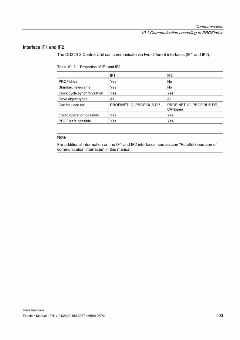
Communication 10.1 Communication according to PROFIdrive
Drive functions Function Manual, (FH1), 01/2012, 6SL3097-4AB00-0BP2 503
Interface IF1 and IF2 The CU320-2 Control Unit can communicate via two different interfaces (IF1 and IF2).
Table 10- 3 Properties of IF1 and IF2
IF1 IF2 PROFIdrive Yes No Standard telegrams Yes No Clock cycle synchronization Yes Yes Drive object types All All Can be used for PROFINET IO, PROFIBUS DP PROFINET IO, PROFIBUS DP,
CANopen Cyclic operation possible Yes Yes PROFIsafe possible Yes Yes
Note
For additional information on the IF1 and IF2 interfaces, see section "Parallel operation of communication interfaces" in this manual.
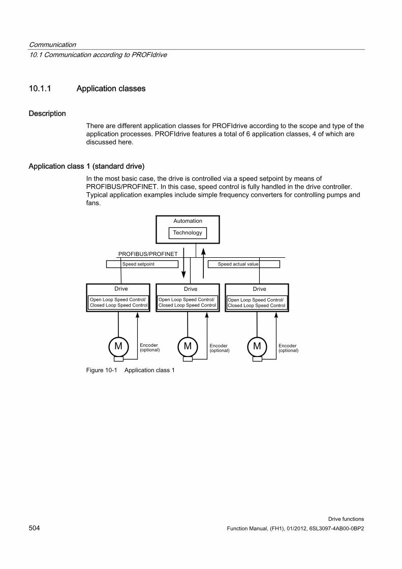
Communication 10.1 Communication according to PROFIdrive
Drive functions 504 Function Manual, (FH1), 01/2012, 6SL3097-4AB00-0BP2
10.1.1 Application classes
Description There are different application classes for PROFIdrive according to the scope and type of the application processes. PROFIdrive features a total of 6 application classes, 4 of which are discussed here.
Application class 1 (standard drive) In the most basic case, the drive is controlled via a speed setpoint by means of PROFIBUS/PROFINET. In this case, speed control is fully handled in the drive controller. Typical application examples include simple frequency converters for controlling pumps and fans.
M MM
Figure 10-1 Application class 1
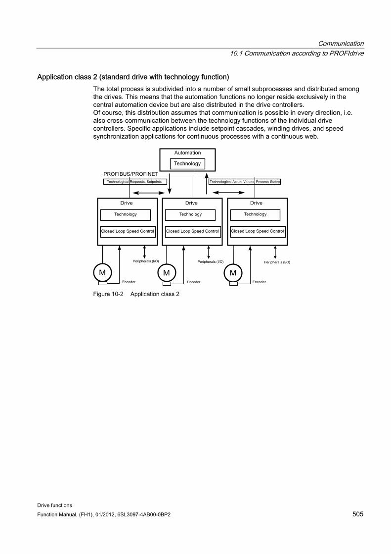
Communication 10.1 Communication according to PROFIdrive
Drive functions Function Manual, (FH1), 01/2012, 6SL3097-4AB00-0BP2 505
Application class 2 (standard drive with technology function) The total process is subdivided into a number of small subprocesses and distributed among the drives. This means that the automation functions no longer reside exclusively in the central automation device but are also distributed in the drive controllers. Of course, this distribution assumes that communication is possible in every direction, i.e. also cross-communication between the technology functions of the individual drive controllers. Specific applications include setpoint cascades, winding drives, and speed synchronization applications for continuous processes with a continuous web.
M MM
Figure 10-2 Application class 2

Communication 10.1 Communication according to PROFIdrive
Drive functions 506 Function Manual, (FH1), 01/2012, 6SL3097-4AB00-0BP2
Application class 3 (positioning drive) In addition to the drive control, the drive also includes a positioning control, which means that it operates as a self-contained single-axis positioning drive while the higher-level technological processes are performed on the controller. Positioning requests are transmitted to the drive controller via PROFIBUS/PROFINET and launched. Positioning drives have a very wide range of applications, e.g., screwing and unscrewing caps in a bottle filling plant or the positioning of cutters on a film cutting machine.
M M
Figure 10-3 Application class 3
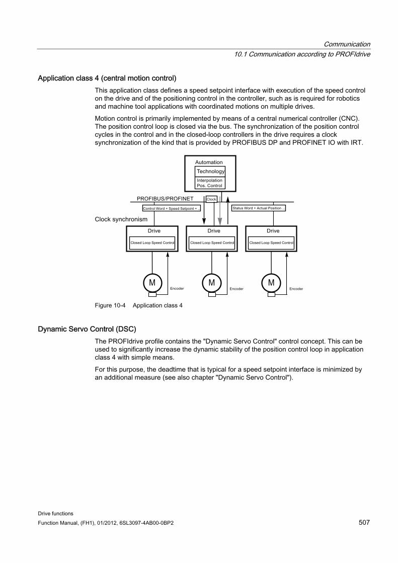
Communication 10.1 Communication according to PROFIdrive
Drive functions Function Manual, (FH1), 01/2012, 6SL3097-4AB00-0BP2 507
Application class 4 (central motion control) This application class defines a speed setpoint interface with execution of the speed control on the drive and of the positioning control in the controller, such as is required for robotics and machine tool applications with coordinated motions on multiple drives.
Motion control is primarily implemented by means of a central numerical controller (CNC). The position control loop is closed via the bus. The synchronization of the position control cycles in the control and in the closed-loop controllers in the drive requires a clock synchronization of the kind that is provided by PROFIBUS DP and PROFINET IO with IRT.
MMM
Figure 10-4 Application class 4
Dynamic Servo Control (DSC) The PROFIdrive profile contains the "Dynamic Servo Control" control concept. This can be used to significantly increase the dynamic stability of the position control loop in application class 4 with simple means.
For this purpose, the deadtime that is typical for a speed setpoint interface is minimized by an additional measure (see also chapter "Dynamic Servo Control").
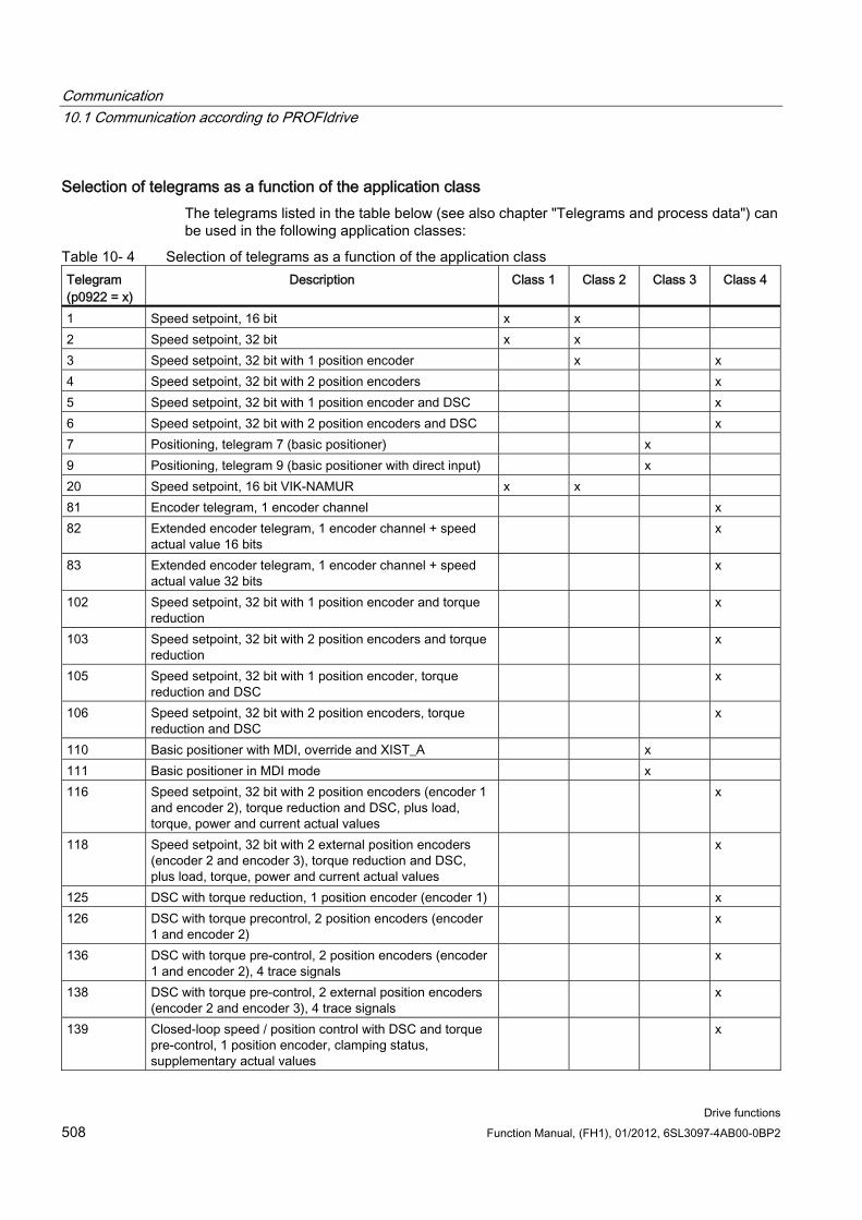
Communication 10.1 Communication according to PROFIdrive
Drive functions 508 Function Manual, (FH1), 01/2012, 6SL3097-4AB00-0BP2
Selection of telegrams as a function of the application class The telegrams listed in the table below (see also chapter "Telegrams and process data") can be used in the following application classes:
Table 10- 4 Selection of telegrams as a function of the application class Telegram (p0922 = x)
Description Class 1 Class 2 Class 3 Class 4
1 Speed setpoint, 16 bit x x 2 Speed setpoint, 32 bit x x 3 Speed setpoint, 32 bit with 1 position encoder x x 4 Speed setpoint, 32 bit with 2 position encoders x 5 Speed setpoint, 32 bit with 1 position encoder and DSC x 6 Speed setpoint, 32 bit with 2 position encoders and DSC x 7 Positioning, telegram 7 (basic positioner) x 9 Positioning, telegram 9 (basic positioner with direct input) x 20 Speed setpoint, 16 bit VIK-NAMUR x x 81 Encoder telegram, 1 encoder channel x 82 Extended encoder telegram, 1 encoder channel + speed
actual value 16 bits x
83 Extended encoder telegram, 1 encoder channel + speed actual value 32 bits
x
102 Speed setpoint, 32 bit with 1 position encoder and torque reduction
x
103 Speed setpoint, 32 bit with 2 position encoders and torque reduction
x
105 Speed setpoint, 32 bit with 1 position encoder, torque reduction and DSC
x
106 Speed setpoint, 32 bit with 2 position encoders, torque reduction and DSC
x
110 Basic positioner with MDI, override and XIST_A x 111 Basic positioner in MDI mode x 116 Speed setpoint, 32 bit with 2 position encoders (encoder 1
and encoder 2), torque reduction and DSC, plus load, torque, power and current actual values
x
118 Speed setpoint, 32 bit with 2 external position encoders (encoder 2 and encoder 3), torque reduction and DSC, plus load, torque, power and current actual values
x
125 DSC with torque reduction, 1 position encoder (encoder 1) x 126 DSC with torque precontrol, 2 position encoders (encoder
1 and encoder 2) x
136 DSC with torque pre-control, 2 position encoders (encoder 1 and encoder 2), 4 trace signals
x
138 DSC with torque pre-control, 2 external position encoders (encoder 2 and encoder 3), 4 trace signals
x
139 Closed-loop speed / position control with DSC and torque pre-control, 1 position encoder, clamping status, supplementary actual values
x
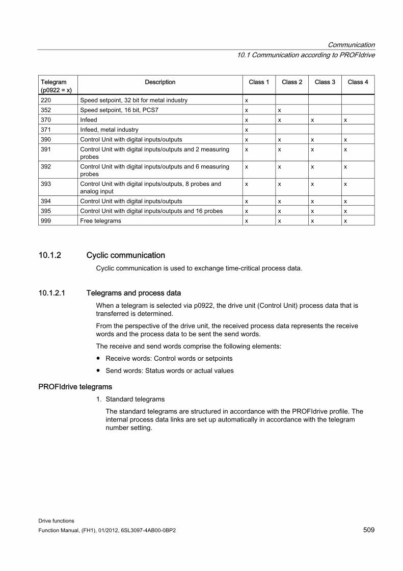
Communication 10.1 Communication according to PROFIdrive
Drive functions Function Manual, (FH1), 01/2012, 6SL3097-4AB00-0BP2 509
Telegram (p0922 = x)
Description Class 1 Class 2 Class 3 Class 4
220 Speed setpoint, 32 bit for metal industry x 352 Speed setpoint, 16 bit, PCS7 x x 370 Infeed x x x x 371 Infeed, metal industry x 390 Control Unit with digital inputs/outputs x x x x 391 Control Unit with digital inputs/outputs and 2 measuring
probes x x x x
392 Control Unit with digital inputs/outputs and 6 measuring probes
x x x x
393 Control Unit with digital inputs/outputs, 8 probes and analog input
x x x x
394 Control Unit with digital inputs/outputs x x x x 395 Control Unit with digital inputs/outputs and 16 probes x x x x 999 Free telegrams x x x x
10.1.2 Cyclic communication Cyclic communication is used to exchange time-critical process data.
10.1.2.1 Telegrams and process data When a telegram is selected via p0922, the drive unit (Control Unit) process data that is transferred is determined.
From the perspective of the drive unit, the received process data represents the receive words and the process data to be sent the send words.
The receive and send words comprise the following elements:
Receive words: Control words or setpoints
Send words: Status words or actual values
PROFIdrive telegrams 1. Standard telegrams
The standard telegrams are structured in accordance with the PROFIdrive profile. The internal process data links are set up automatically in accordance with the telegram number setting.
Communication 10.1 Communication according to PROFIdrive
Drive functions 510 Function Manual, (FH1), 01/2012, 6SL3097-4AB00-0BP2
The following standard telegrams can be set via p0922:
– 1 Speed setpoint, 16 bit
– 2 Speed setpoint, 32 bit
– 3 Speed setpoint, 32 bit with 1 position encoder
– 4 Speed setpoint, 32 bit with 2 position encoders
– 5 Speed setpoint, 32 bit with 1 position encoder and DSC
– 6 Speed setpoint, 32 bit with 2 position encoders and DSC
– 7 Positioning, telegram 7 (basic positioner)
– 9 Positioning, telegram 9 (basic positioner with direct input)
– 20 Speed setpoint, 16 bit VIK-NAMUR
– 81 Encoder telegram, 1 encoder channel
– 82 Extended encoder telegram, 1 encoder channel + speed actual value 16 bit
– 83 Extended encoder telegram, 1 encoder channel + speed actual value 32 bit
2. Manufacturer-specific telegrams
The manufacturer-specific telegrams are structured in accordance with internal company specifications. The internal process data links are set up automatically in accordance with the telegram number setting.
The following vendor-specific telegrams can be set via p0922:
– 102 Speed setpoint, 32 bit with 1 position encoder and torque reduction
– 103 Speed setpoint, 32 bit with 2 position encoders and torque reduction
– 105 Speed setpoint, 32 bit with 1 position encoder, torque reduction and DSC
– 106 Speed setpoint, 32 bit with 2 position encoders, torque reduction and DSC
– 110 Positioning, telegram 10 (basic positioner with MDI, override and Xist_A)
– 111 Positioning, telegram 11 (basic positioner in MDI mode)
– 116 Speed setpoint, 32 bit with 2 position encoders, torque reduction and DSC, plus load, torque, power and current actual values
– 118 Speed setpoint, 32 bit with 2 external position encoders, torque reduction and DSC, as well as actual load, torque, power, and current values
– 125 DSC with torque precontrol, 1 position encoder (encoder 1)
– 126 DSC with torque precontrol, 2 position encoders (encoder 1 and encoder 2)
– 136 DSC with torque precontrol, 2 position encoders (encoder 1 and encoder 2), 4 trace signals
– 138 DSC with torque precontrol, 2 position encoders (encoder 2 and encoder 3), 4 trace signals
– 139 closed-loop speed / position control with/without DSC and torque pre-control, 1 position encoder, clamping status, supplementary actual values
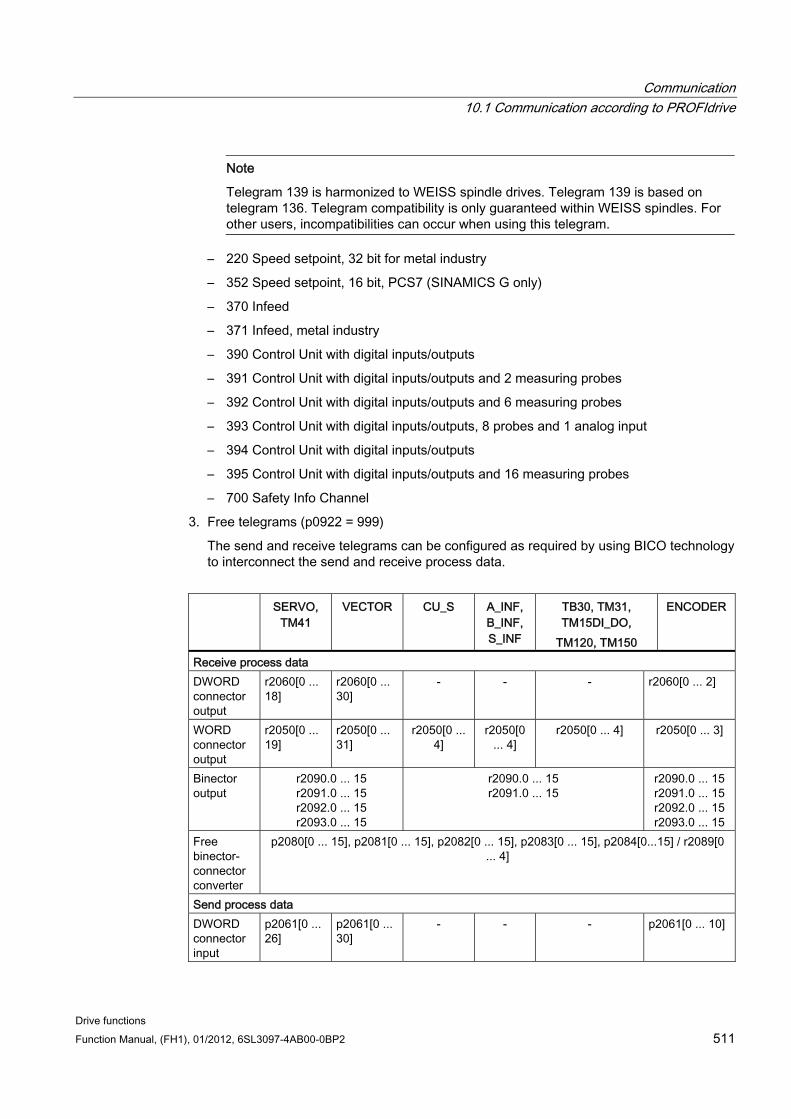
Communication 10.1 Communication according to PROFIdrive
Drive functions Function Manual, (FH1), 01/2012, 6SL3097-4AB00-0BP2 511
Note
Telegram 139 is harmonized to WEISS spindle drives. Telegram 139 is based on telegram 136. Telegram compatibility is only guaranteed within WEISS spindles. For other users, incompatibilities can occur when using this telegram.
– 220 Speed setpoint, 32 bit for metal industry
– 352 Speed setpoint, 16 bit, PCS7 (SINAMICS G only)
– 370 Infeed
– 371 Infeed, metal industry
– 390 Control Unit with digital inputs/outputs
– 391 Control Unit with digital inputs/outputs and 2 measuring probes
– 392 Control Unit with digital inputs/outputs and 6 measuring probes
– 393 Control Unit with digital inputs/outputs, 8 probes and 1 analog input
– 394 Control Unit with digital inputs/outputs
– 395 Control Unit with digital inputs/outputs and 16 measuring probes
– 700 Safety Info Channel
3. Free telegrams (p0922 = 999)
The send and receive telegrams can be configured as required by using BICO technology to interconnect the send and receive process data.
SERVO,
TM41 VECTOR CU_S A_INF,
B_INF, S_INF
TB30, TM31, TM15DI_DO,
TM120, TM150
ENCODER
Receive process data DWORD connector output
r2060[0 ... 18]
r2060[0 ... 30]
- - - r2060[0 ... 2]
WORD connector output
r2050[0 ... 19]
r2050[0 ... 31]
r2050[0 ... 4]
r2050[0 ... 4]
r2050[0 ... 4] r2050[0 ... 3]
Binector output
r2090.0 ... 15 r2091.0 ... 15 r2092.0 ... 15 r2093.0 ... 15
r2090.0 ... 15 r2091.0 ... 15
r2090.0 ... 15r2091.0 ... 15r2092.0 ... 15r2093.0 ... 15
Free binector-connector converter
p2080[0 ... 15], p2081[0 ... 15], p2082[0 ... 15], p2083[0 ... 15], p2084[0...15] / r2089[0 ... 4]
Send process data DWORD connector input
p2061[0 ... 26]
p2061[0 ... 30]
- - - p2061[0 ... 10]
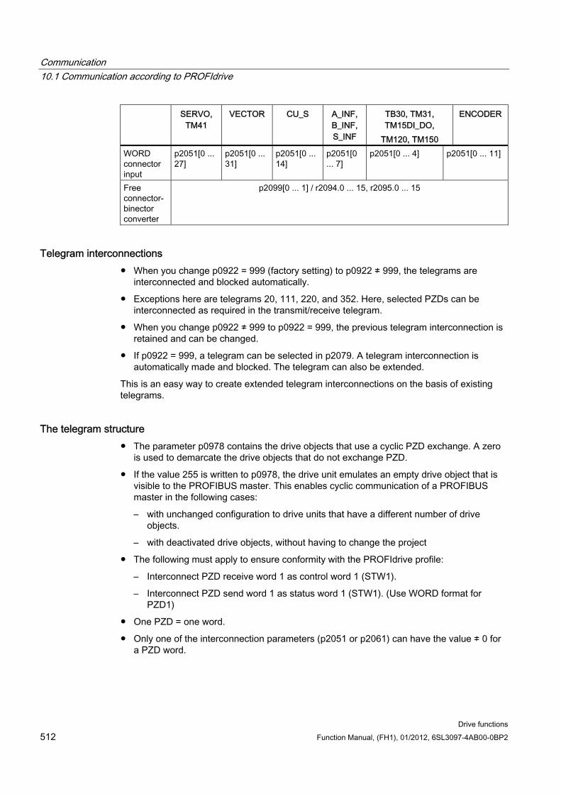
Communication 10.1 Communication according to PROFIdrive
Drive functions 512 Function Manual, (FH1), 01/2012, 6SL3097-4AB00-0BP2
SERVO, TM41
VECTOR CU_S A_INF, B_INF, S_INF
TB30, TM31, TM15DI_DO,
TM120, TM150
ENCODER
WORD connector input
p2051[0 ... 27]
p2051[0 ... 31]
p2051[0 ... 14]
p2051[0 ... 7]
p2051[0 ... 4] p2051[0 ... 11]
Free connector-binector converter
p2099[0 ... 1] / r2094.0 ... 15, r2095.0 ... 15
Telegram interconnections When you change p0922 = 999 (factory setting) to p0922 ≠ 999, the telegrams are
interconnected and blocked automatically.
Exceptions here are telegrams 20, 111, 220, and 352. Here, selected PZDs can be interconnected as required in the transmit/receive telegram.
When you change p0922 ≠ 999 to p0922 = 999, the previous telegram interconnection is retained and can be changed.
If p0922 = 999, a telegram can be selected in p2079. A telegram interconnection is automatically made and blocked. The telegram can also be extended.
This is an easy way to create extended telegram interconnections on the basis of existing telegrams.
The telegram structure The parameter p0978 contains the drive objects that use a cyclic PZD exchange. A zero
is used to demarcate the drive objects that do not exchange PZD.
If the value 255 is written to p0978, the drive unit emulates an empty drive object that is visible to the PROFIBUS master. This enables cyclic communication of a PROFIBUS master in the following cases:
– with unchanged configuration to drive units that have a different number of drive objects.
– with deactivated drive objects, without having to change the project
The following must apply to ensure conformity with the PROFIdrive profile:
– Interconnect PZD receive word 1 as control word 1 (STW1).
– Interconnect PZD send word 1 as status word 1 (STW1). (Use WORD format for PZD1)
One PZD = one word.
Only one of the interconnection parameters (p2051 or p2061) can have the value ≠ 0 for a PZD word.
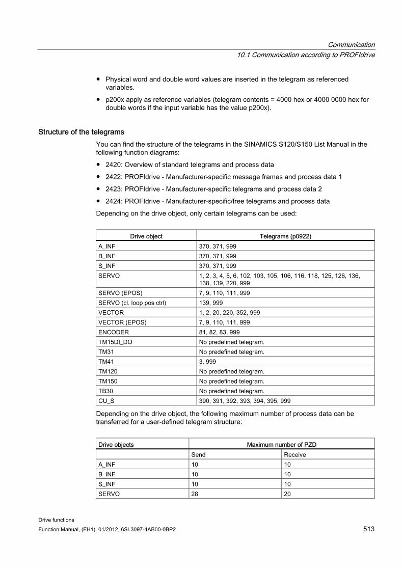
Communication 10.1 Communication according to PROFIdrive
Drive functions Function Manual, (FH1), 01/2012, 6SL3097-4AB00-0BP2 513
Physical word and double word values are inserted in the telegram as referenced variables.
p200x apply as reference variables (telegram contents = 4000 hex or 4000 0000 hex for double words if the input variable has the value p200x).
Structure of the telegrams You can find the structure of the telegrams in the SINAMICS S120/S150 List Manual in the following function diagrams:
2420: Overview of standard telegrams and process data
2422: PROFIdrive - Manufacturer-specific message frames and process data 1
2423: PROFIdrive - Manufacturer-specific telegrams and process data 2
2424: PROFIdrive - Manufacturer-specific/free telegrams and process data
Depending on the drive object, only certain telegrams can be used:
Drive object Telegrams (p0922)
A_INF 370, 371, 999 B_INF 370, 371, 999 S_INF 370, 371, 999 SERVO 1, 2, 3, 4, 5, 6, 102, 103, 105, 106, 116, 118, 125, 126, 136,
138, 139, 220, 999 SERVO (EPOS) 7, 9, 110, 111, 999 SERVO (cl. loop pos ctrl) 139, 999 VECTOR 1, 2, 20, 220, 352, 999 VECTOR (EPOS) 7, 9, 110, 111, 999 ENCODER 81, 82, 83, 999 TM15DI_DO No predefined telegram. TM31 No predefined telegram. TM41 3, 999 TM120 No predefined telegram. TM150 No predefined telegram. TB30 No predefined telegram. CU_S 390, 391, 392, 393, 394, 395, 999
Depending on the drive object, the following maximum number of process data can be transferred for a user-defined telegram structure:
Drive objects Maximum number of PZD Send Receive A_INF 10 10 B_INF 10 10 S_INF 10 10 SERVO 28 20
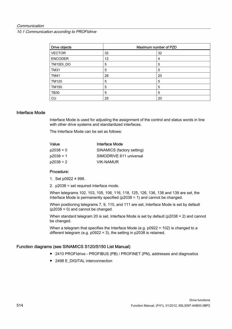
Communication 10.1 Communication according to PROFIdrive
Drive functions 514 Function Manual, (FH1), 01/2012, 6SL3097-4AB00-0BP2
Drive objects Maximum number of PZD VECTOR 32 32 ENCODER 12 4 TM15DI_DO 5 5 TM31 5 5 TM41 28 20 TM120 5 5 TM150 5 5 TB30 5 5 CU 25 20
Interface Mode Interface Mode is used for adjusting the assignment of the control and status words in line with other drive systems and standardized interfaces.
The Interface Mode can be set as follows:
Value Interface Mode p2038 = 0 SINAMICS (factory setting) p2038 = 1 SIMODRIVE 611 universal p2038 = 2 VIK-NAMUR
Procedure:
1. Set p0922 ≠ 999.
2. p2038 = set required interface mode.
When telegrams 102, 103, 105, 106, 116, 118, 125, 126, 136, 138 and 139 are set, the Interface Mode is permanently specified (p2038 = 1) and cannot be changed.
When positioning telegrams 7, 9, 110, and 111 are set, Interface Mode is set by default (p2038 = 0) and cannot be changed.
When standard telegram 20 is set, Interface Mode is set by default (p2038 = 2) and cannot be changed.
When a telegram that specifies the Interface Mode (e.g. p0922 = 102) is changed to a different telegram (e.g. p0922 = 3), the setting in p2038 is retained.
Function diagrams (see SINAMICS S120/S150 List Manual) 2410 PROFIdrive - PROFIBUS (PB) / PROFINET (PN), addresses and diagnostics
2498 E_DIGITAL interconnection
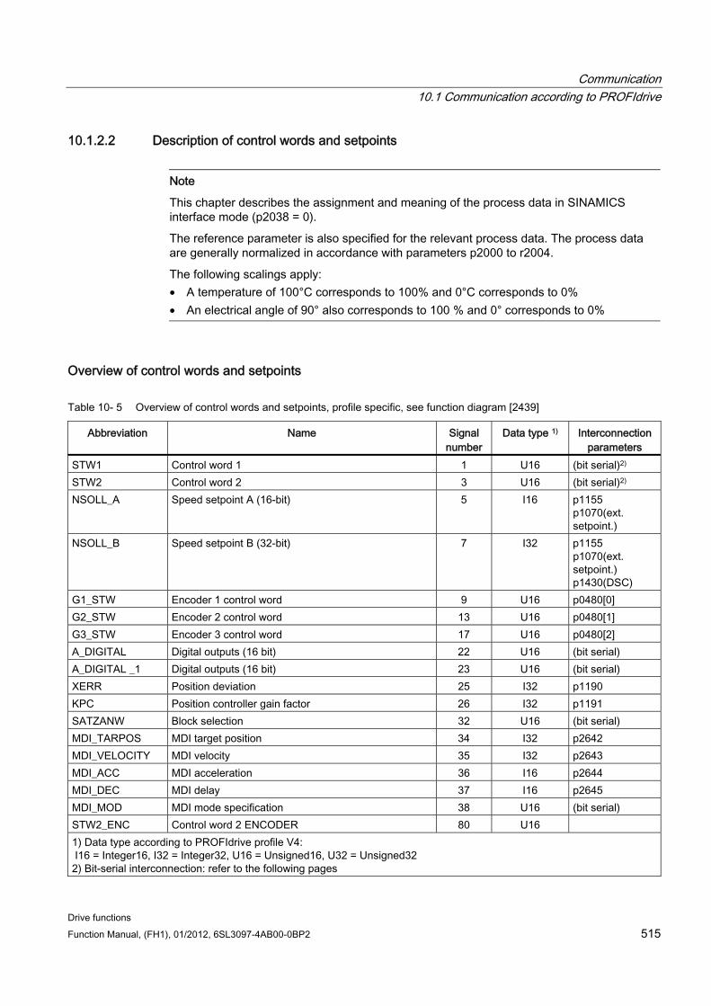
Communication 10.1 Communication according to PROFIdrive
Drive functions Function Manual, (FH1), 01/2012, 6SL3097-4AB00-0BP2 515
10.1.2.2 Description of control words and setpoints
Note
This chapter describes the assignment and meaning of the process data in SINAMICS interface mode (p2038 = 0).
The reference parameter is also specified for the relevant process data. The process data are generally normalized in accordance with parameters p2000 to r2004.
The following scalings apply: • A temperature of 100°C corresponds to 100% and 0°C corresponds to 0% • An electrical angle of 90° also corresponds to 100 % and 0° corresponds to 0%
Overview of control words and setpoints
Table 10- 5 Overview of control words and setpoints, profile specific, see function diagram [2439]
Abbreviation Name Signal number
Data type 1) Interconnection parameters
STW1 Control word 1 1 U16 (bit serial)2) STW2 Control word 2 3 U16 (bit serial)2) NSOLL_A Speed setpoint A (16-bit) 5 I16 p1155
p1070(ext. setpoint.)
NSOLL_B Speed setpoint B (32-bit) 7 I32 p1155 p1070(ext. setpoint.) p1430(DSC)
G1_STW Encoder 1 control word 9 U16 p0480[0] G2_STW Encoder 2 control word 13 U16 p0480[1] G3_STW Encoder 3 control word 17 U16 p0480[2] A_DIGITAL Digital outputs (16 bit) 22 U16 (bit serial) A_DIGITAL _1 Digital outputs (16 bit) 23 U16 (bit serial) XERR Position deviation 25 I32 p1190 KPC Position controller gain factor 26 I32 p1191 SATZANW Block selection 32 U16 (bit serial) MDI_TARPOS MDI target position 34 I32 p2642 MDI_VELOCITY MDI velocity 35 I32 p2643 MDI_ACC MDI acceleration 36 I16 p2644 MDI_DEC MDI delay 37 I16 p2645 MDI_MOD MDI mode specification 38 U16 (bit serial) STW2_ENC Control word 2 ENCODER 80 U16 1) Data type according to PROFIdrive profile V4: I16 = Integer16, I32 = Integer32, U16 = Unsigned16, U32 = Unsigned32 2) Bit-serial interconnection: refer to the following pages
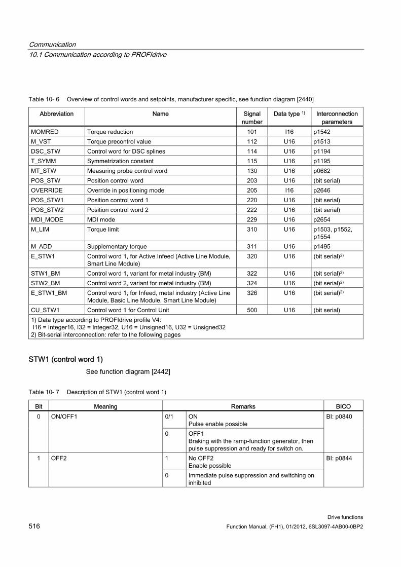
Communication 10.1 Communication according to PROFIdrive
Drive functions 516 Function Manual, (FH1), 01/2012, 6SL3097-4AB00-0BP2
Table 10- 6 Overview of control words and setpoints, manufacturer specific, see function diagram [2440]
Abbreviation Name Signal number
Data type 1) Interconnection parameters
MOMRED Torque reduction 101 I16 p1542 M_VST Torque precontrol value 112 U16 p1513 DSC_STW Control word for DSC splines 114 U16 p1194 T_SYMM Symmetrization constant 115 U16 p1195 MT_STW Measuring probe control word 130 U16 p0682 POS_STW Position control word 203 U16 (bit serial) OVERRIDE Override in positioning mode 205 I16 p2646 POS_STW1 Position control word 1 220 U16 (bit serial) POS_STW2 Position control word 2 222 U16 (bit serial) MDI_MODE MDI mode 229 U16 p2654 M_LIM Torque limit 310 U16 p1503, p1552,
p1554 M_ADD Supplementary torque 311 U16 p1495 E_STW1 Control word 1, for Active Infeed (Active Line Module,
Smart Line Module) 320 U16 (bit serial)2)
STW1_BM Control word 1, variant for metal industry (BM) 322 U16 (bit serial)2) STW2_BM Control word 2, variant for metal industry (BM) 324 U16 (bit serial)2) E_STW1_BM Control word 1, for Infeed, metal industry (Active Line
Module, Basic Line Module, Smart Line Module) 326 U16 (bit serial)2)
CU_STW1 Control word 1 for Control Unit 500 U16 (bit serial) 1) Data type according to PROFIdrive profile V4: I16 = Integer16, I32 = Integer32, U16 = Unsigned16, U32 = Unsigned32 2) Bit-serial interconnection: refer to the following pages
STW1 (control word 1) See function diagram [2442]
Table 10- 7 Description of STW1 (control word 1)
Bit Meaning Remarks BICO 0/1 ON
Pulse enable possible 0 ON/OFF1
0 OFF1 Braking with the ramp-function generator, then pulse suppression and ready for switch on.
BI: p0840
1 No OFF2 Enable possible
1 OFF2
0 Immediate pulse suppression and switching on inhibited
BI: p0844
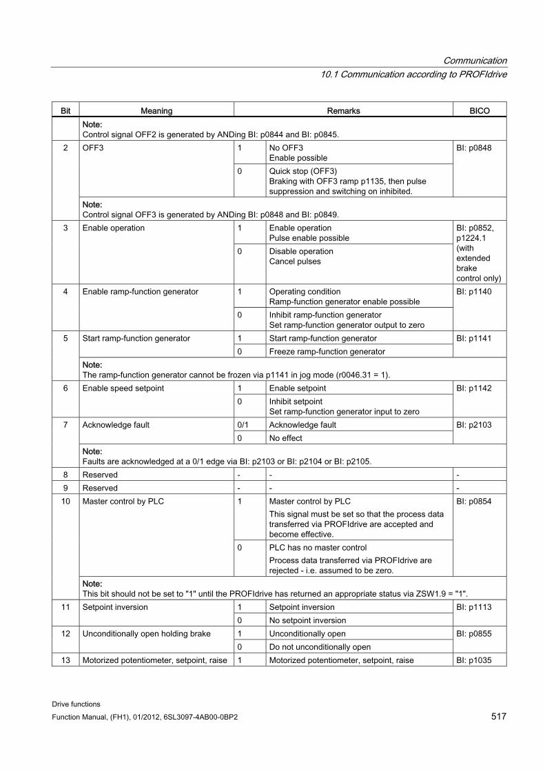
Communication 10.1 Communication according to PROFIdrive
Drive functions Function Manual, (FH1), 01/2012, 6SL3097-4AB00-0BP2 517
Bit Meaning Remarks BICO Note: Control signal OFF2 is generated by ANDing BI: p0844 and BI: p0845.
1 No OFF3 Enable possible
OFF3
0 Quick stop (OFF3) Braking with OFF3 ramp p1135, then pulse suppression and switching on inhibited.
BI: p0848 2
Note: Control signal OFF3 is generated by ANDing BI: p0848 and BI: p0849.
1 Enable operation Pulse enable possible
3 Enable operation
0 Disable operation Cancel pulses
BI: p0852, p1224.1 (with extended brake control only)
1 Operating condition Ramp-function generator enable possible
4 Enable ramp-function generator
0 Inhibit ramp-function generator Set ramp-function generator output to zero
BI: p1140
1 Start ramp-function generator Start ramp-function generator 0 Freeze ramp-function generator
BI: p1141 5
Note: The ramp-function generator cannot be frozen via p1141 in jog mode (r0046.31 = 1).
1 Enable setpoint 6 Enable speed setpoint 0 Inhibit setpoint
Set ramp-function generator input to zero
BI: p1142
0/1 Acknowledge fault Acknowledge fault 0 No effect
BI: p2103 7
Note: Faults are acknowledged at a 0/1 edge via BI: p2103 or BI: p2104 or BI: p2105.
8 Reserved - - - 9 Reserved - - -
1 Master control by PLC This signal must be set so that the process data transferred via PROFIdrive are accepted and become effective.
Master control by PLC
0 PLC has no master control Process data transferred via PROFIdrive are rejected - i.e. assumed to be zero.
BI: p0854 10
Note: This bit should not be set to "1" until the PROFIdrive has returned an appropriate status via ZSW1.9 = "1".
1 Setpoint inversion 11 Setpoint inversion 0 No setpoint inversion
BI: p1113
1 Unconditionally open 12 Unconditionally open holding brake 0 Do not unconditionally open
BI: p0855
13 Motorized potentiometer, setpoint, raise 1 Motorized potentiometer, setpoint, raise BI: p1035
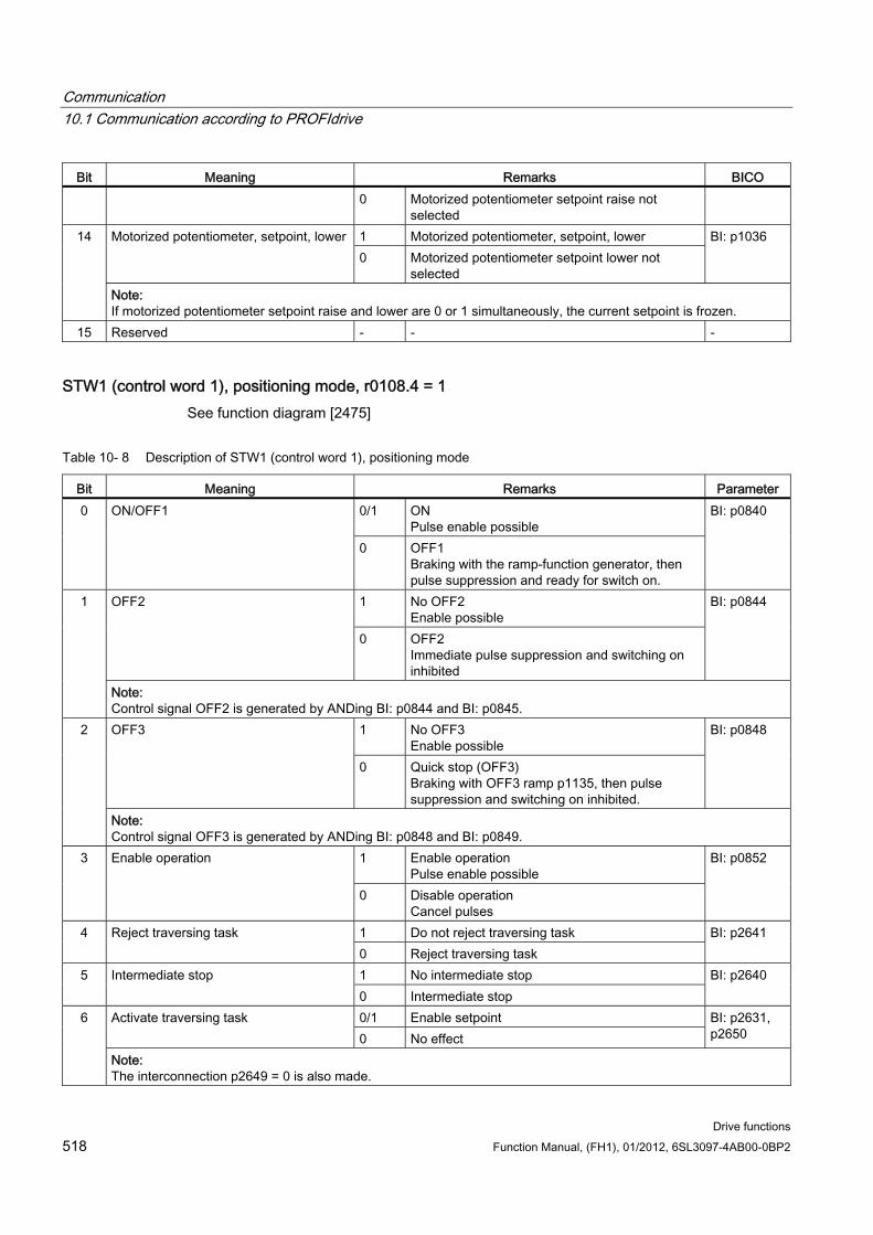
Communication 10.1 Communication according to PROFIdrive
Drive functions 518 Function Manual, (FH1), 01/2012, 6SL3097-4AB00-0BP2
Bit Meaning Remarks BICO 0 Motorized potentiometer setpoint raise not
selected 1 Motorized potentiometer, setpoint, lower Motorized potentiometer, setpoint, lower 0 Motorized potentiometer setpoint lower not
selected
BI: p1036 14
Note: If motorized potentiometer setpoint raise and lower are 0 or 1 simultaneously, the current setpoint is frozen.
15 Reserved - - -
STW1 (control word 1), positioning mode, r0108.4 = 1 See function diagram [2475]
Table 10- 8 Description of STW1 (control word 1), positioning mode
Bit Meaning Remarks Parameter 0/1 ON
Pulse enable possible 0 ON/OFF1
0 OFF1 Braking with the ramp-function generator, then pulse suppression and ready for switch on.
BI: p0840
1 No OFF2 Enable possible
OFF2
0 OFF2 Immediate pulse suppression and switching on inhibited
BI: p0844 1
Note: Control signal OFF2 is generated by ANDing BI: p0844 and BI: p0845.
1 No OFF3 Enable possible
OFF3
0 Quick stop (OFF3) Braking with OFF3 ramp p1135, then pulse suppression and switching on inhibited.
BI: p0848 2
Note: Control signal OFF3 is generated by ANDing BI: p0848 and BI: p0849.
1 Enable operation Pulse enable possible
3 Enable operation
0 Disable operation Cancel pulses
BI: p0852
1 Do not reject traversing task 4 Reject traversing task 0 Reject traversing task
BI: p2641
1 No intermediate stop 5 Intermediate stop 0 Intermediate stop
BI: p2640
0/1 Enable setpoint Activate traversing task 0 No effect
BI: p2631, p2650
6
Note: The interconnection p2649 = 0 is also made.
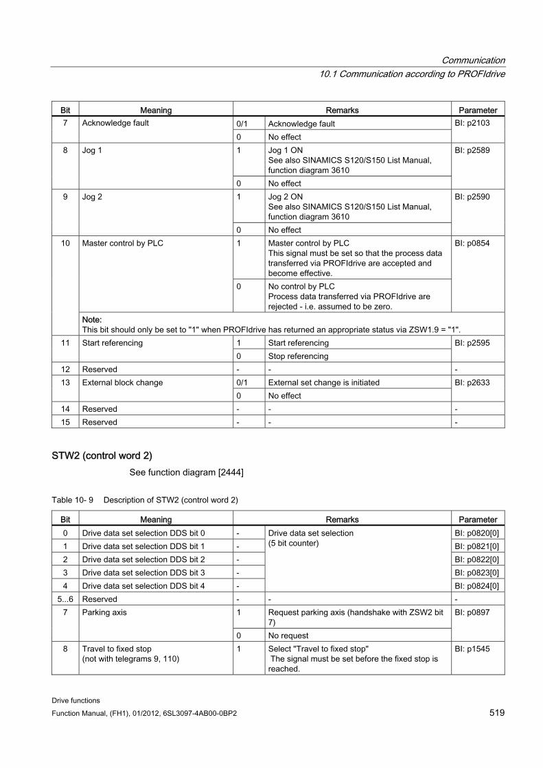
Communication 10.1 Communication according to PROFIdrive
Drive functions Function Manual, (FH1), 01/2012, 6SL3097-4AB00-0BP2 519
Bit Meaning Remarks Parameter 0/1 Acknowledge fault 7 Acknowledge fault 0 No effect
BI: p2103
1 Jog 1 ON See also SINAMICS S120/S150 List Manual, function diagram 3610
8 Jog 1
0 No effect
BI: p2589
1 Jog 2 ON See also SINAMICS S120/S150 List Manual, function diagram 3610
9 Jog 2
0 No effect
BI: p2590
1 Master control by PLC This signal must be set so that the process data transferred via PROFIdrive are accepted and become effective.
Master control by PLC
0 No control by PLC Process data transferred via PROFIdrive are rejected - i.e. assumed to be zero.
BI: p0854 10
Note: This bit should only be set to "1" when PROFIdrive has returned an appropriate status via ZSW1.9 = "1".
1 Start referencing 11 Start referencing 0 Stop referencing
BI: p2595
12 Reserved - - - 0/1 External set change is initiated 13 External block change 0 No effect
BI: p2633
14 Reserved - - - 15 Reserved - - -
STW2 (control word 2) See function diagram [2444]
Table 10- 9 Description of STW2 (control word 2)
Bit Meaning Remarks Parameter 0 Drive data set selection DDS bit 0 - BI: p0820[0] 1 Drive data set selection DDS bit 1 - BI: p0821[0] 2 Drive data set selection DDS bit 2 - BI: p0822[0] 3 Drive data set selection DDS bit 3 - BI: p0823[0] 4 Drive data set selection DDS bit 4 -
Drive data set selection (5 bit counter)
BI: p0824[0] 5...6 Reserved - - -
1 Request parking axis (handshake with ZSW2 bit 7)
7 Parking axis
0 No request
BI: p0897
8 Travel to fixed stop (not with telegrams 9, 110)
1 Select "Travel to fixed stop" The signal must be set before the fixed stop is reached.
BI: p1545
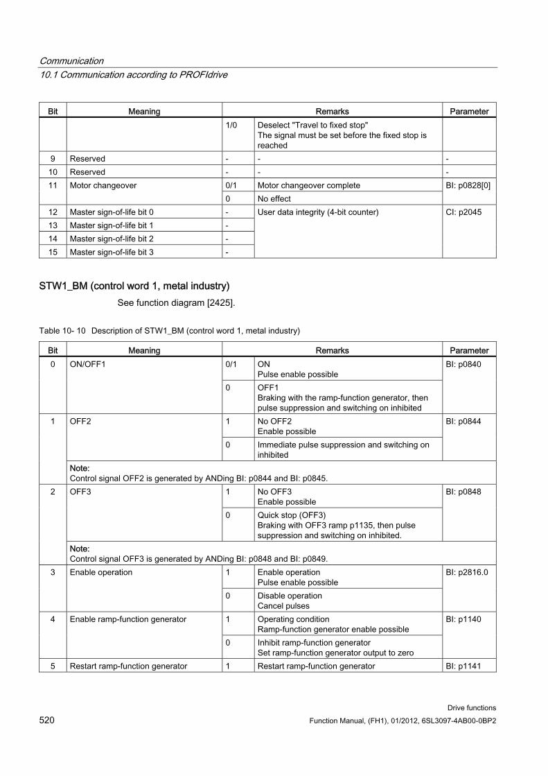
Communication 10.1 Communication according to PROFIdrive
Drive functions 520 Function Manual, (FH1), 01/2012, 6SL3097-4AB00-0BP2
Bit Meaning Remarks Parameter 1/0 Deselect "Travel to fixed stop"
The signal must be set before the fixed stop is reached
9 Reserved - - - 10 Reserved - - -
0/1 Motor changeover complete 11 Motor changeover 0 No effect
BI: p0828[0]
12 Master sign-of-life bit 0 - 13 Master sign-of-life bit 1 - 14 Master sign-of-life bit 2 - 15 Master sign-of-life bit 3 -
User data integrity (4-bit counter) CI: p2045
STW1_BM (control word 1, metal industry) See function diagram [2425].
Table 10- 10 Description of STW1_BM (control word 1, metal industry)
Bit Meaning Remarks Parameter 0/1 ON
Pulse enable possible 0 ON/OFF1
0 OFF1 Braking with the ramp-function generator, then pulse suppression and switching on inhibited
BI: p0840
1 No OFF2 Enable possible
OFF2
0 Immediate pulse suppression and switching on inhibited
BI: p0844 1
Note: Control signal OFF2 is generated by ANDing BI: p0844 and BI: p0845.
1 No OFF3 Enable possible
OFF3
0 Quick stop (OFF3) Braking with OFF3 ramp p1135, then pulse suppression and switching on inhibited.
BI: p0848 2
Note: Control signal OFF3 is generated by ANDing BI: p0848 and BI: p0849.
1 Enable operation Pulse enable possible
3 Enable operation
0 Disable operation Cancel pulses
BI: p2816.0
1 Operating condition Ramp-function generator enable possible
4 Enable ramp-function generator
0 Inhibit ramp-function generator Set ramp-function generator output to zero
BI: p1140
5 Restart ramp-function generator 1 Restart ramp-function generator BI: p1141
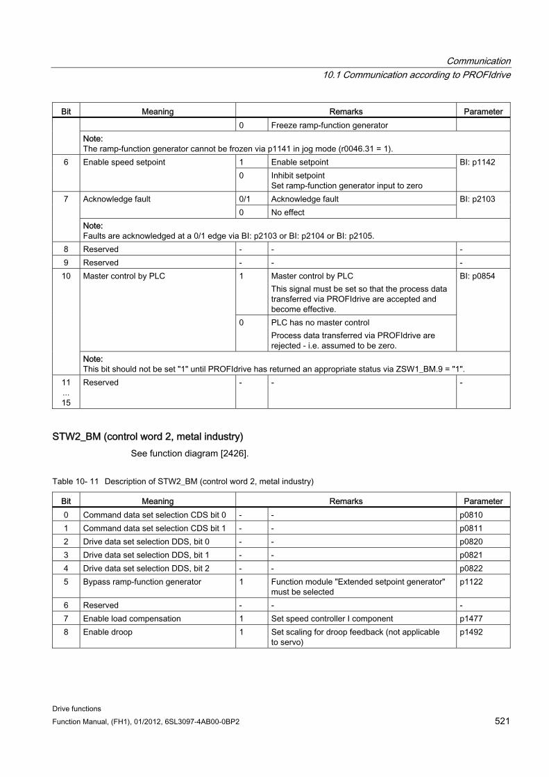
Communication 10.1 Communication according to PROFIdrive
Drive functions Function Manual, (FH1), 01/2012, 6SL3097-4AB00-0BP2 521
Bit Meaning Remarks Parameter 0 Freeze ramp-function generator
Note: The ramp-function generator cannot be frozen via p1141 in jog mode (r0046.31 = 1).
1 Enable setpoint 6 Enable speed setpoint 0 Inhibit setpoint
Set ramp-function generator input to zero
BI: p1142
0/1 Acknowledge fault Acknowledge fault 0 No effect
BI: p2103 7
Note: Faults are acknowledged at a 0/1 edge via BI: p2103 or BI: p2104 or BI: p2105.
8 Reserved - - - 9 Reserved - - -
1 Master control by PLC This signal must be set so that the process data transferred via PROFIdrive are accepted and become effective.
Master control by PLC
0 PLC has no master control Process data transferred via PROFIdrive are rejected - i.e. assumed to be zero.
BI: p0854 10
Note: This bit should not be set "1" until PROFIdrive has returned an appropriate status via ZSW1_BM.9 = "1".
11 ... 15
Reserved - - -
STW2_BM (control word 2, metal industry) See function diagram [2426].
Table 10- 11 Description of STW2_BM (control word 2, metal industry)
Bit Meaning Remarks Parameter 0 Command data set selection CDS bit 0 - - p0810 1 Command data set selection CDS bit 1 - - p0811 2 Drive data set selection DDS, bit 0 - - p0820 3 Drive data set selection DDS, bit 1 - - p0821 4 Drive data set selection DDS, bit 2 - - p0822 5 Bypass ramp-function generator 1 Function module "Extended setpoint generator"
must be selected p1122
6 Reserved - - - 7 Enable load compensation 1 Set speed controller I component p1477 8 Enable droop 1 Set scaling for droop feedback (not applicable
to servo) p1492

Communication 10.1 Communication according to PROFIdrive
Drive functions 522 Function Manual, (FH1), 01/2012, 6SL3097-4AB00-0BP2
Bit Meaning Remarks Parameter 9 Enable speed controller
(incl. brake) 1 Enable the speed controller and the brake.
Controller enable via r2093.9. Parameter p0856 remains freely interconnectable for "extended brake control".
p0856, p2093.9
10 Reserved - - - 11 Speed/torque-controlled operation 1 Slave drive torque control
Set the signal source for switchover between speed and torque control
p1501
12 Reserved - - - 13 Reserved - - - 14 Reserved - - -
1 Toggle bit communication active 15 Controller sign of life toggle bit 0 Toggle bit communication not active
r2081.15
STW2_ENC See function diagram [2433].
Table 10- 12 Description STW2_ENC (control word 2 encoder)
Bit Meaning Remarks Parameter 0...6 Reserved – – –
Acknowledge fault 0/1 Acknowledge fault BI: p2103 7 Note: Faults are acknowledged at a 0/1 edge via BI: p2103 or BI: p2104 or BI: p2105.
8, 9 Reserved – – – 1 Master control by PLC
This signal must be set so that the process data transferred via PROFIdrive are accepted and become effective.
Master control by PLC
0 No master control by PLC Process data transferred via PROFIdrive is rejected - i.e. assumed to be zero.
BI: p0854 10
Note: This bit should not be set to "1" until PROFIdrive has returned an appropriate status via E_ZSW1.9 = "1".
11 Reserved – – – 12 Controller sign-of-life bit 0 – p2045 13 Controller sign-of-life bit 1 – p2045 14 Controller sign-of-life bit 2 – p2045 15 Controller sign-of-life bit 3 – p2045
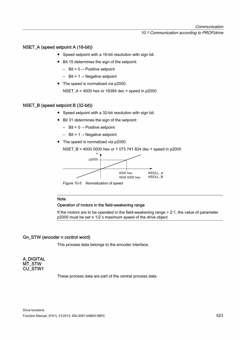
Communication 10.1 Communication according to PROFIdrive
Drive functions Function Manual, (FH1), 01/2012, 6SL3097-4AB00-0BP2 523
NSET_A (speed setpoint A (16-bit)) Speed setpoint with a 16-bit resolution with sign bit.
Bit 15 determines the sign of the setpoint:
– Bit = 0 → Positive setpoint
– Bit = 1 → Negative setpoint
The speed is normalized via p2000.
NSET_A = 4000 hex or 16384 dec ≐ speed in p2000
NSET_B (speed setpoint B (32-bit)) Speed setpoint with a 32-bit resolution with sign bit.
Bit 31 determines the sign of the setpoint:
– Bit = 0 → Positive setpoint
– Bit = 1 → Negative setpoint
The speed is normalized via p2000.
NSET_B = 4000 0000 hex or 1 073 741 824 dec ≐ speed in p2000
Figure 10-5 Normalization of speed
Note Operation of motors in the field-weakening range
If the motors are to be operated in the field-weakening range > 2:1, the value of parameter p2000 must be set ≤ 1/2 x maximum speed of the drive object.
Gn_STW (encoder n control word) This process data belongs to the encoder interface.
A_DIGITAL MT_STW CU_STW1
These process data are part of the central process data.
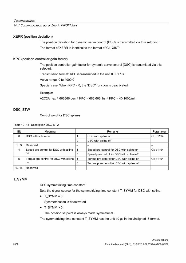
Communication 10.1 Communication according to PROFIdrive
Drive functions 524 Function Manual, (FH1), 01/2012, 6SL3097-4AB00-0BP2
XERR (position deviation) The position deviation for dynamic servo control (DSC) is transmitted via this setpoint.
The format of XERR is identical to the format of G1_XIST1.
KPC (position controller gain factor) The position controller gain factor for dynamic servo control (DSC) is transmitted via this setpoint.
Transmission format: KPC is transmitted in the unit 0.001 1/s.
Value range: 0 to 4000.0
Special case: When KPC = 0, the "DSC" function is deactivated.
Example:
A2C2A hex ≐ 666666 dec ≐ KPC = 666.666 1/s ≐ KPC = 40 1000/min.
DSC_STW Control word for DSC splines
Table 10- 13 Description DSC_STW
Bit Meaning Remarks Parameter 1 DSC with spline on 0 DSC with spline on 0 DSC with spline off
CI: p1194
1...3 Reserved – – – 1 Speed pre-control for DSC with spline on 4 Speed pre-control for DSC with spline
on 0 Speed pre-control for DSC with spline off CI: p1194
1 Torque pre-control for DSC with spline on 5 Torque pre-control for DSC with spline on 0 Torque pre-control for DSC with spline off
CI: p1194
6...15 Reserved - -
T_SYMM DSC symmetrizing time constant
Sets the signal source for the symmetrizing time constant T_SYMM for DSC with spline.
T_SYMM = 0:
Symmetrization is deactivated
T_SYMM > 0:
The position setpoint is always made symmetrical.
The symmetrizing time constant T_SYMM has the unit 10 μs in the Unsigned16 format.
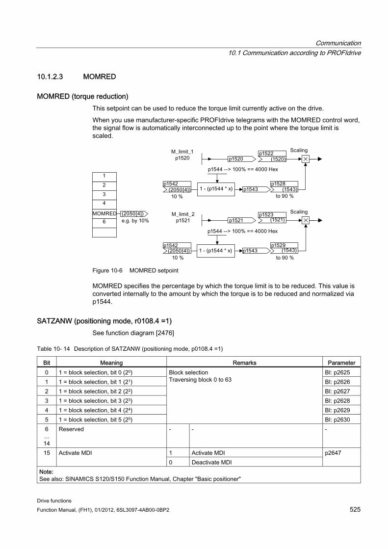
Communication 10.1 Communication according to PROFIdrive
Drive functions Function Manual, (FH1), 01/2012, 6SL3097-4AB00-0BP2 525
10.1.2.3 MOMRED
MOMRED (torque reduction) This setpoint can be used to reduce the torque limit currently active on the drive.
When you use manufacturer-specific PROFIdrive telegrams with the MOMRED control word, the signal flow is automatically interconnected up to the point where the torque limit is scaled.
Figure 10-6 MOMRED setpoint
MOMRED specifies the percentage by which the torque limit is to be reduced. This value is converted internally to the amount by which the torque is to be reduced and normalized via p1544.
SATZANW (positioning mode, r0108.4 =1) See function diagram [2476]
Table 10- 14 Description of SATZANW (positioning mode, p0108.4 =1)
Bit Meaning Remarks Parameter 0 1 = block selection, bit 0 (20) BI: p2625 1 1 = block selection, bit 1 (21) BI: p2626 2 1 = block selection, bit 2 (22) BI: p2627 3 1 = block selection, bit 3 (23) BI: p2628 4 1 = block selection, bit 4 (24) BI: p2629 5 1 = block selection, bit 5 (25)
Block selection Traversing block 0 to 63
BI: p2630 6 ... 14
Reserved - - -
1 Activate MDI 15 Activate MDI 0 Deactivate MDI
p2647
Note: See also: SINAMICS S120/S150 Function Manual, Chapter "Basic positioner"
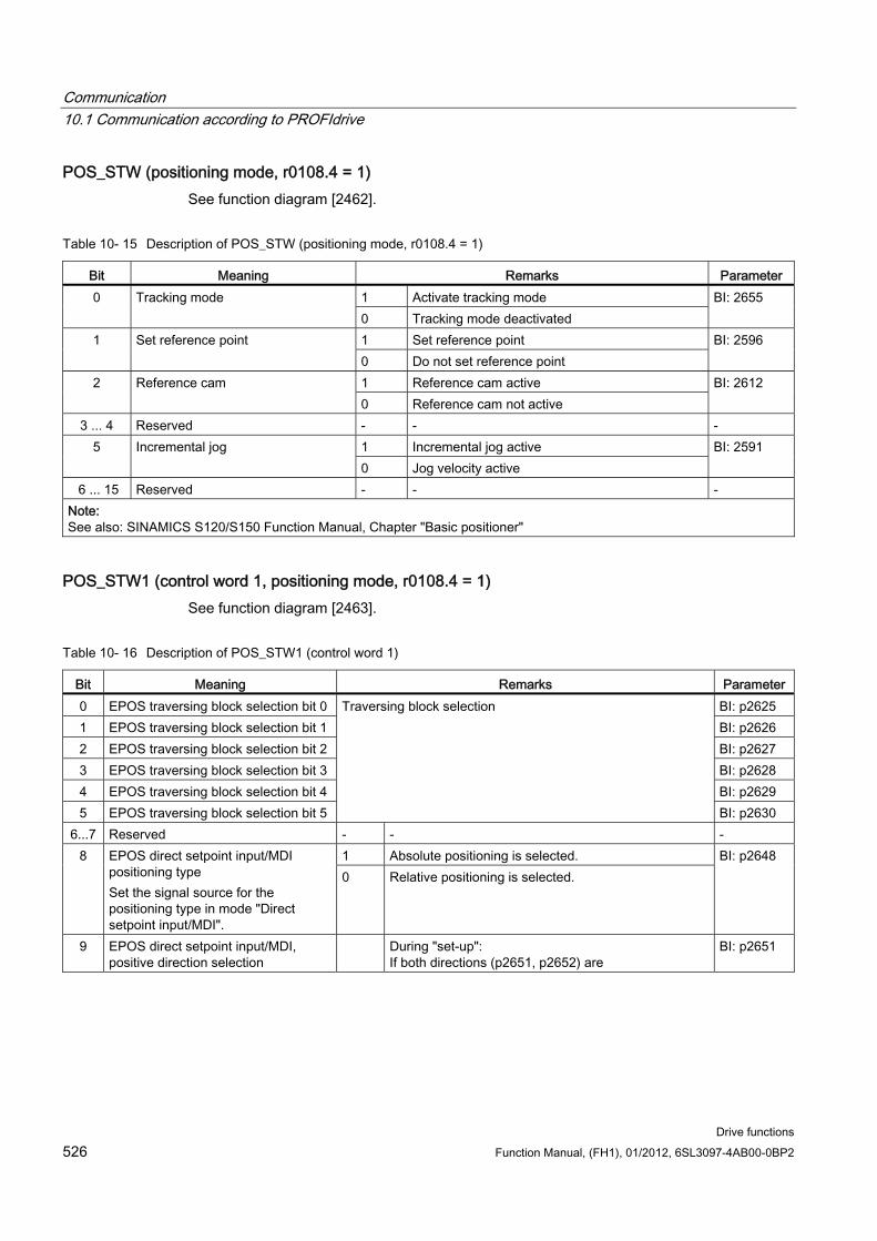
Communication 10.1 Communication according to PROFIdrive
Drive functions 526 Function Manual, (FH1), 01/2012, 6SL3097-4AB00-0BP2
POS_STW (positioning mode, r0108.4 = 1) See function diagram [2462].
Table 10- 15 Description of POS_STW (positioning mode, r0108.4 = 1)
Bit Meaning Remarks Parameter 1 Activate tracking mode 0 Tracking mode 0 Tracking mode deactivated
BI: 2655
1 Set reference point 1 Set reference point 0 Do not set reference point
BI: 2596
1 Reference cam active 2 Reference cam 0 Reference cam not active
BI: 2612
3 ... 4 Reserved - - - 1 Incremental jog active 5 Incremental jog 0 Jog velocity active
BI: 2591
6 ... 15 Reserved - - - Note: See also: SINAMICS S120/S150 Function Manual, Chapter "Basic positioner"
POS_STW1 (control word 1, positioning mode, r0108.4 = 1) See function diagram [2463].
Table 10- 16 Description of POS_STW1 (control word 1)
Bit Meaning Remarks Parameter 0 EPOS traversing block selection bit 0 BI: p2625 1 EPOS traversing block selection bit 1 BI: p2626 2 EPOS traversing block selection bit 2 BI: p2627 3 EPOS traversing block selection bit 3 BI: p2628 4 EPOS traversing block selection bit 4 BI: p2629 5 EPOS traversing block selection bit 5
Traversing block selection
BI: p2630 6...7 Reserved - - -
1 Absolute positioning is selected. 8 EPOS direct setpoint input/MDI positioning type Set the signal source for the positioning type in mode "Direct setpoint input/MDI".
0 Relative positioning is selected.
BI: p2648
9 EPOS direct setpoint input/MDI, positive direction selection
During "set-up": If both directions (p2651, p2652) are
BI: p2651
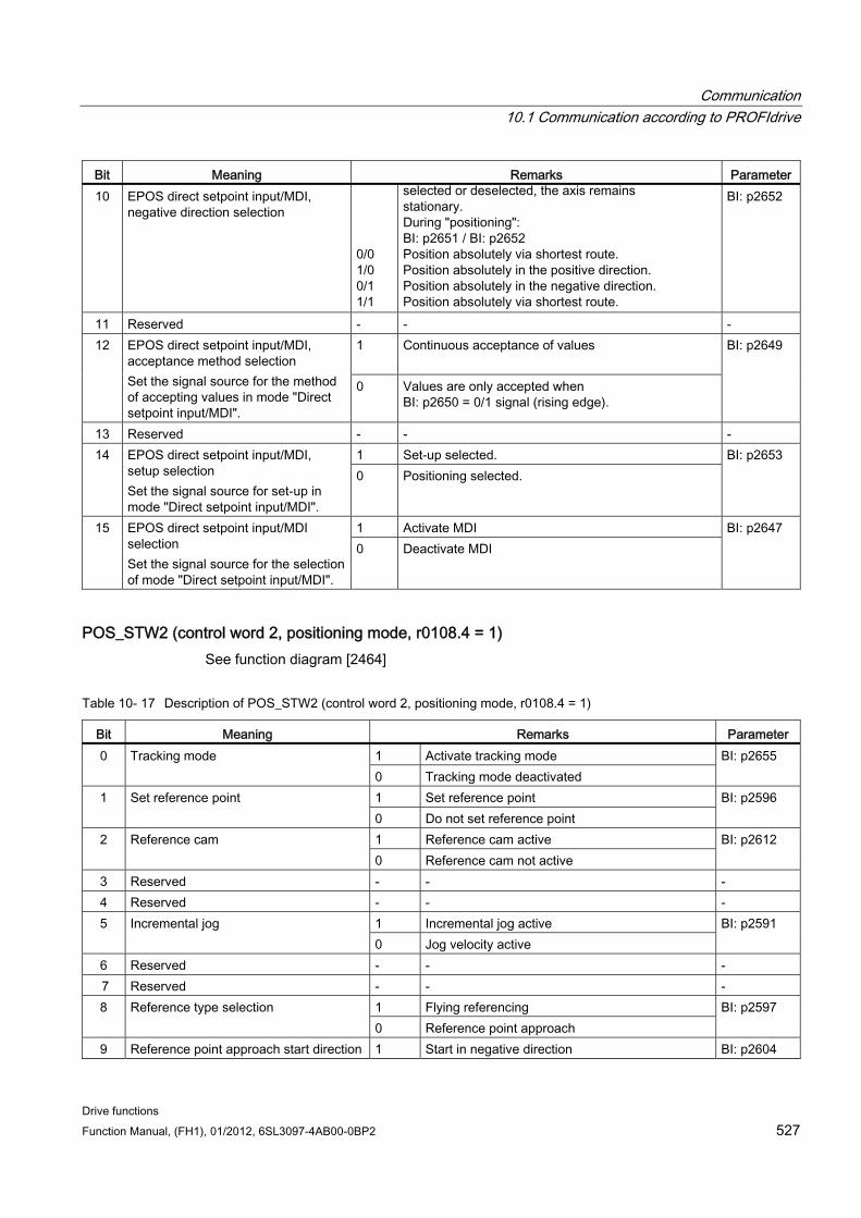
Communication 10.1 Communication according to PROFIdrive
Drive functions Function Manual, (FH1), 01/2012, 6SL3097-4AB00-0BP2 527
Bit Meaning Remarks Parameter 10 EPOS direct setpoint input/MDI,
negative direction selection 0/0 1/0 0/1 1/1
selected or deselected, the axis remains stationary. During "positioning": BI: p2651 / BI: p2652 Position absolutely via shortest route. Position absolutely in the positive direction. Position absolutely in the negative direction. Position absolutely via shortest route.
BI: p2652
11 Reserved - - - 1 Continuous acceptance of values
12 EPOS direct setpoint input/MDI,
acceptance method selection Set the signal source for the method of accepting values in mode "Direct setpoint input/MDI".
0 Values are only accepted when BI: p2650 = 0/1 signal (rising edge).
BI: p2649
13 Reserved - - - 1 Set-up selected. 14 EPOS direct setpoint input/MDI,
setup selection Set the signal source for set-up in mode "Direct setpoint input/MDI".
0 Positioning selected. BI: p2653
1 Activate MDI 15 EPOS direct setpoint input/MDI selection Set the signal source for the selection of mode "Direct setpoint input/MDI".
0 Deactivate MDI BI: p2647
POS_STW2 (control word 2, positioning mode, r0108.4 = 1) See function diagram [2464]
Table 10- 17 Description of POS_STW2 (control word 2, positioning mode, r0108.4 = 1)
Bit Meaning Remarks Parameter 1 Activate tracking mode 0 Tracking mode 0 Tracking mode deactivated
BI: p2655
1 Set reference point 1 Set reference point 0 Do not set reference point
BI: p2596
1 Reference cam active 2 Reference cam 0 Reference cam not active
BI: p2612
3 Reserved - - - 4 Reserved - - -
1 Incremental jog active 5 Incremental jog 0 Jog velocity active
BI: p2591
6 Reserved - - - 7 Reserved - - -
1 Flying referencing 8 Reference type selection 0 Reference point approach
BI: p2597
9 Reference point approach start direction 1 Start in negative direction BI: p2604
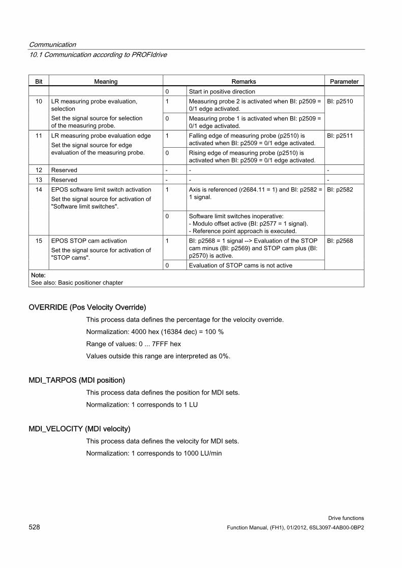
Communication 10.1 Communication according to PROFIdrive
Drive functions 528 Function Manual, (FH1), 01/2012, 6SL3097-4AB00-0BP2
Bit Meaning Remarks Parameter 0 Start in positive direction
1 Measuring probe 2 is activated when BI: p2509 = 0/1 edge activated.
10 LR measuring probe evaluation, selection Set the signal source for selection of the measuring probe.
0 Measuring probe 1 is activated when BI: p2509 = 0/1 edge activated.
BI: p2510
1 Falling edge of measuring probe (p2510) is activated when BI: p2509 = 0/1 edge activated.
11 LR measuring probe evaluation edge Set the signal source for edge evaluation of the measuring probe. 0 Rising edge of measuring probe (p2510) is
activated when BI: p2509 = 0/1 edge activated.
BI: p2511
12 Reserved - - - 13 Reserved - - -
1 Axis is referenced (r2684.11 = 1) and BI: p2582 = 1 signal.
14 EPOS software limit switch activation Set the signal source for activation of "Software limit switches".
0 Software limit switches inoperative: - Modulo offset active (BI: p2577 = 1 signal). - Reference point approach is executed.
BI: p2582
1 BI: p2568 = 1 signal --> Evaluation of the STOP cam minus (BI: p2569) and STOP cam plus (BI: p2570) is active.
15 EPOS STOP cam activation Set the signal source for activation of "STOP cams".
0 Evaluation of STOP cams is not active
BI: p2568
Note: See also: Basic positioner chapter
OVERRIDE (Pos Velocity Override) This process data defines the percentage for the velocity override.
Normalization: 4000 hex (16384 dec) = 100 %
Range of values: 0 ... 7FFF hex
Values outside this range are interpreted as 0%.
MDI_TARPOS (MDI position) This process data defines the position for MDI sets.
Normalization: 1 corresponds to 1 LU
MDI_VELOCITY (MDI velocity) This process data defines the velocity for MDI sets.
Normalization: 1 corresponds to 1000 LU/min
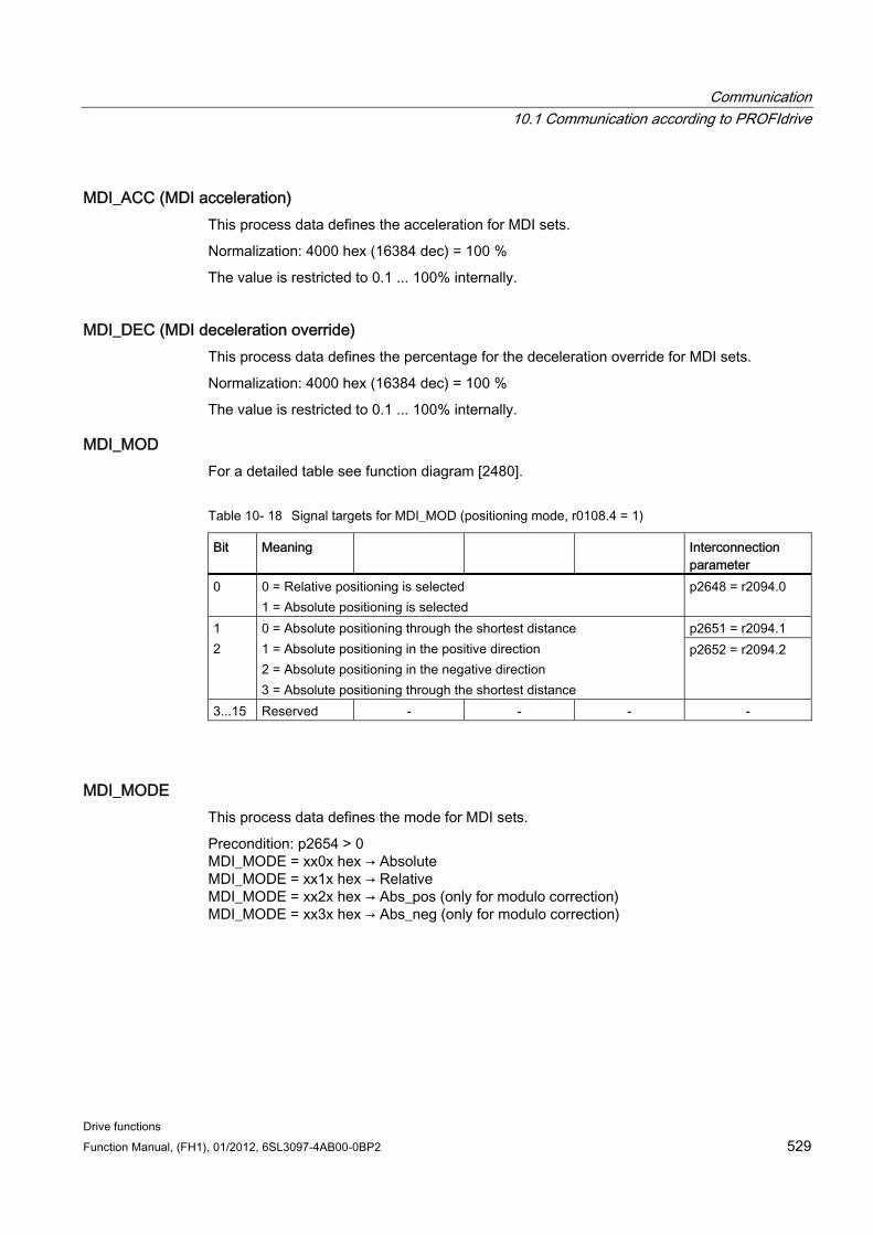
Communication 10.1 Communication according to PROFIdrive
Drive functions Function Manual, (FH1), 01/2012, 6SL3097-4AB00-0BP2 529
MDI_ACC (MDI acceleration) This process data defines the acceleration for MDI sets.
Normalization: 4000 hex (16384 dec) = 100 %
The value is restricted to 0.1 ... 100% internally.
MDI_DEC (MDI deceleration override) This process data defines the percentage for the deceleration override for MDI sets.
Normalization: 4000 hex (16384 dec) = 100 %
The value is restricted to 0.1 ... 100% internally.
MDI_MOD For a detailed table see function diagram [2480].
Table 10- 18 Signal targets for MDI_MOD (positioning mode, r0108.4 = 1)
Bit Meaning Interconnection parameter
0 0 = Relative positioning is selected 1 = Absolute positioning is selected
p2648 = r2094.0
p2651 = r2094.1 1 2
0 = Absolute positioning through the shortest distance 1 = Absolute positioning in the positive direction 2 = Absolute positioning in the negative direction 3 = Absolute positioning through the shortest distance
p2652 = r2094.2
3...15 Reserved - - - -
MDI_MODE This process data defines the mode for MDI sets.
Precondition: p2654 > 0 MDI_MODE = xx0x hex → Absolute MDI_MODE = xx1x hex → Relative MDI_MODE = xx2x hex → Abs_pos (only for modulo correction) MDI_MODE = xx3x hex → Abs_neg (only for modulo correction)
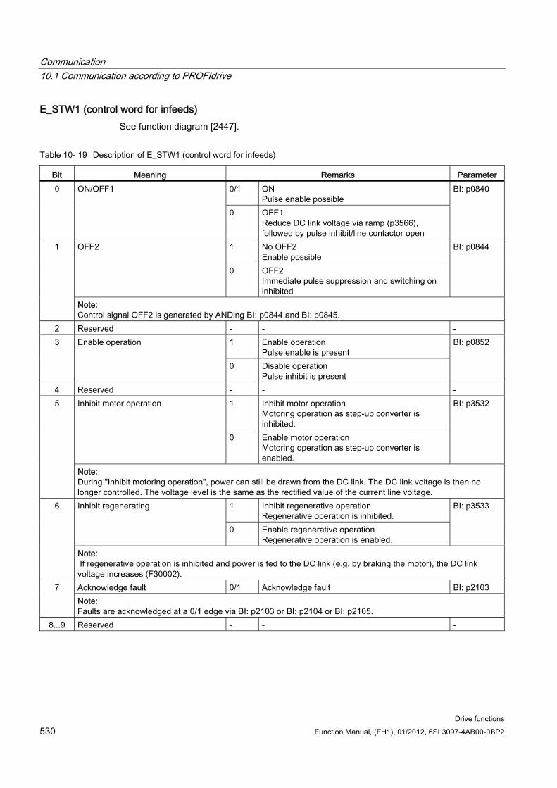
Communication 10.1 Communication according to PROFIdrive
Drive functions 530 Function Manual, (FH1), 01/2012, 6SL3097-4AB00-0BP2
E_STW1 (control word for infeeds) See function diagram [2447].
Table 10- 19 Description of E_STW1 (control word for infeeds)
Bit Meaning Remarks Parameter 0/1 ON
Pulse enable possible 0 ON/OFF1
0 OFF1 Reduce DC link voltage via ramp (p3566), followed by pulse inhibit/line contactor open
BI: p0840
1 No OFF2 Enable possible
OFF2
0 OFF2 Immediate pulse suppression and switching on inhibited
BI: p0844 1
Note: Control signal OFF2 is generated by ANDing BI: p0844 and BI: p0845.
2 Reserved - - - 1 Enable operation
Pulse enable is present 3 Enable operation
0 Disable operation Pulse inhibit is present
BI: p0852
4 Reserved - - - 1 Inhibit motor operation
Motoring operation as step-up converter is inhibited.
Inhibit motor operation
0 Enable motor operation Motoring operation as step-up converter is enabled.
BI: p3532 5
Note: During "Inhibit motoring operation", power can still be drawn from the DC link. The DC link voltage is then no longer controlled. The voltage level is the same as the rectified value of the current line voltage.
1 Inhibit regenerative operation Regenerative operation is inhibited.
Inhibit regenerating
0 Enable regenerative operation Regenerative operation is enabled.
BI: p3533 6
Note: If regenerative operation is inhibited and power is fed to the DC link (e.g. by braking the motor), the DC link voltage increases (F30002). Acknowledge fault 0/1 Acknowledge fault BI: p2103 7 Note: Faults are acknowledged at a 0/1 edge via BI: p2103 or BI: p2104 or BI: p2105.
8...9 Reserved - - -
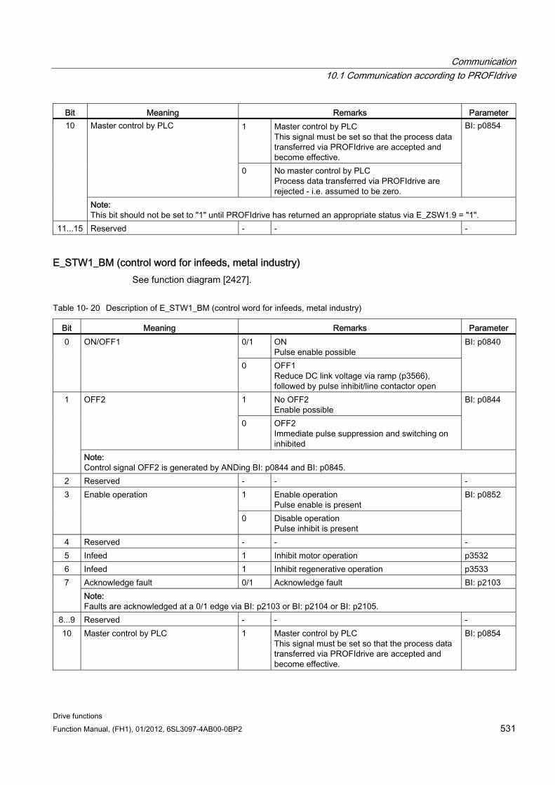
Communication 10.1 Communication according to PROFIdrive
Drive functions Function Manual, (FH1), 01/2012, 6SL3097-4AB00-0BP2 531
Bit Meaning Remarks Parameter 1 Master control by PLC
This signal must be set so that the process data transferred via PROFIdrive are accepted and become effective.
Master control by PLC
0 No master control by PLC Process data transferred via PROFIdrive are rejected - i.e. assumed to be zero.
BI: p0854 10
Note: This bit should not be set to "1" until PROFIdrive has returned an appropriate status via E_ZSW1.9 = "1".
11...15 Reserved - - -
E_STW1_BM (control word for infeeds, metal industry) See function diagram [2427].
Table 10- 20 Description of E_STW1_BM (control word for infeeds, metal industry)
Bit Meaning Remarks Parameter 0/1 ON
Pulse enable possible 0 ON/OFF1
0 OFF1 Reduce DC link voltage via ramp (p3566), followed by pulse inhibit/line contactor open
BI: p0840
1 No OFF2 Enable possible
OFF2
0 OFF2 Immediate pulse suppression and switching on inhibited
BI: p0844 1
Note: Control signal OFF2 is generated by ANDing BI: p0844 and BI: p0845.
2 Reserved - - - 1 Enable operation
Pulse enable is present 3 Enable operation
0 Disable operation Pulse inhibit is present
BI: p0852
4 Reserved - - - 5 Infeed 1 Inhibit motor operation p3532 6 Infeed 1 Inhibit regenerative operation p3533
Acknowledge fault 0/1 Acknowledge fault BI: p2103 7 Note: Faults are acknowledged at a 0/1 edge via BI: p2103 or BI: p2104 or BI: p2105.
8...9 Reserved - - - 10 Master control by PLC 1 Master control by PLC
This signal must be set so that the process data transferred via PROFIdrive are accepted and become effective.
BI: p0854
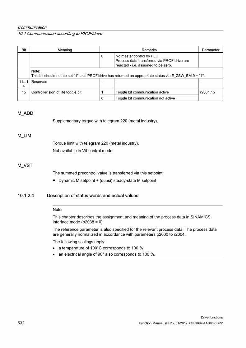
Communication 10.1 Communication according to PROFIdrive
Drive functions 532 Function Manual, (FH1), 01/2012, 6SL3097-4AB00-0BP2
Bit Meaning Remarks Parameter 0 No master control by PLC
Process data transferred via PROFIdrive are rejected - i.e. assumed to be zero.
Note: This bit should not be set "1" until PROFIdrive has returned an appropriate status via E_ZSW_BM.9 = "1".
11...14
Reserved - - -
1 Toggle bit communication active 15 Controller sign of life toggle bit 0 Toggle bit communication not active
r2081.15
M_ADD Supplementary torque with telegram 220 (metal industry).
M_LIM Torque limit with telegram 220 (metal industry).
Not available in V/f control mode.
M_VST The summed precontrol value is transferred via this setpoint:
Dynamic M setpoint + (quasi) steady-state M setpoint
10.1.2.4 Description of status words and actual values
Note
This chapter describes the assignment and meaning of the process data in SINAMICS interface mode (p2038 = 0).
The reference parameter is also specified for the relevant process data. The process data are generally normalized in accordance with parameters p2000 to r2004.
The following scalings apply: • a temperature of 100°C corresponds to 100 % • an electrical angle of 90° also corresponds to 100 %.
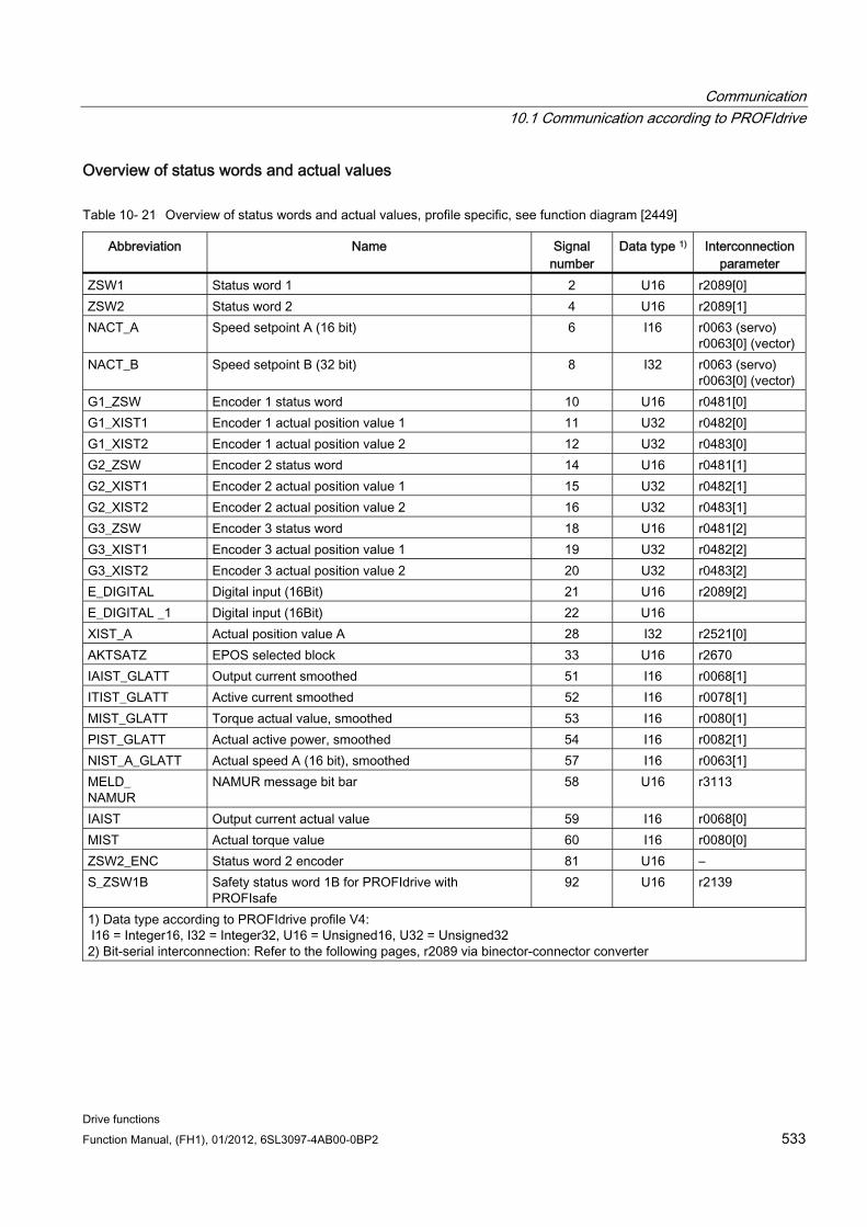
Communication 10.1 Communication according to PROFIdrive
Drive functions Function Manual, (FH1), 01/2012, 6SL3097-4AB00-0BP2 533
Overview of status words and actual values
Table 10- 21 Overview of status words and actual values, profile specific, see function diagram [2449]
Abbreviation Name Signal number
Data type 1) Interconnection parameter
ZSW1 Status word 1 2 U16 r2089[0] ZSW2 Status word 2 4 U16 r2089[1] NACT_A Speed setpoint A (16 bit) 6 I16 r0063 (servo)
r0063[0] (vector) NACT_B Speed setpoint B (32 bit) 8 I32 r0063 (servo)
r0063[0] (vector) G1_ZSW Encoder 1 status word 10 U16 r0481[0] G1_XIST1 Encoder 1 actual position value 1 11 U32 r0482[0] G1_XIST2 Encoder 1 actual position value 2 12 U32 r0483[0] G2_ZSW Encoder 2 status word 14 U16 r0481[1] G2_XIST1 Encoder 2 actual position value 1 15 U32 r0482[1] G2_XIST2 Encoder 2 actual position value 2 16 U32 r0483[1] G3_ZSW Encoder 3 status word 18 U16 r0481[2] G3_XIST1 Encoder 3 actual position value 1 19 U32 r0482[2] G3_XIST2 Encoder 3 actual position value 2 20 U32 r0483[2] E_DIGITAL Digital input (16Bit) 21 U16 r2089[2] E_DIGITAL _1 Digital input (16Bit) 22 U16 XIST_A Actual position value A 28 I32 r2521[0] AKTSATZ EPOS selected block 33 U16 r2670 IAIST_GLATT Output current smoothed 51 I16 r0068[1] ITIST_GLATT Active current smoothed 52 I16 r0078[1] MIST_GLATT Torque actual value, smoothed 53 I16 r0080[1] PIST_GLATT Actual active power, smoothed 54 I16 r0082[1] NIST_A_GLATT Actual speed A (16 bit), smoothed 57 I16 r0063[1] MELD_ NAMUR
NAMUR message bit bar 58 U16 r3113
IAIST Output current actual value 59 I16 r0068[0] MIST Actual torque value 60 I16 r0080[0] ZSW2_ENC Status word 2 encoder 81 U16 – S_ZSW1B Safety status word 1B for PROFIdrive with
PROFIsafe 92 U16 r2139
1) Data type according to PROFIdrive profile V4: I16 = Integer16, I32 = Integer32, U16 = Unsigned16, U32 = Unsigned32 2) Bit-serial interconnection: Refer to the following pages, r2089 via binector-connector converter
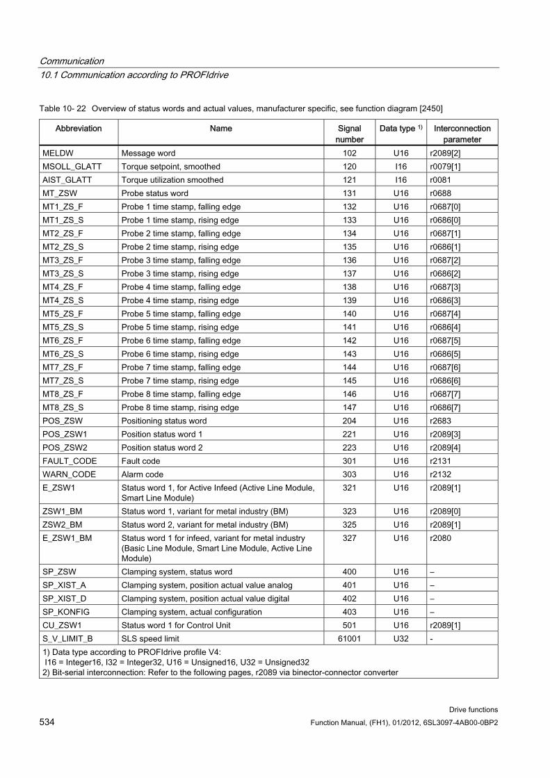
Communication 10.1 Communication according to PROFIdrive
Drive functions 534 Function Manual, (FH1), 01/2012, 6SL3097-4AB00-0BP2
Table 10- 22 Overview of status words and actual values, manufacturer specific, see function diagram [2450]
Abbreviation Name Signal number
Data type 1) Interconnection parameter
MELDW Message word 102 U16 r2089[2] MSOLL_GLATT Torque setpoint, smoothed 120 I16 r0079[1] AIST_GLATT Torque utilization smoothed 121 I16 r0081 MT_ZSW Probe status word 131 U16 r0688 MT1_ZS_F Probe 1 time stamp, falling edge 132 U16 r0687[0] MT1_ZS_S Probe 1 time stamp, rising edge 133 U16 r0686[0] MT2_ZS_F Probe 2 time stamp, falling edge 134 U16 r0687[1] MT2_ZS_S Probe 2 time stamp, rising edge 135 U16 r0686[1] MT3_ZS_F Probe 3 time stamp, falling edge 136 U16 r0687[2] MT3_ZS_S Probe 3 time stamp, rising edge 137 U16 r0686[2] MT4_ZS_F Probe 4 time stamp, falling edge 138 U16 r0687[3] MT4_ZS_S Probe 4 time stamp, rising edge 139 U16 r0686[3] MT5_ZS_F Probe 5 time stamp, falling edge 140 U16 r0687[4] MT5_ZS_S Probe 5 time stamp, rising edge 141 U16 r0686[4] MT6_ZS_F Probe 6 time stamp, falling edge 142 U16 r0687[5] MT6_ZS_S Probe 6 time stamp, rising edge 143 U16 r0686[5] MT7_ZS_F Probe 7 time stamp, falling edge 144 U16 r0687[6] MT7_ZS_S Probe 7 time stamp, rising edge 145 U16 r0686[6] MT8_ZS_F Probe 8 time stamp, falling edge 146 U16 r0687[7] MT8_ZS_S Probe 8 time stamp, rising edge 147 U16 r0686[7] POS_ZSW Positioning status word 204 U16 r2683 POS_ZSW1 Position status word 1 221 U16 r2089[3] POS_ZSW2 Position status word 2 223 U16 r2089[4] FAULT_CODE Fault code 301 U16 r2131 WARN_CODE Alarm code 303 U16 r2132 E_ZSW1 Status word 1, for Active Infeed (Active Line Module,
Smart Line Module) 321 U16 r2089[1]
ZSW1_BM Status word 1, variant for metal industry (BM) 323 U16 r2089[0] ZSW2_BM Status word 2, variant for metal industry (BM) 325 U16 r2089[1] E_ZSW1_BM Status word 1 for infeed, variant for metal industry
(Basic Line Module, Smart Line Module, Active Line Module)
327 U16 r2080
SP_ZSW Clamping system, status word 400 U16 – SP_XIST_A Clamping system, position actual value analog 401 U16 – SP_XIST_D Clamping system, position actual value digital 402 U16 – SP_KONFIG Clamping system, actual configuration 403 U16 – CU_ZSW1 Status word 1 for Control Unit 501 U16 r2089[1] S_V_LIMIT_B SLS speed limit 61001 U32 - 1) Data type according to PROFIdrive profile V4: I16 = Integer16, I32 = Integer32, U16 = Unsigned16, U32 = Unsigned32 2) Bit-serial interconnection: Refer to the following pages, r2089 via binector-connector converter
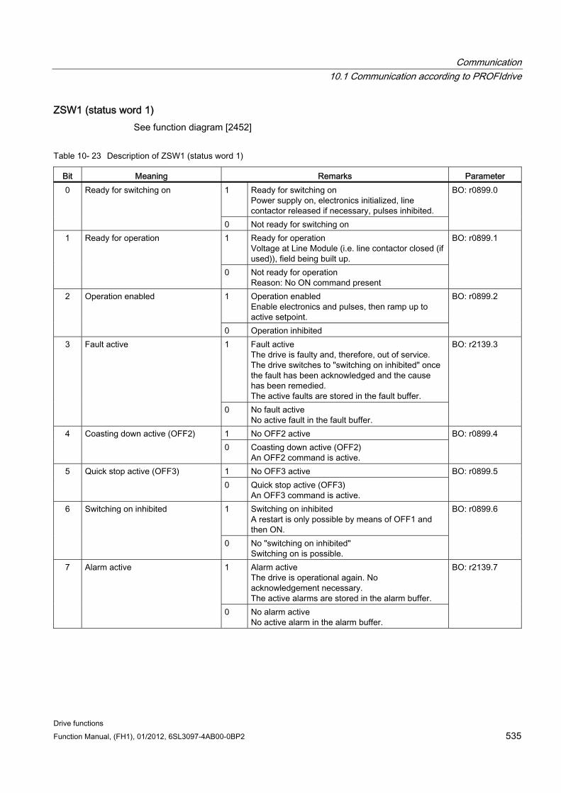
Communication 10.1 Communication according to PROFIdrive
Drive functions Function Manual, (FH1), 01/2012, 6SL3097-4AB00-0BP2 535
ZSW1 (status word 1) See function diagram [2452]
Table 10- 23 Description of ZSW1 (status word 1)
Bit Meaning Remarks Parameter 1 Ready for switching on
Power supply on, electronics initialized, line contactor released if necessary, pulses inhibited.
0 Ready for switching on
0 Not ready for switching on
BO: r0899.0
1 Ready for operation Voltage at Line Module (i.e. line contactor closed (if used)), field being built up.
1 Ready for operation
0 Not ready for operation Reason: No ON command present
BO: r0899.1
1 Operation enabled Enable electronics and pulses, then ramp up to active setpoint.
2 Operation enabled
0 Operation inhibited
BO: r0899.2
1 Fault active The drive is faulty and, therefore, out of service. The drive switches to "switching on inhibited" once the fault has been acknowledged and the cause has been remedied. The active faults are stored in the fault buffer.
3 Fault active
0 No fault active No active fault in the fault buffer.
BO: r2139.3
1 No OFF2 active 4 Coasting down active (OFF2) 0 Coasting down active (OFF2)
An OFF2 command is active.
BO: r0899.4
1 No OFF3 active 5 Quick stop active (OFF3) 0 Quick stop active (OFF3)
An OFF3 command is active.
BO: r0899.5
1 Switching on inhibited A restart is only possible by means of OFF1 and then ON.
6 Switching on inhibited
0 No "switching on inhibited" Switching on is possible.
BO: r0899.6
1 Alarm active The drive is operational again. No acknowledgement necessary. The active alarms are stored in the alarm buffer.
7 Alarm active
0 No alarm active No active alarm in the alarm buffer.
BO: r2139.7
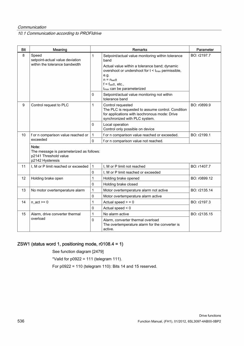
Communication 10.1 Communication according to PROFIdrive
Drive functions 536 Function Manual, (FH1), 01/2012, 6SL3097-4AB00-0BP2
Bit Meaning Remarks Parameter 1 Setpoint/actual value monitoring within tolerance
band Actual value within a tolerance band; dynamic overshoot or undershoot for t < tmax permissible, e.g. n = nset± f = fset±, etc., tmax can be parameterized
8 Speed setpoint-actual value deviation within the tolerance bandwidth
0 Setpoint/actual value monitoring not within tolerance band
BO: r2197.7
1 Control requested The PLC is requested to assume control. Condition for applications with isochronous mode: Drive synchronized with PLC system.
9 Control request to PLC
0 Local operation Control only possible on device
BO: r0899.9
1 f or n comparison value reached or exceeded. f or n comparison value reached or exceeded 0 f or n comparison value not reached.
BO: r2199.1 10
Note: The message is parameterized as follows: p2141 Threshold value p2142 Hysteresis
1 I, M or P limit not reached 11 I, M or P limit reached or exceeded 0 I, M or P limit reached or exceeded
BO: r1407.7
1 Holding brake opened 12 Holding brake open 0 Holding brake closed
BO: r0899.12
1 Motor overtemperature alarm not active 13 No motor overtemperature alarm 0 Motor overtemperature alarm active
BO: r2135.14
1 Actual speed > = 0 14 n_act >= 0 0 Actual speed < 0
BO: r2197.3
1 No alarm active 15 Alarm, drive converter thermal overload 0 Alarm, converter thermal overload
The overtemperature alarm for the converter is active.
BO: r2135.15
ZSW1 (status word 1, positioning mode, r0108.4 = 1) See function diagram [2479]
*Valid for p0922 = 111 (telegram 111).
For p0922 = 110 (telegram 110): Bits 14 and 15 reserved.
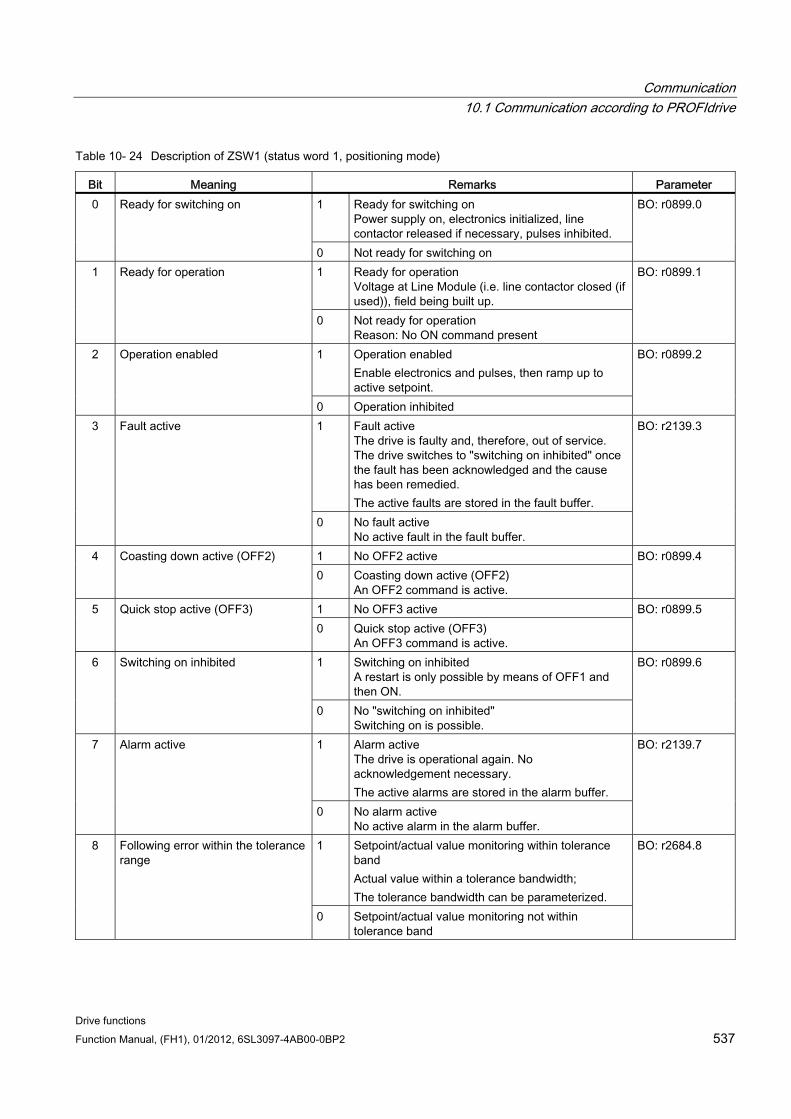
Communication 10.1 Communication according to PROFIdrive
Drive functions Function Manual, (FH1), 01/2012, 6SL3097-4AB00-0BP2 537
Table 10- 24 Description of ZSW1 (status word 1, positioning mode)
Bit Meaning Remarks Parameter 1 Ready for switching on
Power supply on, electronics initialized, line contactor released if necessary, pulses inhibited.
0 Ready for switching on
0 Not ready for switching on
BO: r0899.0
1 Ready for operation Voltage at Line Module (i.e. line contactor closed (if used)), field being built up.
1 Ready for operation
0 Not ready for operation Reason: No ON command present
BO: r0899.1
1 Operation enabled Enable electronics and pulses, then ramp up to active setpoint.
2 Operation enabled
0 Operation inhibited
BO: r0899.2
1 Fault active The drive is faulty and, therefore, out of service. The drive switches to "switching on inhibited" once the fault has been acknowledged and the cause has been remedied. The active faults are stored in the fault buffer.
3 Fault active
0 No fault active No active fault in the fault buffer.
BO: r2139.3
1 No OFF2 active 4 Coasting down active (OFF2) 0 Coasting down active (OFF2)
An OFF2 command is active.
BO: r0899.4
1 No OFF3 active 5 Quick stop active (OFF3) 0 Quick stop active (OFF3)
An OFF3 command is active.
BO: r0899.5
1 Switching on inhibited A restart is only possible by means of OFF1 and then ON.
6 Switching on inhibited
0 No "switching on inhibited" Switching on is possible.
BO: r0899.6
1 Alarm active The drive is operational again. No acknowledgement necessary. The active alarms are stored in the alarm buffer.
7 Alarm active
0 No alarm active No active alarm in the alarm buffer.
BO: r2139.7
1 Setpoint/actual value monitoring within tolerance band Actual value within a tolerance bandwidth; The tolerance bandwidth can be parameterized.
8 Following error within the tolerance range
0 Setpoint/actual value monitoring not within tolerance band
BO: r2684.8
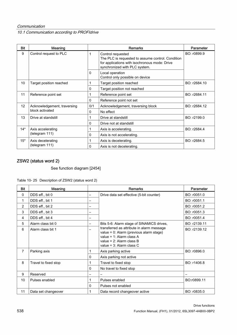
Communication 10.1 Communication according to PROFIdrive
Drive functions 538 Function Manual, (FH1), 01/2012, 6SL3097-4AB00-0BP2
Bit Meaning Remarks Parameter 1 Control requested
The PLC is requested to assume control. Condition for applications with isochronous mode: Drive synchronized with PLC system.
9 Control request to PLC
0 Local operation Control only possible on device
BO: r0899.9
1 Target position reached 10 Target position reached 0 Target position not reached
BO: r2684.10
1 Reference point set 11 Reference point set 0 Reference point not set
BO: r2684.11
0/1 Acknowledgement, traversing block 12 Acknowledgement, traversing block activated 0 No effect
BO: r2684.12
1 Drive at standstill 13 Drive at standstill 0 Drive not at standstill
BO: r2199.0
1 Axis is accelerating. 14* Axis accelerating (telegram 111) 0 Axis is not accelerating.
BO: r2684.4
1 Axis is decelerating. 15* Axis decelerating (telegram 111) 0 Axis is not decelerating.
BO: r2684.5
ZSW2 (status word 2) See function diagram [2454]
Table 10- 25 Description of ZSW2 (status word 2)
Bit Meaning Remarks Parameter 0 DDS eff., bit 0 – BO: r0051.0 1 DDS eff., bit 1 – BO: r0051.1 2 DDS eff., bit 2 – BO: r0051.2 3 DDS eff., bit 3 – BO: r0051.3 4 DDS eff., bit 4 –
Drive data set effective (5-bit counter)
BO: r0051.4 5 Alarm class bit 0 – BO: r2139.11 6 Alarm class bit 1 –
Bits 5-6: Alarm stage of SINAMICS drives, transferred as attribute in alarm message value = 0: Alarm (previous alarm stage) value = 1: Alarm class A value = 2: Alarm class B value = 3: Alarm class C
BO: r2139.12
1 Axis parking active 7 Parking axis 0 Axis parking not active
BO: r0896.0
1 Travel to fixed stop 8 Travel to fixed stop 0 No travel to fixed stop
BO: r1406.8
9 Reserved – – – 1 Pulses enabled 10 Pulses enabled 0 Pulses not enabled
BO:r0899.11
11 Data set changeover 1 Data record changeover active BO: r0835.0

Communication 10.1 Communication according to PROFIdrive
Drive functions Function Manual, (FH1), 01/2012, 6SL3097-4AB00-0BP2 539
Bit Meaning Remarks Parameter 0 Data set changeover active
12 Slave sign-of-life bit 0 – User data integrity (4-bit counter) Implicitly interconnected
13 Slave sign-of-life bit 1 – – – 14 Slave sign-of-life bit 2 – – – 15 Slave sign-of-life bit 3 – – –
ZSW1_BM (status word 1, metal industry) See function diagram [2428].
Table 10- 26 Description of ZSW1_BM (status word 1, metal industry)
Bit Meaning Remarks Parameter 1 Ready for switching on
Power supply on, electronics initialized, line contactor released if necessary, pulses inhibited.
0 Ready to start
0 Not ready to start
BO: r0899.0
1 Ready for operation Voltage at Line Module (i.e. line contactor closed (if used)), field being built up.
1 Ready
0 Not ready for operation Reason: No ON command present
BO: r0899.1
1 Operation enabled Enable electronics and pulses, then ramp up to active setpoint.
2 Operation enabled
0 Operation inhibited
BO: r0899.2
1 Fault active The drive is faulty and, therefore, out of service. The drive switches to "switching on inhibited" once the fault has been acknowledged and the cause has been remedied. The active faults are stored in the fault buffer.
3 Fault active
0 No fault active No active fault in the fault buffer.
BO: r2139.3
1 No OFF2 active 4 Coasting down active (OFF2) 0 Coasting down active (OFF2)
An OFF2 command is active.
BO: r0899.4
1 No OFF3 active 5 Quick stop active (OFF3) 0 Quick stop active (OFF3)
An OFF3 command is active.
BO: r0899.5
1 Switching on inhibited A restart is only possible by means of OFF1 and then ON.
6 Switching on inhibited
0 No "switching on inhibited" Switching on is possible.
BO: r0899.6
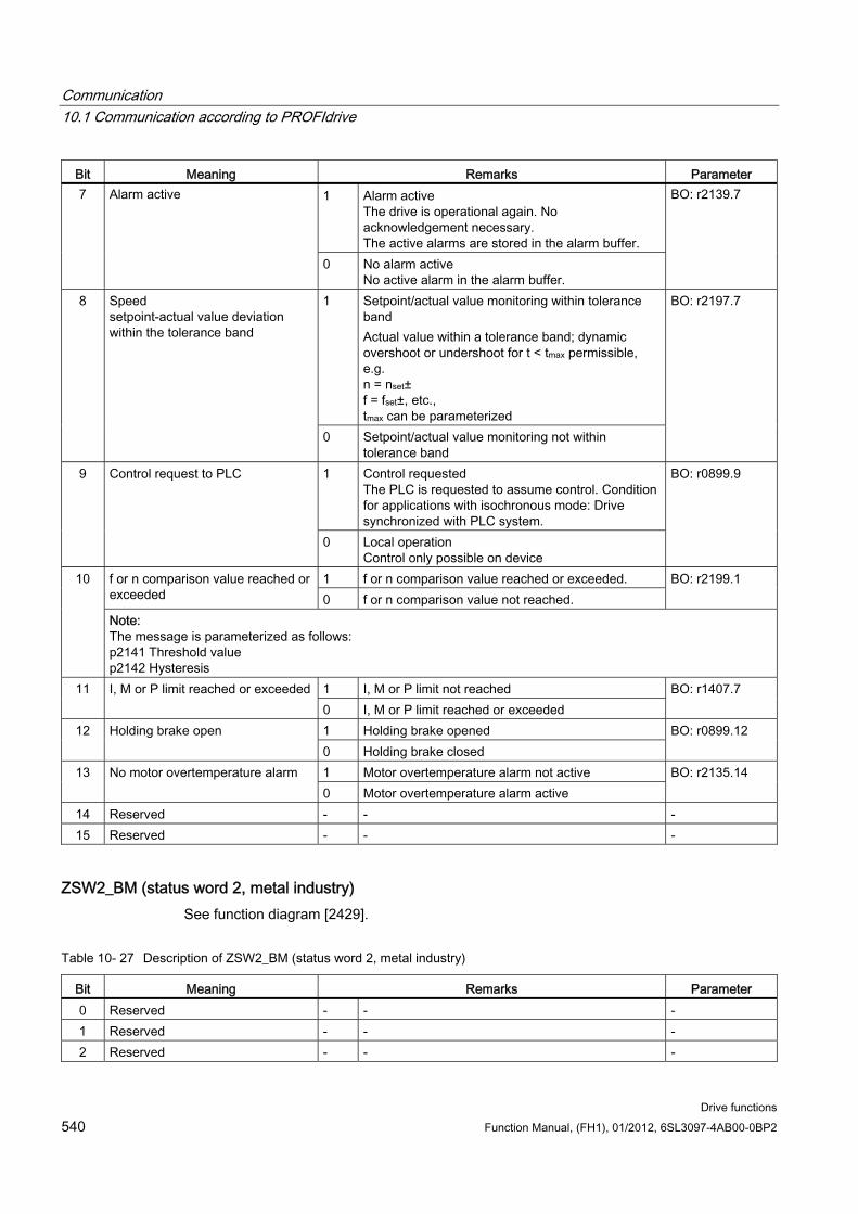
Communication 10.1 Communication according to PROFIdrive
Drive functions 540 Function Manual, (FH1), 01/2012, 6SL3097-4AB00-0BP2
Bit Meaning Remarks Parameter 1 Alarm active
The drive is operational again. No acknowledgement necessary. The active alarms are stored in the alarm buffer.
7 Alarm active
0 No alarm active No active alarm in the alarm buffer.
BO: r2139.7
1 Setpoint/actual value monitoring within tolerance band Actual value within a tolerance band; dynamic overshoot or undershoot for t < tmax permissible, e.g. n = nset± f = fset±, etc., tmax can be parameterized
8 Speed setpoint-actual value deviation within the tolerance band
0 Setpoint/actual value monitoring not within tolerance band
BO: r2197.7
1 Control requested The PLC is requested to assume control. Condition for applications with isochronous mode: Drive synchronized with PLC system.
9 Control request to PLC
0 Local operation Control only possible on device
BO: r0899.9
1 f or n comparison value reached or exceeded. f or n comparison value reached or exceeded 0 f or n comparison value not reached.
BO: r2199.1 10
Note: The message is parameterized as follows: p2141 Threshold value p2142 Hysteresis
1 I, M or P limit not reached 11 I, M or P limit reached or exceeded 0 I, M or P limit reached or exceeded
BO: r1407.7
1 Holding brake opened 12 Holding brake open 0 Holding brake closed
BO: r0899.12
1 Motor overtemperature alarm not active 13 No motor overtemperature alarm 0 Motor overtemperature alarm active
BO: r2135.14
14 Reserved - - - 15 Reserved - - -
ZSW2_BM (status word 2, metal industry) See function diagram [2429].
Table 10- 27 Description of ZSW2_BM (status word 2, metal industry)
Bit Meaning Remarks Parameter 0 Reserved - - - 1 Reserved - - - 2 Reserved - - -
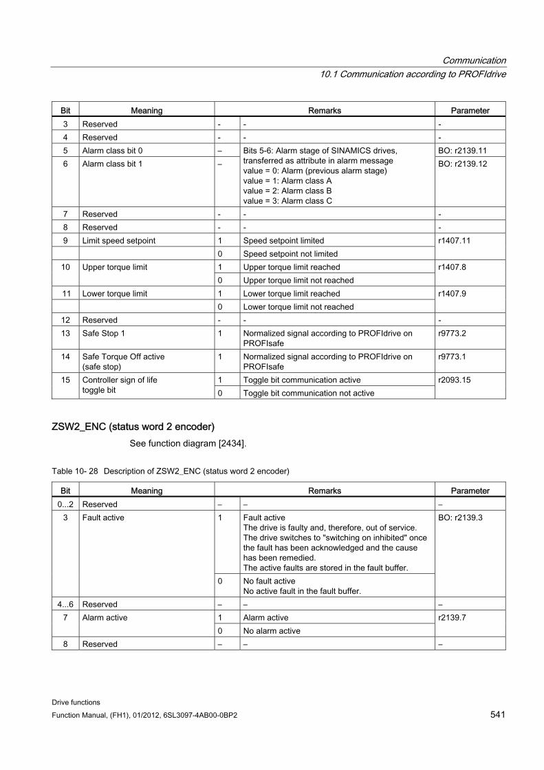
Communication 10.1 Communication according to PROFIdrive
Drive functions Function Manual, (FH1), 01/2012, 6SL3097-4AB00-0BP2 541
Bit Meaning Remarks Parameter 3 Reserved - - - 4 Reserved - - - 5 Alarm class bit 0 – BO: r2139.11 6 Alarm class bit 1 –
Bits 5-6: Alarm stage of SINAMICS drives, transferred as attribute in alarm message value = 0: Alarm (previous alarm stage) value = 1: Alarm class A value = 2: Alarm class B value = 3: Alarm class C
BO: r2139.12
7 Reserved - - - 8 Reserved - - - 9 Limit speed setpoint 1 Speed setpoint limited 0 Speed setpoint not limited
r1407.11
1 Upper torque limit reached 10
Upper torque limit 0 Upper torque limit not reached
r1407.8
11 Lower torque limit 1 Lower torque limit reached 0 Lower torque limit not reached
r1407.9
12 Reserved - - - 13 Safe Stop 1 1 Normalized signal according to PROFIdrive on
PROFIsafe r9773.2
14 Safe Torque Off active (safe stop)
1 Normalized signal according to PROFIdrive on PROFIsafe
r9773.1
1 Toggle bit communication active 15 Controller sign of life toggle bit 0 Toggle bit communication not active
r2093.15
ZSW2_ENC (status word 2 encoder) See function diagram [2434].
Table 10- 28 Description of ZSW2_ENC (status word 2 encoder)
Bit Meaning Remarks Parameter 0...2 Reserved – – –
1 Fault active The drive is faulty and, therefore, out of service. The drive switches to "switching on inhibited" once the fault has been acknowledged and the cause has been remedied. The active faults are stored in the fault buffer.
3 Fault active
0 No fault active No active fault in the fault buffer.
BO: r2139.3
4...6 Reserved – – – 1 Alarm active 7 Alarm active 0 No alarm active
r2139.7
8 Reserved – – –
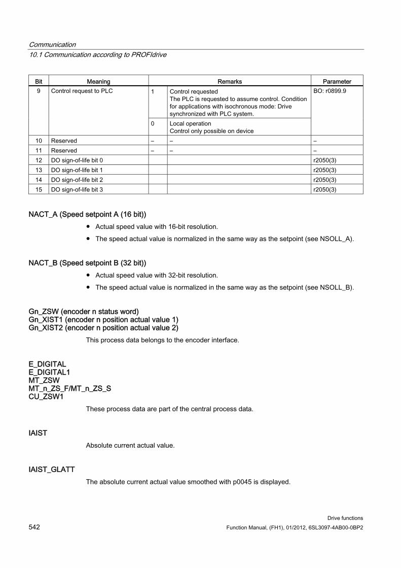
Communication 10.1 Communication according to PROFIdrive
Drive functions 542 Function Manual, (FH1), 01/2012, 6SL3097-4AB00-0BP2
Bit Meaning Remarks Parameter 1 Control requested
The PLC is requested to assume control. Condition for applications with isochronous mode: Drive synchronized with PLC system.
9 Control request to PLC
0 Local operation Control only possible on device
BO: r0899.9
10 Reserved – – – 11 Reserved – – – 12 DO sign-of-life bit 0 r2050(3) 13 DO sign-of-life bit 1 r2050(3) 14 DO sign-of-life bit 2 r2050(3) 15 DO sign-of-life bit 3 r2050(3)
NACT_A (Speed setpoint A (16 bit)) Actual speed value with 16-bit resolution.
The speed actual value is normalized in the same way as the setpoint (see NSOLL_A).
NACT_B (Speed setpoint B (32 bit)) Actual speed value with 32-bit resolution.
The speed actual value is normalized in the same way as the setpoint (see NSOLL_B).
Gn_ZSW (encoder n status word) Gn_XIST1 (encoder n position actual value 1) Gn_XIST2 (encoder n position actual value 2)
This process data belongs to the encoder interface.
E_DIGITAL E_DIGITAL1 MT_ZSW MT_n_ZS_F/MT_n_ZS_S CU_ZSW1
These process data are part of the central process data.
IAIST Absolute current actual value.
IAIST_GLATT The absolute current actual value smoothed with p0045 is displayed.
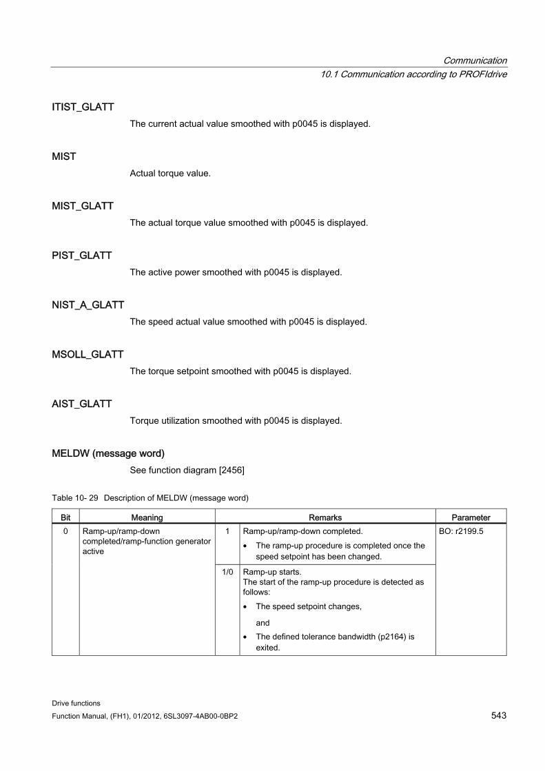
Communication 10.1 Communication according to PROFIdrive
Drive functions Function Manual, (FH1), 01/2012, 6SL3097-4AB00-0BP2 543
ITIST_GLATT The current actual value smoothed with p0045 is displayed.
MIST Actual torque value.
MIST_GLATT The actual torque value smoothed with p0045 is displayed.
PIST_GLATT The active power smoothed with p0045 is displayed.
NIST_A_GLATT The speed actual value smoothed with p0045 is displayed.
MSOLL_GLATT The torque setpoint smoothed with p0045 is displayed.
AIST_GLATT Torque utilization smoothed with p0045 is displayed.
MELDW (message word) See function diagram [2456]
Table 10- 29 Description of MELDW (message word)
Bit Meaning Remarks Parameter 1 Ramp-up/ramp-down completed.
• The ramp-up procedure is completed once the speed setpoint has been changed.
0 Ramp-up/ramp-down completed/ramp-function generator active
1/0 Ramp-up starts. The start of the ramp-up procedure is detected as follows: • The speed setpoint changes,
and • The defined tolerance bandwidth (p2164) is
exited.
BO: r2199.5
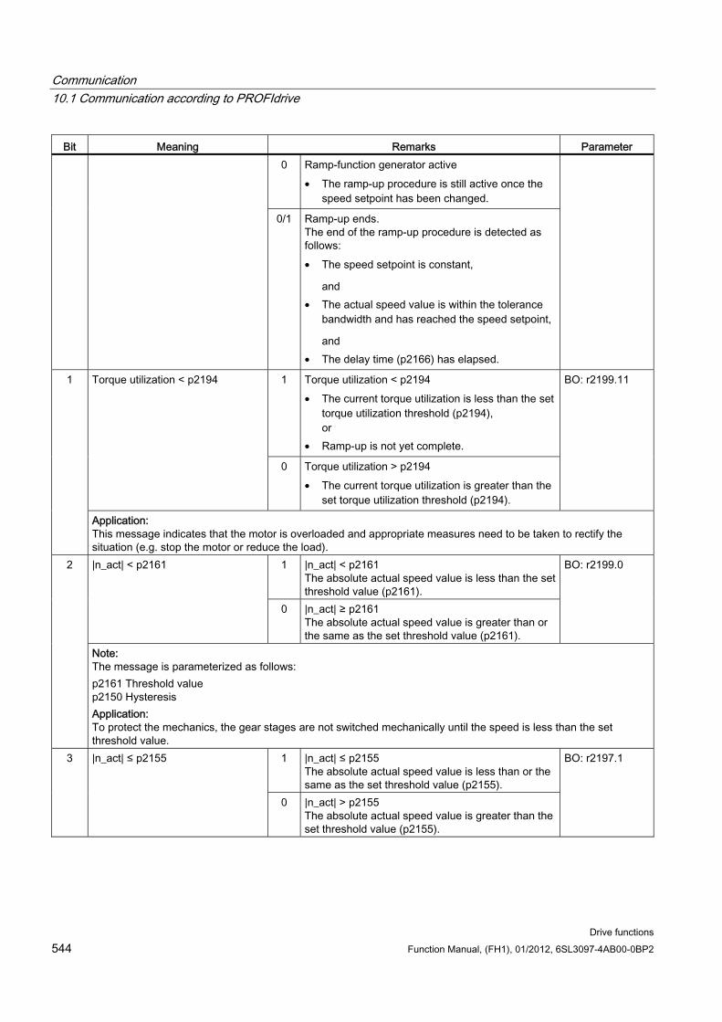
Communication 10.1 Communication according to PROFIdrive
Drive functions 544 Function Manual, (FH1), 01/2012, 6SL3097-4AB00-0BP2
Bit Meaning Remarks Parameter 0 Ramp-function generator active
• The ramp-up procedure is still active once the speed setpoint has been changed.
0/1 Ramp-up ends. The end of the ramp-up procedure is detected as follows: • The speed setpoint is constant,
and • The actual speed value is within the tolerance
bandwidth and has reached the speed setpoint,
and • The delay time (p2166) has elapsed.
1 Torque utilization < p2194 • The current torque utilization is less than the set
torque utilization threshold (p2194), or
• Ramp-up is not yet complete.
Torque utilization < p2194
0 Torque utilization > p2194 • The current torque utilization is greater than the
set torque utilization threshold (p2194).
BO: r2199.11 1
Application: This message indicates that the motor is overloaded and appropriate measures need to be taken to rectify the situation (e.g. stop the motor or reduce the load).
1 |n_act| < p2161 The absolute actual speed value is less than the set threshold value (p2161).
|n_act| < p2161
0 |n_act| ≥ p2161 The absolute actual speed value is greater than or the same as the set threshold value (p2161).
BO: r2199.0 2
Note: The message is parameterized as follows: p2161 Threshold value p2150 Hysteresis Application: To protect the mechanics, the gear stages are not switched mechanically until the speed is less than the set threshold value.
1 |n_act| ≤ p2155 The absolute actual speed value is less than or the same as the set threshold value (p2155).
3 |n_act| ≤ p2155
0 |n_act| > p2155 The absolute actual speed value is greater than the set threshold value (p2155).
BO: r2197.1
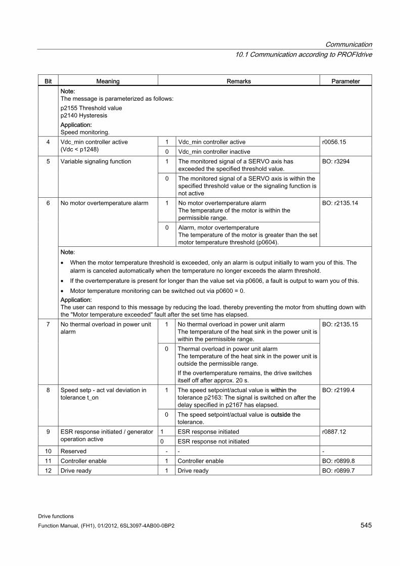
Communication 10.1 Communication according to PROFIdrive
Drive functions Function Manual, (FH1), 01/2012, 6SL3097-4AB00-0BP2 545
Bit Meaning Remarks Parameter Note: The message is parameterized as follows: p2155 Threshold value p2140 Hysteresis Application: Speed monitoring.
1 Vdc_min controller active 4 Vdc_min controller active (Vdc < p1248) 0 Vdc_min controller inactive
r0056.15
1 The monitored signal of a SERVO axis has exceeded the specified threshold value.
5 Variable signaling function
0 The monitored signal of a SERVO axis is within the specified threshold value or the signaling function is not active
BO: r3294
1 No motor overtemperature alarm The temperature of the motor is within the permissible range.
No motor overtemperature alarm
0 Alarm, motor overtemperature The temperature of the motor is greater than the set motor temperature threshold (p0604).
BO: r2135.14
6
Note: • When the motor temperature threshold is exceeded, only an alarm is output initially to warn you of this. The
alarm is canceled automatically when the temperature no longer exceeds the alarm threshold. • If the overtemperature is present for longer than the value set via p0606, a fault is output to warn you of this. • Motor temperature monitoring can be switched out via p0600 = 0. Application: The user can respond to this message by reducing the load. thereby preventing the motor from shutting down with the "Motor temperature exceeded" fault after the set time has elapsed.
1 No thermal overload in power unit alarm The temperature of the heat sink in the power unit is within the permissible range.
7 No thermal overload in power unit alarm
0 Thermal overload in power unit alarm The temperature of the heat sink in the power unit is outside the permissible range. If the overtemperature remains, the drive switches itself off after approx. 20 s.
BO: r2135.15
1 The speed setpoint/actual value is within the tolerance p2163: The signal is switched on after the delay specified in p2167 has elapsed.
8 Speed setp - act val deviation in tolerance t_on
0 The speed setpoint/actual value is outside the tolerance.
BO: r2199.4
1 ESR response initiated 9 ESR response initiated / generator operation active 0 ESR response not initiated
r0887.12
10 Reserved - - - 11 Controller enable 1 Controller enable BO: r0899.8 12 Drive ready 1 Drive ready BO: r0899.7
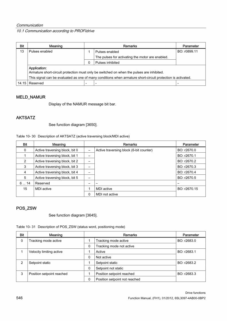
Communication 10.1 Communication according to PROFIdrive
Drive functions 546 Function Manual, (FH1), 01/2012, 6SL3097-4AB00-0BP2
Bit Meaning Remarks Parameter 1 Pulses enabled
The pulses for activating the motor are enabled. Pulses enabled
0 Pulses inhibited
BO: r0899.11 13
Application: Armature short-circuit protection must only be switched on when the pulses are inhibited. This signal can be evaluated as one of many conditions when armature short-circuit protection is activated.
14.15 Reserved - - -
MELD_NAMUR Display of the NAMUR message bit bar.
AKTSATZ See function diagram [3650].
Table 10- 30 Description of AKTSATZ (active traversing block/MDI active)
Bit Meaning Remarks Parameter 0 Active traversing block, bit 0 – BO: r2670.0 1 Active traversing block, bit 1 – BO: r2670.1 2 Active traversing block, bit 2 – BO: r2670.2 3 Active traversing block, bit 3 – BO: r2670.3 4 Active traversing block, bit 4 – BO: r2670.4 5 Active traversing block, bit 5 –
Active traversing block (6-bit counter)
BO: r2670.5 6 ... 14 Reserved – – –
1 MDI active 15 MDI active 0 MDI not active
BO: r2670.15
POS_ZSW See function diagram [3645].
Table 10- 31 Description of POS_ZSW (status word, positioning mode)
Bit Meaning Remarks Parameter 1 Tracking mode active 0 Tracking mode active 0 Tracking mode not active
BO: r2683.0
1 Active 1 Velocity limiting active 0 Not active
BO: r2683.1
1 Setpoint static 2 Setpoint static 0 Setpoint not static
BO: r2683.2
1 Position setpoint reached 3 Position setpoint reached 0 Position setpoint not reached
BO: r2683.3
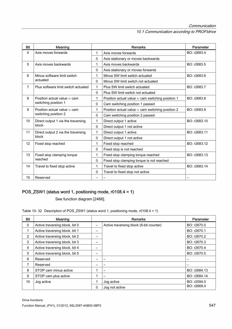
Communication 10.1 Communication according to PROFIdrive
Drive functions Function Manual, (FH1), 01/2012, 6SL3097-4AB00-0BP2 547
Bit Meaning Remarks Parameter 1 Axis moves forwards 4 Axis moves forwards 0 Axis stationary or moves backwards
BO: r2683.4
1 Axis moves backwards 5 Axis moves backwards 0 Axis stationary or moves forwards
BO: r2683.5
1 Minus SW limit switch actuated 6 Minus software limit switch actuated 0 Minus SW limit switch not actuated
BO: r2683.6
1 Plus SW limit switch actuated 7 Plus software limit switch actuated 0 Plus SW limit switch not actuated
BO: r2683.7
1 Position actual value ⇐ cam switching position 1 8 Position actual value ⇐ cam switching position 1 0 Cam switching position 1 passed
BO: r2683.8
1 Position actual value ⇐ cam switching position 2 9 Position actual value ⇐ cam switching position 2 0 Cam switching position 2 passed
BO: r2683.9
1 Direct output 1 active 10 Direct output 1 via the traversing block 0 Direct output 1 not active
BO: r2683.10
1 Direct output 1 active 11 Direct output 2 via the traversing block 0 Direct output 1 not active
BO: r2683.11
1 Fixed stop reached 12 Fixed stop reached 0 Fixed stop is not reached
BO: r2683.12
1 Fixed stop clamping torque reached 13 Fixed stop clamping torque reached 0 Fixed stop clamping torque is not reached
BO: r2683.13
1 Travel to fixed stop active 14 Travel to fixed stop active 0 Travel to fixed stop not active
BO: r2683.14
15 Reserved – – –
POS_ZSW1 (status word 1, positioning mode, r0108.4 = 1) See function diagram [2466].
Table 10- 32 Description of POS_ZSW1 (status word 1, positioning mode, r0108.4 = 1)
Bit Meaning Remarks Parameter 0 Active traversing block, bit 0 – BO: r2670.0 1 Active traversing block, bit 1 – BO: r2670.1 2 Active traversing block, bit 2 – BO: r2670.2 3 Active traversing block, bit 3 – BO: r2670.3 4 Active traversing block, bit 4 – BO: r2670.4 5 Active traversing block, bit 5 –
Active traversing block (6-bit counter)
BO: r2670.5 6 Reserved – – – 7 Reserved – – – 8 STOP cam minus active 1 – BO: r2684.13 9 STOP cam plus active 1 – BO: r2684.14
1 Jog active 10 Jog active 0 Jog not active
BO: r2094.0 BO: r2669.0
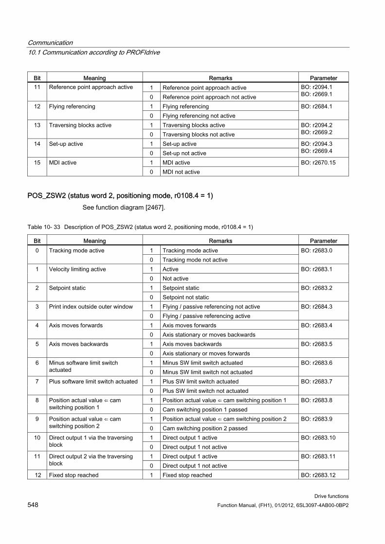
Communication 10.1 Communication according to PROFIdrive
Drive functions 548 Function Manual, (FH1), 01/2012, 6SL3097-4AB00-0BP2
Bit Meaning Remarks Parameter 1 Reference point approach active 11 Reference point approach active 0 Reference point approach not active
BO: r2094.1 BO: r2669.1
1 Flying referencing 12 Flying referencing 0 Flying referencing not active
BO: r2684.1
1 Traversing blocks active 13 Traversing blocks active 0 Traversing blocks not active
BO: r2094.2 BO: r2669.2
1 Set-up active 14 Set-up active 0 Set-up not active
BO: r2094.3 BO: r2669.4
1 MDI active 15 MDI active 0 MDI not active
BO: r2670.15
POS_ZSW2 (status word 2, positioning mode, r0108.4 = 1) See function diagram [2467].
Table 10- 33 Description of POS_ZSW2 (status word 2, positioning mode, r0108.4 = 1)
Bit Meaning Remarks Parameter 1 Tracking mode active 0 Tracking mode active 0 Tracking mode not active
BO: r2683.0
1 Active 1 Velocity limiting active 0 Not active
BO: r2683.1
1 Setpoint static 2 Setpoint static 0 Setpoint not static
BO: r2683.2
1 Flying / passive referencing not active 3 Print index outside outer window 0 Flying / passive referencing active
BO: r2684.3
1 Axis moves forwards 4 Axis moves forwards 0 Axis stationary or moves backwards
BO: r2683.4
1 Axis moves backwards 5 Axis moves backwards 0 Axis stationary or moves forwards
BO: r2683.5
1 Minus SW limit switch actuated 6 Minus software limit switch actuated 0 Minus SW limit switch not actuated
BO: r2683.6
1 Plus SW limit switch actuated 7 Plus software limit switch actuated 0 Plus SW limit switch not actuated
BO: r2683.7
1 Position actual value ⇐ cam switching position 1 8 Position actual value ⇐ cam switching position 1 0 Cam switching position 1 passed
BO: r2683.8
1 Position actual value ⇐ cam switching position 2 9 Position actual value ⇐ cam switching position 2 0 Cam switching position 2 passed
BO: r2683.9
1 Direct output 1 active 10 Direct output 1 via the traversing block 0 Direct output 1 not active
BO: r2683.10
1 Direct output 1 active 11 Direct output 2 via the traversing block 0 Direct output 1 not active
BO: r2683.11
12 Fixed stop reached 1 Fixed stop reached BO: r2683.12
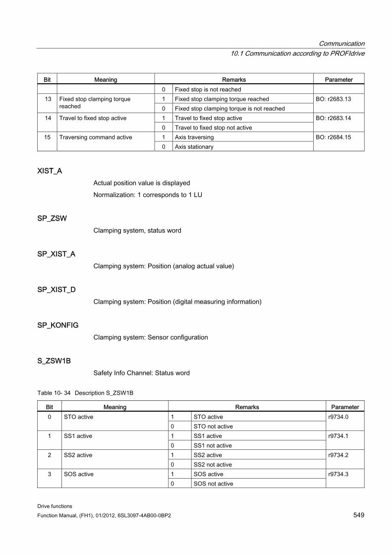
Communication 10.1 Communication according to PROFIdrive
Drive functions Function Manual, (FH1), 01/2012, 6SL3097-4AB00-0BP2 549
Bit Meaning Remarks Parameter 0 Fixed stop is not reached 1 Fixed stop clamping torque reached 13 Fixed stop clamping torque
reached 0 Fixed stop clamping torque is not reached BO: r2683.13
1 Travel to fixed stop active 14 Travel to fixed stop active 0 Travel to fixed stop not active
BO: r2683.14
1 Axis traversing 15 Traversing command active 0 Axis stationary
BO: r2684.15
XIST_A Actual position value is displayed
Normalization: 1 corresponds to 1 LU
SP_ZSW Clamping system, status word
SP_XIST_A Clamping system: Position (analog actual value)
SP_XIST_D Clamping system: Position (digital measuring information)
SP_KONFIG Clamping system: Sensor configuration
S_ZSW1B Safety Info Channel: Status word
Table 10- 34 Description S_ZSW1B
Bit Meaning Remarks Parameter 1 STO active 0 STO active 0 STO not active
r9734.0
1 SS1 active 1 SS1 active 0 SS1 not active
r9734.1
1 SS2 active 2 SS2 active 0 SS2 not active
r9734.2
1 SOS active 3 SOS active 0 SOS not active
r9734.3
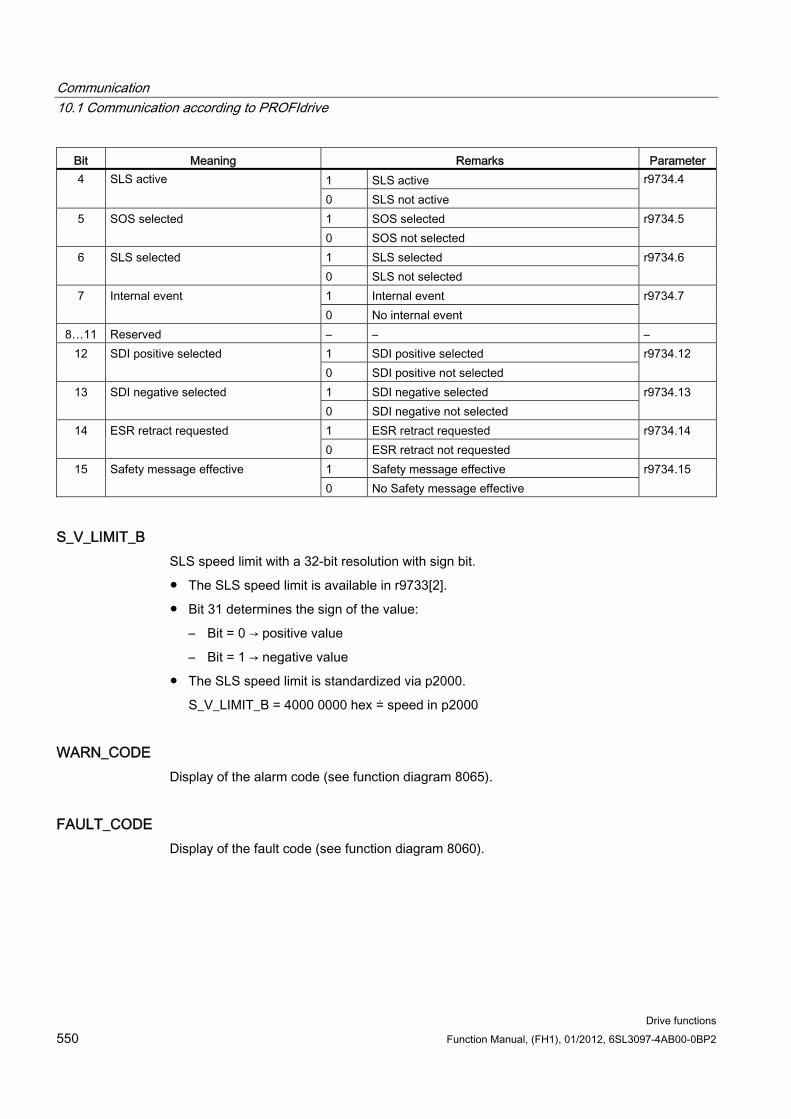
Communication 10.1 Communication according to PROFIdrive
Drive functions 550 Function Manual, (FH1), 01/2012, 6SL3097-4AB00-0BP2
Bit Meaning Remarks Parameter 1 SLS active 4 SLS active 0 SLS not active
r9734.4
1 SOS selected 5 SOS selected 0 SOS not selected
r9734.5
1 SLS selected 6 SLS selected 0 SLS not selected
r9734.6
1 Internal event 7 Internal event 0 No internal event
r9734.7
8…11 Reserved – – – 1 SDI positive selected 12 SDI positive selected 0 SDI positive not selected
r9734.12
1 SDI negative selected 13 SDI negative selected 0 SDI negative not selected
r9734.13
1 ESR retract requested 14 ESR retract requested 0 ESR retract not requested
r9734.14
1 Safety message effective 15 Safety message effective 0 No Safety message effective
r9734.15
S_V_LIMIT_B SLS speed limit with a 32-bit resolution with sign bit.
The SLS speed limit is available in r9733[2].
Bit 31 determines the sign of the value:
– Bit = 0 → positive value
– Bit = 1 → negative value
The SLS speed limit is standardized via p2000.
S_V_LIMIT_B = 4000 0000 hex ≐ speed in p2000
WARN_CODE Display of the alarm code (see function diagram 8065).
FAULT_CODE Display of the fault code (see function diagram 8060).
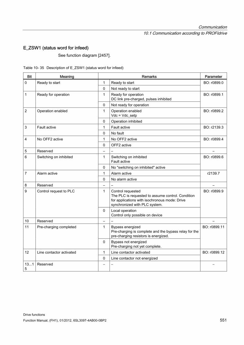
Communication 10.1 Communication according to PROFIdrive
Drive functions Function Manual, (FH1), 01/2012, 6SL3097-4AB00-0BP2 551
E_ZSW1 (status word for infeed) See function diagram [2457].
Table 10- 35 Description of E_ZSW1 (status word for infeed)
Bit Meaning Remarks Parameter 1 Ready to start 0 Ready to start 0 Not ready to start
BO: r0899.0
1 Ready for operation DC link pre-charged, pulses inhibited
1 Ready for operation
0 Not ready for operation
BO: r0899.1
1 Operation enabled Vdc = Vdc_setp
2 Operation enabled
0 Operation inhibited
BO: r0899.2
1 Fault active 3 Fault active 0 No fault
BO: r2139.3
1 No OFF2 active 4 No OFF2 active 0 OFF2 active
BO: r0899.4
5 Reserved – – – 1 Switching on inhibited
Fault active 6 Switching on inhibited
0 No "switching on inhibited" active
BO: r0899.6
1 Alarm active 7 Alarm active 0 No alarm active
r2139.7
8 Reserved – – – 1 Control requested
The PLC is requested to assume control. Condition for applications with isochronous mode: Drive synchronized with PLC system.
9 Control request to PLC
0 Local operation Control only possible on device
BO: r0899.9
10 Reserved – – – 1 Bypass energized
Pre-charging is complete and the bypass relay for the pre-charging resistors is energized.
11 Pre-charging completed
0 Bypass not energized Pre-charging not yet complete.
BO: r0899.11
1 Line contactor activated 12 Line contactor activated 0 Line contactor not energized
BO: r0899.12
13...15
Reserved – – –
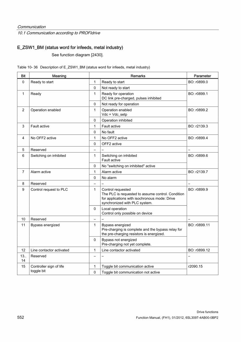
Communication 10.1 Communication according to PROFIdrive
Drive functions 552 Function Manual, (FH1), 01/2012, 6SL3097-4AB00-0BP2
E_ZSW1_BM (status word for infeeds, metal industry) See function diagram [2430].
Table 10- 36 Description of E_ZSW1_BM (status word for infeeds, metal industry)
Bit Meaning Remarks Parameter 1 Ready to start 0 Ready to start 0 Not ready to start
BO: r0899.0
1 Ready for operation DC link pre-charged, pulses inhibited
1 Ready
0 Not ready for operation
BO: r0899.1
1 Operation enabled Vdc = Vdc_setp
2 Operation enabled
0 Operation inhibited
BO: r0899.2
1 Fault active 3 Fault active 0 No fault
BO: r2139.3
1 No OFF2 active 4 No OFF2 active 0 OFF2 active
BO: r0899.4
5 Reserved – – – 1 Switching on inhibited
Fault active 6 Switching on inhibited
0 No "switching on inhibited" active
BO: r0899.6
1 Alarm active 7 Alarm active 0 No alarm
BO: r2139.7
8 Reserved – – – 1 Control requested
The PLC is requested to assume control. Condition for applications with isochronous mode: Drive synchronized with PLC system.
9 Control request to PLC
0 Local operation Control only possible on device
BO: r0899.9
10 Reserved – – – 1 Bypass energized
Pre-charging is complete and the bypass relay for the pre-charging resistors is energized.
11 Bypass energized
0 Bypass not energized Pre-charging not yet complete.
BO: r0899.11
12 Line contactor activated 1 Line contactor activated BO: r0899.12 13.. 14
Reserved – – –
1 Toggle bit communication active 15 Controller sign of life toggle bit 0 Toggle bit communication not active
r2090.15
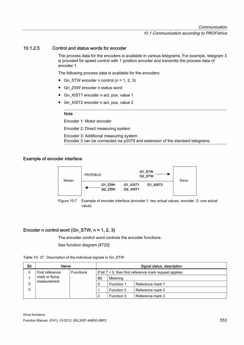
Communication 10.1 Communication according to PROFIdrive
Drive functions Function Manual, (FH1), 01/2012, 6SL3097-4AB00-0BP2 553
10.1.2.5 Control and status words for encoder The process data for the encoders is available in various telegrams. For example, telegram 3 is provided for speed control with 1 position encoder and transmits the process data of encoder 1.
The following process data is available for the encoders:
Gn_STW encoder n control (n = 1, 2, 3)
Gn_ZSW encoder n status word
Gn_XIST1 encoder n act. pos. value 1
Gn_XIST2 encoder n act. pos. value 2
Note
Encoder 1: Motor encoder
Encoder 2: Direct measuring system
Encoder 3: Additional measuring system Encoder 3 can be connected via p2079 and extension of the standard telegrams.
Example of encoder interface
Figure 10-7 Example of encoder interface (encoder-1: two actual values, encoder -2: one actual
value)
Encoder n control word (Gn_STW, n = 1, 2, 3) The encoder control word controls the encoder functions.
See function diagram [4720]
Table 10- 37 Description of the individual signals in Gn_STW
Bit Name Signal status, description If bit 7 = 0, then find reference mark request applies: Bit Meaning 0 Function 1 Reference mark 1 1 Function 2 Reference mark 2
0 1 2 3
Find reference mark or flying measurement
Functions
2 Function 3 Reference mark 3
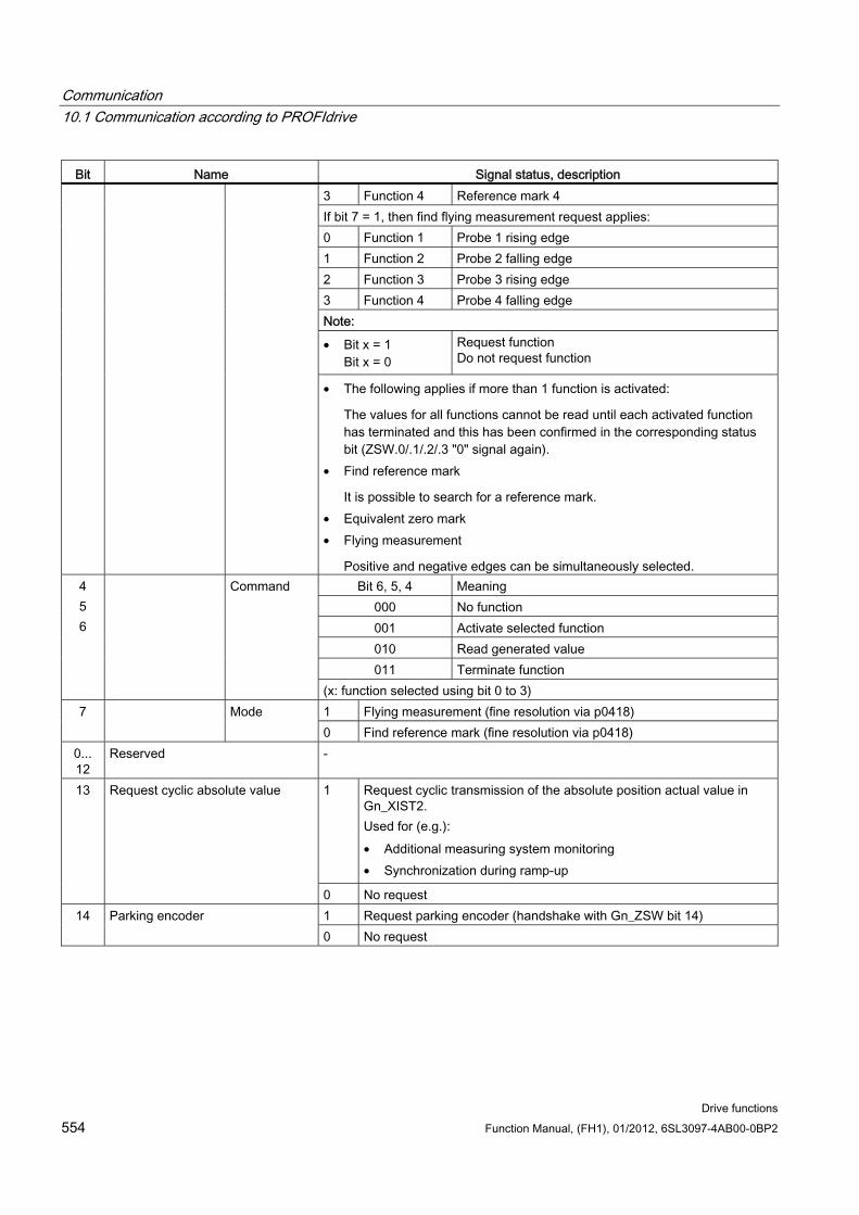
Communication 10.1 Communication according to PROFIdrive
Drive functions 554 Function Manual, (FH1), 01/2012, 6SL3097-4AB00-0BP2
Bit Name Signal status, description 3 Function 4 Reference mark 4 If bit 7 = 1, then find flying measurement request applies: 0 Function 1 Probe 1 rising edge 1 Function 2 Probe 2 falling edge 2 Function 3 Probe 3 rising edge 3 Function 4 Probe 4 falling edge Note:
• Bit x = 1 Bit x = 0
Request function Do not request function
• The following applies if more than 1 function is activated:
The values for all functions cannot be read until each activated function has terminated and this has been confirmed in the corresponding status bit (ZSW.0/.1/.2/.3 "0" signal again).
• Find reference mark
It is possible to search for a reference mark. • Equivalent zero mark • Flying measurement
Positive and negative edges can be simultaneously selected. Bit 6, 5, 4 Meaning
000 No function 001 Activate selected function 010 Read generated value 011 Terminate function
4 5 6
Command
(x: function selected using bit 0 to 3) 1 Flying measurement (fine resolution via p0418) 7 Mode 0 Find reference mark (fine resolution via p0418)
0... 12
Reserved -
1 Request cyclic transmission of the absolute position actual value in Gn_XIST2. Used for (e.g.): • Additional measuring system monitoring • Synchronization during ramp-up
13 Request cyclic absolute value
0 No request 1 Request parking encoder (handshake with Gn_ZSW bit 14) 14 Parking encoder 0 No request
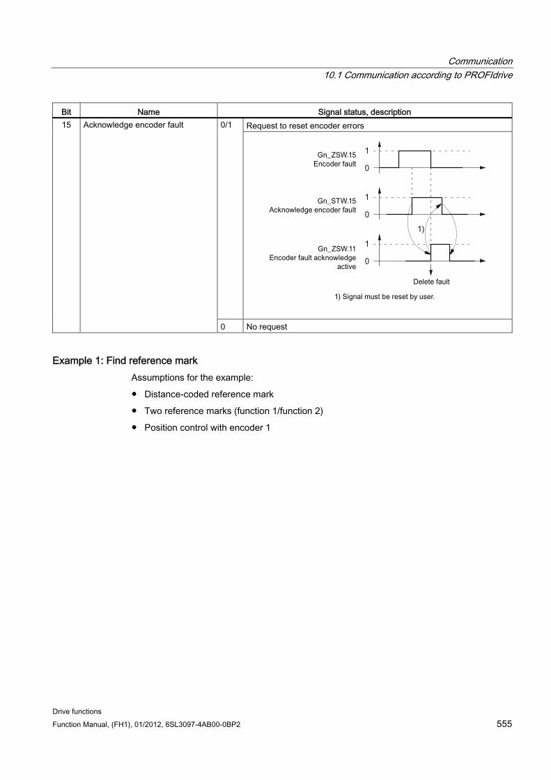
Communication 10.1 Communication according to PROFIdrive
Drive functions Function Manual, (FH1), 01/2012, 6SL3097-4AB00-0BP2 555
Bit Name Signal status, description Request to reset encoder errors 0/1 15 Acknowledge encoder fault
0 No request
Example 1: Find reference mark Assumptions for the example:
Distance-coded reference mark
Two reference marks (function 1/function 2)
Position control with encoder 1
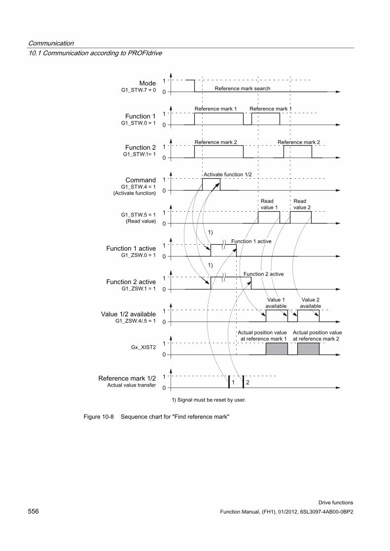
Communication 10.1 Communication according to PROFIdrive
Drive functions 556 Function Manual, (FH1), 01/2012, 6SL3097-4AB00-0BP2
Figure 10-8 Sequence chart for "Find reference mark"
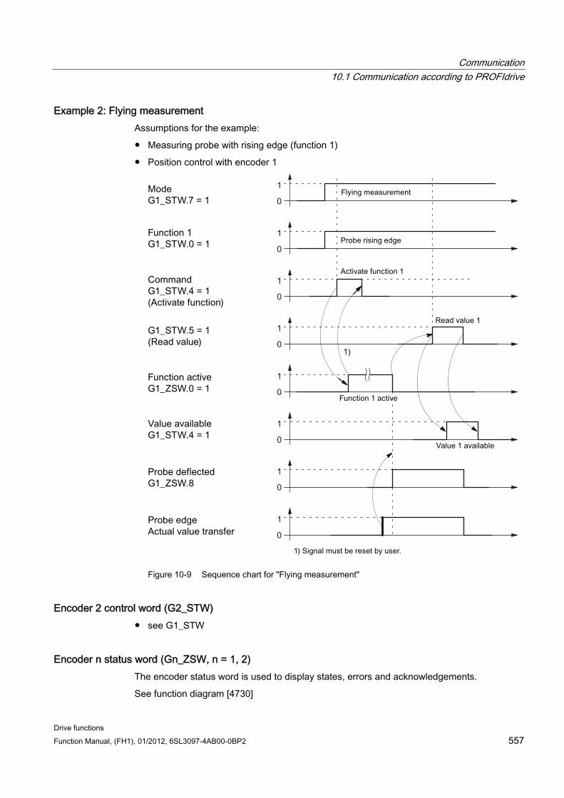
Communication 10.1 Communication according to PROFIdrive
Drive functions Function Manual, (FH1), 01/2012, 6SL3097-4AB00-0BP2 557
Example 2: Flying measurement Assumptions for the example:
Measuring probe with rising edge (function 1)
Position control with encoder 1
Figure 10-9 Sequence chart for "Flying measurement"
Encoder 2 control word (G2_STW) see G1_STW
Encoder n status word (Gn_ZSW, n = 1, 2) The encoder status word is used to display states, errors and acknowledgements.
See function diagram [4730]
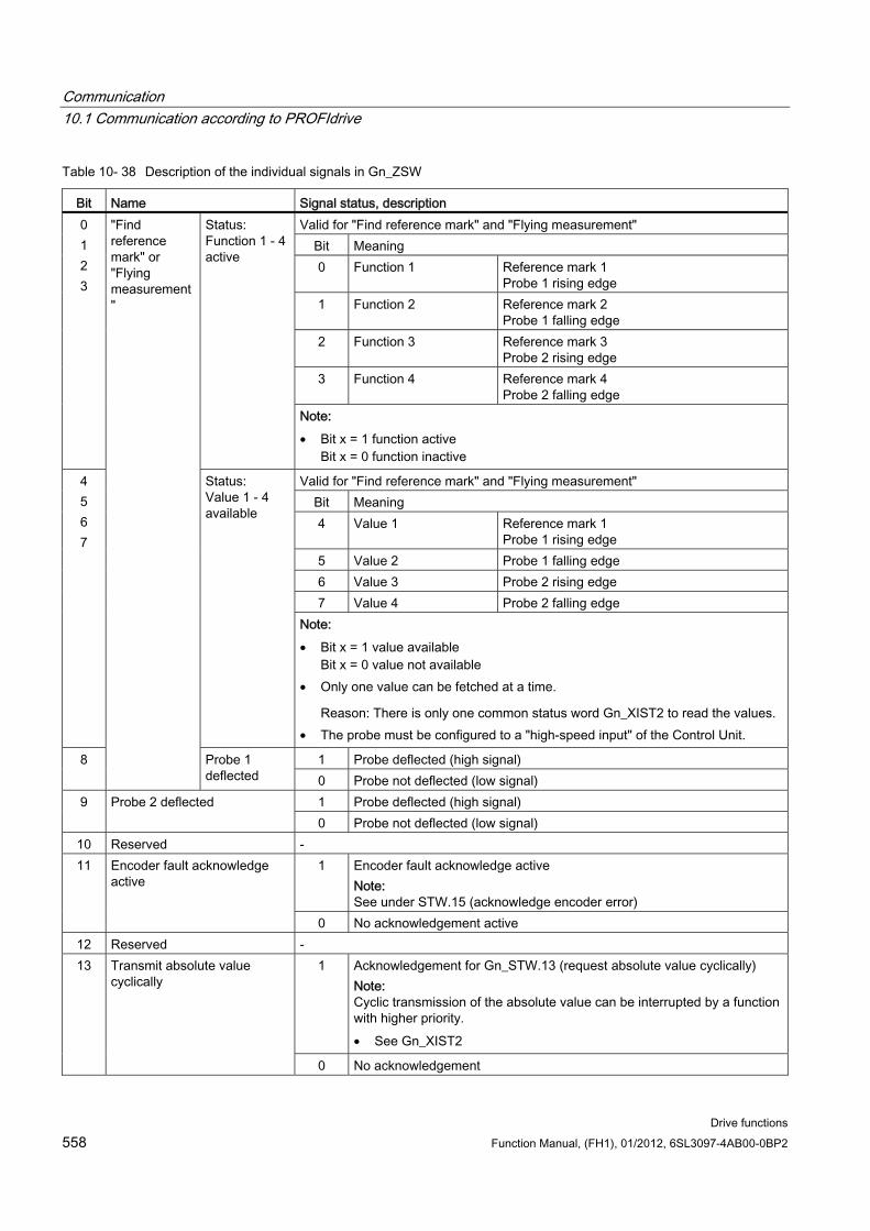
Communication 10.1 Communication according to PROFIdrive
Drive functions 558 Function Manual, (FH1), 01/2012, 6SL3097-4AB00-0BP2
Table 10- 38 Description of the individual signals in Gn_ZSW
Bit Name Signal status, description Valid for "Find reference mark" and "Flying measurement"
Bit Meaning 0 Function 1 Reference mark 1
Probe 1 rising edge 1 Function 2 Reference mark 2
Probe 1 falling edge 2 Function 3 Reference mark 3
Probe 2 rising edge 3 Function 4 Reference mark 4
Probe 2 falling edge
0 1 2 3
Status: Function 1 - 4 active
Note: • Bit x = 1 function active
Bit x = 0 function inactive
Valid for "Find reference mark" and "Flying measurement" Bit Meaning 4 Value 1 Reference mark 1
Probe 1 rising edge 5 Value 2 Probe 1 falling edge 6 Value 3 Probe 2 rising edge 7 Value 4 Probe 2 falling edge
4 5 6 7
Status: Value 1 - 4 available
Note: • Bit x = 1 value available
Bit x = 0 value not available • Only one value can be fetched at a time.
Reason: There is only one common status word Gn_XIST2 to read the values. • The probe must be configured to a "high-speed input" of the Control Unit.
1 Probe deflected (high signal) 8
"Find reference mark" or "Flying measurement"
Probe 1 deflected 0 Probe not deflected (low signal)
1 Probe deflected (high signal) 9 Probe 2 deflected 0 Probe not deflected (low signal)
10 Reserved - 1 Encoder fault acknowledge active
Note: See under STW.15 (acknowledge encoder error)
11 Encoder fault acknowledge active
0 No acknowledgement active 12 Reserved -
1 Acknowledgement for Gn_STW.13 (request absolute value cyclically) Note: Cyclic transmission of the absolute value can be interrupted by a function with higher priority. • See Gn_XIST2
13 Transmit absolute value cyclically
0 No acknowledgement
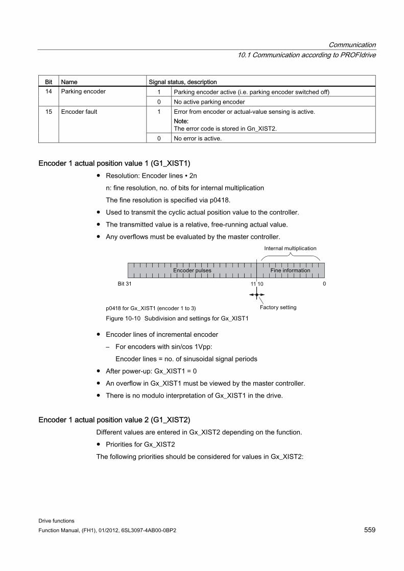
Communication 10.1 Communication according to PROFIdrive
Drive functions Function Manual, (FH1), 01/2012, 6SL3097-4AB00-0BP2 559
Bit Name Signal status, description 1 Parking encoder active (i.e. parking encoder switched off) 14 Parking encoder 0 No active parking encoder 1 Error from encoder or actual-value sensing is active.
Note: The error code is stored in Gn_XIST2.
15 Encoder fault
0 No error is active.
Encoder 1 actual position value 1 (G1_XIST1) Resolution: Encoder lines ∙ 2n
n: fine resolution, no. of bits for internal multiplication
The fine resolution is specified via p0418.
Used to transmit the cyclic actual position value to the controller.
The transmitted value is a relative, free-running actual value.
Any overflows must be evaluated by the master controller.
Figure 10-10 Subdivision and settings for Gx_XIST1
Encoder lines of incremental encoder
– For encoders with sin/cos 1Vpp:
Encoder lines = no. of sinusoidal signal periods
After power-up: Gx_XIST1 = 0
An overflow in Gx_XIST1 must be viewed by the master controller.
There is no modulo interpretation of Gx_XIST1 in the drive.
Encoder 1 actual position value 2 (G1_XIST2) Different values are entered in Gx_XIST2 depending on the function.
Priorities for Gx_XIST2
The following priorities should be considered for values in Gx_XIST2:
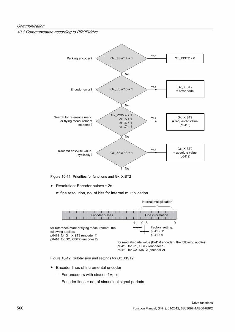
Communication 10.1 Communication according to PROFIdrive
Drive functions 560 Function Manual, (FH1), 01/2012, 6SL3097-4AB00-0BP2
Figure 10-11 Priorities for functions and Gx_XIST2
Resolution: Encoder pulses ∙ 2n
n: fine resolution, no. of bits for internal multiplication
Figure 10-12 Subdivision and settings for Gx_XIST2
Encoder lines of incremental encoder
– For encoders with sin/cos 1Vpp:
Encoder lines = no. of sinusoidal signal periods
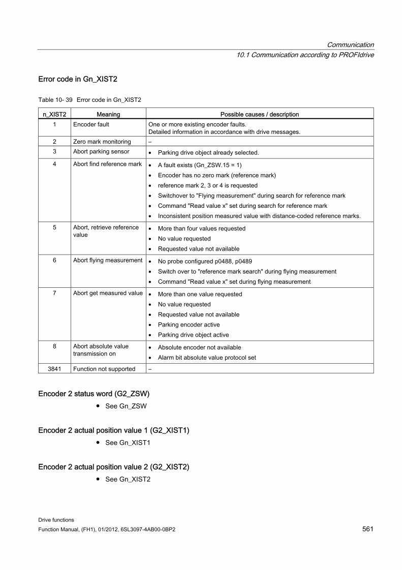
Communication 10.1 Communication according to PROFIdrive
Drive functions Function Manual, (FH1), 01/2012, 6SL3097-4AB00-0BP2 561
Error code in Gn_XIST2
Table 10- 39 Error code in Gn_XIST2
n_XIST2 Meaning Possible causes / description 1 Encoder fault One or more existing encoder faults.
Detailed information in accordance with drive messages. 2 Zero mark monitoring – 3 Abort parking sensor • Parking drive object already selected.
4 Abort find reference mark • A fault exists (Gn_ZSW.15 = 1) • Encoder has no zero mark (reference mark) • reference mark 2, 3 or 4 is requested • Switchover to "Flying measurement" during search for reference mark • Command "Read value x" set during search for reference mark • Inconsistent position measured value with distance-coded reference marks.
5 Abort, retrieve reference value
• More than four values requested • No value requested • Requested value not available
6 Abort flying measurement • No probe configured p0488, p0489 • Switch over to "reference mark search" during flying measurement • Command "Read value x" set during flying measurement
7 Abort get measured value • More than one value requested • No value requested • Requested value not available • Parking encoder active • Parking drive object active
8 Abort absolute value transmission on
• Absolute encoder not available • Alarm bit absolute value protocol set
3841 Function not supported –
Encoder 2 status word (G2_ZSW) See Gn_ZSW
Encoder 2 actual position value 1 (G2_XIST1) See Gn_XIST1
Encoder 2 actual position value 2 (G2_XIST2) See Gn_XIST2
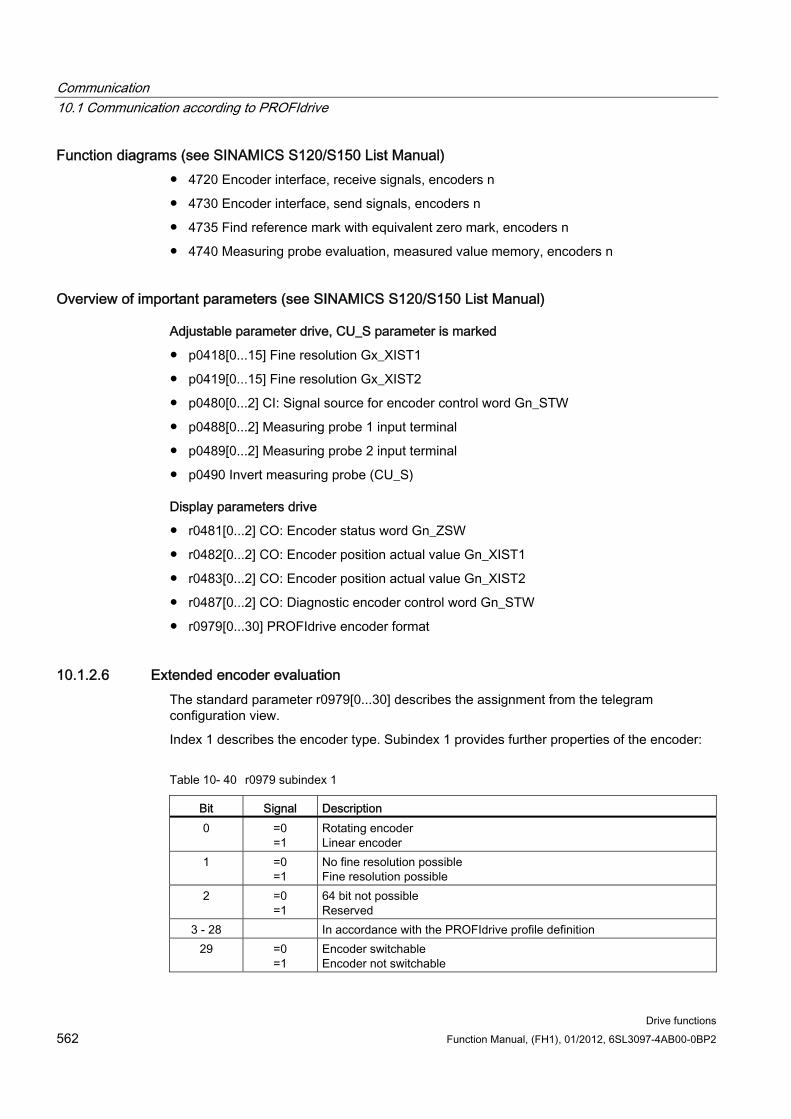
Communication 10.1 Communication according to PROFIdrive
Drive functions 562 Function Manual, (FH1), 01/2012, 6SL3097-4AB00-0BP2
Function diagrams (see SINAMICS S120/S150 List Manual) 4720 Encoder interface, receive signals, encoders n
4730 Encoder interface, send signals, encoders n
4735 Find reference mark with equivalent zero mark, encoders n
4740 Measuring probe evaluation, measured value memory, encoders n
Overview of important parameters (see SINAMICS S120/S150 List Manual)
Adjustable parameter drive, CU_S parameter is marked
p0418[0...15] Fine resolution Gx_XIST1
p0419[0...15] Fine resolution Gx_XIST2
p0480[0...2] CI: Signal source for encoder control word Gn_STW
p0488[0...2] Measuring probe 1 input terminal
p0489[0...2] Measuring probe 2 input terminal
p0490 Invert measuring probe (CU_S)
Display parameters drive
r0481[0...2] CO: Encoder status word Gn_ZSW
r0482[0...2] CO: Encoder position actual value Gn_XIST1
r0483[0...2] CO: Encoder position actual value Gn_XIST2
r0487[0...2] CO: Diagnostic encoder control word Gn_STW
r0979[0...30] PROFIdrive encoder format
10.1.2.6 Extended encoder evaluation The standard parameter r0979[0...30] describes the assignment from the telegram configuration view.
Index 1 describes the encoder type. Subindex 1 provides further properties of the encoder:
Table 10- 40 r0979 subindex 1
Bit Signal Description 0 =0
=1 Rotating encoder Linear encoder
1 =0 =1
No fine resolution possible Fine resolution possible
2 =0 =1
64 bit not possible Reserved
3 - 28 In accordance with the PROFIdrive profile definition 29 =0
=1 Encoder switchable Encoder not switchable
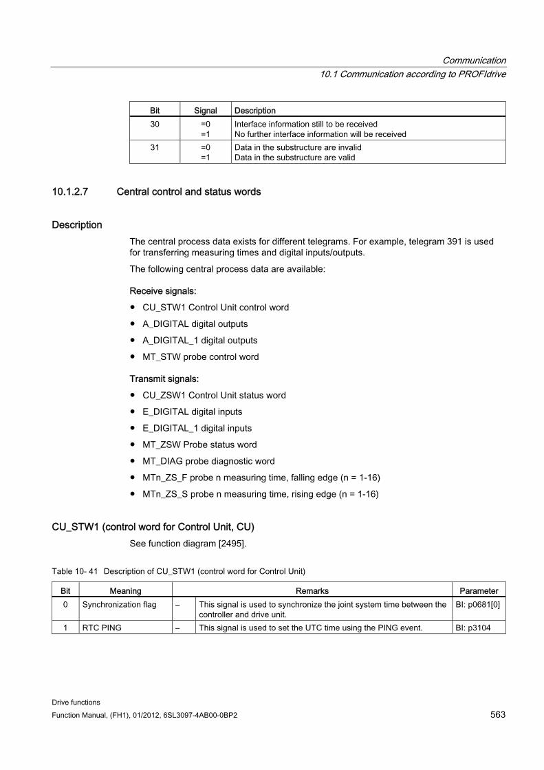
Communication 10.1 Communication according to PROFIdrive
Drive functions Function Manual, (FH1), 01/2012, 6SL3097-4AB00-0BP2 563
Bit Signal Description 30 =0
=1 Interface information still to be received No further interface information will be received
31 =0 =1
Data in the substructure are invalid Data in the substructure are valid
10.1.2.7 Central control and status words
Description The central process data exists for different telegrams. For example, telegram 391 is used for transferring measuring times and digital inputs/outputs.
The following central process data are available:
Receive signals:
CU_STW1 Control Unit control word
A_DIGITAL digital outputs
A_DIGITAL_1 digital outputs
MT_STW probe control word
Transmit signals:
CU_ZSW1 Control Unit status word
E_DIGITAL digital inputs
E_DIGITAL_1 digital inputs
MT_ZSW Probe status word
MT_DIAG probe diagnostic word
MTn_ZS_F probe n measuring time, falling edge (n = 1-16)
MTn_ZS_S probe n measuring time, rising edge (n = 1-16)
CU_STW1 (control word for Control Unit, CU) See function diagram [2495].
Table 10- 41 Description of CU_STW1 (control word for Control Unit)
Bit Meaning Remarks Parameter 0 Synchronization flag – This signal is used to synchronize the joint system time between the
controller and drive unit. BI: p0681[0]
1 RTC PING – This signal is used to set the UTC time using the PING event. BI: p3104
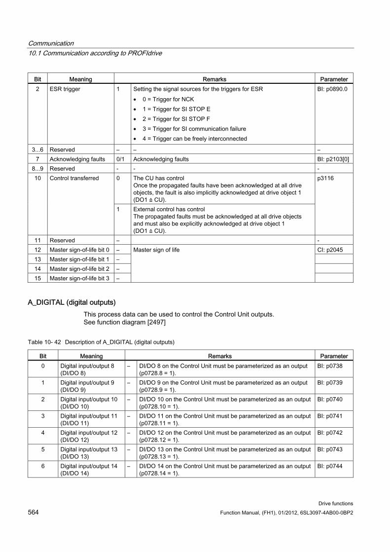
Communication 10.1 Communication according to PROFIdrive
Drive functions 564 Function Manual, (FH1), 01/2012, 6SL3097-4AB00-0BP2
Bit Meaning Remarks Parameter 2 ESR trigger 1 Setting the signal sources for the triggers for ESR
• 0 = Trigger for NCK • 1 = Trigger for SI STOP E • 2 = Trigger for SI STOP F • 3 = Trigger for SI communication failure • 4 = Trigger can be freely interconnected
BI: p0890.0
3...6 Reserved – – – 7 Acknowledging faults 0/1 Acknowledging faults BI: p2103[0]
8...9 Reserved - - - 0 The CU has control
Once the propagated faults have been acknowledged at all drive objects, the fault is also implicitly acknowledged at drive object 1 (DO1 ≙ CU).
10 Control transferred
1 External control has control The propagated faults must be acknowledged at all drive objects and must also be explicitly acknowledged at drive object 1 (DO1 ≙ CU).
p3116
11 Reserved – - 12 Master sign-of-life bit 0 – CI: p2045 13 Master sign-of-life bit 1 – 14 Master sign-of-life bit 2 – 15 Master sign-of-life bit 3 –
Master sign of life
A_DIGITAL (digital outputs) This process data can be used to control the Control Unit outputs. See function diagram [2497]
Table 10- 42 Description of A_DIGITAL (digital outputs)
Bit Meaning Remarks Parameter 0 Digital input/output 8
(DI/DO 8) – DI/DO 8 on the Control Unit must be parameterized as an output
(p0728.8 = 1). BI: p0738
1 Digital input/output 9 (DI/DO 9)
– DI/DO 9 on the Control Unit must be parameterized as an output (p0728.9 = 1).
BI: p0739
2 Digital input/output 10 (DI/DO 10)
– DI/DO 10 on the Control Unit must be parameterized as an output (p0728.10 = 1).
BI: p0740
3 Digital input/output 11 (DI/DO 11)
– DI/DO 11 on the Control Unit must be parameterized as an output (p0728.11 = 1).
BI: p0741
4 Digital input/output 12 (DI/DO 12)
– DI/DO 12 on the Control Unit must be parameterized as an output (p0728.12 = 1).
BI: p0742
5 Digital input/output 13 (DI/DO 13)
– DI/DO 13 on the Control Unit must be parameterized as an output (p0728.13 = 1).
BI: p0743
6 Digital input/output 14 (DI/DO 14)
– DI/DO 14 on the Control Unit must be parameterized as an output (p0728.14 = 1).
BI: p0744
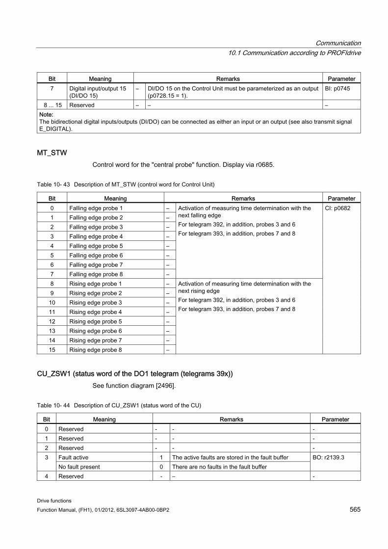
Communication 10.1 Communication according to PROFIdrive
Drive functions Function Manual, (FH1), 01/2012, 6SL3097-4AB00-0BP2 565
Bit Meaning Remarks Parameter 7 Digital input/output 15
(DI/DO 15) – DI/DO 15 on the Control Unit must be parameterized as an output
(p0728.15 = 1). BI: p0745
8 ... 15 Reserved – – – Note: The bidirectional digital inputs/outputs (DI/DO) can be connected as either an input or an output (see also transmit signal E_DIGITAL).
MT_STW Control word for the "central probe" function. Display via r0685.
Table 10- 43 Description of MT_STW (control word for Control Unit)
Bit Meaning Remarks Parameter 0 Falling edge probe 1 – 1 Falling edge probe 2 – 2 Falling edge probe 3 – 3 Falling edge probe 4 – 4 Falling edge probe 5 – 5 Falling edge probe 6 – 6 Falling edge probe 7 – 7 Falling edge probe 8 –
Activation of measuring time determination with the next falling edge For telegram 392, in addition, probes 3 and 6 For telegram 393, in addition, probes 7 and 8
8 Rising edge probe 1 – 9 Rising edge probe 2 –
10 Rising edge probe 3 – 11 Rising edge probe 4 – 12 Rising edge probe 5 – 13 Rising edge probe 6 – 14 Rising edge probe 7 – 15 Rising edge probe 8 –
Activation of measuring time determination with the next rising edge For telegram 392, in addition, probes 3 and 6 For telegram 393, in addition, probes 7 and 8
CI: p0682
CU_ZSW1 (status word of the DO1 telegram (telegrams 39x)) See function diagram [2496].
Table 10- 44 Description of CU_ZSW1 (status word of the CU)
Bit Meaning Remarks Parameter 0 Reserved - - - 1 Reserved - - - 2 Reserved - - -
Fault active 1 The active faults are stored in the fault buffer 3 No fault present 0 There are no faults in the fault buffer
BO: r2139.3
4 Reserved - – -
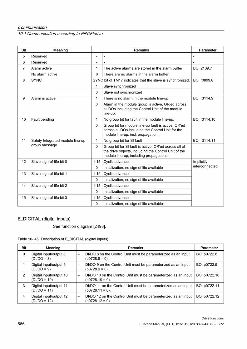
Communication 10.1 Communication according to PROFIdrive
Drive functions 566 Function Manual, (FH1), 01/2012, 6SL3097-4AB00-0BP2
Bit Meaning Remarks Parameter 5 Reserved - - - 6 Reserved - - -
Alarm active 1 The active alarms are stored in the alarm buffer 7 No alarm active 0 There are no alarms in the alarm buffer
BO: 2139.7
SYNC bit of TM17 indicates that the slave is synchronized. 1 Slave synchronized
8 SYNC
0 Slave not synchronized
BO: r0899.8
1 There is no alarm in the module line-up. 9 Alarm is active 0 Alarm in the module group is active, OR'ed across
all DOs including the Control Unit of the module line-up.
BO: r3114.9
1 No group bit for fault in the module line-up. 10 Fault pending 0 Group bit for module line-up fault is active, OR'ed
across all DOs including the Control Unit for the module line-up, incl. propagation.
BO: r3114.10
1 No group bit for SI fault BO: r3114.11 11 Safety Integrated module line-up group message 0 Group bit for SI fault is active, OR'ed across all of
the drive objects, including the Control Unit of the module line-up, including propagations.
1-15 Cyclic advance 12 Slave sign-of-life bit 0 0 Initialization, no sign of life available
1-15 Cyclic advance 13 Slave sign-of-life bit 1 0 Initialization, no sign of life available
1-15 Cyclic advance 14 Slave sign-of-life bit 2 0 Initialization, no sign of life available
1-15 Cyclic advance 15 Slave sign-of-life bit 3 0 Initialization, no sign of life available
Implicitly interconnected
E_DIGITAL (digital inputs) See function diagram [2498].
Table 10- 45 Description of E_DIGITAL (digital inputs)
Bit Meaning Remarks Parameter 0 Digital input/output 8
(DI/DO = 8) – DI/DO 8 on the Control Unit must be parameterized as an input
(p0728.8 = 0). BO: p0722.8
1 Digital input/output 9 (DI/DO = 9)
– DI/DO 9 on the Control Unit must be parameterized as an input (p0728.9 = 0).
BO: p0722.9
2 Digital input/output 10 (DI/DO = 10)
– DI/DO 10 on the Control Unit must be parameterized as an input (p0728.10 = 0).
BO: p0722.10
3 Digital input/output 11 (DI/DO = 11)
– DI/DO 11 on the Control Unit must be parameterized as an input (p0728.11 = 0).
BO: p0722.11
4 Digital input/output 12 (DI/DO = 12)
– DI/DO 12 on the Control Unit must be parameterized as an input (p0728.12 = 0).
BO: p0722.12
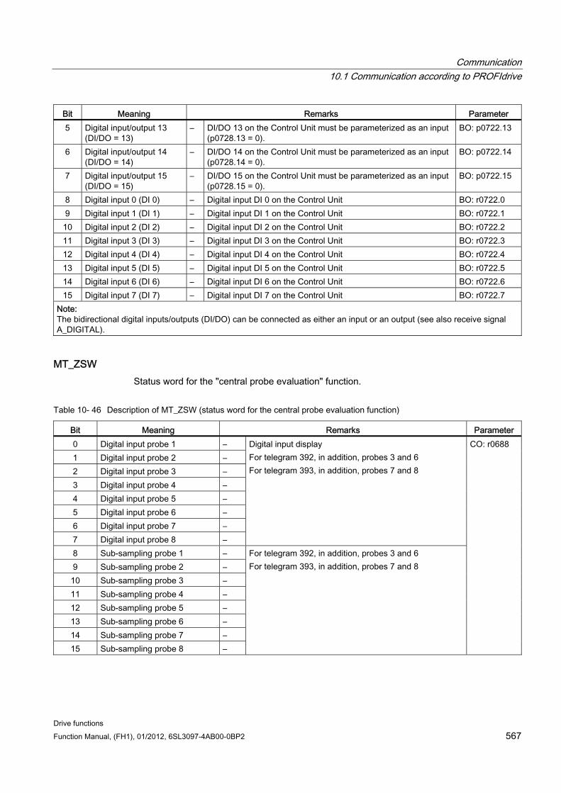
Communication 10.1 Communication according to PROFIdrive
Drive functions Function Manual, (FH1), 01/2012, 6SL3097-4AB00-0BP2 567
Bit Meaning Remarks Parameter 5 Digital input/output 13
(DI/DO = 13) – DI/DO 13 on the Control Unit must be parameterized as an input
(p0728.13 = 0). BO: p0722.13
6 Digital input/output 14 (DI/DO = 14)
– DI/DO 14 on the Control Unit must be parameterized as an input (p0728.14 = 0).
BO: p0722.14
7 Digital input/output 15 (DI/DO = 15)
– DI/DO 15 on the Control Unit must be parameterized as an input (p0728.15 = 0).
BO: p0722.15
8 Digital input 0 (DI 0) – Digital input DI 0 on the Control Unit BO: r0722.0 9 Digital input 1 (DI 1) – Digital input DI 1 on the Control Unit BO: r0722.1 10 Digital input 2 (DI 2) – Digital input DI 2 on the Control Unit BO: r0722.2 11 Digital input 3 (DI 3) – Digital input DI 3 on the Control Unit BO: r0722.3 12 Digital input 4 (DI 4) – Digital input DI 4 on the Control Unit BO: r0722.4 13 Digital input 5 (DI 5) – Digital input DI 5 on the Control Unit BO: r0722.5 14 Digital input 6 (DI 6) – Digital input DI 6 on the Control Unit BO: r0722.6 15 Digital input 7 (DI 7) – Digital input DI 7 on the Control Unit BO: r0722.7
Note: The bidirectional digital inputs/outputs (DI/DO) can be connected as either an input or an output (see also receive signal A_DIGITAL).
MT_ZSW Status word for the "central probe evaluation" function.
Table 10- 46 Description of MT_ZSW (status word for the central probe evaluation function)
Bit Meaning Remarks Parameter 0 Digital input probe 1 – 1 Digital input probe 2 – 2 Digital input probe 3 – 3 Digital input probe 4 – 4 Digital input probe 5 – 5 Digital input probe 6 – 6 Digital input probe 7 – 7 Digital input probe 8 –
Digital input display For telegram 392, in addition, probes 3 and 6 For telegram 393, in addition, probes 7 and 8
8 Sub-sampling probe 1 – 9 Sub-sampling probe 2 – 10 Sub-sampling probe 3 – 11 Sub-sampling probe 4 – 12 Sub-sampling probe 5 – 13 Sub-sampling probe 6 – 14 Sub-sampling probe 7 – 15 Sub-sampling probe 8 –
For telegram 392, in addition, probes 3 and 6 For telegram 393, in addition, probes 7 and 8
CO: r0688
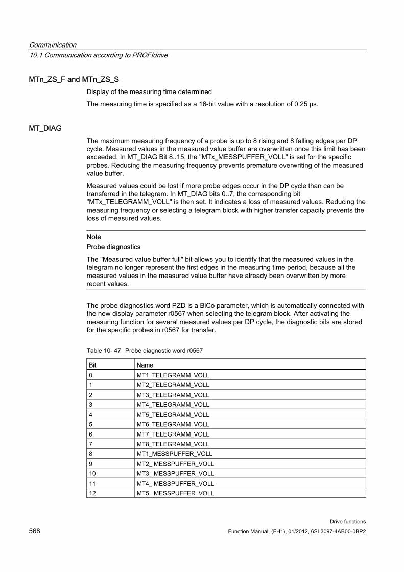
Communication 10.1 Communication according to PROFIdrive
Drive functions 568 Function Manual, (FH1), 01/2012, 6SL3097-4AB00-0BP2
MTn_ZS_F and MTn_ZS_S Display of the measuring time determined
The measuring time is specified as a 16-bit value with a resolution of 0.25 μs.
MT_DIAG The maximum measuring frequency of a probe is up to 8 rising and 8 falling edges per DP cycle. Measured values in the measured value buffer are overwritten once this limit has been exceeded. In MT_DIAG Bit 8..15, the "MTx_MESSPUFFER_VOLL" is set for the specific probes. Reducing the measuring frequency prevents premature overwriting of the measured value buffer.
Measured values could be lost if more probe edges occur in the DP cycle than can be transferred in the telegram. In MT_DIAG bits 0..7, the corresponding bit "MTx_TELEGRAMM_VOLL" is then set. It indicates a loss of measured values. Reducing the measuring frequency or selecting a telegram block with higher transfer capacity prevents the loss of measured values.
Note Probe diagnostics
The "Measured value buffer full" bit allows you to identify that the measured values in the telegram no longer represent the first edges in the measuring time period, because all the measured values in the measured value buffer have already been overwritten by more recent values.
The probe diagnostics word PZD is a BiCo parameter, which is automatically connected with the new display parameter r0567 when selecting the telegram block. After activating the measuring function for several measured values per DP cycle, the diagnostic bits are stored for the specific probes in r0567 for transfer.
Table 10- 47 Probe diagnostic word r0567
Bit Name 0 MT1_TELEGRAMM_VOLL 1 MT2_TELEGRAMM_VOLL 2 MT3_TELEGRAMM_VOLL 3 MT4_TELEGRAMM_VOLL 4 MT5_TELEGRAMM_VOLL 5 MT6_TELEGRAMM_VOLL 6 MT7_TELEGRAMM_VOLL 7 MT8_TELEGRAMM_VOLL 8 MT1_MESSPUFFER_VOLL 9 MT2_ MESSPUFFER_VOLL 10 MT3_ MESSPUFFER_VOLL 11 MT4_ MESSPUFFER_VOLL 12 MT5_ MESSPUFFER_VOLL
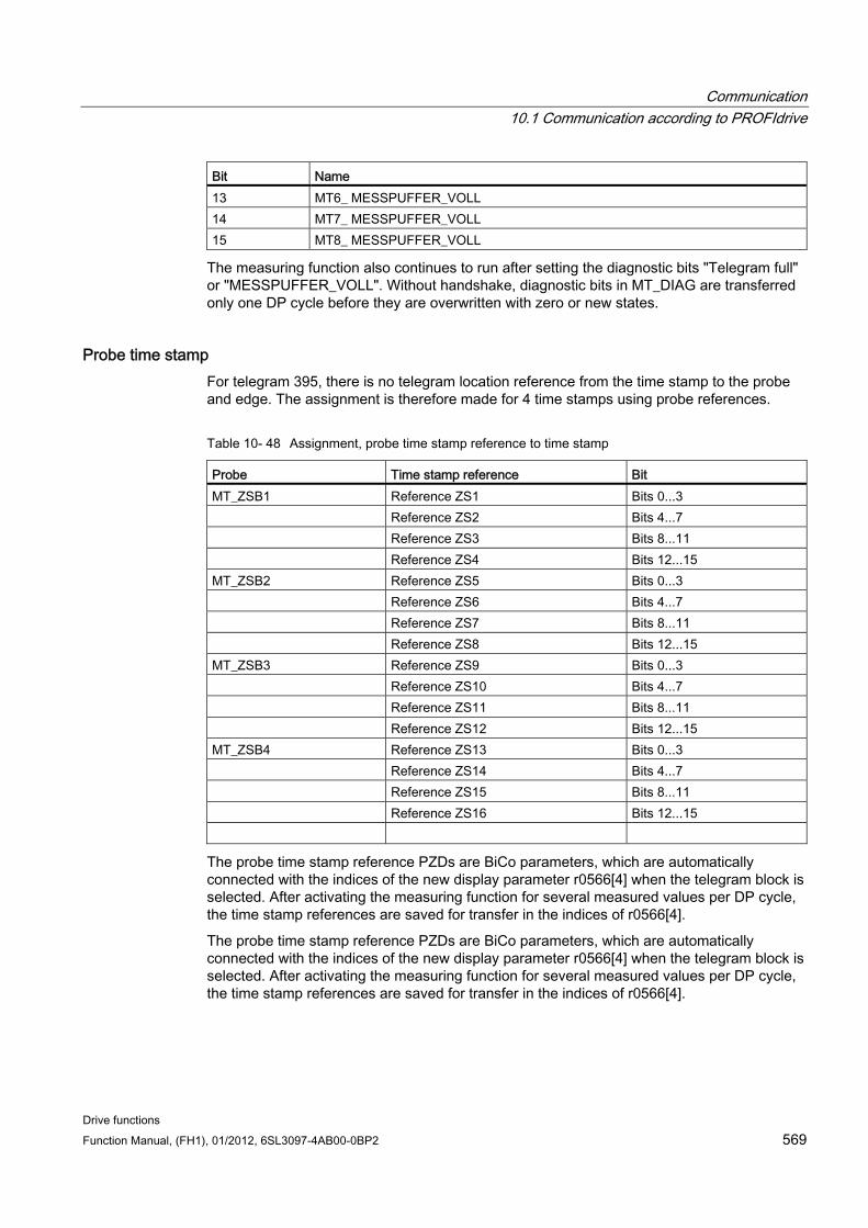
Communication 10.1 Communication according to PROFIdrive
Drive functions Function Manual, (FH1), 01/2012, 6SL3097-4AB00-0BP2 569
Bit Name 13 MT6_ MESSPUFFER_VOLL 14 MT7_ MESSPUFFER_VOLL 15 MT8_ MESSPUFFER_VOLL
The measuring function also continues to run after setting the diagnostic bits "Telegram full" or "MESSPUFFER_VOLL". Without handshake, diagnostic bits in MT_DIAG are transferred only one DP cycle before they are overwritten with zero or new states.
Probe time stamp For telegram 395, there is no telegram location reference from the time stamp to the probe and edge. The assignment is therefore made for 4 time stamps using probe references.
Table 10- 48 Assignment, probe time stamp reference to time stamp
Probe Time stamp reference Bit MT_ZSB1 Reference ZS1 Bits 0...3 Reference ZS2 Bits 4...7 Reference ZS3 Bits 8...11 Reference ZS4 Bits 12...15 MT_ZSB2 Reference ZS5 Bits 0...3 Reference ZS6 Bits 4...7 Reference ZS7 Bits 8...11 Reference ZS8 Bits 12...15 MT_ZSB3 Reference ZS9 Bits 0...3 Reference ZS10 Bits 4...7 Reference ZS11 Bits 8...11 Reference ZS12 Bits 12...15 MT_ZSB4 Reference ZS13 Bits 0...3 Reference ZS14 Bits 4...7 Reference ZS15 Bits 8...11 Reference ZS16 Bits 12...15
The probe time stamp reference PZDs are BiCo parameters, which are automatically connected with the indices of the new display parameter r0566[4] when the telegram block is selected. After activating the measuring function for several measured values per DP cycle, the time stamp references are saved for transfer in the indices of r0566[4].
The probe time stamp reference PZDs are BiCo parameters, which are automatically connected with the indices of the new display parameter r0566[4] when the telegram block is selected. After activating the measuring function for several measured values per DP cycle, the time stamp references are saved for transfer in the indices of r0566[4].
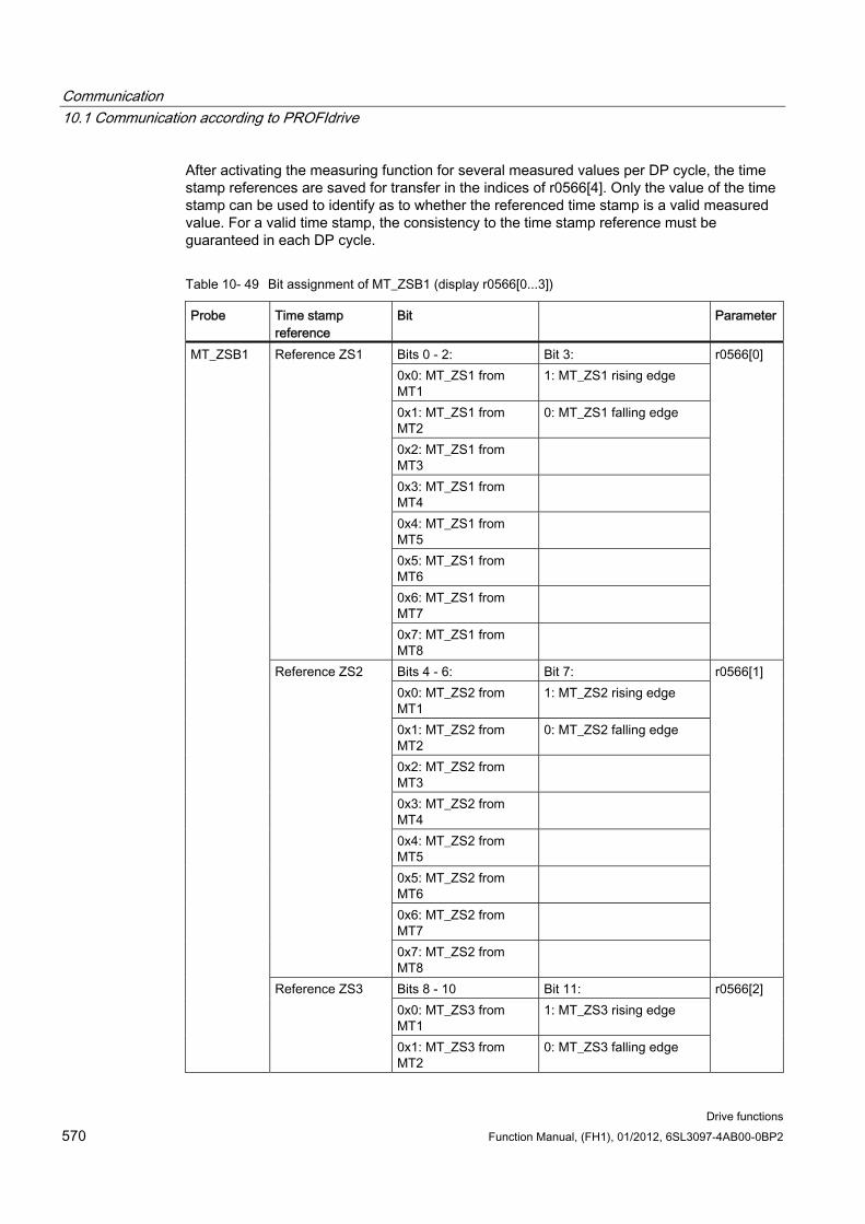
Communication 10.1 Communication according to PROFIdrive
Drive functions 570 Function Manual, (FH1), 01/2012, 6SL3097-4AB00-0BP2
After activating the measuring function for several measured values per DP cycle, the time stamp references are saved for transfer in the indices of r0566[4]. Only the value of the time stamp can be used to identify as to whether the referenced time stamp is a valid measured value. For a valid time stamp, the consistency to the time stamp reference must be guaranteed in each DP cycle.
Table 10- 49 Bit assignment of MT_ZSB1 (display r0566[0...3])
Probe Time stamp reference
Bit Parameter
Bits 0 - 2: Bit 3: 0x0: MT_ZS1 from MT1
1: MT_ZS1 rising edge
0x1: MT_ZS1 from MT2
0: MT_ZS1 falling edge
0x2: MT_ZS1 from MT3
0x3: MT_ZS1 from MT4
0x4: MT_ZS1 from MT5
0x5: MT_ZS1 from MT6
0x6: MT_ZS1 from MT7
Reference ZS1
0x7: MT_ZS1 from MT8
r0566[0]
Bits 4 - 6: Bit 7: 0x0: MT_ZS2 from MT1
1: MT_ZS2 rising edge
0x1: MT_ZS2 from MT2
0: MT_ZS2 falling edge
0x2: MT_ZS2 from MT3
0x3: MT_ZS2 from MT4
0x4: MT_ZS2 from MT5
0x5: MT_ZS2 from MT6
0x6: MT_ZS2 from MT7
Reference ZS2
0x7: MT_ZS2 from MT8
r0566[1]
Bits 8 - 10 Bit 11: 0x0: MT_ZS3 from MT1
1: MT_ZS3 rising edge
MT_ZSB1
Reference ZS3
0x1: MT_ZS3 from MT2
0: MT_ZS3 falling edge
r0566[2]
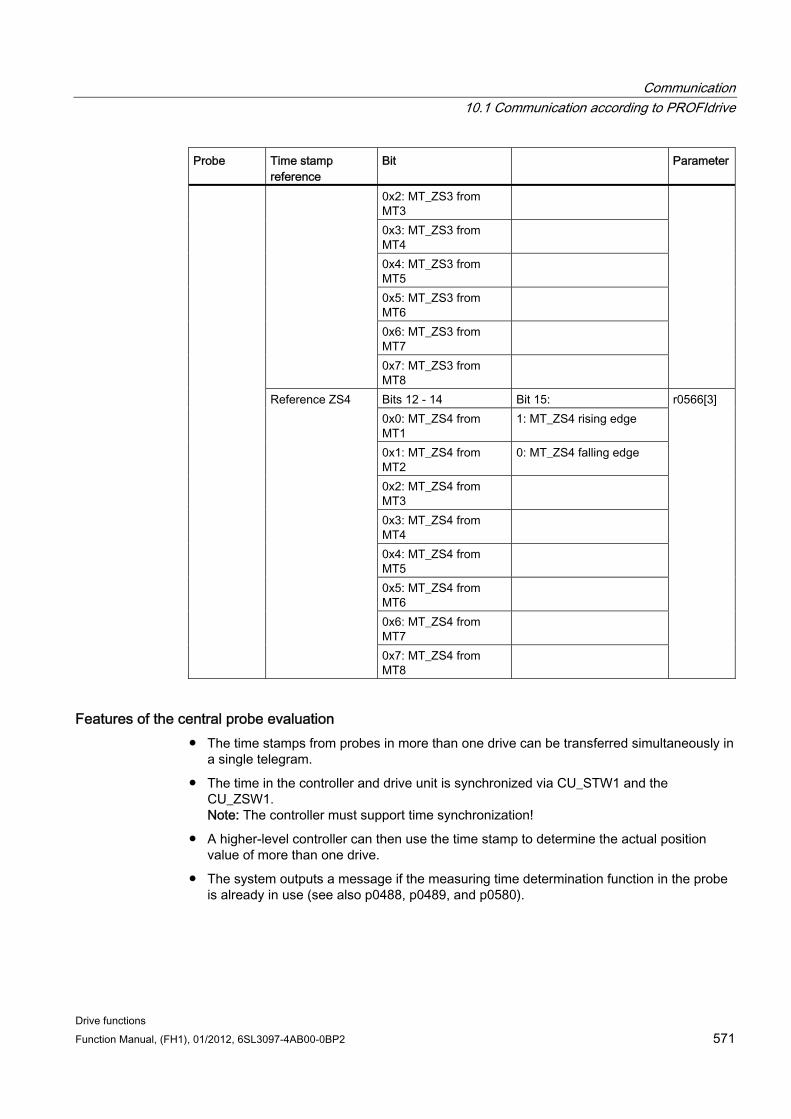
Communication 10.1 Communication according to PROFIdrive
Drive functions Function Manual, (FH1), 01/2012, 6SL3097-4AB00-0BP2 571
Probe Time stamp reference
Bit Parameter
0x2: MT_ZS3 from MT3
0x3: MT_ZS3 from MT4
0x4: MT_ZS3 from MT5
0x5: MT_ZS3 from MT6
0x6: MT_ZS3 from MT7
0x7: MT_ZS3 from MT8
Bits 12 - 14 Bit 15: 0x0: MT_ZS4 from MT1
1: MT_ZS4 rising edge
0x1: MT_ZS4 from MT2
0: MT_ZS4 falling edge
0x2: MT_ZS4 from MT3
0x3: MT_ZS4 from MT4
0x4: MT_ZS4 from MT5
0x5: MT_ZS4 from MT6
0x6: MT_ZS4 from MT7
Reference ZS4
0x7: MT_ZS4 from MT8
r0566[3]
Features of the central probe evaluation The time stamps from probes in more than one drive can be transferred simultaneously in
a single telegram.
The time in the controller and drive unit is synchronized via CU_STW1 and the CU_ZSW1. Note: The controller must support time synchronization!
A higher-level controller can then use the time stamp to determine the actual position value of more than one drive.
The system outputs a message if the measuring time determination function in the probe is already in use (see also p0488, p0489, and p0580).
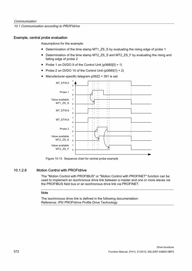
Communication 10.1 Communication according to PROFIdrive
Drive functions 572 Function Manual, (FH1), 01/2012, 6SL3097-4AB00-0BP2
Example, central probe evaluation Assumptions for the example:
Determination of the time stamp MT1_ZS_S by evaluating the rising edge of probe 1
Determination of the time stamp MT2_ZS_S and MT2_ZS_F by evaluating the rising and falling edge of probe 2
Probe 1 on DI/DO 9 of the Control Unit (p0680[0] = 1)
Probe 2 on DI/DO 10 of the Control Unit (p0680[1] = 2)
Manufacturer-specific telegram p0922 = 391 is set.
Figure 10-13 Sequence chart for central probe example
10.1.2.8 Motion Control with PROFIdrive The "Motion Control with PROFIBUS" or "Motion Control with PROFINET" function can be used to implement an isochronous drive link between a master and one or more slaves via the PROFIBUS field bus or an isochronous drive link via PROFINET.
Note
The isochronous drive link is defined in the following documentation: Reference: /P5/ PROFIdrive Profile Drive Technology
Communication 10.1 Communication according to PROFIdrive
Drive functions Function Manual, (FH1), 01/2012, 6SL3097-4AB00-0BP2 573
Properties No additional parameters need to be entered in addition to the bus configuration in order
to activate this function, the master and slave must only be preset for this function (PROFIBUS).
The master-side default setting is made via the hardware configuration, e.g. B. HWConfig with SIMATIC S7. The slave-side default setting is made via the parameterization telegram when the bus is ramping up.
Fixed sampling times are used for all data communication.
The Global Control (GC) clock information on PROFIBUS is transmitted before the beginning of each cycle.
The length of the clock cycle depends on the bus configuration. When the clock cycle is selected, the bus configuration tool (e.g. HWConfig) supports:
– High number of drives per slave/drive unit → longer cycle
– Large number of slaves/drive units → longer cycle
A sign-of-life counter is used to monitor user data transfer and clock pulse failures.
Overview of closed-loop control Sensing of the actual position value on the slave can be performed using:
– Indirect measuring system (motor encoder)
– Additional direct measuring system
The encoder interface must be configured in the process data.
The control loop is closed via the PROFIBUS.
The position controller is located on the master.
The current and speed control systems and actual value sensing (encoder interface) are located on the slave.
The position controller clock cycle is transmitted across the field bus to the slaves.
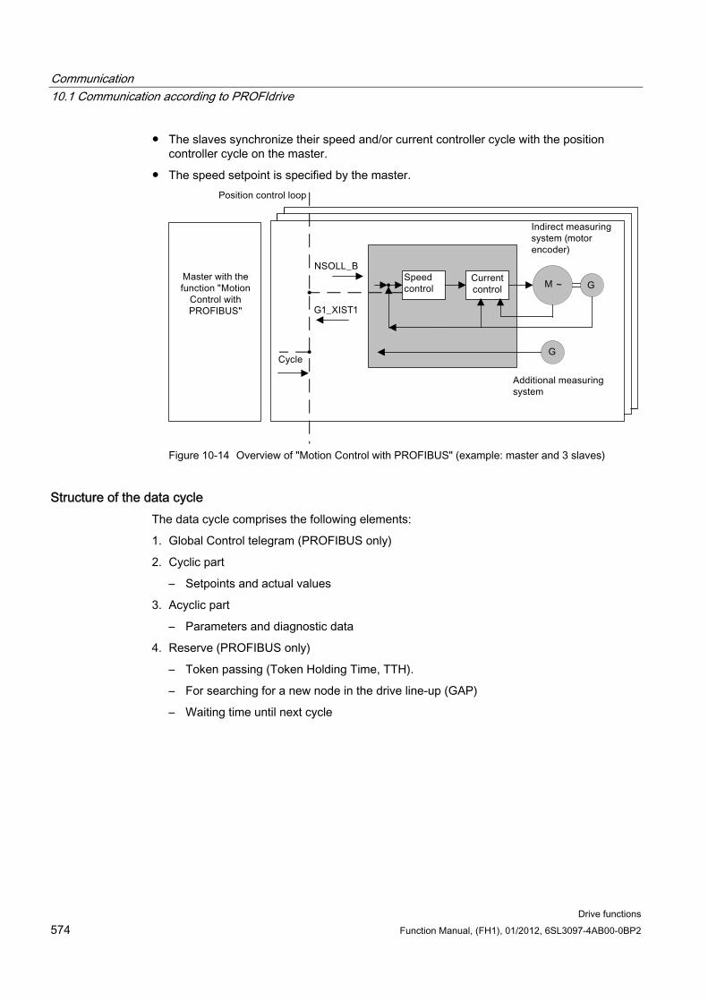
Communication 10.1 Communication according to PROFIdrive
Drive functions 574 Function Manual, (FH1), 01/2012, 6SL3097-4AB00-0BP2
The slaves synchronize their speed and/or current controller cycle with the position controller cycle on the master.
The speed setpoint is specified by the master.
Figure 10-14 Overview of "Motion Control with PROFIBUS" (example: master and 3 slaves)
Structure of the data cycle The data cycle comprises the following elements:
1. Global Control telegram (PROFIBUS only)
2. Cyclic part
– Setpoints and actual values
3. Acyclic part
– Parameters and diagnostic data
4. Reserve (PROFIBUS only)
– Token passing (Token Holding Time, TTH).
– For searching for a new node in the drive line-up (GAP)
– Waiting time until next cycle
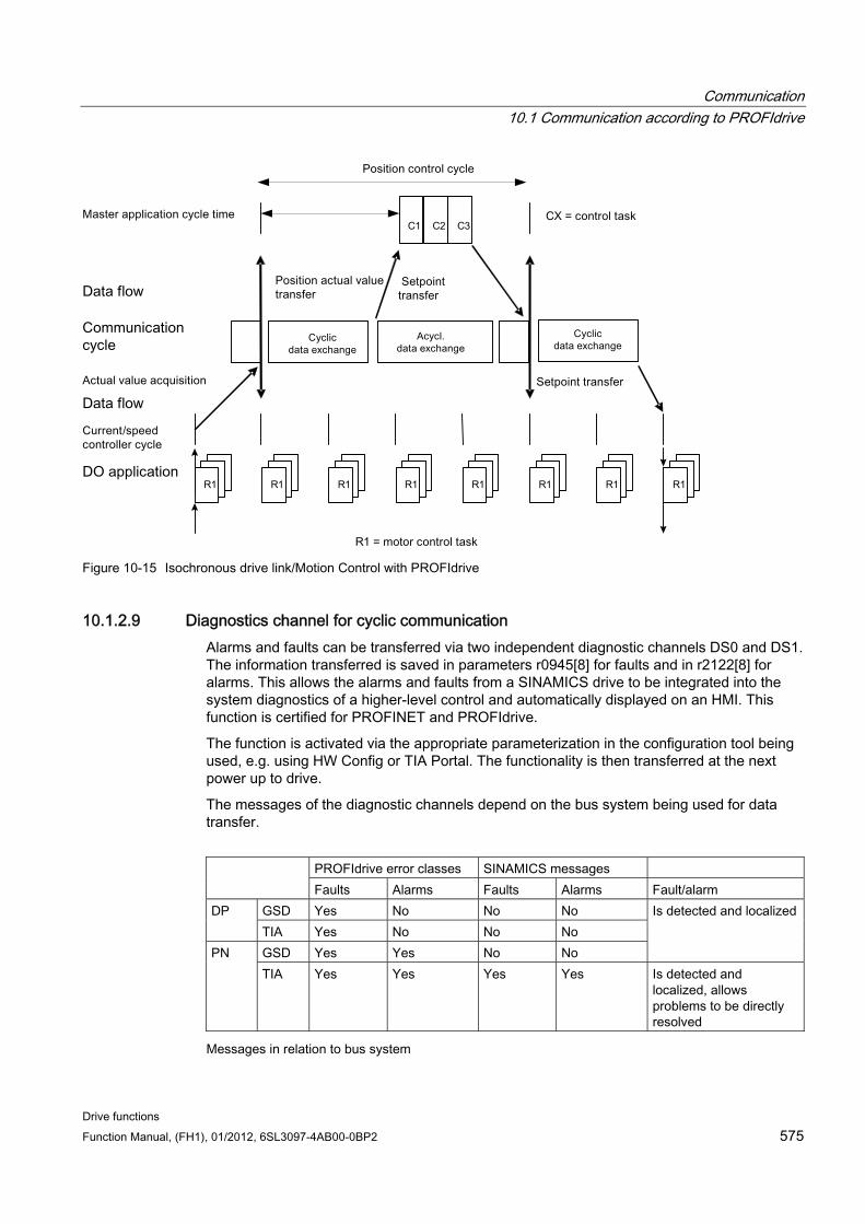
Communication 10.1 Communication according to PROFIdrive
Drive functions Function Manual, (FH1), 01/2012, 6SL3097-4AB00-0BP2 575
1 2 3C C C
1 1 1 1 11 1 1R R R R RR R R
Figure 10-15 Isochronous drive link/Motion Control with PROFIdrive
10.1.2.9 Diagnostics channel for cyclic communication Alarms and faults can be transferred via two independent diagnostic channels DS0 and DS1. The information transferred is saved in parameters r0945[8] for faults and in r2122[8] for alarms. This allows the alarms and faults from a SINAMICS drive to be integrated into the system diagnostics of a higher-level control and automatically displayed on an HMI. This function is certified for PROFINET and PROFIdrive.
The function is activated via the appropriate parameterization in the configuration tool being used, e.g. using HW Config or TIA Portal. The functionality is then transferred at the next power up to drive.
The messages of the diagnostic channels depend on the bus system being used for data transfer.
PROFIdrive error classes SINAMICS messages Faults Alarms Faults Alarms Fault/alarm
GSD Yes No No No DP TIA Yes No No No GSD Yes Yes No No
Is detected and localized
PN TIA Yes Yes Yes Yes Is detected and
localized, allows problems to be directly resolved
Messages in relation to bus system
Communication 10.1 Communication according to PROFIdrive
Drive functions 576 Function Manual, (FH1), 01/2012, 6SL3097-4AB00-0BP2
The alarms and faults correspond to the error classes defined in the PROFIdrive profile.
You can select whether alarms and faults are transferred to a higher-level control either as SINAMICS messages or using the error classes of the PROFIdrive profile.
The alarms and faults can be mapped with standard resources (e.g. standard slave, GSD, GSDML)
The alarms or faults are logically and locally signaled:
– With alarm or fault number
– With assignment of the drive object, message value and hardware component assignment
– In a user-friendly fashion with plain message texts
– Display with user-defined names for drive objects and components
– SINAMICS transfers the messages in the order that they have occurred
– SINAMICS does not record any time stamps
– The time stamps are generated from the higher-level control when the messages are received
– To transfer the SINAMICS messages, the extended channel diagnostics is used
The existing mechanisms of TIA and S7 Classic can be used.
The messages are compatible with PROFINET controllers.
Alarms or faults are acknowledged using the already known acknowledgment routes.
Transfer possible via interface IF1 and/or IF2
Note Constraint
If a shared device is activated, the extended diagnostics is not possible.
Data transfer for cyclic communication, the following applies: For PROFINET, there is a unique assignment of the drive objects to the slots of the cyclic
communication. The diagnostics is issued at the MAP/PAP-submodule.
Data transfer for acyclic communication, the following applies: There is no slot or subslot configured at which diagnostics can be issued.
Faults or alarms that occur are routed along the BICO connections to the drive objects.
Display of error classes according to PROFIdrive: For transfer with PROFINET, the PROFIdrive error class and the extended channel
diagnostics
Communication 10.1 Communication according to PROFIdrive
Drive functions Function Manual, (FH1), 01/2012, 6SL3097-4AB00-0BP2 577
10.1.3 Parallel operation of communication interfaces Cyclic process data (setpoints/actual values) are processed using interfaces IF1 and IF2. The following interfaces are used:
Onboard interfaces of the Control Unit for PROFIBUS DP or PROFINET
An additional interface (COMM - BOARD) for PROFINET (CBE20) or CANopen (CBE10) for insertion in the Control Unit as an option
Parameter p8839 is used to set the parallel use of the Control Unit onboard interfaces and COMM - BOARD in the SINAMICS system. The functionality is assigned to interfaces IF1 and IF2 using indices.
For example, the following applications are possible:
PROFIBUS DP for control and PROFINET to acquire actual values/measured values of the drive
PROFIBUS DP for control and PROFINET for engineering only
Mixed mode with two masters (the first for logic and coordination and the second for technology)
SINAMICS Link via IF2 (CBE20); standard telegrams and PROFIsafe via IF1
Operation of redundant communication interfaces
Assignment of communication interfaces to cyclic interfaces The two cyclic interfaces for the setpoints and actual values differ by the parameter ranges used (BICO technology etc.) and the functions that can be used. The interfaces are designated as cyclic interface 1 (IF1) and cyclic interface 2 (IF2).
With the factory setting p8839 = 99, the communication interfaces are permanently assigned one of the cyclic interfaces (IF1, IF2), depending on the communication system, e.g. PROFIBUS DP, PROFINET or CANopen.
The assignment to the cyclic interfaces can essentially be freely defined by user parameterization for the parallel operation of the communication interfaces.
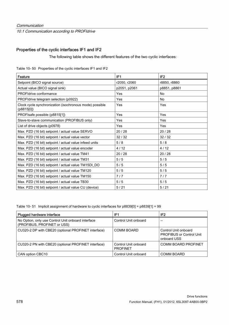
Communication 10.1 Communication according to PROFIdrive
Drive functions 578 Function Manual, (FH1), 01/2012, 6SL3097-4AB00-0BP2
Properties of the cyclic interfaces IF1 and IF2 The following table shows the different features of the two cyclic interfaces:
Table 10- 50 Properties of the cyclic interfaces IF1 and IF2
Feature IF1 IF2 Setpoint (BICO signal source) r2050, r2060 r8850, r8860 Actual value (BICO signal sink) p2051, p2061 p8851, p8861 PROFIdrive conformance Yes No PROFIdrive telegram selection (p0922) Yes No Clock cycle synchronization (isochronous mode) possible (p8815[0])
Yes Yes
PROFIsafe possible (p8815[1]) Yes Yes Slave-to-slave communication (PROFIBUS only) Yes Yes List of drive objects (p0978) Yes Yes Max. PZD (16 bit) setpoint / actual value SERVO 20 / 28 20 / 28 Max. PZD (16 bit) setpoint / actual value vector 32 / 32 32 / 32 Max. PZD (16 bit) setpoint / actual value infeed units 5 / 8 5 / 8 Max. PZD (16 bit) setpoint / actual value encoder 4 / 12 4 / 12 Max. PZD (16 bit) setpoint / actual value TM41 20 / 28 20 / 28 Max. PZD (16 bit) setpoint / actual value TM31 5 / 5 5 / 5 Max. PZD (16 bit) setpoint / actual value TM15DI_DO 5 / 5 5 / 5 Max. PZD (16 bit) setpoint / actual value TM120 5 / 5 5 / 5 Max. PZD (16 bit) setpoint / actual value TM150 7 / 7 7 / 7 Max. PZD (16 bit) setpoint / actual value TB30 5 / 5 5 / 5 Max. PZD (16 bit) setpoint / actual value CU (device) 5 / 21 5 / 21
Table 10- 51 Implicit assignment of hardware to cyclic interfaces for p8839[0] = p8839[1] = 99
Plugged hardware interface IF1 IF2 No Option, only use Control Unit onboard interface (PROFIBUS, PROFINET or USS)
Control Unit onboard --
CU320-2 DP with CBE20 (optional PROFINET interface) COMM BOARD Control Unit onboard PROFIBUS or Control Unit onboard USS
CU320-2 PN with CBE20 (optional PROFINET interface) Control Unit onboard PROFINET
COMM BOARD PROFINET
CAN option CBC10 Control Unit onboard COMM BOARD
Communication 10.1 Communication according to PROFIdrive
Drive functions Function Manual, (FH1), 01/2012, 6SL3097-4AB00-0BP2 579
Parameter p8839[0,1] is used to set the parallel operation of the hardware interfaces and the assignment to the cyclic interfaces IF1 and IF2 for the Control Unit drive object.
The object sequence for process data exchange via IF2 depends on the object sequence from IF1; see "List of drive objects" (p0978).
The factory setting of p8839[0,1] =99 enables the implicit assignment (see table above).
An alarm is generated in case of unvalid or inconsistent parameterization of the assignment.
Note Parallel operation of PROFIBUS and PROFINET
The data of isochronous applications can only be processed via one of the two interfaces IF1 or IF2 (p8815). Two parameterization options are possible if additionally the PROFINET module CBE20 is inserted in the CU320-2 DP:
- p8839[0] = 1 and p8839[1] = 2: PROFIBUS isochronous, PROFINET cyclic
- p8839[0] = 2 and p8839[1] = 1: PROFINET isochronous, PROFIBUS cyclic
Parameters for IF2
The following parameters are available in order to optimize the IF2 for a PROFIBUS or PROFINET interface:
Receive and send process data: r8850, p8851, r8853, r8860, p8861, r88631)
Diagnostic parameters: r8874, r8875, r88761)
Binector-connector converter p8880, p8881, p8882, p8883, p8884, r88891)
Connector-binector converter r8894, r8895, p8898, p88991)
1) Significance of 88xx identical to 20xx
Note
Using the HW Config configuring tool, a PROFIBUS / PROFINET slave with two interfaces cannot be shown. In parallel operation, this is the reason that SINAMICS appears twice in the project or in two projects, although physically it is just one device.
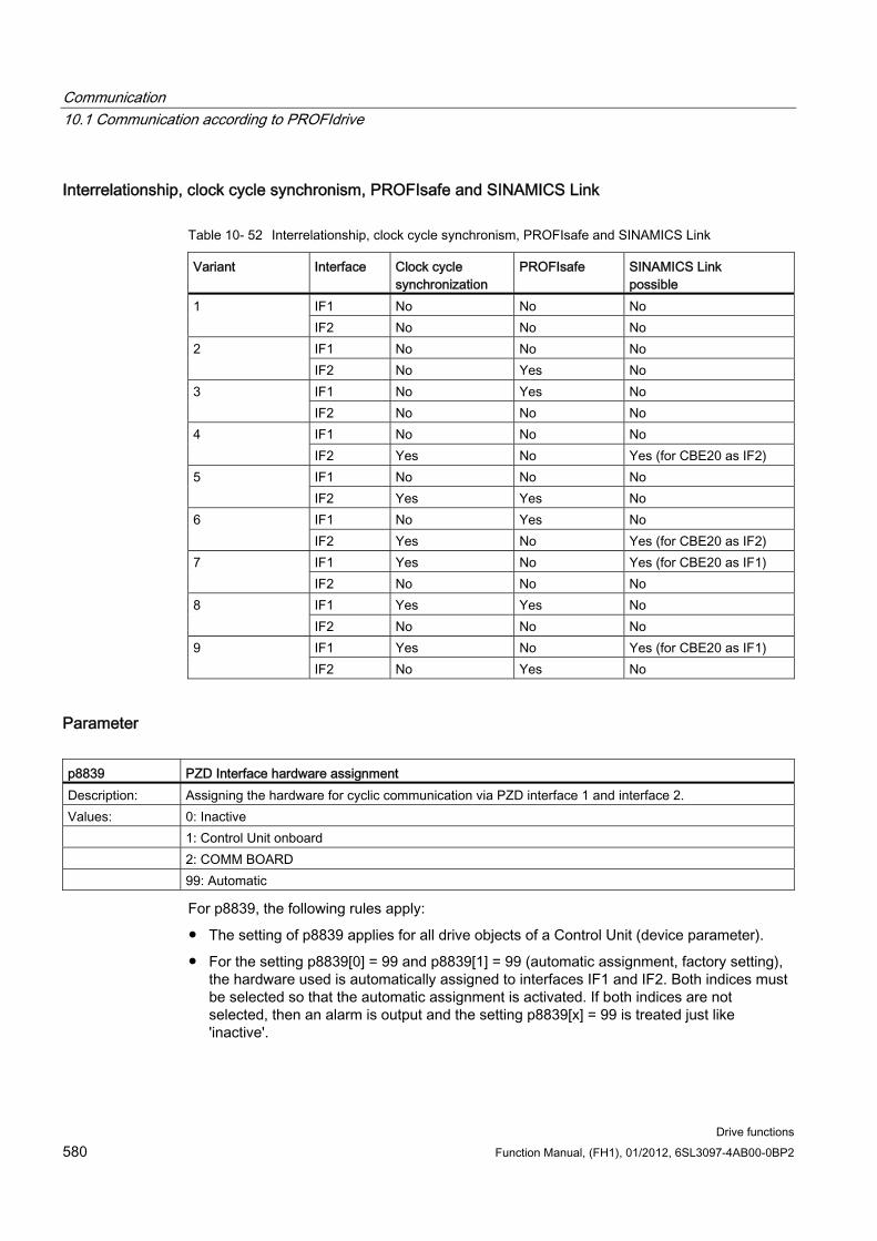
Communication 10.1 Communication according to PROFIdrive
Drive functions 580 Function Manual, (FH1), 01/2012, 6SL3097-4AB00-0BP2
Interrelationship, clock cycle synchronism, PROFIsafe and SINAMICS Link
Table 10- 52 Interrelationship, clock cycle synchronism, PROFIsafe and SINAMICS Link
Variant Interface Clock cycle synchronization
PROFIsafe SINAMICS Link possible
IF1 No No No 1 IF2 No No No IF1 No No No 2 IF2 No Yes No IF1 No Yes No 3 IF2 No No No IF1 No No No 4 IF2 Yes No Yes (for CBE20 as IF2) IF1 No No No 5 IF2 Yes Yes No IF1 No Yes No 6 IF2 Yes No Yes (for CBE20 as IF2) IF1 Yes No Yes (for CBE20 as IF1) 7 IF2 No No No IF1 Yes Yes No 8 IF2 No No No IF1 Yes No Yes (for CBE20 as IF1) 9 IF2 No Yes No
Parameter p8839 PZD Interface hardware assignment Description: Assigning the hardware for cyclic communication via PZD interface 1 and interface 2. Values: 0: Inactive 1: Control Unit onboard 2: COMM BOARD 99: Automatic
For p8839, the following rules apply:
The setting of p8839 applies for all drive objects of a Control Unit (device parameter).
For the setting p8839[0] = 99 and p8839[1] = 99 (automatic assignment, factory setting), the hardware used is automatically assigned to interfaces IF1 and IF2. Both indices must be selected so that the automatic assignment is activated. If both indices are not selected, then an alarm is output and the setting p8839[x] = 99 is treated just like 'inactive'.
Communication 10.1 Communication according to PROFIdrive
Drive functions Function Manual, (FH1), 01/2012, 6SL3097-4AB00-0BP2 581
An alarm is issued if the same hardware (Control Unit onboard or COMM BOARD) is selected in p8839[0] and p8839[1]. Then the setting of p8839[0] is valid – and the setting of p8839[1] is treated just like 'inactive'.
If the CAN module (CBC10) is used, the entry of p8839[0] = 2 is not permissible (no assignment of the CAN module to IF1). An alarm is then issued.
If p8839[x] is set to 2, and the COMM - BOARD is missing/defective, then the corresponding interface is not automatically supplied from the Control Unit onboard interface. Message A08550 is output instead.
Overview of important parameters (see SINAMICS S120/S150 List Manual) p0922 IF1 PROFIdrive telegram selection
p0978[0...24] List of drive objects
p8815[0...1] Selects the functionality IF1/IF2
p8839[0...1] PZD Interface hardware assignment
p9601 SI enable, functions integrated in the drive (Control Unit)
10.1.4 Acyclic communication
10.1.4.1 General information about acyclic communication With acyclic communication, as opposed to cyclic communication, data transfer takes place only when an explicit request is made (e.g. in order to read and write parameters).
The "Read data record" and "Write data record" services are available for acyclic communication.
The following options are available for reading and writing parameters:
S7 protocol
This protocol uses the STARTER commissioning tool, for example, in the online mode via PROFIBUS.
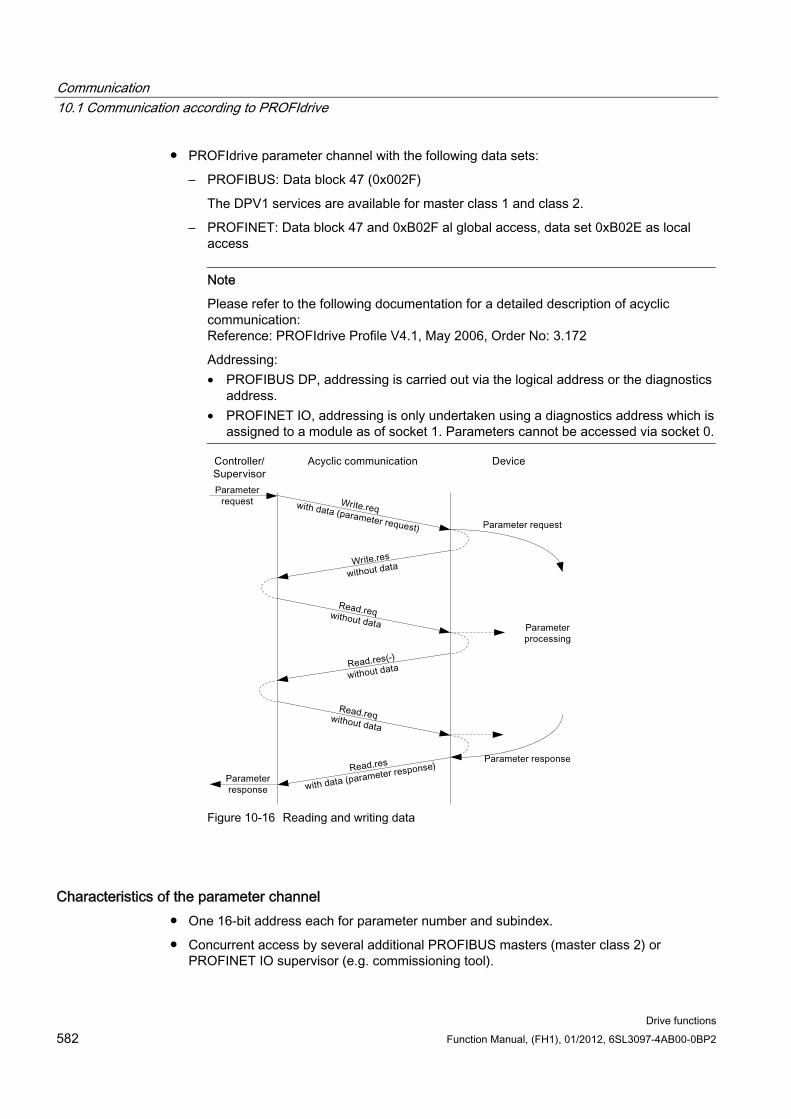
Communication 10.1 Communication according to PROFIdrive
Drive functions 582 Function Manual, (FH1), 01/2012, 6SL3097-4AB00-0BP2
PROFIdrive parameter channel with the following data sets:
– PROFIBUS: Data block 47 (0x002F)
The DPV1 services are available for master class 1 and class 2.
– PROFINET: Data block 47 and 0xB02F al global access, data set 0xB02E as local access
Note
Please refer to the following documentation for a detailed description of acyclic communication: Reference: PROFIdrive Profile V4.1, May 2006, Order No: 3.172
Addressing: • PROFIBUS DP, addressing is carried out via the logical address or the diagnostics
address. • PROFINET IO, addressing is only undertaken using a diagnostics address which is
assigned to a module as of socket 1. Parameters cannot be accessed via socket 0.
Figure 10-16 Reading and writing data
Characteristics of the parameter channel One 16-bit address each for parameter number and subindex.
Concurrent access by several additional PROFIBUS masters (master class 2) or PROFINET IO supervisor (e.g. commissioning tool).
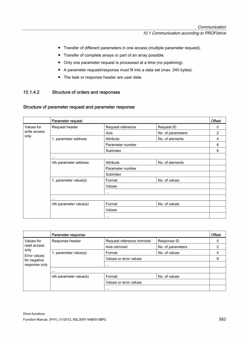
Communication 10.1 Communication according to PROFIdrive
Drive functions Function Manual, (FH1), 01/2012, 6SL3097-4AB00-0BP2 583
Transfer of different parameters in one access (multiple parameter request).
Transfer of complete arrays or part of an array possible.
Only one parameter request is processed at a time (no pipelining).
A parameter request/response must fit into a data set (max. 240 bytes).
The task or response header are user data.
10.1.4.2 Structure of orders and responses
Structure of parameter request and parameter response Parameter request Offset
Request reference Request ID 0 Request header Axis No. of parameters 2 Attribute No. of elements 4 Parameter number 6
1. parameter address
Subindex 8 ...
Attribute No. of elements Parameter number
nth parameter address
Subindex Format No. of values Values
1. parameter value(s)
... ...
Format No. of values Values
Values for write access only
nth parameter value(s)
...
Parameter response Offset
Request reference mirrored Response ID 0 Response header Axis mirrored No. of parameters 2 Format No. of values 4 Values or error values 6
1. parameter value(s)
... ...
Format No. of values Values or error values
Values for read access only Error values for negative response only
nth parameter value(s)
...
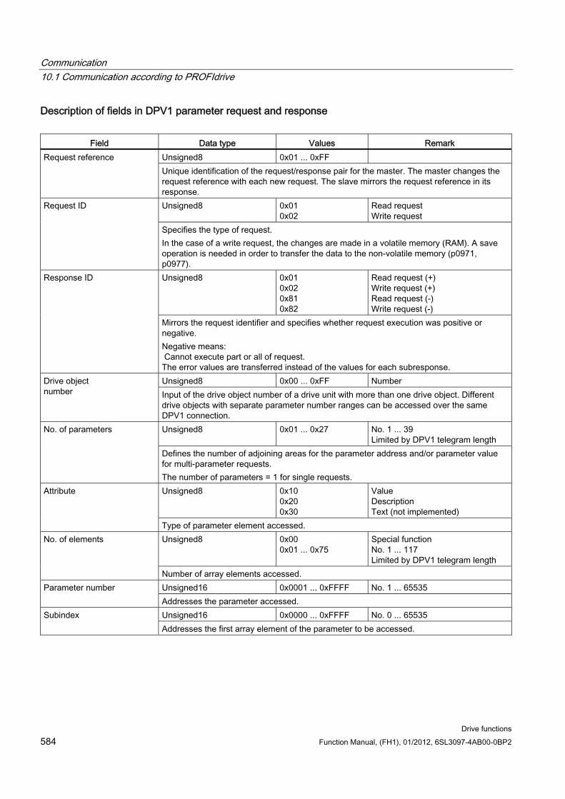
Communication 10.1 Communication according to PROFIdrive
Drive functions 584 Function Manual, (FH1), 01/2012, 6SL3097-4AB00-0BP2
Description of fields in DPV1 parameter request and response
Field Data type Values Remark Unsigned8 0x01 ... 0xFF Request reference Unique identification of the request/response pair for the master. The master changes the request reference with each new request. The slave mirrors the request reference in its response. Unsigned8 0x01
0x02 Read request Write request
Request ID
Specifies the type of request. In the case of a write request, the changes are made in a volatile memory (RAM). A save operation is needed in order to transfer the data to the non-volatile memory (p0971, p0977). Unsigned8 0x01
0x02 0x81 0x82
Read request (+) Write request (+) Read request (-) Write request (-)
Response ID
Mirrors the request identifier and specifies whether request execution was positive or negative. Negative means: Cannot execute part or all of request. The error values are transferred instead of the values for each subresponse. Unsigned8 0x00 ... 0xFF Number Drive object
number Input of the drive object number of a drive unit with more than one drive object. Different drive objects with separate parameter number ranges can be accessed over the same DPV1 connection. Unsigned8 0x01 ... 0x27 No. 1 ... 39
Limited by DPV1 telegram length No. of parameters
Defines the number of adjoining areas for the parameter address and/or parameter value for multi-parameter requests. The number of parameters = 1 for single requests. Unsigned8 0x10
0x20 0x30
Value Description Text (not implemented)
Attribute
Type of parameter element accessed. Unsigned8 0x00
0x01 ... 0x75 Special function No. 1 ... 117 Limited by DPV1 telegram length
No. of elements
Number of array elements accessed. Unsigned16 0x0001 ... 0xFFFF No. 1 ... 65535 Parameter number Addresses the parameter accessed. Unsigned16 0x0000 ... 0xFFFF No. 0 ... 65535 Subindex Addresses the first array element of the parameter to be accessed.
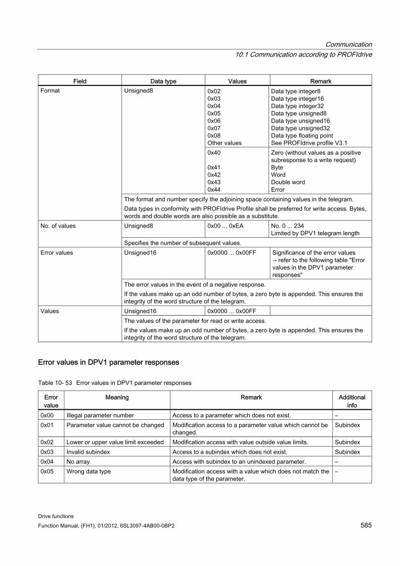
Communication 10.1 Communication according to PROFIdrive
Drive functions Function Manual, (FH1), 01/2012, 6SL3097-4AB00-0BP2 585
Field Data type Values Remark 0x02 0x03 0x04 0x05 0x06 0x07 0x08 Other values
Data type integer8 Data type integer16 Data type integer32 Data type unsigned8 Data type unsigned16 Data type unsigned32 Data type floating point See PROFIdrive profile V3.1
Unsigned8
0x40 0x41 0x42 0x43 0x44
Zero (without values as a positive subresponse to a write request) Byte Word Double word Error
Format
The format and number specify the adjoining space containing values in the telegram. Data types in conformity with PROFIdrive Profile shall be preferred for write access. Bytes, words and double words are also possible as a substitute. Unsigned8 0x00 ... 0xEA No. 0 ... 234
Limited by DPV1 telegram length No. of values
Specifies the number of subsequent values. Unsigned16 0x0000 ... 0x00FF Significance of the error values
→ refer to the following table "Error values in the DPV1 parameter responses"
Error values
The error values in the event of a negative response. If the values make up an odd number of bytes, a zero byte is appended. This ensures the integrity of the word structure of the telegram. Unsigned16 0x0000 ... 0x00FF Values The values of the parameter for read or write access. If the values make up an odd number of bytes, a zero byte is appended. This ensures the integrity of the word structure of the telegram.
Error values in DPV1 parameter responses
Table 10- 53 Error values in DPV1 parameter responses
Error value
Meaning Remark Additional info
0x00 Illegal parameter number Access to a parameter which does not exist. – 0x01 Parameter value cannot be changed Modification access to a parameter value which cannot be
changed. Subindex
0x02 Lower or upper value limit exceeded Modification access with value outside value limits. Subindex 0x03 Invalid subindex Access to a subindex which does not exist. Subindex 0x04 No array Access with subindex to an unindexed parameter. – 0x05 Wrong data type Modification access with a value which does not match the
data type of the parameter. –
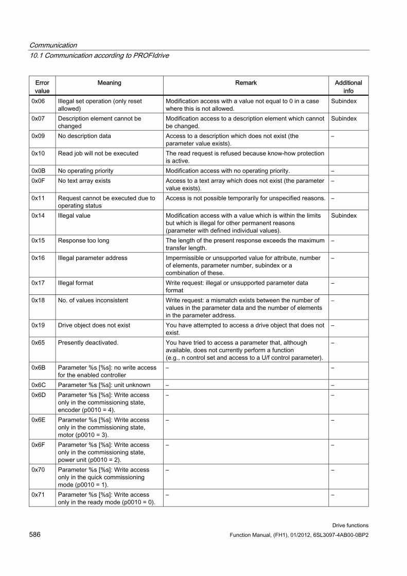
Communication 10.1 Communication according to PROFIdrive
Drive functions 586 Function Manual, (FH1), 01/2012, 6SL3097-4AB00-0BP2
Error value
Meaning Remark Additional info
0x06 Illegal set operation (only reset allowed)
Modification access with a value not equal to 0 in a case where this is not allowed.
Subindex
0x07 Description element cannot be changed
Modification access to a description element which cannot be changed.
Subindex
0x09 No description data Access to a description which does not exist (the parameter value exists).
–
0x10 Read job will not be executed The read request is refused because know-how protection is active.
0x0B No operating priority Modification access with no operating priority. – 0x0F No text array exists Access to a text array which does not exist (the parameter
value exists). –
0x11 Request cannot be executed due to operating status
Access is not possible temporarily for unspecified reasons. –
0x14 Illegal value Modification access with a value which is within the limits but which is illegal for other permanent reasons (parameter with defined individual values).
Subindex
0x15 Response too long The length of the present response exceeds the maximum transfer length.
–
0x16 Illegal parameter address Impermissible or unsupported value for attribute, number of elements, parameter number, subindex or a combination of these.
–
0x17 Illegal format Write request: illegal or unsupported parameter data format
–
0x18 No. of values inconsistent Write request: a mismatch exists between the number of values in the parameter data and the number of elements in the parameter address.
–
0x19 Drive object does not exist You have attempted to access a drive object that does not exist.
–
0x65 Presently deactivated. You have tried to access a parameter that, although available, does not currently perform a function (e.g., n control set and access to a U/f control parameter).
–
0x6B Parameter %s [%s]: no write access for the enabled controller
– –
0x6C Parameter %s [%s]: unit unknown – – 0x6D Parameter %s [%s]: Write access
only in the commissioning state, encoder (p0010 = 4).
– –
0x6E Parameter %s [%s]: Write access only in the commissioning state, motor (p0010 = 3).
– –
0x6F Parameter %s [%s]: Write access only in the commissioning state, power unit (p0010 = 2).
– –
0x70 Parameter %s [%s]: Write access only in the quick commissioning mode (p0010 = 1).
– –
0x71 Parameter %s [%s]: Write access only in the ready mode (p0010 = 0).
– –

Communication 10.1 Communication according to PROFIdrive
Drive functions Function Manual, (FH1), 01/2012, 6SL3097-4AB00-0BP2 587
Error value
Meaning Remark Additional info
0x72 Parameter %s [%s]: Write access only in the commissioning state, parameter reset (p0010 = 30).
– –
0x73 Parameter %s [%s]: Write access only in the commissioning state, Safety (p0010 = 95).
– –
0x74 Parameter %s [%s]: Write access only in the commissioning state, tech. application/units (p0010 = 5).
– –
0x75 Parameter %s [%s]: Write access only in the commissioning state (p0010 not equal to 0).
– –
0x76 Parameter %s [%s]: Write access only in the commissioning state, download (p0010 = 29).
– –
0x77 Parameter %s [%s] may not be written in download.
– –
0x78 Parameter %s [%s]: Write access only in the commissioning state, drive configuration (device: p0009 = 3).
– –
0x79 Parameter %s [%s]: Write access only in the commissioning state, define drive type (device: p0009 = 2).
– –
0x7A Parameter %s [%s]: write access only in the commissioning state, database configuration (device: p0009 = 4).
– –
0x7B Parameter %s [%s]: Write access only in the commissioning state, device configuration (device: p0009 = 1).
– –
0x7C Parameter %s [%s]: Write access only in the commissioning state, device download (device: p0009 = 29).
– –
0x7D Parameter %s [%s]: Write access only in the commissioning state, device parameter reset (device: p0009 = 30).
– –
0x7E Parameter %s [%s]: Write access only in the commissioning state, device ready (device: p0009 = 0).
– –
0x7F Parameter %s [%s]: Write access only in the commissioning state, device (device: p0009 not 0).
– –
0x81 Parameter %s [%s] may not be written in download.
– –
0x82 Transfer of the control authority (master) is inhibited by BI: p0806.
– –

Communication 10.1 Communication according to PROFIdrive
Drive functions 588 Function Manual, (FH1), 01/2012, 6SL3097-4AB00-0BP2
Error value
Meaning Remark Additional info
0x83 Parameter %s [%s]: requested BICO interconnection not possible
BICO output does not supply float values. The BICO input, however, requires a float value.
–
0x84 Parameter %s [%s]: parameter change inhibited (refer to p0300, p0400, p0922)
– –
0x85 Parameter %s [%s]: access method not defined.
– –
0x87 Write job will not be executed The write job is rejected because know-how protection is active.
–
0xC8 Below the valid values. Modification request for a value that, although within "absolute" limits, is below the currently valid lower limit.
–
0xC9 Above the valid values. Modification request for a value that, although within "absolute" limits, is below the currently valid lower limit (e.g. governed by the current converter rating).
–
0xCC Write access not permitted. Write access is not permitted because an access key is not available.
–
10.1.4.3 Determining the drive object numbers Further information about the drive system (e.g. drive object numbers) can be determined as follows using parameters p0101, r0102, and p0107/r0107:
1. The value of parameter r0102 ("Number of drive objects") for drive object/axis 1 is read via a read request.
Drive object 1 is the Control Unit (CU), which is a minimum requirement for each drive system.
2. Depending on the result of the initial read request, further read requests for drive object 1 are used to read the indices for parameter p0101 ("Drive object numbers"), as specified by parameter r0102.
Example: If the number of drive objects is "5", the values for indices 0 to 4 for parameter p0101 are read. Of course, the relevant indexes can also be read at once.
Note
The first two points provide you with the following information: • How many drive objects exist in the drive system? • The numbers of the existing drive objects
3. Following this, parameter r0107/p0107 ("Drive object type") is read for each drive object/axis (indicated by the drive object number).
Depending on the drive object, parameter 107 can be either an adjustable or visualization parameter.
The value in parameter r0107/p0107 indicates the drive object type. The coding for the drive object type is specified in the parameter list.
4. From here, refer to the parameter list for each drive object.
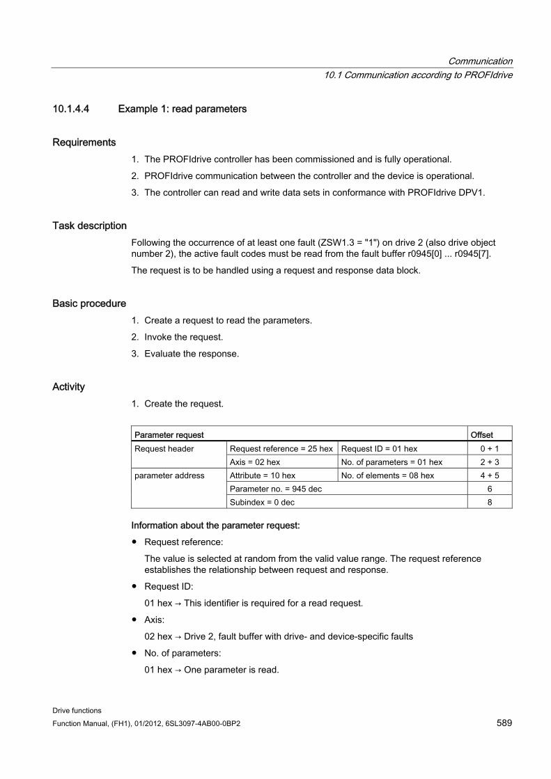
Communication 10.1 Communication according to PROFIdrive
Drive functions Function Manual, (FH1), 01/2012, 6SL3097-4AB00-0BP2 589
10.1.4.4 Example 1: read parameters
Requirements 1. The PROFIdrive controller has been commissioned and is fully operational.
2. PROFIdrive communication between the controller and the device is operational.
3. The controller can read and write data sets in conformance with PROFIdrive DPV1.
Task description Following the occurrence of at least one fault (ZSW1.3 = "1") on drive 2 (also drive object number 2), the active fault codes must be read from the fault buffer r0945[0] ... r0945[7].
The request is to be handled using a request and response data block.
Basic procedure 1. Create a request to read the parameters.
2. Invoke the request.
3. Evaluate the response.
Activity 1. Create the request.
Parameter request Offset
Request reference = 25 hex Request ID = 01 hex 0 + 1 Request header Axis = 02 hex No. of parameters = 01 hex 2 + 3 Attribute = 10 hex No. of elements = 08 hex 4 + 5 Parameter no. = 945 dec 6
parameter address
Subindex = 0 dec 8
Information about the parameter request:
Request reference:
The value is selected at random from the valid value range. The request reference establishes the relationship between request and response.
Request ID:
01 hex → This identifier is required for a read request.
Axis:
02 hex → Drive 2, fault buffer with drive- and device-specific faults
No. of parameters:
01 hex → One parameter is read.
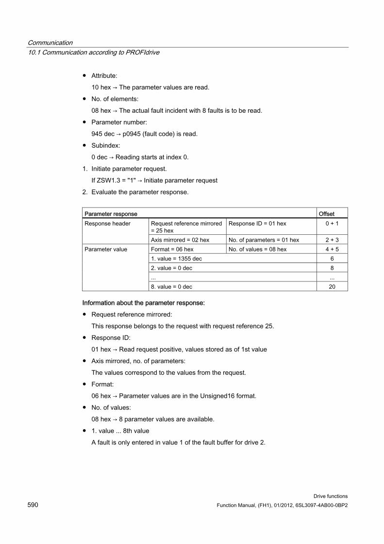
Communication 10.1 Communication according to PROFIdrive
Drive functions 590 Function Manual, (FH1), 01/2012, 6SL3097-4AB00-0BP2
Attribute:
10 hex → The parameter values are read.
No. of elements:
08 hex → The actual fault incident with 8 faults is to be read.
Parameter number:
945 dec → p0945 (fault code) is read.
Subindex:
0 dec → Reading starts at index 0.
1. Initiate parameter request.
If ZSW1.3 = "1" → Initiate parameter request
2. Evaluate the parameter response.
Parameter response Offset
Request reference mirrored = 25 hex
Response ID = 01 hex 0 + 1 Response header
Axis mirrored = 02 hex No. of parameters = 01 hex 2 + 3 Format = 06 hex No. of values = 08 hex 4 + 5 1. value = 1355 dec 6 2. value = 0 dec 8 ... ...
Parameter value
8. value = 0 dec 20
Information about the parameter response:
Request reference mirrored:
This response belongs to the request with request reference 25.
Response ID:
01 hex → Read request positive, values stored as of 1st value
Axis mirrored, no. of parameters:
The values correspond to the values from the request.
Format:
06 hex → Parameter values are in the Unsigned16 format.
No. of values:
08 hex → 8 parameter values are available.
1. value ... 8th value
A fault is only entered in value 1 of the fault buffer for drive 2.
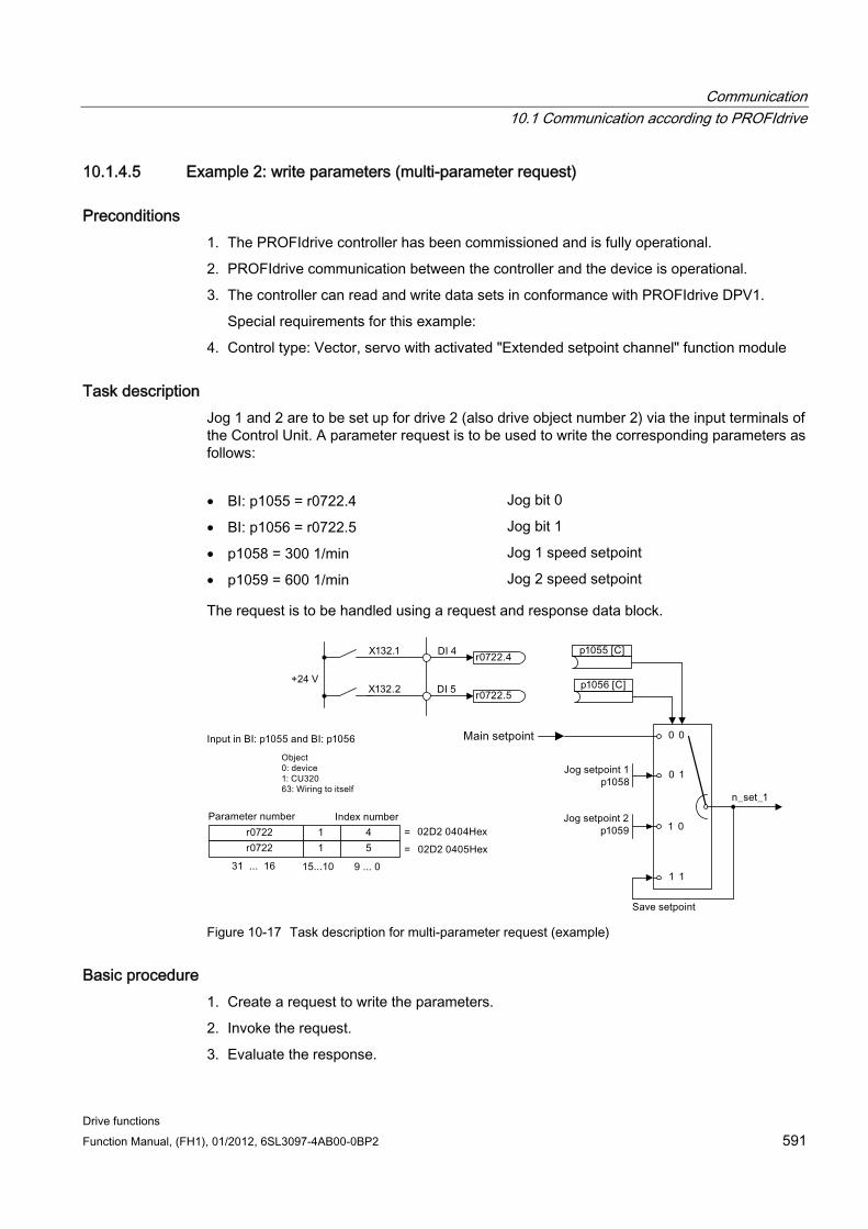
Communication 10.1 Communication according to PROFIdrive
Drive functions Function Manual, (FH1), 01/2012, 6SL3097-4AB00-0BP2 591
10.1.4.5 Example 2: write parameters (multi-parameter request)
Preconditions 1. The PROFIdrive controller has been commissioned and is fully operational.
2. PROFIdrive communication between the controller and the device is operational.
3. The controller can read and write data sets in conformance with PROFIdrive DPV1.
Special requirements for this example:
4. Control type: Vector, servo with activated "Extended setpoint channel" function module
Task description Jog 1 and 2 are to be set up for drive 2 (also drive object number 2) via the input terminals of the Control Unit. A parameter request is to be used to write the corresponding parameters as follows:
• BI: p1055 = r0722.4 Jog bit 0
• BI: p1056 = r0722.5 Jog bit 1
• p1058 = 300 1/min Jog 1 speed setpoint
• p1059 = 600 1/min Jog 2 speed setpoint
The request is to be handled using a request and response data block.
Figure 10-17 Task description for multi-parameter request (example)
Basic procedure 1. Create a request to write the parameters.
2. Invoke the request.
3. Evaluate the response.
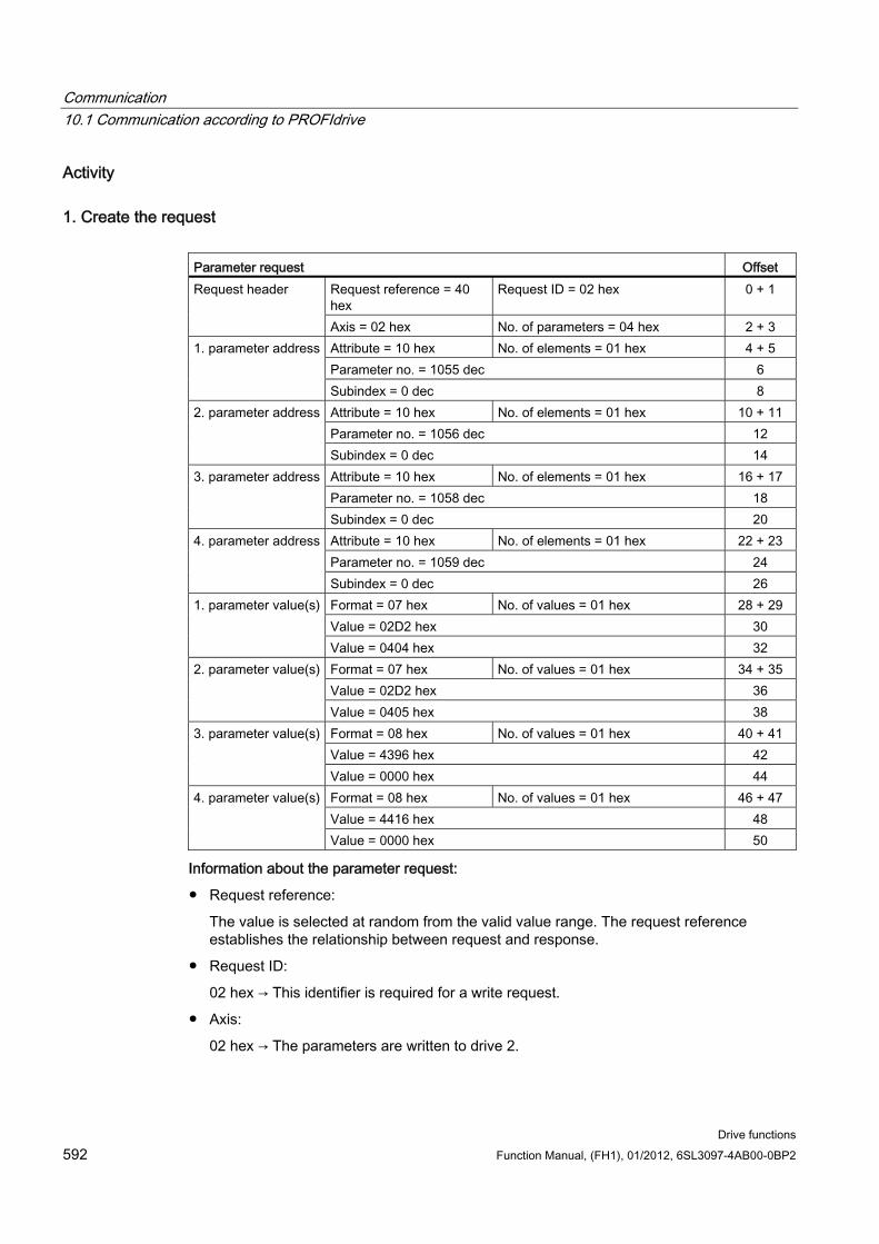
Communication 10.1 Communication according to PROFIdrive
Drive functions 592 Function Manual, (FH1), 01/2012, 6SL3097-4AB00-0BP2
Activity
1. Create the request Parameter request Offset
Request reference = 40 hex
Request ID = 02 hex 0 + 1 Request header
Axis = 02 hex No. of parameters = 04 hex 2 + 3 Attribute = 10 hex No. of elements = 01 hex 4 + 5 Parameter no. = 1055 dec 6
1. parameter address
Subindex = 0 dec 8 Attribute = 10 hex No. of elements = 01 hex 10 + 11 Parameter no. = 1056 dec 12
2. parameter address
Subindex = 0 dec 14 Attribute = 10 hex No. of elements = 01 hex 16 + 17 Parameter no. = 1058 dec 18
3. parameter address
Subindex = 0 dec 20 Attribute = 10 hex No. of elements = 01 hex 22 + 23 Parameter no. = 1059 dec 24
4. parameter address
Subindex = 0 dec 26 Format = 07 hex No. of values = 01 hex 28 + 29 Value = 02D2 hex 30
1. parameter value(s)
Value = 0404 hex 32 Format = 07 hex No. of values = 01 hex 34 + 35 Value = 02D2 hex 36
2. parameter value(s)
Value = 0405 hex 38 Format = 08 hex No. of values = 01 hex 40 + 41 Value = 4396 hex 42
3. parameter value(s)
Value = 0000 hex 44 Format = 08 hex No. of values = 01 hex 46 + 47 Value = 4416 hex 48
4. parameter value(s)
Value = 0000 hex 50
Information about the parameter request:
Request reference:
The value is selected at random from the valid value range. The request reference establishes the relationship between request and response.
Request ID:
02 hex → This identifier is required for a write request.
Axis:
02 hex → The parameters are written to drive 2.
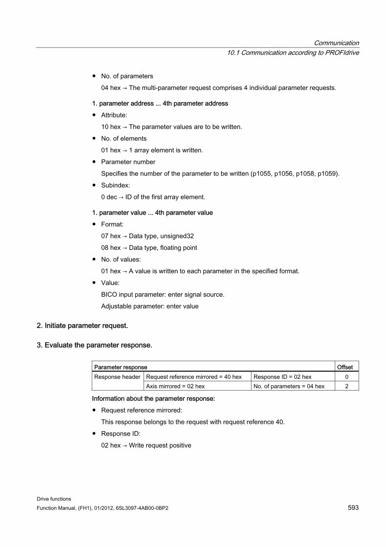
Communication 10.1 Communication according to PROFIdrive
Drive functions Function Manual, (FH1), 01/2012, 6SL3097-4AB00-0BP2 593
No. of parameters
04 hex → The multi-parameter request comprises 4 individual parameter requests.
1. parameter address ... 4th parameter address
Attribute:
10 hex → The parameter values are to be written.
No. of elements
01 hex → 1 array element is written.
Parameter number
Specifies the number of the parameter to be written (p1055, p1056, p1058, p1059).
Subindex:
0 dec → ID of the first array element.
1. parameter value ... 4th parameter value
Format:
07 hex → Data type, unsigned32
08 hex → Data type, floating point
No. of values:
01 hex → A value is written to each parameter in the specified format.
Value:
BICO input parameter: enter signal source.
Adjustable parameter: enter value
2. Initiate parameter request.
3. Evaluate the parameter response. Parameter response Offset
Request reference mirrored = 40 hex Response ID = 02 hex 0 Response header Axis mirrored = 02 hex No. of parameters = 04 hex 2
Information about the parameter response:
Request reference mirrored:
This response belongs to the request with request reference 40.
Response ID:
02 hex → Write request positive
Communication 10.2 Communication via PROFIBUS DP
Drive functions 594 Function Manual, (FH1), 01/2012, 6SL3097-4AB00-0BP2
Axis mirrored:
02 hex → The value matches the value from the request.
No. of parameters:
04 hex → The value matches the value from the request.
10.2 Communication via PROFIBUS DP
10.2.1 General information about PROFIBUS
10.2.1.1 General information about PROFIBUS for SINAMICS PROFIBUS is an open international field bus standard for a wide range of production and process automation applications.
The following standards ensure open, multi-vendor systems:
International standard EN 50170
International standard IEC 61158
PROFIBUS is optimized for high-speed, time-critical data communication at field level.
Note
PROFIBUS for drive technology is standardized and described in the following document: References: /P5/ PROFIdrive Profile Drive Technology
CAUTION Before synchronizing to the isochronous PROFIBUS, all of the pulses of the drive objects must be inhibited - also for those drives that are not controlled via PROFIBUS.
The cyclic PZD channel is deactivated when the CBE20 is plugged in!
CAUTION No CAN cables must be connected to interface X126. If CAN cables are connected, the CU320-2 and other CAN bus nodes may be destroyed.
Communication 10.2 Communication via PROFIBUS DP
Drive functions Function Manual, (FH1), 01/2012, 6SL3097-4AB00-0BP2 595
Master and slave Master and slave properties
Table 10- 54 Master and slave properties
Properties Master Slave As bus node Active Passive Send messages Permitted without external
request Only possible on request by master
Receive messages Possible without any restrictions Only receive and acknowledge permitted
Master
Masters are categorized into the following classes:
– Master class 1 (DPMC1):
Central automation stations that exchange data with the slaves in cyclic and acyclic mode. Communication between the masters is also possible.
Examples: SIMATIC S7, SIMOTION
– Master class 2 (DPMC2):
Devices for configuration, commissioning, operator control and monitoring during bus operation. Devices that only exchange data with the slaves in acyclic mode.
Examples: Programming devices, human machine interfaces
Slaves
With respect to PROFIBUS, the SINAMICS drive unit is a slave.
Bus access method PROFIBUS uses the token passing method, i.e. the active stations (masters) are arranged in a logical ring in which the authorization to send is received within a defined time frame.
Within this time frame, the master with authorization to send can communicate with other masters or handle communication with the assigned slaves in a master/slave procedure.
PROFIBUS telegram for cyclic data transmission and acyclic services Each drive unit that supports cyclic process data exchange uses a telegram to send and receive all the process data. A separate telegram is sent in order to perform all the acyclic services (read/write parameters) under a single PROFIBUS address. The acyclic data is transmitted with a lower priority after cyclic data transmission.
The overall length of the telegram increases with the number of drive objects that are involved in exchanging process data.
Communication 10.2 Communication via PROFIBUS DP
Drive functions 596 Function Manual, (FH1), 01/2012, 6SL3097-4AB00-0BP2
Sequence of drive objects in the telegram On the drive side, the sequence of drive objects in the telegram is displayed via a list in p0978[0...24] where it can also be changed.
You can use the STARTER commissioning tool to display the sequence of drive objects for a commissioned drive system in the online mode under → Drive unit → Communication→ Telegram configuration.
When you create the configuration on the controller side (e.g. HWConfig), the process-data-capable drive objects for the application are added to the telegram in this sequence.
The following drive objects can exchange process data:
Active Infeed (A_INF)
Basic Infeed (B_INF)
Control Unit (CU_S)
ENCODER
Smart Infeed (S_INF)
SERVO
Terminal Board 30 (TB30)
Terminal Module 15 (TM15)
Terminal Module 31 (TM31)
Terminal Module 41 (TM41)
Terminal Module 120 (TM120)
Terminal Module 150 (TM150)
VECTOR
Note
The sequence of drive objects in HW Config must be the same as that in the drive (p0978).
The structure of the telegram depends on the drive objects taken into account during configuration. Configurations are permitted that do not take into account all of the drive objects that are present in the drive system.
Example:
The following configurations, for example, are possible:
Configuration with SERVO, SERVO, SERVO
Configuration with A_INF, SERVO, SERVO, SERVO, TB30
and others
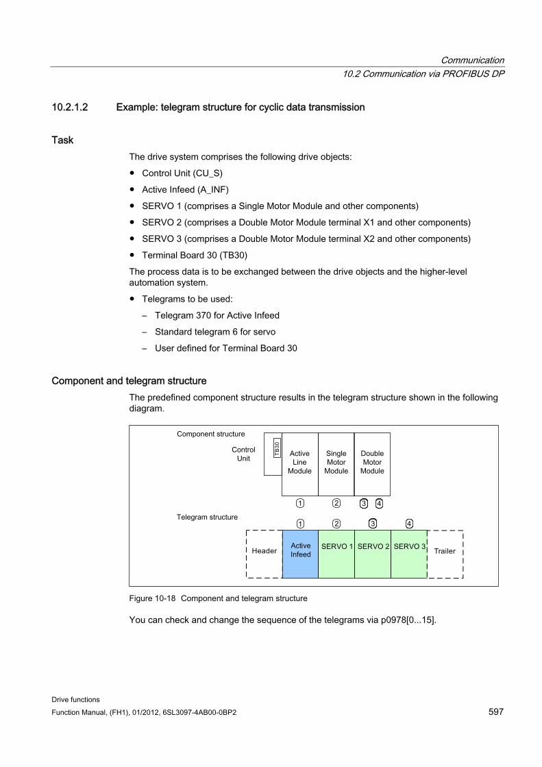
Communication 10.2 Communication via PROFIBUS DP
Drive functions Function Manual, (FH1), 01/2012, 6SL3097-4AB00-0BP2 597
10.2.1.2 Example: telegram structure for cyclic data transmission
Task The drive system comprises the following drive objects:
Control Unit (CU_S)
Active Infeed (A_INF)
SERVO 1 (comprises a Single Motor Module and other components)
SERVO 2 (comprises a Double Motor Module terminal X1 and other components)
SERVO 3 (comprises a Double Motor Module terminal X2 and other components)
Terminal Board 30 (TB30)
The process data is to be exchanged between the drive objects and the higher-level automation system.
Telegrams to be used:
– Telegram 370 for Active Infeed
– Standard telegram 6 for servo
– User defined for Terminal Board 30
Component and telegram structure The predefined component structure results in the telegram structure shown in the following diagram.
Figure 10-18 Component and telegram structure
You can check and change the sequence of the telegrams via p0978[0...15].
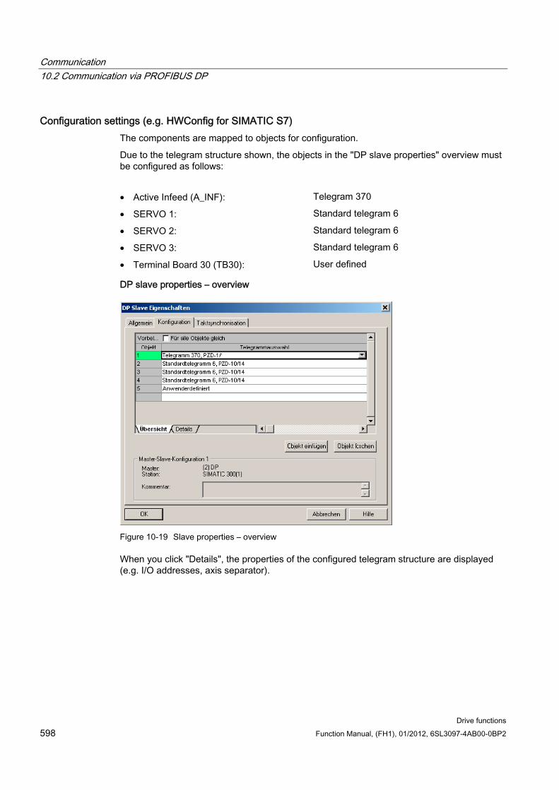
Communication 10.2 Communication via PROFIBUS DP
Drive functions 598 Function Manual, (FH1), 01/2012, 6SL3097-4AB00-0BP2
Configuration settings (e.g. HWConfig for SIMATIC S7) The components are mapped to objects for configuration.
Due to the telegram structure shown, the objects in the "DP slave properties" overview must be configured as follows:
• Active Infeed (A_INF): Telegram 370
• SERVO 1: Standard telegram 6
• SERVO 2: Standard telegram 6
• SERVO 3: Standard telegram 6
• Terminal Board 30 (TB30): User defined
DP slave properties – overview
Figure 10-19 Slave properties – overview
When you click "Details", the properties of the configured telegram structure are displayed (e.g. I/O addresses, axis separator).
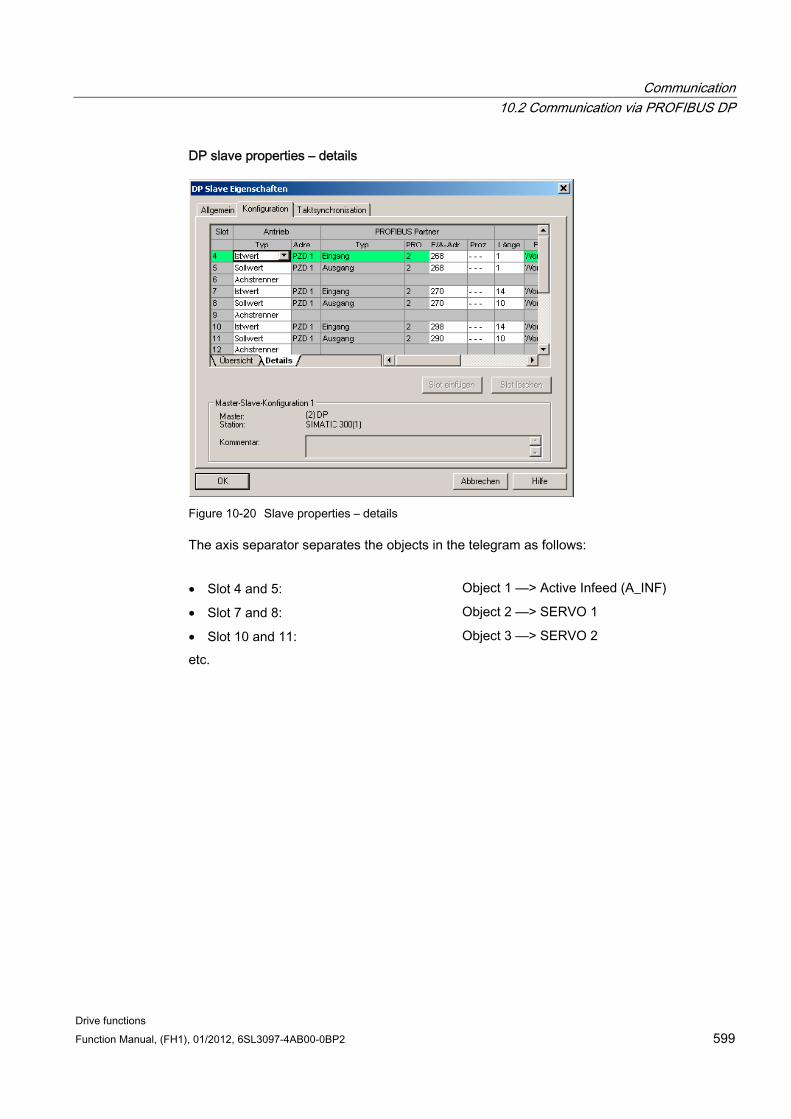
Communication 10.2 Communication via PROFIBUS DP
Drive functions Function Manual, (FH1), 01/2012, 6SL3097-4AB00-0BP2 599
DP slave properties – details
Figure 10-20 Slave properties – details
The axis separator separates the objects in the telegram as follows:
• Slot 4 and 5: Object 1 ––> Active Infeed (A_INF)
• Slot 7 and 8: Object 2 ––> SERVO 1
• Slot 10 and 11: Object 3 ––> SERVO 2
etc.
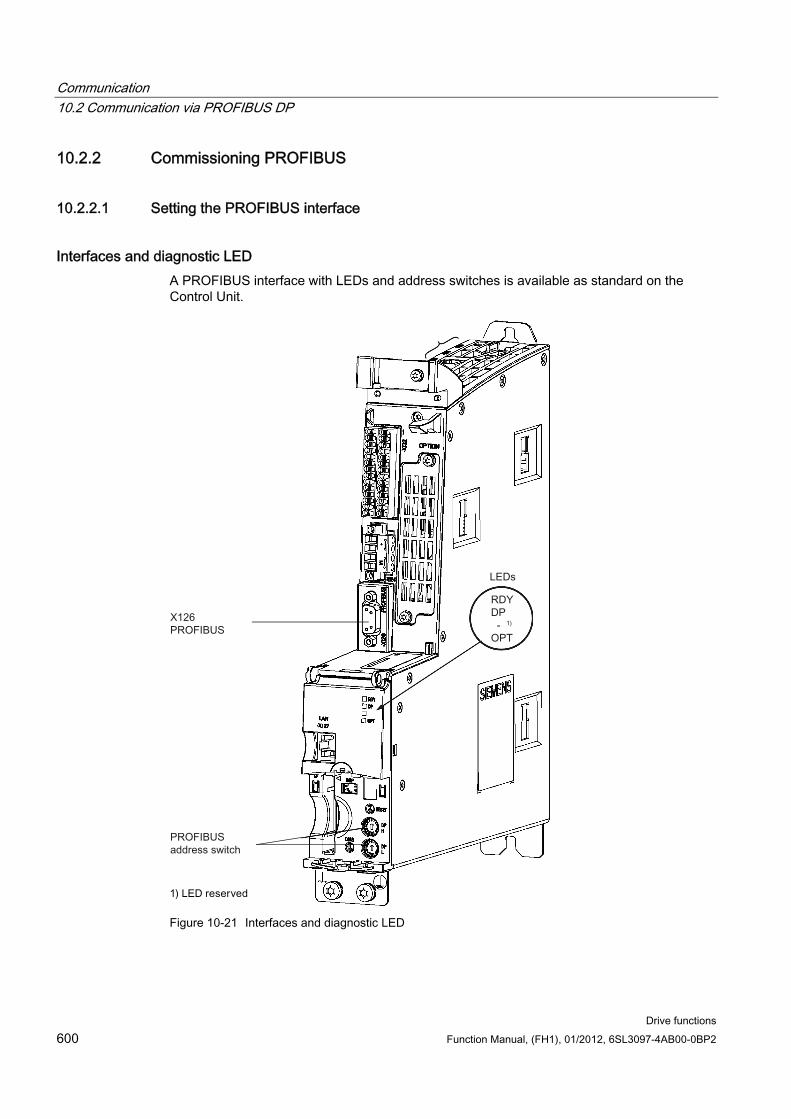
Communication 10.2 Communication via PROFIBUS DP
Drive functions 600 Function Manual, (FH1), 01/2012, 6SL3097-4AB00-0BP2
10.2.2 Commissioning PROFIBUS
10.2.2.1 Setting the PROFIBUS interface
Interfaces and diagnostic LED A PROFIBUS interface with LEDs and address switches is available as standard on the Control Unit.
Figure 10-21 Interfaces and diagnostic LED
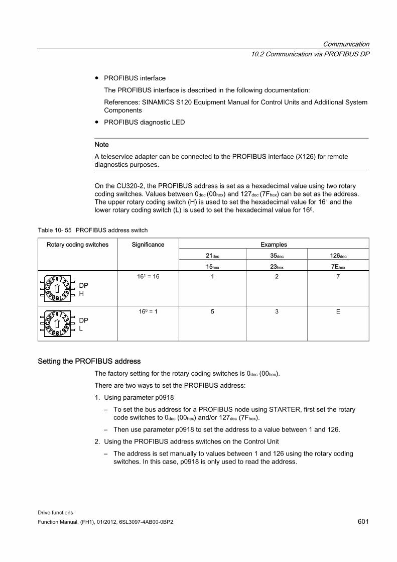
Communication 10.2 Communication via PROFIBUS DP
Drive functions Function Manual, (FH1), 01/2012, 6SL3097-4AB00-0BP2 601
PROFIBUS interface
The PROFIBUS interface is described in the following documentation:
References: SINAMICS S120 Equipment Manual for Control Units and Additional System Components
PROFIBUS diagnostic LED
Note
A teleservice adapter can be connected to the PROFIBUS interface (X126) for remote diagnostics purposes.
On the CU320-2, the PROFIBUS address is set as a hexadecimal value using two rotary coding switches. Values between 0dec (00hex) and 127dec (7Fhex) can be set as the address. The upper rotary coding switch (H) is used to set the hexadecimal value for 161 and the lower rotary coding switch (L) is used to set the hexadecimal value for 160.
Table 10- 55 PROFIBUS address switch
Examples
21dec 35dec 126dec
Rotary coding switches Significance
15hex 23hex 7Ehex
161 = 16 1 2 7
160 = 1 5 3 E
Setting the PROFIBUS address The factory setting for the rotary coding switches is 0dec (00hex).
There are two ways to set the PROFIBUS address:
1. Using parameter p0918
– To set the bus address for a PROFIBUS node using STARTER, first set the rotary code switches to 0dec (00hex) and/or 127dec (7Fhex).
– Then use parameter p0918 to set the address to a value between 1 and 126.
2. Using the PROFIBUS address switches on the Control Unit
– The address is set manually to values between 1 and 126 using the rotary coding switches. In this case, p0918 is only used to read the address.
Communication 10.2 Communication via PROFIBUS DP
Drive functions 602 Function Manual, (FH1), 01/2012, 6SL3097-4AB00-0BP2
Note
The rotary coding switches used to set the PROFIBUS address are located beneath the blanking cover Auto-Hotspot.
Note
Address 126 is used for commissioning. Permitted PROFIBUS addresses are 1 ... 126.
When several Control Units are connected to a PROFIBUS line, you set the addresses differently than for the factory setting. Each PROFIBUS address in a PROFIBUS line can only be assigned once. Either set the PROFIBUS address in absolute terms using the rotary coding switches – or selectively in parameter p0918. Each change made to the bus address is not effective until POWER ON.
The currently set address of the rotary coding switch is displayed in parameter r2057.
Note
Only values from 1 to 126 (7Ehex) are valid for PROFIBUS addressing. If values above 127 are set, then the set value is interpreted as "0". If a value "0" or "127" is set, the value in parameter p0918 defines the PROFIBUS address.
10.2.2.2 PROFIBUS interface in operation
Generic station description file A generic station description file clearly and completely defines the properties of a PROFIBUS slave.
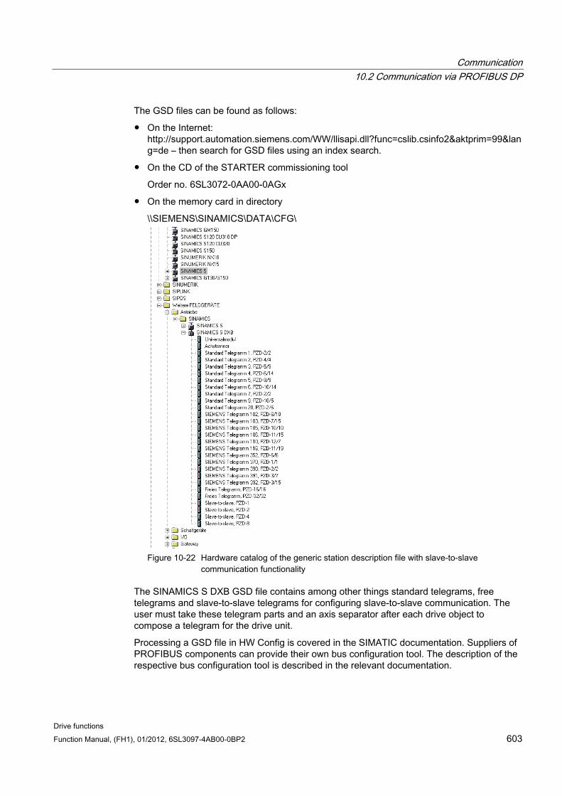
Communication 10.2 Communication via PROFIBUS DP
Drive functions Function Manual, (FH1), 01/2012, 6SL3097-4AB00-0BP2 603
The GSD files can be found as follows:
On the Internet: http://support.automation.siemens.com/WW/llisapi.dll?func=cslib.csinfo2&aktprim=99&lang=de – then search for GSD files using an index search.
On the CD of the STARTER commissioning tool
Order no. 6SL3072-0AA00-0AGx
On the memory card in directory
\\SIEMENS\SINAMICS\DATA\CFG\
Figure 10-22 Hardware catalog of the generic station description file with slave-to-slave
communication functionality
The SINAMICS S DXB GSD file contains among other things standard telegrams, free telegrams and slave-to-slave telegrams for configuring slave-to-slave communication. The user must take these telegram parts and an axis separator after each drive object to compose a telegram for the drive unit.
Processing a GSD file in HW Config is covered in the SIMATIC documentation. Suppliers of PROFIBUS components can provide their own bus configuration tool. The description of the respective bus configuration tool is described in the relevant documentation.
Communication 10.2 Communication via PROFIBUS DP
Drive functions 604 Function Manual, (FH1), 01/2012, 6SL3097-4AB00-0BP2
Note for commissioning for VIK–NAMUR To be able to operate a SINAMICS drive as a VIK-NAMUR drive, standard telegram 20 must be set and the VIK-NAMUR identification number activated via p2042 =1.
Device identification Identification for individual slaves facilitates diagnostics and provides an overview of the nodes on the PROFIBUS.
The information for each slave is stored in the following CU-specific parameter: r0964[0...6] device identification
Bus terminating resistor and shielding Reliable data transmission via PROFIBUS depends, amongst other things, on the setting of the bus terminating resistors and the shielding of the PROFIBUS cables.
Bus terminating resistor
The bus terminating resistors in the PROFIBUS plugs must be set as follows:
– First and last nodes in the line: switch in terminating resistor
– Other nodes in the line: switch out terminating resistor
Shielding of the PROFIBUS cables The cable shield must be connected in the plug through a large surface area at both ends. References: /GH1/ SINAMICS S120 Equipment Manual for Control Units and Additional System Components
10.2.2.3 Commissioning PROFIBUS
Preconditions and assumptions for commissioning PROFIBUS slave
The PROFIBUS address to be set for the application is known.
The telegram type for each drive object is known by the application.
PROFIBUS master
The communication properties of the SINAMICS S120 slave must be available in the master (GSD file or drive ES slave OM).
Commissioning steps (example with SIMATIC S7) 1. Set the PROFIBUS address on the slave.
2. Set the telegram type on the slave.
Communication 10.2 Communication via PROFIBUS DP
Drive functions Function Manual, (FH1), 01/2012, 6SL3097-4AB00-0BP2 605
3. Carry out the following in HWConfig:
– Connect the drive to PROFIBUS and assign an address.
– Set the telegram type.
The same telegram type as on the slave should be set for every drive object exchanging process data via PROFIBUS.
The master can send more process data than the slave uses. A telegram with a larger PZD number than is assigned for the drive object STARTER can be configured on the master.
The PZDs not supplied by the drive object are filled with zeros.
The setting "without PZD" can be defined on a node or object (e.g. infeed controlled via terminals).
4. The I/O addresses must be assigned in accordance with the user program.
10.2.2.4 Diagnostics options The standard slave diagnostics can be read online in the HW config.
10.2.2.5 SIMATIC HMI addressing You can use a SIMATIC HMI as a PROFIBUS master (master class 2) to access SINAMICS directly. With respect to SIMATIC HMI, SINAMICS behaves like a SIMATIC S7. For accessing drive parameters, the following simple rule applies:
Parameter number = data block number
Parameter sub-index = bit 0 ... 9 of data block offset
Drive object number = bit 10 ... 15 of data block offset
Pro Tool and WinCC flexible The SIMATIC HMI can be configured flexibly with "Pro Tool" or "WinCC flexible".
The following specific settings for drives must be observed when configuration is carried out with Pro Tool or WinCC flexible.
Controllers: Protocol always "SIMATIC S7 - 300/400"
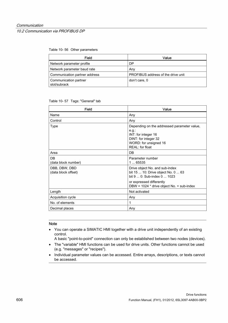
Communication 10.2 Communication via PROFIBUS DP
Drive functions 606 Function Manual, (FH1), 01/2012, 6SL3097-4AB00-0BP2
Table 10- 56 Other parameters
Field Value Network parameter profile DP Network parameter baud rate Any Communication partner address PROFIBUS address of the drive unit Communication partner slot/subrack
don’t care, 0
Table 10- 57 Tags: "General" tab
Field Value Name Any Control Any Type Depending on the addressed parameter value,
e.g.: INT: for integer 16 DINT: for integer 32 WORD: for unsigned 16 REAL: for float
Area DB DB (data block number)
Parameter number 1 ... 65535
DBB, DBW, DBD (data block offset)
Drive object No. and sub-index bit 15 ... 10: Drive object No. 0 ... 63 bit 9 ... 0: Sub-index 0 ... 1023 or expressed differently DBW = 1024 * drive object No. + sub-index
Length Not activated Acquisition cycle Any No. of elements 1 Decimal places Any
Note • You can operate a SIMATIC HMI together with a drive unit independently of an existing
control. A basic "point-to-point" connection can only be established between two nodes (devices).
• The "variable" HMI functions can be used for drive units. Other functions cannot be used (e.g. "messages" or "recipes").
• Individual parameter values can be accessed. Entire arrays, descriptions, or texts cannot be accessed.
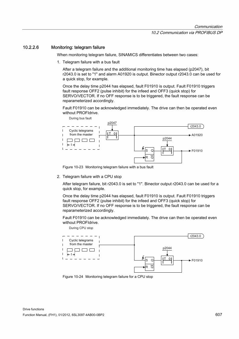
Communication 10.2 Communication via PROFIBUS DP
Drive functions Function Manual, (FH1), 01/2012, 6SL3097-4AB00-0BP2 607
10.2.2.6 Monitoring: telegram failure When monitoring telegram failure, SINAMICS differentiates between two cases:
1. Telegram failure with a bus fault
After a telegram failure and the additional monitoring time has elapsed (p2047), bit r2043.0 is set to "1" and alarm A01920 is output. Binector output r2043.0 can be used for a quick stop, for example.
Once the delay time p2044 has elapsed, fault F01910 is output. Fault F01910 triggers fault response OFF2 (pulse inhibit) for the infeed and OFF3 (quick stop) for SERVO/VECTOR. If no OFF response is to be triggered, the fault response can be reparameterized accordingly.
Fault F01910 can be acknowledged immediately. The drive can then be operated even without PROFIdrive.
Figure 10-23 Monitoring telegram failure with a bus fault
2. Telegram failure with a CPU stop
After telegram failure, bit r2043.0 is set to "1". Binector output r2043.0 can be used for a quick stop, for example.
Once the delay time p2044 has elapsed, fault F01910 is output. Fault F01910 triggers fault response OFF2 (pulse inhibit) for the infeed and OFF3 (quick stop) for SERVO/VECTOR. If no OFF response is to be triggered, the fault response can be reparameterized accordingly.
Fault F01910 can be acknowledged immediately. The drive can then be operated even without PROFIdrive.
Figure 10-24 Monitoring telegram failure for a CPU stop
Communication 10.2 Communication via PROFIBUS DP
Drive functions 608 Function Manual, (FH1), 01/2012, 6SL3097-4AB00-0BP2
Example: emergency stop with telegram failure Assumption:
A drive unit with an Active Line Module and a Single Motor Module.
VECTOR mode is activated.
After a ramp-down time (p1135) of two seconds, the drive is at a standstill.
Settings:
CU p2047 = 20 ms
A_INF p2044 = 2 ms
VECTOR p2044 = 0 ms
Sequence:
Following a telegram failure and once the additional monitoring time (p2047) has elapsed, binector output r2043.0 of drive object CU switches to "1". At the same time, alarm A01920 is output for the A_INF drive objects and alarm A01920 and fault F01910 are output for VECTOR. When F01910 is output, an OFF3 is triggered for the drive. After a two-second delay time (p2044), fault F01910 is output on the infeed and triggers OFF2.
Note
The additional monitoring time parameter p2047 is only useful for cyclic communication. During isochronous communication, a telegram failure should be recorded without delay, in order to respond as quickly as possible.
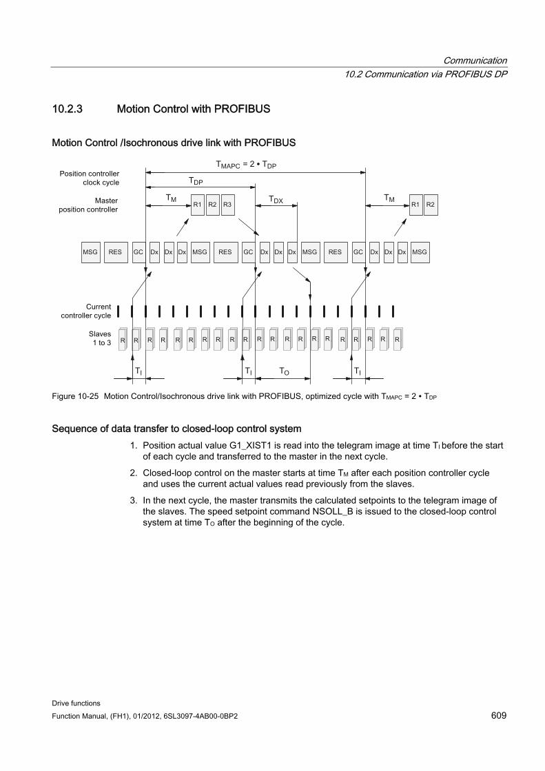
Communication 10.2 Communication via PROFIBUS DP
Drive functions Function Manual, (FH1), 01/2012, 6SL3097-4AB00-0BP2 609
10.2.3 Motion Control with PROFIBUS
Motion Control /Isochronous drive link with PROFIBUS
Figure 10-25 Motion Control/Isochronous drive link with PROFIBUS, optimized cycle with TMAPC = 2 ∙ TDP
Sequence of data transfer to closed-loop control system 1. Position actual value G1_XIST1 is read into the telegram image at time TI before the start
of each cycle and transferred to the master in the next cycle.
2. Closed-loop control on the master starts at time TM after each position controller cycle and uses the current actual values read previously from the slaves.
3. In the next cycle, the master transmits the calculated setpoints to the telegram image of the slaves. The speed setpoint command NSOLL_B is issued to the closed-loop control system at time TO after the beginning of the cycle.
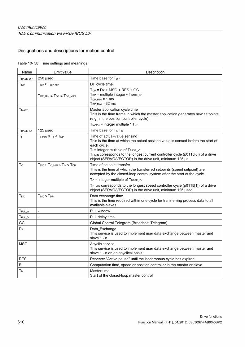
Communication 10.2 Communication via PROFIBUS DP
Drive functions 610 Function Manual, (FH1), 01/2012, 6SL3097-4AB00-0BP2
Designations and descriptions for motion control
Table 10- 58 Time settings and meanings
Name Limit value Description TBASE_DP 250 µsec Time base for TDP TDP TDP ≥ TDP_MIN
TDP_MIN ≤ TDP ≤ TDP_MAX
DP cycle time TDP = Dx + MSG + RES + GC TDP = multiple integer ∙ TBASE_DP TDP_MIN = 1 ms TDP_MAX =32 ms
TMAPC Master application cycle time This is the time frame in which the master application generates new setpoints (e.g. in the position controller cycle). TMAPC = integer multiple * TDP
TBASE_IO 125 µsec Time base for TI, TO TI TI_MIN ≤ TI < TDP Time of actual-value sensing
This is the time at which the actual position value is sensed before the start of each cycle. TI = integer multiple of TBASE_IO TI_MIN corresponds to the longest current controller cycle (p0115[0]) of a drive object (SERVO/VECTOR) in the drive unit, minimum 125 µs.
TO TDX + TO_MIN ≤ TO < TDP Time of setpoint transfer This is the time at which the transferred setpoints (speed setpoint) are accepted by the closed-loop control system after the start of the cycle. TO = integer multiple of TBASE_IO TO_MIN corresponds to the longest speed controller cycle (p0115[1]) of a drive object (SERVO/VECTOR) in the drive unit, minimum 125 µsec
TDX TDX < TDP Data exchange time This is the time required within one cycle for transferring process data to all available slaves.
TPLL_W - PLL window TPLL_D - PLL delay time GC Global Control Telegram (Broadcast Telegram) Dx Data_Exchange
This service is used to implement user data exchange between master and slave 1 - n.
MSG Acyclic service This service is used to implement user data exchange between master and slave 1 - n on an acyclical basis.
RES Reserve: "Active pause" until the isochronous cycle has expired R Computation time, speed or position controller in the master or slave TM Master time
Start of the closed-loop master control
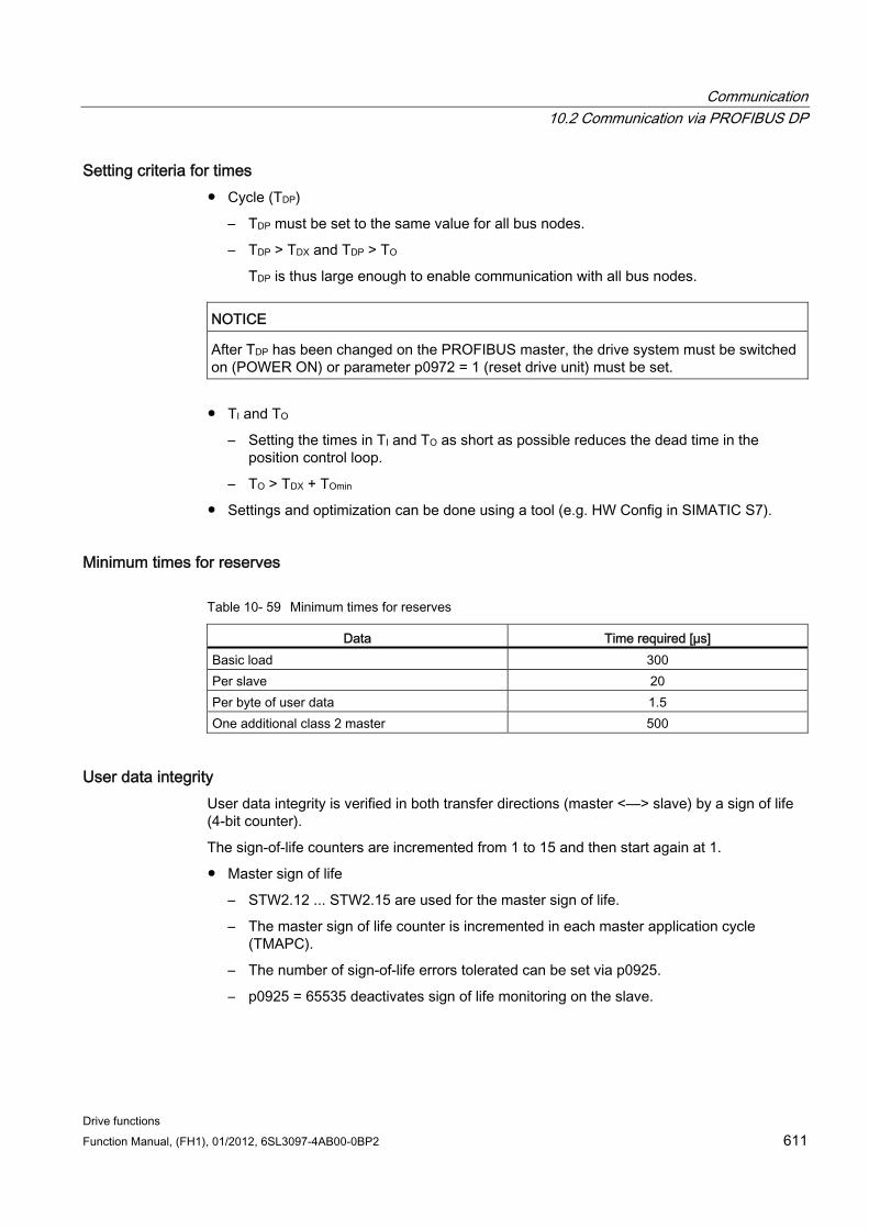
Communication 10.2 Communication via PROFIBUS DP
Drive functions Function Manual, (FH1), 01/2012, 6SL3097-4AB00-0BP2 611
Setting criteria for times Cycle (TDP)
– TDP must be set to the same value for all bus nodes.
– TDP > TDX and TDP > TO
TDP is thus large enough to enable communication with all bus nodes.
NOTICE After TDP has been changed on the PROFIBUS master, the drive system must be switched on (POWER ON) or parameter p0972 = 1 (reset drive unit) must be set.
TI and TO
– Setting the times in TI and TO as short as possible reduces the dead time in the position control loop.
– TO > TDX + TOmin
Settings and optimization can be done using a tool (e.g. HW Config in SIMATIC S7).
Minimum times for reserves
Table 10- 59 Minimum times for reserves
Data Time required [µs] Basic load 300 Per slave 20 Per byte of user data 1.5 One additional class 2 master 500
User data integrity User data integrity is verified in both transfer directions (master <––> slave) by a sign of life (4-bit counter).
The sign-of-life counters are incremented from 1 to 15 and then start again at 1.
Master sign of life
– STW2.12 ... STW2.15 are used for the master sign of life.
– The master sign of life counter is incremented in each master application cycle (TMAPC).
– The number of sign-of-life errors tolerated can be set via p0925.
– p0925 = 65535 deactivates sign of life monitoring on the slave.
Communication 10.2 Communication via PROFIBUS DP
Drive functions 612 Function Manual, (FH1), 01/2012, 6SL3097-4AB00-0BP2
– Monitoring
The master sign of life is monitored on the slave and any sign-of-life errors are evaluated accordingly.
The maximum number of tolerated master sign-of-life errors can be set via p0925.
If the number of tolerated sign-of-life errors set in p0925 is exceeded, the response is as follows:
– A corresponding message is output.
– The value zero is output as the slave sign of life.
– Synchronization with the master sign of life is started.
Slave sign of life
– ZSW2.12 ... ZSW2.15 are used for the slave sign of life.
– The slave sign of life counter is incremented in each DP cycle (TDP).
Example: SINAMICS vector drives with SIMOTION D4x5 and/or CX modules
To determine what cycles in the SINAMICS drive unit will be set after a project has been downloaded, dependable cycle values should be initially set in HW Config.
The following settings and sequences are recommended:
1. TDP = 3.0 ms (TDP = DP cycle time)
2. TI = To = 1.5 ms (TI = time of actual value acquisition, To = time of setpoint transfer)
3. TMAPC = 6.0 ms (TMAPC = master application cycle time)
After successful download, all current and speed controller cycles can be determined. These cycles can be optimized in HW Config if necessary. The cycles are set in HW Config under the DP slave properties of the SINAMICS drive unit (slave, master e.g. SIMOTION D4x5) under the "Clock synchronization" tab.
10.2.4 Slave-to-slave communication For PROFIBUS DP, the master interrogates all of the slaves one after the other in a DP cycle. In this case, the master transfers its output data (setpoints) to the particular slave and receives as response the input data (actual values). Fast, distributed data transfer between drives (slaves) is possible using the "slave-to-slave communication" function without direct involvement from the master.
The following terms are used for the function described in this chapter:
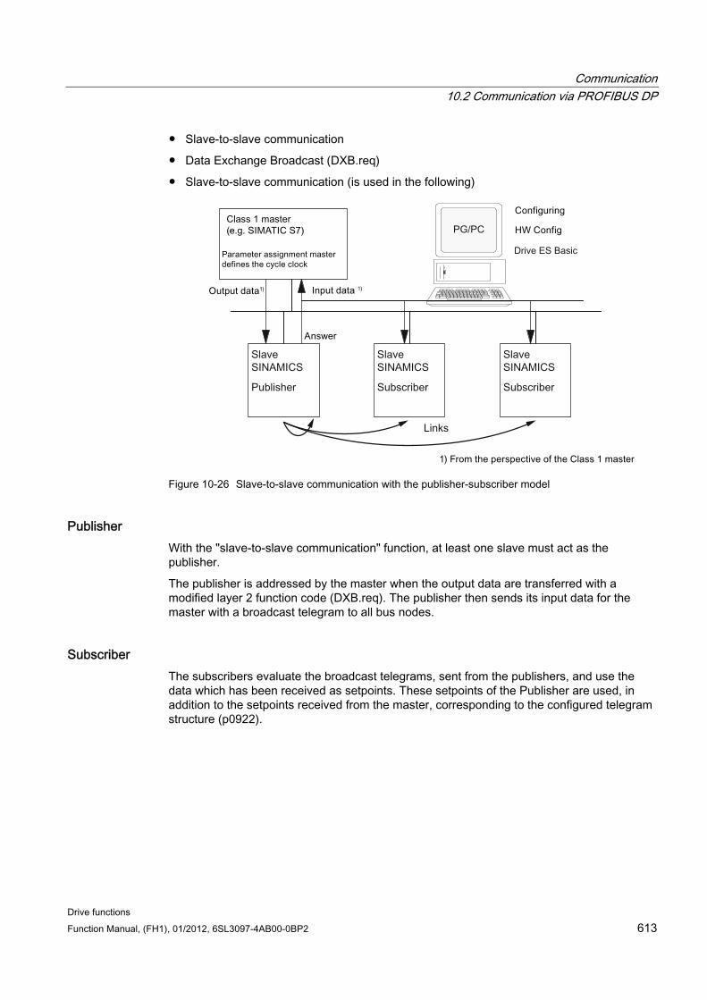
Communication 10.2 Communication via PROFIBUS DP
Drive functions Function Manual, (FH1), 01/2012, 6SL3097-4AB00-0BP2 613
Slave-to-slave communication
Data Exchange Broadcast (DXB.req)
Slave-to-slave communication (is used in the following)
Figure 10-26 Slave-to-slave communication with the publisher-subscriber model
Publisher With the "slave-to-slave communication" function, at least one slave must act as the publisher.
The publisher is addressed by the master when the output data are transferred with a modified layer 2 function code (DXB.req). The publisher then sends its input data for the master with a broadcast telegram to all bus nodes.
Subscriber The subscribers evaluate the broadcast telegrams, sent from the publishers, and use the data which has been received as setpoints. These setpoints of the Publisher are used, in addition to the setpoints received from the master, corresponding to the configured telegram structure (p0922).

Communication 10.2 Communication via PROFIBUS DP
Drive functions 614 Function Manual, (FH1), 01/2012, 6SL3097-4AB00-0BP2
Links and taps The links configured in the subscriber (connections to publisher) contain the following information:
From which Publisher the input data are received
What is the content of the input data
Where the additional setpoints are received
Several taps are possible within a link. Several input data or input data areas, which are not associated with one another, can be used as setpoint via a tap.
Links to your own drive units are possible. For example, data in a Double Motor Module can be transferred from drive A to drive B. This internal link corresponds, as far as the timing is concerned, to a link via PROFIBUS
Preconditions The following preconditions should be observed for the "slave-to-slave communication" function:
STARTER Version 4.2 or higher
Configuration:
– Drive ES Basic, Drive ES SIMATIC or Drive ES PCS7 Version 5.3 SP3 or higher
– Alternatively using a GSD file
Firmware version 4.3 or higher
The maximum number of process data per drive can be identified from the value in r2050 – minus the resources that have already been used
A maximum of 16 links to Publishers
Note
The "slave-to-slave communication" function is not available for the CU310-2 PN.
Applications For example, the following applications can be implemented using the "slave-to-slave communication" function:
Axis couplings (this is practical for isochronous mode)
Specifying binector connections from another slave
Communication 10.2 Communication via PROFIBUS DP
Drive functions Function Manual, (FH1), 01/2012, 6SL3097-4AB00-0BP2 615
10.2.4.1 Setpoint assignment in the subscriber
Information about setpoints Number of setpoint
When bus communication is being established, the master signals the slave the number of setpoints (process data) to be transferred using the configuring telegram (ChkCfg).
Contents of the setpoints
The structure and contents of the data are determined using the local process data configuration for the "SINAMICS slave".
Operation as "standard" slave
The drive unit (slave) only receives its setpoints as output data from the master.
Operation as subscriber
When a slave is operated as a subscriber, some of the setpoints are defined by one or more publishers rather than by the master.
The slave is informed of the assignment via the parameterization and configuration telegram when bus communication is being established.
10.2.4.2 Activating/parameterizing slave-to-slave communication The "slave-to-slave communication" function must be activated both in the publishers as well as in the subscribers, whereby only the subscriber is to be configured. The publisher is automatically activated during bus startup.
Activation in the Publisher The master is informed abut which slaves are to be addressed as publishers with a modified layer 2 function code (DXB req) via the configuration of the subscriber links.
The publisher then sends its input data not only to the master but also as a broadcast telegram to all bus nodes.
These settings are made automatically using the bus configuration tool (e.g. HW Config).
Activation in the Subscriber The slave, which is to be used as Subscriber, requires a filter table. The slave must know which setpoints are received from the master and which are received from a publisher.
The filter table is created automatically via the bus configuration tool (e.g. HW Config).
The following diagram shows the information contained in the filter table.
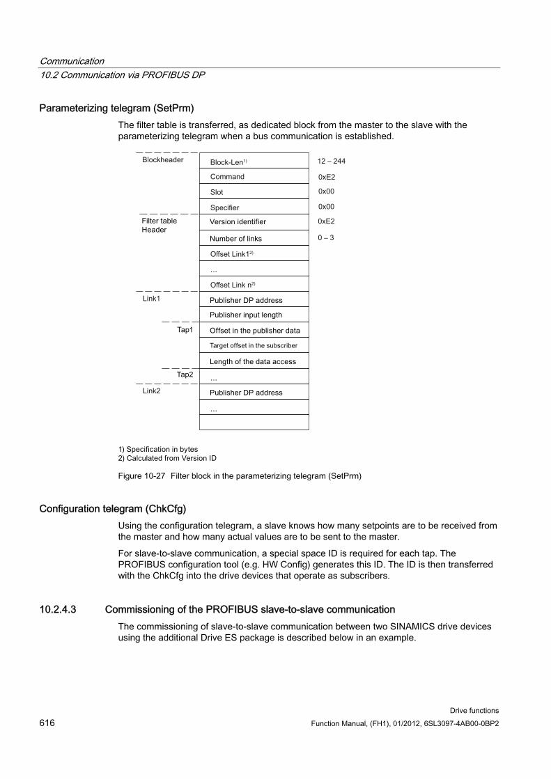
Communication 10.2 Communication via PROFIBUS DP
Drive functions 616 Function Manual, (FH1), 01/2012, 6SL3097-4AB00-0BP2
Parameterizing telegram (SetPrm) The filter table is transferred, as dedicated block from the master to the slave with the parameterizing telegram when a bus communication is established.
Figure 10-27 Filter block in the parameterizing telegram (SetPrm)
Configuration telegram (ChkCfg) Using the configuration telegram, a slave knows how many setpoints are to be received from the master and how many actual values are to be sent to the master.
For slave-to-slave communication, a special space ID is required for each tap. The PROFIBUS configuration tool (e.g. HW Config) generates this ID. The ID is then transferred with the ChkCfg into the drive devices that operate as subscribers.
10.2.4.3 Commissioning of the PROFIBUS slave-to-slave communication The commissioning of slave-to-slave communication between two SINAMICS drive devices using the additional Drive ES package is described below in an example.
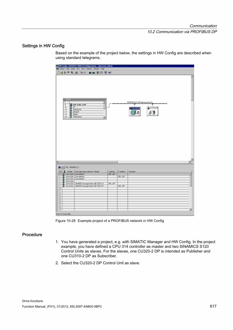
Communication 10.2 Communication via PROFIBUS DP
Drive functions Function Manual, (FH1), 01/2012, 6SL3097-4AB00-0BP2 617
Settings in HW Config Based on the example of the project below, the settings in HW Config are described when using standard telegrams.
Figure 10-28 Example project of a PROFIBUS network in HW Config
Procedure 1. You have generated a project, e.g. with SIMATIC Manager and HW Config. In the project
example, you have defined a CPU 314 controller as master and two SINAMICS S120 Control Units as slaves. For the slaves, one CU320-2 DP is intended as Publisher and one CU310-2 DP as Subscriber.
2. Select the CU320-2 DP Control Unit as slave.
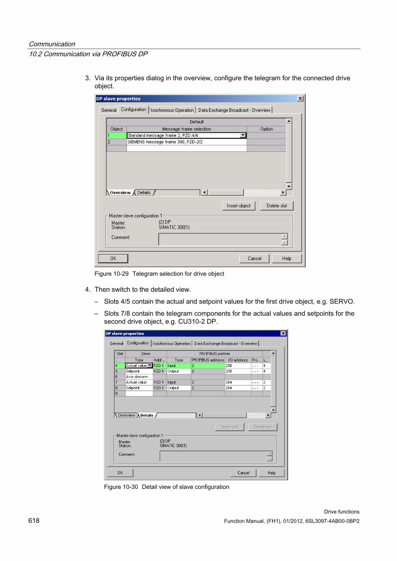
Communication 10.2 Communication via PROFIBUS DP
Drive functions 618 Function Manual, (FH1), 01/2012, 6SL3097-4AB00-0BP2
3. Via its properties dialog in the overview, configure the telegram for the connected drive object.
Figure 10-29 Telegram selection for drive object
4. Then switch to the detailed view.
– Slots 4/5 contain the actual and setpoint values for the first drive object, e.g. SERVO.
– Slots 7/8 contain the telegram components for the actual values and setpoints for the second drive object, e.g. CU310-2 DP.
Figure 10-30 Detail view of slave configuration
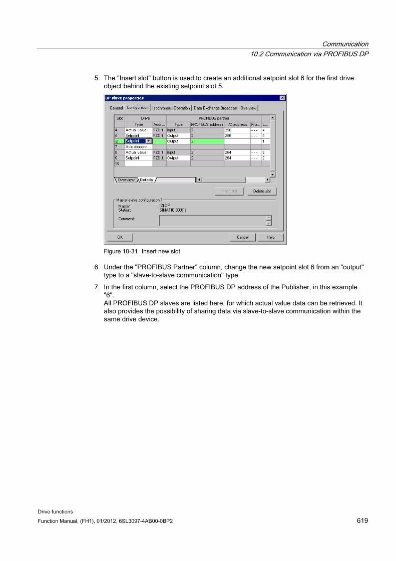
Communication 10.2 Communication via PROFIBUS DP
Drive functions Function Manual, (FH1), 01/2012, 6SL3097-4AB00-0BP2 619
5. The "Insert slot" button is used to create an additional setpoint slot 6 for the first drive object behind the existing setpoint slot 5.
Figure 10-31 Insert new slot
6. Under the "PROFIBUS Partner" column, change the new setpoint slot 6 from an "output" type to a "slave-to-slave communication" type.
7. In the first column, select the PROFIBUS DP address of the Publisher, in this example "6". All PROFIBUS DP slaves are listed here, for which actual value data can be retrieved. It also provides the possibility of sharing data via slave-to-slave communication within the same drive device.
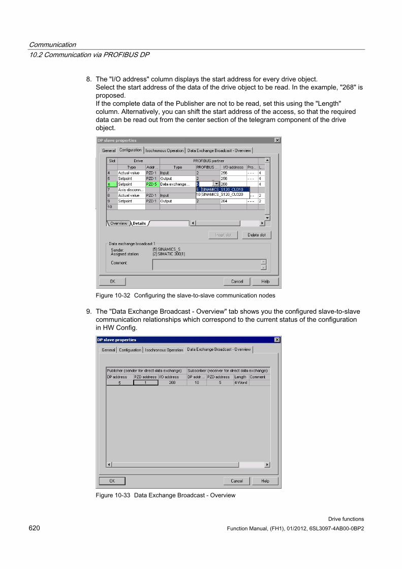
Communication 10.2 Communication via PROFIBUS DP
Drive functions 620 Function Manual, (FH1), 01/2012, 6SL3097-4AB00-0BP2
8. The "I/O address" column displays the start address for every drive object. Select the start address of the data of the drive object to be read. In the example, "268" is proposed. If the complete data of the Publisher are not to be read, set this using the "Length" column. Alternatively, you can shift the start address of the access, so that the required data can be read out from the center section of the telegram component of the drive object.
Figure 10-32 Configuring the slave-to-slave communication nodes
9. The "Data Exchange Broadcast - Overview" tab shows you the configured slave-to-slave communication relationships which correspond to the current status of the configuration in HW Config.
Figure 10-33 Data Exchange Broadcast - Overview
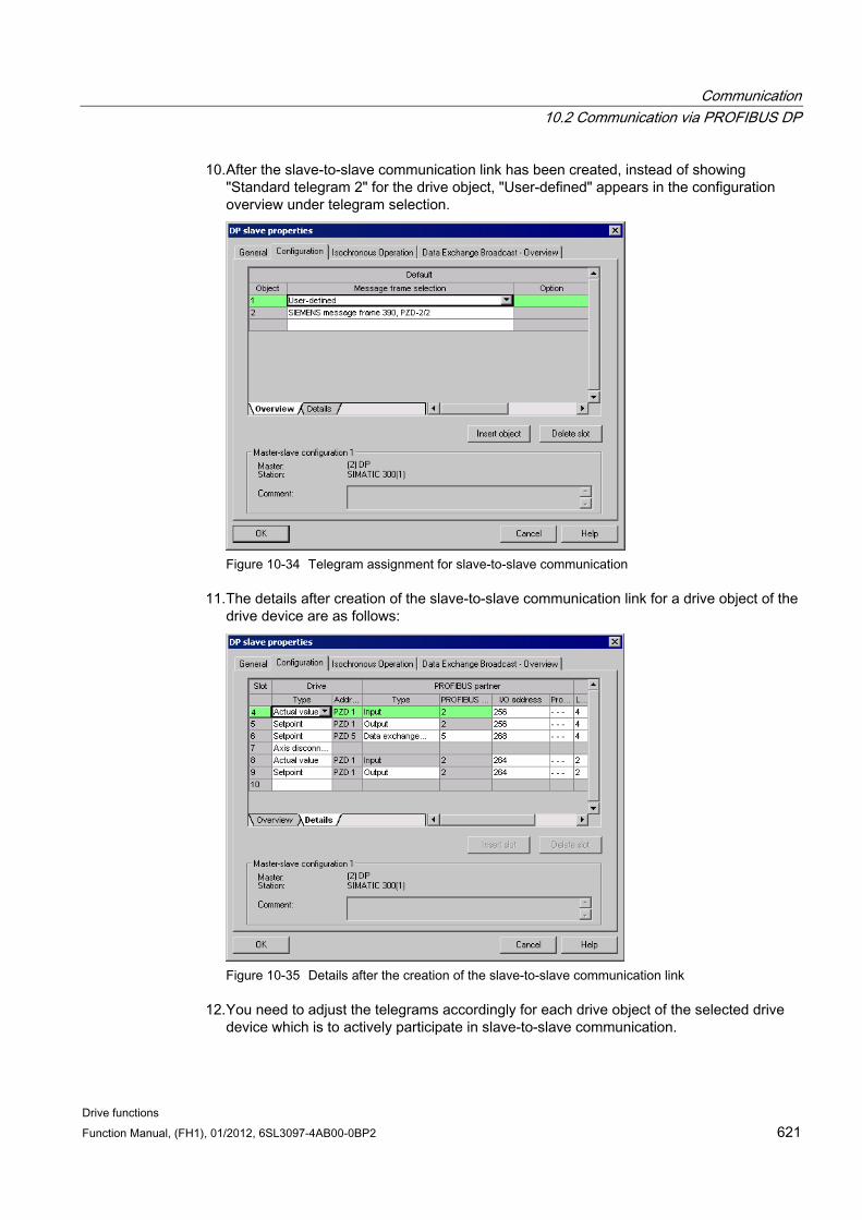
Communication 10.2 Communication via PROFIBUS DP
Drive functions Function Manual, (FH1), 01/2012, 6SL3097-4AB00-0BP2 621
10. After the slave-to-slave communication link has been created, instead of showing "Standard telegram 2" for the drive object, "User-defined" appears in the configuration overview under telegram selection.
Figure 10-34 Telegram assignment for slave-to-slave communication
11. The details after creation of the slave-to-slave communication link for a drive object of the drive device are as follows:
Figure 10-35 Details after the creation of the slave-to-slave communication link
12. You need to adjust the telegrams accordingly for each drive object of the selected drive device which is to actively participate in slave-to-slave communication.
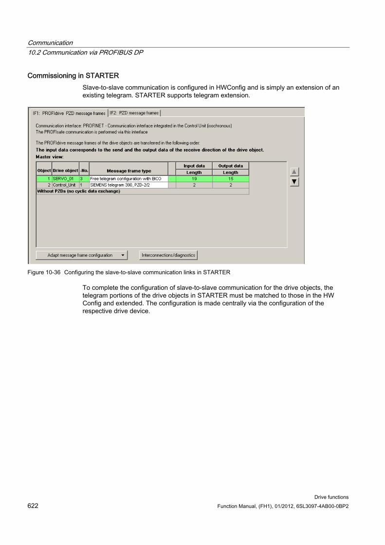
Communication 10.2 Communication via PROFIBUS DP
Drive functions 622 Function Manual, (FH1), 01/2012, 6SL3097-4AB00-0BP2
Commissioning in STARTER Slave-to-slave communication is configured in HWConfig and is simply an extension of an existing telegram. STARTER supports telegram extension.
Figure 10-36 Configuring the slave-to-slave communication links in STARTER
To complete the configuration of slave-to-slave communication for the drive objects, the telegram portions of the drive objects in STARTER must be matched to those in the HW Config and extended. The configuration is made centrally via the configuration of the respective drive device.
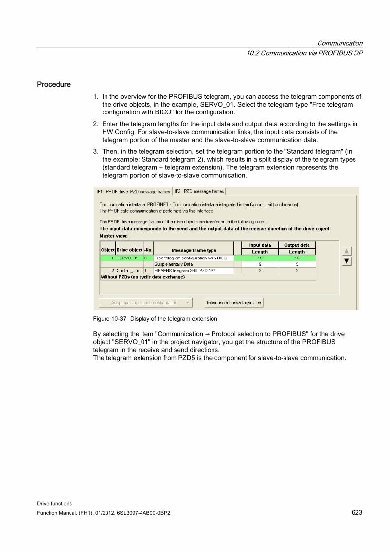
Communication 10.2 Communication via PROFIBUS DP
Drive functions Function Manual, (FH1), 01/2012, 6SL3097-4AB00-0BP2 623
Procedure 1. In the overview for the PROFIBUS telegram, you can access the telegram components of
the drive objects, in the example, SERVO_01. Select the telegram type "Free telegram configuration with BICO" for the configuration.
2. Enter the telegram lengths for the input data and output data according to the settings in HW Config. For slave-to-slave communication links, the input data consists of the telegram portion of the master and the slave-to-slave communication data.
3. Then, in the telegram selection, set the telegram portion to the "Standard telegram" (in the example: Standard telegram 2), which results in a split display of the telegram types (standard telegram + telegram extension). The telegram extension represents the telegram portion of slave-to-slave communication.
Figure 10-37 Display of the telegram extension
By selecting the item "Communication → Protocol selection to PROFIBUS" for the drive object "SERVO_01" in the project navigator, you get the structure of the PROFIBUS telegram in the receive and send directions. The telegram extension from PZD5 is the component for slave-to-slave communication.
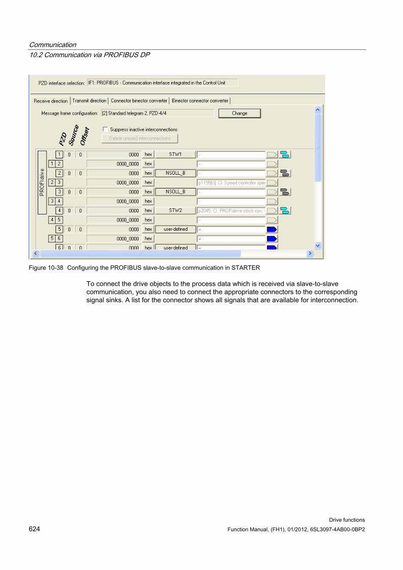
Communication 10.2 Communication via PROFIBUS DP
Drive functions 624 Function Manual, (FH1), 01/2012, 6SL3097-4AB00-0BP2
Figure 10-38 Configuring the PROFIBUS slave-to-slave communication in STARTER
To connect the drive objects to the process data which is received via slave-to-slave communication, you also need to connect the appropriate connectors to the corresponding signal sinks. A list for the connector shows all signals that are available for interconnection.
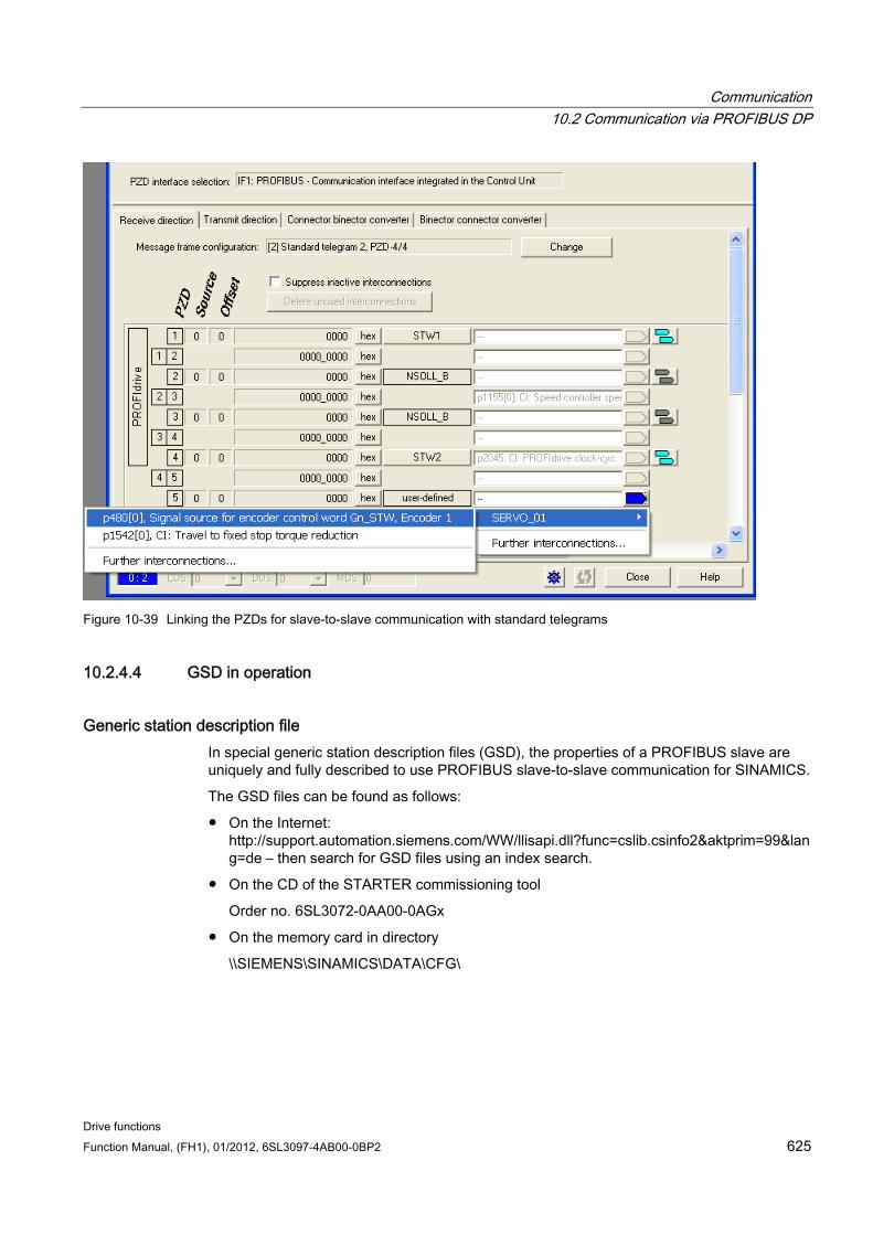
Communication 10.2 Communication via PROFIBUS DP
Drive functions Function Manual, (FH1), 01/2012, 6SL3097-4AB00-0BP2 625
Figure 10-39 Linking the PZDs for slave-to-slave communication with standard telegrams
10.2.4.4 GSD in operation
Generic station description file In special generic station description files (GSD), the properties of a PROFIBUS slave are uniquely and fully described to use PROFIBUS slave-to-slave communication for SINAMICS.
The GSD files can be found as follows:
On the Internet: http://support.automation.siemens.com/WW/llisapi.dll?func=cslib.csinfo2&aktprim=99&lang=de – then search for GSD files using an index search.
On the CD of the STARTER commissioning tool
Order no. 6SL3072-0AA00-0AGx
On the memory card in directory
\\SIEMENS\SINAMICS\DATA\CFG\
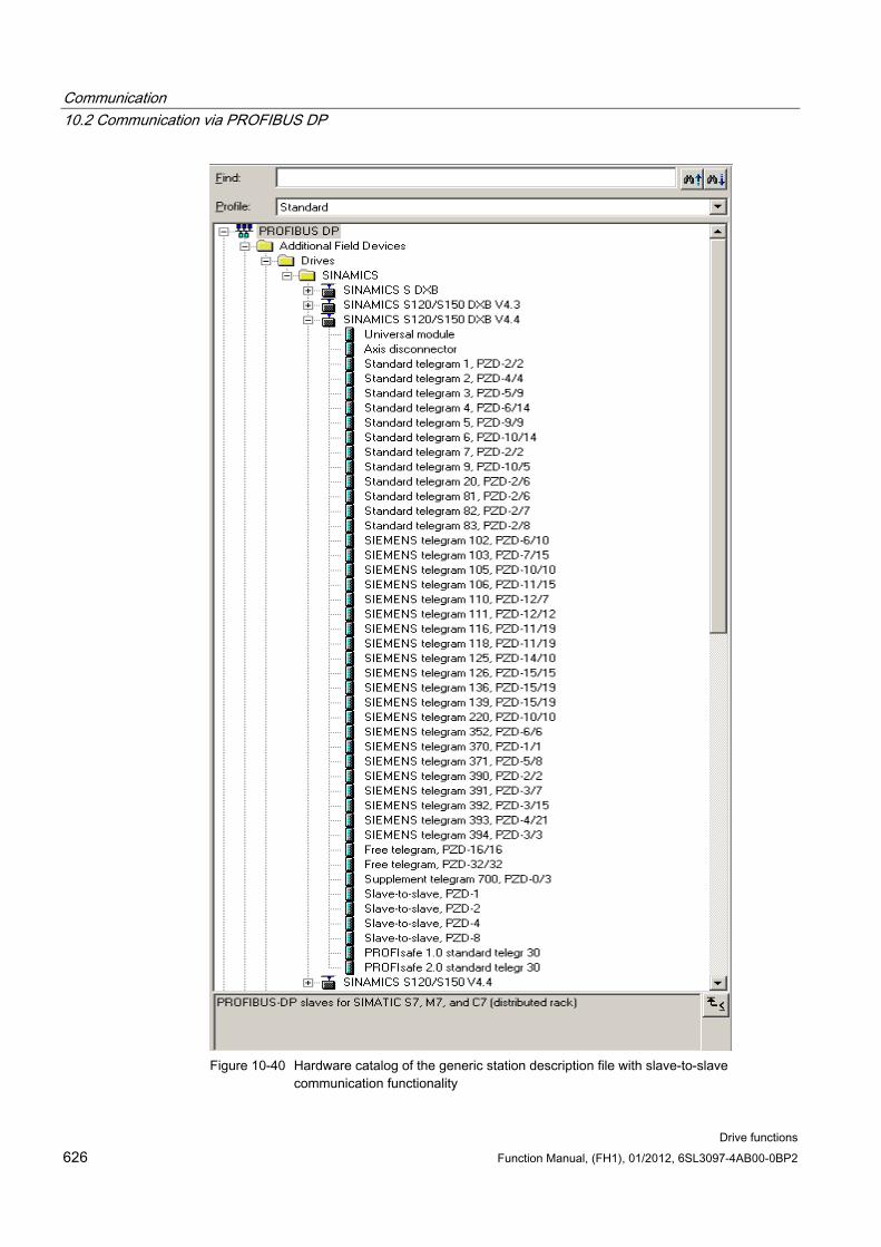
Communication 10.2 Communication via PROFIBUS DP
Drive functions 626 Function Manual, (FH1), 01/2012, 6SL3097-4AB00-0BP2
Figure 10-40 Hardware catalog of the generic station description file with slave-to-slave
communication functionality
Communication 10.2 Communication via PROFIBUS DP
Drive functions Function Manual, (FH1), 01/2012, 6SL3097-4AB00-0BP2 627
The SINAMICS S DXB GSD file contains among other things standard telegrams, free telegrams and slave-to-slave telegrams for configuring slave-to-slave communication. The user must take these telegram parts and an axis separator after each drive object to compose a telegram for the drive unit.
Processing a GSD file in HW Config is covered in the SIMATIC documentation. Suppliers of PROFIBUS components can provide their own bus configuration tool. The description of the respective bus configuration tool is described in the relevant documentation.
Device identification Identification for individual slaves facilitates diagnostics and provides an overview of the nodes on the PROFIBUS.
The information for each slave is stored in the Control Unit parameter r0964[0...6] device identification.
10.2.4.5 Diagnosing the PROFIBUS slave-to-slave communication in STARTER Since the PROFIBUS slave-to-slave communication is implemented on the basis of a broadcast telegram, only the subscriber can detect connection or data faults, e.g. via the Publisher data length (see "Configuration telegram").
The Publisher can only detect and report an interruption of the cyclic connection to the DP master (A01920, F01910). The broadcast telegram to the subscriber will not provide any feedback. A fault of a subscriber must be fed back via slave-to-slave communication. In case of a "master drive" 1:n, however, the limited quantity framework (see "Links and requests") should be observed. It is not possible to have n subscribers report their status via slave-to-slave communication directly to the "master drive" (Publisher)!
Diagnostics can be performed using the diagnostic parameters r2075 ("Receive PROFIBUS diagnostics telegram offset PZD") and r2076 ("Send PROFIBUS diagnostics telegram offset PZD"). The parameter r2074 ("PROFIBUS diagnostics, receive bus address PZD") displays the DP address of the setpoint source of the respective PZD.
r2074 and r2075 enable the source of a slave-to-slave communication relationship to be verified in the Subscriber.
Note
The Subscribers do not monitor the existence of an isochronous Publisher sign of life.
Faults and alarms with PROFIBUS slave-to-slave communication The alarm A01945 signals that the connection to a least one Publisher of the drive device is missing or has failed. Any interruption to the Publisher is also reported by the fault F01946 at the affected drive object. A failure of the Publisher only impacts the respective drive objects.
More detailed information on the messages can be found in
References: SINAMICS S120/150 List Manual

Communication 10.3 Communication via PROFINET IO
Drive functions 628 Function Manual, (FH1), 01/2012, 6SL3097-4AB00-0BP2
10.3 Communication via PROFINET IO
10.3.1 General information about PROFINET IO
General information PROFINET IO is an open Industrial Ethernet standard for a wide range of production and process automation applications. PROFINET IO is based on Industrial Ethernet and observes TCP/IP and IT standards.
Deterministic signal processing in real time is important in industrial networks. PROFINET IO satisfies these requirements.
The following standards ensure open, multi-vendor systems:
International standard IEC 61158
PROFINET IO is optimized for high-speed, time-critical data transfers at field level.
PROFINET IO Within the context of Totally Integrated Automation (TIA), PROFINET IO is the systematic development of the following systems:
1. PROFIBUS DP, the established fieldbus,
2. Industrial Ethernet, the communications bus for the cell level.
Experience gained from both systems was integrated into PROFINET IO. PROFINET IO as the Ethernet-based automation standard from PROFIBUS International (PROFIBUS User Organization e.V.) defines a cross vendor communications and engineering model.
PROFINET IO defines every aspect of the data exchange between IO controllers (devices with what is known as "master functionality" and the IO devices (those with what is known as "slave functionality") as well as carrying out parameterization and diagnostics. A PROFINET IO system is configured in virtually the same way as a PROFIBUS system.
A PROFINET IO system is assembled from the following devices:
An IO controller controls automation tasks.
An IO Device is controlled and monitored by an IO controller. An IO device consists of several modules and submodules.
An IO Supervisor is an engineering tool, typically based on a PC, with which the individual IO devices (drive units) are parameterized and diagnosed.
IO device: Drive units with PROFINET interface
SINAMICS S120 with CU320-2 DP and inserted CBE20
SINAMICS S120 with CU320-2 PN
SINAMICS S120 with CU310-2 PN
Communication 10.3 Communication via PROFINET IO
Drive functions Function Manual, (FH1), 01/2012, 6SL3097-4AB00-0BP2 629
Cycle communication using PROFINET IO with IRT or using RT is possible on all drive units equipped with a PROFINET interface. This means that problem-free communication using other standard protocols is guaranteed within the same network.
Note
PROFINET for drive technology is standardized and described in the following document:
PROFIBUS profile PROFIdrive - Profile Drive Technology
Version V4.1, May 2006,
PROFIBUS User Organization e. V.
Haid-und-Neu-Straße 7,
D-76131 Karlsruhe
http://www.profibus.com,
Order no. 3.172, spec. Chapter 6 • IEC 61800-7
CAUTION For CU320-2 DP with inserted CBE20, the cyclic PZD channel for PROFIBUS DP is deactivated. When setting parameter p8839 = 1, the PZD channel can be reactivated (see Chapter "Parallel operation of communication interfaces").
10.3.1.1 Real-time (RT) and isochronous real-time (IRT) communication
Real-time communication When communication takes place via TCP/IP, the resultant transmission times may be too long and non-deterministic to meet production automation requirements. When communicating time-critical IO user data, PROFINET IO therefore uses its own real-time channel, rather than TCP/IP.
Determinism Determinism means that a system will react in a predictable ("deterministic") manner. With PROFINET IO, it is possible to precisely determine (predict) transmission times.
PROFINET IO with RT (Real Time) Real time means that a system processes external events over a defined period.
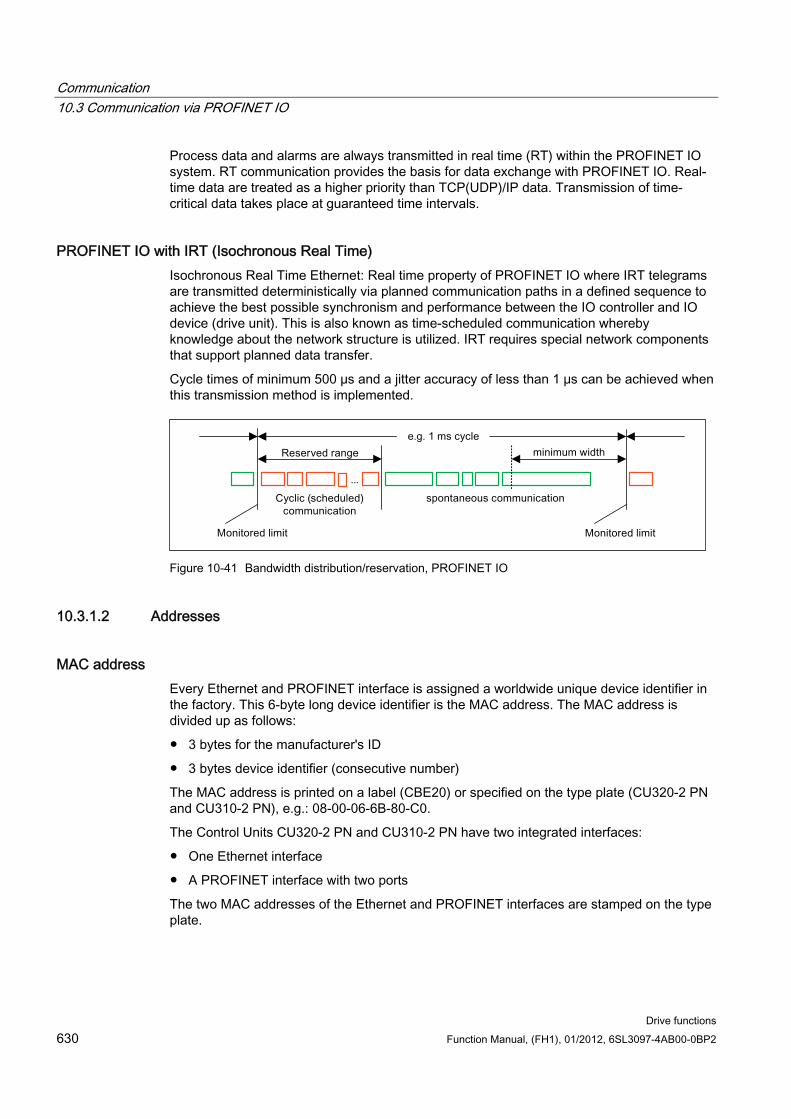
Communication 10.3 Communication via PROFINET IO
Drive functions 630 Function Manual, (FH1), 01/2012, 6SL3097-4AB00-0BP2
Process data and alarms are always transmitted in real time (RT) within the PROFINET IO system. RT communication provides the basis for data exchange with PROFINET IO. Real-time data are treated as a higher priority than TCP(UDP)/IP data. Transmission of time-critical data takes place at guaranteed time intervals.
PROFINET IO with IRT (Isochronous Real Time) Isochronous Real Time Ethernet: Real time property of PROFINET IO where IRT telegrams are transmitted deterministically via planned communication paths in a defined sequence to achieve the best possible synchronism and performance between the IO controller and IO device (drive unit). This is also known as time-scheduled communication whereby knowledge about the network structure is utilized. IRT requires special network components that support planned data transfer.
Cycle times of minimum 500 μs and a jitter accuracy of less than 1 μs can be achieved when this transmission method is implemented.
Figure 10-41 Bandwidth distribution/reservation, PROFINET IO
10.3.1.2 Addresses
MAC address Every Ethernet and PROFINET interface is assigned a worldwide unique device identifier in the factory. This 6-byte long device identifier is the MAC address. The MAC address is divided up as follows:
3 bytes for the manufacturer's ID
3 bytes device identifier (consecutive number)
The MAC address is printed on a label (CBE20) or specified on the type plate (CU320-2 PN and CU310-2 PN), e.g.: 08-00-06-6B-80-C0.
The Control Units CU320-2 PN and CU310-2 PN have two integrated interfaces:
One Ethernet interface
A PROFINET interface with two ports
The two MAC addresses of the Ethernet and PROFINET interfaces are stamped on the type plate.
Communication 10.3 Communication via PROFINET IO
Drive functions Function Manual, (FH1), 01/2012, 6SL3097-4AB00-0BP2 631
IP address The TCP/IP protocol is a prerequisite for establishing a connection and parameterization. To allow a PROFINET device to be addressed as a node on Industrial Ethernet, this device requires a unique IP address in the network. The IP address is made up of 4 decimal numbers with a range of values from 0 through 255. The decimal numbers are separated by a period. The IP address comprises:
the address of the node/participant (also called host or network node)
the address of the (sub) network
IP address assignment The IP addresses of IO devices can be assigned by the IO controller and always have the same sub-network mask as the IO controller. In this case, the IP address is not stored permanently. The IP address entry is lost after POWER ON/OFF. If the IP address is to be stored in a non-volatile memory, the address must be assigned using the Primary Setup Tool (PST).
This function can also be performed with HW Config of STEP 7. Here, the function is called "Edit Ethernet node".
NOTICE IP addresses of the onboard interfaces
It is not permissible that the IP address band of the Ethernet interface and the PROFINET interface are the same. The factory setting of the IP address of the Ethernet interface X127 is 169.254.11.22; the subnet mask is 255.255.0.0.
Note
If the network is part of an existing Ethernet company network, obtain the information (IP address) from your network administrator.
Device name (NameOfStation) When it is shipped, an IO device does not have a device name. An IO device can only be addressed by an IO controller, for example, for the transfer of project engineering data (including the IP address) during startup or for user data exchange in cyclic operation, after it has been assigned a device name with the IO supervisor.
NOTICE The device name must be stored retentively using either STARTER, the Primary Setup Tool (PST) or with HW Config of STEP 7.
Communication 10.3 Communication via PROFINET IO
Drive functions 632 Function Manual, (FH1), 01/2012, 6SL3097-4AB00-0BP2
Note
You can enter the address data for the internal PROFINET ports X150 P1 and P2 in STARTER in the expert list using parameters p8920, p8921, p8922 and p8923.
You can enter the address data for the ports of the optional CBE20 module in STARTER in the expert list using parameters p8940, p8941, p8942 and p8943.
Replacing the CU320-2 DP/PN and CU310-2 PN Control Units (IO device) If the IP address and device name are stored in non-volatile memory, these data are also forwarded with the memory card of the Control Unit.
If a complete Control Unit needs to be replaced due to a device or module defect, the new Control Unit automatically parameterizes and configures using the data on the memory card. Following this, cyclic exchange of user data are restarted. The memory card allows module exchange without an IO supervisor when a fault occurs in a PROFINET device.
10.3.1.3 Data transfer
Properties The PROFINET interface on a drive unit supports the simultaneous operation of:
IRT – isochronous real-time Ethernet
RT – real-time Ethernet
Standard Ethernet services (TCP/IP, LLDP, UDP and DCP)
PROFIdrive telegram for cyclic data transmission, acyclic services Telegrams to send and receive process data are available for each drive object of a drive unit with cyclic process data exchange. In addition to cyclic data transfer, acyclic services can also be used for parameterizing and configuring the drive unit. These acyclic services can be utilized by the IO supervisor or IO controller.
Sequence of drive objects in the telegram On the drive side, the sequence of drive objects in the telegram is displayed via a list in p0978[0...24] where it can also be changed.
You can use the STARTER commissioning tool to display the sequence of drive objects for a commissioned drive system in the online mode under → Drive unit → Communication→ Telegram configuration.
When you create the configuration on the controller side (e.g. HWConfig), the process-data-capable drive objects for the application are added to the telegram in this sequence.
Communication 10.3 Communication via PROFINET IO
Drive functions Function Manual, (FH1), 01/2012, 6SL3097-4AB00-0BP2 633
The following drive objects can exchange process data:
Active Infeed (A_INF)
Basic Infeed (B_INF)
Control Unit (CU_S)
ENCODER
Smart Infeed (S_INF)
SERVO
Terminal Board 30 (TB30)
Terminal Module 15 (TM15)
Terminal Module 31 (TM31)
Terminal Module 41 (TM41)
Terminal Module 120 (TM120)
Terminal Module 150 (TM150)
VECTOR
Note
The sequence of drive objects in HW Config must be the same as that in the drive (p0978).
The structure of the telegram depends on the drive objects taken into account during configuration. Configurations are permitted that do not take into account all of the drive objects that are present in the drive system.
Example:
The following configurations, for example, are possible:
Configuration with SERVO, SERVO, SERVO
Configuration with A_INF, SERVO, SERVO, SERVO, TB30
and others
10.3.1.4 Communication channels for PROFINET
PROFINET connection channels A Control Unit has an integrated Ethernet interface (X127).
The PROFINET versions CU320-2PN and CU310-2PN each have a PROFINET interface (X150) with two onboard ports: P1 and P2
A CU320-2PN or a CU310-2PN Control Unit can simultaneously establish a total of 8 communication links via the integrated PROFINET interfaces.
Communication 10.3 Communication via PROFINET IO
Drive functions 634 Function Manual, (FH1), 01/2012, 6SL3097-4AB00-0BP2
Control Unit with CBE20 A Communication Board can be optionally inserted in the Control Unit CU320-2PN/DP:
The CBE20 Communication Board is a PROFINET switch with 4 additional PROFINET ports.
Note PROFINET routing
Routing is neither possible between the onboard interfaces X127 and X150 – nor between the onboard interfaces of the Control Unit 320-2PN and inserted CBE20.
Overview of important parameters (see the SINAMICS S120/S150 List Manual)
Integrated PROFINET interface p8920[0...239] PN Name of station
p8921[0...3] PN IP Address of station
p8922[0...3] PN Default gateway of station
p8923[0...3] PN Subnet mask of station
p8925 PN interface configuration
p8929 PN Number of remote controllers
r8930[0...239] PN Name of station active
r8931[0...3] PN IP Address of station active
r8932[0...3] PN Default gateway of station active
r8933[0...3] PN Subnet mask of station active
r8935[0...5] PN MAC address of station
r8936[0...1] PN State of the cyclical connections
r8937[0...5] PN Diagnostics
CBE20 p8829 CBE20 Remote Controller number
p8940 CBE20 Name of Station
p8941 CBE20 IP Address of Station
p8942 CBE20 Default Gateway of Station
p8943 CBE20 Subnet Mask of Station
p8944 CBE20 DHCP Mode
p8945 CBE20 interfaces configuration
Communication 10.3 Communication via PROFINET IO
Drive functions Function Manual, (FH1), 01/2012, 6SL3097-4AB00-0BP2 635
r8950 CBE20 Name of Station active
r8951 CBE20 IP Address of Station active
r8952 CBE20 Default Gateway of Station active
r8953 CBE20 Subnet Mask of Station active
r8954 CBE20 DHCP Mode active
r8955 CBE20 MAC Address of Station
r8959 CBE20 DAP ID
10.3.2 Drive control with PROFINET
PROFINET interfaces for CU310-2 PN, CU320-2 DP and CU320-2 PN The Control Units CU310-2 PN and CU320-2 PN have an integrated PROFINET interface with 2 ports.
The CBE20 option board can be additionally inserted in the option slot of a CU320-2 DP or CU320-2 PN. The CBE20 is a PROFINET switch with 4 ports.
NOTICE PROFINET interfaces on the CU320-2 PN with CBE20
The integrated PROFINET interface of the CU320-2 PN is independent of the optionally inserted CBE20 module. The two PROFINET interfaces are not connected with each other. Routing is not possible between the two PROFINET interfaces.
Note Ring topology
When connecting the ports, it must be ensured that for standard applications a ring topology is not created. Additional information on ring topologies can be found in the Chapter, Media redundancy.
References The integration of a SINAMICS S120 with CU310-2 PN/CU320-2 DP/CU320-2PN in a
PROFINET IO system is described in detail in the System Manual "SIMOTION SCOUT Communication".
For an example of how to link a Control Unit to a SIMATIC S7 via PROFINET IO, please refer to the FAQ "PROFINET IO communication between an S7-CPU and SINAMICS S120" on the Internet.
Communication 10.3 Communication via PROFINET IO
Drive functions 636 Function Manual, (FH1), 01/2012, 6SL3097-4AB00-0BP2
For a description of the CBE20 and how you can use it in the drive, please refer to the following reference: SINAMICS S120 Equipment Manual Control Units.
The PROFINET interface on the CU310-2 PN unit is described in the reference: SINAMICS S120 Manual for AC Drives.
Clock generation via PROFINET IO (isochronous communication) The SINAMICS S120 with CU310-2 PN/CU320-2 DP/CU320-2 PN can only assume the role of a synchronization slave within a PROFINET IO network.
For a CU310-2 PN/CU320-2 DP/CU320-2 PN with CBE20 module, the following applies:
Transmission type IRT, IO device is synchronization slave and isochronous, send clock cycle is applied to bus: Control Unit synchronizes with the bus and the send clock cycle becomes the cycle for the Control Unit.
RT or IRT (option drive unit "not isochronous") has been configured. SINAMICS uses the local clock cycle configured in SINAMICS.
The following applies to a CU320-2 DP/CU320-2 PN for which a CBE20 is configured, but does not exist:
SINAMICS uses the local clock (clock configured in SINAMICS); if there is no data exchange via PROFINET, alarm A01487 is output ("Topology: Comparison option slot components missing in the actual topology"). Access via PROFINET is not available.
Telegrams PROFIdrive telegrams are available for implementing cyclic communication via PROFINET IO (see section "Communication according to PROFIdrive", cyclic communication).
DCP flashing This function is used to check the correct assignment to a module and its interfaces. This function is supported by a CU310-2 PN and a CU320-2 DP/PN with inserted CBE20.
1. In HW Config or STEP7 Manager, select the menu item "Target system" > "Ethernet" > "Edit Ethernet node".
2. The "Edit Ethernet node" dialog box opens.
3. Click on the "Browse" button.
4. The "Browse Network" dialog box opens and displays the connected nodes.
5. After the CU310-2 PN or the CU320-2 DP with plugged CBE20 has been selected as a node, the "DCP flashing" function is activated using the "Flash" button.
The DCP flashing will be effective on the RDY LED (READY LED 2 Hz, green/orange or red/orange) on the CU310-2 PN/CU320-2 DP.
The LED will continue to flash as long as the dialog is open. When the dialog is closed, the LED will go out automatically. The function is available as of STEP7 V5.3 SP1 via Ethernet.
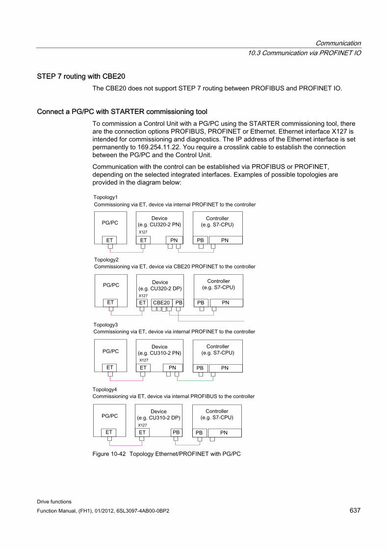
Communication 10.3 Communication via PROFINET IO
Drive functions Function Manual, (FH1), 01/2012, 6SL3097-4AB00-0BP2 637
STEP 7 routing with CBE20 The CBE20 does not support STEP 7 routing between PROFIBUS and PROFINET IO.
Connect a PG/PC with STARTER commissioning tool To commission a Control Unit with a PG/PC using the STARTER commissioning tool, there are the connection options PROFIBUS, PROFINET or Ethernet. Ethernet interface X127 is intended for commissioning and diagnostics. The IP address of the Ethernet interface is set permanently to 169.254.11.22. You require a crosslink cable to establish the connection between the PG/PC and the Control Unit.
Communication with the control can be established via PROFIBUS or PROFINET, depending on the selected integrated interfaces. Examples of possible topologies are provided in the diagram below:
Figure 10-42 Topology Ethernet/PROFINET with PG/PC
Communication 10.3 Communication via PROFINET IO
Drive functions 638 Function Manual, (FH1), 01/2012, 6SL3097-4AB00-0BP2
10.3.2.1 Media redundancy To increase the availability of PROFINET, you can create a ring topology for redundancy purposes. If the ring is interrupted at one point, the data paths between the devices are automatically reconfigured. Following reconfiguration, the devices can once again be accessed in the resulting new topology.
To create a ring topology with media redundancy, route the two ends of a line-type PROFINET topology into one device, the Scalance device. Closing the linear bus topology is realized using two ports (ring ports) of the Scalance device. The Scalance device is the redundancy manager. The redundancy manager monitors the data telegrams in the PROFINET ring. All other connected PROFINET nodes are redundant clients.
The Media Redundancy Protocol (MRP) is the standard procedure for media redundancy. Using this technique, a maximum of 50 devices can participate in each ring. In the case of an interrupted cable, data transfer is only briefly interrupted as the system switches over to the redundant data path.
If a short-term interruption is not permitted, data transfer must be set to IRT High Performance. The uninterruptible MRRT is automatically set.
The two integrated PROFINET IO interfaces of the Control Units CU320-2 PN and CU310-2 PN can be configured as redundant clients.
From a CBE20, only the first two ports are capable of establishing a ring topology. Routing between the integrated PROFINET IO interfaces and a CBE20 is not possible.
Configuring media redundancy The ring topology is configured by appropriately configuring the participating devices individually in STEP7.
10.3.3 RT classes for PROFINET IO PROFINET IO is a scalable realtime communication system based on Ethernet technology. The scalable approach is expressed with three realtime classes.
RT
RT communication is based on standard Ethernet. The data are transferred via prioritized Ethernet telegrams. Because standard Ethernet does not support any synchronization mechanisms, isochronous operation is not possible with PROFINET IO with RT! The real-time capability is comparable with the present PROFIBUS DP solutions with 12 MBaud, i.e. a sufficiently large bandwidth portion is available for the parallel transmission of IT services on the same line.
The real update cycle in which cyclic data are exchanged depends on the bus load, the devices used and the quantity framework of the I/O data. The update cycle is a multiple of the send cycle.
Communication 10.3 Communication via PROFINET IO
Drive functions Function Manual, (FH1), 01/2012, 6SL3097-4AB00-0BP2 639
IRT
Two options are available with this RT class:
IRT "high flexibility"
IRT "high performance".
Software preconditions for configuring IRT:
STEP 7 5.4 SP4 (HW Config)
Note
For further information about configuring the PROFINET interface for the I/O controller and I/O device, please refer to the following document: SIMOTION SCOUT Communication System Manual.
IRT "high flexibility" The telegrams are sent cyclically in a deterministic cycle (Isochronous Real Time). The telegrams are exchanged in a bandwidth reserved by the hardware. One IRT time interval and one standard Ethernet time interval are created for each cycle.
Note
IRT "high flexibility" cannot be used for isochronous applications.
IRT "high performance" In addition to the bandwidth reservation, the telegram traffic can be further optimized by configuring the topology. This enhances the performance during data exchange and the deterministic behavior. The IRT time interval can thus be further optimized or minimized with respect to IRT "high flexibility".
In addition to the isochronous data transfer provided by IRT, even the application itself (position control cycle, IPO cycle) can be isochronous in the devices. This is an essential requirement for closed-loop axis control and synchronization via the bus. Isochronous data transfer with cycle times well below one millisecond and with a deviation in the cycle start (jitter) of less than a microsecond provide sufficient performance reserves for demanding motion control applications.
The RT classes IRT "high flexibility" and IRT "high performance" can be selected as options in the synchronization settings configuration area of HW Config. In the description below, both these classes are simply referred to as "IRT".
In contrast to standard Ethernet and PROFINET IO with RT, the telegrams for PROFINET IO with IRT are transmitted according to a schedule.
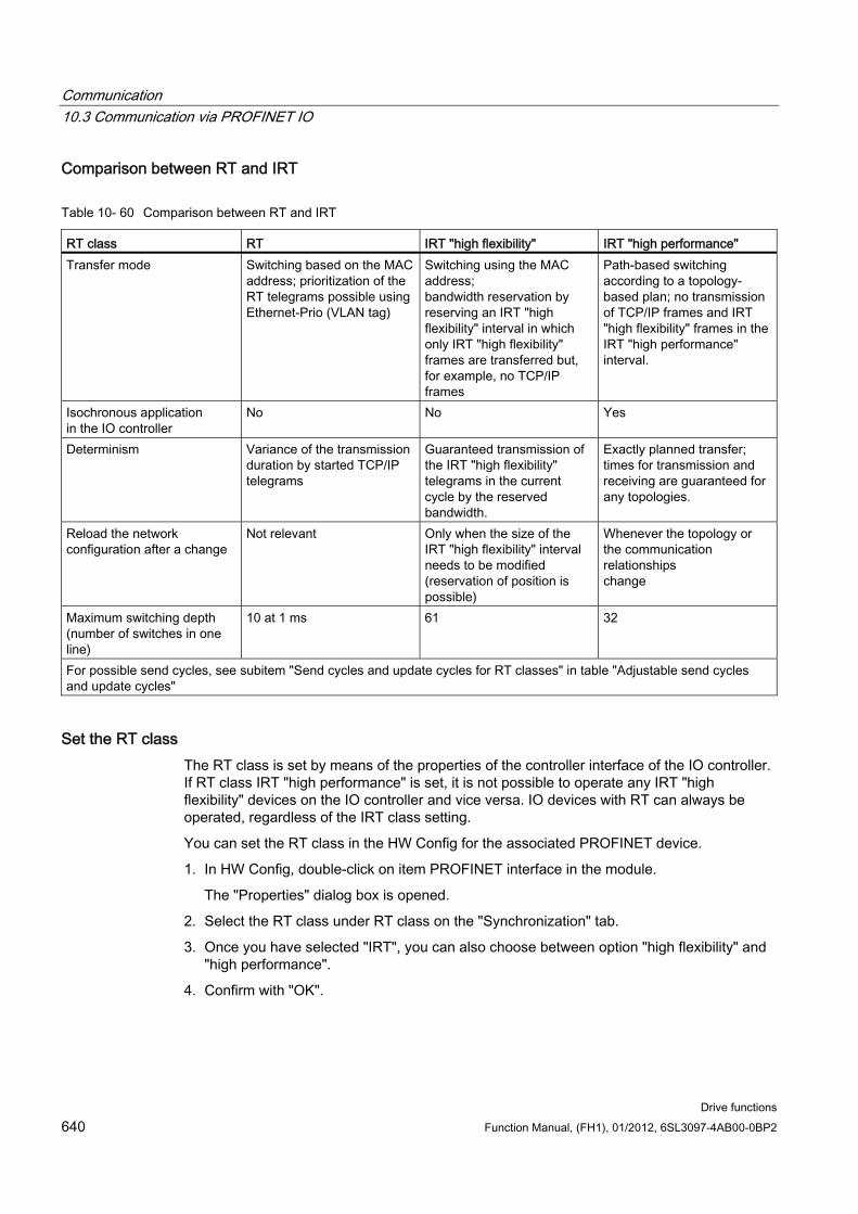
Communication 10.3 Communication via PROFINET IO
Drive functions 640 Function Manual, (FH1), 01/2012, 6SL3097-4AB00-0BP2
Comparison between RT and IRT
Table 10- 60 Comparison between RT and IRT
RT class RT IRT "high flexibility" IRT "high performance" Transfer mode Switching based on the MAC
address; prioritization of the RT telegrams possible using Ethernet-Prio (VLAN tag)
Switching using the MAC address; bandwidth reservation by reserving an IRT "high flexibility" interval in which only IRT "high flexibility" frames are transferred but, for example, no TCP/IP frames
Path-based switching according to a topology-based plan; no transmission of TCP/IP frames and IRT "high flexibility" frames in the IRT "high performance" interval.
Isochronous application in the IO controller
No No Yes
Determinism Variance of the transmission duration by started TCP/IP telegrams
Guaranteed transmission of the IRT "high flexibility" telegrams in the current cycle by the reserved bandwidth.
Exactly planned transfer; times for transmission and receiving are guaranteed for any topologies.
Reload the network configuration after a change
Not relevant Only when the size of the IRT "high flexibility" interval needs to be modified (reservation of position is possible)
Whenever the topology or the communication relationships change
Maximum switching depth (number of switches in one line)
10 at 1 ms 61 32
For possible send cycles, see subitem "Send cycles and update cycles for RT classes" in table "Adjustable send cycles and update cycles"
Set the RT class The RT class is set by means of the properties of the controller interface of the IO controller. If RT class IRT "high performance" is set, it is not possible to operate any IRT "high flexibility" devices on the IO controller and vice versa. IO devices with RT can always be operated, regardless of the IRT class setting.
You can set the RT class in the HW Config for the associated PROFINET device.
1. In HW Config, double-click on item PROFINET interface in the module.
The "Properties" dialog box is opened.
2. Select the RT class under RT class on the "Synchronization" tab.
3. Once you have selected "IRT", you can also choose between option "high flexibility" and "high performance".
4. Confirm with "OK".
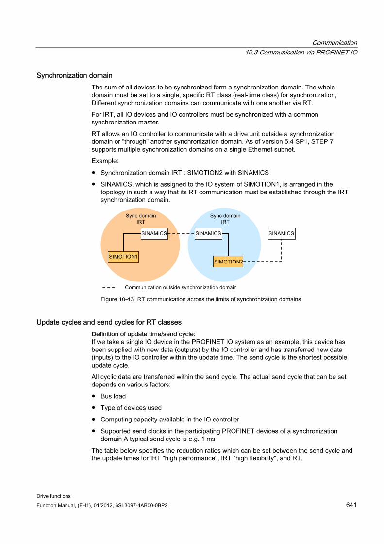
Communication 10.3 Communication via PROFINET IO
Drive functions Function Manual, (FH1), 01/2012, 6SL3097-4AB00-0BP2 641
Synchronization domain The sum of all devices to be synchronized form a synchronization domain. The whole domain must be set to a single, specific RT class (real-time class) for synchronization, Different synchronization domains can communicate with one another via RT.
For IRT, all IO devices and IO controllers must be synchronized with a common synchronization master.
RT allows an IO controller to communicate with a drive unit outside a synchronization domain or "through" another synchronization domain. As of version 5.4 SP1, STEP 7 supports multiple synchronization domains on a single Ethernet subnet.
Example:
Synchronization domain IRT : SIMOTION2 with SINAMICS
SINAMICS, which is assigned to the IO system of SIMOTION1, is arranged in the topology in such a way that its RT communication must be established through the IRT synchronization domain.
Figure 10-43 RT communication across the limits of synchronization domains
Update cycles and send cycles for RT classes Definition of update time/send cycle: If we take a single IO device in the PROFINET IO system as an example, this device has been supplied with new data (outputs) by the IO controller and has transferred new data (inputs) to the IO controller within the update time. The send cycle is the shortest possible update cycle.
All cyclic data are transferred within the send cycle. The actual send cycle that can be set depends on various factors:
Bus load
Type of devices used
Computing capacity available in the IO controller
Supported send clocks in the participating PROFINET devices of a synchronization domain A typical send cycle is e.g. 1 ms
The table below specifies the reduction ratios which can be set between the send cycle and the update times for IRT "high performance", IRT "high flexibility", and RT.
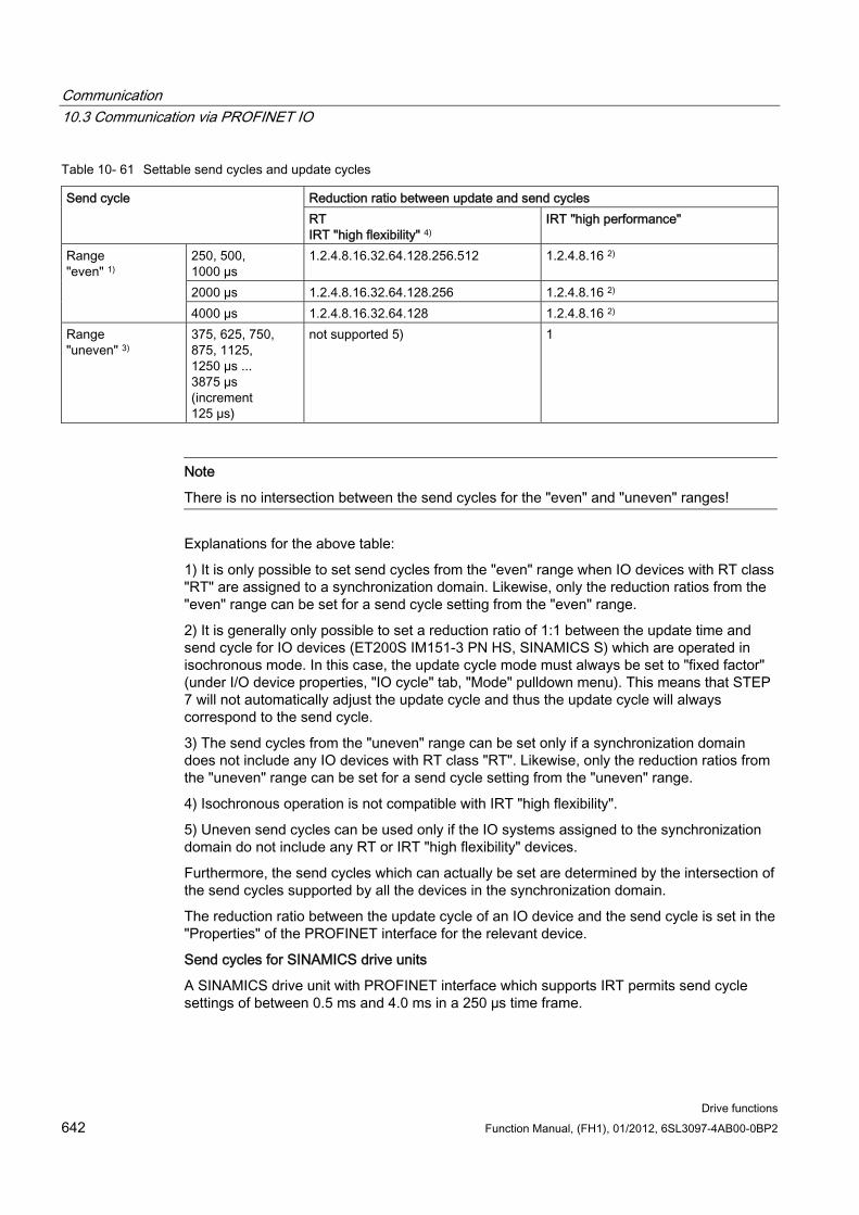
Communication 10.3 Communication via PROFINET IO
Drive functions 642 Function Manual, (FH1), 01/2012, 6SL3097-4AB00-0BP2
Table 10- 61 Settable send cycles and update cycles
Reduction ratio between update and send cycles Send cycle RT IRT "high flexibility" 4)
IRT "high performance"
250, 500, 1000 µs
1.2.4.8.16.32.64.128.256.512 1.2.4.8.16 2)
2000 µs 1.2.4.8.16.32.64.128.256 1.2.4.8.16 2)
Range "even" 1)
4000 µs 1.2.4.8.16.32.64.128 1.2.4.8.16 2) Range "uneven" 3)
375, 625, 750, 875, 1125, 1250 µs ... 3875 µs (increment 125 µs)
not supported 5) 1
Note
There is no intersection between the send cycles for the "even" and "uneven" ranges!
Explanations for the above table:
1) It is only possible to set send cycles from the "even" range when IO devices with RT class "RT" are assigned to a synchronization domain. Likewise, only the reduction ratios from the "even" range can be set for a send cycle setting from the "even" range.
2) It is generally only possible to set a reduction ratio of 1:1 between the update time and send cycle for IO devices (ET200S IM151-3 PN HS, SINAMICS S) which are operated in isochronous mode. In this case, the update cycle mode must always be set to "fixed factor" (under I/O device properties, "IO cycle" tab, "Mode" pulldown menu). This means that STEP 7 will not automatically adjust the update cycle and thus the update cycle will always correspond to the send cycle.
3) The send cycles from the "uneven" range can be set only if a synchronization domain does not include any IO devices with RT class "RT". Likewise, only the reduction ratios from the "uneven" range can be set for a send cycle setting from the "uneven" range.
4) Isochronous operation is not compatible with IRT "high flexibility".
5) Uneven send cycles can be used only if the IO systems assigned to the synchronization domain do not include any RT or IRT "high flexibility" devices.
Furthermore, the send cycles which can actually be set are determined by the intersection of the send cycles supported by all the devices in the synchronization domain.
The reduction ratio between the update cycle of an IO device and the send cycle is set in the "Properties" of the PROFINET interface for the relevant device.
Send cycles for SINAMICS drive units
A SINAMICS drive unit with PROFINET interface which supports IRT permits send cycle settings of between 0.5 ms and 4.0 ms in a 250 µs time frame.
Communication 10.3 Communication via PROFINET IO
Drive functions Function Manual, (FH1), 01/2012, 6SL3097-4AB00-0BP2 643
Topology rules Topology rules for RT
A topology can be, but need not be configured for RT. If a topology has been configured, the devices must be wired in accordance with the topology.
Otherwise, the wiring between devices is entirely optional.
Topology rules for IRT
Mixed operation is not supported by STEP 7 V5.4 SP4, i.e. IRT "high performance" cannot be combined with IRT "high flexibility" in the same synchronization domain.
A synchronization domain with IRT "high performance" can contain a maximum of one IRT "high performance" island. "Island" means that the devices must be interconnected to match the configured topology. A synchronization master must be positioned in the relevant island.
IRT "high flexibility" is subject to the same topology rules as IRT "high performance", the only exception being that a topology does not need to be configured. However, if a topology has been configured, the devices must be wired to match the topology.
Device selection in HW Config Hardware catalog: The drive unit from the appropriate unit family entry in the hardware catalog must be configured. For the RT class IRT, these are all entries with the end identification ...PN-V2.2.
GSD: The names of GSD files for devices which contain IRT end in …PN-V2.2.
10.3.4 PROFINET GSDML To embed a SINAMICS S into a PROFINET network, SINAMICS S120 supports two different PROFINET GSDML versions (generic station description file):
PROFINET GSDML for compact modules
PROFINET GSDML with subslot configuring
PROFINET GSDML for compact modules With PROFINET GSDML, you can precisely configure a complete module, which corresponds to a drive object (Drive Object=DO). Each of these modules involves two subslots: The Parameter Access Point (PAP) and a PZD telegram for transferring process data. You can identify the PROFINET GSDML for compact modules by the following structure of the file name: GSDML-V2.2-Siemens-Sinamics_S_CU3x0-20090101.xml (example)
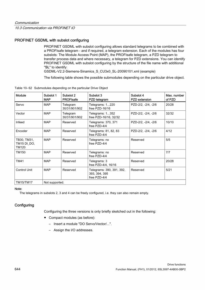
Communication 10.3 Communication via PROFINET IO
Drive functions 644 Function Manual, (FH1), 01/2012, 6SL3097-4AB00-0BP2
PROFINET GSDML with subslot configuring PROFINET GSDML with subslot configuring allows standard telegrams to be combined with a PROFIsafe telegram - and if required, a telegram extension. Each of the modules has four subslots: The Module Access Point (MAP), the PROFIsafe telegram, a PZD telegram to transfer process data and where necessary, a telegram for PZD extensions. You can identify PROFINET GSDML with subslot configuring by the structure of the file name with additional "SL" to identify: GSDML-V2.2-Siemens-Sinamics_S_CU3x0_SL-20090101.xml (example)
The following table shows the possible submodules depending on the particular drive object.
Table 10- 62 Submodules depending on the particular Drive Object
Module Subslot 1 MAP
Subslot 2 PROFIsafe
Subslot 3 PZD telegram
Subslot 4 PZD extension
Max. number of PZD
Servo MAP Telegram 30/31/901/902
Telegrams: 1...220 free PZD-16/16
PZD-2/2, -2/4, -2/6 20/28
Vector MAP Telegram 30/31/901/902
Telegrams: 1...352 free PZD-16/16, 32/32
PZD-2/2, -2/4, -2/6 32/32
Infeed MAP Reserved Telegrams: 370, 371 free PZD-4/4
PZD-2/2, -2/4, -2/6 10/10
Encoder MAP Reserved Telegrams: 81, 82, 83 free PZD-4/4
PZD-2/2, -2/4, -2/6 4/12
TB30, TM31, TM15 DI_DO, TM120
MAP Reserved Telegrams: no free PZD-4/4
Reserved 5/5
TM150 MAP Reserved Telegrams: no free PZD-4/4
Reserved 7/7
TM41 MAP Reserved Telegrams: 3 free PZD-4/4, 16/16
Reserved 20/28
Control Unit MAP Reserved Telegrams: 390, 391, 392, 393, 394, 395 free PZD-4/4
Reserved 5/21
TM15/TM17 Not supported.
Note: The telegrams in subslots 2, 3 and 4 can be freely configured, i.e. they can also remain empty.
Configuring Configuring the three versions is only briefly sketched out in the following:
Compact modules (as before):
– Insert a module "DO Servo/Vector/...".
– Assign the I/O addresses.
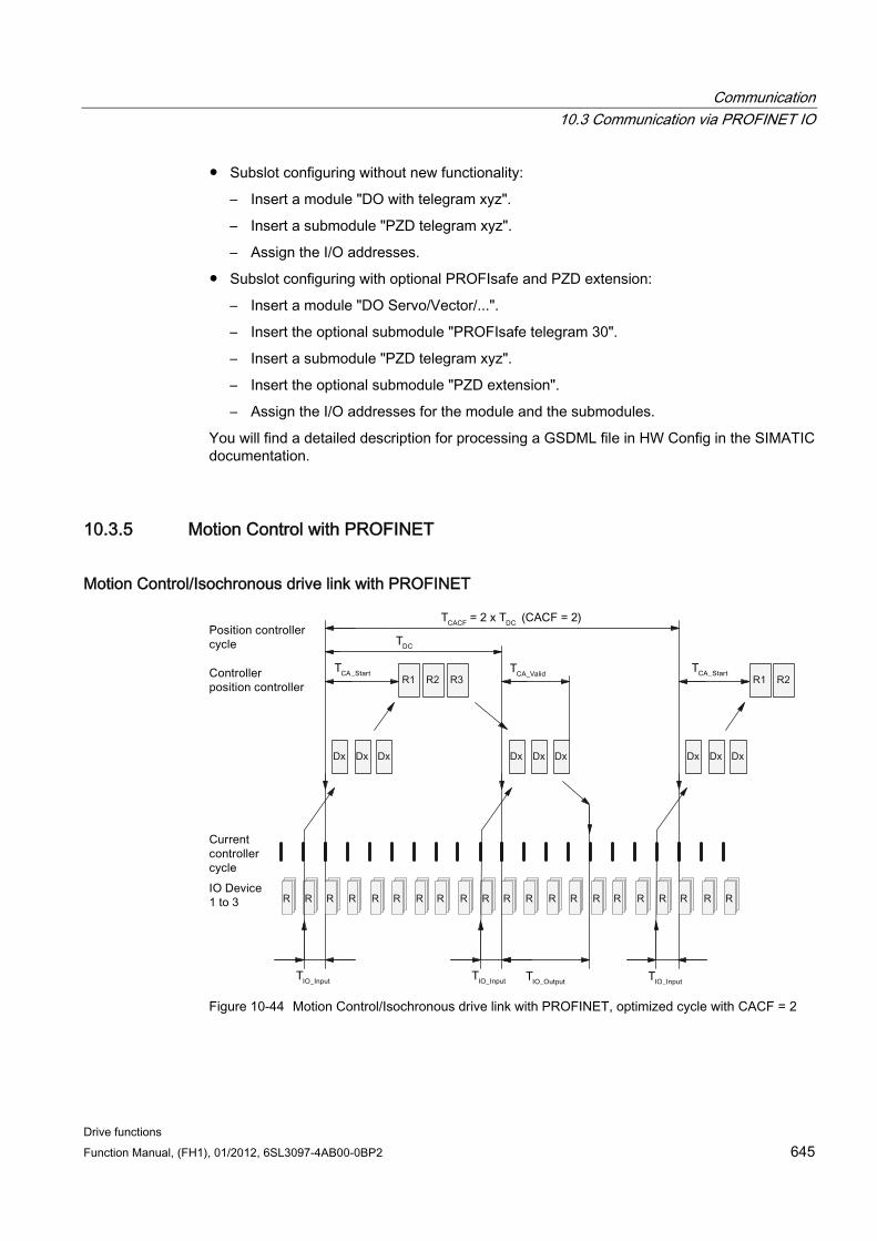
Communication 10.3 Communication via PROFINET IO
Drive functions Function Manual, (FH1), 01/2012, 6SL3097-4AB00-0BP2 645
Subslot configuring without new functionality:
– Insert a module "DO with telegram xyz".
– Insert a submodule "PZD telegram xyz".
– Assign the I/O addresses.
Subslot configuring with optional PROFIsafe and PZD extension:
– Insert a module "DO Servo/Vector/...".
– Insert the optional submodule "PROFIsafe telegram 30".
– Insert a submodule "PZD telegram xyz".
– Insert the optional submodule "PZD extension".
– Assign the I/O addresses for the module and the submodules.
You will find a detailed description for processing a GSDML file in HW Config in the SIMATIC documentation.
10.3.5 Motion Control with PROFINET
Motion Control/Isochronous drive link with PROFINET
Figure 10-44 Motion Control/Isochronous drive link with PROFINET, optimized cycle with CACF = 2
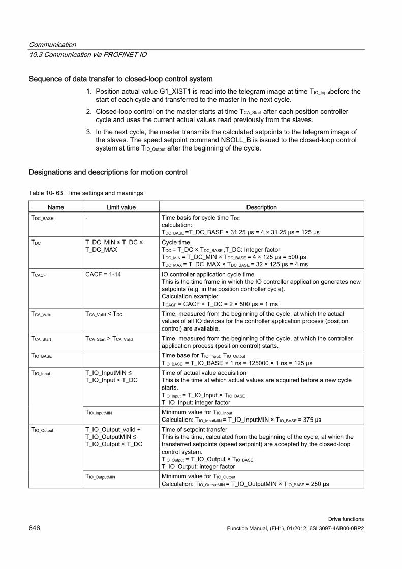
Communication 10.3 Communication via PROFINET IO
Drive functions 646 Function Manual, (FH1), 01/2012, 6SL3097-4AB00-0BP2
Sequence of data transfer to closed-loop control system 1. Position actual value G1_XIST1 is read into the telegram image at time TIO_Inputbefore the
start of each cycle and transferred to the master in the next cycle.
2. Closed-loop control on the master starts at time TCA_Start after each position controller cycle and uses the current actual values read previously from the slaves.
3. In the next cycle, the master transmits the calculated setpoints to the telegram image of the slaves. The speed setpoint command NSOLL_B is issued to the closed-loop control system at time TIO_Output after the beginning of the cycle.
Designations and descriptions for motion control
Table 10- 63 Time settings and meanings
Name Limit value Description TDC_BASE - Time basis for cycle time TDC
calculation: TDC_BASE =T_DC_BASE × 31.25 µs = 4 × 31.25 µs = 125 µs
TDC T_DC_MIN ≤ T_DC ≤ T_DC_MAX
Cycle time TDC = T_DC × TDC_BASE ,T_DC: Integer factor TDC_MIN = T_DC_MIN × TDC_BASE = 4 × 125 µs = 500 µs TDC_MAX = T_DC_MAX × TDC_BASE = 32 × 125 µs = 4 ms
TCACF CACF = 1-14 IO controller application cycle time This is the time frame in which the IO controller application generates new setpoints (e.g. in the position controller cycle). Calculation example: TCACF = CACF × T_DC = 2 × 500 µs = 1 ms
TCA_Valid TCA_Valid < TDC Time, measured from the beginning of the cycle, at which the actual values of all IO devices for the controller application process (position control) are available.
TCA_Start
TCA_Start > TCA_Valid Time, measured from the beginning of the cycle, at which the controller application process (position control) starts.
TIO_BASE Time base for TIO_Input, TIO_Output TIO_BASE = T_IO_BASE × 1 ns = 125000 × 1 ns = 125 µs
T_IO_InputMIN ≤ T_IO_Input < T_DC
Time of actual value acquisition This is the time at which actual values are acquired before a new cycle starts. TIO_Input = T_IO_Input × TIO_BASE T_IO_Input: integer factor
TIO_Input
TIO_InputMIN Minimum value for TIO_Input Calculation: TIO_InputMIN = T_IO_InputMIN × TIO_BASE = 375 µs
T_IO_Output_valid + T_IO_OutputMIN ≤ T_IO_Output < T_DC
Time of setpoint transfer This is the time, calculated from the beginning of the cycle, at which the transferred setpoints (speed setpoint) are accepted by the closed-loop control system. TIO_Output = T_IO_Output × TIO_BASE T_IO_Output: integer factor
TIO_Output
TIO_OutputMIN Minimum value for TIO_Output Calculation: TIO_OutputMIN = T_IO_OutputMIN × TIO_BASE = 250 µs
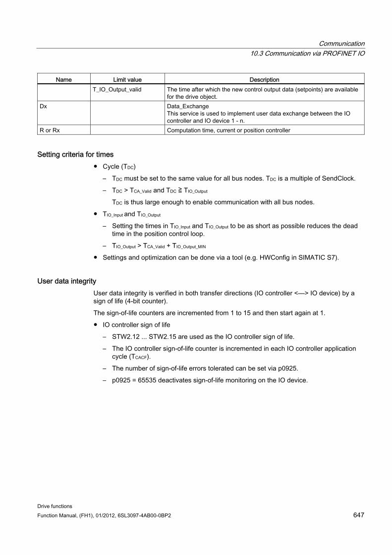
Communication 10.3 Communication via PROFINET IO
Drive functions Function Manual, (FH1), 01/2012, 6SL3097-4AB00-0BP2 647
Name Limit value Description T_IO_Output_valid The time after which the new control output data (setpoints) are available
for the drive object. Dx Data_Exchange
This service is used to implement user data exchange between the IO controller and IO device 1 - n.
R or Rx Computation time, current or position controller
Setting criteria for times Cycle (TDC)
– TDC must be set to the same value for all bus nodes. TDC is a multiple of SendClock.
– TDC > TCA_Valid and TDC ≧ TIO_Output
TDC is thus large enough to enable communication with all bus nodes.
TIO_Input and TIO_Output
– Setting the times in TIO_Input and TIO_Output to be as short as possible reduces the dead time in the position control loop.
– TIO_Output > TCA_Valid + TIO_Output_MIN
Settings and optimization can be done via a tool (e.g. HWConfig in SIMATIC S7).
User data integrity User data integrity is verified in both transfer directions (IO controller <––> IO device) by a sign of life (4-bit counter).
The sign-of-life counters are incremented from 1 to 15 and then start again at 1.
IO controller sign of life
– STW2.12 ... STW2.15 are used as the IO controller sign of life.
– The IO controller sign-of-life counter is incremented in each IO controller application cycle (TCACF).
– The number of sign-of-life errors tolerated can be set via p0925.
– p0925 = 65535 deactivates sign-of-life monitoring on the IO device.
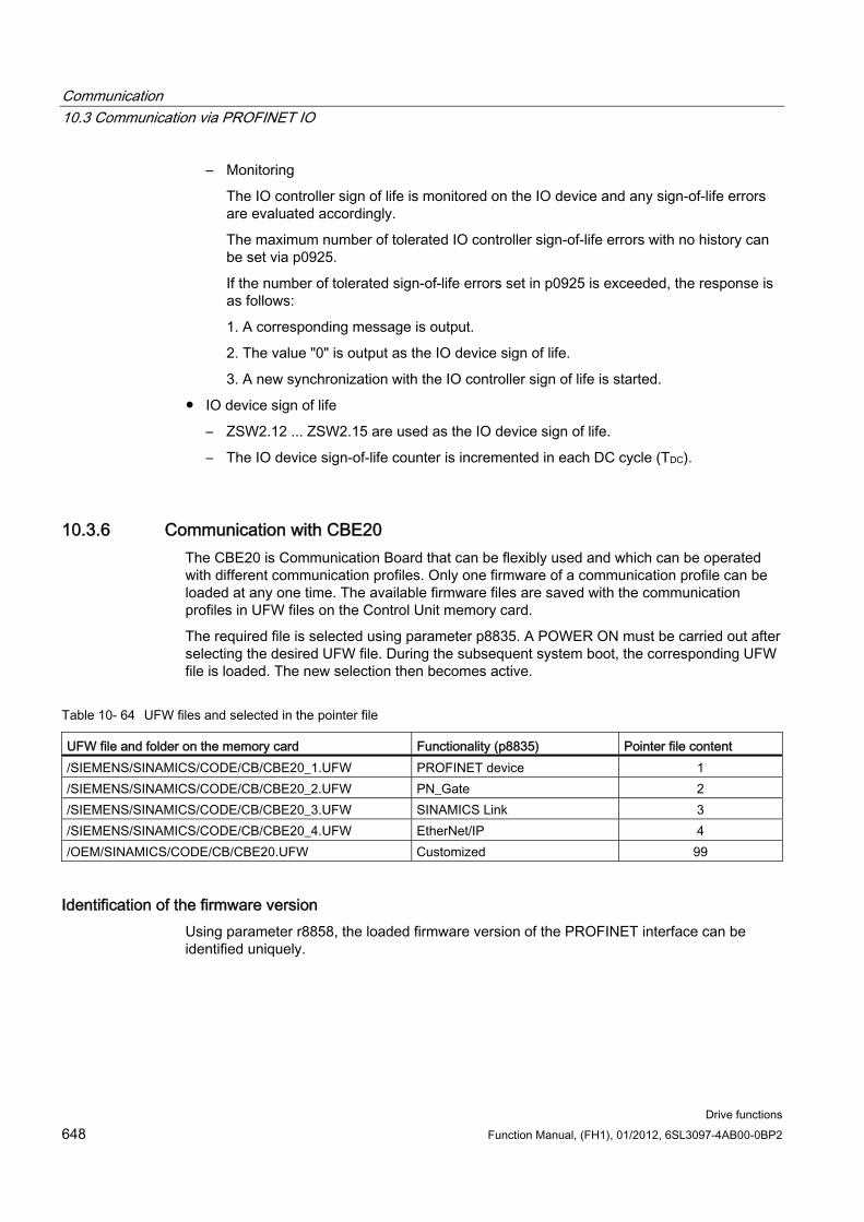
Communication 10.3 Communication via PROFINET IO
Drive functions 648 Function Manual, (FH1), 01/2012, 6SL3097-4AB00-0BP2
– Monitoring
The IO controller sign of life is monitored on the IO device and any sign-of-life errors are evaluated accordingly.
The maximum number of tolerated IO controller sign-of-life errors with no history can be set via p0925.
If the number of tolerated sign-of-life errors set in p0925 is exceeded, the response is as follows:
1. A corresponding message is output.
2. The value "0" is output as the IO device sign of life.
3. A new synchronization with the IO controller sign of life is started.
IO device sign of life
– ZSW2.12 ... ZSW2.15 are used as the IO device sign of life.
– The IO device sign-of-life counter is incremented in each DC cycle (TDC).
10.3.6 Communication with CBE20 The CBE20 is Communication Board that can be flexibly used and which can be operated with different communication profiles. Only one firmware of a communication profile can be loaded at any one time. The available firmware files are saved with the communication profiles in UFW files on the Control Unit memory card.
The required file is selected using parameter p8835. A POWER ON must be carried out after selecting the desired UFW file. During the subsequent system boot, the corresponding UFW file is loaded. The new selection then becomes active.
Table 10- 64 UFW files and selected in the pointer file
UFW file and folder on the memory card Functionality (p8835) Pointer file content /SIEMENS/SINAMICS/CODE/CB/CBE20_1.UFW PROFINET device 1 /SIEMENS/SINAMICS/CODE/CB/CBE20_2.UFW PN_Gate 2 /SIEMENS/SINAMICS/CODE/CB/CBE20_3.UFW SINAMICS Link 3 /SIEMENS/SINAMICS/CODE/CB/CBE20_4.UFW EtherNet/IP 4 /OEM/SINAMICS/CODE/CB/CBE20.UFW Customized 99
Identification of the firmware version Using parameter r8858, the loaded firmware version of the PROFINET interface can be identified uniquely.
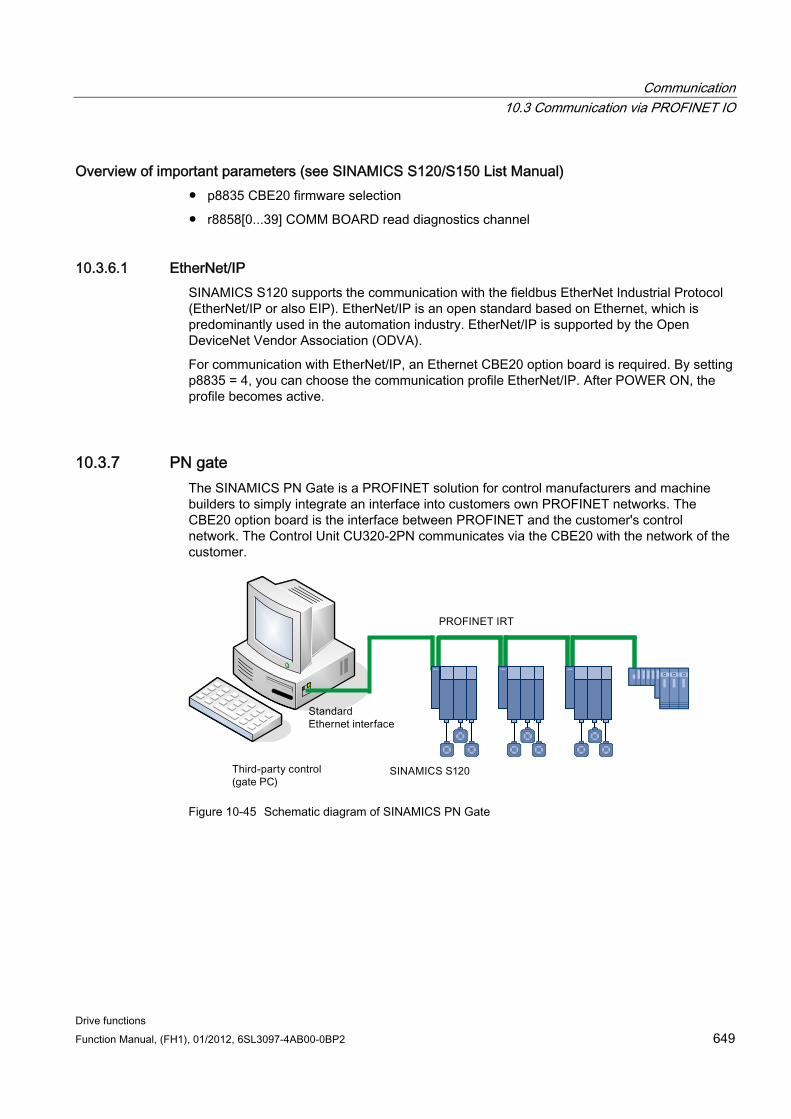
Communication 10.3 Communication via PROFINET IO
Drive functions Function Manual, (FH1), 01/2012, 6SL3097-4AB00-0BP2 649
Overview of important parameters (see SINAMICS S120/S150 List Manual) p8835 CBE20 firmware selection
r8858[0...39] COMM BOARD read diagnostics channel
10.3.6.1 EtherNet/IP SINAMICS S120 supports the communication with the fieldbus EtherNet Industrial Protocol (EtherNet/IP or also EIP). EtherNet/IP is an open standard based on Ethernet, which is predominantly used in the automation industry. EtherNet/IP is supported by the Open DeviceNet Vendor Association (ODVA).
For communication with EtherNet/IP, an Ethernet CBE20 option board is required. By setting p8835 = 4, you can choose the communication profile EtherNet/IP. After POWER ON, the profile becomes active.
10.3.7 PN gate The SINAMICS PN Gate is a PROFINET solution for control manufacturers and machine builders to simply integrate an interface into customers own PROFINET networks. The CBE20 option board is the interface between PROFINET and the customer's control network. The Control Unit CU320-2PN communicates via the CBE20 with the network of the customer.
Figure 10-45 Schematic diagram of SINAMICS PN Gate
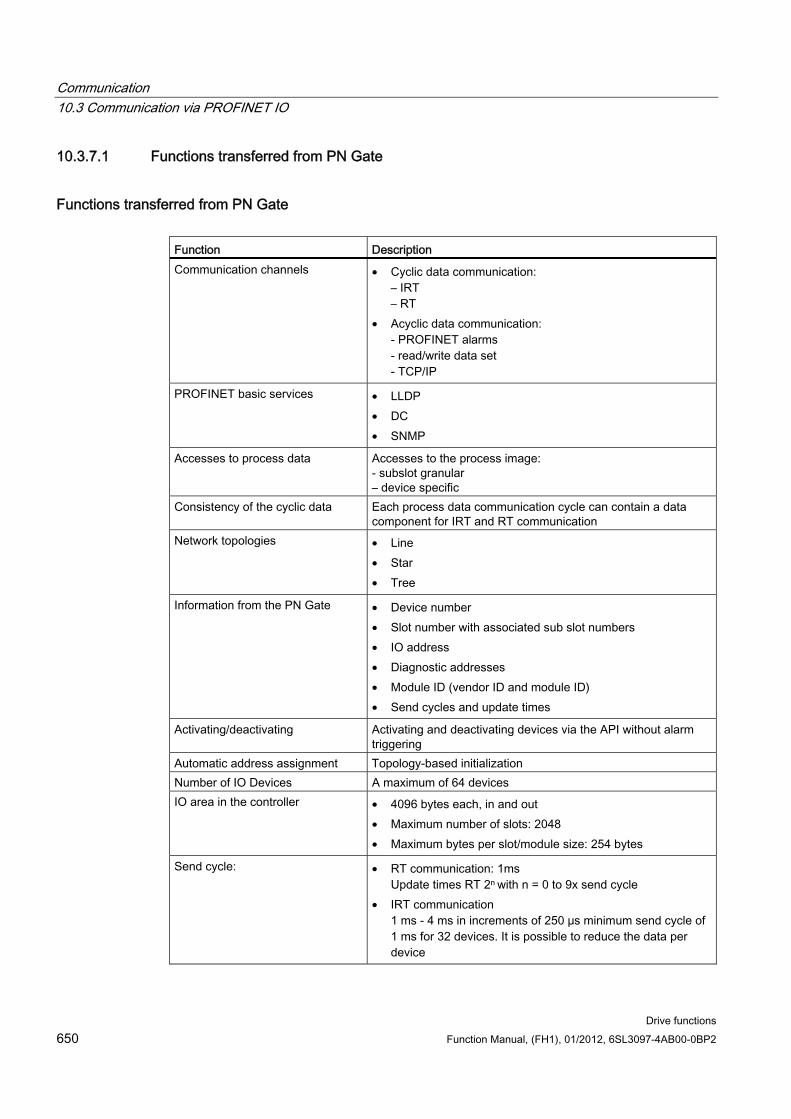
Communication 10.3 Communication via PROFINET IO
Drive functions 650 Function Manual, (FH1), 01/2012, 6SL3097-4AB00-0BP2
10.3.7.1 Functions transferred from PN Gate
Functions transferred from PN Gate Function Description Communication channels • Cyclic data communication:
– IRT – RT
• Acyclic data communication: - PROFINET alarms - read/write data set - TCP/IP
PROFINET basic services • LLDP • DC • SNMP
Accesses to process data Accesses to the process image: - subslot granular – device specific
Consistency of the cyclic data Each process data communication cycle can contain a data component for IRT and RT communication
Network topologies • Line • Star • Tree
Information from the PN Gate • Device number • Slot number with associated sub slot numbers • IO address • Diagnostic addresses • Module ID (vendor ID and module ID) • Send cycles and update times
Activating/deactivating Activating and deactivating devices via the API without alarm triggering
Automatic address assignment Topology-based initialization Number of IO Devices A maximum of 64 devices IO area in the controller • 4096 bytes each, in and out
• Maximum number of slots: 2048 • Maximum bytes per slot/module size: 254 bytes
Send cycle: • RT communication: 1ms Update times RT 2n with n = 0 to 9x send cycle
• IRT communication 1 ms - 4 ms in increments of 250 μs minimum send cycle of 1 ms for 32 devices. It is possible to reduce the data per device
Communication 10.3 Communication via PROFINET IO
Drive functions Function Manual, (FH1), 01/2012, 6SL3097-4AB00-0BP2 651
10.3.7.2 Preconditions for PN Gate
Hardware SINAMICS CU320-2PN with firmware version 4.5 or higher
Communication Board Ethernet 20 (CBE20)
Short Ethernet cable to connect CBE20 and CU320-2 PN (X 132) Recommendation: Ethernet cable with the order number MLFB: 6SL3060-4AB00-0AA0
Control hardware with Ethernet (100 Mbit/s or higher), for example, the SIMATIC Box IPC 427C.
Software SIMATIC Step7 firmware version 5.5 SP2 or higher
STARTER firmware version 4.3, or
SIMOTION SCOUT firmware version 4.3 or higher
PROFINET version SINAMICS PN Gate V2 is compatible with PROFINET V2.2
Scope of delivery PN Gate Dev-Kit (Development Kit) The PN Gate development kit is supplied on a DVD and contains the following components:
1. Step7 addon setup
– CD1 Step7 5.2 SP2 (minimum requirement) general release with Step7 5.5 SP2, Starter 4.3, SINAMICS V4.5,
2. PN Gate driver
– Bin Binary files of the driver in the Tar format.
– Src The source files as a zip file and unzipped.
– Doc Doxygen documentation as zip file. The Doxygen documentation is available in HTML and PDF formats.
Communication 10.3 Communication via PROFINET IO
Drive functions 652 Function Manual, (FH1), 01/2012, 6SL3097-4AB00-0BP2
3. Application example
– PROFIdrive Basic
– Binary code of the completed application example (PROFIdrive)
– Project example STEP 7 HW-Config 1 CU320-2 PN project with 3 simulated axes 1 CU320-2 PN project with 3 simulated axes plus ET200S
– Application example (PROFIdrive) in source code
– Doxygen documentation
4. Documentation
– German PN Gate documentation in German.
5. English
– PN Gate documentation in English. PN Gate addon setup for STEP7 (installation of all the necessary OMs, delivered with SINAMICS PN Gate DevKit CD)
You can find additional information in the "SINAMICS 120 PN Gate Configuration Manual".
10.3.8 PROFINET with 2 controllers
10.3.8.1 Control Unit settings SINAMICS S120 allows two control systems to be simultaneously connected to a Control Unit via PROFINET, e.g. an automation control (A-CPU) and a safety control (F-CPU).
SINAMICS S supports, for this communication, standard telegrams 30 and 31, as well as Siemens telegrams 901 and 902 for the safety control.
The following diagram shows the basic structure of this connection version, based on the example of a CU320-2 PN or CU310-2 PN.
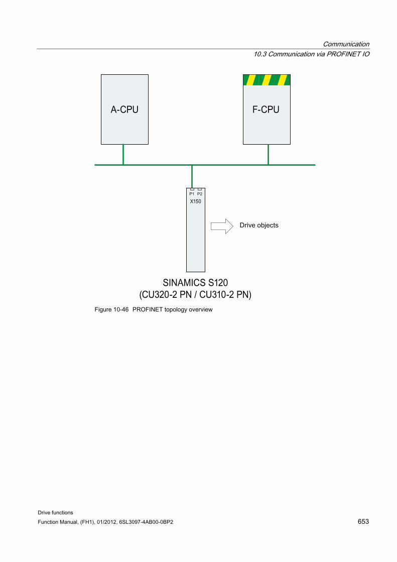
Communication 10.3 Communication via PROFINET IO
Drive functions Function Manual, (FH1), 01/2012, 6SL3097-4AB00-0BP2 653
Figure 10-46 PROFINET topology overview
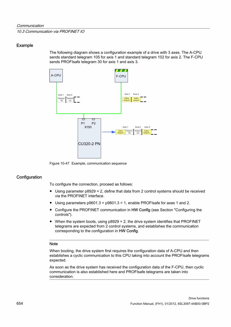
Communication 10.3 Communication via PROFINET IO
Drive functions 654 Function Manual, (FH1), 01/2012, 6SL3097-4AB00-0BP2
Example The following diagram shows a configuration example of a drive with 3 axes. The A-CPU sends standard telegram 105 for axis 1 and standard telegram 102 for axis 2. The F-CPU sends PROFIsafe telegram 30 for axis 1 and axis 3.
Figure 10-47 Example, communication sequence
Configuration To configure the connection, proceed as follows:
Using parameter p8929 = 2, define that data from 2 control systems should be received via the PROFINET interface.
Using parameters p9601.3 = p9801.3 = 1, enable PROFIsafe for axes 1 and 2.
Configure the PROFINET communication in HW Config (see Section "Configuring the controls").
When the system boots, using p8929 = 2, the drive system identifies that PROFINET telegrams are expected from 2 control systems, and establishes the communication corresponding to the configuration in HW Config.
Note
When booting, the drive system first requires the configuration data of A-CPU and then establishes a cyclic communication to this CPU taking into account the PROFIsafe telegrams expected.
As soon as the drive system has received the configuration data of the F-CPU, then cyclic communication is also established here and PROFIsafe telegrams are taken into consideration.
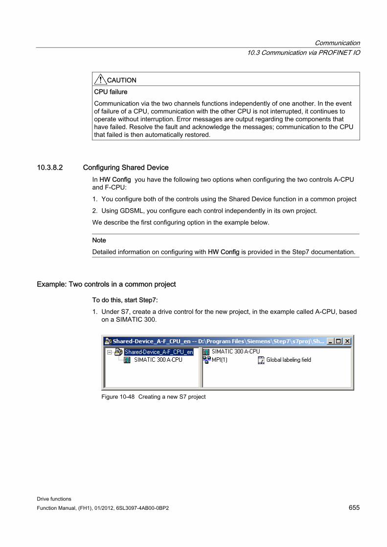
Communication 10.3 Communication via PROFINET IO
Drive functions Function Manual, (FH1), 01/2012, 6SL3097-4AB00-0BP2 655
CAUTION CPU failure
Communication via the two channels functions independently of one another. In the event of failure of a CPU, communication with the other CPU is not interrupted, it continues to operate without interruption. Error messages are output regarding the components that have failed. Resolve the fault and acknowledge the messages; communication to the CPU that failed is then automatically restored.
10.3.8.2 Configuring Shared Device In HW Config you have the following two options when configuring the two controls A-CPU and F-CPU:
1. You configure both of the controls using the Shared Device function in a common project
2. Using GDSML, you configure each control independently in its own project.
We describe the first configuring option in the example below.
Note
Detailed information on configuring with HW Config is provided in the Step7 documentation.
Example: Two controls in a common project
To do this, start Step7:
1. Under S7, create a drive control for the new project, in the example called A-CPU, based on a SIMATIC 300.
Figure 10-48 Creating a new S7 project
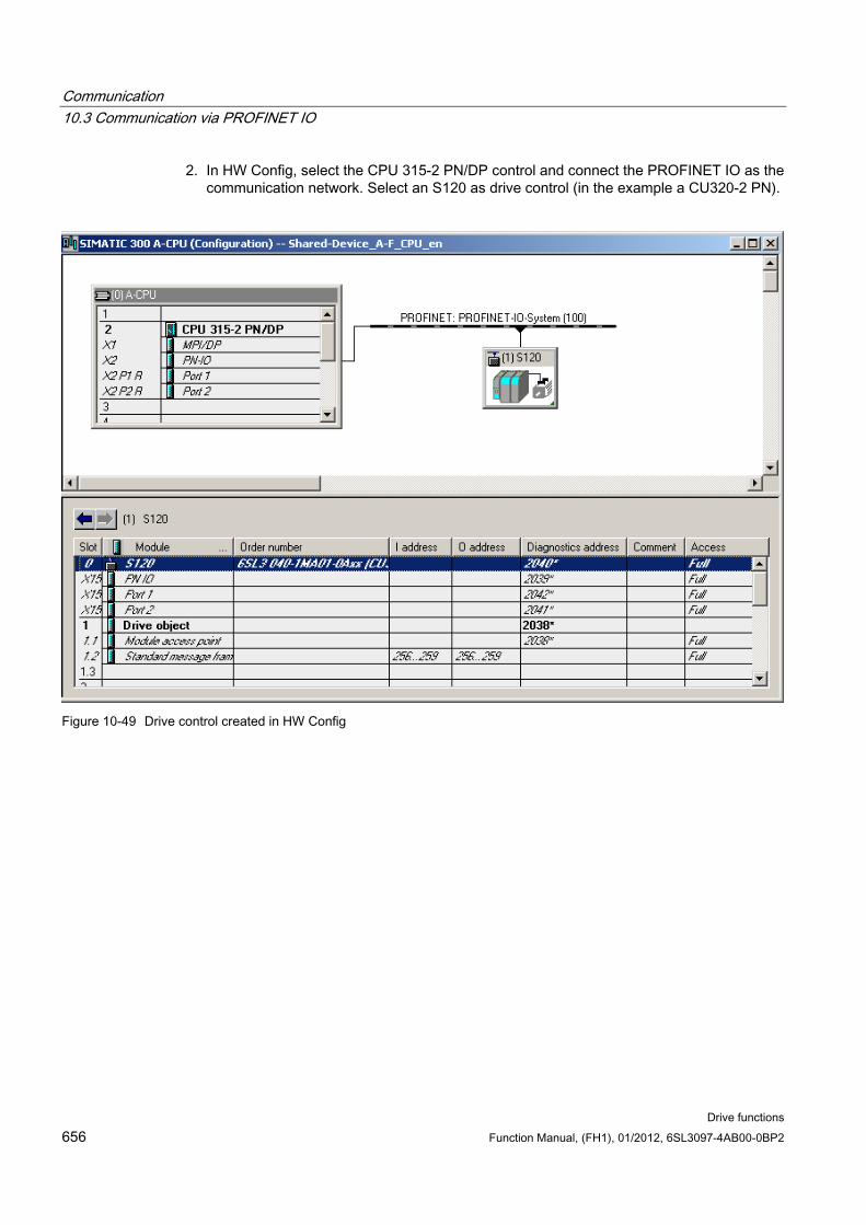
Communication 10.3 Communication via PROFINET IO
Drive functions 656 Function Manual, (FH1), 01/2012, 6SL3097-4AB00-0BP2
2. In HW Config, select the CPU 315-2 PN/DP control and connect the PROFINET IO as the communication network. Select an S120 as drive control (in the example a CU320-2 PN).
Figure 10-49 Drive control created in HW Config
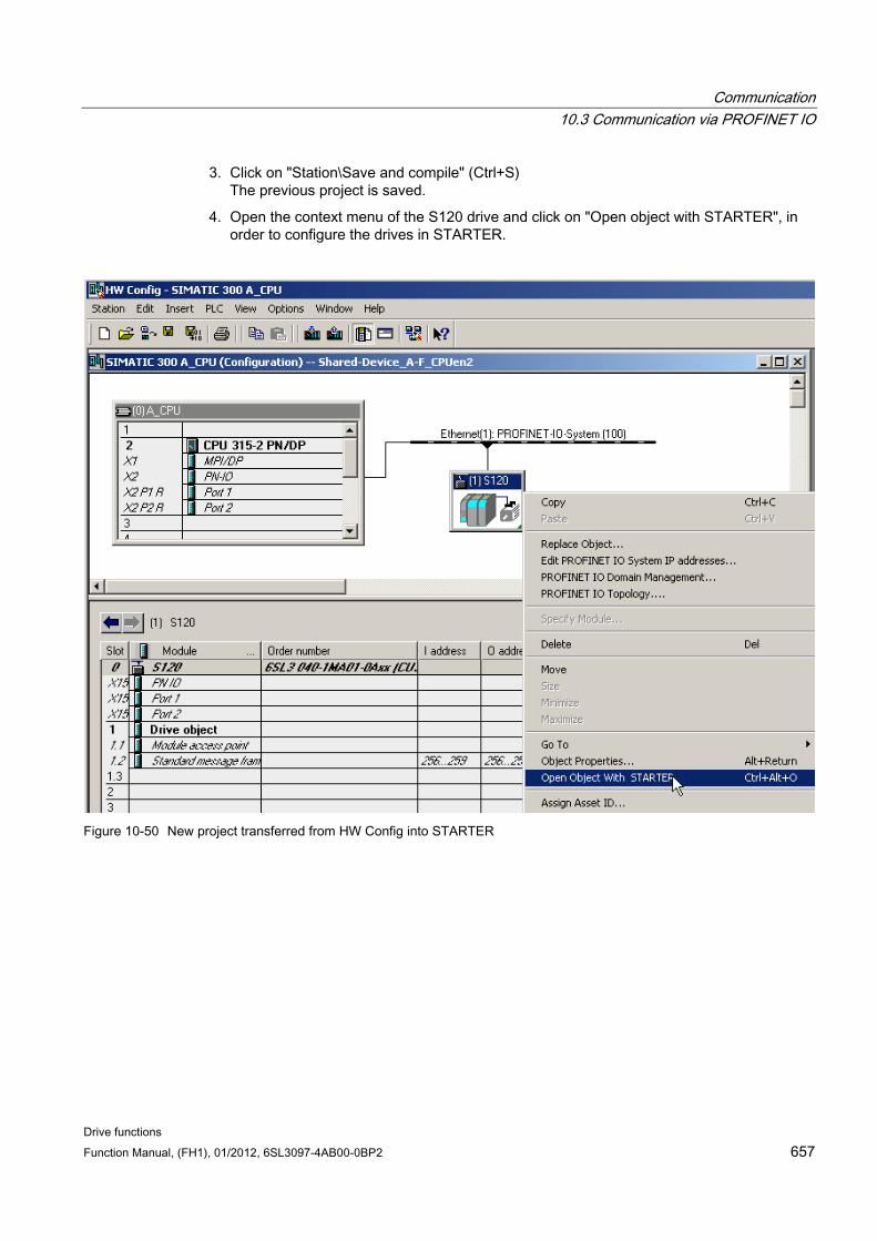
Communication 10.3 Communication via PROFINET IO
Drive functions Function Manual, (FH1), 01/2012, 6SL3097-4AB00-0BP2 657
3. Click on "Station\Save and compile" (Ctrl+S) The previous project is saved.
4. Open the context menu of the S120 drive and click on "Open object with STARTER", in order to configure the drives in STARTER.
Figure 10-50 New project transferred from HW Config into STARTER
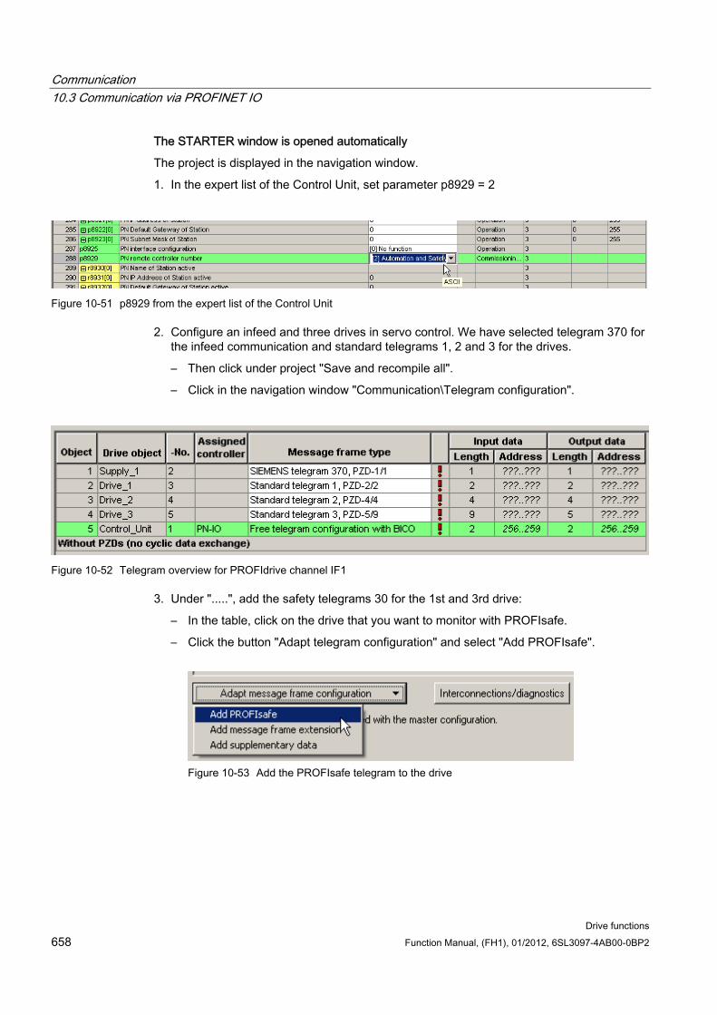
Communication 10.3 Communication via PROFINET IO
Drive functions 658 Function Manual, (FH1), 01/2012, 6SL3097-4AB00-0BP2
The STARTER window is opened automatically
The project is displayed in the navigation window.
1. In the expert list of the Control Unit, set parameter p8929 = 2
Figure 10-51 p8929 from the expert list of the Control Unit
2. Configure an infeed and three drives in servo control. We have selected telegram 370 for the infeed communication and standard telegrams 1, 2 and 3 for the drives.
– Then click under project "Save and recompile all".
– Click in the navigation window "Communication\Telegram configuration".
Figure 10-52 Telegram overview for PROFIdrive channel IF1
3. Under ".....", add the safety telegrams 30 for the 1st and 3rd drive:
– In the table, click on the drive that you want to monitor with PROFIsafe.
– Click the button "Adapt telegram configuration" and select "Add PROFIsafe".
Figure 10-53 Add the PROFIsafe telegram to the drive
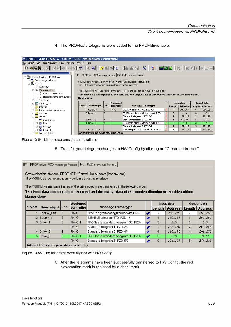
Communication 10.3 Communication via PROFINET IO
Drive functions Function Manual, (FH1), 01/2012, 6SL3097-4AB00-0BP2 659
4. The PROFIsafe telegrams were added to the PROFIdrive table:
Figure 10-54 List of telegrams that are available
5. Transfer your telegram changes to HW Config by clicking on "Create addresses".
Figure 10-55 The telegrams were aligned with HW Config
6. After the telegrams have been successfully transferred to HW Config, the red exclamation mark is replaced by a checkmark.
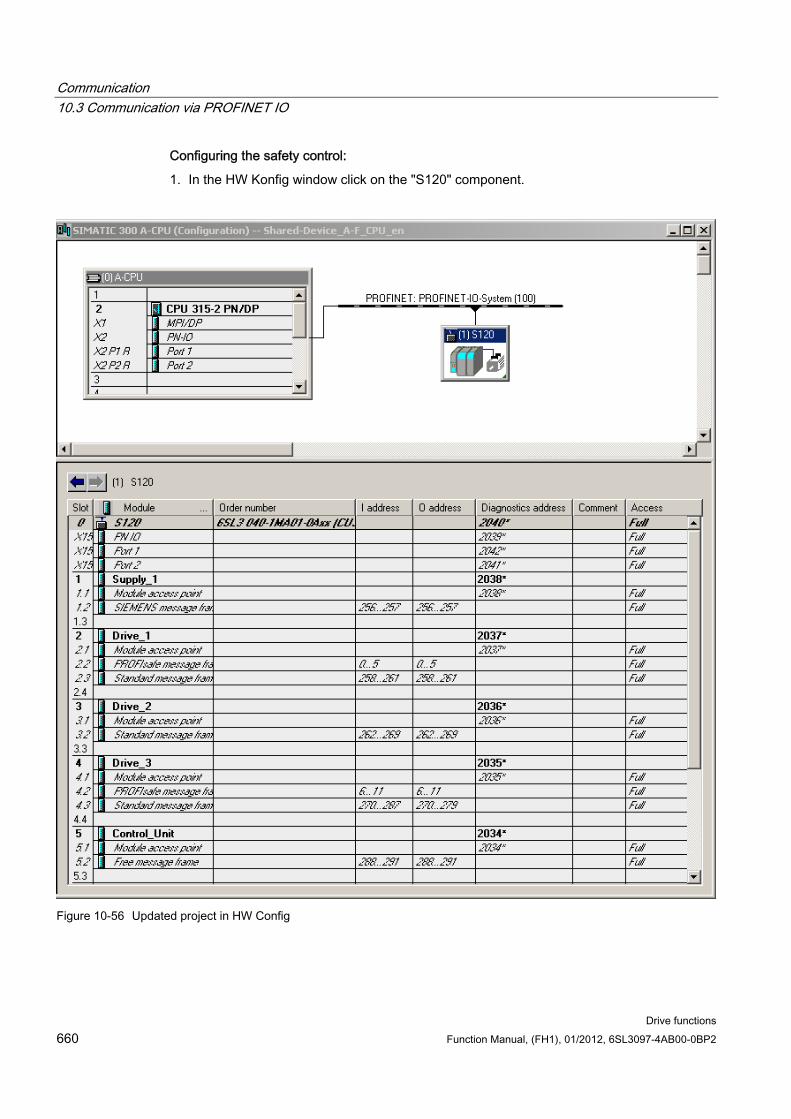
Communication 10.3 Communication via PROFINET IO
Drive functions 660 Function Manual, (FH1), 01/2012, 6SL3097-4AB00-0BP2
Configuring the safety control:
1. In the HW Konfig window click on the "S120" component.
Figure 10-56 Updated project in HW Config
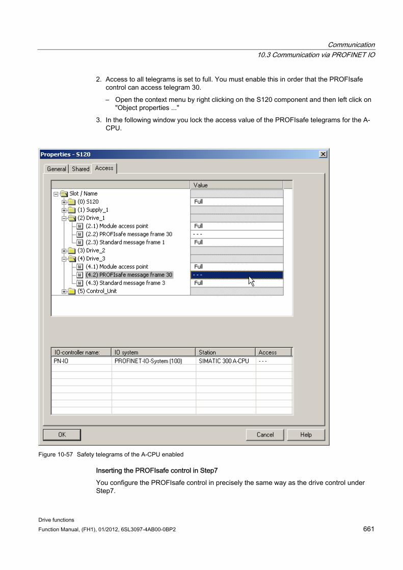
Communication 10.3 Communication via PROFINET IO
Drive functions Function Manual, (FH1), 01/2012, 6SL3097-4AB00-0BP2 661
2. Access to all telegrams is set to full. You must enable this in order that the PROFIsafe control can access telegram 30.
– Open the context menu by right clicking on the S120 component and then left click on "Object properties ..."
3. In the following window you lock the access value of the PROFIsafe telegrams for the A-CPU.
Figure 10-57 Safety telegrams of the A-CPU enabled
Inserting the PROFIsafe control in Step7
You configure the PROFIsafe control in precisely the same way as the drive control under Step7.
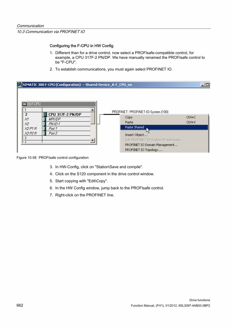
Communication 10.3 Communication via PROFINET IO
Drive functions 662 Function Manual, (FH1), 01/2012, 6SL3097-4AB00-0BP2
Configuring the F-CPU in HW Config
1. Different than for a drive control, now select a PROFIsafe-compatible control, for example, a CPU 317F-2 PN/DP. We have manually renamed the PROFIsafe control to be "F-CPU".
2. To establish communications, you must again select PROFINET IO.
Figure 10-58 PROFIsafe control configuration
3. In HW-Config, click on "Station\Save and compile".
4. Click on the S120 component in the drive control window.
5. Start copying with "Edit\Copy".
6. In the HW Config window, jump back to the PROFIsafe control.
7. Right-click on the PROFINET line.
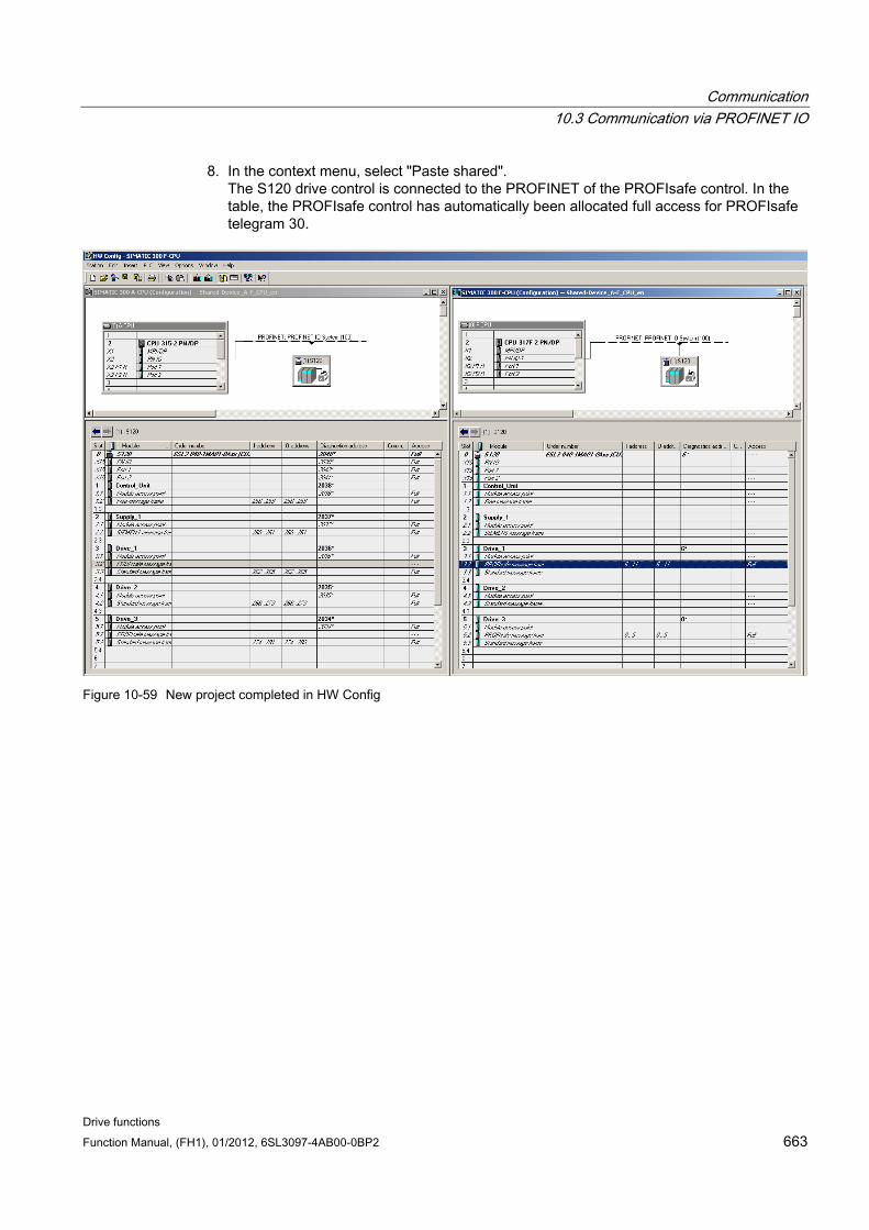
Communication 10.3 Communication via PROFINET IO
Drive functions Function Manual, (FH1), 01/2012, 6SL3097-4AB00-0BP2 663
8. In the context menu, select "Paste shared". The S120 drive control is connected to the PROFINET of the PROFIsafe control. In the table, the PROFIsafe control has automatically been allocated full access for PROFIsafe telegram 30.
Figure 10-59 New project completed in HW Config
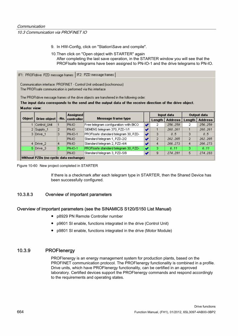
Communication 10.3 Communication via PROFINET IO
Drive functions 664 Function Manual, (FH1), 01/2012, 6SL3097-4AB00-0BP2
9. In HW-Config, click on "Station\Save and compile".
10. Then click on "Open object with STARTER" again After completing the last save operation, in the STARTER window you will see that the PROFIsafe telegrams have been assigned to PN-IO-1 and the drive telegrams to PN-IO.
Figure 10-60 New project completed in STARTER
If there is a checkmark after each telegram type in STARTER, then the Shared Device has been successfully configured.
10.3.8.3 Overview of important parameters
Overview of important parameters (see the SINAMICS S120/S150 List Manual) p8929 PN Remote Controller number
p9601 SI enable, functions integrated in the drive (Control Unit)
p9801 SI enable, functions integrated in the drive (Motor Module)
10.3.9 PROFIenergy PROFIenergy is an energy management system for production plants, based on the PROFINET communication protocol. The PROFIenergy functionality is combined in a profile. Drive units, which have PROFIenergy functionality, can be certified in an approved laboratory. Certified devices support the PROFIenergy commands and respond accordingly to the requirements and operating states.
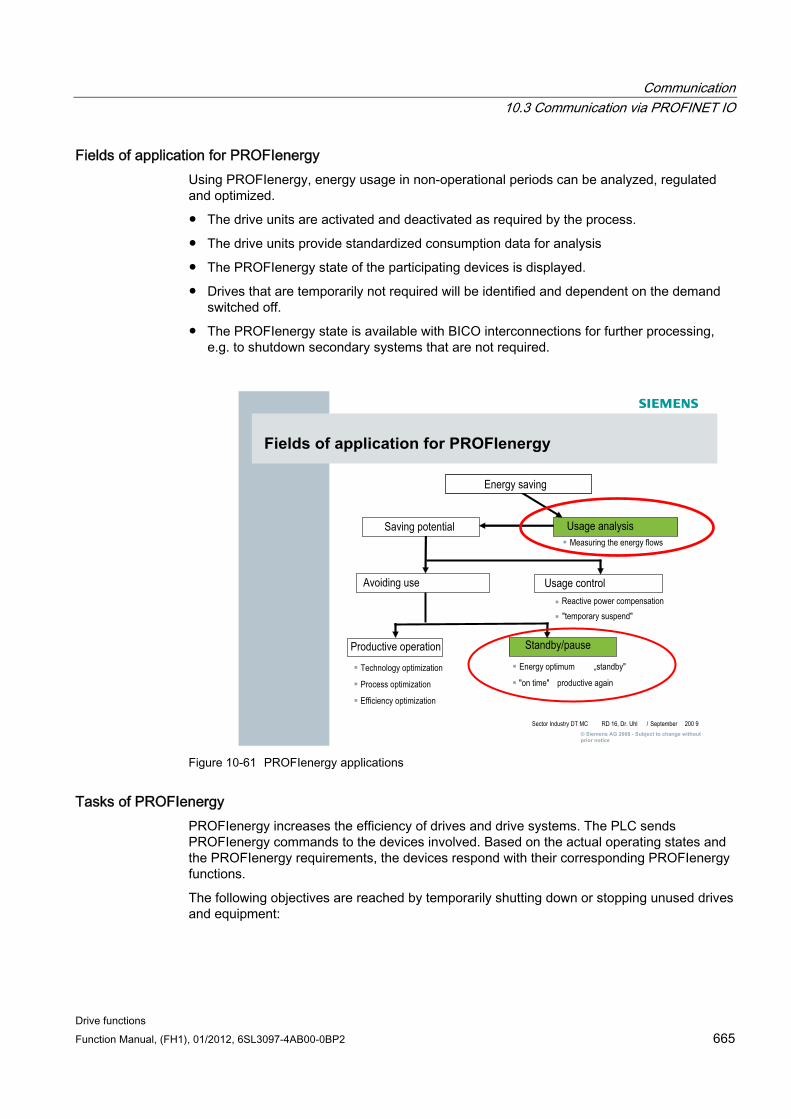
Communication 10.3 Communication via PROFINET IO
Drive functions Function Manual, (FH1), 01/2012, 6SL3097-4AB00-0BP2 665
Fields of application for PROFIenergy Using PROFIenergy, energy usage in non-operational periods can be analyzed, regulated and optimized.
The drive units are activated and deactivated as required by the process.
The drive units provide standardized consumption data for analysis
The PROFIenergy state of the participating devices is displayed.
Drives that are temporarily not required will be identified and dependent on the demand switched off.
The PROFIenergy state is available with BICO interconnections for further processing, e.g. to shutdown secondary systems that are not required.
Energy saving
Usage analysis
Usage control
Saving potentialMeasuring the energy flows
Productive operation
"temporary suspend"Reactive power compensation
productive again
Energy optimum
Efficiency optimization
Process optimization
Technology optimization
Standby/pause
Avoiding use
Fields of application for PROFIenergy
"on time"
„standby"
9200September/ RD 16, Dr. UhlSector Industry DT MC © Siemens AG 2008 - Subject to change without prior notice
Figure 10-61 PROFIenergy applications
Tasks of PROFIenergy PROFIenergy increases the efficiency of drives and drive systems. The PLC sends PROFIenergy commands to the devices involved. Based on the actual operating states and the PROFIenergy requirements, the devices respond with their corresponding PROFIenergy functions.
The following objectives are reached by temporarily shutting down or stopping unused drives and equipment:
Communication 10.3 Communication via PROFINET IO
Drive functions 666 Function Manual, (FH1), 01/2012, 6SL3097-4AB00-0BP2
Lower energy costs
Reduction of thermal emissions
Longer service life by reducing the effective operating times
PROFIenergy properties of the SINAMICS S120 drive system SINAMICS S120 drive system devices meet the following requirements:
SINAMICS S120 devices are certified for PROFIenergy
SINAMICS S120 devices support PROFIenergy Class Type 3
PROFIenergy command Parameter number PROFIenergy command r5600 PE_Mode_ID p5601 PE_Mode_Attributes p5602[0...1] Time_min_Pause r5603[0...1] Time_to_Pause r5604[0...1] Time_to_operate r5605[0...1] Time_min_length_of_stay p5606[0...1] Time_max_length_of_stay p5607 Mode_Power_Consumption r5608 Energy_Consumption_to_Pause r5609 Energy_Consumption_to_Operate r5610 Energy_Consumption_to_Destination p5611 Generally enable/inhibit energy saving p5612[0...1] Enable/inhibit device energy saving r5613 BO: Energy saving active/inactive
Parameters r5600 to r5610 are standard PROFIenergy parameters.
Parameters from p5611 are manufacturer-specific PROFIenergy parameters.
10.3.9.1 Function diagrams and parameters
Function diagrams (see SINAMICS S120/S150 List Manual) 2610 Execution control
Overview of important parameters (see SINAMICS S120/S150 List Manual) r5600 PE_Mode_ID
p5602[0...1] PE minimum energy-saving mode idle time
p5606[0...1] PE maximum energy-saving mode dwell time
p5611 PE energy saving generally enable/disable
Communication 10.4 Communication via SINAMICS Link
Drive functions Function Manual, (FH1), 01/2012, 6SL3097-4AB00-0BP2 667
p5612[0...1] PE energy-saving properties enable/disable
r5613 BO: Energy saving active/inactive
10.4 Communication via SINAMICS Link
10.4.1 Basic principles of SINAMICS Link A drive unit (with a node number) most frequently comprises a Control Unit with a number of connected drive objects (DOs). SINAMICS Link allows data to be directly exchanged between up to 64 Control Units CU320-2PN or CU320-2DP or CUD. SINAMICS Link functionality requires the CBE20 supplementary module. All participating Control Units must be equipped with a CBE20. Possible applications are, for example:
Torque distribution for n drives
Setpoint cascading for n drives
Load distribution of drives coupled through a material web
Master/slave function for infeed units
Links between SINAMICS DC-MASTER and SINAMICS S120
Preconditions The following preconditions must be fulfilled to operate SINAMICS Link:
r2064[1]: The bus cycle time (Tdp) must be an integer multiple of p0115[0] (current controller clock cycle).
r2064[2]: The master cycle time (Tmapc) must be an integer multiple of p0115[1] (speed control cycle).
The current controller clock cycle must be set to 250 µs or 500 µs. One clock with 400 µs is not permitted. For 400 µs, alarm A01902[4] is output. As countermeasure, then set the current controller cycle clock with p0115[0] to 500 µs.
Note
The "SINAMICS Link" function is not available for the Control Unit CU310-2.
Note SINAMICS Link for chassis format
For the following devices in the chassis format, you must manually set parameter p0115[0] to 250 μs or 500 μs: • 3 380 - 480 V AC: All devices with rated current In ≥ 605 A • 3 500 - 690 V AC: All units
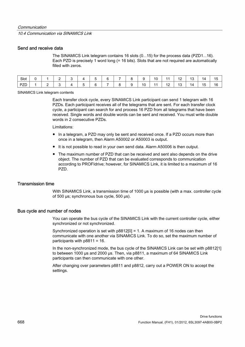
Communication 10.4 Communication via SINAMICS Link
Drive functions 668 Function Manual, (FH1), 01/2012, 6SL3097-4AB00-0BP2
Send and receive data The SINAMICS Link telegram contains 16 slots (0...15) for the process data (PZD1...16). Each PZD is precisely 1 word long (= 16 bits). Slots that are not required are automatically filled with zeros.
Slot 0 1 2 3 4 5 6 7 8 9 10 11 12 13 14 15 PZD 1 2 3 4 5 6 7 8 9 10 11 12 13 14 15 16
SINAMICS Link telegram contents
Each transfer clock cycle, every SINAMICS Link participant can send 1 telegram with 16 PZDs. Each participant receives all of the telegrams that are sent. For each transfer clock cycle, a participant can search for and process 16 PZD from all telegrams that have been received. Single words and double words can be sent and received. You must write double words in 2 consecutive PZDs.
Limitations:
In a telegram, a PZD may only be sent and received once. If a PZD occurs more than once in a telegram, then Alarm A50002 or A50003 is output.
It is not possible to read in your own send data. Alarm A50006 is then output.
The maximum number of PZD that can be received and sent also depends on the drive object. The number of PZD that can be evaluated corresponds to communication according to PROFIdrive; however, for SINAMICS Link, it is limited to a maximum of 16 PZD.
Transmission time With SINAMICS Link, a transmission time of 1000 µs is possible (with a max. controller cycle of 500 µs; synchronous bus cycle, 500 µs).
Bus cycle and number of nodes You can operate the bus cycle of the SINAMICS Link with the current controller cycle, either synchronized or not synchronized.
Synchronized operation is set with p8812[0] = 1. A maximum of 16 nodes can then communicate with one another via SINAMICS Link. To do so, set the maximum number of participants with p8811 = 16.
In the non-synchronized mode, the bus cycle of the SINAMICS Link can be set with p8812[1] to between 1000 µs and 2000 µs. Then, via p8811, a maximum of 64 SINAMICS Link participants can then communicate with one other.
After changing over parameters p8811 and p8812, carry out a POWER ON to accept the settings.
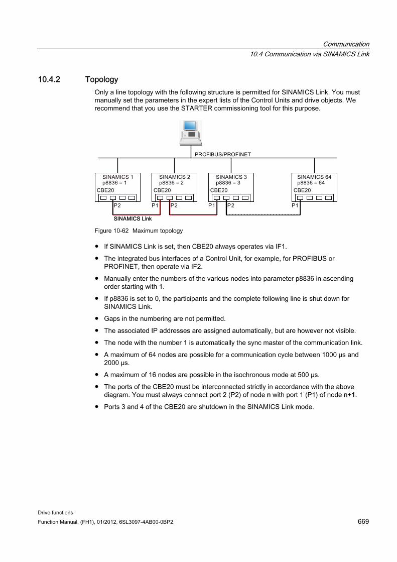
Communication 10.4 Communication via SINAMICS Link
Drive functions Function Manual, (FH1), 01/2012, 6SL3097-4AB00-0BP2 669
10.4.2 Topology Only a line topology with the following structure is permitted for SINAMICS Link. You must manually set the parameters in the expert lists of the Control Units and drive objects. We recommend that you use the STARTER commissioning tool for this purpose.
Figure 10-62 Maximum topology
If SINAMICS Link is set, then CBE20 always operates via IF1.
The integrated bus interfaces of a Control Unit, for example, for PROFIBUS or PROFINET, then operate via IF2.
Manually enter the numbers of the various nodes into parameter p8836 in ascending order starting with 1.
If p8836 is set to 0, the participants and the complete following line is shut down for SINAMICS Link.
Gaps in the numbering are not permitted.
The associated IP addresses are assigned automatically, but are however not visible.
The node with the number 1 is automatically the sync master of the communication link.
A maximum of 64 nodes are possible for a communication cycle between 1000 µs and 2000 µs.
A maximum of 16 nodes are possible in the isochronous mode at 500 µs.
The ports of the CBE20 must be interconnected strictly in accordance with the above diagram. You must always connect port 2 (P2) of node n with port 1 (P1) of node n+1.
Ports 3 and 4 of the CBE20 are shutdown in the SINAMICS Link mode.
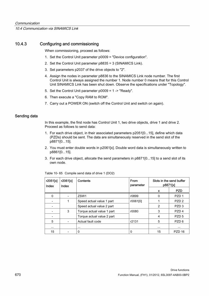
Communication 10.4 Communication via SINAMICS Link
Drive functions 670 Function Manual, (FH1), 01/2012, 6SL3097-4AB00-0BP2
10.4.3 Configuring and commissioning When commissioning, proceed as follows:
1. Set the Control Unit parameter p0009 = "Device configuration".
2. Set the Control Unit parameter p8835 = 3 (SINAMICS Link).
3. Set parameters p2037 of the drive objects to "2".
4. Assign the nodes in parameter p8836 to the SINAMICS Link node number. The first Control Unit is always assigned the number 1. Node number 0 means that for this Control Unit SINAMICS Link has been shut down. Observe the specifications under "Topology".
5. Set the Control Unit parameter p0009 = 1 -> "Ready".
6. Then execute a "Copy RAM to ROM".
7. Carry out a POWER ON (switch off the Control Unit and switch on again).
Sending data In this example, the first node has Control Unit 1, two drive objects, drive 1 and drive 2. Proceed as follows to send data:
1. For each drive object, in their associated parameters p2051[0...15], define which data (PZDs) should be sent. The data are simultaneously reserved in the send slot of the p8871[0...15].
2. You must enter double words in p2061[x]. Double word data is simultaneously written to p8861[0...15].
3. For each drive object, allocate the send parameters in p8871[0...15] to a send slot of its own node.
Table 10- 65 Compile send data of drive 1 (DO2)
Slots in the send buffer p8871[x]
r2051[x] Index
r2061[x] Index
Contents From parameter
x PZD 0 - ZSW1 r0899 0 PZD 1 - Speed actual value 1 part 1 PZD 2 -
1 Speed actual value 2 part
r0061[0] 2 PZD 3
- Torque actual value 1 part 3 PZD 4 -
3 Torque actual value 2 part
r0080 4 PZD 5
5 - Actual fault code r2131 5 PZD 6 ... ... ... ... 15 - 0 0 15 PZD 16
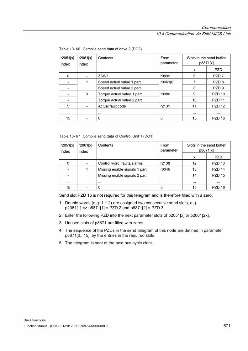
Communication 10.4 Communication via SINAMICS Link
Drive functions Function Manual, (FH1), 01/2012, 6SL3097-4AB00-0BP2 671
Table 10- 66 Compile send data of drive 2 (DO3)
Slots in the send buffer p8871[x]
r2051[x] Index
r2061[x] Index
Contents From parameter
x PZD 0 - ZSW1 r0899 6 PZD 7 - Speed actual value 1 part 7 PZD 8 -
1 Speed actual value 2 part
r0061[0] 8 PZD 9
- Torque actual value 1 part 9 PZD 10 -
3 Torque actual value 2 part
r0080 10 PZD 11
5 - Actual fault code r2131 11 PZD 12 ... ... ... ... 15 - 0 0 15 PZD 16
Table 10- 67 Compile send data of Control Unit 1 (DO1)
Slots in the send buffer p8871[x]
r2051[x] Index
r2061[x] Index
Contents From parameter
x PZD 0 - Control word, faults/alarms r2138 12 PZD 13 - Missing enable signals 1 part 13 PZD 14 -
1 Missing enable signals 2 part
r0046 14 PZD 15
... ... ... ... 15 - 0 0 15 PZD 16
Send slot PZD 16 is not required for this telegram and is therefore filled with a zero.
1. Double words (e.g. 1 + 2) are assigned two consecutive send slots, e.g. p2061[1] => p8871[1] = PZD 2 and p8871[2] = PZD 3.
2. Enter the following PZD into the next parameter slots of p2051[x] or p2061[2x].
3. Unused slots of p8871 are filled with zeros.
4. The sequence of the PZDs in the send telegram of this node are defined in parameter p8871[0...15] by the entries in the required slots.
5. The telegram is sent at the next bus cycle clock.
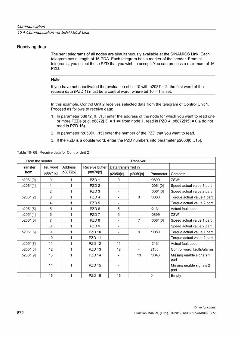
Communication 10.4 Communication via SINAMICS Link
Drive functions 672 Function Manual, (FH1), 01/2012, 6SL3097-4AB00-0BP2
Receiving data The sent telegrams of all nodes are simultaneously available at the SINAMICS Link. Each telegram has a length of 16 PDA. Each telegram has a marker of the sender. From all telegrams, you select those PZD that you wish to accept. You can process a maximum of 16 PZD.
Note
If you have not deactivated the evaluation of bit 10 with p2037 = 2, the first word of the receive data (PZD 1) must be a control word, where bit 10 = 1 is set.
In this example, Control Unit 2 receives selected data from the telegram of Control Unit 1. Proceed as follows to receive data:
1. In parameter p8872[ 0…15] enter the address of the node for which you want to read one or more PZDs (e.g. p8872[ 3] = 1 => from node 1, read in PZD 4, p8872[15] = 0 ≙ do not read in PZD 16).
2. In parameter r2050[0…15] enter the number of the PZD that you want to read.
3. If the PZD is a double word, enter the PZD numbers into parameter p2060[0…15].
Table 10- 68 Receive data for Control Unit 2
From the sender Receiver Data transferred in Transfer
from Tel. word p8871[x]
Address p8872[x]
Receive buffer p8870[x] p2050[x] p2060[x] Parameter Contents
p2051[0] 0 1 PZD 1 0 - r0899 ZSW1 1 1 PZD 2 - r0061[0] Speed actual value 1 part p2061[1] 2 1 PZD 3 -
1 r0061[0] Speed actual value 2 part
3 1 PZD 4 - Torque actual value 1 part p2061[2] 4 1 PZD 5 -
3
r0080 Torque actual value 2 part
p2051[5] 5 1 PZD 6 5 - r2131 Actual fault code p2051[4] 6 1 PZD 7 6 - r0899 ZSW1
7 1 PZD 8 - Speed actual value 1 part p2061[5] 8 1 PZD 9 -
7 r0061[0] Speed actual value 2 part
9 1 PZD 10 - Torque actual value 1 part p2061[6] 10 1 PZD 11 -
9 r0080 Torque actual value 2 part
p2051[7] 11 1 PZD 12 11 - r2131 Actual fault code p2051[8] 12 1 PZD 13 12 - 2138 Control word, faults/alarms
13 1 PZD 14 - Missing enable signals 1 part
p2061[9]
14 1 PZD 15 -
13 r0046
Missing enable signals 2 part
- 15 1 PZD 16 15 - 0 Empty
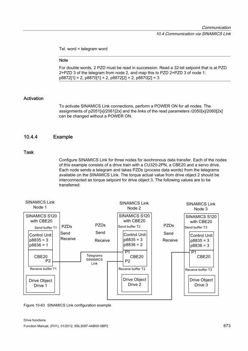
Communication 10.4 Communication via SINAMICS Link
Drive functions Function Manual, (FH1), 01/2012, 6SL3097-4AB00-0BP2 673
Tel. word = telegram word
Note
For double words, 2 PZD must be read in succession. Read a 32-bit setpoint that is at PZD 2+PZD 3 of the telegram from node 2, and map this to PZD 2+PZD 3 of node 1: p8872[1] = 2, p8870[1] = 2, p8872[2] = 2, p8870[2] = 3
Activation To activate SINAMICS Link connections, perform a POWER ON for all nodes. The assignments of p2051[x]/2061[2x] and the links of the read parameters r2050[x]/2060[2x] can be changed without a POWER ON.
10.4.4 Example
Task Configure SINAMICS Link for three nodes for isochronous data transfer. Each of the nodes of this example consists of a drive train with a CU320-2PN, a CBE20 and a servo drive. Each node sends a telegram and takes PZDs (process data words) from the telegrams available on the SINAMICS Link. The torque actual value from drive object 2 should be interconnected as torque setpoint for drive object 3. The following values are to be transferred:
Figure 10-63 SINAMICS Link configuration example
Communication 10.4 Communication via SINAMICS Link
Drive functions 674 Function Manual, (FH1), 01/2012, 6SL3097-4AB00-0BP2
Send:
First telegram: Send data from node 1
– r0898 CO/BO: Control word 1 drive object 1 (1 x PZD)
– r0062 CO: Speed setpoint drive object 2 (2 x PZD)
– r0079 CO: Total torque setpoint (2 x PZD)
Second telegram: Send data from node 2
– r0899 CO/BO: Status word 1 drive object 2 (1 x PZD)
– r0021 CO: Speed actual value drive object 2 (2 x PZD)
– r0031 CO: Torque actual value drive object 2 (2 x PZD)
Third telegram: Send data from node
– r0899 CO/BO: Status word 1 drive object 3 (1 x PZD)
– r0021 CO: Speed actual value drive object 3 (2 x PZD)
– r0031 CO: Torque actual value drive object 3 (2 x PZD)
Receiving:
First node: Receive data with actual values from nodes 2 and 3
– r0899 CO/BO: Status word 1 drive object 2 (1 x PZD)
– r0021 CO: Speed actual value drive object 2 (2 x PZD)
– r0031 CO: Torque actual value drive object 2 (2 x PZD)
– r0899 CO/BO: Status word 1 drive object 3 (1 x PZD)
– r0021 CO: Speed actual value drive object 3 (2 x PZD)
– r0031 CO: Torque actual value drive object 3 (2 x PZD)
Second node: Receive data of setpoints from node 1
– r0898 CO/BO: Control word 1 drive object 1 (1 x PZD): Node 1
– r0062 CO: Speed setpoint drive object 2 (2 x PZD): Node 1
Third node: Receive data with setpoints from nodes 1 and 2
– r0898 CO/BO: Control word 1 drive object 1 (1 x PZD): Node 1
– r0031 CO: Torque actual value drive object 2 (2 x PZD): Node 2
Legend r0898 CO/BO: Control word 1 from node 1: STW1_T1
r0899 CO/BO: Status word 1 from node 2: ZSW1_T2
r0021 CO: Speed actual value drive object: n_act_A2_a and n_act_A2_b
r0062 CO: Speed setpoint: n_set_A2_a and n_set_A2_b
r0031 torque actual value drive object: m_act_A2_a and m_act_A2_b
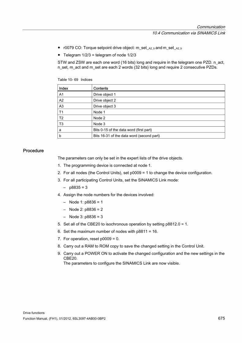
Communication 10.4 Communication via SINAMICS Link
Drive functions Function Manual, (FH1), 01/2012, 6SL3097-4AB00-0BP2 675
r0079 CO: Torque setpoint drive object: m_set_A2_b and m_set_A2_b
Telegram 1/2/3 = telegram of node 1/2/3
STW and ZSW are each one word (16 bits) long and require in the telegram one PZD. n_act, n_set, m_act and m_set are each 2 words (32 bits) long and require 2 consecutive PZDs.
Table 10- 69 Indices
Index Contents A1 Drive object 1 A2 Drive object 2 A3 Drive object 3 T1 Node 1 T2 Node 2 T3 Node 3 a Bits 0-15 of the data word (first part) b Bits 16-31 of the data word (second part)
Procedure The parameters can only be set in the expert lists of the drive objects.
1. The programming device is connected at node 1.
2. For all nodes (the Control Units), set p0009 = 1 to change the device configuration.
3. For all participating Control Units, set the SINAMICS Link mode:
– p8835 = 3
4. Assign the node numbers for the devices involved:
– Node 1: p8836 = 1
– Node 2: p8836 = 2
– Node 3: p8836 = 3
5. Set all of the CBE20 to isochronous operation by setting p8812.0 = 1.
6. Set the maximum number of nodes with p8811 = 16.
7. For operation, reset p0009 = 0.
8. Carry out a RAM to ROM copy to save the changed setting in the Control Unit.
9. Carry out a POWER ON to activate the changed configuration and the new settings in the CBE20. The parameters to configure the SINAMICS Link are now visible.
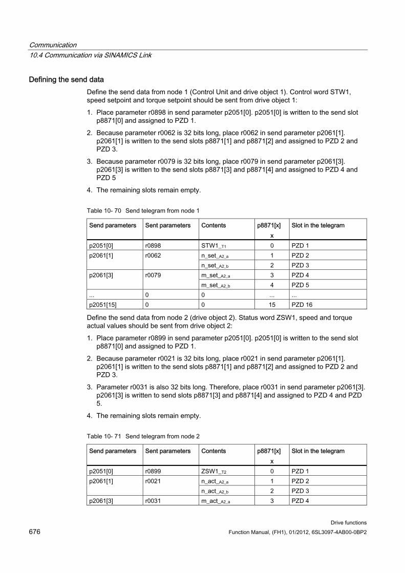
Communication 10.4 Communication via SINAMICS Link
Drive functions 676 Function Manual, (FH1), 01/2012, 6SL3097-4AB00-0BP2
Defining the send data Define the send data from node 1 (Control Unit and drive object 1). Control word STW1, speed setpoint and torque setpoint should be sent from drive object 1:
1. Place parameter r0898 in send parameter p2051[0]. p2051[0] is written to the send slot p8871[0] and assigned to PZD 1.
2. Because parameter r0062 is 32 bits long, place r0062 in send parameter p2061[1]. p2061[1] is written to the send slots p8871[1] and p8871[2] and assigned to PZD 2 and PZD 3.
3. Because parameter r0079 is 32 bits long, place r0079 in send parameter p2061[3]. p2061[3] is written to the send slots p8871[3] and p8871[4] and assigned to PZD 4 and PZD 5
4. The remaining slots remain empty.
Table 10- 70 Send telegram from node 1
Send parameters Sent parameters Contents p8871[x] x
Slot in the telegram
p2051[0] r0898 STW1_T1 0 PZD 1 n_set_A2_a 1 PZD 2 p2061[1] r0062 n_set_A2_b 2 PZD 3 m_set_A2_a 3 PZD 4 p2061[3] r0079 m_set_A2_b 4 PZD 5
... 0 0 ... ... p2051[15] 0 0 15 PZD 16
Define the send data from node 2 (drive object 2). Status word ZSW1, speed and torque actual values should be sent from drive object 2:
1. Place parameter r0899 in send parameter p2051[0]. p2051[0] is written to the send slot p8871[0] and assigned to PZD 1.
2. Because parameter r0021 is 32 bits long, place r0021 in send parameter p2061[1]. p2061[1] is written to the send slots p8871[1] and p8871[2] and assigned to PZD 2 and PZD 3.
3. Parameter r0031 is also 32 bits long. Therefore, place r0031 in send parameter p2061[3]. p2061[3] is written to send slots p8871[3] and p8871[4] and assigned to PZD 4 and PZD 5.
4. The remaining slots remain empty.
Table 10- 71 Send telegram from node 2
Send parameters Sent parameters Contents p8871[x] x
Slot in the telegram
p2051[0] r0899 ZSW1_T2 0 PZD 1 n_act_A2_a 1 PZD 2 p2061[1] r0021 n_act_A2_b 2 PZD 3
p2061[3] r0031 m_act_A2_a 3 PZD 4
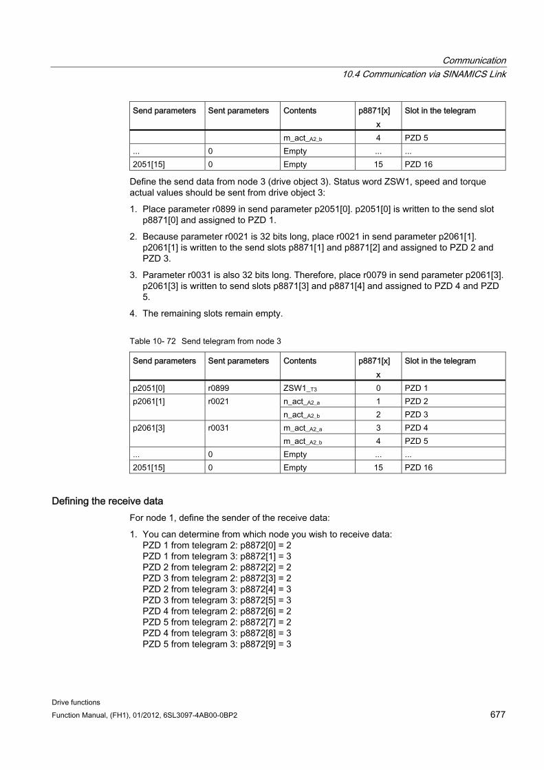
Communication 10.4 Communication via SINAMICS Link
Drive functions Function Manual, (FH1), 01/2012, 6SL3097-4AB00-0BP2 677
Send parameters Sent parameters Contents p8871[x] x
Slot in the telegram
m_act_A2_b 4 PZD 5 ... 0 Empty ... ... 2051[15] 0 Empty 15 PZD 16
Define the send data from node 3 (drive object 3). Status word ZSW1, speed and torque actual values should be sent from drive object 3:
1. Place parameter r0899 in send parameter p2051[0]. p2051[0] is written to the send slot p8871[0] and assigned to PZD 1.
2. Because parameter r0021 is 32 bits long, place r0021 in send parameter p2061[1]. p2061[1] is written to the send slots p8871[1] and p8871[2] and assigned to PZD 2 and PZD 3.
3. Parameter r0031 is also 32 bits long. Therefore, place r0079 in send parameter p2061[3]. p2061[3] is written to send slots p8871[3] and p8871[4] and assigned to PZD 4 and PZD 5.
4. The remaining slots remain empty.
Table 10- 72 Send telegram from node 3
Send parameters Sent parameters Contents p8871[x] x
Slot in the telegram
p2051[0] r0899 ZSW1_T3 0 PZD 1 n_act_A2_a 1 PZD 2 p2061[1] r0021 n_act_A2_b 2 PZD 3 m_act_A2_a 3 PZD 4 p2061[3] r0031 m_act_A2_b 4 PZD 5
... 0 Empty ... ... 2051[15] 0 Empty 15 PZD 16
Defining the receive data For node 1, define the sender of the receive data:
1. You can determine from which node you wish to receive data: PZD 1 from telegram 2: p8872[0] = 2 PZD 1 from telegram 3: p8872[1] = 3 PZD 2 from telegram 2: p8872[2] = 2 PZD 3 from telegram 2: p8872[3] = 2 PZD 2 from telegram 3: p8872[4] = 3 PZD 3 from telegram 3: p8872[5] = 3 PZD 4 from telegram 2: p8872[6] = 2 PZD 5 from telegram 2: p8872[7] = 2 PZD 4 from telegram 3: p8872[8] = 3 PZD 5 from telegram 3: p8872[9] = 3
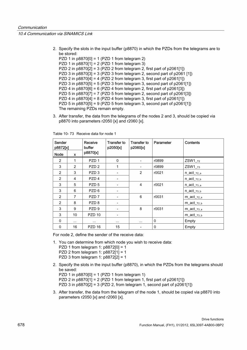
Communication 10.4 Communication via SINAMICS Link
Drive functions 678 Function Manual, (FH1), 01/2012, 6SL3097-4AB00-0BP2
2. Specify the slots in the input buffer (p8870) in which the PZDs from the telegrams are to be stored: PZD 1 in p8870[0] = 1 (PZD 1 from telegram 2) PZD 1 in p8870[1] = 2 (PZD 1 from telegram 3) PZD 2 in p8870[2] = 3 (PZD 2 from telegram 2, first part of p2061[1]) PZD 3 in p8870[3] = 3 (PZD 3 from telegram 2, second part of p2061 [1]) PZD 2 in p8870[4] = 4 (PZD 2 from telegram 3, first part of p2061[1]) PZD 3 in p8870[5] = 5 (PZD 3 from telegram 3, second part of p2061[1]) PZD 4 in p8870[6] = 6 (PZD 4 from telegram 2, first part of p2061[3]) PZD 5 in p8870[7] = 7 (PZD 5 from telegram 2, second part of p2061[3]) PZD 4 in p8870[4] = 8 (PZD 4 from telegram 3, first part of p2061[1]) PZD 5 in p8870[5] = 9 (PZD 5 from telegram 3, second part of p2061[1]) The remaining PZDs remain empty.
3. After transfer, the data from the telegrams of the nodes 2 and 3, should be copied via p8870 into parameters r2050 [x] and r2060 [x].
Table 10- 73 Receive data for node 1
Sender p8872[x]
Node x
Receive buffer p8870[x]
Transfer to p2050[x]
Transfer to p2060[x]
Parameter Contents
2 1 PZD 1 0 - r0899 ZSW1_T2 3 2 PZD 2 1 - r0899 ZSW1_T3 2 3 PZD 3 - n_act_T2_a 2 4 PZD 4 -
2 r0021 n_act_T2_b
3 5 PZD 5 - n_act_T3_a 3 6 PZD 6 -
4 r0021 n_act_T3_b
2 7 PZD 7 - m_act_T2_a 2 8 PZD 8 -
6 r0031 m_act_T2_b
3 9 PZD 9 - m_act_T3_a 3 10 PZD 10 -
8 r0031 m_act_T3_b
0 ... ... ... ... 0 Empty 0 16 PZD 16 15 - 0 Empty
For node 2, define the sender of the receive data:
1. You can determine from which node you wish to receive data: PZD 1 from telegram 1: p8872[0] = 1 PZD 2 from telegram 1: p8872[1] = 1 PZD 3 from telegram 1: p8872[2] = 1
2. Specify the slots in the input buffer (p8870), in which the PZDs from the telegrams should be saved: PZD 1 in p8870[0] = 1 (PZD 1 from telegram 1) PZD 2 in p8870[1] = 2 (PZD 1 from telegram 1, first part of p2061[1]) PZD 3 in p8870[2] = 3 (PZD 2, from telegram 1, second part of p2061[1])
3. After transfer, the data from the telegram of the node 1, should be copied via p8870 into parameters r2050 [x] and r2060 [x].
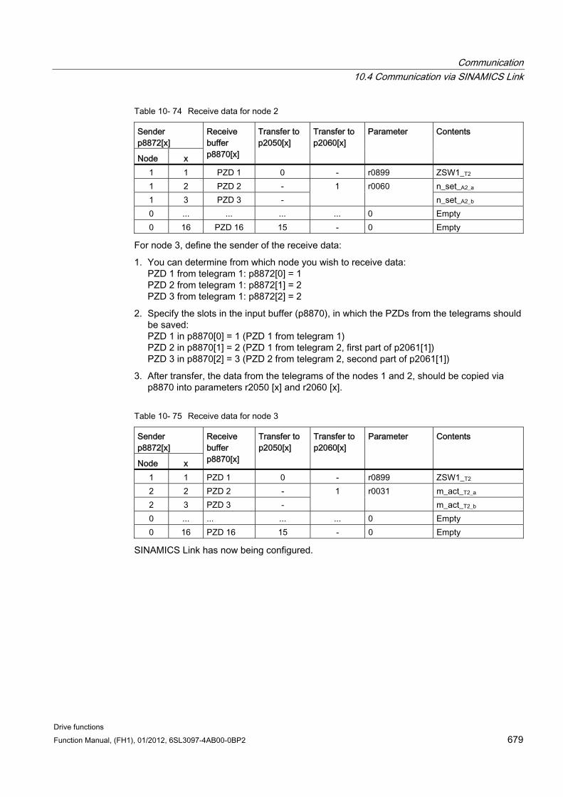
Communication 10.4 Communication via SINAMICS Link
Drive functions Function Manual, (FH1), 01/2012, 6SL3097-4AB00-0BP2 679
Table 10- 74 Receive data for node 2
Sender p8872[x]
Node x
Receive buffer p8870[x]
Transfer to p2050[x]
Transfer to p2060[x]
Parameter Contents
1 1 PZD 1 0 - r0899 ZSW1_T2 1 2 PZD 2 - n_set_A2_a 1 3 PZD 3 -
1 r0060 n_set_A2_b
0 ... ... ... ... 0 Empty 0 16 PZD 16 15 - 0 Empty
For node 3, define the sender of the receive data:
1. You can determine from which node you wish to receive data: PZD 1 from telegram 1: p8872[0] = 1 PZD 2 from telegram 1: p8872[1] = 2 PZD 3 from telegram 1: p8872[2] = 2
2. Specify the slots in the input buffer (p8870), in which the PZDs from the telegrams should be saved: PZD 1 in p8870[0] = 1 (PZD 1 from telegram 1) PZD 2 in p8870[1] = 2 (PZD 1 from telegram 2, first part of p2061[1]) PZD 3 in p8870[2] = 3 (PZD 2 from telegram 2, second part of p2061[1])
3. After transfer, the data from the telegrams of the nodes 1 and 2, should be copied via p8870 into parameters r2050 [x] and r2060 [x].
Table 10- 75 Receive data for node 3
Sender p8872[x]
Node x
Receive buffer p8870[x]
Transfer to p2050[x]
Transfer to p2060[x]
Parameter Contents
1 1 PZD 1 0 - r0899 ZSW1_T2 2 2 PZD 2 - m_act_T2_a 2 3 PZD 3 -
1 r0031 m_act_T2_b
0 ... ... ... ... 0 Empty 0 16 PZD 16 15 - 0 Empty
SINAMICS Link has now being configured.
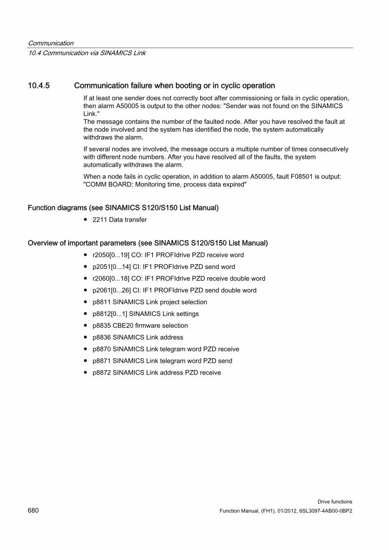
Communication 10.4 Communication via SINAMICS Link
Drive functions 680 Function Manual, (FH1), 01/2012, 6SL3097-4AB00-0BP2
10.4.5 Communication failure when booting or in cyclic operation If at least one sender does not correctly boot after commissioning or fails in cyclic operation, then alarm A50005 is output to the other nodes: "Sender was not found on the SINAMICS Link." The message contains the number of the faulted node. After you have resolved the fault at the node involved and the system has identified the node, the system automatically withdraws the alarm.
If several nodes are involved, the message occurs a multiple number of times consecutively with different node numbers. After you have resolved all of the faults, the system automatically withdraws the alarm.
When a node fails in cyclic operation, in addition to alarm A50005, fault F08501 is output: "COMM BOARD: Monitoring time, process data expired"
Function diagrams (see SINAMICS S120/S150 List Manual) 2211 Data transfer
Overview of important parameters (see SINAMICS S120/S150 List Manual) r2050[0...19] CO: IF1 PROFIdrive PZD receive word
p2051[0...14] CI: IF1 PROFIdrive PZD send word
r2060[0...18] CO: IF1 PROFIdrive PZD receive double word
p2061[0...26] CI: IF1 PROFIdrive PZD send double word
p8811 SINAMICS Link project selection
p8812[0...1] SINAMICS Link settings
p8835 CBE20 firmware selection
p8836 SINAMICS Link address
p8870 SINAMICS Link telegram word PZD receive
p8871 SINAMICS Link telegram word PZD send
p8872 SINAMICS Link address PZD receive

Communication 10.4 Communication via SINAMICS Link
Drive functions Function Manual, (FH1), 01/2012, 6SL3097-4AB00-0BP2 681

Communication 10.4 Communication via SINAMICS Link
Drive functions 682 Function Manual, (FH1), 01/2012, 6SL3097-4AB00-0BP2
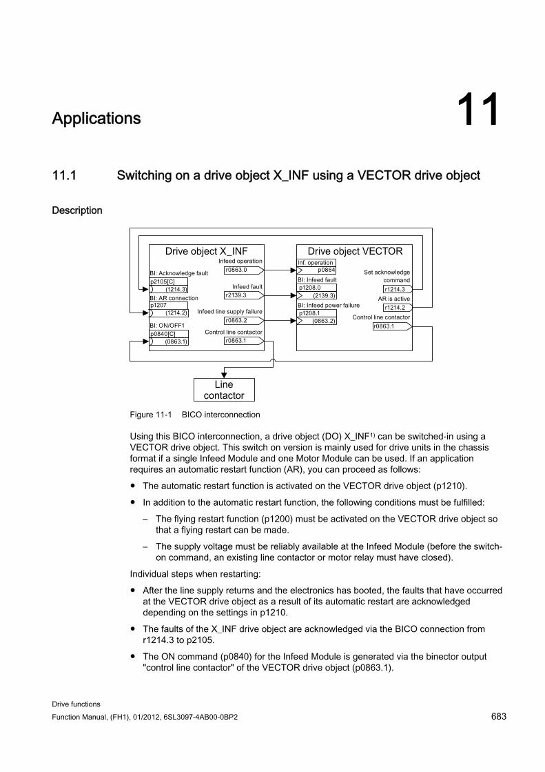
Drive functions Function Manual, (FH1), 01/2012, 6SL3097-4AB00-0BP2 683
Applications 1111.1 Switching on a drive object X_INF using a VECTOR drive object
Description
Figure 11-1 BICO interconnection
Using this BICO interconnection, a drive object (DO) X_INF1) can be switched-in using a VECTOR drive object. This switch on version is mainly used for drive units in the chassis format if a single Infeed Module and one Motor Module can be used. If an application requires an automatic restart function (AR), you can proceed as follows:
The automatic restart function is activated on the VECTOR drive object (p1210).
In addition to the automatic restart function, the following conditions must be fulfilled:
– The flying restart function (p1200) must be activated on the VECTOR drive object so that a flying restart can be made.
– The supply voltage must be reliably available at the Infeed Module (before the switch-on command, an existing line contactor or motor relay must have closed).
Individual steps when restarting:
After the line supply returns and the electronics has booted, the faults that have occurred at the VECTOR drive object as a result of its automatic restart are acknowledged depending on the settings in p1210.
The faults of the X_INF drive object are acknowledged via the BICO connection from r1214.3 to p2105.
The ON command (p0840) for the Infeed Module is generated via the binector output "control line contactor" of the VECTOR drive object (p0863.1).
Applications 11.2 Description
Drive functions 684 Function Manual, (FH1), 01/2012, 6SL3097-4AB00-0BP2
The switch on attempt is interrupted if, during the restart, a fault occurs in the Infeed Module (drive object X_INF). The fault is communicated to the VECTOR drive object via the BICO connection from p1208.0 to r2139.3 shown above.
The automatic restart of the Infeed Module has absolutely no significance for the described switch-on version.
1) X_INF stands for all drive objects "Infeed"; i.e.: A_INF, B_INF, S_INF
11.2 Description The motor changeover is used in the following cases, for example:
Changing-over between different motors and encoders
Switching over different windings in a motor (e.g. star-delta changeover)
Adapting the motor data
If several motors are operated alternately on a Motor Module, a matching number of drive data sets must be created.
Note
For the "Vector" control mode, the following applies: To connect to a rotating motor, the "flying restart" function must be activated (p1200).
NOTICE When changing over the drive data set between several motors that physically exist with integrated holding brakes, it is not permissible that the internal brake control is used.
Example of a motor changeover for four motors (encoderless) Preconditions
First commissioning has been completed.
4 motor data sets (MDS), p0130 = 4
4 drive data sets (DDS), p0180 = 4
4 digital outputs for controlling the auxiliary contactors
4 digital inputs for monitoring the auxiliary contactors
2 digital inputs for selecting the data set
4 auxiliary contactors with auxiliary contacts (1 NO contact)
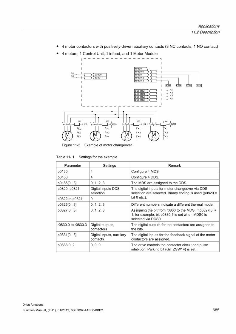
Applications 11.2 Description
Drive functions Function Manual, (FH1), 01/2012, 6SL3097-4AB00-0BP2 685
4 motor contactors with positively-driven auxiliary contacts (3 NC contacts, 1 NO contact)
4 motors, 1 Control Unit, 1 infeed, and 1 Motor Module
Figure 11-2 Example of motor changeover
Table 11- 1 Settings for the example
Parameter Settings Remark p0130 4 Configure 4 MDS. p0180 4 Configure 4 DDS. p0186[0...3] 0, 1, 2, 3 The MDS are assigned to the DDS. p0820, p0821 Digital inputs DDS
selection p0822 to p0824 0
The digital inputs for motor changeover via DDS selection are selected. Binary coding is used (p0820 = bit 0 etc.).
p0826[0...3] 0, 1, 2, 3 Different numbers indicate a different thermal model p0827[0...3] 0, 1, 2, 3 Assigning the bit from r0830 to the MDS. If p0827[0] =
1, for example, bit p0830.1 is set when MDS0 is selected via DDS0.
r0830.0 to r0830.3 Digital outputs, contactors
The digital outputs for the contactors are assigned to the bits.
p0831[0...3] Digital inputs, auxiliary contacts
The digital inputs for the feedback signal of the motor contactors are assigned.
p0833.0..2 0, 0, 0 The drive controls the contactor circuit and pulse inhibition. Parking bit (Gn_ZSW14) is set.
Applications 11.2 Description
Drive functions 686 Function Manual, (FH1), 01/2012, 6SL3097-4AB00-0BP2
Procedure for changeover between motor data sets
1. Start condition:
For synchronous motors, the actual speed must be lower than the speed at the start of field weakening. This prevents the regenerative voltage from exceeding the terminal voltage.
2. Pulse inhibit:
The pulses are inhibited after a new drive data set is selected with p0820 to p0824.
3. Open the motor contactor:
Motor contactor 1 is opened (r0830 = 0) and the status bit "Motor changeover active" (r0835.0) is set.
4. Change over the drive data set:
The requested data set is activated (r0051 = requested data set).
5. Energize the motor contactor:
After the feedback signal (motor contactor opened) for motor contactor 1, the appropriate bit of r0830 is set and motor contactor 2 is energized.
6. Enable the pulses:
After the feedback signal (motor contactor closed) for motor contactor 2, the bit "motor changeover active" (r0835.0) is reset and the pulses are enabled. The motor has now been changed over.
Example of a star/delta changeover (via speed threshold; encoderless) Preconditions
First commissioning has been completed.
2 motor data sets (MDS), p0130 = 2
2 drive data sets (DDS), p0180 = 2
2 digital outputs for controlling the auxiliary contactors
2 digital inputs for monitoring the auxiliary contactors
1 free speed monitoring (p2155)
2 auxiliary contactors with auxiliary contacts (1 NO contact)
2 motor contactors with positively-driven auxiliary contacts (1 NC contact, 1 NO contact)
1 motor, 1 Control Unit, 1 infeed, and 1 Motor Module
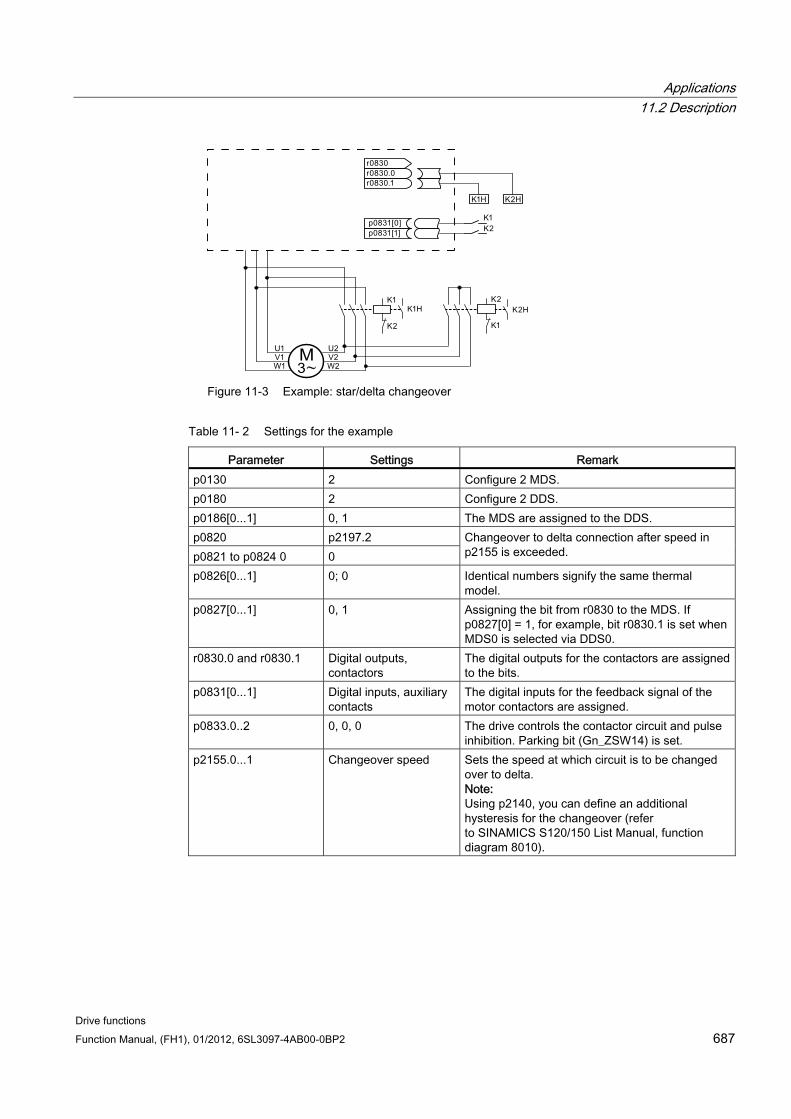
Applications 11.2 Description
Drive functions Function Manual, (FH1), 01/2012, 6SL3097-4AB00-0BP2 687
Figure 11-3 Example: star/delta changeover
Table 11- 2 Settings for the example
Parameter Settings Remark p0130 2 Configure 2 MDS. p0180 2 Configure 2 DDS. p0186[0...1] 0, 1 The MDS are assigned to the DDS. p0820 p2197.2 p0821 to p0824 0 0
Changeover to delta connection after speed in p2155 is exceeded.
p0826[0...1] 0; 0 Identical numbers signify the same thermal model.
p0827[0...1] 0, 1 Assigning the bit from r0830 to the MDS. If p0827[0] = 1, for example, bit r0830.1 is set when MDS0 is selected via DDS0.
r0830.0 and r0830.1 Digital outputs, contactors
The digital outputs for the contactors are assigned to the bits.
p0831[0...1] Digital inputs, auxiliary contacts
The digital inputs for the feedback signal of the motor contactors are assigned.
p0833.0..2 0, 0, 0 The drive controls the contactor circuit and pulse inhibition. Parking bit (Gn_ZSW14) is set.
p2155.0...1 Changeover speed Sets the speed at which circuit is to be changed over to delta. Note: Using p2140, you can define an additional hysteresis for the changeover (refer to SINAMICS S120/150 List Manual, function diagram 8010).
Applications 11.2 Description
Drive functions 688 Function Manual, (FH1), 01/2012, 6SL3097-4AB00-0BP2
Procedure for star/delta changeover
1. Start condition:
For synchronous motors, the actual speed must be lower than the star field weakening speed. This prevents the regenerative voltage from exceeding the terminal voltage.
2. Pulse inhibit:
The pulses are suppressed after the changeover speed (p2155) is reached.
3. Open the motor contactor:
Motor contactor 1 is opened (r0830 = 0) and the status bit "Motor data set changeover active" (r0835.0) is set.
4. Change over the drive data set:
The requested data set is activated (r0051 = requested data set).
5. Energize the motor contactor:
After the feedback signal (motor contactor opened) for motor contactor 1, the appropriate bit of r0830 is set and motor contactor 2 is energized.
6. Enable the pulses:
After the feedback signal (motor contactor closed) for motor contactor 2, the bit "motor changeover active" (r0835.0) is reset and the pulses are enabled. The changeover is complete.
Function diagrams (see SINAMICS S120/S150 List Manual) 8565 Drive Data Sets (DDS)
8570 Encoder Data Sets (EDS)
8575 Motor Data Sets (MDS)
Overview of important parameters (see SINAMICS S120/S150 List Manual) r0051 0...4 CO/BO: Drive data set DDS effective
p0130 Motor data sets (MDS) number
p0140 Encoder data sets (EDS) number
p0180 Drive data sets (DDS) number
p0186 [0...n] motor data sets (MDS) number
p0187 [0...n] encoder 1 encoder data set number
p0188 [0...n] encoder 2 encoder data set number
p0189 [0...n] encoder 3 encoder data set number
p0820 BI: Drive data set selection DDS, bit 0
...
p0824 BI: Drive data set selection DDS, bit 4
p0826 [0...n] motor changeover motor number
Applications 11.3 Application examples with DMC20
Drive functions Function Manual, (FH1), 01/2012, 6SL3097-4AB00-0BP2 689
p0827 [0...n] motor changeover status word bit number
p0828 [0...n] BI: Motor changeover feedback
r0830.0...15 CO/BO: Motor changeover status word
p0831 [0...15] BI: Motor changeover contactor feedback
p0833 Data set changeover configuration
11.3 Application examples with DMC20
Features The DRIVE-CLiQ Hub Module Cabinet 20 (DMC20) has the following features:
Own drive object
6 DRIVE-CLiQ ports
Own faults and alarms
Typical applications:
Implementation of a distributed topology via a DRIVE-CLiQ cable
Hot plugging (a DRIVE-CLiQ connection is withdrawn in operation)
DME20 DME20 offers the same functions as the DMC20. However, the difference is that it has a different enclosure with degree of protection IP67 for mounting outside a control cabinet.
Description The DRIVE-CLiQ Hub Module Cabinet 20 (DMC20/DME20) is used for the star-shaped distribution of a DRIVE-CLiQ line. With the DMC20, an axis grouping can be expanded with 4 DRIVE-CLiQ sockets for additional subgroups.
The component is especially suitable for applications which require DRIVE-CLiQ nodes to be removed in groups, without interrupting the DRIVE-CLiQ line and, therefore, the data exchange process.
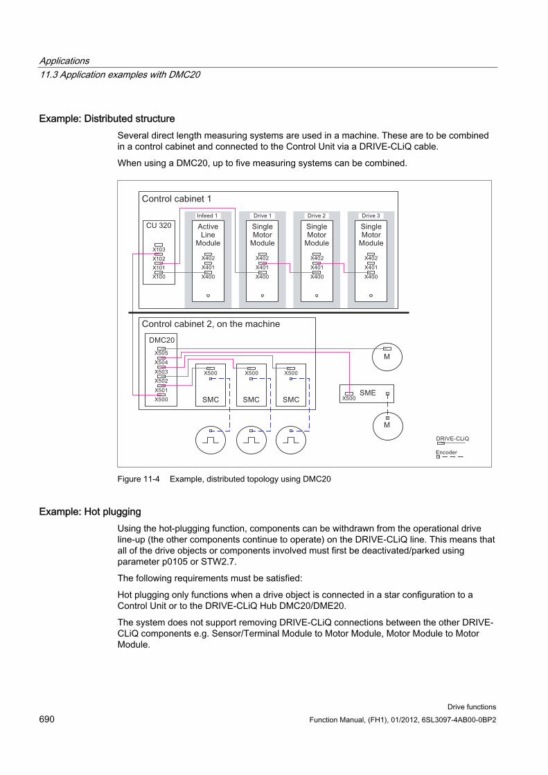
Applications 11.3 Application examples with DMC20
Drive functions 690 Function Manual, (FH1), 01/2012, 6SL3097-4AB00-0BP2
Example: Distributed structure Several direct length measuring systems are used in a machine. These are to be combined in a control cabinet and connected to the Control Unit via a DRIVE-CLiQ cable.
When using a DMC20, up to five measuring systems can be combined.
Figure 11-4 Example, distributed topology using DMC20
Example: Hot plugging Using the hot-plugging function, components can be withdrawn from the operational drive line-up (the other components continue to operate) on the DRIVE-CLiQ line. This means that all of the drive objects or components involved must first be deactivated/parked using parameter p0105 or STW2.7.
The following requirements must be satisfied:
Hot plugging only functions when a drive object is connected in a star configuration to a Control Unit or to the DRIVE-CLiQ Hub DMC20/DME20.
The system does not support removing DRIVE-CLiQ connections between the other DRIVE-CLiQ components e.g. Sensor/Terminal Module to Motor Module, Motor Module to Motor Module.
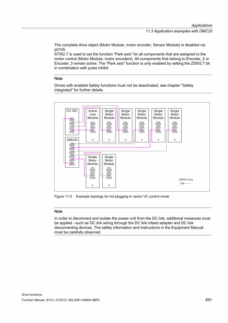
Applications 11.3 Application examples with DMC20
Drive functions Function Manual, (FH1), 01/2012, 6SL3097-4AB00-0BP2 691
The complete drive object (Motor Module, motor encoder, Sensor Module) is disabled via p0105. STW2.7 is used to set the function "Park axis" for all components that are assigned to the motor control (Motor Module, motor encoders). All components that belong to Encoder_2 or Encoder_3 remain active. The "Park axis" function is only enabled by setting the ZSW2.7 bit in combination with pulse inhibit.
Note
Drives with enabled Safety functions must not be deactivated, see chapter "Safety Integrated" for further details.
Figure 11-5 Example topology for hot plugging in vector V/f_control mode
Note
In order to disconnect and isolate the power unit from the DC link, additional measures must be applied - such as DC link wiring through the DC link infeed adapter and DC link disconnecting devices. The safety information and instructions in the Equipment Manual must be carefully observed.
Applications 11.3 Application examples with DMC20
Drive functions 692 Function Manual, (FH1), 01/2012, 6SL3097-4AB00-0BP2
Instructions for offline commissioning with STARTER With automatic online configuration in STARTER, the DMC20 is detected and integrated in the topology. The following steps must be taken to commission offline:
1. Configure a drive unit offline
2. Right-click on Topology -> Insert New Object -> DRIVE-CLiQ Hub
3. Configure the topology
Overview of important parameters (see SINAMICS S120/S150 List Manual) p0105 Activate/deactivate drive object
r0106 Drive object active/inactive
p0897 BI: Parking axis selection
r0896.0 BO: Parking axis status word
p0151 DRIVE-CLiQ Hub component number
p0154 DRIVE-CLiQ Hub identification using LED
p0157 DRIVE-CLiQ Hub EPROM data version
r0158 DRIVE-CLiQ Hub firmware version
Applications 11.4 DCC axial winder
Drive functions Function Manual, (FH1), 01/2012, 6SL3097-4AB00-0BP2 693
11.4 DCC axial winder The "DCC axial winder" functionality covers a wide variety of winder applications.
With a suitable device configuration, it allows a winder or unwinder to be configured for a wide variety of applications, such as film production plants, printing machines, coating plants, coil winders for wire-drawing machines or textile machines.
An axial winder solution usually comprises a winder drive, a continuous web and possibly sensors. The axial winder is used to wind or unwind a continuous web with a defined tension. The wound roll diameter changes during the winding process. The product thickness increases or decreases during the winding or unwinding process. The drive system calculates the current diameter on the basis of system variables and influences the speed or torque, depending on the application, so that the tension and velocity of the web is maintained according to specifications. This requires the current velocity of the web and the rotational speed of the winder axis to be known.
Features Different winding and control methods can be applied, e.g. direct closed-loop tension
control through speed correction or torque limiting and indirect closed-loop tension control
Closed-loop control can be implemented through "Tension controller acting on torque limits" or "Tension controller acting on speed setpoint"
Adaptation of tension controller and speed controller gain based on diameter or inertia
Diameter-based winding hardness characteristic
Diameter calculation
Acceleration-based torque pre-control
Flexible sensor evaluation (e.g. dancer roll, load cell)
Note
Documentation for a standard application for the DCC axial winder is available on demand from your responsible SIEMENS distribution partner.
Function blocks The "DCC axial winder" function involves the following DCBs (drive control blocks – function blocks for the drive control):
Note
Detailed information on the function blocks is provided in the "SINAMICS SIMOTION Function Manual DCC Block Description" as well as in the "SINAMICS SIMOTION Programming Manual DCC Editor".
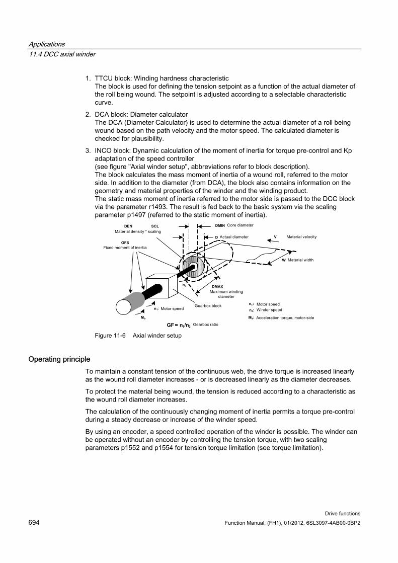
Applications 11.4 DCC axial winder
Drive functions 694 Function Manual, (FH1), 01/2012, 6SL3097-4AB00-0BP2
1. TTCU block: Winding hardness characteristic The block is used for defining the tension setpoint as a function of the actual diameter of the roll being wound. The setpoint is adjusted according to a selectable characteristic curve.
2. DCA block: Diameter calculator The DCA (Diameter Calculator) is used to determine the actual diameter of a roll being wound based on the path velocity and the motor speed. The calculated diameter is checked for plausibility.
3. INCO block: Dynamic calculation of the moment of inertia for torque pre-control and Kp adaptation of the speed controller (see figure "Axial winder setup", abbreviations refer to block description). The block calculates the mass moment of inertia of a wound roll, referred to the motor side. In addition to the diameter (from DCA), the block also contains information on the geometry and material properties of the winder and the winding product. The static mass moment of inertia referred to the motor side is passed to the DCC block via the parameter r1493. The result is fed back to the basic system via the scaling parameter p1497 (referred to the static moment of inertia).
DMIN
DMAX
W
n
OFSD
n : n :
M :
GF
SCL DEN
= n /n
2
:
b
1 2
n1
M
V
1
2
b
Figure 11-6 Axial winder setup
Operating principle To maintain a constant tension of the continuous web, the drive torque is increased linearly as the wound roll diameter increases - or is decreased linearly as the diameter decreases.
To protect the material being wound, the tension is reduced according to a characteristic as the wound roll diameter increases.
The calculation of the continuously changing moment of inertia permits a torque pre-control during a steady decrease or increase of the winder speed.
By using an encoder, a speed controlled operation of the winder is possible. The winder can be operated without an encoder by controlling the tension torque, with two scaling parameters p1552 and p1554 for tension torque limitation (see torque limitation).
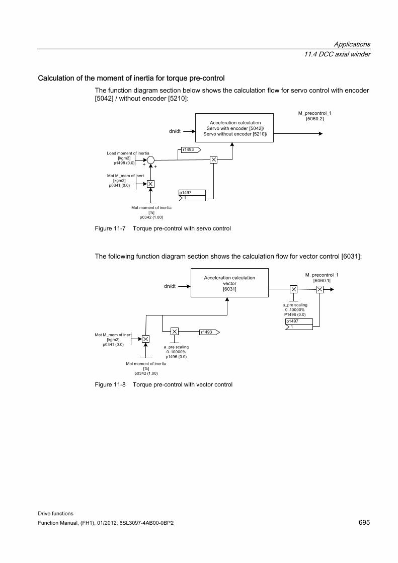
Applications 11.4 DCC axial winder
Drive functions Function Manual, (FH1), 01/2012, 6SL3097-4AB00-0BP2 695
Calculation of the moment of inertia for torque pre-control The function diagram section below shows the calculation flow for servo control with encoder [5042] / without encoder [5210]:
1493
1497
dn/dt
r
1
p
+ +
Figure 11-7 Torque pre-control with servo control
The following function diagram section shows the calculation flow for vector control [6031]:
1493
1497
1
dn/dt
p
r
Figure 11-8 Torque pre-control with vector control
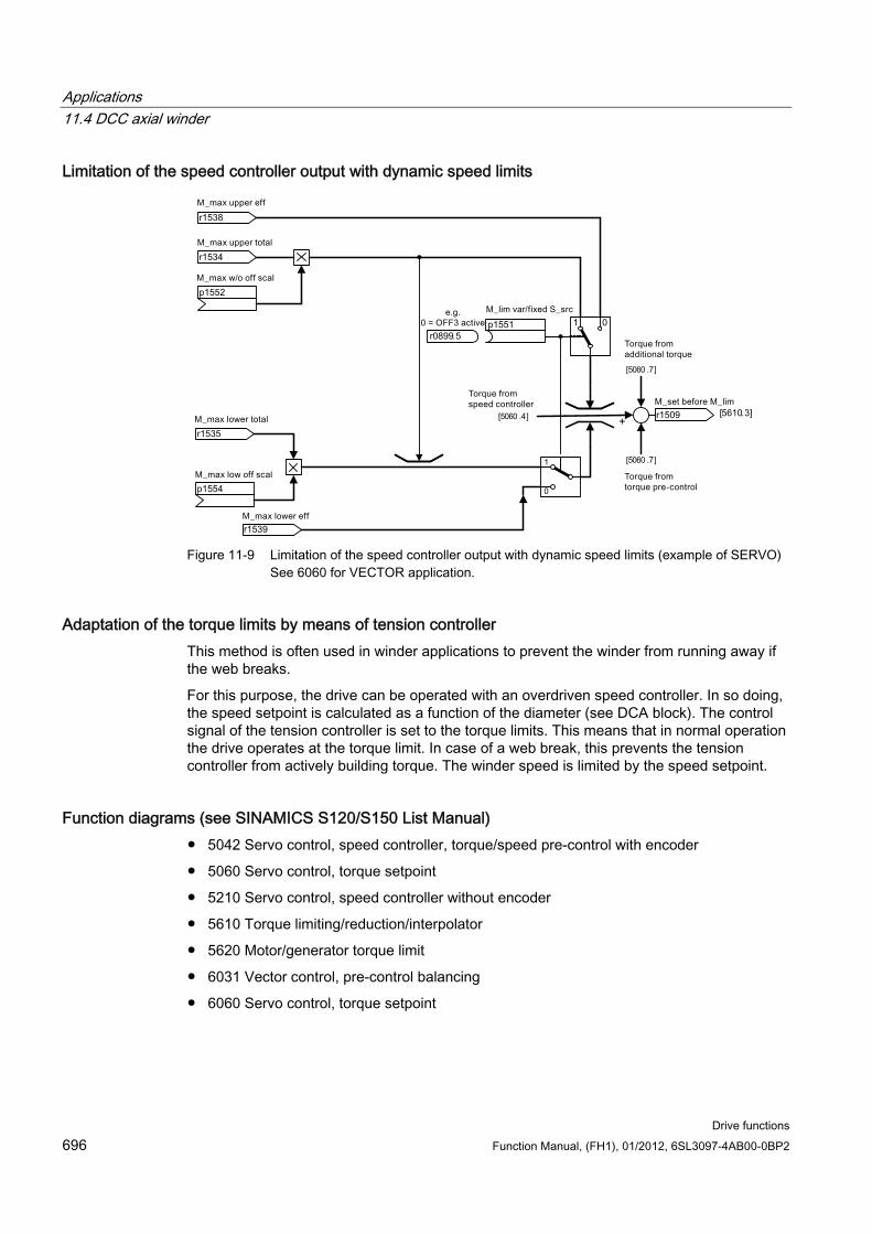
Applications 11.4 DCC axial winder
Drive functions 696 Function Manual, (FH1), 01/2012, 6SL3097-4AB00-0BP2
Limitation of the speed controller output with dynamic speed limits
r1509 [5610.3]+
1 0
1
0
r1538
r1534
p1551
p1552
r0899.5
r1535
r1539
p1554
[5060 .4]
[5060 .7]
[5060 .7]
Figure 11-9 Limitation of the speed controller output with dynamic speed limits (example of SERVO)
See 6060 for VECTOR application.
Adaptation of the torque limits by means of tension controller This method is often used in winder applications to prevent the winder from running away if the web breaks.
For this purpose, the drive can be operated with an overdriven speed controller. In so doing, the speed setpoint is calculated as a function of the diameter (see DCA block). The control signal of the tension controller is set to the torque limits. This means that in normal operation the drive operates at the torque limit. In case of a web break, this prevents the tension controller from actively building torque. The winder speed is limited by the speed setpoint.
Function diagrams (see SINAMICS S120/S150 List Manual) 5042 Servo control, speed controller, torque/speed pre-control with encoder
5060 Servo control, torque setpoint
5210 Servo control, speed controller without encoder
5610 Torque limiting/reduction/interpolator
5620 Motor/generator torque limit
6031 Vector control, pre-control balancing
6060 Servo control, torque setpoint
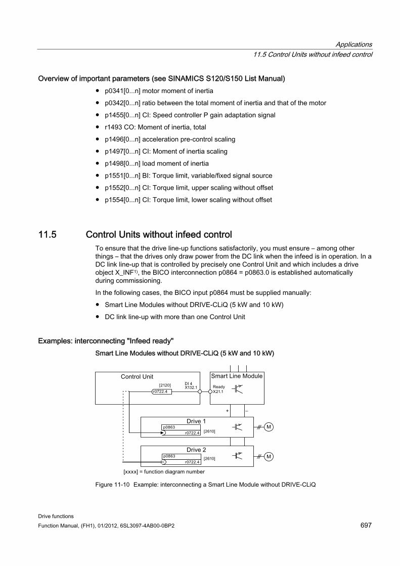
Applications 11.5 Control Units without infeed control
Drive functions Function Manual, (FH1), 01/2012, 6SL3097-4AB00-0BP2 697
Overview of important parameters (see SINAMICS S120/S150 List Manual) p0341[0...n] motor moment of inertia
p0342[0...n] ratio between the total moment of inertia and that of the motor
p1455[0...n] CI: Speed controller P gain adaptation signal
r1493 CO: Moment of inertia, total
p1496[0...n] acceleration pre-control scaling
p1497[0...n] CI: Moment of inertia scaling
p1498[0...n] load moment of inertia
p1551[0...n] BI: Torque limit, variable/fixed signal source
p1552[0...n] CI: Torque limit, upper scaling without offset
p1554[0...n] CI: Torque limit, lower scaling without offset
11.5 Control Units without infeed control To ensure that the drive line-up functions satisfactorily, you must ensure – among other things – that the drives only draw power from the DC link when the infeed is in operation. In a DC link line-up that is controlled by precisely one Control Unit and which includes a drive object X_INF1), the BICO interconnection p0864 = p0863.0 is established automatically during commissioning.
In the following cases, the BICO input p0864 must be supplied manually:
Smart Line Modules without DRIVE-CLiQ (5 kW and 10 kW)
DC link line-up with more than one Control Unit
Examples: interconnecting "Infeed ready" Smart Line Modules without DRIVE-CLiQ (5 kW and 10 kW)
Figure 11-10 Example: interconnecting a Smart Line Module without DRIVE-CLiQ
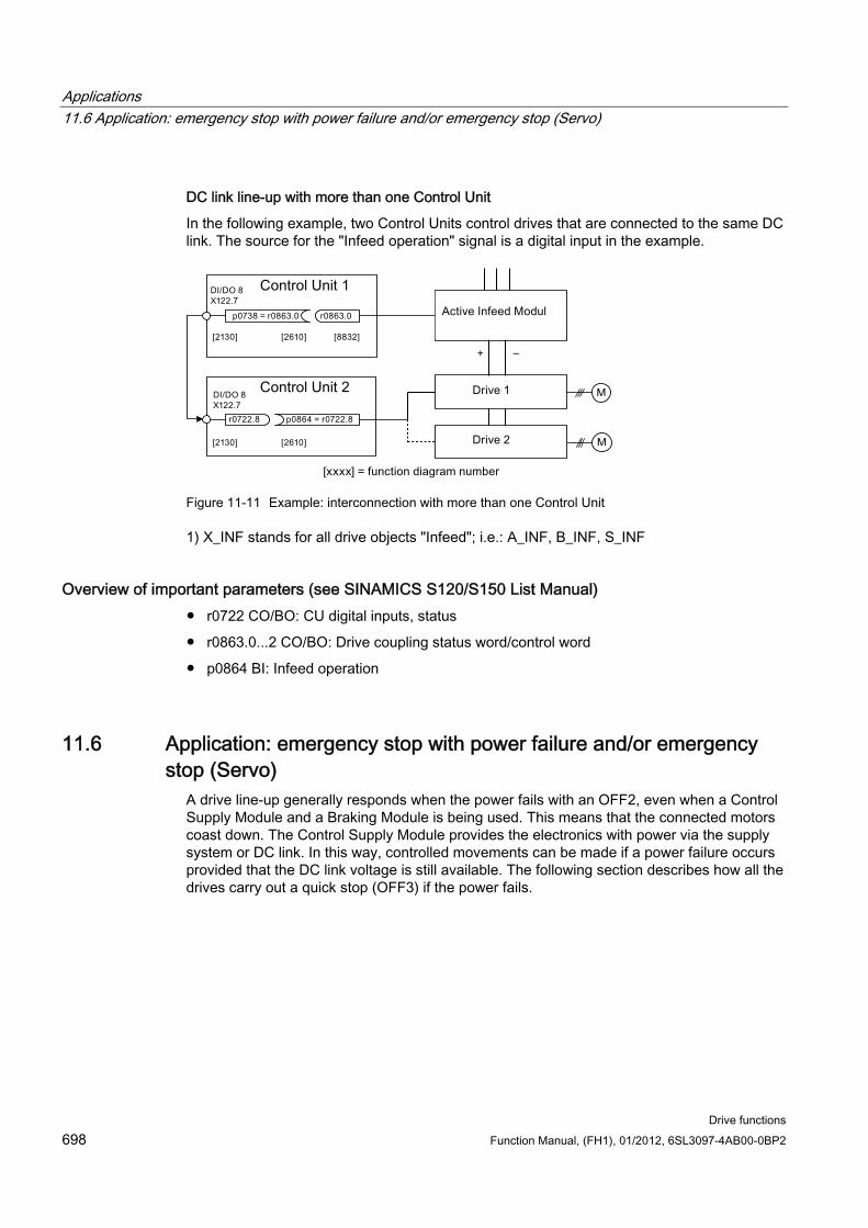
Applications 11.6 Application: emergency stop with power failure and/or emergency stop (Servo)
Drive functions 698 Function Manual, (FH1), 01/2012, 6SL3097-4AB00-0BP2
DC link line-up with more than one Control Unit
In the following example, two Control Units control drives that are connected to the same DC link. The source for the "Infeed operation" signal is a digital input in the example.
Figure 11-11 Example: interconnection with more than one Control Unit
1) X_INF stands for all drive objects "Infeed"; i.e.: A_INF, B_INF, S_INF
Overview of important parameters (see SINAMICS S120/S150 List Manual) r0722 CO/BO: CU digital inputs, status
r0863.0...2 CO/BO: Drive coupling status word/control word
p0864 BI: Infeed operation
11.6 Application: emergency stop with power failure and/or emergency stop (Servo)
A drive line-up generally responds when the power fails with an OFF2, even when a Control Supply Module and a Braking Module is being used. This means that the connected motors coast down. The Control Supply Module provides the electronics with power via the supply system or DC link. In this way, controlled movements can be made if a power failure occurs provided that the DC link voltage is still available. The following section describes how all the drives carry out a quick stop (OFF3) if the power fails.
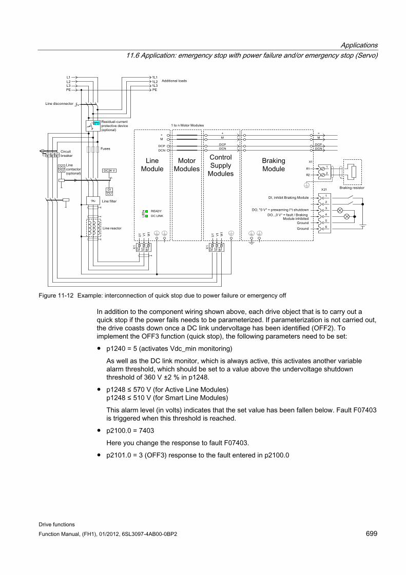
Applications 11.6 Application: emergency stop with power failure and/or emergency stop (Servo)
Drive functions Function Manual, (FH1), 01/2012, 6SL3097-4AB00-0BP2 699
Figure 11-12 Example: interconnection of quick stop due to power failure or emergency off
In addition to the component wiring shown above, each drive object that is to carry out a quick stop if the power fails needs to be parameterized. If parameterization is not carried out, the drive coasts down once a DC link undervoltage has been identified (OFF2). To implement the OFF3 function (quick stop), the following parameters need to be set:
p1240 = 5 (activates Vdc_min monitoring)
As well as the DC link monitor, which is always active, this activates another variable alarm threshold, which should be set to a value above the undervoltage shutdown threshold of 360 V ±2 % in p1248.
p1248 ≤ 570 V (for Active Line Modules) p1248 ≤ 510 V (for Smart Line Modules)
This alarm level (in volts) indicates that the set value has been fallen below. Fault F07403 is triggered when this threshold is reached.
p2100.0 = 7403
Here you change the response to fault F07403.
p2101.0 = 3 (OFF3) response to the fault entered in p2100.0

Applications 11.6 Application: emergency stop with power failure and/or emergency stop (Servo)
Drive functions 700 Function Manual, (FH1), 01/2012, 6SL3097-4AB00-0BP2
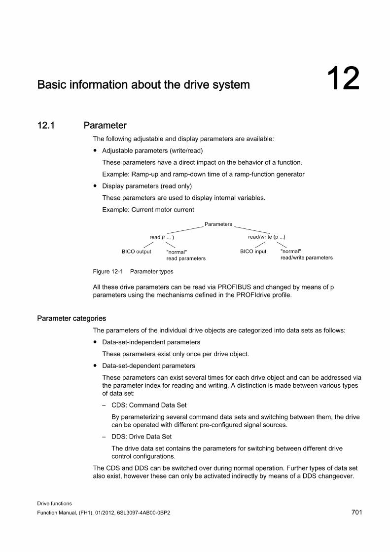
Drive functions Function Manual, (FH1), 01/2012, 6SL3097-4AB00-0BP2 701
Basic information about the drive system 1212.1 Parameter
The following adjustable and display parameters are available:
Adjustable parameters (write/read)
These parameters have a direct impact on the behavior of a function.
Example: Ramp-up and ramp-down time of a ramp-function generator
Display parameters (read only)
These parameters are used to display internal variables.
Example: Current motor current
Figure 12-1 Parameter types
All these drive parameters can be read via PROFIBUS and changed by means of p parameters using the mechanisms defined in the PROFIdrive profile.
Parameter categories The parameters of the individual drive objects are categorized into data sets as follows:
Data-set-independent parameters
These parameters exist only once per drive object.
Data-set-dependent parameters
These parameters can exist several times for each drive object and can be addressed via the parameter index for reading and writing. A distinction is made between various types of data set:
– CDS: Command Data Set
By parameterizing several command data sets and switching between them, the drive can be operated with different pre-configured signal sources.
– DDS: Drive Data Set
The drive data set contains the parameters for switching between different drive control configurations.
The CDS and DDS can be switched over during normal operation. Further types of data set also exist, however these can only be activated indirectly by means of a DDS changeover.
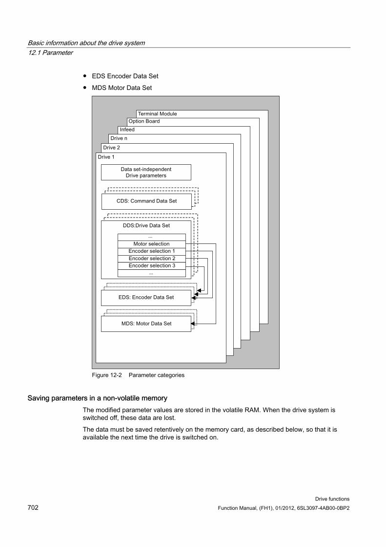
Basic information about the drive system 12.1 Parameter
Drive functions 702 Function Manual, (FH1), 01/2012, 6SL3097-4AB00-0BP2
EDS Encoder Data Set
MDS Motor Data Set
Figure 12-2 Parameter categories
Saving parameters in a non-volatile memory The modified parameter values are stored in the volatile RAM. When the drive system is switched off, these data are lost.
The data must be saved retentively on the memory card, as described below, so that it is available the next time the drive is switched on.
Basic information about the drive system 12.1 Parameter
Drive functions Function Manual, (FH1), 01/2012, 6SL3097-4AB00-0BP2 703
Save parameters - device and all drives
p0977 = 1; automatically reset to 0
Save the parameters with STARTER
See "Copy RAM to ROM" function
Resetting parameters The parameters can be reset to the factory setting as follows:
Reset parameters - current drive object
p0970 = 1; automatically reset to 0
Reset parameters - all parameters of the drive object "Control Unit" (CU_*)
p0009 = 30 parameter reset
p0976 = 1; automatically reset to 0
Access level The parameters are subdivided into access levels. The SINAMICS S120/S150 List Manual specifies the access level in which the parameter is displayed and can be changed. The required access levels 0 to 4 can be set in p0003.
Table 12- 1 Access levels
Access level Remark 0 User-defined Parameters from the user-defined list (p0013) 1 Standard Parameters for the simplest operator functions (e.g. p1120 = ramp-function
generator ramp-up time) 2 Extended Parameters to handle the basic functions of the device. 3 Expert Expert knowledge is already required for this parameter (e.g. knowledge
about BICO parameterization) 4 Service Please contact your local Siemens office for the password for parameters
with access level 4 (Service). It must be entered into p3950.
Note
Parameter p0003 is CU-specific (belongs to Control Unit).
Basic information about the drive system 12.2 Data sets
Drive functions 704 Function Manual, (FH1), 01/2012, 6SL3097-4AB00-0BP2
12.2 Data sets
12.2.1 CDS: Command Data Set The BICO parameters are combined (binector and connector inputs) in a command data set (CDS). These parameters are used to interconnect the signal sources of a drive.
By parameterizing several command data sets and switching between them, the drive can be operated with different pre-configured signal sources.
A command data set contains the following (examples):
Binector inputs for control commands (digital signals)
– ON/OFF, enable signals (p0844, etc.)
– Jog (p1055, etc.)
Connector inputs for setpoints (analog signals)
– Voltage setpoint for V/f control (p1330)
– Torque limits and scaling factors (p1522, p1523, p1528, p1529)
A drive object can – depending on the type – manage up to 4 command data sets. The number of command data sets is configured with p0170.
The following parameters are available for selecting command data sets and for displaying currently selected command data sets - e.g. in the vector mode:
Binector inputs p0810 to p0811 are used to select a command data set. They represent the number of the command data set (0 to 3) in binary format (where p0811 is the most significant bit).
p0810 BI: Command data set selection CDS bit 0
p0811 BI: Command data set selection CDS bit 1
If a command data set that does not exist is selected, the current data set remains active. The selected data set is displayed using parameter (r0836).
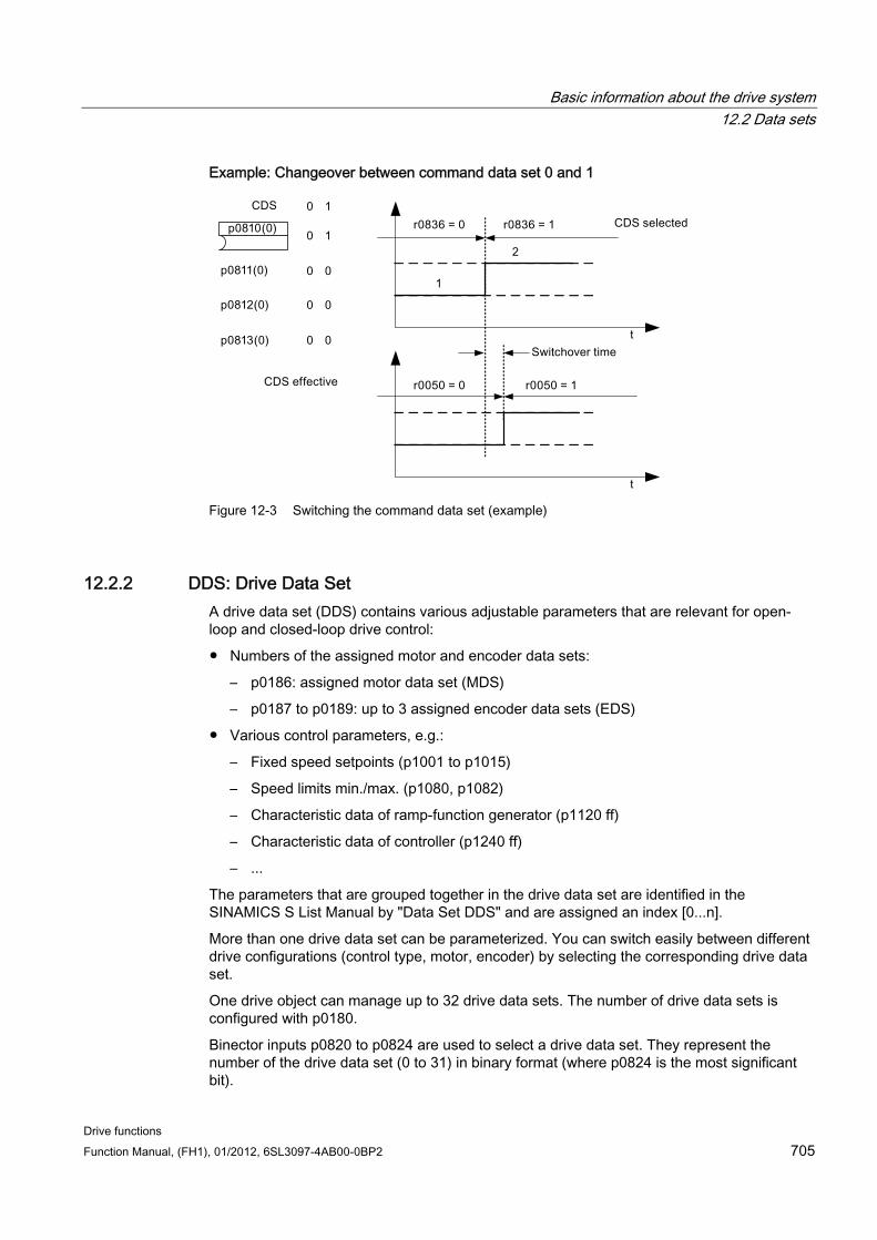
Basic information about the drive system 12.2 Data sets
Drive functions Function Manual, (FH1), 01/2012, 6SL3097-4AB00-0BP2 705
Example: Changeover between command data set 0 and 1
Figure 12-3 Switching the command data set (example)
12.2.2 DDS: Drive Data Set A drive data set (DDS) contains various adjustable parameters that are relevant for open-loop and closed-loop drive control:
Numbers of the assigned motor and encoder data sets:
– p0186: assigned motor data set (MDS)
– p0187 to p0189: up to 3 assigned encoder data sets (EDS)
Various control parameters, e.g.:
– Fixed speed setpoints (p1001 to p1015)
– Speed limits min./max. (p1080, p1082)
– Characteristic data of ramp-function generator (p1120 ff)
– Characteristic data of controller (p1240 ff)
– ...
The parameters that are grouped together in the drive data set are identified in the SINAMICS S List Manual by "Data Set DDS" and are assigned an index [0...n].
More than one drive data set can be parameterized. You can switch easily between different drive configurations (control type, motor, encoder) by selecting the corresponding drive data set.
One drive object can manage up to 32 drive data sets. The number of drive data sets is configured with p0180.
Binector inputs p0820 to p0824 are used to select a drive data set. They represent the number of the drive data set (0 to 31) in binary format (where p0824 is the most significant bit).

Basic information about the drive system 12.2 Data sets
Drive functions 706 Function Manual, (FH1), 01/2012, 6SL3097-4AB00-0BP2
p0820 BI: Drive data set selection DDS, bit 0
p0821 BI: Drive data set selection DDS, bit 1
p0822 BI: Drive data set selection DDS, bit 2
p0823 BI: Drive data set selection DDS, bit 3
p0824 BI: Drive data set selection DDS, bit 4
Supplementary conditions and recommendations
Recommendation for the number of drive data sets for a drive
The number of drive data sets for a drive should correspond to the options for changeover. The following must therefore apply:
p0180 (DDS) ≥ max. (p0120 (PDS), p0130 (MDS))
Max. number of DDS for one drive object = 32 DDS
12.2.3 EDS: Encoder Data Set An encoder data set (EDS) contains various adjustable parameters of the connected encoder, which are relevant for configuring the drive; e.g.:
Encoder interface component number (p0141)
Encoder component number (p0142)
Encoder type selection (p0400)
The parameters that are grouped together in the encoder data set are identified in the parameter list by "Data Set EDS" and are assigned an index [0...n].
A separate encoder data set is required for each encoder controlled by the Control Unit. Up to 3 encoder data sets are assigned to a drive data set via parameters p0187, p0188, and p0189.
An encoder data set can only be changed over using a DDS changeover.
An encoder data set changeover without pulse inhibit (motor is being fed with power) may only be performed on adjusted encoders (pole position identification has been carried out or the commutation angle determined for absolute encoders).
Within a drive, each encoder must always be either encoder 1, encoder 2, or encoder 3 in each drive data set.
Using a power unit for the alternating operation of several motors would be an EDS changeover application. Contactors are changed over so that the power unit can be connected to the different motors. Each of the motors can be equipped with an encoder or can also be operated without an encoder. Each encoder must be connected to its own SMx.
Basic information about the drive system 12.2 Data sets
Drive functions Function Manual, (FH1), 01/2012, 6SL3097-4AB00-0BP2 707
If encoder 1 (p0187) is changed over via DDS, then an MDS must also be changed over.
Note Switching over between several encoders
In order to be able to switch between two or several encoders using the EDS switchover function, you must connect these encoders via various Sensor Modules or DRIVE-CLiQ ports.
When using the same connection for several encoders, the same EDS and the same encoder type must be used. In this case a switchover on the analog side (e.g. of the SMC) is recommended. A switchover on the DRIVE-CLiQ side is, due to the permissible insertion cycles and the longer times to establish DRIVE-CLiQ communication, only possible with some restrictions.
If a motor is operated at one time with motor encoder 1 and the other time with motor encoder 2, then two different MDSs must be created with identical motor data.
One drive object can manage up to 16 encoder data sets. The number of encoder data sets configured is specified in p0140.
When a drive data set is selected, the assigned encoder data sets are also selected.
NOTICE EDS in the Safety mode
The encoders that are used for Safety functions must not be changed when the data set is switched over. The Safety functionality checks the safety-relevant encoder data after a data set switchover: If a change is detected, fault F01670 is displayed with a fault value of 10, which results in a non-acknowledgeable STOP A.
The safety-relevant encoder data in the various data sets must therefore be identical.
12.2.4 MDS: Motor Data Set A motor data set (MDS) contains various setting parameters of the connected motor, which are relevant when configuring the drive. It also contains certain display parameters with calculated data.
Adjustable parameters, e.g.:
– Motor component number (p0131)
– Motor type selection (p0300)
– Rated motor data (p0304 ff.)
– ...
Display parameters, e.g.:
– Calculated rated data (p0330 ff.)
– ...
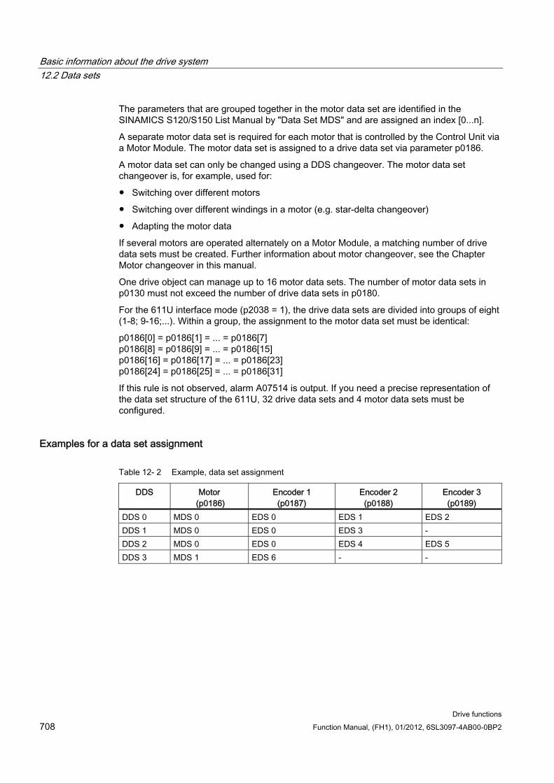
Basic information about the drive system 12.2 Data sets
Drive functions 708 Function Manual, (FH1), 01/2012, 6SL3097-4AB00-0BP2
The parameters that are grouped together in the motor data set are identified in the SINAMICS S120/S150 List Manual by "Data Set MDS" and are assigned an index [0...n].
A separate motor data set is required for each motor that is controlled by the Control Unit via a Motor Module. The motor data set is assigned to a drive data set via parameter p0186.
A motor data set can only be changed using a DDS changeover. The motor data set changeover is, for example, used for:
Switching over different motors
Switching over different windings in a motor (e.g. star-delta changeover)
Adapting the motor data
If several motors are operated alternately on a Motor Module, a matching number of drive data sets must be created. Further information about motor changeover, see the Chapter Motor changeover in this manual.
One drive object can manage up to 16 motor data sets. The number of motor data sets in p0130 must not exceed the number of drive data sets in p0180.
For the 611U interface mode (p2038 = 1), the drive data sets are divided into groups of eight (1-8; 9-16;...). Within a group, the assignment to the motor data set must be identical:
p0186[0] = p0186[1] = ... = p0186[7] p0186[8] = p0186[9] = ... = p0186[15] p0186[16] = p0186[17] = ... = p0186[23] p0186[24] = p0186[25] = ... = p0186[31]
If this rule is not observed, alarm A07514 is output. If you need a precise representation of the data set structure of the 611U, 32 drive data sets and 4 motor data sets must be configured.
Examples for a data set assignment
Table 12- 2 Example, data set assignment
DDS Motor (p0186)
Encoder 1 (p0187)
Encoder 2 (p0188)
Encoder 3 (p0189)
DDS 0 MDS 0 EDS 0 EDS 1 EDS 2 DDS 1 MDS 0 EDS 0 EDS 3 - DDS 2 MDS 0 EDS 0 EDS 4 EDS 5 DDS 3 MDS 1 EDS 6 - -
Basic information about the drive system 12.2 Data sets
Drive functions Function Manual, (FH1), 01/2012, 6SL3097-4AB00-0BP2 709
12.2.5 Function diagrams and parameters
Function diagrams (see SINAMICS S120/S150 List Manual) 8560 Command Data Sets (CDS)
8565 Drive Data Sets (DDS)
8570 Encoder Data Sets (EDS)
8575 Motor Data Sets (MDS)
Overview of important parameters (see SINAMICS S120/S150 List Manual) p0120 Power unit data sets (PDS) number
p0130 Motor data sets (MDS) number
p0139 Copy motor data set (MDS)
p0140 Encoder data sets (EDS) number
p0170 Command data set (CDS) number
p0180 Drive data sets (DDS) number
p0186 Motor data set (MDS) number
p0187 Encoder 1 encoder data set number
p0188 Encoder 2 encoder data set number
p0189 Encoder 3 encoder data set number
p0809 Copy command data set (CDS)
p0810 BI: Command data set selection CDS bit 0
p0811 BI: Command data set selection CDS bit 1
p0812 BI: Command data set selection CDS bit 2
p0813 BI: Command data set selection CDS bit 3
p0819[0...2] Copy drive data set DDS
p0820 BI: Drive data set selection DDS, bit 0
p0821 BI: Drive data set selection DDS, bit 1
p0822 BI: Drive data set selection DDS, bit 2
p0823 BI: Drive data set selection DDS, bit 3
p0824 BI: Drive data set selection DDS, bit 4
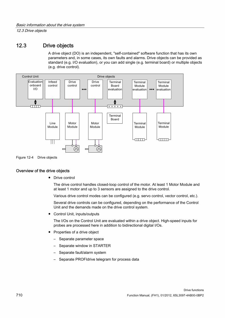
Basic information about the drive system 12.3 Drive objects
Drive functions 710 Function Manual, (FH1), 01/2012, 6SL3097-4AB00-0BP2
12.3 Drive objects A drive object (DO) is an independent, "self-contained" software function that has its own parameters and, in some cases, its own faults and alarms. Drive objects can be provided as standard (e.g. I/O evaluation), or you can add single (e.g. terminal board) or multiple objects (e.g. drive control).
Figure 12-4 Drive objects
Overview of the drive objects Drive control
The drive control handles closed-loop control of the motor. At least 1 Motor Module and at least 1 motor and up to 3 sensors are assigned to the drive control.
Various drive control modes can be configured (e.g. servo control, vector control, etc.).
Several drive controls can be configured, depending on the performance of the Control Unit and the demands made on the drive control system.
Control Unit, inputs/outputs
The I/Os on the Control Unit are evaluated within a drive object. High-speed inputs for probes are processed here in addition to bidirectional digital I/Os.
Properties of a drive object
– Separate parameter space
– Separate window in STARTER
– Separate fault/alarm system
– Separate PROFIdrive telegram for process data
Basic information about the drive system 12.3 Drive objects
Drive functions Function Manual, (FH1), 01/2012, 6SL3097-4AB00-0BP2 711
Supply: Line Module infeed control with DRIVE-CLiQ interface
If an Active Line Module with a DRIVE-CLiQ interface is used for the infeed in a drive system, open-loop/closed-loop control is implemented on the Control Unit within a corresponding drive object.
Supply: Line Module infeed control with DRIVE-CLiQ interface
If a Line Module without a DRIVE-CLiQ interface is used for the infeed in a drive system, the Control Unit must handle activation and evaluation of the corresponding signals (RESET, READY).
Option Board evaluation
An additional drive object is responsible for evaluating an inserted option board. The specific method of operation depends on the type of option board.
Terminal Module evaluation
A separate drive object handles evaluation of the respective optional Terminal Modules.
Evaluating an external ENCODER
A dedicated drive object is responsible for evaluating an optional additional encoder that can be connected.
Note Drive object/Drive Object
A list of all of the drive objects is provided in the SINAMICS S120/S150 List Manual in the Chapter, Overview of parameters.
Configuring drive objects The "Drive objects" processed by the Control Unit are set up in STARTER using configuration parameters during the first commissioning. Various drive objects can be created within a Control Unit.
The drive objects are configurable function blocks and are used to execute specific drive functions.
If you need to configure additional drive objects or delete existing ones after first commissioning, the drive system must be switched to configuration mode.
The parameters of a drive object cannot be accessed until the drive object has been configured and you have switched from configuration mode to parameterization mode.
Note
Each installed drive object is allocated a number between 0 and 63 during first commissioning for unique identification.
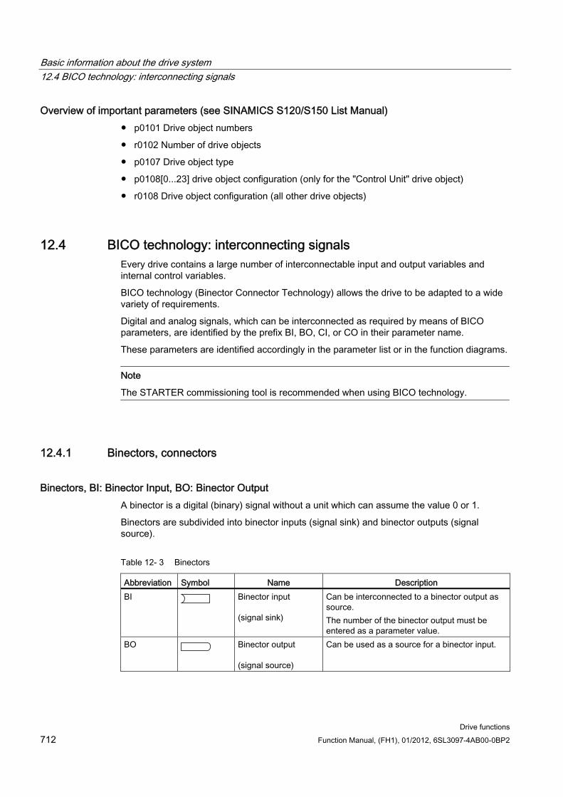
Basic information about the drive system 12.4 BICO technology: interconnecting signals
Drive functions 712 Function Manual, (FH1), 01/2012, 6SL3097-4AB00-0BP2
Overview of important parameters (see SINAMICS S120/S150 List Manual) p0101 Drive object numbers
r0102 Number of drive objects
p0107 Drive object type
p0108[0...23] drive object configuration (only for the "Control Unit" drive object)
r0108 Drive object configuration (all other drive objects)
12.4 BICO technology: interconnecting signals Every drive contains a large number of interconnectable input and output variables and internal control variables.
BICO technology (Binector Connector Technology) allows the drive to be adapted to a wide variety of requirements.
Digital and analog signals, which can be interconnected as required by means of BICO parameters, are identified by the prefix BI, BO, CI, or CO in their parameter name.
These parameters are identified accordingly in the parameter list or in the function diagrams.
Note
The STARTER commissioning tool is recommended when using BICO technology.
12.4.1 Binectors, connectors
Binectors, BI: Binector Input, BO: Binector Output A binector is a digital (binary) signal without a unit which can assume the value 0 or 1.
Binectors are subdivided into binector inputs (signal sink) and binector outputs (signal source).
Table 12- 3 Binectors
Abbreviation Symbol Name Description BI Binector input
(signal sink)
Can be interconnected to a binector output as source. The number of the binector output must be entered as a parameter value.
BO Binector output (signal source)
Can be used as a source for a binector input.
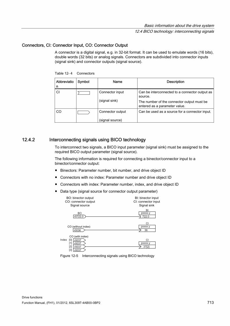
Basic information about the drive system 12.4 BICO technology: interconnecting signals
Drive functions Function Manual, (FH1), 01/2012, 6SL3097-4AB00-0BP2 713
Connectors, CI: Connector Input, CO: Connector Output A connector is a digital signal, e.g. in 32-bit format. It can be used to emulate words (16 bits), double words (32 bits) or analog signals. Connectors are subdivided into connector inputs (signal sink) and connector outputs (signal source).
Table 12- 4 Connectors
Abbreviation
Symbol Name Description
CI Connector input (signal sink)
Can be interconnected to a connector output as source. The number of the connector output must be entered as a parameter value.
CO Connector output (signal source)
Can be used as a source for a connector input.
12.4.2 Interconnecting signals using BICO technology To interconnect two signals, a BICO input parameter (signal sink) must be assigned to the required BICO output parameter (signal source).
The following information is required for connecting a binector/connector input to a binector/connector output:
Binectors: Parameter number, bit number, and drive object ID
Connectors with no index: Parameter number and drive object ID
Connectors with index: Parameter number, index, and drive object ID
Data type (signal source for connector output parameter)
Figure 12-5 Interconnecting signals using BICO technology
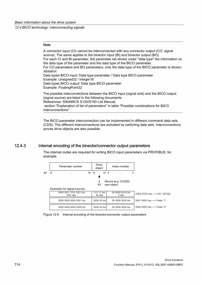
Basic information about the drive system 12.4 BICO technology: interconnecting signals
Drive functions 714 Function Manual, (FH1), 01/2012, 6SL3097-4AB00-0BP2
Note
A connector input (CI) cannot be interconnected with any connector output (CO, signal source). The same applies to the binector input (BI) and binector output (BO). For each CI and BI parameter, the parameter list shows under "data type" the information on the data type of the parameter and the data type of the BICO parameter. For CO parameters and BO parameters, only the data type of the BICO parameter is shown.Notation: Data types BICO input: Data type parameter / Data type BICO parameter Example: Unsigned32 / Integer16 Data types BICO output: Data type BICO parameter Example: FloatingPoint32
The possible interconnections between the BICO input (signal sink) and the BICO output (signal source) are listed in the following documents: References: SINAMICS S120/S150 List Manual, section "Explanation of list of parameters" in table "Possible combinations for BICO interconnections".
The BICO parameter interconnection can be implemented in different command data sets (CDS). The different interconnections are activated by switching data sets. Interconnections across drive objects are also possible.
12.4.3 Internal encoding of the binector/connector output parameters The internal codes are required for writing BICO input parameters via PROFIBUS, for example.
Figure 12-6 Internal encoding of the binector/connector output parameters
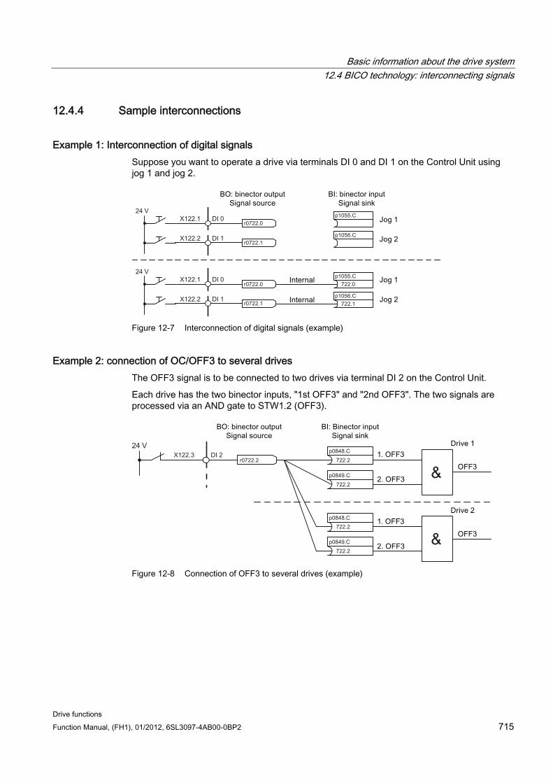
Basic information about the drive system 12.4 BICO technology: interconnecting signals
Drive functions Function Manual, (FH1), 01/2012, 6SL3097-4AB00-0BP2 715
12.4.4 Sample interconnections
Example 1: Interconnection of digital signals Suppose you want to operate a drive via terminals DI 0 and DI 1 on the Control Unit using jog 1 and jog 2.
Figure 12-7 Interconnection of digital signals (example)
Example 2: connection of OC/OFF3 to several drives The OFF3 signal is to be connected to two drives via terminal DI 2 on the Control Unit.
Each drive has the two binector inputs, "1st OFF3" and "2nd OFF3". The two signals are processed via an AND gate to STW1.2 (OFF3).
Figure 12-8 Connection of OFF3 to several drives (example)
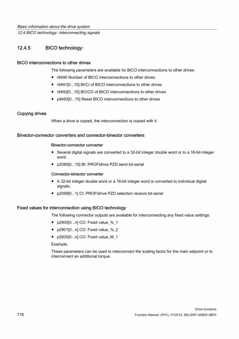
Basic information about the drive system 12.4 BICO technology: interconnecting signals
Drive functions 716 Function Manual, (FH1), 01/2012, 6SL3097-4AB00-0BP2
12.4.5 BICO technology:
BICO interconnections to other drives The following parameters are available for BICO interconnections to other drives:
r9490 Number of BICO interconnections to other drives
r9491[0...15] BI/CI of BICO interconnections to other drives
r9492[0...15] BO/CO of BICO interconnections to other drives
p9493[0...15] Reset BICO interconnections to other drives
Copying drives When a drive is copied, the interconnection is copied with it.
Binector-connector converters and connector-binector converters
Binector-connector converter
Several digital signals are converted to a 32-bit integer double word or to a 16-bit integer word.
p2080[0...15] BI: PROFIdrive PZD send bit-serial
Connector-binector converter
A 32-bit integer double word or a 16-bit integer word is converted to individual digital signals.
p2099[0...1] CI: PROFIdrive PZD selection receive bit-serial
Fixed values for interconnection using BICO technology The following connector outputs are available for interconnecting any fixed value settings:
p2900[0...n] CO: Fixed value_%_1
p2901[0...n] CO: Fixed value_%_2
p2930[0...n] CO: Fixed value_M_1
Example:
These parameters can be used to interconnect the scaling factor for the main setpoint or to interconnect an additional torque.
Basic information about the drive system 12.4 BICO technology: interconnecting signals
Drive functions Function Manual, (FH1), 01/2012, 6SL3097-4AB00-0BP2 717
12.4.6 Scaling
Signals for the analog outputs
Table 12- 5 List of signals for analog outputs
Signal Parameter Unit Normalization (100 % = ...)
Speed setpoint before the setpoint filter
r0060 RPM p2000
Speed actual value motor encoder r0061 RPM p2000 Speed actual value r0063 RPM p2000 Drive output frequency r0066 Hz Reference frequency Absolute current actual value r0068 Aeff p2002 Actual DC link voltage value r0070 V p2001 Total torque setpoint r0079 Nm p2003 Actual active power r0082 kW r2004 Control deviation r0064 RPM p2000 Modulation depth r0074 % Reference modulation depth Current setpoint, torque-generating r0077 A p2002 Current actual value, torque-generating
r0078 A p2002
Flux setpoint r0083 % Reference flux Flux actual value r0084 % Reference flux Speed controller PI torque output
r1480 Nm p2003
Speed controller I torque output
r1482 Nm p2003
Changing scaling parameters p2000 to p2007
CAUTION If a per unit representation is selected and the reference parameter is subsequently changed (e.g. p2000), the per unit values of some control parameters are automatically adapted so that the control behavior does not change.
Basic information about the drive system 12.4 BICO technology: interconnecting signals
Drive functions 718 Function Manual, (FH1), 01/2012, 6SL3097-4AB00-0BP2
12.4.7 Propagation of faults
Forwarding faults to the Control Unit When faults are triggered on the Control Unit drive object, it is always assumed that central functions of the drive are affected. For this reason, these faults are also forwarded to all other drive objects (propagation). The fault responses act on the Control Unit drive object and all other drive objects. This behavior also applies to the faults that are set in a DCC chart on the Control Unit with the aid of the DCC block.
A fault propagated from the Control Unit must be acknowledged at all drive objects to which this fault was transferred. In this way, this fault on the Control Unit is automatically acknowledged. Alternatively, the faults of the drive objects can also be acknowledged on the Control Unit.
Alarms are not propagated from the Control Unit, i.e. transferred to other drive objects.
Example Drive object faults are only transferred to the drives, i.e. a fault on a TB30 stops the drive - however, a fault on the drive does not stop the TB30.
Forwarding of faults due to BICO interconnections If two or more drive objects are connected via BICO interconnections, faults of drive objects of type Control Unit, TB30, DMC20, DME20, all Terminal Modules or ENCODER DO are transferred to drive objects with closed-loop control functions, e.g. infeed units or Motor Modules. There is no forwarding of faults within these two groups of drive object types.
This behavior also applies to the faults set in a DCC chart on the above drive object types with the aid of DCC STM.
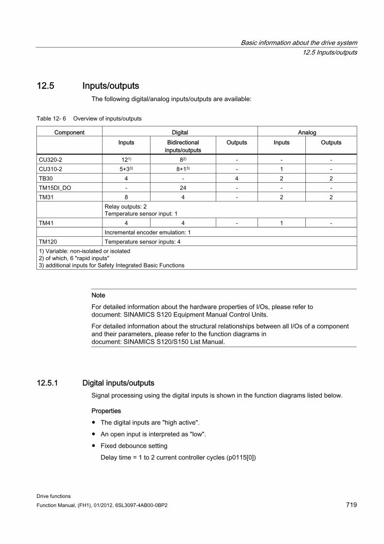
Basic information about the drive system 12.5 Inputs/outputs
Drive functions Function Manual, (FH1), 01/2012, 6SL3097-4AB00-0BP2 719
12.5 Inputs/outputs The following digital/analog inputs/outputs are available:
Table 12- 6 Overview of inputs/outputs
Component Digital Analog Inputs Bidirectional
inputs/outputs Outputs Inputs Outputs
CU320-2 121) 82) - - - CU310-2 5+33) 8+13) - 1 - TB30 4 - 4 2 2 TM15DI_DO - 24 - - - TM31 8 4 - 2 2 Relay outputs: 2
Temperature sensor input: 1 TM41 4 4 - 1 - Incremental encoder emulation: 1 TM120 Temperature sensor inputs: 4 1) Variable: non-isolated or isolated 2) of which, 6 "rapid inputs" 3) additional inputs for Safety Integrated Basic Functions
Note
For detailed information about the hardware properties of I/Os, please refer to document: SINAMICS S120 Equipment Manual Control Units.
For detailed information about the structural relationships between all I/Os of a component and their parameters, please refer to the function diagrams in document: SINAMICS S120/S150 List Manual.
12.5.1 Digital inputs/outputs Signal processing using the digital inputs is shown in the function diagrams listed below.
Properties
The digital inputs are "high active".
An open input is interpreted as "low".
Fixed debounce setting
Delay time = 1 to 2 current controller cycles (p0115[0])
Basic information about the drive system 12.5 Inputs/outputs
Drive functions 720 Function Manual, (FH1), 01/2012, 6SL3097-4AB00-0BP2
Availability of the input signal for further interconnection
– inverted and not inverted as a binector output
– as a connector output
Simulation mode settable and parameterizable.
Isolation block by block, set by jumper.
– Jumper open: electrically isolated. The digital inputs function only if a reference ground is connected.
– Jumper closed, non-floating. The reference potential of the digital inputs is the ground of the Control Unit.
Sampling time for digital inputs/outputs can be adjusted (p0799)
Function diagrams (see SINAMICS S120/S150 List Manual) Control Unit 320-2:
2120 Digital inputs, electrically isolated (DI 0 ... DI 3)
2121 Digital inputs, electrically isolated (DI 4 ... DI 7)
TB30:
9100 Digital inputs, electrically isolated (DI 0 ... DI 3)
TM15:
9550 Digital inputs, electrically isolated (DI 0 ... DI 3)
9552 Digital inputs, electrically isolated (DI 4 ... DI 7)
TM41:
9660 Digital inputs, electrically isolated (DI 0 ... DI 3)
Control Unit 310-2:
2020 – digital inputs, electrically isolated (DI 0 … DI 3, DI 22)
2021 – digital inputs, electrically isolated (DI 16 ... DI 21)
2030 – digital inputs/outputs, bidirectional (DI/DO 8 ... DI/DO 9)
2031 – digital inputs/outputs, bidirectional (DI/DO 10 ... DI/DO 11)
2032 – digital inputs/outputs, bidirectional (DI/DO 12 ... DI/DO 13)
2033 – digital inputs/outputs, bidirectional (DI/DO 14 ... DI/DO 15)
2038 – digital output (DO 16)
Basic information about the drive system 12.5 Inputs/outputs
Drive functions Function Manual, (FH1), 01/2012, 6SL3097-4AB00-0BP2 721
Digital outputs Signal processing using the digital outputs is shown in the function diagrams listed below.
Properties
Separate power supply for the digital outputs.
Source of output signal can be selected by parameter.
Signal can be inverted by parameter.
Status of output signal can be displayed
– as a binector output
– as a connector output
Note
Before the digital outputs can function, their own electronics power supply must be connected.
Function diagrams (see SINAMICS S120/S150 List Manual) Control Unit CU310-2:
2038 – digital output (DO 16)
TB30:
9102 Electrically isolated digital outputs (DO 0 to DO 3)
TM31:
9556 Digital relay outputs, electrically isolated (DO 0 and DO 1)
Bidirectional digital inputs/outputs Signal processing using the bidirectional inputs/outputs is shown in the function diagrams listed below.
Properties
Can be parameterized as digital input or output.
When set as digital input:
– Six "high-speed inputs" on Control Unit
If these inputs are used, for example, for the "flying measurement" function, they act as "high-speed inputs" with virtually no time delay when the actual value is saved.
– The properties of the "pure" digital outputs apply.
Basic information about the drive system 12.5 Inputs/outputs
Drive functions 722 Function Manual, (FH1), 01/2012, 6SL3097-4AB00-0BP2
When set as digital output:
– The properties of the "pure" digital outputs apply.
Sharing of bidirectional input/output resources by the CU and higher-level control (see section "Use of bidirectional inputs/outputs on the CU")
Function diagrams (see SINAMICS S120/S150 List Manual) Control Unit CU310-2:
2030 digital inputs/outputs, bidirectional (DI/DO 8 ... DI/DO 9)
2031 digital inputs/outputs, bidirectional (DI/DO 10 ... DI/DO 11)
2032 digital inputs/outputs, bidirectional (DI/DO 12 ... DI/DO 13)
2033 digital inputs/outputs, bidirectional (DI/DO 14 … DI/DO 15)
Control Unit CU320-2:
2130 Bidirectional digital inputs/outputs (DI/DO 8 and DI/DO 9)
2131 Bidirectional digital inputs/outputs (DI/DO 10 and DI/DO 11)
2132 Bidirectional digital inputs/outputs (DI/DO 12 and DI/DO 13)
2133 Bidirectional digital inputs/outputs (DI/DO 14 and DI/DO 5)
TM15:
9400 Bidirectional digital inputs/outputs (DI/DO 0 ... DI/DO 7)
9401 Bidirectional digital inputs/outputs (DI/DO 8 ... DI/DO 15)
9402 Bidirectional digital inputs/outputs (DI/DO 16 ... DI/DO 23)
TM31:
9560 Bidirectional digital inputs/outputs (DI/DO8 and DI/DO 9)
9562 Bidirectional digital inputs/outputs (DI/DO 10 and DI/DO 1)
TM41
9661 Bidirectional digital inputs/outputs (DI/DO 0 and DI/DO 1)
9662 digital inputs/outputs, bidirectional (DI/DO 2 and DI/DO 3)
12.5.2 Use of bidirectional inputs/outputs on the CU
Description The bidirectional inputs/outputs of terminals X122 and X132 on the CU (DO1) can be used by a drive object as well as a higher-level control (resource sharing). The assignment to a terminal is defined by means of BICO interconnections, which are either connected to a control via the DO1 telegram p0922 = 39x or to a drive object.
Basic information about the drive system 12.5 Inputs/outputs
Drive functions Function Manual, (FH1), 01/2012, 6SL3097-4AB00-0BP2 723
The setting of parameter p0729 indicates how a digital output of a Control Unit has been assigned, i.e. whether the output of an onboard terminal X122 or X132 is assigned directly to the Control Unit or connected via PROFIBUS to a higher-level control.
r0729 = 0: The output is assigned to the Control Unit of the drive or terminal output not available.
r0729 = 1: Output is assigned to the higher-level control (PROFIBUS connection). Assignment to the control means:
– Terminal is parameterized as output x (p0728.x =1) and
– Terminal is connected with p2901 via BICO, i.e. the control uses the output in conjunction with the DO1 telegram (p0922 = 39x)
– Use of the terminal's output signal for integrated platform via high-speed bypass channel of the control (standard channel with DO1 telegram is always written in parallel).
Parameter r0729 is updated if
the direction of the onboard terminals changes over (p0728), or
the signal sources for the outputs (p0738 ff) are changed.
Access priorities
Reparameterization output control --> output drive via parameter p0738 ff The drive output has higher priority than a standard control output using the DO1 telegram, but direct access by the control to the terminal (bypass) has higher priority than the drive output. When the output is reconfigured to the drive, the control needs to cancel a bypass to the terminals (if one has been set up) before the new configuration can take effect.
Reconfiguration input drive --> output control The output of the control has higher priority. This is the specified behavior. The drive is notified of the change so that the affected application can issue an alarm.
Reconfiguration output drive --> output control The output of the control has higher priority. This is the specified behavior. The drive is notified of the change so that the affected application can issue an alarm/fault message is necessary. Readback of the output information can cause problems in the drive, i.e. the drive application checks the interconnection condition of "its" terminals. If the terminal remains assigned to a drive I/O device as required by the drive function, but is assigned simultaneously a control terminal status, the drive function cannot be guaranteed to work correctly.
Fault reaction to control failure The onboard I/Os assigned to the control are switched to the safe state in response to a fault. This also applies to terminals whose signals are transferred via the bypass channel on the control. This status is signaled by failure of the DO1 telegram (sign-of-life failure).
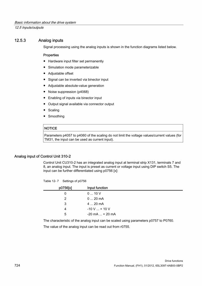
Basic information about the drive system 12.5 Inputs/outputs
Drive functions 724 Function Manual, (FH1), 01/2012, 6SL3097-4AB00-0BP2
12.5.3 Analog inputs Signal processing using the analog inputs is shown in the function diagrams listed below.
Properties
Hardware input filter set permanently
Simulation mode parameterizable
Adjustable offset
Signal can be inverted via binector input
Adjustable absolute-value generation
Noise suppression (p4068)
Enabling of inputs via binector input
Output signal available via connector output
Scaling
Smoothing
NOTICE Parameters p4057 to p4060 of the scaling do not limit the voltage values/current values (for TM31, the input can be used as current input).
Analog input of Control Unit 310-2 Control Unit CU310-2 has an integrated analog input at terminal strip X131, terminals 7 and 8, an analog input. The input is preset as current or voltage input using DIP switch S5. The input can be further differentiated using p0756 [x]:
Table 12- 7 Settings of p0756
p0756[x] Input function 0 0 ... 10 V 2 0 ... 20 mA 3 4 ... 20 mA 4 -10 V ... + 10 V 5 -20 mA ... + 20 mA
The characteristic of the analog input can be scaled using parameters p0757 to P0760.
The value of the analog input can be read out from r0755.

Basic information about the drive system 12.5 Inputs/outputs
Drive functions Function Manual, (FH1), 01/2012, 6SL3097-4AB00-0BP2 725
Function diagrams (see SINAMICS S120/S150 List Manual) 9104 Analog inputs (AI 0 and AI 1)
9566 Analog input 0 (AI 0)
9568 Analog input 1 (AI 1)
9663 Analog input (AI 0)
CU310-2:
2040 Analog input (AI 0)
Parameter
r0752[0] CO: CU analog input input voltage
p0753[0] CU analog input smoothing time constant
p0761[0] CU analog input wire breakage monitoring response threshold
p0762[0] CU analog input wire breakage monitoring delay time
CU analog input offset
CU analog input activate absolute value generation
BI: CU analog input enable signal source
CU310-2:
r0755[0] CO: CU analog input actual value in percent
p0756[0] CU analog input type
p0757[0] CU analog input characteristic value x1
p0758[0] CU analog input characteristic value y1
p0759[0] CU analog input characteristic value x2
p0760[0] CU analog input characteristic value y2
12.5.4 Analog outputs Signal processing using the analog outputs is shown in the function diagrams listed below.
Properties
Adjustable absolute-value generation
Inversion via binector input
Adjustable smoothing
Adjustable transfer characteristic
Output signal can be displayed via visualization parameter
Basic information about the drive system 12.6 Backing up the non-volatile memory
Drive functions 726 Function Manual, (FH1), 01/2012, 6SL3097-4AB00-0BP2
NOTICE Parameters p4077 to p4080 of the scaling do not limit the voltage values/current values (for TM31, the output can be used as current output).
Function diagrams (see SINAMICS S120/S150 List Manual) 9106 Analog outputs (AO 0 and AO 1)
9572 Analog outputs (AO 0 and AO 1)
12.6 Backing up the non-volatile memory For operation-relevant data, the CU320-2 and the CU310-2 have a non-volatile memory, the NVRAM (Non-Volatile Random Access Memory). The data of the fault buffer, the diagnostics buffer and message buffer are saved in this memory.
Certain circumstances, for example, a defect in the Control Unit or if the Control Unit has been replaced, require that this data is backed up. After the hardware has been replaced, transfer the backed up data back to the NVRAM of the Control Unit. You can perform these operations using parameter p7775:
1. p7775 = 1 backs up the NVRAM data on the memory card.
2. p7775 = 2 copies the NVRAM data from the memory card to the NVRAM.
3. p7775 = 3 deletes the data in the NVRAM. After the data have been successfully cleared, a POWER ON is automatically carried out.
p7775 is automatically set to 0 if the operation was successful. If the operation was not successful, p7775 indicates a corresponding fault value. Further details of the fault values can be found in the SINAMICS S120/150 List Manual.
Note NVRAM data change
The data in the NVRAM can only be restored or deleted if the pulse inhibit is set.
Backing up NVRAM data With p7775 = 1, the NVRAM data of a stand-alone Control Unit are saved in the subdirectory: "... \USER\SINAMICS\NVRAM\PMEMORY.ACX" on the memory card. If a file with this name is already in the folder on the memory card, then this is renamed "...\PMEMORY.BAK".
When the Control Unit is integrated in a control system, the NVRAM data are saved in the subdirectory: "... \USER\SINAMICS\NVRAM\xx\PMEMORY.ACX" on the memory card. "xx" corresponds to the DRIVE-CLiQ port.
Basic information about the drive system 12.6 Backing up the non-volatile memory
Drive functions Function Manual, (FH1), 01/2012, 6SL3097-4AB00-0BP2 727
When saving, all data are backed up from the NVRAM.
NOTICE Backing up NVRAM data
The backup of the NVRAM data to the memory card is also possible when the pulses are enabled. However, if the drive is operated when NVRAM data are being transferred, then it is possible that the backed up data are not consistent with the NVRAM data.
Restoring NVRAM data With p7775 = 2, the NVRAM data are transferred back from the memory card into the Control Unit. When restoring you decide which data you require and want to copy.
There are two reasons that necessitate the NVRAM data to be restored.
1. Replacing the Control Unit
2. Specific restoration of the NVRAM data as it is possible that there are data errors.
When restoring, the Control Unit always searches first for the "PMEMORY.ACX" file. If the file is available with a valid checksum, then it is loaded. If a "PMEMORY.ACX" file is not found, the Control Unit searches for a "PMEMORY.BAK" file, and if the checksum is valid then this is loaded.
Replacing the Control Unit:
If a Control Unit has to be replaced, then this is identified by SINAMICS as a result of the modified Control Unit serial number. After the POWER ON, the NVRAM of the Control Unit is first deleted. The new NVRAM data are then loaded.
NVRAM restoration:
A specific restoration of the saved NVRAM data is initiated by setting p7775 = 2. The original file in the NVRAM is first deleted. If the file "PMEMORY.ACX" is available with a valid checksum, it is loaded to the NVRAM.
The following data is not imported again:
Control Unit operating hours counter,
Control Unit temperature
Safety logbook
Crash diagnostics data
Basic information about the drive system 12.7 Parameterizing using the BOP20 (Basic Operator Panel 20)
Drive functions 728 Function Manual, (FH1), 01/2012, 6SL3097-4AB00-0BP2
Deleting the NVRAM data With p7775 = 3, the NVRAM data is deleted.
The following data is not deleted:
Control Unit operating hours counter,
Control Unit temperature
Safety logbook
Crash diagnostics data
Note NVRAM and know-how protection
Know-how protection and write protection apply to parameter p7775. If the parameter should be readable despite activated protection mechanisms, then p7775 must be placed in the exception list.
Note NVRAM and write protection
When write protection is activated, p7775 can only be written to from a higher-level control using cyclic communication.
More information on fault buffers, diagnostic buffers and message buffers is provided in the SINAMICS S120 Commissioning Manual.
12.7 Parameterizing using the BOP20 (Basic Operator Panel 20)
12.7.1 General information about the BOP20 The BOP20 can be used to switch on and switch off drives during the commissioning phase as well as to display and modify parameters. Faults can be diagnosed as well as acknowledged.
The BOP20 is snapped onto the Control Unit. To do this, the blanking cover must be removed (for additional information on mounting, please refer to the Manual SINAMICS S120 Control Units and supplementary system components).
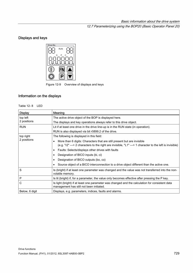
Basic information about the drive system 12.7 Parameterizing using the BOP20 (Basic Operator Panel 20)
Drive functions Function Manual, (FH1), 01/2012, 6SL3097-4AB00-0BP2 729
Displays and keys
Figure 12-9 Overview of displays and keys
Information on the displays
Table 12- 8 LED
Display Meaning top left 2 positions
The active drive object of the BOP is displayed here. The displays and key operations always refer to this drive object.
RUN Lit if at least one drive in the drive line-up is in the RUN state (in operation). RUN is also displayed via bit r0899.2 of the drive.
top right 2 positions
The following is displayed in this field: • More than 6 digits: Characters that are still present but are invisible
(e.g. "r2" ––> 2 characters to the right are invisible, "L1" ––> 1 character to the left is invisible)• Faults: Selects/displays other drives with faults • Designation of BICO inputs (bi, ci) • Designation of BICO outputs (bo, co) • Source object of a BICO interconnection to a drive object different than the active one.
S Is (bright) if at least one parameter was changed and the value was not transferred into the non-volatile memory.
P Is lit (bright) if, for a parameter, the value only becomes effective after pressing the P key. C Is light (bright) if at least one parameter was changed and the calculation for consistent data
management has still not been initiated. Below, 6 digit Displays, e.g. parameters, indices, faults and alarms.
Basic information about the drive system 12.7 Parameterizing using the BOP20 (Basic Operator Panel 20)
Drive functions 730 Function Manual, (FH1), 01/2012, 6SL3097-4AB00-0BP2
Information on the keys
Table 12- 9 Keys
Key Name Meaning
ON Powering up the drives for which the command "ON/OFF1" should come from the BOP.
Binector output r0019.0 is set using this key.
OFF Powering down the drives for which the commands "ON/OFF1", "OFF2" or "OFF3" should come
from the BOP. The binector outputs r0019.0, .1 and .2 are simultaneously reset when this key is pressed. After the key has been released, binector outputs r0019.1 and .2 are again set to a "1" signal. Note: The effectiveness of these keys can be defined by appropriately parameterizing the BICO (e.g. using these keys it is possible to simultaneously control all of the existing drives).
Functions The significance of this key depends on the actual display.
Note: The effectiveness of this key to acknowledge faults can be defined using the appropriate BiCo parameterization.
Parameter The significance of this key depends on the actual display.
If this key is pressed for 3 s, the "Copy RAM to ROM" function is executed. The "S" displayed on the BOP disappears.
Raise
Lower
The significance of these keys is dependent on the actual display and is used to increase or decrease values.
BOP20 functions
Table 12- 10 Functions
Name Description Backlighting The backlighting can be set using p0007 in such a way that it switches itself off automatically
after the set time if no actions are carried out. Changeover active drive From the BOP perspective the active drive is defined using p0008 or using the keys "FN" and
"Arrow up". Units The units are not displayed on the BOP. Access level The access level for the BOP is defined using p0003.
The higher the access level, the more parameters can be selected using the BOP. Parameter filter Using the parameter filter in p0004, the available parameters can be filtered corresponding to
their particular function. Selecting the operating display
Actual values and setpoints are displayed on the operating display. The operating display can be set using p0006.
User parameter list Using the user parameter list in p0013, parameters can be selected for access.
Basic information about the drive system 12.7 Parameterizing using the BOP20 (Basic Operator Panel 20)
Drive functions Function Manual, (FH1), 01/2012, 6SL3097-4AB00-0BP2 731
Name Description Unplug while voltage is present
The BOP can be withdrawn and inserted under voltage. • The ON key and OFF key have a function.
When withdrawing, the drives are stopped.
After inserting, the drives must be switched on again. • The ON key and OFF key have no function.
Withdrawing and inserting has no effect on the drives. Actuating keys The following applies to the "P" and "FN" keys:
• When used in a combination with another key, "P" or "FN" must be pressed first and then the other key.
Basic information about the drive system 12.7 Parameterizing using the BOP20 (Basic Operator Panel 20)
Drive functions 732 Function Manual, (FH1), 01/2012, 6SL3097-4AB00-0BP2
Overview of important parameters (see SINAMICS S120/S150 List Manual)
All drive objects
p0005 BOP operating display selection
p0006 BOP operating display mode
p0013 BOP user-defined list
p0971 Drive object, save parameters
Drive object, Control Unit
r0002 Control Unit status display
p0003 BOP access level
p0004 BOP display filter
p0007 BOP background lighting
p0008 BOP drive object selection
p0009 Device commissioning, parameter filter
p0011 BOP password input (p0013)
p0012 BOP password confirmation (p0013)
r0019 CO/BO: Control word, BOP
p0977 Save all parameters
Other drive objects (e.g. SERVO, VECTOR, X_INF, TM41 etc.)
p0010 Commissioning parameter filter
Basic information about the drive system 12.7 Parameterizing using the BOP20 (Basic Operator Panel 20)
Drive functions Function Manual, (FH1), 01/2012, 6SL3097-4AB00-0BP2 733
12.7.2 Displays and using the BOP20
Features Status indicator
Changing the active drive object
Displaying/changing parameters
Displaying/acknowledging faults and alarms
Controlling the drive using the BOP20
Status indicator The operating display for each drive object can be set using p0005 and p0006. Using the operating display, you can change into the parameter display or to another drive object. The following functions are possible:
Changing the active drive object
– Press key "FN" and "Arrow up" -> the drive object number at the top left flashes
– Select the required drive object using the arrow keys
– Acknowledge using the "P" key
Parameter display
– Press the "P" key.
– The required parameters can be selected using the arrow keys.
– Press the "FN" key -> "r00000" is displayed
– Press the "P" key -> changes back to the operating display
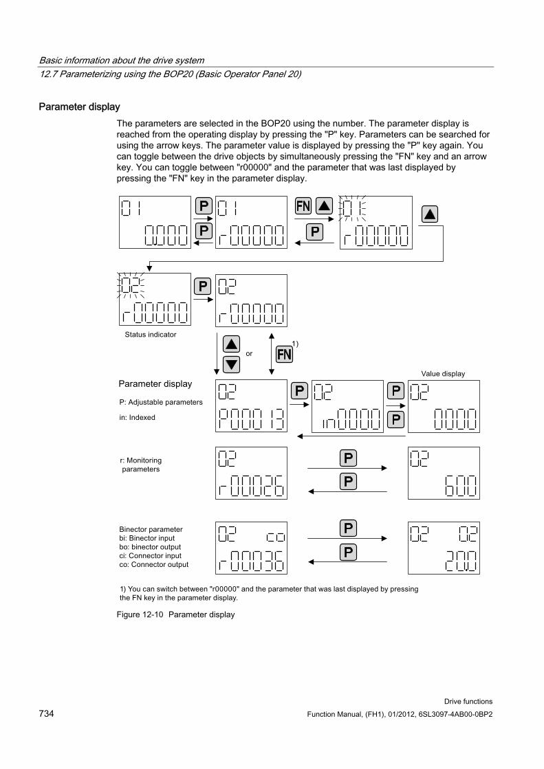
Basic information about the drive system 12.7 Parameterizing using the BOP20 (Basic Operator Panel 20)
Drive functions 734 Function Manual, (FH1), 01/2012, 6SL3097-4AB00-0BP2
Parameter display The parameters are selected in the BOP20 using the number. The parameter display is reached from the operating display by pressing the "P" key. Parameters can be searched for using the arrow keys. The parameter value is displayed by pressing the "P" key again. You can toggle between the drive objects by simultaneously pressing the "FN" key and an arrow key. You can toggle between "r00000" and the parameter that was last displayed by pressing the "FN" key in the parameter display.
Figure 12-10 Parameter display
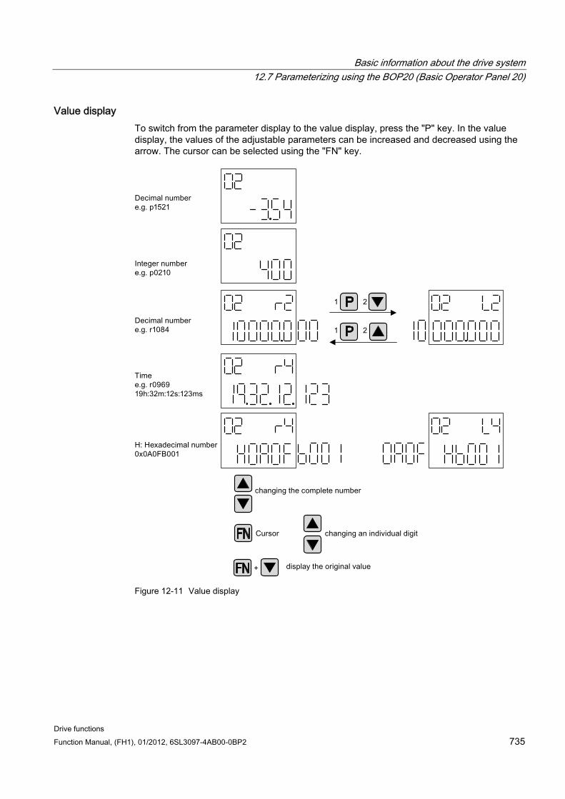
Basic information about the drive system 12.7 Parameterizing using the BOP20 (Basic Operator Panel 20)
Drive functions Function Manual, (FH1), 01/2012, 6SL3097-4AB00-0BP2 735
Value display To switch from the parameter display to the value display, press the "P" key. In the value display, the values of the adjustable parameters can be increased and decreased using the arrow. The cursor can be selected using the "FN" key.
Figure 12-11 Value display
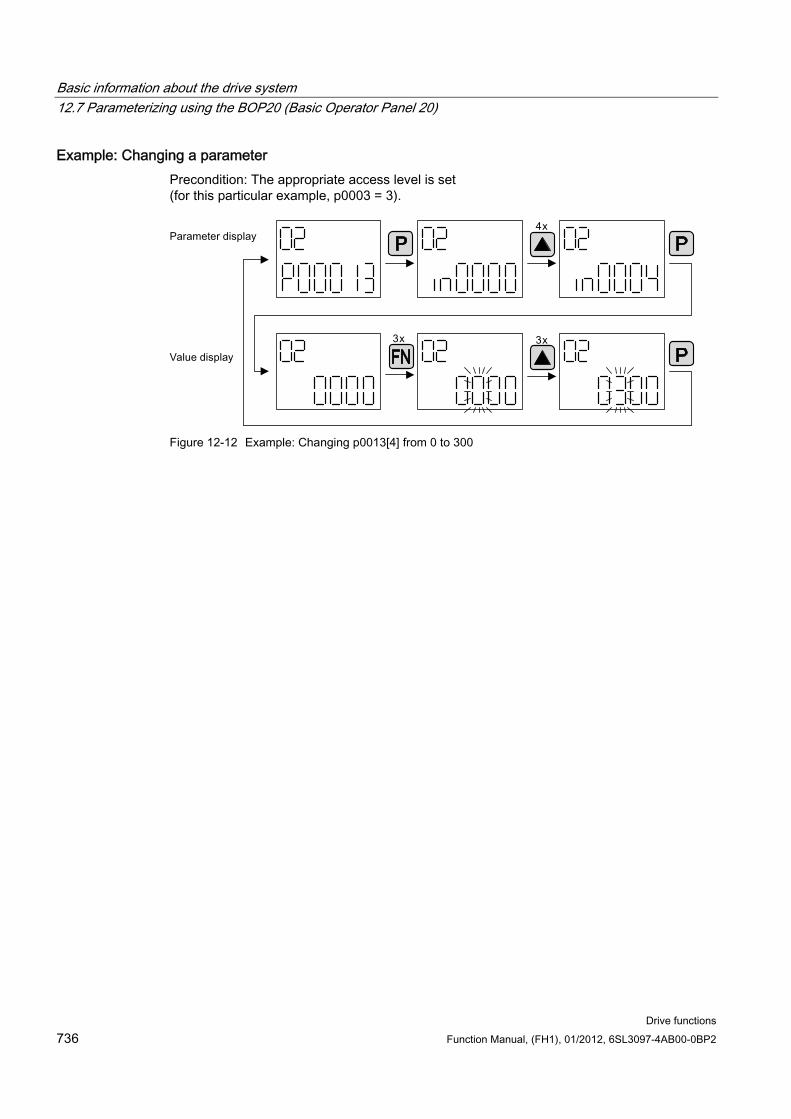
Basic information about the drive system 12.7 Parameterizing using the BOP20 (Basic Operator Panel 20)
Drive functions 736 Function Manual, (FH1), 01/2012, 6SL3097-4AB00-0BP2
Example: Changing a parameter Precondition: The appropriate access level is set (for this particular example, p0003 = 3).
Figure 12-12 Example: Changing p0013[4] from 0 to 300
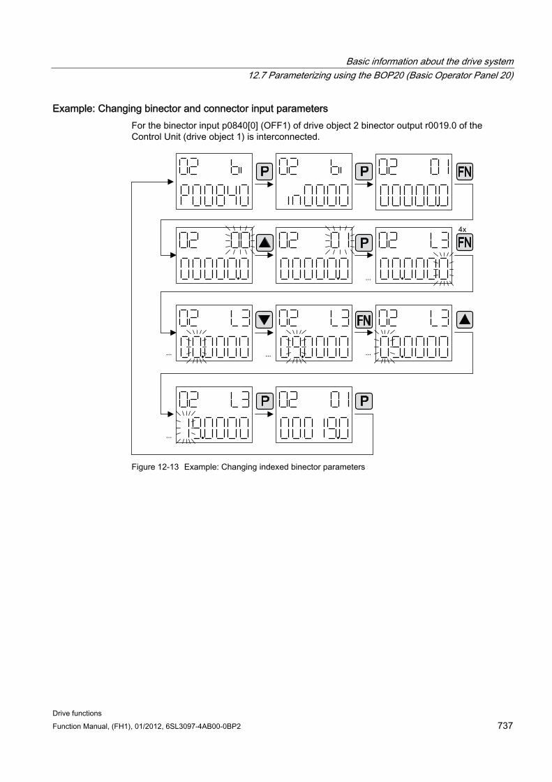
Basic information about the drive system 12.7 Parameterizing using the BOP20 (Basic Operator Panel 20)
Drive functions Function Manual, (FH1), 01/2012, 6SL3097-4AB00-0BP2 737
Example: Changing binector and connector input parameters For the binector input p0840[0] (OFF1) of drive object 2 binector output r0019.0 of the Control Unit (drive object 1) is interconnected.
Figure 12-13 Example: Changing indexed binector parameters

Basic information about the drive system 12.7 Parameterizing using the BOP20 (Basic Operator Panel 20)
Drive functions 738 Function Manual, (FH1), 01/2012, 6SL3097-4AB00-0BP2
12.7.3 Fault and alarm displays
Displaying faults
Figure 12-14 Faults
Displaying alarms
Figure 12-15 Alarms
Basic information about the drive system 12.8 Examples of replacing components
Drive functions Function Manual, (FH1), 01/2012, 6SL3097-4AB00-0BP2 739
12.7.4 Controlling the drive using the BOP20 When commissioning the drive, it can be controlled via the BOP20. A control word is available on the Control Unit drive object (r0019) for this purpose, which can be interconnected with the appropriate binector inputs of e.g. the drive.
The interconnections do not function if a standard PROFIdrive telegram was selected as its interconnection cannot be disconnected.
Table 12- 11 BOP20 control word
Bit (r0019) Name Example, interconnection parameters 0 ON / OFF (OFF1) p0840 1 No coast down/coast down (OFF2) p0844 2 No fast stop/fast stop (OFF3) p0848 Note: For simple commissioning, only bit 0 should be interconnected. When interconnecting bits 0 ... 2, then the system is powered-down according to the following priority: OFF2, OFF3, OFF1. 7 Acknowledge fault (0 -> 1) p2102 13 Motorized potentiometer, raise p1035 14 Motorized potentiometer, lower p1036
12.8 Examples of replacing components
Note
To ensure that the entire functionality of a firmware version can be used, it is recommended that all the components in a drive line-up have the same firmware version.
Description If the type of comparison is set to the highest setting, the following examples apply.
A distinction is made between the following scenarios:
Component with a different order number
Components with identical order number
– Topology comparison component replacement active (p9909 = 1)
– Topology comparison component replacement inactive (p9909 = 0)
For p9909 = 1, the serial number and the hardware version of the new replaced component are automatically transferred from the actual topology into the target topology and then saved in a non-volatile manner.
For p9909 = 0, serial numbers and hardware versions are not automatically transferred. In this case, when the data in the electronic rating plate match, the transfer is realized using p9904 = 1 or p9905 = 1.
Basic information about the drive system 12.8 Examples of replacing components
Drive functions 740 Function Manual, (FH1), 01/2012, 6SL3097-4AB00-0BP2
For the components that have been replaced, the electronic rating plate must match as far as the following data are concerned:
Component type (e.g. "SMC20")
Order No. (e.g. "6SL3055–0AA00–5Bxx")
Example: Replacing a component with a different order number
Precondition:
The replaced component has a different order number
Table 12- 12 Example: Replacing a component with a different order number
Action Reaction Remark
• Switch off the power supply • Replace the defective
component and connect the new one
• Switch on the power supply
• Alarm A01420
• Load the project from the Control Unit to the STARTER (PG)
• Configure the replacement drive and select the current component
• Load the project to the Control Unit (target system)
• Alarm disappears The new order number is stored in the RAM of the Control Unit and has to be copied to the non-volatile memory with p0977 = 1 and p0971 = 1. As an alternative, STARTER can be used to backup data with a RAM to ROM operation.
The component has been successfully replaced.
Example: (p9909 = 1) Replacing a defective component with an identical order number
Precondition:
The replaced component has an identical order number
The serial number of the new replacement component must not be contained in the stored target topology of the Control Unit.
Topology comparison component replacement active p9909 = 1.
Sequence:
During startup of the Control Unit, the serial number of the new component is automatically transferred to the target topology and saved.

Basic information about the drive system 12.8 Examples of replacing components
Drive functions Function Manual, (FH1), 01/2012, 6SL3097-4AB00-0BP2 741
Example: (p9909 = 0) Replacing a defective component with an identical order number
Precondition:
The replaced component has an identical order number
Topology comparison component replacement inactive p9909 = 0.
Table 12- 13 Example: Replacing a Motor Module
Action Reaction Remark
• Switch off the power supply • Replace the defective
component and connect the new one
• Switch on the power supply
• Alarm A01425
• Set p9905 to "1" • Alarm disappears • The serial number is copied
to the target topology
The serial number is stored in the RAM of the Control Unit and has to be copied to the non-volatile memory with p0977 = 1 and p0971 = 1. As an alternative, STARTER can be used to backup data with a RAM to ROM operation.
The component has been successfully replaced.
Example: Replacing a Motor Module/Power Module with a different power rating
Preconditions:
The replaced power unit has a different power rating
Vector: Power rating of the Motor Module/Power Module not greater than 4 * motor current
Table 12- 14 Example: Replacing a power unit with a different power rating
Action Reaction Remark
• Switch off the power supply • Replace the defective
component and connect the new one
• Switch on the power supply
• Alarm A01420
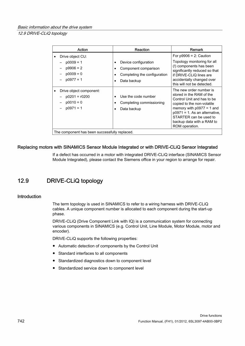
Basic information about the drive system 12.9 DRIVE-CLiQ topology
Drive functions 742 Function Manual, (FH1), 01/2012, 6SL3097-4AB00-0BP2
Action Reaction Remark
• Drive object CU: – p0009 = 1 – p9906 = 2 – p0009 = 0 – p0977 = 1
• Device configuration • Component comparison • Completing the configuration • Data backup
For p9906 = 2: Caution Topology monitoring for all (!) components has been significantly reduced so that if DRIVE-CLiQ lines are accidentally changed over this will not be detected.
• Drive object component: – p0201 = r0200 – p0010 = 0 – p0971 = 1
• Use the code number • Completing commissioning • Data backup
The new order number is stored in the RAM of the Control Unit and has to be copied to the non-volatile memory with p0977 = 1 and p0971 = 1. As an alternative, STARTER can be used to backup data with a RAM to ROM operation.
The component has been successfully replaced.
Replacing motors with SINAMICS Sensor Module Integrated or with DRIVE-CLiQ Sensor Integrated If a defect has occurred in a motor with integrated DRIVE-CLiQ interface (SINAMICS Sensor Module Integrated), please contact the Siemens office in your region to arrange for repair.
12.9 DRIVE-CLiQ topology
Introduction The term topology is used in SINAMICS to refer to a wiring harness with DRIVE-CLiQ cables. A unique component number is allocated to each component during the start-up phase.
DRIVE-CLiQ (Drive Component Link with IQ) is a communication system for connecting various components in SINAMICS (e.g. Control Unit, Line Module, Motor Module, motor and encoder).
DRIVE-CLiQ supports the following properties:
Automatic detection of components by the Control Unit
Standard interfaces to all components
Standardized diagnostics down to component level
Standardized service down to component level
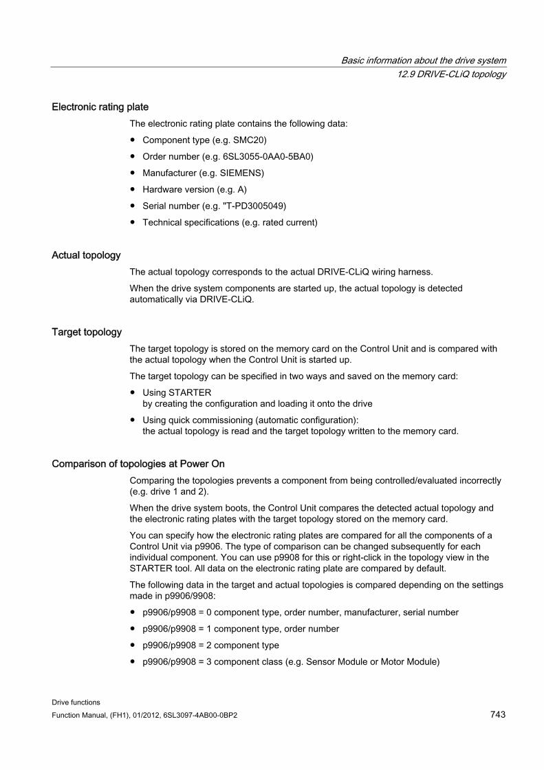
Basic information about the drive system 12.9 DRIVE-CLiQ topology
Drive functions Function Manual, (FH1), 01/2012, 6SL3097-4AB00-0BP2 743
Electronic rating plate The electronic rating plate contains the following data:
Component type (e.g. SMC20)
Order number (e.g. 6SL3055-0AA0-5BA0)
Manufacturer (e.g. SIEMENS)
Hardware version (e.g. A)
Serial number (e.g. "T-PD3005049)
Technical specifications (e.g. rated current)
Actual topology The actual topology corresponds to the actual DRIVE-CLiQ wiring harness.
When the drive system components are started up, the actual topology is detected automatically via DRIVE-CLiQ.
Target topology The target topology is stored on the memory card on the Control Unit and is compared with the actual topology when the Control Unit is started up.
The target topology can be specified in two ways and saved on the memory card:
Using STARTER by creating the configuration and loading it onto the drive
Using quick commissioning (automatic configuration): the actual topology is read and the target topology written to the memory card.
Comparison of topologies at Power On Comparing the topologies prevents a component from being controlled/evaluated incorrectly (e.g. drive 1 and 2).
When the drive system boots, the Control Unit compares the detected actual topology and the electronic rating plates with the target topology stored on the memory card.
You can specify how the electronic rating plates are compared for all the components of a Control Unit via p9906. The type of comparison can be changed subsequently for each individual component. You can use p9908 for this or right-click in the topology view in the STARTER tool. All data on the electronic rating plate are compared by default.
The following data in the target and actual topologies is compared depending on the settings made in p9906/9908:
p9906/p9908 = 0 component type, order number, manufacturer, serial number
p9906/p9908 = 1 component type, order number
p9906/p9908 = 2 component type
p9906/p9908 = 3 component class (e.g. Sensor Module or Motor Module)
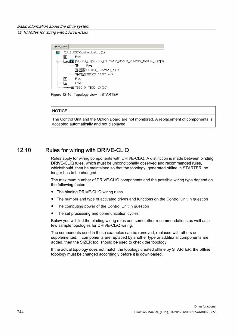
Basic information about the drive system 12.10 Rules for wiring with DRIVE-CLiQ
Drive functions 744 Function Manual, (FH1), 01/2012, 6SL3097-4AB00-0BP2
Figure 12-16 Topology view in STARTER
NOTICE The Control Unit and the Option Board are not monitored. A replacement of components is accepted automatically and not displayed.
12.10 Rules for wiring with DRIVE-CLiQ Rules apply for wiring components with DRIVE-CLiQ. A distinction is made between binding DRIVE-CLiQ rules, which must be unconditionally observed and recommended rules, whichshould then be maintained so that the topology, generated offline in STARTER, no longer has to be changed.
The maximum number of DRIVE-CLiQ components and the possible wiring type depend on the following factors:
The binding DRIVE-CLiQ wiring rules
The number and type of activated drives and functions on the Control Unit in question
The computing power of the Control Unit in question
The set processing and communication cycles
Below you will find the binding wiring rules and some other recommendations as well as a few sample topologies for DRIVE-CLiQ wiring.
The components used in these examples can be removed, replaced with others or supplemented. If components are replaced by another type or additional components are added, then the SIZER tool should be used to check the topology.
If the actual topology does not match the topology created offline by STARTER, the offline topology must be changed accordingly before it is downloaded.
Basic information about the drive system 12.10 Rules for wiring with DRIVE-CLiQ
Drive functions Function Manual, (FH1), 01/2012, 6SL3097-4AB00-0BP2 745
12.10.1 Changing the offline topology in STARTER The device topology can be changed in STARTER by shifting the components in the topology tree.
Table 12- 15 Example: changing the DRIVE-CLiQ topology
Topology tree view Remark Select the DRIVE-CLiQ component.
Keeping the mouse button depressed, drag the component to the required DRIVE-CLiQ interface and release the mouse button.
You have changed the topology in STARTER.
12.10.2 Binding DRIVE-CLiQ rules
DRIVE-CLiQ rules The wiring rules below apply to standard cycle times (servo control 125 µs, vector control 250 µs). For cycle times that are shorter than the corresponding standard cycle times, additional restrictions apply due to the computing power of the Control Unit (configured using the SIZER configuration tool).
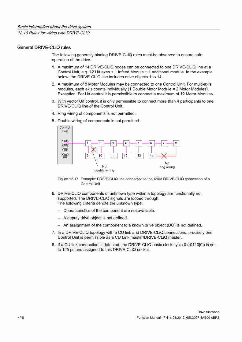
Basic information about the drive system 12.10 Rules for wiring with DRIVE-CLiQ
Drive functions 746 Function Manual, (FH1), 01/2012, 6SL3097-4AB00-0BP2
General DRIVE-CLiQ rules The following generally binding DRIVE-CLiQ rules must be observed to ensure safe operation of the drive.
1. A maximum of 14 DRIVE-CLiQ nodes can be connected to one DRIVE-CLiQ line at a Control Unit, e.g. 12 U/f axes + 1 Infeed Module + 1 additional module. In the example below, the DRIVE-CLiQ line includes drive objects 1 to 14.
2. A maximum of 8 Motor Modules may be connected to one Control Unit. For multi-axis modules, each axis counts individually (1 Double Motor Module = 2 Motor Modules). Exception: For U/f control it is permissible to connect a maximum of 12 Motor Modules.
3. With vector U/f control, it is only permissible to connect more than 4 participants to one DRIVE-CLiQ line of the Control Unit.
4. Ring wiring of components is not permitted.
5. Double wiring of components is not permitted.
Figure 12-17 Example: DRIVE-CLiQ line connected to the X103 DRIVE-CLiQ connection of a
Control Unit
6. DRIVE-CLiQ components of unknown type within a topology are functionally not supported. The DRIVE-CLiQ signals are looped through. The following criteria denote the unknown type:
– Characteristics of the component are not available.
– A deputy drive object is not defined.
– An assignment of the component to a known drive object (DO) is not defined.
7. In a DRIVE-CLiQ topology with a CU link and DRIVE-CLiQ connections, precisely one Control Unit is permissible as a CU Link master/DRIVE-CLiQ master.
8. If a CU link connection is detected, the DRIVE-CLiQ basic clock cycle 0 (r0110[0]) is set to 125 μs and assigned to this DRIVE-CLiQ socket.
Basic information about the drive system 12.10 Rules for wiring with DRIVE-CLiQ
Drive functions Function Manual, (FH1), 01/2012, 6SL3097-4AB00-0BP2 747
9. The following applies for booksize format:
– In the servo control and vector U/f control operating modes, only one Line Module may be connected to the Control Unit. In the vector control operating mode, a maximum of three further Line Modules may be connected in parallel (i.e. at total of 4 Line Modules).
– It is permissible that one Line Module and Motor Modules are connected together to one DRIVE-CLiQ line in the servo control mode.
– One Line Module and Motor Modules must be connected to separate DRIVE-CLiQ lines in the vector control mode.
– For booksize format, a parallel connection of Infeed Modules or Motor Modules is not possible.
10. The following applies for chassis format:
– Line Modules (Active Line, Basic Line, Smart Line) and Motor Modules must be connected to separate DRIVE-CLiQ lines.
11. Parallel operation of power units in chassis format:
– A parallel connection of Infeed Modules as well as Motor Modules is only permitted for vector control or for V/f control.
– A maximum of 4 Infeed Modules are permissible within a parallel connection.
– A maximum of 4 Motor Modules are permissible within a parallel connection.
– Precisely one parallel connection of Motor Modules is permitted. For a parallel connection, precisely one drive object is created in the topology.
12. For a parallel connection of Motor Modules, only one motor with integrated DRIVE-CLiQ interface (SINAMICS Sensor Module Integrated) is permitted for each Motor Module.
13. Switchover between different motors is not permitted for a parallel connection.
14. Mixed operation of Infeed Modules or Motor Modules:
– The operation of Infeed Modules or Motor Modules with different performance values is not permitted within a parallel connection.
– For Line Modules in chassis format, two parallel connections are permissible for mixed operation of Smart Line Modules and Basic Line Modules.
– The following combinations of Line Modules are not permissible: Active Line Module (ALM) with Basic Line Module (BLM) Active Line Module (ALM) with Smart Line Module (SLM)
15. Mixed operation of formats:
– Chassis Motor Modules and booksize Motor Modules must be connected to separate DRIVE-CLiQ lines.
16. Mixed operation of control types:
– Mixed operation of servo control and vector control is not permissible.
– Mixed operation of servo control and U/f control is permissible.
– Mixed operation of vector control and U/f control is permissible.
Basic information about the drive system 12.10 Rules for wiring with DRIVE-CLiQ
Drive functions 748 Function Manual, (FH1), 01/2012, 6SL3097-4AB00-0BP2
17. Mixed operation of control cycles: The following combinations are permissible:
– Servo with 62.5 µs and servo with 125 µs
– Servo with 125 µs servo with 250 µs
– Vector with 250 µs and vector with 500 µs
18. Operation with Voltage Sensing Module (VSM):
– Exactly 1 Voltage Sensing Module (VSM) may be connected to one Line Module. Exception: If the "Line transformer" function module is activated, a second VSM may be connected.
– A maximum of 2 VSMs may be connected to one Motor Module.
– The VSM must be connected to a free DRIVE-CLiQ socket of the associated Line Modules or Motor Modules (to support automatic assignment of the VSM).
19. At a drive object "SERVO" or "VECTOR", up to three encoder data sets can be created for each drive data set. The maximum number of encoder data sets depends on the quantity structure and the current controller clock cycle:
– For a quantity structure of 6 axes in servo control with a controller cycle of 125 μs and one Line Module, it is permissible to connect a maximum of 9 encoders.
– For 5 axes in servo control with a current controller cycle of 125 µs, a maximum of 15 encoders can be connected.
20. A maximum of 24 drive objects (DOs) can be connected.
21. At the CU320-2 Control Unit, a maximum of 16 Terminal Modules can be connected. Note: If a TM15 Base, TM31, TM54F or a TM41 is connected, it is necessary to reduce the number of connected standard axes.
22. At the CU310-2 Control unit a maximum of 8 Terminal Modules, type TM15BASE and TM31 can be connected.
23. At the CU310-2 Control Unit, a maximum of 3 Terminal Modules, type TM15, TM17 or TM41 can be connected.
24. Cycle times with TM31 A maximum of 3 Terminal Modules 31 (TM31) can be connected for a 2 ms time slice.
Note
A Double Motor Module, one DMC20, one DME20, one TM54F and one CUA32 each correspond to two DRIVE-CLiQ participants. This also applies to Double Motor Modules, at which just one drive is configured.
25. The communication basic clock cycles (p0115[0] and p4099) of all components that are connected to a DRIVE-CLiQ line must be divisible by one another with an integer result.
– The smallest communication basic clock cycle is 125 µs.
– The exception are a maximum of 3 servo-controlled axes with 62.5 µs communication basic clock cycle or a servo-controlled axis with 31.25 µs communication basic clock cycle.
Basic information about the drive system 12.10 Rules for wiring with DRIVE-CLiQ
Drive functions Function Manual, (FH1), 01/2012, 6SL3097-4AB00-0BP2 749
26. For current controller clock cycles Ti < 125 μs, the Motor Modules - also with the same controller clock cycle - must be symmetrically connected to two DRIVE-CLiQ ports.
27. The fastest sampling time of a drive object in the servo control mode is obtained as follows:
– Ti = 31.25 µs: Exactly 1 drive object in servo control (only CU 320-2)
– Ti = 62.5 µs: Max. 3 drive objects in servo control (maximum for CU310-2)
– Ti = 125 µs: Max. 6 drive objects in servo control
28. The fastest sampling time of a drive object in vector control mode is obtained as follows:
– Ti = 250 µs: Max. 3 drive objects in vector control
– Ti = 400 µs: Max. 5 drive objects in vector control
– Ti = 500 µs: Max. 6 drive objects in vector control
29. The fastest sampling time of a drive object in vector U/f vector control mode is given as:
– Ti = 500 µs: Max. 12 drive objects in U/f control mode
30. The maximum number of DRIVE-CLiQ nodes on a DRIVE-CLiQ line of the Control Unit 320-2 depends on the basic clock cycle of the DRIVE-CLiQ line:
– For a current controller cycle of 31.25 µs, a maximum of 3 DRIVE-CLiQ nodes are permissible
– For a current controller cycle of 62.5 µs, a maximum of 5 DRIVE-CLiQ nodes are permissible
– For a current controller cycle of 125 µs, a maximum of 14 DRIVE-CLiQ nodes are permissible
– For a current controller cycle of 250 µs, a maximum of 20 DRIVE-CLiQ nodes are permissible
– For a current controller cycle of 500 µs, a maximum of 30 DRIVE-CLiQ nodes are permissible
31. The maximum number of DRIVE-CLiQ nodes on a DRIVE-CLiQ line of the Control Unit 310-2 depends on the basic clock cycle of the DRIVE-CLiQ line:
– From a current controller cycle of 125 µs, a maximum of 8 DRIVE-CLiQ nodes are permissible
32. Examples, CU320-2 with 62.5 µs clock level:
– Topology 1: 1 x ALM (250 µs) + 2 x servo (62.5 µs) + 2 x servo (125 µs) + 3 x TM15 + TM54F + 4 x Safety Integrated Extended Functions with encoder SI Motion monitoring clock cycle (p9500) = 12 ms + SI Motion actual value sensing clock cycle (p9511) = 4 ms + 4 x dir. measuring systems
– Topology 2: 1 x ALM (250 µs) + 2 x servo (62.5 µs) + 2 x U/f (500 µs) + 3 x TM15 Base 2 ms +2 x Safety Integrated Extended Functions with encoder SI Motion monitoring clock cycle (p9500) = 12 ms + SI Motion actual value sensing clock cycle (p9511) = 4 ms + 2 x Safety Integrated Extended Functions sensorless + 2 x dir. measuring systems
– Topology 3: 1 x servo (62.5 μs) + 4 x U/f is not possible in connection with Safety Integrated.
Basic information about the drive system 12.10 Rules for wiring with DRIVE-CLiQ
Drive functions 750 Function Manual, (FH1), 01/2012, 6SL3097-4AB00-0BP2
33. Example, CU320-2 with 31.25 µs clock level:
– Topology 1: 1 ALM (250 µs) on a line, 1 x servo (31.25 µs) on a line, 3 Terminal Modules on a line and in series
– Topology 2: 1 ALM (250 µs) on a line, 1 x servo (31.25 µs) on a line, 1 direct measuring system on a line
34. If the current controller sampling time Ti at one drive object has to be changed in a sampling time that does not match the other drive objects in the DRIVE-CLiQ line, the following solutions are available:
– Insert the modified drive object into a separate DRIVE-CLiQ line.
– Modify the current controller sampling times and/or the sampling times of the inputs/outputs of the other drive objects in the same way, so that they match the modified sampling time again.
35. Only components that have the same sampling time may be be connected to free DRIVE-CLiQ connections with a sampling time of Ti = 31.25 μs. The following components are permissible:
– Sensor Modules
– High-frequency damping modules (HF damping modules)
– Active Line Modules Booksize in the line of the HF filter module.
– Smart Line Modules Booksize in the line of the HF filter module.
– Additional DRIVE-CLiQ lines must be used for additional components: Additional Motor Modules in servo control, in vector control, in U/f control or Terminal Modules.
36. Connection of the following components is not permissible for a sampling time of Ti = 31.25 μs:
– Further Motor Modules in servo control.
– Further Motor Modules in U/f control.
– When using a 310-2 Control Unit.
37. Rules for using a TM54F:
– A TM54F must be connected directly to a Control Unit via DRIVE-CLiQ.
– Only one TM54F Terminal Module can be assigned to each Control Unit.
– On the TM54F, other DRIVE-CLiQ nodes such as Sensor Modules and Terminal Modules can be connected, however not another TM54F.
– In the case of a CU310-2 Control Unit, it is not possible to connect the TM54F to the DRIVE-CLiQ line of a Power Module. The TM54F can only be connected to the sole DRIVE-CLiQ X100 socket of the Control Unit.
38. A maximum of 4 Motor Modules with Safety Extended Functions may be operated on one DRIVE-CLiQ line (only for TI = 125 μs). Additional DRIVE-CLiQ components may not be connected to this DRIVE-CLiQ line.
39. If an axis has only one encoder, and if Safety functions are activated for this axis, then this encoder may be connected to the Motor Module or to the Hub Module DMC20 only.
Basic information about the drive system 12.10 Rules for wiring with DRIVE-CLiQ
Drive functions Function Manual, (FH1), 01/2012, 6SL3097-4AB00-0BP2 751
40. The following applies to the DRIVE-CLiQ connection of CX/NX components to a Control Unit:
The connection to the Control Unit is obtained from the PROFIBUS address of the CX/NX (10 → X100, 11 → X101, 12 → X102, 13 → X103, 14 → X104, 15 → X105).
41. It is not permissible to combine SIMOTION Master Control Units and SINUMERIK Slave Control Units.
42. It is not permissible to combine SINUMERIK Master Control Units and SIMOTION Slave Control Units.
For the CU310-2 Control Unit the following applies:
1. The CU310-2 is a 1-axis control module that is plugged on to a PM340 Power Module
2. When plugged on, in operation, current controller sampling times up to a minimum of 125.00 µs can be selected.
3. The minimum current controller clock cycle that can be selected via the DRIVE-CLiQ connection X100 is 62.5 µs.
4. A current controller clock cycle of 31.25 µs is not possible.
5. The connection to the chassis format is established via the DRIVE-CLiQ connection X100.
12.10.3 Recommended DRIVE-CLiQ rules
Note
To enable the function "Automatic configuration" to assign the encoders to the drives, the recommended rules below must also be observed.
Recommended DRIVE-CLiQ rules 1. The following applies to all DRIVE-CLiQ components with the exception of the Control
Unit: The DRIVE-CLiQ sockets Xx00 are DRIVE-CLiQ inputs, the other DRIVE-CLiQ sockets are outputs.
2. A single Line Module should be connected directly to the X100 DRIVE-CLiQ socket of the Control Unit.
– Several Line Modules should be connected in a line.
– If the X100 DRIVE-CLiQ socket is not available, the next higher DRIVE-CLiQ socket should be used.
3. For a current controller cycle of 31.25 μs, a filter module should be directly connected to a DRIVE-CLiQ socket of the Control Unit.
Basic information about the drive system 12.10 Rules for wiring with DRIVE-CLiQ
Drive functions 752 Function Manual, (FH1), 01/2012, 6SL3097-4AB00-0BP2
4. For the chassis format, Motor Modules with a current controller cycle of 250 μs should be connected to DRIVE-CLiQ socket X101 of the Control Unit. If required, they should be connected in a line.
– If the DRIVE-CLiQ socket X101 is not available, the next higher DRIVE-CLiQ socket should be used for these Motor Modules.
5. For the chassis format, Motor Modules with a current controller cycle of 400 μs should be connected to DRIVE-CLiQ socket X102 of the Control Unit. If required, they should be connected in a line.
– If the DRIVE-CLiQ socket X102 is not available, the next higher DRIVE-CLiQ socket should be used for these Motor Modules.
6. Motor Modules in the chassis format with different pulse frequencies (frame sizes FX, GX, HX, JX) should be connected to separate DRIVE-CLiQ lines.
7. Line Modules and Motor Modules in the chassis format should be connected to separate DRIVE-CLiQ lines.
8. Peripheral components (e.g. Terminal Module, TM) should be connected to DRIVE-CLiQ socket X103 of the Control Unit in a line.
– If the DRIVE-CLiQ socket X103 is not available, any free DRIVE-CLiQ socket can be selected for the peripheral components.
9. In the servo control mode, Motor Modules in the booksize format should be connected to DRIVE-CLiQ socket X100 on the Control Unit in the line.
– If the DRIVE-CLiQ socket X100 is not available, the next higher DRIVE-CLiQ socket should be used for these Motor Modules.
10. The motor encoders for the first drive of a Double Motor Module should be connected to the associated DRIVE-CLiQ socket X202.
11. The motor encoders for the second drive of a Double Motor Module should be connected to the associated DRIVE-CLiQ socket X203.
12. The motor encoder should be connected to the associated Motor Module: Connecting the motor encoder via DRIVE-CLiQ:
– Single Motor Module Booksize to terminal X202
– Double Motor Module Booksize motor X1 to terminal X202 and motor X2 to terminal X203
– Single Motor Module Chassis to terminal X402
– Power Module Blocksize with CUA31: Encoder to terminal X202
– Power Module blocksize with CU310-2: Encoder to terminal X100 or via TM31 to X501
– Power Module Chassis to terminal X402
Note
If an additional encoder is connected to a Motor Module, it is assigned to this drive as encoder 2 in the automatic configuration.
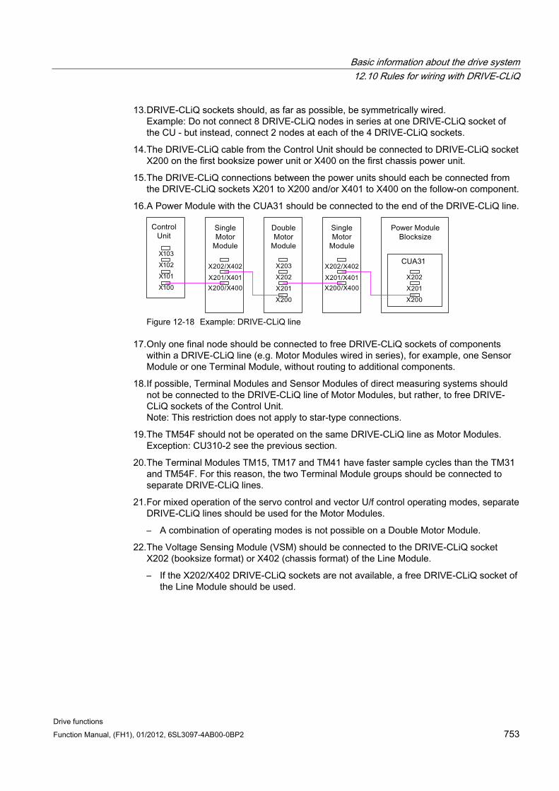
Basic information about the drive system 12.10 Rules for wiring with DRIVE-CLiQ
Drive functions Function Manual, (FH1), 01/2012, 6SL3097-4AB00-0BP2 753
13. DRIVE-CLiQ sockets should, as far as possible, be symmetrically wired. Example: Do not connect 8 DRIVE-CLiQ nodes in series at one DRIVE-CLiQ socket of the CU - but instead, connect 2 nodes at each of the 4 DRIVE-CLiQ sockets.
14. The DRIVE-CLiQ cable from the Control Unit should be connected to DRIVE-CLiQ socket X200 on the first booksize power unit or X400 on the first chassis power unit.
15. The DRIVE-CLiQ connections between the power units should each be connected from the DRIVE-CLiQ sockets X201 to X200 and/or X401 to X400 on the follow-on component.
16. A Power Module with the CUA31 should be connected to the end of the DRIVE-CLiQ line.
Figure 12-18 Example: DRIVE-CLiQ line
17. Only one final node should be connected to free DRIVE-CLiQ sockets of components within a DRIVE-CLiQ line (e.g. Motor Modules wired in series), for example, one Sensor Module or one Terminal Module, without routing to additional components.
18. If possible, Terminal Modules and Sensor Modules of direct measuring systems should not be connected to the DRIVE-CLiQ line of Motor Modules, but rather, to free DRIVE-CLiQ sockets of the Control Unit. Note: This restriction does not apply to star-type connections.
19. The TM54F should not be operated on the same DRIVE-CLiQ line as Motor Modules. Exception: CU310-2 see the previous section.
20. The Terminal Modules TM15, TM17 and TM41 have faster sample cycles than the TM31 and TM54F. For this reason, the two Terminal Module groups should be connected to separate DRIVE-CLiQ lines.
21. For mixed operation of the servo control and vector U/f control operating modes, separate DRIVE-CLiQ lines should be used for the Motor Modules.
– A combination of operating modes is not possible on a Double Motor Module.
22. The Voltage Sensing Module (VSM) should be connected to the DRIVE-CLiQ socket X202 (booksize format) or X402 (chassis format) of the Line Module.
– If the X202/X402 DRIVE-CLiQ sockets are not available, a free DRIVE-CLiQ socket of the Line Module should be used.
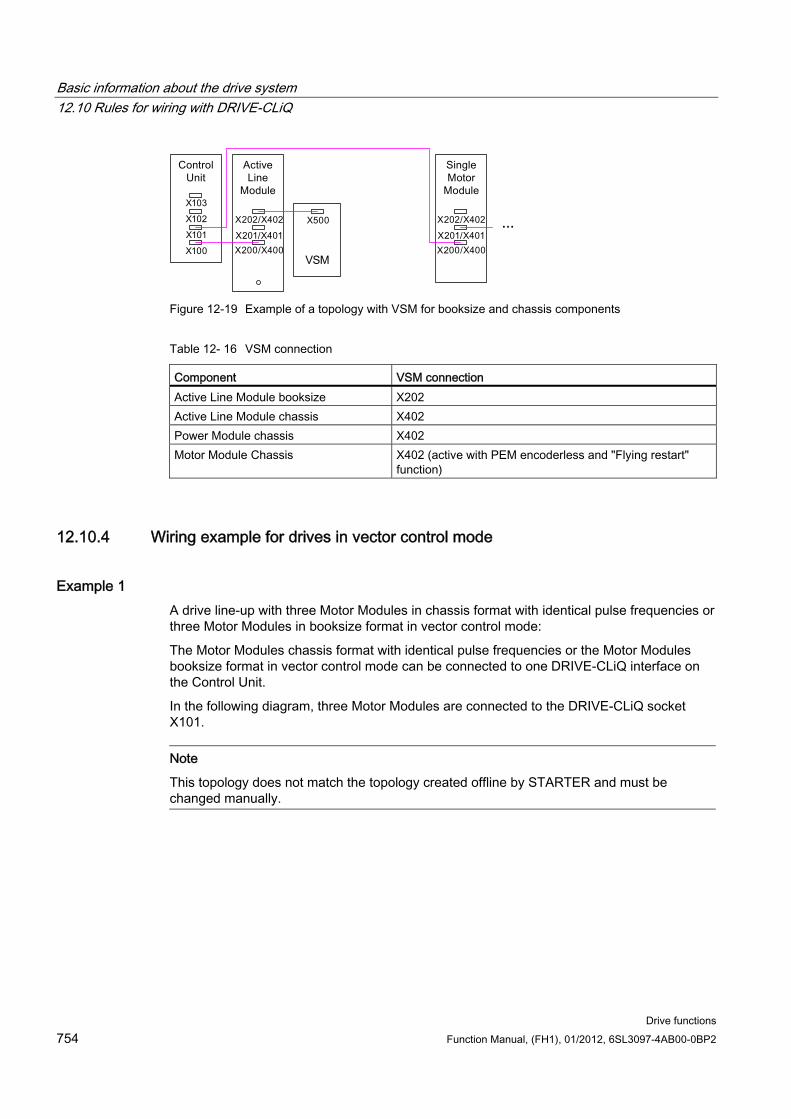
Basic information about the drive system 12.10 Rules for wiring with DRIVE-CLiQ
Drive functions 754 Function Manual, (FH1), 01/2012, 6SL3097-4AB00-0BP2
Figure 12-19 Example of a topology with VSM for booksize and chassis components
Table 12- 16 VSM connection
Component VSM connection Active Line Module booksize X202 Active Line Module chassis X402 Power Module chassis X402 Motor Module Chassis X402 (active with PEM encoderless and "Flying restart"
function)
12.10.4 Wiring example for drives in vector control mode
Example 1 A drive line-up with three Motor Modules in chassis format with identical pulse frequencies or three Motor Modules in booksize format in vector control mode:
The Motor Modules chassis format with identical pulse frequencies or the Motor Modules booksize format in vector control mode can be connected to one DRIVE-CLiQ interface on the Control Unit.
In the following diagram, three Motor Modules are connected to the DRIVE-CLiQ socket X101.
Note
This topology does not match the topology created offline by STARTER and must be changed manually.
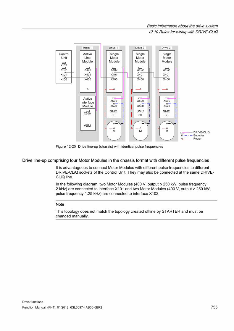
Basic information about the drive system 12.10 Rules for wiring with DRIVE-CLiQ
Drive functions Function Manual, (FH1), 01/2012, 6SL3097-4AB00-0BP2 755
Figure 12-20 Drive line-up (chassis) with identical pulse frequencies
Drive line-up comprising four Motor Modules in the chassis format with different pulse frequencies It is advantageous to connect Motor Modules with different pulse frequencies to different DRIVE-CLiQ sockets of the Control Unit. They may also be connected at the same DRIVE-CLiQ line.
In the following diagram, two Motor Modules (400 V, output ≤ 250 kW, pulse frequency 2 kHz) are connected to interface X101 and two Motor Modules (400 V, output > 250 kW, pulse frequency 1.25 kHz) are connected to interface X102.
Note
This topology does not match the topology created offline by STARTER and must be changed manually.
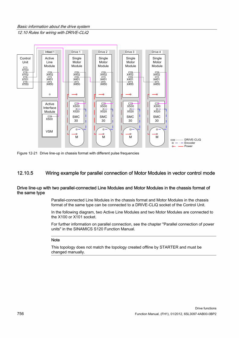
Basic information about the drive system 12.10 Rules for wiring with DRIVE-CLiQ
Drive functions 756 Function Manual, (FH1), 01/2012, 6SL3097-4AB00-0BP2
Figure 12-21 Drive line-up in chassis format with different pulse frequencies
12.10.5 Wiring example for parallel connection of Motor Modules in vector control mode
Drive line-up with two parallel-connected Line Modules and Motor Modules in the chassis format of the same type
Parallel-connected Line Modules in the chassis format and Motor Modules in the chassis format of the same type can be connected to a DRIVE-CLiQ socket of the Control Unit.
In the following diagram, two Active Line Modules and two Motor Modules are connected to the X100 or X101 socket.
For further information on parallel connection, see the chapter "Parallel connection of power units" in the SINAMICS S120 Function Manual.
Note
This topology does not match the topology created offline by STARTER and must be changed manually.
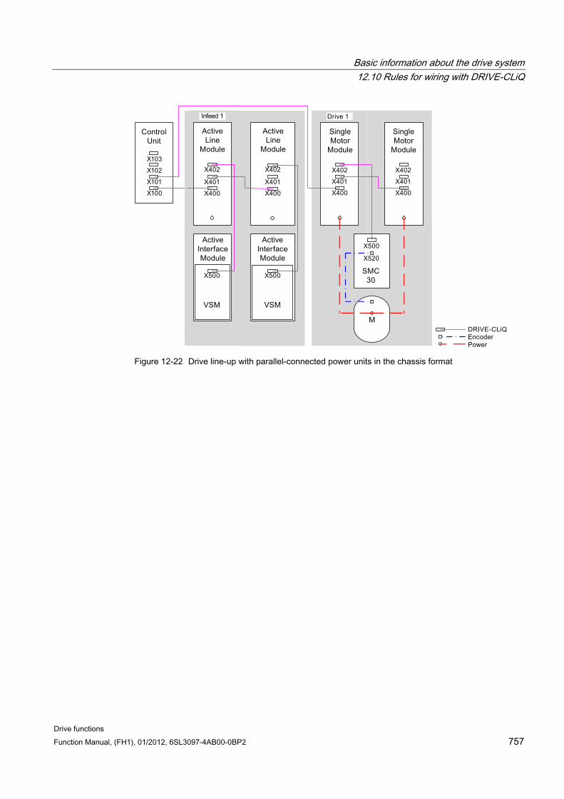
Basic information about the drive system 12.10 Rules for wiring with DRIVE-CLiQ
Drive functions Function Manual, (FH1), 01/2012, 6SL3097-4AB00-0BP2 757
Figure 12-22 Drive line-up with parallel-connected power units in the chassis format
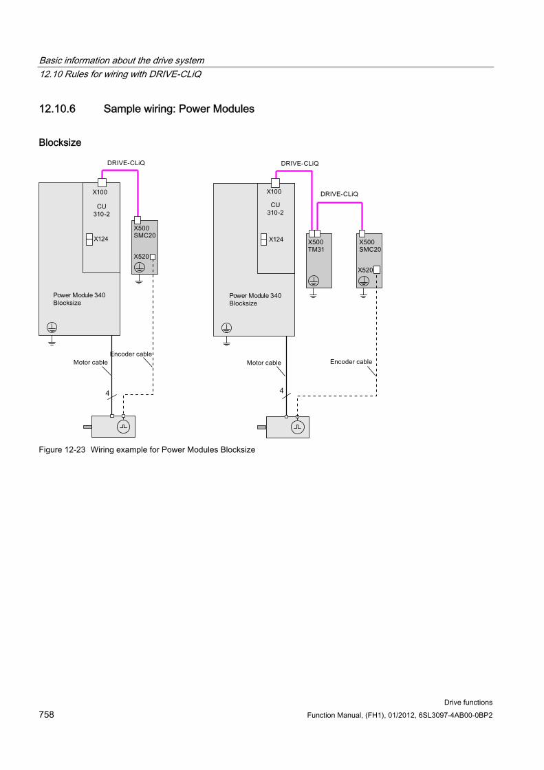
Basic information about the drive system 12.10 Rules for wiring with DRIVE-CLiQ
Drive functions 758 Function Manual, (FH1), 01/2012, 6SL3097-4AB00-0BP2
12.10.6 Sample wiring: Power Modules
Blocksize
Figure 12-23 Wiring example for Power Modules Blocksize
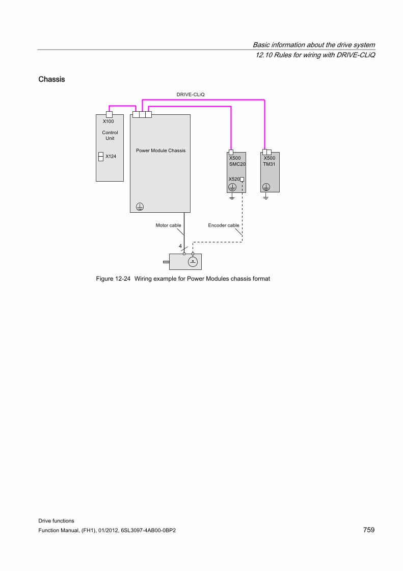
Basic information about the drive system 12.10 Rules for wiring with DRIVE-CLiQ
Drive functions Function Manual, (FH1), 01/2012, 6SL3097-4AB00-0BP2 759
Chassis
Figure 12-24 Wiring example for Power Modules chassis format
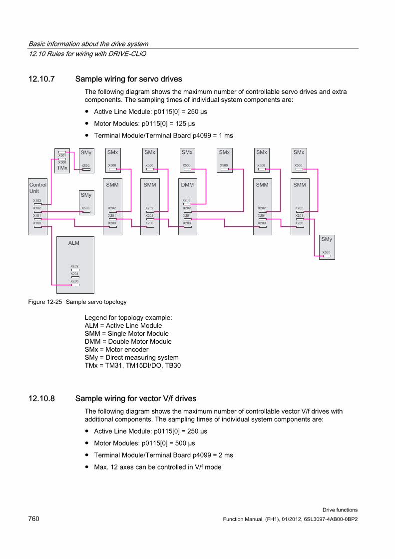
Basic information about the drive system 12.10 Rules for wiring with DRIVE-CLiQ
Drive functions 760 Function Manual, (FH1), 01/2012, 6SL3097-4AB00-0BP2
12.10.7 Sample wiring for servo drives The following diagram shows the maximum number of controllable servo drives and extra components. The sampling times of individual system components are:
Active Line Module: p0115[0] = 250 µs
Motor Modules: p0115[0] = 125 µs
Terminal Module/Terminal Board p4099 = 1 ms
Figure 12-25 Sample servo topology
Legend for topology example: ALM = Active Line Module SMM = Single Motor Module DMM = Double Motor Module SMx = Motor encoder SMy = Direct measuring system TMx = TM31, TM15DI/DO, TB30
12.10.8 Sample wiring for vector V/f drives The following diagram shows the maximum number of controllable vector V/f drives with additional components. The sampling times of individual system components are:
Active Line Module: p0115[0] = 250 µs
Motor Modules: p0115[0] = 500 µs
Terminal Module/Terminal Board p4099 = 2 ms
Max. 12 axes can be controlled in V/f mode
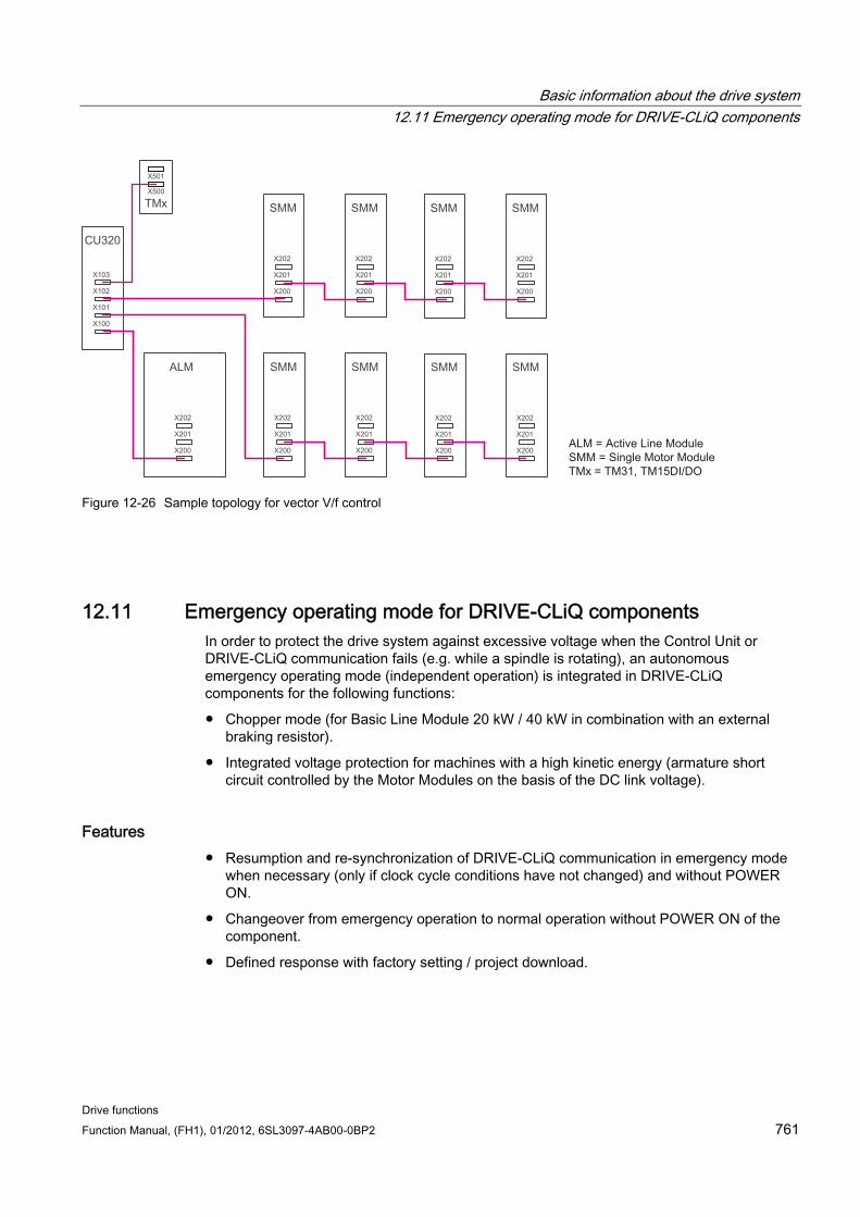
Basic information about the drive system 12.11 Emergency operating mode for DRIVE-CLiQ components
Drive functions Function Manual, (FH1), 01/2012, 6SL3097-4AB00-0BP2 761
Figure 12-26 Sample topology for vector V/f control
12.11 Emergency operating mode for DRIVE-CLiQ components In order to protect the drive system against excessive voltage when the Control Unit or DRIVE-CLiQ communication fails (e.g. while a spindle is rotating), an autonomous emergency operating mode (independent operation) is integrated in DRIVE-CLiQ components for the following functions:
Chopper mode (for Basic Line Module 20 kW / 40 kW in combination with an external braking resistor).
Integrated voltage protection for machines with a high kinetic energy (armature short circuit controlled by the Motor Modules on the basis of the DC link voltage).
Features Resumption and re-synchronization of DRIVE-CLiQ communication in emergency mode
when necessary (only if clock cycle conditions have not changed) and without POWER ON.
Changeover from emergency operation to normal operation without POWER ON of the component.
Defined response with factory setting / project download.
Basic information about the drive system 12.11 Emergency operating mode for DRIVE-CLiQ components
Drive functions 762 Function Manual, (FH1), 01/2012, 6SL3097-4AB00-0BP2
Note
Autonomous (emergency) operation is only possible for Motor Modules and Basic Line Modules with order numbers which end with the code ..3, e.g. 6SL3130-6TE21-6AA3, .
Principle of operation Two task profiles are obtained for autonomous operation:
Recognize that a component is getting into a critical state and the protective function must be maintained.
Restore communication with the higher-level control.
In order to maintain the protective function, the time-slice system must remain active. The logged-on time-slice system remains active until the protective functions signal that a safe state has been reached and the time slices can therefore be deactivated. When restarting the communication, if the DRIVE-CLiQ master signals that no bus timing changes have been made with respect to the old parameterization, then synchronization is possible. The time-slice system remains the same as before.
Note
All algorithms for autonomous operation are executed as a background process for the component. They thus have no influence on the computer resources utilized cyclically by the component.
Communication restart includes a topology detection during emergency operation.
Note
When the component is running in emergency mode, it cannot be deactivated.
Preparation for autonomous time-slice operation The application signals (basic system DRIVE-CLiQ slave components) preparation for autonomous time-slice operation. This occurs, for example, when the "armature short circuit" protective function is active or in chopper operation.
Changeover from normal to autonomous operation The application activates autonomous time-slice operation. Changeover takes place instantaneously.
Changeover from autonomous to normal operation It is always possible to change over into normal operation without a POWER ON.
Basic information about the drive system 12.12 System sampling times and number of controllable drives
Drive functions Function Manual, (FH1), 01/2012, 6SL3097-4AB00-0BP2 763
Resumption of DRIVE-CLiQ communication when autonomous mode is active A distinction must be made between the two operating states below:
The DRIVE-CLiQ bus timing, e.g. clock cycle settings, has not changed since the component last booted: The DRIVE-CLiQ component boots in cyclic mode.
The DRIVE-CLiQ timing has changed: Autonomous operation must continue at all costs. The DRIVE-CLiQ component refuses to boot until the application signals that autonomous operation is no longer required. The component can then restart with the modified clock cycle settings.
The component may already be running when the second download takes place. To permit a second download (reparameterization, factory setting, ...), the DRIVE-CLiQ master must "deactivate" the protective function (if one is selected) and thus also autonomous time-slice operation. All timing changes can be accepted in this state.
The DRIVE-CLiQ master performs a relevance check on the download (relevant here means only those settings which affect the time-slice behavior of the component).
Reconfigurations which must be linked to the DRIVE-CLiQ slave with message "Timing change" are
Changes to the DRIVE-CLiQ clock cycle for the component
Changes to oversampling settings which require internal reconfiguration of the time-slice system.
Please also note the following:
Changes to component connections and longer cables between components require adjustments to signal propagation delays and therefore also change the timing.
12.12 System sampling times and number of controllable drives The software functions installed in the system are executed cyclically with different sampling times (p0115, p0799, p4099).
The sampling times of the functions are automatically pre-assigned when configuring the drive unit.
These settings are based on the selected mode (vector/servo), the number of connected components, and the functions activated.
The sampling times can be adjusted using parameter p0112 (sampling times, pre-setting p0115), p0113 (pulse frequency, minimum selection) or directly using p0115.
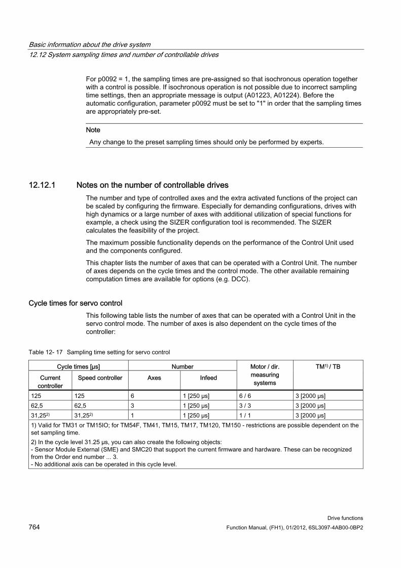
Basic information about the drive system 12.12 System sampling times and number of controllable drives
Drive functions 764 Function Manual, (FH1), 01/2012, 6SL3097-4AB00-0BP2
For p0092 = 1, the sampling times are pre-assigned so that isochronous operation together with a control is possible. If isochronous operation is not possible due to incorrect sampling time settings, then an appropriate message is output (A01223, A01224). Before the automatic configuration, parameter p0092 must be set to "1" in order that the sampling times are appropriately pre-set.
Note
Any change to the preset sampling times should only be performed by experts.
12.12.1 Notes on the number of controllable drives The number and type of controlled axes and the extra activated functions of the project can be scaled by configuring the firmware. Especially for demanding configurations, drives with high dynamics or a large number of axes with additional utilization of special functions for example, a check using the SIZER configuration tool is recommended. The SIZER calculates the feasibility of the project.
The maximum possible functionality depends on the performance of the Control Unit used and the components configured.
This chapter lists the number of axes that can be operated with a Control Unit. The number of axes depends on the cycle times and the control mode. The other available remaining computation times are available for options (e.g. DCC).
Cycle times for servo control This following table lists the number of axes that can be operated with a Control Unit in the servo control mode. The number of axes is also dependent on the cycle times of the controller:
Table 12- 17 Sampling time setting for servo control
Cycle times [µs] Number
Current controller
Speed controller Axes Infeed
Motor / dir. measuring systems
TM1) / TB
125 125 6 1 [250 μs] 6 / 6 3 [2000 μs] 62,5 62,5 3 1 [250 μs] 3 / 3 3 [2000 μs] 31,252) 31,252) 1 1 [250 μs] 1 / 1 3 [2000 μs] 1) Valid for TM31 or TM15IO; for TM54F, TM41, TM15, TM17, TM120, TM150 - restrictions are possible dependent on the set sampling time. 2) In the cycle level 31.25 µs, you can also create the following objects: - Sensor Module External (SME) and SMC20 that support the current firmware and hardware. These can be recognized from the Order end number ... 3. - No additional axis can be operated in this cycle level.
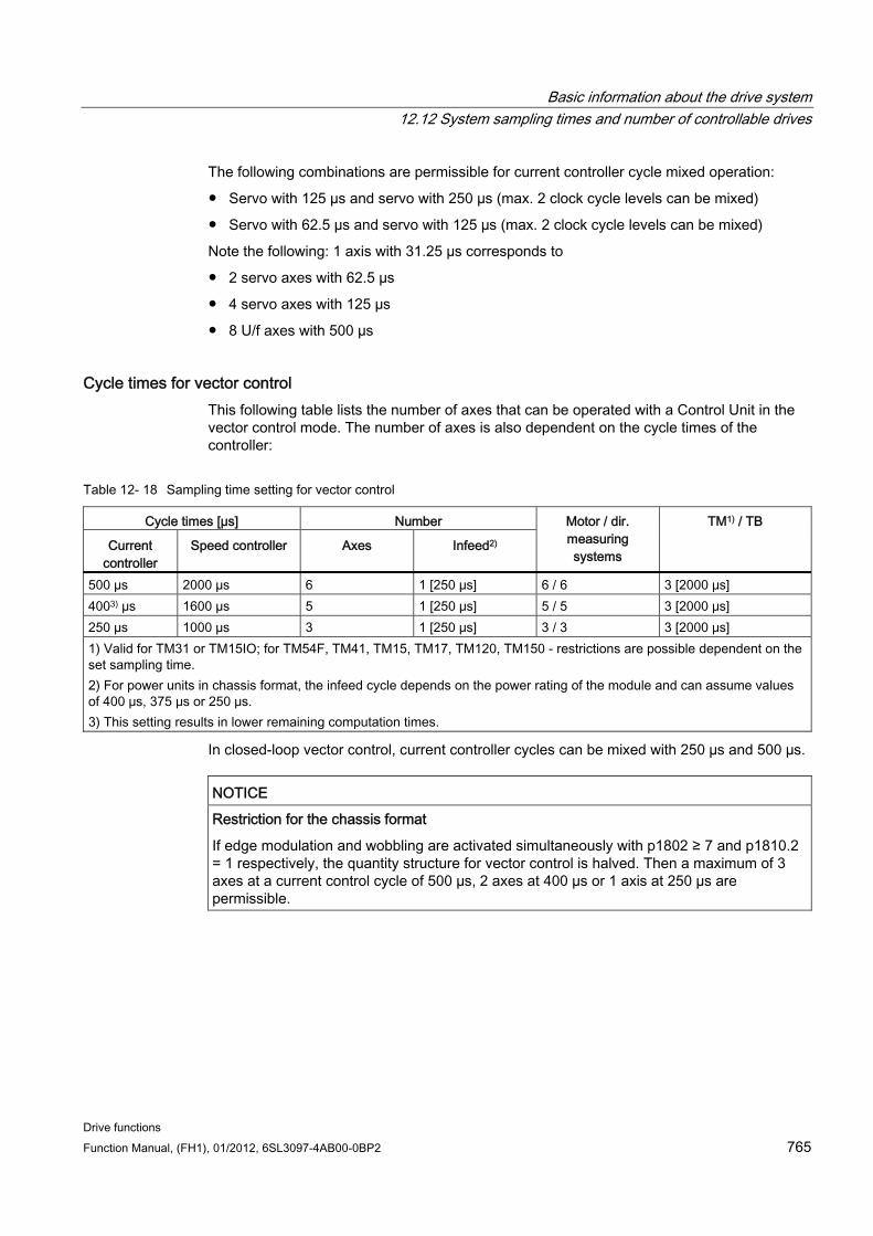
Basic information about the drive system 12.12 System sampling times and number of controllable drives
Drive functions Function Manual, (FH1), 01/2012, 6SL3097-4AB00-0BP2 765
The following combinations are permissible for current controller cycle mixed operation:
Servo with 125 µs and servo with 250 µs (max. 2 clock cycle levels can be mixed)
Servo with 62.5 µs and servo with 125 µs (max. 2 clock cycle levels can be mixed)
Note the following: 1 axis with 31.25 µs corresponds to
2 servo axes with 62.5 µs
4 servo axes with 125 µs
8 U/f axes with 500 µs
Cycle times for vector control This following table lists the number of axes that can be operated with a Control Unit in the vector control mode. The number of axes is also dependent on the cycle times of the controller:
Table 12- 18 Sampling time setting for vector control
Cycle times [µs] Number
Current controller
Speed controller Axes Infeed2)
Motor / dir. measuring systems
TM1) / TB
500 µs 2000 µs 6 1 [250 μs] 6 / 6 3 [2000 μs] 4003) µs 1600 µs 5 1 [250 μs] 5 / 5 3 [2000 μs] 250 µs 1000 µs 3 1 [250 μs] 3 / 3 3 [2000 μs] 1) Valid for TM31 or TM15IO; for TM54F, TM41, TM15, TM17, TM120, TM150 - restrictions are possible dependent on the set sampling time. 2) For power units in chassis format, the infeed cycle depends on the power rating of the module and can assume values of 400 μs, 375 μs or 250 μs. 3) This setting results in lower remaining computation times.
In closed-loop vector control, current controller cycles can be mixed with 250 µs and 500 µs.
NOTICE Restriction for the chassis format
If edge modulation and wobbling are activated simultaneously with p1802 ≥ 7 and p1810.2 = 1 respectively, the quantity structure for vector control is halved. Then a maximum of 3 axes at a current control cycle of 500 µs, 2 axes at 400 µs or 1 axis at 250 µs are permissible.
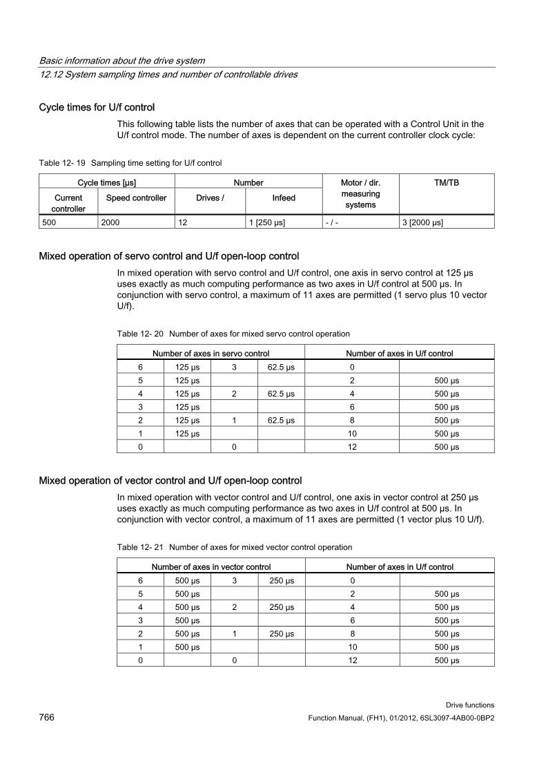
Basic information about the drive system 12.12 System sampling times and number of controllable drives
Drive functions 766 Function Manual, (FH1), 01/2012, 6SL3097-4AB00-0BP2
Cycle times for U/f control This following table lists the number of axes that can be operated with a Control Unit in the U/f control mode. The number of axes is dependent on the current controller clock cycle:
Table 12- 19 Sampling time setting for U/f control
Cycle times [µs] Number
Current controller
Speed controller Drives / Infeed
Motor / dir. measuring systems
TM/TB
500 2000 12 1 [250 μs] - / - 3 [2000 μs]
Mixed operation of servo control and U/f open-loop control In mixed operation with servo control and U/f control, one axis in servo control at 125 µs uses exactly as much computing performance as two axes in U/f control at 500 µs. In conjunction with servo control, a maximum of 11 axes are permitted (1 servo plus 10 vector U/f).
Table 12- 20 Number of axes for mixed servo control operation
Number of axes in servo control Number of axes in U/f control 6 125 µs 3 62.5 µs 0 5 125 µs 2 500 µs 4 125 µs 2 62.5 µs 4 500 µs 3 125 µs 6 500 µs 2 125 µs 1 62.5 µs 8 500 µs 1 125 µs 10 500 µs 0 0 12 500 µs
Mixed operation of vector control and U/f open-loop control In mixed operation with vector control and U/f control, one axis in vector control at 250 µs uses exactly as much computing performance as two axes in U/f control at 500 µs. In conjunction with vector control, a maximum of 11 axes are permitted (1 vector plus 10 U/f).
Table 12- 21 Number of axes for mixed vector control operation
Number of axes in vector control Number of axes in U/f control 6 500 µs 3 250 µs 0 5 500 µs 2 500 µs 4 500 µs 2 250 µs 4 500 µs 3 500 µs 6 500 µs 2 500 µs 1 250 µs 8 500 µs 1 500 µs 10 500 µs 0 0 12 500 µs
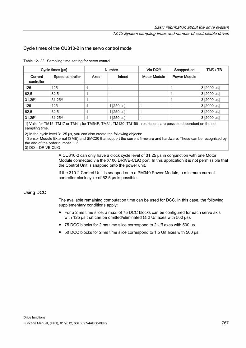
Basic information about the drive system 12.12 System sampling times and number of controllable drives
Drive functions Function Manual, (FH1), 01/2012, 6SL3097-4AB00-0BP2 767
Cycle times of the CU310-2 in the servo control mode
Table 12- 22 Sampling time setting for servo control
Cycle times [µs] Number Via DQ3) Snapped-on
Current controller
Speed controller Axes Infeed Motor Module Power Module
TM1) / TB
125 125 1 - - 1 3 [2000 μs] 62,5 62,5 1 - - 1 3 [2000 μs] 31,252) 31,252) 1 - - 1 3 [2000 μs] 125 125 1 1 [250 μs] 1 - 3 [2000 μs] 62,5 62,5 1 1 [250 μs] 1 - 3 [2000 μs] 31,252) 31,252) 1 1 [250 μs] 1 - 3 [2000 μs] 1) Valid for TM15, TM17 or TM41; for TM54F, TM31, TM120, TM150 - restrictions are possible dependent on the set sampling time. 2) In the cycle level 31.25 µs, you can also create the following objects: - Sensor Module External (SME) and SMC20 that support the current firmware and hardware. These can be recognized by the end of the order number ... 3. 3) DQ = DRIVE-CLiQ
A CU310-2 can only have a clock cycle level of 31.25 µs in conjunction with one Motor Module connected via the X100 DRIVE-CLiQ port. In this application it is not permissible that the Control Unit is snapped onto the power unit.
If the 310-2 Control Unit is snapped onto a PM340 Power Module, a minimum current controller clock cycle of 62.5 µs is possible.
Using DCC The available remaining computation time can be used for DCC. In this case, the following supplementary conditions apply:
For a 2 ms time slice, a max. of 75 DCC blocks can be configured for each servo axis with 125 μs that can be omitted/eliminated (≙ 2 U/f axes with 500 μs).
75 DCC blocks for 2 ms time slice correspond to 2 U/f axes with 500 μs.
50 DCC blocks for 2 ms time slice correspond to 1.5 U/f axes with 500 μs.
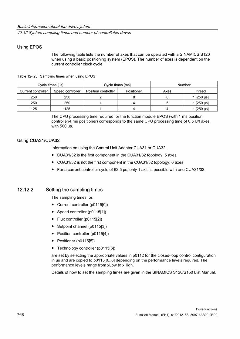
Basic information about the drive system 12.12 System sampling times and number of controllable drives
Drive functions 768 Function Manual, (FH1), 01/2012, 6SL3097-4AB00-0BP2
Using EPOS The following table lists the number of axes that can be operated with a SINAMICS S120 when using a basic positioning system (EPOS). The number of axes is dependent on the current controller clock cycle.
Table 12- 23 Sampling times when using EPOS
Cycle times [µs] Cycle times [ms] Number Current controller Speed controller Position controller Positioner Axes Infeed
250 250 2 8 6 1 [250 μs] 250 250 1 4 5 1 [250 μs] 125 125 1 4 4 1 [250 μs]
The CPU processing time required for the function module EPOS (with 1 ms position controller/4 ms positioner) corresponds to the same CPU processing time of 0.5 U/f axes with 500 μs.
Using CUA31/CUA32 Information on using the Control Unit Adapter CUA31 or CUA32:
CUA31/32 is the first component in the CUA31/32 topology: 5 axes
CUA31/32 is not the first component in the CUA31/32 topology: 6 axes
For a current controller cycle of 62.5 µs, only 1 axis is possible with one CUA31/32.
12.12.2 Setting the sampling times The sampling times for:
Current controller (p0115[0])
Speed controller (p0115[1])
Flux controller (p0115[2])
Setpoint channel (p0115[3])
Position controller (p0115[4])
Positioner (p0115[5])
Technology controller (p0115[6])
are set by selecting the appropriate values in p0112 for the closed-loop control configuration in µs and are copied to p0115[0...6] depending on the performance levels required. The performance levels range from xLow to xHigh.
Details of how to set the sampling times are given in the SINAMICS S120/S150 List Manual.
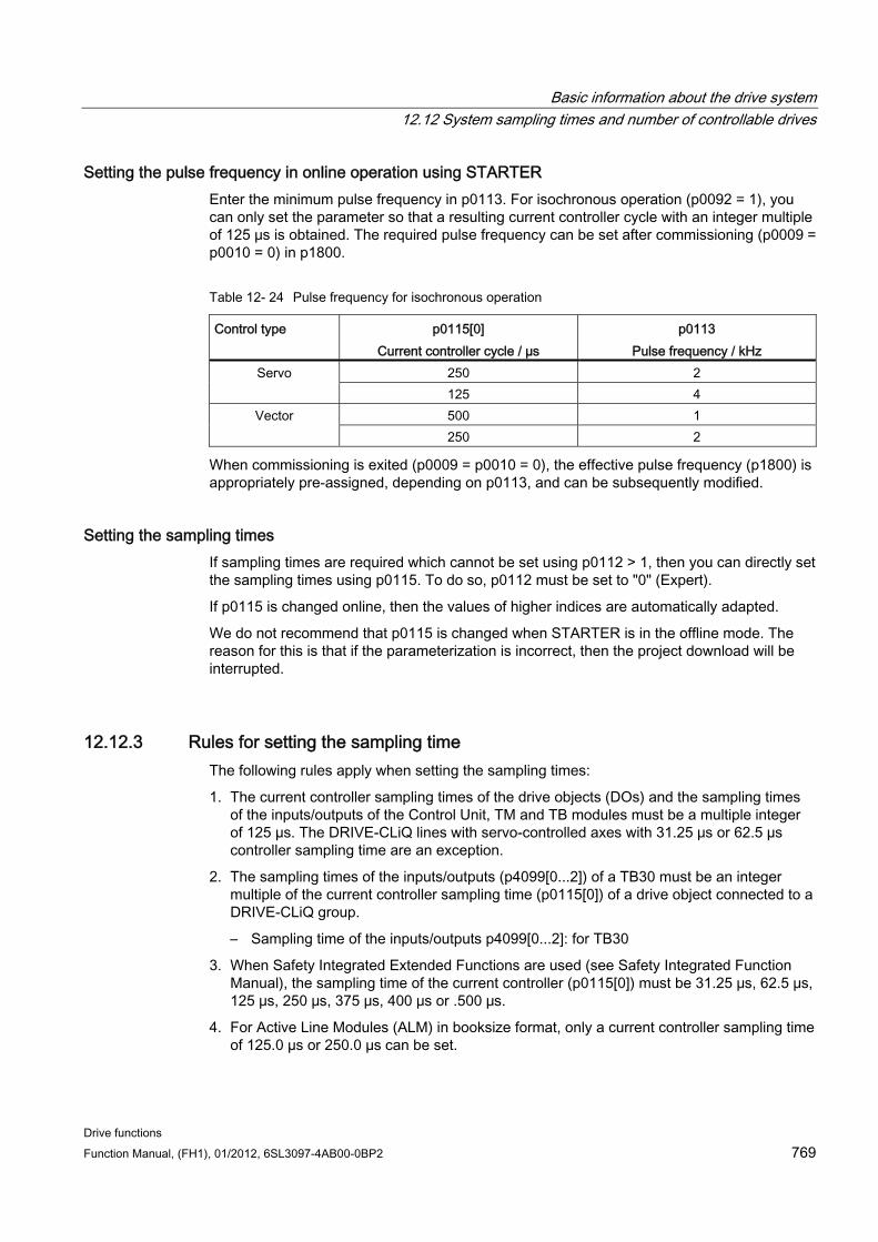
Basic information about the drive system 12.12 System sampling times and number of controllable drives
Drive functions Function Manual, (FH1), 01/2012, 6SL3097-4AB00-0BP2 769
Setting the pulse frequency in online operation using STARTER Enter the minimum pulse frequency in p0113. For isochronous operation (p0092 = 1), you can only set the parameter so that a resulting current controller cycle with an integer multiple of 125 μs is obtained. The required pulse frequency can be set after commissioning (p0009 = p0010 = 0) in p1800.
Table 12- 24 Pulse frequency for isochronous operation
Control type p0115[0] Current controller cycle / µs
p0113 Pulse frequency / kHz
250 2 Servo 125 4 500 1 Vector 250 2
When commissioning is exited (p0009 = p0010 = 0), the effective pulse frequency (p1800) is appropriately pre-assigned, depending on p0113, and can be subsequently modified.
Setting the sampling times If sampling times are required which cannot be set using p0112 > 1, then you can directly set the sampling times using p0115. To do so, p0112 must be set to "0" (Expert).
If p0115 is changed online, then the values of higher indices are automatically adapted.
We do not recommend that p0115 is changed when STARTER is in the offline mode. The reason for this is that if the parameterization is incorrect, then the project download will be interrupted.
12.12.3 Rules for setting the sampling time The following rules apply when setting the sampling times:
1. The current controller sampling times of the drive objects (DOs) and the sampling times of the inputs/outputs of the Control Unit, TM and TB modules must be a multiple integer of 125 µs. The DRIVE-CLiQ lines with servo-controlled axes with 31.25 μs or 62.5 µs controller sampling time are an exception.
2. The sampling times of the inputs/outputs (p4099[0...2]) of a TB30 must be an integer multiple of the current controller sampling time (p0115[0]) of a drive object connected to a DRIVE-CLiQ group.
– Sampling time of the inputs/outputs p4099[0...2]: for TB30
3. When Safety Integrated Extended Functions are used (see Safety Integrated Function Manual), the sampling time of the current controller (p0115[0]) must be 31.25 μs, 62.5 μs, 125 μs, 250 μs, 375 μs, 400 μs or .500 μs.
4. For Active Line Modules (ALM) in booksize format, only a current controller sampling time of 125.0 µs or 250.0 µs can be set.
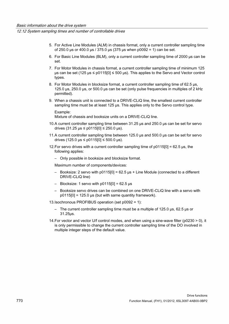
Basic information about the drive system 12.12 System sampling times and number of controllable drives
Drive functions 770 Function Manual, (FH1), 01/2012, 6SL3097-4AB00-0BP2
5. For Active Line Modules (ALM) in chassis format, only a current controller sampling time of 250.0 µs or 400.0 µs / 375.0 µs (375 µs when p0092 = 1) can be set.
6. For Basic Line Modules (BLM), only a current controller sampling time of 2000 µs can be set.
7. For Motor Modules in chassis format, a current controller sampling time of minimum 125 µs can be set (125 µs ≤ p0115[0] ≤ 500 µs). This applies to the Servo and Vector control types.
8. For Motor Modules in blocksize format, a current controller sampling time of 62.5 µs, 125.0 µs, 250.0 µs, or 500.0 µs can be set (only pulse frequencies in multiples of 2 kHz permitted).
9. When a chassis unit is connected to a DRIVE-CLiQ line, the smallest current controller sampling time must be at least 125 µs. This applies only to the Servo control type.
Example: Mixture of chassis and booksize units on a DRIVE-CLiQ line.
10. A current controller sampling time between 31.25 µs and 250.0 µs can be set for servo drives (31.25 µs ≤ p0115[0] ≤ 250.0 µs).
11. A current controller sampling time between 125.0 µs and 500.0 µs can be set for servo drives (125.0 µs ≤ p0115[0] ≤ 500.0 µs).
12. For servo drives with a current controller sampling time of p0115[0] = 62.5 µs, the following applies:
– Only possible in booksize and blocksize format.
Maximum number of components/devices:
– Booksize: 2 servo with p0115[0] = 62.5 µs + Line Module (connected to a different DRIVE-CLiQ line)
– Blocksize: 1 servo with p0115[0] = 62.5 µs
– Booksize servo drives can be combined on one DRIVE-CLiQ line with a servo with p0115[0] = 125.0 µs (but with same quantity framework).
13. Isochronous PROFIBUS operation (set p0092 = 1):
– The current controller sampling time must be a multiple of 125.0 µs, 62.5 µs or 31.25μs.
14. For vector and vector U/f control modes, and when using a sine-wave filter (p0230 > 0), it is only permissible to change the current controller sampling time of the DO involved in multiple integer steps of the default value.
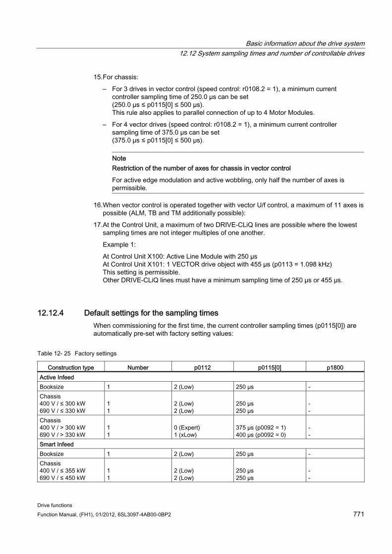
Basic information about the drive system 12.12 System sampling times and number of controllable drives
Drive functions Function Manual, (FH1), 01/2012, 6SL3097-4AB00-0BP2 771
15. For chassis:
– For 3 drives in vector control (speed control: r0108.2 = 1), a minimum current controller sampling time of 250.0 µs can be set (250.0 µs ≤ p0115[0] ≤ 500 µs). This rule also applies to parallel connection of up to 4 Motor Modules.
– For 4 vector drives (speed control: r0108.2 = 1), a minimum current controller sampling time of 375.0 µs can be set (375.0 µs ≤ p0115[0] ≤ 500 µs).
Note Restriction of the number of axes for chassis in vector control
For active edge modulation and active wobbling, only half the number of axes is permissible.
16. When vector control is operated together with vector U/f control, a maximum of 11 axes is possible (ALM, TB and TM additionally possible):
17. At the Control Unit, a maximum of two DRIVE-CLiQ lines are possible where the lowest sampling times are not integer multiples of one another.
Example 1:
At Control Unit X100: Active Line Module with 250 µs At Control Unit X101: 1 VECTOR drive object with 455 µs (p0113 = 1.098 kHz) This setting is permissible. Other DRIVE-CLiQ lines must have a minimum sampling time of 250 µs or 455 µs.
12.12.4 Default settings for the sampling times When commissioning for the first time, the current controller sampling times (p0115[0]) are automatically pre-set with factory setting values:
Table 12- 25 Factory settings
Construction type Number p0112 p0115[0] p1800 Active Infeed Booksize 1 2 (Low) 250 µs - Chassis 400 V / ≤ 300 kW 690 V / ≤ 330 kW
1 1
2 (Low) 2 (Low)
250 µs 250 µs
- -
Chassis 400 V / > 300 kW 690 V / > 330 kW
1 1
0 (Expert) 1 (xLow)
375 µs (p0092 = 1) 400 µs (p0092 = 0)
- -
Smart Infeed Booksize 1 2 (Low) 250 µs - Chassis 400 V / ≤ 355 kW 690 V / ≤ 450 kW
1 1
2 (Low) 2 (Low)
250 µs 250 µs
- -
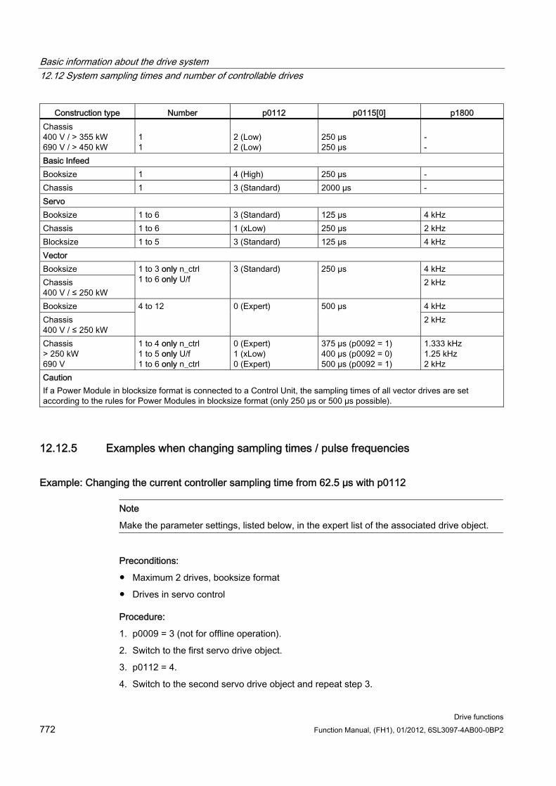
Basic information about the drive system 12.12 System sampling times and number of controllable drives
Drive functions 772 Function Manual, (FH1), 01/2012, 6SL3097-4AB00-0BP2
Construction type Number p0112 p0115[0] p1800 Chassis 400 V / > 355 kW 690 V / > 450 kW
1 1
2 (Low) 2 (Low)
250 µs 250 µs
- -
Basic Infeed Booksize 1 4 (High) 250 µs - Chassis 1 3 (Standard) 2000 µs - Servo Booksize 1 to 6 3 (Standard) 125 µs 4 kHz Chassis 1 to 6 1 (xLow) 250 µs 2 kHz Blocksize 1 to 5 3 (Standard) 125 µs 4 kHz Vector Booksize 4 kHz Chassis 400 V / ≤ 250 kW
1 to 3 only n_ctrl 1 to 6 only U/f
3 (Standard) 250 µs 2 kHz
Booksize 4 kHz Chassis 400 V / ≤ 250 kW
4 to 12 0 (Expert) 500 µs 2 kHz
Chassis > 250 kW 690 V
1 to 4 only n_ctrl 1 to 5 only U/f 1 to 6 only n_ctrl
0 (Expert) 1 (xLow) 0 (Expert)
375 µs (p0092 = 1) 400 µs (p0092 = 0) 500 µs (p0092 = 1)
1.333 kHz 1.25 kHz 2 kHz
Caution If a Power Module in blocksize format is connected to a Control Unit, the sampling times of all vector drives are set according to the rules for Power Modules in blocksize format (only 250 µs or 500 µs possible).
12.12.5 Examples when changing sampling times / pulse frequencies
Example: Changing the current controller sampling time from 62.5 µs with p0112
Note
Make the parameter settings, listed below, in the expert list of the associated drive object.
Preconditions:
Maximum 2 drives, booksize format
Drives in servo control
Procedure:
1. p0009 = 3 (not for offline operation).
2. Switch to the first servo drive object.
3. p0112 = 4.
4. Switch to the second servo drive object and repeat step 3.
Basic information about the drive system 12.12 System sampling times and number of controllable drives
Drive functions Function Manual, (FH1), 01/2012, 6SL3097-4AB00-0BP2 773
5. p0009 = 0 (not for offline operation).
6. When STARTER is in offline mode: Download into the drive.
7. Save the parameter changes in a non-volatile fashion using the function "Copy RAM to ROM" (see also the Commissioning Manual).
8. We recommend that the controller settings are recalculated (p0340 = 4).
Example: Changing the pulse frequency with p0113
Preconditions:
STARTER is in the online mode.
Assumption:
A TB30 has been installed.
Drives in servo control
Procedure:
1. p0009 = 3 (not for offline operation).
2. Switch to the first servo drive object.
3. p0112 = 0.
4. Enter the required minimum pulse frequency in p0113.
If this pulse of frequency contradicts rule 1 for setting the sampling times, an alarm is output and a suitable pulse frequency is recommended in p0114. The current controller sampling times of the drive objects (DOs) and the sampling time of the inputs/outputs of the Control Unit, TM and TB modules must be a multiple integer of 125 µs. This can be entered in p0113 (remember to take into account the rules for setting the sampling times).
5. Switch to the second servo drive object and repeat steps 3 and 4.
6. Switch to the drive object TB30.
7. Set the three sampling times p4099[0..2] to a multiple of the current controller sampling time of a servo drive.
8. p0009 = 0. Note: The pulse frequency in p1800 is automatically adapted.
9. Save the parameter changes in a non-volatile fashion using the function "Copy RAM to ROM" (see also the SINAMICS S120 Commissioning Manual).
10. We recommend that the controller settings are recalculated (p0340 = 4).
12.12.6 Overview of important parameters (see SINAMICS S120/S150 List Manual) p0009 Device commissioning, parameter filter
p0092 Isochronous PROFIBUS operation, pre-assignment/check
p0097 Selects the drive object type
Basic information about the drive system 12.13 Licensing
Drive functions 774 Function Manual, (FH1), 01/2012, 6SL3097-4AB00-0BP2
r0110 [0...2] DRIVE-CLiQ basic sampling times
p0112 Sampling times pre-setting p0115
p0113 Selects the minimum pulse frequency
r0114 Recommended minimum pulse frequency
p0115[0...6] Sampling times for internal control loops
r0116 Recommended drive sampling time
p0118 Current controller computation deadtime
p0799 CU inputs/outputs sampling time
p1800 Pulse frequency
p4099 Inputs/outputs sampling time
r9780 SI monitoring clock cycle (Control Unit)
r9880 SI monitoring clock cycle (Motor Module)
12.13 Licensing
Description To use the SINAMICS S120 drive system and the activated options, you need to assign the corresponding licenses to the hardware. When doing so, you receive a license key, which electronically links the relevant option with the hardware.
The license key is an electronic license stamp that indicates that one or more software licenses are owned.
Actual customer verification of the license for the software that is subject to license is called a certificate of license.
Note
Refer to the order documentation (e.g. catalogs) for information on basic functions and functions subject to license.
System response if there is a not a sufficient license for an option An insufficient license for an option is indicated via the following alarm and LED on the Control Unit:
A13000 License not sufficient
LED RDY flashes green/red at 0.5 Hz
Basic information about the drive system 12.13 Licensing
Drive functions Function Manual, (FH1), 01/2012, 6SL3097-4AB00-0BP2 775
NOTICE The drive can only be operated with an insufficient license for an option during commissioning and servicing.
The drive requires a sufficient license in order for it to operate.
System response for an insufficient license for a function module An insufficient license for a function module is indicated using the following fault and LED on the Control Unit:
F13010 licensing, function module not licensed
The drive is stopped with an OFF1 response.
LED RDY continuous light, red
NOTICE It is not possible to operate a drive system with an insufficient license for a function module.
The drive requires a sufficient license in order for it to operate.
Information on performance expansion The Performance option (order number: 6SL3074-0AA01-0AA0) is required from a computation time utilization greater than 50%. The remaining computation time is displayed in parameter r9976[2]. As of a CPU runtime utilization greater than 50%, alarm A13000 is output and the READY LED on the Control Unit flashes green/red at 0.5 Hz.
System response for an insufficient license for an OA application An insufficient license for an OA application is indicated using the following fault and LED on the Control Unit:
F13009 licensing, OA application not licensed
The drive is stopped with an OFF1 response.
LED READY continuous light, red
NOTICE It is not possible to operate a drive system with an insufficient license for an OA application. The drive requires a sufficient license in order for it to operate.
Basic information about the drive system 12.13 Licensing
Drive functions 776 Function Manual, (FH1), 01/2012, 6SL3097-4AB00-0BP2
Properties of the license key Is assigned to a specific memory card.
Is stored retentively on the memory card.
Is not transferrable.
Can be acquired using the "WEB License Manager" from a license database.
Generating a license key via the "WEB License Manager" The following information is required:
Memory card serial number (printed on the memory card)
License number and delivery note number of the license (on the Certificate of License)
1. Call up the "WEB License Manager".
http://www.siemens.com/automation/license
2. Choose "Direct access".
3. Enter the license number and delivery note number of the license.
--> Click "Next".
4. Enter memory card serial number.
5. Select a product e.g. "SINAMICS S CU320-2 DP".
--> Click "Next".
6. Choose "Available license numbers".
--> Click "Next".
7. Check the assignment.
--> Click "Assign".
8. When you are sure that the license has been correctly assigned, click "OK".
9. The license key is displayed and can be entered.
Enter license key in STARTER With the STARTER commissioning tool, the ASCII characters are not entered in code, but the letters and numbers of the license key can be entered directly as they appear on the license certificate. Always enter upper case letters in parameter p9920. In this case, STARTER handles the ASCII coding in the background.
Example of a license key:
E1MQ-4BEA = 69 49 77 81 45 52 66 69 65 dec (ASCII characters)
Procedure for entering a license key (see example):
p9920[0] = E 1st character
...
p9920[8] = A 9th character
Basic information about the drive system 12.13 Licensing
Drive functions Function Manual, (FH1), 01/2012, 6SL3097-4AB00-0BP2 777
Note
When changing p9920[x] to the value 0, all of the following indices are also set to 0.
After the license key has been entered, it has to be activated as follows:
p9921 = 1 Licensing, activate license key
The parameter is automatically reset to 0
Enter license key with BOP20 If you enter the license key via BOP20, use the ASCII code for the key (example: see above). In the table below, you can enter the characters of the license key and the associated decimal numbers.
Table 12- 26 License key table
Letter/number
decimal
ASCII code
Table 12- 27 Excerpt of ASCII code
Letter/number decimal Letter/number decimal - 45 I 73 0 48 J 74 1 49 K 75 2 50 L 76 3 51 M 77 4 52 N 78 5 53 O 79 6 54 P 80 7 55 Q 81 8 56 R 82 9 57 S 83 A 65 T 84 B 66 U 85 C 67 V 86 D 68 W 87 E 69 X 88 F 70 Y 89
Basic information about the drive system 12.14 Write and know-how protection
Drive functions 778 Function Manual, (FH1), 01/2012, 6SL3097-4AB00-0BP2
Letter/number decimal Letter/number decimal G 71 Z 90 H 72 Blanks 32
Overview of important parameters (see SINAMICS S120/S150 List Manual) p9920 Licensing, enter license key
p9921 Licensing, activate license key
p9976[0...2] system utilization
12.14 Write and know-how protection In order to protect your own projects against changes, unauthorized viewing or copying, SINAMICS S120 has write protection and know-how protection functions (KHP).
KHP = Know-how-protection
12.14.1 Write protection Write protection prevents settings from being inadvertently changed. No password is required for write protection.
Setting up and activating write protection 1. Connect the Control Unit to the programming device.
2. Open STARTER.
3. Download your project.
4. Establish a connection to the target device (go online).
5. Select the desired drive unit in the navigation window your STARTER project.
6. In the shortcut menu, select "Write protection drive unit".
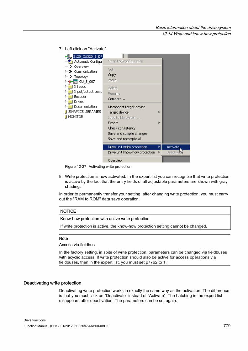
Basic information about the drive system 12.14 Write and know-how protection
Drive functions Function Manual, (FH1), 01/2012, 6SL3097-4AB00-0BP2 779
7. Left click on "Activate".
Figure 12-27 Activating write protection
8. Write protection is now activated. In the expert list you can recognize that write protection is active by the fact that the entry fields of all adjustable parameters are shown with gray shading.
In order to permanently transfer your setting, after changing write protection, you must carry out the "RAM to ROM" data save operation.
NOTICE Know-how protection with active write protection
If write protection is active, the know-how protection setting cannot be changed.
Note Access via fieldbus
In the factory setting, in spite of write protection, parameters can be changed via fieldbuses with acyclic access. If write protection should also be active for access operations via fieldbuses, then in the expert list, you must set p7762 to 1.
Deactivating write protection Deactivating write protection works in exactly the same way as the activation. The difference is that you must click on "Deactivate" instead of "Activate". The hatching in the expert list disappears after deactivation. The parameters can be set again.
Basic information about the drive system 12.14 Write and know-how protection
Drive functions 780 Function Manual, (FH1), 01/2012, 6SL3097-4AB00-0BP2
Parameters without write protection Certain parameters are excluded from write protection in order not to endanger the functionality and operability of the drives. The list of these parameters can be found in the SINAMICS S120/150 List Manual in the Chapter, Parameters for write protection and know-how protection, subchapter, Parameters with "WRITE_NO_LOCK".
The function "restore factory settings" is also not locked when write protection is activated.
12.14.2 Know-how protection The know-how protection function (KHP) prevents e.g. strictly confidential company know-how for configuration and parameter assignment from being read.
The know-how protection requires a password. The password must comprise at least 1 and a maximum of 30 characters.
Note Password security
You are responsible for the security of your password. We recommend that you use a password with adequate length, which includes upper and lowercase letters and special characters.
If you set the password via a network connection, then it is possible that unauthorized persons can "listen in" without being noticed. Therefore, we recommend that you establish a direct connection to the Control Unit to set the password.
Characteristics when know-how protection is activated:
Certain parameters are locked. In the expert list, the value of these parameters cannot be read or changed.
In the locked parameters of the expert list of STARTER, the text "know-how protected" is present in black lettering on a pink background instead of the parameter values.
The locked parameters of the expert list can be hidden using a filter.
– To do this, click on the drop-down list "Online value of the Control Unit" on the triangle.
– If you select the entry "Without know-how protection", the know-how-protected parameters will be hidden.
The values of display parameters remain visible.
The contents of screen forms are not displayed when know-how protection is active.
Know-how protection can be combined with copy protection.
Functions locked using know-how protection The following listed functions are inhibited when know-how protection is active:
Download
Export/import
Basic information about the drive system 12.14 Write and know-how protection
Drive functions Function Manual, (FH1), 01/2012, 6SL3097-4AB00-0BP2 781
Trace functions
Function generator
Measuring functions
Automatic controller setting
Stationary/rotating measurement
Deleting the alarm history
Creating acceptance documentation
Functions that can be executed for know-how protection The following listed functions can still be executed despite of the fact that know-how protection is activated:
Restoring factory settings
Acknowledging alarms
Displaying alarms and warnings
Displaying the alarm history
Reading out the diagnostic buffer
Switch over to the control panel (fetch the master control, all the buttons and setting parameters)
Uploading parameters, which are not locked by know-how protection
Parameters that can be changed when know-how protection is active In spite of active know-how protection, certain parameters can be changed and read. The list of these parameters can be found in the SINAMICS S120/150 List Manual in the Chapter, Parameters for write protection and know-how protection in the subchapter, Parameters for write protection and know-how protection/parameters with "KHP_WRITE_NO_LOCK".
Parameters that can be read when know-how protection is active In spite of know-how protection being active, additional parameters can be read, but are locked against changes. The list of these parameters can be found in the SINAMICS S120/150 List Manual in the Chapter, Parameters for write protection and know-how protection, in the subchapter, Parameters with "KHP_ACTIVE_READ".
NOTICE Password check for know-how protection
Please note that if the Windows language settings are changed, after activating know-how protection, errors can occur when subsequently checking the password. Therefore, only use characters from the ASCII character set for your password.
Basic information about the drive system 12.14 Write and know-how protection
Drive functions 782 Function Manual, (FH1), 01/2012, 6SL3097-4AB00-0BP2
Note Data security of the memory card
After setting up and activating the know-how protection, for encrypted data backup on the memory card, previously backed up, non-encrypted data of the SINAMICS software will be deleted. This is standard deletion technique, in which only the entries on the memory card are deleted. The data itself is still available and can be reconstructed.
In order to guarantee know-how protection, we recommend that you specifically delete your relevant data on the memory card before use.
To completely delete your previous data on the memory card, you must reliably delete this data using a suitable PC tool before activating know-how protection. The data is located on the memory card in the following directory:
- \\USER\SINAMICS\DATA.
NOTICE Diagnostics under know-how protection
When know-how protection is active, if service or diagnostics is required, then Siemens AG can only provide support in collaboration with the OEM partner.
12.14.2.1 Copy protection
Activated copy protection Copy protection prevents project settings from being copied and transferred to other Control Units. Additional features include:
Copy protection can only be activated in conjunction with know-how protection.
When copy protection is active, memory card and Control Unit are connected with one another and only function together.
The copy protection prevents any other memory card from being used in the Control Unit.
The data of the Control Unit cannot be copied to another memory card.
The copy-protected data on the memory card cannot be read or copied.
Basic information about the drive system 12.14 Write and know-how protection
Drive functions Function Manual, (FH1), 01/2012, 6SL3097-4AB00-0BP2 783
12.14.2.2 Using know-how protection
Overview Before activating know-how protection, the following conditions must be met:
The drive unit has been fully commissioned. (Configuration, download into the drive unit, complete commissioning. You then carried out an upload in order to upload the parameters calculated by the drive into the STARTER project)
The OEM-exception list has been created
The password is entered at the end. After setting the password, you must backup with "RAM to ROM", so that protection is retained the next time the system is switched off.
To guarantee know-how protection, you must ensure that the project isn't left with the end-user in the form of a file.
Creating the OEM exception list Enter the parameters into this exception list that should still be able to be read and written in spite of active know-how protection. The exception list can only be created via the expert list. The exception list has no influence on the input screen forms in STARTER.
In p7763, define the required number of parameters of the exception list. You can enter a maximum of 500 parameters in the exception list. In p7764[0...n], assign the required parameter numbers to the individual indices of p7763. Finally, transfer the changes to the Control Unit so that they can become effective.
Factory setting for the exception list:
p7763 = 1 (exception list contains precisely one parameter)
p7764[0] = 7766 (parameter number for entering the password)
CAUTION Parameters of the exception list are not checked
The Control Unit does not check which parameters you include or delete in the exception list.
Absolute know-how protection By removing parameter p7766 from the exception list of p7764[0] = 0, you prevent any access at all to the data of the Control Unit and your project settings. It is then impossible to read or change the protected data. The know-how protection and the copy protection can no longer be canceled or deactivated.
Basic information about the drive system 12.14 Write and know-how protection
Drive functions 784 Function Manual, (FH1), 01/2012, 6SL3097-4AB00-0BP2
Activating know-how protection 1. Connect the Control Unit to the programming device.
2. Open STARTER.
3. Open your project.
4. Establish a connection to the target device (go online).
5. Select the desired drive unit in the project navigator of your STARTER project.
6. In the shortcut menu, select "Know-how protection drive unit"
7. Click with the left-hand mouse button on "Activate".
The dialog window "Activate know-how protection" opens.
8. Enter your password, and click OK.
– The password can comprise a minimum of 1 up to a maximum of 30 characters.
– If the check mark for "Copy RAM to ROM" is set, know-how protection is permanently saved in the Control Unit.
9. Know-how protection is now activated. The text "Know-how protected" is in all protected parameters of the expert list instead of the content.
Deactivating know-how protection Deactivating know-how protection works in exactly the same way as the activation. You only have to click on "Deactivate" in the list box.
1. The dialog window "Deactivate know-how protection" opens.
2. Select whether you want to "temporarily" or "permanently" delete know-how protection.
– "temporarily" deactivating: Know-how protection is active again after switching off and switching on.
– "permanently" deactivating: The know-how protection remains deactivated even after switching off and switching on again.
– If you select "permanently", you can also carry out a data backup on the Control Unit with "RAM to ROM".
3. Enter your password, and click on OK.
4. Know-how protection is now deactivated. All of the parameter values are displayed again.
Basic information about the drive system 12.14 Write and know-how protection
Drive functions Function Manual, (FH1), 01/2012, 6SL3097-4AB00-0BP2 785
Changing the password In order to change the password for know-how protection, you must connect your Control Unit to the programming device.
1. The know-how protection must be activated.
2. Connect the Control Unit to the programming device.
3. Open STARTER
4. Download your project and go online.
5. Select the desired drive unit in the navigation window your STARTER project.
6. In the shortcut menu, select "Know-how protection drive unit"
7. Click with the left-hand mouse button on "Change password". The "Change Password" entry field opens.
8. Enter your old password in the uppermost text box. Enter your new password into the following text box and repeat it in the lowest text box.
9. Select whether you want to subsequently carry out a "RAM to ROM" data save.
10. Exit the entry field with OK.
11. The new password is now valid.
12.14.2.3 Replacing devices for know-how protection with copy protection The "Know-how protection with copy protection" function prevents that configuration settings, e.g. from an OEM machine, are copied and passed on to third-parties.
However, to allow a Control Unit to be replaced, the machine manufacturer (OEM) must have the files of the STARTER project of the machine.
The following procedure is required to replace the Control Unit:
1. The end customer sends the OEM the serial number of the new Control Unit (r7758) and the new memory card (r7843) – and specifies the machine in which the Control Unit is installed.
2. The OEM enters the new serial numbers of the Control Unit (p7759) and the memory card (p7769) as reference serial numbers in the expert list of the STARTER project associated with the machine.
3. The OEM activates know-how protection with copy protection.
4. The OEM executes a "RAM to ROM".
5. The OEM sends the "User" directory of the memory card to the end customer (e.g. by e-mail).
6. The end customer copies the "User" directory to the new memory card and inserts it into the new Control Unit.
7. The end customer switches on the drive.
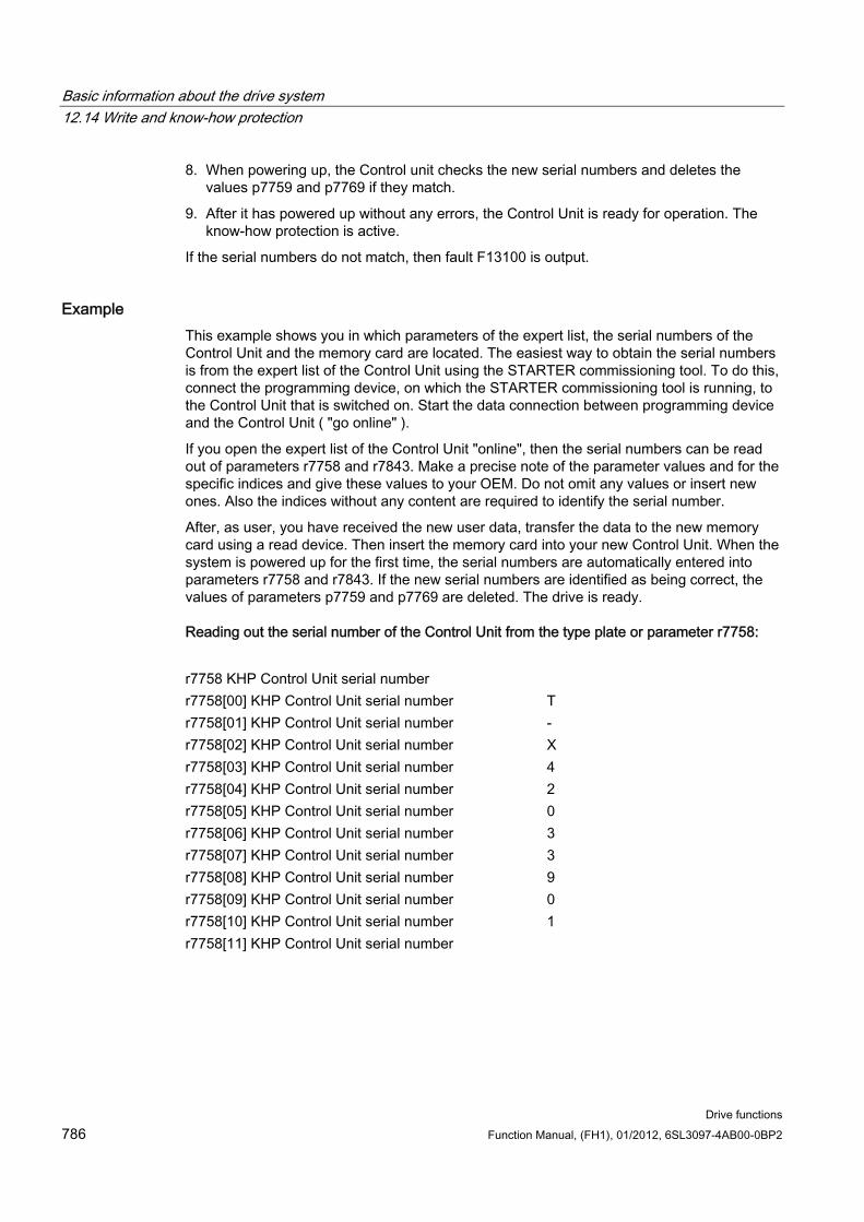
Basic information about the drive system 12.14 Write and know-how protection
Drive functions 786 Function Manual, (FH1), 01/2012, 6SL3097-4AB00-0BP2
8. When powering up, the Control unit checks the new serial numbers and deletes the values p7759 and p7769 if they match.
9. After it has powered up without any errors, the Control Unit is ready for operation. The know-how protection is active.
If the serial numbers do not match, then fault F13100 is output.
Example This example shows you in which parameters of the expert list, the serial numbers of the Control Unit and the memory card are located. The easiest way to obtain the serial numbers is from the expert list of the Control Unit using the STARTER commissioning tool. To do this, connect the programming device, on which the STARTER commissioning tool is running, to the Control Unit that is switched on. Start the data connection between programming device and the Control Unit ( "go online" ).
If you open the expert list of the Control Unit "online", then the serial numbers can be read out of parameters r7758 and r7843. Make a precise note of the parameter values and for the specific indices and give these values to your OEM. Do not omit any values or insert new ones. Also the indices without any content are required to identify the serial number.
After, as user, you have received the new user data, transfer the data to the new memory card using a read device. Then insert the memory card into your new Control Unit. When the system is powered up for the first time, the serial numbers are automatically entered into parameters r7758 and r7843. If the new serial numbers are identified as being correct, the values of parameters p7759 and p7769 are deleted. The drive is ready.
Reading out the serial number of the Control Unit from the type plate or parameter r7758:
r7758 KHP Control Unit serial number r7758[00] KHP Control Unit serial number T r7758[01] KHP Control Unit serial number - r7758[02] KHP Control Unit serial number X r7758[03] KHP Control Unit serial number 4 r7758[04] KHP Control Unit serial number 2 r7758[05] KHP Control Unit serial number 0 r7758[06] KHP Control Unit serial number 3 r7758[07] KHP Control Unit serial number 3 r7758[08] KHP Control Unit serial number 9 r7758[09] KHP Control Unit serial number 0 r7758[10] KHP Control Unit serial number 1 r7758[11] KHP Control Unit serial number
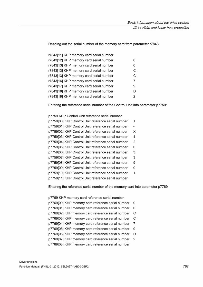
Basic information about the drive system 12.14 Write and know-how protection
Drive functions Function Manual, (FH1), 01/2012, 6SL3097-4AB00-0BP2 787
Reading out the serial number of the memory card from parameter r7843:
r7843[11] KHP memory card serial number r7843[12] KHP memory card serial number 0 r7843[13] KHP memory card serial number 0 r7843[13] KHP memory card serial number C r7843[13] KHP memory card serial number C r7843[16] KHP memory card serial number 7 r7843[17] KHP memory card serial number 9 r7843[18] KHP memory card serial number D r7843[19] KHP memory card serial number 2
Entering the reference serial number of the Control Unit into parameter p7759:
p7759 KHP Control Unit reference serial number p7759[00] KHP Control Unit reference serial number T p7759[01] KHP Control Unit reference serial number - p7759[02] KHP Control Unit reference serial number X p7759[03] KHP Control Unit reference serial number 4 p7759[04] KHP Control Unit reference serial number 2 p7759[05] KHP Control Unit reference serial number 0 p7759[06] KHP Control Unit reference serial number 3 p7759[07] KHP Control Unit reference serial number 3 p7759[08] KHP Control Unit reference serial number 9 p7759[09] KHP Control Unit reference serial number 0 p7759[10] KHP Control Unit reference serial number 1 p7759[11] KHP Control Unit reference serial number
Entering the reference serial number of the memory card into parameter p7769
p7769 KHP memory card reference serial number p7769[00] KHP memory card reference serial number 0 p7769[01] KHP memory card reference serial number 0 p7769[02] KHP memory card reference serial number C p7769[03] KHP memory card reference serial number C p7769[04] KHP memory card reference serial number 7 p7769[05] KHP memory card reference serial number 9 p7769[06] KHP memory card reference serial number D p7769[07] KHP memory card reference serial number 2 p7769[08] KHP memory card reference serial number
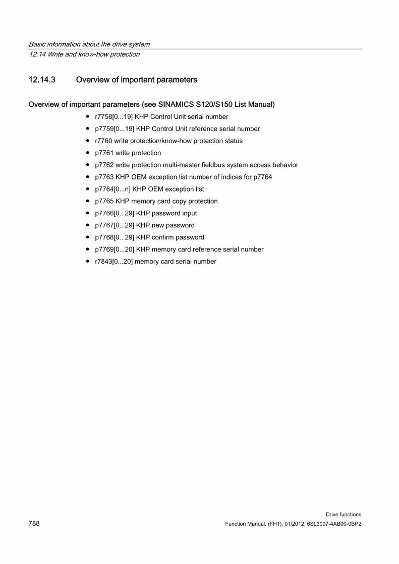
Basic information about the drive system 12.14 Write and know-how protection
Drive functions 788 Function Manual, (FH1), 01/2012, 6SL3097-4AB00-0BP2
12.14.3 Overview of important parameters
Overview of important parameters (see SINAMICS S120/S150 List Manual) r7758[0...19] KHP Control Unit serial number
p7759[0...19] KHP Control Unit reference serial number
r7760 write protection/know-how protection status
p7761 write protection
p7762 write protection multi-master fieldbus system access behavior
p7763 KHP OEM exception list number of indices for p7764
p7764[0...n] KHP OEM exception list
p7765 KHP memory card copy protection
p7766[0...29] KHP password input
p7767[0...29] KHP new password
p7768[0...29] KHP confirm password
p7769[0...20] KHP memory card reference serial number
r7843[0...20] memory card serial number

Basic information about the drive system 12.14 Write and know-how protection
Drive functions Function Manual, (FH1), 01/2012, 6SL3097-4AB00-0BP2 789

Basic information about the drive system 12.14 Write and know-how protection
Drive functions 790 Function Manual, (FH1), 01/2012, 6SL3097-4AB00-0BP2
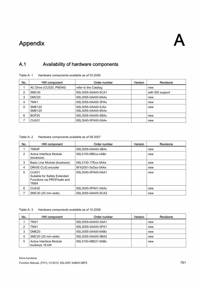
Drive functions Function Manual, (FH1), 01/2012, 6SL3097-4AB00-0BP2 791
Appendix AA.1 Availability of hardware components
Table A- 1 Hardware components available as of 03.2006
No. HW component Order number Version Revisions 1 AC Drive (CU320, PM340) refer to the Catalog new 2 SMC30 6SL3055-0AA00-5CA1 with SSI support 3 DMC20 6SL3055-0AA00-6AAx new 4 TM41 6SL3055-0AA00-3PAx new 5 SME120
SME125 6SL3055-0AA00-5JAx 6SL3055-0AA00-5KAx
new
6 BOP20 6SL3055-0AA00-4BAx new 7 CUA31 6SL3040-0PA00-0AAx new
Table A- 2 Hardware components available as of 08.2007
No. HW component Order number Version Revisions 1 TM54F 6SL3055-0AA00-3BAx new 2 Active Interface Module
(booksize) 6SL3100-0BExx-xABx new
3 Basic Line Module (booksize) 6SL3130-1TExx-0AAx new 4 DRIVE-CLiQ encoder 6FX2001-5xDxx-0AAx new 5 CUA31
Suitable for Safety Extended Functions via PROFIsafe and TM54
6SL3040-0PA00-0AA1 new
6 CUA32 6SL3040-0PA01-0AAx new 7 SMC30 (30 mm wide) 6SL3055-0AA00-5CA2 new
Table A- 3 Hardware components available as of 10.2008
No. HW component Order number Version Revisions 1 TM31 6SL3055-0AA00-3AA1 new 2 TM41 6SL3055-0AA00-3PA1 new 3 DME20 6SL3055-0AA00-6ABx new 4 SMC20 (30 mm wide) 6SL3055-0AA00-5BA2 new 5 Active Interface Module
booksize 16 kW 6SL3100-0BE21-6ABx new
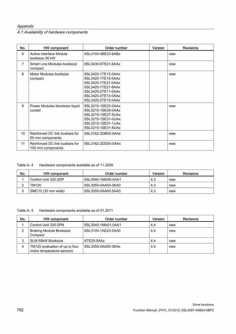
Appendix A.1 Availability of hardware components
Drive functions 792 Function Manual, (FH1), 01/2012, 6SL3097-4AB00-0BP2
No. HW component Order number Version Revisions 6 Active Interface Module
booksize 36 kW 6SL3100-0BE23-6ABx new
7 Smart Line Modules booksize compact
6SL3430-6TE21-6AAx new
8 Motor Modules booksize compact
6SL3420-1TE13-0AAx 6SL3420-1TE15-0AAx 6SL3420-1TE21-0AAx 6SL3420-1TE21-8AAx 6SL3420-2TE11-0AAx 6SL3420-2TE13-0AAx 6SL3420-2TE15-0AAx
new
9 Power Modules blocksize liquid cooled
6SL3215-1SE23-0AAx 6SL3215-1SE26-0AAx 6SL3215-1SE27-5UAx 6SL3215-1SE31-0UAx 6SL3215-1SE31-1UAx 6SL3215-1SE31-8UAx
new
10 Reinforced DC link busbars for 50 mm components
6SL3162-2DB00-0AAx new
11 Reinforced DC link busbars for 100 mm components
6SL3162-2DD00-0AAx new
Table A- 4 Hardware components available as of 11.2009
No. HW component Order number Version Revisions 1 Control Unit 320-2DP 6SL3040-1MA00-0AA1 4.3 new 2 TM120 6SL3055-0AA00-3KA0 4.3 new 3 SMC10 (30 mm wide) 6SL3055-0AA00-5AA3 4.3 new
Table A- 5 Hardware components available as of 01.2011
No. HW component Order number Version Revisions 1 Control Unit 320-2PN 6SL3040-1MA01-0AA1 4.4 new 2 Braking Module Booksize
Compact 6SL3100-1AE23-5AA0 4.4 new
3 SLM 55kW Booksize 6TE25-5AAx 4.4 new 4 TM120 evaluation of up to four
motor temperature sensors 6SL3055-0AA00-3KAx 4.4 new
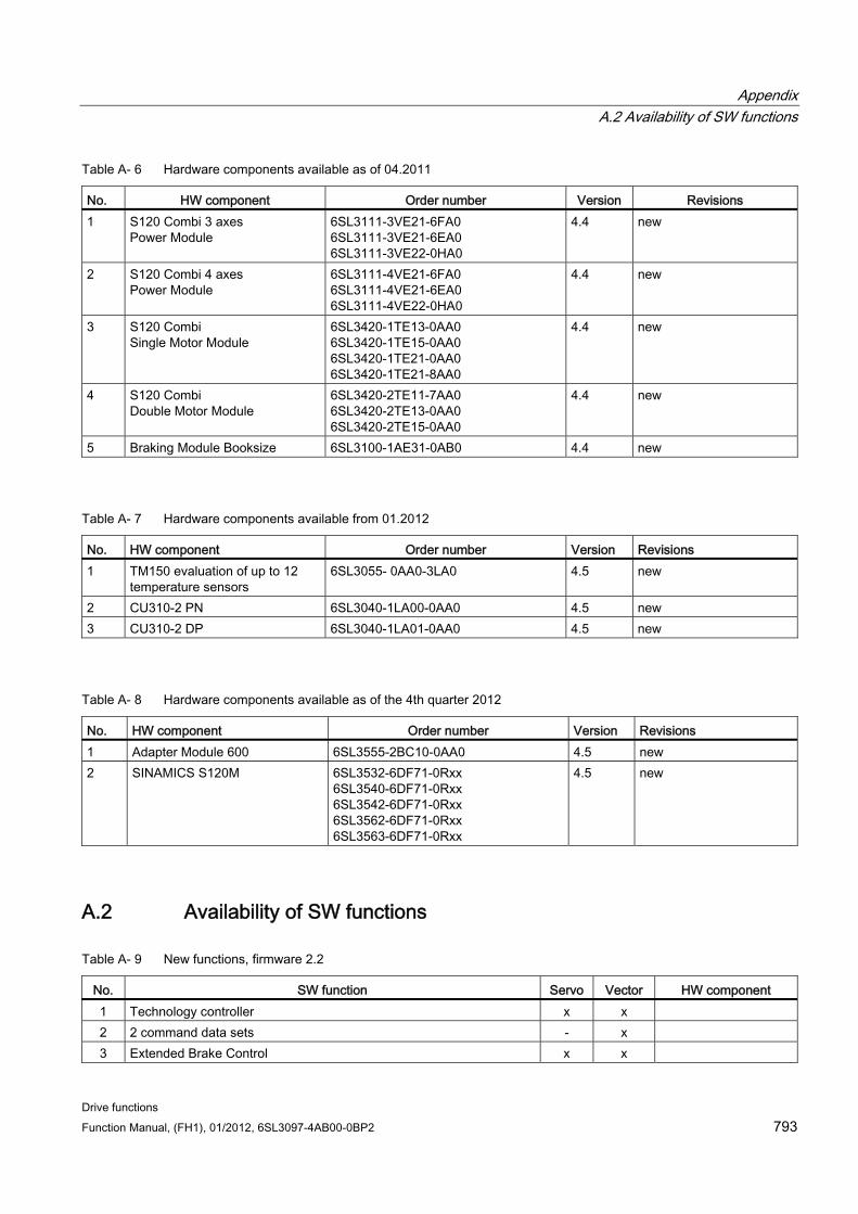
Appendix A.2 Availability of SW functions
Drive functions Function Manual, (FH1), 01/2012, 6SL3097-4AB00-0BP2 793
Table A- 6 Hardware components available as of 04.2011
No. HW component Order number Version Revisions 1 S120 Combi 3 axes
Power Module 6SL3111-3VE21-6FA0 6SL3111-3VE21-6EA0 6SL3111-3VE22-0HA0
4.4 new
2 S120 Combi 4 axes Power Module
6SL3111-4VE21-6FA0 6SL3111-4VE21-6EA0 6SL3111-4VE22-0HA0
4.4 new
3 S120 Combi Single Motor Module
6SL3420-1TE13-0AA0 6SL3420-1TE15-0AA0 6SL3420-1TE21-0AA0 6SL3420-1TE21-8AA0
4.4 new
4 S120 Combi Double Motor Module
6SL3420-2TE11-7AA0 6SL3420-2TE13-0AA0 6SL3420-2TE15-0AA0
4.4 new
5 Braking Module Booksize 6SL3100-1AE31-0AB0 4.4 new
Table A- 7 Hardware components available from 01.2012
No. HW component Order number Version Revisions 1 TM150 evaluation of up to 12
temperature sensors 6SL3055- 0AA0-3LA0 4.5 new
2 CU310-2 PN 6SL3040-1LA00-0AA0 4.5 new 3 CU310-2 DP 6SL3040-1LA01-0AA0 4.5 new
Table A- 8 Hardware components available as of the 4th quarter 2012
No. HW component Order number Version Revisions 1 Adapter Module 600 6SL3555-2BC10-0AA0 4.5 new 2 SINAMICS S120M 6SL3532-6DF71-0Rxx
6SL3540-6DF71-0Rxx 6SL3542-6DF71-0Rxx 6SL3562-6DF71-0Rxx 6SL3563-6DF71-0Rxx
4.5 new
A.2 Availability of SW functions
Table A- 9 New functions, firmware 2.2
No. SW function Servo Vector HW component 1 Technology controller x x 2 2 command data sets - x 3 Extended Brake Control x x
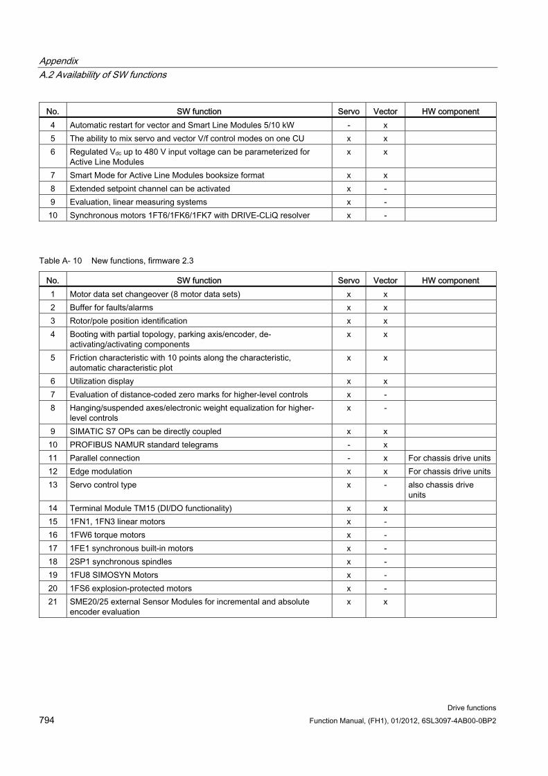
Appendix A.2 Availability of SW functions
Drive functions 794 Function Manual, (FH1), 01/2012, 6SL3097-4AB00-0BP2
No. SW function Servo Vector HW component 4 Automatic restart for vector and Smart Line Modules 5/10 kW - x 5 The ability to mix servo and vector V/f control modes on one CU x x 6 Regulated Vdc up to 480 V input voltage can be parameterized for
Active Line Modules x x
7 Smart Mode for Active Line Modules booksize format x x 8 Extended setpoint channel can be activated x - 9 Evaluation, linear measuring systems x - 10 Synchronous motors 1FT6/1FK6/1FK7 with DRIVE-CLiQ resolver x -
Table A- 10 New functions, firmware 2.3
No. SW function Servo Vector HW component 1 Motor data set changeover (8 motor data sets) x x 2 Buffer for faults/alarms x x 3 Rotor/pole position identification x x 4 Booting with partial topology, parking axis/encoder, de-
activating/activating components x x
5 Friction characteristic with 10 points along the characteristic, automatic characteristic plot
x x
6 Utilization display x x 7 Evaluation of distance-coded zero marks for higher-level controls x - 8 Hanging/suspended axes/electronic weight equalization for higher-
level controls x -
9 SIMATIC S7 OPs can be directly coupled x x 10 PROFIBUS NAMUR standard telegrams - x 11 Parallel connection - x For chassis drive units 12 Edge modulation x x For chassis drive units 13 Servo control type x - also chassis drive
units 14 Terminal Module TM15 (DI/DO functionality) x x 15 1FN1, 1FN3 linear motors x - 16 1FW6 torque motors x - 17 1FE1 synchronous built-in motors x - 18 2SP1 synchronous spindles x - 19 1FU8 SIMOSYN Motors x - 20 1FS6 explosion-protected motors x - 21 SME20/25 external Sensor Modules for incremental and absolute
encoder evaluation x x
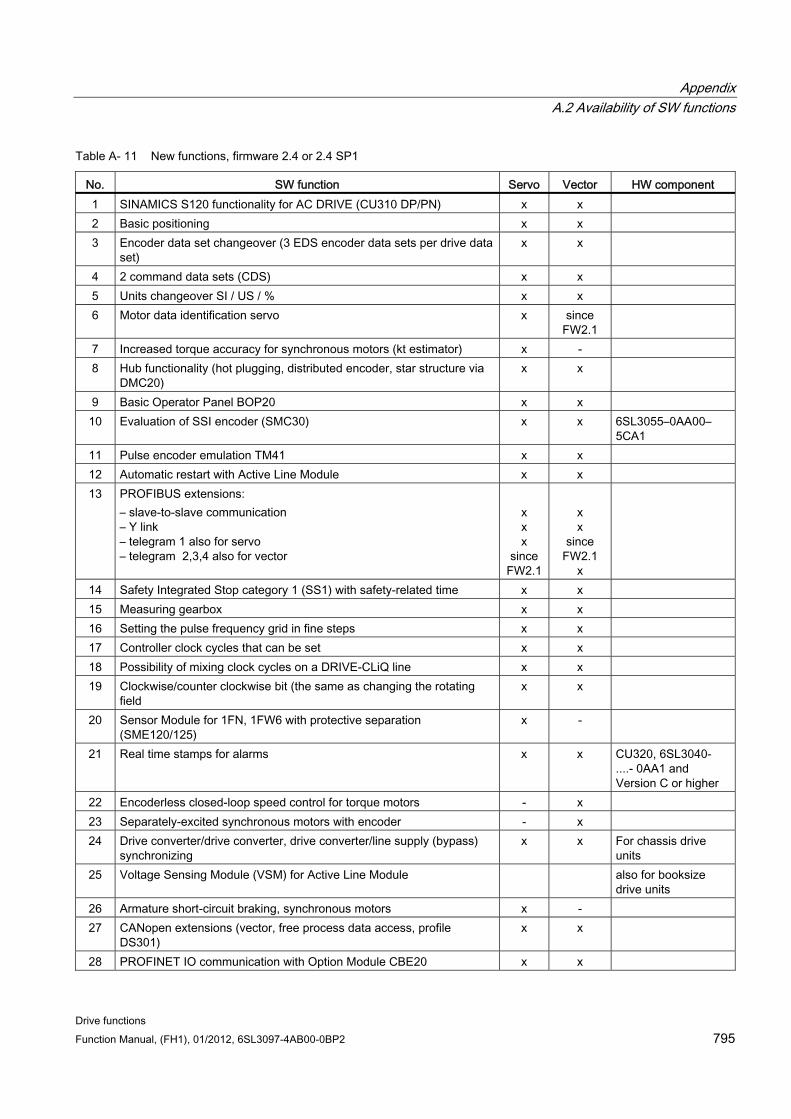
Appendix A.2 Availability of SW functions
Drive functions Function Manual, (FH1), 01/2012, 6SL3097-4AB00-0BP2 795
Table A- 11 New functions, firmware 2.4 or 2.4 SP1
No. SW function Servo Vector HW component 1 SINAMICS S120 functionality for AC DRIVE (CU310 DP/PN) x x 2 Basic positioning x x 3 Encoder data set changeover (3 EDS encoder data sets per drive data
set) x x
4 2 command data sets (CDS) x x 5 Units changeover SI / US / % x x 6 Motor data identification servo x since
FW2.1
7 Increased torque accuracy for synchronous motors (kt estimator) x - 8 Hub functionality (hot plugging, distributed encoder, star structure via
DMC20) x x
9 Basic Operator Panel BOP20 x x 10 Evaluation of SSI encoder (SMC30) x x 6SL3055–0AA00–
5CA1 11 Pulse encoder emulation TM41 x x 12 Automatic restart with Active Line Module x x 13 PROFIBUS extensions:
– slave-to-slave communication – Y link – telegram 1 also for servo – telegram 2,3,4 also for vector
x x x
since FW2.1
x x
since FW2.1
x
14 Safety Integrated Stop category 1 (SS1) with safety-related time x x 15 Measuring gearbox x x 16 Setting the pulse frequency grid in fine steps x x 17 Controller clock cycles that can be set x x 18 Possibility of mixing clock cycles on a DRIVE-CLiQ line x x 19 Clockwise/counter clockwise bit (the same as changing the rotating
field x x
20 Sensor Module for 1FN, 1FW6 with protective separation (SME120/125)
x -
21 Real time stamps for alarms x x CU320, 6SL3040- ....- 0AA1 and Version C or higher
22 Encoderless closed-loop speed control for torque motors - x 23 Separately-excited synchronous motors with encoder - x 24 Drive converter/drive converter, drive converter/line supply (bypass)
synchronizing x x For chassis drive
units 25 Voltage Sensing Module (VSM) for Active Line Module also for booksize
drive units 26 Armature short-circuit braking, synchronous motors x - 27 CANopen extensions (vector, free process data access, profile
DS301) x x
28 PROFINET IO communication with Option Module CBE20 x x
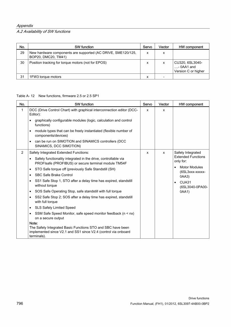
Appendix A.2 Availability of SW functions
Drive functions 796 Function Manual, (FH1), 01/2012, 6SL3097-4AB00-0BP2
No. SW function Servo Vector HW component 29 New hardware components are supported (AC DRIVE, SME120/125,
BOP20, DMC20, TM41) x x
30 Position tracking for torque motors (not for EPOS) x x CU320, 6SL3040- ....- 0AA1 and Version C or higher
31 1FW3 torque motors x -
Table A- 12 New functions, firmware 2.5 or 2.5 SP1
No. SW function Servo Vector HW component 1 DCC (Drive Control Chart) with graphical interconnection editor (DCC-
Editor): • graphically configurable modules (logic, calculation and control
functions) • module types that can be freely instantiated (flexible number of
components/devices) • can be run on SIMOTION and SINAMICS controllers (DCC
SINAMICS, DCC SIMOTION)
x x
2 Safety Integrated Extended Functions: • Safety functionality integrated in the drive, controllable via
PROFIsafe (PROFIBUS) or secure terminal module TM54F • STO Safe torque off (previously Safe Standstill (SH) • SBC Safe Brake Control • SS1 Safe Stop 1, STO after a delay time has expired, standstill
without torque • SOS Safe Operating Stop, safe standstill with full torque • SS2 Safe Stop 2; SOS after a delay time has expired, standstill
with full torque • SLS Safely Limited Speed • SSM Safe Speed Monitor, safe speed monitor feedback (n < nx)
on a secure output Note: The Safety Integrated Basic Functions STO and SBC have been implemented since V2.1 and SS1 since V2.4 (control via onboard terminals).
x x Safety Integrated Extended Functions only for: • Motor Modules
(6SL3xxx-xxxxx-0AA3)
• CUA31 (6SL3040-0PA00-0AA1)
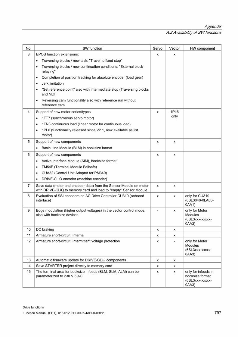
Appendix A.2 Availability of SW functions
Drive functions Function Manual, (FH1), 01/2012, 6SL3097-4AB00-0BP2 797
No. SW function Servo Vector HW component 3 EPOS function extensions:
• Traversing blocks / new task: "Travel to fixed stop" • Traversing blocks / new continuation conditions: "External block
relaying" • Completion of position tracking for absolute encoder (load gear) • Jerk limitation • "Set reference point" also with intermediate stop (Traversing blocks
and MDI) • Reversing cam functionality also with reference run without
reference cam
x x
4 Support of new motor series/types • 1FT7 (synchronous servo motor) • 1FN3 continuous load (linear motor for continuous load) • 1PL6 (functionality released since V2.1, now available as list
motor)
x 1PL6 only
5 Support of new components • Basic Line Module (BLM) in booksize format
x x
6 Support of new components • Active Interface Module (AIM), booksize format • TM54F (Terminal Module Failsafe) • CUA32 (Control Unit Adapter for PM340) • DRIVE-CLiQ encoder (machine encoder)
x x
7 Save data (motor and encoder data) from the Sensor Module on motor with DRIVE-CLiQ to memory card and load to "empty" Sensor Module
x x
8 Evaluation of SSI encoders on AC Drive Controller CU310 (onboard interface)
x x only for CU310 (6SL3040-0LA00-0AA1)
9 Edge modulation (higher output voltages) in the vector control mode, also with booksize devices
- x only for Motor Modules (6SL3xxx-xxxxx-0AA3)
10 DC braking x x 11 Armature short-circuit: Internal x x 12 Armature short-circuit: Intermittent voltage protection x - only for Motor
Modules (6SL3xxx-xxxxx-0AA3)
13 Automatic firmware update for DRIVE-CLiQ components x x 14 Save STARTER project directly to memory card x x 15 The terminal area for booksize infeeds (BLM, SLM, ALM) can be
parameterized to 230 V 3 AC x x only for infeeds in
booksize format (6SL3xxx-xxxxx-0AA3)
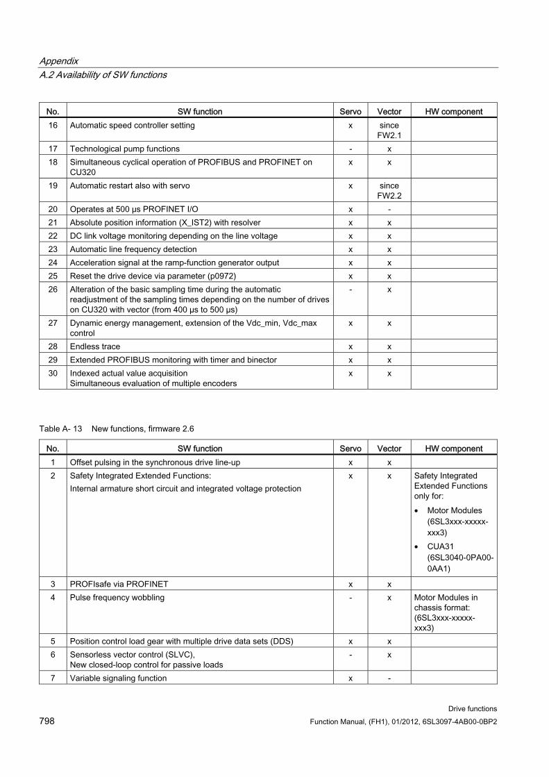
Appendix A.2 Availability of SW functions
Drive functions 798 Function Manual, (FH1), 01/2012, 6SL3097-4AB00-0BP2
No. SW function Servo Vector HW component 16 Automatic speed controller setting x since
FW2.1
17 Technological pump functions - x 18 Simultaneous cyclical operation of PROFIBUS and PROFINET on
CU320 x x
19 Automatic restart also with servo x since FW2.2
20 Operates at 500 μs PROFINET I/O x - 21 Absolute position information (X_IST2) with resolver x x 22 DC link voltage monitoring depending on the line voltage x x 23 Automatic line frequency detection x x 24 Acceleration signal at the ramp-function generator output x x 25 Reset the drive device via parameter (p0972) x x 26 Alteration of the basic sampling time during the automatic
readjustment of the sampling times depending on the number of drives on CU320 with vector (from 400 µs to 500 µs)
- x
27 Dynamic energy management, extension of the Vdc_min, Vdc_max control
x x
28 Endless trace x x 29 Extended PROFIBUS monitoring with timer and binector x x 30 Indexed actual value acquisition
Simultaneous evaluation of multiple encoders x x
Table A- 13 New functions, firmware 2.6
No. SW function Servo Vector HW component 1 Offset pulsing in the synchronous drive line-up x x 2 Safety Integrated Extended Functions:
Internal armature short circuit and integrated voltage protection x x Safety Integrated
Extended Functions only for: • Motor Modules
(6SL3xxx-xxxxx-xxx3)
• CUA31 (6SL3040-0PA00-0AA1)
3 PROFIsafe via PROFINET x x 4 Pulse frequency wobbling - x Motor Modules in
chassis format: (6SL3xxx-xxxxx-xxx3)
5 Position control load gear with multiple drive data sets (DDS) x x 6 Sensorless vector control (SLVC),
New closed-loop control for passive loads - x
7 Variable signaling function x -
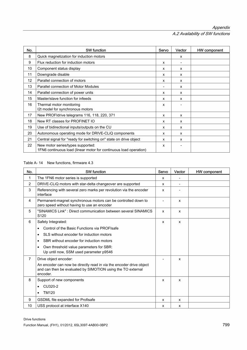
Appendix A.2 Availability of SW functions
Drive functions Function Manual, (FH1), 01/2012, 6SL3097-4AB00-0BP2 799
No. SW function Servo Vector HW component 8 Quick magnetization for induction motors x 9 Flux reduction for induction motors x - 10 Component status display x x 11 Downgrade disable x x 12 Parallel connection of motors x x 13 Parallel connection of Motor Modules - x 14 Parallel connection of power units x x 15 Master/slave function for infeeds x x 16 Thermal motor monitoring
I2t model for synchronous motors x -
17 New PROFIdrive telegrams 116, 118, 220, 371 x x 18 New RT classes for PROFINET IO x x 19 Use of bidirectional inputs/outputs on the CU x x 20 Autonomous operating mode for DRIVE-CLiQ components x x 21 Central signal for "ready for switching on" state on drive object x x 22 New motor series/types supported:
1FN6 continuous load (linear motor for continuous load operation) x -
Table A- 14 New functions, firmware 4.3
No. SW function Servo Vector HW component 1 The 1FN6 motor series is supported x - 2 DRIVE-CLiQ motors with star-delta changeover are supported x - 3 Referencing with several zero marks per revolution via the encoder
interface x -
4 Permanent-magnet synchronous motors can be controlled down to zero speed without having to use an encoder
- x
5 "SINAMICS Link" : Direct communication between several SINAMICS S120
x x
6 Safety Integrated: • Control of the Basic Functions via PROFIsafe • SLS without encoder for induction motors • SBR without encoder for induction motors • Own threshold value parameters for SBR:
Up until now, SSM used parameter p9546
x x
7 Drive object encoder: An encoder can now be directly read in via the encoder drive object and can then be evaluated by SIMOTION using the TO external encoder.
- x
8 Support of new components • CU320-2 • TM120
x x
9 GSDML file expanded for Profisafe x x 10 USS protocol at interface X140 x x
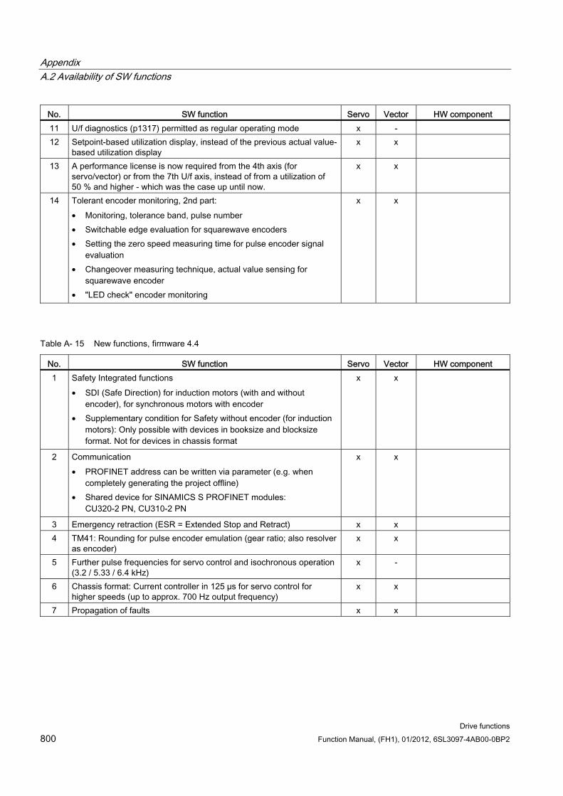
Appendix A.2 Availability of SW functions
Drive functions 800 Function Manual, (FH1), 01/2012, 6SL3097-4AB00-0BP2
No. SW function Servo Vector HW component 11 U/f diagnostics (p1317) permitted as regular operating mode x - 12 Setpoint-based utilization display, instead of the previous actual value-
based utilization display x x
13 A performance license is now required from the 4th axis (for servo/vector) or from the 7th U/f axis, instead of from a utilization of 50 % and higher - which was the case up until now.
x x
14 Tolerant encoder monitoring, 2nd part: • Monitoring, tolerance band, pulse number • Switchable edge evaluation for squarewave encoders • Setting the zero speed measuring time for pulse encoder signal
evaluation • Changeover measuring technique, actual value sensing for
squarewave encoder • "LED check" encoder monitoring
x x
Table A- 15 New functions, firmware 4.4
No. SW function Servo Vector HW component 1 Safety Integrated functions
• SDI (Safe Direction) for induction motors (with and without encoder), for synchronous motors with encoder
• Supplementary condition for Safety without encoder (for induction motors): Only possible with devices in booksize and blocksize format. Not for devices in chassis format
x x
2 Communication • PROFINET address can be written via parameter (e.g. when
completely generating the project offline) • Shared device for SINAMICS S PROFINET modules:
CU320-2 PN, CU310-2 PN
x x
3 Emergency retraction (ESR = Extended Stop and Retract) x x 4 TM41: Rounding for pulse encoder emulation (gear ratio; also resolver
as encoder) x x
5 Further pulse frequencies for servo control and isochronous operation (3.2 / 5.33 / 6.4 kHz)
x -
6 Chassis format: Current controller in 125 µs for servo control for higher speeds (up to approx. 700 Hz output frequency)
x x
7 Propagation of faults x x
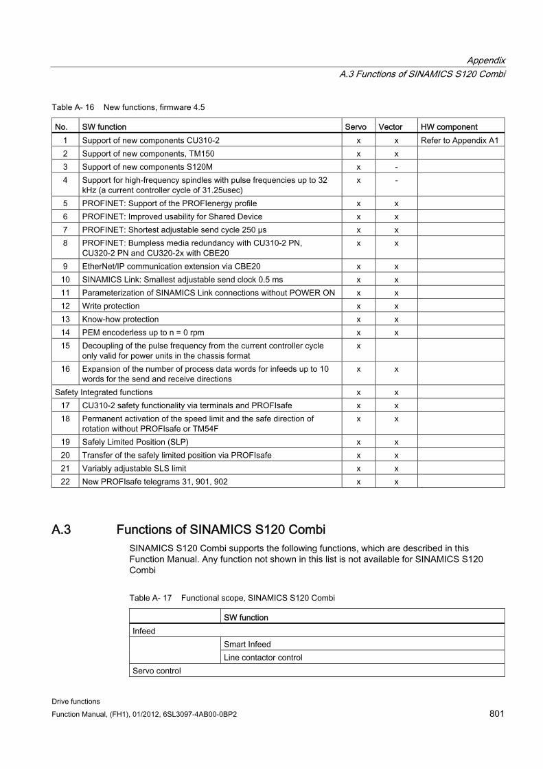
Appendix A.3 Functions of SINAMICS S120 Combi
Drive functions Function Manual, (FH1), 01/2012, 6SL3097-4AB00-0BP2 801
Table A- 16 New functions, firmware 4.5
No. SW function Servo Vector HW component 1 Support of new components CU310-2 x x Refer to Appendix A1 2 Support of new components, TM150 x x 3 Support of new components S120M x - 4 Support for high-frequency spindles with pulse frequencies up to 32
kHz (a current controller cycle of 31.25usec) x -
5 PROFINET: Support of the PROFIenergy profile x x 6 PROFINET: Improved usability for Shared Device x x 7 PROFINET: Shortest adjustable send cycle 250 µs x x 8 PROFINET: Bumpless media redundancy with CU310-2 PN,
CU320-2 PN and CU320-2x with CBE20 x x
9 EtherNet/IP communication extension via CBE20 x x 10 SINAMICS Link: Smallest adjustable send clock 0.5 ms x x 11 Parameterization of SINAMICS Link connections without POWER ON x x 12 Write protection x x 13 Know-how protection x x 14 PEM encoderless up to n = 0 rpm x x 15 Decoupling of the pulse frequency from the current controller cycle
only valid for power units in the chassis format x
16 Expansion of the number of process data words for infeeds up to 10 words for the send and receive directions
x x
Safety Integrated functions x x 17 CU310-2 safety functionality via terminals and PROFIsafe x x 18 Permanent activation of the speed limit and the safe direction of
rotation without PROFIsafe or TM54F x x
19 Safely Limited Position (SLP) x x 20 Transfer of the safely limited position via PROFIsafe x x 21 Variably adjustable SLS limit x x 22 New PROFIsafe telegrams 31, 901, 902 x x
A.3 Functions of SINAMICS S120 Combi SINAMICS S120 Combi supports the following functions, which are described in this Function Manual. Any function not shown in this list is not available for SINAMICS S120 Combi
Table A- 17 Functional scope, SINAMICS S120 Combi
SW function Infeed
Smart Infeed Line contactor control
Servo control
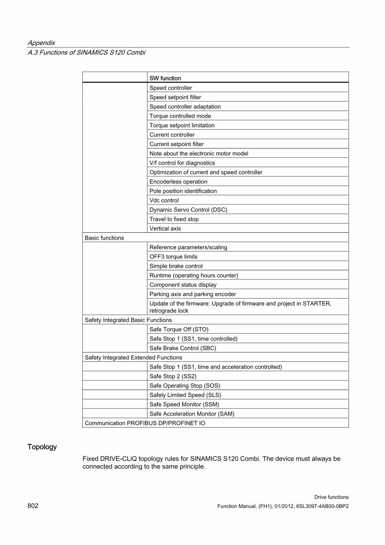
Appendix A.3 Functions of SINAMICS S120 Combi
Drive functions 802 Function Manual, (FH1), 01/2012, 6SL3097-4AB00-0BP2
SW function Speed controller Speed setpoint filter Speed controller adaptation Torque controlled mode Torque setpoint limitation Current controller Current setpoint filter Note about the electronic motor model V/f control for diagnostics Optimization of current and speed controller Encoderless operation Pole position identification Vdc control Dynamic Servo Control (DSC) Travel to fixed stop
Vertical axis Basic functions
Reference parameters/scaling OFF3 torque limits Simple brake control Runtime (operating hours counter) Component status display Parking axis and parking encoder
Update of the firmware: Upgrade of firmware and project in STARTER, retrograde lock
Safety Integrated Basic Functions Safe Torque Off (STO) Safe Stop 1 (SS1, time controlled)
Safe Brake Control (SBC) Safety Integrated Extended Functions Safe Stop 1 (SS1, time and acceleration controlled) Safe Stop 2 (SS2) Safe Operating Stop (SOS) Safely Limited Speed (SLS) Safe Speed Monitor (SSM) Safe Acceleration Monitor (SAM) Communication PROFIBUS DP/PROFINET IO
Topology Fixed DRIVE-CLiQ topology rules for SINAMICS S120 Combi. The device must always be connected according to the same principle.
Appendix A.4 SINAMICS S120 Functions
Drive functions Function Manual, (FH1), 01/2012, 6SL3097-4AB00-0BP2 803
System clocks The sampling times for:
Current controller
Speed controller and
Flux controller
are permanently set to 125 μs. The pulse frequency is permanently set to 4 kHz. This means that a maximum spindle speed of 24000 rpm can be reached.
Available motors Synchronous motors: 1FT6, 1FT7, 1FK7, 1FW3
Induction motors: 1PH7, 1PH4, 1PL6, 1PH8
A.4 SINAMICS S120 Functions SINAMICS S120M is the distributed version of the SINAMICS S120 Booksize family. SINAMICS S120M supports the functions, which are described in this Function Manual.
Note Availability
The SINAMICS S120M component is available from the 4th quarter of 2012. Releases for S120M for use with the corresponding systems will be published through PRODIS.
Hardware The SINAMICS S120M system comprises the following units:
S120M (1FK7 synchronous motor with integrated Power Module and modified DQI encoder)
Adapter Module 600 (AM600)
Hybrid cable (connection system)
DRIVE-CLiQ extension (DQE)
Hybrid Cabinet Bushing (HCB)
Functionality of the distributed SINAMICS S120M drive technology The 24 V electronics power supply is either provided from an external supply or from a
Control Supply Module (CSM).
Use of the Line Modules (ALM, BLM or SLM) from the modular SINAMICS S120 system.
Every Adapter Module 600 (AM600) opens a line of distributed S120M drives.
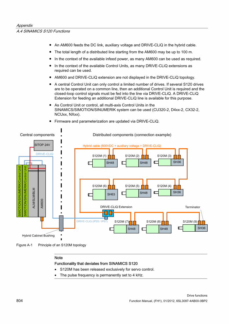
Appendix A.4 SINAMICS S120 Functions
Drive functions 804 Function Manual, (FH1), 01/2012, 6SL3097-4AB00-0BP2
An AM600 feeds the DC link, auxiliary voltage and DRIVE-CLiQ in the hybrid cable.
The total length of a distributed line starting from the AM600 may be up to 100 m.
In the context of the available infeed power, as many AM600 can be used as required.
In the context of the available Control Units, as many DRIVE-CLiQ extensions as required can be used.
AM600 and DRIVE-CLiQ extension are not displayed in the DRIVE-CLiQ topology.
A central Control Unit can only control a limited number of drives. If several S120 drives are to be operated on a common line, then an additional Control Unit is required and the closed-loop control signals must be fed into the line via DRIVE-CLiQ. A DRIVE-CLiQ Extension for feeding an additional DRIVE-CLiQ line is available for this purpose.
As Control Unit or control, all multi-axis Control Units in the SINAMICS/SIMOTION/SINUMERIK system can be used (CU320-2, D4xx-2, CX32-2, NCUxx, NXxx).
Firmware and parameterization are updated via DRIVE-CLiQ.
Figure A-1 Principle of an S120M topology
Note Functionality that deviates from SINAMICS S120 • S120M has been released exclusively for servo control. • The pulse frequency is permanently set to 4 kHz.
Appendix A.4 SINAMICS S120 Functions
Drive functions Function Manual, (FH1), 01/2012, 6SL3097-4AB00-0BP2 805
S120M safety concept Safety functions (Basic and Extended Functions) can be controlled with PROFIsafe, or
TM54F
Interfaces Adapter Module 600
– X1: Hybrid connector
– X21: Terminal strip for operating states
– X24: Terminal strip for 24 V ext.
– X210: DRIVE-CLiQ interface
S120M
– X1/X2: Hybrid connector
– X3: Connecting actuators and sensors to the S120M. (two bidirectional, electrically isolated digital inputs/outputs with sensor supply)
– X4: Connection to externally open a holding brake (option)
– LEDs: Display of operating states
DRIVE-CLiQ Extension
– X1 (IN): Hybrid connector
– X2(OUT): Hybrid connector
Hybrid Cabinet Bushing
– DRIVE-CLiQ connection
– Hybrid connector connection
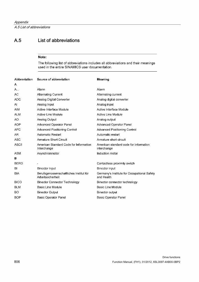
Appendix A.5 List of abbreviations
Drive functions 806 Function Manual, (FH1), 01/2012, 6SL3097-4AB00-0BP2
A.5 List of abbreviations
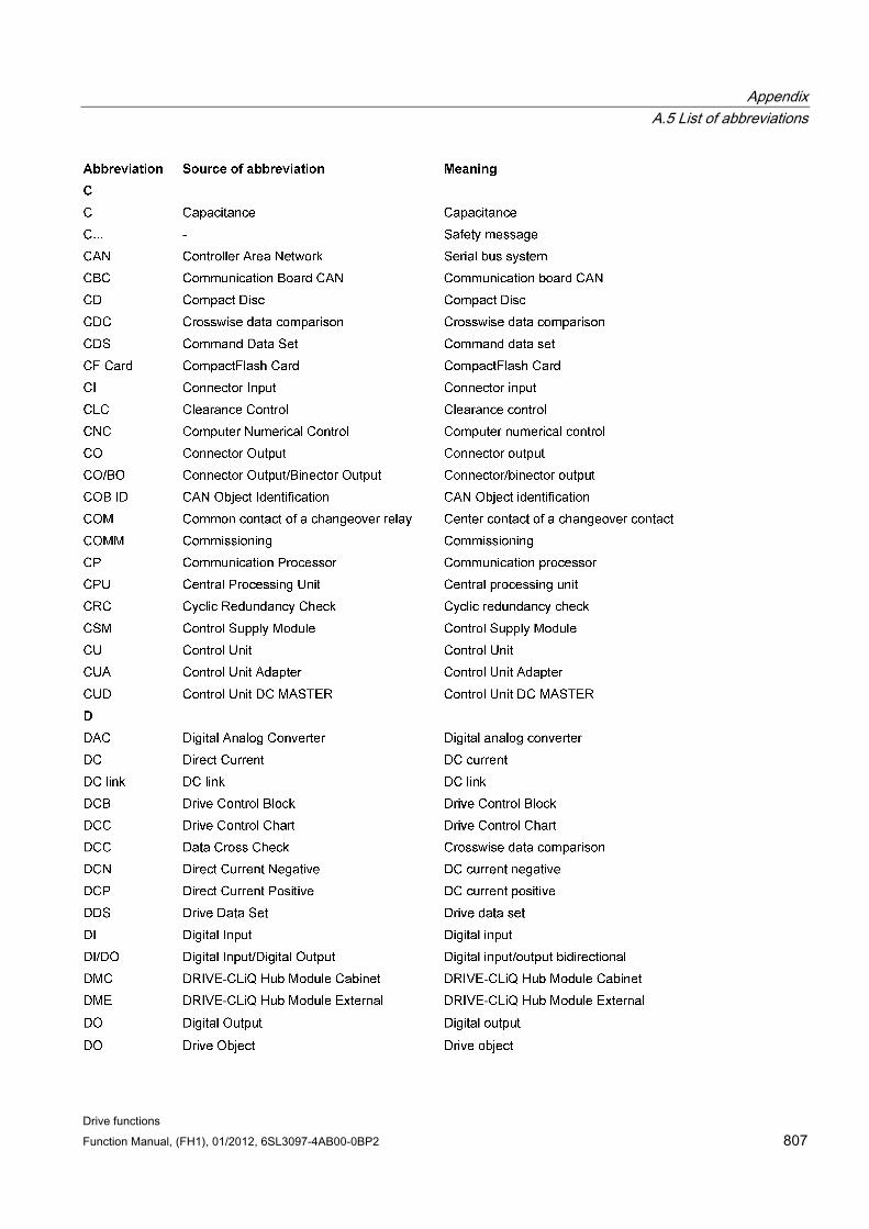
Appendix A.5 List of abbreviations
Drive functions Function Manual, (FH1), 01/2012, 6SL3097-4AB00-0BP2 807
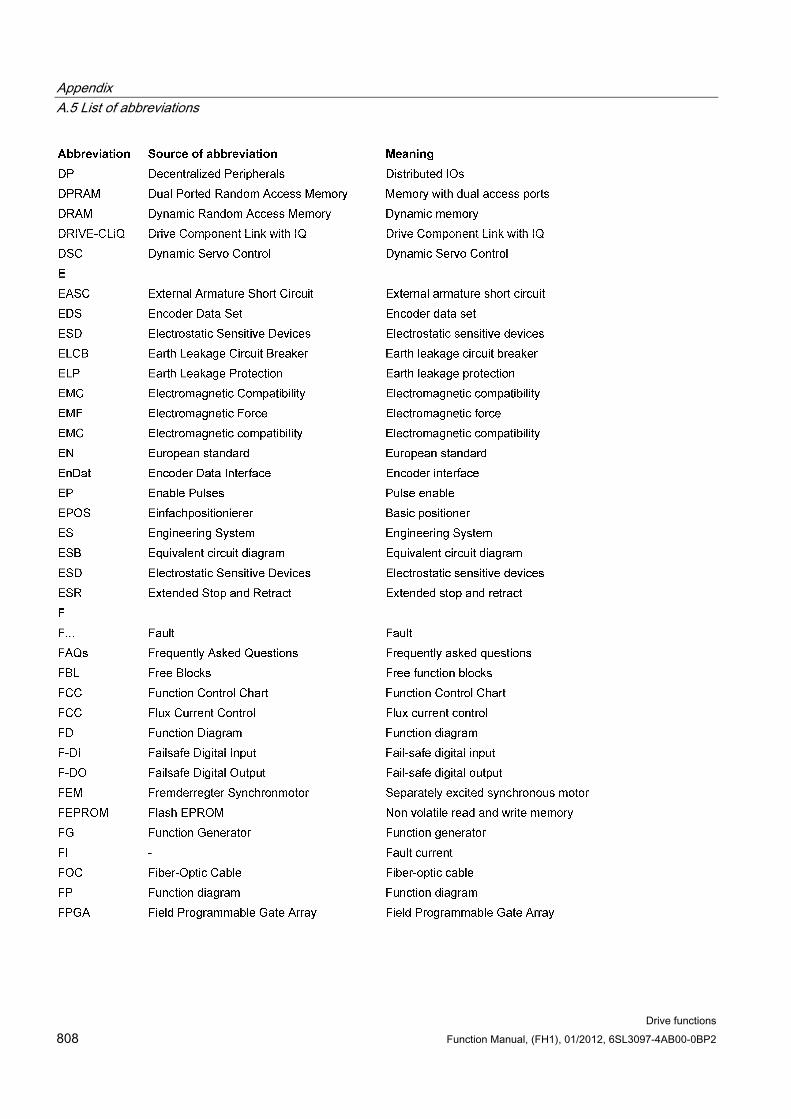
Appendix A.5 List of abbreviations
Drive functions 808 Function Manual, (FH1), 01/2012, 6SL3097-4AB00-0BP2
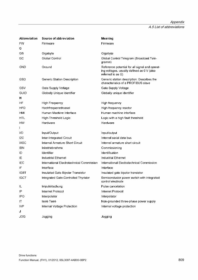
Appendix A.5 List of abbreviations
Drive functions Function Manual, (FH1), 01/2012, 6SL3097-4AB00-0BP2 809
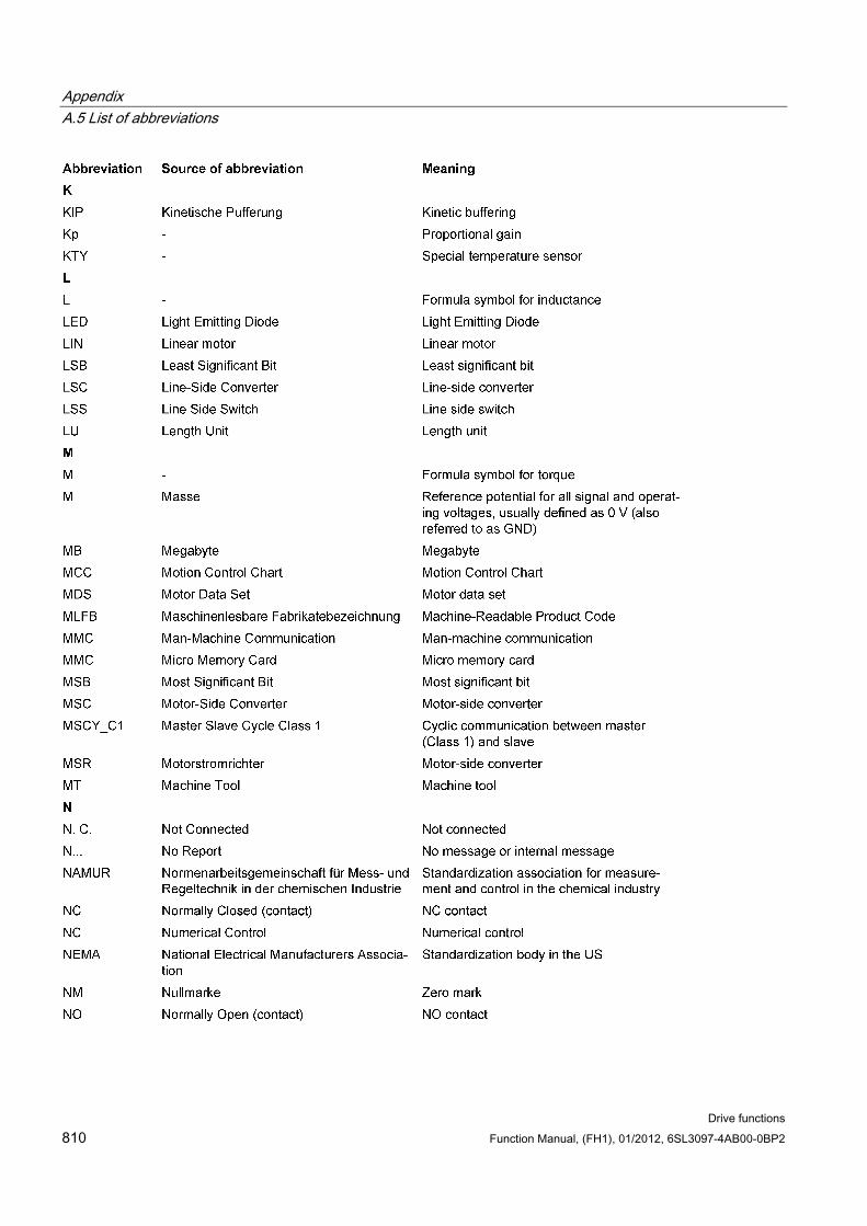
Appendix A.5 List of abbreviations
Drive functions 810 Function Manual, (FH1), 01/2012, 6SL3097-4AB00-0BP2
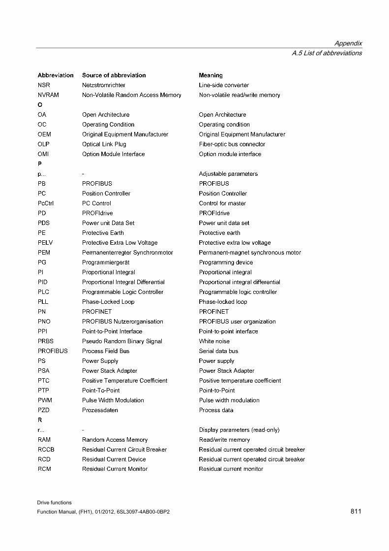
Appendix A.5 List of abbreviations
Drive functions Function Manual, (FH1), 01/2012, 6SL3097-4AB00-0BP2 811
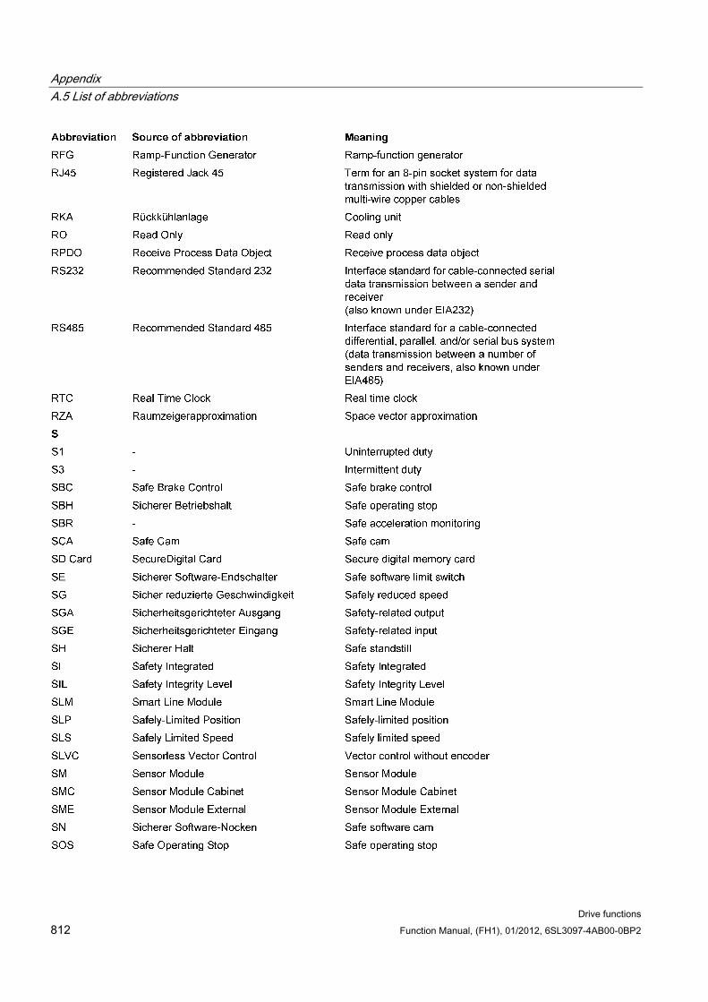
Appendix A.5 List of abbreviations
Drive functions 812 Function Manual, (FH1), 01/2012, 6SL3097-4AB00-0BP2
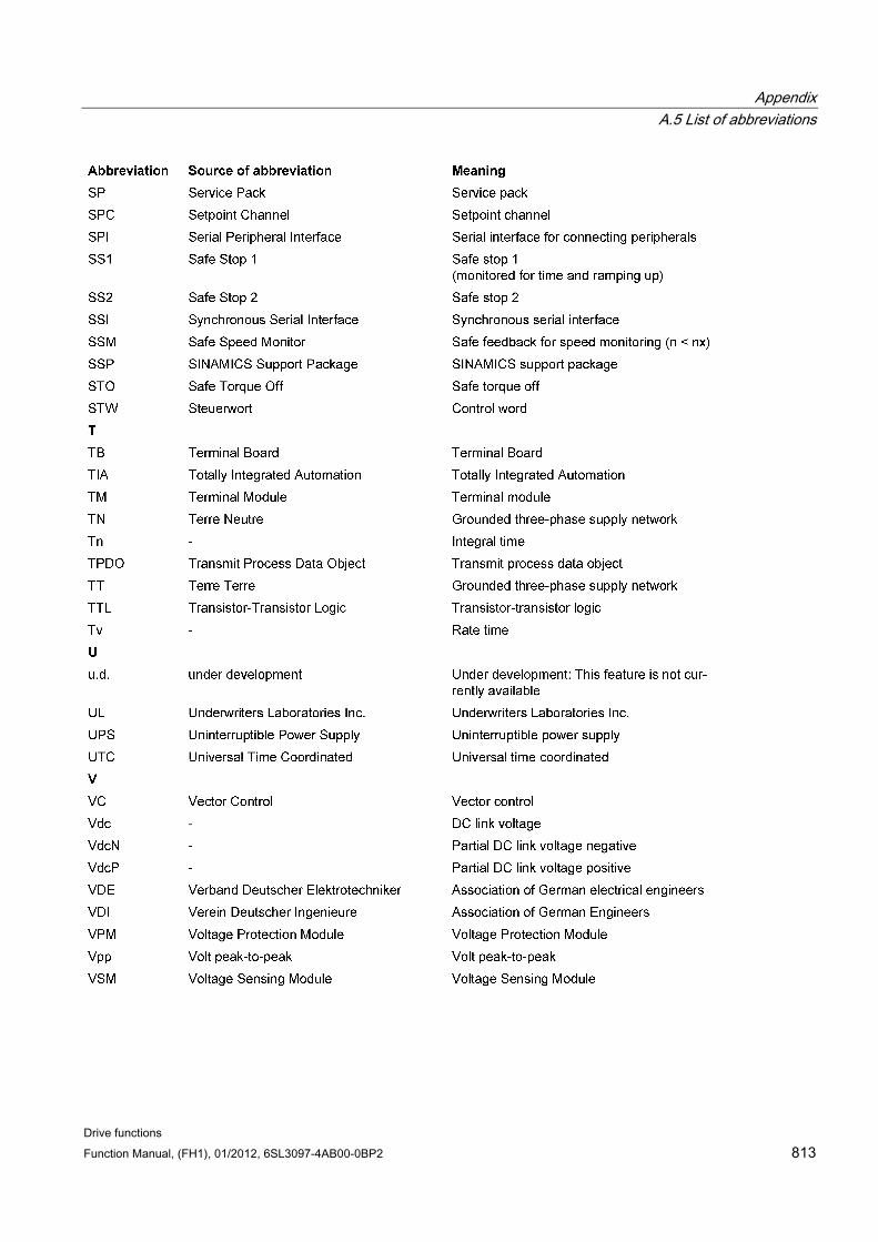
Appendix A.5 List of abbreviations
Drive functions Function Manual, (FH1), 01/2012, 6SL3097-4AB00-0BP2 813

Appendix A.5 List of abbreviations
Drive functions 814 Function Manual, (FH1), 01/2012, 6SL3097-4AB00-0BP2
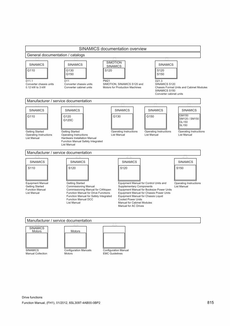
Drive functions Function Manual, (FH1), 01/2012, 6SL3097-4AB00-0BP2 815

Basic information about the drive system
Drive functions 816 Function Manual, (FH1), 01/2012, 6SL3097-4AB00-0BP2
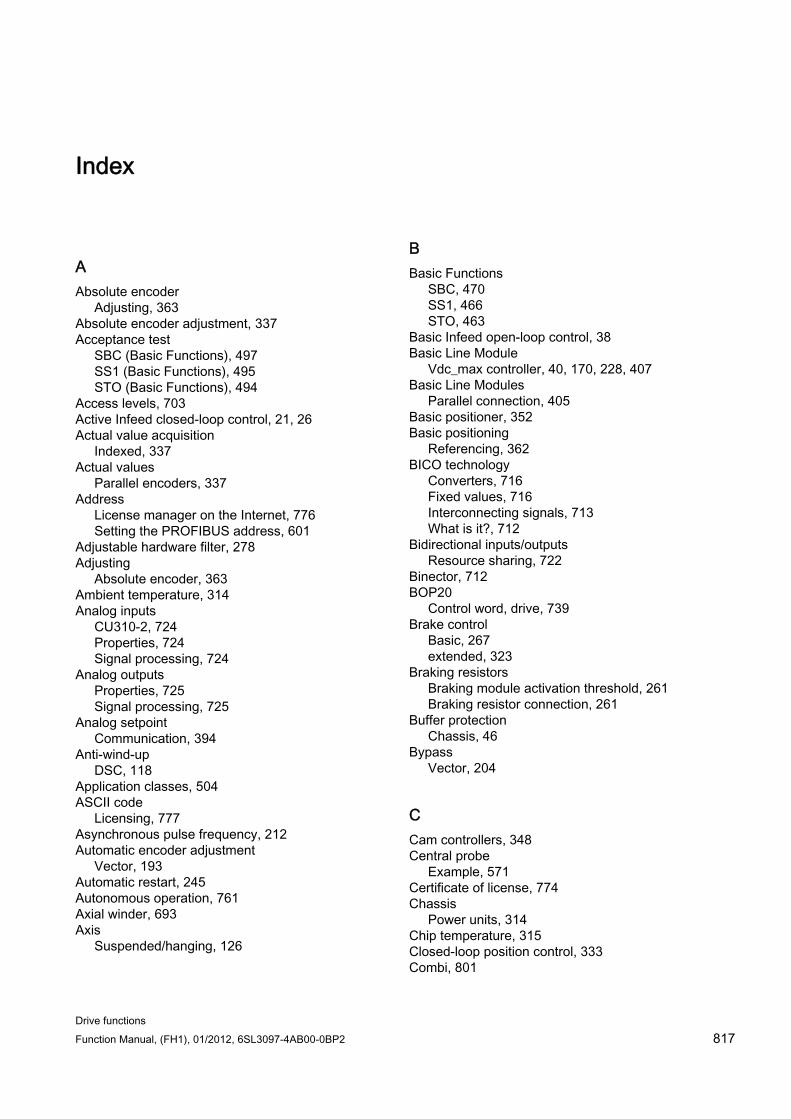
Drive functions Function Manual, (FH1), 01/2012, 6SL3097-4AB00-0BP2 817
Index
A Absolute encoder
Adjusting, 363 Absolute encoder adjustment, 337 Acceptance test
SBC (Basic Functions), 497 SS1 (Basic Functions), 495 STO (Basic Functions), 494
Access levels, 703 Active Infeed closed-loop control, 21, 26 Actual value acquisition
Indexed, 337 Actual values
Parallel encoders, 337 Address
License manager on the Internet, 776 Setting the PROFIBUS address, 601
Adjustable hardware filter, 278 Adjusting
Absolute encoder, 363 Ambient temperature, 314 Analog inputs
CU310-2, 724 Properties, 724 Signal processing, 724
Analog outputs Properties, 725 Signal processing, 725
Analog setpoint Communication, 394
Anti-wind-up DSC, 118
Application classes, 504 ASCII code
Licensing, 777 Asynchronous pulse frequency, 212 Automatic encoder adjustment
Vector, 193 Automatic restart, 245 Autonomous operation, 761 Axial winder, 693 Axis
Suspended/hanging, 126
B Basic Functions
SBC, 470 SS1, 466 STO, 463
Basic Infeed open-loop control, 38 Basic Line Module
Vdc_max controller, 40, 170, 228, 407 Basic Line Modules
Parallel connection, 405 Basic positioner, 352 Basic positioning
Referencing, 362 BICO technology
Converters, 716 Fixed values, 716 Interconnecting signals, 713 What is it?, 712
Bidirectional inputs/outputs Resource sharing, 722
Binector, 712 BOP20
Control word, drive, 739 Brake control
Basic, 267 extended, 323
Braking resistors Braking module activation threshold, 261 Braking resistor connection, 261
Buffer protection Chassis, 46
Bypass Vector, 204
C Cam controllers, 348 Central probe
Example, 571 Certificate of license, 774 Chassis
Power units, 314 Chip temperature, 315 Closed-loop position control, 333 Combi, 801
Index
Drive functions 818 Function Manual, (FH1), 01/2012, 6SL3097-4AB00-0BP2
Commissioning Safety Integrated, 478
Communication about PROFIdrive, 501 via PROFIBUS, 594
Component replacement Examples, 739
Connector, 713 Controller setting, automatic
Servo, 95 Current controller (vector)
Current controller adaptation, 173 Current distribution factor, 396 Current setpoint, 396 Current setpoint filter, 171
Servo, 85
D Data backup
NVRAM, 726 Data cross-check, 456 Data sets
Command data set (CDS), 704 Drive data set (DDS), 705 Encoder data set (EDS), 706 Motor data set (MDS), 707
Data transfer PROFINET, 632
Datalogger, 274 DC brake, 253 DC braking
activating via parameters, 253 activation as response to a speed threshold, 255 as fault response, 254 deactivating via parameters, 254 OFF1/3, 254 Preconditions, 253 setting as a response to a speed threshold, 255 setting via parameters, 253
DC braking after an OFF signal activating, 255 setting, 254
DC breaker, 393 DCC axial winder, 693 DCP flashing, 636 DDS changeover
with load gear position tracking, 342 Derating function, 314 Determining the axis number, 588 Determining the object number, 588 Determinism, 629
Device identification, 604, 627 Device name, 631 Diagnostics function
V/f control for servo control, 91 Digital inputs
Bidirectional, 721 If they are not functioning, 720 Properties, 719 Signal processing, 719
Digital outputs Bidirectional, 721 Properties, 721 Signal processing, 721
Direct setpoint input (MDI), 384 Direction reversal, 244 Directives, 454 DME20, 689 dn/dt monitoring:freezing the speed raw value, 278 Downgrade lock, 312 Drive object, 711 Drive Object, 711 DRIVE-CLiQ
Autonomous operation, 761 Emergency mode, 761 Wiring rules, 744
DRIVE-CLiQ encoder, 364 DRIVE-CLiQ Hub
DMC20, 689 Droop, 160 DSC
Anti-wind-up, 118 dv/dt filter compact plus Voltage Peak Limiter, 241 dv/dt filter plus Voltage Peak Limiter, 240 Dynamic Servo Control, 118
Maximum number of drives, 119 Dynamic setpoint limiting, 118
E Edge evaluation of the zero mark, 279 Efficiency optimization
Vector, 181 Electronic rating plate, 743 Encoder
External, 121 Encoder adjustment, 191
Fine adjustment, 193 Encoder dirty signal, 275 Encoder evaluation, 275 Encoder interface, 553
Find reference mark, 555 Flying measurement, 557
Index
Drive functions Function Manual, (FH1), 01/2012, 6SL3097-4AB00-0BP2 819
Encoder range, 293 Encoder track monitoring, 276 EP terminal
Sampling time, 474 EPOS, 352
Direct setpoint input (MDI), 384 Flying referencing, 368 Flying referencing using Safety Integrated functions, 376 Intermediate stop, 378, 386 Jog, 387 Limits, 357 Mechanical system, 355 Reject traversing task, 378, 386 Safe referencing, 374 Starting against a holding brake, 360 Traversing blocks, 376
ESR Communication failure for Safety, 420 Generator operation, 420 Initiating ESR, 417 Overview, 415 Preconditions, 416 Retraction, 419 several axes, 420 Stopping, 418 Telegram extensions, 421 unsuitable motors, 420
Example PROFIBUS telegram structure, 597
Expansion of the encoder evaluation, 283 Extended torque control, 331 External armature short-circuit braking
activating, 250 Braking resistors calculate, 251 Example, 251 setting, 250
external braking resistors Example, 250
F FAULT_CODE, 550 Faults and alarms
BICO interconnections, 718 Forwarding, 718 Propagation, 718
Filter On/off test, 477
Find reference mark, 555 Fixed setpoints, 51 Fixed speed setpoints, 51
Flying measurement, 557 Flying referencing
EPOS, 368 Flying restart, 197 Following error monitoring
Dynamic, 348 Forced dormant error detection
Basic Functions, 461 Free telegrams, 511 Freezing the speed raw value, 278 Frequency setpoint
SMC30, 312 Friction characteristic
Technology function, 265 Function blocks
DCC axial winder, 693 Function module
Closed-loop position control, 333 Extended Brake Control, 323
Function modules, 317 Braking Module, 328 Extended monitoring functions, 321 Extended torque control, 331 Technology controller, 317
Functions Fixed speed setpoints, 51 Jog, 54 Motorized potentiometer, 52 Servo control, 69 Travel to fixed stop, 122 V/f control for servo control, 91
G GSD
GSD file, 602
H Heat-sink temperature, 315 Hot plugging
DRIVE-CLiQ, 690
I IEC61000-2-4 standard, 23 Induction motors
DC brake, 253 Industrial security, 501 Infeed
12-pulse, 405
Index
Drive functions 820 Function Manual, (FH1), 01/2012, 6SL3097-4AB00-0BP2
Basic Infeed, 38 Pre-charging, 405
Infeed concepts, 404 Infeeds
Master/slave, 397 Inputs/outputs
Overview, 719 Interconnecting signals using BICO technology, 713 Interconnection using BICO technology, 713 Intermediate stop
EPOS, 378, 386 Internal armature short-circuit, 465 Internal armature short-circuit braking
Activating, 249 Deactivate, 249 Setting, 249
IO controller, 628 IO device, 628 IO supervisor, 628 IRT, 639
Comparison with RT, 640 IRT, 639 IRT, 639 IT security, 501
J Jerk limitation, 359 Jog, 54
EPOS, 387 JOG
Jog, 54
K Kinetic buffering, 33, 167, 224
Vdc control, 114 Know-how protection
Absolute know-how protection, 783 Copy protection, 782 Data security of the memory card, 782 Executable functions, 781 Locked functions, 780 Overview, 780 Parameters that can be changed, 781 Password check, 781 Password security, 780 Replacing the Control Unit, 785
kT estimator Servo, 331
L License key, 776 License manager, 774 Licensing, 774
ASCII code, 777 Limits
Torque setpoint, 78 Line contactor control, 44 Line supply and DC link identification routine, 397 Load gear, 342 LU
Length Unit, 333 LU example, 334
M Main/supplementary setpoint, 58 Manufacturer-specific telegrams, 510 Master/slave infeeds
Activation of the function, 397 Current distribution factor, 396 Description of the function module, 394 Function diagram, 395 Operating principle, 390 Topology, 392 VDC-link control band, 396
Maximum acceleration, 358 Maximum deceleration, 358 Maximum velocity, 357 Measuring gearbox, 294 Measuring time to evaluate zero speed, 284 Media redundancy, 638 Minimum speed, 61 Modular machine concept, 236 Moment of inertia, 695 Monitoring cycle, 456 Monitoring functions
extended, 321 Monitoring, tolerance band, pulse number, 282 Motion Control with PROFIBUS, 572 Motor changeover, 684 Motor identification, 175 Motor Modules
Derating, 314 Parallel connection, 401, 410
Motor temperature monitoring, 432 CU310-2, 448 CUA31/32, 448 Motor Module, 447 Motor with DRIVE-CLiQ, 449 Power Module, 447
Index
Drive functions Function Manual, (FH1), 01/2012, 6SL3097-4AB00-0BP2 821
Sensor Module, 437 SMC, 437 SMC10, 437 SMC20, 437 SMC30, 437 SME120/125, 438 Temperature sensor evaluation, 449 Terminal Modules, 440 Thermal motor model 1, 433 Thermal motor model 2, 433 TM120, 441 TM150, 443 TM31, 440 Wire break, short-circuit, 450
Motorized potentiometer, 52 Motors
Two-winding system, 411 Multiturn encoder, 293
N Non-volatile memory, 726 Number of controllable drives
Notes, 764 Number of current controller cycles to generate the average value of the speed actual value, 284 NVRAM, 726
O OFF3
Torque limits, 265 open actual speed value, 161 Operating hours counter, 269 Operating temperature, 314 Operation without an encoder
Servo, 97 Output current
Power units, 315
P Parallel connection
Basic Line Modules, 405 Motor Modules, 401, 410
Parameter Categories, 701 Types, 701
Parameterization using the BOP, 728
PN gate, 649
Development kit, 651 Prerequisites, 651 Transferred functions, 650
Pole position adaptation, 280 Pole position identification
Servo, 108 Vector, 195
Position controller, 346 Monitoring functions, 348
Position tracking, 294, 342 Load gear, 338 Measuring gearbox, 293
Positioning monitoring, 348 Power Modules
Derating, 314 Power unit
Overload, 315 Pre-charging contactor
Chassis, 46 Pre-control
Speed, 156 Preface, 3 probe
central, 571 Probe
MT_DIAG, 563, 568 MT_STW, 563 MT_ZSW, 563
Probe evaluation, 129 Example, 134 Handshake, 129 More than two edges, 131 Time-critical data transfer, 130 with handshake, 130 without handshake, 131
Process data, 513 Process data, actual values
E_DIGITAL, 533 G1_XIST1, 533, 559 G1_XIST2, 533, 559 G2_XIST1, 533, 561 G2_XIST2, 533, 561 G3_XIST1, 533 G3_XIST2, 533 IAIST_GLATT, 533 ITIST_GLATT, 533 MIST_GLATT, 533, 533 NACT_A, 533, 542 NACT_B, 533, 542 NIST_A_GLATT, 533 PIST_GLATT, 533
Process data, control words
Index
Drive functions 822 Function Manual, (FH1), 01/2012, 6SL3097-4AB00-0BP2
A_DIGITAL, 508, 515, 564 CU_STW1, 516, 563 E_STW1, 516, 530 E_STW1_BM, 516 G1_STW, 508, 515 G2_STW, 508, 515, 557 G3_STW, 508, 515 Gn_STW, 553 M_ADD, 516 M_LIM, 516 MDI_ACC, 515, 529 MDI_DEC, 529 MDI_MOD, 515, 516, 529 MDI_TARPOS, 528 MDI_VELOCITY, 528 MDIDEC, 515 MDITARPOS, 515 MDIVELOCITY, 515 MT_STW, 508, 516, 565 OVERRIDE, 516, 528 POS_STW, 516, 526 POS_STW1, 516 POS_STW2, 516 SATZANW, 515, 525 STW1, 508, 515, 516 STW1 (positioning mode), 518 STW1_BM, 516 STW2, 508, 515, 519 STW2_BM, 516
Process data, setpoints KPC, 508, 515, 524 MOMRED, 508, 516, 525 NSET_A, 523 NSET_B, 523 NSOLL_A, 508, 515 NSOLL_B, 508, 515 XERR, 508, 515, 524
Process data, status words AIST_GLATT, 534 AKTSATZ, 533 CU_ZSW1, 565 E_DIGITAL, 566 E_ZSW1, 534, 551 E_ZSW1_BM, 534 G1_ZSW, 533 G2_ZSW, 533, 561 G3_ZSW, 533 Gn_ZSW, 557 MELD_NAMUR, 546 MELDW, 534, 543 MSOLL_GLATT, 534 MT_ZSW, 534, 567
MT1_ZS_F, 534 MT1_ZS_S, 534 MTx_ZS_F, 534 MTx_ZS_S, 534 POS_ZSW, 534, 546 POS_ZSW1, 534 POS_ZSW2, 534 XIST_A, 533 ZSW1, 533, 535 ZSW1_BM, 534, 534 ZSW2, 533, 538
PROFIBUS, 594 Device identification, 604, 627 Generic station description file, 602, 625 Interface Mode, 514 Master class 1 and 2, 595 Motion Control with PROFIBUS, 572 Setting the address, 601 Sign of life, 611, 647 Slave-to-slave communication, 612 Telegrams, 509 Terminating resistor, 604 VIK-NAMUR, 604
PROFIBUS slave-to-slave communication, 393 PROFIBUS telegram structure, 597 PROFIdrive, 501
Controller, Supervisor, Drive Unit, 502 Device classes, 501 read parameters, 589 Telegrams, 509 Write parameter, 591
PROFIenergy, 664 Certification, 664 PROFIenergy commands, 666
PROFINET Connection channels, 633 Data transfer, 632
PROFINET interface, 635 PROFINET IO, 628
Addresses, 630 IRT, 639
PROFINET IO with IRT, 630 PROFINET IO with RT, 629 PROFINET with 2 controllers, 652 Propagation, 718 Pulse frequency, 315 Pulse frequency wobbling, 243 Pulse number correction for faults, 281 Pulse/direction interface, 312
Index
Drive functions Function Manual, (FH1), 01/2012, 6SL3097-4AB00-0BP2 823
R Ramp-down generator
Scaling, 65 Ramp-function generator
Scaling, 65 ramp-function generator, extended, 63 Ramp-function generator, extended, 63 Ramp-up with partial topology, 236 Rating plate, electronic, 743 Real-time communication, 629 Redundancy
Power unit, 203 Reference model, 156 Reference variables
Disabling/protecting, 232 Referencing
Basic positioning, 362 Response times, 472 Ring topology, 638
Scalance, 638 RT
Comparison with IRT, 640 RT class
Setting, 640 RT classes
Send cycles, 641 Update cycles, 641
S S120 Combi, 801 Safe Brake Control
SBC, 470 Safe Stop 1
Basic Functions, 466 SS1, 466 time controlled, 466 With OFF3 (Basic Functions), 466 Without OFF3 (Basic Functions), 467
Safe Torque Off Basic Functions, 463 STO, 463
Safety Integrated, 459 Commissioning, 478 Component replacement, 479 Password, 460 Standard commissioning, 479
Safety Integrated Basic Functions Stop responses, 484
Safety Integrated password, 460 Safety logbook, 491
Sampling times, 763 SBC
Acceptance test, 497 Basic Functions, 470 Safe Brake Control, 470
Separately excited synchronous motor FESM, 196
Sequence of objects in the telegram, 596, 632 Servo
Automatic controller setting, 95 Encoderless operation, 97 Vdc control, 114
Servo control, 69 Activate setpoint channel, 49 Comparison with vector control, 69, 140 Current controller, 82 Optimization, 95 Properties, 69, 140 Speed controller, 72 Torque setpoint, 78 Torque-controlled operation, 76 Travel to fixed stop, 122 U/f control, 91
Servo current controller Closed-loop current control, 82 Current and torque limitation, 83 Current controller adaptation, 83
Setpoint channel Direction of rotation limiting, 59 Direction reversal, 59 extended, 50 Fixed speed setpoints, 51 Jog, 54 Main/supplementary setpoint, 58 Motorized potentiometer, 52 ramp-function generator, extended, 63 Servo amplifier, 49 Setpoint limitation, 61 Setpoint modification, 58 Skip frequency bands, 61
Setpoint modification, 58 Setpoint sources, 50 Setting the fault responses, 255 Shared device, 652 SINAMICS Link
Activation, 673 Bus cycle, 668 Configuring, 670 Example, 673 Preconditions, 667 Synchronous cycle, 668 Transmission time, 668
Index
Drive functions 824 Function Manual, (FH1), 01/2012, 6SL3097-4AB00-0BP2
SINAMICS S120 Combi, 801 Sine-wave filter, 238 Singleturn encoder, 293 Slave-to-slave communication
Faults, 627 GSD, 625 PROFIBUS, 612 Setting in HW Config, 617 Settings in STARTER, 622
Sliding averaging of the speed actual value, 284 Slip compensation, 222 Smart Infeed closed-loop control, 31 SMC30
Frequency setpoint, 312 Software limit switches, 358 Speed actual value filter, 172 Speed controller, 150
Free Kp_n/Tn_n adaptation, 153 Limits, 72 Properties, 72 Reference model, 156 Speed controller adaptation, 74 Speed controller pre-control, 156 Speed setpoint filter, 73 Speed-dependent Kp_n/Tn_n adaptation, 153
Speed limitation Droop, 160
SS1 Acceptance test (Basic Functions), 495 Basic Functions, 466 Safe Stop 1, 466 Safe Stop 1 (Basic Functions), 466 With OFF3 (Basic Functions), 466 Without OFF3 (Basic Functions), 467
Standard telegrams, 509 Standards, 454 Standstill measurement
Motor identification, 175 Step-up factor, 25 STO
Basic Functions, 463 Safe Torque Off (Basic Functions), 463
STOP A, 484 Stop cam, 359 STOP F, 484 Stop response
STOP A, 484 STOP F, 484
Sublicensing, 774 Switches for PROFIBUS address, 601 Switching on inhibited, 535, 537, 539 Switchover
Fixed speed setpoints, 51 Synchronization (vector control), 199 Synchronization domain, 641 Synchronous motors
Permanent-magnet, vector, 188 System runtime, 269 System sampling times, 763
CU31/CU32, 768 DCC, 767 EPOS, 768 Mixed operation, 766 Servo control, 764 U/f control, 766 Vector control, 765
T Technology controller, 317 Technology function
Friction characteristic, 265 Telegram 111
POS_ZSW1, 547 POS_ZSW2, 548
Telegram 220 ZSW2_BM, 540
Telegram 371 STW1, 516
Telegrams Layout, 513 Manufacturer-specific, 510 Sequence of objects, 596, 632 Standard, 509 User-defined, 511
Tension controller, 696 Terminal Module 41
Commissioning, 307 Example, 307 Limit frequencies, 306 Signaling faults, 300 SIMOTION mode, 300 SINAMICS mode, 301 TM41, 300 Zero mark synchronization, 305
Test of switch-off signal paths, 461 Thermal motor monitoring
Thermal motor models, 433 Three-winding transformer, 393 TM120, 441 TM150
Forming groups, 445 Sensor failure, 446 Temperature sensor types, 443
Index
Drive functions Function Manual, (FH1), 01/2012, 6SL3097-4AB00-0BP2 825
TM31, 440 TM41, 300
Referencing modes, 302 SIMOTION mode, 300 SINAMICS mode, 301 Zero mark emulation, 302
Tolerant encoder monitoring, 275 Topology, parallel connection with an auxiliary drive, 413 Torque control, 163
extended, 331 Torque limiting, 165 torque limits
Dynamic, 696 Torque limits
OFF3, 265 Torque pre-control, 695 Torque setpoint, 78 Torque-controlled operation, 76 traceable, 127 Travel to fixed stop, 122 Traversing blocks, 376 Traversing task
reject, 378, 386 Two-channel brake control, 471
U U/f control, 215
Servo control, 91 Vdc control, 224
Unit changeover, 231
V V/f control
Slip compensation, 222 Vdc control
Servo, 114 U/f control, 224 Vector n/m control, 167
Vdc_max control Vector n/m control, 169
Vdc_min control Servo, 116 Vector n/m control, 168 Vector V/f control, 226
Vector Bypass, 204 Motor data identification, 174 Permanent-magnet synchronous motors, 188
Rotating measurement, 174 Speed controller adaptation, 153 Torque control, 163 Torque limiting, 165
Vector closed-loop control encoderless Torque setpoint, 143
Vector control Automatic restart, 245 Comparison with servo control, 69, 140 Current setpoint filter, 171 Properties, 69, 140 Speed actual value filter, 172 With speed controller, 150 Without speed encoder, 142
Vector drives Voltage Sensing Module, 200
Voltage boost Servo, 94 Vector, 218
Voltage Sensing Module, 23 VSM
Commissioning, 201 Identification via LED, 201 Vector drives, 200
VSM10, 23
W WARN_CODE, 550 Winder applications, 693 Wiring rules
DRIVE-CLiQ, 744 Write protection
Activating, 778 Deactivate, 779 Overview, 778
Z Zero mark tolerance, 277

Index
Drive functions 826 Function Manual, (FH1), 01/2012, 6SL3097-4AB00-0BP2

Index
Drive functions Function Manual, (FH1), 01/2012, 6SL3097-4AB00-0BP2 827

www.siemens.com/motioncontrol
Subject to change without prior notice© Siemens AG 2012
Siemens AGIndustry SectorDrive TechnologiesMotion Control SystemsP.O. 318091050 ERLANGENGERMANY
Related Documents