SINAMICS Perfect Harmony GH180 Manual www.eltra-trade.com [email protected] +421 552 601 099 www.eltra-trade.com [email protected] +421 552 601 099

Welcome message from author
This document is posted to help you gain knowledge. Please leave a comment to let me know what you think about it! Share it to your friends and learn new things together.
Transcript

SINAMICS Perfect Harmony GH180 Manual
www.eltra-trade.com [email protected] +421 552 601 099www.eltra-trade.com [email protected] +421 552 601 099

Sinamics Perfect Harmony is a series of Siemens drives for work with medium voltage featuring high reliability and accuracy.
The main advantages of Sinamics Perfect Harmony converter drives include: low exploitation rates, precise control process, lowmaintenance expenses, high reliability, user-friendly interface and high level of capacity.
Siemens Perfect Harmony combines innovative technologies with high reliability in its medium voltage converters to sustain availability for every industry and variable motor power from 225KW to 120000 KW.
To find out stock ability and delivery time to your region, please contact our manager.
www.eltra-trade.com [email protected] +421 552 601 099www.eltra-trade.com [email protected] +421 552 601 099
Medium-Voltage Drive
SINAMICS PERFECT HARMONY GH180Type 6SR41
Operating InstructionsInstallation Instructions
Introduction 1
Safety Notes 2
Description 3
Preparing for Use 4
Assembly 5
Electrical Connections 6
Commissioning 7
Operation 8
Maintenance 9
Disposal and Recycling 10
Service and Support A
Technical Data B
Quality C
Abbreviations D
www.eltra-trade.com [email protected] +421 552 601 099www.eltra-trade.com [email protected] +421 552 601 099

Legal informationWarning notice system
This manual contains notices you have to observe in order to ensure your personal safety, as well as to prevent damage to property. The notices referring to your personal safety are highlighted in the manual by a safety alert symbol, notices referring only to property damage have no safety alert symbol. These notices shown below are graded according to the degree of danger.
DANGERindicates that death or severe personal injury will result if proper precautions are not taken.
WARNINGindicates that death or severe personal injury may result if proper precautions are not taken.
CAUTIONindicates that minor personal injury can result if proper precautions are not taken.
NOTICEindicates that property damage can result if proper precautions are not taken.If more than one degree of danger is present, the warning notice representing the highest degree of danger will be used. A notice warning of injury to persons with a safety alert symbol may also include a warning relating to property damage.
Qualified PersonnelThe product/system described in this documentation may be operated only by personnel qualified for the specific task in accordance with the relevant documentation, in particular its warning notices and safety instructions. Qualified personnel are those who, based on their training and experience, are capable of identifying risks and avoiding potential hazards when working with these products/systems.
Proper use of Siemens productsNote the following:
WARNINGSiemens products may only be used for the applications described in the catalog and in the relevant technical documentation. If products and components from other manufacturers are used, these must be recommended or approved by Siemens. Proper transport, storage, installation, assembly, commissioning, operation and maintenance are required to ensure that the products operate safely and without any problems. The permissible ambient conditions must be complied with. The information in the relevant documentation must be observed.
TrademarksAll names identified by ® are registered trademarks of Siemens AG. The remaining trademarks in this publication may be trademarks whose use by third parties for their own purposes could violate the rights of the owner.
Disclaimer of LiabilityWe have reviewed the contents of this publication to ensure consistency with the hardware and software described. Since variance cannot be precluded entirely, we cannot guarantee full consistency. However, the information in this publication is reviewed regularly and any necessary corrections are included in subsequent editions.
www.eltra-trade.com in [email protected] +421 552 601 099www.eltra-trade.com [email protected] +421 552 601 099
Table of contents
1 Introduction.................................................................................................................................................19
1.1 About these instructions.........................................................................................................19
1.2 Text format features...............................................................................................................20
1.3 Warning symbols on the device.............................................................................................21
1.4 Introduction............................................................................................................................22
2 Safety Notes...............................................................................................................................................23
2.1 General Safety Information....................................................................................................23
2.2 Safety Concept.......................................................................................................................24
2.3 Observing the Five Safety Rules............................................................................................25
2.4 Safety Information and Warnings...........................................................................................26
2.5 ESD-sensitive Components...................................................................................................28
2.6 Electromagnetic Fields in Electrical Power Engineering Installations ...................................30
2.7 Information for nominated persons in control of an electrical installation...............................312.7.1 Security information...............................................................................................................31
3 Description..................................................................................................................................................33
3.1 Cabinet Details.......................................................................................................................333.1.1 Supply Scope ........................................................................................................................333.1.2 Input / Output Section............................................................................................................333.1.3 Cell Section............................................................................................................................343.1.4 Control Section.......................................................................................................................343.1.4.1 Control Section.......................................................................................................................343.1.4.2 Control Door Cabinet Components........................................................................................363.1.5 Cooling Section......................................................................................................................413.1.6 Description of the option codes..............................................................................................443.1.6.1 Modbus Interface (software activation) (option G22).............................................................443.1.6.2 Modbus Interface (software activation) (option G32).............................................................443.1.6.3 DeviceNet profile 12 interface (option G23)...........................................................................443.1.6.4 DeviceNet profile 12 interface (option G43)...........................................................................443.1.6.5 Control Net Interface (option G26).........................................................................................443.1.6.6 Control Net Interface (option G46).........................................................................................443.1.6.7 Modbus Ethernet Interface (software activation) (option G28)...............................................443.1.6.8 Modbus Ethernet Interface (software activation) (option G38)...............................................453.1.6.9 PROFIBUS DP (option G91)..................................................................................................453.1.6.10 PROFIBUS DP (option G93)..................................................................................................453.1.6.11 Connection for control voltage provided by customer AC 220/230 V (option K68)................453.1.6.12 Control voltage AC 12 V internal (option K69).......................................................................453.1.6.13 Connection for control voltage provided by customer AC 120 V (option K79).......................453.1.6.14 Output reactor (option L09)....................................................................................................453.1.6.15 Bidirectional synchronized bypass operation (option L29).....................................................46
SINAMICS PERFECT HARMONY GH180 6SR41 manufactured in NMA Nuernberg, GermanyOperating Instructions Rev.201706301306 5
www.eltra-trade.com [email protected] +421 552 601 099www.eltra-trade.com [email protected] +421 552 601 099

3.1.6.16 Cabinet illumination and service socket in trigger and control section (option L50)...............473.1.6.17 Cabinet anti-condensation heating, temperature-monitored (option L55)..............................483.1.6.18 2 x 2 thermistor protection relays for alarms and faults (option L81).....................................483.1.6.19 3 x 2 thermistor protection relays for alarms and faults (option L82).....................................483.1.6.20 2 Pt100 evaluation units with 3 inputs each (option L91).......................................................493.1.6.21 Pt100 evaluation unit with 6 inputs and 2 analog outputs (option L93)..................................493.1.6.22 Pt100 evaluation unit with 6 inputs for ex-proof motors and6 analog outputs(option L95)
...............................................................................................................................................493.1.6.23 Mechanical safety locking system - Castell (option M10)......................................................503.1.6.24 Gland plates (option M35)......................................................................................................503.1.6.25 Gland plates (option M36)......................................................................................................513.1.6.26 Gland plates (option M37)......................................................................................................513.1.6.27 IP42 degree of protection (option M42)..................................................................................513.1.6.28 Redundant fan (Option M61).................................................................................................513.1.6.29 Drive prepared for duct flange connection in front (M64).......................................................513.1.6.30 Harsh environment conditions (M67).....................................................................................523.1.6.31 Drive prepared for duct flange connection in rear (M68)........................................................523.1.6.32 Extended space for bottom cable entry (Option M69)............................................................533.1.6.33 Controlled outgoing circuit for auxiliary equipment 400 V 3 AC or 460/480 V 3 AC (option
N30).......................................................................................................................................533.1.6.34 Controlled outgoing circuit for auxiliary equipment 400 V 3 AC or 460/480 V 3 AC (option
N31).......................................................................................................................................543.1.6.35 Controlled outgoing circuit for auxiliary equipment 400 V 3 AC or 460/480 V 3 AC (option
N32).......................................................................................................................................553.1.6.36 Controlled outgoing circuit for auxiliary equipment 400 V 3 AC or 460/480 V 3 AC (option
N33).......................................................................................................................................563.1.6.37 Controlled outgoing circuit for auxiliary equipment 230 V 1 AC or 120 V 1 AC (option
N35).......................................................................................................................................563.1.6.38 Controlled outgoing circuit for auxiliary equipment 230 V 1 AC or 120 V 1 AC (option
N36).......................................................................................................................................573.1.6.39 Controlled outgoing circuit for auxiliary equipment 230 V 1 AC or 120 V 1 AC (option
N37).......................................................................................................................................583.1.6.40 Controlled outgoing circuit for auxiliary equipment 230 V 1 AC or 120 V 1 AC (option
N38).......................................................................................................................................583.1.6.41 Motor-side grounding switch (option N45).............................................................................593.1.6.42 Power supply for auxiliaries 24 V DC/2.5 A (option N75).......................................................593.1.6.43 Cell Bypass (option U11).......................................................................................................593.1.6.44 Individual redundant cell (option U12)....................................................................................593.1.6.45 Redundant cell rank (option U13)..........................................................................................603.1.6.46 Sinusodial filter (option Y15)..................................................................................................60
4 Preparing for Use.......................................................................................................................................61
4.1 Requirements for installation location....................................................................................61
4.2 Checking on delivery..............................................................................................................62
4.3 The purpose of shock and tilt indicators.................................................................................63
4.4 Monitoring the Transport........................................................................................................64
4.5 Transportation........................................................................................................................674.5.1 Transporting the cabinet units................................................................................................674.5.2 Transporting the cabinet units................................................................................................684.5.3 Transport Using a Crane........................................................................................................69
Table of contents
SINAMICS PERFECT HARMONY GH180 6SR41 manufactured in NMA Nuernberg, Germany6 Operating Instructions Rev.201706301306
www.eltra-trade.com [email protected] +421 552 601 099www.eltra-trade.com [email protected] +421 552 601 099
4.5.4 Transport Using a Fork Lift Truck...........................................................................................714.5.5 Definition of a packed and unpacked device..........................................................................724.5.6 Transport markings................................................................................................................724.5.7 Transport requirements..........................................................................................................724.5.8 Take the center of gravity into account..................................................................................734.5.9 Transport with a fork-lift truck.................................................................................................744.5.10 Transport with a crane...........................................................................................................744.5.11 Using lifting rods.....................................................................................................................754.5.11.1 Force absorption....................................................................................................................754.5.11.2 Using lifting rods.....................................................................................................................75
4.6 Receiving and Unpacking......................................................................................................774.6.1 Receiving...............................................................................................................................774.6.2 Unpacking..............................................................................................................................77
4.7 Off-Loading............................................................................................................................794.7.1 Off-Loading............................................................................................................................79
4.8 Transportation and Handling..................................................................................................804.8.1 Transporting the cabinet units................................................................................................804.8.2 Transporting the cabinet units................................................................................................814.8.3 Transport Using a Crane........................................................................................................824.8.4 Transport Using a Fork Lift Truck...........................................................................................84
5 Assembly....................................................................................................................................................87
5.1 Protective Earthing Bars Connection.....................................................................................87
5.2 Assembly instructions............................................................................................................885.2.1 Requirements for the installation location..............................................................................885.2.2 Required tools........................................................................................................................885.2.3 Required tools........................................................................................................................885.2.4 Combining two Transport Units: Output reactor (L09)and Sine-wave filter (Y15)..................895.2.5 Combining several Transport Units........................................................................................905.2.6 Unlocking the Power Section Doors manually.......................................................................915.2.7 Unlocking the Power Section Doors manually.......................................................................925.2.8 Connecting the Transport Units and Power Section Cables..................................................935.2.9 Connecting the Transport Units.............................................................................................955.2.10 Overview of connection points in the converter.....................................................................965.2.11 Connecting the power section cables (M69)..........................................................................975.2.12 Connecting the Power Section...............................................................................................985.2.13 Connecting the Power Section cables between Transformer Cabinet and Filter Cabinet
...............................................................................................................................................995.2.14 Installing the fans.................................................................................................................
1005.2.15 Installing the Fans (IP42).....................................................................................................
1015.2.16 Closing the Cabinet Units.....................................................................................................
1035.2.17 Interface terminals (option L09 or Y15)................................................................................
1035.2.18 Connecting the Interface Terminals.....................................................................................
104
Table of contents
SINAMICS PERFECT HARMONY GH180 6SR41 manufactured in NMA Nuernberg, GermanyOperating Instructions Rev.201706301306 7
www.eltra-trade.com [email protected] +421 552 601 099www.eltra-trade.com [email protected] +421 552 601 099
6 Electrical Connections..............................................................................................................................107
6.1 General Electrical ................................................................................................................107
6.2 Installation External Wiring .................................................................................................108
6.3 Torques................................................................................................................................109
6.4 Grounding, Cabling, and Shielding Recommendations.......................................................110
6.5 Electromagnetic compatibility...............................................................................................113
6.6 Terminal Blocks....................................................................................................................115
6.7 Cable Gland Plates Removal and Installation Guidelines....................................................116
6.8 Closing the make-proof grounding switch............................................................................117
6.9 E-Stops................................................................................................................................119
6.10 Circuit Breaker (provided by the customer)..........................................................................120
7 Commissioning.........................................................................................................................................121
7.1 RCD Compatibility................................................................................................................121
7.2 Cell Reforming.....................................................................................................................122
7.3 Commissioning Process.......................................................................................................123
8 Operation..................................................................................................................................................125
8.1 Operating the Drive..............................................................................................................125
8.2 Major Drive Faults and Alarms.............................................................................................126
8.2.1 Faults / Alarms Types / Responses.....................................................................................126
8.2.2 External Serial Communications Related Faults..................................................................127
8.2.3 Input Transformer Temperature Related..............................................................................127
Table of contents
SINAMICS PERFECT HARMONY GH180 6SR41 manufactured in NMA Nuernberg, Germany8 Operating Instructions Rev.201706301306
www.eltra-trade.com [email protected] +421 552 601 099www.eltra-trade.com [email protected] +421 552 601 099
8.2.4 Modulator Related Cell Faults..............................................................................................128
8.2.5 Low Voltage Power Supply Related Faults..........................................................................128
8.2.6 User Faults and Alarms........................................................................................................128
8.2.7 User Defined Faults.............................................................................................................129
8.2.8 Input Line Disturbance Faults and Alarms...........................................................................129
8.2.9 Motor Output Related Faults and Alarms.............................................................................130
8.2.10 Dedicated I/O For Input Protection.......................................................................................132
8.2.11 Dedicated I/O For Input Protection (NXGpro)......................................................................133
8.2.12 Input Over-Voltage Fault......................................................................................................133
8.2.13 Speed Rollback....................................................................................................................134
8.2.14 Disabling the Speed Rollup..................................................................................................134
8.2.15 Synchronous Transfer Related Faults..................................................................................135
8.2.16 Unexpected Output Conditions............................................................................................135
8.2.17 Fault Reset...........................................................................................................................137
8.3 General Troubleshooting Information...................................................................................138
8.3.1 Handling General Cell and Power Circuitry Faults...............................................................138
8.3.2 Cell Over Temperature Faults..............................................................................................140
8.3.3 Status Indicator Summaries for MV Mechanical Bypass Boards.........................................141
8.3.4 Overvoltage Faults...............................................................................................................141
9 Maintenance.............................................................................................................................................145
9.1 Safety instructions for maintenance.....................................................................................145
9.2 Door Access.........................................................................................................................148
9.2.1 Unlocking the doors.............................................................................................................148
9.2.2 Electromagnetic Door Interlock System...............................................................................148
9.2.3 Closing the make-proof grounding switch............................................................................149
Table of contents
SINAMICS PERFECT HARMONY GH180 6SR41 manufactured in NMA Nuernberg, GermanyOperating Instructions Rev.201706301306 9
www.eltra-trade.com [email protected] +421 552 601 099www.eltra-trade.com [email protected] +421 552 601 099
9.3 Preventive Maintenance.......................................................................................................151
9.3.1 Inspection.............................................................................................................................151
9.3.2 Preventive Maintenance Checklist.......................................................................................151
9.3.3 Visual Inspections................................................................................................................152
9.3.3.1 Equipment for visual inspections..........................................................................................152
9.3.3.2 Checking the isolating clearances........................................................................................152
9.3.3.3 Checking hoisting solenoids and security bolts....................................................................153
9.3.3.4 Checking the plug connections............................................................................................153
9.3.3.5 Checking the cable and screw terminals..............................................................................153
9.3.3.6 Checking the filter mats........................................................................................................153
9.4 Touch-Up Paint....................................................................................................................154
9.5 Cleaning...............................................................................................................................155
9.5.1 Contact for Cleaning Measures............................................................................................155
9.5.2 Removing Dust Deposits......................................................................................................155
9.6 Repair and Replace.............................................................................................................156
9.6.1 Safety-relevant Checks........................................................................................................156
9.6.2 Maintenance and Earthing Procedure..................................................................................157
9.6.3 Part Replacement ...............................................................................................................159
9.6.4 Replacing the Filter Mats.....................................................................................................159
9.6.5 Replacing the Control Fuse..................................................................................................161
9.6.6 Replacing the Door-Mounted Keypad and Operator Panel..................................................162
9.6.7 Removing the Power Cell Procedure...................................................................................162
9.6.8 Returning the Power Cell to Siemens..................................................................................166
9.6.9 Replacing the Compact Flash Card (NXGpro).....................................................................167
9.6.10 Installing Peferct Harmony Power Cells...............................................................................168
Table of contents
SINAMICS PERFECT HARMONY GH180 6SR41 manufactured in NMA Nuernberg, Germany10 Operating Instructions Rev.201706301306
www.eltra-trade.com [email protected] +421 552 601 099www.eltra-trade.com [email protected] +421 552 601 099
9.6.11 Replacing Cell Input Power Fuses.......................................................................................168
9.6.12 Replacing Cell Input Power Fuses Assembly......................................................................169
9.6.13 Cell Input Power Fuse Replacement Procedure..................................................................170
9.6.14 Printed Circuit Board Replacement Procedure (NXGpro)....................................................170
10 Disposal and Recycling............................................................................................................................173
10.1 Disposing of Device Components........................................................................................173
10.2 Disposing of Packaging........................................................................................................174
A Service and Support.................................................................................................................................175
A.1 Siemens Industry Online Support (order documentation)....................................................175
B Technical Data..........................................................................................................................................177
B.1 Standards and regulations...................................................................................................177
B.2 Storage, Transport and Operation Ambient Conditions.......................................................178
B.3 Power Cell Specifications.....................................................................................................180
B.3.1 Power Cell Specifications Table ..........................................................................................180
B.4 System Specifications..........................................................................................................182
B.4.1 9 Cell System Specifications................................................................................................182
B.4.2 15 Cell System Specifications..............................................................................................184
B.5 Output Filters Data...............................................................................................................185
B.5.1 9 Cell Output Filter, Capacitance.........................................................................................185
B.5.2 15 Cell Output Filter, Capacitance.......................................................................................186
B.5.3 9 Cell Output Filter, Inductance............................................................................................187
B.5.4 15 Cell Output Filter, Inductance..........................................................................................188
B.6 Ingress Protection (IP) Ratings............................................................................................189
Table of contents
SINAMICS PERFECT HARMONY GH180 6SR41 manufactured in NMA Nuernberg, GermanyOperating Instructions Rev.201706301306 11
www.eltra-trade.com [email protected] +421 552 601 099www.eltra-trade.com [email protected] +421 552 601 099
C Quality......................................................................................................................................................191
C.1 CE Marking and Directives for SINAMICS PERFECT HARMONY GH180 Products..........191
C.1.1 CE Marking on Power Drive Systems (PDS).......................................................................191
C.1.2 Directives that apply to the Power Drive System (PDS)......................................................193
C.2 Motor Compatibility..............................................................................................................195
C.3 IEEE 519 Conformance.......................................................................................................197
D Abbreviations............................................................................................................................................199
D.1 Abbreviations.......................................................................................................................199
Glossary...................................................................................................................................................205
Index.........................................................................................................................................................217
Tables
Table 3-1 Outgoing circuit for auxiliary equipment (option N30).................................................................54Table 3-2 T-X30 terminal strip for connecting auxiliary equipment.............................................................54Table 3-3 Outgoing circuit for auxiliary equipment (option N31).................................................................54Table 3-4 T-X30 terminal strip for connecting auxiliary equipment.............................................................55Table 3-5 Outgoing circuit for auxiliary equipment (option N32).................................................................55Table 3-6 T-X30 terminal strip for connecting auxiliary equipment.............................................................55Table 3-7 Outgoing circuit for auxiliary equipment (option N33).................................................................56Table 3-8 T-X30 terminal strip for connecting auxiliary equipment.............................................................56Table 3-9 Outgoing circuit for auxiliary equipment (option N35).................................................................56Table 3-10 T-X30 terminal strip for connecting auxiliary equipment.............................................................57Table 3-11 Outgoing circuit for auxiliary equipment (option N33).................................................................57Table 3-12 T-X30 terminal strip for connecting auxiliary equipment.............................................................57Table 3-13 Outgoing circuit for auxiliary equipment (option N33).................................................................58Table 3-14 T-X30 terminal strip for connecting auxiliary equipment.............................................................58Table 3-15 Outgoing circuit for auxiliary equipment (option N33).................................................................58Table 3-16 T-X30 terminal strip for connecting auxiliary equipment.............................................................59Table 6-1 Tightening torque for screws.....................................................................................................
109
Table of contents
SINAMICS PERFECT HARMONY GH180 6SR41 manufactured in NMA Nuernberg, Germany12 Operating Instructions Rev.201706301306
www.eltra-trade.com [email protected] +421 552 601 099www.eltra-trade.com [email protected] +421 552 601 099

Table 6-2 Tightening torques for screw terminals for copper cables without cable lug 1)..........................109
Table 6-3 Control Signal Cabling General Guidelines...............................................................................112
Table 8-1 Fault / Alarm Types and Responses.........................................................................................126
Table 8-2 External Serial Communication Related Faults.........................................................................127
Table 8-3 Input Transformer Temperature Related Faults and Alarms Table...........................................127
Table 8-4 Modulator Related Faults and Alarms ......................................................................................128
Table 8-5 Low Voltage Power Supply Related Faults...............................................................................128
Table 8-6 Input Line Disturbance Faults and Alarms ...............................................................................129
Table 8-7 Motor Output Related Faults and Alarms..................................................................................130
Table 8-8 Speed Rollup Control Flags......................................................................................................135
Table 8-9 Synchronous Transfer Related Faults Table.............................................................................135
Table 8-10 Operation Mode Displays -- Line 1............................................................................................136
Table 8-11 Mode of Operation, Mode Displays -- Line 2 ...........................................................................136
Table 8-12 MV Mechanical Bypass Board Status LEDs.............................................................................141
Table B-1 Standards and conformity.........................................................................................................177
Table B-2 General Ambient Conditions.....................................................................................................178
Table B-3 Power Cell Frame Size 1 ..........................................................................................................180
Table B-4 9-Cell System Parameters........................................................................................................182
Table B-5 15-Cell System Parameters......................................................................................................184
Table B-6 9-Cell Output Filter, Capacitance (40-260A).............................................................................185
Table B-7 15-Cell Output Filter, Capacitance............................................................................................186
Table B-8 9-Cell Output Filter, Inductance.................................................................................................187
Table B-9 Fifteen Cell Output Filter, Inductance........................................................................................188
Table D-1 Commonly Used Abbreviations.................................................................................................199
Table of contents
SINAMICS PERFECT HARMONY GH180 6SR41 manufactured in NMA Nuernberg, GermanyOperating Instructions Rev.201706301306 13
www.eltra-trade.com [email protected] +421 552 601 099www.eltra-trade.com [email protected] +421 552 601 099
Figures
Figure 2-1 ESD Protective Measures...........................................................................................................29Figure 3-1 Multi-Language Keypad and Display Interface............................................................................37Figure 3-2 Operator panel KTP700..............................................................................................................38Figure 3-3 Cabinet anti-condensation heating..............................................................................................48Figure 3-4 Principle of the mechanical safety locking system - Castell........................................................50Figure 4-1 Transport Indicators....................................................................................................................64Figure 4-2 Back view....................................................................................................................................70Figure 4-3 Proper Fork Lift Handling and Dimensions..................................................................................72Figure 4-4 Example Illustration of centers of gravity.....................................................................................73Figure 4-5 Sticker.........................................................................................................................................76Figure 4-6 Securing the lifting rods...............................................................................................................76Figure 4-7 Back view....................................................................................................................................83Figure 4-8 Proper Fork Lift Handling and Dimensions..................................................................................85Figure 5-1 Installing the transport units........................................................................................................90Figure 5-2 Combining power cell cabinet and transformer cabinet (back view)...........................................91Figure 5-3 Orifice for opening the doors manually........................................................................................92Figure 5-4 Orifice for opening the doors manually........................................................................................93Figure 5-5 Connecting the transport units....................................................................................................95Figure 5-6 Connection points in the converter..............................................................................................96Figure 5-7 Lugs for power section cables.....................................................................................................97Figure 5-8 Lugs in an additional cabinet (option L09 or Y15).......................................................................98Figure 5-9 Schematic diagram for installing the fans (side view)...............................................................
101Figure 5-10 Installing the fans......................................................................................................................
102Figure 5-11 Example: Back view of power cell cabinet (without fans)..........................................................
103Figure 5-12 Interface terminals in filter cabinet.............................................................................................
104Figure 5-13 Connecting the interface terminals............................................................................................
105Figure 6-1 Grounding of cable shields when multiple sections (or splices) are used.................................
111Figure 6-2 Make-proof grounding switch....................................................................................................
118Figure 8-1 Keypad Mode Display...............................................................................................................
135Figure 8-2 Excessive Drive Loss Protection...............................................................................................
142
Table of contents
SINAMICS PERFECT HARMONY GH180 6SR41 manufactured in NMA Nuernberg, Germany14 Operating Instructions Rev.201706301306
www.eltra-trade.com [email protected] +421 552 601 099www.eltra-trade.com [email protected] +421 552 601 099

Figure 9-1 Make-proof grounding switch....................................................................................................150
Figure 9-2 Output Cable to Motor...............................................................................................................157
Figure 9-3 DC Bus View.............................................................................................................................165
Figure 9-4 NXGpro Digital Control Rack - Compact Flash ........................................................................167
Figure 9-5 Cut-Out View of Fuse Assembly...............................................................................................169
Figure C-1 Power Drive System..................................................................................................................192
Figure C-2 Overview of PDS containing the SINAMICS PERFECT HARMONY BDM and CDM...............193
Figure C-3 Results: Harmonic Voltage Factor for 9 Cell Air-Cooled Principle............................................195
Figure C-4 Results: 9-Cell - Harmonic Current Distortion (TDD < %) ........................................................197
Table of contents
SINAMICS PERFECT HARMONY GH180 6SR41 manufactured in NMA Nuernberg, GermanyOperating Instructions Rev.201706301306 15
www.eltra-trade.com [email protected] +421 552 601 099www.eltra-trade.com [email protected] +421 552 601 099

Table of contents
SINAMICS PERFECT HARMONY GH180 6SR41 manufactured in NMA Nuernberg, Germany16 Operating Instructions Rev.201706301306
www.eltra-trade.com [email protected] +421 552 601 099www.eltra-trade.com [email protected] +421 552 601 099

Introduction 11.1 About these instructions
These instructions describe the drive and explain how to handle it, from initial delivery to final disposal of the equipment. Keep these instructions for later use.
Read these instructions before you handle the drive and follow the instructions. The instructions contain information about the safe handling of the drive as well as its components and modules. They provide information on assembling, installing, and maintaining the equipment properly.
If you have suggestions for improving the document, please contact our Service Center.
SINAMICS PERFECT HARMONY GH180 6SR41 manufactured in NMA Nuernberg, GermanyOperating Instructions Rev.201706301306 17
www.eltra-trade.com [email protected] +421 552 601 099www.eltra-trade.com [email protected] +421 552 601 099

1.2 Text format features
Text format featuresThe warning notice system is explained on the rear of the inside front. Always follow the safety instructions and notices in these instructions.
In addition to the safety-related warning notices which you must read, you will find the text in these instructions is formatted in the following way:
1. Handling instructions are always formatted as a numbered list. Always perform the steps in the order given.
● Lists are formatted as bulleted lists.
– Lists on the second level are hyphenated.
Note
A Note is an important item of information about the product, handling of the product or the relevant section of the document. Notes provide you with help or further suggestions/ideas.
Introduction1.2 Text format features
SINAMICS PERFECT HARMONY GH180 6SR41 manufactured in NMA Nuernberg, Germany18 Operating Instructions Rev.201706301306
www.eltra-trade.com [email protected] +421 552 601 099www.eltra-trade.com [email protected] +421 552 601 099

1.3 Warning symbols on the devicePlease observe the warning symbols attached to the device. The warning symbols have the following meaning:
Warning symbol MeaningWarning: Voltage
Warning: Hot surface
General warning symbol: Observe the explanations about the hazard on the device labels.
For transportation, observe the "transportation markings" on the device packaging.
Introduction1.3 Warning symbols on the device
SINAMICS PERFECT HARMONY GH180 6SR41 manufactured in NMA Nuernberg, GermanyOperating Instructions Rev.201706301306 19
www.eltra-trade.com [email protected] +421 552 601 099www.eltra-trade.com [email protected] +421 552 601 099
1.4 Introduction
About This ManualThis manual provides customer documentation for the SINAMICS PERFECT HARMONY GH180 Variable Frequency Drive (VFD).
The content of this manual provides standard information as well as descriptions of all available options for this product line. The contents also provides safety warning and notes, preparation for use, assembly/installation, electrical, commissioning, operation, maintenance, spare parts, and disposal information. The latter pages of this manual contain appendices for specific technical documents, support services information, technical drawings, and other relevant data.
This manual is intended for use by trained personnel having unique job functions and qualifications since there are areas on the VFD that are hazardous and therefore may cause death or serious bodily harm to personnel and also cause serious damage to the Drive.
The manual is also intended for use by planners, project engineers, installation personnel, programmers, commissioning personnel, operators, service and maintenance personnel.
This documentation contains the most important safety-related information for the SINAMICS PERFECT HARMONY GH180 VFD. It is important supplementary information, but is not a replacement for the operating instructions nor the other product documentation on your CD.
WARNING
Familiarity with the Product Documentation
Only the complete product documentation will allow you to assemble and install the equipment, to put it into operation and to maintain it correctly and safely.
Incorrect work on the equipment can result in death, severe injury or material damage.
Always refer to the operating instructions when working on the equipment. You will find the operating instructions and other equipment information about your product that you will need on the CD supplied with the Drive.
Variable Frequency Drive Introduction A variable frequency drive (VFD) system controls the rotational speed and torque of an alternating current (AC) electric motor by adjusting the frequency and voltage of the electrical power supplied to the motor. In an AC motor, frequency determines the motor speed.
Introduction1.4 Introduction
SINAMICS PERFECT HARMONY GH180 6SR41 manufactured in NMA Nuernberg, Germany20 Operating Instructions Rev.201706301306
www.eltra-trade.com [email protected] +421 552 601 099www.eltra-trade.com [email protected] +421 552 601 099
Safety Notes 22.1 General Safety Information
Proper Use SINAMICS PERFECT HARMONY GH180 medium voltage drives must always be installed in closed electrical operating areas. The drive is connected to the industrial network via a circuit-breaker.
The specific transport conditions must be observed when the equipment is transported. The equipment shall be assembled/installed and the separate cabinet units connected properly by cable and/or busbar in accordance with the assembly/installation instructions. The relevant instructions regarding correct storage, EMC-compliant installation, cabling, shielding and grounding and an adequate auxiliary power supply must be strictly observed. Fault-free operation is also dependent on careful operation and maintenance.
The power sections are designed for variable-speed drives use with synchronous and asynchronous motors. Operating modes, overload conditions, load cycles, and ambient conditions different to those described in this document are allowed only by special arrangement with the manufacturer.
Commissioning should only be carried out by trained service personnel in accordance with the commissioning instructions.
System components such as circuit-breaker, transformer, cables, cooling unit, motor, speed sensors, etc., must be matched to VFD operation. System configuration may only be carried out by an experienced system integrator.
See alsoSafety instructions for maintenance (Page 145)
SINAMICS PERFECT HARMONY GH180 6SR41 manufactured in NMA Nuernberg, GermanyOperating Instructions Rev.201706301306 21
www.eltra-trade.com [email protected] +421 552 601 099www.eltra-trade.com [email protected] +421 552 601 099

2.2 Safety ConceptThe medium-voltage variable frequency drive (VFD) and its components are subject to a comprehensive safety concept which, when properly implemented, ensures safe installation, operation, servicing, and maintenance.
The safety concept encompasses safety components and functions to protect the device and operators.
The VFD is also equipped with monitoring functions to protect external components.
The VFD operates safely when the interlock and protection systems are functioning properly. Nevertheless, there are areas on the medium-voltage drive that are hazardous for personnel and that can cause material damage if the safety instructions described in this section and throughout the product documentation are not strictly observed.
Safety Notes2.2 Safety Concept
SINAMICS PERFECT HARMONY GH180 6SR41 manufactured in NMA Nuernberg, Germany22 Operating Instructions Rev.201706301306
www.eltra-trade.com [email protected] +421 552 601 099www.eltra-trade.com [email protected] +421 552 601 099

2.3 Observing the Five Safety RulesThere are five safety rules that must always be observed to assure not only personal safety, but to prevent material damage as well. Always obey safety-related labels located on the product itself and always read and understand each safety precaution prior to operating or working on the drive.
The five safety rules:
1. Disconnect the system.
2. Protect against reconnection.
3. Make sure that the equipment is de-energized.
4. Apply grounding means.
5. Cover or enclose adjacent components that are still live.
DANGER
Danger Due to High Voltages
High voltages cause death or serious injury if the safety instructions are not observed or if the equipment is handled incorrectly.
Potentially fatal voltages occur when this equipment is in operation which can remain present even after the VFD is switched off.
Ensure that only qualified and trained personnel carry out work on the equipment.
Follow the five safety rules during each stage of the work.
Safety Notes2.3 Observing the Five Safety Rules
SINAMICS PERFECT HARMONY GH180 6SR41 manufactured in NMA Nuernberg, GermanyOperating Instructions Rev.201706301306 23
www.eltra-trade.com [email protected] +421 552 601 099www.eltra-trade.com [email protected] +421 552 601 099

2.4 Safety Information and Warnings
DANGER
Hazardous Voltage! ● Always follow the proper lock-out/tag-out procedures before beginning any maintenance
or troubleshooting work on the VFD. ● Always follow standard safety precautions and local codes during installation of external
wiring. The installation must follow wiring practices and insulation systems as specified in IEC 61800-5-1.
● Hazardous voltages may still exist within the VFD cabinets even when the disconnect switch is open (off) and the supply power is shut off.
● Only qualified individuals should install, operate, troubleshoot, and maintain this VFD. A qualified individual is "a person, who is familiar with the construction and operation of the equipment and the hazards involved."
● Always work with one hand, wear electrical safety gloves, wear insulated electrical hazard rated safety shoes, and safety goggles. Also, always work with another person present.
● Always use extreme caution when handling or measuring components that are inside the enclosure. Be careful to prevent meter leads from shorting together or from touching other terminals.
● Use only instrumentation (e.g., meters, oscilloscopes, etc.) intended for high voltage measurements (that is, isolation is provided inside the instrument, not provided by isolating the chassis ground of the instrument).
● Never assume that switching off the input disconnector will remove all voltage from internal components. Voltage is still present on the terminals of the input disconnector. Also, there may be voltages present that are applied from other external sources.
● Never touch anything within the VFD cabinets until verifying that it is neither thermally hot nor electrically alive.
● Never remove safety shields (marked with a HIGH VOLTAGE sign) or attempt to measure points beneath the shields.
● Never operate the VFD with cabinet doors open. The only exception is the control cabinet which contains extra low voltages (ELV).
● Never connect any grounded (i.e., non-isolated) meters or oscilloscopes to the system.● Never connect or disconnect any meters, wiring, or printed circuit boards while the VFD
is energized.● Never defeat the instrument’s grounding.● When a system is configured with VFD bypass switchgear (e.g. contactors between line
and motor, and VFD and motor), these switches should be interlocked so that the line voltage is never applied to the VFD output if the medium input voltage is removed from the VFD.
Safety Notes2.4 Safety Information and Warnings
SINAMICS PERFECT HARMONY GH180 6SR41 manufactured in NMA Nuernberg, Germany24 Operating Instructions Rev.201706301306
www.eltra-trade.com [email protected] +421 552 601 099www.eltra-trade.com [email protected] +421 552 601 099

WARNING
Potential Arc Hazard● Arcing can result in damage to property, serious injury and even death. ● The equipment has not been tested and rated for arc flash protection.● Avoiding arc hazard risks is dependent upon proper installation and maintenance.● Incorrectly applied equipment, incorrectly selected, connected or unconnected cables, or
the presence of foreign materials can cause arcing in the equipment.● Follow all applicable precautionary rules and guidelines as used in working with medium
voltage equipment.● The equipment may be used only:
– for the applications defined as suitable in the technical description.– in combination with equipment and components supplied by other manufacturers which
have been approved and recommended by Siemens.
Additional safety precautions and warnings appear throughout this manual. These important messages should be followed to reduce the risk of personal injury or equipment damage.
WARNING
Obey Rules to Avoid Risk of Death● Always comply with local codes and requirements if disposal of failed components is
necessary.● Always ensure the use of an even and flat truck bed to transport the VFD system. Before
unloading, be sure that the concrete pad is level for storage and permanent positioning.● Always confirm proper tonnage ratings of cranes, cables, and hooks when lifting the VFD
system. Dropping the cabinet or lowering it too quickly could damage the unit.● Never disconnect control power while medium voltage is energized. This could cause
severe system overheating and/or damage.● Never store flammable material in, on, or near the drive enclosure. This includes
equipment drawings and manuals.● Never use fork trucks to lift cabinets that are not equipped with lifting tubes. Be sure that
the fork truck tines fit the lifting tubes properly and are the appropriate length.
Safety Notes2.4 Safety Information and Warnings
SINAMICS PERFECT HARMONY GH180 6SR41 manufactured in NMA Nuernberg, GermanyOperating Instructions Rev.201706301306 25
www.eltra-trade.com [email protected] +421 552 601 099www.eltra-trade.com [email protected] +421 552 601 099
2.5 ESD-sensitive Components
Guidelines for Handling Electrostatic Sensitive Devices (ESD)
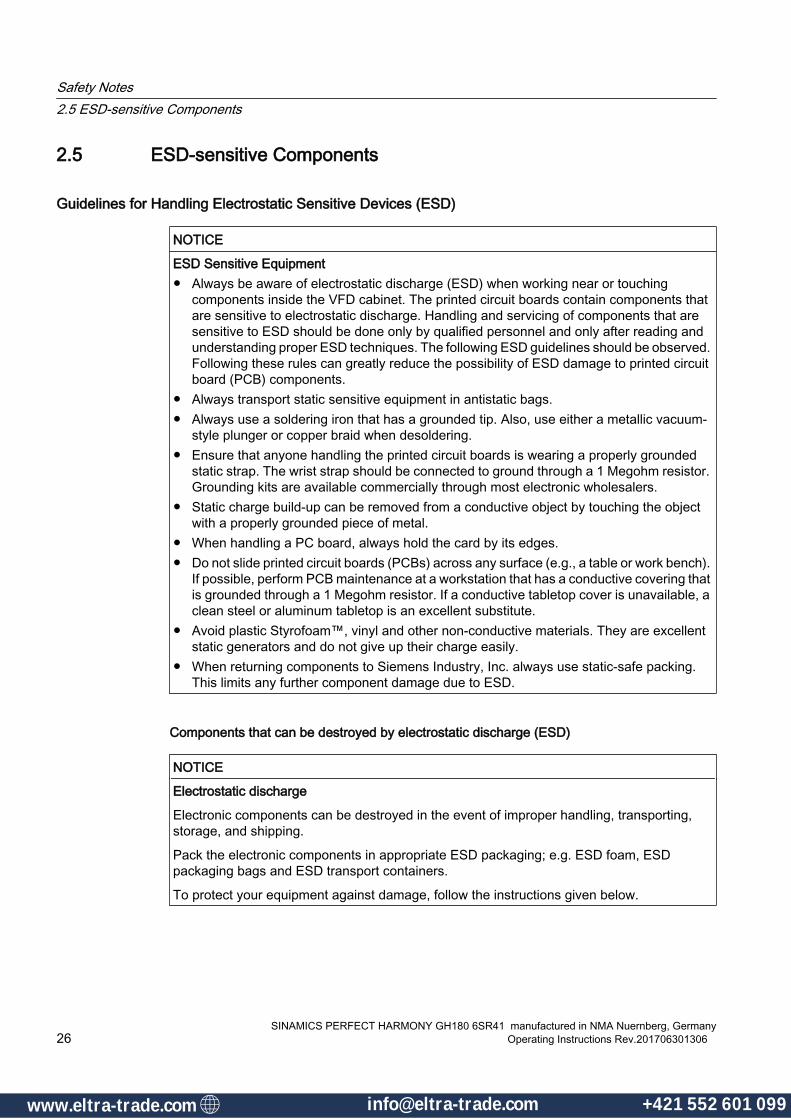
NOTICE
ESD Sensitive Equipment● Always be aware of electrostatic discharge (ESD) when working near or touching
components inside the VFD cabinet. The printed circuit boards contain components that are sensitive to electrostatic discharge. Handling and servicing of components that are sensitive to ESD should be done only by qualified personnel and only after reading and understanding proper ESD techniques. The following ESD guidelines should be observed. Following these rules can greatly reduce the possibility of ESD damage to printed circuit board (PCB) components.
● Always transport static sensitive equipment in antistatic bags.● Always use a soldering iron that has a grounded tip. Also, use either a metallic vacuum-
style plunger or copper braid when desoldering.● Ensure that anyone handling the printed circuit boards is wearing a properly grounded
static strap. The wrist strap should be connected to ground through a 1 Megohm resistor. Grounding kits are available commercially through most electronic wholesalers.
● Static charge build-up can be removed from a conductive object by touching the object with a properly grounded piece of metal.
● When handling a PC board, always hold the card by its edges.● Do not slide printed circuit boards (PCBs) across any surface (e.g., a table or work bench).
If possible, perform PCB maintenance at a workstation that has a conductive covering that is grounded through a 1 Megohm resistor. If a conductive tabletop cover is unavailable, a clean steel or aluminum tabletop is an excellent substitute.
● Avoid plastic Styrofoam™, vinyl and other non-conductive materials. They are excellent static generators and do not give up their charge easily.
● When returning components to Siemens Industry, Inc. always use static-safe packing. This limits any further component damage due to ESD.
Components that can be destroyed by electrostatic discharge (ESD)
NOTICE
Electrostatic discharge
Electronic components can be destroyed in the event of improper handling, transporting, storage, and shipping.
Pack the electronic components in appropriate ESD packaging; e.g. ESD foam, ESD packaging bags and ESD transport containers.
To protect your equipment against damage, follow the instructions given below.
Safety Notes2.5 ESD-sensitive Components
SINAMICS PERFECT HARMONY GH180 6SR41 manufactured in NMA Nuernberg, Germany26 Operating Instructions Rev.201706301306
www.eltra-trade.com [email protected] +421 552 601 099www.eltra-trade.com [email protected] +421 552 601 099

● Avoid physical contact with electronic components. If you need to perform absolutely essential work on these components, then you must wear one of the following protective gear:
– Grounded ESD wrist strap
– ESD shoes or ESD shoe grounding strips if there is also an ESD floor.
● Do not place electronic components close to data terminals, monitors or televisions. Maintain a minimum clearance to the screen (> 10 cm).
● Electronic components should not be brought into contact with electrically insulating materials such as plastic foil, plastic parts, insulating table supports or clothing made of synthetic fibers.
● Place components in contact with ESD-suited materials e.g. ESD tables, ESD surfaces, ESD packaging.
● Measure on the components only if one of the following conditions is met:
– The measuring device is grounded with a protective conductor, for example.
– The measuring head of a floating measuring device has been discharged directly before the measurement.
The necessary ESD protective measures for the entire working range for electrostatically sensitive devices are illustrated once again in the following drawings. Precise instructions for ESD protective measures are specified in the standard DIN EN 61340-5-1.
1 Sitting2 Standing3 Standing/sittinga Conductive floor surface, only effective in conjunction with ESD shoes or ESD shoe grounding
stripsb ESD furniturec ESD shoes or ESD shoe grounding strips are only effective in conjunction with conductive floor‐
ingd ESD clothinge ESD wristbandf Cabinet ground connection
Figure 2-1 ESD Protective Measures
Safety Notes2.5 ESD-sensitive Components
SINAMICS PERFECT HARMONY GH180 6SR41 manufactured in NMA Nuernberg, GermanyOperating Instructions Rev.201706301306 27
www.eltra-trade.com [email protected] +421 552 601 099www.eltra-trade.com [email protected] +421 552 601 099
2.6 Electromagnetic Fields in Electrical Power Engineering Installations
WARNING
Electromagnetic fields "electro smog" when operating electrical power engineering installations
Electromagnetic fields are generated during operation of electrical power engineering installations.
Electromagnetic fields can interfere with electronic devices, which could cause them to malfunction. For example, the operation of heart pacemakers can be impaired, potentially leading to damage to a person's health or even death. It is therefore forbidden for persons with heart pacemakers to enter these areas.
The plant operator is responsible for taking appropriate measures (labels and hazard warnings) to adequately protect operating personnel and others against any possible risk.
● Observe the relevant nationally applicable health and safety regulations. For example, in Germany, "electromagnetic fields" are subject to regulations BGV B11 and BGR B11 stipulated by the German statutory industrial accident insurance institution.
● Display adequate hazard warning notices on the installation.
● Place barriers around hazardous areas.
● Take measures, e.g. using shields, to reduce electromagnetic fields at their source.
● Ensure personnel are wearing the appropriate protective gear.
Safety Notes2.6 Electromagnetic Fields in Electrical Power Engineering Installations
SINAMICS PERFECT HARMONY GH180 6SR41 manufactured in NMA Nuernberg, Germany28 Operating Instructions Rev.201706301306
www.eltra-trade.com [email protected] +421 552 601 099www.eltra-trade.com [email protected] +421 552 601 099

2.7 Information for nominated persons in control of an electrical installation
2.7.1 Security informationSiemens provides products and solutions with industrial security functions that support the secure operation of plants, systems, machines and networks.
In order to protect plants, systems, machines and networks against cyber threats, it is necessary to implement – and continuously maintain – a holistic, state-of-the-art industrial security concept. Siemens’ products and solutions only form one element of such a concept.
Customer is responsible to prevent unauthorized access to its plants, systems, machines and networks. Systems, machines and components should only be connected to the enterprise network or the internet if and to the extent necessary and with appropriate security measures (e.g. use of firewalls and network segmentation) in place.
Additionally, Siemens’ guidance on appropriate security measures should be taken into account. For more information about industrial security, please visit:http://www.siemens.com/industrialsecurity
Siemens’ products and solutions undergo continuous development to make them more secure. Siemens strongly recommends to apply product updates as soon as available and to always use the latest product versions. Use of product versions that are no longer supported, and failure to apply latest updates may increase customer’s exposure to cyber threats.
To stay informed about product updates, subscribe to the Siemens Industrial Security RSS Feed under:http://www.siemens.com/industrialsecurity
Safety Notes2.7 Information for nominated persons in control of an electrical installation
SINAMICS PERFECT HARMONY GH180 6SR41 manufactured in NMA Nuernberg, GermanyOperating Instructions Rev.201706301306 29
www.eltra-trade.com [email protected] +421 552 601 099www.eltra-trade.com [email protected] +421 552 601 099

Safety Notes2.7 Information for nominated persons in control of an electrical installation
SINAMICS PERFECT HARMONY GH180 6SR41 manufactured in NMA Nuernberg, Germany30 Operating Instructions Rev.201706301306
www.eltra-trade.com [email protected] +421 552 601 099www.eltra-trade.com [email protected] +421 552 601 099

Description 33.1 Cabinet Details
3.1.1 Supply Scope
Standard Scope of Supply The scope of supply for the air-cooled SINAMICS PERFECT HARMONY GH180 VFD System Basic unit consists of multiple sections:
● Input / Output section
● Transformer section
● Cell section
● Control section
● Blowers
The standard core VFD enclosure is NEMA 1 Ventilated, and is provided with top and bottom cable access plates, hinged doors with either mechanical or electrical key interlocks, and IP21 degree of protection. Please refer to the Options section of this manual to view other available choices for items such as IP42 degree of protection, redundant cooling, etc.
3.1.2 Input / Output Section
Input / Output SectionThe Input / Output section primarily houses the following lines:
● input medium voltage terminals:
– U1
– V1
– W1
● output medium voltage terminals:
– U2
– V2
– W2
● The bus connections are accessible by way of both top and bottom gland plates.
● The I/O section also contains a protective earth (PE).
SINAMICS PERFECT HARMONY GH180 6SR41 manufactured in NMA Nuernberg, GermanyOperating Instructions Rev.201706301306 31
www.eltra-trade.com [email protected] +421 552 601 099www.eltra-trade.com [email protected] +421 552 601 099

For details see the dimension drawing.
3.1.3 Cell SectionThe basic electrical diagrams for all SINAMICS PERFECT HARMONY GH180 systems are similar. One of the most critical components of the drives is the power cell. The cell voltage is 750V. Depending on the operating load voltage, 9, 12, or 15 cells are used to develop the multi-level PWM output waveform.
Each power cell input side is configured as a 6-pulse diode rectifier. Terminals are supplied with power via a secondary winding of the transformer. The DC output of the rectifier is filtered via the capacitor bank and supplies power to a single-phase converter on the output side. Output terminals of each cell are connected in series in each phase group.
NoteDischarging the DC Link
The power cells include discharge resistors to dissipate stored energy after the input voltage is removed. The power cell DC bus voltage decays to less than 50 VDC in less than 10 minutes.
3.1.4 Control Section
3.1.4.1 Control Section
Coordinated Input Protection SchemeThe SINAMICS PERFECT HARMONY GH180 product uses the NXG controller with an integral I/O system. The Control System continuously measures input currents and voltages to the drive's input transformer and also protects against transformer secondary side faults that cannot be seen by typical primary protection relaying.
Information such as efficiency, power factor, and harmonics are available to the user. Thus, it is required that the drive input switchgear, if not supplied as standard, is interlocked to the control system so that input medium voltage can be interrupted upon the rare event of such a fault.
DANGER
Secondary Circuit Fault
It is required that the drive medium voltage switchgear be interlocked to the control system so that the input medium voltage can be interrupted upon the rare event of such a fault.
Failure to integrate a medium voltage circuit breaking device, or contactor, may cause death, serious personal injury, and damage to the drive.
Description3.1 Cabinet Details
SINAMICS PERFECT HARMONY GH180 6SR41 manufactured in NMA Nuernberg, Germany32 Operating Instructions Rev.201706301306
www.eltra-trade.com [email protected] +421 552 601 099www.eltra-trade.com [email protected] +421 552 601 099
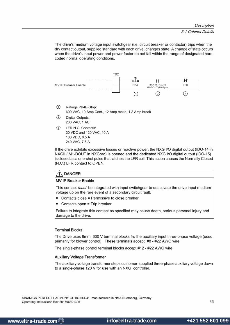
The drive's medium voltage input switchgear (i.e. circuit breaker or contactor) trips when the dry contact output, supplied standard with each drive, changes state. A change of state occurs when the drive's input power and power factor do not fall within the range of designated hard-coded normal operating conditions.
① Ratings PB4E-Stop:600 VAC, 10 Amp Cont., 12 Amp make, 1.2 Amp break
② Digital Outputs:230 VAC, 1 AC
③ LFR N.C. Contacts:30 VDC and 120 VAC, 10 A100 VDC, 0.5 A240 VAC, 7.5 A
If the drive exhibits excessive losses or reactive power, the NXG I/O digital output (IDO-14 in NXGII / M1-DOUT in NXGpro) is opened and the dedicated NXG I/O digital output (IDO-15) is closed as a one-shot pulse that latches the LFR coil. This action causes the Normally Closed (N.C.) LFR contact to OPEN.
DANGER
MV IP Breaker Enable
This contact must be integrated with input switchgear to deactivate the drive input medium voltage up on the rare event of a secondary circuit fault.● Contacts close = Permissive to close breaker● Contacts open = Trip breaker
Failure to integrate this contact as specified may cause death, serious personal injury and damage to the drive.
Terminal BlocksThe Drive uses 8mm, 600 V terminal blocks fro the auxiliary input three-phase voltage (used primarily for blower control). These terminals accept #8 - #22 AWG wire.
The single-phase control terminal blocks accept #12 - #22 AWG wire.
Auxiliary Voltage TransformerThe auxiliary voltage transformer steps customer-supplied three-phase auxiliary voltage down to a single-phase 120 V for use with an NXG controller.
Description3.1 Cabinet Details
SINAMICS PERFECT HARMONY GH180 6SR41 manufactured in NMA Nuernberg, GermanyOperating Instructions Rev.201706301306 33
www.eltra-trade.com [email protected] +421 552 601 099www.eltra-trade.com [email protected] +421 552 601 099
FusesThree control fuses (2 primary, 1 secondary) located in the control wireway section of the drive enclosure, protect the 500 VA transformer.
NoteSelection Option Code K79
With the selection of Option K79 (Auxiliary and Control Voltage Supply) is selected, there is no Auxiliary Transformer installed. The customer supplies voltage to the drive.
3.1.4.2 Control Door Cabinet Components
Multilanguage Keypad and Operator Panel Depending on configuration the drive is equipped with one of the following panels:
● Multi-Language Keypad
● SIMATIC HMI KTP700 operator panel
The panels are located on the front of the drive control cabinet.
Multi-Language Keypad
Multi-Language Keypad and Display Interface
Description3.1 Cabinet Details
SINAMICS PERFECT HARMONY GH180 6SR41 manufactured in NMA Nuernberg, Germany34 Operating Instructions Rev.201706301306
www.eltra-trade.com [email protected] +421 552 601 099www.eltra-trade.com [email protected] +421 552 601 099
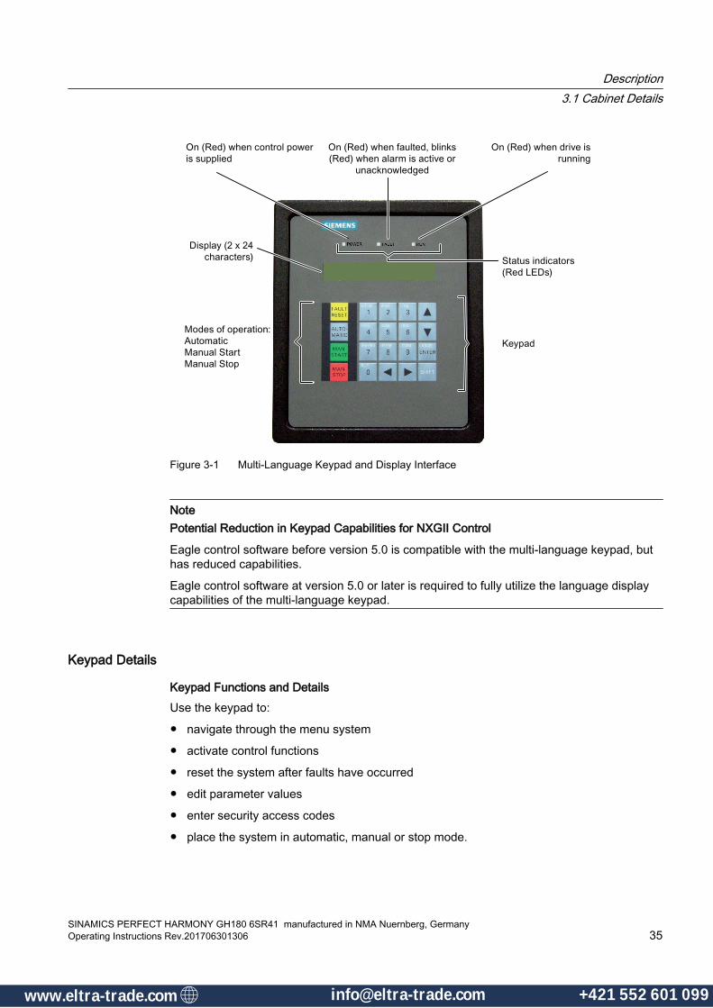
Figure 3-1 Multi-Language Keypad and Display Interface
NotePotential Reduction in Keypad Capabilities for NXGII Control
Eagle control software before version 5.0 is compatible with the multi-language keypad, but has reduced capabilities.
Eagle control software at version 5.0 or later is required to fully utilize the language display capabilities of the multi-language keypad.
Keypad Details
Keypad Functions and DetailsUse the keypad to:
● navigate through the menu system
● activate control functions
● reset the system after faults have occurred
● edit parameter values
● enter security access codes
● place the system in automatic, manual or stop mode.
Description3.1 Cabinet Details
SINAMICS PERFECT HARMONY GH180 6SR41 manufactured in NMA Nuernberg, GermanyOperating Instructions Rev.201706301306 35
www.eltra-trade.com [email protected] +421 552 601 099www.eltra-trade.com [email protected] +421 552 601 099
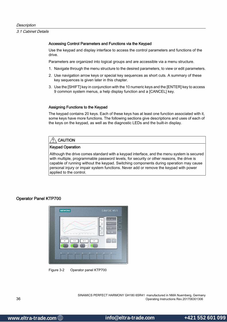
Accessing Control Parameters and Functions via the KeypadUse the keypad and display interface to access the control parameters and functions of the drive.
Parameters are organized into logical groups and are accessible via a menu structure.
1. Navigate through the menu structure to the desired parameters, to view or edit parameters.
2. Use navigation arrow keys or special key sequences as short cuts. A summary of these key sequences is given later in this chapter.
3. Use the [SHIFT] key in conjunction with the 10 numeric keys and the [ENTER] key to access 9 common system menus, a help display function and a [CANCEL] key.
Assigning Functions to the KeypadThe keypad contains 20 keys. Each of these keys has at least one function associated with it, some keys have more functions. The following sections give descriptions and uses of each of the keys on the keypad, as well as the diagnostic LEDs and the built-in display.
CAUTION
Keypad Operation
Although the drive comes standard with a keypad interface, and the menu system is secured with multiple, programmable password levels, for security or other reasons, the drive is capable of running without the keypad. Switching components during operation may cause personal injury or impair system functions. Never add or remove the keypad with power applied to the control.
Operator Panel KTP700
Figure 3-2 Operator panel KTP700
Description3.1 Cabinet Details
SINAMICS PERFECT HARMONY GH180 6SR41 manufactured in NMA Nuernberg, Germany36 Operating Instructions Rev.201706301306
www.eltra-trade.com [email protected] +421 552 601 099www.eltra-trade.com [email protected] +421 552 601 099

The operator panel is located on the front of the control cabinet. It is used for operating, monitoring and commissioning the drive.
Functions and featuresThe operator panel offers the following functions and features:
● Key and touch operation
● Five integrated languages:
– English
– German
– Chinese
– Russian
– Portuguese
● Numerical soft key pad to enter setpoints or parameter values
● Parameter monitoring
● Cursor keys to navigate in the display:
– up
– down
– left
– right
● Fault reset key to reset fault messages
● Automatic key to switch the drive into the automatic mode
● Manual start key to enable the operator to control the drive from the operator panel
● Security access code for secure operation.
Further information about functionsFor a detailed description of parameters that can be monitored on the operator panel, see "NXGpro Control" and "NXGpro Communication manual".
Signal Lights on Cabinet Door (option K20)This option includes signal lights for Drive Ready (white indication), Local Operation (white indication), Operation (green indication), Alarm (amber indication), and Fault (red indication).
Description3.1 Cabinet Details
SINAMICS PERFECT HARMONY GH180 6SR41 manufactured in NMA Nuernberg, GermanyOperating Instructions Rev.201706301306 37
www.eltra-trade.com [email protected] +421 552 601 099www.eltra-trade.com [email protected] +421 552 601 099

Display Instruments on Cabinet Door (option K21)Analog display instruments that display process variables as percentages (%) are integrated in the control cabinet door:
● Motor current (0 % to +120 %)
● Motor speed (–120 % ... 0 … +120 %)
● Motor voltage (0 % to +120 %).
Push button kit (option K29)The components of the pushbutton kit in the control cabinet door panel:
● a START pushbutton
● a STOP pushbutton
● a fault reset button
● a manual speed potentiometer
Off-Local-Remote Selector SwitchThe Off-Local-Remote Selector is the default three-position mode select switch that is mounted on the front of the Drive. If the switch is in the OFF position, the inverter output is inhibited. If the switch is in the Remote position, the control uses either a Remote 4-20 mA DC speed demand or a Network demand, depending on how the project SOP is written. Local mode operation occurs if SW1 is not in the OFF or Remote position; and, the speed demand is set by the Keypad operator .
Off-Hand-Auto Selector SwitchThe Off-Hand- Auto Selector is a three-position mode select switch that is mounted on the front of the Control Door. If the switch is in the OFF position, the inverter output is inhibited. If the switch is in the Auto position, the control uses either a Remote 4-20 mA DC speed demand or a Network demand, depending on how the project SOP is written. Hand mode operation occurs when SW1 is not in the OFF or Auto position; and, the speed demand is set by the Keypad operator.
Keyed Off-Local-Remote Selector SwitchThe Keyed Off-Local-Remote Selector is a three-position mode select switch provided with keyed protection. The switch is mounted on the front of the Drive. If the switch is in the OFF position, the inverter output is inhibited. If the switch is in the Remote position, the control uses either a Remote 4-20 mA DC speed demand or a Network demand, depending on how the project SOP is written. Local mode operation occurs if SW1 is not in the OFF or Remote position; and, the speed demand is set by the Keypad operator.
Keyed Off-Hand-Auto Selector SwitchThe Keyed Off-Hand- Auto Selector is a three-position mode select switch provided with keyed protection. The switch is mounted on the front of the Control Door. If the switch is in the OFF position, the inverter output is inhibited. If the switch is in the Auto position, the control uses either a Remote 4-20 mA DC speed demand or a Network demand, depending on how the
Description3.1 Cabinet Details
SINAMICS PERFECT HARMONY GH180 6SR41 manufactured in NMA Nuernberg, Germany38 Operating Instructions Rev.201706301306
www.eltra-trade.com [email protected] +421 552 601 099www.eltra-trade.com [email protected] +421 552 601 099
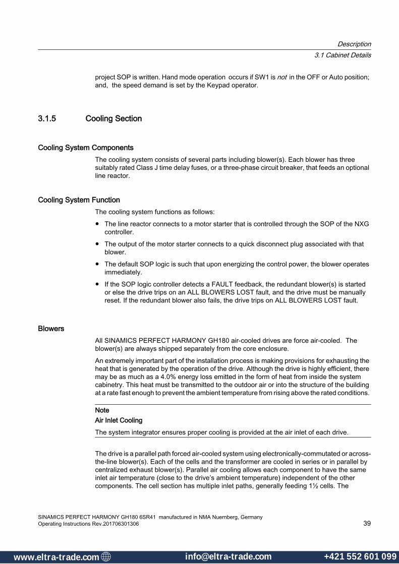
project SOP is written. Hand mode operation occurs if SW1 is not in the OFF or Auto position; and, the speed demand is set by the Keypad operator.
3.1.5 Cooling Section
Cooling System Components The cooling system consists of several parts including blower(s). Each blower has three suitably rated Class J time delay fuses, or a three-phase circuit breaker, that feeds an optional line reactor.
Cooling System Function The cooling system functions as follows:
● The line reactor connects to a motor starter that is controlled through the SOP of the NXG controller.
● The output of the motor starter connects to a quick disconnect plug associated with that blower.
● The default SOP logic is such that upon energizing the control power, the blower operates immediately.
● If the SOP logic controller detects a FAULT feedback, the redundant blower(s) is started or else the drive trips on an ALL BLOWERS LOST fault, and the drive must be manually reset. If the redundant blower also fails, the drive trips on ALL BLOWERS LOST fault.
BlowersAll SINAMICS PERFECT HARMONY GH180 air-cooled drives are force air-cooled. The blower(s) are always shipped separately from the core enclosure.
An extremely important part of the installation process is making provisions for exhausting the heat that is generated by the operation of the drive. Although the drive is highly efficient, there may be as much as a 4.0% energy loss emitted in the form of heat from inside the system cabinetry. This heat must be transmitted to the outdoor air or into the structure of the building at a rate fast enough to prevent the ambient temperature from rising above the rated conditions.
NoteAir Inlet Cooling
The system integrator ensures proper cooling is provided at the air inlet of each drive.
The drive is a parallel path forced air-cooled system using electronically-commutated or across-the-line blower(s). Each of the cells and the transformer are cooled in series or in parallel by centralized exhaust blower(s). Parallel air cooling allows each component to have the same inlet air temperature (close to the drive’s ambient temperature) independent of the other components. The cell section has multiple inlet paths, generally feeding 1½ cells. The
Description3.1 Cabinet Details
SINAMICS PERFECT HARMONY GH180 6SR41 manufactured in NMA Nuernberg, GermanyOperating Instructions Rev.201706301306 39
www.eltra-trade.com [email protected] +421 552 601 099www.eltra-trade.com [email protected] +421 552 601 099
transformer section has multiple air inlet paths. The transformer is baffled to force air through the secondary coils and around the winding.
The cell section and transformer section exhaust air into an air duct. Each cell’s input and output power connections are made at the rear of the cell via blind-mate power plugs. The male connecting bus is located in line with the exhaust air of the cell. For systems with mechanical cell bypass, the contactors are mounted on an additional bus, located in the rear common exhaust air plenum. All of the bus and the contactors are therefore forced-air cooled, but at an elevated ambient due to cell and transformer losses. Two phases of each cell’s inputs are fused. The fuse ambient is the same as the drive’s ambient air temperature.
If redundant blowers are required, a cover plate is removed from the top of the enclosure and a redundant blower cage assembly is installed. Dampers are installed at the base of the redundant blower cage to prevent reverse air flow. The dampers are opened and closed based on differential air pressure. The blower cage assembly design consists of a steel frame with mesh on three sides (duct interface jobs require alternative pre-engineered blower cage).
Air is exhausted out of the front and sides of the cage. Air is not exhausted out of the back or top of the cage (with the exception of rear duct cage).
Note
Upon customer request, design for a front or rear duct exhaust can be engineered. Contact Siemens.
A fault contact is wired into the NXG control I/O. If a redundant blower is selected, the control cycles the blower periodically (generally every seven days) and toggles them upon receiving a FAULT feedback from the blower.
NOTICE
Never energize the drive without operational blowers providing air flow.
The drive contains components that have losses in the IDLE state. Without air flow, these losses may heat up components and eventually damage the drive over time.
Applying Medium Voltage without air flow will result in a trip from the Coordinated Input Protection Scheme.
To remove the unit's latent heat, Siemens recommends running the blower for ten minutes after removing Medium Voltage.
See alsoPreparing for Use (Page 61)
Air-to-Air Heat Exchanged (W41) Drive Preparation
NOTICE
To avoid serious personal injury, accidental death, or major property damage, read and follow all safety instructions in manual provided with heat exchanger. Maintain all safety labels in good condition. If necessary, replace labels using provided part numbers.
Description3.1 Cabinet Details
SINAMICS PERFECT HARMONY GH180 6SR41 manufactured in NMA Nuernberg, Germany40 Operating Instructions Rev.201706301306
www.eltra-trade.com [email protected] +421 552 601 099www.eltra-trade.com [email protected] +421 552 601 099

Use of an air-to-air heat exchanger is an alternative solution to use of fans in air-cooled drives. Whenever heat exchanger cooling method is selected by customer, the fans shipping split are not required. Additional parts such as plenums and exhaust hood may be required. Some of these parts may be shipping splits depending upon each specific design. Refer to project specific outline and assembly drawings provided by Siemens for more detail.
Follow procedures in this manual and other respective manuals delivered with the drive for additional information about handling, installation, commissioning and maintenance of drive.
Heat Exchanger
The heat exchanger may be shipped with or without the drive. It usually ships in multiple shipping splits.
Before starting any work on the unit, be sure to review the heat exchanger manual. While working with heat exchangers some items may require special attention. The following items include, but are not limited to, those listed below:
● Initial inspection (including fans and blades)
● Handling
● Installation
● Sealing or water-proofing
● Ductwork installation
Note
Refer to the heat exchanger manual for more details related to handling, assembly and start-up of heat exchanger.
Heat exchanger units require periodic maintenance. This includes but is not limited to the areas listed below:
● Ductwork seals
● Drains
● Filters
● Ambient air stream
● Drive cooling air stream
Note
Refer to the heat exchanger manual for details related to heat exchanger maintenance.
Description3.1 Cabinet Details
SINAMICS PERFECT HARMONY GH180 6SR41 manufactured in NMA Nuernberg, GermanyOperating Instructions Rev.201706301306 41
www.eltra-trade.com [email protected] +421 552 601 099www.eltra-trade.com [email protected] +421 552 601 099

3.1.6 Description of the option codes
3.1.6.1 Modbus Interface (software activation) (option G22)Modbus RTU Interface, Network 1, for serial communication is included. Software activation of the interface is included without additional hardware.
For further information see Function manual "NXG Communication", chapter "Modbus Communication".
3.1.6.2 Modbus Interface (software activation) (option G32)An additional Modbus Interface, Network 2, for serial communication is included. Software activation of the interface is included without additional hardware.
For further information see Function manual "NXG Communication", chapter "Modbus Communication".
3.1.6.3 DeviceNet profile 12 interface (option G23)DeviceNet Profile12 Interface, Network 1, for serial communication is included.
For further information see Function manual "NXG Communication", chapter "DeviceNet (profile 12) Communication".
3.1.6.4 DeviceNet profile 12 interface (option G43)An additional DeviceNet Profile12 Interface, Network 2, for serial communication is included.
For further information see Function manual "NXG Communication", chapter "DeviceNet (profile 12) Communication".
3.1.6.5 Control Net Interface (option G26)Control Net Interface, Network 1, for serial communication is included.
For further information see Function manual "NXG Communication", chapter "Control Net Communication".
3.1.6.6 Control Net Interface (option G46)An additional Control Net Interface, Network 2, for serial communication is included.
For further information see Function manual "NXG Communication", chapter "Control Net Communication".
3.1.6.7 Modbus Ethernet Interface (software activation) (option G28)Modbus Ethernet Interface, Network 1, for serial communication is included.
Description3.1 Cabinet Details
SINAMICS PERFECT HARMONY GH180 6SR41 manufactured in NMA Nuernberg, Germany42 Operating Instructions Rev.201706301306
www.eltra-trade.com [email protected] +421 552 601 099www.eltra-trade.com [email protected] +421 552 601 099
For further information see Function manual "NXG Communication", chapter "Modbus Ethernet Communication".
3.1.6.8 Modbus Ethernet Interface (software activation) (option G38)An additional Modbus Ethernet Interface, Network 2, for serial communication is included.
For further information see Function manual "NXG Communication", chapter "Modbus Ethernet Communication".
3.1.6.9 PROFIBUS DP (option G91)PROFIBUS DP, Network 1, for serial communication is included.
For further information see Function manual "NXG Communication", chapter "PROFIBUS DP Communication".
3.1.6.10 PROFIBUS DP (option G93)An additional PROFIBUS DP, Network 2, for serial communication is included.
For further information see Function manual "NXG Communication", chapter "PROFIBUS DP Communication".
3.1.6.11 Connection for control voltage provided by customer AC 220/230 V (option K68)The drive is prepared to connect control voltage provided by customer. The maximum current consumption is limited to 4 A.
For further details see: Circuit diagrams and charts
3.1.6.12 Control voltage AC 12 V internal (option K69)The drive has an integrated control circuit transformer.
For further details see: Circuit diagrams and charts
3.1.6.13 Connection for control voltage provided by customer AC 120 V (option K79)With this option the customer can control voltage for the drive.
For further details see: Circuit diagrams and charts
3.1.6.14 Output reactor (option L09)The output reactor limits the capacitive charge/discharge currents of motor supply cables.
The output reactor is installed in an auxiliary cabinet that has the same degree of protection as the drive. The width of the cabinet increases as a result.
For further details, see: Layout diagrams, dimension drawings.
Description3.1 Cabinet Details
SINAMICS PERFECT HARMONY GH180 6SR41 manufactured in NMA Nuernberg, GermanyOperating Instructions Rev.201706301306 43
www.eltra-trade.com [email protected] +421 552 601 099www.eltra-trade.com [email protected] +421 552 601 099
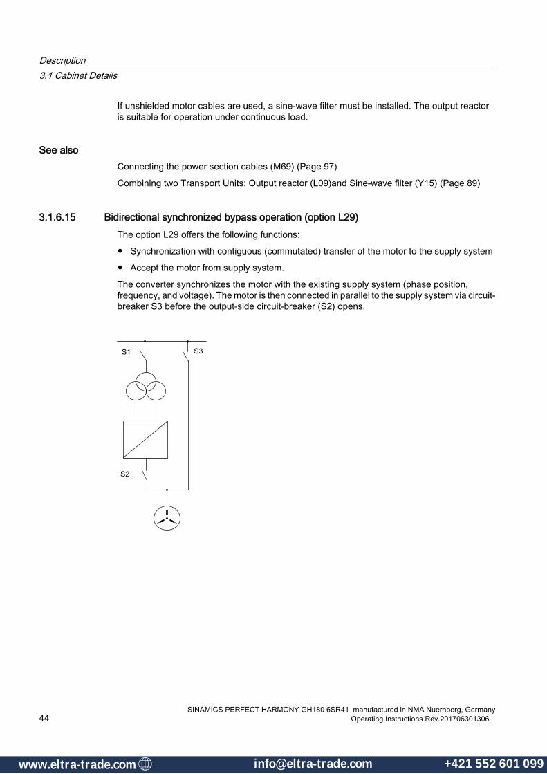
If unshielded motor cables are used, a sine-wave filter must be installed. The output reactor is suitable for operation under continuous load.
See alsoConnecting the power section cables (M69) (Page 97)
Combining two Transport Units: Output reactor (L09)and Sine-wave filter (Y15) (Page 89)
3.1.6.15 Bidirectional synchronized bypass operation (option L29)The option L29 offers the following functions:
● Synchronization with contiguous (commutated) transfer of the motor to the supply system
● Accept the motor from supply system.
The converter synchronizes the motor with the existing supply system (phase position, frequency, and voltage). The motor is then connected in parallel to the supply system via circuit-breaker S3 before the output-side circuit-breaker (S2) opens.
Description3.1 Cabinet Details
SINAMICS PERFECT HARMONY GH180 6SR41 manufactured in NMA Nuernberg, Germany44 Operating Instructions Rev.201706301306
www.eltra-trade.com [email protected] +421 552 601 099www.eltra-trade.com [email protected] +421 552 601 099
Principle of operationApprox. 200 ms to 300 ms elapse taking into account the intrinsic time constants of both circuit breakers (opening and closing times). During this period, the motor commutates from the converter to the supply system. This results in a smooth transition of the motor to the supply system. If the motor is then to be removed from the supply system and operated via the converter, commutation occurs in the reverse sequence. The converter is first ramped up (no load) and its output voltage is aligned with the line voltage with respect to the phase position, frequency, and amplitude (= motor voltage). Circuit-breaker S2 is closed before S3 is opened and the motor is disconnected from the supply system. In this way, the motor is transferred smoothly to the converter and can be operated with speed control or brought to a controlled standstill. Regulated operation during the ramp-up/down procedure minimizes starting and impulse torques that could damage the mechanical assembly or cause surge and pressure fluctuations in the process.
Voltage Sensing Module (VSM10)With option L29, a Voltage Sensing Module VSM10 is integrated in the converter. In conjunction with voltage converters provided by the customer on the medium-voltage side, the VSM10 records the line voltage with respect to the phase position, frequency, and voltage. It provides the data for synchronizing the motor with the supply system and the supply system with the converter. The converter controller provides the control signals for the two circuit-breakers, which must be provided on the system side. To decouple the converter output to ground during commutation, option L08 (output reactor) or option Y15 (sinusoidal filter) are also required. The circuit-breaker S3 must be dimensioned to provide adequate protection for the motor concerned. If temperature sensors are installed in the motor, these must be monitored on the system side during supply system operation.
You can find further information on the Voltage Sensing Module (VSM10) in Section "Description of the Components".
Note
Option L29 can only be used when the converter output voltage and the line voltage are the same.
3.1.6.16 Cabinet illumination and service socket in trigger and control section (option L50)One universal light and one service socket are installed in each cabinet element for the control section. It is supplied externally with voltage and must be protected with fuses (max. 10 A).
The cabinet illumination can be switched on manually.
Description3.1 Cabinet Details
SINAMICS PERFECT HARMONY GH180 6SR41 manufactured in NMA Nuernberg, GermanyOperating Instructions Rev.201706301306 45
www.eltra-trade.com [email protected] +421 552 601 099www.eltra-trade.com [email protected] +421 552 601 099

3.1.6.17 Cabinet anti-condensation heating, temperature-monitored (option L55)The anti-condensation heating is used at low ambient temperatures and high levels of humidity to prevent condensation. The number of cabinet heaters installed depends on the number of cabinet panels. A constant minimum temperature in the cabinet is ensured as the temperatures of the anti-condensation heaters are automatically monitored using a thermostat. The anti-condensation heating is controlled using a bimetallic switch that can be adjusted.
Figure 3-3 Cabinet anti-condensation heating
For further detail see Technical data and drawings.
3.1.6.18 2 x 2 thermistor protection relays for alarms and faults (option L81)This option provides four thermistor protection relays for PTC thermistors (type A) for alarm and trip. The power supply for the relay and the evaluation is provided in the drive.
For further details refer to the Interconnection diagram
3.1.6.19 3 x 2 thermistor protection relays for alarms and faults (option L82)This option provides six thermistor protection relays for PTC thermistors (type A) for alarm and trip. The power supply for the relay and the evaluation is provided in the drive.
For further details refer to the Interconnection diagram
Description3.1 Cabinet Details
SINAMICS PERFECT HARMONY GH180 6SR41 manufactured in NMA Nuernberg, Germany46 Operating Instructions Rev.201706301306
www.eltra-trade.com [email protected] +421 552 601 099www.eltra-trade.com [email protected] +421 552 601 099
3.1.6.20 2 Pt100 evaluation units with 3 inputs each (option L91)Each Pt100 evaluation unit can monitor up to three sensors. For all three sensors, the limits for alarm and trip must be set centrally. The output relays are integrated into the internal fault and shutdown circuit of the drive.
For further details refer to the Circuit diagrams and charts
3.1.6.21 Pt100 evaluation unit with 6 inputs and 2 analog outputs (option L93)The Pt100 evaluation unit can monitor up to six sensors. The limit values can be programmed by the user for each channel. In the
standard setting, the measuring channels are divided into two groups of three channels each. With motors, for example, three Pt100 can be monitored in the stator windings and two Pt100 in the motor bearings. Channels that are not used can be suppressed using appropriate parameter settings.
The output relays are integrated into the internal fault and shutdown circuit of the drive. Additionally two freely programmable analog outputs (0/4 mA to 20 mA and 0/2 V to 10 V) are available.
Note
The analog outputs are not evaluated by the controller.
For further details see: Interconnection diagram.
3.1.6.22 Pt100 evaluation unit with 6 inputs for ex-proof motors and6 analog outputs(option L95)For use in explosion-proof motors, Zone 2, Zone 22 (non-conductive dusts) Div. 2, and non-hazardous zones, six evaluation units are available (marking, explosion protection: II (1) GD [EEx ia] IIC/IIB and II 3 G EEx nAC II T4). The resistance thermometers can be connected using a two-wire, three-wire or four-wire system. The following temperature sensors can be connected:
● Resistance thermometers according to IEC 60751: Pt100, Pt500, Pt1000
● Resistance thermometers according to DIN 43760: Ni100, Ni500, Ni1000
The alarm and fault messages are combined and integrated into the signaling and shutdown circuit of the drive.
Note
The analog outputs are not evaluated by the control.
Note
The maximum cable cross-section that can be connected on the plant side is 1.5 mm². The cables for the intrinsically safe circuits are routed according to the layout diagram.
Description3.1 Cabinet Details
SINAMICS PERFECT HARMONY GH180 6SR41 manufactured in NMA Nuernberg, GermanyOperating Instructions Rev.201706301306 47
www.eltra-trade.com [email protected] +421 552 601 099www.eltra-trade.com [email protected] +421 552 601 099

3.1.6.23 Mechanical safety locking system - Castell (option M10)The mechanical safety locking system is based on the key transfer system developed by Castell.
The medium-voltage breaker must be opened before access can be gained to the coded key of the key exchange unit. The opened medium-voltage breaker releases the key to the key exchange unit. This key is used in turn to release the keys for the cabinet doors of the power unit. This key interlocking system means that the drive is disconnected from the medium-voltage supply and that no cabinet components are connected to medium voltage. As long as the cabinet doors are not closed again and the keys to the converter cabinet doors are not inserted back in the key unit, the key for the medium-voltage breaker will not be released and thus the breaker cannot be closed.
① Circuit-breaker② Coded key for the key transfer unit③ Key transfer unit④ Coded key for cabinet doors⑤ Locks for the cabinet doors
Figure 3-4 Principle of the mechanical safety locking system - Castell
3.1.6.24 Gland plates (option M35)With this option the gland plate for input/output power is made of aluminum.
Description3.1 Cabinet Details
SINAMICS PERFECT HARMONY GH180 6SR41 manufactured in NMA Nuernberg, Germany48 Operating Instructions Rev.201706301306
www.eltra-trade.com [email protected] +421 552 601 099www.eltra-trade.com [email protected] +421 552 601 099

Note
Gland plates for control cables always are made of aluminum.
3.1.6.25 Gland plates (option M36)With this option the gland plate for input/output power is made of brass.
Note
Gland plates for control cables always are made of aluminum.
3.1.6.26 Gland plates (option M37)With this option the gland plate for input/output power is made of stainless steel.
Note
Gland plates for control cables always are made of aluminum.
3.1.6.27 IP42 degree of protection (option M42)This option increases the degree of protection of the converter from IP22 to IP42. Additional close-meshed grilles where the air comes in and goes out prevent the ingress of solid matter with diameters > 1.0 mm.
See alsoInstalling the Fans (IP42) (Page 101)
3.1.6.28 Redundant fan (Option M61)To increase the plant availability, the drive can be fitted with an additional, redundant fan. If a fan in the drive cabinet fails, the redundant fan is switched in by the drive controller without this causing the drive. This prevents production failures or interruptions. The replacement of the defective fan can be postponed to the next planned stoppage.
3.1.6.29 Drive prepared for duct flange connection in front (M64)With option M64, the drive is prepared for connection to an external exhaust air system to the front of the blower assembly.
Description3.1 Cabinet Details
SINAMICS PERFECT HARMONY GH180 6SR41 manufactured in NMA Nuernberg, GermanyOperating Instructions Rev.201706301306 49
www.eltra-trade.com [email protected] +421 552 601 099www.eltra-trade.com [email protected] +421 552 601 099

This option is applicable when external exhaust ducting at the output of the blower to carry the hot air blowing out of the drive cabinet outside the room.
When configuring the exhaust air ducts for the drive ventilation system, it is essential to ensure that the air flow rates stipulated in the technical data are observed. The pressure drop between the air inlet and air outlet of the drive is different for different versions. The additional pressure drop due to the external exhaust air system must not be lower than 0Pa and higher than 50Pa.
Note Connection of an external air duct● Provide suitable openings in the air duct for changing the blowers● Make sure that the cabinet doors can be opened and closed after mounting the air duct.
CAUTION
Values for sound pressure level
Depending on the design, the exhaust air system can affect the values for sound pressure level. For further information contat your local Siemens partner.
See alsopartner (www.siemens.com/automation/partner)
3.1.6.30 Harsh environment conditions (M67)With option M67, the drive is equipped for harsh environment conditions (high humidity, tropical or seaside location).
Note
This is not a marine certification compliant option.
Measures comprise:
● Aluminum parts coated or anodized
● Galvanized parts coated or replaced with stainless steel parts
● Double vacuum pressure impregnation (VPI) of the transformer (protection against salt-mist, environment class 3C2 acc. to IEC60721-3-3)
● Paint finish for tropical conditions
● Coated printed circuit boards
3.1.6.31 Drive prepared for duct flange connection in rear (M68)With option M64, the drive is prepared for connection to an external exhaust air system to the rear of the blower assembly.
Description3.1 Cabinet Details
SINAMICS PERFECT HARMONY GH180 6SR41 manufactured in NMA Nuernberg, Germany50 Operating Instructions Rev.201706301306
www.eltra-trade.com [email protected] +421 552 601 099www.eltra-trade.com [email protected] +421 552 601 099

This option is applicable when external exhaust ducting at the output of the blower to carry the hot air blowing out of the drive cabinet outside the room.
When configuring the exhaust air ducts for the drive ventilation system, make sure that the air flow rates are observed.
The pressure drop between the air inlet and air outlet of the drive is different for different versions. The additional pressure drop due to the external exhaust air system must not be lower than 0 Pa and higher than 50 Pa.
Note Connection of an external air duct● Provide suitable openings in the air duct for changing the blowers● Make sure that the cabinet doors can be opened and closed after mounting the air duct.
Layout diagrams, dimension drawings
CAUTION
Values for sound pressure level
Depending on the design, the exhaust air system can affect the values for sound pressure level. For further information contat your local Siemens partner.
You can find your local contact here (http://support.automation.siemens.com/WW/view/en/16604999).
3.1.6.32 Extended space for bottom cable entry (Option M69)Extra control cabinet, mounted at the left side.
Dimensions● 300 mm width
● 520 mm depth
● cable entry area: 300 x 400 mm
For further details see: Layout diagrams, dimension drawings
See alsoConnecting the power section cables (M69) (Page 97)
3.1.6.33 Controlled outgoing circuit for auxiliary equipment 400 V 3 AC or 460/480 V 3 AC (option N30)
This option provides a controlled output that is protected via the motor circuit breaker and is used for operating external auxiliary equipment (e.g. separately-driven fan for motor, pumps, and oil supplies).
Description3.1 Cabinet Details
SINAMICS PERFECT HARMONY GH180 6SR41 manufactured in NMA Nuernberg, GermanyOperating Instructions Rev.201706301306 51
www.eltra-trade.com [email protected] +421 552 601 099www.eltra-trade.com [email protected] +421 552 601 099

The contactor is energized by means of an ON command on the converter. The OFF command deactivates the contactor.
Table 3-1 Outgoing circuit for auxiliary equipment (option N30)
Controlled outgoing circuit for auxiliary equipment Setting range of the motor circuit breaker400 V 3 AC, 50 Hz, max. 4 KW Cos phi = 0.8; 9 A to 12.5 A460/480 V 3 AC, 60 Hz, max. 4.8 KW Cos phi = 0.8; 9 A to 12.5 A
Table 3-2 T-X30 terminal strip for connecting auxiliary equipment
Supplying the auxiliary voltage Outgoing circuit for auxiliary equip‐ment
Feedback: auxiliary equipment ON
Terminal Connector Terminal Connector Terminal Connector.T–X30:6 L1 .T–X30:3 L1 .T–X30:1 Relay contact
max. 60 V DC .T–X30:7 L2 .T–X30:4 L2 .T–X30:2.T–X30:8 L3 .T–X30:5 L3
Note
The infeed required for the drive power supply must be provided externally.
For further details see: Interconnection diagram
3.1.6.34 Controlled outgoing circuit for auxiliary equipment 400 V 3 AC or 460/480 V 3 AC (option N31)
This option provides a controlled output that is protected via the motor circuit breaker and is used for operating external auxiliary equipment (e.g. separately-driven fan for motor, pumps, and oil supplies).
The contactor is energized by means of an ON command on the converter. The OFF command deactivates the contactor.
Table 3-3 Outgoing circuit for auxiliary equipment (option N31)
Controlled outgoing circuit for auxiliary equipment Setting range of the motor circuit breaker400 V 3 AC, 50 Hz, max. 7 KW Cos phi = 0.8; 14 A to 20 A460/480 V 3 AC, 60 Hz, max. 8 KW Cos phi = 0.8; 14 A to 20 A
Description3.1 Cabinet Details
SINAMICS PERFECT HARMONY GH180 6SR41 manufactured in NMA Nuernberg, Germany52 Operating Instructions Rev.201706301306
www.eltra-trade.com [email protected] +421 552 601 099www.eltra-trade.com [email protected] +421 552 601 099
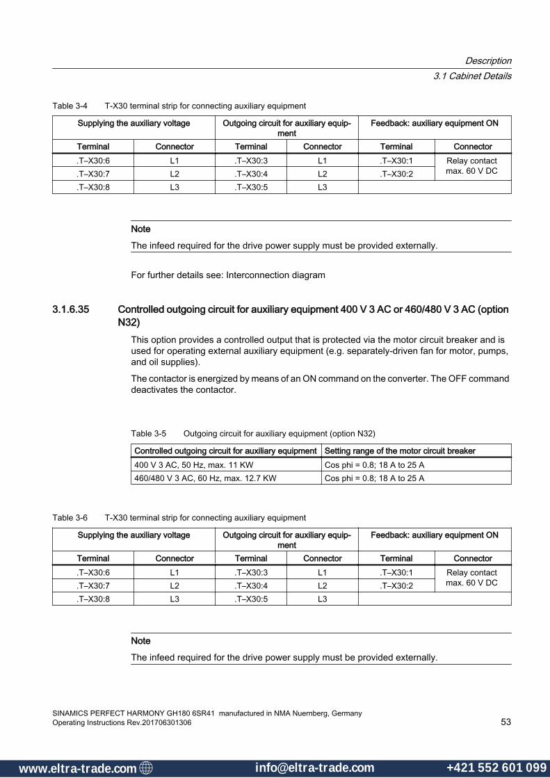
Table 3-4 T-X30 terminal strip for connecting auxiliary equipment
Supplying the auxiliary voltage Outgoing circuit for auxiliary equip‐ment
Feedback: auxiliary equipment ON
Terminal Connector Terminal Connector Terminal Connector.T–X30:6 L1 .T–X30:3 L1 .T–X30:1 Relay contact
max. 60 V DC .T–X30:7 L2 .T–X30:4 L2 .T–X30:2.T–X30:8 L3 .T–X30:5 L3
Note
The infeed required for the drive power supply must be provided externally.
For further details see: Interconnection diagram
3.1.6.35 Controlled outgoing circuit for auxiliary equipment 400 V 3 AC or 460/480 V 3 AC (option N32)
This option provides a controlled output that is protected via the motor circuit breaker and is used for operating external auxiliary equipment (e.g. separately-driven fan for motor, pumps, and oil supplies).
The contactor is energized by means of an ON command on the converter. The OFF command deactivates the contactor.
Table 3-5 Outgoing circuit for auxiliary equipment (option N32)
Controlled outgoing circuit for auxiliary equipment Setting range of the motor circuit breaker400 V 3 AC, 50 Hz, max. 11 KW Cos phi = 0.8; 18 A to 25 A460/480 V 3 AC, 60 Hz, max. 12.7 KW Cos phi = 0.8; 18 A to 25 A
Table 3-6 T-X30 terminal strip for connecting auxiliary equipment
Supplying the auxiliary voltage Outgoing circuit for auxiliary equip‐ment
Feedback: auxiliary equipment ON
Terminal Connector Terminal Connector Terminal Connector.T–X30:6 L1 .T–X30:3 L1 .T–X30:1 Relay contact
max. 60 V DC .T–X30:7 L2 .T–X30:4 L2 .T–X30:2.T–X30:8 L3 .T–X30:5 L3
Note
The infeed required for the drive power supply must be provided externally.
Description3.1 Cabinet Details
SINAMICS PERFECT HARMONY GH180 6SR41 manufactured in NMA Nuernberg, GermanyOperating Instructions Rev.201706301306 53
www.eltra-trade.com [email protected] +421 552 601 099www.eltra-trade.com [email protected] +421 552 601 099

3.1.6.36 Controlled outgoing circuit for auxiliary equipment 400 V 3 AC or 460/480 V 3 AC (option N33)
This option provides a controlled output that is protected via the motor circuit breaker and is used for operating external auxiliary equipment (e.g. separately-driven fan for motor, pumps, and oil supplies).
The contactor is energized by means of an ON command on the converter. The OFF command deactivates the contactor.
Table 3-7 Outgoing circuit for auxiliary equipment (option N33)
Controlled outgoing circuit for auxiliary equipment Setting range of the motor circuit breaker400 V 3 AC, 50 Hz, max. 15 KW Cos phi = 0.8; 28 A to 40 A460/480 V 3 AC, 60 Hz, max. 17.5 KW Cos phi = 0.8; 28 A to 40 A
Table 3-8 T-X30 terminal strip for connecting auxiliary equipment
Supplying the auxiliary voltage Outgoing circuit for auxiliary equip‐ment
Feedback: auxiliary equipment ON
Terminal Connector Terminal Connector Terminal Connector.T–X30:6 L1 .T–X30:3 L1 .T–X30:1 Relay contact
max. 60 V DC .T–X30:7 L2 .T–X30:4 L2 .T–X30:2.T–X30:8 L3 .T–X30:5 L3
Note
The infeed required for the drive power supply must be provided externally.
3.1.6.37 Controlled outgoing circuit for auxiliary equipment 230 V 1 AC or 120 V 1 AC (option N35)This option provides a controlled output that is protected via the motor circuit breaker and is used for operating external auxiliary equipment (e.g. separately-driven fan for motor, pumps, and oil supplies).
The contactor is energized by means of an ON command on the converter. The OFF command deactivates the contactor.
Table 3-9 Outgoing circuit for auxiliary equipment (option N35)
Controlled outgoing circuit for auxiliary equipment Setting range of the motor circuit breaker120 V 1 AC, 60 Hz, max. 1 KW 230 V 1 AC, 50 Hz, max. 1.2 KW
Description3.1 Cabinet Details
SINAMICS PERFECT HARMONY GH180 6SR41 manufactured in NMA Nuernberg, Germany54 Operating Instructions Rev.201706301306
www.eltra-trade.com [email protected] +421 552 601 099www.eltra-trade.com [email protected] +421 552 601 099

Table 3-10 T-X30 terminal strip for connecting auxiliary equipment
Supplying the auxiliary voltage Outgoing circuit for auxiliary equip‐ment
Feedback: auxiliary equipment ON
Terminal Connector Terminal Connector Terminal Connector.T–X30:6 L1 .T–X30:3 L1 .T–X30:1 Relay contact
max. 60 V DC .T–X30:7 L2 .T–X30:4 L2 .T–X30:2.T–X30:8 L3 .T–X30:5 L3
Note
The infeed required for the drive power supply must be provided externally.
3.1.6.38 Controlled outgoing circuit for auxiliary equipment 230 V 1 AC or 120 V 1 AC (option N36)This option provides a controlled output that is protected via the motor circuit breaker and is used for operating external auxiliary equipment (e.g. separately-driven fan for motor, pumps, and oil supplies).
The contactor is energized by means of an ON command on the converter. The OFF command deactivates the contactor.
Table 3-11 Outgoing circuit for auxiliary equipment (option N33)
Controlled outgoing circuit for auxiliary equipment Setting range of the motor circuit breaker400 V 3 AC, 50 Hz, max. 15 KW Cos phi = 0.8; 28 A to 40 A460/480 V 3 AC, 60 Hz, max. 17.5 KW Cos phi = 0.8; 28 A to 40 A
Table 3-12 T-X30 terminal strip for connecting auxiliary equipment
Supplying the auxiliary voltage Outgoing circuit for auxiliary equip‐ment
Feedback: auxiliary equipment ON
Terminal Connector Terminal Connector Terminal Connector.T–X30:6 L1 .T–X30:3 L1 .T–X30:1 Relay contact
max. 60 V DC .T–X30:7 L2 .T–X30:4 L2 .T–X30:2.T–X30:8 L3 .T–X30:5 L3
Note
The infeed required for the drive power supply must be provided externally.
Description3.1 Cabinet Details
SINAMICS PERFECT HARMONY GH180 6SR41 manufactured in NMA Nuernberg, GermanyOperating Instructions Rev.201706301306 55
www.eltra-trade.com [email protected] +421 552 601 099www.eltra-trade.com [email protected] +421 552 601 099
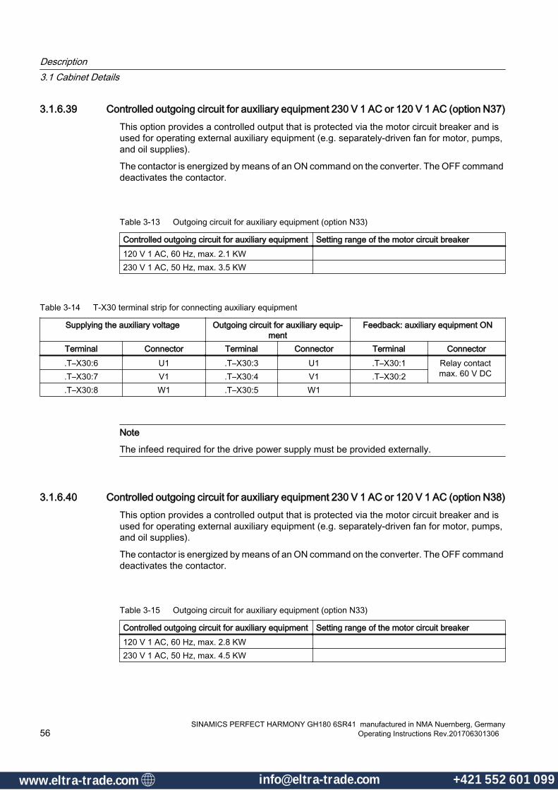
3.1.6.39 Controlled outgoing circuit for auxiliary equipment 230 V 1 AC or 120 V 1 AC (option N37)This option provides a controlled output that is protected via the motor circuit breaker and is used for operating external auxiliary equipment (e.g. separately-driven fan for motor, pumps, and oil supplies).
The contactor is energized by means of an ON command on the converter. The OFF command deactivates the contactor.
Table 3-13 Outgoing circuit for auxiliary equipment (option N33)
Controlled outgoing circuit for auxiliary equipment Setting range of the motor circuit breaker120 V 1 AC, 60 Hz, max. 2.1 KW 230 V 1 AC, 50 Hz, max. 3.5 KW
Table 3-14 T-X30 terminal strip for connecting auxiliary equipment
Supplying the auxiliary voltage Outgoing circuit for auxiliary equip‐ment
Feedback: auxiliary equipment ON
Terminal Connector Terminal Connector Terminal Connector.T–X30:6 U1 .T–X30:3 U1 .T–X30:1 Relay contact
max. 60 V DC .T–X30:7 V1 .T–X30:4 V1 .T–X30:2.T–X30:8 W1 .T–X30:5 W1
Note
The infeed required for the drive power supply must be provided externally.
3.1.6.40 Controlled outgoing circuit for auxiliary equipment 230 V 1 AC or 120 V 1 AC (option N38)This option provides a controlled output that is protected via the motor circuit breaker and is used for operating external auxiliary equipment (e.g. separately-driven fan for motor, pumps, and oil supplies).
The contactor is energized by means of an ON command on the converter. The OFF command deactivates the contactor.
Table 3-15 Outgoing circuit for auxiliary equipment (option N33)
Controlled outgoing circuit for auxiliary equipment Setting range of the motor circuit breaker120 V 1 AC, 60 Hz, max. 2.8 KW 230 V 1 AC, 50 Hz, max. 4.5 KW
Description3.1 Cabinet Details
SINAMICS PERFECT HARMONY GH180 6SR41 manufactured in NMA Nuernberg, Germany56 Operating Instructions Rev.201706301306
www.eltra-trade.com [email protected] +421 552 601 099www.eltra-trade.com [email protected] +421 552 601 099
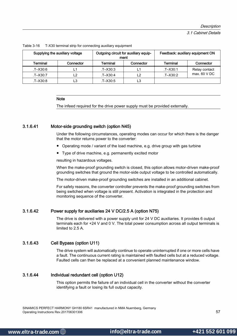
Table 3-16 T-X30 terminal strip for connecting auxiliary equipment
Supplying the auxiliary voltage Outgoing circuit for auxiliary equip‐ment
Feedback: auxiliary equipment ON
Terminal Connector Terminal Connector Terminal Connector.T–X30:6 L1 .T–X30:3 L1 .T–X30:1 Relay contact
max. 60 V DC .T–X30:7 L2 .T–X30:4 L2 .T–X30:2.T–X30:8 L3 .T–X30:5 L3
Note
The infeed required for the drive power supply must be provided externally.
3.1.6.41 Motor-side grounding switch (option N45)Under the following circumstances, operating modes can occur for which there is the danger that the motor returns power to the converter:
● Operating mode / variant of the load machine, e.g. drive group with gas turbine
● Type of drive machine, e.g. permanently excited motor
resulting in hazardous voltages.
When the make-proof grounding switch is closed, this option allows motor-driven make-proof grounding switches that ground the motor-side output voltage to be controlled automatically.
The motor-driven make-proof grounding switches are installed in an additional cabinet.
For safety reasons, the converter controller prevents the make-proof grounding switches from being switched when voltage is still present. Activation is integrated in the protection and monitoring sequence of the converter.
3.1.6.42 Power supply for auxiliaries 24 V DC/2.5 A (option N75)The drive is delivered with a power supply unit for 24 V DC auxiliaries. It provides 6 output terminals each for +24 V and 0 V. The total power consumption across all output terminals is limited to 2.5 A.
3.1.6.43 Cell Bypass (option U11)The drive system will automatically continue to operate uninterrupted if one or more cells have a fault. The continuous current rating is maintained with faulted cells but at a reduced voltage. Faulted cells can then be replaced at a convenient planned maintenance window.
3.1.6.44 Individual redundant cell (option U12)This option permits the failure of an individual cell in the converter without the converter identifying a fault or losing its full output capacity.
Description3.1 Cabinet Details
SINAMICS PERFECT HARMONY GH180 6SR41 manufactured in NMA Nuernberg, GermanyOperating Instructions Rev.201706301306 57
www.eltra-trade.com [email protected] +421 552 601 099www.eltra-trade.com [email protected] +421 552 601 099

3.1.6.45 Redundant cell rank (option U13)This option permits the failure of one cell per converter phase, without the converter identifying a fault or losing its full output capacity.
3.1.6.46 Sinusodial filter (option Y15)This option allows line motors or motors with insulation systems that are not compatible with converters to be operated with speed control. The sine-wave filter supplies the motors with virtually sinusoidal motor currents and voltages, which means that line motors can be used. These filters are generally required when the output cable is longer than 2.2 km. With such lengths, harmonics and sidebands in the switching frequency can produce a line frequency that may cause overvoltage in the transmission line at the motor terminals.-++
The sine-wave filter essentially contains an L-C filter; these components are installed in transition cabinets. The reactors are usually custom-configured.
See alsoInterface terminals (option L09 or Y15) (Page 103)
Combining two Transport Units: Output reactor (L09)and Sine-wave filter (Y15) (Page 89)
Description3.1 Cabinet Details
SINAMICS PERFECT HARMONY GH180 6SR41 manufactured in NMA Nuernberg, Germany58 Operating Instructions Rev.201706301306
www.eltra-trade.com [email protected] +421 552 601 099www.eltra-trade.com [email protected] +421 552 601 099

Preparing for Use 44.1 Requirements for installation location
SINAMICS PERFECT HARMONY GH180 medium voltage drives must always be installed in closed electrical operating areas.
The operating areas must be dry and free of dust. The air supplied must not contain any electrically conductive gas, vapors, or dust which could impair operation.
For information about permissible ambient and installation conditions, see the "Technical specifications" section.
SINAMICS PERFECT HARMONY GH180 6SR41 manufactured in NMA Nuernberg, GermanyOperating Instructions Rev.201706301306 59
www.eltra-trade.com [email protected] +421 552 601 099www.eltra-trade.com [email protected] +421 552 601 099

4.2 Checking on delivery
Checking on delivery for completenessThe drive systems are put together on an individual basis. When you take receipt of the delivery, please check immediately whether the items delivered are in accordance with the accompanying documents. Siemens will not accept any claims relating to items missing from the delivery and which are submitted at a later date.
● Report any apparent transport damage to the delivery agent immediately. Never commission a damaged motor.
● Report any apparent defects/missing components to the appropriate Siemens office immediately.
The safety instructions are part of the scope of supply; keep them in a location where they can be easily accessed.
Preparing for Use4.2 Checking on delivery
SINAMICS PERFECT HARMONY GH180 6SR41 manufactured in NMA Nuernberg, Germany60 Operating Instructions Rev.201706301306
www.eltra-trade.com [email protected] +421 552 601 099www.eltra-trade.com [email protected] +421 552 601 099
4.3 The purpose of shock and tilt indicators
The purpose of shock and tilt indicatorsThe unit is equipped with shock and tilt indicators to monitor for damage during transit. It is essential that you check the shock and tilt indicators before commissioning the unit.
WARNING
Tripped shock and tilt indicators
Safe operation of the device is not guaranteed if the shock or tilt indicator has tripped (responded)
This can result in death, serious injury or material damage.● If one of the indicators has tripped, do not start commissioning.● Inform Technical Support . Only specialist Siemens technicians/engineers can
recommend appropriate measures.
NoteWarranty
If one of the shock or tilt indicators has been tripped, then warranty is no longer valid from this time onwards.
Preparing for Use4.3 The purpose of shock and tilt indicators
SINAMICS PERFECT HARMONY GH180 6SR41 manufactured in NMA Nuernberg, GermanyOperating Instructions Rev.201706301306 61
www.eltra-trade.com [email protected] +421 552 601 099www.eltra-trade.com [email protected] +421 552 601 099
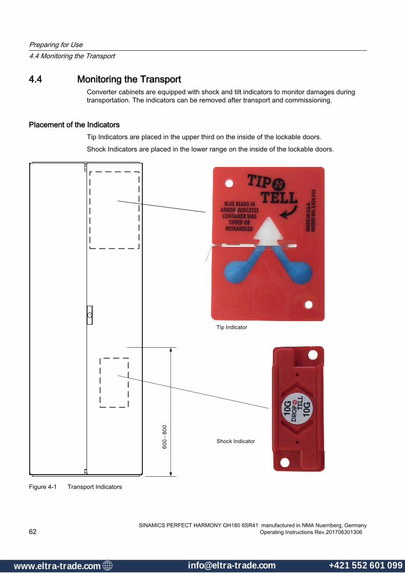
4.4 Monitoring the TransportConverter cabinets are equipped with shock and tilt indicators to monitor damages during transportation. The indicators can be removed after transport and commissioning.
Placement of the IndicatorsTip Indicators are placed in the upper third on the inside of the lockable doors.
Shock Indicators are placed in the lower range on the inside of the lockable doors.
Figure 4-1 Transport Indicators
Preparing for Use4.4 Monitoring the Transport
SINAMICS PERFECT HARMONY GH180 6SR41 manufactured in NMA Nuernberg, Germany62 Operating Instructions Rev.201706301306
www.eltra-trade.com [email protected] +421 552 601 099www.eltra-trade.com [email protected] +421 552 601 099
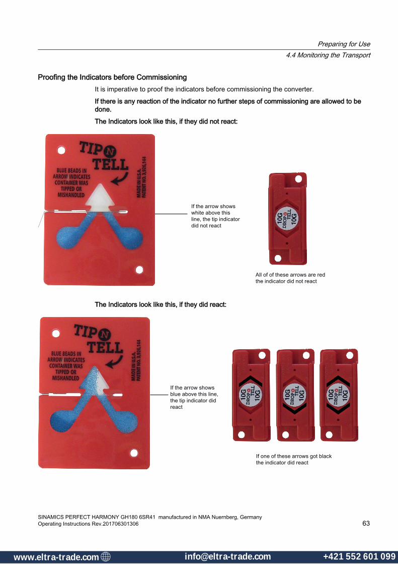
Proofing the Indicators before CommissioningIt is imperative to proof the indicators before commissioning the converter.
If there is any reaction of the indicator no further steps of commissioning are allowed to be done.
The Indicators look like this, if they did not react:
The Indicators look like this, if they did react:
Preparing for Use4.4 Monitoring the Transport
SINAMICS PERFECT HARMONY GH180 6SR41 manufactured in NMA Nuernberg, GermanyOperating Instructions Rev.201706301306 63
www.eltra-trade.com [email protected] +421 552 601 099www.eltra-trade.com [email protected] +421 552 601 099
WARNING
Inform Technical Support (Hotline)
Only Siemens technical experts can advice appropriate or initiate necessary actions.
Commissioning the converter without inspection through Technical Support can not guarantee save operating of the converter. Death or severe personal injury, as well as property damage may result.
The warranty is exposed from this point of time on.
Inquiries can be made worldwide at three Technical Support Centers.
Telephone inquiries
● Europe and Africa time zone:Tel.: +49 (0)180 50 50 222If your order is managed by Siemens Nürnberg, please contact Mr. Josef Proesl first:Tel: +49 911 433 9096
● Asia and Australia time zone:Tel.: +86 1064 719 990
● America time zone:Tel.: +1 423 262 2522If your order is managed by Siemens Pittsburgh, please contact Mr. Dave Yerger first:Tel: +1 724 339 8189
On the Internet worldwide:
www.siemens.com/automation/support‑request
The contacts may change. Please find the current contact partners in the Siemens AG A&D service catalog:
www.automation.siemens.com/partner
Preparing for Use4.4 Monitoring the Transport
SINAMICS PERFECT HARMONY GH180 6SR41 manufactured in NMA Nuernberg, Germany64 Operating Instructions Rev.201706301306
www.eltra-trade.com [email protected] +421 552 601 099www.eltra-trade.com [email protected] +421 552 601 099

4.5 Transportation
4.5.1 Transporting the cabinet unitsWhen the transport units are transported with a crane, note that force is applied via the supporting frame of the cabinet. The supporting frame remains on the unit. The device is mounted at the installation site via the supporting frame.
WARNING
Inadequately dimensioned lifting rods
Inadequately dimensioned lifting rods are liable to bend or break. The converter could drop off the crane as a result, causing death, serious injury, or material damage.
Use suitable lifting rods for transportation. The weight of the converter is indicated on the type plate.
CAUTION
Incorrect lifting
If the transport unit is lifted incorrectly, this can damage the decorative trim, cabinet doors, or fans.
Protect the cabinet and protruding parts against damage. Always lift the transport units with the appropriate spreading devices or hoisting tackle.
Preparing for Use4.5 Transportation
SINAMICS PERFECT HARMONY GH180 6SR41 manufactured in NMA Nuernberg, GermanyOperating Instructions Rev.201706301306 65
www.eltra-trade.com [email protected] +421 552 601 099www.eltra-trade.com [email protected] +421 552 601 099

Procedure1. Push the lifting rods through the holes.
2. Place the sling ropes on the ends of the lifting rods and secure the ends of the lifting rods using the splint.
3. To lift the transport unit, use single sling ropes or two ropes with a cross stitch. Attach the crane rope to the ends of the lifting rods and then lift the cabinet. Avoid displacing the center of gravity or distorting the cabinet. When suspended, the cabinet must be parallel to the ground.
4.5.2 Transporting the cabinet unitsWhen the transport units are transported with a crane, note that force is applied via the supporting frame of the cabinet. The supporting frame remains on the unit. The device is mounted at the installation site via the supporting frame.
WARNING
Inadequately dimensioned lifting rods
Inadequately dimensioned lifting rods are liable to bend or break. The converter could drop off the crane as a result, causing death, serious injury, or material damage.
Use suitable lifting rods for transportation. The weight of the converter is indicated on the type plate.
Preparing for Use4.5 Transportation
SINAMICS PERFECT HARMONY GH180 6SR41 manufactured in NMA Nuernberg, Germany66 Operating Instructions Rev.201706301306
www.eltra-trade.com [email protected] +421 552 601 099www.eltra-trade.com [email protected] +421 552 601 099

CAUTION
Incorrect lifting
If the transport unit is lifted incorrectly, this can damage the decorative trim, cabinet doors, or fans.
Protect the cabinet and protruding parts against damage. Always lift the transport units with the appropriate spreading devices or hoisting tackle.
Procedure1. Push the lifting rods through the holes.
2. Place the sling ropes on the ends of the lifting rods and secure the ends of the lifting rods using the splint.
3. To lift the transport unit, use single sling ropes or two ropes with a cross stitch. Attach the crane rope to the ends of the lifting rods and then lift the cabinet. Avoid displacing the center of gravity or distorting the cabinet. When suspended, the cabinet must be parallel to the ground.
4.5.3 Transport Using a Crane
NOTICE
Minimum clearance between crane and cabinet
A minimum clearance of 51 ´´ (1.3 m) must be maintained to avoid deformation of the drive cabinet.
If this minimum clearance cannot be maintained, spreader bars of suitable strength must be used.
Preparing for Use4.5 Transportation
SINAMICS PERFECT HARMONY GH180 6SR41 manufactured in NMA Nuernberg, GermanyOperating Instructions Rev.201706301306 67
www.eltra-trade.com [email protected] +421 552 601 099www.eltra-trade.com [email protected] +421 552 601 099

Drives up to 1 750 kVA, and a weight of approximately 7 000 kg (one transport unit)
Figure 4-2 Back view
Drives from 2 000 kVA and approximately 7 100 kg weight (two transport units)
① Transformer cabinet (back view)② Cell cabinet (back view)
Preparing for Use4.5 Transportation
SINAMICS PERFECT HARMONY GH180 6SR41 manufactured in NMA Nuernberg, Germany68 Operating Instructions Rev.201706301306
www.eltra-trade.com [email protected] +421 552 601 099www.eltra-trade.com [email protected] +421 552 601 099
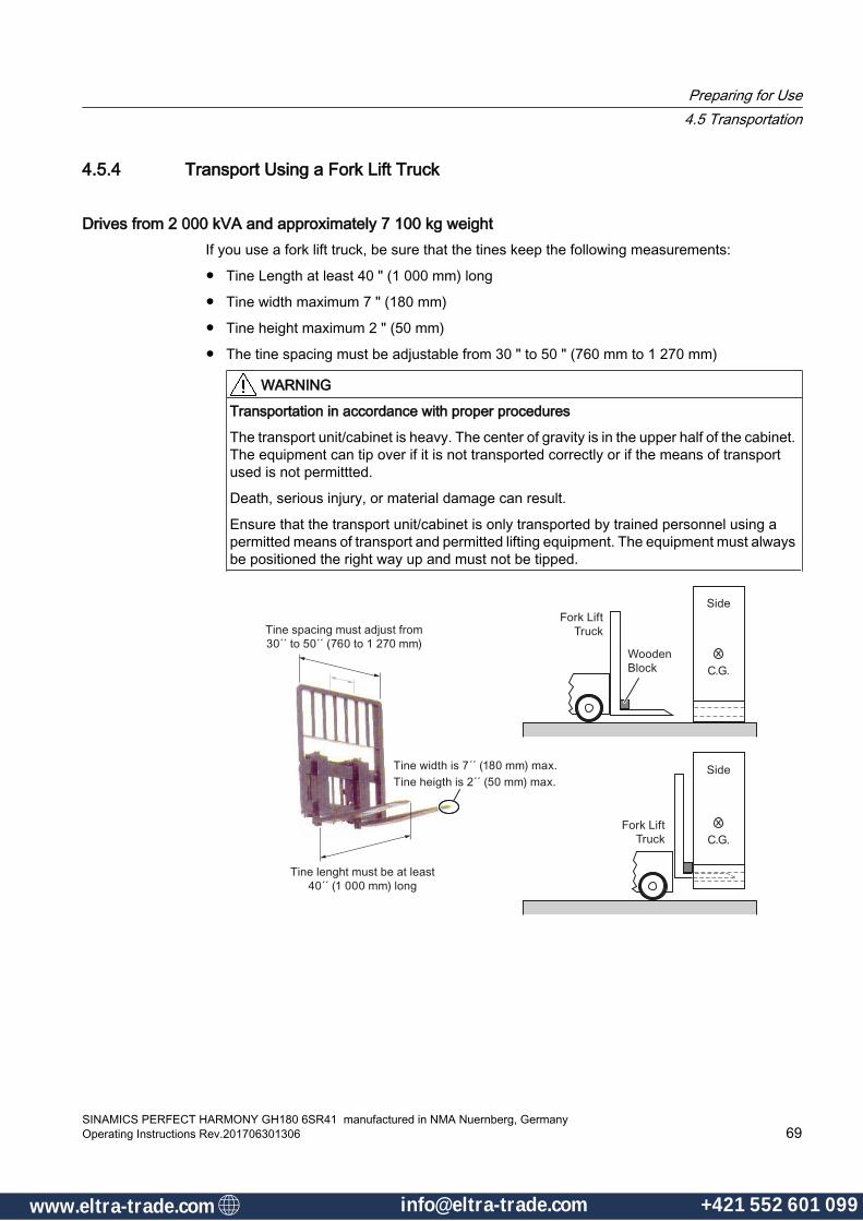
4.5.4 Transport Using a Fork Lift Truck
Drives from 2 000 kVA and approximately 7 100 kg weightIf you use a fork lift truck, be sure that the tines keep the following measurements:
● Tine Length at least 40 " (1 000 mm) long
● Tine width maximum 7 " (180 mm)
● Tine height maximum 2 " (50 mm)
● The tine spacing must be adjustable from 30 " to 50 " (760 mm to 1 270 mm)
WARNING
Transportation in accordance with proper procedures
The transport unit/cabinet is heavy. The center of gravity is in the upper half of the cabinet. The equipment can tip over if it is not transported correctly or if the means of transport used is not permittted.
Death, serious injury, or material damage can result.
Ensure that the transport unit/cabinet is only transported by trained personnel using a permitted means of transport and permitted lifting equipment. The equipment must always be positioned the right way up and must not be tipped.
Preparing for Use4.5 Transportation
SINAMICS PERFECT HARMONY GH180 6SR41 manufactured in NMA Nuernberg, GermanyOperating Instructions Rev.201706301306 69
www.eltra-trade.com [email protected] +421 552 601 099www.eltra-trade.com [email protected] +421 552 601 099

Figure 4-3 Proper Fork Lift Handling and Dimensions
4.5.5 Definition of a packed and unpacked deviceThe terms are defined as follows in the following part of the instructions:
● "Transportation unit" refers to the unit before it has been unpacked
● "Cabinet" refers to the unit after it has been unpacked
4.5.6 Transport markingsThe packing differs depending on the transport type and size. If not otherwise contractually agreed, the packaging corresponds to the packing guidelines for International Standards for Phytosanitary Measures (ISPM).
Comply with the images shown on the packaging. Their meaning is as follows:
This way up
Fragile goods Keep dry Keep cool Center of gravity
Do not use hand hook
Attach here
4.5.7 Transport requirements● Persons driving cranes and fork-lift trucks must hold appropriate licenses.
● You must observe the specifications to avoid transport damage to the enclosure and you must maintain the permissible climatic conditions during operation in accordance with IEC 60721-3-1/2/3. Please also observe the "Technical specifications" instructions.
Preparing for Use4.5 Transportation
SINAMICS PERFECT HARMONY GH180 6SR41 manufactured in NMA Nuernberg, Germany70 Operating Instructions Rev.201706301306
www.eltra-trade.com [email protected] +421 552 601 099www.eltra-trade.com [email protected] +421 552 601 099

● When lifting the converter, use only approved and undamaged sling guides and spreaders of sufficient rated capacity. Check these before using them. The weight of the converter is specified on the rating plate.
● When lifting, refer to the information on the lifting plate or in "Technical data and drawings." Comply with the specified spreading angles.
NOTICE
Avoid vibrations
Significant vibration during transportation and shocks when setting down can damage the equipment.
Avoid vibrations and shocks.
4.5.8 Take the center of gravity into account
WARNING
Non-observance of center of gravity specifications
The cabinet is heavy. The center of gravity can be in the upper half of the cabinet. The unit can tip over if you transport it incorrectly – or if you use transport equipment that is not permitted for the purpose. This can result in death, serious injury or material damage.● Ensure that only trained personnel transport the device with approved transport equipment
and lifting tools. ● Observe the center of gravity specifications. A label or stamp is attached to each
transportation unit and precisely shows the center of gravity of the cabinet.● Do not tilt the device or allow it to fall.
The following figure shows the centers of gravity as an example: Carefully note the centers of gravity when performing any lifting or installation work.
Figure 4-4 Example Illustration of centers of gravity
Preparing for Use4.5 Transportation
SINAMICS PERFECT HARMONY GH180 6SR41 manufactured in NMA Nuernberg, GermanyOperating Instructions Rev.201706301306 71
www.eltra-trade.com [email protected] +421 552 601 099www.eltra-trade.com [email protected] +421 552 601 099

4.5.9 Transport with a fork-lift truck
WARNING
Use of non-approved fork-lift trucks
If the forks are too short, this can cause the transport unit/cabinet to tip over resulting in death, serious injury, or damage to the cabinet.
The forks of the truck must protrude at the rear of the transport pallet. The floor panels of the transport units will not support a load.
Only use fork-lift trucks approved for this purpose to transport the units.
When the transport units are transported or moved with a fork-lift truck, the force is absorbed through the transport pallet.
Observe the following for a safe transport:
● Transport the transport unit/cabinet with the greatest care.
● Choose the lowest transport height possible. The pallet may not touch the ground. Always transport the cabinet in an upright position.
● Avoid driving over bumps.
4.5.10 Transport with a crane
WARNING
Improper transport
If the transportation unit is not properly transported with a crane, the transportation unit / cabinet could fall or tip over This can result in death, serious injury or material damage.
Make sure that you read the safety information about transportation and the information provided on the transportation unit (e.g. center of gravity specifications).
WARNING
Use of inappropriate cross-arms
If inappropriate cross-arms are used, the transport unit or cabinet can tip over. This can result in death, serious injury or material damage.
Observe the specifications provided in DIN EN 13155 on crossbars.
Preparing for Use4.5 Transportation
SINAMICS PERFECT HARMONY GH180 6SR41 manufactured in NMA Nuernberg, Germany72 Operating Instructions Rev.201706301306
www.eltra-trade.com [email protected] +421 552 601 099www.eltra-trade.com [email protected] +421 552 601 099

WARNING
Standing under suspended loads
If the lifting gear or load suspension devices were to fail, the transportation unit / cabinet could fall. Death, serious injury, or material damage can result.
Do not stand underneath or near to a raised load.
Observe the following for a safe transport:
● When using a crane to transport the equipment, keep to the permissible lifting capacity. Carefully observe the center of gravity.
● If the cabinet center of gravity is off-center, use suitable and undamaged suspension equipment, e.g. a cross beam. The lifting beam reduces the pressure on the device and prevents damage.
● If the cabinet has eye hooks, use them. In such cases, do not use any lifting rods.
4.5.11 Using lifting rods
4.5.11.1 Force absorptionDuring transportation with a crane, force is absorbed by the supporting frame of the cabinet. The supporting frame remains on the unit. The device is mounted at the installation site via the supporting frame.
4.5.11.2 Using lifting rods
WARNING
Inadequately dimensioned lifting rods
Inadequately dimensioned lifting rods are liable to bend or break. The converter could drop off the crane as a result, This can result in death, serious injury or material damage.
Use suitable lifting rods for transporting. The weight of the cabinet is indicated on the rating plate.
NOTICE
Improper lifting
If the transport unit is lifted incorrectly, this can damage the decorative trim, cabinet doors, or fans.
Protect the cabinet and protruding parts against damage.
Always lift the transport units with the appropriate spreading devices or hoisting tackle.
Preparing for Use4.5 Transportation
SINAMICS PERFECT HARMONY GH180 6SR41 manufactured in NMA Nuernberg, GermanyOperating Instructions Rev.201706301306 73
www.eltra-trade.com [email protected] +421 552 601 099www.eltra-trade.com [email protected] +421 552 601 099

Procedure1. If there are several holes, select which holes to use based on the center of gravity.
2. Push the lifting rods through the holes.
Figure 4-5 Sticker
3. Place the sling ropes on the lifting rods so they are close to the cabinet. Secure the ends of the lifting rods using the splint.
Figure 4-6 Securing the lifting rods
4. To lift the transport unit, use single sling ropes or two ropes with a cross stitch. Attach the crane rope to the lifting rods so it is close to the cabinet.
5. Lift the cabinet. Avoid shifting the center of gravity or distorting or damaging the cabinet. When suspended, the cabinet must be parallel to the ground.
Preparing for Use4.5 Transportation
SINAMICS PERFECT HARMONY GH180 6SR41 manufactured in NMA Nuernberg, Germany74 Operating Instructions Rev.201706301306
www.eltra-trade.com [email protected] +421 552 601 099www.eltra-trade.com [email protected] +421 552 601 099
4.6 Receiving and Unpacking
4.6.1 ReceivingThe receiving procedure consists of the following steps:
1. Verify that the proper items have been shipped.
2. Inspect all items for damage that may have occurred during shipping, handling, or storage.
3. File a claim with the shipping carrier if any damage is present.
4.6.2 Unpacking
NoteComply with All On-Site Requirements
Siemens recommends that the operating areas be dry and free of dust. The air supplied should not contain any electrically conductive gas, vapors, or dust, which could impair operation.
Upon receipt of the drives:
1. Perform a visual inspection to assure shipment is undamaged.
2. Verify that all items are received.
3. Carefully remove the plastic and stretch wrap, and all load securing devices.
4. Do not remove the packaging until immediately prior to installation.
5. If equipment will not be placed in operation after installation, cover louvers and external openings to prevent entry of dust, moisture, and contaminants. In addition to covering louvers and openings, Siemens recommended covering the equipment cabinet with a tarp or protective cover.
6. Inspect the equipment for any enclosure / cabinet damage such as cabinet deformation, damaged welding, filters and rubber gaskets, lose or missing hardware and broken louvers.
7. If no shipment damage claims required, discard the packaging material in accordance with the applicable country-specific guidelines and rules.
8. Inspect the equipment for any internal component damage such as insulators, air baffles, barriers and hardware.
9. Prior to commissioning, protect the cabinets against dust, moisture, and contaminants by covering the ventilation opening and keeping the doors closed.
10.Do not remove crane instructions from the cabinet(s).
Preparing for Use4.6 Receiving and Unpacking
SINAMICS PERFECT HARMONY GH180 6SR41 manufactured in NMA Nuernberg, GermanyOperating Instructions Rev.201706301306 75
www.eltra-trade.com [email protected] +421 552 601 099www.eltra-trade.com [email protected] +421 552 601 099

NoteDamage During Shipment
If damage occurs during shipment, contact the shipping carrier to file a claim. For technical assistance, call Technical Support - Worldwide Centers (800-333-7421).
Preparing for Use4.6 Receiving and Unpacking
SINAMICS PERFECT HARMONY GH180 6SR41 manufactured in NMA Nuernberg, Germany76 Operating Instructions Rev.201706301306
www.eltra-trade.com [email protected] +421 552 601 099www.eltra-trade.com [email protected] +421 552 601 099

4.7 Off-Loading
4.7.1 Off-LoadingDue to the size and weight of the SINAMICS PERFECT HARMONY GH180 components, it is important to carefully plan all handling operations when off-loading equipment. Siemens recommends that prior considerations be made for ceiling heights, door widths, and ease of installation in advance of receipt of equipment.
Off-loading from the truck is often the most critical operation because of the limited access. Advance planning and coordination among the manufacturer, the carrier, the installation contractor, and the owner are vital.
Prior to Moving the UnitBefore moving the unit, verify the following:
● The unit doors are closed/installed
● The unit is in an upright position
● The unit is stabilized to prevent tilting
● Each cell’s locking latches are tie-wrapped in an upright position
Preparing for Use4.7 Off-Loading
SINAMICS PERFECT HARMONY GH180 6SR41 manufactured in NMA Nuernberg, GermanyOperating Instructions Rev.201706301306 77
www.eltra-trade.com [email protected] +421 552 601 099www.eltra-trade.com [email protected] +421 552 601 099

4.8 Transportation and Handling
4.8.1 Transporting the cabinet unitsWhen the transport units are transported with a crane, note that force is applied via the supporting frame of the cabinet. The supporting frame remains on the unit. The device is mounted at the installation site via the supporting frame.
WARNING
Inadequately dimensioned lifting rods
Inadequately dimensioned lifting rods are liable to bend or break. The converter could drop off the crane as a result, causing death, serious injury, or material damage.
Use suitable lifting rods for transportation. The weight of the converter is indicated on the type plate.
CAUTION
Incorrect lifting
If the transport unit is lifted incorrectly, this can damage the decorative trim, cabinet doors, or fans.
Protect the cabinet and protruding parts against damage. Always lift the transport units with the appropriate spreading devices or hoisting tackle.
Preparing for Use4.8 Transportation and Handling
SINAMICS PERFECT HARMONY GH180 6SR41 manufactured in NMA Nuernberg, Germany78 Operating Instructions Rev.201706301306
www.eltra-trade.com [email protected] +421 552 601 099www.eltra-trade.com [email protected] +421 552 601 099

Procedure1. Push the lifting rods through the holes.
2. Place the sling ropes on the ends of the lifting rods and secure the ends of the lifting rods using the splint.
3. To lift the transport unit, use single sling ropes or two ropes with a cross stitch. Attach the crane rope to the ends of the lifting rods and then lift the cabinet. Avoid displacing the center of gravity or distorting the cabinet. When suspended, the cabinet must be parallel to the ground.
4.8.2 Transporting the cabinet unitsWhen the transport units are transported with a crane, note that force is applied via the supporting frame of the cabinet. The supporting frame remains on the unit. The device is mounted at the installation site via the supporting frame.
WARNING
Inadequately dimensioned lifting rods
Inadequately dimensioned lifting rods are liable to bend or break. The converter could drop off the crane as a result, causing death, serious injury, or material damage.
Use suitable lifting rods for transportation. The weight of the converter is indicated on the type plate.
Preparing for Use4.8 Transportation and Handling
SINAMICS PERFECT HARMONY GH180 6SR41 manufactured in NMA Nuernberg, GermanyOperating Instructions Rev.201706301306 79
www.eltra-trade.com [email protected] +421 552 601 099www.eltra-trade.com [email protected] +421 552 601 099
CAUTION
Incorrect lifting
If the transport unit is lifted incorrectly, this can damage the decorative trim, cabinet doors, or fans.
Protect the cabinet and protruding parts against damage. Always lift the transport units with the appropriate spreading devices or hoisting tackle.
Procedure1. Push the lifting rods through the holes.
2. Place the sling ropes on the ends of the lifting rods and secure the ends of the lifting rods using the splint.
3. To lift the transport unit, use single sling ropes or two ropes with a cross stitch. Attach the crane rope to the ends of the lifting rods and then lift the cabinet. Avoid displacing the center of gravity or distorting the cabinet. When suspended, the cabinet must be parallel to the ground.
4.8.3 Transport Using a Crane
NOTICE
Minimum clearance between crane and cabinet
A minimum clearance of 51 ´´ (1.3 m) must be maintained to avoid deformation of the drive cabinet.
If this minimum clearance cannot be maintained, spreader bars of suitable strength must be used.
Preparing for Use4.8 Transportation and Handling
SINAMICS PERFECT HARMONY GH180 6SR41 manufactured in NMA Nuernberg, Germany80 Operating Instructions Rev.201706301306
www.eltra-trade.com [email protected] +421 552 601 099www.eltra-trade.com [email protected] +421 552 601 099

Drives up to 1 750 kVA, and a weight of approximately 7 000 kg (one transport unit)
Figure 4-7 Back view
Drives from 2 000 kVA and approximately 7 100 kg weight (two transport units)
① Transformer cabinet (back view)② Cell cabinet (back view)
Preparing for Use4.8 Transportation and Handling
SINAMICS PERFECT HARMONY GH180 6SR41 manufactured in NMA Nuernberg, GermanyOperating Instructions Rev.201706301306 81
www.eltra-trade.com [email protected] +421 552 601 099www.eltra-trade.com [email protected] +421 552 601 099
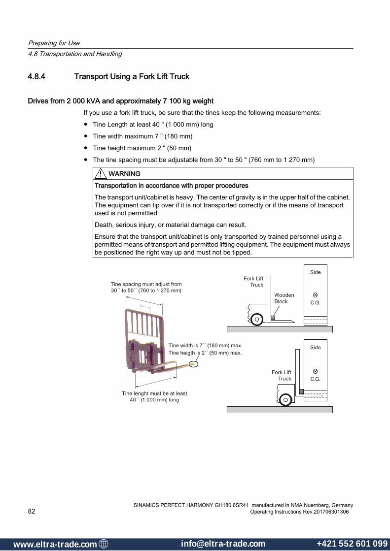
4.8.4 Transport Using a Fork Lift Truck
Drives from 2 000 kVA and approximately 7 100 kg weightIf you use a fork lift truck, be sure that the tines keep the following measurements:
● Tine Length at least 40 " (1 000 mm) long
● Tine width maximum 7 " (180 mm)
● Tine height maximum 2 " (50 mm)
● The tine spacing must be adjustable from 30 " to 50 " (760 mm to 1 270 mm)
WARNING
Transportation in accordance with proper procedures
The transport unit/cabinet is heavy. The center of gravity is in the upper half of the cabinet. The equipment can tip over if it is not transported correctly or if the means of transport used is not permittted.
Death, serious injury, or material damage can result.
Ensure that the transport unit/cabinet is only transported by trained personnel using a permitted means of transport and permitted lifting equipment. The equipment must always be positioned the right way up and must not be tipped.
Preparing for Use4.8 Transportation and Handling
SINAMICS PERFECT HARMONY GH180 6SR41 manufactured in NMA Nuernberg, Germany82 Operating Instructions Rev.201706301306
www.eltra-trade.com [email protected] +421 552 601 099www.eltra-trade.com [email protected] +421 552 601 099

Figure 4-8 Proper Fork Lift Handling and Dimensions
Preparing for Use4.8 Transportation and Handling
SINAMICS PERFECT HARMONY GH180 6SR41 manufactured in NMA Nuernberg, GermanyOperating Instructions Rev.201706301306 83
www.eltra-trade.com [email protected] +421 552 601 099www.eltra-trade.com [email protected] +421 552 601 099

Preparing for Use4.8 Transportation and Handling
SINAMICS PERFECT HARMONY GH180 6SR41 manufactured in NMA Nuernberg, Germany84 Operating Instructions Rev.201706301306
www.eltra-trade.com [email protected] +421 552 601 099www.eltra-trade.com [email protected] +421 552 601 099

Assembly 55.1 Protective Earthing Bars Connection
DANGER
Grounding the Drive
The VFD must be grounded to allow safe operation.If not sufficiently grounded during operation, the protection and monitoring functions can fail.
Death, serious injury, or material damage will result.● Always take the appropriate precautions and observe the five safety rules before carrying
out any work on the converter.● Follow these steps when grounding the machine:
– Make the connections to the PE busbars within a cabinet.– Ensure that the connections to the PE busbars are made over several cabinets.– Set up the ground connection for the whole plant immediately.
Connecting the Protective Earthing (PE) Bars (for several cabinets)
Note
Each cabinet in the lineup is bonded together, generally via 1/0 cable.
SINAMICS PERFECT HARMONY GH180 6SR41 manufactured in NMA Nuernberg, GermanyOperating Instructions Rev.201706301306 85
www.eltra-trade.com [email protected] +421 552 601 099www.eltra-trade.com [email protected] +421 552 601 099

5.2 Assembly instructions
5.2.1 Requirements for the installation locationFor details about the mounting, refer to the dimension drawing.
5.2.2 Required toolsThe following tools are required for mechanical and electrical installation (commercially available, insulated mechanics' tools):
● Spanner or socket spanner, width across flats 10
● Spanner or socket spanner, width across flats 13
● Spanner or socket spanner, width across flats 16/17
● Spanner or socket spanner, width across flats 18/19
● Torque wrench up to 250 Nm
● Size 1/2 screwdriver
● Screwdriver Torx T20
● Screwdriver Torx T30
● Cross-tip screwdriver size 2/3
● Cordless screwdriver with Torx set
● Diagonal cutter
5.2.3 Required toolsThe following tools are required for mechanical and electrical installation (commercially available, insulated mechanics' tools):
● Spanner or socket spanner, width across flats 10
● Spanner or socket spanner, width across flats 13
● Spanner or socket spanner, width across flats 16/17
● Spanner or socket spanner, width across flats 18/19
● Socket wrench with nut size 30
● Torque wrench up to 250 Nm
● Size 1/2 screwdriver
● Screwdriver Torx T20
● Screwdriver Torx T30
● Cross-tip screwdriver size 2/3
Assembly5.2 Assembly instructions
SINAMICS PERFECT HARMONY GH180 6SR41 manufactured in NMA Nuernberg, Germany86 Operating Instructions Rev.201706301306
www.eltra-trade.com [email protected] +421 552 601 099www.eltra-trade.com [email protected] +421 552 601 099
● Cordless screwdriver with Torx set
● Diagonal cutter
CAUTION
Mechanical damage
Stress that occurs during transport may exert mechanical pressure on the components. Material damage can result.● Align the cabinet units precisely to avoid sheering forces when connecting the basic units.● Ensure that the ground on which the converter is to be installed is level and horizontal.
5.2.4 Combining two Transport Units: Output reactor (L09)and Sine-wave filter (Y15)The transport units can be installed as a combined unit or at separate locations.
PrerequisitesBefore installation, adhere to the transport instructions.
Assembly5.2 Assembly instructions
SINAMICS PERFECT HARMONY GH180 6SR41 manufactured in NMA Nuernberg, GermanyOperating Instructions Rev.201706301306 87
www.eltra-trade.com [email protected] +421 552 601 099www.eltra-trade.com [email protected] +421 552 601 099
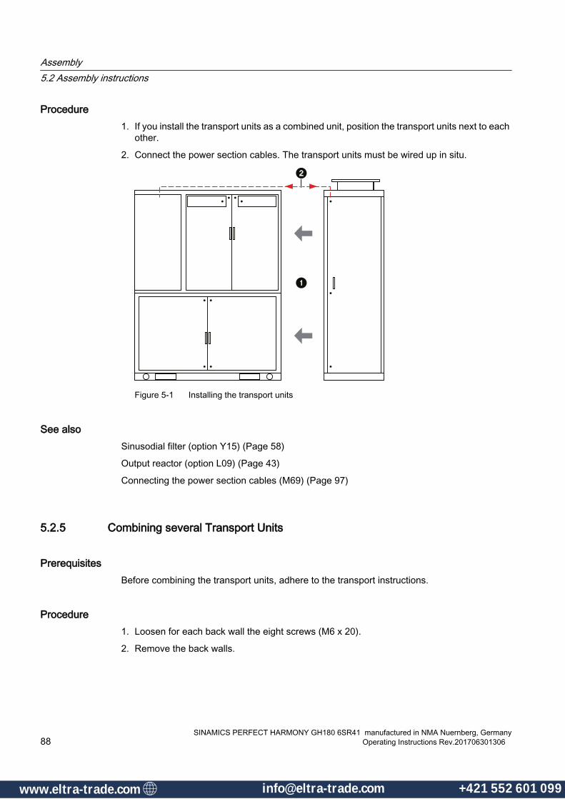
Procedure1. If you install the transport units as a combined unit, position the transport units next to each
other.
2. Connect the power section cables. The transport units must be wired up in situ.
Figure 5-1 Installing the transport units
See alsoSinusodial filter (option Y15) (Page 58)
Output reactor (option L09) (Page 43)
Connecting the power section cables (M69) (Page 97)
5.2.5 Combining several Transport Units
PrerequisitesBefore combining the transport units, adhere to the transport instructions.
Procedure1. Loosen for each back wall the eight screws (M6 x 20).
2. Remove the back walls.
Assembly5.2 Assembly instructions
SINAMICS PERFECT HARMONY GH180 6SR41 manufactured in NMA Nuernberg, Germany88 Operating Instructions Rev.201706301306
www.eltra-trade.com [email protected] +421 552 601 099www.eltra-trade.com [email protected] +421 552 601 099

3. Position the transport units next to each other.
4. Connect the power section cables.
Figure 5-2 Combining power cell cabinet and transformer cabinet (back view)
NOTICE
No transportation with crane or fork-lift truck after screwing units together
Specify the place of installation of the converter discreetly prior to installing the transport units.
Once the transport units have been screwed together, it is no longer permitted to transport them by crane or fork-lift truck.
5.2.6 Unlocking the Power Section Doors manuallySince the doors are interlocked electromagnetically, they do not unlock because the auxiliary voltage supply is missing.
In this case, the doors can only be unlocked manually. Each transport unit is therefore provided with a fitting cabinet key.
Assembly5.2 Assembly instructions
SINAMICS PERFECT HARMONY GH180 6SR41 manufactured in NMA Nuernberg, GermanyOperating Instructions Rev.201706301306 89
www.eltra-trade.com [email protected] +421 552 601 099www.eltra-trade.com [email protected] +421 552 601 099
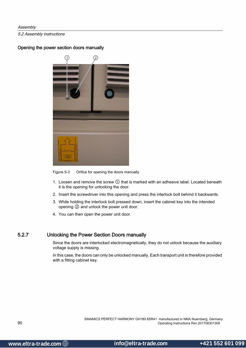
Opening the power section doors manually
Figure 5-3 Orifice for opening the doors manually
1. Loosen and remove the screw ① that is marked with an adhesive label. Located beneath it is the opening for unlocking the door.
2. Insert the screwdriver into this opening and press the interlock bolt behind it backwards.
3. While holding the interlock bolt pressed down, insert the cabinet key into the intended opening ② and unlock the power unit door.
4. You can then open the power unit door.
5.2.7 Unlocking the Power Section Doors manuallySince the doors are interlocked electromagnetically, they do not unlock because the auxiliary voltage supply is missing.
In this case, the doors can only be unlocked manually. Each transport unit is therefore provided with a fitting cabinet key.
Assembly5.2 Assembly instructions
SINAMICS PERFECT HARMONY GH180 6SR41 manufactured in NMA Nuernberg, Germany90 Operating Instructions Rev.201706301306
www.eltra-trade.com [email protected] +421 552 601 099www.eltra-trade.com [email protected] +421 552 601 099
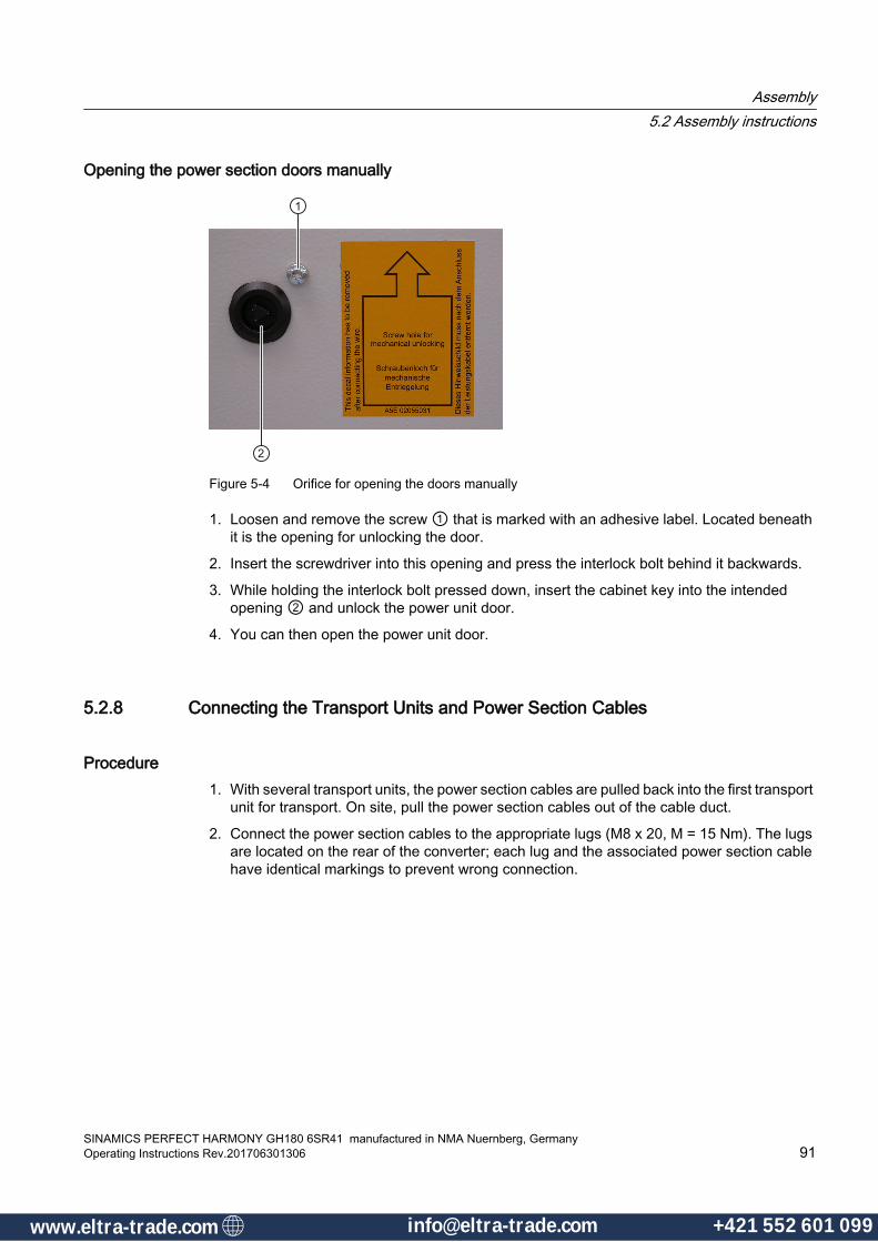
Opening the power section doors manually
Figure 5-4 Orifice for opening the doors manually
1. Loosen and remove the screw ① that is marked with an adhesive label. Located beneath it is the opening for unlocking the door.
2. Insert the screwdriver into this opening and press the interlock bolt behind it backwards.
3. While holding the interlock bolt pressed down, insert the cabinet key into the intended opening ② and unlock the power unit door.
4. You can then open the power unit door.
5.2.8 Connecting the Transport Units and Power Section Cables
Procedure1. With several transport units, the power section cables are pulled back into the first transport
unit for transport. On site, pull the power section cables out of the cable duct.
2. Connect the power section cables to the appropriate lugs (M8 x 20, M = 15 Nm). The lugs are located on the rear of the converter; each lug and the associated power section cable have identical markings to prevent wrong connection.
Assembly5.2 Assembly instructions
SINAMICS PERFECT HARMONY GH180 6SR41 manufactured in NMA Nuernberg, GermanyOperating Instructions Rev.201706301306 91
www.eltra-trade.com [email protected] +421 552 601 099www.eltra-trade.com [email protected] +421 552 601 099

3. Connect the transport units as described in detail in "Connecting the Transport Units".
4. At the bottom of the transport units, connect them by using the screws (M20 x 55, M = 215 Nm).
Assembly5.2 Assembly instructions
SINAMICS PERFECT HARMONY GH180 6SR41 manufactured in NMA Nuernberg, Germany92 Operating Instructions Rev.201706301306
www.eltra-trade.com [email protected] +421 552 601 099www.eltra-trade.com [email protected] +421 552 601 099

5.2.9 Connecting the Transport Units
Assembly MaterialThe following assembly material is included for connecting the transport units:
● Self-adhesive sealing strips
● Hexagon head screws
● Contact washers
Connecting the Transport Units
① Hexagon head screws② Contact washer③ Self-adhesive sealing strip④ Hexagonal weld nut⑤ Transport units
Figure 5-5 Connecting the transport units
Perform the following steps to connect the transport units:
1. Affix the self-adhesive sealing strip.
2. Align the cabinet units.
3. Place the contact washers onto the hexagon head screws and insert these into the holes.
4. Tighten the nuts to connect the transport units. Make sure that the tightening torque is correct (T = 88 Nm)!
Assembly5.2 Assembly instructions
SINAMICS PERFECT HARMONY GH180 6SR41 manufactured in NMA Nuernberg, GermanyOperating Instructions Rev.201706301306 93
www.eltra-trade.com [email protected] +421 552 601 099www.eltra-trade.com [email protected] +421 552 601 099
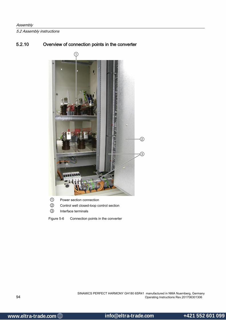
5.2.10 Overview of connection points in the converter
① Power section connection② Control well closed-loop control section③ Interface terminals
Figure 5-6 Connection points in the converter
Assembly5.2 Assembly instructions
SINAMICS PERFECT HARMONY GH180 6SR41 manufactured in NMA Nuernberg, Germany94 Operating Instructions Rev.201706301306
www.eltra-trade.com [email protected] +421 552 601 099www.eltra-trade.com [email protected] +421 552 601 099
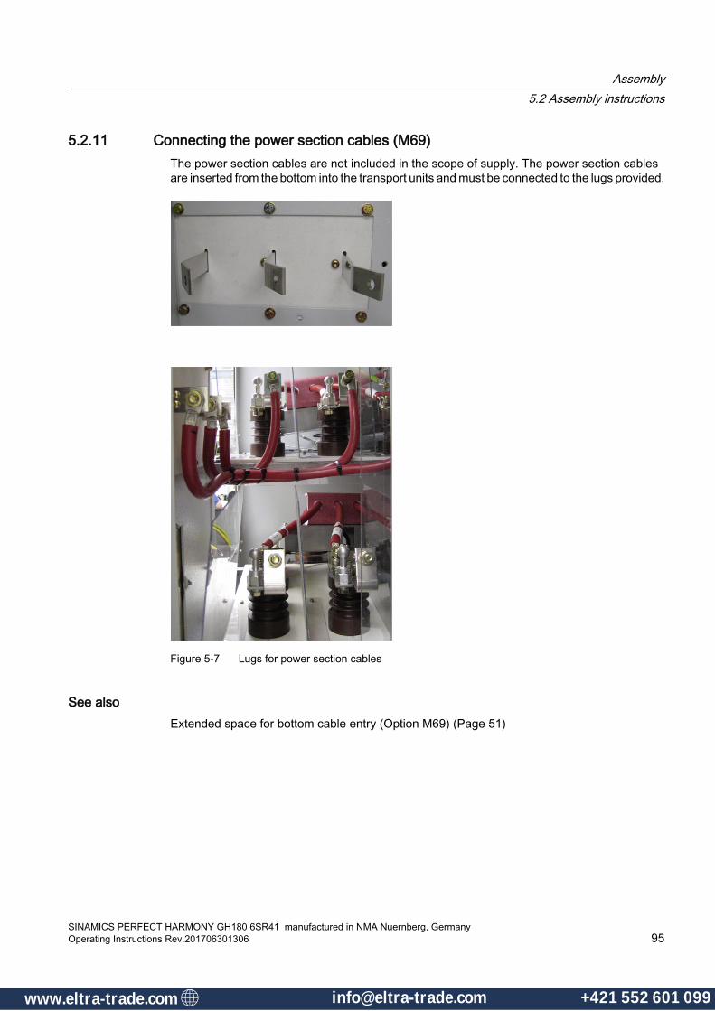
5.2.11 Connecting the power section cables (M69)The power section cables are not included in the scope of supply. The power section cables are inserted from the bottom into the transport units and must be connected to the lugs provided.
Figure 5-7 Lugs for power section cables
See alsoExtended space for bottom cable entry (Option M69) (Page 51)
Assembly5.2 Assembly instructions
SINAMICS PERFECT HARMONY GH180 6SR41 manufactured in NMA Nuernberg, GermanyOperating Instructions Rev.201706301306 95
www.eltra-trade.com [email protected] +421 552 601 099www.eltra-trade.com [email protected] +421 552 601 099
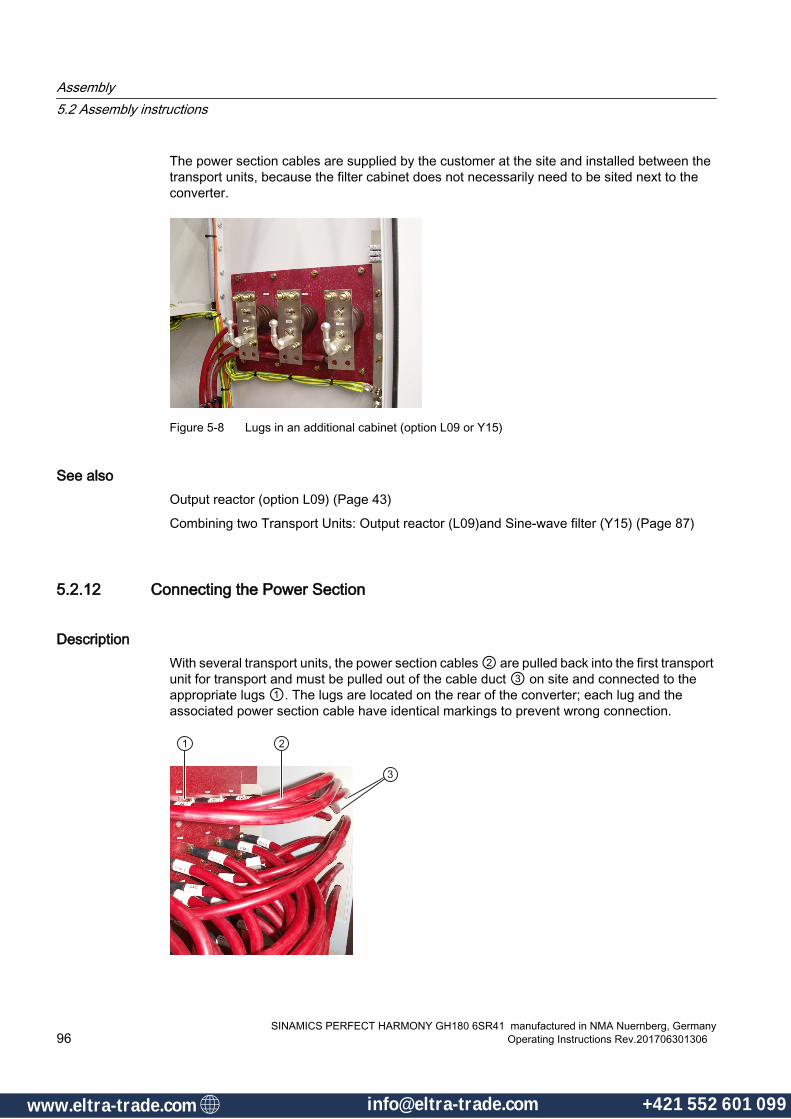
The power section cables are supplied by the customer at the site and installed between the transport units, because the filter cabinet does not necessarily need to be sited next to the converter.
Figure 5-8 Lugs in an additional cabinet (option L09 or Y15)
See alsoOutput reactor (option L09) (Page 43)
Combining two Transport Units: Output reactor (L09)and Sine-wave filter (Y15) (Page 87)
5.2.12 Connecting the Power Section
DescriptionWith several transport units, the power section cables ② are pulled back into the first transport unit for transport and must be pulled out of the cable duct ③ on site and connected to the appropriate lugs ①. The lugs are located on the rear of the converter; each lug and the associated power section cable have identical markings to prevent wrong connection.
Assembly5.2 Assembly instructions
SINAMICS PERFECT HARMONY GH180 6SR41 manufactured in NMA Nuernberg, Germany96 Operating Instructions Rev.201706301306
www.eltra-trade.com [email protected] +421 552 601 099www.eltra-trade.com [email protected] +421 552 601 099
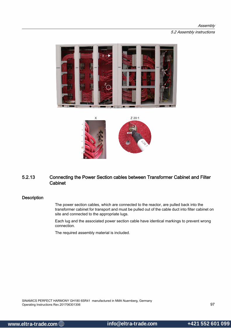
5.2.13 Connecting the Power Section cables between Transformer Cabinet and Filter Cabinet
DescriptionThe power section cables, which are connected to the reactor, are pulled back into the transformer cabinet for transport and must be pulled out of the cable duct into filter cabinet on site and connected to the appropriate lugs.
Each lug and the associated power section cable have identical markings to prevent wrong connection.
The required assembly material is included.
Assembly5.2 Assembly instructions
SINAMICS PERFECT HARMONY GH180 6SR41 manufactured in NMA Nuernberg, GermanyOperating Instructions Rev.201706301306 97
www.eltra-trade.com [email protected] +421 552 601 099www.eltra-trade.com [email protected] +421 552 601 099

5.2.14 Installing the fans
PrerequisitesBefore raising the fan housing, the crane eyebolts must be attached to the fan housing. Remove the crane eyebolts again after having connected the fans.
Assembly5.2 Assembly instructions
SINAMICS PERFECT HARMONY GH180 6SR41 manufactured in NMA Nuernberg, Germany98 Operating Instructions Rev.201706301306
www.eltra-trade.com [email protected] +421 552 601 099www.eltra-trade.com [email protected] +421 552 601 099

Procedure1. Raise and place the fan housing on the power cell cabinet.
2. Tighten the screws (M6 x 25).
3. Connect the fans. The terminals (-X31 and / or -X32) for the power supply to the fans are located at the top underneath the fans.
Figure 5-9 Schematic diagram for installing the fans (side view)
5.2.15 Installing the Fans (IP42)
Procedure1. Raise and place the fan housing on the transport unit.
2. Tighten the screws of the fan housing (M6 x 16, M = 10 Nm).
Assembly5.2 Assembly instructions
SINAMICS PERFECT HARMONY GH180 6SR41 manufactured in NMA Nuernberg, GermanyOperating Instructions Rev.201706301306 99
www.eltra-trade.com [email protected] +421 552 601 099www.eltra-trade.com [email protected] +421 552 601 099
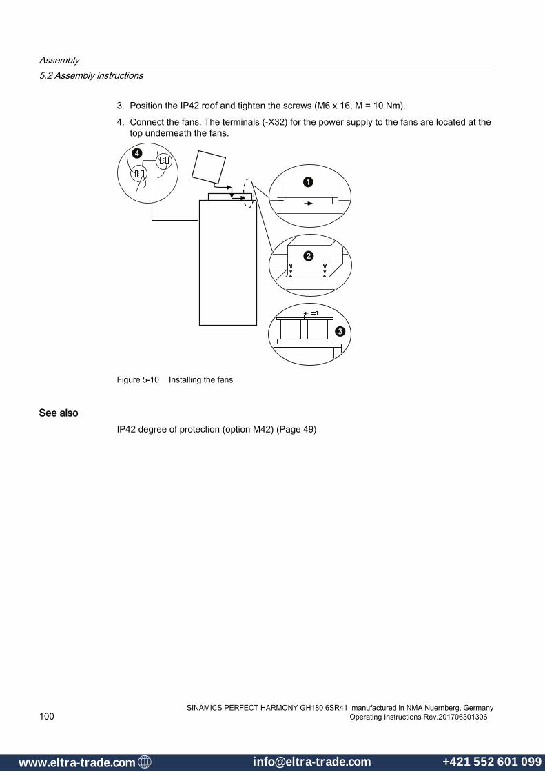
3. Position the IP42 roof and tighten the screws (M6 x 16, M = 10 Nm).
4. Connect the fans. The terminals (-X32) for the power supply to the fans are located at the top underneath the fans.
Figure 5-10 Installing the fans
See alsoIP42 degree of protection (option M42) (Page 49)
Assembly5.2 Assembly instructions
SINAMICS PERFECT HARMONY GH180 6SR41 manufactured in NMA Nuernberg, Germany100 Operating Instructions Rev.201706301306
www.eltra-trade.com [email protected] +421 552 601 099www.eltra-trade.com [email protected] +421 552 601 099
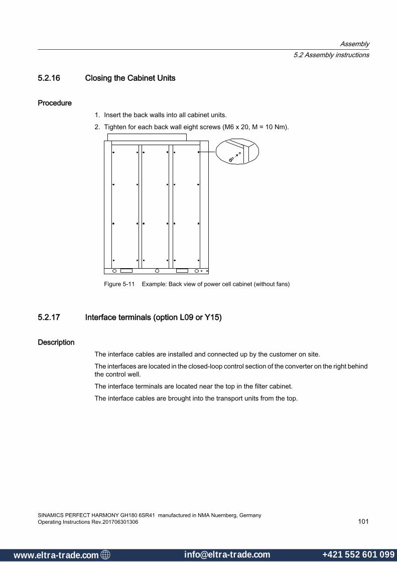
5.2.16 Closing the Cabinet Units
Procedure1. Insert the back walls into all cabinet units.
2. Tighten for each back wall eight screws (M6 x 20, M = 10 Nm).
Figure 5-11 Example: Back view of power cell cabinet (without fans)
5.2.17 Interface terminals (option L09 or Y15)
DescriptionThe interface cables are installed and connected up by the customer on site.
The interfaces are located in the closed-loop control section of the converter on the right behind the control well.
The interface terminals are located near the top in the filter cabinet.
The interface cables are brought into the transport units from the top.
Assembly5.2 Assembly instructions
SINAMICS PERFECT HARMONY GH180 6SR41 manufactured in NMA Nuernberg, GermanyOperating Instructions Rev.201706301306 101
www.eltra-trade.com [email protected] +421 552 601 099www.eltra-trade.com [email protected] +421 552 601 099
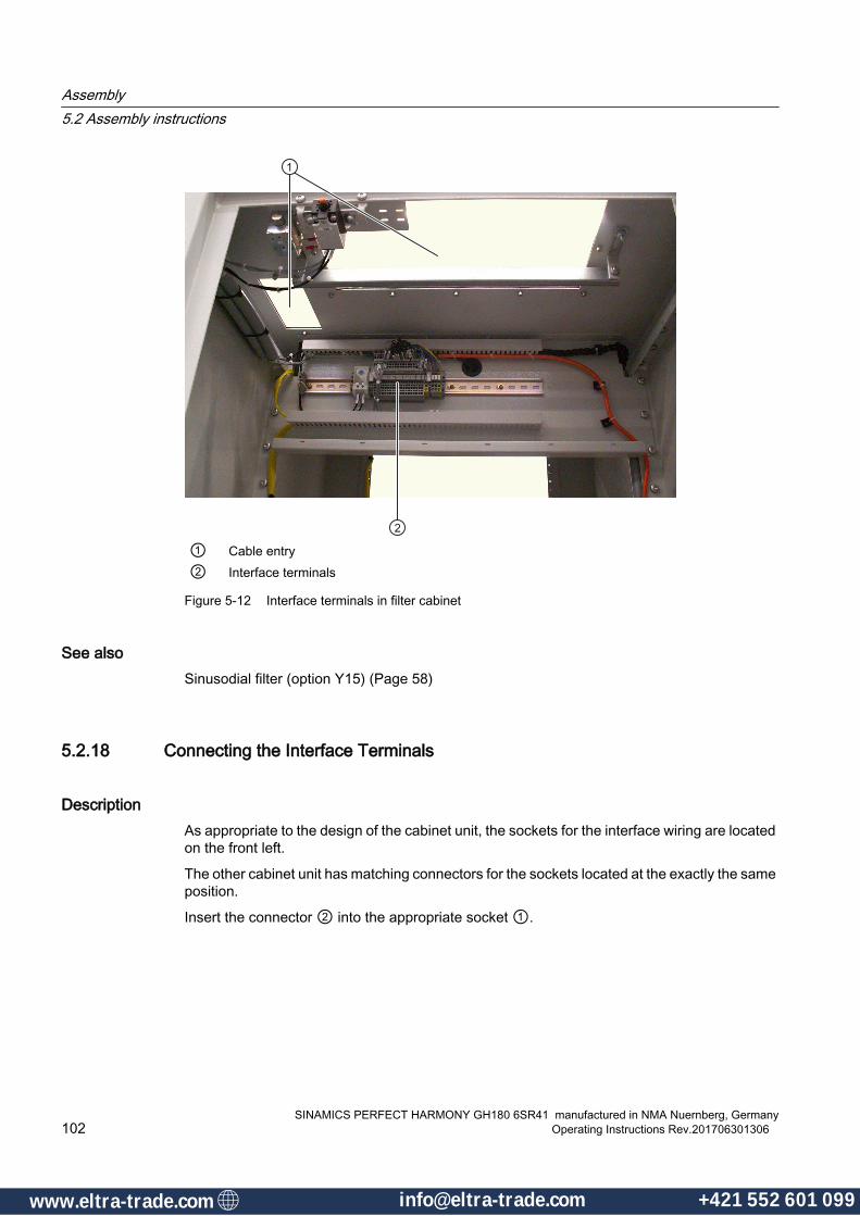
① Cable entry② Interface terminals
Figure 5-12 Interface terminals in filter cabinet
See alsoSinusodial filter (option Y15) (Page 58)
5.2.18 Connecting the Interface Terminals
DescriptionAs appropriate to the design of the cabinet unit, the sockets for the interface wiring are located on the front left.
The other cabinet unit has matching connectors for the sockets located at the exactly the same position.
Insert the connector ② into the appropriate socket ①.
Assembly5.2 Assembly instructions
SINAMICS PERFECT HARMONY GH180 6SR41 manufactured in NMA Nuernberg, Germany102 Operating Instructions Rev.201706301306
www.eltra-trade.com [email protected] +421 552 601 099www.eltra-trade.com [email protected] +421 552 601 099
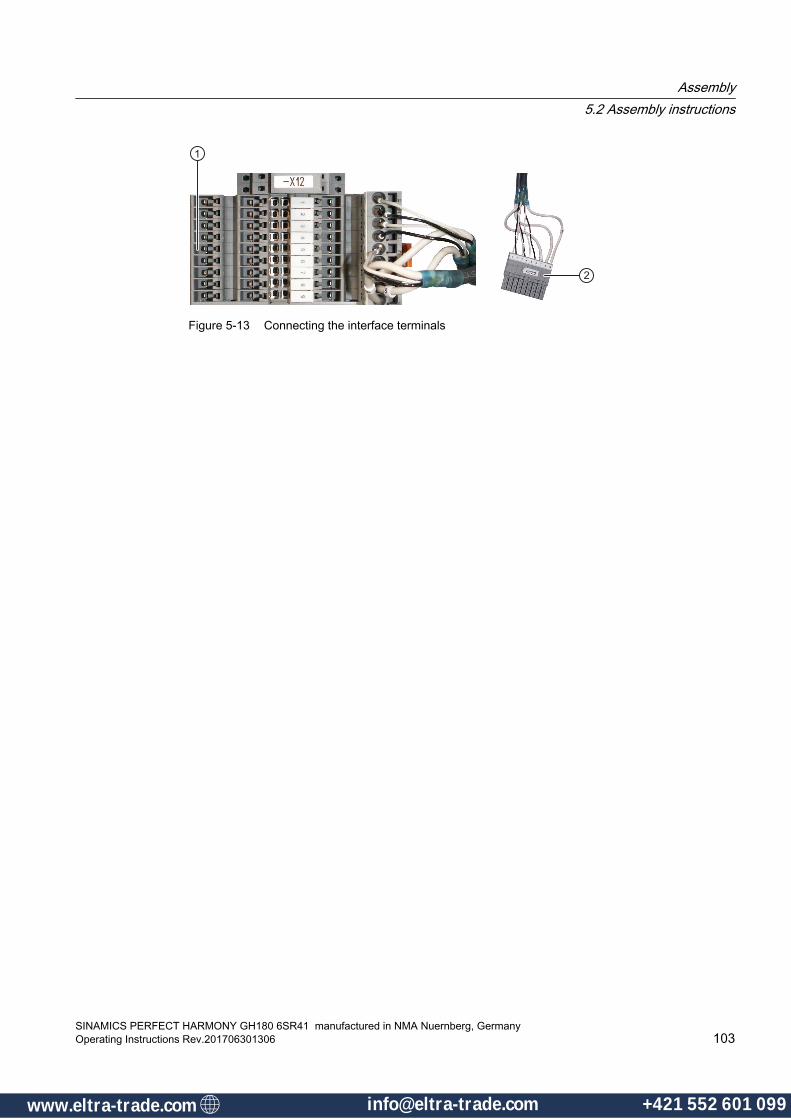
Figure 5-13 Connecting the interface terminals
Assembly5.2 Assembly instructions
SINAMICS PERFECT HARMONY GH180 6SR41 manufactured in NMA Nuernberg, GermanyOperating Instructions Rev.201706301306 103
www.eltra-trade.com [email protected] +421 552 601 099www.eltra-trade.com [email protected] +421 552 601 099

Assembly5.2 Assembly instructions
SINAMICS PERFECT HARMONY GH180 6SR41 manufactured in NMA Nuernberg, Germany104 Operating Instructions Rev.201706301306
www.eltra-trade.com [email protected] +421 552 601 099www.eltra-trade.com [email protected] +421 552 601 099
Electrical Connections 66.1 General Electrical
Standard Work PracticePrior to performing any type of electrical work on the equipment, be sure to read and understand all vendor supplied information and all information presented in the Safety Notes chapter of this manual.
SINAMICS PERFECT HARMONY GH180 6SR41 manufactured in NMA Nuernberg, GermanyOperating Instructions Rev.201706301306 105
www.eltra-trade.com [email protected] +421 552 601 099www.eltra-trade.com [email protected] +421 552 601 099

6.2 Installation External Wiring Customer-supplied medium voltage cables enter an access plate in the top or bottom.
Customer-supplied low-voltage cables for the control enter an access plate in the top or bottom.
The input terminals and output medium voltage terminals are offset from one another:
● input medium voltage terminals:
– U1
– V1
– W1
● output medium voltage terminals:
– U2
– V2
– W2
For details see the dimension drawing.
VFD
OBJECTINPUT OUTPUT PROTECTIVE CON‐
DUCTOR
MaximumCross-Section of Exter‐
nal Wires
9 cells40 - 140 A
1x120 mm2
1x250 MCM1x120 mm2
1x250 MCM70 mm²2/0 AWG
12 cells40 – 375 A
2x240 mm²2x500 MCM
2x240 mm²2x500 MCM
70 mm²2/0 AWG
15 cells40 – 375 A
2x240 mm²2x500 MCM
2x240 mm²2x500 MCM
70 mm²2/0 AWG
NoteIndividual conductor breakdown for three-conductor single-core cables
The SINAMICS PERFECT HARMONY GH180 drive design is best accommodated for single-conductor single-core medium voltage cables.
NoteInput Conductor Sizing
Be sure to size the input conductors appropriately for the particular application, taking into account the length of the input power feed as well as local electrical code and local standards. Labels located near the connections recommend the use of 75○ C conductors.
Electrical Connections6.2 Installation External Wiring
SINAMICS PERFECT HARMONY GH180 6SR41 manufactured in NMA Nuernberg, Germany106 Operating Instructions Rev.201706301306
www.eltra-trade.com [email protected] +421 552 601 099www.eltra-trade.com [email protected] +421 552 601 099

6.3 Torques
Table 6-1 Tightening torque for screws
Screw type Soft materials S31 Hard materials S22 Hard materials S13
nm in - lb nm in - lb nm in - lbM3 0.8 7.1 1.8 15.9 1.3 11.5M4 1.8 15.9 3.9 34.5 3.0 26.6M5 3.0 26.6 7.8 69.0 6.0 53.1M6 6.0 53.1 13.0 115 10.0 88.5M8 13.0 115 32.0 283 25.0 221M10 25.0 221 65.0 575 50.0 443M12 50.0 443 115.0 1020 88.0 779M16 115.0 1020 270.0 2390 215.0 1900
1 Examples of soft materials: Cu, Al, CuZn cable entries, laminate materials, plastics, cast resin post insulators, press nuts, welding nuts, blind rivet nuts, and cage nuts.
2 Hard materials S2 are materials with friction-enhancing washer components, for example a contact washer.
3 Hard S1 materials include steel, for example.
Table 6-2 Tightening torques for screw terminals for copper cables without cable lug 1)
Screw type Set screws and headless screws
Head screws with slit
Head screws with hexagon profile
nm in - lb nm in - lb nm in - lbM2 - - - M2.5 0.25 2.2 0.5 4.4 0.5 4.4M3 0.3 2.7 0.6 5.3 0.6 5.3M3.5 0.5 4.4 1.0 8.9 1.0 8.9M4 0.8 7.1 1.3 11.5 1.3 11.5M5 1.0 8.6 2.5 22.1 2.5 22.1M6 1.3 11.5 3.0 26.6 3.5 31.0M8 1.8 15.9 3.9 34.5 7.2 63.7M10 - - 4.8 42.5 13 115M12 - - - - 18 159.3M16 - - - - 30 265.5
Observe the tightening torques of the terminal manufacturer and the test torques according to DIN EN 60999-1, VED 609-1.
Electrical Connections6.3 Torques
SINAMICS PERFECT HARMONY GH180 6SR41 manufactured in NMA Nuernberg, GermanyOperating Instructions Rev.201706301306 107
www.eltra-trade.com [email protected] +421 552 601 099www.eltra-trade.com [email protected] +421 552 601 099
6.4 Grounding, Cabling, and Shielding RecommendationsThe following fundamental information and guidelines facilitate compliance with the EMC directives.
Note
We recommend that EMC is planned for the entire plant.
Electromagnetic compatibility
NOTICE
Non-compliance with Local Safety Regulations
Understand and obey all local safety regulations with regards to grounding. Recommendations do not supersede safety grounding regulations.
VFD GroundingThe variable frequency drive as a whole should be bonded to the facility ground using the following two methods;
● Bond the VFD at one point only using the shortest cable length. The VFD cabinet to facility ground connection shall be properly sized per local codes or regulations.
– The connection can be made in the VFD either in the input cabinetry or in the output cabinet.
– In the event of ground faults, the peak current and duration are much greater for the input than the output. Therefore, it is preferable to ground the VFD in the input cabinet to minimized the fault current flowing through the cabinet to cabinet connections.
● If a grounding grid is available under the VFD, the VFD cabinet can be solidly grounded to the facility ground structure at multiple points.
Neither the SINAMICS PERFECT HARMONY GH180 transformer primary neutral point on the input, nor the medium voltage output neutral point, shall be bonded to ground.
If used, the precharge winding shall be resistance grounded.
Motor GroundingThe motor case must be bonded to facility ground using the shortest cable length.
Bearing Currents:
● If machine induced bearing currents are of concern, then isolated bearings on the non-drive end of the motor shaft can be implemented
● Siemens recommends using a shaft ground brush on the drive-end of the motor shaft when concerns exist regarding whether the rotating load or the drive could cause harmful bearing currents.
● The encoder must be electrically isolated from the motor shaft.
Electrical Connections6.4 Grounding, Cabling, and Shielding Recommendations
SINAMICS PERFECT HARMONY GH180 6SR41 manufactured in NMA Nuernberg, Germany108 Operating Instructions Rev.201706301306
www.eltra-trade.com [email protected] +421 552 601 099www.eltra-trade.com [email protected] +421 552 601 099
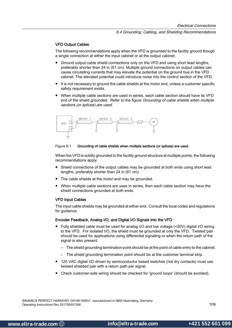
VFD Output CablesThe following recommendations apply when the VFD is grounded to the facility ground though a single connection at either the input cabinet or at the output cabinet:
● Ground output cable shield connections only on the VFD end using short lead lengths, preferably shorter than 24 in (61 cm). Multiple ground connections on output cables can cause circulating currents that may elevate the potential on the ground bus in the VFD cabinet. The elevated potential could introduce noise into the control section of the VFD.
● It is not necessary to ground the cable shields at the motor end, unless a customer specific safety requirement exists.
● When multiple cable sections are used in series, each cable section should have its VFD end of the shield grounded. Refer to the figure Grounding of cable shields when multiple sections (or splices) are used.
Figure 6-1 Grounding of cable shields when multiple sections (or splices) are used.
When the VFD is solidly grounded to the facility ground structure at multiple points, the following recommendations apply:
● Shield connections of the output cables may be grounded at both ends using short lead lengths, preferably shorter than 24 in (61 cm).
● The cable shields at the motor end may be grounded.
● When multiple cable sections are uses in series, then each cable section may have the shield connections grounded at both ends.
VFD Input CablesThe input cable shields may be grounded at either end. Consult the local codes and regulations for guidance.
Encoder Feedback, Analog I/O, and Digital I/O Signals into the VFD● Fully shielded cable must be used for analog I/O and low voltage (<50V) digital I/O wiring
to the VFD. For isolated I/O, the shield must be grounded at only the VFD. Twisted pair should be used for applications using differential signaling or when the return path of the signal is also present.
– The shield grounding termination point should be at the point of cable entry to the cabinet.
– The shield grounding termination point should be at the customer terminal strip.
● 120 VAC digital I/O driven by semiconductor based switches (not dry contacts) must use twisted shielded pair with a return path per signal.
● Check customer-side wiring should be checked for 'ground loops' (should be avoided).
Electrical Connections6.4 Grounding, Cabling, and Shielding Recommendations
SINAMICS PERFECT HARMONY GH180 6SR41 manufactured in NMA Nuernberg, GermanyOperating Instructions Rev.201706301306 109
www.eltra-trade.com [email protected] +421 552 601 099www.eltra-trade.com [email protected] +421 552 601 099
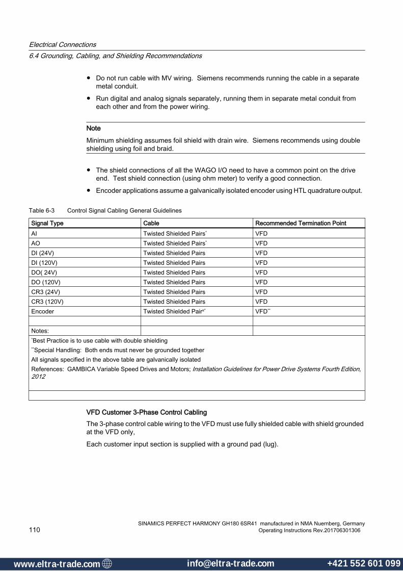
● Do not run cable with MV wiring. Siemens recommends running the cable in a separate metal conduit.
● Run digital and analog signals separately, running them in separate metal conduit from each other and from the power wiring.
Note
Minimum shielding assumes foil shield with drain wire. Siemens recommends using double shielding using foil and braid.
● The shield connections of all the WAGO I/O need to have a common point on the drive end. Test shield connection (using ohm meter) to verify a good connection.
● Encoder applications assume a galvanically isolated encoder using HTL quadrature output.
Table 6-3 Control Signal Cabling General Guidelines
Signal Type Cable Recommended Termination PointAI Twisted Shielded Pairs* VFDAO Twisted Shielded Pairs* VFDDI (24V) Twisted Shielded Pairs VFDDI (120V) Twisted Shielded Pairs VFDDO( 24V) Twisted Shielded Pairs VFDDO (120V) Twisted Shielded Pairs VFDCR3 (24V) Twisted Shielded Pairs VFDCR3 (120V) Twisted Shielded Pairs VFDEncoder Twisted Shielded Pairs* VFD**
Notes: *Best Practice is to use cable with double shielding**Special Handling: Both ends must never be grounded togetherAll signals specified in the above table are galvanically isolatedReferences: GAMBICA Variable Speed Drives and Motors; Installation Guidelines for Power Drive Systems Fourth Edition, 2012
VFD Customer 3-Phase Control CablingThe 3-phase control cable wiring to the VFD must use fully shielded cable with shield grounded at the VFD only,
Each customer input section is supplied with a ground pad (lug).
Electrical Connections6.4 Grounding, Cabling, and Shielding Recommendations
SINAMICS PERFECT HARMONY GH180 6SR41 manufactured in NMA Nuernberg, Germany110 Operating Instructions Rev.201706301306
www.eltra-trade.com [email protected] +421 552 601 099www.eltra-trade.com [email protected] +421 552 601 099

6.5 Electromagnetic compatibility
Cable installation ● Cables that are subject to or sensitive to interference should be laid as far apart from each
other as possible.
● The distance between the electric power cable and signal cable should be > 20 cm. The converter-specific information applies to power cables. You can find further information on power cables under "Connecting power cables".
● When the cables are routed close to ground potential, the immunity to interference is increased. For this reason, you are advised to lay these cables along edges and at ground potential.
● Ground the reserve cores on at least one end.
● In order to avoid additional locations where interference can be coupled in, long cables should be shortened or routed where there is little interference.
● If conductors or cables conduct signals of different classes, then the conductors and cables must cross at a right angle. This especially involves sensitive and noisy signals.
– Class 1: Unshielded cables for ≤ 60 V DCUnshielded cables for ≤ 25 V ACShielded analog signal cablesShielded bus and data cablesOperator panel interfaces, incremental/absolute encoder cables
– Class 2:Unshielded cables for > 60 V DC and ≤ 230 V DCUnshielded cables for > 25 V AC and ≤ 230 V AC
– Class 3:Unshielded cables for > 230 V AC/V DC and ≤ 1000 V AC/DC
– Class 4: Unshielded cables for > 1000 V AC/DC
Shield connection● Do not use cable shields to conduct current. In other words, cable shields must not
simultaneously act as neutral or PE conductors.
● Apply the cable shield so that it covers the greatest possible surface area. Use ground clamps, ground terminals or ground screw connections.
● Avoid extending the cable shield to the grounding point using a wire. This reduces the shield effectiveness by up to 90%.
I/O connection ● Create a low-impedance ground connection for additional cabinets, system components,
and distributed devices with the largest possible cross-section (at least 16 mm²).
● Ground unused lines at one end in the cabinet.
Electrical Connections6.5 Electromagnetic compatibility
SINAMICS PERFECT HARMONY GH180 6SR41 manufactured in NMA Nuernberg, GermanyOperating Instructions Rev.201706301306 111
www.eltra-trade.com [email protected] +421 552 601 099www.eltra-trade.com [email protected] +421 552 601 099

● Choose the greatest possible clearance between the power and signal cables (at least 20 cm). The greater the distance over which the cables are routed in parallel, the greater the clearance must be. You must install additional shields if sufficient clearance cannot be maintained.
● Avoid unnecessarily long cable loops.
● Surge suppressors, e.g. RC elements or varistors must be connected to the operating coils for contactors and relays in the converter.
● In order to reduce noise/interference entering or exiting via the cable, filter auxiliary voltages in the control cabinet.
Electrical Connections6.5 Electromagnetic compatibility
SINAMICS PERFECT HARMONY GH180 6SR41 manufactured in NMA Nuernberg, Germany112 Operating Instructions Rev.201706301306
www.eltra-trade.com [email protected] +421 552 601 099www.eltra-trade.com [email protected] +421 552 601 099
6.6 Terminal Blocks
Terminal BlocksRefer to the Control Section of this manual for specific information about terminal blocks.
NoteSpare Terminal Availability
Consult Siemens for customized systems requiring additional terminals.
DANGER
Electrical Hazard!
Standard safety precautions and local codes must be followed during installation of external wiring.
Protection separation must be kept between extra low voltage (ELV) wiring and any other wiring as specified in the CE safety standard IEC61800-5-1.
Electrical Connections6.6 Terminal Blocks
SINAMICS PERFECT HARMONY GH180 6SR41 manufactured in NMA Nuernberg, GermanyOperating Instructions Rev.201706301306 113
www.eltra-trade.com [email protected] +421 552 601 099www.eltra-trade.com [email protected] +421 552 601 099

6.7 Cable Gland Plates Removal and Installation Guidelines
Cable Gland Plates Removal and Installation GuidelinesRemoval of gland plates is necessary to complete input and output power cable installation. Gland plates are attached to the drive enclosure and can be removed by unfastening the hardware.
Gland Plate Installation Preparation and Procedure:1. Place the unfastened hardware in a safe place to allow for quick retrieval when re-installing
the gland plates.
2. Fit the cable entries with a proper water-tight seal.
3. If cable size permits, make holes for drilling cable entries.
4. Do not drill the gland plate while it is still mounted to the enclosure.
NOTICE
Gland Plate Drilling
Do not drill the gland plate while it is mounted to the enclosure.
Drilling the plate while it is mounted leads to metal dust accumulation on sensitive electronics that are located inside of the unit, which may cause loss of component integrity and possibly affect system operability.
Gland Plate Drilling Guidelines1. Take care not to damage the rubber gasket seal material during the drilling process
2. Fit the cable entries with a proper water-tight seal.
3. Ensure that gland plates are properly fastened to the drive with the original hardware.
4. Be sure to check the integrity of the rubber gasket seal prior to installing the gland plate.
NoteMaintain IP Rating of Enclosure
To maintain the IP rating of the enclosure / cabinet, a proper gasket seal is required.
Inspect for any damaged gasket prior to and after installing the gland plates.
Electrical Connections6.7 Cable Gland Plates Removal and Installation Guidelines
SINAMICS PERFECT HARMONY GH180 6SR41 manufactured in NMA Nuernberg, Germany114 Operating Instructions Rev.201706301306
www.eltra-trade.com [email protected] +421 552 601 099www.eltra-trade.com [email protected] +421 552 601 099

6.8 Closing the make-proof grounding switchThe converter is optionally equipped with make-proof grounding switches (N44 or N45).
The make-proof grounding switches can be closed when the doors have been closed and the following prerequisites are fulfilled:
● The DC link voltage must be de-energized.
● The EMERGENCY-OFF switch on the cabinet unit must be activated.
● The key-operated switch on the converter must be set to the OFF position.
● A delay time of 10 minutes must have expired.
If the auxiliary voltage fails completely, the make-proof grounding switch cannot be closed.
The doors are secured by the electrical door magnet system and can be opened only after the make-proof grounding switch is closed.
Electrical Connections6.8 Closing the make-proof grounding switch
SINAMICS PERFECT HARMONY GH180 6SR41 manufactured in NMA Nuernberg, GermanyOperating Instructions Rev.201706301306 115
www.eltra-trade.com [email protected] +421 552 601 099www.eltra-trade.com [email protected] +421 552 601 099

Procedure1. Take the socket spanner, which can be found in the tool set, and turn it from position "O"
to position "I". The red dot marks the current position.
Figure 6-2 Make-proof grounding switch
2. The contacts are closed and the voltage DC link is grounded.
CAUTION
Grounding while the system is live
You must note the following to prevent injury or material damage:
For operation, the make-proof grounding switch must be deactivated and the grounding switch lever must be removed before the voltage is switched on. The interlock mechanism is thus activated.
This prevents grounding while the system is live, which could cause a DC link short-circuit.
Electrical Connections6.8 Closing the make-proof grounding switch
SINAMICS PERFECT HARMONY GH180 6SR41 manufactured in NMA Nuernberg, Germany116 Operating Instructions Rev.201706301306
www.eltra-trade.com [email protected] +421 552 601 099www.eltra-trade.com [email protected] +421 552 601 099

6.9 E-StopsE-Stop incorporation into the Coordinated Input Protection Scheme is discussed in the section of this manual titled Control.
See alsoControl Section (Page 32)
Electrical Connections6.9 E-Stops
SINAMICS PERFECT HARMONY GH180 6SR41 manufactured in NMA Nuernberg, GermanyOperating Instructions Rev.201706301306 117
www.eltra-trade.com [email protected] +421 552 601 099www.eltra-trade.com [email protected] +421 552 601 099
6.10 Circuit Breaker (provided by the customer)To ensure adequate protection for VFDs, the circuit breaker provided by the customer must fulfill the following requirements:
● The maximum time between when the circuit breaker trips, to when a no-current state (I=0) is reached, is 100 ms.
● The circuit breaker must be equipped with an undervoltage tripping function.
● The circuit breaker is enabled by the VFD closed-loop controller. It must never be switched on by any other method when connected to the VFD input transformer.
● An overcurrent protection device is provided to protect the VFD transformer.
Electrical Connections6.10 Circuit Breaker (provided by the customer)
SINAMICS PERFECT HARMONY GH180 6SR41 manufactured in NMA Nuernberg, Germany118 Operating Instructions Rev.201706301306
www.eltra-trade.com [email protected] +421 552 601 099www.eltra-trade.com [email protected] +421 552 601 099
Commissioning 77.1 RCD Compatibility
Residual Current Device Compatibility
CAUTION
RCD Incompatibility
Connecting this device to a power supply protected by a residual-current device can result in damage to property and minor personal injury.
This product can produce a DC current in the grounding conductor.
When using a Residual-Current Device (RCD) in cases where direct or indirect contact can be made, only a Type-B RCD shall be permissible on the line side of this product. If this is not possible, an alternative means of protection must be applied. Isolation from the environment through double or reinforced insulation, or isolation from the power supply using a transformer, is an example of alternative means of protection.
Note
The master mechanical interlock key (K1) must be coordinated with the input voltage switchgear. Please refer to the section of the manual titled Option Codes that is located in the Description chapter. The relevant option codes are M08, M09, M10, and M38.
SINAMICS PERFECT HARMONY GH180 6SR41 manufactured in NMA Nuernberg, GermanyOperating Instructions Rev.201706301306 119
www.eltra-trade.com [email protected] +421 552 601 099www.eltra-trade.com [email protected] +421 552 601 099
7.2 Cell ReformingNo Load ConditionsWhen an aluminum electrolytic capacitor is stored under no load conditions for a long period of time, its leakage current tends to increase. If the storage temperature is high, the leakage current will increase substantially. This is due to a drop in the withstand voltage of the dielectric caused by the reaction of the anode oxide layer with the electrolyte. At this point the capacitor should not be subjected to full voltage until the leakage current returns to its initial level, which can be done by reforming the electrolyte. Reforming can be done by applying a voltage that is slowly increased to maximum over a period of several hours, with current limited to rated leakage current.
If capacitors have been out of service for more than 24 months, they must be reformed.
NOTICE
Reform Capacitors Schedule
If capacitors have been out of service for more than 24 months, they must be reformed. This will assure the electrolytics are not not in a degraded state and will perform at the level needed for optimal drive performance.
Power Cell Capacitor ReformThe capacitors can be reformed with the cell in or out of the drive. If reformed out of the drive, each cell must be reformed one-at-a-time. If reformed in the drive, then all the cells can be formed at the same time.
WARNING
Unqualified personnel are NOT permitted to reform cells.
Only qualified personnel may perform cell reforming. Potential electrical hazards and physical injury, including death, can occur when the voltage is applied to a Power Cell that is outside of the Cell Cabinet enclosure.
Please contact the Siemens factory for further information about the Power Cell Reforming.
Commissioning7.2 Cell Reforming
SINAMICS PERFECT HARMONY GH180 6SR41 manufactured in NMA Nuernberg, Germany120 Operating Instructions Rev.201706301306
www.eltra-trade.com [email protected] +421 552 601 099www.eltra-trade.com [email protected] +421 552 601 099

7.3 Commissioning ProcessAfter determining the final installation location, install the VFD. Ensure proper anchoring of the drive. Once this is done, Siemens can arrive at the site to commence the pre-commissioning process. Contact the Siemens Technical Support team.
Process1. Obtain site equipment information and verify that equipment matches factory information.
2. Install lockouts and de-energize equipment.
3. Torque check the cabinet connections. Inspect the entire drive for shipping and/or installation damage, and verify each cell is properly engaged to its rear bus connectors.
4. Ensure the enclosure is earth grounded at the P.E. point of the drive. Confirm what type of cable the customer is using for the motor connections. If it is a shielded cable, only one end of the shield can be grounded. It must be grounded at the drive. Inspect MV input cabling and hardwired I/O control wiring.
5. Check and note if the VFD integral isolation transformer neutral is grounded. Is transformer neutral grounded? Note "yes" or "no" on the applicable commissioning form. Ohm check all secondary transformer connections to the chassis cabinet to ensure no damage has occurred during shipment.
Note
Siemens strongly recommends no ground on transformer neutral conductor. However, the transformer iron core is routinely chassis-grounded to the enclosure by Siemens.
6. Inspect customer load.
7. Inspect internal routing of the fiber optic connections and their integrity.
8. Obtain permission to energize.
Commissioning7.3 Commissioning Process
SINAMICS PERFECT HARMONY GH180 6SR41 manufactured in NMA Nuernberg, GermanyOperating Instructions Rev.201706301306 121
www.eltra-trade.com [email protected] +421 552 601 099www.eltra-trade.com [email protected] +421 552 601 099
9. At this time, it is necessary to have an auxiliary control voltage(s) source connected per the VFD schematics to allow the pre-commissioning process to continue. A temporary source can be used.
CAUTION
RCD incompatibility
Connecting this device to a power supply protected by a residual-current device can result in damage to property and minor personal injury.
This product can produce a DC current in the grounding conductor.
When using a Residual-Current Device (RCD) in cases where direct or indirect contact can be made, only a Type-B RCD shall be permissible on the line side of this product. If this is not possible, an alternative means of protection must be applied; for example isolation from the environment through double or reinforced insulation, or isolation from the power supply using a transformer.
Do not connect this device to a power supply that is protected by a Type-A residual-current device.
NoteMaster Mechanical Interlock Key Coordination
The master mechanical interlock key (K1) must be coordinated with the input voltage switchgear.
10.Remove lockouts and energize LV controls.
11.Power is required to test the cooling system and control. To verify the rotation and phase sequencing of the cooling fans, verify the VAC input value and apply 3-phase power to the blowers.
12.Confirm input and output voltage attenuator resistors and output Hall Effect current sensor burden resistors according to project drawings.
NoteItems to Check● The motor leads should not be connected to the drive when performing the following
OLTM check.● The input MV switchgear should be locked and tagged out prior to OLTM checks in the
next step.
13.In OLTM, backfeed the drive with a variac connected to one of the transformer secondary windings. Verify all cell and the drive input line-voltages are correct.
14.If the VFD has cell bypass, verify contactor operation by removing cell fiber optics at the control digital control rack (DCR).
15.De-energize and apply lockouts until start up and commissioning is performed.
16.At the end of the pre-commissioning, a copy of the pre-commissioning report should be left with the responsible site manager.
Commissioning7.3 Commissioning Process
SINAMICS PERFECT HARMONY GH180 6SR41 manufactured in NMA Nuernberg, Germany122 Operating Instructions Rev.201706301306
www.eltra-trade.com [email protected] +421 552 601 099www.eltra-trade.com [email protected] +421 552 601 099
Operation 88.1 Operating the Drive
When operating the drive, be sure to read and understand all safety warnings as detailed in the Safety Notes chapter of this manual. Obey all warnings and safety material presented in each chapter.
DANGER
Qualified Personnel ONLY
Only trained personnel may operate a SINAMICS PERFECT HARMONY GH180. Improperly operating the drive can cause damage to property, serious injury, and possible death.
SINAMICS PERFECT HARMONY GH180 6SR41 manufactured in NMA Nuernberg, GermanyOperating Instructions Rev.201706301306 123
www.eltra-trade.com [email protected] +421 552 601 099www.eltra-trade.com [email protected] +421 552 601 099

8.2 Major Drive Faults and AlarmsThe control senses all drive faults and alarms, either from direct hardware or via software algorithms.
Use the following tables to quickly locate major causes of fault conditions. The tables also list the type of drive response, if it is a fault (F), alarm (A), or both (F/A), and whether it can be enabled or disabled using the SOP program (SOP), Menu, or if it is permanently enabled, i.e. fixed in software.
Refer to the Fault / Alarm Types and Responses table, to determine the drive response for the various fault and alarm conditions:
Table 8-1 Fault / Alarm Types and Responses
Type Drive ResponsesFault ● All IGBT gate drivers are inhibited.
● Motor coasts to stop.● The fault is logged. Refer to the Fault Log Menu (6210).● The fault is displayed on the front panel.● The keypad fault LED is ON. ● Most faults are logged to the Event Log.
User Faults ● The motor either ramp stops or coast stops depending on the content of the system program.● The fault is logged. Refer to the Fault Log Menu (6210).● The fault is displayed on the front panel.● The keypad fault LED is ON. ● User defined faults are logged to the Event Log.
Alarm ● The drive does not necessarily revert to the idle state via a coast or ramp stop unless specifically required to by the system program.
● The alarm is logged. Refer to the Fault Log Menu (6210).● The alarm is displayed on the front panel.● The keypad fault LED flashes.
8.2.1 Faults / Alarms Types / ResponsesExisting fault or alarm conditions are annunciated on the keypad. The NXG Control software and hardware sense faults and alarms and store them within the fault logger and the event logger.
The cell control system logic, located on the cell control board in each output power cell, senses cell faults. Each power cell has its own sense circuitry. The NXG Control software interprets the cell faults and displays them and logs them based on the faulted cell and the specific fault within the cell.
All sensed faults immediately inhibit the drive from running and remove power from the drive to the motor. Some user-defined faults can control the drive response via the system program. Alarms are annunciated and logged but usually do not inhibit the drive from operation.
Operation8.2 Major Drive Faults and Alarms
SINAMICS PERFECT HARMONY GH180 6SR41 manufactured in NMA Nuernberg, Germany124 Operating Instructions Rev.201706301306
www.eltra-trade.com [email protected] +421 552 601 099www.eltra-trade.com [email protected] +421 552 601 099
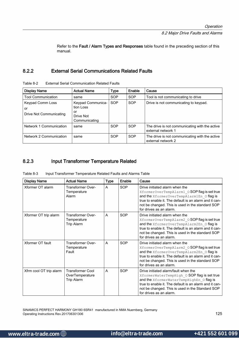
Refer to the Fault / Alarm Types and Responses table found in the preceding section of this manual.
8.2.2 External Serial Communications Related Faults
Table 8-2 External Serial Communication Related Faults
Display Name Actual Name Type Enable CauseTool Communication same SOP SOP Tool is not communicating to driveKeypad Comm LossorDrive Not Communicating
Keypad Communica‐tion Lossor Drive NotCommunicating
SOP SOP Drive is not communicating to keypad.
Network 1 Communication same SOP SOP The drive is not communicating with the active external network 1
Network 2 Communication same SOP SOP The drive is not communicating with the active external network 2
8.2.3 Input Transformer Temperature Related
Table 8-3 Input Transformer Temperature Related Faults and Alarms Table
Display Name Actual Name Type Enable CauseXformer OT alarm Transformer Over‐
TemperatureAlarm
A SOP Drive initiated alarm when the XformerOverTempAlarm1_O SOP flag is set true and the XformerOverTempAlarm1En_O flag is true to enable it. The default is an alarm and it can‐not be changed. This is used in the standard SOP for drives as an alarm.
Xformer OT trip alarm Transformer Over‐TemperatureTrip Alarm
A SOP Drive initiated alarm when the XformerOverTempAlarm2_O SOP flag is set true and the XformerOverTempAlarm2En_O flag is true to enable it. The default is an alarm and it can‐not be changed. This is used in the standard SOP for drives as an alarm.
Xformer OT fault Transformer Over‐TemperatureFault
A SOP Drive initiated alarm when the XformerOverTempAlarm2_O SOP flag is set true and the XformerOverTempAlarm2En_O flag is true to enable it. The default is an alarm and it can‐not be changed. This is used in the standard SOP for drives as an alarm.
Xfrm cool OT trip alarm Transformer Cool OverTemperatureTrip Alarm
A SOP Drive initiated alarm/fault when the XformerWaterTempHigh_O SOP flag is set true and the XformerWaterTempHighEn_O flag is true to enable it. The default is an alarm and it can‐not be changed. This is used in the Standard SOP for drives as an alarm.
Operation8.2 Major Drive Faults and Alarms
SINAMICS PERFECT HARMONY GH180 6SR41 manufactured in NMA Nuernberg, GermanyOperating Instructions Rev.201706301306 125
www.eltra-trade.com [email protected] +421 552 601 099www.eltra-trade.com [email protected] +421 552 601 099
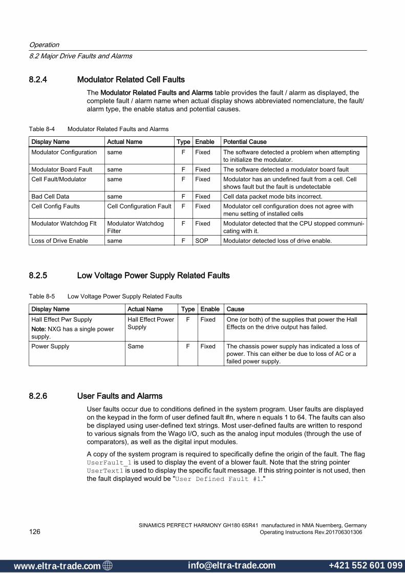
8.2.4 Modulator Related Cell FaultsThe Modulator Related Faults and Alarms table provides the fault / alarm as displayed, the complete fault / alarm name when actual display shows abbreviated nomenclature, the fault/alarm type, the enable status and potential causes.
Table 8-4 Modulator Related Faults and Alarms
Display Name Actual Name Type Enable Potential CauseModulator Configuration same F Fixed The software detected a problem when attempting
to initialize the modulator.Modulator Board Fault same F Fixed The software detected a modulator board faultCell Fault/Modulator same F Fixed Modulator has an undefined fault from a cell. Cell
shows fault but the fault is undetectableBad Cell Data same F Fixed Cell data packet mode bits incorrect.Cell Config Faults Cell Configuration Fault F Fixed Modulator cell configuration does not agree with
menu setting of installed cellsModulator Watchdog Flt Modulator Watchdog
FilterF Fixed Modulator detected that the CPU stopped communi‐
cating with it.Loss of Drive Enable same F SOP Modulator detected loss of drive enable.
8.2.5 Low Voltage Power Supply Related Faults
Table 8-5 Low Voltage Power Supply Related Faults
Display Name Actual Name Type Enable CauseHall Effect Pwr SupplyNote: NXG has a single power supply.
Hall Effect Power Supply
F Fixed One (or both) of the supplies that power the Hall Effects on the drive output has failed.
Power Supply Same F Fixed The chassis power supply has indicated a loss of power. This can either be due to loss of AC or a failed power supply.
8.2.6 User Faults and AlarmsUser faults occur due to conditions defined in the system program. User faults are displayed on the keypad in the form of user defined fault #n, where n equals 1 to 64. The faults can also be displayed using user-defined text strings. Most user-defined faults are written to respond to various signals from the Wago I/O, such as the analog input modules (through the use of comparators), as well as the digital input modules.
A copy of the system program is required to specifically define the origin of the fault. The flag UserFault_1 is used to display the event of a blower fault. Note that the string pointer UserText1 is used to display the specific fault message. If this string pointer is not used, then the fault displayed would be "User Defined Fault #1."
Operation8.2 Major Drive Faults and Alarms
SINAMICS PERFECT HARMONY GH180 6SR41 manufactured in NMA Nuernberg, Germany126 Operating Instructions Rev.201706301306
www.eltra-trade.com [email protected] +421 552 601 099www.eltra-trade.com [email protected] +421 552 601 099

8.2.7 User Defined Faults
Fault Display Type Enable Potential Causes User defined fault (64) F/A SOP Cause
The UserFault_1 through UserFault_64 flags in the system program have been set to the value "true". These can be set up as either faults or alarms, and the message can be defined via the SOP.
8.2.8 Input Line Disturbance Faults and AlarmsThe Input Line Disturbance Faults and Alarms table provides the fault / alarm as displayed, the complete fault / alarm name when actual display shows abbreviated nomenclature, the alarm type, the enable status and potential causes.
Table 8-6 Input Line Disturbance Faults and Alarms
Display Name Actual Name Type Enable Potential CausesInput Phase Loss same A Fixed Loss of input phase. Input Ground same A Fixed The estimated input ground voltage is greater than the
limit set by the ground fault limit in the drive protection menu.
Line Overvoltage 1 same A SOP The drive-input RMS voltage is greater than 110% of the drive rated input voltage.Note: This alarm can be caused by a transient condi‐tion, and may not be present when making the meas‐urements.
Line Overvoltage 2 same A SOP The dive input RMS voltage is greater than 115% of the drive rated input voltage.Note: Refer to Line over voltage 1 section above. Val‐ues greater than 4.37 VRMS will trigger this alarm.
Line Overvoltage Fault same F SOP The drive-input RMS voltage is greater than 120% of the drive rated input voltage.Note: Refer to line over voltage 1 section above. Values greater than 4.56 VRMS will trigger an alarm or trip, depending on the SOP.
Medium Voltage Low 1 same A SOP The drive-input RMS voltage is less than 90% of the drive rated input voltage. Note: This alarm can be caused by a transient condi‐tion, and may not be present when making the meas‐urements.
Medium Voltage Low 2 same A Fixed The drive-input RMS voltage is less than 70% of the drive rated input voltage.Note: Refer to "Medium voltage low 1" section above. The threshold is 2.66 V.
Operation8.2 Major Drive Faults and Alarms
SINAMICS PERFECT HARMONY GH180 6SR41 manufactured in NMA Nuernberg, GermanyOperating Instructions Rev.201706301306 127
www.eltra-trade.com [email protected] +421 552 601 099www.eltra-trade.com [email protected] +421 552 601 099
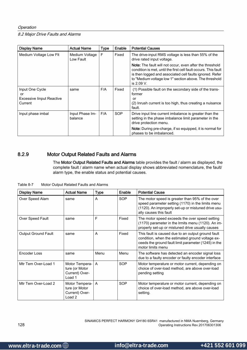
Display Name Actual Name Type Enable Potential CausesMedium Voltage Low Flt Medium Voltage
Low FaultF Fixed The drive-input RMS voltage is less than 55% of the
drive rated input voltage.Note: The fault will not occur, even after the threshold condition is met, until the first cell fault occurs. This fault is then logged and associated cell faults ignored. Refer to "Medium voltage low 1" section above. The threshold is 2.09 V.
Input One Cycle orExcessive Iinput Reactive Current
same F/A Fixed (1) Possible fault on the secondary side of the trans‐former or (2) Inrush current is too high, thus creating a nuisance fault.
Input phase imbal Input Phase Im‐balance
F/A SOP Drive input line current imbalance is greater than the setting in the phase imbalance limit parameter in the drive protection menu.Note: During pre-charge, if so equipped, it is normal for phases to be imbalanced.
8.2.9 Motor Output Related Faults and AlarmsThe Motor Output Related Faults and Alarms table provides the fault / alarm as displayed, the complete fault / alarm name when actual display shows abbreviated nomenclature, the fault/alarm type, the enable status and potential causes.
Table 8-7 Motor Output Related Faults and Alarms
Display Name Actual Name Type Enable Potential CauseOver Speed Alam same A SOP The motor speed is greater than 95% of the over
speed parameter setting (1170) in the limits menu (1120). An improperly set-up or mistuned drive usu‐ally causes this fault
Over Speed Fault same F Fixed The motor speed exceeds the over speed setting (1170) parameter in the lrmits menu (1120). An im‐properly set-up or mistuned drive usually causes
Output Ground Fault same A Fixed This fault is caused due to an output ground fault condition, when the estimated ground voltage ex‐ceeds the ground fault limit parameter (1245) in the motor limits menu
Encoder Loss same Menu Menu The software has detected an encoder signal loss due to a faulty encoder or faulty encoder interface
Mtr Tem Over-Load 1 Motor Tempera‐ture (or Motor Current) Over-Load 1
A SOP Motor temperature or motor current, depending on choice of over-load method, are above over-load pending setting
Mtr Tem Over-Load 2 Motor Tempera‐ture (or Motor Current) Over-Load 2
A SOP Motor temperature or motor current, depending on choice of over-load method, are above over-load setting.
Operation8.2 Major Drive Faults and Alarms
SINAMICS PERFECT HARMONY GH180 6SR41 manufactured in NMA Nuernberg, Germany128 Operating Instructions Rev.201706301306
www.eltra-trade.com [email protected] +421 552 601 099www.eltra-trade.com [email protected] +421 552 601 099

Display Name Actual Name Type Enable Potential CauseMtr Tem Over-Load Fault Motor Tempera‐
ture (or Motor Current) Over-Load Fault
F Fixed Motor temperature or motor current, depending on choice of over-load method, has exceeded the over-load setting for the time specified by the over-load timeout parameter.
Motor Over Volt Alarm Motor Over Volt‐age Alarm
A SOP If motor voltage exceeds 90% of the motor over‐voltage limit in the motor limit menu.
Motor Over Volt Fault Motor Over Volt‐ageFault
F SOP The measured motor voltage exceeds the threshold set by the motor trip volts (1160) parameter in the limits menu (1120). An improperly set-up or tuned drive usually causes this fault. This could include the secondary tap setting. A high line condition can also cause this.
IOC Instantanteous Over Current
F Fixed Drive instantaneous over-current (IOC) faults usu‐ally result when the signal from test point IOC on the system interface board exceeds the level set by the drive IOC setpoint (7110) parameter in the input protect menu (7000).
Under Load Alarm same A SOP The torque producing current of the drive has drop‐ped below a preset value set by the user.
Under Load Alarm same F Menu This fault usually indicates a loss of load condition when the torque producing current of the drive has dropped below a preset value set by the user for the specified amount of time.
Output Phase Imbal Output Phase Imbalance
A Fixed The software has detected an imbalance in the mo‐tor currents.
Output Phase Open same A SOP The software has detected an open phase condition at the drive output to the motor. Generally, if this occurs, the problem is with the feedback. A true open output phase will result in an IOC trip.
In Torque Limit same A SOP This alarm is issued when the drive is in speed roll‐back, due to a torque limit condition, for more than one minute.
In Torq Limit Rollback In Torque Limit Rollback
F/A SOP This fault or alarm, depending on the SOP program, is issued when the drive is in speed rollback, due to a torque limit condition, for more than 30 minutes.
Minimum Speed Trip same F/A SOP Motor speed is below the zero speed setting (2200). This is either due to a motor stall condition, if speed demand is higher than the zero speed setting, or a low speed demand condition, where speed demand is lower than the zero speed setting.
Loss of Field Current same F/A SOP This occurs only with synchronous motor control due to field exciter failure or loss of power to the exciter.
Operation8.2 Major Drive Faults and Alarms
SINAMICS PERFECT HARMONY GH180 6SR41 manufactured in NMA Nuernberg, GermanyOperating Instructions Rev.201706301306 129
www.eltra-trade.com [email protected] +421 552 601 099www.eltra-trade.com [email protected] +421 552 601 099
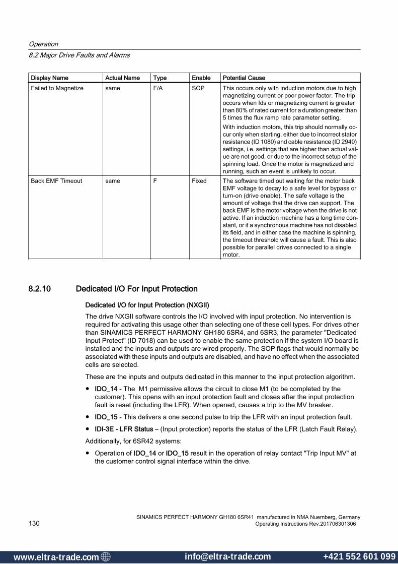
Display Name Actual Name Type Enable Potential CauseFailed to Magnetize same F/A SOP This occurs only with induction motors due to high
magnetizing current or poor power factor. The trip occurs when Ids or magnetizing current is greater than 80% of rated current for a duration greater than 5 times the flux ramp rate parameter setting.With induction motors, this trip should normally oc‐cur only when starting, either due to incorrect stator resistance (ID 1080) and cable resistance (ID 2940) settings, i.e. settings that are higher than actual val‐ue are not good, or due to the incorrect setup of the spinning load. Once the motor is magnetized and running, such an event is unlikely to occur.
Back EMF Timeout same F Fixed The software timed out waiting for the motor back EMF voltage to decay to a safe level for bypass or turn-on (drive enable). The safe voltage is the amount of voltage that the drive can support. The back EMF is the motor voltage when the drive is not active. If an induction machine has a long time con‐stant, or if a synchronous machine has not disabled its field, and in either case the machine is spinning, the timeout threshold will cause a fault. This is also possible for parallel drives connected to a single motor.
8.2.10 Dedicated I/O For Input Protection
Dedicated I/O for Input Protection (NXGII)The drive NXGII software controls the I/O involved with input protection. No intervention is required for activating this usage other than selecting one of these cell types. For drives other than SINAMICS PERFECT HARMONY GH180 6SR4, and 6SR3, the parameter "Dedicated Input Protect" (ID 7018) can be used to enable the same protection if the system I/O board is installed and the inputs and outputs are wired properly. The SOP flags that would normally be associated with these inputs and outputs are disabled, and have no effect when the associated cells are selected.
These are the inputs and outputs dedicated in this manner to the input protection algorithm.
● IDO_14 - The M1 permissive allows the circuit to close M1 (to be completed by the customer). This opens with an input protection fault and closes after the input protection fault is reset (including the LFR). When opened, causes a trip to the MV breaker.
● IDO_15 - This delivers a one second pulse to trip the LFR with an input protection fault.
● IDI-3E - LFR Status – (Input protection) reports the status of the LFR (Latch Fault Relay).
Additionally, for 6SR42 systems:
● Operation of IDO_14 or IDO_15 result in the operation of relay contact "Trip Input MV" at the customer control signal interface within the drive.
Operation8.2 Major Drive Faults and Alarms
SINAMICS PERFECT HARMONY GH180 6SR41 manufactured in NMA Nuernberg, Germany130 Operating Instructions Rev.201706301306
www.eltra-trade.com [email protected] +421 552 601 099www.eltra-trade.com [email protected] +421 552 601 099

8.2.11 Dedicated I/O For Input Protection (NXGpro)
Dedicated I/O for Input Protection (NXGpro)The drive NXGpro software controls the I/O involved with input protection. No intervention is required for activating this usage other than selecting one of these cell types. For drives other than SINAMICS PERFECT HARMONY GH180 6SR4, and 6SR3, the parameter "Dedicated Input Protect" (ID 7018) can be used to enable the same protection if the system I/O board is installed and the inputs and outputs are wired properly. When dedicated I/O is used, the parameter "Drive Has Input Breaker" must be set to "Yes" or the system will not allow the breaker to close. The SOP flags that would normally be associated with these inputs and outputs are disabled, and have no effect when dedicated I/O is enabled.
These are the inputs and outputs dedicated in this manner to the input protection algorithm.
● M1_DOUT - The M1 permissive allows the circuit to close M1 (to be completed by the customer). This opens with an input protection fault and closes after the input protection fault is reset (including the LFR). When opened, causes a trip to the MV breaker.
● IDO_15 - This delivers a one second pulse to trip the LFR with an input protection fault.
● IDI-3E - LFR Status – (Input protection) reports the status of the LFR (Latch Fault Relay).
Tamper Resistant Input Protection (NXGpro)The "Tamper Resistant Input Protection" feature :
1. Tests the proper functioning of the input circuit breaker (ICB). The ICB must function correctly or the drive will be inhibited thereby preventingdrive operation.
2. Requires the completion of a test to verify that the input circuit breaker is operating correctly and is able to remove medium voltage within a specified timeframe.
● The test must be performed and successfully passed before the drive will be permitted to run.
● The test must be run once initially and will rerun automatically any time the system opens the input breaker.The result of the test is stored in nonvolatile memory in the NXGpro control so that the test need not be performed every time the system is repowered.
● If this test is not performed and successfully passed, the drive will be inhibited and will notbe permitted to run.
● This test must be performed and successfully passed if the NXGpro DCR rack is replaced.
– To run this test, apply medium voltage and activate parameter "Test TRIPResponse" (ID 7126). This function will measure the ICB response time.The input breaker will open during the test and removal of medium voltagewithin the required time period will be verified. Parameter "Input BreakerOpen Time" (ID 7125) may be used to adjust the maximum allowablebreaker opening time.
8.2.12 Input Over-Voltage FaultBeginning with Version 5.1.0 release, the Input Over-Voltage Fault will create an Input Protection (IP) fault.
Operation8.2 Major Drive Faults and Alarms
SINAMICS PERFECT HARMONY GH180 6SR41 manufactured in NMA Nuernberg, GermanyOperating Instructions Rev.201706301306 131
www.eltra-trade.com [email protected] +421 552 601 099www.eltra-trade.com [email protected] +421 552 601 099

This fault is hard-coded such that if the input line voltage exceeds 120%, a fault is created. This is only true for Dedicated I/O IP protection. SOP based IP must include the Input Over-voltage (LineOverVoltageFault_I) fault in the IP logic.
8.2.13 Speed RollbackThe Speed Rollback is a feature of the speed regulator. The feature prevents windup of the integrator term when the regulator enters the non-linear state of being in torque limit.
The output of the regulator, which is the torque current reference, is clamped to one of the torque limits. This sets the internal indicator as to whether the minimum limit or maximum limit is the active limit. The integrator is prevented from winding up any further past the limit.
In the command generator algorithm, the speed ramp output (the speed regulator input) is "rolled back" so that it maintains the speed regulator in saturation (at the clamp limit) but then resets the ramp internal storage to at that level. This allows for a smooth transition when the limiting condition is removed. In recovery, the ramp will then continue on from that point, to the desired speed demand until the speed regulator is satisfied and the output speed matches the desired speed. This action prevents a sudden speed or torque step should the torque limiting source (usually the load) suddenly change, thus allowing a smooth transition from the non-linear operating condition.
8.2.14 Disabling the Speed RollupSpeed Rollback (rollup) is a normal process during ramp stopping. However, not all processes are conducive to the speed rollback operation when the drive is in a regen limit.
Other processes may find it unacceptable when the torque limit occurs during the regeneration quadrant in the motor, resulting in what has been termed "Speed Rollup". This is when the torque limit is preventing the motor from regening too quickly. The ramp is still affected, but the ramp output will be forced to go up in speed to get to the equilibrium point of the speed reference (the input of the speed regulator) to maintain the regulator just inside the saturation point.
This is generally true if the load is slowing down more than the speed ramp, resulting in a regen condition of the motor. The ramp will "rollup" to prevent the speed error from climbing too high. This type of load is referred to as an "over-hauling" load. An example might be a pump with a large column of liquid or a draft fan with air flow pushing back on the blade. These would tend to push the motor in the reverse direction requiring the drive to "regen" to a stop before going forward.
NoteFour-Quadrant Capability
The SINAMICS PERFECT HARMONY GH180 is NOT a four-quadrant capable drive.
Operation8.2 Major Drive Faults and Alarms
SINAMICS PERFECT HARMONY GH180 6SR41 manufactured in NMA Nuernberg, Germany132 Operating Instructions Rev.201706301306
www.eltra-trade.com [email protected] +421 552 601 099www.eltra-trade.com [email protected] +421 552 601 099

Two SOP flags can be used to identify, or disable this condition.
Table 8-8 Speed Rollup Control Flags
Speed Rollback Control Flag DescriptionDisableSpeedRollup_O This flag disables the speed rollback completely – for both minimum and max‐
imum limits (in motoring and in regeneration of the motor)SpeedRollupActive_I This flag is set when the regen limit is in effect and a rollup condition exists.
A special condition can occur in lightly loaded drives - usually on test stands where small motors are used on a much bigger drive, or if a transorb in the output voltage feedback goes bad. With rollup in this case, the drive can be seen as "running away" with the speed reference going higher than the commanded speed (Speed Demand). Disabling Speed Rollup will eliminate this condition.
8.2.15 Synchronous Transfer Related Faults
Table 8-9 Synchronous Transfer Related Faults Table
Display Name Actual Name Type Enable CauseUp Transfer Failed same A SOP Time-out has occurred from request to up sync transfer
complete.Down Transfer Failed same A SOP Time-out has occurred from request to down sync transfer.Phase Sequence same F/A SOP Sign of input frequency and operating frequency are oppo‐
site. This will prohibit a transfer but is not fatal for normal operation. This fault needs to be enabled via the system program flags for transfer operations..
8.2.16 Unexpected Output ConditionsIn some cases, the Perfect Harmony™ VFD will revert to operating conditions that limit the amount of output current, output speed, or output voltage, but with no apparent fault condition displayed. The most usual causes of these conditions are described in the subsections that follow.
Keypad ModeThe keypad mode displays can sometimes be used to troubleshoot the cause of the output limitation. The modes are displayed in two lines at the left of the keypad display as shown in the following figure:
Figure 8-1 Keypad Mode Display
The following two tables list the mode displays for the first and second lines, respectively. The first column of the tables lists the abbreviated message that is shown on the display of the
Operation8.2 Major Drive Faults and Alarms
SINAMICS PERFECT HARMONY GH180 6SR41 manufactured in NMA Nuernberg, GermanyOperating Instructions Rev.201706301306 133
www.eltra-trade.com [email protected] +421 552 601 099www.eltra-trade.com [email protected] +421 552 601 099
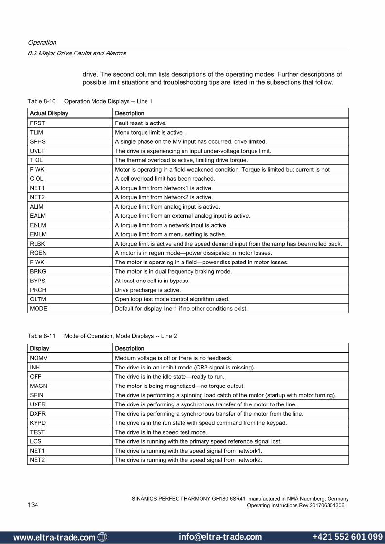
drive. The second column lists descriptions of the operating modes. Further descriptions of possible limit situations and troubleshooting tips are listed in the subsections that follow.
Table 8-10 Operation Mode Displays -- Line 1
Actual Diisplay DescriptionFRST Fault reset is active.TLIM Menu torque limit is active.SPHS A single phase on the MV input has occurred, drive limited.UVLT The drive is experiencing an input under-voltage torque limit.T OL The thermal overload is active, limiting drive torque.F WK Motor is operating in a field-weakened condition. Torque is limited but current is not.C OL A cell overload limit has been reached.NET1 A torque limit from Network1 is active.NET2 A torque limit from Network2 is active.ALIM A torque limit from analog input is active.EALM A torque limit from an external analog input is active.ENLM A torque limit from a network input is active.EMLM A torque limit from a menu setting is active.RLBK A torque limit is active and the speed demand input from the ramp has been rolled back.RGEN A motor is in regen mode—power dissipated in motor losses.F WK The motor is operating in a field—power dissipated in motor losses.BRKG The motor is in dual frequency braking mode.BYPS At least one cell is in bypass.PRCH Drive precharge is active.OLTM Open loop test mode control algorithm used.MODE Default for display line 1 if no other conditions exist.
Table 8-11 Mode of Operation, Mode Displays -- Line 2
Display DescriptionNOMV Medium voltage is off or there is no feedback. INH The drive is in an inhibit mode (CR3 signal is missing).OFF The drive is in the idle state—ready to run.MAGN The motor is being magnetized—no torque output.SPIN The drive is performing a spinning load catch of the motor (startup with motor turning).UXFR The drive is performing a synchronous transfer of the motor to the line.DXFR The drive is performing a synchronous transfer of the motor from the line.KYPD The drive is in the run state with speed command from the keypad.TEST The drive is in the speed test mode.LOS The drive is running with the primary speed reference signal lost.NET1 The drive is running with the speed signal from network1.NET2 The drive is running with the speed signal from network2.
Operation8.2 Major Drive Faults and Alarms
SINAMICS PERFECT HARMONY GH180 6SR41 manufactured in NMA Nuernberg, Germany134 Operating Instructions Rev.201706301306
www.eltra-trade.com [email protected] +421 552 601 099www.eltra-trade.com [email protected] +421 552 601 099

Display DescriptionAUTO The SOP "AutoDisplayMode_0" flag is set to true—speed reference is usually from an
analog signal selected by the SOP.HAND Default running mode—speed reference is selected by the SOP and
"AutoDisplayMode_0" is set to false.BRAK The drive is in the stop state with dual frequency braking active.DECL The drive is in the ramp stop state—speed is ramping down.COAS The drive is in the coast stop state—drive output is forced off.TUNE The drive is in the auto tune state—auto tuning is active.
If the mode display shows rollback mode (RLBK), then the Perfect Harmony™ VFD is attempting to reduce the output speed due to a torque limit condition.
8.2.17 Fault Reset
Manual ResetTo reset a fault manually, use the <FAULT RESET> key on the keypad. Return the drive to the run condition by performing manual start or by forcing the RunRequest_I equal to "true".
Auto ResetCertain faults can be reset automatically if enabled by the auto fault reset enable (7120). Refer to Table " Auto re-settable faults" below, for a list of auto re-settable faults shown in Appendix D. These are fixed and not adjustable. If reset is successful, then drive will return to the run state automatically only if the RunRequest_I is maintained at the value "true". The <FAULT RESET> key of the keypad can acknowledge alarms.
Operation8.2 Major Drive Faults and Alarms
SINAMICS PERFECT HARMONY GH180 6SR41 manufactured in NMA Nuernberg, GermanyOperating Instructions Rev.201706301306 135
www.eltra-trade.com [email protected] +421 552 601 099www.eltra-trade.com [email protected] +421 552 601 099

8.3 General Troubleshooting Information
8.3.1 Handling General Cell and Power Circuitry Faults
General Cell and Power Circuitry FaultsThe types of faults addressed in this section include the following:
● capacitor sharing faults
● blocking failure faults
● switching failure faults.
● AC fuse(s) blown faults
● control power faults
● device out of saturation (OOS) faults
● bypass failed faults
● VDC undervoltage faults
WARNING
Electrical Shock Hazard (MV Present)
Prior to working on the equipment as discussed in the following paragraphs, refer to the secion of this manual titled, Safety Notes.
Because MV is present, only qualified personnel are permitted to work on this equipment. Failure to to use qualified personnel may result in death, serious personal injury, and damage to the equipment.
NoteCell Replacement
The power cell is the lowest replaceable unit by customer.
When a power cell must be replaced, contact Siemens Industry, Inc. Technical support. See the section of this manual titled, Contacts and Technical Support.
Handling Capacitor Sharing Faults The cell capacitor bank is made up of from two to three series capacitor banks. Circuitry on the CCB measures the voltage on each section and if the voltages are off by any amount, the fault is set. This indicates that under load the capacitors are not sharing load evenly and could be the result of faulty capacitors or loose connections.
Course of Action● Fix or replace damaged or defective components.
Operation8.3 General Troubleshooting Information
SINAMICS PERFECT HARMONY GH180 6SR41 manufactured in NMA Nuernberg, Germany136 Operating Instructions Rev.201706301306
www.eltra-trade.com [email protected] +421 552 601 099www.eltra-trade.com [email protected] +421 552 601 099

Handling Blocking Failure Faults Blocking failures occur when IGBTs short due to perforation of their junction caused by excessive current, i.e. high current density. This may be a result of out of saturation conditions and frequent trips. The device will need to be replaced when the cell is removed for service. A defective gate driver may be the root cause. A faulty CCB or bad data from the CCB could give a faulty indication of this fault.
Course of Action● Replace damaged or defective parts.
Handling Switching Failure Faults Switching failures occur when a device opens or fails to turn on. It could also be caused by a defective gate drive or a damaged device. Also, a defective CCB or modulator board could give a faulty indication.
Course of Action● Replace defective parts.
Handling AC Fuse(s) Blown Faults These faults are caused by the blowing of the power fuses on the front end of the cell.
Course of ActionCheck the fuses and replace any that are blown—more than one could be out. Replace defective or damaged parts.
Handling Control Power Faults This fault is caused when one or more of the control fuses that supply power to the CCB are blown. This is rarely seen because the CCB is supplied by two circuits: the control power supply bridge and the DC link. If Control Power Fault is observed, the AC fuses might also be blown.
Course of Action● Replace the defective or damaged parts.
Handling Q1-Q4 OOS (Out Of Saturation) Faults Out of saturation faults occur when the transistor junction is depleted of charge carriers resulting in a higher junction resistance. This in turn created a larger voltage drop and more losses in the transistor which can lead to premature failure. The cause of the OOS can be a defective gate driver board or a high di/dt transition on the device. The gate board is designed with circuitry to detect the larger voltage drop when the device should be on, shutting down the device in a fault condition. The fault can also be caused by a defective CCB or noise on the CCB.
Course of Action● The exact cause needs to be determined before pulling a power cell out of service.
Operation8.3 General Troubleshooting Information
SINAMICS PERFECT HARMONY GH180 6SR41 manufactured in NMA Nuernberg, GermanyOperating Instructions Rev.201706301306 137
www.eltra-trade.com [email protected] +421 552 601 099www.eltra-trade.com [email protected] +421 552 601 099
Handling Failed Bypass Faults This fault results from the failure of a cell to go into bypass when faulted. The cause can be from a defective modulator board, bad link between the modulator and the MV bypass board, a defective MV bypass board or supply, or a defective bypass contactor.
Course of Action● Find and replace the faulty components.
Handling VDC Undervoltage Faults The undervoltage fault occurs when the voltage drops below the threshold of the detection circuitry on the CCB. This can be the result of a low MV level coupled with a high current drainage by the load, or simply as an excessive load that may give a momentary dip in current. It can also occur if one of the AC power fuses fails under load.
Course of Action● Check the cell fuses and check the historic log for line dips.
● Correct the problem before continuing operation. A faulty CCB could give a false indication as well.
● Replace defective or faulty parts.
8.3.2 Cell Over Temperature Faults
Cell Over Temperature FaultsCell overtemperature faults are typically caused by problems in the cooling system. Use the following steps to troubleshoot this type of fault:
Course of Action1. Check the cooling system for proper flows and temperatures.
2. Inspect cell cooling paths for kinked hoses or major leaks.
3. Be sure all cell cabinet manifold valves are fully open.
4. Check that the blowers are working properly.
5. Check ambient temperature.
6. Verify that all cabinet doors are shut to ensure proper air flow.
Operation8.3 General Troubleshooting Information
SINAMICS PERFECT HARMONY GH180 6SR41 manufactured in NMA Nuernberg, Germany138 Operating Instructions Rev.201706301306
www.eltra-trade.com [email protected] +421 552 601 099www.eltra-trade.com [email protected] +421 552 601 099
8.3.3 Status Indicator Summaries for MV Mechanical Bypass Boards
Status Indicator Summaries for MV Mechanical Bypass BoardsThe MV Mechanical Bypass Board includes three LEDs that provide complete status of the MV board. These LEDs are summarized in the following table.
NoteFault and Alarm Designations
User faults and alarms are closely tied to the system program configuration and will be designated here generically as faults although they can be programmed as alarms only.
Table 8-12 MV Mechanical Bypass Board Status LEDs
LED Function Color DescriptionCommOK Green Indicates active communication link established with modulator boardFault Red Indicates that a bypass fault is activePwrOK Green This LED is hardware controlled and indicates that the 5 / 15 VDC supplies are in
tolerance.
8.3.4 Overvoltage Faults
Overvoltage FaultsAn Overvoltage Fault is usually caused by an improperly set-up or tuned drive. Use the following steps to troubleshoot this type of fault.
Course of Action1. Verify that the motor and drive nameplate settings match parameters in the motor parameter
menu (1000) and drive parameter menu (2000).
2. Reduce the regen torque limit parameters (1200, 1220, 1240) in the limits menu (1120).
3. Reduce flux regulator proportional gain (3110) and flux regulator integral gain (3120) parameters in the flux control menu (3100).
4. If the failure is occurring in bypass mode, increase the energy saver minimum flux (3170) parameter in the flux control menu (3100) to at least 50%.
5. If the measured signals from the previous section seem to be correct, change the modulator board.
Operation8.3 General Troubleshooting Information
SINAMICS PERFECT HARMONY GH180 6SR41 manufactured in NMA Nuernberg, GermanyOperating Instructions Rev.201706301306 139
www.eltra-trade.com [email protected] +421 552 601 099www.eltra-trade.com [email protected] +421 552 601 099
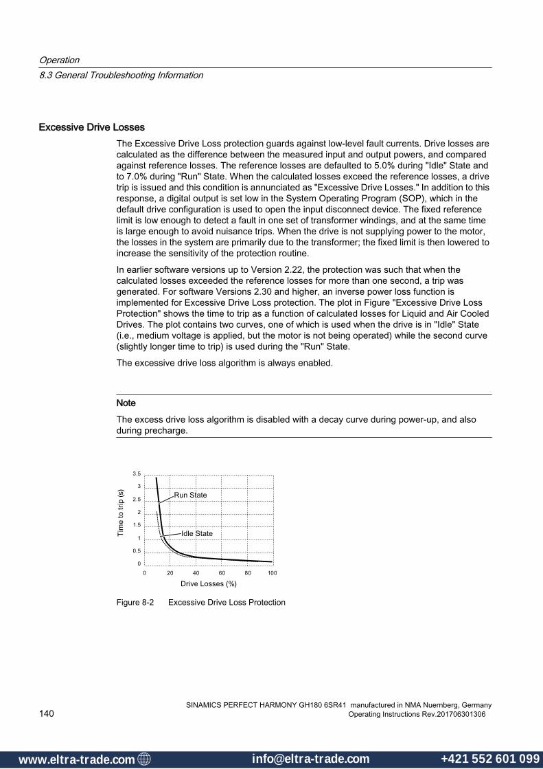
Excessive Drive LossesThe Excessive Drive Loss protection guards against low-level fault currents. Drive losses are calculated as the difference between the measured input and output powers, and compared against reference losses. The reference losses are defaulted to 5.0% during "Idle" State and to 7.0% during "Run" State. When the calculated losses exceed the reference losses, a drive trip is issued and this condition is annunciated as "Excessive Drive Losses." In addition to this response, a digital output is set low in the System Operating Program (SOP), which in the default drive configuration is used to open the input disconnect device. The fixed reference limit is low enough to detect a fault in one set of transformer windings, and at the same time is large enough to avoid nuisance trips. When the drive is not supplying power to the motor, the losses in the system are primarily due to the transformer; the fixed limit is then lowered to increase the sensitivity of the protection routine.
In earlier software versions up to Version 2.22, the protection was such that when the calculated losses exceeded the reference losses for more than one second, a trip was generated. For software Versions 2.30 and higher, an inverse power loss function is implemented for Excessive Drive Loss protection. The plot in Figure "Excessive Drive Loss Protection" shows the time to trip as a function of calculated losses for Liquid and Air Cooled Drives. The plot contains two curves, one of which is used when the drive is in "Idle" State (i.e., medium voltage is applied, but the motor is not being operated) while the second curve (slightly longer time to trip) is used during the "Run" State.
The excessive drive loss algorithm is always enabled.
Note
The excess drive loss algorithm is disabled with a decay curve during power-up, and also during precharge.
Figure 8-2 Excessive Drive Loss Protection
Operation8.3 General Troubleshooting Information
SINAMICS PERFECT HARMONY GH180 6SR41 manufactured in NMA Nuernberg, Germany140 Operating Instructions Rev.201706301306
www.eltra-trade.com [email protected] +421 552 601 099www.eltra-trade.com [email protected] +421 552 601 099
Protection Scheme Reset Procedure
DANGER
Reset Protection Scheme Caution
Failure to obey all safety precautions may cause death and equipment damage and drive failure. Prior to resetting the protection scheme, read the section of this manual titled Major Drive Faults and Alarms, and then contact Siemens technical personnel.
Resetting the protection scheme1. In the control tub, reset the LFR using SW2 or keyed reset pushbutton. The LFR N.C.
contacts are immediately reclosed.
2. Initiate a "Drive Fault Reset". The control will not re-close IDO_14 (NXGII) or M1_DOUT (NXGpro) if the fault conditions still exist. Refer to the section of this manual Dedicated I/O for Input Protection.
DANGER
MV IP Breaker Enable
This contact must be integrated with input switchgear to deactivate the drive input medium voltage. upon the rare event of a secondary circuit fault. Failure to do so may result in death, and equipment damage.● Contacts close = Permissive to close breaker● Contacts open = Trip breaker
Note
Given the amperage rating of the components used in the coordinated input protection scheme, an additional customer pilot relay may be required.
Operation8.3 General Troubleshooting Information
SINAMICS PERFECT HARMONY GH180 6SR41 manufactured in NMA Nuernberg, GermanyOperating Instructions Rev.201706301306 141
www.eltra-trade.com [email protected] +421 552 601 099www.eltra-trade.com [email protected] +421 552 601 099

Operation8.3 General Troubleshooting Information
SINAMICS PERFECT HARMONY GH180 6SR41 manufactured in NMA Nuernberg, Germany142 Operating Instructions Rev.201706301306
www.eltra-trade.com [email protected] +421 552 601 099www.eltra-trade.com [email protected] +421 552 601 099

Maintenance 99.1 Safety instructions for maintenance
Observe the general safety instructions for all work on the drive.
WARNING
Improper maintenance and repairs
Improper maintenance and repairs can result in death and serious physical injury. Only qualified maintenance and installation personnel may perform repairs.
WARNING
Defective seals
When working on the device, seals at the doors, roof panels as well as front, rear and side panels can be damaged. Operating the device with defective seals can result in death, serious injury or material damage.
Replace the defective seals before commissioning. Observe the environmental conditions stated in the technical data.
WARNING
High voltages from external supplies
Magnetizing and demagnetizing equipment that is fed from an external voltage source can cause high voltages on the drive. This voltage can result in death or serious injury.
Ensure that no voltage from external feeds exists before commencing maintenance and repair work.
WARNING
High voltage when anti-condensating heating is operational
The anti-condensation heating system is used when the drive is switched off due to production downtime or maintenance. For this reason, the heating is supplied with voltage from a separate line supply. When the supply voltage for the anti-condensation heating is connected, dangerous voltages are present in the cabinet unit. The dangerous voltages are even present with EMERGENCY OFF or when the main switch is open.
This voltage can cause serious injury.
Observe the five safety rules. (Page 23)
SINAMICS PERFECT HARMONY GH180 6SR41 manufactured in NMA Nuernberg, GermanyOperating Instructions Rev.201706301306 143
www.eltra-trade.com [email protected] +421 552 601 099www.eltra-trade.com [email protected] +421 552 601 099

WARNING
Hot anti-condensation heating surface
When the temperature control limit value is reached the anti-condensation heating is switched on. Once activated, the anti-condensation heating can generate a great deal of heat. Contact can result in serious injury, such as skin burns.
Make sure that the anti-condensation heating cannot be touched.
For safe maintenance access, make sure the anti-condensation heating is switched off and has cooled down before starting the work.
CAUTION
Risk of falling
Climbing onto the cover of the anti-condensation heating represents a risk of injury.
Therefore, do not use the anti-condensation heating system to help you get to the top of the cabinet.
NOTICE
Non-approved spare part
Using non-approved spare parts can affect the function of the equipment and damage it. Third-party spare parts and unapproved spare parts may not meet the requirements. Therefore, only use spare parts that have been approved by the manufacturer.
NOTICE
Foreign bodies in the drive
If, after installation and maintenance work, foreign bodies are left in the drive, this can damage it when switching on. Before switching on, check as to whether there are any foreign bodies in the drive. Remove any foreign bodies.
NOTICE
Contamination
Contamination and dirt can damage the device.
Visually inspect the equipment at least once per year. For more information, please refer to the section "Visual inspections".
Qualified personnel in line with the relevant safety regulations must remove dust deposits inside the cabinet at regular intervals, or at least once a year.
Maintenance9.1 Safety instructions for maintenance
SINAMICS PERFECT HARMONY GH180 6SR41 manufactured in NMA Nuernberg, Germany144 Operating Instructions Rev.201706301306
www.eltra-trade.com [email protected] +421 552 601 099www.eltra-trade.com [email protected] +421 552 601 099

Note
The actual intervals at which maintenance procedures are to be performed depend on the environmental and operating conditions. Define maintenance intervals for the drive which reflect your plant-specific environmental and operating conditions and meet your availability requirements. When doing so, take the prescribed maintenance intervals into consideration, as well as the instructions for repairing and replacing installed components. See also Visual Inspections (Page 152).
Note
The actual intervals at which maintenance procedures are to be performed depend on the environmental and operating conditions. Define maintenance intervals for the drive which reflect your plant-specific environmental and operating conditions and meet your availability requirements. When doing so, take the prescribed maintenance intervals into consideration, as well as the instructions for repairing and replacing installed components.
Note
Siemens offers its customers support in the form of a service contract. For further details, contact your regional office or sales office.
Note
Inform the manufacturer about each maintenance job that has been carried out and about each spare part replacement for the purposes of a reliability analysis.
Maintenance9.1 Safety instructions for maintenance
SINAMICS PERFECT HARMONY GH180 6SR41 manufactured in NMA Nuernberg, GermanyOperating Instructions Rev.201706301306 145
www.eltra-trade.com [email protected] +421 552 601 099www.eltra-trade.com [email protected] +421 552 601 099www.eltra-trade.com [email protected] +421 552 601 099www.eltra-trade.com [email protected] +421 552 601 099

9.2 Door Access
9.2.1 Unlocking the doorsThe drive can be locked either mechanically or electromechanically.
Opening the Power Unit DoorsThe doors must not be opened until the following statuses are present:
● The DC link voltage has been de-energized
– DC Bus Voltage Indicator LED, located on the front of each cell's Cell Control Board, must NOT be illuminated. An illuminated DC bus voltage-indicator LED shows that more than 50 Vdc is present on the DC bus. This indicator light may not be visible until the cell doors are opened.
– Do not touch, remove or service the cell if the indicator is illuminated
● The EMERGENCY-OFF switch on the cabinet has been activated.
● The key-operated switch on the drive has been set to the OFF position.
● A delay time of 10 minutes has expired.
● The make-proof grounding switches (option codes N44 or N45) are closed (they can be closed only after waiting 10 minutes).
● Use the K1 key (option codes M08, M09, M10, M38) from the OPEN breaker to allow release of the K2 door keys.
Opening the Door for the Control CabinetThe standard drive can be opened during operation.
9.2.2 Electromagnetic Door Interlock System
Electromechanical Interlock SystemThe electromagnetic door interlock system is designed to protect personnel and is an integral part of the safety concept. During operation and when the make-proof grounding switches (if applicable) are open, all the doors are interlocked (with the exception of the door for the control section).
The electromagnetic door interlock system ensures that the doors for the power unit cannot be opened when the voltage at the drive is still above a defined threshold value.
The electromagnetic door interlock system guarantees that the doors can only be opened after the doors have been released by the software. They are not released unless the protection and monitoring sequence has been observed.
The drive cannot be switched on again until all the doors are closed and if applicable, the make-proof grounding switches are open.
The doors remain interlocked if the auxiliary voltage fails.
Maintenance9.2 Door Access
SINAMICS PERFECT HARMONY GH180 6SR41 manufactured in NMA Nuernberg, Germany146 Operating Instructions Rev.201706301306
www.eltra-trade.com [email protected] +421 552 601 099www.eltra-trade.com [email protected] +421 552 601 099

9.2.3 Closing the make-proof grounding switchThe converter is optionally equipped with make-proof grounding switches (N44 or N45).
The make-proof grounding switches can be closed when the doors have been closed and the following prerequisites are fulfilled:
● The DC link voltage must be de-energized.
● The EMERGENCY-OFF switch on the cabinet unit must be activated.
● The key-operated switch on the converter must be set to the OFF position.
● A delay time of 10 minutes must have expired.
If the auxiliary voltage fails completely, the make-proof grounding switch cannot be closed.
The doors are secured by the electrical door magnet system and can be opened only after the make-proof grounding switch is closed.
Maintenance9.2 Door Access
SINAMICS PERFECT HARMONY GH180 6SR41 manufactured in NMA Nuernberg, GermanyOperating Instructions Rev.201706301306 147
www.eltra-trade.com [email protected] +421 552 601 099www.eltra-trade.com [email protected] +421 552 601 099
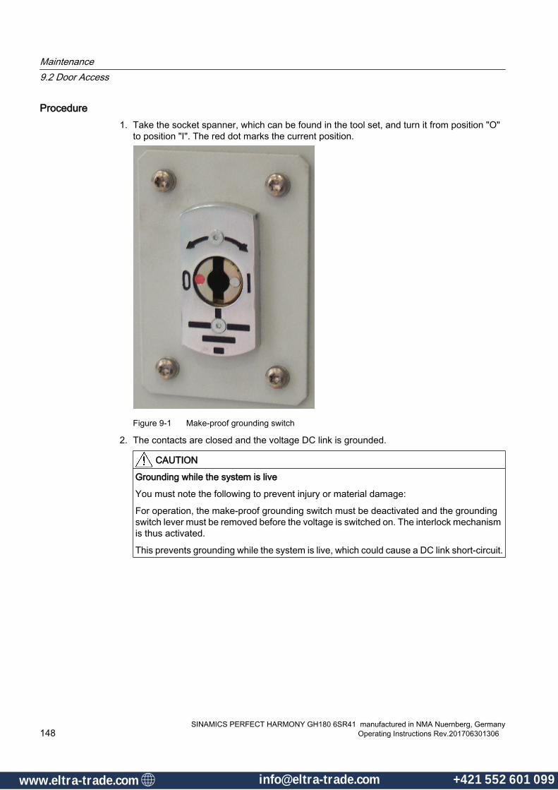
Procedure1. Take the socket spanner, which can be found in the tool set, and turn it from position "O"
to position "I". The red dot marks the current position.
Figure 9-1 Make-proof grounding switch
2. The contacts are closed and the voltage DC link is grounded.
CAUTION
Grounding while the system is live
You must note the following to prevent injury or material damage:
For operation, the make-proof grounding switch must be deactivated and the grounding switch lever must be removed before the voltage is switched on. The interlock mechanism is thus activated.
This prevents grounding while the system is live, which could cause a DC link short-circuit.
Maintenance9.2 Door Access
SINAMICS PERFECT HARMONY GH180 6SR41 manufactured in NMA Nuernberg, Germany148 Operating Instructions Rev.201706301306
www.eltra-trade.com [email protected] +421 552 601 099www.eltra-trade.com [email protected] +421 552 601 099
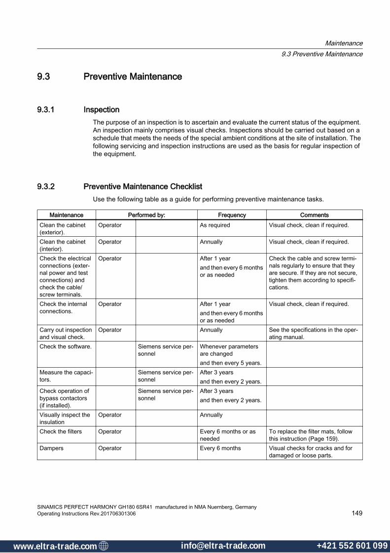
9.3 Preventive Maintenance
9.3.1 InspectionThe purpose of an inspection is to ascertain and evaluate the current status of the equipment. An inspection mainly comprises visual checks. Inspections should be carried out based on a schedule that meets the needs of the special ambient conditions at the site of installation. The following servicing and inspection instructions are used as the basis for regular inspection of the equipment.
9.3.2 Preventive Maintenance ChecklistUse the following table as a guide for performing preventive maintenance tasks.
Maintenance Performed by: Frequency CommentsClean the cabinet (exterior).
Operator As required Visual check, clean if required.
Clean the cabinet (interior).
Operator Annually Visual check, clean if required.
Check the electrical connections (exter‐nal power and test connections) and check the cable/screw terminals.
Operator After 1 yearand then every 6 months or as needed
Check the cable and screw termi‐nals regularly to ensure that they are secure. If they are not secure, tighten them according to specifi‐cations.
Check the internal connections.
Operator After 1 yearand then every 6 months or as needed
Visual check, clean if required.
Carry out inspection and visual check.
Operator Annually See the specifications in the oper‐ating manual.
Check the software. Siemens service per‐sonnel
Whenever parameters are changedand then every 5 years.
Measure the capaci‐tors.
Siemens service per‐sonnel
After 3 yearsand then every 2 years.
Check operation of bypass contactors (if installed).
Siemens service per‐sonnel
After 3 yearsand then every 2 years.
Visually inspect the insulation
Operator Annually
Check the filters Operator Every 6 months or as needed
To replace the filter mats, follow this instruction (Page 159).
Dampers Operator Every 6 months Visual checks for cracks and for damaged or loose parts.
Maintenance9.3 Preventive Maintenance
SINAMICS PERFECT HARMONY GH180 6SR41 manufactured in NMA Nuernberg, GermanyOperating Instructions Rev.201706301306 149
www.eltra-trade.com [email protected] +421 552 601 099www.eltra-trade.com [email protected] +421 552 601 099
Note
The actual intervals at which maintenance procedures are to be performed depend on the installation conditions (cabinet environment) and the operating conditions.
Siemens offers its customers support in the form of a service contract. For further details, contact your regional office or sales office.
9.3.3 Visual Inspections
9.3.3.1 Equipment for visual inspectionsYou require the following basic equipment to carry out the visual checks and maintenance work:
● Mirror
● Flashlight
● Torque wrench for tightening screws
NOTICE
Contamination
Contamination and dirt can damage the device.
Visually inspect the equipment at least once per year. For more information, please refer to the section "Visual inspections".
Qualified personnel in line with the relevant safety regulations must remove dust deposits inside the cabinet at regular intervals, or at least once a year.
Note
The actual intervals at which maintenance procedures are to be performed depend on the environmental and operating conditions. Define maintenance intervals for the drive which reflect your plant-specific environmental and operating conditions and meet your availability requirements. When doing so, take the prescribed maintenance intervals into consideration, as well as the instructions for repairing and replacing installed components.
See also Visual Inspections (Page 150).
9.3.3.2 Checking the isolating clearances● Slight, dry, non-conducting contamination is permitted.
● Remove contamination caused by dust in conjunction with high humidity.
Maintenance9.3 Preventive Maintenance
SINAMICS PERFECT HARMONY GH180 6SR41 manufactured in NMA Nuernberg, Germany150 Operating Instructions Rev.201706301306
www.eltra-trade.com [email protected] +421 552 601 099www.eltra-trade.com [email protected] +421 552 601 099
9.3.3.3 Checking hoisting solenoids and security bolts● Check the hoisting solenoids and security bolts at regular intervals.
● Replace defective hoisting solenoids and security bolts before (re)commissioning.
9.3.3.4 Checking the plug connectionsRegularly check the plug connections to ensure they are seated correctly and the contacts are not corroded.
Note
The fiber-optic cables for the gating boards must be properly inserted in the connectors.
9.3.3.5 Checking the cable and screw terminals● Check the cable and screw terminals regularly to ensure that they are secure.
● Tighten the screws if necessary. When doing this, comply with the specified torques.
● Check the cabling for defects.
● Replace any defective parts immediately.
9.3.3.6 Checking the filter mats● Check the air filters in the cabinet doors for pollution.
● Clean the filter mats or replace them if the air flow is obstructed. To replace the filter mats, follow this instruction (Page 159).
Maintenance9.3 Preventive Maintenance
SINAMICS PERFECT HARMONY GH180 6SR41 manufactured in NMA Nuernberg, GermanyOperating Instructions Rev.201706301306 151
www.eltra-trade.com [email protected] +421 552 601 099www.eltra-trade.com [email protected] +421 552 601 099

9.4 Touch-Up Paint
Touch -Up PaintUse touch-up paint, as needed, on any rusty or exposed parts on the cabinet enclosure. Clear surface of any rust prior to painting.
Maintenance9.4 Touch-Up Paint
SINAMICS PERFECT HARMONY GH180 6SR41 manufactured in NMA Nuernberg, Germany152 Operating Instructions Rev.201706301306
www.eltra-trade.com [email protected] +421 552 601 099www.eltra-trade.com [email protected] +421 552 601 099

9.5 Cleaning
9.5.1 Contact for Cleaning MeasuresIf contamination occurs, contact Siemens customer service. Refer to Appendix Service and Support.
NoteProper Cleaning Agents
Be sure to use cleaning agents that do not cause corrosion. Using cleaning agents that may cause corrosion can produce unwanted equipment damage.
9.5.2 Removing Dust Deposits
Dust Deposits Dust deposits inside the cabinet unit must be removed at regular intervals (or at least once a year) by qualified personnel in line with the relevant safety regulations.
The unit must be cleaned using a brush and vacuum cleaner, and dry compressed air (max.1 bar) for areas that cannot be easily reached.
The ventilation openings in the cabinet must never be obstructed. The fan must be checked to make sure that it is functioning correctly.
VentilationThe ventilation openings in the cabinet must never be obstructed, The fan must be checked to ensure that it is functioning properly.
Cable and Terminal-Screws● Check the cable and terminal-screws regularly to ensue that they are secure. Tighten them
if necessary.
● Check for cabling defects.
● Immediately replace any defective parts.
Maintenance9.5 Cleaning
SINAMICS PERFECT HARMONY GH180 6SR41 manufactured in NMA Nuernberg, GermanyOperating Instructions Rev.201706301306 153
www.eltra-trade.com [email protected] +421 552 601 099www.eltra-trade.com [email protected] +421 552 601 099

9.6 Repair and Replace
9.6.1 Safety-relevant Checks
WARNING
Visual Check of Cable Insulation
Improperly laid or damaged cables and incorrectly attached cable shieldings can heat up in places and cause fires or short-circuits wherever they make contact.● Make sure that the cable shields are intact and insulate any that are damaged.● Make sure that a short-circuit cannot occur on the power cables due to failure of the
insulation as a result of incorrect cable installation.
NoteComponent Replacement
Unless otherwise indicated by Siemens, always replace components with the same part number and revision level.
NoteDrive Failure
When the power supply is switched off, data about error message statuses is lost.
Inadequate diagnostic and error rectification measures can result in damage to the Drive.
For additional technical support, please contact the Siemens Service Center.
NoteDoor Interlock Failure
Please contact Siemens Service Center for technical support.
Maintenance9.6 Repair and Replace
SINAMICS PERFECT HARMONY GH180 6SR41 manufactured in NMA Nuernberg, Germany154 Operating Instructions Rev.201706301306
www.eltra-trade.com [email protected] +421 552 601 099www.eltra-trade.com [email protected] +421 552 601 099

9.6.2 Maintenance and Earthing Procedure
Maintenance and Earthing Procedure
WARNING
Qualified Personnel Only
Due to the modularity of the SINAMICS PERFECT HARMONY GH180 VFD design, the Maintenance and Earthing Procedure does not cover all variations of equipment types or installations. Siemens strongly recommends that only qualified personnel be allowed to perform maintenance on SINAMICS PERFECT HARMONY Systems.
Maintenance and Earthing Procedure 1. Stop drive operation, either through remote or local controls.
2. De-energize input voltage by opening incoming switchgear and locking to OPEN position with mechanical interlock. Apply lock-out/tag-out principles as required by local code.
3. De-energize control voltages for synchronous motor field/exciter controls.
4. Wait ten minutes to allow stored energy to dissipate from the drive and until the door interlocking system has been released.
WARNING
Discharging Resistors
The power cells include discharge resistors to dissipate stored energy after the input voltage is removed. The power cell DC bus voltage decays to less than 50 VDC in less than 10 minutes.
Ensure to follow all safety precautions to avoid risk of death, serious personal injury, and equipment damage.
5. If applicable, close all make-proof grounding switches and lock into the CLOSE position.
Figure 9-2 Output Cable to Motor
6. Observe the cell control board voltage LEDs by removing the interlock key from the input/output switchgear and opening the cell sections door(s).
7. When none of the cell LEDs are lighted, the voltage at the input and output terminals has fallen below 50 V. Use ancillary AC voltage sensing devices to confirm the drive is de-energized.
8. Apply Green/Yellow insulated gournd cables from U1/V1/W1 and U2/V2/W2 to protective earth, P.E.
Maintenance9.6 Repair and Replace
SINAMICS PERFECT HARMONY GH180 6SR41 manufactured in NMA Nuernberg, GermanyOperating Instructions Rev.201706301306 155
www.eltra-trade.com [email protected] +421 552 601 099www.eltra-trade.com [email protected] +421 552 601 099

9. Perform maintenance as required.
10.After the DC Bus LED is extinguished, verify with an appropriately sized multimeter that the DC bus is 0 Vdc.
DANGER
Possible Residual Charge
After the LED is extinguished, the capacitors inside the cell may contain a residual charge that can lead to a lethal shock hazard. The input voltage to the cells is 750 Vac that can produce a DC potential of 1,060 Vdc on the DC Bus
11.Connect a temporary grounding cable to the exterior metal case of the cell. Be sure to use a cable that is long enough to reach from the cell to the cell lifter and to the floor in front of the equipment or work bench. Use appropriate PPE and be sure not to touch any bare bus bars while removing the cell. Note that the power cells do not have any bolted power connections.
12.Remove the fiber optic connection
13.Route in the Panduit to prevent breaking or damaging the connector
14.Remove the outer chassis hardware and remove the chassis top cover to expose the power electronics.
15.Remove the grounding device.
16.Close the doors in reverse sequence, and replace interlock key into input switchgear.
Maintenance9.6 Repair and Replace
SINAMICS PERFECT HARMONY GH180 6SR41 manufactured in NMA Nuernberg, Germany156 Operating Instructions Rev.201706301306
www.eltra-trade.com [email protected] +421 552 601 099www.eltra-trade.com [email protected] +421 552 601 099

9.6.3 Part Replacement Replacement of component parts may be the best method of troubleshooting when spare parts are available. When any sub-assembly is to be replaced, always check that the part number of the new unit matches that of the old unit (including the revision letter).
● Failures traced to individual PC boards within the Control Cabinet are best serviced by replacement of the entire board.
● Failures traced to individual power cells are best serviced by replacement of the entire cell.
NOTICE
Proper Disposal of Failed Components
The disposal of any failed components (capacitors, etc.) must be done in accordance with local codes and requirements.
9.6.4 Replacing the Filter MatsConvection-cooled drives are equipped with filter mats to prevent dangerous dust deposits from accumulating on the power unit components.The filter mats are fitted to the exterior of the cabinet doors, which means that they can be replaced with the doors closed.
WARNING
Danger of arcing through dust deposits
Dust deposits on the components of the power unit can reduce the clearances and creepage distances and form conductive connections between current-conducting parts. This can result in the formation of arcs. Arcing can result in damage to property, serious injury and even death.
Dust can enter the cabinet, for example, through open doors or via the air drawn in by the cabinet fans. Ensure that no dust enters the cabinet when replacing the filter mats.● Keep all doors of the drive closed.● Replace the filter mats separately for each segment to keep the time required to a
minimum.● If necessary, switch off the drive and the cabinet fan if you are unable to ensure the values
for the degree of contamination (see Storage, Transport and Operation Ambient Conditions (Page 178)).
Maintenance9.6 Repair and Replace
SINAMICS PERFECT HARMONY GH180 6SR41 manufactured in NMA Nuernberg, GermanyOperating Instructions Rev.201706301306 157
www.eltra-trade.com [email protected] +421 552 601 099www.eltra-trade.com [email protected] +421 552 601 099
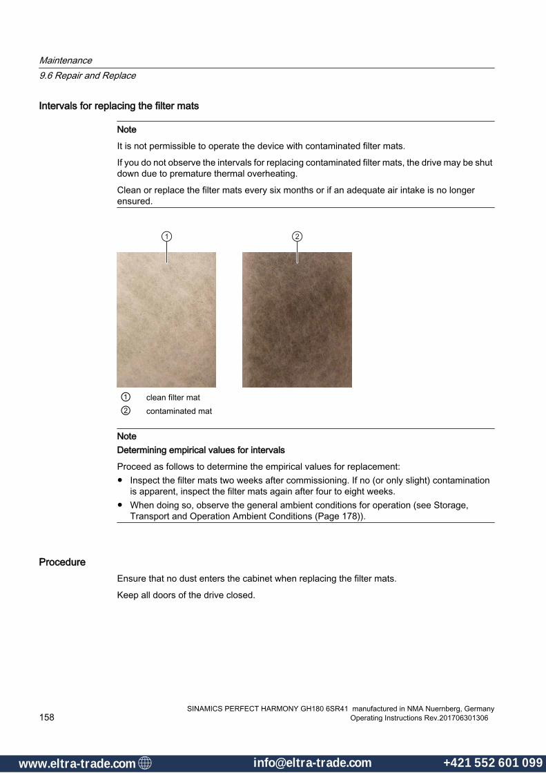
Intervals for replacing the filter mats
Note
It is not permissible to operate the device with contaminated filter mats.
If you do not observe the intervals for replacing contaminated filter mats, the drive may be shut down due to premature thermal overheating.
Clean or replace the filter mats every six months or if an adequate air intake is no longer ensured.
① clean filter mat② contaminated mat
NoteDetermining empirical values for intervals
Proceed as follows to determine the empirical values for replacement:● Inspect the filter mats two weeks after commissioning. If no (or only slight) contamination
is apparent, inspect the filter mats again after four to eight weeks.● When doing so, observe the general ambient conditions for operation (see Storage,
Transport and Operation Ambient Conditions (Page 178)).
ProcedureEnsure that no dust enters the cabinet when replacing the filter mats.
Keep all doors of the drive closed.
Maintenance9.6 Repair and Replace
SINAMICS PERFECT HARMONY GH180 6SR41 manufactured in NMA Nuernberg, Germany158 Operating Instructions Rev.201706301306
www.eltra-trade.com [email protected] +421 552 601 099www.eltra-trade.com [email protected] +421 552 601 099
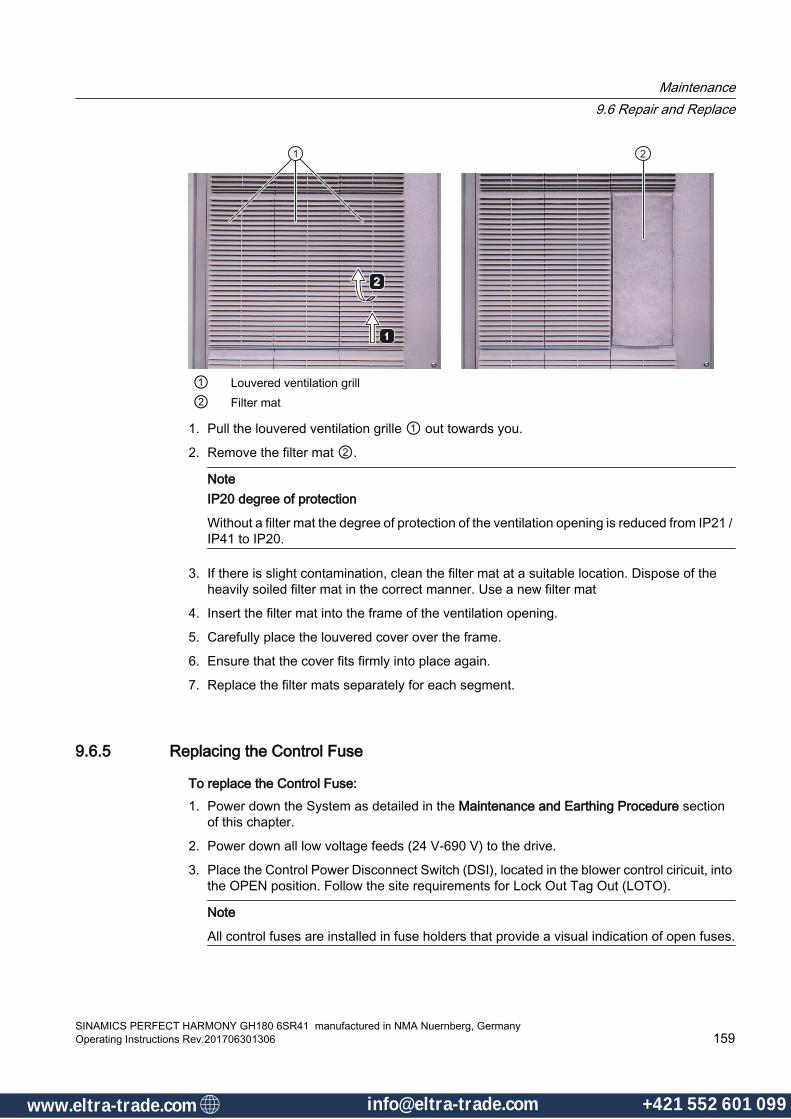
① Louvered ventilation grill② Filter mat
1. Pull the louvered ventilation grille ① out towards you.
2. Remove the filter mat ②.
NoteIP20 degree of protection
Without a filter mat the degree of protection of the ventilation opening is reduced from IP21 / IP41 to IP20.
3. If there is slight contamination, clean the filter mat at a suitable location. Dispose of the heavily soiled filter mat in the correct manner. Use a new filter mat
4. Insert the filter mat into the frame of the ventilation opening.
5. Carefully place the louvered cover over the frame.
6. Ensure that the cover fits firmly into place again.
7. Replace the filter mats separately for each segment.
9.6.5 Replacing the Control Fuse
To replace the Control Fuse:1. Power down the System as detailed in the Maintenance and Earthing Procedure section
of this chapter.
2. Power down all low voltage feeds (24 V-690 V) to the drive.
3. Place the Control Power Disconnect Switch (DSI), located in the blower control ciricuit, into the OPEN position. Follow the site requirements for Lock Out Tag Out (LOTO).
Note
All control fuses are installed in fuse holders that provide a visual indication of open fuses.
Maintenance9.6 Repair and Replace
SINAMICS PERFECT HARMONY GH180 6SR41 manufactured in NMA Nuernberg, GermanyOperating Instructions Rev.201706301306 159
www.eltra-trade.com [email protected] +421 552 601 099www.eltra-trade.com [email protected] +421 552 601 099
4. Use an appropriately sized AC voltage detector to ensure that all power is removed to the fuses being serviced.
Note
The Drive can accommodate up to a 690 Vac power for the blowers.
5. Open the fuse holder and replace the fuse with a suitably rated spare fuse.
Note
Use customer specific documentation to identify both the voltage and current rating of the fuse
6. Close the fuse holder and check the resistance with an ohm meter to validate that a proper connection has been made.
9.6.6 Replacing the Door-Mounted Keypad and Operator Panel
To replace the Door-Mounted Keypad:1. Switch off the main circuit breaker.
2. Open the cabinet.
To replace the Operator Panel:1. Remove the Macrolon cover
2. Disconnect the ribbon cable at J2 from the operator panel
3. Unscrew the four hexagon-head screws
4. Pull out the operator panel to the front
5. Fit a new operator panel.
6. Screw in the four hexagon-head screws
7. Reconnect the ribbon cable at J2 on the operator panel
8. Reattach the Macrolon cover
9.6.7 Removing the Power Cell Procedure
How to Remove Power Cells The DC bus voltage-indicator LED shows that more than 50 V DC is present on the DC bus. This indicator light is located on the front of each cell’s Cell Control Board and may not be visible until the cell doors are opened.
Maintenance9.6 Repair and Replace
SINAMICS PERFECT HARMONY GH180 6SR41 manufactured in NMA Nuernberg, Germany160 Operating Instructions Rev.201706301306
www.eltra-trade.com [email protected] +421 552 601 099www.eltra-trade.com [email protected] +421 552 601 099
To remove the Power Cells:
● Power down the system, obeying all standard electrical and safety instructions.
DANGER
Lethal Voltages
Even when the system is powered down, power may still be present at the power cell's DC bus. The recommended waiting time before opening the doors or removing covers is 10 minutes.
● Open the doors, or remove covers, to access the power cells.
● Make sure that the DC bus LED is unlit.
DANGER
Lethal Voltages
The cell should not be touched, removed, or serviced if the indicator is illuminated.The cell chassis is not grounded and when energized can float to lethal voltages. Touching the ungrounded chassis will result in death and damage to equipment.
● Connect a temporary grounding cable to the exterior metal case of the power cell that is long enough to reach from the power cell to the cell lifter, and to the floor in front of the equipment or work bench. Use appropriate PPE, and be sure not to touch any bare bus bars while removing the power cell.
CAUTION
Existing Voltage May Still Be Present
An LED that is not extinguished indicates that power is present. Even if an LED is extinguished, voltage may still be present and must be checked with an appropriately sized multimeter.
The power cells include discharge resistors to dissipate stored energy after the input voltage is removed. The power cell DC bus voltage decays to less than 50 VDC in less than 10 minutes
Connecting a temporary grounding cable to the exterior metal case of the power cell that still has voltage present, can cause personal injury and damage to the equipment.
● Remove the fiber optic from the CCB as follows:
Maintenance9.6 Repair and Replace
SINAMICS PERFECT HARMONY GH180 6SR41 manufactured in NMA Nuernberg, GermanyOperating Instructions Rev.201706301306 161
www.eltra-trade.com [email protected] +421 552 601 099www.eltra-trade.com [email protected] +421 552 601 099
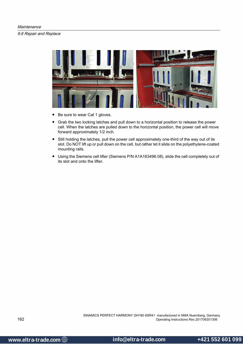
● Be sure to wear Cat 1 gloves.
● Grab the two locking latches and pull down to a horizontal position to release the power cell. When the latches are pulled down to the horizontal position, the power cell will move forward approximately 1/2 inch.
● Still holding the latches, pull the power cell approximately one-third of the way out of its slot. Do NOT lift up or pull down on the cell, but rather let it slide on the polyethylene-coated mounting rails.
● Using the Siemens cell lifter (Siemens P/N A1A163496.08), slide the cell completely out of its slot and onto the lifter.
Maintenance9.6 Repair and Replace
SINAMICS PERFECT HARMONY GH180 6SR41 manufactured in NMA Nuernberg, Germany162 Operating Instructions Rev.201706301306
www.eltra-trade.com [email protected] +421 552 601 099www.eltra-trade.com [email protected] +421 552 601 099

● Once on the lifter (or work bench), remove the outer chassis hardware to lift off the chassis top cover to expose the power electronics
● Measure the residual DC bus voltage between the plates as shown below, taking care not to inadvertently short the distance with the meter terminals. Verify the voltage is low (<50 Vdc) or zero potential, personnel may place a temporary shorting lead across the DC bus as a precaution.
W/V and
2/3 Bleeder
WHT and
1/3 Bleeder
Bleeder and
Harness Wire
Connections
BLK and "+" Bleeder
Grey and "-" Bleeder
WHT
Figure 9-3 DC Bus View
WARNING
Dangerous Potential Level
The DC potential of a VFD Power Cell is 1060 Vdc across the DC bus. If a value >50 Vdc is read, immediately STOP work on the cell. Properly lock out the work area and contact Siemens personnel.
Possible death, serious injury to personnel and damage to equipment is possible,
Maintenance9.6 Repair and Replace
SINAMICS PERFECT HARMONY GH180 6SR41 manufactured in NMA Nuernberg, GermanyOperating Instructions Rev.201706301306 163
www.eltra-trade.com [email protected] +421 552 601 099www.eltra-trade.com [email protected] +421 552 601 099

9.6.8 Returning the Power Cell to Siemens
To ship the cell back to the factory be sure to package the cell as shown below.
Fill bottom of box with Instapak sealed air foam in bag packag‐ing material.
Place cell into box on top of foam. Be sure that the locking latches are pointed up.
Fill sides and top with Insta‐pak sealed air foam packag‐ing material. Before cooling, close box lid to form top. Check for air pockets and fill as needed. Seal box and ship.
Maintenance9.6 Repair and Replace
SINAMICS PERFECT HARMONY GH180 6SR41 manufactured in NMA Nuernberg, Germany164 Operating Instructions Rev.201706301306
www.eltra-trade.com [email protected] +421 552 601 099www.eltra-trade.com [email protected] +421 552 601 099www.eltra-trade.com [email protected] +421 552 601 099www.eltra-trade.com [email protected] +421 552 601 099

9.6.9 Replacing the Compact Flash Card (NXGpro)Refer to the following figure when replacing the Compact Flash card.
① Compact Flash card insertion slot
Figure 9-4 NXGpro Digital Control Rack - Compact Flash
To replace the Compact Flash card, perform the following steps:
1. Remove the Compact Flash card from the insertion slot ①, located on the NXGpro digital control rack (DCR).
2. Copy the stored data of the old card to the new original Siemens card.
3. Place the new card into the insertion slot ① on the DCR.
Maintenance9.6 Repair and Replace
SINAMICS PERFECT HARMONY GH180 6SR41 manufactured in NMA Nuernberg, GermanyOperating Instructions Rev.201706301306 165
www.eltra-trade.com [email protected] +421 552 601 099www.eltra-trade.com [email protected] +421 552 601 099

9.6.10 Installing Peferct Harmony Power Cells
To Install the Power Cell: 1. Using the Siemens cell lifter, line up the power cell with its slot.
2. Push the cell into its slot. Do not lift up on the cell, but instead let it slide in on the polyethylene-coated mounting rails.
3. Make sure that the cell latches are above the ledge of the cell rail, and align the locking latches with the corresponding rail notches, as shown below.
4. Push up on the latches until they are vertical.
5. Reinstall the Fiber Optic.
9.6.11 Replacing Cell Input Power FusesA label is located on the left side of the fuse block that shows all approved replacements. Only two phases of each transformer secondary (power cell input) are fused.
Blown Cell Input Power Fuse IndicatorEach fuse has visual blown indication, making it easy to diagnose a fuse’s condition. Fuses are forced air cooled for longer life and less thermal stress.
The fuses are mounted external to the cell. This not only reduces the size of the cell, but also allows for the fuses to be located in an accessible location. They primarily provide secondary
Maintenance9.6 Repair and Replace
SINAMICS PERFECT HARMONY GH180 6SR41 manufactured in NMA Nuernberg, Germany166 Operating Instructions Rev.201706301306
www.eltra-trade.com [email protected] +421 552 601 099www.eltra-trade.com [email protected] +421 552 601 099

short circuit protection and are sized to accommodate power cell charging currents upon initial energizing.
NoteMatching Fuses
A mixture of the approved fuse vendors are permitted in terms of fuse replacement as long as any two fuses protecting the secondary windings are matched (i.e., FA1A and FA1C should be from the same vendor).
NoteRecommended Time Limit for Fuse Replacement
As a preventive maintenance measure for drives that experience daily inrush events, Siemens recommends replacing all power fuses that have been in operation for ten years.
NotePrimary and E-Rated Fuses
The core drive does not include primary fuses. When E-rated fuses are required, choose the smallest rating greater than or equal to the transformer’s primary nameplate current value (e.g., 1000 KVA / (1.732 * 4160 V) = 139 A, use 150E fuses).
9.6.12 Replacing Cell Input Power Fuses Assembly
Assembly
Figure 9-5 Cut-Out View of Fuse Assembly
The secondary fuse block is located in the front of the transformer section.
Maintenance9.6 Repair and Replace
SINAMICS PERFECT HARMONY GH180 6SR41 manufactured in NMA Nuernberg, GermanyOperating Instructions Rev.201706301306 167
www.eltra-trade.com [email protected] +421 552 601 099www.eltra-trade.com [email protected] +421 552 601 099
The fuses are located on the left hand side of the cell cabinet behind the front control.
9.6.13 Cell Input Power Fuse Replacement Procedure
Cell Input Power Fuse Replacement Procedure
To replace an open Cell Input fuse:1. Power down the System, obeying all standard electrical and safety instructions. Refer to
the section titled Maintenance and Earthing Procedure located in this chapter of the manual.
2. Open the doors to access the Cell Input Fuse section.
3. Use an appropriately sized AC voltage detector to ensure that the power is removed.
WARNING
Electrical Hazard
The secondary rating of the air-cooled transformer to the input of the cell power fuse is 750 Vac. Qualified personnel must obey all safety precautions. Risk of death, serious personal injury, and eqipment damage can occur.
4. Use the appropriate tools to remove the bolts holding the power cable to the fuse mounting feet.
5. Remove the open fuse and replace with a spare Cell Input Power Fuse.
6. Re-apply the power cable connections and apply a new torque mark to the bolt.
Note
Torque the M8 bolt connections to 17 Nm (13 ft-lb) and torque M10 bolt connections to 31 Nm (23 ft-lb).
9.6.14 Printed Circuit Board Replacement Procedure (NXGpro)Use the following procedure to replace:
● System Interface Board
● User I/O Board
1. Power down the system, following the standard shut-down procedure.
2. Power down all low voltage feeds (24 V-690 V) to the drive.
Note
Low voltage feeds vary per customer design. The customer specific documentation shall be referenced to identify all low voltage feeds.
Maintenance9.6 Repair and Replace
SINAMICS PERFECT HARMONY GH180 6SR41 manufactured in NMA Nuernberg, Germany168 Operating Instructions Rev.201706301306
www.eltra-trade.com [email protected] +421 552 601 099www.eltra-trade.com [email protected] +421 552 601 099
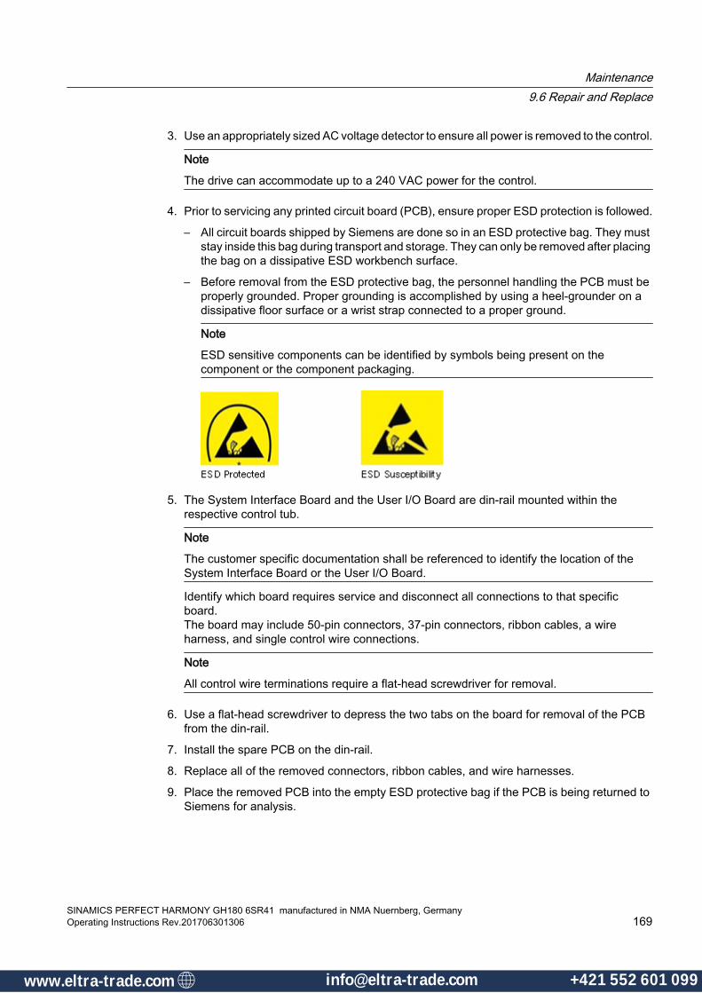
3. Use an appropriately sized AC voltage detector to ensure all power is removed to the control.
Note
The drive can accommodate up to a 240 VAC power for the control.
4. Prior to servicing any printed circuit board (PCB), ensure proper ESD protection is followed.
– All circuit boards shipped by Siemens are done so in an ESD protective bag. They must stay inside this bag during transport and storage. They can only be removed after placing the bag on a dissipative ESD workbench surface.
– Before removal from the ESD protective bag, the personnel handling the PCB must be properly grounded. Proper grounding is accomplished by using a heel-grounder on a dissipative floor surface or a wrist strap connected to a proper ground.
Note
ESD sensitive components can be identified by symbols being present on the component or the component packaging.
5. The System Interface Board and the User I/O Board are din-rail mounted within the respective control tub.
Note
The customer specific documentation shall be referenced to identify the location of the System Interface Board or the User I/O Board.
Identify which board requires service and disconnect all connections to that specific board. The board may include 50-pin connectors, 37-pin connectors, ribbon cables, a wire harness, and single control wire connections.
Note
All control wire terminations require a flat-head screwdriver for removal.
6. Use a flat-head screwdriver to depress the two tabs on the board for removal of the PCB from the din-rail.
7. Install the spare PCB on the din-rail.
8. Replace all of the removed connectors, ribbon cables, and wire harnesses.
9. Place the removed PCB into the empty ESD protective bag if the PCB is being returned to Siemens for analysis.
Maintenance9.6 Repair and Replace
SINAMICS PERFECT HARMONY GH180 6SR41 manufactured in NMA Nuernberg, GermanyOperating Instructions Rev.201706301306 169
www.eltra-trade.com [email protected] +421 552 601 099www.eltra-trade.com [email protected] +421 552 601 099

Maintenance9.6 Repair and Replace
SINAMICS PERFECT HARMONY GH180 6SR41 manufactured in NMA Nuernberg, Germany170 Operating Instructions Rev.201706301306
www.eltra-trade.com [email protected] +421 552 601 099www.eltra-trade.com [email protected] +421 552 601 099

Disposal and Recycling 1010.1 Disposing of Device Components
Before dismantling the Drive, ensure that it is brought to a standstill and grounded.
If disposed of properly, none of the material listed below will pose any threat to the environment. Take particular care when disposing of and recycling the following components:
● Batteries
● Capacitors
● PCBs
● Electronic components
Be sure to dispose of or recycle in accordance with the applicable country-specific guidelines / regulations and with the applicable national regulations. .
SINAMICS PERFECT HARMONY GH180 6SR41 manufactured in NMA Nuernberg, GermanyOperating Instructions Rev.201706301306 171
www.eltra-trade.com [email protected] +421 552 601 099www.eltra-trade.com [email protected] +421 552 601 099

10.2 Disposing of PackagingDescription
The packing is designed in such a way as to pose the minimum risk to the environment. Some of the packaging can be recycled.
The disposal of packaging is controlled by country-specific laws. If in doubt, ask local disposal specialists or contact the local authorities.
List of Packing Waste Materials● Wooden frames
● Wooden pallets
● Polyethylene foil
● Plywood
● Plastic
● Silica gel
Disposal and Recycling10.2 Disposing of Packaging
SINAMICS PERFECT HARMONY GH180 6SR41 manufactured in NMA Nuernberg, Germany172 Operating Instructions Rev.201706301306
www.eltra-trade.com [email protected] +421 552 601 099www.eltra-trade.com [email protected] +421 552 601 099
Service and Support AA.1 Siemens Industry Online Support (order documentation)
Details regarding the design of this device and the permissible operating conditions are described in these instructions.
On-site service and spare partsIf you wish to request on-site service or if you require spare parts, please contact your local sales partner who establishes the contact to the responsible service center.
Technical queries or additional informationIf you have any technical queries or you require additional information, please contact the Siemens Service Center.
Please have the following data ready:
● Order number
● Serial number
You can find this data on the rating plate of the device.
Answers to frequently asked questions and the possibility of sending your questions to the service department can be found here (http://www.siemens.com/automation/support-request).
You can find your local contact partner here (www.siemens.com/automation/partner).
You can also call the following numbers directly during local working hours to reach a contact partner who speaks the corresponding national language.
Contact to central technical support
Europe and Africa
+49 911 895 7222+49 911 895 [email protected]
Americas
+1 423 262 5710+1 423 262 [email protected]
SINAMICS PERFECT HARMONY GH180 6SR41 manufactured in NMA Nuernberg, GermanyOperating Instructions Rev.201706301306 173
www.eltra-trade.com [email protected] +421 552 601 099www.eltra-trade.com [email protected] +421 552 601 099

Asia/Australia/Pacific
+86 10 6475 7575+86 10 6474 [email protected]
Service and SupportA.1 Siemens Industry Online Support (order documentation)
SINAMICS PERFECT HARMONY GH180 6SR41 manufactured in NMA Nuernberg, Germany174 Operating Instructions Rev.201706301306
www.eltra-trade.com [email protected] +421 552 601 099www.eltra-trade.com [email protected] +421 552 601 099

Technical Data BB.1 Standards and regulations
Table B-1 Standards and conformity
StandardsStandards DIN EN 61800-3/VDE 0160 T103 (IEC 61800-3)
DIN EN 61800-4 / VDE 0160 T104 (IEC6 1800-4), however, only when referenced in the standards DIN EN 61800-3 or DIN EN 61800-5-1 DIN EN 61800-5-1/VDE 0160 T105 (IEC 61800-5-1)
EU directives Up to April 19, 20162006/95/EC + amendments (Low Voltage Directive)2004/108/EC + amendments (Electromagnetic Compatibility)from April 20, 20162014/35/EU + amendments (Low Voltage Directive)2014/30/EU + amendments (Electromagnetic Compatibility)
Certificate of compliance with order
For the EMC Directive (2004/108/EC + amendments or 2014/30/EU + amendments)(Product cannot be operated independently; limited distribution channel)
Interference omission This drive unit is part of a PDS, Category C4 according to DIN EN 61800-3/VDE 0160 T103 (IEC 61800-3). The drive unit has not been designed to be connected to the public line supply. The equipment can cause electromagnetic interference when it is connected to the public grid. The essential requirements placed on EMC protection for the drive system should be secured using an EMC plan at the customer site.
Insulation According to DIN EN 50178/VDE 0160 (IEC 62103), IEC 61800-5-1: Pollution degree 2 (without conductive pollution), non-condensing
Degree of protection In accordance with DIN VDE 0470 T1, EN 60 529, IEC 60 529Protection class Class 1 according to DIN EN 61800-5-1/VDE 0160 T105 (IEC 61800-5-1)Touch protection DIN EN 50274/VDE 0660 T514
SINAMICS PERFECT HARMONY GH180 6SR41 manufactured in NMA Nuernberg, GermanyOperating Instructions Rev.201706301306 175
www.eltra-trade.com [email protected] +421 552 601 099www.eltra-trade.com [email protected] +421 552 601 099

B.2 Storage, Transport and Operation Ambient ConditionsRefer to the General Ambient Conditions table to view the various ambient conditions of air-cooled SINAMICS PERFECT HARMONY GH180. Note that these conditions meet the IEC 60721 and 61800 applicable standards.
Table B-2 General Ambient Conditions
Storage Transport OperatingCLIMATIC AMBIENT CONDITIONSAmbient temperature +5 °C to +40 °C –25 °C to +60 °C
in accordance withIEC 60721 3-2, Class 2K2
+5 °C to +40 °C
Relative air humidity < 95 % (VFD must be completely dry before commission‐ing)
< 95 % (VFD must be completely dry before commissioning)
< 95 % (condensation not permitted)
Other climatic conditions in accordance with class
1K2, 1Z2 in accordance with IEC 60721-3-1
2K2 in accordance withIEC 60721 3-2, Class 2K2
3K3 in accordance with IEC 60721-3-3
Degree of pollution 2 without conductive pollu‐tion in accordance with IEC 61800-5
2 without conductive pollution in accordance withIEC 61800-5-1
2 without conductive pollution in ac‐cordance with IEC 61800-5-1
MECHANICAL AMBIENT CONDITIONSSTATIONARY VIBRATION, SINUSOIDALDisplacement 1,5 mm (2 to 9 Hz) 3,5 mm (2 to 9 Hz) 0,3 mm (2 to 9 Hz)Acceleration 5 m/s2 (9 to 200 Hz) 10 m/s2 (9 to 200 Hz)
15 m/s2 (200 to 500 Hz)1 m/s2 (9 to 200 Hz)
Other mechanical condi‐tions in accordance with class
1M2 in accordance with IEC 60721-3-1
2M1 in accordance withIEC 60721-3-2with exception that tilt must be > 0 .
3M1 in accordance withIEC 60721-3-3
OTHER AMBIENT CONDITIONSBiological ambient condi‐tions in accordance with class
1B1 in accordance withIEC 60721-3-1
2B1 in accordance with IEC 60721-3-2
3B1 in accordance withIEC 60721-3-3
Chemical active substances in accordance with class
1C1 in accordance withIEC 60721-3-1
2C1 in accordance withIEC 60721-3-2
3C1 in accordance withIEC 60721-3-3
Mechanical active substan‐ces in accordance with class
1S1 in accordance withIEC 60721-3-1
2S1 in accordance with IEC 60721-3-2
3S1 (standard) in accordance withIEC 60721-3-3 with addition of sand content of 0.01 mg / m3
Technical DataB.2 Storage, Transport and Operation Ambient Conditions
SINAMICS PERFECT HARMONY GH180 6SR41 manufactured in NMA Nuernberg, Germany176 Operating Instructions Rev.201706301306
www.eltra-trade.com [email protected] +421 552 601 099www.eltra-trade.com [email protected] +421 552 601 099

Note
For transportation and storage, Option Code (M66) complies with 2M1 in accordance with IEC 60721-3-2. Additionally, pitch and roll for operation, storage, and transport is ± 22.5° as referenced in GL VI-7-2 Table 3.20.
Technical DataB.2 Storage, Transport and Operation Ambient Conditions
SINAMICS PERFECT HARMONY GH180 6SR41 manufactured in NMA Nuernberg, GermanyOperating Instructions Rev.201706301306 177
www.eltra-trade.com [email protected] +421 552 601 099www.eltra-trade.com [email protected] +421 552 601 099

B.3 Power Cell Specifications
B.3.1 Power Cell Specifications Table
Table B-3 Power Cell Frame Size 1
Cell Frame FRAME 1 Sizes 040 070 100 140Output Nameplate Current 40 A 70 A 100 A 140 AInput Voltage 750 V ± 10%, 3 phase, 50/60 HzInput Current 28 A 48 A 73 A 96 AOverload Capacity (see Note)(* Ambient <40°C)
CL-1: 110% of nameplate 1 minute/10 minutesCL-2: 150% of nameplate 1 minute/10 minutes
CL-3: 200% of nameplate 3 seconds/10 minutesLosses % 1.37 1.22 1.15 1.00Discharge to 50 VDC (minutes) 0.84 1.68 2.53 3.37Electrical Connections Rear access blind connection via power plugsWeight 52 lbs
23.58 kg57.5 lbs26 kg
63 lbs28.6 kg
68.5 lbs31 kg
Enclosure Width 13.49"342.8 mm
Enclosure Depth 22.08"560.98 mm
Enclosure Height 10.25"260.48 mm
Forced Air Cooling > 180 CFM (225-250 typical)
Power Cell Frame Size 2
Cell Frame FRAME 2 Sizes 200 260 315 375Output Nameplate Current 200 A 260 A 315 A 375 AInput Voltage 750 V ± 10%, 3 phase, 50/60 HzInput Current 140 A 182 A 220 A 375 AOverload Capacity (see Note)(* Ambient <40°C)
CL-1: 110% of nameplate 1 minute/10 mi‐nutesCL-2: 150% of nameplate 1 minute/10 mi‐nutesCL-3: 200% of nameplate 3 seconds/10 mi‐nutes
CL-1: 110% of nameplate 1 minute/10 mi‐nutes
Losses % 1.16 1.18 1.26 1.32Discharge to 50 VDC (mi‐nutes)
4.51 6.02 4.65 5.82
Electrical Connections Rear access blind connection via power plugs
Technical DataB.3 Power Cell Specifications
SINAMICS PERFECT HARMONY GH180 6SR41 manufactured in NMA Nuernberg, Germany178 Operating Instructions Rev.201706301306
www.eltra-trade.com [email protected] +421 552 601 099www.eltra-trade.com [email protected] +421 552 601 099

Cell Frame FRAME 2 Sizes 200 260 315 375Weight 102.8 lbs
46.63 kg112.6 lbs51.07 kg
101.5 lbs46.04 kg
131.6 lbs59.69 kg
Enclosure Width 13.99"355.55 mm
Enclosure Depth 25.88"657.48 mm
Enclosure Height 13.12"333.17 mm
Forced Air Cooling > 300 CFM (300-350 typical) > 425 CFM (425-450 typical)
Note
At ambient temperatures ranging from 40° to 50° C, the 140 A cell frame is limited to 150 % - 1 minute/10 minutes overload with a 130 amp continuous rating.
The general ambient conditions shown in Table B-1 are applicable to spare parts.
See alsoSystem Specifications (Page 182)
Technical DataB.3 Power Cell Specifications
SINAMICS PERFECT HARMONY GH180 6SR41 manufactured in NMA Nuernberg, GermanyOperating Instructions Rev.201706301306 179
www.eltra-trade.com [email protected] +421 552 601 099www.eltra-trade.com [email protected] +421 552 601 099

B.4 System Specifications
B.4.1 9 Cell System Specifications
Table B-4 9-Cell System Parameters
Cells in Drive(without Redundancy)
Output VoltageAvailable L-L (with O-M)
Hp Range Power Cell Types(Continuous Current Rating)
9 4000 V (4160 V) 200-1100 40, 70, 100, 1409 4000 V (4160 V) 800-2250 40, 70, 100, 140, 200, 2609 4000 V (4160 V) 1500-3500 315, 375
Parameters RatingsInput Line Voltage 2.4, 3.0, 3.3, 4.16, 4.8, 6.0, 6.3, 6.6, 6.9, 7.2, 8.4, 10, 11, 12, 12.47, 13.2, or 13.8 kV; 3 phase;
10% / -5%Input Frequency 50 or 60 Hz ±5%Input Power Factor > 0.95 above 10% loadInput Harmonics <= 5% TDD with ambient THDv <= 2%Efficiency Copper Wound Transformer: 98% Transformer, 99% Converter, > 96,5% Total VFD
Aluminium Wound Transformer: 97.5% Transformer, 99% Converter, > 96% Total VFDOutput Voltage 9 Cell
2300 V3000 V3300 V4000 V4160 V
Output HVF < 0.03Output dv/dt < 3000 V/µSOverload Capacity 110 % 1 minute / 10 minute Output Frequency & Drift1 0.5 - 330 Hz, ± 0.5 % (derates at <10 Hz and at >167 Hz)Output Torque 10 - 167 Hz rated torque (2 - Quadrant)Design Life 20 yearsAuxiliary Voltage 200 V, 380 V - 400 V - 415 V, 50 Hz;
230 V, 460 - 480 V, 575 V, 60 Hz; 3 phase2
Enclosure Type NEMA 1 VentilatedDegree of Protection IP21 (optional IP42)Ambient Temperature 0 - 40°C (maximum 50° C, derating starts from 40°C on)Altitude 0 - 3300 ft. without derating (maximum 12,300 ft with derating)Sound level 80 dB(A)Cooling Ventilated, forced air-cooled with integrated fans
Technical DataB.4 System Specifications
SINAMICS PERFECT HARMONY GH180 6SR41 manufactured in NMA Nuernberg, Germany180 Operating Instructions Rev.201706301306
www.eltra-trade.com [email protected] +421 552 601 099www.eltra-trade.com [email protected] +421 552 601 099

1. For high speed projects (>300 Hz), consult Siemens concerning trade sanctions
2. Consult factory for availability of auxiliary voltages other than shown
Note
The general ambient conditions shown in Table B-1 are applicable to spare parts.
Technical DataB.4 System Specifications
SINAMICS PERFECT HARMONY GH180 6SR41 manufactured in NMA Nuernberg, GermanyOperating Instructions Rev.201706301306 181
www.eltra-trade.com [email protected] +421 552 601 099www.eltra-trade.com [email protected] +421 552 601 099

B.4.2 15 Cell System Specifications
Table B-5 15-Cell System Parameters
Cells in Drive(without Redundancy)
Output VoltageAvailable L-L (with O-M)
Hp Range Power Cell Types(Continuous Current Rating)
15 6600 V 300-4900 40, 70, 100, 140, 200, 260, 315, 375 A
Parameters RatingsInput Line Voltage 2.4, 3.0, 3.3, 4.16, 4.8, 6.0, 6.3, 6.6, 6.9, 7.2, 8.4, 10, 11, 12, 12.47, 13.2, or 13.8 kV; 3 phase;
+10% / -5%Input Frequency 50 or 60 Hz ±5%Input Power Factor > 0.95 above 10% loadInput Harmonics <= 5% TDD with ambient THDv <= 2%Efficiency Copper Wound Transformer: 98% Transformer, 99% Converter, > 96,5% Total VFD
Aluminium Wound Transformer: 97.5% Transformer, 99% Converter, > 96% Total VFDOutput Voltage 6600 V Output HVF <0.03Output dv/dt < 3000 V/µSOverload Capacity 110 % 1 minute / 10 minute Output Frequency & Drift1 0.5 - 330 Hz, ± 0.5 % (derates at <10 Hz and at >167 Hz)Output Torque 10 - 167 Hz rated torque (2 - Quadrant)Design Life 20 yearsAuxiliary Voltage 380 V - 400 V - 415 V, 50 Hz;
460 - 480 V, 575 V, 60 Hz; 3 phase2
Enclosure Type NEMA 1 VentilatedDegree of Protection IP21 (optional IP42)Ambient Temperature 0 - 40°C (maximum 50° C, derating starts from 40°C on)Altitude 0 - 3300 ft. without derating (maximum 12,300 ft with derating)Sound level 80 dB(A)Cooling Ventilated, forced air-cooled with integrated fans
1. For high speed projects (>300 Hz), consult Siemens concerning trade sanctions
2. Consult factory for availability of auxiliary voltages other than shown
Technical DataB.4 System Specifications
SINAMICS PERFECT HARMONY GH180 6SR41 manufactured in NMA Nuernberg, Germany182 Operating Instructions Rev.201706301306
www.eltra-trade.com [email protected] +421 552 601 099www.eltra-trade.com [email protected] +421 552 601 099
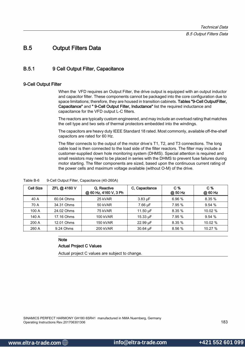
B.5 Output Filters Data
B.5.1 9 Cell Output Filter, Capacitance
9-Cell Output FilterWhen the VFD requires an Output Filter, the drive output is equipped with an output inductor and capacitor filter. These components cannot be packaged into the core configuration due to space limitations; therefore, they are housed in transition cabinets. Tables "9-Cell OutputFilter, Capacitance" and " 9-Cell Output Filter, Inductance" list the required inductance and capacitance for the VFD output L-C filters.
The reactors are typically custom engineered, and may include an overload rating that matches the cell type and two sets of thermal protectors embedded into the windings.
The capacitors are heavy duty IEEE Standard 18 rated. Most commonly, available off-the-shelf capacitors are rated for 60 Hz.
The filter connects to the output of the motor drive’s T1, T2, and T3 connections. The long cable load is then connected to the load side of the filter reactors. The filter may include a customer-supplied down hole monitoring system (DHMS). Special attention is required and small resistors may need to be placed in series with the DHMS to prevent fuse failures during motor starting. The filter components are sized, based upon the continuous current rating of the power cells and maximum voltage available (without O-M) of the drive.
Table B-6 9-Cell Output Filter, Capacitance (40-260A)
Cell Size ZFL @ 4160 V Q, Reactive @ 60 Hz, 4160 V, 3 Ph
C, Capacitance C % @ 50 Hz
C % @ 60 Hz
40 A 60.04 Ohms 25 kVAR 3.83 μF 6.96 % 8.35 %70 A 34.31 Ohms 50 kVAR 7.66 μF 7.95 % 9.54 %
100 A 24.02 Ohms 75 kVAR 11.50 μF 8.35 % 10.02 %140 A 17.16 Ohms 100 kVAR 15.33 μF 7.95 % 9.54 %200 A 12.01 Ohms 150 kVAR 22.99 μF 8.35 % 10.02 %260 A 9.24 Ohms 200 kVAR 30.64 μF 8.56 % 10.27 %
NoteActual Project C Values
Actual project C values are subject to change.
Technical DataB.5 Output Filters Data
SINAMICS PERFECT HARMONY GH180 6SR41 manufactured in NMA Nuernberg, GermanyOperating Instructions Rev.201706301306 183
www.eltra-trade.com [email protected] +421 552 601 099www.eltra-trade.com [email protected] +421 552 601 099

B.5.2 15 Cell Output Filter, Capacitance
15-Cell Output FilterWhen the VFD requires an Output Filter, the drive output is equipped with an output inductor and capacitor filter. These components cannot be packaged into the core configuration due to space limitations; therefore, they are housed in transition cabinets. Tables " 15-Cell Output Filter, Capacitance" and " 15-Cell Output Filter, Inductance" list the required inductance and capacitance for the VFD output L-C filters.
The reactors are typically custom engineered, and may include an overload rating that matches the cell type and two sets of thermal protectors embedded into the windings.
The capacitors are heavy duty IEEE Standard 18 rated. Most commonly, available off-the-shelf capacitors are rated for 60 Hz.
The filter connects to the output of the motor drive’s T1, T2, and T3 connections. The long cable load is then connected to the load side of the filter reactors. The filter may include a customer-supplied down hole monitoring system (DHMS). Special attention is required and small resistors may need to be placed in series with the DHMS to prevent fuse failures during motor starting. The filter components are sized, based upon the continuous current rating of the power cells and maximum voltage available (without O-M) of the drive.
Table B-7 15-Cell Output Filter, Capacitance
Cell Size ZFL @ 6600 V Q, Reactive @ 60 Hz, 7200 V, 3 Ph
C, Capacitance C % @ 50 Hz
C % @ 60 Hz
40 A 95.26 Ohms 50 kVAR 2.56 μF 7.66 % 9.19 %70 A 54.44 Ohms 100 kVAR 5.12 μF 8.75 % 10.50 %
100 A 38.11 Ohms 150 kVAR 7.68 μF 9.19 % 11.03 %140 A 27.22 Ohms 200 kVAR 10.23 μF 8.75 % 10.50 %200 A 19.05 Ohms 300 kVAR 15.35 μF 9.19 % 11.03 %260 A 14.66 Ohms 300 kVAR 15.35 μF 7.07 % 8.48 %
NoteActual Project C Values
Actual project C values are subject to change.
Technical DataB.5 Output Filters Data
SINAMICS PERFECT HARMONY GH180 6SR41 manufactured in NMA Nuernberg, Germany184 Operating Instructions Rev.201706301306
www.eltra-trade.com [email protected] +421 552 601 099www.eltra-trade.com [email protected] +421 552 601 099
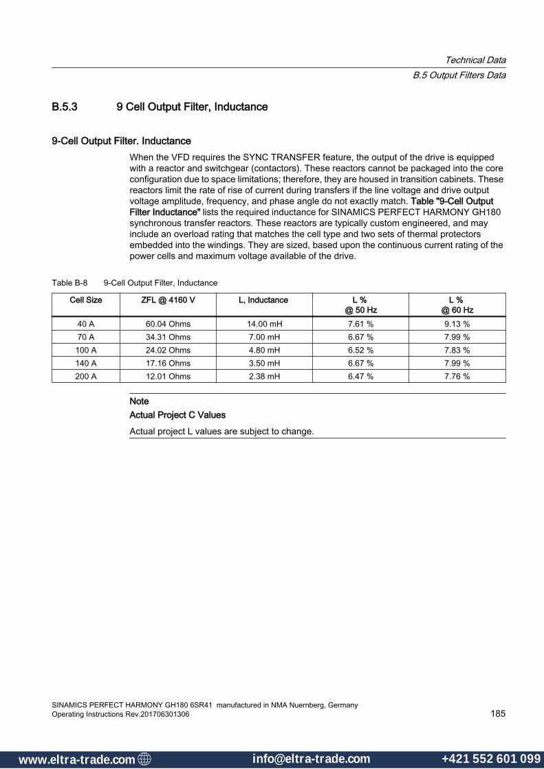
B.5.3 9 Cell Output Filter, Inductance
9-Cell Output Filter. InductanceWhen the VFD requires the SYNC TRANSFER feature, the output of the drive is equipped with a reactor and switchgear (contactors). These reactors cannot be packaged into the core configuration due to space limitations; therefore, they are housed in transition cabinets. These reactors limit the rate of rise of current during transfers if the line voltage and drive output voltage amplitude, frequency, and phase angle do not exactly match. Table "9-Cell Output Filter Inductance" lists the required inductance for SINAMICS PERFECT HARMONY GH180 synchronous transfer reactors. These reactors are typically custom engineered, and may include an overload rating that matches the cell type and two sets of thermal protectors embedded into the windings. They are sized, based upon the continuous current rating of the power cells and maximum voltage available of the drive.
Table B-8 9-Cell Output Filter, Inductance
Cell Size ZFL @ 4160 V L, Inductance L % @ 50 Hz
L % @ 60 Hz
40 A 60.04 Ohms 14.00 mH 7.61 % 9.13 %70 A 34.31 Ohms 7.00 mH 6.67 % 7.99 %
100 A 24.02 Ohms 4.80 mH 6.52 % 7.83 %140 A 17.16 Ohms 3.50 mH 6.67 % 7.99 %200 A 12.01 Ohms 2.38 mH 6.47 % 7.76 %
NoteActual Project C Values
Actual project L values are subject to change.
Technical DataB.5 Output Filters Data
SINAMICS PERFECT HARMONY GH180 6SR41 manufactured in NMA Nuernberg, GermanyOperating Instructions Rev.201706301306 185
www.eltra-trade.com [email protected] +421 552 601 099www.eltra-trade.com [email protected] +421 552 601 099
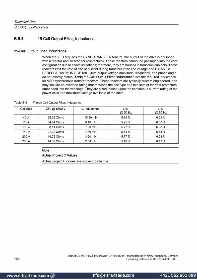
B.5.4 15 Cell Output Filter, Inductance
15-Cell Output Filter. InductanceWhen the VFD requires the SYNC TRANSFER feature, the output of the drive is equipped with a reactor and switchgear (contactors). These reactors cannot be packaged into the core configuration due to space limitations; therefore, they are housed in transition cabinets. These reactors limit the rate of rise of current during transfers if the line voltage and SINAMICS PERFECT HARMONY GH180 Drive output voltage amplitude, frequency, and phase angle do not exactly match. Table "15-Cell Output Filter, Inductance" lists the required inductance for VFD synchronous transfer reactors. These reactors are typically custom engineered, and may include an overload rating that matches the cell type and two sets of thermal protectors embedded into the windings. They are sized, based upon the continuous current rating of the power cells and maximum voltage available of the drive.
Table B-9 Fifteen Cell Output Filter, Inductance
Cell Size ZFL @ 6600 V L, Inductance L % @ 50 Hz
L % @ 60 Hz
40 A 95.26 Ohms 15.90 mH 5.24 % 6.29 %70 A 54.44 Ohms 9.10 mH 5.25 % 6.30 %
100 A 38.11 Ohms 7.00 mH 5.77 % 6.93 %140 A 27.22 Ohms 4.80 mH 5.54 % 6.65 %200 A 19.05 Ohms 3.50 mH 5.77 % 6.93 %260 A 14.66 Ohms 2.38 mH 5.10 % 6.12 %
NoteActual Project C Values
Actual project L values are subject to change.
Technical DataB.5 Output Filters Data
SINAMICS PERFECT HARMONY GH180 6SR41 manufactured in NMA Nuernberg, Germany186 Operating Instructions Rev.201706301306
www.eltra-trade.com [email protected] +421 552 601 099www.eltra-trade.com [email protected] +421 552 601 099

B.6 Ingress Protection (IP) RatingsIP ratings are developed by the European Committee for Electro Technical Standardization (CENELEC) (NEMA IEC 60529 Degrees of Protection Provided by Enclosures - IP Code), specifying the environmental protection the enclosure provides.
The IP rating normally has two (or three) numbers:
● Protection from solid objects or materials
● Protection from liquids (water)
● Protection against mechanical impacts (commonly omitted, the third number is not a part of IEC 60529).
Refer to the following table using the example shown to help in understanding the IP rating as it applies to your equipment.
Example - IP Rating● With the IP rating IP 54, 5 describes the level of protection from solid objects and 4 describes
the level of protection from liquids.● An "X" can be used for one of the digits if there is only one class of protection (e.g.,IPX1,
which, addresses protection against vertically falling drops of water such as condensation).
IP First Number: Protection against solid objects0 No special protection.1 Protected against solid objects over 50 mm e.g. accidental touch by person's hands.2 Protected against solid objects over 12 mm e.g. person's fingers.3 Protected against solid objects over 2.5 mm (tools and wires).4 Protected against solid objects over 1 mm (tools, wires and small wires).5 Protected against dust limited ingress (no harmful deposit).6 Totally protected against dust.
IP Second Number: Protection against liquids0 No protection.1 Protected against vertically falling drops of water e.g. condensation.2 Protected against direct sprays of water up to 15 ° from the vertical.3 Protected against direct sprays of water up to 60 ° from the vertical.4 Protected against water sprayed from all directions - limited ingress permitted.5 Protected against low pressure jets of water from all directions - limited ingress.6 Protected against temporary flooding of water e.g. for use on ship decks - limited ingress permitted.7 Protected against the effect of immersion between 15 cm and 1 m.8 Protected against long periods of immersion under pressure.
Technical DataB.6 Ingress Protection (IP) Ratings
SINAMICS PERFECT HARMONY GH180 6SR41 manufactured in NMA Nuernberg, GermanyOperating Instructions Rev.201706301306 187
www.eltra-trade.com [email protected] +421 552 601 099www.eltra-trade.com [email protected] +421 552 601 099

IP Third Number: Protection against mechanical impacts0 No protection.1 Protected against impact of 0.225 joule (e.g. 150 g weight falling from 15 cm height).2 Protected against impact of 0.375 joule (e.g. 250 g weight falling from 15 cm height).3 Protected against impact of 0.5 joule (e.g. 250 g weight falling from 20 cm height).4 Protected against impact of 2.0 joule (e.g. 500 g weight falling from 40 cm height).5 Protected against impact of 6.0 joule (e.g. 1.5 kg weight falling from 40 cm height).6 Protected against impact of 20.0 joule (e.g. 5 kg weight falling from 40 cm height).
To comply with the stringent requirements for CE marking machine makers today fit their machines with parts certified according to European Union and international standards.
Technical DataB.6 Ingress Protection (IP) Ratings
SINAMICS PERFECT HARMONY GH180 6SR41 manufactured in NMA Nuernberg, Germany188 Operating Instructions Rev.201706301306
www.eltra-trade.com [email protected] +421 552 601 099www.eltra-trade.com [email protected] +421 552 601 099

Quality CC.1 CE Marking and Directives for SINAMICS PERFECT HARMONY
GH180 ProductsThe CE marking identifies products that are in compliance with the appropriate EU directives. The CE marking is not a seal of quality. It was created to guarantee end users safe products in the free flow of goods within the European Economic Community (EEC) and the European Community (EC). By applying the CE marking the manufacturer acknowledges the product is in conformance with the applicable EU Directives and the product complies with the “essential requirements” defined in these directives. Based on the Gambica CE Marking and Technical Standardization Guidelines, Edition 3.0, compliance to EN 61800-5-1 is a harmonized standard and confers a presumption of conformity with the essentials of the Low Voltage Directive (LVD).
C.1.1 CE Marking on Power Drive Systems (PDS)The terminology used throughout IEC and EN standards relating to electrical VFDs is contained in the IEC 61800 series of standards. The IEC 61800 series fo standards references other components of the PDS with respect to the VFD; however, those components are covered by different IEC product relevant materials.
As referenced in Figure "Power Drive System", the installation, parts of the installation, the motor or any machinery, including gearboxes and the driven equipment, are outside of the scope of Siemens LD's responsibility.
SINAMICS PERFECT HARMONY GH180 6SR41 manufactured in NMA Nuernberg, GermanyOperating Instructions Rev.201706301306 189
www.eltra-trade.com [email protected] +421 552 601 099www.eltra-trade.com [email protected] +421 552 601 099
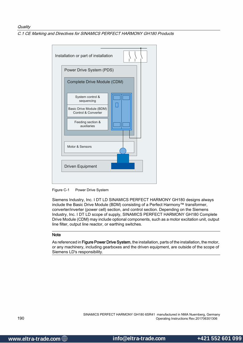
Figure C-1 Power Drive System
Siemens Industry, Inc. I DT LD SINAMICS PERFECT HARMONY GH180 designs always include the Basic Drive Module (BDM) consisting of a Perfect Harmony™ transformer, converter/inverter (power cell) section, and control section. Depending on the Siemens Industry, Inc. I DT LD scope of supply, SINAMICS PERFECT HARMONY GH180 Complete Drive Module (CDM) may include optional components, such as a motor excitation unit, output line filter, output line reactor, or earthing switches.
Note
As referenced in Figure Power Drive System, the installation, parts of the installation, the motor, or any machinery, including gearboxes and the driven equipment, are outside of the scope of Siemens LD's responsibility.
QualityC.1 CE Marking and Directives for SINAMICS PERFECT HARMONY GH180 Products
SINAMICS PERFECT HARMONY GH180 6SR41 manufactured in NMA Nuernberg, Germany190 Operating Instructions Rev.201706301306
www.eltra-trade.com [email protected] +421 552 601 099www.eltra-trade.com [email protected] +421 552 601 099
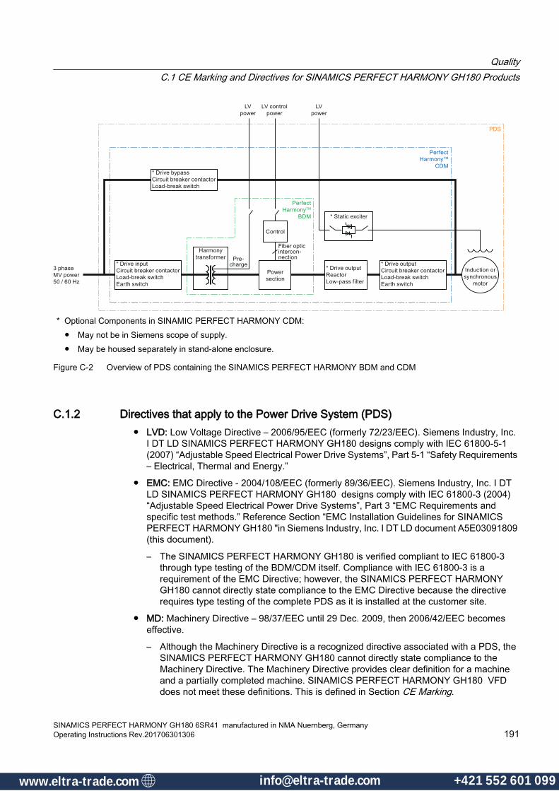
* Optional Components in SINAMIC PERFECT HARMONY CDM:● May not be in Siemens scope of supply.● May be housed separately in stand-alone enclosure.
Figure C-2 Overview of PDS containing the SINAMICS PERFECT HARMONY BDM and CDM
C.1.2 Directives that apply to the Power Drive System (PDS)● LVD: Low Voltage Directive – 2006/95/EEC (formerly 72/23/EEC). Siemens Industry, Inc.
I DT LD SINAMICS PERFECT HARMONY GH180 designs comply with IEC 61800-5-1 (2007) “Adjustable Speed Electrical Power Drive Systems”, Part 5-1 “Safety Requirements – Electrical, Thermal and Energy.”
● EMC: EMC Directive - 2004/108/EEC (formerly 89/36/EEC). Siemens Industry, Inc. I DT LD SINAMICS PERFECT HARMONY GH180 designs comply with IEC 61800-3 (2004) “Adjustable Speed Electrical Power Drive Systems”, Part 3 “EMC Requirements and specific test methods.” Reference Section “EMC Installation Guidelines for SINAMICS PERFECT HARMONY GH180 "in Siemens Industry, Inc. I DT LD document A5E03091809 (this document).
– The SINAMICS PERFECT HARMONY GH180 is verified compliant to IEC 61800-3 through type testing of the BDM/CDM itself. Compliance with IEC 61800-3 is a requirement of the EMC Directive; however, the SINAMICS PERFECT HARMONY GH180 cannot directly state compliance to the EMC Directive because the directive requires type testing of the complete PDS as it is installed at the customer site.
● MD: Machinery Directive – 98/37/EEC until 29 Dec. 2009, then 2006/42/EEC becomes effective.
– Although the Machinery Directive is a recognized directive associated with a PDS, the SINAMICS PERFECT HARMONY GH180 cannot directly state compliance to the Machinery Directive. The Machinery Directive provides clear definition for a machine and a partially completed machine. SINAMICS PERFECT HARMONY GH180 VFD does not meet these definitions. This is defined in Section CE Marking.
QualityC.1 CE Marking and Directives for SINAMICS PERFECT HARMONY GH180 Products
SINAMICS PERFECT HARMONY GH180 6SR41 manufactured in NMA Nuernberg, GermanyOperating Instructions Rev.201706301306 191
www.eltra-trade.com [email protected] +421 552 601 099www.eltra-trade.com [email protected] +421 552 601 099

● PED: Pressure Equipment Directive – 97/23EC. Liquid cooled Siemens Industry, Inc. I DT LD SINAMICS PERFECT HARMONY GH180 designs are exempt since they operate at pressures less than ten bars.
● ATEX: Explosive Atmospheres – 94/9/EC. Siemens Industry, Inc. I DT LD does not authorize the use of SINAMICS PERFECT HARMONY GH180 designs in an explosive atmosphere.
QualityC.1 CE Marking and Directives for SINAMICS PERFECT HARMONY GH180 Products
SINAMICS PERFECT HARMONY GH180 6SR41 manufactured in NMA Nuernberg, Germany192 Operating Instructions Rev.201706301306
www.eltra-trade.com [email protected] +421 552 601 099www.eltra-trade.com [email protected] +421 552 601 099
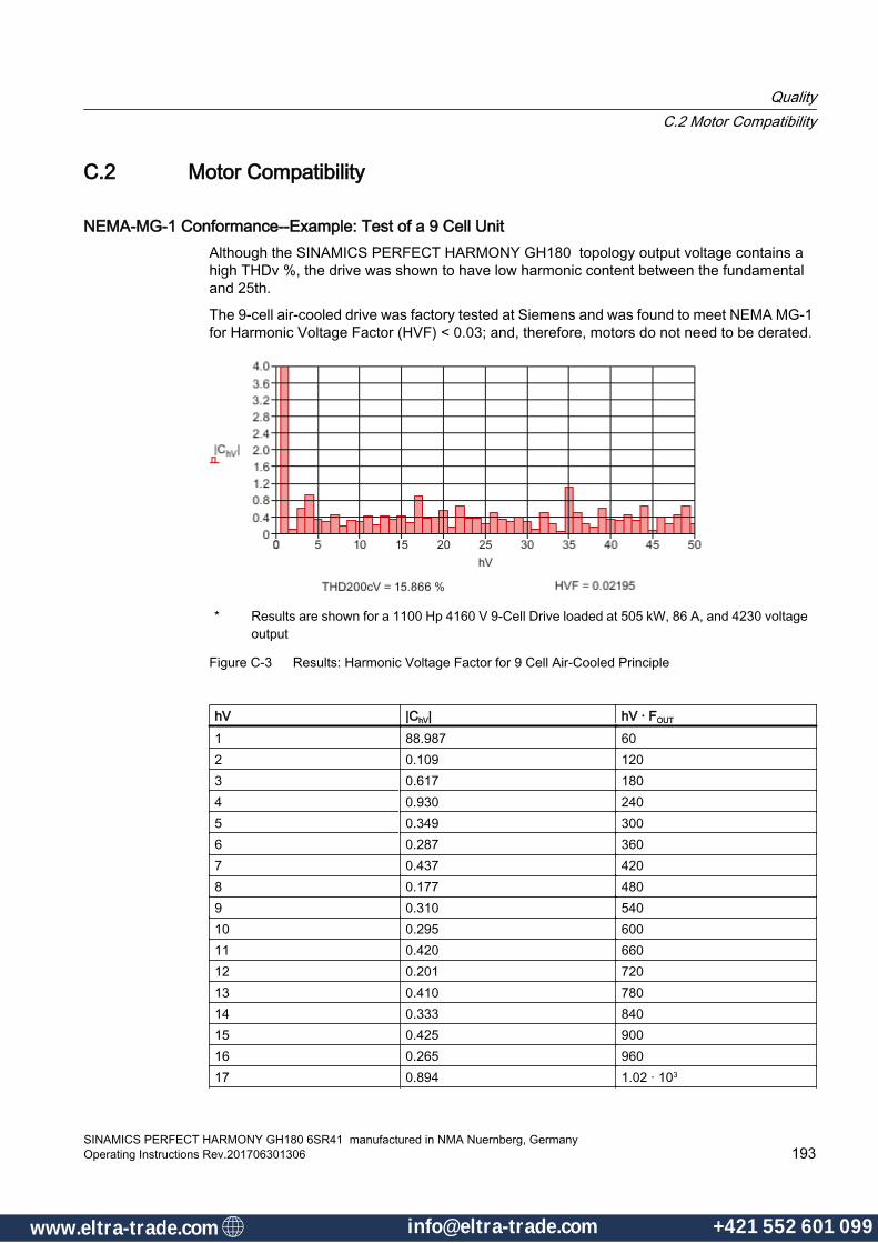
C.2 Motor Compatibility
NEMA-MG-1 Conformance--Example: Test of a 9 Cell Unit Although the SINAMICS PERFECT HARMONY GH180 topology output voltage contains a high THDv %, the drive was shown to have low harmonic content between the fundamental and 25th.
The 9-cell air-cooled drive was factory tested at Siemens and was found to meet NEMA MG-1 for Harmonic Voltage Factor (HVF) < 0.03; and, therefore, motors do not need to be derated.
* Results are shown for a 1100 Hp 4160 V 9-Cell Drive loaded at 505 kW, 86 A, and 4230 voltage output
Figure C-3 Results: Harmonic Voltage Factor for 9 Cell Air-Cooled Principle
hV |ChV| hV · FOUT
1 88.987 602 0.109 1203 0.617 1804 0.930 2405 0.349 3006 0.287 3607 0.437 4208 0.177 4809 0.310 54010 0.295 60011 0.420 66012 0.201 72013 0.410 78014 0.333 84015 0.425 90016 0.265 96017 0.894 1.02 · 103
QualityC.2 Motor Compatibility
SINAMICS PERFECT HARMONY GH180 6SR41 manufactured in NMA Nuernberg, GermanyOperating Instructions Rev.201706301306 193
www.eltra-trade.com [email protected] +421 552 601 099www.eltra-trade.com [email protected] +421 552 601 099

hV |ChV| hV · FOUT
18 0.368 1.08 · 103
19 0.384 1.14 · 103
20 0.554 1.20 · 103
21 0.157 1.26 · 103
22 0.672 1.32 · 103
23 0.383 1.38 · 103
24 0.380 1.44 · 103
25 0.245 1.50 · 103
QualityC.2 Motor Compatibility
SINAMICS PERFECT HARMONY GH180 6SR41 manufactured in NMA Nuernberg, Germany194 Operating Instructions Rev.201706301306
www.eltra-trade.com [email protected] +421 552 601 099www.eltra-trade.com [email protected] +421 552 601 099

C.3 IEEE 519 Conformance
IEEE 519 Conformance -- Example: 18-Pulse Test of a 9-Cell Unit The 18--pulse 9-cell air-cooled drive was factory tested at SIEMENS and was found to meet IEEE 519 for the most stringent TDD limits. The pre-existing voltage distortion was less than 2 % and the primary current contained a K-factor of less than 2 A.
* Results shown for a 4160 V input 1100 Hp drive.THDi < 5%, for THDv existing ≦2%18-pulse, air-cooled Micro Harmony meets IEEE 519-1992 TDD Harmonic Limits
Figure C-4 Results: 9-Cell - Harmonic Current Distortion (TDD < %)
hl |Chl| · 100 / |Cl|1 1002 0.8883 1.8844 0.4075 2.4536 0.4907 1.1718 0.2249 0.50810 0.324
QualityC.3 IEEE 519 Conformance
SINAMICS PERFECT HARMONY GH180 6SR41 manufactured in NMA Nuernberg, GermanyOperating Instructions Rev.201706301306 195
www.eltra-trade.com [email protected] +421 552 601 099www.eltra-trade.com [email protected] +421 552 601 099
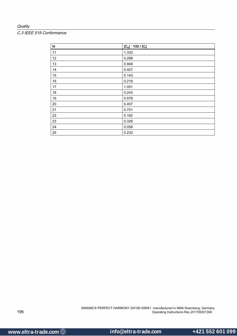
hl |Chl| · 100 / |Cl|11 1.33312 0.29913 0.94914 0.40715 0.14316 0.21817 1.05118 0.24319 0.57820 0.40721 0.70122 0.16223 0.32624 0.05825 0.233
QualityC.3 IEEE 519 Conformance
SINAMICS PERFECT HARMONY GH180 6SR41 manufactured in NMA Nuernberg, Germany196 Operating Instructions Rev.201706301306
www.eltra-trade.com [email protected] +421 552 601 099www.eltra-trade.com [email protected] +421 552 601 099

Abbreviations DD.1 Abbreviations
This appendix contains a list of symbols and abbreviations commonly used throughout this manual group.
Table D-1 Commonly Used Abbreviations
Abbreviation Meaning• Boolean AND function+ Addition or Boolean OR function∑ Summationµ MicrosecondA Amp, AmpereAC Alternating Currentaccel AccelerationA/D Analog-to-digital (converter)AI Analog InputAlg AnalogAP Advanced protocol for cell communicationavail AvailableBTU British thermal unitsC Centigrade or Capacitorcap CapacitorCCB Cell Control Boardccw Counter clockwiseCE Formerly European Conformity, now true definitionCFM Cubic Feet per MinuteCLVC Closed Loop Vector Controlcmd Commandcom Commonconn ConnectorCPS Control Power SupplyCPU Central Processing UnitCSMC Closed Loop Synchronous Motor ControlCT Current Transformercu Cubiccurr, I Currentcw ClockwiseD Derivative (PID), depthD/A Digital-to-analog (converter)
SINAMICS PERFECT HARMONY GH180 6SR41 manufactured in NMA Nuernberg, GermanyOperating Instructions Rev.201706301306 197
www.eltra-trade.com [email protected] +421 552 601 099www.eltra-trade.com [email protected] +421 552 601 099
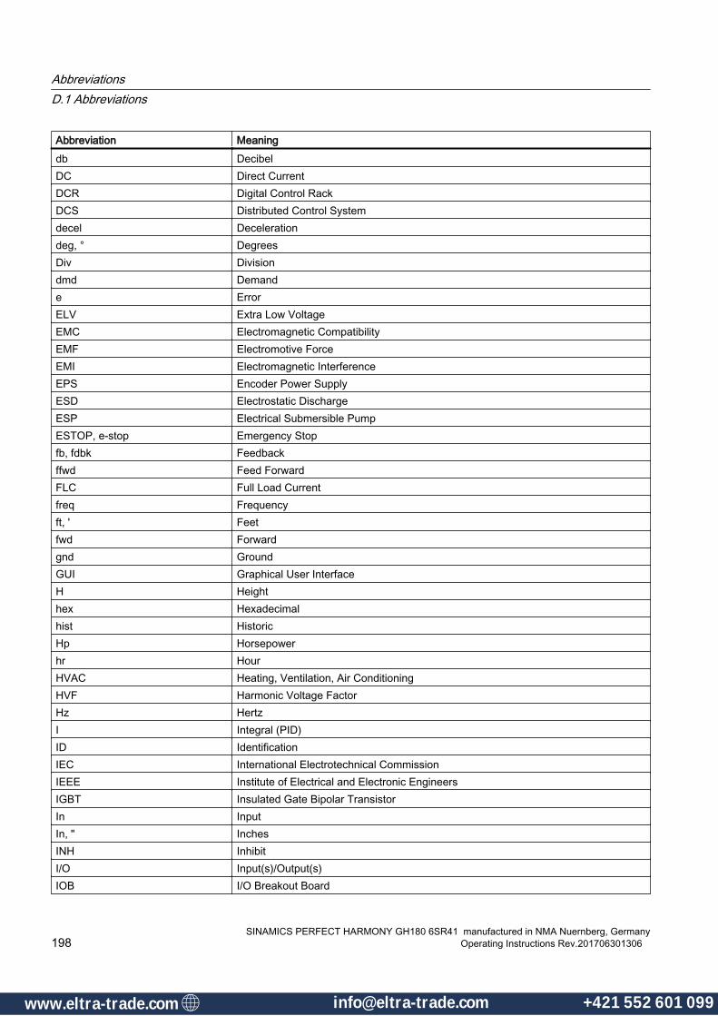
Abbreviation Meaningdb DecibelDC Direct CurrentDCR Digital Control RackDCS Distributed Control Systemdecel Decelerationdeg, ° DegreesDiv Divisiondmd Demande ErrorELV Extra Low VoltageEMC Electromagnetic CompatibilityEMF Electromotive ForceEMI Electromagnetic InterferenceEPS Encoder Power SupplyESD Electrostatic DischargeESP Electrical Submersible PumpESTOP, e-stop Emergency Stopfb, fdbk Feedbackffwd Feed ForwardFLC Full Load Currentfreq Frequencyft, ' Feetfwd Forwardgnd GroundGUI Graphical User InterfaceH Heighthex Hexadecimalhist HistoricHp Horsepowerhr HourHVAC Heating, Ventilation, Air ConditioningHVF Harmonic Voltage FactorHz HertzI Integral (PID)ID IdentificationIEC International Electrotechnical CommissionIEEE Institute of Electrical and Electronic EngineersIGBT Insulated Gate Bipolar TransistorIn InputIn, " InchesINH InhibitI/O Input(s)/Output(s)IOB I/O Breakout Board
AbbreviationsD.1 Abbreviations
SINAMICS PERFECT HARMONY GH180 6SR41 manufactured in NMA Nuernberg, Germany198 Operating Instructions Rev.201706301306
www.eltra-trade.com [email protected] +421 552 601 099www.eltra-trade.com [email protected] +421 552 601 099

Abbreviation MeaningIOC Instantaneous OvercurrentIP Input Protectionk 1,000 (e.g., Kohm)kHz KiloHertzkV Kilo VoltskVA One Thousand Volt AmpskW KilowattL InductorLAN Local Area NetworkLbs Pounds (weight)LCD Liquid Crystal Displayld LoadLED Light-emitting DiodeLFR Latch Fault RelayLim LimitLOS Loss Of Signallps Liters Per SecondmA Milliamperesmag Magnetizingmax MaximumMCC Motor Control CenterMg MilligramMin Minimum, Minutemsec Millisecond(S)Msl Mean Sea LevelMV Medium Voltagemvlt Motor VoltageMW MegawattNC Normally ClosedNEMA National Electrical Manufacturer’s AssociationNo Normally OpenNVRAM Non-Volatile Random Access MemoryNXG Next Generation ControlNXGII Next Generation Control IINXGpro Next Generation Control proOLVC Open Loop Vector ControlO-M OvermodulationOOS Out of Saturation (IGBT)overld OverloadP Proportional (PID)Pa Pascalspb Push ButtonPC Personal Computer or Printed Circuit
AbbreviationsD.1 Abbreviations
SINAMICS PERFECT HARMONY GH180 6SR41 manufactured in NMA Nuernberg, GermanyOperating Instructions Rev.201706301306 199
www.eltra-trade.com [email protected] +421 552 601 099www.eltra-trade.com [email protected] +421 552 601 099

Abbreviation MeaningPCB Printed Circuit BoardPID Proportional Integral DerivativePLC Programmable Logic ControllerPLL Phase Locked Looppot Potentiometerpp Peak-to-peakppm Parts per MillionPPR Pulses per RevolutionPQM Power Quality MeterProToPSTM Process Tolerant Protection StrategyPSDBP Power Spectral Density Break Pointpsi Pounds Per Square Inchpt PointPT Potential TransformerPWM Pulse Width ModulationQ1,Q2,Q3,Q4 Output Transistor Designationsrad RadiansRAM Random Access Memoryref Referencerev Reverse, Revolution(S)RFI Radio Frequency InterferenceRLBK Rollbackrms Root-mean-squaredRPM Revolutions Per MinuteRTD Resistance Temperature DetectorRTU Remote Terminal UnitRX Receive (RS232 Communications)s Second(s)SCB Signal Conditioning BoardSCR Silicon Controlled Rectifiersec Second(s)ser SerialSMC Synchronous Motor ControlSOP Sum of Products; System Operating Programspd Speedstab Stabilitystd Standardsw SwitchT1, T2 Output Terminals TI and T2TB Terminal BlockTBD To Be DeterminedTCP/IP Transmission Control Protocol/Internet ProtocolTHD Total Harmonic Distortion
AbbreviationsD.1 Abbreviations
SINAMICS PERFECT HARMONY GH180 6SR41 manufactured in NMA Nuernberg, Germany200 Operating Instructions Rev.201706301306
www.eltra-trade.com [email protected] +421 552 601 099www.eltra-trade.com [email protected] +421 552 601 099
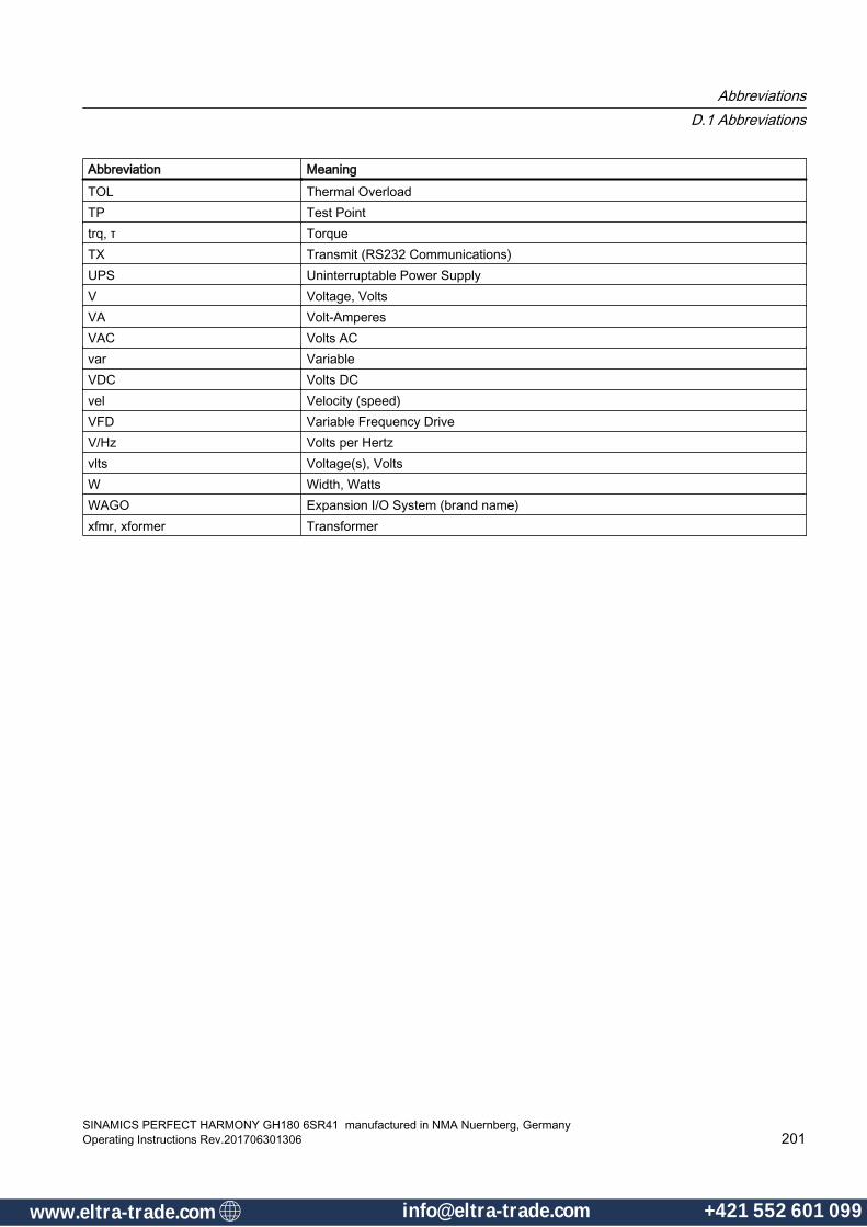
Abbreviation MeaningTOL Thermal OverloadTP Test Pointtrq, τ TorqueTX Transmit (RS232 Communications)UPS Uninterruptable Power SupplyV Voltage, VoltsVA Volt-AmperesVAC Volts ACvar VariableVDC Volts DCvel Velocity (speed)VFD Variable Frequency DriveV/Hz Volts per Hertzvlts Voltage(s), VoltsW Width, WattsWAGO Expansion I/O System (brand name)xfmr, xformer Transformer
AbbreviationsD.1 Abbreviations
SINAMICS PERFECT HARMONY GH180 6SR41 manufactured in NMA Nuernberg, GermanyOperating Instructions Rev.201706301306 201
www.eltra-trade.com [email protected] +421 552 601 099www.eltra-trade.com [email protected] +421 552 601 099

AbbreviationsD.1 Abbreviations
SINAMICS PERFECT HARMONY GH180 6SR41 manufactured in NMA Nuernberg, Germany202 Operating Instructions Rev.201706301306
www.eltra-trade.com [email protected] +421 552 601 099www.eltra-trade.com [email protected] +421 552 601 099
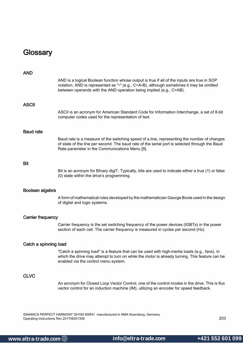
Glossary
ANDAND is a logical Boolean function whose output is true if all of the inputs are true in SOP notation, AND is represented as "∗" (e.g., C=A∗B), although sometimes it may be omitted between operands with the AND operation being implied (e.g., C=AB).
ASCIIASCII is an acronym for American Standard Code for Information Interchange, a set of 8-bit computer codes used for the representation of text.
Baud rateBaud rate is a measure of the switching speed of a line, representing the number of changes of state of the line per second. The baud rate of the serial port is selected through the Baud Rate parameter in the Communications Menu [9].
BitBit is an acronym for BInary digiT. Typically, bits are used to indicate either a true (1) or false (0) state within the drive’s programming.
Boolean algebraA form of mathematical rules developed by the mathematician George Boole used in the design of digital and logic systems.
Carrier frequencyCarrier frequency is the set switching frequency of the power devices (IGBTs) in the power section of each cell. The carrier frequency is measured in cycles per second (Hz).
Catch a spinning load"Catch a spinning load" is a feature that can be used with high-inertia loads (e.g., fans), in which the drive may attempt to turn on while the motor is already turning. This feature can be enabled via the control menu system.
CLVCAn acronym for Closed Loop Vector Control, one of the control modes in the drive. This is flux vector control for an induction machine (IM), utilizing an encoder for speed feedback.
SINAMICS PERFECT HARMONY GH180 6SR41 manufactured in NMA Nuernberg, GermanyOperating Instructions Rev.201706301306 203
www.eltra-trade.com [email protected] +421 552 601 099www.eltra-trade.com [email protected] +421 552 601 099
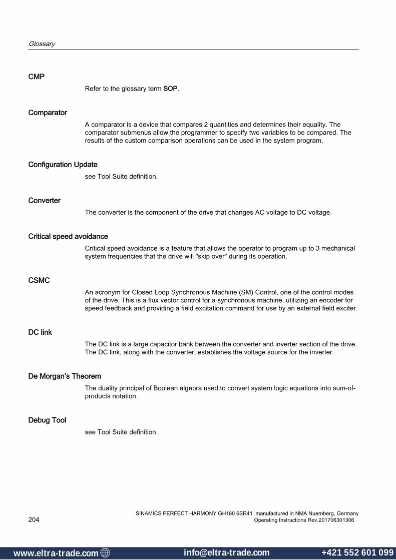
CMP Refer to the glossary term SOP.
ComparatorA comparator is a device that compares 2 quantities and determines their equality. The comparator submenus allow the programmer to specify two variables to be compared. The results of the custom comparison operations can be used in the system program.
Configuration Updatesee Tool Suite definition.
ConverterThe converter is the component of the drive that changes AC voltage to DC voltage.
Critical speed avoidanceCritical speed avoidance is a feature that allows the operator to program up to 3 mechanical system frequencies that the drive will "skip over" during its operation.
CSMCAn acronym for Closed Loop Synchronous Machine (SM) Control, one of the control modes of the drive. This is a flux vector control for a synchronous machine, utilizing an encoder for speed feedback and providing a field excitation command for use by an external field exciter.
DC linkThe DC link is a large capacitor bank between the converter and inverter section of the drive. The DC link, along with the converter, establishes the voltage source for the inverter.
De Morgan’s TheoremThe duality principal of Boolean algebra used to convert system logic equations into sum-of-products notation.
Debug Toolsee Tool Suite definition.
Glossary
SINAMICS PERFECT HARMONY GH180 6SR41 manufactured in NMA Nuernberg, Germany204 Operating Instructions Rev.201706301306
www.eltra-trade.com [email protected] +421 552 601 099www.eltra-trade.com [email protected] +421 552 601 099
DownloadingDownloading is a process by which information is transmitted from a remote device (such as a PC) to the drive. The term "downloading" implies the transmission of an entire file of information (e.g., the system program) rather than continued interactive communications between the two devices. The use of a PC for downloading requires special serial communications software to be available on the PC, which may link to the drive via RS232 or through the Host Simulator via an ethernet connection.
DRCTRYDirectory file for system tokens and flags used in the compilation of system programs. It provides a direct lookup table of ASCII names to internal ID numbers. It also identifies whether the flag is a word or bit-field, and also whether it can be used as an input or output only, or can be used for both.
DriveThe term "drive" refers to the power conversion equipment that converts utility power into power for a motor in a controlled manner.
ELVELV is an acronym for extra low voltage, and represents any voltage not exceeding a limit that is generally accepted to be 50 VAC and 120 VDC (ripple free).
EMC EMC is an acronym for electromagnetic compatibility–the ability of equipment to function satisfactorily in its electromagnetic environment without introducing intolerable electromagnetic disturbances to anything in that environment.
ESDESD is an acronym for ElectroStatic Discharge. ESD is an undesirable electrical side effect that occurs when static charges build up on a surface and are discharged to another. When printed circuit boards are involved, impaired operation and component damage are possible side effects due to the static-sensitive nature of the PC board components. These side effects may manifest themselves as intermittent problems or total component failures. It is important to recognize that these effects are cumulative and may not be obvious.
Fault logFault messages are saved to memory so that the operator may view them at a later time. This memory location is called the fault log. The fault log lists both fault and alarm messages, the date and time that they occurred, and the time and date that they are reset.
Glossary
SINAMICS PERFECT HARMONY GH180 6SR41 manufactured in NMA Nuernberg, GermanyOperating Instructions Rev.201706301306 205
www.eltra-trade.com [email protected] +421 552 601 099www.eltra-trade.com [email protected] +421 552 601 099

FaultsFaults are error conditions that have occurred in the system. The severity of faults vary. Likewise, the treatment or corrective action for a fault may vary from changing a parameter value to replacing a hardware component such as a fuse.
Flash CardNon-volatile memory storage device for the control. It stores the drive program, system program, logs, parameters, and other related drive files.
FPGAField Programmable Gate Array. An FPGA is an integrated circuit that contains thousands of logic gates.
FunctionA function is one of four components found in the menu system. Functions are built-in programs that perform specific tasks. Examples of functions include System Program Upload/Download and Display System Program Name.
HarmonicsHarmonics are undesirable AC currents or voltages at integer multiples of the fundamental frequency. The fundamental frequency is the lowest frequency in the wave form (generally the repetition frequency). Harmonics are present in any non-sinusoidal wave form and cannot transfer power on average.
Harmonics arise from non-linear loads in which current is not strictly proportional to voltage. Linear loads like resistors, capacitors, and inductors do not produce harmonics. However, non-linear devices such as diodes and silicon controlled rectifiers (SCRs) do generate harmonic currents. Harmonics are also found in uninterruptable power supplies (UPSs), rectifiers, transformers, ballasts, welders, arc furnaces, and personal computers.
Hexadecimal digitsHexadecimal (or "hex") digits are the "numerals" used to represent numbers in the base 16 (hex) number system. Unlike the more familiar decimal system, which uses the numerals 0 through 9 to make numbers in powers of 10, the base 16 number system uses the numerals 0, 1, 2, 3, 4, 5, 6, 7, 8, 9, A, B, C, D, E, and F to make numbers in powers of 16.
Glossary
SINAMICS PERFECT HARMONY GH180 6SR41 manufactured in NMA Nuernberg, Germany206 Operating Instructions Rev.201706301306
www.eltra-trade.com [email protected] +421 552 601 099www.eltra-trade.com [email protected] +421 552 601 099
Historic logThe historic log is a troubleshooting/diagnostic tool of the control. The historic log continuously logs drive status, including the drive state, internal fault words, and multiple user-selectable variables. This information is sampled every slow loop cycle of the control (typically 450 to 900 times per second). If a fault occurs, the log is frozen a predefined number of samples after the fault event, and data samples prior to and after the fault condition are recorded to allow post-fault analysis. The number of samples recorded are user-selectable via the control, as well as the option to record the historic log within the VFD event log.
Host Simulatorsee Tool Suite definition.
I/OI/O is an acronym for input/output. I/O refers to any and all inputs and outputs connected to a computer system. Both inputs and outputs can be classified as analog (e.g., input power, drive output, meter outputs, etc.) or digital (e.g., contact closures or switch inputs, relay outputs, etc.).
IGBTIGBT is an acronym for Insulated Gate Bipolar Transistors. IGBTs are semiconductors that are used in the drive to provide reliable, high-speed switching, high-power capabilities, improved control accuracy, and reduced motor noise.
Induction motorAn induction motor is an AC motor that produces torque by the reaction between a varying magnetic field (generated in the stator) and the current induced in the coils of the rotor.
Intel hexIntel hex refers to a file format in which records consist of ASCII format hexadecimal (base 16) numbers with load address information and error checking embedded.
InverterThe inverter is a portion of the drive that changes DC voltage into AC voltage. The term "inverter" is sometimes used mistakenly to refer to the entire drive (the converter, DC link, and inverter sections).
Jog modeJog mode is an operational mode that uses a pre-programmed jog speed when a digital input (programmed as the jog mode input) is closed.
Glossary
SINAMICS PERFECT HARMONY GH180 6SR41 manufactured in NMA Nuernberg, GermanyOperating Instructions Rev.201706301306 207
www.eltra-trade.com [email protected] +421 552 601 099www.eltra-trade.com [email protected] +421 552 601 099
JumpersJumper blocks are groups of pins that can control functions of the system, based on the state of the jumpers. Jumpers (small, removable connectors) are either installed (on) or not installed (off) to provide a hardware switch.
Ladder logic (Also Ladder Diagram)A graphical representation of logic in which two vertical lines, representing power, flow from the source on the left and the sink on the right, with logic branches running between, resembling rungs of a ladder. Each branch consists of various labeled contacts placed in series and connected to a single relay coil (or function block) on the right.
Loss of signal featureThe loss of signal feature is a control scheme that gives the operator the ability to select one of three possible actions in the event that the signal from an external sensor, configured to specify the speed demand, is lost. Under this condition, the operator may program the drive (through the system program) to (1) revert to a fixed, pre-programmed speed, (2) maintain the current speed, or (3) perform a controlled (ramped) stop of the drive. By default, current speed is maintained.
LVDLVD is an acronym for Low Voltage Directive, a safety directive in the EU.
Lvl RHThis term refers the two security fields associated with each parameter of the system. These fields allow the operator to individually customize specific security features for each menu option (submenu, parameter, pick list, and function). These fields are shown in parameter dumps and have the following meanings. Lvl is the term for the security level. Setting R=1 blocks parameter change, and setting H=1 hides the menu option from view until the appropriate access level has been activated.
MemoryMemory is the working storage area for the drive that is a collection of RAM chips.
Microprocessor A microprocessor is a central processing unit (CPU) that exists on a single silicon chip. The microprocessor board is the printed circuit board on which the microprocessor is mounted. The drive employs a single-board computer with a Pentium® microprocessor.
Glossary
SINAMICS PERFECT HARMONY GH180 6SR41 manufactured in NMA Nuernberg, Germany208 Operating Instructions Rev.201706301306
www.eltra-trade.com [email protected] +421 552 601 099www.eltra-trade.com [email protected] +421 552 601 099

NEMA 1 and NEMA 12NEMA 1 is an enclosure rating in which no openings allow penetration of a 0.25-inch diameter rod. NEMA 1 enclosures are intended for indoor use only. NEMA 12 is a more stringent NEMA rating in which the cabinet is said to be "dust tight" (although it is still not advisable to use NEMA 12 in conductive dust atmospheres). The approximate equivalent IEC rating is IP52.
Normally closed (NC)Normally closed refers to the contact of a relay that is closed when the coil is de-energized.
Normally open (NO)Normally open refers to the contact of a relay that is open when the coil is de-energized.
OLTMAn acronym for Open Loop Test Mode, one of the control modes of the drive.
OLVCAn acronym for Open Loop Vector Control, also known as Encoderless Vector Control. OLVC is a flux vector control that is one of the control modes of the drive. The drive computes the rotational speed of the rotor and uses it for speed feedback.
OOSOOS is an abbreviation for out of saturation - a type of fault condition in which a voltage drop is detected across one of the IGBTs during conduction. This can indicate that the motor is drawing current too rapidly or in excess.
OROR is a logical Boolean function whose output is true if any of the inputs is true. In SOP notation, OR is represented as "+".
ParameterA parameter is one of four items found in the menu system. Parameters are system attributes that have corresponding values that can be monitored or, in some cases, changed by the user.
PED PED is an acronym for pressure equipment directive, a directive of the EU relating to pressure vessels.
Glossary
SINAMICS PERFECT HARMONY GH180 6SR41 manufactured in NMA Nuernberg, GermanyOperating Instructions Rev.201706301306 209
www.eltra-trade.com [email protected] +421 552 601 099www.eltra-trade.com [email protected] +421 552 601 099
Pick listA pick list is one of four items found in the menu system. Pick lists are parameters that have a finite list of pre-defined "values" from which to choose, rather than a value range used by parameters.
PIDPID is an acronym for proportional + integral + derivative, a control scheme used to control modulating equipment in such a way that the control output is based on (1) a proportional amount of the error between the desired setpoint and the actual feedback value, (2) the summation of this error over time, and (3) the change in error over time. Output contributions from each of these three components are combined to create a single output response. The amount of contribution from each component is programmable through gain parameters. By optimizing these gain parameters, the operator can "tune" the PID control loop for maximum efficiency, minimal overshoot, quick response time, and minimal cycling.
Qualified userA qualified user is a properly trained individual who is familiar with the construction and operation of the equipment and the hazards involved.
RAMRAM is an acronym for Random Access Memory, a temporary storage area for drive information. The information in RAM is lost when power is no longer supplied to it. Therefore, it is referred to as volatile memory.
RegenerationRegeneration is the characteristic of an AC motor to act as a generator when the rotor’s mechanical frequency is greater than the applied electrical frequency.
RelayA relay is an electrically controlled device that causes electrical contacts to change their status. Open contacts will close and closed contacts will open when rated voltage is applied to the coil of a relay.
RS232CRS232C is a serial communications standard of the Electronics Industries Association (EIA).
Set pointSet point is the desired or optimal speed of the VFD to maintain process levels (speed command).
Glossary
SINAMICS PERFECT HARMONY GH180 6SR41 manufactured in NMA Nuernberg, Germany210 Operating Instructions Rev.201706301306
www.eltra-trade.com [email protected] +421 552 601 099www.eltra-trade.com [email protected] +421 552 601 099
SlipSlip is the difference between the stator electrical frequency of the motor and the rotor mechanical frequency of the motor, normalized to the stator frequency as shown in the following equation:
Slip = (ωS - ωR) / ωS
Slip compensationSlip compensation is a method of increasing the speed reference to the speed regulator circuit (based on the motor torque) to maintain motor speed as the load on the motor changes. The slip compensation circuit increases the frequency at which the inverter section is controlled to compensate for decreased speed due to load droop. For example, a motor with a full load speed of 1760 rpm has a slip of 40 rpm. The no load rpm would be 1800 rpm. If the motor nameplate current is 100 A, the drive is sending a 60 Hz wave form to the motor (fully loaded); then the slip compensation circuit would cause the inverter to run 1.33 Hz faster to allow the motor to operate at 1800 rpm, which is the synchronous speed of the motor.
SMCIs an acronym for Synchronous Motor Control, one of the control modes of the drive. This mode computes the rotational speed similarly to open-loop vector control, and controls the field reference or the synchronous motor as in closed-loop synchronous motor control.
SOP(1) SOP is an acronym for Sum Of Products. The term "sum-of-products" comes from the application of Boolean algebraic rules to produce a set of terms or conditions that are grouped in a fashion that represents parallel paths (ORing) of required conditions that all must be met (ANDing). This would be equivalent to branches of connected contacts on a relay logic ladder that connect to a common relay coil. In fact, the notation can be used as a shortcut to describe the ladder logic.
(2) SOP, when used as a filename extension, refers to System Operating Program.
SOP UtilitiesThe program within the Siemens Tool suite used for converting between text and machine loadable code. It can also be used for uploading and downloading files over the RS232 connection.
See Tool Suite definition.
Speed Menu functionSpeed menu is a feature of the menu system that allows the operator to directly access any of the menus or parameters, rather than scrolling through menus to the appropriate item. This feature uses the [Shift] button in conjunction with the right arrow. The user is prompted to enter the four digit ID number associated with the desired menu or parameter.
Glossary
SINAMICS PERFECT HARMONY GH180 6SR41 manufactured in NMA Nuernberg, GermanyOperating Instructions Rev.201706301306 211
www.eltra-trade.com [email protected] +421 552 601 099www.eltra-trade.com [email protected] +421 552 601 099

Stop modeStop mode is used to shut down the drive in a controlled manner, regardless of its current state.
SubmenusA submenu is one of four components found in the menu system. Submenus are nested menus (i.e., menus within other menus). Submenus are used to logically group menu items based on similar functionality or use.
Synchronous speedSynchronous speed refers to the speed of an AC induction motor’s rotating magnetic field. It is determined by the frequency applied to the stator and the number of magnetic poles present in each phase of the stator windings. Synchronous Speed equals 120 times the applied Frequency (in Hz) divided by the number of poles per phase.
System Operating ProgramThe functions of the programmable inputs and outputs are determined by the default system program. These functions can be changed by modifying the appropriate setup menus from the front keypad and display. I/O assignments can also be changed by editing the system program (an ASCII text file with the extension .SOP), compiling it using the compiler program, and then downloading it to the controller through its serial port, all by utilizing the SOP Utility Program with the Siemens ToolSuite.
Tool SuiteIs the suite of programs developed by Siemens that allows easier access to the drive for programming and monitoring. It is comprised of the following components:
● Tool Suite Launcher - also referred to as Tool Suite; used for coordinating other tools.
● SOP Utilities - used to launch an editor that compiles or reverse compiles a System Program. It also allows for serial connection to the drive for uploading and downloading System Programs.
● Configuration Update - allows for backing-up, updating, and cloning drives via direct access to the Flash Disk.
● Host Simulator - used for monitoring, programming, and controlling a drive remotely from a PC over the built-in ethernet port of the drive. Parameter changes, status display, and graphing of internal variables are its main functions.
● Debug Tool - this tool is used to display the diagnostic screens of the drive for diagnosing drive problems or improving performance via the built-in ethernet port of the drive.
Tool Suite Launchersee Tool Suite definition.
Glossary
SINAMICS PERFECT HARMONY GH180 6SR41 manufactured in NMA Nuernberg, Germany212 Operating Instructions Rev.201706301306
www.eltra-trade.com [email protected] +421 552 601 099www.eltra-trade.com [email protected] +421 552 601 099

TorqueThe force that produces (or attempts to produce) rotation, as in the case of a motor.
UploadingUploading is a process by which information is transmitted from the drive to a remote device such as a PC. The term uploading implies the transmission of an entire file of information (e.g., the system program) rather than continued interactive communications between the two devices. The use of a PC for uploading requires communications software to be available on the PC.
Variable frequency drive (VFD)A VFD is a device that takes a fixed voltage and fixed frequency AC input source and converts it to a variable voltage, variable frequency output that can control the speed of a motor.
VHZIs an acronym for Volts per Hertz control, one of the control modes in the drive. This mode is intended for multiple motors connected in parallel. Therefore, it disables spinning load and fast bypass. This is essentially open-loop vector control with de-tuned (smaller bandwidth obtained by reducing the gain) current regulators.
Glossary
SINAMICS PERFECT HARMONY GH180 6SR41 manufactured in NMA Nuernberg, GermanyOperating Instructions Rev.201706301306 213
www.eltra-trade.com [email protected] +421 552 601 099www.eltra-trade.com [email protected] +421 552 601 099

Glossary
SINAMICS PERFECT HARMONY GH180 6SR41 manufactured in NMA Nuernberg, Germany214 Operating Instructions Rev.201706301306
www.eltra-trade.com [email protected] +421 552 601 099www.eltra-trade.com [email protected] +421 552 601 099
Index
Aabbreviations, 197Access plate, 106Arcing, 25Asynchronous motors, 21Auxiliary power supply, 21Auxiliary voltage
Interference suppression, 112
Bbasic drive module, 190
Ccable, 85Cable cross section
Ground connection to the peripherals, 111Cabling, 21CE marking, 189
Gambica guidelines, 189Cell Frame, 178Cell Input Power Fuse
matching fuses, fuse replacement, primary fuses, E-rated fuses, 167
circuit breakercustomer, 118
cleaningcontamination, 153
Commissioning, 21Commutation process, 45Conformance Example
IEE-519, 195NEMA-MG-1, 193
Contact person, 173Control Door Analog Display, 38Cooling System
components, 39function of, 39
DDisposal of
packing waste materials, 172
door interlock systemelectrical, 146
drivegrounding, 85
Dust deposits, 153
EElectromagnetic fields, 28
electro smog, 28Electrostatic discharge, 26Electrostatic Protective Measures, 27EMC Directive, 191EMC-compliant installation, 21ESD guidelines, 26EU directives, 189
FFaults and Alarms Response Type Data, 124Filter mats, 159Five safety rules, 23fuse replacement
12-cell, 1689-cell, 167
fuse sourcesblown cell input fuse, 166
GGrounding, 21, 85
IIndustrial network, 21ingress protection ratings, 187Input conductor
sizing guidelines, 106Input Line Disturbance Faults and Alarms, 127Input Protection Scheme, 32Install Perfect Harmony Power Cells, 166Installation, 21
Kkey interlocks
electrical, 146
SINAMICS PERFECT HARMONY GH180 6SR41 manufactured in NMA Nuernberg, GermanyOperating Instructions Rev.201706301306 215
www.eltra-trade.com [email protected] +421 552 601 099www.eltra-trade.com [email protected] +421 552 601 099

Keypadoperation, 36
Keypad Functionsactivate control functions, 35edit parameters, 35enter security access codes, 35enter system in desired mode, 35navigation, 35reset system after faults, 35
LLock-out / Tag-out procedure, 24Low Voltage Directive, 189, 191
MMachinery Directive, 191Main entry, 190Major Faults and Alarms
Fault / Alarm Types and Responses, 124medium input voltage circuit breaker
Coordinated Input Protection Scheme, 33Mode Displays
Keypad Mode, 133Mode of Operation, 134
More information, 173Motor Output Related Faults and Alarms, 128
Type, 128, 129, 130MV Mechanical Bypass, 139
Ooff-loading, 77On-site service, 173Origin of User Faults and Alarms, 126
PPower Cell Specifications, 178Pressure Equipment Directive, 192protective earthing, 85
RReactors and Capacitors, 183, 184receiving procedure
carrier, 75damage, 75inspection, 75
replacement of partsCompact Flash card, 165
Replacement of Parts, 157Replacing the filter mats, 158
SSafety information
Crane, 72Fork-lift truck, 72
Secondary Circuit FaultCoordinated Input Protection Scheme, 32
Selector SwitchKeyed Off-Local-Remote, 38Off-Hand-Auto Selector, 38Off-Local-Remote, 38
Service Center, 173Shielding, 21Siemens Service Center, 173Software version
keypad, 35Spare parts, 173Standard Scope of Supply
Blowers, 31Control Section, 31Input/Output Section, 31Transformer Section, 31
symbols, 197Synchronization, 44Synchronous motors, 21Synchronous Transfer Reactors, 185, 186Synchronous Transfer Related Faults, 133
Tterminal blocks, 33touch-up paint, 152Transport, 21Troubleshooting
Handling AC Fuses Blown Faults, 137Handling Blocking Failure Faults, 137Handling Capacitor Sharing Faults, 136Handling Cell Overtemperature Faults, 138Handling Control Power Faults, 137Handling Failed Bypass Faults, 138Handling Q1-Q4 OOS Faults, 137Handling Switching Failure Faults, 137Handling VDC Undervoltage Faults, 138
Index
SINAMICS PERFECT HARMONY GH180 6SR41 manufactured in NMA Nuernberg, Germany216 Operating Instructions Rev.201706301306
www.eltra-trade.com [email protected] +421 552 601 099www.eltra-trade.com [email protected] +421 552 601 099

Uunpacking, 75
damage, 76inspection, 75
User faults, 126
VVariable-Speed Drives, 21Voltage Sensing Module, 45Voltage transformer, 45VSM10, 45
WWarranty, 61
Index
SINAMICS PERFECT HARMONY GH180 6SR41 manufactured in NMA Nuernberg, GermanyOperating Instructions Rev.201706301306 217
www.eltra-trade.com [email protected] +421 552 601 099www.eltra-trade.com [email protected] +421 552 601 099

www.eltra-trade.com [email protected] +421 552 601 099www.eltra-trade.com [email protected] +421 552 601 099
SINAMICS G150
SINAMICS G180
SINAMICS S120
SINAMICS V20
Ø SINAMICS Perfect Harmony
other Siemens products
range of Siemens Drives with the best prices and delivery terms.
We supply: Eltra Trade s.r.o. supplies full
STAY UPDATED
Best prices
The fastest supply
Best level technical
support
Customers in over
100 countries
To find out stock ability and delivery time to your region, please contact our manager.
Related Documents