Welcome message from author
This document is posted to help you gain knowledge. Please leave a comment to let me know what you think about it! Share it to your friends and learn new things together.
Transcript


Basic positioner
___________________
___________________
___________________
___________________
SINAMICS
SINAMICS G120 Basic positioner
Function Manual
Edition 04/2014, firmware V4.7
04/2014, FW V4.7 A5E34257659B AA
Fundamental safety instructions
1
Introduction 2
Basic positioner 3
Appendix A

Siemens AG Industry Sector Postfach 48 48 90026 NÜRNBERG GERMANY
A5E34257659B AA Ⓟ 07/2014 Subject to change
Copyright © Siemens AG 2013 - 2014. All rights reserved
Legal information Warning notice system
This manual contains notices you have to observe in order to ensure your personal safety, as well as to prevent damage to property. The notices referring to your personal safety are highlighted in the manual by a safety alert symbol, notices referring only to property damage have no safety alert symbol. These notices shown below are graded according to the degree of danger.
DANGER indicates that death or severe personal injury will result if proper precautions are not taken.
WARNING indicates that death or severe personal injury may result if proper precautions are not taken.
CAUTION indicates that minor personal injury can result if proper precautions are not taken.
NOTICE indicates that property damage can result if proper precautions are not taken.
If more than one degree of danger is present, the warning notice representing the highest degree of danger will be used. A notice warning of injury to persons with a safety alert symbol may also include a warning relating to property damage.
Qualified Personnel The product/system described in this documentation may be operated only by personnel qualified for the specific task in accordance with the relevant documentation, in particular its warning notices and safety instructions. Qualified personnel are those who, based on their training and experience, are capable of identifying risks and avoiding potential hazards when working with these products/systems.
Proper use of Siemens products Note the following:
WARNING Siemens products may only be used for the applications described in the catalog and in the relevant technical documentation. If products and components from other manufacturers are used, these must be recommended or approved by Siemens. Proper transport, storage, installation, assembly, commissioning, operation and maintenance are required to ensure that the products operate safely and without any problems. The permissible ambient conditions must be complied with. The information in the relevant documentation must be observed.
Trademarks All names identified by ® are registered trademarks of Siemens AG. The remaining trademarks in this publication may be trademarks whose use by third parties for their own purposes could violate the rights of the owner.
Disclaimer of Liability We have reviewed the contents of this publication to ensure consistency with the hardware and software described. Since variance cannot be precluded entirely, we cannot guarantee full consistency. However, the information in this publication is reviewed regularly and any necessary corrections are included in subsequent editions.
Basic positioner Function Manual, 04/2014, FW V4.7, A5E34257659B AA 5
Table of contents
1 Fundamental safety instructions .............................................................................................................. 7
1.1 General safety instructions ............................................................................................................ 7
1.2 Industrial security ........................................................................................................................... 8
2 Introduction ............................................................................................................................................. 9
3 Basic positioner .................................................................................................................................... 11
3.1 Basic positioner and position control ........................................................................................... 11
3.2 Permissible encoder combinations .............................................................................................. 12
3.3 PROFIdrive interfaces .................................................................................................................. 15 3.3.1 Control and status word 1 ............................................................................................................ 17 3.3.2 Control and status word 2 ............................................................................................................ 19 3.3.3 Control and status word for the positioner ................................................................................... 20 3.3.4 Control and status word 1 for the positioner ................................................................................ 22 3.3.5 Control and status word 2 for the positioner ................................................................................ 24 3.3.6 Control word block selection ........................................................................................................ 26 3.3.7 Control word MDI mode ............................................................................................................... 27 3.3.8 Status word messages ................................................................................................................. 28 3.3.9 Function block FB283 .................................................................................................................. 28
3.4 Commissioning............................................................................................................................. 29 3.4.1 Commissioning sequence ............................................................................................................ 29 3.4.2 Normalizing the encoder signal.................................................................................................... 30 3.4.2.1 Define the resolution .................................................................................................................... 30 3.4.2.2 Modulo range setting ................................................................................................................... 32 3.4.2.3 Checking the actual position value .............................................................................................. 34 3.4.2.4 Setting the backlash ..................................................................................................................... 35 3.4.3 Limiting the positioning range ...................................................................................................... 37 3.4.4 Setting the position controller ....................................................................................................... 39 3.4.4.1 Precontrol and gain ...................................................................................................................... 39 3.4.4.2 Optimizing the position controller ................................................................................................. 40 3.4.4.3 Limiting the traversing profile ....................................................................................................... 42 3.4.5 Setting the monitoring functions................................................................................................... 44 3.4.5.1 Standstill and positioning monitoring ........................................................................................... 44 3.4.5.2 Following error monitoring ........................................................................................................... 46 3.4.5.3 Cam sequencer ............................................................................................................................ 48 3.4.6 Referencing .................................................................................................................................. 49 3.4.6.1 Referencing methods ................................................................................................................... 49 3.4.6.2 Setting the reference point approach ........................................................................................... 50 3.4.6.3 Setting the flying referencing ....................................................................................................... 56 3.4.6.4 Set reference point ....................................................................................................................... 60 3.4.6.5 Absolute encoder adjustment ...................................................................................................... 61 3.4.7 Jogging ......................................................................................................................................... 62 3.4.7.1 Jog velocity .................................................................................................................................. 62 3.4.7.2 Incremental jogging ...................................................................................................................... 63
Table of contents
Basic positioner 6 Function Manual, 04/2014, FW V4.7, A5E34257659B AA
3.4.7.3 Setting jogging ............................................................................................................................ 63 3.4.8 Traversing blocks ........................................................................................................................ 65 3.4.8.1 Travel to fixed stop ...................................................................................................................... 73 3.4.8.2 Examples..................................................................................................................................... 77 3.4.9 Direct setpoint input (MDI) .......................................................................................................... 79
A Appendix .............................................................................................................................................. 85
A.1 Manuals and technical support ................................................................................................... 85 A.1.1 Manuals for your converter ......................................................................................................... 85 A.1.2 Configuring support ..................................................................................................................... 86 A.1.3 Product Support .......................................................................................................................... 87
Index .................................................................................................................................................... 89

Basic positioner Function Manual, 04/2014, FW V4.7, A5E34257659B AA 7
Fundamental safety instructions 1 1.1 General safety instructions
WARNING
Risk of death if the safety instructions and remaining risks are not carefully observed
If the safety instructions and residual risks are not observed in the associated hardware documentation, accidents involving severe injuries or death can occur. • Observe the safety instructions given in the hardware documentation. • Consider the residual risks for the risk evaluation.
WARNING
Danger to life or malfunctions of the machine as a result of incorrect or changed parameterization
As a result of incorrect or changed parameterization, machines can malfunction, which in turn can lead to injuries or death. • Protect the parameterization (parameter assignments) against unauthorized access. • Respond to possible malfunctions by applying suitable measures (e.g. EMERGENCY
STOP or EMERGENCY OFF).

Fundamental safety instructions 1.2 Industrial security
Basic positioner 8 Function Manual, 04/2014, FW V4.7, A5E34257659B AA
1.2 Industrial security
Note Industrial security
Siemens provides products and solutions with industrial security functions that support the secure operation of plants, solutions, machines, equipment and/or networks. They are important components in a holistic industrial security concept. With this in mind, Siemens’ products and solutions undergo continuous development. Siemens recommends strongly that you regularly check for product updates.
For the secure operation of Siemens products and solutions, it is necessary to take suitable preventive action (e.g. cell protection concept) and integrate each component into a holistic, state-of-the-art industrial security concept. Third-party products that may be in use should also be considered. For more information about industrial security, visit Hotspot-Text (http://www.siemens.com/industrialsecurity).
To stay informed about product updates as they occur, sign up for a product-specific newsletter. For more information, visit Hotspot-Text (http://support.automation.siemens.com).
WARNING
Danger as a result of unsafe operating states resulting from software manipulation
Software manipulation (e.g. by viruses, Trojan horses, malware, worms) can cause unsafe operating states to develop in your installation which can result in death, severe injuries and/or material damage. • Keep the software up to date.
You will find relevant information and newsletters at this address (http://support.automation.siemens.com).
• Incorporate the automation and drive components into a holistic, state-of-the-art industrial security concept for the installation or machine. You will find further information at this address (http://www.siemens.com/industrialsecurity).
• Make sure that you include all installed products into the holistic industrial security concept.

Basic positioner Function Manual, 04/2014, FW V4.7, A5E34257659B AA 9
Introduction 2
Who requires this manual and why? This manual addresses machine and plant manufacturers and commissioning engineers. The manual describes the function "basic positioner" of the SINAMICS G120 inverter equipped with the CU250S-2 Control Unit.
What is described in this manual?
This manual covers all the information, procedures and operations required for the following scenarios:
● Controlling the basic positioner via the fieldbus.
● Commissioning the basic positioner.
What other information do you need?
This manual alone is not sufficient for installing or commissioning the standard inverter functions. An overview of the documentation available and the associated applications is provided in the sectionManuals and technical support (Page 85).
What is the meaning of the symbols in the manual?
An operating instruction starts here.
This concludes the operating instruction.

Introduction
Basic positioner 10 Function Manual, 04/2014, FW V4.7, A5E34257659B AA

Basic positioner Function Manual, 04/2014, FW V4.7, A5E34257659B AA 11
Basic positioner 3 3.1 Basic positioner and position control
Overview Position control means controlling the position of an axis. An "axis" is a machine or system component that comprises the inverter with active position control and the driven mechanical system.
The basic positioner (EPos) calculates the traversing profile for the time-optimized traversing of the axis to the target position.
Figure 3-1 Basic positioner and position control
The basic positioner has the following operating modes: • Direct setpoint input (MDI): The external control specifies the position setpoint for
the axis. • Traversing block selection: Position setpoints are saved in different traversing
blocks in the inverter. The external control selects a traversing block.
• Referencing: Referencing establishes the reference of the position measurement in the inverter to the machine.
• Jogging: This function is used to incrementally traverse the axis (Set up).
• Travel to fixed stop: The inverter positions the axis with a defined torque against a mechanical fixed stop.

Basic positioner 3.2 Permissible encoder combinations
Basic positioner 12 Function Manual, 04/2014, FW V4.7, A5E34257659B AA
3.2 Permissible encoder combinations
Overview You can connect two encoders to the inverter. The encoder for the speed controller must be mounted on the motor shaft.
Table 3- 1 Encoder combinations
Encoders for the speed controller
Encoders for the position controller
SUB-D connector
Terminal strip
DRIVE-CLiQ interface
HTL or TTL
encoder
SSI encode
r
Resolver
HTL encode
r
Connection via Sensor Module SMC or SME DRIVE-CLiQ
encoder
HTL or TTL
encoder
SSI encode
r
Resolver
Endat 2.1
sin/cos encode
r
Encoderless ② ② ② ② ② ② ② ② ② ②
HTL or TTL encoder
① --- --- ③ ③ ③ ③ ③ ③ ③
Resolver --- --- ① --- --- --- --- --- --- ---
HTL encoder ③ ③ --- ① ③ ③ ③ ③ ③ ③
HTL or TTL encoder
③ ③ --- ③ ① --- --- --- --- ---
Resolver ③ ③ --- ③ --- --- ① --- --- ---
Endat 2.1 ③ ③ --- ③ --- --- --- ① --- ---
DRIVE-CLiQ encoder
③ ③ --- ③ --- --- --- --- --- ①
sin/cos encoder ③ ③ --- ③ --- --- --- --- ① ---
The symbols ---, ①, ② and ③ are explained in the table below.

Basic positioner 3.2 Permissible encoder combinations
Basic positioner Function Manual, 04/2014, FW V4.7, A5E34257659B AA 13
Table 3- 2 Explanation regarding encoder combinations
--- This combination is not permissible.
① Position controllers and speed controllers use the same encoder on the motor shaft.
Advantage: Favorably-priced solution Disadvantages: • Depending on the gear ratio,
restrictions regarding the accuracy of the position control.
• Not suitable for position control in the case of mechanical slip on the load side
② The position controller evaluates an encoder on the motor shaft or on the load side. The speed controller operates without an encoder.
Advantages: • You can use an encoder that is
already present on the load side, e.g. an SSI encoder, for position control.
• Favorably-priced solution Disadvantages: • Restrictions regarding the
accuracy and dynamic performance of the position control
• Not suitable for the position control of hoisting gear
• The "Travel to fixed stop" EPos function is not possible.
③ The position controller evaluates an encoder on the load side. The speed controller evaluates an encoder on the motor shaft.
Compared to the other options of encoder assignment, this configuration provides the best control results.
Basic positioner 3.2 Permissible encoder combinations
Basic positioner 14 Function Manual, 04/2014, FW V4.7, A5E34257659B AA
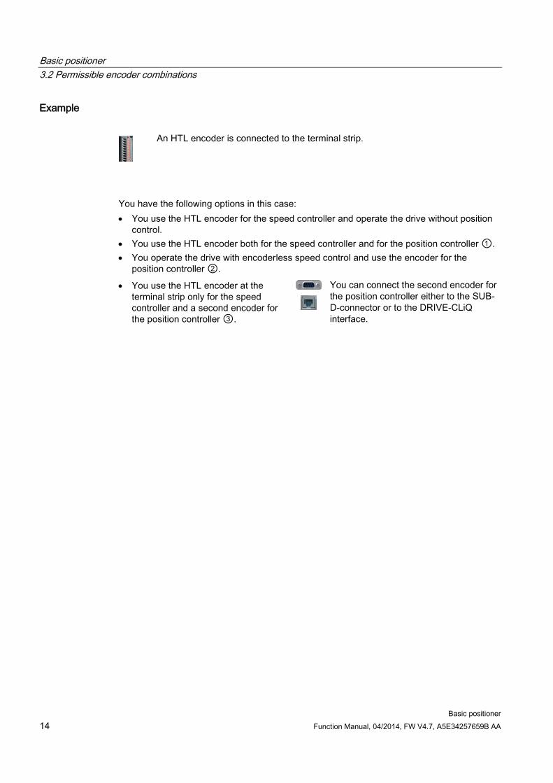
Example
An HTL encoder is connected to the terminal strip.
You have the following options in this case: • You use the HTL encoder for the speed controller and operate the drive without position
control. • You use the HTL encoder both for the speed controller and for the position controller ①. • You operate the drive with encoderless speed control and use the encoder for the
position controller ②.
• You use the HTL encoder at the terminal strip only for the speed controller and a second encoder for the position controller ③.
You can connect the second encoder for the position controller either to the SUB-D-connector or to the DRIVE-CLiQ interface.

Basic positioner 3.3 PROFIdrive interfaces
Basic positioner Function Manual, 04/2014, FW V4.7, A5E34257659B AA 15
3.3 PROFIdrive interfaces The send and receive telegrams of the inverter for cyclic communication are structured as follows:
Figure 3-2 Telegrams for cyclic communication - Position control

Basic positioner 3.3 PROFIdrive interfaces
Basic positioner 16 Function Manual, 04/2014, FW V4.7, A5E34257659B AA
Table 3- 3 Explanation of the abbreviations
Abbreviation Significance STW1 ZSW1 STW2 ZSW2 SATZANW AKTSATZ MDI_TARPOS XIST_A OVERRIDE MELDW NIST_B frei MDI_VELOCITY MDI_ACC MDI_DEC MDI_MOD POS_STW POS_ZSW POS_STW1 POS_ZSW1 POS_STW2 POS_ZSW2 WARN_CODE FAULT_CODE
Control word 1 Status word 1 see Control and status word 1 (Page 17) Control word 2 Status word 2 see Control and status word 2 (Page 19) Selection of traversing block see Control word block selection (Page 26) Currently selected traversing block Position setpoint for direct setpoint input (MDI) Actual position value (32 bits) Speed setpoint Status word for messages see Status word messages (Page 28) Actual speed value (32 bits) Freely interconnectable MDI velocity MDI acceleration MDI deceleration Selection of positioning mode with direct setpoint input (MDI) see Control word MDI mode (Page 27) Control word for basic positioner Status word for basic positioner see Control and status word for the positioner (Page 20) Control word 1 for basic positioner Status word 1 for basic positioner see Control and status word 1 for the positioner (Page 22) Control word 2 for basic positioner Status word 2 for basic positioner see Control and status word 2 for the positioner (Page 24) Number of the actual alarm Number of the actual fault

Basic positioner 3.3 PROFIdrive interfaces
Basic positioner Function Manual, 04/2014, FW V4.7, A5E34257659B AA 17
3.3.1 Control and status word 1
Control word 1 (STW1)
Table 3- 4 Control word 1 for active basic positioner
Bit Meaning Comments P No. 0 0 = OFF1 The motor brakes with the ramp-down time p1121 of the
ramp-function generator. The converter switches off the motor at standstill.
p0840[0] = r2090.0
0 → 1 = ON The converter goes into the "ready" state. If, in addition, bit 3 = 1, the converter switches on the motor.
1 0 = OFF2 Switch off motor immediately, then the motor coasts to a standstill.
p0844[0] = r2090.1
1 = No OFF2 It is possible to switch on the motor (ON command). 2 0 = Quick stop (OFF3) Quick stop: the motor brakes with the OFF3 ramp-down time
p1135 down to standstill. p0848[0] = r2090.2
1 = No quick stop (OFF3) It is possible to switch on the motor (ON command). 3 0 = Inhibit operation Immediately switch-off motor (cancel pulses). p0852[0] =
r2090.3 1 = Enable operation Switch-on motor (pulses can be enabled). 4 0 = Reject traversing job Axis brakes down to standstill with the maximum
deceleration. Converter rejects the actual traversing block. p2641 = r2090.4
1 = Do not reject traversing task Axis can be started or travel to position setpoint. 5 0 = Intermediate stop Axis brakes down to standstill with the specified deceleration
override. Converter remains in the actual traversing block. p2640 = r2090.5
1 = No intermediate stop Axis can be started or continue to travel to position setpoint. 6 0 → 1: Activate traversing job The converter starts axis travel to the setpoint position. p2631 =
r2090.6 0 → 1: Setpoint transfer MDI p2650 =
r2090.6 7 0 → 1: = Acknowledge faults Acknowledge fault in the converter. If the ON command is
still active, the converter switches to "closing lockout" state. p2103[0] = r2090.7
8 1 = jogging bit 0 Jogging 1 p2589 = r2090.7
9 1 = jogging bit 1 Jogging 2 p2590 = r2090.7
10 0 = No control via PLC Converter ignores the process data from the fieldbus. p0854[0] = r2090.10 1 = Control via PLC Control via fieldbus, converter accepts the process data from
the fieldbus. 11 0 = Stop referencing --- p2595 =
r2090.11 1 = Start referencing The converter does not start referencing. 12 Reserved 13 0 → 1: External block change The axis goes to the next traversing block. p2633 =
r2090.13 14, 15 Reserved

Basic positioner 3.3 PROFIdrive interfaces
Basic positioner 18 Function Manual, 04/2014, FW V4.7, A5E34257659B AA
Status word 1 (ZSW1)
Table 3- 5 Status word 1 when the basic positioner is active
Bit Meaning Comments P No.
Telegram 110 Telegram 111 0 1 = Ready to start Power supply is switched on; electronics initialized; pulses are
inhibited. p2080[0] = r0899.0
1 1 = Ready Motor is switched on (ON command = 1); no fault is active. With the command "Enable operation" (STW1.3) the converter switches on the motor.
p2080[1] = r0899.1
2 1 = Operation enabled Motor follows setpoint. See control word 1, bit 3. p2080[2] = r0899.2
3 1 = Fault present The converter has a fault. Acknowledge fault using STW1.7. p2080[3] = r2139.3
4 1 = OFF2 inactive Coast down to standstill is not active. p2080[4] = r0899.4
5 1 = OFF3 inactive Quick stop is not active. p2080[5] = r0899.5
6 1 = Closing lockout active It is only possible to switch on the motor after an OFF1 command and an additional ON command.
p2080[6] = r0899.6
7 1 = Alarm present Motor remains switched on; no acknowledgment necessary. p2080[7] = r2139.7
8 1 = Following error in tolerance The actual difference between the actual position and the position setpoint is within the permissible tolerance p2546.
p2080[8] = r2684.8
9 1 = Control requested The automation system is requested to accept the control from the converter.
p2080[9] = r0899.9
10 1 = Position setpoint reached The axis has reached the position setpoint. p2080[10] = r2684.10
11 1 = Reference point set The axis is referenced. p2080[11] = r2684.11
12 0 → 1 = Acknowledgement, traversing block active
--- p2080[12] = r2684.12
13 1 = Axis is at a standstill The absolute speed is less than p2161. p2080[13] = r2199.0
14 Reserved 1 = Axis accelerates
--- p2080[14] = r2684.4
15 Reserved 1 = Axis brakes --- p2080[15] = r2684.5

Basic positioner 3.3 PROFIdrive interfaces
Basic positioner Function Manual, 04/2014, FW V4.7, A5E34257659B AA 19
3.3.2 Control and status word 2
Control word 2 (STW2)
Table 3- 6 Control word 2 and interconnection in the converter
Bit Meaning Comments Interconnection
Telegram 9 Telegrams 110, 111
0 Drive data set selection DDS, bit 0 p0820[0] = r2092.0
p0820[0] = r2093.0
1 Drive data set selection DDS, bit 1 p0821[0] = r2092.1
p0821[0] = r2093.1
1 to 6 Reserved 7 1 = Parking axis selection p0897 =
r2092.7 p0897 = r2093.7
8 1 = Travel to fixed stop p1545[0] = r2092.8
p1545[0] = r2093.8
9 to 15 Reserved
Status word 2 (ZSW2)
Table 3- 7 Control word 2 and interconnection in the converter
Bit Meaning Description Interconnection 0 1 = Drive data set DDS effective, bit 0 p2081[0] =
r0051.0 1 1 = Drive data set DDS effective, bit 1 p2081[1] =
r0051.1 2 to 4 Reserved --- 5 1 = Alarm class bit 0 Only for internal diagnostics when using a
SIMOTION control. p2081[5] = r2139.11
6 1 = Alarm class bit 1 p2081[6] = r2139.12
7 1 = Parking axis active --- p2081[7] = r0896.0
8 1 = Travel to fixed stop --- p2081[8] = r1406.8
9 Reserved --- 10 1 = Pulses enabled Motor switched on p2081[10] =
r0899.11 11 to 15 Reserved --- p2081[11] =
r0835.0

Basic positioner 3.3 PROFIdrive interfaces
Basic positioner 20 Function Manual, 04/2014, FW V4.7, A5E34257659B AA
3.3.3 Control and status word for the positioner
Positioning control word (POS_STW)
Table 3- 8 POS_STW and interconnection with parameters in the inverter
Bit Meaning Comments P No. 0 1 = Follow-up mode The inverter continuously corrects the position setpoint to
follow the position actual value. p2655[0] = r2092.0
1 1 = Set reference point The inverter accepts the reference point coordinate in its position actual value and setpoint.
p2596 = r2092.1
2 1 = Reference cam active The load is currently on the reference cam. p2612 = r2092.2
3 Reserved --- --- 4 5 1 = Incremental jogging active If the jogging command is active, the inverter positions the
load by the specified traversing path in a positive or negative direction.
p2591 = r2092.5
0 = Jogging velocity active If the jogging command is active, the inverter positions the load with the jog velocity in the direction of the beginning or end of the traversing range.
6…15 Reserved --- ---

Basic positioner 3.3 PROFIdrive interfaces
Basic positioner Function Manual, 04/2014, FW V4.7, A5E34257659B AA 21
Positioning status word (POS_ZSW)
Table 3- 9 POS_ZSW and interconnection with parameters in the inverter
Bit Meaning Comments P No. 0 1 = Follow-up mode active The inverter is in the follow-up mode. p2084[0] =
r2683.0 1 1 = Velocity limiting is active The inverter limits the velocity of the axis. p2084[1] =
r2683.1 2 1 = Setpoint is stationary During a positioning operation, the setpoint no longer
changes. p2084[2] = r2683.2
3 1 = Position setpoint reached The axis has reached the specified target position. p2084[3] = r2684.3
4 1 = Axis traverses forwards The axis traverses in the positive direction. p2084[4] = r2683.4 0 = Axis is stationary or traverses
backwards ---
5 1 = Axis traverses backwards The axis traverses in the negative direction. p2084[5] = r2683.5 0 = Axis is stationary or traverses forwards ---
6 1 = Software limit switch, minus actuated The load is outside the permitted traversing range. p2084[6] = r2683.6
7 1 = Software limit switch, plus actuated p2084[7] = r2683.7
8 1 = Position actual value ≤ cam switching position 1
Feedback of the software cams in the inverter. p2084[8] = r2683.8
0 = Cam switching position 1 passed 9 1 = Position actual value ≤ cam switching
position 2 p2084[9] = r2683.9
0 = Cam switching position 2 passed 10 1 = Direct output 1 active The inverter sets these signals in the actual traversing
block. See also Section: Traversing blocks (Page 65)
p2084[10] = r2683.10
11 1 = Direct output 2 active p2084[11] = r2683.11
12 1 = Fixed stop reached The axis is at the fixed stop p2084[12] = r2683.12
13 1 = Fixed stop clamping torque reached The axis is at the fixed stop and has reached the clamping torque.
p2084[13] = r2683.13
14 1 = Travel to fixed stop active The inverter moves the axis to a fixed stop. p2084[14] = r2683.14
15 Reserved --- ---
Basic positioner 3.3 PROFIdrive interfaces
Basic positioner 22 Function Manual, 04/2014, FW V4.7, A5E34257659B AA
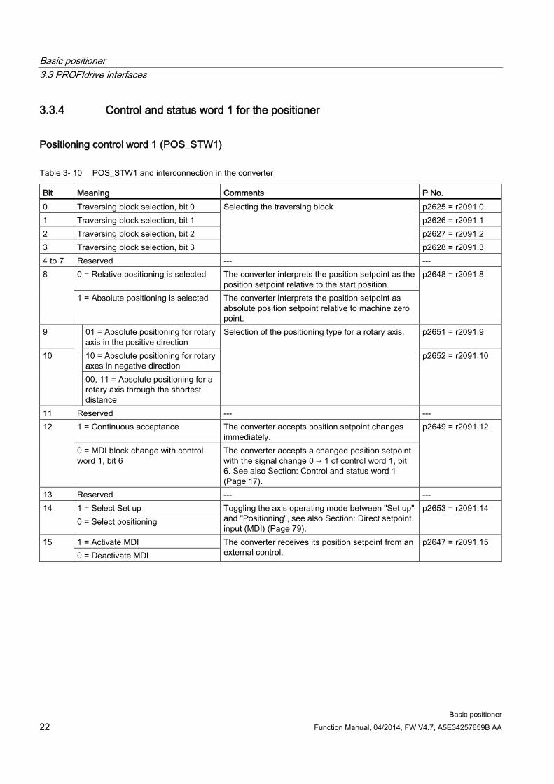
3.3.4 Control and status word 1 for the positioner
Positioning control word 1 (POS_STW1)
Table 3- 10 POS_STW1 and interconnection in the converter
Bit Meaning Comments P No. 0 Traversing block selection, bit 0 Selecting the traversing block p2625 = r2091.0 1 Traversing block selection, bit 1 p2626 = r2091.1 2 Traversing block selection, bit 2 p2627 = r2091.2 3 Traversing block selection, bit 3 p2628 = r2091.3 4 to 7 Reserved --- --- 8 0 = Relative positioning is selected The converter interprets the position setpoint as the
position setpoint relative to the start position. p2648 = r2091.8
1 = Absolute positioning is selected The converter interprets the position setpoint as absolute position setpoint relative to machine zero point.
9 01 = Absolute positioning for rotary axis in the positive direction
Selection of the positioning type for a rotary axis. p2651 = r2091.9
10 10 = Absolute positioning for rotary axes in negative direction
p2652 = r2091.10
00, 11 = Absolute positioning for a rotary axis through the shortest distance
11 Reserved --- --- 12 1 = Continuous acceptance The converter accepts position setpoint changes
immediately. p2649 = r2091.12
0 = MDI block change with control word 1, bit 6
The converter accepts a changed position setpoint with the signal change 0 → 1 of control word 1, bit 6. See also Section: Control and status word 1 (Page 17).
13 Reserved --- --- 14 1 = Select Set up Toggling the axis operating mode between "Set up"
and "Positioning", see also Section: Direct setpoint input (MDI) (Page 79).
p2653 = r2091.14 0 = Select positioning
15 1 = Activate MDI The converter receives its position setpoint from an external control.
p2647 = r2091.15 0 = Deactivate MDI

Basic positioner 3.3 PROFIdrive interfaces
Basic positioner Function Manual, 04/2014, FW V4.7, A5E34257659B AA 23
Positioning status word 1 (POS_ZSW1)
Table 3- 11 POS_ZSW1 and interconnection in the converter
Bit Meaning Comments P No. 0 Active traversing block bit 0 (20) Number of the currently selected traversing block. p2083[0] =
r2670[0] 1 Active traversing block bit 1 (21) p2083[1] =
r2670[1] 2 Active traversing block bit 2 (22) p2083[2] =
r2670[2] 3 Active traversing block bit 3 (23) p2083[3] =
r2670[3] 4 Active traversing block bit 4 (24) p2083[4] =
r2670[4] 5 Active traversing block bit 5 (25) p2083[5] =
r2670[5] 6 Reserved --- --- 7 8 1 = STOP cam minus active The axis is currently located at a STOP cam. p2083[08] =
r2684[13] 9 1 = STOP cam plus active p2083[09] =
r2684[14] 10 1 = Jogging active The converter is in the jogging mode. p2083[10] =
r2094[0] 11 1 = Reference point approach active The converter is presently executing a reference point
approach. p2083[11] = r2094[1]
12 1 = Flying referencing active The converter references when passing the reference cam.
p2083[12] = r2684[1]
13 1 = Traversing block active The converter receives its position setpoint from a traversing block.
p2083[13] = r2094[2]
14 1 = Set up active The axis is in the "Set up" operating mode. p2083[14] = r2094[4]
15 1 = MDI active The converter receives its position setpoint from an external control.
p2083[15] = r2670[15] 0 = MDI inactive

Basic positioner 3.3 PROFIdrive interfaces
Basic positioner 24 Function Manual, 04/2014, FW V4.7, A5E34257659B AA
3.3.5 Control and status word 2 for the positioner
Positioning control word 2 (POS_STW2)
Table 3- 12 POS_STW2 and interconnection with parameters in the converter
Bit Meaning Comments P No. 0 1 = Activate follow-up mode The converter continuously corrects the position setpoint to
follow the position actual value. p2655[0] = r2092.0
1 1 = Set reference point The converter accepts the reference point coordinate in its position actual value and setpoint.
p2596 = r2092.1
2 1 = Reference cam active The axes is currently located at the reference cam. p2612 = r2092.2
3 Reserved --- --- 4 5 1 = Incremental jogging active If the jogging command is active, the converter positions the
axis by the specified traversing path in a positive or negative direction.
p2591 = r2092.5
0 = Jogging velocity active If the jogging command is active, the converter positions the axis with the jog velocity in the direction of the beginning or end of the traversing range.
6 Reserved --- --- 7 8 1 = Selects referencing using flying
referencing Select the referencing type. p2597 =
r2092.8 0 = Selects referencing via the reference point approach
9 1 = Starts reference point approach in negative direction
Select the start direction for automatic referencing. p2604 = r2092.9
0 = Starts reference point approach in positive direction
10 1 = Selects probe 2 Edge of the probe input, with which the converter references its actual position value.
p2510[0] = r2092.10 0 = Selects probe 1
11 1 = Probe falling edge Select the edge of the probe input, with which the converter references its actual position value.
p2511[0] = r2092.11 0 = Probe, rising edge
12 Reserved --- --- 13 14 1 = Software limit switch active The converter evaluates its software limit switch. p2582 =
r2092.14 15 1 = STOP cams active Converter evaluates the stop cams. p2568 =
r2092.15

Basic positioner 3.3 PROFIdrive interfaces
Basic positioner Function Manual, 04/2014, FW V4.7, A5E34257659B AA 25
Positioning status word 2 (POS_ZSW2)
Table 3- 13 POS_ZSW2 and interconnection with parameters in the converter
Bit Meaning Comments P No. 0 1 = Follow-up mode active The converter is in the follow-up mode. p2084[0] =
r2683.0 1 1 = Velocity limiting is active The converter limits the velocity of the axis. p2084[1] =
r2683.1 2 1 = Setpoint is stationary During a positioning operation, the setpoint no longer
changes. p2084[2] = r2683.2
3 1 = Print index outside outer window The discrepancy between the actual position and the reference point was greater than permitted during flying referencing.
p2084[3] = r2684.3
4 1 = Axis traverses forwards The axis traverses in the positive direction. p2084[4] = r2683.4 0 = Axis is stationary or traverses
backwards ---
5 1 = Axis traverses backwards The axis traverses in the negative direction. p2084[5] = r2683.5 0 = Axis is stationary or traverses forwards ---
6 1 = Software limit switch, minus actuated The axis is outside the permitted traversing range. p2084[6] = r2683.6
7 1 = Software limit switch, plus actuated p2084[7] = r2683.7
8 1 = Position actual value ≤ cam switching position 1
Feedback of the cam sequencer in the converter. p2084[8] = r2683.8
0 = Cam switching position 1 passed 9 1 = Position actual value ≤ cam switching
position 2 p2084[9] = r2683.9
0 = Cam switching position 2 passed 10 1 = Direct output 1 active The converter sets these signals in the actual traversing
block. See also paragraph: Traversing blocks (Page 65)
p2084[10] = r2683.10
11 1 = Direct output 2 active p2084[11] = r2683.11
12 1 = Fixed stop reached The axis is at the fixed stop p2084[12] = r2683.12
13 1 = Fixed stop clamping torque reached The axis is at the fixed stop and has reached the clamping torque.
p2084[13] = r2683.13
14 1 = Travel to fixed stop active The converter moves the axis to a fixed stop. p2084[14] = r2683.14
15 1 = Traversing command active Feedback signal indicating as to whether the converter is currently moving the axis.
p2084[15] = r2684.15 0 = Axis stationary

Basic positioner 3.3 PROFIdrive interfaces
Basic positioner 26 Function Manual, 04/2014, FW V4.7, A5E34257659B AA
3.3.6 Control word block selection
Block selection
Table 3- 14 Block selection and interconnection in the converter
Bit Meaning Comments P No. 0 Block selection, bit 0 Example for selecting
traversing block number 5:
p2625 = r2091.0 1 Block selection, bit 1 p2626 = r2091.1 2 Block selection, bit 2 p2627 = r2091.2 3 Block selection, bit 3 p2628 = r2091.3
4…14 Reserved 15 0 = Deactivate MDI Switching from traversing blocks to direct setpoint
input. p2647 = r2091.15
1 = Activate MDI
Actual traversing block
Table 3- 15 Feedback signal of the actual traversing block
Bit Meaning Comments P No. 0 Actual traversing block, bit 0 --- p2081[0] = r2670.0 1 Actual traversing block, bit 1 p2081[1] = r2670.1 2 Actual traversing block, bit 2 p2081[2] = r2670.2 3 Actual traversing block, bit 3 p2081[3] = r2670.3 4…14 Reserved 15 0 = MDI active --- p2081[15] = r2670.15
1 = MDI not active

Basic positioner 3.3 PROFIdrive interfaces
Basic positioner Function Manual, 04/2014, FW V4.7, A5E34257659B AA 27
3.3.7 Control word MDI mode
MDI mode
Table 3- 16 Selection of the MDI mode and interconnection with parameters in the converter
Bit Meaning Comments P No. 0 0 = Relative positioning is selected The converter interprets the position setpoint as
the position setpoint relative to the start position. p2648 = r2094.0
1 = Absolute positioning is selected The converter interprets the position setpoint as absolute position setpoint relative to machine zero point.
1 01 = Absolute positioning for rotary axis in the positive direction
Selection of the positioning type for a rotary axis.
p2651 = r2094.1
2 10 = Absolute positioning for rotary axes in negative direction
p2652 = r2094.2
00, 11 = Absolute positioning for a rotary axis through the shortest distance
3…15 Reserved

Basic positioner 3.3 PROFIdrive interfaces
Basic positioner 28 Function Manual, 04/2014, FW V4.7, A5E34257659B AA
3.3.8 Status word messages
Status word messages (MELDW)
Table 3- 17 Status word for messages and interconnection with parameters in the converter
Bit Meaning Description P No. 0 0 = Ramp-function generator active The motor is presently accelerating or
braking p2082[0] = r2199.5
1 = Ramp-up/ramp-down completed Speed setpoint and actual speed are the same.
1 1 = Torque utilization [%] < torque threshold value 2 (p2194)
--- p2082[1] = r2199.11
2 1 = |n_act| < speed threshold value 3 (p2161) --- p2082[2] = r2199.0 3 1 = |n_act| speed threshold value 2 (p2155) --- p2082[3] = r2197.1 4, 5 Reserved 6 1 = No motor overtemperature alarm The motor temperature is within the
permissible range. p2082[6] = r2135.14
7 1 = No alarm, thermal power unit overload The converter temperature is within the permissible range.
p2082[7] = r2135.15
8 1 = Speed setpoint - actual value deviation within tolerance t_on
Speed setpoint and actual speed are within the permissible tolerance range p2163.
p2082[8] = r2199.4
9, 10 Reserved 11 1 = Controller enable The speed controller is enabled. p2082[11] = r0899.8 12 1 = Drive ready The converter is ready to be switched on. p2082[12] = r0899.7 13 1 = Pulses enabled The motor is switched on. p2082[13] = r0899.11 14, 15 Reserved
3.3.9 Function block FB283
Overview The function block FB283 is an interface block that connects an inverter with basic positioner to a SIMATIC S7 controller via PROFIBUS/PROFINET.
The block FB283 transfers all of the required process data to and from the drive. It is suitable for both controlling the basic positioner and for a pure speed-controlled drive.
The FB283 additionally provides the following functions: ● Reading and writing parameters in the inverter. ● Reading out the fault buffer of the inverter. ● Transferring up to 16 traversing blocks when a function is initiated. ● Reading or writing a maximum of any 10 parameters with one job, e.g. for product
adaptation.
A configuration example and a description of the FB283 can be found on the Internet: FB283 (http://support.automation.siemens.com/WW/view/en/25166781).
Basic positioner 3.4 Commissioning
Basic positioner Function Manual, 04/2014, FW V4.7, A5E34257659B AA 29
3.4 Commissioning
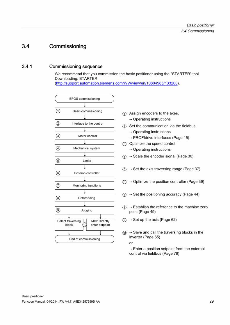
3.4.1 Commissioning sequence We recommend that you commission the basic positioner using the "STARTER" tool. Downloading: STARTER (http://support.automation.siemens.com/WW/view/en/10804985/133200).
① Assign encoders to the axes.
→ Operating instructions ② Set the communication via the fieldbus.
→ Operating instructions → PROFIdrive interfaces (Page 15)
③ Optimize the speed control → Operating instructions
④ → Scale the encoder signal (Page 30)
⑤ → Set the axis traversing range (Page 37)
⑥ → Optimize the position controller (Page 39)
⑦ → Set the positioning accuracy (Page 44)
⑧ → Establish the reference to the machine zero
point (Page 49) ⑨ → Set up the axis (Page 62)
⑩ → Save and call the traversing blocks in the
inverter (Page 65) or → Enter a position setpoint from the external
control via fieldbus (Page 79)

Basic positioner 3.4 Commissioning
Basic positioner 30 Function Manual, 04/2014, FW V4.7, A5E34257659B AA
3.4.2 Normalizing the encoder signal
3.4.2.1 Define the resolution
Distance unit (LU): the resolution of the position actual value in the inverter The inverter calculates the position actual value of the axis using the neutral position unit LU (Length Unit). The distance unit LU is independent of whether the inverter controls e.g. the position of an elevating platform or the angle of rotary table.
Firstly, for your application define the required resolution. In other words: Which distance or angle corresponds to the length unit (LU)?
The following rules apply when selecting the distance unit LU:
1. The higher the resolution of the distance unit LU, the higher the accuracy of the position control.
2. If you select a resolution that is too high, then the inverter cannot represent the position actual value over the complete axis traversing range. The inverter responds with a fault in the case of an overflow when representing the number.
3. The resolution of the distance unit LU should be less than the maximum resolution that is obtained from the resolution of the distance-encoder.
Normalize the encoder signal
Preconditions
● You are online with the STARTER .
● You have selected the "Mechanical system" screen.
● You have defined the required resolution for your particular application (e.g. 1 LU ≙ 1 µm or 1 LU ≙ 1/1,000° (1 millidegree).
Procedure
To normalize the encoder signal, proceed as follows:
1. Enable the settings so they can be edited.
2. Enter the gear ratio of the axis. Load revolutions.
3. Motor revolutions
Unknown gear ratio If you do not know the gear ratio, then you must measure the ratio, for example by manually rotating the motor and counting the load revolutions. Example: After 5 motor revolutions, the load has turned through 37 °. The ratio is therefore 37 ° / (5 × 360 °). You must then enter the following values into STARTER:
– ② 37 [load revolution]
– ③ 1800 [motor revolution]
Basic positioner 3.4 Commissioning
Basic positioner Function Manual, 04/2014, FW V4.7, A5E34257659B AA 31
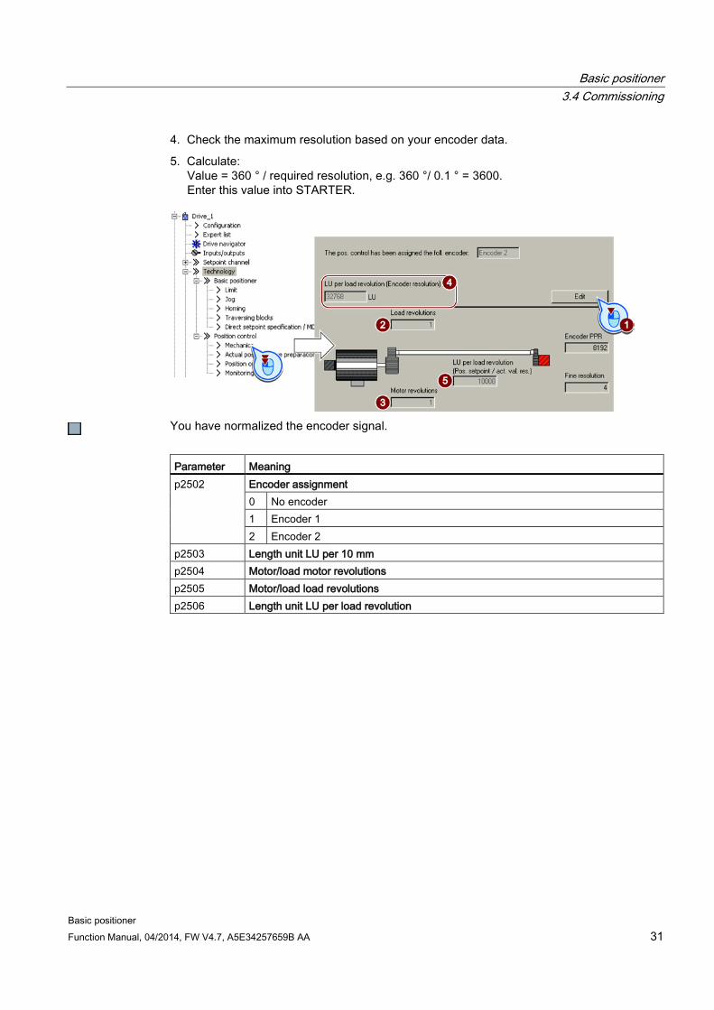
4. Check the maximum resolution based on your encoder data.
5. Calculate: Value = 360 ° / required resolution, e.g. 360 °/ 0.1 ° = 3600. Enter this value into STARTER.
You have normalized the encoder signal.
Parameter Meaning p2502 Encoder assignment
0 No encoder 1 Encoder 1 2 Encoder 2
p2503 Length unit LU per 10 mm p2504 Motor/load motor revolutions p2505 Motor/load load revolutions p2506 Length unit LU per load revolution

Basic positioner 3.4 Commissioning
Basic positioner 32 Function Manual, 04/2014, FW V4.7, A5E34257659B AA
3.4.2.2 Modulo range setting
Description
Linear axis
A linear axis is an axis whose traversing range is limited in both motor directions of rotation by the mechanical system of the machine, e.g.:
• Stacker crane • Elevating platform • Tilting station • Gate/door drive
The converter maps the complete traversing range to the
position actual value.
Modulo axis
A modulo axis is an axis with an infinite traversing range, e.g.:
• Rotary table • Conveyor belt • Roller conveyor
The converter maps the modulo range on the position
actual value. If the load position leaves the modulo range, then the value range of the position actual value repeats in the converter.

Basic positioner 3.4 Commissioning
Basic positioner Function Manual, 04/2014, FW V4.7, A5E34257659B AA 33
Setting the modulo range
Preconditions
● You are online with the STARTER .
● You have selected the "Mechanical system" screen.
Procedure
To set the modulo range, proceed as follows:
1. Enable the modulo correction.
2. Define the modulo range.
Example 1: In the case of a rotary table, one load revolution corresponds to 3600 LU. In this case, the modulo correction is also 3600.
Example 2: For a roller conveyor, 100 motor revolutions corresponds to one production cycle. For a resolution of 3600 LU per motor revolution, the modulo range is 360000 LU.
You have now set the modulo range.
Parameter Meaning p2576 Modulo offset, modulo range p2577 Modulo correction activation (signal = 1) r2685 Offset value

Basic positioner 3.4 Commissioning
Basic positioner 34 Function Manual, 04/2014, FW V4.7, A5E34257659B AA
3.4.2.3 Checking the actual position value After normalization of the encoder signal you should check the actual position value.
Preconditions
● You are online with the STARTER .
● You have selected the screen for "Actual value processing".
Procedure
To ensure that the converter calculates the actual position value correctly, you must check the following:
● There must be no overflow of the actual position value in the entire traverse range. The converter can show as a maximum the value range of -2147483648 … 2147483647. If this maximum value is exceeded, the converter reports fault F07493.
● If you have defined a modulo range, the converter resets the actual position value after passing through the range.
You have now checked the calculation for the actual position value.
Parameter Meaning r2521[0] Position actual value for position control
Basic positioner 3.4 Commissioning
Basic positioner Function Manual, 04/2014, FW V4.7, A5E34257659B AA 35
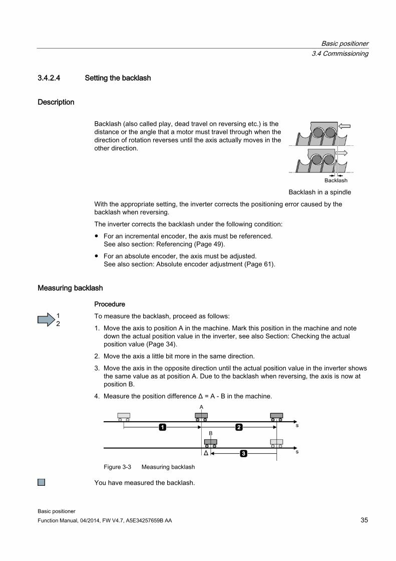
3.4.2.4 Setting the backlash
Description Backlash (also called play, dead travel on reversing etc.) is the distance or the angle that a motor must travel through when the direction of rotation reverses until the axis actually moves in the other direction.
Backlash in a spindle
With the appropriate setting, the inverter corrects the positioning error caused by the backlash when reversing.
The inverter corrects the backlash under the following condition:
● For an incremental encoder, the axis must be referenced. See also section: Referencing (Page 49).
● For an absolute encoder, the axis must be adjusted. See also section: Absolute encoder adjustment (Page 61).
Measuring backlash
Procedure
To measure the backlash, proceed as follows:
1. Move the axis to position A in the machine. Mark this position in the machine and note down the actual position value in the inverter, see also Section: Checking the actual position value (Page 34).
2. Move the axis a little bit more in the same direction.
3. Move the axis in the opposite direction until the actual position value in the inverter shows the same value as at position A. Due to the backlash when reversing, the axis is now at position B.
4. Measure the position difference Δ = A - B in the machine.
Figure 3-3 Measuring backlash
You have measured the backlash.

Basic positioner 3.4 Commissioning
Basic positioner 36 Function Manual, 04/2014, FW V4.7, A5E34257659B AA
Correcting backlash
Precondition
You have selected the "Mechanical system" screen.
Procedure
To correct the measured backlash, set the following:
● If the axis has not traveled far enough, then set a positive backlash.
● If the axis has traveled too far, then set a negative backlash.
You have corrected the backlash.
Parameter Meaning p2583 Backlash compensation r2685 Offset value

Basic positioner 3.4 Commissioning
Basic positioner Function Manual, 04/2014, FW V4.7, A5E34257659B AA 37
3.4.3 Limiting the positioning range
Description
Positioning range for linear axes
The converter limits the positioning range of a linear axis using a software limit switch. The converter only accepts position setpoints that lie within the software limit switches.
Figure 3-4 Limiting the positioning range of a linear axis
In addition, using its digital inputs, the converter evaluates signals from stop cams. When passing a STOP cam, the converter responds – depending on the setting – either with a fault or an alarm.
Fault as response
When passing the STOP cam, the inverter brakes the axis with the OFF3 ramp-down time, switches the motor off, and reports the fault F07491 or. F07492. To switch the motor on again, you must do the following:
● Switch the motor off (OFF1).
● Acknowledge the fault.
● Move the axis away from the STOP cam, e.g. using the jogging function.
Alarm as response
When passing the STOP cam, the converter brakes the axis with the maximum deceleration (see Section: Limiting the traversing profile (Page 42)), maintains the axis in closed-loop control and outputs alarm A07491 or A07492. In order to bring the axis back into the valid traversing range, you must move the axis from the STOP cam, e.g. using the jogging function.
Setting the limits of the positioning range
Precondition
You have selected the "Limit" screen.
Procedure
To set the limits of the positioning range, proceed as follows:
1. Enable the software limit switch.
2. Move the axis to the positive limit position in your machine. Set the position of the software limit switches to the actual position value.

Basic positioner 3.4 Commissioning
Basic positioner 38 Function Manual, 04/2014, FW V4.7, A5E34257659B AA
3. Move the axis to the negative limit position in your machine. Set the position of the software limit switches to the actual position value.
4. Enable the STOP cams.
5. Interconnect the signal of the STOP cam minus with the corresponding signal of your machine. Signal = 0 means an active STOP cam.
6. Interconnect the signal of the STOP cam plus with the corresponding signal of your machine.
You have now set the limits of the positioning range.
Parameter Meaning p2568 STOP cam activation p2569 STOP cam, minus p2570 STOP cam, plus p2578 Software limit switch, minus signal source p2579 Software limit switch, plus signal source p2580 Software limit switch, minus p2581 Software limit switch, plus p2582 Software limit switch activation r2683.6 Software limit switch, minus actuated r2683.7 Software limit switch, plus actuated r2684.13 STOP cam minus active r2684.14 STOP cam plus active

Basic positioner 3.4 Commissioning
Basic positioner Function Manual, 04/2014, FW V4.7, A5E34257659B AA 39
3.4.4 Setting the position controller
3.4.4.1 Precontrol and gain
Preconditions and constraints Before you optimize the position controller, the closed-loop drive speed control must be optimally set.
Dynamic response and accuracy of the closed-loop position control depend heavily on the lower-level closed-loop or open-loop control or the motor speed:
● Position control in connection with an optimally set vector control with speed encoder provides the best results.
● Position control with encoderless vector control (sensorless vector control, SLVC) provides satisfactory results for most applications. Hoisting/lifting applications require a speed controller.
● If you operate the position control with the U/f control of drive, then you must take into account some significant reduction in closed-loop control performance and precision.
Position controllers in hoisting gear
U/f control is not suitable for vertical axes, such as elevating platforms or hoisting gear used in high-bay racking units, as the axis generally cannot reach the target position as a result of the limited precision of the U/f control.
Description
Figure 3-5 Position controller with precontrol
If the speed control of the converter has an encoder to feedback the actual speed, then deactivate the integral component TN of the position controller.
If you use the position control together with the encoderless vector control (SLVC, SensorLess Vector Control), the positioning accuracy may be inadequate. With active integral time, positioning accuracy improves.

Basic positioner 3.4 Commissioning
Basic positioner 40 Function Manual, 04/2014, FW V4.7, A5E34257659B AA
3.4.4.2 Optimizing the position controller To optimize the position controller, you must move the axis with the position control and assess the control performance. How you move an axis using the STARTER is described below.
Optimizing the position controller
Procedure
To optimize the position controller, proceed as follows:
1. In the control panel, select the operating mode "Basic positioner".
2. Click the "Jog" button.
3. Enter a speed setpoint.
4. Adjust the proportional gain.
Assess the controller characteristics:
– If the motor is running unevenly, the controller is unstable. In this case, reduce the proportional gain ④ of the position controller.
If the closed-loop control is stable, but you are still dissatisfied with the control dynamics, then increase the position controller proportional gain. Then check the stability of the controller.
5. Adjust the integral time.
Start with an integral time of 100 ms, and test your setting by traversing the axis with the active position controller using the "jog" function. Lower integral times increase the control dynamics but can, however, result in unstable controller characteristics.

Basic positioner 3.4 Commissioning
Basic positioner Function Manual, 04/2014, FW V4.7, A5E34257659B AA 41
6. Following controller optimization, set the precontrol of the position controller to 100%.
7. Check the controller characteristics again.
You have optimized the position controller.

Basic positioner 3.4 Commissioning
Basic positioner 42 Function Manual, 04/2014, FW V4.7, A5E34257659B AA
Parameter Meaning p2534 Speed precontrol factor p2538 Proportional gain / Kp p2539 Integral time / Tn p2731 Signal = 0: activate position controller
Advanced settings If you permanently activate the integral time of the position controller, the characteristics of the position control change as follows:
● The following error while positioning goes to zero.
● When positioning the axis, it tends to overshoot; this means that the axis briefly moves beyond the target position.
3.4.4.3 Limiting the traversing profile
Description The converter calculates the traversing profile when positioning from specified values for velocity, acceleration and jerk (= acceleration change with respect to time).
Figure 3-6 Example: Effect of jerk limiting
If the axis must traverse more slowly or must accelerate at a lower rate or "softly", then you must set the relevant limits to lower values. The lower that one of the limits is, the longer the converter needs to position the axis.

Basic positioner 3.4 Commissioning
Basic positioner Function Manual, 04/2014, FW V4.7, A5E34257659B AA 43
Setting the traversing profile limitation
Precondition
You have selected the "Limit" screen and the "Traversing profile limitation" tab.
Procedure
To set the limitation of the traversing profile, proceed as follows:
1. Set the maximum velocity with which the converter may position the axis.
2. Set the maximum acceleration.
3. Set the maximum delay.
The "override" in the traversing blocks or for the direct setpoint input refers to the values ② and ③.
4. Reduce the maximum jerk, if you require softer acceleration and braking.
5. For permanent jerk limiting, set this signal to 1.
You have now set the limitation of the traversing profile.
Parameter Meaning p2571 Maximum velocity p2572 Maximum acceleration p2573 Maximum deceleration p2574 Jerk limiting p2575 Activating jerk limiting
1 signal: Jerk limiting is active

Basic positioner 3.4 Commissioning
Basic positioner 44 Function Manual, 04/2014, FW V4.7, A5E34257659B AA
3.4.5 Setting the monitoring functions
3.4.5.1 Standstill and positioning monitoring
Description As soon as the setpoint for the position within a positioning operation no longer changes, then the converter sets the "Setpoint stationary" signal to 1. With this signal, the converter starts to monitor the position actual value:
● As soon as the axis has reached the positioning window, the converter signals that the target has been reached, and maintains the axis in closed-loop control.
● If the axis does not come to a standstill within the standstill monitoring time, the converter reports fault F07450.
● If the axis does not enter the positioning window within the positioning monitoring time, the converter reports fault F07451.
Figure 3-7 Standstill monitoring and positioning monitoring
Setting standstill monitoring and positioning monitoring
Precondition
You have selected the "Monitoring" screen and the "Position monitoring" tab.

Basic positioner 3.4 Commissioning
Basic positioner Function Manual, 04/2014, FW V4.7, A5E34257659B AA 45
Procedure
To set the standstill and positioning monitoring, proceed as follows:
1. Set the required positioning accuracy.
2. Set the time within which the axis must be positioned.
3. Set the required standstill window.
The standstill window must be larger than the positioning window.
4. Set the time within which the axis must be at standstill.
5. Define the signal "Target position reached" as a message to a higher-level control.
You have now set the standstill and position monitoring.
Parameter Meaning p2542 Standstill window (target position ±p2542) p2543 Standstill monitoring time p2544 Positioning window (target position ±p2544) p2545 Positioning monitoring time

Basic positioner 3.4 Commissioning
Basic positioner 46 Function Manual, 04/2014, FW V4.7, A5E34257659B AA
3.4.5.2 Following error monitoring
Description The following error is the deviation between the position setpoint and the position actual value while the converter is positioning the axis.
Figure 3-8 Monitoring the following error
The converter reports fault F07452 if the following error is too high. If you set the tolerance to 0, monitoring is deactivated.
Setting following error monitoring
Precondition
You have selected the "Monitoring" screen and the "Following error monitoring" tab.
Procedure
To set the monitoring of the following error, proceed as follows:
1. Set the monitoring window.
Start with the factory setting value.
Test your setting by positioning the axis at maximum velocity, e.g. from the control panel. If the converter stops the travel with fault F07452 , you will need to either increase the monitoring window or increase the dynamics of the position controller.
2. If you want to evaluate the message in your higher-level control, interconnect this signal with, for example, a status bit in the fieldbus telegram.

Basic positioner 3.4 Commissioning
Basic positioner Function Manual, 04/2014, FW V4.7, A5E34257659B AA 47
You have now set the monitoring of the following error.
Parameter Meaning p2546 Dynamic following error monitoring tolerance r2563 Following error, dynamic model

Basic positioner 3.4 Commissioning
Basic positioner 48 Function Manual, 04/2014, FW V4.7, A5E34257659B AA
3.4.5.3 Cam sequencer
Description The converter compares the position actual value with two different positions and therefore simulates two independent cam switching signals.
If you need this function, set the cam switching position to match your particular application and appropriately interconnect the cam switching signal.
Parameter Meaning p2547 Cam switching position 1 p2548 Cam switching position 2 r2683.8 Position actual value <= cam switching position 1 r2683.9 Position actual value <= cam switching position 2

Basic positioner 3.4 Commissioning
Basic positioner Function Manual, 04/2014, FW V4.7, A5E34257659B AA 49
3.4.6 Referencing
3.4.6.1 Referencing methods
Overview If you are using an incremental encoder for the position actual value, after the supply voltage is switched off, the converter loses its valid position actual value. After the supply voltage is switched on again, the converter no longer knows the reference of the axis position to the machine.
Referencing re-establishes the reference between the zero point of the position calculated in the converter and the machine zero point.
Absolute encoders retain their position information, even after the supply has been switched off.
The converter offers various ways of referencing the axis:
● Reference point approach - only with incremental encoders
● Flying referencing - with all encoder types
● Set reference point - with all encoder types
● Absolute encoder adjustment - with absolute encoders
Reference point approach The converter automatically traverses the axis to a defined reference point.
Example: A workpiece must be positioned at a starting point before machining starts.
Flying referencing
The converter corrects its position actual value while traversing and reduces errors, e.g. caused by wheel slip or a gear ratio that has not been precisely set.
Example: A pallet on a roller conveyor must be stopped at a specific position. However, the exact position of the pallet on the conveyor is only known when a sensor is passed.
Figure 3-9 Positioning an item to be transported on a roller conveyor
Set the reference point and adjust the absolute encoder
The converter takes the reference point coordinate as the new axis position.
Basic positioner 3.4 Commissioning
Basic positioner 50 Function Manual, 04/2014, FW V4.7, A5E34257659B AA
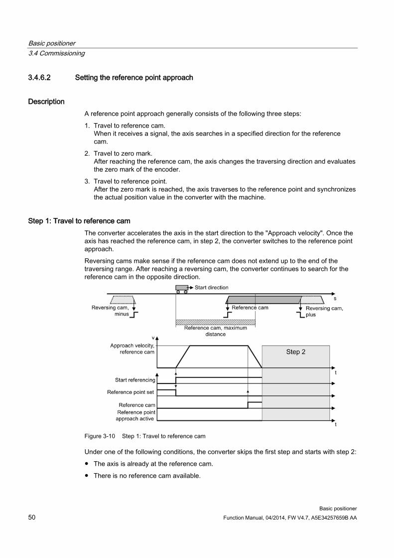
3.4.6.2 Setting the reference point approach
Description A reference point approach generally consists of the following three steps:
1. Travel to reference cam. When it receives a signal, the axis searches in a specified direction for the reference cam.
2. Travel to zero mark. After reaching the reference cam, the axis changes the traversing direction and evaluates the zero mark of the encoder.
3. Travel to reference point. After the zero mark is reached, the axis traverses to the reference point and synchronizes the actual position value in the converter with the machine.
Step 1: Travel to reference cam The converter accelerates the axis in the start direction to the "Approach velocity". Once the axis has reached the reference cam, in step 2, the converter switches to the reference point approach.
Reversing cams make sense if the reference cam does not extend up to the end of the traversing range. After reaching a reversing cam, the converter continues to search for the reference cam in the opposite direction.
Figure 3-10 Step 1: Travel to reference cam
Under one of the following conditions, the converter skips the first step and starts with step 2:
● The axis is already at the reference cam.
● There is no reference cam available.

Basic positioner 3.4 Commissioning
Basic positioner Function Manual, 04/2014, FW V4.7, A5E34257659B AA 51
Step 2: Travel to zero mark The behavior of the axis in step 2 depends on whether a reference cam is available:
• Reference cam available: When the converter reaches the reference cam, the axis accelerates in the opposite direction to the start direction , to the "approach velocity zero mark".
• No reference cam is available: The converter accelerates the axis in the start direction to the "approach velocity zero mark".
Figure 3-11 Step 2: Travel to zero mark if a reference cam is available
Figure 3-12 Travel to the zero mark if a reference cam is not available

Basic positioner 3.4 Commissioning
Basic positioner 52 Function Manual, 04/2014, FW V4.7, A5E34257659B AA
Step 3: Travel to reference point After the converter has detected a zero mark, the axis moves with the "approach velocity reference point" to the reference point coordinate.
Figure 3-13 Step 3: Travel to reference point
After the load has reached the reference point coordinate, the converter sets its position setpoint and actual value to this value.
Setting the reference point approach
Preconditions
1. You have selected the "Homing" screen.
2. You have come to the settings via the button on the screen.
3. You have selected "Active homing".
Procedure
To set the reference point approach, proceed as follows:
1. You specify the referencing mode:
– Only using the encoder zero mark
– With external zero mark
– With reference cam and encoder zero mark
2. Specify the start direction.
3. Set the approach velocity to the reference cam.
4. Set the approach velocity to the reference point.
5. Set the approach velocity to the zero mark.

Basic positioner 3.4 Commissioning
Basic positioner Function Manual, 04/2014, FW V4.7, A5E34257659B AA 53
6. Specify the reference point coordinate.
7. Specify the reference point offset.
8. Specify the max. permissible distance to the reference cam in step 1 of active referencing.
9. If a reference cam is available: Define the maximum permitted distance to the zero mark.
10.If no reference cam is available: Define the tolerance for travel to the zero mark.
11.Close the screen form.
You have set the USB reference point approach.

Basic positioner 3.4 Commissioning
Basic positioner 54 Function Manual, 04/2014, FW V4.7, A5E34257659B AA
Defining the digital signals for controlling referencing
Procedure
To define the digital signals for controlling, proceed as follows:
1. This signal starts the reference point approach.
2. This signal must be 0 for the reference point approach.
3. Interconnect the signal of the reference cam with the corresponding signal of your machine.
4. If you use the reversing cam minus, interconnect the reversing cam with the corresponding signal, e.g. with the fieldbus. 0 = Reversing cams active.
5. If you use the reversing cam plus, interconnect the reversing cam with the corresponding signal, e.g. with the fieldbus. 0 = Reversing cams active.
You have now defined the digital signals for controlling.
Defining the analog signals for controlling referencing
Procedure
To define the analog signals for controlling, proceed as follows:
1. Define the signal source for the velocity override.
See also section: Direct setpoint input (MDI) (Page 79).
2. Change the source for the reference point coordinate, if necessary.
You have now defined the analog signals for controlling.

Basic positioner 3.4 Commissioning
Basic positioner Function Manual, 04/2014, FW V4.7, A5E34257659B AA 55
Parameter Meaning p2595 Start referencing p2598 Reference point coordinate, signal source p2599 Reference point coordinate value p2600 Reference point approach, reference point offset p2604 Reference point approach, start direction p2605 Reference point approach, approach velocity, reference cam p2606 Reference point approach reference cam, maximum distance p2607 Reference point approach reference cam available p2608 Reference point approach, approach velocity, zero mark p2609 Reference point approach, max distance reference cam and zero mark p2610 Reference point approach, tolerance band for the distance to the zero mark p2611 Reference point approach, approach velocity, reference point p2612 Reference point approach, reference cam p2613 Reference point approach reversing cam, minus p2614 Reference point approach reversing cam, plus r2684.0 Reference point approach active r2684.11 Reference point set

Basic positioner 3.4 Commissioning
Basic positioner 56 Function Manual, 04/2014, FW V4.7, A5E34257659B AA
3.4.6.3 Setting the flying referencing
Description During motion, the load passes a reference cam. The converter evaluates the reference cam signal via a suitable fast digital input, and corrects its calculated position during travel. The fast digital inputs of the converter used for flying referencing are also called probe inputs.
For flying referencing, the converter corrects the position setpoint and actual value simultaneously.
If the position actual value correction means that the axis has already passed the point where it should start braking, then the axis travels beyond the target and approaches the target from the opposite direction.
Figure 3-14 Flying referencing
The converter sets the "Reference point set" signal back to zero after its supply voltage is switched off and switched on again. The converter only corrects its position actual value for a 1 signal from "Start referencing". In this way, you can define, for example, the direction of travel when the converter is referencing.
Setting flying referencing
Precondition
1. You have selected the "Homing" screen.
2. You have come to the settings via the button on the screen.
3. You have selected "Passive homing".

Basic positioner 3.4 Commissioning
Basic positioner Function Manual, 04/2014, FW V4.7, A5E34257659B AA 57
Procedure
To set the flying referencing, proceed as follows: 1. Set with which edge of the reference cam signal the converter references its position
actual value: 0: Rising edge 1: Falling edge
2. Interconnect the switchover of reference cams 1 and 2 with a signal of your choice. 3. Select the digital input with which reference cam 1 is interconnected. 4. Select the digital input with which reference cam 2 is interconnected.
Several reference points: If you require several reference points for an axis, then you must do the following: – Assign the corresponding digital input to the respective reference point. – Change the reference point coordinate during operation, e.g. using the non-cyclic
communication of the fieldbus. 5. Set the inner window for referencing. You deactivate the inner window with the value 0. 6. Set the outer window for referencing. You deactivate the outer window with the value 0.
Referencing can be suppressed depending on the deviation of the actual position value: Inner window: For excessively small deviations, the converter does not correct its position actual value. Outer window: The converter signals an excessive deviation, but does not correct its position actual value.
Figure 3-15 Outer and inner window for flying referencing
7. Specify the following:
– Taking into account the offset in traversing distance: The converter corrects both the actual position as well as the setpoint. The relative traversing distance is shorter or longer by the value of the correction. Example: 500 LU is the axis start position. The axis should travel relatively through 1000 LU. The converter corrects the reference point during travel by 2 LU, and travels to the corrected target position 1498 LU.
– Not taking into account the correction in the traversing distance: The converter corrects both the actual position as well as the setpoint. The relative travel distance remains unchanged. Example: 500 LU is the axis start position. The axis should travel relatively through 1000 LU. The converter corrects the reference point during travel by 2 LU, however, moves to the old target position 1500 LU.

Basic positioner 3.4 Commissioning
Basic positioner 58 Function Manual, 04/2014, FW V4.7, A5E34257659B AA
8. Set the reference point coordinate p2599 via the expert list in the STARTER.
9. Close the screen form.
You have now set flying referencing.

Basic positioner 3.4 Commissioning
Basic positioner Function Manual, 04/2014, FW V4.7, A5E34257659B AA 59
Defining the digital signals for controlling referencing
Procedure
To define the digital signals for controlling, proceed as follows: 1. This signal starts flying referencing.
2. For flying referencing, this signal must be 1. The other signals are of no significance for flying referencing.
You have now defined the digital signals for controlling.
Defining the analog signals for controlling referencing
Procedure
To define the analog signals for controlling, proceed as follows: 1. Define the signal source for the velocity override.
See also section: Direct setpoint input (MDI) (Page 79).
2. Change the source for the reference point coordinate, if necessary.
You have now defined the analog signals for controlling. Parameter Meaning p2595 Start referencing p2598 Reference point coordinate, signal source p2599 Reference point coordinate value p2601 Flying referencing, inner window p2602 Flying referencing, outer window p2603 Flying referencing, relative positioning mode p2612 Reference point approach, reference cam r2684.11 Reference point set p2660 Measured value referencing

Basic positioner 3.4 Commissioning
Basic positioner 60 Function Manual, 04/2014, FW V4.7, A5E34257659B AA
3.4.6.4 Set reference point
Description Position the load, e.g. using the "jog" function, at the reference position in the machine.
Figure 3-16 Set reference point
Activate 'set home position'
Precondition
You have selected the "Homing" screen.
Procedure
To activate 'set home position', proceed as follows:
1. Interconnect this bit with the corresponding signal of your machine. If the axis is stationary, with the signal change 0 → 1, the inverter sets its actual position value to the reference point coordinate. For this function, all of the other signals are of no significance.
2. In STARTER, proceed in the expert list and set p2599 to the reference point coordinate.
You have now activated 'set home position'.

Basic positioner 3.4 Commissioning
Basic positioner Function Manual, 04/2014, FW V4.7, A5E34257659B AA 61
Parameter Meaning p2596 Set reference point p2598 Reference point coordinate, signal source p2599 Reference point coordinate value r2684.11 Reference point set
3.4.6.5 Absolute encoder adjustment
Absolute encoder adjustment
Precondition 1. You have positioned the axis (e.g. using the "jog" function) to the reference position in the
machine. 2. You have selected the "Homing" screen. 3. You have come to the settings via the button on the screen. 4. You have selected "Absolute encoder adjustment".
Procedure
To adjust the absolute encoder, proceed as follows: 1. Specify the reference point coordinate. 2. Accept the reference point coordinate in the position actual value.
You have now adjusted the absolute encoder.

Basic positioner 3.4 Commissioning
Basic positioner 62 Function Manual, 04/2014, FW V4.7, A5E34257659B AA
Parameter Meaning p2598 Reference point coordinate, signal source p2599 Reference point coordinate value p2507 Absolute encoder adjustment status
0 Error has occurred in the adjustment 1 Absolute encoder was not adjusted 2 Absolute encoder was not adjusted and encoder adjustment was initiated 3 Absolute encoder adjusted
3.4.7 Jogging
3.4.7.1 Jog velocity
Description Only input a setpoint velocity for the converter for velocity jog. With the signal "Jogging 1" or "Jogging 2", the converter accelerates the axis to the relevant setpoint velocity. The converter stops the axis when the respective "Jog" signal returns to zero.
Figure 3-17 Jog velocity

Basic positioner 3.4 Commissioning
Basic positioner Function Manual, 04/2014, FW V4.7, A5E34257659B AA 63
3.4.7.2 Incremental jogging
Description In the case of incremental jogging, input a relative traversing distance and a velocity setpoint into the converter. With the signals "Jogging 1" or "Jogging 2" the converter positions the axis by the respective travel path.
Figure 3-18 Incremental jogging
3.4.7.3 Setting jogging
Precondition
You have selected the "Jog" screen.
Procedure
To set the "jog" function, proceed as follows:
1. Interconnect the signal that defines the mode for the "jog" function.
0: Velocity jogging
1: Incremental jogging
2. Interconnect the signal for jogging 1.
3. Interconnect the signal for jogging 2.
4. Select the button for the other settings.
5. Set the velocities for the "jogging 1" function.
6. Set the velocities for the "jogging 2" function.

Basic positioner 3.4 Commissioning
Basic positioner 64 Function Manual, 04/2014, FW V4.7, A5E34257659B AA
7. If you use the incremental jog, set the relative position setpoint for the "jogging 1" function.
This value has no significance for velocity jogging.
8. If you use the incremental jog, set the relative position setpoint for the "jogging 2" function.
This value has no significance for velocity jogging.
You have set the "jog" function.
Parameter Meaning p2585 Jogging 1 setpoint velocity p2586 Jogging 2 setpoint velocity p2587 Jogging 1 traversing distance p2588 Jogging 2 traversing distance p2589 Jogging 1 signal source p2590 Jogging 2 signal source p2591 Incremental jogging

Basic positioner 3.4 Commissioning
Basic positioner Function Manual, 04/2014, FW V4.7, A5E34257659B AA 65
3.4.8 Traversing blocks
Description A traversing block describes a positioning instruction for the drive.
The converter saves 16 different traversing blocks, which it normally executes one after the other. However, you can also directly select a specific traversing block or skip traversing blocks.
Table 3- 18 Components of a traversing block
Element Meaning Number With this number in the range 0 to 15, every traversing block can be selected
using binary-coded control signals. Job Positioning command: You can give the converter various commands. For some
jobs, you must also specify a parameter. See the table below. Parameter Mode Positioning mode: Positioning relative to the start position or absolute to the
machine zero point. Position Target position Velocity v
Setpoints for the traversing profile. Acceleration a Braking -a
Advance Jump condition to the next traversing block. See the table below.

Basic positioner 3.4 Commissioning
Basic positioner 66 Function Manual, 04/2014, FW V4.7, A5E34257659B AA
Job and parameters
Table 3- 19 Job and parameters
Job Parameter Meaning Positioning --- • Axis absolute or relative positioning.
• Rotary axis with modulo correction in a positive or negative direction, absolute positioning.
Travel to fixed stop
Force [N] or torque [0.01 Nm]
Traverse axis to a fixed stop: • Linear axis with reduced force. • Rotary axis with reduced torque. See also the section: Travel to fixed stop (Page 73).
Endless travel --- Traverse the axis at the specified velocity to the positive or negative end of the traversing range.
Wait Time [ms] Wait the specified time. Go to Number The converter then executes the next traversing block
with the specified number. Set, reset 1 Set output 1 Set or reset internal signals in the converter:
• Output 1: r2683.10 • Output 2: r2683.11 You can interconnect the signals with digital outputs of the converter or with bit 10 and 11 of the positioning status word of the fieldbus. See also the sections: Control and status word for the positioner (Page 20) , Control and status word 2 for the positioner (Page 24)
2 Set output 2 3 Set outputs 1 and
2
Jerk 0 Inactive Activate or deactivate jerk limiting. See also the section: Limiting the traversing profile (Page 42).
1 active

Basic positioner 3.4 Commissioning
Basic positioner Function Manual, 04/2014, FW V4.7, A5E34257659B AA 67
Conditions for advance
Table 3- 20 Advance: Jump condition to the next traversing block
Condition Meaning Traversing block CONTINUE WITH STOP
If the axis has reached the setpoint position and has come to a standstill, the converter executes the next traversing block.
CONTINUE FLYING
The converter goes to next traversing block at the braking instant.
CONTINUE EXTERNAL
At the external E signal, the converter goes to the next traversing block.
If the E signal is not present, the drive behaves just the same as for "CONTINUE FLYING".
CONTINUE EXTERNAL WAIT
If the E signal is not present, the converter exits the actual traversing block and continues to wait for the signal.
---
CONTINUE EXTERNAL ALARM
As long as the axis is at a standstill, the converter signals alarm A07463.
END The converter exits the actual traversing block if the target position has been reached. The converter does not go to the next traversing block.

Basic positioner 3.4 Commissioning
Basic positioner 68 Function Manual, 04/2014, FW V4.7, A5E34257659B AA
Programming traversing blocks
Precondition
1. You have selected the "Traversing blocks" screen.
2. You select the "Program traversing blocks" button.
Procedure
To program the traversing blocks, proceed as follows:
1. Assign a unique number for each traversing block.
2. Define the command and the corresponding parameters.
3. Set the job-specific values.
4. Define the step enabling condition for the next job.
5. If you travel to a fixed stop, a button appears to make additional settings for this function. See also section: Travel to fixed stop (Page 73).
6. Click this button to interconnect the status signals of the traversing blocks, for example, with bit 10 and 11 of the positioner status word with the fieldbus.
7. When you have programmed all traversing blocks, close the screen.
You have programmed the traversing blocks.

Basic positioner 3.4 Commissioning
Basic positioner Function Manual, 04/2014, FW V4.7, A5E34257659B AA 69
Define digital signals for controlling
Procedure
To define the digital signals for controlling the traversing blocks, proceed as follows:
1. Define the signal for the start of the traversing block.
The signal change 0 → 1 starts the currently selected traversing block.
2. In the factory setting, this signal is interconnected with the appropriate internal signals of the converter. We recommend that you do not change this setting.
3. See ②.
4. See ②.
5. Define the signal for the settings for the intermediate stop.
The axis temporarily stops for the "intermediate stop" = 0 signal. The axis continues its travel with "intermediate stop" = 1. The same traversing block as before the stop is active. See also section: Examples (Page 77).
6. Define the signal for "reject signaling task".
For the signal "reject traversing task" = 0, the converter stops the axis with the maximum deceleration (p2573). If you start the axis again with "Activate traversing request" = 0 → 1, the converter starts again with the currently selected traversing block.
7. Interconnect the signals for selecting the traversing block number.
The converter reads the traversing block number as binary code.
You have now defined the digital signals for controlling the traversing blocks.

Basic positioner 3.4 Commissioning
Basic positioner 70 Function Manual, 04/2014, FW V4.7, A5E34257659B AA
Define analog signals for controlling
Procedure
To define the analog signals for controlling the traversing blocks, proceed as follows:
1. Change the signal source for the velocity override, if required. The velocity override refers to the velocity values you have set in the screen for programming the traversing blocks.
You have now defined the analog signals for controlling the traversing blocks.
Define an external signal for block change
Precondition
You have selected the "External block change" button.
Procedure
To define an external signal for the block change, proceed as follows:
1. Specify whether the external signal is received via a fast digital input (probe) or from another source, e.g. via the fieldbus.
2. To initiate a block change via the machine control system, you must interconnect this signal with a signal of your choice.
3. Select the input with which cam signal 1 is interconnected.
4. Select the input with which cam signal 2 is interconnected.
5. Specify the edge with which the inverter jumps to the next traversing block: 0: Rising edge 1: Falling edge

Basic positioner 3.4 Commissioning
Basic positioner Function Manual, 04/2014, FW V4.7, A5E34257659B AA 71
You have now defined an external signal for the block change.
Parameter Meaning p0488 Probe 1, input terminal p0489 Probe 2, input terminal p0581 Probe edge
0 Positive edge 0 → 1 1 Negative edge 1 → 0
p2615 Maximum number of traversing blocks p2616[0…n] Traversing block, block number p2617[0…n] Traversing block, position p2618[0…n] Traversing block, velocity p2619[0…n] Traversing block, acceleration override p2620[0…n] Traversing block, deceleration override p2621[0…n] Traversing block, job
1 POSITIONING 6 GOTO 2 FIXED STOP 7 SET_O 3 ENDLESS_POS 8 RESET_O 4 ENDLESS_NEG 9 JERK 5 WAIT
p2622[0…n] Traversing block, job parameter

Basic positioner 3.4 Commissioning
Basic positioner 72 Function Manual, 04/2014, FW V4.7, A5E34257659B AA
Parameter Meaning p2623[0…n] Traversing block, job mode
Value = 0000 cccc bbbb aaaa cccc = 0000 Positioning
mode Absolute
cccc = 0001 Relative cccc = 0010 Absolute positive (only for rotary axis with modulo
correction) cccc = 0011 Absolute negative (only for rotary axis with modulo
correction) bbbb = 0000 Advance
condition End
bbbb = 0001 Continue with stop bbbb = 0010 Continue flying bbbb = 0011 Continue external bbbb = 0100 Continue external wait bbbb = 0101 Continue external alarm aaaa = 0001 Identifiers: Skip block
p2624 Sort traversing block To sort the traversing blocks according to their block number: p2624 = 0 → 1.
p2625 Traversing block selection, bit 0 p2626 Traversing block selection, bit 1 p2627 Traversing block selection, bit 2 p2628 Traversing block selection, bit 3 p2631 Activate traversing block (0 → 1) p2632 External block change evaluation
0 External block change via probe 1 External block change via BI: p2633
p2633 External block change (0 → 1) p2640 Intermediate stop (0 signal) p2641 Reject traversing job (0 signal) p2646 Velocity override

Basic positioner 3.4 Commissioning
Basic positioner Function Manual, 04/2014, FW V4.7, A5E34257659B AA 73
3.4.8.1 Travel to fixed stop
Preconditions The "Travel to fixed stop" function is only possible with the control type vector control with encoder (VC):
"Travel to fixed stop" is not possible with the following types of control:
● V/f control
● Vector control without encoder (SLVC)
Description With this function, the converter positions a machine part to another machine part with force locking – and presses both machine parts together with an adjustable force.
Examples:
1. A door is pressed against a frame so that it is reliably closed.
2. A rotary table is pressed against a mechanical fixed stop, in order to secure a specific alignment.
When traveling to a fixed stop, the following applies: • You must specify the position
setpoint far enough behind the mechanical fixed stop. The load must reach the mechanical fixed stop before the converter brakes the axis.
• If the start of braking point is located in front of the mechanical fixed stop, the converter cancels the travel and outputs fault F07485.
• Before starting the travel, the converter calculates the traversing profile for accelerating and braking the axis. The selected torque limit for the fixed stop has no influence on this calculation. However, the torque limit for the fixed stop reduces the available drive torque for the complete traversing distance. If the torque available for the predicted acceleration is not sufficient, then the following error is higher. If the following error monitoring for travel to fixed stop responds, then you must reduce the acceleration override.
Fixed stop has been reached
You have two options to define when the fixed stop is reached:
1. Fixed stop via an external sensor: At the fixed stop, the load actuates an external sensor. The sensor signals the converter that the fixed stop has been reached. Depending on the advance condition, the converter maintains the axis at the position with the set torque or goes to the next traversing block.
2. Fixed stop using maximum following error: If the axis comes into contact with the mechanical fixed stop, then the actual position

Basic positioner 3.4 Commissioning
Basic positioner 74 Function Manual, 04/2014, FW V4.7, A5E34257659B AA
value remains stationary. However, the converter still increases its position setpoint. The converter detects the fixed stop from a settable difference between the position setpoint and position actual value. Depending on the advance condition, the converter maintains the axis at the position with the set torque or goes to the next traversing block.
Example: Fixed stop using maximum following error
Table 3- 21 Traversing blocks
Ind. No. Job Par. Mode s v a -a Advance 1 1 TRAVEL TO FIXED
STOP 5 RELATIVE 10,000 10 100 100 CONTINUE WITH STOP
2 2 POSITIONING 0 ABSOLUTE 0 500 100 100 END
Figure 3-19 Converter detects the fixed stop using the following error
Set travel to fixed stop
Precondition
1. You have programmed "Travel to fixed stop" as traversing block. See also section: Traversing blocks (Page 65).
2. If you select the "Programming traversing blocks" button, the "Configuration of fixed stop" button appears.

Basic positioner 3.4 Commissioning
Basic positioner Function Manual, 04/2014, FW V4.7, A5E34257659B AA 75
Procedure: Fixed stop using an external signal
To set "Travel to fixed stop" using an external signal, proceed as follows:
1. Select "Fixed stop using an external signal".
2. Interconnect the sensor that signals when the fixed stop is reached with this signal.
3. Set the tolerance.
After the fixed stop is detected, the inverter monitors the actual position of the axis. If the position actual value changes by more than this distance, then the converter stops the axis and outputs fault F07484. Therefore, the converter detects that the fixed stop has "broken away"
You have now set "Travel to fixed stop" using an external signal.

Basic positioner 3.4 Commissioning
Basic positioner 76 Function Manual, 04/2014, FW V4.7, A5E34257659B AA
Procedure: Fixed stop using maximum following error
To set "Travel to fixed stop" using maximum following error, proceed as follows:
1. Select "Fixed stop using maximum following error":
2. Set the following error that the inverter uses to detect the fixed stop.
3. Set the tolerance.
After the fixed stop is detected, the inverter monitors the actual position of the axis. If the actual position value changes by more than this distance, then the converter stops the axis and outputs fault F07484. Therefore, the converter detects that the fixed stop has "broken away"
You have now set "Travel to fixed stop" using maximum following error.
Parameter Meaning p2634 Fixed stop, maximum following error p2635 Fixed stop, monitoring window p2637 Fixed stop reached
0 Fixed stop has not been reached. 1 Fixed stop has been reached.
p2638 Fixed stop outside the monitoring window p2639 Torque limit reached
0 Torque limit has not been reached. 1 Torque limit has been reached.

Basic positioner 3.4 Commissioning
Basic positioner Function Manual, 04/2014, FW V4.7, A5E34257659B AA 77
3.4.8.2 Examples
1. Example
Table 3- 22 Traversing blocks
Ind. No. Job Par. Mode s v a -a Advance 1 1 POSITIONING 0 RELATIVE 10000 5000 100 100 CONTINUE WITH STOP 2 2 POSITIONING 0 ABSOLUTE 0 5000 100 100 END
Figure 3-20 Positioning an axis using traversing blocks

Basic positioner 3.4 Commissioning
Basic positioner 78 Function Manual, 04/2014, FW V4.7, A5E34257659B AA
2. Example
Table 3- 23 Traversing blocks
Ind. No. Job Par. Mode s v a -a Advance 1 1 POSITIONING 0 RELATIVE 10000 2000 100 100 CONTINUE EXTERNAL
ALARM 2 2 POSITIONING 0 RELATIVE 10000 5000 100 100 CONTINUE EXTERNAL
ALARM 3 3 POSITIONING 0 ABSOLUTE 0 5000 100 100 END
The converter only goes to the next traversing block for the 0 → 1 change of the "External block selection" signal.
Figure 3-21 Positioning an axis using traversing blocks

Basic positioner 3.4 Commissioning
Basic positioner Function Manual, 04/2014, FW V4.7, A5E34257659B AA 79
3.4.9 Direct setpoint input (MDI)
Description For direct setpoint input (MDI, Manual Data Input), a higher-level control provides the converter with the position setpoint and traversing profile.
Example 1
The higher-level control specifies the value of the setpoint either as a relative or an absolute position setpoint:
Figure 3-22 Axis with direct setpoint input (MDI) positioning
Example 2
The higher-level control selects the mode "Set-up":
Figure 3-23 Set up axis with direct setpoint input (MDI)

Basic positioner 3.4 Commissioning
Basic positioner 80 Function Manual, 04/2014, FW V4.7, A5E34257659B AA
Defining the digital signals for controlling direct setpoint input
Precondition
You have selected the "Direct setpoint input (MDI)" screen.
Procedure
Interconnect the signals to control the direct setpoint input using the appropriate signals from your machine control.
① Enables MDI. This bit must be = 1 if you control the converter using MDI.
② Specifies the MDI mode: 0: Positioning: Traverse the axis with position control using the target position. 1: Set up: Traverse the axis position-controlled using velocity input While operational, the axis operating mode can be switched over from "Set up" to "Positioning". If "Set up" is active, then the two bits ⑥ and ⑦ define the direction of travel.
③ Intermediate stop: 0: The converter stops the axis and maintains the axis in position after standstill. The actual traversing block still remains valid. 1: The axis continues the interrupted traversing block.
④ Reject traversing block: 0: The converter stops the axis and maintains the axis in position after standstill. The converter can no longer continue the actual traversing block. 1: Axis waits for a new start command.

Basic positioner 3.4 Commissioning
Basic positioner Function Manual, 04/2014, FW V4.7, A5E34257659B AA 81
⑤ Positioning mode: 0: Relative (see also bit ⑨). 1: Absolute (the axis must be referenced).
These signals are only effective if, in the interface for analog signals, the value ⑥ is not interconnected. See also the table below.
⑥ ⑦
Direction selection for "Set up" (Bit ② = 1): Bit ⑥ = 1: Positive direction. Bit ⑦ = 1: Negative direction. If both bits are the same, the axis stops.
⑧ Accept setpoint: 0 → 1: Start axis Is only active, if bit ⑨ = 0.
⑨ 1: Continuous mode: The converter continually accepts changes to the position setpoint. In this mode, relative positioning is not permitted (see bit ⑤).
0: The converter starts using bit ⑧.
You have now interconnected the digital signals for controlling the direct setpoint input.
Defining the analog signals for controlling direct setpoint input
Precondition
You have selected the "Direct setpoint input (MDI)" screen.
Procedure
Interconnect the signals to control the direct setpoint input using the appropriate signals from your machine control:
① Override velocity, referred to ③
② Position setpoint
③ Velocity setpoint for the traversing profile.

Basic positioner 3.4 Commissioning
Basic positioner 82 Function Manual, 04/2014, FW V4.7, A5E34257659B AA
④ ⑤
Acceleration override and deceleration, referred to the values of the traversing profile limitation. See also section: Limiting the traversing profile (Page 42).
⑥ "Mode adaptation" is interconnected with a signal: xx0x hex Absolute positioning. xx1x hex Relative positioning. xx2x hex Position the rotary axis in the positive direction. xx3x hex Position the rotary axis in the negative direction. "Mode adaptation" is not interconnected (=0): The signals ⑤, ⑥ and ⑦ of the upper table are effective.
You have now interconnected the analog signals for controlling the direct setpoint input.
Set fixed setpoint In some applications it is sufficient if the inverter moves the axis for each task in the same way, absolute or relative to the position setpoint. This approach can be achieved with fixed setpoints.
Procedure
To set the fixed setpoints, proceed as follows:
1. Select the button for configuring the fixed setpoint:
2. Set the values suitable to your application:
You have set the fixed setpoints.
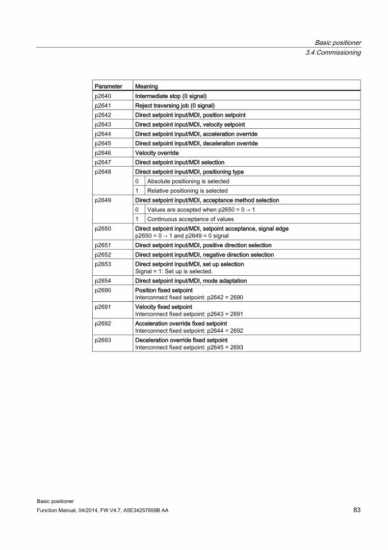
Basic positioner 3.4 Commissioning
Basic positioner Function Manual, 04/2014, FW V4.7, A5E34257659B AA 83
Parameter Meaning p2640 Intermediate stop (0 signal) p2641 Reject traversing job (0 signal) p2642 Direct setpoint input/MDI, position setpoint p2643 Direct setpoint input/MDI, velocity setpoint p2644 Direct setpoint input/MDI, acceleration override p2645 Direct setpoint input/MDI, deceleration override p2646 Velocity override p2647 Direct setpoint input/MDI selection p2648 Direct setpoint input/MDI, positioning type
0 Absolute positioning is selected 1 Relative positioning is selected
p2649 Direct setpoint input/MDI, acceptance method selection 0 Values are accepted when p2650 = 0 → 1 1 Continuous acceptance of values
p2650 Direct setpoint input/MDI, setpoint acceptance, signal edge p2650 = 0 → 1 and p2649 = 0 signal
p2651 Direct setpoint input/MDI, positive direction selection p2652 Direct setpoint input/MDI, negative direction selection p2653 Direct setpoint input/MDI, set up selection
Signal = 1: Set up is selected. p2654 Direct setpoint input/MDI, mode adaptation p2690 Position fixed setpoint
Interconnect fixed setpoint: p2642 = 2690 p2691 Velocity fixed setpoint
Interconnect fixed setpoint: p2643 = 2691 p2692 Acceleration override fixed setpoint
Interconnect fixed setpoint: p2644 = 2692 p2693 Deceleration override fixed setpoint
Interconnect fixed setpoint: p2645 = 2693

Basic positioner 3.4 Commissioning
Basic positioner 84 Function Manual, 04/2014, FW V4.7, A5E34257659B AA

Basic positioner Function Manual, 04/2014, FW V4.7, A5E34257659B AA 85
Appendix A A.1 Manuals and technical support
A.1.1 Manuals for your converter
Table A- 1 Manuals for your inverter
Information depth
Manual Contents Available languages
Download or order number
++ Getting Started Guide Installing the inverter and commissioning.
English, German, Italian, French, Spanish, Chinese
Download manuals (http://support.automation.siemens.com/WW/view/en/22339653/133300) SINAMICS Manual Collection Documentation on DVD, order number 6SL3097-4CA00-0YG0
+++ Operating Instructions for the SINAMICS G120 inverter with the CU250S-2 Control Unit
Installing the inverter and commissioning. Description of the inverter functions.
+++ Function Manual Basic Positioner (this manual) English, German, Chinese
+++ Function Manual for Safety Integrated for the SINAMICS G110M, G120, G120C, G120D inverters and SIMATIC ET 200pro FC-2 converters
Configuring PROFIsafe. Installing, commissioning and operating fail-safe functions of the inverter.
+++ Fieldbus Function Manual for the SINAMICS G120, G120C and G120D inverters
Configuring fieldbuses.
+++ List Manual Complete list of all parameters, alarms and faults. Graphic function diagrams.
+ Getting Started Guide for the following SINAMICS G120 Power Modules: • PM240, PM250 and PM260 • PM240-2
Installing the Power Module English
+ Installation Instructions for reactors, filters and braking resistors
Installing components

Appendix A.1 Manuals and technical support
Basic positioner 86 Function Manual, 04/2014, FW V4.7, A5E34257659B AA
Information depth
Manual Contents Available languages
Download or order number
+++ Hardware Installation Manual for the following SINAMICS G120 Power Modules: • PM240 • PM240-2 • PM250 • PM260
Installing power modules, reactors and filters. Maintaining power modules.
English, German
+++ Operating Instructions for the following Operator Panels: • BOP-2 • IOP
Operating operator panels, installing door assembly for IOP
A.1.2 Configuring support
Table A- 2 Support when configuring and selecting the inverter
Manual or tool Contents Available languages
Download or order number
Catalog D 31 Ordering data and technical information for the standard SINAMICS G inverters
English, German, Italian, French, Spanish
Everything about SINAMICS G120 (www.siemens.en/sinamics-g120)
Online catalog (Industry Mall)
Ordering data and technical information for all SIEMENS products
English, German
SIZER The overall configuration tool for SINAMICS, MICROMASTER and DYNAVERT T drives, motor starters, as well as SINUMERIK, SIMOTION controls and SIMATIC Technology
English, German, Italian, French
You obtain SIZER on a DVD (Order number: 6SL3070-0AA00-0AG0) and in the Internet: Download SIZER (http://support.automation.siemens.com/WW/view/en/10804987/130000)
See also Configuration Manual (http://support.automation.siemens.com/WW/view/en/37728795)

Appendix A.1 Manuals and technical support
Basic positioner Function Manual, 04/2014, FW V4.7, A5E34257659B AA 87
A.1.3 Product Support You can find additional information on the product and more in the Internet under: Product support (http://www.siemens.com/automation/service&support).
In addition to our documentation, under this address we offer our complete knowledge base online: You can find the following information:
● Actual product information (Update), FAQ (frequently asked questions), downloads.
● The Newsletter contains the latest information on the products you use.
● The Knowledge Manager (Intelligent Search) helps you find the documents you need.
● Users and specialists from around the world share their experience and knowledge in the Forum.
● You can find your local representative for Automation & Drives via our contact database under "Contact & Partner".
● Information about local service, repair, spare parts and much more can be found under "Services".

Appendix A.1 Manuals and technical support
Basic positioner 88 Function Manual, 04/2014, FW V4.7, A5E34257659B AA

Basic positioner Function Manual, 04/2014, FW V4.7, A5E34257659B AA 89
Index
A Absolute encoder, 61 Accuracy, 39, 45 Actual position value, 30, 34 Axis, 11
B Backlash, 35 Block selection, 26
C Cam sequencer, 25, 48 Cam switching position, 21 Catalog, 86 Configuring support, 86 Control dynamics, 39 Control panel, 40 Control precision, 39 Control word 1, 17 Control word 2, 19 Conveyor belt, 32
D DRIVE-CLiQ, 14 Dynamic response, 39
E Elevating platform, 30, 32 Encoder zero mark, 52 Encoderless speed control, 39 Endat 2.1, 12 EPos (basic positioner), 11
F FB283, 28 Fixed stop, 73 Fixed stop reached, 21 Flying referencing, 23, 24
Following error, 74 Follow-up mode, 24 Function block FB283, 28
G Gate/door drive, 32 Gear ratio, 30 Getting Started, 85
H Hardware Installation Manual, 85 Hoisting gear, 39 Hotline, 87 HTL encoder, 12
I Incremental jogging, 63 Industry Mall, 86 Integral component, 42 Integral time, 42 Intermediate stop, 69, 80
J Jerk limiting, 42 Jog velocity, 62 Jogging, 40 Jogging (EPos), 11
L Limit switch (software), 37 Limit switches, 37 Linear axis, 32 List Manual, 85 LU (Length Unit), 30
M Machine zero point, 49 Manual Collection, 85 Manuals

Index
Basic positioner 90 Function Manual, 04/2014, FW V4.7, A5E34257659B AA
Download, 85 Function Manual for Safety Integrated, 85 Inverter accessories, 85 Overview, 85
MDI, 11 MDI (Manual Data Input), 79 MDI mode, 27 Mechanical fixed stop, 73 MELDW (status word messages), 28 Modulo axis, 32 Modulo correction, 33 Modulo range, 32
N Neutral distance unit LU, 30
O Operating instruction, 9 Operating instructions, 85 Override, 81 Overview
Manuals, 85
P POS_STW (positioning control word), 20 POS_STW1 (positioning control word 1), 22 POS_STW2 (positioning control word 2), 24 POS_ZSW (positioning status word), 21 POS_ZSW1 (positioning status word 1), 23 POS_ZSW2 (positioning status word 2), 25 Position actual value, value range, 34 Position control, 11 Position controller, 39 Position setpoint reached, 45 Positioning control word, 20 Positioning control word 1, 22 Positioning control word2, 24 Positioning monitoring, 44 Positioning status word, 21 Positioning status word 1, 23 Positioning status word 2, 25 Positioning window, 44 Precontrol, 39 Probe, 56 Procedure, 9 Proportional controller, 39 Proportional gain, 40 Pulse cancelation, 17
Pulse enable, 17
Q Questions, 87
R Reference cam, 50 Reference point, 50 Reference point approach, 49, 50 Reference point approach, 49, 50 Reference point approach, 49, 50 referencing
Flying, Referencing, 11
Absolute encoder adjustment, Set reference point,
Resolution, 30 Resolver, 12 Reversing cam, 50 Roller conveyor, 32, 49 Rotary table, 30, 32, 73
S Sensorless Vector Control (SLVC), 39 Set reference point, 24 Set up, 11, 22, 23, 80 sin/cos encoder, 12 SIZER, 86 Software limit switch, 21, 24 SSI encoder, 12 Stacker crane, 32 Standstill monitoring, 44 Status word 1, 18 Status word 2, 19 Status word messages, 28 STOP cam, 23, 24, 37 STW1 (control word 1), 17 STW2 (control word 2), 19 SUB-D connector, 14 Support, 87 Symbols, 9
T Target position reached, 45 Terminal strip, 14 Tilting station, 32

Index
Basic positioner Function Manual, 04/2014, FW V4.7, A5E34257659B AA 91
Traversing block, 11, 23, 65 Traversing block selection, 22 Traversing profile, 42
V Value range, position actual value, 34
Z Zero mark, 50 ZSW1 (status word 1), 18 ZSW2 (status word 2), 19

Related Documents