Welcome message from author
This document is posted to help you gain knowledge. Please leave a comment to let me know what you think about it! Share it to your friends and learn new things together.
Transcript

SINAMICS
SINAMICS DCM DC Converter
Operating Instructions
Software version 1.4.1
02.2015 A5E34763375/RS-AA/001
Preface
Information 1
Type spectrum, ordering information
2
Description 3
Technical data 4
Transportation, unpacking, installation
5
Connecting 6
Additional system components
7
Commissioning 8
Operation 9
Descriptions of functions 10
Maintenance 11
Applications 12
Appendix A A
Appendix B B

Siemens AG Division Process Industries and Drives Postfach 48 48 90026 NÜRNBERG GERMANY
Order number: 6RX1800-0AD76 05/2015 Subject to change
Copyright © Siemens AG 2009 - 2015. All rights reserved
Legal information Warning notice system
This manual contains notices you have to observe in order to ensure your personal safety, as well as to prevent damage to property. The notices referring to your personal safety are highlighted in the manual by a safety alert symbol, notices referring only to property damage have no safety alert symbol. These notices shown below are graded according to the degree of danger.
DANGER indicates that death or severe personal injury will result if proper precautions are not taken.
WARNING indicates that death or severe personal injury may result if proper precautions are not taken.
CAUTION indicates that minor personal injury can result if proper precautions are not taken.
NOTICE indicates that property damage can result if proper precautions are not taken.
If more than one degree of danger is present, the warning notice representing the highest degree of danger will be used. A notice warning of injury to persons with a safety alert symbol may also include a warning relating to property damage.
Qualified Personnel The product/system described in this documentation may be operated only by personnel qualified for the specific task in accordance with the relevant documentation, in particular its warning notices and safety instructions. Qualified personnel are those who, based on their training and experience, are capable of identifying risks and avoiding potential hazards when working with these products/systems.
Proper use of Siemens products Note the following:
WARNING Siemens products may only be used for the applications described in the catalog and in the relevant technical documentation. If products and components from other manufacturers are used, these must be recommended or approved by Siemens. Proper transport, storage, installation, assembly, commissioning, operation and maintenance are required to ensure that the products operate safely and without any problems. The permissible ambient conditions must be complied with. The information in the relevant documentation must be observed.
Trademarks All names identified by ® are registered trademarks of Siemens AG. The remaining trademarks in this publication may be trademarks whose use by third parties for their own purposes could violate the rights of the owner.
Disclaimer of Liability We have reviewed the contents of this publication to ensure consistency with the hardware and software described. Since variance cannot be precluded entirely, we cannot guarantee full consistency. However, the information in this publication is reviewed regularly and any necessary corrections are included in subsequent editions.
SINAMICS DCM DC Converter Operating Instructions, 02.2015, A5E34763375/RS-AA/001 5
Preface
Note
Information on connecting the device
The inside front cover of the SINAMICS DC MASTER Operating Instructions contains a summary of the key information required for connecting the device.
Product name The SINAMICS DCM documentation uses the following product names:
SINAMICS DCM
SINAMICS DC MASTER
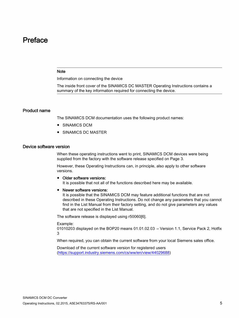
Device software version When these operating instructions went to print, SINAMICS DCM devices were being supplied from the factory with the software release specified on Page 3.
However, these Operating Instructions can, in principle, also apply to other software versions.
Older software versions: It is possible that not all of the functions described here may be available.
Newer software versions: It is possible that the SINAMICS DCM may feature additional functions that are not described in these Operating Instructions. Do not change any parameters that you cannot find in the List Manual from their factory setting, and do not give parameters any values that are not specified in the List Manual.
The software release is displayed using r50060[6].
Example: 01010203 displayed on the BOP20 means 01.01.02.03 → Version 1.1, Service Pack 2, Hotfix 3
When required, you can obtain the current software from your local Siemens sales office.
Download of the current software version for registered users (https://support.industry.siemens.com/cs/ww/en/view/44029688)
Preface
SINAMICS DCM DC Converter 6 Operating Instructions, 02.2015, A5E34763375/RS-AA/001
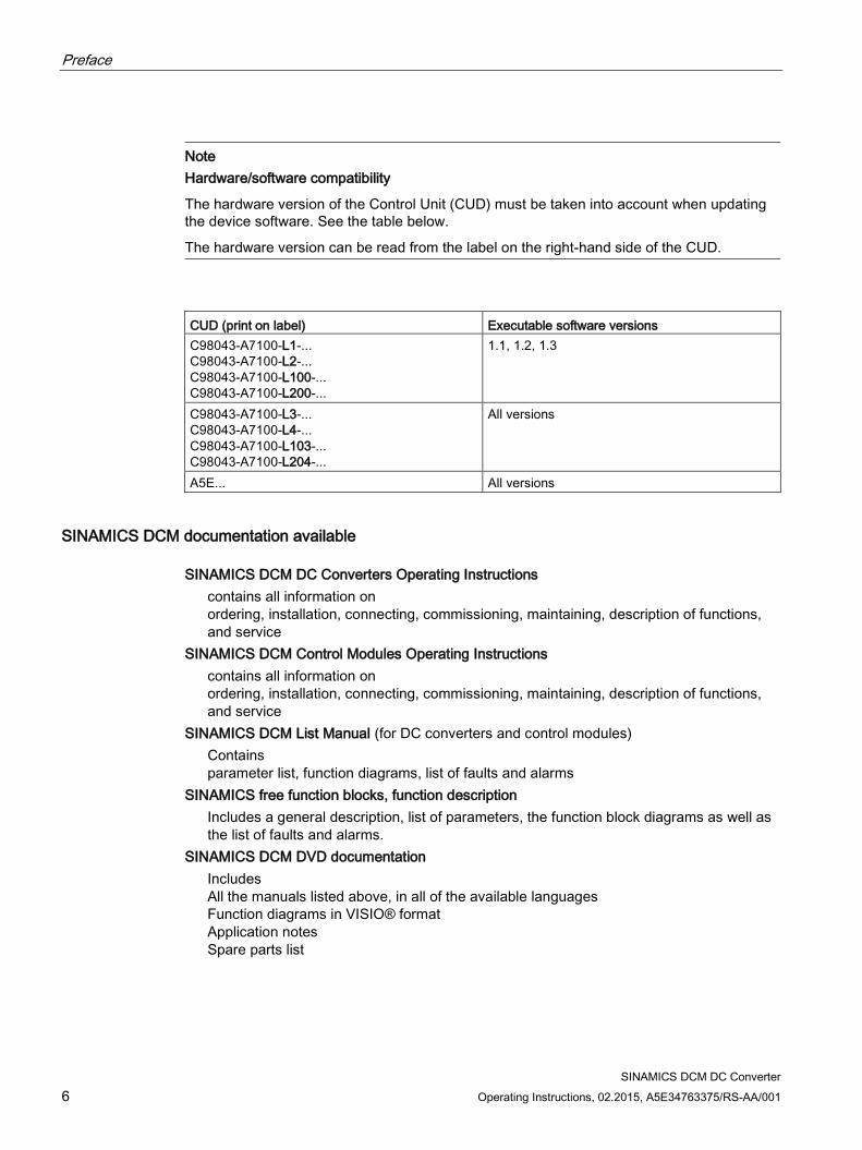
Note Hardware/software compatibility
The hardware version of the Control Unit (CUD) must be taken into account when updating the device software. See the table below.
The hardware version can be read from the label on the right-hand side of the CUD.
CUD (print on label) Executable software versions C98043-A7100-L1-... C98043-A7100-L2-... C98043-A7100-L100-... C98043-A7100-L200-...
1.1, 1.2, 1.3
C98043-A7100-L3-... C98043-A7100-L4-... C98043-A7100-L103-... C98043-A7100-L204-...
All versions
A5E... All versions
SINAMICS DCM documentation available SINAMICS DCM DC Converters Operating Instructions contains all information on
ordering, installation, connecting, commissioning, maintaining, description of functions, and service
SINAMICS DCM Control Modules Operating Instructions contains all information on
ordering, installation, connecting, commissioning, maintaining, description of functions, and service
SINAMICS DCM List Manual (for DC converters and control modules) Contains
parameter list, function diagrams, list of faults and alarms SINAMICS free function blocks, function description Includes a general description, list of parameters, the function block diagrams as well as
the list of faults and alarms. SINAMICS DCM DVD documentation Includes
All the manuals listed above, in all of the available languages Function diagrams in VISIO® format Application notes Spare parts list
Preface
SINAMICS DCM DC Converter
Operating Instructions, 02.2015, A5E34763375/RS-AA/001 7
Manuals and application notes on the Internet
The manuals and application documents are also available in the Internet:
Manuals (https://support.industry.siemens.com/cs/ww/en/ps/13298/man)
The list of general conditions available there include current supplements to the manuals.
The notes included in the general condition lists have a higher priority than the statements
made in the manuals.
FAQ in the Internet
FAQ (http://support.automation.siemens.com/WW/view/en/38157755/133000)
Service
You can find information on our services and regional contact persons in the Internet -
(https://support.industry.siemens.com/sc/ww/en/sc)
Technical Support
Our technical support can provide you with technical assistance for products, systems, and
solutions:
Service (https://support.industry.siemens.com/sc/ww/en/sc)
Central hotlines for SINAMICS DCM technical support
European and African time
zone
Service Request
(https://support.industry.siemens.com/My/ww/en/requests#cr
eateRequest)
America time zone 24-hour hotline: +1 800 333 7421
Phone: +1 423 262 2960
Fax: +1 423 262 2200
email (mailto:[email protected])
8:00 to 17:00
Eastern Standard Time
Asia/Australia time zone Phone: +86 1064 757575
Fax: +86 1064 747474
email (mailto:[email protected])
7:30 to 17:30
Beijing local time
Preface
SINAMICS DCM DC Converter 8 Operating Instructions, 02.2015, A5E34763375/RS-AA/001
Spare parts You can find information on spare parts
In catalog D23.1
On the SINAMICS DCM documentation DVD (to reorder please quote article number 6RX1800-0AD64)
Via the electronic spare parts catalog Spares On Web, after entering the serial number and article number of your SINAMICS DCM in the Internet (registration required).
Spares on Web (http://www.siemens.com/sow)
Remark for users of Internet Explorer 10:
This website may only be correctly displayed when the browser is switched to compatibility mode (activate the appropriate button in the input line or use the menu Options → Settings of the compatibility view).
Availability of spare parts (http://www.siemens.com/sos)
Further Internet links Generic station description file (GSD) for
PROFIBUS (https://support.industry.siemens.com/cs/ww/en/view/98206128)
PROFINET (https://support.industry.siemens.com/cs/ww/en/view/98206128)
SINAMICS DCM DC Converter Operating Instructions, 02.2015, A5E34763375/RS-AA/001 9
Table of contents
Preface ................................................................................................................................................... 5
1 Information ............................................................................................................................................ 19
1.1 Warning information ................................................................................................................ 19
1.2 ESD-sensitive components ..................................................................................................... 22
2 Type spectrum, ordering information ..................................................................................................... 23
2.1 Device article numbers ........................................................................................................... 24
2.2 Key for the device article numbers ......................................................................................... 26
2.3 Rating plates, packaging label ................................................................................................ 28
2.4 Ordering information for options and accessories .................................................................. 30
2.5 Accessories ............................................................................................................................. 35 2.5.1 SIMOREG DC-MASTER Converter Commutation Protector (CCP) ...................................... 35 2.5.2 Mounting kit to increase the degree of protection to IP20 ...................................................... 36
3 Description ............................................................................................................................................ 37
4 Technical data ...................................................................................................................................... 41
4.1 Load types .............................................................................................................................. 42
4.2 Environmental requirements ................................................................................................... 47
4.3 Unit data .................................................................................................................................. 49
4.4 Derating .................................................................................................................................. 74
5 Transportation, unpacking, installation .................................................................................................. 77
5.1 Transportation, unpacking ...................................................................................................... 77
5.2 Installation ............................................................................................................................... 78 5.2.1 Dimension drawings ................................................................................................................ 81 5.2.2 Installing options and accessories .......................................................................................... 90 5.2.2.1 AOP30 operator panel ............................................................................................................ 90 5.2.2.2 Installing a second CUD ......................................................................................................... 90
6 Connecting ........................................................................................................................................... 93
6.1 Instructions for EMC-compliant drive installation .................................................................... 95 6.1.1 Basic information about EMC ................................................................................................. 95 6.1.2 EMC-compliant drive installation (installation instructions)..................................................... 98 6.1.3 Arranging components for converter units ............................................................................ 105 6.1.4 RFI suppression filter ............................................................................................................ 106 6.1.5 Information on line-side harmonics produced by converter units in a fully-controlled
two-pulse bridge circuit configuration (B6C and (B6)A(B6)C) .............................................. 107 6.1.6 Data on the line-side harmonics from converter units in a fully-controlled AC bridge
circuit B2C ............................................................................................................................. 109
6.2 Cable routing into the unit ..................................................................................................... 110
Table of contents
SINAMICS DCM DC Converter 10 Operating Instructions, 02.2015, A5E34763375/RS-AA/001
6.3 Block diagram with connection suggestion .......................................................................... 114
6.4 Power connections ............................................................................................................... 122
6.5 Field supply .......................................................................................................................... 143
6.6 Line reactors ........................................................................................................................ 146
6.7 Fuses ................................................................................................................................... 150 6.7.1 Fuses for the exciter circuit .................................................................................................. 150 6.7.2 Fuses for the armature circuit .............................................................................................. 150 6.7.3 Fuses in the Power Interface ............................................................................................... 156
6.8 Arrangement of terminals and connectors ........................................................................... 157
6.9 Assignment of terminals and connectors ............................................................................. 168 6.9.1 Power unit ............................................................................................................................ 169 6.9.2 Exciter circuit ........................................................................................................................ 171 6.9.3 Electronics power supply ..................................................................................................... 172 6.9.4 Fan ....................................................................................................................................... 173 6.9.5 Open-loop and closed-loop control section ......................................................................... 174 6.9.6 Assignment of the RS485 cable to the AOP30 .................................................................... 182
6.10 Installation notes for installation according to UL 508C ....................................................... 187
7 Additional system components ............................................................................................................. 189
7.1 Option Board: Communication Board Ethernet CBE20 ....................................................... 190 7.1.1 Description ........................................................................................................................... 190 7.1.2 Safety instructions ................................................................................................................ 190 7.1.3 Interface description ............................................................................................................. 191 7.1.3.1 Overview .............................................................................................................................. 191 7.1.3.2 X1400 Ethernet interface ..................................................................................................... 191 7.1.4 Meaning of the LEDs ........................................................................................................... 192 7.1.5 Installation ............................................................................................................................ 194 7.1.6 Technical data ...................................................................................................................... 194
7.2 Sensor Module Cabinet-Mounted SMC30 ........................................................................... 195 7.2.1 Description ........................................................................................................................... 195 7.2.2 Safety instructions ................................................................................................................ 196 7.2.3 Interface description ............................................................................................................. 199 7.2.3.1 Overview .............................................................................................................................. 199 7.2.3.2 X500 DRIVE-CLiQ interface ................................................................................................ 200 7.2.3.3 X520 encoder system interface ........................................................................................... 200 7.2.3.4 X521/X531 alternative encoder system interface ................................................................ 201 7.2.3.5 X524 electronic power supply .............................................................................................. 203 7.2.4 Connection examples .......................................................................................................... 203 7.2.5 Meaning of the LEDs ........................................................................................................... 206 7.2.6 Dimension drawing .............................................................................................................. 207 7.2.7 Installation ............................................................................................................................ 208 7.2.8 Protective conductor connection and shield support ........................................................... 209 7.2.9 Technical data ...................................................................................................................... 210
7.3 Terminal Module TM15 ........................................................................................................ 214 7.3.1 Description ........................................................................................................................... 214 7.3.2 Safety instructions ................................................................................................................ 214 7.3.3 Interface description ............................................................................................................. 215 7.3.3.1 Overview .............................................................................................................................. 215
Table of contents
SINAMICS DCM DC Converter Operating Instructions, 02.2015, A5E34763375/RS-AA/001 11
7.3.3.2 X500 and X501 DRIVE-CLiQ interface ................................................................................. 216 7.3.3.3 X524 electronic power supply ............................................................................................... 217 7.3.3.4 X520 digital inputs/outputs .................................................................................................... 217 7.3.3.5 X521 digital inputs/outputs .................................................................................................... 218 7.3.3.6 X522 digital inputs/outputs .................................................................................................... 218 7.3.4 Connection example ............................................................................................................. 219 7.3.5 Meaning of the LEDs on the Terminal Module TM15 ........................................................... 220 7.3.6 Dimension drawing ............................................................................................................... 221 7.3.7 Installation ............................................................................................................................. 222 7.3.8 Protective conductor connection and shield support ............................................................ 223 7.3.9 Connector coding .................................................................................................................. 224 7.3.10 Technical data ....................................................................................................................... 225
7.4 Terminal Module TM31 ......................................................................................................... 227 7.4.1 Description ............................................................................................................................ 227 7.4.2 Safety instructions ................................................................................................................. 227 7.4.3 Interface description .............................................................................................................. 229 7.4.3.1 Overview ............................................................................................................................... 229 7.4.3.2 X500/X501 DRIVE-CLiQ interfaces ...................................................................................... 230 7.4.3.3 X520, X530 digital inputs ...................................................................................................... 231 7.4.3.4 X521 analog inputs ............................................................................................................... 232 7.4.3.5 Analog inputs current/voltage switch .................................................................................... 233 7.4.3.6 X522 analog outputs/temperature sensor............................................................................. 233 7.4.3.7 X524 electronic power supply ............................................................................................... 234 7.4.3.8 X540 auxiliary voltage for the digital inputs .......................................................................... 234 7.4.3.9 X541 bidirectional digital inputs/outputs ............................................................................... 235 7.4.3.10 X542 relay outputs ................................................................................................................ 236 7.4.4 Connection example ............................................................................................................. 237 7.4.5 Meanings of the LEDs on the Terminal Module TM31 ......................................................... 238 7.4.6 Dimension drawing ............................................................................................................... 239 7.4.7 Installation ............................................................................................................................. 240 7.4.8 Protective conductor connection and shield support ............................................................ 241 7.4.9 Connector coding .................................................................................................................. 242 7.4.10 Technical data ....................................................................................................................... 243
7.5 Terminal Module TM150 ....................................................................................................... 244 7.5.1 Description ............................................................................................................................ 244 7.5.2 Safety instructions ................................................................................................................. 244 7.5.3 Interface description .............................................................................................................. 246 7.5.3.1 Overview ............................................................................................................................... 246 7.5.3.2 X500 and X501 DRIVE-CLiQ interfaces ............................................................................... 247 7.5.3.3 X524 Electronics power supply ............................................................................................. 248 7.5.3.4 X531-X536 temperature sensor inputs ................................................................................. 248 7.5.4 Connection examples ........................................................................................................... 250 7.5.5 Meaning of the LEDs on the Terminal Module TM150 ......................................................... 252 7.5.6 Dimension drawing ............................................................................................................... 253 7.5.7 Installation ............................................................................................................................. 254 7.5.8 Protective conductor connection and shield support ............................................................ 255 7.5.9 Technical data ....................................................................................................................... 256
8 Commissioning ................................................................................................................................... 257
8.1 Switching on .......................................................................................................................... 259
8.2 Commissioning using the BOP20 operator panel ................................................................. 260
Table of contents
SINAMICS DCM DC Converter 12 Operating Instructions, 02.2015, A5E34763375/RS-AA/001
8.2.1 Preconditions ....................................................................................................................... 260 8.2.2 Commissioning steps ........................................................................................................... 260
8.3 Commissioning using the AOP30 operator panel ................................................................ 267 8.3.1 First commissioning ............................................................................................................. 267 8.3.1.1 First power-up ...................................................................................................................... 267 8.3.1.2 Full drive commissioning ...................................................................................................... 268 8.3.2 Status after commissioning .................................................................................................. 272 8.3.3 Resetting parameters to factory settings ............................................................................. 272
8.4 Commissioning with the STARTER commissioning tool ..................................................... 273 8.4.1 STARTER commissioning tool ............................................................................................. 273 8.4.1.1 Installing the STARTER commissioning tool ....................................................................... 273 8.4.1.2 Layout of the STARTER user interface ............................................................................... 274 8.4.2 Procedure for commissioning with STARTER ..................................................................... 275 8.4.2.1 Creating the project .............................................................................................................. 275 8.4.2.2 Configuring a drive unit ........................................................................................................ 282 8.4.2.3 Starting the drive project ...................................................................................................... 294 8.4.2.4 Connection through a serial interface .................................................................................. 298
8.5 Activating function modules ................................................................................................. 301 8.5.1 Activating offline with STARTER .......................................................................................... 302 8.5.2 Activating online through parameters .................................................................................. 303
8.6 Commissioning optional additional modules ........................................................................ 305 8.6.1 Terminal Modules (TM31, TM15, TM150) ........................................................................... 305 8.6.1.1 Commissioning with STARTER ........................................................................................... 305 8.6.1.2 Commissioning via parameter assignment .......................................................................... 307 8.6.2 Encoder evaluation (SMC30) ............................................................................................... 308 8.6.2.1 Add/commissioning (with STARTER) .................................................................................. 308 8.6.2.2 Remove (with STARTER) .................................................................................................... 311 8.6.3 PROFINET module (CBE20) ............................................................................................... 311 8.6.3.1 Adding online into the drive .................................................................................................. 311 8.6.3.2 Adding offline in STARTER .................................................................................................. 312 8.6.3.3 Deleting from the drive online .............................................................................................. 312 8.6.3.4 Deleting offline with STARTER ............................................................................................ 312
8.7 Drive optimization................................................................................................................. 313
8.8 Manual optimization ............................................................................................................. 319 8.8.1 Optimization of closed-loop armature current control .......................................................... 320 8.8.2 Optimization of closed-loop field-current control .................................................................. 322 8.8.3 Optimizing the speed controller ........................................................................................... 323
9 Operation ............................................................................................................................................. 325
9.1 Basic information.................................................................................................................. 325 9.1.1 Parameter ............................................................................................................................ 325 9.1.2 Data sets .............................................................................................................................. 328 9.1.2.1 Function diagrams and parameters ..................................................................................... 331 9.1.2.2 Using data sets .................................................................................................................... 331 9.1.3 Drive objects ........................................................................................................................ 332 9.1.4 Memory card functions ......................................................................................................... 334 9.1.5 BICO technology: Interconnecting signals ........................................................................... 339 9.1.5.1 Binectors, connectors .......................................................................................................... 340 9.1.5.2 Interconnecting signals using BICO technology .................................................................. 340
Table of contents
SINAMICS DCM DC Converter Operating Instructions, 02.2015, A5E34763375/RS-AA/001 13
9.1.5.3 Internal encoding of the binector/connector output parameters ........................................... 342 9.1.5.4 Example: Interconnecting digital signals............................................................................... 342 9.1.5.5 Information on BICO technology ........................................................................................... 342
9.2 Parameterizing using the BOP20 (Basic Operator Panel 20)............................................... 344 9.2.1 General information about the BOP20.................................................................................. 344 9.2.2 Displays and using the BOP20 ............................................................................................. 347 9.2.3 Displaying faults and alarms ................................................................................................. 352 9.2.4 Controlling the drive using the BOP20.................................................................................. 353
9.3 Controlling via the AOP30 operator panel ............................................................................ 354 9.3.1 Overview and menu structure ............................................................................................... 355 9.3.2 Menu: Operation screen ....................................................................................................... 357 9.3.3 Parameterization menu ......................................................................................................... 358 9.3.4 Menu: Fault/alarm memory ................................................................................................... 359 9.3.5 Menu: Commissioning/Service ............................................................................................. 360 9.3.5.1 Drive commissioning ............................................................................................................. 360 9.3.5.2 Device commissioning .......................................................................................................... 361 9.3.5.3 AOP settings ......................................................................................................................... 361 9.3.5.4 Lists of signals for the operation screen ............................................................................... 362 9.3.5.5 AOP30 diagnostics ............................................................................................................... 365 9.3.6 Sprachauswahl/Language selection ..................................................................................... 366 9.3.7 Operation via the operator panel (LOCAL mode) ................................................................. 367 9.3.7.1 LOCAL/REMOTE key ........................................................................................................... 367 9.3.7.2 ON key/OFF key ................................................................................................................... 368 9.3.7.3 CCW/CW changeover........................................................................................................... 368 9.3.7.4 Jogging ................................................................................................................................. 368 9.3.7.5 Increase setpoint/Decrease setpoint .................................................................................... 369 9.3.7.6 AOP setpoint ......................................................................................................................... 369 9.3.7.7 Inhibiting AOP LOCAL mode ................................................................................................ 370 9.3.7.8 Acknowledging errors via the AOP ....................................................................................... 370 9.3.7.9 Timeout monitoring ............................................................................................................... 370 9.3.7.10 Operator inhibit lock/Parameters disable .............................................................................. 371 9.3.8 Faults and alarms ................................................................................................................. 372 9.3.9 Saving the parameters permanently ..................................................................................... 374 9.3.10 Parameterization errors ........................................................................................................ 374 9.3.11 Assigning parameters to make AOP30 time-of-day master ................................................. 375
10 Descriptions of functions ..................................................................................................................... 377
10.1 Inputs/Outputs ....................................................................................................................... 377 10.1.1 Overview of inputs/outputs ................................................................................................... 377 10.1.2 Digital inputs/outputs............................................................................................................. 377 10.1.3 Analog inputs ........................................................................................................................ 378 10.1.4 Analog outputs ...................................................................................................................... 379
10.2 Communication, IT security .................................................................................................. 380
10.3 Communication according to PROFIdrive ............................................................................ 381 10.3.1 Application classes ............................................................................................................... 383 10.3.2 Cyclic communication ........................................................................................................... 385 10.3.2.1 Telegrams and process data ................................................................................................ 385 10.3.2.2 Description of control words and setpoints ........................................................................... 388 10.3.2.3 Description of status words and actual values ..................................................................... 393 10.3.2.4 Control and status words for encoders ................................................................................. 399
Table of contents
SINAMICS DCM DC Converter 14 Operating Instructions, 02.2015, A5E34763375/RS-AA/001
10.3.2.5 Extended encoder evaluation .............................................................................................. 408 10.3.2.6 Central control and status words ......................................................................................... 408 10.3.2.7 Diagnostics channels for cyclic communication ................................................................... 411 10.3.3 Parallel operation of communication interfaces ................................................................... 412 10.3.4 Acyclic communication ......................................................................................................... 415 10.3.4.1 General information about acyclic communication .............................................................. 415 10.3.4.2 Structure of orders and responses....................................................................................... 417 10.3.4.3 Determining the drive object numbers ................................................................................. 422 10.3.4.4 Example 1: read parameters ................................................................................................ 423 10.3.4.5 Example 2: write parameters (multi-parameter request) ..................................................... 425
10.4 Communication via PROFIBUS DP ..................................................................................... 429 10.4.1 PROFIBUS connection ........................................................................................................ 429 10.4.2 General information about PROFIBUS ................................................................................ 431 10.4.2.1 General information about PROFIBUS for SINAMICS ........................................................ 431 10.4.2.2 Example of a telegram structure for acyclic data acquisition ............................................... 433 10.4.3 Commissioning PROFIBUS ................................................................................................. 435 10.4.3.1 Setting the PROFIBUS interface .......................................................................................... 435 10.4.3.2 PROFIBUS interface in operation ........................................................................................ 436 10.4.3.3 Commissioning PROFIBUS ................................................................................................. 437 10.4.3.4 Diagnostics options .............................................................................................................. 438 10.4.3.5 SIMATIC HMI addressing .................................................................................................... 438 10.4.3.6 Monitoring, telegram failure ................................................................................................. 440 10.4.4 Direct data exchange ........................................................................................................... 441 10.4.4.1 Setpoint assignment in the subscriber ................................................................................. 443 10.4.4.2 Activating/parameterizing slave-to-slave communication .................................................... 444 10.4.4.3 Commissioning of the PROFIBUS slave-to-slave communication ...................................... 446 10.4.4.4 GSD during operation .......................................................................................................... 456 10.4.4.5 Diagnostics of the PROFIBUS slave-to-slave communication in STARTER ...................... 458 10.4.5 Messages via diagnostics channels..................................................................................... 458
10.5 Communication via PROFINET IO ...................................................................................... 461 10.5.1 Activating online mode: STARTER via PROFINET IO ........................................................ 461 10.5.2 General information about PROFINET IO ........................................................................... 467 10.5.2.1 Real-time (RT) and isochronous real-time (IRT) communication ........................................ 468 10.5.2.2 Addresses ............................................................................................................................ 469 10.5.2.3 Data transmission ................................................................................................................ 471 10.5.2.4 Communication channels for PROFINET ............................................................................ 472 10.5.3 Drive control with PROFINET .............................................................................................. 473 10.5.3.1 Media redundancy ............................................................................................................... 475 10.5.4 RT classes for PROFINET IO .............................................................................................. 475 10.5.5 PROFINET GSDML ............................................................................................................. 481 10.5.6 Communication with CBE20 ................................................................................................ 482 10.5.6.1 EtherNet/IP ........................................................................................................................... 483 10.5.7 Messages via diagnostics channels..................................................................................... 483
10.6 Communication via SINAMICS Link .................................................................................... 487 10.6.1 Basic principles of SINAMICS Link ...................................................................................... 487 10.6.2 Topology .............................................................................................................................. 489 10.6.3 Configuring and commissioning ........................................................................................... 490 10.6.4 Example ............................................................................................................................... 493 10.6.5 Communication failure during power-up or in cyclic operation ............................................ 495 10.6.6 Example: Transmission times for SINAMICS Link ............................................................... 495 10.6.7 Function diagrams and parameters ..................................................................................... 496
Table of contents
SINAMICS DCM DC Converter Operating Instructions, 02.2015, A5E34763375/RS-AA/001 15
10.7 EtherNet/IP ........................................................................................................................... 497 10.7.1 Connection of SINAMICS DCM with EtherNet/IP to Ethernet networks ............................... 497 10.7.2 Configuration of SINAMICS DCM for EtherNet/IP ................................................................ 498 10.7.2.1 Setting the IP address and activating the EtherNet/IP protocol ........................................... 498 10.7.2.2 Communication with the SINAMICS DCM ............................................................................ 499 10.7.3 Examples of the use of a Rockwell PLC ............................................................................... 505 10.7.3.1 Configuration of a Rockwell PLC for the communication with SINAMICS DCM .................. 505 10.7.3.2 Writing and reading parameters with Class 4xx ................................................................... 508
10.8 Serial interface with USS protocol ........................................................................................ 510
10.9 Switch on, switch off, enable ................................................................................................ 512 10.9.1 Switch on/Switch off (ON/OFF1) - control word bit 0 ............................................................ 512 10.9.2 OFF2 (disconnection) - control word bit 1............................................................................. 514 10.9.3 OFF3 (quick stop) - control word bit 2 .................................................................................. 514 10.9.4 Operation enable (enable) - control word bit 3 ..................................................................... 516
10.10 Safety shutdown (E-STOP) .................................................................................................. 517
10.11 Setpoint channel ................................................................................................................... 518 10.11.1 Ramp-function generator ...................................................................................................... 518 10.11.2 Jog ........................................................................................................................................ 523 10.11.3 Creep .................................................................................................................................... 524 10.11.4 Fixed setpoint ........................................................................................................................ 525
10.12 Encoder evaluation ............................................................................................................... 526 10.12.1 Actual speed values .............................................................................................................. 527 10.12.2 Control and status words for encoders ................................................................................. 528
10.13 Speed controller .................................................................................................................... 529
10.14 Adaptation of the armature and field current controller ........................................................ 533
10.15 Technology controller............................................................................................................ 536
10.16 Switch-on command for holding or operational brake .......................................................... 539
10.17 Switching on auxiliary circuits ............................................................................................... 542
10.18 Operating hours counter, unit fan ......................................................................................... 543
10.19 Thermal overload protection for the DC motor (I2t monitoring of the motor) ........................ 544
10.20 Measuring the motor temperature ........................................................................................ 547
10.21 Speed-dependent current limitation ...................................................................................... 549
10.22 Dynamic overload capability of the power unit ..................................................................... 552 10.22.1 Overview of functions............................................................................................................ 552 10.22.2 Configuring for dynamic overload capability ......................................................................... 553
10.23 Sensor for the ambient and/or air intake temperature .......................................................... 556
10.24 Calculating the thyristor blocking voltage ............................................................................. 558
10.25 Automatic restart ................................................................................................................... 560
10.26 Operation on a single-phase line supply............................................................................... 561
10.27 Connecting units in parallel and in series ............................................................................. 563 10.27.1 6-pulse parallel connection ................................................................................................... 566 10.27.2 12-pulse parallel connection ................................................................................................. 572
Table of contents
SINAMICS DCM DC Converter 16 Operating Instructions, 02.2015, A5E34763375/RS-AA/001
10.27.3 6-pulse series connection .................................................................................................... 574 10.27.4 6-pulse series connection: controlled converter + uncontrolled converter .......................... 577 10.27.5 12-pulse series connection .................................................................................................. 579 10.27.6 12-pulse series connection: controlled converter + uncontrolled converter ........................ 582 10.27.7 Switchover of the power unit topology - option S50 ............................................................. 583
10.28 Field reversal ........................................................................................................................ 584 10.28.1 Direction of rotation reversal using field reversal ................................................................. 584 10.28.2 Braking using field reversal .................................................................................................. 586
10.29 Serial interface with peer-to-peer protocol ........................................................................... 589 10.29.1 Examples of peer-to-peer connections ................................................................................ 591
10.30 Expanding the SINAMICS DCM to include a second CUD ................................................. 594
10.31 Terminal Module Cabinet TMC (option G63) ....................................................................... 596
10.32 Runtime (operating hours counter) ...................................................................................... 597
10.33 Diagnostics ........................................................................................................................... 598 10.33.1 Diagnostic memory .............................................................................................................. 598 10.33.2 Trend recorder function ........................................................................................................ 598 10.33.3 Thyristor diagnostics ............................................................................................................ 599 10.33.4 Description of the LEDs on the CUD ................................................................................... 601 10.33.5 Diagnostics via STARTER ................................................................................................... 604 10.33.5.1 Function generator ............................................................................................................... 604 10.33.5.2 Trace function ...................................................................................................................... 607 10.33.6 Faults and alarms................................................................................................................. 614 10.33.6.1 General information ............................................................................................................. 614 10.33.6.2 Buffer for faults and alarms .................................................................................................. 616 10.33.6.3 Configuring messages ......................................................................................................... 619 10.33.6.4 Parameters and function diagrams for faults and alarms .................................................... 621 10.33.6.5 Forwarding faults and alarms ............................................................................................... 621
10.34 CPU time load with SINAMICS DCM ................................................................................... 623 10.34.1 Maximum configuration ........................................................................................................ 624 10.34.2 Computation examples ........................................................................................................ 625
10.35 Free function blocks ............................................................................................................. 626
10.36 Drive Control Chart (DCC) ................................................................................................... 628 10.36.1 Loading the DCC technology option into the drive unit memory ......................................... 629 10.36.2 CPU time load through DCC ................................................................................................ 630 10.36.3 Memory load through DCC .................................................................................................. 632 10.36.4 Backing up the DCC diagrams ............................................................................................. 633
10.37 Write and know-how protection ............................................................................................ 635 10.37.1 Write protection .................................................................................................................... 635 10.37.2 Know-how protection ........................................................................................................... 637 10.37.2.1 Copy protection .................................................................................................................... 640 10.37.2.2 Configuring know-how protection ......................................................................................... 640 10.37.2.3 Loading know-how protected data to the file system ........................................................... 644 10.37.3 Overview of important parameters ....................................................................................... 649
11 Maintenance ........................................................................................................................................ 651
11.1 Upgrading software releases ............................................................................................... 652 11.1.1 Upgrading the unit software ................................................................................................. 653
Table of contents
SINAMICS DCM DC Converter Operating Instructions, 02.2015, A5E34763375/RS-AA/001 17
11.1.2 Upgrading the DCC technology option ................................................................................. 655
11.2 Replacing components ......................................................................................................... 659 11.2.1 Replacing the fan .................................................................................................................. 659 11.2.2 Replacing fuses .................................................................................................................... 665 11.2.3 Replacing the CUD ............................................................................................................... 667 11.2.4 Replacement of diodes and thyristor modules on devices up to 1200 A .............................. 670
11.3 Replacing the back-up battery in the AOP30 operator panel ............................................... 671
12 Applications ........................................................................................................................................ 673
12.1 Using SINAMICS DCM in shipbuilding ................................................................................. 673
12.2 Connecting an incremental encoder ..................................................................................... 674
12.3 Use of the SINAMICS DCM in galvanizing and dip-painting plants ..................................... 676
A Appendix A ......................................................................................................................................... 679
A.1 Certifications and standards ................................................................................................. 679
A.2 List of abbreviations .............................................................................................................. 682
A.3 Environmental compatibility .................................................................................................. 690
A.4 Servicing ............................................................................................................................... 691
B Appendix B ......................................................................................................................................... 693
B.1 Runtimes of the DCC blocks for SINAMICS DCM ................................................................ 693
B.2 BOP20 status display during power-up ................................................................................ 698
Index................................................................................................................................................... 699

Table of contents
SINAMICS DCM DC Converter 18 Operating Instructions, 02.2015, A5E34763375/RS-AA/001
SINAMICS DCM DC Converter Operating Instructions, 02.2015, A5E34763375/RS-AA/001 19
Information 1 1.1 Warning information
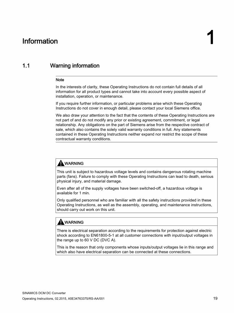
Note
In the interests of clarity, these Operating Instructions do not contain full details of all information for all product types and cannot take into account every possible aspect of installation, operation, or maintenance.
If you require further information, or particular problems arise which these Operating Instructions do not cover in enough detail, please contact your local Siemens office.
We also draw your attention to the fact that the contents of these Operating Instructions are not part of and do not modify any prior or existing agreement, commitment, or legal relationship. Any obligations on the part of Siemens arise from the respective contract of sale, which also contains the solely valid warranty conditions in full. Any statements contained in these Operating Instructions neither expand nor restrict the scope of these contractual warranty conditions.
WARNING
This unit is subject to hazardous voltage levels and contains dangerous rotating machine parts (fans). Failure to comply with these Operating Instructions can lead to death, serious physical injury, and material damage.
Even after all of the supply voltages have been switched-off, a hazardous voltage is available for 1 min.
Only qualified personnel who are familiar with all the safety instructions provided in these Operating Instructions, as well as the assembly, operating, and maintenance instructions, should carry out work on this unit.
WARNING
There is electrical separation according to the requirements for protection against electric shock according to EN61800-5-1 at all customer connections with input/output voltages in the range up to 60 V DC (DVC A).
This is the reason that only components whose inputs/output voltages lie in this range and which also have electrical separation can be connected at these connections.
Information 1.1 Warning information
SINAMICS DCM DC Converter 20 Operating Instructions, 02.2015, A5E34763375/RS-AA/001
DANGER
When this unit is operated, it is inevitable that certain components will be subject to dangerous electrical voltage levels. Touching these components may lead to serious physical injury or even death. The following precautions should be taken in order to reduce the risk to life and limb: 1. Only qualified personnel who are familiar with this unit and the information supplied with
it should be charged with work on the unit involving installation, operation, troubleshooting and fault correction, or repair.
2. The unit must be installed in accordance with safety regulations (e.g. EN, DIN, or VDE) as well as all other applicable national or local regulations. Grounding, conductor dimensioning, and the relevant short-circuit protection work must be carried out correctly in order to ensure operational safety.
3. The unit must be operated with all covers supplied. The fixing screws for the front cover of the SINAMICS DCM must be tight. When required, additional covers should be provided in the control cabinet.
4. Before carrying out visual inspections and maintenance work, ensure that the unit is disconnected from the supply voltage and disabled. Before they are shut down, both the converter unit and the motor are subject to dangerous voltage levels; these may be present even when the converter unit's line contactor is open.
5. If measurements need to be taken while the power supply is switched on, do not under any circumstances touch the electrical connection points. Remove all jewelry from wrists and fingers. Make sure that the measuring and test equipment is in good condition and is safe to operate.
6. When working on a unit that is switched on and on an insulated surface, make sure that no grounding has been put in place.
7. Follow these Operating Instructions faithfully and observe all information concerning hazards, warnings, or areas where caution is required.
8. This list is not exhaustive and as such cannot outline all the measures required in order to operate the unit safely. Should you require further information or encounter specific problems which have not been handled in enough detail for the purposes of the buyer, please contact your local Siemens office.
NOTICE
Operating the unit in the immediate vicinity (< 1.5 m) of mobile telephones with a transmitter power of > 1 W may lead to incorrect operation of the unit.
Information 1.1 Warning information
SINAMICS DCM DC Converter Operating Instructions, 02.2015, A5E34763375/RS-AA/001 21
WARNING
Hearing protection
Note the regional regulations for the use of hearing protection.
In general, the use of hearing protection is required or recommended for a sound level of ≥ 80 dB(A).
The noise emission is specified in Chapter Unit data (Page 49) in the line, fan noise.
WARNING
The OFF switch on the AOP30 operator panel does not have an EMERGENCY OFF function.
In order to avoid dangerous incorrect operator actions, the EMERGENCY OFF pushbutton must be installed in a plant or system at an adequate distance from the AOP30.
Information 1.2 ESD-sensitive components
SINAMICS DCM DC Converter 22 Operating Instructions, 02.2015, A5E34763375/RS-AA/001
1.2 ESD-sensitive components
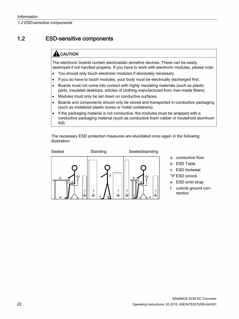
CAUTION
The electronic boards contain electrostatic sensitive devices. These can be easily destroyed if not handled properly. If you have to work with electronic modules, please note: • You should only touch electronic modules if absolutely necessary. • If you do have to touch modules, your body must be electrically discharged first. • Boards must not come into contact with highly insulating materials (such as plastic
parts, insulated desktops, articles of clothing manufactured from man-made fibers). • Modules must only be set down on conductive surfaces. • Boards and components should only be stored and transported in conductive packaging
(such as metalized plastic boxes or metal containers). • If the packaging material is not conductive, the modules must be wrapped with a
conductive packaging material (such as conductive foam rubber or household aluminum foil).
The necessary ESD protection measures are elucidated once again in the following illustration: Seated Standing Seated/standing
a conductive floor b ESD Table c ESD footwear "d" ESD smock e ESD wrist strap f cubicle ground con-
nection
SINAMICS DCM DC Converter Operating Instructions, 02.2015, A5E34763375/RS-AA/001 23
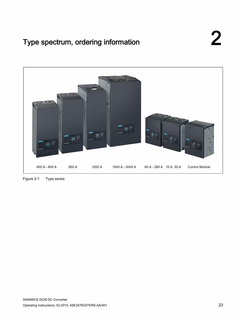
Type spectrum, ordering information 2
Figure 2-1 Type series
Type spectrum, ordering information 2.1 Device article numbers
SINAMICS DCM DC Converter 24 Operating Instructions, 02.2015, A5E34763375/RS-AA/001
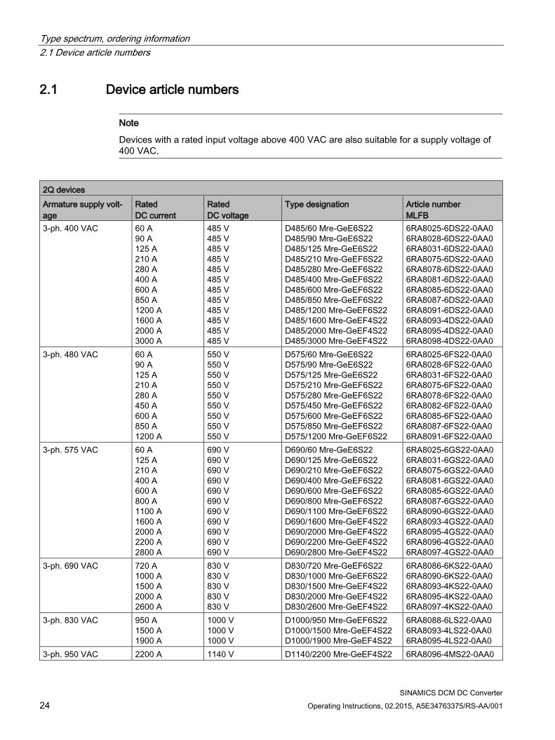
2.1 Device article numbers
Note
Devices with a rated input voltage above 400 VAC are also suitable for a supply voltage of 400 VAC.
2Q devices Armature supply volt-age
Rated DC current
Rated DC voltage
Type designation Article number MLFB
3-ph. 400 VAC 60 A 90 A 125 A 210 A 280 A 400 A 600 A 850 A 1200 A 1600 A 2000 A 3000 A
485 V 485 V 485 V 485 V 485 V 485 V 485 V 485 V 485 V 485 V 485 V 485 V
D485/60 Mre-GeE6S22 D485/90 Mre-GeE6S22 D485/125 Mre-GeE6S22 D485/210 Mre-GeEF6S22 D485/280 Mre-GeEF6S22 D485/400 Mre-GeEF6S22 D485/600 Mre-GeEF6S22 D485/850 Mre-GeEF6S22 D485/1200 Mre-GeEF6S22 D485/1600 Mre-GeEF4S22 D485/2000 Mre-GeEF4S22 D485/3000 Mre-GeEF4S22
6RA8025-6DS22-0AA0 6RA8028-6DS22-0AA0 6RA8031-6DS22-0AA0 6RA8075-6DS22-0AA0 6RA8078-6DS22-0AA0 6RA8081-6DS22-0AA0 6RA8085-6DS22-0AA0 6RA8087-6DS22-0AA0 6RA8091-6DS22-0AA0 6RA8093-4DS22-0AA0 6RA8095-4DS22-0AA0 6RA8098-4DS22-0AA0
3-ph. 480 VAC 60 A 90 A 125 A 210 A 280 A 450 A 600 A 850 A 1200 A
550 V 550 V 550 V 550 V 550 V 550 V 550 V 550 V 550 V
D575/60 Mre-GeE6S22 D575/90 Mre-GeE6S22 D575/125 Mre-GeE6S22 D575/210 Mre-GeEF6S22 D575/280 Mre-GeEF6S22 D575/450 Mre-GeEF6S22 D575/600 Mre-GeEF6S22 D575/850 Mre-GeEF6S22 D575/1200 Mre-GeEF6S22
6RA8025-6FS22-0AA0 6RA8028-6FS22-0AA0 6RA8031-6FS22-0AA0 6RA8075-6FS22-0AA0 6RA8078-6FS22-0AA0 6RA8082-6FS22-0AA0 6RA8085-6FS22-0AA0 6RA8087-6FS22-0AA0 6RA8091-6FS22-0AA0
3-ph. 575 VAC 60 A 125 A 210 A 400 A 600 A 800 A 1100 A 1600 A 2000 A 2200 A 2800 A
690 V 690 V 690 V 690 V 690 V 690 V 690 V 690 V 690 V 690 V 690 V
D690/60 Mre-GeE6S22 D690/125 Mre-GeE6S22 D690/210 Mre-GeEF6S22 D690/400 Mre-GeEF6S22 D690/600 Mre-GeEF6S22 D690/800 Mre-GeEF6S22 D690/1100 Mre-GeEF6S22 D690/1600 Mre-GeEF4S22 D690/2000 Mre-GeEF4S22 D690/2200 Mre-GeEF4S22 D690/2800 Mre-GeEF4S22
6RA8025-6GS22-0AA0 6RA8031-6GS22-0AA0 6RA8075-6GS22-0AA0 6RA8081-6GS22-0AA0 6RA8085-6GS22-0AA0 6RA8087-6GS22-0AA0 6RA8090-6GS22-0AA0 6RA8093-4GS22-0AA0 6RA8095-4GS22-0AA0 6RA8096-4GS22-0AA0 6RA8097-4GS22-0AA0
3-ph. 690 VAC 720 A 1000 A 1500 A 2000 A 2600 A
830 V 830 V 830 V 830 V 830 V
D830/720 Mre-GeEF6S22 D830/1000 Mre-GeEF6S22 D830/1500 Mre-GeEF4S22 D830/2000 Mre-GeEF4S22 D830/2600 Mre-GeEF4S22
6RA8086-6KS22-0AA0 6RA8090-6KS22-0AA0 6RA8093-4KS22-0AA0 6RA8095-4KS22-0AA0 6RA8097-4KS22-0AA0
3-ph. 830 VAC 950 A 1500 A 1900 A
1000 V 1000 V 1000 V
D1000/950 Mre-GeEF6S22 D1000/1500 Mre-GeEF4S22 D1000/1900 Mre-GeEF4S22
6RA8088-6LS22-0AA0 6RA8093-4LS22-0AA0 6RA8095-4LS22-0AA0
3-ph. 950 VAC 2200 A 1140 V D1140/2200 Mre-GeEF4S22 6RA8096-4MS22-0AA0
Type spectrum, ordering information 2.1 Device article numbers
SINAMICS DCM DC Converter Operating Instructions, 02.2015, A5E34763375/RS-AA/001 25
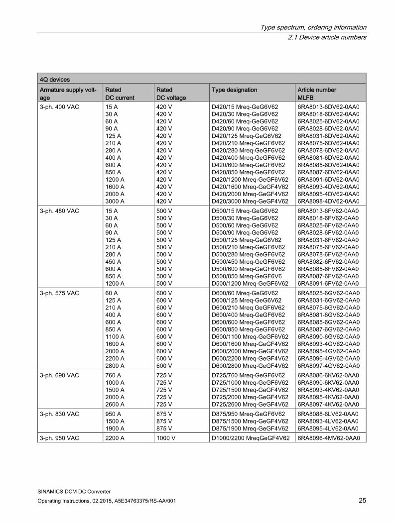
4Q devices Armature supply volt-age
Rated DC current
Rated DC voltage
Type designation Article number MLFB
3-ph. 400 VAC 15 A 30 A 60 A 90 A 125 A 210 A 280 A 400 A 600 A 850 A 1200 A 1600 A 2000 A 3000 A
420 V 420 V 420 V 420 V 420 V 420 V 420 V 420 V 420 V 420 V 420 V 420 V 420 V 420 V
D420/15 Mreq-GeG6V62 D420/30 Mreq-GeG6V62 D420/60 Mreq-GeG6V62 D420/90 Mreq-GeG6V62 D420/125 Mreq-GeG6V62 D420/210 Mreq-GeGF6V62 D420/280 Mreq-GeGF6V62 D420/400 Mreq-GeGF6V62 D420/600 Mreq-GeGF6V62 D420/850 Mreq-GeGF6V62 D420/1200 Mreq-GeGF6V62 D420/1600 Mreq-GeGF4V62 D420/2000 Mreq-GeGF4V62 D420/3000 Mreq-GeGF4V62
6RA8013-6DV62-0AA0 6RA8018-6DV62-0AA0 6RA8025-6DV62-0AA0 6RA8028-6DV62-0AA0 6RA8031-6DV62-0AA0 6RA8075-6DV62-0AA0 6RA8078-6DV62-0AA0 6RA8081-6DV62-0AA0 6RA8085-6DV62-0AA0 6RA8087-6DV62-0AA0 6RA8091-6DV62-0AA0 6RA8093-4DV62-0AA0 6RA8095-4DV62-0AA0 6RA8098-4DV62-0AA0
3-ph. 480 VAC 15 A 30 A 60 A 90 A 125 A 210 A 280 A 450 A 600 A 850 A 1200 A
500 V 500 V 500 V 500 V 500 V 500 V 500 V 500 V 500 V 500 V 500 V
D500/15 Mreq-GeG6V62 D500/30 Mreq-GeG6V62 D500/60 Mreq-GeG6V62 D500/90 Mreq-GeG6V62 D500/125 Mreq-GeG6V62 D500/210 Mreq-GeGF6V62 D500/280 Mreq-GeGF6V62 D500/450 Mreq-GeGF6V62 D500/600 Mreq-GeGF6V62 D500/850 Mreq-GeGF6V6 D500/1200 Mreq-GeGF6V62
6RA8013-6FV62-0AA0 6RA8018-6FV62-0AA0 6RA8025-6FV62-0AA0 6RA8028-6FV62-0AA0 6RA8031-6FV62-0AA0 6RA8075-6FV62-0AA0 6RA8078-6FV62-0AA0 6RA8082-6FV62-0AA0 6RA8085-6FV62-0AA0 6RA8087-6FV62-0AA0 6RA8091-6FV62-0AA0
3-ph. 575 VAC 60 A 125 A 210 A 400 A 600 A 850 A 1100 A 1600 A 2000 A 2200 A 2800 A
600 V 600 V 600 V 600 V 600 V 600 V 600 V 600 V 600 V 600 V 600 V
D600/60 Mreq-GeG6V62 D600/125 Mreq-GeG6V62 D600/210 Mreq GeGF6V62 D600/400 Mreq-GeGF6V62 D600/600 Mreq-GeGF6V62 D600/850 Mreq-GeGF6V62 D600/1100 Mreq-GeGF6V62 D600/1600 Mreq-GeGF4V62 D600/2000 Mreq-GeGF4V62 D600/2200 Mreq-GeGF4V62 D600/2800 Mreq-GeGF4V62
6RA8025-6GV62-0AA0 6RA8031-6GV62-0AA0 6RA8075-6GV62-0AA0 6RA8081-6GV62-0AA0 6RA8085-6GV62-0AA0 6RA8087-6GV62-0AA0 6RA8090-6GV62-0AA0 6RA8093-4GV62-0AA0 6RA8095-4GV62-0AA0 6RA8096-4GV62-0AA0 6RA8097-4GV62-0AA0
3-ph. 690 VAC 760 A 1000 A 1500 A 2000 A 2600 A
725 V 725 V 725 V 725 V 725 V
D725/760 Mreq-GeGF6V62 D725/1000 Mreq-GeGF6V62 D725/1500 Mreq-GeGF4V62 D725/2000 Mreq-GeGF4V62 D725/2600 Mreq-GeGF4V62
6RA8086-6KV62-0AA0 6RA8090-6KV62-0AA0 6RA8093-4KV62-0AA0 6RA8095-4KV62-0AA0 6RA8097-4KV62-0AA0
3-ph. 830 VAC 950 A 1500 A 1900 A
875 V 875 V 875 V
D875/950 Mreq-GeGF6V62 D875/1500 Mreq-GeGF4V62 D875/1900 Mreq-GeGF4V62
6RA8088-6LV62-0AA0 6RA8093-4LV62-0AA0 6RA8095-4LV62-0AA0
3-ph. 950 VAC 2200 A 1000 V D1000/2200 MreqGeGF4V62 6RA8096-4MV62-0AA0
Type spectrum, ordering information 2.2 Key for the device article numbers
SINAMICS DCM DC Converter 26 Operating Instructions, 02.2015, A5E34763375/RS-AA/001
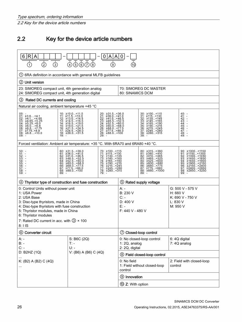
2.2 Key for the device article numbers
① 6RA definition in accordance with general MLFB guidelines
② Unit version 23: SIMOREG compact unit, 4th generation analog 24: SIMOREG compact unit, 4th generation digital
70: SIMOREG DC MASTER 80: SINAMICS DCM
③ Rated DC currents and cooling Natural air cooling, ambient temperature +45 °C
Forced ventilation: Ambient air temperature: +35 °C. With 6RA70 and 6RA80 +40 °C.
④ Thyristor type of construction and fuse construction ⑤ Rated supply voltage 0: Control Units without power unit 1: USA Power 2: USA Base 3: Disc-type thyristors, made in China 4: Disc-type thyristors with fuse construction 5: Thyristor modules, made in China 6: Thyristor modules 7: Rated DC current in acc. with ③ × 100 8: I IS
A: - B: 230 V C: - D: 400 V E: - F: 440 V - 480 V
G: 500 V - 575 V H: 660 V K: 690 V - 750 V L: 830 V M: 950 V
⑥ Converter circuit ⑦ Closed-loop control A: - B: - C: - D: B2HZ (1Q) ... K: (B2) A (B2) C (4Q) ...
S: B6C (2Q) T: - U: - V: (B6) A (B6) C (4Q)
0: No closed-loop control 1: 2Q, analog 2: 2Q, digital
6: 4Q digital 7: 4Q analog
⑧ Field closed-loop control 0: No field 1: Field without closed-loop control
2: Field with closed-loop control
⑨ Innovation
⑩ Z: With option

Type spectrum, ordering information 2.2 Key for the device article numbers
SINAMICS DCM DC Converter Operating Instructions, 02.2015, A5E34763375/RS-AA/001 27
Type spectrum, ordering information 2.3 Rating plates, packaging label
SINAMICS DCM DC Converter 28 Operating Instructions, 02.2015, A5E34763375/RS-AA/001
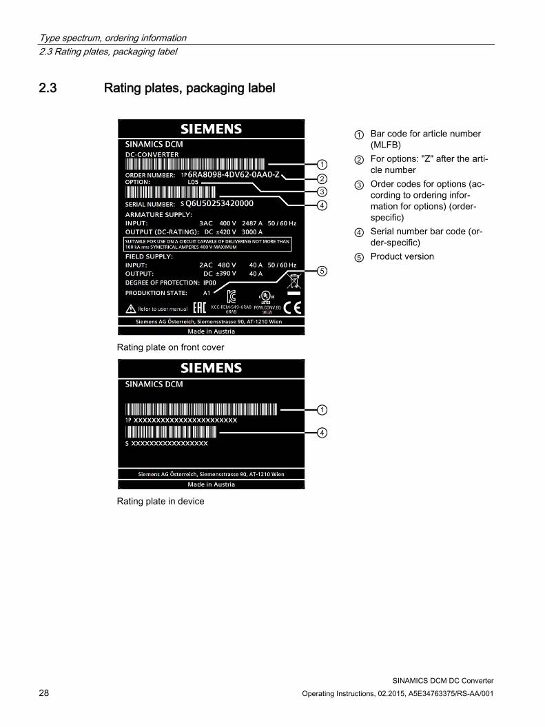
2.3 Rating plates, packaging label
Rating plate on front cover
Rating plate in device
① Bar code for article number
(MLFB) ② For options: "Z" after the arti-
cle number ③ Order codes for options (ac-
cording to ordering infor-mation for options) (order-specific)
④ Serial number bar code (or-der-specific)
⑤ Product version

Type spectrum, ordering information 2.3 Rating plates, packaging label
SINAMICS DCM DC Converter Operating Instructions, 02.2015, A5E34763375/RS-AA/001 29
① For options: "Z" after the article number ② Order codes for options (according to ordering information for options)
Figure 2-2 Packaging label
Type spectrum, ordering information 2.4 Ordering information for options and accessories
SINAMICS DCM DC Converter 30 Operating Instructions, 02.2015, A5E34763375/RS-AA/001
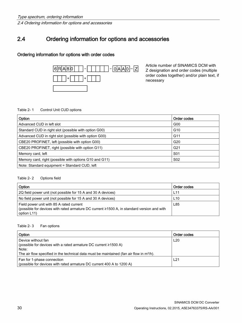
2.4 Ordering information for options and accessories
Ordering information for options with order codes
Article number of SINAMICS DCM with Z designation and order codes (multiple order codes together) and/or plain text, if necessary
Table 2- 1 Control Unit CUD options
Option Order codes Advanced CUD in left slot G00 Standard CUD in right slot (possible with option G00) G10 Advanced CUD in right slot (possible with option G00) G11 CBE20 PROFINET, left (possible with option G00) G20 CBE20 PROFINET, right (possible with option G11) G21 Memory card, left S01 Memory card, right (possible with options G10 and G11) S02 Note: Standard equipment = Standard CUD, left
Table 2- 2 Options field
Option Order codes 2Q field power unit (not possible for 15 A and 30 A devices) L11 No field power unit (not possible for 15 A and 30 A devices) L10 Field power unit with 85 A rated current (possible for devices with rated armature DC current ≥1500 A, in standard version and with option L11)
L85
Table 2- 3 Fan options
Option Order codes Device without fan (possible for devices with a rated armature DC current ≥1500 A) Note: The air flow specified in the technical data must be maintained (fan air flow in m3/h).
L20
Fan for 1-phase connection (possible for devices with rated armature DC current 400 A to 1200 A)
L21
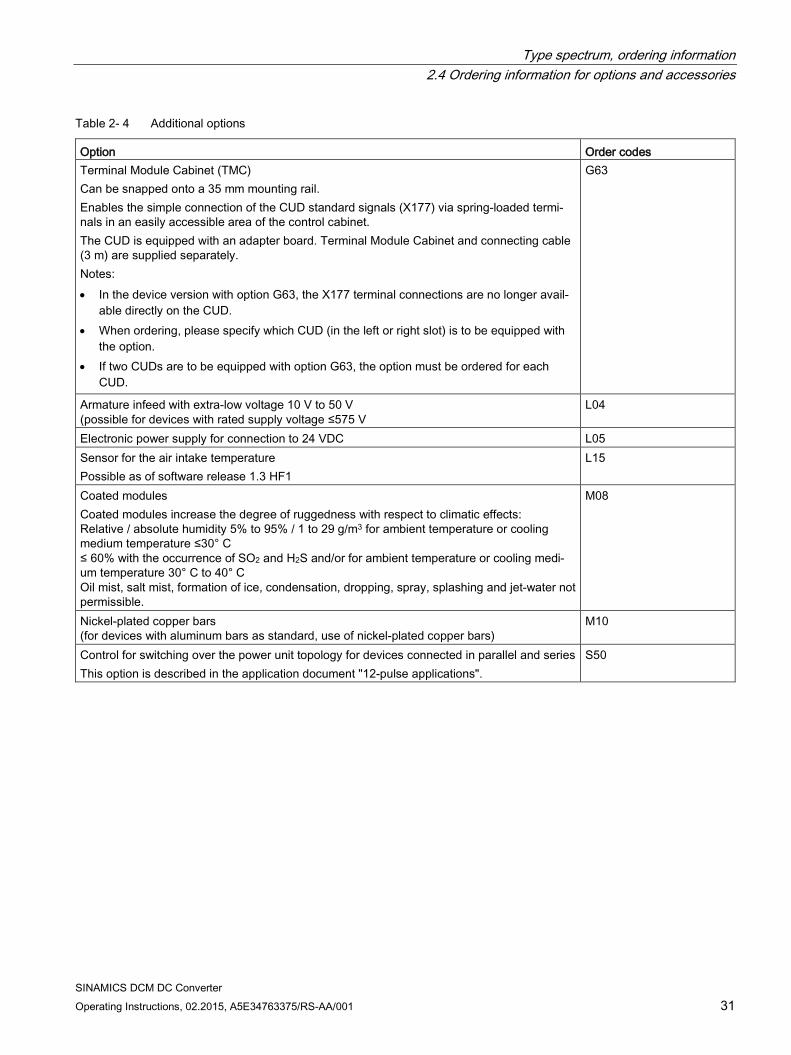
Type spectrum, ordering information 2.4 Ordering information for options and accessories
SINAMICS DCM DC Converter Operating Instructions, 02.2015, A5E34763375/RS-AA/001 31
Table 2- 4 Additional options
Option Order codes Terminal Module Cabinet (TMC) Can be snapped onto a 35 mm mounting rail. Enables the simple connection of the CUD standard signals (X177) via spring-loaded termi-nals in an easily accessible area of the control cabinet. The CUD is equipped with an adapter board. Terminal Module Cabinet and connecting cable (3 m) are supplied separately. Notes: • In the device version with option G63, the X177 terminal connections are no longer avail-
able directly on the CUD. • When ordering, please specify which CUD (in the left or right slot) is to be equipped with
the option. • If two CUDs are to be equipped with option G63, the option must be ordered for each
CUD.
G63
Armature infeed with extra-low voltage 10 V to 50 V (possible for devices with rated supply voltage ≤575 V
L04
Electronic power supply for connection to 24 VDC L05 Sensor for the air intake temperature Possible as of software release 1.3 HF1
L15
Coated modules Coated modules increase the degree of ruggedness with respect to climatic effects: Relative / absolute humidity 5% to 95% / 1 to 29 g/m3 for ambient temperature or cooling medium temperature ≤30° C ≤ 60% with the occurrence of SO2 and H2S and/or for ambient temperature or cooling medi-um temperature 30° C to 40° C Oil mist, salt mist, formation of ice, condensation, dropping, spray, splashing and jet-water not permissible.
M08
Nickel-plated copper bars (for devices with aluminum bars as standard, use of nickel-plated copper bars)
M10
Control for switching over the power unit topology for devices connected in parallel and series This option is described in the application document "12-pulse applications".
S50

Type spectrum, ordering information 2.4 Ordering information for options and accessories
SINAMICS DCM DC Converter 32 Operating Instructions, 02.2015, A5E34763375/RS-AA/001
Ordering information for accessories
Table 2- 5 Articles numbers for documentation
Article Article number Set of manuals, German 6RX1800-0GD00 SINAMICS DCM DC Converter Operating Instructions, German 6RX1800-0AD00 SINAMICS DCM List Manual, German 6RX1800-0ED00 Free Function Blocks Manual, German 6RX1800-0FD00 Set of manuals, English 6RX1800-0GD76 SINAMICS DCM DC Converter Operating Instructions, English 6RX1800-0AD76 SINAMICS DCM List Manual, English 6RX1800-0ED76 Free Function Blocks Manual, English 6RX1800-0FD76 Set of manuals, French (includes the Free Function Blocks Manual in English)
6RX1800-0GD77
SINAMICS DCM DC Converter Operating Instructions, French 6RX1800-0AD77 SINAMICS DCM List Manual, French 6RX1800-0ED77 Set of manuals, Italian (includes the Free Function Blocks Manual in English)
6RX1800-0GD72
SINAMICS DCM DC Converter Operating Instructions, Italian 6RX1800-0AD72 SINAMICS DCM List Manual, Italian 6RX1800-0ED72 Set of manuals, Russian (includes the Free Function Blocks Manual in English)
6RX1800-0GD56
SINAMICS DCM DC Converter Operating Instructions, Russian 6RX1800-0AD56 SINAMICS DCM List Manual, Russian 6RX1800-0ED56 Set of manuals, Spanish (includes the Free Function Blocks Manual in English)
6RX1800-0GD78
SINAMICS DCM DC Converter Operating Instructions, Spanish 6RX1800-0AD78 SINAMICS DCM List Manual, Spanish 6RX1800-0ED78 Set of manuals, Chinese (includes the Free Function Blocks Manual in English)
6RX1800-0GD27
SINAMICS DCM DC Converter Operating Instructions, Chinese 6RX1800-0AD27 SINAMICS DCM List Manual, Chinese 6RX1800-0ED27 All documentation in all of the above languages on DVD 6RX1800-0AD64
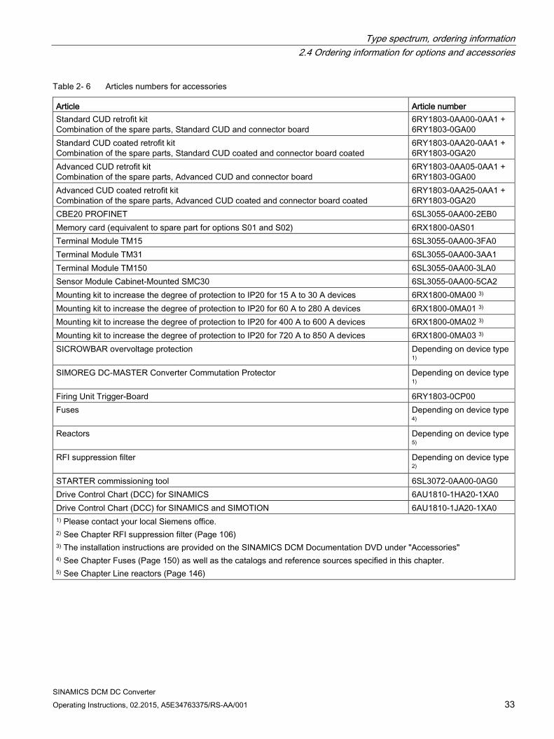
Type spectrum, ordering information 2.4 Ordering information for options and accessories
SINAMICS DCM DC Converter Operating Instructions, 02.2015, A5E34763375/RS-AA/001 33
Table 2- 6 Articles numbers for accessories
Article Article number Standard CUD retrofit kit Combination of the spare parts, Standard CUD and connector board
6RY1803-0AA00-0AA1 + 6RY1803-0GA00
Standard CUD coated retrofit kit Combination of the spare parts, Standard CUD coated and connector board coated
6RY1803-0AA20-0AA1 + 6RY1803-0GA20
Advanced CUD retrofit kit Combination of the spare parts, Advanced CUD and connector board
6RY1803-0AA05-0AA1 + 6RY1803-0GA00
Advanced CUD coated retrofit kit Combination of the spare parts, Advanced CUD coated and connector board coated
6RY1803-0AA25-0AA1 + 6RY1803-0GA20
CBE20 PROFINET 6SL3055-0AA00-2EB0 Memory card (equivalent to spare part for options S01 and S02) 6RX1800-0AS01 Terminal Module TM15 6SL3055-0AA00-3FA0 Terminal Module TM31 6SL3055-0AA00-3AA1 Terminal Module TM150 6SL3055-0AA00-3LA0 Sensor Module Cabinet-Mounted SMC30 6SL3055-0AA00-5CA2 Mounting kit to increase the degree of protection to IP20 for 15 A to 30 A devices 6RX1800-0MA00 3) Mounting kit to increase the degree of protection to IP20 for 60 A to 280 A devices 6RX1800-0MA01 3) Mounting kit to increase the degree of protection to IP20 for 400 A to 600 A devices 6RX1800-0MA02 3) Mounting kit to increase the degree of protection to IP20 for 720 A to 850 A devices 6RX1800-0MA03 3) SICROWBAR overvoltage protection Depending on device type
1) SIMOREG DC-MASTER Converter Commutation Protector Depending on device type
1) Firing Unit Trigger-Board 6RY1803-0CP00 Fuses Depending on device type
4) Reactors Depending on device type
5) RFI suppression filter Depending on device type
2) STARTER commissioning tool 6SL3072-0AA00-0AG0 Drive Control Chart (DCC) for SINAMICS 6AU1810-1HA20-1XA0 Drive Control Chart (DCC) for SINAMICS and SIMOTION 6AU1810-1JA20-1XA0 1) Please contact your local Siemens office. 2) See Chapter RFI suppression filter (Page 106) 3) The installation instructions are provided on the SINAMICS DCM Documentation DVD under "Accessories" 4) See Chapter Fuses (Page 150) as well as the catalogs and reference sources specified in this chapter. 5) See Chapter Line reactors (Page 146)
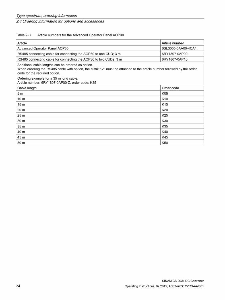
Type spectrum, ordering information 2.4 Ordering information for options and accessories
SINAMICS DCM DC Converter 34 Operating Instructions, 02.2015, A5E34763375/RS-AA/001
Table 2- 7 Article numbers for the Advanced Operator Panel AOP30
Article Article number Advanced Operator Panel AOP30 6SL3055-0AA00-4CA4 RS485 connecting cable for connecting the AOP30 to one CUD; 3 m 6RY1807-0AP00 RS485 connecting cable for connecting the AOP30 to two CUDs; 3 m 6RY1807-0AP10 Additional cable lengths can be ordered as option. When ordering the RS485 cable with option, the suffix "-Z" must be attached to the article number followed by the order code for the required option. Ordering example for a 35 m long cable: Article number: 6RY1807-0AP00-Z, order code: K35 Cable length Order code 5 m K05 10 m K10 15 m K15 20 m K20 25 m K25 30 m K30 35 m K35 40 m K40 45 m K45 50 m K50
Type spectrum, ordering information 2.5 Accessories
SINAMICS DCM DC Converter Operating Instructions, 02.2015, A5E34763375/RS-AA/001 35
2.5 Accessories
2.5.1 SIMOREG DC-MASTER Converter Commutation Protector (CCP) As supplement to the series of SINAMICS DCM converters, we offer the SIMOREG DC-MASTER Converter Commutation Protector (SIMOREG CCP).
Area of application The SIMOREG DC-MASTER Converter Commutation Protector (SIMOREG CCP) is used to protect the semiconductor fuses of a line-commutated converter when operating in the inverter mode.
When an inverter commutation fault occurs, a high current flows in the regenerative feedback direction via the line supply or a cross-current in the converter. SIMOREG CCP limits the current to a non-hazardous value so that the thyristors and the associated super-fast fuses are protected. This therefore eliminates the complex replacement of fuses that takes a considerable amount of time. Although it cannot prevent inverter commutation faults, it can protect its effects.
Compatibility The SIMOREG CCP is compatible to line-commutated SIMOREG DC-MASTER converters (6RA70 series) and SINAMICS DCM. It can be used for converters connected in parallel.
Using the SIMOREG CCP The SIMOREG CCP is operated (parameter assignment, fault signals) is realized via the SINAMICS DCM. The SINAMICS DCM must have a software release of 1.2 or higher.
For a parallel connection of SINAMICS DCM units, a SIMOREG CCP must be used for each SINAMICS DCM. In this particular application, each of the SINAMICS DCM must be equipped with a Firing Unit Trigger-Board. The input for the "fast pulse inhibit interface" is implemented there.
For ordering data, see also the section titled "Ordering information for options and accessories".
The operating instructions for the SIMOREG CCP are included on the DVD "SINAMICS DCM documentation". These operating instructions also include
help to select the suitable SIMOREG CCP
the instructions to install the Firing Unit Trigger-Board in the SINAMICS DCM
the instructions to operate the SINAMICS DCM with the SIMOREG CCP
Type spectrum, ordering information 2.5 Accessories
SINAMICS DCM DC Converter 36 Operating Instructions, 02.2015, A5E34763375/RS-AA/001
NOTICE
The parallel interface (X165, X166) at the SINAMICS DCM is not compatible to the parallel interface (X165) at the SIMOREG CCP. It is not permissible that both connectors are connected.
For more detailed information as well as support when selecting a suitable SIMOREG CCP for your application, please contact your local Siemens office.
2.5.2 Mounting kit to increase the degree of protection to IP20 Degree of protection IP20 acc. to EN 60529
The degree of protection indicates protection against touching and penetration of solid objects and/or water.
Units in the SINAMICS DCM range are delivered with degree of protection IP00 and therefore offer no protection against touching or penetration. The mounting kit for units with a rated DC current up to 850 A increases the degree of protection to IP20.
Degree of protection IP20 offer protection against touching with the finger and penetration of solid objects greater than 12.5 mm dia, but no protection against water.
For ordering data, see also the section titled "Ordering information for options and accessories".
The installation instructions are provided on the SINAMICS DCM Documentation DVD (as of 12/2010 edition) under "Accessories"
SINAMICS DCM DC Converter Operating Instructions, 02.2015, A5E34763375/RS-AA/001 37
Description 3
Area of application The SINAMICS DC MASTER converter units have been specifically designed to supply the armature and field of variable-speed DC motors.
Alternative applications (e.g. supplying the field of a synchronous generator) are also possible.
Design SINAMICS DC MASTER converter units are compact units containing both the power unit for the armature supply and the power unit for the field supply, as well as the control electronics and possible additional modules.
In the case of units with a 15 A to 1200 A rated DC current, the power units for the armature and field include electrically insulated thyristor modules, meaning that the heat sink is at ground potential. In units with a higher rated DC current, the power unit for the armature circuit includes disc-type thyristors and heat sinks (thyristor modules) at voltage potential.
The units have degree of protection IP00.
The connecting terminals are accessible from the front. The fan supply is fed in from the top; depending on the unit type, the field supply is either fed in from the top or the bottom.
All SINAMICS DC MASTER units are equipped with a Basic Operator Panel BOP20 in the front plate.
The BOP20 can be used
To make all the settings that are required for commissioning
To display all relevant measured values
To display faults and alarms and acknowledge faults
To switch the drive on and off
Versions The armature supply is available in the following versions:
2-quadrant units: The armature is supplied via a fully-controlled three-phase bridge (B6C).
4-quadrant units: The armature is supplied via two fully-controlled three-phase bridges connected in a circulating-current-free inverse-parallel configuration ((B6)A(B6)C).

Description
SINAMICS DCM DC Converter 38 Operating Instructions, 02.2015, A5E34763375/RS-AA/001
The field supply is available in the following versions:
1-phase, single-pair controllable two-pulse bridge circuit (B2HZ)
1-phase, fully-controlled two-pulse bridge circuit (B2C) (option)
The electronics (CUD) are available in the following versions:
Standard CUD
Advanced CUD (option) This CUD can be expanded to include a PROFINET module (CBE20) and features two DRIVE-CLiQ connections for connecting additional components from the SINAMICS drive system, as well as a connector for expansion purposes (to include a second CUD).
Additional (second) CUD (Standard or Advanced) (option) This additional CUD can be fitted to the right of the first CUD and is used for system-specific extension of the SINAMICS DC MASTER functions.
Additional components Advanced Operator Panel AOP30
The optional Advanced Operator Panel AOP30 is mounted outside of the unit - in the control cabinet door, for example - rather than inside it. The AOP30
– Supports commissioning by means of a commissioning wizard
– Supports the display of measured values via a graphical operation screen
– Displays a user-friendly parameter list, including text
– Features several editors for user-friendly setting and changing of parameters
– Displays lists of faults and alarms that have occurred, as well as help text concerning the individual faults and alarms
– Enables "local" drive control (ON/OFF, setpoint setting, jog mode, direction reversal)
– Features three LEDs for displaying the drive state
Additional module CBE20 The additional module CBE20 is inserted in the optional module slot of an Advanced CUD. It enables the SINAMICS DC MASTER to participate in PROFINET network as slave as well as to establish SINAMICS Link connections.
DRIVE-CLiQ components The DRIVE-CLiQ interface enables components from the SINAMICS drive system to be connected. The following components are supported:
– TM15 (digital inputs/outputs)
– TM31 (digital inputs/outputs, analog inputs/outputs)
– TM150 (temperature sensor inputs)
– SMC30 (incremental encoder evaluation for actual speed value acquisition)
An SMC30 and up to three TMx modules can be connected to each CUD.

Description
SINAMICS DCM DC Converter Operating Instructions, 02.2015, A5E34763375/RS-AA/001 39
Free function blocks (FBLOCKS) In a wide variety of applications, a logic operation connecting several states (e.g. access control, system status) to a control signal (e.g. ON command) is required to control the drive system. In addition to logic operations, however, drive systems require mathematical operations and latching elements. These functions are available in the form of the "free function blocks" function module. There is a range of elementary function blocks that are freely available for use:
– Logic function blocks (AND, OR, XOR, inverter)
– Calculation function blocks (adder, multiplier, divider, absolute-value generator)
– Time function blocks (pulse generator, pulse contracting block, ON delay, OFF delay, pulse stretching)
– Memory function blocks (RS flip-flop, D flip-flop)
– Switch function blocks (binary selector switch, numerical selector switch)
– Control function blocks (limiter, smoothing element, integrator, derivative element)
– Complex function blocks (double-sided limit monitor with hysteresis)
Drive Control Chart (DCC) DCC is available for applications requiring a more complex method of controlling the drive system which cannot be accomplished using the free function blocks. DCC makes it possible for one of the interconnected elementary function blocks to generate a graphical depiction of an existing function diagram and load it to the SINAMICS DC MASTER. The function diagram may contain up to 750 function blocks. It is possible to configure the time slices in which the individual parts of the function diagram are processed. Note: A DCC function diagram can be loaded not only to the CUD in the left-hand slot, but also to an optional second CUD in the right-hand slot. The automatic speed control processes are computed on the CUD in the left-hand slot, which means that it only provides a small amount of computing capacity for a DCC function diagram (in other words, either only a few function blocks can be computed, or computing can only be carried out in a long time slice). The CUD in the right-hand slot is primarily available (in addition to the operating system) for one DCC function diagram only.

Description
SINAMICS DCM DC Converter 40 Operating Instructions, 02.2015, A5E34763375/RS-AA/001

SINAMICS DCM DC Converter Operating Instructions, 02.2015, A5E34763375/RS-AA/001 41
Technical data 4
Note
You can find the technical data for the connectors and terminals in the section titled "Connecting".

Technical data 4.1 Load types
SINAMICS DCM DC Converter 42 Operating Instructions, 02.2015, A5E34763375/RS-AA/001
4.1 Load types For maximum efficiency when adapting the SINAMICS DC MASTER to the load profile for the driven machine, you can use the load cycle to carry out dimensioning.
Parameter p50067 is used to make the setting on the SINAMICS DC MASTER.
Table 4- 1 Load classes
Load class Load for converter Load cycle DC I (p50067 = 1)
IDC I continuous (IdN)
DC II (p50067 = 2)
IDC II for 15 mins and 1.5 × IDC II for 60 s
DC III (p50067 = 3)
IDC III for 15 mins and 1.5 × IDC III for 120 s
DC IV (p50067 = 4)
IDC IV for 15 mins and 2 × IDC IV for 10 s
US rating (p50067 = 5)
IUS for 15 mins and 1.5 × IUS for 60 s

Technical data 4.1 Load types
SINAMICS DCM DC Converter Operating Instructions, 02.2015, A5E34763375/RS-AA/001 43
Note • If a value > 1 is set at p50067, you need to make sure that the "Dynamic overload
capability of the power unit" is enabled. This requires a value > 0 to be set at p50075. • The SINAMICS DC MASTER does not monitor whether the load class set using p50067
is being adhered to. If the power unit permits it, longer overload periods can be used than correspond to the load class. The actual permissible overload duration for the particular power unit is always greater than the overload duration corresponding to the particular load class. and the SINAMICS DC MASTER does monitor whether the overload duration that is actually permitted for the power unit is being adhered to. For details on the power unit's dynamic overload capability, refer to Chapter 10.
• The 100 % IDCx shown above DO NOT generally correspond to the rated unit current, but are reduced corresponding to the subsequent table.

Technical data 4.1 Load types
SINAMICS DCM DC Converter 44 Operating Instructions, 02.2015, A5E34763375/RS-AA/001
Duty cycles for 2Q applications
Table 4- 2 Duty cycles
SINAMICS DCM
6RA80..
Duty cycles Tu DC I
continuous DC II DC III DC IV US rating
Tu = 45 °C 15 min 100 %
60 s 150%
15 min 100 %
120 s 150%
15 min 100 %
10 s 200 %
15 min 100 %
60 s 150%
°C A A A A A A A A A 400 V, 2Q .25-6DS22 45 60 51.4 77.1 50.2 75.3 46.4 92.8 51.4 77.1 .28-6DS22 45 90 74.4 111 72.8 109 65.4 130 74.4 111 .31-6DS22 45 125 106 159 103 155 96.3 192 106 159 .75-6DS22 40 210 164 247 161 242 136 273 157 236 .78-6DS22 40 280 226 340 219 328 201 402 215 323 .81-6DS22 40 400 290 435 282 423 244 488 278 417 .85-6DS22 40 600 462 693 446 669 413 826 443 665 .87-6DS22 40 850 652 978 622 933 609 1219 619 929 .91-6DS22 40 1200 884 1326 857 1286 768 1537 842 1263 .93-4DS22 40 1600 1255 1883 1213 1819 1139 2279 1190 1785 .95-4DS22 40 2000 1477 2216 1435 2152 1326 2653 1404 2106 .98-4DS22 40 3000 2288 3432 2189 3283 2164 4328 2178 3267 480 V, 2Q .25-6FS22 45 60 51.4 77.1 50.2 75.3 46.4 92.8 51.4 77.1 .28-6FS22 45 90 74.4 111 72.8 109 65.4 130 74.4 111 .31-6FS22 45 125 106 159 103 155 96.3 192 106 159 .75-6FS22 40 210 164 247 161 242 136 273 157 236 .78-6FS22 40 280 226 340 219 328 201 402 215 323 .82-6FS22 40 450 320 480 311 466 274 548 306 460 .85-6FS22 40 600 462 693 446 669 413 826 443 665 .87-6FS22 40 850 652 978 622 933 609 1219 619 929 .91-6FS22 40 1200 884 1326 857 1286 768 1537 842 1263 575 V, 2Q .25-6GS22 45 60 51.4 77.1 50.2 75.3 46.4 92.8 51.4 77.1 .31-6GS22 45 125 106 159 103 155 96.3 192 106 159 .75-6GS22 40 210 164 247 161 242 136 273 157 236 .81-6GS22 40 400 290 435 282 423 244 488 278 417 .85-6GS22 40 600 462 693 446 669 413 826 443 665 .87-6GS22 40 800 607 911 581 872 559 1118 578 867 .90-6GS22 40 1100 804 1207 782 1173 689 1379 766 1150 .93-4GS22 40 1600 1255 1883 1213 1819 1139 2279 1190 1785 .95-4GS22 40 2000 1663 2494 1591 2386 1568 3136 1569 2354 .96-4GS22 40 2200 1779 2669 1699 2549 1697 3394 1678 2517

Technical data 4.1 Load types
SINAMICS DCM DC Converter Operating Instructions, 02.2015, A5E34763375/RS-AA/001 45
.97-4GS22 40 2800 2136 3204 2044 3066 2022 4044 2024 3036 690 V, 2Q .86-6KS22 40 720 553 829 527 791 515 1031 525 788 .90-6KS22 40 1000 737 1105 715 1072 639 1279 702 1053 .93-4KS22 40 1500 1171 1757 1140 1710 1036 2073 1116 1674 .95-4KS22 40 2000 1589 2383 1522 2283 1505 3011 1503 2255 .97-4KS22 40 2600 1992 2989 1906 2859 1887 3774 1876 2815 830 V, 2Q .88-6LS22 40 950 700 1051 679 1019 607 1215 667 1001 .93-4LS22 40 1500 1171 1757 1140 1710 1036 2073 1116 1674 .95-4LS22 40 1900 1485 2228 1421 2132 1396 2793 1414 2121 950 V, 2Q .96-4MS22 40 2200 1674 2511 1603 2404 1570 3141 1588 2382
Duty cycles for 4Q applications
Table 4- 3 Duty cycles
SINAMICS DCM
6RA80..
Duty cycles Tu DC I
continuous DC II DC III DC IV US rating
Tu = 45 °C 15 min 100 %
60 s 150%
15 min 100 %
120 s 150%
15 min 100 %
10 s 200 %
15 min 100 %
60 s 150%
°C A A A A A A A A A 400 V, 4Q .13-6DV62 45 15 13.9 20.8 13.5 20.2 12.6 25.2 13.9 20.8 .18-6DV62 45 30 24.9 37.3 24.2 36.3 22.4 44.8 24.9 37.3 .25-6DV62 45 60 53.1 79.6 51.8 77.7 47.2 94.4 53.1 79.6 .28-6DV62 45 90 78.2 117 76.0 114 72.2 144 78.2 117 .31-6DV62 45 125 106 159 103 155 95.4 190 106 159 .75-6DV62 40 210 164 247 161 242 136 273 157 236 .78-6DV62 40 280 226 340 219 328 201 402 215 323 .81-6DV62 40 400 300 450 292 438 247 494 285 428 .85-6DV62 40 600 470 706 453 680. 410 820 450 675 .87-6DV62 40 850 658 987 634 951 579 1159 626 939 .91-6DV62 40 1200 884 1326 857 1286 768 1537 842 1263 .93-4DV62 40 1600 1255 1883 1213 1819 1139 2279 1190 1785 .95-4DV62 40 2000 1477 2216 1435 2152 1326 2653 1404 2106 .98-4DV62 40 3000 2288 3432 2189 3283 2164 4328 2178 3267 480 V, 4Q .13-6FV62 45 15 13.9 20.8 13.5 20.2 12.6 25.2 13.9 20.8 .18-6FV62 45 30 24.9 37.3 24.2 36.3 22.4 44.8 24.9 37.3 .25-6FV62 45 60 53.1 79.6 51.8 77.7 47.2 94.4 53.1 79.6 .28-6FV62 45 90 78.2 117 76 114 72.2 144 78.2 117

Technical data 4.1 Load types
SINAMICS DCM DC Converter 46 Operating Instructions, 02.2015, A5E34763375/RS-AA/001
.31-6FV62 45 125 106 159 103 155 95.4 190 106 159
.75-6FV62 40 210 164 247 161 242 136 273 157 236
.78-6FV62 40 280 226 340 219 328 201 402 215 323
.82-6FV62 40 450 320 480 311 466 274 548 306 460
.85-6FV62 40 600 470 706 453 680 410 820 450 675
.87-6FV62 40 850 658 987 634 951 579 1159 626 939
.91-6FV62 40 1200 884 1326 857 1286 768 1537 842 1263 575 V, 4Q .25-6GV62 45 60 53.1 79.6 51.8 77.7 47.2 94.4 53.1 79.6 .31-6GV62 45 125 106 159 103 155 95.4 190 106 159 .75-6GV62 40 210 164 247 161 242 136 273 157 236 .81-6GV62 40 400 300 450 292 438 247 494 285 428 .85-6GV62 40 600 470 706 453 680 410 820 450 675 .87-6GV62 40 850 658 987 634 951 579 1159 626 939 .90-6GV62 40 1100 804 1207 782 1173 689 1379 766 1150 .93-4GV62 40 1600 1255 1883 1213 1819 1139 2279 1190 1785 .95-4GV62 40 2000 1663 2494 1591 2386 1568 3136 1569 2354 .96-4GV62 40 2200 1779 2669 1699 2549 1697 3394 1678 2517 .97-4GV62 40 2800 2136 3204 2044 3066 2022 4044 2024 3036 690 V, 4Q .86-6KV62 40 760 598 898 575 863 532 1065 569 853 .90-6KV62 40 1000 737 1105 715 1072 639 1279 702 1053 .93-4KV62 40 1500 1171 1757 1140 1710 1036 2073 1116 1674 .95-4KV62 40 2000 1589 2383 1522 2283 1505 3011 1503 2255 .97-4KV62 40 2600 1992 2989 1906 2859 1887 3774 1876 2815 830 V, 4Q .88-6LV62 40 950 700 1051 679 1019 607 1215 667 1001 .93-4LV62 40 1500 1171 1757 1140 1710 1036 2073 1116 1674 .95-4LV62 40 1900 1485 2228 1421 2132 1396 2793 1414 2121 950 V, 4Q .96-4MV62 40 2200 1674 2511 1603 2404 1570 3141 1588 2382

Technical data 4.2 Environmental requirements
SINAMICS DCM DC Converter Operating Instructions, 02.2015, A5E34763375/RS-AA/001 47
4.2 Environmental requirements
Environmental classes according to EN 60721-3
Table 4- 4 Environmental classes
Use Environmental condition Environmental class
Comment
Operation Mechanical stability see remark • Vibratory load (test and measuring proce-dure according to EN 60068-2-6, Fc): Con-stant deflection = 0.075 mm at 10 ... 58 Hz Constant acceleration = 10 m/s² at 58 ... 200 Hz
• Shock load (test and measuring procedure according to EN 60068-2-27, Ea): Accelera-tion = 150 m/s² at 11 ms
Climatic influences 3K3 No condensation, splash water, or icing allowed. For air temperature, see "Ambient temperature" below
Biological influences 3B1 - Hazardous chemical substances 3C1 - Mechanically hazardous materials 3S2 -
Transporta-tion
Mechanical stability 2M2 Tipping is not permitted. Climatic influences 2K2 Air temperature of -40 °C to +70 °C is permitted
1) Biological influences 2B1 - Hazardous chemical substances 2C1 - Mechanically hazardous materials 2S1 -
Storage Mechanical stability 1M2 Tipping is not permitted. Climatic influences 1K3 Air temperature of -40 °C to +70 °C is permitted
1) Biological influences 1B1 - Hazardous chemical substances 1C1 - Mechanically hazardous materials 1S1 -
1) Only applies when product is in its original packing

Technical data 4.2 Environmental requirements
SINAMICS DCM DC Converter 48 Operating Instructions, 02.2015, A5E34763375/RS-AA/001
Ambient temperature
Table 4- 5 Ambient temperature Tu
Use Tu [°C] Comment Storage -40 ... +70 Only applies when product is in its original packing Transportation -40 ... +70 Only applies when product is in its original packing Operation 0 ... +45 for units with a rated DC current ≤125 A (self-ventilated units),
at rated DC current 0 ... +40 for units with a rated DC current ≥210 A (force ventilated units),
at rated DC current 0 ... +55 With derating; see the section titled "Derating" after the unit data
Installation altitude above sea level ≤ 1,000 m With rated DC current > 1,000 m With derating; see the section titled "Derating" after the unit data

Technical data 4.3 Unit data
SINAMICS DCM DC Converter Operating Instructions, 02.2015, A5E34763375/RS-AA/001 49
4.3 Unit data For dimension drawings, please refer to Chapter 5.
Explanation of footnotes following tables
3-ph. 400 VAC, 2Q devices 6RA8025-6DS22-0AA0 6RA8078-6DS22-0AA0 6RA8091-6DS22-0AA0 6RA8093-4DS22-0AA0
6RA8028-6DS22-0AA0 6RA8081-6DS22-0AA0 6RA8095-4DS22-0AA0
6RA8031-6DS22-0AA0 6RA8085-6DS22-0AA0 6RA8098-4DS22-0AA0
6RA8075-6DS22-0AA0 6RA8087-6DS22-0AA0
Table 4- 6 Technical data for 3-ph. 400 VAC, 2Q devices
Common data Rated armature supply voltage 1)
V 3-ph. 400 VAC (+15% / -20%); for device 6RA8098-4DS22-0AA0: +10% / -20%
Electronic power supply, rated supply voltage
V 2-ph. 380 (-25%) to 480 VAC (+10%); In = 1 A or 1-ph. 190 (-25%) to 240 VAC (+10%); In = 2 A (-35% for 1 min.) With option L05: 18 to 30 VDC; In = 5 A
Rated DC voltage 1) V 485 Rated frequency Hz 45 to 65 10) Overload possibility 6) Max. 1.8x rated DC current Closed-loop control constancy Δn = 0.006% of the rated motor speed during operation with
incremental encoder and digital setpoint Δn = 0.1% of the rated motor speed during operation with analog tachometer or analog setpoint 5)
Degree of protection IP00 acc. to DIN EN 60529 Protection class Class I (with protective conductor system) and class III (PELV)
according to EN 61800-5-1
Table 4- 7 Technical data for 3-ph. 400 VAC, 60 to 210 A, 2Q devices
Article number 6RA80 .. ..25-6DS22-... ..28-6DS22-... ..31-6DS22-... ..75-6DS22-... Rated DC current A 60 90 125 210 Rated armature input current 2) A 49.8 74.7 104 174 Rated power kW 29.1 43.7 60.6 102 Power loss at rated DC current (approx.)
W 250 356 409 689
Rated field supply voltage 1)
V 2-ph. 400 VAC (+15% / -20%)
Rated field DC voltage 1)
V 325 325 325 325
Rated field DC current A 10 10 10 15

Technical data 4.3 Unit data
SINAMICS DCM DC Converter 50 Operating Instructions, 02.2015, A5E34763375/RS-AA/001
Article number 6RA80 .. ..25-6DS22-... ..28-6DS22-... ..31-6DS22-... ..75-6DS22-... Type of cooling Self-ventilated Self-ventilated Self-ventilated Forced ventila-
tion Rated fan supply voltage
V - - - Fan with internal power supply
Fan air flow m3/h - - - 300 Fan noise level dBA - - - 70.3 Dimensions (HxWxD) mm 385x268x252 385x268x252 385x268x252 385x268x252 Weight (approx.) kg 11 14 14 14 Rated DC voltage for single-phase operation
V 320 320 320 -
Rated DC current for single-phase operation
A 42.0 63.0 87.5 -
Table 4- 8 Technical data for 3-ph. 400 VAC, 280 to 850 A, 2Q devices
Article number 6RA80 .. ..78-6DS22-... ..81-6DS22-... ..85-6DS22-... ..87-6DS22-... Rated DC current A 280 400 600 850 Rated armature input current 2) A 232 332 498 706 Rated power kW 136 194 291 412 Power loss at rated DC current (approx.)
W 812 1375 1844 2467
Rated field supply voltage 1)
V 2-ph. 400 VAC (+15% / -20%)
Rated field DC voltage 1)
V 325 325 325 325
Rated field DC current A 15 25 25 30 Type of cooling Forced ventila-
tion Forced ventila-
tion Forced ventila-
tion Forced ventila-
tion Rated fan supply voltage
V Fan with internal power supply
3-ph. 400 VAC (±15%) 50 Hz / clockwise phase se-quence
3-ph. 460 VAC (±10%) 60 Hz / clockwise phase se-quence
With option L21: 1-ph. 230 VAC (±10%) Rated fan current 50 Hz
60 Hz A - 0.23 8)
0.26 8) 0.23 8) 0.26 8)
0.23 8) 0.26 8)
Rated fan current with option L21
50 Hz 60 Hz
A - 0.51 8) 0.72 8)
0.51 8) 0.72 8)
0.51 8) 0.72 8)
Fan air flow m3/h 300 600 600 600 Fan noise level 50 Hz
60 Hz dBA 70.3
70.3 70.3 74.4
70.3 74.4
70.3 74.4
Dimensions (HxWxD) mm 385x268x252 625x268x275 625x268x275 700x268x311 Weight (approx.) kg 15 26 28 38

Technical data 4.3 Unit data
SINAMICS DCM DC Converter Operating Instructions, 02.2015, A5E34763375/RS-AA/001 51
Table 4- 9 Technical data for 3-ph. 400 VAC, 1200 A, 2Q devices
Article number 6RA80 .. ..91-6DS22-... Rated DC current A 1200 Rated armature input current 2) A 995 Rated power kW 582 Power loss at rated DC current (approx.)
W 4107
Rated field supply voltage 1)
V 2-ph. 480 VAC (+10% / -20%)
Rated field DC voltage 1)
V 390
Rated field DC current A 40 Type of cooling Forced ventilation Rated fan supply voltage
V 3-ph. 400 VAC (±10%) 50 Hz / clockwise phase sequence 3-ph. 460 VAC (±10%) 60 Hz / clockwise phase sequence with option L21: 1-ph. 230 VAC (±10%)
Rated fan current 50 Hz 60 Hz
A 0.38 9) 0.5 9)
Rated fan current with option L21
50 Hz 60 Hz
A 1.16 9) 1.7 9)
Fan air flow m3/h 1000 Fan noise level 50 Hz
60 Hz dBA 70.4
74.2
Dimensions (HxWxD) mm 785x268x435 Weight (approx.) kg 78
Table 4- 10 Technical data for 3-ph. 400 VAC, 1600 A to 3000 A, 2Q devices
Article number 6RA80 .. ..93-4DS22-... ..95-4DS22-... ..98-4DS22-... Rated DC current A 1600 2000 3000 Rated armature input current 2) A 1328 1660 2490 Rated power kW 776 970 1455 Power loss at rated DC current (approx.)
W 5678 6781 10640
Rated field supply voltage 1)
V 2-ph. 480 VAC (+10% / -20%)
Rated field DC voltage 1)
V 390 390 390
Rated field DC current A 40 40 40 Type of cooling Forced ventilation Forced ventilation Forced ventilation Rated fan supply voltage
V 3-ph. 400 VAC (±10%) 50 Hz / clockwise phase sequence 3-ph. 460 VAC (±10%) 60 Hz / clockwise phase sequence

Technical data 4.3 Unit data
SINAMICS DCM DC Converter 52 Operating Instructions, 02.2015, A5E34763375/RS-AA/001
Article number 6RA80 .. ..93-4DS22-... ..95-4DS22-... ..98-4DS22-... Rated fan current 50 Hz
60 Hz A 0.95 9)
1.25 9) 0.95 9) 1.25 9)
0.95 9) 1.25 9)
Fan air flow m3/h 2400 2400 2400 Fan noise level 50 Hz
60 Hz dBA 80.8
83.2 80.8 83.2
80.8 83.2
Dimensions (HxWxD) mm 883x453x505 883x453x505 883x453x505 Weight (approx.) kg 135 135 165
3-ph. 480 VAC, 2Q devices 6RA8025-6FS22-0AA0 6RA8075-6FS22-0AA0 6RA8082-6FS22-0AA0
6RA8028-6FS22-0AA0 6RA8078-6FS22-0AA0 6RA8085-6FS22-0AA0
6RA8031-6FS22-0AA0 6RA8087-6FS22-0AA0
6RA8091-6FS22-0AA0
Table 4- 11 Technical data for 3-ph. 480 VAC, 2Q devices
Common data Rated armature supply voltage 1)
V 3-ph. 480 VAC (+10% / -20%)
Rated field supply voltage 1)
V 2-ph. 480 VAC (+10% / -20%)
Electronic power supply, rated supply voltage
V 2-ph. 380 (-25%) to 480 VAC (+10%); In = 1 A or 1-ph. 190 (-25%) to 240 VAC (+10%); In = 2 A (-35% for 1 min.) With option L05: 18 to 30 VDC; In = 5 A
Rated DC voltage 1) V 575 Rated field DC voltage 1)
V 390
Rated frequency Hz 45 to 65 10) Overload possibility 6) Max. 1.8x rated DC current Closed-loop control constancy Δn = 0.006% of the rated motor speed during operation with
incremental encoder and digital setpoint Δn = 0.1% of the rated motor speed during operation with analog tachometer or analog setpoint 5)
Degree of protection IP00 acc. to DIN EN 60529 Protection class Class I (with protective conductor system) and class III (PELV)
according to EN 61800-5-1

Technical data 4.3 Unit data
SINAMICS DCM DC Converter Operating Instructions, 02.2015, A5E34763375/RS-AA/001 53
Table 4- 12 Technical data for 3-ph. 480 VAC, 60 A to 125 A, 2Q devices
Article number 6RA80 .. ..25-6FS22-... ..28-6FS22-... ..31-6FS22-... Rated DC current A 60 90 125 Rated armature input current 2) A 49.8 74.7 104 Rated power kW 34.5 51.8 71.9 Power loss at rated DC current (approx.)
W 299 378 431
Rated field DC current A 10 10 10 Type of cooling Self-ventilated Self-ventilated Self-ventilated Dimensions (HxWxD) mm 385x268x252 385x268x252 385x268x252 Weight (approx.) kg 11 14 14 Rated DC voltage for single-phase operation
V 385 385 385
Rated DC current for single-phase operation
A 42.0 63.0 87.5
Table 4- 13 Technical data for 3-ph. 480 VAC, 210 A to 280 A, 2Q devices
Article number 6RA80 .. ..75-6FS22-... ..78-6FS22-... Rated DC current A 210 280 Rated armature input current 2) A 174 232 Rated power kW 121 161 Power loss at rated DC current (approx.)
W 720 811
Rated field DC current A 15 15 Type of cooling Forced ventilation Forced ventilation Rated fan supply voltage
V Fan with internal power supply Fan with internal power supply
Fan air flow m3/h 300 300 Fan noise level dBA 70.3 70.3 Dimensions (HxWxD) mm 385x268x252 385x268x252 Weight (approx.) kg 14 15

Technical data 4.3 Unit data
SINAMICS DCM DC Converter 54 Operating Instructions, 02.2015, A5E34763375/RS-AA/001
Table 4- 14 Technical data for 3-ph. 480 VAC, 450 A to 1200 A, 2Q devices
Article number 6RA80 .. ..82-6FS22-... ..85-6FS22-... ..87-6FS22-... ..91-6FS22-... Rated DC current A 450 600 850 1200 Rated armature input current 2) A 374 498 706 996 Rated power kW 259 345 489 690 Power loss at rated DC current (approx.)
W 1583 1909 2597 4237
Rated field DC current A 25 25 30 40 Type of cooling Forced ventila-
tion Forced ventila-
tion Forced ventila-
tion Forced ventila-
tion Rated fan supply voltage
50 Hz V 3-ph. 400 VAC (±15%)
3-ph. 400 VAC (±15%)
3-ph. 400 VAC (±15%)
3-ph. 400 VAC (±10%)
60 Hz V 3-ph. 460 VAC (±10%)
3-ph. 460 VAC (±10%)
3-ph. 460 VAC (±10%)
3-ph. 460 VAC (±10%)
V With option L21: 1-ph. 230 VAC (±10%) Rated fan current 50 Hz
60 Hz A 0.27
0.33 0.27 0.33
0.27 0.33
0.38 0.5
Rated fan current with option L21
50 Hz 60 Hz
A 0.68 0.95
0.68 0.95
0.68 0.95
0.16 1.7
Fan air flow m3/h 600 600 600 1000 Fan noise level 50 Hz
60 Hz dBA 70.3
74.4 70.3 74.4
70.3 74.4
70.4 74.2
Dimensions (HxWxD) mm 625x268x275 625x268x275 700x268x311 785x268x435 Weight (approx.) kg 28 28 38 78
3-ph. 575 VAC, 2Q devices 6RA8025-6GS22-0AA0 6RA8081-6GS22-0AA0 6RA8093-4GS22-0AA0
6RA8031-6GS22-0AA0 6RA8085-6GS22-0AA0 6RA8095-4GS22-0AA0
6RA8075-6GS22-0AA0 6RA8087-6GS22-0AA0 6RA8096-4GS22-0AA0
6RA8090-6GS22-0AA0 6RA8097-4GS22-0AA0
Table 4- 15 Technical data for 3-ph. 575 VAC, 2Q devices
Common data Rated armature supply voltage 1)
V 3-ph. 575 VAC (+10% / -20%)
Rated field supply voltage 1)
V 2-ph. 480 VAC (+10% / -20%)
Electronic power supply, rated supply voltage
V 2-ph. 380 (-25%) to 480 VAC (+10%); In = 1 A or 1-ph. 190 (-25%) to 240 VAC (+10%); In = 2 A (-35% for 1 min.) With option L05: 18 to 30 VDC; In = 5 A
Rated DC voltage 1) V 690 Rated field DC voltage 1)
V 390

Technical data 4.3 Unit data
SINAMICS DCM DC Converter Operating Instructions, 02.2015, A5E34763375/RS-AA/001 55
Common data Rated frequency Hz 45 to 65 10) Overload possibility 6) Max. 1.8x rated DC current Closed-loop control constancy Δn = 0.006% of the rated motor speed during operation with
incremental encoder and digital setpoint Δn = 0.1% of the rated motor speed during operation with analog tachometer or analog setpoint 5)
Degree of protection IP00 acc. to DIN EN 60529 Protection class Class I (with protective conductor system) and class III (PELV)
according to EN 61800-5-1
Table 4- 16 Technical data for 3-ph. 575 VAC, 60 A to 210 A, 2Q devices
Article number 6RA80 .. ..25-6GS22-... ..31-6GS22-... ..75-6GS22-... Rated DC current A 60 125 210 Rated armature input current 2) A 49.8 104 174 Rated power kW 41.4 86.3 145 Power loss at rated DC current (approx.)
W 274 463 742
Rated field DC current A 10 10 15 Type of cooling Self-ventilated Self-ventilated Forced ventilation Rated fan supply voltage
V - - Fan with internal power supply
Fan air flow m3/h - - 300 Fan noise level dBA - - 70.3 Dimensions (HxWxD) mm 385x268x252 385x268x252 385x268x252 Weight (approx.) kg 11 14 14 Rated DC voltage for single-phase operation
V 460 460 -
Rated DC current for single-phase operation
A 42.0 87.5 -

Technical data 4.3 Unit data
SINAMICS DCM DC Converter 56 Operating Instructions, 02.2015, A5E34763375/RS-AA/001
Table 4- 17 Technical data for 3-ph. 575 VAC, 400 A to 1100 A, 2Q devices
Article number 6RA80 .. ..81-6GS22-... ..85-6GS22-... ..87-6GS22-... ..90-6GS22-... Rated DC current A 400 600 800 1100 Rated armature input current 2) A 332 498 664 913 Rated power kW 276 414 552 759 Power loss at rated DC current (approx.)
W 1598 2002 2686 4022
Rated field DC current A 25 25 30 40 Type of cooling Forced ventila-
tion Forced ventila-
tion Forced ventila-
tion Forced ventila-
tion Rated fan supply voltage
50 Hz V 3-ph. 400 VAC (±15%)
clockwise phase sequence
3-ph. 400 VAC (±15%)
clockwise phase sequence
3-ph. 400 VAC (±15%)
clockwise phase sequence
3-ph. 400 VAC (±10%)
clockwise phase sequence
60 Hz V 3-ph. 460 VAC (±10%)
clockwise phase sequence
3-ph. 460 VAC (±10%)
clockwise phase sequence
3-ph. 460 VAC (±10%)
clockwise phase sequence
3-ph. 460 VAC (±10%)
clockwise phase sequence
With option L21: 1-ph. 230 VAC (±10%) Rated fan current 50 Hz
60 Hz A 0.27 8)
0.33 0.27 8) 0.33
0.27 8) 0.33
0.38 9) 0.5
Rated fan current with option L21
50 Hz 60 Hz
A 0.68 0.95
0.68 0.95
0.68 0.95
1.16 1.7
Fan air flow m3/h 600 600 600 1000 Fan noise level 50 Hz
60 Hz dBA 70.3
74.4 70.3 74.4
70.3 74.4
70.4 74.2
Dimensions (HxWxD) mm 625x268x275 625x268x275 700x268x311 785x268x435 Weight (approx.) kg 26 28 38 78
Table 4- 18 Technical data for 3-ph. 575 VAC, 1600 A to 2800 A, 2Q devices
Article number 6RA80 .. ..93-4GS22-... ..95-4GS22-... ..96-4GS22-... ..97-4GS22-... Rated DC current A 1600 2000 2200 2800 Rated armature input current 2) A 1328 1660 1826 2324 Rated power kW 1104 1380 1518 1932 Power loss at rated DC current (approx.)
W 6036 7073 7391 10530
Rated field DC current A 40 40 40 40 Type of cooling Forced ventila-
tion Forced ventila-
tion Forced ventila-
tion Forced ventila-
tion Rated fan supply voltage
V 3-ph. 400 VAC (±10%) 50 Hz / clockwise phase sequence 3-ph. 460 VAC (±10%) 60 Hz / clockwise phase sequence
Rated fan current 50 Hz 60 Hz
A 0.95 9) 1.25
0.95 9) 1.25
0.95 9) 1.25
0.95 9) 1.25
Fan air flow m3/h 2400 2400 2400 2400

Technical data 4.3 Unit data
SINAMICS DCM DC Converter Operating Instructions, 02.2015, A5E34763375/RS-AA/001 57
Article number 6RA80 .. ..93-4GS22-... ..95-4GS22-... ..96-4GS22-... ..97-4GS22-... Fan noise level 50 Hz
60 Hz dBA 80.3
83.2 80.3 83.2
80.3 83.2
80.3 83.2
Dimensions (HxWxD) mm 883x453x505 883x453x505 883x453x505 883x453x505 Weight (approx.) kg 135 135 165 165
3-ph. 690 VAC, 2Q devices 6RA8086-6KS22-0AA0 6RA8093-4KS22-0AA0
6RA8090-6KS22-0AA0 6RA8095-4KS22-0AA0
6RA8097-4KS22-0AA0
Table 4- 19 Technical data for 3-ph. 690 VAC, 2Q devices
Common data Rated armature supply voltage 1)
V 3-ph. 690 VAC (+10% / -20%)
Rated field supply voltage 1)
V 2-ph. 480 VAC (+10% / -20%)
Electronic power supply, rated supply voltage
V 2-ph. 380 (-25%) to 480 VAC (+10%); In=1 A or 1-ph. 190 (-25%) to 240 VAC (+10%); In=2 A (-35% for 1 min.) With option L05: 18 to 30 VDC; In = 5 A
Rated DC voltage 1) V 830 Rated field DC voltage 1)
V 390
Rated frequency Hz 45 to 65 10) Overload possibility 6) Max. 1.8x rated DC current Closed-loop control constancy Δn = 0.006% of the rated motor speed during operation with
incremental encoder and digital setpoint Δn = 0.1% of the rated motor speed during operation with analog tachometer or analog setpoint 5)
Degree of protection IP00 acc. to DIN EN 60529 Protection class Class I (with protective conductor system) and class III (PELV)
according to EN 61800-5-1

Technical data 4.3 Unit data
SINAMICS DCM DC Converter 58 Operating Instructions, 02.2015, A5E34763375/RS-AA/001
Table 4- 20 Technical data for 3-ph. 690 VAC, 720 A to 1000 A, 2Q devices
Article number 6RA80 .. ..86-6KS22-... ..90-6KS22-... Rated DC current A 720 1000 Rated armature input current 2) A 598 830 Rated power kW 598 830 Power loss at rated DC current (approx.)
W 2767 3963
Rated field DC current A 30 40 Type of cooling Forced ventilation Forced ventilation Rated fan supply voltage
V 3-ph. 400 VAC (±15%) 50 Hz / clockwise phase sequence
3-ph. 460 VAC (±10%) 60 Hz / clockwise phase sequence
With option L21: 1-ph. 230 VAC (±10%)
3-ph. 400 VAC (±10%) 50 Hz / clockwise phase sequence
3-ph. 460 VAC (±10%) 60 Hz / clockwise phase sequence
With option L21: 1-ph. 230 VAC (±10%)
Rated fan current 50 Hz 60 Hz
A 0.27 8) 0.33
0.38 9) 0.5
Rated fan current with option L21
50 Hz 60 Hz
A 0.68 0.95
1.16 1.7
Fan air flow m3/h 600 1000 Fan noise level 50 Hz
60 Hz dBA 70.3
74.4 70.4 74.2
Dimensions (HxWxD) mm 700x268x311 785x268x435 Weight (approx.) kg 38 78
Table 4- 21 Technical data for 3-ph. 690 VAC, 1500 A to 2600 A, 2Q devices
Article number 6RA80 .. ..93-4KS22-... ..95-4KS22-... ..97-4KS22-... Rated DC current A 1500 2000 2600 Rated armature input current 2) A 1245 1660 2158 Rated power kW 1245 1660 2158 Power loss at rated DC current (approx.)
W 6675 8158 10300
Rated field DC current A 40 40 40 Type of cooling Forced ventilation Forced ventilation Forced ventilation Rated fan supply voltage
V 3-ph. 400 VAC (±10%) 50 Hz / clockwise phase sequence 3-ph. 460 VAC (±10%) 60 Hz / clockwise phase sequence
Rated fan current 50 Hz 60 Hz
A 0.95 9) 1.25
0.95 9) 1.25
0.95 9) 1.25
Fan air flow m3/h 2400 2400 2400 Fan noise level 50 Hz
60 Hz dBA 80.8
83.2 80.8 83.2
80.8 83.2
Dimensions (HxWxD) mm 883x453x505 883x453x505 883x453x505 Weight (approx.) kg 135 135 165

Technical data 4.3 Unit data
SINAMICS DCM DC Converter Operating Instructions, 02.2015, A5E34763375/RS-AA/001 59
3-ph. 830 VAC, 2Q devices 6RA8088-6LS22-0AA0 6RA8093-4LS22-0AA0 6RA8095-4LS22-0AA0
Table 4- 22 Technical data for 3-ph. 830 VAC, 2Q devices
Common data Rated armature supply voltage 1)
V 3-ph. 830 VAC (+10% / -20%)
Rated field supply voltage 1)
V 2-ph. 480 VAC (+10% / -20%)
Electronic power supply, rated supply voltage
V 2-ph. 380 (-25%) to 480 VAC (+10%); In = 1 A or 1-ph. 190 (-25%) to 240 VAC (+10%); In = 2 A (-35% for 1min.) With option L05: 18 to 30 VDC; In = 5 A
Rated DC voltage 1) V 1000 Rated field DC voltage 1)
V 390
Rated frequency Hz 45 to 65 10) Overload possibility 6) Max. 1.8x rated DC current Closed-loop control constancy Δn = 0.006% of the rated motor speed during operation with
incremental encoder and digital setpoint Δn = 0.1% of the rated motor speed during operation with analog tachometer or analog setpoint 5)
Degree of protection IP00 acc. to DIN EN 60529 Protection class Class I (with protective conductor system) and class III (PELV)
according to EN 61800-5-1
Table 4- 23 Technical data for 3-ph. 830 VAC, 900 A to 1900 A, 2Q devices
Article number 6RA80 .. ..88-6LS22-... ..93-4LS22-... ..95-4LS22-... Rated DC current A 950 1500 1900 Rated armature input current 2) A 789 1245 1577 Rated power kW 950 1500 1900 Power loss at rated DC current (approx.)
W 4221 7122 8669
Rated field DC current A 40 40 40 Type of cooling Forced ventilation Forced ventilation Forced ventilation Rated fan supply voltage
50 Hz 60 Hz
V 3-ph. 400 VAC (±10%) / clockwise phase se-quence 3-ph. 460 VAC (±10%) / clockwise phase se-quence
3-ph. 400 VAC (±10%) / clockwise phase se-quence
3-ph. 460 VAC (±10%) / clockwise phase se-quence

Technical data 4.3 Unit data
SINAMICS DCM DC Converter 60 Operating Instructions, 02.2015, A5E34763375/RS-AA/001
Article number 6RA80 .. ..88-6LS22-... ..93-4LS22-... ..95-4LS22-... With option L21:
1-ph. 230 VAC (±10%) -
Rated fan current 50 Hz 60 Hz
A 0.38 9) 0.5
0.95 9) 1.25
0.95 9) 1.25
Rated fan current with option L21
50 Hz 60 Hz
A 1.16 1.7
- -
Fan air flow m3/h 1000 2400 2400 Fan noise level 50 Hz
60 Hz dBA 70.4
74.2 80.8 83.2
80.8 83.2
Dimensions (HxWxD) mm 785x268x435 883x453x505 883x453x505 Weight (approx.) kg 78 135 135
3-ph. 400 VAC, 4Q devices 6RA8013-6DV62-0AA0 6RA8031-6DV62-0AA0 6RA8081-6DV62-0AA0 6RA8091-6DV62-0AA0 6RA8093-4DV62-0AA0
6RA8018-6DV62-0AA0 6RA8075-6DV62-0AA0 6RA8085-6DV62-0AA0 6RA8095-4DV62-0AA0
6RA8025-6DV62-0AA0 6RA8078-6DV62-0AA0 6RA8087-6DV62-0AA0 6RA8098-4DV62-0AA0
6RA8028-6DV62-0AA0
Table 4- 24 Technical data for 3-ph. 400 VAC, 4Q devices
Common data Rated armature supply voltage 1)
V 3-ph. 400 VAC (+15% / -20%); for devices 6RA8098-4DV62-0AA0: +10% / -20%
Electronic power supply, rated supply voltage
V 2-ph. 380 (-25%) to 480 VAC (+10%); In = 1 A or 1-ph. 190 (-25%) to 240 VAC (+10%); In = 2 A (-35% for 1 min.) With option L05: 18 to 30 VDC; In = 5 A
Rated DC voltage 1) V 420 Rated frequency Hz 45 to 65 10) Overload possibility 6) Max. 1.8x rated DC current Closed-loop control constancy Δn = 0.006% of the rated motor speed during operation with
incremental encoder and digital setpoint Δn = 0.1% of the rated motor speed during operation with analog tachometer or analog setpoint 5)
Degree of protection IP00 acc. to DIN EN 60529 Protection class Class I (with protective conductor system) and class III (PELV)
according to EN 61800-5-1

Technical data 4.3 Unit data
SINAMICS DCM DC Converter Operating Instructions, 02.2015, A5E34763375/RS-AA/001 61
Table 4- 25 Technical data for 3-ph. 400 VAC, 15 A to 90 A, 4Q devices
Article number 6RA80 .. ..13-6DV62-... ..18-6DV62-... ..25-6DV62-... ..28-6DV62-... Rated DC current A 15 30 60 90 Rated armature input current 2) A 12.5 24.9 49.8 74.7 Rated power kW 6.3 12.6 25.2 37.8 Power loss at rated DC current (ap-prox.)
W 131 180 250 321
Rated field supply voltage 1)
V 2-ph. 400 VAC (+15% / -20%)
Rated field DC voltage 1)
V 325 325 325 325
Rated field DC current A 3 5 10 10 Type of cooling Self-ventilated Self-ventilated Self-ventilated Self-ventilated Dimensions (HxWxD) mm 385x268x221 385x268x221 385x268x252 385x268x252 Weight (approx.) kg 11 11 11 14 Rated DC voltage for single-phase operation
V 280 280 280 280
Rated DC current for single-phase operation
A 10.5 21.0 42.0 63.0
Table 4- 26 Technical data for 3-ph. 400 VAC, 125 A to 280 A, 4Q devices
Article number 6RA80 .. ..31-6DV62-... ..75-6DV62-... ..78-6DV62-... Rated DC current A 125 210 280 Rated armature input current 2) A 104 174 232 Rated power kW 52.5 88.2 118 Power loss at rated DC current (approx.)
W 409 689 812
Rated field supply voltage 1)
V 2-ph. 400 VAC (+15% / -20%)
Rated field DC voltage 1)
V 325 325 325
Rated field DC current A 10 15 15 Type of cooling Self-ventilated Forced ventilation Forced ventilation Rated fan supply voltage
V - Fan with internal power supply
Fan with internal power supply
Fan air flow m3/h - 300 300 Fan noise level dBA - 70.3 70.3 Dimensions (HxWxD) mm 385x268x252 385x268x252 385x268x252 Weight (approx.) kg 14 15 15 Rated DC voltage for single-phase operation
V 280 - -
Rated DC current for single-phase operation
A 87.5 - -

Technical data 4.3 Unit data
SINAMICS DCM DC Converter 62 Operating Instructions, 02.2015, A5E34763375/RS-AA/001
Table 4- 27 Technical data for 3-ph. 400 VAC, 400 A to 850 A, 4Q devices
Article number 6RA80 .. ..81-6DV62-... ..85-6DV62-... ..87-6DV62-... Rated DC current A 400 600 850 Rated armature input current 2) A 332 498 706 Rated power kW 168 252 357 Power loss at rated DC current (approx.)
W 1375 1844 2467
Rated field supply voltage 1)
V 2-ph. 400 VAC (+15% / -20%)
Rated field DC voltage 1)
V 325 325 325
Rated field DC current A 25 25 30 Type of cooling Forced ventilation Forced ventilation Forced ventilation Rated fan supply voltage
V 3-ph. 400 VAC (±15%) 50 Hz / clockwise phase sequence 3-ph. 460 VAC (±10%) 60 Hz / clockwise phase sequence
With option L21: 1-ph. 230 VAC (±10%) Rated fan current 50 Hz
60 Hz A 0.27 8)
0.33 0.27 8) 0.33
0.27 8) 0.33
Rated fan current with option L21
50 Hz 60 Hz
A 0.68 0.95
0.68 0.95
0.68 0.95
Fan air flow m3/h 600 600 600 Fan noise level 50 Hz
60 Hz dBA 70.3
74.4 70.3 74.4
70.3 74.4
Dimensions (HxWxD) mm 625x268x275 625x268x275 700x268x311 Weight (approx.) kg 26 31 42
Table 4- 28 Technical data for 3-ph. 400 VAC, 1200 A, 4Q devices
Article number 6RA80 .. ..91-6DV62-... Rated DC current A 1200 Rated armature input current 2) A 996 Rated power kW 504 Power loss at rated DC current (approx.)
W 4107
Rated field supply voltage 1)
V 2-ph. 480 VAC (+10% / -20%)
Rated field DC voltage 1)
V 390
Rated field DC current A 40 Type of cooling Forced ventilation
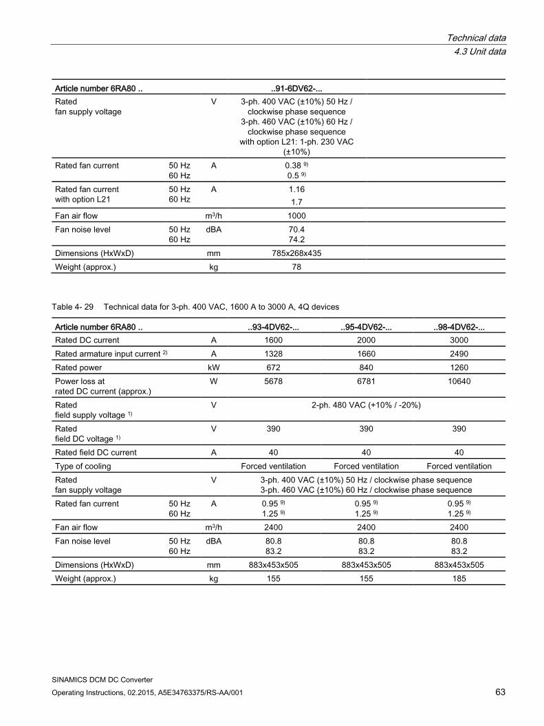
Technical data 4.3 Unit data
SINAMICS DCM DC Converter Operating Instructions, 02.2015, A5E34763375/RS-AA/001 63
Article number 6RA80 .. ..91-6DV62-... Rated fan supply voltage
V 3-ph. 400 VAC (±10%) 50 Hz / clockwise phase sequence
3-ph. 460 VAC (±10%) 60 Hz / clockwise phase sequence
with option L21: 1-ph. 230 VAC (±10%)
Rated fan current 50 Hz 60 Hz
A 0.38 9) 0.5 9)
Rated fan current with option L21
50 Hz 60 Hz
A 1.16 1.7
Fan air flow m3/h 1000 Fan noise level 50 Hz
60 Hz dBA 70.4
74.2
Dimensions (HxWxD) mm 785x268x435 Weight (approx.) kg 78
Table 4- 29 Technical data for 3-ph. 400 VAC, 1600 A to 3000 A, 4Q devices
Article number 6RA80 .. ..93-4DV62-... ..95-4DV62-... ..98-4DV62-... Rated DC current A 1600 2000 3000 Rated armature input current 2) A 1328 1660 2490 Rated power kW 672 840 1260 Power loss at rated DC current (approx.)
W 5678 6781 10640
Rated field supply voltage 1)
V 2-ph. 480 VAC (+10% / -20%)
Rated field DC voltage 1)
V 390 390 390
Rated field DC current A 40 40 40 Type of cooling Forced ventilation Forced ventilation Forced ventilation Rated fan supply voltage
V 3-ph. 400 VAC (±10%) 50 Hz / clockwise phase sequence 3-ph. 460 VAC (±10%) 60 Hz / clockwise phase sequence
Rated fan current 50 Hz 60 Hz
A 0.95 9) 1.25 9)
0.95 9) 1.25 9)
0.95 9) 1.25 9)
Fan air flow m3/h 2400 2400 2400 Fan noise level 50 Hz
60 Hz dBA 80.8
83.2 80.8 83.2
80.8 83.2
Dimensions (HxWxD) mm 883x453x505 883x453x505 883x453x505 Weight (approx.) kg 155 155 185
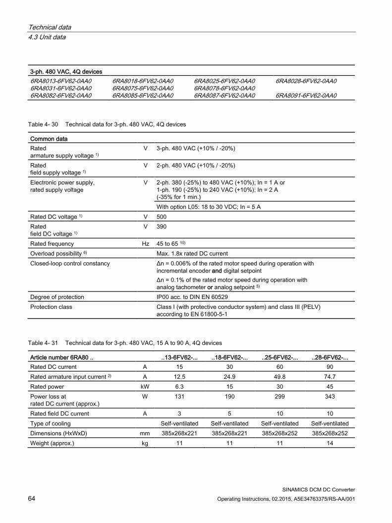
Technical data 4.3 Unit data
SINAMICS DCM DC Converter 64 Operating Instructions, 02.2015, A5E34763375/RS-AA/001
3-ph. 480 VAC, 4Q devices 6RA8013-6FV62-0AA0 6RA8031-6FV62-0AA0 6RA8082-6FV62-0AA0
6RA8018-6FV62-0AA0 6RA8075-6FV62-0AA0 6RA8085-6FV62-0AA0
6RA8025-6FV62-0AA0 6RA8078-6FV62-0AA0 6RA8087-6FV62-0AA0
6RA8028-6FV62-0AA0 6RA8091-6FV62-0AA0
Table 4- 30 Technical data for 3-ph. 480 VAC, 4Q devices
Common data Rated armature supply voltage 1)
V 3-ph. 480 VAC (+10% / -20%)
Rated field supply voltage 1)
V 2-ph. 480 VAC (+10% / -20%)
Electronic power supply, rated supply voltage
V 2-ph. 380 (-25%) to 480 VAC (+10%); In = 1 A or 1-ph. 190 (-25%) to 240 VAC (+10%); In = 2 A (-35% for 1 min.) With option L05: 18 to 30 VDC; In = 5 A
Rated DC voltage 1) V 500 Rated field DC voltage 1)
V 390
Rated frequency Hz 45 to 65 10) Overload possibility 6) Max. 1.8x rated DC current Closed-loop control constancy Δn = 0.006% of the rated motor speed during operation with
incremental encoder and digital setpoint Δn = 0.1% of the rated motor speed during operation with analog tachometer or analog setpoint 5)
Degree of protection IP00 acc. to DIN EN 60529 Protection class Class I (with protective conductor system) and class III (PELV)
according to EN 61800-5-1
Table 4- 31 Technical data for 3-ph. 480 VAC, 15 A to 90 A, 4Q devices
Article number 6RA80 .. ..13-6FV62-... ..18-6FV62-... ..25-6FV62-... ..28-6FV62-... Rated DC current A 15 30 60 90 Rated armature input current 2) A 12.5 24.9 49.8 74.7 Rated power kW 6.3 15 30 45 Power loss at rated DC current (approx.)
W 131 190 299 343
Rated field DC current A 3 5 10 10 Type of cooling Self-ventilated Self-ventilated Self-ventilated Self-ventilated Dimensions (HxWxD) mm 385x268x221 385x268x221 385x268x252 385x268x252 Weight (approx.) kg 11 11 11 14
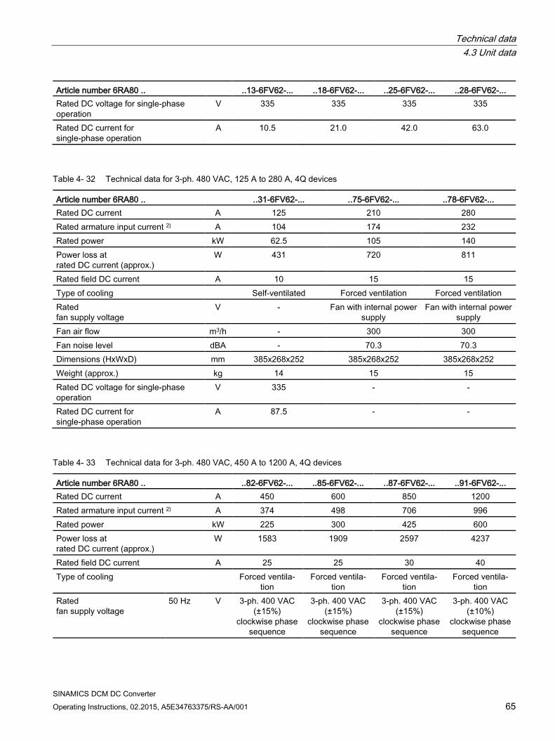
Technical data 4.3 Unit data
SINAMICS DCM DC Converter Operating Instructions, 02.2015, A5E34763375/RS-AA/001 65
Article number 6RA80 .. ..13-6FV62-... ..18-6FV62-... ..25-6FV62-... ..28-6FV62-... Rated DC voltage for single-phase operation
V 335 335 335 335
Rated DC current for single-phase operation
A 10.5 21.0 42.0 63.0
Table 4- 32 Technical data for 3-ph. 480 VAC, 125 A to 280 A, 4Q devices
Article number 6RA80 .. ..31-6FV62-... ..75-6FV62-... ..78-6FV62-... Rated DC current A 125 210 280 Rated armature input current 2) A 104 174 232 Rated power kW 62.5 105 140 Power loss at rated DC current (approx.)
W 431 720 811
Rated field DC current A 10 15 15 Type of cooling Self-ventilated Forced ventilation Forced ventilation Rated fan supply voltage
V - Fan with internal power supply
Fan with internal power supply
Fan air flow m3/h - 300 300 Fan noise level dBA - 70.3 70.3 Dimensions (HxWxD) mm 385x268x252 385x268x252 385x268x252 Weight (approx.) kg 14 15 15 Rated DC voltage for single-phase operation
V 335 - -
Rated DC current for single-phase operation
A 87.5 - -
Table 4- 33 Technical data for 3-ph. 480 VAC, 450 A to 1200 A, 4Q devices
Article number 6RA80 .. ..82-6FV62-... ..85-6FV62-... ..87-6FV62-... ..91-6FV62-... Rated DC current A 450 600 850 1200 Rated armature input current 2) A 374 498 706 996 Rated power kW 225 300 425 600 Power loss at rated DC current (approx.)
W 1583 1909 2597 4237
Rated field DC current A 25 25 30 40 Type of cooling Forced ventila-
tion Forced ventila-
tion Forced ventila-
tion Forced ventila-
tion Rated fan supply voltage
50 Hz V 3-ph. 400 VAC (±15%)
clockwise phase sequence
3-ph. 400 VAC (±15%)
clockwise phase sequence
3-ph. 400 VAC (±15%)
clockwise phase sequence
3-ph. 400 VAC (±10%)
clockwise phase sequence
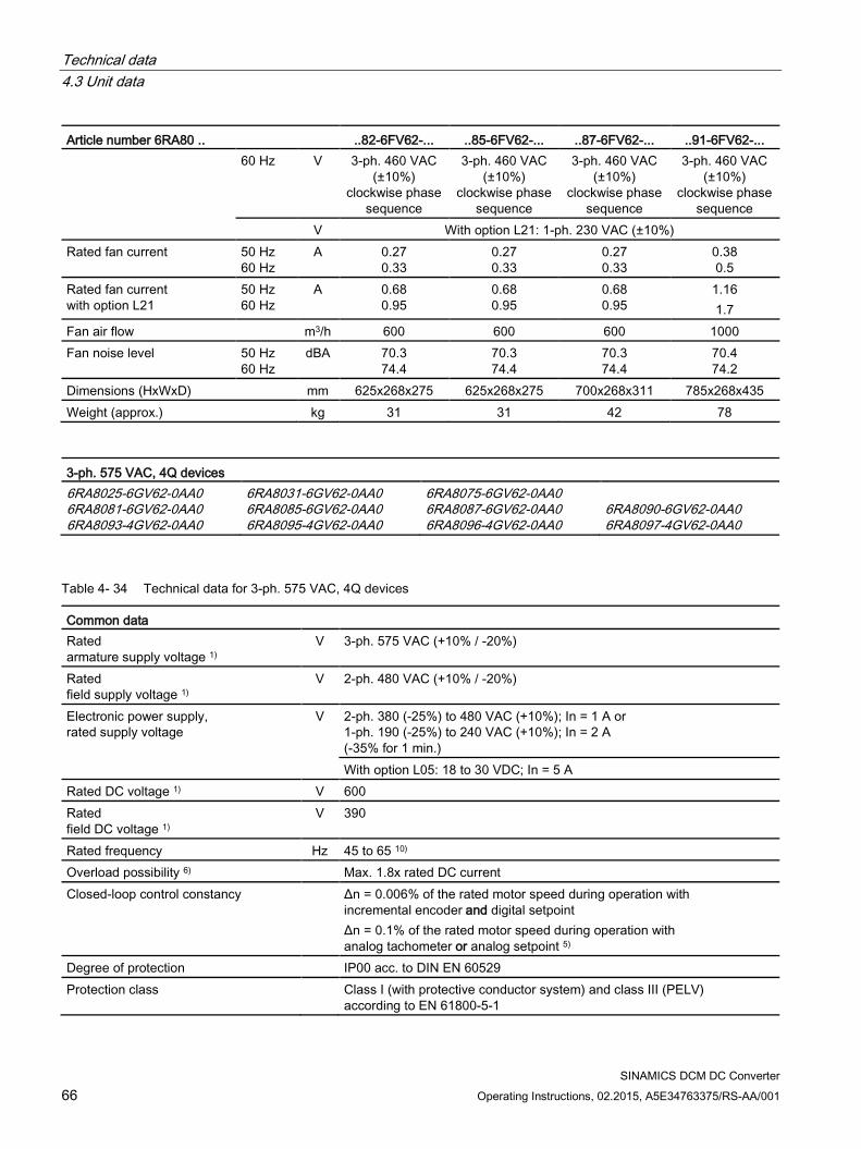
Technical data 4.3 Unit data
SINAMICS DCM DC Converter 66 Operating Instructions, 02.2015, A5E34763375/RS-AA/001
Article number 6RA80 .. ..82-6FV62-... ..85-6FV62-... ..87-6FV62-... ..91-6FV62-... 60 Hz V 3-ph. 460 VAC
(±10%) clockwise phase
sequence
3-ph. 460 VAC (±10%)
clockwise phase sequence
3-ph. 460 VAC (±10%)
clockwise phase sequence
3-ph. 460 VAC (±10%)
clockwise phase sequence
V With option L21: 1-ph. 230 VAC (±10%) Rated fan current 50 Hz
60 Hz A 0.27
0.33 0.27 0.33
0.27 0.33
0.38 0.5
Rated fan current with option L21
50 Hz 60 Hz
A 0.68 0.95
0.68 0.95
0.68 0.95
1.16 1.7
Fan air flow m3/h 600 600 600 1000 Fan noise level 50 Hz
60 Hz dBA 70.3
74.4 70.3 74.4
70.3 74.4
70.4 74.2
Dimensions (HxWxD) mm 625x268x275 625x268x275 700x268x311 785x268x435 Weight (approx.) kg 31 31 42 78
3-ph. 575 VAC, 4Q devices 6RA8025-6GV62-0AA0 6RA8081-6GV62-0AA0 6RA8093-4GV62-0AA0
6RA8031-6GV62-0AA0 6RA8085-6GV62-0AA0 6RA8095-4GV62-0AA0
6RA8075-6GV62-0AA0 6RA8087-6GV62-0AA0 6RA8096-4GV62-0AA0
6RA8090-6GV62-0AA0 6RA8097-4GV62-0AA0
Table 4- 34 Technical data for 3-ph. 575 VAC, 4Q devices
Common data Rated armature supply voltage 1)
V 3-ph. 575 VAC (+10% / -20%)
Rated field supply voltage 1)
V 2-ph. 480 VAC (+10% / -20%)
Electronic power supply, rated supply voltage
V 2-ph. 380 (-25%) to 480 VAC (+10%); In = 1 A or 1-ph. 190 (-25%) to 240 VAC (+10%); In = 2 A (-35% for 1 min.) With option L05: 18 to 30 VDC; In = 5 A
Rated DC voltage 1) V 600 Rated field DC voltage 1)
V 390
Rated frequency Hz 45 to 65 10) Overload possibility 6) Max. 1.8x rated DC current Closed-loop control constancy Δn = 0.006% of the rated motor speed during operation with
incremental encoder and digital setpoint Δn = 0.1% of the rated motor speed during operation with analog tachometer or analog setpoint 5)
Degree of protection IP00 acc. to DIN EN 60529 Protection class Class I (with protective conductor system) and class III (PELV)
according to EN 61800-5-1
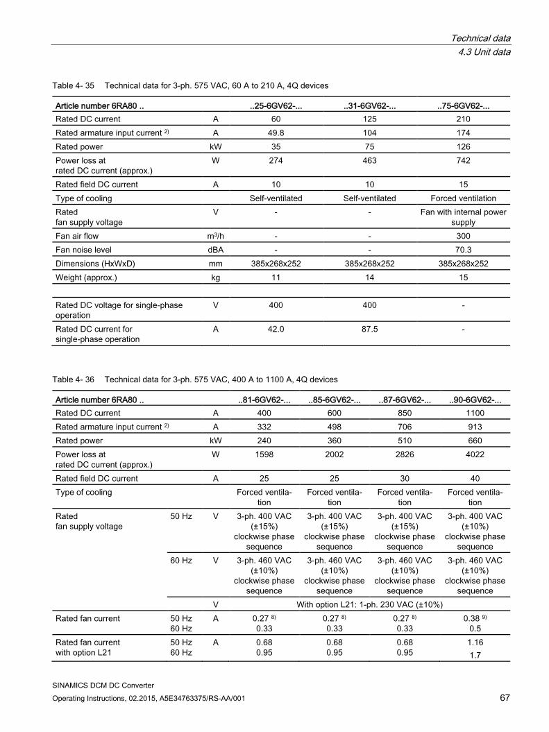
Technical data 4.3 Unit data
SINAMICS DCM DC Converter Operating Instructions, 02.2015, A5E34763375/RS-AA/001 67
Table 4- 35 Technical data for 3-ph. 575 VAC, 60 A to 210 A, 4Q devices
Article number 6RA80 .. ..25-6GV62-... ..31-6GV62-... ..75-6GV62-... Rated DC current A 60 125 210 Rated armature input current 2) A 49.8 104 174 Rated power kW 35 75 126 Power loss at rated DC current (approx.)
W 274 463 742
Rated field DC current A 10 10 15 Type of cooling Self-ventilated Self-ventilated Forced ventilation Rated fan supply voltage
V - - Fan with internal power supply
Fan air flow m3/h - - 300 Fan noise level dBA - - 70.3 Dimensions (HxWxD) mm 385x268x252 385x268x252 385x268x252 Weight (approx.) kg 11 14 15 Rated DC voltage for single-phase operation
V 400 400 -
Rated DC current for single-phase operation
A 42.0 87.5 -
Table 4- 36 Technical data for 3-ph. 575 VAC, 400 A to 1100 A, 4Q devices
Article number 6RA80 .. ..81-6GV62-... ..85-6GV62-... ..87-6GV62-... ..90-6GV62-... Rated DC current A 400 600 850 1100 Rated armature input current 2) A 332 498 706 913 Rated power kW 240 360 510 660 Power loss at rated DC current (approx.)
W 1598 2002 2826 4022
Rated field DC current A 25 25 30 40 Type of cooling Forced ventila-
tion Forced ventila-
tion Forced ventila-
tion Forced ventila-
tion Rated fan supply voltage
50 Hz V 3-ph. 400 VAC (±15%)
clockwise phase sequence
3-ph. 400 VAC (±15%)
clockwise phase sequence
3-ph. 400 VAC (±15%)
clockwise phase sequence
3-ph. 400 VAC (±10%)
clockwise phase sequence
60 Hz V 3-ph. 460 VAC (±10%)
clockwise phase sequence
3-ph. 460 VAC (±10%)
clockwise phase sequence
3-ph. 460 VAC (±10%)
clockwise phase sequence
3-ph. 460 VAC (±10%)
clockwise phase sequence
V With option L21: 1-ph. 230 VAC (±10%) Rated fan current 50 Hz
60 Hz A 0.27 8)
0.33 0.27 8) 0.33
0.27 8) 0.33
0.38 9) 0.5
Rated fan current with option L21
50 Hz 60 Hz
A 0.68 0.95
0.68 0.95
0.68 0.95
1.16 1.7
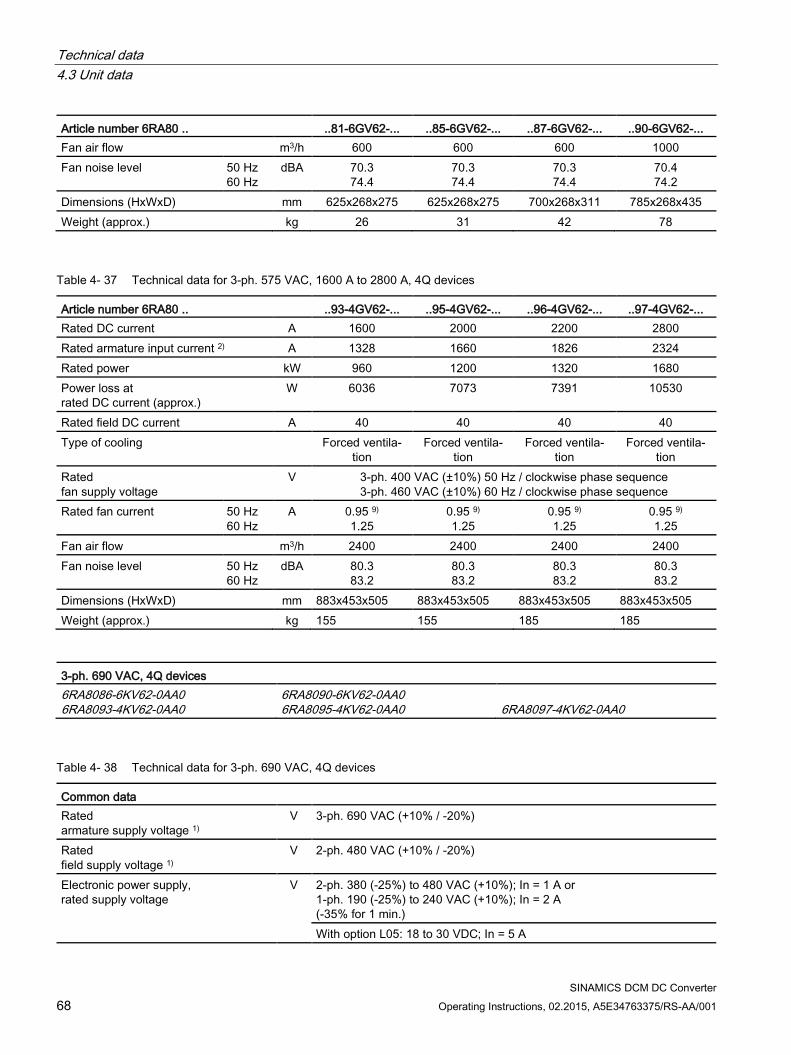
Technical data 4.3 Unit data
SINAMICS DCM DC Converter 68 Operating Instructions, 02.2015, A5E34763375/RS-AA/001
Article number 6RA80 .. ..81-6GV62-... ..85-6GV62-... ..87-6GV62-... ..90-6GV62-... Fan air flow m3/h 600 600 600 1000 Fan noise level 50 Hz
60 Hz dBA 70.3
74.4 70.3 74.4
70.3 74.4
70.4 74.2
Dimensions (HxWxD) mm 625x268x275 625x268x275 700x268x311 785x268x435 Weight (approx.) kg 26 31 42 78
Table 4- 37 Technical data for 3-ph. 575 VAC, 1600 A to 2800 A, 4Q devices
Article number 6RA80 .. ..93-4GV62-... ..95-4GV62-... ..96-4GV62-... ..97-4GV62-... Rated DC current A 1600 2000 2200 2800 Rated armature input current 2) A 1328 1660 1826 2324 Rated power kW 960 1200 1320 1680 Power loss at rated DC current (approx.)
W 6036 7073 7391 10530
Rated field DC current A 40 40 40 40 Type of cooling Forced ventila-
tion Forced ventila-
tion Forced ventila-
tion Forced ventila-
tion Rated fan supply voltage
V 3-ph. 400 VAC (±10%) 50 Hz / clockwise phase sequence 3-ph. 460 VAC (±10%) 60 Hz / clockwise phase sequence
Rated fan current 50 Hz 60 Hz
A 0.95 9) 1.25
0.95 9) 1.25
0.95 9) 1.25
0.95 9) 1.25
Fan air flow m3/h 2400 2400 2400 2400 Fan noise level 50 Hz
60 Hz dBA 80.3
83.2 80.3 83.2
80.3 83.2
80.3 83.2
Dimensions (HxWxD) mm 883x453x505 883x453x505 883x453x505 883x453x505 Weight (approx.) kg 155 155 185 185
3-ph. 690 VAC, 4Q devices 6RA8086-6KV62-0AA0 6RA8093-4KV62-0AA0
6RA8090-6KV62-0AA0 6RA8095-4KV62-0AA0
6RA8097-4KV62-0AA0
Table 4- 38 Technical data for 3-ph. 690 VAC, 4Q devices
Common data Rated armature supply voltage 1)
V 3-ph. 690 VAC (+10% / -20%)
Rated field supply voltage 1)
V 2-ph. 480 VAC (+10% / -20%)
Electronic power supply, rated supply voltage
V 2-ph. 380 (-25%) to 480 VAC (+10%); In = 1 A or 1-ph. 190 (-25%) to 240 VAC (+10%); In = 2 A (-35% for 1 min.) With option L05: 18 to 30 VDC; In = 5 A
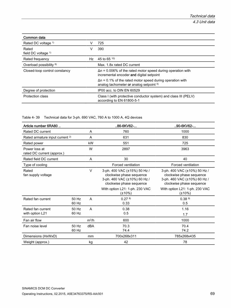
Technical data 4.3 Unit data
SINAMICS DCM DC Converter Operating Instructions, 02.2015, A5E34763375/RS-AA/001 69
Common data Rated DC voltage 1) V 725 Rated field DC voltage 1)
V 390
Rated frequency Hz 45 to 65 10) Overload possibility 6) Max. 1.8x rated DC current Closed-loop control constancy Δn = 0.006% of the rated motor speed during operation with
incremental encoder and digital setpoint Δn = 0.1% of the rated motor speed during operation with analog tachometer or analog setpoint 5)
Degree of protection IP00 acc. to DIN EN 60529 Protection class Class I (with protective conductor system) and class III (PELV)
according to EN 61800-5-1
Table 4- 39 Technical data for 3-ph. 690 VAC, 760 A to 1000 A, 4Q devices
Article number 6RA80 .. ..86-6KV62-... ..90-6KV62-... Rated DC current A 760 1000 Rated armature input current 2) A 631 830 Rated power kW 551 725 Power loss at rated DC current (approx.)
W 2897 3963
Rated field DC current A 30 40 Type of cooling Forced ventilation Forced ventilation Rated fan supply voltage
V 3-ph. 400 VAC (±15%) 50 Hz / clockwise phase sequence
3-ph. 460 VAC (±10%) 60 Hz / clockwise phase sequence
With option L21: 1-ph. 230 VAC (±10%)
3-ph. 400 VAC (±10%) 50 Hz / clockwise phase sequence
3-ph. 460 VAC (±10%) 60 Hz / clockwise phase sequence
With option L21: 1-ph. 230 VAC (±10%)
Rated fan current 50 Hz 60 Hz
A 0.27 8) 0.33
0.38 9) 0.5
Rated fan current with option L21
50 Hz 60 Hz
A 0.38 0.5
1.16 1.7
Fan air flow m3/h 600 1000 Fan noise level 50 Hz
60 Hz dBA 70.3
74.4 70.4 74.2
Dimensions (HxWxD) mm 700x268x311 785x268x435 Weight (approx.) kg 42 78
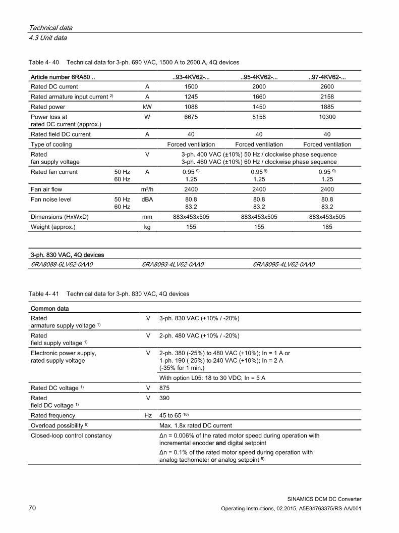
Technical data 4.3 Unit data
SINAMICS DCM DC Converter 70 Operating Instructions, 02.2015, A5E34763375/RS-AA/001
Table 4- 40 Technical data for 3-ph. 690 VAC, 1500 A to 2600 A, 4Q devices
Article number 6RA80 .. ..93-4KV62-... ..95-4KV62-... ..97-4KV62-... Rated DC current A 1500 2000 2600 Rated armature input current 2) A 1245 1660 2158 Rated power kW 1088 1450 1885 Power loss at rated DC current (approx.)
W 6675 8158 10300
Rated field DC current A 40 40 40 Type of cooling Forced ventilation Forced ventilation Forced ventilation Rated fan supply voltage
V 3-ph. 400 VAC (±10%) 50 Hz / clockwise phase sequence 3-ph. 460 VAC (±10%) 60 Hz / clockwise phase sequence
Rated fan current 50 Hz 60 Hz
A 0.95 9) 1.25
0.95 9) 1.25
0.95 9) 1.25
Fan air flow m3/h 2400 2400 2400 Fan noise level 50 Hz
60 Hz dBA 80.8
83.2 80.8 83.2
80.8 83.2
Dimensions (HxWxD) mm 883x453x505 883x453x505 883x453x505 Weight (approx.) kg 155 155 185
3-ph. 830 VAC, 4Q devices 6RA8088-6LV62-0AA0 6RA8093-4LV62-0AA0 6RA8095-4LV62-0AA0
Table 4- 41 Technical data for 3-ph. 830 VAC, 4Q devices
Common data Rated armature supply voltage 1)
V 3-ph. 830 VAC (+10% / -20%)
Rated field supply voltage 1)
V 2-ph. 480 VAC (+10% / -20%)
Electronic power supply, rated supply voltage
V 2-ph. 380 (-25%) to 480 VAC (+10%); In = 1 A or 1-ph. 190 (-25%) to 240 VAC (+10%); In = 2 A (-35% for 1 min.) With option L05: 18 to 30 VDC; In = 5 A
Rated DC voltage 1) V 875 Rated field DC voltage 1)
V 390
Rated frequency Hz 45 to 65 10) Overload possibility 6) Max. 1.8x rated DC current Closed-loop control constancy Δn = 0.006% of the rated motor speed during operation with
incremental encoder and digital setpoint Δn = 0.1% of the rated motor speed during operation with analog tachometer or analog setpoint 5)
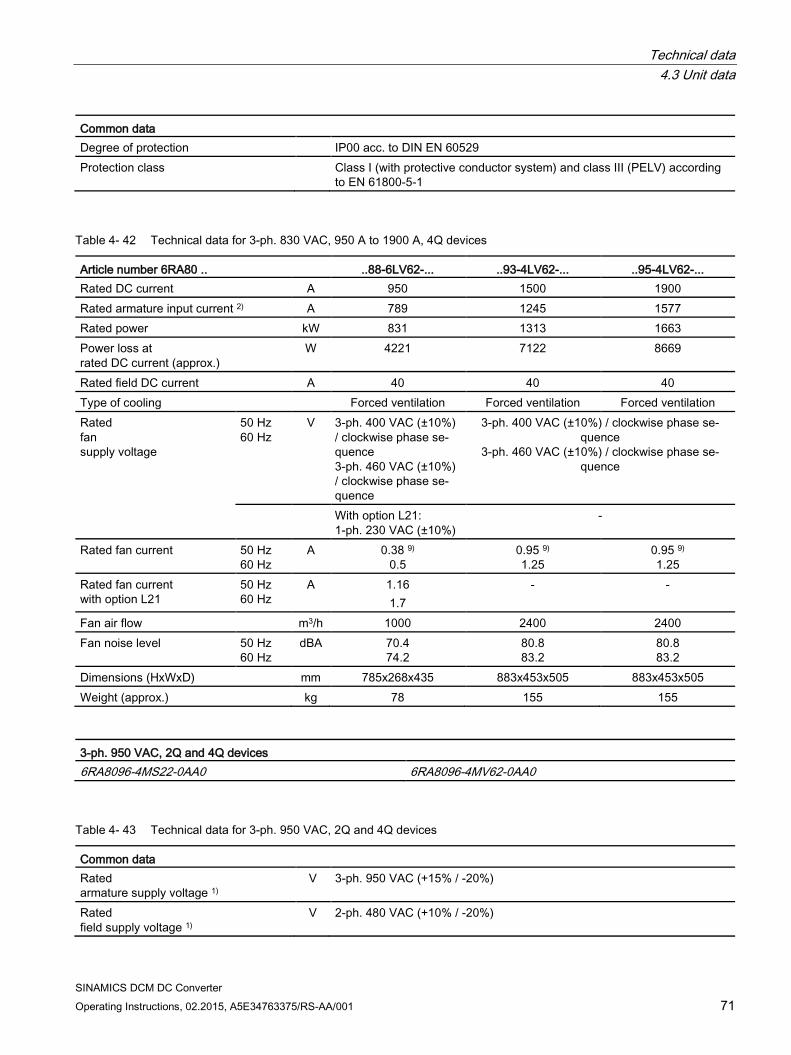
Technical data 4.3 Unit data
SINAMICS DCM DC Converter Operating Instructions, 02.2015, A5E34763375/RS-AA/001 71
Common data Degree of protection IP00 acc. to DIN EN 60529 Protection class Class I (with protective conductor system) and class III (PELV) according
to EN 61800-5-1
Table 4- 42 Technical data for 3-ph. 830 VAC, 950 A to 1900 A, 4Q devices
Article number 6RA80 .. ..88-6LV62-... ..93-4LV62-... ..95-4LV62-... Rated DC current A 950 1500 1900 Rated armature input current 2) A 789 1245 1577 Rated power kW 831 1313 1663 Power loss at rated DC current (approx.)
W 4221 7122 8669
Rated field DC current A 40 40 40 Type of cooling Forced ventilation Forced ventilation Forced ventilation Rated fan supply voltage
50 Hz 60 Hz
V 3-ph. 400 VAC (±10%) / clockwise phase se-quence 3-ph. 460 VAC (±10%) / clockwise phase se-quence
3-ph. 400 VAC (±10%) / clockwise phase se-quence
3-ph. 460 VAC (±10%) / clockwise phase se-quence
With option L21: 1-ph. 230 VAC (±10%)
-
Rated fan current 50 Hz 60 Hz
A 0.38 9) 0.5
0.95 9) 1.25
0.95 9) 1.25
Rated fan current with option L21
50 Hz 60 Hz
A 1.16 1.7
- -
Fan air flow m3/h 1000 2400 2400 Fan noise level 50 Hz
60 Hz dBA 70.4
74.2 80.8 83.2
80.8 83.2
Dimensions (HxWxD) mm 785x268x435 883x453x505 883x453x505 Weight (approx.) kg 78 155 155
3-ph. 950 VAC, 2Q and 4Q devices 6RA8096-4MS22-0AA0 6RA8096-4MV62-0AA0
Table 4- 43 Technical data for 3-ph. 950 VAC, 2Q and 4Q devices
Common data Rated armature supply voltage 1)
V 3-ph. 950 VAC (+15% / -20%)
Rated field supply voltage 1)
V 2-ph. 480 VAC (+10% / -20%)
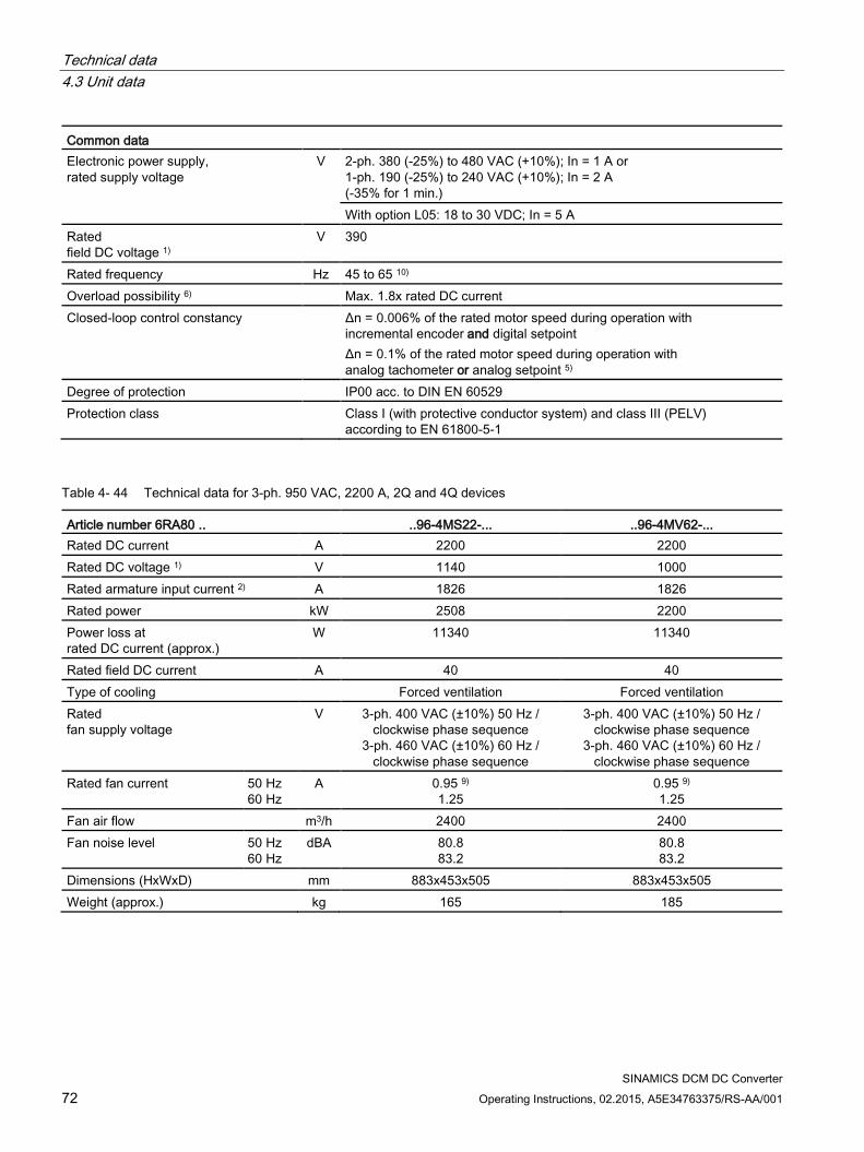
Technical data 4.3 Unit data
SINAMICS DCM DC Converter 72 Operating Instructions, 02.2015, A5E34763375/RS-AA/001
Common data Electronic power supply, rated supply voltage
V 2-ph. 380 (-25%) to 480 VAC (+10%); In = 1 A or 1-ph. 190 (-25%) to 240 VAC (+10%); In = 2 A (-35% for 1 min.) With option L05: 18 to 30 VDC; In = 5 A
Rated field DC voltage 1)
V 390
Rated frequency Hz 45 to 65 10) Overload possibility 6) Max. 1.8x rated DC current Closed-loop control constancy Δn = 0.006% of the rated motor speed during operation with
incremental encoder and digital setpoint Δn = 0.1% of the rated motor speed during operation with analog tachometer or analog setpoint 5)
Degree of protection IP00 acc. to DIN EN 60529 Protection class Class I (with protective conductor system) and class III (PELV)
according to EN 61800-5-1
Table 4- 44 Technical data for 3-ph. 950 VAC, 2200 A, 2Q and 4Q devices
Article number 6RA80 .. ..96-4MS22-... ..96-4MV62-... Rated DC current A 2200 2200 Rated DC voltage 1) V 1140 1000 Rated armature input current 2) A 1826 1826 Rated power kW 2508 2200 Power loss at rated DC current (approx.)
W 11340 11340
Rated field DC current A 40 40 Type of cooling Forced ventilation Forced ventilation Rated fan supply voltage
V 3-ph. 400 VAC (±10%) 50 Hz / clockwise phase sequence
3-ph. 460 VAC (±10%) 60 Hz / clockwise phase sequence
3-ph. 400 VAC (±10%) 50 Hz / clockwise phase sequence
3-ph. 460 VAC (±10%) 60 Hz / clockwise phase sequence
Rated fan current 50 Hz 60 Hz
A 0.95 9) 1.25
0.95 9) 1.25
Fan air flow m3/h 2400 2400 Fan noise level 50 Hz
60 Hz dBA 80.8
83.2 80.8 83.2
Dimensions (HxWxD) mm 883x453x505 883x453x505 Weight (approx.) kg 165 185
Technical data 4.3 Unit data
SINAMICS DCM DC Converter Operating Instructions, 02.2015, A5E34763375/RS-AA/001 73
Footnotes: 1) The supply voltage for the armature/field can lie below the rated armature/field volt-
age (set in p50078): Permissible input voltage: ≥50 V for devices with rated voltage 400 V, 480 V and 575 V ≥100 V for units with rated voltage 690 V, 830 V and 950 V The output voltage is reduced accordingly. The specified output DC voltage can be ensured for an undervoltage up to 95 % of the line voltage (rated supply voltage of the armature/field). Note: Option L04 is available for armature infeed with extra-low voltage (ordering data for options, see Chapter 2)
2) Values apply to rated DC output current 5) Conditions:
The closed-loop control (closed-loop PI control) constancy is related to the rated motor speed and applies when the SINAMICS DC MASTER is at the operating tem-perature. This is subject to the following preconditions: • Temperature changes of ±10 °K
Changes to the line voltage of +10% / – 5% of the rated input voltage • Temperature coefficient of tachometer generator with temperature compensation:
0.15‰ every 10 °K (with analog tachometer generator only) • Constant setpoint (14-bit resolution)
6) For dynamic overload capability, see also Chapter 10 8) 9) see also Chapter "Installation notes for design according to UL 508C" 10) The option of operating in an extended frequency range can be provided on request.
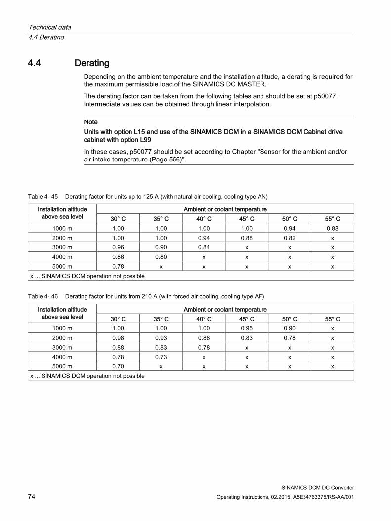
Technical data 4.4 Derating
SINAMICS DCM DC Converter 74 Operating Instructions, 02.2015, A5E34763375/RS-AA/001
4.4 Derating Depending on the ambient temperature and the installation altitude, a derating is required for the maximum permissible load of the SINAMICS DC MASTER.
The derating factor can be taken from the following tables and should be set at p50077. Intermediate values can be obtained through linear interpolation.
Note Units with option L15 and use of the SINAMICS DCM in a SINAMICS DCM Cabinet drive cabinet with option L99
In these cases, p50077 should be set according to Chapter "Sensor for the ambient and/or air intake temperature (Page 556)".
Table 4- 45 Derating factor for units up to 125 A (with natural air cooling, cooling type AN)
Installation altitude above sea level
Ambient or coolant temperature 30° C 35° C 40° C 45° C 50° C 55° C
1000 m 1.00 1.00 1.00 1.00 0.94 0.88 2000 m 1.00 1.00 0.94 0.88 0.82 x 3000 m 0.96 0.90 0.84 x x x 4000 m 0.86 0.80 x x x x 5000 m 0.78 x x x x x
x ... SINAMICS DCM operation not possible
Table 4- 46 Derating factor for units from 210 A (with forced air cooling, cooling type AF)
Installation altitude above sea level
Ambient or coolant temperature 30° C 35° C 40° C 45° C 50° C 55° C
1000 m 1.00 1.00 1.00 0.95 0.90 x 2000 m 0.98 0.93 0.88 0.83 0.78 x 3000 m 0.88 0.83 0.78 x x x 4000 m 0.78 0.73 x x x x 5000 m 0.70 x x x x x
x ... SINAMICS DCM operation not possible
Technical data 4.4 Derating
SINAMICS DCM DC Converter Operating Instructions, 02.2015, A5E34763375/RS-AA/001 75
Voltage derating depending on the installation altitude The series of SINAMICS DCM units fulfill overvoltage category III according to EN 61800-5-1 for line supply circuits with respect to the environment (other line supply circuits, housing, electronics).
For electronics and field supplies with voltages of 2-ph. 480 VAC (line-to-line; maximum 300 VAC to ground), operation is permitted up to 4500 m above sea level. A maximum of 2-ph. 400 VAC (line-to-line; maximum 230 VAC to ground) is permitted up to 5000 m.
All units, with 400 V up to 575 V as well as also with 690 V to 950 V rated armature supply voltage, can be operated up to a maximum of 4000 m above sea level without voltage derating.
For units with rated armature supply voltages of 690 V to 950 V, up to 4500 m a maximum 930 VAC and up to 5000 m, a maximum 880 VAC is permissible as armature supply voltage.
For units with rated armature supply voltages of 400 V to 575 V, up to 4500 m a maximum 550 VAC and up to 5000 m, a maximum 500 VAC is permissible as armature supply voltage.
If the specified voltages with respect to ground are exceeded or the installation altitude is exceeded, then a reduction of the overvoltage category to II must be applied. As a consequence, operation up to 6000 m without derating is permissible.
The overvoltage category of the line supply can be reduced to II using an appropriate surge arrester, filter or isolation transformer. If this is not realized, then there is no longer safe electrical separation of the electronics (interface connections on the CUD) with respect to the line supply.
According to EN61800-5-1, operation of units without "safe electrical separation" is only permissible if it can be absolutely excluded that persons are in danger by being able to directly touch or indirectly touch parts, i.e. in operation, none of the CUD interfaces can be touched. A digital connection can be realized using an optical isolation.

Technical data 4.4 Derating
SINAMICS DCM DC Converter 76 Operating Instructions, 02.2015, A5E34763375/RS-AA/001
SINAMICS DCM DC Converter Operating Instructions, 02.2015, A5E34763375/RS-AA/001 77
Transportation, unpacking, installation 5 5.1 Transportation, unpacking
The SINAMICS DC MASTER is packaged at the manufacturer's site in accordance with the order specification. A product packaging label is located on the carton.
Avoid heavy vibrations and severe shocks during transportation, e.g. when lowering the unit into position.
Follow the instructions on the packaging concerning transportation, storage, and proper handling.
The SINAMICS DC MASTER can be installed once it has been unpacked, and you have checked that the delivery is complete and the unit is intact.
The packaging materials consist of the carton and corrugated cardboard, and can be disposed of in accordance with local regulations for cardboard packaging.
If you discover any damage that has occurred in transit, please inform your shipping agent immediately.
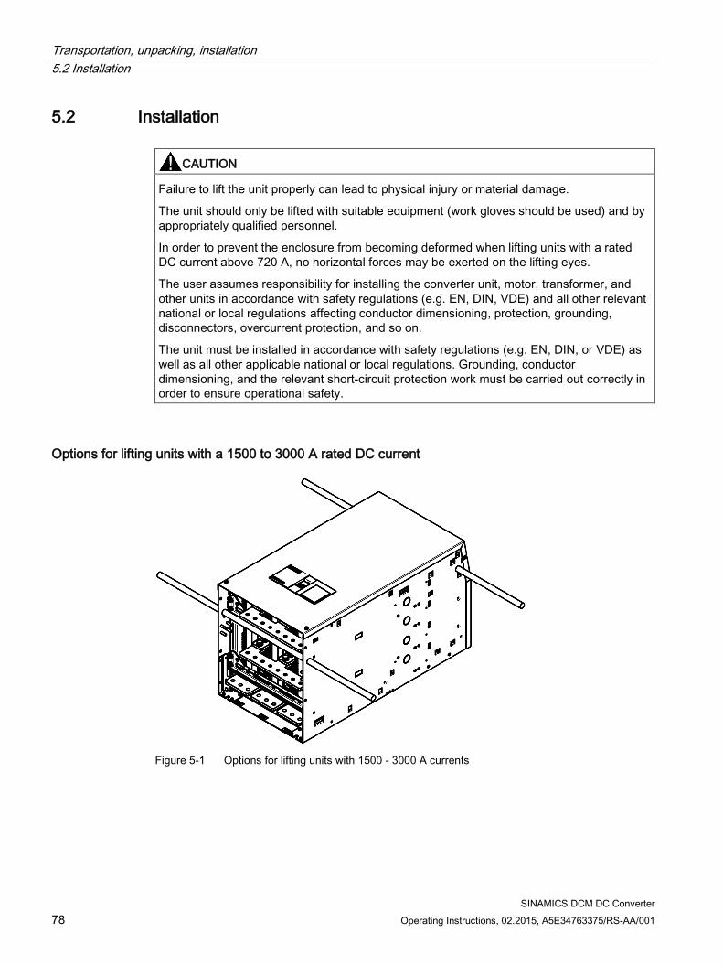
Transportation, unpacking, installation 5.2 Installation
SINAMICS DCM DC Converter 78 Operating Instructions, 02.2015, A5E34763375/RS-AA/001
5.2 Installation
CAUTION
Failure to lift the unit properly can lead to physical injury or material damage.
The unit should only be lifted with suitable equipment (work gloves should be used) and by appropriately qualified personnel.
In order to prevent the enclosure from becoming deformed when lifting units with a rated DC current above 720 A, no horizontal forces may be exerted on the lifting eyes.
The user assumes responsibility for installing the converter unit, motor, transformer, and other units in accordance with safety regulations (e.g. EN, DIN, VDE) and all other relevant national or local regulations affecting conductor dimensioning, protection, grounding, disconnectors, overcurrent protection, and so on.
The unit must be installed in accordance with safety regulations (e.g. EN, DIN, or VDE) as well as all other applicable national or local regulations. Grounding, conductor dimensioning, and the relevant short-circuit protection work must be carried out correctly in order to ensure operational safety.
Options for lifting units with a 1500 to 3000 A rated DC current
Figure 5-1 Options for lifting units with 1500 - 3000 A currents
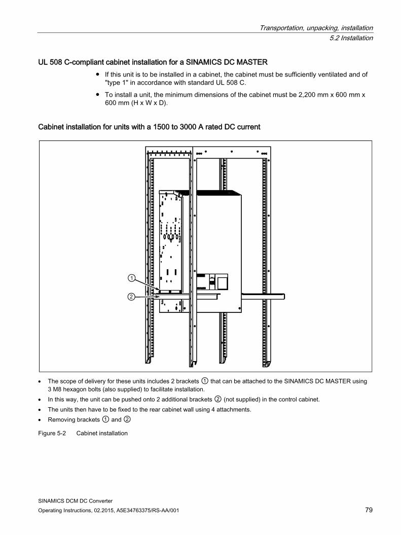
Transportation, unpacking, installation 5.2 Installation
SINAMICS DCM DC Converter Operating Instructions, 02.2015, A5E34763375/RS-AA/001 79
UL 508 C-compliant cabinet installation for a SINAMICS DC MASTER If this unit is to be installed in a cabinet, the cabinet must be sufficiently ventilated and of
"type 1" in accordance with standard UL 508 C.
To install a unit, the minimum dimensions of the cabinet must be 2,200 mm x 600 mm x 600 mm (H x W x D).
Cabinet installation for units with a 1500 to 3000 A rated DC current
• The scope of delivery for these units includes 2 brackets ① that can be attached to the SINAMICS DC MASTER using
3 M8 hexagon bolts (also supplied) to facilitate installation. • In this way, the unit can be pushed onto 2 additional brackets ② (not supplied) in the control cabinet. • The units then have to be fixed to the rear cabinet wall using 4 attachments. • Removing brackets ① and ②
Figure 5-2 Cabinet installation

Transportation, unpacking, installation 5.2 Installation
SINAMICS DCM DC Converter 80 Operating Instructions, 02.2015, A5E34763375/RS-AA/001
WARNING
To ensure that cooling air can flow in and out uninhibited, there must be a clearance of 100 m both above and below the unit.
Otherwise, the unit will run the risk of overheating.
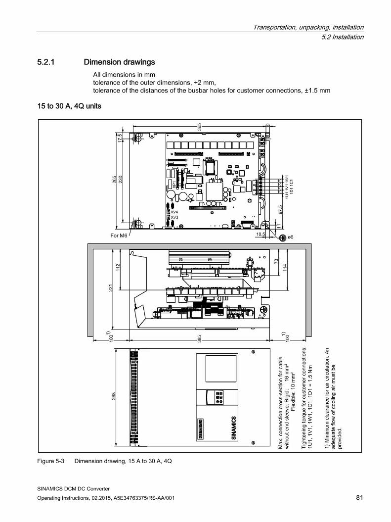
Transportation, unpacking, installation 5.2 Installation
SINAMICS DCM DC Converter Operating Instructions, 02.2015, A5E34763375/RS-AA/001 81
5.2.1 Dimension drawings All dimensions in mm tolerance of the outer dimensions, +2 mm, tolerance of the distances of the busbar holes for customer connections, ±1.5 mm
15 to 30 A, 4Q units
Figure 5-3 Dimension drawing, 15 A to 30 A, 4Q
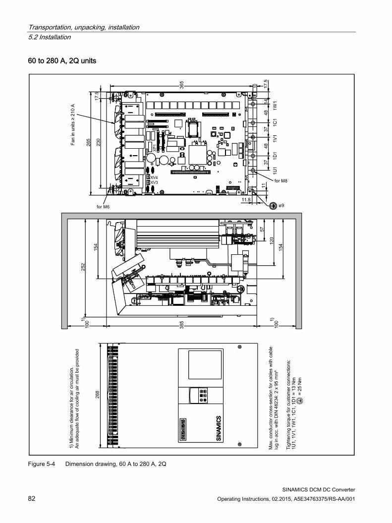
Transportation, unpacking, installation 5.2 Installation
SINAMICS DCM DC Converter 82 Operating Instructions, 02.2015, A5E34763375/RS-AA/001
60 to 280 A, 2Q units
Figure 5-4 Dimension drawing, 60 A to 280 A, 2Q

Transportation, unpacking, installation 5.2 Installation
SINAMICS DCM DC Converter Operating Instructions, 02.2015, A5E34763375/RS-AA/001 83
60 to 280 A, 4Q units
Figure 5-5 Dimension drawing 60 A to 280 A, 4Q

Transportation, unpacking, installation 5.2 Installation
SINAMICS DCM DC Converter 84 Operating Instructions, 02.2015, A5E34763375/RS-AA/001
400 to 600 A, 2Q units
Figure 5-6 Dimension drawing: 400 to 600 A, 2Q

Transportation, unpacking, installation 5.2 Installation
SINAMICS DCM DC Converter Operating Instructions, 02.2015, A5E34763375/RS-AA/001 85
400 to 600 A, 4Q units
Figure 5-7 Dimension drawing, 400 A to 600 A, 4Q

Transportation, unpacking, installation 5.2 Installation
SINAMICS DCM DC Converter 86 Operating Instructions, 02.2015, A5E34763375/RS-AA/001
720 to 850 A, 2Q units
Figure 5-8 Dimension drawing: 720 to 850 A, 2Q

Transportation, unpacking, installation 5.2 Installation
SINAMICS DCM DC Converter Operating Instructions, 02.2015, A5E34763375/RS-AA/001 87
760 to 850 A, 4Q units
Figure 5-9 Dimension drawing: 760 to 850 A, 4Q

Transportation, unpacking, installation 5.2 Installation
SINAMICS DCM DC Converter 88 Operating Instructions, 02.2015, A5E34763375/RS-AA/001
900 to 1200 A units
Figure 5-10 Dimension drawing: 900 to 1200 A

Transportation, unpacking, installation 5.2 Installation
SINAMICS DCM DC Converter Operating Instructions, 02.2015, A5E34763375/RS-AA/001 89
1500 to 3000 A units
Figure 5-11 Dimension drawing: 1500 to 3000 A

Transportation, unpacking, installation 5.2 Installation
SINAMICS DCM DC Converter 90 Operating Instructions, 02.2015, A5E34763375/RS-AA/001
5.2.2 Installing options and accessories
5.2.2.1 AOP30 operator panel Installation cut-out required in the cabinet door: 197.5 × 141.5 mm
5.2.2.2 Installing a second CUD
NOTICE
Note the information provided on "Electrostatic sensitive devices (ESD)" in Chapter 1.
Note
Use the supplied mounting aid. See Chapter Replacing the CUD (Page 667).
• Unlock and tilt up the BOP support ①.
Figure 5-12 Installing a second CUD (1)
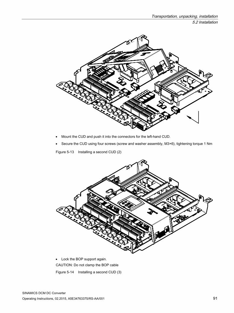
Transportation, unpacking, installation 5.2 Installation
SINAMICS DCM DC Converter Operating Instructions, 02.2015, A5E34763375/RS-AA/001 91
• Mount the CUD and push it into the connectors for the left-hand CUD.
• Secure the CUD using four screws (screw and washer assembly, M3×6), tightening torque 1 Nm
Figure 5-13 Installing a second CUD (2)
• Lock the BOP support again. CAUTION: Do not clamp the BOP cable
Figure 5-14 Installing a second CUD (3)

Transportation, unpacking, installation 5.2 Installation
SINAMICS DCM DC Converter 92 Operating Instructions, 02.2015, A5E34763375/RS-AA/001
SINAMICS DCM DC Converter Operating Instructions, 02.2015, A5E34763375/RS-AA/001 93
Connecting 6
Note
Information on connecting the device
The inside front cover of the SINAMICS DC MASTER Operating Instructions contains a summary of the key information required for connecting the device.
WARNING
The devices are operated with high voltages.
All connection work must be carried out while the cabinet is de-energized.
Only qualified personnel who are familiar with all the safety instructions in these Operating Instructions, as well as the assembly, installation, operating, and maintenance instructions, should carry out work on these devices.
Death, serious injury, or substantial material damage can result if these warnings are not taken into account.
Connecting the device incorrectly can lead to it being damaged or destroyed.
The devices may be connected to a line supply with residual current operated circuit breaker if a universal current sensitive device is being used, which in the case of a ground fault, can also detect a DC component in the fault current. We recommend a residual current operated circuit breaker with an operating current ≥300 mA, which means that it is not suitable to protect personnel. If you have additional questions, please contact Technical Support.
The power and control terminals may be live even when the motor is not running.
The TSE capacitors may continue to carry dangerous voltage levels following disconnection. For this reason, the device should not be opened until a reasonable period of time has elapsed.
When handling the device while it is open, remember that live parts are exposed. The device must only be operated with the front covers provided by the factory fitted. When required, additional covers should be provided in the control cabinet (for example, in the area around the busbars).
Explicit note on the connection of the PROFIBUS cable to connector X126: The PROFIBUS cable must only be connected or disconnected in a de-energized state. Otherwise, there is a danger of coming into contact with live components behind the terminal.
Connecting
SINAMICS DCM DC Converter 94 Operating Instructions, 02.2015, A5E34763375/RS-AA/001
WARNING
The operator is responsible for ensuring that the motor, SINAMICS DC MASTER, and other devices are installed and connected in accordance with recognized engineering practice in the country of installation and in compliance with applicable regional regulations. Special attention should be paid to cable dimensioning, fuses, grounding, shutdown, disconnection, and overcurrent protection.
The devices listed here contain dangerous rotating machine parts (fans) and control rotating mechanical parts (drives). Failure to follow these operating instructions may result in death, serious physical injury, or extensive material damage.
Perfect, safe, and reliable operation of the devices is conditional upon them having been transported, stored, mounted, and installed correctly, as well as carefully operated and serviced.
To operate the SINAMICS DC MASTER, both front cover fixing screws must be tight.
NOTICE
Surge arresters must be in compliance with IEC 60364-5-53:2002.
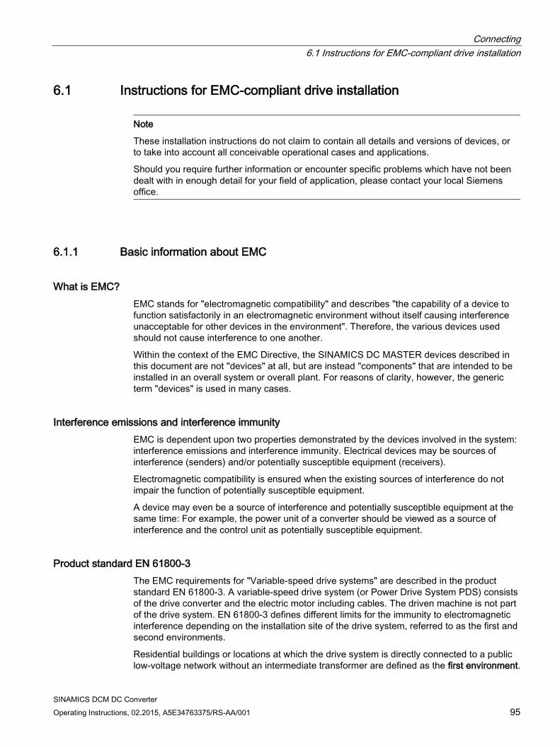
Connecting 6.1 Instructions for EMC-compliant drive installation
SINAMICS DCM DC Converter Operating Instructions, 02.2015, A5E34763375/RS-AA/001 95
6.1 Instructions for EMC-compliant drive installation
Note
These installation instructions do not claim to contain all details and versions of devices, or to take into account all conceivable operational cases and applications.
Should you require further information or encounter specific problems which have not been dealt with in enough detail for your field of application, please contact your local Siemens office.
6.1.1 Basic information about EMC
What is EMC? EMC stands for "electromagnetic compatibility" and describes "the capability of a device to function satisfactorily in an electromagnetic environment without itself causing interference unacceptable for other devices in the environment". Therefore, the various devices used should not cause interference to one another.
Within the context of the EMC Directive, the SINAMICS DC MASTER devices described in this document are not "devices" at all, but are instead "components" that are intended to be installed in an overall system or overall plant. For reasons of clarity, however, the generic term "devices" is used in many cases.
Interference emissions and interference immunity EMC is dependent upon two properties demonstrated by the devices involved in the system: interference emissions and interference immunity. Electrical devices may be sources of interference (senders) and/or potentially susceptible equipment (receivers).
Electromagnetic compatibility is ensured when the existing sources of interference do not impair the function of potentially susceptible equipment.
A device may even be a source of interference and potentially susceptible equipment at the same time: For example, the power unit of a converter should be viewed as a source of interference and the control unit as potentially susceptible equipment.
Product standard EN 61800-3 The EMC requirements for "Variable-speed drive systems" are described in the product standard EN 61800-3. A variable-speed drive system (or Power Drive System PDS) consists of the drive converter and the electric motor including cables. The driven machine is not part of the drive system. EN 61800-3 defines different limits for the immunity to electromagnetic interference depending on the installation site of the drive system, referred to as the first and second environments.
Residential buildings or locations at which the drive system is directly connected to a public low-voltage network without an intermediate transformer are defined as the first environment.
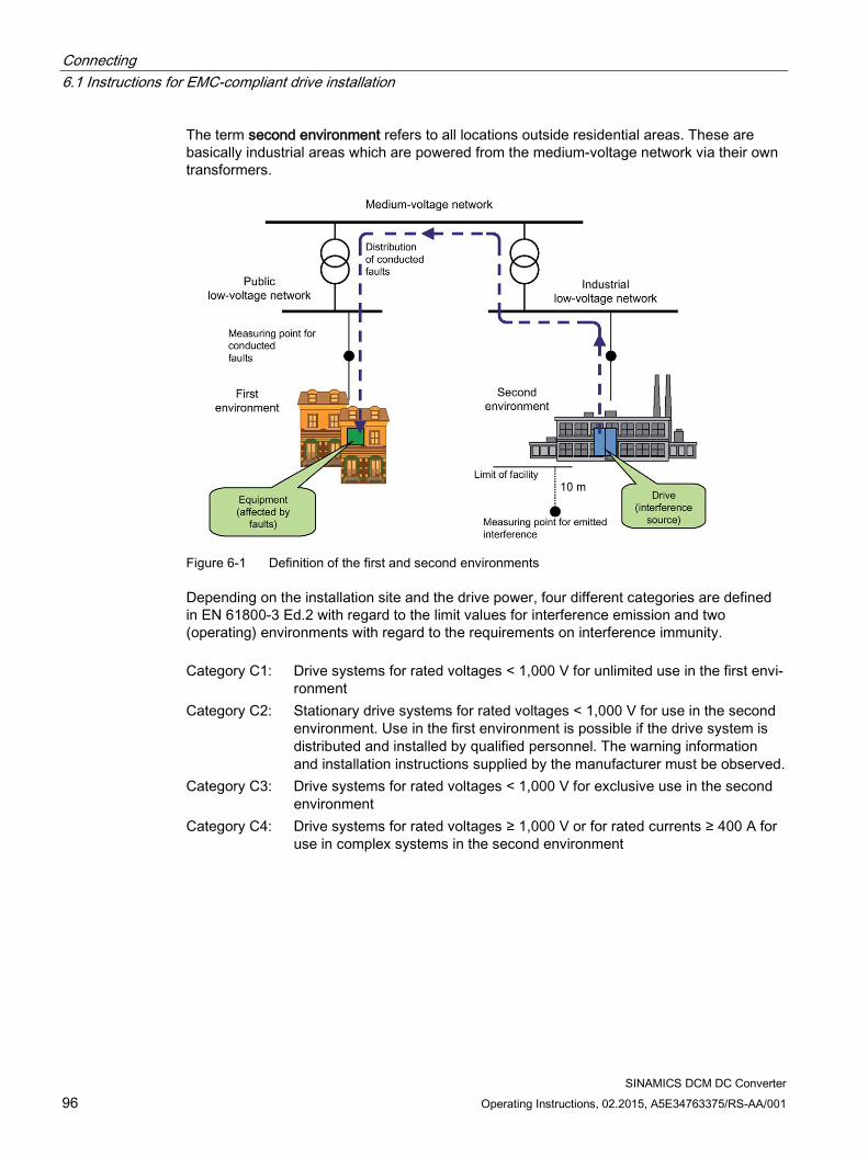
Connecting 6.1 Instructions for EMC-compliant drive installation
SINAMICS DCM DC Converter 96 Operating Instructions, 02.2015, A5E34763375/RS-AA/001
The term second environment refers to all locations outside residential areas. These are basically industrial areas which are powered from the medium-voltage network via their own transformers.
Figure 6-1 Definition of the first and second environments
Depending on the installation site and the drive power, four different categories are defined in EN 61800-3 Ed.2 with regard to the limit values for interference emission and two (operating) environments with regard to the requirements on interference immunity. Category C1: Drive systems for rated voltages < 1,000 V for unlimited use in the first envi-
ronment Category C2: Stationary drive systems for rated voltages < 1,000 V for use in the second
environment. Use in the first environment is possible if the drive system is distributed and installed by qualified personnel. The warning information and installation instructions supplied by the manufacturer must be observed.
Category C3: Drive systems for rated voltages < 1,000 V for exclusive use in the second environment
Category C4: Drive systems for rated voltages ≥ 1,000 V or for rated currents ≥ 400 A for use in complex systems in the second environment
Connecting 6.1 Instructions for EMC-compliant drive installation
SINAMICS DCM DC Converter Operating Instructions, 02.2015, A5E34763375/RS-AA/001 97
The figure below shows how the four categories are assigned to the first and second environments:
Figure 6-2 Definition of categories C1 to C4
SINAMICS DC MASTER devices are nearly always used in the second environment (categories C3 and C4).
RFI suppression filters and line reactors are required whenever they are to be used in Category C2.
The SINAMICS DC MASTER conform to the interference immunity requirements defined in EN 61800-3 for the second environment, and thus also with the lower interference immunity requirements for the first environment.
SINAMICS DC MASTER: Industrial applications Industrial applications demand that devices demonstrate an extremely high level of interference immunity, but by contrast place very low requirements on them in terms of interference emission levels.
SINAMICS DC MASTER converters are components of an electrical drive, such as contactors and switches. Qualified personnel must install them into a drive system which, as an absolute minimum, consists of the converter, motor cables, and motor. Line reactors and fuses are also required in most cases. Therefore, whether or not a limit value is adhered to is determined by the components being installed correctly. In order to limit the interference emission in compliance with the limit value for category C2 according to EN61800-3, RFI suppression filters are required in the mains supply conductors for the armature and field power units and the line reactors. Without RFI suppression filters, the interference emission of SINAMICS DC MASTER converters exceeds the limit value for category C2.
If the drive forms part of a system, it does not initially need to fulfill any interference emission requirements, but the EMC Directive does require the system as a whole to be electromagnetically compatible with its environment.
Non-grounded networks Non-grounded networks (IT systems) are used in some branches of industry in order to increase the availability of the plant. In the event of a ground fault, no fault current flows and the plant can continue with production. If RFI suppression filters are brought into the equation, however, a fault current does flow in the event of a ground fault, which may cause the drives to shut down or the RFI suppression filter to potentially be destroyed. For this reason, the product standard does not define any limit values for these networks. From an economical perspective, any necessary EMC conformance measures should be taken on the grounded primary side of the supply transformer.
Connecting 6.1 Instructions for EMC-compliant drive installation
SINAMICS DCM DC Converter 98 Operating Instructions, 02.2015, A5E34763375/RS-AA/001
EMC planning If two devices are not electromagnetically compatible, you can reduce the interference emission level of the source of interference or increase the interference immunity of the potentially susceptible equipment. Sources of interference are generally power electronics devices with high power consumption; reducing their interference emission levels requires complex filters. Potentially susceptible equipment usually refers to control gear and sensors, including their evaluation circuit. There is less work involved in increasing the interference immunity of inefficient devices, meaning that - economically speaking - increasing interference immunity is generally a more favorable option for industrial applications than reducing the interference emission level.
In industrial applications, EMC between devices should be based on a carefully-balanced combination of the interference emission and interference immunity levels.
The most cost-effective measure that can be put in place to achieve EMC conformance is to physically separate sources of interference and potentially susceptible equipment - provided that you have taken this option into account during the planning stage of your machine/plant. In the first instance, it is necessary to determine whether each device used is a potential source of interference or potentially susceptible equipment. Within this context, converters and contactors, for example, can be counted as sources of interference, while examples of potentially susceptible equipment are PLCs, encoders, and sensors.
The components in the control cabinet (sources of interference and potentially susceptible equipment) must be physically separated, by means of partition plates if necessary, or by installing them in metal enclosures.
6.1.2 EMC-compliant drive installation (installation instructions)
General information Not only are drives operated in a wide variety of environments, but the electrical components used (controllers, switch mode power supplies, and so on) can also differ widely with respect to interference immunity and interference emission levels, meaning that all installation guidelines of any kind can offer is a practical compromise. For this reason, EMC rules do not need to be implemented to the letter in all cases, provided that measures are tested on a case-by-case basis.
In order to ensure electromagnetic compatibility (EMC) in your control cabinets in rugged electrical environments and adhere to the standards required by the relevant legislating body, the EMC rules listed below should be followed during the construction and design stages.
Rules 1 to 10 apply on a general level. Rules 11 to 15 must be followed in order to fulfill interference emission standards.
Connecting 6.1 Instructions for EMC-compliant drive installation
SINAMICS DCM DC Converter Operating Instructions, 02.2015, A5E34763375/RS-AA/001 99
Rules for EMC-compliant installation 1 Connect all metallic parts of the control cabinet to one another over a flat area with
good conductivity (not paint against paint!). Use contact or scratch washers if neces-sary. The cabinet door must be connected to the cabinet using the shortest possible ground strips (at the top, center, and bottom).
2 Contactors, relays, solenoid valves, electromechanical operating hours counters, etc., in the cabinet and - where applicable - in neighboring cabinets - must be provided with quenching combinations such as RC elements, varistors, and diodes. These must be connected directly at the appropriate coil.
3 Whenever possible, guide signal cables 1) into the cabinet at one level only. 4 Unshielded cables in the same circuit (outgoing/incoming conductors) must be twisted
where possible, or the area between them minimized, to prevent unnecessary frame antennae.
5 Connect spare wires to the cabinet ground 2) at both ends. This achieves an additional shielding effect.
6 Avoid unnecessary cable lengths in order to keep coupling capacities and inductances low.
7 Crosstalk is generally reduced if the cables are laid close to the control cabinet ground. Do not, therefore, route cables freely around the cabinet, but lay them as close as pos-sible to the cabinet enclosure/mounting plates. This also applies to spare cables.
8 Signal and power cables must be physically separated (to prevent coupling paths). Minimum clearance: You should aim for a minimum of 20 cm. If it is not possible to physically separate the encoder and motor cables, the encoder cable must be decoupled either using a partition or by laying it in a metal conduit. The partition or metal conduit must be grounded at several points.
9 Ground the shields of digital signal cables at both ends (source and destination), ensur-ing maximum contact area and good conductivity. In the event of poor equipotential bonding between the shield connections, run an additional equalizing conductor with a cross-section of at least 10 mm² parallel to the shield for the purpose of reducing the shield current. Generally speaking, the shields may also be connected to the cabinet enclosure (ground) 2) at several points, and connected at several points outside the control cabinet. Foil shields should be avoided as they are are at least 5 times less effective than braid-ed shields.
10 Shields for analog signal cables may be connected to ground at both ends if equipoten-tial bonding is good (this must be done over a large area with good conductivity). It can be assumed that equipotential bonding is good if all metal parts are well interconnected and the electronics components are supplied from a single source. Connecting shields at one end prevents low-frequency, capacitive interference injec-tions (e.g. 50 Hz humming). In this case, the shield should be connected in the control cabinet; a sheath wire may also be used for this purpose. The cable to the temperature sensor on the motor (X177:53 to 55) must be shielded and connected to ground at both ends.
11 Ensure that the RFI suppression filter is always located close to the suspected source of interference. The filter must be attached to the cabinet enclosure, mounting plate, etc., over a flat area. Incoming and outgoing cables must be physically separated.
Connecting 6.1 Instructions for EMC-compliant drive installation
SINAMICS DCM DC Converter 100 Operating Instructions, 02.2015, A5E34763375/RS-AA/001
12 RFI suppression filters must be used in order to conform to limit value class A1. Addi-tional loads must be connected upstream of the filter (on the line side). The controller used and the manner in which the rest of the control cabinet is wired will determine whether an additional line filter needs to be installed.
13 A line reactor must be included in the field circuit for controlled field power supplies. 14 A line reactor must be included in the armature circuit of the converter. 15 The motor cables do not have to be shielded. There must be a clearance of at least 20
cm between the power supply and the motor cables (field, armature). Use a partition if necessary.
Footnotes 1) Signal cables are defined as:
Digital signal cables: E.g. cables for incremental encoders Analog signal cables: E.g. ±10 V setpoint cable Serial interfaces: E.g. PROFIBUS DP
2) Generally speaking, "ground" refers to all metallic conductive parts that can be con-nected to a protective conductor, such as the cabinet enclosure, motor enclosure, or foundation ground.
Cabinet configuration and shielding The cabinet configuration image below is intended to help the user become familiar with EMC-critical parts. This example does not claim to show all possible cabinet components or configuration options.
Later figures show details that are not made immediately clear by the overview image and which may also have an effect on the cabinet's resistance/interference emission levels, as well as shield connection techniques.
Arrangement of RFI suppression filters and line reactors Another section shows how the RFI suppression filters and line reactors are arranged in a SINAMICS DC MASTER. The order in which the reactors and filters are installed must be adhered to. The filter cables on the line side and modular side must be physically separated. For information on selecting fuses for semiconductor protection, see Chapter "Fuses".
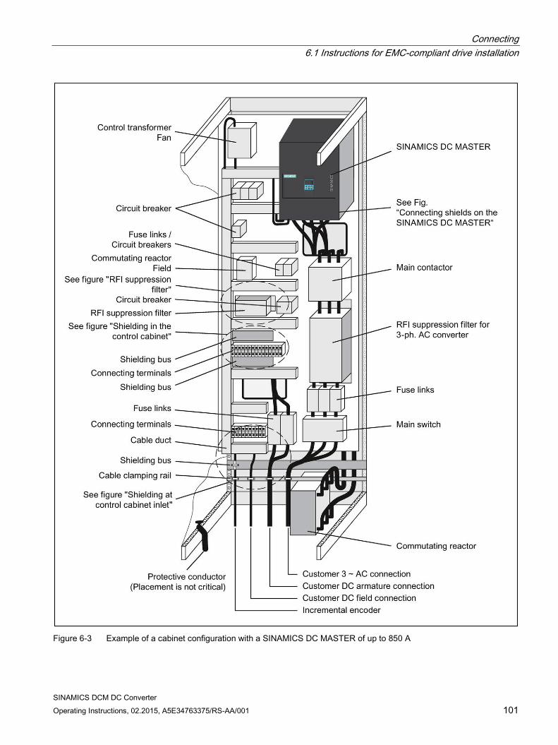
Connecting 6.1 Instructions for EMC-compliant drive installation
SINAMICS DCM DC Converter Operating Instructions, 02.2015, A5E34763375/RS-AA/001 101
Figure 6-3 Example of a cabinet configuration with a SINAMICS DC MASTER of up to 850 A
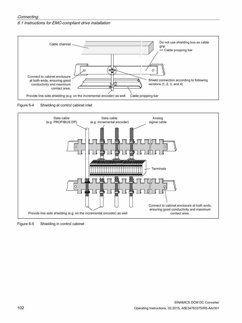
Connecting 6.1 Instructions for EMC-compliant drive installation
SINAMICS DCM DC Converter 102 Operating Instructions, 02.2015, A5E34763375/RS-AA/001
Figure 6-4 Shielding at control cabinet inlet
Figure 6-5 Shielding in control cabinet
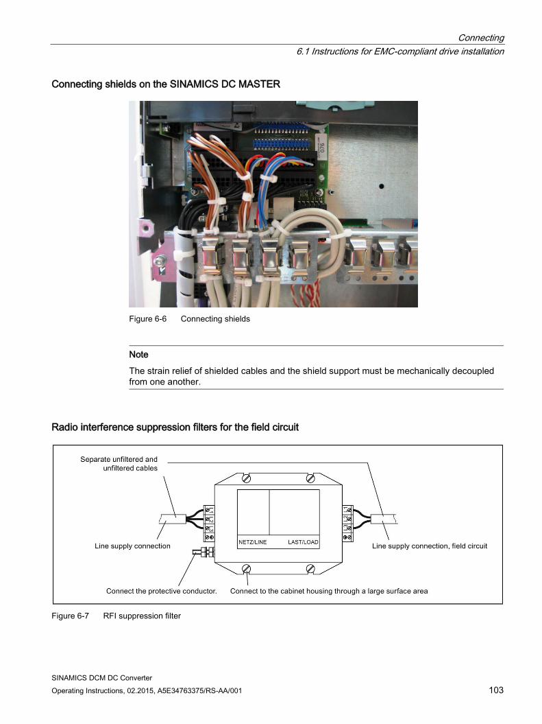
Connecting 6.1 Instructions for EMC-compliant drive installation
SINAMICS DCM DC Converter Operating Instructions, 02.2015, A5E34763375/RS-AA/001 103
Connecting shields on the SINAMICS DC MASTER
Figure 6-6 Connecting shields
Note
The strain relief of shielded cables and the shield support must be mechanically decoupled from one another.
Radio interference suppression filters for the field circuit
Figure 6-7 RFI suppression filter
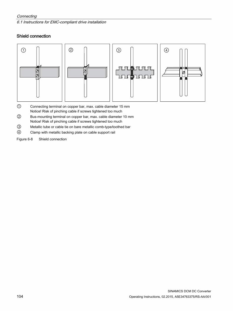
Connecting 6.1 Instructions for EMC-compliant drive installation
SINAMICS DCM DC Converter 104 Operating Instructions, 02.2015, A5E34763375/RS-AA/001
Shield connection
① Connecting terminal on copper bar, max. cable diameter 15 mm
Notice! Risk of pinching cable if screws tightened too much ② Bus-mounting terminal on copper bar, max. cable diameter 10 mm
Notice! Risk of pinching cable if screws tightened too much ③ Metallic tube or cable tie on bare metallic comb-type/toothed bar ④ Clamp with metallic backing plate on cable support rail
Figure 6-8 Shield connection
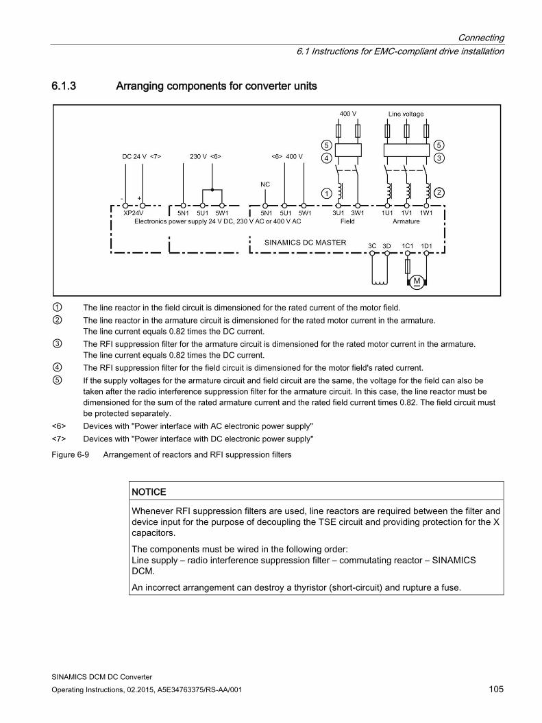
Connecting 6.1 Instructions for EMC-compliant drive installation
SINAMICS DCM DC Converter Operating Instructions, 02.2015, A5E34763375/RS-AA/001 105
6.1.3 Arranging components for converter units
① The line reactor in the field circuit is dimensioned for the rated current of the motor field. ② The line reactor in the armature circuit is dimensioned for the rated motor current in the armature.
The line current equals 0.82 times the DC current. ③ The RFI suppression filter for the armature circuit is dimensioned for the rated motor current in the armature.
The line current equals 0.82 times the DC current. ④ The RFI suppression filter for the field circuit is dimensioned for the motor field's rated current. ⑤ If the supply voltages for the armature circuit and field circuit are the same, the voltage for the field can also be
taken after the radio interference suppression filter for the armature circuit. In this case, the line reactor must be dimensioned for the sum of the rated armature current and the rated field current times 0.82. The field circuit must be protected separately.
<6> Devices with "Power interface with AC electronic power supply" <7> Devices with "Power interface with DC electronic power supply"
Figure 6-9 Arrangement of reactors and RFI suppression filters
NOTICE
Whenever RFI suppression filters are used, line reactors are required between the filter and device input for the purpose of decoupling the TSE circuit and providing protection for the X capacitors.
The components must be wired in the following order: Line supply – radio interference suppression filter – commutating reactor – SINAMICS DCM.
An incorrect arrangement can destroy a thyristor (short-circuit) and rupture a fuse.
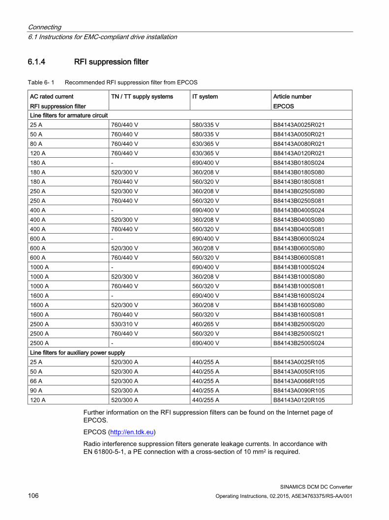
Connecting 6.1 Instructions for EMC-compliant drive installation
SINAMICS DCM DC Converter 106 Operating Instructions, 02.2015, A5E34763375/RS-AA/001
6.1.4 RFI suppression filter
Table 6- 1 Recommended RFI suppression filter from EPCOS
AC rated current RFI suppression filter
TN / TT supply systems IT system Article number EPCOS
Line filters for armature circuit 25 A 760/440 V 580/335 V B84143A0025R021 50 A 760/440 V 580/335 V B84143A0050R021 80 A 760/440 V 630/365 V B84143A0080R021 120 A 760/440 V 630/365 V B84143A0120R021 180 A - 690/400 V B84143B0180S024 180 A 520/300 V 360/208 V B84143B0180S080 180 A 760/440 V 560/320 V B84143B0180S081 250 A 520/300 V 360/208 V B84143B0250S080 250 A 760/440 V 560/320 V B84143B0250S081 400 A - 690/400 V B84143B0400S024 400 A 520/300 V 360/208 V B84143B0400S080 400 A 760/440 V 560/320 V B84143B0400S081 600 A - 690/400 V B84143B0600S024 600 A 520/300 V 360/208 V B84143B0600S080 600 A 760/440 V 560/320 V B84143B0600S081 1000 A - 690/400 V B84143B1000S024 1000 A 520/300 V 360/208 V B84143B1000S080 1000 A 760/440 V 560/320 V B84143B1000S081 1600 A - 690/400 V B84143B1600S024 1600 A 520/300 V 360/208 V B84143B1600S080 1600 A 760/440 V 560/320 V B84143B1600S081 2500 A 530/310 V 460/265 V B84143B2500S020 2500 A 760/440 V 560/320 V B84143B2500S021 2500 A - 690/400 V B84143B2500S024 Line filters for auxiliary power supply 25 A 520/300 A 440/255 A B84143A0025R105 50 A 520/300 A 440/255 A B84143A0050R105 66 A 520/300 A 440/255 A B84143A0066R105 90 A 520/300 A 440/255 A B84143A0090R105 120 A 520/300 A 440/255 A B84143A0120R105
Further information on the RFI suppression filters can be found on the Internet page of EPCOS.
EPCOS (http://en.tdk.eu)
Radio interference suppression filters generate leakage currents. In accordance with EN 61800-5-1, a PE connection with a cross-section of 10 mm2 is required.
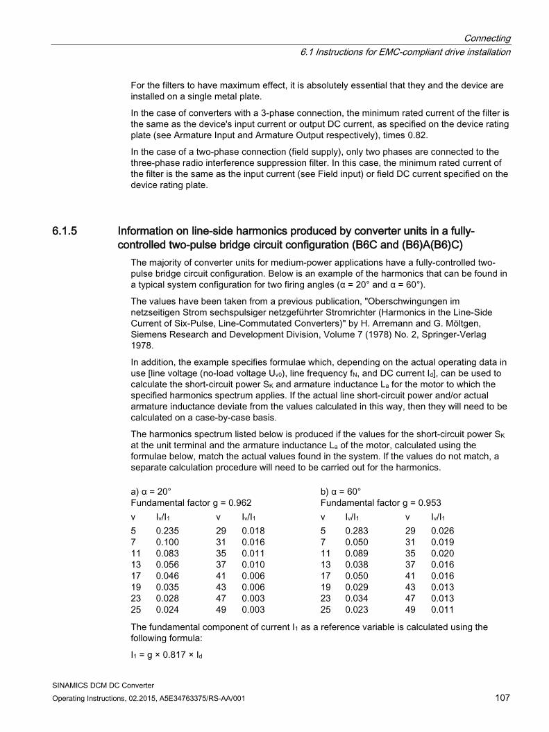
Connecting 6.1 Instructions for EMC-compliant drive installation
SINAMICS DCM DC Converter Operating Instructions, 02.2015, A5E34763375/RS-AA/001 107
For the filters to have maximum effect, it is absolutely essential that they and the device are installed on a single metal plate.
In the case of converters with a 3-phase connection, the minimum rated current of the filter is the same as the device's input current or output DC current, as specified on the device rating plate (see Armature Input and Armature Output respectively), times 0.82.
In the case of a two-phase connection (field supply), only two phases are connected to the three-phase radio interference suppression filter. In this case, the minimum rated current of the filter is the same as the input current (see Field input) or field DC current specified on the device rating plate.
6.1.5 Information on line-side harmonics produced by converter units in a fully-controlled two-pulse bridge circuit configuration (B6C and (B6)A(B6)C)
The majority of converter units for medium-power applications have a fully-controlled two-pulse bridge circuit configuration. Below is an example of the harmonics that can be found in a typical system configuration for two firing angles (α = 20° and α = 60°).
The values have been taken from a previous publication, "Oberschwingungen im netzseitigen Strom sechspulsiger netzgeführter Stromrichter (Harmonics in the Line-Side Current of Six-Pulse, Line-Commutated Converters)" by H. Arremann and G. Möltgen, Siemens Research and Development Division, Volume 7 (1978) No. 2, Springer-Verlag 1978.
In addition, the example specifies formulae which, depending on the actual operating data in use [line voltage (no-load voltage Uv0), line frequency fN, and DC current Id], can be used to calculate the short-circuit power SK and armature inductance La for the motor to which the specified harmonics spectrum applies. If the actual line short-circuit power and/or actual armature inductance deviate from the values calculated in this way, then they will need to be calculated on a case-by-case basis.
The harmonics spectrum listed below is produced if the values for the short-circuit power SK at the unit terminal and the armature inductance La of the motor, calculated using the formulae below, match the actual values found in the system. If the values do not match, a separate calculation procedure will need to be carried out for the harmonics. a) α = 20° Fundamental factor g = 0.962
b) α = 60° Fundamental factor g = 0.953
ν Iν/I1 ν Iν/I1 ν Iν/I1 ν Iν/I1 5 7 11 13 17 19 23 25
0.235 0.100 0.083 0.056 0.046 0.035 0.028 0.024
29 31 35 37 41 43 47 49
0.018 0.016 0.011 0.010 0.006 0.006 0.003 0.003
5 7 11 13 17 19 23 25
0.283 0.050 0.089 0.038 0.050 0.029 0.034 0.023
29 31 35 37 41 43 47 49
0.026 0.019 0.020 0.016 0.016 0.013 0.013 0.011
The fundamental component of current I1 as a reference variable is calculated using the following formula:
I1 = g × 0.817 × Id
Connecting 6.1 Instructions for EMC-compliant drive installation
SINAMICS DCM DC Converter 108 Operating Instructions, 02.2015, A5E34763375/RS-AA/001
where Id is the DC current of the operating point under investigation and where g is the fundamental factor (see above)
The harmonics currents calculated on the basis of the tables above only apply to
I.) Short-circuit power SK at the converter unit terminal
SK = U2v0/XN (VA)
where
XN = XK - XD = 0.03526 × Uv0 / Id - 2πfN × LD (Ω)
and
Uv0 is the no-load voltage at the converter unit terminal in V, Id is the DC current of the operating point under investigation in A, fN is the line frequency in Hz, LD is the inductance of the line reactor used in H, XD is the line reactor impedance, XN is the network impedance, and XK is the impedance at the unit terminals
II.) Armature inductance La
La = 0.0488 × Uv0 / (fN × Id) (H)
If the actual values for the short-circuit power SK and/or armature inductance La deviate from the values calculated using the formulae above, a separate calculation procedure will need to be carried out.
Example:
Let us take a drive with the following data:
Uv0 = 400 V Id = 150 A fN = 50 Hz LD = 0.169 mH (4EU2421-7AA10 with ILn = 125 A)
Where XN = 0.03536 × 400 / 150 - 2π × 50 × 0.169 × 10-3 = 0.0412 Ω,
the network short-circuit power at the converter unit terminal is as follows:
SK = 4002 / 0.0412 = 3.88 MVA
and the armature inductance of the motor is as follows:
La = 0.0488 × 400 / (50 × 150) = 2.60 mH
The harmonic currents Iν (where I1 = g × 0.817 × Id for firing angles α = 20° and α = 60°) that can be taken from the tables only apply for the values SK and La calculated using this method. If the actual values deviate from these, a separate calculation procedure will need to be carried out.
For the purpose of dimensioning filters and compensation equipment with reactors, it is only possible to draw on the information provided by the harmonics values calculated in this way if the values calculated for SK and La match the actual drive values. In all other cases, a separate calculation procedure needs to be carried out (this particularly applies when using machines with compensation, as they demonstrate a very low armature inductance level).
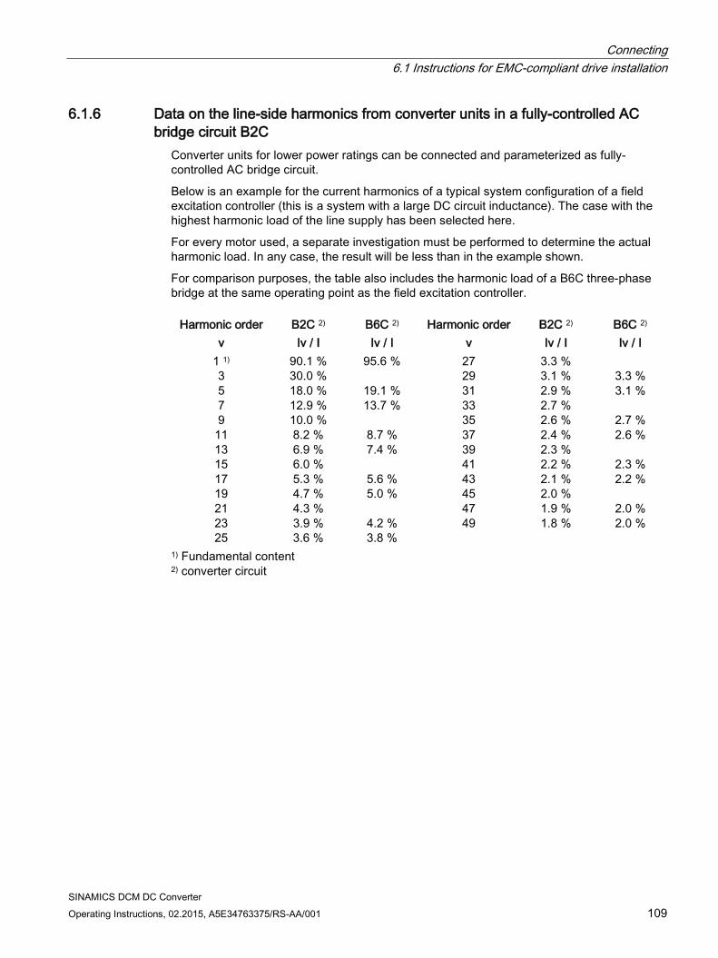
Connecting 6.1 Instructions for EMC-compliant drive installation
SINAMICS DCM DC Converter Operating Instructions, 02.2015, A5E34763375/RS-AA/001 109
6.1.6 Data on the line-side harmonics from converter units in a fully-controlled AC bridge circuit B2C
Converter units for lower power ratings can be connected and parameterized as fully-controlled AC bridge circuit.
Below is an example for the current harmonics of a typical system configuration of a field excitation controller (this is a system with a large DC circuit inductance). The case with the highest harmonic load of the line supply has been selected here.
For every motor used, a separate investigation must be performed to determine the actual harmonic load. In any case, the result will be less than in the example shown.
For comparison purposes, the table also includes the harmonic load of a B6C three-phase bridge at the same operating point as the field excitation controller.
Harmonic order B2C 2) B6C 2) Harmonic order B2C 2) B6C 2) v Iv / I Iv / I v Iv / I Iv / I
1 1) 3 5 7 9
11 13 15 17 19 21 23 25
90.1 % 30.0 % 18.0 % 12.9 % 10.0 % 8.2 % 6.9 % 6.0 % 5.3 % 4.7 % 4.3 % 3.9 % 3.6 %
95.6 %
19.1 % 13.7 %
8.7 % 7.4 %
5.6 % 5.0 %
4.2 % 3.8 %
27 29 31 33 35 37 39 41 43 45 47 49
3.3 % 3.1 % 2.9 % 2.7 % 2.6 % 2.4 % 2.3 % 2.2 % 2.1 % 2.0 % 1.9 % 1.8 %
3.3 % 3.1 %
2.7 % 2.6 %
2.3 % 2.2 %
2.0 % 2.0 %
1) Fundamental content 2) converter circuit
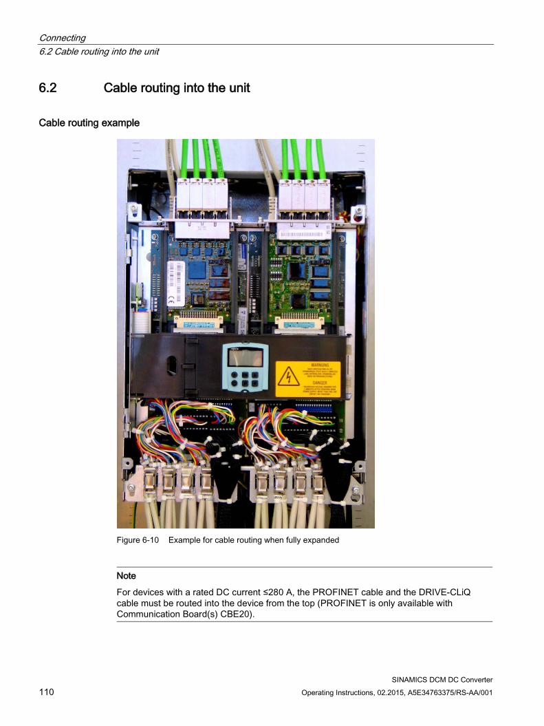
Connecting 6.2 Cable routing into the unit
SINAMICS DCM DC Converter 110 Operating Instructions, 02.2015, A5E34763375/RS-AA/001
6.2 Cable routing into the unit
Cable routing example
Figure 6-10 Example for cable routing when fully expanded
Note
For devices with a rated DC current ≤280 A, the PROFINET cable and the DRIVE-CLiQ cable must be routed into the device from the top (PROFINET is only available with Communication Board(s) CBE20).
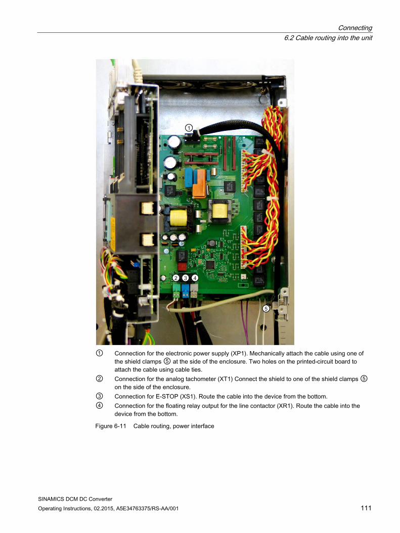
Connecting 6.2 Cable routing into the unit
SINAMICS DCM DC Converter Operating Instructions, 02.2015, A5E34763375/RS-AA/001 111
① Connection for the electronic power supply (XP1). Mechanically attach the cable using one of
the shield clamps ⑤ at the side of the enclosure. Two holes on the printed-circuit board to attach the cable using cable ties.
② Connection for the analog tachometer (XT1) Connect the shield to one of the shield clamps ⑤ on the side of the enclosure.
③ Connection for E-STOP (XS1). Route the cable into the device from the bottom. ④ Connection for the floating relay output for the line contactor (XR1). Route the cable into the
device from the bottom.
Figure 6-11 Cable routing, power interface
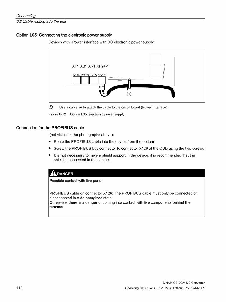
Connecting 6.2 Cable routing into the unit
SINAMICS DCM DC Converter 112 Operating Instructions, 02.2015, A5E34763375/RS-AA/001
Option L05: Connecting the electronic power supply Devices with "Power interface with DC electronic power supply"
① Use a cable tie to attach the cable to the circuit board (Power Interface)
Figure 6-12 Option L05, electronic power supply
Connection for the PROFIBUS cable (not visible in the photographs above):
Route the PROFIBUS cable into the device from the bottom
Screw the PROFIBUS bus connector to connector X126 at the CUD using the two screws
It is not necessary to have a shield support in the device, it is recommended that the shield is connected in the cabinet.
DANGER
Possible contact with live parts
PROFIBUS cable on connector X126: The PROFIBUS cable must only be connected or disconnected in a de-energized state. Otherwise, there is a danger of coming into contact with live components behind the terminal.
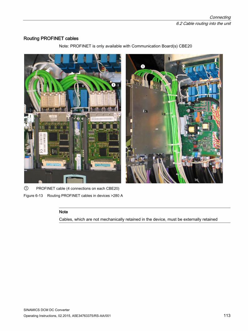
Connecting 6.2 Cable routing into the unit
SINAMICS DCM DC Converter Operating Instructions, 02.2015, A5E34763375/RS-AA/001 113
Routing PROFINET cables Note: PROFINET is only available with Communication Board(s) CBE20
① PROFINET cable (4 connections on each CBE20)
Figure 6-13 Routing PROFINET cables in devices >280 A
Note
Cables, which are not mechanically retained in the device, must be externally retained
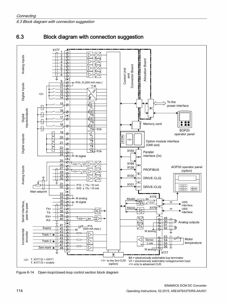
Connecting 6.3 Block diagram with connection suggestion
SINAMICS DCM DC Converter 114 Operating Instructions, 02.2015, A5E34763375/RS-AA/001
6.3 Block diagram with connection suggestion
Figure 6-14 Open-loop/closed-loop control section block diagram
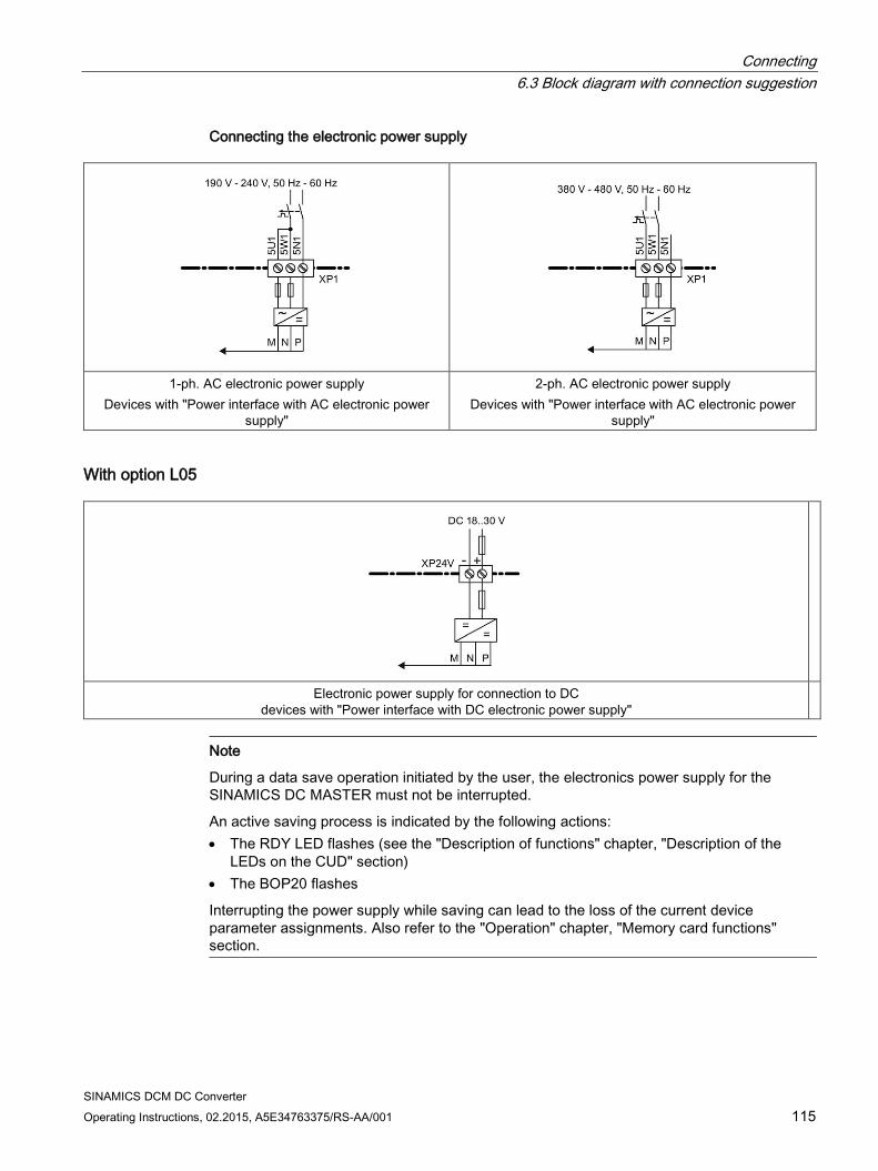
Connecting 6.3 Block diagram with connection suggestion
SINAMICS DCM DC Converter Operating Instructions, 02.2015, A5E34763375/RS-AA/001 115
Connecting the electronic power supply
1-ph. AC electronic power supply
Devices with "Power interface with AC electronic power supply"
2-ph. AC electronic power supply Devices with "Power interface with AC electronic power
supply"
With option L05
Electronic power supply for connection to DC devices with "Power interface with DC electronic power supply"
Note
During a data save operation initiated by the user, the electronics power supply for the SINAMICS DC MASTER must not be interrupted.
An active saving process is indicated by the following actions: • The RDY LED flashes (see the "Description of functions" chapter, "Description of the
LEDs on the CUD" section) • The BOP20 flashes
Interrupting the power supply while saving can lead to the loss of the current device parameter assignments. Also refer to the "Operation" chapter, "Memory card functions" section.
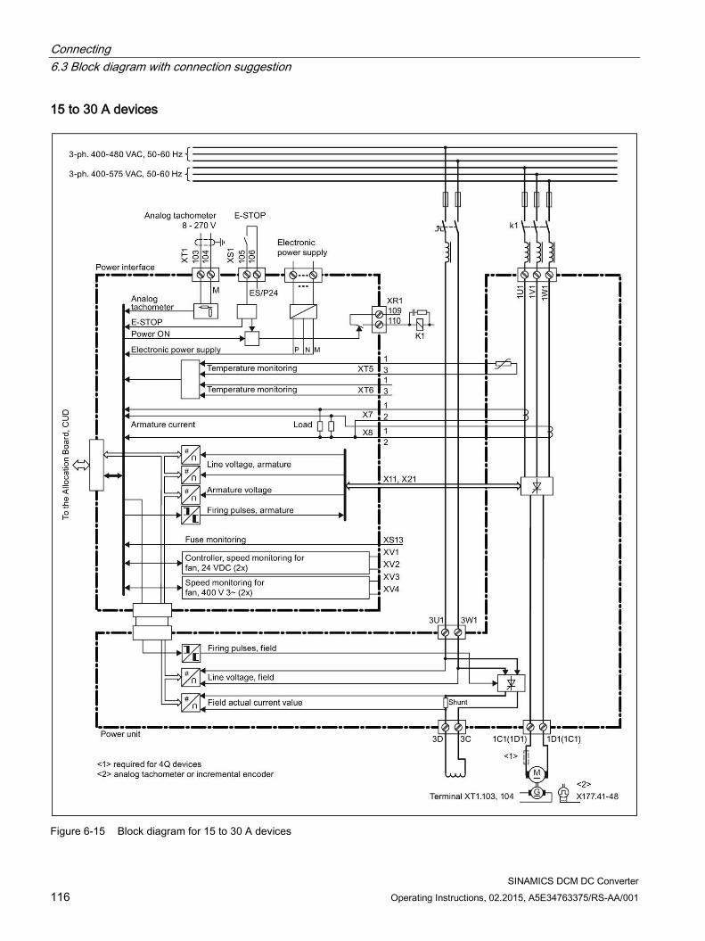
Connecting 6.3 Block diagram with connection suggestion
SINAMICS DCM DC Converter 116 Operating Instructions, 02.2015, A5E34763375/RS-AA/001
15 to 30 A devices
Figure 6-15 Block diagram for 15 to 30 A devices
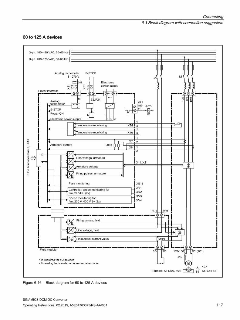
Connecting 6.3 Block diagram with connection suggestion
SINAMICS DCM DC Converter Operating Instructions, 02.2015, A5E34763375/RS-AA/001 117
60 to 125 A devices
Figure 6-16 Block diagram for 60 to 125 A devices
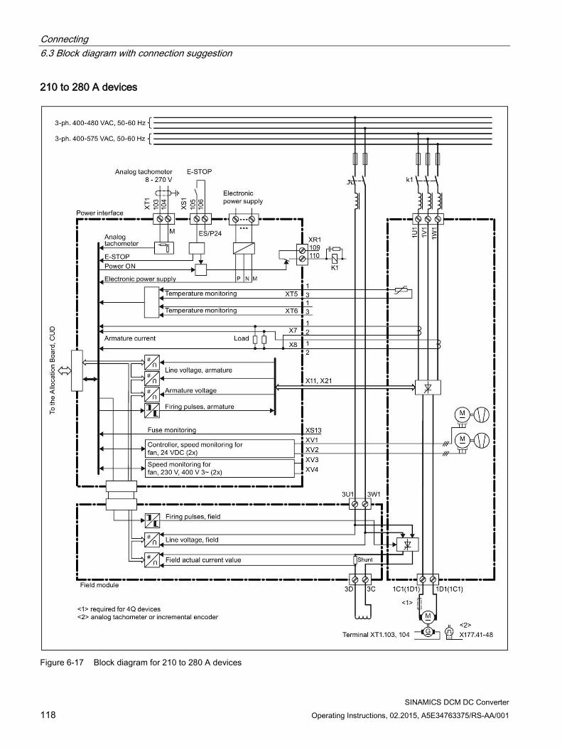
Connecting 6.3 Block diagram with connection suggestion
SINAMICS DCM DC Converter 118 Operating Instructions, 02.2015, A5E34763375/RS-AA/001
210 to 280 A devices
Figure 6-17 Block diagram for 210 to 280 A devices
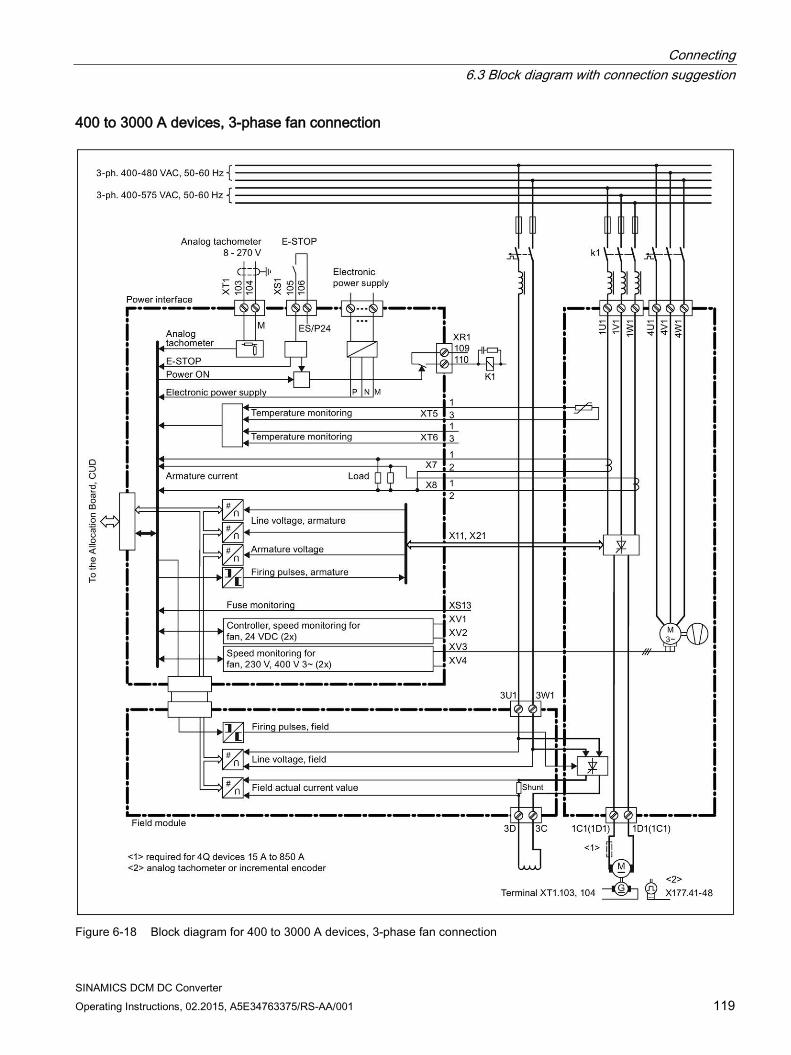
Connecting 6.3 Block diagram with connection suggestion
SINAMICS DCM DC Converter Operating Instructions, 02.2015, A5E34763375/RS-AA/001 119
400 to 3000 A devices, 3-phase fan connection
Figure 6-18 Block diagram for 400 to 3000 A devices, 3-phase fan connection
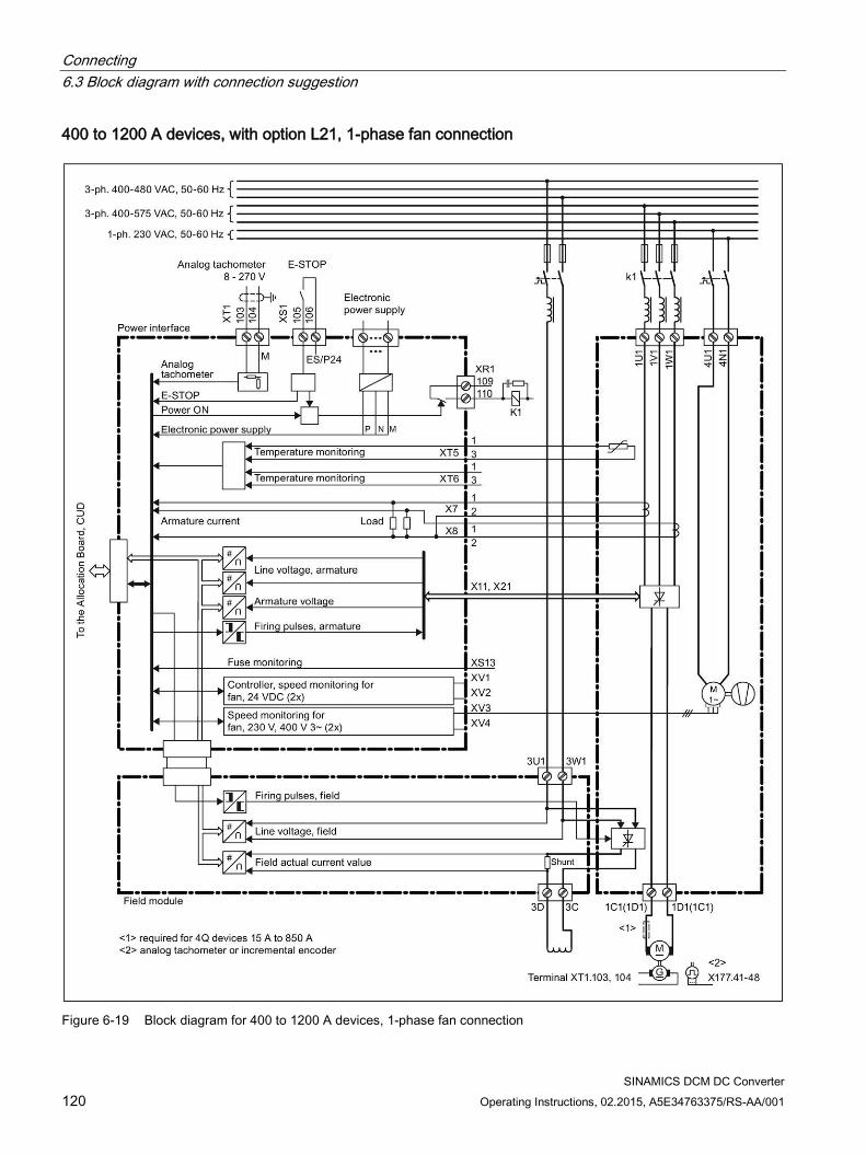
Connecting 6.3 Block diagram with connection suggestion
SINAMICS DCM DC Converter 120 Operating Instructions, 02.2015, A5E34763375/RS-AA/001
400 to 1200 A devices, with option L21, 1-phase fan connection
Figure 6-19 Block diagram for 400 to 1200 A devices, 1-phase fan connection
Connecting 6.3 Block diagram with connection suggestion
SINAMICS DCM DC Converter Operating Instructions, 02.2015, A5E34763375/RS-AA/001 121
For 15 A to 125 A, the following applies:
The fuses are not integrated in the device. The externally required semiconductor fuses 1NE1... are also suitable for the conductor protection.
For 210 A to 850 A, the following applies:
The fuses are not integrated in the device. The externally required semiconductor fuses are not suitable for the conductor protection. Fuses for the conductor protection must be provided separately.
For 900 A to 3000 A, the following applies:
The required semiconductor fuses are integrated in the device and external fuses must be provided for the conductor protection.
Connecting 6.4 Power connections
SINAMICS DCM DC Converter 122 Operating Instructions, 02.2015, A5E34763375/RS-AA/001
6.4 Power connections Explanations for the connection diagrams G Gate cables ⇒ yellow K Cathode cables ⇒ red a Copper/aluminum busbar b Copper/aluminum busbar c Raychem 44A0311-20-9 Firing cables (G, K): In units with a rated armature supply voltage of < 690 V: Betatherm 145, 0.5 mm2, UL In units with a rated armature supply voltage of ≥ 690 V: Radox 125, 0.75 mm2
Cable ends are marked with their specified designation.
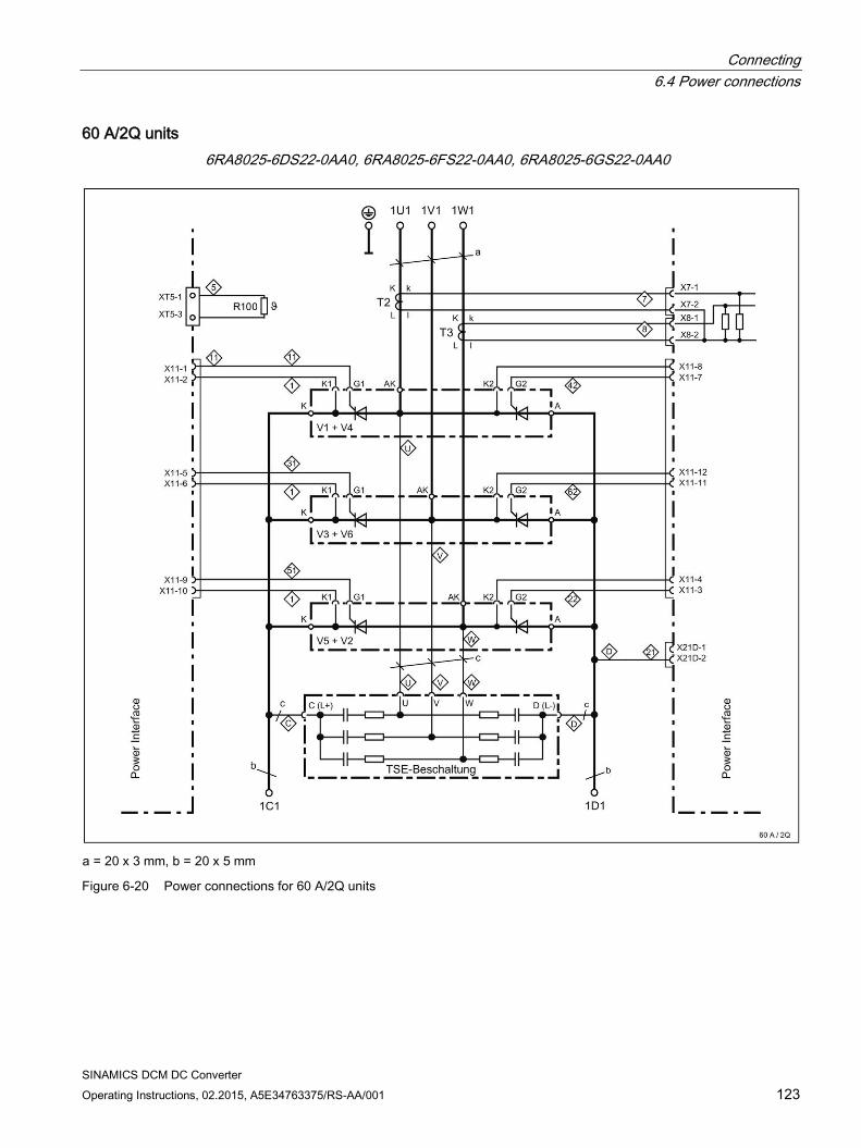
Connecting 6.4 Power connections
SINAMICS DCM DC Converter Operating Instructions, 02.2015, A5E34763375/RS-AA/001 123
60 A/2Q units 6RA8025-6DS22-0AA0, 6RA8025-6FS22-0AA0, 6RA8025-6GS22-0AA0
a = 20 x 3 mm, b = 20 x 5 mm
Figure 6-20 Power connections for 60 A/2Q units
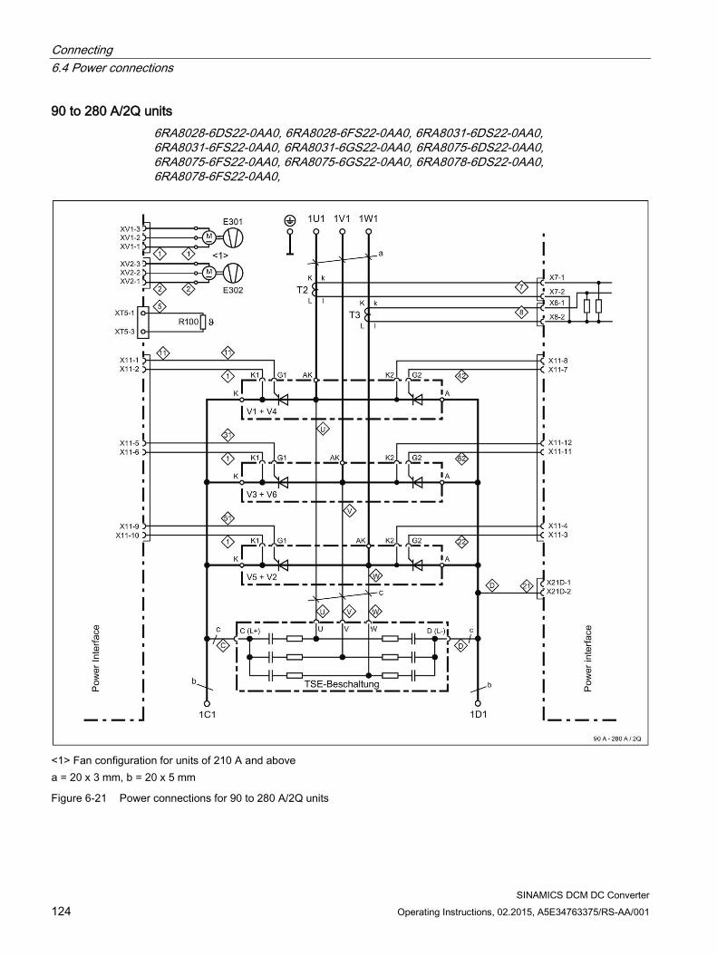
Connecting 6.4 Power connections
SINAMICS DCM DC Converter 124 Operating Instructions, 02.2015, A5E34763375/RS-AA/001
90 to 280 A/2Q units 6RA8028-6DS22-0AA0, 6RA8028-6FS22-0AA0, 6RA8031-6DS22-0AA0, 6RA8031-6FS22-0AA0, 6RA8031-6GS22-0AA0, 6RA8075-6DS22-0AA0, 6RA8075-6FS22-0AA0, 6RA8075-6GS22-0AA0, 6RA8078-6DS22-0AA0, 6RA8078-6FS22-0AA0,
<1> Fan configuration for units of 210 A and above a = 20 x 3 mm, b = 20 x 5 mm
Figure 6-21 Power connections for 90 to 280 A/2Q units
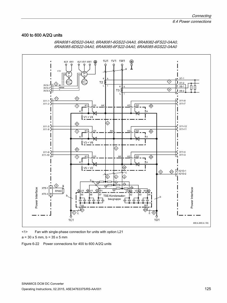
Connecting 6.4 Power connections
SINAMICS DCM DC Converter Operating Instructions, 02.2015, A5E34763375/RS-AA/001 125
400 to 600 A/2Q units 6RA8081-6DS22-0AA0, 6RA8081-6GS22-0AA0, 6RA8082-6FS22-0AA0, 6RA8085-6DS22-0AA0, 6RA8085-6FS22-0AA0, 6RA8085-6GS22-0AA0
<1> Fan with single-phase connection for units with option L21 a = 30 x 5 mm, b = 35 x 5 mm
Figure 6-22 Power connections for 400 to 600 A/2Q units
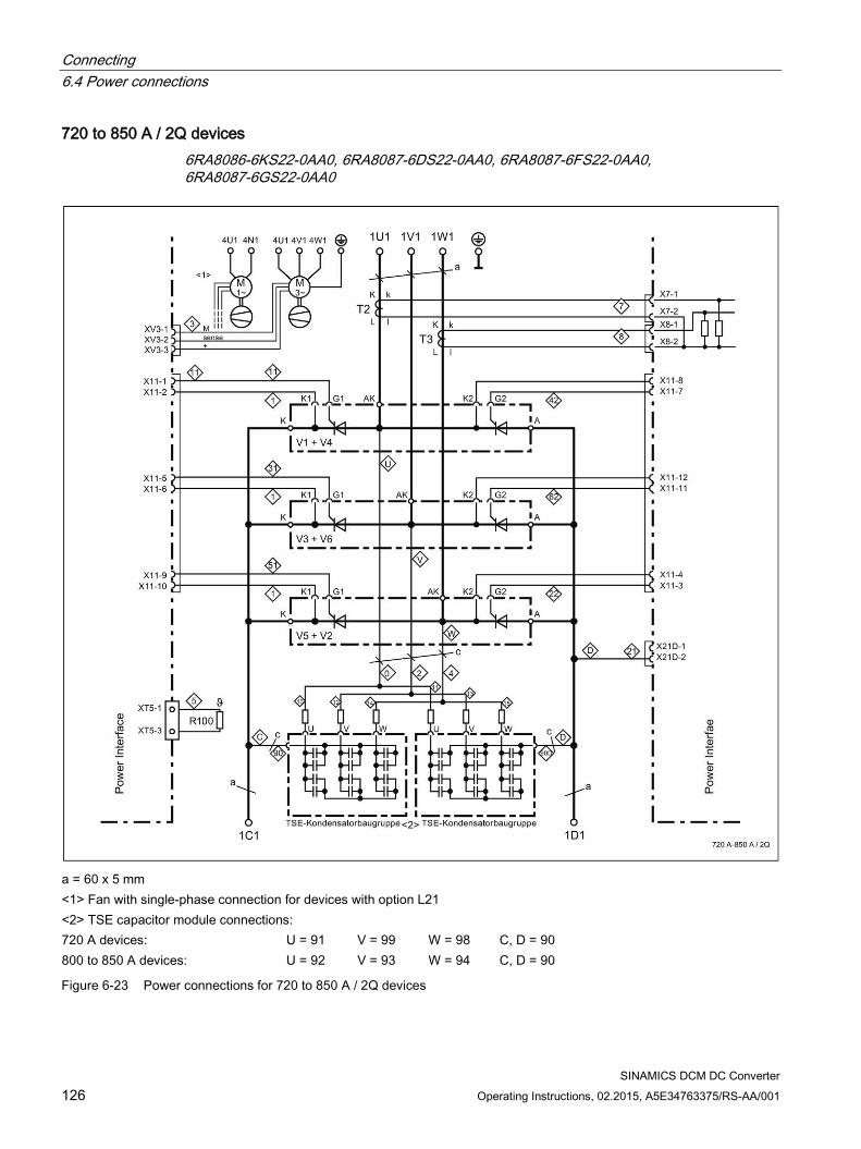
Connecting 6.4 Power connections
SINAMICS DCM DC Converter 126 Operating Instructions, 02.2015, A5E34763375/RS-AA/001
720 to 850 A / 2Q devices 6RA8086-6KS22-0AA0, 6RA8087-6DS22-0AA0, 6RA8087-6FS22-0AA0, 6RA8087-6GS22-0AA0
a = 60 x 5 mm <1> Fan with single-phase connection for devices with option L21 <2> TSE capacitor module connections: 720 A devices: U = 91 V = 99 W = 98 C, D = 90 800 to 850 A devices: U = 92 V = 93 W = 94 C, D = 90
Figure 6-23 Power connections for 720 to 850 A / 2Q devices
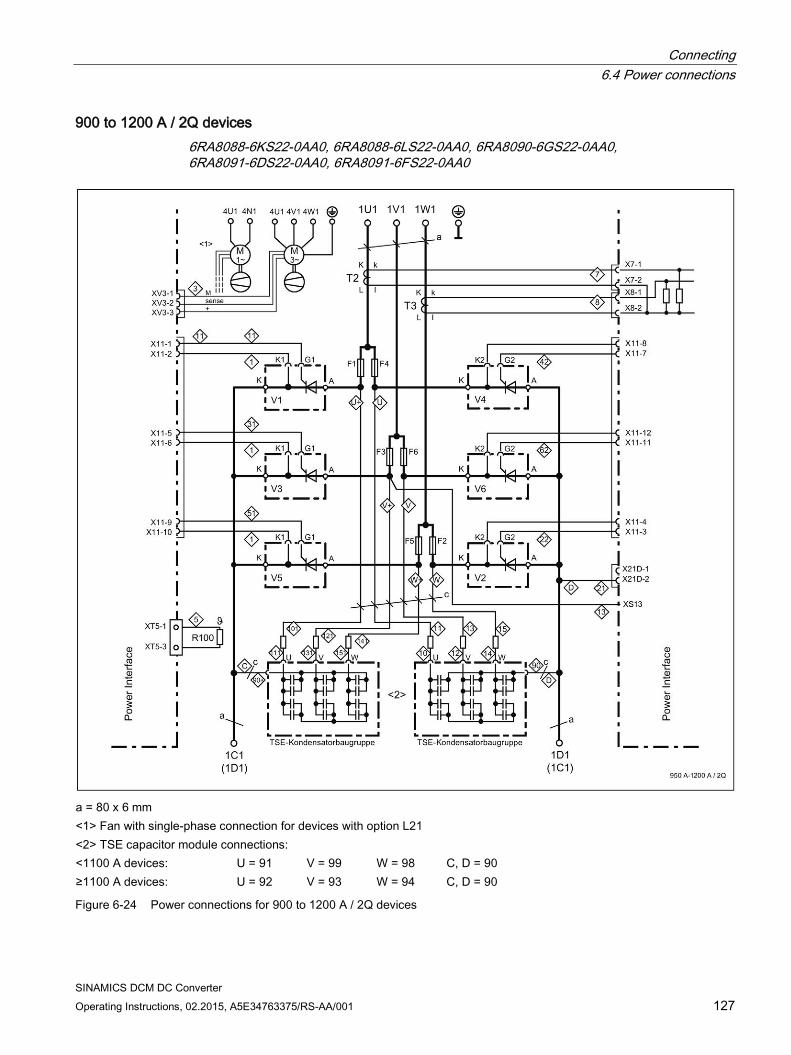
Connecting 6.4 Power connections
SINAMICS DCM DC Converter Operating Instructions, 02.2015, A5E34763375/RS-AA/001 127
900 to 1200 A / 2Q devices 6RA8088-6KS22-0AA0, 6RA8088-6LS22-0AA0, 6RA8090-6GS22-0AA0, 6RA8091-6DS22-0AA0, 6RA8091-6FS22-0AA0
a = 80 x 6 mm <1> Fan with single-phase connection for devices with option L21 <2> TSE capacitor module connections: <1100 A devices: U = 91 V = 99 W = 98 C, D = 90 ≥1100 A devices: U = 92 V = 93 W = 94 C, D = 90
Figure 6-24 Power connections for 900 to 1200 A / 2Q devices
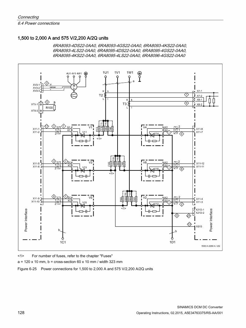
Connecting 6.4 Power connections
SINAMICS DCM DC Converter 128 Operating Instructions, 02.2015, A5E34763375/RS-AA/001
1,500 to 2,000 A and 575 V/2,200 A/2Q units 6RA8093-4DS22-0AA0, 6RA8093-4GS22-0AA0, 6RA8093-4KS22-0AA0, 6RA8093-4LS22-0AA0, 6RA8095-4DS22-0AA0, 6RA8095-4GS22-0AA0, 6RA8095-4KS22-0AA0, 6RA8095-4LS22-0AA0, 6RA8096-4GS22-0AA0
<1> For number of fuses, refer to the chapter "Fuses" a = 120 x 10 mm, b = cross-section 60 x 10 mm / width 323 mm
Figure 6-25 Power connections for 1,500 to 2,000 A and 575 V/2,200 A/2Q units
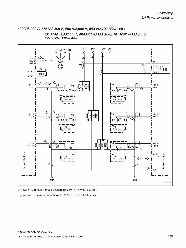
Connecting 6.4 Power connections
SINAMICS DCM DC Converter Operating Instructions, 02.2015, A5E34763375/RS-AA/001 129
400 V/3,000 A, 575 V/2,800 A, 690 V/2,600 A, 950 V/2,200 A/2Q units 6RA8096-4MS22-0AA0, 6RA8097-4GS22-0AA0, 6RA8097-4KS22-0AA0, 6RA8098-4DS22-0AA0
a = 120 x 10 mm, b = cross-section 60 x 10 mm / width 323 mm
Figure 6-26 Power connections for 2,200 to 3,000 A/2Q units
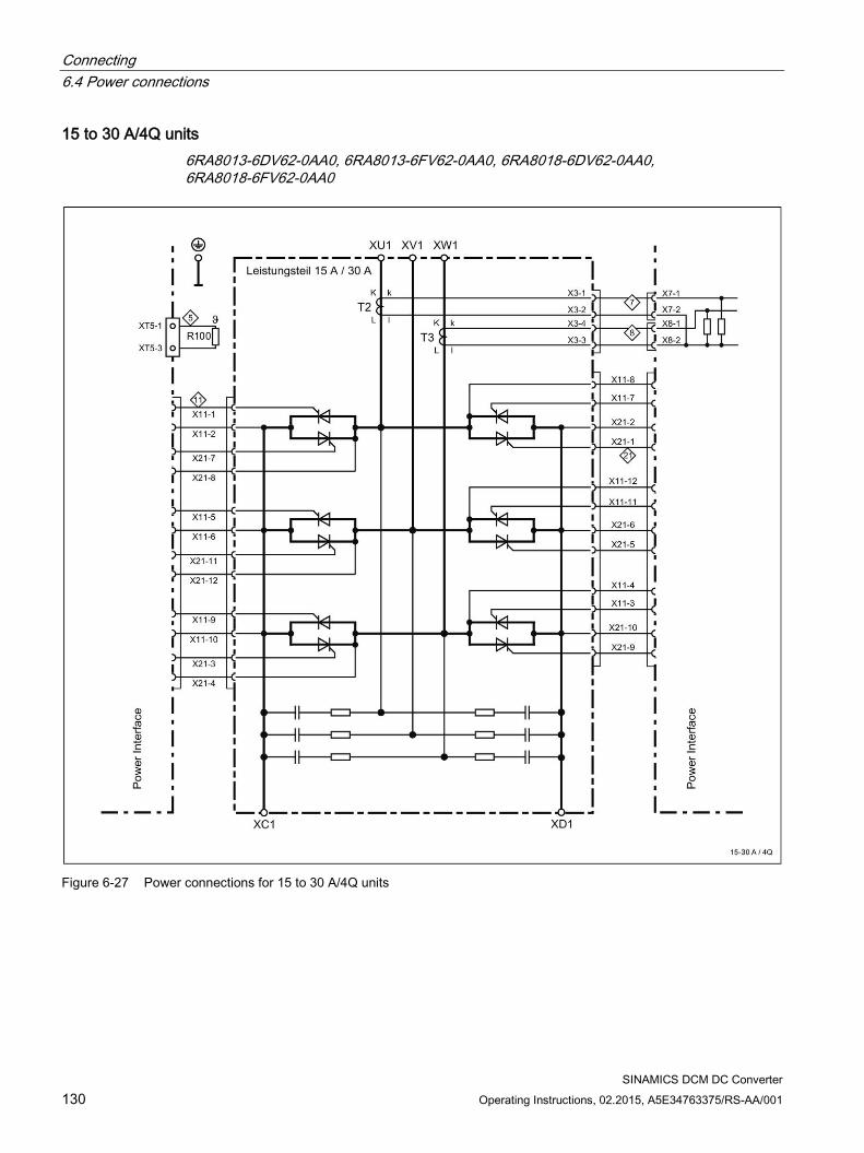
Connecting 6.4 Power connections
SINAMICS DCM DC Converter 130 Operating Instructions, 02.2015, A5E34763375/RS-AA/001
15 to 30 A/4Q units 6RA8013-6DV62-0AA0, 6RA8013-6FV62-0AA0, 6RA8018-6DV62-0AA0, 6RA8018-6FV62-0AA0
Figure 6-27 Power connections for 15 to 30 A/4Q units
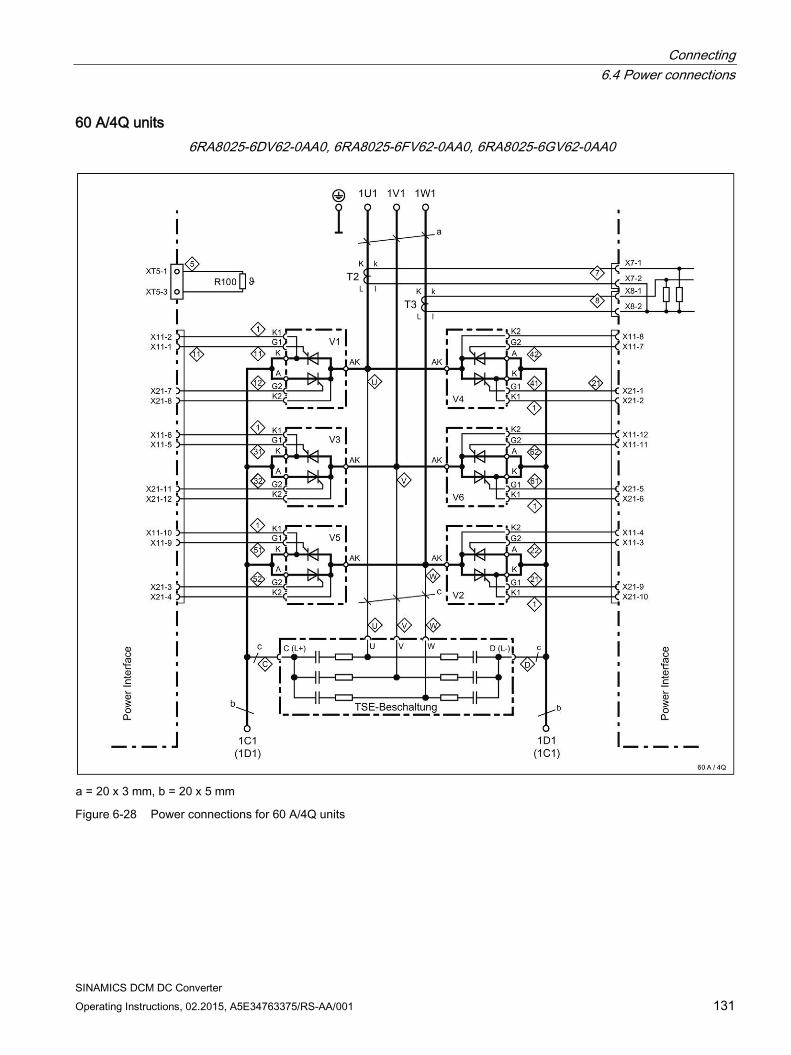
Connecting 6.4 Power connections
SINAMICS DCM DC Converter Operating Instructions, 02.2015, A5E34763375/RS-AA/001 131
60 A/4Q units 6RA8025-6DV62-0AA0, 6RA8025-6FV62-0AA0, 6RA8025-6GV62-0AA0
a = 20 x 3 mm, b = 20 x 5 mm
Figure 6-28 Power connections for 60 A/4Q units
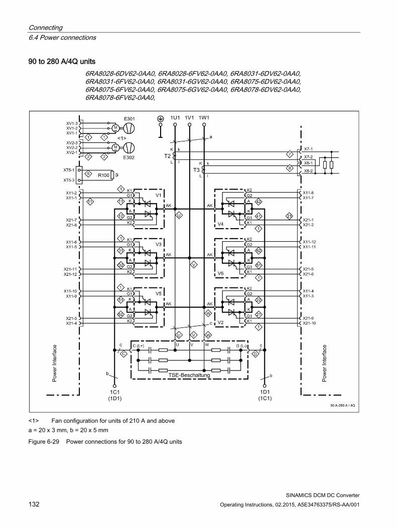
Connecting 6.4 Power connections
SINAMICS DCM DC Converter 132 Operating Instructions, 02.2015, A5E34763375/RS-AA/001
90 to 280 A/4Q units 6RA8028-6DV62-0AA0, 6RA8028-6FV62-0AA0, 6RA8031-6DV62-0AA0, 6RA8031-6FV62-0AA0, 6RA8031-6GV62-0AA0, 6RA8075-6DV62-0AA0, 6RA8075-6FV62-0AA0, 6RA8075-6GV62-0AA0, 6RA8078-6DV62-0AA0, 6RA8078-6FV62-0AA0,
<1> Fan configuration for units of 210 A and above a = 20 x 3 mm, b = 20 x 5 mm
Figure 6-29 Power connections for 90 to 280 A/4Q units
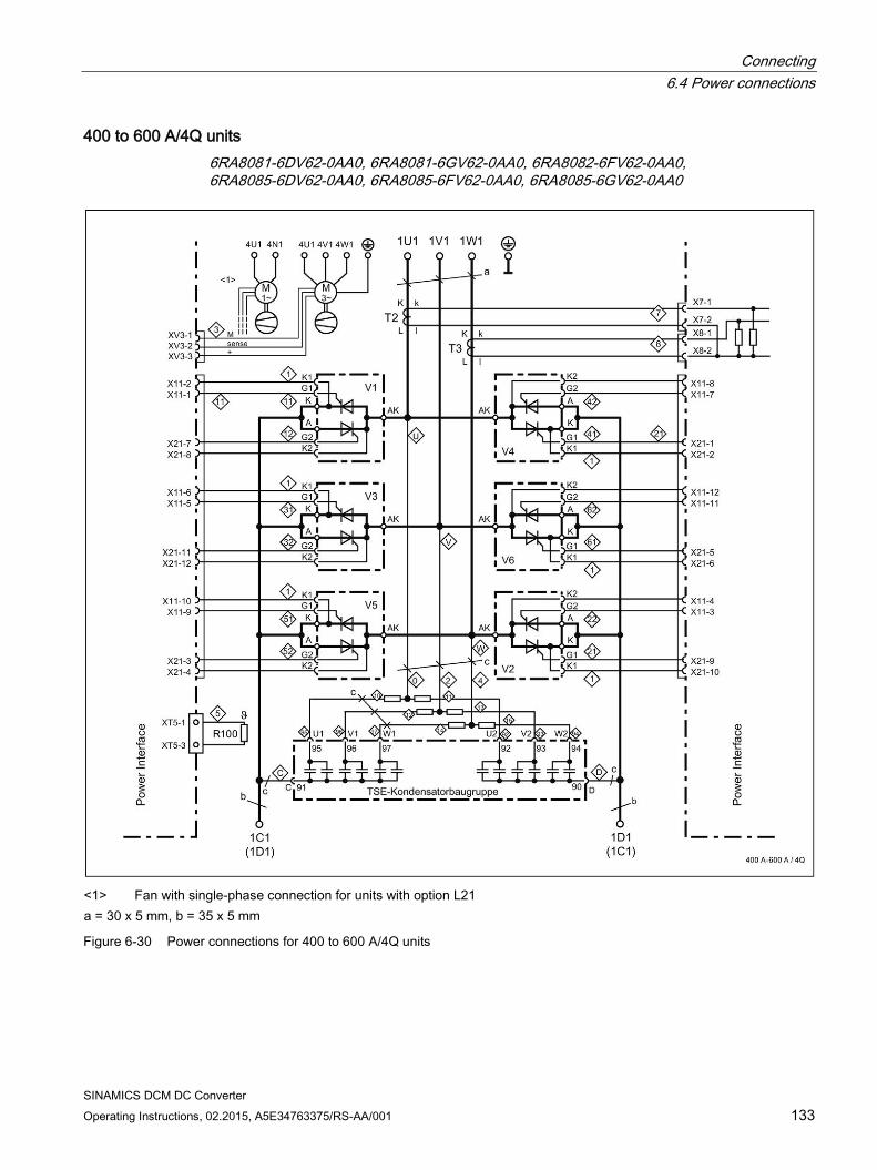
Connecting 6.4 Power connections
SINAMICS DCM DC Converter Operating Instructions, 02.2015, A5E34763375/RS-AA/001 133
400 to 600 A/4Q units 6RA8081-6DV62-0AA0, 6RA8081-6GV62-0AA0, 6RA8082-6FV62-0AA0, 6RA8085-6DV62-0AA0, 6RA8085-6FV62-0AA0, 6RA8085-6GV62-0AA0
<1> Fan with single-phase connection for units with option L21 a = 30 x 5 mm, b = 35 x 5 mm
Figure 6-30 Power connections for 400 to 600 A/4Q units
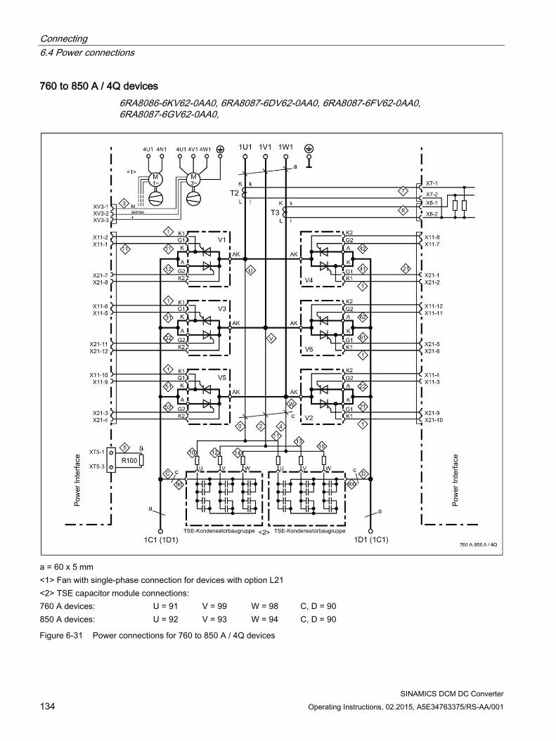
Connecting 6.4 Power connections
SINAMICS DCM DC Converter 134 Operating Instructions, 02.2015, A5E34763375/RS-AA/001
760 to 850 A / 4Q devices 6RA8086-6KV62-0AA0, 6RA8087-6DV62-0AA0, 6RA8087-6FV62-0AA0, 6RA8087-6GV62-0AA0,
a = 60 x 5 mm <1> Fan with single-phase connection for devices with option L21 <2> TSE capacitor module connections: 760 A devices: U = 91 V = 99 W = 98 C, D = 90 850 A devices: U = 92 V = 93 W = 94 C, D = 90
Figure 6-31 Power connections for 760 to 850 A / 4Q devices
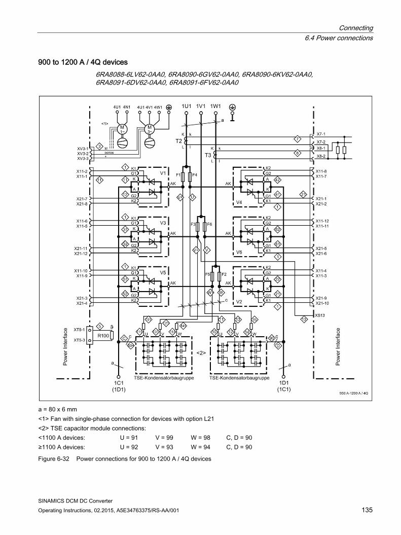
Connecting 6.4 Power connections
SINAMICS DCM DC Converter Operating Instructions, 02.2015, A5E34763375/RS-AA/001 135
900 to 1200 A / 4Q devices 6RA8088-6LV62-0AA0, 6RA8090-6GV62-0AA0, 6RA8090-6KV62-0AA0, 6RA8091-6DV62-0AA0, 6RA8091-6FV62-0AA0
a = 80 x 6 mm <1> Fan with single-phase connection for devices with option L21 <2> TSE capacitor module connections: <1100 A devices: U = 91 V = 99 W = 98 C, D = 90 ≥1100 A devices: U = 92 V = 93 W = 94 C, D = 90
Figure 6-32 Power connections for 900 to 1200 A / 4Q devices
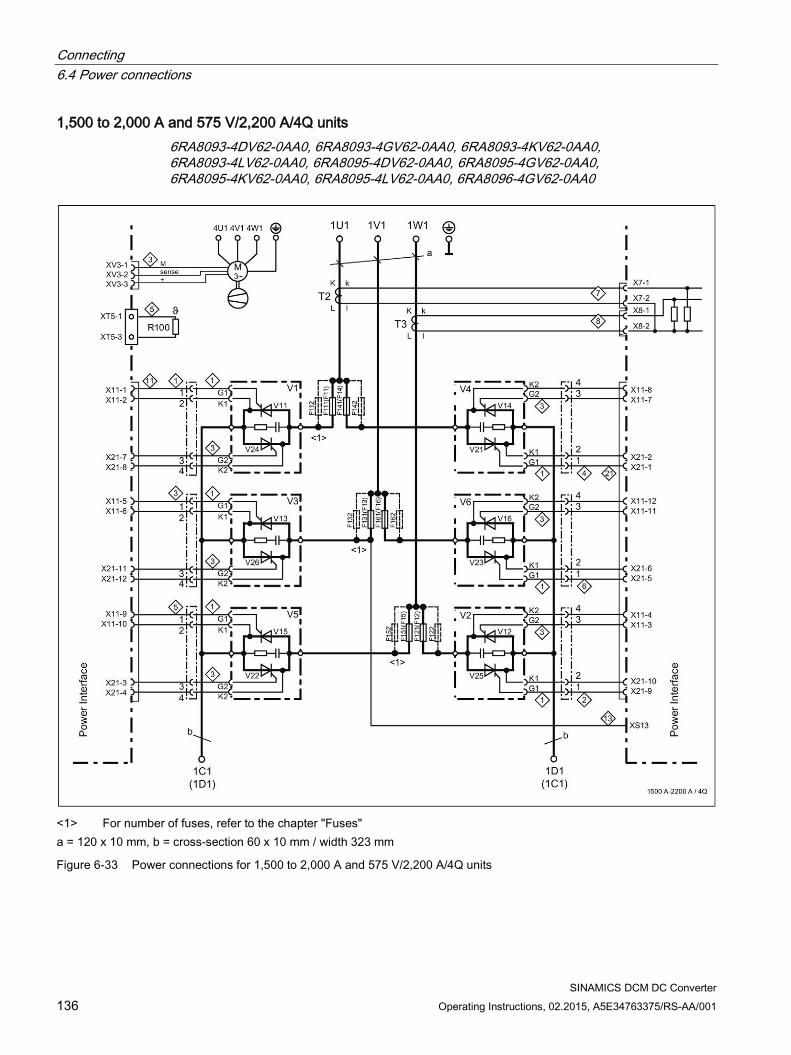
Connecting 6.4 Power connections
SINAMICS DCM DC Converter 136 Operating Instructions, 02.2015, A5E34763375/RS-AA/001
1,500 to 2,000 A and 575 V/2,200 A/4Q units 6RA8093-4DV62-0AA0, 6RA8093-4GV62-0AA0, 6RA8093-4KV62-0AA0, 6RA8093-4LV62-0AA0, 6RA8095-4DV62-0AA0, 6RA8095-4GV62-0AA0, 6RA8095-4KV62-0AA0, 6RA8095-4LV62-0AA0, 6RA8096-4GV62-0AA0
<1> For number of fuses, refer to the chapter "Fuses" a = 120 x 10 mm, b = cross-section 60 x 10 mm / width 323 mm
Figure 6-33 Power connections for 1,500 to 2,000 A and 575 V/2,200 A/4Q units
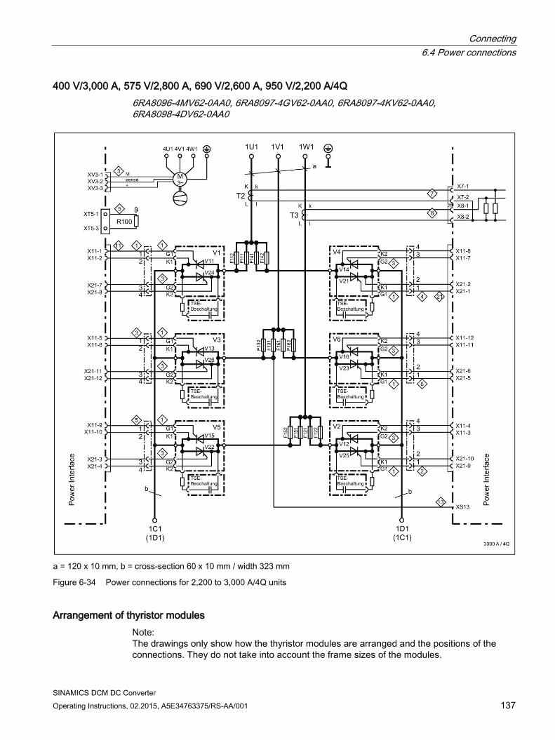
Connecting 6.4 Power connections
SINAMICS DCM DC Converter Operating Instructions, 02.2015, A5E34763375/RS-AA/001 137
400 V/3,000 A, 575 V/2,800 A, 690 V/2,600 A, 950 V/2,200 A/4Q 6RA8096-4MV62-0AA0, 6RA8097-4GV62-0AA0, 6RA8097-4KV62-0AA0, 6RA8098-4DV62-0AA0
a = 120 x 10 mm, b = cross-section 60 x 10 mm / width 323 mm
Figure 6-34 Power connections for 2,200 to 3,000 A/4Q units
Arrangement of thyristor modules Note: The drawings only show how the thyristor modules are arranged and the positions of the connections. They do not take into account the frame sizes of the modules.
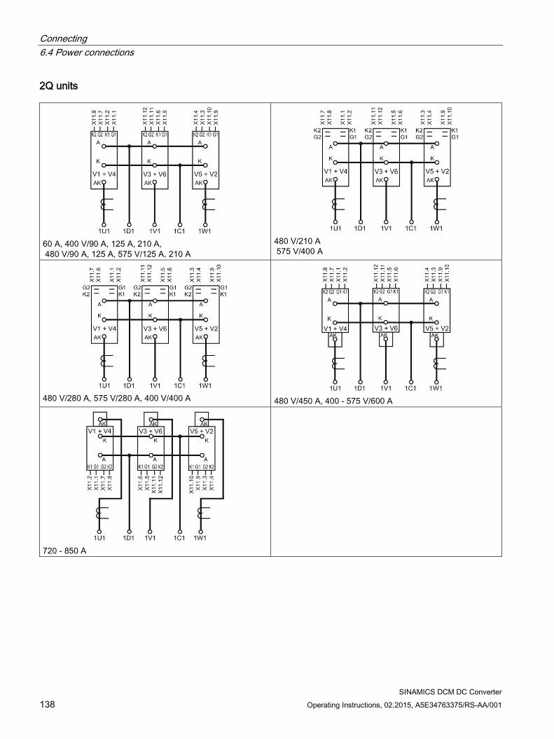
Connecting 6.4 Power connections
SINAMICS DCM DC Converter 138 Operating Instructions, 02.2015, A5E34763375/RS-AA/001
2Q units
60 A, 400 V/90 A, 125 A, 210 A, 480 V/90 A, 125 A, 575 V/125 A, 210 A
480 V/210 A 575 V/400 A
480 V/280 A, 575 V/280 A, 400 V/400 A
480 V/450 A, 400 - 575 V/600 A
720 - 850 A
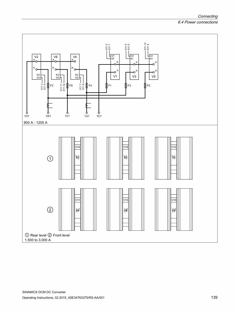
Connecting 6.4 Power connections
SINAMICS DCM DC Converter Operating Instructions, 02.2015, A5E34763375/RS-AA/001 139
900 A - 1200 A
① Rear level ② Front level 1,500 to 3,000 A
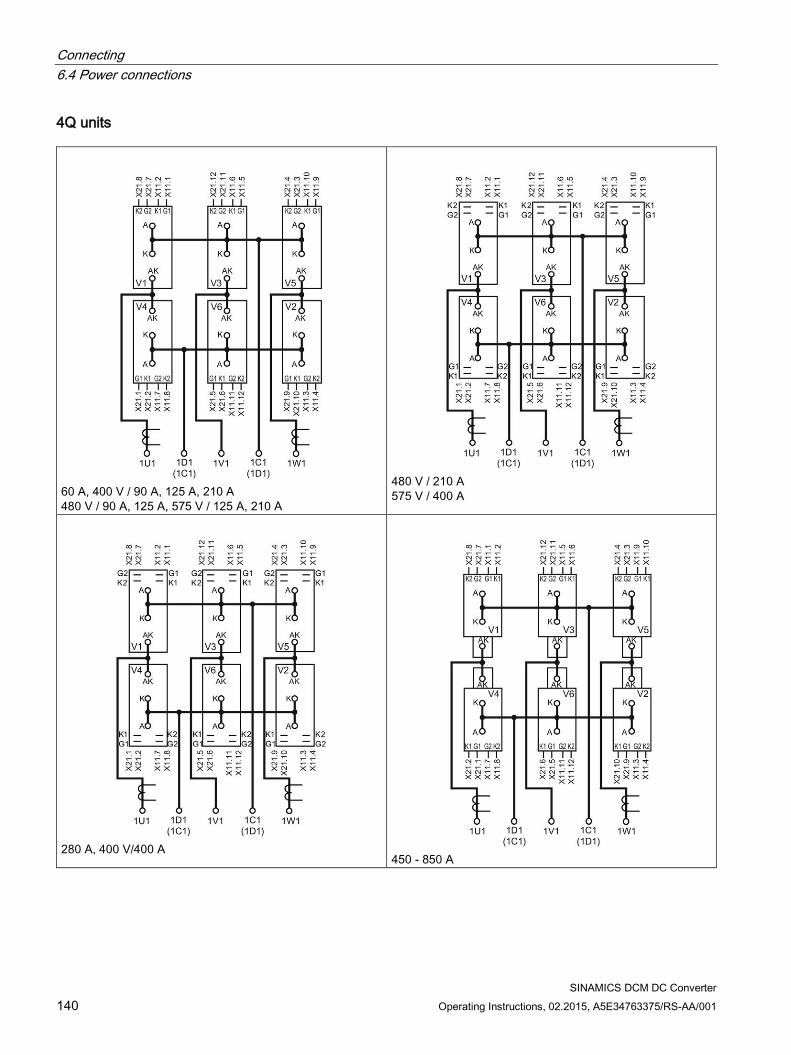
Connecting 6.4 Power connections
SINAMICS DCM DC Converter 140 Operating Instructions, 02.2015, A5E34763375/RS-AA/001
4Q units
60 A, 400 V / 90 A, 125 A, 210 A 480 V / 90 A, 125 A, 575 V / 125 A, 210 A
480 V / 210 A 575 V / 400 A
280 A, 400 V/400 A
450 - 850 A
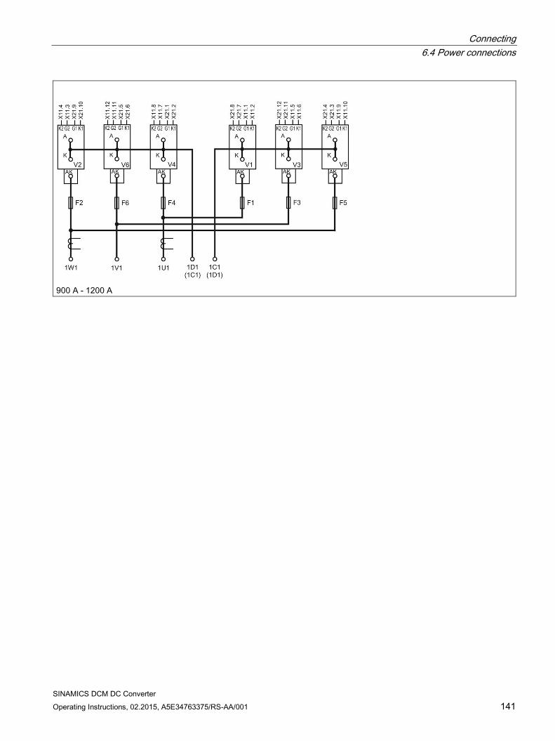
Connecting 6.4 Power connections
SINAMICS DCM DC Converter Operating Instructions, 02.2015, A5E34763375/RS-AA/001 141
900 A - 1200 A
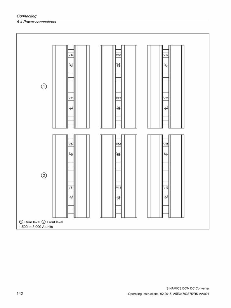
Connecting 6.4 Power connections
SINAMICS DCM DC Converter 142 Operating Instructions, 02.2015, A5E34763375/RS-AA/001
① Rear level ② Front level 1,500 to 3,000 A units
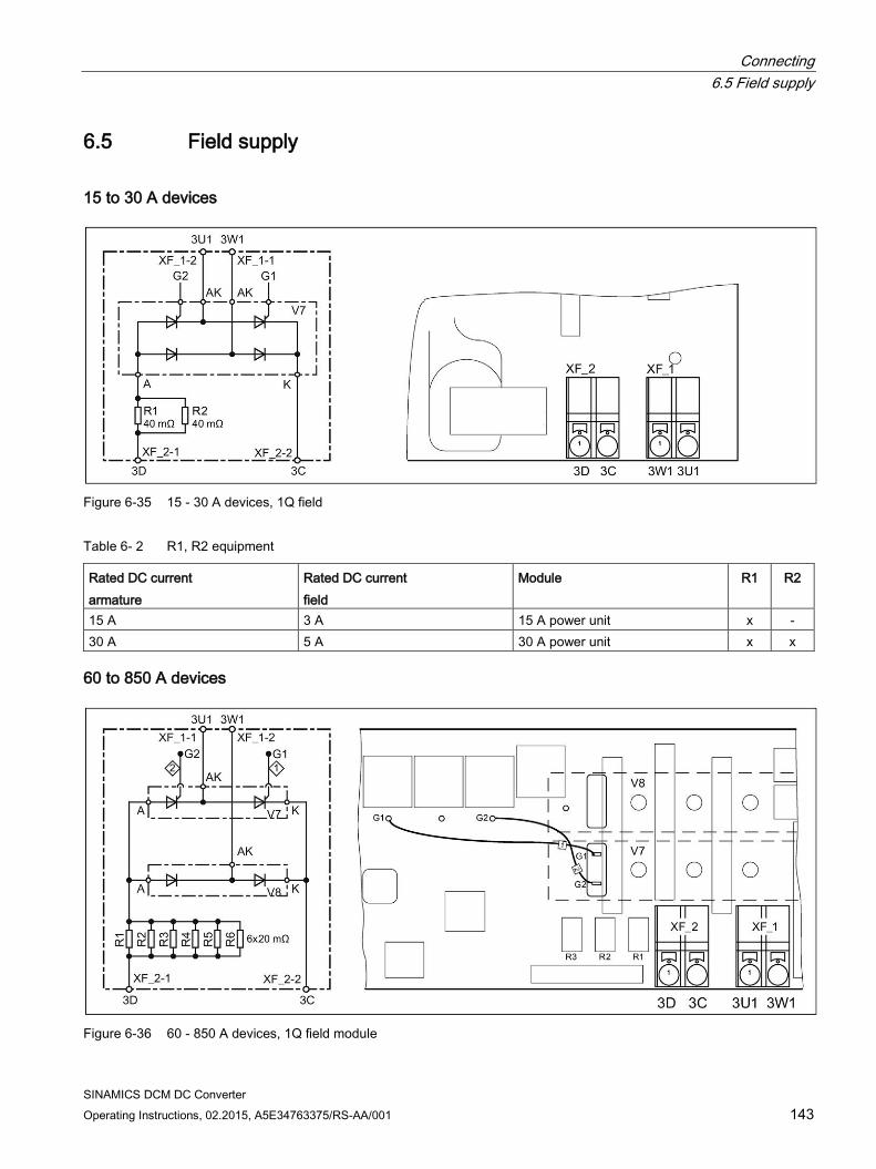
Connecting 6.5 Field supply
SINAMICS DCM DC Converter Operating Instructions, 02.2015, A5E34763375/RS-AA/001 143
6.5 Field supply
15 to 30 A devices
Figure 6-35 15 - 30 A devices, 1Q field
Table 6- 2 R1, R2 equipment
Rated DC current armature
Rated DC current field
Module R1 R2
15 A 3 A 15 A power unit x - 30 A 5 A 30 A power unit x x
60 to 850 A devices
Figure 6-36 60 - 850 A devices, 1Q field module
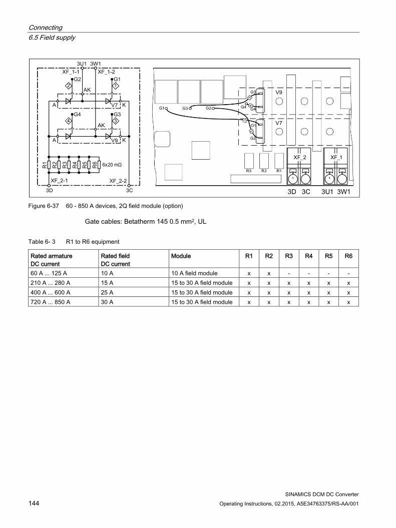
Connecting 6.5 Field supply
SINAMICS DCM DC Converter 144 Operating Instructions, 02.2015, A5E34763375/RS-AA/001
Figure 6-37 60 - 850 A devices, 2Q field module (option)
Gate cables: Betatherm 145 0.5 mm2, UL
Table 6- 3 R1 to R6 equipment
Rated armature DC current
Rated field DC current
Module
R1 R2 R3 R4 R5 R6
60 A ... 125 A 10 A 10 A field module x x - - - - 210 A ... 280 A 15 A 15 to 30 A field module x x x x x x 400 A ... 600 A 25 A 15 to 30 A field module x x x x x x 720 A ... 850 A 30 A 15 to 30 A field module x x x x x x
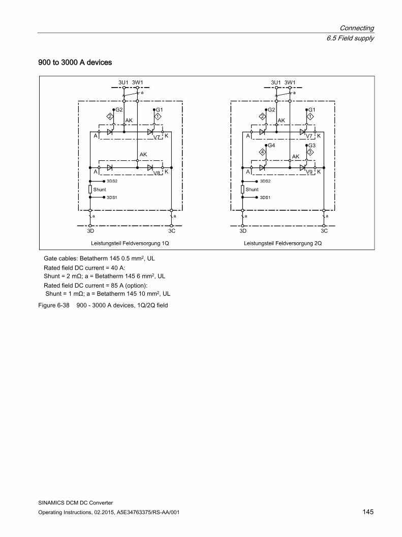
Connecting 6.5 Field supply
SINAMICS DCM DC Converter Operating Instructions, 02.2015, A5E34763375/RS-AA/001 145
900 to 3000 A devices
Gate cables: Betatherm 145 0.5 mm2, UL Rated field DC current = 40 A:
Shunt = 2 mΩ; a = Betatherm 145 6 mm2, UL Rated field DC current = 85 A (option):
Shunt = 1 mΩ; a = Betatherm 145 10 mm2, UL
Figure 6-38 900 - 3000 A devices, 1Q/2Q field
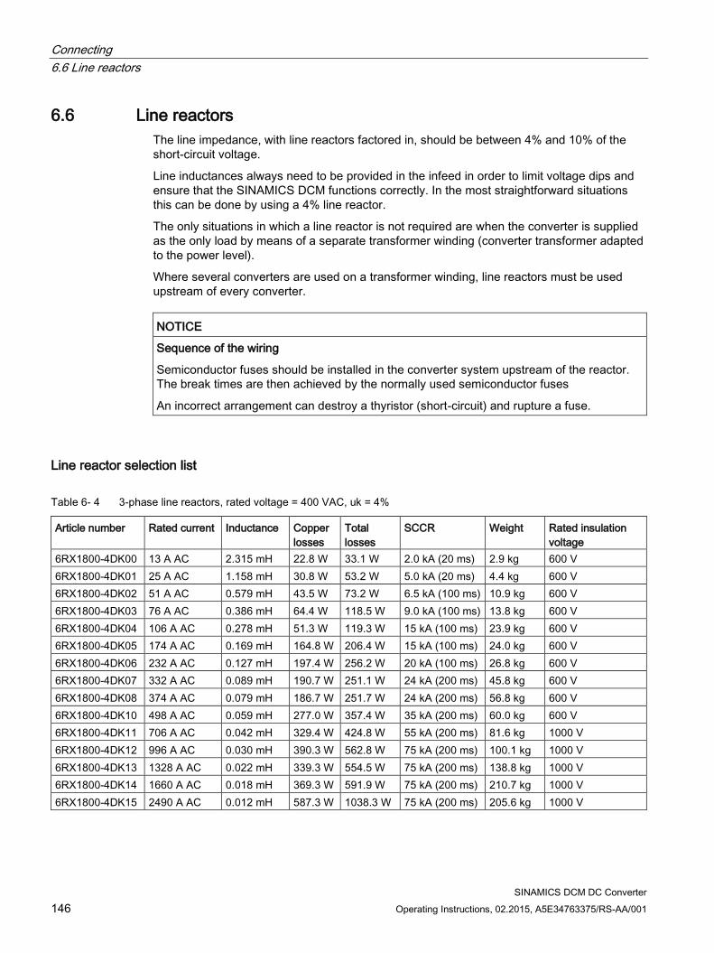
Connecting 6.6 Line reactors
SINAMICS DCM DC Converter 146 Operating Instructions, 02.2015, A5E34763375/RS-AA/001
6.6 Line reactors The line impedance, with line reactors factored in, should be between 4% and 10% of the short-circuit voltage.
Line inductances always need to be provided in the infeed in order to limit voltage dips and ensure that the SINAMICS DCM functions correctly. In the most straightforward situations this can be done by using a 4% line reactor.
The only situations in which a line reactor is not required are when the converter is supplied as the only load by means of a separate transformer winding (converter transformer adapted to the power level).
Where several converters are used on a transformer winding, line reactors must be used upstream of every converter.
NOTICE
Sequence of the wiring
Semiconductor fuses should be installed in the converter system upstream of the reactor. The break times are then achieved by the normally used semiconductor fuses
An incorrect arrangement can destroy a thyristor (short-circuit) and rupture a fuse.
Line reactor selection list
Table 6- 4 3-phase line reactors, rated voltage = 400 VAC, uk = 4%
Article number Rated current Inductance Copper losses
Total losses
SCCR Weight Rated insulation voltage
6RX1800-4DK00 13 A AC 2.315 mH 22.8 W 33.1 W 2.0 kA (20 ms) 2.9 kg 600 V 6RX1800-4DK01 25 A AC 1.158 mH 30.8 W 53.2 W 5.0 kA (20 ms) 4.4 kg 600 V 6RX1800-4DK02 51 A AC 0.579 mH 43.5 W 73.2 W 6.5 kA (100 ms) 10.9 kg 600 V 6RX1800-4DK03 76 A AC 0.386 mH 64.4 W 118.5 W 9.0 kA (100 ms) 13.8 kg 600 V 6RX1800-4DK04 106 A AC 0.278 mH 51.3 W 119.3 W 15 kA (100 ms) 23.9 kg 600 V 6RX1800-4DK05 174 A AC 0.169 mH 164.8 W 206.4 W 15 kA (100 ms) 24.0 kg 600 V 6RX1800-4DK06 232 A AC 0.127 mH 197.4 W 256.2 W 20 kA (100 ms) 26.8 kg 600 V 6RX1800-4DK07 332 A AC 0.089 mH 190.7 W 251.1 W 24 kA (200 ms) 45.8 kg 600 V 6RX1800-4DK08 374 A AC 0.079 mH 186.7 W 251.7 W 24 kA (200 ms) 56.8 kg 600 V 6RX1800-4DK10 498 A AC 0.059 mH 277.0 W 357.4 W 35 kA (200 ms) 60.0 kg 600 V 6RX1800-4DK11 706 A AC 0.042 mH 329.4 W 424.8 W 55 kA (200 ms) 81.6 kg 1000 V 6RX1800-4DK12 996 A AC 0.030 mH 390.3 W 562.8 W 75 kA (200 ms) 100.1 kg 1000 V 6RX1800-4DK13 1328 A AC 0.022 mH 339.3 W 554.5 W 75 kA (200 ms) 138.8 kg 1000 V 6RX1800-4DK14 1660 A AC 0.018 mH 369.3 W 591.9 W 75 kA (200 ms) 210.7 kg 1000 V 6RX1800-4DK15 2490 A AC 0.012 mH 587.3 W 1038.3 W 75 kA (200 ms) 205.6 kg 1000 V
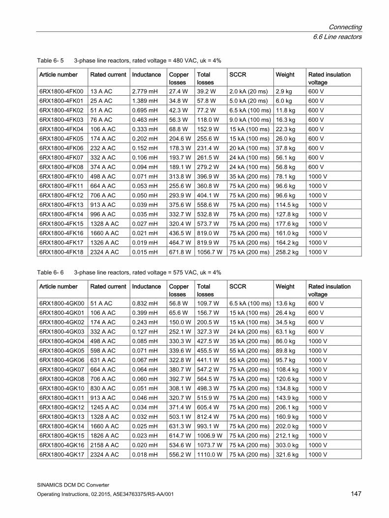
Connecting 6.6 Line reactors
SINAMICS DCM DC Converter Operating Instructions, 02.2015, A5E34763375/RS-AA/001 147
Table 6- 5 3-phase line reactors, rated voltage = 480 VAC, uk = 4%
Article number Rated current Inductance Copper losses
Total losses
SCCR Weight Rated insulation voltage
6RX1800-4FK00 13 A AC 2.779 mH 27.4 W 39.2 W 2.0 kA (20 ms) 2.9 kg 600 V 6RX1800-4FK01 25 A AC 1.389 mH 34.8 W 57.8 W 5.0 kA (20 ms) 6.0 kg 600 V 6RX1800-4FK02 51 A AC 0.695 mH 42.3 W 77.2 W 6.5 kA (100 ms) 11.8 kg 600 V 6RX1800-4FK03 76 A AC 0.463 mH 56.3 W 118.0 W 9.0 kA (100 ms) 16.3 kg 600 V 6RX1800-4FK04 106 A AC 0.333 mH 68.8 W 152.9 W 15 kA (100 ms) 22.3 kg 600 V 6RX1800-4FK05 174 A AC 0.202 mH 204.6 W 255.6 W 15 kA (100 ms) 26.0 kg 600 V 6RX1800-4FK06 232 A AC 0.152 mH 178.3 W 231.4 W 20 kA (100 ms) 37.8 kg 600 V 6RX1800-4FK07 332 A AC 0.106 mH 193.7 W 261.5 W 24 kA (100 ms) 56.1 kg 600 V 6RX1800-4FK08 374 A AC 0.094 mH 189.1 W 279.2 W 24 kA (100 ms) 56.8 kg 600 V 6RX1800-4FK10 498 A AC 0.071 mH 313.8 W 396.9 W 35 kA (200 ms) 78.1 kg 1000 V 6RX1800-4FK11 664 A AC 0.053 mH 255.6 W 360.8 W 75 kA (200 ms) 96.6 kg 1000 V 6RX1800-4FK12 706 A AC 0.050 mH 293.9 W 404.1 W 75 kA (200 ms) 96.6 kg 1000 V 6RX1800-4FK13 913 A AC 0.039 mH 375.6 W 558.6 W 75 kA (200 ms) 114.5 kg 1000 V 6RX1800-4FK14 996 A AC 0.035 mH 332.7 W 532.8 W 75 kA (200 ms) 127.8 kg 1000 V 6RX1800-4FK15 1328 A AC 0.027 mH 320.4 W 573.7 W 75 kA (200 ms) 177.6 kg 1000 V 6RX1800-4FK16 1660 A AC 0.021 mH 436.5 W 819.0 W 75 kA (200 ms) 161.0 kg 1000 V 6RX1800-4FK17 1326 A AC 0.019 mH 464.7 W 819.9 W 75 kA (200 ms) 164.2 kg 1000 V 6RX1800-4FK18 2324 A AC 0.015 mH 671.8 W 1056.7 W 75 kA (200 ms) 258.2 kg 1000 V
Table 6- 6 3-phase line reactors, rated voltage = 575 VAC, uk = 4%
Article number Rated current Inductance Copper losses
Total losses
SCCR Weight Rated insulation voltage
6RX1800-4GK00 51 A AC 0.832 mH 56.8 W 109.7 W 6.5 kA (100 ms) 13.6 kg 600 V 6RX1800-4GK01 106 A AC 0.399 mH 65.6 W 156.7 W 15 kA (100 ms) 26.4 kg 600 V 6RX1800-4GK02 174 A AC 0.243 mH 150.0 W 200.5 W 15 kA (100 ms) 34.5 kg 600 V 6RX1800-4GK03 332 A AC 0.127 mH 252.1 W 327.3 W 24 kA (200 ms) 63.1 kg 600 V 6RX1800-4GK04 498 A AC 0.085 mH 330.3 W 427.5 W 35 kA (200 ms) 86.0 kg 1000 V 6RX1800-4GK05 598 A AC 0.071 mH 339.6 W 455.5 W 55 kA (200 ms) 89.8 kg 1000 V 6RX1800-4GK06 631 A AC 0.067 mH 322.8 W 441.1 W 55 kA (200 ms) 95.7 kg 1000 V 6RX1800-4GK07 664 A AC 0.064 mH 380.7 W 547.2 W 75 kA (200 ms) 108.4 kg 1000 V 6RX1800-4GK08 706 A AC 0.060 mH 392.7 W 564.5 W 75 kA (200 ms) 120.6 kg 1000 V 6RX1800-4GK10 830 A AC 0.051 mH 308.1 W 498.3 W 75 kA (200 ms) 134.8 kg 1000 V 6RX1800-4GK11 913 A AC 0.046 mH 320.7 W 515.9 W 75 kA (200 ms) 143.9 kg 1000 V 6RX1800-4GK12 1245 A AC 0.034 mH 371.4 W 605.4 W 75 kA (200 ms) 206.1 kg 1000 V 6RX1800-4GK13 1328 A AC 0.032 mH 503.1 W 812.4 W 75 kA (200 ms) 160.9 kg 1000 V 6RX1800-4GK14 1660 A AC 0.025 mH 631.3 W 993.1 W 75 kA (200 ms) 202.0 kg 1000 V 6RX1800-4GK15 1826 A AC 0.023 mH 614.7 W 1006.9 W 75 kA (200 ms) 212.1 kg 1000 V 6RX1800-4GK16 2158 A AC 0.020 mH 534.6 W 1073.7 W 75 kA (200 ms) 303.0 kg 1000 V 6RX1800-4GK17 2324 A AC 0.018 mH 556.2 W 1110.0 W 75 kA (200 ms) 321.6 kg 1000 V
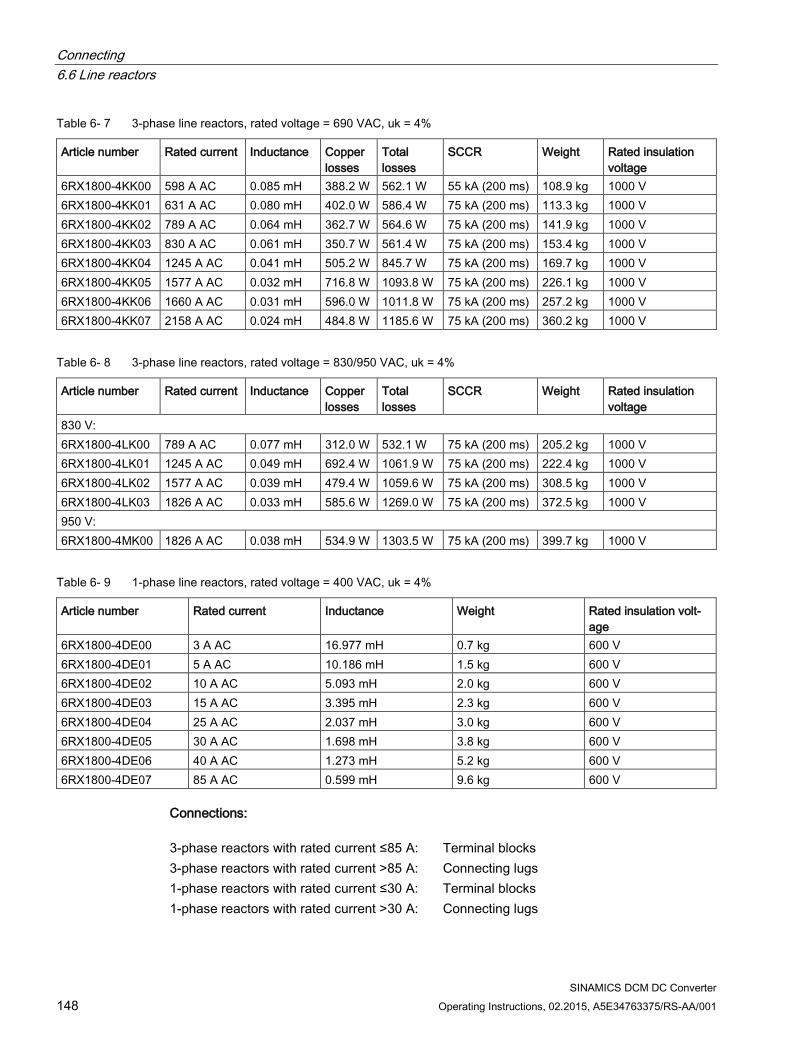
Connecting 6.6 Line reactors
SINAMICS DCM DC Converter 148 Operating Instructions, 02.2015, A5E34763375/RS-AA/001
Table 6- 7 3-phase line reactors, rated voltage = 690 VAC, uk = 4%
Article number Rated current Inductance Copper losses
Total losses
SCCR Weight Rated insulation voltage
6RX1800-4KK00 598 A AC 0.085 mH 388.2 W 562.1 W 55 kA (200 ms) 108.9 kg 1000 V 6RX1800-4KK01 631 A AC 0.080 mH 402.0 W 586.4 W 75 kA (200 ms) 113.3 kg 1000 V 6RX1800-4KK02 789 A AC 0.064 mH 362.7 W 564.6 W 75 kA (200 ms) 141.9 kg 1000 V 6RX1800-4KK03 830 A AC 0.061 mH 350.7 W 561.4 W 75 kA (200 ms) 153.4 kg 1000 V 6RX1800-4KK04 1245 A AC 0.041 mH 505.2 W 845.7 W 75 kA (200 ms) 169.7 kg 1000 V 6RX1800-4KK05 1577 A AC 0.032 mH 716.8 W 1093.8 W 75 kA (200 ms) 226.1 kg 1000 V 6RX1800-4KK06 1660 A AC 0.031 mH 596.0 W 1011.8 W 75 kA (200 ms) 257.2 kg 1000 V 6RX1800-4KK07 2158 A AC 0.024 mH 484.8 W 1185.6 W 75 kA (200 ms) 360.2 kg 1000 V
Table 6- 8 3-phase line reactors, rated voltage = 830/950 VAC, uk = 4%
Article number Rated current Inductance Copper losses
Total losses
SCCR Weight Rated insulation voltage
830 V: 6RX1800-4LK00 789 A AC 0.077 mH 312.0 W 532.1 W 75 kA (200 ms) 205.2 kg 1000 V 6RX1800-4LK01 1245 A AC 0.049 mH 692.4 W 1061.9 W 75 kA (200 ms) 222.4 kg 1000 V 6RX1800-4LK02 1577 A AC 0.039 mH 479.4 W 1059.6 W 75 kA (200 ms) 308.5 kg 1000 V 6RX1800-4LK03 1826 A AC 0.033 mH 585.6 W 1269.0 W 75 kA (200 ms) 372.5 kg 1000 V 950 V: 6RX1800-4MK00 1826 A AC 0.038 mH 534.9 W 1303.5 W 75 kA (200 ms) 399.7 kg 1000 V
Table 6- 9 1-phase line reactors, rated voltage = 400 VAC, uk = 4%
Article number Rated current Inductance Weight Rated insulation volt-age
6RX1800-4DE00 3 A AC 16.977 mH 0.7 kg 600 V 6RX1800-4DE01 5 A AC 10.186 mH 1.5 kg 600 V 6RX1800-4DE02 10 A AC 5.093 mH 2.0 kg 600 V 6RX1800-4DE03 15 A AC 3.395 mH 2.3 kg 600 V 6RX1800-4DE04 25 A AC 2.037 mH 3.0 kg 600 V 6RX1800-4DE05 30 A AC 1.698 mH 3.8 kg 600 V 6RX1800-4DE06 40 A AC 1.273 mH 5.2 kg 600 V 6RX1800-4DE07 85 A AC 0.599 mH 9.6 kg 600 V
Connections: 3-phase reactors with rated current ≤85 A: Terminal blocks 3-phase reactors with rated current >85 A: Connecting lugs 1-phase reactors with rated current ≤30 A: Terminal blocks 1-phase reactors with rated current >30 A: Connecting lugs
Connecting 6.6 Line reactors
SINAMICS DCM DC Converter Operating Instructions, 02.2015, A5E34763375/RS-AA/001 149
Notes
3-phase line reactors with uk = 2% can be supplied on request.
The line reactors are suitable for 50 Hz and 60 Hz operation.
In 60 Hz operation, the next highest voltage class should be selected
e.g. 480 V at 50 Hz, 575 V at 60 Hz.
For SCCR specifications (time specifications 20 ms): These break times are achieved with the recommended semiconductor fuses
Standards, approvals
REACH, ROHS, CE, cULus
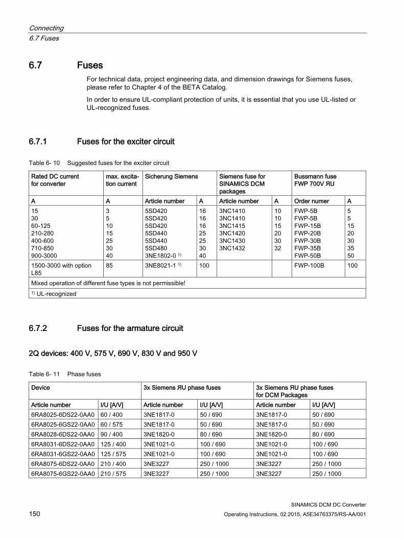
Connecting
6.7 Fuses
SINAMICS DCM DC Converter
150 Operating Instructions, 02.2015, A5E34763375/RS-AA/001
6.7 Fuses
For technical data, project engineering data, and dimension drawings for Siemens fuses,
please refer to Chapter 4 of the BETA Catalog.
In order to ensure UL-compliant protection of units, it is essential that you use UL-listed or
UL-recognized fuses.
6.7.1 Fuses for the exciter circuit
Table 6- 10 Suggested fuses for the exciter circuit
Rated DC current
for converter
max. excita-
tion current
Sicherung Siemens Siemens fuse for
SINAMICS DCM
packages
Bussmann fuse
FWP 700V ЯU
A A Article number A Article number A Order numer A
15
30
60-125
210-280
400-600
710-850
900-3000
3
5
10
15
25
30
40
5SD420
5SD420
5SD420
5SD440
5SD440
5SD480
3NE1802-0 1)
16
16
16
25
25
30
40
3NC1410
3NC1410
3NC1415
3NC1420
3NC1430
3NC1432
10
10
15
20
30
32
FWP-5B
FWP-5B
FWP-15B
FWP-20B
FWP-30B
FWP-35B
FWP-50B
5
5
15
20
30
35
50
1500-3000 with option
L85
85 3NE8021-1 1) 100 FWP-100B 100
Mixed operation of different fuse types is not permissible!
1) UL-recognized
6.7.2 Fuses for the armature circuit
2Q devices: 400 V, 575 V, 690 V, 830 V and 950 V
Table 6- 11 Phase fuses
Device 3x Siemens ЯU phase fuses 3x Siemens ЯU phase fuses
for DCM Packages
Article number I/U [A/V] Article number I/U [A/V] Article number I/U [A/V]
6RA8025-6DS22-0AA0 60 / 400 3NE1817-0 50 / 690 3NE1817-0 50 / 690
6RA8025-6GS22-0AA0 60 / 575 3NE1817-0 50 / 690 3NE1817-0 50 / 690
6RA8028-6DS22-0AA0 90 / 400 3NE1820-0 80 / 690 3NE1820-0 80 / 690
6RA8031-6DS22-0AA0 125 / 400 3NE1021-0 100 / 690 3NE1021-0 100 / 690
6RA8031-6GS22-0AA0 125 / 575 3NE1021-0 100 / 690 3NE1021-0 100 / 690
6RA8075-6DS22-0AA0 210 / 400 3NE3227 250 / 1000 3NE3227 250 / 1000
6RA8075-6GS22-0AA0 210 / 575 3NE3227 250 / 1000 3NE3227 250 / 1000
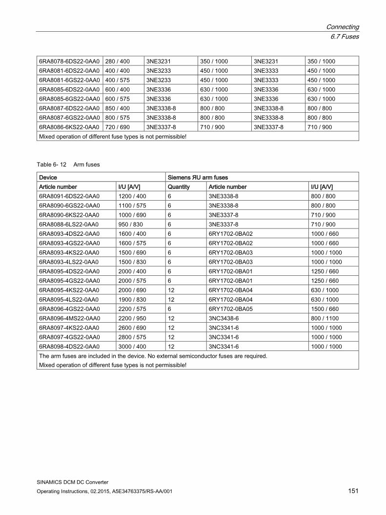
Connecting 6.7 Fuses
SINAMICS DCM DC Converter Operating Instructions, 02.2015, A5E34763375/RS-AA/001 151
6RA8078-6DS22-0AA0 280 / 400 3NE3231 350 / 1000 3NE3231 350 / 1000 6RA8081-6DS22-0AA0 400 / 400 3NE3233 450 / 1000 3NE3333 450 / 1000 6RA8081-6GS22-0AA0 400 / 575 3NE3233 450 / 1000 3NE3333 450 / 1000 6RA8085-6DS22-0AA0 600 / 400 3NE3336 630 / 1000 3NE3336 630 / 1000 6RA8085-6GS22-0AA0 600 / 575 3NE3336 630 / 1000 3NE3336 630 / 1000 6RA8087-6DS22-0AA0 850 / 400 3NE3338-8 800 / 800 3NE3338-8 800 / 800 6RA8087-6GS22-0AA0 800 / 575 3NE3338-8 800 / 800 3NE3338-8 800 / 800 6RA8086-6KS22-0AA0 720 / 690 3NE3337-8 710 / 900 3NE3337-8 710 / 900 Mixed operation of different fuse types is not permissible!
Table 6- 12 Arm fuses
Device Siemens ЯU arm fuses Article number I/U [A/V] Quantity Article number I/U [A/V] 6RA8091-6DS22-0AA0 1200 / 400 6 3NE3338-8 800 / 800 6RA8090-6GS22-0AA0 1100 / 575 6 3NE3338-8 800 / 800 6RA8090-6KS22-0AA0 1000 / 690 6 3NE3337-8 710 / 900 6RA8088-6LS22-0AA0 950 / 830 6 3NE3337-8 710 / 900 6RA8093-4DS22-0AA0 1600 / 400 6 6RY1702-0BA02 1000 / 660 6RA8093-4GS22-0AA0 1600 / 575 6 6RY1702-0BA02 1000 / 660 6RA8093-4KS22-0AA0 1500 / 690 6 6RY1702-0BA03 1000 / 1000 6RA8093-4LS22-0AA0 1500 / 830 6 6RY1702-0BA03 1000 / 1000 6RA8095-4DS22-0AA0 2000 / 400 6 6RY1702-0BA01 1250 / 660 6RA8095-4GS22-0AA0 2000 / 575 6 6RY1702-0BA01 1250 / 660 6RA8095-4KS22-0AA0 2000 / 690 12 6RY1702-0BA04 630 / 1000 6RA8095-4LS22-0AA0 1900 / 830 12 6RY1702-0BA04 630 / 1000 6RA8096-4GS22-0AA0 2200 / 575 6 6RY1702-0BA05 1500 / 660 6RA8096-4MS22-0AA0 2200 / 950 12 3NC3438-6 800 / 1100 6RA8097-4KS22-0AA0 2600 / 690 12 3NC3341-6 1000 / 1000 6RA8097-4GS22-0AA0 2800 / 575 12 3NC3341-6 1000 / 1000 6RA8098-4DS22-0AA0 3000 / 400 12 3NC3341-6 1000 / 1000 The arm fuses are included in the device. No external semiconductor fuses are required. Mixed operation of different fuse types is not permissible!
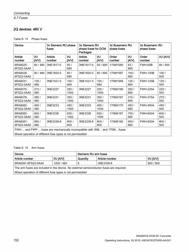
Connecting 6.7 Fuses
SINAMICS DCM DC Converter 152 Operating Instructions, 02.2015, A5E34763375/RS-AA/001
2Q devices: 480 V
Table 6- 13 Phase fuses
Device 3x Siemens ЯU phase fuses
3x Siemens ЯU phase fuses for DCM Packages
3x Bussmann ЯU phase fuses
3x Bussmann ЯU phase fuses
Article number
I/U [A/V]
Article number
I/U [A/V]
Article number
I/U [A/V]
Order number
I/U [A/V]
Order number
I/U [A/V]
6RA8025-6FS22-0AA0
60 / 480 3NE1817-0 50 / 690
3NE1817-0 50 / 690 170M1565 63 / 660
FWH-60B 60 / 500
6RA8028-6FS22-0AA0
90 / 480 3NE1820-0 80 / 690
3NE1820-0 80 / 690 170M1567 100 / 660
FWH-100B 100 / 500
6RA8031-6FS22-0AA0
125 / 480
3NE1021-0 100 / 690
3NE1021-0 100 / 690
170M1568 125 / 660
FWH-125B 125 / 500
6RA8075-6FS22-0AA0
210 / 480
3NE3227 250 / 1000
3NE3227 250 / 1000
170M3166 250 / 660
FWH-225A 225 / 500
6RA8078-6FS22-0AA0
280 / 480
3NE3231 350 / 1000
3NE3231 350 / 1000
170M3167 315 / 660
FWH-275A 275 / 500
6RA8082-6FS22-0AA0
450 / 480
3NE3233 450 / 1000
3NE3333 450 / 1000
170M3170 450 / 660
FWH-450A 450 / 500
6RA8085-6FS22-0AA0
600 / 480
3NE3336 630 / 1000
3NE3336 630 / 1000
170M4167 700 / 660
FWH-600A 600 / 500
6RA8087-6FS22-0AA0
850 / 480
3NE3338-8 800 / 800
3NE3338-8 800 / 800
170M5165 900 / 660
FWH-800A 800 / 500
FWH-... and FWP-... fuses are mechanically incompatible with 3NE... and 170M... fuses. Mixed operation of different fuse types is not permissible!
Table 6- 14 Arm fuses
Device Siemens ЯU arm fuses Article number I/U [A/V] Quantity Article number I/U [A/V] 6RA8091-6FS22-0AA0 1200 / 480 6 3NE3338-8 800 / 800 The arm fuses are included in the device. No external semiconductor fuses are required. Mixed operation of different fuse types is not permissible!
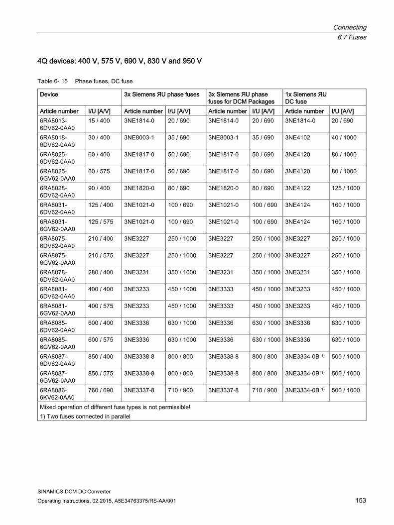
Connecting 6.7 Fuses
SINAMICS DCM DC Converter Operating Instructions, 02.2015, A5E34763375/RS-AA/001 153
4Q devices: 400 V, 575 V, 690 V, 830 V and 950 V
Table 6- 15 Phase fuses, DC fuse
Device 3x Siemens ЯU phase fuses 3x Siemens ЯU phase fuses for DCM Packages
1x Siemens ЯU DC fuse
Article number I/U [A/V] Article number I/U [A/V] Article number I/U [A/V] Article number I/U [A/V] 6RA8013-6DV62-0AA0
15 / 400 3NE1814-0 20 / 690 3NE1814-0 20 / 690 3NE1814-0 20 / 690
6RA8018-6DV62-0AA0
30 / 400 3NE8003-1 35 / 690 3NE8003-1 35 / 690 3NE4102 40 / 1000
6RA8025-6DV62-0AA0
60 / 400 3NE1817-0 50 / 690 3NE1817-0 50 / 690 3NE4120 80 / 1000
6RA8025-6GV62-0AA0
60 / 575 3NE1817-0 50 / 690 3NE1817-0 50 / 690 3NE4120 80 / 1000
6RA8028-6DV62-0AA0
90 / 400 3NE1820-0 80 / 690 3NE1820-0 80 / 690 3NE4122 125 / 1000
6RA8031-6DV62-0AA0
125 / 400 3NE1021-0 100 / 690 3NE1021-0 100 / 690 3NE4124 160 / 1000
6RA8031-6GV62-0AA0
125 / 575 3NE1021-0 100 / 690 3NE1021-0 100 / 690 3NE4124 160 / 1000
6RA8075-6DV62-0AA0
210 / 400 3NE3227 250 / 1000 3NE3227 250 / 1000 3NE3227 250 / 1000
6RA8075-6GV62-0AA0
210 / 575 3NE3227 250 / 1000 3NE3227 250 / 1000 3NE3227 250 / 1000
6RA8078-6DV62-0AA0
280 / 400 3NE3231 350 / 1000 3NE3231 350 / 1000 3NE3231 350 / 1000
6RA8081-6DV62-0AA0
400 / 400 3NE3233 450 / 1000 3NE3333 450 / 1000 3NE3233 450 / 1000
6RA8081-6GV62-0AA0
400 / 575 3NE3233 450 / 1000 3NE3333 450 / 1000 3NE3233 450 / 1000
6RA8085-6DV62-0AA0
600 / 400 3NE3336 630 / 1000 3NE3336 630 / 1000 3NE3336 630 / 1000
6RA8085-6GV62-0AA0
600 / 575 3NE3336 630 / 1000 3NE3336 630 / 1000 3NE3336 630 / 1000
6RA8087-6DV62-0AA0
850 / 400 3NE3338-8 800 / 800 3NE3338-8 800 / 800 3NE3334-0B 1) 500 / 1000
6RA8087-6GV62-0AA0
850 / 575 3NE3338-8 800 / 800 3NE3338-8 800 / 800 3NE3334-0B 1) 500 / 1000
6RA8086-6KV62-0AA0
760 / 690 3NE3337-8 710 / 900 3NE3337-8 710 / 900 3NE3334-0B 1) 500 / 1000
Mixed operation of different fuse types is not permissible! 1) Two fuses connected in parallel

Connecting 6.7 Fuses
SINAMICS DCM DC Converter 154 Operating Instructions, 02.2015, A5E34763375/RS-AA/001
Table 6- 16 Arm fuses
Device Siemens ЯU arm fuses Article number I/U [A/V] Quantity Article number I/U [A/V] 6RA8091-6DV62-0AA0 1200 / 400 6 3NE3338-8 800 / 800 6RA8090-6GV62-0AA0 1100 / 575 6 3NE3338-8 800 / 800 6RA8090-6KV62-0AA0 1000 / 690 6 3NE3337-8 710 / 900 6RA8088-6LV62-0AA0 950 / 830 6 3NE3337-8 710 / 900 6RA8093-4DV62-0AA0 1600 / 400 6 6RY1702-0BA02 1000 / 660 6RA8093-4GV62-0AA0 1600 / 575 6 6RY1702-0BA02 1000 / 660 6RA8093-4KV62-0AA0 1500 / 690 6 6RY1702-0BA03 1000 / 1000 6RA8093-4LV62-0AA0 1500 / 830 6 6RY1702-0BA03 1000 / 1000 6RA8095-4DV62-0AA0 2000 / 400 6 6RY1702-0BA01 1250 / 660 6RA8095-4GV62-0AA0 2000 / 575 6 6RY1702-0BA01 1250 / 660 6RA8095-4KV62-0AA0 2000 / 690 12 6RY1702-0BA04 630 / 1000 6RA8095-4LV62-0AA0 1900 / 830 12 6RY1702-0BA04 630 / 1000 6RA8096-4GV62-0AA0 2200 / 575 6 6RY1702-0BA05 1500 / 660 6RA8096-4MV62-0AA0 2200 / 950 12 3NC3438-6 800 / 1100 6RA8097-4KV62-0AA0 2600 / 690 12 3NC3341-6 1000 / 1000 6RA8097-4GV62-0AA0 2800 / 575 12 3NC3341-6 1000 / 1000 6RA8098-4DV62-0AA0 3000 / 400 12 3NC3341-6 1000 / 1000 The arm fuses are included in the device. No external semiconductor fuses are required. Mixed operation of different fuse types is not permissible!
4Q devices: 480 V
Table 6- 17 Phase fuses
Device 3x Siemens ЯU phase fuses
3x Siemens ЯU phase fuses for DCM Packages
3x Bussmann ЯU phase fuses
3x Bussmann ЯU phase fuses
Article number
I/U [A/V]
Article number
I/U [A/V]
Article number
I/U [A/V] Order number
I/U [A/V] Order number
I/U [A/V]
6RA8013-6FV62-0AA0
15 / 480 3NE1814-0 20 / 690
3NE1814-0 20 / 690 170M1562 32 / 660 FWH-35B 35 / 500
6RA8018-6FV62-0AA0
30 / 480 3NE1815-0 25 / 690
3NE1815-0 25 / 690 170M1562 32 / 660 FWH-35B 35 / 500
6RA8025-6FV62-0AA0
60 / 480 3NE1817-0 50 / 690
3NE1817-0 50 / 690 170M1565 63 / 660 FWH-60B 60 / 500
6RA8028-6FV62-0AA0
90 / 480 3NE1820-0 80 / 690
3NE1820-0 80 / 690 170M1567 100 / 660
FWH-100B 100 / 500
6RA8031-6FV62-0AA0
125 / 480
3NE1021-0 100 / 690
3NE1021-0 100 / 690
170M1568 125 / 660
FWH-125B 125 / 500
6RA8075-6FV62-0AA0
210 / 480
3NE3227 250 / 1000
3NE3227 250 / 1000
170M3166 250 / 660
FWH-225A 225 / 500
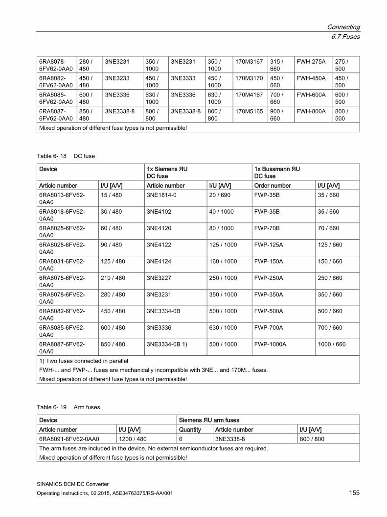
Connecting 6.7 Fuses
SINAMICS DCM DC Converter Operating Instructions, 02.2015, A5E34763375/RS-AA/001 155
6RA8078-6FV62-0AA0
280 / 480
3NE3231 350 / 1000
3NE3231 350 / 1000
170M3167 315 / 660
FWH-275A 275 / 500
6RA8082-6FV62-0AA0
450 / 480
3NE3233 450 / 1000
3NE3333 450 / 1000
170M3170 450 / 660
FWH-450A 450 / 500
6RA8085-6FV62-0AA0
600 / 480
3NE3336 630 / 1000
3NE3336 630 / 1000
170M4167 700 / 660
FWH-600A 600 / 500
6RA8087-6FV62-0AA0
850 / 480
3NE3338-8 800 / 800
3NE3338-8 800 / 800
170M5165 900 / 660
FWH-800A 800 / 500
Mixed operation of different fuse types is not permissible!
Table 6- 18 DC fuse
Device 1x Siemens ЯU DC fuse
1x Bussmann ЯU DC fuse
Article number I/U [A/V] Article number I/U [A/V] Order number I/U [A/V] 6RA8013-6FV62-0AA0
15 / 480 3NE1814-0 20 / 690 FWP-35B 35 / 660
6RA8018-6FV62-0AA0
30 / 480 3NE4102 40 / 1000 FWP-35B 35 / 660
6RA8025-6FV62-0AA0
60 / 480 3NE4120 80 / 1000 FWP-70B 70 / 660
6RA8028-6FV62-0AA0
90 / 480 3NE4122 125 / 1000 FWP-125A 125 / 660
6RA8031-6FV62-0AA0
125 / 480 3NE4124 160 / 1000 FWP-150A 150 / 660
6RA8075-6FV62-0AA0
210 / 480 3NE3227 250 / 1000 FWP-250A 250 / 660
6RA8078-6FV62-0AA0
280 / 480 3NE3231 350 / 1000 FWP-350A 350 / 660
6RA8082-6FV62-0AA0
450 / 480 3NE3334-0B 500 / 1000 FWP-500A 500 / 660
6RA8085-6FV62-0AA0
600 / 480 3NE3336 630 / 1000 FWP-700A 700 / 660
6RA8087-6FV62-0AA0
850 / 480 3NE3334-0B 1) 500 / 1000 FWP-1000A 1000 / 660
1) Two fuses connected in parallel FWH-... and FWP-... fuses are mechanically incompatible with 3NE... and 170M... fuses. Mixed operation of different fuse types is not permissible!
Table 6- 19 Arm fuses
Device Siemens ЯU arm fuses Article number I/U [A/V] Quantity Article number I/U [A/V] 6RA8091-6FV62-0AA0 1200 / 480 6 3NE3338-8 800 / 800 The arm fuses are included in the device. No external semiconductor fuses are required. Mixed operation of different fuse types is not permissible!

Connecting 6.7 Fuses
SINAMICS DCM DC Converter 156 Operating Instructions, 02.2015, A5E34763375/RS-AA/001
6.7.3 Fuses in the Power Interface Only UL-listed or UL-recognized fuses may be used in UL-listed devices.
Table 6- 20 Power interface with AC electronic power supply: F200 and F201 fuses
Manufacturer Type Data Dimensions Order designation UL Littlefuse 239 1 A / 250 V, time-lag 5 x 20 mm 239 001, MXP Schurter FST 1 A / 250 V, time-lag 5 x 20 mm 0034.3117
With option L05 (Devices with "Power interface with DC electronic power supply", F200 fuse):
T 6.3 A / 250 V 5×20 mm (Slow-Acting Fuse) e.g. Wickmann 193, Littlefuse 217P Series

Connecting 6.8 Arrangement of terminals and connectors
SINAMICS DCM DC Converter Operating Instructions, 02.2015, A5E34763375/RS-AA/001 157
6.8 Arrangement of terminals and connectors
Module - Control Unit (CUD)
Figure 6-39 Terminal/connector arrangement on the "Control Unit (CUD)"

Connecting 6.8 Arrangement of terminals and connectors
SINAMICS DCM DC Converter 158 Operating Instructions, 02.2015, A5E34763375/RS-AA/001
Module - Control Unit (CUD), option G63
Figure 6-40 Terminal/connector arrangement on the "Control Unit (CUD)" - option G63

Connecting 6.8 Arrangement of terminals and connectors
SINAMICS DCM DC Converter Operating Instructions, 02.2015, A5E34763375/RS-AA/001 159
Module - Power Interface for 2Q devices, 400 - 600 V with AC electronic power supply
Figure 6-41 Terminal/connector arrangement on the "Power Interface for 2Q devices, 400 - 600 V with AC electronic
power supply"

Connecting 6.8 Arrangement of terminals and connectors
SINAMICS DCM DC Converter 160 Operating Instructions, 02.2015, A5E34763375/RS-AA/001
Module - Power Interface for 4Q devices, 400 - 600 V with AC electronic power supply
Figure 6-42 Terminal/connector arrangement on the "Power Interface for 4Q devices, 400 - 600 V with AC electronic
power supply"

Connecting 6.8 Arrangement of terminals and connectors
SINAMICS DCM DC Converter Operating Instructions, 02.2015, A5E34763375/RS-AA/001 161
Module - Power Interface for 690 - 950 V devices with AC electronic power supply
<1> Connector X21 not fitted on 2Q devices
Connector X21D not fitted on 4Q devices
Figure 6-43 Terminal/connector arrangement on the "Power Interface for 690 - 950 V devices with AC electronic power supply"

Connecting 6.8 Arrangement of terminals and connectors
SINAMICS DCM DC Converter 162 Operating Instructions, 02.2015, A5E34763375/RS-AA/001
Module - Power Interface for 2Q devices, 400 - 600 V with DC electronic power supply
Figure 6-44 Terminal/connector arrangement on the "Power Interface for 2Q devices, 400 - 600 V with DC electronic
power supply"

Connecting 6.8 Arrangement of terminals and connectors
SINAMICS DCM DC Converter Operating Instructions, 02.2015, A5E34763375/RS-AA/001 163
Module - Power Interface for 4Q devices, 400 - 600 V with DC electronic power supply
Figure 6-45 Terminal/connector arrangement on the "Power Interface for 4Q devices, 400 - 600 V with DC electronic
power supply"
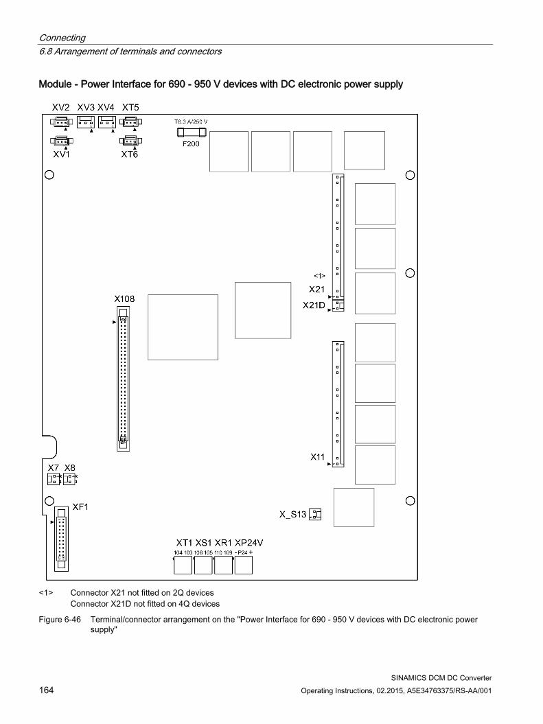
Connecting 6.8 Arrangement of terminals and connectors
SINAMICS DCM DC Converter 164 Operating Instructions, 02.2015, A5E34763375/RS-AA/001
Module - Power Interface for 690 - 950 V devices with DC electronic power supply
<1> Connector X21 not fitted on 2Q devices
Connector X21D not fitted on 4Q devices
Figure 6-46 Terminal/connector arrangement on the "Power Interface for 690 - 950 V devices with DC electronic power supply"

Connecting 6.8 Arrangement of terminals and connectors
SINAMICS DCM DC Converter Operating Instructions, 02.2015, A5E34763375/RS-AA/001 165
Module - 15/30 A power unit
Figure 6-47 Terminal/connector arrangement on the "15/30 A power unit"

Connecting 6.8 Arrangement of terminals and connectors
SINAMICS DCM DC Converter 166 Operating Instructions, 02.2015, A5E34763375/RS-AA/001
Modules for option G63
Figure 6-48 Terminal/connector arrangement on the "Cabinet Board"
Figure 6-49 Terminal arrangement on the "Terminal Module Cabinet (TMC)"
Module - 10 to 30 A field module
Figure 6-50 Terminal/connector arrangement on the "10 to 30 A field module"

Connecting 6.8 Arrangement of terminals and connectors
SINAMICS DCM DC Converter Operating Instructions, 02.2015, A5E34763375/RS-AA/001 167
"Connector Board" module
Figure 6-51 Terminal/connector arrangement on the "Connector Board"

Connecting 6.9 Assignment of terminals and connectors
SINAMICS DCM DC Converter 168 Operating Instructions, 02.2015, A5E34763375/RS-AA/001
6.9 Assignment of terminals and connectors
WARNING
Connecting the device incorrectly can lead to damage or destruction. Power cables and busbars must be mechanically fastened in place outside of the device.
NOTICE
The information regarding the connection capability of the terminals in the tables below is based on values from the terminal data sheets. The connecting cables must be dimensioned for the currents that will flow.
Overview
Table 6- 21 Terminals and connectors overview
1U1, 1V1, 1W1, 1C1, 1D1 Power unit 3U1, 3W1, 3C, 3D Exciter circuit 4U1, 4V1, 4W1, 4N1 Fan 5U1, 5W1, 5N1 Devices with "Power interface with AC electronic power supply" XP24V Devices with "Power interface with DC electronic power supply" X100, X101 DRIVE-CLiQ X126 PROFIBUS X165, X166 Parallel interface X177 for option G63: X177_1, X177_2, X177_5
Analog inputs, digital inputs, digital outputs, setpoints, reference voltage (P10/N10), serial interface (peer-to-peer), incremental encoder, analog outputs, temperature sensor
X178, X179 Interface to AOP30, USS interface XR1 Relay output for line contactor (up to 240 V) XS1 Safety shutdown E-STOP XT1 Analog tachometer

Connecting 6.9 Assignment of terminals and connectors
SINAMICS DCM DC Converter Operating Instructions, 02.2015, A5E34763375/RS-AA/001 169
6.9.1 Power unit
Table 6- 22 Connection system for the power connections 1U1, 1V1, 1W1, 1C1, 1D1
Devices Permissible connection type Connections 1U1, 1V1, 1W1 Connections 1C1, 1D1
15 A - 30 A Cable Cable 60 A - 850 A Cable, busbars Cable, busbars 900 A - 1200 A Cable, busbars Busbars 1500 A - 3000 A Cable, busbars Cable, busbars Handling the contact surfaces of busbar connections: All contact surfaces must be clean and may not be damaged. • Busbars manufactured out of Cu, Al, Al-Mg-Si:
The contact surfaces should be bare metal (e.g. use a file brush, abrasive stone). Use separate brushes for Cu and Al, mark appropriately. Immediately apply acid-free Vaseline (for example, Shell 8422) to aluminum busbars. Apply the appropriate grease to the contact points of the Al busbars approx. 10 mm beyond the contact surface. Do not apply grease to copper busbars.
• Nickel-plated copper busbars: Wipe the contact surfaces with a clean, dry cloth. If the nickel-plated surfaces are slightly oxidized, then remove these oxide layers before bolting. It is not permissible to use a steel brush or similar.
Note: The clearances required between the power connections (12.7 mm / 1/2 ") must not be fallen below. Otherwise, insulating elements must be inserted.
Table 6- 23 Terminal type, power connections for 15 A and 30 A devices
Type KDS 10 PC board terminal Connection capacity Rigid/flexible/conductor sizes (mm2/mm2/AWG): 0.5-16 / 0.5-10 / 20-6
Flexible with end sleeve with/without plastic sleeve: 0.5-10/0.5-10 mm2 Stripped length 12 mm Tightening torque 1.2 - 1.5 Nm
Table 6- 24 Terminal type, power connections for devices of 60 A and above
Devices Data 60 A - 210 A 1U1, 1V1, 1W1: 3x20 mm aluminum busbar, through hole for M8
1C1, 1D1: 5x20 mm aluminum busbar, through hole for M8 Max. conductor cross-section for cables with cable lug according to DIN 46234: 1U1, 1V1, 1W1, 1C1, 1D1: 2×95 mm2 Tightening torque for 1U1, 1V1, 1W1, 1C1, 1D1: 13 Nm Tightening torque for protective conductor: 25 Nm
280 A 1U1, 1V1, 1W1: 3x20 mm copper busbar, through hole for M8 1C1, 1D1: 5x20 mm copper busbar, through hole for M8 Max. conductor cross-section for cables with cable lug according to DIN 46234: 1U1, 1V1, 1W1, 1C1, 1D1: 2×95 mm2

Connecting 6.9 Assignment of terminals and connectors
SINAMICS DCM DC Converter 170 Operating Instructions, 02.2015, A5E34763375/RS-AA/001
Devices Data Tightening torque for 1U1, 1V1, 1W1, 1C1, 1D1: 13 Nm Tightening torque for protective conductor: 25 Nm
400 A - 450 A 1U1, 1V1, 1W1: 5x30 mm aluminum busbar, through hole for M10 1C1, 1D1: 5x35 mm aluminum busbar, through hole for M10 Max. conductor cross-section for cables with cable lug according to DIN 46234: 1U1, 1V1, 1W1: 2×150 mm2
1C1, 1D1: 2×185 mm2 Tightening torque for 1U1, 1V1, 1W1, 1C1, 1D1: 25 Nm Tightening torque for protective conductor: 50 Nm
600 A 1U1, 1V1, 1W1: 5x30 mm copper busbar, through hole for M10 1C1, 1D1: 5x35 mm copper busbar, through hole for M10 Max. conductor cross-section for cables with cable lug according to DIN 46234: 1U1, 1V1, 1W1: 2×150 mm2
1C1, 1D1: 2×185 mm2 Tightening torque for 1U1, 1V1, 1W1, 1C1, 1D1: 25 Nm Tightening torque for protective conductor: 50 Nm
720 A - 850 A 1U1, 1V1, 1W1, 1C1, 1D1: 5x60 mm copper busbar, through hole for M12 Max. conductor cross-section for cables with cable lug according to DIN 46234: 1U1, 1V1, 1W1, 1C1, 1D1: 4×150 mm2 Tightening torque for 1U1, 1V1, 1W1, 1C1, 1D1: 44 Nm Tightening torque for protective conductor: 50 Nm
900 A - 1200 A 1U1, 1V1, 1W1, 1C1, 1D1: 6x80 mm copper busbar, insert nut M12 Max. conductor cross-section for cables with cable lug according to DIN 46234: 1U1, 1V1, 1W1: 4×150 mm2 Tightening torque for 1U1, 1V1, 1W1, 1C1, 1D1: 44 Nm Tightening torque for protective conductor: 60 Nm
1500 A - 2000 A 1U1, 1V1, 1W1: 10x120 mm aluminum busbar, through hole for M12 1C1, 1D1: Aluminum busbar, cross-section 60 x 10 mm / 323 mm wide, insert nut M12 Max. conductor cross-section for cables with cable lug according to DIN 46234: 1U1, 1V1, 1W1: 6×240 mm2 1C1, 1D1: 8×240 mm2 Tightening torque for 1U1, 1V1, 1W1, 1C1, 1D1: 44 Nm Tightening torque for protective conductor: 60 Nm
2200 A - 3000 A 1U1, 1V1, 1W1: 10x120 mm copper busbar, through hole for M12 1C1, 1D1: Copper busbar, cross-section 60 x 10 mm / 323 mm wide, insert nut M12 Max. conductor cross-section for cables with cable lug according to DIN 46234: 1U1, 1V1, 1W1: 6×240 mm2 1C1, 1D1: 8×240 mm2 Tightening torque for 1U1, 1V1, 1W1, 1C1, 1D1: 44 Nm Tightening torque for protective conductor: 60 Nm
See Chapter Dimension drawings (Page 81) for how the protective conductor can be connected. Note: If the device is stored for a longer period of time, a layer of corrosion can form on the bare metal surfaces of the housing. Before connecting the protective conductor, this must be removed from the connection points.

Connecting 6.9 Assignment of terminals and connectors
SINAMICS DCM DC Converter Operating Instructions, 02.2015, A5E34763375/RS-AA/001 171
The devices are designed for a permanent line supply connection in accordance with EN 61800-5-1.
The conductor cross-sections (also for the protective conductor) must be determined in accordance with the applicable regulations that apply in each case – e.g. EN 60204-1.
Table 6- 25 Assignment of power connections
Terminal Function Technical specifications 1U1 1V1 1W1
Power unit line connection, ar-mature circuit
See Chapter Technical data (Page 41)
Protective conductor PE
1C1 (1D1) 1D1 (1C1)
Motor connection, armature circuit
6.9.2 Exciter circuit
Table 6- 26 Terminal type, connections for the exciter circuit
Devices with "15/30 A power unit" and devices with "10 to 30 A field module" (the terminals are located on the module): Type ZFKDS 4-10 PC board terminal Connection capacity Rigid/flexible/conductor sizes (mm2/mm2/AWG): 0.2-6 / 0.2-4 / 24-10
Flexible with end sleeve with/without plastic sleeve: 0.25-4/0.25-4 mm2 Stripped length 10 mm Devices with "field supply power unit" with rated armature DC current = 900 - 1,200 A: Type 20E/4DS terminal strip Connection capacity Rigid/flexible (mm2/mm2): 6-16 / 6-10 Stripped length 8 mm Tightening torque 1.5 Nm Devices with "field supply power unit" with rated armature DC current = 1,500 - 3,000 A: Type UK16N terminal block Connection capacity Rigid/conductor sizes (mm2/AWG): 2.5-25 / 14-4
Flexible / conductor sizes (mm2/AWG): 4-16 / 12-6 Stripped length 11 mm Tightening torque 1.5 - 1.8 Nm Devices with option L85 (with rated field DC current = 85 A): Type UK35 terminal block Connection capacity Rigid/flexible/conductor sizes (mm2/mm2/AWG): 0.75-50 / 0.75-35 / 18-0/1
Flexible with end sleeve with/without plastic sleeve: 0.75-35/0.75-35 mm2 Stripped length 16 mm Tightening torque 3.2 - 3.7 Nm
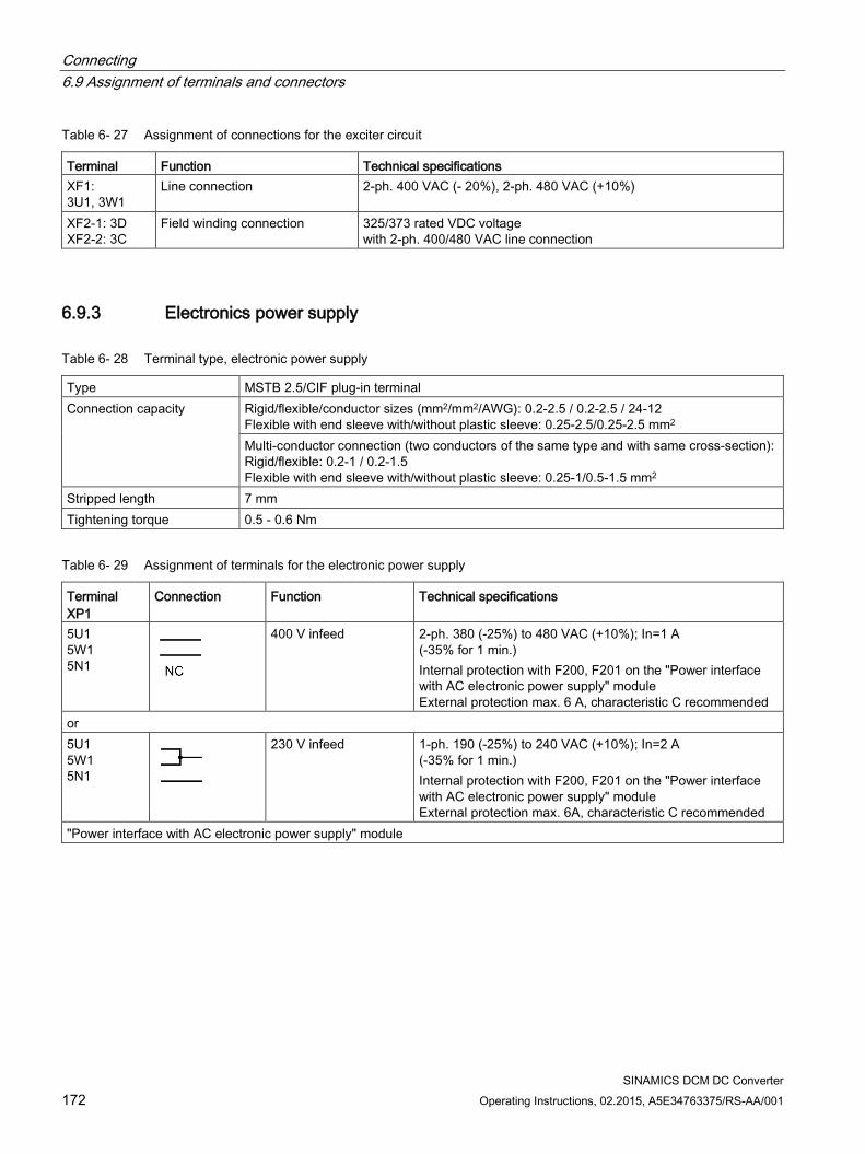
Connecting 6.9 Assignment of terminals and connectors
SINAMICS DCM DC Converter 172 Operating Instructions, 02.2015, A5E34763375/RS-AA/001
Table 6- 27 Assignment of connections for the exciter circuit
Terminal Function Technical specifications XF1: 3U1, 3W1
Line connection 2-ph. 400 VAC (- 20%), 2-ph. 480 VAC (+10%)
XF2-1: 3D XF2-2: 3C
Field winding connection 325/373 rated VDC voltage with 2-ph. 400/480 VAC line connection
6.9.3 Electronics power supply
Table 6- 28 Terminal type, electronic power supply
Type MSTB 2.5/CIF plug-in terminal Connection capacity Rigid/flexible/conductor sizes (mm2/mm2/AWG): 0.2-2.5 / 0.2-2.5 / 24-12
Flexible with end sleeve with/without plastic sleeve: 0.25-2.5/0.25-2.5 mm2 Multi-conductor connection (two conductors of the same type and with same cross-section): Rigid/flexible: 0.2-1 / 0.2-1.5 Flexible with end sleeve with/without plastic sleeve: 0.25-1/0.5-1.5 mm2
Stripped length 7 mm Tightening torque 0.5 - 0.6 Nm
Table 6- 29 Assignment of terminals for the electronic power supply
Terminal XP1
Connection Function Technical specifications
5U1 5W1 5N1
400 V infeed 2-ph. 380 (-25%) to 480 VAC (+10%); In=1 A (-35% for 1 min.) Internal protection with F200, F201 on the "Power interface with AC electronic power supply" module External protection max. 6 A, characteristic C recommended
or 5U1 5W1 5N1
230 V infeed 1-ph. 190 (-25%) to 240 VAC (+10%); In=2 A (-35% for 1 min.) Internal protection with F200, F201 on the "Power interface with AC electronic power supply" module External protection max. 6A, characteristic C recommended
"Power interface with AC electronic power supply" module
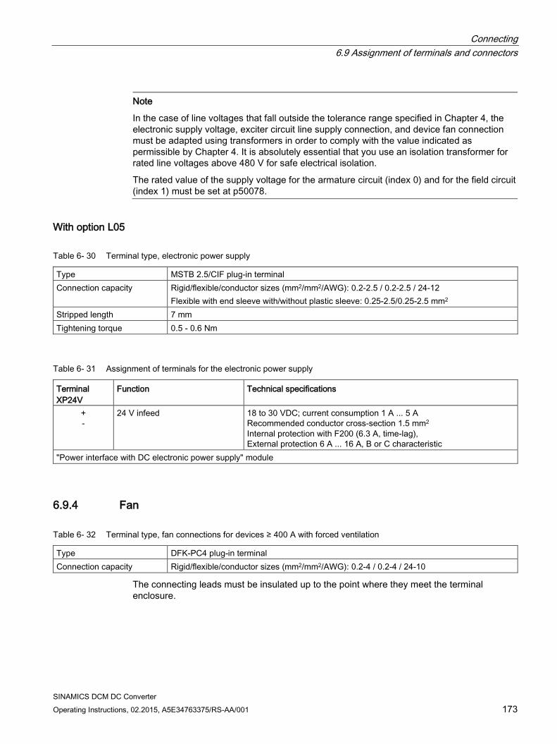
Connecting 6.9 Assignment of terminals and connectors
SINAMICS DCM DC Converter Operating Instructions, 02.2015, A5E34763375/RS-AA/001 173
Note
In the case of line voltages that fall outside the tolerance range specified in Chapter 4, the electronic supply voltage, exciter circuit line supply connection, and device fan connection must be adapted using transformers in order to comply with the value indicated as permissible by Chapter 4. It is absolutely essential that you use an isolation transformer for rated line voltages above 480 V for safe electrical isolation.
The rated value of the supply voltage for the armature circuit (index 0) and for the field circuit (index 1) must be set at p50078.
With option L05
Table 6- 30 Terminal type, electronic power supply
Type MSTB 2.5/CIF plug-in terminal Connection capacity Rigid/flexible/conductor sizes (mm2/mm2/AWG): 0.2-2.5 / 0.2-2.5 / 24-12
Flexible with end sleeve with/without plastic sleeve: 0.25-2.5/0.25-2.5 mm2 Stripped length 7 mm Tightening torque 0.5 - 0.6 Nm
Table 6- 31 Assignment of terminals for the electronic power supply
Terminal XP24V
Function Technical specifications
+ -
24 V infeed 18 to 30 VDC; current consumption 1 A ... 5 A Recommended conductor cross-section 1.5 mm2 Internal protection with F200 (6.3 A, time-lag), External protection 6 A ... 16 A, B or C characteristic
"Power interface with DC electronic power supply" module
6.9.4 Fan
Table 6- 32 Terminal type, fan connections for devices ≥ 400 A with forced ventilation
Type DFK-PC4 plug-in terminal Connection capacity Rigid/flexible/conductor sizes (mm2/mm2/AWG): 0.2-4 / 0.2-4 / 24-10
The connecting leads must be insulated up to the point where they meet the terminal enclosure.
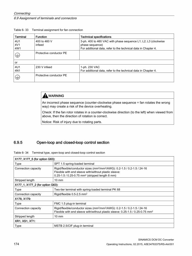
Connecting 6.9 Assignment of terminals and connectors
SINAMICS DCM DC Converter 174 Operating Instructions, 02.2015, A5E34763375/RS-AA/001
Table 6- 33 Terminal assignment for fan connection
Terminal Function Technical specifications 4U1 4V1 4W1
400 to 460 V infeed
3-ph. 400 to 460 VAC with phase sequence L1; L2; L3 (clockwise phase sequence) For additional data, refer to the technical data in Chapter 4.
Protective conductor PE
or 4U1 4N1
230 V infeed 1-ph. 230 VAC For additional data, refer to the technical data in Chapter 4.
Protective conductor PE
WARNING
An incorrect phase sequence (counter-clockwise phase sequence = fan rotates the wrong way) may create a risk of the device overheating.
Check: If the fan rotor rotates in a counter-clockwise direction (to the left) when viewed from above, then the direction of rotation is correct.
Notice: Risk of injury due to rotating parts.
6.9.5 Open-loop and closed-loop control section
Table 6- 34 Terminal type, open-loop and closed-loop control section
X177, X177_5 (for option G63): Type SPT 1.5 spring-loaded terminal Connection capacity Rigid/flexible/conductor sizes (mm2/mm2/AWG): 0.2-1.5 / 0.2-1.5 / 24-16
Flexible with end sleeve with/without plastic sleeve: 0.25-1.5 / 0.25-0.75 mm2 (stripped length 8 mm)
Stripped length 10 mm X177_1, X177_2 (for option G63): Type Two-tier terminal with spring-loaded terminal PK 68 Connection capacity Rigid/flexible 0.5-2.5 mm2 X178, X179: Type FMC 1.5 plug-in terminal Connection capacity Rigid/flexible/conductor sizes (mm2/mm2/AWG): 0.2-1.5 / 0.2-1.5 / 24-16
Flexible with end sleeve with/without plastic sleeve: 0.25-1.5 / 0.25-0.75 mm2 Stripped length 10 mm XR1, XS1, XT1: Type MSTB 2.5/CIF plug-in terminal

Connecting 6.9 Assignment of terminals and connectors
SINAMICS DCM DC Converter Operating Instructions, 02.2015, A5E34763375/RS-AA/001 175
Connection capacity Rigid/flexible/conductor sizes (mm2/mm2/AWG): 0.2-2.5 / 0.2-2.5 / 24-12 Flexible with end sleeve with/without plastic sleeve: 0.25-2.5 / 0.25-2.5 mm2
Stripped length 7 mm Tightening torque 0.5 - 0.6 Nm X126: Type Submin D, 9-pin X100, X101: Type Modular jack 8/4 (RJ45)
Terminals at the Power Interface (analog tachometer, E-STOP, relay for line contactor)
Table 6- 35 Terminals XR1, XS1, XT1
Terminal Function Technical specifications Analog tachometer XT1-103 Tachometer connection
8 to 270 V ±270 V Input resistance 159 kΩ Resolution ±14 bits XT1-104 Ground, analog M
Safety shutdown E-STOP XS1-105 Input (switch) Ie = 20 mA XS1-106 Supply (output) 24 VDC, max. load 50 mA, short-circuit proof Potential-free relay output XR1-109 XR1-110
Relay for line contactor Current carrying capacity: ≤ 250 VAC, 4 A; cosφ = 1 ≤ 250 VAC, 2 A; cosφ = 0.4 ≤ 30 VDC, 2 A External protection: max. 4 A, characteristic C recommended Devices that have option L05 (with "Power interface with DC electronic power supply") require external protection with max. 6.3 A.
"Power Interface 400 - 600 V" or "Power Interface 690 - 950 V" module

Connecting 6.9 Assignment of terminals and connectors
SINAMICS DCM DC Converter 176 Operating Instructions, 02.2015, A5E34763375/RS-AA/001
Terminals on the Connector Board Also refer to "Inputs/Outputs" in the section titled "Descriptions of functions".
Table 6- 36 Assignment, terminal X177
Terminal X177
Function Technical specifications
Analog inputs (assignable inputs) 1 2
AI 3 + AI 3 -
Analog input 3 Input type (signal type): Differential input ±10 V; 150 kΩ Resolution approx. 5.4 mV (±11 bits) Common-mode controllability: ±15 V
3 4
AI 4 + AI 4 -
Analog input 4
5 6
AI 5 + AI 5 -
Analog input 5
7 8
AI 6 + AI 6 -
Analog input 6
Digital inputs (assignable inputs) 9 10
24 V DC
24 V supply (output) 24 VDC, short-circuit proof Max. load 200 mA (terminals 9 and 10 together), internal supply related to internal ground terminal
11 DI 0 Digital input 0 H signal: +15 V to +30 V L signal: -30 to +5 V or terminal open 8.5 mA at 24 V
12 DI 1 Digital input 1 13 DI 2 Digital input 2 14 DI 3 Digital input 3 Digital inputs/outputs (assignable inputs/outputs) 15 DI/
DO 4 Digital input /output 4
Type, input/output parameterizable Features of inputs: H signal: +15 V to +30 V L signal: 0 V to +5 V or terminal open 8.5 mA at 24 V Features of outputs: H signal: +20 V to +26 V L signal: 0 to +2 V short-circuit proof; max. current carrying capacity: 100 mA per DO; max. total load of all DO (CUD left X177:15-22 + CUD right X177:15-22): 800 mA internal protection circuit (freewheeling diode) If overload occurs: alarm A60018
16 DI/ DO 5
Digital input /output 5
17 DI/ DO 6
Digital input /output 6
18 DI/ DO 7
Digital input /output 7
19 DO 0 Digital output 0 H signal: +20 V to +26 V L signal: 0 to +2 V short-circuit proof; max. current carrying capacity: 100 mA per DO; max. total load of all DO (CUD left X177:15-22 + CUD right X177:15-22): 800 mA internal protection circuit (freewheeling diode) If overload occurs: alarm A60018
20 DO 1 Digital output 1 21 DO 2 Digital output 2 22 DO 3 Digital output 3 23, 24 M Ground, digital
Analog inputs, setpoint inputs (assignable inputs) 25 26
AI 0 + AI 0 -
Analog input 0 Main setpoint
Input type (signal type), parameterizable: - Differential input ±10 V; 150 kΩ

Connecting 6.9 Assignment of terminals and connectors
SINAMICS DCM DC Converter Operating Instructions, 02.2015, A5E34763375/RS-AA/001 177
Terminal X177
Function Technical specifications
27 28
AI 1 + AI 1 -
Analog input 1 - Current input 0 - 20 mA; 300 Ω or 4 - 20 mA; 300 Ω Resolution approx. 0.66 mV (±14 bits) Common-mode controllability: ±15 V
29 30
AI 2 + AI 2 -
Analog input 2 Input type (signal type): - Differential input ±10 V; 150 kΩ Resolution approx. 0.66 mV (±14 bits) Common-mode controllability: ±15 V Note: An external armature voltage actual value can also be connected at this input. See function diagram 6902 in the SINAMICS DCM List Manual.
Reference voltage 31 32
P10 N10
Reference voltage ±10 V (output)
Tolerance ±1% at 25° C Stability 0.1% per 10° K 10 mA short-circuit proof 33, 34 M Ground, analog
Serial interface, peer-to-peer RS485 35, 36 M Ground, digital 37 TX+ Send cable + 4-wire send cable, positive differential output 38 TX- Send cable - 4-wire send cable, negative differential output 39 RX+ Receive cable + 4-wire receive cable, positive differential output 40 RX- Receive cable - 4-wire receive cable, negative differential output Incremental encoder input 41 Incremental encoder supply +13.7 to +15.2 V, 300 mA short-circuit proof (electronically protected)
If overload occurs: alarm A60018 42 Ground, incremental encoder 43 Track 1 positive connection Load: ≤ 5.25 mA at 15 V (without switching losses)
Pulse duty factor: 1:1 See below for data relating to cables, cable length, shield support, input pulse levels, hysteresis, track displacement, and pulse frequen-cy.
44 Track 1 negative connection 45 Track 2 positive connection 46 Track 2 negative connection 47 Zero mark positive connection 48 Zero mark negative connection Analog outputs (assignable outputs) 49 AO 0 Analog output 0 ±10 V, max. 2 mA short-circuit proof, resolution ±15 bits 50 M Ground, analog 51 AO 1 Analog output 1 52 M Ground, analog Connections for temperature sensor (motor interface 1) 53 Temp 1 Sensor acc. to p50490 (refer to SINAMICS DCM List Manual
The cable to the temperature sensor on the motor must be shielded 54 Temp 2 (sense cable)

Connecting 6.9 Assignment of terminals and connectors
SINAMICS DCM DC Converter 178 Operating Instructions, 02.2015, A5E34763375/RS-AA/001
Terminal X177
Function Technical specifications
55 Temp 3 and connected to ground at both ends. The cables for the Temp 1 and Temp 3 connections to the tempera-ture sensor must be approximately the same length. The sense cable (Temp 2) is used for compensating the cable re-sistances. If you are not using a sense cable, terminals 54 and 55 must be connected. Connection with/without sense cable:
56 M Ground, analog Connector board module
Characteristic values for the incremental encoder evaluation electronics For supported encoder types, refer to the description of parameter p0400 and Appendix A.2 in the SINAMICS DCM List Manual.
Note
Incremental encoder evaluation via terminals X177.41 to 48 does not support any SSI encoders.
A Sensor Module Cabinet-Mounted SMC30 is required for evaluating SSI encoders (see the section titled "Additional system components").
NOTICE
Selecting the encoder type with p0400 does not result in any changes to the supply voltage for the incremental encoder (terminals X177.41 and 42).
Terminal X177.41 always supplies +15 V. An external power supply is required for incremental encoders with other supply voltages (e.g. +5 V).
Input pulse levels:
Encoder signals (symmetrical/asymmetrical) up to a maximum of 27 V differential voltage can be processed by the evaluation electronics.

Connecting 6.9 Assignment of terminals and connectors
SINAMICS DCM DC Converter Operating Instructions, 02.2015, A5E34763375/RS-AA/001 179
The encoder type is selected using p0400. The evaluation electronics are adjusted electronically to the encoder signal voltage: Rated input voltage 5 V 15 V Encoder TTL HTL Low signal level (differential voltage) < 0.8 V < 5.0 V High signal level (differential voltage) > 2.0 V > 8.0 V Hysteresis > 0.2 V > 1.0 V Common-mode controllability ±10 V ±10 V
If the incremental encoder does not supply any symmetrical encoder signals, it must be grounded with each signal cable twisted in pairs and connected to the negative connections of track 1, track 2, and zero mark.
Switching frequency:
The maximum frequency of the encoder pulses is 300 kHz. To ensure the encoder pulses are evaluated correctly, the minimum distance (Tmin) between two encoder signal edges (track 1, track 2), as listed in the table, must be adhered to. Rated input voltage 5 V 15 V Differential voltage 1) 2 V > 2.5 V 8 V 10 V > 14 V Tmin 2) 630 ns 380 ns 630 ns 430 ns 380 ns
1) Differential voltage at the terminals of the evaluation electronics
2) The phase error LG (deviation from 90°) that may occur as a result of the encoder and cable can be calculated on the basis of Tmin:
LG= ± (90° – fp × Tmin × 360°)
LG = Phase error fp = Pulse frequency Tmin = Minimum edge distance
This formula only applies if the pulse duty factor of the encoder signals is 1:1.
If the incremental encoder is incorrectly matched to the encoder cable, disturbing cable reflections will occur at the receiving end. To ensure that encoder pulses of this type can be evaluated without errors, these reflections need to be damped. The limit values listed in the table below must be adhered to in order to prevent the resulting power losses in the evaluation electronics adaptor from being exceeded. fmax 50 kHz 100 kHz 150 kHz 200 kHz 300 kHz Differential voltage 3) ≤ 27 V ≤ 22 V ≤ 18 V ≤ 16 V ≤ 14 V
3) Differential voltage of encoder pulses without load (= approximately the supply voltage of the incremental encoder)
Cable, cable length, shield support:
The encoder cable capacitance must be recharged at each encoder edge change. The rms value of this current is proportional to the cable length and pulse frequency, and must not exceed the current permitted by the encoder manufacturer. A suitable cable that meets the recommendations of the encoder manufacturer must be used, and the maximum cable length must not be exceeded.

Connecting 6.9 Assignment of terminals and connectors
SINAMICS DCM DC Converter 180 Operating Instructions, 02.2015, A5E34763375/RS-AA/001
Generally speaking, a twisted cable pair with a single pair shield is sufficient for each track. This reduces crosstalk between the cables. Shielding all the pairs provides protection against interference pulses. The shield should be connected to the SINAMICS DC MASTER shield support over a large area.
Note
For connecting an incremental encoder (see also Chapter "Applications").
Figure 6-52 Arrangement X178 and X179
Serial interface to AOP30/USS interface
Table 6- 37 Terminal X178
Terminal X178
Function Technical specifications
1 Supply (output) 24 VDC short-circuit proof, maximum load 200 mA Internal supply related to internal ground terminal
2 Ground, AOP M 3 RX+/TX+ Send and receive cable, RS485, two-wire
Positive differential input/output 4 RX-/TX- Send and receive cable, RS485, two-wire
Negative differential input/output 5 Ground, digital M 6 Ground, digital M "Control Unit (CUD)" module

Connecting 6.9 Assignment of terminals and connectors
SINAMICS DCM DC Converter Operating Instructions, 02.2015, A5E34763375/RS-AA/001 181
Table 6- 38 Terminal X179
Terminal X179
Function Technical specifications
1 Supply (output) 4.4 to 5.4 VDC short-circuit proof, maximum load 300 mA Internal supply related to internal ground terminal
2 Ground, digital M 3 TXD1 Send cable, RS232 standard (V.24) 4 RXD1 Receive cable, RS232 standard (V.24) 5 TXD2 Send cable, RS232 standard (V.24) 6 RXD2 Receive cable, RS232 standard (V.24) "Control Unit (CUD)" module
Note
Only one of the two interfaces - RS485 (X178-3, 4) or RS232 (X179-3, 4) - may be used.

Connecting 6.9 Assignment of terminals and connectors
SINAMICS DCM DC Converter 182 Operating Instructions, 02.2015, A5E34763375/RS-AA/001
6.9.6 Assignment of the RS485 cable to the AOP30
Note
A 24 V power supply is required to operate the AOP30. For a maximum cable length of 50 m, this can be taken from the CUD of the SINAMICS DCM. An external power supply must be used for cable lengths > 50 m.
① RS485 cable with 24 V DC power supply from the CUD - max. 50 m ② RS485 cable when operating with 2 CUDs, 24 V DC power supply from one CUD - max. 50 m ③ RS485 cable when supplying the AOP30 from an external 24 V DC source - max. 200 m X524 Plug terminals X178 Plug terminals X540 9-pin Sub-D socket
Figure 6-53 Assignment, RS485 cable

Connecting 6.9 Assignment of terminals and connectors
SINAMICS DCM DC Converter Operating Instructions, 02.2015, A5E34763375/RS-AA/001 183
PROFIBUS connection
Table 6- 39 PROFIBUS connector assignment
Connector X126
Pin Signal name Technical specifications
1 - Not assigned 2 - Not assigned 3 RxD/TxD-P RS485 receive/transmit data P (B) 4 CNTR-P Control signal (TTL) 5 DGND PROFIBUS data ground 6 VP Positive supply voltage (5 V +/-10%) 7 - Not assigned 8 RxD/TxD-N RS485 receive/transmit data N (A) 9 - Not assigned
"Control Unit (CUD)" module
DRIVE-CLiQ
Table 6- 40 DRIVE-CLiQ connector assignment
Connector X100, X101
Pin Signal name Technical specifications
1 TXP Transmit data + 2 TXN Transmit data - 3 RXP Receive data + 4 - Reserved, do not use 5 - Reserved, do not use 6 RXN Receive data - 7 - Reserved, do not use 8 - Reserved, do not use - Shield Permanently connected to ground
"Advanced CUD" module

Connecting 6.9 Assignment of terminals and connectors
SINAMICS DCM DC Converter 184 Operating Instructions, 02.2015, A5E34763375/RS-AA/001
Parallel interface
Table 6- 41 Connector assignment, parallel interface
Connector X165, X166
Pin Signal name Technical specifications
1 SYNC_P Synchronization + 2 SYNC_N Synchronization - 3 CANH CAN + 4 - Reserved, do not use 5 - Reserved, do not use 6 CANL CAN - 7 - Reserved, do not use 8 - Reserved, do not use - Shield Permanently connected to ground
Standard CUD, Advanced CUD module
Terminal assignment for option G63 The technical data for terminals X177_1, X177_2 and X177_5 corresponds to the specifications for terminal X177 on the Connector Board in the version without option G63, see Table 6-36 Assignment, terminal X177 X177 (Page 176).
Table 6- 42 Assignment of the terminals on the Terminal Module Cabinet (TMC) (overview)
Terminal X177_1, X177_2
Function Description
1st terminal block (X177_1) 1, 2 AI 3 +, AI 3 - Analog input 3 See X177.1 and 2 3, 4 AI 4 +, AI 4 - Analog input 4 See X177.3 and 4 5, 6 AI 5 +, AI 5 - Analog input 5 See X177.5 and 6 7, 8 AI 6 +, AI 6 - Analog input 6 See X177.7 and 8 9, 10 24 VDC 24 V supply (output) 24 VDC, short-circuit proof
Max. load 200 mA (terminals 9, 10, 57, 58, 59 and 60 combined), internal supply to digital ground and analog ground
11, 12, 13, 14 DI 0, 1, 2, 3 Digital input 0, 1, 2, 3 See X177.11, 12, 13, 14 15, 16, 17, 18 DI/DO 4, 5, 6, 7 Digital input/output 4, 5,
6, 7 See X177.15, 16, 17, 18
19, 20, 21 22 DO 0, 1, 2, 3 Digital output 0, 1, 2, 3 See X177.19, 20, 21, 22, 23, 24 23, 24 M Ground, digital
25, 26 AI 0 +, AI 0 - Analog input 0, main setpoint
See X177.25 and 26
27, 28 AI 1 +, AI 1 - Analog input 1 See X177.27 and 28 29, 30 AI 2 +, AI 2 - Analog input 2 See X177.29 and 30

Connecting 6.9 Assignment of terminals and connectors
SINAMICS DCM DC Converter Operating Instructions, 02.2015, A5E34763375/RS-AA/001 185
Terminal X177_1, X177_2
Function Description
31, 32 P10, N10 Reference voltage ±10 V (output)
See X177.31, 32, 33, 34
33, 34 M Ground, analog 2nd terminal block (X177_2) 35, 36 M Ground, digital See X177.35 and 36 37, 38 RS485: TX+, TX- Send cable +, - See X177.37 and 38 39, 40 RS485: RX+, RX- Receive cable +, - See X177.39 and 40 41, 42 Incremental encoder supply See X177.41 and 42 43, 44 Incremental encoder track 1 +/- See X177.43 and 44 45, 46 Incremental encoder track 2 +/- See X177.45 and 46 47, 48 Incremental encoder zero mark +/- See X177.47 and 48 49, 50 AO 0, M Analog output 0, analog
ground See X177.49 and 50
51, 52 AO 1, M Analog output 1, analog ground
See X177.51 and 52
53, 54, 55 Temp 1, 2, 3 Temperature sensor, motor interface 1
See X177.53, 54, 55
56 M Ground, analog See X177.56 57, 58, 59, 60 24 VDC 24 V supply (output) 24 VDC, short-circuit proof
Max. load 200 mA (terminals 9, 10, 57, 58, 59 and 60 combined), internal supply to digital ground and analog ground
61, 62, 63, 64 M Ground, digital - "Terminal Module Cabinet (TMC)" module
Table 6- 43 Assignment of the terminals on the Cabinet Board (overview)
Terminal X177_5
Function Description
33, 34 M Ground, analog - 35, 36 M Ground, digital See X177.35 and 36 37, 38 RS485: TX+, TX- Send cable +, - See X177.37 and 38 39, 40 RS485: RX+, RX- Receive cable +, - See X177.39 and 40 "Cabinet Board" module Note:
The terminals on X177_5 are connected in parallel to the terminals with the same name on the Terminal Module Cabinet (TMC).
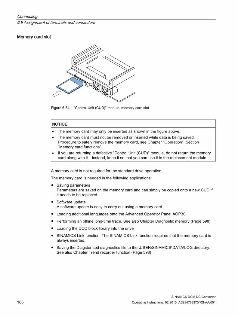
Connecting 6.9 Assignment of terminals and connectors
SINAMICS DCM DC Converter 186 Operating Instructions, 02.2015, A5E34763375/RS-AA/001
Memory card slot
Figure 6-54 "Control Unit (CUD)" module, memory card slot
NOTICE
• The memory card may only be inserted as shown in the figure above. • The memory card must not be removed or inserted while data is being saved.
Procedure to safely remove the memory card, see Chapter "Operation", Section "Memory card functions".
• If you are returning a defective "Control Unit (CUD)" module, do not return the memory card along with it – instead, keep it so that you can use it in the replacement module.
A memory card is not required for the standard drive operation.
The memory card is needed in the following applications:
Saving parameters Parameters are saved on the memory card and can simply be copied onto a new CUD if it needs to be replaced.
Software update A software update is easy to carry out using a memory card.
Loading additional languages onto the Advanced Operator Panel AOP30.
Performing an offline long-time trace. See also Chapter Diagnostic memory (Page 598)
Loading the DCC block library into the drive
SINAMICS Link function: The SINAMICS Link function requires that the memory card is always inserted.
Saving the Diagstor.spd diagnostics file to the \USER\SINAMICS\DATA\LOG directory. See also Chapter Trend recorder function (Page 598)
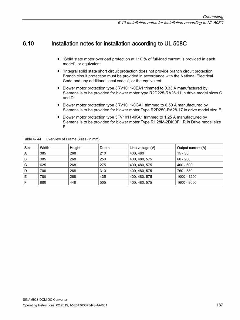
Connecting 6.10 Installation notes for installation according to UL 508C
SINAMICS DCM DC Converter Operating Instructions, 02.2015, A5E34763375/RS-AA/001 187
6.10 Installation notes for installation according to UL 508C
"Solid state motor overload protection at 110 % of full-load current is provided in each model", or equivalent.
"Integral solid state short circuit protection does not provide branch circuit protection. Branch circuit protection must be provided in accordance with the National Electrical Code and any additional local codes", or the equivalent.
Blower motor protection type 3RV1011-0EA1 trimmed to 0.33 A manufactured by Siemens is to be provided for blower motor type R2D225-RA26-11 in drive model sizes C and D.
Blower motor protection type 3RV1011-0GA1 trimmed to 0.50 A manufactured by Siemens is to be provided for blower motor Type R2D250-RA28-17 in drive model size E.
Blower motor protection type 3FV1011-0KA1 trimmed to 1.25 A manufactured by Siemens is to be provided for blower motor Type RH28M-2DK.3F.1R in Drive model size F.
Table 6- 44 Overview of Frame Sizes (in mm)
Size Width Height Depth Line voltage (V) Output current (A) A 385 268 210 400, 480 15 - 30 B 385 268 250 400, 480, 575 60 - 280 C 625 268 275 400, 480, 575 400 - 600 D 700 268 310 400, 480, 575 760 - 850 E 780 268 435 400, 480, 575 1000 - 1200 F 880 448 505 400, 480, 575 1600 - 3000

Connecting 6.10 Installation notes for installation according to UL 508C
SINAMICS DCM DC Converter 188 Operating Instructions, 02.2015, A5E34763375/RS-AA/001
SINAMICS DCM DC Converter Operating Instructions, 02.2015, A5E34763375/RS-AA/001 189
Additional system components 7
Note
The components described here are used in several units in the SINAMICS family. The next chapter may, therefore, contain references to manuals for these units.
The SINAMICS DC MASTER supports the following components from the SINAMICS drive system: CBE20 Communication Board SMC30 Sensor Module Cabinet-Mounted TM15 Terminal Module TM31 Terminal Module TM150 Terminal Module
In order to operate the SINAMICS DC MASTER with these components, it must be equipped with (an) Advanced CUD(s); see the list of options in Chapter 2.
The Communication Board CBE20 can be ordered as an option for the SINAMICS DC MASTER and is installed directly in the unit (in the OMI (Option Module Interface) slot of the CUD).
The SMC30, TM15, TM31 and TM150 modules are installed separately and connected to the SINAMICS DC MASTER via the DRIVE-CLiQ interface.
DRIVE-CLiQ interface On the SINAMICS DC MASTER, up to three terminal modules TM15/TM31/TM150 can be connected to the DRIVE-CLiQ in any desired combination and in addition one Sensor Module Cabinet-Mounted SMC30 can be connected.
The CUD features two DRIVE-CLiQ ports (X100, X101). Any combination of the modules can be connected in series or in parallel. An SMC30 only possesses one DRIVE-CLiQ interface and is, therefore, always the last module on the bus.
Additional system components 7.1 Option Board: Communication Board Ethernet CBE20
SINAMICS DCM DC Converter 190 Operating Instructions, 02.2015, A5E34763375/RS-AA/001
7.1 Option Board: Communication Board Ethernet CBE20
7.1.1 Description The SINAMICS DC MASTER can be connected to PROFINET using the Communication Board CBE20 interface module. The module supports PROFINET IO with Isochronous Realtime Ethernet (IRT) and PROFINET IO with RT. Mixed operation is not permissible. PROFINET CBA is not supported.
The option board has an X1400 interface with 4 ports for communication.
The Communication Board CBE20 allows SINAMICS Link connections and the connection to EtherNet/IP to be established.
Note
By inserting the CBE20, the IF1 communication channel switches over from PROFIBUS to PROFINET. Communication is therefor no longer possible via PROFIBUS.
7.1.2 Safety instructions
NOTICE
Damage or malfunctions of the Option Board by inserting and withdrawing during operation
Withdrawing and inserting the Option Board during operation can damage it or cause it to malfunction. • Only withdraw or insert the Option Board when the Control Unit is de-energized.
NOTICE
The CBE20 must only be operated by qualified personnel. The ESD information must be observed.
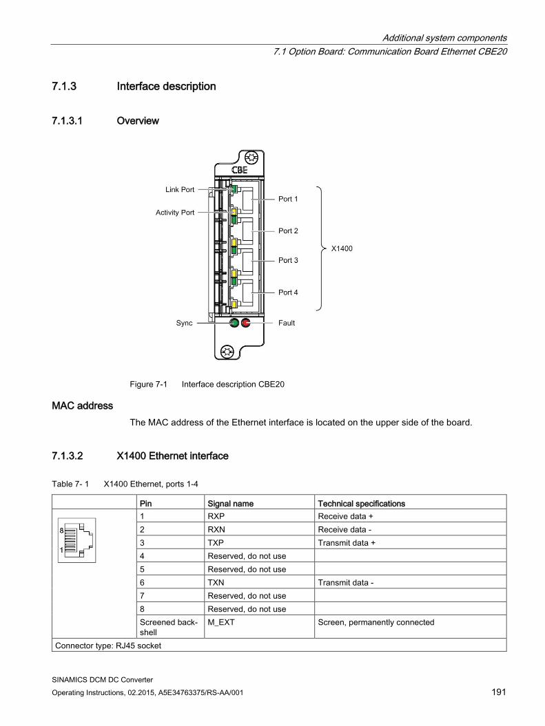
Additional system components 7.1 Option Board: Communication Board Ethernet CBE20
SINAMICS DCM DC Converter Operating Instructions, 02.2015, A5E34763375/RS-AA/001 191
7.1.3 Interface description
7.1.3.1 Overview
Figure 7-1 Interface description CBE20
MAC address The MAC address of the Ethernet interface is located on the upper side of the board.
7.1.3.2 X1400 Ethernet interface
Table 7- 1 X1400 Ethernet, ports 1-4
Pin Signal name Technical specifications
1 RXP Receive data + 2 RXN Receive data - 3 TXP Transmit data + 4 Reserved, do not use 5 Reserved, do not use 6 TXN Transmit data - 7 Reserved, do not use 8 Reserved, do not use Screened back-shell
M_EXT Screen, permanently connected
Connector type: RJ45 socket
Additional system components 7.1 Option Board: Communication Board Ethernet CBE20
SINAMICS DCM DC Converter 192 Operating Instructions, 02.2015, A5E34763375/RS-AA/001
For diagnostic purposes, the ports have one green and one yellow LED (refer to "Meaning of the LEDs" for descriptions)
Cable and connector types Information on PROFINET cables and connectors can be found in the following catalog:
Industrial Communication Catalog IK PI, 2009 Edition,
7.1.4 Meaning of the LEDs
Table 7- 2 Meaning of the LEDs at ports 1 to 4 of the X1400 interface
LED Color Status Description Link port - Off Electronics power supply is missing or outside permissible tolerance range (link
missing or defective). Green Continuous
light A different device is connected to port x and a physical connection exists.
Activity port - Off Electronics power supply is missing or outside permissible tolerance range (no activity).
Yellow Flashing light Data is being received or sent at port x.
Table 7- 3 Meaning of the Sync and Fault LEDs on the CBE20
LED Color Status Description Fault – Off If the link port LED is green:
The CBE20 is operating normally, data is being exchanged with the configured IO Controller.
Red Flashing • The response monitoring interval has elapsed. • Communications is interrupted. • The IP address is incorrect. • Incorrect or no configuration. • Incorrect parameter settings. • Incorrect or missing device name. • IO Controller not connected/switched off, although an Ethernet connection
has been established. • Other CBE20 errors
Continuous light
CBE20 bus error • No physical connection to a subnet/switch. • Incorrect transmission rate • Full duplex transmission is not activated.
Additional system components 7.1 Option Board: Communication Board Ethernet CBE20
SINAMICS DCM DC Converter Operating Instructions, 02.2015, A5E34763375/RS-AA/001 193
LED Color Status Description Sync – Off If the link port LED is green:
Control Unit task system is not synchronized with the IRT clock. An internal sub-stitute clock is generated.
Green Flashing light Control Unit task system has synchronized with the IRT clock and data is being exchanged.
Continuous light
Task system and MC-PLL have synchronized with the IRT clock.
Table 7- 4 Meaning of the OPT LED on the Control Unit
LED Color Status Description, cause Remedy OPT – OFF Electronics power supply is missing or outside permissible
tolerance range. Communication Board either defective or not inserted.
–
Green Continuous light
Communication Board is ready and cyclic communication is taking place.
–
0.5 Hz flashing light
The Communication Board is ready, but cyclic communi-cations is not running. Possible causes: • At least one fault is present. • Communication is being established.
–
Red Continuous light
Cyclic communication via PROFINET has not yet been established. However, non-cyclic communication is possi-ble. SINAMICS waits for a parameterizing/configuring telegram
–
0.5 Hz flashing light
The firmware update into the CBE20 has been completed with an error. Possible causes: • The CBE20 is defective. • The memory card for the Control Unit is defective. CBE20 cannot be used in this state.
–
2 Hz flashing light
There is a communications error between the Control Unit and the CBE20. Possible causes: • Board was withdrawn after booting. • The board is defective
Correctly insert the board, if required, replace.
Orange 0.5 Hz flashing light
Firmware is being updated. –
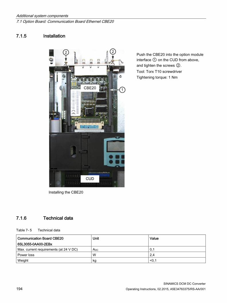
Additional system components 7.1 Option Board: Communication Board Ethernet CBE20
SINAMICS DCM DC Converter 194 Operating Instructions, 02.2015, A5E34763375/RS-AA/001
7.1.5 Installation
Installing the CBE20
Push the CBE20 into the option module interface ① on the CUD from above, and tighten the screws ②. Tool: Torx T10 screwdriver Tightening torque: 1 Nm
7.1.6 Technical data
Table 7- 5 Technical data
Communication Board CBE20 6SL3055-0AA00-2EBx
Unit Value
Max. current requirements (at 24 V DC) ADC 0,1 Power loss W 2,4 Weight kg <0,1
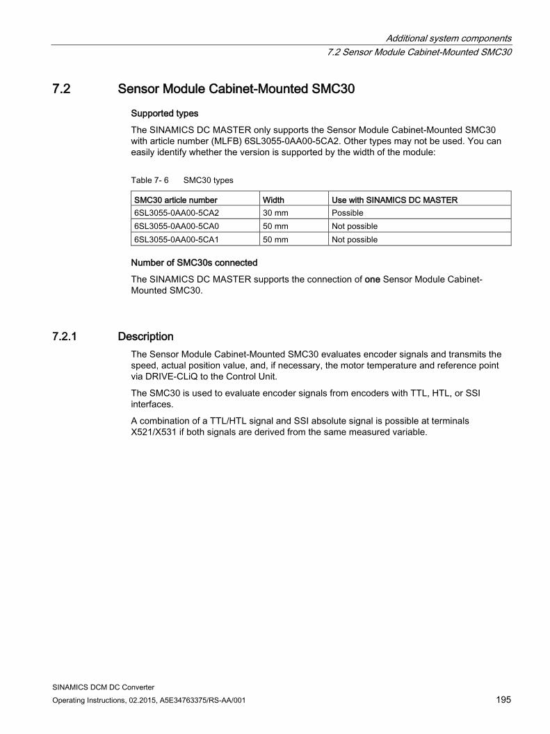
Additional system components 7.2 Sensor Module Cabinet-Mounted SMC30
SINAMICS DCM DC Converter Operating Instructions, 02.2015, A5E34763375/RS-AA/001 195
7.2 Sensor Module Cabinet-Mounted SMC30
Supported types
The SINAMICS DC MASTER only supports the Sensor Module Cabinet-Mounted SMC30 with article number (MLFB) 6SL3055-0AA00-5CA2. Other types may not be used. You can easily identify whether the version is supported by the width of the module:
Table 7- 6 SMC30 types
SMC30 article number Width Use with SINAMICS DC MASTER 6SL3055-0AA00-5CA2 30 mm Possible 6SL3055-0AA00-5CA0 50 mm Not possible 6SL3055-0AA00-5CA1 50 mm Not possible
Number of SMC30s connected
The SINAMICS DC MASTER supports the connection of one Sensor Module Cabinet-Mounted SMC30.
7.2.1 Description The Sensor Module Cabinet-Mounted SMC30 evaluates encoder signals and transmits the speed, actual position value, and, if necessary, the motor temperature and reference point via DRIVE-CLiQ to the Control Unit.
The SMC30 is used to evaluate encoder signals from encoders with TTL, HTL, or SSI interfaces.
A combination of a TTL/HTL signal and SSI absolute signal is possible at terminals X521/X531 if both signals are derived from the same measured variable.
Additional system components 7.2 Sensor Module Cabinet-Mounted SMC30
SINAMICS DCM DC Converter 196 Operating Instructions, 02.2015, A5E34763375/RS-AA/001
7.2.2 Safety instructions
WARNING
Danger to life through non-observance of the safety instructions
If the safety instructions in Chapter 1 are not observed, accidents can occur involving severe injuries or death. • Make sure that the safety instructions are observed.
WARNING
Risk of fire through overheating if there are insufficient ventilation clearances
Inadequate ventilation clearances cause overheating with a risk for personnel due to smoke and fire. This can also result in more downtimes and reduced service lives of the Terminal Module. • For this reason, it is imperative that you maintain the 50 mm clearances above and
below the Terminal Module.
NOTICE
Shield support
When the encoder system is connected via terminals, make sure that the cable shield is connected to the component.
NOTICE
Device failure as a result of unshielded or incorrectly routed cables to temperature sensors
Unshielded or incorrectly routed cables to temperature sensors can result in interference being coupled into the signal processing electronics from the power side. This can result in significant disturbance of all signals (fault messages) up to failure of individual components (destruction of the devices). • Only use shielded cables as temperature sensor cables. • If temperature sensor cables are routed together with the motor cable, use separately
shielded cables twisted in pairs. • Connect the cable shield at both ends to ground potential over a large surface area.
Additional system components 7.2 Sensor Module Cabinet-Mounted SMC30
SINAMICS DCM DC Converter Operating Instructions, 02.2015, A5E34763375/RS-AA/001 197
Note
Risk of encoder failures by encoder signal disturbances
Unfavorable material combinations generate static electricity between the belt pulley and the belt. This electrostatic charge (several kV) can discharge via the motor shaft and the encoder which leads to disturbance of the encoder signals (encoder error). • Use an antistatic version of the belt (special conductive polyurethane mixture).
WARNING
Danger to life due to electric shock when disconnecting and connecting encoder cables during operation
When disconnecting plug-in connections during operation, arcs can result in severe injury or death. • Only disconnect or connect the encoder cables to Siemens motors in a voltage-free
state if hot-plugging has not been specifically released. When using direct measuring systems (third-party encoders), ask the manufacturer whether hot-plugging is permitted.
NOTICE
Damage when connecting an impermissible number of encoder systems
Damage results when more than the maximum permissible number of encoder systems are connected to a Sensor Module. • Only connect one encoder system to a Sensor Module.
Note
Reduced interference immunity through equalization currents via the electronic ground
Make sure there is no electrical connection between the encoder system housing and the signal lines and the sensor system electronics.
If this is not carefully observed, under certain circumstances the system will not be able to reach the required interference immunity level (there is then a danger of equalization currents flowing through the electronics ground).
NOTICE
Damage through the use of incorrect DRIVE-CLiQ cables
Damage or malfunctions can occur on the devices or system when incorrect or unreleased DRIVE-CLiQ cables are used. • Only use suitable DRIVE-CLiQ cables that have been released by Siemens for the
respective application.
Additional system components 7.2 Sensor Module Cabinet-Mounted SMC30
SINAMICS DCM DC Converter 198 Operating Instructions, 02.2015, A5E34763375/RS-AA/001
Note
Malfunctions due to polluted DRIVE-CLiQ interfaces
Malfunctions can occur in the system through the use of polluted DRIVE-CLiQ interfaces. • Cover unused DRIVE-CLiQ interfaces with the supplied blanking covers.
Note
The safety instructions on the Sensor Module must be observed.
After the product has reached the end of its service life, the individual parts should be disposed of in compliance with local regulations.
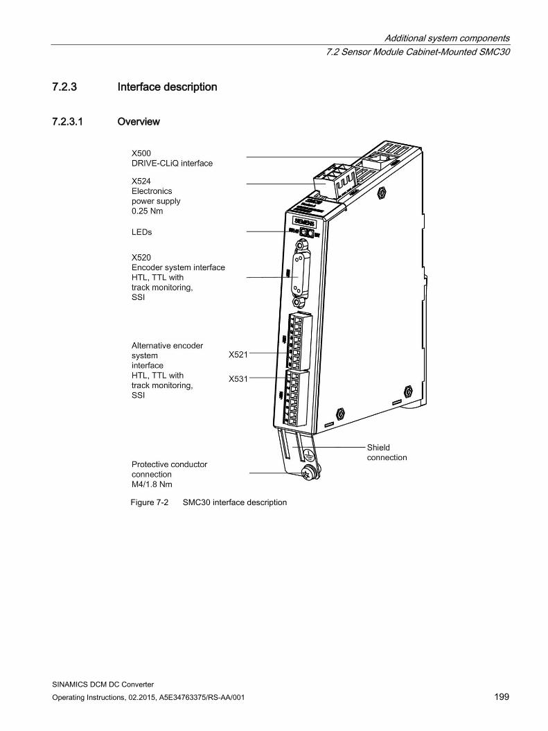
Additional system components 7.2 Sensor Module Cabinet-Mounted SMC30
SINAMICS DCM DC Converter Operating Instructions, 02.2015, A5E34763375/RS-AA/001 199
7.2.3 Interface description
7.2.3.1 Overview
Figure 7-2 SMC30 interface description
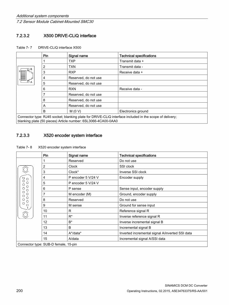
Additional system components 7.2 Sensor Module Cabinet-Mounted SMC30
SINAMICS DCM DC Converter 200 Operating Instructions, 02.2015, A5E34763375/RS-AA/001
7.2.3.2 X500 DRIVE-CLiQ interface
Table 7- 7 DRIVE-CLiQ interface X500
Pin Signal name Technical specifications
1 TXP Transmit data + 2 TXN Transmit data - 3 RXP Receive data + 4 Reserved, do not use 5 Reserved, do not use 6 RXN Receive data - 7 Reserved, do not use 8 Reserved, do not use A Reserved, do not use B M (0 V) Electronics ground
Connector type: RJ45 socket; blanking plate for DRIVE-CLiQ interface included in the scope of delivery; blanking plate (50 pieces) Article number: 6SL3066-4CA00-0AA0
7.2.3.3 X520 encoder system interface
Table 7- 8 X520 encoder system interface
Pin Signal name Technical specifications
1 Reserved Do not use 2 Clock SSI clock 3 Clock* Inverse SSI clock 4 P encoder 5 V/24 V Encoder supply 5 P encoder 5 V/24 V 6 P sense Sense input, encoder supply 7 M encoder (M) Ground, encoder supply 8 Reserved Do not use 9 M sense Ground for sense input 10 R Reference signal R 11 R* Inverse reference signal R 12 B* Inverse incremental signal B 13 B Incremental signal B 14 A*/data* Inverted incremental signal A/inverted SSI data 15 A/data Incremental signal A/SSI data
Connector type: SUB-D female, 15-pin
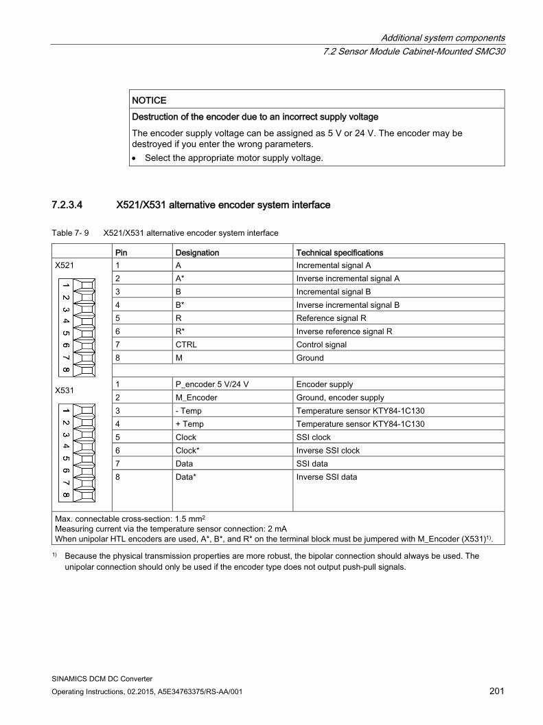
Additional system components 7.2 Sensor Module Cabinet-Mounted SMC30
SINAMICS DCM DC Converter Operating Instructions, 02.2015, A5E34763375/RS-AA/001 201
NOTICE
Destruction of the encoder due to an incorrect supply voltage
The encoder supply voltage can be assigned as 5 V or 24 V. The encoder may be destroyed if you enter the wrong parameters. • Select the appropriate motor supply voltage.
7.2.3.4 X521/X531 alternative encoder system interface
Table 7- 9 X521/X531 alternative encoder system interface
Pin Designation Technical specifications X521
X531
1 A Incremental signal A 2 A* Inverse incremental signal A 3 B Incremental signal B 4 B* Inverse incremental signal B 5 R Reference signal R 6 R* Inverse reference signal R 7 CTRL Control signal 8 M Ground 1 P_encoder 5 V/24 V Encoder supply 2 M_Encoder Ground, encoder supply 3 - Temp Temperature sensor KTY84-1C130 4 + Temp Temperature sensor KTY84-1C130 5 Clock SSI clock 6 Clock* Inverse SSI clock 7 Data SSI data 8 Data* Inverse SSI data
Max. connectable cross-section: 1.5 mm2
Measuring current via the temperature sensor connection: 2 mA When unipolar HTL encoders are used, A*, B*, and R* on the terminal block must be jumpered with M_Encoder (X531)1). 1) Because the physical transmission properties are more robust, the bipolar connection should always be used. The
unipolar connection should only be used if the encoder type does not output push-pull signals.
Additional system components 7.2 Sensor Module Cabinet-Mounted SMC30
SINAMICS DCM DC Converter 202 Operating Instructions, 02.2015, A5E34763375/RS-AA/001
WARNING
Danger to life through electric shock due to unconnected cable shields
Hazardous touch voltages can occur through capacitive cross-coupling due to unconnected cable shields. • Attach the cable shield to the component via terminals for the encoder system
connection.
Temperature sensor connection
For the evaluation of the temperature sensor, see function diagram 8030 in the SINAMICS DCM List Manual.
NOTICE
Motor damage due to incorrectly connected KTY temperature sensor
A KTY temperature sensor connected with incorrect polarity cannot detect if the motor overheats. Overheating may result in damage to the motor. • Connect a KTY temperature sensor with the correct polarity.
WARNING
Danger to life through electric shock due to flashover to the temperature sensor cable
Flashover to the signal electronics can occur on motors without safe electrical separation of the temperature sensors. • Only use temperature sensors that satisfy the specifications for electrical separation
according to IEC 61800-5-1.
Note
The maximum length of the temperature sensor cable is 100 m. The cables must be shielded.
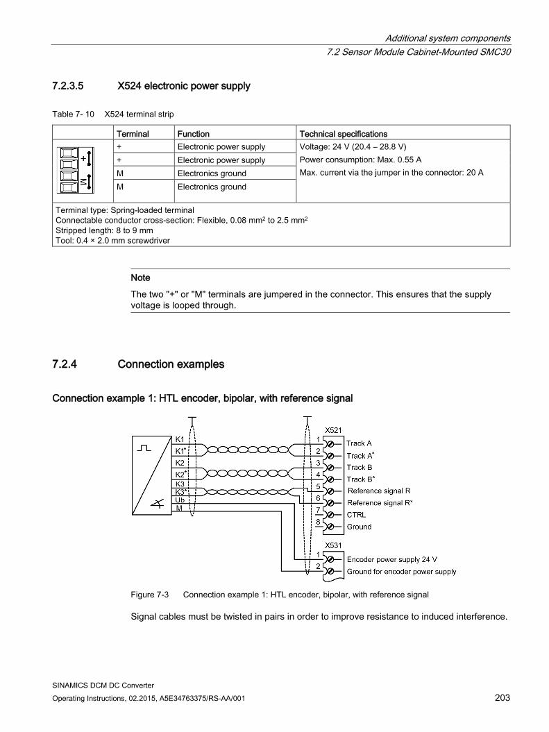
Additional system components 7.2 Sensor Module Cabinet-Mounted SMC30
SINAMICS DCM DC Converter Operating Instructions, 02.2015, A5E34763375/RS-AA/001 203
7.2.3.5 X524 electronic power supply
Table 7- 10 X524 terminal strip
Terminal Function Technical specifications
+ Electronic power supply Voltage: 24 V (20.4 – 28.8 V) Power consumption: Max. 0.55 A Max. current via the jumper in the connector: 20 A
+ Electronic power supply M Electronics ground M Electronics ground
Terminal type: Spring-loaded terminal Connectable conductor cross-section: Flexible, 0.08 mm2 to 2.5 mm2 Stripped length: 8 to 9 mm Tool: 0.4 × 2.0 mm screwdriver
Note
The two "+" or "M" terminals are jumpered in the connector. This ensures that the supply voltage is looped through.
7.2.4 Connection examples
Connection example 1: HTL encoder, bipolar, with reference signal
Figure 7-3 Connection example 1: HTL encoder, bipolar, with reference signal
Signal cables must be twisted in pairs in order to improve resistance to induced interference.
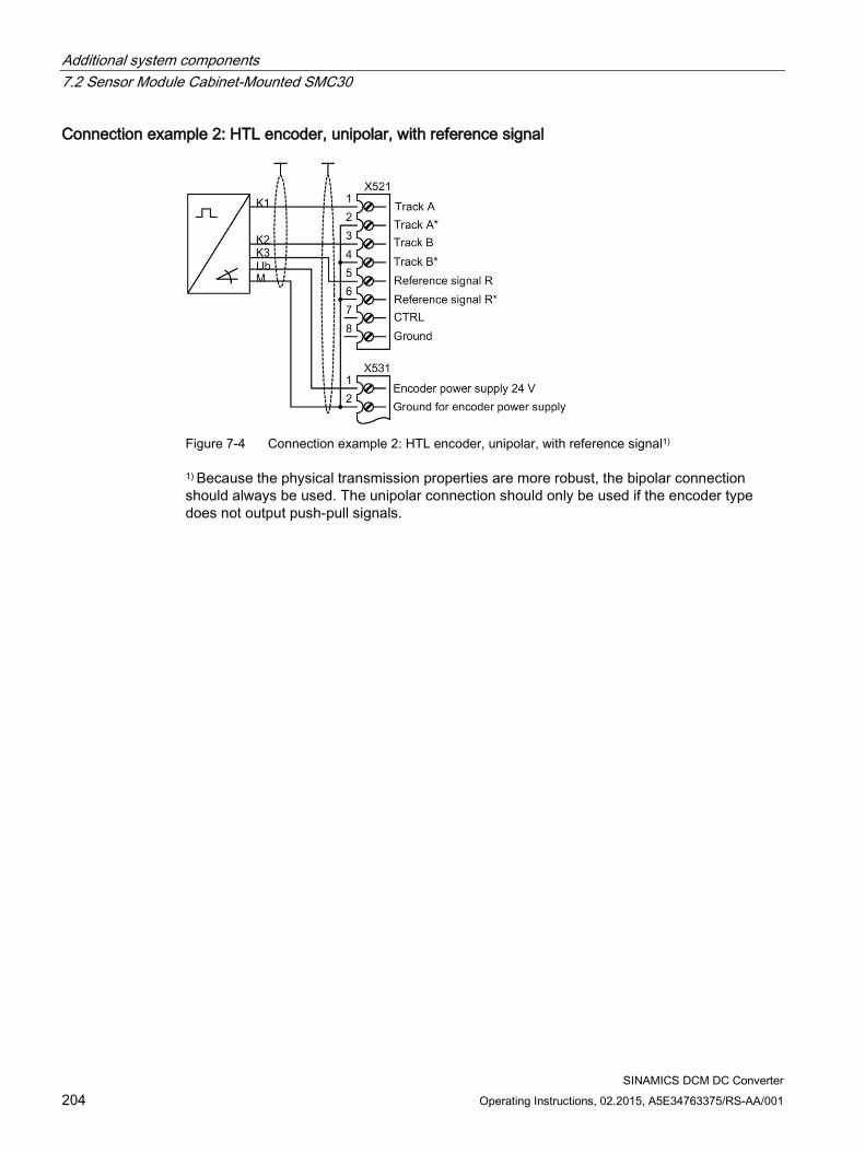
Additional system components 7.2 Sensor Module Cabinet-Mounted SMC30
SINAMICS DCM DC Converter 204 Operating Instructions, 02.2015, A5E34763375/RS-AA/001
Connection example 2: HTL encoder, unipolar, with reference signal
Figure 7-4 Connection example 2: HTL encoder, unipolar, with reference signal1)
1) Because the physical transmission properties are more robust, the bipolar connection should always be used. The unipolar connection should only be used if the encoder type does not output push-pull signals.
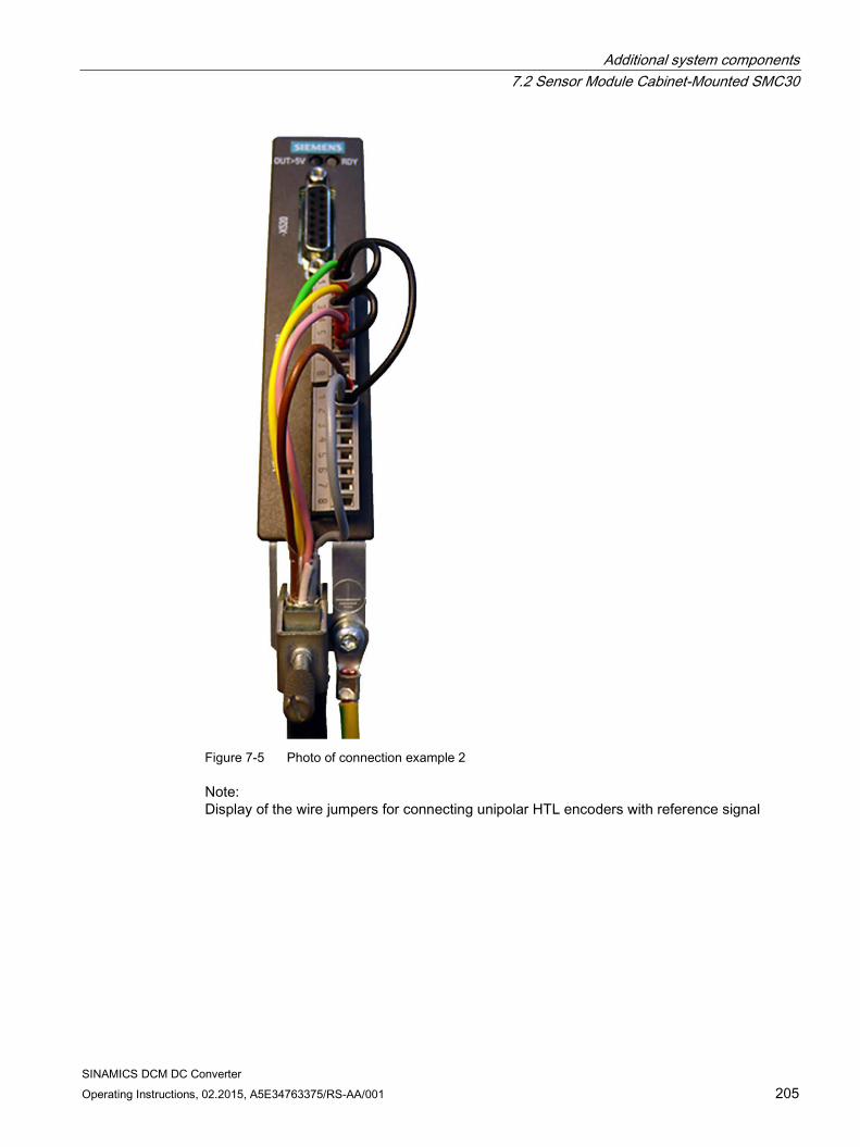
Additional system components 7.2 Sensor Module Cabinet-Mounted SMC30
SINAMICS DCM DC Converter Operating Instructions, 02.2015, A5E34763375/RS-AA/001 205
Figure 7-5 Photo of connection example 2
Note: Display of the wire jumpers for connecting unipolar HTL encoders with reference signal
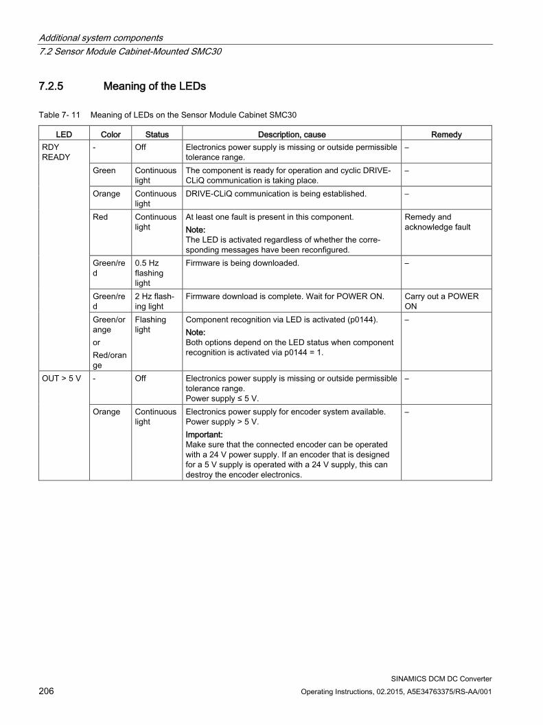
Additional system components 7.2 Sensor Module Cabinet-Mounted SMC30
SINAMICS DCM DC Converter 206 Operating Instructions, 02.2015, A5E34763375/RS-AA/001
7.2.5 Meaning of the LEDs
Table 7- 11 Meaning of LEDs on the Sensor Module Cabinet SMC30
LED Color Status Description, cause Remedy RDY READY
- Off Electronics power supply is missing or outside permissible tolerance range.
–
Green Continuous light
The component is ready for operation and cyclic DRIVE-CLiQ communication is taking place.
–
Orange Continuous light
DRIVE-CLiQ communication is being established. –
Red Continuous light
At least one fault is present in this component. Note: The LED is activated regardless of whether the corre-sponding messages have been reconfigured.
Remedy and acknowledge fault
Green/red
0.5 Hz flashing light
Firmware is being downloaded. –
Green/red
2 Hz flash-ing light
Firmware download is complete. Wait for POWER ON. Carry out a POWER ON
Green/orange or Red/orange
Flashing light
Component recognition via LED is activated (p0144). Note: Both options depend on the LED status when component recognition is activated via p0144 = 1.
–
OUT > 5 V - Off Electronics power supply is missing or outside permissible tolerance range. Power supply ≤ 5 V.
–
Orange Continuous light
Electronics power supply for encoder system available. Power supply > 5 V. Important: Make sure that the connected encoder can be operated with a 24 V power supply. If an encoder that is designed for a 5 V supply is operated with a 24 V supply, this can destroy the encoder electronics.
–
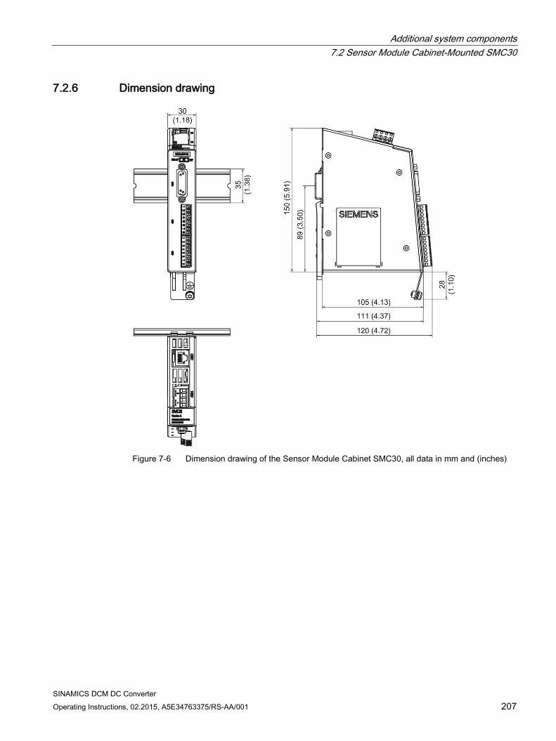
Additional system components 7.2 Sensor Module Cabinet-Mounted SMC30
SINAMICS DCM DC Converter Operating Instructions, 02.2015, A5E34763375/RS-AA/001 207
7.2.6 Dimension drawing
Figure 7-6 Dimension drawing of the Sensor Module Cabinet SMC30, all data in mm and (inches)
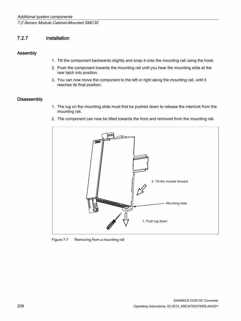
Additional system components 7.2 Sensor Module Cabinet-Mounted SMC30
SINAMICS DCM DC Converter 208 Operating Instructions, 02.2015, A5E34763375/RS-AA/001
7.2.7 Installation
Assembly 1. Tilt the component backwards slightly and snap it onto the mounting rail using the hook.
2. Push the component towards the mounting rail until you hear the mounting slide at the rear latch into position.
3. You can now move the component to the left or right along the mounting rail, until it reaches its final position.
Disassembly 1. The lug on the mounting slide must first be pushed down to release the interlock from the
mounting rail.
2. The component can now be tilted towards the front and removed from the mounting rail.
Figure 7-7 Removing from a mounting rail
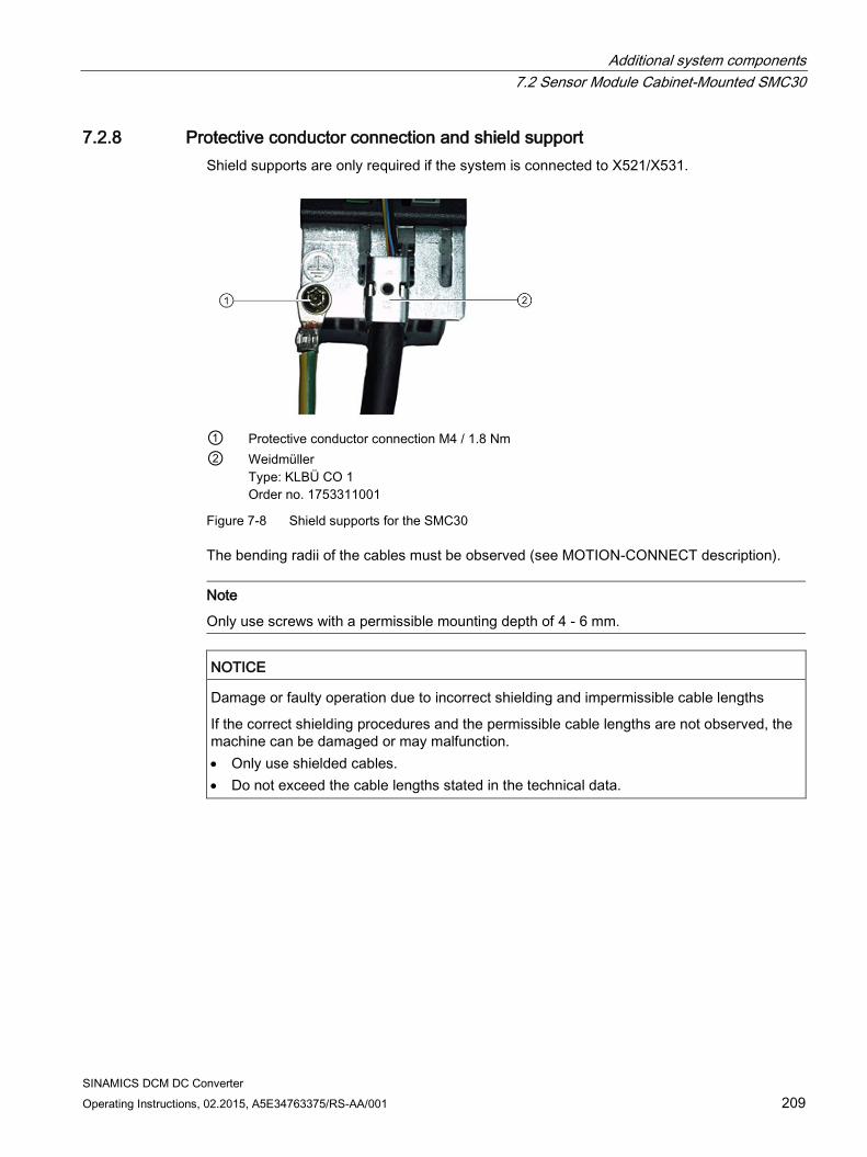
Additional system components 7.2 Sensor Module Cabinet-Mounted SMC30
SINAMICS DCM DC Converter Operating Instructions, 02.2015, A5E34763375/RS-AA/001 209
7.2.8 Protective conductor connection and shield support Shield supports are only required if the system is connected to X521/X531.
① Protective conductor connection M4 / 1.8 Nm ② Weidmüller
Type: KLBÜ CO 1 Order no. 1753311001
Figure 7-8 Shield supports for the SMC30
The bending radii of the cables must be observed (see MOTION-CONNECT description).
Note
Only use screws with a permissible mounting depth of 4 - 6 mm.
NOTICE
Damage or faulty operation due to incorrect shielding and impermissible cable lengths
If the correct shielding procedures and the permissible cable lengths are not observed, the machine can be damaged or may malfunction. • Only use shielded cables. • Do not exceed the cable lengths stated in the technical data.
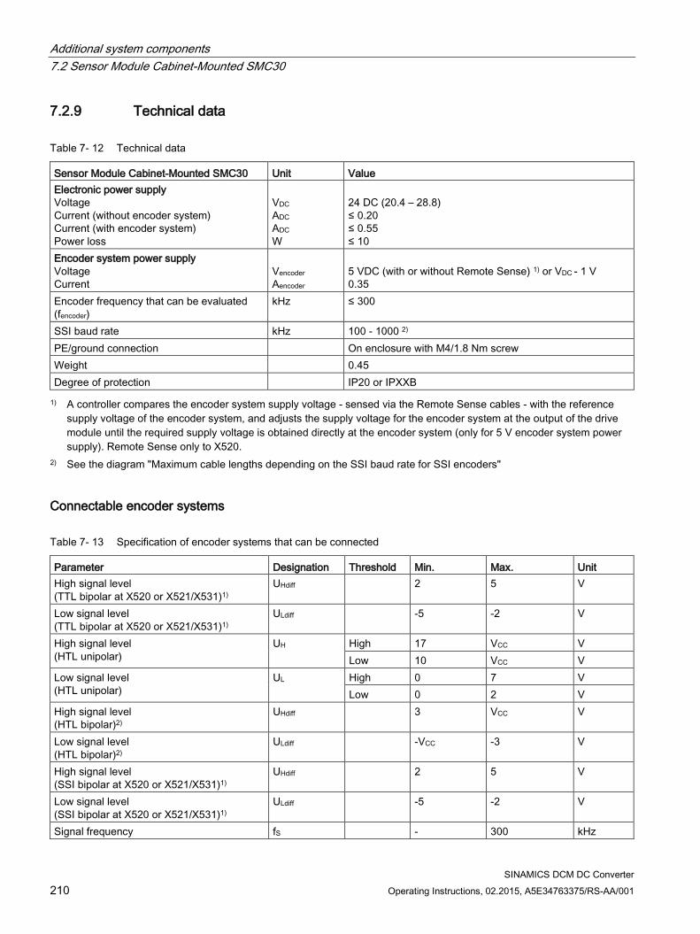
Additional system components 7.2 Sensor Module Cabinet-Mounted SMC30
SINAMICS DCM DC Converter 210 Operating Instructions, 02.2015, A5E34763375/RS-AA/001
7.2.9 Technical data
Table 7- 12 Technical data
Sensor Module Cabinet-Mounted SMC30 Unit Value Electronic power supply Voltage Current (without encoder system) Current (with encoder system) Power loss
VDC ADC ADC W
24 DC (20.4 – 28.8) ≤ 0.20 ≤ 0.55 ≤ 10
Encoder system power supply Voltage Current
Vencoder Aencoder
5 VDC (with or without Remote Sense) 1) or VDC - 1 V 0.35
Encoder frequency that can be evaluated (fencoder)
kHz ≤ 300
SSI baud rate kHz 100 - 1000 2) PE/ground connection On enclosure with M4/1.8 Nm screw Weight 0.45 Degree of protection IP20 or IPXXB 1) A controller compares the encoder system supply voltage - sensed via the Remote Sense cables - with the reference
supply voltage of the encoder system, and adjusts the supply voltage for the encoder system at the output of the drive module until the required supply voltage is obtained directly at the encoder system (only for 5 V encoder system power supply). Remote Sense only to X520.
2) See the diagram "Maximum cable lengths depending on the SSI baud rate for SSI encoders"
Connectable encoder systems
Table 7- 13 Specification of encoder systems that can be connected
Parameter Designation Threshold Min. Max. Unit High signal level (TTL bipolar at X520 or X521/X531)1)
UHdiff 2 5 V
Low signal level (TTL bipolar at X520 or X521/X531)1)
ULdiff -5 -2 V
High signal level (HTL unipolar)
UH High 17 VCC V Low 10 VCC V
Low signal level (HTL unipolar)
UL High 0 7 V Low 0 2 V
High signal level (HTL bipolar)2)
UHdiff 3 VCC V
Low signal level (HTL bipolar)2)
ULdiff -VCC -3 V
High signal level (SSI bipolar at X520 or X521/X531)1)
UHdiff 2 5 V
Low signal level (SSI bipolar at X520 or X521/X531)1)
ULdiff -5 -2 V
Signal frequency fS - 300 kHz
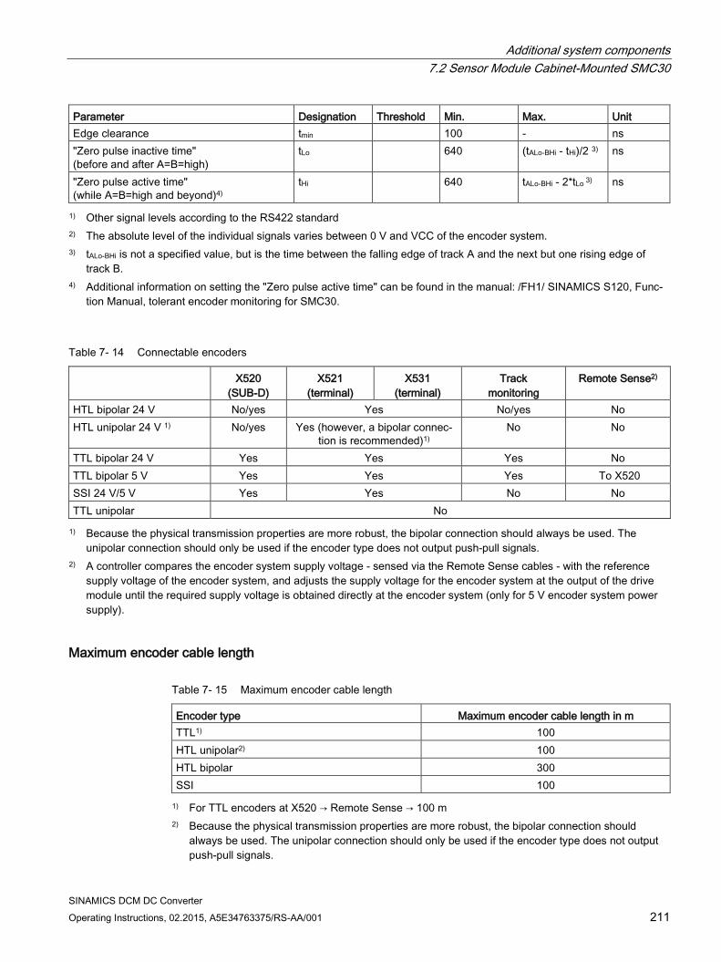
Additional system components 7.2 Sensor Module Cabinet-Mounted SMC30
SINAMICS DCM DC Converter Operating Instructions, 02.2015, A5E34763375/RS-AA/001 211
Parameter Designation Threshold Min. Max. Unit Edge clearance tmin 100 - ns "Zero pulse inactive time" (before and after A=B=high)
tLo 640 (tALo-BHi - tHi)/2 3) ns
"Zero pulse active time" (while A=B=high and beyond)4)
tHi 640 tALo-BHi - 2*tLo 3) ns
1) Other signal levels according to the RS422 standard 2) The absolute level of the individual signals varies between 0 V and VCC of the encoder system. 3) tALo-BHi is not a specified value, but is the time between the falling edge of track A and the next but one rising edge of
track B. 4) Additional information on setting the "Zero pulse active time" can be found in the manual: /FH1/ SINAMICS S120, Func-
tion Manual, tolerant encoder monitoring for SMC30.
Table 7- 14 Connectable encoders
X520 (SUB-D)
X521 (terminal)
X531 (terminal)
Track monitoring
Remote Sense2)
HTL bipolar 24 V No/yes Yes No/yes No HTL unipolar 24 V 1) No/yes Yes (however, a bipolar connec-
tion is recommended)1) No No
TTL bipolar 24 V Yes Yes Yes No TTL bipolar 5 V Yes Yes Yes To X520 SSI 24 V/5 V Yes Yes No No TTL unipolar No 1) Because the physical transmission properties are more robust, the bipolar connection should always be used. The
unipolar connection should only be used if the encoder type does not output push-pull signals. 2) A controller compares the encoder system supply voltage - sensed via the Remote Sense cables - with the reference
supply voltage of the encoder system, and adjusts the supply voltage for the encoder system at the output of the drive module until the required supply voltage is obtained directly at the encoder system (only for 5 V encoder system power supply).
Maximum encoder cable length
Table 7- 15 Maximum encoder cable length
Encoder type Maximum encoder cable length in m TTL1) 100 HTL unipolar2) 100 HTL bipolar 300 SSI 100 1) For TTL encoders at X520 → Remote Sense → 100 m
2) Because the physical transmission properties are more robust, the bipolar connection should always be used. The unipolar connection should only be used if the encoder type does not output push-pull signals.
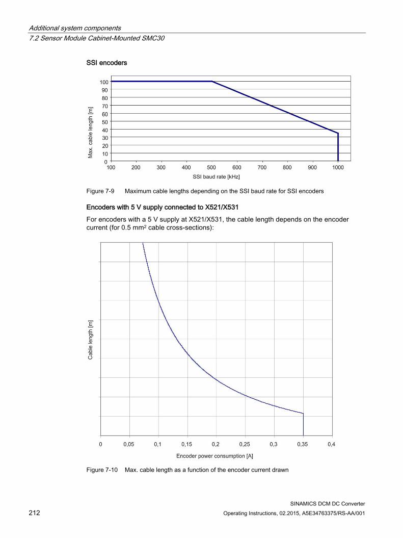
Additional system components 7.2 Sensor Module Cabinet-Mounted SMC30
SINAMICS DCM DC Converter 212 Operating Instructions, 02.2015, A5E34763375/RS-AA/001
SSI encoders
Figure 7-9 Maximum cable lengths depending on the SSI baud rate for SSI encoders
Encoders with 5 V supply connected to X521/X531
For encoders with a 5 V supply at X521/X531, the cable length depends on the encoder current (for 0.5 mm2 cable cross-sections):
Figure 7-10 Max. cable length as a function of the encoder current drawn
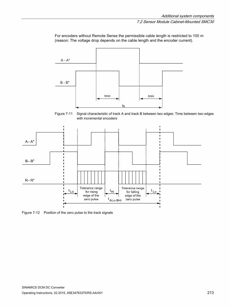
Additional system components 7.2 Sensor Module Cabinet-Mounted SMC30
SINAMICS DCM DC Converter Operating Instructions, 02.2015, A5E34763375/RS-AA/001 213
For encoders without Remote Sense the permissible cable length is restricted to 100 m (reason: The voltage drop depends on the cable length and the encoder current).
Figure 7-11 Signal characteristic of track A and track B between two edges: Time between two edges
with incremental encoders
Figure 7-12 Position of the zero pulse to the track signals
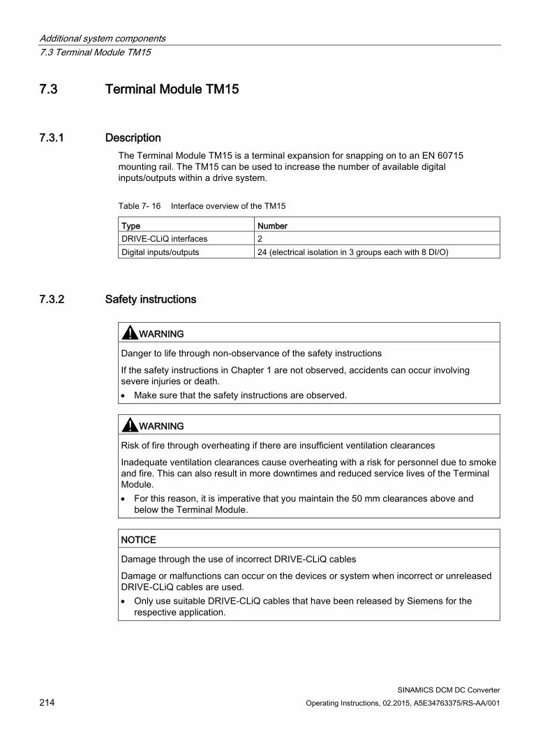
Additional system components 7.3 Terminal Module TM15
SINAMICS DCM DC Converter 214 Operating Instructions, 02.2015, A5E34763375/RS-AA/001
7.3 Terminal Module TM15
7.3.1 Description The Terminal Module TM15 is a terminal expansion for snapping on to an EN 60715 mounting rail. The TM15 can be used to increase the number of available digital inputs/outputs within a drive system.
Table 7- 16 Interface overview of the TM15
Type Number DRIVE-CLiQ interfaces 2 Digital inputs/outputs 24 (electrical isolation in 3 groups each with 8 DI/O)
7.3.2 Safety instructions
WARNING
Danger to life through non-observance of the safety instructions
If the safety instructions in Chapter 1 are not observed, accidents can occur involving severe injuries or death. • Make sure that the safety instructions are observed.
WARNING
Risk of fire through overheating if there are insufficient ventilation clearances
Inadequate ventilation clearances cause overheating with a risk for personnel due to smoke and fire. This can also result in more downtimes and reduced service lives of the Terminal Module. • For this reason, it is imperative that you maintain the 50 mm clearances above and
below the Terminal Module.
NOTICE
Damage through the use of incorrect DRIVE-CLiQ cables
Damage or malfunctions can occur on the devices or system when incorrect or unreleased DRIVE-CLiQ cables are used. • Only use suitable DRIVE-CLiQ cables that have been released by Siemens for the
respective application.
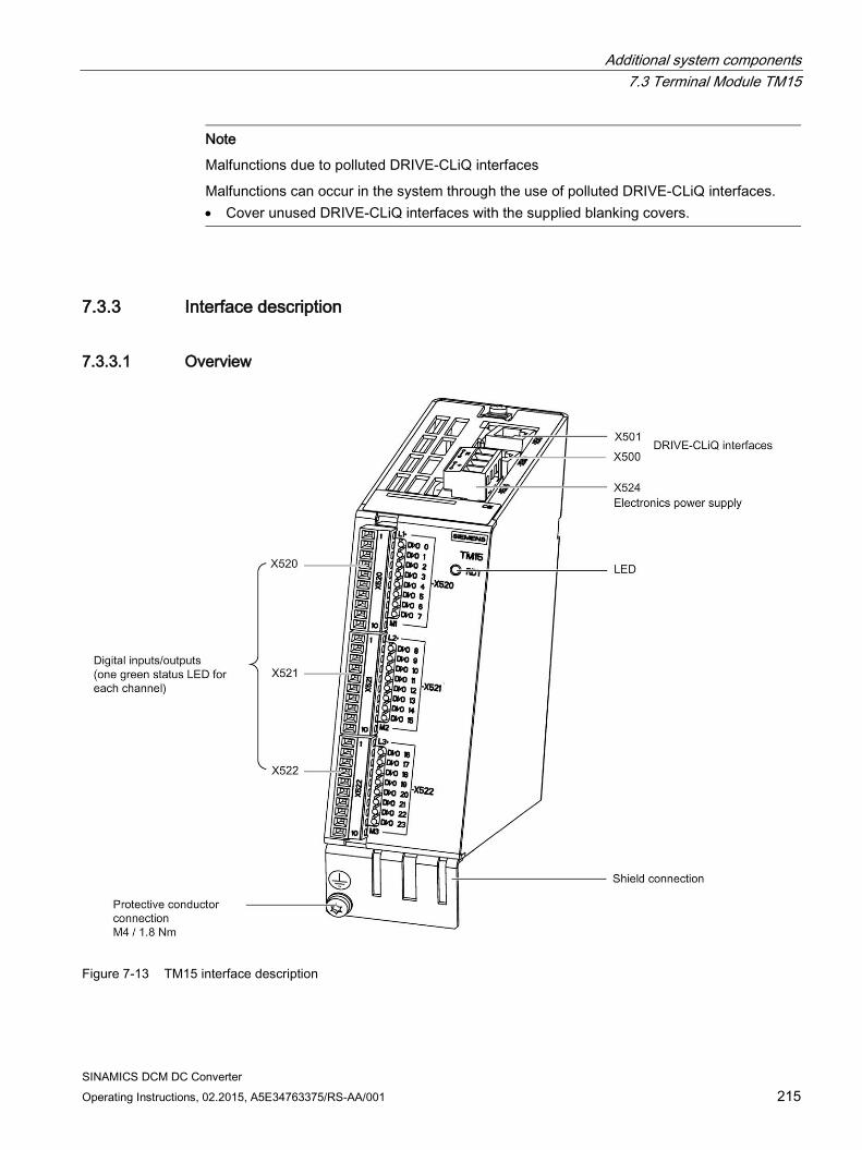
Additional system components 7.3 Terminal Module TM15
SINAMICS DCM DC Converter Operating Instructions, 02.2015, A5E34763375/RS-AA/001 215
Note
Malfunctions due to polluted DRIVE-CLiQ interfaces
Malfunctions can occur in the system through the use of polluted DRIVE-CLiQ interfaces. • Cover unused DRIVE-CLiQ interfaces with the supplied blanking covers.
7.3.3 Interface description
7.3.3.1 Overview
Figure 7-13 TM15 interface description
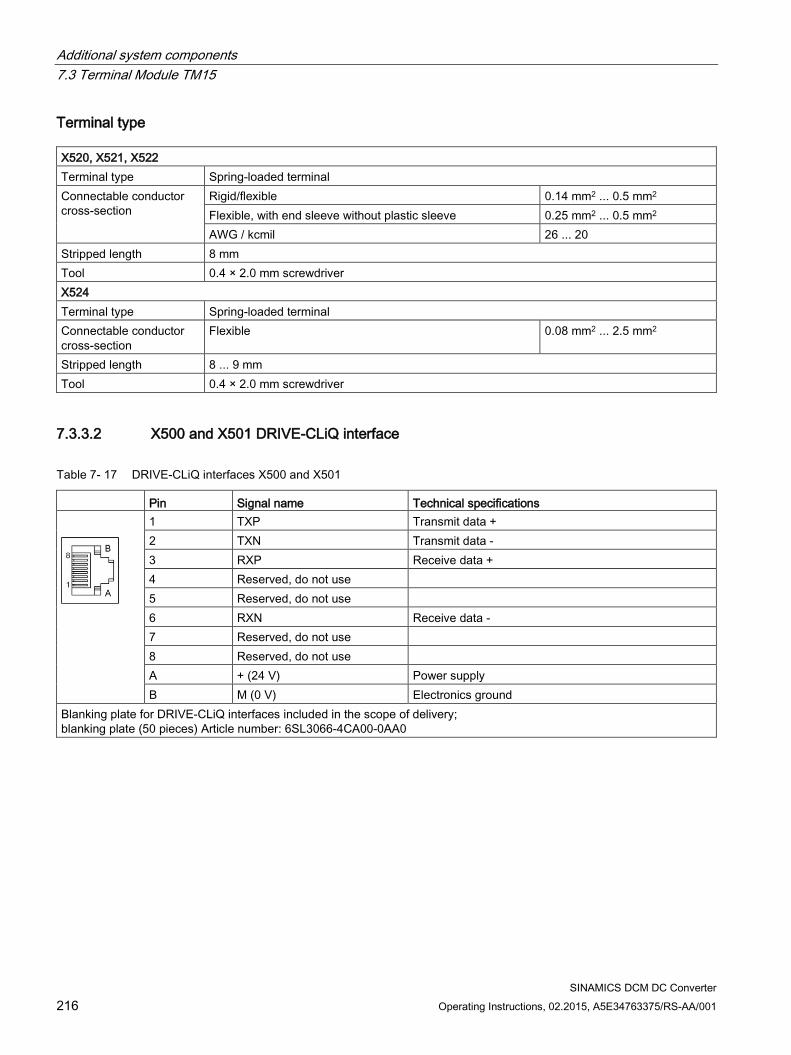
Additional system components 7.3 Terminal Module TM15
SINAMICS DCM DC Converter 216 Operating Instructions, 02.2015, A5E34763375/RS-AA/001
Terminal type X520, X521, X522 Terminal type Spring-loaded terminal Connectable conductor cross-section
Rigid/flexible 0.14 mm2 ... 0.5 mm2 Flexible, with end sleeve without plastic sleeve 0.25 mm2 ... 0.5 mm2 AWG / kcmil 26 ... 20
Stripped length 8 mm Tool 0.4 × 2.0 mm screwdriver X524 Terminal type Spring-loaded terminal Connectable conductor cross-section
Flexible 0.08 mm2 ... 2.5 mm2
Stripped length 8 ... 9 mm Tool 0.4 × 2.0 mm screwdriver
7.3.3.2 X500 and X501 DRIVE-CLiQ interface
Table 7- 17 DRIVE-CLiQ interfaces X500 and X501
Pin Signal name Technical specifications
1 TXP Transmit data + 2 TXN Transmit data - 3 RXP Receive data + 4 Reserved, do not use 5 Reserved, do not use 6 RXN Receive data - 7 Reserved, do not use 8 Reserved, do not use A + (24 V) Power supply B M (0 V) Electronics ground
Blanking plate for DRIVE-CLiQ interfaces included in the scope of delivery; blanking plate (50 pieces) Article number: 6SL3066-4CA00-0AA0
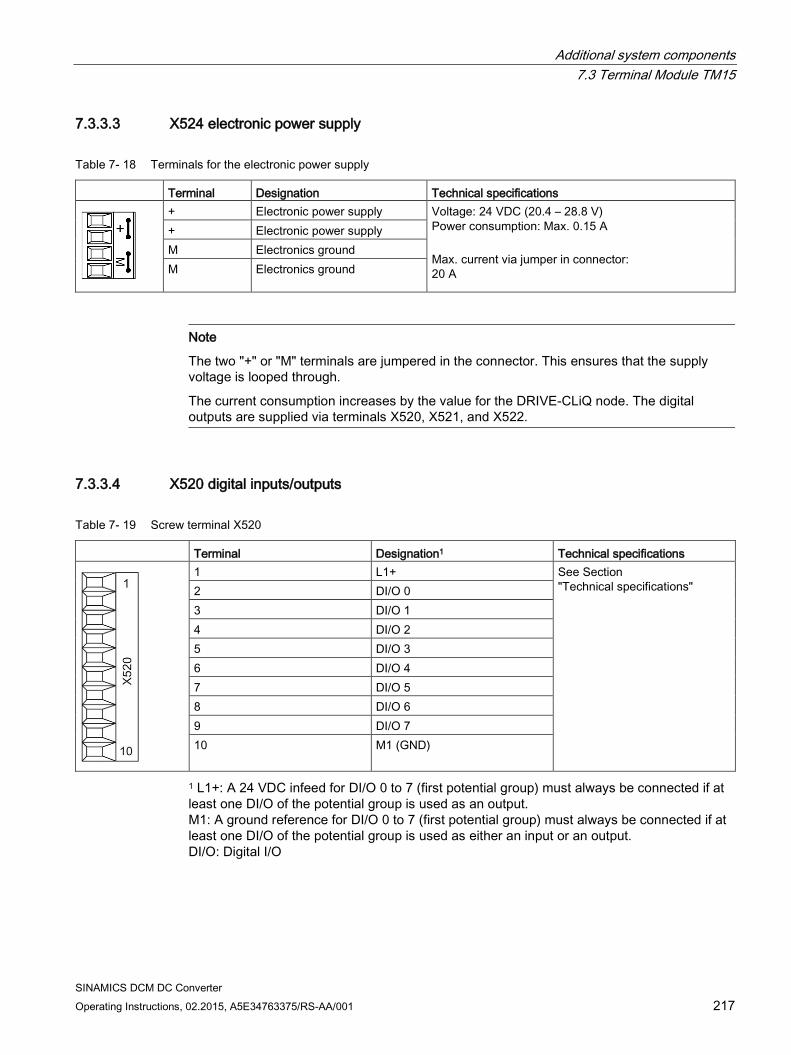
Additional system components 7.3 Terminal Module TM15
SINAMICS DCM DC Converter Operating Instructions, 02.2015, A5E34763375/RS-AA/001 217
7.3.3.3 X524 electronic power supply
Table 7- 18 Terminals for the electronic power supply
Terminal Designation Technical specifications
+ Electronic power supply Voltage: 24 VDC (20.4 – 28.8 V) Power consumption: Max. 0.15 A Max. current via jumper in connector: 20 A
+ Electronic power supply M Electronics ground M Electronics ground
Note
The two "+" or "M" terminals are jumpered in the connector. This ensures that the supply voltage is looped through.
The current consumption increases by the value for the DRIVE-CLiQ node. The digital outputs are supplied via terminals X520, X521, and X522.
7.3.3.4 X520 digital inputs/outputs
Table 7- 19 Screw terminal X520
Terminal Designation1 Technical specifications
1 L1+ See Section "Technical specifications" 2 DI/O 0
3 DI/O 1 4 DI/O 2 5 DI/O 3 6 DI/O 4 7 DI/O 5 8 DI/O 6 9 DI/O 7 10 M1 (GND)
1 L1+: A 24 VDC infeed for DI/O 0 to 7 (first potential group) must always be connected if at least one DI/O of the potential group is used as an output. M1: A ground reference for DI/O 0 to 7 (first potential group) must always be connected if at least one DI/O of the potential group is used as either an input or an output. DI/O: Digital I/O
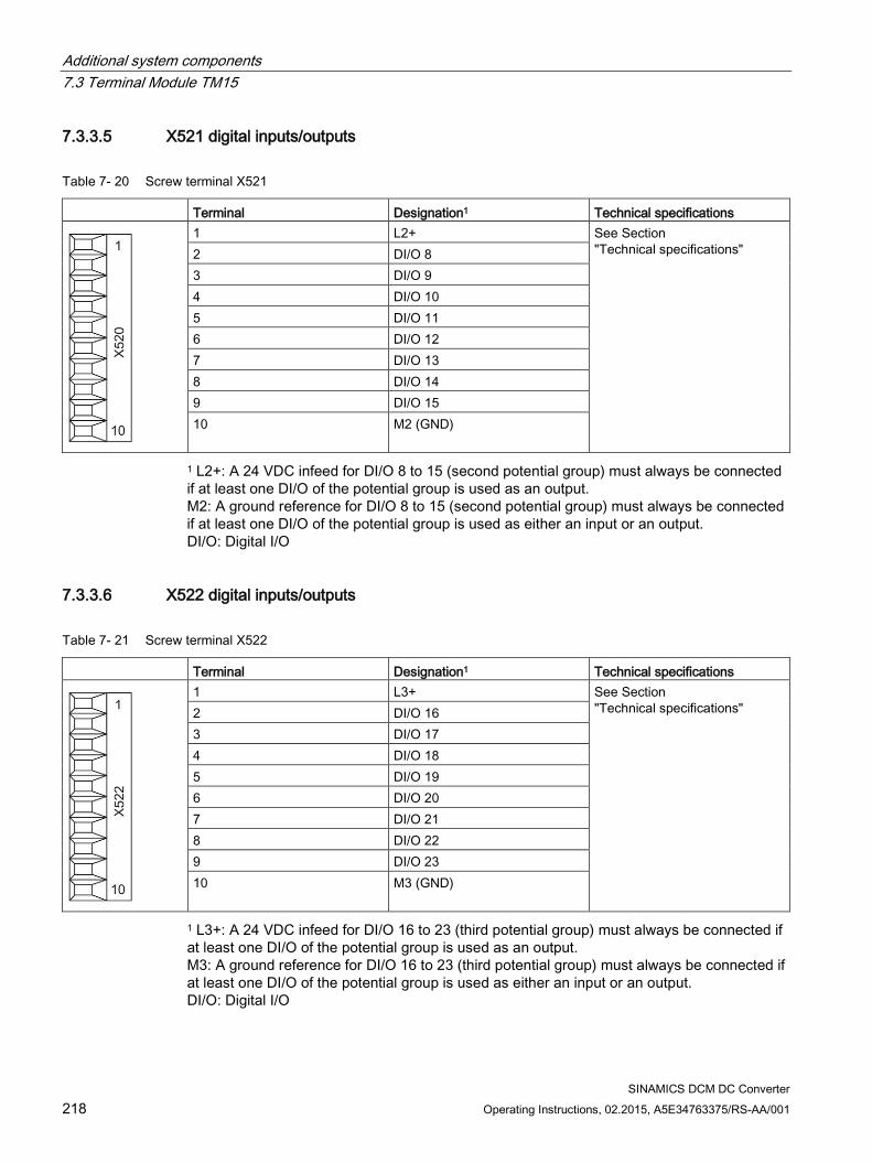
Additional system components 7.3 Terminal Module TM15
SINAMICS DCM DC Converter 218 Operating Instructions, 02.2015, A5E34763375/RS-AA/001
7.3.3.5 X521 digital inputs/outputs
Table 7- 20 Screw terminal X521
Terminal Designation1 Technical specifications
1 L2+ See Section "Technical specifications" 2 DI/O 8
3 DI/O 9 4 DI/O 10 5 DI/O 11 6 DI/O 12 7 DI/O 13 8 DI/O 14 9 DI/O 15 10 M2 (GND)
1 L2+: A 24 VDC infeed for DI/O 8 to 15 (second potential group) must always be connected if at least one DI/O of the potential group is used as an output. M2: A ground reference for DI/O 8 to 15 (second potential group) must always be connected if at least one DI/O of the potential group is used as either an input or an output. DI/O: Digital I/O
7.3.3.6 X522 digital inputs/outputs
Table 7- 21 Screw terminal X522
Terminal Designation1 Technical specifications
1 L3+ See Section "Technical specifications" 2 DI/O 16
3 DI/O 17 4 DI/O 18 5 DI/O 19 6 DI/O 20 7 DI/O 21 8 DI/O 22 9 DI/O 23 10 M3 (GND)
1 L3+: A 24 VDC infeed for DI/O 16 to 23 (third potential group) must always be connected if at least one DI/O of the potential group is used as an output. M3: A ground reference for DI/O 16 to 23 (third potential group) must always be connected if at least one DI/O of the potential group is used as either an input or an output. DI/O: Digital I/O
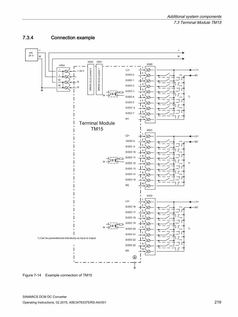
Additional system components 7.3 Terminal Module TM15
SINAMICS DCM DC Converter Operating Instructions, 02.2015, A5E34763375/RS-AA/001 219
7.3.4 Connection example
Figure 7-14 Example connection of TM15
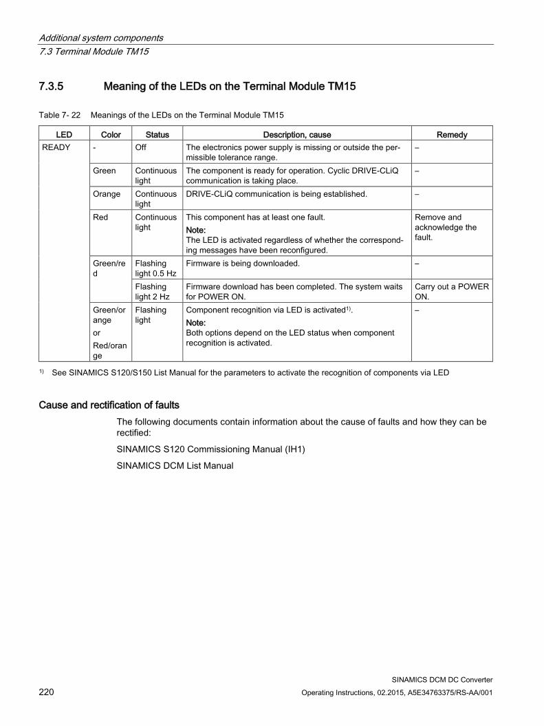
Additional system components 7.3 Terminal Module TM15
SINAMICS DCM DC Converter 220 Operating Instructions, 02.2015, A5E34763375/RS-AA/001
7.3.5 Meaning of the LEDs on the Terminal Module TM15
Table 7- 22 Meanings of the LEDs on the Terminal Module TM15
LED Color Status Description, cause Remedy READY - Off The electronics power supply is missing or outside the per-
missible tolerance range. –
Green Continuous light
The component is ready for operation. Cyclic DRIVE-CLiQ communication is taking place.
–
Orange Continuous light
DRIVE-CLiQ communication is being established. –
Red Continuous light
This component has at least one fault. Note: The LED is activated regardless of whether the correspond-ing messages have been reconfigured.
Remove and acknowledge the fault.
Green/red
Flashing light 0.5 Hz
Firmware is being downloaded. –
Flashing light 2 Hz
Firmware download has been completed. The system waits for POWER ON.
Carry out a POWER ON.
Green/orange or Red/orange
Flashing light
Component recognition via LED is activated1). Note: Both options depend on the LED status when component recognition is activated.
–
1) See SINAMICS S120/S150 List Manual for the parameters to activate the recognition of components via LED
Cause and rectification of faults The following documents contain information about the cause of faults and how they can be rectified:
SINAMICS S120 Commissioning Manual (IH1)
SINAMICS DCM List Manual
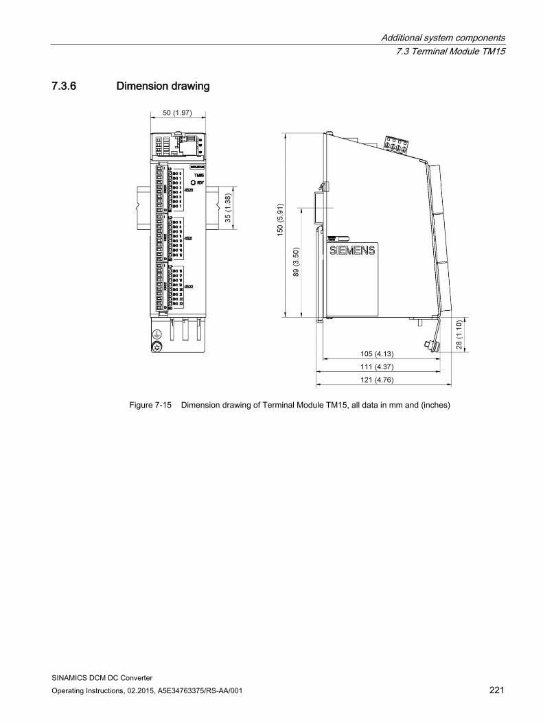
Additional system components 7.3 Terminal Module TM15
SINAMICS DCM DC Converter Operating Instructions, 02.2015, A5E34763375/RS-AA/001 221
7.3.6 Dimension drawing
Figure 7-15 Dimension drawing of Terminal Module TM15, all data in mm and (inches)
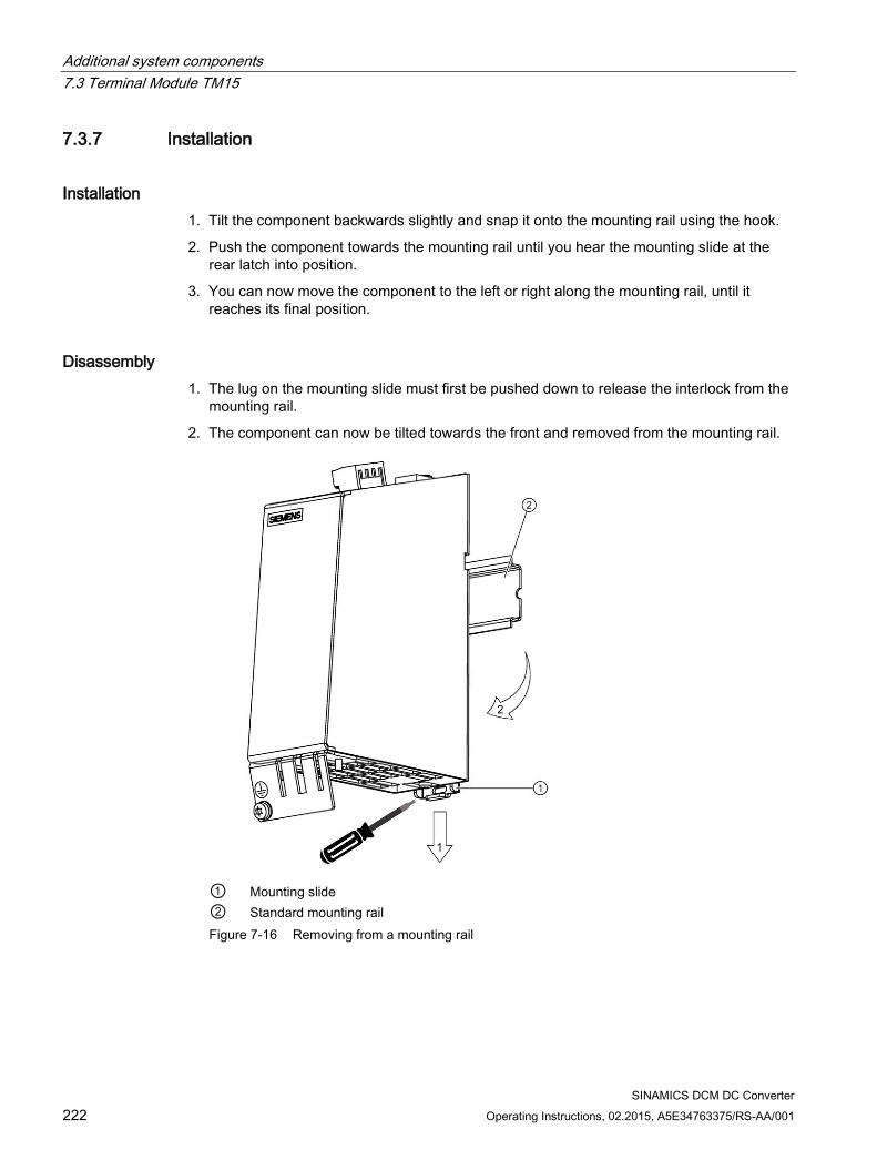
Additional system components 7.3 Terminal Module TM15
SINAMICS DCM DC Converter 222 Operating Instructions, 02.2015, A5E34763375/RS-AA/001
7.3.7 Installation
Installation 1. Tilt the component backwards slightly and snap it onto the mounting rail using the hook.
2. Push the component towards the mounting rail until you hear the mounting slide at the rear latch into position.
3. You can now move the component to the left or right along the mounting rail, until it reaches its final position.
Disassembly 1. The lug on the mounting slide must first be pushed down to release the interlock from the
mounting rail.
2. The component can now be tilted towards the front and removed from the mounting rail.
① Mounting slide ② Standard mounting rail Figure 7-16 Removing from a mounting rail
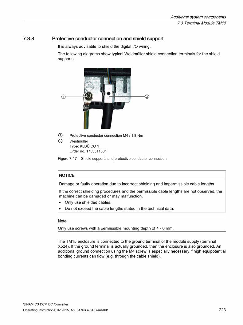
Additional system components 7.3 Terminal Module TM15
SINAMICS DCM DC Converter Operating Instructions, 02.2015, A5E34763375/RS-AA/001 223
7.3.8 Protective conductor connection and shield support It is always advisable to shield the digital I/O wiring.
The following diagrams show typical Weidmüller shield connection terminals for the shield supports.
① Protective conductor connection M4 / 1.8 Nm ② Weidmüller
Type: KLBÜ CO 1 Order no. 1753311001
Figure 7-17 Shield supports and protective conductor connection
NOTICE
Damage or faulty operation due to incorrect shielding and impermissible cable lengths
If the correct shielding procedures and the permissible cable lengths are not observed, the machine can be damaged or may malfunction. • Only use shielded cables. • Do not exceed the cable lengths stated in the technical data.
Note
Only use screws with a permissible mounting depth of 4 - 6 mm.
The TM15 enclosure is connected to the ground terminal of the module supply (terminal X524). If the ground terminal is actually grounded, then the enclosure is also grounded. An additional ground connection using the M4 screw is especially necessary if high equipotential bonding currents can flow (e.g. through the cable shield).
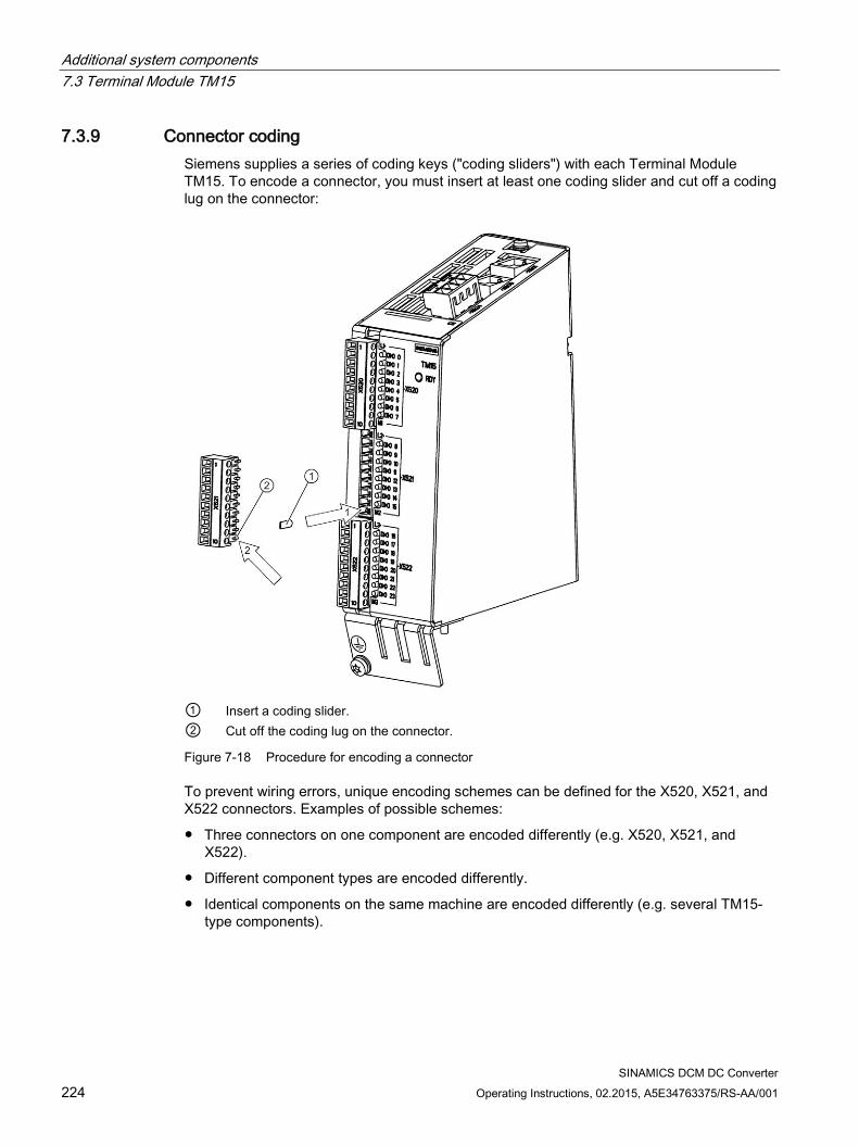
Additional system components 7.3 Terminal Module TM15
SINAMICS DCM DC Converter 224 Operating Instructions, 02.2015, A5E34763375/RS-AA/001
7.3.9 Connector coding Siemens supplies a series of coding keys ("coding sliders") with each Terminal Module TM15. To encode a connector, you must insert at least one coding slider and cut off a coding lug on the connector:
① Insert a coding slider. ② Cut off the coding lug on the connector.
Figure 7-18 Procedure for encoding a connector
To prevent wiring errors, unique encoding schemes can be defined for the X520, X521, and X522 connectors. Examples of possible schemes:
Three connectors on one component are encoded differently (e.g. X520, X521, and X522).
Different component types are encoded differently.
Identical components on the same machine are encoded differently (e.g. several TM15-type components).
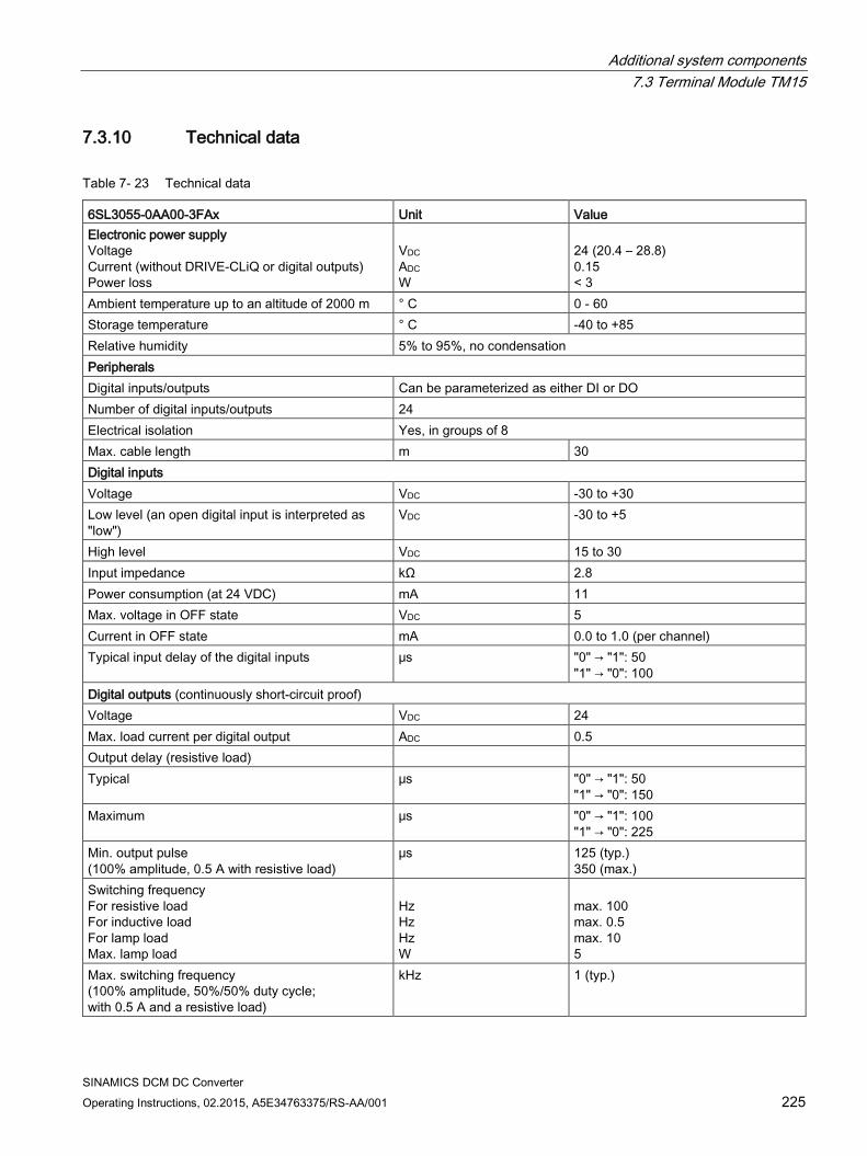
Additional system components 7.3 Terminal Module TM15
SINAMICS DCM DC Converter Operating Instructions, 02.2015, A5E34763375/RS-AA/001 225
7.3.10 Technical data
Table 7- 23 Technical data
6SL3055-0AA00-3FAx Unit Value Electronic power supply Voltage Current (without DRIVE-CLiQ or digital outputs) Power loss
VDC ADC W
24 (20.4 – 28.8) 0.15 < 3
Ambient temperature up to an altitude of 2000 m ° C 0 - 60 Storage temperature ° C -40 to +85 Relative humidity 5% to 95%, no condensation Peripherals Digital inputs/outputs Can be parameterized as either DI or DO Number of digital inputs/outputs 24 Electrical isolation Yes, in groups of 8 Max. cable length m 30 Digital inputs Voltage VDC -30 to +30 Low level (an open digital input is interpreted as "low")
VDC -30 to +5
High level VDC 15 to 30 Input impedance kΩ 2.8 Power consumption (at 24 VDC) mA 11 Max. voltage in OFF state VDC 5 Current in OFF state mA 0.0 to 1.0 (per channel) Typical input delay of the digital inputs μs "0" → "1": 50
"1" → "0": 100 Digital outputs (continuously short-circuit proof) Voltage VDC 24 Max. load current per digital output ADC 0.5 Output delay (resistive load) Typical μs "0" → "1": 50
"1" → "0": 150 Maximum μs "0" → "1": 100
"1" → "0": 225 Min. output pulse (100% amplitude, 0.5 A with resistive load)
μs 125 (typ.) 350 (max.)
Switching frequency For resistive load For inductive load For lamp load Max. lamp load
Hz Hz Hz W
max. 100 max. 0.5 max. 10 5
Max. switching frequency (100% amplitude, 50%/50% duty cycle; with 0.5 A and a resistive load)
kHz 1 (typ.)
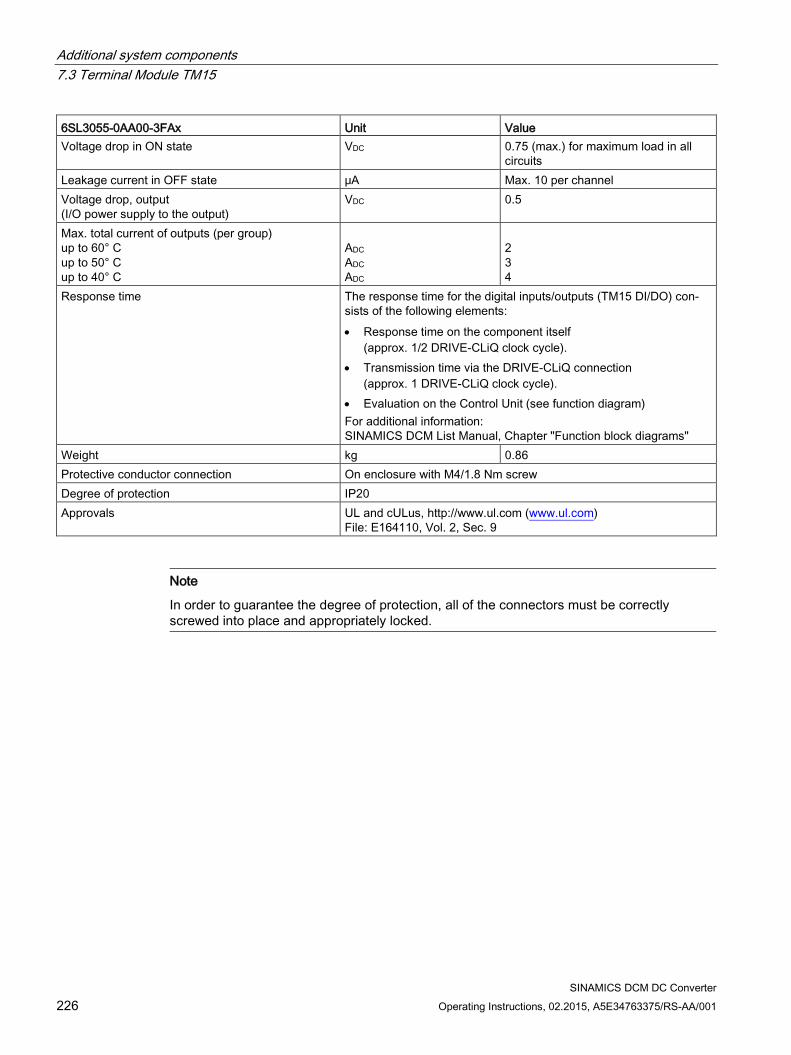
Additional system components 7.3 Terminal Module TM15
SINAMICS DCM DC Converter 226 Operating Instructions, 02.2015, A5E34763375/RS-AA/001
6SL3055-0AA00-3FAx Unit Value Voltage drop in ON state VDC 0.75 (max.) for maximum load in all
circuits Leakage current in OFF state μA Max. 10 per channel Voltage drop, output (I/O power supply to the output)
VDC 0.5
Max. total current of outputs (per group) up to 60° C up to 50° C up to 40° C
ADC ADC ADC
2 3 4
Response time The response time for the digital inputs/outputs (TM15 DI/DO) con-sists of the following elements: • Response time on the component itself
(approx. 1/2 DRIVE-CLiQ clock cycle). • Transmission time via the DRIVE-CLiQ connection
(approx. 1 DRIVE-CLiQ clock cycle). • Evaluation on the Control Unit (see function diagram) For additional information: SINAMICS DCM List Manual, Chapter "Function block diagrams"
Weight kg 0.86 Protective conductor connection On enclosure with M4/1.8 Nm screw Degree of protection IP20 Approvals UL and cULus, http://www.ul.com (www.ul.com)
File: E164110, Vol. 2, Sec. 9
Note
In order to guarantee the degree of protection, all of the connectors must be correctly screwed into place and appropriately locked.
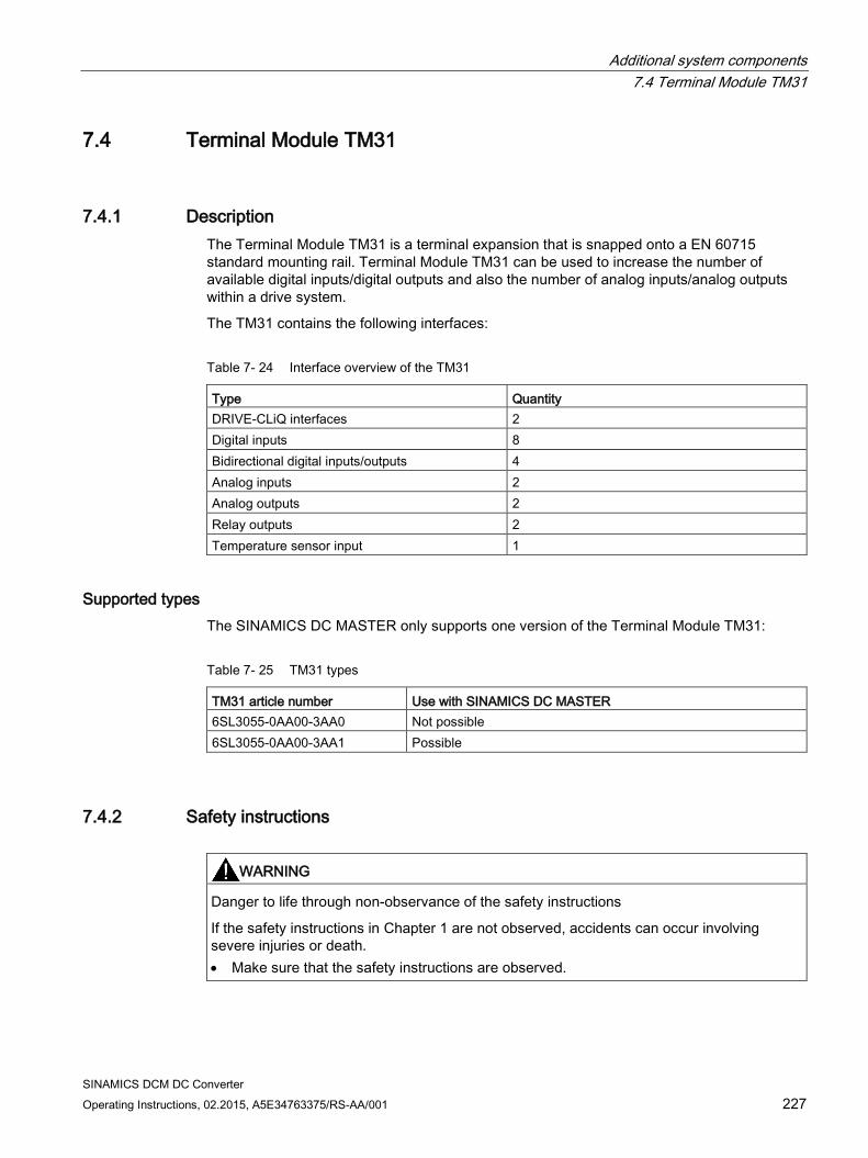
Additional system components 7.4 Terminal Module TM31
SINAMICS DCM DC Converter Operating Instructions, 02.2015, A5E34763375/RS-AA/001 227
7.4 Terminal Module TM31
7.4.1 Description The Terminal Module TM31 is a terminal expansion that is snapped onto a EN 60715 standard mounting rail. Terminal Module TM31 can be used to increase the number of available digital inputs/digital outputs and also the number of analog inputs/analog outputs within a drive system.
The TM31 contains the following interfaces:
Table 7- 24 Interface overview of the TM31
Type Quantity DRIVE-CLiQ interfaces 2 Digital inputs 8 Bidirectional digital inputs/outputs 4 Analog inputs 2 Analog outputs 2 Relay outputs 2 Temperature sensor input 1
Supported types The SINAMICS DC MASTER only supports one version of the Terminal Module TM31:
Table 7- 25 TM31 types
TM31 article number Use with SINAMICS DC MASTER 6SL3055-0AA00-3AA0 Not possible 6SL3055-0AA00-3AA1 Possible
7.4.2 Safety instructions
WARNING
Danger to life through non-observance of the safety instructions
If the safety instructions in Chapter 1 are not observed, accidents can occur involving severe injuries or death. • Make sure that the safety instructions are observed.
Additional system components 7.4 Terminal Module TM31
SINAMICS DCM DC Converter 228 Operating Instructions, 02.2015, A5E34763375/RS-AA/001
WARNING
Risk of fire through overheating if there are insufficient ventilation clearances
Inadequate ventilation clearances cause overheating with a risk for personnel due to smoke and fire. This can also result in more downtimes and reduced service lives of the Terminal Module. • For this reason, it is imperative that you maintain the 50 mm clearances above and
below the Terminal Module.
NOTICE
Device failure as a result of unshielded or incorrectly routed cables to temperature sensors
Unshielded or incorrectly routed cables to temperature sensors can result in interference being coupled into the signal processing electronics from the power side. This can result in significant disturbance of all signals (fault messages) up to failure of individual components (destruction of the devices). • Only use shielded cables as temperature sensor cables. • If temperature sensor cables are routed together with the motor cable, use separately
shielded cables twisted in pairs. • Connect the cable shield at both ends to ground potential over a large surface area.
NOTICE
Damage through the use of incorrect DRIVE-CLiQ cables
Damage or malfunctions can occur on the devices or system when incorrect or unreleased DRIVE-CLiQ cables are used. • Only use suitable DRIVE-CLiQ cables that have been released by Siemens for the
respective application.
Note
Malfunctions due to polluted DRIVE-CLiQ interfaces
Malfunctions can occur in the system through the use of polluted DRIVE-CLiQ interfaces. • Cover unused DRIVE-CLiQ interfaces with the supplied blanking covers.
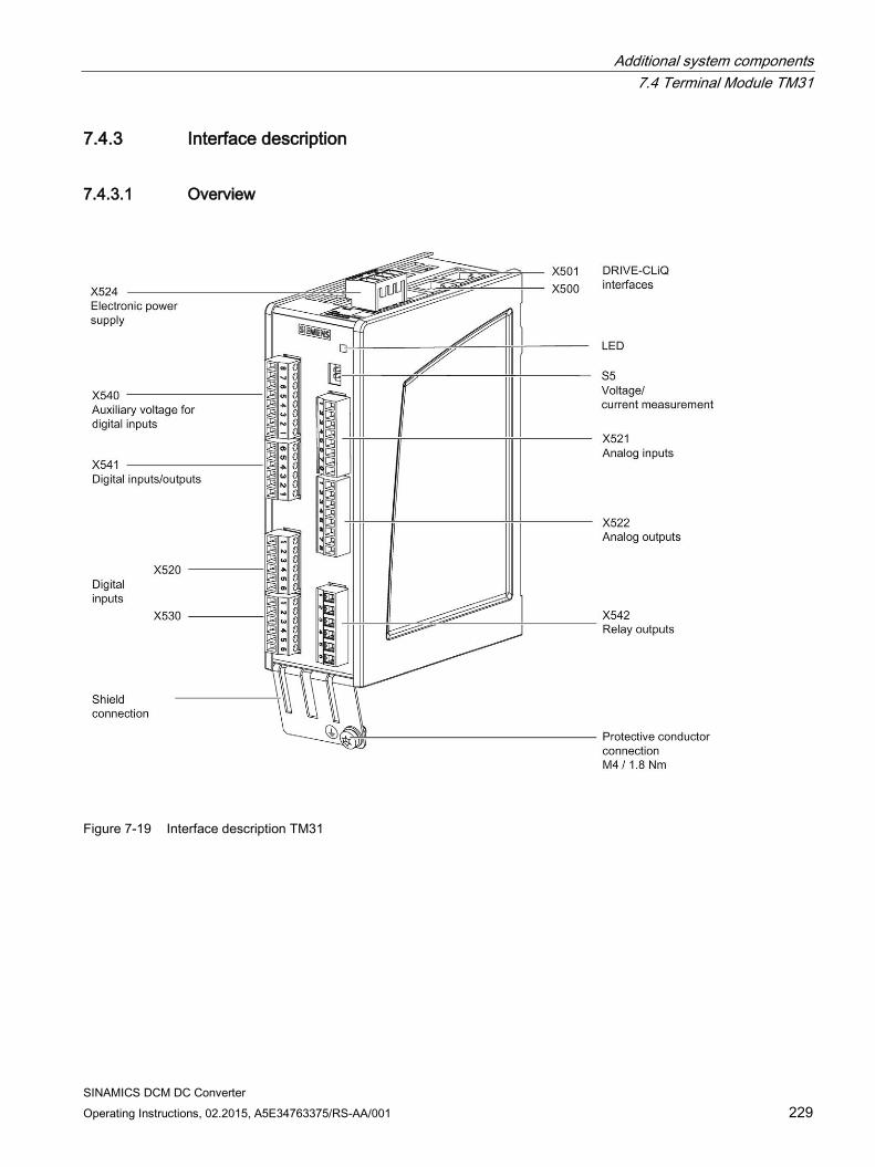
Additional system components 7.4 Terminal Module TM31
SINAMICS DCM DC Converter Operating Instructions, 02.2015, A5E34763375/RS-AA/001 229
7.4.3 Interface description
7.4.3.1 Overview
Figure 7-19 Interface description TM31
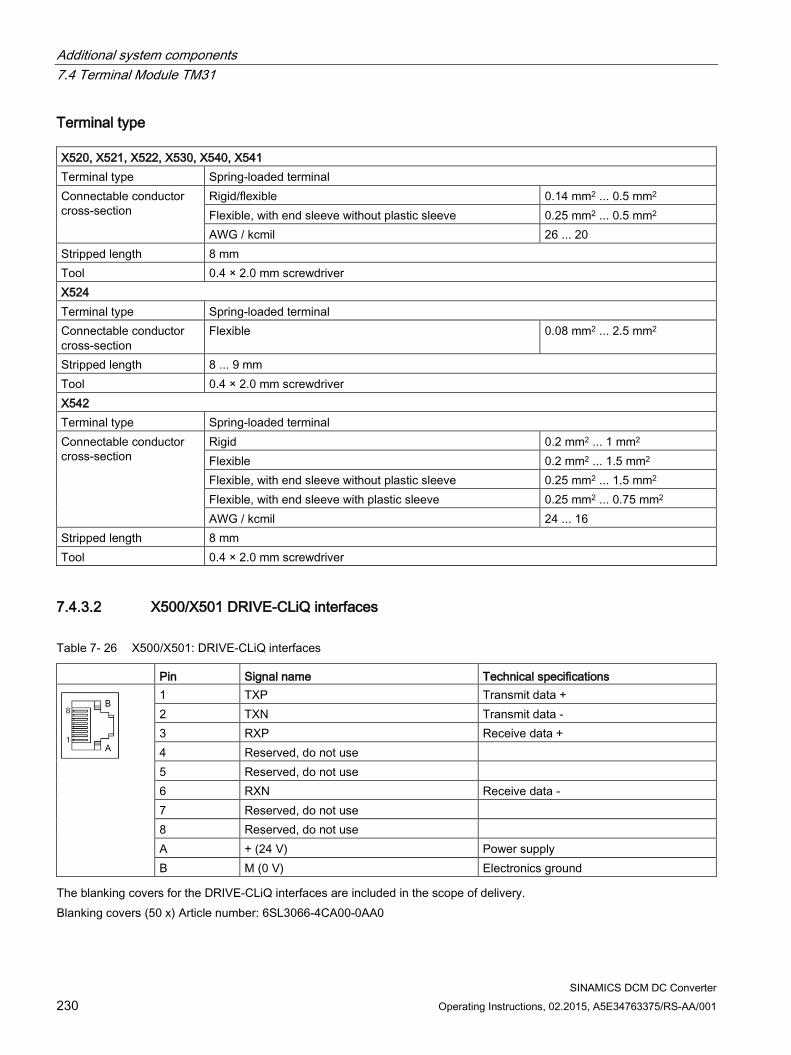
Additional system components 7.4 Terminal Module TM31
SINAMICS DCM DC Converter 230 Operating Instructions, 02.2015, A5E34763375/RS-AA/001
Terminal type X520, X521, X522, X530, X540, X541 Terminal type Spring-loaded terminal Connectable conductor cross-section
Rigid/flexible 0.14 mm2 ... 0.5 mm2 Flexible, with end sleeve without plastic sleeve 0.25 mm2 ... 0.5 mm2 AWG / kcmil 26 ... 20
Stripped length 8 mm Tool 0.4 × 2.0 mm screwdriver X524 Terminal type Spring-loaded terminal Connectable conductor cross-section
Flexible 0.08 mm2 ... 2.5 mm2
Stripped length 8 ... 9 mm Tool 0.4 × 2.0 mm screwdriver X542 Terminal type Spring-loaded terminal Connectable conductor cross-section
Rigid 0.2 mm2 ... 1 mm2 Flexible 0.2 mm2 ... 1.5 mm2 Flexible, with end sleeve without plastic sleeve 0.25 mm2 ... 1.5 mm2 Flexible, with end sleeve with plastic sleeve 0.25 mm2 ... 0.75 mm2 AWG / kcmil 24 ... 16
Stripped length 8 mm Tool 0.4 × 2.0 mm screwdriver
7.4.3.2 X500/X501 DRIVE-CLiQ interfaces
Table 7- 26 X500/X501: DRIVE-CLiQ interfaces
Pin Signal name Technical specifications
1 TXP Transmit data + 2 TXN Transmit data - 3 RXP Receive data + 4 Reserved, do not use 5 Reserved, do not use 6 RXN Receive data - 7 Reserved, do not use 8 Reserved, do not use A + (24 V) Power supply B M (0 V) Electronics ground
The blanking covers for the DRIVE-CLiQ interfaces are included in the scope of delivery. Blanking covers (50 x) Article number: 6SL3066-4CA00-0AA0
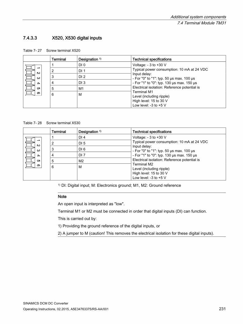
Additional system components 7.4 Terminal Module TM31
SINAMICS DCM DC Converter Operating Instructions, 02.2015, A5E34763375/RS-AA/001 231
7.4.3.3 X520, X530 digital inputs
Table 7- 27 Screw terminal X520
Terminal Designation 1) Technical specifications
1 DI 0 Voltage: - 3 to +30 V Typical power consumption: 10 mA at 24 VDC Input delay: - For "0" to "1": typ. 50 µs max. 100 µs - For "1" to "0": typ. 130 µs max. 150 µs Electrical isolation: Reference potential is Terminal M1 Level (including ripple) High level: 15 to 30 V Low level: -3 to +5 V
2 DI 1 3 DI 2 4 DI 3 5 M1 6 M
Table 7- 28 Screw terminal X530
Terminal Designation 1) Technical specifications
1 DI 4 Voltage: - 3 to +30 V Typical power consumption: 10 mA at 24 VDC Input delay: - For "0" to "1": typ. 50 µs max. 100 µs - For "1" to "0": typ. 130 µs max. 150 µs Electrical isolation: Reference potential is Terminal M2 Level (including ripple) High level: 15 to 30 V Low level: -3 to +5 V
2 DI 5 3 DI 6 4 DI 7 5 M2 6 M
1) DI: Digital input; M: Electronics ground; M1, M2: Ground reference
Note
An open input is interpreted as "low".
Terminal M1 or M2 must be connected in order that digital inputs (DI) can function.
This is carried out by:
1) Providing the ground reference of the digital inputs, or
2) A jumper to M (caution! This removes the electrical isolation for these digital inputs).
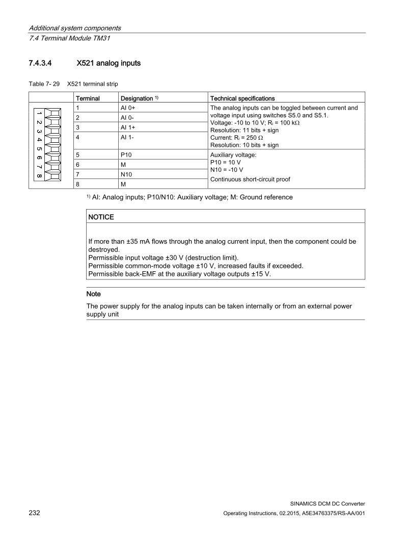
Additional system components 7.4 Terminal Module TM31
SINAMICS DCM DC Converter 232 Operating Instructions, 02.2015, A5E34763375/RS-AA/001
7.4.3.4 X521 analog inputs
Table 7- 29 X521 terminal strip
Terminal Designation 1) Technical specifications
1 AI 0+ The analog inputs can be toggled between current and voltage input using switches S5.0 and S5.1. Voltage: -10 to 10 V; Ri = 100 kΩ Resolution: 11 bits + sign Current: Ri = 250 Ω Resolution: 10 bits + sign
2 AI 0- 3 AI 1+ 4 AI 1-
5 P10 Auxiliary voltage: P10 = 10 V N10 = -10 V Continuous short-circuit proof
6 M 7 N10 8 M
1) AI: Analog inputs; P10/N10: Auxiliary voltage; M: Ground reference
NOTICE
If more than ±35 mA flows through the analog current input, then the component could be destroyed. Permissible input voltage ±30 V (destruction limit). Permissible common-mode voltage ±10 V, increased faults if exceeded. Permissible back-EMF at the auxiliary voltage outputs ±15 V.
Note
The power supply for the analog inputs can be taken internally or from an external power supply unit
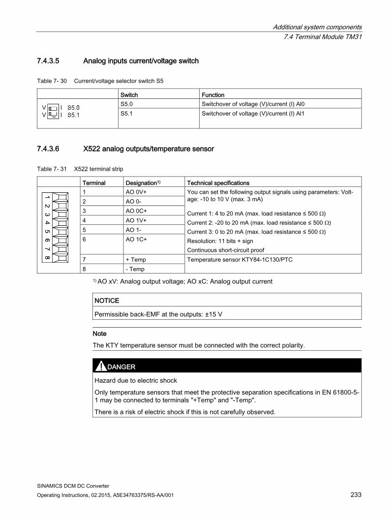
Additional system components 7.4 Terminal Module TM31
SINAMICS DCM DC Converter Operating Instructions, 02.2015, A5E34763375/RS-AA/001 233
7.4.3.5 Analog inputs current/voltage switch
Table 7- 30 Current/voltage selector switch S5
Switch Function
S5.0 Switchover of voltage (V)/current (I) Al0 S5.1 Switchover of voltage (V)/current (I) Al1
7.4.3.6 X522 analog outputs/temperature sensor
Table 7- 31 X522 terminal strip
Terminal Designation1) Technical specifications
1 AO 0V+ You can set the following output signals using parameters: Volt-age: -10 to 10 V (max. 3 mA) Current 1: 4 to 20 mA (max. load resistance ≤ 500 Ω) Current 2: -20 to 20 mA (max. load resistance ≤ 500 Ω) Current 3: 0 to 20 mA (max. load resistance ≤ 500 Ω) Resolution: 11 bits + sign Continuous short-circuit proof
2 AO 0- 3 AO 0C+ 4 AO 1V+ 5 AO 1- 6 AO 1C+
7 + Temp Temperature sensor KTY84-1C130/PTC 8 - Temp
1) AO xV: Analog output voltage; AO xC: Analog output current
NOTICE
Permissible back-EMF at the outputs: ±15 V
Note
The KTY temperature sensor must be connected with the correct polarity.
DANGER
Hazard due to electric shock
Only temperature sensors that meet the protective separation specifications in EN 61800-5-1 may be connected to terminals "+Temp" and "-Temp".
There is a risk of electric shock if this is not carefully observed.
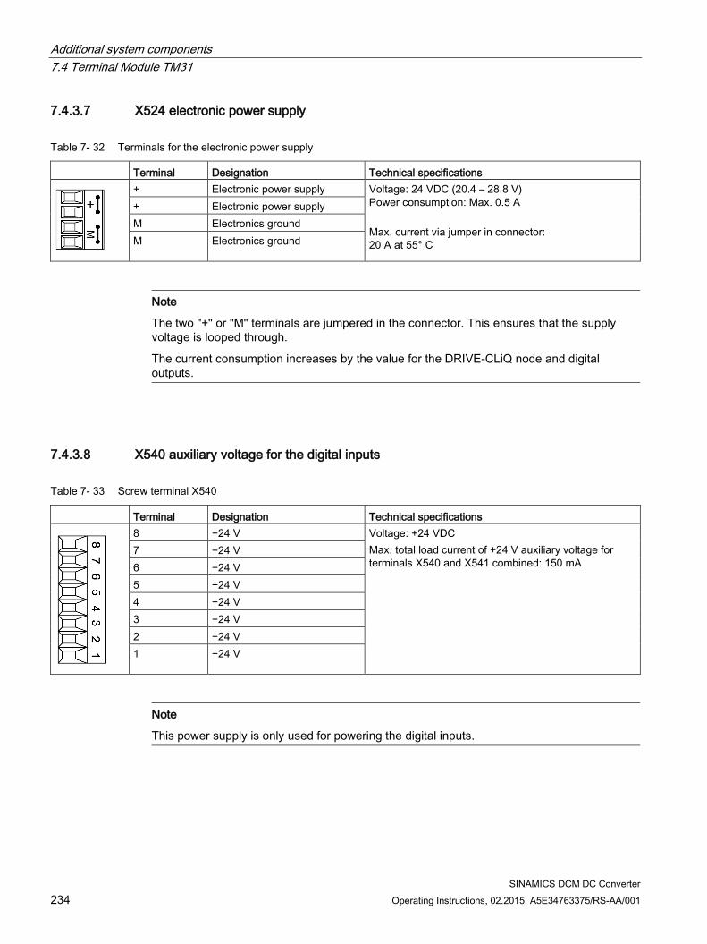
Additional system components 7.4 Terminal Module TM31
SINAMICS DCM DC Converter 234 Operating Instructions, 02.2015, A5E34763375/RS-AA/001
7.4.3.7 X524 electronic power supply
Table 7- 32 Terminals for the electronic power supply
Terminal Designation Technical specifications
+ Electronic power supply Voltage: 24 VDC (20.4 – 28.8 V) Power consumption: Max. 0.5 A Max. current via jumper in connector: 20 A at 55° C
+ Electronic power supply M Electronics ground M Electronics ground
Note
The two "+" or "M" terminals are jumpered in the connector. This ensures that the supply voltage is looped through.
The current consumption increases by the value for the DRIVE-CLiQ node and digital outputs.
7.4.3.8 X540 auxiliary voltage for the digital inputs
Table 7- 33 Screw terminal X540
Terminal Designation Technical specifications
8 +24 V Voltage: +24 VDC Max. total load current of +24 V auxiliary voltage for terminals X540 and X541 combined: 150 mA
7 +24 V 6 +24 V 5 +24 V 4 +24 V 3 +24 V 2 +24 V 1 +24 V
Note
This power supply is only used for powering the digital inputs.
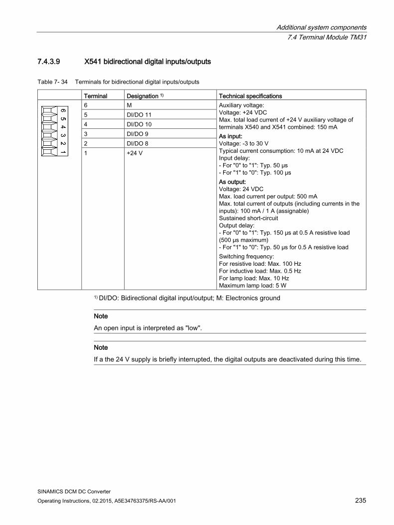
Additional system components 7.4 Terminal Module TM31
SINAMICS DCM DC Converter Operating Instructions, 02.2015, A5E34763375/RS-AA/001 235
7.4.3.9 X541 bidirectional digital inputs/outputs
Table 7- 34 Terminals for bidirectional digital inputs/outputs
Terminal Designation 1) Technical specifications
6 M Auxiliary voltage: Voltage: +24 VDC Max. total load current of +24 V auxiliary voltage of terminals X540 and X541 combined: 150 mA As input: Voltage: -3 to 30 V Typical current consumption: 10 mA at 24 VDC Input delay: - For "0" to "1": Typ. 50 μs - For "1" to "0": Typ. 100 μs As output: Voltage: 24 VDC Max. load current per output: 500 mA Max. total current of outputs (including currents in the inputs): 100 mA / 1 A (assignable) Sustained short-circuit Output delay: - For "0" to "1": Typ. 150 μs at 0.5 A resistive load (500 μs maximum) - For "1" to "0": Typ. 50 μs for 0.5 A resistive load Switching frequency: For resistive load: Max. 100 Hz For inductive load: Max. 0.5 Hz For lamp load: Max. 10 Hz Maximum lamp load: 5 W
5 DI/DO 11 4 DI/DO 10 3 DI/DO 9 2 DI/DO 8 1 +24 V
1) DI/DO: Bidirectional digital input/output; M: Electronics ground
Note
An open input is interpreted as "low".
Note
If a the 24 V supply is briefly interrupted, the digital outputs are deactivated during this time.
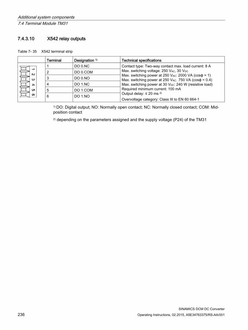
Additional system components 7.4 Terminal Module TM31
SINAMICS DCM DC Converter 236 Operating Instructions, 02.2015, A5E34763375/RS-AA/001
7.4.3.10 X542 relay outputs
Table 7- 35 X542 terminal strip
Terminal Designation 1) Technical specifications
1 DO 0.NC Contact type: Two-way contact max. load current: 8 A Max. switching voltage: 250 VAC, 30 VDC Max. switching power at 250 VAC: 2000 VA (cosϕ = 1) Max. switching power at 250 VAC: 750 VA (cosϕ = 0.4) Max. switching power at 30 VDC: 240 W (resistive load) Required minimum current: 100 mA Output delay: ≤ 20 ms 2) Overvoltage category: Class III to EN 60 664-1
2 DO 0.COM 3 DO 0.NO 4 DO 1.NC 5 DO 1.COM 6 DO 1.NO
1) DO: Digital output; NO: Normally open contact; NC: Normally closed contact; COM: Mid-position contact 2) depending on the parameters assigned and the supply voltage (P24) of the TM31
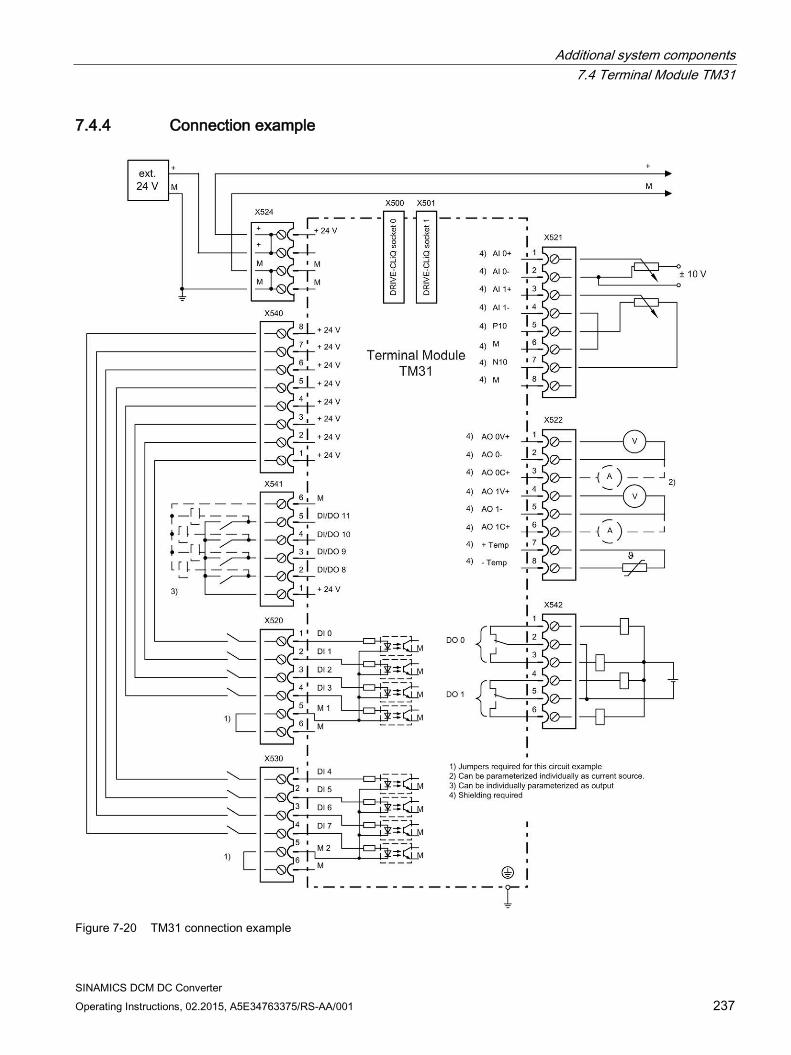
Additional system components 7.4 Terminal Module TM31
SINAMICS DCM DC Converter Operating Instructions, 02.2015, A5E34763375/RS-AA/001 237
7.4.4 Connection example
Figure 7-20 TM31 connection example
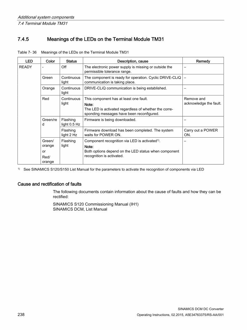
Additional system components 7.4 Terminal Module TM31
SINAMICS DCM DC Converter 238 Operating Instructions, 02.2015, A5E34763375/RS-AA/001
7.4.5 Meanings of the LEDs on the Terminal Module TM31
Table 7- 36 Meanings of the LEDs on the Terminal Module TM31
LED Color Status Description, cause Remedy READY - Off The electronic power supply is missing or outside the
permissible tolerance range. –
Green Continuous light
The component is ready for operation. Cyclic DRIVE-CLiQ communication is taking place.
–
Orange Continuous light
DRIVE-CLiQ communication is being established. –
Red Continuous light
This component has at least one fault. Note: The LED is activated regardless of whether the corre-sponding messages have been reconfigured.
Remove and acknowledge the fault.
Green/red
Flashing light 0.5 Hz
Firmware is being downloaded. –
Flashing light 2 Hz
Firmware download has been completed. The system waits for POWER ON.
Carry out a POWER ON.
Green/ orange or Red/ orange
Flashing light
Component recognition via LED is activated1). Note: Both options depend on the LED status when component recognition is activated.
–
1) See SINAMICS S120/S150 List Manual for the parameters to activate the recognition of components via LED
Cause and rectification of faults The following documents contain information about the cause of faults and how they can be rectified:
SINAMICS S120 Commissioning Manual (IH1) SINAMICS DCM, List Manual
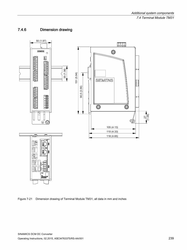
Additional system components 7.4 Terminal Module TM31
SINAMICS DCM DC Converter Operating Instructions, 02.2015, A5E34763375/RS-AA/001 239
7.4.6 Dimension drawing
Figure 7-21 Dimension drawing of Terminal Module TM31, all data in mm and inches

Additional system components 7.4 Terminal Module TM31
SINAMICS DCM DC Converter 240 Operating Instructions, 02.2015, A5E34763375/RS-AA/001
7.4.7 Installation
Installation 1. Tilt the component backwards slightly and snap it onto the mounting rail using the hook.
2. Push the component towards the mounting rail until you hear the mounting slide at the rear latch into position.
3. You can now move the component to the left or right along the mounting rail, until it reaches its final position.
Disassembly 1. The lug on the mounting slide must first be pushed down to release the interlock from the
mounting rail.
2. The component can now be tilted towards the front and removed from the mounting rail.
① Mounting slide ② Standard mounting rail Figure 7-22 Removing from a mounting rail

Additional system components 7.4 Terminal Module TM31
SINAMICS DCM DC Converter Operating Instructions, 02.2015, A5E34763375/RS-AA/001 241
7.4.8 Protective conductor connection and shield support It is always advisable to shield the digital input/output wiring.
The following diagrams show typical Weidmüller shield connection terminals for the shield supports.
① Protective conductor connection M4 / 1.8 Nm ② Shield connection terminal, Weidmüller company, type: KLBÜ CO1, order number:
1753311001
Figure 7-23 Shield supports
NOTICE
Damage or faulty operation due to incorrect shielding and impermissible cable lengths
If the correct shielding procedures and the permissible cable lengths are not observed, the machine can be damaged or may malfunction. • Only use shielded cables. • Do not exceed the cable lengths stated in the technical data.
Note
Only use screws with a permissible mounting depth of 4 - 6 mm.
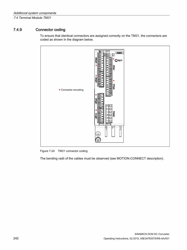
Additional system components 7.4 Terminal Module TM31
SINAMICS DCM DC Converter 242 Operating Instructions, 02.2015, A5E34763375/RS-AA/001
7.4.9 Connector coding To ensure that identical connectors are assigned correctly on the TM31, the connectors are coded as shown in the diagram below.
Figure 7-24 TM31 connector coding
The bending radii of the cables must be observed (see MOTION-CONNECT description).
Additional system components 7.4 Terminal Module TM31
SINAMICS DCM DC Converter Operating Instructions, 02.2015, A5E34763375/RS-AA/001 243
7.4.10 Technical data
Table 7- 37 Technical data
Unit Value Electronic power supply Voltage Current (without DRIVE-CLiQ or digital outputs) Power loss
VDC ADC W
24 DC (20.4 – 28.8) 0.5 <10
PE/ground connection On enclosure with M4/1.8 Nm screw Response time The response time for the digital inputs/outputs and the analog inputs/outputs
consists of the following elements: • Response time on the component itself (approx. 1/2 DRIVE-CLiQ clock cy-
cle). • Transmission time via the DRIVE-CLiQ connection (approx. 1 DRIVE-CLiQ
clock cycle) • Evaluation on the Control Unit (see function diagram) Further information: SINAMICS DCM List Manual, Chapter "Function diagrams"
Weight kg 1 Degree of protection IP20
Note
In order to guarantee the degree of protection, all of the connectors must be correctly screwed into place and appropriately locked.
Additional system components 7.5 Terminal Module TM150
SINAMICS DCM DC Converter 244 Operating Instructions, 02.2015, A5E34763375/RS-AA/001
7.5 Terminal Module TM150
7.5.1 Description The terminal module TM150 is a DRIVE-CLiQ component for temperature evaluation. The temperature is measured in a temperature range from -99 °C to +250 °C for the following temperature sensors:
PT100 (with monitoring for wire breakage and short-circuit)
PT1000 (with monitoring for wire breakage and short-circuit)
KTY84 (with monitoring for wire breakage and short-circuit)
PTC (with short-circuit monitoring)
Bimetallic NC contact (without monitoring)
For the temperature sensor inputs, for each terminal block the evaluation can be parameterized for 1x2-wire, 2x2-wire, 3-wire or 4-wire. There is no galvanic isolation in the TM150.
The TM150 is mounted in the control cabinet and can be snapped on to a standard mounting rail (EN 60715).
The TM150 contains the following interfaces:
Table 7- 38 Overview of the TM150 interfaces
Type Quantity DRIVE-CLiQ interfaces 2 Temperature sensor inputs 6/12 Electronics power supply 1
7.5.2 Safety instructions
WARNING
Danger to life through non-observance of the safety instructions
If the safety instructions in Chapter 1 are not observed, accidents can occur involving severe injuries or death. • Make sure that the safety instructions are observed.
Additional system components 7.5 Terminal Module TM150
SINAMICS DCM DC Converter Operating Instructions, 02.2015, A5E34763375/RS-AA/001 245
WARNING
Risk of fire through overheating if there are insufficient ventilation clearances
Inadequate ventilation clearances cause overheating with a risk for personnel due to smoke and fire. This can also result in more downtimes and reduced service lives of the Terminal Module. • For this reason, it is imperative that you maintain the 50 mm clearances above and
below the Terminal Module.
NOTICE
Device failure as a result of unshielded or incorrectly routed cables to temperature sensors
Unshielded or incorrectly routed cables to temperature sensors can result in interference being coupled into the signal processing electronics from the power side. This can result in significant disturbance of all signals (fault messages) up to failure of individual components (destruction of the devices). • Only use shielded cables as temperature sensor cables. • If temperature sensor cables are routed together with the motor cable, use separately
shielded cables twisted in pairs. • Connect the cable shield at both ends to ground potential over a large surface area.
NOTICE
Damage through the use of incorrect DRIVE-CLiQ cables
Damage or malfunctions can occur on the devices or system when incorrect or unreleased DRIVE-CLiQ cables are used. • Only use suitable DRIVE-CLiQ cables that have been released by Siemens for the
respective application.
Note
Malfunctions due to polluted DRIVE-CLiQ interfaces
Malfunctions can occur in the system through the use of polluted DRIVE-CLiQ interfaces. • Cover unused DRIVE-CLiQ interfaces with the supplied blanking covers.
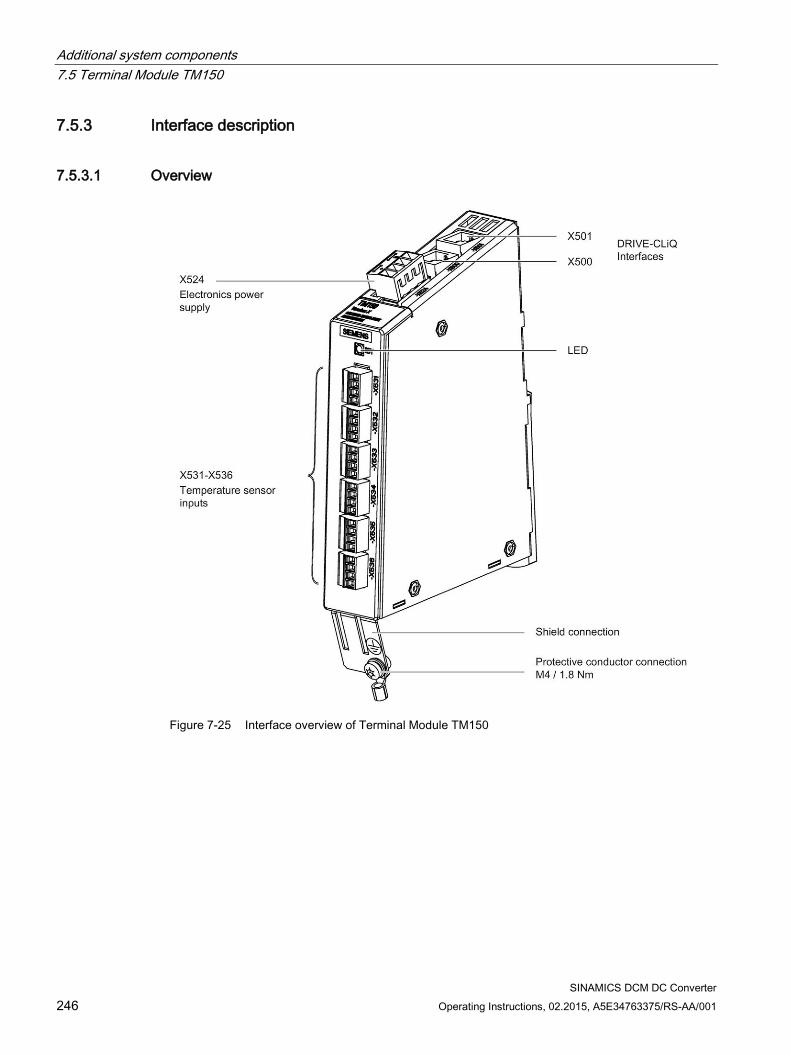
Additional system components 7.5 Terminal Module TM150
SINAMICS DCM DC Converter 246 Operating Instructions, 02.2015, A5E34763375/RS-AA/001
7.5.3 Interface description
7.5.3.1 Overview
Figure 7-25 Interface overview of Terminal Module TM150
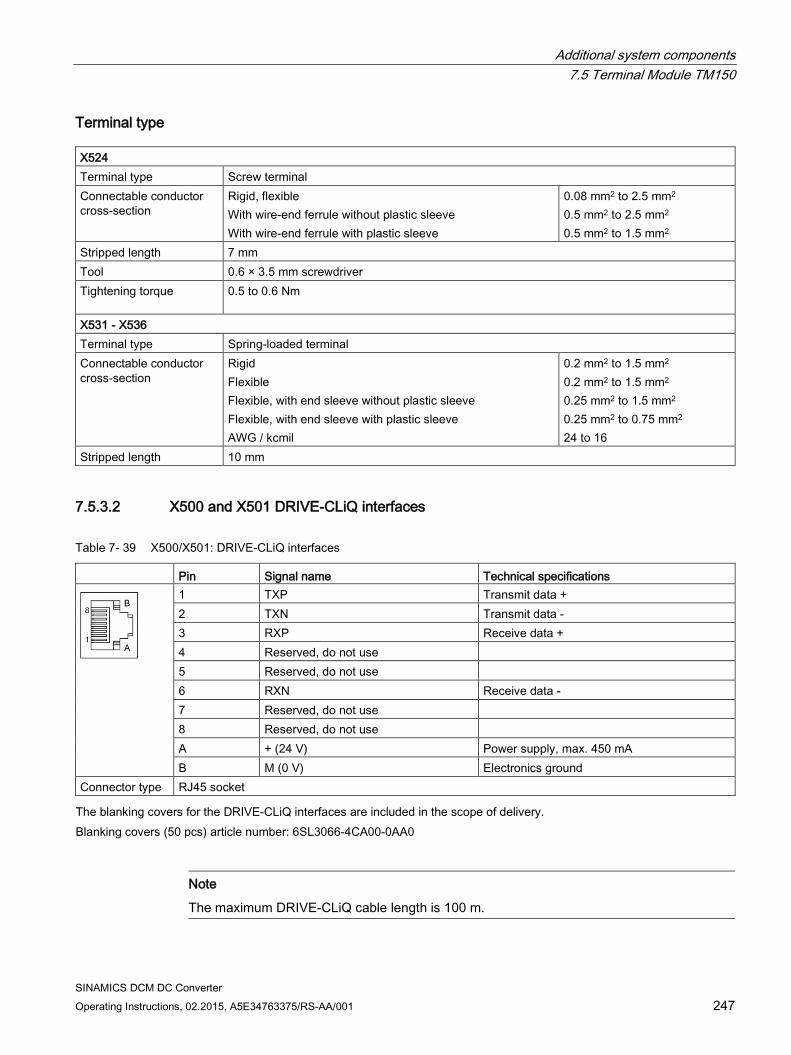
Additional system components 7.5 Terminal Module TM150
SINAMICS DCM DC Converter Operating Instructions, 02.2015, A5E34763375/RS-AA/001 247
Terminal type X524 Terminal type Screw terminal Connectable conductor cross-section
Rigid, flexible With wire-end ferrule without plastic sleeve With wire-end ferrule with plastic sleeve
0.08 mm2 to 2.5 mm2 0.5 mm2 to 2.5 mm2 0.5 mm2 to 1.5 mm2
Stripped length 7 mm Tool 0.6 × 3.5 mm screwdriver Tightening torque 0.5 to 0.6 Nm
X531 - X536 Terminal type Spring-loaded terminal Connectable conductor cross-section
Rigid Flexible Flexible, with end sleeve without plastic sleeve Flexible, with end sleeve with plastic sleeve AWG / kcmil
0.2 mm2 to 1.5 mm2 0.2 mm2 to 1.5 mm2 0.25 mm2 to 1.5 mm2 0.25 mm2 to 0.75 mm2 24 to 16
Stripped length 10 mm
7.5.3.2 X500 and X501 DRIVE-CLiQ interfaces
Table 7- 39 X500/X501: DRIVE-CLiQ interfaces
Pin Signal name Technical specifications
1 TXP Transmit data + 2 TXN Transmit data - 3 RXP Receive data + 4 Reserved, do not use 5 Reserved, do not use 6 RXN Receive data - 7 Reserved, do not use 8 Reserved, do not use A + (24 V) Power supply, max. 450 mA B M (0 V) Electronics ground
Connector type RJ45 socket The blanking covers for the DRIVE-CLiQ interfaces are included in the scope of delivery.
Blanking covers (50 pcs) article number: 6SL3066-4CA00-0AA0
Note
The maximum DRIVE-CLiQ cable length is 100 m.
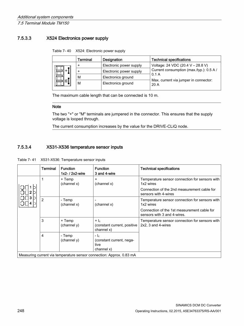
Additional system components 7.5 Terminal Module TM150
SINAMICS DCM DC Converter 248 Operating Instructions, 02.2015, A5E34763375/RS-AA/001
7.5.3.3 X524 Electronics power supply
Table 7- 40 X524: Electronic power supply
Terminal Designation Technical specifications
+ Electronic power supply Voltage: 24 VDC (20.4 V – 28.8 V) Current consumption (max./typ.): 0.5 A / 0.1 A Max. current via jumper in connector: 20 A
+ Electronic power supply M Electronics ground M Electronics ground
The maximum cable length that can be connected is 10 m.
Note
The two "+" or "M" terminals are jumpered in the connector. This ensures that the supply voltage is looped through.
The current consumption increases by the value for the DRIVE-CLiQ node.
7.5.3.4 X531-X536 temperature sensor inputs
Table 7- 41 X531-X536: Temperature sensor inputs
Terminal Function 1x2- / 2x2-wire
Function 3 and 4-wire
Technical specifications
1 + Temp (channel x)
+ (channel x)
Temperature sensor connection for sensors with 1x2 wires Connection of the 2nd measurement cable for sensors with 4-wires
2 - Temp (channel x)
- (channel x)
Temperature sensor connection for sensors with 1x2 wires Connection of the 1st measurement cable for sensors with 3 and 4-wires.
3 + Temp (channel y)
+ Ic (constant current, positive channel x)
Temperature sensor connection for sensors with 2x2, 3 and 4-wires
4 - Temp (channel y)
- Ic (constant current, nega-tive channel x)
Measuring current via temperature sensor connection: Approx. 0.83 mA
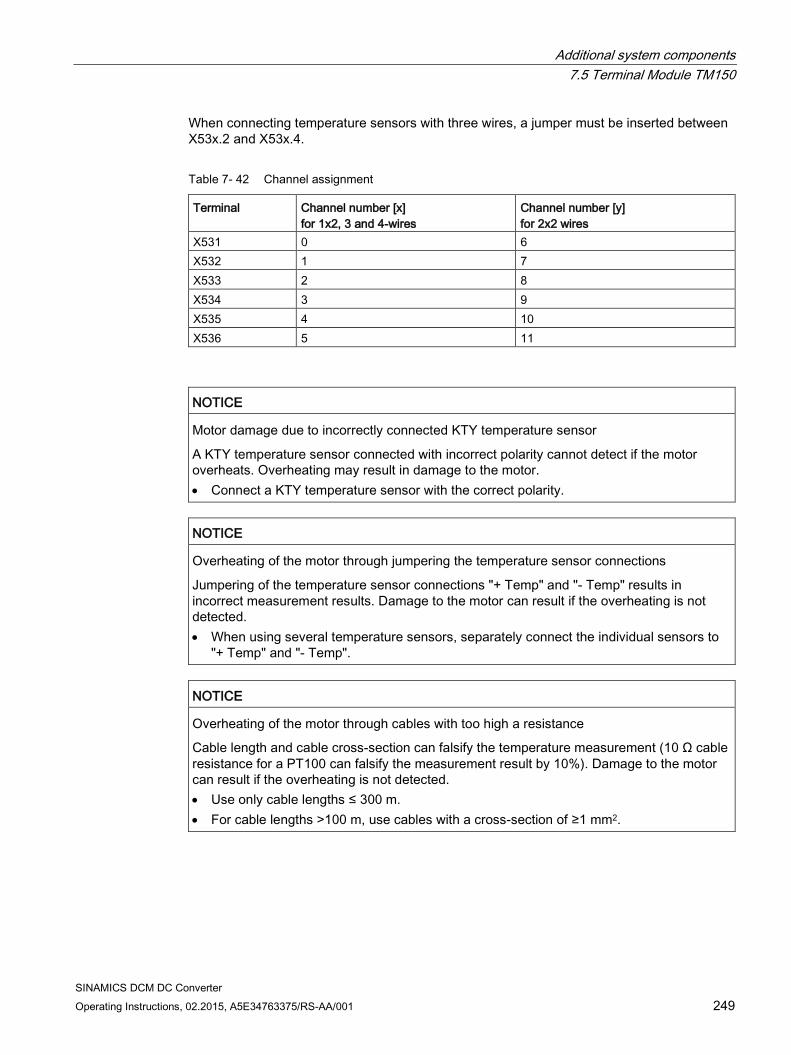
Additional system components 7.5 Terminal Module TM150
SINAMICS DCM DC Converter Operating Instructions, 02.2015, A5E34763375/RS-AA/001 249
When connecting temperature sensors with three wires, a jumper must be inserted between X53x.2 and X53x.4.
Table 7- 42 Channel assignment
Terminal Channel number [x] for 1x2, 3 and 4-wires
Channel number [y] for 2x2 wires
X531 0 6 X532 1 7 X533 2 8 X534 3 9 X535 4 10 X536 5 11
NOTICE
Motor damage due to incorrectly connected KTY temperature sensor
A KTY temperature sensor connected with incorrect polarity cannot detect if the motor overheats. Overheating may result in damage to the motor. • Connect a KTY temperature sensor with the correct polarity.
NOTICE
Overheating of the motor through jumpering the temperature sensor connections
Jumpering of the temperature sensor connections "+ Temp" and "- Temp" results in incorrect measurement results. Damage to the motor can result if the overheating is not detected. • When using several temperature sensors, separately connect the individual sensors to
"+ Temp" and "- Temp".
NOTICE
Overheating of the motor through cables with too high a resistance
Cable length and cable cross-section can falsify the temperature measurement (10 Ω cable resistance for a PT100 can falsify the measurement result by 10%). Damage to the motor can result if the overheating is not detected. • Use only cable lengths ≤ 300 m. • For cable lengths >100 m, use cables with a cross-section of ≥1 mm2.
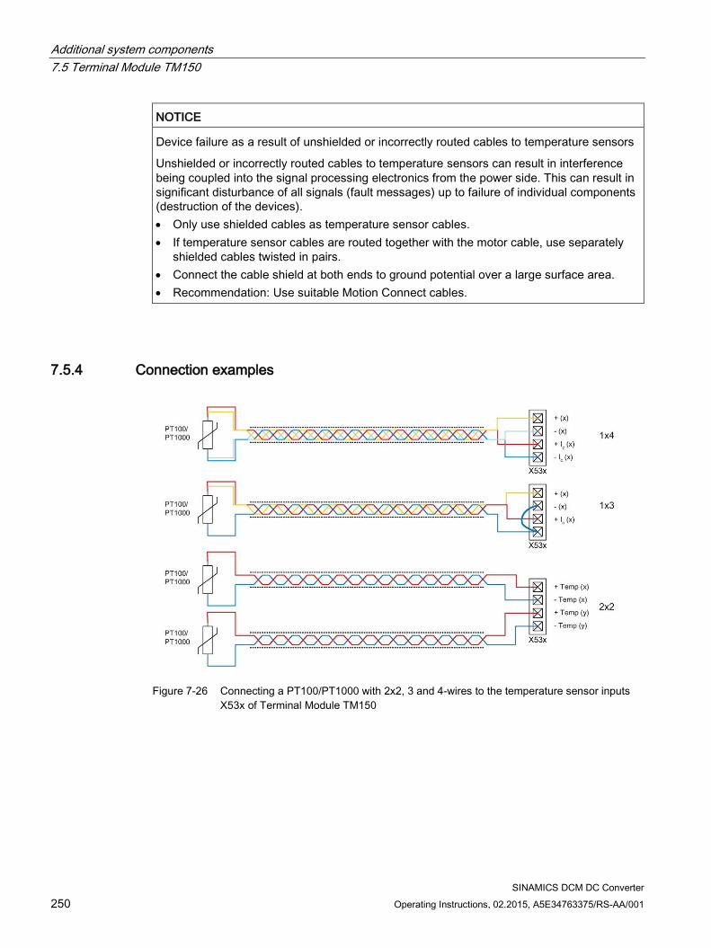
Additional system components 7.5 Terminal Module TM150
SINAMICS DCM DC Converter 250 Operating Instructions, 02.2015, A5E34763375/RS-AA/001
NOTICE
Device failure as a result of unshielded or incorrectly routed cables to temperature sensors
Unshielded or incorrectly routed cables to temperature sensors can result in interference being coupled into the signal processing electronics from the power side. This can result in significant disturbance of all signals (fault messages) up to failure of individual components (destruction of the devices). • Only use shielded cables as temperature sensor cables. • If temperature sensor cables are routed together with the motor cable, use separately
shielded cables twisted in pairs. • Connect the cable shield at both ends to ground potential over a large surface area. • Recommendation: Use suitable Motion Connect cables.
7.5.4 Connection examples
Figure 7-26 Connecting a PT100/PT1000 with 2x2, 3 and 4-wires to the temperature sensor inputs
X53x of Terminal Module TM150
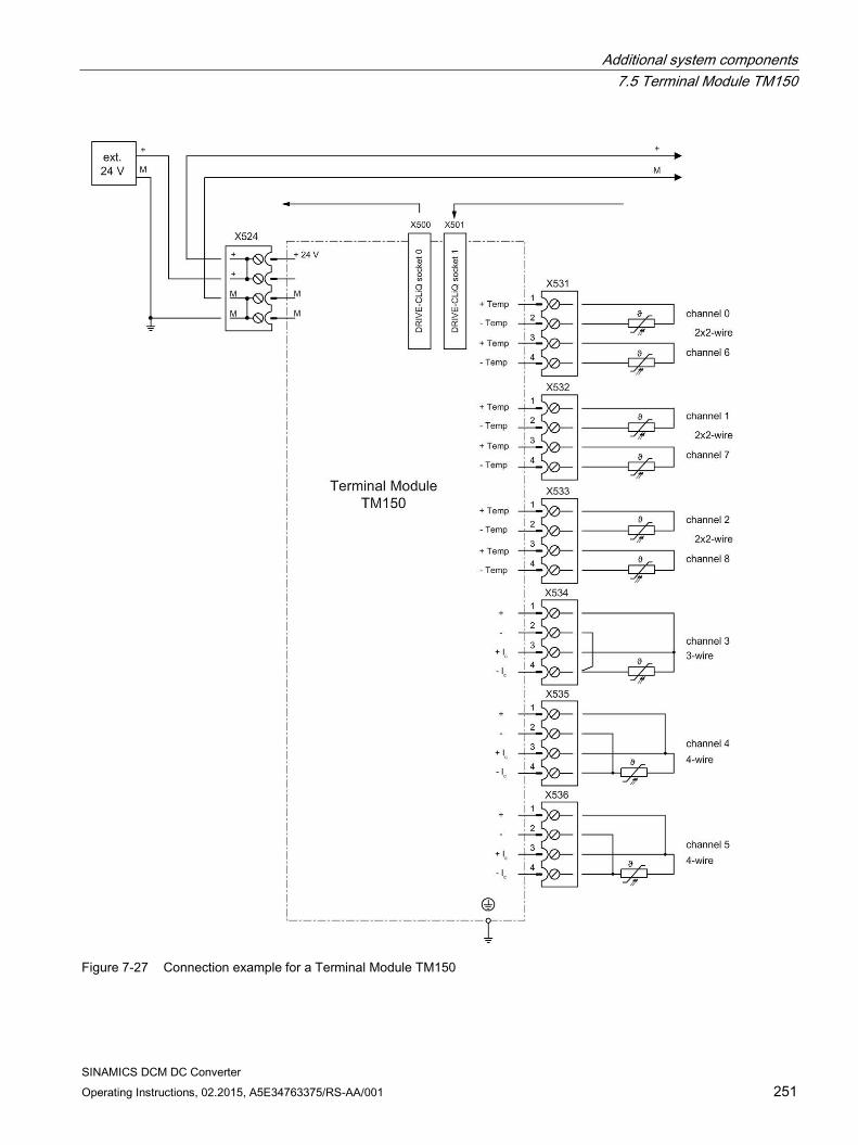
Additional system components 7.5 Terminal Module TM150
SINAMICS DCM DC Converter Operating Instructions, 02.2015, A5E34763375/RS-AA/001 251
Figure 7-27 Connection example for a Terminal Module TM150
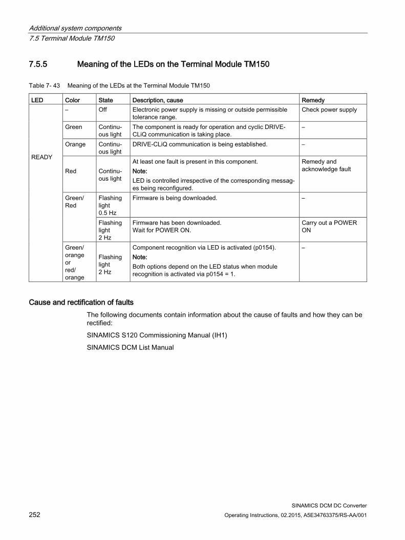
Additional system components 7.5 Terminal Module TM150
SINAMICS DCM DC Converter 252 Operating Instructions, 02.2015, A5E34763375/RS-AA/001
7.5.5 Meaning of the LEDs on the Terminal Module TM150
Table 7- 43 Meaning of the LEDs at the Terminal Module TM150
LED Color State Description, cause Remedy READY
– Off Electronic power supply is missing or outside permissible tolerance range.
Check power supply
Green Continu-ous light
The component is ready for operation and cyclic DRIVE-CLiQ communication is taking place.
–
Orange Continu-ous light
DRIVE-CLiQ communication is being established. –
Red
Continu-ous light
At least one fault is present in this component. Note: LED is controlled irrespective of the corresponding messag-es being reconfigured.
Remedy and acknowledge fault
Green/ Red
Flashing light 0.5 Hz
Firmware is being downloaded. –
Flashing light 2 Hz
Firmware has been downloaded. Wait for POWER ON.
Carry out a POWER ON
Green/ orange or red/ orange
Flashing light 2 Hz
Component recognition via LED is activated (p0154). Note: Both options depend on the LED status when module recognition is activated via p0154 = 1.
–
Cause and rectification of faults The following documents contain information about the cause of faults and how they can be rectified:
SINAMICS S120 Commissioning Manual (IH1)
SINAMICS DCM List Manual
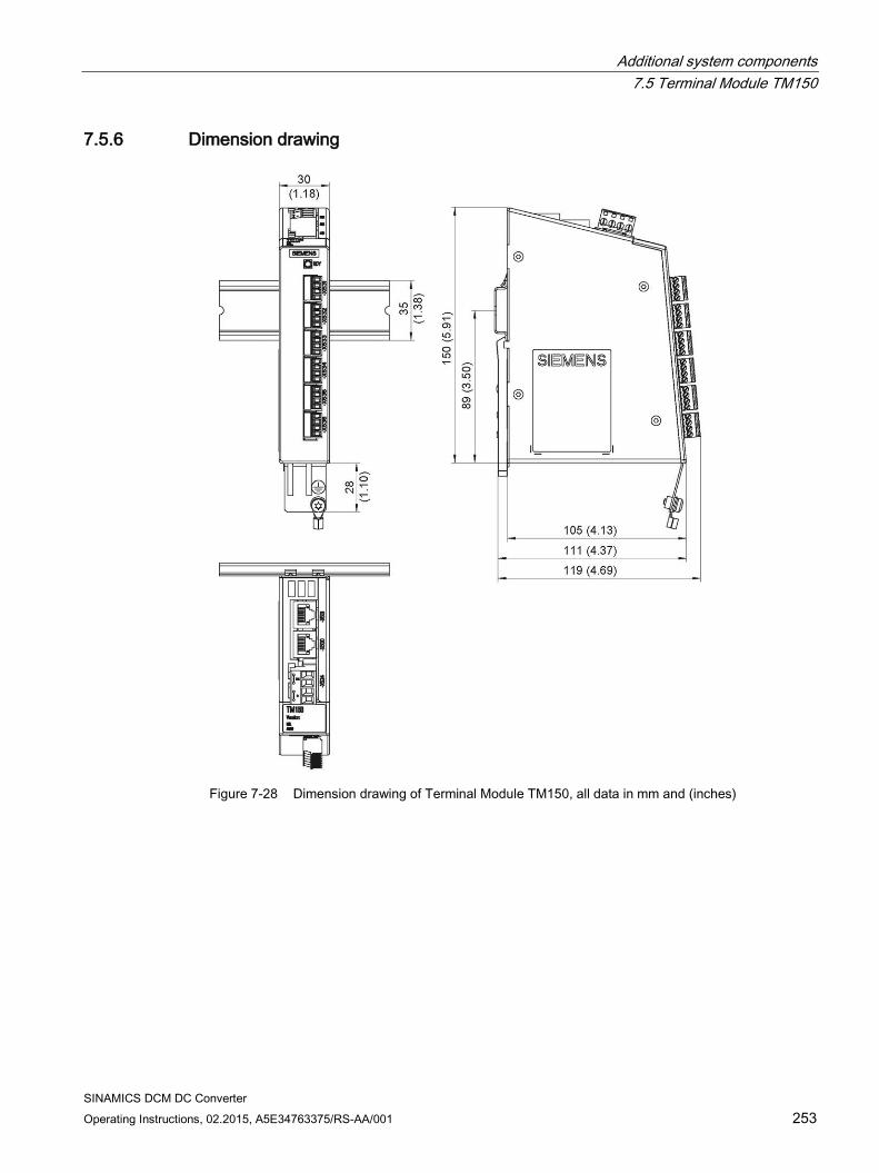
Additional system components 7.5 Terminal Module TM150
SINAMICS DCM DC Converter Operating Instructions, 02.2015, A5E34763375/RS-AA/001 253
7.5.6 Dimension drawing
Figure 7-28 Dimension drawing of Terminal Module TM150, all data in mm and (inches)
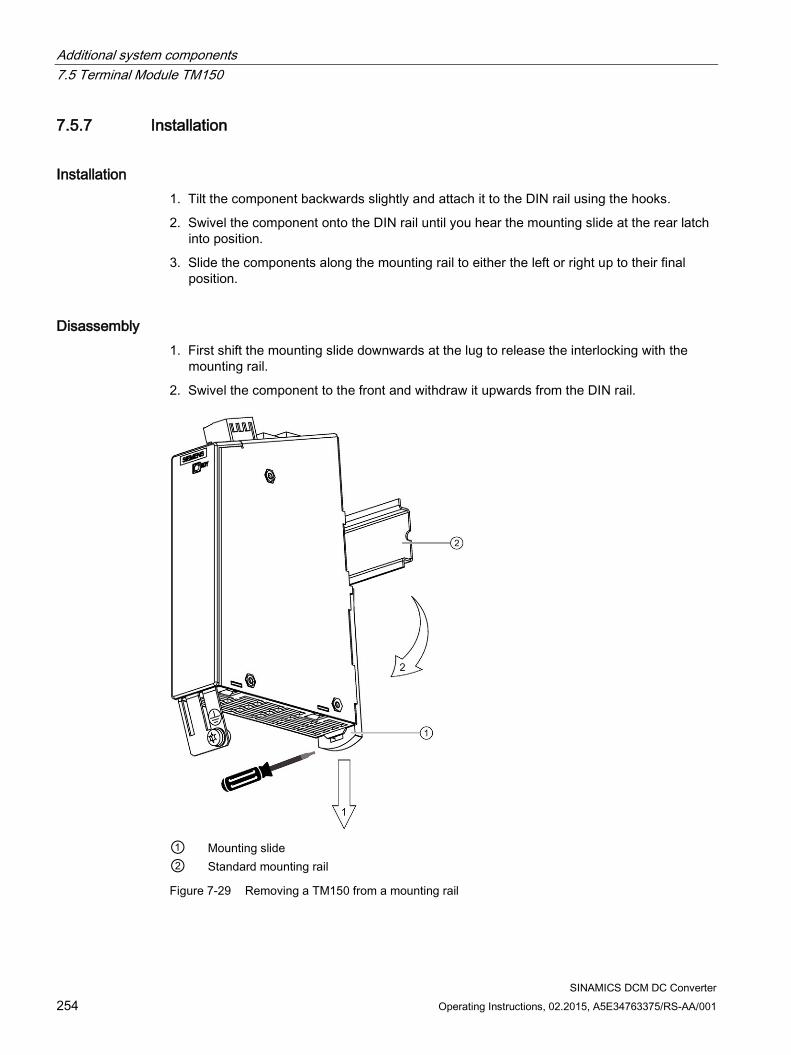
Additional system components 7.5 Terminal Module TM150
SINAMICS DCM DC Converter 254 Operating Instructions, 02.2015, A5E34763375/RS-AA/001
7.5.7 Installation
Installation 1. Tilt the component backwards slightly and attach it to the DIN rail using the hooks.
2. Swivel the component onto the DIN rail until you hear the mounting slide at the rear latch into position.
3. Slide the components along the mounting rail to either the left or right up to their final position.
Disassembly 1. First shift the mounting slide downwards at the lug to release the interlocking with the
mounting rail.
2. Swivel the component to the front and withdraw it upwards from the DIN rail.
① Mounting slide ② Standard mounting rail
Figure 7-29 Removing a TM150 from a mounting rail
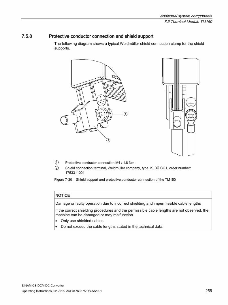
Additional system components 7.5 Terminal Module TM150
SINAMICS DCM DC Converter Operating Instructions, 02.2015, A5E34763375/RS-AA/001 255
7.5.8 Protective conductor connection and shield support The following diagram shows a typical Weidmüller shield connection clamp for the shield supports.
① Protective conductor connection M4 / 1.8 Nm ② Shield connection terminal, Weidmüller company, type: KLBÜ CO1, order number:
1753311001
Figure 7-30 Shield support and protective conductor connection of the TM150
NOTICE
Damage or faulty operation due to incorrect shielding and impermissible cable lengths
If the correct shielding procedures and the permissible cable lengths are not observed, the machine can be damaged or may malfunction. • Only use shielded cables. • Do not exceed the cable lengths stated in the technical data.
Additional system components 7.5 Terminal Module TM150
SINAMICS DCM DC Converter 256 Operating Instructions, 02.2015, A5E34763375/RS-AA/001
7.5.9 Technical data
Table 7- 44 Technical data
6SL3055-0AA00-3LA0 Unit Value Voltage Current (without DRIVE-CLiQ) Power loss
VDC ADC W
24 VDC (20.4 – 28.8) 0.07 1.6
PE/ground connection On enclosure with M4/1.8 Nm screw Weight kg 0.4 Degree of protection IP20
Note
In order to guarantee the degree of protection, all of the connectors must be correctly screwed into place and appropriately locked.
SINAMICS DCM DC Converter Operating Instructions, 02.2015, A5E34763375/RS-AA/001 257
Commissioning 8
WARNING
This unit is subject to hazardous voltage levels and contains dangerous rotating machine parts (fans). Failure to comply with these Operating Instructions can lead to death, serious physical injury, and material damage.
Dangerous voltage levels may be present at the signaling relays at the customer's site.
The units may be connected to a line supply with residual current operated circuit breaker if a universal current sensitive device is being used, which in the case of a ground fault, can also detect a DC component in the fault current. We recommend a residual current operated circuit breaker with an operating current ≥300 mA, which means that it is not suitable to protect personnel. If you have additional questions, please contact Technical Support.
Only qualified personnel who are familiar with all the safety instructions in this description, as well as the installation, operating, and maintenance instructions, should carry out work on this unit.
Perfect, safe, and reliable operation of this unit is conditional upon it having been transported, stored, mounted, and installed correctly, as well as carefully operated and serviced.
The unit is subject to dangerous voltage levels even when the converter unit's line contactor is open. The control module (Power Interface) contains several circuits that are subject to dangerous voltage levels. Before commencing maintenance or servicing work, disconnect all current sources of the converter infeed and disable them.
To operate the SINAMICS DC MASTER, both front cover fixing screws must be tight.
These instructions are not exhaustive and as such cannot outline all the measures required in order to operate the unit safely. Where necessary, additional information or instructions may be required for special applications. If you encounter specific problems which have not been handled in enough detail for the purposes of the buyer, please contact your local Siemens office.
The use of non-approved parts for carrying out repair work on the unit or handling of the unit by inadequately qualified personnel will result in dangerous conditions with the risk of death, serious physical injury, or extensive damage to equipment. All safety measures listed in these Operating Instructions, as well as all warning signs attached to the unit, must be followed.
Observe all the warning information outlined in Chapter 1 of these Operating Instructions.
Commissioning
SINAMICS DCM DC Converter 258 Operating Instructions, 02.2015, A5E34763375/RS-AA/001
NOTICE
Before coming into contact with modules (and in particular the CUDs), the operator must be electrostatically discharged in order to protect electronic components against high voltages that are produced by electrostatic charging. The easiest way to do this is to touch a conductive, grounded object immediately beforehand (for example, the bare metal part of a control cabinet).
Modules must not come into contact with highly insulating materials (such as plastic sheets, insulated desktops, or articles of clothing manufactured from man-made fibers).
Modules must only be set down on conductive surfaces.
Note
During a data save operation initiated by the user, the electronics power supply for the SINAMICS DC MASTER must not be interrupted.
An active saving process is indicated by the following actions: • The RDY LED flashes (see the "Description of functions" chapter, "Description of the
LEDs on the CUD" section) • The BOP20 flashes
Interrupting the power supply while saving can lead to the loss of the current device parameter assignments. Also refer to the "Operation" chapter, "Memory card functions" section.
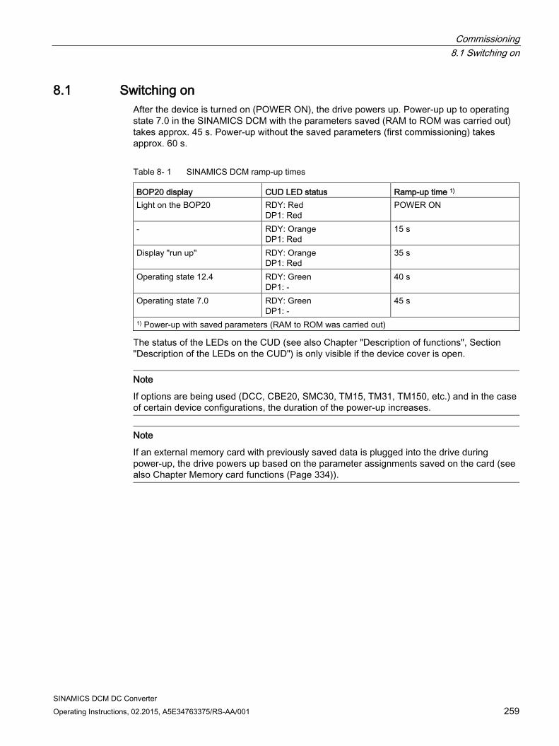
Commissioning 8.1 Switching on
SINAMICS DCM DC Converter Operating Instructions, 02.2015, A5E34763375/RS-AA/001 259
8.1 Switching on After the device is turned on (POWER ON), the drive powers up. Power-up up to operating state 7.0 in the SINAMICS DCM with the parameters saved (RAM to ROM was carried out) takes approx. 45 s. Power-up without the saved parameters (first commissioning) takes approx. 60 s.
Table 8- 1 SINAMICS DCM ramp-up times
BOP20 display CUD LED status Ramp-up time 1) Light on the BOP20 RDY: Red
DP1: Red POWER ON
- RDY: Orange DP1: Red
15 s
Display "run up" RDY: Orange DP1: Red
35 s
Operating state 12.4 RDY: Green DP1: -
40 s
Operating state 7.0 RDY: Green DP1: -
45 s
1) Power-up with saved parameters (RAM to ROM was carried out)
The status of the LEDs on the CUD (see also Chapter "Description of functions", Section "Description of the LEDs on the CUD") is only visible if the device cover is open.
Note
If options are being used (DCC, CBE20, SMC30, TM15, TM31, TM150, etc.) and in the case of certain device configurations, the duration of the power-up increases.
Note
If an external memory card with previously saved data is plugged into the drive during power-up, the drive powers up based on the parameter assignments saved on the card (see also Chapter Memory card functions (Page 334)).
Commissioning 8.2 Commissioning using the BOP20 operator panel
SINAMICS DCM DC Converter 260 Operating Instructions, 02.2015, A5E34763375/RS-AA/001
8.2 Commissioning using the BOP20 operator panel
8.2.1 Preconditions
SINAMICS basics
If you are not yet familiar with SINAMICS basics (parameters, drive objects, BICO technology, and so on), please read "Basics" in the section titled "Operation" before starting commissioning.
BOP20 operator panel
If you are not yet familiar with the BOP20 operator panel, please read "Assigning parameters using the BOP20" in the section titled "Operation" before starting commissioning.
Notation of the parameters
Expressed in full, a parameter consists of the drive object + parameter number + index, with the following notation: (oo)pxxxxx[ii] for indexed parameters (oo)pxxxxx for non-indexed parameters
To make these easier to read, in this chapter the drive object specification has been omitted from all parameters belonging to the "automatic speed control" drive object (= drive object 2). For example, the specification p50076[1] refers to parameter (2)p50076[1] (= drive object 2, parameter 50076, index 1).
8.2.2 Commissioning steps Note: Parameters with [D] are data-set dependent. Commissioning must be carried out for each data set.
〈1〉Access authorization In order to be able to set the access authorization, drive object 1 (DO1) must be activated at the BOP20, see Chapter 9, Section, Displaying and operation using the BOP20.
Access level (1)p0003 = 1 Standard (1)p0003 = 2 Advanced (1)p0003 = 3 Expert
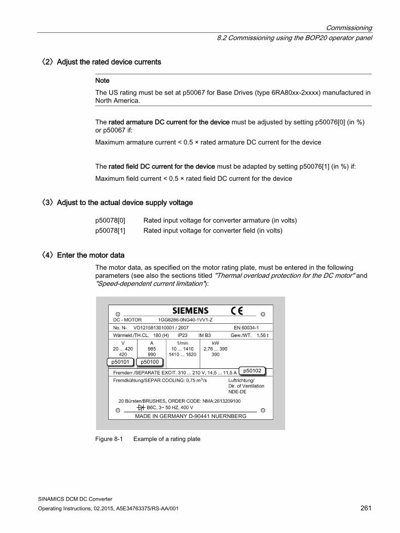
Commissioning 8.2 Commissioning using the BOP20 operator panel
SINAMICS DCM DC Converter Operating Instructions, 02.2015, A5E34763375/RS-AA/001 261
〈2〉Adjust the rated device currents
Note
The US rating must be set at p50067 for Base Drives (type 6RA80xx-2xxxx) manufactured in North America.
The rated armature DC current for the device must be adjusted by setting p50076[0] (in %) or p50067 if:
Maximum armature current < 0.5 × rated armature DC current for the device
The rated field DC current for the device must be adapted by setting p50076[1] (in %) if:
Maximum field current < 0.5 × rated field DC current for the device
〈3〉Adjust to the actual device supply voltage p50078[0] Rated input voltage for converter armature (in volts) p50078[1] Rated input voltage for converter field (in volts)
〈4〉Enter the motor data The motor data, as specified on the motor rating plate, must be entered in the following parameters (see also the sections titled "Thermal overload protection for the DC motor" and "Speed-dependent current limitation"):
Figure 8-1 Example of a rating plate
Commissioning 8.2 Commissioning using the BOP20 operator panel
SINAMICS DCM DC Converter 262 Operating Instructions, 02.2015, A5E34763375/RS-AA/001
p50100[D] Rated armature current (in amperes) p50101[D] Rated armature voltage (in volts) p50102[D] Rated excitation current (in amperes) p50104[D] Speed n1 (in rpm) p50105[D] Armature current I1 (in amperes) p50106[D] Speed n2 (in rpm) p50107[D] Armature current I2 (in amperes) p50108[D] Maximum operating speed n3 (in rpm) p50109[D] 1 = Speed-dependent current limitation active p50114[D] Motor thermal time constant (in seconds)
〈5〉Data for actual speed value acquisition 〈5.1〉Operation with analog tachometer p50083[D] = 1 The actual speed value comes from the "Main actual value" (r52013) chan-
nel (terminals XT.103, XT.104).
p50741[D] Tachometer voltage at maximum speed (– 270.00 to +270.00 V) Remark: The value set here determines the 100% speed for the closed-loop speed control.
p2000 Speed in rpm for tachometer voltage set on p50741[0] Comment 1: Parameter p2000 is used to convert from a "physical speed" (rpm) into a "relative speed" (%) and vice versa. This conversion is required for: • Speed setpoint input via the control panel in STARTER • Speed setpoint input via the operating screen form at the AOP30 • Calculating the display values r020, r021, r060 and r063 Remark 2: Parameter p2000 and parameters r020, r021, r060 and r063 are not data-set dependent. This is the reason why the physical speed can only be displayed correctly for one data set (DDS).
〈5.2〉Operation with incremental encoder p50083[D] = 2 The actual speed value comes from an incremental encoder (r0061) con-
nected to terminal block X177. p0400[0] Encoder type selection
Commissioning 8.2 Commissioning using the BOP20 operator panel
SINAMICS DCM DC Converter Operating Instructions, 02.2015, A5E34763375/RS-AA/001 263
p2000 Speed in rpm at 100% speed Remark: The value set here determines the 100% speed for the closed-loop speed control.
〈5.3〉Operation without tachometer (closed-loop EMF control) p50083[D] = 3 The actual speed value comes from the "Actual EMF value" channel
(r52287), but is evaluated with p50115.
p50115[D] EMF at 100% speed (1.00 to 140.00% of device rated supply voltage (p50078[0])) Remark: The value set here determines the 100% speed for the closed-loop speed control.
p2000 Speed in rpm for EMF set on p50115[0] Comment 1: Parameter p2000 is used to convert from a "physical speed" (rpm) into a "relative speed" (%) and vice versa. This conversion is required for: • Speed setpoint input via the control panel in STARTER • Speed setpoint input via the operating screen form at the AOP30 • Calculating the display values r020, r021, r060 and r063 Remark 2: Parameter p2000 and parameters r020, r021, r060 and r063 are not data-set dependent. This is the reason why the physical speed can only be displayed correctly for one data set (DDS).
〈5.4〉Freely-wired actual value p50083[D] = 4 The actual-value input is defined with p50609[C] p50609[C] Number of the parameter that is switched to the actual speed controller val-
ue p2000 Speed in rpm at which the parameter selected on p50609[0] accepts the
value 100% Comment 1: Parameter p2000 is used to convert from a "physical speed" (rpm) into a "relative speed" (%) and vice versa. This conversion is required for: • Speed setpoint input via the control panel in STARTER • Speed setpoint input via the operating screen form at the AOP30 • Calculating the display values r020, r021, r060 and r063 Remark 2: Parameter p2000 and parameters r020, r021, r060 and r063 are not data-set dependent. For that reason, the physical speed can only be displayed cor-rectly for one data set (CDS).
Commissioning 8.2 Commissioning using the BOP20 operator panel
SINAMICS DCM DC Converter 264 Operating Instructions, 02.2015, A5E34763375/RS-AA/001
〈5.5〉Operation with incremental encoder and SMC30 p50083[D] = 5 The actual speed value comes from an incremental encoder connected to
an SMC30 (r3770). p0400[1] Encoder type selection p2000 Speed in rpm at 100% speed
Remark: The value set here determines the 100% speed for the closed-loop speed control.
〈6〉Data for field 〈6.1〉Control of the field p50082 = 0 Internal field is not used
(e.g. in the case of permanent-magnet motors) p50082 = 1 The field is activated with the line contactor
(field pulses are activated or deactivated at the same time as the line con-tactor)
p50082 = 2 Automatic switching-in of the standstill field set using p50257 after a time that can be parameterized using p50258 has elapsed, once operating state o7 or higher has been reached
p50082 = 3 Field current permanently switched on 〈6.2〉Field weakening p50081 = 0 No speed-dependent or EMF-dependent field weakening p50081 = 1 Field-weakening operation by means of internal closed-loop EMF control,
i.e. at speeds above the motor's rated speed (= "cut-in speed"), the motor EMF is constantly kept at setpoint EMFset (r52289) = p50101 – p50100 x p50110
〈7〉Set basic technological functions 〈7.1〉Current limits p50171[D] System current limit in torque direction I (as % of p50100) p50172[D] System current limit in torque direction II (as % of p50100) 〈7.2〉Torque limits p50180[D] Torque limit 1 in torque direction I
(as % of rated motor torque) p50181[D] Torque limit 1 in torque direction II
(as % of rated motor torque)
Commissioning 8.2 Commissioning using the BOP20 operator panel
SINAMICS DCM DC Converter Operating Instructions, 02.2015, A5E34763375/RS-AA/001 265
〈7.3〉Ramp-function generator p50303[D] Ramp-up time 1 (in seconds) p50304[D] Ramp-down time 1 (in seconds) p50305[D] Initial rounding 1 (in seconds) p50306[D] Final rounding 1 (in seconds)
〈8〉Complete quick commissioning Set p3900 = 3.
This triggers the calculation of the motor data (Ra, La, Lf) as well as the calculation of the controller parameters resulting from the data that was entered in the previous steps.
p3900 is then reset to 0 and quick commissioning is ended, i.e. p0010 is reset to 0.
〈9〉Execute optimization runs Perform the optimization runs one after the other: p50051 = 23 Optimization of the armature current control for induction load p50051 = 24 Optimization of the field current control p50051 = 25 Optimization of the armature current control p50051 = 26 Optimization of the speed control p50051 = 27 Optimization of the EMF control (incl. field characteristic recording) p50051 = 28 Recording of the friction characteristic p50051 = 29 Optimization of the speed control for drives with a mechanical system capa-
ble of oscillation
See Chapter "Drive optimization" for more details
If an optimization run is not carried out, the motor control uses the motor characteristic values calculated from the rating plate data rather than the measured values.
WARNING
During optimization runs, the drive initiates movements of the motor shaft that can reach the maximum motor speed. The EMERGENCY OFF functions must function at the commissioning. To protect man and machines, the relevant safety regulations must be observed.
Commissioning 8.2 Commissioning using the BOP20 operator panel
SINAMICS DCM DC Converter 266 Operating Instructions, 02.2015, A5E34763375/RS-AA/001
〈10〉Checking and potential fine adjustment of maximum speed
Once the optimization runs have been executed, the maximum speed needs to be checked and, if necessary, the setting for it corrected.
If the maximum speed has now shifted by more than around 10%, the control response of the speed control loop will need to be checked; it may be necessary to repeat the optimization run for the speed controller or carry out re-optimization manually.
The optimization runs for field weakening and for friction and moment of inertia compensation must be repeated if there is any change to the maximum speed.
〈11〉Checking the drive settings
The optimization runs do not produce the best results for every application, so in all cases it is necessary to check the controller settings using the appropriate tools (oscilloscope, STARTER trace, and so on). Some cases may require manual re-optimization.
〈12〉Manual (re-)optimization (where required)
If the result of the optimization runs is not satisfactory, then manual post or new optimization can be performed.
The procedure is described in Chapter "Manual optimization".
〈13〉Saving non-volatile set values
Previously, all changes in the set values were made in the RAM (Random Access Memory). If the device is switched off in this state, all settings made previously are lost. To permanently store the settings in the ROM (non-volatile memory), a RAM to ROM must be triggered by setting p0977 to 1 (p0977 is allocated to the DO 1). The saving process is indicated by the flashing of BOP20 (and the RDY LED on the CUD) and takes approx. 45 s. After the saving process has been completed, the settings are backed up in the ROM.
The drive can now be switched off (POWER OFF) without losing the settings that have been made. Also refer to the "Operation" chapter, "Memory card functions" section.
〈14〉Documentation of set values
The following facilities are available to document the executed settings outside the device:
External Memory card was inserted during the RAM to ROM (p0977=1). The parameters were therefore also transferred to the external Memory card.
Write the parameters to a Memory card (p0804).
Document the parameters in a STARTER project (load to PG). Also refer to the "Operation" chapter, "Memory card functions" section and "Commissioning with the STARTER commissioning tool" chapter.
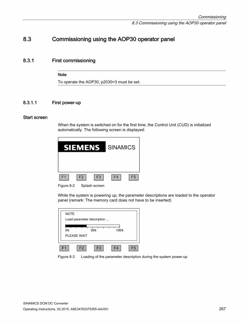
Commissioning 8.3 Commissioning using the AOP30 operator panel
SINAMICS DCM DC Converter Operating Instructions, 02.2015, A5E34763375/RS-AA/001 267
8.3 Commissioning using the AOP30 operator panel
8.3.1 First commissioning
Note
To operate the AOP30, p2030=3 must be set.
8.3.1.1 First power-up
Start screen When the system is switched on for the first time, the Control Unit (CUD) is initialized automatically. The following screen is displayed:
Figure 8-2 Splash screen
While the system is powering up, the parameter descriptions are loaded to the operator panel (remark: The memory card does not have to be inserted)
Figure 8-3 Loading of the parameter description during the system power-up
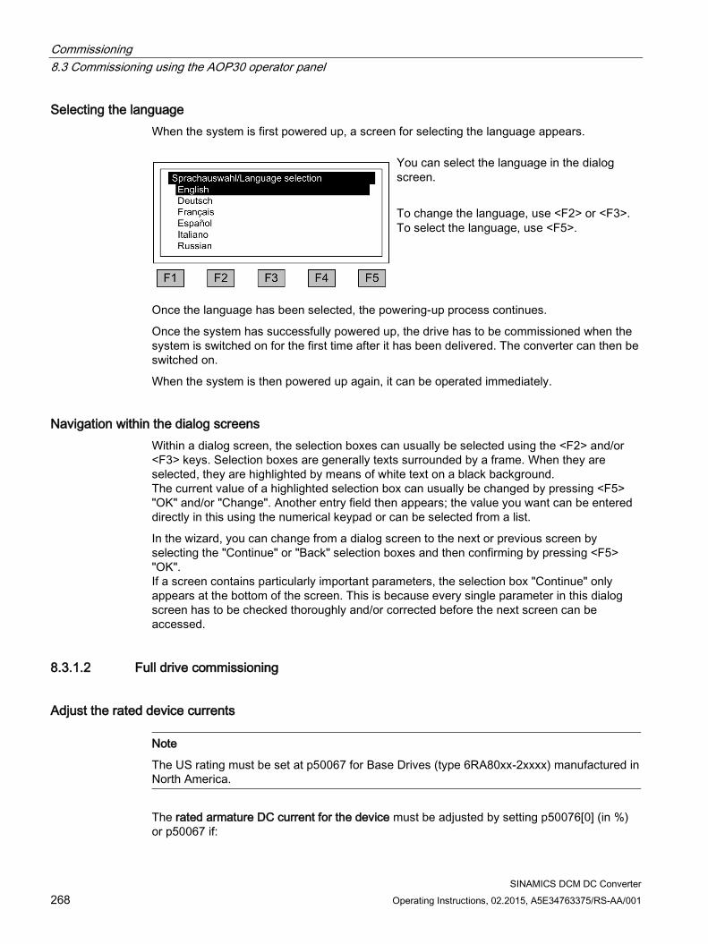
Commissioning 8.3 Commissioning using the AOP30 operator panel
SINAMICS DCM DC Converter 268 Operating Instructions, 02.2015, A5E34763375/RS-AA/001
Selecting the language When the system is first powered up, a screen for selecting the language appears.
You can select the language in the dialog screen. To change the language, use <F2> or <F3>. To select the language, use <F5>.
Once the language has been selected, the powering-up process continues.
Once the system has successfully powered up, the drive has to be commissioned when the system is switched on for the first time after it has been delivered. The converter can then be switched on.
When the system is then powered up again, it can be operated immediately.
Navigation within the dialog screens Within a dialog screen, the selection boxes can usually be selected using the <F2> and/or <F3> keys. Selection boxes are generally texts surrounded by a frame. When they are selected, they are highlighted by means of white text on a black background. The current value of a highlighted selection box can usually be changed by pressing <F5> "OK" and/or "Change". Another entry field then appears; the value you want can be entered directly in this using the numerical keypad or can be selected from a list.
In the wizard, you can change from a dialog screen to the next or previous screen by selecting the "Continue" or "Back" selection boxes and then confirming by pressing <F5> "OK". If a screen contains particularly important parameters, the selection box "Continue" only appears at the bottom of the screen. This is because every single parameter in this dialog screen has to be checked thoroughly and/or corrected before the next screen can be accessed.
8.3.1.2 Full drive commissioning
Adjust the rated device currents
Note
The US rating must be set at p50067 for Base Drives (type 6RA80xx-2xxxx) manufactured in North America.
The rated armature DC current for the device must be adjusted by setting p50076[0] (in %) or p50067 if:
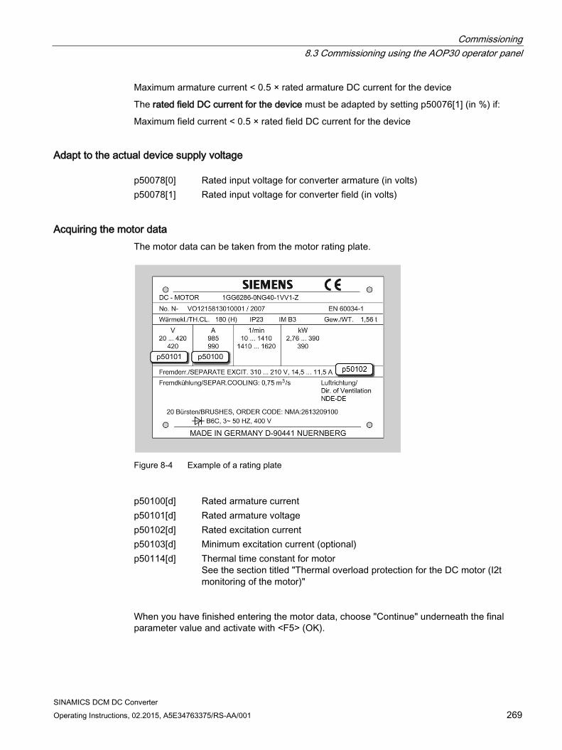
Commissioning 8.3 Commissioning using the AOP30 operator panel
SINAMICS DCM DC Converter Operating Instructions, 02.2015, A5E34763375/RS-AA/001 269
Maximum armature current < 0.5 × rated armature DC current for the device
The rated field DC current for the device must be adapted by setting p50076[1] (in %) if:
Maximum field current < 0.5 × rated field DC current for the device
Adapt to the actual device supply voltage p50078[0] Rated input voltage for converter armature (in volts) p50078[1] Rated input voltage for converter field (in volts)
Acquiring the motor data The motor data can be taken from the motor rating plate.
Figure 8-4 Example of a rating plate
p50100[d] Rated armature current p50101[d] Rated armature voltage p50102[d] Rated excitation current p50103[d] Minimum excitation current (optional) p50114[d] Thermal time constant for motor
See the section titled "Thermal overload protection for the DC motor (I2t monitoring of the motor)"
When you have finished entering the motor data, choose "Continue" underneath the final parameter value and activate with <F5> (OK).
Commissioning 8.3 Commissioning using the AOP30 operator panel
SINAMICS DCM DC Converter 270 Operating Instructions, 02.2015, A5E34763375/RS-AA/001
Encoder selection p50083[d] Actual speed controller value selection
Analog tachometer screen p50741[d] Tachometer voltage at maximum speed p2000 Reference speed
Pulse encoder screen p0400[e] Encoder type selection p0404[e] Encoder configuration active p0405[e] Square-wave encoder A/B p0408[e] Rotary encoder pulse no. p2000 Reference speed
EMF controlled screen p50115[d] EMF at maximum speed p2000 Reference speed
Freely wired screen p50609[c] Actual speed controller value signal source p2000 Reference speed
DRIVE-CLiQ encoder screen p0400[e] Encoder type selection p0404[e] Encoder configuration active p0405[e] Square-wave encoder A/B p0408[e] Rotary encoder pulse no. p2000 Reference speed
Data on field p50081 Field weakening p50082 Field operating mode
Commissioning 8.3 Commissioning using the AOP30 operator panel
SINAMICS DCM DC Converter Operating Instructions, 02.2015, A5E34763375/RS-AA/001 271
Basic commissioning p50171 Current limit, torque direction I p50172 Current limit, torque direction II p50180 Torque limit I p50181 Torque limit II p50303 Ramp-up time 1 p50304 Ramp-down time 1 p50305 Initial rounding 1 p50306 Final rounding 1
Final confirmation Confirm the parameters you have entered to save them. Once you have selected "Continue" and activated your entries with <F5>, the parameters you entered will be permanently saved and the calculations required for closed-loop control carried out.
Optimization runs Perform the optimization runs one after the other:
To navigate through the selection fields, choose <F2> or <F3>. To activate a selection, choose <F5>. p50051 = 23 Optimization of the armature current control for induction load p50051 = 24 Optimization of the field current control p50051 = 25 Optimization of the armature current control p50051 = 26 Optimization of the speed control p50051 = 27 Optimization of the EMF control (incl. field characteristic recording) p50051 = 28 Recording of the friction characteristic p50051 = 29 Optimization of the speed control for drives with a mechanical system capa-
ble of oscillation
See Chapter "Drive optimization" for more details
If an optimization run is not carried out, the motor control uses the motor characteristic values calculated from the rating plate data rather than the measured values.
WARNING
During optimization runs, the drive initiates motor movements that can reach the maximum motor speed.
The EMERGENCY OFF functions must function at the commissioning. To protect man and machines, the relevant safety regulations must be observed.
Commissioning 8.3 Commissioning using the AOP30 operator panel
SINAMICS DCM DC Converter 272 Operating Instructions, 02.2015, A5E34763375/RS-AA/001
8.3.2 Status after commissioning
LOCAL mode (control via operator panel)
You switch to LOCAL mode by pressing the "LOCAL/REMOTE" key.
Control (ON/OFF) is carried out via the "ON" and "OFF" keys.
You can set the setpoint using the "Increase" and "Decrease" keys or by entering the appropriate numbers on the operation screen using the numeric keypad.
8.3.3 Resetting parameters to factory settings The factory settings represent the defined original status of the unit on delivery.
Resetting the parameters to the factory settings means that all the parameter settings made since the system was delivered are reset.
Setting the parameter filter to "Parameter reset"
<MENU> <Commissioning/Service> <OK> <Device commissioning> <OK> <30: Parameter Reset> <OK>
Restoring all parameters to their factory settings
All of the unit parameters are reset to their factory settings. The AOP30 is powered down and back up again during this process.
Commissioning 8.4 Commissioning with the STARTER commissioning tool
SINAMICS DCM DC Converter Operating Instructions, 02.2015, A5E34763375/RS-AA/001 273
8.4 Commissioning with the STARTER commissioning tool
8.4.1 STARTER commissioning tool
Description You can use the STARTER commissioning tool to configure and commission your SINAMICS drives or drive systems. The drive configuration can be performed with the aid of the STARTER wizard for drive configuration.
Note
This chapter described how to commission with STARTER. STARTER has a comprehensive online help that explains in detail all of the sequences and setting options in the system. This is the reason that this chapter is restricted to the individual commissioning steps.
Prerequisites for installing STARTER STARTER is installed on a PG / PC. The hardware and software preconditions are described in the readme file for STARTER. This file can be called from the starting page of the SINAMICS DCM documentation on DVD.
Note
The SIMOTION SCOUT engineering tool includes the STARTER functionality to commission drives.
From version V4.2, SCOUT has also been released for commissioning SINAMICS DCM.
8.4.1.1 Installing the STARTER commissioning tool STARTER is installed using the "setup" file on the CD supplied. When you double-click the "Setup" file, the installation wizard guides you through the process of installing STARTER.
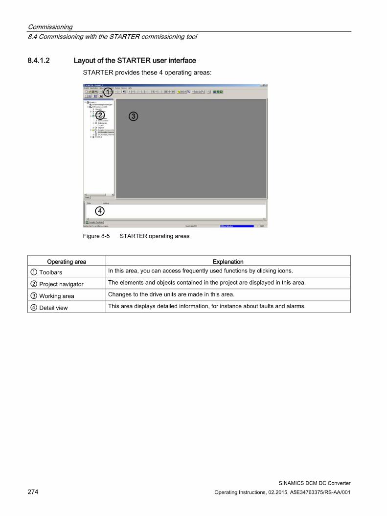
Commissioning 8.4 Commissioning with the STARTER commissioning tool
SINAMICS DCM DC Converter 274 Operating Instructions, 02.2015, A5E34763375/RS-AA/001
8.4.1.2 Layout of the STARTER user interface STARTER provides these 4 operating areas:
Figure 8-5 STARTER operating areas
Operating area Explanation
① Toolbars In this area, you can access frequently used functions by clicking icons.
② Project navigator The elements and objects contained in the project are displayed in this area.
③ Working area Changes to the drive units are made in this area.
④ Detail view This area displays detailed information, for instance about faults and alarms.
Commissioning 8.4 Commissioning with the STARTER commissioning tool
SINAMICS DCM DC Converter Operating Instructions, 02.2015, A5E34763375/RS-AA/001 275
8.4.2 Procedure for commissioning with STARTER
Basic procedure when using STARTER STARTER uses a series of interactive screens to enter the data required for the drive unit.
Note
The interactive screens are pre-assigned defaults that you need to adapt to your application and configuration under certain circumstances.
This is a deliberate procedure! Target: By taking time to consider what configuration data you enter, you can prevent inconsistencies between the project data and drive unit data (identifiable in online mode).
8.4.2.1 Creating the project Click the STARTER icon on the desktop or select the menu command Start > Simatic > STEP 7 > STARTER in the Windows start menu to start the STARTER commissioning tool.
The following main screen with the interactive dialogs appears after starting for the first time:
STARTER Getting Started Drive Commissioning
STARTER Project Wizard
The commissioning steps are listed below as numbered step sequences.
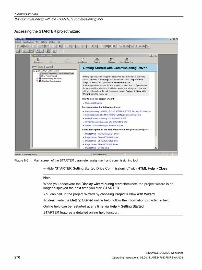
Commissioning 8.4 Commissioning with the STARTER commissioning tool
SINAMICS DCM DC Converter 276 Operating Instructions, 02.2015, A5E34763375/RS-AA/001
Accessing the STARTER project wizard
Figure 8-6 Main screen of the STARTER parameter assignment and commissioning tool
⇒ Hide "STARTER Getting Started Drive Commissioning" with HTML Help > Close
Note
When you deactivate the Display wizard during start checkbox, the project wizard is no longer displayed the next time you start STARTER.
You can call up the project Wizard by choosing Project > New with Wizard.
To deactivate the Getting Started online help, follow the information provided in help.
Online help can be restarted at any time via Help > Getting Started.
STARTER features a detailed online help function.
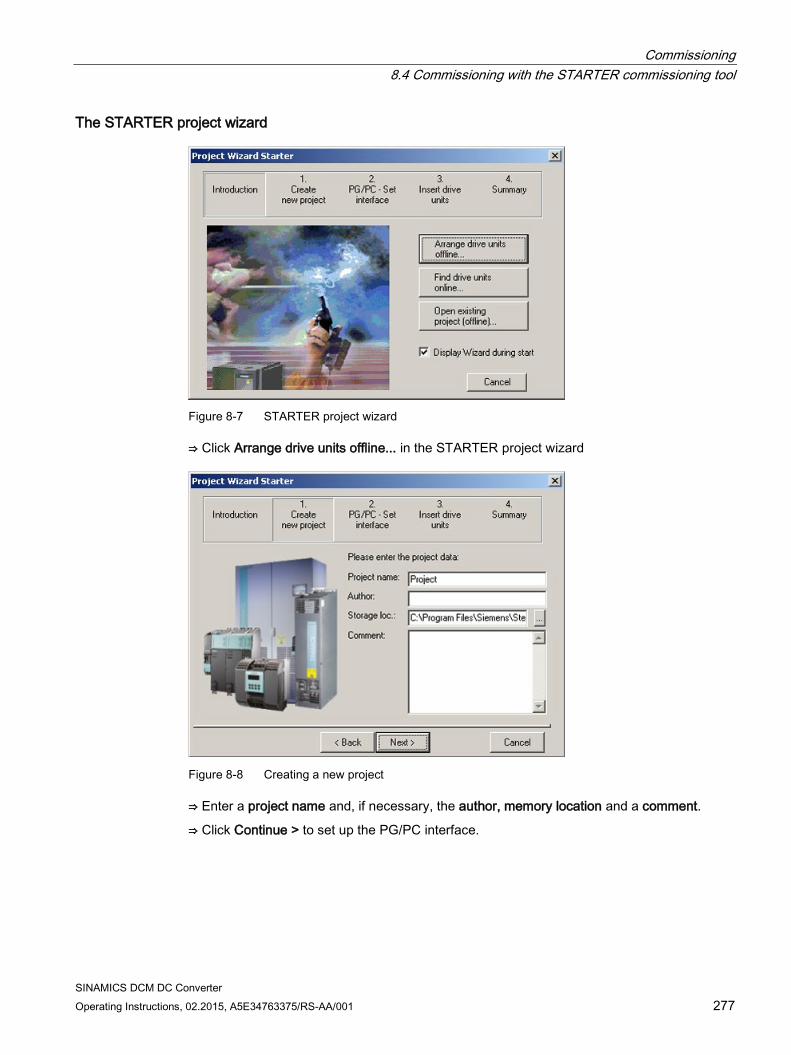
Commissioning 8.4 Commissioning with the STARTER commissioning tool
SINAMICS DCM DC Converter Operating Instructions, 02.2015, A5E34763375/RS-AA/001 277
The STARTER project wizard
Figure 8-7 STARTER project wizard
⇒ Click Arrange drive units offline... in the STARTER project wizard
Figure 8-8 Creating a new project
⇒ Enter a project name and, if necessary, the author, memory location and a comment.
⇒ Click Continue > to set up the PG/PC interface.
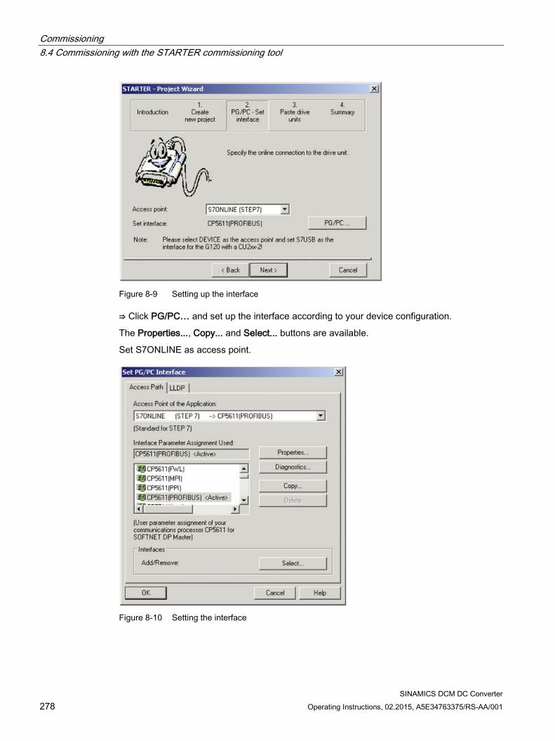
Commissioning 8.4 Commissioning with the STARTER commissioning tool
SINAMICS DCM DC Converter 278 Operating Instructions, 02.2015, A5E34763375/RS-AA/001
Figure 8-9 Setting up the interface
⇒ Click PG/PC… and set up the interface according to your device configuration.
The Properties..., Copy... and Select... buttons are available.
Set S7ONLINE as access point.
Figure 8-10 Setting the interface
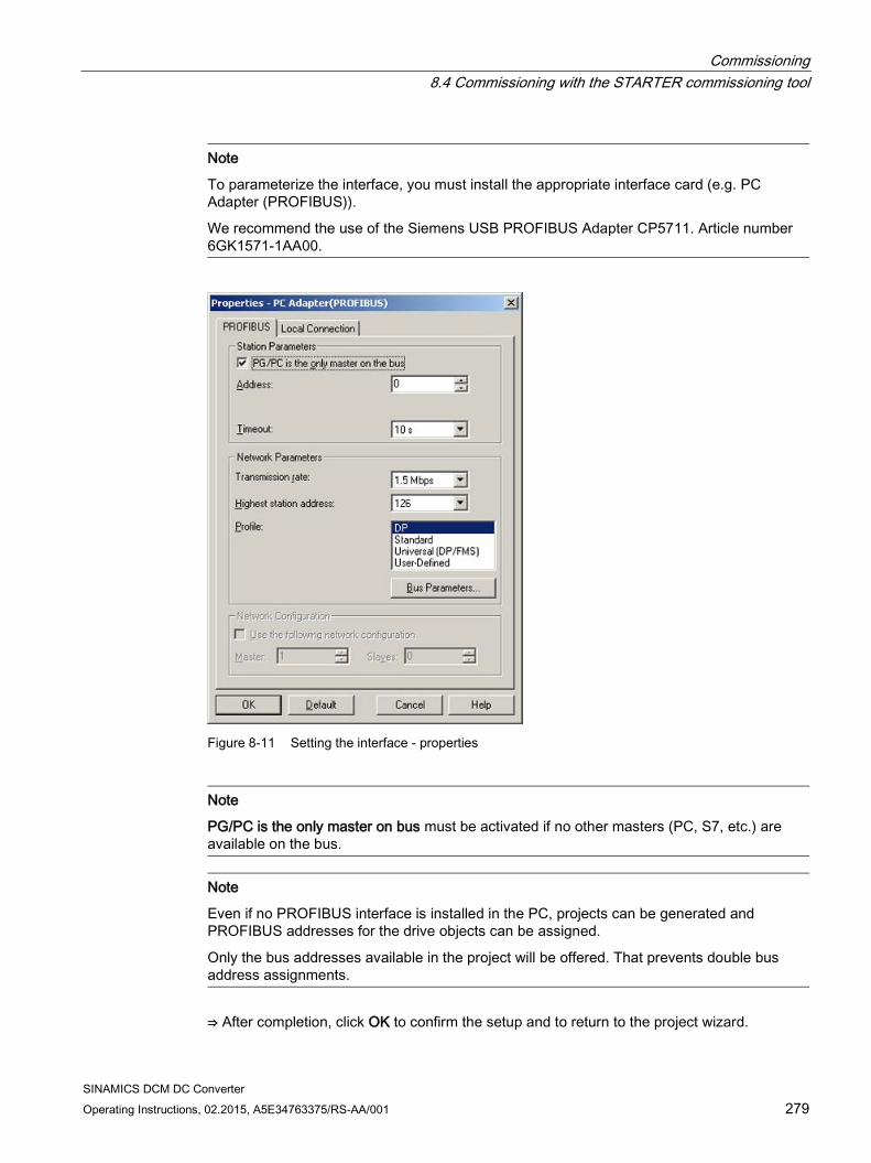
Commissioning 8.4 Commissioning with the STARTER commissioning tool
SINAMICS DCM DC Converter Operating Instructions, 02.2015, A5E34763375/RS-AA/001 279
Note
To parameterize the interface, you must install the appropriate interface card (e.g. PC Adapter (PROFIBUS)).
We recommend the use of the Siemens USB PROFIBUS Adapter CP5711. Article number 6GK1571-1AA00.
Figure 8-11 Setting the interface - properties
Note
PG/PC is the only master on bus must be activated if no other masters (PC, S7, etc.) are available on the bus.
Note
Even if no PROFIBUS interface is installed in the PC, projects can be generated and PROFIBUS addresses for the drive objects can be assigned.
Only the bus addresses available in the project will be offered. That prevents double bus address assignments.
⇒ After completion, click OK to confirm the setup and to return to the project wizard.
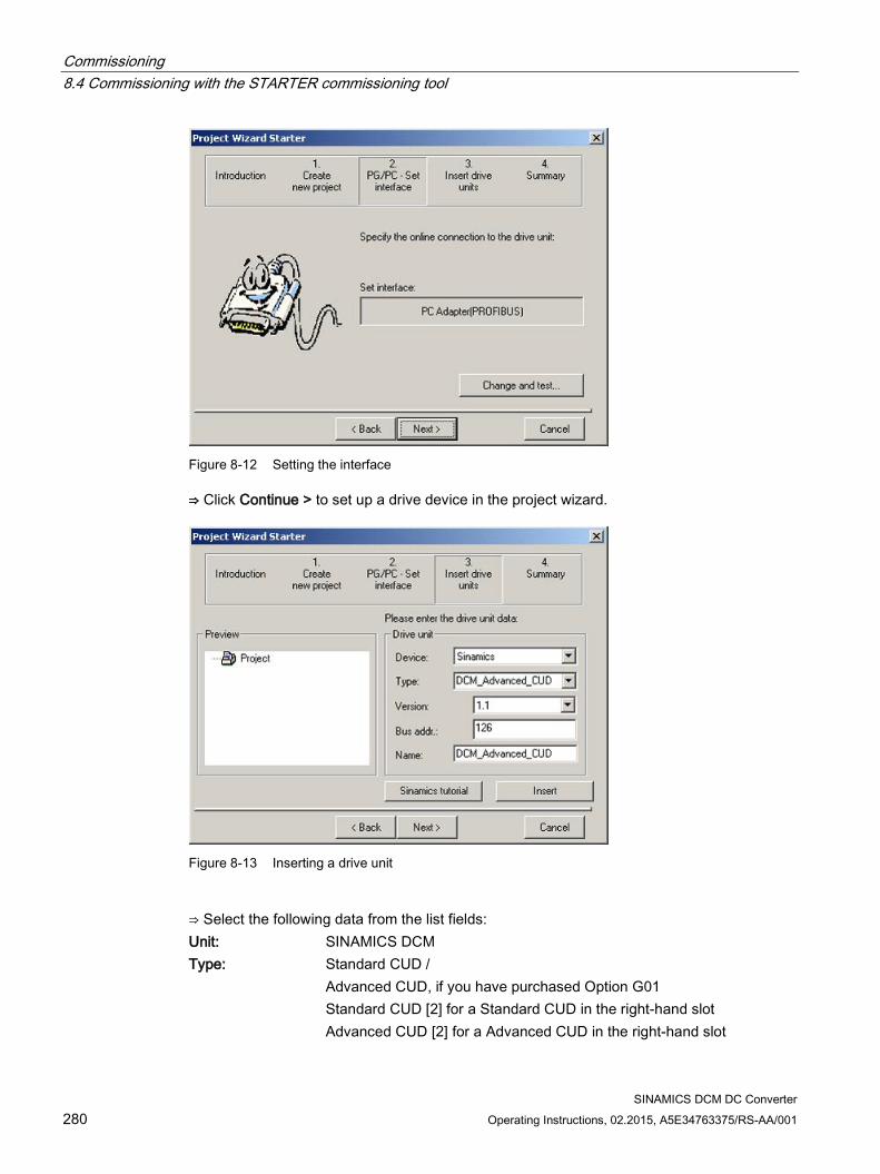
Commissioning 8.4 Commissioning with the STARTER commissioning tool
SINAMICS DCM DC Converter 280 Operating Instructions, 02.2015, A5E34763375/RS-AA/001
Figure 8-12 Setting the interface
⇒ Click Continue > to set up a drive device in the project wizard.
Figure 8-13 Inserting a drive unit
⇒ Select the following data from the list fields: Unit: SINAMICS DCM Type: Standard CUD /
Advanced CUD, if you have purchased Option G01 Standard CUD [2] for a Standard CUD in the right-hand slot Advanced CUD [2] for a Advanced CUD in the right-hand slot
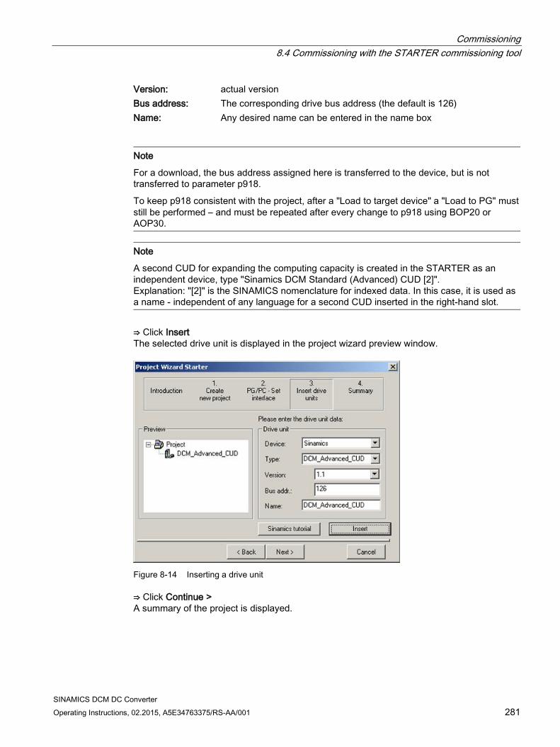
Commissioning 8.4 Commissioning with the STARTER commissioning tool
SINAMICS DCM DC Converter Operating Instructions, 02.2015, A5E34763375/RS-AA/001 281
Version: actual version Bus address: The corresponding drive bus address (the default is 126) Name: Any desired name can be entered in the name box
Note
For a download, the bus address assigned here is transferred to the device, but is not transferred to parameter p918.
To keep p918 consistent with the project, after a "Load to target device" a "Load to PG" must still be performed – and must be repeated after every change to p918 using BOP20 or AOP30.
Note
A second CUD for expanding the computing capacity is created in the STARTER as an independent device, type "Sinamics DCM Standard (Advanced) CUD [2]". Explanation: "[2]" is the SINAMICS nomenclature for indexed data. In this case, it is used as a name - independent of any language for a second CUD inserted in the right-hand slot.
⇒ Click Insert The selected drive unit is displayed in the project wizard preview window.
Figure 8-14 Inserting a drive unit
⇒ Click Continue > A summary of the project is displayed.
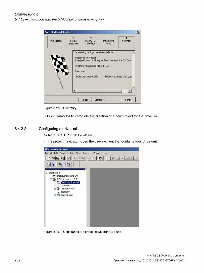
Commissioning 8.4 Commissioning with the STARTER commissioning tool
SINAMICS DCM DC Converter 282 Operating Instructions, 02.2015, A5E34763375/RS-AA/001
Figure 8-15 Summary
⇒ Click Complete to complete the creation of a new project for the drive unit.
8.4.2.2 Configuring a drive unit Note: STARTER must be offline.
In the project navigator, open the tree element that contains your drive unit.
Figure 8-16 Configuring the project navigator drive unit
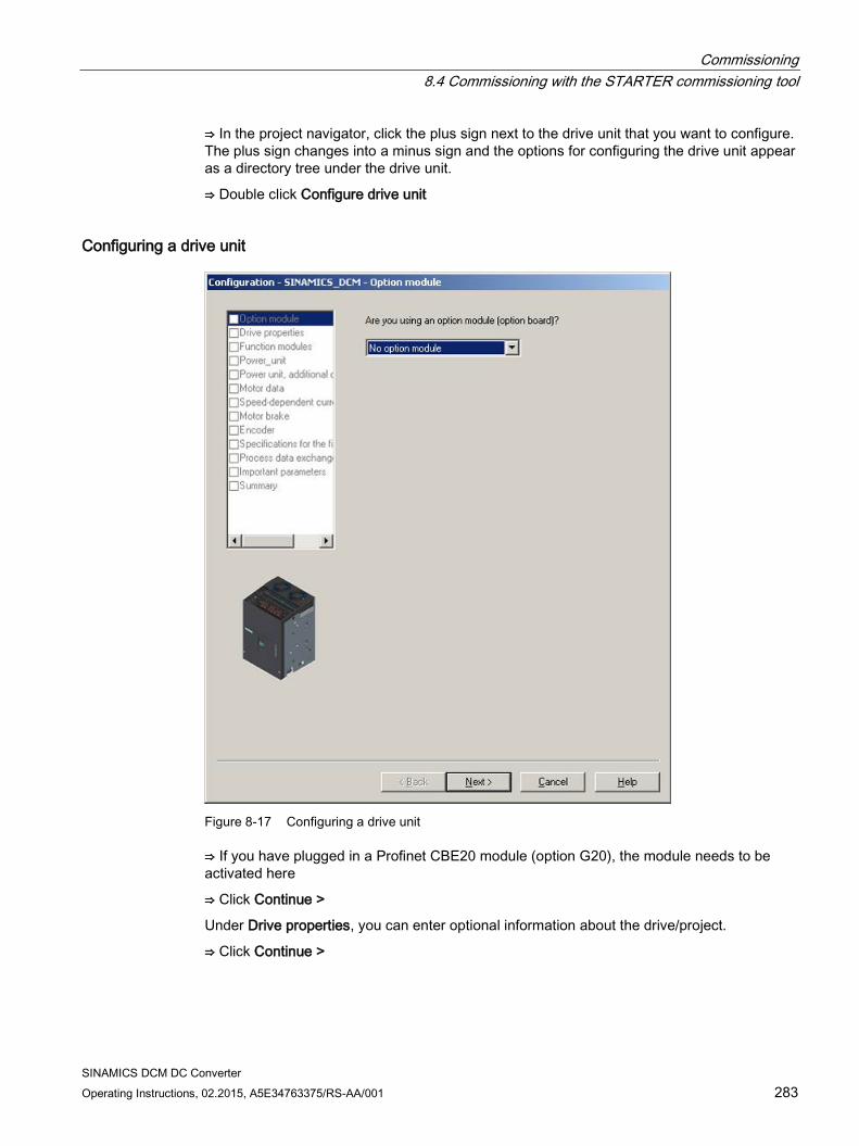
Commissioning 8.4 Commissioning with the STARTER commissioning tool
SINAMICS DCM DC Converter Operating Instructions, 02.2015, A5E34763375/RS-AA/001 283
⇒ In the project navigator, click the plus sign next to the drive unit that you want to configure. The plus sign changes into a minus sign and the options for configuring the drive unit appear as a directory tree under the drive unit.
⇒ Double click Configure drive unit
Configuring a drive unit
Figure 8-17 Configuring a drive unit
⇒ If you have plugged in a Profinet CBE20 module (option G20), the module needs to be activated here
⇒ Click Continue >
Under Drive properties, you can enter optional information about the drive/project.
⇒ Click Continue >
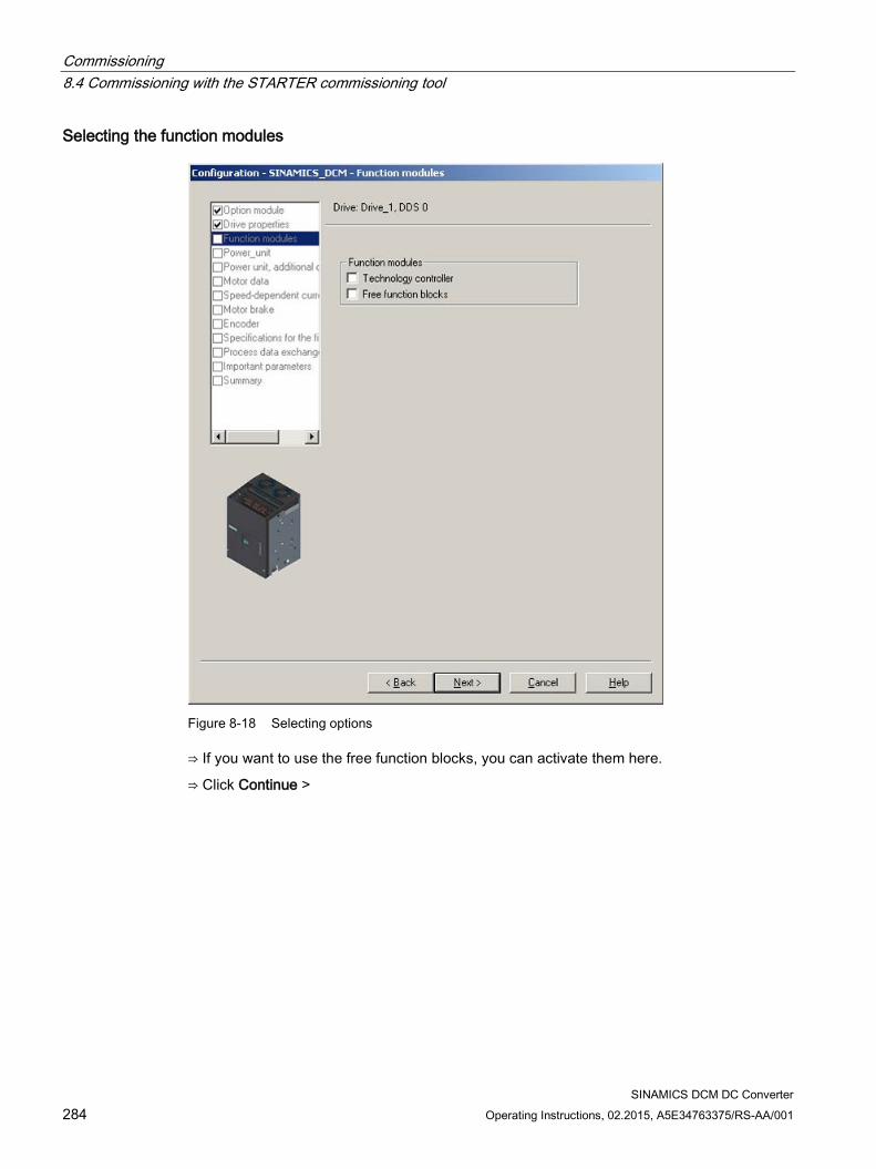
Commissioning 8.4 Commissioning with the STARTER commissioning tool
SINAMICS DCM DC Converter 284 Operating Instructions, 02.2015, A5E34763375/RS-AA/001
Selecting the function modules
Figure 8-18 Selecting options
⇒ If you want to use the free function blocks, you can activate them here.
⇒ Click Continue >
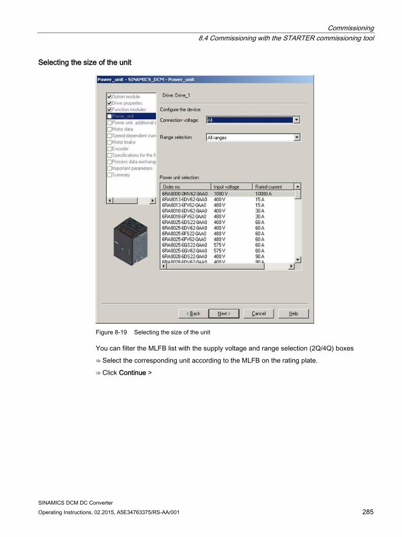
Commissioning 8.4 Commissioning with the STARTER commissioning tool
SINAMICS DCM DC Converter Operating Instructions, 02.2015, A5E34763375/RS-AA/001 285
Selecting the size of the unit
Figure 8-19 Selecting the size of the unit
You can filter the MLFB list with the supply voltage and range selection (2Q/4Q) boxes
⇒ Select the corresponding unit according to the MLFB on the rating plate.
⇒ Click Continue >
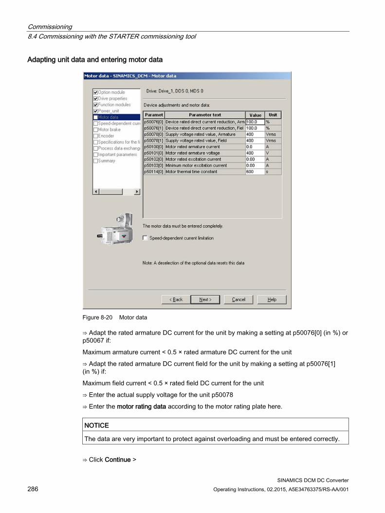
Commissioning 8.4 Commissioning with the STARTER commissioning tool
SINAMICS DCM DC Converter 286 Operating Instructions, 02.2015, A5E34763375/RS-AA/001
Adapting unit data and entering motor data
Figure 8-20 Motor data
⇒ Adapt the rated armature DC current for the unit by making a setting at p50076[0] (in %) or p50067 if:
Maximum armature current < 0.5 × rated armature DC current for the unit
⇒ Adapt the rated armature DC current field for the unit by making a setting at p50076[1] (in %) if:
Maximum field current < 0.5 × rated field DC current for the unit
⇒ Enter the actual supply voltage for the unit p50078
⇒ Enter the motor rating data according to the motor rating plate here.
NOTICE
The data are very important to protect against overloading and must be entered correctly.
⇒ Click Continue >
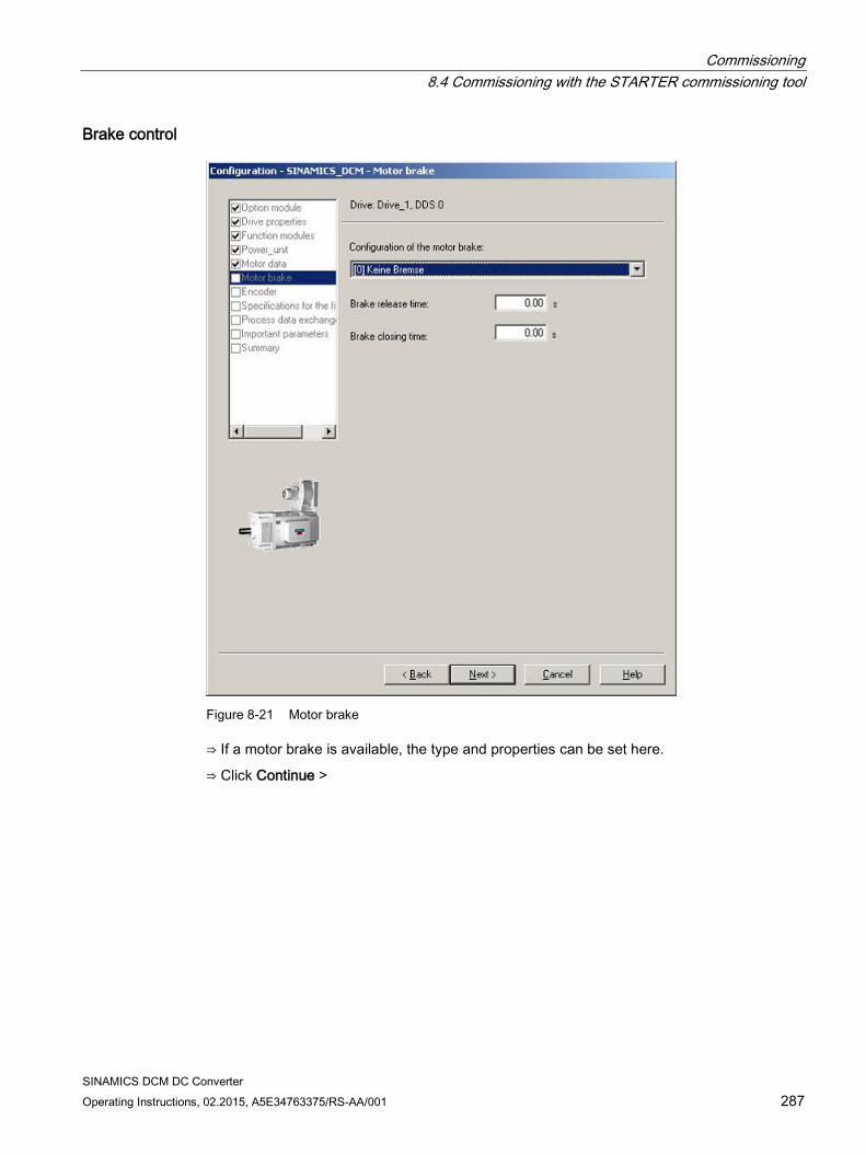
Commissioning 8.4 Commissioning with the STARTER commissioning tool
SINAMICS DCM DC Converter Operating Instructions, 02.2015, A5E34763375/RS-AA/001 287
Brake control
Figure 8-21 Motor brake
⇒ If a motor brake is available, the type and properties can be set here.
⇒ Click Continue >
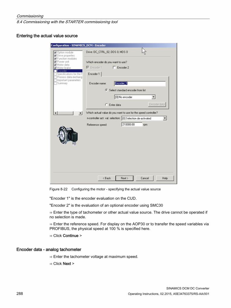
Commissioning 8.4 Commissioning with the STARTER commissioning tool
SINAMICS DCM DC Converter 288 Operating Instructions, 02.2015, A5E34763375/RS-AA/001
Entering the actual value source
Figure 8-22 Configuring the motor - specifying the actual value source
"Encoder 1" is the encoder evaluation on the CUD.
"Encoder 2" is the evaluation of an optional encoder using SMC30
⇒ Enter the type of tachometer or other actual value source. The drive cannot be operated if no selection is made.
⇒ Enter the reference speed. For display on the AOP30 or to transfer the speed variables via PROFIBUS, the physical speed at 100 % is specified here.
⇒ Click Continue >
Encoder data - analog tachometer ⇒ Enter the tachometer voltage at maximum speed.
⇒ Click Next >
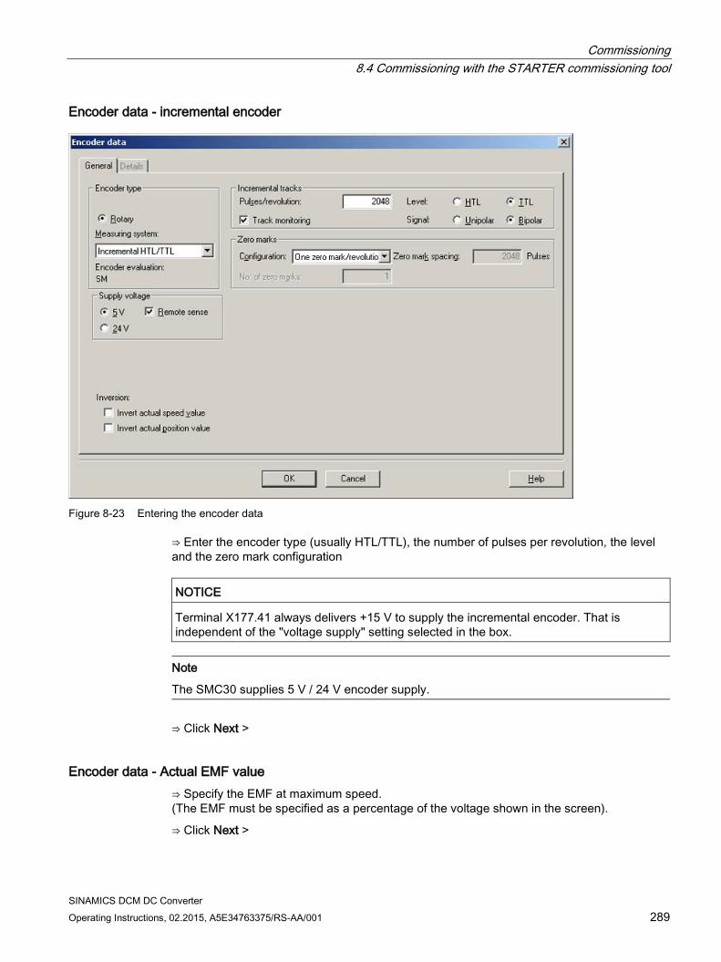
Commissioning 8.4 Commissioning with the STARTER commissioning tool
SINAMICS DCM DC Converter Operating Instructions, 02.2015, A5E34763375/RS-AA/001 289
Encoder data - incremental encoder
Figure 8-23 Entering the encoder data
⇒ Enter the encoder type (usually HTL/TTL), the number of pulses per revolution, the level and the zero mark configuration
NOTICE
Terminal X177.41 always delivers +15 V to supply the incremental encoder. That is independent of the "voltage supply" setting selected in the box.
Note
The SMC30 supplies 5 V / 24 V encoder supply.
⇒ Click Next >
Encoder data - Actual EMF value ⇒ Specify the EMF at maximum speed. (The EMF must be specified as a percentage of the voltage shown in the screen).
⇒ Click Next >
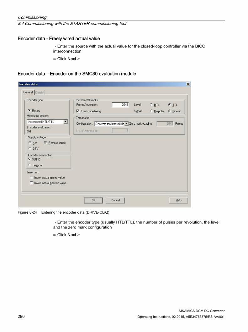
Commissioning 8.4 Commissioning with the STARTER commissioning tool
SINAMICS DCM DC Converter 290 Operating Instructions, 02.2015, A5E34763375/RS-AA/001
Encoder data - Freely wired actual value ⇒ Enter the source with the actual value for the closed-loop controller via the BICO interconnection.
⇒ Click Next >
Encoder data – Encoder on the SMC30 evaluation module
Figure 8-24 Entering the encoder data (DRIVE-CLiQ)
⇒ Enter the encoder type (usually HTL/TTL), the number of pulses per revolution, the level and the zero mark configuration
⇒ Click Next >
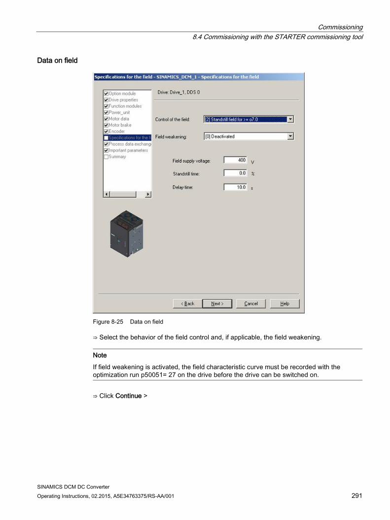
Commissioning 8.4 Commissioning with the STARTER commissioning tool
SINAMICS DCM DC Converter Operating Instructions, 02.2015, A5E34763375/RS-AA/001 291
Data on field
Figure 8-25 Data on field
⇒ Select the behavior of the field control and, if applicable, the field weakening.
Note
If field weakening is activated, the field characteristic curve must be recorded with the optimization run p50051= 27 on the drive before the drive can be switched on.
⇒ Click Continue >
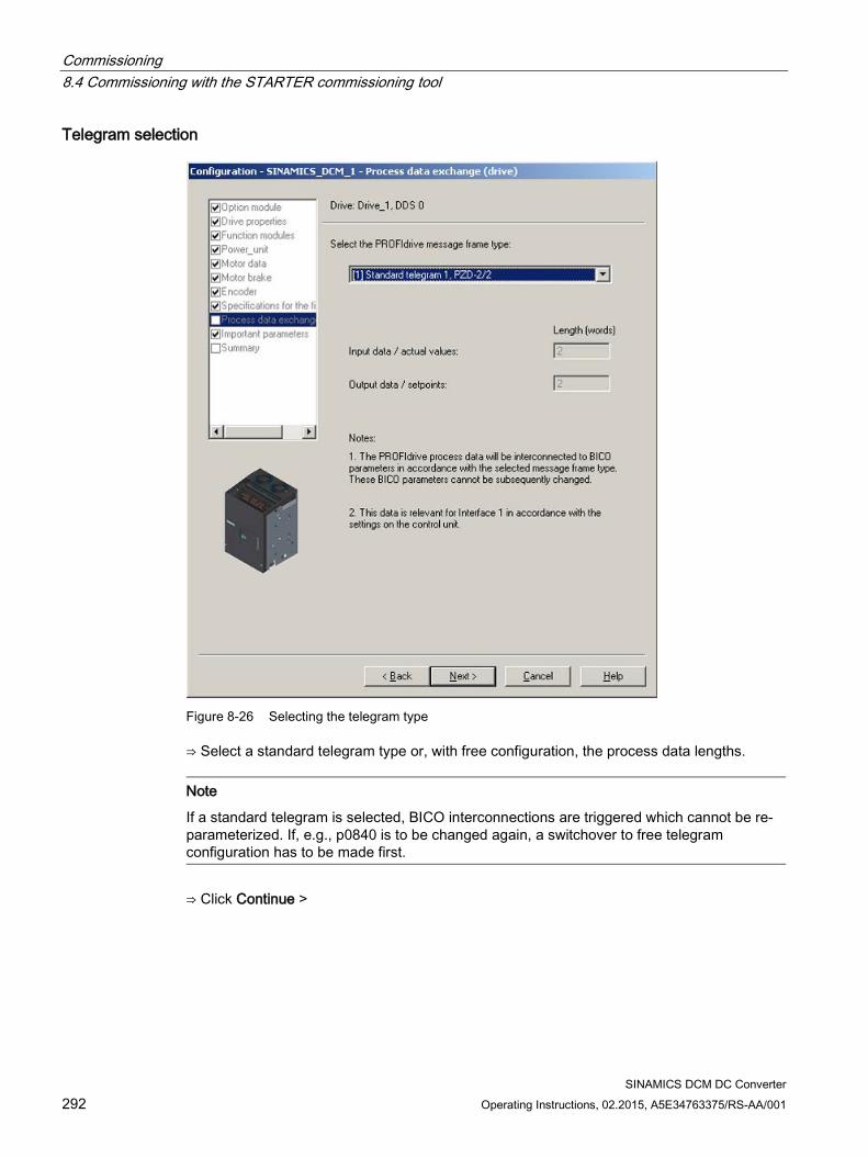
Commissioning 8.4 Commissioning with the STARTER commissioning tool
SINAMICS DCM DC Converter 292 Operating Instructions, 02.2015, A5E34763375/RS-AA/001
Telegram selection
Figure 8-26 Selecting the telegram type
⇒ Select a standard telegram type or, with free configuration, the process data lengths.
Note
If a standard telegram is selected, BICO interconnections are triggered which cannot be re-parameterized. If, e.g., p0840 is to be changed again, a switchover to free telegram configuration has to be made first.
⇒ Click Continue >
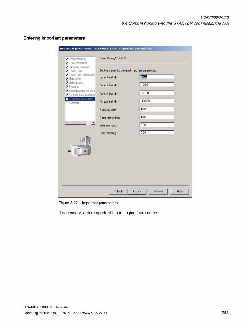
Commissioning 8.4 Commissioning with the STARTER commissioning tool
SINAMICS DCM DC Converter Operating Instructions, 02.2015, A5E34763375/RS-AA/001 293
Entering important parameters
Figure 8-27 Important parameters
If necessary, enter important technological parameters.
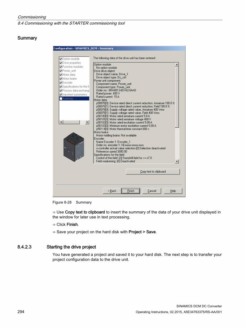
Commissioning 8.4 Commissioning with the STARTER commissioning tool
SINAMICS DCM DC Converter 294 Operating Instructions, 02.2015, A5E34763375/RS-AA/001
Summary
Figure 8-28 Summary
⇒ Use Copy text to clipboard to insert the summary of the data of your drive unit displayed in the window for later use in text processing.
⇒ Click Finish.
⇒ Save your project on the hard disk with Project > Save.
8.4.2.3 Starting the drive project You have generated a project and saved it to your hard disk. The next step is to transfer your project configuration data to the drive unit.
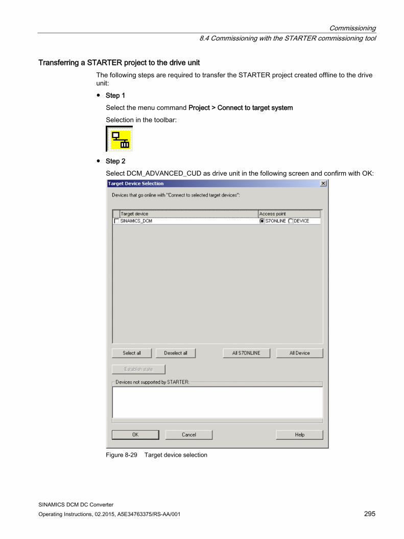
Commissioning 8.4 Commissioning with the STARTER commissioning tool
SINAMICS DCM DC Converter Operating Instructions, 02.2015, A5E34763375/RS-AA/001 295
Transferring a STARTER project to the drive unit The following steps are required to transfer the STARTER project created offline to the drive unit:
Step 1
Select the menu command Project > Connect to target system
Selection in the toolbar:
Step 2
Select DCM_ADVANCED_CUD as drive unit in the following screen and confirm with OK:
Figure 8-29 Target device selection
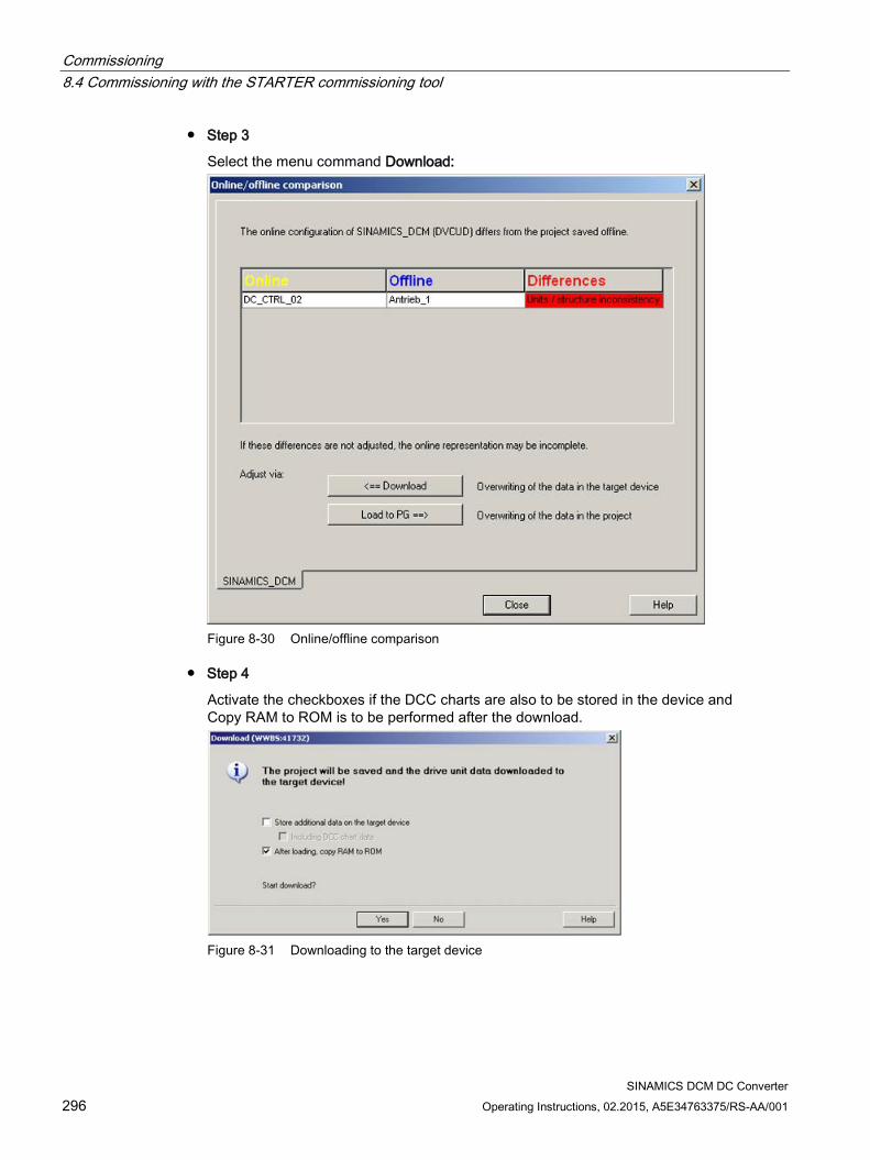
Commissioning 8.4 Commissioning with the STARTER commissioning tool
SINAMICS DCM DC Converter 296 Operating Instructions, 02.2015, A5E34763375/RS-AA/001
Step 3
Select the menu command Download:
Figure 8-30 Online/offline comparison
Step 4
Activate the checkboxes if the DCC charts are also to be stored in the device and Copy RAM to ROM is to be performed after the download.
Figure 8-31 Downloading to the target device
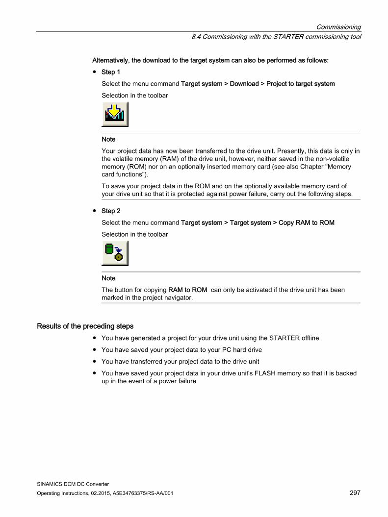
Commissioning 8.4 Commissioning with the STARTER commissioning tool
SINAMICS DCM DC Converter Operating Instructions, 02.2015, A5E34763375/RS-AA/001 297
Alternatively, the download to the target system can also be performed as follows:
Step 1
Select the menu command Target system > Download > Project to target system
Selection in the toolbar
Note
Your project data has now been transferred to the drive unit. Presently, this data is only in the volatile memory (RAM) of the drive unit, however, neither saved in the non-volatile memory (ROM) nor on an optionally inserted memory card (see also Chapter "Memory card functions").
To save your project data in the ROM and on the optionally available memory card of your drive unit so that it is protected against power failure, carry out the following steps.
Step 2
Select the menu command Target system > Target system > Copy RAM to ROM
Selection in the toolbar
Note
The button for copying RAM to ROM can only be activated if the drive unit has been marked in the project navigator.
Results of the preceding steps You have generated a project for your drive unit using the STARTER offline
You have saved your project data to your PC hard drive
You have transferred your project data to the drive unit
You have saved your project data in your drive unit's FLASH memory so that it is backed up in the event of a power failure
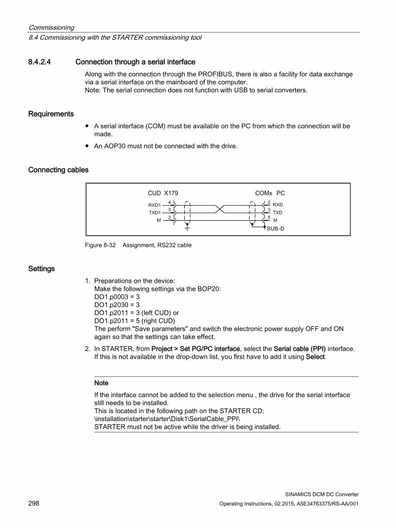
Commissioning 8.4 Commissioning with the STARTER commissioning tool
SINAMICS DCM DC Converter 298 Operating Instructions, 02.2015, A5E34763375/RS-AA/001
8.4.2.4 Connection through a serial interface Along with the connection through the PROFIBUS, there is also a facility for data exchange via a serial interface on the mainboard of the computer. Note: The serial connection does not function with USB to serial converters.
Requirements A serial interface (COM) must be available on the PC from which the connection will be
made.
An AOP30 must not be connected with the drive.
Connecting cables
Figure 8-32 Assignment, RS232 cable
Settings 1. Preparations on the device:
Make the following settings via the BOP20: DO1.p0003 = 3 DO1.p2030 = 3 DO1.p2011 = 3 (left CUD) or DO1.p2011 = 5 (right CUD) The perform "Save parameters" and switch the electronic power supply OFF and ON again so that the settings can take effect.
2. In STARTER, from Project > Set PG/PC interface, select the Serial cable (PPI) interface. If this is not available in the drop-down list, you first have to add it using Select.
Note
If the interface cannot be added to the selection menu , the drive for the serial interface still needs to be installed. This is located in the following path on the STARTER CD: \installation\starter\starter\Disk1\SerialCable_PPI\ STARTER must not be active while the driver is being installed.
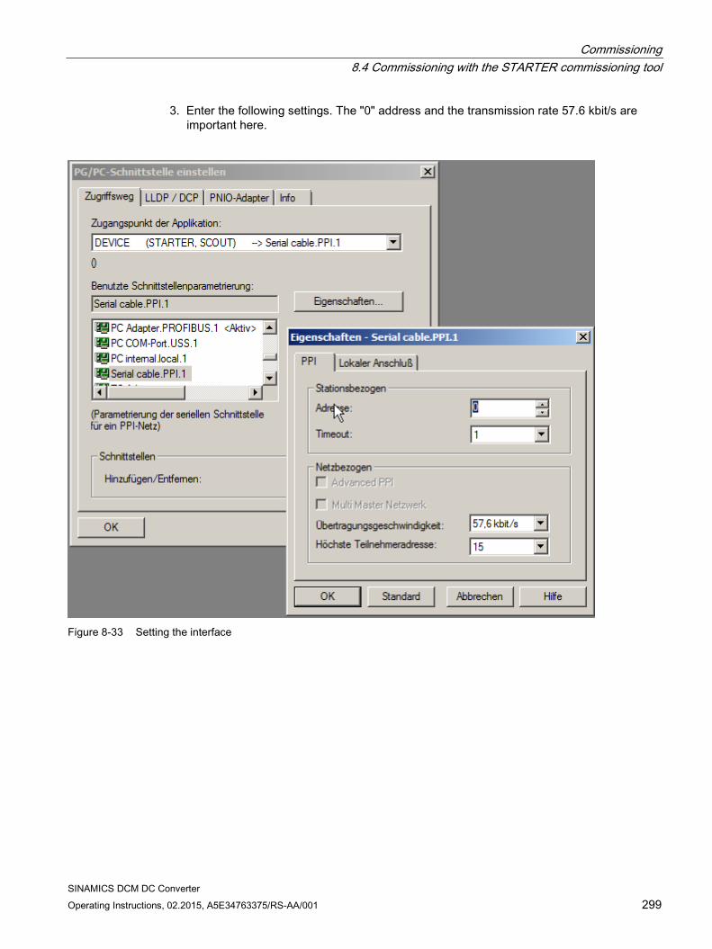
Commissioning 8.4 Commissioning with the STARTER commissioning tool
SINAMICS DCM DC Converter Operating Instructions, 02.2015, A5E34763375/RS-AA/001 299
3. Enter the following settings. The "0" address and the transmission rate 57.6 kbit/s are important here.
Figure 8-33 Setting the interface
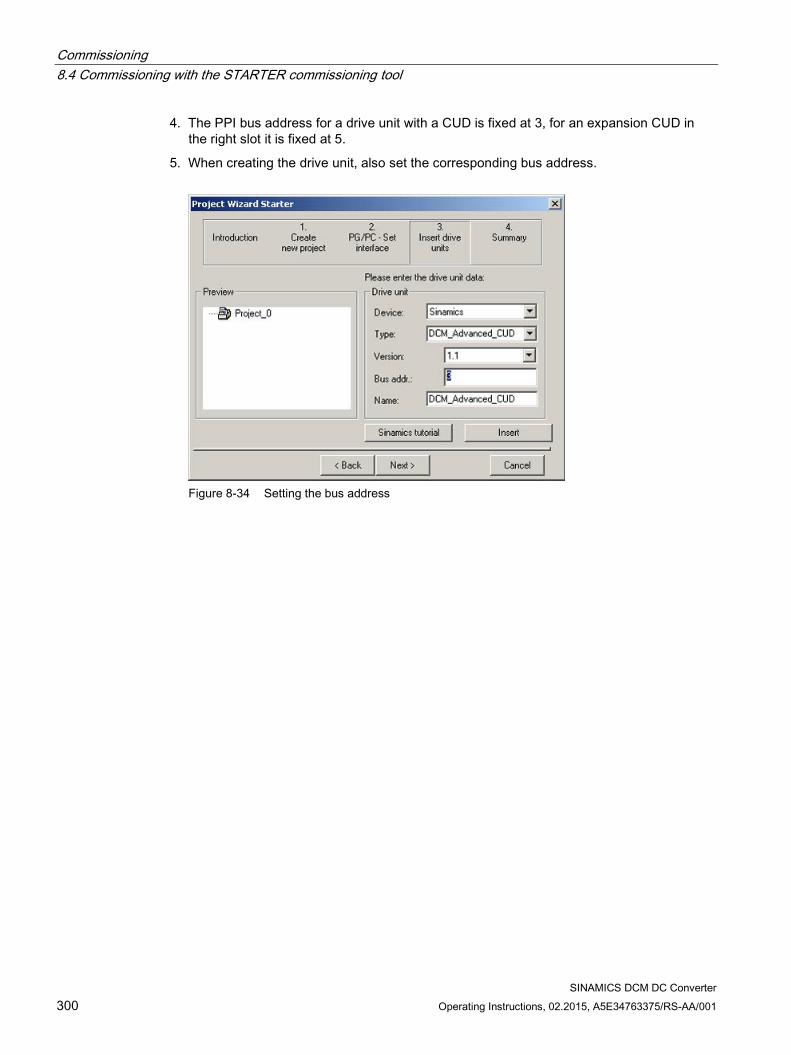
Commissioning 8.4 Commissioning with the STARTER commissioning tool
SINAMICS DCM DC Converter 300 Operating Instructions, 02.2015, A5E34763375/RS-AA/001
4. The PPI bus address for a drive unit with a CUD is fixed at 3, for an expansion CUD in the right slot it is fixed at 5.
5. When creating the drive unit, also set the corresponding bus address.
Figure 8-34 Setting the bus address
Commissioning 8.5 Activating function modules
SINAMICS DCM DC Converter Operating Instructions, 02.2015, A5E34763375/RS-AA/001 301
8.5 Activating function modules Subfunctions can be activated in the SINAMICS family drives as function modules.
Through activation, the parameters of the corresponding functionalities are also displayed.
Function modules can be individually activated / deactivated on every drive object.
For SINAMICS DC MASTER, the following subfunctions are modeled as function module.
Technology controller
Free function blocks
PROFINET interface

Commissioning 8.5 Activating function modules
SINAMICS DCM DC Converter 302 Operating Instructions, 02.2015, A5E34763375/RS-AA/001
8.5.1 Activating offline with STARTER Function modules can be defined for all DOs by using the properties dialog (activate by clicking with the right mouse button on the DO in the project navigator). Shown as example for the closed-loop control DO "Drive_1":
Figure 8-35 Properties
The function modules can be reached in the "Function modules" tab in the opening dialog.
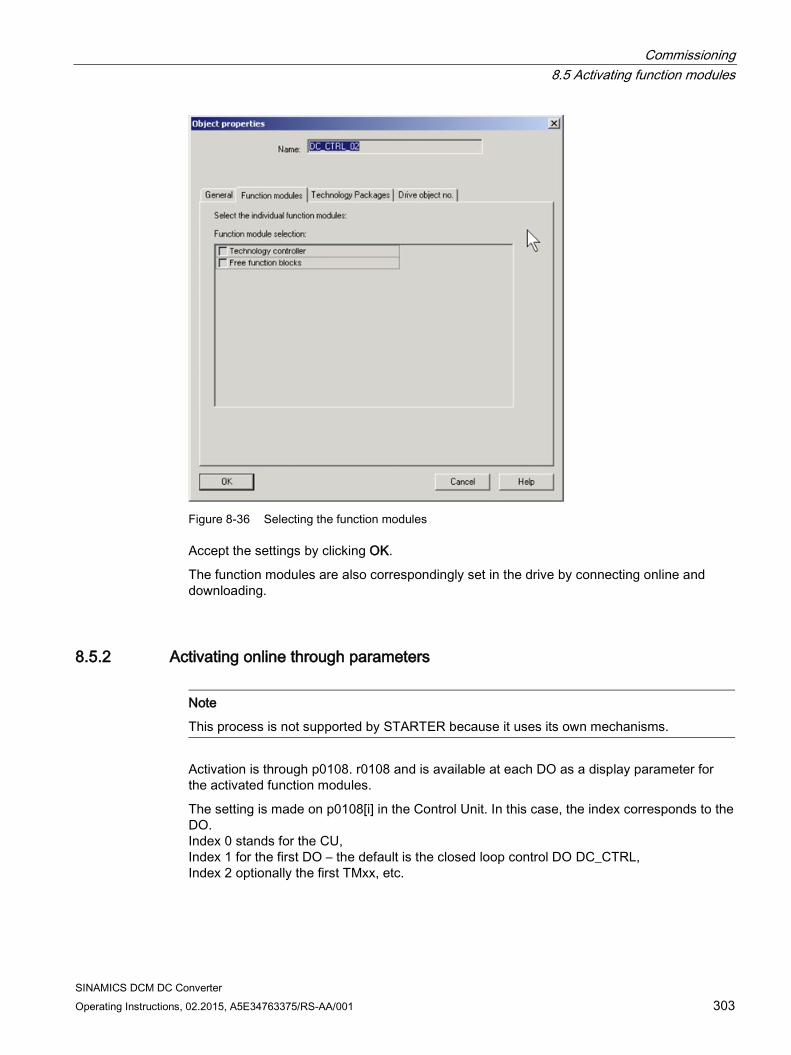
Commissioning 8.5 Activating function modules
SINAMICS DCM DC Converter Operating Instructions, 02.2015, A5E34763375/RS-AA/001 303
Figure 8-36 Selecting the function modules
Accept the settings by clicking OK.
The function modules are also correspondingly set in the drive by connecting online and downloading.
8.5.2 Activating online through parameters
Note
This process is not supported by STARTER because it uses its own mechanisms.
Activation is through p0108. r0108 and is available at each DO as a display parameter for the activated function modules.
The setting is made on p0108[i] in the Control Unit. In this case, the index corresponds to the DO. Index 0 stands for the CU, Index 1 for the first DO – the default is the closed loop control DO DC_CTRL, Index 2 optionally the first TMxx, etc.
Commissioning 8.5 Activating function modules
SINAMICS DCM DC Converter 304 Operating Instructions, 02.2015, A5E34763375/RS-AA/001
Sub-function p0108 bit Technology controller 16 Free function blocks 18 PROFINET interface 31
The function modules are activated / deactivated by setting the bits to 1 or 0.
On BOP20 or AOP30 parameter assignment is made at DO1 (CU_DC)
p0009=2
Correspondingly set or delete p0108[i] bits
p0009=0
This triggers the software to reboot, therefore activating the function modules that have been set - together with the associated parameters.
Note
Changing the parameters – The quantity structure is copied to the optional AOP30 by "relearning" the existing parameters. This takes a few minutes.
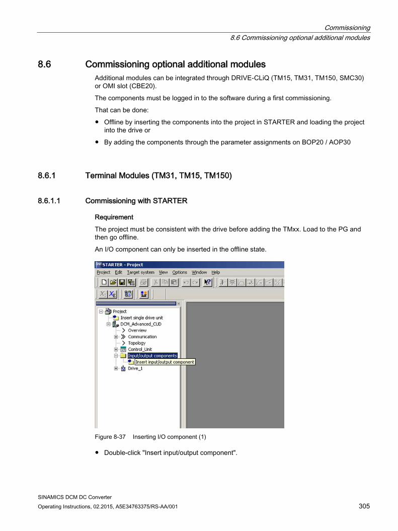
Commissioning 8.6 Commissioning optional additional modules
SINAMICS DCM DC Converter Operating Instructions, 02.2015, A5E34763375/RS-AA/001 305
8.6 Commissioning optional additional modules Additional modules can be integrated through DRIVE-CLiQ (TM15, TM31, TM150, SMC30) or OMI slot (CBE20).
The components must be logged in to the software during a first commissioning.
That can be done:
Offline by inserting the components into the project in STARTER and loading the project into the drive or
By adding the components through the parameter assignments on BOP20 / AOP30
8.6.1 Terminal Modules (TM31, TM15, TM150)
8.6.1.1 Commissioning with STARTER
Requirement
The project must be consistent with the drive before adding the TMxx. Load to the PG and then go offline.
An I/O component can only be inserted in the offline state.
Figure 8-37 Inserting I/O component (1)
Double-click "Insert input/output component".
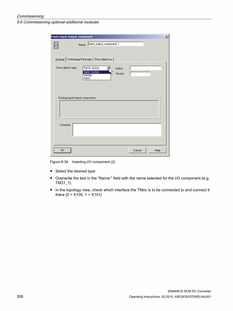
Commissioning 8.6 Commissioning optional additional modules
SINAMICS DCM DC Converter 306 Operating Instructions, 02.2015, A5E34763375/RS-AA/001
Figure 8-38 Inserting I/O component (2)
Select the desired type
Overwrite the text in the "Name:" field with the name selected for the I/O component (e.g. TM31_1).
In the topology view, check which interface the TMxx is to be connected to and connect it there (0 = X100, 1 = X101)
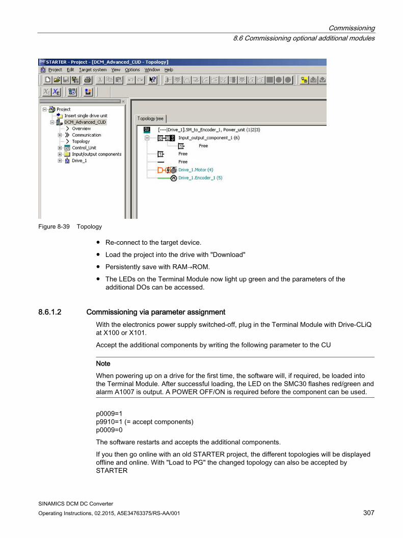
Commissioning 8.6 Commissioning optional additional modules
SINAMICS DCM DC Converter Operating Instructions, 02.2015, A5E34763375/RS-AA/001 307
Figure 8-39 Topology
Re-connect to the target device.
Load the project into the drive with "Download"
Persistently save with RAM→ROM.
The LEDs on the Terminal Module now light up green and the parameters of the additional DOs can be accessed.
8.6.1.2 Commissioning via parameter assignment With the electronics power supply switched-off, plug in the Terminal Module with Drive-CLiQ at X100 or X101.
Accept the additional components by writing the following parameter to the CU
Note
When powering up on a drive for the first time, the software will, if required, be loaded into the Terminal Module. After successful loading, the LED on the SMC30 flashes red/green and alarm A1007 is output. A POWER OFF/ON is required before the component can be used.
p0009=1 p9910=1 (= accept components) p0009=0
The software restarts and accepts the additional components.
If you then go online with an old STARTER project, the different topologies will be displayed offline and online. With "Load to PG" the changed topology can also be accepted by STARTER
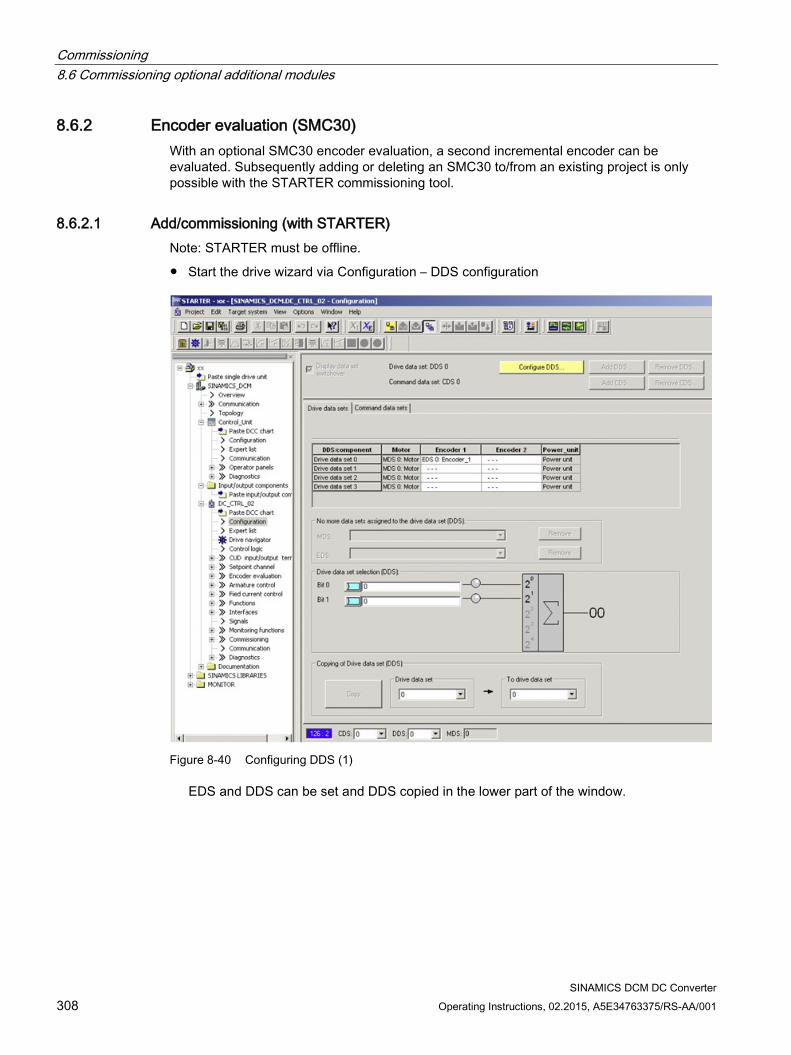
Commissioning 8.6 Commissioning optional additional modules
SINAMICS DCM DC Converter 308 Operating Instructions, 02.2015, A5E34763375/RS-AA/001
8.6.2 Encoder evaluation (SMC30) With an optional SMC30 encoder evaluation, a second incremental encoder can be evaluated. Subsequently adding or deleting an SMC30 to/from an existing project is only possible with the STARTER commissioning tool.
8.6.2.1 Add/commissioning (with STARTER)
Note: STARTER must be offline.
Start the drive wizard via Configuration – DDS configuration
Figure 8-40 Configuring DDS (1)
EDS and DDS can be set and DDS copied in the lower part of the window.
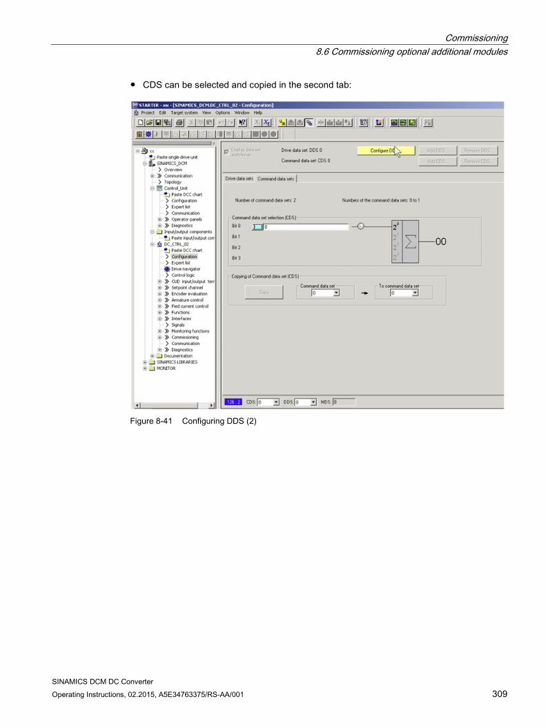
Commissioning 8.6 Commissioning optional additional modules
SINAMICS DCM DC Converter Operating Instructions, 02.2015, A5E34763375/RS-AA/001 309
CDS can be selected and copied in the second tab:
Figure 8-41 Configuring DDS (2)
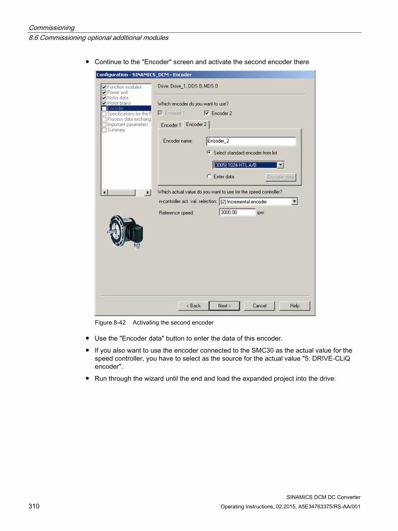
Commissioning 8.6 Commissioning optional additional modules
SINAMICS DCM DC Converter 310 Operating Instructions, 02.2015, A5E34763375/RS-AA/001
Continue to the "Encoder" screen and activate the second encoder there
Figure 8-42 Activating the second encoder
Use the "Encoder data" button to enter the data of this encoder.
If you also want to use the encoder connected to the SMC30 as the actual value for the speed controller, you have to select as the source for the actual value "5: DRIVE-CLiQ encoder".
Run through the wizard until the end and load the expanded project into the drive.

Commissioning 8.6 Commissioning optional additional modules
SINAMICS DCM DC Converter Operating Instructions, 02.2015, A5E34763375/RS-AA/001 311
8.6.2.2 Remove (with STARTER) Note: It is only possible to remove the encoder evaluation from the project in the offline mode
Start the drive wizard via Configuration - configure DDS
With Continue>, go to the "Encoder" screen form, and there, deselect encoder 2
Run through the wizard until the end
Unplug the encoder evaluation SMC30
Go online
Load the project to the drive
8.6.3 PROFINET module (CBE20)
8.6.3.1 Adding online into the drive The CBE20 is automatically detected when plugged into the slot and is integrated into the system.
Before the module can also be addressed in the network, an IP address and device name must be assigned; refer to the Chapter "Function descriptions", Section "PROFINET IO".
Note: If PROFINET is to be used only as a commissioning interface but process control is through PROFIBUS, after commissioning the CBE20 the process data interface needs to be set back to PROFIBUS (p8839=1).
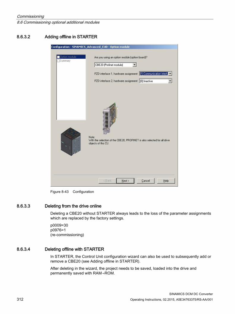
Commissioning 8.6 Commissioning optional additional modules
SINAMICS DCM DC Converter 312 Operating Instructions, 02.2015, A5E34763375/RS-AA/001
8.6.3.2 Adding offline in STARTER
Figure 8-43 Configuration
8.6.3.3 Deleting from the drive online Deleting a CBE20 without STARTER always leads to the loss of the parameter assignments which are replaced by the factory settings.
p0009=30 p0976=1 (re-commissioning)
8.6.3.4 Deleting offline with STARTER In STARTER, the Control Unit configuration wizard can also be used to subsequently add or remove a CBE20 (see Adding offline in STARTER).
After deleting in the wizard, the project needs to be saved, loaded into the drive and permanently saved with RAM→ROM.
Commissioning 8.7 Drive optimization
SINAMICS DCM DC Converter Operating Instructions, 02.2015, A5E34763375/RS-AA/001 313
8.7 Drive optimization
Basic information The individual control loops must be optimized when commissioning a drive.
4 control loops must be set or optimized:
Field current closed-loop control
Armature current closed-loop control
Speed control
EMF closed-loop control
SINAMICS DCM supports this task in 2 ways.
Quick commissioning The controller parameters are calculated from the rated data of the motor and the power unit. No measurements are made. Only the parameters for the field current closed-loop control, the armature closed-loop control and the speed closed-loop control are determined. The parameters set during the quick commissioning allow reliable drive operation in the majority of cases.
Optimization runs The controller parameters are determined from the rated data of the motor and the power unit and by evaluating measurement results. The parameters of all 4 control loops are determined. The parameters set using the optimization runs can be kept in the majority of cases. In exceptional cases, manual post-optimization is necessary (see Chapter "Manual optimization").
Quick commissioning Procedure
Start the quick commissioning with p10 = 1 (= factory setting)
Set all of the important parameters (see e.g. commissioning steps in Chapter "Commissioning using the BOP20") operator panel
Complete the quick commissioning with p3900 = 3 (calculations are performed, p10 and p3900 are reset to 0)
Commissioning using the BOP20 operator panel: This procedure is explained for the commissioning steps in Chapter "Commissioning using the BOP20" operator panel.
Commissioning using the AOP30 operator panel: Quick commissioning is completed (p3900 = 3) as part of the final confirmation. (see Chapter "Commissioning using the AOP30 operator panel", Section "Complete drive commissioning").
Commissioning 8.7 Drive optimization
SINAMICS DCM DC Converter 314 Operating Instructions, 02.2015, A5E34763375/RS-AA/001
Commissioning using the STARTER commissioning tool: The completion of quick commissioning (p3900 = 3) is selected as part of "Complete" of the Wizard "Configuring the drive unit". (see Chapter "Commissioning using the STARTER commissioning tool", Section "Configuring the drive unit"). After successfully "Loading the project into the target system" (see Chapter "Commissioning using the STARTER commissioning tool", Section "Start drive project"), quick commissioning is completed in the SINAMICS DCM.
Optimization runs
WARNING
During optimization runs, the drive initiates movements of the motor shaft that can reach the maximum motor speed.
The EMERGENCY OFF functions must function at the commissioning. To protect man and machines, the relevant safety regulations must be observed.
Procedure 〈1〉 The drive must be in operating state o7.0 or o7.1 (enter SHUTDOWN!). 〈2〉 p50051 = 23 Optimization of the armature current control for induction load
p50051 = 24 Optimization of the field current control p50051 = 25 Optimization of the armature current control p50051 = 26 Optimization of the speed control p50051 = 27 Optimization of the EMF control (incl. field characteristic recording) p50051 = 28 Recording of the friction characteristic p50051 = 29 Optimization of the speed control for drives with a mechanical system
capable of oscillation 〈3〉 The SINAMICS DCM Control Module goes into operating state o7.4 for a few sec-
onds, and then goes into o7.0 or o7.1 and waits for SWITCH ON and OPERATION ENABLE to be entered. Enter the commands SWITCH ON and OPERATION ENABLE! If the switch-on command is not entered within 30 s, this wait state is exited and fault message F60052 is output.
〈4〉 Execution of the optimization run starts once operating state <o1.0 (OPERATION) is reached.
〈5〉 When the optimization run has been completed, the drive goes into operating state o8.0
Note
The optimization runs should be performed in the order specified above.
Commissioning 8.7 Drive optimization
SINAMICS DCM DC Converter Operating Instructions, 02.2015, A5E34763375/RS-AA/001 315
Details on the individual optimization runs p50051 = 24 Optimization of closed-loop field current control
(duration of up to 1 min.) This optimization run may also be executed without a mechanical load con-nected. The following parameters are set automatically: p50112, field resistance (Rf) p50116, field inductance (Lf) p50255, P gain of field current controller (Kp) p50256, integral time of field current controller (Tn) p51597, field inductance reduction factor
p50051 = 25 Optimization of closed-loop armature current control (takes about 1 min.) The current controller optimization run may also be executed without a me-chanical load connected; if necessary, the drive should be locked. The following parameters are set automatically: p50110, armature resistance (Ra) p50111, armature inductance (La) p51591, non-linearity factor of armature inductance (La_fak) p51592, armature commutation inductance (Lk) p51594, filter inductance for 12-pulse operation (Ls) p51595, filter inductance reduction factor (Ls_fak) p51596, filter resistance in 12-pulse operation (Rs) p50155, P gain of the armature current controller (Kp) p50156, integral time of armature current controller (Tn)
NOTICE
Motors with a permanent field, a very high level of retentiveness, or a series field must be locked during this optimization run.
WARNING
The current limits set are not active during the current controller optimization run. 75% of the rated armature current for the motor flows for approximately 0.7 s.
Note
The parameters determined are dependent on the motor temperature. The values set with the motor in the cold state can serve as a good default setting. For drives with a high dynamic performance, the optimization run p50051=25 should be repeated after operating the drive with a load (e.g. with the motor at the operating temperature).
Commissioning 8.7 Drive optimization
SINAMICS DCM DC Converter 316 Operating Instructions, 02.2015, A5E34763375/RS-AA/001
p50051 = 26 Optimization of the speed control
(takes at least 6 s) The dynamic performance of the speed control loop can be selected using p50236, whereby lower values represent a softer closed-loop control. Before carrying out the speed controller optimization run, p50236 must be set and influences the setting of p50225, p50226, p50228 and p50540. Where possible, the final mechanical load should be connected to the motor for the purpose of optimizing the speed controller, as the parameters set depend on the measured moment of inertia. The following parameters are automatically set: p50225, P gain of speed controller (Kp) p50226, integral time of speed controller (Tn) p50228, speed setpoint smoothing time constant p50540, speed controller acceleration time Remark: The speed controller optimization run only takes into account the filtering of the actual speed controller value that is set at p50200; and if p50083 = 1, also filtering of the main actual value, which is parameterized at p50745. For p50200 <20 ms, P50225 (gain) is limited to a value of 30.00. The speed controller optimization run always sets p50228 (speed setpoint filtering) to 0.
WARNING
During the speed controller optimization run, the motor is accelerated at a maximum of 45% of its rated armature current. The motor can reach speeds of up to approximately 20% of the maximum speed.
p50051 = 27 Optimization of the EMF control (incl. field characteristic recording)
(duration, approx. 1 min) This optimization run must be executed whenever field-weakening operation has been selected (p50081 = 1), if closed-loop torque control (p50170 = 1) or torque limiting (p50169 = 1) has been selected, or if a variable field cur-rent setpoint has been entered. This optimization run may also be started without a mechanical load. The following parameters are set automatically:
p50120 to p50139
Field characteristic (magnetization characteristic) of motor
p50275 P gain of EMF controller (Kp) p50276 Integral time of EMF controller (Tn)
Commissioning 8.7 Drive optimization
SINAMICS DCM DC Converter Operating Instructions, 02.2015, A5E34763375/RS-AA/001 317
Remark:
In order to determine the magnetization characteristic, during this optimization run the field-current setpoint is reduced to a minimum value of 8% (starting from 100% of the motor's rated excitation current as specified in p50102). Setting p50103 to values < 50% of p50102 for the duration of this optimization run limits the value entered for the field-current setpoint to the minimum value specified in p50103. This may be necessary for uncompensated motors with an extremely high armature response.
The magnetization characteristic approaches 0 along a linear path (starting from the measuring point), with the minimum field-current setpoint.
To execute this optimization run, the minimum excitation current for the motor (p50103) must be set to a lower value than 50% of the motor's rated excitation current (p50102).
WARNING
During this optimization run, the drive accelerates to approx. 80% of the rated motor speed. The maximum armature voltage is 80% of the rated armature voltage of the motor (p50101).
p50051 = 28 Recording of the friction characteristic
(duration, approx. 1 min) The following parameters are set automatically:
p50520 to p50530
Friction characteristic
Remark 1: The friction characteristic is only active in operation if it is manually activat-ed with p50223=1! Remark 2: In order to execute this optimization run, the speed controller must not be parameterized as a pure P controller or as a controller with droop.
WARNING
During this optimization run, the drive accelerates up to its maximum speed.
Commissioning 8.7 Drive optimization
SINAMICS DCM DC Converter 318 Operating Instructions, 02.2015, A5E34763375/RS-AA/001
p50051 = 29 Optimization of the speed control for drives with a mechanical system capa-ble of oscillation (duration up to 10 min) The following parameters are set automatically:
p50225 P gain of the speed controller (Kp) p50226 Integral time of the speed controller (Tn) p50228 Speed setpoint, smoothing time constant p50540 Speed controller acceleration time The frequency response of the controlled system for frequencies between 1
and 100 Hz is recorded during this optimization run. For this purpose, the drive is first accelerated to a basic speed (p50565, factory setting = 20%). A sinusoidal speed setpoint with a low amplitude (p50566, factory setting = 1%) is then switched in. The frequency of this additional setpoint is changed in 1 Hz increments from 1 to 100 Hz. For each frequency, an average is generated over a specific time (p50567, fac-tory setting = 1 s). The value set at p50567 essentially defines the duration of this optimization run. For a setting of 1 s it takes about 3 to 4 min. The measured frequency response of the controlled system forms the basis for determining its optimal speed controller setting.
WARNING
This optimization run must not be executed if the motor is connected to a mechanical load that is able to move the motor while it is in a torque-free state (e.g. a suspended load).
Note
For drives with limited travel distance, the optimization run for field weakening (p50051 = 27) should be interrupted by entering the SHUTDOWN command at the earliest after the 1st field-weakening measuring point has been plotted or the friction characteristic has been plotted (p50051 = 28) and at the earliest after determining the measuring point at 10% of the maximum speed - without fault message F60052 being initiated. Once the optimization run in question (p50051 = 27 or p50051 = 28) has been restarted, it will resume at a more advanced point, meaning that it can be completed in several stages even in cases where the travel distance is limited.
In the following cases, each optimization run is completely executed again after a restart: • If a fault occurs during the optimization run • If the electronic supply is switched off prior to restarting the optimization run in question • If a different drive data set from the previous one is selected • If a different optimization run is started in the meantime
The parameters for the drive data set that has been selected in each case are optimized.
The drive data set selection must remain the same throughout the optimization runs to avoid a fault being output.
Commissioning 8.8 Manual optimization
SINAMICS DCM DC Converter Operating Instructions, 02.2015, A5E34763375/RS-AA/001 319
8.8 Manual optimization Manual optimization is best performed using the STARTER commissioning tool.
For this purpose, STARTER provides the functions
function generator and
trace.
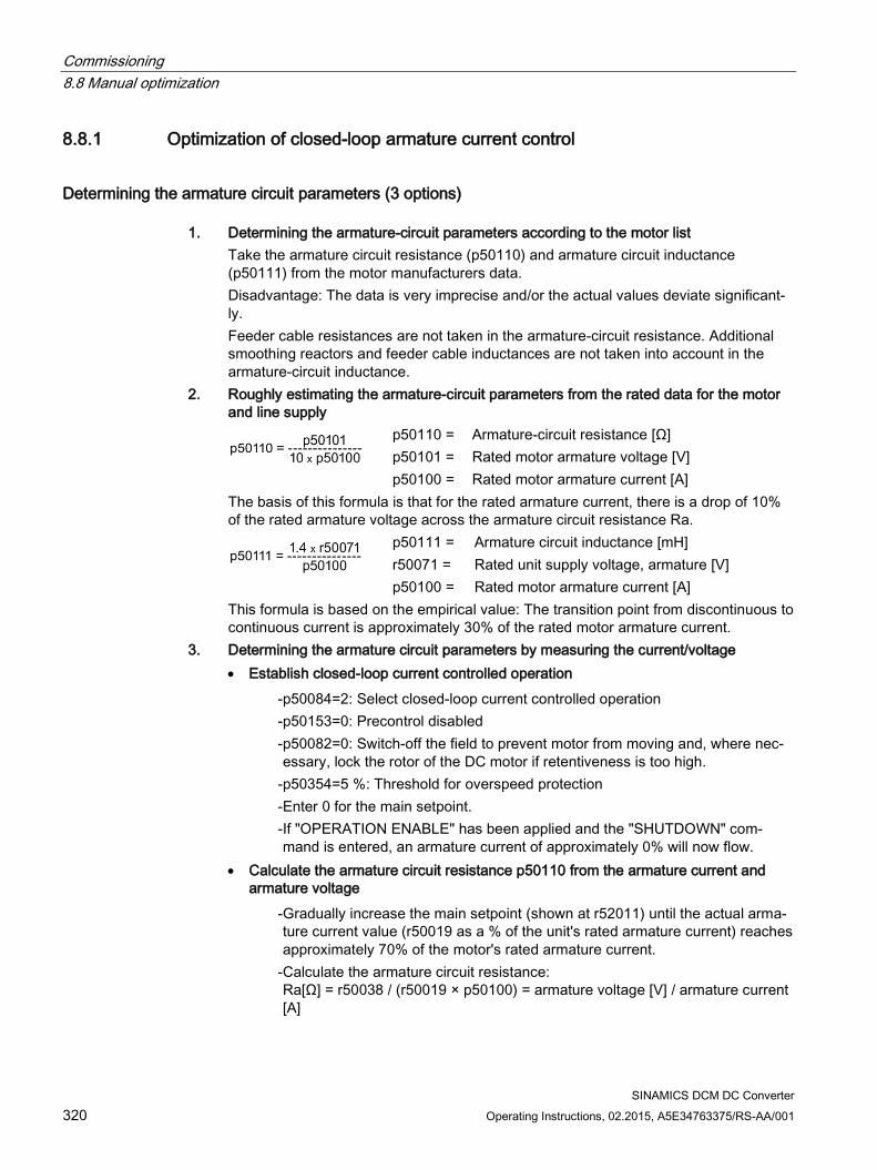
Commissioning 8.8 Manual optimization
SINAMICS DCM DC Converter 320 Operating Instructions, 02.2015, A5E34763375/RS-AA/001
8.8.1 Optimization of closed-loop armature current control
Determining the armature circuit parameters (3 options) 1. Determining the armature-circuit parameters according to the motor list
Take the armature circuit resistance (p50110) and armature circuit inductance (p50111) from the motor manufacturers data. Disadvantage: The data is very imprecise and/or the actual values deviate significant-ly. Feeder cable resistances are not taken in the armature-circuit resistance. Additional smoothing reactors and feeder cable inductances are not taken into account in the armature-circuit inductance.
2. Roughly estimating the armature-circuit parameters from the rated data for the motor and line supply
p50110 = Armature-circuit resistance [Ω] p50101 = Rated motor armature voltage [V] p50100 = Rated motor armature current [A] The basis of this formula is that for the rated armature current, there is a drop of 10%
of the rated armature voltage across the armature circuit resistance Ra.
p50111 = Armature circuit inductance [mH] r50071 = Rated unit supply voltage, armature [V] p50100 = Rated motor armature current [A] This formula is based on the empirical value: The transition point from discontinuous to
continuous current is approximately 30% of the rated motor armature current. 3. Determining the armature circuit parameters by measuring the current/voltage • Establish closed-loop current controlled operation - p50084=2: Select closed-loop current controlled operation - p50153=0: Precontrol disabled - p50082=0: Switch-off the field to prevent motor from moving and, where nec-
essary, lock the rotor of the DC motor if retentiveness is too high. - p50354=5 %: Threshold for overspeed protection - Enter 0 for the main setpoint. - If "OPERATION ENABLE" has been applied and the "SHUTDOWN" com-
mand is entered, an armature current of approximately 0% will now flow. • Calculate the armature circuit resistance p50110 from the armature current and
armature voltage - Gradually increase the main setpoint (shown at r52011) until the actual arma-
ture current value (r50019 as a % of the unit's rated armature current) reaches approximately 70% of the motor's rated armature current.
- Calculate the armature circuit resistance: Ra[Ω] = r50038 / (r50019 × p50100) = armature voltage [V] / armature current [A]
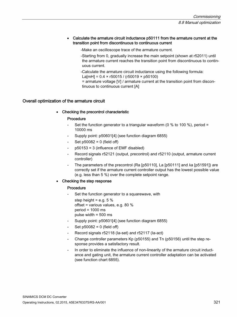
Commissioning 8.8 Manual optimization
SINAMICS DCM DC Converter Operating Instructions, 02.2015, A5E34763375/RS-AA/001 321
• Calculate the armature circuit inductance p50111 from the armature current at the transition point from discontinuous to continuous current
- Make an oscilloscope trace of the armature current. - Starting from 0, gradually increase the main setpoint (shown at r52011) until
the armature current reaches the transition point from discontinuous to contin-uous current.
- Calculate the armature circuit inductance using the following formula: La[mH] = 0.4 × r50015 / (r50019 × p50100) = armature voltage [V] / armature current at the transition point from discon-tinuous to continuous current [A]
Overall optimization of the armature circuit • Checking the precontrol characteristic Procedure - Set the function generator to a triangular waveform (0 % to 100 %), period =
10000 ms - Supply point: p50601[4] (see function diagram 6855) - Set p50082 = 0 (field off) - p50153 = 3 (influence of EMF disabled) - Record signals r52121 (output, precontrol) and r52110 (output, armature current
controller) - The parameters of the precontrol (Ra [p50110], La [p50111] and λa [p51591]) are
correctly set if the armature current controller output has the lowest possible value (e.g. less than 5 %) over the complete setpoint range.
• Checking the step response Procedure - Set the function generator to a squarewave, with
step height = e.g. 5 % offset = various values, e.g. 80 % period = 1000 ms pulse width = 500 ms
- Supply point: p50601[4] (see function diagram 6855) - Set p50082 = 0 (field off) - Record signals r52118 (Ia-set) and r52117 (Ia-act) - Change controller parameters Kp (p50155) and Tn (p50156) until the step re-
sponse provides a satisfactory result. - In order to eliminate the influence of non-linearity of the armature circuit induct-
ance and gating unit, the armature current controller adaptation can be activated (see function chart 6855).
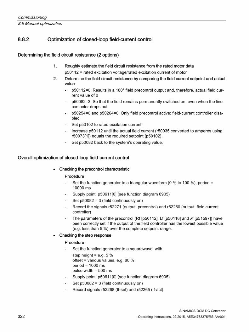
Commissioning 8.8 Manual optimization
SINAMICS DCM DC Converter 322 Operating Instructions, 02.2015, A5E34763375/RS-AA/001
8.8.2 Optimization of closed-loop field-current control
Determining the field circuit resistance (2 options) 1. Roughly estimate the field circuit resistance from the rated motor data
p50112 = rated excitation voltage/rated excitation current of motor 2. Determine the field-circuit resistance by comparing the field current setpoint and actual
value - p50112=0: Results in a 180° field precontrol output and, therefore, actual field cur-
rent value of 0 - p50082=3: So that the field remains permanently switched on, even when the line
contactor drops out - p50254=0 and p50264=0: Only field precontrol active; field-current controller disa-
bled - Set p50102 to rated excitation current. - Increase p50112 until the actual field current (r50035 converted to amperes using
r50073[1]) equals the required setpoint (p50102). - Set p50082 back to the system's operating value.
Overall optimization of closed-loop field-current control • Checking the precontrol characteristic Procedure - Set the function generator to a triangular waveform (0 % to 100 %), period =
10000 ms - Supply point: p50611[0] (see function diagram 6905) - Set p50082 = 3 (field continuously on) - Record the signals r52271 (output, precontrol) and r52260 (output, field current
controller) - The parameters of the precontrol (Rf [p50112], Lf [p50116] and λf [p51597]) have
been correctly set if the output of the field controller has the lowest possible value (e.g. less than 5 %) over the complete setpoint range.
• Checking the step response Procedure - Set the function generator to a squarewave, with
step height = e.g. 5 % offset = various values, e.g. 80 % period = 1000 ms pulse width = 500 ms
- Supply point: p50611[0] (see function diagram 6905) - Set p50082 = 3 (field continuously on) - Record signals r52268 (If-set) and r52265 (If-act)
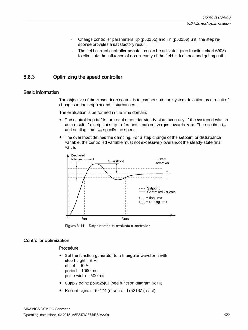
Commissioning 8.8 Manual optimization
SINAMICS DCM DC Converter Operating Instructions, 02.2015, A5E34763375/RS-AA/001 323
- Change controller parameters Kp (p50255) and Tn (p50256) until the step re-sponse provides a satisfactory result.
- The field current controller adaptation can be activated (see function chart 6908) to eliminate the influence of non-linearity of the field inductance and gating unit.
8.8.3 Optimizing the speed controller
Basic information The objective of the closed-loop control is to compensate the system deviation as a result of changes to the setpoint and disturbances.
The evaluation is performed in the time domain:
The control loop fulfills the requirement for steady-state accuracy, if the system deviation as a result of a setpoint step (reference input) converges towards zero. The rise time tan and settling time taus specify the speed.
The overshoot defines the damping. For a step change of the setpoint or disturbance variable, the controlled variable must not excessively overshoot the steady-state final value.
Figure 8-44 Setpoint step to evaluate a controller
Controller optimization Procedure
Set the function generator to a triangular waveform with step height = 5 % offset = 10 % period = 1000 ms pulse width = 500 ms
Supply point: p50625[C] (see function diagram 6810)
Record signals r52174 (n-set) and r52167 (n-act)
Commissioning 8.8 Manual optimization
SINAMICS DCM DC Converter 324 Operating Instructions, 02.2015, A5E34763375/RS-AA/001
Assessment
If the step response of the speed controller is recorded after performing the optimization run for the speed controller, then the significant increase of the setpoint step can be clearly seen - which is characteristic for optimization according to the symmetrical optimum.
A controller adjusted according to the symmetrical optimum has a significant overshoot, however, a favorable response to disturbances. This optimization has especially established itself in drive technology as many systems require a good disturbance variable compensation. This is the reason why the optimization run for the speed controller sets the controller parameters according to the symmetrical optimum.
An improved response to setpoint changes with the response to disturbances remaining the same can be achieved using the reference model. See Chapter "Function descriptions", Section "Speed controller".
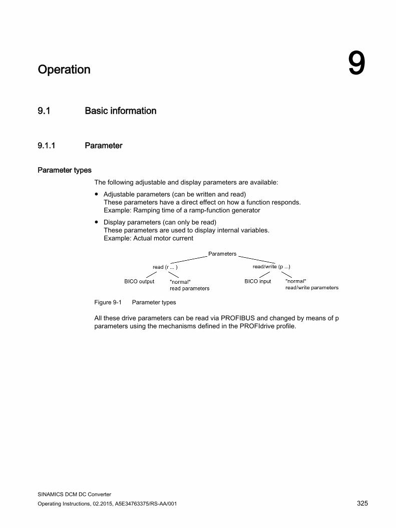
SINAMICS DCM DC Converter Operating Instructions, 02.2015, A5E34763375/RS-AA/001 325
Operation 9 9.1 Basic information
9.1.1 Parameter
Parameter types The following adjustable and display parameters are available:
Adjustable parameters (can be written and read) These parameters have a direct effect on how a function responds. Example: Ramping time of a ramp-function generator
Display parameters (can only be read) These parameters are used to display internal variables. Example: Actual motor current
Figure 9-1 Parameter types
All these drive parameters can be read via PROFIBUS and changed by means of p parameters using the mechanisms defined in the PROFIdrive profile.
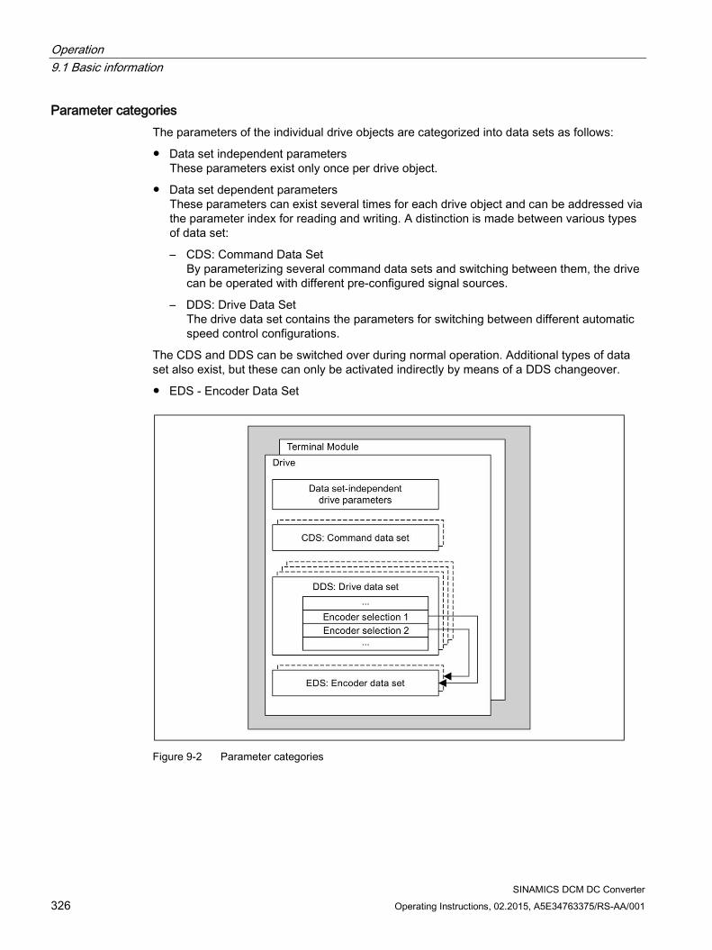
Operation 9.1 Basic information
SINAMICS DCM DC Converter 326 Operating Instructions, 02.2015, A5E34763375/RS-AA/001
Parameter categories The parameters of the individual drive objects are categorized into data sets as follows:
Data set independent parameters These parameters exist only once per drive object.
Data set dependent parameters These parameters can exist several times for each drive object and can be addressed via the parameter index for reading and writing. A distinction is made between various types of data set:
– CDS: Command Data Set By parameterizing several command data sets and switching between them, the drive can be operated with different pre-configured signal sources.
– DDS: Drive Data Set The drive data set contains the parameters for switching between different automatic speed control configurations.
The CDS and DDS can be switched over during normal operation. Additional types of data set also exist, but these can only be activated indirectly by means of a DDS changeover.
EDS - Encoder Data Set
Figure 9-2 Parameter categories
Operation 9.1 Basic information
SINAMICS DCM DC Converter Operating Instructions, 02.2015, A5E34763375/RS-AA/001 327
Saving parameters in a non-volatile memory The modified parameter values are stored in the volatile RAM. When the drive system is switched off, this data is lost.
The data must be saved in the non-volatile memory, as described below, so that the changes are available the next time the drive is switched on.
Saving parameters with STARTER See "Copy RAM to ROM" function
Saving parameters p0977 = 1; automatically reset to 0
Note
The power supply to the Control Unit may first be switched off only after saving has finished (i.e. after saving has started, wait until the parameter has the value 0 again).
Resetting parameters The parameters can be reset to the factory setting as follows: p0009 = 30 Parameter reset p0976 = 1 Start restoring all parameters to their factory settings
After this has been done, p0976 is automatically set to 0 and p0009 is set to 1.
Deleting all user data In addition to the actual parameter data set, which saves the parameter assignment of the device in a non-volatile memory (ROM) of the device and which can be deleted using p0976=1 (restore factory settings), the following data also belongs to the non-volatile user data:
DCC charts
The DCC block library
Additional parameter data sets (see p0802, p0803, p0804)
This data is also saved in the non-volatile memory (ROM). All user data is deleted from the ROM as follows: p0009 = 30 Parameter reset p0976 = 200 Start to delete all user data
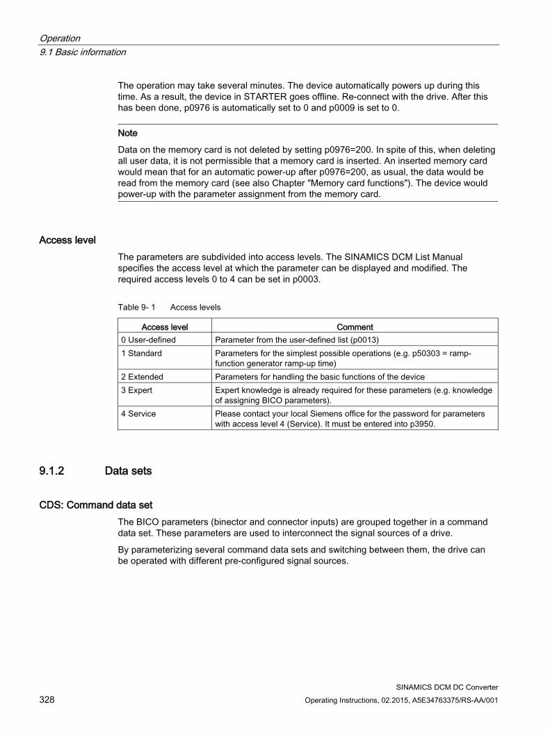
Operation 9.1 Basic information
SINAMICS DCM DC Converter 328 Operating Instructions, 02.2015, A5E34763375/RS-AA/001
The operation may take several minutes. The device automatically powers up during this time. As a result, the device in STARTER goes offline. Re-connect with the drive. After this has been done, p0976 is automatically set to 0 and p0009 is set to 0.
Note
Data on the memory card is not deleted by setting p0976=200. In spite of this, when deleting all user data, it is not permissible that a memory card is inserted. An inserted memory card would mean that for an automatic power-up after p0976=200, as usual, the data would be read from the memory card (see also Chapter "Memory card functions"). The device would power-up with the parameter assignment from the memory card.
Access level The parameters are subdivided into access levels. The SINAMICS DCM List Manual specifies the access level at which the parameter can be displayed and modified. The required access levels 0 to 4 can be set in p0003.
Table 9- 1 Access levels
Access level Comment 0 User-defined Parameter from the user-defined list (p0013) 1 Standard Parameters for the simplest possible operations (e.g. p50303 = ramp-
function generator ramp-up time) 2 Extended Parameters for handling the basic functions of the device 3 Expert Expert knowledge is already required for these parameters (e.g. knowledge
of assigning BICO parameters). 4 Service Please contact your local Siemens office for the password for parameters
with access level 4 (Service). It must be entered into p3950.
9.1.2 Data sets
CDS: Command data set The BICO parameters (binector and connector inputs) are grouped together in a command data set. These parameters are used to interconnect the signal sources of a drive.
By parameterizing several command data sets and switching between them, the drive can be operated with different pre-configured signal sources.
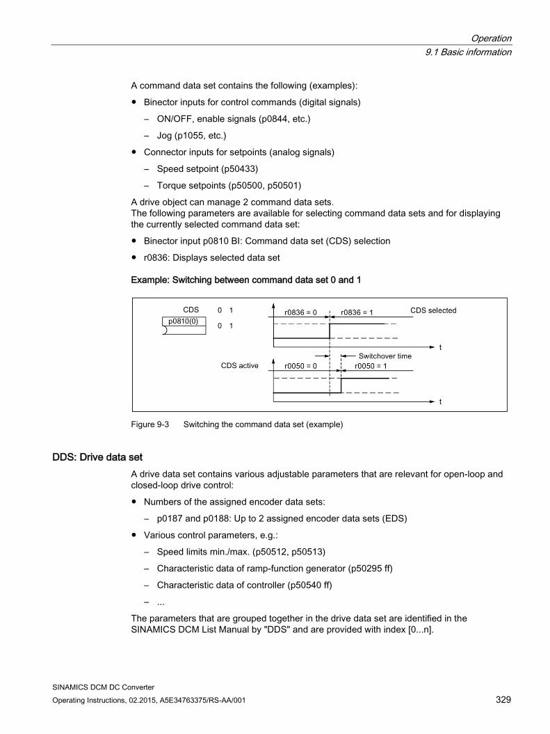
Operation 9.1 Basic information
SINAMICS DCM DC Converter Operating Instructions, 02.2015, A5E34763375/RS-AA/001 329
A command data set contains the following (examples):
Binector inputs for control commands (digital signals)
– ON/OFF, enable signals (p0844, etc.)
– Jog (p1055, etc.)
Connector inputs for setpoints (analog signals)
– Speed setpoint (p50433)
– Torque setpoints (p50500, p50501)
A drive object can manage 2 command data sets. The following parameters are available for selecting command data sets and for displaying the currently selected command data set:
Binector input p0810 BI: Command data set (CDS) selection
r0836: Displays selected data set
Example: Switching between command data set 0 and 1
Figure 9-3 Switching the command data set (example)
DDS: Drive data set A drive data set contains various adjustable parameters that are relevant for open-loop and closed-loop drive control:
Numbers of the assigned encoder data sets:
– p0187 and p0188: Up to 2 assigned encoder data sets (EDS)
Various control parameters, e.g.:
– Speed limits min./max. (p50512, p50513)
– Characteristic data of ramp-function generator (p50295 ff)
– Characteristic data of controller (p50540 ff)
– ...
The parameters that are grouped together in the drive data set are identified in the SINAMICS DCM List Manual by "DDS" and are provided with index [0...n].
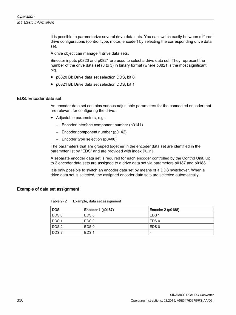
Operation 9.1 Basic information
SINAMICS DCM DC Converter 330 Operating Instructions, 02.2015, A5E34763375/RS-AA/001
It is possible to parameterize several drive data sets. You can switch easily between different drive configurations (control type, motor, encoder) by selecting the corresponding drive data set.
A drive object can manage 4 drive data sets.
Binector inputs p0820 and p0821 are used to select a drive data set. They represent the number of the drive data set (0 to 3) in binary format (where p0821 is the most significant bit).
p0820 BI: Drive data set selection DDS, bit 0
p0821 BI: Drive data set selection DDS, bit 1
EDS: Encoder data set An encoder data set contains various adjustable parameters for the connected encoder that are relevant for configuring the drive.
Adjustable parameters, e.g.:
– Encoder interface component number (p0141)
– Encoder component number (p0142)
– Encoder type selection (p0400)
The parameters that are grouped together in the encoder data set are identified in the parameter list by "EDS" and are provided with index [0...n].
A separate encoder data set is required for each encoder controlled by the Control Unit. Up to 2 encoder data sets are assigned to a drive data set via parameters p0187 and p0188.
It is only possible to switch an encoder data set by means of a DDS switchover. When a drive data set is selected, the assigned encoder data sets are selected automatically.
Example of data set assignment
Table 9- 2 Example, data set assignment
DDS Encoder 1 (p0187) Encoder 2 (p0188) DDS 0 EDS 0 EDS 1 DDS 1 EDS 0 EDS 0 DDS 2 EDS 0 EDS 0 DDS 3 EDS 1 -
Operation 9.1 Basic information
SINAMICS DCM DC Converter Operating Instructions, 02.2015, A5E34763375/RS-AA/001 331
9.1.2.1 Function diagrams and parameters Function diagrams (see the SINAMICS DCM List Manual)
8560 Command data sets (CDS)
8565 Drive data sets (DDS)
8570 Encoder data sets (EDS)
Overview of important parameters (refer to the SINAMICS DCM List Manual) Adjustable parameters
p0140 Encoder data sets (EDS) number
p0170 Command data sets (CDS) number
p0180 Drive data sets (DDS) number
p0187 Encoder 1 encoder data set number
p0188 Encoder 2 encoder data set number
p0809 Copy command data set (CDS)
p0810 BI: Command data set CDS bit 0
p0819[0...2] Copy drive data set DDS
p0820 BI: Drive data set selection DDS, bit 0
p0821 BI: Drive data set selection DDS, bit 1
9.1.2.2 Using data sets
Copying a command data set Set parameter p0809 as follows:
1. p0809[0] = Number of the command data set to be copied (source)
2. p0809[1] = Number of the command data to which the data is to be copied (target)
3. p0809[2] = 1
Starts copying.
Copying is finished when p0809[2] = 0.
Copying a drive data set Set parameter p0819 as follows:
1. p0819[0] = Number of the drive data set to be copied (source)
2. p0819[1] = Number of the drive data set to which the data is to be copied (target)
3. p0819[2] = 1
Starts copying.
Copying is finished when p0819[2] = 0.
Operation 9.1 Basic information
SINAMICS DCM DC Converter 332 Operating Instructions, 02.2015, A5E34763375/RS-AA/001
Uncommissioned data sets Drive commissioning can be completed even if uncommissioned data sets (EDS, DDS) are available.
Uncommissioned data sets are marked as "uncommissioned".
The attributes are displayed in STARTER or in the expert list or OPs.
Activating these data sets is not permitted and any attempt to do so will be rejected with an error. Assigning these data sets to a drive data set (DDS) is only possible by means of a commissioning step (p0009 ≠ 0, p0010 ≠ 0).
Note
If there is no DDS dataset with the attribute "commissioned", the drive remains in a controller inhibit state.
9.1.3 Drive objects A drive object is a self-contained software function with its own parameters and potentially its own faults and alarms. Drive objects can be provided as standard (e.g. automatic speed control), or can be added individually or in groups times (e.g. TM31).
Properties of a drive object:
Separate parameter space
Separate window in STARTER
Separate fault/alarm system
Separate PROFIdrive telegram for process data
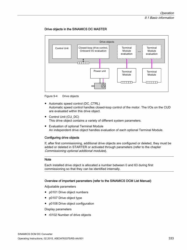
Operation 9.1 Basic information
SINAMICS DCM DC Converter Operating Instructions, 02.2015, A5E34763375/RS-AA/001 333
Drive objects in the SINAMICS DC MASTER
Figure 9-4 Drive objects
Automatic speed control (DC_CTRL) Automatic speed control handles closed-loop control of the motor. The I/Os on the CUD are evaluated within this drive object.
Control Unit (CU_DC) This drive object contains a variety of different system parameters.
Evaluation of optional Terminal Module An independent drive object handles evaluation of each optional Terminal Module.
Configuring drive objects
If, after first commissioning, additional drive objects are configured or deleted, they must be added or deleted in STARTER or activated through parameters (refer to the chapter Commissioning optional additional modules).
Note
Each installed drive object is allocated a number between 0 and 63 during first commissioning so that they can be identified internally.
Overview of important parameters (refer to the SINAMICS DCM List Manual)
Adjustable parameters
p0101 Drive object numbers
p0107 Drive object type
p0108 Drive object configuration
Display parameters
r0102 Number of drive objects
Operation 9.1 Basic information
SINAMICS DCM DC Converter 334 Operating Instructions, 02.2015, A5E34763375/RS-AA/001
Standard drive objects
Automatic speed control
Control Unit
9.1.4 Memory card functions This chapter describes the basic functions of the memory card in the SINAMICS DCM system.
Basic information The CUD (Control Unit for the SINAMICS DCM) manages three memory areas:
A volatile memory, the RAM, also called work memory
A non-volatile memory, the ROM, also called flash memory
An optionally available portable memory card
Note
Memory cards can be ordered as an option (S01/S02) or as accessories, see Chapter Ordering information for options and accessories (Page 30).
SINAMICS DCM does not accept other memory cards.
The work memory receives all project information and application programs while the device is being operated. To save the current data from the work memory, you must copy it to non-volatile memory before shutting down, see Chapter "Commissioning", "Copy RAM to ROM" function.
An optional memory card is used:
For saving various parameter data sets
For transferring the parameter data sets to additional SINAMICS DCM drives
For series commissioning
The memory card is needed:
For installing software updates
For using an AOP30 in languages other than German, English and Chinese
To use the function "SINAMICS Link" (see Chapter "Communication via SINAMICS Link")
To load the DCC block library into the drive
Operation 9.1 Basic information
SINAMICS DCM DC Converter Operating Instructions, 02.2015, A5E34763375/RS-AA/001 335
Note
The memory card supplied from Siemens as option S01 or S02 includes, when supplied, a dump of the internal device software. These files are required to update the software as well as to use the "SINAMICS Link" function. These files can be deleted for other applications.
Before you use the card for the functions described in this chapter, copy these files to a local folder of your PG/PC and delete the files on the memory card.
Parameter data sets Parameter data sets represent all of the parameters of a project - including the DCC charts and the project itself. Parameter data sets differ on the basis of drive configuration (power unit, motor, encoder, etc. used) and application (e.g. function modules, type of control).
Different data volumes can be saved in the three memory areas:
ROM: Four parameter data sets with the indices 0, 10, 11, and 12
The parameter data set with the index 0 is active in the RAM
Memory card: Depending on the free storage space, up to 101 parameter data sets (indices 0 to 100)
Note
The DCC library itself is not saved as a part of the parameter data set.
Copying parameter data sets from non-volatile memory to the memory card There are three ways of copying parameter data sets from non-volatile memory (ROM) to the memory card:
The system is powered down
– Insert the memory card that does not contain a parameter data set with index 0 into the CUD.
– Switch on the system
– The system is put into operation by the software in the "ROM"
– Then the complete updated parameter data set with the index 0 is automatically copied from the "ROM" to the memory card without a prompt appearing.
The system is switched on
– Insert a memory card into the CUD
– Execute the command "RAM to ROM" (p0977 = 1). The updated parameter data set is copied automatically, first to the "ROM" and then as a data set to the memory card with index 0. If the memory card already contains a parameter data set with the index 0, this will be overwritten without a prompt appearing.
Operation 9.1 Basic information
SINAMICS DCM DC Converter 336 Operating Instructions, 02.2015, A5E34763375/RS-AA/001
The system is switched on
– By the user, utilizing the parameter data transfer from ROM to the memory card: p0804 = 2, p0802 = (0...100) as target on the memory card and p0803 = (0/10/11/12) as source from the ROM.
Note
If when switching on, a memory card with a parameter data set with index 0 is inserted in the CUD, the parameter data set with index 0 in the non-volatile memory of the CUD is overwritten with the parameter data set with index 0 on the memory card.
Note
When a memory card is inserted, the RAM to ROM command (p0977 = 1) will copy the parameter data set with the index 0 from the ROM to the memory card. A parameter data set that might have been previously saved on the memory card is overwritten.
Note
While saving (BOP20 flashes, RDY LED flashes), the electronic power supply must NOT be switched off. Switching off while saving leads to the loss of the most recently performed and not yet saved device parameterization.
Note
When options are being used (DCC, SMC30, TM15, TM31, TM150, etc.) and with certain device configurations, the duration of the power-up can take several minutes.
Copying parameter data sets from the memory card to non-volatile memory There are two ways of copying parameter data sets from the memory card to non-volatile memory:
The system is powered down
– Insert a memory card containing a parameter data set with the index 0 into the CUD.
– Switch on the system. The new parameter data set will be copied to the ROM automatically. The parameter data set with the index 0 which was previously in the ROM will be overwritten.
– The system will then boot with the new parameter data set.
The system is switched on The user starts data transmission from the memory card to the ROM with parameters p0802, p0803 and p0804:
– p0804 = 1
– p0802 = (0...100) as source from the memory card and p0803 = (0/10/11/12) as target to the ROM.
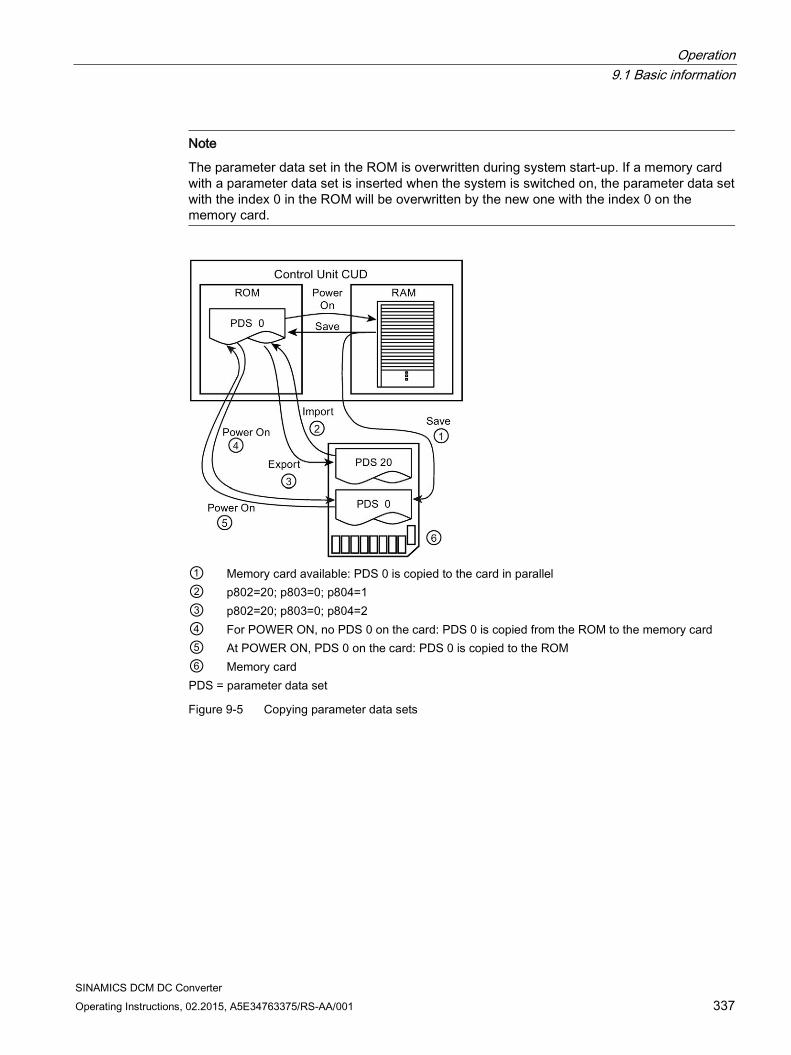
Operation 9.1 Basic information
SINAMICS DCM DC Converter Operating Instructions, 02.2015, A5E34763375/RS-AA/001 337
Note
The parameter data set in the ROM is overwritten during system start-up. If a memory card with a parameter data set is inserted when the system is switched on, the parameter data set with the index 0 in the ROM will be overwritten by the new one with the index 0 on the memory card.
① Memory card available: PDS 0 is copied to the card in parallel ② p802=20; p803=0; p804=1 ③ p802=20; p803=0; p804=2 ④ For POWER ON, no PDS 0 on the card: PDS 0 is copied from the ROM to the memory card ⑤ At POWER ON, PDS 0 on the card: PDS 0 is copied to the ROM ⑥ Memory card PDS = parameter data set
Figure 9-5 Copying parameter data sets
Operation 9.1 Basic information
SINAMICS DCM DC Converter 338 Operating Instructions, 02.2015, A5E34763375/RS-AA/001
Using the memory card for series commissioning The memory card can also be used for series commissioning of several devices with the same parameter assignment.
Procedure:
Completely commission a "sample" drive. As soon as all of the parameters have been correctly set, carry out "RAM to ROM".
Switch-off the system and insert a memory card into the CUD. Switch on the system.
The parameter assignment is saved on the memory card. If DCC charts are activated in the system, then these as well as the DCC library are also saved on the memory card.
Remove the card.
Insert the card into a CUD that is switched-off and has still not been parameterized. Switch on the system (POWER ON).
When powering up, the parameter assignment is transferred into the CUD and copied into the ROM as well as into the RAM. If DCC charts and the DCC library were saved on the memory card, then these are also copied.
The card can be removed once the system has powered-up. The CUD that was still not parameterized now has the same parameter assignment as the original "sample" drive.
Note
The MLFB of the device from which the parameter data set originated is also saved in a parameter data set. If the parameter data set is loaded into a device with another MLFB (POWER ON with the memory card inserted), then the device signals an inconsistent topology (power-up stops with display "33" on the BOP, fault A1420 is output). This occurs, if e.g. a parameter set that was generated from a 30 A device is loaded into a 60 A device. In this state, the user can accept the parameter set by setting p9906 to 3. The system continues to power up.
The same procedure also applies if a parameter data set from a standard CUD is loaded into an Advanced-CUD - or vice versa. The power-up procedure stops with display "33" on the BOP; the parameter set is accepted using p9906=3 and the system continues to power up.
Important parameters p0977: Save all parameters (for more information, see the SINAMICS DCM List Manual). p0802: Data transfer of parameters [0,10,11,12], memory card as source or target p0803: Data transfer of parameters [0...100], non-volatile device memory as source or
target p0804: Start of parameter data transfer and specification of transfer direction: p0804=1: Transfer from the memory card to non-volatile device memory p0804=2: Transfer from non-volatile device memory to memory card
Operation 9.1 Basic information
SINAMICS DCM DC Converter Operating Instructions, 02.2015, A5E34763375/RS-AA/001 339
Safely removing a memory card Removing the memory card must be requested using p9400.
Procedure: p9400 = 2 Request to "safely remove" the memory card p9400 = 3 Feedback: "You can safely remove the memory card"
Remove the memory card p9400 = 100 Feedback: "It is not possible to safely remove the memory card"
SINAMICS DCM is accessing the memory card. Leave the memory card in the unit and try again later.
p9400 = 0 Message: No memory card inserted
Note
If the memory card is removed without a request being made, this can destroy the file system on the memory card.
9.1.5 BICO technology: Interconnecting signals Every drive contains a large number of interconnectable input and output variables and internal control variables.
The drive unit can be adapted to a wide range of requirements using BICO technology (Binector Connector Technology).
Digital and analog signals, which can be interconnected as required by means of BICO parameters, are identified by the prefix BI, BO, CI, or CO in their parameter name.
These parameters are identified accordingly in the parameter list or in the function diagrams.
Note
The STARTER commissioning tool is recommended when using BICO technology.
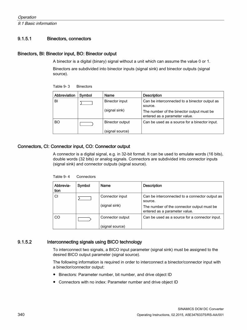
Operation 9.1 Basic information
SINAMICS DCM DC Converter 340 Operating Instructions, 02.2015, A5E34763375/RS-AA/001
9.1.5.1 Binectors, connectors
Binectors, BI: Binector input, BO: Binector output A binector is a digital (binary) signal without a unit which can assume the value 0 or 1.
Binectors are subdivided into binector inputs (signal sink) and binector outputs (signal source).
Table 9- 3 Binectors
Abbreviation Symbol Name Description BI
Binector input (signal sink)
Can be interconnected to a binector output as source. The number of the binector output must be entered as a parameter value.
BO
Binector output (signal source)
Can be used as a source for a binector input.
Connectors, CI: Connector input, CO: Connector output A connector is a digital signal, e.g. in 32-bit format. It can be used to emulate words (16 bits), double words (32 bits) or analog signals. Connectors are subdivided into connector inputs (signal sink) and connector outputs (signal source).
Table 9- 4 Connectors
Abbrevia-tion
Symbol Name Description
CI
Connector input (signal sink)
Can be interconnected to a connector output as source. The number of the connector output must be entered as a parameter value.
CO
Connector output (signal source)
Can be used as a source for a connector input.
9.1.5.2 Interconnecting signals using BICO technology To interconnect two signals, a BICO input parameter (signal sink) must be assigned to the desired BICO output parameter (signal source).
The following information is required in order to interconnect a binector/connector input with a binector/connector output:
Binectors: Parameter number, bit number, and drive object ID
Connectors with no index: Parameter number and drive object ID
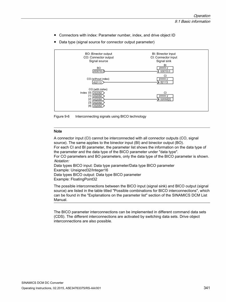
Operation 9.1 Basic information
SINAMICS DCM DC Converter Operating Instructions, 02.2015, A5E34763375/RS-AA/001 341
Connectors with index: Parameter number, index, and drive object ID
Data type (signal source for connector output parameter)
Figure 9-6 Interconnecting signals using BICO technology
Note
A connector input (CI) cannot be interconnected with all connector outputs (CO, signal source). The same applies to the binector input (BI) and binector output (BO). For each CI and BI parameter, the parameter list shows the information on the data type of the parameter and the data type of the BICO parameter under "data type". For CO parameters and BO parameters, only the data type of the BICO parameter is shown. Notation: Data types BICO input: Data type parameter/Data type BICO parameter Example: Unsigned32/Integer16 Data types BICO output: Data type BICO parameter Example: FloatingPoint32
The possible interconnections between the BICO input (signal sink) and BICO output (signal source) are listed in the table titled "Possible combinations for BICO interconnections", which can be found in the "Explanations on the parameter list" section of the SINAMICS DCM List Manual.
The BICO parameter interconnections can be implemented in different command data sets (CDS). The different interconnections are activated by switching data sets. Drive object interconnections are also possible.
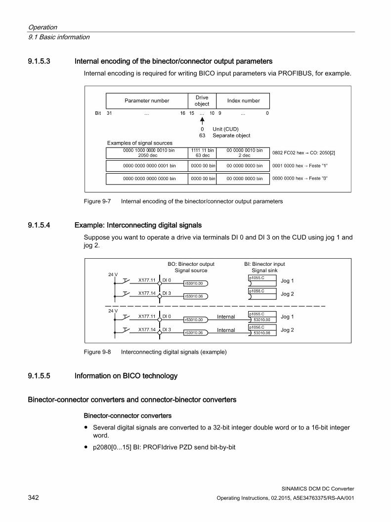
Operation 9.1 Basic information
SINAMICS DCM DC Converter 342 Operating Instructions, 02.2015, A5E34763375/RS-AA/001
9.1.5.3 Internal encoding of the binector/connector output parameters Internal encoding is required for writing BICO input parameters via PROFIBUS, for example.
Figure 9-7 Internal encoding of the binector/connector output parameters
9.1.5.4 Example: Interconnecting digital signals Suppose you want to operate a drive via terminals DI 0 and DI 3 on the CUD using jog 1 and jog 2.
Figure 9-8 Interconnecting digital signals (example)
9.1.5.5 Information on BICO technology
Binector-connector converters and connector-binector converters
Binector-connector converters
Several digital signals are converted to a 32-bit integer double word or to a 16-bit integer word.
p2080[0...15] BI: PROFIdrive PZD send bit-by-bit
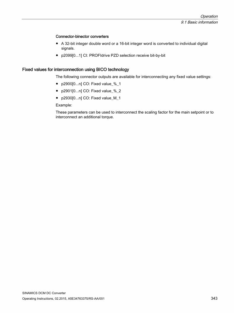
Operation 9.1 Basic information
SINAMICS DCM DC Converter Operating Instructions, 02.2015, A5E34763375/RS-AA/001 343
Connector-binector converters
A 32-bit integer double word or a 16-bit integer word is converted to individual digital signals.
p2099[0...1] CI: PROFIdrive PZD selection receive bit-by-bit
Fixed values for interconnection using BICO technology The following connector outputs are available for interconnecting any fixed value settings:
p2900[0...n] CO: Fixed value_%_1
p2901[0...n] CO: Fixed value_%_2
p2930[0...n] CO: Fixed value_M_1
Example:
These parameters can be used to interconnect the scaling factor for the main setpoint or to interconnect an additional torque.
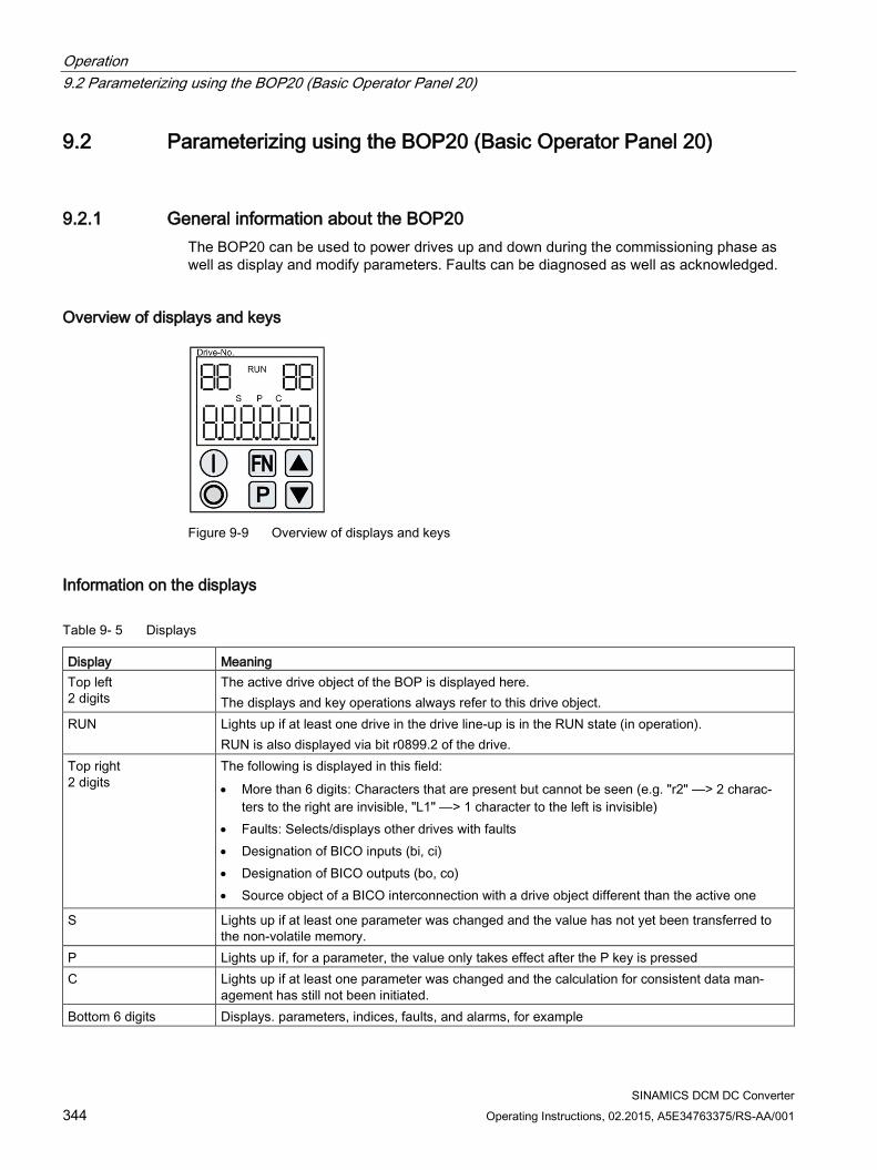
Operation 9.2 Parameterizing using the BOP20 (Basic Operator Panel 20)
SINAMICS DCM DC Converter 344 Operating Instructions, 02.2015, A5E34763375/RS-AA/001
9.2 Parameterizing using the BOP20 (Basic Operator Panel 20)
9.2.1 General information about the BOP20 The BOP20 can be used to power drives up and down during the commissioning phase as well as display and modify parameters. Faults can be diagnosed as well as acknowledged.
Overview of displays and keys
Figure 9-9 Overview of displays and keys
Information on the displays
Table 9- 5 Displays
Display Meaning Top left 2 digits
The active drive object of the BOP is displayed here. The displays and key operations always refer to this drive object.
RUN Lights up if at least one drive in the drive line-up is in the RUN state (in operation). RUN is also displayed via bit r0899.2 of the drive.
Top right 2 digits
The following is displayed in this field: • More than 6 digits: Characters that are present but cannot be seen (e.g. "r2" ––> 2 charac-
ters to the right are invisible, "L1" ––> 1 character to the left is invisible) • Faults: Selects/displays other drives with faults • Designation of BICO inputs (bi, ci) • Designation of BICO outputs (bo, co) • Source object of a BICO interconnection with a drive object different than the active one
S Lights up if at least one parameter was changed and the value has not yet been transferred to the non-volatile memory.
P Lights up if, for a parameter, the value only takes effect after the P key is pressed C Lights up if at least one parameter was changed and the calculation for consistent data man-
agement has still not been initiated. Bottom 6 digits Displays. parameters, indices, faults, and alarms, for example
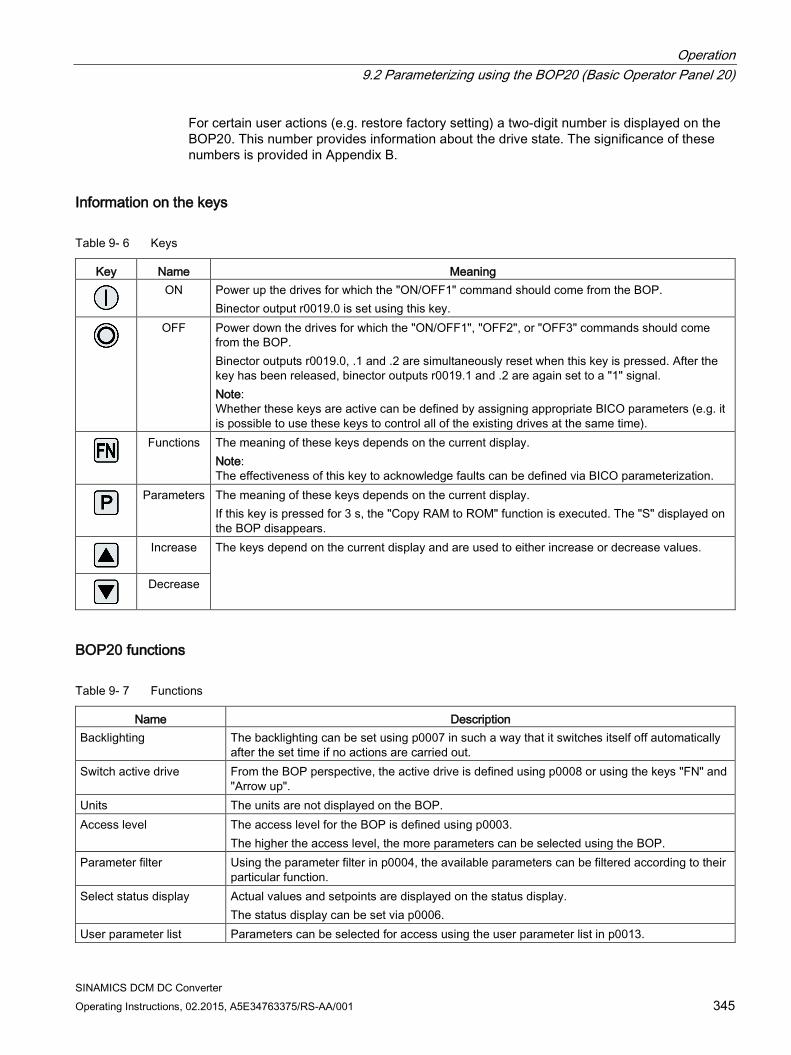
Operation 9.2 Parameterizing using the BOP20 (Basic Operator Panel 20)
SINAMICS DCM DC Converter Operating Instructions, 02.2015, A5E34763375/RS-AA/001 345
For certain user actions (e.g. restore factory setting) a two-digit number is displayed on the BOP20. This number provides information about the drive state. The significance of these numbers is provided in Appendix B.
Information on the keys
Table 9- 6 Keys
Key Name Meaning
ON Power up the drives for which the "ON/OFF1" command should come from the BOP.
Binector output r0019.0 is set using this key.
OFF Power down the drives for which the "ON/OFF1", "OFF2", or "OFF3" commands should come
from the BOP. Binector outputs r0019.0, .1 and .2 are simultaneously reset when this key is pressed. After the key has been released, binector outputs r0019.1 and .2 are again set to a "1" signal. Note: Whether these keys are active can be defined by assigning appropriate BICO parameters (e.g. it is possible to use these keys to control all of the existing drives at the same time).
Functions The meaning of these keys depends on the current display.
Note: The effectiveness of this key to acknowledge faults can be defined via BICO parameterization.
Parameters The meaning of these keys depends on the current display.
If this key is pressed for 3 s, the "Copy RAM to ROM" function is executed. The "S" displayed on the BOP disappears.
Increase The keys depend on the current display and are used to either increase or decrease values.
Decrease
BOP20 functions
Table 9- 7 Functions
Name Description Backlighting The backlighting can be set using p0007 in such a way that it switches itself off automatically
after the set time if no actions are carried out. Switch active drive From the BOP perspective, the active drive is defined using p0008 or using the keys "FN" and
"Arrow up". Units The units are not displayed on the BOP. Access level The access level for the BOP is defined using p0003.
The higher the access level, the more parameters can be selected using the BOP. Parameter filter Using the parameter filter in p0004, the available parameters can be filtered according to their
particular function. Select status display Actual values and setpoints are displayed on the status display.
The status display can be set via p0006. User parameter list Parameters can be selected for access using the user parameter list in p0013.
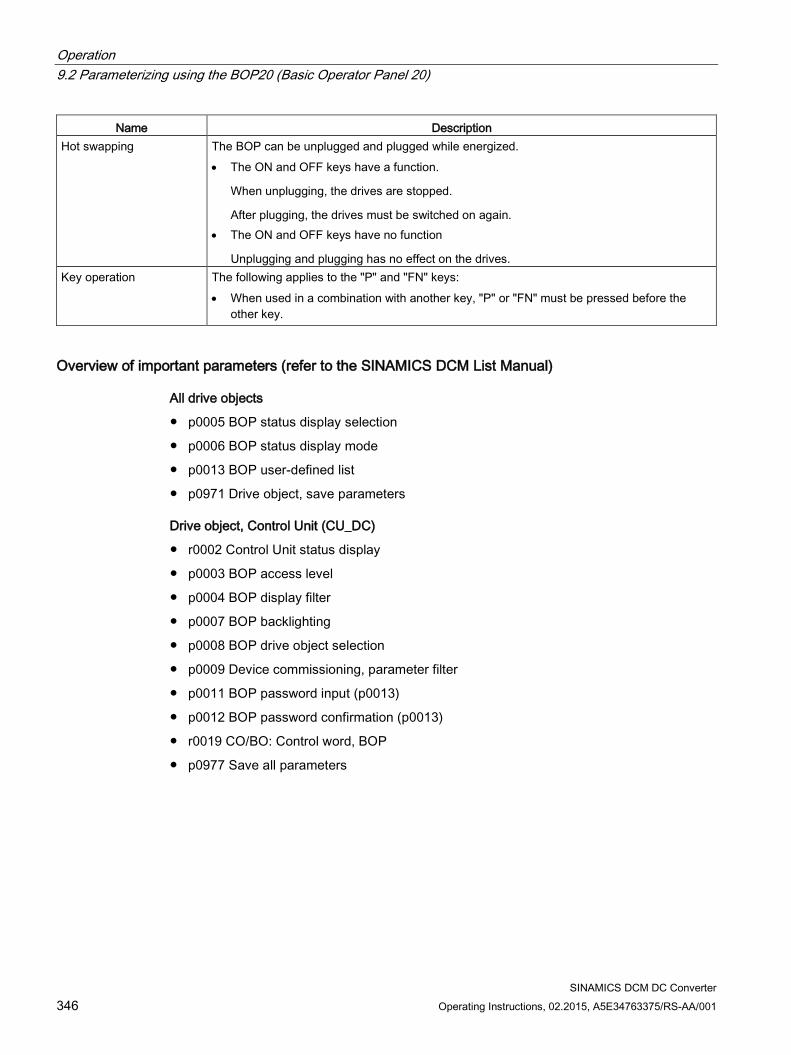
Operation 9.2 Parameterizing using the BOP20 (Basic Operator Panel 20)
SINAMICS DCM DC Converter 346 Operating Instructions, 02.2015, A5E34763375/RS-AA/001
Name Description Hot swapping The BOP can be unplugged and plugged while energized.
• The ON and OFF keys have a function.
When unplugging, the drives are stopped.
After plugging, the drives must be switched on again. • The ON and OFF keys have no function
Unplugging and plugging has no effect on the drives. Key operation The following applies to the "P" and "FN" keys:
• When used in a combination with another key, "P" or "FN" must be pressed before the other key.
Overview of important parameters (refer to the SINAMICS DCM List Manual)
All drive objects
p0005 BOP status display selection
p0006 BOP status display mode
p0013 BOP user-defined list
p0971 Drive object, save parameters
Drive object, Control Unit (CU_DC)
r0002 Control Unit status display
p0003 BOP access level
p0004 BOP display filter
p0007 BOP backlighting
p0008 BOP drive object selection
p0009 Device commissioning, parameter filter
p0011 BOP password input (p0013)
p0012 BOP password confirmation (p0013)
r0019 CO/BO: Control word, BOP
p0977 Save all parameters
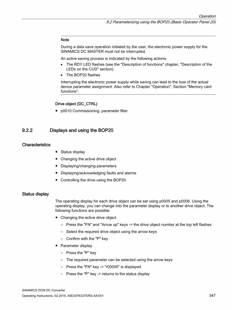
Operation 9.2 Parameterizing using the BOP20 (Basic Operator Panel 20)
SINAMICS DCM DC Converter Operating Instructions, 02.2015, A5E34763375/RS-AA/001 347
Note
During a data save operation initiated by the user, the electronic power supply for the SINAMICS DC MASTER must not be interrupted.
An active saving process is indicated by the following actions: • The RDY LED flashes (see the "Description of functions" chapter, "Description of the
LEDs on the CUD" section) • The BOP20 flashes
Interrupting the electronic power supply while saving can lead to the loss of the actual device parameter assignment. Also refer to Chapter "Operation", Section "Memory card functions".
Drive object (DC_CTRL)
p0010 Commissioning, parameter filter
9.2.2 Displays and using the BOP20
Characteristics Status display
Changing the active drive object
Displaying/changing parameters
Displaying/acknowledging faults and alarms
Controlling the drive using the BOP20
Status display The operating display for each drive object can be set using p0005 and p0006. Using the operating display, you can change into the parameter display or to another drive object. The following functions are possible:
Changing the active drive object
– Press the "FN" and "Arrow up" keys -> the drive object number at the top left flashes
– Select the required drive object using the arrow keys
– Confirm with the "P" key
Parameter display
– Press the "P" key
– The required parameter can be selected using the arrow keys
– Press the "FN" key -> "r00000" is displayed
– Press the "P" key -> returns to the status display
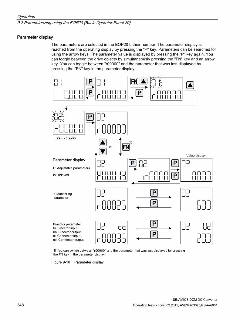
Operation 9.2 Parameterizing using the BOP20 (Basic Operator Panel 20)
SINAMICS DCM DC Converter 348 Operating Instructions, 02.2015, A5E34763375/RS-AA/001
Parameter display The parameters are selected in the BOP20 b their number. The parameter display is reached from the operating display by pressing the "P" key. Parameters can be searched for using the arrow keys. The parameter value is displayed by pressing the "P" key again. You can toggle between the drive objects by simultaneously pressing the "FN" key and an arrow key. You can toggle between "r00000" and the parameter that was last displayed by pressing the "FN" key in the parameter display.
Figure 9-10 Parameter display
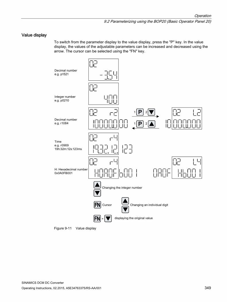
Operation 9.2 Parameterizing using the BOP20 (Basic Operator Panel 20)
SINAMICS DCM DC Converter Operating Instructions, 02.2015, A5E34763375/RS-AA/001 349
Value display To switch from the parameter display to the value display, press the "P" key. In the value display, the values of the adjustable parameters can be increased and decreased using the arrow. The cursor can be selected using the "FN" key.
Figure 9-11 Value display
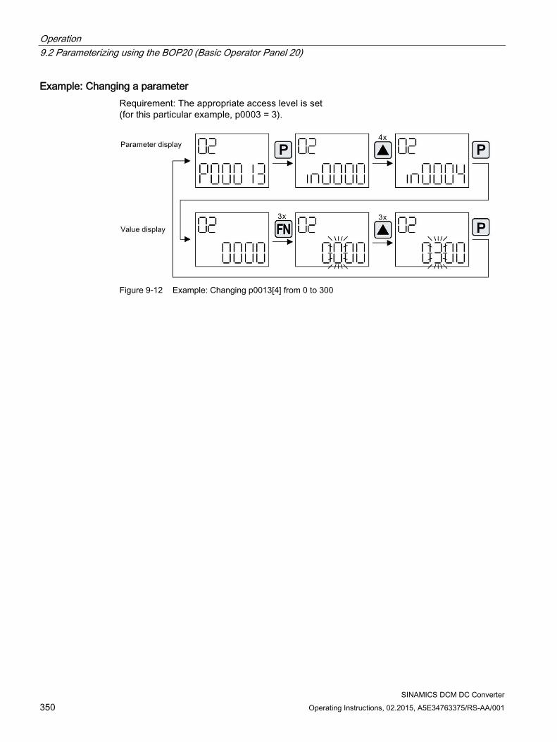
Operation 9.2 Parameterizing using the BOP20 (Basic Operator Panel 20)
SINAMICS DCM DC Converter 350 Operating Instructions, 02.2015, A5E34763375/RS-AA/001
Example: Changing a parameter Requirement: The appropriate access level is set (for this particular example, p0003 = 3).
Figure 9-12 Example: Changing p0013[4] from 0 to 300
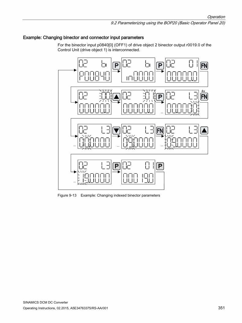
Operation 9.2 Parameterizing using the BOP20 (Basic Operator Panel 20)
SINAMICS DCM DC Converter Operating Instructions, 02.2015, A5E34763375/RS-AA/001 351
Example: Changing binector and connector input parameters For the binector input p0840[0] (OFF1) of drive object 2 binector output r0019.0 of the Control Unit (drive object 1) is interconnected.
Figure 9-13 Example: Changing indexed binector parameters
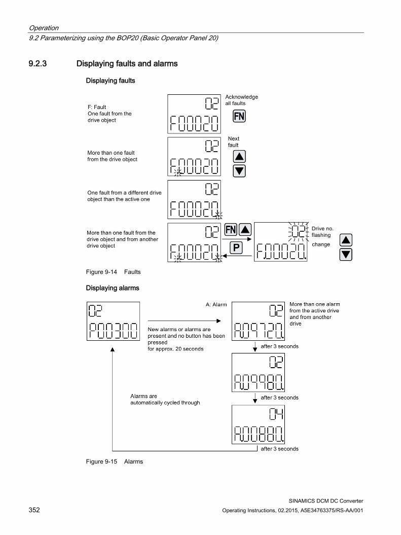
Operation 9.2 Parameterizing using the BOP20 (Basic Operator Panel 20)
SINAMICS DCM DC Converter 352 Operating Instructions, 02.2015, A5E34763375/RS-AA/001
9.2.3 Displaying faults and alarms
Displaying faults
Figure 9-14 Faults
Displaying alarms
Figure 9-15 Alarms
Operation 9.2 Parameterizing using the BOP20 (Basic Operator Panel 20)
SINAMICS DCM DC Converter Operating Instructions, 02.2015, A5E34763375/RS-AA/001 353
9.2.4 Controlling the drive using the BOP20 When commissioning the drive, it can be controlled via the BOP20. A control word is available on the Control Unit drive object (r0019) for this purpose, which can be interconnected with the appropriate binector inputs of e.g. the drive.
The interconnections do not function if a standard PROFIdrive telegram was selected as its interconnection cannot be disconnected.
Table 9- 8 BOP20 control word
Bit (r0019) Name Example, interconnection parameters 0 ON / OFF (OFF1) p0840 1 No coast down/coast down (OFF2) p0844 2 No fast stop/fast stop (OFF3) p0848 7 Acknowledge fault (0 -> 1) p2102 13 Motorized potentiometer, raise p1035 14 Motorized potentiometer, lower p1036
Note
For simple commissioning, only bit 0 should be interconnected. When interconnecting bits 0 ... 2, then the system is powered-down according to the following priority: OFF2, OFF3, OFF1.
Operation 9.3 Controlling via the AOP30 operator panel
SINAMICS DCM DC Converter 354 Operating Instructions, 02.2015, A5E34763375/RS-AA/001
9.3 Controlling via the AOP30 operator panel
WARNING
The OFF switch on the AOP30 operator panel does not have an EMERGENCY OFF function.
In order to avoid dangerous incorrect operator actions, the EMERGENCY OFF pushbutton must be installed in a plant or system at an adequate distance from the AOP30.
Note
To operate the AOP30, p2030=3 must be set.
An operator panel is located in the cabinet door of the cabinet unit for operating, monitoring, and commissioning tasks. It has the following features:
Graphical, backlit LCD for plain-text display and a "bar display" of process variables
LEDs for displaying the operating states
Help function describing the causes of and remedies for faults and alarms
Keypad for controlling a drive under normal operating conditions
LOCAL/REMOTE switchover for selecting the control terminal (master control assigned to operator panel or customer terminal block/PROFIBUS)
Numeric keypad for entering setpoints or parameter values
Function keys for prompted navigation through the menus
Two-stage safety concept to protect against accidental or unauthorized changes to settings
IP54 degree of protection (as installed)
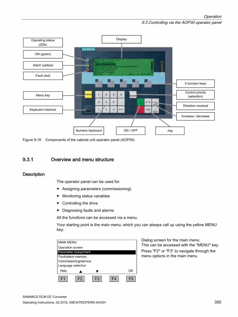
Operation 9.3 Controlling via the AOP30 operator panel
SINAMICS DCM DC Converter Operating Instructions, 02.2015, A5E34763375/RS-AA/001 355
Figure 9-16 Components of the cabinet unit operator panel (AOP30)
9.3.1 Overview and menu structure
Description The operator panel can be used for:
Assigning parameters (commissioning)
Monitoring status variables
Controlling the drive
Diagnosing faults and alarms
All the functions can be accessed via a menu.
Your starting point is the main menu, which you can always call up using the yellow MENU key:
Dialog screen for the main menu: This can be accessed with the "MENU" key. Press "F2" or "F3" to navigate through the menu options in the main menu.
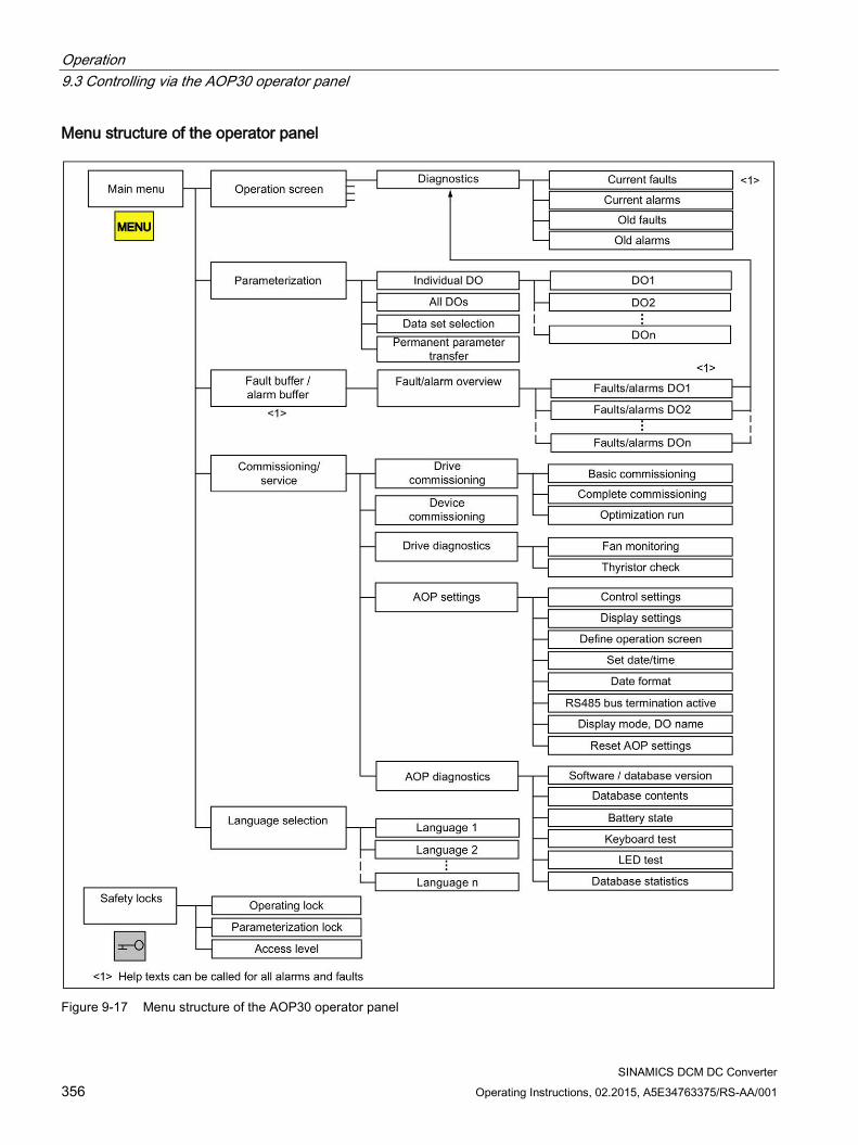
Operation 9.3 Controlling via the AOP30 operator panel
SINAMICS DCM DC Converter 356 Operating Instructions, 02.2015, A5E34763375/RS-AA/001
Menu structure of the operator panel
Figure 9-17 Menu structure of the AOP30 operator panel
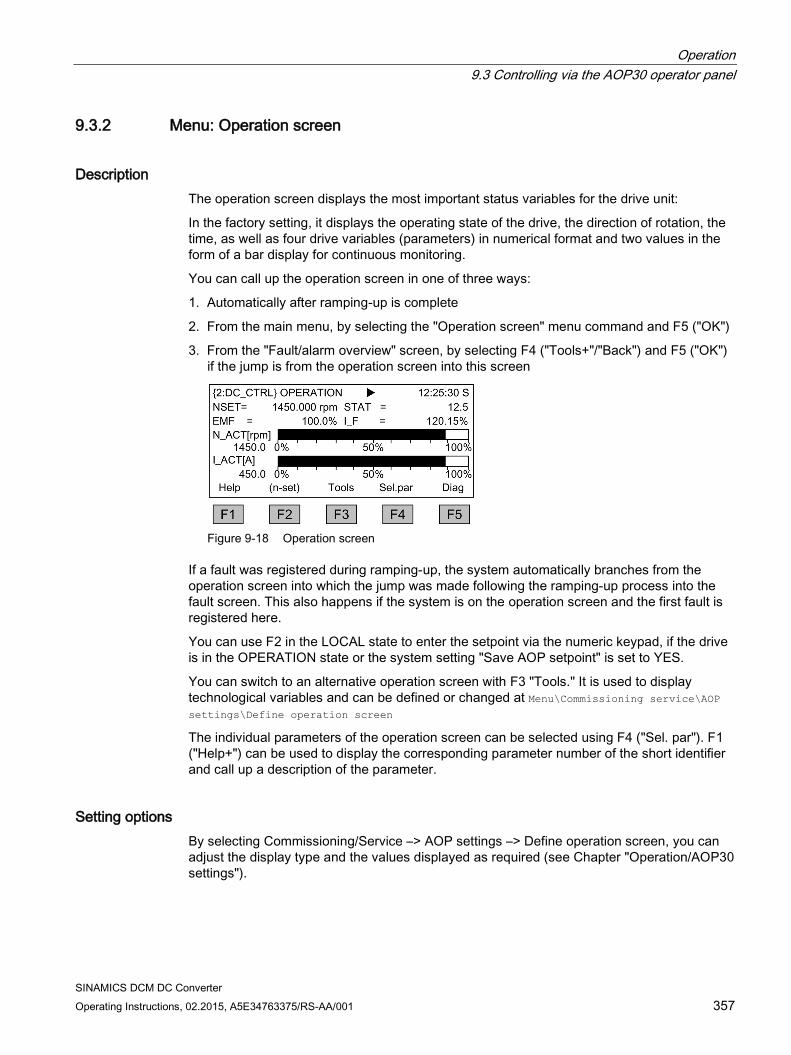
Operation 9.3 Controlling via the AOP30 operator panel
SINAMICS DCM DC Converter Operating Instructions, 02.2015, A5E34763375/RS-AA/001 357
9.3.2 Menu: Operation screen
Description The operation screen displays the most important status variables for the drive unit:
In the factory setting, it displays the operating state of the drive, the direction of rotation, the time, as well as four drive variables (parameters) in numerical format and two values in the form of a bar display for continuous monitoring.
You can call up the operation screen in one of three ways:
1. Automatically after ramping-up is complete
2. From the main menu, by selecting the "Operation screen" menu command and F5 ("OK")
3. From the "Fault/alarm overview" screen, by selecting F4 ("Tools+"/"Back") and F5 ("OK") if the jump is from the operation screen into this screen
Figure 9-18 Operation screen
If a fault was registered during ramping-up, the system automatically branches from the operation screen into which the jump was made following the ramping-up process into the fault screen. This also happens if the system is on the operation screen and the first fault is registered here.
You can use F2 in the LOCAL state to enter the setpoint via the numeric keypad, if the drive is in the OPERATION state or the system setting "Save AOP setpoint" is set to YES.
You can switch to an alternative operation screen with F3 "Tools." It is used to display technological variables and can be defined or changed at Menu\Commissioning service\AOP settings\Define operation screen
The individual parameters of the operation screen can be selected using F4 ("Sel. par"). F1 ("Help+") can be used to display the corresponding parameter number of the short identifier and call up a description of the parameter.
Setting options By selecting Commissioning/Service –> AOP settings –> Define operation screen, you can adjust the display type and the values displayed as required (see Chapter "Operation/AOP30 settings").
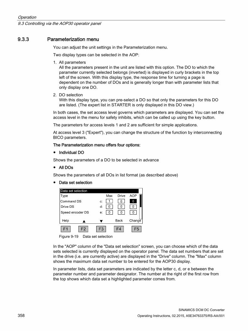
Operation 9.3 Controlling via the AOP30 operator panel
SINAMICS DCM DC Converter 358 Operating Instructions, 02.2015, A5E34763375/RS-AA/001
9.3.3 Parameterization menu You can adjust the unit settings in the Parameterization menu.
Two display types can be selected in the AOP:
1. All parameters All the parameters present in the unit are listed with this option. The DO to which the parameter currently selected belongs (inverted) is displayed in curly brackets in the top left of the screen. With this display type, the response time for turning a page is dependent on the number of DOs and is generally longer than with parameter lists that only display one DO.
2. DO selection With this display type, you can pre-select a DO so that only the parameters for this DO are listed. (The expert list in STARTER is only displayed in this DO view.)
In both cases, the set access level governs which parameters are displayed. You can set the access level in the menu for safety inhibits, which can be called up using the key button.
The parameters for access levels 1 and 2 are sufficient for simple applications.
At access level 3 ("Expert"), you can change the structure of the function by interconnecting BICO parameters.
The Parameterization menu offers four options:
Individual DO
Shows the parameters of a DO to be selected in advance
All DOs
Shows the parameters of all DOs in list format (as described above)
Data set selection
Figure 9-19 Data set selection
In the "AOP" column of the "Data set selection" screen, you can choose which of the data sets selected is currently displayed on the operator panel. The data set numbers that are set in the drive (i.e. are currently active) are displayed in the "Drive" column. The "Max" column shows the maximum data set number to be entered for the AOP30 display.
In parameter lists, data set parameters are indicated by the letter c, d, or e between the parameter number and parameter designator. The number at the right of the first row from the top shows which data set a highlighted parameter comes from.

Operation 9.3 Controlling via the AOP30 operator panel
SINAMICS DCM DC Converter Operating Instructions, 02.2015, A5E34763375/RS-AA/001 359
In the commissioning wizard, the drive is commissioned using the data set selected on this screen in the AOP column.
The data set selection dialog appears whenever a data set parameter is changed in the parameter list. The data set selected in the data set selection screen is a default setting.
Permanent parameter transfer
Parameter changes in the SINAMICS DC MASTER are only made temporarily in the RAM. If a parameter assignment is intended to be permanent, it is possible to trigger a save process at this point. Depending on the configuration, this can take from 45 s to several minutes.
See also Chapter "Operation", Section "Memory card functions".
9.3.4 Menu: Fault/alarm memory When you select this menu, a screen appears containing an overview of faults and alarms that are present.
For each drive object, the system indicates whether any faults or alarms are present ("Fault" or "Alarm" appears next to the drive object in question).
In the graphic below, you can see that at least one active fault/alarm is present for the "DC_CTRL" drive object. No faults or alarms are indicated for the other drive two objects.
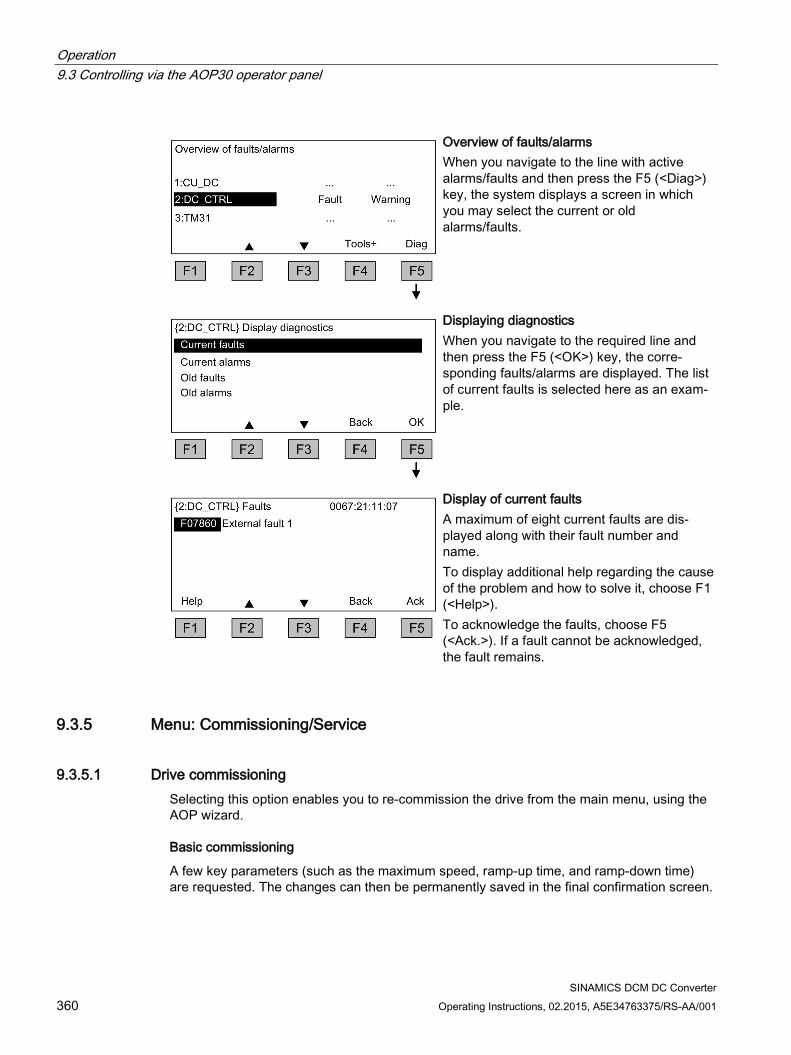
Operation 9.3 Controlling via the AOP30 operator panel
SINAMICS DCM DC Converter 360 Operating Instructions, 02.2015, A5E34763375/RS-AA/001
Overview of faults/alarms When you navigate to the line with active alarms/faults and then press the F5 (<Diag>) key, the system displays a screen in which you may select the current or old alarms/faults.
Displaying diagnostics When you navigate to the required line and then press the F5 (<OK>) key, the corre-sponding faults/alarms are displayed. The list of current faults is selected here as an exam-ple.
Display of current faults A maximum of eight current faults are dis-played along with their fault number and name. To display additional help regarding the cause of the problem and how to solve it, choose F1 (<Help>). To acknowledge the faults, choose F5 (<Ack.>). If a fault cannot be acknowledged, the fault remains.
9.3.5 Menu: Commissioning/Service
9.3.5.1 Drive commissioning Selecting this option enables you to re-commission the drive from the main menu, using the AOP wizard.
Basic commissioning
A few key parameters (such as the maximum speed, ramp-up time, and ramp-down time) are requested. The changes can then be permanently saved in the final confirmation screen.
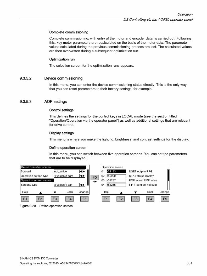
Operation 9.3 Controlling via the AOP30 operator panel
SINAMICS DCM DC Converter Operating Instructions, 02.2015, A5E34763375/RS-AA/001 361
Complete commissioning
Complete commissioning, with entry of the motor and encoder data, is carried out. Following this, key motor parameters are recalculated on the basis of the motor data. The parameter values calculated during the previous commissioning process are lost. The calculated values are then overwritten during a subsequent optimization run.
Optimization run
The selection screen for the optimization runs appears.
9.3.5.2 Device commissioning In this menu, you can enter the device commissioning status directly. This is the only way that you can reset parameters to their factory settings, for example.
9.3.5.3 AOP settings
Control settings
This defines the settings for the control keys in LOCAL mode (see the section titled "Operation/Operation via the operator panel") as well as additional settings that are relevant for drive control.
Display settings
This menu is where you make the lighting, brightness, and contrast settings for the display.
Define operation screen
In this menu, you can switch between five operation screens. You can set the parameters that are to be displayed.
Figure 9-20 Define operation screen
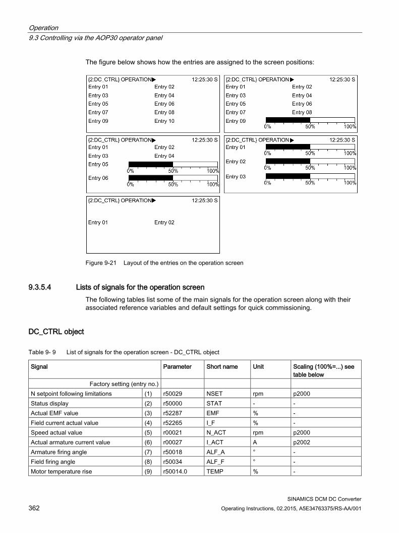
Operation 9.3 Controlling via the AOP30 operator panel
SINAMICS DCM DC Converter 362 Operating Instructions, 02.2015, A5E34763375/RS-AA/001
The figure below shows how the entries are assigned to the screen positions:
Figure 9-21 Layout of the entries on the operation screen
9.3.5.4 Lists of signals for the operation screen The following tables list some of the main signals for the operation screen along with their associated reference variables and default settings for quick commissioning.
DC_CTRL object
Table 9- 9 List of signals for the operation screen - DC_CTRL object
Signal Parameter Short name Unit Scaling (100%=...) see table below
Factory setting (entry no.) N setpoint following limitations (1) r50029 NSET rpm p2000 Status display (2) r50000 STAT - - Actual EMF value (3) r52287 EMF % - Field current actual value (4) r52265 I_F % - Speed actual value (5) r00021 N_ACT rpm p2000 Actual armature current value (6) r00027 I_ACT A p2002 Armature firing angle (7) r50018 ALF_A ° - Field firing angle (8) r50034 ALF_F ° - Motor temperature rise (9) r50014.0 TEMP % -
Operation 9.3 Controlling via the AOP30 operator panel
SINAMICS DCM DC Converter Operating Instructions, 02.2015, A5E34763375/RS-AA/001 363
Signal Parameter Short name Unit Scaling (100%=...) see table below
Thyristor temperature rise (10) r50014.1 TEMP1 % - For diagnostic purposes Speed setpoint smoothed r0020 NSET rpm p2000 Actual speed value, motor encoder r0061 N_ACT rpm p2000 Actual speed value following smoothing r0063 N_ACT rpm p2000 For further diagnostic purposes PROFIBUS setpoint r2050 PBSET rpm p2000
Scalings for DC_CTRL object
Table 9- 10 Scalings for DC_CTRL object
Variable Scaling parameter Default for quick commissioning Reference speed 100% = p2000 p2000 Reference voltage 100% = p2001 p2001 = 1,000 V Reference current 100% = p2002 p2002 = Current limit (p0640) Reference torque 100% = p2003 p2003 = 2 × rated motor torque Reference power 100% = r2004 r2004 = (p2003 × p2000 × π) / 30 Reference temperature 100% = 100° C -
TM31 object
Table 9- 11 List of signals for the operation screen – TM31 object
Signal Parameter Short name Unit Scaling (100% = ...) Analog input 0 [V, mA] r4052[0] AI_UI V, mA V: 100 V / mA: 100 mA Analog input 1 [V, mA] r4052[1] AI_UI V, mA V: 100 V / mA: 100 mA Analog input 0, scaled r4055[0] AI_% % V: 100 V / mA: 100 mA Analog input 1, scaled r4055[1] AI_% % V: 100 V / mA: 100 mA
Setting the date/time
Settings: MENU – Commissioning/Service – AOP settings
For date stamping in the case of fault codes and alarms, and for AOP time display on the operation screen
The AOP30 contains a battery-buffered real-time clock.
You set the date and time on this screen.
Operation 9.3 Controlling via the AOP30 operator panel
SINAMICS DCM DC Converter 364 Operating Instructions, 02.2015, A5E34763375/RS-AA/001
Synchronization
You can also set whether and/or how the AOP30 and drive unit are to be synchronized. Synchronizing the AOP with the drive enables fault codes and alarms to be date-stamped and time-stamped (in the default setting, time-stamping occurs in accordance with the CU runtime).
None (factory setting) The AOP30 and drive unit times are not synchronized.
AOP → Drive
– Activating this option synchronizes the AOP and drive unit immediately, whereby the current AOP time is transferred to the drive unit.
– The current AOP30 time is transferred to the drive unit every time the AOP30 is started.
– At 02:00 (AOP time) every day, the current AOP30 time is transferred to the drive unit.
Drive → AOP
– If a time-of-day master is connected to the drive, then activating this option enables the AOP and drive unit to be synchronized immediately, whereby the current drive unit time is transferred to the AOP30.
– The current drive unit time is transferred to the AOP30 every time the AOP30 is restarted.
– At 02:00 (AOP time) every day, the current drive unit time is transferred to the AOP30.
Date format The date format can be set in this menu:
DD.MM.YYYY: European date format
MM/DD/YYYY: North American date format
RS485 bus termination active Settings are not effective: The RS485 bus termination is continuously active.
DO name display mode A user-definable DO name can be activated/deactivated on this screen.
In the drive, there is the option of entering a user-defined, 25-character DO name for each DO, using the configuration software.
Operation 9.3 Controlling via the AOP30 operator panel
SINAMICS DCM DC Converter Operating Instructions, 02.2015, A5E34763375/RS-AA/001 365
The possible number of characters in a DC name display is limited by the screen in question:
1. DO name in screens displaying the current DO Examples of screens in this category are operation screens, parameter lists, quick commissioning wizard screens, etc. The maximum text length is 7 characters. Example 2:DC_CTRL Texts of up to 7 characters in length are displayed in full. The first 6 characters of texts that are 8 to 25 characters in length are displayed with "..." as the 7th character.
2. DO names in the overview of faults and alarms (alarm overview) The maximum text length is 12 characters. Example 2: HOIST 1234 Texts of up to 12 characters in length are displayed in full. The first 11 characters of texts that are 13 to 25 characters in length are displayed with "..." as the 12th character.
Texts that have been shortened can be displayed in full for around 3 seconds by pressing the "+/-" button, provided that the "User-definable DO name" function is activated.
Reset AOP settings
Selecting this menu command resets the AOP factory settings for the following:
Language
Display (brightness, contrast)
Operation screen
Control settings
Note
When you reset parameters, all settings that are different from the factory settings are immediately reset on the operator panel. This may cause the unit to switch to an unwanted operating state. For this reason, you should always take great care when resetting parameters.
9.3.5.5 AOP30 diagnostics
Software/database version
This menu command shows the versions of the software and database.
The database version must be compatible with the drive software version (refer to parameter r0018).
Database contents
Shows detailed information on the drive objects (DOs) present in the system
Battery status
This menu displays the battery voltage (in volts and as a bar chart). The battery ensures that the data in the database and the current time are retained.
Operation 9.3 Controlling via the AOP30 operator panel
SINAMICS DCM DC Converter 366 Operating Instructions, 02.2015, A5E34763375/RS-AA/001
When the battery voltage is represented as a percentage, a battery voltage of ≤ 2 V is equal to 0%, and a voltage of ≥ 3 V to 100%.
The data is secure up to a battery voltage of 2 V.
If the battery voltage is ≤ 2.45 V, the message "Replace battery" is displayed in the status bar.
If the battery voltage is ≤ 2.30 V, the system displays the following message: "Alarm, weak battery".
If the battery voltage is ≤ 2 V, the system displays the following message: "Caution: The battery is dead".
If the time and/or database are unavailable due to lack of voltage after a prolonged system downtime, the loss is established by means of a CRC check when the system is switched on again. This triggers a message instructing the user to replace the battery and then load the database and/or set the time.
For instructions on how to change the battery, see "Maintenance and servicing". Keyboard test
On this screen, you can check that the keys are functioning properly. Keys that you press are represented on a symbolic keyboard on the display. You can press keys in any order you wish. You cannot exit the screen (F4 – "Back") until you have pressed each key at least once.
Note
Alternatively, you can exit the keyboard test screen by pressing any key and holding it down.
LED test On this screen, you can check that the 4 LEDs are functioning properly.
Database statistics
Data related to the database is displayed here (e.g. free memory for additional DOs)
9.3.6 Sprachauswahl/Language selection The operator panel downloads the texts for the different languages from the drive.
In the delivery condition without a memory card, you can toggle between German and English. With memory card (from V1.2), French, Italian, Spanish and Russian are also automatically available. The memory card must remain inserted for operation with these languages. The software provided for the update also includes all of the language packages that are available.
You can change the language of the operator panel via the "Sprachauswahl/Language selection" menu.
Note
Languages in addition to those that are currently available for the operator panel are available on request.
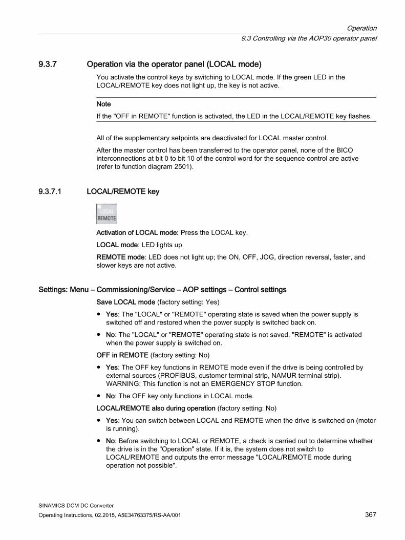
Operation 9.3 Controlling via the AOP30 operator panel
SINAMICS DCM DC Converter Operating Instructions, 02.2015, A5E34763375/RS-AA/001 367
9.3.7 Operation via the operator panel (LOCAL mode) You activate the control keys by switching to LOCAL mode. If the green LED in the LOCAL/REMOTE key does not light up, the key is not active.
Note
If the "OFF in REMOTE" function is activated, the LED in the LOCAL/REMOTE key flashes.
All of the supplementary setpoints are deactivated for LOCAL master control.
After the master control has been transferred to the operator panel, none of the BICO interconnections at bit 0 to bit 10 of the control word for the sequence control are active (refer to function diagram 2501).
9.3.7.1 LOCAL/REMOTE key
Activation of LOCAL mode: Press the LOCAL key.
LOCAL mode: LED lights up
REMOTE mode: LED does not light up; the ON, OFF, JOG, direction reversal, faster, and slower keys are not active.
Settings: Menu – Commissioning/Service – AOP settings – Control settings Save LOCAL mode (factory setting: Yes)
Yes: The "LOCAL" or "REMOTE" operating state is saved when the power supply is switched off and restored when the power supply is switched back on.
No: The "LOCAL" or "REMOTE" operating state is not saved. "REMOTE" is activated when the power supply is switched on.
OFF in REMOTE (factory setting: No)
Yes: The OFF key functions in REMOTE mode even if the drive is being controlled by external sources (PROFIBUS, customer terminal strip, NAMUR terminal strip). WARNING: This function is not an EMERGENCY STOP function.
No: The OFF key only functions in LOCAL mode.
LOCAL/REMOTE also during operation (factory setting: No)
Yes: You can switch between LOCAL and REMOTE when the drive is switched on (motor is running).
No: Before switching to LOCAL or REMOTE, a check is carried out to determine whether the drive is in the "Operation" state. If it is, the system does not switch to LOCAL/REMOTE and outputs the error message "LOCAL/REMOTE mode during operation not possible".
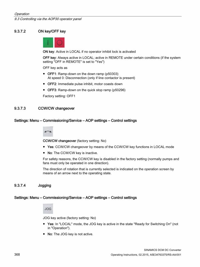
Operation 9.3 Controlling via the AOP30 operator panel
SINAMICS DCM DC Converter 368 Operating Instructions, 02.2015, A5E34763375/RS-AA/001
9.3.7.2 ON key/OFF key
ON key: Active in LOCAL if no operator inhibit lock is activated
OFF key: Always active in LOCAL; active in REMOTE under certain conditions (if the system setting "OFF in REMOTE" is set to "Yes")
OFF key acts as
OFF1: Ramp-down on the down ramp (p50303) At speed 0: Disconnection (only if line contactor is present)
OFF2: Immediate pulse inhibit, motor coasts down
OFF3: Ramp-down on the quick stop ramp (p50296)
Factory setting: OFF1
9.3.7.3 CCW/CW changeover
Settings: Menu – Commissioning/Service – AOP settings – Control settings
CCW/CW changeover (factory setting: No)
Yes: CCW/CW changeover by means of the CCW/CW key functions in LOCAL mode
No: The CCW/CW key is inactive.
For safety reasons, the CCW/CW key is disabled in the factory setting (normally pumps and fans must only be operated in one direction).
The direction of rotation that is currently selected is indicated on the operation screen by means of an arrow next to the operating state.
9.3.7.4 Jogging
Settings: Menu – Commissioning/Service – AOP settings – Control settings
JOG key active (factory setting: No)
Yes: In "LOCAL" mode, the JOG key is active in the state "Ready for Switching On" (not in "Operation").
No: The JOG key is not active.
Operation 9.3 Controlling via the AOP30 operator panel
SINAMICS DCM DC Converter Operating Instructions, 02.2015, A5E34763375/RS-AA/001 369
See also function diagram 3125 in the SINAMICS DCM List Manual.
The speed for the JOG function is entered using parameter p50436.
9.3.7.5 Increase setpoint/Decrease setpoint
You can use the Increase and Decrease keys to enter the setpoint with a resolution of 1% of the maximum speed.
Alternatively, the setpoint can also be entered via the numeric keypad. To do this, press F2 while on the operation screen. The system displays an inverted edit field for entering the required speed. Enter the required value using the numeric keypad. Press F5 ("OK") to confirm the setpoint.
Any speed between 0 and the maximum speed (p2000) can be entered using the numeric keypad.
Setpoint entry in LOCAL mode is unipolar. You can change the direction of rotation by pressing the key that allows you to switch between CCW/CW rotation.
CW rotation and "Increase" key mean: The setpoint displayed is positive and the speed is increased.
CCW rotation and "Increase" key mean: The setpoint displayed is negative and the speed is increased.
9.3.7.6 AOP setpoint
Settings: Menu – Commissioning/Service – AOP settings – Control settings Save AOP setpoint (factory setting: No)
Yes: In LOCAL mode, the last setpoint (once you have released the Increase or Decrease key or confirmed a numeric entry) is saved. The next time you switch the system on in LOCAL mode, the saved value is selected. This occurs even if you switched to REMOTE in the meantime or the power supply was switched off. When the system is switched from REMOTE to LOCAL mode while the drive is switched on (motor is running), the actual value that was last present is set as the output value for the AOP setpoint and saved. If the system is switched from REMOTE to LOCAL mode while the drive is switched off, the AOP setpoint that was last saved is used.
No: When the system is switched on in LOCAL mode, the speed is always set to the value entered under "AOP starting setpoint". When the system is switched from REMOTE to LOCAL mode while the drive is switched on (motor is running), the actual value that was last present is set as the output value for the AOP setpoint.
AOP setpoint ramp-up time (factory setting: 20 s) Defines the speed at which the setpoint specified by the AOP is increased when the "+" key is pressed
Operation 9.3 Controlling via the AOP30 operator panel
SINAMICS DCM DC Converter 370 Operating Instructions, 02.2015, A5E34763375/RS-AA/001
AOP setpoint ramp-down time (factory setting: 30 s) Defines the speed at which the setpoint specified by the AOP is decreased when the "-" key is pressed
AOP starting setpoint (factory setting: 0.000 rpm) The AOP starting setpoint is the speed setpoint which is active when the drive is switched on (with the "ON" key on the AOP30); the "Save setpoint" system setting must be set to "No" for this purpose (see also the description of the "Save AOP setpoint" system setting).
Note
The internal drive ramp-function generator is always active.
9.3.7.7 Inhibiting AOP LOCAL mode
Settings: Menu – Commissioning/Service – AOP settings – Control settings Inhibit AOP LOCAL mode (factory setting: No)
Yes: Deactivates the "Control via operator panel" function, thereby disabling the LOCAL/REMOTE key.
No: Activates the LOCAL/REMOTE key.
Note
LOCAL functionality can also be inhibited on the drive by means of the p0806 parameter (BI: Inhibit master control).
9.3.7.8 Acknowledging errors via the AOP
Settings: Menu – Commissioning/Service – AOP settings – Control settings Acknowledge error from the AOP (factory setting: Yes)
Yes: Errors can be acknowledged via the AOP.
No: Errors cannot be acknowledged via the AOP.
9.3.7.9 Timeout monitoring In "LOCAL" mode or if "OFF in REMOTE" is active, the drive is shut down after 1 s. if the data cable between the AOP and drive is disconnected.
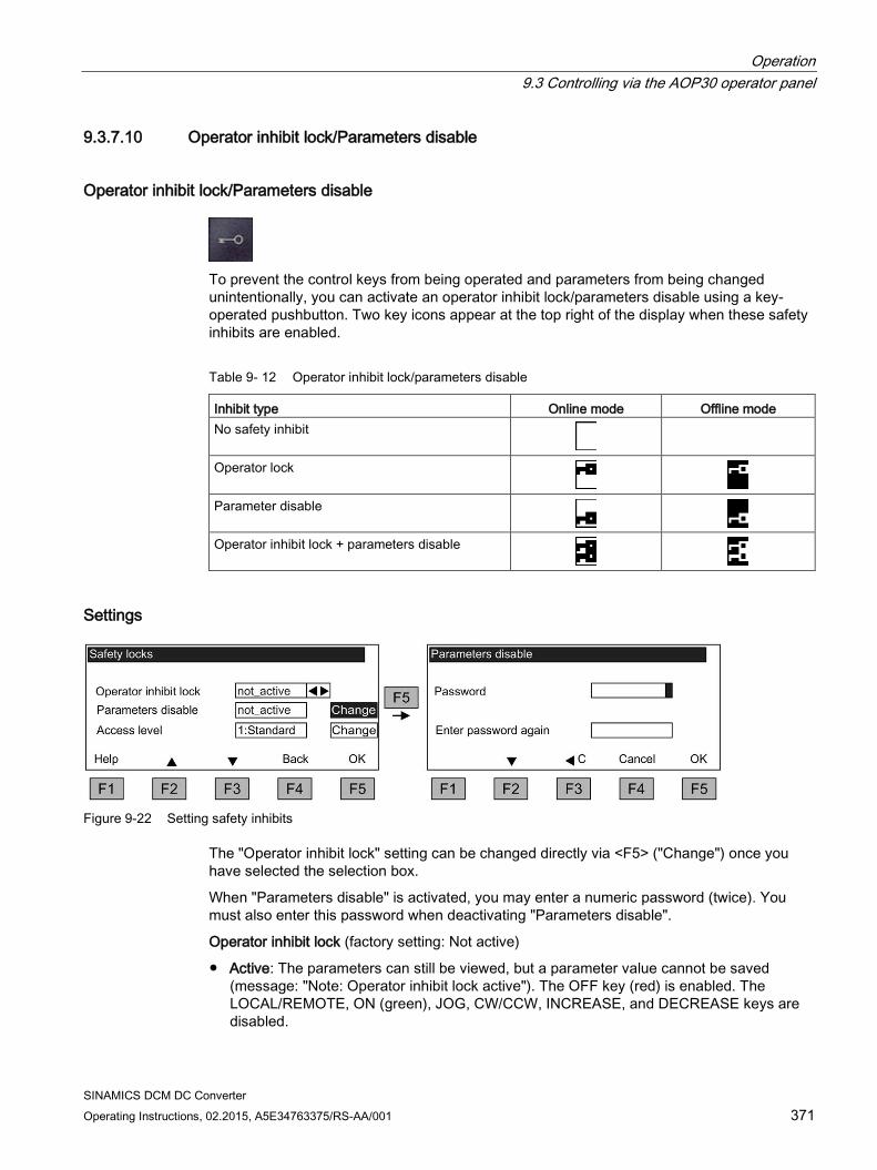
Operation 9.3 Controlling via the AOP30 operator panel
SINAMICS DCM DC Converter Operating Instructions, 02.2015, A5E34763375/RS-AA/001 371
9.3.7.10 Operator inhibit lock/Parameters disable
Operator inhibit lock/Parameters disable
To prevent the control keys from being operated and parameters from being changed unintentionally, you can activate an operator inhibit lock/parameters disable using a key-operated pushbutton. Two key icons appear at the top right of the display when these safety inhibits are enabled.
Table 9- 12 Operator inhibit lock/parameters disable
Inhibit type Online mode Offline mode No safety inhibit
Operator lock
Parameter disable
Operator inhibit lock + parameters disable
Settings
Figure 9-22 Setting safety inhibits
The "Operator inhibit lock" setting can be changed directly via <F5> ("Change") once you have selected the selection box.
When "Parameters disable" is activated, you may enter a numeric password (twice). You must also enter this password when deactivating "Parameters disable".
Operator inhibit lock (factory setting: Not active)
Active: The parameters can still be viewed, but a parameter value cannot be saved (message: "Note: Operator inhibit lock active"). The OFF key (red) is enabled. The LOCAL/REMOTE, ON (green), JOG, CW/CCW, INCREASE, and DECREASE keys are disabled.
Operation 9.3 Controlling via the AOP30 operator panel
SINAMICS DCM DC Converter 372 Operating Instructions, 02.2015, A5E34763375/RS-AA/001
Parameters disable (factory setting: Not active)
Active: Parameters cannot be changed unless a password is entered. Parameters are assigned in the same way as in the operator inhibit lock state. If you try to change parameter values, the message "Note: Parameters disable active" is displayed. All the control keys, however, remain enabled.
Access level (factory setting: Expert):
The different parameters required for this complex application are filtered so that they can be displayed as clearly as possible. You select them according to the access level.
An expert level, which must only be used by expert personnel, is required for certain actions.
9.3.8 Faults and alarms
Displaying faults and alarms If a fault occurs, the drive displays the fault(s) and/or alarm(s) on the operator panel. Faults are indicated by means of the red "FAULT" LED lighting up.
The "Fault/alarm overview" also appears automatically in the following two cases:
1. When a fault is registered while the system is ramping up
2. If the first fault is registered on the operation screen
You can use the F1 (Help) function on the screen to call up information about the cause of the fault and how to remedy it. You can use F5 (Ack.) to acknowledge a stored fault.
Any alarms that are pending are indicated by means of the yellow "ALARM" LED lighting up. Additionally, a note relating to the cause of the alarm is displayed in the status bar of the operator panel.
What is a fault? A fault is a message from the drive indicating an error or other exceptional (unwanted) status. This could be caused by a fault within the converter or an external fault triggered, for example, by the winding temperature monitoring function for the motor. The faults are displayed and can be reported to a higher-level control system via PROFIBUS.
What is an alarm? An alarm is the response to a fault condition identified by the drive. It does not result in the drive being switched off and does not have to be acknowledged. Alarms are "self-acknowledging"; that is, they are reset automatically when the cause of the alarm has been eliminated.
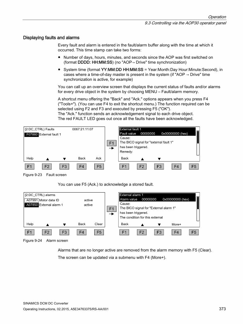
Operation 9.3 Controlling via the AOP30 operator panel
SINAMICS DCM DC Converter Operating Instructions, 02.2015, A5E34763375/RS-AA/001 373
Displaying faults and alarms Every fault and alarm is entered in the fault/alarm buffer along with the time at which it occurred. This time stamp can take two forms:
Number of days, hours, minutes, and seconds since the AOP was first switched on (format DDDD: HH:MM:SS) (no "AOP→ Drive" time synchronization)
System time (format YY:MM:DD HH:MM:SS = Year:Month:Day Hour:Minute:Second), in cases where a time-of-day master is present in the system (if "AOP → Drive" time synchronization is active, for example)
You can call up an overview screen that displays the current status of faults and/or alarms for every drive object in the system by choosing MENU – Fault/alarm memory.
A shortcut menu offering the "Back" and "Ack." options appears when you press F4 ("Tools+"). (You can use F4 to exit the shortcut menu.) The function required can be selected using F2 and F3 and executed by pressing F5 ("OK"). The "Ack." function sends an acknowledgement signal to each drive object. The red FAULT LED goes out once all the faults have been acknowledged.
Figure 9-23 Fault screen
You can use F5 (Ack.) to acknowledge a stored fault.
Figure 9-24 Alarm screen
Alarms that are no longer active are removed from the alarm memory with F5 (Clear).
The screen can be updated via a submenu with F4 (More+).
Operation 9.3 Controlling via the AOP30 operator panel
SINAMICS DCM DC Converter 374 Operating Instructions, 02.2015, A5E34763375/RS-AA/001
9.3.9 Saving the parameters permanently
Description If parameters are changed using the operator panel (confirm with OK in the Parameter editor), the new values are initially stored in the volatile memory (RAM) of the converter. An "S" flashes in the top right of the AOP display until they are saved permanently. This indicates that at least 1 parameter has been changed and not yet stored permanently.
2 methods are available for permanently saving parameters that have been changed:
To store the parameters permanently, choose <MENU> <Parameterization> <OK> <Permanent parameter transfer>.
When confirming a parameter setting with the OK key, press it for > 1 s. The system displays a message asking you whether the setting is to be saved in the EEPROM. If you press "Yes", the system saves the setting in the EEPROM. If you press "No", the setting is not saved permanently and the "S" starts flashing to indicate this fact.
In both cases, all changes that have not yet been saved permanently are stored in the EEPROM. Depending on the configuration, this can take from 45 s to several minutes. Also refer to the "Memory card functions" chapter.
Note
During a data save operation initiated by the user, the electronics power supply for the SINAMICS DC MASTER must not be interrupted.
An active saving process is indicated by the following actions: • The RDY LED flashes (see the "Description of functions" chapter, "Description of the
LEDs on the CUD" section) • The BOP20 flashes
Interrupting the power supply while saving can lead to the loss of the current device parameter assignments. Also refer to the "Operation" chapter, "Memory card functions" section.
9.3.10 Parameterization errors If an error is made when reading or writing parameters, a popup window explaining the cause of the problem in plain text appears. Example: Parameter write error
Value limit exceeded
Operation 9.3 Controlling via the AOP30 operator panel
SINAMICS DCM DC Converter Operating Instructions, 02.2015, A5E34763375/RS-AA/001 375
9.3.11 Assigning parameters to make AOP30 time-of-day master The AOP30 contains an integrated real-time clock. The SINAMICS DCM system time can be synchronized with this real-time clock.
Activate this function:
On the AOP30 in the "Menu/Commissioning/Service/AOP settings/Date and Time" menu command activate to "AOP sets clock in SINAMICS". The current time in the AOP30 is then written into the drive.
In the display for faults and alarms, the time stamp is now displayed in the format YY-MM-DD hh:mm in real-time. The time stamp mode and the current time can be read from the parameters p3100, p3102 and p3103. For details, please see the SINAMICS DCM List Manual.
The current time is resynchronized at each power-up. (The AOP30 must be switched on together with the drive). During uninterrupted duty, a synchronization takes place every day at 02:00.

Operation 9.3 Controlling via the AOP30 operator panel
SINAMICS DCM DC Converter 376 Operating Instructions, 02.2015, A5E34763375/RS-AA/001
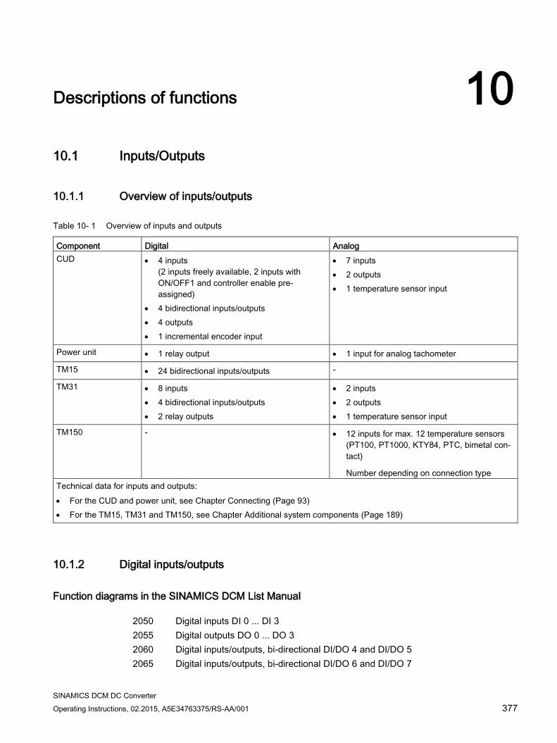
SINAMICS DCM DC Converter Operating Instructions, 02.2015, A5E34763375/RS-AA/001 377
Descriptions of functions 10 10.1 Inputs/Outputs
10.1.1 Overview of inputs/outputs
Table 10- 1 Overview of inputs and outputs
Component Digital Analog CUD • 4 inputs
(2 inputs freely available, 2 inputs with ON/OFF1 and controller enable pre-assigned)
• 4 bidirectional inputs/outputs • 4 outputs • 1 incremental encoder input
• 7 inputs • 2 outputs • 1 temperature sensor input
Power unit • 1 relay output • 1 input for analog tachometer
TM15 • 24 bidirectional inputs/outputs -
TM31 • 8 inputs • 4 bidirectional inputs/outputs • 2 relay outputs
• 2 inputs • 2 outputs • 1 temperature sensor input
TM150 - • 12 inputs for max. 12 temperature sensors (PT100, PT1000, KTY84, PTC, bimetal con-tact)
Number depending on connection type Technical data for inputs and outputs: • For the CUD and power unit, see Chapter Connecting (Page 93) • For the TM15, TM31 and TM150, see Chapter Additional system components (Page 189)
10.1.2 Digital inputs/outputs
Function diagrams in the SINAMICS DCM List Manual 2050 Digital inputs DI 0 ... DI 3 2055 Digital outputs DO 0 ... DO 3 2060 Digital inputs/outputs, bi-directional DI/DO 4 and DI/DO 5 2065 Digital inputs/outputs, bi-directional DI/DO 6 and DI/DO 7
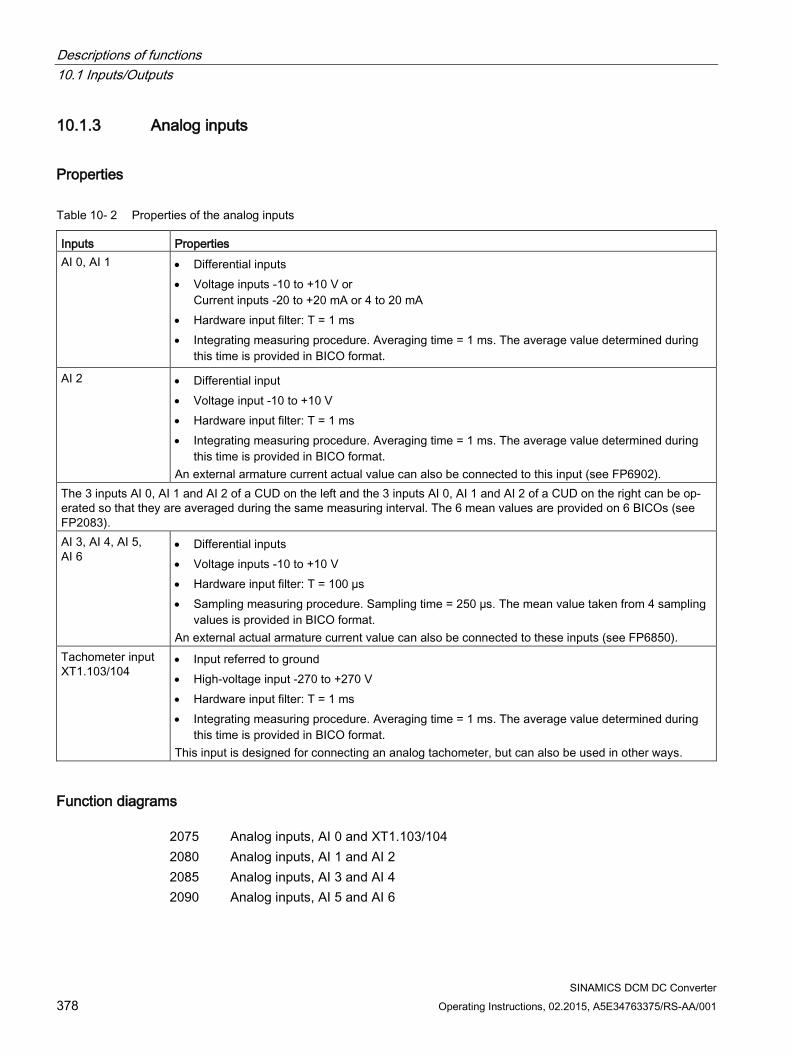
Descriptions of functions 10.1 Inputs/Outputs
SINAMICS DCM DC Converter 378 Operating Instructions, 02.2015, A5E34763375/RS-AA/001
10.1.3 Analog inputs
Properties
Table 10- 2 Properties of the analog inputs
Inputs Properties AI 0, AI 1 • Differential inputs
• Voltage inputs -10 to +10 V or Current inputs -20 to +20 mA or 4 to 20 mA
• Hardware input filter: T = 1 ms • Integrating measuring procedure. Averaging time = 1 ms. The average value determined during
this time is provided in BICO format.
AI 2 • Differential input • Voltage input -10 to +10 V • Hardware input filter: T = 1 ms • Integrating measuring procedure. Averaging time = 1 ms. The average value determined during
this time is provided in BICO format. An external armature current actual value can also be connected to this input (see FP6902).
The 3 inputs AI 0, AI 1 and AI 2 of a CUD on the left and the 3 inputs AI 0, AI 1 and AI 2 of a CUD on the right can be op-erated so that they are averaged during the same measuring interval. The 6 mean values are provided on 6 BICOs (see FP2083). AI 3, AI 4, AI 5, AI 6
• Differential inputs • Voltage inputs -10 to +10 V • Hardware input filter: T = 100 µs • Sampling measuring procedure. Sampling time = 250 µs. The mean value taken from 4 sampling
values is provided in BICO format. An external actual armature current value can also be connected to these inputs (see FP6850).
Tachometer input XT1.103/104
• Input referred to ground • High-voltage input -270 to +270 V • Hardware input filter: T = 1 ms • Integrating measuring procedure. Averaging time = 1 ms. The average value determined during
this time is provided in BICO format. This input is designed for connecting an analog tachometer, but can also be used in other ways.
Function diagrams 2075 Analog inputs, AI 0 and XT1.103/104 2080 Analog inputs, AI 1 and AI 2 2085 Analog inputs, AI 3 and AI 4 2090 Analog inputs, AI 5 and AI 6

Descriptions of functions 10.1 Inputs/Outputs
SINAMICS DCM DC Converter Operating Instructions, 02.2015, A5E34763375/RS-AA/001 379
10.1.4 Analog outputs See function diagram 2095 in the SINAMICS DCM List Manual.
Descriptions of functions 10.2 Communication, IT security
SINAMICS DCM DC Converter 380 Operating Instructions, 02.2015, A5E34763375/RS-AA/001
10.2 Communication, IT security
Note
IT security (industrial security)
In order to ensure the safe operation of your systems, you must take suitable measures, e.g. industrial security or network segmentation. You can find more information on Industrial Security on the Internet at: IT security (http://www.industry.siemens.com/topics/global/en/industrial-security)

Descriptions of functions 10.3 Communication according to PROFIdrive
SINAMICS DCM DC Converter Operating Instructions, 02.2015, A5E34763375/RS-AA/001 381
10.3 Communication according to PROFIdrive PROFIdrive is the PROFIBUS and PROFINET profile for drive technology with a wide range of applications in production and process automation systems.
PROFIdrive is independent of the bus system used (PROFIBUS, PROFINET).
Note
PROFINET for drive technology is standardized and described in the following document: • PROFIBUS profile PROFIdrive–Profile Drive Technology, Version V4.1, May 2006,
PROFIBUS User Organization e. V. Haid-und-Neu-Straße 7, D-76131 Karlsruhe, http://www.profibus.com Order Number 3.172, spec. Chapter 6
• IEC 61800-7
PROFIdrive device classes
Table 10- 3 PROFIdrive device classes
PROFIdrive PROFIBUS DP PROFINET IO Peripheral device (P device) DP slave (I slaves) IO Device Controller (higher-level controller or host of the automation sys-tem)
Class 1 DP master IO Controller
Supervisor (engineering station) Class 2 DP master IO Supervisor
Properties of the Controller, Supervisor and drive units
Table 10- 4 Properties of the Controller, Supervisor and drive units
Properties Controller Supervisor Drive unit As bus node Active Passive Send messages Permitted without external
request Only possible on request by the controller
Receive messages Possible without any re-strictions
Only receive and acknowledge permitted
Drive unit (PROFIBUS: Slave, PROFINET IO: IO Device)
Example: Control Unit CUD
Controller (PROFIBUS: Master Class 1, PROFINET IO: IO Controller)
A controller is typically a higher-level controller in which the automation program runs.
Example: SIMATIC S7 and SIMOTION
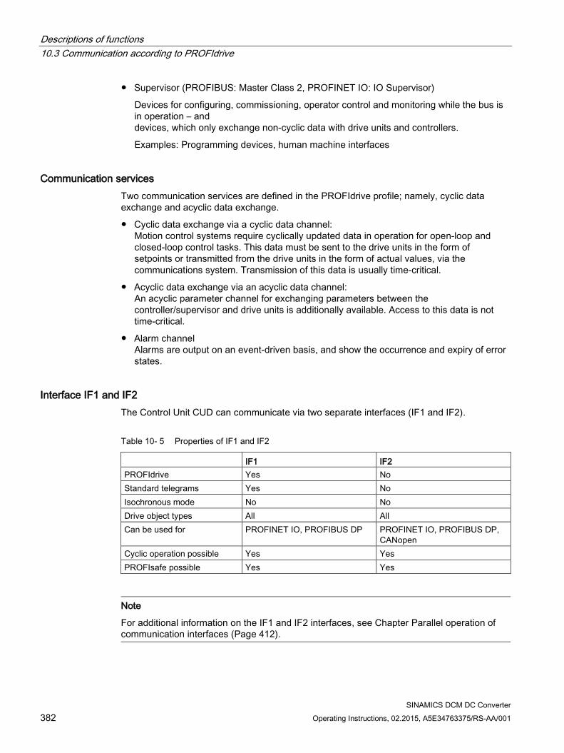
Descriptions of functions 10.3 Communication according to PROFIdrive
SINAMICS DCM DC Converter 382 Operating Instructions, 02.2015, A5E34763375/RS-AA/001
Supervisor (PROFIBUS: Master Class 2, PROFINET IO: IO Supervisor)
Devices for configuring, commissioning, operator control and monitoring while the bus is in operation – and devices, which only exchange non-cyclic data with drive units and controllers.
Examples: Programming devices, human machine interfaces
Communication services Two communication services are defined in the PROFIdrive profile; namely, cyclic data exchange and acyclic data exchange.
Cyclic data exchange via a cyclic data channel: Motion control systems require cyclically updated data in operation for open-loop and closed-loop control tasks. This data must be sent to the drive units in the form of setpoints or transmitted from the drive units in the form of actual values, via the communications system. Transmission of this data is usually time-critical.
Acyclic data exchange via an acyclic data channel: An acyclic parameter channel for exchanging parameters between the controller/supervisor and drive units is additionally available. Access to this data is not time-critical.
Alarm channel Alarms are output on an event-driven basis, and show the occurrence and expiry of error states.
Interface IF1 and IF2 The Control Unit CUD can communicate via two separate interfaces (IF1 and IF2).
Table 10- 5 Properties of IF1 and IF2
IF1 IF2 PROFIdrive Yes No Standard telegrams Yes No Isochronous mode No No Drive object types All All Can be used for PROFINET IO, PROFIBUS DP PROFINET IO, PROFIBUS DP,
CANopen Cyclic operation possible Yes Yes PROFIsafe possible Yes Yes
Note
For additional information on the IF1 and IF2 interfaces, see Chapter Parallel operation of communication interfaces (Page 412).
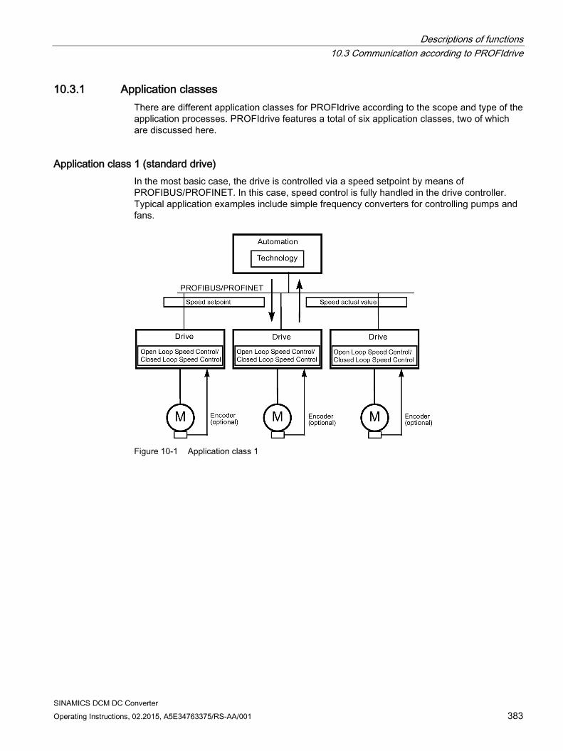
Descriptions of functions 10.3 Communication according to PROFIdrive
SINAMICS DCM DC Converter Operating Instructions, 02.2015, A5E34763375/RS-AA/001 383
10.3.1 Application classes There are different application classes for PROFIdrive according to the scope and type of the application processes. PROFIdrive features a total of six application classes, two of which are discussed here.
Application class 1 (standard drive) In the most basic case, the drive is controlled via a speed setpoint by means of PROFIBUS/PROFINET. In this case, speed control is fully handled in the drive controller. Typical application examples include simple frequency converters for controlling pumps and fans.
Figure 10-1 Application class 1
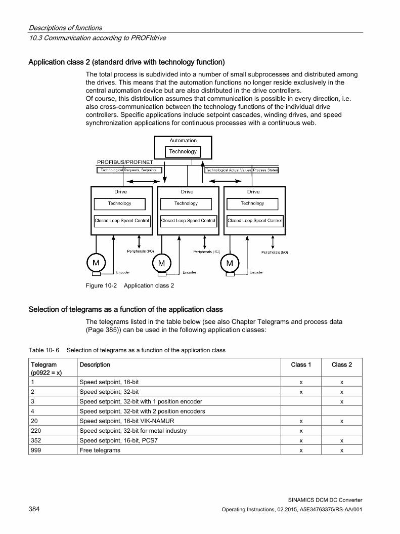
Descriptions of functions 10.3 Communication according to PROFIdrive
SINAMICS DCM DC Converter 384 Operating Instructions, 02.2015, A5E34763375/RS-AA/001
Application class 2 (standard drive with technology function) The total process is subdivided into a number of small subprocesses and distributed among the drives. This means that the automation functions no longer reside exclusively in the central automation device but are also distributed in the drive controllers. Of course, this distribution assumes that communication is possible in every direction, i.e. also cross-communication between the technology functions of the individual drive controllers. Specific applications include setpoint cascades, winding drives, and speed synchronization applications for continuous processes with a continuous web.
Figure 10-2 Application class 2
Selection of telegrams as a function of the application class The telegrams listed in the table below (see also Chapter Telegrams and process data (Page 385)) can be used in the following application classes:
Table 10- 6 Selection of telegrams as a function of the application class
Telegram (p0922 = x)
Description Class 1 Class 2
1 Speed setpoint, 16-bit x x 2 Speed setpoint, 32-bit x x 3 Speed setpoint, 32-bit with 1 position encoder x 4 Speed setpoint, 32-bit with 2 position encoders 20 Speed setpoint, 16-bit VIK-NAMUR x x 220 Speed setpoint, 32-bit for metal industry x 352 Speed setpoint, 16-bit, PCS7 x x 999 Free telegrams x x
Descriptions of functions 10.3 Communication according to PROFIdrive
SINAMICS DCM DC Converter Operating Instructions, 02.2015, A5E34763375/RS-AA/001 385
10.3.2 Cyclic communication Cyclic communication is used to exchange time-critical process data.
10.3.2.1 Telegrams and process data When a telegram is selected via p0922, the drive unit (Control Unit) process data that is transferred is determined.
From the perspective of the drive unit, the received process data represents the receive words and the process data to be sent the send words.
The receive and send words comprise the following elements:
Receive words: Control words or setpoints
Send words: Status words or actual values
PROFIdrive telegrams Standard telegrams
The standard telegrams are structured in accordance with the PROFIdrive profile. The internal process data links are set up automatically in accordance with the telegram number setting.
The following standard telegrams can be set via p0922:
– 1 Speed setpoint, 16-bit
– 2 Speed setpoint, 32-bit
– 3 Speed setpoint, 32-bit with 1 position encoder
– 4 Speed setpoint, 32-bit with 2 position encoders
– 20 Speed setpoint, 16-bit VIK-NAMUR
Manufacturer-specific telegrams
The manufacturer-specific telegrams are structured in accordance with internal company specifications. The internal process data links are set up automatically in accordance with the telegram number setting.
The following vendor-specific telegrams can be set via p0922:
– 220 Speed setpoint, 32-bit for metal industry
– 352 Speed setpoint, 16-bit, PCS7
– 390 Control Unit with digital inputs/outputs
Free telegrams (p0922 = 999)
The send and receive telegrams can be configured as required by using BICO technology to interconnect the send and receive process data.

Descriptions of functions 10.3 Communication according to PROFIdrive
SINAMICS DCM DC Converter 386 Operating Instructions, 02.2015, A5E34763375/RS-AA/001
DC_CTRL CU_DC TM31,
TM15DI_DO, TM150
ENCODER
Receive process data DWORD connect-or output
r2060[0 ... 62] - - r2060[0 ... 2]
WORD connector output
r2050[0 ... 63] r2050[0 ... 19] r2050[0 ... 4] r2050[0 ... 3]
Binector output r2090.0 ... 15 r2091.0 ... 15 r2092.0 ... 15 r2093.0 ... 15
r2090.0 ... 15 r2091.0 ... 15
r2090.0 ... 15 r2091.0 ... 15 r2092.0 ... 15 r2093.0 ... 15
Free binector-connector con-verter
p2080[0 ... 15], p2081[0 ... 15], p2082[0 ... 15], p2083[0 ... 15], p2084[0...15] / r2089[0 ... 4]
Send process data DWORD connect-or input
p2061[0 ... 62] - - p2061[0 ... 10]
WORD connector input
p2051[0 ... 63] p2051[0 ... 24] p2051[0 ... 4] p2051[0 ... 11]
Free connector-binector converter
p2099[0 ... 1] / r2094.0 ... 15, r2095.0 ... 15
Notes on telegram interconnections When you change p0922 = 999 (factory setting) to p0922 ≠ 999, the telegrams are
interconnected and blocked automatically.
Exceptions here are telegrams 20, 220 and 352. Here, selected PZDs can be interconnected as required in the send/receive telegram.
When you change p0922 ≠ 999 to p0922 = 999, the previous telegram interconnection is retained and can be changed.
If p0922 = 999, a telegram can be selected in p2079. A telegram interconnection is automatically made and blocked. The telegram can also be extended.
This is an easy method for creating extended telegram interconnections on the basis of existing telegrams.
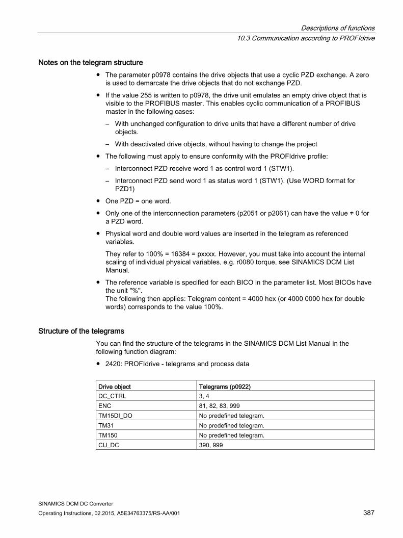
Descriptions of functions 10.3 Communication according to PROFIdrive
SINAMICS DCM DC Converter Operating Instructions, 02.2015, A5E34763375/RS-AA/001 387
Notes on the telegram structure The parameter p0978 contains the drive objects that use a cyclic PZD exchange. A zero
is used to demarcate the drive objects that do not exchange PZD.
If the value 255 is written to p0978, the drive unit emulates an empty drive object that is visible to the PROFIBUS master. This enables cyclic communication of a PROFIBUS master in the following cases:
– With unchanged configuration to drive units that have a different number of drive objects.
– With deactivated drive objects, without having to change the project
The following must apply to ensure conformity with the PROFIdrive profile:
– Interconnect PZD receive word 1 as control word 1 (STW1).
– Interconnect PZD send word 1 as status word 1 (STW1). (Use WORD format for PZD1)
One PZD = one word.
Only one of the interconnection parameters (p2051 or p2061) can have the value ≠ 0 for a PZD word.
Physical word and double word values are inserted in the telegram as referenced variables.
They refer to 100% = 16384 = pxxxx. However, you must take into account the internal scaling of individual physical variables, e.g. r0080 torque, see SINAMICS DCM List Manual.
The reference variable is specified for each BICO in the parameter list. Most BICOs have the unit "%". The following then applies: Telegram content = 4000 hex (or 4000 0000 hex for double words) corresponds to the value 100%.
Structure of the telegrams You can find the structure of the telegrams in the SINAMICS DCM List Manual in the following function diagram:
2420: PROFIdrive - telegrams and process data
Drive object Telegrams (p0922) DC_CTRL 3, 4 ENC 81, 82, 83, 999 TM15DI_DO No predefined telegram. TM31 No predefined telegram. TM150 No predefined telegram. CU_DC 390, 999
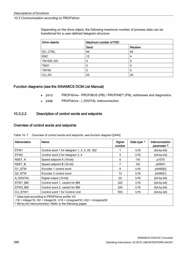
Descriptions of functions 10.3 Communication according to PROFIdrive
SINAMICS DCM DC Converter 388 Operating Instructions, 02.2015, A5E34763375/RS-AA/001
Depending on the drive object, the following maximum number of process data can be transferred for a user-defined telegram structure: Drive objects Maximum number of PZD
Send Receive DC_CTRL 64 64 ENC 12 4 TM15DI_DO 5 5 TM31 5 5 TM150 5 5 CU_DC 25 20
Function diagrams (see the SINAMICS DCM List Manual) • 2410 PROFIdrive - PROFIBUS (PB) / PROFINET (PN), addresses and diagnostics
• 2498 PROFIdrive - I_DIGITAL interconnection
10.3.2.2 Description of control words and setpoints
Overview of control words and setpoints
Table 10- 7 Overview of control words and setpoints, see function diagram [2440]
Abbreviation Name Signal number
Data type 1) Interconnection parameter 2)
STW1 Control word 1 for telegram 1, 3, 4, 20, 352 1 U16 (bit-by-bit) STW2 Control word 2 for telegram 3, 4 3 U16 (bit-by-bit) NSET_A Speed setpoint A (16-bit) 5 I16 p1070 NSET_B Speed setpoint B (32-bit) 7 I32 p50621 G1_STW Encoder 1 control word 9 U16 p0480[0] G2_STW Encoder 2 control word 13 U16 p0480[1] A_DIGITAL Digital output (16-bit) 22 U16 (bit-by-bit) STW1_BM Control word 1, variant for BM 322 U16 (bit-by-bit) STW2_BM Control word 2, variant for BM 324 U16 (bit-by-bit) CU_STW1 Control word 1 for Control Unit 500 U16 (bit-by-bit) 1) Data type according to PROFIdrive profile V4: I16 = Integer16, I32 = Integer32, U16 = Unsigned16, U32 = Unsigned32 2) Bit-by-bit interconnection: Refer to the following pages
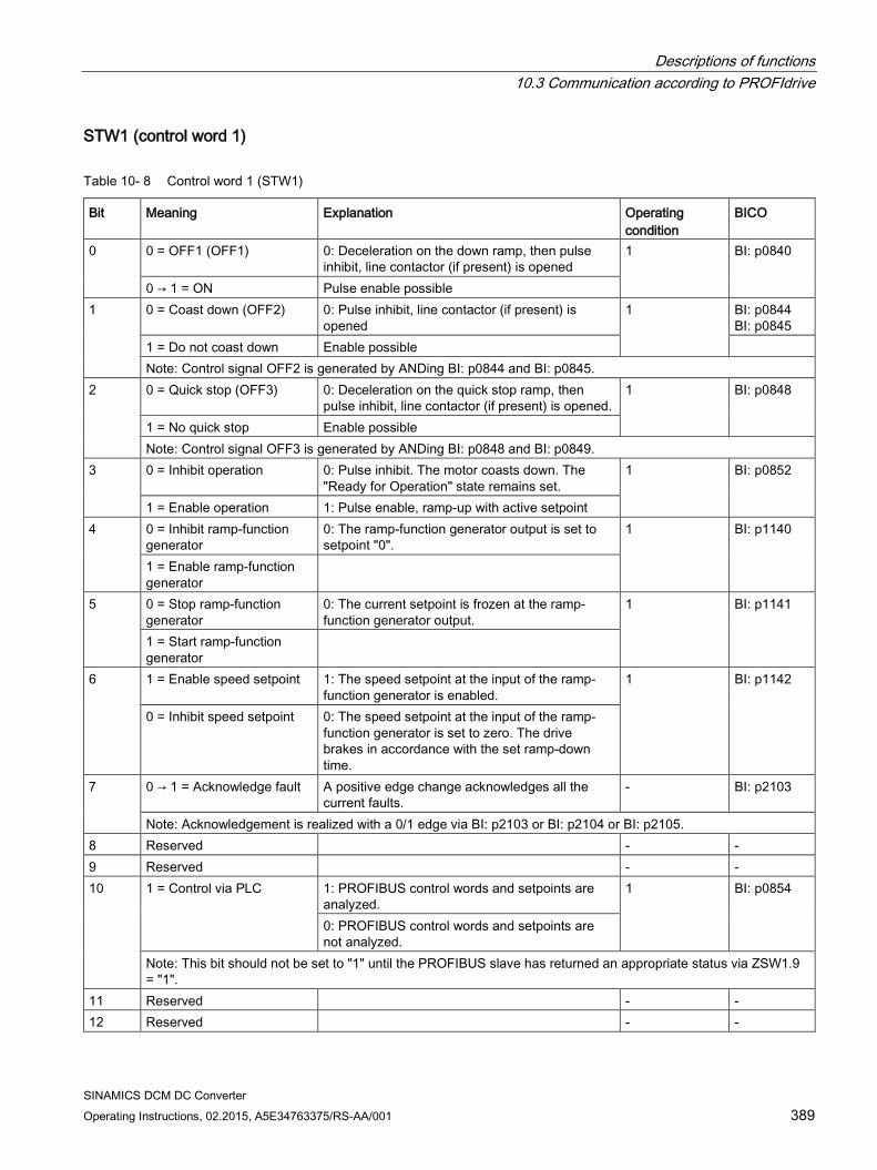
Descriptions of functions 10.3 Communication according to PROFIdrive
SINAMICS DCM DC Converter Operating Instructions, 02.2015, A5E34763375/RS-AA/001 389
STW1 (control word 1)
Table 10- 8 Control word 1 (STW1)
Bit Meaning Explanation Operating condition
BICO
0 0 = OFF1 (OFF1) 0: Deceleration on the down ramp, then pulse inhibit, line contactor (if present) is opened
1 BI: p0840
0 → 1 = ON Pulse enable possible 1 0 = Coast down (OFF2) 0: Pulse inhibit, line contactor (if present) is
opened 1 BI: p0844
BI: p0845 1 = Do not coast down Enable possible Note: Control signal OFF2 is generated by ANDing BI: p0844 and BI: p0845.
2 0 = Quick stop (OFF3) 0: Deceleration on the quick stop ramp, then pulse inhibit, line contactor (if present) is opened.
1 BI: p0848
1 = No quick stop Enable possible Note: Control signal OFF3 is generated by ANDing BI: p0848 and BI: p0849.
3 0 = Inhibit operation 0: Pulse inhibit. The motor coasts down. The "Ready for Operation" state remains set.
1 BI: p0852
1 = Enable operation 1: Pulse enable, ramp-up with active setpoint 4 0 = Inhibit ramp-function
generator 0: The ramp-function generator output is set to setpoint "0".
1 BI: p1140
1 = Enable ramp-function generator
5 0 = Stop ramp-function generator
0: The current setpoint is frozen at the ramp-function generator output.
1 BI: p1141
1 = Start ramp-function generator
6 1 = Enable speed setpoint 1: The speed setpoint at the input of the ramp-function generator is enabled.
1 BI: p1142
0 = Inhibit speed setpoint 0: The speed setpoint at the input of the ramp-function generator is set to zero. The drive brakes in accordance with the set ramp-down time.
7 0 → 1 = Acknowledge fault A positive edge change acknowledges all the current faults.
- BI: p2103
Note: Acknowledgement is realized with a 0/1 edge via BI: p2103 or BI: p2104 or BI: p2105. 8 Reserved - - 9 Reserved - - 10 1 = Control via PLC 1: PROFIBUS control words and setpoints are
analyzed. 1 BI: p0854
0: PROFIBUS control words and setpoints are not analyzed.
Note: This bit should not be set to "1" until the PROFIBUS slave has returned an appropriate status via ZSW1.9 = "1".
11 Reserved - - 12 Reserved - -
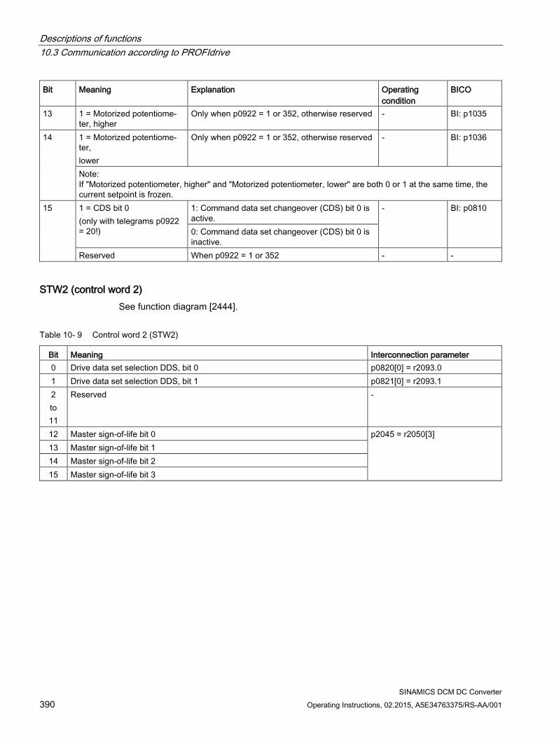
Descriptions of functions 10.3 Communication according to PROFIdrive
SINAMICS DCM DC Converter 390 Operating Instructions, 02.2015, A5E34763375/RS-AA/001
Bit Meaning Explanation Operating condition
BICO
13 1 = Motorized potentiome-ter, higher
Only when p0922 = 1 or 352, otherwise reserved - BI: p1035
14 1 = Motorized potentiome-ter, lower
Only when p0922 = 1 or 352, otherwise reserved - BI: p1036
Note: If "Motorized potentiometer, higher" and "Motorized potentiometer, lower" are both 0 or 1 at the same time, the current setpoint is frozen.
15 1 = CDS bit 0 (only with telegrams p0922 = 20!)
1: Command data set changeover (CDS) bit 0 is active.
- BI: p0810
0: Command data set changeover (CDS) bit 0 is inactive.
Reserved When p0922 = 1 or 352 - -
STW2 (control word 2) See function diagram [2444].
Table 10- 9 Control word 2 (STW2)
Bit Meaning Interconnection parameter 0 Drive data set selection DDS, bit 0 p0820[0] = r2093.0 1 Drive data set selection DDS, bit 1 p0821[0] = r2093.1 2 to 11
Reserved -
12 Master sign-of-life bit 0 p2045 = r2050[3] 13 Master sign-of-life bit 1 14 Master sign-of-life bit 2 15 Master sign-of-life bit 3
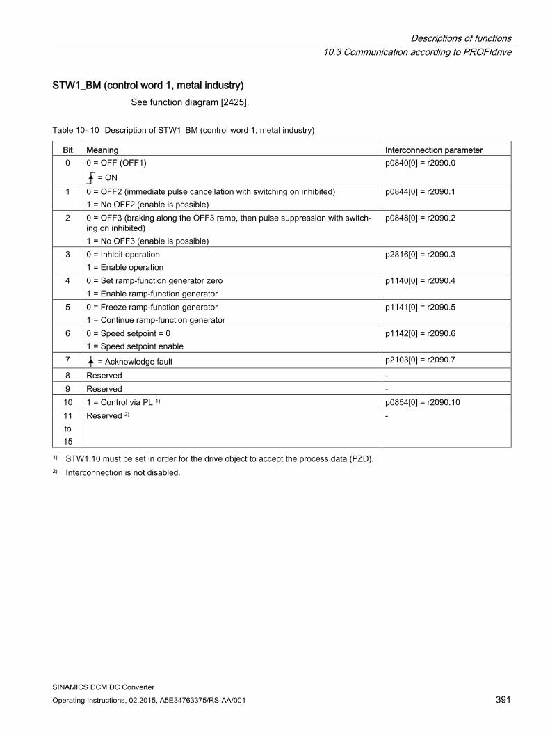
Descriptions of functions 10.3 Communication according to PROFIdrive
SINAMICS DCM DC Converter Operating Instructions, 02.2015, A5E34763375/RS-AA/001 391
STW1_BM (control word 1, metal industry) See function diagram [2425].
Table 10- 10 Description of STW1_BM (control word 1, metal industry)
Bit Meaning Interconnection parameter 0 0 = OFF (OFF1)
= ON
p0840[0] = r2090.0
1 0 = OFF2 (immediate pulse cancellation with switching on inhibited) 1 = No OFF2 (enable is possible)
p0844[0] = r2090.1
2 0 = OFF3 (braking along the OFF3 ramp, then pulse suppression with switch-ing on inhibited) 1 = No OFF3 (enable is possible)
p0848[0] = r2090.2
3 0 = Inhibit operation 1 = Enable operation
p2816[0] = r2090.3
4 0 = Set ramp-function generator zero 1 = Enable ramp-function generator
p1140[0] = r2090.4
5 0 = Freeze ramp-function generator 1 = Continue ramp-function generator
p1141[0] = r2090.5
6 0 = Speed setpoint = 0 1 = Speed setpoint enable
p1142[0] = r2090.6
7 = Acknowledge fault p2103[0] = r2090.7
8 Reserved - 9 Reserved - 10 1 = Control via PL 1) p0854[0] = r2090.10 11 to 15
Reserved 2) -
1) STW1.10 must be set in order for the drive object to accept the process data (PZD). 2) Interconnection is not disabled.
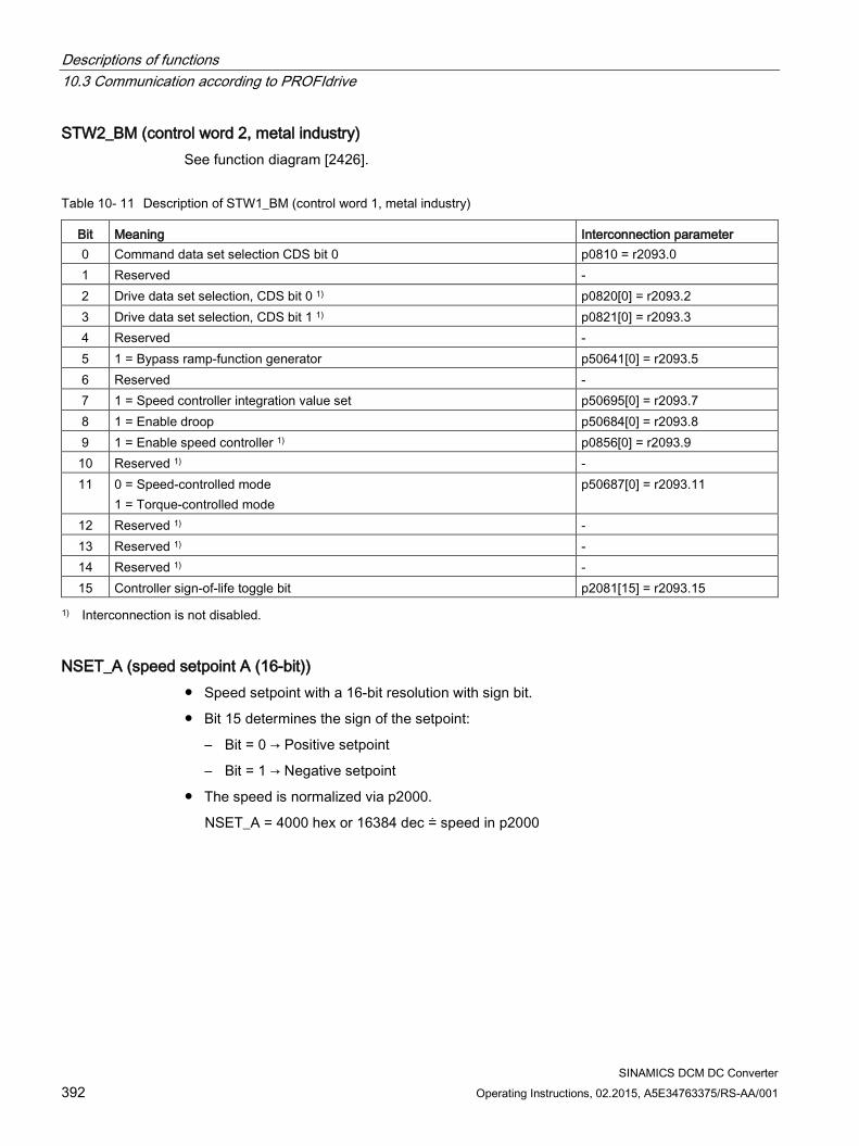
Descriptions of functions 10.3 Communication according to PROFIdrive
SINAMICS DCM DC Converter 392 Operating Instructions, 02.2015, A5E34763375/RS-AA/001
STW2_BM (control word 2, metal industry) See function diagram [2426].
Table 10- 11 Description of STW1_BM (control word 1, metal industry)
Bit Meaning Interconnection parameter 0 Command data set selection CDS bit 0 p0810 = r2093.0 1 Reserved - 2 Drive data set selection, CDS bit 0 1) p0820[0] = r2093.2 3 Drive data set selection, CDS bit 1 1) p0821[0] = r2093.3 4 Reserved - 5 1 = Bypass ramp-function generator p50641[0] = r2093.5 6 Reserved - 7 1 = Speed controller integration value set p50695[0] = r2093.7 8 1 = Enable droop p50684[0] = r2093.8 9 1 = Enable speed controller 1) p0856[0] = r2093.9 10 Reserved 1) - 11 0 = Speed-controlled mode
1 = Torque-controlled mode p50687[0] = r2093.11
12 Reserved 1) - 13 Reserved 1) - 14 Reserved 1) - 15 Controller sign-of-life toggle bit p2081[15] = r2093.15
1) Interconnection is not disabled.
NSET_A (speed setpoint A (16-bit)) Speed setpoint with a 16-bit resolution with sign bit.
Bit 15 determines the sign of the setpoint:
– Bit = 0 → Positive setpoint
– Bit = 1 → Negative setpoint
The speed is normalized via p2000.
NSET_A = 4000 hex or 16384 dec ≐ speed in p2000
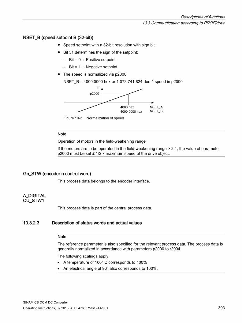
Descriptions of functions 10.3 Communication according to PROFIdrive
SINAMICS DCM DC Converter Operating Instructions, 02.2015, A5E34763375/RS-AA/001 393
NSET_B (speed setpoint B (32-bit)) Speed setpoint with a 32-bit resolution with sign bit.
Bit 31 determines the sign of the setpoint:
– Bit = 0 → Positive setpoint
– Bit = 1 → Negative setpoint
The speed is normalized via p2000.
NSET_B = 4000 0000 hex or 1 073 741 824 dec ≐ speed in p2000
Figure 10-3 Normalization of speed
Note
Operation of motors in the field-weakening range
If the motors are to be operated in the field-weakening range > 2:1, the value of parameter p2000 must be set ≤ 1/2 x maximum speed of the drive object.
Gn_STW (encoder n control word) This process data belongs to the encoder interface.
A_DIGITAL CU_STW1
This process data is part of the central process data.
10.3.2.3 Description of status words and actual values
Note
The reference parameter is also specified for the relevant process data. The process data is generally normalized in accordance with parameters p2000 to r2004.
The following scalings apply: • A temperature of 100° C corresponds to 100% • An electrical angle of 90° also corresponds to 100%.
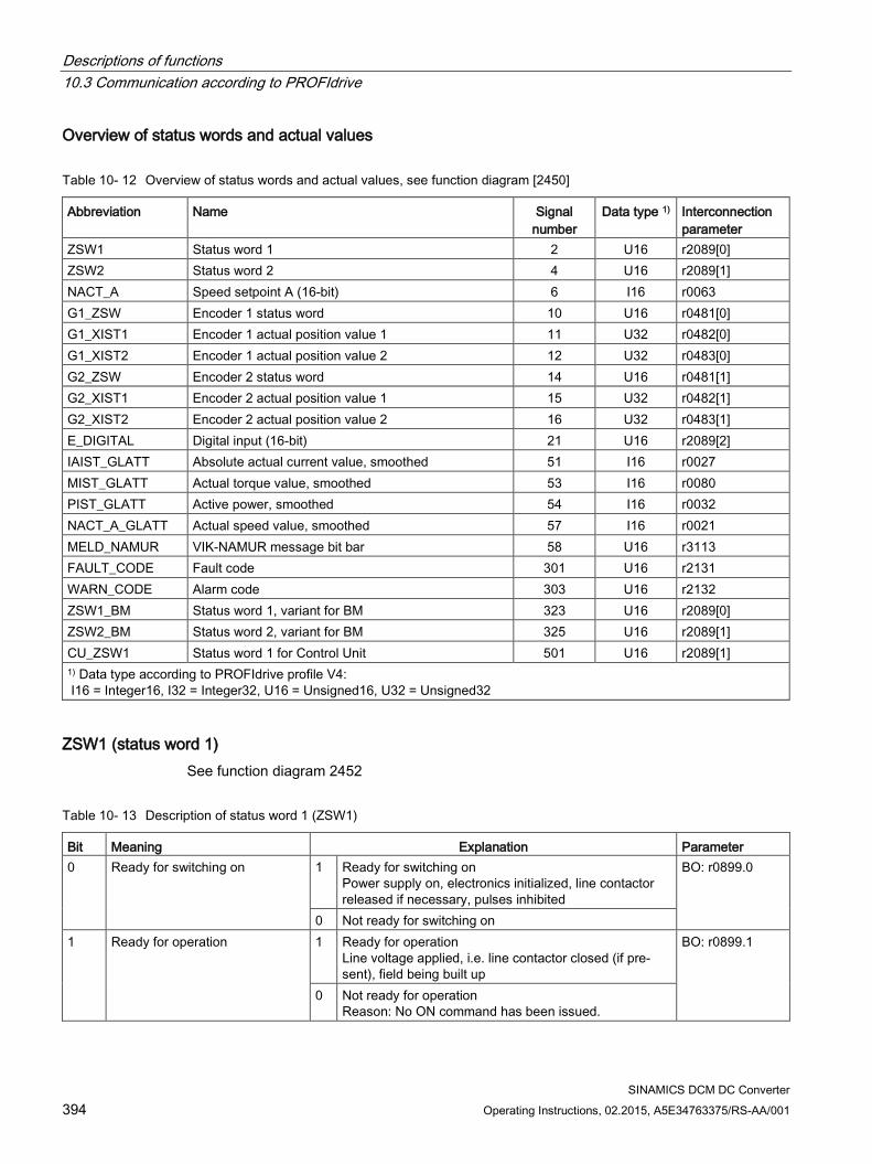
Descriptions of functions 10.3 Communication according to PROFIdrive
SINAMICS DCM DC Converter 394 Operating Instructions, 02.2015, A5E34763375/RS-AA/001
Overview of status words and actual values
Table 10- 12 Overview of status words and actual values, see function diagram [2450]
Abbreviation Name Signal number
Data type 1) Interconnection parameter
ZSW1 Status word 1 2 U16 r2089[0] ZSW2 Status word 2 4 U16 r2089[1] NACT_A Speed setpoint A (16-bit) 6 I16 r0063 G1_ZSW Encoder 1 status word 10 U16 r0481[0] G1_XIST1 Encoder 1 actual position value 1 11 U32 r0482[0] G1_XIST2 Encoder 1 actual position value 2 12 U32 r0483[0] G2_ZSW Encoder 2 status word 14 U16 r0481[1] G2_XIST1 Encoder 2 actual position value 1 15 U32 r0482[1] G2_XIST2 Encoder 2 actual position value 2 16 U32 r0483[1] E_DIGITAL Digital input (16-bit) 21 U16 r2089[2] IAIST_GLATT Absolute actual current value, smoothed 51 I16 r0027 MIST_GLATT Actual torque value, smoothed 53 I16 r0080 PIST_GLATT Active power, smoothed 54 I16 r0032 NACT_A_GLATT Actual speed value, smoothed 57 I16 r0021 MELD_NAMUR VIK-NAMUR message bit bar 58 U16 r3113 FAULT_CODE Fault code 301 U16 r2131 WARN_CODE Alarm code 303 U16 r2132 ZSW1_BM Status word 1, variant for BM 323 U16 r2089[0] ZSW2_BM Status word 2, variant for BM 325 U16 r2089[1] CU_ZSW1 Status word 1 for Control Unit 501 U16 r2089[1] 1) Data type according to PROFIdrive profile V4: I16 = Integer16, I32 = Integer32, U16 = Unsigned16, U32 = Unsigned32
ZSW1 (status word 1) See function diagram 2452
Table 10- 13 Description of status word 1 (ZSW1)
Bit Meaning Explanation Parameter 0 Ready for switching on 1 Ready for switching on
Power supply on, electronics initialized, line contactor released if necessary, pulses inhibited
BO: r0899.0
0 Not ready for switching on 1 Ready for operation 1 Ready for operation
Line voltage applied, i.e. line contactor closed (if pre-sent), field being built up
BO: r0899.1
0 Not ready for operation Reason: No ON command has been issued.
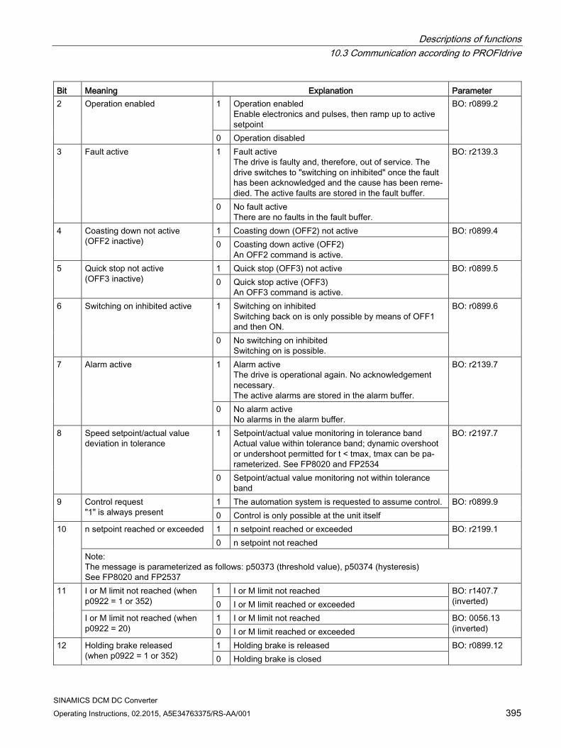
Descriptions of functions 10.3 Communication according to PROFIdrive
SINAMICS DCM DC Converter Operating Instructions, 02.2015, A5E34763375/RS-AA/001 395
Bit Meaning Explanation Parameter 2 Operation enabled 1 Operation enabled
Enable electronics and pulses, then ramp up to active setpoint
BO: r0899.2
0 Operation disabled 3 Fault active 1 Fault active
The drive is faulty and, therefore, out of service. The drive switches to "switching on inhibited" once the fault has been acknowledged and the cause has been reme-died. The active faults are stored in the fault buffer.
BO: r2139.3
0 No fault active There are no faults in the fault buffer.
4 Coasting down not active (OFF2 inactive)
1 Coasting down (OFF2) not active BO: r0899.4 0 Coasting down active (OFF2)
An OFF2 command is active. 5 Quick stop not active
(OFF3 inactive) 1 Quick stop (OFF3) not active BO: r0899.5 0 Quick stop active (OFF3)
An OFF3 command is active. 6 Switching on inhibited active 1 Switching on inhibited
Switching back on is only possible by means of OFF1 and then ON.
BO: r0899.6
0 No switching on inhibited Switching on is possible.
7 Alarm active 1 Alarm active The drive is operational again. No acknowledgement necessary. The active alarms are stored in the alarm buffer.
BO: r2139.7
0 No alarm active No alarms in the alarm buffer.
8 Speed setpoint/actual value deviation in tolerance
1 Setpoint/actual value monitoring in tolerance band Actual value within tolerance band; dynamic overshoot or undershoot permitted for t < tmax, tmax can be pa-rameterized. See FP8020 and FP2534
BO: r2197.7
0 Setpoint/actual value monitoring not within tolerance band
9 Control request "1" is always present
1 The automation system is requested to assume control. BO: r0899.9 0 Control is only possible at the unit itself
10 n setpoint reached or exceeded 1 n setpoint reached or exceeded BO: r2199.1 0 n setpoint not reached
Note: The message is parameterized as follows: p50373 (threshold value), p50374 (hysteresis) See FP8020 and FP2537
11 I or M limit not reached (when p0922 = 1 or 352)
1 I or M limit not reached BO: r1407.7 (inverted) 0 I or M limit reached or exceeded
I or M limit not reached (when p0922 = 20)
1 I or M limit not reached BO: 0056.13 (inverted) 0 I or M limit reached or exceeded
12 Holding brake released (when p0922 = 1 or 352)
1 Holding brake is released BO: r0899.12 0 Holding brake is closed
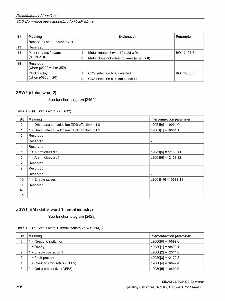
Descriptions of functions 10.3 Communication according to PROFIdrive
SINAMICS DCM DC Converter 396 Operating Instructions, 02.2015, A5E34763375/RS-AA/001
Bit Meaning Explanation Parameter Reserved (when p0922 = 20)
13 Reserved 14 Motor rotates forward
(n_act ≥ 0) 1 Motor rotates forward (n_act ≥ 0) BO: r2197.3 0 Motor does not rotate forward (n_act < 0)
15 Reserved (when p0922 = 1 or 352)
CDS display (when p0922 = 20)
1 CDS selection bit 0 selected BO: r0836.0 0 CDS selection bit 0 not selected
ZSW2 (status word 2) See function diagram [2454].
Table 10- 14 Status word 2 (ZSW2)
Bit Meaning Interconnection parameter 0 1 = Drive data set selection DDS effective, bit 0 p2081[0] = r0051.0 1 1 = Drive data set selection DDS effective, bit 1 p2081[1] = r0051.1 2 Reserved - 3 Reserved - 4 Reserved - 5 1 = Alarm class bit 0 p2081[5] = r2139.11 6 1 = Alarm class bit 1 p2081[6] = r2139.12 7 Reserved - 8 Reserved - 9 Reserved -
10 1 = Enable pulses p2081[10] = r0899.11 11 to 15
Reserved -
ZSW1_BM (status word 1, metal industry) See function diagram [2428].
Table 10- 15 Status word 1, metal industry (ZSW1 BM) 1)
Bit Meaning Interconnection parameter 0 1 = Ready to switch on p2080[0] = r0899.0 1 1 = Ready p2080[1] = r0899.1 2 1 = Enable operation 1 p2080[2] = r2811.0 3 1 = Fault present p2080[3] = r2139.3 4 0 = Coast to stop active (OFF2) p2080[4] = r0899.4 5 0 = Quick stop active (OFF3) p2080[5] = r0899.5
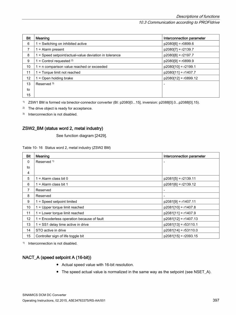
Descriptions of functions 10.3 Communication according to PROFIdrive
SINAMICS DCM DC Converter Operating Instructions, 02.2015, A5E34763375/RS-AA/001 397
Bit Meaning Interconnection parameter 6 1 = Switching on inhibited active p2080[6] = r0899.6 7 1 = Alarm present p2080[7] = r2139.7 8 1 = Speed setpoint/actual-value deviation in tolerance p2080[8] = r2197.7 9 1 = Control requested 2) p2080[9] = r0899.9
10 1 = n comparison value reached or exceeded p2080[10] = r2199.1 11 1 = Torque limit not reached p2080[11] = r1407.7 12 1 = Open holding brake p2080[12] = r0899.12 13 to 15
Reserved 3) -
1) ZSW1 BM is formed via binector-connector converter (BI: p2080[0...15], inversion: p2088[0].0...p2088[0].15). 2) The drive object is ready for acceptance. 3) Interconnection is not disabled.
ZSW2_BM (status word 2, metal industry) See function diagram [2429].
Table 10- 16 Status word 2, metal industry (ZSW2 BM)
Bit Meaning Interconnection parameter 0 to 4
Reserved 1) -
5 1 = Alarm class bit 0 p2081[5] = r2139.11 6 1 = Alarm class bit 1 p2081[6] = r2139.12 7 Reserved - 8 Reserved - 9 1 = Speed setpoint limited p2081[9] = r1407.11
10 1 = Upper torque limit reached p2081[10] = r1407.8 11 1 = Lower torque limit reached p2081[11] = r1407.9 12 1 = Encoderless operation because of fault p2081[12] = r1407.13 13 1 = SS1 delay time active in drive p2081[13] = r53110.1 14 STO active in drive p2081[14] = r53110.0 15 Controller sign of life toggle bit p2081[15] = r2093.15
1) Interconnection is not disabled.
NACT_A (speed setpoint A (16-bit)) Actual speed value with 16-bit resolution.
The speed actual value is normalized in the same way as the setpoint (see NSET_A).
Descriptions of functions 10.3 Communication according to PROFIdrive
SINAMICS DCM DC Converter 398 Operating Instructions, 02.2015, A5E34763375/RS-AA/001
NACT_B (speed setpoint B (32-bit)) Actual speed value with 32-bit resolution.
The speed actual value is normalized in the same way as the setpoint (see NSET_B).
Gn_ZSW (encoder n status word) Gn_XIST1 (encoder n actual position value 1) Gn_XIST2 (encoder n actual position value 2)
This process data belongs to the encoder interface.
E_DIGITAL CU_ZSW1
This process data is part of the central process data.
IAIST_GLATT The absolute current actual value smoothed with p0045 is displayed.
MIST_GLATT The actual torque value smoothed with p0045 is displayed.
PIST_GLATT The active power smoothed with p0045 is displayed.
NACT_A_GLATT The actual speed value smoothed with p0045 is displayed.
MELD_NAMUR Display of the NAMUR message bit bar.
WARN_CODE Display of the alarm code (see function diagram 8065).
FAULT_CODE Display of the fault code (see function diagram 8060).
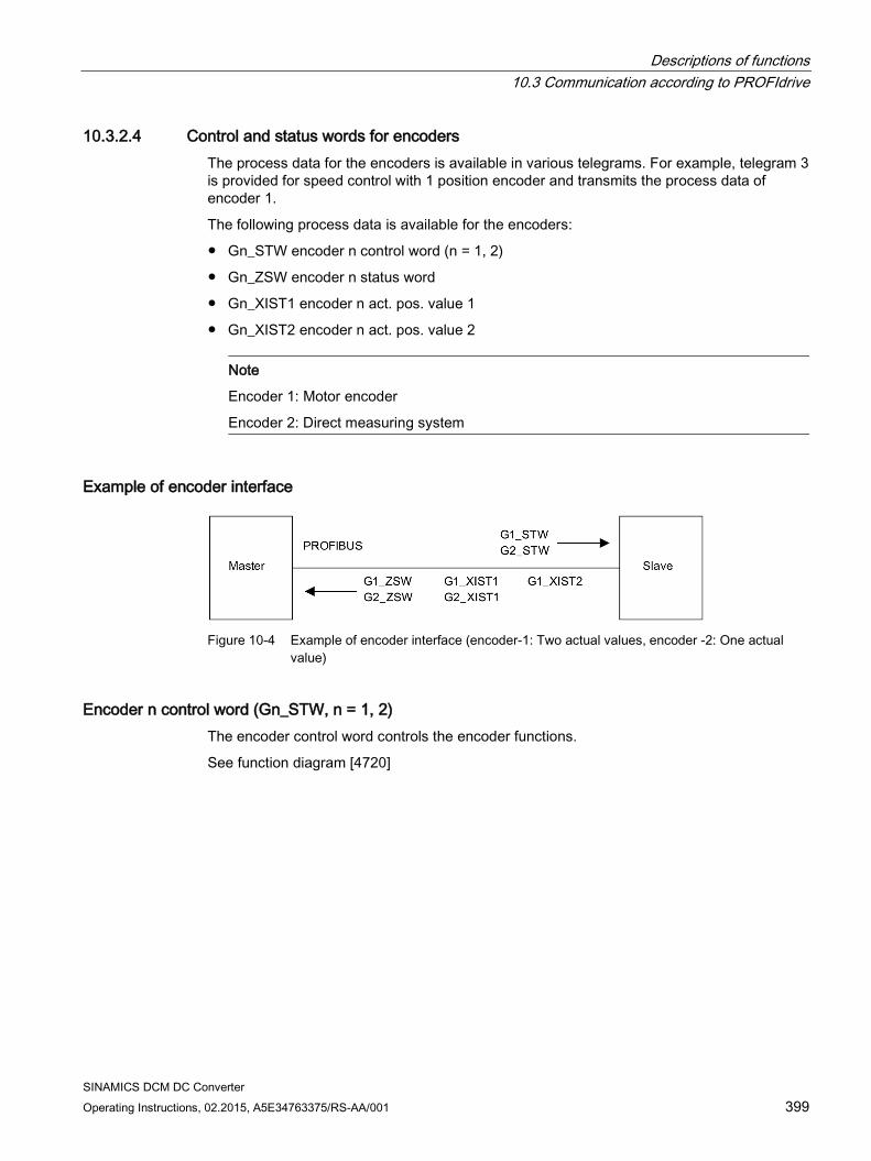
Descriptions of functions 10.3 Communication according to PROFIdrive
SINAMICS DCM DC Converter Operating Instructions, 02.2015, A5E34763375/RS-AA/001 399
10.3.2.4 Control and status words for encoders The process data for the encoders is available in various telegrams. For example, telegram 3 is provided for speed control with 1 position encoder and transmits the process data of encoder 1.
The following process data is available for the encoders:
Gn_STW encoder n control word (n = 1, 2)
Gn_ZSW encoder n status word
Gn_XIST1 encoder n act. pos. value 1
Gn_XIST2 encoder n act. pos. value 2
Note
Encoder 1: Motor encoder
Encoder 2: Direct measuring system
Example of encoder interface
Figure 10-4 Example of encoder interface (encoder-1: Two actual values, encoder -2: One actual
value)
Encoder n control word (Gn_STW, n = 1, 2) The encoder control word controls the encoder functions.
See function diagram [4720]
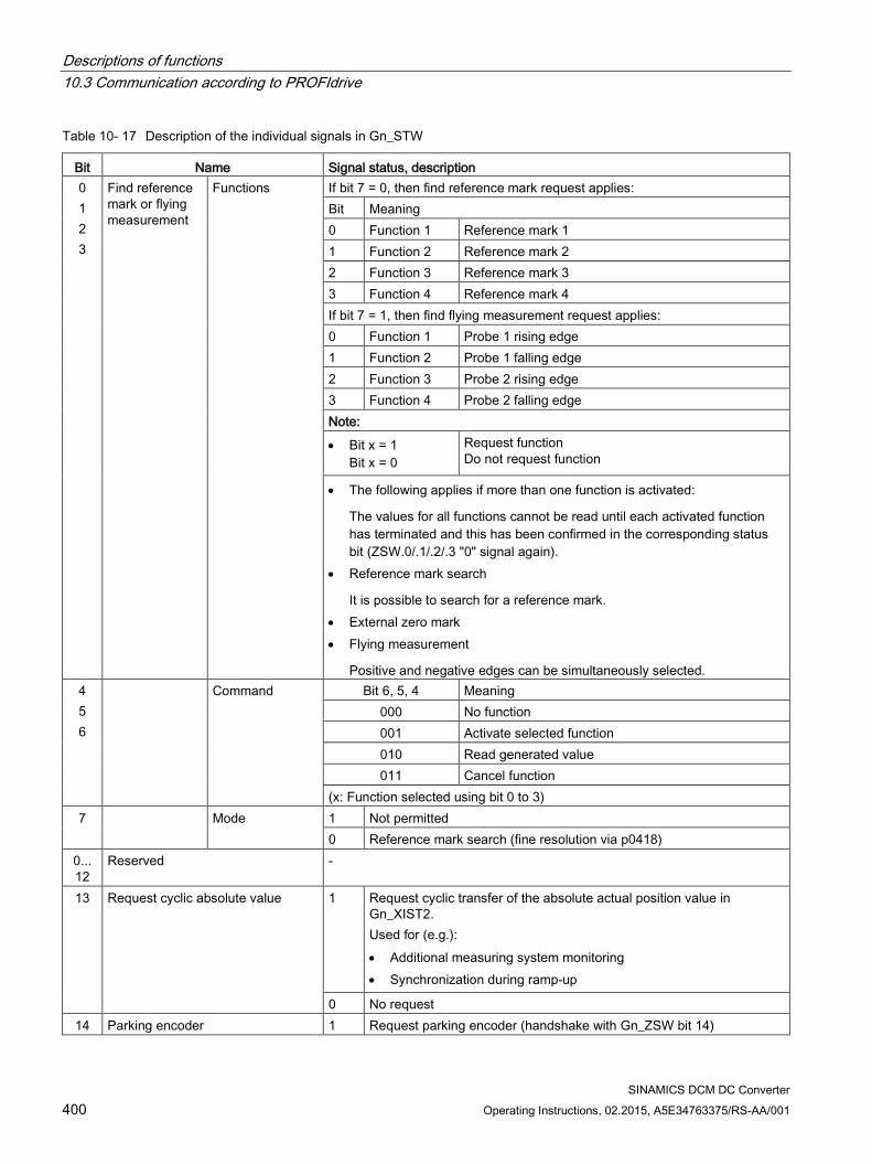
Descriptions of functions 10.3 Communication according to PROFIdrive
SINAMICS DCM DC Converter 400 Operating Instructions, 02.2015, A5E34763375/RS-AA/001
Table 10- 17 Description of the individual signals in Gn_STW
Bit Name Signal status, description 0 1 2 3
Find reference mark or flying measurement
Functions If bit 7 = 0, then find reference mark request applies: Bit Meaning 0 Function 1 Reference mark 1 1 Function 2 Reference mark 2 2 Function 3 Reference mark 3 3 Function 4 Reference mark 4 If bit 7 = 1, then find flying measurement request applies: 0 Function 1 Probe 1 rising edge 1 Function 2 Probe 1 falling edge 2 Function 3 Probe 2 rising edge 3 Function 4 Probe 2 falling edge Note:
• Bit x = 1 Bit x = 0
Request function Do not request function
• The following applies if more than one function is activated:
The values for all functions cannot be read until each activated function has terminated and this has been confirmed in the corresponding status bit (ZSW.0/.1/.2/.3 "0" signal again).
• Reference mark search
It is possible to search for a reference mark. • External zero mark • Flying measurement
Positive and negative edges can be simultaneously selected. 4 5 6
Command Bit 6, 5, 4 Meaning 000 No function 001 Activate selected function 010 Read generated value 011 Cancel function
(x: Function selected using bit 0 to 3) 7 Mode 1 Not permitted
0 Reference mark search (fine resolution via p0418) 0... 12
Reserved -
13 Request cyclic absolute value 1 Request cyclic transfer of the absolute actual position value in Gn_XIST2. Used for (e.g.): • Additional measuring system monitoring • Synchronization during ramp-up
0 No request 14 Parking encoder 1 Request parking encoder (handshake with Gn_ZSW bit 14)
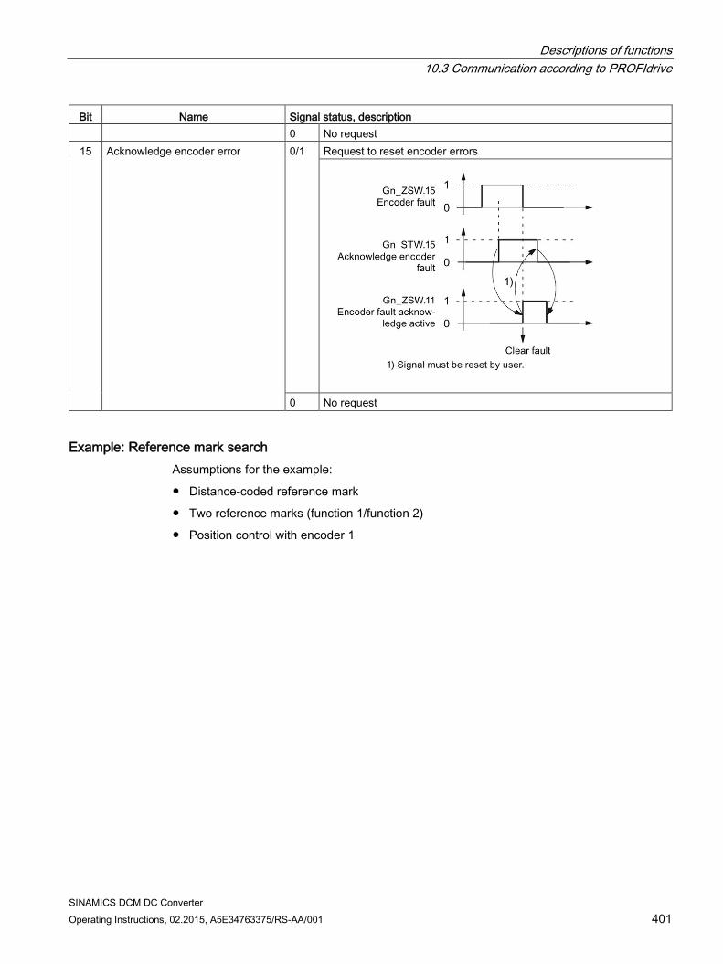
Descriptions of functions 10.3 Communication according to PROFIdrive
SINAMICS DCM DC Converter Operating Instructions, 02.2015, A5E34763375/RS-AA/001 401
Bit Name Signal status, description 0 No request
15 Acknowledge encoder error 0/1 Request to reset encoder errors
0 No request
Example: Reference mark search Assumptions for the example:
Distance-coded reference mark
Two reference marks (function 1/function 2)
Position control with encoder 1
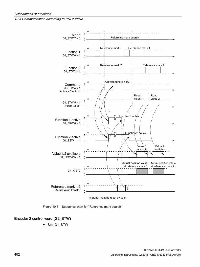
Descriptions of functions 10.3 Communication according to PROFIdrive
SINAMICS DCM DC Converter 402 Operating Instructions, 02.2015, A5E34763375/RS-AA/001
Figure 10-5 Sequence chart for "Reference mark search"
Encoder 2 control word (G2_STW) See G1_STW
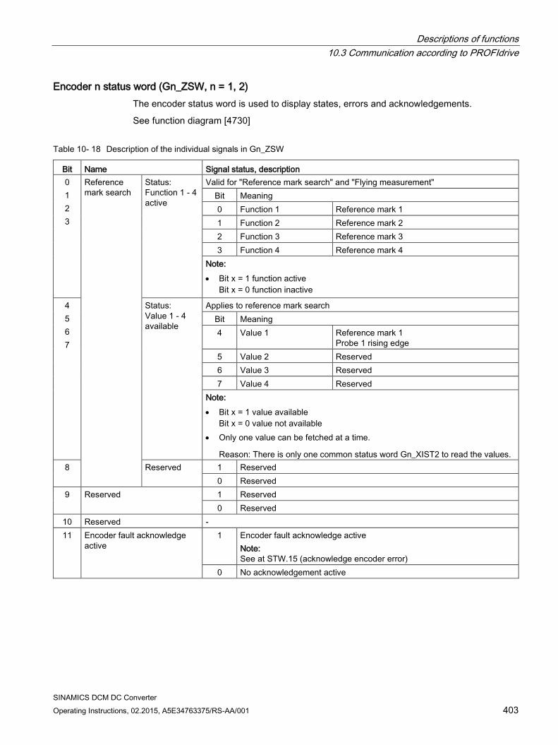
Descriptions of functions 10.3 Communication according to PROFIdrive
SINAMICS DCM DC Converter Operating Instructions, 02.2015, A5E34763375/RS-AA/001 403
Encoder n status word (Gn_ZSW, n = 1, 2) The encoder status word is used to display states, errors and acknowledgements.
See function diagram [4730]
Table 10- 18 Description of the individual signals in Gn_ZSW
Bit Name Signal status, description 0 1 2 3
Reference mark search
Status: Function 1 - 4 active
Valid for "Reference mark search" and "Flying measurement" Bit Meaning 0 Function 1 Reference mark 1 1 Function 2 Reference mark 2 2 Function 3 Reference mark 3 3 Function 4 Reference mark 4
Note: • Bit x = 1 function active
Bit x = 0 function inactive
4 5 6 7
Status: Value 1 - 4 available
Applies to reference mark search Bit Meaning 4 Value 1 Reference mark 1
Probe 1 rising edge 5 Value 2 Reserved 6 Value 3 Reserved 7 Value 4 Reserved
Note: • Bit x = 1 value available
Bit x = 0 value not available • Only one value can be fetched at a time.
Reason: There is only one common status word Gn_XIST2 to read the values. 8 Reserved 1 Reserved
0 Reserved 9 Reserved 1 Reserved
0 Reserved 10 Reserved - 11 Encoder fault acknowledge
active 1 Encoder fault acknowledge active
Note: See at STW.15 (acknowledge encoder error)
0 No acknowledgement active
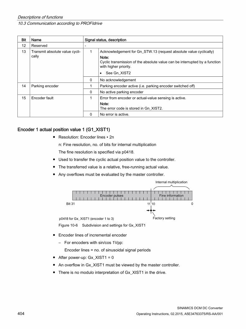
Descriptions of functions 10.3 Communication according to PROFIdrive
SINAMICS DCM DC Converter 404 Operating Instructions, 02.2015, A5E34763375/RS-AA/001
Bit Name Signal status, description 12 Reserved - 13 Transmit absolute value cycli-
cally 1 Acknowledgement for Gn_STW.13 (request absolute value cyclically)
Note: Cyclic transmission of the absolute value can be interrupted by a function with higher priority. • See Gn_XIST2
0 No acknowledgement 14 Parking encoder 1 Parking encoder active (i.e. parking encoder switched off)
0 No active parking encoder 15 Encoder fault 1 Error from encoder or actual-value sensing is active.
Note: The error code is stored in Gn_XIST2.
0 No error is active.
Encoder 1 actual position value 1 (G1_XIST1) Resolution: Encoder lines ∙ 2n
n: Fine resolution, no. of bits for internal multiplication
The fine resolution is specified via p0418.
Used to transfer the cyclic actual position value to the controller.
The transferred value is a relative, free-running actual value.
Any overflows must be evaluated by the master controller.
Figure 10-6 Subdivision and settings for Gx_XIST1
Encoder lines of incremental encoder
– For encoders with sin/cos 1Vpp:
Encoder lines = no. of sinusoidal signal periods
After power-up: Gx_XIST1 = 0
An overflow in Gx_XIST1 must be viewed by the master controller.
There is no modulo interpretation of Gx_XIST1 in the drive.
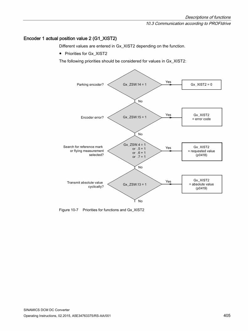
Descriptions of functions 10.3 Communication according to PROFIdrive
SINAMICS DCM DC Converter Operating Instructions, 02.2015, A5E34763375/RS-AA/001 405
Encoder 1 actual position value 2 (G1_XIST2) Different values are entered in Gx_XIST2 depending on the function.
Priorities for Gx_XIST2
The following priorities should be considered for values in Gx_XIST2:
Figure 10-7 Priorities for functions and Gx_XIST2
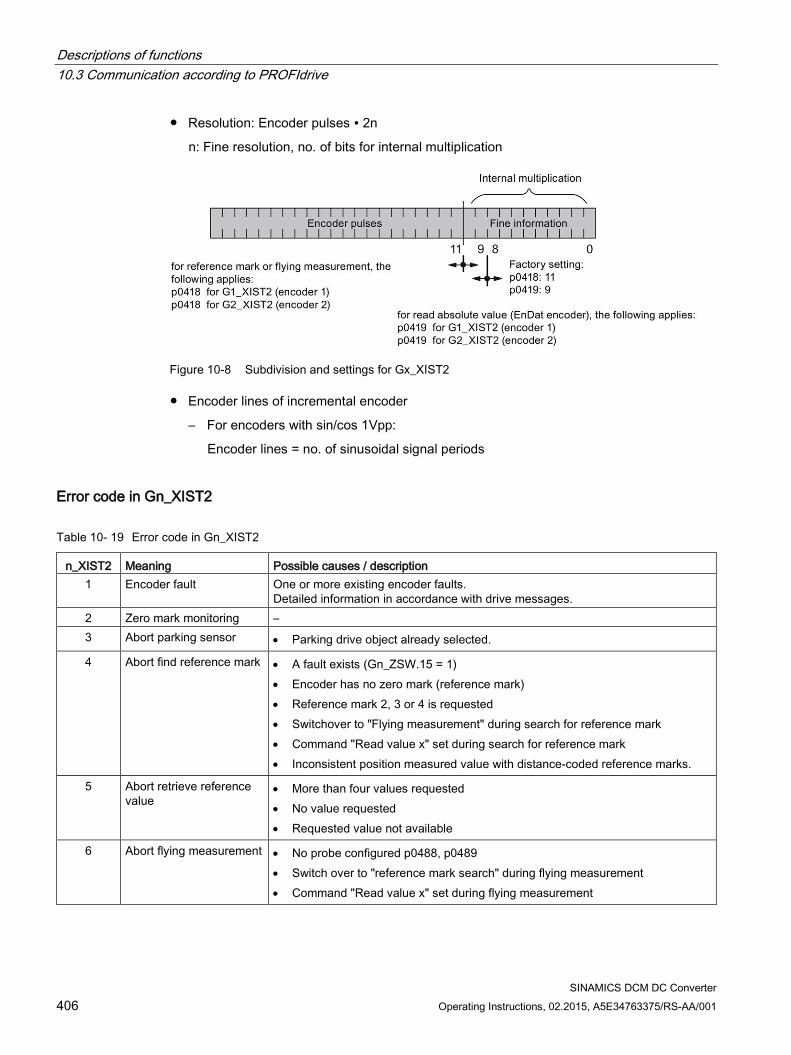
Descriptions of functions 10.3 Communication according to PROFIdrive
SINAMICS DCM DC Converter 406 Operating Instructions, 02.2015, A5E34763375/RS-AA/001
Resolution: Encoder pulses ∙ 2n
n: Fine resolution, no. of bits for internal multiplication
Figure 10-8 Subdivision and settings for Gx_XIST2
Encoder lines of incremental encoder
– For encoders with sin/cos 1Vpp:
Encoder lines = no. of sinusoidal signal periods
Error code in Gn_XIST2
Table 10- 19 Error code in Gn_XIST2
n_XIST2 Meaning Possible causes / description 1 Encoder fault One or more existing encoder faults.
Detailed information in accordance with drive messages. 2 Zero mark monitoring – 3 Abort parking sensor • Parking drive object already selected.
4 Abort find reference mark • A fault exists (Gn_ZSW.15 = 1) • Encoder has no zero mark (reference mark) • Reference mark 2, 3 or 4 is requested • Switchover to "Flying measurement" during search for reference mark • Command "Read value x" set during search for reference mark • Inconsistent position measured value with distance-coded reference marks.
5 Abort retrieve reference value
• More than four values requested • No value requested • Requested value not available
6 Abort flying measurement • No probe configured p0488, p0489 • Switch over to "reference mark search" during flying measurement • Command "Read value x" set during flying measurement
Descriptions of functions 10.3 Communication according to PROFIdrive
SINAMICS DCM DC Converter Operating Instructions, 02.2015, A5E34763375/RS-AA/001 407
n_XIST2 Meaning Possible causes / description 7 Abort get measured value • More than one value requested
• No value requested • Requested value not available • Parking encoder active • Parking drive object active
8 Abort absolute value transmission on
• Absolute encoder not available • Alarm bit absolute value protocol set
3841 Function not supported –
Encoder 2 status word (G2_ZSW) See Gn_ZSW
Encoder 2 actual position value 1 (G2_XIST1) See Gn_XIST1
Encoder 2 actual position value 2 (G2_XIST2) See Gn_XIST2
Function diagrams (see the SINAMICS DCM List Manual) • 4720 Encoder evaluation - Encoder interface, receive signals, encoders 1 ... 2
• 4730 Encoder evaluation - Encoder interface, send signals, encoders 1 ... 2
• 4735 Encoder evaluation - Reference mark search with external zero mark, encoders 1 ... 2
Overview of important parameters (see SINAMICS DCM List Manual) Adjustable parameter drive, CU_S parameter is marked • p0418[0...15] Fine resolution Gx_XIST1 (in bits)
• p0419[0...15] Fine resolution absolute value Gx_XIST2 (in bits)
• p0480[0...2] CI: Encoder control word Gn_STW signal source
Display parameters drive • r0481[0...2] CO: Encoder status word Gn_ZSW
• r0482[0...2] CO: Encoder actual position value Gn_XIST1
• r0483[0...2] CO: Encoder actual position value Gn_XIST2
• r0487[0...2] CO: Diagnostic encoder control word Gn_STW
• r0979[0...30] PROFIdrive encoder format
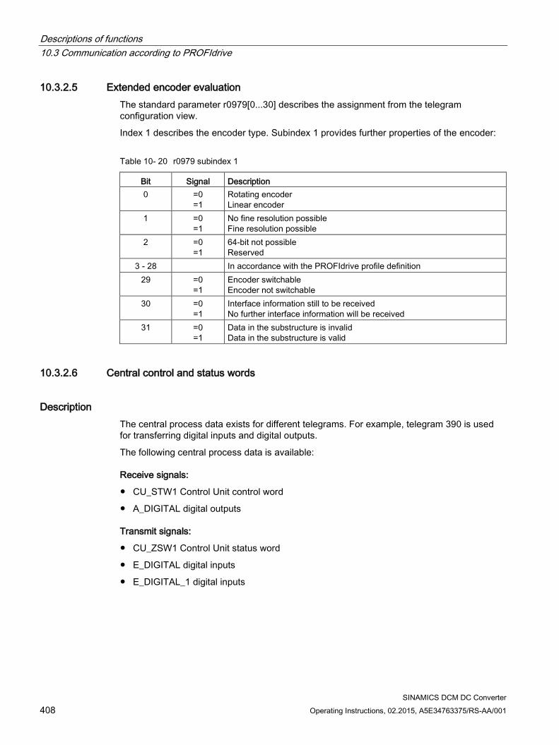
Descriptions of functions 10.3 Communication according to PROFIdrive
SINAMICS DCM DC Converter 408 Operating Instructions, 02.2015, A5E34763375/RS-AA/001
10.3.2.5 Extended encoder evaluation The standard parameter r0979[0...30] describes the assignment from the telegram configuration view.
Index 1 describes the encoder type. Subindex 1 provides further properties of the encoder:
Table 10- 20 r0979 subindex 1
Bit Signal Description 0 =0
=1 Rotating encoder Linear encoder
1 =0 =1
No fine resolution possible Fine resolution possible
2 =0 =1
64-bit not possible Reserved
3 - 28 In accordance with the PROFIdrive profile definition 29 =0
=1 Encoder switchable Encoder not switchable
30 =0 =1
Interface information still to be received No further interface information will be received
31 =0 =1
Data in the substructure is invalid Data in the substructure is valid
10.3.2.6 Central control and status words
Description The central process data exists for different telegrams. For example, telegram 390 is used for transferring digital inputs and digital outputs.
The following central process data is available:
Receive signals:
CU_STW1 Control Unit control word
A_DIGITAL digital outputs
Transmit signals:
CU_ZSW1 Control Unit status word
E_DIGITAL digital inputs
E_DIGITAL_1 digital inputs
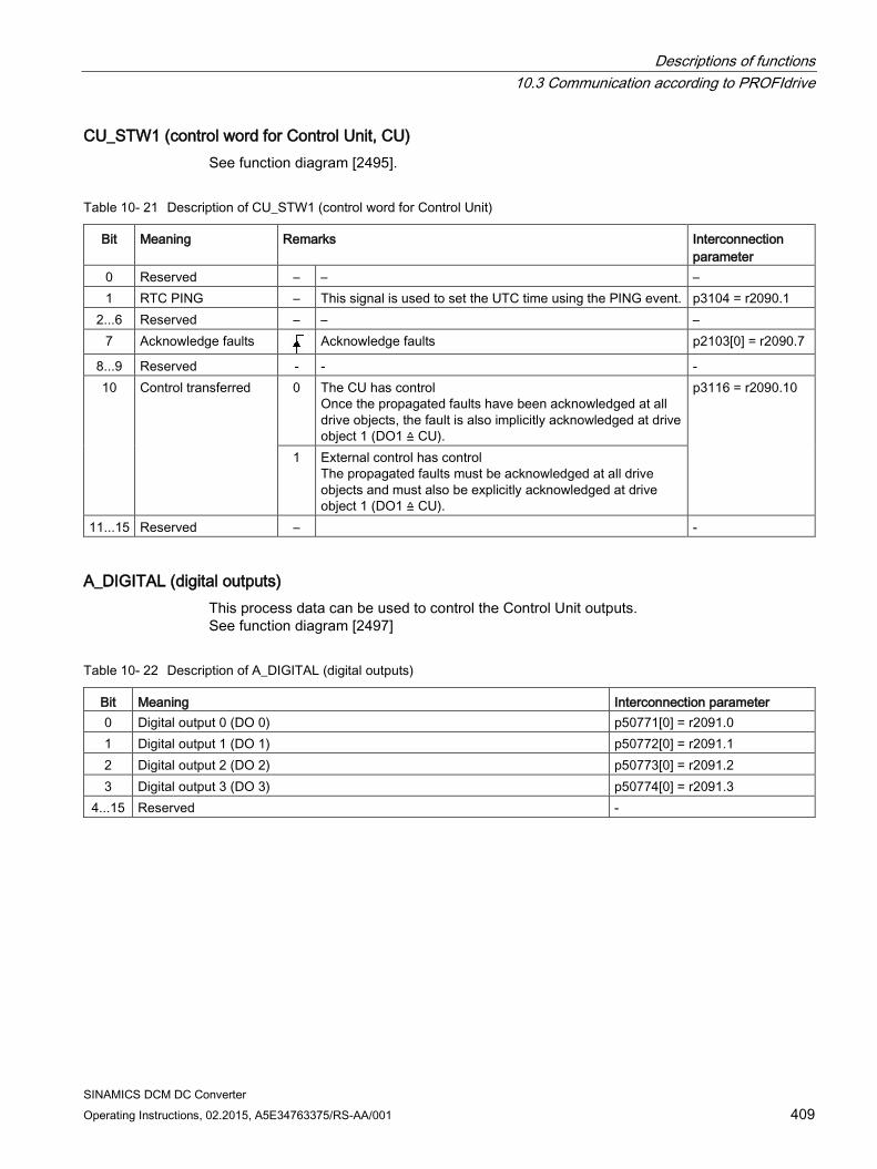
Descriptions of functions 10.3 Communication according to PROFIdrive
SINAMICS DCM DC Converter Operating Instructions, 02.2015, A5E34763375/RS-AA/001 409
CU_STW1 (control word for Control Unit, CU) See function diagram [2495].
Table 10- 21 Description of CU_STW1 (control word for Control Unit)
Bit Meaning Remarks Interconnection parameter
0 Reserved – – – 1 RTC PING – This signal is used to set the UTC time using the PING event. p3104 = r2090.1
2...6 Reserved – – – 7 Acknowledge faults Acknowledge faults p2103[0] = r2090.7
8...9 Reserved - - - 10 Control transferred 0 The CU has control
Once the propagated faults have been acknowledged at all drive objects, the fault is also implicitly acknowledged at drive object 1 (DO1 ≙ CU).
p3116 = r2090.10
1 External control has control The propagated faults must be acknowledged at all drive objects and must also be explicitly acknowledged at drive object 1 (DO1 ≙ CU).
11...15 Reserved – -
A_DIGITAL (digital outputs) This process data can be used to control the Control Unit outputs. See function diagram [2497]
Table 10- 22 Description of A_DIGITAL (digital outputs)
Bit Meaning Interconnection parameter 0 Digital output 0 (DO 0) p50771[0] = r2091.0 1 Digital output 1 (DO 1) p50772[0] = r2091.1 2 Digital output 2 (DO 2) p50773[0] = r2091.2 3 Digital output 3 (DO 3) p50774[0] = r2091.3
4...15 Reserved -
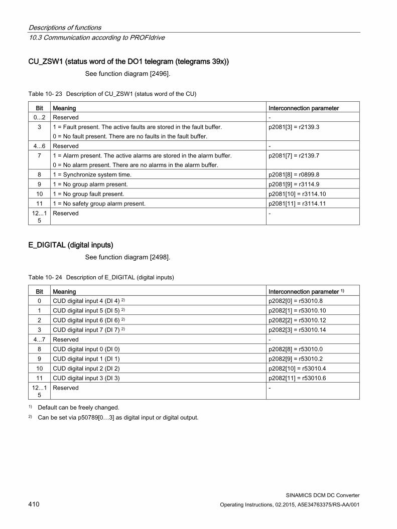
Descriptions of functions 10.3 Communication according to PROFIdrive
SINAMICS DCM DC Converter 410 Operating Instructions, 02.2015, A5E34763375/RS-AA/001
CU_ZSW1 (status word of the DO1 telegram (telegrams 39x)) See function diagram [2496].
Table 10- 23 Description of CU_ZSW1 (status word of the CU)
Bit Meaning Interconnection parameter 0...2 Reserved -
3 1 = Fault present. The active faults are stored in the fault buffer. 0 = No fault present. There are no faults in the fault buffer.
p2081[3] = r2139.3
4...6 Reserved - 7 1 = Alarm present. The active alarms are stored in the alarm buffer.
0 = No alarm present. There are no alarms in the alarm buffer. p2081[7] = r2139.7
8 1 = Synchronize system time. p2081[8] = r0899.8 9 1 = No group alarm present. p2081[9] = r3114.9 10 1 = No group fault present. p2081[10] = r3114.10 11 1 = No safety group alarm present. p2081[11] = r3114.11
12...15
Reserved -
E_DIGITAL (digital inputs) See function diagram [2498].
Table 10- 24 Description of E_DIGITAL (digital inputs)
Bit Meaning Interconnection parameter 1) 0 CUD digital input 4 (DI 4) 2) p2082[0] = r53010.8 1 CUD digital input 5 (DI 5) 2) p2082[1] = r53010.10 2 CUD digital input 6 (DI 6) 2) p2082[2] = r53010.12 3 CUD digital input 7 (DI 7) 2) p2082[3] = r53010.14
4...7 Reserved - 8 CUD digital input 0 (DI 0) p2082[8] = r53010.0 9 CUD digital input 1 (DI 1) p2082[9] = r53010.2 10 CUD digital input 2 (DI 2) p2082[10] = r53010.4 11 CUD digital input 3 (DI 3) p2082[11] = r53010.6
12...15
Reserved -
1) Default can be freely changed. 2) Can be set via p50789[0…3] as digital input or digital output.
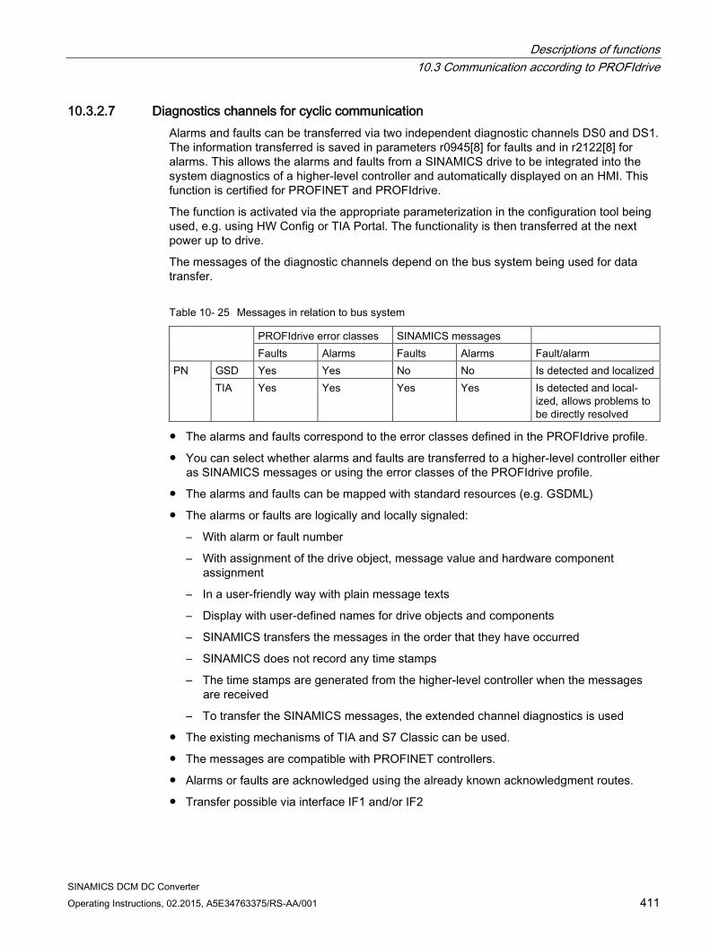
Descriptions of functions 10.3 Communication according to PROFIdrive
SINAMICS DCM DC Converter Operating Instructions, 02.2015, A5E34763375/RS-AA/001 411
10.3.2.7 Diagnostics channels for cyclic communication Alarms and faults can be transferred via two independent diagnostic channels DS0 and DS1. The information transferred is saved in parameters r0945[8] for faults and in r2122[8] for alarms. This allows the alarms and faults from a SINAMICS drive to be integrated into the system diagnostics of a higher-level controller and automatically displayed on an HMI. This function is certified for PROFINET and PROFIdrive.
The function is activated via the appropriate parameterization in the configuration tool being used, e.g. using HW Config or TIA Portal. The functionality is then transferred at the next power up to drive.
The messages of the diagnostic channels depend on the bus system being used for data transfer.
Table 10- 25 Messages in relation to bus system
PROFIdrive error classes SINAMICS messages Faults Alarms Faults Alarms Fault/alarm
PN GSD Yes Yes No No Is detected and localized TIA Yes Yes Yes Yes Is detected and local-
ized, allows problems to be directly resolved
The alarms and faults correspond to the error classes defined in the PROFIdrive profile.
You can select whether alarms and faults are transferred to a higher-level controller either as SINAMICS messages or using the error classes of the PROFIdrive profile.
The alarms and faults can be mapped with standard resources (e.g. GSDML)
The alarms or faults are logically and locally signaled:
– With alarm or fault number
– With assignment of the drive object, message value and hardware component assignment
– In a user-friendly way with plain message texts
– Display with user-defined names for drive objects and components
– SINAMICS transfers the messages in the order that they have occurred
– SINAMICS does not record any time stamps
– The time stamps are generated from the higher-level controller when the messages are received
– To transfer the SINAMICS messages, the extended channel diagnostics is used
The existing mechanisms of TIA and S7 Classic can be used.
The messages are compatible with PROFINET controllers.
Alarms or faults are acknowledged using the already known acknowledgment routes.
Transfer possible via interface IF1 and/or IF2
Descriptions of functions 10.3 Communication according to PROFIdrive
SINAMICS DCM DC Converter 412 Operating Instructions, 02.2015, A5E34763375/RS-AA/001
Note
Constraint
If Shared device is activated, only one of the controllers can receive diagnoses.
Data transfer for cyclic communication, the following applies: For PROFINET, there is a unique assignment of the drive objects to the slots of the cyclic
communication. The diagnostics is issued at the MAP/PAP-submodule.
Data transfer for acyclic communication, the following applies: There is no slot or subslot configured at which diagnostics can be issued.
Faults or alarms that occur are routed along the BICO connections to the drive objects.
Display of error classes according to PROFIdrive: For transfer with PROFINET, the PROFIdrive error class and the extended channel
diagnostics.
10.3.3 Parallel operation of communication interfaces Cyclic process data (setpoints / actual values) are processed using interfaces IF1 and IF2. The following interfaces are used:
Onboard interfaces of the Control Unit for PROFIBUS DP
An additional interface (COMM - BOARD) for PROFINET or Ethernet/IP (CBE20) for insertion in the Control Unit as an option.
Parameter p8839 is used to set the parallel use of the Control Unit onboard interfaces and COMM - BOARD in the SINAMICS system. The functionality is assigned to interfaces IF1 and IF2 using indices.
For example, the following applications are possible:
PROFIBUS DP for control and PROFINET to acquire actual values / measured values of the drive
PROFIBUS DP for control and PROFINET for engineering only
Mixed mode with two masters (the first for logic and coordination, and the second for technology)
SINAMICS Link via IF1 (CBE20); PROFIBUS (only DO Drive, max. 16 PZD) IF2
Operation of redundant communication interfaces
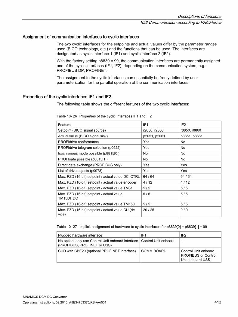
Descriptions of functions 10.3 Communication according to PROFIdrive
SINAMICS DCM DC Converter Operating Instructions, 02.2015, A5E34763375/RS-AA/001 413
Assignment of communication interfaces to cyclic interfaces The two cyclic interfaces for the setpoints and actual values differ by the parameter ranges used (BICO technology, etc.) and the functions that can be used. The interfaces are designated as cyclic interface 1 (IF1) and cyclic interface 2 (IF2).
With the factory setting p8839 = 99, the communication interfaces are permanently assigned one of the cyclic interfaces (IF1, IF2), depending on the communication system, e.g. PROFIBUS DP, PROFINET.
The assignment to the cyclic interfaces can essentially be freely defined by user parameterization for the parallel operation of the communication interfaces.
Properties of the cyclic interfaces IF1 and IF2 The following table shows the different features of the two cyclic interfaces:
Table 10- 26 Properties of the cyclic interfaces IF1 and IF2
Feature IF1 IF2 Setpoint (BICO signal source) r2050, r2060 r8850, r8860 Actual value (BICO signal sink) p2051, p2061 p8851, p8861 PROFIdrive conformance Yes No PROFIdrive telegram selection (p0922) Yes No Isochronous mode possible (p8815[0]) No No PROFIsafe possible (p8815[1]) No No Direct data exchange (PROFIBUS only) Yes Yes List of drive objects (p0978) Yes Yes Max. PZD (16-bit) setpoint / actual value DC_CTRL 64 / 64 64 / 64 Max. PZD (16-bit) setpoint / actual value encoder 4 / 12 4 / 12 Max. PZD (16-bit) setpoint / actual value TM31 5 / 5 5 / 5 Max. PZD (16-bit) setpoint / actual value TM15DI_DO
5 / 5 5 / 5
Max. PZD (16-bit) setpoint / actual value TM150 5 / 5 5 / 5 Max. PZD (16-bit) setpoint / actual value CU (de-vice)
20 / 25 0 / 0
Table 10- 27 Implicit assignment of hardware to cyclic interfaces for p8839[0] = p8839[1] = 99
Plugged hardware interface IF1 IF2 No option, only use Control Unit onboard interface (PROFIBUS, PROFINET or USS)
Control Unit onboard --
CUD with CBE20 (optional PROFINET interface) COMM BOARD Control Unit onboard PROFIBUS or Control Unit onboard USS
Descriptions of functions 10.3 Communication according to PROFIdrive
SINAMICS DCM DC Converter 414 Operating Instructions, 02.2015, A5E34763375/RS-AA/001
Parameter p8839[0,1] is used to set the parallel operation of the hardware interfaces and the assignment to the cyclic interfaces IF1 and IF2 for the Control Unit drive object.
The object sequence for process data exchange via IF2 depends on the object sequence from IF1; see "List of drive objects" (p0978).
The factory setting of p8839[0,1] =99 enables the implicit assignment (see table above).
An alarm is generated in case of invalid or inconsistent parameterization of the assignment.
Parameters for IF2
The following parameters are available in order to optimize the IF2 for a PROFIBUS or PROFINET interface:
Receive and send process data: r8850, p8851, r8853, r8860, p8861, r88631)
Diagnostic parameters: r8874, r8875, r88761)
Binector-connector converters: p8880, p8881, p8882, p8883, p8884, r88891)
Connector-binector converters: r8894, r8895, p8898, p88991)
1) Significance of 88xx identical to 20xx
Note
Using the HW Config configuration tool, a PROFIBUS/PROFINET slave with two interfaces cannot be shown. In parallel operation, this is the reason that SINAMICS appears twice in the project or in two projects, although physically it is just one device.
Parameter p8839 PZD Interface hardware assignment Description: Assigning the hardware for cyclic communication via PZD interface 1 and interface
2. Values: 0: Inactive 1: Control Unit onboard 2: COMM BOARD 99: Automatic
For p8839, the following rules apply:
The setting of p8839 applies for all drive objects of a Control Unit (device parameter).
For the setting p8839[0] = 99 and p8839[1] = 99 (automatic assignment, factory setting), the hardware used is automatically assigned to interfaces IF1 and IF2. Both indices must be selected so that the automatic assignment is activated. If both indices are not selected, then an alarm is output and the setting p8839[x] = 99 is treated just like 'inactive'.

Descriptions of functions 10.3 Communication according to PROFIdrive
SINAMICS DCM DC Converter Operating Instructions, 02.2015, A5E34763375/RS-AA/001 415
An alarm is issued if the same hardware (Control Unit onboard or COMM BOARD) is selected in p8839[0] and p8839[1]. Then the setting of p8839[0] is valid, and the setting of p8839[1] is treated just like 'inactive'.
If p8839[x] is set to 2, and the COMM BOARD is missing/defective, then the corresponding interface is not automatically supplied from the Control Unit onboard interface. Message A08550 is output instead.
Overview of important parameters (see SINAMICS DCM List Manual) • p0922 IF1 PROFIdrive PZD telegram selection
• p0978[0...24] List of drive objects
• p8815[0...1] IF1/IF2 PZD functionality selection
• p8839[0...1] PZD Interface hardware assignment
10.3.4 Acyclic communication
10.3.4.1 General information about acyclic communication With acyclic communication, as opposed to cyclic communication, data transfer takes place only when an explicit request is made (e.g. in order to read and write parameters).
The "Read data record" and "Write data record" services are available for acyclic communication.
The following options are available for reading and writing parameters:
S7 protocol
This protocol uses the STARTER commissioning tool, for example, in online mode via PROFIBUS.
PROFIdrive parameter channel with the following data sets:
– PROFIBUS: Data block 47 (0x002F)
The DPV1 services are available for master class 1 and class 2.
– PROFINET: Data block 47 and 0xB02F al global access, data set 0xB02E as local access
Note
Please refer to the following documentation for a detailed description of acyclic communication: Reference: PROFIdrive Profile V4.1, May 2006, order no.: 3.172
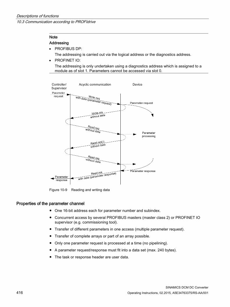
Descriptions of functions 10.3 Communication according to PROFIdrive
SINAMICS DCM DC Converter 416 Operating Instructions, 02.2015, A5E34763375/RS-AA/001
Note Addressing • PROFIBUS DP:
The addressing is carried out via the logical address or the diagnostics address. • PROFINET IO:
The addressing is only undertaken using a diagnostics address which is assigned to a module as of slot 1. Parameters cannot be accessed via slot 0.
Figure 10-9 Reading and writing data
Properties of the parameter channel One 16-bit address each for parameter number and subindex.
Concurrent access by several PROFIBUS masters (master class 2) or PROFINET IO supervisor (e.g. commissioning tool).
Transfer of different parameters in one access (multiple parameter request).
Transfer of complete arrays or part of an array possible.
Only one parameter request is processed at a time (no pipelining).
A parameter request/response must fit into a data set (max. 240 bytes).
The task or response header are user data.
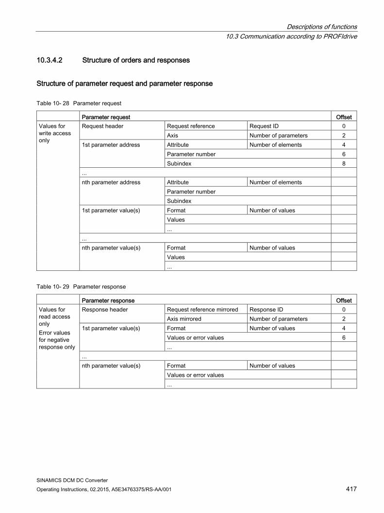
Descriptions of functions 10.3 Communication according to PROFIdrive
SINAMICS DCM DC Converter Operating Instructions, 02.2015, A5E34763375/RS-AA/001 417
10.3.4.2 Structure of orders and responses
Structure of parameter request and parameter response
Table 10- 28 Parameter request
Parameter request Offset Values for write access only
Request header Request reference Request ID 0 Axis Number of parameters 2
1st parameter address Attribute Number of elements 4 Parameter number 6 Subindex 8
... nth parameter address Attribute Number of elements
Parameter number Subindex
1st parameter value(s) Format Number of values Values ...
... nth parameter value(s) Format Number of values
Values ...
Table 10- 29 Parameter response
Parameter response Offset Values for read access only Error values for negative response only
Response header Request reference mirrored Response ID 0 Axis mirrored Number of parameters 2
1st parameter value(s) Format Number of values 4 Values or error values 6 ...
... nth parameter value(s) Format Number of values
Values or error values ...
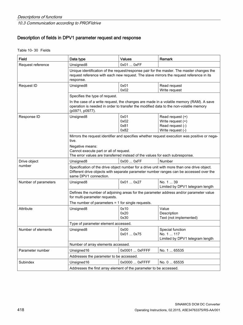
Descriptions of functions 10.3 Communication according to PROFIdrive
SINAMICS DCM DC Converter 418 Operating Instructions, 02.2015, A5E34763375/RS-AA/001
Description of fields in DPV1 parameter request and response
Table 10- 30 Fields
Field Data type Values Remark Request reference Unsigned8 0x01 ... 0xFF
Unique identification of the request/response pair for the master. The master changes the request reference with each new request. The slave mirrors the request reference in its response.
Request ID Unsigned8 0x01 0x02
Read request Write request
Specifies the type of request. In the case of a write request, the changes are made in a volatile memory (RAM). A save operation is needed in order to transfer the modified data to the non-volatile memory (p0971, p0977).
Response ID Unsigned8 0x01 0x02 0x81 0x82
Read request (+) Write request (+) Read request (-) Write request (-)
Mirrors the request identifier and specifies whether request execution was positive or nega-tive. Negative means: Cannot execute part or all of request. The error values are transferred instead of the values for each subresponse.
Drive object number
Unsigned8 0x00 ... 0xFF Number Specification of the drive object number for a drive unit with more than one drive object. Different drive objects with separate parameter number ranges can be accessed over the same DPV1 connection.
Number of parameters Unsigned8 0x01 ... 0x27 No. 1 ... 39 Limited by DPV1 telegram length
Defines the number of adjoining areas for the parameter address and/or parameter value for multi-parameter requests. The number of parameters = 1 for single requests.
Attribute Unsigned8 0x10 0x20 0x30
Value Description Text (not implemented)
Type of parameter element accessed. Number of elements Unsigned8 0x00
0x01 ... 0x75 Special function No. 1 ... 117 Limited by DPV1 telegram length
Number of array elements accessed. Parameter number Unsigned16 0x0001 ... 0xFFFF No. 1 ... 65535
Addresses the parameter to be accessed. Subindex Unsigned16 0x0000 ... 0xFFFF No. 0 ... 65535
Addresses the first array element of the parameter to be accessed.
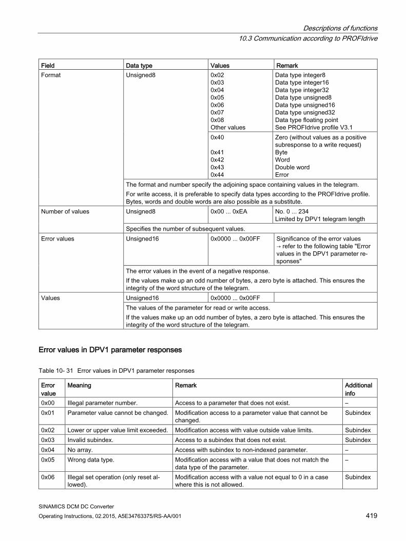
Descriptions of functions 10.3 Communication according to PROFIdrive
SINAMICS DCM DC Converter Operating Instructions, 02.2015, A5E34763375/RS-AA/001 419
Field Data type Values Remark Format Unsigned8 0x02
0x03 0x04 0x05 0x06 0x07 0x08 Other values
Data type integer8 Data type integer16 Data type integer32 Data type unsigned8 Data type unsigned16 Data type unsigned32 Data type floating point See PROFIdrive profile V3.1
0x40 0x41 0x42 0x43 0x44
Zero (without values as a positive subresponse to a write request) Byte Word Double word Error
The format and number specify the adjoining space containing values in the telegram. For write access, it is preferable to specify data types according to the PROFIdrive profile. Bytes, words and double words are also possible as a substitute.
Number of values Unsigned8 0x00 ... 0xEA No. 0 ... 234 Limited by DPV1 telegram length
Specifies the number of subsequent values. Error values Unsigned16 0x0000 ... 0x00FF Significance of the error values
→ refer to the following table "Error values in the DPV1 parameter re-sponses"
The error values in the event of a negative response. If the values make up an odd number of bytes, a zero byte is attached. This ensures the integrity of the word structure of the telegram.
Values Unsigned16 0x0000 ... 0x00FF The values of the parameter for read or write access. If the values make up an odd number of bytes, a zero byte is attached. This ensures the integrity of the word structure of the telegram.
Error values in DPV1 parameter responses
Table 10- 31 Error values in DPV1 parameter responses
Error value
Meaning Remark Additional info
0x00 Illegal parameter number. Access to a parameter that does not exist. – 0x01 Parameter value cannot be changed. Modification access to a parameter value that cannot be
changed. Subindex
0x02 Lower or upper value limit exceeded. Modification access with value outside value limits. Subindex 0x03 Invalid subindex. Access to a subindex that does not exist. Subindex 0x04 No array. Access with subindex to non-indexed parameter. – 0x05 Wrong data type. Modification access with a value that does not match the
data type of the parameter. –
0x06 Illegal set operation (only reset al-lowed).
Modification access with a value not equal to 0 in a case where this is not allowed.
Subindex
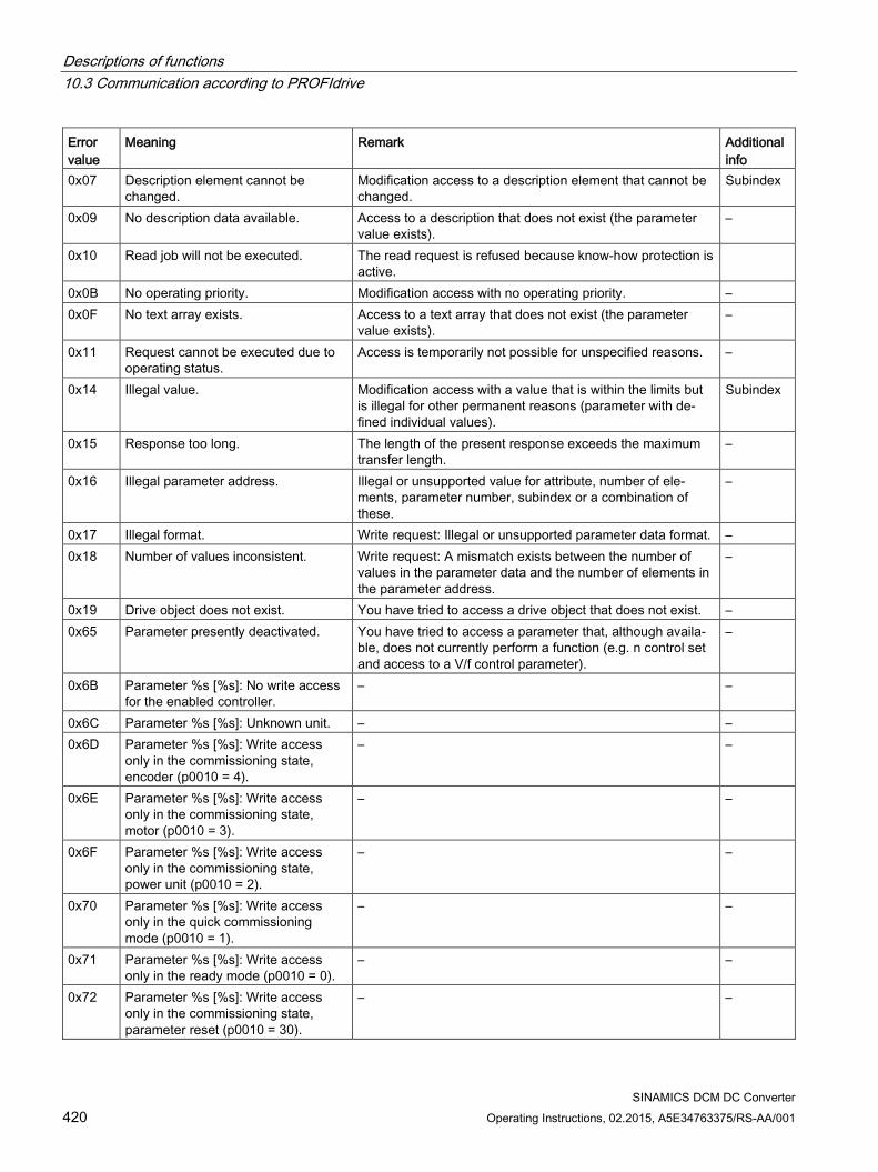
Descriptions of functions 10.3 Communication according to PROFIdrive
SINAMICS DCM DC Converter 420 Operating Instructions, 02.2015, A5E34763375/RS-AA/001
Error value
Meaning Remark Additional info
0x07 Description element cannot be changed.
Modification access to a description element that cannot be changed.
Subindex
0x09 No description data available. Access to a description that does not exist (the parameter value exists).
–
0x10 Read job will not be executed. The read request is refused because know-how protection is active.
0x0B No operating priority. Modification access with no operating priority. – 0x0F No text array exists. Access to a text array that does not exist (the parameter
value exists). –
0x11 Request cannot be executed due to operating status.
Access is temporarily not possible for unspecified reasons. –
0x14 Illegal value. Modification access with a value that is within the limits but is illegal for other permanent reasons (parameter with de-fined individual values).
Subindex
0x15 Response too long. The length of the present response exceeds the maximum transfer length.
–
0x16 Illegal parameter address. Illegal or unsupported value for attribute, number of ele-ments, parameter number, subindex or a combination of these.
–
0x17 Illegal format. Write request: Illegal or unsupported parameter data format. – 0x18 Number of values inconsistent. Write request: A mismatch exists between the number of
values in the parameter data and the number of elements in the parameter address.
–
0x19 Drive object does not exist. You have tried to access a drive object that does not exist. – 0x65 Parameter presently deactivated. You have tried to access a parameter that, although availa-
ble, does not currently perform a function (e.g. n control set and access to a V/f control parameter).
–
0x6B Parameter %s [%s]: No write access for the enabled controller.
– –
0x6C Parameter %s [%s]: Unknown unit. – – 0x6D Parameter %s [%s]: Write access
only in the commissioning state, encoder (p0010 = 4).
– –
0x6E Parameter %s [%s]: Write access only in the commissioning state, motor (p0010 = 3).
– –
0x6F Parameter %s [%s]: Write access only in the commissioning state, power unit (p0010 = 2).
– –
0x70 Parameter %s [%s]: Write access only in the quick commissioning mode (p0010 = 1).
– –
0x71 Parameter %s [%s]: Write access only in the ready mode (p0010 = 0).
– –
0x72 Parameter %s [%s]: Write access only in the commissioning state, parameter reset (p0010 = 30).
– –
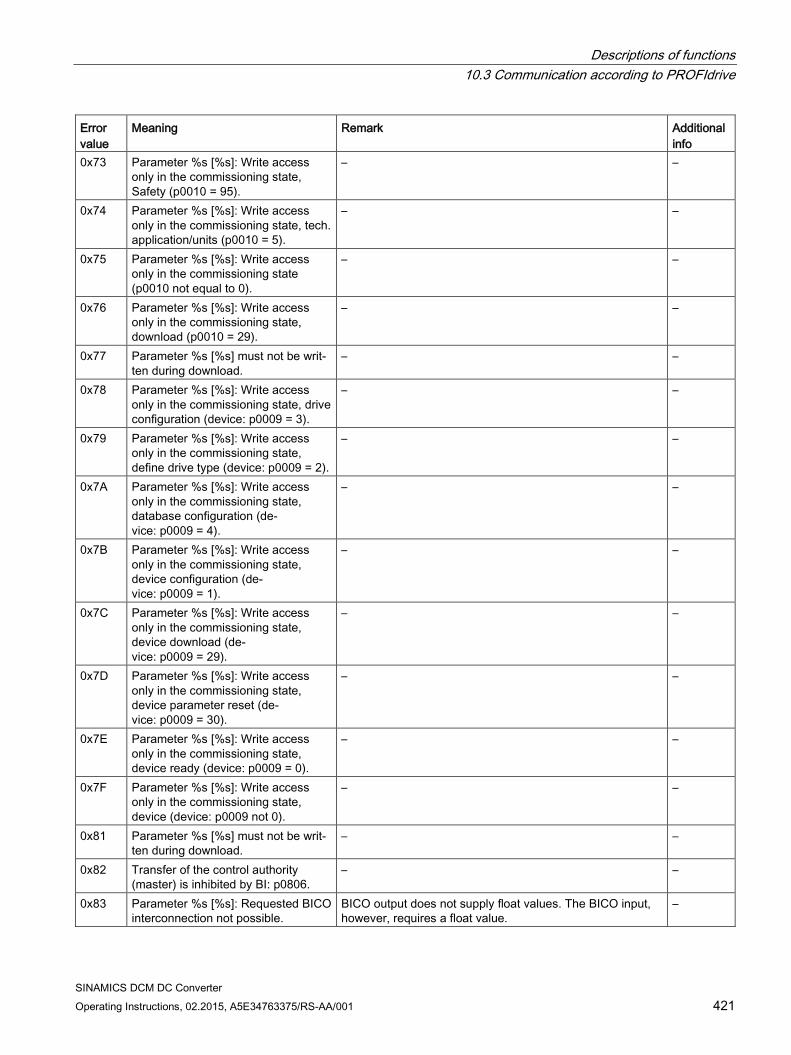
Descriptions of functions 10.3 Communication according to PROFIdrive
SINAMICS DCM DC Converter Operating Instructions, 02.2015, A5E34763375/RS-AA/001 421
Error value
Meaning Remark Additional info
0x73 Parameter %s [%s]: Write access only in the commissioning state, Safety (p0010 = 95).
– –
0x74 Parameter %s [%s]: Write access only in the commissioning state, tech. application/units (p0010 = 5).
– –
0x75 Parameter %s [%s]: Write access only in the commissioning state (p0010 not equal to 0).
– –
0x76 Parameter %s [%s]: Write access only in the commissioning state, download (p0010 = 29).
– –
0x77 Parameter %s [%s] must not be writ-ten during download.
– –
0x78 Parameter %s [%s]: Write access only in the commissioning state, drive configuration (device: p0009 = 3).
– –
0x79 Parameter %s [%s]: Write access only in the commissioning state, define drive type (device: p0009 = 2).
– –
0x7A Parameter %s [%s]: Write access only in the commissioning state, database configuration (de-vice: p0009 = 4).
– –
0x7B Parameter %s [%s]: Write access only in the commissioning state, device configuration (de-vice: p0009 = 1).
– –
0x7C Parameter %s [%s]: Write access only in the commissioning state, device download (de-vice: p0009 = 29).
– –
0x7D Parameter %s [%s]: Write access only in the commissioning state, device parameter reset (de-vice: p0009 = 30).
– –
0x7E Parameter %s [%s]: Write access only in the commissioning state, device ready (device: p0009 = 0).
– –
0x7F Parameter %s [%s]: Write access only in the commissioning state, device (device: p0009 not 0).
– –
0x81 Parameter %s [%s] must not be writ-ten during download.
– –
0x82 Transfer of the control authority (master) is inhibited by BI: p0806.
– –
0x83 Parameter %s [%s]: Requested BICO interconnection not possible.
BICO output does not supply float values. The BICO input, however, requires a float value.
–
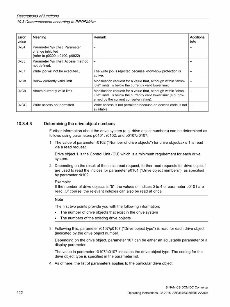
Descriptions of functions 10.3 Communication according to PROFIdrive
SINAMICS DCM DC Converter 422 Operating Instructions, 02.2015, A5E34763375/RS-AA/001
Error value
Meaning Remark Additional info
0x84 Parameter %s [%s]: Parameter change inhibited (refer to p0300, p0400, p0922)
– –
0x85 Parameter %s [%s]: Access method not defined.
– –
0x87 Write job will not be executed.. The write job is rejected because know-how protection is active.
–
0xC8 Below currently valid limit. Modification request for a value that, although within "abso-lute" limits, is below the currently valid lower limit.
–
0xC9 Above currently valid limit. Modification request for a value that, although within "abso-lute" limits, is below the currently valid lower limit (e.g. gov-erned by the current converter rating).
–
0xCC Write access not permitted. Write access is not permitted because an access code is not available.
–
10.3.4.3 Determining the drive object numbers Further information about the drive system (e.g. drive object numbers) can be determined as follows using parameters p0101, r0102, and p0107/r0107:
1. The value of parameter r0102 ("Number of drive objects") for drive object/axis 1 is read via a read request.
Drive object 1 is the Control Unit (CU) which is a minimum requirement for each drive system.
2. Depending on the result of the initial read request, further read requests for drive object 1 are used to read the indices for parameter p0101 ("Drive object numbers"), as specified by parameter r0102.
Example: If the number of drive objects is "5", the values of indices 0 to 4 of parameter p0101 are read. Of course, the relevant indexes can also be read at once.
Note
The first two points provide you with the following information: • The number of drive objects that exist in the drive system • The numbers of the existing drive objects
3. Following this, parameter r0107/p0107 ("Drive object type") is read for each drive object (indicated by the drive object number).
Depending on the drive object, parameter 107 can be either an adjustable parameter or a display parameter.
The value in parameter r0107/p0107 indicates the drive object type. The coding for the drive object type is specified in the parameter list.
4. As of here, the list of parameters applies to the particular drive object.
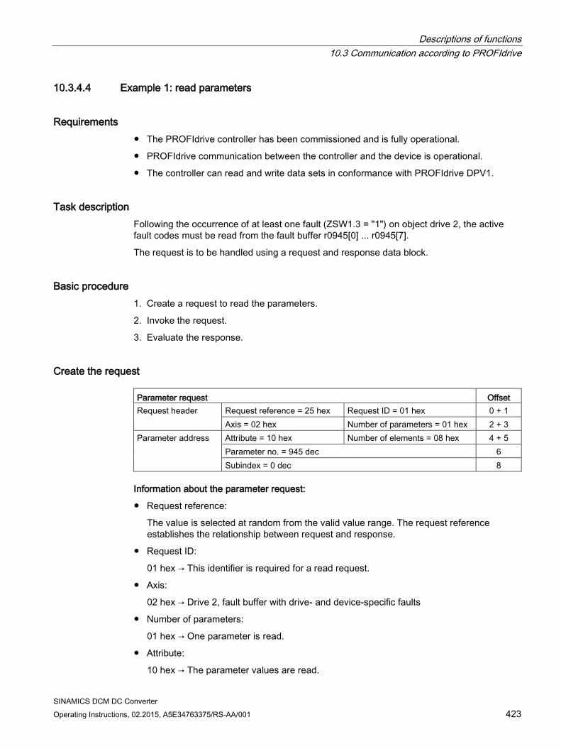
Descriptions of functions 10.3 Communication according to PROFIdrive
SINAMICS DCM DC Converter Operating Instructions, 02.2015, A5E34763375/RS-AA/001 423
10.3.4.4 Example 1: read parameters
Requirements The PROFIdrive controller has been commissioned and is fully operational.
PROFIdrive communication between the controller and the device is operational.
The controller can read and write data sets in conformance with PROFIdrive DPV1.
Task description Following the occurrence of at least one fault (ZSW1.3 = "1") on object drive 2, the active fault codes must be read from the fault buffer r0945[0] ... r0945[7].
The request is to be handled using a request and response data block.
Basic procedure 1. Create a request to read the parameters.
2. Invoke the request.
3. Evaluate the response.
Create the request Parameter request Offset Request header Request reference = 25 hex Request ID = 01 hex 0 + 1
Axis = 02 hex Number of parameters = 01 hex 2 + 3 Parameter address Attribute = 10 hex Number of elements = 08 hex 4 + 5
Parameter no. = 945 dec 6 Subindex = 0 dec 8
Information about the parameter request:
Request reference:
The value is selected at random from the valid value range. The request reference establishes the relationship between request and response.
Request ID:
01 hex → This identifier is required for a read request.
Axis:
02 hex → Drive 2, fault buffer with drive- and device-specific faults
Number of parameters:
01 hex → One parameter is read.
Attribute:
10 hex → The parameter values are read.
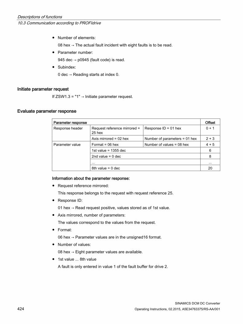
Descriptions of functions 10.3 Communication according to PROFIdrive
SINAMICS DCM DC Converter 424 Operating Instructions, 02.2015, A5E34763375/RS-AA/001
Number of elements:
08 hex → The actual fault incident with eight faults is to be read.
Parameter number:
945 dec → p0945 (fault code) is read.
Subindex:
0 dec → Reading starts at index 0.
Initiate parameter request If ZSW1.3 = "1" → Initiate parameter request.
Evaluate parameter response Parameter response Offset Response header Request reference mirrored =
25 hex Response ID = 01 hex 0 + 1
Axis mirrored = 02 hex Number of parameters = 01 hex 2 + 3 Parameter value Format = 06 hex Number of values = 08 hex 4 + 5
1st value = 1355 dec 6 2nd value = 0 dec 8 ... ... 8th value = 0 dec 20
Information about the parameter response:
Request reference mirrored:
This response belongs to the request with request reference 25.
Response ID:
01 hex → Read request positive, values stored as of 1st value.
Axis mirrored, number of parameters:
The values correspond to the values from the request.
Format:
06 hex → Parameter values are in the unsigned16 format.
Number of values:
08 hex → Eight parameter values are available.
1st value ... 8th value
A fault is only entered in value 1 of the fault buffer for drive 2.
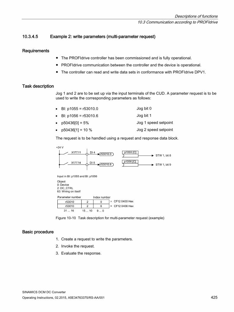
Descriptions of functions 10.3 Communication according to PROFIdrive
SINAMICS DCM DC Converter Operating Instructions, 02.2015, A5E34763375/RS-AA/001 425
10.3.4.5 Example 2: write parameters (multi-parameter request)
Requirements The PROFIdrive controller has been commissioned and is fully operational.
PROFIdrive communication between the controller and the device is operational.
The controller can read and write data sets in conformance with PROFIdrive DPV1.
Task description Jog 1 and 2 are to be set up via the input terminals of the CUD. A parameter request is to be used to write the corresponding parameters as follows: • BI: p1055 = r53010.0 Jog bit 0
• BI: p1056 = r53010.6 Jog bit 1
• p50436[0] = 5% Jog 1 speed setpoint
• p50436[1] = 10 % Jog 2 speed setpoint
The request is to be handled using a request and response data block.
Figure 10-10 Task description for multi-parameter request (example)
Basic procedure 1. Create a request to write the parameters.
2. Invoke the request.
3. Evaluate the response.
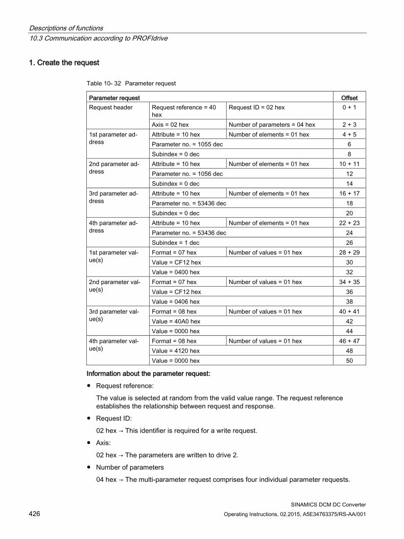
Descriptions of functions 10.3 Communication according to PROFIdrive
SINAMICS DCM DC Converter 426 Operating Instructions, 02.2015, A5E34763375/RS-AA/001
1. Create the request
Table 10- 32 Parameter request
Parameter request Offset Request header Request reference = 40
hex Request ID = 02 hex 0 + 1
Axis = 02 hex Number of parameters = 04 hex 2 + 3 1st parameter ad-dress
Attribute = 10 hex Number of elements = 01 hex 4 + 5 Parameter no. = 1055 dec 6 Subindex = 0 dec 8
2nd parameter ad-dress
Attribute = 10 hex Number of elements = 01 hex 10 + 11 Parameter no. = 1056 dec 12 Subindex = 0 dec 14
3rd parameter ad-dress
Attribute = 10 hex Number of elements = 01 hex 16 + 17 Parameter no. = 53436 dec 18 Subindex = 0 dec 20
4th parameter ad-dress
Attribute = 10 hex Number of elements = 01 hex 22 + 23 Parameter no. = 53436 dec 24 Subindex = 1 dec 26
1st parameter val-ue(s)
Format = 07 hex Number of values = 01 hex 28 + 29 Value = CF12 hex 30 Value = 0400 hex 32
2nd parameter val-ue(s)
Format = 07 hex Number of values = 01 hex 34 + 35 Value = CF12 hex 36 Value = 0406 hex 38
3rd parameter val-ue(s)
Format = 08 hex Number of values = 01 hex 40 + 41 Value = 40A0 hex 42 Value = 0000 hex 44
4th parameter val-ue(s)
Format = 08 hex Number of values = 01 hex 46 + 47 Value = 4120 hex 48 Value = 0000 hex 50
Information about the parameter request:
Request reference:
The value is selected at random from the valid value range. The request reference establishes the relationship between request and response.
Request ID:
02 hex → This identifier is required for a write request.
Axis:
02 hex → The parameters are written to drive 2.
Number of parameters
04 hex → The multi-parameter request comprises four individual parameter requests.
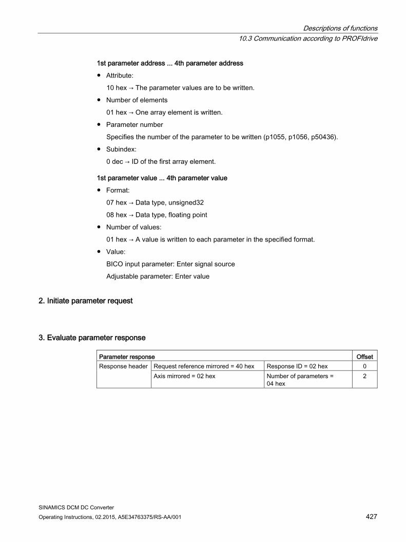
Descriptions of functions 10.3 Communication according to PROFIdrive
SINAMICS DCM DC Converter Operating Instructions, 02.2015, A5E34763375/RS-AA/001 427
1st parameter address ... 4th parameter address
Attribute:
10 hex → The parameter values are to be written.
Number of elements
01 hex → One array element is written.
Parameter number
Specifies the number of the parameter to be written (p1055, p1056, p50436).
Subindex:
0 dec → ID of the first array element.
1st parameter value ... 4th parameter value
Format:
07 hex → Data type, unsigned32
08 hex → Data type, floating point
Number of values:
01 hex → A value is written to each parameter in the specified format.
Value:
BICO input parameter: Enter signal source
Adjustable parameter: Enter value
2. Initiate parameter request
3. Evaluate parameter response Parameter response Offset Response header Request reference mirrored = 40 hex Response ID = 02 hex 0
Axis mirrored = 02 hex Number of parameters = 04 hex
2
Descriptions of functions 10.3 Communication according to PROFIdrive
SINAMICS DCM DC Converter 428 Operating Instructions, 02.2015, A5E34763375/RS-AA/001
Information about the parameter response:
Request reference mirrored:
This response belongs to the request with request reference 40.
Response ID:
02 hex → Write request positive
Axis mirrored:
02 hex → The value matches the value from the request.
Number of parameters:
04 hex → The value matches the value from the request.
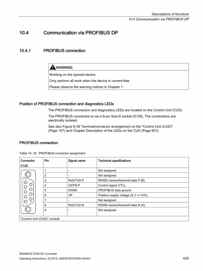
Descriptions of functions 10.4 Communication via PROFIBUS DP
SINAMICS DCM DC Converter Operating Instructions, 02.2015, A5E34763375/RS-AA/001 429
10.4 Communication via PROFIBUS DP
10.4.1 PROFIBUS connection
WARNING
Working on the opened device
Only perform all work when the device is current-free.
Please observe the warning notices in Chapter 1.
Position of PROFIBUS connection and diagnostics LEDs The PROFIBUS connection and diagnostics LEDs are located on the Control Unit (CUD).
The PROFIBUS connection is via a 9-pin Sub-D socket (X126). The connections are electrically isolated.
See also Figure 6-39 Terminal/connector arrangement on the "Control Unit (CUD)" (Page 157) and Chapter Description of the LEDs on the CUD (Page 601).
PROFIBUS connection
Table 10- 33 PROFIBUS connector assignment
Connector X126
Pin Signal name Technical specifications
1 - Not assigned 2 - Not assigned 3 RxD/TxD-P RS485 receive/transmit data P (B) 4 CNTR-P Control signal (TTL) 5 DGND PROFIBUS data ground 6 VP Positive supply voltage (5 V +/-10%) 7 - Not assigned 8 RxD/TxD-N RS485 receive/transmit data N (A) 9 - Not assigned
"Control Unit (CUD)" module
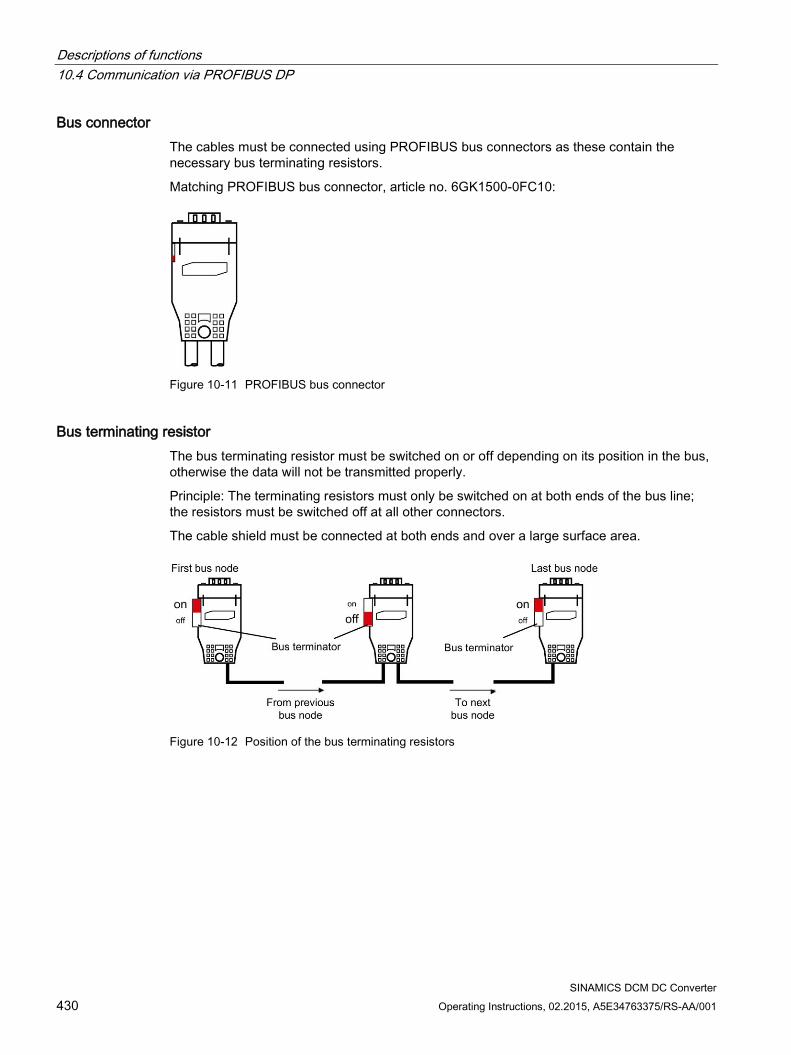
Descriptions of functions 10.4 Communication via PROFIBUS DP
SINAMICS DCM DC Converter 430 Operating Instructions, 02.2015, A5E34763375/RS-AA/001
Bus connector The cables must be connected using PROFIBUS bus connectors as these contain the necessary bus terminating resistors.
Matching PROFIBUS bus connector, article no. 6GK1500-0FC10:
Figure 10-11 PROFIBUS bus connector
Bus terminating resistor The bus terminating resistor must be switched on or off depending on its position in the bus, otherwise the data will not be transmitted properly.
Principle: The terminating resistors must only be switched on at both ends of the bus line; the resistors must be switched off at all other connectors.
The cable shield must be connected at both ends and over a large surface area.
Figure 10-12 Position of the bus terminating resistors
Descriptions of functions 10.4 Communication via PROFIBUS DP
SINAMICS DCM DC Converter Operating Instructions, 02.2015, A5E34763375/RS-AA/001 431
10.4.2 General information about PROFIBUS
10.4.2.1 General information about PROFIBUS for SINAMICS PROFIBUS is an open international fieldbus standard for a wide range of production and process automation applications.
The following standards ensure open, multi-vendor systems:
International standard EN 50170
International standard IEC 61158
PROFIBUS is optimized for high-speed, time-critical data communication at field level.
Note
PROFIBUS for drive technology is standardized and described in the following document:
References: /P5/ PROFIdrive Profile Drive Technology
NOTICE
Destruction of the CAN bus nodes
No CAN cables must be connected to interface X126. If CAN cables are connected, the CUD and other CAN bus nodes may be destroyed.
Master and slave Master and slave properties
Properties Master Slave As bus node Active Passive Send messages Permitted without external
request Only possible on request by master
Receive messages Possible without any re-strictions
Only receive and acknowledge permitted

Descriptions of functions 10.4 Communication via PROFIBUS DP
SINAMICS DCM DC Converter 432 Operating Instructions, 02.2015, A5E34763375/RS-AA/001
Master
Masters are categorized into the following classes:
– Master class 1 (DPMC1):
Central automation stations that exchange data with the slaves in cyclic and acyclic mode. Communication between the masters is also possible.
Examples: SIMATIC S7, SIMOTION
– Master class 2 (DPMC2):
Devices for configuration, commissioning, operator control and monitoring during bus operation. Devices that only exchange data with the slaves in acyclic mode.
Examples: Programming devices, human machine interfaces
Slaves
With respect to PROFIBUS, the SINAMICS drive unit is a slave.
Bus access method PROFIBUS uses the token passing method, i.e. the active stations (masters) are arranged in a logical ring in which the authorization to send is received within a defined time frame.
Within this time frame, the master with authorization to send can communicate with other masters or handle communication with the assigned slaves in a master/slave procedure.
PROFIBUS telegram for cyclic data transmission and acyclic services Each drive unit that supports cyclic process data exchange uses a telegram to send and receive all the process data. A separate telegram is sent in order to perform all the acyclic services (read/write parameters) under a single PROFIBUS address. The acyclic data is transferred with a lower priority after cyclic data transmission.
The overall length of the telegram increases with the number of drive objects that are involved in exchanging process data.
Sequence of drive objects in the telegram On the drive side, the sequence of drive objects in the telegram is displayed via a list in p0978[0...24] where it can also be changed.
You can use the STARTER commissioning tool to display the sequence of drive objects for a commissioned drive system in online mode in the project navigator under "Drive unit" > "Communication" > "Telegram configuration".
When you create the configuration on the controller side (e.g. HW Config), the process-data-capable drive objects for the application are added to the telegram in this sequence.
Descriptions of functions 10.4 Communication via PROFIBUS DP
SINAMICS DCM DC Converter Operating Instructions, 02.2015, A5E34763375/RS-AA/001 433
The following drive objects can exchange process data:
Control Unit CU_DC
ENC
Terminal Board 30 (TB30)
Terminal Module 15 (TM15)
Terminal Module 31 (TM31)
Terminal Module 150 (TM150)
DC_CTRL
Note
The sequence of drive objects in HW Config must be the same as that in the drive (p0978).
The structure of the telegram depends on the drive objects taken into account during configuration. Configurations are permitted that do not take into account all of the drive objects that are present in the drive system.
Example:
The following configurations, for example, are possible:
Configuration with CU_DC, DC_STRL
Configuration with DC_CTRL, TM31, TM31
etc.
10.4.2.2 Example of a telegram structure for acyclic data acquisition
Task The drive system comprises the following drive objects:
SINAMICS DCM with the objects
CU_DC
DC_CTRL
Configuration settings (e.g. HW Config for SIMATIC S7) The components are mapped to objects for configuration.
Due to the telegram structure shown, the objects in the "DP slave properties" overview must be configured as follows: • CU_DC Standard telegram 390
• DC_CTRL Standard telegram 352
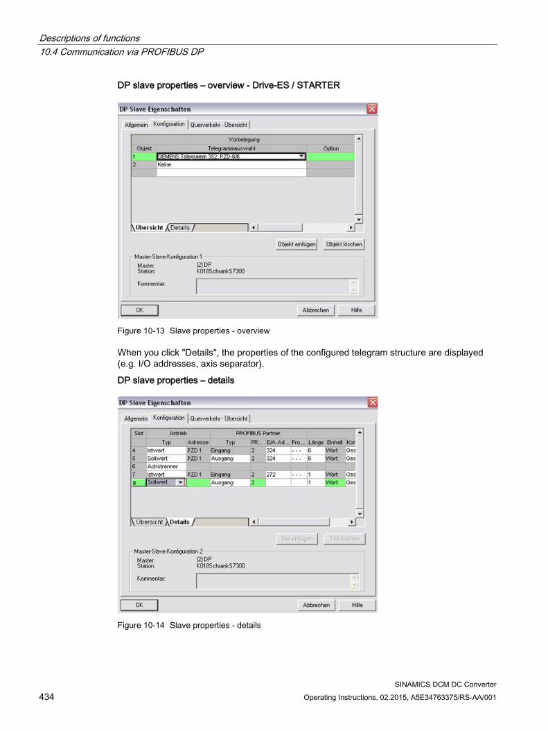
Descriptions of functions 10.4 Communication via PROFIBUS DP
SINAMICS DCM DC Converter 434 Operating Instructions, 02.2015, A5E34763375/RS-AA/001
DP slave properties – overview - Drive-ES / STARTER
Figure 10-13 Slave properties - overview
When you click "Details", the properties of the configured telegram structure are displayed (e.g. I/O addresses, axis separator).
DP slave properties – details
Figure 10-14 Slave properties - details
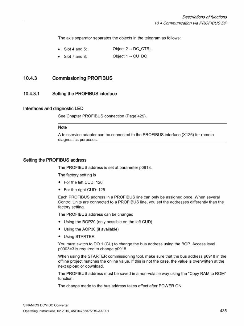
Descriptions of functions 10.4 Communication via PROFIBUS DP
SINAMICS DCM DC Converter Operating Instructions, 02.2015, A5E34763375/RS-AA/001 435
The axis separator separates the objects in the telegram as follows: • Slot 4 and 5: Object 2 → DC_CTRL
• Slot 7 and 8: Object 1 → CU_DC
10.4.3 Commissioning PROFIBUS
10.4.3.1 Setting the PROFIBUS interface
Interfaces and diagnostic LED See Chapter PROFIBUS connection (Page 429).
Note
A teleservice adapter can be connected to the PROFIBUS interface (X126) for remote diagnostics purposes.
Setting the PROFIBUS address The PROFIBUS address is set at parameter p0918.
The factory setting is
For the left CUD: 126
For the right CUD: 125
Each PROFIBUS address in a PROFIBUS line can only be assigned once. When several Control Units are connected to a PROFIBUS line, you set the addresses differently than the factory setting.
The PROFIBUS address can be changed
Using the BOP20 (only possible on the left CUD)
Using the AOP30 (if available)
Using STARTER
You must switch to DO 1 (CU) to change the bus address using the BOP. Access level p0003=3 is required to change p0918.
When using the STARTER commissioning tool, make sure that the bus address p0918 in the offline project matches the online value. If this is not the case, the value is overwritten at the next upload or download.
The PROFIBUS address must be saved in a non-volatile way using the "Copy RAM to ROM" function.
The change made to the bus address takes effect after POWER ON.
Descriptions of functions 10.4 Communication via PROFIBUS DP
SINAMICS DCM DC Converter 436 Operating Instructions, 02.2015, A5E34763375/RS-AA/001
10.4.3.2 PROFIBUS interface in operation
Generic station description file A generic station description file clearly and completely defines the properties of a PROFIBUS slave.
The GSD files can be found:
On the Internet. For the link, see Preface (Page 5)
On the DVD SINAMICS DCM Documentation at Accessories. See Chapter Ordering information for options and accessories (Page 30) for ordering data.
On the memory card in directory
\\SIEMENS\SINAMICS\DATA\CFG\
Figure 10-15 Hardware catalog of the GSD file with direct data exchange functionality
The SINAMICS S DXB GSD file contains among other things standard telegrams, free telegrams and slave-to-slave telegrams for configuring direct data exchange. With the aid of these telegram parts and an axis separator, a telegram for the drive unit must be composed for each drive object.
Processing a GSD file in HW Config is covered in the SIMATIC documentation. Suppliers of PROFIBUS components can provide their own bus configuration tool. The description of the respective bus configuration tool is described in the relevant documentation.
Note for commissioning for VIK-NAMUR To be able to operate a SINAMICS drive as a VIK-NAMUR drive, standard telegram 20 must be set and the VIK-NAMUR identification number activated via p2042 =1.
Descriptions of functions 10.4 Communication via PROFIBUS DP
SINAMICS DCM DC Converter Operating Instructions, 02.2015, A5E34763375/RS-AA/001 437
Device identification Identification for individual slaves facilitates diagnostics and provides an overview of the nodes on the PROFIBUS.
The information for each slave is stored in the following CU-specific parameter: r0964[0...6] device identification
Bus terminating resistor and shielding Reliable data transmission via PROFIBUS depends, amongst other things, on the setting of the bus terminating resistors and the shielding of the PROFIBUS cables.
Bus terminating resistor
The bus terminating resistors in the PROFIBUS plugs must be set as follows:
– First and last nodes in the line: Switch on terminating resistor
– Other nodes in the line: Switch off terminating resistor
Shielding of the PROFIBUS cables The cable shield must be connected in the plug through a large surface area at both ends. See also Chapter PROFIBUS connection (Page 429).
10.4.3.3 Commissioning PROFIBUS
Preconditions and assumptions for commissioning PROFIBUS slave
The PROFIBUS address to be set for the application is known.
The telegram type for each drive object is known by the application.
PROFIBUS master
The communication properties of the SINAMICS DCM slave must be available in the master (GSD file or Drive ES slave OM).
Commissioning steps (example with SIMATIC S7) 1. Set the PROFIBUS address on the slave.
2. Set the telegram type on the slave.
Descriptions of functions 10.4 Communication via PROFIBUS DP
SINAMICS DCM DC Converter 438 Operating Instructions, 02.2015, A5E34763375/RS-AA/001
3. Perform the following in the HW Config:
– Connect the drive unit to PROFIBUS and assign the address.
– Set the telegram type.
The same telegram type as on the slave should be set for every drive object exchanging process data via PROFIBUS.
The master can send more process data than the slave uses. A telegram with a larger PZD number than is assigned for the drive object STARTER can be configured on the master.
The PZDs not supplied by the drive object are filled with zeros.
The setting "without PZD" can be defined on a node or object (e.g. infeed controlled via terminals).
4. Assign the I/O addresses according to the user program.
10.4.3.4 Diagnostics options The standard slave diagnostics can be read online in the HW config.
10.4.3.5 SIMATIC HMI addressing You can use a SIMATIC HMI as a PROFIBUS master (master class 2) to access SINAMICS directly. With respect to SIMATIC HMI, SINAMICS behaves like a SIMATIC S7. For accessing drive parameters, the following simple rule applies:
Parameter number = data block number
Parameter sub-index = bit 0 ... 9 of data block offset
Drive object number = bit 10 ... 15 of data block offset
Pro Tool and WinCC flexible The SIMATIC HMI can be configured flexibly with "Pro Tool" or "WinCC flexible".
The following specific settings for drives must be observed when configuration is carried out with Pro Tool or WinCC flexible.
Controllers: Protocol always "SIMATIC S7 - 300/400"
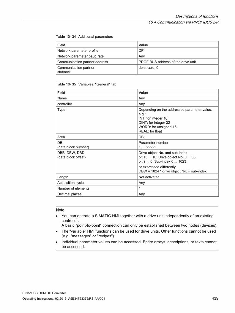
Descriptions of functions 10.4 Communication via PROFIBUS DP
SINAMICS DCM DC Converter Operating Instructions, 02.2015, A5E34763375/RS-AA/001 439
Table 10- 34 Additional parameters
Field Value Network parameter profile DP Network parameter baud rate Any Communication partner address PROFIBUS address of the drive unit Communication partner slot/rack
don’t care, 0
Table 10- 35 Variables: "General" tab
Field Value Name Any controller Any Type Depending on the addressed parameter value,
e.g.: INT: for integer 16 DINT: for integer 32 WORD: for unsigned 16 REAL: for float
Area DB DB (data block number)
Parameter number 1 ... 65535
DBB, DBW, DBD (data block offset)
Drive object No. and sub-index bit 15 ... 10: Drive object No. 0 ... 63 bit 9 ... 0: Sub-index 0 ... 1023 or expressed differently DBW = 1024 * drive object No. + sub-index
Length Not activated Acquisition cycle Any Number of elements 1 Decimal places Any
Note • You can operate a SIMATIC HMI together with a drive unit independently of an existing
controller. A basic "point-to-point" connection can only be established between two nodes (devices).
• The "variable" HMI functions can be used for drive units. Other functions cannot be used (e.g. "messages" or "recipes").
• Individual parameter values can be accessed. Entire arrays, descriptions, or texts cannot be accessed.
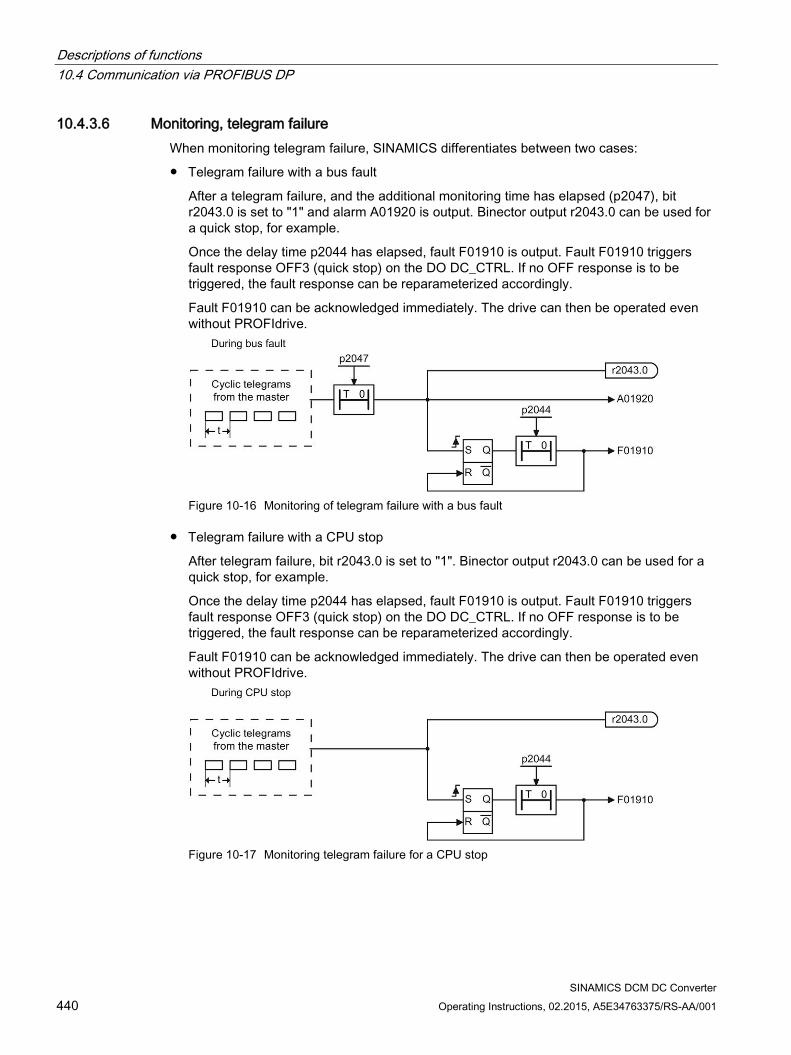
Descriptions of functions 10.4 Communication via PROFIBUS DP
SINAMICS DCM DC Converter 440 Operating Instructions, 02.2015, A5E34763375/RS-AA/001
10.4.3.6 Monitoring, telegram failure When monitoring telegram failure, SINAMICS differentiates between two cases:
Telegram failure with a bus fault
After a telegram failure, and the additional monitoring time has elapsed (p2047), bit r2043.0 is set to "1" and alarm A01920 is output. Binector output r2043.0 can be used for a quick stop, for example.
Once the delay time p2044 has elapsed, fault F01910 is output. Fault F01910 triggers fault response OFF3 (quick stop) on the DO DC_CTRL. If no OFF response is to be triggered, the fault response can be reparameterized accordingly.
Fault F01910 can be acknowledged immediately. The drive can then be operated even without PROFIdrive.
Figure 10-16 Monitoring of telegram failure with a bus fault
Telegram failure with a CPU stop
After telegram failure, bit r2043.0 is set to "1". Binector output r2043.0 can be used for a quick stop, for example.
Once the delay time p2044 has elapsed, fault F01910 is output. Fault F01910 triggers fault response OFF3 (quick stop) on the DO DC_CTRL. If no OFF response is to be triggered, the fault response can be reparameterized accordingly.
Fault F01910 can be acknowledged immediately. The drive can then be operated even without PROFIdrive.
Figure 10-17 Monitoring telegram failure for a CPU stop
Descriptions of functions 10.4 Communication via PROFIBUS DP
SINAMICS DCM DC Converter Operating Instructions, 02.2015, A5E34763375/RS-AA/001 441
Example: Quick stop at telegram failure
Settings:
CU p2047 = 20 ms
DC_CTRL p2044 = 0 s
Sequence:
1. Following a telegram failure, and once the additional monitoring time (p2047) has elapsed, binector output r2043.0 of drive object CU switches to "1".
Alarm A01920 and fault F01910 are output at the same time for the DC_CTRL drive objects.
2. When F01910 is output, an OFF3 is triggered for the drive.
Note
The additional monitoring time p2047 is only useful for cyclic communication.
10.4.4 Direct data exchange For PROFIBUS DP, the master interrogates all of the slaves one after the other in a DP cycle. In this case, the master transfers its output data (setpoints) to the particular slave and receives as response the input data (actual values). Fast, distributed data transfer between drives (slaves) is possible using the "direct data exchange" function without direct involvement from the master.
The following terms are used for the function described in this chapter:
Direct data exchange
Data Exchange Broadcast (DXB.req)
Direct data exchange (is used in the following)
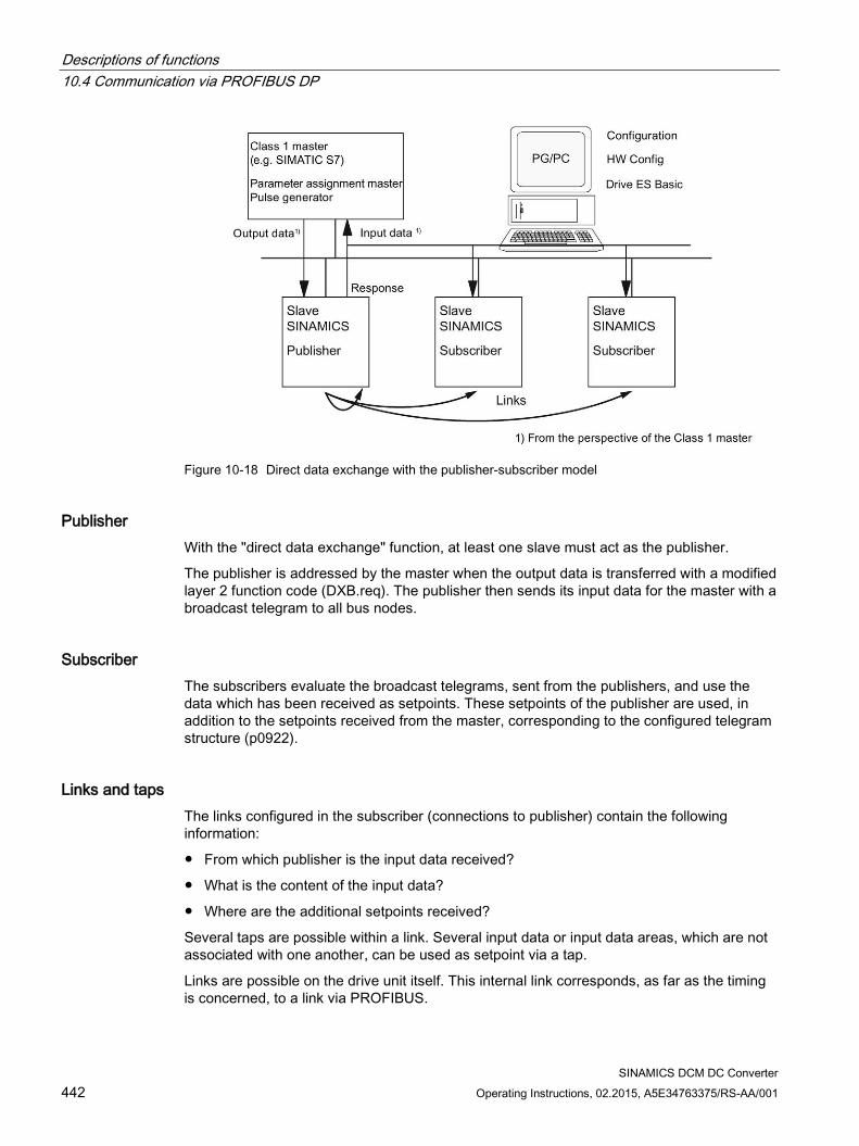
Descriptions of functions 10.4 Communication via PROFIBUS DP
SINAMICS DCM DC Converter 442 Operating Instructions, 02.2015, A5E34763375/RS-AA/001
Figure 10-18 Direct data exchange with the publisher-subscriber model
Publisher With the "direct data exchange" function, at least one slave must act as the publisher.
The publisher is addressed by the master when the output data is transferred with a modified layer 2 function code (DXB.req). The publisher then sends its input data for the master with a broadcast telegram to all bus nodes.
Subscriber The subscribers evaluate the broadcast telegrams, sent from the publishers, and use the data which has been received as setpoints. These setpoints of the publisher are used, in addition to the setpoints received from the master, corresponding to the configured telegram structure (p0922).
Links and taps The links configured in the subscriber (connections to publisher) contain the following information:
From which publisher is the input data received?
What is the content of the input data?
Where are the additional setpoints received?
Several taps are possible within a link. Several input data or input data areas, which are not associated with one another, can be used as setpoint via a tap.
Links are possible on the drive unit itself. This internal link corresponds, as far as the timing is concerned, to a link via PROFIBUS.
Descriptions of functions 10.4 Communication via PROFIBUS DP
SINAMICS DCM DC Converter Operating Instructions, 02.2015, A5E34763375/RS-AA/001 443
Requirements The following requirements should be observed for the "direct data exchange" function:
STARTER as of Version 4.2
Configuration:
– Drive ES Basic, Drive ES SIMATIC or Drive ES PCS7 as of Version 5.3 SP3
– Alternatively using a GSD file
Firmware as of Version 1.2
The maximum number of process data per drive can be identified from the value in r2050 – minus the resources that have already been used
A maximum of 16 links to publishers
Applications For example, the following applications can be implemented using the "direct data exchange" function:
Axis couplings
Specifying binector connections from another slave
10.4.4.1 Setpoint assignment in the subscriber
Information about setpoints Number of setpoint
When bus communication is being established, the master signals the slave the number of setpoints (process data) to be transferred using the configuring telegram (ChkCfg).
Contents of the setpoints
The structure and contents of the data are determined using the local process data configuration for the "SINAMICS slave".
Operation as "standard" slave
The drive unit (slave) only receives its setpoints as output data from the master.
Operation as subscriber
When a slave is operated as a subscriber, some of the setpoints are defined by one or more publishers rather than by the master.
The slave is informed of the assignment via the parameterization and configuration telegram when bus communication is being established.
Descriptions of functions 10.4 Communication via PROFIBUS DP
SINAMICS DCM DC Converter 444 Operating Instructions, 02.2015, A5E34763375/RS-AA/001
10.4.4.2 Activating/parameterizing slave-to-slave communication The "direct data exchange" function must be activated in the publishers as well as in the subscribers, whereby only the subscriber is to be configured. The publisher is automatically activated during bus startup.
Activation in the publisher The master is informed abut which slaves are to be addressed as publishers with a modified layer 2 function code (DXB req) via the configuration of the subscriber links.
The publisher then sends its input data not only to the master but also as a broadcast telegram to all bus nodes.
These settings are made automatically using the bus configuration tool (e.g. HW Config).
Activation in the subscriber The slave, which is to be used as subscriber, requires a filter table. The slave must know which setpoints are received from the master and which are received from a publisher.
The filter table is created automatically via the bus configuration tool (e.g. HW Config).
The following diagram shows the information contained in the filter table.
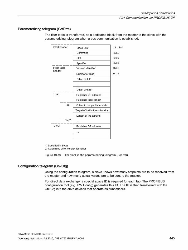
Descriptions of functions 10.4 Communication via PROFIBUS DP
SINAMICS DCM DC Converter Operating Instructions, 02.2015, A5E34763375/RS-AA/001 445
Parameterizing telegram (SetPrm) The filter table is transferred, as a dedicated block from the master to the slave with the parameterizing telegram when a bus communication is established.
Figure 10-19 Filter block in the parameterizing telegram (SetPrm)
Configuration telegram (ChkCfg) Using the configuration telegram, a slave knows how many setpoints are to be received from the master and how many actual values are to be sent to the master.
For direct data exchange, a special space ID is required for each tap. The PROFIBUS configuration tool (e.g. HW Config) generates this ID. The ID is then transferred with the ChkCfg into the drive devices that operate as subscribers.

Descriptions of functions 10.4 Communication via PROFIBUS DP
SINAMICS DCM DC Converter 446 Operating Instructions, 02.2015, A5E34763375/RS-AA/001
10.4.4.3 Commissioning of the PROFIBUS slave-to-slave communication The commissioning of direct data exchange between two SINAMICS drives using the additional Drive ES Basic package is described below.
Settings in HW Config The project below is used to describe the settings in HW Config.
Figure 10-20 Example project of a PROFIBUS network in HW Config
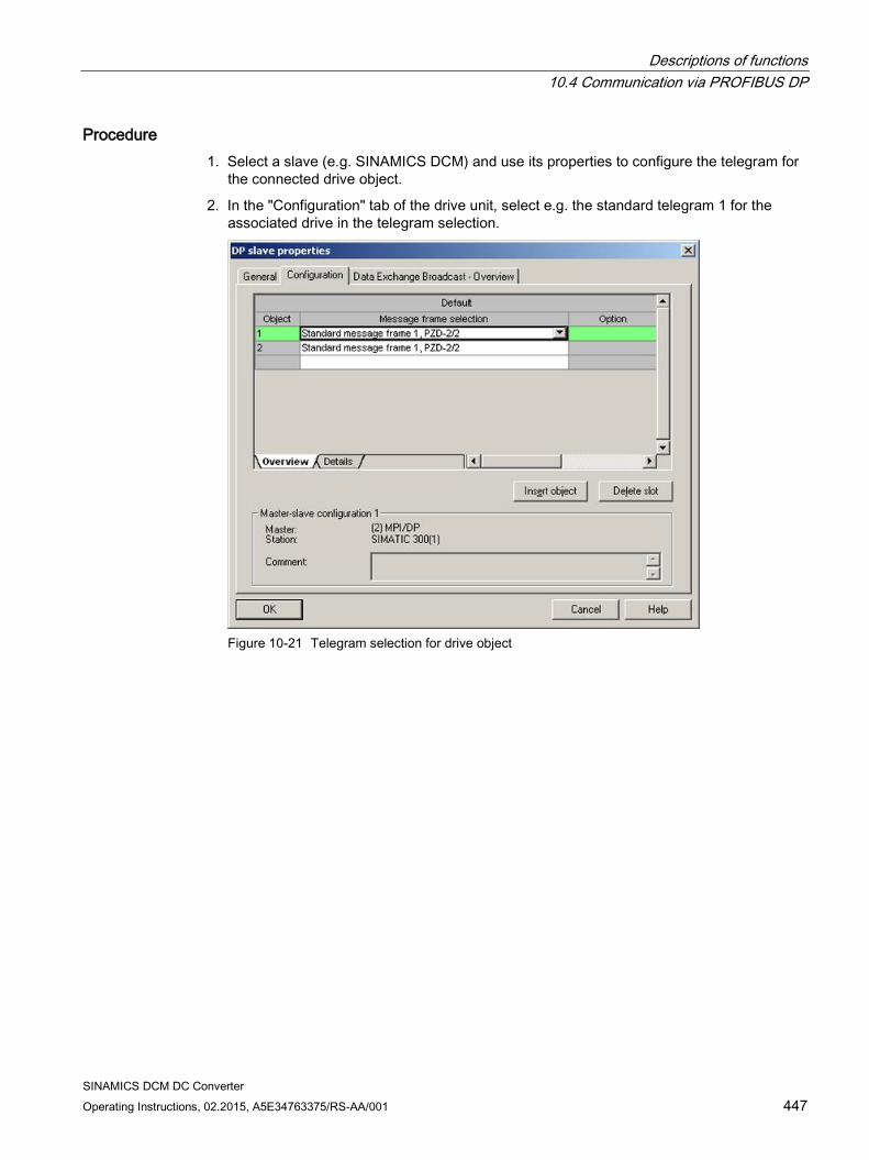
Descriptions of functions 10.4 Communication via PROFIBUS DP
SINAMICS DCM DC Converter Operating Instructions, 02.2015, A5E34763375/RS-AA/001 447
Procedure 1. Select a slave (e.g. SINAMICS DCM) and use its properties to configure the telegram for
the connected drive object.
2. In the "Configuration" tab of the drive unit, select e.g. the standard telegram 1 for the associated drive in the telegram selection.
Figure 10-21 Telegram selection for drive object
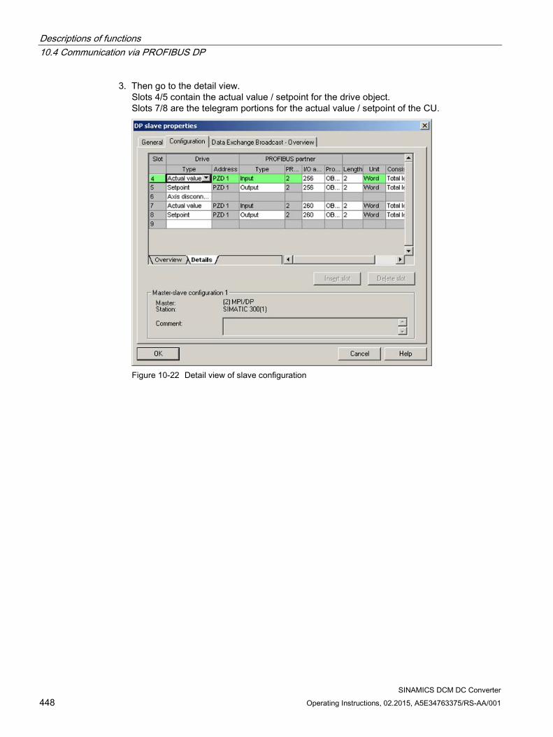
Descriptions of functions 10.4 Communication via PROFIBUS DP
SINAMICS DCM DC Converter 448 Operating Instructions, 02.2015, A5E34763375/RS-AA/001
3. Then go to the detail view. Slots 4/5 contain the actual value / setpoint for the drive object. Slots 7/8 are the telegram portions for the actual value / setpoint of the CU.
Figure 10-22 Detail view of slave configuration
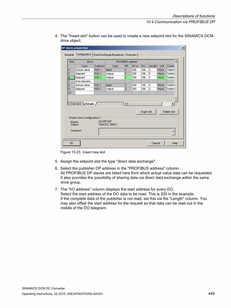
Descriptions of functions 10.4 Communication via PROFIBUS DP
SINAMICS DCM DC Converter Operating Instructions, 02.2015, A5E34763375/RS-AA/001 449
4. The "Insert slot" button can be used to create a new setpoint slot for the SINAMICS DCM drive object.
Figure 10-23 Insert new slot
5. Assign the setpoint slot the type "direct data exchange".
6. Select the publisher DP address in the "PROFIBUS address" column. All PROFIBUS DP slaves are listed here from which actual value data can be requested. It also provides the possibility of sharing data via direct data exchange within the same drive group.
7. The "I/O address" column displays the start address for every DO. Select the start address of the DO data to be read. This is 200 in the example. If the complete data of the publisher is not read, set this via the "Length" column. You may also offset the start address for the request so that data can be read out in the middle of the DO telegram.
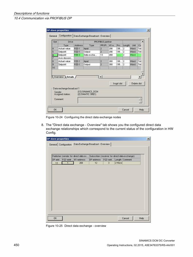
Descriptions of functions 10.4 Communication via PROFIBUS DP
SINAMICS DCM DC Converter 450 Operating Instructions, 02.2015, A5E34763375/RS-AA/001
Figure 10-24 Configuring the direct data exchange nodes
8. The "Direct data exchange - Overview" tab shows you the configured direct data exchange relationships which correspond to the current status of the configuration in HW Config.
Figure 10-25 Direct data exchange - overview
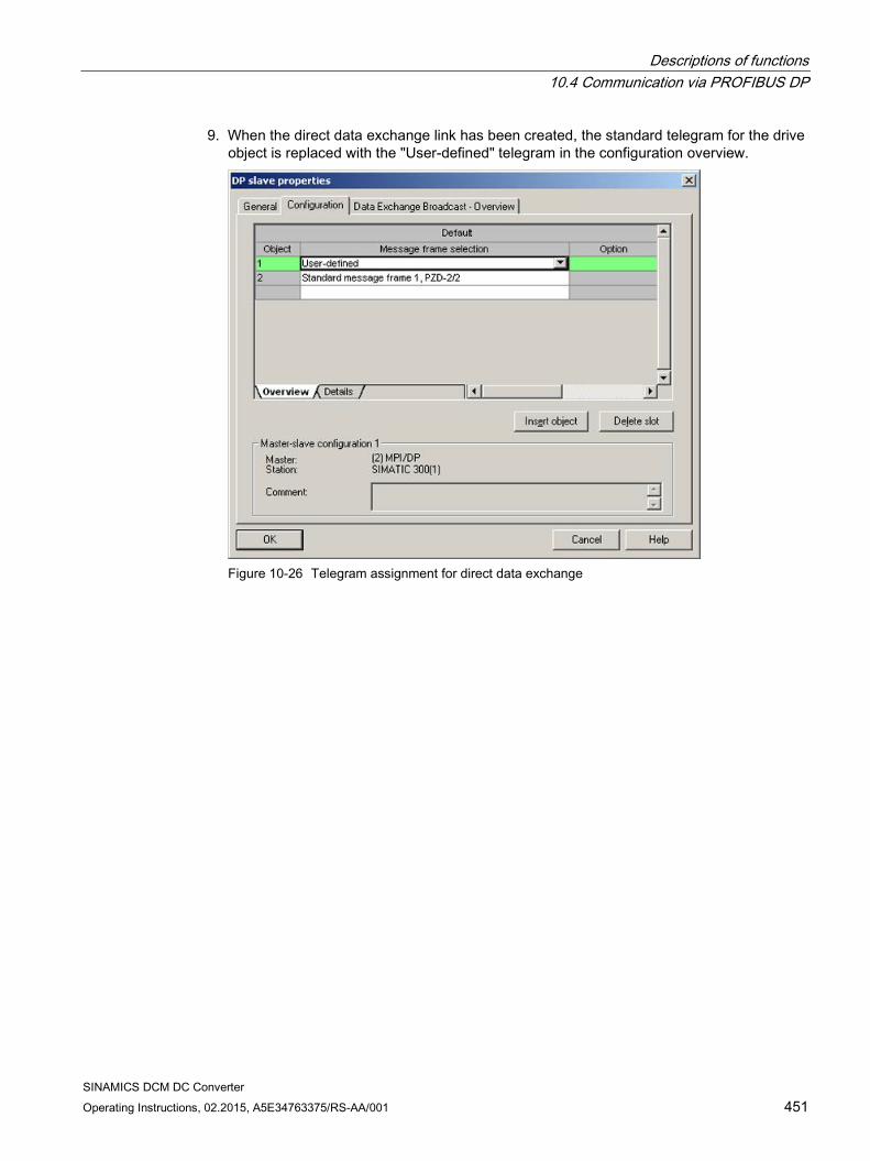
Descriptions of functions 10.4 Communication via PROFIBUS DP
SINAMICS DCM DC Converter Operating Instructions, 02.2015, A5E34763375/RS-AA/001 451
9. When the direct data exchange link has been created, the standard telegram for the drive object is replaced with the "User-defined" telegram in the configuration overview.
Figure 10-26 Telegram assignment for direct data exchange
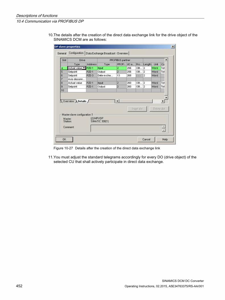
Descriptions of functions 10.4 Communication via PROFIBUS DP
SINAMICS DCM DC Converter 452 Operating Instructions, 02.2015, A5E34763375/RS-AA/001
10.The details after the creation of the direct data exchange link for the drive object of the SINAMICS DCM are as follows:
Figure 10-27 Details after the creation of the direct data exchange link
11.You must adjust the standard telegrams accordingly for every DO (drive object) of the selected CU that shall actively participate in direct data exchange.
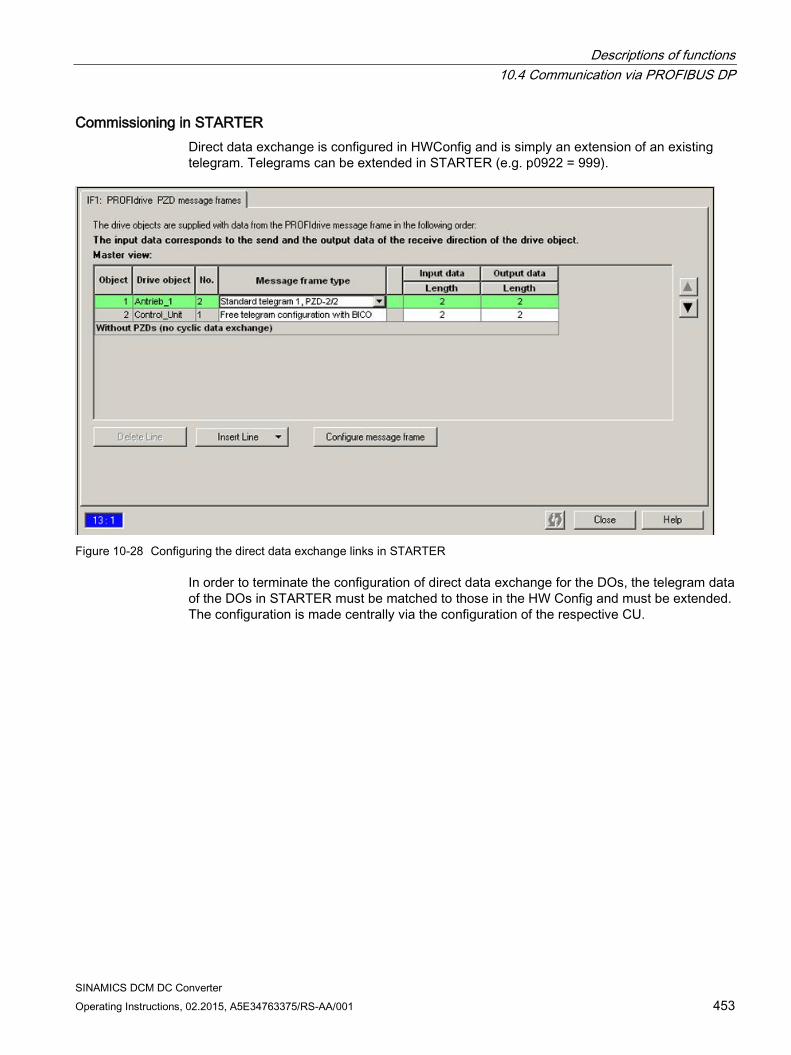
Descriptions of functions 10.4 Communication via PROFIBUS DP
SINAMICS DCM DC Converter Operating Instructions, 02.2015, A5E34763375/RS-AA/001 453
Commissioning in STARTER Direct data exchange is configured in HWConfig and is simply an extension of an existing telegram. Telegrams can be extended in STARTER (e.g. p0922 = 999).
Figure 10-28 Configuring the direct data exchange links in STARTER
In order to terminate the configuration of direct data exchange for the DOs, the telegram data of the DOs in STARTER must be matched to those in the HW Config and must be extended. The configuration is made centrally via the configuration of the respective CU.
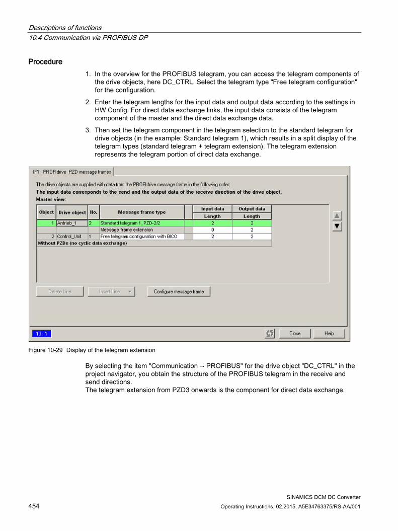
Descriptions of functions 10.4 Communication via PROFIBUS DP
SINAMICS DCM DC Converter 454 Operating Instructions, 02.2015, A5E34763375/RS-AA/001
Procedure 1. In the overview for the PROFIBUS telegram, you can access the telegram components of
the drive objects, here DC_CTRL. Select the telegram type "Free telegram configuration" for the configuration.
2. Enter the telegram lengths for the input data and output data according to the settings in HW Config. For direct data exchange links, the input data consists of the telegram component of the master and the direct data exchange data.
3. Then set the telegram component in the telegram selection to the standard telegram for drive objects (in the example: Standard telegram 1), which results in a split display of the telegram types (standard telegram + telegram extension). The telegram extension represents the telegram portion of direct data exchange.
Figure 10-29 Display of the telegram extension
By selecting the item "Communication → PROFIBUS" for the drive object "DC_CTRL" in the project navigator, you obtain the structure of the PROFIBUS telegram in the receive and send directions. The telegram extension from PZD3 onwards is the component for direct data exchange.
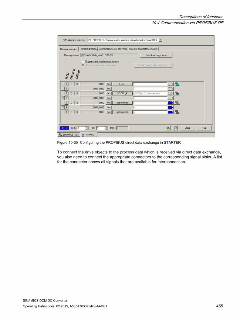
Descriptions of functions 10.4 Communication via PROFIBUS DP
SINAMICS DCM DC Converter Operating Instructions, 02.2015, A5E34763375/RS-AA/001 455
Figure 10-30 Configuring the PROFIBUS direct data exchange in STARTER
To connect the drive objects to the process data which is received via direct data exchange, you also need to connect the appropriate connectors to the corresponding signal sinks. A list for the connector shows all signals that are available for interconnection.
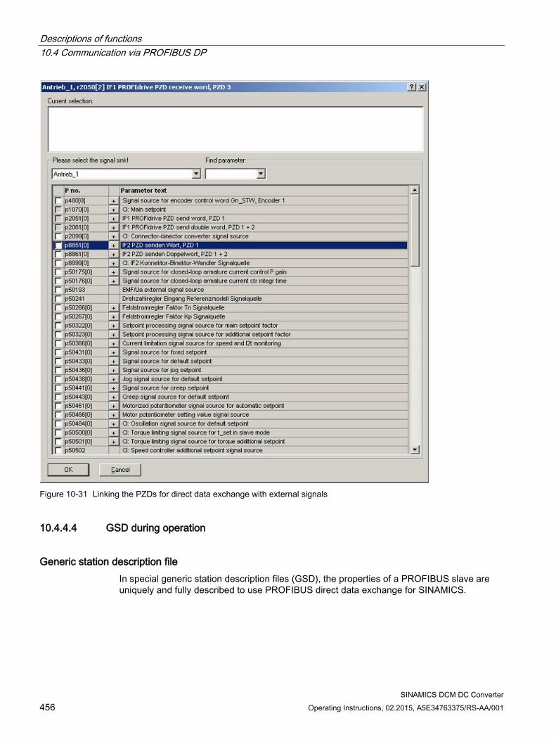
Descriptions of functions 10.4 Communication via PROFIBUS DP
SINAMICS DCM DC Converter 456 Operating Instructions, 02.2015, A5E34763375/RS-AA/001
Figure 10-31 Linking the PZDs for direct data exchange with external signals
10.4.4.4 GSD during operation
Generic station description file In special generic station description files (GSD), the properties of a PROFIBUS slave are uniquely and fully described to use PROFIBUS direct data exchange for SINAMICS.
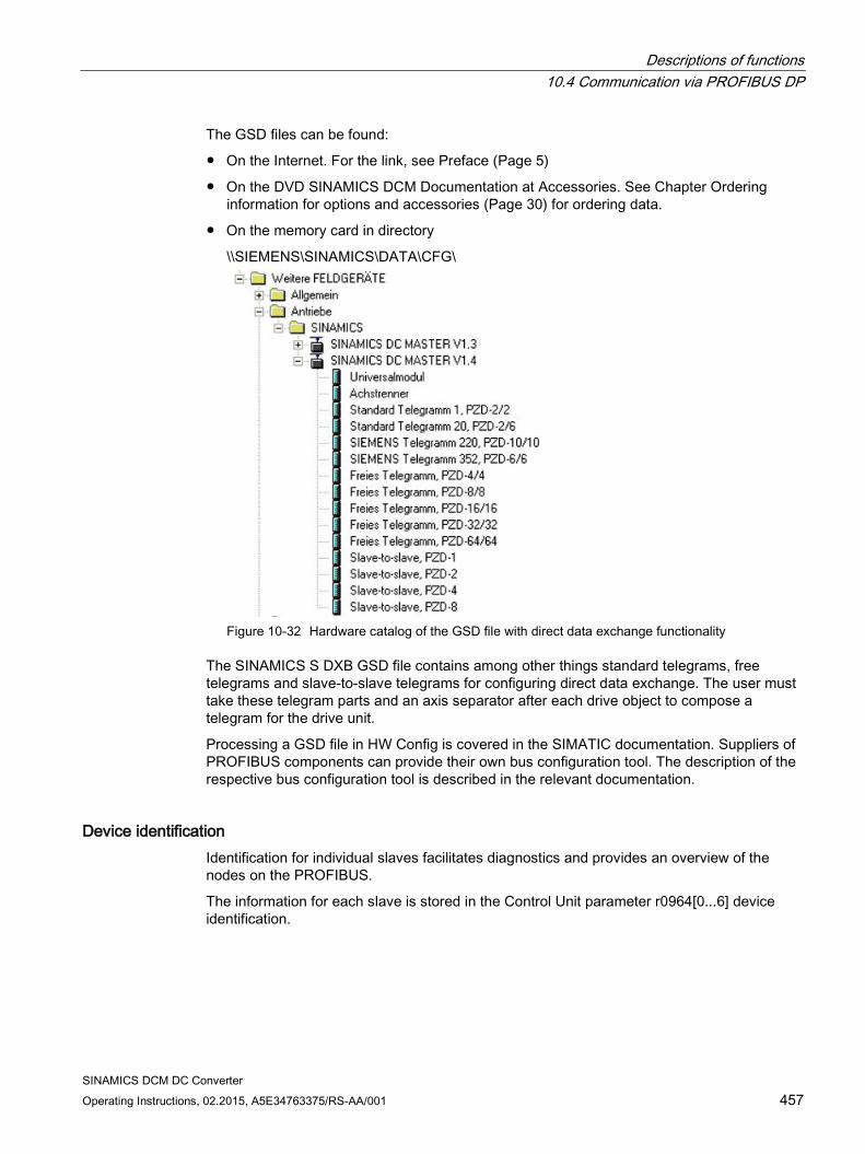
Descriptions of functions 10.4 Communication via PROFIBUS DP
SINAMICS DCM DC Converter Operating Instructions, 02.2015, A5E34763375/RS-AA/001 457
The GSD files can be found:
On the Internet. For the link, see Preface (Page 5)
On the DVD SINAMICS DCM Documentation at Accessories. See Chapter Ordering information for options and accessories (Page 30) for ordering data.
On the memory card in directory
\\SIEMENS\SINAMICS\DATA\CFG\
Figure 10-32 Hardware catalog of the GSD file with direct data exchange functionality
The SINAMICS S DXB GSD file contains among other things standard telegrams, free telegrams and slave-to-slave telegrams for configuring direct data exchange. The user must take these telegram parts and an axis separator after each drive object to compose a telegram for the drive unit.
Processing a GSD file in HW Config is covered in the SIMATIC documentation. Suppliers of PROFIBUS components can provide their own bus configuration tool. The description of the respective bus configuration tool is described in the relevant documentation.
Device identification Identification for individual slaves facilitates diagnostics and provides an overview of the nodes on the PROFIBUS.
The information for each slave is stored in the Control Unit parameter r0964[0...6] device identification.
Descriptions of functions 10.4 Communication via PROFIBUS DP
SINAMICS DCM DC Converter 458 Operating Instructions, 02.2015, A5E34763375/RS-AA/001
10.4.4.5 Diagnostics of the PROFIBUS slave-to-slave communication in STARTER Since the PROFIBUS direct data exchange is implemented on the basis of a broadcast telegram, only the subscriber can detect connection or data faults, e.g. via the publisher data length (see "Configuration telegram").
The publisher can only detect and report an interruption of the cyclic connection to the DP master (A01920, F01910). The broadcast telegram to the subscriber will not provide any feedback. A fault of a subscriber must be fed back via direct data exchange. In case of a "master drive" 1:n, however, the limited quantity framework (see "Links and requests") should be observed. It is not possible to have n subscribers report their status via direct data exchange directly to the "master drive" (publisher)!
Diagnostics can be performed using the diagnostic parameters r2075 ("Receive PROFIBUS diagnostics telegram offset PZD") and r2076 ("Send PROFIBUS diagnostics telegram offset PZD"). The parameter r2074 ("PROFIBUS diagnostics, receive bus address PZD") displays the DP address of the setpoint source of the respective PZD.
r2074 and r2075 enable the source of a direct data exchange relationship to be verified in the subscriber.
Note
The subscribers do not monitor the existence of an isochronous publisher sign of life.
Faults and alarms with PROFIBUS direct data exchange Alarm A01945 signals that the connection to at least one publisher of the drive device is missing or has failed. Any interruption to the publisher is also reported by fault F01946 at the affected drive object. A failure of the publisher only impacts the respective drive objects.
More detailed information on the messages can be found in the SINAMICS DCM List Manual.
10.4.5 Messages via diagnostics channels Messages can be displayed not only via the well-known commissioning tools (STARTER, SCOUT). After the activation of a diagnostic function, the messages are also transferred to the higher-level controller via the standardized diagnostic channels. The messages are evaluated there or forwarded for convenient display to the corresponding user interfaces (SIMATIC HMI, TIA Portal, etc.). The messages are shown on the respective user interfaces similarly as in STARTER.
In this way, problems or faults can be located immediately regardless of the tool currently being used, and then corrected immediately. No further tools must therefore be called for the correction.
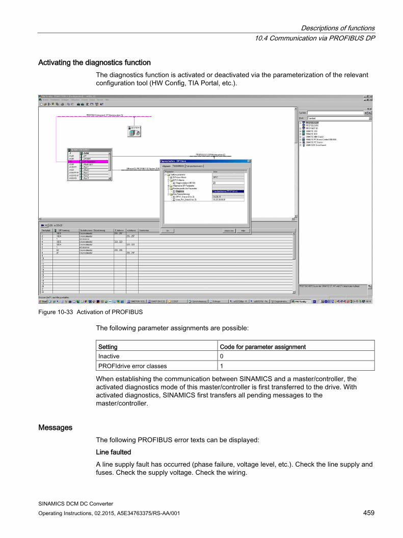
Descriptions of functions 10.4 Communication via PROFIBUS DP
SINAMICS DCM DC Converter Operating Instructions, 02.2015, A5E34763375/RS-AA/001 459
Activating the diagnostics function The diagnostics function is activated or deactivated via the parameterization of the relevant configuration tool (HW Config, TIA Portal, etc.).
Figure 10-33 Activation of PROFIBUS
The following parameter assignments are possible: Setting Code for parameter assignment Inactive 0 PROFIdrive error classes 1
When establishing the communication between SINAMICS and a master/controller, the activated diagnostics mode of this master/controller is first transferred to the drive. With activated diagnostics, SINAMICS first transfers all pending messages to the master/controller.
Messages The following PROFIBUS error texts can be displayed:
Line faulted
A line supply fault has occurred (phase failure, voltage level, etc.). Check the line supply and fuses. Check the supply voltage. Check the wiring.
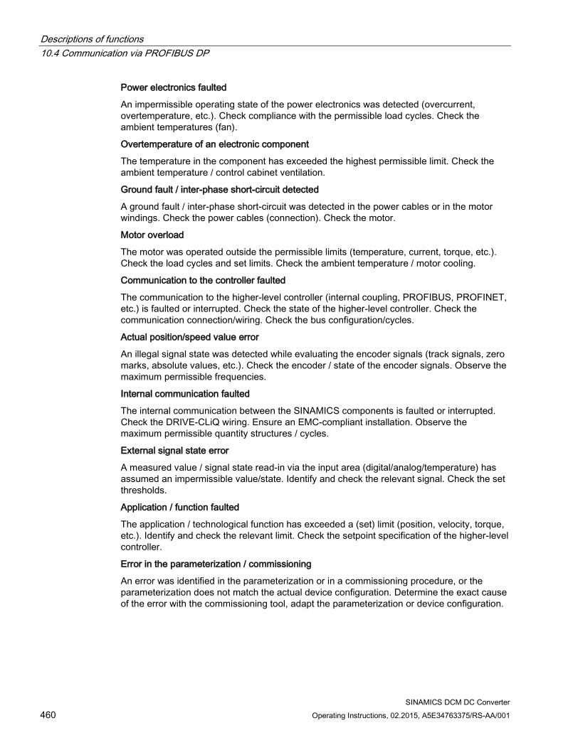
Descriptions of functions 10.4 Communication via PROFIBUS DP
SINAMICS DCM DC Converter 460 Operating Instructions, 02.2015, A5E34763375/RS-AA/001
Power electronics faulted
An impermissible operating state of the power electronics was detected (overcurrent, overtemperature, etc.). Check compliance with the permissible load cycles. Check the ambient temperatures (fan).
Overtemperature of an electronic component
The temperature in the component has exceeded the highest permissible limit. Check the ambient temperature / control cabinet ventilation.
Ground fault / inter-phase short-circuit detected
A ground fault / inter-phase short-circuit was detected in the power cables or in the motor windings. Check the power cables (connection). Check the motor.
Motor overload
The motor was operated outside the permissible limits (temperature, current, torque, etc.). Check the load cycles and set limits. Check the ambient temperature / motor cooling.
Communication to the controller faulted
The communication to the higher-level controller (internal coupling, PROFIBUS, PROFINET, etc.) is faulted or interrupted. Check the state of the higher-level controller. Check the communication connection/wiring. Check the bus configuration/cycles.
Actual position/speed value error
An illegal signal state was detected while evaluating the encoder signals (track signals, zero marks, absolute values, etc.). Check the encoder / state of the encoder signals. Observe the maximum permissible frequencies.
Internal communication faulted
The internal communication between the SINAMICS components is faulted or interrupted. Check the DRIVE-CLiQ wiring. Ensure an EMC-compliant installation. Observe the maximum permissible quantity structures / cycles.
External signal state error
A measured value / signal state read-in via the input area (digital/analog/temperature) has assumed an impermissible value/state. Identify and check the relevant signal. Check the set thresholds.
Application / function faulted
The application / technological function has exceeded a (set) limit (position, velocity, torque, etc.). Identify and check the relevant limit. Check the setpoint specification of the higher-level controller.
Error in the parameterization / commissioning
An error was identified in the parameterization or in a commissioning procedure, or the parameterization does not match the actual device configuration. Determine the exact cause of the error with the commissioning tool, adapt the parameterization or device configuration.
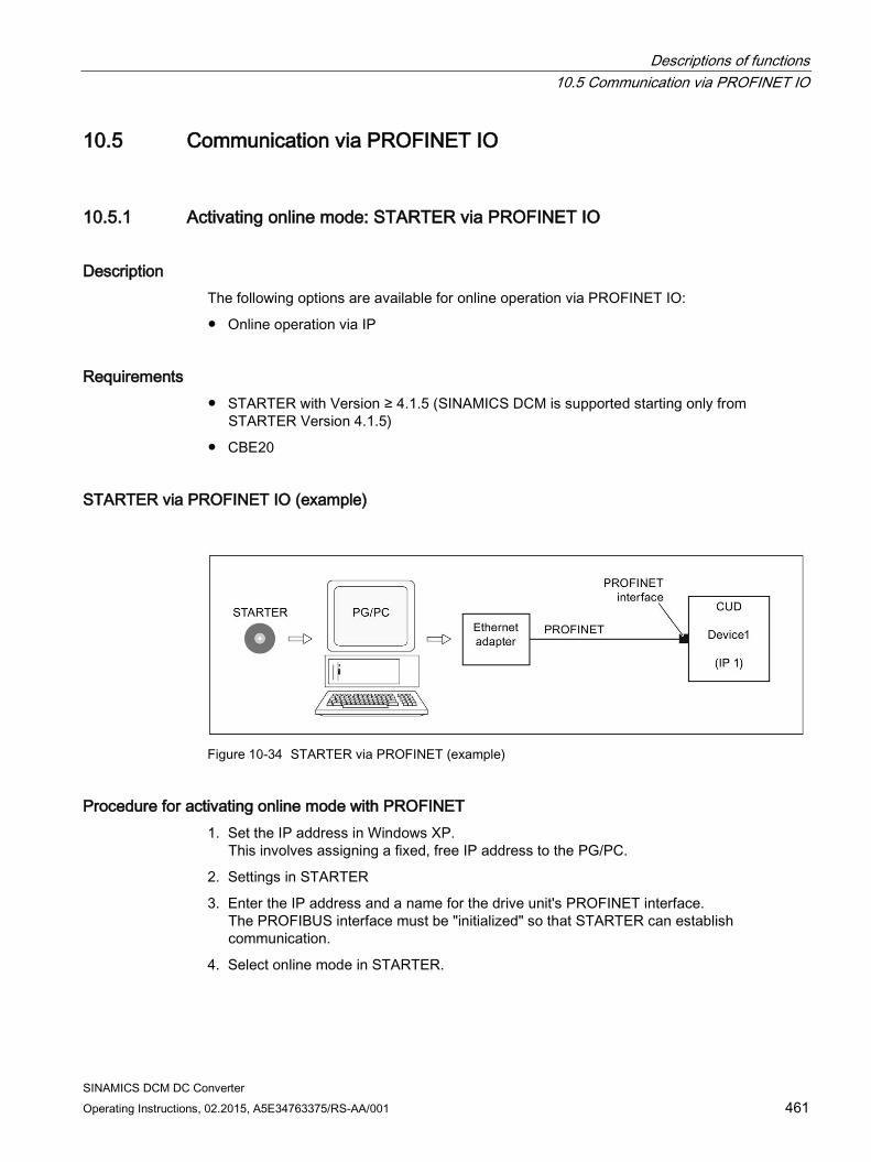
Descriptions of functions 10.5 Communication via PROFINET IO
SINAMICS DCM DC Converter Operating Instructions, 02.2015, A5E34763375/RS-AA/001 461
10.5 Communication via PROFINET IO
10.5.1 Activating online mode: STARTER via PROFINET IO
Description The following options are available for online operation via PROFINET IO:
Online operation via IP
Requirements STARTER with Version ≥ 4.1.5 (SINAMICS DCM is supported starting only from
STARTER Version 4.1.5)
CBE20
STARTER via PROFINET IO (example)
Figure 10-34 STARTER via PROFINET (example)
Procedure for activating online mode with PROFINET 1. Set the IP address in Windows XP.
This involves assigning a fixed, free IP address to the PG/PC.
2. Settings in STARTER
3. Enter the IP address and a name for the drive unit's PROFINET interface. The PROFIBUS interface must be "initialized" so that STARTER can establish communication.
4. Select online mode in STARTER.
Descriptions of functions 10.5 Communication via PROFINET IO
SINAMICS DCM DC Converter 462 Operating Instructions, 02.2015, A5E34763375/RS-AA/001
Set the IP address in Windows XP. On the desktop, right-click on "Network environment" -> Properties -> double-click on Network card and choose -> Properties -> Internet Protocol (TCP/IP) -> Properties -> Enter the freely-assignable addresses.
Figure 10-35 Internet Protocol (TCP/IP) properties
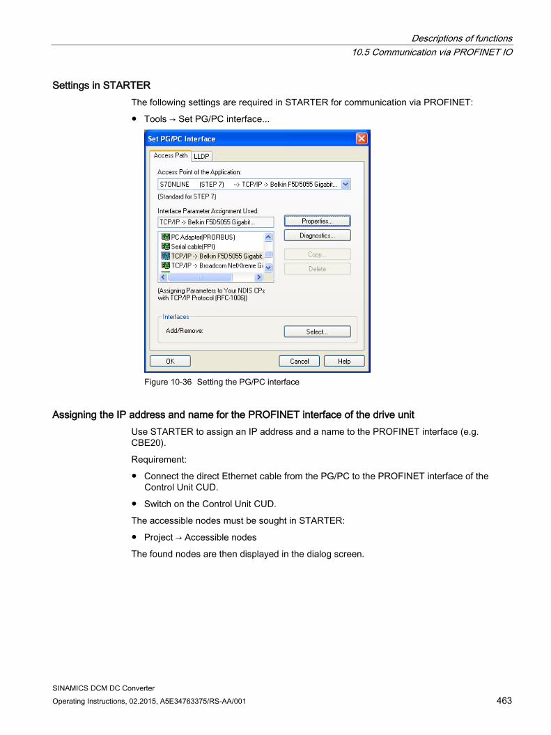
Descriptions of functions 10.5 Communication via PROFINET IO
SINAMICS DCM DC Converter Operating Instructions, 02.2015, A5E34763375/RS-AA/001 463
Settings in STARTER The following settings are required in STARTER for communication via PROFINET:
Tools → Set PG/PC interface...
Figure 10-36 Setting the PG/PC interface
Assigning the IP address and name for the PROFINET interface of the drive unit Use STARTER to assign an IP address and a name to the PROFINET interface (e.g. CBE20).
Requirement:
Connect the direct Ethernet cable from the PG/PC to the PROFINET interface of the Control Unit CUD.
Switch on the Control Unit CUD.
The accessible nodes must be sought in STARTER:
Project → Accessible nodes
The found nodes are then displayed in the dialog screen.
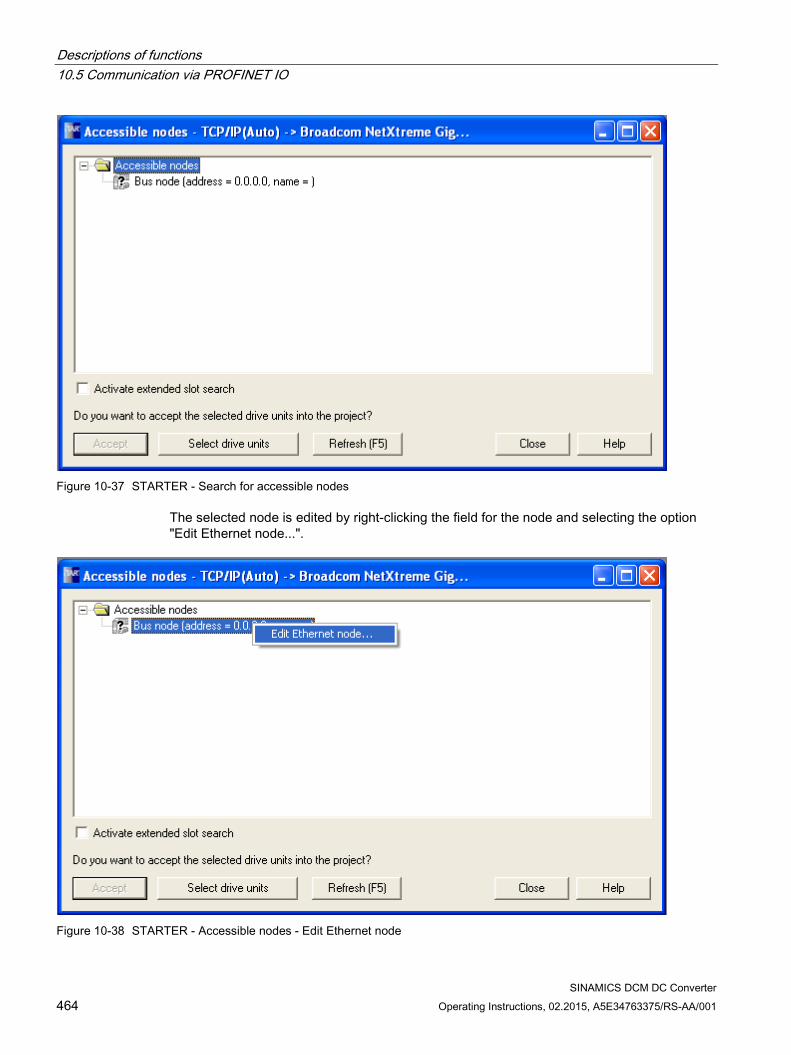
Descriptions of functions 10.5 Communication via PROFINET IO
SINAMICS DCM DC Converter 464 Operating Instructions, 02.2015, A5E34763375/RS-AA/001
Figure 10-37 STARTER - Search for accessible nodes
The selected node is edited by right-clicking the field for the node and selecting the option "Edit Ethernet node...".
Figure 10-38 STARTER - Accessible nodes - Edit Ethernet node
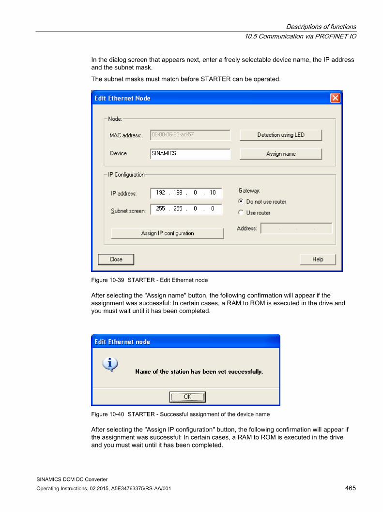
Descriptions of functions 10.5 Communication via PROFINET IO
SINAMICS DCM DC Converter Operating Instructions, 02.2015, A5E34763375/RS-AA/001 465
In the dialog screen that appears next, enter a freely selectable device name, the IP address and the subnet mask.
The subnet masks must match before STARTER can be operated.
Figure 10-39 STARTER - Edit Ethernet node
After selecting the "Assign name" button, the following confirmation will appear if the assignment was successful: In certain cases, a RAM to ROM is executed in the drive and you must wait until it has been completed.
Figure 10-40 STARTER - Successful assignment of the device name
After selecting the "Assign IP configuration" button, the following confirmation will appear if the assignment was successful: In certain cases, a RAM to ROM is executed in the drive and you must wait until it has been completed.
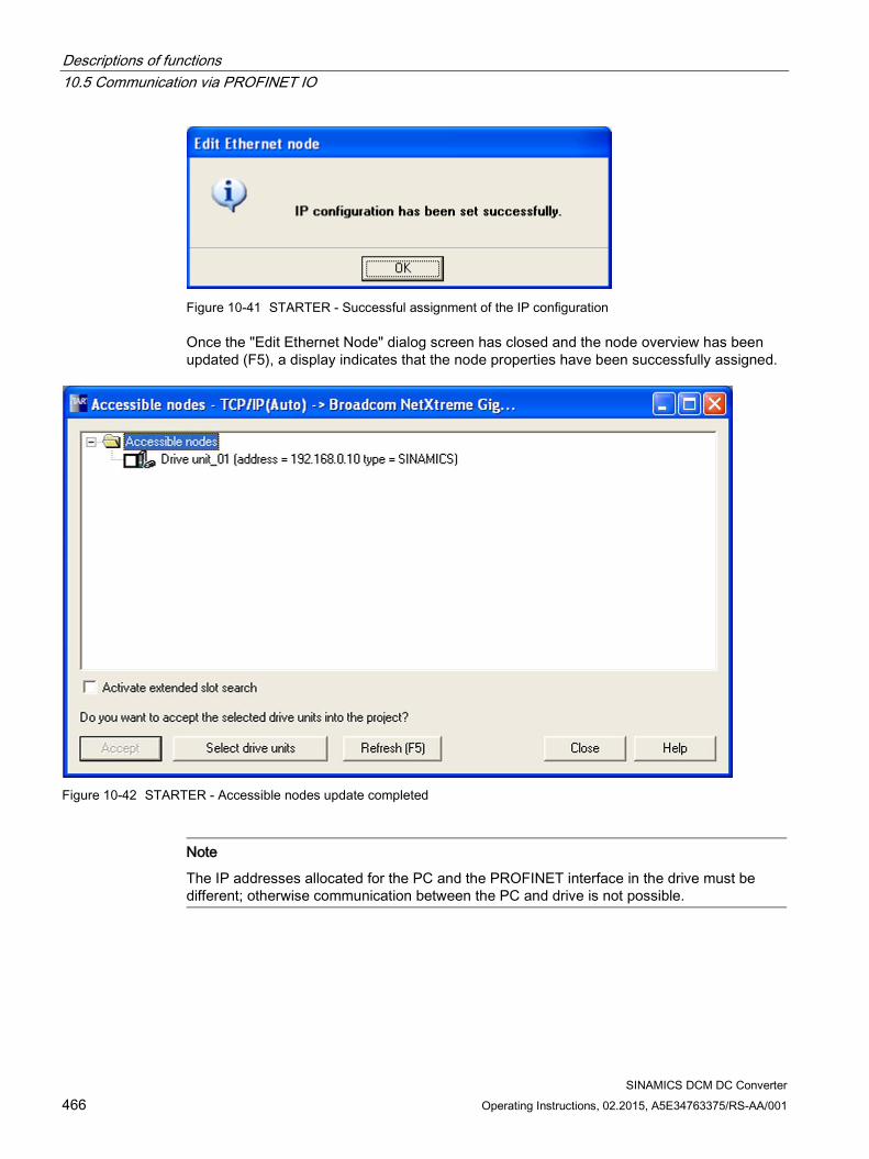
Descriptions of functions 10.5 Communication via PROFINET IO
SINAMICS DCM DC Converter 466 Operating Instructions, 02.2015, A5E34763375/RS-AA/001
Figure 10-41 STARTER - Successful assignment of the IP configuration
Once the "Edit Ethernet Node" dialog screen has closed and the node overview has been updated (F5), a display indicates that the node properties have been successfully assigned.
Figure 10-42 STARTER - Accessible nodes update completed
Note
The IP addresses allocated for the PC and the PROFINET interface in the drive must be different; otherwise communication between the PC and drive is not possible.
Descriptions of functions 10.5 Communication via PROFINET IO
SINAMICS DCM DC Converter Operating Instructions, 02.2015, A5E34763375/RS-AA/001 467
10.5.2 General information about PROFINET IO
General information PROFINET IO is an open Industrial Ethernet standard for a wide range of production and process automation applications. PROFINET IO is based on Industrial Ethernet and observes TCP/IP and IT standards.
Deterministic signal processing in real time is important in industrial networks. PROFINET IO satisfies these requirements.
The following standards ensure open, multi-vendor systems:
International standard IEC 61158
PROFINET IO is optimized for high-speed, time-critical data transfers at field level.
PROFINET IO Within the context of Totally Integrated Automation (TIA), PROFINET IO is the systematic development of the following systems:
PROFIBUS DP, the established fieldbus.
Industrial Ethernet, the communications bus for the cell level.
Experience gained from both systems was integrated into PROFINET IO. PROFINET IO as the Ethernet-based automation standard from PROFIBUS International (PROFIBUS User Organization e.V.) defines a cross-vendor communications and engineering model.
PROFINET IO defines every aspect of the data exchange between IO controllers (devices with what is known as "master functionality" and the IO devices (those with what is known as "slave functionality") as well as carrying out parameterization and diagnostics. A PROFINET IO system is configured in virtually the same way as a PROFIBUS system.
A PROFINET IO system is assembled from the following devices:
An IO controller controls automation tasks.
An IO device is controlled and monitored by an IO controller. An IO device consists of several modules and submodules.
An IO supervisor is an engineering tool, typically based on a PC, with which the individual IO devices (drive units) are parameterized and diagnosed.
IO devices: Drive units with PROFINET interface SINAMICS DCM with inserted CBE20
Descriptions of functions 10.5 Communication via PROFINET IO
SINAMICS DCM DC Converter 468 Operating Instructions, 02.2015, A5E34763375/RS-AA/001
Cyclic communication using PROFINET IO with IRT or using RT is possible on all drive units equipped with a PROFINET interface. This means that error-free communication using other standard protocols is guaranteed within the same network.
Note
PROFINET for drive technology is standardized and described in the following document:
PROFIBUS profile PROFIdrive - Profile Drive Technology
Version V4.1, May 2006
PROFIBUS User Organization e. V.
Haid-und-Neu-Straße 7
D-76131 Karlsruhe
http://www.profibus.com
Order no. 3.172, spec. Chapter 6 • IEC 61800-7
Note
For a CUD with inserted CBE20, the cyclic PZD channel is deactivated for PROFIBUS DP. By setting parameter p8839 = 1, the PZD channel can be reactivated, see Chapter Parallel operation of communication interfaces (Page 412).
10.5.2.1 Real-time (RT) and isochronous real-time (IRT) communication
Real-time communication When communication takes place via TCP/IP, the resultant transmission times may be too long and non-deterministic to meet production automation requirements. When communicating time-critical IO user data, PROFINET IO therefore uses its own real-time channel, rather than TCP/IP.
Determinism Determinism means that a system will react in a predictable ("deterministic") manner. With PROFINET IO, it is possible to precisely determine (predict) transmission times.
PROFINET IO with RT (Real Time) Real time means that a system processes external events over a defined period.
Process data and alarms are always transferred in real time (RT) within the PROFINET IO system. RT communication provides the basis for data exchange with PROFINET IO. Real-time data is treated with a higher priority than TCP(UDP)/IP data. Transmission of time-critical data takes place at guaranteed time intervals.
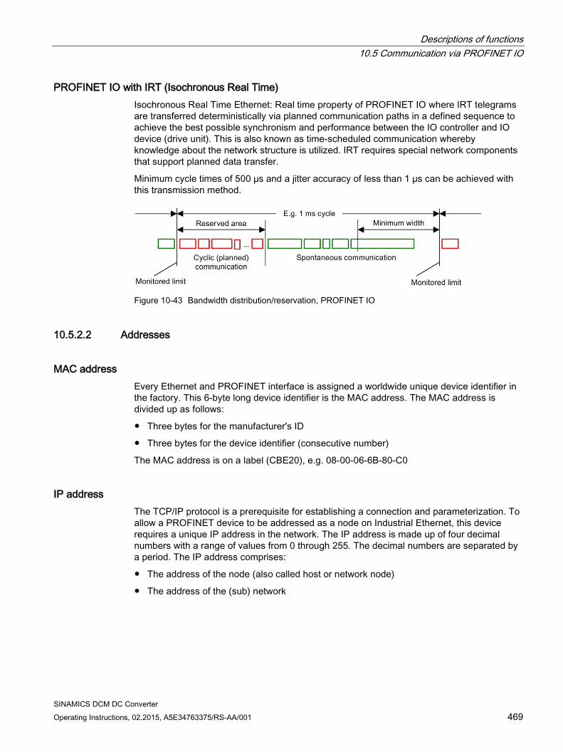
Descriptions of functions 10.5 Communication via PROFINET IO
SINAMICS DCM DC Converter Operating Instructions, 02.2015, A5E34763375/RS-AA/001 469
PROFINET IO with IRT (Isochronous Real Time) Isochronous Real Time Ethernet: Real time property of PROFINET IO where IRT telegrams are transferred deterministically via planned communication paths in a defined sequence to achieve the best possible synchronism and performance between the IO controller and IO device (drive unit). This is also known as time-scheduled communication whereby knowledge about the network structure is utilized. IRT requires special network components that support planned data transfer.
Minimum cycle times of 500 μs and a jitter accuracy of less than 1 μs can be achieved with this transmission method.
Figure 10-43 Bandwidth distribution/reservation, PROFINET IO
10.5.2.2 Addresses
MAC address Every Ethernet and PROFINET interface is assigned a worldwide unique device identifier in the factory. This 6-byte long device identifier is the MAC address. The MAC address is divided up as follows:
Three bytes for the manufacturer's ID
Three bytes for the device identifier (consecutive number)
The MAC address is on a label (CBE20), e.g. 08-00-06-6B-80-C0
IP address The TCP/IP protocol is a prerequisite for establishing a connection and parameterization. To allow a PROFINET device to be addressed as a node on Industrial Ethernet, this device requires a unique IP address in the network. The IP address is made up of four decimal numbers with a range of values from 0 through 255. The decimal numbers are separated by a period. The IP address comprises:
The address of the node (also called host or network node)
The address of the (sub) network
Descriptions of functions 10.5 Communication via PROFINET IO
SINAMICS DCM DC Converter 470 Operating Instructions, 02.2015, A5E34763375/RS-AA/001
IP address assignment The IP addresses of IO devices can be assigned by the IO controller and always have the same subnet screen as the IO controller. In this case, the IP address is not stored permanently. The IP address entry is lost after POWER ON/OFF. The IP address can be assigned retentively via the STARTER function "Accessible nodes".
This function can also be performed with HW Config of STEP 7. The function is called "Edit Ethernet node" here.
Note
If the network is part of an existing Ethernet company network, obtain the information (IP address) from your network administrator.
Device name (NameOfStation) When it is shipped, an IO device does not have a device name. An IO device can only be addressed by an IO controller, for example, for the transfer of project engineering data (including the IP address) during startup or for user data exchange in cyclic operation, after it has been assigned a device name with the IO supervisor.
Note
The device name must be stored retentively using either STARTER, the Primary Setup Tool (PST) or with HW Config of STEP 7.
Note
You can enter the address data for the ports of the optional CBE20 module in STARTER in the expert list using parameters p8940, p8941, p8942 and p8943.
Replacing the Control Unit (CUD) (IO device) If the IP address and device name are stored in non-volatile memory, this data is also forwarded with the memory card of the Control Unit.
If a complete Control Unit needs to be replaced due to a device or module defect, the new Control Unit automatically parameterizes and configures using the data on the memory card. Following this, cyclic exchange of user data is restarted. The memory card allows module exchange without an IO supervisor when a fault occurs in a PROFINET device.
Descriptions of functions 10.5 Communication via PROFINET IO
SINAMICS DCM DC Converter Operating Instructions, 02.2015, A5E34763375/RS-AA/001 471
10.5.2.3 Data transmission
Properties The PROFINET interface on a drive unit supports the simultaneous operation of:
IRT – isochronous real-time Ethernet
RT – real-time Ethernet
Standard Ethernet services (TCP/IP, LLDP, UDP and DCP)
PROFIdrive telegram for cyclic data transmission, acyclic services Telegrams to send and receive process data are available for each drive object of a drive unit with cyclic process data exchange. In addition to cyclic data transfer, acyclic services can also be used for parameterizing and configuring the drive unit. These acyclic services can be utilized by the IO supervisor or IO controller.
Sequence of drive objects in the telegram On the drive side, the sequence of drive objects in the telegram is displayed via a list in p0978[0...24] where it can also be changed.
You can use the STARTER commissioning tool to display the sequence of drive objects for a commissioned drive system in online mode in the project navigator under "Drive unit" > "Communication" > "Telegram configuration".
When you create the configuration on the controller side (e.g. HW Config), the process-data-capable drive objects for the application are added to the telegram in this sequence.
The following drive objects can exchange process data:
Control Unit CU_DC
ENC
Terminal Board 30 (TB30)
Terminal Module 15 (TM15)
Terminal Module 31 (TM31)
Terminal Module 150 (TM150)
DC_CTRL
Note
The sequence of drive objects in HW Config must be the same as that in the drive (p0978).
Descriptions of functions 10.5 Communication via PROFINET IO
SINAMICS DCM DC Converter 472 Operating Instructions, 02.2015, A5E34763375/RS-AA/001
The structure of the telegram depends on the drive objects taken into account during configuration. Configurations are permitted that do not take into account all of the drive objects that are present in the drive system.
Example:
The following configurations, for example, are possible:
Configuration with CU_DC, DC_STRL
Configuration with DC_CTRL, TM31, TM31
etc.
10.5.2.4 Communication channels for PROFINET
Control Unit with CBE20 A Communication Board can be optionally inserted in the Control Unit CUD:
The CBE20 Communication Board is a PROFINET switch with four PROFINET ports.
Overview of important parameters (see the SINAMICS DCM List Manual) • p8829 CBE20 remote controller number
• p8940[0...239] CBE20 name of station
• p8941[0...3] CBE20 IP address of station
• p8942[0...3] CBE20 default gateway of station
• p8943[0...3] CBE20 subnet mask of station
• p8944 CBE20 DHCP mode
• p8945 CBE20 interface configuration
• r8950[0...239] CBE20 name of active station
• r8951[0...3] CBE20 IP address of active station
• r8952[0...3] CBE20 default gateway of active station
• r8953[0...3] CBE20 subnet mask of active station
• r8954 CBE20 DHCP mode active
• r8955[0...5] CBE20 MAC address of station
• r8959 CBE20 DAP ID
Descriptions of functions 10.5 Communication via PROFINET IO
SINAMICS DCM DC Converter Operating Instructions, 02.2015, A5E34763375/RS-AA/001 473
10.5.3 Drive control with PROFINET
PROFINET interfaces The CBE20 option module can be inserted in the option slot of a CUD. The CBE20 is a PROFINET switch with four ports.
Note
Ring topology
When connecting the ports, it must be ensured that for standard applications a ring topology is not created. Additional information on ring topologies can be found in Chapter Media redundancy (Page 475).
References The integration of a SINAMICS Control Unit in a PROFINET IO system is described in
detail in System Manual "SIMOTION SCOUT Communication".
For an example of how to link a Control Unit to a SIMATIC S7 via PROFINET IO, please refer to the FAQ "PROFINET IO communication between an S7-CPU and SINAMICS S120" on the Internet.
For a description of the CBE20 and how you can use it in the drive, see Chapter Option Board: Communication Board Ethernet CBE20 (Page 190).
Telegrams PROFIdrive telegrams are available for implementing cyclic communication via PROFINET IO (see Chapter "Communication according to PROFIdrive", cyclic communication).
DCP flashing This function checks the correct assignment to a module and its interfaces.
1. In HW Config or the STEP 7 Manager, select the menu item "Target system" > Ethernet > Edit Ethernet node".
The "Edit Ethernet Node" dialog box opens.
2. Click the "Browse" button.
The "Browse Network" dialog box opens and displays the connected nodes.
3. Select the CUD with inserted CBE20 as node.
The "DCP flashing" function is then activated via the "Flash" button.
The "DCP flashing" function is activated on the RDY LED (READY LED 2 Hz, green/orange or red/orange) on the CUD.
The LED will continue to flash as long as the dialog is open. When the dialog is closed, the LED will go out automatically. The function is available as of STEP 7 V5.3 SP1 via Ethernet.
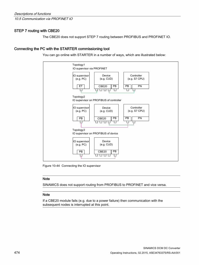
Descriptions of functions 10.5 Communication via PROFINET IO
SINAMICS DCM DC Converter 474 Operating Instructions, 02.2015, A5E34763375/RS-AA/001
STEP 7 routing with CBE20 The CBE20 does not support STEP 7 routing between PROFIBUS and PROFINET IO.
Connecting the PC with the STARTER commissioning tool You can go online with STARTER in a number of ways, which are illustrated below:
Figure 10-44 Connecting the IO supervisor
Note
SINAMICS does not support routing from PROFIBUS to PROFINET and vice versa.
Note
If a CBE20 module fails (e.g. due to a power failure) then communication with the subsequent nodes is interrupted at this point.
Descriptions of functions 10.5 Communication via PROFINET IO
SINAMICS DCM DC Converter Operating Instructions, 02.2015, A5E34763375/RS-AA/001 475
10.5.3.1 Media redundancy To increase the availability of PROFINET, you can create a ring topology for redundancy purposes. If the ring is interrupted at one point, the data paths between the devices are automatically reconfigured. Following reconfiguration, the devices can once again be accessed in the resulting new topology.
To create a ring topology with media redundancy, route the two ends of a line-type PROFINET topology into one device, the SCALANCE device. Closing the linear bus topology is realized using two ports (ring ports) of the SCALANCE device. The Scalance device is the redundancy manager. The redundancy manager monitors the data telegrams in the PROFINET ring. All other connected PROFINET nodes are redundant clients.
The Media Redundancy Protocol (MRP) is the standard procedure for media redundancy. Using this procedure, a maximum of 50 devices can participate in each ring. In the case of an interrupted cable, data transfer is only briefly interrupted as the system switches over to the redundant data path.
If a short-term interruption is not permitted, data transfer must be set to IRT High Performance. The uninterruptible MRRT is automatically set.
From a CBE20, only the first two ports are capable of establishing a ring topology.
Note
In order to use the ring topology, the GSDML file version V2.3 must be installed.
This file can be found, for example, on the memory card as "\SIEMENS\SINAMICS\DATA\CFG\PNGSD.ZIP".
Configuring media redundancy The ring topology is configured by appropriately configuring the participating devices individually in STEP 7.
10.5.4 RT classes for PROFINET IO PROFINET IO is a scalable realtime communication system based on Ethernet technology. The scalable approach is expressed with three realtime classes.
RT
RT communication is based on standard Ethernet. The data is transferred via prioritized Ethernet telegrams. Because standard Ethernet does not support any synchronization mechanisms, isochronous operation is not possible with PROFINET IO with RT!
The real update cycle in which cyclic data is exchanged depends on the bus load, the devices used and the quantity framework of the I/O data. The update cycle is a multiple of the send cycle.
Descriptions of functions 10.5 Communication via PROFINET IO
SINAMICS DCM DC Converter 476 Operating Instructions, 02.2015, A5E34763375/RS-AA/001
IRT
Two options are available with this RT class:
IRT "high flexibility"
IRT "high performance"
(Not supported by SINAMICS DCM)
Software preconditions for configuring IRT:
STEP 7 5.4 SP4 (HW Config)
Note
For further information about configuring the PROFINET interface for the I/O controller and I/O device, please refer to the following document: SIMOTION SCOUT Communication System Manual.
IRT "high flexibility" The telegrams are sent cyclically in a deterministic cycle (Isochronous Real Time). The telegrams are exchanged in a bandwidth reserved by the hardware. One IRT time interval and one standard Ethernet time interval are created for each cycle.
IRT "high performance"
Note
IRT "high performance" is not supported by SINAMICS DCM.
The IRT "high performance" real-time class is supported by the drives of the SINAMICS S110 and S120 series and is described here for reasons of completeness.
In addition to the bandwidth reservation, the telegram traffic can be further optimized by configuring the topology. This enhances the performance during data exchange and the deterministic behavior. The IRT time interval can thus be further optimized or minimized with respect to IRT "high flexibility".
In addition to the isochronous data transfer provided by IRT, even the application itself (position control cycle, IPO cycle) can be isochronous in the devices. This is an essential requirement for closed-loop axis control and synchronization via the bus. Isochronous data transfer with cycle times well below one millisecond and with a deviation in the cycle start (jitter) of less than a microsecond provide sufficient performance reserves for demanding motion control applications.
The RT classes IRT "high flexibility" and IRT "high performance" can be selected as options in the synchronization settings configuration area of HW Config. In the description below, both these classes are simply referred to as "IRT".
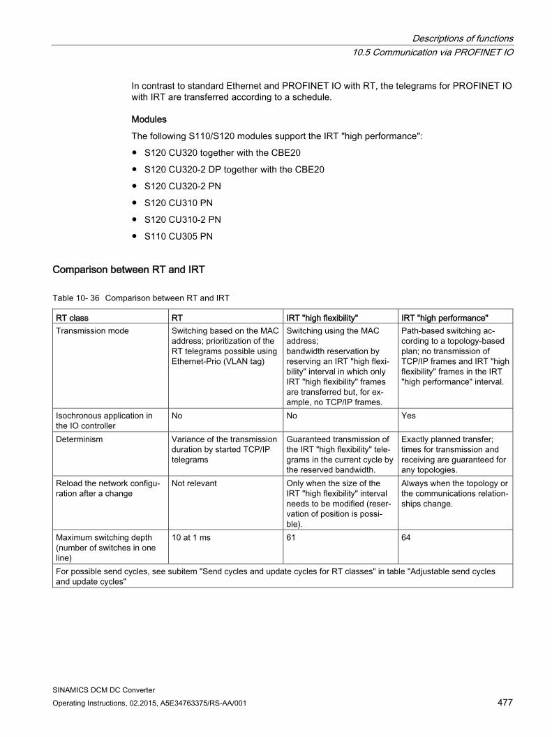
Descriptions of functions 10.5 Communication via PROFINET IO
SINAMICS DCM DC Converter Operating Instructions, 02.2015, A5E34763375/RS-AA/001 477
In contrast to standard Ethernet and PROFINET IO with RT, the telegrams for PROFINET IO with IRT are transferred according to a schedule.
Modules
The following S110/S120 modules support the IRT "high performance":
S120 CU320 together with the CBE20
S120 CU320-2 DP together with the CBE20
S120 CU320-2 PN
S120 CU310 PN
S120 CU310-2 PN
S110 CU305 PN
Comparison between RT and IRT
Table 10- 36 Comparison between RT and IRT
RT class RT IRT "high flexibility" IRT "high performance" Transmission mode Switching based on the MAC
address; prioritization of the RT telegrams possible using Ethernet-Prio (VLAN tag)
Switching using the MAC address; bandwidth reservation by reserving an IRT "high flexi-bility" interval in which only IRT "high flexibility" frames are transferred but, for ex-ample, no TCP/IP frames.
Path-based switching ac-cording to a topology-based plan; no transmission of TCP/IP frames and IRT "high flexibility" frames in the IRT "high performance" interval.
Isochronous application in the IO controller
No No Yes
Determinism Variance of the transmission duration by started TCP/IP telegrams
Guaranteed transmission of the IRT "high flexibility" tele-grams in the current cycle by the reserved bandwidth.
Exactly planned transfer; times for transmission and receiving are guaranteed for any topologies.
Reload the network configu-ration after a change
Not relevant Only when the size of the IRT "high flexibility" interval needs to be modified (reser-vation of position is possi-ble).
Always when the topology or the communications relation-ships change.
Maximum switching depth (number of switches in one line)
10 at 1 ms 61 64
For possible send cycles, see subitem "Send cycles and update cycles for RT classes" in table "Adjustable send cycles and update cycles"
Descriptions of functions 10.5 Communication via PROFINET IO
SINAMICS DCM DC Converter 478 Operating Instructions, 02.2015, A5E34763375/RS-AA/001
Set the RT class The RT class is set by means of the IO controller interface properties. If RT class IRT "high performance" is set, it is not possible to operate any IRT "high flexibility" devices on the IO controller and vice versa. IO devices with RT can always be operated, regardless of the IRT class setting.
You can set the RT class in the HW Config for the associated PROFINET device.
1. In HW Config, double-click item PROFINET interface in the module.
The "Properties" dialog box opens.
2. Select the RT class under RT class on the "Synchronization" tab.
3. Once you have selected "IRT", you can also choose between option "high flexibility" and "high performance".
Note
The "high performance" option must not be selected for SINAMICS DCM (an error message is issued).
4. Confirm with "OK".
Synchronization domain The sum of all devices to be synchronized form a synchronization domain. The whole domain must be set to a single, specific RT class (real-time class) for synchronization. Different synchronization domains can communicate with one another via RT.
For IRT, all IO devices and IO controllers must be synchronized with a common synchronization master.
RT allows an IO controller to communicate with a drive unit outside a synchronization domain or "through" another synchronization domain. As of version 5.4 SP1, STEP 7 supports multiple synchronization domains on a single Ethernet subnet.
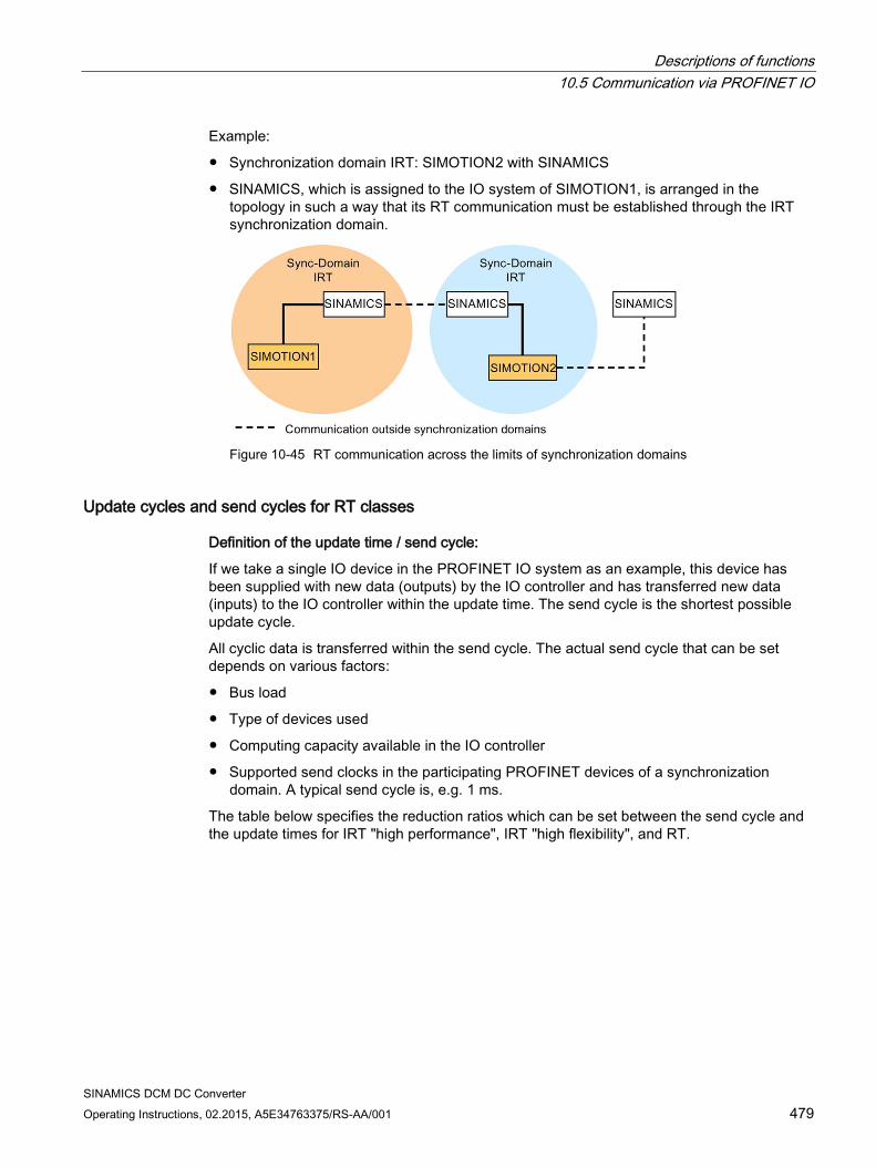
Descriptions of functions 10.5 Communication via PROFINET IO
SINAMICS DCM DC Converter Operating Instructions, 02.2015, A5E34763375/RS-AA/001 479
Example:
Synchronization domain IRT: SIMOTION2 with SINAMICS
SINAMICS, which is assigned to the IO system of SIMOTION1, is arranged in the topology in such a way that its RT communication must be established through the IRT synchronization domain.
Figure 10-45 RT communication across the limits of synchronization domains
Update cycles and send cycles for RT classes
Definition of the update time / send cycle:
If we take a single IO device in the PROFINET IO system as an example, this device has been supplied with new data (outputs) by the IO controller and has transferred new data (inputs) to the IO controller within the update time. The send cycle is the shortest possible update cycle.
All cyclic data is transferred within the send cycle. The actual send cycle that can be set depends on various factors:
Bus load
Type of devices used
Computing capacity available in the IO controller
Supported send clocks in the participating PROFINET devices of a synchronization domain. A typical send cycle is, e.g. 1 ms.
The table below specifies the reduction ratios which can be set between the send cycle and the update times for IRT "high performance", IRT "high flexibility", and RT.
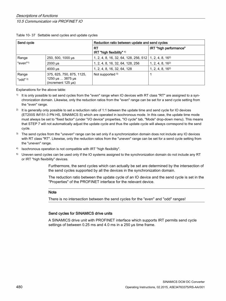
Descriptions of functions 10.5 Communication via PROFINET IO
SINAMICS DCM DC Converter 480 Operating Instructions, 02.2015, A5E34763375/RS-AA/001
Table 10- 37 Settable send cycles and update cycles
Send cycle Reduction ratio between update and send cycles RT IRT "high flexibility" 4)
IRT "high performance"
Range "even"1)
250, 500, 1000 µs 1, 2, 4, 8, 16, 32, 64, 128, 256, 512 1, 2, 4, 8, 162) 2000 µs 1, 2, 4, 8, 16, 32, 64, 128, 256 1, 2, 4, 8, 162) 4000 µs 1, 2, 4, 8, 16, 32, 64, 128 1, 2, 4, 8, 162)
Range "odd" 3)
375, 625, 750, 875, 1125, 1250 µs ... 3875 µs (increment 125 µs)
Not supported 5) 1
Explanations for the above table: 1) It is only possible to set send cycles from the "even" range when IO devices with RT class "RT" are assigned to a syn-
chronization domain. Likewise, only the reduction ratios from the "even" range can be set for a send cycle setting from the "even" range.
2) It is generally only possible to set a reduction ratio of 1:1 between the update time and send cycle for IO devices (ET200S IM151-3 PN HS, SINAMICS S) which are operated in isochronous mode. In this case, the update time mode must always be set to "fixed factor" (under "I/O device" properties, "IO cycle" tab, "Mode" drop-down menu). This means that STEP 7 will not automatically adjust the update cycle and thus the update cycle will always correspond to the send cycle.
3) The send cycles from the "uneven" range can be set only if a synchronization domain does not include any IO devices with RT class "RT". Likewise, only the reduction ratios from the "uneven" range can be set for a send cycle setting from the "uneven" range.
4) Isochronous operation is not compatible with IRT "high flexibility". 5) Uneven send cycles can be used only if the IO systems assigned to the synchronization domain do not include any RT
or IRT "high flexibility" devices.
Furthermore, the send cycles which can actually be set are determined by the intersection of the send cycles supported by all the devices in the synchronization domain.
The reduction ratio between the update cycle of an IO device and the send cycle is set in the "Properties" of the PROFINET interface for the relevant device.
Note
There is no intersection between the send cycles for the "even" and "odd" ranges!
Send cycles for SINAMICS drive units
A SINAMICS drive unit with PROFINET interface which supports IRT permits send cycle settings of between 0.25 ms and 4.0 ms in a 250 µs time frame.
Descriptions of functions 10.5 Communication via PROFINET IO
SINAMICS DCM DC Converter Operating Instructions, 02.2015, A5E34763375/RS-AA/001 481
Topology rules
Topology rules for RT
A topology can be, but need not be configured for RT. If a topology has been configured, the devices must be wired in accordance with the topology.
Otherwise, the wiring between devices is entirely optional.
Topology rules for IRT
Mixed operation is not supported by STEP 7 V5.4 SP4, i.e. IRT "high performance" cannot be combined with IRT "high flexibility" in the same synchronization domain.
A synchronization domain with IRT "high performance" can contain a maximum of one IRT "high performance" island. "Island" means that the devices must be interconnected to match the configured topology. A synchronization master must be positioned in the relevant island.
IRT "high flexibility" is subject to the same topology rules as IRT "high performance", the only exception being that a topology does not need to be configured. However, if a topology has been configured, the devices must be wired to match the topology.
Device selection in HW Config
Hardware catalog:
The drive unit from the appropriate device family entry in the hardware catalog must be configured.
10.5.5 PROFINET GSDML As with PROFIBUS, when DriveES is present, the device can be inserted using a DriveES/STARTER interface or using a GSDML file.
The GSDML file is available as a zip archive on the memory card with the current firmware:
\\Siemens\SINAMICS\DATA\CFG\PNGSD.zip
See Chapter Ordering information for options and accessories (Page 30) for ordering data of the memory card.
Alternatively, the GSDML file can be requested from the Customer Support.
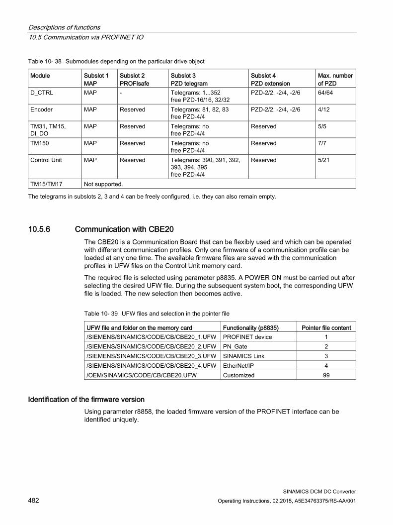
Descriptions of functions 10.5 Communication via PROFINET IO
SINAMICS DCM DC Converter 482 Operating Instructions, 02.2015, A5E34763375/RS-AA/001
Table 10- 38 Submodules depending on the particular drive object
Module Subslot 1 MAP
Subslot 2 PROFIsafe
Subslot 3 PZD telegram
Subslot 4 PZD extension
Max. number of PZD
D_CTRL MAP - Telegrams: 1...352 free PZD-16/16, 32/32
PZD-2/2, -2/4, -2/6 64/64
Encoder MAP Reserved Telegrams: 81, 82, 83 free PZD-4/4
PZD-2/2, -2/4, -2/6 4/12
TM31, TM15, DI_DO
MAP Reserved Telegrams: no free PZD-4/4
Reserved 5/5
TM150 MAP Reserved Telegrams: no free PZD-4/4
Reserved 7/7
Control Unit MAP Reserved Telegrams: 390, 391, 392, 393, 394, 395 free PZD-4/4
Reserved 5/21
TM15/TM17 Not supported. The telegrams in subslots 2, 3 and 4 can be freely configured, i.e. they can also remain empty.
10.5.6 Communication with CBE20 The CBE20 is a Communication Board that can be flexibly used and which can be operated with different communication profiles. Only one firmware of a communication profile can be loaded at any one time. The available firmware files are saved with the communication profiles in UFW files on the Control Unit memory card.
The required file is selected using parameter p8835. A POWER ON must be carried out after selecting the desired UFW file. During the subsequent system boot, the corresponding UFW file is loaded. The new selection then becomes active.
Table 10- 39 UFW files and selection in the pointer file
UFW file and folder on the memory card Functionality (p8835) Pointer file content /SIEMENS/SINAMICS/CODE/CB/CBE20_1.UFW PROFINET device 1 /SIEMENS/SINAMICS/CODE/CB/CBE20_2.UFW PN_Gate 2 /SIEMENS/SINAMICS/CODE/CB/CBE20_3.UFW SINAMICS Link 3 /SIEMENS/SINAMICS/CODE/CB/CBE20_4.UFW EtherNet/IP 4 /OEM/SINAMICS/CODE/CB/CBE20.UFW Customized 99
Identification of the firmware version Using parameter r8858, the loaded firmware version of the PROFINET interface can be identified uniquely.
Descriptions of functions 10.5 Communication via PROFINET IO
SINAMICS DCM DC Converter Operating Instructions, 02.2015, A5E34763375/RS-AA/001 483
Overview of important parameters (see SINAMICS DCM List Manual) • p8835 CBE20 firmware selection
• r8858[0...39] COMM BOARD read diagnostics channel
10.5.6.1 EtherNet/IP SINAMICS DCM supports the communication with the fieldbus EtherNet Industrial Protocol (EtherNet/IP or also EIP). EtherNet/IP is an open standard based on Ethernet, which is predominantly used in the automation industry. EtherNet/IP is supported by the Open DeviceNet Vendor Association (ODVA).
For communication with EtherNet/IP, an Ethernet CBE20 option board is required. By setting p8835 = 4, you can choose the communication profile EtherNet/IP. After POWER ON, the profile becomes active.
10.5.7 Messages via diagnostics channels Messages can be displayed not only via the well-known commissioning tools (STARTER, SCOUT). After the activation of a diagnostic function, the messages are also transferred to the higher-level controller via the standardized diagnostic channels. The messages are evaluated there or forwarded for convenient display to the corresponding user interfaces (SIMATIC HMI, TIA Portal, etc.). The messages are shown on the respective user interfaces similarly as in STARTER.
In this way, problems or faults can be located immediately regardless of the tool currently being used, and then corrected immediately. No further tools must therefore be called for the correction.
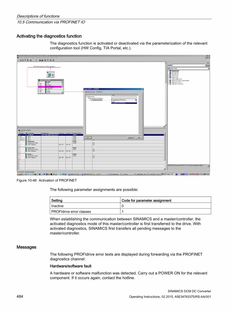
Descriptions of functions 10.5 Communication via PROFINET IO
SINAMICS DCM DC Converter 484 Operating Instructions, 02.2015, A5E34763375/RS-AA/001
Activating the diagnostics function The diagnostics function is activated or deactivated via the parameterization of the relevant configuration tool (HW Config, TIA Portal, etc.).
Figure 10-46 Activation of PROFINET
The following parameter assignments are possible: Setting Code for parameter assignment Inactive 0 PROFIdrive error classes 1
When establishing the communication between SINAMICS and a master/controller, the activated diagnostics mode of this master/controller is first transferred to the drive. With activated diagnostics, SINAMICS first transfers all pending messages to the master/controller.
Messages The following PROFIdrive error texts are displayed during forwarding via the PROFINET diagnostics channel:
Hardware/software fault
A hardware or software malfunction was detected. Carry out a POWER ON for the relevant component. If it occurs again, contact the hotline.
Descriptions of functions 10.5 Communication via PROFINET IO
SINAMICS DCM DC Converter Operating Instructions, 02.2015, A5E34763375/RS-AA/001 485
Line supply fault
A line supply fault has occurred (phase failure, voltage level, etc.). Check the line supply and fuses. Check the supply voltage. Check the wiring.
Supply voltage fault
An electronic power supply fault (48 V, 24 V, 5 V, etc.) was detected. Check the wiring. Check the voltage level.
Power electronics faulted
An impermissible operating state of the power electronics was detected (overcurrent, overtemperature, etc.). Check compliance with the permissible load cycles. Check the ambient temperatures (fan).
Overtemperature of an electronic component
The temperature in the component has exceeded the highest permissible limit. Check the ambient temperature / control cabinet ventilation.
Ground fault / inter-phase short-circuit detected
A ground fault / inter-phase short-circuit was detected in the power cables or in the motor windings. Check the power cables (connection). Check the motor.
Motor overload
The motor was operated outside the permissible limits (temperature, current, torque, etc.). Check the load cycles and set limits. Check the ambient temperature / motor cooling.
Communication to the higher-level controller faulted
The communication to the higher-level controller (internal coupling, PROFIBUS, PROFINET, etc.) is faulted or interrupted. Check the state of the higher-level controller. Check the communication connection/wiring. Check the bus configuration/cycles.
Actual position/speed value incorrect or not available
An illegal signal state was detected while evaluating the encoder signals (track signals, zero marks, absolute values, etc.). Check the encoder / state of the encoder signals. Observe the maximum permissible frequencies.
Internal (DRIVE-CLiQ) communication faulted
The internal communication between the SINAMICS components is faulted or interrupted. Check the DRIVE-CLiQ wiring. Ensure an EMC-compliant installation. Observe the maximum permissible quantity structures / cycles.
External measured value / signal state outside of the permissible range
A measured value / signal state read-in via the input area (digital/analog/temperature) has assumed an impermissible value/state. Identify and check the relevant signal. Check the set thresholds.
Application / technological function disrupted
The application / technological function has exceeded a (set) limit (position, velocity, torque, etc.). Identify and check the relevant limit. Check the setpoint specification of the higher-level controller.
Descriptions of functions 10.5 Communication via PROFINET IO
SINAMICS DCM DC Converter 486 Operating Instructions, 02.2015, A5E34763375/RS-AA/001
Error in the parameterization/configuration/commissioning procedure
An error was identified in the parameterization or in a commissioning procedure, or the parameterization does not match the actual device configuration. Determine the exact cause of the error with the commissioning tool, adapt the parameterization or device configuration.
General drive fault
Group fault, determine the exact cause of the fault with the commissioning tool.
Auxiliary unit faulted
The monitoring of an auxiliary unit (incoming transformer, cooling unit, etc.) has detected an illegal state. Determine the exact cause of the error and check the relevant device.
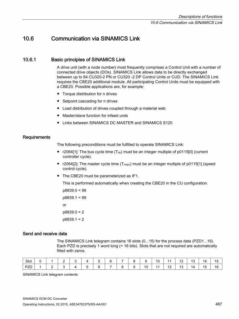
Descriptions of functions 10.6 Communication via SINAMICS Link
SINAMICS DCM DC Converter Operating Instructions, 02.2015, A5E34763375/RS-AA/001 487
10.6 Communication via SINAMICS Link
10.6.1 Basic principles of SINAMICS Link A drive unit (with a node number) most frequently comprises a Control Unit with a number of connected drive objects (DOs). SINAMICS Link allows data to be directly exchanged between up to 64 CU320-2 PN or CU320 -2 DP Control Units or CUD. The SINAMICS Link requires the CBE20 additional module. All participating Control Units must be equipped with a CBE20. Possible applications are, for example:
Torque distribution for n drives
Setpoint cascading for n drives
Load distribution of drives coupled through a material web
Master/slave function for infeed units
Links between SINAMICS DC MASTER and SINAMICS S120
Requirements The following preconditions must be fulfilled to operate SINAMICS Link:
r2064[1]: The bus cycle time (Tdp) must be an integer multiple of p0115[0] (current controller cycle).
r2064[2]: The master cycle time (Tmapc) must be an integer multiple of p0115[1] (speed control cycle).
The CBE20 must be parameterized as IF1.
This is performed automatically when creating the CBE20 in the CU configuration.
p8839.0 = 99
p8839.1 = 99
or
p8839.0 = 2
p8839.1 = 2
Send and receive data The SINAMICS Link telegram contains 16 slots (0...15) for the process data (PZD1...16). Each PZD is precisely 1 word long (= 16 bits). Slots that are not required are automatically filled with zeros.
Slot 0 1 2 3 4 5 6 7 8 9 10 11 12 13 14 15 PZD 1 2 3 4 5 6 7 8 9 10 11 12 13 14 15 16 SINAMICS Link telegram contents
Descriptions of functions 10.6 Communication via SINAMICS Link
SINAMICS DCM DC Converter 488 Operating Instructions, 02.2015, A5E34763375/RS-AA/001
Each transfer cycle, every SINAMICS Link node can send one telegram with 16 PZD. Each node receives all of the telegrams that are sent. For each transfer cycle, a node can select and process up to 16 PZD from all telegrams that have been received. Single words and double words can be sent and received. You must write double words in two consecutive PZD.
Limitations:
In a telegram, a PZD may only be sent and received once. If a PZD occurs more than once in a telegram, then Alarm A50002 or A50003 is output.
It is not possible to read in your own send data. Alarm A50006 is then output.
The maximum number of PZD that can be received and sent also depends on the drive object. The number of PZD that can be evaluated corresponds to communication according to PROFIdrive; however, for SINAMICS Link, it is limited to a maximum of 16 PZD.
Transmission time With SINAMICS Link, a transmission time of 1000 µs is possible (with a max. controller cycle of 500 µs; synchronous bus cycle, 500 µs).
Bus cycle and number of nodes You can operate the bus cycle of the SINAMICS Link with the current controller cycle, either synchronized or non-synchronized.
Synchronized operation is set with p8812[0] = 1. A maximum of 16 nodes can then communicate with one another via SINAMICS Link. To do so, set the maximum number of nodes with p8811 = 16.
In the non-synchronized mode, the bus cycle of the SINAMICS Link can be set with p8812[1] to between 1000 µs and 2000 µs. Then, via p8811, a maximum of 64 SINAMICS Link nodes can communicate with one other.
After changing over parameters p8811 and p8812, carry out a POWER ON to accept the settings.
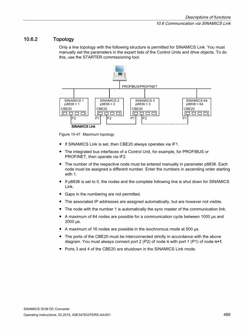
Descriptions of functions 10.6 Communication via SINAMICS Link
SINAMICS DCM DC Converter Operating Instructions, 02.2015, A5E34763375/RS-AA/001 489
10.6.2 Topology Only a line topology with the following structure is permitted for SINAMICS Link. You must manually set the parameters in the expert lists of the Control Units and drive objects. To do this, use the STARTER commissioning tool.
Figure 10-47 Maximum topology
If SINAMICS Link is set, then CBE20 always operates via IF1.
The integrated bus interfaces of a Control Unit, for example, for PROFIBUS or PROFINET, then operate via IF2.
The number of the respective node must be entered manually in parameter p8836. Each node must be assigned a different number. Enter the numbers in ascending order starting with 1.
If p8836 is set to 0, the nodes and the complete following line is shut down for SINAMICS Link.
Gaps in the numbering are not permitted.
The associated IP addresses are assigned automatically, but are however not visible.
The node with the number 1 is automatically the sync master of the communication link.
A maximum of 64 nodes are possible for a communication cycle between 1000 µs and 2000 µs.
A maximum of 16 nodes are possible in the isochronous mode at 500 µs.
The ports of the CBE20 must be interconnected strictly in accordance with the above diagram. You must always connect port 2 (P2) of node n with port 1 (P1) of node n+1.
Ports 3 and 4 of the CBE20 are shutdown in the SINAMICS Link mode.
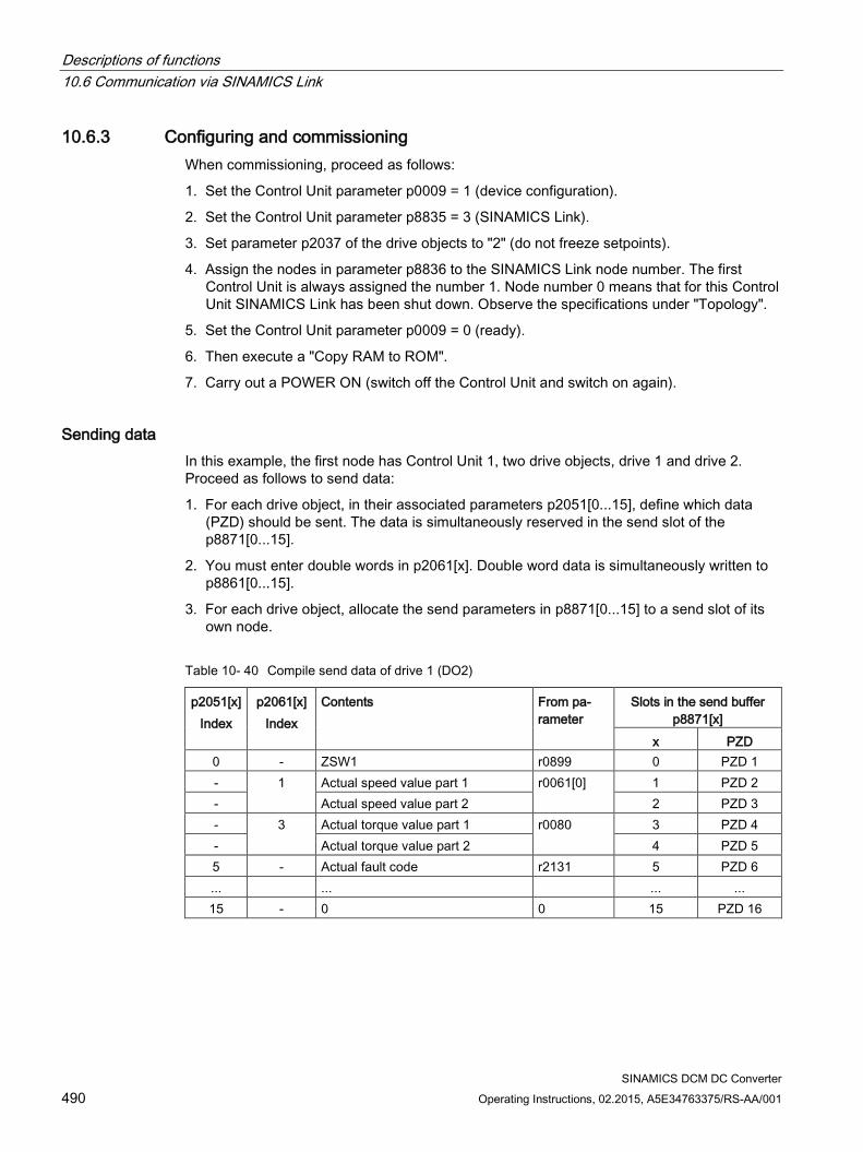
Descriptions of functions 10.6 Communication via SINAMICS Link
SINAMICS DCM DC Converter 490 Operating Instructions, 02.2015, A5E34763375/RS-AA/001
10.6.3 Configuring and commissioning When commissioning, proceed as follows:
1. Set the Control Unit parameter p0009 = 1 (device configuration).
2. Set the Control Unit parameter p8835 = 3 (SINAMICS Link).
3. Set parameter p2037 of the drive objects to "2" (do not freeze setpoints).
4. Assign the nodes in parameter p8836 to the SINAMICS Link node number. The first Control Unit is always assigned the number 1. Node number 0 means that for this Control Unit SINAMICS Link has been shut down. Observe the specifications under "Topology".
5. Set the Control Unit parameter p0009 = 0 (ready).
6. Then execute a "Copy RAM to ROM".
7. Carry out a POWER ON (switch off the Control Unit and switch on again).
Sending data In this example, the first node has Control Unit 1, two drive objects, drive 1 and drive 2. Proceed as follows to send data:
1. For each drive object, in their associated parameters p2051[0...15], define which data (PZD) should be sent. The data is simultaneously reserved in the send slot of the p8871[0...15].
2. You must enter double words in p2061[x]. Double word data is simultaneously written to p8861[0...15].
3. For each drive object, allocate the send parameters in p8871[0...15] to a send slot of its own node.
Table 10- 40 Compile send data of drive 1 (DO2)
p2051[x] Index
p2061[x] Index
Contents From pa-rameter
Slots in the send buffer p8871[x]
x PZD 0 - ZSW1 r0899 0 PZD 1 - 1 Actual speed value part 1 r0061[0] 1 PZD 2 - Actual speed value part 2 2 PZD 3 - 3 Actual torque value part 1 r0080 3 PZD 4 - Actual torque value part 2 4 PZD 5 5 - Actual fault code r2131 5 PZD 6 ... ... ... ... 15 - 0 0 15 PZD 16
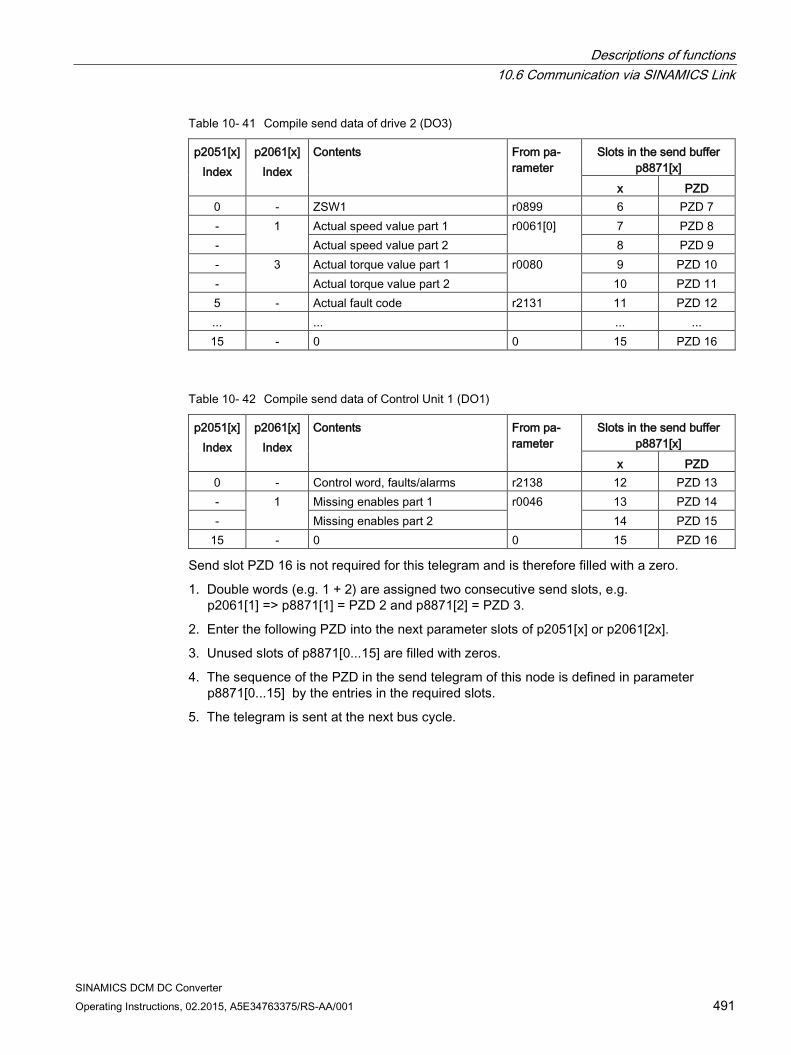
Descriptions of functions 10.6 Communication via SINAMICS Link
SINAMICS DCM DC Converter Operating Instructions, 02.2015, A5E34763375/RS-AA/001 491
Table 10- 41 Compile send data of drive 2 (DO3)
p2051[x] Index
p2061[x] Index
Contents From pa-rameter
Slots in the send buffer p8871[x]
x PZD 0 - ZSW1 r0899 6 PZD 7 - 1 Actual speed value part 1 r0061[0] 7 PZD 8 - Actual speed value part 2 8 PZD 9 - 3 Actual torque value part 1 r0080 9 PZD 10 - Actual torque value part 2 10 PZD 11 5 - Actual fault code r2131 11 PZD 12 ... ... ... ... 15 - 0 0 15 PZD 16
Table 10- 42 Compile send data of Control Unit 1 (DO1)
p2051[x] Index
p2061[x] Index
Contents From pa-rameter
Slots in the send buffer p8871[x]
x PZD 0 - Control word, faults/alarms r2138 12 PZD 13 - 1 Missing enables part 1 r0046 13 PZD 14 - Missing enables part 2 14 PZD 15
15 - 0 0 15 PZD 16
Send slot PZD 16 is not required for this telegram and is therefore filled with a zero.
1. Double words (e.g. 1 + 2) are assigned two consecutive send slots, e.g. p2061[1] => p8871[1] = PZD 2 and p8871[2] = PZD 3.
2. Enter the following PZD into the next parameter slots of p2051[x] or p2061[2x].
3. Unused slots of p8871[0...15] are filled with zeros.
4. The sequence of the PZD in the send telegram of this node is defined in parameter p8871[0...15] by the entries in the required slots.
5. The telegram is sent at the next bus cycle.
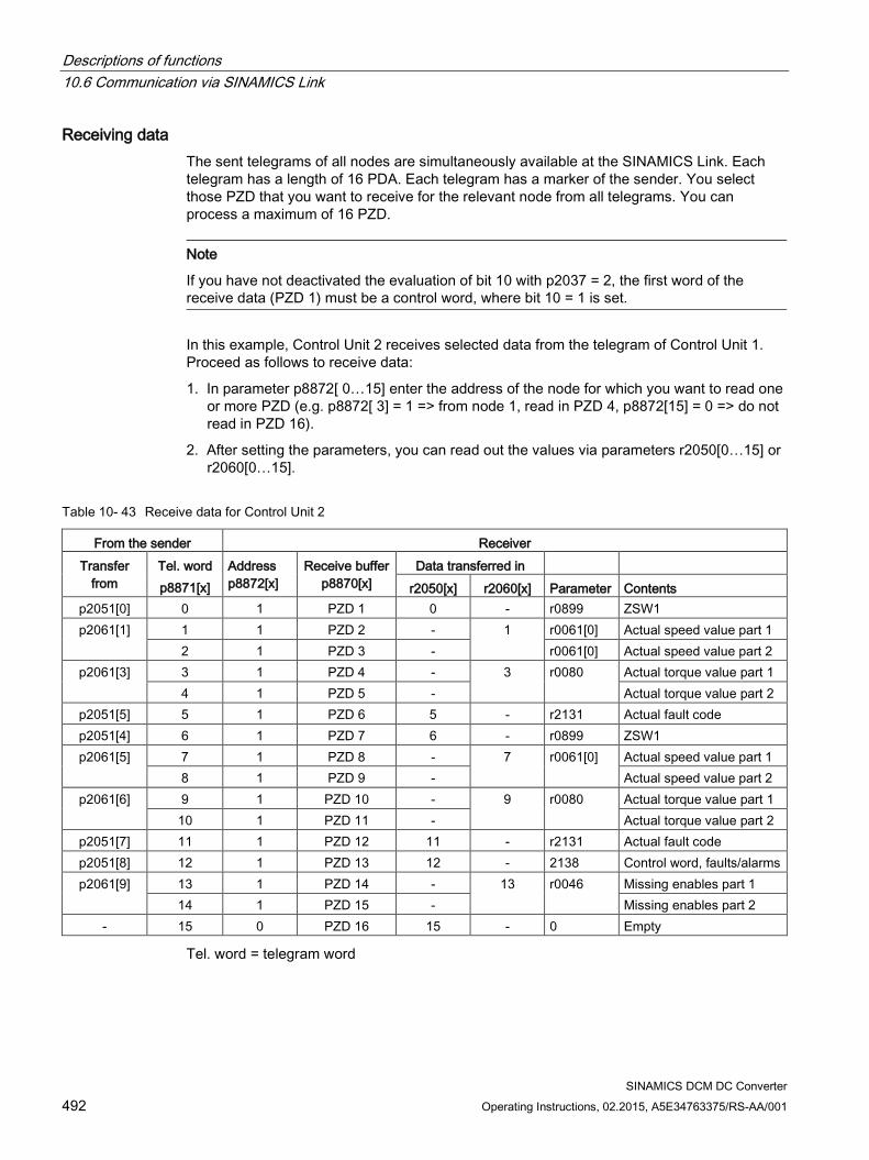
Descriptions of functions 10.6 Communication via SINAMICS Link
SINAMICS DCM DC Converter 492 Operating Instructions, 02.2015, A5E34763375/RS-AA/001
Receiving data The sent telegrams of all nodes are simultaneously available at the SINAMICS Link. Each telegram has a length of 16 PDA. Each telegram has a marker of the sender. You select those PZD that you want to receive for the relevant node from all telegrams. You can process a maximum of 16 PZD.
Note
If you have not deactivated the evaluation of bit 10 with p2037 = 2, the first word of the receive data (PZD 1) must be a control word, where bit 10 = 1 is set.
In this example, Control Unit 2 receives selected data from the telegram of Control Unit 1. Proceed as follows to receive data:
1. In parameter p8872[ 0…15] enter the address of the node for which you want to read one or more PZD (e.g. p8872[ 3] = 1 => from node 1, read in PZD 4, p8872[15] = 0 => do not read in PZD 16).
2. After setting the parameters, you can read out the values via parameters r2050[0…15] or r2060[0…15].
Table 10- 43 Receive data for Control Unit 2
From the sender Receiver Transfer
from Tel. word p8871[x]
Address p8872[x]
Receive buffer p8870[x]
Data transferred in r2050[x] r2060[x] Parameter Contents
p2051[0] 0 1 PZD 1 0 - r0899 ZSW1 p2061[1] 1 1 PZD 2 - 1 r0061[0] Actual speed value part 1
2 1 PZD 3 - r0061[0] Actual speed value part 2 p2061[3] 3 1 PZD 4 - 3
r0080 Actual torque value part 1
4 1 PZD 5 - Actual torque value part 2 p2051[5] 5 1 PZD 6 5 - r2131 Actual fault code p2051[4] 6 1 PZD 7 6 - r0899 ZSW1 p2061[5] 7 1 PZD 8 - 7 r0061[0] Actual speed value part 1
8 1 PZD 9 - Actual speed value part 2 p2061[6] 9 1 PZD 10 - 9 r0080 Actual torque value part 1
10 1 PZD 11 - Actual torque value part 2 p2051[7] 11 1 PZD 12 11 - r2131 Actual fault code p2051[8] 12 1 PZD 13 12 - 2138 Control word, faults/alarms p2061[9] 13 1 PZD 14 - 13 r0046 Missing enables part 1
14 1 PZD 15 - Missing enables part 2 - 15 0 PZD 16 15 - 0 Empty
Tel. word = telegram word
Descriptions of functions 10.6 Communication via SINAMICS Link
SINAMICS DCM DC Converter Operating Instructions, 02.2015, A5E34763375/RS-AA/001 493
Note
For double words, two PZD must be read in succession. Read a 32-bit setpoint that is at PZD 2+PZD 3 of the telegram from node 2, and map this to PZD 2+PZD 3 of node 1: p8872[1] = 2, p8870[1] = 2, p8872[2] = 2, p8870[2] = 3
Activation To activate SINAMICS Link connections, perform a POWER ON for all nodes. The assignments of p2051[x]/2061[2x] and the links of the read parameters r2050[x]/2060[2x] can be changed without a POWER ON.
10.6.4 Example
Task Configure the speed control of a SINAMICS DCM on a CU320-2 to increase the computational performance when using SINAMICS Link and DCC.
Send data from SINAMICS DCM to CU320-2:
– r0898 CO/BO: Control word SINAMICS DCM (1 PZD), in the example PZD 1
– r0899 CO/BO: Status word SINAMICS DCM (1 PZD), in the example PZD 2
– r52211 CO: Fixed setpoint output to AOP30 (1 PZD), in the example PZD3
– r52013 CO: Analog input, main actual value (1 PZD), in the example, PZD4
Send data from CU320-2 to SINAMICS DCM:
– r21530 CO: Output, PI controller (1 PZD), in the example, PZD 1
Procedure 1. For all nodes, set the SINAMICS Link mode: DO1 p8835 = 3
2. Assign node numbers for the two devices:
– SINAMICS DCM: DO1 p8836 = 1
– CU320-2: DO1 p8836 = 2
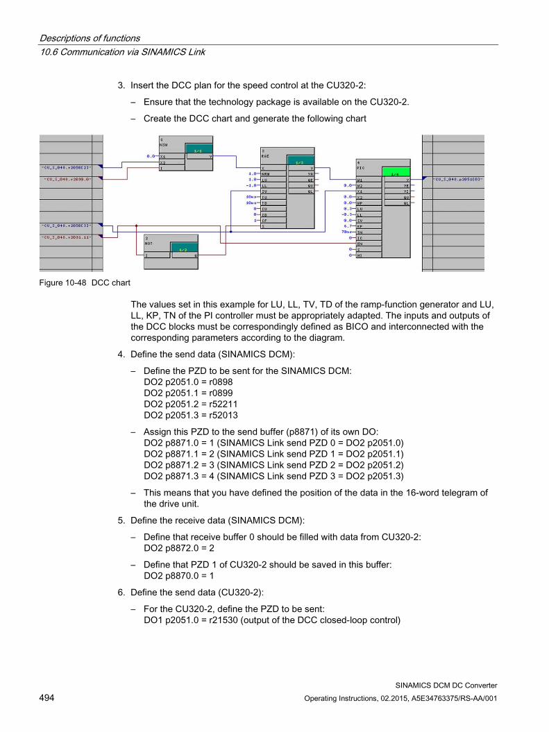
Descriptions of functions 10.6 Communication via SINAMICS Link
SINAMICS DCM DC Converter 494 Operating Instructions, 02.2015, A5E34763375/RS-AA/001
3. Insert the DCC plan for the speed control at the CU320-2:
– Ensure that the technology package is available on the CU320-2.
– Create the DCC chart and generate the following chart
Figure 10-48 DCC chart
The values set in this example for LU, LL, TV, TD of the ramp-function generator and LU, LL, KP, TN of the PI controller must be appropriately adapted. The inputs and outputs of the DCC blocks must be correspondingly defined as BICO and interconnected with the corresponding parameters according to the diagram.
4. Define the send data (SINAMICS DCM):
– Define the PZD to be sent for the SINAMICS DCM: DO2 p2051.0 = r0898 DO2 p2051.1 = r0899 DO2 p2051.2 = r52211 DO2 p2051.3 = r52013
– Assign this PZD to the send buffer (p8871) of its own DO: DO2 p8871.0 = 1 (SINAMICS Link send PZD 0 = DO2 p2051.0) DO2 p8871.1 = 2 (SINAMICS Link send PZD 1 = DO2 p2051.1) DO2 p8871.2 = 3 (SINAMICS Link send PZD 2 = DO2 p2051.2) DO2 p8871.3 = 4 (SINAMICS Link send PZD 3 = DO2 p2051.3)
– This means that you have defined the position of the data in the 16-word telegram of the drive unit.
5. Define the receive data (SINAMICS DCM):
– Define that receive buffer 0 should be filled with data from CU320-2: DO2 p8872.0 = 2
– Define that PZD 1 of CU320-2 should be saved in this buffer: DO2 p8870.0 = 1
6. Define the send data (CU320-2):
– For the CU320-2, define the PZD to be sent: DO1 p2051.0 = r21530 (output of the DCC closed-loop control)
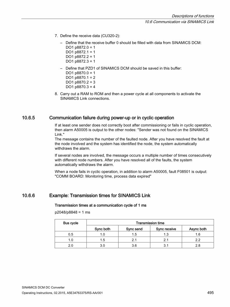
Descriptions of functions 10.6 Communication via SINAMICS Link
SINAMICS DCM DC Converter Operating Instructions, 02.2015, A5E34763375/RS-AA/001 495
7. Define the receive data (CU320-2):
– Define that the receive buffer 0 should be filled with data from SINAMICS DCM: DO1 p8872.0 = 1 DO1 p8872.1 = 1 DO1 p8872.2 = 1 DO1 p8872.3 = 1
– Define that PZD1 of SINAMICS DCM should be saved in this buffer: DO1 p8870.0 = 1 DO1 p8870.1 = 2 DO1 p8870.2 = 3 DO1 p8870.3 = 4
8. Carry out a RAM to ROM and then a power cycle at all components to activate the SINAMICS Link connections.
10.6.5 Communication failure during power-up or in cyclic operation If at least one sender does not correctly boot after commissioning or fails in cyclic operation, then alarm A50005 is output to the other nodes: "Sender was not found on the SINAMICS Link." The message contains the number of the faulted node. After you have resolved the fault at the node involved and the system has identified the node, the system automatically withdraws the alarm.
If several nodes are involved, the message occurs a multiple number of times consecutively with different node numbers. After you have resolved all of the faults, the system automatically withdraws the alarm.
When a node fails in cyclic operation, in addition to alarm A50005, fault F08501 is output: "COMM BOARD: Monitoring time, process data expired"
10.6.6 Example: Transmission times for SINAMICS Link
Transmission times at a communication cycle of 1 ms
p2048/p8848 = 1 ms
Bus cycle Transmission time Sync both Sync send Sync receive Async both
0.5 1.0 1.5 1.3 1.6 1.0 1.5 2.1 2.1 2.2 2.0 3.0 3.6 3.1 2.8
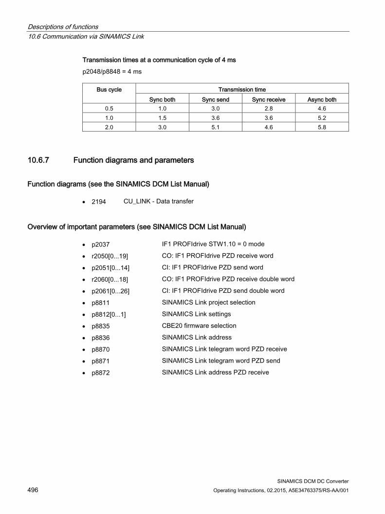
Descriptions of functions 10.6 Communication via SINAMICS Link
SINAMICS DCM DC Converter 496 Operating Instructions, 02.2015, A5E34763375/RS-AA/001
Transmission times at a communication cycle of 4 ms
p2048/p8848 = 4 ms
Bus cycle Transmission time Sync both Sync send Sync receive Async both
0.5 1.0 3.0 2.8 4.6 1.0 1.5 3.6 3.6 5.2 2.0 3.0 5.1 4.6 5.8
10.6.7 Function diagrams and parameters
Function diagrams (see the SINAMICS DCM List Manual) • 2194 CU_LINK - Data transfer
Overview of important parameters (see SINAMICS DCM List Manual) • p2037 IF1 PROFIdrive STW1.10 = 0 mode
• r2050[0...19] CO: IF1 PROFIdrive PZD receive word
• p2051[0...14] CI: IF1 PROFIdrive PZD send word
• r2060[0...18] CO: IF1 PROFIdrive PZD receive double word
• p2061[0...26] CI: IF1 PROFIdrive PZD send double word
• p8811 SINAMICS Link project selection
• p8812[0...1] SINAMICS Link settings
• p8835 CBE20 firmware selection
• p8836 SINAMICS Link address
• p8870 SINAMICS Link telegram word PZD receive
• p8871 SINAMICS Link telegram word PZD send
• p8872 SINAMICS Link address PZD receive
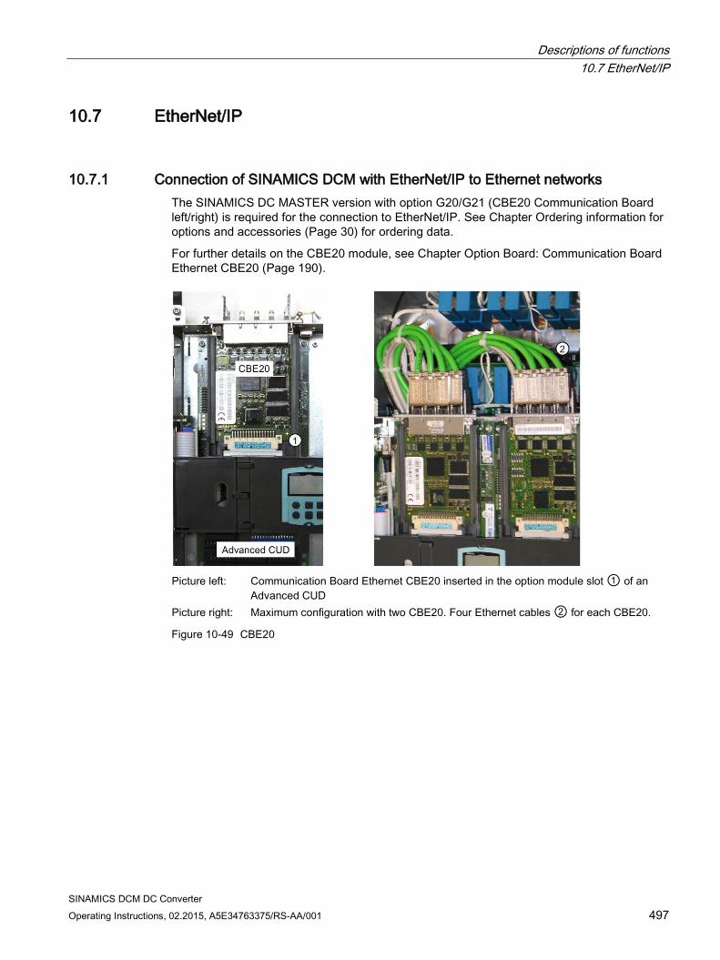
Descriptions of functions 10.7 EtherNet/IP
SINAMICS DCM DC Converter Operating Instructions, 02.2015, A5E34763375/RS-AA/001 497
10.7 EtherNet/IP
10.7.1 Connection of SINAMICS DCM with EtherNet/IP to Ethernet networks The SINAMICS DC MASTER version with option G20/G21 (CBE20 Communication Board left/right) is required for the connection to EtherNet/IP. See Chapter Ordering information for options and accessories (Page 30) for ordering data.
For further details on the CBE20 module, see Chapter Option Board: Communication Board Ethernet CBE20 (Page 190).
Picture left: Communication Board Ethernet CBE20 inserted in the option module slot ① of an
Advanced CUD Picture right: Maximum configuration with two CBE20. Four Ethernet cables ② for each CBE20.
Figure 10-49 CBE20
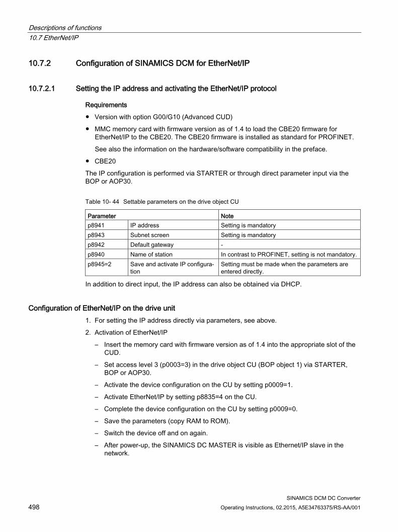
Descriptions of functions 10.7 EtherNet/IP
SINAMICS DCM DC Converter 498 Operating Instructions, 02.2015, A5E34763375/RS-AA/001
10.7.2 Configuration of SINAMICS DCM for EtherNet/IP
10.7.2.1 Setting the IP address and activating the EtherNet/IP protocol
Requirements
Version with option G00/G10 (Advanced CUD)
MMC memory card with firmware version as of 1.4 to load the CBE20 firmware for EtherNet/IP to the CBE20. The CBE20 firmware is installed as standard for PROFINET.
See also the information on the hardware/software compatibility in the preface.
CBE20
The IP configuration is performed via STARTER or through direct parameter input via the BOP or AOP30.
Table 10- 44 Settable parameters on the drive object CU
Parameter Note p8941 IP address Setting is mandatory p8943 Subnet screen Setting is mandatory p8942 Default gateway - p8940 Name of station In contrast to PROFINET, setting is not mandatory. p8945=2 Save and activate IP configura-
tion Setting must be made when the parameters are entered directly.
In addition to direct input, the IP address can also be obtained via DHCP.
Configuration of EtherNet/IP on the drive unit 1. For setting the IP address directly via parameters, see above.
2. Activation of EtherNet/IP
– Insert the memory card with firmware version as of 1.4 into the appropriate slot of the CUD.
– Set access level 3 (p0003=3) in the drive object CU (BOP object 1) via STARTER, BOP or AOP30.
– Activate the device configuration on the CU by setting p0009=1.
– Activate EtherNet/IP by setting p8835=4 on the CU.
– Complete the device configuration on the CU by setting p0009=0.
– Save the parameters (copy RAM to ROM).
– Switch the device off and on again.
– After power-up, the SINAMICS DC MASTER is visible as Ethernet/IP slave in the network.
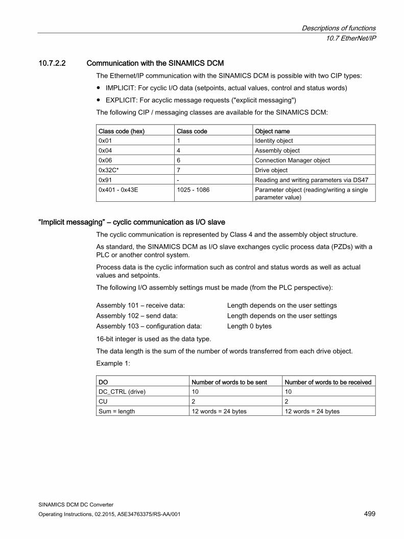
Descriptions of functions 10.7 EtherNet/IP
SINAMICS DCM DC Converter Operating Instructions, 02.2015, A5E34763375/RS-AA/001 499
10.7.2.2 Communication with the SINAMICS DCM The Ethernet/IP communication with the SINAMICS DCM is possible with two CIP types:
IMPLICIT: For cyclic I/O data (setpoints, actual values, control and status words)
EXPLICIT: For acyclic message requests ("explicit messaging")
The following CIP / messaging classes are available for the SINAMICS DCM: Class code (hex) Class code Object name 0x01 1 Identity object 0x04 4 Assembly object 0x06 6 Connection Manager object 0x32C* 7 Drive object 0x91 - Reading and writing parameters via DS47 0x401 - 0x43E 1025 - 1086 Parameter object (reading/writing a single
parameter value)
“Implicit messaging” – cyclic communication as I/O slave The cyclic communication is represented by Class 4 and the assembly object structure.
As standard, the SINAMICS DCM as I/O slave exchanges cyclic process data (PZDs) with a PLC or another control system.
Process data is the cyclic information such as control and status words as well as actual values and setpoints.
The following I/O assembly settings must be made (from the PLC perspective): Assembly 101 – receive data: Length depends on the user settings Assembly 102 – send data: Length depends on the user settings Assembly 103 – configuration data: Length 0 bytes
16-bit integer is used as the data type.
The data length is the sum of the number of words transferred from each drive object.
Example 1: DO Number of words to be sent Number of words to be received DC_CTRL (drive) 10 10 CU 2 2 Sum = length 12 words = 24 bytes 12 words = 24 bytes

Descriptions of functions 10.7 EtherNet/IP
SINAMICS DCM DC Converter 500 Operating Instructions, 02.2015, A5E34763375/RS-AA/001
Example 2: DO Number of words to be sent Number of words to be received DC_CTRL (drive) 10 5 CU 0 0 TM31 1 1 Sum = length 11 words = 22 bytes 6 words = 12 bytes
In contrast to PROFIBUS and PROFINET communication, only connected PZDs in the drive can be used in the assembly.
In example 1, all ten words of the drive and the two words of the CU must have an active BICO connection. This means that all data received from the PLC must be connected to a parameter, which correspondingly also applies to the data sent to the PLC. All words must therefore be supplied with status or actual values.
To avoid "dummy" connections, all the required BICO connections and the last word can be parameterized.
With reference to example 1, only six or the ten words defined for sending/receiving, are required the operation. The remaining four are in reserve. Consequently, the first six words are assigned to their respective parameters and in addition, the last word (PZD10) is assigned to a dummy value, i.e. a parameter that is not used for the drive application.
The number of PZDs must be mapped to the assembly. When the assignment of the PZDs is complete, parameter p8842=1 must be set on the CU.
If the change is to be permanent, copy RAM to ROM.
The sequence of the drive objects depends on the communication settings in the drive which can be accessed via the "communication item" of the associated drive in the project tree of the STARTER software.
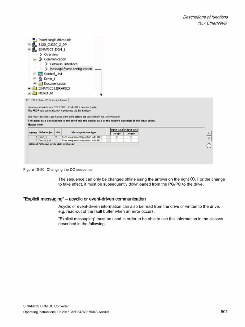
Descriptions of functions 10.7 EtherNet/IP
SINAMICS DCM DC Converter Operating Instructions, 02.2015, A5E34763375/RS-AA/001 501
Figure 10-50 Changing the DO sequence
The sequence can only be changed offline using the arrows on the right ①. For the change to take effect, it must be subsequently downloaded from the PG/PC to the drive.
"Explicit messaging" – acyclic or event-driven communication Acyclic or event-driven information can also be read from the drive or written to the drive, e.g. read-out of the fault buffer when an error occurs.
"Explicit messaging" must be used in order to be able to use this information in the classes described in the following.
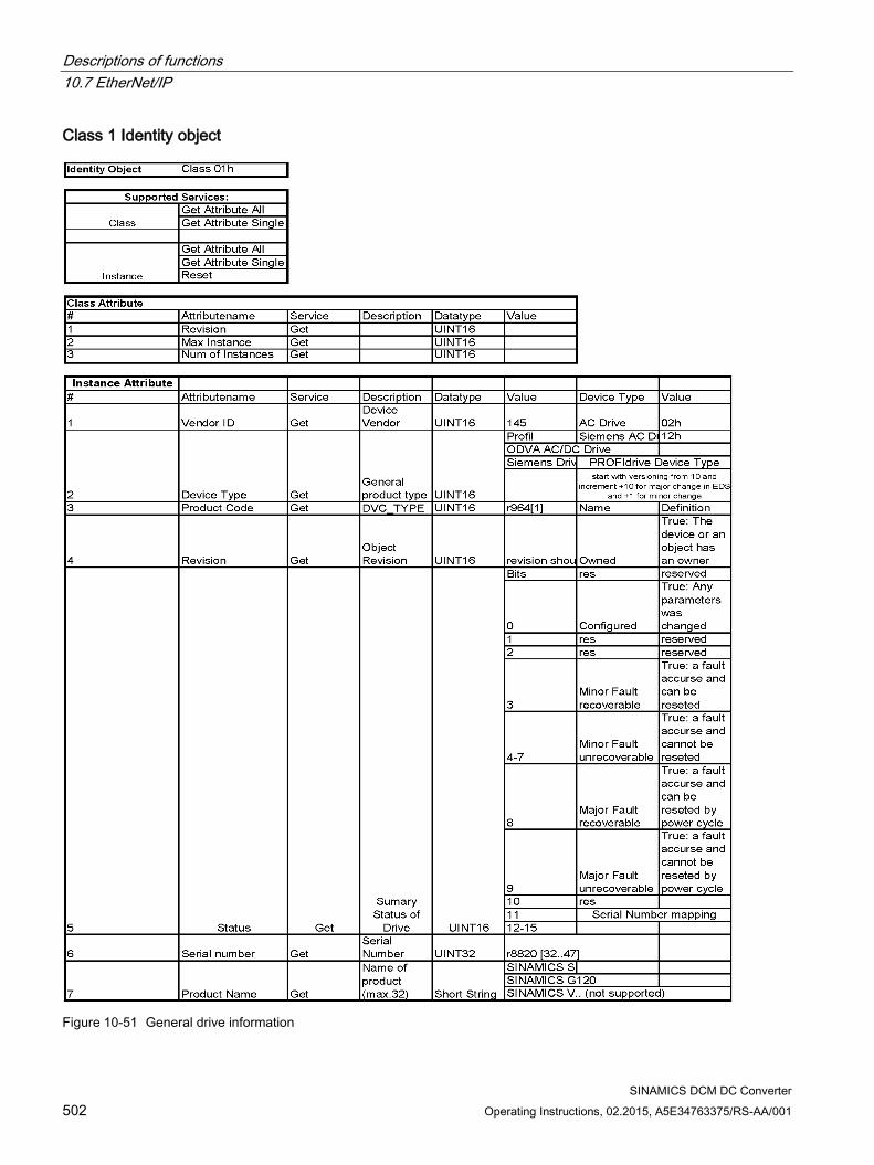
Descriptions of functions 10.7 EtherNet/IP
SINAMICS DCM DC Converter 502 Operating Instructions, 02.2015, A5E34763375/RS-AA/001
Class 1 Identity object
Figure 10-51 General drive information
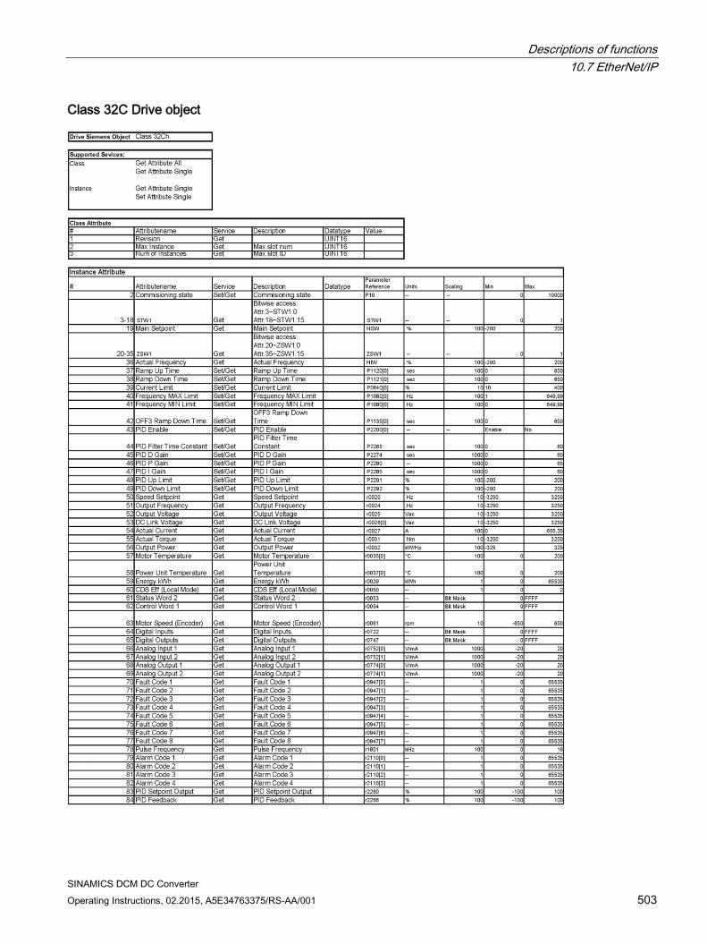
Descriptions of functions 10.7 EtherNet/IP
SINAMICS DCM DC Converter Operating Instructions, 02.2015, A5E34763375/RS-AA/001 503
Class 32C Drive object

Descriptions of functions 10.7 EtherNet/IP
SINAMICS DCM DC Converter 504 Operating Instructions, 02.2015, A5E34763375/RS-AA/001
As shown in the table above, certain drive parameters can be read and written. Note that this function was originally created for SINAMICS AC drives. It can therefore only access parameters that are available on the SINAMICS DCM.
The function described in Chapter Class 0x401 - 0x43E Writing and reading of parameters (Page 504) is preferred instead of Class 0x32C for reading and writing parameter data.
Class 0x401 - 0x43E Writing and reading of parameters With this class, it is possible to read and write an arbitrary parameter of the respective drive object (DO). Class value selects the DO. 0x4xx xx = object number Instance represents the parameter number,
e.g. p50100 ⇒ instance = 50100 Attribute represents the index to be read or written,
e.g. index 0 ⇒ attribute = 0
The appropriate object number must be taken from the "Message frame configuration" shown in Figure 10-50 Changing the DO sequence (Page 501).
Generally, the following applies:
Object number 1 = CU of the DCM ⇒ Class 401
Object number 2 = drive unit of the DCM ⇒ Class 402
The data type of the parameter is specified by the drive and can be found in the SINAMICS DCM List Manual (Chapter "List of parameters").
Note
All bytes defined by the data type must be assigned, even if they are not used.
Examples
INT/UINT 16 must be assigned to 4 bytes.
Floating point 32, INT/UINT 32 must be assigned to 8 bytes.
Class 0x91 Writing and reading of parameters with DS47 Through the use of data set DS47, it is possible to read and write more than one parameter value or parameter index at one time or in a data block.
For the structure and function, see Chapter Acyclic communication (Page 415).
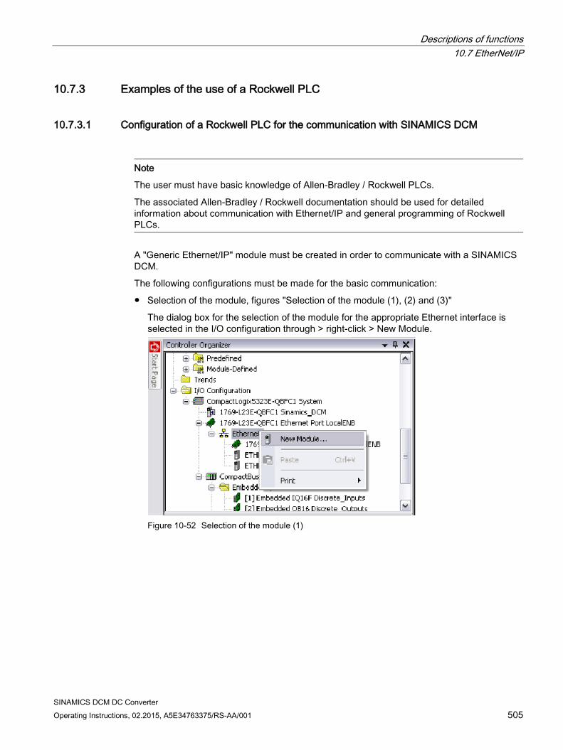
Descriptions of functions 10.7 EtherNet/IP
SINAMICS DCM DC Converter Operating Instructions, 02.2015, A5E34763375/RS-AA/001 505
10.7.3 Examples of the use of a Rockwell PLC
10.7.3.1 Configuration of a Rockwell PLC for the communication with SINAMICS DCM
Note
The user must have basic knowledge of Allen-Bradley / Rockwell PLCs.
The associated Allen-Bradley / Rockwell documentation should be used for detailed information about communication with Ethernet/IP and general programming of Rockwell PLCs.
A "Generic Ethernet/IP" module must be created in order to communicate with a SINAMICS DCM.
The following configurations must be made for the basic communication:
Selection of the module, figures "Selection of the module (1), (2) and (3)"
The dialog box for the selection of the module for the appropriate Ethernet interface is selected in the I/O configuration through > right-click > New Module.
Figure 10-52 Selection of the module (1)
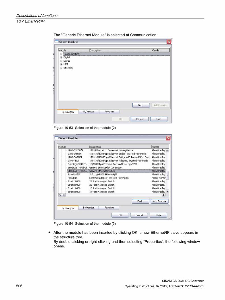
Descriptions of functions 10.7 EtherNet/IP
SINAMICS DCM DC Converter 506 Operating Instructions, 02.2015, A5E34763375/RS-AA/001
The "Generic Ethernet Module" is selected at Communication:
Figure 10-53 Selection of the module (2)
Figure 10-54 Selection of the module (3)
After the module has been inserted by clicking OK, a new Ethernet/IP slave appears in the structure tree. By double-clicking or right-clicking and then selecting “Properties”, the following window opens.
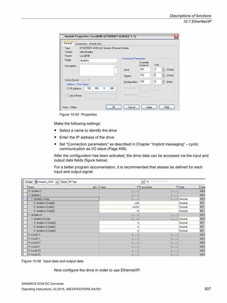
Descriptions of functions 10.7 EtherNet/IP
SINAMICS DCM DC Converter Operating Instructions, 02.2015, A5E34763375/RS-AA/001 507
Figure 10-55 Properties
Make the following settings:
Select a name to identify the drive
Enter the IP address of the drive
Set "Connection parameters" as described in Chapter “Implicit messaging” – cyclic communication as I/O slave (Page 499).
After the configuration has been activated, the drive data can be accessed via the input and output data fields (figure below).
For a better program documentation, it is recommended that aliases be defined for each input and output signal.
Figure 10-56 Input data and output data
Now configure the drive in order to use Ethernet/IP.
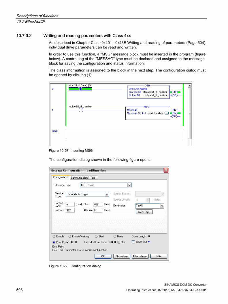
Descriptions of functions 10.7 EtherNet/IP
SINAMICS DCM DC Converter 508 Operating Instructions, 02.2015, A5E34763375/RS-AA/001
10.7.3.2 Writing and reading parameters with Class 4xx As described in Chapter Class 0x401 - 0x43E Writing and reading of parameters (Page 504), individual drive parameters can be read and written.
In order to use this function, a "MSG" message block must be inserted in the program (figure below). A control tag of the "MESSAG" type must be declared and assigned to the message block for saving the configuration and status information.
The class information is assigned to the block in the next step. The configuration dialog must be opened by clicking (1).
Figure 10-57 Inserting MSG
The configuration dialog shown in the following figure opens:
Figure 10-58 Configuration dialog
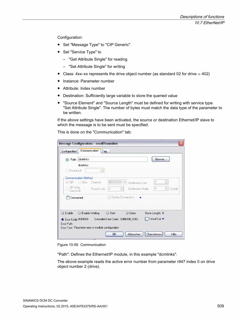
Descriptions of functions 10.7 EtherNet/IP
SINAMICS DCM DC Converter Operating Instructions, 02.2015, A5E34763375/RS-AA/001 509
Configuration:
Set "Message Type" to "CIP Generic"
Set "Service Type" to
– "Get Attribute Single" for reading
– "Set Attribute Single" for writing
Class: 4xx–xx represents the drive object number (as standard 02 for drive ⇒ 402)
Instance: Parameter number
Attribute: Index number
Destination: Sufficiently large variable to store the queried value
"Source Element" and "Source Length" must be defined for writing with service type "Set Attribute Single". The number of bytes must match the data type of the parameter to be written.
If the above settings have been activated, the source or destination Ethernet/IP slave to which the message is to be sent must be specified.
This is done on the "Communication" tab:
Figure 10-59 Communication
"Path": Defines the Ethernet/IP module, in this example "dcmlinks".
The above example reads the active error number from parameter r947 index 0 on drive object number 2 (drive).
Descriptions of functions 10.8 Serial interface with USS protocol
SINAMICS DCM DC Converter 510 Operating Instructions, 02.2015, A5E34763375/RS-AA/001
10.8 Serial interface with USS protocol
Specification Developed by Siemens, the USS® protocol is a proprietary fieldbus which was already being used in a variety of applications before PROFIBUS was established. Since the USS® protocol had not yet been replaced by PROFIBUS in some applications, it was implemented in the SINAMICS DCM.
The USS® protocol is described in the following document: USS® Protocol Specification: Order number E20125-D0001-S302-A1
Properties The USS® protocol can only be used as a fieldbus instead of PROFIBUS; USS and PROFIBUS cannot run at the same time.
The USS® protocol enables one or more SINAMICS DCMs to be connected to a master station. It is a point-to-point coupling or a bus-type coupling. A maximum of 31 nodes can be connected in the bus configuration (1 master and a maximum of 30 slaves). The bus terminator must be activated on both bus nodes at each end of the bus line.
The USS® protocol enables access to all relevant process data, diagnostic information, and parameters for the SINAMICS DCM.
The USS® protocol is purely a master-slave protocol in which a SINAMICS DCM can only ever be a slave. In this case, a SINAMICS DCM only sends a telegram to the master if it has received a telegram from it. Therefore, SINAMICS DCMs cannot use the USS® protocol to exchange data with one another directly.
Connecting Terminal X178, X178
Function diagrams The function diagrams for the fieldbus interface are relevant: See FP2410, FP2420, FP2440, FP2442, FP2450, FP2452, FP2460, FP2470, FP2472, FP2481, and FP2483.
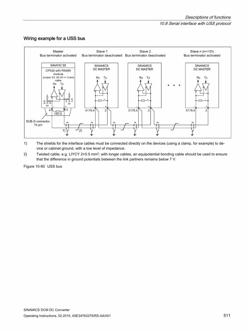
Descriptions of functions 10.8 Serial interface with USS protocol
SINAMICS DCM DC Converter Operating Instructions, 02.2015, A5E34763375/RS-AA/001 511
Wiring example for a USS bus
1) The shields for the interface cables must be connected directly on the devices (using a clamp, for example) to de-
vice or cabinet ground, with a low level of impedance. 2) Twisted cable, e.g. LIYCY 2×0.5 mm2; with longer cables, an equipotential bonding cable should be used to ensure
that the difference in ground potentials between the link partners remains below 7 V.
Figure 10-60 USS bus
Descriptions of functions 10.9 Switch on, switch off, enable
SINAMICS DCM DC Converter 512 Operating Instructions, 02.2015, A5E34763375/RS-AA/001
10.9 Switch on, switch off, enable
10.9.1 Switch on/Switch off (ON/OFF1) - control word bit 0 The "Switch on/Shutdown" (ON/OFF1) function is controlled using the "ON/OFF1 switch-on command" (= ANDing the signal from terminal X177.12 with the signal selected using p0840). The following operating modes are possible here: p50445 = 0: The "ON/OFF1 switch-on command" takes the form of ANDing the signal from
terminal X177.12 with the signal selected using p0840 (level-controlled, 0 = shutdown, 1 = switch on).
p50445 = 1: Edge triggering of "ON/OFF1 switch-on command": The switch-on command is saved when a 0 → 1 transition takes place (see function diagram 3130 in the SINAMICS DCM List Manual). The binector se-lected using p50444 must be in the log. "1" state at this point. The memory is reset when this binector enters the log. "0" state.
Sequence of events for switching on the drive:
1. Apply the "Switch on" command (e.g. using the "Switch on/Shutdown" terminal).
2. The system exits operating state o7.
3. The "Line contactor closed" relay (terminal XR1-109 and -110) picks up.
4. The field-current reduction function stops. If "Operation enable" is applied:
5. With positive brake-release time (p50087): The "Release holding or operational brake" (r53210.0 = 0) signal is output and p50087 is awaited in operating state o1.0. With negative brake-release time (p50087 negative): Procedure goes straight to step 6; brake not yet closed (r53210.0 = 1).
6. The ramp-function generator, n controller, and I controller are enabled.
7. Once a negative brake-release time (p50087) has elapsed, the "Release holding or operational brake" (r53210.0 = 0) signal is output.
Procedure for shutting down the drive:
1. Apply the "Shutdown" command (e.g. using the "Switch on/Shutdown" terminal).
2. Deceleration along the ramp-function generator ramp
3. Wait until n < nmin (p50370, p50371).
4. The "Close holding or operational brake" (r53210.0 = 1) signal is output.
5. The brake-closing time (p50088) is awaited.
6. The ramp-function generator and n controller are disabled.
7. Reduction in armature current
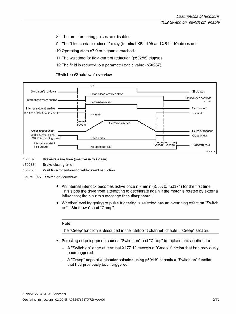
Descriptions of functions 10.9 Switch on, switch off, enable
SINAMICS DCM DC Converter Operating Instructions, 02.2015, A5E34763375/RS-AA/001 513
8. The armature firing pulses are disabled.
9. The "Line contactor closed" relay (terminal XR1-109 and XR1-110) drops out.
10.Operating state o7.0 or higher is reached.
11.The wait time for field-current reduction (p50258) elapses.
12.The field is reduced to a parameterizable value (p50257).
"Switch on/Shutdown" overview
p50087 Brake-release time (positive in this case) p50088 Brake-closing time p50258 Wait time for automatic field-current reduction
Figure 10-61 Switch on/Shutdown
An internal interlock becomes active once n < nmin (r50370, r50371) for the first time. This stops the drive from attempting to decelerate again if the motor is rotated by external influences; the n < nmin message then disappears.
Whether level triggering or pulse triggering is selected has an overriding effect on "Switch on", "Shutdown", and "Creep".
Note
The "Creep' function is described in the "Setpoint channel" chapter, "Creep" section.
Selecting edge triggering causes "Switch on" and "Creep" to replace one another, i.e.:
– A "Switch on" edge at terminal X177.12 cancels a "Creep" function that had previously been triggered.
– A "Creep" edge at a binector selected using p50440 cancels a "Switch on" function that had previously been triggered.
Descriptions of functions 10.9 Switch on, switch off, enable
SINAMICS DCM DC Converter 514 Operating Instructions, 02.2015, A5E34763375/RS-AA/001
With edge triggering, an automatic restart following a brief interruption in the electronic power supply voltage is not possible.
To ensure that "Shutdown" functions even when rewiring is carried out, current or torque lower limits are specified, or additional setpoints are supplied, certain functions are disabled automatically when "Shutdown" is applied.
– All torque limits are disabled during braking to n < nmin.
– Of the current limits, only the system current limit (p50171 and p50172), speed-dependent current limit, and current limit resulting from I2t monitoring of the power unit are enabled.
10.9.2 OFF2 (disconnection) - control word bit 1 The OFF2 signal is LOW active (log. "0" state = disconnection).
Procedure for applying disconnection:
1. The ramp-function generator, n controller, and Ia controller are disabled.
2. Reduction in armature current
3. The firing pulses are disabled.
4. "Close operational brake" is output (r53210.0 = 1, where p50080 = 2).
5. Operating state o10.0 or higher is reached.
6. The field current is maintained at a fixed point (i.e. there is no increase in the field current, even on exiting the field-weakening range).
7. The "Line contactor closed" relay (terminal XR1-109 and XR1-110) drops out.
8. The drive coasts down (or is decelerated by the operational brake).
9. The parameterizable wait time (p50258) elapses.
10.The field is reduced to a parameterizable value (p50257).
11.Once n < nmin (p50370, p50371), the "Close holding brake" signal is output (r53210.0 = 1, where p50080 = 1).
10.9.3 OFF3 (quick stop) - control word bit 2 The OFF3 signal is LOW active (log. "0" state = quick stop).
Procedure for applying "Quick stop":
1. The ramp-function generator is disabled.
2. A speed setpoint of zero is applied.
3. Deceleration along the down ramp acc. to p50296, p50297, p50298
4. Wait until n < nmin (p50370, p50371).
5. "Close operational or holding brake" (r53210.0 = 1) is output.
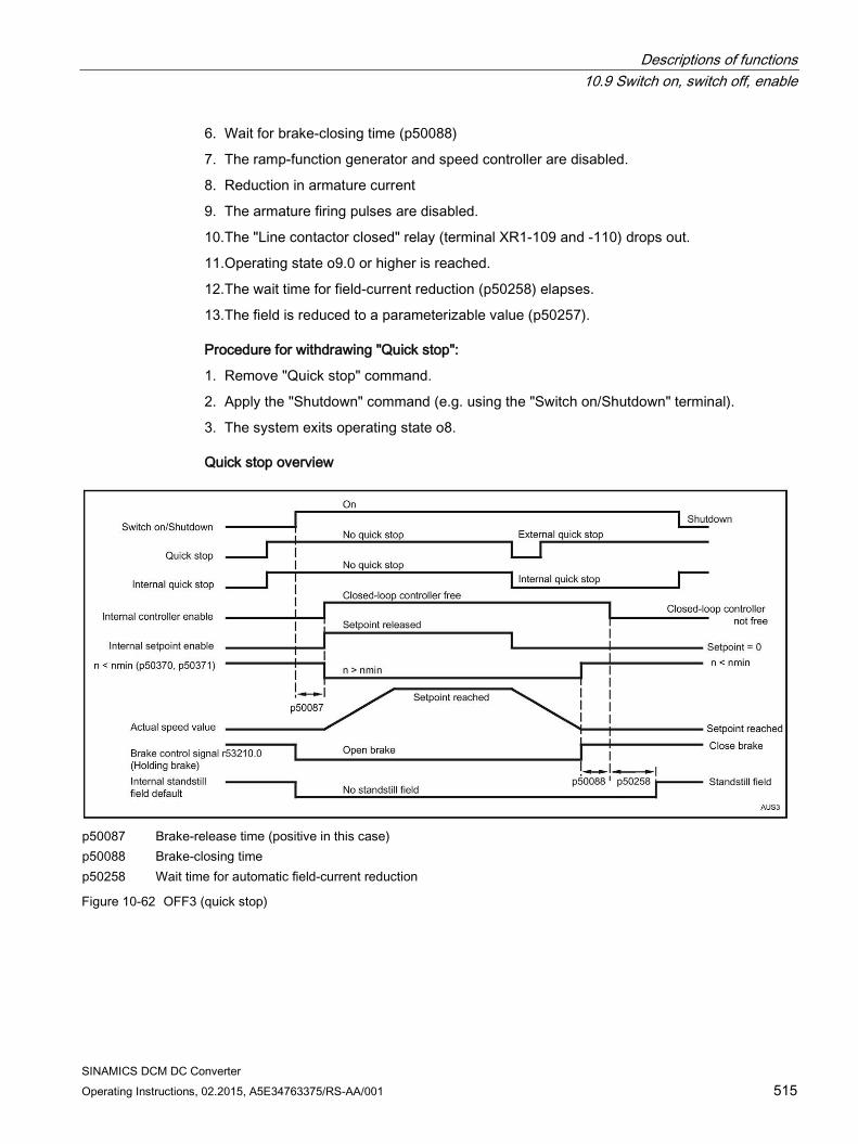
Descriptions of functions 10.9 Switch on, switch off, enable
SINAMICS DCM DC Converter Operating Instructions, 02.2015, A5E34763375/RS-AA/001 515
6. Wait for brake-closing time (p50088)
7. The ramp-function generator and speed controller are disabled.
8. Reduction in armature current
9. The armature firing pulses are disabled.
10.The "Line contactor closed" relay (terminal XR1-109 and -110) drops out.
11.Operating state o9.0 or higher is reached.
12.The wait time for field-current reduction (p50258) elapses.
13.The field is reduced to a parameterizable value (p50257).
Procedure for withdrawing "Quick stop":
1. Remove "Quick stop" command.
2. Apply the "Shutdown" command (e.g. using the "Switch on/Shutdown" terminal).
3. The system exits operating state o8.
Quick stop overview
p50087 Brake-release time (positive in this case) p50088 Brake-closing time p50258 Wait time for automatic field-current reduction
Figure 10-62 OFF3 (quick stop)
Descriptions of functions 10.9 Switch on, switch off, enable
SINAMICS DCM DC Converter 516 Operating Instructions, 02.2015, A5E34763375/RS-AA/001
The "Quick stop" command only needs to be present as a short pulse (> 10 ms). It is then saved internally. It is only possible to reset the memory by applying the "Shutdown" command.
The SINAMICS DC MASTER links all "Quick stop" commands in such a way that the "Quick stop" function is only disabled once all commands are in the "No quick stop" state.
An internal interlock becomes active once n < nmin (r50370, r50371) for the first time. This stops the drive from attempting to decelerate again if the motor is rotated by external influences; the n < nmin message then disappears.
To ensure that "fast stopping" functions even when rewiring is carried out, current or torque lower limits are specified, or additional setpoints are supplied, certain functions are disabled automatically when "fast stopping" is applied.
– All torque limits are disabled while braking to n < nmin.
– Of the current limits, only the system current limit (p50171 and p50172), speed-dependent current limit, and current limit resulting from I2t monitoring of the power unit are enabled.
10.9.4 Operation enable (enable) - control word bit 3 The enable signal is HIGH active (log. "1" state = enable).
Control word bit 3 and terminal X177.13 (enable) are logically ANDed. See also function diagram 2580.
Procedure for applying operation enable (if a switch-on command is present):
1. With positive brake-release time (p50087): The "Release holding or operational brake" signal (r53210.0 = 0) is output and p50087 is awaited in operating state o1.0. With negative brake-opening time (p50087 negative): Go immediately to step 2; brake is still closed (r53210.0 = 1)
2. The ramp-function generator, n controller, and I controller are enabled.
3. Operating state o0 is reached.
4. Once a negative brake-release time (p50087) has elapsed, the "Release holding or operational brake" (r53210.0 = 0) signal is output.
Procedure for withdrawing operation enable:
1. The ramp-function generator, n controller, and I controller are disabled.
2. Reduction in armature current
3. The armature firing pulses are disabled.
4. The "Close operational brake" signal is output (r53210.0 = 1, where p50080 = 2).
5. Operating state o1.0 or higher is reached.
6. The drive coasts down (or is decelerated by the operational brake).
7. Once n < nmin (p50370, p50371), the "Close holding brake" signal is output (r53210.0 = 1, where p50080 = 1).
Descriptions of functions 10.10 Safety shutdown (E-STOP)
SINAMICS DCM DC Converter Operating Instructions, 02.2015, A5E34763375/RS-AA/001 517
10.10 Safety shutdown (E-STOP)
Note
The E-STOP function is not an EMERGENCY STOP function in the sense of EN 60204-1.
The E-STOP function forces the "line contactor closed" relay to drop out, activating the relay contact (terminals XR1-109 and -110) for the main contactor control within approximately 15 ms, independent of the semiconductor components and Control Unit (CUD) functions. If the CUD is operating correctly, applying I = 0 via the controller serves to disconnect the line contactor from the power supply. The drive coasts down once E-STOP has been applied.
The E-STOP function is triggered when the switch between terminals XS1-105 and XS1-106 is opened.
The E-STOP function causes the drive to enter the "Switching on inhibited" operating state. This must be acknowledged by activating the "Shutdown" function by opening terminal X177.12, for example.
Procedure for applying E-STOP:
1. The ramp-function generator, n controller, and I controller are disabled.
2. Reduction in armature current
3. a) p51616 = 0: E-STOP acts like OFF2 (firing pulses are disabled as soon as I = 0). b) p51616 = 1: E-STOP immediately stops firing pulses from being output (without waiting for I = 0).
4. The "Close operational brake" signal is output (r53210.0 = 1, where p50080 = 2).
5. Operating state o10.0 or higher is reached.
6. The field current is maintained at a fixed point (i.e. there is no increase in the field current, even on exiting the field-weakening range).
7. The "Line contactor closed" relay (terminal XR1-109 and XR1-110) drops out.
8. The drive coasts down (or is decelerated by the operational brake).
9. The wait time (to be set at p50258) elapses.
10.The field is reduced to a parameterizable value (p50257).
11.Once n < nmin (p50370, p50371), the "Close holding brake" signal is output (r53210.0 = 1, where p50080 = 1).
Note 15 ms after E-STOP has been applied (even if point 7 in this procedure has not yet been reached), the "Line contactor closed" relay (terminal XR1-109 and XR1-110) will always drop out; this is triggered by the hardware.
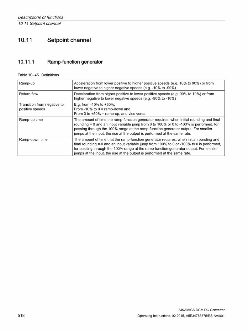
Descriptions of functions 10.11 Setpoint channel
SINAMICS DCM DC Converter 518 Operating Instructions, 02.2015, A5E34763375/RS-AA/001
10.11 Setpoint channel
10.11.1 Ramp-function generator
Table 10- 45 Definitions
Ramp-up Acceleration from lower positive to higher positive speeds (e.g. 10% to 90%) or from lower negative to higher negative speeds (e.g. -10% to -90%)
Return flow Deceleration from higher positive to lower positive speeds (e.g. 90% to 10%) or from higher negative to lower negative speeds (e.g. -90% to -10%)
Transition from negative to positive speeds
E.g. from -10% to +50%: From -10% to 0 = ramp-down and From 0 to +50% = ramp-up, and vice versa
Ramp-up time The amount of time the ramp-function generator requires, when initial rounding and final rounding = 0 and an input variable jump from 0 to 100% or 0 to -100% is performed, for passing through the 100% range at the ramp-function generator output. For smaller jumps at the input, the rise at the output is performed at the same rate.
Ramp-down time The amount of time that the ramp-function generator requires, when initial rounding and final rounding = 0 and an input variable jump from 100% to 0 or -100% to 0 is performed, for passing through the 100% range at the ramp-function generator output. For smaller jumps at the input, the rise at the output is performed at the same rate.
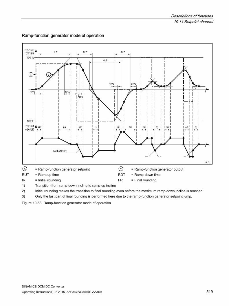
Descriptions of functions 10.11 Setpoint channel
SINAMICS DCM DC Converter Operating Instructions, 02.2015, A5E34763375/RS-AA/001 519
Ramp-function generator mode of operation
= Ramp-function generator setpoint = Ramp-function generator output
RUT = Rampup time RDT = Ramp-down time IR = Initial rounding FR = Final rounding 1) Transition from ramp-down incline to ramp-up incline 2) Initial rounding makes the transition to final rounding even before the maximum ramp-down incline is reached. 3) Only the last part of final rounding is performed here due to the ramp-function generator setpoint jump.
Figure 10-63 Ramp-function generator mode of operation
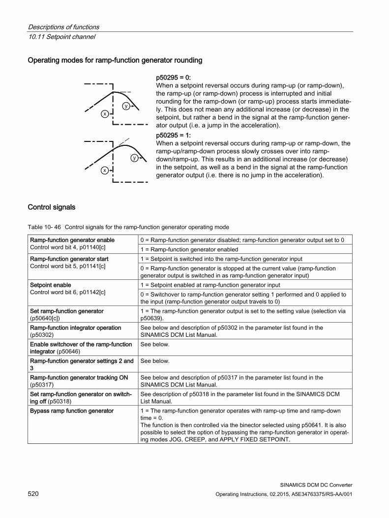
Descriptions of functions 10.11 Setpoint channel
SINAMICS DCM DC Converter 520 Operating Instructions, 02.2015, A5E34763375/RS-AA/001
Operating modes for ramp-function generator rounding
p50295 = 0: When a setpoint reversal occurs during ramp-up (or ramp-down), the ramp-up (or ramp-down) process is interrupted and initial rounding for the ramp-down (or ramp-up) process starts immediate-ly. This does not mean any additional increase (or decrease) in the setpoint, but rather a bend in the signal at the ramp-function gener-ator output (i.e. a jump in the acceleration).
p50295 = 1: When a setpoint reversal occurs during ramp-up or ramp-down, the ramp-up/ramp-down process slowly crosses over into ramp-down/ramp-up. This results in an additional increase (or decrease) in the setpoint, as well as a bend in the signal at the ramp-function generator output (i.e. there is no jump in the acceleration).
Control signals
Table 10- 46 Control signals for the ramp-function generator operating mode
Ramp-function generator enable Control word bit 4, p01140[c]
0 = Ramp-function generator disabled; ramp-function generator output set to 0 1 = Ramp-function generator enabled
Ramp-function generator start Control word bit 5, p01141[c]
1 = Setpoint is switched into the ramp-function generator input 0 = Ramp-function generator is stopped at the current value (ramp-function generator output is switched in as ramp-function generator input)
Setpoint enable Control word bit 6, p01142[c]
1 = Setpoint enabled at ramp-function generator input 0 = Switchover to ramp-function generator setting 1 performed and 0 applied to the input (ramp-function generator output travels to 0)
Set ramp-function generator (p50640[c])
1 = The ramp-function generator output is set to the setting value (selection via p50639).
Ramp-function integrator operation (p50302)
See below and description of p50302 in the parameter list found in the SINAMICS DCM List Manual.
Enable switchover of the ramp-function integrator (p50646)
See below.
Ramp-function generator settings 2 and 3
See below.
Ramp-function generator tracking ON (p50317)
See below and description of p50317 in the parameter list found in the SINAMICS DCM List Manual.
Set ramp-function generator on switch-ing off (p50318)
See description of p50318 in the parameter list found in the SINAMICS DCM List Manual.
Bypass ramp function generator 1 = The ramp-function generator operates with ramp-up time and ramp-down time = 0. The function is then controlled via the binector selected using p50641. It is also possible to select the option of bypassing the ramp-function generator in operat-ing modes JOG, CREEP, and APPLY FIXED SETPOINT.
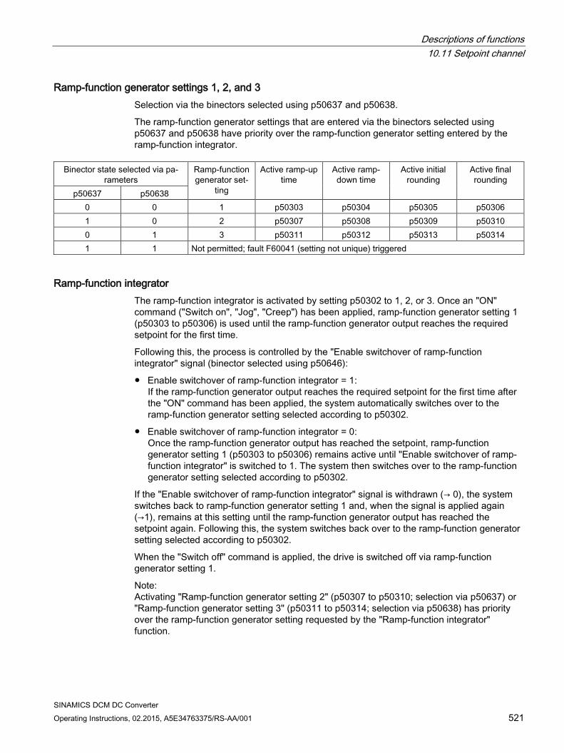
Descriptions of functions 10.11 Setpoint channel
SINAMICS DCM DC Converter Operating Instructions, 02.2015, A5E34763375/RS-AA/001 521
Ramp-function generator settings 1, 2, and 3 Selection via the binectors selected using p50637 and p50638.
The ramp-function generator settings that are entered via the binectors selected using p50637 and p50638 have priority over the ramp-function generator setting entered by the ramp-function integrator.
Binector state selected via pa-
rameters Ramp-function generator set-
ting
Active ramp-up time
Active ramp-down time
Active initial rounding
Active final rounding
p50637 p50638 0 0 1 p50303 p50304 p50305 p50306 1 0 2 p50307 p50308 p50309 p50310 0 1 3 p50311 p50312 p50313 p50314 1 1 Not permitted; fault F60041 (setting not unique) triggered
Ramp-function integrator The ramp-function integrator is activated by setting p50302 to 1, 2, or 3. Once an "ON" command ("Switch on", "Jog", "Creep") has been applied, ramp-function generator setting 1 (p50303 to p50306) is used until the ramp-function generator output reaches the required setpoint for the first time.
Following this, the process is controlled by the "Enable switchover of ramp-function integrator" signal (binector selected using p50646):
Enable switchover of ramp-function integrator = 1: If the ramp-function generator output reaches the required setpoint for the first time after the "ON" command has been applied, the system automatically switches over to the ramp-function generator setting selected according to p50302.
Enable switchover of ramp-function integrator = 0: Once the ramp-function generator output has reached the setpoint, ramp-function generator setting 1 (p50303 to p50306) remains active until "Enable switchover of ramp-function integrator" is switched to 1. The system then switches over to the ramp-function generator setting selected according to p50302.
If the "Enable switchover of ramp-function integrator" signal is withdrawn (→ 0), the system switches back to ramp-function generator setting 1 and, when the signal is applied again (→1), remains at this setting until the ramp-function generator output has reached the setpoint again. Following this, the system switches back over to the ramp-function generator setting selected according to p50302.
When the "Switch off" command is applied, the drive is switched off via ramp-function generator setting 1.
Note: Activating "Ramp-function generator setting 2" (p50307 to p50310; selection via p50637) or "Ramp-function generator setting 3" (p50311 to p50314; selection via p50638) has priority over the ramp-function generator setting requested by the "Ramp-function integrator" function.
Descriptions of functions 10.11 Setpoint channel
SINAMICS DCM DC Converter 522 Operating Instructions, 02.2015, A5E34763375/RS-AA/001
Ramp-function-generator tracking
The ramp-function generator output (r52190) is limited to the following values when ramp-function generator tracking is active:
When p50170 = 1 (closed-loop torque control), the following applies:
When p50170 = 0 (closed-loop current control), the following applies:
Φmotor Scaled motor flux (1 at rated excitation current) nact Actual speed value (r52167) +Mlimit Smallest positive torque limit (r52143) -Mlimit Smallest negative torque limit (r52144) +IA.limit Smallest positive current limit (r52131) -IA.limit Smallest negative current limit (r52132) Kp Active speed controller gain
If, however, the value added to nact would be less than 1%, then +1% or is –1% is added.
The "Ramp-function generator tracking" function prevents the ramp-function generator value from straying too far from the actual speed value if the torque or current limit has been reached.
Note: When ramp-function generator tracking is active, the filtering time of the speed setpoint p50228 should be low (ideally = 0).
Limiting after ramp-function generator This limiting stage can be used by freely selecting the input signal, independently from the ramp-function generator.
A distinguishing feature of this type of limiting is that lower limiting can also be set to positive values and upper limiting to negative values (see p50300 and p50301). In this case, a limit set using this method acts as a lower limit (lower limiting value) for the output signal of the ramp-function generator, with the sign inverted.
Example: p50632.01-04 = 1 (= 100.00%) p50300 = 100.00 (%) p50301 = 10.00 (%) p50633.01-04 = 9 (= -100.00%) results in the value range of r52170 being limited to between +10.00% and +100.00%.
Descriptions of functions 10.11 Setpoint channel
SINAMICS DCM DC Converter Operating Instructions, 02.2015, A5E34763375/RS-AA/001 523
Velocity signal dv/dt (r52191) This signal specifies the change in ramp-function generator output r52190 during the time set in p50542.
Braking distance (r52047, r52048) This signal specifies the distance that the drive would travel if, e.g. it would be stopped using an OFF1 command.
This braking distance is calculated under the assumption that at the ramp-function generator input, a speed setpoint of 0 would be input and the speed actual value would go down to 0 with the set ramp-down time and the set rounding-off. The braking distance calculation is only correct if, during braking, the ramp-down time and the rounding-off do not change. The braking distance is output in the same unit as the encoder position actual value r0482. This means that one encoder revolution corresponds to a value of p400×2^p418
The braking distance is available in two different data formats:
r52047 has the Unsigned32 data type
r52048 has the FloatingPoint32 data type
10.11.2 Jog See also function diagram 3125 in the SINAMICS DCM List Manual.
The JOG function can be applied via the binectors selected using p50435 index .00 to .07, and via control word bit 8 and bit 9 (r898.8 & r898.9) (see function diagram for logic operation).
The "Jog" function can only be executed if "Switch off" and "Operation enable" have been applied.
The "Jog" function is applied by one or more of the sources referred to (binectors, control word bits) entering the log. "1" state. During this, each source is assigned a setpoint (to be selected using p50436).
If two or more sources apply the "Jog" function at the same time, then 0 is applied as the jog setpoint.
For each source (binector, control word bit) with which the "Jog" function can be applied, p50437 may be used to determine whether the ramp-function generator is bypassed (binector r53170.11). In this case, the ramp-function generator operates with ramp-up time = 0 and ramp-down time = 0.
Procedure for applying jog:
If "Jog" is applied, the system is switched on and the jog setpoint applied via the ramp-function generator. For this procedure, refer to the section titled "Switch on/Switch off (ON/OFF1)".
Descriptions of functions 10.11 Setpoint channel
SINAMICS DCM DC Converter 524 Operating Instructions, 02.2015, A5E34763375/RS-AA/001
Procedure for withdrawing jog:
Once the "Jog" function has been withdrawn, the procedure begins in the same way as the "Switch off" function, as outlined in the section titled "Switch on/Switch off (ON/OFF1)". Once n < nmin, the controller is disabled and, following a parameterizable time (p50085) of 0 to 60 s, the line contactor is opened (operating state o7.0 or higher). While the wait time that can be parameterized using p50085 (max. 60.0 s.) is running, the drive remains in operating state o1.3.
10.11.3 Creep See also function diagram 3130 in the SINAMICS DCM List Manual.
The "Creep" function can be activated in operating state o7 and the "Operation" state while "Operation enable" applies.
"Creep" is applied by means of one or more of the binectors selected using p50440 entering the log. "1" state. During this, each binector is assigned a setpoint (to be selected using p50441). If "Creep" is applied by several binectors, their corresponding setpoints are added together.
For each source (binector) with which the "Creep" function can be applied, p50442 may be used to determine whether the ramp-function generator is bypassed (binector r53170.12). In this case, the ramp-function generator operates with ramp-up time = 0 and ramp-down time = 0.
Level/Edge P50445 = 0: Level-controlled
Binector selected using p50440= 0: No creep Binector selected using p50440= 1: Creep
P50445 = 1: Edge-triggered The application of the "Creep" function is saved when the binector makes the 0 → 1 transition. The binector selected using p50444 must be in the log. "1" state at this point. The memory is reset when this binector enters the log. "0" state.
Procedure for applying creep:
If "Creep" is applied in operating state o7, the system is switched on and the creep setpoint is applied via the ramp-function generator.
If "Creep" is applied in the "Operation" state, the drive uses the ramp-function generator to travel from the operating speed to the creep setpoint.
Procedure for withdrawing creep:
For "Creep" when the "Switch on" command is not present:
If all binectors that apply the "Creep" function enter the log. "0" state, the controller is disabled and the line contactor is opened (operating state o7.0 or higher) after n < nmin.
Descriptions of functions 10.11 Setpoint channel
SINAMICS DCM DC Converter Operating Instructions, 02.2015, A5E34763375/RS-AA/001 525
For "Creep" from the "Operation" state:
If all binectors that apply the "Creep" function enter the log. "0" state, and the conditions for the "Operation" state are still present, the drive uses the ramp-function generator to travel from the set creep speed to the operating speed.
See also the section titled "Switch on/Switch off (ON/OFF1)" for information on edge triggering, automatic restart, and the effect of current and torque limits when decelerating.
10.11.4 Fixed setpoint See also function diagram 3115 in the SINAMICS DCM List Manual.
The "Fixed setpoint" function can be applied via the binectors selected using p50435 index .00 to .07, p50680 and p50681 (see function diagram for logic operation).
"Fixed setpoint" is applied by one of more of the sources referred to (binectors) entering the log. "1" state. During this, each source is assigned a setpoint (to be selected using p50431). If "Fixed setpoint" is applied by several sources at the same time, their corresponding setpoints are added together (limited to ±200%).
For each source with which "Fixed setpoint" can be applied, p50432 may be used to determine whether the ramp-function generator is bypassed. In this case, the ramp-function generator operates with ramp-up time = 0 and ramp-down time = 0.
Response when "Fixed setpoint" is applied:
The fixed setpoint is switched in instead of the r52211 setpoint.
Withdrawal of "Fixed setpoint":
If all possible sources for switching in the fixed setpoint are in the log. "0" state again, r52211 is switched through as a setpoint.
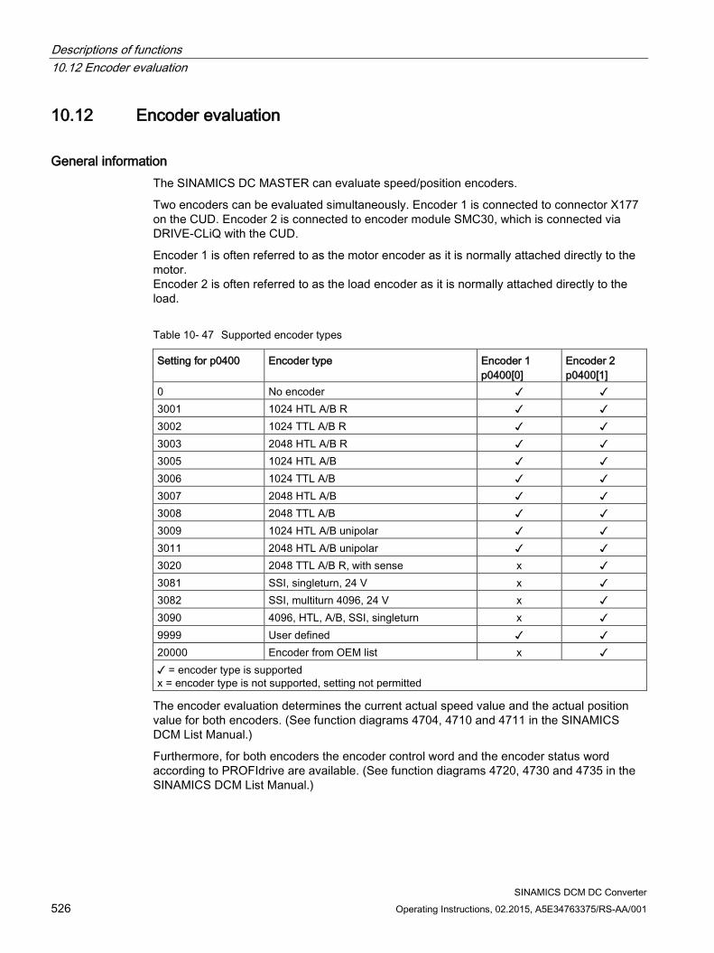
Descriptions of functions 10.12 Encoder evaluation
SINAMICS DCM DC Converter 526 Operating Instructions, 02.2015, A5E34763375/RS-AA/001
10.12 Encoder evaluation
General information The SINAMICS DC MASTER can evaluate speed/position encoders.
Two encoders can be evaluated simultaneously. Encoder 1 is connected to connector X177 on the CUD. Encoder 2 is connected to encoder module SMC30, which is connected via DRIVE-CLiQ with the CUD.
Encoder 1 is often referred to as the motor encoder as it is normally attached directly to the motor. Encoder 2 is often referred to as the load encoder as it is normally attached directly to the load.
Table 10- 47 Supported encoder types
Setting for p0400 Encoder type Encoder 1 p0400[0]
Encoder 2 p0400[1]
0 No encoder 3001 1024 HTL A/B R 3002 1024 TTL A/B R 3003 2048 HTL A/B R 3005 1024 HTL A/B 3006 1024 TTL A/B 3007 2048 HTL A/B 3008 2048 TTL A/B 3009 1024 HTL A/B unipolar 3011 2048 HTL A/B unipolar 3020 2048 TTL A/B R, with sense x 3081 SSI, singleturn, 24 V x 3082 SSI, multiturn 4096, 24 V x 3090 4096, HTL, A/B, SSI, singleturn x 9999 User defined 20000 Encoder from OEM list x = encoder type is supported x = encoder type is not supported, setting not permitted
The encoder evaluation determines the current actual speed value and the actual position value for both encoders. (See function diagrams 4704, 4710 and 4711 in the SINAMICS DCM List Manual.)
Furthermore, for both encoders the encoder control word and the encoder status word according to PROFIdrive are available. (See function diagrams 4720, 4730 and 4735 in the SINAMICS DCM List Manual.)
Descriptions of functions 10.12 Encoder evaluation
SINAMICS DCM DC Converter Operating Instructions, 02.2015, A5E34763375/RS-AA/001 527
PROFIdrive V4.1 is the PROFIBUS profile for drive technology with a wide range of applications in production and process automation systems.
Note
PROFIdrive for drive technology is standardized and described in the following document:
References: /P5/ PROFIdrive Profile Drive Technology
10.12.1 Actual speed values The calculation of the actual speed value can be seen in the following function diagrams:
FP4710 (for encoder 1)
FP4711 (for encoder 2)
The actual speed values of the encoders are always available as freely interconnected BICO outputs.
r0061[0]: Actual speed value for encoder 1
r0061[1] = r3370: Actual speed value for encoder 2
If you want to use an actual speed value from the encoder as an actual-value input, you need to set the actual speed value selection p50083 to 1 (for encoder 1) or to 5 (for encoder 2). See FP6810.
The maximum speed (i.e. the 100% speed) is set via p2000 in both cases.
Actual position values G1_XIST1 Encoder 1 actual position value 1 G1_XIST2 Encoder 1 actual position value 2 Gn_XIST2 Fault code G2_XIST1 Encoder 2 actual position value 1 G2_XIST2) Encoder 2 actual position value 2
For the description, see Chapter Control and status words for encoders (Page 399).
Descriptions of functions 10.12 Encoder evaluation
SINAMICS DCM DC Converter 528 Operating Instructions, 02.2015, A5E34763375/RS-AA/001
10.12.2 Control and status words for encoders Description
An encoder interface is defined in the PROFIBUS Profile for drive technology (PROFIdrive V4.1). This interface defines a control and status word for encoders. They are available in the following parameters:
r0480[0] = G1_STW encoder 1 control word
r0480[1] = G2_STW encoder 2 control word
r0481[0] = G1_ZSW encoder 1 status word
r0481[1] = G2_ZSW encoder 2 status word
The bit assignments of the control and status words for the encoders can be seen in the following function diagrams:
FP4720 (control word for encoders 1 and 2)
FP4730 (status word for encoders 1 and 2)
For the description, see Chapter Control and status words for encoders (Page 399).
Descriptions of functions 10.13 Speed controller
SINAMICS DCM DC Converter Operating Instructions, 02.2015, A5E34763375/RS-AA/001 529
10.13 Speed controller The speed controller is a PI controller with the following additional properties:
Start pulse
When starting the speed controller (i.e. when the controller is enabled) the I component can start with a selectable value. This is necessary for suspended/hanging loads in order to prevent the load from briefly sagging.
Adaptation
P gain and integral action time can be changed as a function of any signal (e.g. from the actual speed value).
Droop
Droop (which can be switched in) can be implemented by feeding back the I component to the input. As a consequence, the controller does not precisely control to the setpoint, but permits a continuous setpoint-actual value deviation. This is required, for example, if two drives are mechanically coupled with one another (e.g. for a production machine where drives are coupled through the material web being processed). In this case, the droop prevents that the two drives start to operate against one another, although both operate with closed-loop speed control. In the case that a mechanical connection is interrupted (e.g. if the material web breaks), then the speed of the drive operating with droop only slightly changes.
Lead/lag element element
The lead/lag element is used to improve the stability of the speed control. If required, it can be inserted in the actual speed value channel.
Remark:
The functions shown in function diagram 6810 have the following execution sequence:
Generation of the speed setpoint (r52174)
Selection of the actual speed value (r52167)
PT1 element (r52179)
Bandstop filter 1 (r52177)
Bandstop filter 2 (r52178)
DT1 element (r52169)
Lead/lag element (r52156)
Generation of the setpoint/actual-value difference (r52165)
Reference model
The reference model represents the P-controlled speed control loop and creates an appropriately processed speed setpoint for the I-component. This means that the I-component largely plays no role for setpoint changes, with the consequent improved, overshoot-free response.
The reference model contains a PT2 element and a dead time element to emulate the controlled system. See function charts 6810 and 6815. Further, it is possible to feed in an external reference model (e.g. generated using DDC function diagrams).

Descriptions of functions 10.13 Speed controller
SINAMICS DCM DC Converter 530 Operating Instructions, 02.2015, A5E34763375/RS-AA/001
The reference model is set using the following parameters:
p50237 natural frequency p50238 damping p50239 deadtime p50240 activation
The reference model is correctly set when the characteristics of the reference model output (r52154) and the actual speed value (r52167) are virtually identical when the I-component of the speed controller (p50224 = 0) is disabled.
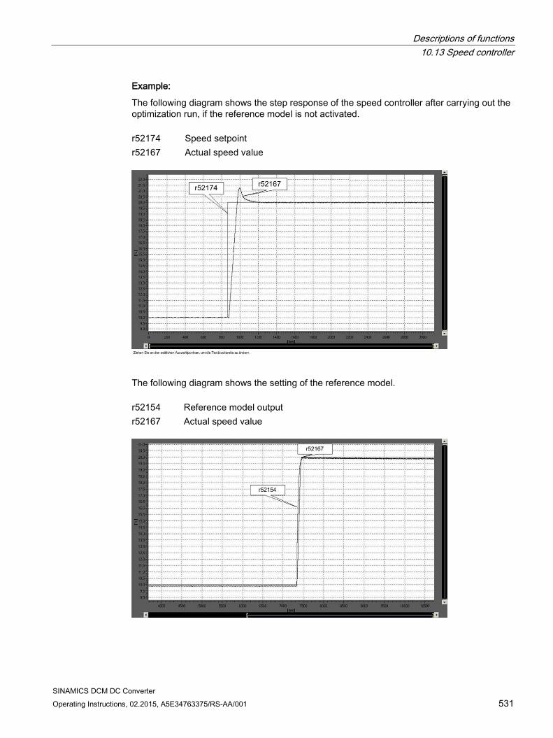
Descriptions of functions 10.13 Speed controller
SINAMICS DCM DC Converter Operating Instructions, 02.2015, A5E34763375/RS-AA/001 531
Example:
The following diagram shows the step response of the speed controller after carrying out the optimization run, if the reference model is not activated. r52174 Speed setpoint r52167 Actual speed value
The following diagram shows the setting of the reference model. r52154 Reference model output r52167 Actual speed value
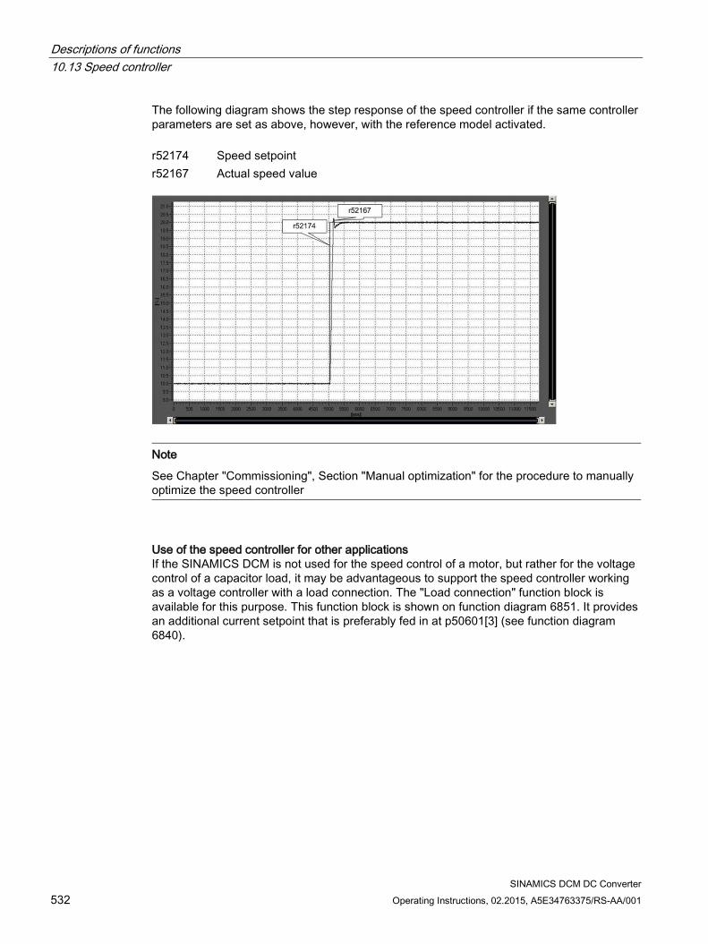
Descriptions of functions 10.13 Speed controller
SINAMICS DCM DC Converter 532 Operating Instructions, 02.2015, A5E34763375/RS-AA/001
The following diagram shows the step response of the speed controller if the same controller parameters are set as above, however, with the reference model activated. r52174 Speed setpoint r52167 Actual speed value
Note
See Chapter "Commissioning", Section "Manual optimization" for the procedure to manually optimize the speed controller
Use of the speed controller for other applications If the SINAMICS DCM is not used for the speed control of a motor, but rather for the voltage control of a capacitor load, it may be advantageous to support the speed controller working as a voltage controller with a load connection. The "Load connection" function block is available for this purpose. This function block is shown on function diagram 6851. It provides an additional current setpoint that is preferably fed in at p50601[3] (see function diagram 6840).
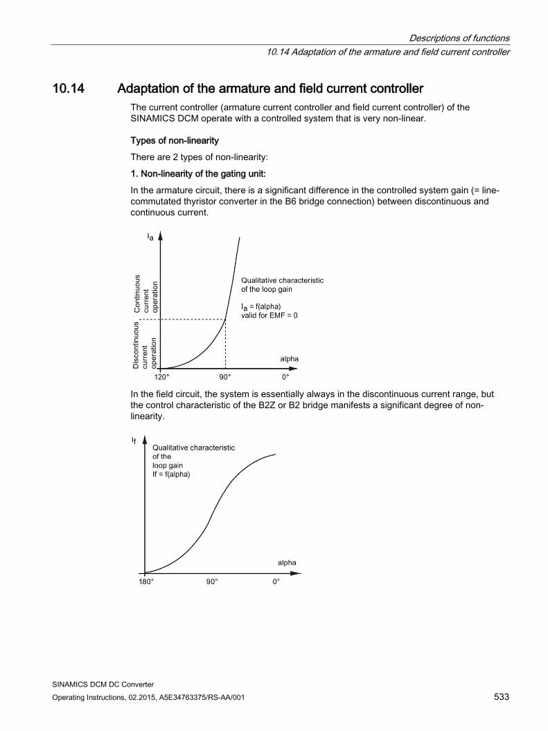
Descriptions of functions 10.14 Adaptation of the armature and field current controller
SINAMICS DCM DC Converter Operating Instructions, 02.2015, A5E34763375/RS-AA/001 533
10.14 Adaptation of the armature and field current controller The current controller (armature current controller and field current controller) of the SINAMICS DCM operate with a controlled system that is very non-linear.
Types of non-linearity
There are 2 types of non-linearity:
1. Non-linearity of the gating unit:
In the armature circuit, there is a significant difference in the controlled system gain (= line-commutated thyristor converter in the B6 bridge connection) between discontinuous and continuous current.
In the field circuit, the system is essentially always in the discontinuous current range, but the control characteristic of the B2Z or B2 bridge manifests a significant degree of non-linearity.
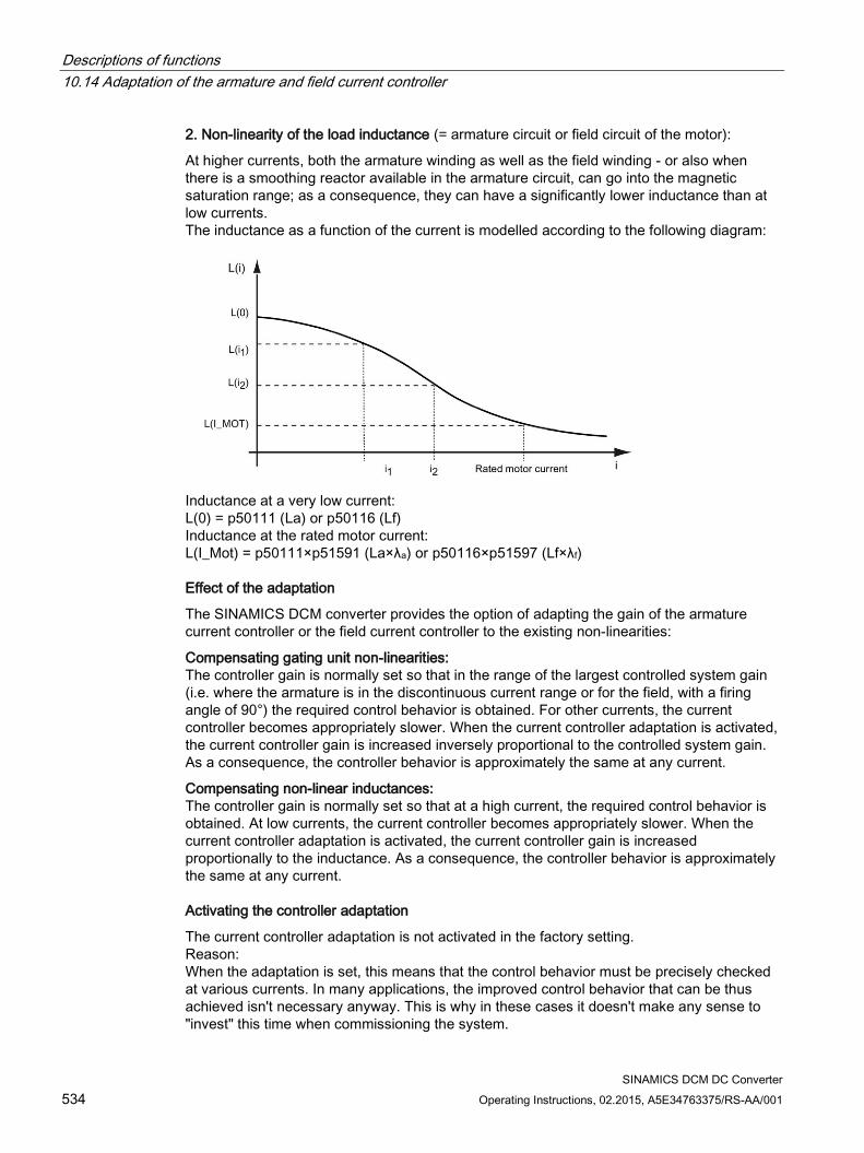
Descriptions of functions 10.14 Adaptation of the armature and field current controller
SINAMICS DCM DC Converter 534 Operating Instructions, 02.2015, A5E34763375/RS-AA/001
2. Non-linearity of the load inductance (= armature circuit or field circuit of the motor):
At higher currents, both the armature winding as well as the field winding - or also when there is a smoothing reactor available in the armature circuit, can go into the magnetic saturation range; as a consequence, they can have a significantly lower inductance than at low currents. The inductance as a function of the current is modelled according to the following diagram:
Inductance at a very low current: L(0) = p50111 (La) or p50116 (Lf) Inductance at the rated motor current: L(I_Mot) = p50111×p51591 (La×λa) or p50116×p51597 (Lf×λf)
Effect of the adaptation
The SINAMICS DCM converter provides the option of adapting the gain of the armature current controller or the field current controller to the existing non-linearities:
Compensating gating unit non-linearities: The controller gain is normally set so that in the range of the largest controlled system gain (i.e. where the armature is in the discontinuous current range or for the field, with a firing angle of 90°) the required control behavior is obtained. For other currents, the current controller becomes appropriately slower. When the current controller adaptation is activated, the current controller gain is increased inversely proportional to the controlled system gain. As a consequence, the controller behavior is approximately the same at any current.
Compensating non-linear inductances: The controller gain is normally set so that at a high current, the required control behavior is obtained. At low currents, the current controller becomes appropriately slower. When the current controller adaptation is activated, the current controller gain is increased proportionally to the inductance. As a consequence, the controller behavior is approximately the same at any current.
Activating the controller adaptation
The current controller adaptation is not activated in the factory setting. Reason: When the adaptation is set, this means that the control behavior must be precisely checked at various currents. In many applications, the improved control behavior that can be thus achieved isn't necessary anyway. This is why in these cases it doesn't make any sense to "invest" this time when commissioning the system.
Descriptions of functions 10.14 Adaptation of the armature and field current controller
SINAMICS DCM DC Converter Operating Instructions, 02.2015, A5E34763375/RS-AA/001 535
Setting the armature current controller adaptation
With the armature current controller, it is possible to calculate the adaptation using p50570 from the actual value or from the setpoint of the armature current. The adaptation to non-linear inductances can be activated using p50571, the discontinuous-continuous current adaptation can be activated using p50572. The adaptation factor can be limited using p50573. In order to be able to incorporate the adaptation at the armature current controller, connector output r52350 must be interconnected to connector input p50175 (Kp adaptation). With this intervention, the armature current controller gain is increased or decreased depending on the armature current actual value and/or setpoint (this is selected using p50570). The calculations of the adaptations are now created to change the gain.
Setting the field current controller adaptation
For the field current controller, it is possible to calculate the adaptation from the actual value or from the setpoint of the field current using p50575. The adaptation to non-linear inductances can be activated using p50576; the adaptation to the non-linearity of the gating unit, can be activated using p50577. The adaptation factor can be limited using p50578. In order to be able to incorporate the adaptation at the field current controller, connector output r52355 must be interconnected to connector input p50267 (Kp adaptation). With this intervention, the field current controller gain can be increased or decreased depending on the field current actual value and/or setpoint (this is selected using p50570). The calculations of the adaptations are only set-up to change the gain.
The corresponding function diagrams show additional details regarding how to activate the gain adaptation and the various setting options: FP 6853 Calculating the adaptation factor for the armature current controller gain FP 6855 Intervention to adapt the armature current controller gain
(p50175 = r52350 establishes the intervention) FP 6908 Calculating the adaptation factor for the armature current controller gain
intervention to adapt the armature current controller gain (p50267 = r52355 establishes the intervention)
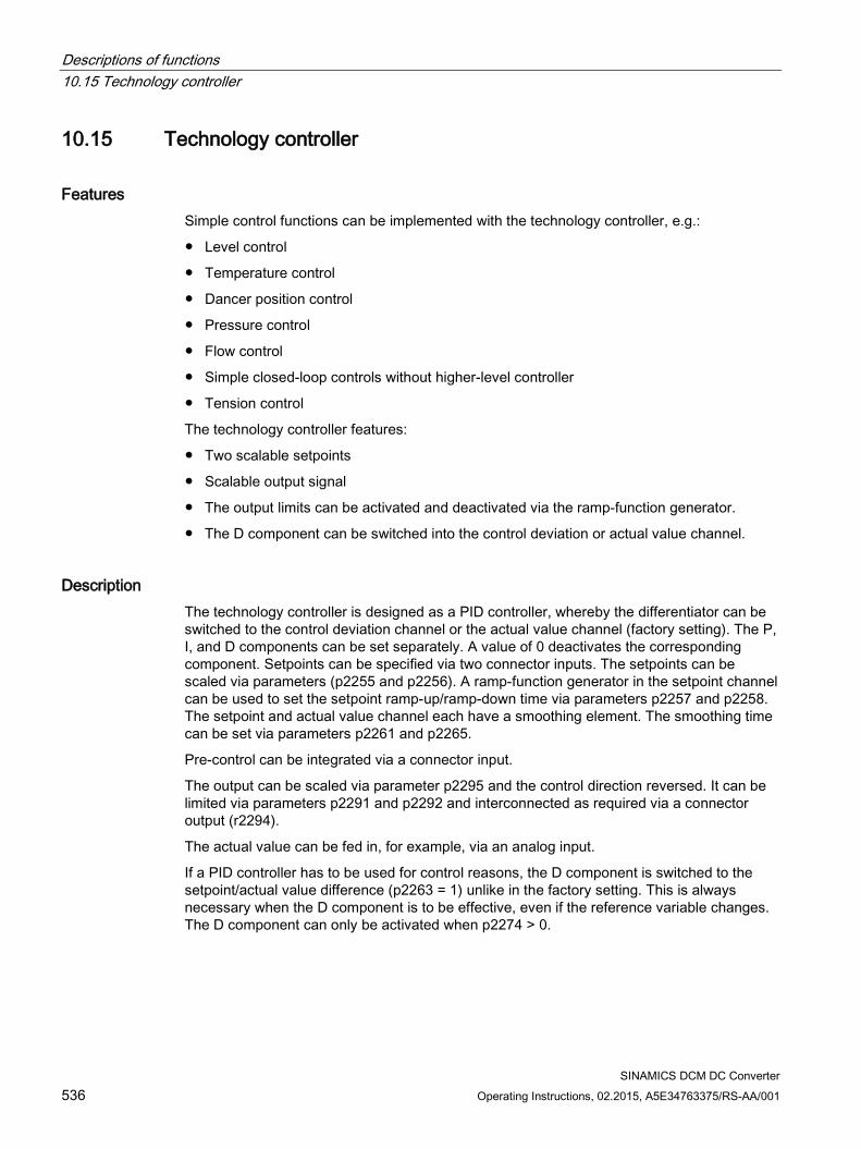
Descriptions of functions 10.15 Technology controller
SINAMICS DCM DC Converter 536 Operating Instructions, 02.2015, A5E34763375/RS-AA/001
10.15 Technology controller
Features Simple control functions can be implemented with the technology controller, e.g.:
Level control
Temperature control
Dancer position control
Pressure control
Flow control
Simple closed-loop controls without higher-level controller
Tension control
The technology controller features:
Two scalable setpoints
Scalable output signal
The output limits can be activated and deactivated via the ramp-function generator.
The D component can be switched into the control deviation or actual value channel.
Description The technology controller is designed as a PID controller, whereby the differentiator can be switched to the control deviation channel or the actual value channel (factory setting). The P, I, and D components can be set separately. A value of 0 deactivates the corresponding component. Setpoints can be specified via two connector inputs. The setpoints can be scaled via parameters (p2255 and p2256). A ramp-function generator in the setpoint channel can be used to set the setpoint ramp-up/ramp-down time via parameters p2257 and p2258. The setpoint and actual value channel each have a smoothing element. The smoothing time can be set via parameters p2261 and p2265.
Pre-control can be integrated via a connector input.
The output can be scaled via parameter p2295 and the control direction reversed. It can be limited via parameters p2291 and p2292 and interconnected as required via a connector output (r2294).
The actual value can be fed in, for example, via an analog input.
If a PID controller has to be used for control reasons, the D component is switched to the setpoint/actual value difference (p2263 = 1) unlike in the factory setting. This is always necessary when the D component is to be effective, even if the reference variable changes. The D component can only be activated when p2274 > 0.
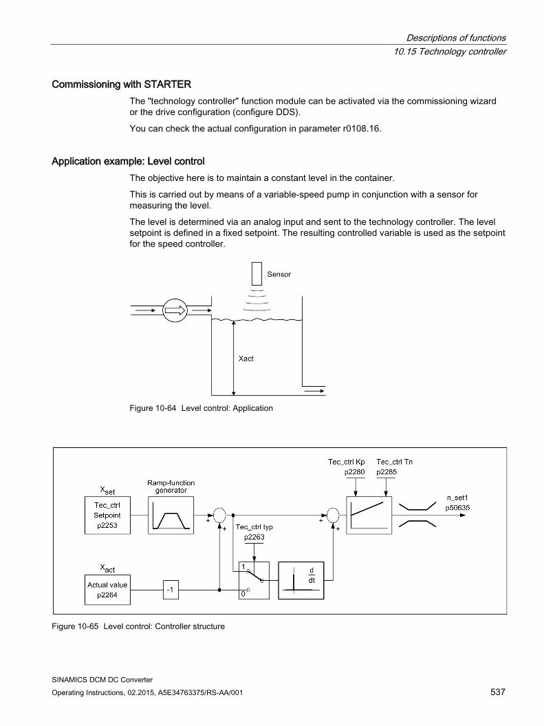
Descriptions of functions 10.15 Technology controller
SINAMICS DCM DC Converter Operating Instructions, 02.2015, A5E34763375/RS-AA/001 537
Commissioning with STARTER The "technology controller" function module can be activated via the commissioning wizard or the drive configuration (configure DDS).
You can check the actual configuration in parameter r0108.16.
Application example: Level control The objective here is to maintain a constant level in the container.
This is carried out by means of a variable-speed pump in conjunction with a sensor for measuring the level.
The level is determined via an analog input and sent to the technology controller. The level setpoint is defined in a fixed setpoint. The resulting controlled variable is used as the setpoint for the speed controller.
Figure 10-64 Level control: Application
Figure 10-65 Level control: Controller structure
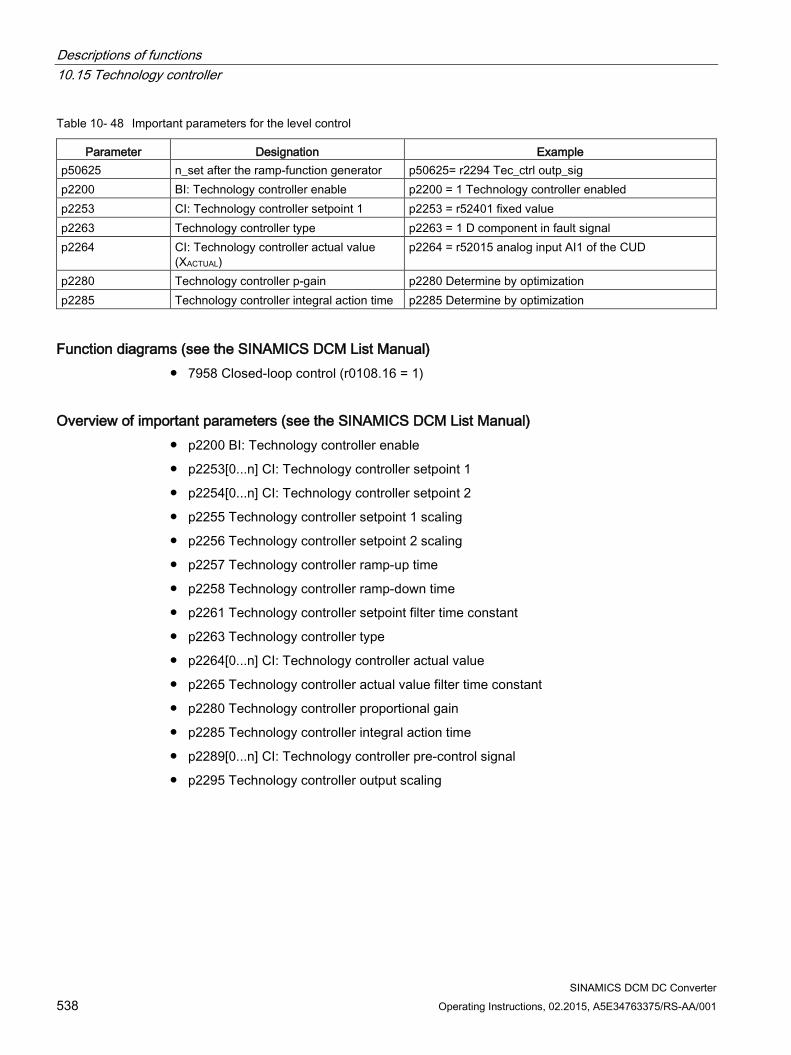
Descriptions of functions 10.15 Technology controller
SINAMICS DCM DC Converter 538 Operating Instructions, 02.2015, A5E34763375/RS-AA/001
Table 10- 48 Important parameters for the level control
Parameter Designation Example p50625 n_set after the ramp-function generator p50625= r2294 Tec_ctrl outp_sig p2200 BI: Technology controller enable p2200 = 1 Technology controller enabled p2253 CI: Technology controller setpoint 1 p2253 = r52401 fixed value p2263 Technology controller type p2263 = 1 D component in fault signal p2264 CI: Technology controller actual value
(XACTUAL) p2264 = r52015 analog input AI1 of the CUD
p2280 Technology controller p-gain p2280 Determine by optimization p2285 Technology controller integral action time p2285 Determine by optimization
Function diagrams (see the SINAMICS DCM List Manual) 7958 Closed-loop control (r0108.16 = 1)
Overview of important parameters (see the SINAMICS DCM List Manual) p2200 BI: Technology controller enable
p2253[0...n] CI: Technology controller setpoint 1
p2254[0...n] CI: Technology controller setpoint 2
p2255 Technology controller setpoint 1 scaling
p2256 Technology controller setpoint 2 scaling
p2257 Technology controller ramp-up time
p2258 Technology controller ramp-down time
p2261 Technology controller setpoint filter time constant
p2263 Technology controller type
p2264[0...n] CI: Technology controller actual value
p2265 Technology controller actual value filter time constant
p2280 Technology controller proportional gain
p2285 Technology controller integral action time
p2289[0...n] CI: Technology controller pre-control signal
p2295 Technology controller output scaling
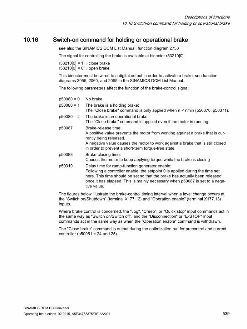
Descriptions of functions 10.16 Switch-on command for holding or operational brake
SINAMICS DCM DC Converter Operating Instructions, 02.2015, A5E34763375/RS-AA/001 539
10.16 Switch-on command for holding or operational brake see also the SINAMICS DCM List Manual, function diagram 2750
The signal for controlling the brake is available at binector r53210[0]:
r53210[0] = 1 ⇒ close brake r53210[0] = 0 ⇒ open brake
This binector must be wired to a digital output in order to activate a brake; see function diagrams 2055, 2060, and 2065 in the SINAMICS DCM List Manual.
The following parameters affect the function of the brake-control signal: p50080 = 0 No brake p50080 = 1 The brake is a holding brake:
The "Close brake" command is only applied when n < nmin (p50370, p50371). p50080 = 2 The brake is an operational brake:
The "Close brake" command is applied even if the motor is running. p50087 Brake-release time:
A positive value prevents the motor from working against a brake that is cur-rently being released. A negative value causes the motor to work against a brake that is still closed in order to prevent a short-term torque-free state.
p50088 Brake-closing time: Causes the motor to keep applying torque while the brake is closing
p50319 Delay time for ramp-function generator enable: Following a controller enable, the setpoint 0 is applied during the time set here. This time should be set so that the brake has actually been released once it has elapsed. This is mainly necessary when p50087 is set to a nega-tive value.
The figures below illustrate the brake-control timing interval when a level change occurs at the "Switch on/Shutdown" (terminal X177.12) and "Operation enable" (terminal X177.13) inputs.
Where brake control is concerned, the "Jog", "Creep", or "Quick stop" input commands act in the same way as "Switch on/Switch off", and the "Disconnection" or "E-STOP" input commands act in the same way as when the "Operation enable" command is withdrawn.
The "Close brake" command is output during the optimization run for precontrol and current controller (p50051 = 24 and 25).
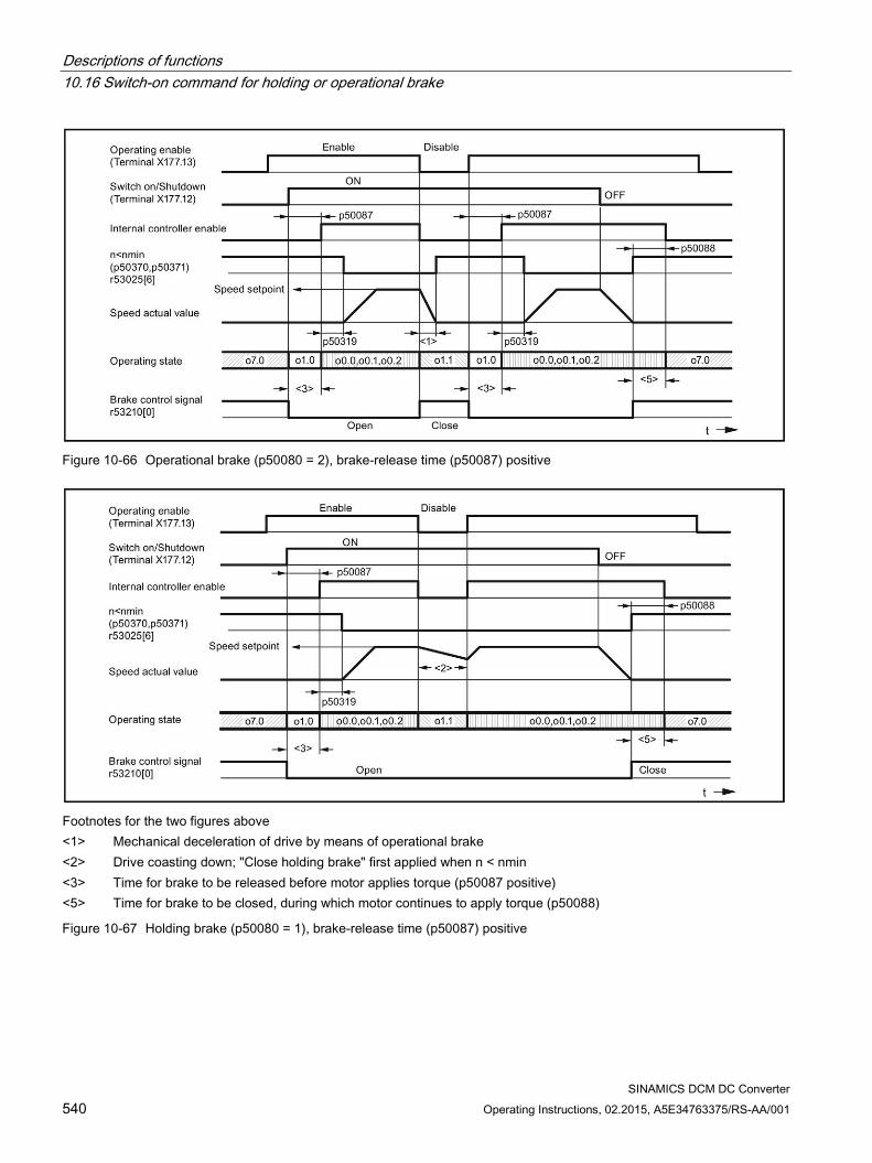
Descriptions of functions 10.16 Switch-on command for holding or operational brake
SINAMICS DCM DC Converter 540 Operating Instructions, 02.2015, A5E34763375/RS-AA/001
Figure 10-66 Operational brake (p50080 = 2), brake-release time (p50087) positive
Footnotes for the two figures above <1> Mechanical deceleration of drive by means of operational brake <2> Drive coasting down; "Close holding brake" first applied when n < nmin <3> Time for brake to be released before motor applies torque (p50087 positive) <5> Time for brake to be closed, during which motor continues to apply torque (p50088)
Figure 10-67 Holding brake (p50080 = 1), brake-release time (p50087) positive
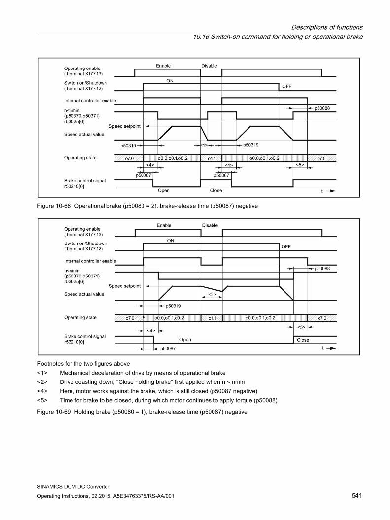
Descriptions of functions 10.16 Switch-on command for holding or operational brake
SINAMICS DCM DC Converter Operating Instructions, 02.2015, A5E34763375/RS-AA/001 541
Figure 10-68 Operational brake (p50080 = 2), brake-release time (p50087) negative
Footnotes for the two figures above <1> Mechanical deceleration of drive by means of operational brake <2> Drive coasting down; "Close holding brake" first applied when n < nmin <4> Here, motor works against the brake, which is still closed (p50087 negative) <5> Time for brake to be closed, during which motor continues to apply torque (p50088)
Figure 10-69 Holding brake (p50080 = 1), brake-release time (p50087) negative
Descriptions of functions 10.17 Switching on auxiliary circuits
SINAMICS DCM DC Converter 542 Operating Instructions, 02.2015, A5E34763375/RS-AA/001
10.17 Switching on auxiliary circuits This function serves as a switch on command for auxiliaries (e.g. motor fans).
The "Switch on auxiliaries" signal is available at binector r53210[2]:
r53210[2] = 0 ⇒ auxiliaries OFF r53210[2] = 1 ⇒ auxiliaries ON
This binector must be wired to a digital output in order to activate the auxiliary circuit; See SINAMICS DCM List Manual, function diagrams 2055, 2060 and 2065.
The "Switch on auxiliaries" signal goes to 1 at the same time as the "Switch on" command. After this, the system stays in operating state o6.0 for a time that can be parameterized (p50093). only once this has elapsed is the line contactor closed.
When the "Switch off" command is applied, the firing pulses are disabled and the line contactor drops out after n < nmin. After a time that can be parameterized (p50094), the "Switch on auxiliaries" signal goes to 0. If, however, the "Switch on" command is issued before this time elapses, the system does not stay in operating state o6.0; instead, the line contactor is closed instantaneously.
Descriptions of functions 10.18 Operating hours counter, unit fan
SINAMICS DCM DC Converter Operating Instructions, 02.2015, A5E34763375/RS-AA/001 543
10.18 Operating hours counter, unit fan SINAMICS DCM converters with rated DC current of ≥210 A, are equipped with fans:
Units <400 A: Two internally supplied fans
Units ≥400 A: One fan that is connected to the line supply
Parameter r53136 displays which unit fan is used for the particular converter.
Operating hours counter Every unit fan has an operating hours counter. The counter states are displayed at parameter r50960 [0..4]. r50960[0..3] Operating hours counter for the fans connected at the internal unit connectors
XV1 to XV4 r50960[4] For SINAMICS DCM Control Modules, operating hours counter for the fan
controlled via r53135[0].
The operating hours counter is incremented, if
SINAMICS DCM switches-on the corresponding fan AND
it actually rotates i.e. the speed is higher than 5 % of the response threshold of the fan monitoring (this does not apply to r50960[4])
The operating hours counters for unit fans that are not available are not incremented.
Monitoring the fan lifetime The planned lifetime for each fan is set at p50961[0...4]; the factory setting is 30000 hours.
Alarm A60165 is output 500 hours before the planned lifetime is reached. It is recommended that the corresponding fan is replaced at the next opportunity when the system is not operational (scheduled downtime).
If the lifetime for a fan is set to zero (p50961[0...4] = 0.0 hours), then the fan lifetime monitoring for this fan is disabled.
The corresponding operating hours counter is reset to 0 by setting parameter p50962[0..4] to 1. This should be done each time that a fan is replaced!
See also the SINAMICS DCM List Manual, function diagram 8045.
The instructions on how to replace a fan are provided in Chapter 11.
Descriptions of functions 10.19 Thermal overload protection for the DC motor (I2t monitoring of the motor)
SINAMICS DCM DC Converter 544 Operating Instructions, 02.2015, A5E34763375/RS-AA/001
10.19 Thermal overload protection for the DC motor (I2t monitoring of the motor)
I2t monitoring protects the motor against impermissible loads.
NOTICE
No full motor protection
I2t monitoring only provides an approximate representation of the motor's thermal image.
If the electronics power supply fails, then the calculated preload of the motor is lost. When switching-on again, the system assumes an unloaded motor!
For p50114 = 0, the I2t monitoring is disabled.
Adaptation
Table 10- 49 Parameter settings for I2t monitoring
Parameter Data p50114 Thermal time constant Time constant [s] with which I2t monitoring is to operate p50100 Rated armature current Determination of permissible continuous current for motor:
Permissible continuous current = p50100 × p50113 p50113 Continuous-current factor
Advance-alarm characteristic/Shutdown characteristic If, for example, the motor load is constantly at around 125% of the permissible continuous current for the motor, alarm A60037 responds after a time constant (p50114) has elapsed. If there is no reduction in the load, the drive is shut down when the shutdown characteristic is reached, and error message F60137 is displayed. Advance-alarm/shutdown times for other loads may be taken from the diagram below.
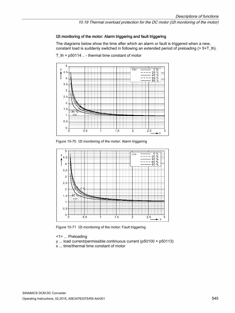
Descriptions of functions 10.19 Thermal overload protection for the DC motor (I2t monitoring of the motor)
SINAMICS DCM DC Converter Operating Instructions, 02.2015, A5E34763375/RS-AA/001 545
I2t monitoring of the motor: Alarm triggering and fault triggering
The diagrams below show the time after which an alarm or fault is triggered when a new, constant load is suddenly switched in following an extended period of preloading (> 5×T_th).
T_th = p50114 .. - thermal time constant of motor
Figure 10-70 I2t monitoring of the motor: Alarm triggering
Figure 10-71 I2t monitoring of the motor: Fault triggering
<1> ... Preloading y ... load current/permissible continuous current (p50100 × p50113) x ... time/thermal time constant of motor
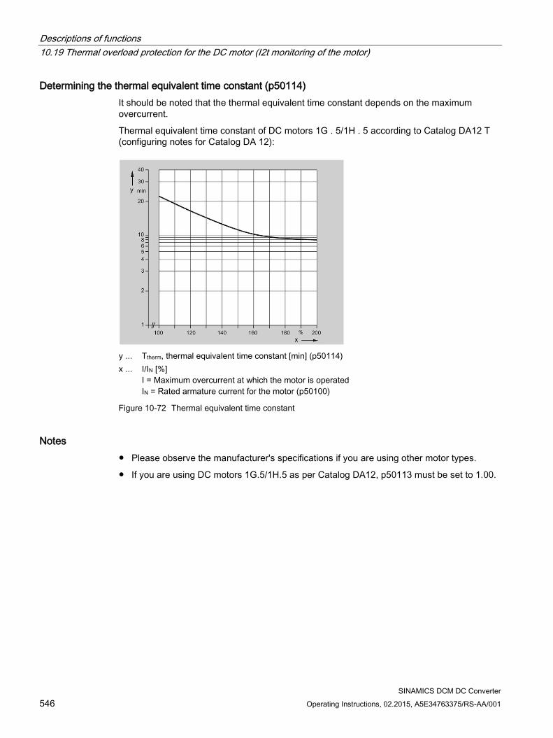
Descriptions of functions 10.19 Thermal overload protection for the DC motor (I2t monitoring of the motor)
SINAMICS DCM DC Converter 546 Operating Instructions, 02.2015, A5E34763375/RS-AA/001
Determining the thermal equivalent time constant (p50114) It should be noted that the thermal equivalent time constant depends on the maximum overcurrent.
Thermal equivalent time constant of DC motors 1G . 5/1H . 5 according to Catalog DA12 T (configuring notes for Catalog DA 12):
y ... Ttherm, thermal equivalent time constant [min] (p50114) x ... I/IN [%]
I = Maximum overcurrent at which the motor is operated IN = Rated armature current for the motor (p50100)
Figure 10-72 Thermal equivalent time constant
Notes Please observe the manufacturer's specifications if you are using other motor types.
If you are using DC motors 1G.5/1H.5 as per Catalog DA12, p50113 must be set to 1.00.
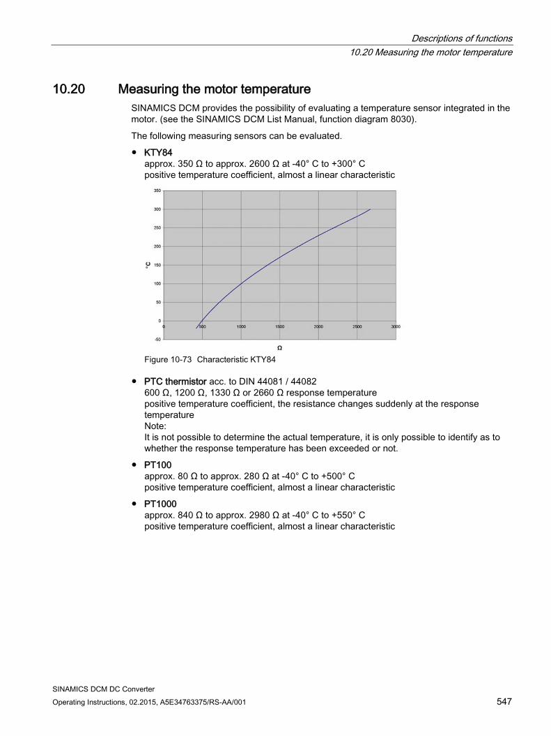
Descriptions of functions 10.20 Measuring the motor temperature
SINAMICS DCM DC Converter Operating Instructions, 02.2015, A5E34763375/RS-AA/001 547
10.20 Measuring the motor temperature SINAMICS DCM provides the possibility of evaluating a temperature sensor integrated in the motor. (see the SINAMICS DCM List Manual, function diagram 8030).
The following measuring sensors can be evaluated.
KTY84 approx. 350 Ω to approx. 2600 Ω at -40° C to +300° C positive temperature coefficient, almost a linear characteristic
Figure 10-73 Characteristic KTY84
PTC thermistor acc. to DIN 44081 / 44082 600 Ω, 1200 Ω, 1330 Ω or 2660 Ω response temperature positive temperature coefficient, the resistance changes suddenly at the response temperature Note: It is not possible to determine the actual temperature, it is only possible to identify as to whether the response temperature has been exceeded or not.
PT100 approx. 80 Ω to approx. 280 Ω at -40° C to +500° C positive temperature coefficient, almost a linear characteristic
PT1000 approx. 840 Ω to approx. 2980 Ω at -40° C to +550° C positive temperature coefficient, almost a linear characteristic
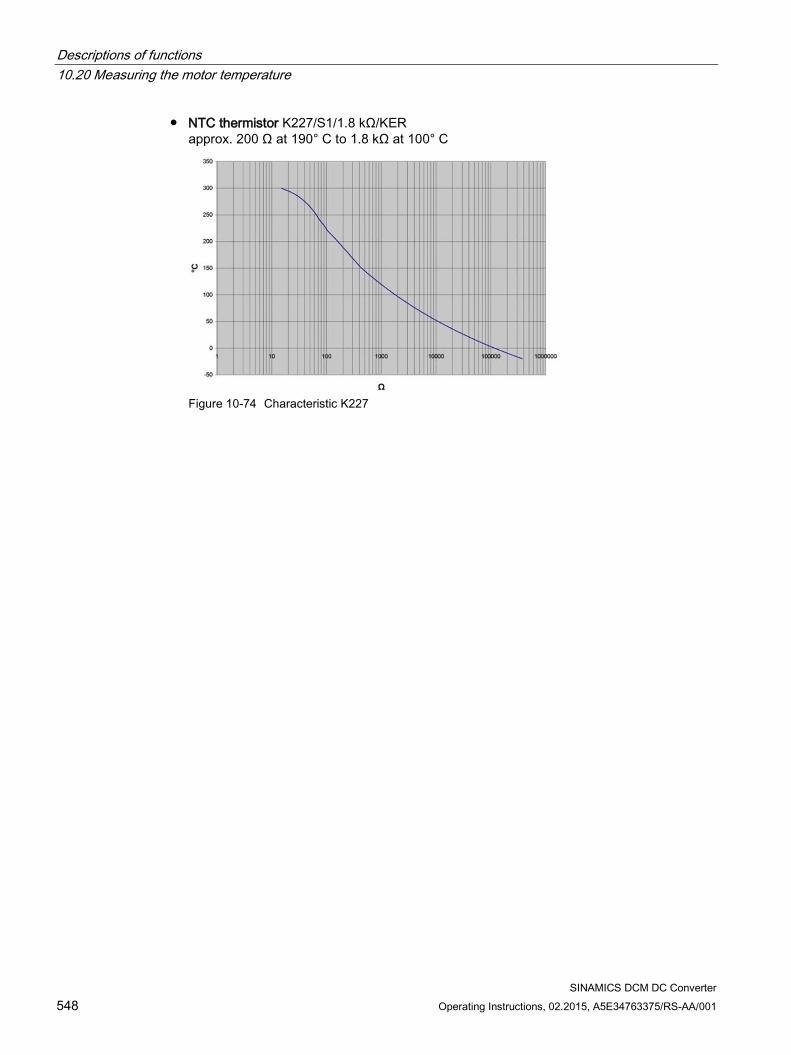
Descriptions of functions 10.20 Measuring the motor temperature
SINAMICS DCM DC Converter 548 Operating Instructions, 02.2015, A5E34763375/RS-AA/001
NTC thermistor K227/S1/1.8 kΩ/KER approx. 200 Ω at 190° C to 1.8 kΩ at 100° C
Figure 10-74 Characteristic K227
Descriptions of functions 10.21 Speed-dependent current limitation
SINAMICS DCM DC Converter Operating Instructions, 02.2015, A5E34763375/RS-AA/001 549
10.21 Speed-dependent current limitation Speed-dependent current limitation protects the DC motor's commutator and brushes at high speeds.
The settings required for this (p50104 to p50107) must be taken from the motor rating plate.
Additionally, the maximum operating speed of the motor (p50108) must be entered; this must match the actual maximum operating speed.
The actual maximum operating speed is determined as follows:
Using p2000 in cases where the actual speed value comes from an incremental encoder
Using p50741 in cases where the actual speed value comes from an analog tachometer
Using p50115 in the case of operation without a tachometer
Aside from this, speed-dependent current limitation must be activated by setting p50109 to 1.
NOTICE
Making an incorrect setting for speed-dependent current limitation can lead to excessive stress on the commutator and brushes, which in turn results in a significantly reduced service life for the brushes.
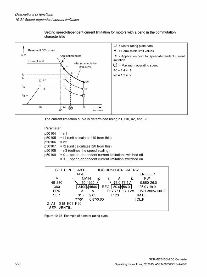
Descriptions of functions 10.21 Speed-dependent current limitation
SINAMICS DCM DC Converter 550 Operating Instructions, 02.2015, A5E34763375/RS-AA/001
Setting speed-dependent current limitation for motors with a bend in the commutation characteristic
= Motor rating plate data = Permissible limit values = Application point for speed-dependent current
limitation = Maximum operating speed
I10 = 1.4 × I1 I20 = 1.2 × I2
The current limitation curve is determined using n1, I10, n2, and I20. Parameter: p50104 p50105 p50106 p50107 p50108 p50109
= n1 = I1 (unit calculates I10 from this) = n2 = I2 (unit calculates I20 from this) = n3 (defines the speed scaling) = 0 ... speed-dependent current limitation switched off = 1 ... speed-dependent current limitation switched on
Figure 10-75 Example of a motor rating plate
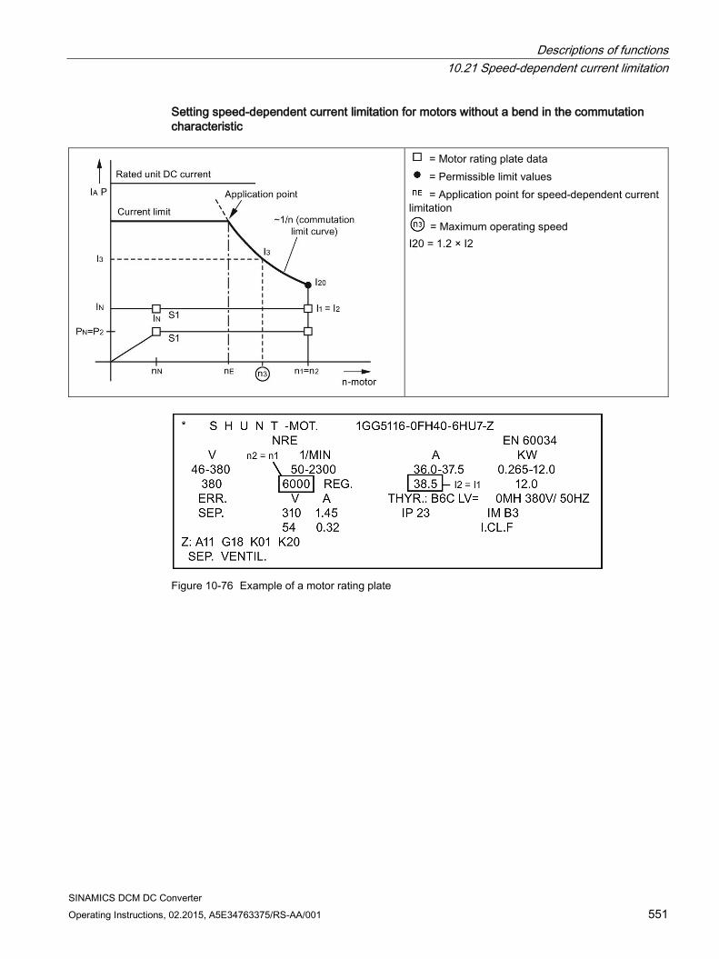
Descriptions of functions 10.21 Speed-dependent current limitation
SINAMICS DCM DC Converter Operating Instructions, 02.2015, A5E34763375/RS-AA/001 551
Setting speed-dependent current limitation for motors without a bend in the commutation characteristic
= Motor rating plate data = Permissible limit values = Application point for speed-dependent current
limitation = Maximum operating speed
I20 = 1.2 × I2
Figure 10-76 Example of a motor rating plate
Descriptions of functions 10.22 Dynamic overload capability of the power unit
SINAMICS DCM DC Converter 552 Operating Instructions, 02.2015, A5E34763375/RS-AA/001
10.22 Dynamic overload capability of the power unit
10.22.1 Overview of functions The rated unit DC current specified on the unit rating plate (= maximum permissible continuous DC current when p50077 = 1.00) may be exceeded during operation. The extent to which this value is exceeded and how long this lasts are subject to certain limits, which are explained in more detail in the section that follows.
The absolute upper limit for overload currents is 1.8x the rated unit DC current × p50077 (= 1.8 × r50072[0] × p50077). The maximum overload duration depends on the overload current's time characteristic as well as on the unit's load history, and differs from power unit to power unit.
Each overload must be preceded by an underload (load phase with load current < p50077 × rated unit DC current). Once the maximum permissible overload duration has elapsed, the load current must return to at least ≤ p50077 × rated unit DC current.
The dynamic overload for the power unit is monitored by a software algorithm (I2t monitoring of the power unit). I2t monitoring uses the time characteristic for the actual load current value to calculate the time characteristic for the thyristors' temperature rise above the ambient temperature. When the converter unit is switched on, the calculation process starts with the initial values that were determined before the electronic power supply was last shut down. The environmental conditions (ambient temperature, installation altitude) can be taken into account by setting parameter p50077. In the delivery condition, the ambient temperature is always set to the maximum possible value without derating (i.e. 45 °C for self-ventilated units and 40 °C for units with forced ventilation).
I2t monitoring responds when the temperature rise calculated in the thyristors becomes too high. However, it is also possible to set the following alternative responses using parameters: p50075 = 0: I2t monitoring is disabled. The armature current is limited to p50077 × rated
unit DC current (= p50077 × r50072[0]). p50075 = 1: Alarm A60039 with reduction in armature current setpoint to p50077 × rated
unit DC current p50075 = 2: Fault F80139 with unit shutdown
Parameters r52310 and r50014[1] show the calculated thyristor temperature rise as a % of the maximum permissible thyristor temperature rise. This maximum temperature rise differs from power unit to power unit, but falls approximately between 80 °C and 90 °C.
Descriptions of functions 10.22 Dynamic overload capability of the power unit
SINAMICS DCM DC Converter Operating Instructions, 02.2015, A5E34763375/RS-AA/001 553
10.22.2 Configuring for dynamic overload capability The DVD documentation for the SINAMICS DCM provides the following information for each converter unit:
The maximum overload duration tonwhen starting up with a cold power unit and specified constant overload with overload factor X (i.e. load with X times the device rated DC current * p50077) (see the small table at the top right)
The maximum zero current interval tstarting from(maximum cooling time) until the power unit reaches the thermal state "cold" (see below the small table at the top right)
Limiting characteristic fields for determining overload capability during thermally stabilized, intermittent operation with overload (periodic duty cycles)
– Tabular representation: Top left
– Representation as curve with logarithmic y axis: Curve at bottom left
– Representation as curve with linear y axis: Curve at bottom right
Note: The power unit is "cold" when the calculated thyristor temperature rise is less than 5% of its maximum permissible value. This state can be queried using a binary assignable output.
Note: If you start duty cycles with a cold power unit at least partially within the specified duty cycle limits, then the thermally stabilized state is reached without I2t monitoring responding.
If I2t monitoring is parameterized for a shutdown function (p50075 = 2), you should not come too close to the limiting characteristic when configuring periodic duty cycles that are longer than, slightly shorter than, or equal to 300 s.
In all other cases, however - and particularly when parameterizing I2t monitoring for a reduction in the armature current setpoint (p50075 = 1) - you can utilize the maximum overload capability determined by the limiting characteristic to its full extent.
Structure of limiting characteristic fields for intermittent operation with overload: Each of the limiting characteristic fields relates to a duty cycle during intermittent overload operation with an overall duration (time period) of 300 s.
A duty cycle of this type consists of two time intervals: The base load duration (actual armature current value ≤ p50077 * rated unit DC current) and The overload duration (actual armature current value ≥ p50077 * rated unit DC current)
Each limiting characteristic represents the maximum permissible overload duration Tp in excess of the maximum base-load current Ig for a specific overload factor X and a specific device. For the remaining duration of the duty cycle, the base-load current determined using the overload factor must not be exceeded.
If no limiting characteristic has been specified for the required overload factor, then it will be subject to the limiting characteristic for the next largest overload factor.
The limiting characteristic fields apply for a duty cycle duration of 300 s. For cycle durations < 300 s, the overload duration must be reduced proportionally (cycle duration/300 s).
Descriptions of functions 10.22 Dynamic overload capability of the power unit
SINAMICS DCM DC Converter 554 Operating Instructions, 02.2015, A5E34763375/RS-AA/001
For cycle durations > 300 s, only the same overload duration as with a cycle duration of 300 s is permitted; the base load duration is correspondingly longer.
The limiting characteristic fields apply for p50077 = 1.00. When setting p50077 to ≤ 1.00, i.e. reducing the thermal load, the currents that are actually flowing must be evaluated with the factor 1/p50077: Overload factor for characteristic X: X = Actual overload current / (p50077×rated unit DC current) Actual maximum base-load current Ig: Ig = p50077 × maximum base-load current acc. to characteristic
as a % of the rated unit DC current
Basic tasks for configuring periodic operation with overload Designations: Base load duration300 = Minimum base load duration for 300 s cycle duration Overload duration300 = Maximum overload duration for 300 s cycle duration
Basic task 1 Known: Device types, cycle duration, overload factor, overload duration To be found: Minimum base load duration and maximum base-load current To reach solution: Select the limiting characteristic for the known unit and overload factor Cycle duration < 300 s: Overload duration300 = (300 s/cycle duration) × overload duration Cycle duration ≥ 300 s: Overload duration300 = Overload duration If: Overload duration300 > overload duration300 for base-load current = 0 Then: Required duty cycle cannot be configured Other-wise:
Read the maximum base-load current for overload duration300 from the limiting characteristic
Example 1:
Known: 30 A/4Q unit; cycle duration 113.2 s; overload factor = 1.45; overload duration = 20 s
To be found: Minimum base load duration and maximum base-load current
Solution: Limiting characteristic for 30 A/4Q unit, overload factor 1.5 Overload duration300 = (300 s./113.2 s.)×20 s. = 53 s. Base load duration300 = 300 s. – 53 s. = 247 s. → Maximum base-load current = approx. 45% of IN = 13.5 A
Descriptions of functions 10.22 Dynamic overload capability of the power unit
SINAMICS DCM DC Converter Operating Instructions, 02.2015, A5E34763375/RS-AA/001 555
Basic task 2 Known: Device types, cycle duration, overload factor, base-load current
To be found: Minimum base load duration and maximum overload duration
To find solution: Select the limiting characteristic for the known unit and the known overload factor. Read the overload duration300 for the base-load current from the limiting characteristic.
Cycle duration < 300 s: Max. overload duration = (cycle duration/300 s) * overload duration300
Min. base load duration = cycle duration – max. overload duration
Cycle duration ≥ 300 s: Max. overload duration = overload duration300
Min. base load duration = cycle duration – max. overload duration
Example 2:
Known: 30 A/4Q unit; cycle duration 140 s; current-overload factor = 1.15; base-load current = 0.6*IN=18 A
To be found: Minimum base load duration and maximum overload duration
Solution: Limiting characteristic for 30 A/4Q unit, overload factor 1.2 Base-load current = 60% of IN → overload duration300 = 126.35 s. Max. overload duration = (140 s./300 s.)×126.35 s. = approx. 58 s. Min. base load duration = 140 s. – 58 s. = 82 s.
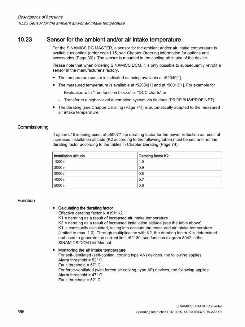
Descriptions of functions 10.23 Sensor for the ambient and/or air intake temperature
SINAMICS DCM DC Converter 556 Operating Instructions, 02.2015, A5E34763375/RS-AA/001
10.23 Sensor for the ambient and/or air intake temperature For the SINAMICS DC MASTER, a sensor for the ambient and/or air intake temperature is available as option (order code L15, see Chapter Ordering information for options and accessories (Page 30)). The sensor is mounted in the cooling air intake of the device.
Please note that when ordering SINAMICS DCM, it is only possible to subsequently retrofit a sensor in the manufacturer's factory.
The temperature sensor is indicated as being available at r52049[1].
The measured temperature is available at r52050[1] and at r50013[1]. For example for
– Evaluation with "free function blocks" or "DCC charts" or
– Transfer to a higher-level automation system via fieldbus (PROFIBUS/PROFINET)
The derating (see Chapter Derating (Page 74)) is automatically adapted to the measured air intake temperature.
Commissioning If option L15 is being used, at p50077 the derating factor for the power reduction as result of increased installation altitude (K2 according to the following table) must be set, and not the derating factor according to the tables in Chapter Derating (Page 74). Installation altitude Derating factor K2 1000 m 1.0 2000 m 0.9 3000 m 0.8 4000 m 0.7 5000 m 0.6
Function Calculating the derating factor
Effective derating factor K = K1×K2 K1 = derating as a result of increased air intake temperature K2 = derating as a result of increased installation altitude (see the table above) K1 is continually calculated, taking into account the measured air intake temperature (limited to max. 1.0). Through multiplication with K2, the derating factor K is determined and used to generate the current limit r52130, see function diagram 8042 in the SINAMICS DCM List Manual.
Monitoring the air intake temperature For self-ventilated (self-cooling, cooling type AN) devices, the following applies: Alarm threshold = 52° C Fault threshold = 57° C For force-ventilated (with forced air cooling, type AF) devices, the following applies: Alarm threshold = 47° C Fault threshold = 52° C
Descriptions of functions 10.23 Sensor for the ambient and/or air intake temperature
SINAMICS DCM DC Converter Operating Instructions, 02.2015, A5E34763375/RS-AA/001 557
Reaction: Measured air intake temperature (r52050[1] or r50013[1]) • Is greater than the alarm threshold → Alarm A60080
• Is higher than the fault threshold → Fault F60067
• Is greater than 115° C → Fault F60096 with fault value 2 (i.e. the temperature sensor is short-circuited)
• Is less than -25° C → Fault F60096 with fault value 1 (i.e. the temperature sensor is interrupted)
Use of the SINAMICS DCM in a SINAMICS DCM Cabinet drive cabinet with option L99 Option L99 provides the same functionality as option L15.
Devices with software version as of 1.4:
Alarm A60082 is output if the drive performs an automatic derating as a result of the measured air intake temperature. The response threshold for this alarm can be configured with p50066.
The description for option L99 can be found in the operating instructions for the SINAMICS DCM Cabinet.
Note
For devices with option L15, p50066 has no effect and A60082 is not available.
Descriptions of functions 10.24 Calculating the thyristor blocking voltage
SINAMICS DCM DC Converter 558 Operating Instructions, 02.2015, A5E34763375/RS-AA/001
10.24 Calculating the thyristor blocking voltage The SINAMICS DCM converter offers the possibility of continually determining the voltage available at each individual thyristor of the armature converter. The voltage is used to identify which armature thyristors are presently conducting and which are presently blocked.
This information is available via BICOs (see function diagram 6950).
This information is used for the following functions as input variable:
Inverter commutation fault detection and initiation of the CCP The thyristor that is relinquishing the current must assume the blocking voltage, otherwise, commutation was unsuccessful.
Torque direction changeover (sequential logic module) Before a thyristor of the new torque direction is triggered, all thyristors associated with the old torque direction must be blocked. The condition is evaluated in addition to the Ia=0 message.
The voltage at the armature thyristors is determined from the following measured values:
Two phase-to-phase line supply voltages (UV, VW)
Voltage at a thyristor (for 4Q: Anti-parallel thyristor pair) (X13/X26)
DC voltage (Va)
Selecting the thyristor blocking voltage calculation using p50166: This parameter is only evaluated once during power up, i.e. a change only takes effect after a restart or power up with saved parameters (p0976 = 11).
The thyristor blocking voltage calculation is only really required in just a few applications and requires approx. 5% processor utilization; this is the reason that it is deactivated in the factory setting.
p50166 = 0 Thyristor blocking voltage monitoring not active (factory setting)
= 1 Thyristor blocking voltage monitoring active
Activation is recommended in the following cases:
If a SIMOREG CCP is connected to the SINAMICS DCM.
If a motor is not connected to the armature converter, but instead, a very large inductance.
Descriptions of functions 10.24 Calculating the thyristor blocking voltage
SINAMICS DCM DC Converter Operating Instructions, 02.2015, A5E34763375/RS-AA/001 559
Note
The thyristor blocking voltage calculation function is available from the following version of the power interface module • C98043-A7105-L1-8 • C98043-A7105-L4-8 • C98043-A7106-L1-6 • C98043-A7106-L4-7 • C98043-A7107-... (option L05): All releases • C98043-A7108-... (option L05): All releases • A5E... : All releases
This information is provided on the bar code label on the printed circuit board.
Descriptions of functions 10.25 Automatic restart
SINAMICS DCM DC Converter 560 Operating Instructions, 02.2015, A5E34763375/RS-AA/001
10.25 Automatic restart "Automatic restart" means: When brief interruptions in the network (such as voltage dips) occur, the SINAMICS DC MASTER does not enter the "FAULT" operating state immediately, but instead blocks the armature firing pulses before automatically re-enabling them once the network returns to normal.
"Brief" refers to a time that is shorter than the time set at p50086 (= hot restart time)
During the brief pulse inhibit period that is initiated when faults occur in the network, the SINAMICS DC MASTER waits in operating state o4.0 (for power system faults in the armature circuit) or o5.1 (for power system faults in the field circuit).
If the network does not return to normal during the hot restart time, the relevant fault is triggered as soon as it elapses.
The following faults relate to the "Automatic restart" function: F60004 Armature circuit phase failure (1U1, 1V1, 1W1) F60005 Field circuit phase failure (3U1, 3W1) F60006 Undervoltage (armature current or field current) F60007 Overvoltage (armature current or field current) F60008 Line frequency too low (armature current or field current) F60009 Line frequency too high (armature current or field current)
Note
There is no automatic restart when the electronics power supply fails.
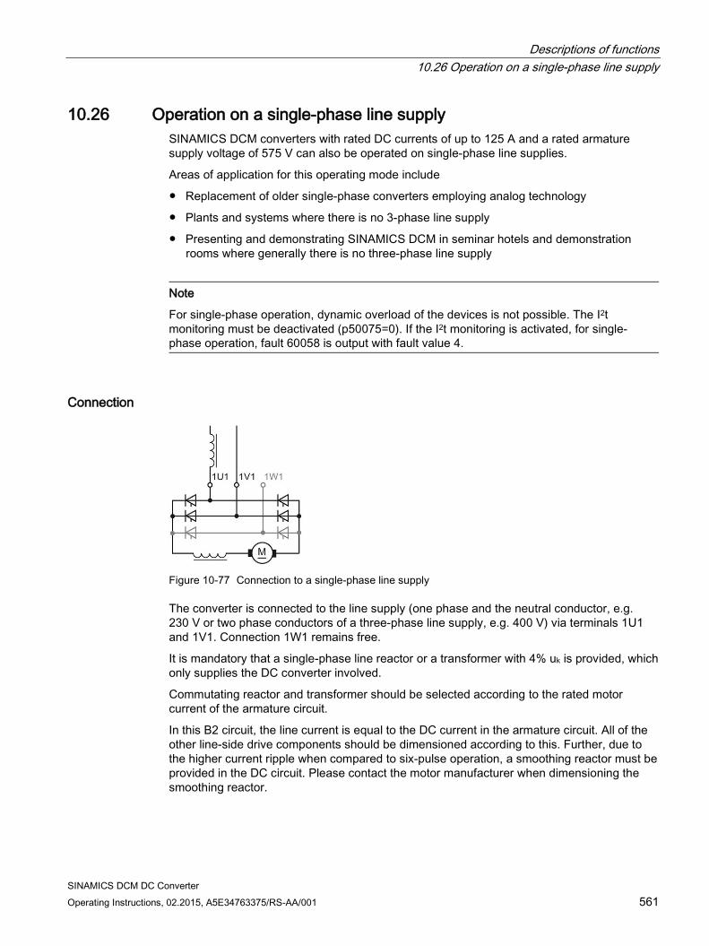
Descriptions of functions 10.26 Operation on a single-phase line supply
SINAMICS DCM DC Converter Operating Instructions, 02.2015, A5E34763375/RS-AA/001 561
10.26 Operation on a single-phase line supply SINAMICS DCM converters with rated DC currents of up to 125 A and a rated armature supply voltage of 575 V can also be operated on single-phase line supplies.
Areas of application for this operating mode include
Replacement of older single-phase converters employing analog technology
Plants and systems where there is no 3-phase line supply
Presenting and demonstrating SINAMICS DCM in seminar hotels and demonstration rooms where generally there is no three-phase line supply
Note
For single-phase operation, dynamic overload of the devices is not possible. The I2t monitoring must be deactivated (p50075=0). If the I2t monitoring is activated, for single-phase operation, fault 60058 is output with fault value 4.
Connection
Figure 10-77 Connection to a single-phase line supply
The converter is connected to the line supply (one phase and the neutral conductor, e.g. 230 V or two phase conductors of a three-phase line supply, e.g. 400 V) via terminals 1U1 and 1V1. Connection 1W1 remains free.
It is mandatory that a single-phase line reactor or a transformer with 4% uk is provided, which only supplies the DC converter involved.
Commutating reactor and transformer should be selected according to the rated motor current of the armature circuit.
In this B2 circuit, the line current is equal to the DC current in the armature circuit. All of the other line-side drive components should be dimensioned according to this. Further, due to the higher current ripple when compared to six-pulse operation, a smoothing reactor must be provided in the DC circuit. Please contact the motor manufacturer when dimensioning the smoothing reactor.
Descriptions of functions 10.26 Operation on a single-phase line supply
SINAMICS DCM DC Converter 562 Operating Instructions, 02.2015, A5E34763375/RS-AA/001
Parameterization Selecting operation on a single-phase line supply with p51799 = 1
If single-phase operation is selected for a converter with more than 125 A rated DC current, then fault message F60058 with fault value r0949[0]=5 is output when the converter is switched-on.
The high current ripple in this mode causes ripple in the actual speed. For smooth speed control, it is recommended to set the actual speed smoothing to approx. 10 ms (p50200 = 10 ms)
Derating When selecting operation on a single-phase line supply, the rated DC current (r50072[0]) is automatically reduced to 67% of the value for 3-phase operation. The reason for this is the uneven distribution of the current in the thyristors in the power unit of the drive converter.
As a consequence, the rated output voltage is also reduced. See also Technical data in Chapter 4.
Descriptions of functions 10.27 Connecting units in parallel and in series
SINAMICS DCM DC Converter Operating Instructions, 02.2015, A5E34763375/RS-AA/001 563
10.27 Connecting units in parallel and in series
Topology overview Several SINAMICS DCM converters can be arranged in various topologies. The following topologies are supported:
6-pulse parallel connection This topology is used in order to realize converter power ratings that are above the highest available SINAMICS DCM rating.
12-pulse parallel connection This topology is especially used at higher power ratings to achieve lower line harmonics. In addition, by using this circuit, a lower DC current ripple is obtained when compared to a 6-pulse connection. One or several 6-pulse converters can be connected in parallel to each of the two 12-pulse converters connected in parallel.
6-pulse series connection This topology is used to achieve a higher no-load DC voltage. The following versions are available:
– Both converters are operated with the same firing angle.
– Sequence control (one of the two converters is always at a control limit, the other converter controls the armature current)
– Series connection of a controlled converter with an uncontrolled converter (thyristor bridge B2 + diode rectifier)
One or several converters can be connected in parallel to each of the converters connected in series to increase the power rating.
12-pulse series connection The topology corresponds to a 6-pulse series connection. In addition, a lower DC current ripple is obtained when compared to a 6-pulse connection. One or several converters can be connected in parallel to each of the converters connected in series to increase the power rating.
Note • All of the topologies listed here are only permissible in the restricted line frequency range
from 20 Hz to 65 Hz. • For all of the topologies listed here, only devices with the same DC current rating may be
used. • For all of the topologies listed here, only devices with the same software version may be
used.
Note
More information about design is given in the associated application notes (see link in preface).
Descriptions of functions 10.27 Connecting units in parallel and in series
SINAMICS DCM DC Converter 564 Operating Instructions, 02.2015, A5E34763375/RS-AA/001
Communication
Note
Before activating the parallel interface (i.e. before setting p51800 > 0), a unique station address must be set at p51806 on all SINAMICS DCMs. Otherwise, the parallel interface will not work property.
Remedy in this case: Switch the electronic power supply off and then on.
In the particular topology, communication between all converters is established via the parallel interface. The CUDs of all converters should be connected with one another.
The parallel interface allows a maximum of 16 nodes to communicate.
The devices are connected using 8-core shielded patch cables, type UTP CAT5 according to ANSI/EIA/TIA 568, such as those that are used to network PCs. A standard 5 m long cable can be directly purchased from Siemens (article number: 6RY1707-0AA08). (n-1) cables are required to connect n devices. The bus termination must be activated at the devices at the start of the bus and at the end of the bus (p51805=1).
Note:
A patch cable according to TIA568A (European) or TIA568B (American) can be used. However, both cable ends must be wired according to the same standard (patch cable = 1:1). A crossover cable is not suitable.
The parallel interface also enables any BICOs (that can be parameterized by the user) to be exchanged between nodes. See function diagrams 9352 and 9355. Exchanging data in this way is not required for closed-loop control of the firing pulses or for generating them, and is available for the user for any purpose. Remark: For a 12-pulse series connection, it is not permissible that the parallel interface is used to transfer BICOs, i.e. p51801 = 0 must be set. Failure to comply with this remark can result in sporadic current peaks.
For additional details on how devices are connected in parallel, please refer to function diagrams 9350, 9352, and 9355.
Controller • For all of the topologies, a SINAMICS DCM is used as the master converter. The other
converters are called slave converters.
• The control commands - switch-on/stop, operating enable, quick stop, etc. are fed to the master converter for all topologies. At the slave converters, terminals 12 and 13 must be permanently connected to terminal 9. If, in spite of this, a control command is entered at a slave converter, then it has the following consequences:
OFF1 Has no effect, as long as n<nmin has not been reached, then the current is reduced to zero at the slave and the slave goes into op-erating state o7.0 or o7.1
OFF2 The current is reduced to zero at the slave, then the slave goes into operating state o10.1 or o10.2
Descriptions of functions 10.27 Connecting units in parallel and in series
SINAMICS DCM DC Converter Operating Instructions, 02.2015, A5E34763375/RS-AA/001 565
OFF3 no effect, as long as n<nmin has not been reached, then the cur-rent is reduced to zero at the slave and the slave goes into operat-ing state o9.1 or 9.2
E-STOP The current is reduced to zero at the slave, then the slave goes into operating state o10.3
Operating enable The current is reduced to zero at the slave, then the slave goes into operating state o1.1 or o1.
As long as the master does not receive a switch-on command, the slaves stay in oper-ating state o10.0 (wait for switch-on from the master). If the master receives a switch-on command, then it automatically transfers this to the slaves. Then, all devices carry out their switch-on sequence, i.e. they attempt to go into operating state o0. However, the master waits in operating state o1.7 until all slaves have reached operating state o0 (exception: n+m operation for a 6-pulse paral-lel connection)
If a slave leaves operating state o0, then the master outputs fault message F60044 (exception: n+m operation for a 6-pulse parallel connection)
• The speed setpoint and the actual speed value should be entered at the master converter.
• The optimization runs should be started at the master converter. The slave converters must be connected and ready for operation at this point.
Miscellaneous
Note
For a slave converter the i2t monitoring of the motor should be deactivated (p50114=0), because for a non-symmetrical current, this would then respond at the slave.
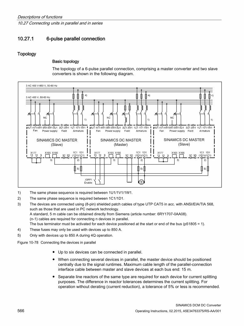
Descriptions of functions 10.27 Connecting units in parallel and in series
SINAMICS DCM DC Converter 566 Operating Instructions, 02.2015, A5E34763375/RS-AA/001
10.27.1 6-pulse parallel connection
Topology Basic topology
The topology of a 6-pulse parallel connection, comprising a master converter and two slave converters is shown in the following diagram.
1) The same phase sequence is required between 1U1/1V1/1W1. 2) The same phase sequence is required between 1C1/1D1. 3) The devices are connected using (8-pin) shielded patch cables of type UTP CAT5 in acc. with ANSI/EIA/TIA 568,
such as those that are used in PC network technology. A standard, 5 m cable can be obtained directly from Siemens (article number: 6RY1707-0AA08). (n-1) cables are required for connecting n devices in parallel. The bus terminator must be activated for each device positioned at the start or end of the bus (p51805 = 1).
4) These fuses may only be used with devices up to 850 A. 5) Only with devices up to 850 A during 4Q operation.
Figure 10-78 Connecting the devices in parallel
Up to six devices can be connected in parallel.
When connecting several devices in parallel, the master device should be positioned centrally due to the signal runtimes. Maximum cable length of the parallel-connection interface cable between master and slave devices at each bus end: 15 m.
Separate line reactors of the same type are required for each device for current splitting purposes. The difference in reactor tolerances determines the current splitting. For operation without derating (current reduction), a tolerance of 5% or less is recommended.
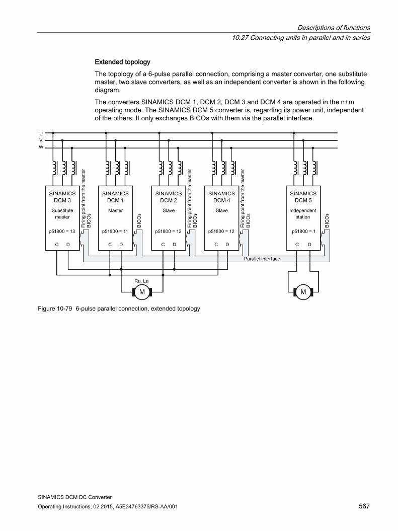
Descriptions of functions 10.27 Connecting units in parallel and in series
SINAMICS DCM DC Converter Operating Instructions, 02.2015, A5E34763375/RS-AA/001 567
Extended topology
The topology of a 6-pulse parallel connection, comprising a master converter, one substitute master, two slave converters, as well as an independent converter is shown in the following diagram.
The converters SINAMICS DCM 1, DCM 2, DCM 3 and DCM 4 are operated in the n+m operating mode. The SINAMICS DCM 5 converter is, regarding its power unit, independent of the others. It only exchanges BICOs with them via the parallel interface.
Figure 10-79 6-pulse parallel connection, extended topology
Descriptions of functions 10.27 Connecting units in parallel and in series
SINAMICS DCM DC Converter 568 Operating Instructions, 02.2015, A5E34763375/RS-AA/001
Operating modes of the 6-pulse parallel connection There are two operating modes:
Standard mode: A SINAMICS DCM is defined as the master. This device carries out the closed-loop speed control, the closed-loop armature-current control, the line synchronization tasks and determines the firing points. The firing points and the thyristor pair to be fired are transferred to the slave devices; all the slaves then fire the thyristor pairs at these points.
n+m mode: n+m converters are connected in parallel. When up to m converters fail (e.g. a fuse ruptures in the power unit, a fault message occurs), operation is maintained without any interruption.
For n+m operation, a SINAMICS DCM is defined as master. Additional SINAMICS DCM are defined as substitute masters. As with the standard mode, the device defined as the master carries out the closed-loop speed control, the closed-loop armature current control, the line synchronization tasks and determines the firing points.
If a slave fails (due to a fuse blowing in the power unit or a fault being output, for example), operation continues with the remaining converters. The SINAMICS DCMs that are still in proper working order continue to operate uninterrupted.
If a master fails (due to a fuse blowing in the power unit or a fault being output, for example) a substitute master automatically becomes the master and the remaining devices continue to operate uninterrupted. If several SINAMICS DCMs are parameterized as substitute master, the substitute master with the lowest bus address (p51806) that is ready for operation takes over. Parameter r53311.0 indicates whether the SINAMICS DCM is currently operating as master (see FP9350).
During configuration, it is important to note that the power produced by n devices alone (rather than n+m devices) must also be sufficient for the application in question.
When operating the SINAMICS DCM together with a SIMOREG DC-MASTER Converter Commutation Protector (CCP), n+m operation must be deactivated. Versions of the n+m operating mode: 1. n+m mode only in the armature circuit In this operating mode, when the master fails, only the armature firing pulses and the
upstream closed-loop control (setpoint channel, speed control, armature-current control) are transferred to the substitute master; however, not the field firing pulses and the up-stream control (EMF control, field current control). The main application for the operating mode is to supply large inductances (e.g. field windings of synchronous generators) with the SINAMICS DCM armature converter.
Activation: At the master and substitute master devices, set p51803=1.
Descriptions of functions 10.27 Connecting units in parallel and in series
SINAMICS DCM DC Converter Operating Instructions, 02.2015, A5E34763375/RS-AA/001 569
2. n+m mode in the armature circuit and in the field circuit In this operating mode, when the master fails
• the armature firing pulses and the upstream control (setpoint channel, speed control, armature current control) and
• the field firing pulses and the upstream control (EMF control, field current control) are transferred to the substitute master.
Activation: At the master and at the substitute master devices, set p51803=2.
Connection: Outputs 3C and 3D (field DC voltage output) of the master and all substitute masters must be connected to the motor field winding in parallel.
Notes: • When commissioning, after carrying out the optimization (by starting optimization
runs, for example), all parameters set by the optimization runs must be transferred to all substitute masters.
• Since the field supplies are connected in parallel, part of the overall motor-field current flows through the freewheeling arm of the respective field power units with disabled field firing pulses. For detecting the total motor field current (displayed at parameter r50035), in the actual master, the free-wheeling current detected by the "partner" device is therefore automatically added. Therefore, for this operating mode, there must be an intact parallel connection as well as an intact electronic power supply of the master and the substitute master – these are prerequisites. If this operating mode is also to be used after the electronic power supply of the master or the substitute master fails, then the total motor field actual current value must be externally sensed. The value must be supplied to the master and substitute master using p50612.
• Generally speaking, the master function is only transferred from the active master to the substitute master via telegram and an intact parallel interface. Even if the master's electronic power supply fails, the master still has enough time to transmit a telegram for the purpose of transferring the master function.
• As soon as the parallel connection is interrupted (by disconnecting the parallel connecting cable), it can no longer guaranteed that the master/slave assignment will be correct. The electronic power supply must be switched off and back on again at all devices!
Notes The control commands - switch-on/stop, operating enable, quick stop, etc. - must also be
entered at all of the substitute master devices.
The speed setpoint and the actual speed value must be entered at all substitute master devices.
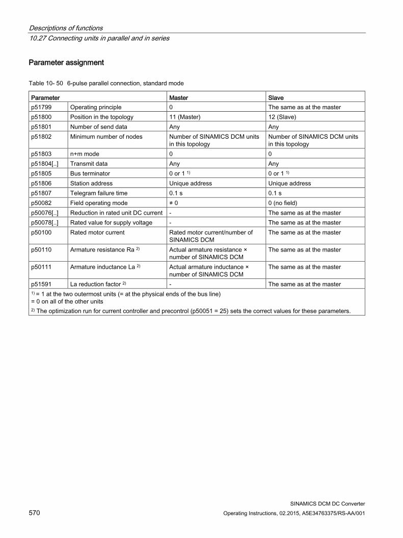
Descriptions of functions 10.27 Connecting units in parallel and in series
SINAMICS DCM DC Converter 570 Operating Instructions, 02.2015, A5E34763375/RS-AA/001
Parameter assignment
Table 10- 50 6-pulse parallel connection, standard mode
Parameter Master Slave p51799 Operating principle 0 The same as at the master p51800 Position in the topology 11 (Master) 12 (Slave) p51801 Number of send data Any Any p51802 Minimum number of nodes Number of SINAMICS DCM units
in this topology Number of SINAMICS DCM units in this topology
p51803 n+m mode 0 0 p51804[..] Transmit data Any Any p51805 Bus terminator 0 or 1 1) 0 or 1 1) p51806 Station address Unique address Unique address p51807 Telegram failure time 0.1 s 0.1 s p50082 Field operating mode ≠ 0 0 (no field) p50076[..] Reduction in rated unit DC current - The same as at the master p50078[..] Rated value for supply voltage - The same as at the master p50100 Rated motor current Rated motor current/number of
SINAMICS DCM The same as at the master
p50110 Armature resistance Ra 2) Actual armature resistance × number of SINAMICS DCM
The same as at the master
p50111 Armature inductance La 2) Actual armature inductance × number of SINAMICS DCM
The same as at the master
p51591 La reduction factor 2) - The same as at the master 1) = 1 at the two outermost units (= at the physical ends of the bus line) = 0 on all of the other units 2) The optimization run for current controller and precontrol (p50051 = 25) sets the correct values for these parameters.
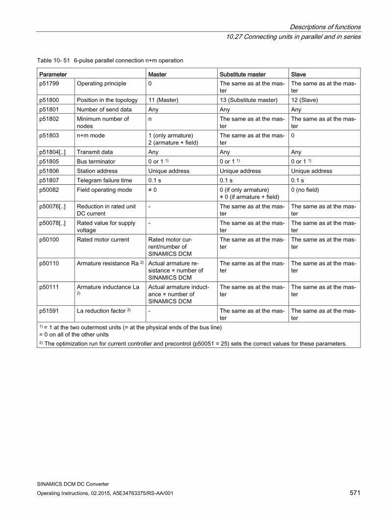
Descriptions of functions 10.27 Connecting units in parallel and in series
SINAMICS DCM DC Converter Operating Instructions, 02.2015, A5E34763375/RS-AA/001 571
Table 10- 51 6-pulse parallel connection n+m operation
Parameter Master Substitute master Slave p51799 Operating principle 0 The same as at the mas-
ter The same as at the mas-ter
p51800 Position in the topology 11 (Master) 13 (Substitute master) 12 (Slave) p51801 Number of send data Any Any Any p51802 Minimum number of
nodes n The same as at the mas-
ter The same as at the mas-ter
p51803 n+m mode 1 (only armature) 2 (armature + field)
The same as at the mas-ter
0
p51804[..] Transmit data Any Any Any p51805 Bus terminator 0 or 1 1) 0 or 1 1) 0 or 1 1) p51806 Station address Unique address Unique address Unique address p51807 Telegram failure time 0.1 s 0.1 s 0.1 s p50082 Field operating mode ≠ 0 0 (if only armature)
≠ 0 (if armature + field) 0 (no field)
p50076[..] Reduction in rated unit DC current
- The same as at the mas-ter
The same as at the mas-ter
p50078[..] Rated value for supply voltage
- The same as at the mas-ter
The same as at the mas-ter
p50100 Rated motor current Rated motor cur-rent/number of SINAMICS DCM
The same as at the mas-ter
The same as at the mas-ter
p50110 Armature resistance Ra 2) Actual armature re-sistance × number of SINAMICS DCM
The same as at the mas-ter
The same as at the mas-ter
p50111 Armature inductance La 2)
Actual armature induct-ance × number of SINAMICS DCM
The same as at the mas-ter
The same as at the mas-ter
p51591 La reduction factor 2) - The same as at the mas-ter
The same as at the mas-ter
1) = 1 at the two outermost units (= at the physical ends of the bus line) = 0 on all of the other units 2) The optimization run for current controller and precontrol (p50051 = 25) sets the correct values for these parameters.
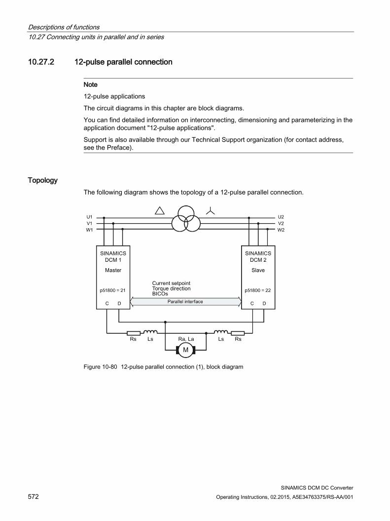
Descriptions of functions 10.27 Connecting units in parallel and in series
SINAMICS DCM DC Converter 572 Operating Instructions, 02.2015, A5E34763375/RS-AA/001
10.27.2 12-pulse parallel connection
Note
12-pulse applications
The circuit diagrams in this chapter are block diagrams.
You can find detailed information on interconnecting, dimensioning and parameterizing in the application document "12-pulse applications".
Support is also available through our Technical Support organization (for contact address, see the Preface).
Topology The following diagram shows the topology of a 12-pulse parallel connection.
Figure 10-80 12-pulse parallel connection (1), block diagram
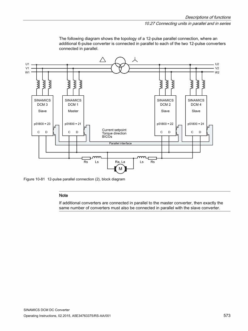
Descriptions of functions 10.27 Connecting units in parallel and in series
SINAMICS DCM DC Converter Operating Instructions, 02.2015, A5E34763375/RS-AA/001 573
The following diagram shows the topology of a 12-pulse parallel connection, where an additional 6-pulse converter is connected in parallel to each of the two 12-pulse converters connected in parallel.
Figure 10-81 12-pulse parallel connection (2), block diagram
Note
If additional converters are connected in parallel to the master converter, then exactly the same number of converters must also be connected in parallel with the slave converter.
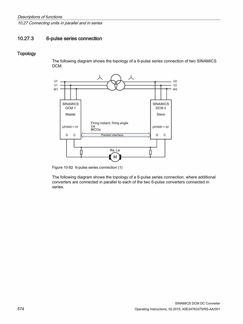
Descriptions of functions 10.27 Connecting units in parallel and in series
SINAMICS DCM DC Converter 574 Operating Instructions, 02.2015, A5E34763375/RS-AA/001
10.27.3 6-pulse series connection
Topology The following diagram shows the topology of a 6-pulse series connection of two SINAMICS DCM.
Figure 10-82 6-pulse series connection (1)
The following diagram shows the topology of a 6-pulse series connection, where additional converters are connected in parallel to each of the two 6-pulse converters connected in series.
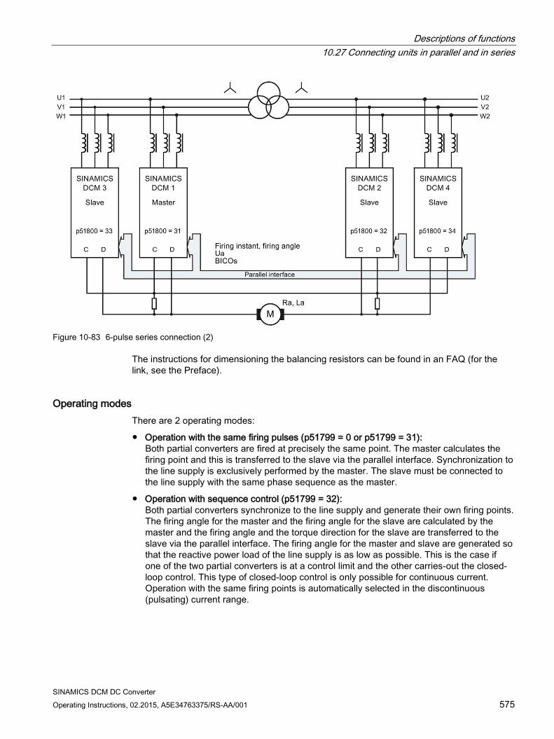
Descriptions of functions 10.27 Connecting units in parallel and in series
SINAMICS DCM DC Converter Operating Instructions, 02.2015, A5E34763375/RS-AA/001 575
Figure 10-83 6-pulse series connection (2)
The instructions for dimensioning the balancing resistors can be found in an FAQ (for the link, see the Preface).
Operating modes There are 2 operating modes:
Operation with the same firing pulses (p51799 = 0 or p51799 = 31): Both partial converters are fired at precisely the same point. The master calculates the firing point and this is transferred to the slave via the parallel interface. Synchronization to the line supply is exclusively performed by the master. The slave must be connected to the line supply with the same phase sequence as the master.
Operation with sequence control (p51799 = 32): Both partial converters synchronize to the line supply and generate their own firing points. The firing angle for the master and the firing angle for the slave are calculated by the master and the firing angle and the torque direction for the slave are transferred to the slave via the parallel interface. The firing angle for the master and slave are generated so that the reactive power load of the line supply is as low as possible. This is the case if one of the two partial converters is at a control limit and the other carries-out the closed-loop control. This type of closed-loop control is only possible for continuous current. Operation with the same firing points is automatically selected in the discontinuous (pulsating) current range.
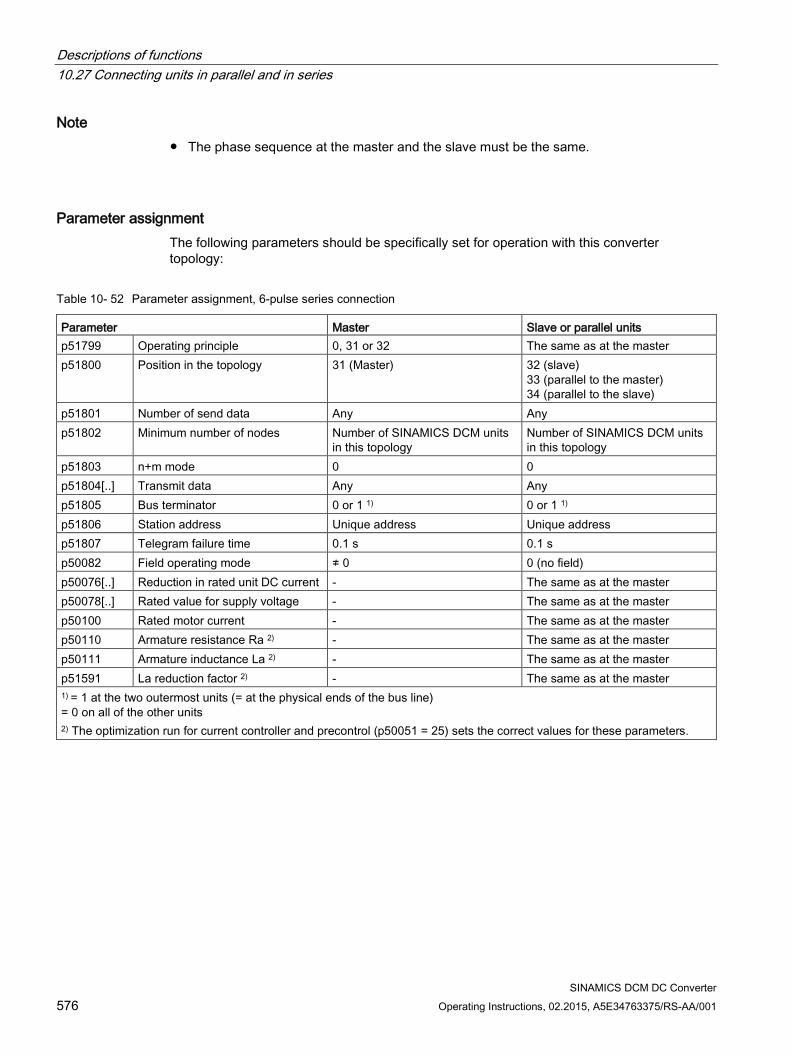
Descriptions of functions 10.27 Connecting units in parallel and in series
SINAMICS DCM DC Converter 576 Operating Instructions, 02.2015, A5E34763375/RS-AA/001
Note The phase sequence at the master and the slave must be the same.
Parameter assignment The following parameters should be specifically set for operation with this converter topology:
Table 10- 52 Parameter assignment, 6-pulse series connection
Parameter Master Slave or parallel units p51799 Operating principle 0, 31 or 32 The same as at the master p51800 Position in the topology 31 (Master) 32 (slave)
33 (parallel to the master) 34 (parallel to the slave)
p51801 Number of send data Any Any p51802 Minimum number of nodes Number of SINAMICS DCM units
in this topology Number of SINAMICS DCM units in this topology
p51803 n+m mode 0 0 p51804[..] Transmit data Any Any p51805 Bus terminator 0 or 1 1) 0 or 1 1) p51806 Station address Unique address Unique address p51807 Telegram failure time 0.1 s 0.1 s p50082 Field operating mode ≠ 0 0 (no field) p50076[..] Reduction in rated unit DC current - The same as at the master p50078[..] Rated value for supply voltage - The same as at the master p50100 Rated motor current - The same as at the master p50110 Armature resistance Ra 2) - The same as at the master p50111 Armature inductance La 2) - The same as at the master p51591 La reduction factor 2) - The same as at the master 1) = 1 at the two outermost units (= at the physical ends of the bus line) = 0 on all of the other units 2) The optimization run for current controller and precontrol (p50051 = 25) sets the correct values for these parameters.
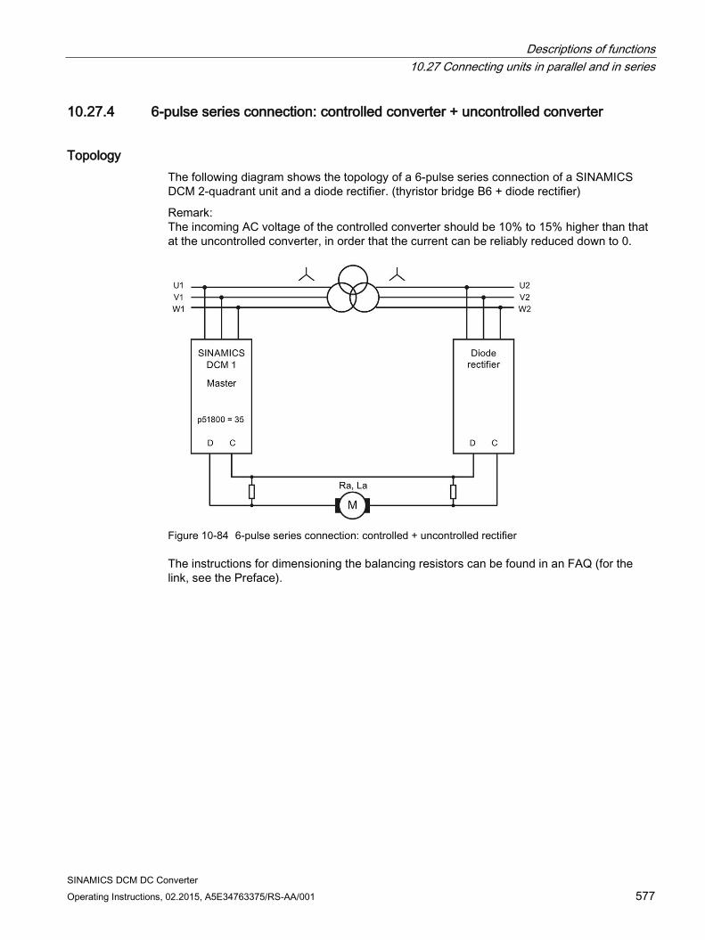
Descriptions of functions 10.27 Connecting units in parallel and in series
SINAMICS DCM DC Converter Operating Instructions, 02.2015, A5E34763375/RS-AA/001 577
10.27.4 6-pulse series connection: controlled converter + uncontrolled converter
Topology The following diagram shows the topology of a 6-pulse series connection of a SINAMICS DCM 2-quadrant unit and a diode rectifier. (thyristor bridge B6 + diode rectifier)
Remark: The incoming AC voltage of the controlled converter should be 10% to 15% higher than that at the uncontrolled converter, in order that the current can be reliably reduced down to 0.
Figure 10-84 6-pulse series connection: controlled + uncontrolled rectifier
The instructions for dimensioning the balancing resistors can be found in an FAQ (for the link, see the Preface).
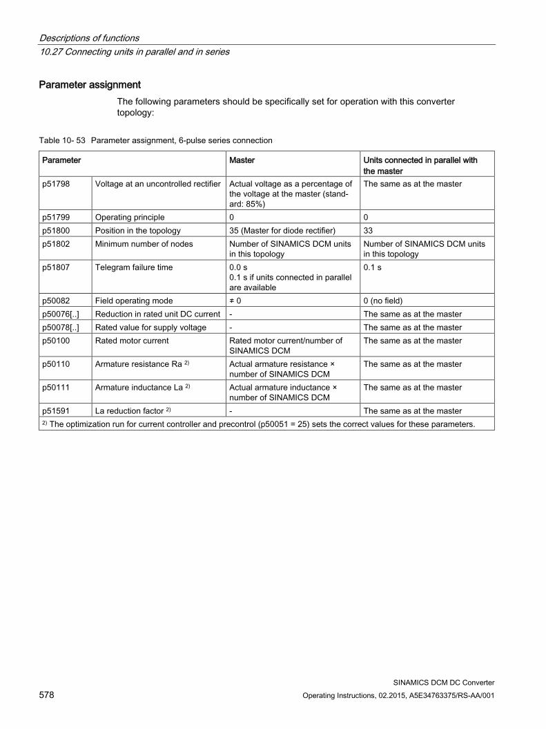
Descriptions of functions 10.27 Connecting units in parallel and in series
SINAMICS DCM DC Converter 578 Operating Instructions, 02.2015, A5E34763375/RS-AA/001
Parameter assignment The following parameters should be specifically set for operation with this converter topology:
Table 10- 53 Parameter assignment, 6-pulse series connection
Parameter Master Units connected in parallel with the master
p51798 Voltage at an uncontrolled rectifier Actual voltage as a percentage of the voltage at the master (stand-ard: 85%)
The same as at the master
p51799 Operating principle 0 0 p51800 Position in the topology 35 (Master for diode rectifier) 33 p51802 Minimum number of nodes Number of SINAMICS DCM units
in this topology Number of SINAMICS DCM units in this topology
p51807 Telegram failure time 0.0 s 0.1 s if units connected in parallel are available
0.1 s
p50082 Field operating mode ≠ 0 0 (no field) p50076[..] Reduction in rated unit DC current - The same as at the master p50078[..] Rated value for supply voltage - The same as at the master p50100 Rated motor current Rated motor current/number of
SINAMICS DCM The same as at the master
p50110 Armature resistance Ra 2) Actual armature resistance × number of SINAMICS DCM
The same as at the master
p50111 Armature inductance La 2) Actual armature inductance × number of SINAMICS DCM
The same as at the master
p51591 La reduction factor 2) - The same as at the master 2) The optimization run for current controller and precontrol (p50051 = 25) sets the correct values for these parameters.
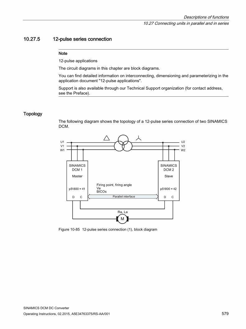
Descriptions of functions 10.27 Connecting units in parallel and in series
SINAMICS DCM DC Converter Operating Instructions, 02.2015, A5E34763375/RS-AA/001 579
10.27.5 12-pulse series connection
Note
12-pulse applications
The circuit diagrams in this chapter are block diagrams.
You can find detailed information on interconnecting, dimensioning and parameterizing in the application document "12-pulse applications".
Support is also available through our Technical Support organization (for contact address, see the Preface).
Topology The following diagram shows the topology of a 12-pulse series connection of two SINAMICS DCM.
Figure 10-85 12-pulse series connection (1), block diagram
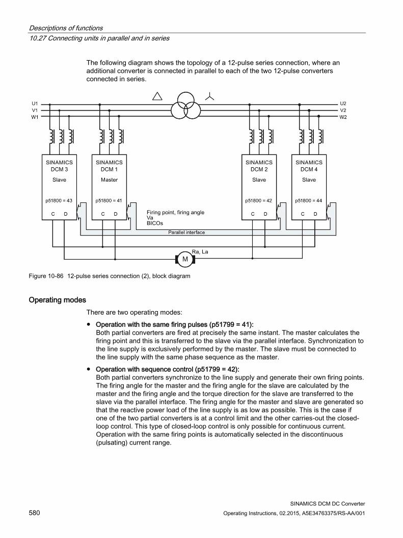
Descriptions of functions 10.27 Connecting units in parallel and in series
SINAMICS DCM DC Converter 580 Operating Instructions, 02.2015, A5E34763375/RS-AA/001
The following diagram shows the topology of a 12-pulse series connection, where an additional converter is connected in parallel to each of the two 12-pulse converters connected in series.
Figure 10-86 12-pulse series connection (2), block diagram
Operating modes There are two operating modes:
Operation with the same firing pulses (p51799 = 41): Both partial converters are fired at precisely the same instant. The master calculates the firing point and this is transferred to the slave via the parallel interface. Synchronization to the line supply is exclusively performed by the master. The slave must be connected to the line supply with the same phase sequence as the master.
Operation with sequence control (p51799 = 42): Both partial converters synchronize to the line supply and generate their own firing points. The firing angle for the master and the firing angle for the slave are calculated by the master and the firing angle and the torque direction for the slave are transferred to the slave via the parallel interface. The firing angle for the master and slave are generated so that the reactive power load of the line supply is as low as possible. This is the case if one of the two partial converters is at a control limit and the other carries-out the closed-loop control. This type of closed-loop control is only possible for continuous current. Operation with the same firing points is automatically selected in the discontinuous (pulsating) current range.
Descriptions of functions 10.27 Connecting units in parallel and in series
SINAMICS DCM DC Converter Operating Instructions, 02.2015, A5E34763375/RS-AA/001 581
Remark The current ripple is significantly higher during during operation with sequence control than operation with the same firing pulses. In this case, the current ripple approximately corresponds to that for 6-pulse operation. Especially in older motors, under certain circumstances this ripple can cause problems (for example, during commutation).
Therefore, a conscious decision must be made:
Low ripple, but no reduction of the reactive power: → Operation with the same firing pulses (p51799 = 41)
Low reactive power, but no reduction of the ripple: → Operation with sequence control (p51799 = 42)
Note The power unit of the slave converter must be connected to the 12-pulse transformer so that its phases lag the phases of the line supply at the master by 30°. The phase sequence must be the same.
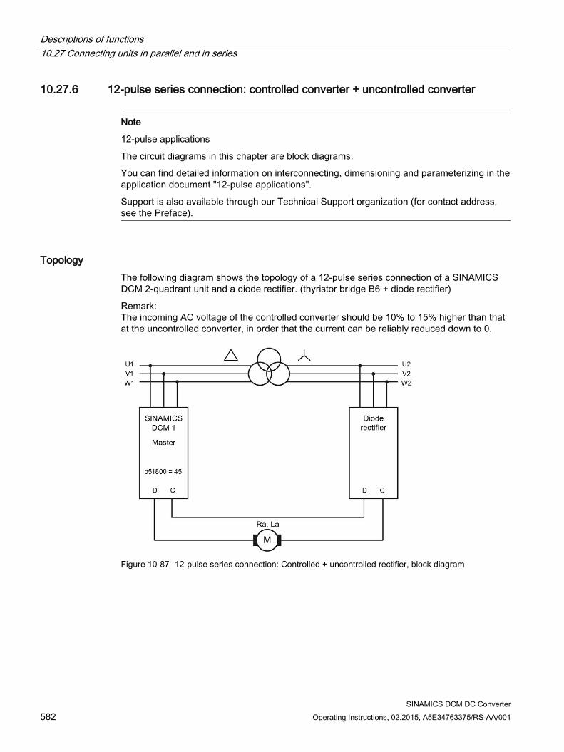
Descriptions of functions 10.27 Connecting units in parallel and in series
SINAMICS DCM DC Converter 582 Operating Instructions, 02.2015, A5E34763375/RS-AA/001
10.27.6 12-pulse series connection: controlled converter + uncontrolled converter
Note
12-pulse applications
The circuit diagrams in this chapter are block diagrams.
You can find detailed information on interconnecting, dimensioning and parameterizing in the application document "12-pulse applications".
Support is also available through our Technical Support organization (for contact address, see the Preface).
Topology The following diagram shows the topology of a 12-pulse series connection of a SINAMICS DCM 2-quadrant unit and a diode rectifier. (thyristor bridge B6 + diode rectifier)
Remark: The incoming AC voltage of the controlled converter should be 10% to 15% higher than that at the uncontrolled converter, in order that the current can be reliably reduced down to 0.
Figure 10-87 12-pulse series connection: Controlled + uncontrolled rectifier, block diagram
Descriptions of functions 10.27 Connecting units in parallel and in series
SINAMICS DCM DC Converter Operating Instructions, 02.2015, A5E34763375/RS-AA/001 583
10.27.7 Switchover of the power unit topology - option S50 Ordering information for option S50, see Chapter 2
Note
SINAMICS DCM can only be retrofitted with option S50 in the manufacturers factory.
Note
You can find detailed information on interconnecting, dimensioning and parameterizing in the application document "12-pulse applications". Support is also available through our Technical Support organization (for contact address, see the Preface).
In certain applications, it is necessary to switch between 12-pulse parallel connection and 12-pulse series connection during operation by means of a command.
External contactors must be used to switch over the power unit topology. Option S50 provides the required firmware functionality.
Requirements for using this functionality All participating SINAMICS DCM units must be equipped with option S50
"n+m" operation is not permissible
The "parallel switching master" function must remain at the same SINAMICS DCM for both power unit topologies
Descriptions of functions 10.28 Field reversal
SINAMICS DCM DC Converter 584 Operating Instructions, 02.2015, A5E34763375/RS-AA/001
10.28 Field reversal see also the SINAMICS DCM List Manual, function diagram 6920
When using a two-quadrant unit (with only one armature current flow direction) by reversing the current in the excitation winding of the DC motor (field reversal) operation in additional quadrants of the speed-torque characteristic is possible (direction of rotation reversal and braking).
Two contactors are required in the field circuit to reverse the field voltage. The functions "Direction of rotation reversal using field reversal" and "Braking using field reversal" control connector outputs r53195[0] (close field contactor 1) and r53195[1] (close field contactor 2), which are then used to control the two field contactors.
A protection circuit is required in the field circuit. r53195[0] = 0 No contactor control = 1 Control for a contactor to switch-in the positive field direction r53195[1] = 0 No contactor control = 1 Control for a contactor to switch-in the negative field direction
10.28.1 Direction of rotation reversal using field reversal The function "Direction of rotation reversal using field reversal" is controlled via the connector input selected with p50580 - and this has a switch function. It defines the field direction and therefore also the direction of rotation for a positive speed setpoint. Connector input = 0 A positive field direction is selected.
"Close field contactor 1" (r53195[0]) = 1, "Close field contactor 2" (r53195[1] = 0
Connector input = 1 A negative field direction is selected. "Close field contactor 1" (r53195[0]) = 0, "Close field contactor 2" (r53195[1] = 1
Changing the logical level of the connector input controlling the function "Direction of rotation reversal using field reversal " brakes the drive and accelerates it in the opposite direction of rotation.
Field reversal is completely executed. Level changes at the connector input have no effect while the field is being reversed.
Note
Only positive speed setpoints make sense.
Descriptions of functions 10.28 Field reversal
SINAMICS DCM DC Converter Operating Instructions, 02.2015, A5E34763375/RS-AA/001 585
Control sequence when specifying "Direction of rotation using field reversal": 1. Drive rotates in direction of rotation 1 (or is at a standstill)
2. Specify "Direction of rotation reversal using field reversal" by changing the logical state of the connector input selected using p50580
3. Field reversal is executed Precondition: No braking was initiated using the button function "Braking using field reversal"
– Wait until armature current IA = 0 , then armature pulse inhibit (the drive then remains in operating state ≥ o1.4)
– Inhibit field firing pulses (r52268=0 also initiates this)
– Wait until Ifield (r52265) < Ifield min (p50394)
– Wait time according to p50092[00] (0.0 to 10.0 s, factory setting 3.0 s)
– Open actual field contactor (r53195.0 = 0 or r53195[1] = 0)
– Wait time according to p50092[01] (0.0 to 10.0 s, factory setting 0.2 s)
– Control new field contactor (r53195.1 = 1 or r53195[0] = 1)
– Reverse the speed actual value (with the exception, for p50083 = 3 ... EMF as speed actual value)
– Wait time according to p50092[02] (0.0 to 10.0 s, factory setting 0.1 s)
– Enable field firing pulses
– Wait until Ifield (r52265) > Ifield set (r52268)*p50398
– Wait time according to p50092[03] (0.0 to 10.0 s, factory setting 3.0 s)
– Enable armature firing pulses (operating state o1.4 can be exited)
4. Drive brakes and then rotates in direction of rotation 2 (or is at a standstill)
Note
In the case of an internal speed actual value reversal as a result of field reversal, p50083 is supplied with inverted signal values (exception: p50083 = 3, see the SINAMICS DCM List Manual, function diagram 6810).
When using the ramp-function generator it is recommended to parameterize p50228 = 0 (no speed controller setpoint filtering). If this is not done, then initial braking can occur at the current limit as a result of the speed actual value reversal and setting the ramp-function generator output to the (reversed) speed actual value or to the value according to p50639 in operating state o1.4.
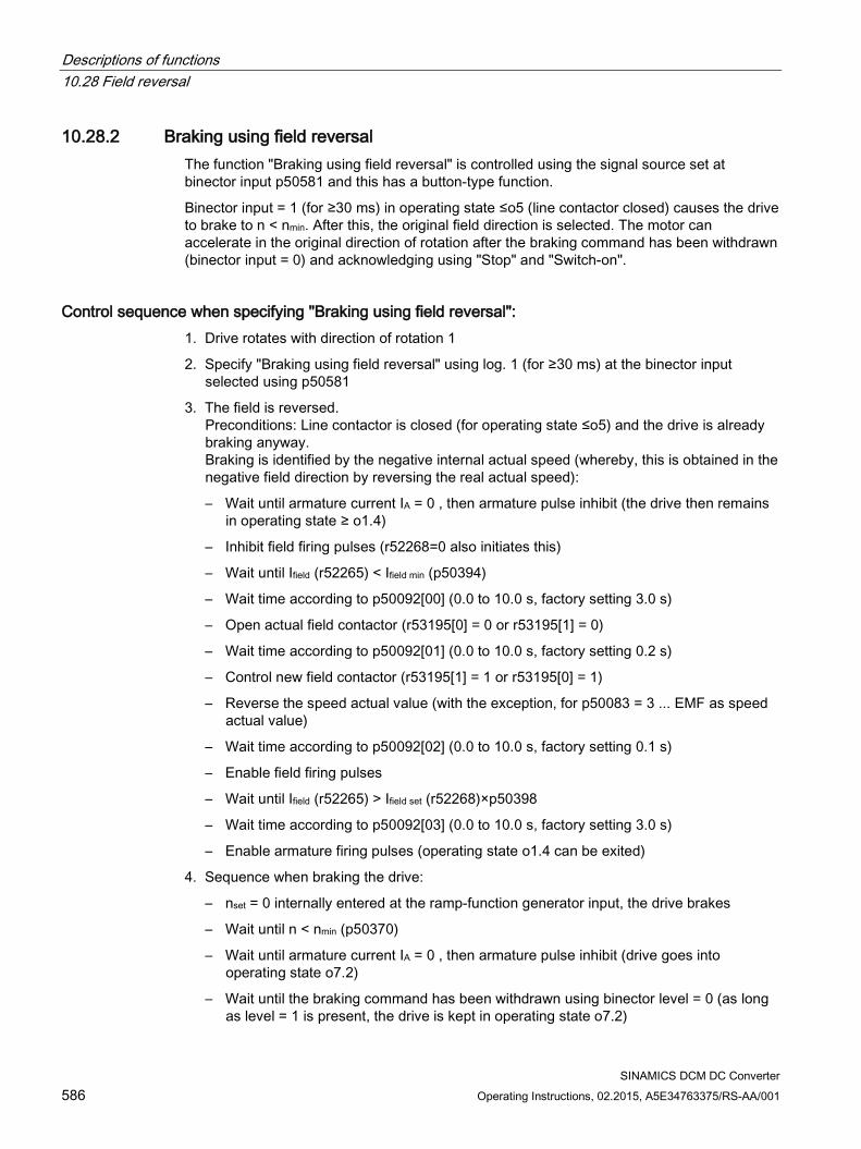
Descriptions of functions 10.28 Field reversal
SINAMICS DCM DC Converter 586 Operating Instructions, 02.2015, A5E34763375/RS-AA/001
10.28.2 Braking using field reversal The function "Braking using field reversal" is controlled using the signal source set at binector input p50581 and this has a button-type function.
Binector input = 1 (for ≥30 ms) in operating state ≤o5 (line contactor closed) causes the drive to brake to n < nmin. After this, the original field direction is selected. The motor can accelerate in the original direction of rotation after the braking command has been withdrawn (binector input = 0) and acknowledging using "Stop" and "Switch-on".
Control sequence when specifying "Braking using field reversal": 1. Drive rotates with direction of rotation 1
2. Specify "Braking using field reversal" using log. 1 (for ≥30 ms) at the binector input selected using p50581
3. The field is reversed. Preconditions: Line contactor is closed (for operating state ≤o5) and the drive is already braking anyway. Braking is identified by the negative internal actual speed (whereby, this is obtained in the negative field direction by reversing the real actual speed):
– Wait until armature current IA = 0 , then armature pulse inhibit (the drive then remains in operating state ≥ o1.4)
– Inhibit field firing pulses (r52268=0 also initiates this)
– Wait until Ifield (r52265) < Ifield min (p50394)
– Wait time according to p50092[00] (0.0 to 10.0 s, factory setting 3.0 s)
– Open actual field contactor (r53195[0] = 0 or r53195[1] = 0)
– Wait time according to p50092[01] (0.0 to 10.0 s, factory setting 0.2 s)
– Control new field contactor (r53195[1] = 1 or r53195[0] = 1)
– Reverse the speed actual value (with the exception, for p50083 = 3 ... EMF as speed actual value)
– Wait time according to p50092[02] (0.0 to 10.0 s, factory setting 0.1 s)
– Enable field firing pulses
– Wait until Ifield (r52265) > Ifield set (r52268)×p50398
– Wait time according to p50092[03] (0.0 to 10.0 s, factory setting 3.0 s)
– Enable armature firing pulses (operating state o1.4 can be exited)
4. Sequence when braking the drive:
– nset = 0 internally entered at the ramp-function generator input, the drive brakes
– Wait until n < nmin (p50370)
– Wait until armature current IA = 0 , then armature pulse inhibit (drive goes into operating state o7.2)
– Wait until the braking command has been withdrawn using binector level = 0 (as long as level = 1 is present, the drive is kept in operating state o7.2)

Descriptions of functions 10.28 Field reversal
SINAMICS DCM DC Converter Operating Instructions, 02.2015, A5E34763375/RS-AA/001 587
5. Sequence to change over to the original field direction Precondition: The present field direction does not match the field direction requested using the function "Direction of rotation reversal using field reversal"
– Wait until armature current IA = 0 , then armature pulse inhibit (the drive then remains in operating state ≥ o1.4)
– Inhibit field firing pulses (r52268=0 also initiates this)
– Wait until Ifield (r52265) < Ifield min (p50394)
– Wait time according to p50092[00] (0.0 to 10.0 s, factory setting 3.0 s)
– Open actual field contactor (r53195[0] = 0 or r53195[1] = 0)
– Wait time according to p50092[01] (0.0 to 10.0 s, factory setting 0.2 s)
– Control new field contactor (r53195[1] = 1 or r53195[0] = 1)
– Reverse the speed actual value (with the exception, for p50083 = 3 ... EMF as speed actual value)
– Wait time according to p50092[02] (0.0 to 10.0 s, factory setting 0.1 s)
– Enable field firing pulses
– Wait until Ifield (r52265) > Ifield set (r52268×p50398)
– Wait time according to p50092[04] (0.0 to 10.0 s, factory setting 3.0 s)
– Armature firing pulses are again possible
6. The drive is in operating state o7.2 Acceleration is possible in the original direction of rotation when acknowledging using an external "Stop" and "Switch-on".
Please also read the note at the end of the chapter "Direction of rotation reversal using field reversal"
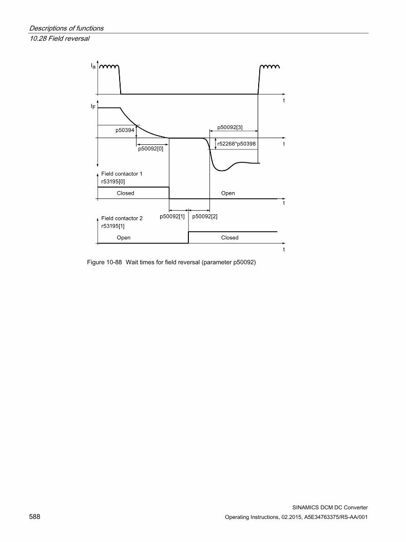
Descriptions of functions 10.28 Field reversal
SINAMICS DCM DC Converter 588 Operating Instructions, 02.2015, A5E34763375/RS-AA/001
Figure 10-88 Wait times for field reversal (parameter p50092)
Descriptions of functions 10.29 Serial interface with peer-to-peer protocol
SINAMICS DCM DC Converter Operating Instructions, 02.2015, A5E34763375/RS-AA/001 589
10.29 Serial interface with peer-to-peer protocol
General information The peer-to-peer interface enables BICO interconnections across several SINAMICS DCMs, as well as allowing the peer-to-peer interface to establish signal connections between converters in the SINAMICS DC MASTER range (MLFB = 6RA80...) and converters in other ranges, such as SIMOREG DC-MASTER (MLFB = 6RA70...) and SIMOREG K (MLFB = 6RA24...).
Properties A "peer-to-peer connection" refers to "a connection between partners with equal status". Unlike the classic master-slave bus systems (such as PROFIBUS or USS), peer-to-peer connections enable the same converter to act as both a master (setpoint source) and a slave (setpoint recipient).
Signals can be transferred via the peer-to-peer connection from one converter to another in fully digital format.
Velocity setpoints for creating a setpoint cascade, e.g. in paper making machines, film manufacturing machines, and wire drawing machines, as well as fiber stretching plants
Torque setpoints for load distribution control systems on drives that are coupled either mechanically or by means of the material, e.g. horizontal-shaft drives on a printing machine or S-roll drives
Acceleration setpoints (dv/dt) for acceleration precontrol in multi-motor drives
Control commands
The peer-to-peer interface uses the RS485 interface at connector X177 (terminals 37, 38, 39, and 40).
Function diagrams Function diagram FP9300 shows the settings and BICO interconnection options for the "peer-to-peer connection".
Diagnostics Parameter r50799 contains information about the distribution of error-free telegrams and telegrams with errors over time, as well as the type of any communications errors that occur.
Descriptions of functions 10.29 Serial interface with peer-to-peer protocol
SINAMICS DCM DC Converter 590 Operating Instructions, 02.2015, A5E34763375/RS-AA/001
Topologies The peer-to-peer interface supports two topologies:
Point-to-point connection (see the series connection example further down)
– 4-wire connection between two converters
– Data transmission in both directions
Bus connection (see the bus connection example further down)
– 2-wire connection between multiple converters
– Data transmission in one direction only
– The active sender is selected by means of the "Send enable" signal selected using p50817. The send enable may only be at the "High" level for one converter in each case. Converters whose send enable is at the "Low" level switch their sender to high resistance.
Parameterization
Table 10- 54 Parameterizing the peer-to-peer interface
Function Parameter Peer-to-peer protocol selection p50790 = 5 PZD number p50791 = 1 to 5 words Baud rate p50793 = 1 to 13, corresponding to between 300 and 187,500
baud Bus terminator p50795 = 0: Bus terminator OFF
p50795 = 1: Bus terminator ON Error statistics r50799[1]: Displays receive errors on the peer-to-peer inter-
face
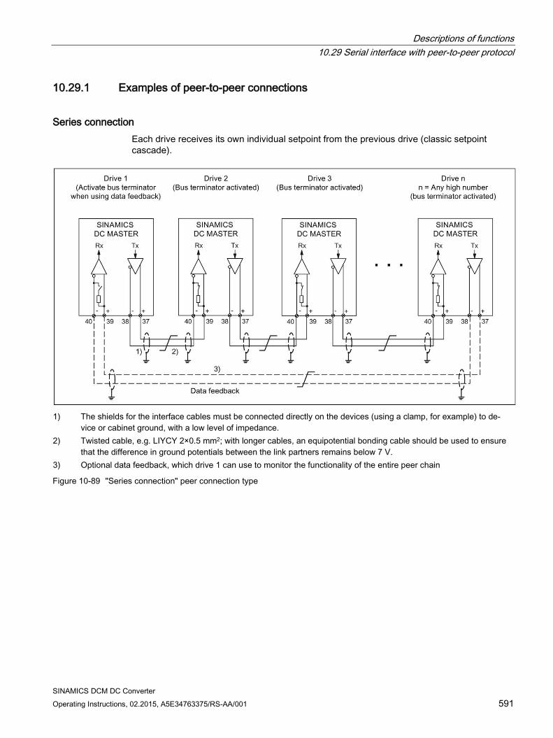
Descriptions of functions 10.29 Serial interface with peer-to-peer protocol
SINAMICS DCM DC Converter Operating Instructions, 02.2015, A5E34763375/RS-AA/001 591
10.29.1 Examples of peer-to-peer connections
Series connection Each drive receives its own individual setpoint from the previous drive (classic setpoint cascade).
1) The shields for the interface cables must be connected directly on the devices (using a clamp, for example) to de-
vice or cabinet ground, with a low level of impedance. 2) Twisted cable, e.g. LIYCY 2×0.5 mm2; with longer cables, an equipotential bonding cable should be used to ensure
that the difference in ground potentials between the link partners remains below 7 V. 3) Optional data feedback, which drive 1 can use to monitor the functionality of the entire peer chain
Figure 10-89 "Series connection" peer connection type
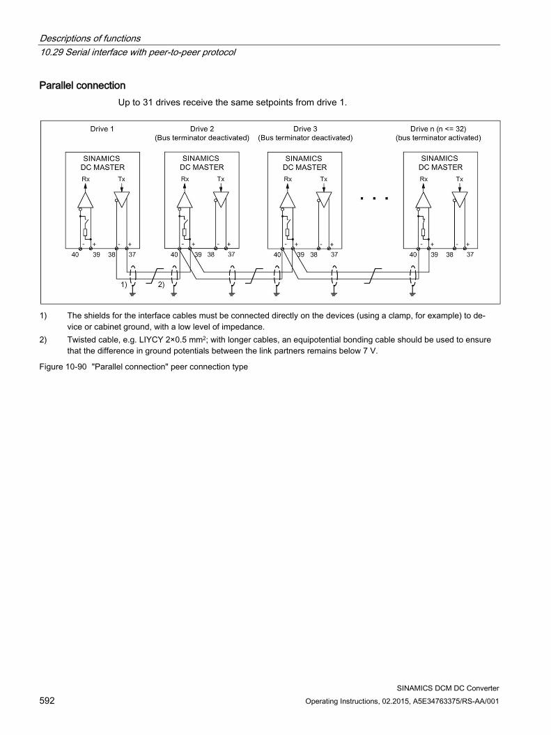
Descriptions of functions 10.29 Serial interface with peer-to-peer protocol
SINAMICS DCM DC Converter 592 Operating Instructions, 02.2015, A5E34763375/RS-AA/001
Parallel connection Up to 31 drives receive the same setpoints from drive 1.
1) The shields for the interface cables must be connected directly on the devices (using a clamp, for example) to de-
vice or cabinet ground, with a low level of impedance. 2) Twisted cable, e.g. LIYCY 2×0.5 mm2; with longer cables, an equipotential bonding cable should be used to ensure
that the difference in ground potentials between the link partners remains below 7 V.
Figure 10-90 "Parallel connection" peer connection type
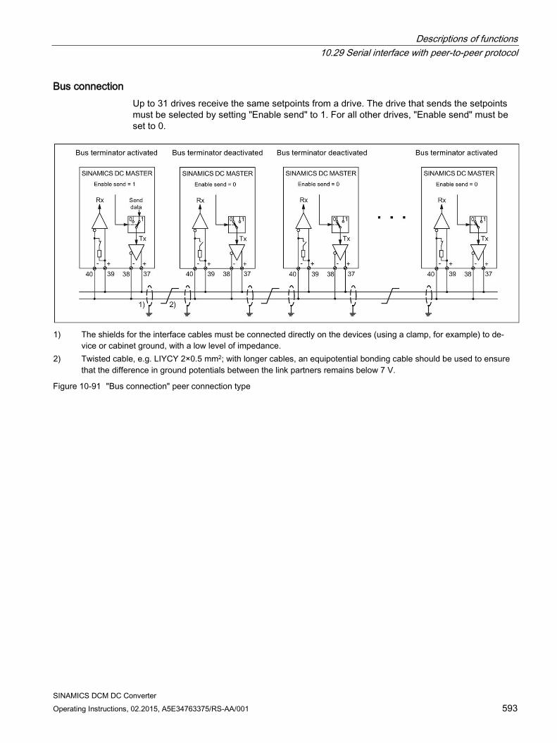
Descriptions of functions 10.29 Serial interface with peer-to-peer protocol
SINAMICS DCM DC Converter Operating Instructions, 02.2015, A5E34763375/RS-AA/001 593
Bus connection Up to 31 drives receive the same setpoints from a drive. The drive that sends the setpoints must be selected by setting "Enable send" to 1. For all other drives, "Enable send" must be set to 0.
1) The shields for the interface cables must be connected directly on the devices (using a clamp, for example) to de-
vice or cabinet ground, with a low level of impedance. 2) Twisted cable, e.g. LIYCY 2×0.5 mm2; with longer cables, an equipotential bonding cable should be used to ensure
that the difference in ground potentials between the link partners remains below 7 V.
Figure 10-91 "Bus connection" peer connection type
Descriptions of functions 10.30 Expanding the SINAMICS DCM to include a second CUD
SINAMICS DCM DC Converter 594 Operating Instructions, 02.2015, A5E34763375/RS-AA/001
10.30 Expanding the SINAMICS DCM to include a second CUD
General information As an option, the SINAMICS DC MASTER can be equipped with a second CUD by inserting it in the right-hand slot. This option is only available in conjunction with option G00 (Advanced CUD in left-hand slot). See also Chapter "Ordering information for options and accessories".
For the installation of the second CUD, see
Chapters Installing a second CUD (Page 90) and Replacing the CUD (Page 667).
NOTICE
Installing or removing a module is only permitted when the SINAMICS DC MASTER is in the voltage-free state.
Properties The right-hand CUD is used for system-specific extension of the SINAMICS DC MASTER functions.
It enables the following function extensions:
Doubling the number of hardware inputs and outputs for applications requiring more analog inputs, analog outputs, digital inputs, or digital outputs
Additional computing capacity for free function blocks and, above all, for application-specific function diagrams generated using DCC
Connection between the left-hand and right-hand CUD:
16 BICO connections can be established in each direction. This involves using the parallel-connection interface. Function diagrams FP9350, FP9352, and FP9355 show the settings and BICO interconnection options for the parallel-connection interface.
The hardware connection for the two CUDs is established inside the unit; there is no need for an external connection using connector X165 or X166. It is also possible to use the parallel-connection interface for controlling a power unit-side configuration in which several SINAMICS DC MASTER units are connected in parallel.
Parameter assignment The parameters for the right-hand CUD are assigned using the AOP30 or the STARTER commissioning tool. The Basic Operator Panel BOP20 cannot be used for this purpose.
Assigning parameters for the right-hand CUD using the AOP30: The AOP30 must be connected to connector X178 (RS485 interface) or X179 (RS232 interface) on the right-hand CUD.
Assigning parameters for the right-hand CUD using STARTER: STARTER views the right-hand CUD as a separate PROFIBUS node.
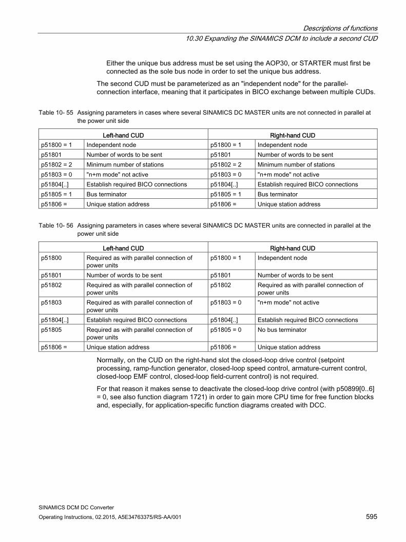
Descriptions of functions 10.30 Expanding the SINAMICS DCM to include a second CUD
SINAMICS DCM DC Converter Operating Instructions, 02.2015, A5E34763375/RS-AA/001 595
Either the unique bus address must be set using the AOP30, or STARTER must first be connected as the sole bus node in order to set the unique bus address.
The second CUD must be parameterized as an "independent node" for the parallel-connection interface, meaning that it participates in BICO exchange between multiple CUDs.
Table 10- 55 Assigning parameters in cases where several SINAMICS DC MASTER units are not connected in parallel at the power unit side
Left-hand CUD Right-hand CUD p51800 = 1 Independent node p51800 = 1 Independent node p51801 Number of words to be sent p51801 Number of words to be sent p51802 = 2 Minimum number of stations p51802 = 2 Minimum number of stations p51803 = 0 "n+m mode" not active p51803 = 0 "n+m mode" not active p51804[..] Establish required BICO connections p51804[..] Establish required BICO connections p51805 = 1 Bus terminator p51805 = 1 Bus terminator p51806 = Unique station address p51806 = Unique station address
Table 10- 56 Assigning parameters in cases where several SINAMICS DC MASTER units are connected in parallel at the power unit side
Left-hand CUD Right-hand CUD p51800 Required as with parallel connection of
power units p51800 = 1 Independent node
p51801 Number of words to be sent p51801 Number of words to be sent p51802 Required as with parallel connection of
power units p51802 Required as with parallel connection of
power units p51803 Required as with parallel connection of
power units p51803 = 0 "n+m mode" not active
p51804[..] Establish required BICO connections p51804[..] Establish required BICO connections p51805 Required as with parallel connection of
power units p51805 = 0 No bus terminator
p51806 = Unique station address p51806 = Unique station address
Normally, on the CUD on the right-hand slot the closed-loop drive control (setpoint processing, ramp-function generator, closed-loop speed control, armature-current control, closed-loop EMF control, closed-loop field-current control) is not required.
For that reason it makes sense to deactivate the closed-loop drive control (with p50899[0..6] = 0, see also function diagram 1721) in order to gain more CPU time for free function blocks and, especially, for application-specific function diagrams created with DCC.
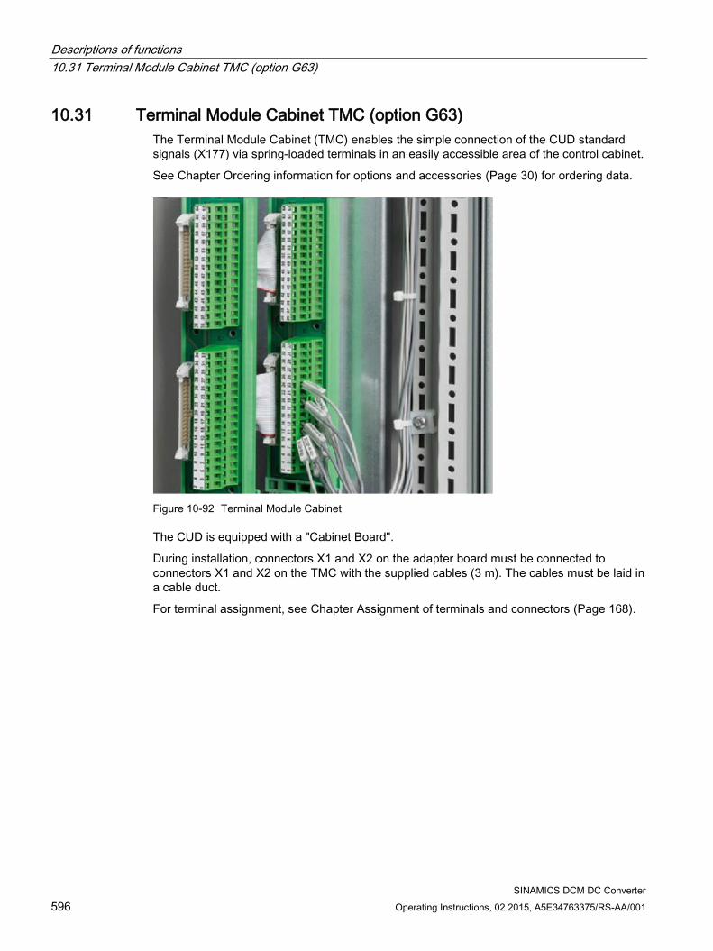
Descriptions of functions 10.31 Terminal Module Cabinet TMC (option G63)
SINAMICS DCM DC Converter 596 Operating Instructions, 02.2015, A5E34763375/RS-AA/001
10.31 Terminal Module Cabinet TMC (option G63) The Terminal Module Cabinet (TMC) enables the simple connection of the CUD standard signals (X177) via spring-loaded terminals in an easily accessible area of the control cabinet.
See Chapter Ordering information for options and accessories (Page 30) for ordering data.
Figure 10-92 Terminal Module Cabinet
The CUD is equipped with a "Cabinet Board".
During installation, connectors X1 and X2 on the adapter board must be connected to connectors X1 and X2 on the TMC with the supplied cables (3 m). The cables must be laid in a cable duct.
For terminal assignment, see Chapter Assignment of terminals and connectors (Page 168).
Descriptions of functions 10.32 Runtime (operating hours counter)
SINAMICS DCM DC Converter Operating Instructions, 02.2015, A5E34763375/RS-AA/001 597
10.32 Runtime (operating hours counter)
Total system runtime The total system runtime is displayed in r2114 (Control Unit).
Index 0 = System runtime in ms. After reaching 86400000 ms (24 h), the value is reset.
Index 1 = System runtime in days. The counter value is saved at switch off. After the drive unit is powered up, the counter continues to run with the most recently saved value.
Note
Errors and alarms are stamped with this system runtime.
If a connected AOP30 is parameterized as the time-of-day master (see Chapter 9, "Assigning parameters to AOP30 as the time-of-day master"), faults and alarms are provided with a real-time stamp.
Relative system runtime The relative system runtime since the last POWER ON is displayed in p0969 (Control Unit) in ms. The counter runs over after 49 days.
Descriptions of functions 10.33 Diagnostics
SINAMICS DCM DC Converter 598 Operating Instructions, 02.2015, A5E34763375/RS-AA/001
10.33 Diagnostics
10.33.1 Diagnostic memory To provide support for troubleshooting and remedying problems, the SINAMICS DC MASTER records various types of data in a diagnostics file. Siemens specialists can use the contents of this file to glean more in-depth information about the cause of inexplicable faults or other problems such as blown fuses or defective thyristors.
When contacting Siemens with queries related to problems of this type, it is, therefore, advisable that you both read out this file and e-mail a copy of it to Siemens experts.
With parallel or series connection, the diagnostics files of all devices must always be read out and sent to the Siemens experts.
Proceed as follows to read out the diagnostics file:
1. Insert the memory card in the drive.
2. Set p50832 to 1: This copies the diagnostics file to the memory card. A process which takes approximately two minutes. Copying is complete when p50832 takes on the value 0 again.
3. The diagnostics file is called DiagStor.spd, is approx. 600 KB in size, and can be found in the \USER\SINAMICS\DATA\LOG directory on the memory card.
For more details on the diagnostic memory, please refer to function diagram FP8052.
10.33.2 Trend recorder function The SINAMICS DC MASTER enables data from 4 channels to be recorded over an extended period, with a large memory depth. A file on the Memory card takes on the role of a long-term storage facility. The signals to be recorded are updated periodically and written cyclically to the file.
The file contains a line-by-line account of the operating hour and values for the 4 channels, in the form of an ASCII string, and can be evaluated and visualized using standard PC tools such as Notepad or Excel.
Recording must be started manually (by setting p51705 = 0/1/2). With a recording period of 1 second, the file grows by approximately 100 kB per hour.
When starting via p51705 = 1, recording is automatically stopped after the number of entries set at p51706 – and p51705 is set to 0.
When starting via p51705 = 2, the oldest entries are overwritten after the number of entries set on p51706. Recording must be stopped manually (with p51705 = 0).
The file is called Track.csv and can be found in the \USER\SINAMICS\DATA\LOG directory on the Memory card.
For more details on the trend recorder function, please refer to function diagram FP8050.
Descriptions of functions 10.33 Diagnostics
SINAMICS DCM DC Converter Operating Instructions, 02.2015, A5E34763375/RS-AA/001 599
10.33.3 Thyristor diagnostics SINAMICS DCM can perform a self-test of its own power unit. As a consequence, defective thyristors and other faults can be detected in the power unit.
Note 1:
Thyristor diagnostics cannot be used when SINAMICS DCMs are connected in series.
Note 2:
In parallel connections of SINAMICS DCMs (6-pulse or 12-pulse), the thyristor diagnostics must only be selected on the master. The thyristor diagnostics are then performed first on the master and then automatically in succession on all slaves. If a faulty thyristor is detected on a SINAMICS DCM, the appropriate fault message is issued on this SINAMICS DCM and not on the master on which the thyristor diagnostics was started.
Note 3:
If a thyristor is fused, in 6-pulse parallel connection it is not possible to identify in which of the parallel devices the defective thyristor is located. The corresponding fault message occurs on the master.
Selecting thyristor diagnostics:
Thyristor diagnostics are performed during the switch-on procedure. Parameter p50830 can be used to select for which switch-on procedures thyristor diagnostics is performed. p50830 = 0 never = 1 at the first ON after switching-on the electronics = 2 at each ON = 3 at the next ON (p50830 is then reset to 0)
Thyristor diagnostics sequence:
At each switch-on procedure, starting from operating state o7 the drive goes into state o0. During thyristor diagnostics, it remains in operating state o3 (see parameter r50000). Thyristor diagnostics takes approx. 30 s.
Descriptions of functions 10.33 Diagnostics
SINAMICS DCM DC Converter 600 Operating Instructions, 02.2015, A5E34763375/RS-AA/001
Thyristor diagnostics comprises two parts:
1. Checking the thyristor for its blocking capability All thyristors are individually fired and it is not permissible that current flows. If it does, this indicates that a thyristor is fused or it triggers with forward breakover or a ground fault has occurred, i.e. terminal 1C or 1D is connected to ground.
NOTICE
Ground leakage circuit breaker
In IT systems (i.e. in systems with an ungrounded neutral point of the supply transformer), the thyristor diagnostics cannot detect a single-pole ground fault.
For these types of line supply, it is recommended that a ground fault monitor is used.
WARNING
Impermissible operation with ground fault
The type and location of the fault cannot be established just from a ground fault error message. In the event of continued operation, serious aftereffects all the way to electric arcs are possible. This can result in death, serious injury or material damage.
If a ground fault occurs during operation, the system must be switched off immediately. Then identify and eliminate the source of the ground fault.
The plant operating company is responsible for the consequences for further operation after a ground fault has been detected. Carry out a risk analysis.
2. Checking that the thyristors can be triggered All of the thyristors are triggered in pairs and in this case, a current must flow (as a minimum, 5% of r50072[1]). Otherwise, a thyristor cannot be triggered. This can also be caused by a fault in the firing pulse generation.
NOTICE
Possible rotation of the motor shaft. The low current that flows during this test can cause the motor to briefly rotate for motors that are very easy to move and are not loaded, as in this operating state, the full field is already present.
Faults that are detected result in fault message F60061. The fault value provides information as to which thyristor was detected to be defective and what the possible cause of the fault could be.
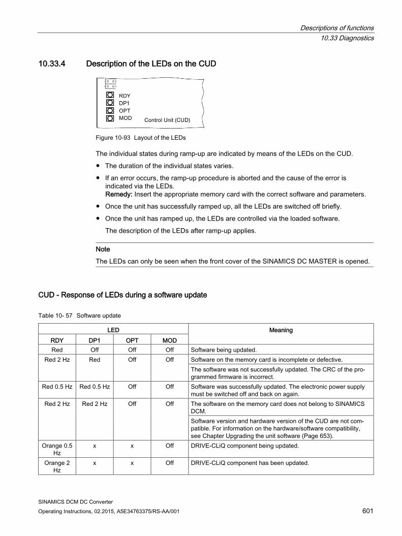
Descriptions of functions 10.33 Diagnostics
SINAMICS DCM DC Converter Operating Instructions, 02.2015, A5E34763375/RS-AA/001 601
10.33.4 Description of the LEDs on the CUD
Figure 10-93 Layout of the LEDs
The individual states during ramp-up are indicated by means of the LEDs on the CUD.
The duration of the individual states varies.
If an error occurs, the ramp-up procedure is aborted and the cause of the error is indicated via the LEDs. Remedy: Insert the appropriate memory card with the correct software and parameters.
Once the unit has successfully ramped up, all the LEDs are switched off briefly.
Once the unit has ramped up, the LEDs are controlled via the loaded software.
The description of the LEDs after ramp-up applies.
Note
The LEDs can only be seen when the front cover of the SINAMICS DC MASTER is opened.
CUD - Response of LEDs during a software update
Table 10- 57 Software update
LED Meaning RDY DP1 OPT MOD Red Off Off Off Software being updated.
Red 2 Hz Red Off Off Software on the memory card is incomplete or defective. The software was not successfully updated. The CRC of the pro-grammed firmware is incorrect.
Red 0.5 Hz Red 0.5 Hz Off Off Software was successfully updated. The electronic power supply must be switched off and back on again.
Red 2 Hz Red 2 Hz Off Off The software on the memory card does not belong to SINAMICS DCM. Software version and hardware version of the CUD are not com-patible. For information on the hardware/software compatibility, see Chapter Upgrading the unit software (Page 653).
Orange 0.5 Hz
x x Off DRIVE-CLiQ component being updated.
Orange 2 Hz
x x Off DRIVE-CLiQ component has been updated.
Descriptions of functions 10.33 Diagnostics
SINAMICS DCM DC Converter 602 Operating Instructions, 02.2015, A5E34763375/RS-AA/001
CUD - Response of LEDs during ramp-up (following Power On)
Table 10- 58 Ramp-up
LED State Remark RDY DP1 OPT MOD Red Red Off Off BIOS loaded -
Red 2 Hz Red Off Off BIOS error - Red 2 Hz Red 2 Hz Off Off File error Memory card not present or
flash file system faulty Red Orange
flashing Off Off Firmware loading DP1 flashing without specific flashing
frequency Red Off Off Off Firmware loaded - Off Red Off Off No CRC error Firmware checked
Red 0.5 Hz Red 0.5 Hz Off Off CRC error Firmware checked, CRC error Orange Off Off Off Drive initialization -
Response of the LEDs after ramp-up
Table 10- 59 CUD - Description of the LEDs after ramp-up
LED Color State Description, cause Remedy RDY (READY) - Off Electronic power supply is missing or outside
permissible tolerance range. Check power supply
Green Continuous light
The component is ready for operation. No errors are present.
-
0.5 Hz flashing light
Commissioning/reset -
2 Hz flash-ing light
Writing to memory card or internal flash memory Notice! The electronic power supply for the SINAMICS DC MASTER must not be switched off during this write process. Switching off the electronic power supply can lead to the loss of the parameter assignments. Also refer to Chapter "Operation", Section "Memory card functions".
-
Red 2 Hz flash-ing light
General errors Check parameteriza-tion/configuration
Orange 0.5 Hz flashing light
Updating the firmware of the connected DRIVE-CLiQ components
–
2 Hz flash-ing light
DRIVE-CLiQ component firmware update com-plete. Wait for POWER ON for the respective components.
Carry out POWER ON for the respective components
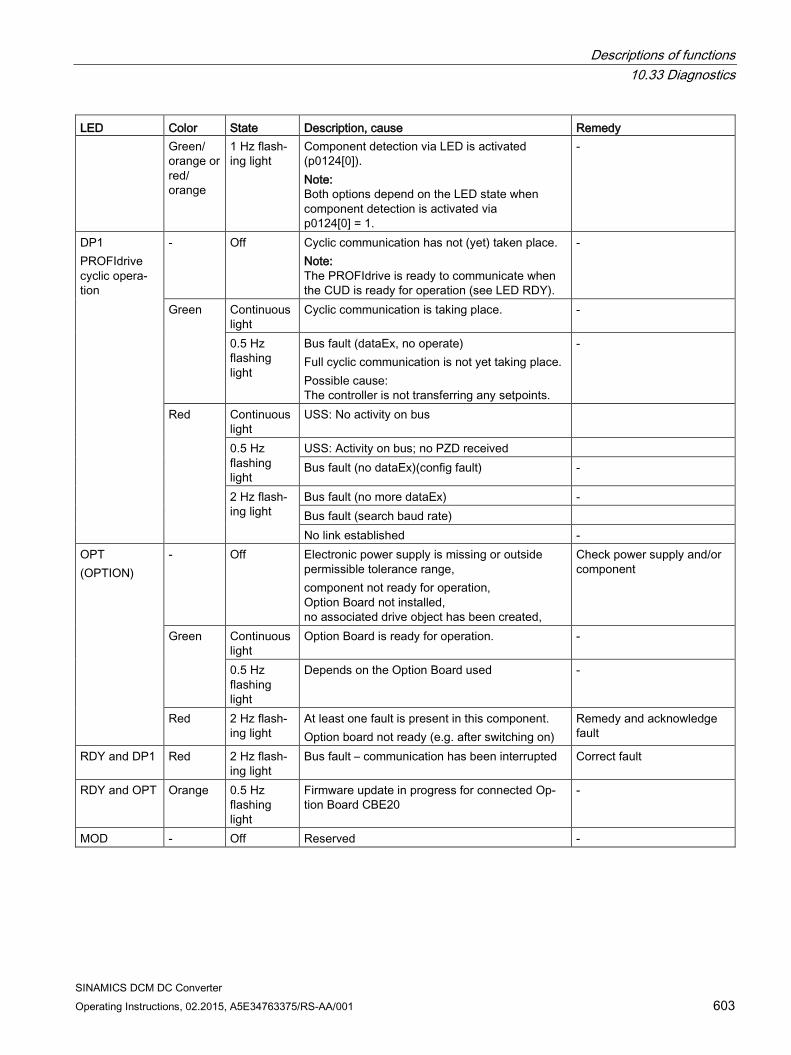
Descriptions of functions 10.33 Diagnostics
SINAMICS DCM DC Converter Operating Instructions, 02.2015, A5E34763375/RS-AA/001 603
LED Color State Description, cause Remedy Green/ orange or red/ orange
1 Hz flash-ing light
Component detection via LED is activated (p0124[0]). Note: Both options depend on the LED state when component detection is activated via p0124[0] = 1.
-
DP1 PROFIdrive cyclic opera-tion
- Off Cyclic communication has not (yet) taken place. Note: The PROFIdrive is ready to communicate when the CUD is ready for operation (see LED RDY).
-
Green Continuous light
Cyclic communication is taking place. -
0.5 Hz flashing light
Bus fault (dataEx, no operate) Full cyclic communication is not yet taking place. Possible cause: The controller is not transferring any setpoints.
-
Red Continuous light
USS: No activity on bus
0.5 Hz flashing light
USS: Activity on bus; no PZD received Bus fault (no dataEx)(config fault) -
2 Hz flash-ing light
Bus fault (no more dataEx) - Bus fault (search baud rate) No link established -
OPT (OPTION)
- Off Electronic power supply is missing or outside permissible tolerance range, component not ready for operation, Option Board not installed, no associated drive object has been created,
Check power supply and/or component
Green Continuous light
Option Board is ready for operation. -
0.5 Hz flashing light
Depends on the Option Board used -
Red 2 Hz flash-ing light
At least one fault is present in this component. Option board not ready (e.g. after switching on)
Remedy and acknowledge fault
RDY and DP1 Red 2 Hz flash-ing light
Bus fault – communication has been interrupted Correct fault
RDY and OPT Orange 0.5 Hz flashing light
Firmware update in progress for connected Op-tion Board CBE20
-
MOD - Off Reserved -
Descriptions of functions 10.33 Diagnostics
SINAMICS DCM DC Converter 604 Operating Instructions, 02.2015, A5E34763375/RS-AA/001
10.33.5 Diagnostics via STARTER The diagnostic functions support commissioning and service personnel during commissioning, troubleshooting, diagnostics and service activities.
Requirement Online operation of the STARTER commissioning tool.
Diagnostic functions The following diagnostic functions are available in the STARTER commissioning tool:
Specification of signals with the ramp-function generator
Signal recording with the trace function
Analysis of the control response with the measuring function
10.33.5.1 Function generator The function generator is part of the STARTER commissioning tool.
The function generator can be used, for example, to perform the following tasks:
Measuring and optimizing control loops.
Comparing the dynamic response of coupled drives.
Specifying a simple traversing profile without a traversing program.
The function generator can be used to generate various waveforms.
In the "Connector output" operating mode (r4818), the output signal can be injected into the control loop via the BICO interconnection.
Properties The following freely parameterizable waveforms can be set:
– Square-wave
– Staircase
– Triangular
– Sinusoidal
– PRBS (pseudo random binary signal, white noise)
An offset is possible for each signal. The power-up to the offset can be parameterized. The signal generation starts after the power-up to the offset.
Limitation of the output signal to the minimum and maximum value can be set.
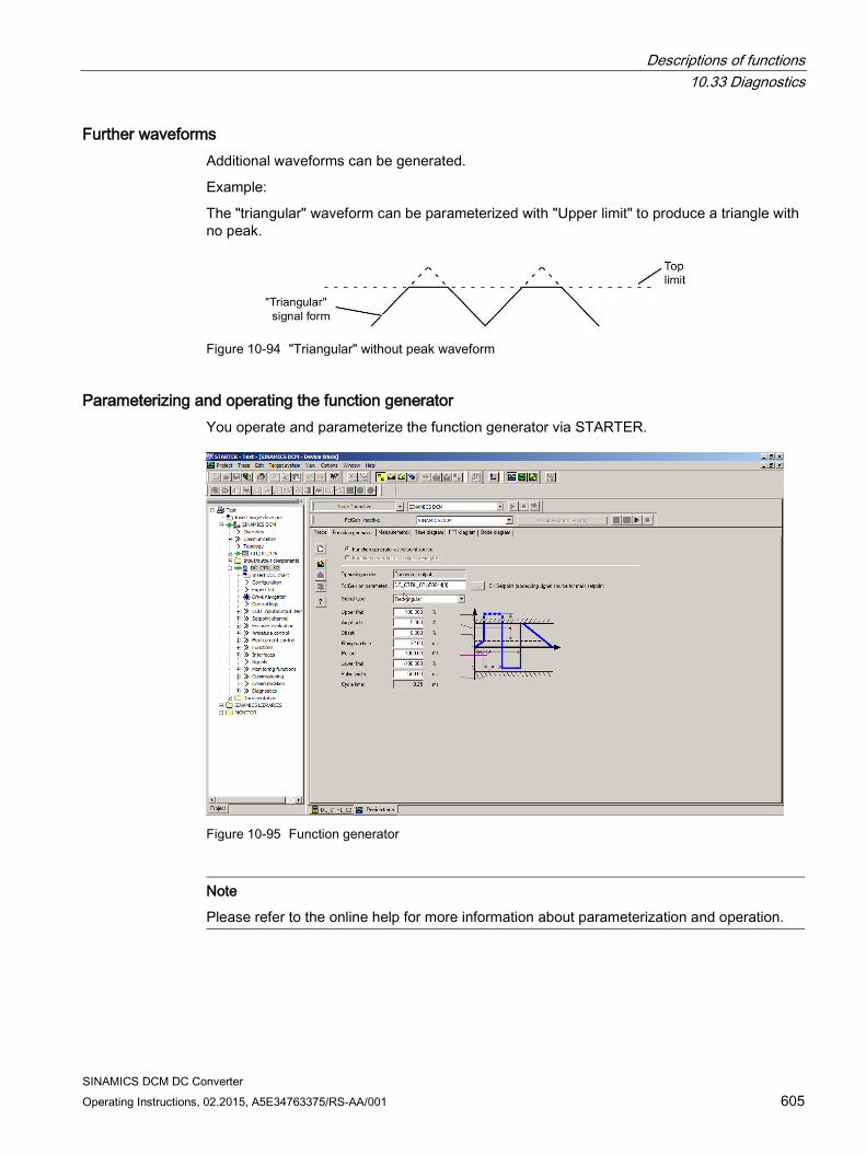
Descriptions of functions 10.33 Diagnostics
SINAMICS DCM DC Converter Operating Instructions, 02.2015, A5E34763375/RS-AA/001 605
Further waveforms Additional waveforms can be generated.
Example:
The "triangular" waveform can be parameterized with "Upper limit" to produce a triangle with no peak.
Figure 10-94 "Triangular" without peak waveform
Parameterizing and operating the function generator You operate and parameterize the function generator via STARTER.
Figure 10-95 Function generator
Note
Please refer to the online help for more information about parameterization and operation.
Descriptions of functions 10.33 Diagnostics
SINAMICS DCM DC Converter 606 Operating Instructions, 02.2015, A5E34763375/RS-AA/001
Note
The "Function generator as commissioning tool" button must not be selected!
If this button is still selected, then the message "Error occurred while parameterizing" is output on STARTER when "Loading the parameterization to the drive" as well as alarm A02007 (Function generator: Drive not SERVO/VECTOR) on the SINAMICS DCM.
Starting/stopping the function generator
WARNING
Danger due to hazardous axis movement
With the corresponding ramp-function generator parameter settings (e.g. offset), the motor can "drift" and travel to its end stop.
The motion of the drive is not monitored with the function generator activated.
Starting the function generator:
1. Load the function generator.
– Click the symbol.
or
– In the project navigator, double-click "Drives" > "Drive_xy" > "Commissioning" > "Function generator".
2. Select "Function generator as setpoint source".
3. Select the BICO input.
4. Set the waveform, for example, "Square-wave".
5. Click the "Assume control priority!" button.
6. For "Sign of life monitoring", click the "Accept" button (the control priority button then changes to yellow).
7. Click the "Drive on" symbol.
8. Start the function generator by clicking the triangle next to the red zero ("Start FctGen" button).
9. Read the "Caution" note and confirm with "Yes". The drive starts and runs through the set trace function. Trace recordings are now possible.
Stopping the function generator:
1. Click the "Stop FctGen" button.
or
2. Click the "Drive off" symbol to stop the drive.
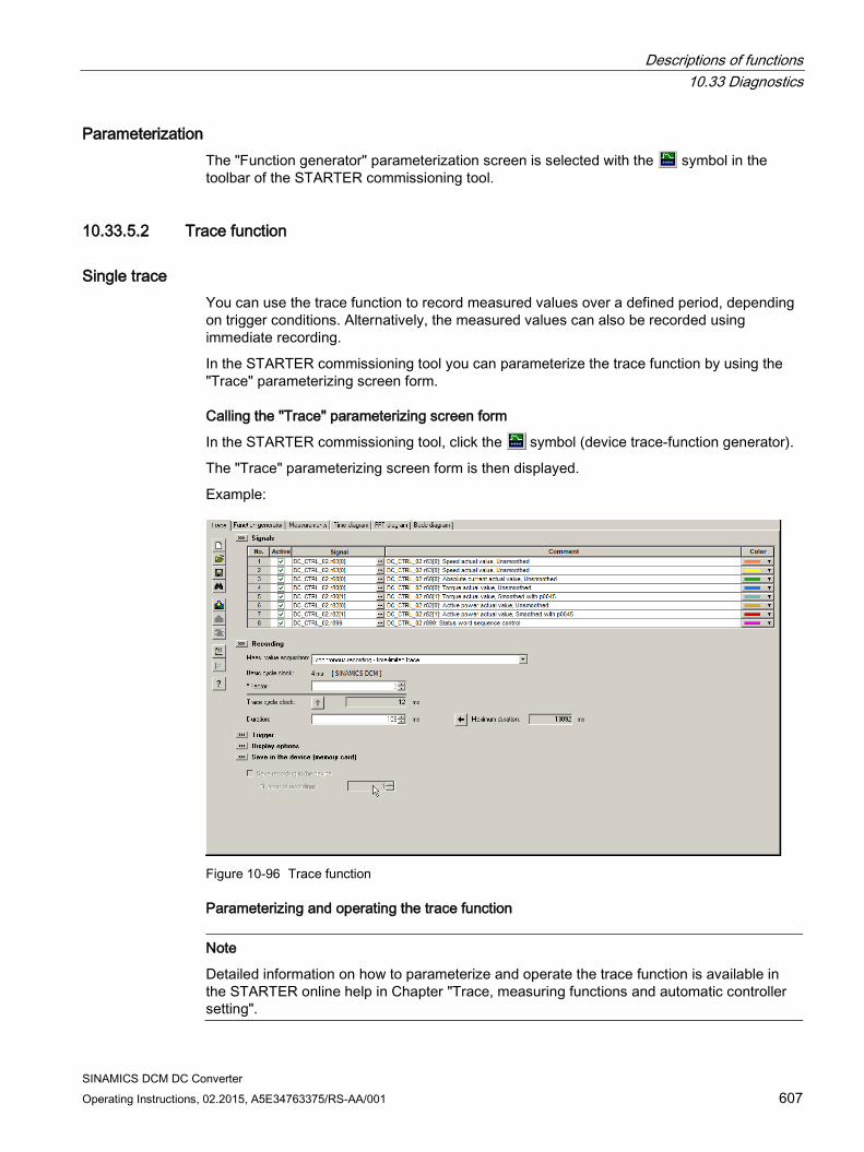
Descriptions of functions 10.33 Diagnostics
SINAMICS DCM DC Converter Operating Instructions, 02.2015, A5E34763375/RS-AA/001 607
Parameterization The "Function generator" parameterization screen is selected with the symbol in the toolbar of the STARTER commissioning tool.
10.33.5.2 Trace function
Single trace You can use the trace function to record measured values over a defined period, depending on trigger conditions. Alternatively, the measured values can also be recorded using immediate recording.
In the STARTER commissioning tool you can parameterize the trace function by using the "Trace" parameterizing screen form.
Calling the "Trace" parameterizing screen form
In the STARTER commissioning tool, click the symbol (device trace-function generator).
The "Trace" parameterizing screen form is then displayed.
Example:
Figure 10-96 Trace function
Parameterizing and operating the trace function
Note
Detailed information on how to parameterize and operate the trace function is available in the STARTER online help in Chapter "Trace, measuring functions and automatic controller setting".

Descriptions of functions 10.33 Diagnostics
SINAMICS DCM DC Converter 608 Operating Instructions, 02.2015, A5E34763375/RS-AA/001
Figure 10-97 Trace function
The device cycle time display flashes 3 times at around 1 Hz when the time slice is changed from < 4 ms to ≥ 4 ms (see description at "Properties"). The display also flashes in the inverse direction from ≥ 4 ms to < 4 ms.
Properties
Two independent traces
Up to eight recording channels for each trace When more than four channels per single trace are used, the trace's device clock cycle is switched automatically from 0.250 ms to 4 ms. As a consequence, the performance of the SINAMICS DCM is not influenced too strongly by the trace function.
Single trace: Device clock cycles of the SINAMICS DCM trace Up to four channels: 0.250 ms ≥ five channels: 4 ms The specified trace cycles can be increased.
Endless trace: The parameter data is written to the memory until this is full. Further parameter data is then lost. A ring buffer can be selected in order to avoid this.
When the ring buffer is activated, then the STARTER commissioning tool automatically starts again from the beginning to write to the trace memory after the last trace parameter was saved. Device cycle of the SINAMICS DCM trace for an endless trace: Up to four channels: 2 ms ≥ five channels: 4 ms
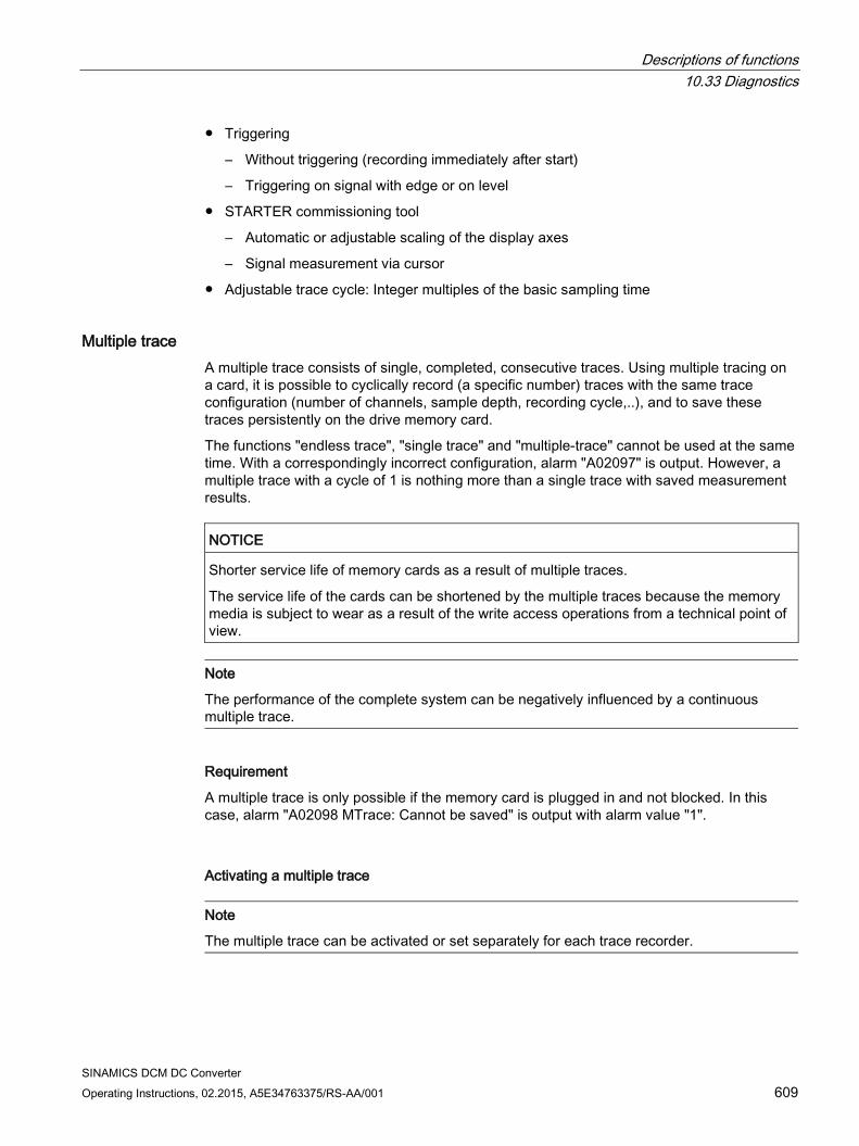
Descriptions of functions 10.33 Diagnostics
SINAMICS DCM DC Converter Operating Instructions, 02.2015, A5E34763375/RS-AA/001 609
Triggering
– Without triggering (recording immediately after start)
– Triggering on signal with edge or on level
STARTER commissioning tool
– Automatic or adjustable scaling of the display axes
– Signal measurement via cursor
Adjustable trace cycle: Integer multiples of the basic sampling time
Multiple trace A multiple trace consists of single, completed, consecutive traces. Using multiple tracing on a card, it is possible to cyclically record (a specific number) traces with the same trace configuration (number of channels, sample depth, recording cycle,..), and to save these traces persistently on the drive memory card.
The functions "endless trace", "single trace" and "multiple-trace" cannot be used at the same time. With a correspondingly incorrect configuration, alarm "A02097" is output. However, a multiple trace with a cycle of 1 is nothing more than a single trace with saved measurement results.
NOTICE
Shorter service life of memory cards as a result of multiple traces.
The service life of the cards can be shortened by the multiple traces because the memory media is subject to wear as a result of the write access operations from a technical point of view.
Note
The performance of the complete system can be negatively influenced by a continuous multiple trace.
Requirement
A multiple trace is only possible if the memory card is plugged in and not blocked. In this case, alarm "A02098 MTrace: Cannot be saved" is output with alarm value "1".
Activating a multiple trace
Note
The multiple trace can be activated or set separately for each trace recorder.
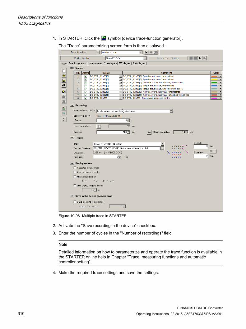
Descriptions of functions 10.33 Diagnostics
SINAMICS DCM DC Converter 610 Operating Instructions, 02.2015, A5E34763375/RS-AA/001
1. In STARTER, click the symbol (device trace-function generator).
The "Trace" parameterizing screen form is then displayed.
Figure 10-98 Multiple trace in STARTER
2. Activate the "Save recording in the device" checkbox.
3. Enter the number of cycles in the "Number of recordings" field.
Note
Detailed information on how to parameterize and operate the trace function is available in the STARTER online help in Chapter "Trace, measuring functions and automatic controller setting".
4. Make the required trace settings and save the settings.
Descriptions of functions 10.33 Diagnostics
SINAMICS DCM DC Converter Operating Instructions, 02.2015, A5E34763375/RS-AA/001 611
Sequence of a multiple trace
1. A multiple trace is started just like a conventional single trace using the STARTER "Trace" screen form.
2. The multiple trace component saves the measurement result after the trigger condition has occurred and the trace data has been completely recorded.
3. The single trace that has actually been completed is now automatically restarted from the multiple trace component. In this case, the same trace configuration (trigger condition, recording cycle, etc. ) is used as before. The trace buffer of the previous single trace is emptied in the process.
Trace status
The status of the multiple trace is displayed in the screen form (red frame):
Figure 10-99 Trace status in STARTER
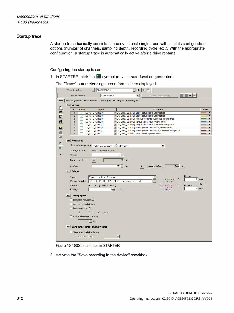
Descriptions of functions 10.33 Diagnostics
SINAMICS DCM DC Converter 612 Operating Instructions, 02.2015, A5E34763375/RS-AA/001
Startup trace A startup trace basically consists of a conventional single trace with all of its configuration options (number of channels, sampling depth, recording cycle, etc.). With the appropriate configuration, a startup trace is automatically active after a drive restarts.
Configuring the startup trace
1. In STARTER, click the symbol (device trace-function generator).
The "Trace" parameterizing screen form is then displayed.
Figure 10-100 Startup trace in STARTER
2. Activate the "Save recording in the device" checkbox.
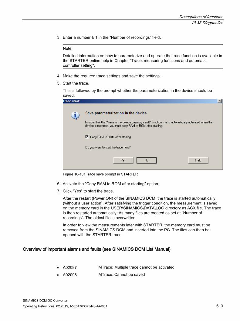
Descriptions of functions 10.33 Diagnostics
SINAMICS DCM DC Converter Operating Instructions, 02.2015, A5E34763375/RS-AA/001 613
3. Enter a number ≥ 1 in the "Number of recordings" field.
Note
Detailed information on how to parameterize and operate the trace function is available in the STARTER online help in Chapter "Trace, measuring functions and automatic controller setting".
4. Make the required trace settings and save the settings.
5. Start the trace.
This is followed by the prompt whether the parameterization in the device should be saved.
Figure 10-101 Trace save prompt in STARTER
6. Activate the "Copy RAM to ROM after starting" option.
7. Click "Yes" to start the trace.
After the restart (Power ON) of the SINAMICS DCM, the trace is started automatically (without a user action). After satisfying the trigger condition, the measurement is saved on the memory card in the USER\SINAMICS\DATA\LOG directory as ACX file. The trace is then restarted automatically. As many files are created as set at "Number of recordings". The oldest file is overwritten.
In order to view the measurements later with STARTER, the memory card must be removed from the SINAMICS DCM and inserted into the PC. The files can then be opened with the STARTER trace.
Overview of important alarms and faults (see SINAMICS DCM List Manual) • A02097 MTrace: Multiple trace cannot be activated
• A02098 MTrace: Cannot be saved
Descriptions of functions 10.33 Diagnostics
SINAMICS DCM DC Converter 614 Operating Instructions, 02.2015, A5E34763375/RS-AA/001
10.33.6 Faults and alarms
10.33.6.1 General information
Description The errors and states detected by the individual components of the drive unit are indicated by messages.
The messages are categorized into faults and alarms.
Note
The individual faults and alarms are described in the section titled "Faults and alarms" in the SINAMICS DCM List Manual. Here you can also find a section titled "Function diagrams" → "Faults and alarms", which contains function diagrams for the fault buffer, alarm buffer, fault trigger, and fault configuration.
Properties of faults and alarms Faults
– Are identified by Fxxxxx
– Can lead to a fault reaction
– Must be acknowledged once the cause has been remedied
– Status via Control Unit and LED RDY
– Status via PROFIBUS status signal ZSW1.3 (fault active)
– Entry in the fault buffer
Alarms
– Are identified by Axxxxx
– Have no further effect on the drive unit
– The alarms are automatically reset once the cause has been remedied. No acknowledgment is required.
– Status via PROFIBUS status signal ZSW1.7 (alarm active)
– Entry in the alarm buffer
General properties of faults and alarms
– Can be configured (e.g. change fault to alarm, fault reaction)
– Triggering on selected messages possible
– Initiation of messages possible via an external signal
– Contains the component number for identifying the SINAMICS component involved
– Contains diagnostic information on the message involved

Descriptions of functions 10.33 Diagnostics
SINAMICS DCM DC Converter Operating Instructions, 02.2015, A5E34763375/RS-AA/001 615
Acknowledging faults The list of faults and alarms specifies how each fault is acknowledged after the cause has been remedied.
1. Acknowledgment of faults with "POWER ON"
– Switch the drive unit on/off (POWER ON).
2. Acknowledgment of faults with "IMMEDIATE"
– Via PROFIBUS control signal
STW1.7 (reset fault memory): 0/1 edge
Set STW1.0 (ON/OFF1) = "0" and "1"
– Via external input signal
Binector input and interconnection with digital input
p2103 = "Requested signal source"
p2104 = "Requested signal source"
p2105 = "Requested signal source"
Across all of the drive objects (DO) of a Control Unit
p2102 = "Requested signal source"
3. Acknowledgment of faults with "PULSE INHIBIT"
– The fault can only be acknowledged with a pulse inhibit (r0899.11 = 0).
– The same options are available for acknowledging as described under acknowledgment with IMMEDIATE.
Note
The drive cannot resume operation until all active faults have been acknowledged.
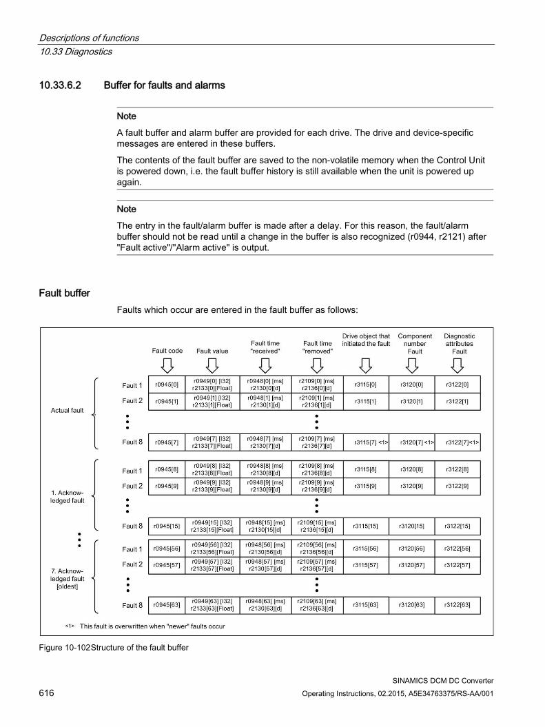
Descriptions of functions 10.33 Diagnostics
SINAMICS DCM DC Converter 616 Operating Instructions, 02.2015, A5E34763375/RS-AA/001
10.33.6.2 Buffer for faults and alarms
Note
A fault buffer and alarm buffer are provided for each drive. The drive and device-specific messages are entered in these buffers.
The contents of the fault buffer are saved to the non-volatile memory when the Control Unit is powered down, i.e. the fault buffer history is still available when the unit is powered up again.
Note
The entry in the fault/alarm buffer is made after a delay. For this reason, the fault/alarm buffer should not be read until a change in the buffer is also recognized (r0944, r2121) after "Fault active"/"Alarm active" is output.
Fault buffer Faults which occur are entered in the fault buffer as follows:
Figure 10-102 Structure of the fault buffer

Descriptions of functions 10.33 Diagnostics
SINAMICS DCM DC Converter Operating Instructions, 02.2015, A5E34763375/RS-AA/001 617
Properties of the fault buffer:
A new fault incident encompasses one or more faults and is entered in "Current fault incident".
The entries appear in the buffer according to the time at which they occurred.
If a new fault incident occurs, the fault buffer is reorganized. The history is recorded in "Acknowledged fault incident" 1 to 7.
If the cause of at least one fault in "Current fault incident" is remedied and acknowledged, the fault buffer is reorganized. Faults that have not been remedied remain in "Current fault incident".
If "Current fault incident" contains 8 faults and a new fault occurs, the fault in the parameters in index 7 is overwritten by the new fault.
r0944 is incremented each time the fault buffer changes.
A fault value (r0949) can be output for a fault. The fault value is used to diagnose the fault more accurately; please refer to the fault description for details of the meaning.
Clearing the fault buffer
The fault buffer is reset as follows: p0952 = 0
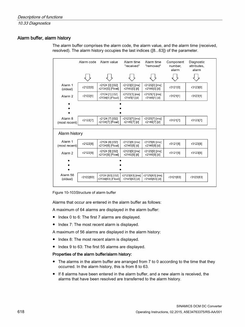
Descriptions of functions 10.33 Diagnostics
SINAMICS DCM DC Converter 618 Operating Instructions, 02.2015, A5E34763375/RS-AA/001
Alarm buffer, alarm history The alarm buffer comprises the alarm code, the alarm value, and the alarm time (received, resolved). The alarm history occupies the last indices ([8...63]) of the parameter.
Figure 10-103 Structure of alarm buffer
Alarms that occur are entered in the alarm buffer as follows:
A maximum of 64 alarms are displayed in the alarm buffer:
Index 0 to 6: The first 7 alarms are displayed.
Index 7: The most recent alarm is displayed.
A maximum of 56 alarms are displayed in the alarm history:
Index 8: The most recent alarm is displayed.
Index 9 to 63: The first 55 alarms are displayed.
Properties of the alarm buffer/alarm history:
The alarms in the alarm buffer are arranged from 7 to 0 according to the time that they occurred. In the alarm history, this is from 8 to 63.
If 8 alarms have been entered in the alarm buffer, and a new alarm is received, the alarms that have been resolved are transferred to the alarm history.
Descriptions of functions 10.33 Diagnostics
SINAMICS DCM DC Converter Operating Instructions, 02.2015, A5E34763375/RS-AA/001 619
r2121 is incremented each time the alarm buffer changes.
An alarm value (r2124) can be output for an alarm. The alarm value is used to diagnose the alarm more accurately; please refer to the alarm description for details of the meaning.
Clearing the alarm buffer, index [0...7]:
The alarm buffer index [0...7] is reset as follows: p2111 = 0
10.33.6.3 Configuring messages The properties of the faults and alarms in the drive system are permanently defined.
The following configuration settings can be made for some of the messages within a permanently defined framework for the drive system: Change message type (example) Select message Set message type p2118[5] = 1001 p2119[5] = 1: Fault (F) = 2: Alarm (A) = 3: No message (N) Change fault response (example) Select message Set fault response p2100[3] = 1002 p2101[3] = 0: None = 1: OFF1 = 2: OFF2 = 3: OFF3 Change acknowledgment (example) Select message Set acknowledgment p2126[4] = 1003 p2127[4] = 1: POWER ON = 2: IMMEDIATE = 3: PULSE INHIBIT
Note
Only those messages which are listed in the indexed parameters can be changed as desired. All other messages retain their factory settings or are reset to the factory settings.
Examples: • In the case of messages listed via p2128[0...19], the message type can be changed. The
factory setting is set for all other messages. • The fault response of fault F12345 has been changed via p2100[n]. The factory settings
are to be restored. – p2100[n] = 0
Descriptions of functions 10.33 Diagnostics
SINAMICS DCM DC Converter 620 Operating Instructions, 02.2015, A5E34763375/RS-AA/001
Delay of the fault response The fault response can be delayed by a parameterized time for all faults. p51780 Delay time (0.000 s .. 60.000 s), factory setting = 0.000 s See also function diagram 2651. The two CO/BOs r2139.3 (Fault active) and r3114.10 (Fault present) can be used by a higher-level controller in order to detect the time when a fault occurs (Fault present) and the time when a fault takes effect (Fault active).
Triggering on messages (example) Select message Trigger signal p2128[0] = 1001 BO: r2129.0 or p2128[1] = 1002 BO: r2129.1
Note
The value from CO: r2129 can be used as a group trigger.
CO: r2129 = 0 No selected message has been output.
CO: r2129 > 0 Group trigger. At least one selected message has been output. The individual binector outputs BO: r2129 should be investigated.
Triggering messages externally If the appropriate binector input is interconnected with an input signal, fault 1, 2, or 3 or alarm 1, 2, or 3 can be triggered via an external input signal.
Once an external fault (1 to 3) has been triggered on the Control Unit drive object, this fault is also present on all associated drive objects. If one of these external faults is triggered on a different drive object, it is only present on that particular drive object. BI: p2106 → External fault 1 → F07860(A) BI: p2107 → External fault 2 → F07861(A) BI: p2108 → External fault 3 → F07862(A) BI: p2112 → External alarm 1 → A07850(F) BI: p2116 → External alarm 2 → A07851(F) BI: p2117 → External alarm 3 → A07852(F)

Descriptions of functions 10.33 Diagnostics
SINAMICS DCM DC Converter Operating Instructions, 02.2015, A5E34763375/RS-AA/001 621
Note
An external fault or alarm is triggered by a 1/0 signal.
An external fault and alarm do not usually mean that an internal drive message has been generated. The cause of an external fault and warning should, therefore, be remedied outside the drive unit.
10.33.6.4 Parameters and function diagrams for faults and alarms
Function diagrams (see the SINAMICS DCM List Manual) 1710 Overview diagram – monitoring functions, faults, alarms
8060 Faults and alarms – fault buffer
8065 Faults and alarms – alarm buffer
8070 Faults and alarms – fault/alarm trigger word r2129
8075 Faults and alarms – fault/alarm configuration
Overview of important parameters (refer to the SINAMICS DCM List Manual) r0944 Counter for fault buffer changes
...
p0952 Fault incident counter
p2100[0...19] Fault code for fault reaction selection ...
r2139 Status word for faults
r3120[0...63] Component number fault
r3121[0...63] Component number alarm
r3122[0...63] Diagnostics attribute fault
r3123[0...63] Diagnostics attribute alarm
10.33.6.5 Forwarding faults and alarms
Forwarding faults and alarms of the CU When faults or alarms are triggered on the drive object of the CU, it is always assumed that central functions of the drive unit are involved. For this reason, these faults and alarms are not only signaled on the drive object of the CU, but are also forwarded to all other drive objects. The fault reaction affects the drive object of the CU and all other drive objects. This behavior also applies to the faults set in a DCC chart on the CU with the aid of DCB STM.

Descriptions of functions 10.33 Diagnostics
SINAMICS DCM DC Converter 622 Operating Instructions, 02.2015, A5E34763375/RS-AA/001
A fault that was set on the drive object of the CU must be acknowledged on all drive objects to which this fault was forwarded. In this way, the fault is then automatically acknowledged on the drive object of the CU. Alternatively, all faults of all drive objects can also be acknowledged on the CU.
If a set alarm is reset on the drive object of the CU, this alarm also disappears automatically on the other drive objects to which this alarm was forwarded.
Forwarding faults and alarms as a result of BICO interconnections If two or more drive objects are connected via BICO interconnections, then faults and alarms from CU, TM31, TM15, TM17, and TM15DIDO drive objects are forwarded to DC_CTRL-type drive objects. Faults are not forwarded within these two groups of drive object types.
This behavior also applies to the faults set in a DCC chart on the above drive object types with the aid of DCB STM.
Descriptions of functions 10.34 CPU time load with SINAMICS DCM
SINAMICS DCM DC Converter Operating Instructions, 02.2015, A5E34763375/RS-AA/001 623
10.34 CPU time load with SINAMICS DCM The CPU time load of the SINAMICS DCM can be read out at r9976[1]. Principally, the following rules apply:
1. The cyclic DC closed-loop control of the SINAMICS DCM generates a base load of approx. 70% (can be read on r9976[1]).
2. The use of peripherals (AOP30, starter, M15, TM31, TM150, SCM30, CBE20, etc.), certain settings in the closed-loop control and/or use of the free function blocks along with the DCC technology option increases this base load. The additional CPU time load through the main components is summarized in the table below.
3. The CPU time load must not exceed a utilization of 100% at r9976[1].
WARNING
At a CPU time load of >100% on r9976[1], the correct functioning of the drive is no longer ensured.
Note
When the time load of the CUD is too high (r9976[1] >100%), fault F60099 (in extreme cases F01205) is output (time slice overflow). In such a case, the drive needs to be switched off and then back on again (POWER OFF / POWER ON).
The CPU time load must be taken into consideration when configuring and commissioning the SINAMICS DCM.
Table 10- 60 Additional CPU time load through optional components
Component Additional CPU time load AOP30 via PPI +4% 1 TM31 +4% 2 TM31 +5% 3 TM31 +6% 1 TM15 +1% 2 TM15 +1.5% 3 TM15 +2% 1 TM150 +1% 2 TM150 +1.5% 3 TM150 +2% 1 SMC30 +2% 1 CBE20 +1% Internal encoder (p50083=2) +2% Parallel interface +4% Peer-to-peer +4% Calculating the thyristor blocking voltage +4.5% Is supported by the CCP +3.5% Memory card inserted +1%
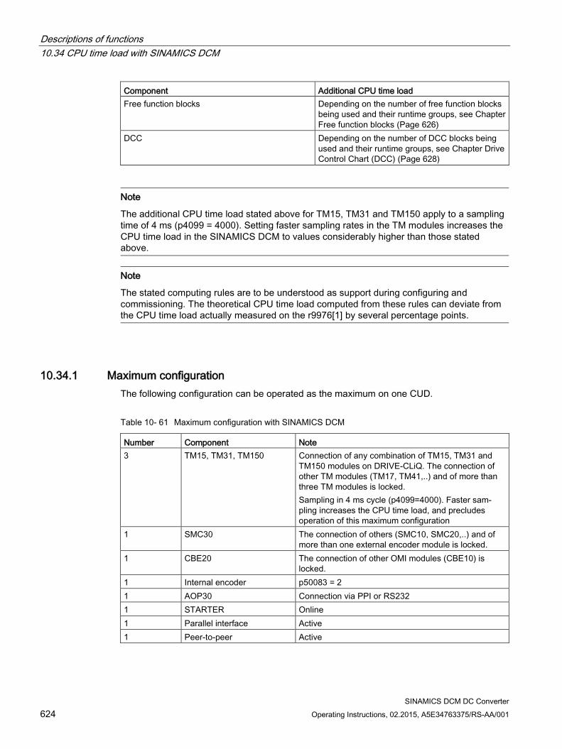
Descriptions of functions 10.34 CPU time load with SINAMICS DCM
SINAMICS DCM DC Converter 624 Operating Instructions, 02.2015, A5E34763375/RS-AA/001
Component Additional CPU time load Free function blocks Depending on the number of free function blocks
being used and their runtime groups, see Chapter Free function blocks (Page 626)
DCC Depending on the number of DCC blocks being used and their runtime groups, see Chapter Drive Control Chart (DCC) (Page 628)
Note
The additional CPU time load stated above for TM15, TM31 and TM150 apply to a sampling time of 4 ms (p4099 = 4000). Setting faster sampling rates in the TM modules increases the CPU time load in the SINAMICS DCM to values considerably higher than those stated above.
Note
The stated computing rules are to be understood as support during configuring and commissioning. The theoretical CPU time load computed from these rules can deviate from the CPU time load actually measured on the r9976[1] by several percentage points.
10.34.1 Maximum configuration The following configuration can be operated as the maximum on one CUD.
Table 10- 61 Maximum configuration with SINAMICS DCM
Number Component Note 3 TM15, TM31, TM150 Connection of any combination of TM15, TM31 and
TM150 modules on DRIVE-CLiQ. The connection of other TM modules (TM17, TM41,..) and of more than three TM modules is locked. Sampling in 4 ms cycle (p4099=4000). Faster sam-pling increases the CPU time load, and precludes operation of this maximum configuration
1 SMC30 The connection of others (SMC10, SMC20,..) and of more than one external encoder module is locked.
1 CBE20 The connection of other OMI modules (CBE10) is locked.
1 Internal encoder p50083 = 2 1 AOP30 Connection via PPI or RS232 1 STARTER Online 1 Parallel interface Active 1 Peer-to-peer Active
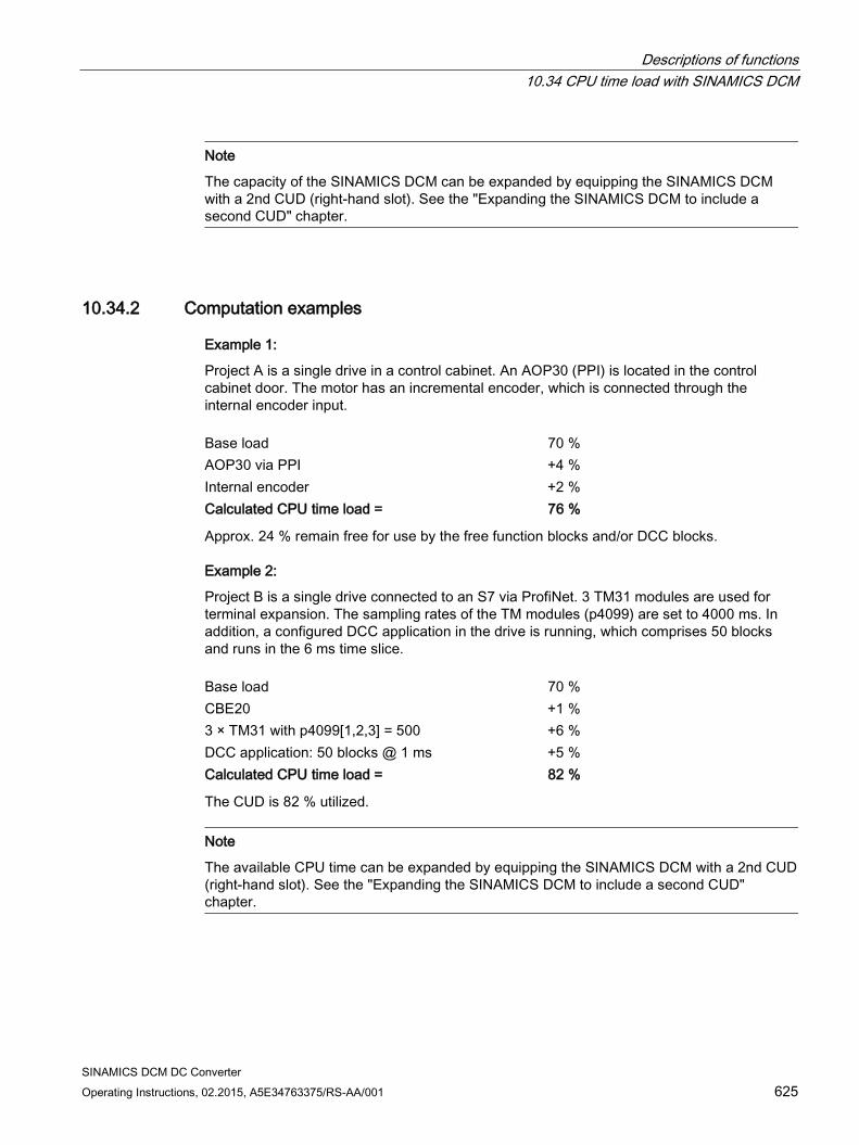
Descriptions of functions 10.34 CPU time load with SINAMICS DCM
SINAMICS DCM DC Converter Operating Instructions, 02.2015, A5E34763375/RS-AA/001 625
Note
The capacity of the SINAMICS DCM can be expanded by equipping the SINAMICS DCM with a 2nd CUD (right-hand slot). See the "Expanding the SINAMICS DCM to include a second CUD" chapter.
10.34.2 Computation examples
Example 1:
Project A is a single drive in a control cabinet. An AOP30 (PPI) is located in the control cabinet door. The motor has an incremental encoder, which is connected through the internal encoder input. Base load 70 % AOP30 via PPI +4 % Internal encoder +2 % Calculated CPU time load = 76 %
Approx. 24 % remain free for use by the free function blocks and/or DCC blocks.
Example 2:
Project B is a single drive connected to an S7 via ProfiNet. 3 TM31 modules are used for terminal expansion. The sampling rates of the TM modules (p4099) are set to 4000 ms. In addition, a configured DCC application in the drive is running, which comprises 50 blocks and runs in the 6 ms time slice. Base load 70 % CBE20 +1 % 3 × TM31 with p4099[1,2,3] = 500 +6 % DCC application: 50 blocks @ 1 ms +5 % Calculated CPU time load = 82 %
The CUD is 82 % utilized.
Note
The available CPU time can be expanded by equipping the SINAMICS DCM with a 2nd CUD (right-hand slot). See the "Expanding the SINAMICS DCM to include a second CUD" chapter.
Descriptions of functions 10.35 Free function blocks
SINAMICS DCM DC Converter 626 Operating Instructions, 02.2015, A5E34763375/RS-AA/001
10.35 Free function blocks A logic operation, which connects several states (e.g. access control, plant status) to a control signal (e.g. ON command), is required for controlling the drive system in a wide variety of applications.
Along with logic operations, a number of arithmetical operations and storing elements are becoming increasingly important in drive systems. This functionality is available as a "Free function blocks" function module (FBLOCKS) on the drive object type of the SINAMICS DCM.
Notes Exact information on the scope of the blocks, about parameter assignment and about
commissioning the free function blocks is available in the "SINAMICS" Free function blocks" manual. This chapter describes the special features of the free function blocks with SINAMICS DCM.
This additional functionality increases the CPU time load. That means the maximum possible configuration with a Control Unit may be restricted.
The free function blocks are restricted in their scope to 52 blocks per drive object (DO). Furthermore, the unassigned function blocks as compared to DCC cause significantly higher CPU time load. If that does not suffice, the application can be implemented with the DCC technology option. See the Drive Control Chart (DCC) chapter.
In the SINAMICS DCM, simultaneous use of the free function blocks and the DCC technology option are feasible.
With the SINAMICS DCM, parameters that specify scaled variables have the unit "Percent". With free function blocks, parameters that specify scaled variables have no dimension. When setting parameter values, the unit of the parameter must always be taken into account. The unit is specified in the List Manual and is displayed in STARTER and on the AOP30.
Remark:
The relationship between percent variables and dimensionless variables is 100% corresponds to 1.00. The conversion is performed according to the formula: Y=X/100%. X..percent variable Y..dimensionless variable Example: The fixed value r52401 is used as the input value of the limit monitor (p20266 = 52401). p50401 and r52401 both have the unit "%". If the value "50%" is specified at p50401, the value "50%" appears at r52401. The value "50%" (= 0.5) is therefore effective as the input signal X of the limit monitor. If a mean interval value of 50% is to be set, then p20267 = 0.5 must be set because parameter p20267 is dimensionless and the relationship 50% = 0.5 applies.
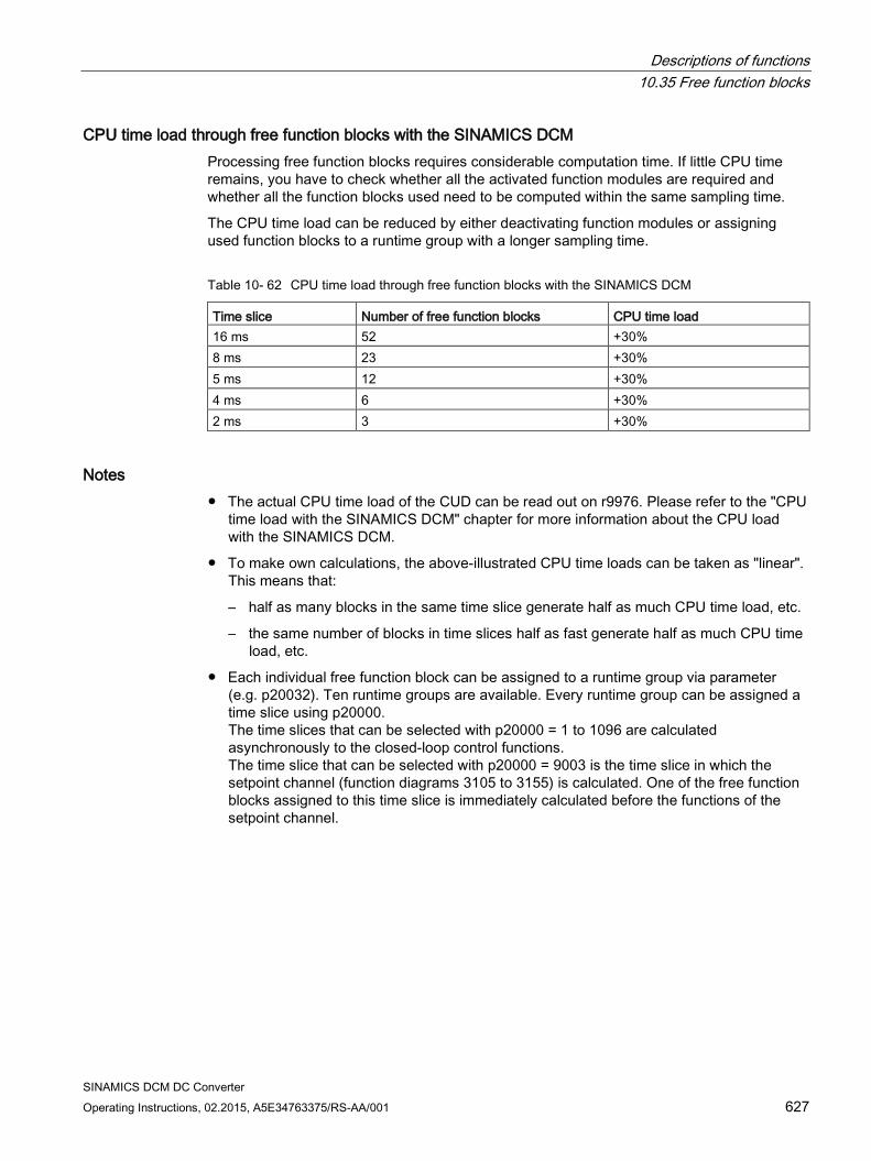
Descriptions of functions 10.35 Free function blocks
SINAMICS DCM DC Converter Operating Instructions, 02.2015, A5E34763375/RS-AA/001 627
CPU time load through free function blocks with the SINAMICS DCM Processing free function blocks requires considerable computation time. If little CPU time remains, you have to check whether all the activated function modules are required and whether all the function blocks used need to be computed within the same sampling time.
The CPU time load can be reduced by either deactivating function modules or assigning used function blocks to a runtime group with a longer sampling time.
Table 10- 62 CPU time load through free function blocks with the SINAMICS DCM
Time slice Number of free function blocks CPU time load 16 ms 52 +30% 8 ms 23 +30% 5 ms 12 +30% 4 ms 6 +30% 2 ms 3 +30%
Notes The actual CPU time load of the CUD can be read out on r9976. Please refer to the "CPU
time load with the SINAMICS DCM" chapter for more information about the CPU load with the SINAMICS DCM.
To make own calculations, the above-illustrated CPU time loads can be taken as "linear". This means that:
– half as many blocks in the same time slice generate half as much CPU time load, etc.
– the same number of blocks in time slices half as fast generate half as much CPU time load, etc.
Each individual free function block can be assigned to a runtime group via parameter (e.g. p20032). Ten runtime groups are available. Every runtime group can be assigned a time slice using p20000. The time slices that can be selected with p20000 = 1 to 1096 are calculated asynchronously to the closed-loop control functions. The time slice that can be selected with p20000 = 9003 is the time slice in which the setpoint channel (function diagrams 3105 to 3155) is calculated. One of the free function blocks assigned to this time slice is immediately calculated before the functions of the setpoint channel.
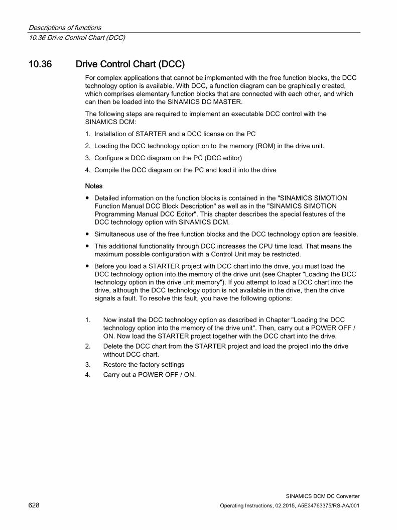
Descriptions of functions 10.36 Drive Control Chart (DCC)
SINAMICS DCM DC Converter 628 Operating Instructions, 02.2015, A5E34763375/RS-AA/001
10.36 Drive Control Chart (DCC) For complex applications that cannot be implemented with the free function blocks, the DCC technology option is available. With DCC, a function diagram can be graphically created, which comprises elementary function blocks that are connected with each other, and which can then be loaded into the SINAMICS DC MASTER.
The following steps are required to implement an executable DCC control with the SINAMICS DCM:
1. Installation of STARTER and a DCC license on the PC
2. Loading the DCC technology option on to the memory (ROM) in the drive unit.
3. Configure a DCC diagram on the PC (DCC editor)
4. Compile the DCC diagram on the PC and load it into the drive
Notes
Detailed information on the function blocks is contained in the "SINAMICS SIMOTION Function Manual DCC Block Description" as well as in the "SINAMICS SIMOTION Programming Manual DCC Editor". This chapter describes the special features of the DCC technology option with SINAMICS DCM.
Simultaneous use of the free function blocks and the DCC technology option are feasible.
This additional functionality through DCC increases the CPU time load. That means the maximum possible configuration with a Control Unit may be restricted.
Before you load a STARTER project with DCC chart into the drive, you must load the DCC technology option into the memory of the drive unit (see Chapter "Loading the DCC technology option in the drive unit memory"). If you attempt to load a DCC chart into the drive, although the DCC technology option is not available in the drive, then the drive signals a fault. To resolve this fault, you have the following options:
1. Now install the DCC technology option as described in Chapter "Loading the DCC
technology option into the memory of the drive unit". Then, carry out a POWER OFF / ON. Now load the STARTER project together with the DCC chart into the drive.
2. Delete the DCC chart from the STARTER project and load the project into the drive without DCC chart.
3. Restore the factory settings 4. Carry out a POWER OFF / ON.
Descriptions of functions 10.36 Drive Control Chart (DCC)
SINAMICS DCM DC Converter Operating Instructions, 02.2015, A5E34763375/RS-AA/001 629
10.36.1 Loading the DCC technology option into the drive unit memory Loading the DCC technology option into the drive unit is usually performed with STARTER and with the SINAMICS DCM takes about 7 min. During this process, the entire DCB library with a scope of approx. 2 MB data is transferred to the drive.
To accelerate this process, the SINAMICS DCM supports an alternative option for transferring the DCB library to the drive. With this method, the process is shortened to less than 5 min:
Step 1 In STARTER, open a project that includes a SINAMICS DCM drive with at least one DCC chart. In the shortcut menu (right mouse button), select "Load into file system" (only possible in the offline mode).
Figure 10-104 Loading into the file system
Step 2 A dialog, "Load into file system", opens. Choose "Select target" and select an empty folder on a local hard drive.
Step 3 After a folder has been selected, STARTER copies the DCB library into this local folder. 2 folders named "OEM" and "USER" are created.
Descriptions of functions 10.36 Drive Control Chart (DCC)
SINAMICS DCM DC Converter 630 Operating Instructions, 02.2015, A5E34763375/RS-AA/001
Step 4 Copy the OEM folder to an empty memory card.
Note
The memory card supplied from Siemens as option S01 or S02 includes, when supplied, a dump of the internal unit software. These files are only required to update software.
These files can be deleted for all other applications of the memory card. Copy the files into a local folder of your PG/PC and delete the files on the memory card, before you use the card for the functions described in this chapter.
Step 5 Insert the Memory card into the switched-off drive and switch on (POWER ON). The DCB library is copied into the non-volatile memory (ROM) in the drive during power-up. The process is complete as soon as the power-up has ended (operating state 7.0 reached).
Step 6 Switch device off/on (POWER OFF / POWER ON). After the new power-up, the DCC is ready.
Repeat steps 5 and 6 on additional SINAMICS DCM drives.
Note
If DCC is installed in the drive, the power-up time increases by approx. 10 s.
Note
This procedure does not transfer the STARTER parameter assignments into the unit. In order to transfer the parameter assignments from STARTER into the drive, the "Load into the target system" function must be run in STARTER.
10.36.2 CPU time load through DCC Calculating the DCC blocks requires CPU time. If the CPU time becomes meager, you have to check whether all the activated blocks are required and whether all the function blocks used need to be computed within the same sampling time.
The CPU time load can be reduced by either deactivating blocks or assigning used blocks to a runtime group with a longer sampling time.

Descriptions of functions 10.36 Drive Control Chart (DCC)
SINAMICS DCM DC Converter Operating Instructions, 02.2015, A5E34763375/RS-AA/001 631
A list of all of the DCC blocks available for SINAMICS DCM and the required computation times are listed in Appendix B.
Table 10- 63 CPU time load DCC blocks left-hand CUD.
Time slice Number of blocks 1) CPU time load 1 ms 50 +30 % 2 ms 100 +30 % 4 ms 200 +30 % 6 ms 300 +30 % 8 ms 400 +30 % 16 ms 800 +30 % 1) This information applies to a left-hand CUD without additional options. These options increase the basic load of the CUD and reduce the available CPU time for the DCC blocks. Please refer to the "CPU time load with the SINAMICS DCM" chapter for more information about the CPU load.
In this information, an average complexity of the blocks being used is assumed. If only highly complex or very simple blocks are computed, the stated limit shifts accordingly.
Notes The actual CPU time load of the CUD can be read out on r9976. Please refer to the "CPU
time load with the SINAMICS DCM" chapter for more information about the CPU load on the SINAMICS DCM.
To make own calculations, the above-illustrated CPU time loads can be taken as "linear". This means that:
– half as many blocks in the same time slice generate half as much CPU time load, etc.
– the same number of blocks in time slices half as fast generate half as much CPU time load, etc.
Examples 1. In the 1 ms time slice, 50 blocks generate about 30 % additional CPU time load. For that
reason, 50 blocks in the 2 ms time slice generate about 30 % × 0.5 = 15 % additional CPU time load.
2. In the 7 ms time slice, (300 + 400) / 2 = 350 blocks generate about 30 % additional CPU time load. That means 250 blocks generate 250 / 350 × 30 % = 21.5 % additional CPU time load.
Descriptions of functions 10.36 Drive Control Chart (DCC)
SINAMICS DCM DC Converter 632 Operating Instructions, 02.2015, A5E34763375/RS-AA/001
10.36.3 Memory load through DCC Along with the CPU time load, the memory load of the processor must also be considered when designing a closed-loop control with the DCC technology option. A higher number of configured DCC blocks and @parameters also more highly loads the internal memory (ROM) of the CUD.
For using DCC, on the SINAMICS DCM, as compared with the maximum possible configurations documented in the "Maximum configuration" chapter, depending on the size of the diagram, one must omit optional components. The number of blocks and the @parameters are decisive.
For one CUD without additional options, the following rules apply:
Table 10- 64 Maximum number of DCC blocks and @parameters
Drive object Number of DCC blocks and @parameters CU_DC 800 DC_CTRL 600
Note: The specified maximum numbers for blocks and @parameters always apply for the entire drive unit and should be regarded as guide values. The CUD is completely utilized with 800 DCC blocks and @parameters on the DO CU_DC or 600 DCC blocks and @parameters on the DO DC_CTRL. Conserving @parameters has little effect on the quantity structure of the blocks; the specified maximum numbers for the blocks should therefore not be exceeded.
On the DO DC_CTRL, due to the large number of drive parameters, fewer DCC blocks can be computed than on the DO CU_DC.
In addition, the memory is loaded by optional components as follows:
Table 10- 65 Additional memory load through optional components
Component Additional memory load (expressed in DCC blocks)
AOP30 - 200 blocks TM31 - 150 blocks TM15 - 150 blocks TM150 - 150 blocks SMC30 - 25 blocks CBE20 - 25 blocks
The final limits are determined by the total memory available on the CUD. If the above-mentioned recommended maximum limits are exceeded, this can result in errors during upload or download (e.g. fault F1105: CU memory insufficient) and the drive can no longer be switched on; power OFF/ON must be performed on the drive unit.
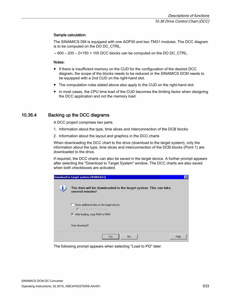
Descriptions of functions 10.36 Drive Control Chart (DCC)
SINAMICS DCM DC Converter Operating Instructions, 02.2015, A5E34763375/RS-AA/001 633
Sample calculation:
The SINAMICS DM is equipped with one AOP30 and two TM31 modules. The DCC diagram is to be computed on the DO DC_CTRL.
→ 600 – 200 – 2×150 = 100 DCC blocks can be computed on the DO DC_CTRL.
Notes:
If there is insufficient memory on the CUD for the configuration of the desired DCC diagram, the scope of the blocks needs to be reduced or the SINAMICS DCM needs to be equipped with a 2nd CUD on the right-hand slot.
The computation rules stated above also apply to the CUD on the right-hand slot.
In most cases, the CPU time load of the CUD becomes the limiting factor when designing the DCC application and not the memory load.
10.36.4 Backing up the DCC diagrams A DCC project comprises two parts.
1. Information about the type, time slices and interconnection of the DCB blocks
2. Information about the layout and graphics in the DCC charts
When downloading the DCC chart to the drive (download to the target system), only the information about the type, time slices and interconnection of the DCB blocks (Point 1) are downloaded to the drive.
If required, the DCC charts can also be saved in the target device. A further prompt appears after selecting the "Download to Target System" window. The DCC charts are also saved when both checkboxes are activated.
The following prompt appears when selecting "Load to PG" later:
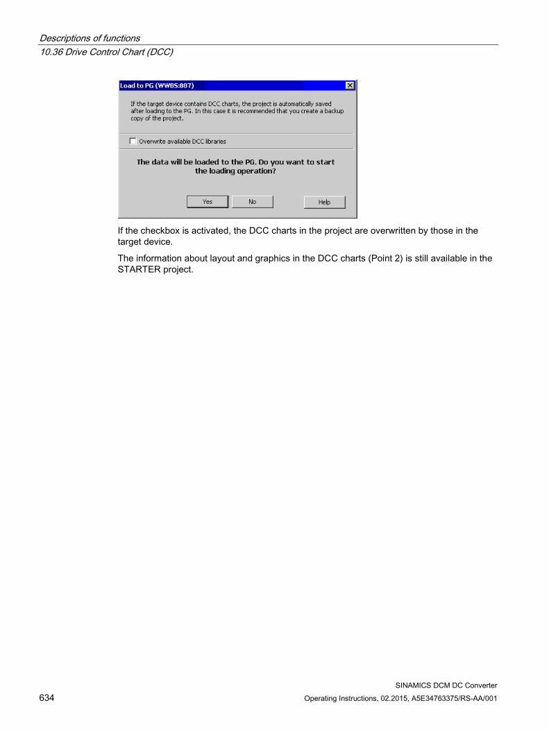
Descriptions of functions 10.36 Drive Control Chart (DCC)
SINAMICS DCM DC Converter 634 Operating Instructions, 02.2015, A5E34763375/RS-AA/001
If the checkbox is activated, the DCC charts in the project are overwritten by those in the target device.
The information about layout and graphics in the DCC charts (Point 2) is still available in the STARTER project.

Descriptions of functions 10.37 Write and know-how protection
SINAMICS DCM DC Converter Operating Instructions, 02.2015, A5E34763375/RS-AA/001 635
10.37 Write and know-how protection In order to protect your own projects against changes, unauthorized viewing or copying, the "Write protection" and "Know-how protection" (KHP) functions are available. Protection Validity Objective Effect Write protec-tion
Online Protection of the parameterization against inadvertent changes by the user.
p-parameters can be read, but cannot be written.
Know-how protection
Online Protection of intellectual property, espe-cially the know-how of the machine man-ufacturers, against unauthorized use or reproduction of their products.
p-parameters can neither be read nor written.
10.37.1 Write protection Write protection prevents settings from being inadvertently changed. No password is required for write protection.
Setting up and activating write protection 1. Connect the Control Unit to the programming device.
2. Call STARTER.
3. Download your project.
4. Establish a connection to the target device.
5. Select the required drive unit in the project navigator of your STARTER project.
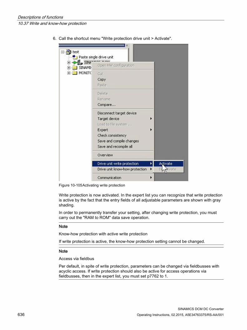
Descriptions of functions 10.37 Write and know-how protection
SINAMICS DCM DC Converter 636 Operating Instructions, 02.2015, A5E34763375/RS-AA/001
6. Call the shortcut menu "Write protection drive unit > Activate".
Figure 10-105 Activating write protection
Write protection is now activated. In the expert list you can recognize that write protection is active by the fact that the entry fields of all adjustable parameters are shown with gray shading.
In order to permanently transfer your setting, after changing write protection, you must carry out the "RAM to ROM" data save operation.
Note
Know-how protection with active write protection
If write protection is active, the know-how protection setting cannot be changed.
Note
Access via fieldbus
Per default, in spite of write protection, parameters can be changed via fieldbusses with acyclic access. If write protection should also be active for access operations via fieldbusses, then in the expert list, you must set p7762 to 1.
Descriptions of functions 10.37 Write and know-how protection
SINAMICS DCM DC Converter Operating Instructions, 02.2015, A5E34763375/RS-AA/001 637
Deactivating write protection 1. Connect the Control Unit to the programming device.
2. Call STARTER.
3. Download your project.
4. Establish a connection to the target device.
5. Select the required drive unit in the project navigator of your STARTER project.
6. Call the shortcut menu "Write protection drive unit > Deactivate".
The hatching in the expert list disappears after deactivation. The parameters can be set again.
Parameters without write protection Certain parameters are excluded from the write protection in order not to restrict the functionality and operability of the drives. The list of these parameters can be found in the SINAMICS DCM List Manual in Chapter "Parameters for write protection and know-how protection", Section "Parameters with WRITE_NO_LOCK".
The "Restore factory settings" function can also be used when write protection is activated.
10.37.2 Know-how protection The "Know-how protection" function prevents, for example, confidential company know-how for configuration and parameter assignment from being read by unauthorized persons.
The know-how protection requires a password. The password must comprise at least 1 and a maximum of 30 characters.
Note
Password security
You are responsible for the security of your password. Whenever possible, use a password with sufficient length (min. eight characters); use upper- and lower-case letters and special characters.
The know-how protection is a pure online function. Therefore, establish a direct connection to the Control Unit before setting the password.
Descriptions of functions 10.37 Write and know-how protection
SINAMICS DCM DC Converter 638 Operating Instructions, 02.2015, A5E34763375/RS-AA/001
Characteristics when know-how protection is activated Except for a small number of system parameters and the parameters specified in an
exception list, all other parameters are locked. In the expert list, the value of these parameters cannot be read or changed.
In the expert list of STARTER, the text "Know-how protected" is displayed for the locked parameters instead of the parameter values.
Know-how protected parameters of the expert list can be hidden in the "Online value of the Control Unit" drop-down list via the entry "Without know-how protection".
The values of display parameters remain visible.
The contents of screen forms are not displayed when know-how protection is active.
Know-how protection can be combined with copy protection.
Functions locked using know-how protection The following listed functions are inhibited when know-how protection is active:
Download
Trace function
Function generator
Deleting the alarm history
Creating acceptance documentation
Functions that can only be partly executed with know-how protection The following listed functions can only be partly executed when know-how protection is active:
Displaying the topology (actual topology only)
Upload (restricted scope; see OEM exception list (Page 640))
Functions that can be executed for know-how protection The following listed functions can still be executed despite of the fact that know-how protection is activated:
Restoring factory settings
Acknowledging alarms
Displaying alarms and warnings
Displaying the alarm history
Reading out the diagnostic buffer
Switching over to the control panel (fetch the master control, all the buttons and setting parameters)
Displaying created acceptance documentation
Descriptions of functions 10.37 Write and know-how protection
SINAMICS DCM DC Converter Operating Instructions, 02.2015, A5E34763375/RS-AA/001 639
Parameters that can be changed when know-how protection is active In spite of active know-how protection, certain parameters can be changed and read. The list of these parameters can be found in the SINAMICS DCM List Manual in Chapter "Parameters for write protection and know-how protection", Section "Parameters with KHP_WRITE_NO_LOCK".
Parameters that can be read when know-how protection is active In spite of know-how protection being active, additional parameters can be read, but are locked against changes. The list of these parameters can be found in the SINAMICS DCM List Manual in Chapter "Parameters for write protection and know-how protection", in Section "Parameters with KHP_ACTIVE_READ".
Note
Password check for know-how protection
Please note that if the Windows language settings are changed, after activating know-how protection, errors can occur when subsequently checking the password. If you use language-specific special characters, you must ensure that the same language setting is active on the computer for subsequent entry of the password.
Note
Data security of the memory card
After setting up and activating the know-how protection, for encrypted data backup on the memory card, previously backed up, non-encrypted data of the SINAMICS software will be deleted. This is the standard deletion procedure, in which only the entries on the memory card are deleted. The data itself is still available and can be reconstructed.
To ensure know-how protection, we recommend the use of a new empty memory card. If you cannot obtain a new memory card in the short term, you should delete all safety-related data on the current memory card.
To completely delete your previous data on the memory card, you must reliably delete this data using a suitable PC tool before activating know-how protection. The data is located on the memory card in the "\\USER\SINAMICS\DATA" directory.
Note
Diagnostics under know-how protection
If service or diagnostics is to be performed when know-how protection is active, then Siemens can only provide support in collaboration with the OEM partner.
Descriptions of functions 10.37 Write and know-how protection
SINAMICS DCM DC Converter 640 Operating Instructions, 02.2015, A5E34763375/RS-AA/001
10.37.2.1 Copy protection
Features of the activated copy protection Copy protection prevents project settings from being copied and transferred to other Control Units. Additional features include:
The copy protection can only be activated in conjunction with the know-how protection (see Activating know-how protection (Page 641)).
When copy protection is activated, the memory card and Control Unit are connected with one another and only function together.
The copy protection prevents the use of each memory card with copied data of one Control Unit in another Control Unit.
With the exception of the DCC library, the copy-protected data on the memory card cannot be read or copied. If a copied memory card is used, a copy protection error is displayed and a pulse inhibit set.
10.37.2.2 Configuring know-how protection
Requirements Before activating know-how protection, the following conditions must be met:
The drive unit has been fully commissioned. (Configuration, download into the drive unit, complete commissioning. You have then carried out an upload in order to upload the parameters calculated by the drive into the STARTER project.)
The OEM exception list has been created (see below).
To guarantee know-how protection, you must ensure that the project does not remain at the end user as a file.
Creating the OEM exception list Before activating the know-how protection, enter the parameters in this exception list that are to remain readable and writable despite the know-how protection. The exception list can only be created via the expert list. The exception list has no influence on the input screen forms in STARTER.
Factory setting for the exception list:
p7763 = 1 (exception list contains precisely one parameter)
p7764[0] = 7766 (parameter number for entering the password)
Descriptions of functions 10.37 Write and know-how protection
SINAMICS DCM DC Converter Operating Instructions, 02.2015, A5E34763375/RS-AA/001 641
Procedure
1. Use parameter p7763 to define the required number of parameters for the exception list.
You can enter a maximum of 500 parameters in the exception list.
2. Execute the "Load to PG" function.
Parameter p7764 is adapted in the expert list according to the setting in p7763. Indices are inserted or deleted depending on the setting.
3. In parameter p7764[0...n], assign the individual indices of p7763 to the required parameter numbers.
4. Transfer the changes to the Control Unit so that they can become effective.
Note
Parameters of the exception list are not checked
The Control Unit does not check which parameters you include or delete in the exception list.
Absolute know-how protection By removing parameter p7766 from the exception list of p7764[0] = 0, you prevent any access at all to the data of the Control Unit and your project settings. It is then impossible to read or change the protected data. The know-how protection and the copy protection can no longer be canceled or deactivated.
Activating know-how protection 1. Connect the Control Unit to the programming device.
2. Call STARTER.
3. Open your project.
4. Establish a connection to the target device.
5. Select the required drive unit in the project navigator of your STARTER project.
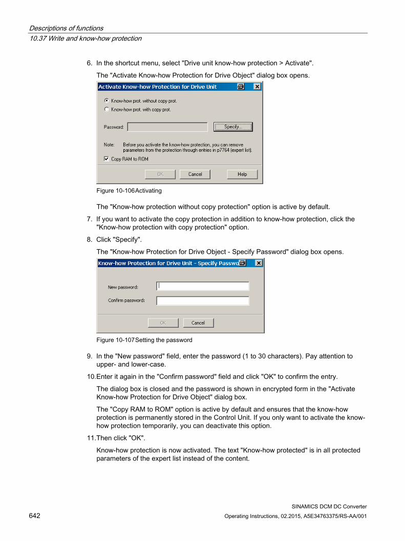
Descriptions of functions 10.37 Write and know-how protection
SINAMICS DCM DC Converter 642 Operating Instructions, 02.2015, A5E34763375/RS-AA/001
6. In the shortcut menu, select "Drive unit know-how protection > Activate".
The "Activate Know-how Protection for Drive Object" dialog box opens.
Figure 10-106 Activating
The "Know-how protection without copy protection" option is active by default.
7. If you want to activate the copy protection in addition to know-how protection, click the "Know-how protection with copy protection" option.
8. Click "Specify".
The "Know-how Protection for Drive Object - Specify Password" dialog box opens.
Figure 10-107 Setting the password
9. In the "New password" field, enter the password (1 to 30 characters). Pay attention to upper- and lower-case.
10.Enter it again in the "Confirm password" field and click "OK" to confirm the entry.
The dialog box is closed and the password is shown in encrypted form in the "Activate Know-how Protection for Drive Object" dialog box.
The "Copy RAM to ROM" option is active by default and ensures that the know-how protection is permanently stored in the Control Unit. If you only want to activate the know-how protection temporarily, you can deactivate this option.
11.Then click "OK".
Know-how protection is now activated. The text "Know-how protected" is in all protected parameters of the expert list instead of the content.
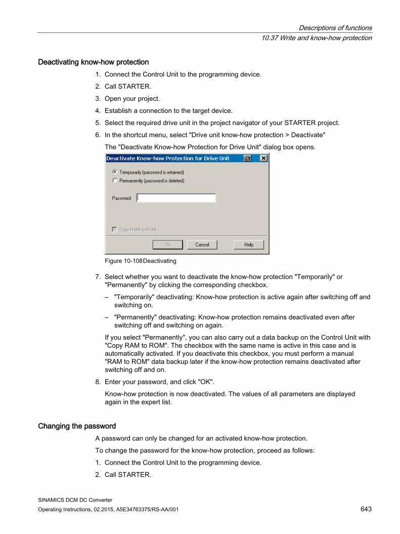
Descriptions of functions 10.37 Write and know-how protection
SINAMICS DCM DC Converter Operating Instructions, 02.2015, A5E34763375/RS-AA/001 643
Deactivating know-how protection 1. Connect the Control Unit to the programming device.
2. Call STARTER.
3. Open your project.
4. Establish a connection to the target device.
5. Select the required drive unit in the project navigator of your STARTER project.
6. In the shortcut menu, select "Drive unit know-how protection > Deactivate"
The "Deactivate Know-how Protection for Drive Unit" dialog box opens.
Figure 10-108 Deactivating
7. Select whether you want to deactivate the know-how protection "Temporarily" or "Permanently" by clicking the corresponding checkbox.
– "Temporarily" deactivating: Know-how protection is active again after switching off and switching on.
– "Permanently" deactivating: Know-how protection remains deactivated even after switching off and switching on again.
If you select "Permanently", you can also carry out a data backup on the Control Unit with "Copy RAM to ROM". The checkbox with the same name is active in this case and is automatically activated. If you deactivate this checkbox, you must perform a manual "RAM to ROM" data backup later if the know-how protection remains deactivated after switching off and on.
8. Enter your password, and click "OK".
Know-how protection is now deactivated. The values of all parameters are displayed again in the expert list.
Changing the password A password can only be changed for an activated know-how protection.
To change the password for the know-how protection, proceed as follows:
1. Connect the Control Unit to the programming device.
2. Call STARTER.
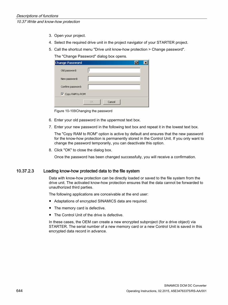
Descriptions of functions 10.37 Write and know-how protection
SINAMICS DCM DC Converter 644 Operating Instructions, 02.2015, A5E34763375/RS-AA/001
3. Open your project.
4. Select the required drive unit in the project navigator of your STARTER project.
5. Call the shortcut menu "Drive unit know-how protection > Change password".
The "Change Password" dialog box opens.
Figure 10-109 Changing the password
6. Enter your old password in the uppermost text box.
7. Enter your new password in the following text box and repeat it in the lowest text box.
The "Copy RAM to ROM" option is active by default and ensures that the new password for the know-how protection is permanently stored in the Control Unit. If you only want to change the password temporarily, you can deactivate this option.
8. Click "OK" to close the dialog box.
Once the password has been changed successfully, you will receive a confirmation.
10.37.2.3 Loading know-how protected data to the file system Data with know-how protection can be directly loaded or saved to the file system from the drive unit. The activated know-how protection ensures that the data cannot be forwarded to unauthorized third parties.
The following applications are conceivable at the end user:
Adaptations of encrypted SINAMICS data are required.
The memory card is defective.
The Control Unit of the drive is defective.
In these cases, the OEM can create a new encrypted subproject (for a drive object) via STARTER. The serial number of a new memory card or a new Control Unit is saved in this encrypted data record in advance.
Descriptions of functions 10.37 Write and know-how protection
SINAMICS DCM DC Converter Operating Instructions, 02.2015, A5E34763375/RS-AA/001 645
Application example: Control Unit is defective
Scenario:
The Control Unit of an end user is defective. The machine manufacturer (OEM) has the end user's STARTER project files of the machine.
Sequence:
1. The end user sends the OEM the serial numbers of the new Control Unit (r7758) and the new memory card (r7843), and specifies the machine in which the Control Unit is installed.
2. The OEM loads the STARTER project data of the end user.
3. The OEM performs the STARTER function "Load to file system" (see Saving data to the file system (Page 644)).
– The OEM specifies whether the data is to be stored zipped or unzipped.
– The OEM makes the required know-how protection settings.
– The OEM enters the serial numbers of the memory card and the new Control Unit.
4. The OEM sends the stored data to the end user (e.g. by e-mail).
5. The end user copies the "User" directory to the new memory card and inserts it into the new Control Unit.
6. The end user switches on the drive.
When powering up, the Control Unit checks the new serial numbers and deletes the values p7759 and p7769 if they match.
After it has powered-up without any errors, the Control Unit is ready for operation. The know-how protection is active.
If the serial numbers do not match, then fault F13100 is output.
If required, the end user must re-enter the changed parameters from the OEM exception lists.
Calling the "Load to File System" dialog box 1. Call STARTER.
2. Open the required project.
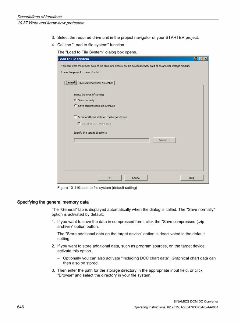
Descriptions of functions 10.37 Write and know-how protection
SINAMICS DCM DC Converter 646 Operating Instructions, 02.2015, A5E34763375/RS-AA/001
3. Select the required drive unit in the project navigator of your STARTER project.
4. Call the "Load to file system" function.
The "Load to File System" dialog box opens.
Figure 10-110 Load to file system (default setting)
Specifying the general memory data The "General" tab is displayed automatically when the dialog is called. The "Save normally" option is activated by default.
1. If you want to save the data in compressed form, click the "Save compressed (.zip archive)" option button.
The "Store additional data on the target device" option is deactivated in the default setting.
2. If you want to store additional data, such as program sources, on the target device, activate this option.
– Optionally you can also activate "Including DCC chart data". Graphical chart data can then also be stored.
3. Then enter the path for the storage directory in the appropriate input field, or click "Browse" and select the directory in your file system.
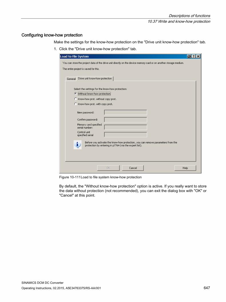
Descriptions of functions 10.37 Write and know-how protection
SINAMICS DCM DC Converter Operating Instructions, 02.2015, A5E34763375/RS-AA/001 647
Configuring know-how protection Make the settings for the know-how protection on the "Drive unit know-how protection" tab.
1. Click the "Drive unit know-how protection" tab.
Figure 10-111 Load to file system know-how protection
By default, the "Without know-how protection" option is active. If you really want to store the data without protection (not recommended), you can exit the dialog box with "OK" or "Cancel" at this point.
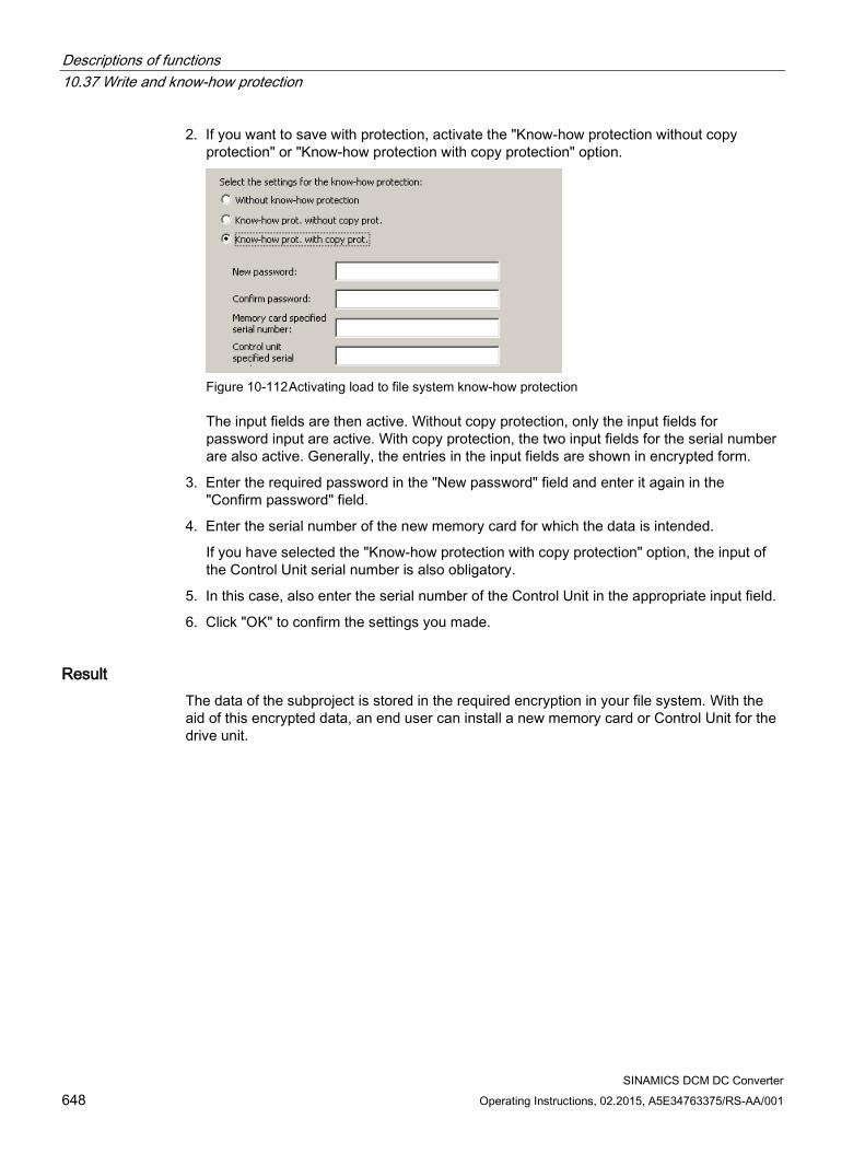
Descriptions of functions 10.37 Write and know-how protection
SINAMICS DCM DC Converter 648 Operating Instructions, 02.2015, A5E34763375/RS-AA/001
2. If you want to save with protection, activate the "Know-how protection without copy protection" or "Know-how protection with copy protection" option.
Figure 10-112 Activating load to file system know-how protection
The input fields are then active. Without copy protection, only the input fields for password input are active. With copy protection, the two input fields for the serial number are also active. Generally, the entries in the input fields are shown in encrypted form.
3. Enter the required password in the "New password" field and enter it again in the "Confirm password" field.
4. Enter the serial number of the new memory card for which the data is intended.
If you have selected the "Know-how protection with copy protection" option, the input of the Control Unit serial number is also obligatory.
5. In this case, also enter the serial number of the Control Unit in the appropriate input field.
6. Click "OK" to confirm the settings you made.
Result The data of the subproject is stored in the required encryption in your file system. With the aid of this encrypted data, an end user can install a new memory card or Control Unit for the drive unit.
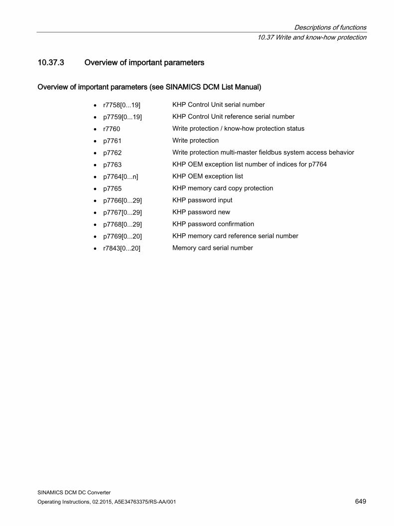
Descriptions of functions 10.37 Write and know-how protection
SINAMICS DCM DC Converter Operating Instructions, 02.2015, A5E34763375/RS-AA/001 649
10.37.3 Overview of important parameters
Overview of important parameters (see SINAMICS DCM List Manual) • r7758[0...19] KHP Control Unit serial number
• p7759[0...19] KHP Control Unit reference serial number
• r7760 Write protection / know-how protection status
• p7761 Write protection
• p7762 Write protection multi-master fieldbus system access behavior
• p7763 KHP OEM exception list number of indices for p7764
• p7764[0...n] KHP OEM exception list
• p7765 KHP memory card copy protection
• p7766[0...29] KHP password input
• p7767[0...29] KHP password new
• p7768[0...29] KHP password confirmation
• p7769[0...20] KHP memory card reference serial number
• r7843[0...20] Memory card serial number

Descriptions of functions 10.37 Write and know-how protection
SINAMICS DCM DC Converter 650 Operating Instructions, 02.2015, A5E34763375/RS-AA/001
SINAMICS DCM DC Converter Operating Instructions, 02.2015, A5E34763375/RS-AA/001 651
Maintenance 11
WARNING
Hazardous voltages are present in certain components of these electrical units during operation.
Dangerous voltage levels may be present at the signaling relays at the customer's site.
Therefore, failure to handle the units properly can result in death or serious physical injury as well as extensive property damage.
When performing maintenance on this unit, you should therefore observe all information provided in this section as well as any notices attached to the product itself. • Only qualified personnel who are familiar with all the safety instructions in this
description, as well as the installation, operating, and maintenance instructions, should carry out maintenance work on this unit.
• Before carrying out visual inspections and maintenance work, it must be ensured that the unit is disconnected from the AC power supply, disabled, and grounded. Before they are shut down, both the converter unit and the motor are subject to dangerous voltage levels; these may be present even when the converter unit's contactor is open.
• The TSE capacitors continue to carry dangerous voltage levels following disconnection. For this reason, the unit should not be opened until an appropriate period of time has elapsed.
Only spare parts approved by the manufacturer may be used.
The converter unit must be provided with extensive protection measures against contamination in order to prevent voltage flashovers and, therefore, destruction. Dust and foreign bodies, which are brought in by the cooling-air flow in particular, must be thoroughly removed at certain intervals; this depends on the rate of accumulation of dirt, but should be carried out at least every 12 months. The unit must be blown out with dry compressed air at a maximum of 1 bar, or cleaned using a vacuum cleaner.
The screw connections (also the protective conductor connections) must be retightened each time that maintenance work is carried out on the SINAMICS DCM.
Please note the following when working with converter units featuring increased air cooling:
The bearings for the fans are designed for an operating period of 30000 hours. The fans must be replaced in good time to ensure the continued availability of the thyristor sets.
Maintenance 11.1 Upgrading software releases
SINAMICS DCM DC Converter 652 Operating Instructions, 02.2015, A5E34763375/RS-AA/001
11.1 Upgrading software releases This chapter describes how you can upgrade a drive – including STARTER project – from one software version to a higher software version (e.g. V1.1 to V1.2).
Basic information The following steps are necessary:
Upgrade the device software
– Step 1: Backup the configuration
– Step 2: Update the drive software (incl. the peripherals)
– Step 3: Update the STARTER project
– Step 4: Load into the target system, RAM to ROM
Upgrade the DCC technology option (optional)
– Step 5: Update the DCC technology option (DCBLIB) and the DCC charts
– Step 6: Load into the target system, RAM to ROM
Note
A memory card is required to update the software (see Chapter "Ordering data for options and accessories").
When updating the software, always proceed as follows:
1. Software update of the drive
– Insert the memory, then switch the electronic power supply OFF and ON again. The device firmware is now installed.
– Switch the electronic power supply OFF and ON again. The device firmware just installed now powers up. If neither a CBE20 nor DRIVE-CLIQ components are available, the drive is ready for operation. However, if a CBE20 or DRIVE-CLIQ components or both are available, the firmware of these components is updated during the power-up of the device firmware. At the end of the power-up of the device firmware, the DRIVE-CLiQ components indicate that a restart is required through flashing red LEDs. Alarm A1006 also appears. Switch the electronic power supply OFF and ON again a third time.
– If only a CBE20 is connected, there is no indication after the second OFF and ON that the CBE20 also requires a restart so that the CBE20 firmware installed in the above step is also started. However, a third OFF and ON of the electronic power supply is also required in this case.
2. Update the STARTER project
3. Load the converted STARTER project to the drive (load to the target device)
Maintenance 11.1 Upgrading software releases
SINAMICS DCM DC Converter Operating Instructions, 02.2015, A5E34763375/RS-AA/001 653
Do not proceed as follows:
1. Software update of the drive
2. Create a NEW STARTER project
3. Load into the PG
In this case, under certain circumstances, STARTER cannot assign the project to the correct drive version. If the STARTER project is not available, generate a new project with the old device version (load into the PG before the software update) and then proceed as normal.
11.1.1 Upgrading the unit software
Note
Hardware/software compatibility
The hardware version of the Control Unit (CUD) must be taken into account when updating the device software. See the table below.
The hardware version can be read from the label on the right-hand side of the CUD.
CUD (print on label) Executable software versions C98043-A7100-L1-... C98043-A7100-L2-... C98043-A7100-L100-... C98043-A7100-L200-...
1.1, 1.2, 1.3
C98043-A7100-L3-... C98043-A7100-L4-... C98043-A7100-L103-... C98043-A7100-L204-...
All versions
A5E... All versions
Step 1: Backup the configuration The drive parameter assignment is not lost while updating the software. Nevertheless, before starting the software update, backup the drive configuration:
Backup the parameter assignment on a memory card (see Chapter "Functions of the memory card") and/or
Backup the parameterization in a STARTER project (see Chapter "Commissioning using the STARTER commissioning tool")
Maintenance 11.1 Upgrading software releases
SINAMICS DCM DC Converter 654 Operating Instructions, 02.2015, A5E34763375/RS-AA/001
Step 2: Software update of the drive Notes:
Only those memory cards that Siemens has prepared for these systems are accepted. If the memory card is formatted, then this must always be realized with the FAT16 setting. Download the current software release: See preface
Procedure:
Unzip the *.zip file to an empty memory card
Insert the card in the drive, which has been switched-off, and switch the device on again. The firmware is updated. The update has been completed if the RDY-LED and the DP1-LED flash at 0.5 Hz (the update takes about 12 min).
Carry out a POWER OFF. Remove the memory card from the drive.
NOTICE
If the memory card is not removed from the drive before the POWER ON, the parameterization in the drive is copied to the memory card during power-up, or a parameterization already on the card copied to the drive.
For a detailed description of this function, see Chapter Memory card functions (Page 334), Section "Copying parameter data sets from non-volatile memory to the memory card".
Carry out a POWER ON. The new software is now active.
If a memory card is already in the drive, the mechanism described in Chapter Memory card functions (Page 334), Section "Copying parameter data sets from non-volatile memory to the memory card" takes effect. During the first power up
– Connected TM modules or SMC30 perform a SW update. A POWER OFF / POWER ON of these components is required after the software update. The memory card no longer needs to be inserted for this step.
– An optionally connected AOP30 indicates that new AOP software is available. Confirm the prompt after the update with "OK".
Note
As a result of the device software update, DCC charts in the device are not automatically upgraded to the new DCC version. This is also not absolutely necessary. See also Step 5 (next chapter).
Note
The electronic power supply must not be interrupted during the update, otherwise the update will need to be restarted.
Note
To safely remove the memory card, see Chapter Memory card functions (Page 334)
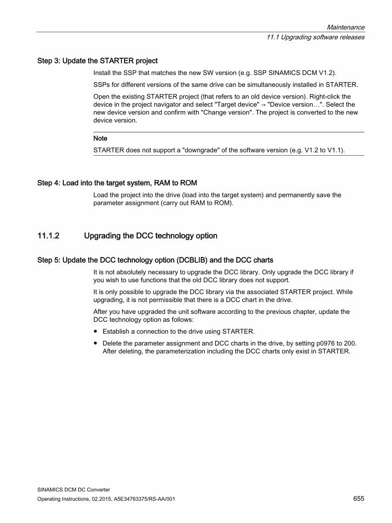
Maintenance 11.1 Upgrading software releases
SINAMICS DCM DC Converter Operating Instructions, 02.2015, A5E34763375/RS-AA/001 655
Step 3: Update the STARTER project Install the SSP that matches the new SW version (e.g. SSP SINAMICS DCM V1.2).
SSPs for different versions of the same drive can be simultaneously installed in STARTER.
Open the existing STARTER project (that refers to an old device version). Right-click the device in the project navigator and select "Target device" → "Device version…". Select the new device version and confirm with "Change version". The project is converted to the new device version.
Note
STARTER does not support a "downgrade" of the software version (e.g. V1.2 to V1.1).
Step 4: Load into the target system, RAM to ROM Load the project into the drive (load into the target system) and permanently save the parameter assignment (carry out RAM to ROM).
11.1.2 Upgrading the DCC technology option
Step 5: Update the DCC technology option (DCBLIB) and the DCC charts It is not absolutely necessary to upgrade the DCC library. Only upgrade the DCC library if you wish to use functions that the old DCC library does not support.
It is only possible to upgrade the DCC library via the associated STARTER project. While upgrading, it is not permissible that there is a DCC chart in the drive.
After you have upgraded the unit software according to the previous chapter, update the DCC technology option as follows:
Establish a connection to the drive using STARTER.
Delete the parameter assignment and DCC charts in the drive, by setting p0976 to 200. After deleting, the parameterization including the DCC charts only exist in STARTER.
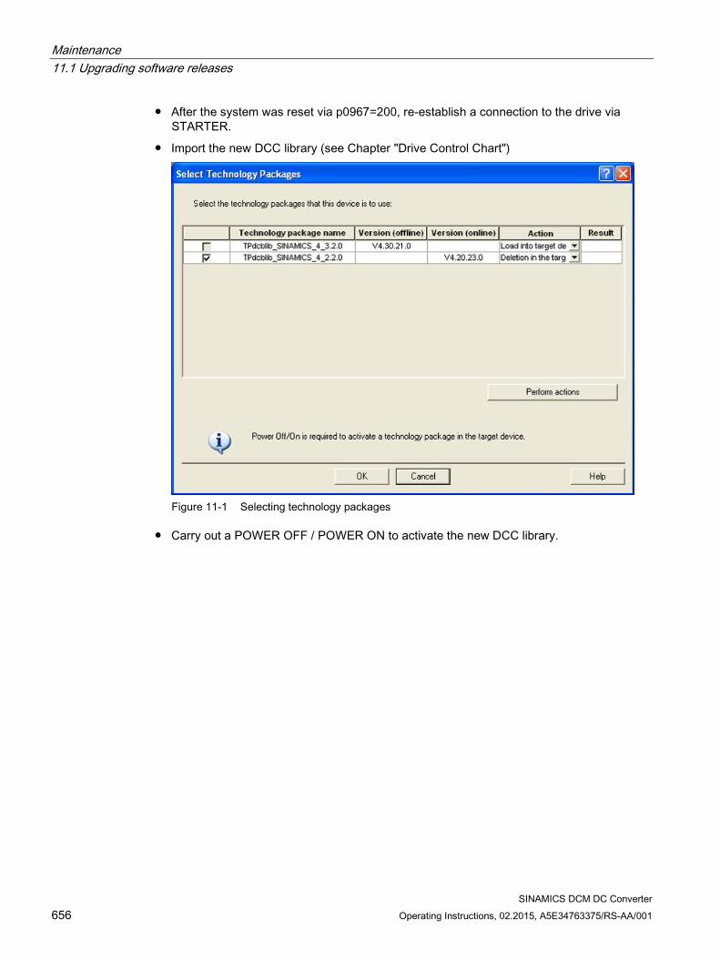
Maintenance 11.1 Upgrading software releases
SINAMICS DCM DC Converter 656 Operating Instructions, 02.2015, A5E34763375/RS-AA/001
After the system was reset via p0967=200, re-establish a connection to the drive via STARTER.
Import the new DCC library (see Chapter "Drive Control Chart")
Figure 11-1 Selecting technology packages
Carry out a POWER OFF / POWER ON to activate the new DCC library.
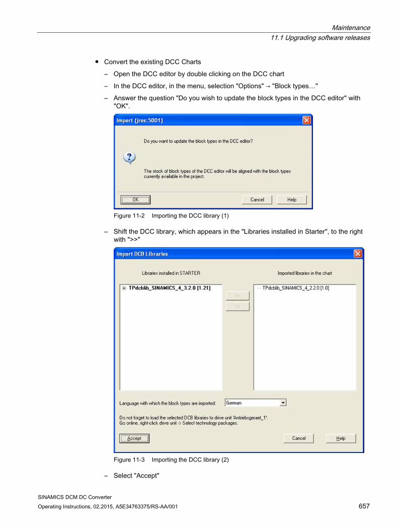
Maintenance 11.1 Upgrading software releases
SINAMICS DCM DC Converter Operating Instructions, 02.2015, A5E34763375/RS-AA/001 657
Convert the existing DCC Charts
– Open the DCC editor by double clicking on the DCC chart
– In the DCC editor, in the menu, selection "Options" → "Block types…"
– Answer the question "Do you wish to update the block types in the DCC editor" with "OK".
Figure 11-2 Importing the DCC library (1)
– Shift the DCC library, which appears in the "Libraries installed in Starter", to the right with ">>"
Figure 11-3 Importing the DCC library (2)
– Select "Accept"

Maintenance 11.1 Upgrading software releases
SINAMICS DCM DC Converter 658 Operating Instructions, 02.2015, A5E34763375/RS-AA/001
– The chart is compiled into the new version
– Perform these steps for all DCC charts which are in the drive.
Step 6: Load into the target system, RAM to ROM Load the project into the drive (load into the target system) to upgrade the charts in the drive to the new version and permanently save the parameter assignment (carry out RAM to ROM).
Maintenance 11.2 Replacing components
SINAMICS DCM DC Converter Operating Instructions, 02.2015, A5E34763375/RS-AA/001 659
11.2 Replacing components
Note
Only authorized Siemens personnel are permitted to repair the power unit.
Exception: Fuses may also be changed by the customer.
11.2.1 Replacing the fan
WARNING
The fan must only be replaced by qualified personnel.
The TSE capacitors continue to carry dangerous voltage levels following disconnection. For this reason, the device should not be opened until a reasonable period of time has elapsed.
Death, serious injury, or substantial material damage can result if these warnings are not taken into account.
WARNING
An incorrect phase sequence (counter-clockwise phase sequence = fan rotates the wrong way) may create a risk of the device overheating.
Check: If the fan rotor rotates in a counter-clockwise direction (to the left) when viewed from above, then the direction of rotation is correct. Notice: Risk of injury due to rotating parts.
The recommendation to replace the fan is displayed in the form of alarm A60165, refer to Chapter 10, Section "Operating hours counter, device fan".
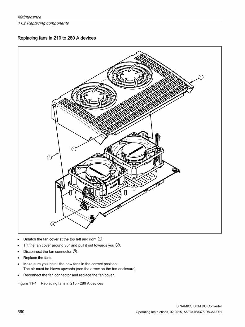
Maintenance 11.2 Replacing components
SINAMICS DCM DC Converter 660 Operating Instructions, 02.2015, A5E34763375/RS-AA/001
Replacing fans in 210 to 280 A devices
• Unlatch the fan cover at the top left and right ①. • Tilt the fan cover around 30° and pull it out towards you ②. • Disconnect the fan connector ③. • Replace the fans. • Make sure you install the new fans in the correct position:
The air must be blown upwards (see the arrow on the fan enclosure). • Reconnect the fan connector and replace the fan cover.
Figure 11-4 Replacing fans in 210 - 280 A devices
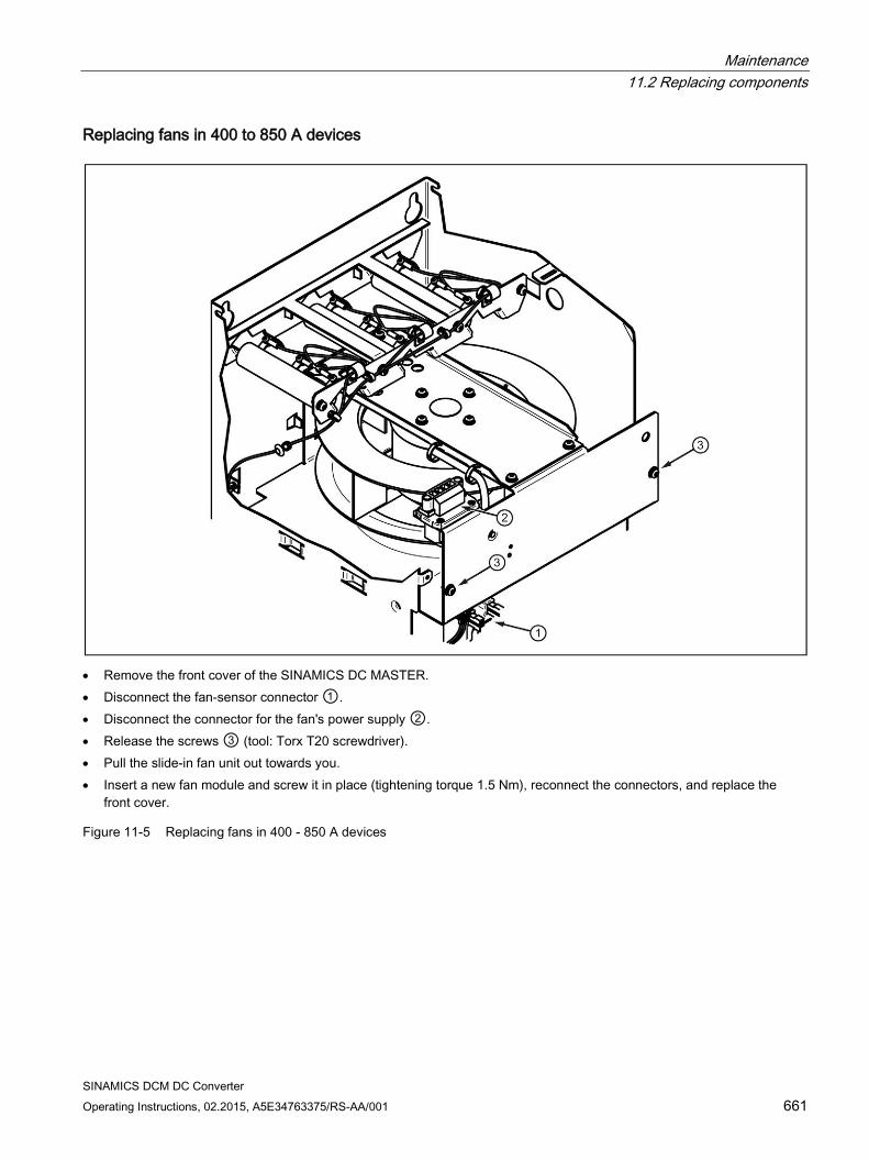
Maintenance 11.2 Replacing components
SINAMICS DCM DC Converter Operating Instructions, 02.2015, A5E34763375/RS-AA/001 661
Replacing fans in 400 to 850 A devices
• Remove the front cover of the SINAMICS DC MASTER. • Disconnect the fan-sensor connector ①. • Disconnect the connector for the fan's power supply ②. • Release the screws ③ (tool: Torx T20 screwdriver). • Pull the slide-in fan unit out towards you. • Insert a new fan module and screw it in place (tightening torque 1.5 Nm), reconnect the connectors, and replace the
front cover.
Figure 11-5 Replacing fans in 400 - 850 A devices
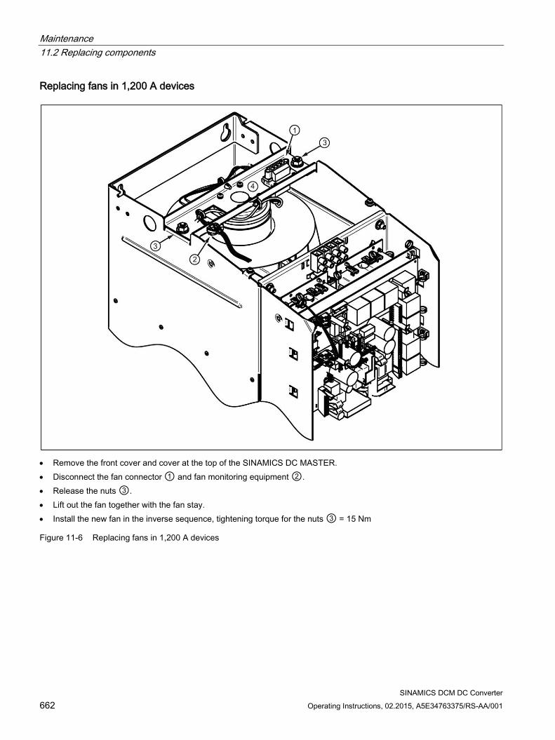
Maintenance 11.2 Replacing components
SINAMICS DCM DC Converter 662 Operating Instructions, 02.2015, A5E34763375/RS-AA/001
Replacing fans in 1,200 A devices
• Remove the front cover and cover at the top of the SINAMICS DC MASTER. • Disconnect the fan connector ① and fan monitoring equipment ②. • Release the nuts ③. • Lift out the fan together with the fan stay. • Install the new fan in the inverse sequence, tightening torque for the nuts ③ = 15 Nm
Figure 11-6 Replacing fans in 1,200 A devices
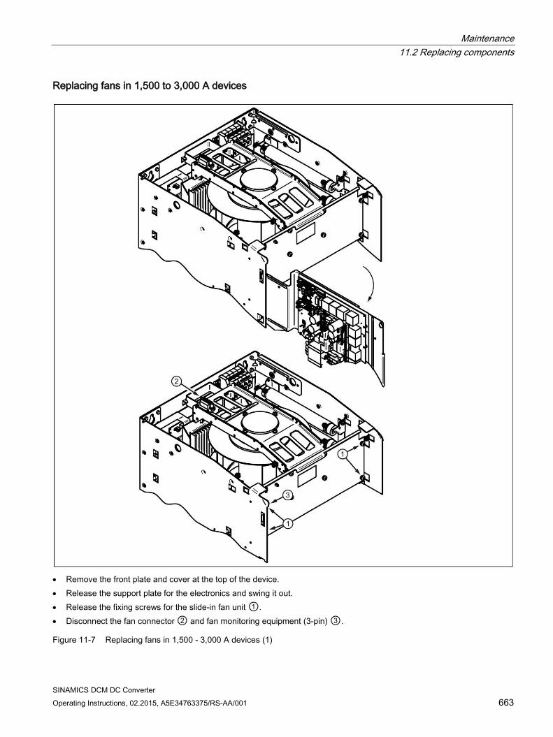
Maintenance 11.2 Replacing components
SINAMICS DCM DC Converter Operating Instructions, 02.2015, A5E34763375/RS-AA/001 663
Replacing fans in 1,500 to 3,000 A devices
• Remove the front plate and cover at the top of the device. • Release the support plate for the electronics and swing it out. • Release the fixing screws for the slide-in fan unit ①. • Disconnect the fan connector ② and fan monitoring equipment (3-pin) ③.
Figure 11-7 Replacing fans in 1,500 - 3,000 A devices (1)
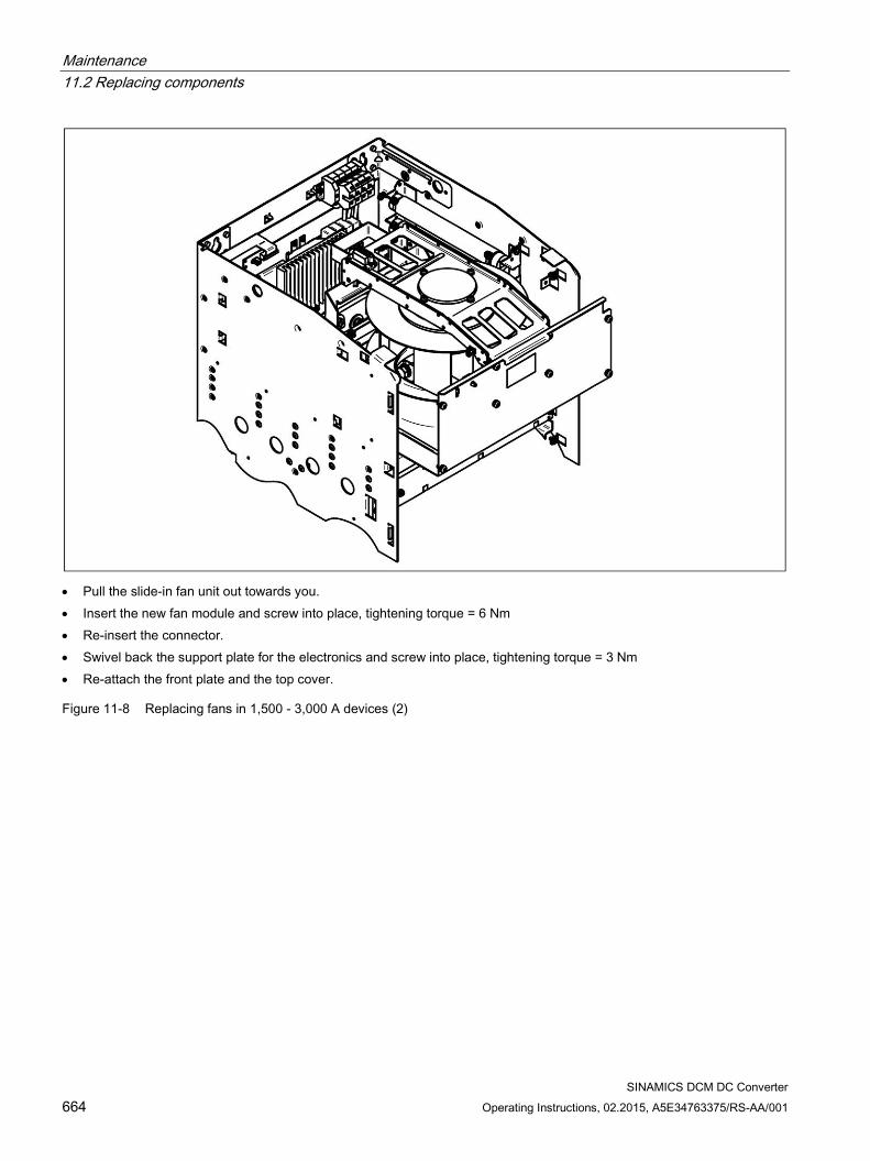
Maintenance 11.2 Replacing components
SINAMICS DCM DC Converter 664 Operating Instructions, 02.2015, A5E34763375/RS-AA/001
• Pull the slide-in fan unit out towards you. • Insert the new fan module and screw into place, tightening torque = 6 Nm • Re-insert the connector. • Swivel back the support plate for the electronics and screw into place, tightening torque = 3 Nm • Re-attach the front plate and the top cover.
Figure 11-8 Replacing fans in 1,500 - 3,000 A devices (2)
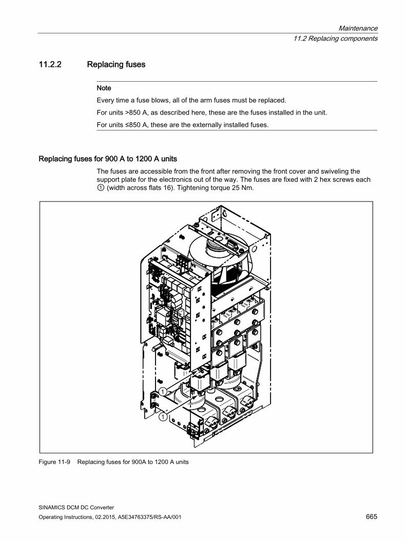
Maintenance 11.2 Replacing components
SINAMICS DCM DC Converter Operating Instructions, 02.2015, A5E34763375/RS-AA/001 665
11.2.2 Replacing fuses
Note
Every time a fuse blows, all of the arm fuses must be replaced.
For units >850 A, as described here, these are the fuses installed in the unit.
For units ≤850 A, these are the externally installed fuses.
Replacing fuses for 900 A to 1200 A units The fuses are accessible from the front after removing the front cover and swiveling the support plate for the electronics out of the way. The fuses are fixed with 2 hex screws each ① (width across flats 16). Tightening torque 25 Nm.
Figure 11-9 Replacing fuses for 900A to 1200 A units
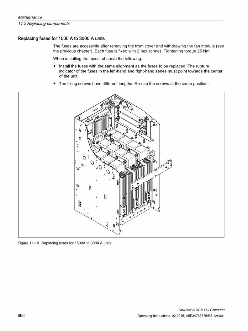
Maintenance 11.2 Replacing components
SINAMICS DCM DC Converter 666 Operating Instructions, 02.2015, A5E34763375/RS-AA/001
Replacing fuses for 1500 A to 3000 A units The fuses are accessible after removing the front cover and withdrawing the fan module (see the previous chapter). Each fuse is fixed with 2 hex screws. Tightening torque 25 Nm.
When installing the fuses, observe the following:
Install the fuses with the same alignment as the fuses to be replaced. The rupture indicator of the fuses in the left-hand and right-hand series must point towards the center of the unit.
The fixing screws have different lengths. Re-use the screws at the same position.
Figure 11-10 Replacing fuses for 1500A to 3000 A units
Maintenance 11.2 Replacing components
SINAMICS DCM DC Converter Operating Instructions, 02.2015, A5E34763375/RS-AA/001 667
11.2.3 Replacing the CUD
WARNING
Qualified personnel
The CUD must only be replaced by qualified personnel.
The TSE capacitors continue to carry dangerous voltage levels following disconnection. For this reason, the device should not be opened until a reasonable period of time has elapsed.
Death, serious injury, or substantial material damage can result if these warnings are not taken into account.
Note
The information regarding electrostatic sensitive devices must be carefully observed. See ESD-sensitive components (Page 22).
Note
Use the supplied protective cover
The module is equipped on both sides with highly sensitive components that can be damaged if installed incorrectly.
It is therefore essential that you use the supplied mounting aid (protective cover) when installing or removing the CUD.
Required tools
Torx screwdrivers TX10 (CUD) and TX20/TX30 (front cover).
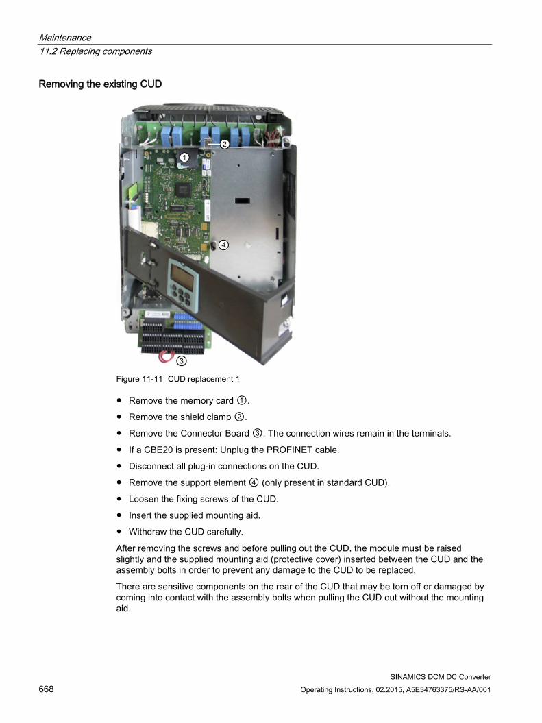
Maintenance 11.2 Replacing components
SINAMICS DCM DC Converter 668 Operating Instructions, 02.2015, A5E34763375/RS-AA/001
Removing the existing CUD
Figure 11-11 CUD replacement 1
Remove the memory card ①.
Remove the shield clamp ②.
Remove the Connector Board ③. The connection wires remain in the terminals.
If a CBE20 is present: Unplug the PROFINET cable.
Disconnect all plug-in connections on the CUD.
Remove the support element ④ (only present in standard CUD).
Loosen the fixing screws of the CUD.
Insert the supplied mounting aid.
Withdraw the CUD carefully.
After removing the screws and before pulling out the CUD, the module must be raised slightly and the supplied mounting aid (protective cover) inserted between the CUD and the assembly bolts in order to prevent any damage to the CUD to be replaced.
There are sensitive components on the rear of the CUD that may be torn off or damaged by coming into contact with the assembly bolts when pulling the CUD out without the mounting aid.
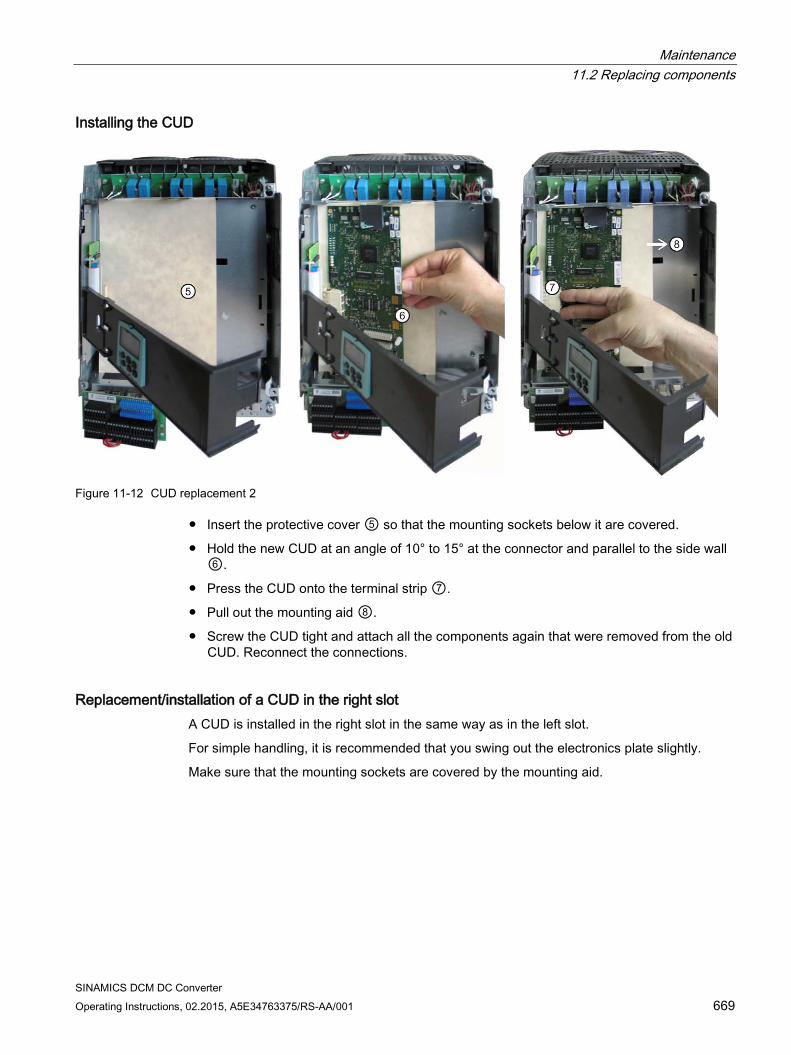
Maintenance 11.2 Replacing components
SINAMICS DCM DC Converter Operating Instructions, 02.2015, A5E34763375/RS-AA/001 669
Installing the CUD
Figure 11-12 CUD replacement 2
Insert the protective cover ⑤ so that the mounting sockets below it are covered.
Hold the new CUD at an angle of 10° to 15° at the connector and parallel to the side wall ⑥.
Press the CUD onto the terminal strip ⑦.
Pull out the mounting aid ⑧.
Screw the CUD tight and attach all the components again that were removed from the old CUD. Reconnect the connections.
Replacement/installation of a CUD in the right slot A CUD is installed in the right slot in the same way as in the left slot.
For simple handling, it is recommended that you swing out the electronics plate slightly.
Make sure that the mounting sockets are covered by the mounting aid.
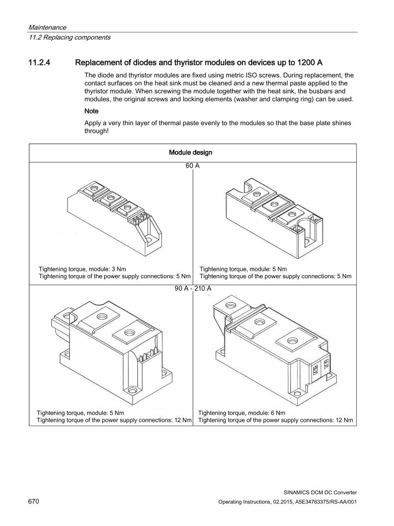
Maintenance 11.2 Replacing components
SINAMICS DCM DC Converter 670 Operating Instructions, 02.2015, A5E34763375/RS-AA/001
11.2.4 Replacement of diodes and thyristor modules on devices up to 1200 A The diode and thyristor modules are fixed using metric ISO screws. During replacement, the contact surfaces on the heat sink must be cleaned and a new thermal paste applied to the thyristor module. When screwing the module together with the heat sink, the busbars and modules, the original screws and locking elements (washer and clamping ring) can be used.
Note
Apply a very thin layer of thermal paste evenly to the modules so that the base plate shines through!
Maintenance 11.3 Replacing the back-up battery in the AOP30 operator panel
SINAMICS DCM DC Converter Operating Instructions, 02.2015, A5E34763375/RS-AA/001 671
11.3 Replacing the back-up battery in the AOP30 operator panel
Table 11- 1 Technical specifications of the backup battery
Type CR2032 3 V lithium battery Manufacturer Maxell, Sony, Panasonic Nominal capacity 220 mAh Self-discharge at 20 °C 1 %/year Service life (in backup mode) > 1 year at 70 °C; >1.5 years at 20 °C Service life (during operation) > 2 years
Replacement 1. Disconnect the SINAMICS DCM from the power supply
2. Open the cabinet.
3. Disconnect the 24 V DC power supply and communications line on the operator panel.
4. Open the cover of the battery compartment.
5. Remove the old battery.
6. Insert the new battery.
7. Close the cover of the battery compartment.
8. Reconnect the 24 V DC power supply and communications line.
9. Close the cabinet.
Note
The battery must be replaced within one minute to ensure that no AOP settings are lost.
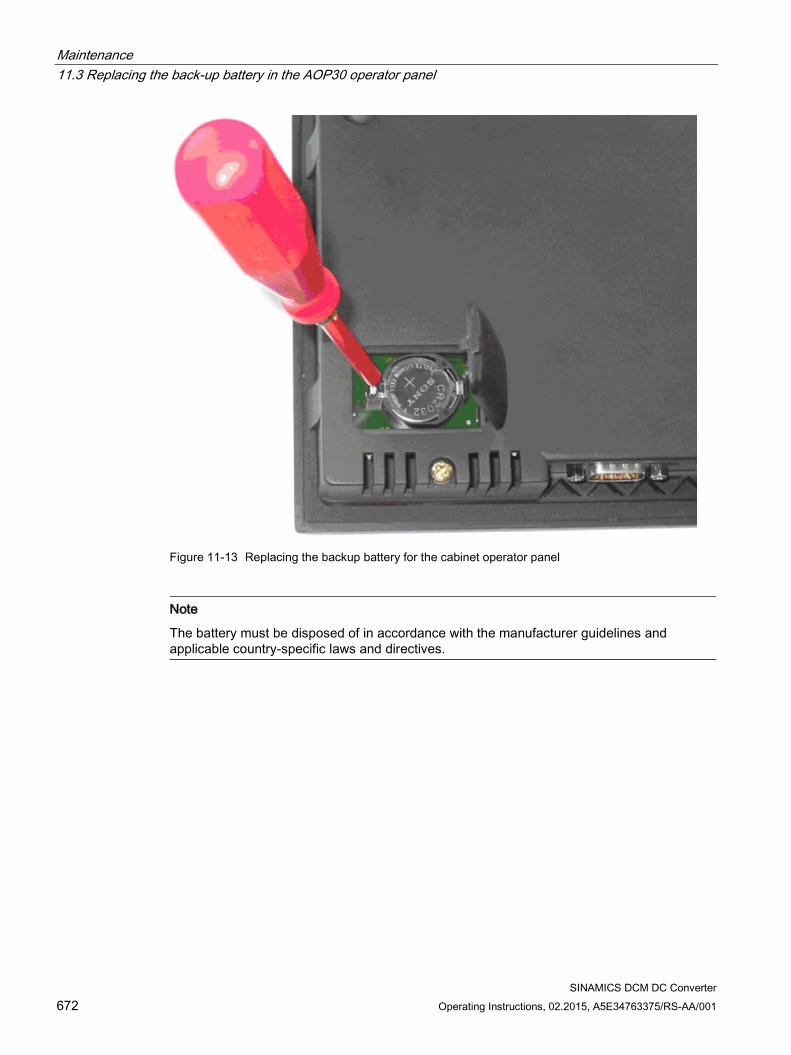
Maintenance 11.3 Replacing the back-up battery in the AOP30 operator panel
SINAMICS DCM DC Converter 672 Operating Instructions, 02.2015, A5E34763375/RS-AA/001
Figure 11-13 Replacing the backup battery for the cabinet operator panel
Note
The battery must be disposed of in accordance with the manufacturer guidelines and applicable country-specific laws and directives.
SINAMICS DCM DC Converter Operating Instructions, 02.2015, A5E34763375/RS-AA/001 673
Applications 12 12.1 Using SINAMICS DCM in shipbuilding
When using SINAMICS DCM in shipbuilding, the following points must be observed:
Radio interference suppression filters must be used in the armature circuit and in the field circuit (see Chapter 6)
EMC-compliant design according to Chapter 6
Use coated modules (option M08). See the ordering data for options and accessories in Chapter 2.
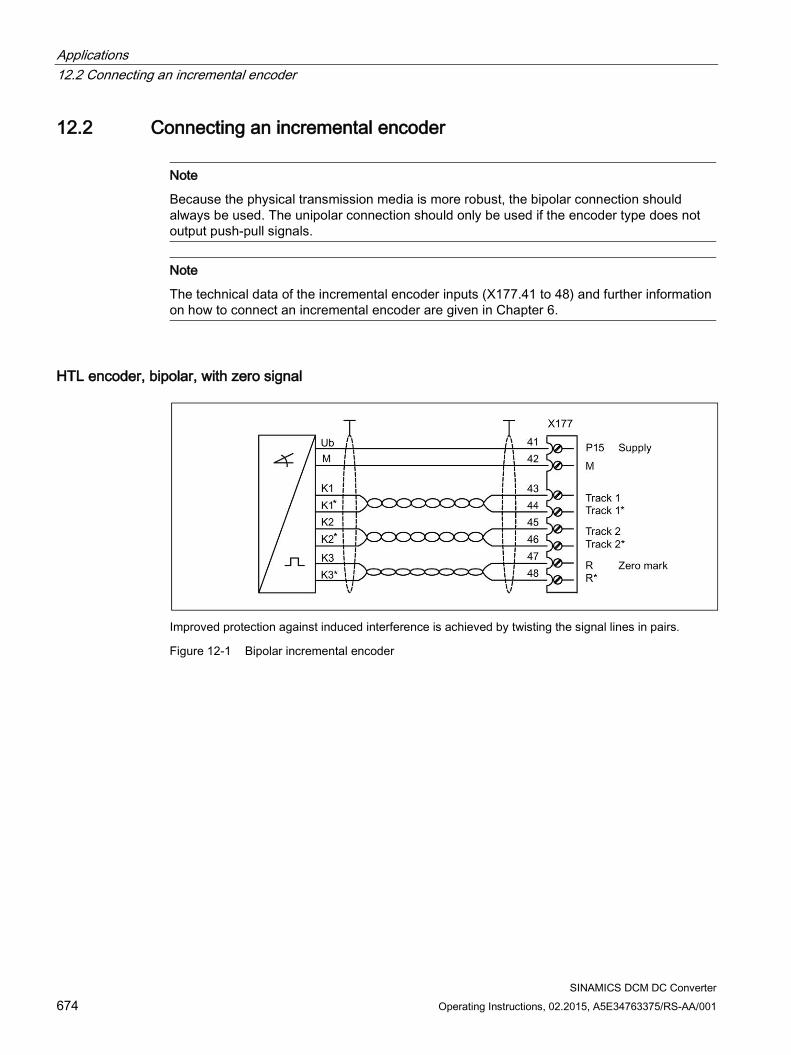
Applications 12.2 Connecting an incremental encoder
SINAMICS DCM DC Converter 674 Operating Instructions, 02.2015, A5E34763375/RS-AA/001
12.2 Connecting an incremental encoder
Note
Because the physical transmission media is more robust, the bipolar connection should always be used. The unipolar connection should only be used if the encoder type does not output push-pull signals.
Note
The technical data of the incremental encoder inputs (X177.41 to 48) and further information on how to connect an incremental encoder are given in Chapter 6.
HTL encoder, bipolar, with zero signal
Improved protection against induced interference is achieved by twisting the signal lines in pairs.
Figure 12-1 Bipolar incremental encoder
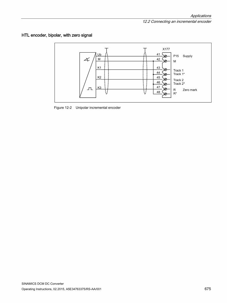
Applications 12.2 Connecting an incremental encoder
SINAMICS DCM DC Converter Operating Instructions, 02.2015, A5E34763375/RS-AA/001 675
HTL encoder, bipolar, with zero signal
Figure 12-2 Unipolar incremental encoder
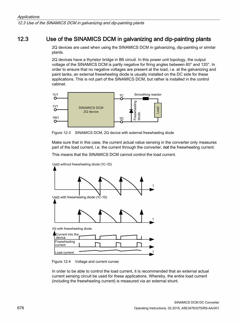
Applications 12.3 Use of the SINAMICS DCM in galvanizing and dip-painting plants
SINAMICS DCM DC Converter 676 Operating Instructions, 02.2015, A5E34763375/RS-AA/001
12.3 Use of the SINAMICS DCM in galvanizing and dip-painting plants 2Q devices are used when using the SINAMICS DCM in galvanizing, dip-painting or similar plants.
2Q devices have a thyristor bridge in B6 circuit. In this power unit topology, the output voltage of the SINAMICS DCM is partly negative for firing angles between 60° and 120°. In order to ensure that no negative voltages are present at the load, i.e. at the galvanizing and paint tanks, an external freewheeling diode is usually installed on the DC side for these applications. This is not part of the SINAMICS DCM, but rather is installed in the control cabinet.
Figure 12-3 SINAMICS DCM, 2Q device with external freewheeling diode
Make sure that in this case, the current actual value sensing in the converter only measures part of the load current, i.e. the current through the converter, not the freewheeling current.
This means that the SINAMICS DCM cannot control the load current.
Figure 12-4 Voltage and current curves
In order to be able to control the load current, it is recommended that an external actual current sensing circuit be used for these applications. Whereby, the entire load current (including the freewheeling current) is measured via an external shunt.
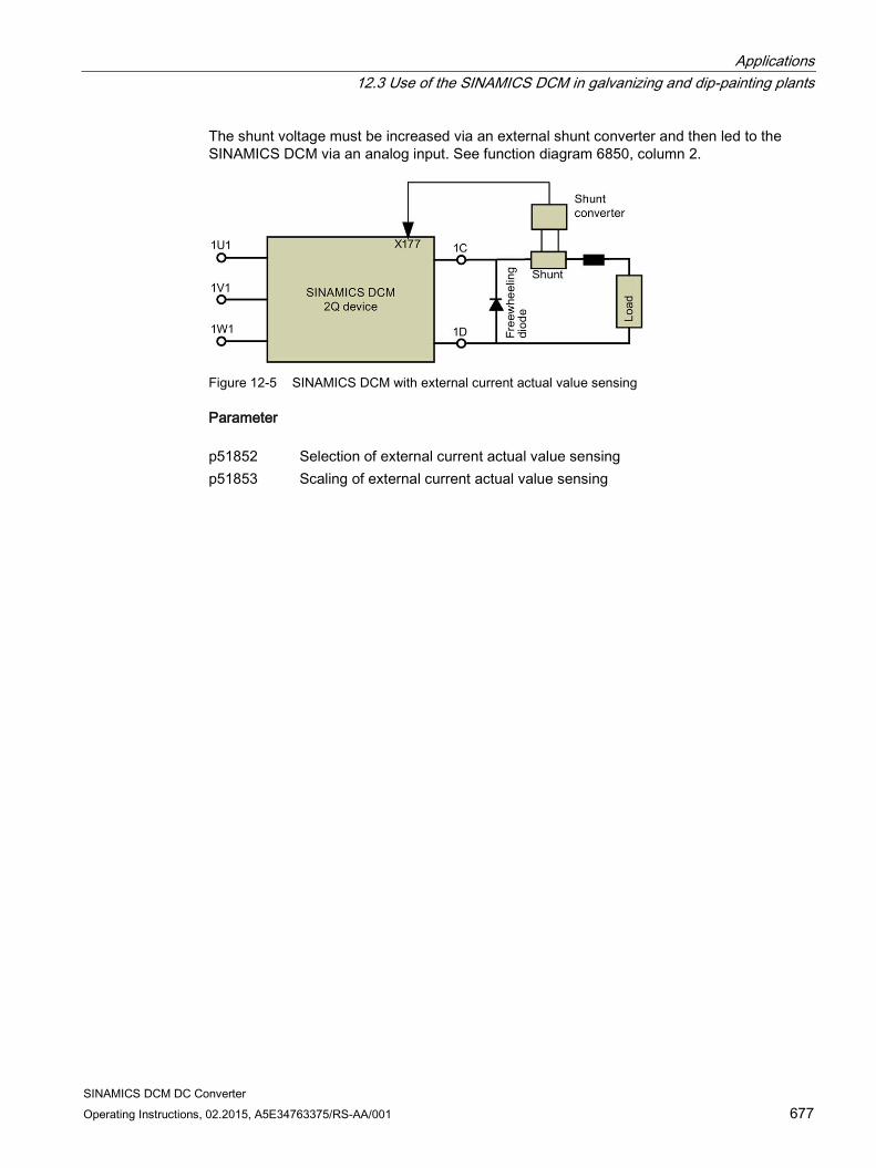
Applications 12.3 Use of the SINAMICS DCM in galvanizing and dip-painting plants
SINAMICS DCM DC Converter Operating Instructions, 02.2015, A5E34763375/RS-AA/001 677
The shunt voltage must be increased via an external shunt converter and then led to the SINAMICS DCM via an analog input. See function diagram 6850, column 2.
Figure 12-5 SINAMICS DCM with external current actual value sensing
Parameter p51852 Selection of external current actual value sensing p51853 Scaling of external current actual value sensing

Applications 12.3 Use of the SINAMICS DCM in galvanizing and dip-painting plants
SINAMICS DCM DC Converter 678 Operating Instructions, 02.2015, A5E34763375/RS-AA/001
SINAMICS DCM DC Converter Operating Instructions, 02.2015, A5E34763375/RS-AA/001 679
Appendix A A A.1 Certifications and standards
Certifications Development, production, sales: ISO 9001:2008 Quality management ISO 14001:2004 Environmental management Devices: UL, cULus File No. E203250 1) EAC Germanischer Lloyd Shipbuilding 2) 11787-10HH Lloyd's Register Shipbuilding 2) No. 06/20053 American Bureau of Shipping Shipbuilding 2) 06-HG196689-1-PDA Det Norske Veritas Shipbuilding 2) No. E-10357 (DC converters)
No. E-10358 (Control Module) Communication: PROFIBUS slave (DP-V0, DP-V1, PROFIdrive 3.1.2) PROFINET IO devices (V 2.2.4, PROFIdrive 4.1) 1) UL online certifications directory:
http://database.ul.com/cgi-bin/XYV/template/LISEXT/1FRAME/index.htm 2) In order to maintain the limit values decisive for certification for marine applications, the
prerequisites as listed in chapter "Using SINAMICS DCM in shipbuilding (Page 673)" must be observed.
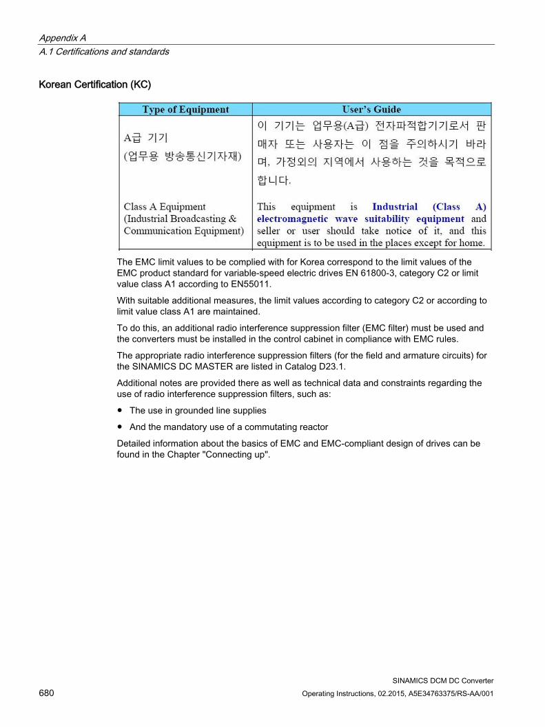
Appendix A A.1 Certifications and standards
SINAMICS DCM DC Converter 680 Operating Instructions, 02.2015, A5E34763375/RS-AA/001
Korean Certification (KC)
The EMC limit values to be complied with for Korea correspond to the limit values of the EMC product standard for variable-speed electric drives EN 61800-3, category C2 or limit value class A1 according to EN55011.
With suitable additional measures, the limit values according to category C2 or according to limit value class A1 are maintained.
To do this, an additional radio interference suppression filter (EMC filter) must be used and the converters must be installed in the control cabinet in compliance with EMC rules.
The appropriate radio interference suppression filters (for the field and armature circuits) for the SINAMICS DC MASTER are listed in Catalog D23.1.
Additional notes are provided there as well as technical data and constraints regarding the use of radio interference suppression filters, such as:
The use in grounded line supplies
And the mandatory use of a commutating reactor
Detailed information about the basics of EMC and EMC-compliant design of drives can be found in the Chapter "Connecting up".
Appendix A A.2 List of abbreviations
SINAMICS DCM DC Converter Operating Instructions, 02.2015, A5E34763375/RS-AA/001 681
Basic standards EN 50178 Electronic equipment for use in power installations EN 50274 Low-voltage switchgear and controlgear assemblies: Protection against
electric shock - Protection against unintentional direct contact with haz-ardous live parts
EN 60146-1-1 Semiconductor converters; General requirements and line-commutated converters; specification of basic requirements
EN 61800-1 Adjustable speed electrical power drive systems - General requirements - Rating specifications for low voltage adjustable speed DC power drive systems
EN 61800-3 Adjustable speed electrical power drive systems - Part 3: EMC product standard including specific test methods
EN 61800-5-1 Adjustable speed electrical power drive systems – Part 5-1: Safety re-quirements – Electrical, thermal, and energy
EN 60204-1 Safety of machinery - Electrical equipment of machines - Part 1: General requirements
UBC 97 Uniform Building Code
Reference standards SN 29500-1 Component failure rates: Anticipated values, general SN 36350-1 Environmentally compatible products, Part 1: Product design guidelines SN 27095 Inspection and testing of switchgear and control equipment for marine
engineering ISO 3740 Determination of sound power levels of noise sources: Guidelines for the
use of basic standards
Country-specific standards NEMA National Electrical Manufacturers Association UL 508 C Power Conversion Equipment UL 840 Insulation Coordination
Including Clearances and Creepage Distances for Electrical Equipment UL 94 Tests for Flammability of Plastic Materials for Parts in Devices and Appli-
ances
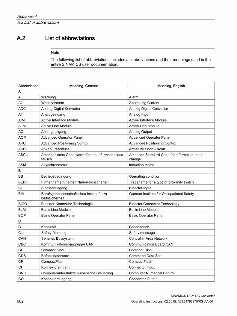
Appendix A A.2 List of abbreviations
SINAMICS DCM DC Converter 682 Operating Instructions, 02.2015, A5E34763375/RS-AA/001
A.2 List of abbreviations
Note
The following list of abbreviations includes all abbreviations and their meanings used in the entire SINAMICS user documentation.
Abbreviation Meaning, German Meaning, English A A... Warnung Alarm AC Wechselstrom Alternating Current ADC Analog-Digital-Konverter Analog Digital Converter AI Analogeingang Analog Input AIM Active Interface Module Active Interface Module ALM Active Line Module Active Line Module AO Analogausgang Analog Output AOP Advanced Operator Panel Advanced Operator Panel APC Advanced Positioning Control Advanced Positioning Control ASC Ankerkurzschluss Armature Short-Circuit ASCII Amerikanische Code-Norm für den Informationsaus-
tausch American Standard Code for Information Inter-change
ASM Asynchronmotor Induction motor B BB Betriebsbedingung Operating condition BERO Firmenname für einen Näherungsschalter Tradename for a type of proximity switch BI Binektoreingang Binector Input BIA Berufsgenossenschaftliches Institut für Ar-
beitssicherheit German Institute for Occupational Safety
BICO Binektor-Konnektor-Technologie Binector Connector Technology BLM Basic Line Module Basic Line Module BOP Basic Operator Panel Basic Operator Panel C C Kapazität Capacitance C... Safety-Meldung Safety message CAN Serielles Bussystem Controller Area Network CBC Kommunikationsbaugruppe CAN Communication Board CAN CD Compact Disc Compact Disc CDS Befehlsdatensatz Command Data Set CF CompactFlash CompactFlash CI Konnektoreingang Connector Input CNC Computerunterstützte numerische Steuerung Computer Numerical Control CO Konnektorausgang Connector Output
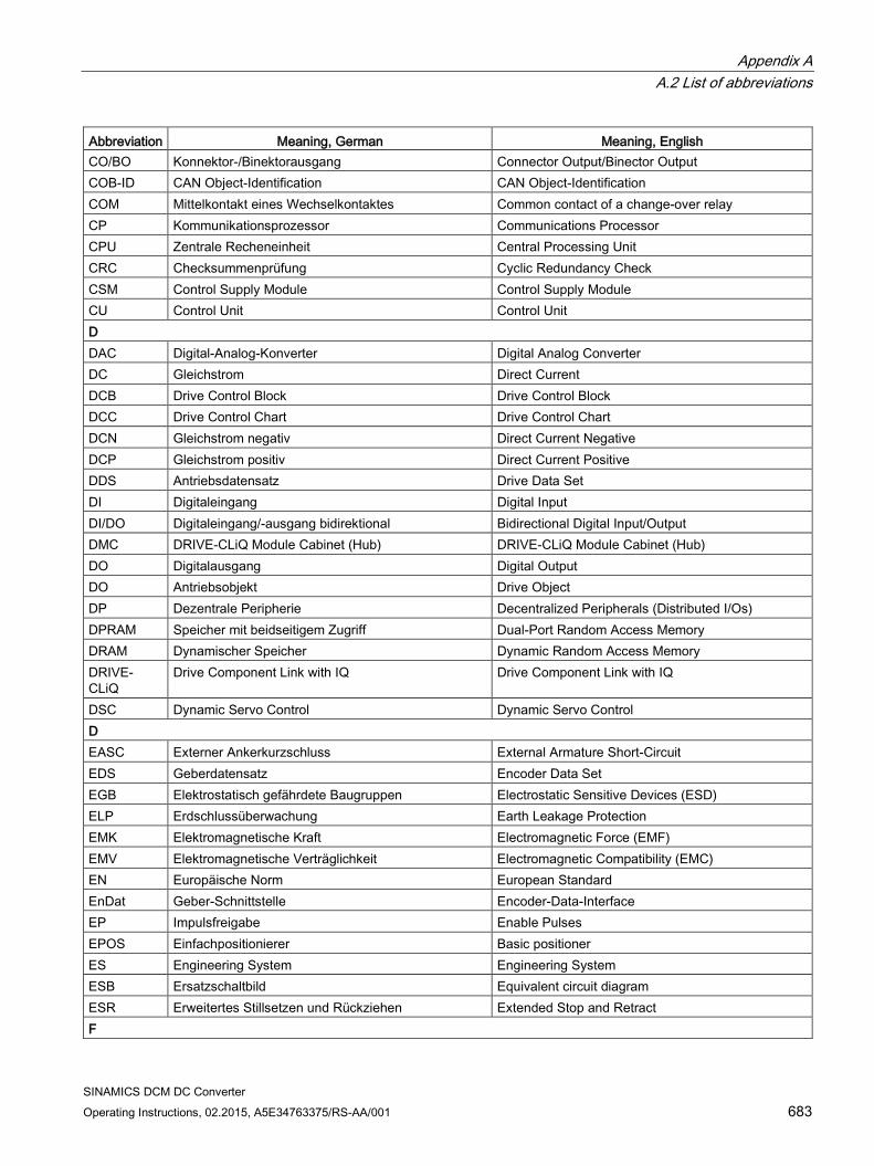
Appendix A A.2 List of abbreviations
SINAMICS DCM DC Converter Operating Instructions, 02.2015, A5E34763375/RS-AA/001 683
Abbreviation Meaning, German Meaning, English CO/BO Konnektor-/Binektorausgang Connector Output/Binector Output COB-ID CAN Object-Identification CAN Object-Identification COM Mittelkontakt eines Wechselkontaktes Common contact of a change-over relay CP Kommunikationsprozessor Communications Processor CPU Zentrale Recheneinheit Central Processing Unit CRC Checksummenprüfung Cyclic Redundancy Check CSM Control Supply Module Control Supply Module CU Control Unit Control Unit D DAC Digital-Analog-Konverter Digital Analog Converter DC Gleichstrom Direct Current DCB Drive Control Block Drive Control Block DCC Drive Control Chart Drive Control Chart DCN Gleichstrom negativ Direct Current Negative DCP Gleichstrom positiv Direct Current Positive DDS Antriebsdatensatz Drive Data Set DI Digitaleingang Digital Input DI/DO Digitaleingang/-ausgang bidirektional Bidirectional Digital Input/Output DMC DRIVE-CLiQ Module Cabinet (Hub) DRIVE-CLiQ Module Cabinet (Hub) DO Digitalausgang Digital Output DO Antriebsobjekt Drive Object DP Dezentrale Peripherie Decentralized Peripherals (Distributed I/Os) DPRAM Speicher mit beidseitigem Zugriff Dual-Port Random Access Memory DRAM Dynamischer Speicher Dynamic Random Access Memory DRIVE-CLiQ
Drive Component Link with IQ Drive Component Link with IQ
DSC Dynamic Servo Control Dynamic Servo Control D EASC Externer Ankerkurzschluss External Armature Short-Circuit EDS Geberdatensatz Encoder Data Set EGB Elektrostatisch gefährdete Baugruppen Electrostatic Sensitive Devices (ESD) ELP Erdschlussüberwachung Earth Leakage Protection EMK Elektromagnetische Kraft Electromagnetic Force (EMF) EMV Elektromagnetische Verträglichkeit Electromagnetic Compatibility (EMC) EN Europäische Norm European Standard EnDat Geber-Schnittstelle Encoder-Data-Interface EP Impulsfreigabe Enable Pulses EPOS Einfachpositionierer Basic positioner ES Engineering System Engineering System ESB Ersatzschaltbild Equivalent circuit diagram ESR Erweitertes Stillsetzen und Rückziehen Extended Stop and Retract F
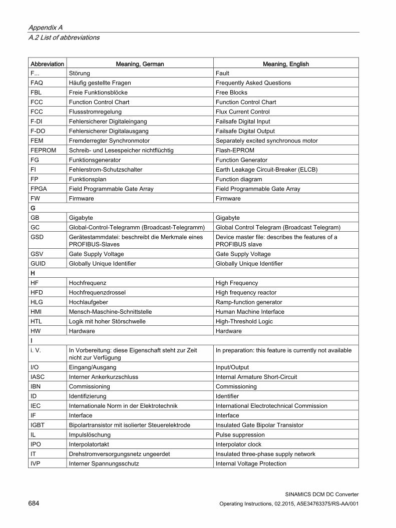
Appendix A A.2 List of abbreviations
SINAMICS DCM DC Converter 684 Operating Instructions, 02.2015, A5E34763375/RS-AA/001
Abbreviation Meaning, German Meaning, English F... Störung Fault FAQ Häufig gestellte Fragen Frequently Asked Questions FBL Freie Funktionsblöcke Free Blocks FCC Function Control Chart Function Control Chart FCC Flussstromregelung Flux Current Control F-DI Fehlersicherer Digitaleingang Failsafe Digital Input F-DO Fehlersicherer Digitalausgang Failsafe Digital Output FEM Fremderregter Synchronmotor Separately excited synchronous motor FEPROM Schreib- und Lesespeicher nichtflüchtig Flash-EPROM FG Funktionsgenerator Function Generator FI Fehlerstrom-Schutzschalter Earth Leakage Circuit-Breaker (ELCB) FP Funktionsplan Function diagram FPGA Field Programmable Gate Array Field Programmable Gate Array FW Firmware Firmware G GB Gigabyte Gigabyte GC Global-Control-Telegramm (Broadcast-Telegramm) Global Control Telegram (Broadcast Telegram) GSD Gerätestammdatei: beschreibt die Merkmale eines
PROFIBUS-Slaves Device master file: describes the features of a PROFIBUS slave
GSV Gate Supply Voltage Gate Supply Voltage GUID Globally Unique Identifier Globally Unique Identifier H HF Hochfrequenz High Frequency HFD Hochfrequenzdrossel High frequency reactor HLG Hochlaufgeber Ramp-function generator HMI Mensch-Maschine-Schnittstelle Human Machine Interface HTL Logik mit hoher Störschwelle High-Threshold Logic HW Hardware Hardware I i. V. In Vorbereitung: diese Eigenschaft steht zur Zeit
nicht zur Verfügung In preparation: this feature is currently not available
I/O Eingang/Ausgang Input/Output IASC Interner Ankerkurzschluss Internal Armature Short-Circuit IBN Commissioning Commissioning ID Identifizierung Identifier IEC Internationale Norm in der Elektrotechnik International Electrotechnical Commission IF Interface Interface IGBT Bipolartransistor mit isolierter Steuerelektrode Insulated Gate Bipolar Transistor IL Impulslöschung Pulse suppression IPO Interpolatortakt Interpolator clock IT Drehstromversorgungsnetz ungeerdet Insulated three-phase supply network IVP Interner Spannungsschutz Internal Voltage Protection
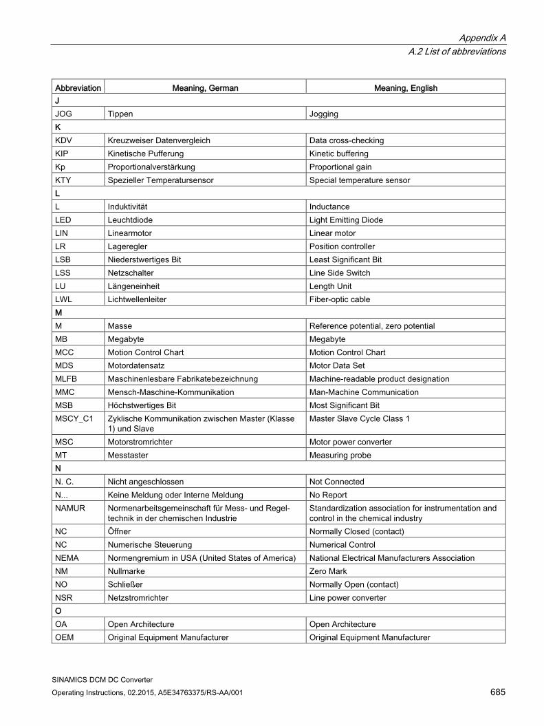
Appendix A A.2 List of abbreviations
SINAMICS DCM DC Converter Operating Instructions, 02.2015, A5E34763375/RS-AA/001 685
Abbreviation Meaning, German Meaning, English J JOG Tippen Jogging K KDV Kreuzweiser Datenvergleich Data cross-checking KIP Kinetische Pufferung Kinetic buffering Kp Proportionalverstärkung Proportional gain KTY Spezieller Temperatursensor Special temperature sensor L L Induktivität Inductance LED Leuchtdiode Light Emitting Diode LIN Linearmotor Linear motor LR Lageregler Position controller LSB Niederstwertiges Bit Least Significant Bit LSS Netzschalter Line Side Switch LU Längeneinheit Length Unit LWL Lichtwellenleiter Fiber-optic cable M M Masse Reference potential, zero potential MB Megabyte Megabyte MCC Motion Control Chart Motion Control Chart MDS Motordatensatz Motor Data Set MLFB Maschinenlesbare Fabrikatebezeichnung Machine-readable product designation MMC Mensch-Maschine-Kommunikation Man-Machine Communication MSB Höchstwertiges Bit Most Significant Bit MSCY_C1 Zyklische Kommunikation zwischen Master (Klasse
1) und Slave Master Slave Cycle Class 1
MSC Motorstromrichter Motor power converter MT Messtaster Measuring probe N N. C. Nicht angeschlossen Not Connected N... Keine Meldung oder Interne Meldung No Report NAMUR Normenarbeitsgemeinschaft für Mess- und Regel-
technik in der chemischen Industrie Standardization association for instrumentation and control in the chemical industry
NC Öffner Normally Closed (contact) NC Numerische Steuerung Numerical Control NEMA Normengremium in USA (United States of America) National Electrical Manufacturers Association NM Nullmarke Zero Mark NO Schließer Normally Open (contact) NSR Netzstromrichter Line power converter O OA Open Architecture Open Architecture OEM Original Equipment Manufacturer Original Equipment Manufacturer

Appendix A A.2 List of abbreviations
SINAMICS DCM DC Converter 686 Operating Instructions, 02.2015, A5E34763375/RS-AA/001
Abbreviation Meaning, German Meaning, English OLP Busstecker für Lichtleiter Optical Link Plug OMI Option Module Interface Option Module Interface P p... Einstellparameter Adjustable parameter PB PROFIBUS PROFIBUS PcCtrl Steuerungshoheit Master Control PD PROFIdrive PROFIdrive PDS Leistungsteildatensatz Power Unit Data Set PE Schutzerde Protective Earth PELV Schutzkleinspannung Protective Extra Low Voltage PEM Permanenterregter Synchronmotor Permanent-magnet synchronous motor PG Programmiergerät Programming terminal PI Proportional Integral Proportional Integral PID Proportional Integral Differential Proportional Integral Differential PLC Speicherprogrammierbare Steuerung (SPS) Programmable Logic Controller (PLC) PLL Phase Locked Loop Phase Locked Loop PNO PROFIBUS Nutzerorganisation PROFIBUS user organization PPI Punkt zu Punkt Schnittstelle Point to Point Interface PRBS Weißes Rauschen Pseudo Random Binary Signal PROFIBUS Serieller Datenbus Process Field Bus PS Stromversorgung Power Supply PSA Power Stack Adapter Power Stack Adapter PTC Positiver Temperaturkoeffizient Positive Temperature Coefficient PTP Punkt zu Punkt Point-To-Point PWM Pulsweitenmodulation Pulse Width Modulation PZD PROFIBUS Prozessdaten PROFIBUS process data R r... Beobachtungsparameter (nur lesbar) Display parameter (read only) RAM Speicher zum Lesen und Schreiben Random Access Memory RCCB Fehlerstrom-Schutzschalter Residual Current Circuit Breaker RCD Fehlerstrom-Schutzschalter Residual Current Device RJ45 Norm. Beschreibt eine 8-polige Steckverbindung mit
Twisted-Pair Ethernet. Standard. Describes an 8-pole plug connector with twisted pair Ethernet.
RKA Rückkühlanlage Recooling system RO Nur lesbar Read Only RPDO Receive Process Data Object Receive Process Data Object RS232 Serielle Schnittstelle Serial Interface RS485 Norm. Beschreibt die Physik einer digitalen seriellen
Schnittstelle. Standard. Describes the physical characteristics of a digital serial interface.
RTC Echtzeituhr Real Time Clock RZA Raumzeigerapproximation Space vector approximation (SVA) S
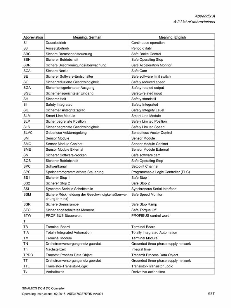
Appendix A A.2 List of abbreviations
SINAMICS DCM DC Converter Operating Instructions, 02.2015, A5E34763375/RS-AA/001 687
Abbreviation Meaning, German Meaning, English S1 Dauerbetrieb Continuous operation S3 Aussetzbetrieb Periodic duty SBC Sichere Bremsenansteuerung Safe Brake Control SBH Sicherer Betriebshalt Safe Operating Stop SBR Sichere Beschleunigungsüberwachung Safe Acceleration Monitor SCA Sichere Nocke Safe Cam SE Sicherer Software-Endschalter Safe software limit switch SG Sicher reduzierte Geschwindigkeit Safely reduced speed SGA Sicherheitsgerichteter Ausgang Safety-related output SGE Sicherheitsgerichteter Eingang Safety-related input SH Sicherer Halt Safety standstill SI Safety Integrated Safety Integrated SIL Sicherheitsintegritätsgrad Safety Integrity Level SLM Smart Line Module Smart Line Module SLP Sicher begrenzte Position Safely Limited Position SLS Sicher begrenzte Geschwindigkeit Safely Limited Speed SLVC Geberlose Vektorregelung Sensorless Vector Control SM Sensor Module Sensor Module SMC Sensor Module Cabinet Sensor Module Cabinet SME Sensor Module External Sensor Module External SN Sicherer Software-Nocken Safe software cam SOS Sicherer Betriebshalt Safe Operating Stop SPC Sollwertkanal Setpoint Channel SPS Speicherprogrammierbare Steuerung Programmable Logic Controller (PLC) SS1 Sicherer Stop 1 Safe Stop 1 SS2 Sicherer Stop 2 Safe Stop 2 SSI Synchron Serielle Schnittstelle Synchronous Serial Interface SSM Sichere Rückmeldung der Geschwindigkeitsüberwa-
chung (n < nx) Safe Speed Monitor
SSR Sichere Bremsrampe Safe Stop Ramp STO Sicher abgeschaltetes Moment Safe Torque Off STW PROFIBUS Steuerwort PROFIBUS control word T TB Terminal Board Terminal Board TIA Totally Integrated Automation Totally Integrated Automation TM Terminal Module Terminal Module TN Drehstromversorgungsnetz geerdet Grounded three-phase supply network Tn Nachstellzeit Integral time TPDO Transmit Process Data Object Transmit Process Data Object TT Drehstromversorgungsnetz geerdet Grounded three-phase supply network TTL Transistor-Transistor-Logik Transistor-Transistor Logic Tv Vorhaltezeit Derivative-action time
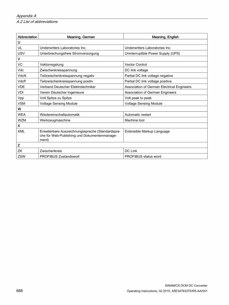
Appendix A A.2 List of abbreviations
SINAMICS DCM DC Converter 688 Operating Instructions, 02.2015, A5E34763375/RS-AA/001
Abbreviation Meaning, German Meaning, English U UL Underwriters Laboratories Inc. Underwriters Laboratories Inc. USV Unterbrechungsfreie Stromversorgung Uninterruptible Power Supply (UPS) V VC Vektorregelung Vector Control Vdc Zwischenkreisspannung DC link voltage VdcN Teilzwischenkreisspannung negativ Partial DC link voltage negative VdcP Teilzwischenkreisspannung positiv Partial DC link voltage positive VDE Verband Deutscher Elektrotechniker Association of German Electrical Engineers VDI Verein Deutscher Ingenieure Association of German Engineers Vpp Volt Spitze zu Spitze Volt peak to peak VSM Voltage Sensing Module Voltage Sensing Module W WEA Wiedereinschaltautomatik Automatic restart WZM Werkzeugmaschine Machine tool X XML Erweiterbare Auszeichnungssprache (Standardspra-
che für Web-Publishing und Dokumentenmanage-ment)
Extensible Markup Language
Z ZK Zwischenkreis DC Link ZSW PROFIBUS Zustandswort PROFIBUS status word
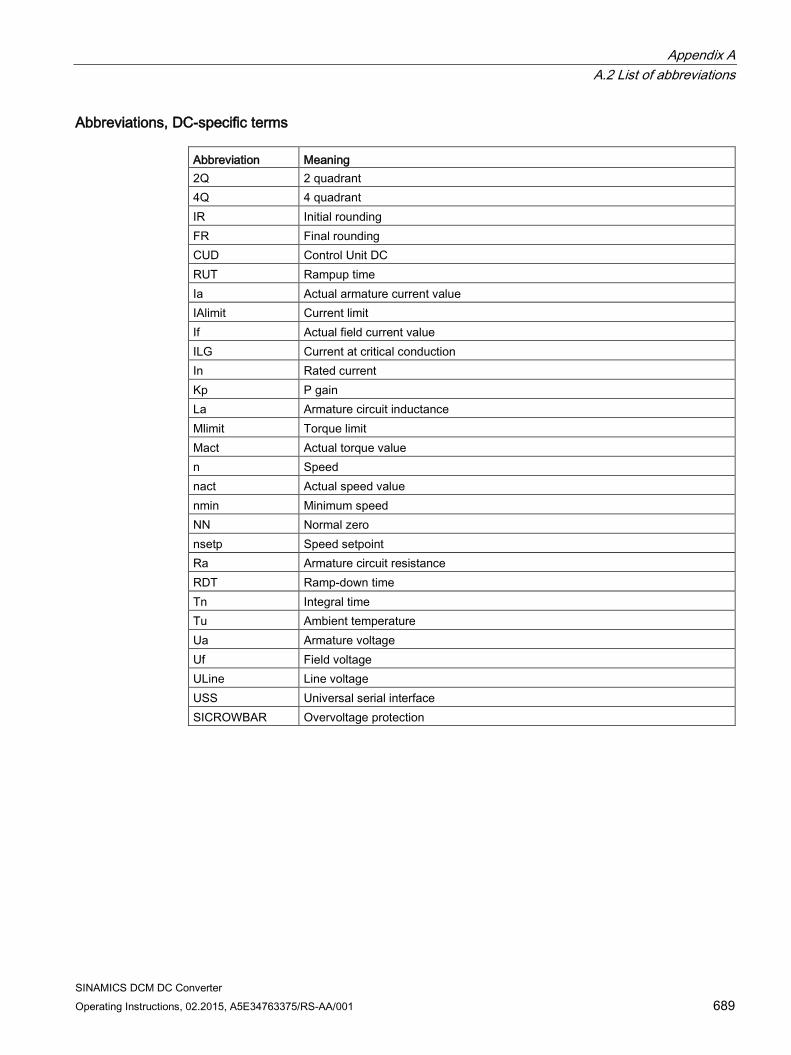
Appendix A A.2 List of abbreviations
SINAMICS DCM DC Converter Operating Instructions, 02.2015, A5E34763375/RS-AA/001 689
Abbreviations, DC-specific terms Abbreviation Meaning 2Q 2 quadrant 4Q 4 quadrant IR Initial rounding FR Final rounding CUD Control Unit DC RUT Rampup time Ia Actual armature current value IAlimit Current limit If Actual field current value ILG Current at critical conduction In Rated current Kp P gain La Armature circuit inductance Mlimit Torque limit Mact Actual torque value n Speed nact Actual speed value nmin Minimum speed NN Normal zero nsetp Speed setpoint Ra Armature circuit resistance RDT Ramp-down time Tn Integral time Tu Ambient temperature Ua Armature voltage Uf Field voltage ULine Line voltage USS Universal serial interface SICROWBAR Overvoltage protection

Appendix A A.3 Environmental compatibility
SINAMICS DCM DC Converter 690 Operating Instructions, 02.2015, A5E34763375/RS-AA/001
A.3 Environmental compatibility
Environmental aspects during development
The use of highly-integrated components has enabled the number of parts to be kept to a minimum, with energy being used as efficiently as possible during production as a result.
Particular emphasis has been placed on ensuring that the metal and plastic parts have a low volume and low weight, and that the number of different types is kept to a minimum. Front parts: PC + ABS Bayblend Bayer Plastic parts in the device: PC Lexan 915-R Insulation materials: PC (FR) fl Makrolon or Lexan Rating plate: Polyester film
Pollutant-free materials have been used for all significant parts. Insulation materials containing silicone are not used. Materials containing halogens are only present to a slight extent (cable insulation in the SINAMICS DCM Control Module).
All materials meet ROHS criteria.
Environmental compatibility was a key criterion in selecting supplier parts.
Environmental aspects during production
The packaging material can be recycled and consists mainly of cardboard.
With the exception of the enclosure, no surface coatings have been used.
The production processes do not produce any emissions.
Environmental aspects for disposal
Disposal guidelines Packaging and packaging aids can be recycled and should always be recy-cled. The product itself should not be disposed of via the domestic waste.
The device features screw-in and snap-in connections that can be easily released in order to separate it into different mechanical components for recycling purposes.
The printed circuit boards may be used in recycling processes involving energy recovery. The proportion of components containing hazardous substances is low.
Appendix A A.4 Servicing
SINAMICS DCM DC Converter Operating Instructions, 02.2015, A5E34763375/RS-AA/001 691
A.4 Servicing
Repairs
If you wish to have a part or unit repaired, please get in touch with your regional contact for repairs.
Service calls
Qualified personnel can perform repair work on your devices and offer services that ensure their availability. This work can be carried out with charges that are scaled according to the amount of time and work involved, or at a flat rate as part of a contract. Services whose charges depend on the amount of time and work involved are performed within the normal working hours for the region and with an appropriate response time.
You can get in touch with your regional contact if you wish to have any services carried out.
Note
We would be grateful if you could specify the following device data when you have any queries: • Device article number and serial number • Software version • Hardware version of the electronics module CUD (printed on the component side) • Hardware version and software version of additional modules (if used)

Appendix A A.4 Servicing
SINAMICS DCM DC Converter 692 Operating Instructions, 02.2015, A5E34763375/RS-AA/001
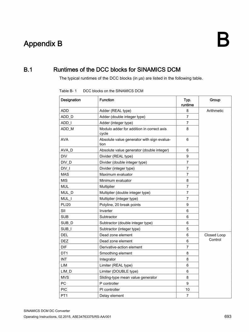
SINAMICS DCM DC Converter Operating Instructions, 02.2015, A5E34763375/RS-AA/001 693
Appendix B B B.1 Runtimes of the DCC blocks for SINAMICS DCM
The typical runtimes of the DCC blocks (in µs) are listed in the following table.
Table B- 1 DCC blocks on the SINAMICS DCM
Designation Function Typ. runtime
Group
ADD Adder (REAL type) 8 Arithmetic ADD_D Adder (double integer type) 7 ADD_l Adder (integer type) 7 ADD_M Modulo adder for addition in correct axis
cycle 8
AVA Absolute value generator with sign evalua-tion
6
AVA_D Absolute value generator (double integer) 6 DIV Divider (REAL type) 9 DIV_D Divider (double integer type) 7 DIV_I Divider (integer type) 7 MAS Maximum evaluator 7 MIS Minimum evaluator 8 MUL Multiplier 7 MUL_D Multiplier (double integer type) 7 MUL_I Multiplier (integer type) 7 PLI20 Polyline, 20 break points 9 SII Inverter 6 SUB Subtractor 6 SUB_D Subtractor (double integer type) 6 SUB_I Subtractor (integer type) 5 DEL Dead zone element 6 Closed Loop
Control DEZ Dead zone element 6 DIF Derivative-action element 7 DT1 Smoothing element 8 INT Integrator 8 LIM Limiter (REAL type) 6 LIM_D Limiter (DOUBLE type) 6 MVS Sliding-type mean value generator 8 PC P controller 9 PIC PI controller 10 PT1 Delay element 7
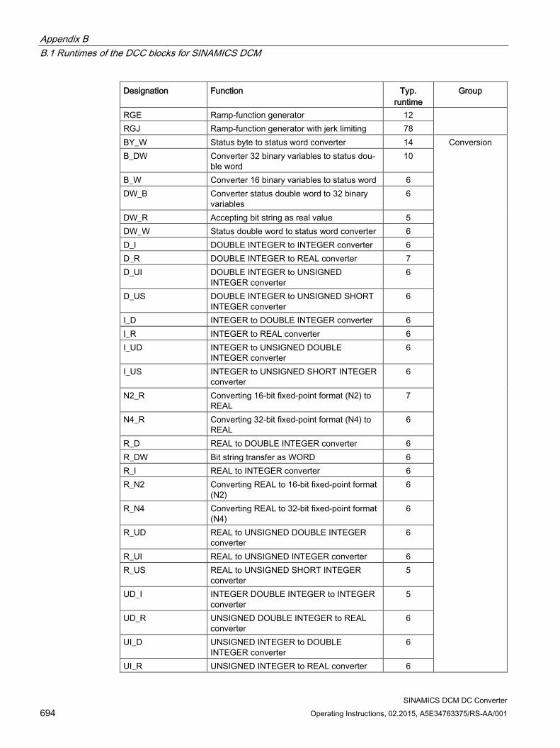
Appendix B B.1 Runtimes of the DCC blocks for SINAMICS DCM
SINAMICS DCM DC Converter 694 Operating Instructions, 02.2015, A5E34763375/RS-AA/001
Designation Function Typ. runtime
Group
RGE Ramp-function generator 12 RGJ Ramp-function generator with jerk limiting 78 BY_W Status byte to status word converter 14 Conversion B_DW Converter 32 binary variables to status dou-
ble word 10
B_W Converter 16 binary variables to status word 6 DW_B Converter status double word to 32 binary
variables 6
DW_R Accepting bit string as real value 5 DW_W Status double word to status word converter 6 D_I DOUBLE INTEGER to INTEGER converter 6 D_R DOUBLE INTEGER to REAL converter 7 D_UI DOUBLE INTEGER to UNSIGNED
INTEGER converter 6
D_US DOUBLE INTEGER to UNSIGNED SHORT INTEGER converter
6
I_D INTEGER to DOUBLE INTEGER converter 6 I_R INTEGER to REAL converter 6 I_UD INTEGER to UNSIGNED DOUBLE
INTEGER converter 6
I_US INTEGER to UNSIGNED SHORT INTEGER converter
6
N2_R Converting 16-bit fixed-point format (N2) to REAL
7
N4_R Converting 32-bit fixed-point format (N4) to REAL
6
R_D REAL to DOUBLE INTEGER converter 6 R_DW Bit string transfer as WORD 6 R_I REAL to INTEGER converter 6 R_N2 Converting REAL to 16-bit fixed-point format
(N2) 6
R_N4 Converting REAL to 32-bit fixed-point format (N4)
6
R_UD REAL to UNSIGNED DOUBLE INTEGER converter
6
R_UI REAL to UNSIGNED INTEGER converter 6 R_US REAL to UNSIGNED SHORT INTEGER
converter 5
UD_I INTEGER DOUBLE INTEGER to INTEGER converter
5
UD_R UNSIGNED DOUBLE INTEGER to REAL converter
6
UI_D UNSIGNED INTEGER to DOUBLE INTEGER converter
6
UI_R UNSIGNED INTEGER to REAL converter 6
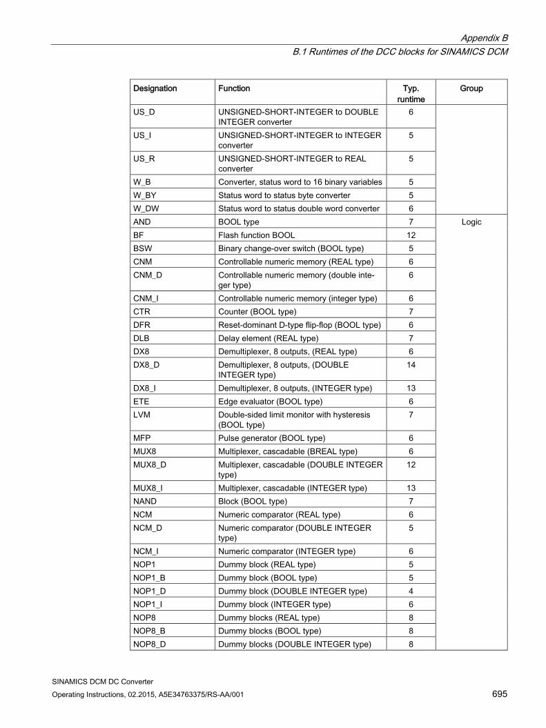
Appendix B B.1 Runtimes of the DCC blocks for SINAMICS DCM
SINAMICS DCM DC Converter Operating Instructions, 02.2015, A5E34763375/RS-AA/001 695
Designation Function Typ. runtime
Group
US_D UNSIGNED-SHORT-INTEGER to DOUBLE INTEGER converter
6
US_I UNSIGNED-SHORT-INTEGER to INTEGER converter
5
US_R UNSIGNED-SHORT-INTEGER to REAL converter
5
W_B Converter, status word to 16 binary variables 5 W_BY Status word to status byte converter 5 W_DW Status word to status double word converter 6 AND BOOL type 7 Logic BF Flash function BOOL 12 BSW Binary change-over switch (BOOL type) 5 CNM Controllable numeric memory (REAL type) 6 CNM_D Controllable numeric memory (double inte-
ger type) 6
CNM_I Controllable numeric memory (integer type) 6 CTR Counter (BOOL type) 7 DFR Reset-dominant D-type flip-flop (BOOL type) 6 DLB Delay element (REAL type) 7 DX8 Demultiplexer, 8 outputs, (REAL type) 6 DX8_D Demultiplexer, 8 outputs, (DOUBLE
INTEGER type) 14
DX8_I Demultiplexer, 8 outputs, (INTEGER type) 13 ETE Edge evaluator (BOOL type) 6 LVM Double-sided limit monitor with hysteresis
(BOOL type) 7
MFP Pulse generator (BOOL type) 6 MUX8 Multiplexer, cascadable (BREAL type) 6 MUX8_D Multiplexer, cascadable (DOUBLE INTEGER
type) 12
MUX8_I Multiplexer, cascadable (INTEGER type) 13 NAND Block (BOOL type) 7 NCM Numeric comparator (REAL type) 6 NCM_D Numeric comparator (DOUBLE INTEGER
type) 5
NCM_I Numeric comparator (INTEGER type) 6 NOP1 Dummy block (REAL type) 5 NOP1_B Dummy block (BOOL type) 5 NOP1_D Dummy block (DOUBLE INTEGER type) 4 NOP1_I Dummy block (INTEGER type) 6 NOP8 Dummy blocks (REAL type) 8 NOP8_B Dummy blocks (BOOL type) 8 NOP8_D Dummy blocks (DOUBLE INTEGER type) 8
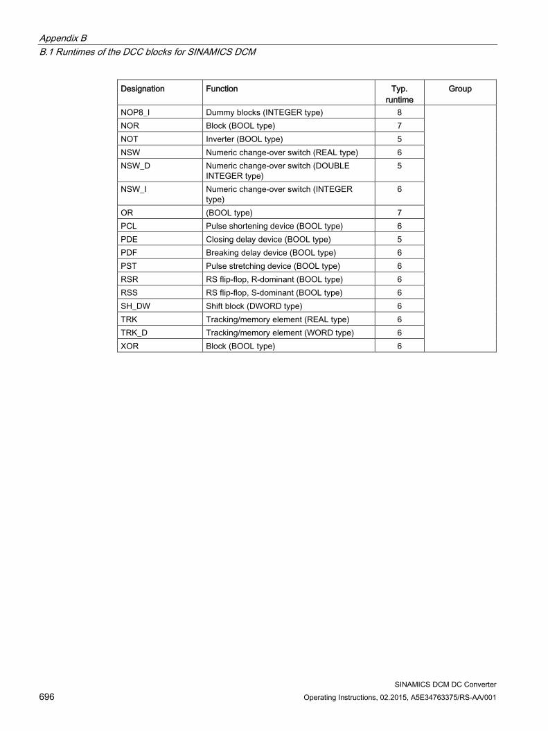
Appendix B B.1 Runtimes of the DCC blocks for SINAMICS DCM
SINAMICS DCM DC Converter 696 Operating Instructions, 02.2015, A5E34763375/RS-AA/001
Designation Function Typ. runtime
Group
NOP8_I Dummy blocks (INTEGER type) 8 NOR Block (BOOL type) 7 NOT Inverter (BOOL type) 5 NSW Numeric change-over switch (REAL type) 6 NSW_D Numeric change-over switch (DOUBLE
INTEGER type) 5
NSW_I Numeric change-over switch (INTEGER type)
6
OR (BOOL type) 7 PCL Pulse shortening device (BOOL type) 6 PDE Closing delay device (BOOL type) 5 PDF Breaking delay device (BOOL type) 6 PST Pulse stretching device (BOOL type) 6 RSR RS flip-flop, R-dominant (BOOL type) 6 RSS RS flip-flop, S-dominant (BOOL type) 6 SH_DW Shift block (DWORD type) 6 TRK Tracking/memory element (REAL type) 6 TRK_D Tracking/memory element (WORD type) 6 XOR Block (BOOL type) 6
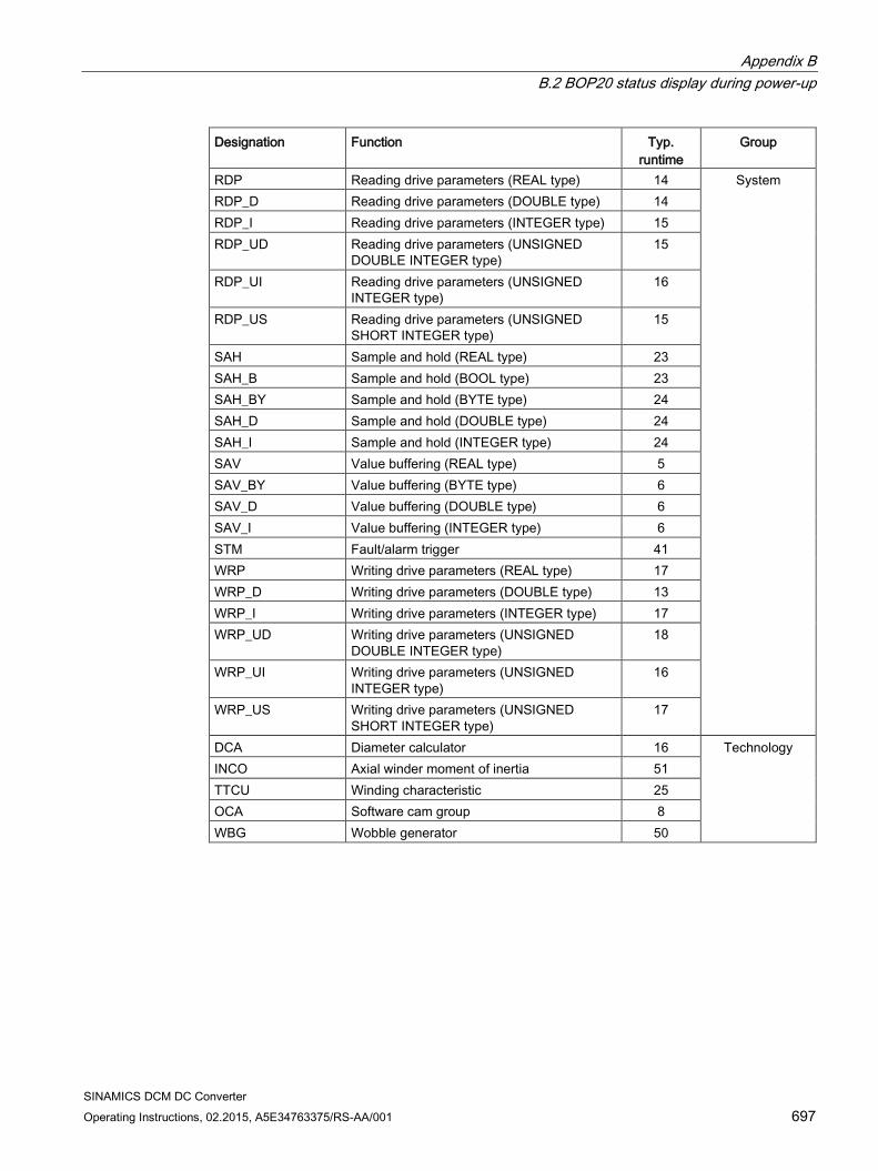
Appendix B B.2 BOP20 status display during power-up
SINAMICS DCM DC Converter Operating Instructions, 02.2015, A5E34763375/RS-AA/001 697
Designation Function Typ. runtime
Group
RDP Reading drive parameters (REAL type) 14 System RDP_D Reading drive parameters (DOUBLE type) 14 RDP_I Reading drive parameters (INTEGER type) 15 RDP_UD Reading drive parameters (UNSIGNED
DOUBLE INTEGER type) 15
RDP_UI Reading drive parameters (UNSIGNED INTEGER type)
16
RDP_US Reading drive parameters (UNSIGNED SHORT INTEGER type)
15
SAH Sample and hold (REAL type) 23 SAH_B Sample and hold (BOOL type) 23 SAH_BY Sample and hold (BYTE type) 24 SAH_D Sample and hold (DOUBLE type) 24 SAH_I Sample and hold (INTEGER type) 24 SAV Value buffering (REAL type) 5 SAV_BY Value buffering (BYTE type) 6 SAV_D Value buffering (DOUBLE type) 6 SAV_I Value buffering (INTEGER type) 6 STM Fault/alarm trigger 41 WRP Writing drive parameters (REAL type) 17 WRP_D Writing drive parameters (DOUBLE type) 13 WRP_I Writing drive parameters (INTEGER type) 17 WRP_UD Writing drive parameters (UNSIGNED
DOUBLE INTEGER type) 18
WRP_UI Writing drive parameters (UNSIGNED INTEGER type)
16
WRP_US Writing drive parameters (UNSIGNED SHORT INTEGER type)
17
DCA Diameter calculator 16 Technology INCO Axial winder moment of inertia 51 TTCU Winding characteristic 25 OCA Software cam group 8 WBG Wobble generator 50
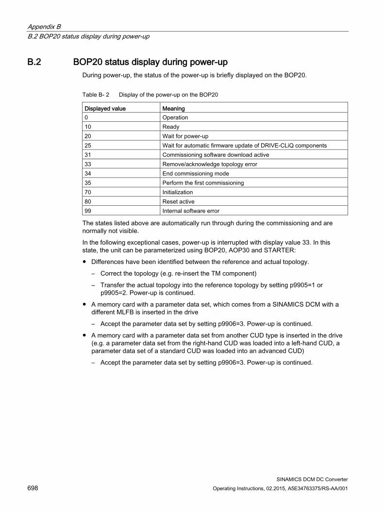
Appendix B B.2 BOP20 status display during power-up
SINAMICS DCM DC Converter 698 Operating Instructions, 02.2015, A5E34763375/RS-AA/001
B.2 BOP20 status display during power-up During power-up, the status of the power-up is briefly displayed on the BOP20.
Table B- 2 Display of the power-up on the BOP20
Displayed value Meaning 0 Operation 10 Ready 20 Wait for power-up 25 Wait for automatic firmware update of DRIVE-CLiQ components 31 Commissioning software download active 33 Remove/acknowledge topology error 34 End commissioning mode 35 Perform the first commissioning 70 Initialization 80 Reset active 99 Internal software error
The states listed above are automatically run through during the commissioning and are normally not visible.
In the following exceptional cases, power-up is interrupted with display value 33. In this state, the unit can be parameterized using BOP20, AOP30 and STARTER:
Differences have been identified between the reference and actual topology.
– Correct the topology (e.g. re-insert the TM component)
– Transfer the actual topology into the reference topology by setting p9905=1 or p9905=2. Power-up is continued.
A memory card with a parameter data set, which comes from a SINAMICS DCM with a different MLFB is inserted in the drive
– Accept the parameter data set by setting p9906=3. Power-up is continued.
A memory card with a parameter data set from another CUD type is inserted in the drive (e.g. a parameter data set from the right-hand CUD was loaded into a left-hand CUD, a parameter data set of a standard CUD was loaded into an advanced CUD)
– Accept the parameter data set by setting p9906=3. Power-up is continued.
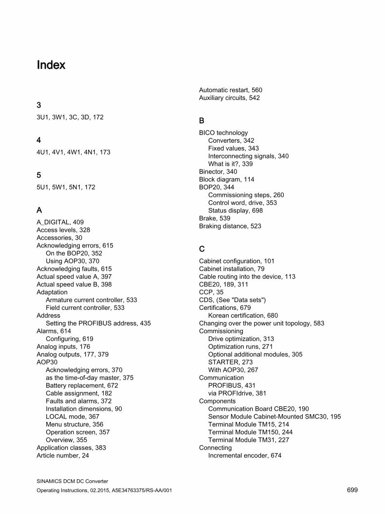
SINAMICS DCM DC Converter Operating Instructions, 02.2015, A5E34763375/RS-AA/001 699
Index
3 3U1, 3W1, 3C, 3D, 172
4 4U1, 4V1, 4W1, 4N1, 173
5 5U1, 5W1, 5N1, 172
A A_DIGITAL, 409 Access levels, 328 Accessories, 30 Acknowledging errors, 615
On the BOP20, 352 Using AOP30, 370
Acknowledging faults, 615 Actual speed value A, 397 Actual speed value B, 398 Adaptation
Armature current controller, 533 Field current controller, 533
Address Setting the PROFIBUS address, 435
Alarms, 614 Configuring, 619
Analog inputs, 176 Analog outputs, 177, 379 AOP30
Acknowledging errors, 370 as the time-of-day master, 375 Battery replacement, 672 Cable assignment, 182 Faults and alarms, 372 Installation dimensions, 90 LOCAL mode, 367 Menu structure, 356 Operation screen, 357 Overview, 355
Application classes, 383 Article number, 24
Automatic restart, 560 Auxiliary circuits, 542
B BICO technology
Converters, 342 Fixed values, 343 Interconnecting signals, 340 What is it?, 339
Binector, 340 Block diagram, 114 BOP20, 344
Commissioning steps, 260 Control word, drive, 353 Status display, 698
Brake, 539 Braking distance, 523
C Cabinet configuration, 101 Cabinet installation, 79 Cable routing into the device, 113 CBE20, 189, 311 CCP, 35 CDS, (See "Data sets") Certifications, 679
Korean certification, 680 Changing over the power unit topology, 583 Commissioning
Drive optimization, 313 Optimization runs, 271 Optional additional modules, 305 STARTER, 273 With AOP30, 267
Communication PROFIBUS, 431 via PROFIdrive, 381
Components Communication Board CBE20, 190 Sensor Module Cabinet-Mounted SMC30, 195 Terminal Module TM15, 214 Terminal Module TM150, 244 Terminal Module TM31, 227
Connecting Incremental encoder, 674
Index
SINAMICS DCM DC Converter 700 Operating Instructions, 02.2015, A5E34763375/RS-AA/001
Connecting the incremental encoder, 674 Connection suggestion, 114 Connector, 340 Control word 1, 389 Control word 1 BM, 391 Control word 2, 390 Control word 2 BM, 392 Converter Commutation Protector, 35 Copy protection
Activating, 642 Copying RAM to ROM, 297 CPU time load, 623 Creep, 524 CU_STW1, 409 CU_ZSW1, 410 CUD
LEDs, 601 Current actual value sensing, 676
D Data sets
Command data set (CDS), 328 Drive data set (DDS), 329 Encoder data set (EDS), 330
Data transfer PROFINET, 471
DCC, 628 DCP flashing, 473 DDS, (See "Data sets") Determining the axis number, 422 Determining the object number, 422 Determinism, 468 Device dimensions, 81 Device identification, 437, 457 Device name, 470 Diagnostics
Diagnostic memory, 598 Trend recorder function, 598 using LEDs for CBE20, 192 using LEDs for the Sensor Module Cabinet SMC30, 206
Diagnostics channel Forwarding of messages, 458, 483
Diagnostics via LEDs Terminal Module TM15, 220 Terminal Module TM150, 252 Terminal Module TM31, 238
Diagnostics via STARTER, 604 Digital inputs, 176 Digital outputs, 176
Dimension drawings, 81 Terminal Module TM150, 253
Dimensions, 81 Direct data exchange
Faults, 458 GSD, 456 PROFIBUS, 441
Disconnection, 514 Disposal, 690 Drive Control Chart, 628 Drive object, 333, 333 Drive optimization, 313
Optimization runs, 314 DRIVE-CLiQ, 183 Duty cycles, 44 Dynamic overload capability of the power unit, 552
E E_DIGITAL, 410 EDS, (See "Data sets") Electromagnetic compatibility, (See EMC) Electronic power supply, 115, 172, 173 EMC, 95
Basic information, 95 Cabinet configuration, 101 EMC-compliant installation, 98 EN 61800-3, 95 RFI suppression filter, 103, 106 Shielding, 103
Enable, 516 Encoder
Incremental encoder evaluation, 177, 178 Encoder evaluation, 526 Encoder interface, 399
Reference mark search, 401 Environmental classes, 47 Environmental compatibility, 690 E-STOP, 517 EtherNet/IP
configuring, activating, 498 Connection, 497
Example PROFIBUS telegram structure, 433
F Factory setting, 272 Fan
Operating hours counter, 543
Index
SINAMICS DCM DC Converter Operating Instructions, 02.2015, A5E34763375/RS-AA/001 701
Replacing the fan, 660 Terminals, 173
Fault buffer, 616 Fault value, 616 FAULT_CODE, 398 Faults, 614
Acknowledging, 615 Configuring, 619 Fault buffer, 616
Faults and alarms, 372, 614 BICO interconnections, 622
Faults and alarms, 372, 614 Field characteristic, 316 Field reversal, 584 Field supply, 143 Fixed setpoint, 525 Free telegrams, 385 Friction characteristic, 317 Function generator, 604 Function modules
Technology controller, 536 Fuses, 150
Replacing fuses, 665
G G2_STW, 402 G2_XIST1, 407, 407 G2_ZSW, 407 Gn_STW, 399 Gn_ZSW, 403 GSD
GSD file, 436
H Hearing protection, 21 Holding brake, 539 Hot restart time, 560
I I2t monitoring, 544 Incremental encoder evaluation, 177, 178, 195, 526 Industrial security
IT security, 380 Inputs, 176
Analog, 176 Digital, 176 Overview, 377 Temperature sensor, 177
Installation Terminal Module TM150, 254
Installation altitude, 48 Interconnecting signals using BICO technology, 340 Interconnecting using BICO technology, 340 Interface descriptions
Terminal Module TM150, 246 Interfaces
DRIVE-CLiQ, 183 Peer-to-peer, 177, 589 USS, 510
IO controller, 467 IO device, 467 IO supervisor, 467 IRT, 476, 476, 476
Comparison with RT, 477 IRT, 476, 476, 476 IRT, 476, 476, 476
J Jog, 523
K Know-how protection
Absolute know-how protection, 641 Activating, 641 Changing the password, 643 Copy protection, 640 Data security of the memory card, 639 Deactivating, 643 Executable functions, 638 For loading to the file system, 645 Locked functions, 638 Overview, 637 Parameters that can be changed, 639 Password check, 639 Password security, 637
Korean certification, 680
L Lead/lag element element, 529 LEDs
for CBE20, 192 for the Sensor Module Cabinet SMC30, 206 On the CUD, 601 Terminal Module TM15, 220 Terminal Module TM150, 252 Terminal Module TM31, 238
Index
SINAMICS DCM DC Converter 702 Operating Instructions, 02.2015, A5E34763375/RS-AA/001
Line reactors, 146 Load class, 42 Load types, 42
M Maintenance, 651
Battery replacement, AOP30, 672 Replacing fuses, 665 Replacing the fan, 660
Manual optimization, 319 Manufacturer-specific telegrams, 385 Mechanical system capable of oscillation, 318 Media redundancy, 475 MELD_NAMUR, 398 Memory card, 334, 339
Safely removing, 339 Menu, (See AOP30) Messages, 614
Configuring, 619 External triggering, 620
Motor temperature, 547 MTrace, 613 Multiple trace, 609
N n+m mode, 568 NACT_A, 397 NACT_B, 398
O OFF2, 514 OFF3, 514 Online mode with STARTER, 461 Operating hours counter
Unit fan, 543 Operation enable, 516 Operation screen, (See AOP30) Operational brake, 539 Operator panel
AOP30, 267, 354 BOP20, 260, 344
Optimization Armature current control, 315 EMF closed-loop control, 316 Field current closed-loop control, 315, 322 Friction characteristic, 317 Manual, 266, 319 Mechanical system capable of oscillation, 318
Optimization runs, 265, 271 Speed control, 316 Speed controller, 323
Optimization runs, 314 Options, 30, 90
G63, 166, 184, 596 Outputs, 176
Analog, 177, 379 Digital, 176 Overview, 377
Overload protection, 544
P Parallel connection, 563
12-pulse, 572 6-pulse, 566 Parameter assignment, 570 Standard mode, 568
Parallel interface, 184 Parameterization
Using BOP20, 344 With AOP30, 358
Parameters Access levels, 328 Categories, 326 Factory setting, 272 Saving, 374 Types, 325
Password Changing, 643
Peer-to-peer interface, 177, 589 Power failure
Restart, 560 Power unit
Connection, 122, 169 Dynamic overload capability, 552
Power unit topology, 583 Process data, 387 Process data, actual values
G1_XIST1, 404 G1_XIST2, 405 G2_XIST1, 407 G2_XIST2, 407
Process data, control words A_DIGITAL, 409 CU_STW1, 409 G2_STW, 402 Gn_STW, 399
Process data, setpoints NSET_A, 392, 392 NSET_B, 393

Index
SINAMICS DCM DC Converter Operating Instructions, 02.2015, A5E34763375/RS-AA/001 703
Process data, status words CU_ZSW1, 410 E_DIGITAL, 410 G2_ZSW, 407 Gn_ZSW, 403 MELD_NAMUR, 398
PROFIBUS, 431 Bus terminating resistor, 430 Cable, 112 Connection, 429 Connector, 112, 183, 429, 430 Device identification, 437, 457 Direct data exchange, 441 Forwarding of messages via diagnostics channels, 458 Generic station description file, 436, 456 Master class 1 and 2, 431 Setting the address, 435 Telegrams, 385 Terminating resistor, 437 VIK-NAMUR, 436
PROFIBUS telegram structure, 433 PROFIdrive, 381
Controller, Supervisor, Drive Unit, 381 Device classes, 381 Reading parameters, 423 Telegrams, 385 Write parameter, 425
PROFINET Data transfer, 471 Forwarding of messages via diagnostics channels, 483 Interface, 473
PROFINET cables, 192 PROFINET IO, 467
Addresses, 469 IRT, 476 With IRT, 469 With RT, 468
Protective conductor connection and shield support Terminal Module TM150, 255
Q Quick stop, 514
R Ramp-down time, 518 Ramp-function generator, 518 Ramp-function integrator, 521
Ramp-function-generator tracking, 522 Ramp-up time, 518 Rating plate, packaging label, 28 Real-time communication, 468 Reference mark search, 401 Replacement
Operator panel battery, 671 Replacing the Backup Battery of the Cabinet Operator Panel, 671 Replacing the CUD, 668 Restart, 560 RFI suppression filter, 106 Ring topology, 475
Scalance, 475 RT
Comparison with IRT, 477 RT class
Setting, 478 RT classes
Send cycles, 479 Update cycles, 479
S Safety instructions
Terminal Modules, 214, 227, 244 Safety shutdown (E-STOP), 517 Sequence of objects in the telegram, 432, 471 Series connection
12-pulse, 582 6-pulse, 574, 577, 579
Setpoint channel Creep, 524 Fixed setpoint, 525 Jog, 523 Ramp-function generator, 518
Shielding, 103 Shipbuilding, 673, 679 Shutdown, 512
OFF2 (disconnection), 514 OFF3 (quick stop), 514
SIMOREG CCP, 35 SINAMICS Link
Activation, 493 Bus cycle, 488 Configuring, 490 Requirements, 487 Synchronous cycle, 488 Transmission time, 488
Single trace, 608 Single-phase line supply, 561 SMC30, 189, 308
Index
SINAMICS DCM DC Converter 704 Operating Instructions, 02.2015, A5E34763375/RS-AA/001
Software update, 652, 653 Speed controller, 529
Adaptation, 529 Droop, 529 Reference model, 529 Start pulse, 529
Speed-dependent current limitation, 549 Standard CUD, 184 Standard telegrams, 385 STARTER, 273
Commissioning, 275 Configuring a drive unit, 282 Connection through a serial interface, 298 Creating the project, 275 Installation, 273 Online mode via PROFINET, 461 Project wizard, 277 Starting the drive project, 294 User interface, 274
Startup trace, 612 Status display at the BOP20, 698 Status word 1, 394 Status word 1 BM, 396 Status word 2, 396 Status word 2 BM, 397 STW2, 390 STW2 BM, 392 Switch on, 512
Operation enable (enable), 516 Synchronization domain, 478
T Technical data
Communication Board CBE20, 194 Duty cycles, 44 Load types, 42 Sensor Module Cabinet SMC30, 210 Terminal Module TM15, 225 Terminal Module TM150, 256 Terminal Module TM31, 243 Unit data, 49
Technology controller, 536 Telegrams
Manufacturer-specific, 385 Sequence of objects, 432, 471 Standard, 385 Structure, 387
Temperature sensor, 177 Terminal Module Cabinet, 166, 184, 596 Terminal Module TM15, 214, 305 Terminal Module TM150, 244
Terminal Module TM31, 227, 305 Thermal overload protection, 544 Thyristor diagnostics, 599 Time-of-day master, 375 Timeout monitoring, 370 TM15, 189, 214 TM150, 189 TMC, 166, 184, 596 Trace function, 607 Trend recorder function, 598
U UL
Installation notes, Error! Bookmark not defined. Unit data, 49 Unit fan
Operating hours counter, 543 Update
Software, 653 Upgrading
Software release, 652 Use of the speed controller for other applications, 532 USS interface, 510
W WARN_CODE, 398 Write protection
Activating, 635 Deactivating, 637 Overview, 635
X X100, X101, 183 X126, 183, 429 X165, 184 X166, 184 X177, 176 X178, 180 X179, 181 XP24V, 173 XR1, XS1, XT1, 175 Z ZSW1, 394 ZSW1 BM, 396 ZSW2, 396 ZSW2 BM, 397


Siemens AGDivision Process Industries and DrivesPostfach 48 4890026 NÜRNBERG德国
本公司保留更改的权利6RX1800-0AD27© Siemens AG 2009-2015
Сименс АОDivision Process Industries and DrivesPostfach 48 4890026 NÜRNBERGГЕРМАНИЯ
Возможны изменения 6RX1800-0AD56© Siemens AG 2009-2015
Siemens AGDivision Process Industries and DrivesPostfach 48 4890026 NÜRNBERGALEMANIA
Sujeto a cambios sin previo aviso6RX1800-0AD78© Siemens AG 2009-2015
Siemens AGDivision Process Industries and DrivesPostfach 48 4890026 NÜRNBERGGERMANIA
Con riserva di modifiche6RX1800-0AD72© Siemens AG 2009-2015
Siemens AGDivision Process Industries and DrivesPostfach 48 4890026 NÜRNBERGALLEMAGNE
Sous réserve de modifications techniques.6RX1800-0AD77© Siemens AG 2009-2015
Siemens AGDivision Process Industries and DrivesPostfach 48 4890026 NÜRNBERGGERMANY
Subject to change6RX1800-0AD76© Siemens AG 2009-2015
Siemens AGDivision Process Industries and DrivesPostfach 48 4890026 NÜRNBERGDEUTSCHLAND
Änderungen vorbehalten6RX1800-0AD00© Siemens AG 2009-2015
DC ConvertersSINAMICS DCM
www.industry.siemens.com/drives
Related Documents