Simultaneous Localization and Map-Building Using Active Vision Andrew J. Davison and David W. Murray, Member, IEEE Abstract—An active approach to sensing can provide the focused measurement capability over a wide field of view which allows correctly formulated Simultaneous Localization and Map-Building (SLAM) to be implemented with vision, permitting repeatable long- term localization using only naturally occurring, automatically-detected features. In this paper, we present the first example of a general system for autonomous localization using active vision, enabled here by a high-performance stereo head, addressing such issues as uncertainty-based measurement selection, automatic map-maintenance, and goal-directed steering. We present varied real-time experiments in a complex environment. Index Terms—Active vision, simultaneous localization and map-building, mobile robots. æ 1 INTRODUCTION I NCREMENTAL building and maintaining of maps for immediate use by a navigating robot has been shown to rely on detailed knowledge of the cross-coupling between running estimates of the locations of robot and mapped features [1]. Without this information, features, which are redetected after a period of neglect, are treated as new and the entire structure suffers progressive error accumulation which depends on the distance traveled, not on distance from the starting position in the fiducial coordinate frame. It becomes impossible to build persistent maps for long-term use as apparent in earlier navigation research [2], [3], [4], [5], [6], [7]. For example, Fig. 5a of reference [7], shows that the start and end of an actually closed path are recovered as different locations. Storing and maintaining coupling information proves to be computationally expensive, in turn imposing the need to use only a sparse sets of features. This runs counter to the emphasis of recent research into visual reconstruction where large numbers of features over many images are used in batch mode to obtain accurate, dense, and visually realistic reconstructions for multimedia applications rather than robotic tasks (e.g., [8], [9]). Although batch methods provide the most accurate and robust reconstructions, the volume of calculation required for each camera location grows depending on the total length of the trajectory. Real- time applications, on the other hand, require updates to be calculable in a time bounded by a constant step interval: It is satisfying this crucial constraint which permits all-impor- tant interaction with the map data as it is acquired. So, although visual sensing is the most information-rich modality for navigation in everyday environments, recent advances in simultaneous localization and map building (SLAM) for mobile robots have been made using sonar and laser range sensing to build maps in 2D and have been largely overlooked in the vision literature. Durrant-Whyte and colleagues (e.g., [10]) have implemented systems using a wide range of vehicles and sensor types and are currently working on ways to ease the computational burden of SLAM. Chong and Kleeman [11] achieved impressive results using advanced tracking sonar and accurate odometry combined with a submapping strategy. Thrun et al. [12] have produced some of the best known demonstrations of robot navigation in real environments (for example, in a museum) using laser range-finders and some vision. Castellanos [13] also used a laser range finder and a mapping strategy called the SPmap. Leonard and Feder [14], working primarily with underwater robots and sonar sensors, have recently proposed new submapping ideas, breaking a large area into smaller regions for more efficient map-building. In this paper, we describe the first application of active vision to real-time, sequential map-building within a SLAM framework, building on our earlier work reported in [15]. We show that active visual sensing is ideally suited to the exploitation of sparse “landmark” information required in robot map-building. Using cameras with the ability both to fixate and to change fixation over a wide angular range ensures that persistent features redetected after lengthy neglect can also be rematched, even if the area is passed through along a different trajectory or in a different direction. This is key to reducing the effect of motion drift from the fiducial coordinate frame: The drift now depends on the distance from the origin, not the total distance traveled. No doubt, active sensing will be implemented electro- nically by choosing to process only a subwindow from high-resolution omni-directional data. At present, however, full resolution multiple sensor cameras (fly-eyes) are expensive to construct and mosaicing still a research problem. On the other hand, fish-eye lenses and catadiop- tric mirrors [16] have the disadvantage of variable and sometimes low angular resolution. In this work, we use a agile electro-mechanical stereo head with known forward kinematics, four degrees of movement freedom, and full odometry permitting the locations of the cameras with respect to the robot to be known accurately at all times and their location to be controlled in an closed-loop sense. While an active head combines a wide field of view with high IEEE TRANSACTIONS ON PATTERN ANALYSIS AND MACHINE INTELLIGENCE, VOL. 24, NO. 7, JULY 2002 865 . The authors are with the Robotics Research Group, Department of Engineering Science, University of Oxford, Oxford, OX1 3PJ, United Kingdom. E-mail: {ajd, dwm}@robots.ox.ac.uk. Manuscript received 9 July 1998; revised 15 June 2001; accepted 5 Dec. 2001. Recommended for acceptance by H. Christensen. For information on obtaining reprints of this article, please send e-mail to: [email protected], and reference IEEECS Log Number 107845. 0162-8828/02/$17.00 ß 2002 IEEE

Welcome message from author
This document is posted to help you gain knowledge. Please leave a comment to let me know what you think about it! Share it to your friends and learn new things together.
Transcript
Simultaneous Localizationand Map-Building Using Active Vision
Andrew J. Davison and David W. Murray, Member, IEEE
AbstractÐAn active approach to sensing can provide the focused measurement capability over a wide field of view which allows
correctly formulated Simultaneous Localization and Map-Building (SLAM) to be implemented with vision, permitting repeatable long-
term localization using only naturally occurring, automatically-detected features. In this paper, we present the first example of a general
system for autonomous localization using active vision, enabled here by a high-performance stereo head, addressing such issues as
uncertainty-based measurement selection, automatic map-maintenance, and goal-directed steering. We present varied real-time
experiments in a complex environment.
Index TermsÐActive vision, simultaneous localization and map-building, mobile robots.
æ
1 INTRODUCTION
INCREMENTAL building and maintaining of maps forimmediate use by a navigating robot has been shown to
rely on detailed knowledge of the cross-coupling betweenrunning estimates of the locations of robot and mappedfeatures [1]. Without this information, features, which areredetected after a period of neglect, are treated as new andthe entire structure suffers progressive error accumulationwhich depends on the distance traveled, not on distancefrom the starting position in the fiducial coordinate frame. Itbecomes impossible to build persistent maps for long-termuse as apparent in earlier navigation research [2], [3], [4],[5], [6], [7]. For example, Fig. 5a of reference [7], shows thatthe start and end of an actually closed path are recovered asdifferent locations.
Storing and maintaining coupling information proves tobe computationally expensive, in turn imposing the need touse only a sparse sets of features. This runs counter to theemphasis of recent research into visual reconstructionwhere large numbers of features over many images areused in batch mode to obtain accurate, dense, and visuallyrealistic reconstructions for multimedia applications ratherthan robotic tasks (e.g., [8], [9]). Although batch methodsprovide the most accurate and robust reconstructions, thevolume of calculation required for each camera locationgrows depending on the total length of the trajectory. Real-time applications, on the other hand, require updates to becalculable in a time bounded by a constant step interval: It issatisfying this crucial constraint which permits all-impor-tant interaction with the map data as it is acquired.
So, although visual sensing is the most information-richmodality for navigation in everyday environments, recentadvances in simultaneous localization and map building(SLAM) for mobile robots have been made using sonar andlaser range sensing to build maps in 2D and have been largely
overlooked in the vision literature. Durrant-Whyte andcolleagues (e.g., [10]) have implemented systems using awide range of vehicles and sensor types and are currentlyworking on ways to ease the computational burden of SLAM.Chong and Kleeman [11] achieved impressive results usingadvanced tracking sonar and accurate odometry combinedwith a submapping strategy. Thrun et al. [12] have producedsome of the best known demonstrations of robot navigation inreal environments (for example, in a museum) using laserrange-finders and some vision. Castellanos [13] also used alaser range finder and a mapping strategy called the SPmap.Leonard and Feder [14], working primarily with underwaterrobots and sonar sensors, have recently proposed newsubmapping ideas, breaking a large area into smaller regionsfor more efficient map-building.
In this paper, we describe the first application of activevision to real-time, sequential map-building within a SLAMframework, building on our earlier work reported in [15]. Weshow that active visual sensing is ideally suited to theexploitation of sparse ªlandmarkº information required inrobot map-building. Using cameras with the ability both tofixate and to change fixation over a wide angular rangeensures that persistent features redetected after lengthyneglect can also be rematched, even if the area is passedthrough along a different trajectory or in a different direction.This is key to reducing the effect of motion drift from thefiducial coordinate frame: The drift now depends on thedistance from the origin, not the total distance traveled.
No doubt, active sensing will be implemented electro-nically by choosing to process only a subwindow fromhigh-resolution omni-directional data. At present, however,full resolution multiple sensor cameras (fly-eyes) areexpensive to construct and mosaicing still a researchproblem. On the other hand, fish-eye lenses and catadiop-tric mirrors [16] have the disadvantage of variable andsometimes low angular resolution. In this work, we use aagile electro-mechanical stereo head with known forwardkinematics, four degrees of movement freedom, and fullodometry permitting the locations of the cameras withrespect to the robot to be known accurately at all times andtheir location to be controlled in an closed-loop sense. Whilean active head combines a wide field of view with high
IEEE TRANSACTIONS ON PATTERN ANALYSIS AND MACHINE INTELLIGENCE, VOL. 24, NO. 7, JULY 2002 865
. The authors are with the Robotics Research Group, Department ofEngineering Science, University of Oxford, Oxford, OX1 3PJ, UnitedKingdom. E-mail: {ajd, dwm}@robots.ox.ac.uk.
Manuscript received 9 July 1998; revised 15 June 2001; accepted 5 Dec. 2001.Recommended for acceptance by H. Christensen.For information on obtaining reprints of this article, please send e-mail to:[email protected], and reference IEEECS Log Number 107845.
0162-8828/02/$17.00 ß 2002 IEEE
sensing resolution, it also introduces the interesting penaltythat a finite time is required to refixate the camera, time inwhich further measurements might have been made of thepreviously fixated scene point.
Selective sensing is the essence of the active approachand, in map-building, there is much more to be gained bymaking observations of some parts of the robot's surround-ings than others: the two appear well-matched. Here, weonly consider how active vision can provide a robot withaccurate localization; but, this could be just one part of arobot's overall task. In [17], one of us described a systemwhere attention is divided between localization andinspection. Regardless of the simplicity or complexity ofthe task, a rigorous statistical framework is necessary ifprudent serial selection of fixation point is to be made.Although the computational complexity is high (in EKF-based SLAM, proportional to N2, where N is the number ofmapped features), real-time implementation is feasible onmodest hardware, even without the various SLAM short-cut methods which have recently appeared [14], [18], [10].
The rest of the paper is organized as follows: In Section 2,we introduce the SLAM problem and discuss some of thepoints relevant to our implementation. We present the imageprocessing approach and active head control strategiesinvolved in identifying and locating natural scene featuresin Section 3 and Section 4 describes an experiment usingcontrived scene features to verify localization and map-building performance against ground-truth. We continue inSection 5 by discussing the additional sensing and processingtools, in particular, active feature selection, which arenecessary in fully autonomous navigation and, in Section 6,give results from a fully automatic experiment. In Section 7,we look at supplementing SLAM with a small amount of priorknowledge and, in Section 8, bring all these elements togetherin a final experiment in goal-directed navigation.
2 SLAM USING ACTIVE VISION
Sequential localization and map-build based on the ex-tended Kalman Filter (EKF) is now increasingly wellunderstood [1], [13], [11], [19], [10] and, in this section, weonly wish to establish some background and notation.Detailed expressions for the kinematics of our particularvehicle and active head can be found in [15].
2.1 The State Vector and Its Covariance
In order for information from motion models, vision, andother sensors to be combined to produce reliable estimates,sequential localization and map-building [20] involves thepropagation through time of probability density functions(PDF's) representing not only uncertain estimates of theposition of the robot and mapped features individually, butcoupling information on how these estimates relate to eachother.
The approach taken in this paper and in most other workon SLAM is to propagate first-order approximations tothese probability distributions in the framework of the EKF,implicitly assuming that all PDF's are Gaussian in shape.Geometrical nonlinearity in the motion and measurementprocesses in most SLAM applications means that thisassumption is a poor one, but the EKF has been widelydemonstrated not to be badly affected by these problems.More significant is the EKF's inability to represent the
multimodal PDF's resulting from imperfect data association(mismatches). The particle filtering approaches which haverecently come to the fore in visual tracking research offer asolution to these problems, but in their current form areinapplicable to the SLAM problem due to their huge growthin computational complexity with state dimension [21]ÐinSLAM, the state consists of coupled estimates of thepositions of a robot and many features and it is impossibleto span a space of this state-dimension with a number ofparticles which would be manageable in real-time; how-ever, some authors [22] are investigating the use of particlefilters in robot localization.
In the first-order uncertainty propagation framework,the overall ªstateº of the system x is a vector which can bepartitioned into the state xv of the robot and the states yi ofentries in the map of its surroundings. The state vector isaccompanied by a covariance matrix P, which can also bepartitioned as follows:
x �xvy1
y2
..
.
0BBB@1CCCA; P �
Pxx Pxy1 Pxy2 ��Py1x Py1y1 Py1y2 ��Py2x Py2y1 Py2y2 ��
..
. ... ..
.
0BBB@1CCCA:
In this paper, the robot state is just ground plane positionand orientation xv � �z; x; ��> and each feature state is a 3Dposition yi � �Xi; Y i; Zi�>, but a state vector is not limitedto pure position estimates: Other feature and robotattributes (such as velocity or the positions of redundantjoints) can be included (e.g., [17]).
2.2 Coordinate Frames and Initialization
When the robot moves in surroundings which are initiallyunknown, the choice of world coordinate frame is arbitrary:Only relative locations are significant. Indeed, it is possibleto do away with a world coordinate frame altogether andestimate the locations of features in a frame fixed to therobot: Motions of the robot simply appear as backwardsmotion of features. However, in most applications, therewill be interaction with information from other frames ofreferenceÐoften in the form of known way-points throughwhich the robot is required to move (even in a case sosimple as that in which the robot must return to its startingposition). A world coordinate frame is essential to interactwith information of this kind and, as there is littlecomputational penalty in including an explicit robot state,we always do so (Fig. 1a).
In typical navigation scenarios (such as that of theexperiments of Sections 4 and 6) where there is no priorknowledge of the environment, the world coordinate framecan be defined with its origin at the robot's starting positionand the initial uncertainty relating to the robot's position inPxx is zeroed.
If there is prior knowledge of some feature locations (asin the experiment of Section 7), these can be insertedexplicitly into the map at initialization and this informationwill effectively define the world coordinate frame. Therobot's starting position relative to these features must alsobe input and both robot and feature positions assignedsuitable initial covariance values.
866 IEEE TRANSACTIONS ON PATTERN ANALYSIS AND MACHINE INTELLIGENCE, VOL. 24, NO. 7, JULY 2002
2.3 Process ModelTemporal updating using an EKF requires prediction of thestate and covariance after a robot movement during apossibly variable period �tk.
xv�k�1jk� � fv�xv�kjk�;uk;�tk�yi�k�1jk� � yi�kjk�; 8i
P�k�1jk� � @f
@xP�kjk�
@f
@x
>�Qk:
Here, f v is a function of the current robot state estimate, theperiod, and control inputs u, which for our robot aresteering angle and wheel velocity (Fig. 1b). The robot'smotion in each time step is modeled as a circular trajectorywith radius R determined by wheel geometry and steeringangle (see [19] for details). The full state transition Jacobianis denoted @f
@x and Qk is the process noise,
Qk �@fv@u
U@f v@u
>;
where U is the diagonal covariance matrix of u. Processnoise accounts essentially for unmodeled effects in thevehicle motion such as wheel slippage.
2.4 Measurement ModelAny sensor which is able to measure the location of fixedfeatures in the scene relative to the robot can contributelocalization information and it is wise in implementation toseparate the details of the sensors (and indeed the robot)from the algorithms used to build and process maps [20].
The key to our active approach is the ability we gain fromour probabilistic state representation to predict the value hi ofany measurement and also calculate the uncertainty expectedin this measurement in the form of the innovation covarianceSi. Explicitly, our measurement model is:
hi ��pi�ei�vi
0@ 1A � tanÿ1 hGixhGiz
tanÿ1 hGiyhGip
tanÿ1 I2hGi
0B@1CA;
where
hGi �hGixhGiyhGiz
0@ 1A � cos��Xi ÿ x� ÿ sin��Zi ÿ z�Yi ÿH
sin��Xi ÿ x� � cos��Zi ÿ z�
0@ 1A
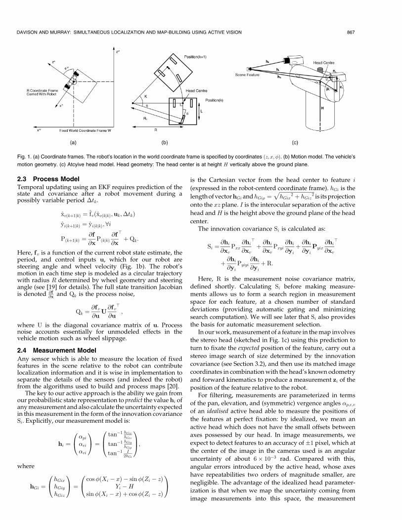
is the Cartesian vector from the head center to feature i
(expressed in the robot-centerd coordinate frame). hGi is the
length of vectorhGi andhGi� ����������������������������hGix
2 � hGiz2p
is its projection
onto the xz plane. I is the interocular separation of the active
head andH is the height above the ground plane of the head
center.The innovation covariance Si is calculated as:
Si � @hi@xv
Pxx@hi@xv
>� @hi@xv
Pxyi@hi@yi� @hi@yi
Pyix@hi@xv
>
� @hi@yi
Pyiyi@hi@yi� R:
Here, R is the measurement noise covariance matrix,defined shortly. Calculating Si before making measure-ments allows us to form a search region in measurementspace for each feature, at a chosen number of standarddeviations (providing automatic gating and minimizingsearch computation). We will see later that Si also providesthe basis for automatic measurement selection.
In our work, measurement of a feature in the map involves
the stereo head (sketched in Fig. 1c) using this prediction to
turn to fixate the expected position of the feature, carry out a
stereo image search of size determined by the innovation
covariance (see Section 3.2), and then use its matched image
coordinates in combination with the head's known odometry
and forward kinematics to produce a measurement zi of the
position of the feature relative to the robot.For filtering, measurements are parameterized in terms
of the pan, elevation, and (symmetric) vergence angles �p;e;vof an idealised active head able to measure the positions of
the features at perfect fixation: by idealized, we mean an
active head which does not have the small offsets between
axes possessed by our head. In image measurements, we
expect to detect features to an accuracy of �1 pixel, which at
the center of the image in the cameras used is an angular
uncertainty of about 6� 10ÿ3 rad. Compared with this,
angular errors introduced by the active head, whose axes
have repeatabilities two orders of magnitude smaller, are
negligible. The advantage of the idealized head parameter-
ization is that when we map the uncertainty coming from
image measurements into this space, the measurement
DAVISON AND MURRAY: SIMULTANEOUS LOCALIZATION AND MAP-BUILDING USING ACTIVE VISION 867
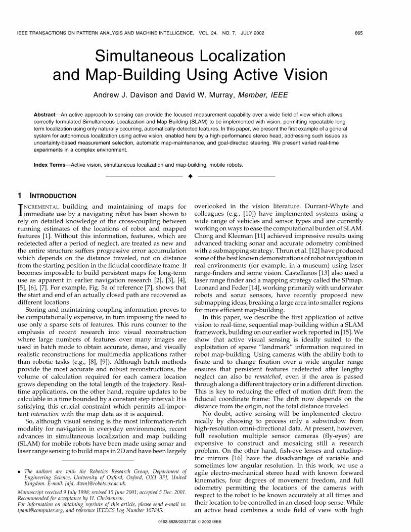
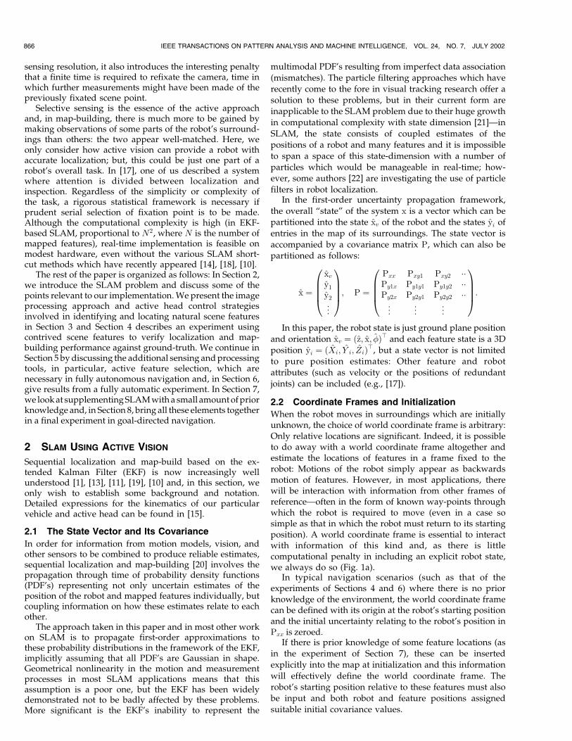
Fig. 1. (a) Coordinate frames. The robot's location in the world coordinate frame is specified by coordinates �z; x; ��. (b) Motion model. The vehicle's
motion geometry. (c) Atcyive head model. Head geometry: The head center is at height H vertically above the ground plane.
noise covariance is very closely diagonal and constant andcan be approximated by:
R ���2
p 0 0
0 ��2e 0
0 0 ��2v
0@ 1A:In fact, in our system ��p � ��e � ��v. This is
preferable to parameterizing measurements in the Cartesianspace of the relative location of feature and robot since, inthat case, the measurement noise covariance would dependon the measurement in a nonlinear fashion (in particular,the uncertainty in depth increases rapidly with featuredistance) and this could lead to biased estimates.
2.5 Updating and Maintaining the Map
Once a measurement zi of a feature has been returned, theKalman gain W can then be calculated and the filter updateperformed in the usual way [20]:
W � P@hi@x
>Sÿ1
�
Pxx
Py1x
Py2x
..
.
0BBBB@1CCCCA @h
@xv
>Sÿ1 �
Pxyi
Pyiyi
Py2y2
..
.
0BBBB@1CCCCA @hi@yi
>Sÿ1
xnew � xold �W�zi ÿ hi�Pnew � Pold ÿWSW>
:
Since, in our measurement model, the measurement noise
R is diagonal, this update can be separated in implementation
into separate, sequential updates for each scalar component
of the measurement (that is to say that we perform the above
update three times, once for each angular component �p;e;v of
the measurement; hi, zi, and S become scalar in these steps):
this is computationally advantageous.Initializing a New Feature. When an unknown feature n
is observed for the first time, a vector measurement hn is
obtained of its position relative to the head and its state
initialized accordingly using the inverse yn�xv;hn� of the
measurement model. Jacobians @yn@xv
and @yn@hG
are calculated
and used to update the total state vector and covariance:
xnew �
xv
y1
..
.
yn
0BBBB@1CCCCA
Pnew �
Pxx Pxy1 �� Pxx@yn@xv
>
Py1x Py1y1 �� Py1x@yn@xv
>
..
. ... ..
. ...
@yn@xv
Pxx@yn@yn
Pxy1@yn@xv
Pxy2 A
0BBBBBBB@
1CCCCCCCA;
where
A � @yn@xv
Pxx@yn@xv
>� @yn@hn
R@yn@hn
>:
Deleting a Feature. A similar Jacobian calculation showsthat deleting a feature from the state vector and covariancematrix is a simple case of excising the rows and columnswhich contain it. For example, where the second of threeknown features is deleted, the parts removed are delineatedas follows:
xvy1
y2
y3
0BB@1CCA;
Pxx Pxy1 j Pxy2 j Pxy3
Py1x Py1y1 j Py1y2 j Py1y3
Py2x Py2y1 j Py2y2 j Py2y3
Py3x Py3y1 j Py3y2 j Py3y3
0BB@1CCA:
3 DETECTION AND MATCHING OF SCENE FEATURES
Repeatable localization in a particular area requires thatreliable, persistent features in the environment can be foundand refound over long periods of time. This differs perhapsfrom the more common use of visual features in structurefrom motion, where they are often treated as transiententities to be matched over a few frames and thendiscarded. When the goal of mapping is localization, it isimportant to remember that motion drift will occur unlessreference can be made to features after periods of neglect.
The visual landmarks we will use should be featureswhich are easily distinguishable from their surroundings,robustly associated with the scene geometry, viewpointinvariant, and seldom occluded. In this work, we assumethe features to be stationary points.
Since when navigating in unknown areas nothing isknown in advance about the scene, we do not attempt tosearch purposively for features in certain locations whichwould be good sites for landmarks: There is no guaranteethat anything will be visible in these sites which will make agood landmark. Rather, feature acquisition takes place as adata-driven process: The robot points its cameras in ratherarbitrary directions and acquires features if regions ofimage interest are found. This rather rough collection offeatures is then refined naturally through the map main-tenance steps described in Section 5.3 into a landmark setwhich spans the robot's area of operation.
3.1 Acquiring 3D Features
Features are detected using the Harris corner detector [23]as applied by Shi and Tomasi [24] to relatively large pixelpatches (15� 15 rather than the usual 5� 5 for cornerdetection). Products of the spatial gradients Ix and Iy of thesmoothed image irradiance are averaged over the patchand, if both eigenvalues of the matrix
IxIx IxIyIxIy IyIy
� �are large, the patch is corner-like.
To acquire a new feature at the current head position, thedetector is run over the left image, finding a predeterminednumber of the most salient nonoverlapping regions. For thestrongest feature, an epipolar line is constructed in the rightimage (via the known head geometry) and a band aroundthe line searched for a stereo match. If a good match isfound, the two pairs of image coordinates �uL; vL� and�uR; vR� allow the feature's 3D location in the robot-centeredcoordinate frame to be calculated. The head is driven tofixate the feature, enforcing symmetric left and right head
868 IEEE TRANSACTIONS ON PATTERN ANALYSIS AND MACHINE INTELLIGENCE, VOL. 24, NO. 7, JULY 2002
vergence angles to remove redundancy, the feature remea-sured, and the process iterated to a given tolerance. Makingmeasurements at fixation reduces dependency on knowl-edge of the camera focal lengths. The image patch intensityvalues of the new feature are saved so that appearancematching is possible later and the feature is inserted into themap with uncertainty derived as in Section 2. Note that thisuncertainty depends only on the geometrical location of thefeature and not on its image characteristics: We assume thatimage matching (see Section 3.2) has a constant uncertaintyin image space; that is to say that how accurately aparticular feature can be located in the image does notdepend on its appearance.
In our work, as in [24], no attempt is made to discerngood or bad features, such as those corresponding toreflections or lying at depth discontinuities (such as thoseseen in the rather pathological examples of Figs. 2a and 2b)or those which are frequently occluded at the detectionstage: The strategy used is to accept or reject featuresdepending on how well they can be tracked once the robot
has started moving. Patches which do not actually
correspond to stationary, point features will quickly look
very different from a new viewpoint, or will not appear in
the position expected from the vehicle motion model and,
thus, matching will fail (this is also the case with frequently
occluded features which are soon hidden behind other
objects. These features can then be deleted from the map as
will become clearer in our discussion of experiments later:
While the initial choice of features is unplanned and
random, the best features survive for long periods and
become persistent landmarks.
3.2 Searching for and Matching Features
Applying the feature detection algorithm to the entire image
is required only to find new features. Since we propagate full
information about the uncertainty present in the map,
whenever a measurement is required of a particular feature,
regions can be generated in the left and right images within
which the feature should lie with some desired probability
DAVISON AND MURRAY: SIMULTANEOUS LOCALIZATION AND MAP-BUILDING USING ACTIVE VISION 869
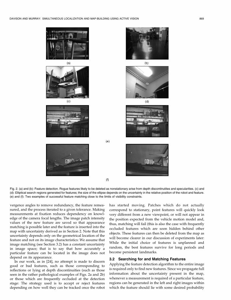
Fig. 2. (a) and (b): Feature detection. Rogue features likely to be deleted as nonstationary arise from depth discontinutites and specularities. (c) and
(d): Elliptical search regions generated for features; the size of the ellipse depends on the uncertainty in the relative position of the robot and feature.
(e) and (f): Two examples of successful feature matching close to the limits of visibility constraints.
(usually three standard deviations from the mean). Typicalsearch ellipses are shown in Figs. 2c and 2d.
Matching within these regions is then achieved by abrute-force correlation search using normalized sum-of-squared-differences for the best match to the saved featurepatch within the (usually relatively small) regions definedby the search ellipses in both left and right images. Aconsistency check is then applied between the two imagelocations found (taking account of the epipolar couplingbetween the two measurements): This gives some robust-ness against mismatches. Normalized sum-of-squared-differences gives the matching a fairly large degree ofrobustness with respect to changing light conditions and inexperiments has meant that the same features could bematched well over the duration of experiments of manyminutes or a few hours, though we have not tested thedurability of matching under extreme changes (fromnatural to artificial lighting, for example).
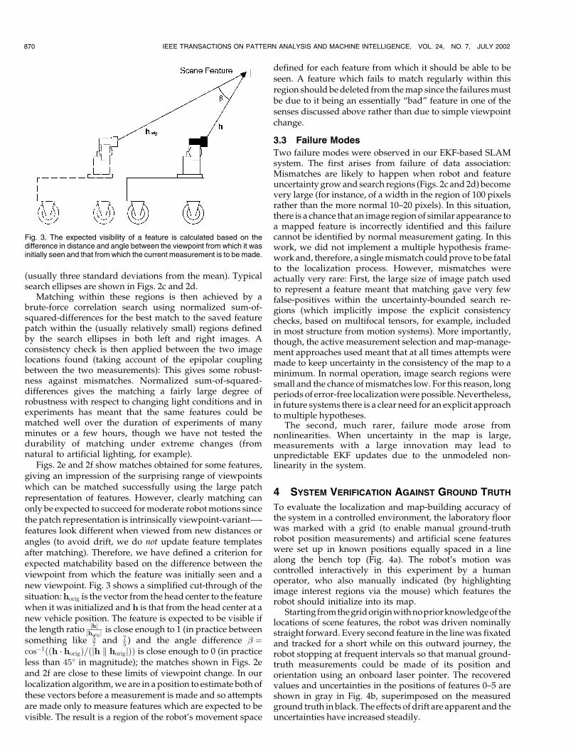
Figs. 2e and 2f show matches obtained for some features,giving an impression of the surprising range of viewpointswhich can be matched successfully using the large patchrepresentation of features. However, clearly matching canonly be expected to succeed for moderate robot motions sincethe patch representation is intrinsically viewpoint-variantÐ-features look different when viewed from new distances orangles (to avoid drift, we do not update feature templatesafter matching). Therefore, we have defined a criterion forexpected matchability based on the difference between theviewpoint from which the feature was initially seen and anew viewpoint. Fig. 3 shows a simplified cut-through of thesituation: horig is the vector from the head center to the featurewhen it was initialized and h is that from the head center at anew vehicle position. The feature is expected to be visible ifthe length ratio jhj
jhorigj is close enough to 1 (in practice betweensomething like 5
7 and 75 ) and the angle difference � �
cosÿ1��h � horig�=�jh k horigj�� is close enough to 0 (in practiceless than 45� in magnitude); the matches shown in Figs. 2eand 2f are close to these limits of viewpoint change. In ourlocalization algorithm, we are in a position to estimate both ofthese vectors before a measurement is made and so attemptsare made only to measure features which are expected to bevisible. The result is a region of the robot's movement space
defined for each feature from which it should be able to beseen. A feature which fails to match regularly within thisregion should be deleted from the map since the failures mustbe due to it being an essentially ªbadº feature in one of thesenses discussed above rather than due to simple viewpointchange.
3.3 Failure Modes
Two failure modes were observed in our EKF-based SLAMsystem. The first arises from failure of data association:Mismatches are likely to happen when robot and featureuncertainty grow and search regions (Figs. 2c and 2d) becomevery large (for instance, of a width in the region of 100 pixelsrather than the more normal 10±20 pixels). In this situation,there is a chance that an image region of similar appearance toa mapped feature is incorrectly identified and this failurecannot be identified by normal measurement gating. In thiswork, we did not implement a multiple hypothesis frame-work and, therefore, a single mismatch could prove to be fatalto the localization process. However, mismatches wereactually very rare: First, the large size of image patch usedto represent a feature meant that matching gave very fewfalse-positives within the uncertainty-bounded search re-gions (which implicitly impose the explicit consistencychecks, based on multifocal tensors, for example, includedin most structure from motion systems). More importantly,though, the active measurement selection and map-manage-ment approaches used meant that at all times attempts weremade to keep uncertainty in the consistency of the map to aminimum. In normal operation, image search regions weresmall and the chance of mismatches low. For this reason, longperiods of error-free localization were possible. Nevertheless,in future systems there is a clear need for an explicit approachto multiple hypotheses.
The second, much rarer, failure mode arose fromnonlinearities. When uncertainty in the map is large,measurements with a large innovation may lead tounpredictable EKF updates due to the unmodeled non-linearity in the system.
4 SYSTEM VERIFICATION AGAINST GROUND TRUTH
To evaluate the localization and map-building accuracy ofthe system in a controlled environment, the laboratory floorwas marked with a grid (to enable manual ground-truthrobot position measurements) and artificial scene featureswere set up in known positions equally spaced in a linealong the bench top (Fig. 4a). The robot's motion wascontrolled interactively in this experiment by a humanoperator, who also manually indicated (by highlightingimage interest regions via the mouse) which features therobot should initialize into its map.
Startingfromthegridoriginwithnopriorknowledgeof thelocations of scene features, the robot was driven nominallystraight forward. Every second feature in the line was fixatedand tracked for a short while on this outward journey, therobot stopping at frequent intervals so that manual ground-truth measurements could be made of its position andorientation using an onboard laser pointer. The recoveredvalues and uncertainties in the positions of features 0±5 areshown in gray in Fig. 4b, superimposed on the measuredground truth in black. The effects of drift are apparent and theuncertainties have increased steadily.
870 IEEE TRANSACTIONS ON PATTERN ANALYSIS AND MACHINE INTELLIGENCE, VOL. 24, NO. 7, JULY 2002
Fig. 3. The expected visibility of a feature is calculated based on thedifference in distance and angle between the viewpoint from which it wasinitially seen and that from which the current measurement is to be made.
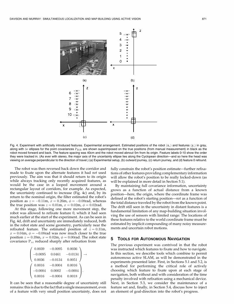
The robot was then reversed back down the corridor andmade to fixate upon the alternate features it had not usedpreviously. The aim was that it should return to its originwhile always tracking only recently acquired features, aswould be the case in a looped movement around arectangular layout of corridors, for example. As expected,the uncertainty continued to increase (Fig. 4c) and, by itsreturn to the nominal origin, the filter estimated the robot'sposition as z � ÿ0:11m, x � 0:26m, � � ÿ0:08rad, whereasthe true position was z � 0:01m, x � 0:02m, � � 0:02rad.
At this stage, following one more movement step, therobot was allowed to refixate feature 0, which it had seenmuch earlier at the start of the experiment. As can be seen inFig. 4d, drift and uncertainty are immediately reduced, bothin the robot state and scene geometry, particularly near therefixated feature. The estimated position of z � 0:31m,x � 0:04m, � � ÿ0:08rad was now much closer to the trueposition z � 0:39m, x � 0:02m, � � 0:00rad. The robot statecovariance Pxx reduced sharply after refixation from
0:0039 ÿ0:0095 0:0036
ÿ0:0095 0:0461 ÿ0:0134
0:0036 ÿ0:0134 0:0051
0B@1CA!
0:0016 ÿ0:0004 0:0016
ÿ0:0004 0:0002 ÿ0:0004
0:0016 ÿ0:0004 0:0018
0B@1CA:
It can be seen that a reasonable degree of uncertainty stillremains: this is due to the fact that a single measurement, evenof a feature with very small position uncertainty, does not
fully constrain the robot's position estimateÐfurther refixa-tions of other features providing complementary informationwill allow the robot's position to be really locked-down (aswill be explained in more detail in Section 5.1).
By maintaining full covariance information, uncertaintygrows as a function of actual distance from a knownpositionÐhere, the origin, where the coordinate frame wasdefined at the robot's starting positionÐnot as a function ofthe total distance traveled by the robot from the known point.The drift still seen in the uncertainty in distant features is afundamental limitation of any map-building situation invol-ving the use of sensors with limited range: The locations ofthese features relative to the world coordinate frame must beestimated by implicit compounding of many noisy measure-ments and uncertain robot motions.
5 TOOLS FOR AUTONOMOUS NAVIGATION
The previous experiment was contrived in that the robotwas instructed which features to fixate and how to navigate.In this section, we describe tools which combine to permitautonomous active SLAM, as will be demonstrated in theexperiments presented later. First, in Sections 5.1 and 5.2, isa method for performing the critical role of activelychoosing which feature to fixate upon at each stage ofnavigation, both without and with consideration of the timepenalty involved with refixation using a mechanical device.Next, in Section 5.3, we consider the maintenance of afeature set and, finally, in Section 5.4, discuss how to injectan element of goal-direction into the robot's progress.
DAVISON AND MURRAY: SIMULTANEOUS LOCALIZATION AND MAP-BUILDING USING ACTIVE VISION 871
Fig. 4. Experiment with artificially introduced features. Experimental arrangement. Estimated positions of the robot �xv� and features �yi� in gray,along with 3� ellipses for the point covariances Pyiyi are shown superimposed on the true positions (from manual measurement) in black as therobot moved forward and back. The feature spacing was 40cm and the robot moved abnout 5m from its origin. Feature labels 0-10 show the orderthey were tracked in. (As ever with stereo, the major axis of the uncertainty ellipse lies along the Cyclopean directionÐand so here the head wasviewing on average perpendicular to the direction of travel.) (a) Experimental setup, (b) outward journey, (c) return journey, and (d) feature 0 refound.
5.1 Active Feature Selection
In our SLAM work, the goal is to build a map of featureswhich aids localization rather than an end result in itself.Nevertheless, in the combined and coupled estimation ofrobot and feature locations which this involves, estimationof the robot position is not intrinsically more ªimportantºthan that of the feature positions: aiming to optimize robotposition uncertainty through active choices is misleadingsince it is the overall integrity and consistency of the mapand the robot's position within it which is the critical factor.We have already seen in the preceding experiment thatrobot position uncertainty relative to a world frame willincrease with distance traveled from the origin of thatframe. It is the mutual, relative uncertainty betweenfeatures and robot which is key.
Our feature selection strategy achieves this by making ameasurement at the currently visible feature in the mapwhose position is hardest to predict, an idea used in the areaof active exploration of surface shape by Whaite and Ferrie[25]. The validity of this principle seems clear: There is littleutility in making a measurement whose result is easy toforecast, whereas much is to be gained by making ameasurement whose result is uncertain and reveals some-thing new. The principle can also be understood in terms ofinformation theory since a measurement which reduces awidely spread prior probability distribution to a more peakedposterior distribution has a high information content.
Our approach to mapping is active, not in the sense ofWhaite and Ferrie who actually control the movement of acamera in order to optimize its utility in sensing surfaceshape, in that we do not choose to alter the robot's path toimprove map estimates. Rather, assuming that the robottrajectory is given or provided by some other goal-drivenprocess, we aim to control the active head's movement andsensing on a short-term tactical basis, making a choicebetween a selection of currently visible features: Whichimmediate feature measurement is the best use of theresources available?
To evaluate candidate measurements, we calculatepredicted measurements h and innovation covariances Sfor all visible features (where feature ªvisibilityº iscalculated as in Section 3.2). In measurement space, thesize of the ellipsoid represented by each S is a normalizedmeasure of the uncertainty in the estimated relative positionof the feature and the robot, and we wish to choose thefeature with the largest uncertainty. To produce a scalardecision criterion, the volume VS in �p;e;v space of theellipsoid at the n� � 3� level is calculated for each visiblefeature (an important point here is that, in our implementa-tion, the measurement noise in the three measurementcomponents �p;e;v is a multiple of the identity matrix).Computing the eigenvalues �1;2;3 of S yields the volume
VS � �4�=3�n3�
����������������1�2�3
p:
We use this measure VS as our score function forcomparing candidate measurements: A measurement withhigh VS is hard to predict and, therefore, advantageous tomake. Here, we do not propose that VS is the optimal choiceof criterion from an information-theoretic point of viewÐ-nevertheless, we believe that it will give results formeasurement comparison which are almost identical to anoptimal criterion. The important point is that since it isevaluated in a measurement space where the measurement
noise is constant, its value reflects how much newinformation is to be obtained from a measurement anddoes not a priori favor features which are, for example,close or far from the robot.
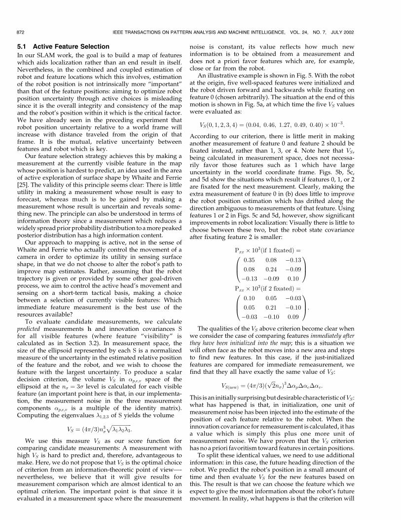
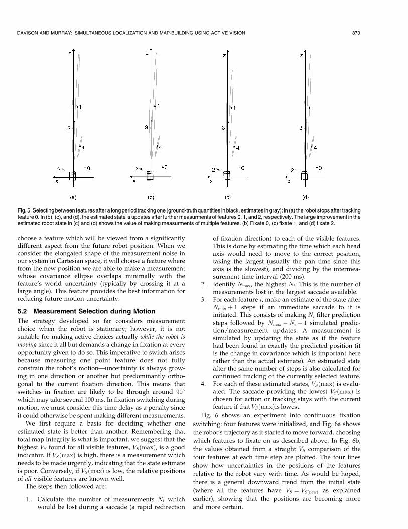
An illustrative example is shown in Fig. 5. With the robotat the origin, five well-spaced features were initialized andthe robot driven forward and backwards while fixating onfeature 0 (chosen arbitrarily). The situation at the end of thismotion is shown in Fig. 5a, at which time the five VS valueswere evaluated as:
VS�0; 1; 2; 3; 4� � �0:04; 0:46; 1:27; 0:49; 0:40� � 10ÿ3:
According to our criterion, there is little merit in makinganother measurement of feature 0 and feature 2 should befixated instead, rather than 1, 3, or 4. Note here that VS ,being calculated in measurement space, does not necessa-rily favor those features such as 1 which have largeuncertainty in the world coordinate frame. Figs. 5b, 5c,and 5d show the situations which result if features 0, 1, or 2are fixated for the next measurement. Clearly, making theextra measurement of feature 0 in (b) does little to improvethe robot position estimation which has drifted along thedirection ambiguous to measurements of that feature. Usingfeatures 1 or 2 in Figs. 5c and 5d, however, show significantimprovements in robot localization: Visually there is little tochoose between these two, but the robot state covarianceafter fixating feature 2 is smaller:
Pxx � 103�if 1 fixated� �0:35 0:08 ÿ0:13
0:08 0:24 ÿ0:09
ÿ0:13 ÿ0:09 0:10
0B@1CA
Pxx � 103�if 2 fixated� �0:10 0:05 ÿ0:03
0:05 0:21 ÿ0:10
ÿ0:03 ÿ0:10 0:09
0B@1CA:
The qualities of the VS above criterion become clear whenwe consider the case of comparing features immediately afterthey have been initialized into the map; this is a situation wewill often face as the robot moves into a new area and stopsto find new features. In this case, if the just-initializedfeatures are compared for immediate remeasurement, wefind that they all have exactly the same value of VS :
VS�new� � �4�=3�����2p
n��3��p��e��v:
This is an initially surprising but desirable characteristic ofVS :what has happened is that, in initialization, one unit ofmeasurement noise has been injected into the estimate of theposition of each feature relative to the robot. When theinnovation covariance for remeasurement is calculated, it hasa value which is simply this plus one more unit ofmeasurement noise. We have proven that the VS criterionhas no a priori favoritism toward features in certain positions.
To split these identical values, we need to use additionalinformation: in this case, the future heading direction of therobot. We predict the robot's position in a small amount oftime and then evaluate VS for the new features based onthis. The result is that we can choose the feature which weexpect to give the most information about the robot's futuremovement. In reality, what happens is that the criterion will
872 IEEE TRANSACTIONS ON PATTERN ANALYSIS AND MACHINE INTELLIGENCE, VOL. 24, NO. 7, JULY 2002
choose a feature which will be viewed from a significantlydifferent aspect from the future robot position: When weconsider the elongated shape of the measurement noise inour system in Cartesian space, it will choose a feature wherefrom the new position we are able to make a measurementwhose covariance ellipse overlaps minimally with thefeature's world uncertainty (typically by crossing it at alarge angle). This feature provides the best information forreducing future motion uncertainty.
5.2 Measurement Selection during Motion
The strategy developed so far considers measurementchoice when the robot is stationary; however, it is notsuitable for making active choices actually while the robot ismoving since it all but demands a change in fixation at everyopportunity given to do so. This imperative to switch arisesbecause measuring one point feature does not fullyconstrain the robot's motionÐuncertainty is always grow-ing in one direction or another but predominantly ortho-gonal to the current fixation direction. This means thatswitches in fixation are likely to be through around 90�
which may take several 100 ms. In fixation switching duringmotion, we must consider this time delay as a penalty sinceit could otherwise be spent making different measurements.
We first require a basis for deciding whether oneestimated state is better than another. Remembering thattotal map integrity is what is important, we suggest that thehighest VS found for all visible features, VS�max�, is a goodindicator. If VS�max� is high, there is a measurement whichneeds to be made urgently, indicating that the state estimateis poor. Conversely, if VS�max� is low, the relative positionsof all visible features are known well.
The steps then followed are:
1. Calculate the number of measurements Ni whichwould be lost during a saccade (a rapid redirection
of fixation direction) to each of the visible features.This is done by estimating the time which each headaxis would need to move to the correct position,taking the largest (usually the pan time since thisaxis is the slowest), and dividing by the intermea-surement time interval (200 ms).
2. Identify Nmax, the highest Ni: This is the number ofmeasurements lost in the largest saccade available.
3. For each feature i, make an estimate of the state afterNmax � 1 steps if an immediate saccade to it isinitiated. This consists of making Ni filter predictionsteps followed by Nmax ÿNi � 1 simulated predic-tion/measurement updates. A measurement issimulated by updating the state as if the featurehad been found in exactly the predicted position (itis the change in covariance which is important hererather than the actual estimate). An estimated stateafter the same number of steps is also calculated forcontinued tracking of the currently selected feature.
4. For each of these estimated states, VS�max� is evalu-ated. The saccade providing the lowest VS�max� ischosen for action or tracking stays with the currentfeature if that VS�max�is lowest.
Fig. 6 shows an experiment into continuous fixation
switching: four features were initialized, and Fig. 6a shows
the robot's trajectory as it started to move forward, choosing
which features to fixate on as described above. In Fig. 6b,
the values obtained from a straight VS comparison of the
four features at each time step are plotted. The four lines
show how uncertainties in the positions of the features
relative to the robot vary with time. As would be hoped,
there is a general downward trend from the initial state
(where all the features have VS � VS�new� as explained
earlier), showing that the positions are becoming more
and more certain.
DAVISON AND MURRAY: SIMULTANEOUS LOCALIZATION AND MAP-BUILDING USING ACTIVE VISION 873
Fig. 5. Selecting between features after a long period tracking one (ground-truth quantities in black, estimates in gray): in (a) the robot stops after trackingfeature 0. In (b), (c), and (d), the estimated state is updates after further measurments of features 0, 1, and 2, respectively. The large improvement in theestimated robot state in (c) and (d) shows the value of making measurments of multiple features. (b) Fixate 0, (c) fixate 1, and (d) fixate 2.
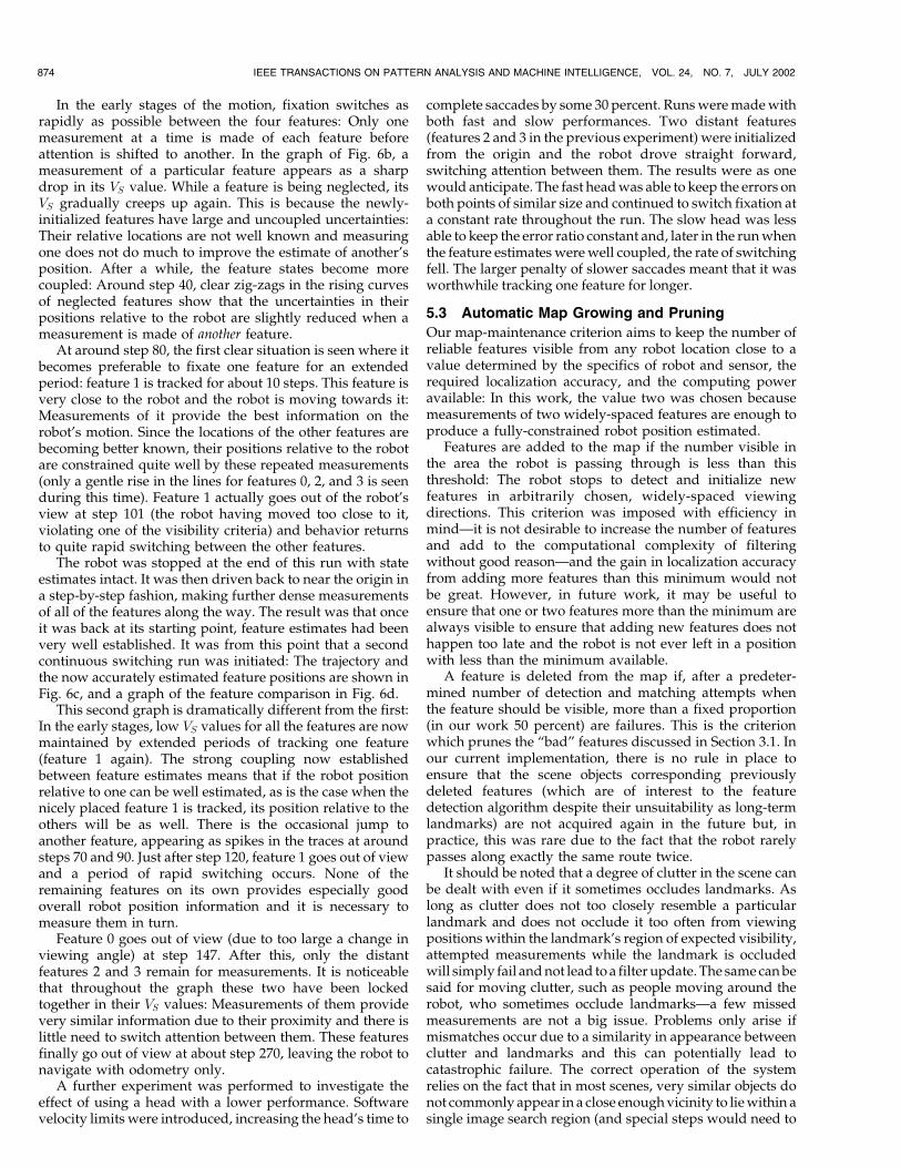
In the early stages of the motion, fixation switches asrapidly as possible between the four features: Only onemeasurement at a time is made of each feature beforeattention is shifted to another. In the graph of Fig. 6b, ameasurement of a particular feature appears as a sharpdrop in its VS value. While a feature is being neglected, itsVS gradually creeps up again. This is because the newly-initialized features have large and uncoupled uncertainties:Their relative locations are not well known and measuringone does not do much to improve the estimate of another'sposition. After a while, the feature states become morecoupled: Around step 40, clear zig-zags in the rising curvesof neglected features show that the uncertainties in theirpositions relative to the robot are slightly reduced when ameasurement is made of another feature.
At around step 80, the first clear situation is seen where itbecomes preferable to fixate one feature for an extendedperiod: feature 1 is tracked for about 10 steps. This feature isvery close to the robot and the robot is moving towards it:Measurements of it provide the best information on therobot's motion. Since the locations of the other features arebecoming better known, their positions relative to the robotare constrained quite well by these repeated measurements(only a gentle rise in the lines for features 0, 2, and 3 is seenduring this time). Feature 1 actually goes out of the robot'sview at step 101 (the robot having moved too close to it,violating one of the visibility criteria) and behavior returnsto quite rapid switching between the other features.
The robot was stopped at the end of this run with stateestimates intact. It was then driven back to near the origin ina step-by-step fashion, making further dense measurementsof all of the features along the way. The result was that onceit was back at its starting point, feature estimates had beenvery well established. It was from this point that a secondcontinuous switching run was initiated: The trajectory andthe now accurately estimated feature positions are shown inFig. 6c, and a graph of the feature comparison in Fig. 6d.
This second graph is dramatically different from the first:In the early stages, low VS values for all the features are nowmaintained by extended periods of tracking one feature(feature 1 again). The strong coupling now establishedbetween feature estimates means that if the robot positionrelative to one can be well estimated, as is the case when thenicely placed feature 1 is tracked, its position relative to theothers will be as well. There is the occasional jump toanother feature, appearing as spikes in the traces at aroundsteps 70 and 90. Just after step 120, feature 1 goes out of viewand a period of rapid switching occurs. None of theremaining features on its own provides especially goodoverall robot position information and it is necessary tomeasure them in turn.
Feature 0 goes out of view (due to too large a change inviewing angle) at step 147. After this, only the distantfeatures 2 and 3 remain for measurements. It is noticeablethat throughout the graph these two have been lockedtogether in their VS values: Measurements of them providevery similar information due to their proximity and there islittle need to switch attention between them. These featuresfinally go out of view at about step 270, leaving the robot tonavigate with odometry only.
A further experiment was performed to investigate theeffect of using a head with a lower performance. Softwarevelocity limits were introduced, increasing the head's time to
complete saccades by some 30 percent. Runs were made withboth fast and slow performances. Two distant features(features 2 and 3 in the previous experiment) were initializedfrom the origin and the robot drove straight forward,switching attention between them. The results were as onewould anticipate. The fast head was able to keep the errors onboth points of similar size and continued to switch fixation ata constant rate throughout the run. The slow head was lessable to keep the error ratio constant and, later in the run whenthe feature estimates were well coupled, the rate of switchingfell. The larger penalty of slower saccades meant that it wasworthwhile tracking one feature for longer.
5.3 Automatic Map Growing and Pruning
Our map-maintenance criterion aims to keep the number ofreliable features visible from any robot location close to avalue determined by the specifics of robot and sensor, therequired localization accuracy, and the computing poweravailable: In this work, the value two was chosen becausemeasurements of two widely-spaced features are enough toproduce a fully-constrained robot position estimated.
Features are added to the map if the number visible inthe area the robot is passing through is less than thisthreshold: The robot stops to detect and initialize newfeatures in arbitrarily chosen, widely-spaced viewingdirections. This criterion was imposed with efficiency inmindÐit is not desirable to increase the number of featuresand add to the computational complexity of filteringwithout good reasonÐand the gain in localization accuracyfrom adding more features than this minimum would notbe great. However, in future work, it may be useful toensure that one or two features more than the minimum arealways visible to ensure that adding new features does nothappen too late and the robot is not ever left in a positionwith less than the minimum available.
A feature is deleted from the map if, after a predeter-mined number of detection and matching attempts whenthe feature should be visible, more than a fixed proportion(in our work 50 percent) are failures. This is the criterionwhich prunes the ªbadº features discussed in Section 3.1. Inour current implementation, there is no rule in place toensure that the scene objects corresponding previouslydeleted features (which are of interest to the featuredetection algorithm despite their unsuitability as long-termlandmarks) are not acquired again in the future but, inpractice, this was rare due to the fact that the robot rarelypasses along exactly the same route twice.
It should be noted that a degree of clutter in the scene canbe dealt with even if it sometimes occludes landmarks. Aslong as clutter does not too closely resemble a particularlandmark and does not occlude it too often from viewingpositions within the landmark's region of expected visibility,attempted measurements while the landmark is occludedwill simply fail and not lead to a filter update. The same can besaid for moving clutter, such as people moving around therobot, who sometimes occlude landmarksÐa few missedmeasurements are not a big issue. Problems only arise ifmismatches occur due to a similarity in appearance betweenclutter and landmarks and this can potentially lead tocatastrophic failure. The correct operation of the systemrelies on the fact that in most scenes, very similar objects donot commonly appear in a close enough vicinity to lie within asingle image search region (and special steps would need to
874 IEEE TRANSACTIONS ON PATTERN ANALYSIS AND MACHINE INTELLIGENCE, VOL. 24, NO. 7, JULY 2002
be taken to enable the system to work in scenes with a lot ofrepeated texture).
5.4 Goal-Directed Navigation
The purpose of this paper is to build a map which aidslocalization rather than one dense enough to be useful foridentifying free space. Nevertheless, this localization meth-od could form part of a complete system where anadditional module (visual or otherwise) could perform thisrole and communicate with the localization system to labelsome of its features with contextual information, such asªthis is a feature at the left-hand side of an obstacle.º
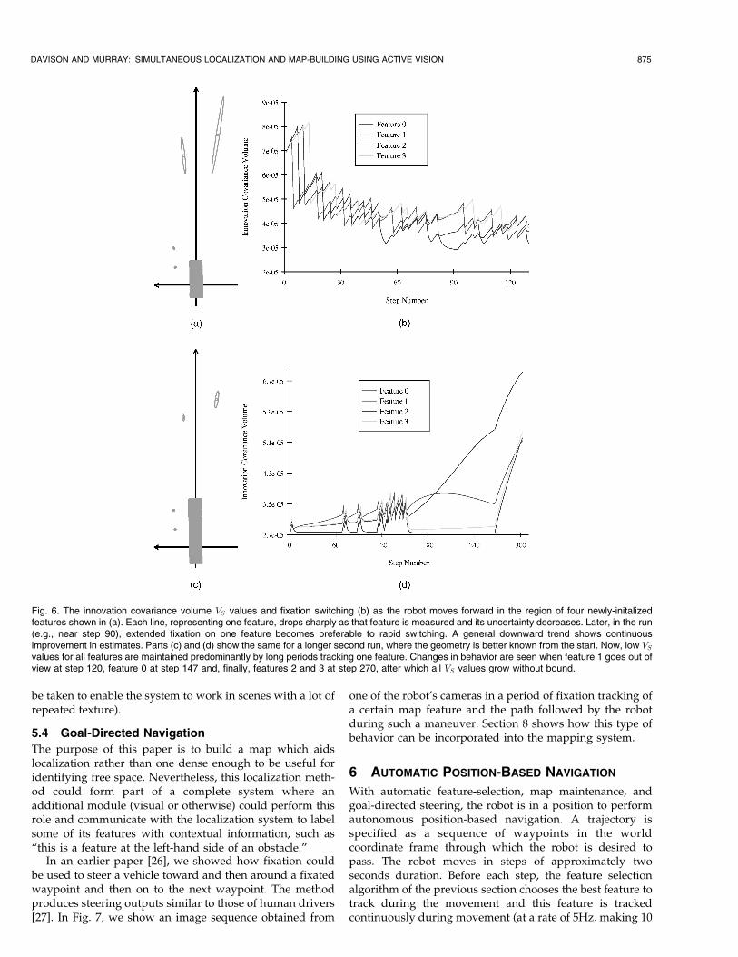
In an earlier paper [26], we showed how fixation couldbe used to steer a vehicle toward and then around a fixatedwaypoint and then on to the next waypoint. The methodproduces steering outputs similar to those of human drivers[27]. In Fig. 7, we show an image sequence obtained from
one of the robot's cameras in a period of fixation tracking ofa certain map feature and the path followed by the robotduring such a maneuver. Section 8 shows how this type ofbehavior can be incorporated into the mapping system.
6 AUTOMATIC POSITION-BASED NAVIGATION
With automatic feature-selection, map maintenance, andgoal-directed steering, the robot is in a position to performautonomous position-based navigation. A trajectory isspecified as a sequence of waypoints in the worldcoordinate frame through which the robot is desired topass. The robot moves in steps of approximately twoseconds duration. Before each step, the feature selectionalgorithm of the previous section chooses the best feature totrack during the movement and this feature is trackedcontinuously during movement (at a rate of 5Hz, making 10
DAVISON AND MURRAY: SIMULTANEOUS LOCALIZATION AND MAP-BUILDING USING ACTIVE VISION 875
Fig. 6. The innovation covariance volume VS values and fixation switching (b) as the robot moves forward in the region of four newly-initalizedfeatures shown in (a). Each line, representing one feature, drops sharply as that feature is measured and its uncertainty decreases. Later, in the run(e.g., near step 90), extended fixation on one feature becomes preferable to rapid switching. A general downward trend shows continuousimprovement in estimates. Parts (c) and (d) show the same for a longer second run, where the geometry is better known from the start. Now, low VSvalues for all features are maintained predominantly by long periods tracking one feature. Changes in behavior are seen when feature 1 goes out ofview at step 120, feature 0 at step 147 and, finally, features 2 and 3 at step 270, after which all VS values grow without bound.
measurements and the same number of filter prediction/update steps per movement step). The robot stops for ashort period between movement steps to make a grossfixation change to another feature. The breaks in movementare also used to automatically add features to or delete themfrom the map as necessary. As the robot drives makingmeasurements of the chosen feature and updating thelocalization filter, the steering angle is continuously set tothe appropriate value to reach the next waypoint.
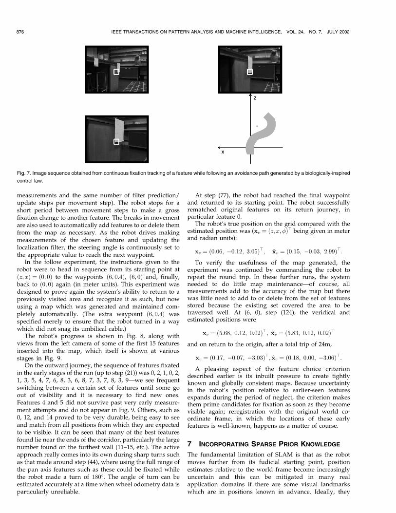
In the follow experiment, the instructions given to therobot were to head in sequence from its starting point at�z; x� � �0; 0� to the waypoints �6; 0:4�, �6; 0� and, finally,back to �0; 0� again (in meter units). This experiment wasdesigned to prove again the system's ability to return to apreviously visited area and recognize it as such, but nowusing a map which was generated and maintained com-pletely automatically. (The extra waypoint �6; 0:4� wasspecified merely to ensure that the robot turned in a waywhich did not snag its umbilical cable.)
The robot's progress is shown in Fig. 8, along withviews from the left camera of some of the first 15 featuresinserted into the map, which itself is shown at variousstages in Fig. 9.
On the outward journey, the sequence of features fixatedin the early stages of the run (up to step (21)) was 0, 2, 1, 0, 2,1, 3, 5, 4, 7, 6, 8, 3, 6, 8, 7, 3, 7, 8, 3, 9Ðwe see frequentswitching between a certain set of features until some goout of visibility and it is necessary to find new ones.Features 4 and 5 did not survive past very early measure-ment attempts and do not appear in Fig. 9. Others, such as0, 12, and 14 proved to be very durable, being easy to seeand match from all positions from which they are expectedto be visible. It can be seen that many of the best featuresfound lie near the ends of the corridor, particularly the largenumber found on the furthest wall (11±15, etc.). The activeapproach really comes into its own during sharp turns suchas that made around step (44), where using the full range ofthe pan axis features such as these could be fixated whilethe robot made a turn of 180�. The angle of turn can beestimated accurately at a time when wheel odometry data isparticularly unreliable.
At step (77), the robot had reached the final waypointand returned to its starting point. The robot successfullyrematched original features on its return journey, inparticular feature 0.
The robot's true position on the grid compared with theestimated position was (xv � �z; x; ��> being given in meterand radian units):
xv � �0:06; ÿ0:12; 3:05�>; xv � �0:15; ÿ0:03; 2:99�>:To verify the usefulness of the map generated, the
experiment was continued by commanding the robot torepeat the round trip. In these further runs, the systemneeded to do little map maintenanceÐof course, allmeasurements add to the accuracy of the map but therewas little need to add to or delete from the set of featuresstored because the existing set covered the area to betraversed well. At (6, 0), step (124), the veridical andestimated positions were
xv � �5:68; 0:12; 0:02�>; xv � �5:83; 0:12; 0:02�>
and on return to the origin, after a total trip of 24m,
xv � �0:17; ÿ0:07; ÿ3:03�>; xv � �0:18; 0:00; ÿ3:06�>:A pleasing aspect of the feature choice criterion
described earlier is its inbuilt pressure to create tightlyknown and globally consistent maps. Because uncertaintyin the robot's position relative to earlier-seen featuresexpands during the period of neglect, the criterion makesthem prime candidates for fixation as soon as they becomevisible again; reregistration with the original world co-ordinate frame, in which the locations of these earlyfeatures is well-known, happens as a matter of course.
7 INCORPORATING SPARSE PRIOR KNOWLEDGE
The fundamental limitation of SLAM is that as the robotmoves further from its fudicial starting point, positionestimates relative to the world frame become increasinglyuncertain and this can be mitigated in many realapplication domains if there are some visual landmarkswhich are in positions known in advance. Ideally, they
876 IEEE TRANSACTIONS ON PATTERN ANALYSIS AND MACHINE INTELLIGENCE, VOL. 24, NO. 7, JULY 2002
Fig. 7. Image sequence obtained from continuous fixation tracking of a feature while following an avoidance path generated by a biologically-inspired
control law.
would be distributed uniformly around the mapped area.They must also be visually distinguishable from otherfeatures which could, within the growing uncertaintybounds, be mistaken for them: however, this can be moreeasily achieved with these hand-picked features thenthose detected autonomously by the robot. There havebeen many approaches to robot localization using land-marks in known locations: when a map is given inadvance, the localization problem becomes relativelysimple [4]. Here, however, we wish to show that a smallnumber of natural visual landmarks (small in the sensethat there are not enough to permit good localizationusing only these landmarks) can be easily integrated intothe SLAM framework to improve localization.
The landmark's known location is initialized into the
estimated state vector as the coordinates yi of a feature i at
the start of the run (i.e., as though it had already been
observed) and its covariance Pyiyi is set with all elements
equal to zero, along with the cross-covariances between the
feature state and that of the robot and other features. In
prediction and measurement updates, the filter handles
these perfectly known landmarks just like any other feature.
Note, however, that uncertainty in a landmark's relative
position will grow as the robot moves before observing it,
and so the VS criterion will, as ever, make the landmark
desirable to look at.When there are perfectly known features in the map, it is
these which define the world coordinate frame, rather than
DAVISON AND MURRAY: SIMULTANEOUS LOCALIZATION AND MAP-BUILDING USING ACTIVE VISION 877
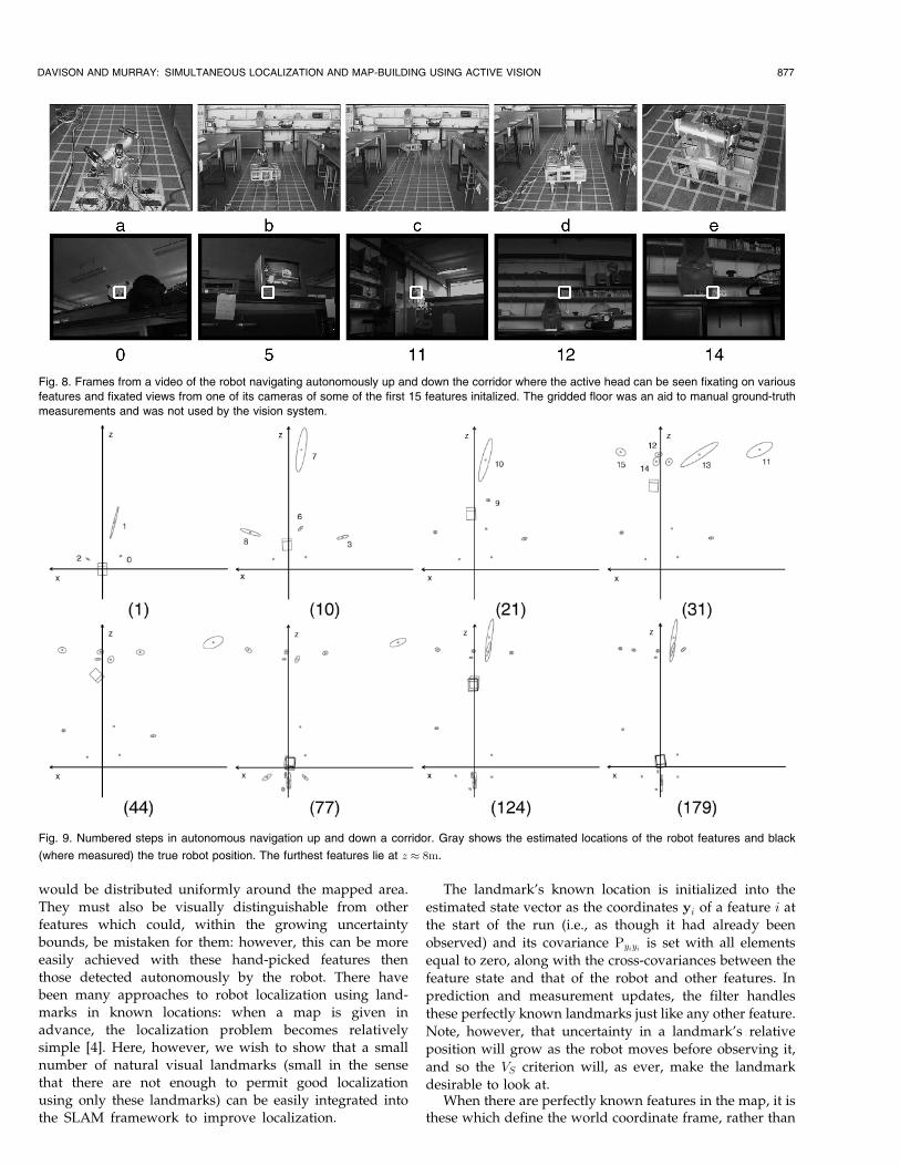
Fig. 8. Frames from a video of the robot navigating autonomously up and down the corridor where the active head can be seen fixating on variousfeatures and fixated views from one of its cameras of some of the first 15 features initalized. The gridded floor was an aid to manual ground-truthmeasurements and was not used by the vision system.
Fig. 9. Numbered steps in autonomous navigation up and down a corridor. Gray shows the estimated locations of the robot features and black
(where measured) the true robot position. The furthest features lie at z � 8m.
the arbitrary definition of this frame at the robot's startingposition used before. Therefore, in this experiment, therobot's position was initialized with a starting uncertaintynot equal to zero: An assessment was made of the uncertaintyin robot location and orientation relative to the knownlandmarks (with standard deviation of the order of a fewcentimetres and degrees) and this formed the initial Pxx. Notetoo that as well as perfectly known landmarks, it would bestraightforward to introduce landmarks in partially knownpositions (i.e., with some uncertainty) into this framework.
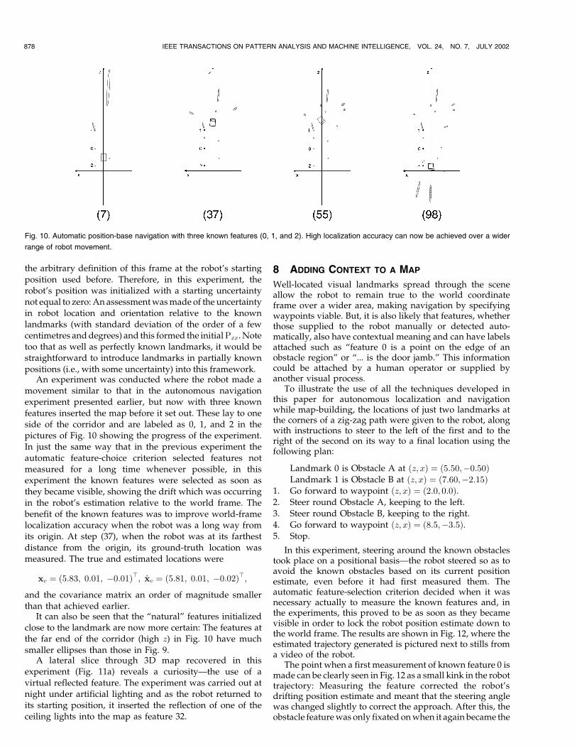
An experiment was conducted where the robot made amovement similar to that in the autonomous navigationexperiment presented earlier, but now with three knownfeatures inserted the map before it set out. These lay to oneside of the corridor and are labeled as 0, 1, and 2 in thepictures of Fig. 10 showing the progress of the experiment.In just the same way that in the previous experiment theautomatic feature-choice criterion selected features notmeasured for a long time whenever possible, in thisexperiment the known features were selected as soon asthey became visible, showing the drift which was occurringin the robot's estimation relative to the world frame. Thebenefit of the known features was to improve world-framelocalization accuracy when the robot was a long way fromits origin. At step (37), when the robot was at its farthestdistance from the origin, its ground-truth location wasmeasured. The true and estimated locations were
xv � �5:83; 0:01; ÿ0:01�>; xv � �5:81; 0:01; ÿ0:02�>;and the covariance matrix an order of magnitude smallerthan that achieved earlier.
It can also be seen that the ªnaturalº features initializedclose to the landmark are now more certain: The features atthe far end of the corridor (high z) in Fig. 10 have muchsmaller ellipses than those in Fig. 9.
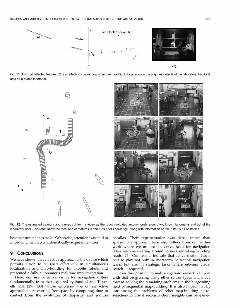
A lateral slice through 3D map recovered in thisexperiment (Fig. 11a) reveals a curiosityÐthe use of avirtual reflected feature. The experiment was carried out atnight under artificial lighting and as the robot returned toits starting position, it inserted the reflection of one of theceiling lights into the map as feature 32.
8 ADDING CONTEXT TO A MAP
Well-located visual landmarks spread through the sceneallow the robot to remain true to the world coordinateframe over a wider area, making navigation by specifyingwaypoints viable. But, it is also likely that features, whetherthose supplied to the robot manually or detected auto-matically, also have contextual meaning and can have labelsattached such as ªfeature 0 is a point on the edge of anobstacle regionº or ª... is the door jamb.º This informationcould be attached by a human operator or supplied byanother visual process.
To illustrate the use of all the techniques developed inthis paper for autonomous localization and navigationwhile map-building, the locations of just two landmarks atthe corners of a zig-zag path were given to the robot, alongwith instructions to steer to the left of the first and to theright of the second on its way to a final location using thefollowing plan:
Landmark 0 is Obstacle A at �z; x� � �5:50;ÿ0:50�Landmark 1 is Obstacle B at �z; x� � �7:60;ÿ2:15�
1. Go forward to waypoint �z; x� � �2:0; 0:0�.2. Steer round Obstacle A, keeping to the left.3. Steer round Obstacle B, keeping to the right.4. Go forward to waypoint �z; x� � �8:5;ÿ3:5�.5. Stop.
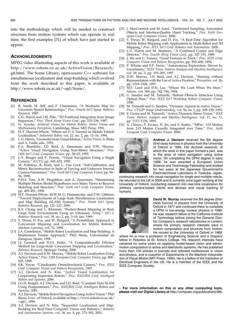
In this experiment, steering around the known obstaclestook place on a positional basisÐthe robot steered so as toavoid the known obstacles based on its current positionestimate, even before it had first measured them. Theautomatic feature-selection criterion decided when it wasnecessary actually to measure the known features and, inthe experiments, this proved to be as soon as they becamevisible in order to lock the robot position estimate down tothe world frame. The results are shown in Fig. 12, where theestimated trajectory generated is pictured next to stills froma video of the robot.
The point when a first measurement of known feature 0 ismade can be clearly seen in Fig. 12 as a small kink in the robottrajectory: Measuring the feature corrected the robot'sdrifting position estimate and meant that the steering anglewas changed slightly to correct the approach. After this, theobstacle feature was only fixated on when it again became the
878 IEEE TRANSACTIONS ON PATTERN ANALYSIS AND MACHINE INTELLIGENCE, VOL. 24, NO. 7, JULY 2002
Fig. 10. Automatic position-base navigation with three known features (0, 1, and 2). High localization accuracy can now be achieved over a wider
range of robot movement.
best measurement to make. Otherwise, attention was paid toimproving the map of automatically-acquired features.
9 CONCLUSIONS
We have shown that an active approach is the device whichpermits vision to be used effectively in simultaneouslocalization and map-building for mobile robots andpresented a fully autonomous real-time implementation.
Here, our use of active vision for navigation differsfundamentally from that explored by Sandini and Tistar-elli [28], [29], [30] whose emphasis was on an activeapproach to recovering free space by computing time tocontact from the evolution of disparity and motion
parallax. Their representation was dense rather thansparse. The approach here also differs from our earlierwork where we utilized an active head for navigationtasks, such as steering around corners and along windingroads [26]. Our results indicate that active fixation has apart to play not only in short-term or tactical navigationtasks, but also in strategic tasks where informed visualsearch is required.
From this position, visual navigation research can joinwith that progressing using other sensor types and movetoward solving the remaining problems in the burgeoningfield of sequential map-building. It is also hoped that byintroducing the problems of robot map-building to re-searchers in visual reconstruction, insights can be gained
DAVISON AND MURRAY: SIMULTANEOUS LOCALIZATION AND MAP-BUILDING USING ACTIVE VISION 879
Fig. 11. A virtual reflected feature: 32 is a reflection in a window of an overhead light. Its position in the map lies outside of the laboratory, but it still
acts as a stable landmark.
Fig. 12. The estimated trajetory and frames cut from a video as the robot navigated autonomously around two known landmarks and out of the
laboratory door. The robot knew the locations of features 0 and 1 as prior knowledge, along with information on their status as obstacles.
into the methodology which will be needed to construct
structure from motion systems which can operate in real
time, the first examples [31] of which have just started to
appear.
ACKNOWLEDGMENTS
MPEG video illustrating aspects of this work is available at
http://www.robots.ox.ac.uk/ActiveVision/Research/
gti.html. The Scene Library, open-source C++ software for
simultaneous localization and map-building which evolved
from the work described in this paper, is available at
http://www.robots.ox.ac.uk/~ajd/Scene/.
REFERENCES
[1] R. Smith, M. Self, and P. Cheeseman, ªA Stochastic Map forUncertain Spatial Relationships,º Proc. Fourth Int'l Symp. RoboticsResearch, 1987.
[2] C.G. Harris and J.M. Pike, ª3D Positional Integration from ImageSequences,º Proc. Third Alvey Vision Conf., pp. 233±236, 1987.
[3] N. Ayache, Artificial Vision for Mobile Robots: Stereo Vision andMultisensory Perception, Cambridge, Mass: MIT Press, 1991.
[4] H. F. Durrant-Whyte, ªWhere am I? A Tutorial on Mobile VehicleLocalization,º Industrial Robot, vol. 21, no. 2, pp. 11±16, 1994.
[5] C.G. Harris, ªGeometry from Visual Motion,º Active Vision, A. Blakeand A. Yuille, eds., 1992.
[6] P.A. Beardsley, I.D. Reid, A. Zisserman, and D.W. Murray,ªActive Visual Navigation Using Non-Metric Structure,º Proc.Fifth Int'l Conf. Computer Vision, pp. 58±65, 1995.
[7] J.-Y. Bouget and P. Perona, ªVisual Navigation Using a SingleCamera,º ICCV5, pp. 645±652, 1995.
[8] M. Pollefeys, R. Koch, and L. Van Gool, ªSelf-Calibration andMetric Reconstruction in Spite of Varying and Unknown InternalCamera Parameters,º Proc. Sixth Int'l Conf. Computer Vision, pp. 90±96, 1998.
[9] P.H.S. Torr, A.W. Fitzgibbon, and A. Zisserman, ªMaintainingMultiple Motion Model Hypotheses over Many Views to RecoverMatching and Structure,º Proc. Sixth Int'l Conf. Computer Vision,pp. 485±491, 1998.
[10] H.F. Durrant-Whyte, M.W.M. G. Dissanayake, and P.W. Gibbens,ªToward Deployments of Large Scale Simultaneous Localizationand Map Building (SLAM) Systems,º Proc. Ninth Int'l Symp.Robotics Research, pp. 121±127, 1999.
[11] K.S. Chong and L. Kleeman, ªFeature-Based Mapping in Real,Large Scale Environments Using an Ultrasonic Array,º Int'l J.Robotics Research, vol. 18, no. 2, pp. 3±19, Jan. 1999.
[12] S. Thrun, D. Fox, and W. Burgard, ªA Probabilistic Approach toConcurrent Mapping and Localization for Mobile Robots,ºMachine Learning, vol. 31, 1998.
[13] J.A. Castellanos, ªMobile Robot Localization and Map Building: AMultisensor Fusion Approach,º PhD thesis, Universidad deZaragoza, Spain, 1998.
[14] J.J. Leonard and H.J.S. Feder, ªA Computationally EfficientMethod for Large-Scale Concurrent Mapping and Localization,ºRobotics Research, Springer Verlag, 2000.
[15] A.J. Davison and D.W. Murray, ªMobile Robot Localization UsingActive Vision,º Proc. Fifth European Conf. Computer Vision, pp. 809±825, 1998.
[16] S.K. Nayar, ªCatadioptric Omnidirectional Camera,º Proc. IEEEConf. Computer Vision and Pattern Recognition, 1997.
[17] A.J. Davison and N. Kita, ªActive Visual Localization forCooperating Inspection Robots,º Proc. IEEE/RSJ Conf. IntelligentRobots and Systems, 2000.
[18] J.G.H. Knight, A.J. Davison, and I.D. Reid, ªConstant Time SLAMUsing Postponement,º Proc. IEEE/RSJ Conf. Intelligent Robots andSystems, 2001.
[19] A.J. Davison, ªMobile Robot Navigation Using Active Vision,º PhDthesis, Univ. of Oxford, available at http://www.robots.ox.ac.uk/~ajd/, 1998.
[20] A.J. Davison and N. Kita, ªSequential Localization and Map-Building for Real-Time Computer Vision and Robotics,º Roboticsand Autonomous Systems, vol. 36, no. 4, pp. 171±183, 2001.
[21] J. MacCormick and M. Isard, ªPartitioned Sampling, ArticulatedObjects and Interface-Quality Hand Tracking,º Proc. Sixth Eur-opean Conf. Computer Vision, 2000.
[22] S. Thrun, W. Burgard, and D. Fox, ªA Real-Time Algorithm forMobile Robot Mapping with Applications to Multi-Robot and 3DMapping,º Proc. IEEE Int'l Conf. Robotics and Automation, 2000.
[23] C.G. Harris and M. Stephens, ªA Combined Corner and EdgeDetector,º Proc. Fourth Alvey Vision Conf., pp. 147±151, 1988.
[24] J. Shi and C. Tomasi, ªGood Features to Track,º Proc. IEEE Conf.Computer Vision and Pattern Recognition, pp. 593±600, 1994.
[25] P. Whaite and F.P. Ferrie, ªAutonomous Exploration: Driven byUncertainty,º IEEE Trans. Pattern Analysis and Machine Intelligence,vol. 19, no. 3, pp. 193±205, 1997.
[26] D.W. Murray, I.D. Reid, and A.J. Davison, ªSteering withoutRepresentation with the Use of Active Fixation,º Perception, vol. 26,pp. 1519±1528, 1997.
[27] M.F. Land and D.N. Lee, ªWhere We Look When We Steer,ºNature, vol. 369, pp. 742±744, 1994.
[28] G. Sandini and M. Tistarelli, ªRobust Obstacle Detection UsingOptical Flow,º Proc. IEEE Int'l Workshop Robust Computer Vision,1990.
[29] M. Tistarelli and G. Sandini, ªDynamic Aspects in Active Vision,ºProc. CVGIP: Image Understanding, vol. 56, no. 1, pp. 108±129, 1992.
[30] E. Grossi and M. Tistarelli, ªActive/Dynamic Stereo Vision,º IEEETrans. Pattern Analysis and Machine Intelligence, vol. 17, no. 11,pp. 1117±1128, 1995.
[31] A. Chiuso, P. Favaro, H. Jin, and S. Soatto, ª`MFm': 3-D Motionfrom 2-D Motion Causally Integrated over Time,º Proc. SixthEuropean Conf. Computer Vision, 2000.
Andrew J. Davison received the BA degree(first-class honors) in physics from the Universityof Oxford in 1994. His doctoral research, ofwhich the work in this paper formed a part, wasin the area of robot navigation using activevision. On completing the DPhil degree in early1998, he was awarded a European UnionScience and Technology Fellowship and workedfor two years at the Japanese Government'sElectrotechnical Laboratory in Tsukuba, Japan,
continuing research into visual navigation for single and multiple robots.He returned to the UK in 2000 and is currently once again working at theUniversity of Oxford, conducting research into real-time localization forarbitrary camera-based robots and devices and visual tracking ofhumans.
David W. Murray received the BA degree (first-class honors) in physics from the University ofOxford in 1977 and continued there to completea DPhil in low-energy nuclear physics in 1980.He was research fellow at the California Instituteof Technology before joining the General Elec-tric Company's research laboratories in London,where his primary research interests were inmotion computation and structure from motion.He moved to the University of Oxford in 1989,
where he is now a professor of Engineering Science and a Drapers'fellow in Robotics at St. Anne's College. His research interests havecentered for some years on applying model-based vision and stereo-motion computation to active and telerobotic systems. He has publishedmore than 100 articles in journals and refereed conferences in visionand physics, and is coauthor of Experiments in the Machine Interpreta-tion of Visual Motion (MIT Press, 1990). He is a fellow of the Institution ofElectrical Engineers in the UK. He is a member of the IEEE and theIEEE Computer Society.
. For more information on this or any other computing topic,please visit our Digital Library at http://computer.org/publications/dlib.
880 IEEE TRANSACTIONS ON PATTERN ANALYSIS AND MACHINE INTELLIGENCE, VOL. 24, NO. 7, JULY 2002
Related Documents